M-Class - Mercedes-Benz
354
M-Class Operator's Manual Order no. 6515 5564 13 Part no. 1665840702 Edition B 2015 É1665840702JËÍ 1665840702 M-Class Operator's Manual
-
Upload
khangminh22 -
Category
Documents
-
view
2 -
download
0
Transcript of M-Class - Mercedes-Benz

M-ClassOperator's Manual
Order no. 6515 5564 13 Part no. 1665840702 Edition B 2015
É1665840702JËÍ1665840702
M-Cla
ssOp
erator
'sMa
nual
Publication detailsInternet
Further information about Mercedes-Benzvehicles and about Daimler AG can be foundon the following websites:http://www.mbusa.com (USA only)http://www.mercedes-benz.ca (Canadaonly)
Editorial office
©Daimler AG: Not to be reprinted, translatedor otherwise reproduced, in whole or in part,without written permission from Daimler AG.
Vehicle manufacturer
Daimler AGMercedesstraße 13770327 StuttgartGermany
SymbolsRegistered trademarks:RBluetooth® is a registered trademark of
Bluetooth SIG Inc.RDTS is a registered trademark of DTS, Inc.RDolby and MLP are registered trademarks
of DOLBY Laboratories.RBabySmart™, ESP® and PRE-SAFE® are
registered trademarks of Daimler AG.RHomeLink® is a registered trademark of
Johnson Controls.RiPod® and iTunes® are registered trade-
marks of Apple Inc.RLogic7® is a registered trademark of Har-
man International Industries.RMicrosoft® and Windows media® are reg-
istered trademarks of Microsoft Corpora-tion.
RSIRIUS is a registered trademark of SiriusXM Radio Inc.
RHD Radio is a registered trademark of iBiq-uity Digital Corporation.
RGracenote® is a registered trademark ofGracenote, Inc.
RZAGATSurvey® and related brands are reg-istered trademarks of ZagatSurvey, LLC.
In this Operator's Manual you will find the fol-lowing symbols:
G WARNINGWarning notes make you aware of dangerswhich could pose a threat to your health orlife, or to the health and life of others.
H Environmental noteEnvironmental notes provide you with infor-mation on environmentally aware actions ordisposal.
! Notes on material damage alert you todangers that could lead to damage to yourvehicle.
i Practical tips or further information thatcould be helpful to you.
X This symbol indicates an instructionthat must be followed.
X Several of these symbols in succes-sion indicate an instruction with sev-eral steps.
(Ypage)
This symbol tells you where you canfind more information about a topic.
YY This symbol indicates a warning or aninstruction that is continued on thenext page.
Disхplay
This text indicates a message in themultifunction/COMAND/Audio dis-play.
~ This symbol tells you that you can findfurther information in the DigitalOperator's Manual.
Parts of the software in the vehicle are pro-tected by copyright © 2005The FreeType Projecthttp://www.freetype.org. All rightsreserved.
As at 12.03.2014

Welcome to the world of Mercedes-BenzWe urge you to read this Operator's Manualcarefully and familiarize yourself with thevehicle before driving. For your own safetyand a longer vehicle life, follow the instruc-tions and warning notices in this manual.Ignoring them could result in damage to thevehicle or personal injury to you or others.Vehicle damage caused by failure to followinstructions is not covered by the Mercedes-Benz Limited Warranty.This Operator's Manual provides informationon the most important functions of your vehi-cle.Additional information on convenience func-tions can be found in COMAND in your DigitalOperator's Manual.The equipment or product designation of yourvehicle may vary depending on:RmodelRorderRcountry specificationRavailabilityMercedes-Benz therefore reserves the rightto introduce changes in the following areas:RdesignRequipmentRtechnical featuresThe equipment in your vehicle may thereforediffer from that shown in the descriptions andillustrations.The following are integral components of thevehicle:RDigital Operator's ManualROperator's ManualRMaintenance BookletREquipment-dependent supplementsKeep these documents in the vehicle at alltimes. If you sell the vehicle, always pass alldocuments on to the new owner.The technical documentation team atDaimler AG wishes you safe and pleasantmotoring.
Mercedes-Benz USA, LLCMercedes-Benz Canada, Inc.A Daimler Company
1665840702 É1665840702JËÍ


Index ....................................................... 4
Digital Operator's Manual .................. 25
Introduction ......................................... 30
At a glance ........................................... 39
Safety ................................................... 49
Opening and closing ........................... 85
Seats, steering wheel and mirrors .. 103
Lights and windshield wipers .......... 109
Climate control ................................. 121
Driving and parking .......................... 129
On-board computer and displays .... 195
COMAND ............................................ 223
Stowage and features ...................... 243
Maintenance and care ...................... 263
Roadside Assistance ........................ 271
Wheels and tires ............................... 289
Technical data ................................... 335
Contents 3

1, 2, 3 ...4ETS
see ETS/4ETS (Electronic Trac-tion System)
4MATIC (permanent four-wheeldrive) .................................................. 18312 V socket
see Sockets115 V socket ...................................... 254360° camera
Function/notes ............................. 169
AABS (Anti-lock Braking System)
Display message ............................ 200Function/notes ................................ 74Important safety notes .................... 74Warning lamp ................................. 215
Access data of the mobile phonenetwork provider
Making entries ............................... 237Selecting ........................................ 236
AccidentAutomaticmeasures after an acci-dent ................................................. 66
Activating/deactivating coolingwith air dehumidification ................. 127Active Blind Spot Assist
Activating/deactivating (on-board computer) ............................ 197Display message ............................ 199Function/information .................... 177
Active Curve SystemDisplay message ............................ 199Function/notes ............................. 162
Active Driving Assistance package .. 177Active Lane Keeping Assist
Activating/deactivating (on-board computer) ............................ 197Display message ............................ 199Function/information .................... 180
Active Parking AssistDisplay message ............................ 199Function/notes ............................. 166Important safety notes .................. 166Towing a trailer .............................. 167
ADAPTIVE BRAKE ................................. 81Adaptive Brake Assist
Function/notes ................................ 77Adaptive damping system
see ADS (Adaptive Damping System)Adaptive Highbeam Assist
Display message ............................ 199Function/notes ............................. 113Switching on/off ........................... 113
Additives (engine oil) ........................ 342Address book
see also Digital Operator's Man-ual .................................................. 224
ADS (Adaptive Damping System)Function/notes ............................. 162
Air bagsDeployment ..................................... 64Display message .................... 199, 205Front air bag (driver, frontpassenger) ....................................... 57Important safety notes .................... 56Introduction ..................................... 56Knee bag .......................................... 58PASSENGER AIR BAG OFF indica-tor lamp ........................................... 51Side impact air bag .......................... 58Window curtain air bag .................... 58
Air filter (display message) .............. 199AIR FLOW ........................................... 127Air-conditioning system
see Climate controlAIRMATIC (display message) ............ 199AIRMATIC package
ADS (Adaptive Damping System) ... 162Function/notes ............................. 162Level control .................................. 162
AlarmATA (Anti-Theft Alarm system) ......... 83Switching off (ATA) .......................... 83Switching the function on/off(ATA) ................................................ 83
Alarm systemsee ATA (Anti-Theft Alarm system)
Ambient lightingSetting the brightness (on-boardcomputer) ...................................... 197
4 Index
Setting the color (on-board com-puter) ............................................. 197
AMG adaptive sport suspensionsystem ................................................ 164AMG menu (on-board computer) ..... 197Anti-lock Braking system
see ABS (Anti-lock Braking System)Anti-Theft Alarm system
see ATA (Anti-Theft Alarm system)Approach/departure angle .............. 151Ashtray ............................................... 254Assistance display (on-board com-puter) .................................................. 197Assistance menu (on-board com-puter) .................................................. 197ASSYST PLUS
Displaying a service message ........ 268Hiding a service message .............. 268Notes ............................................. 268Resetting the service interval dis-play ................................................ 268Service message ............................ 268Special service requirements ......... 268
ATA (Anti-Theft Alarm system)Activating/deactivating ................... 83Function ........................................... 83Switching off the alarm .................... 83
ATTENTION ASSISTActivating/deactivating ................. 197Display message ............................ 199Function/notes ............................. 171
Audio menu (on-board computer) .... 197Audio system
see separate operating instructionsAuthorized Mercedes-Benz Center
see Qualified specialist workshopAuthorized workshop
see Qualified specialist workshopAUTO lights
Display message ............................ 199see Lights
Automatic car wash (care) ............... 269Automatic engine start (ECO start/stop function) .................................... 136Automatic engine switch-off (ECOstart/stop function) .......................... 136Automatic headlamp mode .............. 111
Automatic transmissionAccelerator pedal position ............. 138Automatic drive program ............... 138Changing gear ............................... 138DIRECT SELECT lever ..................... 137Display message ............................ 199Drive program display .................... 137Driving tips .................................... 138Emergency running mode .............. 138Engaging drive position .................. 137Engaging neutral ............................ 137Engaging park position automati-cally ............................................... 137Engaging reverse gear ................... 137Engaging the park position ............ 137Kickdown ....................................... 138Manual drive program .................... 138Manual drive program (AMG vehi-cles) ............................................... 138Manual drive program (vehicleswith the ON&OFFROAD package) .. 138Overview ........................................ 136Problem (malfunction) ................... 138Program selector button ................ 138Pulling away ................................... 134Starting the engine ........................ 134Steering wheel paddle shifters ...... 138Trailer towing ................................. 138Transmission position display ........ 137Transmission positions .................. 138
Automatic transmission emer-gency mode ....................................... 138Axle load, permissible (trailer tow-ing) ...................................................... 350
BBack button ....................................... 232Backup lamp
Display message ............................ 199Bag hook ............................................ 248Ball coupling
Installing ........................................ 188Removing ....................................... 193
BAS (Brake Assist System) ................. 74BAS PLUS (Brake Assist SystemPLUS) .................................................... 75
Index 5

Battery (SmartKey)Checking .......................................... 89Important safety notes .................... 88Replacing ......................................... 89
Battery (vehicle)Charging ........................................ 279Display message ............................ 199Important safety notes .................. 277Jump starting ................................. 281Overview ........................................ 277
Beltsee Seat belts
Blind Spot AssistActivating/deactivating ................. 197Display message ............................ 199Notes/function .............................. 174see Active Blind Spot Assist
BlueTEC (DEF) .................................... 341BlueTEC®
Adding DEF .................................... 142Bluetooth®
see also Digital Operator's Man-ual .................................................. 224
Brake Assistsee BAS (Brake Assist System)
Brake fluidDisplay message ............................ 203Notes ............................................. 343
Brake lampsChanging bulbs .............................. 117Display message ............................ 199
BrakesABS .................................................. 74Adaptive Brake Assist ...................... 77BAS .................................................. 74BAS PLUS ........................................ 75Brake fluid (notes) ......................... 343Display message ............................ 200High-performance brake system .... 148Important safety notes .................. 148Maintenance .................................. 148Parking brake ................................ 146Riding tips ...................................... 148Warning lamp ................................. 214
Breakdownsee Flat tiresee Towing away
Brightness control (instrumentcluster lighting) ................................... 41Bulbs
see Replacing bulbsButtons on the COMAND control-ler ........................................................ 232
CCalifornia
Important notice for retail cus-tomers and lessees .......................... 32
Calling up a malfunctionsee Display messages
Carsee Vehicle
Car keysee SmartKey
CareCar wash ........................................ 269Carpets .......................................... 270Display ........................................... 270Exterior lights ................................ 270Gear or selector lever .................... 270Interior ........................................... 270Matte finish ................................... 270Night View Assist Plus ................... 270Notes ............................................. 268Paint .............................................. 270Plastic trim .................................... 270Power washer ................................ 270Rear view camera .......................... 270Roof lining ...................................... 270Seat belt ........................................ 270Seat cover ..................................... 270Sensors ......................................... 270Tail pipes ....................................... 270Trim pieces .................................... 270Washing by hand ........................... 270Wheels ........................................... 270Windows ........................................ 270Wiper blades .................................. 270Wooden trim .................................. 270
Cargo compartment coverNotes/how to use ......................... 249
Cargo compartment enlargementImportant safety notes .................. 246
6 Index

Cargo compartment floorImportant safety notes .................. 252Opening/closing ............................ 252Stowage well (under) ..................... 252
Cargo netAttaching ....................................... 250Important safety information ......... 250
Cargo tie down rings ......................... 247CD
see also Digital Operator's Man-ual .................................................. 224
CD player/CD changer (on-boardcomputer) .......................................... 197Center console
Lower section .................................. 45Upper section .................................. 44
Central lockingAutomatic locking (on-board com-puter) ............................................. 197Locking/unlocking (SmartKey) ........ 86
Changing bulbsBrake lamps ................................... 117High-beam headlamps ................... 116Low-beam headlamps .................... 115Parking lamps ................................ 116Side marker lamps ......................... 116Standing lamps (front) ................... 116
ChildRestraint system .............................. 68
Child seatForward-facing restraint system ...... 71LATCH-type (ISOFIX) child seatanchors ............................................ 69On the front-passenger seat ............ 71Rearward-facing restraint system .... 71Top Tether ....................................... 70
Child-proof locksImportant safety notes .................... 72Rear doors ....................................... 72
ChildrenIn the vehicle ................................... 67Special seat belt retractor ............... 67
Cigarette lighter ................................ 254Cleaning
Mirror turn signal ........................... 270Trailer tow hitch ............................. 270
Clear button ....................................... 232
Climate controlAutomatic climate control (3-zone) .............................................. 125Controlling automatically ............... 127Cooling with air dehumidification .. 127Defrosting the windows ................. 127Defrosting the windshield .............. 127Dual-zone automatic climate con-trol ................................................. 123General notes ................................ 122Indicator lamp ................................ 127Maximum cooling .......................... 127Overview of systems ...................... 122Problem with the rear windowdefroster ........................................ 127Problems with cooling with airdehumidification ............................ 127Rear control panel ......................... 125Refrigerant ..................................... 345Refrigerant filling capacity ............. 345Setting the air distribution ............. 127Setting the air vents ...................... 127Setting the airflow ......................... 127Setting the climate mode (AIRFLOW) ............................................ 127Setting the temperature ................ 127Switching air-recirculation modeon/off ............................................ 127Switching on/off ........................... 127Switching residual heat on/off ...... 127Switching the rear windowdefroster on/off ............................ 127Switching the ZONE function on/off .................................................. 127
Coat hooks ......................................... 251Cockpit
Overview .......................................... 40see Instrument cluster
COLLISION PREVENTION ASSISTOperation/notes .............................. 76
COMANDDisplay ........................................... 227Examples of operation ................... 232Menu overview .............................. 228ON&OFFROAD menu ..................... 186
COMAND and Internetsee Online and Internet functions
COMAND control panel ..................... 230
Index 7

COMAND controller ........................... 231Combination switch .......................... 112Combined cargo cover and net ........ 250Connecting a USB device
see also Digital Operator's Man-ual .................................................. 224
Consumption statistics (on-boardcomputer) .......................................... 197Coolant (engine)
Checking the level ......................... 267Display message ............................ 208Filling capacity ............................... 344Important safety notes .................. 343Temperature (on-board com-puter) ............................................. 197Temperature gauge ........................ 196Warning lamp ................................. 220
Coolingsee Climate control
Copyright ............................................. 37Cornering light function
Display message ............................ 199Function/notes ............................. 112
Crash-responsive emergency light-ing ....................................................... 114Cruise control
Activation conditions ..................... 153Cruise control lever ....................... 152Deactivating ................................... 153Display message ............................ 199Driving system ............................... 152Function/notes ............................. 152Important safety notes .................. 152Selecting ........................................ 153Setting a speed .............................. 153Storing and maintaining currentspeed ............................................. 153
Cup holderCenter console .............................. 254Important safety notes .................. 254Rear compartment ......................... 254Temperature controlled ................. 254
Customer Assistance Center(CAC) ..................................................... 35Customer Relations Department ....... 35
DDashboard
see Instrument clusterData
see Technical dataDaytime running lamps
Display message ............................ 199Function/notes ............................. 111Switching on/off (on-board com-puter) ............................................. 197
Declarations of conformity ................. 34DEF
Adding ........................................... 142Display message ............................ 199Filling capacity ............................... 342Important safety notes .................. 341
Delayed switch-offExterior lighting (on-board com-puter) ............................................. 197Interior lighting .............................. 197
Diagnostics connection ...................... 34Differential lock (display mes-sage) ................................................... 199Digital Operator's Manual
Contents .......................................... 28Installation ....................................... 25Introduction ..................................... 25Keyword search ............................... 27Operating notes ............................... 26Visual search ................................... 26
Digital speedometer ......................... 197DIRECT SELECT lever
Automatic transmission ................. 137Display (cleaning instructions) ........ 270Display messages
ASSYST PLUS ................................ 268Calling up (on-board com-puter) ............................................. 199Driving systems ............................. 209Engine ............................................ 208General notes ................................ 199Hiding (on-board computer) ........... 199KEYLESS-GO .................................. 199Lights ............................................. 199Safety systems .............................. 200SmartKey ....................................... 199Tires ............................................... 210
8 Index

Vehicle ........................................... 212Distance recorder ............................. 197
see Odometersee Trip odometer
Distance warning (warning lamp) .... 221Distance warning function
Activating/deactivating ................. 197Function/notes ................................ 76Warning lamp ................................. 221
DISTRONICDisplay message ............................ 199
DISTRONIC PLUSActivating ....................................... 155Activation conditions ..................... 155Cruise control lever ....................... 155Deactivating ................................... 157Display message ............................ 199Displays in the multifunction dis-play ................................................ 157Driving tips .................................... 158Function/notes ............................. 153Important safety notes .................. 154Setting the specified minimumdistance ......................................... 157Warning lamp ................................. 221
DoorsAutomatic locking (on-board com-puter) ............................................. 197Automatic locking (switch) ............... 90Central locking/unlocking(SmartKey) ....................................... 86Control panel ................................... 48Display message ............................ 199Emergency locking ........................... 91Emergency unlocking ....................... 90Important safety notes .................... 90Opening (from inside) ...................... 90Overview .......................................... 90Power closing feature ...................... 90
Downhill speed regulationsee DSR (Downhill Speed Regulation)
Drinking and driving ......................... 147Drive program
Automatic ...................................... 138Display (DIRECT SELECT lever) ...... 137Manual ........................................... 138Manual (AMG vehicles) .................. 138
Manual (vehicles with theON&OFFROAD package) ................ 138Off-road program (vehicles withthe ON&OFFROAD package) .......... 184SETUP (on-board computer) .......... 197see On-road programs
Driver's doorsee Doors
Driving abroadMercedes-Benz Service ................. 268Symmetrical low beam .................. 110
Driving in mountainous terrainApproach/departure angle ............ 151
Driving lampssee Daytime running lamps
Driving off-roadsee Off-road driving
Driving safety systemsABS (Anti-lock Braking System) ....... 74ADAPTIVE BRAKE ............................. 81Adaptive Brake Assist ...................... 77BAS (Brake Assist System) .............. 74BAS PLUS (Brake Assist SystemPLUS) ............................................... 75COLLISION PREVENTION ASSIST .... 76Distance warning function ............... 76EBD (electronic brake force distri-bution) ............................................. 81ESP® (Electronic Stability Pro-gram) ............................................... 78ETS/4ETS (Electronic TractionSystem) ........................................... 78Important safety information ........... 73Overview .......................................... 73PRE-SAFE® Brake ............................. 81STEER CONTROL ............................. 83
Driving systems360°camera .................................. 169Active Blind Spot Assist ................. 177Active Curve System ...................... 162Active Driving Assistance pack-age ................................................. 177Active Lane Keeping Assist ............ 180Active Parking Assist ..................... 166ADS ............................................... 162AIRMATIC package ........................ 162AMG adaptive sport suspensionsystem ........................................... 164
Index 9

ATTENTION ASSIST ........................ 171Blind Spot Assist ............................ 174Cruise control ................................ 152Display message ............................ 209DISTRONIC PLUS ........................... 153HOLD function ............................... 161Lane Keeping Assist ...................... 176Level control (vehicles with AIR-MATIC package) ............................. 162Level control (vehicles with theON&OFFROAD package) ................ 159On-road programs .......................... 182PARKTRONIC ................................. 165Rear view camera .......................... 167
Driving tipsAutomatic transmission ................. 138Brakes ........................................... 148Break-in period .............................. 130DISTRONIC PLUS ........................... 158Downhill gradient ........................... 148Drinking and driving ....................... 147Driving abroad ............................... 110Driving in winter ............................. 148Driving on flooded roads ................ 148Driving on sand .............................. 151Driving on wet roads ...................... 148Driving over obstacles ................... 151Exhaust check ............................... 147Fuel ................................................ 147General .......................................... 147Hydroplaning ................................. 148Icy road surfaces ........................... 148Limited braking efficiency on sal-ted roads ....................................... 148Off-road driving .............................. 150Off-road fording ............................. 148Snow chains .................................. 293Symmetrical low beam .................. 110Tire ruts ......................................... 151Towing a trailer .............................. 187Traveling uphill ............................... 151Wet road surface ........................... 148
DSR (Downhill Speed Regulation)Display message ............................ 199Function/notes ............................. 184
DVD videoOperating (on-board computer) ..... 197
see also Digital Operator's Man-ual .................................................. 224
EEASY-ENTRY feature
Activating/deactivating ................. 197Function/notes ............................. 107
EASY-EXIT featureFunction/notes ............................. 107Switching on/off ........................... 197
EASY-PACK load-securing kitComponents and storage .............. 251
EBD (electronic brake force distri-bution)
Display message ............................ 202Function/notes ................................ 81
ECO displayFunction/notes ............................. 148
ECO start/stop functionAutomatic engine start .................. 136Automatic engine switch-off .......... 136Deactivating/activating ................. 136General information ....................... 136Important safety notes .................. 136Introduction ................................... 136
Electronic Stability Programsee ESP® (Electronic Stability Program)
EmergencyAutomaticmeasures after an acci-dent ................................................. 66
Emergency releaseDriver's door .................................... 90Vehicle ............................................. 90
Emergency spare wheelGeneral notes ................................ 330Important safety notes .................. 330Removing ....................................... 331Storage location ............................ 331Technical data ............................... 333
Emergency Tensioning DevicesActivation ......................................... 64
Emergency unlockingTailgate ............................................ 95
Emissions controlService and warranty information .... 31
EngineCheck Engine warning lamp ........... 212
10 Index

Display message ............................ 208ECO start/stop function ................ 136Engine number ............................... 337Irregular running ............................ 136Jump-starting ................................. 281Starting problems .......................... 136Starting the engine with theSmartKey ....................................... 134Starting with KEYLESS-GO ............. 134Switching off .................................. 146Tow-starting (vehicle) ..................... 286
Engine electronicsProblem (malfunction) ................... 136
Engine jump startingsee Jump starting (engine)
Engine oilAdding ........................................... 266Additives ........................................ 342Checking the oil level ..................... 265Checking the oil level using thedipstick .......................................... 265Display message ............................ 199Filling capacity ............................... 342Notes about oil grades ................... 342Notes on oil level/consumption .... 265Temperature (on-board com-puter) ............................................. 197Viscosity ........................................ 343
Entering an addresssee also Digital Operator's Man-ual .................................................. 224
ESP® (Electronic Stability Pro-gram)
AMG menu (on-board computer) ... 197Characteristics ................................. 79Deactivating/activating ................... 79Display message ............................ 200ETS/4ETS ........................................ 78Function/notes ................................ 78General notes .................................. 78Important safety information ........... 79Trailer stabilization ........................... 80Warning lamp ................................. 217
ETS/4ETS (Electronic Traction Sys-tem) ...................................................... 78Exhaust check ................................... 147
Exhaust tail pipe (cleaning instruc-tions) .................................................. 270Exterior lighting
see LightsExterior mirrors
Adjusting ....................................... 108Dipping (automatic) ....................... 108Folding in when locking (on-boardcomputer) ...................................... 197Folding in/out (automatically) ....... 108Folding in/out (electrically) ........... 108Out of position (troubleshooting) ... 108Setting ........................................... 108Storing settings (memory func-tion) ............................................... 108Storing the parking position .......... 108
Eyeglasses compartment ................. 245
FFiller cap
see Fuel filler flapFlat tire
MOExtended tires .......................... 273Preparing the vehicle ..................... 273TIREFIT kit ...................................... 274see Emergency spare wheel
Floormats ........................................... 262Folding the rear bench seat for-wards/back ....................................... 246Fording
Off-road ......................................... 148On flooded roads ........................... 148
FuelAdditives ........................................ 339Consumption statistics .................. 197Displaying the current consump-tion ................................................ 197Displaying the range ...................... 197Driving tips .................................... 147Flexible fuel vehicles ...................... 340Fuel gauge ............................... 41, 196Grade (gasoline) ............................ 338Important safety notes .................. 338Low outside temperatures ............. 340Problem (malfunction) ................... 142Quality (diesel) ............................... 339Refueling ........................................ 139
Index 11

Tank content/reserve fuel ............. 338Fuel filler flap
Opening ......................................... 140Fuel filter (display message) ............ 199Fuel level
Calling up the range (on-boardcomputer) ...................................... 197
Fuel tankCapacity ........................................ 338Problem (malfunction) ................... 142
FusesAllocation chart ............................. 286Before changing ............................. 286Dashboard fuse box ....................... 287Fuse box in the engine compart-ment .............................................. 287Fuse box under rear bench seat .... 288Important safety notes .................. 286
GGarage door opener
Clearing the memory ..................... 262General notes ................................ 259Important safety notes .................. 259Opening/closing the garage door .. 262Programming (button in the rear-view mirror) ................................... 260Synchronizing the rolling code ....... 260
Gear indicator (on-board com-puter) .................................................. 197Gear or selector lever (cleaningguidelines) ......................................... 270Genuine parts ...................................... 30Glove box ........................................... 245Google™ Local Search
see also Digital Operator's Man-ual .................................................. 224
GTW (Gross Trailer Weight) (defini-tion) .................................................... 310
HHandbrake
see Parking brakeHazard warning lamps ...................... 110Head bags
Display message ............................ 199
Head restraintsAdjusting ....................................... 106Adjusting (rear) .............................. 106Installing/removing (rear) .............. 106
HeadlampsFogging up ..................................... 110see Automatic headlamp mode
Heatingsee Climate control
High-beam headlampsAdaptive Highbeam Assist ............. 113Changing bulbs .............................. 116Display message ............................ 199Switching on/off ........................... 112
Hill start assist .................................. 135HOLD function
Deactivating ................................... 162Display message ............................ 199Function/notes ............................. 161
Home addresssee also Digital Operator's Man-ual .................................................. 224
HoodClosing ........................................... 265Display message ............................ 212Important safety notes .................. 264Opening ......................................... 264
Horn ...................................................... 40Hydroplaning ..................................... 148
IIgnition lock
see Key positionsImmobilizer .......................................... 83Indicator lamps
see Warning and indicator lampsIndicators
see Turn signalsInsect protection on the radiator .... 265Instrument cluster
Overview .................................. 41, 196Warning and indicator lamps ........... 42
Instrument cluster lighting .............. 196Interior lighting
Automatic control .......................... 114Delayed switch-off (on-boardcomputer) ...................................... 197
12 Index
Emergency lighting ........................ 114Manual control ............................... 114Overview ........................................ 114Reading lamp ................................. 114Setting the brightness of theambient lighting (on-board com-puter) ............................................. 197Setting the color of the ambientlighting (on-board computer) ......... 197
InternetCalling up the carousel view .......... 240Conditions for access .................... 233Entering the URL ............................ 240Selecting/setting access data ....... 235
Internet radioCalling up ....................................... 239Searching for stations .................... 240
iPod®
see also Digital Operator's Man-ual .................................................. 224
JJack
Storage location ............................ 272Using ............................................. 314
Jump starting (engine) ...................... 281
KKey positions
KEYLESS-GO .................................. 132SmartKey ....................................... 131
KEYLESS-GODisplay message ............................ 199Locking ............................................ 87Removing the Start/Stop button ... 133Start/Stop button .......................... 132Starting the engine ........................ 134Unlocking ......................................... 87
KickdownDriving tips .................................... 138Manual drive program .................... 139
Knee bag .............................................. 58
LLamps
see Warning and indicator lamps
Lane detection (automatic)see Lane Keeping Assist
Lane Keeping AssistActivating/deactivating ................. 197Display message ............................ 199Function/information .................... 176see Active Lane Keeping Assist
Lap time (RACETIMER) ...................... 197LATCH-type (ISOFIX) child seatanchors ................................................ 69Level control (display message) ...... 199Level control (vehicles with AIR-MATIC package)
Basic settings ................................ 164Function/notes ............................. 162Important safety notes .................. 162
Level control (vehicles with theON&OFFROAD package)
Basic settings ................................ 160Function/notes ............................. 159Important safety notes .................. 159
License plate lampDisplay message ............................ 199
License plate lamp (display mes-sage) ................................................... 199Light function, active
Display message ............................ 199Light sensor (display message) ....... 199Lights
Activating/deactivating the inte-rior lighting delayed switch-off ....... 197Adaptive Highbeam Assist ............. 113Automatic headlamp mode ............ 111Cornering light function ................. 112Driving abroad ............................... 110Hazard warning lamps ................... 110High beam flasher .......................... 112High-beam headlamps ................... 112Light switch ................................... 110Low-beam headlamps .................... 111Parking lamps ................................ 112Rear fog lamp ................................ 112Setting the brightness of theambient lighting (on-board com-puter) ............................................. 197Setting the color of the ambientlighting (on-board computer) ......... 197
Index 13
Standing lamps .............................. 112Switching the daytime runninglamps on/off (on-board com-puter) ............................................. 197Switching the exterior lightingdelayed switch-off on/off (on-board computer) ............................ 197Switching the surround lightingon/off (on-board computer) .......... 197Turn signals ................................... 112see Replacing bulbs
List of access dataNew provider ................................. 237
List of mobile phone network pro-viders
Empty ............................................ 235With the selected provider ............. 236
Loading guidelines ............................ 244Locking
see Central lockingLocking (doors)
Automatic ........................................ 90Emergency locking ........................... 91From inside (central locking but-ton) .................................................. 90
Locking centrallysee Central locking
Locking verification signal (on-board computer) ............................... 197LOW RANGE
Display message ............................ 199Off-road gear ................................. 185
LOW RANGE off-road gear ................ 185Low-beam headlamps
Changing bulbs .............................. 115Display message ............................ 199Setting for driving abroad (sym-metrical) ........................................ 110Switching on/off ........................... 111
Luggage holder (EASY-PACK load-securing kit) ....................................... 251
MM+S tires ............................................ 292Malfunction message
see Display messages
Matte finish (cleaning instruc-tions) .................................................. 270mbrace
Call priority .................................... 259Display message ............................ 199Downloading destinations(COMAND) ..................................... 254Downloading routes ....................... 254Emergency call .............................. 256General notes ................................ 255Geo fencing ................................... 254Locating a stolen vehicle ............... 254MB info call button ........................ 258Remote vehicle locking .................. 254Roadside Assistance button .......... 257Search & Send ............................... 254Self-test ......................................... 255Speed alert .................................... 254System .......................................... 255Triggering the vehicle alarm ........... 254Vehicle remote malfunction diag-nosis .............................................. 254Vehicle remote unlocking .............. 254
Mechanical keyFunction/notes ................................ 88Inserting .......................................... 88Locking vehicle ................................ 91Removing ......................................... 88Unlocking the driver's door .............. 90
Memory card (audio) ......................... 197Memory function ............................... 108Mercedes-Benz Intelligent Drive
Active Blind Spot Assist ................. 177Active Lane Keeping Assist ............ 180Active Parking Assist ..................... 166Blind Spot Assist ............................ 174DISTRONIC PLUS ........................... 153General notes ................................ 152Lane Keeping Assist ...................... 176PARKTRONIC ................................. 165
Message memory (on-board com-puter) .................................................. 199Mirrors
see Exterior mirrorssee Rear-view mirrorsee Vanity mirror (in the sun visor)
Mobile phoneMenu (on-board computer) ............ 197
14 Index
Mobile phone network providersCalling up ....................................... 235
Modifying the programming(SmartKey) ........................................... 88MOExtended tires .............................. 273Mounting wheels
Lowering the vehicle ...................... 316Mounting a new wheel ................... 316Preparing the vehicle ..................... 313Raising the vehicle ......................... 314Removing a wheel .......................... 315Securing the vehicle against roll-ing away ........................................ 313
MP3Operation ....................................... 197see also Digital Operator's Man-ual .................................................. 224see separate operating instructions
Multicontour seat .............................. 106Multifunction display
Function/notes ............................. 196Permanent display ......................... 197
Multifunction steering wheelOperating the on-board com-puter .............................................. 196Overview .......................................... 43
Music filessee also Digital Operator's Man-ual .................................................. 224
NNavigation
Menu (on-board computer) ............ 197see also Digital Operator's Man-ual .................................................. 224see separate operating instructions
Night View Assist PlusActivating/deactivating ................. 172Cleaning ......................................... 270Problem (malfunction) ................... 174
Notes on breaking-in a new vehi-cle ....................................................... 130
OOccupant Classification System(OCS)
Conditions ....................................... 59Faults ............................................... 63Operation ......................................... 59System self-test ............................... 61
Occupant safetyAutomaticmeasures after an acci-dent ................................................. 66Children in the vehicle ..................... 67Important safety notes .................... 51Pets in the vehicle ........................... 73PRE-SAFE® (anticipatory occu-pant protection) ............................... 66
OCSConditions ....................................... 59Faults ............................................... 63Operation ......................................... 59System self-test ............................... 61
Odometer ........................................... 197Off-road driving
Approach/departure angle ............ 348Checklist after driving off-road ...... 150Checklist before driving off-road .... 150Fording depth ................................ 347General information ....................... 150Important safety notes .................. 149Maximum gradient climbing abil-ity .................................................. 348Traveling uphill ............................... 151
Off-road programs (vehicles withthe ON&OFFROAD package)
Displays in the COMAND display ... 186Function/notes ............................. 184Off-road program 1 ........................ 185Off-road program 2 ........................ 185
Off-road system4MATIC .......................................... 183DSR ............................................... 184LOW RANGE off-road gear ............. 185Off-road 4ETS .................................. 79Off-road ABS .................................... 74Off-road ESP® .................................. 80Off-road programs (vehicles withthe ON&OFFROAD package) .......... 184
Index 15

Oilsee Engine oil
On and Offroad menu (on-boardcomputer) .......................................... 197On-board computer
AMG menu ..................................... 197Assistance menu ........................... 197Audio menu ................................... 197Convenience submenu .................. 197Display messages .......................... 199Displaying a service message ........ 268DISTRONIC PLUS ........................... 157Factory settings submenu ............. 197Important safety notes .................. 196Instrument cluster submenu .......... 197Lighting submenu .......................... 197Menu overview .............................. 197Message memory .......................... 199Message memory menu ................. 199Navigation menu ............................ 197On and Offroad menu .................... 197Operation ....................................... 196RACETIMER ................................... 197Service menu ................................. 197Settings menu ............................... 197Standard display ............................ 197Telephone menu ............................ 197Trip menu ...................................... 197Vehicle submenu ........................... 197Video DVD operation ..................... 197
On-road programsAUTO program ............................... 183Function/notes ............................. 182Snow program ............................... 183SPORT program ............................. 183Trailer program .............................. 183
Online and Internet functionsEnding the connection ................... 239Establishing/ending the connec-tion ................................................ 238Manually setting the access dataof the mobile phone network pro-vider .............................................. 237Selecting the access data of themobile phone network provider ..... 236
Opening and closing the side trimpanels ................................................. 117
Operating safetyDeclaration of conformity ................ 34Important safety notes .................... 33
Operating systemsee On-board computer
Operator's ManualVehicle equipment ........................... 31
Outside temperature dis-play ..................................................... 196Overhead control panel ...................... 47Override feature
Rear side windows ........................... 73
PPaint code number ............................ 336Paintwork (cleaning instructions) ... 270Panic alarm .......................................... 50Panorama roof with power tilt/sliding panel
Important safety notes .................... 98Opening/closing ............................ 100Opening/closing the roller sun-blind ............................................... 101Problem (malfunction) ................... 102Resetting ....................................... 101
ParkingImportant safety notes .................. 145Parking brake ................................ 146Position of exterior mirror, front-passenger side ............................... 108Rear view camera .......................... 167see PARKTRONIC
Parking aidActive Parking Assist ..................... 166see Exterior mirrorssee PARKTRONIC
Parking assistancesee PARKTRONIC
Parking brakeDisplay message ............................ 199Electric parking brake .................... 146Warning lamp ................................. 212
Parking lampsSwitching on/off ........................... 112
Parking lamps (changing bulbs) ...... 116PARKTRONIC
Deactivating/activating ................. 166
16 Index

Driving system ............................... 165Function/notes ............................. 165Important safety notes .................. 165Problem (malfunction) ................... 166Range of the sensors ..................... 165Trailer towing ................................. 166Warning display ............................. 166
PASSENGER AIR BAG OFFIndicator lamp .................................. 51Problems (malfunction) .................. 205
Pets in the vehicle ............................... 73Phone book
see also Digital Operator's Man-ual .................................................. 224
Plastic trim (cleaning instruc-tions) .................................................. 270Power closing feature ......................... 90Power washers .................................. 270Power windows
see Side windowsPRE-SAFE® (anticipatory occupantprotection)
Display message ............................ 199Operation ......................................... 66
PRE-SAFE® BrakeActivating/deactivating ................. 197Display message ............................ 199Function/notes ................................ 81Important safety notes .................... 81Warning lamp ................................. 221
Program selector button .................. 138Protection against theft
ATA (Anti-Theft Alarm system) ......... 83Immobilizer ...................................... 83
Protection of the environmentGeneral notes .................................. 30
Pulling awayTrailer ............................................ 135
Pulling away (automatic transmis-sion) .................................................... 134
QQR code
Rescue card ..................................... 36Qualified specialist workshop ........... 35
RRACETIMER (on-board computer) .... 197Radiator cover ................................... 265Radio
Selecting a station ......................... 197see separate operating instructions
Radio modesee also Digital Operator's Man-ual .................................................. 224
Radio-controlled devices (instal-ling) ..................................................... 254Radio-wave reception/transmis-sion in the vehicle
Declaration of conformity ................ 34Reading lamp ..................................... 114Rear fog lamp
Switching on/off ........................... 112Rear seats
Adjusting ....................................... 106Display message ............................ 199
Rear view cameraCleaning instructions ..................... 270Function/notes ............................. 167Switching on/off ........................... 168
Rear window defrosterProblem (malfunction) ................... 127Switching on/off ........................... 127
Rear window wiperReplacing the wiper blade .............. 119Switching on/off ........................... 118
Rear-view mirrorAnti-glare (manual) ........................ 108Dipping (automatic) ....................... 108
Refrigerant (air-conditioning sys-tem)
Important safety notes .................. 345Refueling
Fuel gauge ............................... 41, 196Important safety notes .................. 139Refueling process .......................... 140see Fuel
Remote controlProgramming (garage dooropener) .......................................... 260
Replacing bulbsImportant safety notes .................. 114Overview of bulb types .................. 115
Index 17

Removing/replacing the cover(front wheel arch) .......................... 115
Reporting safety defects .................... 35Rescue card ......................................... 36Reserve (fuel tank)
see FuelReserve fuel
Display message ............................ 199Warning lamp ................................. 212see Fuel
Residual heat (climate control) ........ 127Restraint system
Display message ............................ 203Introduction ..................................... 50Warning lamp ................................. 219Warning lamp (function) ................... 51
Reversing featurePanorama sliding sunroof ................ 99Roller sunblinds ............................. 100Side windows ................................... 96Sliding sunroof ................................. 99Tailgate ............................................ 92
Reversing lamps (display mes-sage) ................................................... 199Roadside Assistance (breakdown) .... 32Roller sunblind
Panorama roof with power tilt/sliding panel .................................. 100Rear side windows ......................... 254
RoofDisplay message ............................ 199
Roof carrier ........................................ 253Roof lining and carpets (cleaningguidelines) ......................................... 270Roof load (maximum) ........................ 346Route (navigation)
see Route guidance (navigation)Route guidance
see also Digital Operator's Man-ual .................................................. 224
Route guidance (navigation) ............ 197
SSafety
Occupant Classification System(OCS) ............................................... 59
Safety systemsee Driving safety systems
SD memory cardsee also Digital Operator's Man-ual .................................................. 224
Search & Sendsee also Digital Operator's Man-ual .................................................. 224
Seat beltsAdjusting the driver's and front-passenger seat belt ......................... 55Adjusting the height ......................... 54Cleaning ......................................... 270Correct usage .................................. 53Display message ............................ 199Fastening ......................................... 54Important safety guidelines ............. 52Introduction ..................................... 52Releasing ......................................... 55Switching belt adjustment on/off(on-board computer) ...................... 197Warning lamp ................................. 213Warning lamp (function) ................... 55
SeatsAdjusting (electrically) ................... 106Adjusting the 4゙way lumbar sup-port ................................................ 106Adjusting the 4゙way lumbar sup-port (on seat) ................................. 106Adjusting the head restraint .......... 106Cleaning the cover ......................... 270Correct driver's seat position ........ 104Folding the 2nd row of seatsforward electrically ........................ 106Folding the 2nd row of seatsforward manually ........................... 106Folding the rear bench seat for-wards/back ................................... 246Important safety notes .................. 105Multicontour seat .......................... 106Seat heating problem .................... 107Storing settings (memory func-tion) ............................................... 108Switching seat heating on/off ....... 106Switching seat ventilation on/off .. 106
Securing hooks .................................. 248Sensors (cleaning instructions) ....... 270
18 Index
Service menu (on-board com-puter) .................................................. 197Service products
Brake fluid ..................................... 343Coolant (engine) ............................ 343DEF special additives ..................... 341Engine oil ....................................... 342Fuel ................................................ 338Important safety notes .................. 337Refrigerant (air-conditioning sys-tem) ............................................... 345Washer fluid ................................... 344
Setting the air distribution ............... 127Setting the airflow ............................ 127Setting the date/time format
see also Digital Operator's Man-ual .................................................. 224
Setting the languagesee also Digital Operator's Man-ual .................................................. 224
Setting the timesee also Digital Operator's Man-ual .................................................. 224
SettingsFactory (on-board computer) ......... 197Menu overview .............................. 228On-board computer ....................... 197
SETUP (on-board computer) ............. 197Side impact air bag ............................. 58Side marker lamp (display mes-sage) ................................................... 199Side marker lamps (changingbulbs) ................................................. 116Side windows
Cleaning ......................................... 270Important safety informa-tion ............................................ 96, 97Opening/closing (all) ....................... 97Opening/closing (front) ................... 97Overview .......................................... 96Problem (malfunction) ..................... 98Resetting ......................................... 97
SIRIUS servicessee also Digital Operator's Man-ual .................................................. 224
Sliding sunroofImportant safety notes .................... 98
Opening/closing .............................. 99Problem (malfunction) ................... 102Resetting ....................................... 100see Panorama roof with powertilt/sliding panel
SmartKeyChanging the battery ....................... 89Changing the programming ............. 88Checking the battery ....................... 89Display message ............................ 199Door central locking/unlocking ....... 86Important safety notes .................... 86KEYLESS-GO start function .............. 88Loss ................................................. 90Mechanical key ................................ 88Overview .......................................... 86Positions (ignition lock) ................. 131Problem (malfunction) ..................... 90Starting the engine ........................ 134
SMSsee also Digital Operator's Man-ual .................................................. 224
Snow chainsInformation .................................... 293Snow drive program ....................... 183
SocketsCenter console .............................. 254General notes ................................ 254Luggage compartment ................... 254Rear compartment ......................... 254
Special seat belt retractor .................. 67Specialist workshop ............................ 35Speed, controlling
see Cruise controlSpeedometer
Digital ............................................ 197In the Instrument clus-ter ............................................ 41, 196Segments ...................................... 196Selecting the unit of measure-ment .............................................. 197see Instrument cluster
Standing lampsChanging bulbs .............................. 116Display message ............................ 199Switching on/off ........................... 112
Start/stop functionsee ECO start/stop function
Index 19

Starting (engine) ................................ 133STEER CONTROL .................................. 83Steering (display message) .............. 212Steering assistant STEER CON-TROL
see STEER CONTROLSteering wheel
Adjusting (electrically) ................... 107Adjusting (manually) ...................... 107Button overview ............................... 43Buttons (on-board com-puter) ............................................. 196Important safety notes .................. 107Paddle shifters ............................... 138Steering wheel heating .................. 107Storing settings (memory func-tion) ............................................... 108
Steering wheel (cleaning instruc-tions) .................................................. 270Steering wheel heating
Switching on/off ........................... 107Steering wheel paddle shifters ........ 138Stopwatch (RACETIMER) ................... 197Stowage areas ................................... 244Stowage compartments
Armrest (under) ............................. 245Center console .............................. 245Center console (rear) ..................... 245Cup holders ................................... 254Display message) ........................... 199Eyeglasses compartment ............... 245Glove box ....................................... 245Important safety information ......... 245Stowage net ................................... 245
Stowage net ....................................... 245Summer tires ..................................... 292Sun visor ............................................ 254Surround lighting (on-board com-puter) .................................................. 197Suspension tuning
AMG adaptive sport suspensionsystem ........................................... 164SETUP (on-board computer) .......... 197
SUV(Sport Utility Vehicle) ....................... 33
Switching air-recirculation modeon/off ................................................. 127
TTachometer ........................................ 196Tail lamps
Display message ............................ 199Tailgate
Display message ............................ 212Emergency unlocking ....................... 95Important safety notes .................... 91Limiting the opening angle ............... 95Opening dimensions ...................... 346Opening/closing (automaticallyfrom inside) ...................................... 94Opening/closing (automaticallyfrom outside) ................................... 93Opening/closing (from outside) ....... 93Power closing .................................. 90
Tanksee Fuel tank
Tank contentFuel gauge ............................... 41, 196
Technical dataCapacities ...................................... 337Emergency spare wheel ................. 333Information .................................... 336Tires/wheels ................................. 317Trailer loads ................................... 350Vehicle data ................................... 346
TELEAIDCall priority .................................... 259Downloading destinations(COMAND) ..................................... 254Downloading routes ....................... 254Emergency call .............................. 256General notes ................................ 255Geo fencing ................................... 254Locating a stolen vehicle ............... 254MB info call button ........................ 258Remote vehicle locking .................. 254Roadside Assistance button .......... 257Search & Send ............................... 254Self-test ......................................... 255Speed alert .................................... 254System .......................................... 255Triggering the vehicle alarm ........... 254Vehicle remote malfunction diag-nosis .............................................. 254Vehicle remote unlocking .............. 254
20 Index
TelephoneAccepting a call ............................. 197Display message ............................ 199Menu (on-board computer) ............ 197Number from the phone book ........ 197Redialing ........................................ 197Rejecting/ending a call ................. 197see also Digital Operator's Man-ual .................................................. 224
Telescopic rod (EASY-PACK load-securing kit) ....................................... 252Temperature
Coolant .......................................... 196Coolant (on-board computer) ......... 197Engine oil (on-board computer) ...... 197Setting (climate control) ................ 127
Through-loading feature ................... 245Timing (RACETIMER) ......................... 197Tire pressure
Calling up (on-board computer) ..... 298Checking manually ........................ 296Display message ............................ 210Important safety notes .................. 298Maximum ....................................... 296Not reached (TIREFIT) .................... 276Notes ............................................. 294Reached (TIREFIT) .......................... 276Recommended ............................... 293
Tire pressure loss warning systemGeneral notes ................................ 296Important safety notes .................. 297Restarting ...................................... 297
Tire pressure monitorChecking the tire pressure elec-tronically ........................................ 299Function/notes ............................. 298General notes ................................ 298Important safety notes .................. 298Radio type approval for the tirepressure monitor ........................... 300Restarting ...................................... 300Warning lamp ................................. 222Warning message .......................... 300
TIREFIT kit .......................................... 274Tires
Aspect ratio (definition) ................. 311Average weight of the vehicleoccupants (definition) .................... 310
Bar (definition) ............................... 309Changing a wheel .......................... 312Characteristics .............................. 309Checking ........................................ 291Curb weight (definition) ................. 311Definition of terms ......................... 309Direction of rotation ...................... 312Display message ............................ 210Distribution of the vehicle occu-pants (definition) ............................ 312DOT (Department of Transporta-tion) (definition) ............................. 310DOT, Tire Identification Number(TIN) ............................................... 309GAWR (Gross Axle Weight Rating)(definition) ..................................... 310GTW (Gross Trailer Weight) (defi-nition) ............................................ 310GVW (Gross Vehicle Weight) (def-inition) ........................................... 310GVWR (Gross Vehicle Weight Rat-ing) (definition) .............................. 310Important safety notes .................. 290Increased vehicle weight due tooptional equipment (definition) ...... 310Information on driving .................... 290Kilopascal (kPa) (definition) ........... 310Labeling (overview) ........................ 306Load bearing index (definition) ...... 311Load index ..................................... 308Load index (definition) ................... 310M+S tires ....................................... 292Maximum load on a tire (defini-tion) ............................................... 311Maximum loaded vehicle weight(definition) ..................................... 310Maximum permissible tire pres-sure (definition) ............................. 311Maximum tire load ......................... 308Maximum tire load (definition) ....... 311MOExtended tires .......................... 292Optional equipment weight (defi-nition) ............................................ 311PSI (pounds per square inch) (def-inition) ........................................... 311Replacing ....................................... 312Service life ..................................... 292Sidewall (definition) ....................... 311
Index 21

Speed rating (definition) ................ 310Storing ........................................... 312Structure and characteristics(definition) ..................................... 309Temperature .................................. 305TIN (Tire Identification Number)(definition) ..................................... 311Tire bead (definition) ...................... 311Tire pressure (definition) ................ 311Tire pressures (recommended) ...... 310Tire size (data) ............................... 317Tire size designation, load-bearingcapacity, speed rating .................... 306Tire tread ....................................... 291Tire tread (definition) ..................... 311Total load limit (definition) ............. 312Traction ......................................... 305Traction (definition) ....................... 311Tread wear ..................................... 305TWR (permissible trailer drawbarnoseweight) (definition) ................. 311Uniform Tire Quality GradingStandards ...................................... 304Uniform Tire Quality GradingStandards (definition) .................... 310Wear indicator (definition) ............. 312Wheel and tire combination ........... 319Wheel rim (definition) .................... 310see Flat tire
Top Tether ............................................ 70Tow-starting
Emergency engine starting ............ 286Important safety notes .................. 283
Towing a trailerActive Parking Assist ..................... 167Axle load, permissible .................... 350Cleaning the trailer tow hitch ......... 270Coupling up a trailer ...................... 190Decoupling a trailer ....................... 192Driving tips .................................... 187ESP® (Electronic Stability Pro-gram) ............................................... 80Important safety notes .................. 186Installing the ball coupling ............. 188Lights display message .................. 199Mounting dimensions .................... 349Power supply ................................. 193Pulling away with a trailer .............. 135
Removing the ball coupling ............ 193Trailer drive program ..................... 183Trailer loads ................................... 350
Towing awayImportant safety guidelines ........... 283Installing the towing eye ................ 284Removing the towing eye ............... 285With both axles on the ground ....... 285With the rear axle raised ................ 285
Traffic reportssee also Digital Operator's Man-ual .................................................. 224
TrailerDisplay message ............................ 199
Trailer couplingsee Towing a trailer
Trailer loads and drawbar nose-weights ............................................... 192Trailer towing
PARKTRONIC ................................. 166Permissible trailer loads anddrawbar noseweights ..................... 192
Transfer case ..................................... 139Transmission
see Automatic transmissionTransmission position display ......... 137Transmission position display(DIRECT SELECT lever) ...................... 137Transporting the vehicle .................. 285Traveling uphill
Brow of hill ..................................... 152Driving downhill ............................. 152Maximumgradient-climbing capa-bility ............................................... 151
Trim pieces (cleaning instruc-tions) .................................................. 270Trip computer (on-board com-puter) .................................................. 197Trip odometer
Calling up ....................................... 197Resetting (on-board computer) ...... 197
Trunksee Tailgate
Trunk lidDisplay message ............................ 199
Trunk partitionDisplay message ............................ 199
22 Index

Turn signalsDisplay message ............................ 199Switching on/off ........................... 112
TWR (Tongue Weight Rating) (defi-nition) ................................................. 311Type identification plate
see Vehicle identification plate
UUnlocking
Emergency unlocking ....................... 90From inside the vehicle (centralunlocking button) ............................. 90
VVanity mirror (in the sun visor) ........ 254Vehicle
Correct use ...................................... 35Data acquisition ............................... 36Display message ............................ 212Equipment ....................................... 31Individual settings .......................... 197Limited Warranty ............................. 36Loading .......................................... 301Locking (in an emergency) ............... 91Locking (SmartKey) .......................... 86Lowering ........................................ 316Maintenance .................................... 32Parking for a long period ................ 147Pulling away ................................... 134Raising ........................................... 314Reporting problems ......................... 35Securing from rolling away ............ 313Towing away .................................. 283Transporting .................................. 285Unlocking (in an emergency) ........... 90Unlocking (SmartKey) ...................... 86Vehicle data ................................... 346
Vehicle batterysee Battery (vehicle)
Vehicle data ....................................... 346Vehicle data (off-road driving)
Approach/departure angle ............ 348Fording depth ................................ 347Maximum gradient climbing abil-ity .................................................. 348
Vehicle dimensions ........................... 346Vehicle emergency locking ................ 91Vehicle identification number
see VINVehicle identification plate .............. 336Vehicle level
AMG adaptive sport suspensionsystem ........................................... 164
Vehicle level (display message) ....... 199Vehicle maintenance
see ASSYST PLUSVehicle tool kit .................................. 272Video
Operating the DVD ......................... 197see also Digital Operator's Man-ual .................................................. 224
Video (DVD) ........................................ 197VIN ...................................................... 336Voice Control System
see Separate operating instructions
WWarning and indicator lamps
ABS ................................................ 215Brakes ........................................... 214Check Engine ................................. 212Coolant .......................................... 220Distance warning ........................... 221DISTRONIC PLUS ........................... 221ESP® .............................................. 217ESP® OFF ....................................... 218Fuel tank ........................................ 212General notes ................................ 212Overview .......................................... 42PASSENGER AIR BAG OFF ............... 51Reserve fuel ................................... 212Restraint system ............................ 219Seat belt ........................................ 213Tire pressure monitor .................... 222
Warranty .............................................. 31Washer fluid
Display message ............................ 199Wheel and tire combination
see TiresWheel bolt tightening torque ........... 316Wheel chock ...................................... 313
Index 23

WheelsChanging a wheel .......................... 312Checking ........................................ 291Cleaning ......................................... 270Emergency spare wheel ................. 330Important safety notes .................. 290Information on driving .................... 290Interchanging/changing ................ 312Mounting a new wheel ................... 316Mounting a wheel .......................... 313Overview ........................................ 290Removing a wheel .......................... 315Storing ........................................... 312Tightening torque ........................... 316Wheel size/tire size ....................... 317
Window curtain air bagDisplay message ............................ 204Operation ......................................... 58
Windowssee Side windows
WindshieldDefrosting ...................................... 127Infrared reflective .......................... 254
Windshield washer fluidsee Windshield washer system
Windshield washer systemAdding washer fluid ....................... 268Notes ............................................. 344
Windshield wipersProblem (malfunction) ................... 119Rear window wiper ........................ 118Replacing the wiper blades ............ 118Switching on/off ........................... 117
Winter drivingSlippery road surfaces ................... 148Snow chains .................................. 293
Winter operationGeneral notes ................................ 292Overview ........................................ 292Radiator cover ............................... 265Snow drive program ....................... 183
Winter tiresM+S tires ....................................... 292
Wiper bladesCleaning ......................................... 270Important safety notes .................. 118Replacing ....................................... 118Replacing (rear window) ................ 119
Replacing (windshield) ................... 118Wooden trim (cleaning instruc-tions) .................................................. 270Workshop
see Qualified specialist workshop
24 Index
Introduction
In addition to the printed Operator's Manual,the vehicle document wallet also containsfurther operating instructions, such as:RDigital Operator's Manual on CDRMaintenance BookletREquipment-dependent supplementsThe printedOperator'sManual provides infor-mation on selected functions of your vehicle.You can also access the Digital Operator'sManual via COMAND. If you have furtherquestions that are not covered in the printedOperator's Manual, please consult the DigitalOperator's Manual. Vehicle and COMANDfunctions are described in the Digital Opera-tor's Manual.You can purchase a printed Operator's Man-ual with the same contents as the DigitalOperator's Manual in an authorizedMercedes-Benz Center.
i You will not incur any costs when callingup the Digital Operator's Manual. It workswithout connecting to the Internet.
In the following sections you will find furtherinformation about:Rhow to install the Digital Operator's Manualon your COMAND (Y page 25)
Rhow to access and operate theDigital Oper-ator's Manual
Rvarious options for accessing the individualtopics covered by the Digital Operator'sManual.
There are three options for accessing via thebasic menu of the Digital Operator's Manual:RVisual searchRKeyword searchRContentsYou can change the set language for the Dig-ital Operator's Manual under "Settings" in thebasic menu.
Installation
Check whether or not the Digital Operator'sManual has already been installed. To do so,call up the Digital Operator's Manual viaCOMAND as follows:X Using the COMAND controller, select the® symbol from the menu bar in theCOMAND display and press7 to confirm.X Select the "Operator's Manual" selectioncard and press7 to confirm.There are two possibilities:1. The Digital Operator's Manual is instal-led. The basic menu for the Digital Opera-tor's Manual opens.2. The Digital Operator's Manual is notinstalled. The following message appears:The Operator's Manual has not yetbeen installed. Please insert thecorrect disc.
If the Digital Operator's Manual has not yetbeen installed, you have the option of instal-ling it yourself. Youwill find the installationCDrequired in the vehicle document wallet.The duration of the installation process canvary.The installation process takes approximately5 minutes. This timespan only applies if youinstall the Digital Operator'sManual while thevehicle is at a standstill and no otherCOMAND functions are in use at the time. Theduration of the installation process mayincrease accordingly if other COMAND func-tions such as navigation or telephony are inuse at the time.If you encounter any problems during instal-lation, please contact your authorizedMercedes-Benz Center.X To install the Digital Operator's Manual:stop the vehicle safely, paying attention toroad and traffic conditions.X Turn the SmartKey to position 2 in the igni-tion lock (Y page 131).X Switch on COMAND.
Digital Operator's Manual 25
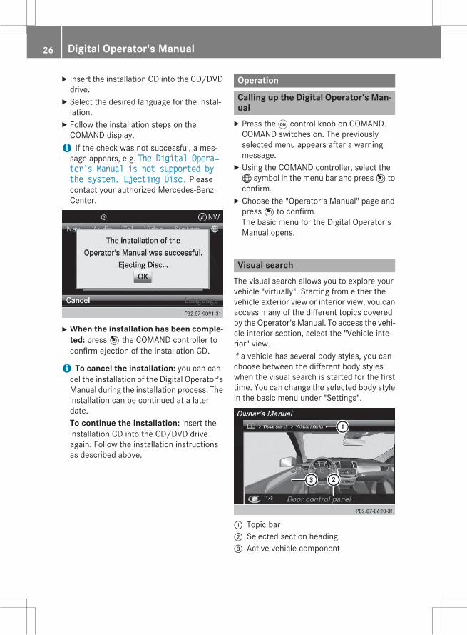
X Insert the installation CD into the CD/DVDdrive.X Select the desired language for the instal-lation.X Follow the installation steps on theCOMAND display.i If the check was not successful, a mes-sage appears, e.g. The Digital Operaхtor's Manual is not supported bythe system. Ejecting Disc. Pleasecontact your authorized Mercedes-BenzCenter.
X When the installation has been comple-ted: press7 the COMAND controller toconfirm ejection of the installation CD.
i To cancel the installation: you can can-cel the installation of the Digital Operator'sManual during the installation process. Theinstallation can be continued at a laterdate.To continue the installation: insert theinstallation CD into the CD/DVD driveagain. Follow the installation instructionsas described above.
Operation
Calling up the Digital Operator's Man-ualX Press theq control knob on COMAND.COMAND switches on. The previouslyselected menu appears after a warningmessage.X Using the COMAND controller, select the® symbol in the menu bar and press7 toconfirm.X Choose the "Operator's Manual" page andpress7 to confirm.The basic menu for the Digital Operator'sManual opens.
Visual searchThe visual search allows you to explore yourvehicle "virtually". Starting from either thevehicle exterior view or interior view, you canaccess many of the different topics coveredby the Operator's Manual. To access the vehi-cle interior section, select the "Vehicle inte-rior" view.If a vehicle has several body styles, you canchoose between the different body styleswhen the visual search is started for the firsttime. You can change the selected body stylein the basic menu under "Settings".
: Topic bar; Selected section heading= Active vehicle component
26 Digital Operator's Manual
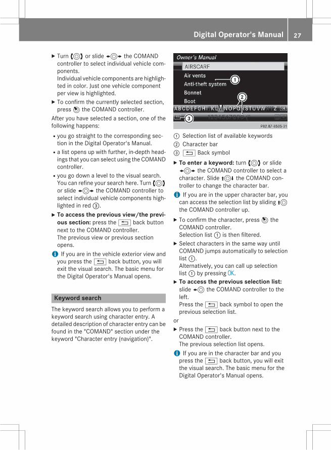
X Turn3 or slide1 the COMANDcontroller to select individual vehicle com-ponents.Individual vehicle components are highligh-ted in color. Just one vehicle componentper view is highlighted.X To confirm the currently selected section,press7 the COMAND controller.
After you have selected a section, one of thefollowing happens:Ryou go straight to the corresponding sec-tion in the Digital Operator's Manual.
Ra list opens up with further, in-depth head-ings that you can select using the COMANDcontroller.
Ryou go down a level to the visual search.You can refine your search here. Turn3or slide1 the COMAND controller toselect individual vehicle components high-lighted in red=.X To access the previous view/the previ-
ous section: press the% back buttonnext to the COMAND controller.The previous view or previous sectionopens.i If you are in the vehicle exterior view andyou press the% back button, you willexit the visual search. The basic menu forthe Digital Operator's Manual opens.
Keyword searchThe keyword search allows you to perform akeyword search using character entry. Adetailed description of character entry can befound in the "COMAND" section under thekeyword "Character entry (navigation)".
: Selection list of available keywords; Character bar=% Back symbolX To enter a keyword: turn3 or slide1 the COMAND controller to select acharacter. Slide4 the COMAND con-troller to change the character bar.i If you are in the upper character bar, youcan access the selection list by sliding5the COMAND controller up.X To confirm the character, press7 theCOMAND controller.Selection list: is then filtered.X Select characters in the same way untilCOMAND jumps automatically to selectionlist:.Alternatively, you can call up selectionlist: by pressing OK.X To access the previous selection list:slide8 the COMAND controller to theleft.Press the% back symbol to open theprevious selection list.
orX Press the% back button next to theCOMAND controller.The previous selection list opens.i If you are in the character bar and youpress the% back button, you will exitthe visual search. The basic menu for theDigital Operator's Manual opens.
Digital Operator's Manual 27

ContentsIn the contents, the topics are listed in thesame order as in the printed Operator's Man-ual. You can select a section and then a sub-section.
: Topic bar; Currently selected section in the contents= Section not currently selected in the con-
tents?% Back symbolX Turn3 or slide4 the COMAND con-troller to select the desired section.X To confirm the selection, press7 theCOMAND controller.A further selection list with the correspond-ing subsection opens.X Select the corresponding subsection in thesame way.X To access the previous selection list:slide8 the COMAND controller to theleft.Press the% back symbol to open theprevious selection list.
orX Press the% back button next to theCOMAND controller.The previous selection list opens.i If you are on the uppermost level in the listof contents, press the% back button.You will then exit the list of contents andthe basic menu for the Digital Operator'sManual opens.
Content pages
:% Back symbol; Hidden warning= Topic bar? Link to a continuing chapterX To navigate within a contents page: turn3 or slide4 the COMAND controllerto scroll the text up and down.X To navigate away from the contents
page: slide8 the COMAND controller tothe left.Press the% back symbol to open theprevious page.
orX Press the% back button next to theCOMAND controller.
orX Turn3 or slide5 the COMAND con-troller up to scroll to the very top of thecontents page.X Slide5 the COMAND controller up againto select topic bar=.X Turn3 or slide1 the COMANDcontroller to select the desired section orsubsection. To confirm the selection, press7 the COMAND controller.The selected topic bar opens including allthe subsections.X To select a link?: links are automaticallyhighlighted when you scroll in a text. Whenyou have selected a link, press7 theCOMAND controller.The desired contents page opens.
28 Digital Operator's Manual

X To open up warning notes, environmen-tal notes and malfunction information:when scrolling through the text, the cursorjumps automatically to the drop downwarnings, environmental information andmalfunction information. When you haveselected the note, press7 the COMANDcontroller.The warning note, environmental note ormalfunction information opens up on thesame page.X To navigate away from the Digital Oper-
ator's Manual: press and hold the%back button next to the COMAND control-ler.A window opens and you are asked if youwould like to exit the browser.X Confirm with "Yes".The overview of COMAND functions opens.X To switch functions from the Digital
Operator's Manual to COMAND usingthe COMAND function buttons: press the$,%,h,Ø orW button inCOMAND.The desired menu opens.X To go back to the Digital Operator's
Manual: use the COMAND controller toselect the® symbol in the menu bar andpress7 to confirm.The last page called up in the Digital Oper-ator's Manual is opened.
i For safety reasons, the "Digital Operator'sManual" function is switched off while youare driving.
Digital Operator's Manual 29
Protection of the environment
General notes
H Environmental noteDaimler's declared policy is one of compre-hensive environmental protection.The objectives are for the natural resourcesthat form the basis of our existence on thisplanet to be used sparingly and in a mannerthat takes the requirements of both natureand humanity into account.You too can help to protect the environmentby operating your vehicle in an environmen-tally responsible manner.Fuel consumption and the rate of engine,transmission, brake and tire wear are affectedby these factors:Roperating conditions of your vehicleRyour personal driving styleYou can influence both factors. You shouldbear the following in mind:Operating conditions:Ravoid short trips as these increase fuel con-sumption.
Ralways make sure that the tire pressuresare correct.
Rdo not carry any unnecessary weight.Rremove roof racks once you no longer needthem.
Ra regularly serviced vehicle will contributeto environmental protection. You shouldtherefore adhere to the service intervals.
Ralways have service work carried out at aqualified specialist workshop.
Personal driving style:Rdo not depress the accelerator pedal whenstarting the engine.
Rdo notwarmup the enginewhen the vehicleis stationary.
Rdrive carefully and maintain a safe distancefrom the vehicle in front.
Ravoid frequent, sudden acceleration andbraking.
Rchange gear in good time and use each gearonly up toÔ of its maximum engine speed.
Rswitch off the engine in stationary traffic.Rkeep an eye on the vehicle's fuel consump-tion.
Environmental concerns and recom-mendationsWherever the operating instructions requireyou to dispose of materials, first try to regen-erate or re-use them. Observe the relevantenvironmental rules and regulations whendisposing of materials. In this way you willhelp to protect the environment.
Genuine Mercedes-Benz parts
H Environmental noteDaimler AG also supplies reconditionedmajorassemblies and parts which are of the samequality as new parts. They are covered by thesame Limited Warranty entitlements as newparts.
! Air bags and Emergency Tensioning Devi-ces, as well as control units and sensors forthese restraint systems, may be installed inthe following areas of your vehicle:RdoorsRdoor pillarsRdoor sillsRseatsRcockpitRinstrument clusterRcenter consoleDo not install accessories such as audiosystems in these areas. Do not carry outrepairs or welding. You could impair theoperating efficiency of the restraint sys-tems.Have aftermarket accessories installed at aqualified specialist workshop.
30 Introduction

You could jeopardize the operating safety ofyour vehicle if you use parts, tires and wheelsas well as accessories relevant to safetywhich have not been approved by Mercedes.This could lead to malfunctions in safety-rel-evant systems, e.g. the brake system. Useonly genuine Mercedes-Benz parts or parts ofequal quality. Only use tires, wheels andaccessories that have been specificallyapproved for your vehicle.Genuine Mercedes-Benz parts are subject tostrict quality control. Every part has been spe-cifically developed, manufactured or selectedfor and adapted to Mercedes-Benz vehicles.Only genuine Mercedes-Benz parts shouldtherefore be used.More than 300,000 different genuineMercedes-Benz parts are available forMercedes-Benz models.All authorized Mercedes-Benz Centers main-tain a supply of genuineMercedes-Benz partsfor necessary service and repair work. In addi-tion, strategically located parts delivery cen-ters provide quick and reliable parts service.Always specify the vehicle identification num-ber (VIN) when ordering genuine Mercedes-Benz parts (Y page 336).
Operator's Manual
Vehicle equipmentThis Operator's Manual describes all modelsand all standard and optional equipment ofyour vehicle available at the time of going toprint. Country-specific differences are possi-ble. Bear in mind that your vehicle may notfeature all functions described here. This alsoapplies to safety-relevant systems and func-tions. The equipment in your vehicle maytherefore differ from that shown in thedescriptions and illustrations.The original purchase agreement lists all sys-tems installed in your vehicle.Should you have any questions concerningequipment and operation, please consult anauthorized Mercedes-Benz Center.
The Operator's Manual and MaintenanceBooklet are important documents and shouldbe kept in the vehicle.
Service and vehicle operation
WarrantyThe implied warranty for your vehicle appliesin accordance with the warranty terms andconditions in the Service and Warranty Infor-mation booklet.Your authorized Mercedes-Benz Center willreplace and repair all factory-installed parts inaccordancewith the followingwarranty termsand conditions:RNew Vehicle Limited WarrantyREmission System WarrantyREmission Performance WarrantyRCalifornia, Connecticut, Maine, Massachu-setts, New York, Pennsylvania, RhodeIsland and Vermont Emission Control Sys-tem Warranty
RState warranty enforcement laws (lemonlaws)
Replacement parts and accessories are cov-ered by the Mercedes-Benz Parts and Acces-sories warranties. These are available at anyauthorized Mercedes-Benz Center.
i Should you lose your Service and War-ranty Information booklet, have an author-ized Mercedes-Benz Center arrange for areplacement. The new Service and War-ranty Information booklet will be posted toyou.
Introduction 31
Z

Information for customers in Califor-niaUnder California law you may be entitled to areplacement of your vehicle or a refund of thepurchase price or lease price, if after a rea-sonable number of repair attemptsMercedes-Benz USA, LLC and/or its author-ized repair or service facilities fail to fix one ormore substantial defects or malfunctions inthe vehicle that are covered by its expresswarranty. During the period of 18 monthsfrom original delivery of the vehicle or theaccumulation of 18,000miles (approximately29,000 km) on the odometer of the vehicle,whichever occurs first, a reasonable numberof repair attempts is presumed for a retailbuyer or lessee if one or more of the followingoccurs:(1) the same substantial defect or malfunc-
tion results in a condition that is likely tocause death or serious bodily injury if thevehicle is driven, that defect or malfunc-tion has been subject to repair two ormore times, and you have directly noti-fied Mercedes-Benz USA, LLC in writingof the need for its repair,
(2) the same substantial defect or malfunc-tion of a less serious nature than cate-gory (1) has been subject to repair four ormore times and you have directly notifiedus in writing of the need for its repair, or
(3) the vehicle is out of service by reason ofrepair of the same or different substantialdefects or malfunctions for a cumulativetotal of more than 30 calendar days.
Please send your written notice to:Mercedes-Benz USA, LLCCustomer Assistance CenterOne Mercedes DriveMontvale, NJ 07645-0350
MaintenanceThe Service and Warranty Booklet describesall the necessary maintenance work whichshould be done at regular intervals.Always have the Service and Warranty Book-let with you when you bring the vehicle to anauthorized Mercedes-Benz Center. The ser-vice advisor will record every service for youin the Service and Warranty Booklet.
Roadside AssistanceThe Mercedes-Benz Roadside AssistanceProgramoffers technical help in the event of abreakdown. Calls to the toll-free RoadsideAssistance Hotline are answered by ouragents 24 hours a day, 365 days a year.1-800-FOR-MERCedes(1-800-367-6372)(USA)1-800-387-0100 (Canada)For additional information, refer to theMercedes-Benz Roadside Assistance Pro-gram brochure (USA) or the "Roadside Assis-tance" section in the Service and Warrantybooklet (Canada). You will find both in yourvehicle literature portfolio.
Change of address or change of own-ershipIn the event of a change of address, pleasesend us the "Notification of Address Change"in the Service and Guarantee booklet or sim-ply call the Mercedes-Benz Customer Assis-tance Center (USA) at the hotline number1-800-FOR-MERCedes(1-800-367-6372) orCustomer Service Center (Canada) at1-800-387-0100. This will assist us in con-tacting you in a timely manner should theneed arise.If you sell your Mercedes, please leave theentire literature in the vehicle so that it isavailable to the next owner.If you have purchased a used car, please sendus the "Notification of Used Car Purchase" in
32 Introduction

the Service and Guarantee booklet or simplycall the Mercedes-Benz Customer AssistanceCenter (USA) at the hotline number1-800-FOR-MERCedes(1-800-367-6372) orCustomer Service (Canada) at1-800-387-0100.
Vehicle operation outside the USAand CanadaIf you plan to operate your vehicle in foreigncountries, please be aware that:Rservice facilities or replacement parts maynot be readily available.
Runleaded fuel for vehicles with a catalyticconvertermay not be available. Leaded fuelmay cause damage to the catalytic con-verter.
Rthe fuel may have a considerably loweroctane rating. Unsuitable fuel can causeengine damage.
Some Mercedes-Benz models are availablefor delivery in Europe through our EuropeanDelivery Program. For details, consult anauthorized Mercedes-Benz Center or write toone of the following addresses.In the USAMercedes-Benz USA, LLCEuropean Delivery DepartmentOne Mercedes DriveMontvale, NJ 07645-0350In CanadaMercedes-Benz Canada, Inc.European Delivery Department98 Vanderhoof AvenueToronto, Ontario M4G 4C9
Sports Utility Vehicle
G WARNINGDue to the high center of gravity, the vehiclemay start to skid and roll over in the event ofan abrupt steering maneuver and/or when
the vehicle's speed is not adapted to the roadconditions. There is a risk of an accident.Always adapt your speed and driving style tothe vehicle's driving characteristics and to theprevailing road and weather conditions.
Utility vehicles have a significantly higher roll-over rate than other types of vehicles.Failure to operate this vehicle safely mayresult in an accident, rollover of the vehicle,and severe or fatal injury.In a rollover crash, an unbelted person is sig-nificantly more likely to die than a personwearing a seat belt.You and all vehicle occupants should alwayswear your seat belts.
Operating safety
Important safety notes
G WARNINGIf you do not have the prescribed service/maintenance work or any required repairscarried out, this can result in malfunctions orsystem failures. There is a risk of an accident.Always have the prescribed service/mainte-nance work as well as any required repairscarried out at a qualified specialist workshop.
G WARNINGFlammable material such as leaves, grass ortwigsmay ignite if they come into contactwithhot parts of the exhaust system. There is a riskof fire.When driving off road or on unpaved roads,check the vehicle's underside regularly. Inparticular, remove parts of plants or otherflammable materials which have becometrapped. In the case of damage, contact aqualified specialist workshop.
G WARNINGModifications to electronic components, theirsoftware as well as wiring can impair theirfunction and/or the function of other net-
Introduction 33
Z

worked components. In particular, systemsrelevant to safety could also be affected. As aresult, these may no longer function as inten-ded and/or jeopardize the operating safety ofthe vehicle. There is an increased risk of anaccident and injury.Never tamper with the wiring as well as elec-tronic components or their software. Youshould have all work to electrical and elec-tronic equipment carried out at a qualifiedspecialist workshop.
If you make any changes to the vehicle elec-tronics, the general operating permit is ren-dered invalid.
! There is a risk of damage to the vehicle if:Rthe vehicle becomes stuck, e.g. on a highcurb or an unpaved road
Ryou drive too fast over an obstacle, e.g. acurb or a hole in the road
Ra heavy object strikes the undercarriageor parts of the chassis
In situations like this, the body, the under-carriage, chassis parts, wheels or tirescould be damaged without the damagebeing visible. Components damaged in thisway can unexpectedly fail or, in the case ofan accident, no longer withstand the strainthey are designed to.If the underbody paneling is damaged,combustible materials such as leaves,grass or twigs can gather between theunderbody and the underbody paneling. Ifthese materials come in contact with hotparts of the exhaust system, they can catchfire.In such situations, have the vehiclechecked and repaired immediately at aqualified specialist workshop. If on con-tinuing your journey you notice that drivingsafety is impaired, pull over and stop thevehicle immediately, paying attention toroad and traffic conditions. In such cases,consult a qualified specialist workshop.
Declarations of conformity
Vehicle components which receiveand/or transmit radio wavesUSA: "The wireless devices of this vehiclecomply with Part 15 of the FCC Rules. Oper-ation is subject to the following two condi-tions: 1) These devices may not cause harm-ful interference, and 2) These devices mustaccept any interference received, includinginterference that may cause undesired oper-ation. Changes ormodifications not expresslyapproved by the party responsible for com-pliance could void the user’s authority tooperate the equipment."Canada: "The wireless devices of this vehiclecomply with Industry Canada license-exemptRSS standard(s). Operation is subject to thefollowing two conditions: (1) These devicesmay not cause interference, and (2) Thesedevicesmust accept any interference, includ-ing interference that may cause undesiredoperation of the device."
Diagnostics connectionThe diagnostics connection is only intendedfor the connection of diagnostic equipment ata qualified specialist workshop.
G WARNINGIf you connect equipment to the diagnosticsconnection in the vehicle, it may affect theoperation of the vehicle systems. As a result,the operating safety of the vehicle could beaffected. There is a risk of an accident.Do not connect any equipment to a diagnos-tics connection in the vehicle.
G WARNINGObjects in the driver's footwell can restrict thepedal travel or obstruct a depressed pedal.The operating and road safety of the vehicle isjeopardized. There is a risk of an accident.Make sure that all objects in the vehicle arestowed correctly, and that they cannot enter
34 Introduction

the driver's footwell. Install the floormatssecurely and as specified in order to ensuresufficient clearance for the pedals. Do not useloose floormats and do not place floormats ontop of one another.
! If the engine is switched off and equip-ment on the diagnostics connection isused, the starter battery may discharge.
Connecting equipment to the diagnosticsconnection can lead to emissions monitoringinformation being reset, for example. Thismay lead to the vehicle failing to meet therequirements of the next emissions test dur-ing the main inspection.
Qualified specialist workshopAn authorized Mercedes-Benz Center is aqualified specialist workshop. It has the nec-essary specialist knowledge, tools and quali-fications to correctly carry out the workrequired on your vehicle. This is especially thecase for work relevant to safety.Observe the notes in the Maintenance Book-let.Always have the following work carried out atan authorized Mercedes-Benz Center:Rwork relevant to safetyRservice and maintenance workRrepair workRalterations, installation work and modifica-tions
Rwork on electronic components
Correct useIf you remove any warning stickers, you orothers could fail to recognize certain dangers.Leave warning stickers in position.Observe the following information when driv-ing your vehicle:Rthe safety notes in this manualRthe Technical Data section in this manual
Rtraffic rules and regulationsRlaws and safety standards pertaining tomotor vehicles
Problems with your vehicleIf you should experience a problem with yourvehicle, particularly one that you believe mayaffect its safe operation, we urge you to con-tact an authorized Mercedes-Benz Centerimmediately to have the problem diagnosedand rectified. If the problem is not resolved toyour satisfaction, please discuss the problemagain with a Mercedes-Benz Center or con-tact us at one of the following addresses.In the USACustomer Assistance CenterMercedes-Benz USA, LLCOne Mercedes DriveMontvale, NJ 07645-0350In CanadaCustomer Relations DepartmentMercedes-Benz Canada, Inc.98 Vanderhoof AvenueToronto, Ontario M4G 4C9
Reporting safety defectsUSA only:The following text is published as required ofmanufacturers under Title 49, Code of U.S.Federal Regulations, Part 575 pursuant to the"National Traffic andMotor Vehicle Safety Actof 1966".If you believe that your vehicle has a defectwhich could cause a crash or could causeinjury or death, you should immediatelyinform the National Highway Traffic SafetyAdministration (NHTSA) in addition to notify-ing Mercedes-Benz USA, LLC.If NHTSA receives similar complaints, it mayopen an investigation, and if it finds that asafety defect exists in a group of vehicles, itmay order a recall and remedy campaign.
Introduction 35
Z

However, NHTSA cannot become involved inindividual problems between you, yourdealer, or Mercedes-Benz USA, LLC.To contact NHTSA, you may call the VehicleSafety Hotline toll-free at1-888-327-4236(TTY: 1-800-424-9153); goto http://www.safercar.gov; or write to:Administrator, NHTSA, 400 Seventh Street,SW., Washington, DC 20590.You can also obtain other information aboutmotor vehicle safety fromhttp://www.safercar.gov
Limited Warranty! Follow the instructions in this manualabout the proper operation of your vehicleas well as about possible vehicle damage.Damage to your vehicle that arises fromculpable contraventions against theseinstructions is not covered either by theMercedes-Benz Limited Warranty or by theNew or Used-Vehicle Warranty.
QR codes for the rescue card
The QR code is secured in the fuel filler flapand on the opposite side on the B-pillar. In theevent of an accident, rescue services can usethe QR code to quickly find the appropriaterescue card for your vehicle. The current res-cue card contains the most important infor-mation about your vehicle in a compact form,e.g. the routing of the electric cables.You can find more information at https://portal.aftersales.i.daimler.com.
Data stored in the vehicle
Data recordingThis vehicle is capable of recording diagnosticinformation relating to vehicle operation,mal-functions, and user settings. This may includeinformation about the performance or status
of various systems, including but not limitedto, engine, throttle, steering or brake sys-tems, that is stored and can be read out withsuitable devices, particularly when the vehi-cle is serviced. The data obtained is used toproperly diagnose and service your vehicle orto further optimize and develop vehicle func-tions.
COMAND/mbrace (Canada: TELEAID)If the vehicle is equipped with COMAND ormbrace, additional data about the vehicle’soperation, the use of the vehicle in certainsituations, and the location of the vehiclemaybe compiled through COMAND or thembracesystem.For additional information please refer to theCOMAND User Manual and/or the mbraceTerms and Conditions.
Event data recordersThis vehicle is equipped with an event datarecorder (EDR). The main purpose of an EDRis to record data that will assist in under-standing how a vehicle’s systems performedin certain crash or near crash-like situations,such as during air bag deployment or whenhitting a road obstacle. The EDR is designedto record data related to vehicle dynamicsand safety systems for a short period of time,typically 30 seconds or less.The EDR in this vehicle is designed to recordsuch data as:Rhow various systems in your vehicle areoperating
Rwhether or not the driver and passengerseat belts are fastened
Rhow far (if at all) the driver is depressing theaccelerator and/or brake pedal and
Rhow fast the vehicle is travelingThis data can help provide a better under-standing of the circumstances in whichcrashes and injuries occur. NOTE: EDR data is
36 Introduction

recorded by your vehicle only if a non-trivialcrash situation occurs; no data is recorded bythe EDR under normal driving conditions andno personal data (e.g., name, gender, age,and crash location) are recorded. However,other parties, such as law enforcement, cancombine the EDR data with the type of per-sonal identification data routinely acquiredduring a crash investigation.To read data recorded by an EDR, specialequipment is required, and access to the vehi-cle or the EDR is needed. In addition to thevehicle manufacturer, other parties that havethe special equipment, such as law enforce-ment, can read the information by accessingthe vehicle or the EDR.EDR data may be used in civil and criminalmatters as a tool in accident reconstruction,accident claims, and vehicle safety. Since theCrash Data Retrieval CDR tool that is used toextract data from the EDR is commerciallyavailable, Mercedes-Benz USA, LLC("MBUSA") expressly disclaims any and all lia-bility arising from the extraction of this infor-mation by unauthorized Mercedes-Benz per-sonnel.MBUSA will not share EDR data with otherswithout the consent of the vehicle owners or,if the vehicle is leased, without the consent ofthe lessee. Exceptions to this representationinclude responses to subpoenas by lawenforcement; by federal, state or local gov-ernment; in connection with or arising out oflitigation involving MBUSA or its subsidiariesand affiliates; or, as required by law.Warning: The EDR is a component of theRestraint System Module. Tampering with,altering, modifying or removing the EDR com-ponent may result in a malfunction of theRestraint System Module and other systems.State laws or regulations regarding EDRs thatconflict with federal regulation are pre-emp-ted. This means that in the event of such con-flict, the federal regulation governs. As ofFebruary 2013, 13 states have enacted lawsrelating to EDRs.
Information on copyright
General informationInformation on license for free and open-source software used in your vehicle and itselectronic components is available on the fol-lowing website:http://www.mercedes-benz.com/opensource
Introduction 37
Z

38

Cockpit ................................................. 40Instrument cluster .............................. 41Multifunction steering wheel ............. 43Center console .................................... 44Overhead control panel ...................... 47Door control panel .............................. 48
39
Ata
glan
ce

Cockpit
Function Page
: Steering wheel paddleshifters ~
; Combination switch 112
= Instrument cluster 41
? Horn ~
A DIRECT SELECT lever 137
B PARKTRONIC warning dis-play 165
C Overhead control panel 47
D Climate control systems 122
E Ignition lock 131Start/Stop button 132
Function Page
F Adjusts the steering wheelmanually ~
G Adjusts the steering wheelelectrically ~
Steering wheel heating ~
H Cruise control lever 152
I Opens the hood 264
J Diagnostics connection 34
K Electric parking brake ~
L Light switch 110
M Night View Assist Plus 172
40 CockpitAt
agl
ance

Instrument cluster
Displays and controls
Function Page
: SpeedometerSpeedometer segments ~
; Fuel gageFuel filler flap location indi-cator8: the fuel fillercap is on the right-handside.
Function Page
= Tachometer ~
? Coolant temperature ~
A Multifunction display ~
Outside temperature dis-play ~
B Instrument cluster lighting ~
Instrument cluster 41
Ata
glan
ce
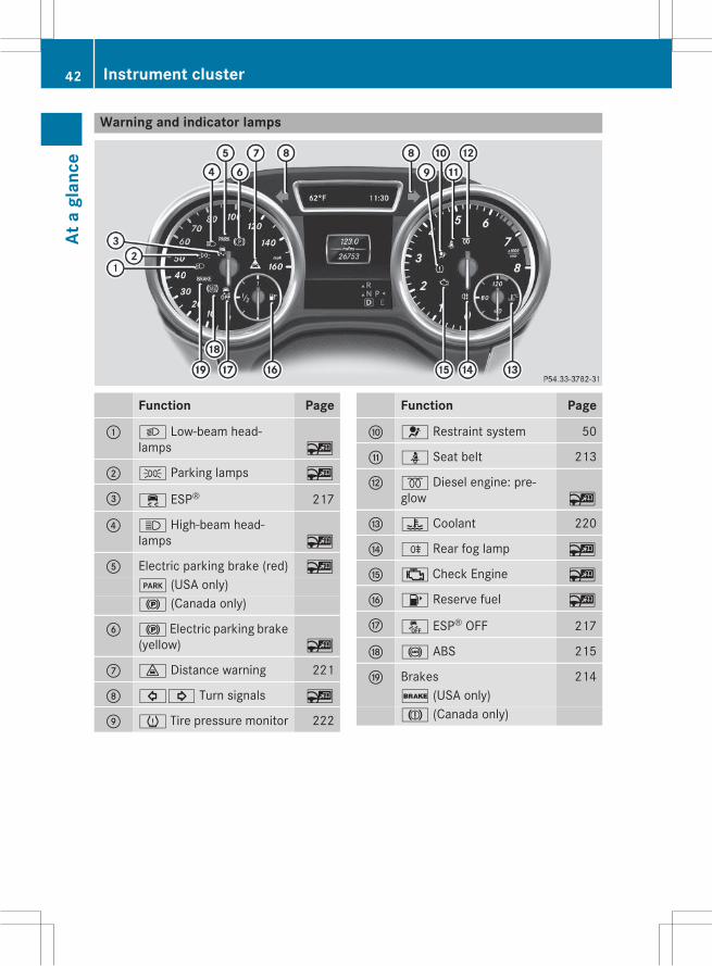
Warning and indicator lamps
Function Page
: L Low-beam head-lamps ~
; T Parking lamps ~
= ÷ ESP® 217
? K High-beam head-lamps ~
A Electric parking brake (red) ~
F (USA only)! (Canada only)
B ! Electric parking brake(yellow) ~
C · Distance warning 221
D #! Turn signals ~
E h Tire pressure monitor 222
Function Page
F 6 Restraint system 50
G ü Seat belt 213
H % Diesel engine: pre-glow ~
I ? Coolant 220
J R Rear fog lamp ~
K ; Check Engine ~
L 8 Reserve fuel ~
M å ESP® OFF 217
N ! ABS 215
O Brakes 214$ (USA only)J (Canada only)
42 Instrument clusterAt
agl
ance
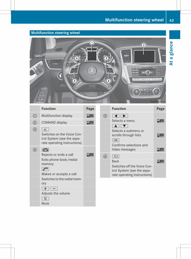
Multifunction steering wheel
Function Page
: Multifunction display ~
; COMAND display ~
= ?
Switches on the Voice Con-trol System (see the sepa-rate operating instructions)
? ~
Rejects or ends a call ~
Exits phone book/redialmemory6
Makes or accepts a callSwitches to the redialmem-oryWX
Adjusts the volume8
Mute
Function Page
A =;
Selects a menu ~
9:
Selects a submenu orscrolls through lists ~
a
Confirms selections andhides messages ~
B %
Back ~
Switches off the Voice Con-trol System (see the sepa-rate operating instructions)
Multifunction steering wheel 43
Ata
glan
ce
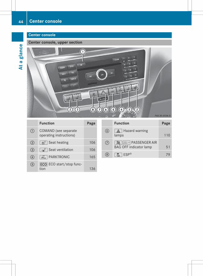
Center console
Center console, upper section
Function Page
: COMAND (see separateoperating instructions)
; c Seat heating 106
= s Seat ventilation 106
? c PARKTRONIC 165
A ¤ ECO start/stop func-tion 136
Function Page
B £ Hazard warninglamps 110
C 45 PASSENGER AIRBAG OFF indicator lamp 51
D å ESP® 79
44 Center consoleAt
agl
ance

Center console, lower section
i Vehicles with the ON&OFFROAD package
Function Page
F Cup holder ~
Ashtray ~
Cigarette lighter ~
Socket ~
G COMAND controller ~
H d ON&OFFROAD menubutton 186
I + LOW RANGE off-roadgear 185
Function Page
J Á Level control 159
K Ã DSR (Downhill SpeedRegulation) 184
L p Manual drive program ~
M Selector wheel for on-roadprograms 182Selector wheel for off-roadprograms 184
N Stowage compartmentwithMedia Interface ~
Center console 45
Ata
glan
ce
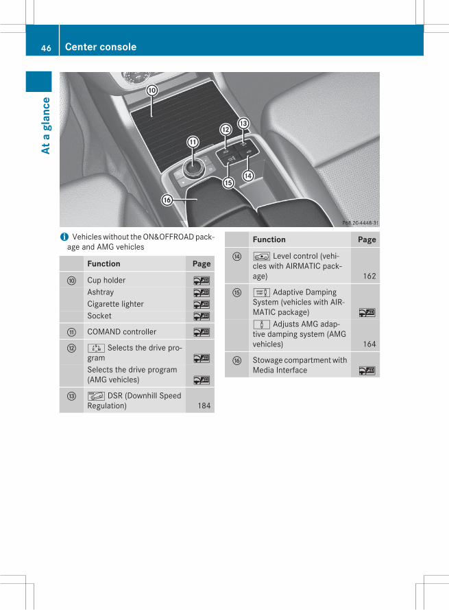
i Vehicleswithout theON&OFFROADpack-age and AMG vehicles
Function Page
F Cup holder ~
Ashtray ~
Cigarette lighter ~
Socket ~
G COMAND controller ~
H Ú Selects the drive pro-gram ~
Selects the drive program(AMG vehicles) ~
I Ã DSR (Downhill SpeedRegulation) 184
Function Page
J Á Level control (vehi-cles with AIRMATIC pack-age) 162
K e Adaptive DampingSystem (vehicles with AIR-MATIC package) ~
à Adjusts AMG adap-tive damping system (AMGvehicles) 164
L Stowage compartmentwithMedia Interface ~
46 Center consoleAt
agl
ance
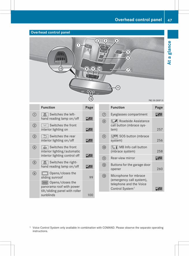
Overhead control panel
Function Page
: p Switches the left-hand reading lamp on/off ~
; c Switches the frontinterior lighting on ~
= u Switches the rearinterior lighting on/off ~
? | Switches the frontinterior lighting/automaticinterior lighting control off ~
A p Switches the right-hand reading lamp on/off ~
B 2 Opens/closes thesliding sunroof 993 Opens/closes thepanorama roof with powertilt/sliding panel with rollersunblinds 100
Function Page
C Eyeglasses compartment ~
D F Roadside Assistancecall button (mbrace sys-tem) 257
E G SOS button (mbracesystem) 256
F ï MB Info call button(mbrace system) 258
G Rear-view mirror ~
H Buttons for the garage dooropener 260
I Microphone for mbrace(emergency call system),telephone and the VoiceControl System1 ~
1 Voice Control System only available in combination with COMAND. Please observe the separate operatinginstructions.
Overhead control panel 47
Ata
glan
ce

Door control panel
Function Page
: Opens the door ~
; %& Unlocks/locksthe vehicle ~
= r45=Stores settings for the seat,exterior mirrors and steer-ing wheel (memory func-tion) ~
? Adjusts the seats 105
A 7Zö\Adjusts and folds the exte-rior mirrors in/out electri-cally ~
Function Page
B W Opens/closes theside windows ~
C q Opens/closes thetailgate 94
D n Activates/deacti-vates the override featurefor the side windows in therear compartment ~
48 Door control panelAt
agl
ance

Useful information .............................. 50Panic alarm .......................................... 50Occupant safety .................................. 50Children in the vehicle ........................ 67Pets in the vehicle ............................... 73Driving safety systems ....................... 73Protection against theft ..................... 83
49
Safe
ty

Useful information
i This Operator's Manual describes allmodels and all standard and optional equip-ment of your vehicle available at the time ofpublication of the Operator's Manual.Country-specific differences are possible.Please note that your vehicle may not beequipped with all features described. Thisalso applies to safety-related systems andfunctions.
i Read the information on qualified special-ist workshops (Y page 35).
Panic alarm
X To activate: press! button: for atleast one second.An alarm sounds and the exterior lightingflashes.X To deactivate: press! button:again.
orX Insert the SmartKey into the ignition lock.orX Press the KEYLESS-GO Start/Stop button.The KEYLESS-GO key must be in the vehi-cle.
Occupant safety
Restraint system: introductionThe restraint system reduces the risk of vehi-cle occupants coming into contact with partsof the vehicle's interior in the event of anaccident. The restraint system can alsoreduce the forces to which vehicle occupantsare subjected during an accident.The restraint system comprises:RSeat belt systemRAir bagsRChild restraint systemRChild seat securing systemsThe components of the restraint systemworkin conjunction with each other. They can onlydeploy their protective function if, at all times,all vehicle occupants:Rhave fastened their seat belts correctly(Y page 53)
Rhave adjusted their seat and head restraintproperly (Y page 105).
As the driver, you also have to make sure thatthe steering wheel is adjusted correctly.Observe the information relating to the cor-rect driver's seat position (Y page 104).You also have tomake sure that an air bag caninflate properly if deployed (Y page 56).An air bag supplements a correctly worn seatbelt. As an additional safety device, the airbag increases the level of protection for vehi-cle occupants in the event of an accident. Forexample, if, in the event of an accident, theprotection offered by the seat belt is suffi-cient, the air bags are not deployed. When anaccident occurs, only the air bags thatincrease protection in that particular accidentsituation are deployed. However, seat beltsand air bags generally do not protect againstobjects penetrating the vehicle from the out-side.Information on restraint system operationcan be found under "Deployment of Emer-gency Tensioning Devices and air bags"(Y page 64).
50 Occupant safetySa
fety

For more information about children travelingwith you in the vehicle and on child restraintsystems, see "Children in the vehicle"(Y page 67).
Important safety notes
G WARNINGModifications to the restraint system maycause it to no longer work as intended. Therestraint system may then not perform itsintended protective function andmay fail in anaccident or trigger unexpectedly, for example.This poses an increased risk of injury or evenfatal injury.Never modify parts of the restraint system.Never tamper with the wiring, the electroniccomponents or their software.If it is necessary tomodify an air bag system toaccommodate a person with disabilities, con-tact an authorized Mercedes-Benz Center fordetails. USA only: for further information con-tact our Customer Assistance Center at1-800-FOR-MERCedes (1゙800゙367゙6372).
Restraint system warning lampThe restraint systems functions are checkedafter the ignition is switched on and at regularintervals when the engine is running. Thisallows malfunctions to be detected in goodtime.When the ignition is switched on, the6restraint system warning lamp in the instru-ment cluster lights up. It goes out no laterthan a few seconds after the vehicle is star-ted. The components of the restraint systemare on standby.A malfunction has occurred if the6restraint system warning lamp:Rdoes not light up after the ignition isswitched on.
Rdoes not go out after a few seconds whenthe engine is running.
Rlights up again when the engine is running.
G WARNINGIf restraint system is malfunctioning, restraintsystem components may be triggered unin-tentionally or might not be triggered at all inthe event of an accident with a high rate ofvehicle deceleration. This can affect the Emer-gency Tensioning Device or air bag, for exam-ple. This poses an increased risk of injury oreven fatal injury.Have the restraint system checked andrepaired in a qualified specialist workshop assoon as possible.
PASSENGER AIR BAG OFF indicatorlamp
PASSENGER AIR BAG OFF indicator lamp:is part of the Occupant Classification System(OCS).The PASSENGER AIR BAG OFF indicator lampinforms you about the status of the front-passenger front air bag.If the PASSENGER AIR BAG OFF indicatorlamp:Ris lit: the front-passenger front air bag isdeactivated. It will then not be deployed inthe event of an accident.
Rdoes not light up: the front-passengerfront air bag is enabled. If, in the event of anaccident, all deployment criteria are met,the front-passenger front air bag isdeployed.
Occupant safety 51
Safe
ty
Z

Depending on the person in the front-passenger seat, the front-passenger front airbag must either be deactivated or enabled;see the following points. You must make sureof this both before and during a journey.RChildren in a child restraint system:whether the front-passenger front air bag isenabled or deactivated depends on theinstalled child restraint system, and the ageand size of the child. Therefore, be sure toobserve the notes on the "Occupant Clas-sification System (OCS)" (Y page 59) andon "Children in the vehicle" (Y page 67).There youwill also find instructions on rear-ward and forward-facing child restraint sys-tems on the front-passenger seat.
RAll other persons: depending on the clas-sification of the person in the front-passenger seat, the front-passenger frontair bag is enabled or deactivated(Y page 59). Be sure to observe the noteson "Seat belts“ (Y page 52) and "Air bags"(Y page 56). There you can also find infor-mation on the correct seat position.
Seat belts
IntroductionSeat belts are the most effective means ofrestricting the movement of vehicle occu-pants in the event of an accident or the vehi-cle rolling over. This reduces the risk of vehi-cle occupants coming into contact with partsof the vehicle interior or being ejected fromthe vehicle. Furthermore, the seat belt helpsto keep the vehicle occupant in the best posi-tion in relation to the air bag.The seat belt system comprises:RSeat beltsREmergency Tensioning Devices for thefront seat belts and the outer seat belts inthe rear
RSeat belt force limitersIf the seat belt is pulled out of the belt outletquickly or with a jerky movement, the belt
retractor locks. The belt strap cannot beextracted any further.The Emergency Tensioning Device tightensthe seat belt in an accident, pulling the beltclose against the body. However it does notpull the vehicle occupant back in the directionof the backrest.The Emergency Tensioning Device does notcorrect an incorrect seat position or the rout-ing of an incorrectly fastened seat belt.When triggered, a seat belt force limiter helpsto reduce the force exerted by the seat belt onthe vehicle occupant.The seat belt force limiters for the front seatsare synchronized with the front air bags,which absorb part of the deceleration force.This can reduce the force exerted on the vehi-cle occupants during an accident.
! If the front-passenger seat is unoccupied,do not insert the belt tongue into the buckleof the front-passenger seat. This may oth-erwise lead to the triggering of the Emer-gency Tensioning Device in the event of anaccident, which will then need to bereplaced.
Important safety notesThe use of seat belts and child restraint sys-tems is required by law in:Rall 50 statesRthe U.S. territoriesRthe District of ColumbiaRall Canadian provincesEven where this is not required by law, allvehicle occupants should correctly fastentheir seat belts before starting the journey.
G WARNINGIf the seat belt is incorrectly fastened, it can-not protect as intended. Furthermore, anincorrectly fastened seat belt can cause addi-tional injury, for example, in an accident, dur-ing braking or when abruptly changing direc-tion. This poses an increased risk of injury oreven fatal injury.
52 Occupant safetySa
fety

Make sure that all vehicle occupants areseated properly with a correctly fastened seatbelt.
G WARNINGThe seat belt does not offer the intended levelof protection if you have not moved the back-rest to an almost vertical position. When brak-ing or in the event of an accident, you couldslide underneath the seat belt and sustainabdomen or neck injuries, for example. Thisposes an increased risk of injury or even fatalinjury.Adjust the seat properly before beginningyour journey. Always ensure that the backrestis in an almost vertical position and that theshoulder section of your seat belt is routedacross the center of your shoulder.
G WARNINGPersons under 5 ft (1.50 m) in height cannotfasten the seat belt correctly without an addi-tional suitable restraint system. If the seatbelt is incorrectly fastened, it cannot protectas intended. Furthermore, an incorrectly fas-tened seat belt can cause additional injury, forexample, in an accident, during braking or anabrupt change of direction. This poses anincreased risk of injury or even fatal injury.For this reason, always secure persons under5 ft (1.50 m) in height in suitable restraintsystems.
If a child younger than 12 years and under 5 ft(1.50 m) in height is traveling in the vehicle:Ralways secure the child in a child restraintsystem suitable for this Mercedes-Benzvehicle. The child restraint system must beappropriate to the age, weight and size ofthe child
Ralways observe the instructions and safetynotes in the "Children in the vehicle" sec-tion of this Operator's Manual(Y page 67) in addition to the child
restraint system manufacturer's installa-tion instructions
Rbe sure to observe the instructions andsafety notes on the "Occupant classifica-tion system (OCS)" (Y page 59)
G WARNINGThe seat belts may not perform their intendedprotective function if:Rthey are damaged, modified, extremelydirty, bleach or dyed
Rthe seat belt buckle is damaged orextremely dirty
Rthe Emergency Tensioning Devices, beltanchorages or inertia reels have beenmodi-fied
Seat belts may sustain non-visible damage inan accident, e.g. due to glass splinters. Modi-fied or damaged seat belts may tear or fail,e.g. in an accident. Modified Emergency Ten-sioning Devices could accidentally trigger orfail to deploy when necessary. This poses anincreased risk of injury or even fatal injury.Never modify the seat belts, Emergency Ten-sioning Devices, belt anchorages or inertiareels. Make sure that the seat belts areundamaged, not worn out and clean. Follow-ing an accident, have the seat belts checkedimmediately at a qualified specialist work-shop.
Only use seat belts that have been approvedfor your vehicle by Mercedes-Benz. Any suchmodifications could invalidate the vehicle'sgeneral operating permit.
Proper use of the seat beltsObserve the safety notes on the seat belt(Y page 52).All vehicle occupants must be wearing theseat belt correctly before beginning the jour-ney. Also make sure that all vehicle occu-pants are always wearing the seat belt cor-rectly while the vehicle is in motion.
Occupant safety 53
Safe
ty
Z
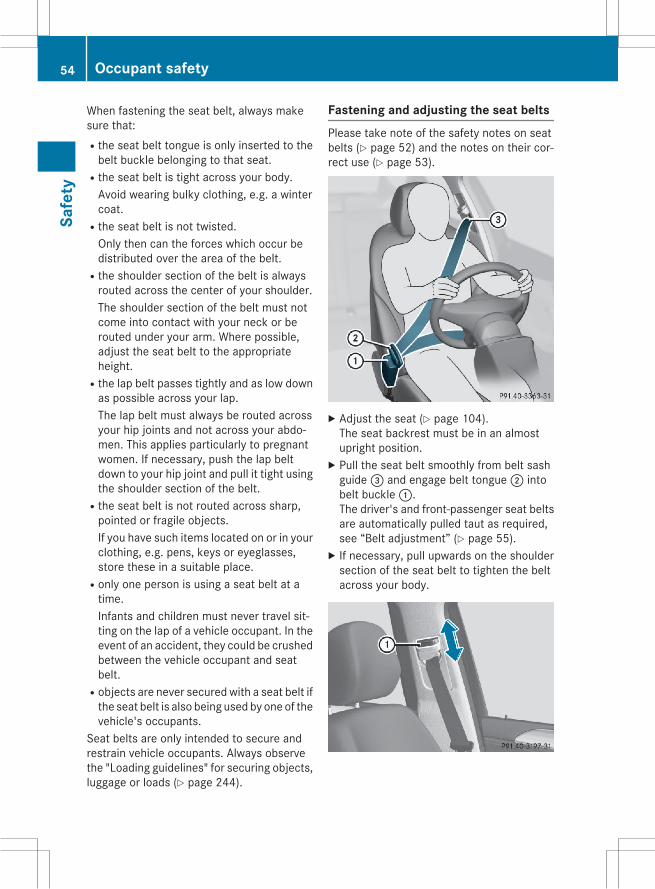
When fastening the seat belt, always makesure that:Rthe seat belt tongue is only inserted to thebelt buckle belonging to that seat.
Rthe seat belt is tight across your body.Avoid wearing bulky clothing, e.g. a wintercoat.
Rthe seat belt is not twisted.Only then can the forces which occur bedistributed over the area of the belt.
Rthe shoulder section of the belt is alwaysrouted across the center of your shoulder.The shoulder section of the belt must notcome into contact with your neck or berouted under your arm. Where possible,adjust the seat belt to the appropriateheight.
Rthe lap belt passes tightly and as low downas possible across your lap.The lap belt must always be routed acrossyour hip joints and not across your abdo-men. This applies particularly to pregnantwomen. If necessary, push the lap beltdown to your hip joint and pull it tight usingthe shoulder section of the belt.
Rthe seat belt is not routed across sharp,pointed or fragile objects.If you have such items located on or in yourclothing, e.g. pens, keys or eyeglasses,store these in a suitable place.
Ronly one person is using a seat belt at atime.Infants and children must never travel sit-ting on the lap of a vehicle occupant. In theevent of an accident, they could be crushedbetween the vehicle occupant and seatbelt.
Robjects are never secured with a seat belt ifthe seat belt is also being used by one of thevehicle's occupants.
Seat belts are only intended to secure andrestrain vehicle occupants. Always observethe "Loading guidelines" for securing objects,luggage or loads (Y page 244).
Fastening and adjusting the seat beltsPlease take note of the safety notes on seatbelts (Y page 52) and the notes on their cor-rect use (Y page 53).
X Adjust the seat (Y page 104).The seat backrest must be in an almostupright position.X Pull the seat belt smoothly from belt sashguide= and engage belt tongue; intobelt buckle:.The driver's and front-passenger seat beltsare automatically pulled taut as required,see “Belt adjustment” (Y page 55).X If necessary, pull upwards on the shouldersection of the seat belt to tighten the beltacross your body.
54 Occupant safetySa
fety

The shoulder section of the belt must alwaysrun over the center of the shoulder. Adjust thebelt outlet if necessary.X To raise: slide the belt outlet upwards.The belt outlet engages in various posi-tions.X To lower: press belt guide release: andslide the belt guide downwards.X Let go of belt guide release: in thedesired position and make sure that thebelt guide engages.
All seat belts in the vehicle, except the driv-er's seat belt, are equippedwith a special seatbelt retractor to secure child restraint sys-tems properly. Further information can befound under "Special seat belt retractor"(Y page 67).
Releasing seat belts
! Make sure that the seat belt is fully rolledup. Otherwise, the seat belt or belt tonguewill be trapped in the door or in the seatmechanism. This could damage the door,the door trim panel and the seat belt. Dam-aged seat belts can no longer fulfill theirprotective function and must be replaced.Visit a qualified specialist workshop.
X Press release button:, hold belttongue; firmly and guide it back towardsbelt outlet=.
Seat belt adjustmentThe seat-belt adjustment is an integral part ofthe PRE-SAFE® convenience function. Thisfunction adjusts the driver's and front-passenger seat belt to the upper body of theoccupants.The belt strap is tightened slightly when:Rthe belt tongue is engaged in the buckleand
Rthe ignition is switched onThe seat-belt adjustment will apply a certainretraction force if any slack is detectedbetween the vehicle occupant and the seatbelt. Do not hold on to the seat belt tightlywhile it is adjusting.You can switch the seat-belt adjustment onand off in the on-board computer(Y page 197).
Belt warning for the driver and frontpassengerThe7 seat belt warning lamp in the instru-ment cluster is a reminder for all occupants tofasten their seat belts. It may light up contin-uously or flash. A warning tone may alsosound.Regardless of whether the driver's and frontpassenger seat belts have already been fas-tened, the7 seat belt warning lamp lightsup for six seconds every time the engine isstarted. If the front doors are closed and thedriver or front passenger has not fastenedtheir seat belt, the7 seat belt warninglamp lights up again after these six seconds.As soon as the driver and the front passengerboth have their seat belts fastened or a frontdoor is opened again, the7 seat beltwarning lamp goes out.If the driver's seat belt is not fastened whenthe engine is started, a warning tone will addi-tionally sound. This warning tone switches off
Occupant safety 55
Safe
ty
Z
after approximately six seconds or once thedriver's seat belt is fastened.Once a vehicle speed of 15 mph (25 km/h) isexceeded and the driver's or front-passengerseat belt is not fastened, a warning tone willsound again. Thewarning tonewill soundwithincreasing intensity for 60 seconds or untilthe driver or front passenger have fastenedtheir seat belts.If the driver or front passenger unfasten theirseat belts during the journey, the belt warningwill be automatically activated once again.
i Further information on the7 seat beltwarning lamp can be found under “Indica-tor and warning lamps in the instrumentcluster, seat belt” (Y page 213).
Air bags
IntroductionThe installation point of an air bag can be rec-ognized by the AIR BAG symbol.An air bag complements the correctly fas-tened seat belt. It is no substitute for the seatbelt. The air bag provides additional protec-tion in applicable accident situations.Not all air bags are deployed in an accident.The different air bag systems function inde-pendently from one another (Y page 64).However, no system available today can com-pletely eliminate injuries and fatalities.It is also not possible to rule out a risk of injurycaused by an air bag due to the high speed atwhich the air bag must be deployed.
Important safety notes
G WARNINGIf you do not sit in the correct seat position,the air bag cannot protect as intended andcould even cause additional injury whendeployed. This poses an increased risk ofinjury or even fatal injury.
To avoid hazardous situations, always makesure that all of the vehicle's occupants:Rhave fastened their seat belts correctly,including pregnant women
Rare sitting correctly andmaintain the great-est possible distance to the air bags
Rfollow the following instructionsAlways make sure that there are no objectsbetween the air bag and the vehicle's occu-pants.
RAdjust the seats properly before beginningyour journey. Always make sure that theseat is in an almost upright position. Thecenter of the head restraint must supportthe head at about eye level.
RMove the driver's and front-passengerseats as far back as possible. The driver'sseat position must allow the vehicle to bedriven safely.
ROnly hold the steering wheel on the out-side. This allows the air bag to be fullydeployed.
RAlways lean against the backrest while driv-ing. Do not lean forwards or lean againstthe door or side window. You may other-wise be in the deployment area of the airbags.
RAlways keep your feet in the footwell infront of the seat. Do not put your feet on thedashboard, for example. Your feet may oth-erwise be in the deployment area of the airbag.
RFor this reason, always secure persons lessthan 5 ft (1.50 m) tall in suitable restraintsystems. Up to this height, the seat beltcannot be worn correctly.
If a child is traveling in your vehicle, alsoobserve the following notes:RAlways secure children under 12 years ofage and less than 5 ft (1.50 m) in height insuitable child restraint systems.
RChild restraint systems should be installedon the rear seats.
56 Occupant safetySa
fety

ROnly secure a child in a rearward-facingchild restraint system on the front-passenger seat when the front-passengerfront air bag is deactivated. If thePASSENGER AIR BAGOFF indicator lamp ispermanently lit, the front-passenger frontair bag is deactivated (Y page 51).
RAlways observe the instructions and safetynotes on the "Occupant Classification Sys-tem (OCS)" (Y page 59) and on "Childrenin the vehicle" (Y page 67) in addition tothe child restraint system manufacturer'sinstallation instructions.
Objects in the vehicle interior may pre-vent an air bag from functioning correctly.Before starting your journey and to avoid risksresulting from the speed of the air bag as itdeploys, make sure that:Rthere are no people, animals or objectsbetween the vehicle occupants and an airbag.
Rthere are no objects between the seat, doorand B-pillar.
Rno hard objects, e.g. coat hangers, hang onthe grab handles or coat hooks.
Rno accessories, such as cup holders, areattached to the vehicle within the deploy-ment area of an air bag, e.g. to doors, sidewindows, rear side trim or side walls.
Rno heavy, sharp-edged or fragile objectsare in the pockets of your clothing. Storesuch objects in a suitable place.
G WARNINGIf you modify the air bag cover or affix objectssuch as stickers to it, the air bag can no longerfunction correctly. There is an increased riskof injury.Never modify an air bag cover or affix objectsto it.
G WARNINGSensors to control the air bags are located inthe doors. Modifications or work not per-formed correctly to the doors or door panel-ing, as well as damaged doors, can lead to the
function of the sensors being impaired. The airbags might therefore not function properlyany more. Consequently, the air bags cannotprotect vehicle occupants as they aredesigned to do. There is an increased risk ofinjury.Never modify the doors or parts of the doors.Always have work on the doors or door pan-eling carried out at a qualified specialist work-shop.
Front air bags
Driver's air bag: deploys in front of thesteering wheel. Front-passenger front airbag; deploys in front of and above the glovebox.When deployed, the front air bags offer addi-tional head and thorax protection for theoccupants in the front seats.The PASSENGER AIR BAG OFF indicator lampinforms you about the status of the front-passenger front air bag (Y page 51).Front-passenger front air bag; will onlydeploy if:Rthe system, based on the OCS weight sen-sor readings, detects that the front-passenger seat is occupied (Y page 59)
Rthe PASSENGER AIR BAG OFF indicatorlamp is not lit (Y page 59)
Rthe restraint system control unit predicts ahigh accident severity
Occupant safety 57
Safe
ty
Z

Driver's knee bag
Driver's knee bag: deploys under the steer-ing column. The driver's knee bag is triggeredtogether with the front air bag.The driver's knee bag offers additional thigh,knee and lower leg protection for the occu-pant in the driver's seat.
Side impact air bags
G WARNINGUnsuitable seat covers could restrict or evenprevent the deployment of the air bags inte-grated into the seats. Consequently, the airbags cannot protect vehicle occupants asthey are designed to do. In addition, the func-tion of the Occupant Classification System(OCS) could be restricted. This poses anincreased risk of injury or even fatal injury.You should only use seat covers that havebeen approved for the respective seat byMercedes-Benz.
Front side impact air bags: and rear sideimpact air bags; deploy next to the outerbolster of the seat backrest.When deployed, the side impact air bag offersadditional thorax protection. It also offersadditional pelvis protection for occupants inthe front seats. However, it does not protectthe:RheadRneckRarmsIn the event of a side impact, the side impactair bag is deployed on the side on which theimpact occurs.The side impact air bag on the front-passenger side (front) deploys in the follow-ing situations:Rthe OCS system detects that the front-passenger seat is occupied or
Rthe belt tongue is engaged in the beltbuckle of the front-passenger seat
If the belt tongue is engaged in the beltbuckle, the side impact air bag on the front-passenger side deploys if an appropriate acci-dent situation occurs. In this case, deploy-ment is independent of whether the front-passenger seat is occupied or not.
Window curtain air bags
Window curtain air bags: are integratedinto the side of the roof frame and deployed inthe area from the A-pillar to the C-pillar.When deployed, the window curtain air bagenhances the level of protection for the head.
58 Occupant safetySa
fety

However, it does not protect the chest orarms.In the event of a side impact, the window cur-tain air bag is deployed on the side on whichthe impact occurs.If the system determines that they can offeradditional protection to that provided by theseat belt, a window curtain air bag may bedeployed in other accident situations(Y page 64).
Occupant Classification System(OCS)
IntroductionThe Occupant Classification System (OCS)categorizes the person in the front-passengerseat. Depending on that result, the front-passenger front air bag is either enabled ordeactivated.The system does not deactivate:Rthe side impact air bagRthe window curtain air bagRthe Emergency Tensioning DevicesIn the following situation, the side impact airbag and the Emergency Tensioning Deviceare deactivated:ROCS has not categorized the person on thefront-passenger seat as an adult or a per-son of corresponding stature and
Rthe seat belt tongue of the seat belt is notinserted into the front-passenger seat beltbuckle.
PrerequisitesTo be classified correctly, the front passengermust sit:Rwith the seat belt fastened correctlyRin an almost upright position with theirback against the seat backrest
Rwith their feet resting on the floor, if possi-ble
If the front passenger does not observe theseconditions, OCS may produce a false classi-fication, e.g. because the front passenger:Rtransfers their weight by supporting them-selves on a vehicle armrest
Rsits in such a way that their weight is raisedfrom the seat cushion
If it is absolutely necessary to install a childrestraint system on the front-passenger seat,be sure to observe the correct positioning ofthe child restraint system. Never placeobjects under or behind the child restraintsystem, e.g. cushions. The entire base of thechild restraint systemmust always rest on theseat cushion of the front-passenger seat. Thebackrest of the forward-facing child restraintsystemmust lie as flat as possible against thebackrest of the front-passenger seat.The child restraint systemmust not touch theroof or be subjected to a load by the headrestraint. Adjust the angle of the seat back-rest and the head restraint position accord-ingly.Only then can OCS be guaranteed to functioncorrectly. Always observe the child restraintsystem manufacturer's installation instruc-tions.
Occupant Classification System opera-tion (OCS)
PASSENGER AIR BAG OFF indicator lamp:shows you whether the front-passenger frontair bag is deactivated.X Turn the SmartKey to position 1 or 2 in theignition lock, or press the Start/Stop but-
Occupant safety 59
Safe
ty
Z
ton once or twice on vehicles with KEY-LESS-GO.The system carries out self-diagnostics.
The PASSENGER AIR BAG OFF indicator lampmust light up for approximately six seconds.The PASSENGER AIR BAG OFF indicator lampthen displays the status of the front-passenger front air bag. If the status of thefront-passenger front air bag changes whilethe vehicle is in motion, an air bag displaymessage may appear in the instrument clus-ter (Y page 199). When the front-passengerseat is occupied, always pay attention to thePASSENGER AIR BAG OFF indicator lamp. Beaware of the status of the front-passengerfront air bag both before and during the jour-ney.If the PASSENGER AIR BAG OFF indicatorlamp:Ris lit: the front-passenger front air bag isdeactivated. It will then not be deployed inthe event of an accident.
Rdoes not light up: the front-passengerfront air bag is enabled. If, in the event of anaccident, all deployment criteria are met,the front-passenger front air bag isdeployed.
G WARNINGIf the PASSENGER AIR BAG OFF indicatorlamp is lit, the front-passenger front air bag isdisabled. It will not be deployed in the event ofan accident and cannot perform its intendedprotective function. A person in the front-passenger seat could then, for example, comeinto contact with the vehicle's interior, espe-cially if the person is sitting too close to thedashboard. This poses an increased risk ofinjury or even fatal injury.When the front-passenger seat is occupied,always ensure that:Rthe classification of the person in the front-passenger seat is correct and the front-passenger front air bag is enabled or disa-
bled in accordance with the person in thefront-passenger seat
Rthe front-passenger seat has been movedback as far back as possible.
Rthe person is seated correctly.Make sure, both before and during the jour-ney, that the status of the front-passengerfront air bag is correct.
G WARNINGIf you secure a child in a child restraint systemon the front-passenger seat and thePASSENGER AIR BAG OFF indicator lamp isoff, the front-passenger front air bag candeploy in the event of an accident. The childcould be struck by the air bag. This poses anincreased risk of injury or even fatal injury.Make sure that the front-passenger front airbag has been disabled. The PASSENGER AIRBAG OFF indicator lamp must be lit.
G WARNINGIf you secure a child in a forward-facing childrestraint system on the front-passenger seatand you position the front-passenger seat tooclose to the dashboard, the child could, in theevent of an accident:Rcome into contact with the vehicle's inte-rior if the PASSENGER AIR BAG OFF indi-cator lamp is lit, for example
Rbe struck by the air bag if the PASSENGERAIR BAG OFF indicator lamp is off
This poses an increased risk of injury or evenfatal injury.Move the front-passenger seat as far back aspossible. Always make sure that the shoulderbelt strap is correctly routed from the vehiclebelt sash guide to the shoulder belt guide onthe child restraint system. The shoulder beltstrap must be routed forwards and down-wards from the vehicle belt sash guide. If nec-essary, adjust the vehicle belt sash guide andthe front-passenger seat accordingly. Alwaysobserve the child restraint system manufac-turer's installation instructions.
60 Occupant safetySa
fety

If OCS determines that:Rthe front-passenger seat is unoccupied, thePASSENGER AIR BAG OFF indicator lamplights up after the system self-test andremains lit. This indicates that the front-passenger front air bag is deactivated.
Rthe front-passenger seat is occupied by achild of up to 12 months old in a standardchild restraint system, the PASSENGER AIRBAG OFF indicator lamp lights up after thesystem self-test and remains lit. This indi-cates that the front-passenger front air bagis deactivated.But in the case of a 12-month-old child in astandard child restraint system, thePASSENGER AIR BAG OFF indicator lampcan go out after the system self-test. Thisindicates that the front-passenger front airbag is activated. The result of the classifi-cation is dependent on, among other fac-tors, the child restraint system and thechild's stature. It is recommended that youinstall the child restraint system on a suit-able rear seat.
Rthe front-passenger seat is occupied by aperson of smaller stature (e.g. a teenageror small adult), the PASSENGER AIR BAGOFF indicator lamp lights up and remains litafter the system self-test depending on theresult of the classification or, alternatively,goes out.- If the PASSENGERAIR BAGOFF indicatorlamp is off, move the front-passengerseat as far back as possible. Alterna-tively, a person of smaller stature can siton a rear seat.
- If the PASSENGERAIR BAGOFF indicatorlamp is lit, a person of smaller statureshould not use the front-passenger seat.
Rthe front-passenger seat is occupied by anadult or a person of a stature correspond-ing to that of an adult, the PASSENGER AIRBAG OFF indicator lamp goes out after thesystem self-test. This indicates that thefront-passenger front air bag is activated.
If children are traveling in the vehicle, be sureto observe the notes on "Children in the vehi-cle" (Y page 67).When OCS is malfunctioning, the red6restraint system warning lamp in the instru-ment cluster and the PASSENGER AIR BAGOFF indicator lamp light up simultaneously.The front-passenger front air bag is deactiva-ted in this case and does not deploy during anaccident. Have the system checked by quali-fied technicians as soon as possible. Consultan authorized Mercedes-Benz Center. Thefront-passenger seat should only be repairedat an authorized Mercedes-Benz Center.If the front-passenger seat, the seat cover orthe seat cushion is damaged, have the nec-essary repair work carried out at an author-ized Mercedes-Benz Center.For safety reasons, Mercedes-Benz recom-mends that you only use seat accessoriesthat have been approved by Mercedes-Benz.If the driver's air bag deploys, this does notmean that the front-passenger front air bagwill also deploy. The Occupant ClassificationSystem (OCS) categorizes the occupant in thefront-passenger seat. Depending on thatresult, the front-passenger front air bag iseither enabled or deactivated.
System self-test
G DANGERIf the PASSENGER AIR BAG OFF indicatorlamp does not light up during the system self-test, then the system is malfunctioning. Thefront-passenger front air bag might be trig-gered unintentionally or might not be trig-gered at all in the event of an accident withhigh deceleration. This poses an increasedrisk of injury or even fatal injury.In this case the front-passenger seat may notbe used. Do not install a child restraint systemon the front-passenger seat. Have the Occu-pant Classification System (OCS) checkedand repaired immediately at a qualified spe-cialist workshop.
Occupant safety 61
Safe
ty
Z
G DANGERIf the PASSENGER AIR BAG OFF indicatorlamp remains lit after the system self-test, thefront-passenger front air bag is disabled. It willnot be deployed in the event of an accident. Inthis case, the front-passenger front air bagcannot perform its intended protective func-tion, e.g. when a person is seated in the front-passenger seat.That person could, for example, come intocontact with the vehicle's interior, especiallyif the person is sitting too close to the dash-board. This poses an increased risk of injury oreven fatal injury.When the front-passenger seat is occupied,always ensure that:Rthe classification of the person in the front-passenger seat is correct and the front-passenger front air bag is enabled or disa-bled in accordance with the person in thefront-passenger seat
Rthe person is seated properly with a cor-rectly fastened seatbelt
Rthe front-passenger seat has been movedback as far back as possible
If the PASSENGER AIR BAG OFF indicatorlamp remains lit when it should not, the front-passenger seat may not be used. Do notinstall a child restraint system on the front-passenger seat. Have the Occupant Classifi-cation System (OCS) checked and repairedimmediately at a qualified specialist work-shop.
G WARNINGObjects between the seat surface and thechild restraint system could affect OCS oper-ation. This could result in the front-passengerair bag not functioning as intended during anaccident. This poses an increased risk ofinjury or even fatal injury.Do not place any objects between the seatsurface and the child restraint system. Theentire base of the child restraint system mustalways rest on the seat cushion of the front-passenger seat. The backrest of the forward-
facing child restraint system must, as far aspossible, be resting on the backrest of thefront-passenger seat. Always comply with thechild restraint system manufacturer's instal-lation instructions.
After the system self-test, the PASSENGERAIR BAG OFF indicator lamp displays the sta-tus of the front-passenger front air bag(Y page 59).For more information about the OCS, see"Problems with the Occupant ClassificationSystem" (Y page 63).
62 Occupant safetySa
fety

Problems with the Occupant Classification System (OCS)Be sure to observe the notes on "System self-test" (Y page 61).
Problem Possible causes/consequences and M Solutions
The PASSENGER AIRBAG OFF indicatorlamp lights up andremains lit, eventhough the front-passenger seat is occu-pied by an adult or aperson of a stature cor-responding to that of anadult.
The classification of the person on the front-passenger seat isincorrect.X Make sure the conditions for a correct classification of the per-son on the front-passenger seat are met (Y page 59).X If the PASSENGER AIR BAG OFF indicator lamp remains lit, thefront-passenger seat may not be used.X Have OCS checked as soon as possible at an authorizedMercedes-Benz Center.
The PASSENGER AIRBAG OFF indicatorlamp does not light upand/or does not stayon.The front-passengerseat is:RunoccupiedRoccupied by theweight of a child upto 12 months old in achild restraint sys-tem
OCS is malfunctioning.X Make sure there is nothing between the seat cushion and thechild seat.X Make sure that the entire base of the child restraint system restson the seat cushion of the front-passenger seat. The backrest ofthe forward-facing child restraint systemmust lie as flat as pos-sible against the backrest of the front-passenger seat. If nec-essary, adjust the position of the front-passenger seat.X When installing the child restraint system, make sure that theseat belt is tight. Do not pull the seat belt tight using the front-passenger seat adjustment. This could result in the seat belt andthe child restraint system being pulled too tightly.X Check for correct installation of the child restraint system.Make sure that the head restraint does not apply a load to thechild restraint system. If necessary, adjust the head restraintaccordingly.X Make sure that no objects are applying additional weight ontothe seat.X If the PASSENGER AIR BAG OFF indicator lamp remains off, donot install a child restraint system on the front-passenger seat.It is recommended that you install the child restraint system ona suitable rear seat.X Have OCS checked as soon as possible at an authorizedMercedes-Benz Center.
Occupant safety 63
Safe
ty
Z

Deployment of Emergency TensioningDevices and air bags
Important safety notes
G WARNINGThe air bag parts are hot after an air bag hasbeen deployed. There is a risk of injury.Do not touch the air bag parts. Have adeployed air bag replaced at a qualified spe-cialist workshop as soon as possible.
G WARNINGA deployed air bag no longer offers any pro-tection and cannot provide the intended pro-tection in an accident. There is an increasedrisk of injury.Have the vehicle towed to a qualified special-ist workshop in order to have a deployed airbag replaced.
It is important for your safety and that of yourpassenger to have deployed air bags replacedand to have any malfunctioning air bagsrepaired. This will help to make sure the airbags continue to perform their protectivefunction for the vehicle occupants in theevent of a crash.
G WARNINGPyrotechnic Emergency Tensioning Devicesthat have been deployed are no longer opera-tional and are unable to perform their inten-ded protective function. This poses anincreased risk of injury or even fatal injury.Therefore, have pyrotechnic Emergency Ten-sioning Devices which have been triggeredimmediately replaced at a qualified specialistworkshop.
An electric motor is used by PRE-SAFE® totrigger the tightening of the seat belt in haz-ardous situations. This procedure is reversi-ble.If Emergency Tensioning Devices are trig-gered or air bags are deployed, you will hear abang, and a small amount of powder may also
be released. The6 restraint system warn-ing lamp lights up.Only in rare cases will the bang affect yourhearing. The powder that is released gener-ally does not constitute a health hazard, but itmay cause short-term breathing difficulties inpeople with asthma or other respiratory prob-lems. To avoid this, youmay wish to get out ofthe vehicle or open the windows as soon as itis safe to do so.Air bags and pyrotechnic Emergency Tension-ing Devices (ETDs) contain perchlorate mate-rial, which may require special handling andregard for the environment. National guide-lines must be observed during disposal. InCalifornia, see www.dtsc.ca.gov/HazardousWaste/Perchlorate/index.cfm.
Method of operationDuring the first stage of a collision, therestraint system control unit evaluates impor-tant physical data relating to vehicle deceler-ation or acceleration, such as:RdurationRdirectionRintensityBased on the evaluation of this data, therestraint system control unit triggers theEmergency Tensioning Devices during a fron-tal or rear collision.An Emergency Tensioning Device can only betriggered, if:Rthe ignition is switched onRthe components of the restraint system areoperational; see "Restraint system warninglamp" (Y page 51)
Rthe belt tongue is engaged in the buckle onthe respective front-passenger seat
The Emergency Tensioning Devices in therear compartment are triggered independ-ently of the lock status of the seat belts.
64 Occupant safetySa
fety

If the restraint system control unit detects amore severe accident, further components ofthe restraint system are activated independ-ently of each other in certain frontal collisionsituations:RFront air bags and driver's knee bagRWindow curtain air bag, if the system deter-mines that deployment can offer additionalprotection to that provided by the seat belt
The front-passenger front air bag is activatedor deactivated depending on the person onthe front-passenger seat. The front-passenger front air bag can only deploy in anaccident if the PASSENGER AIR BAGOFF indi-cator lamp is off. Observe the information onthe PASSENGER AIR BAG OFF indicator lamp(Y page 51).Your vehicle has two-stage front air bags.During the first deployment stage, the frontair bag is filled with propellant gas to reducethe risk of injuries. The front air bag is fullydeployed with the maximum amount of pro-pellant gas if a second deployment thresholdis reached within a few milliseconds.The activation threshold of the EmergencyTensioning Devices and the air bag are deter-mined by evaluating the rate of vehicle decel-eration or acceleration which occurs at vari-ous points in the vehicle. This process is pre-emptive in nature. Deployment should takeplace in good time at the start of the collision.The rate of vehicle deceleration or accelera-tion and the direction of the force are essen-tially determined by:Rthe distribution of forces during the colli-sion
Rthe collision angleRthe deformation characteristics of the vehi-cle
Rthe characteristics of the object with whichthe vehicle has collided
Factorswhich can only be seen andmeasuredafter a collision has occurred do not play adecisive role in the deployment of an air bag.
Nor do they provide an indication of air bagdeployment.The vehicle can be deformed considerably,without an air bag being deployed. This is thecase if only parts which are relatively easilydeformed are affected and the rate of decel-eration is not high. Conversely, air bags maybe deployed even though the vehicle suffersonly minor deformation. This is the case if, forexample, very rigid vehicle parts such as lon-gitudinal bodymembers are hit, and sufficientdeceleration occurs as a result.If the restraint system control unit detects aside impact or that the vehicle is rolling over,the relevant restraint system components areactivated independently of one anotherdepending on the apparent type of accident.If the systemdetermines a need for additionalprotection for the vehicle occupants, theEmergency Tensioning Devices are triggered.RSide impact air bags on the side of impact,independently of the Emergency Tension-ing Device and the use of the seat belt onthe driver's seat and outer seats in the sec-ond rowThe side impact air bag on the front-passenger side (front) deploys in the fol-lowing situations:- the OCS system detects that the front-passenger seat is occupied or
- the belt tongue is engaged in the beltbuckle of the front-passenger seat
RWindow curtain air bag on the side ofimpact, independently of the use of theseat belt and independently of whether thefront-passenger seat is occupied
RWindow curtain air bags on the driver's andfront-passenger side in certain situationswhen the vehicle rolls over, if the systemdetermines that deployment can offer addi-tional protection to that provided by theseat belt
i Not all air bags are deployed in an acci-dent. The different air bag systems workindependently of each other.
Occupant safety 65
Safe
ty
Z

How the air bag system works is deter-mined by the severity of the accident detec-ted, especially the vehicle deceleration oracceleration and the apparent type of acci-dent:Rfrontal collisionRside impactRrollover
PRE-SAFE® (anticipatory occupantprotection system)
Introduction
In certain hazardous situations, PRE-SAFE®takes pre-emptive measures to protect thevehicle occupants.
Important safety notes
! Make sure that there are no objects in thefootwell or behind the seats. There is a dan-ger that the seats and/or objects could bedamaged when PRE-SAFE® is activated.
Although your vehicle is equipped with PRE-SAFE®, the possibility of injury in the event ofan accident cannot be ruled out. Alwaysadapt your driving style to suit the prevailingroad and weather conditions and maintain asafe distance from the vehicle in front. Drivecarefully.
Function
PRE-SAFE® intervenes:Rin emergency braking situations, e.g. whenBAS is activated
Rin critical driving situations, e.g. when phys-ical limits are exceeded and the vehicleundersteers or oversteers severely
Ron vehicles with the Driving Assistancepackage: if BAS PLUS intervenes power-fully or the radar sensor system detects animminent danger of collision in certain sit-uations
PRE-SAFE® takes the following measuresdepending on the hazardous situation detec-ted:Rthe front seat belts are pre-tensioned.Rif the vehicle skids, the sliding sunroof andthe side windows are closed so that only asmall gap remains. The panorama roof withpower tilt/sliding panel is completelyclosed.
Rvehicles with the memory function: thefront-passenger seat is adjusted if it is in anunfavorable position.
Rvehicles with a multicontour seat: the airpressure in the side bolsters of the back-rest is increased.
If the hazardous situation passes withoutresulting in an accident, PRE-SAFE® slackensthe belt pre-tensioning. On vehicles with mul-ticontour seats, the air pressure in the sidebolsters is reduced again. All settings madeby PRE-SAFE® can then be reversed.If the seat belt pre-tensioning is not reduced:X Move the seat backrest or seat backslightly when the vehicle is stationary.The seat belt pre-tensioning is reduced andthe locking mechanism is released.
The seat-belt adjustment is an integral part ofthe PRE-SAFE® convenience function. Infor-mation about the convenience function canbe found under "Belt adjustment"(Y page 55).
Automatic measures after an acci-dentImmediately after an accident, the followingmeasures are implemented, depending onthe type and severity of the impact:Rthe hazard warning lamps are activatedRthe emergency lighting is activatedRthe vehicle doors are unlockedRthe front side windows are loweredRvehicles with a memory function: the elec-trically adjustable steering wheel is raised
66 Occupant safetySa
fety

Rthe engine is switched off and the fuel sup-ply is cut off
Rvehicles with mbrace: automatic emer-gency call
Children in the vehicle
Important safety notesAccident statistics show that childrensecured in the rear seats are safer than chil-dren secured in the front-passenger seat. Forthis reason, Mercedes-Benz strongly advisesthat you install a child restraint system on arear seat. Children are generally better pro-tected there.If a child younger than 12 years and under 5 ft(1.50 m) in height is traveling in the vehicle:Ralways secure the child in a child restraintsystem suitable for Mercedes-Benz vehi-cles. The child restraint system must beappropriate to the age, weight and size ofthe child
Rbe sure to observe the instructions andsafety notes in this section in addition tothe child restraint system manufacturer'sinstallation instructions
Rbe sure to observe the instructions andsafety notes on the "Occupant classifica-tion system (OCS)" (Y page 59)
G WARNINGIf you leave children unsupervised in the vehi-cle, they could set it inmotion by, for example:Rrelease the parking brake.Rshift the automatic transmission out of theparking position P.
Rstart the engine.In addition, they may operate vehicle equip-ment and become trapped. There is a risk ofan accident and injury.When leaving the vehicle, always take theSmartKeywith you and lock the vehicle. Neverleave children unsupervised in the vehicle.
G WARNINGIf persons, particularly children are subjectedto prolonged exposure to extreme heat orcold, there is a risk of injury, possibly evenfatal. Never leave children unattended in thevehicle.
G WARNINGIf the child restraint system is subjected todirect sunlight, parts may get very hot. Chil-dren may burn themselves on these parts,particularly on the metal parts of the childrestraint system. There is a risk of injury.If you leave the vehicle, taking the child withyou, always ensure that the child restraintsystem is not exposed to direct sunlight. Pro-tect it with a blanket, for example. If the childrestraint system has been exposed to directsunlight, let it cool down before securing thechild in it. Never leave children unattended inthe vehicle.
Always ensure that all vehicle occupants havetheir seat belts fastened correctly and are sit-ting properly. Particular attention must bepaid to children.Observe the safety notes on the seat belt(Y page 52) and the notes on correct use ofseat belts (Y page 53).A booster seat may be necessary to achieveproper seat belt positioning for children over41 lbs (18 kg) or until they reach a heightwhere a lap/shoulder belt can be fastenedproperly without a booster seat.
Special seat belt retractor
G WARNINGIf the seat belt is released while driving, thechild restraint system will no longer besecured properly. The special seat belt retrac-tor is disabled and the inertia real draws in aportion of the seat belt. The seat belt cannotbe immediately refastened. There is anincreased risk of injury, possibly even fatal.
Children in the vehicle 67
Safe
ty
Z

Stop the vehicle immediately, paying atten-tion to road and traffic conditions. Reactivatethe special seat belt retractor and secure thechild restraint system properly.
All seat belts in the vehicle, except the driv-er's seat belt, are equippedwith a special seatbelt retractor. When activated, the specialseat belt retractor ensures that the seat beltcannot slacken once the child seat is secured.Installing a child restraint system:X Make sure you observe the child restraintsystemmanufacturer's installation instruc-tions.X Pull the seat belt smoothly from the beltoutlet.X Engage seat belt tongue in belt buckle.
Activating the special seat belt retractor:X Pull the seat belt out fully and let the inertiareel retract it again.While the seat belt is retracting, you shouldhear a ratcheting sound. The special seatbelt retractor is enabled.X Push the child restraint system down sothat the seat belt is tight and does notloosen.
Removing a child restraint system/deactivat-ing the special seat belt retractor:X Make sure you observe the child restraintsystemmanufacturer's installation instruc-tions.X Press the belt buckle release button, holdthe belt tongue and guide it back towardsthe belt outlet.The special seat belt retractor is deactiva-ted.
Child restraint systemThe use of seat belts and child restraint sys-tems is required by law in:Rall 50 statesRthe U.S. territories
Rthe District of ColumbiaRall Canadian provincesIf you install a rearward-facing child restraintsystem to the center rear seat, the rear armrest must be folded back as far as possible.You can obtain further information about thecorrect child restraint system from anyauthorized Mercedes-Benz Center.
G WARNINGIf the child restraint system is installed incor-rectly on a suitable seat, it cannot protect asintended. The child cannot then be restrainedin the event of an accident, heavy braking orsudden changes of direction. There is anincreased risk of injury, possibly even fatal.Make sure that you observe the child restraintsystem manufacturer's installation instruc-tions and the notes on use. Please ensure,that the base of the child restraint system isalways resting completely on the seat cush-ion. Never place objects, e.g. cushions, underor behind the child restraint system. Only usechild restraint systems with the original coverdesigned for them. Only replace damagedcovers with genuine covers.
G WARNINGIf the child restraint system is installed incor-rectly or is not secured, it can come loose inthe event of an accident, heavy braking or asudden change in direction. The childrestraint system could be thrown about, strik-ing vehicle occupants. There is an increasedrisk of injury, possibly even fatal.Always install child restraint systems prop-erly, even if they are not being used. Makesure that you observe the child restraint sys-tem manufacturer's installation instructions.
You will find further information on stowingobjects, luggage or loads under "Loadingguidelines" (Y page 244).
G WARNINGChild restraint systems or their securing sys-tems which have been damaged or subjected
68 Children in the vehicleSa
fety

to a load in an accident can no longer protectas intended. The child cannot then berestrained in the event of an accident, heavybraking or sudden changes of direction. Thereis an increased risk of injury, possibly evenfatal.Replace child restraint systems which havebeen damaged or subjected to a load in anaccident as soon as possible. Have the secur-ing systems on the child restraint systemchecked at a qualified specialist workshop,before you install a child restraint systemagain.
The securing systems of child restraint sys-tems are:Rthe seat belt systemRthe LATCH-type (ISOFIX) securing ringsRthe Top Tether anchoragesIf it is absolutely necessary to carry a child onthe front-passenger seat, be sure to observethe information on the "Occupant Classifica-tion System (OCS)" (Y page 59). There youwill also find information on deactivating thefront-passenger front air bag.All child restraint systems must meet the fol-lowing standards:RU.S. Federal Motor Vehicle Safety Stand-ards 213 and 225
RCanadian Motor Vehicle Safety Standards213 and 210.2
Confirmation that the child restraint systemcorresponds to the standards can be foundon an instruction label on the child restraintsystem. This confirmation can also be foundin the installation instructions that are inclu-ded with the child restraint system.Observe thewarning labels in the vehicle inte-rior and on the child restraint system.
LATCH-type (ISOFIX) child seat secur-ing system
G WARNINGLATCH-type (ISOFIX) child restraint systemsdo not offer sufficient protective effect forchildren whose weight is greater than 48 lbs(22 kg) who are secured using the safety beltintegrated in the child restraint system. In theevent of an accident, a child might not berestrained correctly. This poses an increasedrisk of injury or even fatal injury.If the child weighs more than 48 lbs (22 kg),only use LATCH-type (ISOFIX) child restraintsystems with which the child is also securedwith the vehicle seat belt. Also secure thechild restraint system with the Top Tetherbelt, if available.
Always comply with the manufacturer'sinstallation and operating instructions for thechild restraint system used.Before every trip, make sure that the LATCH-type (ISOFIX) child restraint system isengaged correctly in both LATCH-type (ISO-FIX) securing rings
! When installing the child restraint system,make sure that the seat belt for the middleseat does not get trapped. The seat beltcould otherwise be damaged.
: LATCH-type (ISOFIX) securing ringsX Install the LATCH-type (ISOFIX) childrestraint system on both LATCH-type (ISO-FIX) securing rings:.
Children in the vehicle 69
Safe
ty
Z

ISOFIX is a standardized securing system forspecially designed child restraint systems onthe rear seats. LATCH-type (ISOFIX) securingrings: for two LATCH-type (ISOFIX) childrestraint systems are installed on the left andright rear seats.Non-LATCH-type (ISOFIX) child seats mayalso be used and can be installed using thevehicle's seat belt system. Install the childseat according to the manufacturer's instruc-tions.
Top Tether
IntroductionTop Tether provides an additional connectionbetween the child restraint system securedwith a LATCH-type (ISOFIX) child seat mountand the vehicle. This helps reduce the risk ofinjury even further. If the child restraint sys-tem is equipped with a Top Tether belt, thisshould always be used.
Important safety notes
G WARNINGIf the rear seat backrests are not locked, theycould fold forwards in the event of an acci-dent, heavy braking or sudden changes ofdirection. As a result, child restraint systemscannot perform their intended protectivefunction. Rear seat backrests that are notlocked can also cause additional injuries, e.g.in the event of an accident. This poses anincreased risk of injury or even fatal injury.Always lock rear seat backrests after instal-ling a Top Tether belt. Adjust the rear seatbackrests so that they are in an upright posi-tion.
Make sure that the backrest in the rear com-partment engages fully. To do so, pull firmlyon the seat backrest.
Top Tether anchorages
Top Tether anchorage points? are locatedon the rear side of the rear seat backrests.
X Move head restraint= upwards.X Install the LATCH-type (ISOFIX) childrestraint system with Top Tether. Alwayscomply with the child restraint systemmanufacturer's installation instructionswhen doing so.X Route Top Tether beltB under headrestraint=between the twohead restraintbars.X Guide Top Tether beltB downwardsbetween cargo compartment cover: andrear seat backrest;.X Hook Top Tether hookA of Top Tether beltB into Top Tether anchorage?.Make sure that:RTop Tether hookA is hooked into TopTether anchorage? as shown.
RTop Tether beltB is not twisted.RTop Tether beltB is routed between rearseat backrest; and cargo compart-
70 Children in the vehicleSa
fety

ment cover: if cargo compartmentcover: is installed.
RTop Tether beltB is routed between therear seat backrest; and the cargo net ifthe cargo net is installed.
X Tension Top Tether beltB. Always complywith the child restraint systemmanufactur-er's installation instructionswhen doing so.X Move head restraint= back down againslightly if necessary (Y page 106). Makesure that you do not interfere with the cor-rect routing of Top Tether beltB.
Child restraint system on the front-passenger seat
General notesAccident statistics show that childrensecured in the rear seats are safer than chil-dren secured in the front-passenger seat. Forthis reason, Mercedes-Benz strongly advisesthat you install the child restraint system on arear seat.If it is absolutely necessary to install a childrestraint system on the front-passenger seat,be sure to observe the instructions and safetynotes on the "OccupantClassification System(OCS)" (Y page 59).You can thus avoid the risks that could ariseas a result of:Ran incorrectly categorized person in thefront-passenger seat
Rthe unintentional deactivation of the front-passenger front air bag
Rthe unsuitable positioning of the childrestraint system, e.g. too close to the dash-board
Rearward-facing child restraint systemIf it is absolutely necessary to install a rear-ward-facing child restraint system on thefront-passenger seat, always make sure thatthe front-passenger front air bag is deactiva-ted. Only if the PASSENGER AIR BAG OFF
indicator lamp is permanently lit (Y page 51)is the front-passenger front air bag deactiva-ted.Always observe the child restraint systemmanufacturer's installation and operatinginstructions.
Forward-facing child restraint systemIf it is absolutely necessary to install aforward-facing child restraint system to thefront-passenger seat, always move the front-passenger seat as far back as possible. Theentire base of the child restraint systemmustalways rest on the seat cushion of the front-passenger seat. The backrest of the childrestraint system must lie as flat as possibleagainst the backrest of the front-passengerseat. The child restraint system must nottouch the roof or be subjected to a load by thehead restraint. Adjust the angle of the seatbackrest and the head restraint positionaccordingly. Alwaysmake sure that the shoul-der belt strap is correctly routed from thevehicle belt outlet to the shoulder belt guideon the child restraint system. The shoulderbelt strapmust be routed forwards and down-wards from the vehicle belt outlet. If neces-sary, adjust the vehicle belt outlet and thefront-passenger seat accordingly.Always observe the child restraint systemmanufacturer's installation and operatinginstructions.
Children in the vehicle 71
Safe
ty
Z

Child-proof locks
Important safety notes
G WARNINGIf children are traveling in the vehicle, theycould:Ropen doors, thus endangering other peopleor road users
Rexit the vehicle and be caught by oncomingtraffic
Roperate vehicle equipment and becometrapped
There is a risk of an accident and injury.Always activate the child-proof locks andoverride feature if children are traveling in thevehicle. When leaving the vehicle, always takethe key with you and lock the vehicle. Neverleave children unattended in the vehicle.
Override feature for:Rthe rear doors (Y page 72)Rthe rear side windows (Y page 73)
G WARNINGIf you leave children unsupervised in the vehi-cle, they could set it inmotion by, for example:Rrelease the parking brake.Rshift the automatic transmission out of theparking position P.
Rstart the engine.In addition, they may operate vehicle equip-ment and become trapped. There is a risk ofan accident and injury.When leaving the vehicle, always take theSmartKeywith you and lock the vehicle. Neverleave children unsupervised in the vehicle.
G WARNINGIf persons, particularly children are subjectedto prolonged exposure to extreme heat orcold, there is a risk of injury, possibly evenfatal. Never leave children unattended in thevehicle.
G WARNINGIf the child restraint system is subjected todirect sunlight, parts may get very hot. Chil-dren may burn themselves on these parts,particularly on the metal parts of the childrestraint system. There is a risk of injury.If you leave the vehicle, taking the child withyou, always ensure that the child restraintsystem is not exposed to direct sunlight. Pro-tect it with a blanket, for example. If the childrestraint system has been exposed to directsunlight, let it cool down before securing thechild in it. Never leave children unattended inthe vehicle.
Child-proof locks for the rear doors
You secure each door individually with thechild-proof locks on the rear doors. A doorsecured with a child-proof lock cannot beopened from inside the vehicle. When thevehicle is unlocked, the door can be openedfrom the outside.X To activate: press the child-proof locklever up in the direction of arrow:.X Make sure that the child-proof locks areworking properly.X To deactivate: press the child-proof locklever down in the direction of arrow;.
72 Children in the vehicleSa
fety
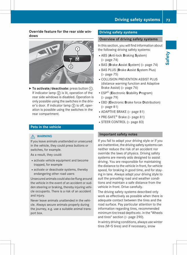
Override feature for the rear side win-dows
X To activate/deactivate: press button:.If indicator lamp; is lit, operation of therear side windows is disabled. Operation isonly possible using the switches in the driv-er's door. If indicator lamp; is off, oper-ation is possible using the switches in therear compartment.
Pets in the vehicle
G WARNINGIf you leave animals unattended or unsecuredin the vehicle, they could press buttons orswitches, for example.As a result, they could:Ractivate vehicle equipment and becometrapped, for example
Ractivate or deactivate systems, therebyendangering other road users
Unsecured animals could also be flung aroundthe vehicle in the event of an accident or sud-den steering or braking, thereby injuring vehi-cle occupants. There is a risk of an accidentand injury.Never leave animals unattended in the vehi-cle. Always secure animals properly duringthe journey, e.g. use a suitable animal trans-port box.
Driving safety systems
Overview of driving safety systemsIn this section, you will find information aboutthe following driving safety systems:RABS (Anti-lock Braking System)(Y page 74)
RBAS (Brake Assist System) (Y page 74)RBAS PLUS (Brake Assist System Plus)(Y page 75)
RCOLLISION PREVENTION ASSIST PLUS(distance warning function and AdaptiveBrake Assist) (Y page 76)
RESP® (Electronic Stability Program)(Y page 79)
REBD (Electronic Brake force Distribution)(Y page 81)
RADAPTIVE BRAKE (Y page 81)RPRE-SAFE® Brake (Y page 81)RSTEER CONTROL (Y page 83)
Important safety notesIf you fail to adapt your driving style or if youare inattentive, the driving safety systems canneither reduce the risk of an accident noroverride the laws of physics. Driving safetysystems are merely aids designed to assistdriving. You are responsible for maintainingthe distance to the vehicle in front, for vehiclespeed, for braking in good time, and for stay-ing in lane. Always adapt your driving style tosuit the prevailing road and weather condi-tions and maintain a safe distance from thevehicle in front. Drive carefully.The driving safety systems described onlywork as effectively as possible when there isadequate contact between the tires and theroad surface. Pay particular attention to theinformation regarding tires, recommendedminimum tire tread depths etc. in the "Wheelsand tires" section (Y page 290).Inwintry driving conditions, always usewintertires (M+S tires) and if necessary, snow
Driving safety systems 73
Safe
ty
Z

chains. Only in this way will the driving safetysystems described in this section work aseffectively as possible.
ABS (Anti-lock Braking System)
General informationABS regulates brake pressure in such a waythat the wheels do not lock when you brake.This allows you to continue steering the vehi-cle when braking.The!ABSwarning lamp in the instrumentcluster lights up when the ignition is switchedon. It goes out when the engine is running.
Important safety notes
i Observe the "Important safety notes" sec-tion (Y page 73).
G WARNINGIf ABS is faulty, the wheels could lock whenbraking. The steerability and braking charac-teristics may be severely impaired. Addition-ally, further driving safety systems are deac-tivated. There is an increased danger of skid-ding and accidents.Drive on carefully. Have ABS checked imme-diately at a qualified specialist workshop.
When ABS is malfunctioning, other systems,including driving safety systems, will alsobecome inoperative. Observe the informationon the ABS warning lamp (Y page 214) anddisplay messages which may be shown in theinstrument cluster (Y page 200).ABS works from a speed of about 5 mph(8 km/h), regardless of road-surface condi-tions. ABS works on slippery surfaces, evenwhen you only brake gently.
BrakingX If ABS intervenes: continue to depress thebrake pedal vigorously until the braking sit-uation is over.X To make a full brake application:depress the brake pedal with full force.
If ABS intervenes when braking, you will feel apulsing in the brake pedal.The pulsating brake pedal can be an indica-tion of hazardous road conditions, and func-tions as a reminder to take extra care whiledriving.
Off-road ABSAn ABS system specifically suited to off-roadterrain is activated automatically once the off-road program is activated (Y page 184).At speeds below 20mph (30 km/h), the frontwheels lock cyclically during braking. The dig-ging-in effect achieved in the process reducesthe stopping distance on off-road terrain. Thislimits steering capability.
BAS (Brake Assist System)
General informationBAS operates in emergency braking situa-tions. If you depress the brake pedal quickly,BAS automatically boosts the braking force,thus shortening the stopping distance.
Important safety notes
i Observe the "Important safety notes" sec-tion (Y page 73).
G WARNINGIf BAS is malfunctioning, the braking distancein an emergency braking situation isincreased. There is a risk of an accident.In an emergency braking situation, depressthe brake pedal with full force. ABS preventsthe wheels from locking.
74 Driving safety systemsSa
fety

BrakingX Keep the brake pedal firmly depressed untilthe emergency braking situation is over.ABS prevents the wheels from locking.
The brakes will function as usual once yourelease the brake pedal. BAS is deactivated.
BAS PLUS (Brake Assist SystemPLUS)
General information
i Observe the "Important safety notes" sec-tion (Y page 73).
BAS PLUS is only available in vehicles equip-ped with DISTRONIC PLUS.For BAS PLUS to assist you, the radar sensorsystem must be operational.With the help of the radar sensor system, BASPLUS can detect obstacles that are in thepath of your vehicle for an extended period oftime.If the radar sensor system is malfunctioning,BAS PLUS will not be available. The brakesystem is still available with complete brakeboosting effect and BAS.BAS PLUS can help you tominimize the risk ofa collision with a vehicle or reduce the effectsof such a collision. If BAS PLUS detects adanger of collision, you are assisted whenbraking.
Important safety notes
G WARNINGBAS PLUS cannot always clearly identifyobjects and complex traffic situations.In such cases, BAS PLUS may:Rintervene unnecessarilyRnot interveneThere is a risk of an accident.Always pay careful attention to the traffic sit-uation and be ready to brake. Terminate theintervention in a non-critical driving situation.
G WARNINGBAS PLUS does not react:Rto people or animalsRto oncoming vehiclesRto crossing trafficRwhen corneringAs a result, BAS PLUSmay not intervene in allcritical situations. There is a risk of an acci-dent.Always pay careful attention to the traffic sit-uation and be ready to brake.
In the event of snowfall or heavy rain, the rec-ognition can be impaired.Recognition by the radar sensor system isalso impaired in the event of:Rthere is dirt on the sensors or anything elsecovering the sensors
Rthere is interference by other radar sourcesRthere are strong radar reflections, forexample in parking garages
Ra narrow vehicle traveling in front, e.g. amotorbike
Ra vehicle traveling in front on a different linerelative to the center of your vehicle
Following damage to the front end of the vehi-cle, have the configuration and operation ofthe radar sensors checked at a qualified spe-cialist workshop. This also applies to colli-sions at low speeds where there is no visibledamage to the front of the vehicle.
FunctionTo avoid a collision, BAS PLUS calculates thebrake force necessary if:Ryou approach an obstacle, andRBAS PLUS has detected a risk of collisionWhen driving at a speed under 20 mph(30 km/h): if you depress the brake pedal,BAS PLUS is activated. The increase in brakepressure will be carried out at the last possi-ble moment.
Driving safety systems 75
Safe
ty
Z
When driving at a speed above 20 mph(30 km/h): if you depress the brake pedalsharply, BAS PLUS automatically raises thebrake pressure to a value adapted to the traf-fic situation.BAS PLUS provides braking assistance in haz-ardous situations with vehicles in front withina speed range between 4 mph (7 km/h) and155 mph (250 km/h).At speeds of up to approximately 40 mph(70 km/h), BAS PLUS can also react to sta-tionary objects. Examples of stationaryobjects are stopped or parked vehicles.
i If BAS PLUS demands particularly highbraking force, preventative passenger pro-tection measures (PRE-SAFE®) are activa-ted simultaneously.X Keep the brake pedal depressed until theemergency braking situation is over.ABS prevents the wheels from locking.
BAS PLUS is deactivated and the brakes func-tion as usual again, if:Ryou release the brake pedal.Rthere is no longer a risk of collision.Rno obstacle is detected in front of yourvehicle.
If you have activated DSR (Y page 184), BASPLUS is likewise deactivated.
COLLISION PREVENTION ASSIST
General notesCOLLISION PREVENTION ASSIST consists ofAdaptive Brake Assist and the distance warn-ing function, which are described in the fol-lowing.
Distance warning function
Important safety notesi Observe the "Important safety notes" sec-tion (Y page 73).
G WARNINGThe distance warning function does not react:Rto people or animalsRto oncoming vehiclesRto crossing trafficRwhen corneringThus, the distance warning function cannotprovide a warning in all critical situations.There is a risk of an accident.Always pay careful attention to the traffic sit-uation and be ready to brake.
G WARNINGThe distance warning function cannot alwaysclearly identify objects and complex trafficsituations.In such cases, the distance warning functionmay:Rgive an unnecessary warningRnot give a warningThere is a risk of an accident.Always pay careful attention to the traffic sit-uation and do not rely solely on the distancewarning function.
FunctionX To activate/deactivate: activate or deac-tivate the distance warning function in theon-board computer (Y page 197).
If the distance warning function is not activa-ted, theæ symbol appears in the assis-tance graphics display.The distancewarning function can help you tominimize the risk of a front-end collision witha vehicle ahead or reduce the effects of sucha collision. If the distance warning functiondetects that there is a risk of a collision, youwill be warned visually and acoustically. Thedistance warning function cannot prevent acollision without your intervention.Starting at a speed of around 4mph (7 km/h),the distance warning function warns you ifyou rapidly approach a vehicle in front. Anintermittent warning tone will then sound,
76 Driving safety systemsSa
fety

and the· distance warning lamp will lightup in the instrument cluster.X Brake immediately in order to increase thedistance from the vehicle in front.
orX Take evasive action, provided it is safe to doso.
Due to the nature of the system, particularlycomplicated but non-critical driving condi-tions may also cause the system to display awarning.With the help of the radar sensor system, thedistance warning function can detect obsta-cles that are in the path of your vehicle for anextended period of time.Up to a speed of about 40mph (70 km/h), thedistance warning function can also react tostationary obstacles, such as stopped orparked vehicles.If you approach an obstacle and the distancewarning function detects a risk of a collision,the system will initially alert you both visuallyand acoustically.In particular, the detection of obstacles canbe impaired if:Rdirt on the sensors or anything else cover-ing the sensors
Rthere is snow or heavy rainRthere is interference by other radar sourcesRthere are strong radar reflections, forexample in parking garages
Ra narrow vehicle traveling in front, e.g. amotorbike
Ra vehicle traveling in front on a different linerelative to the center of your vehicle
Rnew vehicles or after the COLLISION PRE-VENTION ASSIST system has been serv-icedObserve the notes in the section on break-ing-in (Y page 130).
Following damage to the front end of the vehi-cle, have the configuration and operation ofthe radar sensor checked at a qualified spe-cialist workshop. This also applies to colli-
sions at low speeds where there is no visibledamage to the front of the vehicle.
Adaptive Brake Assist
i Observe the "Important safety notes" sec-tion (Y page 73).
Adaptive Brake Assist provides braking assis-tance in hazardous situations at speedsabove 4 mph (7 km/h). It uses radar sensortechnology to assess the traffic situation.
G WARNINGAdaptive Brake Assist cannot always clearlyidentify objects and complex traffic situa-tions.In such cases, Adaptive Brake Assist can:Rintervene unnecessarilyRnot interveneThere is a risk of an accident.Always pay careful attention to the traffic sit-uation and be ready to brake. Terminate theintervention in a non-critical driving situation.
G WARNINGAdaptive Brake Assist does not react:Rto people or animalsRto oncoming vehiclesRto crossing trafficRto stationary obstaclesRwhen corneringAs a result, the Adaptive Brake Assist may notintervene in all critical conditions. There is arisk of an accident.Always pay careful attention to the traffic sit-uation and be ready to brake.
Due to the nature of the system, particularlycomplicated but non-critical driving condi-tions may also cause Brake Assist to inter-vene.With the help of Adaptive Brake Assist, thedistance warning signal can detect obstaclesthat are in the path of your vehicle for anextended period of time.
Driving safety systems 77
Safe
ty
Z
If adaptive Brake Assist has detected thatthere is a risk of a collision, it calculates thebraking force necessary to avoid a collision.Should you apply the brakes vigorously,Adaptive Brake Assist will automaticallyincrease the braking force to a level suitablefor the traffic conditions.X Keep the brake pedal depressed until theemergency braking situation is over.ABS prevents the wheels from locking.
The brakes will work normally again if:Ryou release the brake pedal.Rthere is no longer any danger of a collision.Rno obstacle is detected in front of yourvehicle.
Adaptive Brake Assist is then deactivated.Vehicles with PRE-SAFE®: if adaptive BrakeAssist requires particularly high brake pres-sure, preventive passenger protection meas-ures (PRE-SAFE®) are deployed simultane-ously.Up to vehicle speeds of around 155 mph(250 km/h), adaptive Brake Assist is capableof reacting to moving objects that havealready been recognized as such at least onceover the period of observation. AdaptiveBrake Assist does not react to stationaryobstacles.If Adaptive Brake Assist is not available due toa malfunction in the radar sensor system, thebrake system remains available with fullbrake boosting effect and BAS.In particular, the detection of obstacles canbe impaired if there is:Rthere is dirt on the sensors or anything elsecovering the sensors
Rthere is snow or heavy rainRthere is interference by other radar sourcesRthere are strong radar reflections, forexample in parking garages
Ra narrow vehicle traveling in front, e.g. amotorbike
Ra vehicle traveling in front on a different linerelative to the center of your vehicle
Rnew vehicles or after the COLLISION PRE-VENTION ASSIST system has been serv-icedObserve the notes in the section on break-ing-in (Y page 130).
Following damage to the front end of the vehi-cle, have the configuration and operation ofthe radar sensor checked at a qualified spe-cialist workshop. This also applies to colli-sions at low speeds where there is no visibledamage to the front of the vehicle.
ESP® (Electronic Stability Program)
General notes
i Observe the "Important safety notes" sec-tion (Y page 73).
ESP® monitors driving stability and traction,i.e. power transmission between the tires andthe road surface.If ESP® detects that the vehicle is deviatingfrom the direction desired by the driver, oneor more wheels are braked to stabilize thevehicle. The engine output is also modified tokeep the vehicle on the desired course withinphysical limits. ESP® assists the driver whenpulling away on wet or slippery roads. ESP®can also stabilize the vehicle during braking.
ETS/4ETS (Electronic Traction System)
i Observe the "Important safety notes" sec-tion (Y page 73).
ETS traction control is part of ESP®. On vehi-cles with 4MATIC, 4ETS is part of ESP®.Traction control brakes the drive wheels indi-vidually if they spin. This enables you to pullaway and accelerate on slippery surfaces, forexample if the road surface is slippery on oneside. In addition, more drive torque is trans-ferred to the wheel or wheels with traction.
78 Driving safety systemsSa
fety

Traction control remains active, even if youdeactivate ESP®.In appropriate driving situations, activate theoff-road program (Y page 184).
Off-road 4ETS (Electronic Traction Sys-tem)A 4ETS system specifically suited to off-roadterrain is activated automatically once the off-road program is activated (Y page 184).
Important safety notes
G WARNINGIf ESP® is malfunctioning, ESP® is unable tostabilize the vehicle. Additionally, further driv-ing safety systems are deactivated. Thisincreases the risk of skidding and an accident.Drive on carefully. Have ESP® checked at aqualified specialist workshop.
! Vehicles with 4MATIC: only operate thevehicle for a maximum of ten seconds on abrake test dynamometer. Switch off theignition.Application of the brakes by ESP®may oth-erwise destroy the brake system.
! Vehicles with 4MATIC: function or per-formance tests may only be carried out ona 2-axle dynamometer. Before you operatethe vehicle on such a dynamometer, pleaseconsult a qualified workshop. You couldotherwise damage the drive train or thebrake system.
ESP® is only deactivated if theå warninglamp is lit continuously.If the÷ warning lamp and theå warn-ing lamp are lit continuously, ESP® is notavailable due to a malfunction.Observe the information on warning lamps(Y page 217) and display messages whichmay be shown in the instrument cluster(Y page 200).
i Only use wheels with the recommendedtire sizes. Only then will ESP® functionproperly.
Characteristics of ESP®
General informationIf the÷ ESP warning lamp goes out beforebeginning the journey, ESP® is automaticallyactive.If ESP® intervenes, the÷ ESP® warninglamp flashes in the instrument cluster.If ESP® intervenes:X Do not deactivate ESP® under any circum-stances.X Only depress the accelerator pedal as far asnecessary when pulling away.X Adapt your driving style to suit the prevail-ing road and weather conditions.
ECO start/stop functionThe ECO start/stop function switches theengine off automatically when the vehiclestops moving. The engine starts automati-cally when the driverwants to pull away again.ESP® remains in its previously selected sta-tus.Example: if ESP®was deactivated beforethe engine was switched off, ESP® remainsdeactivated when the engine is switched onagain.
Deactivating/activating ESP®
Important safety notesi Observe the "Important safety notes" sec-tion (Y page 73).
You can select between the following statesof ESP®:RESP® is activated.RESP® is deactivated.
Driving safety systems 79
Safe
ty
Z

G WARNINGIf you deactivate ESP®, ESP® no longer sta-bilizes the vehicle. There is an increased riskof skidding and an accident.Only deactivate ESP® in the situations descri-bed in the following.
It may be best to deactivate ESP® in the fol-lowing situations:Rwhen using snow chainsRin deep snowRon sand or gravel
i Activate ESP® as soon as the situationsdescribed above no longer apply. ESP® willotherwise not be able to stabilize the vehi-cle if the vehicle starts to skid or a wheelstarts to spin.
! Avoid spinning the driven wheels for anextended period with ESP® deactivated.You could otherwise damage the drivetrain.
Deactivating/activating ESP®
X To switch off: press button:.Theå ESP® OFF warning lamp in theinstrument cluster lights up.X To switch on: press button:.Theå ESP® OFF warning lamp in theinstrument cluster goes out.
Characteristics when ESP® is deactivatedIf ESP® is deactivated and one ormorewheelsstart to spin, the÷ ESP® warning lamp in
the instrument cluster flashes. In such situa-tions, ESP® will not stabilize the vehicle.If you deactivate ESP®:RESP® no longer improves driving stability.Rengine torque is no longer limited and thedrive wheels are able to spin.The spinning of the wheels results in a cut-ting action for better traction on loose sur-faces.
Rtraction control is still activated.RESP® still provides support when youbrake.
Off-road ESP® (vehicles with Off-RoadEngineering package)
An ESP® system specifically suited to off-roadterrain is activated automatically once the off-road program is activated (Y page 184).Off-road ESP® intervenes with a delay if thereis oversteering or understeering, thus improv-ing traction.
ESP® trailer stabilization
General informationIf your vehicle/trailer combination begins toswerve, ESP® assists you in this situation.ESP® slows the vehicle down by braking andlimiting the engine output until the vehicle/trailer combination has stabilized.
Important safety notesG WARNINGIf road and weather conditions are poor,trailer stabilization will not be able to preventthe vehicle/trailer combination from swerv-ing. Trailers with a high center of gravity cantip over before ESP® can detect this. There isa risk of an accident.Always adapt your driving style to the prevail-ing road and weather conditions.
If your vehicle with trailer (vehicle/trailercombination) begins to lurch, you can only
80 Driving safety systemsSa
fety

stabilize the vehicle/trailer combination bydepressing the brake firmly.Trailer stabilization is active above speeds ofabout 37 mph (60 km/h).ESP® trailer stabilization does not work ifESP® is deactivated or disabled because of amalfunction.
EBD (electronic brake force distribu-tion)
General informationEBD monitors and controls the brake pres-sure on the rear wheels to improve drivingstability while braking.
Important safety notes
i Observe the "Important safety notes" sec-tion for driving safety systems (Y page 73).
G WARNINGIf EBD is malfunctioning, the rear wheels canlock, e.g. under full braking. This increases therisk of skidding and an accident.You should therefore adapt your driving styleto the different handling characteristics. Havethe brake system checked at a qualified spe-cialist workshop.
Observe information regarding indicator andwarning lamps (Y page 215) as well as dis-play messages (Y page 202).
ADAPTIVE BRAKEADAPTIVE BRAKE enhances braking safetyand offers increased braking comfort. In addi-tion to the braking function, ADAPTIVEBRAKEalso has the HOLD function (Y page 161) andhill start assist (Y page 135).
PRE-SAFE® Brake
General information
i Observe the "Important safety notes" sec-tion (Y page 73).
PRE゙SAFE® Brake is only available for vehi-cles with the Driving Assistance package.For PRE-SAFE® Brake to assist you when driv-ing, the radar sensor system must be opera-tional.With the help of the radar sensor system,PRE-SAFE® Brake can detect obstacles thatare in front of your vehicle for an extendedperiod of time.PRE-SAFE® Brake can help you to minimizethe risk of a collisionwith a vehicle ahead, andreduce the effects of such a collision. If PRE-SAFE® Brake has detected a risk of collision,youwill bewarned visually and acoustically aswell as by automatic braking. PRE-SAFE®Brake cannot prevent a collision without yourintervention.
Important safety notes
G WARNINGPRE-SAFE® Brake will initially brake your vehi-cle by a partial application of the brakes if adanger of collision is detected. There may bea collision unless you also brake. Automaticemergency braking cannot prevent a colli-sion. There is a risk of an accident.Always apply the brakes yourself and try totake evasive action.
G WARNINGPRE-SAFE® Brake cannot always clearly iden-tify objects and complex traffic conditions.In these cases, PRE-SAFE® Brake may:Rgive an unnecessary warning and thenbrake the vehicle
Rnot give a warning or interveneThere is a risk of an accident.
Driving safety systems 81
Safe
ty
Z

Always pay particular attention to the trafficsituation and be ready to brake, especially ifPRE-SAFE® Brake warns you. Terminate theintervention in a non-critical driving situation.
In order to maintain the appropriate distanceto the vehicle in front and thus prevent a col-lision, you must apply the brakes yourself.At speeds of up to approximately 40 mph(70 km/h) PRE-SAFE® Brake can also detectstationary objects. Examples of stationaryobjects are stopped or parked vehicles.
G WARNINGPRE-SAFE® Brake does not react:Rto people or animalsRto oncoming vehiclesRto crossing trafficRwhen corneringAs a result, PRE-SAFE® Brake may neithergive warnings nor intervene in all critical sit-uations. There is a risk of an accident.Always pay careful attention to the traffic sit-uation and be ready to brake.
In the event of snowfall or heavy rain, the rec-ognition can be impaired.Recognition by the radar sensor system isalso impaired in the event of:Rthere is dirt on the sensors or anything elsecovering the sensors
Rthere is interference by other radar sourcesRthere are strong radar reflections, forexample in parking garages
Ra narrow vehicle traveling in front, e.g. amotorbike
Ra vehicle traveling in front on a different linerelative to the center of your vehicle
Following damage to the front end of the vehi-cle, have the configuration and operation ofthe radar sensors checked at a qualified spe-cialist workshop. This also applies to colli-sions at low speeds where there is no visibledamage to the front of the vehicle.
FunctionX To activate/deactivate: activate or deac-tivate PRE-SAFE® Brake in the on-boardcomputer (Y page 197).If the PRE-SAFE®Brake is not activated, theæ symbol appears in the multifunctiondisplay.
Starting at a speed of around 4mph (7 km/h),this function warns you if you rapidlyapproach a vehicle in front. An intermittentwarning tone will then sound and the·distance warning lamp will light up in theinstrument cluster.X Brake immediately to defuse the situation.orX Take evasive action provided it is safe to doso.
PRE-SAFE® Brake can also brake the vehicleautomatically under the following conditions:Rthe driver and front-passenger have theirseat belts fastenedand
Rthe vehicle speed is between approx-imately 4 mph (7 km/h) and 124 mph(200 km/h)
i If there is an increased risk of collision,preventive passenger protection measures(PRE-SAFE®) are activated.
If the risk of collision with the vehicle in frontremains and you do not brake, take evasiveaction or accelerate significantly, the vehiclemay perform automatic emergency braking,up to the point of full brake application. Auto-matic emergency braking is not performeduntil immediately prior to an imminent acci-dent.You can prevent the intervention of the PRE-SAFE® Brake at any time by:Rdepressing the accelerator pedal further.Ractivating kickdown.Rreleasing the brake pedal.
82 Driving safety systemsSa
fety

The braking action of PRE-SAFE® Brake isended automatically if:Ryou maneuver to avoid the obstacle.Rthere is no longer any danger of a collision.Rthere is no longer an obstacle detected infront of your vehicle.
If you have activated DSR (Y page 184), PRE-SAFE® Brake is deactivated.
STEER CONTROL
General informationSTEER CONTROL helps you by transmitting anoticeable steering force to the steeringwheel in the direction required for vehiclestabilization.This steering assistance is provided in partic-ular if:Rboth right wheels or both left wheels are ona wet or slippery road surface when youbrake.
Rthe vehicle starts to skid.
Important safety notes
i Observe the "Important safety notes" sec-tion (Y page 73).
No steering support is provided from STEERCONTROL, if:RESP® is malfunctioning.Rthe lighting is faulty.Power steering will, however, continue tofunction.
Protection against theft
ImmobilizerX To activate with the SmartKey: removethe SmartKey from the ignition lock.X To activate with KEYLESS-GO: switch theignition off and open the driver's door.X To deactivate: switch on the ignition.
The immobilizer prevents your vehicle frombeing started without the correct SmartKey.When leaving the vehicle, always take theSmartKey with you and lock the vehicle. Any-one can start the engine if a valid SmartKeyhas been left inside the vehicle.
i The immobilizer is always deactivatedwhen you start the engine.In the event that the engine cannot be star-ted (yet the vehicle's battery is charged),the system is not operational. Contact anauthorized Mercedes-Benz Center or call1-800-FOR-MERCedes (in the USA) or1-800-387-0100 (in Canada).
ATA (anti-theft alarm system)
X To arm: lock the vehicle with the SmartKeyor KEYLESS-GO.Indicator lamp: flashes. The alarm sys-tem is armed after approximately15 seconds.X To disarm using the SmartKey: unlockthe vehicle with the SmartKey.
orX Insert the SmartKey into the ignition lock.X To disarm using KEYLESS-GO: unlock thevehicle with KEYLESS-GO.
orX Press the Start/Stop button on the dash-board. The SmartKey must be inside thevehicle.
Protection against theft 83
Safe
ty
Z

A visual and audible alarm is triggered if thealarm system is armed and you open:Ra doorRthe vehicle with the mechanical keyRthe tailgateRthe hoodX To turn the alarm off with the SmartKey:press the% or& button on theSmartKey.The alarm is switched off.
orX Insert the SmartKey into the ignition lock.The alarm is switched off.X To stop the alarm using KEYLESS-GO:grasp the outside door handle. The Smart-Key must be outside the vehicle.The alarm is switched off.
orX Press the Start/Stop button on the dash-board. The SmartKey must be inside thevehicle.The alarm is switched off.
The alarm is not switched off, even if youclose the open door that triggered it, forexample.
i If the alarm continues for more than30 seconds, the mbrace emergency callsystem automatically notifies the Cus-tomer Assistance Center. This is doneeither by text message or data connection.The emergency call system sends the mes-sage or data provided that:Ryou have subscribed to the mbrace ser-vice.
Rthe mbrace service has been activatedproperly.
Rthe necessary mobile phone network isavailable.
84 Protection against theftSa
fety

Useful information .............................. 86SmartKey ............................................. 86Doors .................................................... 90Cargo compartment ............................ 91Side windows ...................................... 96Sliding sunroof .................................... 98
85
Open
ing
and
clos
ing

Useful information
i This Operator's Manual describes allmodels and all standard and optional equip-ment of your vehicle available at the time ofpublication of the Operator's Manual.Country-specific differences are possible.Please note that your vehicle may not beequipped with all features described. Thisalso applies to safety-related systems andfunctions.
i Read the information on qualified special-ist workshops (Y page 35).
SmartKey
Important safety notes
G WARNINGIf children are left unsupervised in the vehicle,they could:Ropen the doors, thus endangering otherpeople or road users.
Rget out and disrupt traffic.Roperate the vehicle's equipment.Additionally, children could set the vehicle inmotion if, for example, they:Rrelease the parking brake.Rshifting the automatic transmission out ofpark position P
RStart the engine.There is a risk of an accident and injury.When leaving the vehicle, always take theSmartKeywith you and lock the vehicle. Neverleave children or animals unattended in thevehicle. Always keep the SmartKey out ofreach of children.
G WARNINGIf persons, particularly children are subjectedto prolonged exposure to extreme heat orcold, there is a risk of injury, possibly evenfatal. Never leave children unattended in thevehicle.
G WARNINGIf you attach heavy or large objects to theSmartKey, the SmartKey could be uninten-tionally turned in the ignition lock. This couldcause the engine to be switched off. There is arisk of an accident.Do not attach any heavy or large objects to theSmartKey. Remove any bulky key rings beforeinserting the SmartKey into the ignition lock.
! Keep the SmartKey away from strongmagnetic fields. Otherwise, the remotecontrol function could be affected.Strong magnetic fields can occur in thevicinity of powerful electrical installations.
Do not keep the SmartKey:Rwith electronic devices, e.g. a mobilephone or another SmartKey.
Rwith metallic objects, e.g. coins or metalfoil.
Rinside metallic objects, e.g. a metal case.This can affect the functionality of theSmartKey.
Do not keep the KEYLESS-GO or KEYLESS-GOStart function key in the temperature-con-trolled cup holder. Otherwise, the KEYLESS-GO key will not be recognized.
SmartKey functions
: & To lock the vehicle; F To open/close the tailgate= % To unlock the vehicleX To unlock centrally: press button=.
86 SmartKeyOp
enin
gan
dcl
osin
g

If you do not open the vehicle withinapproximately 40 seconds of unlocking:Rthe vehicle is locked again.Rthe theft deterrent locking system isarmed again.
X To lock centrally: press button:.The SmartKey centrally locks/unlocks:Rthe doorsRthe tailgateRthe fuel filler flapThe turn signals flash once when unlockingand three times when locking.You can also set an audible signal to confirmthat the vehicle has been locked. The audiblesignal can be activated and deactivated usingthe on-board computer (Y page 197).When it is dark, the surround lighting alsocomes on if it is activated in the on-boardcomputer (Y page 197).
KEYLESS-GO
General notesBear inmind that the engine can be started byany of the vehicle occupants if there is a KEY-LESS-GO key in the vehicle.
Locking/unlocking centrallyYou can start, lock or unlock the vehicle usingKEYLESS-GO. To do this, you only need carrythe SmartKey with you. You can combine thefunctions of KEYLESS-GOwith those of a con-ventional SmartKey. Unlock the vehicle byusing KEYLESS-GO, for instance, and lock itusing the& button on the SmartKey.When locking or unlocking with KEYLESS-GO,the distance between the SmartKey and thecorresponding door handle must not begreater than 3 ft (1 m).
KEYLESS-GO checks whether a valid Smart-Key is in the vehicle by periodically establish-ing a radio connection between the vehicleand the SmartKey. This happens:Rwhen the external door handles aretouched
Rwhen starting the engineRwhile the vehicle is in motion
X To unlock the vehicle: touch the innersurface of the door handle.X To lock the vehicle: touch sensor sur-face:.X Convenience closing feature: touchrecessed sensor surface; for an exten-ded period.
If you pull on the handle of the tailgate, onlythe cargo compartment of the vehicle isunlocked.
Deactivating and activatingIf you do not intend to use the vehicle for alonger period of time, you can deactivate KEY-LESS-GO. The SmartKey will then use very lit-tle power, thereby conserving battery power.For the purposes of activation/deactivation,the vehicle must not be nearby.
SmartKey 87
Open
ing
and
clos
ing
Z

X To deactivate: press the& button onthe SmartKey twice in rapid succession.The battery check lamp of the SmartKey(Y page 89) lights up twice briefly andKEYLESS-GO is deactivated.X To activate: press any button on theSmartKey or insert the SmartKey into theignition lock.KEYLESS-GO and all of its associated fea-tures are available again.
KEYLESS-GO start functionBear inmind that the engine can be started byany of the vehicle occupants if there is aSmartKey in the vehicle.
Changing the settings of the lockingsystemYou can find information about this in theDigital Operator's Manual.
Mechanical key
General notesIf the vehicle can no longer be locked orunlocked with the SmartKey, use themechanical key.If you use the mechanical key to unlock andopen the driver's door, the anti-theft alarmsystem will be triggered (Y page 83).There are several ways to turn off the alarm:X To deactivate the alarm with the Smart-
Key: press the% or& button on theSmartKey.
orX Insert the SmartKey into the ignition lock.orX To deactivate the alarm with KEYLESS-
GO: press the Start/Stop button in the igni-tion lock. The SmartKey must be in thevehicle.
orX Lock or unlock the vehicle using KEYLESS-GO. The SmartKey must be outside thevehicle.
If you unlock the vehicle using themechanicalkey, the fuel filler flap will not be unlockedautomatically.X To unlock the fuel filler flap: insert theSmartKey into the ignition lock.
Removing the mechanical key
X Push release catch: in the direction ofthe arrow and at the same time removemechanical key; from the SmartKey.
For further information about:Runlocking the driver's door (Y page 90)Runlocking the cargo compartment(Y page 95)
Rlocking the vehicle (Y page 91)
Inserting the mechanical keyX Push mechanical key; completely intothe SmartKey until it engages and releasecatch: is back in its basic position.
SmartKey battery
Important safety notes
G WARNINGBatteries contain toxic and corrosive substan-ces. If batteries are swallowed, it can result in
88 SmartKeyOp
enin
gan
dcl
osin
g

severe health problems. There is a risk of fatalinjury.Keep batteries out of the reach of children. Ifa battery is swallowed, seekmedical attentionimmediately.
Mercedes-Benz recommends that you havethe batteries replaced at a qualified specialistworkshop.The SmartKey batteries contain perchloratematerial, which may require special handlingand regard for the environment. Nationalguidelines must be observed during disposal.In California, see www.dtsc.ca.gov/Hazard-ousWaste/Perchlorate/index.cfm.
Checking the battery
X Press the& or% button.The battery is working properly if batterycheck lamp: lights up briefly.The battery is discharged if battery checklamp: does not light up briefly.X Change the battery (Y page 89).i If the SmartKey battery is checked withinthe signal reception range of the vehicle,pressing the& or% button:Rlocks orRunlocks the vehicle
i You can get a battery at any qualified spe-cialist workshop.
Replacing the batteryYou require a CR 2025 3 V cell battery.X Take the mechanical key out of the Smart-Key (Y page 88).
X Press mechanical key; into the openingin the SmartKey in the direction of thearrow until battery compartment cover:opens. Do not hold battery compartmentcover: closed while doing so.X Remove battery compartment cover:.
X Repeatedly tap the SmartKey against yourpalm until battery= falls out.X Insert the new battery with the positive ter-minal facing upwards. Use a lint-free clothto do so.X Make sure that the surface of the battery isfree of lint, grease and other contaminants.X Insert the front tabs of battery compart-ment cover: into the housing first andthen press to close it.
SmartKey 89
Open
ing
and
clos
ing
Z

X Insert mechanical key; into the Smart-Key.X Check the function of all SmartKey buttonson the vehicle.
Problems with the SmartKeyYou can find information about this in theDigital Operator's Manual.
Doors
Important safety notes
G WARNINGIf children are left unsupervised in the vehicle,they could:Ropen the doors, thus endangering otherpeople or road users.
Rget out and disrupt traffic.Roperate the vehicle's equipment.Additionally, children could set the vehicle inmotion if, for example, they:Rrelease the parking brake.Rshifting the automatic transmission out ofpark position P
RStart the engine.There is a risk of an accident and injury.When leaving the vehicle, always take theSmartKeywith you and lock the vehicle. Neverleave children or animals unattended in thevehicle. Always keep the SmartKey out ofreach of children.
G WARNINGIf persons, particularly children are subjectedto prolonged exposure to extreme heat orcold, there is a risk of injury, possibly evenfatal. Never leave children unattended in thevehicle.
G WARNINGIf objects, luggage or loads are not secured ornot secured sufficiently, they could slip, tip
over or be flung around and thereby hit vehicleoccupants. There is a risk of injury, particu-larly in the event of sudden braking or a sud-den change in direction.Always store objects so that they cannot beflung around. Secure objects, luggage orloads against slipping or tipping before thejourney.
You should preferably place luggage or loadsin the cargo compartment. Observe the load-ing guidelines (Y page 244).
Information in the Digital Operator'sManualIn the Digital Operator's Manual you will findinformation on the following topics:RUnlocking and opening doors from theinside
RCentrally locking and unlocking the vehiclefrom the inside
RAutomatic locking featureRPower closing feature
Unlocking the driver's door (mechan-ical key)If the vehicle can no longer be unlocked withthe SmartKey, use the mechanical key.If you use the mechanical key to unlock andopen the driver's door, the anti-theft alarmsystem will be triggered (Y page 83).X Take the mechanical key out of the Smart-Key (Y page 88).X Insert the mechanical key into the lock ofthe driver's door as far as it will go.
90 DoorsOp
enin
gan
dcl
osin
g

X Turn themechanical key counter-clockwiseto position1.The door is unlocked.X Turn the mechanical key back and removeit.X Insert the mechanical key into the Smart-Key.
Locking the vehicle (mechanical key)If the vehicle can no longer be locked with theSmartKey, use the mechanical key.X Open the driver's door.X Close the front-passenger door, the reardoors and the tailgate.X Press the locking button (Y page 90).X Check whether the locking knobs on thefront-passenger door and the rear doorsare still visible. Press down the lockingknobs by hand, if necessary.X Close the driver's door.X Take the mechanical key out of the Smart-Key (Y page 88).X Insert the mechanical key into the lock ofthe driver's door as far as it will go.
X Turn themechanical key clockwise as far asit will go to position1.X Turn the mechanical key back and removeit.X Make sure that the doors and the tailgateare locked.X Insert the mechanical key into the Smart-Key.
i If you lock the vehicle as described above,the fuel filler flap is not locked. The anti-theft alarm system is not armed.
Cargo compartment
Important safety notes
G WARNINGIf persons, particularly children are subjectedto prolonged exposure to extreme heat orcold, there is a risk of injury, possibly evenfatal. Never leave children unattended in thevehicle.
G WARNINGCombustion engines emit poisonous exhaustgases such as carbonmonoxide. If the tailgateis open when the engine is running, particu-larly if the vehicle is moving, exhaust fumescould enter the passenger compartment.There is a risk of poisoning.Turn off the engine before opening the tail-gate. Never drive with the tailgate open.
Cargo compartment 91
Open
ing
and
clos
ing
Z

G WARNINGIf objects, luggage or loads are not secured ornot secured sufficiently, they could slip, tipover or be flung around and thereby hit vehicleoccupants. There is a risk of injury, particu-larly in the event of sudden braking or a sud-den change in direction.Always store objects so that they cannot beflung around. Secure objects, luggage orloads against slipping or tipping before thejourney.
! The tailgate swings upwards and to therear when opened. Therefore, make surethat there is sufficient clearance above andbehind the tailgate.
i Tailgate opening dimensions(Y page 346).
You should preferably place luggage or loadsin the cargo compartment. Observe the load-ing guidelines (Y page 244).Do not leave the SmartKey in the cargo com-partment. You could otherwise lock yourselfout.Vehicles without the EASY-PACK tailgate:the tailgate can be:Ropened and closed manually from outsideRunlocked from inside with the emergencyrelease
For vehicles with the EASY-PACK tailgateyou can:Rclose the tailgate manually from outsideRopen and close the tailgate automaticallyfrom outside
Ropen and close the tailgate automaticallyfrom inside
Runlock the tailgate from inside with theemergency release
Rlimit the opening angle of the tailgate
Tailgate reversing feature
On vehicles with tailgate remote closing fea-ture, the tailgate is equipped with automaticobstacle recognition with a reversing feature.If a solid object blocks or restricts the tailgatewhen automatically opening or closing, thisprocedure is stopped. If the tailgate is stop-ped during the closing procedure, it will openagain automatically. The automatic obstaclerecognition with reversing feature is only anaid. It is not a substitute for your attentive-ness when opening and closing the tailgate.
G WARNINGThe reversing feature does not react:Rto soft, light and thin objects, e.g. small fin-gers
Rover the last 1/3 in (8 mm) of the closingmovement
This means that the reversing feature cannotprevent someone being trapped in these sit-uations. There is a risk of injury.Make sure that no body parts are in closeproximity during the closing procedure.If somebody becomes trapped:Rpress theF button on the SmartKey, orRpull or press the remote operating switchon the driver's door or
Rpress the closing or locking button on thetailgate or
Rpull the handle on the tailgate
92 Cargo compartmentOp
enin
gan
dcl
osin
g

Opening and closing manually fromoutside
Opening
X Press the% button on the SmartKey.X Pull handle:.X Raise the tailgate.Vehicles with the EASY-PACK tailgate: ifyou pull handle: and then release it, thetailgate opens automatically.
Closing
X Pull the tailgate down using recess:.X Allow the tailgate to drop into the lock.X Lock the vehicle if necessary with the&button on the SmartKey or with KEYLESS-GO.
i If a KEYLESS-GO key is detected in thecargo compartment, the tailgate will notlock.
Opening/closing automatically fromoutside
Important safety notes
G WARNINGParts of the body could become trapped dur-ing automatic closing of the tailgate. More-over, people, e.g. children, may be standing inthe closing area or may enter the closing areaduring the closing process. There is a risk ofinjury.Make sure that nobody is in the vicinity of theclosing area during the closing process.Use one of the following options to stop theclosing process:Rpress theF button on the SmartKey.Rpull or press the remote operating switchon the driver's door.
Rpress the closing or locking button on thetailgate.
Rpull the handle on the tailgate.
G WARNINGCombustion engines emit poisonous exhaustgases such as carbonmonoxide. If the tailgateis open when the engine is running, particu-larly if the vehicle is moving, exhaust fumescould enter the passenger compartment.There is a risk of poisoning.Turn off the engine before opening the tail-gate. Never drive with the tailgate open.
! The tailgate swings upwards and to therear when opened. Therefore, make surethat there is sufficient clearance above andbehind the tailgate.
i Tailgate opening dimensions(Y page 346).
i Notes on the reversing feature for the tail-gate (Y page 92).
Cargo compartment 93
Open
ing
and
clos
ing
Z

Opening the tailgate automaticallyYou can open the tailgate automatically withthe SmartKey or the handle in the tailgate.X Press and hold theF button on theSmartKey until the tailgate opens.
orX If the tailgate is unlocked, pull the handleand let it go again immediately.
Closing the tailgate automatically
G WARNINGParts of the body could become trapped dur-ing automatic closing of the tailgate. More-over, people, e.g. children, may be standing inthe closing area or may enter the closing areaduring the closing process. There is a risk ofinjury.Make sure that nobody is in the vicinity of theclosing area during the closing process.Use one of the following options to stop theclosing process:Rpress theF button on the SmartKey.Rpull or press the remote operating switchon the driver's door.
Rpress the closing or locking button on thetailgate.
Rpull the handle on the tailgate.
Closing and locking button (example: vehicle withEASY-PACK tailgate and KEYLESS-GO)
X To close: press closing button: on thetailgate.
orX Press and hold theF button on theSmartKey until the tailgate closes.
Vehicles with the EASY-PACK tailgate andKEYLESS-GO: you can simultaneously closeand lock the tailgate.X Press locking button; on the tailgate.If a KEYLESS-GO key is detected outsidethe vehicle, the tailgate closes and locks.All the doors must be shut and the Smart-Key located in the vicinity of the tailgate.i The tailgate cannot be opened and closedwith the SmartKey if there is a SmartKey inthe ignition.If the tailgate touches an object while clos-ing, the closing procedure is interruptedand the tailgate reopens.
i If a KEYLESS-GO key is detected in thecargo compartment, the tailgate will notlock.
Opening/closing automatically frominside
Important safety notes
G WARNINGParts of the body could become trapped dur-ing automatic closing of the tailgate. More-over, people, e.g. children, may be standing inthe closing area or may enter the closing areaduring the closing process. There is a risk ofinjury.Make sure that nobody is in the vicinity of theclosing area during the closing process.Use one of the following options to stop theclosing process:Rpress theF button on the SmartKey.Rpull or press the remote operating switchon the driver's door.
94 Cargo compartmentOp
enin
gan
dcl
osin
g

Rpress the closing or locking button on thetailgate.
Rpull the handle on the tailgate.
G WARNINGCombustion engines emit poisonous exhaustgases such as carbonmonoxide. If the tailgateis open when the engine is running, particu-larly if the vehicle is moving, exhaust fumescould enter the passenger compartment.There is a risk of poisoning.Turn off the engine before opening the tail-gate. Never drive with the tailgate open.
! The tailgate swings upwards and to therear when opened. Therefore, make surethat there is sufficient clearance above andbehind the tailgate.
i Tailgate opening dimensions(Y page 346).
i Notes on the reversing feature for the tail-gate (Y page 92).
Opening and closing
You can open and close the tailgate from thedriver's seat when the vehicle is stationaryand unlocked.X To open: pull remote operating switch:for the tailgate until the tailgate opens.X To close: turn the SmartKey to position 1or 2 in the ignition lock.X Press remote operating switch for tail-gate: until the tailgate is closed.
Limiting the opening angle of the tail-gate
Important safety notes
! Make sure there is sufficient clearance toopen the tailgate fully when setting theopening angle. The tailgate could otherwisebe damaged. Ideally, set the opening angleoutside.
ActivatingYou can limit the opening angle of the tail-gate. This is possible in the top half of itsopening range, up to approximately 4 in(10 cm) before the stop.This could be useful, for example, if there isinsufficient space above the tailgate.X To open the tailgate: pull the handle onthe tailgate.X To stop the opening procedure at the
desired position: press the closing button(Y page 93) in the tailgate or pull the handleon the outside of the tailgate again.X To store the position: press and hold theclosing button in the tailgate until you heara short tone.The opening angle limiter is activated. Thetailgate will now stop in the stored positionwhen opening.
DeactivatingX Press and hold the closing button(Y page 93) in the tailgate until you heartwo short tones.
Tailgate emergency release
Important safety notes
! The tailgate swings upwards and to therear when opened. Therefore, make surethat there is sufficient clearance above andbehind the tailgate.
Cargo compartment 95
Open
ing
and
clos
ing
Z

i Tailgate opening dimensions(Y page 346).
If the tailgate can no longer be unlocked:Rusing the SmartKey, orRusing the remote operating switch in thedoor control panel:
Use the emergency release.
Opening
X Take the mechanical key out of the Smart-Key (Y page 88).X Insert mechanical key; into the openingin paneling:.X Turn mechanical key; 90° clockwise.X Push mechanical key; in the direction ofthe arrow and open the tailgate.X Insert the mechanical key into the Smart-Key.
Side windows
Important safety notes
G WARNINGWhile opening the side windows, body partscould become trapped between the side win-dow and the door frame as the side windowmoves. There is a risk of injury.Make sure that nobody touches the side win-dow during the opening procedure. If some-body becomes trapped, release the switch orpull the switch to close the sidewindow again.
G WARNINGWhile closing the side windows, body parts inthe closing area could become trapped. Thereis a risk of injury.When closing make sure that no parts of thebody are in the closing area. If somebodybecomes trapped, release the switch or pressthe switch to open the side window again.
G WARNINGIf children operate the side windows theycould become trapped, particularly if they areleft unsupervised. There is a risk of injury.Activate the override feature for the rear sidewindows. When leaving the vehicle, alwaystake the SmartKey with you and lock the vehi-cle. Never leave children unsupervised in thevehicle.
Side window reversing featureThe side windows are equipped with an auto-matic reversing feature. If a solid objectblocks or restricts a side window during theclosing process, the side window opens againautomatically. However, the automaticreversing feature is only an aid and does notrelieve you of the responsibility of payingattention when closing a side window.
G WARNINGThe reversing feature does not react:Rto soft, light and thin objects, e.g. small fin-gers
Rover the last 1/6 in(4 mm) of the closingmovement
Rduring resettingRwhen closing the side window again man-ually immediately after automatic reversing
This means that the reversing feature cannotprevent someone being trapped in these sit-uations. There is a risk of injury.Make sure that no body parts are in closeproximity during the closing procedure. If
96 Side windowsOp
enin
gan
dcl
osin
g
someone becomes trapped, press the switchto open the side window again.
Information in the Digital Operator'sManualIn the Digital Operator's Manual you will findinformation on the following topics:ROpening and closing the side windowsRConvenience openingRConvenience closingRResetting the side windows
Side windows 97
Open
ing
and
clos
ing
Z

Problems with the side windows
G WARNINGIf you close a side window again immediately after it has been blocked or reset, the side windowcloses with increased or maximum force. The reversing feature is then not active. Parts of thebody could be trapped in the closing area in the process. This poses an increased risk of injury oreven fatal injury.Make sure that no parts of the body are in the closing area. To stop the closing process, releasethe switch or push the switch again to reopen the side window.
Problem Possible causes/consequences and M Solutions
A side window cannotbe closed because it isblocked by objects, e.g.leaves in the windowguide.
X Remove the objects.X Close the side window.
A side window cannotbe closed and you can-not see the cause.
If a side window is obstructed during closing and reopens againslightly:X Immediately after the window blocks, pull the correspondingswitch again until the side window has closed.The side window is closed with increased force.
If a side window is obstructed again during closing and reopensagain slightly:X Immediately after the window blocks, pull the correspondingswitch again until the side window has closed.The side window is closed without the anti-entrapment feature.
Sliding sunroof
Important safety notesYour vehicle may be equipped with a slidingsunroof or a panorama roof with power tilt/sliding panel. In this section, the term "slidingsunroof" refers to both types of sliding sun-roof.
G WARNINGWhile opening and closing the sliding sunroof,body parts in close proximity could becometrapped. There is a risk of injury.Make sure that no body parts are in closeproximity during the opening and closing pro-cedures.
If somebody becomes trapped:Rrelease the switch immediately, orRduring automatic operation, push theswitch briefly in any direction
The opening or closing procedure will be stop-ped.
G WARNINGIf children operate the sliding sunroof theycould become trapped, particularly if they areleft unsupervised. There is a risk of injury.When leaving the vehicle, always take theSmartKeywith you and lock the vehicle. Neverleave children unsupervised in the vehicle.
98 Sliding sunroofOp
enin
gan
dcl
osin
g

! Only open the sliding sunroof if it is free ofsnow and ice. Otherwise,malfunctionsmayoccur.Do not allow anything to protrude from thesliding sunroof. Otherwise, the seals couldbe damaged.
i Resonance noises can occur in addition tothe usual airflow noises when the slidingsunroof is open. They are caused by minorpressure fluctuations in the vehicle interior.Change the position of the sliding sunroofor open a side window. The noise will bereduced or eliminated.
Sliding sunroof reversing featureThe sliding sunroof is equipped with an auto-matic reversing feature. If a solid objectblocks or restricts the sliding sunroof duringthe closing process, the sliding sunroof opensagain automatically. However, the automaticreversing feature is only an aid and does notrelieve you of the responsibility of payingattention when closing the sliding sunroof.
G WARNINGThe reversing feature does not react:Rto soft, light and thin objects, e.g. small fin-gers
Rover the last 1/6 in(4 mm) of the closingmovement
Rduring resettingRwhen closing the sliding sunroof againman-ually immediately after automatic reversing
This means that the reversing feature cannotprevent someone being trapped in these sit-uations. There is a risk of injury.Make sure that no body parts are in closeproximity during the closing procedure.If somebody becomes trapped:Rrelease the switch immediately, orRduring automatic operation, push theswitch briefly in any direction
The closing process is stopped.
Operating the sliding sunroof
Opening and closing
Overhead control panel: To raise; To open= To close/lowerX Turn the SmartKey to position 1 or 2 in theignition lock.X Press or pull the2 switch in the corre-sponding direction.i If you press the2 switch beyond thepoint of resistance, an automatic opening/closing process is started in the corre-sponding direction. You can stop automaticoperation by pressing/pulling the switchagain.When opening and raising the roof, auto-matic operation is only available if the slid-ing sunroof is in the closed position.
The sun protection cover automatically opensalong with the sliding sunroof. You can openor close the sun protection cover manuallywhen the sliding sunroof is raised or closed.
i You can continue to operate the slidingsunroof after switching off the engine orremoving the SmartKey from the ignitionlock. This function is available for up to fiveminutes or until the driver's or front-passenger door is opened.
Sliding sunroof 99
Open
ing
and
clos
ing
Z

Resetting
! If the sliding sunroof still cannot beopened or closed fully after resetting, con-tact a qualified specialist workshop.
Reset the sliding sunroof if it does not movesmoothly.X Turn the SmartKey to position 1 or 2 in theignition lock.X Raise the sliding sunroof fully at the rear(Y page 99).X Keep the2 switch pressed for anothersecond.X Make sure that the sliding sunroof can befully opened and closed again (Y page 99).X If this is not the case, repeat the stepsabove again.
Operating the panorama roof withpower tilt/sliding panel
Overhead control panel: To raise; Opening= To close/lowerThe panorama roof with power tilt/slidingpanel can only be operated when the rollersunblind is open (Y page 101).X To open and close: turn the SmartKey toposition 1 or 2 in the ignition lock.X Press or pull the2 switch in the corre-sponding direction.i If you press the2 switch beyond thepoint of resistance, an automatic opening/
closing process is started in the corre-sponding direction. You can stop automaticoperation by pressing/pulling the switchagain.Automatic operation for raising is availableonly when the sliding sunroof is closed.
Operating the roller sunblinds for thepanorama roof with power tilt/slidingpanel
Important safety notes
G WARNINGWhen opening or closing the roller sunblind,parts of the body could be trapped betweenthe roller sunblind and the frame or slidingsunroof. There is a risk of injury.When opening or closing make sure that noparts of the body are in the sweep of the rollersunblind.If somebody becomes trapped:Rrelease the switch immediately, orRduring automatic operation, push theswitch briefly in any direction
The opening or closing procedure will be stop-ped.
The roller sunblinds shield the vehicle interiorfrom sunlight. The roller sunblinds can only beopened and closed together when the pano-rama roof with power tilt/sliding panel isclosed.
Roller sunblind reversing featureThe roller sunblinds are equipped with anautomatic reversing feature. If a solid objectblocks or restricts a roller sunblind during theclosing process, the roller sunblind opensagain automatically. However, the automaticreversing feature is only an aid and does notrelieve you of the responsibility of payingattention when closing the roller sunblinds.
100 Sliding sunroofOp
enin
gan
dcl
osin
g

G WARNINGThe reversing feature especially does notreact to soft, light and thin objects such assmall fingers. This means that the reversingfeature cannot prevent someone being trap-ped in these situations. There is a risk ofinjury.When closing make sure that no parts of thebody are in the sweep of the roller sunblind.If somebody becomes trapped:Rrelease the switch immediately, orRduring automatic operation, push theswitch briefly in any direction
The closing process is stopped.
Opening and closing the roller sun-blinds
Overhead control panel: To open; To open= To closeX Turn the SmartKey to position 1 or 2 in theignition lock.X Press or pull the2 switch in the corre-sponding direction.i If you press the2 switch beyond thepoint of resistance, an automatic opening/closing process is started in the corre-sponding direction. You can stop automaticoperation by pressing/pulling the switchagain.
Resetting the panorama roof withpower tilt/sliding panel and the rollersunblinds
! If the panorama roof with power tilt/slid-ing panel and the roller sunblinds cannot befully opened or closed after resetting, con-tact a qualified specialist workshop.
Reset the panorama roof with power tilt/slid-ing panel and the roller sunblinds if the pan-orama roof with power tilt/sliding panel orthe roller sunblinds do not move smoothly.X Turn the SmartKey to position 1 or 2 in theignition lock.X Pull the2 switch repeatedly to the pointof resistance in the direction of arrow=until the panorama roof with power tilt/sliding panel is fully closed.X Keep the2 switch pulled for an addi-tional second.X Pull the2 switch repeatedly to the pointof resistance in the direction of arrow=until the roller sunblinds are fully closed.X Keep the2 switch pulled for an addi-tional second.X Make sure that the panorama roof withpower tilt/sliding panel (Y page 100) andthe roller sunblinds (Y page 101) can befully opened again.X If this is not the case, repeat the stepsabove again.
Sliding sunroof 101
Open
ing
and
clos
ing
Z
Problems with the sliding sunroofYour vehicle may be equipped with a sliding sunroof or a panorama roof with power tilt/slidingpanel. In this section, the term "sliding sunroof" refers to both types of sliding sunroof.
G WARNINGIf you close the sliding sunroof again immediately after it has been blocked or reset, the slidingsunroof closes with increased or maximum force. The reversing feature is then not active. Partsof the body could be trapped in the closing area in the process. This poses an increased risk ofinjury or even fatal injury.Make sure that no parts of the body are in the closing area.If somebody becomes trapped:Rrelease the switch immediately, orRduring automatic operation, push the switch briefly in any directionThe closing process is stopped.
! If the sliding sunroof still cannot be opened or closed as a result of a malfunction, contacta qualified specialist workshop.
Problem Possible causes/consequences and M Solutions
The sliding sunroof can-not be closed and youcannot see the cause.
If the sliding sunroof is obstructed during closing and reopensagain slightly:X Immediately after the sliding sunroof blocks, pull the2switch in the overhead control panel down to the point of resist-ance and hold it until the sliding sunroof is closed.The sliding sunroof is closed with increased force.
If the sliding sunroof is obstructed again during closing and thenreopens slightly:X Immediately after the sliding sunroof blocks, pull the2switch in the overhead control panel down to the point of resist-ance and hold it until the sliding sunroof is closed.The sliding sunroof is closed without the anti-entrapment fea-ture.
i Note on the automatic reversing feature of the sliding sunroof (Y page 99).
102 Sliding sunroofOp
enin
gan
dcl
osin
g

Useful information ............................ 104Correct driver's seat position .......... 104Seats .................................................. 105Steering wheel .................................. 107Mirrors ............................................... 108Memory function ............................... 108
103
Seat
s,st
eerin
gw
heel
and
mirr
ors

Useful information
i This Operator's Manual describes allmodels and all standard and optional equip-ment of your vehicle available at the time ofpublication of the Operator's Manual.Country-specific differences are possible.Please note that your vehicle may not beequipped with all features described. Thisalso applies to safety-related systems andfunctions.
i Read the information on qualified special-ist workshops (Y page 35).
Correct driver's seat position
G WARNINGYou could lose control of your vehicle if you dothe following while driving:Radjust the driver's seat, head restraint,steering wheel or mirrors
Rfasten the seat beltThere is a risk of an accident.Adjust the driver's seat, head restraint, steer-ing wheel andmirror and fasten your seat beltbefore starting the engine.
X Observe the safety guidelines on seatadjustment (Y page 105).X Make sure that seat= is adjusted prop-erly.Electrical seat adjustment (Y page 106)
When adjusting the seat, make sure that:Ryou are as far away from the driver's air bagas possible
Ryou are sitting in a normal upright positionRyou can fasten the seat belt properlyRyou have moved the backrest to an almostvertical position
Ryou have set the seat cushion angle so thatyour thighs are gently supported
Ryou can depress the pedals properlyX Check whether the head restraint is adjus-ted properly.When doing so, make sure that you haveadjusted the head restraint so that the backof your head is supported at eye level by thecenter of the head restraint. Also makesure that you have adjusted the headrestraint so that the back of your head is asclose to the head restraint as possible.X Observe the safety guidelines on steeringwheel adjustment (Y page 107).X Make sure that steering wheel: is adjus-ted properly.Adjusting the steering wheel manually(Y page 107)Adjusting the steering wheel electrically(Y page 107)
When adjusting the steering wheel, makesure that:Ryou can hold the steering wheel with yourarms slightly bent
Ryou can move your legs freelyRyou can see all the displays in the instru-ment cluster clearlyX Observe the safety guidelines for seat belts(Y page 52).X Check whether you have fastened the seatbelt; properly (Y page 54).
104 Correct driver's seat positionSe
ats,
stee
ring
whe
elan
dm
irror
s

The seat belt should:Rfit snugly across your bodyRbe routed across the middle of your shoul-der
Rbe routed in your pelvic area across the hipjointsX Before starting off, adjust the rear-viewmir-ror and the exterior mirrors in such a waythat you have a good view of road and traf-fic conditions (Y page 108).X Vehicles with a memory function: savethe seat, steering wheel and exterior mirrorsettings with the memory function(Y page 108).
Seats
Important safety notes
G WARNINGChildren could become trapped if they adjustthe seats, particularly when unattended.There is a risk of injury.When leaving the vehicle, always take theSmartKeywith you and lock the vehicle. Neverleave children unsupervised in the vehicle.
The seats can still be adjusted when there isno SmartKey in the ignition lock.
G WARNINGWhen you adjust a seat, you or other vehicleoccupants could become trapped, e.g. on theseat guide rail. There is a risk of injury.Make sure when adjusting a seat that no onehas any body parts in the sweep of the seat.
Observe the safety notes on "Air bags"(Y page 56) and "Children in the vehicle"(Y page 67).
G WARNINGYou could lose control of your vehicle if you dothe following while driving:Radjust the driver's seat, head restraint,steering wheel or mirrors
Rfasten the seat beltThere is a risk of an accident.Adjust the driver's seat, head restraint, steer-ing wheel andmirror and fasten your seat beltbefore starting the engine.
G WARNINGIf you adjust the seat height carelessly, you orother vehicle occupants could be trapped andthereby injured. Children in particular couldaccidentally press the electrical seat adjust-ment buttons and become trapped. There is arisk of injury.While moving the seats, make sure that yourhands or other body parts do not get under thelever assembly of the seat adjustment sys-tem.
G WARNINGIf head restraints are not installed and adjus-ted correctly, they cannot provide protectionas intended. There is an increased risk ofinjury in the head and neck area, e.g. in theevent of an accident or when braking.Always drive with the head restraints instal-led. Before driving off, make sure for everyvehicle occupant that the center of the headrestraint supports the back of the head atabout eye level.
G WARNINGThe seat belt does not offer the intended levelof protection if you have not moved the back-rest to an almost vertical position.When brak-ing or in the event of an accident, you couldslide underneath the seat belt and sustainabdomen or neck injuries, for example. Thisposes an increased risk of injury or even fatalinjury.
Seats 105
Seat
s,st
eerin
gw
heel
and
mirr
ors
Z

Adjust the seat properly before beginningyour journey. Always ensure that the backrestis in an almost vertical position and that theshoulder section of your seat belt is routedacross the center of your shoulder.
! To avoid damage to the seats and the seatheating, observe the following information:Rkeep liquids from spilling on the seats. Ifliquid is spilled on the seats, dry them assoon as possible.
Rif the seat covers are damp or wet, do notswitch on the seat heating. The seatheating should also not be used to drythe seats.
Rclean the seat covers as recommended;see the "Interior care" section.
Rdo not transport heavy loads on theseats. Do not place sharp objects on theseat cushions, e.g. knives, nails or tools.The seats should only be occupied bypassengers, if possible.
Rwhen the seat heating is in operation, donot cover the seats with insulating mate-rials, e.g. blankets, coats, bags, seat cov-ers, child seats or booster seats.
! Make sure that there are no objects in thefootwell under or behind the seats whenmoving the seats back. There is a risk thatthe seats and/or the objects could be dam-aged.
i It is not possible to remove the headrestraints from the front seats. The rear-compartment head restraints, however,can be removed. You can find informationabout this in the Digital Operator's Manual.For more information, contact a qualifiedspecialist workshop.
i Further related subjects:RCargo compartment enlargement (fold-ing down the rear bench seat)(Y page 246)
Information in the Digital Operator'sManualIn the Digital Operator's Manual you will findinformation on the following topics:RAdjusting the seatsRAdjusting the head restraintsRAdjusting the 4-way lumbar supportRSwitching the seat ventilation on/off
Switching the seat heating on/off
Switching on/off
G WARNINGRepeatedly switching on the seat heating cancause the seat cushion and backrest pads tobecome very hot. The health of persons withlimited temperature sensitivity or a limitedability to react to excessively high tempera-tures may be affected or they may even sufferburn-like injuries. There is a risk of injury.Therefore, do not switch the seat heating onrepeatedly.
106 SeatsSe
ats,
stee
ring
whe
elan
dm
irror
s

Driver's and front-passenger seat
Rear seats
The three red indicator lamps in the buttonindicate the heating level you have selected.The system automatically switches downfrom level 3 to level 2 after approximatelyeight minutes.The system automatically switches downfrom level 2 to level 1 after approximately tenminutes.The system automatically switches offapproximately 35 minutes after it is set tolevel 1.X Turn the SmartKey to position 1 or 2 in theignition lock (Y page 131).X To switch on: press button: repeatedlyuntil the desired heating level is set.X To switch off: press button: repeatedlyuntil all the indicator lamps go out.
i If the battery voltage is too low, the seatheating may switch off.
Problems with the seat heatingYou can find information about this in theDigital Operator's Manual.
Steering wheel
Important safety notes
G WARNINGYou could lose control of your vehicle if you dothe following while driving:Radjust the driver's seat, head restraint,steering wheel or mirrors
Rfasten the seat beltThere is a risk of an accident.Adjust the driver's seat, head restraint, steer-ing wheel and mirror and fasten your seat beltbefore starting the engine.
G WARNINGChildren could injure themselves if theyadjust the steering wheel. There is a risk ofinjury.When leaving the vehicle, always take theSmartKeywith you and lock the vehicle. Neverleave children unsupervised in the vehicle.
The electrically adjustable steering wheel canstill be adjusted when there is no SmartKey inthe ignition lock.
Information in the Digital Operator'sManualIn the Digital Operator's Manual you will findinformation on the following topics:RAdjusting the steering wheelRSteering wheel heatingREASY-ENTRY/EXIT feature
Steering wheel 107
Seat
s,st
eerin
gw
heel
and
mirr
ors
Z

Mirrors
In the Digital Operator's Manual you will findinformation on the following topics:RRear-view mirrorRExterior mirrorsRAutomatic anti-glare mirrorsRParking position for the exterior mirror onthe front-passenger side
Memory function
In the Digital Operator's Manual you will findinformation on the following topics:RStoring settingsRCalling up a stored setting
108 Memory functionSe
ats,
stee
ring
whe
elan
dm
irror
s
Useful information ............................ 110Exterior lighting ................................ 110Interior lighting ................................. 114Replacing bulbs ................................. 114Windshield wipers ............................ 117
109
Ligh
tsan
dw
inds
hiel
dw
iper
s
Useful information
i This Operator's Manual describes allmodels and all standard and optional equip-ment of your vehicle available at the time ofpublication of the Operator's Manual.Country-specific differences are possible.Please note that your vehicle may not beequipped with all features described. Thisalso applies to safety-related systems andfunctions.
i Read the information on qualified special-ist workshops (Y page 35).
Exterior lighting
General notesFor reasons of safety, Mercedes-Benz recom-mends that you drive with the lights switchedon even during the daytime. In some coun-tries, operation of the headlamps varies dueto legal requirements and self-imposed obli-gations.
Driving abroad
Conversion to symmetrical low beamSwitch the headlamps to symmetrical lowbeam in countries in which traffic drives onthe opposite side of the road from the countrywhere the vehicle is registered. This preventsglare to oncoming traffic. When using sym-metrical lights, the edge of the road is not litas widely and as far ahead as normal.Have the headlamps converted at a qualifiedspecialist workshop as close to the border aspossible before driving in these countries.
Conversion to asymmetrical low beamafter returningHave the headlamps converted back to asym-metrical low-beam headlamps at a qualifiedspecialist workshop as soon as possible aftercrossing the border again.
Information in the Digital Operator'sManualIn the Digital Operator's Manual you will findinformation on the following topics:RHazard warning lampsRHeadlamps fogged up on the inside
Setting the exterior lighting
Setting optionsExterior lighting can be set using:Rthe light switchRthe combination switch (Y page 112)Rthe on-board computer
Light switch
Operation
1W Left-hand standing lamps2X Right-hand standing lamps3 T Parking lamps, license plate and
instrument cluster lighting4Ã Automatic headlamp mode, control-
led by the light sensor5L Low-beam/high-beam headlampsBR Rear fog lampIf you hear a warning tone when you leave thevehicle, the lights may still be switched on.X Turn the light switch toÃ.
110 Exterior lightingLi
ghts
and
win
dshi
eld
wip
ers
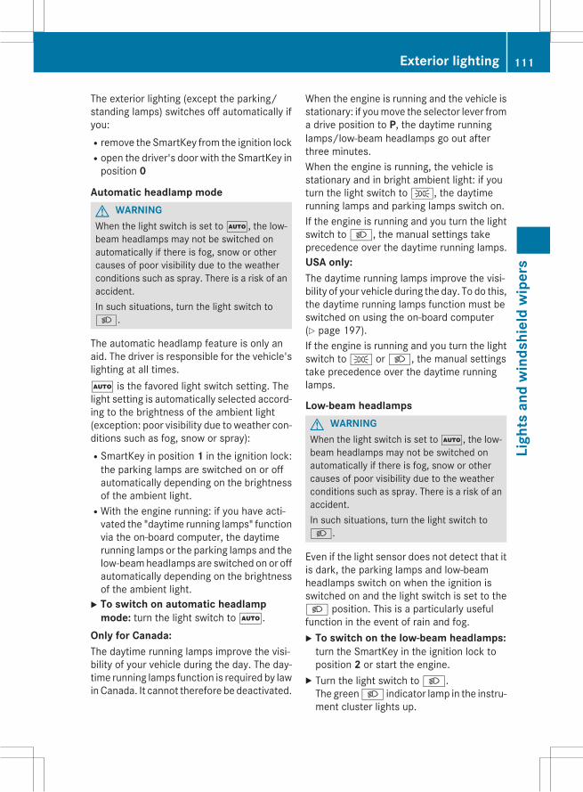
The exterior lighting (except the parking/standing lamps) switches off automatically ifyou:Rremove the SmartKey from the ignition lockRopen the driver's door with the SmartKey inposition 0
Automatic headlamp modeG WARNINGWhen the light switch is set toÃ, the low-beam headlamps may not be switched onautomatically if there is fog, snow or othercauses of poor visibility due to the weatherconditions such as spray. There is a risk of anaccident.In such situations, turn the light switch toL.
The automatic headlamp feature is only anaid. The driver is responsible for the vehicle'slighting at all times.Ã is the favored light switch setting. Thelight setting is automatically selected accord-ing to the brightness of the ambient light(exception: poor visibility due to weather con-ditions such as fog, snow or spray):RSmartKey in position 1 in the ignition lock:the parking lamps are switched on or offautomatically depending on the brightnessof the ambient light.
RWith the engine running: if you have acti-vated the "daytime running lamps" functionvia the on-board computer, the daytimerunning lamps or the parking lamps and thelow-beamheadlamps are switched on or offautomatically depending on the brightnessof the ambient light.X To switch on automatic headlamp
mode: turn the light switch toÃ.Only for Canada:The daytime running lamps improve the visi-bility of your vehicle during the day. The day-time running lamps function is required by lawinCanada. It cannot therefore be deactivated.
When the engine is running and the vehicle isstationary: if youmove the selector lever froma drive position to P, the daytime runninglamps/low-beam headlamps go out afterthree minutes.When the engine is running, the vehicle isstationary and in bright ambient light: if youturn the light switch toT, the daytimerunning lamps and parking lamps switch on.If the engine is running and you turn the lightswitch toL, the manual settings takeprecedence over the daytime running lamps.USA only:The daytime running lamps improve the visi-bility of your vehicle during the day. To do this,the daytime running lamps function must beswitched on using the on-board computer(Y page 197).If the engine is running and you turn the lightswitch toT orL, the manual settingstake precedence over the daytime runninglamps.
Low-beam headlampsG WARNINGWhen the light switch is set toÃ, the low-beam headlamps may not be switched onautomatically if there is fog, snow or othercauses of poor visibility due to the weatherconditions such as spray. There is a risk of anaccident.In such situations, turn the light switch toL.
Even if the light sensor does not detect that itis dark, the parking lamps and low-beamheadlamps switch on when the ignition isswitched on and the light switch is set to theL position. This is a particularly usefulfunction in the event of rain and fog.X To switch on the low-beam headlamps:turn the SmartKey in the ignition lock toposition 2 or start the engine.X Turn the light switch toL.The greenL indicator lamp in the instru-ment cluster lights up.
Exterior lighting 111
Ligh
tsan
dw
inds
hiel
dw
iper
s
Z

Rear fog lampThe rear fog lamp improves visibility of yourvehicle for the traffic behind in the event ofthick fog. Please take note of the country-specific regulations for the use of rear foglamps.X To switch on the rear fog lamps: turn theSmartKey in the ignition lock to position 2or start the engine.X Turn the light switch toL orÃ.X Press theR button.The yellowR indicator lamp in theinstrument cluster lights up.X To switch off the rear fog lamp: press theR button.The yellowR indicator lamp in theinstrument cluster goes out.
Parking lamps! If the battery has been excessively dis-charged, the parking lamps or standinglamps are automatically switched off toenable the next engine start. Always parkyour vehicle safely and sufficiently litaccording to legal standards. Avoid thecontinuous use of theT parking lampsfor several hours. If possible, switch on theX right or theW left standing lamp.X To switch on: turn the light switch toT.The greenT indicator lamp in the instru-ment cluster lights up.
Standing lampsSwitching on the standing lamps ensures thecorresponding side of the vehicle is illumina-ted.X To switch on the standing lamps: theSmartKey is not in the ignition lock or it is inposition 0.X Turn the light switch toW (left-hand sideof the vehicle) orX (right-hand side ofthe vehicle).
Combination switch
: High-beam headlamps; Turn signal, right= High-beam flasher? Turn signal, leftIn the Digital Operator's Manual you will findinformation on the following topics:RTurn signalRHigh-beam headlampsRHigh-beam flasher
Cornering light function
The cornering light function improves the illu-mination of the road over a wide angle in thedirection you are turning, enabling better vis-ibility in tight bends, for example. It can onlybe activated when the low-beam headlampsare switched on.
112 Exterior lightingLi
ghts
and
win
dshi
eld
wip
ers

Active:Rif you are driving at speeds below 25 mph(40 km/h) and switch on the turn signal orturn the steering wheel
Rif you are driving at speeds between25 mph (40 km/h) and 45 mph (70 km/h)and turn the steering wheel
The cornering lamp may remain lit for a shorttime, but is automatically switched off afterno more than three minutes.
Adaptive Highbeam Assist
General notes
You can use this function to set the head-lamps to change between low beam and highbeam automatically. The system recognizesvehicles with their lights on, either approach-ing from the opposite direction or traveling infront of your vehicle, and consequentlyswitches the headlamps from high beam tolow beam.The system automatically adapts the low-beam headlamp range depending on the dis-tance to the other vehicle. Once the systemno longer detects any other vehicles, it reac-tivates the high-beam headlamps.
The system's optical sensor is located behindthe windshield near the overhead controlpanel.
Important safety notes
G WARNINGAdaptive HighbeamAssist does not recognizeroad users:Rwho have no lights, e.g. pedestriansRwho have poor lighting, e.g. cyclistsRwhose lighting is blocked, e.g. by a barrierIn very rare cases, Adaptive Highbeam Assistmay fail to recognize other road users thathave lights, or may recognize them too late. Inthis or similar situations, the automatic high-beam headlamps will not be deactivated oractivated regardless. There is a risk of an acci-dent.Always carefully observe the traffic conditionsand switch off the high-beam headlamps ingood time.
Adaptive Highbeam Assist cannot take intoaccount road, weather or traffic conditions.Adaptive Highbeam Assist is only an aid. Youare responsible for adjusting the vehicle'slighting to the prevailing light, visibility andtraffic conditions.In particular, the detection of obstacles canbe restricted if there is:Rpoor visibility, e.g. due to fog, heavy rain orsnow
Rdirt on the sensors or the sensors areobscured
Switching Adaptive Highbeam Assiston/offX To switch on: turn the light switch toÃ.X Press the combination switch beyond thepressure point in the direction of arrow:.The_ indicator lamp in the multifunc-tion display lights up when it is dark and thelight sensor activates the low-beam head-lamps.
Exterior lighting 113
Ligh
tsan
dw
inds
hiel
dw
iper
s
Z
If you are driving at speeds above approx-imately 16 mph (25 km/h):The headlamp range is set automaticallydepending on the distance between thevehicle and other road users.If you are driving at speeds above approx-imately 19 mph (30 km/h) and no otherroad users have been detected:The high-beam headlamps are switched onautomatically. TheK indicator lamp inthe instrument cluster also lights up.If you are driving at speeds below approx-imately 16 mph (25 km/h) or other roadusers have been detected or the roads areadequately lit:The high-beam headlamps are switched offautomatically. TheK indicator lamp inthe instrument cluster goes out. The_indicator lamp in the multifunction displayremains lit.X To switch off: move the combinationswitch back to its normal position or movethe light switch to another position.The_ indicator lamp in the multifunc-tion display goes out.
Interior lighting
An overview of the interior lighting and theoverhead control panel can be found in the"At a glance" section.In the Digital Operator's Manual you will findinformation on the following topics:RAutomatic interior lighting controlRManual interior lighting controlRCrash-responsive emergency lighting
Replacing bulbs
Important safety notes
G DANGERXenon bulbs carry a high voltage. You can getan electric shock if you remove the cover of
the Xenon bulb and touch the electrical con-tacts. There is a risk of fatal injury.Never touch the parts or the electrical con-tacts of the Xenon bulb. Always have work onthe Xenon bulbs carried out at a qualified spe-cialist workshop.
If your vehicle is equipped with Xenon bulbs,you can recognize this by the following: thecone of light from the Xenon bulbs movesfrom the top to the bottom and back againwhen you start the engine. For this to beobserved, the lights must be switched onbefore starting the engine.
G WARNINGBulbs, lamps and connectors can get very hotwhen operating. If you change a bulb, youcould burn yourself on these components.There is a risk of injury.Allow these components to cool down beforechanging a bulb.
Do not use a bulb that has been dropped or ifits glass tube has been scratched.The bulb may explode if:Ryou touch itRit is hotRyou drop itRyou scratch itOnly operate bulbs in enclosed lampsdesigned for that purpose. Only install sparebulbs of the same type and the specified volt-age.Marks on the glass tube reduce the servicelife of the bulbs. Do not touch the glass tubewith your bare hands. If necessary, clean theglass tubewhen coldwith alcohol or spirit andrub it off with a lint-free cloth.Protect bulbs from moisture during opera-tion. Do not allow bulbs to come into contactwith liquids.There are bulbs other than the Xenon bulbsthat you cannot replace. Replace only thebulbs listed (Y page 115). Have the bulbs that
114 Replacing bulbsLi
ghts
and
win
dshi
eld
wip
ers

you cannot replace yourself changed at aqualified specialist workshop.If you require assistance changing bulbs, con-sult a qualified specialist workshop.If the new bulb still does not light up, consulta qualified specialist workshop.Bulbs and lamps are an important aspect ofvehicle safety. You must therefore make surethat these function correctly at all times.Have the headlamp setting checked regularly.
Overview: changing bulbs/bulb typesYou can change the following bulbs. The bulbtype can be found in the legend.
Halogen headlamps: Low-beam headlamp: H7 55 W; High-beam headlamp: H7 55 W= Parking lamp/standing lamp: W 5 W BV? Side marker lamp: WY 5 W
Tail lamps: Brake lamp: P 21 W-L
Changing the front bulbs
Removing and installing the cover in thefront wheel housing
You must remove the cover from the frontwheel housing before you can change thefront bulbs.X To remove: switch off the lights.X Turn the front wheels inwards.X Remove securing pin; using a suitabletool.X Slide cover: up and remove it.X To install: insert cover: again and slide itdown until it engages.X Insert securing pin;.
Low-beam headlamps (halogen head-lamps)
X Remove the cover in the front wheel hous-ing (Y page 115).X Turn housing cover: counter-clockwiseand pull it out.
Replacing bulbs 115
Ligh
tsan
dw
inds
hiel
dw
iper
s
Z
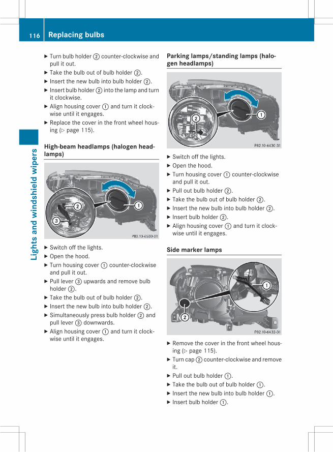
X Turn bulb holder; counter-clockwise andpull it out.X Take the bulb out of bulb holder;.X Insert the new bulb into bulb holder;.X Insert bulb holder; into the lamp and turnit clockwise.X Align housing cover: and turn it clock-wise until it engages.X Replace the cover in the front wheel hous-ing (Y page 115).
High-beam headlamps (halogen head-lamps)
X Switch off the lights.X Open the hood.X Turn housing cover: counter-clockwiseand pull it out.X Pull lever= upwards and remove bulbholder;.X Take the bulb out of bulb holder;.X Insert the new bulb into bulb holder;.X Simultaneously press bulb holder; andpull lever= downwards.X Align housing cover: and turn it clock-wise until it engages.
Parking lamps/standing lamps (halo-gen headlamps)
X Switch off the lights.X Open the hood.X Turn housing cover: counter-clockwiseand pull it out.X Pull out bulb holder;.X Take the bulb out of bulb holder;.X Insert the new bulb into bulb holder;.X Insert bulb holder;.X Align housing cover: and turn it clock-wise until it engages.
Side marker lamps
X Remove the cover in the front wheel hous-ing (Y page 115).X Turn cap; counter-clockwise and removeit.X Pull out bulb holder:.X Take the bulb out of bulb holder:.X Insert the new bulb into bulb holder:.X Insert bulb holder:.
116 Replacing bulbsLi
ghts
and
win
dshi
eld
wip
ers

X Align cap; and turn it clockwise until itengages.X Replace the cover in the front wheel hous-ing (Y page 115).
Changing the rear bulbs
Opening and closing the service flap
Left-hand service flap
Right-hand service flap
You must open the service flap in the cargocompartment before you can change thebulbs in the brake lamp.X To open: release service flap: at the top,e.g. with a screwdriver, and swing it down-ward in the direction of the arrow.X Right side: remove the first-aid kit before-hand and pull the parcel net down.X To close: reinsert service flap:.
Brake lamp
X Switch off the lights.X Open the cargo compartment.X Open the service flap (Y page 117).X Turn bulb holder: counter-clockwise andremove it.X Take bulb out of bulb holder:.X Insert the new bulb into bulb holder:.X Insert bulb holder: into the lamp and turnit clockwise.X Close the service flap (Y page 117).
Windshield wipers
Switching the windshield wiperson/off
Combination switch1 $ Windshield wiper off2 Ä Intermittent wipe, low (rain sensor
set to low sensitivity)3 Å Intermittent wipe, high (rain sensor
set to high sensitivity)
Windshield wipers 117
Ligh
tsan
dw
inds
hiel
dw
iper
s
Z

4 ° Continuous wipe, slow5 ¯ Continuous wipe, fastB í Single wipeC î To wipe with washer fluidIf the wiper blades are worn, the windshieldwill no longer be wiped properly. This couldprevent you from observing the traffic condi-tions.
Switching the rear window wiper on/off
Combination switch: è Rear window wiper switch2 b Wipes with washer fluid3 I Switches on intermittent wiping4 0 Switches off intermittent wiping5 ô Wipes with washer fluid
Replacing the wiper blades
Important safety notes
G WARNINGIf the windshield wipers begin to move whileyou are changing the wiper blades, you couldbe trapped by the wiper arm. There is a risk ofinjury.Always switch off the windshield wipers andignition before changing the wiper blades.
! Never open the hood/tailgate if a wiperarm has been folded away from the wind-shield/rear window.
Never fold awindshieldwiper armwithout awiper blade back onto the windshield/rearwindow.Hold the windshield wiper arm firmly whenyou change the wiper blade. If you releasethe wiper arm without a wiper blade and itfalls onto the windshield/rear window, thewindshield/rear window may be damagedby the force of the impact.Mercedes-Benz recommends that you havethe wiper blades changed at a qualifiedspecialist workshop.
! To avoid damaging the wiper blades,make sure that you touch only the wiperarm of the wiper.
Changing the windshield wiper blades
Removing the wiper bladesX Remove the SmartKey from the ignitionlock.X Fold the wiper arm away from the wind-shield.
X Firmly press release knob: and pull wiperblade; upwards from thewiper arm in thedirection of the arrow.
118 Windshield wipersLi
ghts
and
win
dshi
eld
wip
ers

Installing the wiper blades
X Position new wiper blade: in the retaineron the wiper arm and slide it into place inthe direction of the arrow.The wiper blade audibly engages.X Make sure that the wiper blade is seatedcorrectly.X Fold the wiper arm back onto the wind-shield.
Replacing the rear window wiper blade
Removing a wiper blade
X Remove the SmartKey from the ignitionlock.X Fold wiper arm: away from the rear win-dow until it engages.X Position wiper blade; at a right angle towiper arm:.X Hold wiper arm: and press wiperblade; in the direction of the arrow untilit releases.X Remove wiper blade;.
Installing a wiper bladeX Place new wiper blade; onto wiperarm:.X Hold wiper arm: and press wiperblade; in the opposite direction to thearrow until it engages.X Make sure that wiper blade; is seatedcorrectly.X Position wiper blade; parallel to wiperarm:.X Fold wiper arm: back onto the rear win-dow.
Problems with the windshield wipersYou can find information about this in theDigital Operator's Manual.
Windshield wipers 119
Ligh
tsan
dw
inds
hiel
dw
iper
s
Z

120

Useful information ............................ 122Overview of climate control sys-tems ................................................... 122Operating the climate control sys-tems ................................................... 127
121
Clim
ate
cont
rol

Useful information
i This Operator's Manual describes allmodels and all standard and optional equip-ment of your vehicle available at the time ofpublication of the Operator's Manual.Country-specific differences are possible.Please note that your vehicle may not beequipped with all features described. Thisalso applies to safety-related systems andfunctions.
i Read the information on qualified special-ist workshops (Y page 35).
Overview of climate control systems
General notesObserve the settings recommended on thefollowing pages. The windows could other-wise fog up.To prevent the windows from fogging up:Rswitch off climate control only brieflyRswitch on air-recirculation mode onlybriefly
Rswitch on the cooling with air dehumidifi-cation function
Rswitch on the defrost windshield functionbriefly, if required
Climate control regulates the temperatureand the humidity in the vehicle interior andfilters undesirable substances out of the air.Climate control can only be operated whenthe engine is running. Optimum operation isonly achieved with the side windows and roofclosed.The residual heat function can only be acti-vated or deactivated if the ignition is switchedoff. See the Digital Operator's Manual, key-word "Residual heat".
i When the weather is warm, ventilate thevehicle for a brief period.This will speed up the cooling process andthe desired interior temperature will bereached more quickly.
i The integrated filter filters out most par-ticles of dust and soot and completely fil-ters out pollen. It also reduces gaseous pol-lutants and odors. A clogged filter reducesthe amount of air supplied to the vehicleinterior. For this reason, you should alwaysobserve the interval for replacing the filter,which is specified in the MaintenanceBooklet. As it depends on environmentalconditions, e.g. heavy air pollution, theinterval may be shorter than stated in theMaintenance Booklet.
i It is possible that under certain circum-stances the residual heat function may beactivated automatically an hour after thekey has been removed in order to dry theautomatic climate control. The vehicle isthen ventilated for 30 minutes.
122 Overview of climate control systemsCl
imat
eco
ntro
l
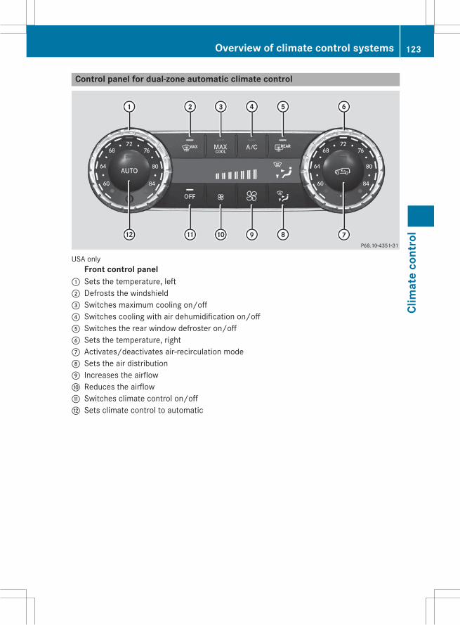
Control panel for dual-zone automatic climate control
USA onlyFront control panel
: Sets the temperature, left; Defrosts the windshield= Switches maximum cooling on/off? Switches cooling with air dehumidification on/offA Switches the rear window defroster on/offB Sets the temperature, rightC Activates/deactivates air-recirculation modeD Sets the air distributionE Increases the airflowF Reduces the airflowG Switches climate control on/offH Sets climate control to automatic
Overview of climate control systems 123
Clim
ate
cont
rol
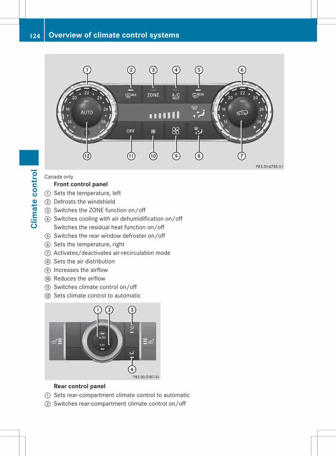
Canada onlyFront control panel
: Sets the temperature, left; Defrosts the windshield= Switches the ZONE function on/off? Switches cooling with air dehumidification on/off
Switches the residual heat function on/offA Switches the rear window defroster on/offB Sets the temperature, rightC Activates/deactivates air-recirculation modeD Sets the air distributionE Increases the airflowF Reduces the airflowG Switches climate control on/offH Sets climate control to automatic
Rear control panel: Sets rear-compartment climate control to automatic; Switches rear-compartment climate control on/off
124 Overview of climate control systemsCl
imat
eco
ntro
l
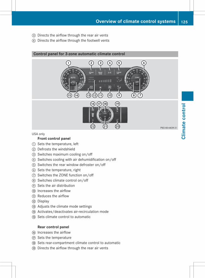
= Directs the airflow through the rear air vents? Directs the airflow through the footwell vents
Control panel for 3-zone automatic climate control
USA onlyFront control panel
: Sets the temperature, left; Defrosts the windshield= Switches maximum cooling on/off? Switches cooling with air dehumidification on/offA Switches the rear window defroster on/offB Sets the temperature, rightC Switches the ZONE function on/offD Switches climate control on/offE Sets the air distributionF Increases the airflowG Reduces the airflowH DisplayI Adjusts the climate mode settingsJ Activates/deactivates air-recirculation modeK Sets climate control to automatic
Rear control panelL Increases the airflowM Sets the temperatureN Sets rear-compartment climate control to automaticO Directs the airflow through the rear air vents
Overview of climate control systems 125
Clim
ate
cont
rol
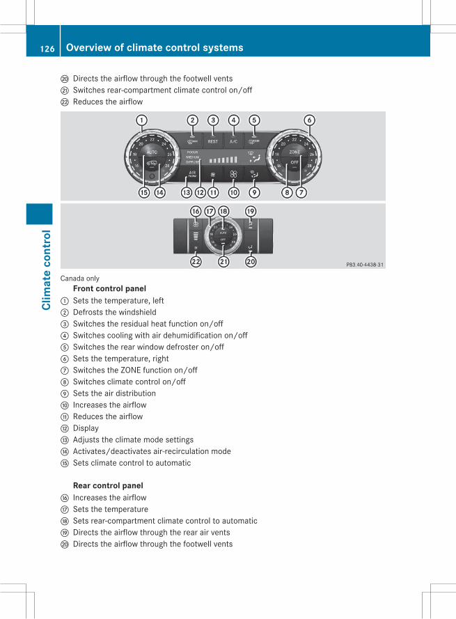
P Directs the airflow through the footwell ventsQ Switches rear-compartment climate control on/offR Reduces the airflow
Canada onlyFront control panel
: Sets the temperature, left; Defrosts the windshield= Switches the residual heat function on/off? Switches cooling with air dehumidification on/offA Switches the rear window defroster on/offB Sets the temperature, rightC Switches the ZONE function on/offD Switches climate control on/offE Sets the air distributionF Increases the airflowG Reduces the airflowH DisplayI Adjusts the climate mode settingsJ Activates/deactivates air-recirculation modeK Sets climate control to automatic
Rear control panelL Increases the airflowM Sets the temperatureN Sets rear-compartment climate control to automaticO Directs the airflow through the rear air ventsP Directs the airflow through the footwell vents
126 Overview of climate control systemsCl
imat
eco
ntro
l

Q Switches rear-compartment climate control on/offR Reduces the airflow
Operating the climate control sys-tems
In the Digital Operator's Manual you will findinformation on the following topics:RSwitching climate control on/offRSwitching cooling with air dehumidificationon/off
RSetting climate control to automaticRAdjusting the climate mode settingsRSetting the temperatureRSetting the air distributionRSetting the airflowRSwitching the ZONE function on/offRDefrosting the windshieldRMAX COOL maximum coolingRDefrosting the windowsRSwitching the rear windowdefroster on/offRActivating/deactivating air-recirculationmode
RSwitching the residual heat function on/offRSetting the air vents
Operating the climate control systems 127
Clim
ate
cont
rol

128

Useful information ............................ 130Notes on breaking-in a new vehi-cle ....................................................... 130Driving ............................................... 130Automatic transmission ................... 136Refueling ............................................ 139Parking ............................................... 145Driving tips ........................................ 147Driving systems ................................ 152Towing a trailer ................................. 186
129
Driv
ing
and
park
ing

Useful information
i This Operator's Manual describes allmodels and all standard and optional equip-ment of your vehicle available at the time ofpublication of the Operator's Manual.Country-specific differences are possible.Please note that your vehicle may not beequipped with all features described. Thisalso applies to safety-related systems andfunctions.
i Read the information on qualified special-ist workshops (Y page 35).
Notes on breaking-in a new vehicle
Important safety notesThe sensor system of some driving and driv-ing safety systems adjusts automaticallywhile a certain distance is being driven afterthe vehicle has been delivered or afterrepairs. Full system effectiveness is notreached until the end of this teach-in proce-dure.New and replaced brake pads and discs onlyreach their optimum braking effect after sev-eral hundred kilometers of driving. Compen-sate for this by applying greater force to thebrake pedal.
The first 1000 miles (1500 km)The more you look after the engine when it isnew, the more satisfied you will be with itsperformance in the future.RYou should therefore drive at varying vehi-cle and engine speeds for the first1000 miles (1500 km).
RAvoid heavy loads, e.g. driving at full throt-tle, during this period.
RChange gear in good time, before the tach-ometer needle isÔ of the way to the redarea of the tachometer.
RDo not manually shift to a lower gear tobrake the vehicle.
RTry to avoid depressing the acceleratorpedal beyond the point of resistance (kick-down).
After 1000miles (1500 km), you can increasethe engine speed gradually and acceleratethe vehicle to full speed.Additional breaking-in notes for AMG vehi-cles:RDo not drive faster than 85 mph(140 km/h) for the first 1,000 miles(1,500 km).
ROnly allow the engine to reach a maximumengine speed of 4,500 rpm briefly.
RChange gear in good time.RIdeally, for the first 1,000miles (1,500 km),drive in program C.
i You should also observe these notes onbreaking in if the engine or parts of the drivetrain on your vehicle have been replaced.
i Always observe the respective speed lim-its.
Driving
Important safety notes
G WARNINGObjects in the driver's footwell can restrict thepedal travel or obstruct a depressed pedal.The operating and road safety of the vehicle isjeopardized. There is a risk of an accident.Make sure that all objects in the vehicle arestowed correctly, and that they cannot enterthe driver's footwell. Install the floormatssecurely and as specified in order to ensuresufficient clearance for the pedals. Do not useloose floormats and do not place floormats ontop of one another.
130 DrivingDr
ivin
gan
dpa
rkin
g
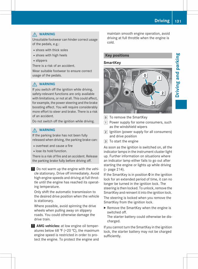
G WARNINGUnsuitable footwear can hinder correct usageof the pedals, e.g.:Rshoes with thick solesRshoes with high heelsRslippersThere is a risk of an accident.Wear suitable footwear to ensure correctusage of the pedals.
G WARNINGIf you switch off the ignition while driving,safety-relevant functions are only availablewith limitations, or not at all. This could affect,for example, the power steering and the brakeboosting effect. You will require considerablymore effort to steer and brake. There is a riskof an accident.Do not switch off the ignition while driving.
G WARNINGIf the parking brake has not been fullyreleased when driving, the parking brake can:Roverheat and cause a fireRlose its hold function.There is a risk of fire and an accident. Releasethe parking brake fully before driving off.
! Do not warm up the engine with the vehi-cle stationary. Drive off immediately. Avoidhigh engine speeds and driving at full throt-tle until the engine has reached its operat-ing temperature.Only shift the automatic transmission tothe desired drive position when the vehicleis stationary.Where possible, avoid spinning the drivewheels when pulling away on slipperyroads. You could otherwise damage thedrive train.
! AMG vehicles: at low engine oil temper-atures below 68 ‡ (+20 †), the maximumengine speed is restricted in order to pro-tect the engine. To protect the engine and
maintain smooth engine operation, avoiddriving at full throttle when the engine iscold.
Key positions
SmartKey
g To remove the SmartKey1 Power supply for some consumers, such
as the windshield wipers2 Ignition (power supply for all consumers)
and drive position3 To start the engineAs soon as the ignition is switched on, all theindicator lamps in the instrument cluster lightup. Further information on situations wherean indicator lamp either fails to go out afterstarting the engine or lights up while driving(Y page 214).If the SmartKey is in position 0 in the ignitionlock for an extended period of time, it can nolonger be turned in the ignition lock. Thesteering is then locked. To unlock, remove theSmartKey and reinsert it into the ignition lock.The steering is locked when you remove theSmartKey from the ignition lock.X Remove the SmartKey when the engine isswitched off.The starter battery could otherwise be dis-charged.
If you cannot turn the SmartKey in the ignitionlock, the starter battery may not be chargedsufficiently.
Driving 131
Driv
ing
and
park
ing
Z
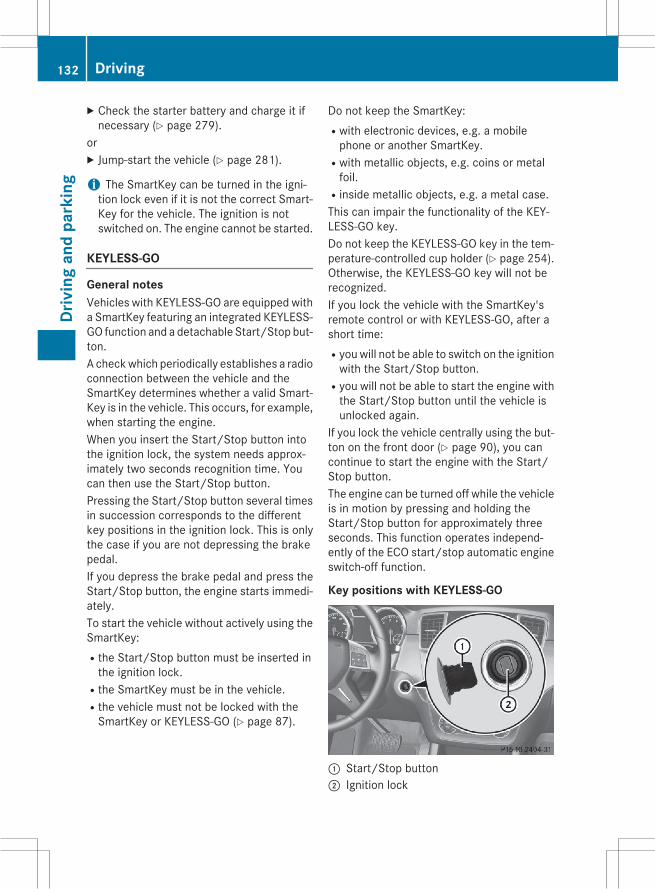
X Check the starter battery and charge it ifnecessary (Y page 279).
orX Jump-start the vehicle (Y page 281).
i The SmartKey can be turned in the igni-tion lock even if it is not the correct Smart-Key for the vehicle. The ignition is notswitched on. The engine cannot be started.
KEYLESS-GO
General notesVehicles with KEYLESS-GO are equipped witha SmartKey featuring an integrated KEYLESS-GO function and a detachable Start/Stop but-ton.A checkwhich periodically establishes a radioconnection between the vehicle and theSmartKey determines whether a valid Smart-Key is in the vehicle. This occurs, for example,when starting the engine.When you insert the Start/Stop button intothe ignition lock, the system needs approx-imately two seconds recognition time. Youcan then use the Start/Stop button.Pressing the Start/Stop button several timesin succession corresponds to the differentkey positions in the ignition lock. This is onlythe case if you are not depressing the brakepedal.If you depress the brake pedal and press theStart/Stop button, the engine starts immedi-ately.To start the vehicle without actively using theSmartKey:Rthe Start/Stop button must be inserted inthe ignition lock.
Rthe SmartKey must be in the vehicle.Rthe vehicle must not be locked with theSmartKey or KEYLESS-GO (Y page 87).
Do not keep the SmartKey:Rwith electronic devices, e.g. a mobilephone or another SmartKey.
Rwith metallic objects, e.g. coins or metalfoil.
Rinside metallic objects, e.g. a metal case.This can impair the functionality of the KEY-LESS-GO key.Do not keep the KEYLESS-GO key in the tem-perature-controlled cup holder (Y page 254).Otherwise, the KEYLESS-GO key will not berecognized.If you lock the vehicle with the SmartKey'sremote control or with KEYLESS-GO, after ashort time:Ryou will not be able to switch on the ignitionwith the Start/Stop button.
Ryou will not be able to start the engine withthe Start/Stop button until the vehicle isunlocked again.
If you lock the vehicle centrally using the but-ton on the front door (Y page 90), you cancontinue to start the engine with the Start/Stop button.The engine can be turned off while the vehicleis in motion by pressing and holding theStart/Stop button for approximately threeseconds. This function operates independ-ently of the ECO start/stop automatic engineswitch-off function.
Key positions with KEYLESS-GO
: Start/Stop button; Ignition lock
132 DrivingDr
ivin
gan
dpa
rkin
g

As soon as the ignition is switched on, all theindicator lamps in the instrument cluster lightup. Further information on situations wherean indicator lamp either fails to go out afterstarting the engine or lights up while driving(Y page 214).If Start/Stop button: has not yet beenpressed, this corresponds to the SmartKeybeing removed from the ignition.X To switch on the power supply: pressStart/Stop button: once.The power supply is switched on. You cannow activate the windshield wipers, forexample.
The power supply is switched off again if:Rthe driver's door is opened andRyou press Start/Stop button: twicewhenin this position.X To switch on the ignition: press Start/Stop button: twice.The ignition is switched on.
The ignition is switched off when:Rthe driver's door is opened andRyou press Start/Stop button: once whenin this position.
= Start/Stop button USA? Start/Stop button Canada
Removing the Start/Stop buttonYou can remove the Start/Stop button fromthe ignition lock and start the vehicle as nor-mal using the SmartKey.
It is only possible to switch between KEY-LESS-GO mode and SmartKey operationwhen the transmission is in position P.X RemoveStart/Stop button: from ignitionlock;.
You do not have to remove the Start/Stopbutton from the ignition lock when you leavethe vehicle. You should, however, always takethe SmartKey with you when leaving the vehi-cle. As long as the SmartKey is in the vehicle:Rthe vehicle can be started using the Start/Stop button
Relectrically powered equipment can beoperated
Starting the engine
Important safety notes
G WARNINGIf children are left unsupervised in the vehicle,they could:Ropen the doors, thus endangering otherpeople or road users.
Rget out and disrupt traffic.Roperate the vehicle's equipment.Additionally, children could set the vehicle inmotion if, for example, they:Rrelease the parking brake.Rshifting the automatic transmission out ofpark position P
RStart the engine.There is a risk of an accident and injury.When leaving the vehicle, always take theSmartKeywith you and lock the vehicle. Neverleave children or animals unattended in thevehicle. Always keep the SmartKey out ofreach of children.
G WARNINGCombustion engines emit poisonous exhaustgases such as carbon monoxide. Inhalingthese exhaust gases leads to poisoning. Thereis a risk of fatal injury. Therefore never leave
Driving 133
Driv
ing
and
park
ing
Z
the engine running in enclosed spaces with-out sufficient ventilation.
G WARNINGFlammable materials introduced throughenvironmental influence or by animals canignite if in contact with the exhaust system orparts of the engine that heat up. There is a riskof fire.Carry out regular checks to make sure thatthere are no flammable foreign materials inthe engine compartment or in the exhaustsystem.
! Do not depress the accelerator whenstarting the engine.
General notes
i Vehicles with a gasoline engine: thecatalytic converter is preheated for up to30 seconds after a cold start. The sound ofthe engine may change during this time.
Automatic transmissionX Shift the transmission to position P. Youcan find information about this in theDigitalOperator's Manual.The transmission position display in themultifunction display shows P. You can findinformation about this in the Digital Oper-ator's Manual.
i You can start the engine in transmissionposition P and N.
Starting procedure with the SmartKeyX To start a gasoline engine: turn theSmartKey to position 3 in the ignition lock
(Y page 131) and release it as soon as theengine is running.X To start a diesel engine: turn the Smart-Key to position 2 in the ignition lock(Y page 131).The% preglow indicator lamp in theinstrument cluster lights up.X When the% preglow indicator lampgoes out, turn the SmartKey to position 3(Y page 131) and release it as soon as theengine is running.
i You can start the engine without preglowif the engine is warm.
Using KEYLESS-GO to start the engineX Depress the brake pedal and keep itdepressed.X To start a gasoline engine: press theStart/Stop button once (Y page 132).The engine starts.X To start a diesel engine: press the Start/Stop button once (Y page 132).Preglow is activated and the engine starts.
i The Start/Stop button can be used tostart the vehicle without inserting theSmartKey into the ignition lock. The Start/Stop buttonmust be inserted in the ignitionlock and the SmartKey must be in the vehi-cle. This mode for starting the engine oper-ates independently of the ECO start/stopautomatic engine start function.
Pulling away
Automatic transmission
G WARNINGIf the engine speed is above the idling speedand you engage transmission position D or R,the vehicle could pull away suddenly. There isa risk of an accident.When engaging transmission position D or R,always firmly depress the brake pedal and donot simultaneously accelerate.
134 DrivingDr
ivin
gan
dpa
rkin
g

X Depress the brake pedal and keep itdepressed.X Shift the transmission to position D or R(Y page 137).X Release the brake pedal.X Carefully depress the accelerator pedal.The electric parking brake is automaticallyreleased. You can find information aboutthis in the Digital Operator's Manual.The redF (USA only) or! (Canadaonly) indicator lamp in the instrument clus-ter goes out.
i It is only possible to shift the transmissionfrom position P to the desired position ifyou depress the brake pedal. Only then isthe parking lock released. If the brakepedal is not depressed, the DIRECT SELECTlever can still bemoved but the parking lockremains engaged.
i The vehicle locks centrally once you havepulled away. The locking knobs in the doorsdrop down.You can open the doors from the inside atany time.You can also deactivate the automatic lock-ing feature (Y page 197).
i Upshifts take place at higher enginespeeds after a cold start. This helps thecatalytic converter to reach its operatingtemperature more quickly.
Pulling away with a trailer
To ensure that you do not roll backwardswhen pulling away on an uphill slope, engagethe electric parking brake.X Press and hold handle:.The electric parking brake continues tobrake and prevent the vehicle from rollingbackwards.The redF (USA only) or! (Canadaonly) indicator lamp in the instrument clus-ter remains on.X Depress the accelerator pedal.X As soon as the vehicle/trailer combinationis held by the driving force of the engine,release lever:.the electric parking brake is released.The redF (USA only) or! (Canadaonly) indicator lamp in the instrument clus-ter goes out.
Hill start assistHill start assist helps you when pulling awayforwards or in reverse on an uphill gradient. Itholds the vehicle for a short time after youhave removed your foot from the brake pedal.This gives you enough time to move your footfrom the brake pedal to the accelerator pedaland to depress it before the vehicle begins toroll.
G WARNINGAfter a short time, hill start assist will no lon-ger brake your vehicle and it could roll away.There is a risk of an accident and injury.Therefore, quickly move your foot from thebrake pedal to the accelerator pedal. Neverleave the vehicle when it is held by hill startassist.
Hill start assist is not active if:Ryou are pulling away on a level road or on adownhill gradient.
Rthe transmission is in position N.Rthe electric parking brake is applied.RESP® is malfunctioning.
Driving 135
Driv
ing
and
park
ing
Z

ECO start/stop function
IntroductionThe ECO start/stop function switches theengine off automatically if the vehicle is stop-ped under certain conditions.The engine starts automatically when thedriver wants to pull away again. The ECOstart/stop function thereby helps you toreduce the fuel consumption and emissionsof your vehicle.
Important safety notes
G WARNINGIf the engine is switched off automatically andyou exit the vehicle, the engine is restartedautomatically. The vehicle may begin moving.There is a risk of accident and injury.If you wish to exit the vehicle, always turn offthe ignition and secure the vehicle againstrolling away.
General notes
: ECO start/stop displayIf the engine has been switched off automat-ically by the ECO start/stop function, the¤ symbol is shown in the multifunctiondisplay.Every time you switch on the engine using theSmartKey or the Start/Stop button, the ECOstart/stop function is activated.AMG vehicles: the ECO start/stop functionis only available in drive program C.
Information in the Digital Operator'sManualIn the Digital Operator's Manual you will findinformation on the following topics:RAutomatic engine switch-offRAutomatic engine startRDeactivating/activating the ECO start/stop function
Problems with the engineYou can find information about this in theDigital Operator's Manual.
Automatic transmission
Important safety notes
G WARNINGIf the engine speed is above the idling speedand you engage transmission position D or R,the vehicle could pull away suddenly. There isa risk of an accident.When engaging transmission position D or R,always firmly depress the brake pedal and donot simultaneously accelerate.
G WARNINGThe automatic transmission switches to neu-tral positionNwhen you switch off the engine.The vehicle may roll away. There is a risk of anaccident.After switching off the engine, always switchto parking positionP. Prevent the parked vehi-cle from rolling away by applying the parkingbrake.
136 Automatic transmissionDr
ivin
gan
dpa
rkin
g

DIRECT SELECT lever
Overview of transmission positions
j Park position with parking lockk Reverse geari Neutralh DriveThe DIRECT SELECT lever is on the right of thesteering column.
i The DIRECT SELECT lever always returnsto its original position. The current trans-mission position P, R,N orD appears in thetransmission position display in the multi-function display. You can find informationabout this in the Digital Operator's Manual.
Information in the Digital Operator'sManualIn the Digital Operator's Manual you will findinformation on the following topics:RTransmission position and drive programdisplay
REngaging park position PREngaging park position P automaticallyREngaging reverse gear RREngaging drive position D
Shifting to neutral N
G WARNINGIf children are left unsupervised in the vehicle,they could:Ropen the doors, thus endangering otherpeople or road users.
Rget out and disrupt traffic.Roperate the vehicle's equipment.Additionally, children could set the vehicle inmotion if, for example, they:Rrelease the parking brake.Rshifting the automatic transmission out ofpark position P
RStart the engine.There is a risk of an accident and injury.When leaving the vehicle, always take theSmartKeywith you and lock the vehicle. Neverleave children or animals unattended in thevehicle. Always keep the SmartKey out ofreach of children.
X If the transmission is in position D or R:push the DIRECT SELECT lever up or downto the first point of resistance.X If the transmission is in position P: depressthe brake pedal and push the DIRECTSELECT lever up or down to the first point ofresistance.
If you switch the engine off with the trans-mission in position R or D, the automatictransmission shifts to N automatically.With the SmartKey: if you then open one ofthe front doors or remove the SmartKey fromthe ignition, the automatic transmissionshifts to P.With the Start/Stop button: if you thenopen one of the front doors, the automatictransmission shifts to P.If you want the automatic transmission toremain in neutral N, e.g. when having thevehicle cleaned in an automatic car washwitha towing system:
Automatic transmission 137
Driv
ing
and
park
ing
Z
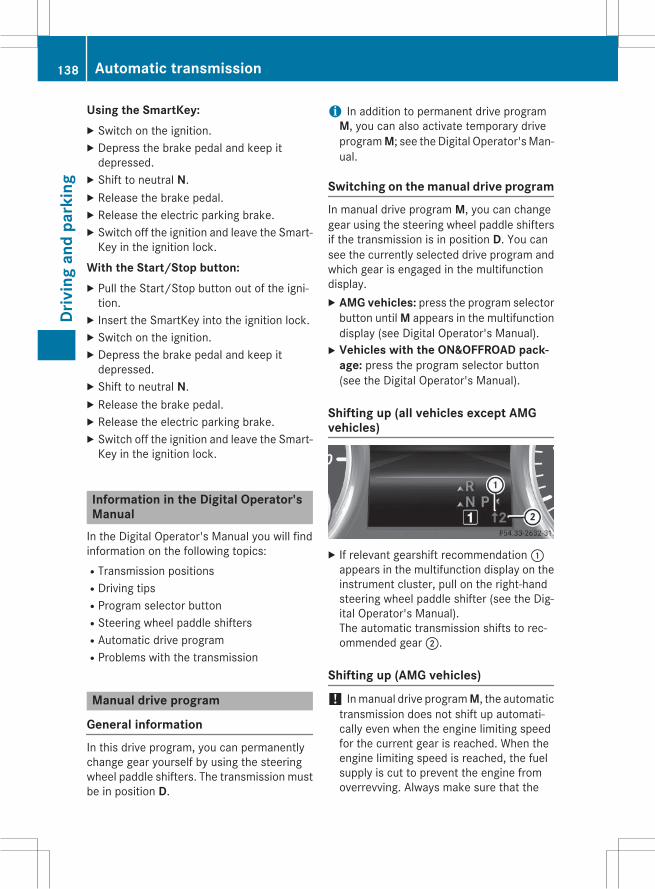
Using the SmartKey:X Switch on the ignition.X Depress the brake pedal and keep itdepressed.X Shift to neutral N.X Release the brake pedal.X Release the electric parking brake.X Switch off the ignition and leave the Smart-Key in the ignition lock.
With the Start/Stop button:X Pull the Start/Stop button out of the igni-tion.X Insert the SmartKey into the ignition lock.X Switch on the ignition.X Depress the brake pedal and keep itdepressed.X Shift to neutral N.X Release the brake pedal.X Release the electric parking brake.X Switch off the ignition and leave the Smart-Key in the ignition lock.
Information in the Digital Operator'sManualIn the Digital Operator's Manual you will findinformation on the following topics:RTransmission positionsRDriving tipsRProgram selector buttonRSteering wheel paddle shiftersRAutomatic drive programRProblems with the transmission
Manual drive program
General informationIn this drive program, you can permanentlychange gear yourself by using the steeringwheel paddle shifters. The transmission mustbe in position D.
i In addition to permanent drive programM, you can also activate temporary driveprogramM; see the Digital Operator'sMan-ual.
Switching on the manual drive programIn manual drive program M, you can changegear using the steering wheel paddle shiftersif the transmission is in position D. You cansee the currently selected drive program andwhich gear is engaged in the multifunctiondisplay.X AMG vehicles: press the program selectorbutton until M appears in the multifunctiondisplay (see Digital Operator's Manual).X Vehicles with the ON&OFFROAD pack-
age: press the program selector button(see the Digital Operator's Manual).
Shifting up (all vehicles except AMGvehicles)
X If relevant gearshift recommendation:appears in the multifunction display on theinstrument cluster, pull on the right-handsteering wheel paddle shifter (see the Dig-ital Operator's Manual).The automatic transmission shifts to rec-ommended gear;.
Shifting up (AMG vehicles)
! Inmanual drive programM, the automatictransmission does not shift up automati-cally even when the engine limiting speedfor the current gear is reached. When theengine limiting speed is reached, the fuelsupply is cut to prevent the engine fromoverrevving. Always make sure that the
138 Automatic transmissionDr
ivin
gan
dpa
rkin
g

engine speed does not reach the red area ofthe tachometer. There is otherwise a risk ofengine damage.
: Gear indicator; Upshift indicatorBefore the engine speed reaches the red area,an upshift indicator will be shown in the mul-tifunction display.X If the color in the speedometer multifunc-tion display changes to red and the UP dis-play message is shown, shift up a gear.
Information in the Digital Operator'sManualIn the Digital Operator's Manual you will findinformation on the following topics:RDownshiftingRKickdownRSwitching off the manual drive program
Transfer case! Performance tests may only be carriedout on a 2-axle dynamometer. The brakesystem or transfer case could otherwise bedamaged. Contact a qualified specialistworkshop for a performance test.
! Because ESP® is an automatic system,the engine and ignition must be switchedoff (SmartKey in position 0 or 1 or Start/Stop button in position 0 or 1) when theelectric parking brake is being tested on abrake dynamometer (maximum10 seconds).Braking triggered automatically by ESP®may seriously damage the brake system.
! Vehicles with 4MATIC must not be towedwith either the front or the rear axle raised,as doing so will damage the transmission.
This section is only valid for vehicles with 4-wheel drive (4MATIC). Power is always trans-mitted to both axles.
Refueling
Important safety notes
G WARNINGFuel is highly flammable. If you handle fuelincorrectly, there is a risk of fire and explo-sion.You must avoid fire, open flames, creatingsparks and smoking. Switch off the engineand, if applicable, the auxiliary heating beforerefueling.
G WARNINGFuel is poisonous and hazardous to health.There is a risk of injury.You must make sure that fuel does not comeinto contact with your skin, eyes or clothingand that it is not swallowed. Do not inhale fuelvapors. Keep fuel away from children.If you or others come into contact with fuel,observe the following:RWash away fuel from skin immediatelyusing soap and water.
RIf fuel comes into contact with your eyes,immediately rinse them thoroughly withclean water. Seek medical assistance with-out delay.
RIf fuel is swallowed, seek medical assis-tance without delay. Do not induce vomit-ing.
RImmediately change out of clothing whichhas come into contact with fuel.
G WARNINGElectrostatic buildup can create sparks andignite fuel vapors. There is a risk of fire andexplosion.
Refueling 139
Driv
ing
and
park
ing
Z
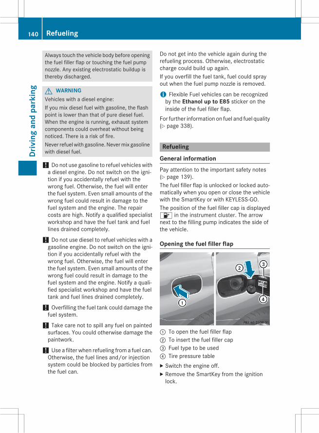
Always touch the vehicle body before openingthe fuel filler flap or touching the fuel pumpnozzle. Any existing electrostatic buildup isthereby discharged.
G WARNINGVehicles with a diesel engine:If you mix diesel fuel with gasoline, the flashpoint is lower than that of pure diesel fuel.When the engine is running, exhaust systemcomponents could overheat without beingnoticed. There is a risk of fire.Never refuel with gasoline. Nevermix gasolinewith diesel fuel.
! Do not use gasoline to refuel vehicles witha diesel engine. Do not switch on the igni-tion if you accidentally refuel with thewrong fuel. Otherwise, the fuel will enterthe fuel system. Even small amounts of thewrong fuel could result in damage to thefuel system and the engine. The repaircosts are high. Notify a qualified specialistworkshop and have the fuel tank and fuellines drained completely.
! Do not use diesel to refuel vehicles with agasoline engine. Do not switch on the igni-tion if you accidentally refuel with thewrong fuel. Otherwise, the fuel will enterthe fuel system. Even small amounts of thewrong fuel could result in damage to thefuel system and the engine. Notify a quali-fied specialist workshop and have the fueltank and fuel lines drained completely.
! Overfilling the fuel tank could damage thefuel system.
! Take care not to spill any fuel on paintedsurfaces. You could otherwise damage thepaintwork.
! Use a filter when refueling from a fuel can.Otherwise, the fuel lines and/or injectionsystem could be blocked by particles fromthe fuel can.
Do not get into the vehicle again during therefueling process. Otherwise, electrostaticcharge could build up again.If you overfill the fuel tank, fuel could sprayout when the fuel pump nozzle is removed.
i Flexible Fuel vehicles can be recognizedby the Ethanol up to E85 sticker on theinside of the fuel filler flap.
For further information on fuel and fuel quality(Y page 338).
Refueling
General informationPay attention to the important safety notes(Y page 139).The fuel filler flap is unlocked or locked auto-matically when you open or close the vehiclewith the SmartKey or with KEYLESS-GO.The position of the fuel filler cap is displayed8 in the instrument cluster. The arrownext to the filling pump indicates the side ofthe vehicle.
Opening the fuel filler flap
: To open the fuel filler flap; To insert the fuel filler cap= Fuel type to be used? Tire pressure tableX Switch the engine off.X Remove the SmartKey from the ignitionlock.
140 RefuelingDr
ivin
gan
dpa
rkin
g
X KEYLESS-GO: open the driver’s door.This corresponds to SmartKey position 0:"SmartKey removed".The driver’s door can be closed again.X Press the fuel filler flap in the direction ofarrow:.The fuel filler flap swings up.X Turn the fuel filler cap counterclockwiseand remove it.X Insert the fuel filler cap into the holderbracket on the inside of filler flap;.X Completely insert the filler neck of the fuelpump nozzle into the tank, hook in placeand refuel.X Only fill the tank until the pump nozzleswitches off.i Vehicles with a diesel engine: the fillerneck is designed for refueling at diesel fill-ing pumps.
i Do not add any more fuel after the pumpstops filling for the first time. Otherwise,fuel may leak out.
Closing the fuel filler flapX Replace the cap on the filler neck and turnclockwise until it engages audibly.X Close the fuel filler flap.
i Close the fuel filler flap before locking thevehicle.
i If you are driving with the fuel filler capopen, the8 reserve fuel warning lampflashes.In addition, the;Check Enginewarninglamp may light up (Y page 212).A message appears in the multifunctiondisplay (Y page 199).For further information onwarning and indi-cator lamps in the instrument cluster, see(Y page 212).
Refueling 141
Driv
ing
and
park
ing
Z

Problems with fuel and the fuel tankThis section provides descriptions of and solutions to safety-relevant problems. Descriptionsof and solutions to further problems can be found in the Digital Operator's Manual.
Problem Possible causes/consequences and M Solutions
Fuel is leaking from thevehicle.
The fuel line or the fuel tank is faulty.
G WARNINGRisk of explosion or fire.X Turn the SmartKey to position 0 in the ignition lock and removeit immediately (Y page 131).X Do not restart the engine under any circumstances.X Consult a qualified specialist workshop.
DEF (BlueTEC vehicles only)
Important notes on useTo function properly, BlueTEC exhaust gasaftertreatment must be operated with thereducing agent DEF. Adding DEF is one of thetasks performed during maintenance. Undernormal operating conditions, a tank of DEFlasts until the next service due date.When the supply of DEF is almost used up, theCheck Additive See Operator's Manualmessage is shown in the multifunction dis-play.If you drive the vehicle faster than 10 mph(16 km/h), the Check Additive See Operхator's Manual message goes out afterapproximately one minute.When the supply of DEF is down to a reserveof approximately 1 gal (3.8 l) the RefillAdBlue See Operator's Manual messageis shown in the multifunction display.When theDEF supply drops to aminimum, theRemaining Starts: 16 message is shownin the multifunction display.If the Refill AdBlue No Start inXXXX km message is shown in the multifunc-tion display, you can still drive the vehicleover the distance shown. If DEF is not refilled,you will subsequently be unable to start theengine. If the Refill AdBlue Eng. Start
Not Possmessage appears in the multifunc-tion display and the engine does not start, youmust add DEF.X Add at least 1 gal (3.8 l) of DEF.X Switch on the ignition for at least 60 sec-onds.X Start the engine.
i Have the DEF tank refilled at a qualifiedspecialist workshop.
Use the special DEF refill bottle when addingDEF between maintenance intervals. Contactan authorized Mercedes-Benz Center withany questions or, if necessary, contact Road-side Assistance (Y page 32).If the outside temperature is below 12 ‡(Ò11 †) it may be difficult to top up. If DEF isfrozen and there is an active warning indica-tor, it may not be possible to add DEF. Parkthe vehicle in a warmer place, e.g. in a garage,until DEF has become fluid again. It will thenbe possible to add DEF again. Alternatively,have the DEF tank refilled at a qualified spe-cialist workshop.Further information about BlueTEC exhaustgas aftertreatment andDEF is available at anyauthorized Mercedes-Benz Center.
142 RefuelingDr
ivin
gan
dpa
rkin
g

Important safety notes on the refillingprocedureDEF is a water-soluble fluid for the exhaustgas aftertreatment of diesel engines. It is:Rnot poisonousRcolorless and odorlessRnot flammableWhen you open the DEF container, smallamounts of ammonia vapor may be released.Ammonia vapors have a pungent odor and areparticularly irritating to the skin, to mucousmembranes and to the eyes. You may expe-rience a burning sensation in your eyes, noseand throat. Coughing and watering of theeyes are possible.Do not inhale ammonia vapors. Fill the DEFtank only in well-ventilated areas.DEF must not come into contact with yourskin, eyes or clothing and must not be swal-lowed. Keep DEF away from children.If you or other persons come into contact withDEF, observe the following:RRinse DEF from your skin immediately withsoap and water.
RIf DEF comes into contact with your eyes,immediately rinse them thoroughly withclean water. Seek medical assistance with-out delay.
RIf DEF has been swallowed, rinse yourmouth out immediately. Drink plenty ofwater. Seek medical assistance withoutdelay.
RChange out of clothing contaminated withDEF immediately.
! Only use DEF in accordance withISO 22241. Do not mix any additives withDEF, and do not dilute DEF with water. Thismay destroy the BlueTEC exhaust gas after-treatment system.
! The vehicle must be parked on levelground to fill the DEF tank. The DEF tankcan only be filled as intended with the vehi-cle parked on a level surface. This avoidsfalse level readings. Filling the tank is not
permitted if the vehicle is not parked on alevel surface. There is a danger of overfill-ing, which could result in damage to com-ponents of the BlueTEC exhaust gas after-treatment.
! Rinse surfaces that have come into con-tact with DEF immediately with water orremove DEF using a damp cloth and coldwater. If the DEF has already crystallized,use a sponge and coldwater to clean it. DEFresidues crystallize after time and contam-inate the affected surfaces.
! DEF is not a fuel additive and must not beadded to the fuel tank. If DEF is added tothe fuel tank, this can lead to engine dam-age.
For further information on DEF, see(Y page 341).
Opening the DEF filler cap
The fuel filler flap is unlocked or locked auto-matically when you open or close the vehiclewith the SmartKey or with KEYLESS-GO.X Switch the ignition off.X Press the fuel filler flap in the direction ofarrow:.The fuel filler flap swings up.X Turn blue DEF fuel filler cap; counter-clockwise and remove it.DEF filler cap; is secured with a plasticstrip.
Refueling 143
Driv
ing
and
park
ing
Z
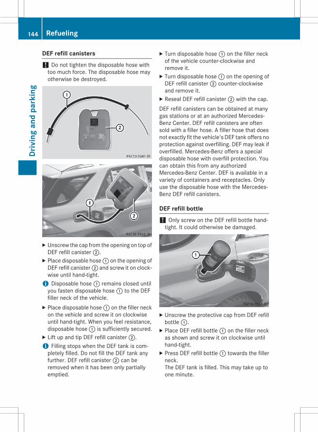
DEF refill canisters
! Do not tighten the disposable hose withtoo much force. The disposable hose mayotherwise be destroyed.
X Unscrew the cap from the opening on top ofDEF refill canister;.X Place disposable hose: on the opening ofDEF refill canister; and screw it on clock-wise until hand-tight.i Disposable hose: remains closed untilyou fasten disposable hose: to the DEFfiller neck of the vehicle.X Place disposable hose: on the filler neckon the vehicle and screw it on clockwiseuntil hand-tight. When you feel resistance,disposable hose: is sufficiently secured.X Lift up and tip DEF refill canister;.i Filling stops when the DEF tank is com-pletely filled. Do not fill the DEF tank anyfurther. DEF refill canister; can beremoved when it has been only partiallyemptied.
X Turn disposable hose: on the filler neckof the vehicle counter-clockwise andremove it.X Turn disposable hose: on the opening ofDEF refill canister; counter-clockwiseand remove it.X Reseal DEF refill canister; with the cap.DEF refill canisters can be obtained at manygas stations or at an authorized Mercedes-Benz Center. DEF refill canisters are oftensold with a filler hose. A filler hose that doesnot exactly fit the vehicle's DEF tank offers noprotection against overfilling. DEF may leak ifoverfilled. Mercedes-Benz offers a specialdisposable hose with overfill protection. Youcan obtain this from any authorizedMercedes-Benz Center. DEF is available in avariety of containers and receptacles. Onlyuse the disposable hose with the Mercedes-Benz DEF refill canisters.
DEF refill bottle
! Only screw on the DEF refill bottle hand-tight. It could otherwise be damaged.
X Unscrew the protective cap from DEF refillbottle:.X Place DEF refill bottle: on the filler neckas shown and screw it on clockwise untilhand-tight.X Press DEF refill bottle: towards the fillerneck.The DEF tank is filled. This may take up toone minute.
144 RefuelingDr
ivin
gan
dpa
rkin
g

i When DEF refill bottle: is no longerpressed, filling stops and the bottle may betaken off again after being only partiallyemptied.X Release DEF refill bottle:.X Turn DEF refill bottle: counter-clockwiseand remove it.X Screw the protective cap onto DEF refillbottle: again.
DEF refill bottles can be obtained at many gasstations or at an authorized Mercedes-BenzCenter. Refill bottles without a threaded capdo not provide overfill protection. DEF mayleak if overfilled. Mercedes Benz offers spe-cial refill bottles with a threaded seal. Theseare available at any authorized Mercedes-Benz Center.
Closing the DEF filler cap
X Set DEF filler cap; on the filler neck andturn it clockwise.X To close the fuel filler flap, press it in thedirection of arrow:.X Drive faster than 10 mph (16 km/h).The Check Additive See Operator'sManual message goes out after approx-imately one minute.i If the Check Additive See Operaхtor's Manual message continues to beshown in the multifunction display, youmust add more DEF.
Parking
Important safety notes
G WARNINGFlammable material such as leaves, grass ortwigsmay ignite if they come into contactwithhot parts of the exhaust system or exhaustgas flow. There is a risk of fire.Park the vehicle so that no flammable mate-rials come into contact with parts of the vehi-cle which are hot. Take particular care not topark on dry grassland or harvested grainfields.
G WARNINGIf you switch off the ignition while driving,safety-relevant functions are only availablewith limitations, or not at all. This could affect,for example, the power steering and the brakeboosting effect. You will require considerablymore effort to steer and brake. There is a riskof an accident.Do not switch off the ignition while driving.
G WARNINGIf you leave children unsupervised in the vehi-cle, they could set it inmotion by, for example:Rrelease the parking brake.Rshift the automatic transmission out of theparking position P.
Rstart the engine.In addition, they may operate vehicle equip-ment and become trapped. There is a risk ofan accident and injury.When leaving the vehicle, always take theSmartKeywith you and lock the vehicle. Neverleave children unsupervised in the vehicle.
! Always secure the vehicle correctlyagainst rolling away. Otherwise, the vehicleor its drivetrain could be damaged.
Parking 145
Driv
ing
and
park
ing
Z

To ensure that the vehicle is secured againstrolling away unintentionally:Rthe electric parking brake must be applied.Rthe transmission must be in position P andthe SmartKey must be removed from theignition lock.
Rthe front wheels must be turned towardsthe curb on steep uphill or downhill gradi-ents.
Rthe empty vehicle must be secured at thefront axle with a wheel chock or similar, forexample, on uphill or downhill gradients.
Ra laden vehicle must also be secured at therear axle with a wheel chock or similar, forexample, on uphill or downhill gradients.
Switching off the engine
Important safety notes
G WARNINGThe automatic transmission switches to neu-tral positionNwhen you switch off the engine.The vehicle may roll away. There is a risk of anaccident.After switching off the engine, always switchto parking positionP. Prevent the parked vehi-cle from rolling away by applying the parkingbrake.
Information in the Digital Operator'sManualA description of how to switch off the enginecan be found in theDigital Operator'sManual.
Electric parking brake
General notes
G WARNINGIf you leave children unsupervised in the vehi-cle, they could set it inmotion by, for example:Rrelease the parking brake.Rshift the automatic transmission out of theparking position P.
Rstart the engine.In addition, they may operate vehicle equip-ment and become trapped. There is a risk ofan accident and injury.When leaving the vehicle, always take theSmartKeywith you and lock the vehicle. Neverleave children unsupervised in the vehicle.
The function of the electric parking brake isdependent on the on-board voltage. If the on-board voltage is low or there is a malfunctionin the system, it may not be possible to applythe released parking brake.X If this is the case, only park the vehicle onlevel ground and secure it to prevent it roll-ing away.X Shift the automatic transmission to posi-tion P.
It may not be possible to release an appliedparking brake if the on-board voltage is low orthere is a malfunction in the system. Contacta qualified specialist workshop.
i The electric parking brake performs afunction test at regular intervals while theengine is switched off. The sounds that canbe heard while this is occurring are normal.
Information in the Digital Operator'sManualIn the Digital Operator's Manual you will findinformation on the following topics:RApplying/releasing manuallyRApplying automatically
146 ParkingDr
ivin
gan
dpa
rkin
g

RReleasing automaticallyREmergency braking
Parking the vehicle for a long periodYou can find information about this in theDigital Operator's Manual.
Driving tips
General notes
Important safety notes
G WARNINGIf you switch off the ignition while driving,safety-relevant functions are only availablewith limitations, or not at all. This could affect,for example, the power steering and the brakeboosting effect. You will require considerablymore effort to steer and brake. There is a riskof an accident.Do not switch off the ignition while driving.
G WARNINGIf you operate mobile communication equip-ment while driving, you will be distracted fromtraffic conditions. You could also lose controlof the vehicle. There is a risk of an accident.Only operate this equipment when the vehicleis stationary.
Observe the legal requirements for the coun-try in which you are driving. Some jurisdic-tions prohibit the driver from using a mobilephone while driving a vehicle.If you make a call while driving, always usehands-freemode. Only operate the telephonewhen the traffic situation permits. If you areunsure, pull over to a safe location and stopbefore operating the telephone.Bear in mind that at a speed of only 30 mph(approximately 50 km/h) the vehicle covers adistance of 44 ft (approximately 14 m) persecond.
Drive sensibly – save fuelObserve the following tips to save fuel:X The tires should always be inflated to therecommended tire pressure.X Remove unnecessary loads.X Remove roof carriers when they are notneeded.X Warm up the engine at low engine speeds.X Avoid frequent acceleration or braking.X Have all maintenance work carried out asindicated by the service intervals in theMaintenance Booklet or by the serviceinterval display.
Fuel consumption also increases when driv-ing in cold weather, in stop-start traffic and inhilly terrain.
Drinking and driving
G WARNINGDrinking and driving and/or taking drugs anddriving are very dangerous combinations.Even a small amount of alcohol or drugs canaffect your reflexes, perceptions and judg-ment.The possibility of a serious or even fatal acci-dent is greatly increased when you drink ortake drugs and drive.Do not drink or take drugs and drive or allowanyone to drive who has been drinking or tak-ing drugs.
Emission control
G WARNINGCombustion engines emit poisonous exhaustgases such as carbon monoxide. Inhalingthese exhaust gases leads to poisoning. Thereis a risk of fatal injury. Therefore never leavethe engine running in enclosed spaces with-out sufficient ventilation.
Certain engine systems are designed to keepthe level of poisonous components in exhaustfumes within legal limits.
Driving tips 147
Driv
ing
and
park
ing
Z
These systems only work at peak efficiency ifthey are serviced exactly in accordance withthe manufacturer's specifications. For thisreason, all work on the enginemust be carriedout by qualified and authorized Mercedes-Benz technicians.The engine settings must not be changedunder any circumstances. Furthermore, allspecific service work must be carried out atregular intervals and in accordance with theMercedes-Benz service requirements. Detailscan be found in the Maintenance Booklet.
ECO displayYou can find information about this in theDigital Operator's Manual.
Braking
Important safety notes
G WARNINGIf you shift down on a slippery road surface inan attempt to increase the engine's brakingeffect, the drive wheels could lose their grip.There is an increased danger of skidding andaccidents.Do not shift down for additional engine brak-ing on a slippery road surface.
Downhill gradientsYou can find information about this in theDigital Operator's Manual.
Heavy and light loads
G WARNINGIf you rest your foot on the brake pedal whiledriving, the braking system can overheat. Thisincreases the stopping distance and can evencause the braking system to fail. There is arisk of an accident.
Never use the brake pedal as a footrest. Neverdepress the brake pedal and the acceleratorpedal at the same time.
Further information can be found in the Digi-tal Operator's Manual.
Wet roadsYou can find information about this in theDigital Operator's Manual.
Limited braking performance on salt-treated roadsYou can find information about this in theDigital Operator's Manual.
Servicing the brakesYou can find information about this in theDigital Operator's Manual.
High-performance brake system forAMG vehiclesYou can find information about this in theDigital Operator's Manual.
Driving on wet roads
Information in the Digital Operator'sManualIn the Digital Operator's Manual you will findinformation on the following topics:RHydroplaningRDriving on flooded roadsROff-road fordingAlways observe the fording depth values(Y page 347).
Winter driving
G WARNINGIf you shift down on a slippery road surface inan attempt to increase the engine's braking
148 Driving tipsDr
ivin
gan
dpa
rkin
g

effect, the drive wheels could lose their grip.There is an increased danger of skidding andaccidents.Do not shift down for additional engine brak-ing on a slippery road surface.
G DANGERIf the exhaust pipe is blocked or adequateventilation is not possible, poisonous gasessuch as carbon monoxide (CO) may enter thevehicle. This is the case, e.g. if the vehiclebecomes trapped in snow. There is a risk offatal injury.If you leave the engine or the auxiliary heatingrunning, make sure the exhaust pipe and areaaround the vehicle are clear of snow. Toensure an adequate supply of fresh air, open awindow on the side of the vehicle that is notfacing into the wind.
Further information can be found in the Digi-tal Operator's Manual.
Off-road driving
Important safety notes
G WARNINGIf you drive on a steep incline at an angle orturn when driving on an incline, the vehiclecould slip sideways, tip and rollover. There is arisk of an accident.Always drive on a steep incline in the line offall (straight up or down) and do not turn thevehicle.
G WARNINGFlammable material such as leaves, grass ortwigsmay ignite if they come into contactwithhot parts of the exhaust system. There is a riskof fire.When driving off road or on unpaved roads,check the vehicle's underside regularly. Inparticular, remove parts of plants or otherflammable materials which have become
trapped. In the case of damage, contact aqualified specialist workshop.
G WARNINGIf the vehicle level is high, the vehicle center ofgravity is raised. This could cause the vehicleto tip over more easily on uphill or downhillgradients. There is a risk of an accident.Select the lowest possible vehicle level.
! There is a risk of damage to the vehicle if:Rthe vehicle becomes stuck, e.g. on a highcurb or an unpaved road
Ryou drive too fast over an obstacle, e.g. acurb or a hole in the road
Ra heavy object strikes the undercarriageor parts of the chassis
In situations like this, the body, the under-carriage, chassis parts, wheels or tirescould be damaged without the damagebeing visible. Components damaged in thisway can unexpectedly fail or, in the case ofan accident, no longer withstand the strainthey are designed to.If the underbody paneling is damaged,combustible materials such as leaves,grass or twigs can gather between theunderbody and the underbody paneling. Ifthese materials come in contact with hotparts of the exhaust system, they can catchfire.In such situations, have the vehiclechecked and repaired immediately at aqualified specialist workshop. If on con-tinuing your journey you notice that drivingsafety is impaired, pull over and stop thevehicle immediately, paying attention toroad and traffic conditions. In such cases,consult a qualified specialist workshop.
When driving off-road, substances such assand, mud and water or water mixed with oilmay get into the brakes. This could result in areduced braking effect or in total brake failureand also in increasedwear and tear. The brak-ing characteristics change depending on thematerial ingressing the brakes. Clean the
Driving tips 149
Driv
ing
and
park
ing
Z

brakes after driving off-road. If you detect areduced braking effect or grinding noises,have the brake system checked in a qualifiedspecialist workshop as soon as possible.Adapt your driving style to the different brak-ing characteristics.Driving off-road increases the likelihood ofdamage to the vehicle, which, in turn, can leadto failure of the mechanical assembly or sys-tems. Adapt your driving style to suit the ter-rain conditions. Drive carefully. Have damageto the vehicle rectified immediately at a quali-fied specialist workshop.Do not switch to transmission position Nwhen driving off-road. If you try to brake thevehicle using the service brake, you couldlose control of the vehicle. If the gradient istoo steep for your vehicle, drive back down inreverse gear.
General notesYou can find information about this in theDigital Operator's Manual.
Checklist before driving off-road
! If the engine oil warning lamp lights upwhile the vehicle is inmotion, stop the vehi-cle in a safe place as soon as possible.Check the engine oil level. The engine oilwarning lampwarningmust not be ignored.Continuing the journey while the symbol isdisplayed could lead to engine damage.X Engine oil level: check the engine oil leveland add oil if necessary.When driving on steep gradients, theengine oil level must be sufficiently high toensure a correct oil supply in the vehicle.X DEF tank (BlueTEC vehicles): check thelevel and top up if necessary (Y page 142).X Tire-changing tool kit: check that the jackis working and make sure you have the lugwrench, a robust tow cable and a foldingspade in the vehicle.X Wheels and tires: check the tire treaddepth and tire pressure.
X Check for damage and remove any foreignobjects, e.g. small stones, from thewheels/tires.X Replace any missing valve caps.X Replace dented or damaged wheels.X Rims: dented or bent rims can result in aloss of tire pressure and damage the tirebead. Therefore, check your rims beforedriving off-road and replace them asrequired.
Checklist after driving off-road
! If you detect damage to the vehicle afterdriving off-road, have the vehicle checkedimmediately at a qualified specialist work-shop.X Vehicles with the ON&OFFROAD pack-
age: activate the on-road program. You canfind information about this in the DigitalOperator's Manual.X Deactivate the LOW RANGE off-road gear.You can find information about this in theDigital Operator's Manual.X Deactivate DSR. You can find informationabout this in the Digital Operator's Manual.X Lower the vehicle level again to a level suit-able to the road conditions, e.g. to the high-way/high-speed level.X Clean the headlamps and rear lights andcheck for damage.X Clean the front and rear license plates.X Clean the wheels/tires with a water jet andremove any foreign objects.X Clean the wheels, wheel housings and thevehicle underside with a water jet; checkfor any foreign objects and damage.X Check whether twigs or other parts ofplants have become trapped. Theseincrease the risk of fire and can damagefuel pipes, brake hoses or the rubber bel-lows of the axle joints and propeller shafts.X After the trip, examine without fail theentire undercarriage, wheels, tires, brakes,
150 Driving tipsDr
ivin
gan
dpa
rkin
g

bodywork structure, steering, chassis andexhaust system for damage.X After driving for extended periods acrosssand, mud, gravel, water or in similarly dirtyconditions, have the brake discs, wheels,brake pads/linings and axle joints checkedand cleaned.X If you detect strong vibrations after off-roadtravel, check for foreign objects in thewheels and drive train and remove them ifnecessary. Foreign objects can disturb thebalance and cause vibrations.
Driving over rough terrain places greaterdemands on your vehicle than driving on nor-mal roads. After driving off-road, check thevehicle. This allows you to detect damagepromptly and reduce the risk of an accident toyourself and other road users.
Driving on sandYou can find information about this in theDigital Operator's Manual.
Tire ruts and gravel roadsYou can find information about this in theDigital Operator's Manual.
Driving over obstaclesYou can find information about this in theDigital Operator's Manual.
Traveling uphill
Approach/departure angle
G WARNINGIf you drive on a steep incline at an angle orturn when driving on an incline, the vehiclecould slip sideways, tip and rollover. There is arisk of an accident.Always drive on a steep incline in the line offall (straight up or down) and do not turn thevehicle.
RObserve the rules on off-road driving.RDo not drive at an angle on slopes, inclinesor gradients, but instead follow the directline of fall. The maximum gradient-climbingcapability of your vehicle is 100%, whichcorresponds to an approach/departureangle of 45°. Note that the climbing abilityof your vehicle depends on the terrain con-ditions.
RWhen driving down an incline, make use ofthe engine's braking effect. Observe theengine speed; do not overrev the engine.
RBefore driving on extreme uphill and down-hill gradients, select the LOW RANGE off-road gear (Y page 185).
RDrive slowly.RAvoid high engine speeds. Drive at appro-priate engine speeds (maximum3,000 rpm).
RUse the left-hand paddle shifter to shift intoa lower gear in good time on long and steepdownhill gradients.
RCheck the brakes after prolonged off-roaddriving.
i Hill start assist will aid you when pullingaway on a hill.For further information about hill startassist, see (Y page 135).
Do not switch to transmission position Nwhen driving off-road. If you try to brake thevehicle using the service brake, you couldlose control of the vehicle. If the gradient istoo steep for your vehicle, drive back down inreverse gear.Always observe the approach/departureangle values (Y page 348).
Maximum gradient-climbing capabilityAlways observe the maximum gradient climb-ing ability values (Y page 348).
Driving tips 151
Driv
ing
and
park
ing
Z

HilltopsYou can find information about this in theDigital Operator's Manual.
Driving downhillYou can find information about this in theDigital Operator's Manual.
Driving systems
Intelligent DriveMercedes-Benz Intelligent Drive stands forinnovative driver assistance and safety sys-tems which enhance comfort and support thedriver in critical situations. With these intelli-gent co-ordinated systems Mercedes-Benzhas set a milestone on the path towardsautonomous driving.Mercedes-Benz Intelligent Drive embraces allelements of active and passive safety in onewell thought out system – for the safety of thevehicle occupants and that of other roadusers.Further information on driving safety systems(Y page 73).
Cruise control
General notesCruise control maintains a constant roadspeed for you. It brakes automatically in orderto avoid exceeding the set speed. You mustselect a lower gear in good time on long andsteep downhill gradients, especially if thevehicle is laden or towing a trailer. By doingso, you will make use of the braking effect ofthe engine. This relieves the load on the brakesystem and prevents the brakes from over-heating and wearing too quickly.Use cruise control only if road and traffic con-ditions make it appropriate to maintain asteady speed for a prolonged period. You canstore any road speed above 20 mph(30 km/h).
i Cruise control should not be activatedwhen driving off-road.
Important safety notesIf you fail to adapt your driving style, cruisecontrol can neither reduce the risk of an acci-dent nor override the laws of physics. Cruisecontrol cannot take into account the road,traffic and weather conditions. Cruise controlis only an aid. You are responsible for the dis-tance to the vehicle in front, for vehicle speed,for braking in good time and for staying inyour lane.Do not use cruise control:Rin road and traffic conditions which do notallow you to maintain a constant speed e.g.in heavy traffic or on winding roads
Ron slippery road surfaces. Braking or accel-erating could cause the drivewheels to losetraction and the vehicle could then skid
Rwhen there is poor visibility, e.g. due to fog,heavy rain or snow
If there is a change of drivers, advise the newdriver of the speed stored.
Cruise control lever
: To activate or increase speed; To activate or reduce speed= To deactivate cruise control? To activate at the current speed/last
stored speedWhen you activate cruise control, the storedspeed is shown in the multifunction displayfor five seconds.
152 Driving systemsDr
ivin
gan
dpa
rkin
g

Information in the Digital Operator'sManualIn the Digital Operator's Manual you will findinformation on the following topics:RActivation conditionsRStoring, maintaining and calling up a speedRSetting a speedRDeactivating cruise control
DISTRONIC PLUS
General notesDISTRONIC PLUS regulates the speed andautomatically helps you maintain the dis-tance to the vehicle detected in front. Vehi-cles are detected with the aid of the radarsensor system. DISTRONIC PLUS brakesautomatically so that the set speed is notexceeded.You must select a lower gear in good time onlong and steep downhill gradients, especiallyif the vehicle is laden or towing a trailer. Bydoing so, you will make use of the brakingeffect of the engine. This relieves the load onthe brake system and prevents the brakesfrom overheating and wearing too quickly.If DISTRONIC PLUS detects that there is a riskof a collision, you will be warned visually andacoustically. DISTRONIC PLUS cannot pre-vent a collision without your intervention. Anintermittent warning tone will then sound andthe distance warning lamp will light up in theinstrument cluster. Brake immediately inorder to increase the distance to the vehiclein front or take evasive action provided it issafe to do so.For DISTRONIC PLUS to assist you when driv-ing, the radar sensor system must beswitched on and operational; see "Radar sen-sor system" in the index.If there is no vehicle in front, DISTRONICPLUS operates in the same way as cruisecontrol in the speed range between 20 mph(Canada: 30 km/h) and 120 mph (Canada:
200 km/h). If a vehicle is driving in front ofyou, it operates in the speed range between0 mph (0 km/h) and 120 mph (Canada:200 km/h).Do not use DISTRONIC PLUS while driving onroads with steep gradients.As DISTRONIC PLUS transmits radar waves, itcan resemble the radar detectors of theresponsible authorities. You can refer to therelevant chapter in the Operator's Manual ifquestions are asked about this.
i USA only:This device has been approved by the FCCas a "Vehicular Radar System". The radarsensor is intended for use in an automotiveradar system only. Removing, tamperingwith, or altering the device will void anywarranties, and is not permitted by theFCC. Do not tamper with, alter, or use inany non-approved way.Any unauthorized modification to thisdevice could void the user’s authority tooperate the equipment.
i Canada only: This device complies withRSS-210 of Industry Canada. Operation issubject to the following two conditions:1. This device may not cause harmful inter-ference, and2. This devicemust accept any interferencereceived, including interference that maycause undesired operation of the device.Removal, tampering, or altering of thedevice will void any warranties, and is notpermitted. Do not tamper with, alter, or usein any non-approved way.Any unauthorized modification to thisdevice could void the user's authority tooperate the equipment.
Driving systems 153
Driv
ing
and
park
ing
Z
Important safety notes
G WARNINGDISTRONIC PLUS does not react to:Rpeople or animalsRstationary obstacles on the road, e.g. stop-ped or parked vehicles
Roncoming and crossing trafficAs a result, DISTRONIC PLUSmay neither givewarnings nor intervene in such situations.There is a risk of an accident.Always pay careful attention to the traffic sit-uation and be ready to brake.
G WARNINGDISTRONIC PLUS cannot always clearly iden-tify other road users and complex traffic sit-uations.In such cases, DISTRONIC PLUS may:Rgive an unnecessary warning and thenbrake the vehicle
Rneither give a warning nor interveneRaccelerate or brake unexpectedlyThere is a risk of an accident.Continue to drive carefully and be ready tobrake, in particular when warned to do so byDISTRONIC PLUS.
G WARNINGDISTRONIC PLUS brakes your vehicle with upto 40% of the maximum braking force. If thisbraking force is insufficient, DISTRONIC PLUSwarns you visually and audibly. There is a riskof an accident.In such cases, apply the brakes yourself andtry to take evasive action.
! If DISTRONIC PLUS or the HOLD functionis activated, the vehicle brakes automati-cally in certain situations. To prevent dam-age to the vehicle, deactivate DISTRONICPLUS and the HOLD function in the follow-ing or other similar situations:Rwhen towing the vehicleRin the car wash
If you fail to adapt your driving style,DISTRONIC PLUS can neither reduce the riskof accident nor override the laws of physics.DISTRONIC PLUS cannot take into accountthe road, traffic and weather conditions.DISTRONIC PLUS is only an aid. You areresponsible for the distance to the vehicle infront, for vehicle speed, for braking in goodtime and for staying in your lane.Do not use DISTRONIC PLUS:Rin road and traffic conditions which do notallow you to maintain a constant speed e.g.in heavy traffic or on winding roads
Ron slippery road surfaces. Braking or accel-erating could cause the drivewheels to losetraction and the vehicle could then skid
Rwhen there is poor visibility, e.g. due to fog,heavy rain or snow
DISTRONIC PLUS may not detect narrowvehicles driving in front, e.g. motorcycles, orvehicles driving on a different line.In particular, the detection of obstacles canbe impaired if:Rthere is dirt on the sensors or anything elsecovering the sensors
Rthere is snow or heavy rainRthere is interference by other radar sourcesRthere are strong radar reflections, forexample, in parking garages
If DISTRONIC PLUS no longer detects a vehi-cle in front, DISTRONIC PLUS may unexpect-edly accelerate the vehicle to the storedspeed.
154 Driving systemsDr
ivin
gan
dpa
rkin
g
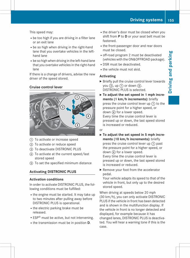
This speed may:Rbe too high if you are driving in a filter laneor an exit lane
Rbe so high when driving in the right-handlane that you overtake vehicles in the left-hand lane
Rbe so highwhen driving in the left-hand lanethat you overtake vehicles in the right-handlane
If there is a change of drivers, advise the newdriver of the speed stored.
Cruise control lever
: To activate or increase speed; To activate or reduce speed= To deactivate DISTRONIC PLUS? To activate at the current speed/last
stored speedA To set the specified minimum distance
Activating DISTRONIC PLUS
Activation conditionsIn order to activate DISTRONIC PLUS, the fol-lowing conditions must be fulfilled:Rthe engine must be started. It may take upto two minutes after pulling away beforeDISTRONIC PLUS is operational.
Rthe electric parking brake must bereleased.
RESP® must be active, but not intervening.Rthe transmission must be in position D.
Rthe driver's door must be closed when youshift from P to D or your seat belt must befastened.
Rthe front-passenger door and rear doorsmust be closed.
Roff-road program 2 must be deactivated(vehicles with the ON&OFFROADpackage).
RDSR must be deactivated.Rthe vehicle must not skid.
ActivatingX Briefly pull the cruise control lever towardsyou=, up: or down?.DISTRONIC PLUS is selected.X To adjust the set speed in 1 mph incre-
ments (1 km/h increments): brieflypress the cruise control lever up: to thepressure point for a higher speed, ordown? for a lower speed.Every time the cruise control lever ispressed up or down, the last speed storedis increased or reduced.
orX To adjust the set speed in 5 mph incre-
ments (10 km/h increments): brieflypress the cruise control lever up: pastthe pressure point for a higher speed, ordown? for a lower speed.Every time the cruise control lever ispressed up or down, the last speed storedis increased or reduced.X Remove your foot from the acceleratorpedal.Your vehicle adapts its speed to that of thevehicle in front, but only up to the desiredstored speed.
When driving at speeds below 20 mph(30 km/h), you can only activate DISTRONICPLUS if the vehicle in front has been detectedand is shown in the multifunction display. Ifthe vehicle in front is no longer detected anddisplayed, for example because it haschanged lanes, DISTRONIC PLUS is deactiva-ted. You will hear a warning tone if this is thecase.
Driving systems 155
Driv
ing
and
park
ing
Z

i If you do not fully release the acceleratorpedal, the DISTRONIC PLUS Passivemes-sage appears in the multifunction display.The set distance to a slower-moving vehiclein front will then not bemaintained. Youwillbe driving at the speed you determine bythe position of the accelerator pedal.
Activating at the current speed/laststored speedG WARNINGIf you call up the stored speed and it differsfrom the current speed, the vehicle acceler-ates or decelerates. If you do not know thestored speed, the vehicle could accelerate orbrake unexpectedly. There is a risk of an acci-dent.Pay attention to the road and traffic condi-tions before calling up the stored speed. If youdo not know the stored speed, store thedesired speed again.
X Briefly pull the cruise control lever towardsyou=.X Remove your foot from the acceleratorpedal.DISTRONIC PLUS is activated. The firsttime it is activated, the current speed isstored. Otherwise, it sets the vehicle cruisespeed to the previously stored value.
Driving with DISTRONIC PLUS
Pulling away and drivingX If you want to pull away with
DISTRONIC PLUS: remove your foot fromthe brake pedal.X Briefly pull the cruise control lever towardsyou=, up: or down?.
orX Accelerate briefly.Your vehicle pulls away and adapts itsspeed to that of the vehicle in front.
If there is no vehicle in front, DISTRONICPLUS operates in the same way as cruisecontrol.
If DISTRONIC PLUS detects that the vehicle infront has slowed down, it brakes your vehicle.In this way, the distance you have selected ismaintained.If DISTRONIC PLUS detects a faster-movingvehicle in front, it increases the driving speed.However, the vehicle is only accelerated up tothe speed you have stored.If you depress the brake, DISTRONIC PLUS isdeactivated unless your vehicle is stationary.
Changing lanesIf you change to the passing lane, DISTRONICPLUS supports you when:Ryou are driving faster than 40 mph(60 km/h)
RDISTRONIC PLUS is maintaining the dis-tance to a vehicle in front
Ryou switch on the appropriate turn signalRDISTRONIC PLUS does not detect a dangerof collision
If these conditions are fulfilled, your vehicle isaccelerated. Acceleration will be interruptedif changing lanes takes too long or if the dis-tance between your vehicle and the vehicle infront becomes too small.
i When changing lanes, DISTRONIC PLUSmonitors the left lane on left-hand drivevehicles and the right lane on right-handdrive vehicles.
StoppingG WARNINGWhen leaving the vehicle, even if it is brakedonly by DISTRONIC PLUS, it could roll away if:Rthere is a malfunction in the system or inthe voltage supply.
RDISTRONIC PLUS has been deactivatedwith the cruise control lever, e.g. by a vehi-cle occupant or from outside the vehicle.
Rthe electrical system in the engine com-partment, the battery or the fuses havebeen tampered with.
156 Driving systemsDr
ivin
gan
dpa
rkin
g

Rthe battery is disconnected.Rthe accelerator pedal has been depressed,e.g. by a vehicle occupant.
There is a risk of an accident.If you wish to exit the vehicle, always turn offDISTRONIC PLUS and secure the vehicleagainst rolling away.
If DISTRONIC PLUS detects that the vehicle infront is stopping, it brakes your vehicle until itis stationary.Once your vehicle is stationary, it remainsstationary and you do not need to depress thebrake.After a time, the electric parking brakesecures the vehicle and relieves the servicebrake.Depending on the specified minimum dis-tance, your vehicle will come to a standstill ata sufficient distance behind the vehicle infront. The specified minimum distance is setusing the control on the cruise control lever.The electric parking brake automaticallysecures the vehicle if DISTRONIC PLUS isactivated and:Rthe driver's door is open and the driver'sseat belt is unfastened.
Rthe engine is switched off, unless it is auto-matically switched off by the ECO start/stop function.
Ra system malfunction occurs.Rthe power supply is not sufficient.On steep uphill or downhill inclines or if thereis a malfunction, the transmission may alsoautomatically be shifted into position P.
Information in the Digital Operator'sManualIn the Digital Operator's Manual you will findinformation on the following topics:RSetting a speedRSetting the specified minimum distanceRDISTRONIC PLUS displays in the instru-ment cluster
Deactivating DISTRONIC PLUS
There are several ways to deactivateDISTRONIC PLUS:X Briefly press the cruise control lever for-wards:.
orX Brake, unless the vehicle is stationaryWhen you deactivate DISTRONIC PLUS, youwill see the DISTRONIC PLUS Offmessage inthe multifunction display for approximatelyfive seconds.
i The last speed stored remains stored untilyou switch off the engine.
i DISTRONIC PLUS is not deactivated if youdepress the accelerator pedal. If you accel-erate to overtake, DISTRONIC PLUSadjusts the vehicle's speed to the lastspeed stored after you have finished over-taking.
DISTRONIC PLUS is automatically deactiva-ted if:Ryou engage the electric parking brake or ifthe vehicle is automatically secured withthe electric parking brake
Ryou are driving slower than 15 mph(25 km/h) and there is no vehicle in front,or if the vehicle in front is no longer detec-ted
RESP® intervenes or you deactivate ESP®Rthe transmission is in the P, R orN positionRyou pull the cruise control lever towardsyou in order to pull away and the front-
Driving systems 157
Driv
ing
and
park
ing
Z
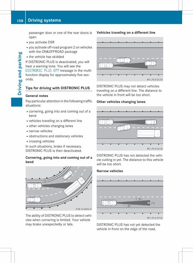
passenger door or one of the rear doors isopen
Ryou activate DSRRyou activate off-road program 2 on vehicleswith the ON&OFFROAD package
Rthe vehicle has skiddedIf DISTRONIC PLUS is deactivated, you willhear a warning tone. You will see theDISTRONIC PLUS Off message in the multi-function display for approximately five sec-onds.
Tips for driving with DISTRONIC PLUS
General notesPay particular attention in the following trafficsituations:Rcornering, going into and coming out of abend
Rvehicles traveling on a different lineRother vehicles changing lanesRnarrow vehiclesRobstructions and stationary vehiclesRcrossing vehiclesIn such situations, brake if necessary.DISTRONIC PLUS is then deactivated.
Cornering, going into and coming out of abend
The ability of DISTRONIC PLUS to detect vehi-cles when cornering is limited. Your vehiclemay brake unexpectedly or late.
Vehicles traveling on a different line
DISTRONIC PLUS may not detect vehiclestraveling on a different line. The distance tothe vehicle in front will be too short.
Other vehicles changing lanes
DISTRONIC PLUS has not detected the vehi-cle cutting in yet. The distance to this vehiclewill be too short.
Narrow vehicles
DISTRONIC PLUS has not yet detected thevehicle in front on the edge of the road,
158 Driving systemsDr
ivin
gan
dpa
rkin
g

because of its narrow width. The distance tothe vehicle in front will be too short.
Obstructions and stationary vehicles
DISTRONIC PLUS does not brake for obsta-cles or stationary vehicles. If, for example, thedetected vehicle turns a corner and revealsan obstacle or stationary vehicle, DISTRONICPLUS will not brake for these.
Crossing vehicles
DISTRONIC PLUS may mistakenly detectvehicles that are crossing your lane. Activat-ing DISTRONIC PLUS at traffic lights withcrossing traffic, for example, could causeyour vehicle to pull away unintentionally.
Level control (vehicles with theON&OFFROAD package)
Important safety notesLevel control adapts the vehicle level auto-matically to the current operating and drivingsituation. This results in reduced fuel con-sumption and improved handling.
Make changes to the vehicle level while thevehicle is in motion. This enables the vehicleto adjust to the new level as quickly as pos-sible.The vehicle level may change visibly if youpark the vehicle and the outside temperaturechanges. If the temperature drops, the vehi-cle level is lower; with an increase in temper-ature, the vehicle level rises.If you unlock the vehicle or open a door, thevehicle begins to compensate for load dis-crepancies while still parked. However, forsignificant level changes, such as after thevehicle has been stationary for a long period,the engine must be on. For safety reasons,the vehicle is only loweredwhen the doors areclosed. Lowering is interrupted if a door isopened, and it continues once the door hasbeen closed.For information about driving off-road, see(Y page 149).
G WARNINGWhen the vehicle is being lowered, peoplecould become trapped if their limbs arebetween the vehicle body and the wheels orunderneath the vehicle. There is a risk ofinjury.Make sure no one is underneath the vehicle orin the immediate vicinity of the wheel archeswhen the vehicle is being lowered.
G WARNINGWhen you drive with the vehicle raised, thedriving characteristics could be impaired bythe vehicle's raised center of gravity. The vehi-cle could rollover more easily, for example ona bend. There is a risk of an accident.Always select as low a vehicle level as possi-ble and adjust your driving style.
G WARNINGWhen you drive with the chassis lowered orraised, the vehicle's braking and driving char-acteristics can be significantly impaired. Youcould also exceed the permissible vehicle
Driving systems 159
Driv
ing
and
park
ing
Z

height if the chassis is raised. There is a risk ofan accident.Adjust the vehicle level before pulling away.
G WARNINGDue to the high center of gravity, the vehiclemay start to skid and roll over in the event ofan abrupt steering maneuver and/or whenthe vehicle's speed is not adapted to the roadconditions. There is a risk of an accident.Always adapt your speed and driving style tothe vehicle's driving characteristics and to theprevailing road and weather conditions.
! When driving on extremely rough terrain,select a high vehicle level in good time.Make sure there is always sufficient groundclearance. You will otherwise damage thevehicle.
RUtility vehicles have a significantly higherrollover rate than other types of vehicles.Failure to operate this vehicle safely mayresult in an accident, rollover of the vehicle,and severe or fatal injury.
RIn a rollover crash, an unbelted person issignificantly more likely to die than a per-son wearing a seat belt.You and all vehicle occupants shouldalways wear your seat belts.
Basic settingsThe extent to which the vehicle is raised orlowered depends on the basic setting selec-ted.Select:Rhighway/high-speed level for driving onnormal roads
Roff-road level 1 for driving on easily nego-tiable off-road terrain
Roff-road level 2 for driving on normal off-road terrain
Roff-road level 3 for freeing the vehicle inparticularly rough terrain at low speedsonly
The individual vehicle levels differ from high-way level as follows:Rhighway level: +/–0 in (+/–0 mm)Rhigh-speed level: –0.6 in (–15 mm)Roff-road level 1: + 1.2 in (+ 30 mm)Roff-road level 2: + 2.3 in (+ 60 mm)Roff-road level 3: + 3.6 in (+ 90 mm)
Overview
! Make sure that there is enough groundclearance when the vehicle is being low-ered. It could otherwise hit the ground,damaging the underbody.
: Selector wheel; To raise the level= Indicator lamps? To lower the level
Information in the Digital Operator'sManualIn the Digital Operator's Manual you can findinformation on the following subjects:RHighway/high-speed levelROff-road levels
160 Driving systemsDr
ivin
gan
dpa
rkin
g

HOLD function
General notesThe HOLD function can assist the driver in thefollowing situations:Rwhen pulling away, especially on steepslopes
Rwhen maneuvering on steep slopesRwhen waiting in trafficThe vehicle is kept stationary without thedriver having to depress the brake pedal.The braking effect is canceled and the HOLDfunction deactivated when you depress theaccelerator pedal to pull away.
i Do not use the HOLD function when driv-ing off-road, on steep uphill or downhill gra-dients or on slippery or loose surfaces. TheHOLD function cannot hold the vehicle onsuch surfaces.
Important safety notes
G WARNINGWhen leaving the vehicle, it can still roll awaydespite being braked by the HOLD function if:Rthere is a malfunction in the system or inthe voltage supply.
Rthe HOLD function has been deactivated bypressing the accelerator pedal or the brakepedal, e.g. by a vehicle occupant.
Rthe electrical system in the engine com-partment, the battery or the fuses havebeen tampered with.
Rthe battery is disconnectedThere is a risk of an accident.If you wish to exit the vehicle, always turn offthe HOLD function and secure the vehicleagainst rolling away.
! If DISTRONIC PLUS or the HOLD functionis activated, the vehicle brakes automati-cally in certain situations. To prevent dam-age to the vehicle, deactivate DISTRONICPLUS and the HOLD function in the follow-ing or other similar situations:Rwhen towing the vehicleRin the car wash
Deactivating the HOLD function(Y page 162).
Activation conditionsYou can activate the HOLD function if:Rthe vehicle is stationaryRthe engine is running or if it has been auto-matically switched off by the ECO start/stop function
Rthe driver's door is closed or your seat beltis fastened
Rthe electric parking brake is releasedRthe transmission is in position D, R or NRDISTRONIC PLUS is deactivated
Activating the HOLD function
X Make sure that the activation conditionsare met.X Depress the brake pedal.X Quickly depress the brake pedal furtheruntil: appears in the multifunction dis-play.The HOLD function is activated. You canrelease the brake pedal.
i If depressing the brake pedal the firsttime does not activate the HOLD function,wait briefly and then try again.
Driving systems 161
Driv
ing
and
park
ing
Z
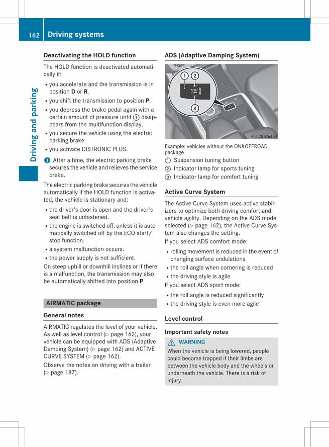
Deactivating the HOLD functionThe HOLD function is deactivated automati-cally if:Ryou accelerate and the transmission is inposition D or R.
Ryou shift the transmission to position P.Ryou depress the brake pedal again with acertain amount of pressure until: disap-pears from the multifunction display.
Ryou secure the vehicle using the electricparking brake.
Ryou activate DISTRONIC PLUS.
i After a time, the electric parking brakesecures the vehicle and relieves the servicebrake.
The electric parking brake secures the vehicleautomatically if the HOLD function is activa-ted, the vehicle is stationary and:Rthe driver's door is open and the driver'sseat belt is unfastened.
Rthe engine is switched off, unless it is auto-matically switched off by the ECO start/stop function.
Ra system malfunction occurs.Rthe power supply is not sufficient.On steep uphill or downhill inclines or if thereis a malfunction, the transmission may alsobe automatically shifted into position P.
AIRMATIC package
General notesAIRMATIC regulates the level of your vehicle.As well as level control (Y page 162), yourvehicle can be equipped with ADS (AdaptiveDamping System) (Y page 162) and ACTIVECURVE SYSTEM (Y page 162).Observe the notes on driving with a trailer(Y page 187).
ADS (Adaptive Damping System)
Example: vehicles without the ON&OFFROADpackage: Suspension tuning button; Indicator lamp for sports tuning= Indicator lamp for comfort tuning
Active Curve SystemThe Active Curve System uses active stabil-izers to optimize both driving comfort andvehicle agility. Depending on the ADS modeselected (Y page 162), the Active Curve Sys-tem also changes the setting.If you select ADS comfort mode:Rrolling movement is reduced in the event ofchanging surface undulations
Rthe roll angle when cornering is reducedRthe driving style is agileIf you select ADS sport mode:Rthe roll angle is reduced significantlyRthe driving style is even more agile
Level control
Important safety notesG WARNINGWhen the vehicle is being lowered, peoplecould become trapped if their limbs arebetween the vehicle body and the wheels orunderneath the vehicle. There is a risk ofinjury.
162 Driving systemsDr
ivin
gan
dpa
rkin
g

Make sure no one is underneath the vehicle orin the immediate vicinity of the wheel archeswhen the vehicle is being lowered.
G WARNINGWhen you drive with the vehicle raised, thedriving characteristics could be impaired bythe vehicle's raised center of gravity. The vehi-cle could rollover more easily, for example ona bend. There is a risk of an accident.Always select as low a vehicle level as possi-ble and adjust your driving style.
G WARNINGWhen you drive with the chassis lowered orraised, the vehicle's braking and driving char-acteristics can be significantly impaired. Youcould also exceed the permissible vehicleheight if the chassis is raised. There is a risk ofan accident.Adjust the vehicle level before pulling away.
G WARNINGDue to the high center of gravity, the vehiclemay start to skid and roll over in the event ofan abrupt steering maneuver and/or whenthe vehicle's speed is not adapted to the roadconditions. There is a risk of an accident.Always adapt your speed and driving style tothe vehicle's driving characteristics and to theprevailing road and weather conditions.
! When driving on extremely rough terrain,select a high vehicle level in good time.Make sure there is always sufficient groundclearance. You will otherwise damage thevehicle.
! When you raise the vehicle in such a waythat not all wheels have contact with theground, remove the SmartKey from theignition lock.
! Make sure that there is enough groundclearance when the vehicle is being low-ered. It could otherwise hit the ground,damaging the underbody.
RUtility vehicles have a significantly higherrollover rate than other types of vehicles.Failure to operate this vehicle safely mayresult in an accident, rollover of the vehicle,and severe or fatal injury.
RIn a rollover crash, an unbelted person issignificantly more likely to die than a per-son wearing a seat belt.You and all vehicle occupants shouldalways wear your seat belts.
General notesFurther information about "Driving off-road"(Y page 149).Level control adapts the vehicle level auto-matically to the current operating and drivingsituation. This results in reduced fuel con-sumption and improved handling.If you select ADS comfort mode (Y page 162),the vehicle is lowered to high-speed level asthe speed increases. As the vehicle speeddecreases, the vehicle is raised back up tohighway level.If you select ADS sport mode (Y page 162),the vehicle skips highway level and lowersdirectly to high-speed level depending on thebasic setting (Y page 164).Make changes to the vehicle level while thevehicle is in motion. This enables the vehicleto adjust to the new level as quickly as pos-sible.The vehicle level may change visibly if youpark the vehicle and the outside temperaturechanges. If the temperature drops, the vehi-cle level is lower; with an increase in temper-ature, the vehicle level rises.If you unlock the vehicle or open a door, thevehicle begins to compensate for load dis-crepancies while still parked. However, forsignificant level changes, such as after thevehicle has been stationary for a long period,the engine must be on. For safety reasons,the vehicle is only loweredwhen the doors areclosed. Lowering is interrupted if a door isopened, and it continues once the door hasbeen closed.
Driving systems 163
Driv
ing
and
park
ing
Z

Basic settings (excluding AMG vehicles)The extent to which the vehicle is raised orlowered depends on the basic setting selec-ted. Select raised level for off-road driving orhighway/high-speed level for normal roads.The individual vehicle levels differ from high-way level as follows:Rhighway level: +/–0 in (+/–0 mm)Rhigh-speed level: –0.6 in (–15 mm)Rraised level: +2.3 in (+60 mm)
Basic settings for AMG vehiclesThe extent to which the vehicle is raised orlowered depends on the AMG adaptive sportsuspension setting selected. Select theraised level for off-road driving or highway/high-speed level for normal roads.The raised level corresponds to a vehicle levelraised by 50 mm when compared with high-way level in comfort mode.
Raised level
: Level control button; Level control indicator lampOnly select raised level if this is appropriatefor the road conditions. Otherwise, fuel con-sumption may increase and handling may beaffected.
Highway/high-speed level! Make sure that there is enough groundclearance when the vehicle is being low-ered. It could otherwise hit the ground,damaging the underbody.
The vehicle automatically adjusts to highwaylevel when you:Rdrive faster than 50 mph (80 km/h).Rdrive between 40 mph (64 km/h) and50 mph (80 km/h) for approximately20 seconds.
Depending on the ADS mode selected(Y page 162), the vehicle is lowered to high-speed level at high speeds.
AMG adaptive sport suspension sys-tem
Information in the Digital Operator'sManualIn the Digital Operator's Manual you will findinformation on the following topics:RVehicle levelRSuspension tuning
Important safety notes
G WARNINGWhen the vehicle is being lowered, peoplecould become trapped if their limbs arebetween the vehicle body and the wheels orunderneath the vehicle. There is a risk ofinjury.Make sure no one is underneath the vehicle orin the immediate vicinity of the wheel archeswhen the vehicle is being lowered.
G WARNINGThe vehicle is lowered if:Ryou have selected the Comfort or Sportsuspension tuning and
Rlock the vehicle after switching off theengine
Persons in the vicinity of the wheel arch or theunderbody may thus become trapped. Thereis a risk of injury.Make sure that nobody is in the vicinity of thewheel arch or the underbody when you switchoff the engine.
164 Driving systemsDr
ivin
gan
dpa
rkin
g

! The vehicle is lowered by approximately10 mm if:Ryou have selected the Sport or Comfortsuspension tuning and
Ryou switch off the engine and thenRlock the vehicleWhen parking, position your vehicle so thatit does not make contact with the curb asthe vehicle is lowered. Your vehicle couldotherwise be damaged.
PARKTRONIC
Important safety notesPARKTRONIC is an electronic parking aid withultrasonic sensors. It monitors the areaaround your vehicle using six sensors in thefront bumper and four sensors in the rearbumper. PARKTRONIC indicates visually andaudibly the distance between your vehicleand an object.PARKTRONIC is only an aid. It is not a replace-ment for your attention to your immediatesurroundings. You are always responsible forsafe maneuvering, parking and exiting a park-ing space. When maneuvering, parking orpulling out of a parking space, make sure thatthere are no persons, animals or objects inthe area in which you are maneuvering.
! When parking, pay particular attention toobjects above or below the sensors, suchas flower pots or trailer drawbars.PARKTRONIC does not detect such objectswhen they are in the immediate vicinity ofthe vehicle. You could damage the vehicleor the objects.The sensorsmay not detect snow and otherobjects that absorb ultrasonic waves.Ultrasonic sources such as an automaticcar wash, the compressed-air brakes on atruck or a pneumatic drill could causePARKTRONIC to malfunction.PARKTRONICmay not function correctly onuneven terrain.
PARKTRONIC is activated automatically whenyou:Rswitch on the ignitionRshift the transmission to position D, R or NRrelease the electric parking brake.PARKTRONIC is deactivated at speeds above11 mph (18 km/h). It is reactivated at lowerspeeds.
Range of the sensors
General notesPARKTRONIC does not take objects into con-sideration that are:Rbelow the detection range, e.g. people, ani-mals or objects.
Rabove the detection range, e.g. overhang-ing loads, truck overhangs or loadingramps.
: Sensors in the front bumper, left-handside (example)
The sensors must be free from dirt, ice orslush. They can otherwise not function cor-rectly. Clean the sensors regularly, takingcare not to scratch or damage them(Y page 270).
Driving systems 165
Driv
ing
and
park
ing
Z
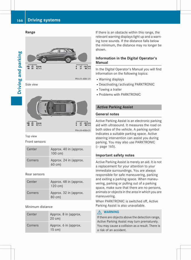
Range
Side view
Top view
Front sensors
Center Approx. 40 in (approx.100 cm)
Corners Approx. 24 in (approx.60 cm)
Rear sensors
Center Approx. 48 in (approx.120 cm)
Corners Approx. 32 in (approx.80 cm)
Minimum distance
Center Approx. 8 in (approx.20 cm)
Corners Approx. 6 in (approx.15 cm)
If there is an obstacle within this range, therelevant warning displays light up and a warn-ing tone sounds. If the distance falls belowthe minimum, the distance may no longer beshown.
Information in the Digital Operator'sManualIn the Digital Operator's Manual you will findinformation on the following topics:RWarning displaysRDeactivating/activating PARKTRONICRTowing a trailerRProblems with PARKTRONIC
Active Parking Assist
General notesActive Parking Assist is an electronic parkingaid with ultrasound. It measures the road onboth sides of the vehicle. A parking symbolindicates a suitable parking space. Activesteering intervention can assist you duringparking. You may also use PARKTRONIC(Y page 165).
Important safety notesActive Parking Assist is merely an aid. It is nota replacement for your attention to yourimmediate surroundings. You are alwaysresponsible for safe maneuvering, parkingand exiting a parking space. When maneu-vering, parking or pulling out of a parkingspace, make sure that there are no persons,animals or objects in the area inwhich you aremaneuvering.When PARKTRONIC is switched off, ActiveParking Assist is also unavailable.
G WARNINGIf there are objects above the detection range,Active Parking Assist may turn prematurely.You may cause a collision as a result. There isa risk of an accident.
166 Driving systemsDr
ivin
gan
dpa
rkin
g

If there are objects above the detection range,stop and deactivate Active Parking Assist.
G WARNINGActive Parking Assist merely aids you by inter-vening actively in the steering. If you do notbrake there is a risk of an accident.Always apply the brakes yourself whenmaneuvering and parking.
G WARNINGWhile parking or pulling out of a parkingspace, the vehicle swings out and can driveonto areas of the oncoming lane. This couldresult in a collision with another road user.There is a risk of an accident.Pay attention to other road users. Stop thevehicle if necessary or cancel the Active Park-ing Assist parking procedure.
! If unavoidable, you should drive overobstacles such as curbs slowly and not at asharp angle. Otherwise, you may damagethe wheels or tires.
Active Parking Assist may possibly indicateparking spaces which are not suitable forparking, for example:Rwhere parking or stopping is prohibitedRin front of driveways or entrances and exitsRon unsuitable surfacesParking tips:ROn narrow roads, drive as close to the park-ing space as possible.
RParking spaces that are littered or over-grown might be identified or measuredincorrectly.
RParking spaces that are partially occupiedby trailer drawbars might not be identifiedas such or be measured incorrectly.
RSnowfall or heavy rainmay lead to a parkingspace being measured inaccurately.
RPay attention to the PARKTRONIC(Y page 166) warning messages during theparking procedure.
RAt any time, you can intervene in the steer-ing procedure to correct it. Active ParkingAssist will then be canceled.
RWhen transporting a load which protrudesfrom your vehicle, you should not useActive Parking Assist.
RNever use Active Parking Assist when snowchains are installed.
RMake sure that the tire pressures arealways correct. This has a direct influenceon the parking characteristics of the vehi-cle.
Use Active Parking Assist for parking spaces:Rthat are parallel to the direction of travelRthat are on straight roads, not bendsRthat are on the same level as the road, e.g.not on the pavement
Information in the Digital Operator'sManualIn the Digital Operator's Manual you will findinformation on the following topics:RDetecting parking spacesRParkingRExiting a parking spaceRCanceling Active Parking AssistRTowing a trailer
Rear view camera
General notes
Driving systems 167
Driv
ing
and
park
ing
Z
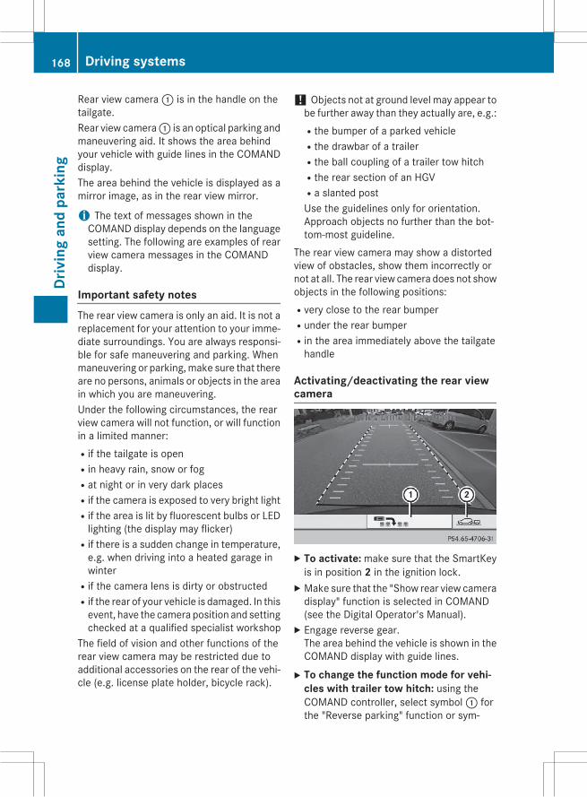
Rear view camera: is in the handle on thetailgate.Rear view camera: is an optical parking andmaneuvering aid. It shows the area behindyour vehicle with guide lines in the COMANDdisplay.The area behind the vehicle is displayed as amirror image, as in the rear view mirror.
i The text of messages shown in theCOMAND display depends on the languagesetting. The following are examples of rearview camera messages in the COMANDdisplay.
Important safety notesThe rear view camera is only an aid. It is not areplacement for your attention to your imme-diate surroundings. You are always responsi-ble for safe maneuvering and parking. Whenmaneuvering or parking,make sure that thereare no persons, animals or objects in the areain which you are maneuvering.Under the following circumstances, the rearview camera will not function, or will functionin a limited manner:Rif the tailgate is openRin heavy rain, snow or fogRat night or in very dark placesRif the camera is exposed to very bright lightRif the area is lit by fluorescent bulbs or LEDlighting (the display may flicker)
Rif there is a sudden change in temperature,e.g. when driving into a heated garage inwinter
Rif the camera lens is dirty or obstructedRif the rear of your vehicle is damaged. In thisevent, have the camera position and settingchecked at a qualified specialist workshop
The field of vision and other functions of therear view camera may be restricted due toadditional accessories on the rear of the vehi-cle (e.g. license plate holder, bicycle rack).
! Objects not at ground level may appear tobe further away than they actually are, e.g.:Rthe bumper of a parked vehicleRthe drawbar of a trailerRthe ball coupling of a trailer tow hitchRthe rear section of an HGVRa slanted postUse the guidelines only for orientation.Approach objects no further than the bot-tom-most guideline.
The rear view camera may show a distortedview of obstacles, show them incorrectly ornot at all. The rear view camera does not showobjects in the following positions:Rvery close to the rear bumperRunder the rear bumperRin the area immediately above the tailgatehandle
Activating/deactivating the rear viewcamera
X To activate: make sure that the SmartKeyis in position 2 in the ignition lock.X Make sure that the "Show rear view cameradisplay" function is selected in COMAND(see the Digital Operator's Manual).X Engage reverse gear.The area behind the vehicle is shown in theCOMAND display with guide lines.X To change the function mode for vehi-
cles with trailer tow hitch: using theCOMAND controller, select symbol: forthe "Reverse parking" function or sym-
168 Driving systemsDr
ivin
gan
dpa
rkin
g

bol; for "Coupling up a trailer" (see theseparate COMAND operating instructions).The symbol of the selected function is high-lighted.
To deactivate: the rear view camera deacti-vates if you shift the transmission toP or afterdriving forwards a short distance.
Information in the Digital Operator'sManualIn the Digital Operator's Manual you will findinformation on the following topics:RDisplays in the COMAND displayR"Reverse parking" functionR"Coupling up a trailer" function
360° camera (surround view)
General notesThe 360° camera is a system consisting offour cameras.The system analyzes images from the follow-ing cameras:RRear view cameraRFront cameraRTwo cameras in the exterior rear view mir-rors
The cameras capture the immediate sur-roundings of the vehicle. The system sup-ports you, e.g. when parking or if vision isrestricted at an exit.The 360° camera images can be shown in fullscreenmode or in seven different split-screenviews on the COMAND display. A split-screenview also includes a top view of the vehicle.This view is calculated from the data suppliedby the installed cameras (virtual camera).The seven split-screen views are:Rtop view and picture from the rear viewcamera (130° viewing angle)
Rtop view and picture from the front camera(without displaying the maximum steeringwheel angle)
Rtop view and enlarged rear viewRtop view and enlarged front viewRtop view and trailer view (vehicles withtrailer tow hitch)
Rtop view and rear-view images from theexterior mirror cameras (rear wheel view)
Rtop view and forward-view images from theexterior mirror cameras (front wheel view)
i The top view and trailer view are availablefor vehicles equipped with a trailer towhitch.
When the function is active and you shift thetransmission from position D or R to N, yousee the previous view in the COMAND dis-play. The dynamic guidelines are hidden.When you change between transmissionpositions D and R, you see the previouslyselected front or rear view.
Important safety notesThe 360° camera is only an aid. It is not areplacement for your attention to your imme-diate surroundings. You are always responsi-ble for safe maneuvering and parking. Whenmaneuvering or parking,make sure that thereare no persons, animals or objects in the areain which you are maneuvering.The 360° camera may show a distorted viewof obstacles, show them incorrectly or not atall. It cannot show objects in the followingareas:Runder the front bumperRvery close to the front bumperRvery close to the rear bumperRunder the rear bumperRin close range above the handle on thetrunk lid
Rvery close to the exterior mirrorsYou are always responsible for safety, andmust always pay attention to your surround-ings when parking and maneuvering. Thisapplies to the areas behind, in front of andbeside the vehicle. You could otherwiseendanger yourself and others.
Driving systems 169
Driv
ing
and
park
ing
Z

The 360° camera will not function or willfunction in a limited manner:Rif the doors are openRif the exterior mirrors are folded inRif the tailgate is openRin heavy rain, snow or fogRat night or in very dark placesRif the cameras are exposed to very brightlight
Rif the area is lit by fluorescent bulbs or LEDlighting (the display may flicker)
Rif there is a sudden change in temperature,e.g. when driving into a heated garage inwinter
Rif the camera lenses are dirty or coveredRif the vehicle components in which thecameras are installed are damaged. In thisevent, have the camera position and settingchecked at a qualified specialist workshop.
Do not use the 360° camera in this case. Youcan otherwise injure others or cause damageto objects or the vehicle.
Activation conditionsThe 360° camera image can be displayed if:Ryour vehicle is equipped with a 360° cam-era
RCOMAND is switched on, see the separateCOMAND operating instructions
Rthe 360° Camera function is activatedActivating the 360° camera using theSYS buttonX Press and hold theW button for longerthan 2 seconds, see the separate COMANDoperating instructions.Depending on whether position D or R isengaged, the following is shown:Rfull screen display with the image fromthe front camera
Rfull screen display with the image fromthe rear view camera
Activating the 360° camera withCOMANDX Press theW button, see the separateCOMAND operating instructions.X Select System by turning cVd theCOMAND controller and pressW to con-firm.X Select 360° Camera and pressW to con-firm.Depending on whether position D or R isengaged, the following is shown:Ra split screen with top view and theimage from the front camera or
Ra split screen with top view and theimage from the rear view camera
For further information about the COMANDcontroller, see the separate COMAND oper-ating instructions.
Activating the 360° camera usingreverse gearThe 360° camera images can be automati-cally displayed by engaging reverse gear.X Make sure that the SmartKey is in position
2 in the ignition lock.X Make sure that the Activation by Rgear function is selected in COMAND, seethe separate COMAND operating instruc-tions.X To show the 360° camera image: engagereverse gear.The COMAND display shows the areabehind the vehicle in split screen:Rvehicle with guide linesRtop view of the vehicle
Information in the Digital Operator'sManualIn the Digital Operator's Manual you will findinformation on the following topics:RDisplays in the COMAND displayRDisplay with the PARKTRONIC display
170 Driving systemsDr
ivin
gan
dpa
rkin
g
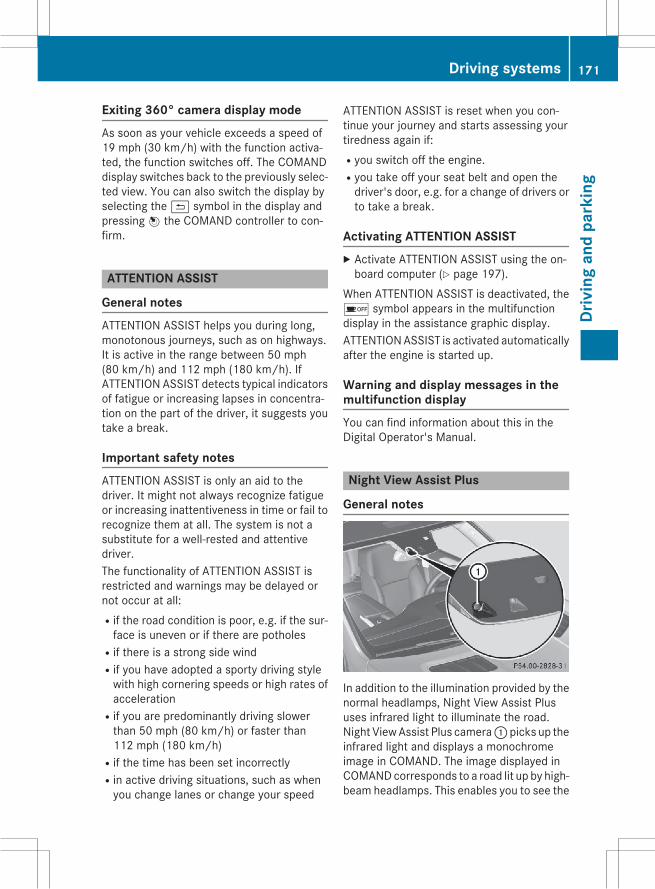
Exiting 360° camera display modeAs soon as your vehicle exceeds a speed of19 mph (30 km/h) with the function activa-ted, the function switches off. The COMANDdisplay switches back to the previously selec-ted view. You can also switch the display byselecting the& symbol in the display andpressingW the COMAND controller to con-firm.
ATTENTION ASSIST
General notesATTENTION ASSIST helps you during long,monotonous journeys, such as on highways.It is active in the range between 50 mph(80 km/h) and 112 mph (180 km/h). IfATTENTION ASSIST detects typical indicatorsof fatigue or increasing lapses in concentra-tion on the part of the driver, it suggests youtake a break.
Important safety notesATTENTION ASSIST is only an aid to thedriver. It might not always recognize fatigueor increasing inattentiveness in time or fail torecognize them at all. The system is not asubstitute for a well-rested and attentivedriver.The functionality of ATTENTION ASSIST isrestricted and warnings may be delayed ornot occur at all:Rif the road condition is poor, e.g. if the sur-face is uneven or if there are potholes
Rif there is a strong side windRif you have adopted a sporty driving stylewith high cornering speeds or high rates ofacceleration
Rif you are predominantly driving slowerthan 50 mph (80 km/h) or faster than112 mph (180 km/h)
Rif the time has been set incorrectlyRin active driving situations, such as whenyou change lanes or change your speed
ATTENTION ASSIST is reset when you con-tinue your journey and starts assessing yourtiredness again if:Ryou switch off the engine.Ryou take off your seat belt and open thedriver's door, e.g. for a change of drivers orto take a break.
Activating ATTENTION ASSISTX Activate ATTENTION ASSIST using the on-board computer (Y page 197).
When ATTENTION ASSIST is deactivated, theé symbol appears in the multifunctiondisplay in the assistance graphic display.ATTENTIONASSIST is activated automaticallyafter the engine is started up.
Warning and display messages in themultifunction displayYou can find information about this in theDigital Operator's Manual.
Night View Assist Plus
General notes
In addition to the illumination provided by thenormal headlamps, Night View Assist Plususes infrared light to illuminate the road.Night ViewAssist Plus camera:picks up theinfrared light and displays a monochromeimage in COMAND. The image displayed inCOMANDcorresponds to a road lit up by high-beam headlamps. This enables you to see the
Driving systems 171
Driv
ing
and
park
ing
Z

road's course and any obstacles in good time.If pedestrian recognition is activated, pedes-trians recognized by the system are highligh-ted in the Night View Assist Plus display.Light from the headlamps of oncoming vehi-cles does not affect theNight ViewAssist Plusdisplay in the multifunction display. This isalso the case if you cannot switch on the high-beam headlamps due to oncoming traffic.
i Infrared light is not visible to the humaneye and therefore does not glare. NightView Assist Plus can therefore remainswitched on even if there is oncoming traf-fic.
Important safety notesNight View Assist Plus is only an aid and is nota substitute for attentive driving. Do not relyon the Night View Assist Plus display. You areresponsible for the distance to the vehicle infront, for vehicle speed and for braking ingood time. Drive carefully and always adaptyour driving style to suit the prevailing roadand traffic conditions.The systemmay be impaired or may not func-tion if:Rthere is poor visibility, e.g. due to snow,rain, fog or spray
Rthe windshield is dirty, fogged up or cov-ered, for instance by a sticker, in the vicinityof the camera
Ron bends, on uphill gradients or downhillgradients
Pedestrian recognition may be impaired orinoperative if:Rpedestrians are partially or entirelyobscured by objects, e.g. parked vehicles
Rthe silhouette of the pedestrian in the NightView Assist Plus display is incomplete orinterrupted, e.g. by powerful light reflec-tions
Rpedestrians do not contrast adequatelyfrom the background
Rpedestrians are not in an upright position,e.g. sitting, squatting or lying
Activating Night View Assist Plus
Activation conditionsYou can only activate Night View Assist Plusif:Rthe SmartKey is in position 2 in the ignitionlock.
Rit is dark.Rthe light switch is in theà orL posi-tion.
Rreverse gear has not been engaged.
Activating Night View Assist Plus
X Make sure that COMAND is switched on.X Press button:.The Night View Assist Plus display appearsin the COMAND display.
You can read about how to adjust the bright-ness of the COMAND display in the COMANDoperating instructions.
i The infrared headlamps only switch onwhen the vehicle is being driven at speedsof approximately 6 mph (10 km/h). Thismeans that you do not have the full visualrange while the vehicle is stationary andcannot check whether Night View AssistPlus is working.
172 Driving systemsDr
ivin
gan
dpa
rkin
g

Pedestrian recognition
: Night View Assist Plus display; Pedestrian recognized= Framing? Symbol for active pedestrian recognition
i Animals are not recognized by pedestrianrecognition.
Night View Assist Plus is able to recognizepedestrians by typical characteristics, e.g. asilhouette in the shape of a person.Pedestrian recognition is then switched onautomatically if:RNight View Assist Plus is activated.Ryou are driving faster than approximately6 mph (10 km/h).
Rthe surroundings are dark, e.g. when driv-ing outside built-up areas without streetlighting.
If pedestrian recognition is active, symbol?appears. If pedestrians are detected, they arehighlighted with framing=. If the pedestrianrecognition system has brought a pedestrianto your attention, look through the windshieldto evaluate the situation. The actual distanceto objects and pedestrians cannot be gagedaccurately by looking at a screen.Itmay be the case that objects are highlightedas well as pedestrians.
Fogged up or dirty windshieldIf the windshield in front of the camera is fog-ged up or dirty on the inside or outside, theNight View Assist Plus display is affected.
X To defrost: check the automatic air condi-tioning settings (Y page 127) and fold downthe camera cover (Y page 270).X To defrost the inside of the windshield:fold down the camera cover (Y page 270)and clean the windshield (Y page 270).
Driving systems 173
Driv
ing
and
park
ing
Z

Problems with Night View Assist Plus
Problem Possible causes/consequences and M Solutions
The picture quality ofNight View Assist Plushas deteriorated.
The windshield wipers are smearing the windshield.X Replace the wiper blades (Y page 118).
The windshield is smeared after the vehicle has been cleaned in acar wash.X Clean the windshield (Y page 270).
There is windshield chip damage in the camera's field of vision.X Replace the windshield.
The windshield is fogged up on the inside.X Defrost the windshield (Y page 127).
The windshield is iced up.X De-ice the windshield (Y page 127).
There is dirt on the inside of the windshield.X Clean the inside of the windshield (Y page 270).
Lane Tracking package
General notesThe Lane Tracking package consists of BlindSpot Assist (Y page 174) and Lane KeepingAssist (Y page 176).
Blind Spot Assist
General notesBlind Spot Assist uses a radar sensor systemto monitor the areas on both sides of yourvehicle. It supports you from a speed ofapproximately 20 mph (30 km/h). A warningdisplay in the exterior mirrors draws yourattention to vehicles detected in the moni-tored area. If you then switch on the corre-sponding turn signal to change lanes, you willalso receive an optical and audible collisionwarning. Blind Spot Assist uses sensors in therear bumper for monitoring purposes.
Important safety notesG WARNINGBlind Spot Assist does not react to:Rvehicles overtaken too closely on the side,placing them in the blind spot area
Rvehicles which approach with a large speeddifferential and overtake your vehicle
As a result, Blind Spot Assist may not givewarnings in such situations. There is a risk ofan accident.Always observe the traffic conditions care-fully, and maintain a safe lateral distance.
Blind Spot Assist is only an aid. It may fail todetect some vehicles and is no substitute forattentive driving.
i USA only:This device has been approved by the FCCas a "Vehicular Radar System". The radarsensor is intended for use in an automotiveradar system only. Removing, tamperingwith, or altering the device will void any
174 Driving systemsDr
ivin
gan
dpa
rkin
g

warranties, and is not permitted by theFCC. Do not tamper with, alter, or use inany non-approved way.Any unauthorized modification to thisdevice could void the user’s authority tooperate the equipment.
Monitoring range of the sensorsIn particular, the detection of obstacles canbe impaired if:Rthere is dirt on the sensors or anything elsecovering the sensors
Rthere is poor visibility, e.g. due to fog, heavyrain, snow or spray
Rthere are narrow vehicles, e.g. motorcyclesor bicycles
Rthe road has very wide lanesRthe road has narrow lanesRyou are not driving in the middle of the laneRthere are barriers or similar lane bordersVehicles in the monitoring range are then notindicated.
Blind Spot Assistmonitors the area up to 10 ft(3 m) behind your vehicle and directly next toyour vehicle, as shown in the diagram.If the lanes are narrow, vehicles driving in thelane beyond the lane next to your vehicle maybe indicated, especially if the vehicles are notdriving in themiddle of their lane. This may be
the case if there are vehicles driving at theinner edge of their lanes.Due to the nature of the system:Rwarnings may be issued in error when driv-ing close to crash barriers or similar solidlane borders.
Rthe warning is canceled when driving for anextended period next to long vehicles, suchas trucks.
The two radar sensors for Blind Spot Assistare integrated into the sides of the rearbumper. Make sure that the bumper is free ofdirt, ice or slush in the vicinity of the sensors.The sensors must not be covered, for exam-ple by cycle racks or overhanging loads. Fol-lowing a severe impact or in the event of dam-age to the bumpers, have the condition of theradar sensors checked at a qualified special-ist workshop. Blind Spot Assist may other-wise not work properly.
Indicator and warning displayBlind Spot Assist is not active at speeds belowapproximately 20mph (30 km/h). Vehicles inthe monitoring range are then not indicated.
: Yellow indicator lamp/red warning lampWhen Blind Spot Assist is activated, indicatorlamp: in the exterior mirrors lights up yel-low at speeds of up to 20 mph (30 km/h). Atspeeds above 20 mph (30 km/h), the indica-tor lamp goes out and Blind Spot Assist isoperational.If a vehicle is detected within the blind spotmonitoring range at speeds above 20 mph(30 km/h), warning lamp: on the corre-
Driving systems 175
Driv
ing
and
park
ing
Z

sponding side lights up red. This warning isalways emitted when a vehicle enters theblind spot monitoring range from behind orfrom the side. When you overtake a vehicle,the warning only occurs if the difference inspeed is less than 7 mph (12 km/h).The yellow indicator lamp goes out if reversegear is engaged. In this event, Blind SpotAssist is no longer active.The brightness of the indicator/warninglamps is adjusted automatically according tothe ambient light.
Collision warningIf a vehicle is detected in themonitoring rangeof Blind Spot Assist and you switch on thecorresponding turn signal, a double warningtone sounds. Red warning lamp: flashes. Ifthe turn signal remains on, detected vehiclesare indicated by the flashing of red warninglamp:. There are no further warning tones.
Information in the Digital Operator's Man-ualIn the Digital Operator's Manual you can findinformation about:RSwitching on Blind Spot AssistRTowing a trailer
Lane Keeping Assist
General notes
: Lane Keeping Assist cameraLane Keeping Assist monitors the area infront of your vehicle by means of a camera:at the top of the windshield. Lane Keeping
Assist detects lane markings on the road andwarns you before you leave your lane unin-tentionally.If you select km on the on-board computer inthe Display Unit Speed-/Odometer func-tion (Y page 197), Lane Keeping Assist isactive starting at a speed of 60 km/h. If themiles display unit is selected, the assistancerange begins at 40 mph.A warning may be given if a front wheelpasses over a lanemarking. It will warn you bymeans of intermittent vibration in the steer-ing wheel for up to 1.5 seconds.
Important safety notesG WARNINGLane Keeping Assist may not always clearlyrecognize lane markings.In this case, Lane Keeping Assist may:Rgive an unnecessary warningRnot give a warningThere is a risk of an accident.Always pay particular attention to the trafficsituation and stay in lane, in particular ifwarned by Lane Keeping Assist.
G WARNINGThe Lane Keeping Assist warning does notreturn the vehicle to the original lane. There isa risk of an accident.You should always steer, brake or accelerateyourself, in particular if warned by Lane Keep-ing Assist.
If you fail to adapt your driving style, LaneKeeping Assist can neither reduce the risk ofan accident nor override the laws of physics.Lane Keeping Assist cannot take into accountthe road, traffic and weather conditions. LaneKeeping Assist is merely an aid. You areresponsible for the distance to the vehicle infront, for vehicle speed, for braking in goodtime and for staying in your lane.The Lane Keeping Assist does not keep thevehicle in the lane.
176 Driving systemsDr
ivin
gan
dpa
rkin
g

The systemmay be impaired or may not func-tion if:Rthere is poor visibility, e.g. due to insuffi-cient illumination of the road, or due tosnow, rain, fog or spray
Rthere is glare, e.g. from oncoming traffic,the sun or reflections (e.g. when the roadsurface is wet)
Rthe windshield is dirty, fogged up, damagedor covered, for instance by a sticker, in thevicinity of the camera
Rthere are no, several or unclear lane mark-ings for a lane, e.g. in areas with road con-struction work
Rthe lane markings are worn away, dark orcovered up, e.g. by dirt or snow
Rthe distance to the vehicle in front is toosmall and the lanemarkings thus cannot bedetected
Rthe lane markings change quickly, e.g.lanes branch off, cross one another ormerge
Rthe road is narrow and windingRthere are strong shadows cast on the road
Switching on Lane Keeping AssistYou can find information about this in theDigital Operator's Manual.
Active Driving Assistance package
General notesThe Active Driving Assistance package con-sists of DISTRONICPLUS (Ypage153), ActiveBlind Spot Assist (Y page 177) and ActiveLane Keeping Assist (Y page 180).
Active Blind Spot Assist
General notesActive Blind Spot Assist uses a radar sensorsystem tomonitor the side areas of your vehi-cle which are behind the driver. A warningdisplay in the exterior mirrors draws yourattention to vehicles detected in the moni-
tored area. If you then switch on the corre-sponding turn signal to change lanes, you willalso receive a visual and audible collisionwarning. If a risk of lateral collision is detec-ted, corrective braking may help you avoid acollision. Before a course-correcting brakeapplication, Active Blind Spot Assist evalu-ates the space in the direction of travel and atthe sides of the vehicle. For this, Active BlindSpot Assist uses radar sensors which arepointed in the direction of travel.Active Blind Spot Assist supports you from aspeed of approximately 20 mph (30 km/h).
Important safety notesActive Blind Spot Assist is only an aid. It mayfail to detect some vehicles and is no substi-tute for attentive driving.
G WARNINGActive Blind Spot Assist does not react to:Rvehicles overtaken too closely on the side,placing them in the blind spot area
Rvehicles which approach with a large speeddifferential and overtake your vehicle
As a result, Active Blind Spot Assist may nei-ther give warnings nor intervene in such sit-uations. There is a risk of an accident.Always observe the traffic conditions care-fully, and maintain a safe lateral distance.
i USA only: This device has been approvedby the FCC as a "Vehicular Radar System".The radar sensor is intended for use in anautomotive radar system only. Removal,tampering, or altering of the devicewill voidany warranties, and is not permitted by theFCC. Do not tamper with, alter, or use inany non-approved way.Any unauthorized modification to thisdevice could void the user's authority tooperate the equipment.
i Canada only: This device complies withRSS-210 of Industry Canada. Operation issubject to the following two conditions:
Driving systems 177
Driv
ing
and
park
ing
Z

1. This device may not cause harmful inter-ference, and2. This devicemust accept any interferencereceived, including interference that maycause undesired operation of the device.Removal, tampering, or altering of thedevice will void any warranties, and is notpermitted. Do not tamper with, alter, or usein any non-approved way.Any unauthorized modification to thisdevice could void the user's authority tooperate the equipment.
Radar sensorsThe Active Blind Spot Assist radar sensors areintegrated into the front and rear bumpersand behind a cover in the radiator trim. Makesure that the bumpers and the cover in theradiator grill are free of dirt, ice or slush. Therear sensors must not be covered, e.g. bybicycle racks or overhanging loads. Followinga severe impact or in the event of damage tothe bumpers, have the function of the radarsensors checked at a qualified specialistworkshop. Active Blind Spot Assist may oth-erwise no longer work properly.
Monitoring areaG WARNINGActive Blind Spot Assist does not detect alltraffic situations and road users. There is arisk of an accident.Always make sure that there is sufficient dis-tance on the side for other traffic or obstacles.
Active Blind Spot Assist monitors the area upto 10 ft (3.0 m) behind your vehicle anddirectly next to your vehicle, as shown in thediagram. For this purpose, Active Blind SpotAssist uses radar sensors in the rear bumper.In particular, the detection of obstacles canbe impaired if:Rthere is dirt on the sensors or anything elsecovering the sensors
Rthere is poor visibility, e.g. due to fog, heavyrain, snow or spray
Vehicles in the monitoring range are then notindicated.Active Blind Spot Assist may not detect nar-row vehicles, such as motorcycles or bicy-cles, or may only detect them too late.If the lanes are narrow, vehicles driving in thelane beyond the lane next to your vehicle maybe indicated, especially if the vehicles are notdriving in themiddle of their lane. This may bethe case if there are vehicles at the inner edgeof your lane.Due to the nature of the system:Rwarnings may be issued in error when driv-ing close to crash barriers or similar solidlane borders.
Rwarnings may be interrupted when drivingalongside particularly long vehicles, e.g.trucks, for a prolonged time.
178 Driving systemsDr
ivin
gan
dpa
rkin
g

Indicator and warning display
: Yellow indicator lamp/red warning lampActive Blind Spot Assist is not active atspeeds below approximately 20 mph(30 km/h). Vehicles in the monitoring rangeare then not indicated.When Active Blind Spot Assist is activated,indicator lamp: in the exteriormirrors lightsup yellow at speeds of up to 20 mph(30 km/h). At speeds above 20 mph(30 km/h), the indicator lamp goes out andActive Blind Spot Assist is operational.If a vehicle is detected within the blind spotmonitoring range at speeds above 20 mph(30 km/h), warning lamp: on the corre-sponding side lights up red. This warning isalways emitted when a vehicle enters theblind spot monitoring range from behind orfrom the side. When you overtake a vehicle,the warning only occurs if the difference inspeed is less than 7 mph (12 km/h).The yellow indicator lamp goes out if reversegear is engaged. In this event, Active BlindSpot Assist is no longer active.The brightness of the indicator/warninglamps is adjusted automatically according tothe ambient light.
Visual and acoustic collision warningIf you switch on the turn signals to changelanes and a vehicle is detected in the sidemonitoring range, you receive a visual andacoustic collision warning. You then hear adouble warning tone and redwarning lamp:flashes. If the turn signal remains on, detec-ted vehicles are indicated by the flashing of
red warning lamp:. There are no furtherwarning tones.
Course-correcting brake applicationIf Active Blind Spot Assist detects a risk of alateral collision in the monitoring range, acourse-correcting brake application is carriedout. This is meant to assist you in avoiding acollision.
G WARNINGA course-correcting brake application cannotalways prevent a collision. There is a risk of anaccident.Always steer, brake or accelerate yourself,especially if Active Blind Spot Assist warnsyou ormakes a course-correcting brake appli-cation. Always maintain a safe distance at thesides.
If a course-correcting brake applicationoccurs, red warning lamp: flashes in theexterior mirror and a dual warning tonesounds. In addition, display; underliningthe danger of a side collision appears in themultifunction display.In very rare cases, the system may make aninappropriate brake application. A course-correcting brake application may be interrup-ted at any time if you steer slightly in theopposite direction or accelerate.The course-correcting brake application isavailable in the speed range between 20 mph(30 km/h) and 120 mph (200 km/h).
Driving systems 179
Driv
ing
and
park
ing
Z

Either no braking application, or a course-correcting brake application adapted to thedriving situation occurs if:Rthere are vehicles or obstacles, e.g. crashbarriers, located on both sides of your vehi-cle.
Ra vehicle approaches you too closely at theside.
Ryou have adopted a sporty driving stylewithhigh cornering speeds.
Ryou clearly brake or accelerate.Ra driving safety system intervenes, e.g.ESP® or PRE-SAFE® Brake.
RESP® is switched off.Rthe off-road program is activated (vehicleswithout the ON&OFFROAD package).
Roff-road program 1 or 2 is activated (vehi-cles with the ON&OFFROAD package).
Rthe LOW RANGE off-road gear is activated(vehicles with the ON&OFFROAD package).
Ra loss of tire pressure or a defective tire isdetected.
Information in the Digital Operator's Man-ualIn the Digital Operator's Manual you can findinformation on:Rswitching on Active Blind Spot AssistRtowing a trailer
Active Lane Keeping Assist
General notes
Active Lane Keeping Assist monitors the areain front of your vehicle bymeans of camera:at the top of the windshield. Active LaneKeeping Assist detects lane markings on theroad and warns you before you leave yourlane unintentionally. If you do not react to thewarning, a lane-correcting application of thebrakes can bring the vehicle back into theoriginal lane.If you select km in the Display UnitSpeed-/Odometer: function on the on-boardcomputer (Y page 197), Active Lane KeepingAssist is activated starting at a speed of60 km/h. If the miles display unit is selected,the assistance range begins at 40 mph.
Important safety notesIf you fail to adapt your driving style, ActiveLane Keeping Assist can neither reduce therisk of accident nor override the laws of phys-ics. Lane Keeping Assist cannot take intoaccount the road, traffic and weather condi-tions. Lane Keeping Assist is merely an aid.You are responsible for the distance to thevehicle in front, for vehicle speed, for brakingin good time and for staying in your lane.Active Lane Keeping Assist cannot continu-ously keep your vehicle in its lane.
G WARNINGActive Lane Keeping Assist cannot alwaysclearly detect lane markings.In such cases, Active Lane Keeping Assistcan:Rgive an unnecessary warning and thenmake a course-correcting brake applicationto the vehicle
Rnot give a warning or interveneThere is a risk of an accident.Always pay particular attention to the trafficsituation and keep within the lane, especiallyif Active Lane Keeping Assist alerts you. Ter-minate the intervention in a non-critical driv-ing situation.
180 Driving systemsDr
ivin
gan
dpa
rkin
g

The systemmay be impaired or may not func-tion if:Rthere is poor visibility, e.g. due to insuffi-cient illumination of the road, or due tosnow, rain, fog or spray
Rthere is glare, e.g. from oncoming traffic,the sun or reflections (e.g. when the roadsurface is wet)
Rthe windshield is dirty, fogged up, damagedor covered, for instance by a sticker, in thevicinity of the camera
Rthere are no, several or unclear lane mark-ings for a lane, e.g. in areas with road con-struction work
Rthe lane markings are worn away, dark orcovered up, e.g. by dirt or snow
Rthe distance to the vehicle in front is toosmall and the lanemarkings thus cannot bedetected
Rthe lane markings change quickly, e.g.lanes branch off, cross one another ormerge
Rthe road is narrow and windingRthere are highly variable shade conditionson the roadway
Rno vehicle is detected in the adjacent laneand there are broken lane markings
Warning vibration in the steering wheelA warning may be given if a front wheelpasses over a lanemarking. It will warn you bymeans of intermittent vibration in the steer-ing wheel for up to 1.5 seconds.In order that you are warned only when nec-essary and in good time if you cross the lanemarking, the system recognizes certain con-ditions and warns you accordingly.The warning vibration occurs earlier if:Ryou approach the outer lane marking on abend.
Rthe road has very wide lanes, e.g. a high-way.
Rthe system recognizes solid lane markings.
The warning vibration occurs later if:Rthe road has narrow lanes.Ryou cut the corner on a bend.
Lane-correcting brake applicationG WARNINGA lane-correcting brake application cannotalways bring the vehicle back into the originallane. There is a risk of an accident.Always steer, brake or accelerate yourself,especially if Active Lane Keeping Assist warnsyou or makes a lane-correcting brake appli-cation.
G WARNINGActive Lane Keeping Assist does not detecttraffic conditions or road users. In very rarecases, the systemmaymake an inappropriatebrake application, e.g. after intentionally driv-ing over a solid lanemarking. There is a risk ofan accident.An inappropriate brake application may beinterrupted at any time if you steer slightly inthe opposite direction. Alwaysmake sure thatthere is sufficient distance on the side forother traffic or obstacles.
If a lane-correcting brake application occurs,display: appears in the multifunction dis-play.If you leave your lane, under certain circum-stances the vehicle will brake briefly on oneside. This is meant to assist you in bringingthe vehicle back to the original lane.
Driving systems 181
Driv
ing
and
park
ing
Z
This function is available in the range between40 mph and 120 mph (60 km/h and200 km/h).A lane-correcting brake application can onlybe made after driving over a solid, recogniz-able lane marking. Before this, a warningmust be given by means of intermittent vibra-tion in the steering wheel. In addition, a lanewith lane markings on both sides must berecognized. The brake application alsoslightly reduces vehicle speed.
i A further lane-correcting brake applica-tion can only occur after your vehicle hasreturned to the original lane.
No lane-correcting brake application occursif:Ryou clearly and actively steer, brake oraccelerate.
Ryou cut the corner on a sharp bend.Ryou have switched on the turn signal.Ra driving safety system intervenes, e.g.ESP®, PRE-SAFE® Brake or Active BlindSpot Assist.
Ryou have adopted a sporty driving stylewithhigh cornering speeds or high rates ofacceleration.
RESP® is switched off.Rthe transmission is not in position D.Ron vehicles with a trailer tow hitch, theelectrical connection to the trailer has beencorrectly established.
Rthe off-road program is activated (vehicleswithout the ON&OFFROAD package).
Roff-road program 1 or 2 is activated (vehi-cles with the ON&OFFROAD package).
Rthe LOW RANGE off-road gear is activated(vehicles with the ON&OFFROADpackage).
Rwhen a loss of tire pressure or a defectivetire has been detected and displayed.
Active Lane Keeping Assist does not detecttraffic situations or road users. An inappro-priate brake applicationmay be interrupted atany time if you:Rsteer slightly in the opposite directionRswitch on the turn signalRclearly brake or accelerateA lane-correcting brake application is inter-rupted automatically if:Ra driving safety system intervenes, e.g.ESP®, PRE-SAFE® Brake or Active BlindSpot Assist.
Rlanemarkings can no longer be recognized.
Information in the Digital Operator's Man-ualIn the Digital Operator's Manual you can findinformation on:RSwitching on Active Lane Keeping AssistRTowing a trailer
On-road programs (vehicles with theON&OFFROAD package)
General notesThe on-road programs assist you during on-road driving and the off-road programs whendriving off-road (Y page 184).The following program messages remain inthe multifunction display until the corre-sponding vehicle level has been set. Up to off-road level 2, you can hide the program mes-sages using the% ora button on themultifunction steering wheel.
182 Driving systemsDr
ivin
gan
dpa
rkin
g

AUTO program
: On-road program selector wheel; AUTO program indicator lamp
SPORT program
: On-road program selector wheel; SPORT program indicator lamp
Snow program
: On-road program selector wheel; Snow program indicator lamp
Trailer program
: On-road program selector wheel; Trailer program indicator lamp
Off-road driving systems
4MATIC (permanent four-wheel drive)If you fail to adapt your driving style, 4MATICcan neither reduce the risk of accident noroverride the laws of physics. 4MATIC cannottake account of road, weather and traffic con-ditions. 4MATIC is only an aid. You areresponsible for the distance to the vehicle infront, for vehicle speed, for braking in goodtime and for staying in your lane.
! Never tow the vehicle with one axleraised. This may damage the transfer case.Damage of this sort is not covered by theMercedes-Benz Limited Warranty. Allwheelsmust remain either on the ground orbe fully raised. Observe the instructions fortowing the vehicle with all wheels in fullcontact with the ground.
! A function or performance test shouldonly be carried out on a two-axle dyna-mometer. Before you operate the vehicleon such a dynamometer, please consult aqualified workshop. You could otherwisedamage the drive train or the brake system.
4MATIC ensures that all four wheels are per-manently driven. Together with ESP® and4ETS, it improves the traction of your vehiclewhenever a drive wheel spins due to insuffi-cient grip.
Driving systems 183
Driv
ing
and
park
ing
Z

i In wintry driving conditions, themaximumeffect of 4MATIC can only be achieved ifyou use winter tires (M+S tires), with snowchains if necessary.
Further information about "Driving off-road"(Y page 149).
DSR (Downhill Speed Regulation)
Important safety notesDSR assists you when driving downhill. Itkeeps the speed of travel at the speed set onthe on-board computer. The steeper thedownhill gradient, the greater the DSR brak-ing effect on the vehicle. When driving on flatstretches of road or on an uphill gradient, theDSR braking effect is minimal or nonexistent.DSR controls the set speed when it is activeand the automatic transmission is in the D, Ror N position. By accelerating or braking, youcan always drive at a higher or a lower speedthan that set on the on-board computer.Further information about "Driving off-road"(Y page 149).If you fail to adapt your driving style, DSR canneither reduce the risk of accident nor over-ride the laws of physics. DSR cannot takeaccount of road, weather and traffic condi-tions. DSR is only an aid. You are responsiblefor the distance to the vehicle in front, forvehicle speed, for braking in good time and forstaying in your lane.You are always responsible for keeping con-trol of the vehicle and for assessing whetherthe downhill gradient can be managed. DSRmay not always be able to keep to the setspeed, depending on road surface and tireconditions. Select a set speed suitable for theprevailing conditions and when necessary,apply the brakes manually.
G WARNINGIf the speed driven and the set speed deviateand you activate DSR on a slippery road sur-face, the wheelsmay lose traction. There is anincreased danger of skidding and accidents.
Before switching DSR on, please take intoconsideration the road surface and the differ-ence between driving speed and the setspeed.
G WARNINGIf you drive faster than the set speed and acti-vate DSR, the vehicle will decelerate on down-hill gradients. If you do not know the setspeed, the vehicle could decelerate unexpect-edly. There is a risk of an accident.Decelerate the vehicle to the set speed beforeactivating DSR. If you do not know what thestored set speed is, store the desired setspeed again.
General notes
Example: vehicles with the ON&OFFROADpackage: DSR button; DSR indicator lampIn the Digital Operator's Manual you can findinformation about:RActivating DSRRDeactivating DSRRChanging the set speed
Off-road programs (vehicles with theON&OFFROAD package)
General notesThe off-road programs assist you in drivingoff-road. The engine's performance charac-teristics and the gearshifting characteristicsof the automatic transmission are adapted forthis purpose. ABS, ESP® and 4ETS programs
184 Driving systemsDr
ivin
gan
dpa
rkin
g
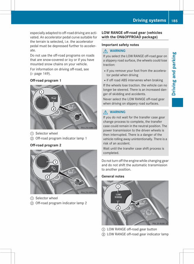
especially adapted to off-road driving are acti-vated. An accelerator pedal curve suitable forthe terrain is selected, i.e. the acceleratorpedal must be depressed further to acceler-ate.Do not use the off-road programs on roadsthat are snow-covered or icy or if you havemounted snow chains on your vehicle.For information on driving off-road, see(Y page 149).
Off-road program 1
: Selector wheel; Off-road program indicator lamp 1
Off-road program 2
: Selector wheel; Off-road program indicator lamp 2
LOW RANGE off-road gear (vehicleswith the ON&OFFROAD package)
Important safety notesG WARNINGIf you select the LOW RANGE off-road gear ona slippery road surface, the wheels could losetraction:Rif you remove your foot from the accelera-tor pedal when driving
Rif off road ABS intervenes when brakingIf the wheels lose traction. the vehicle can nolonger be steered. There is an increased dan-ger of skidding and accidents.Never select the LOW RANGE off-road gearwhen driving on slippery road surfaces.
G WARNINGIf you do not wait for the transfer case gearchange process to complete, the transfercase could remain in the neutral position. Thepower transmission to the driven wheels isthen interrupted. There is a danger of thevehicle rolling away unintentionally. There is arisk of an accident.Wait until the transfer case shift process iscompleted.
Donot turn off the enginewhile changing gearand do not shift the automatic transmissionto another position.
General notes
: LOW RANGE off-road gear button; LOW RANGE off-road gear indicator lamp
Driving systems 185
Driv
ing
and
park
ing
Z

The LOW RANGE off-road gear assists you indriving off-road and when fording. When LOWRANGE is engaged, the engine’s performancecharacteristics and the gearshifting charac-teristics of the automatic transmission areadapted for this purpose.
From HIGH RANGE to LOW RANGE! Only change from LOW RANGE to HIGHRANGE if:Rthe engine is running.Rthe transmission is in position NRyou are driving at a speed below40 km/h
From LOW RANGE to HIGH RANGE! Only change from LOW RANGE to HIGHRANGE if:Rthe engine is running.Rthe transmission is in position NRyou are driving at a speed below70 km/h
ON&OFFROAD menu in the COMANDdisplay (vehicles with the ON&OFF-ROAD package)
You can display some driving systems, drivingprograms and additional information in theCOMAND display.
X Make sure that the SmartKey is in position2 in the ignition lock.X Make sure that COMAND is activated, seethe separate COMAND operating instruc-tions.X Press function button:.The corresponding displays appear in theCOMAND display:Rlevel controlRsteering angleRvehicle's angle of inclinationRuphill or downhill gradient in percentageRon-road/off-road program selectedRcondition of the differential lock for thetransfer case
Rthe LOWRANGE off-road gear is selectedRcondition of the LOW RANGE off-roadgear
Rthe on-road trailer program is selected
Towing a trailer
Important safety notes
G WARNINGInstalling an unsuitable ball coupling mayresult in overloading of the trailer tow hitchand the rear axle. This applies especially if theball coupling in question is longer or angleddifferently. This could seriously impair thedriving characteristics and the trailer cancome loose. There is a risk of an accident.You should only ever install a ball couplingthat has the permissible dimensions and thatis designed to meet your trailer-towingrequirements. Do not modify the ball couplingor the trailer tow hitch.
You will find the values approved by the man-ufacturer on the vehicle identification platesand those for the towing vehicle under "Tech-nical data" (Y page 350).
186 Towing a trailerDr
ivin
gan
dpa
rkin
g

G WARNINGIf the ball coupling is not installed correctly ornot secured with the bolt provided and thecorresponding spring cotter, the trailer maycome loose. There is a risk of an accident.Always install and secure the ball coupling asdescribed. Before every journey, ensure thatthe ball coupling is secured with the bolt andthe corresponding spring cotter.
G WARNINGWhen the vehicle/trailer combination beginsto lurch, you could lose control of it. The vehi-cle/trailer combination could even rollover.There is a risk of an accident.On no account should you attempt tostraighten up the vehicle/trailer combinationby increasing the speed. Reduce vehiclespeed and do not countersteer. Apply thebrake as necessary.
Please observe the manufacturer's operatinginstructions for the trailer coupling if adetachable trailer coupling is used.Couple and uncouple the trailer carefully. Ifyou do not couple the trailer to the towingvehicle correctly, the trailer could becomedetached.Make sure that the following values are notexceeded:Rthe permissible trailer drawbar noseweightRthe permissible trailer loadRthe permissible rear axle load of the towingvehicle
Rthe maximum permissible gross vehicleweight of both the towing vehicle and thetrailer
The applicable permissible values, whichmust not be exceeded, can be found:Rin the vehicle documentsRon the identification plates for the trailertow hitch and the trailer
Ron the vehicle identification plateIf the values differ, the lowest value applies.
When towing a trailer, your vehicle's handlingcharacteristics will be different in comparisonwith when driving without a trailer.The vehicle/trailer combination:Ris heavierRis restricted in its acceleration and gradi-ent-climbing capability
Rhas an increased braking distanceRis affected more by strong crosswindsRdemands more sensitive steeringRhas a larger turning radiusThis could impair the handling characteris-tics.When towing a trailer, always adjust yourspeed to the current road and weather con-ditions. Do not exceed the maximum permis-sible speed for your vehicle/trailer combina-tion.
Notes on towing a trailer
General notesRDo not exceed the legally prescribed max-imum speed for vehicle/trailer combina-tions in the relevant country.This lowers the risk of an accident.
ROnly install an approved trailer coupling onyour vehicle.Further information on availability and oninstallation is available from any authorizedMercedes-Benz Center.
RThe bumpers of your vehicle are not suita-ble for installing detachable trailer cou-plings.
RDo not install hired trailer couplings orother detachable trailer couplings on thebumpers of your vehicle.
RIf you no longer need the ball coupling,remove it from the ball coupling recess.This will reduce the risk of damage to theball coupling.
i When towing a trailer, set the tire pres-sure on the rear axle of the towing vehicle
Towing a trailer 187
Driv
ing
and
park
ing
Z
for a maximum load; see the tire pressuretable in the fuel filler flap (Y page 310).
Please note that when towing a trailer,PARKTRONIC (Y page 165) and Blind SpotAssist (Y page 174) are only available withlimitations, or not at all.
i On vehicles without level control, theheight of the ball coupling will alter accord-ing to the load placed on the vehicle. If nec-essary, use a trailer with a height-adjusta-ble drawbar.
You will find installing dimensions and loadsunder "Technical data" (Y page 349).
Driving tips
i Observe the information on ESP® trailerstabilization (Y page 80) and on pullingaway with a trailer (Y page 135).
The maximum permissible speed for vehicle/trailer combinations depends on the type oftrailer. Before beginning the journey, checkthe trailer's documents to see what the max-imum permissible speed is. Observe thelegally prescribed maximum speed in the rel-evant country.For certainMercedes-Benz vehicles, themax-imum permissible rear axle load is increasedwhen towing a trailer. See "Technical data" tofind out whether this applies to your vehicle(Y page 350). If you utilize any of the addedmaximum rear axle loadwhen towing a trailer,the vehicle/trailer combination may notexceed a maximum speed of 60 mph(100 km/h) for reasons concerning the oper-ating permit. This also applies in countries inwhich the permissible maximum speed forvehicle/trailer combinations is above 60mph(100 km/h).When towing a trailer, your vehicle's handlingcharacteristics will be different in comparisonwith when driving without a trailer.Use the left-hand paddle shifter to shift into alower gear in good time on long and steepdownhill gradients.
i This also applies if you have activatedcruise control or DISTRONIC PLUS.
This will use the braking effect of the engine,so that less braking will be required to main-tain the speed. This relieves the load on thebrake system and prevents the brakes fromoverheating and wearing too quickly. If youneed additional braking, depress the brakepedal repeatedly rather than continuously.
Driving tipsIf the trailer swings from side to side:X Do not accelerate.X Do not counter-steer.X Brake if necessary.RMaintain a greater distance from the vehi-cle in front than when driving without atrailer.
RAvoid braking abruptly. If possible, brakegently at first to allow the trailer to run on.Then, increase the braking force rapidly.
RThe values given for gradient-climbingcapabilities from a standstill refer to sealevel. When driving in mountainous areas,note that the power output of the engineand, consequently, the vehicle's gradient-climbing capability, decreases withincreasing altitude.
Installing the ball coupling
G WARNINGIf the ball coupling is not correctly installedand secured, it can come loose during thejourney and endanger other road users. Thereis a risk of an accident and injury.Always install and secure the ball coupling asdescribed. Before every journey, ensure thatthe ball coupling is secured with the bolt andthe corresponding spring cotter.
G WARNINGIf the ball coupling is not installed correctly ornot secured with the bolt provided and the
188 Towing a trailerDr
ivin
gan
dpa
rkin
g

corresponding spring cotter, the trailer maycome loose. There is a risk of an accident.Always install and secure the ball coupling asdescribed. Before every journey, ensure thatthe ball coupling is secured with the bolt andthe corresponding spring cotter.
G WARNINGIf the ball coupling is not installed and securedcorrectly the trailer may come loose. There isa risk of an accident.Install and secure the ball coupling as descri-bed in the ball coupling installation instruc-tions. Make sure that the ball coupling isinstalled and secured correctly before everyjourney.
X Pull protective cap: in the direction of thearrow, out of the ball coupling recess.X Place protective cap: in the ball couplingrecess.
X Insert the ball coupling horizontally into ballcoupling recess; in the direction of thearrow until the holes in ball coupling= arein line with the holes in ball couplingrecess?.
X Slide boltA into the hole in the ball cou-pling recess and the ball coupling to thestop.
Towing a trailer 189
Driv
ing
and
park
ing
Z

X Secure the bolt using spring cotterB.
X Check the ball coupling, bolt and springcotter for correct installation.
If the ball coupling cannot be correctly moun-ted, remove the ball coupling. Under thesecircumstances, the ball coupling must not beused for trailer towing.If the ball coupling cannot be locked and thekey cannot be removed, remove the ball cou-pling and clean it. If the ball coupling can stillnot be installed (locked) after it has beencleaned, remove the ball coupling. The trailertow hitch must then not be used to tow atrailer, as safe operation cannot be guaran-teed.Have the entire trailer tow hitch checked at aqualified specialist workshop.
Coupling up a trailer! Do not connect the trailer's brake system(if featured) to the hydraulic brake systemof the towing vehicle, as the latter is equip-ped with an anti-lock brake system. Doing
so will result in a loss of function of thebrake systems of both the vehicle and thetrailer.X Make sure that the automatic transmissionis set to position P.X Apply the vehicle's electric parking brake.X Start the engine.X Vehicles with the AIRMATIC package:select highway level.X Vehicles with ADS: set ADS to AUTO or
COMF.X Switch off the engine.X Close all doors and the tailgate.X Couple up the trailer.X Establish all electrical connections.X Check that the trailer lighting system isworking.
i Vehicles with the AIRMATIC package:with a trailer attached, the vehicle willalways remain at highway level. When cou-pling up a trailer, please observe the fol-lowing:RUnless highway level has been set man-ually, the vehicle is automatically low-ered to highway level. This is the case if aspeed of 5 mph (8 km/h) is reached.
RHigh-speed level is not available.These restrictions apply to all accessoriespowered through a connection to the trailerpower socket of your vehicle, e.g. a bicyclecarrier.
Observe the maximum permissible trailerdimensions (width and length).Most U.S. states and all Canadian provincesrequire by law:RSafety chains between the towing vehicleand the trailer. The chains should be cross-wound under the trailer drawbar. Theymustbe fastened to the vehicle's trailer cou-pling, not to the bumper or the axle.
190 Towing a trailerDr
ivin
gan
dpa
rkin
g

Leave enough play in the chains to maketight cornering possible.
RA separate brake system for certain typesof trailer.
RA safety switch for braked trailers. Checkthe specific legal requirements applicableto your state.If the trailer detaches from the towing vehi-cle, the safety switch applies the trailer'sbrakes.
Towing a trailerThere are numerous legal requirements con-cerning the towing of a trailer, e.g. speedrestrictions. Make sure that your car/trailercombination complies with the local regula-tions:Rin your place of residenceRin the location to which you are drivingThe police and local authorities can providereliable information.Observe the following when towing a trailer:RTo gain driving experience and to becomeaccustomed to the new handling charac-teristics, you should practice the followingin a traffic-free location:- cornering- stopping- backing up
RBefore driving, check:- trailer tow hitch- safety switch for braked trailers- safety chains- electrical connections- lights- wheels
RAdjust the exterior mirrors to provide anunobstructed view of the rear section of thetrailer.
RIf the trailer has electronically controlledbrakes, pull away carefully. Brake manually
using the brake controller and checkwhether the brakes function correctly.
RSecure any objects on the trailer to preventthe cargo from slipping when the vehicle isin motion.
RWhen you couple up a trailer, check at reg-ular intervals that the load is firmly secured.If the trailer is equipped with trailer lightsand brakes, check the trailer to ensure thatthese are working.
RBear in mind that the handling will be lessstable when towing a trailer thanwhen driv-ing without one. Avoid sudden steeringmovements.
RThe vehicle/trailer combination is heavier,accelerates more slowly, has a decreasedgradient climbing capability and a longerbraking distance.It is more susceptible to side winds andrequires more careful steering.
RIf possible, do not brake suddenly, butinstead depress the brake pedal moder-ately at first so that the trailer can activateits brakes. Then increase the pressure onthe brake pedal.
RIf the automatic transmission repeatedlyshifts between gears on uphill or downhillgradients, shift to a lower gear using theleft-hand steering wheel paddle shifter.A lower gear and lower speed reduce therisk of engine failure.
RWhen driving downhill, shift to a lower gearto utilize the engine's braking effect.Avoid continuous brake application as thismay overheat the vehicle brakes and, ifinstalled, the trailer brakes.
RIf the coolant temperature increases dra-matically while the air-conditioning systemis switched on, switch off the air-condition-ing system.Coolant heat can also be dissipated byopening the windows and switching the
Towing a trailer 191
Driv
ing
and
park
ing
Z

ventilation blower and the interior temper-ature to the highest level.
RWhen overtaking, pay particular attentionto the extended length of your vehicle/trailer combination.Due to the length of the vehicle/trailercombination, you require additional roadspace in relation to the vehicle you areovertaking before you can change back tothe original lane.
Decoupling a trailer
G WARNINGIf you uncouple a trailer with the overrunbrake engaged, you could trap your handbetween the vehicle and the trailer drawbar.There is a risk of injury.Do not uncouple a trailer if the overrun brakeis engaged.
G WARNINGVehicles with level control:The vehicle is lowered as soon as you discon-nect the trailer cable. This could result in yourlimbs or those of other people that arebetween the vehicle body and tires or under-neath the vehicle being trapped. There is arisk of injury.Make sure that nobody is in the immediatevicinity of the wheel housings or under thevehicle when you disconnect the trailer cable.
! Do not disconnect a trailer with anengaged overrun brake. Otherwise, yourvehicle could be damaged by the rebound-ing of the overrun brake.X Make sure that the automatic transmissionis set to position P.X Apply the vehicle's electric parking brake.X Start the engine.X Close all doors and the tailgate.X Apply the trailer's parking brake.
X Detach the trailer cable and decouple thetrailer.X Switch off the engine.
Permissible trailer loads and drawbarloads
Weight specifications
Maximum permissible gross vehicleweight ratingThe gross trailer weight is calculated by add-ing the weight of the trailer to the weight ofthe load and equipment on the trailer.You will find installing dimensions and loadsunder "Technical data" (Y page 349).
Permissible noseweightYou will find installing dimensions and loadsunder "Technical data" (Y page 349).
Loading a trailerRWhen loading the trailer, make sure thatneither the permissible gross weight of thetrailer nor the gross vehicle weight isexceeded. The permissible gross vehicleweight is indicated on the identificationplate on the B-pillar on the driver's side ofthe vehicle.You can find the maximum permissible val-ues on the type plates of your vehicle andthe trailer. When calculating how muchweight the vehicle and trailer may carry,pay attention to the respective lowest val-ues.
RThe trailer drawbar load on the ball couplingmust be added to the rear axle load to avoidexceeding the permissible gross axleweight. The permissible gross vehicleweight is indicated on the identificationplate on the B-pillar on the driver's side ofthe vehicle.
i Mercedes-Benz recommends a trailerload where the trailer drawbar noseweight
192 Towing a trailerDr
ivin
gan
dpa
rkin
g

accounts for 8% to 15% of the trailer's per-missible gross weight.
i The weight of additional accessories, pas-sengers, and cargo reduces the permissi-ble trailer load and drawbar load for yourvehicle.
Checking the vehicle and trailer weightRTo check that the weights of the towingvehicle and the trailer comply with themax-imumpermissible values, have the vehicle/trailer combination (including the driver,passengers, and cargo with a fully ladentrailer) weighed on a calibrated weigh-bridge.
RCheck the gross axle weight rating of thefront and rear axles, the gross weight of thetrailer and trailer drawbar load.
Removing the ball couplingX Remove the spring cotter.X Remove the bolt from the ball couplingrecess.X Remove the ball coupling from the ball cou-pling recess.X Clean the ball coupling if it is dirty.X Stow the ball coupling so that it cannot bethrown around.
Observe the loading guidelines (Y page 244)and the important safety notes regardingstowage spaces (Y page 245).Information on cleaning and care of the trailertow hitch (Y page 270).
Trailer power supplyYou can find information about this in theDigital Operator's Manual.
Towing a trailer 193
Driv
ing
and
park
ing
Z

194

Useful information ............................ 196Important safety notes ..................... 196Displays and operation ..................... 196Menus and submenus ...................... 197Display messages ............................. 199Warning and indicator lamps in theinstrument cluster ............................ 212
195
On-b
oard
com
pute
rand
disp
lays

Useful information
i This Operator's Manual describes allmodels and all standard and optional equip-ment of your vehicle available at the time ofpublication of the Operator's Manual.Country-specific differences are possible.Please note that your vehicle may not beequipped with all features described. Thisalso applies to safety-related systems andfunctions.
i Read the information on qualified special-ist workshops (Y page 35).
Important safety notes
G WARNINGIf you operate information systems and com-munication equipment integrated in the vehi-cle while driving, you will be distracted fromtraffic conditions. You could also lose controlof the vehicle. There is a risk of an accident.Only operate the equipment when the trafficsituation permits. If you are not sure that thisis possible, park the vehicle paying attentionto traffic conditions and operate the equip-ment when the vehicle is stationary.
You must observe the legal requirements forthe country in which you are currently drivingwhen operating the on-board computer.
G WARNINGIf the instrument cluster has failed or mal-functioned, you may not recognize functionrestrictions in systems relevant to safety. Theoperating safety of your vehicle may beimpaired. There is a risk of an accident.Drive on carefully. Have the vehicle checkedat a qualified specialist workshop immedi-ately.
The on-board computer only showsmessagesor warnings from certain systems in the mul-tifunction display. You should therefore make
sure your vehicle is operating safely at alltimes.If the operating safety of your vehicle isimpaired, pull over as soon as it is safe to doso. Contact a qualified specialist workshop.For an overview, see the instrument panelillustration (Y page 41).
Displays and operation
Information in the Digital Operator'sManualIn the Digital Operator's Manual you will findinformation on the following topics:RCoolant temperature displayRTachometerRSpeedometer with segmentsRMultifunction displayROutside temperature display
Operating the on-board computer
Overview
: Multifunction display; Switches on the Voice Control System
(see the separate operating instructions)= Right control panel
196 Displays and operationOn
-boa
rdco
mpu
tera
nddi
spla
ys

? Left control panelA Back buttonX To activate the on-board computer: turnthe SmartKey to position 1 in the ignitionlock.
You can control the multifunction display andthe settings in the on-board computer usingthe buttons on the multifunction steeringwheel.
Left control panel
=
;
RCalls up the menu and menu bar
9
:
Press briefly:RScrolls in listsRSelects a submenu or functionRIn the Audio menu: selects astored station, an audio track ora video scene
RIn the Tel (telephone) menu:switches to the phone book andselects a name or telephonenumber
9
:
Press and hold:RIn the Audio menu: selects theprevious/next station or selectsan audio track or a video sceneusing rapid scrolling
RIn the Tel (Telephone) menu:starts rapid scrolling if the phonebook is open
a RConfirms a selection/displaymessage
RIn the Tel (Telephone) menu:switches to the telephone bookand starts dialing the selectednumber
RIn the Audio menu: stops thestation search function at thedesired station
Right control panel
~ RRejects or ends a callRExits phone book/redial mem-ory
6 RMakes or accepts a callRSwitches to the redial memory
WX
RAdjusts the volume
8 RMute
Back button
% Press briefly:RBackRSwitches off the Voice ControlSystem (see the separate oper-ating instructions)
RHides display messages/callsup the last Trip menu functionused
RExits the telephone book/redialmemory
% Press and hold:RCalls up the standard display inthe Trip menu
Menus and submenus
Menu overviewPress the= or; button on the steer-ing wheel to call up the menu bar and select amenu.Operating the on-board computer(Y page 196).You can find more information on the individ-ual menus in the Digital Operator's Manual.Depending on the equipment installed in thevehicle, you can call up the following menus:RTrip menuRNavi menu (navigation instructions)
Menus and submenus 197
On-b
oard
com
pute
rand
disp
lays
Z

RAudioAudio menuRTelTel menu (telephone)RDriveAssistDriveAssist menu (assistance)RServiceService menuRSettSett menu (settings)RON&OFFROADON&OFFROAD menuRAMGAMG menu in AMG vehicles
198 Menus and submenusOn
-boa
rdco
mpu
tera
nddi
spla
ys

Display messages
Introduction
General notesThis section describes display messages relevant to safety together with their solutions. Adescription of other messages and their solutions can be found in the Digital Operator's Man-ual.Display messages appear in the multifunction display.Display messages with graphic displays may be shown in simplified form in the Operator'sManual and may therefore differ from the multifunction display.Please respond in accordancewith the displaymessages and follow the additional notes in thisOperator's Manual.Certain display messages are accompanied by an audible warning tone or a continuous tone.When you stop and park the vehicle, please observe the notes on the HOLD function(Y page 161) and parking (Y page 145).
Hiding display messagesX Press thea or% button on the steering wheel to hide the display message.The display message is cleared.
The multifunction display shows high-priority display messages in red. Some high-priority dis-play messages cannot be hidden.The multifunction display shows these messages continuously until the causes for the mes-sages have been remedied.
Message memoryThe on-board computer saves certain displaymessages in themessage memory. You can callup the display messages:X Press the= or; button on the steering wheel to select the Serv. menu.If there are display messages, the multifunction display shows 2 Messages, for example.X Press the9 or: button to select the entry, e.g. 2 Messages.X Pressa to confirm.X Press the9 or: button to scroll through the display messages.When the ignition is switched off, all display messages are deleted, apart from some high-priority display messages. Once the causes of the high-priority display messages have beenrectified, the corresponding display messages are also deleted.
Display messages 199
On-b
oard
com
pute
rand
disp
lays
Z
Safety systems
Display messages Possible causes/consequences and M Solutions
!÷Currently Unavailхable See Operaхtor's Manual
ABS (Anti-lock Braking System), ESP® (Electronic Stability Pro-gram), BAS (Brake Assist), PRE-SAFE®, the HOLD function, hillstart assist and ESP® trailer stabilization are temporarily unavail-able.COLLISION PREVENTION ASSIST, BAS PLUS andPRE゙SAFE® Brake may also have failed.In addition, the÷,å and!warning lamps light up in theinstrument cluster.ATTENTION ASSIST is deactivated.Possible causes are:Rself-diagnosis is not yet complete.Rthe on-board voltage may be insufficient.
G WARNINGThe brake system continues to function normally, but without thefunctions listed above. The wheels could therefore lock if youbrake hard, for example.The steerability and braking characteristics may be severely affec-ted. The braking distance in an emergency braking situation canincrease.If ESP® is not operational, ESP® is unable to stabilize the vehicle.There is an increased risk of skidding and an accident.X Carefully drive a suitable distance, making slight steering move-ments at a speed above 12 mph (20 km/h).If the display message disappears, the functions mentionedabove are available again.
If the display message continues to be displayed:X Drive on carefully.X Visit a qualified specialist workshop.
!÷Inoperative SeeOperator's Manual
ABS, ESP®, BAS, PRE-SAFE®, the HOLD function, hill start assistand ESP® trailer stabilization are unavailable due to amalfunction.COLLISION PREVENTION ASSIST, BAS PLUS andPRE゙SAFE® Brake may also have failed.The$ (USA only)/J (Canada only),÷,å and!warning lamps in the instrument cluster also light up.ATTENTION ASSIST is deactivated.
G WARNING
200 Display messagesOn
-boa
rdco
mpu
tera
nddi
spla
ys

Display messages Possible causes/consequences and M SolutionsThe brake system continues to function normally, but without thefunctions listed above. The wheels could therefore lock if youbrake hard, for example.The steerability and braking characteristics may be severely affec-ted. The braking distance in an emergency braking situation canincrease.If ESP® is not operational, ESP® is unable to stabilize the vehicle.There is an increased risk of skidding and an accident.X Drive on carefully.X Visit a qualified specialist workshop immediately.
÷Currently Unavailхable See Operaхtor's Manual
ESP®, BAS, PRE-SAFE®, the HOLD function, hill start assist andESP® trailer stabilization are unavailable due to a malfunction.COLLISION PREVENTION ASSIST, BAS PLUS andPRE゙SAFE® Brake may also have failed.In addition, the÷ andå warning lamps light up in theinstrument cluster.The self-diagnosis function might not be complete, for example.ATTENTION ASSIST is deactivated.
G WARNINGThe brake system continues to function normally, but without thefunctions listed above. The wheels could therefore lock if youbrake hard, for example.The braking distance in an emergency braking situation can thusincrease.If ESP® is not operational, ESP® is unable to stabilize the vehicle.There is an increased risk of skidding and an accident.X Carefully drive a suitable distance, making slight steering move-ments at a speed above 12 mph (20 km/h).If the display message disappears, the functions mentionedabove are available again.
If the display message continues to be displayed:X Drive on carefully.X Visit a qualified specialist workshop.
Display messages 201
On-b
oard
com
pute
rand
disp
lays
Z

Display messages Possible causes/consequences and M Solutions
÷Inoperative SeeOperator's Manual
ESP®, BAS, PRE-SAFE®, the HOLD function, hill start assist andESP® trailer stabilization are unavailable due to a malfunction.COLLISION PREVENTION ASSIST, BAS PLUS andPRE゙SAFE® Brake may also have failed.In addition, the÷ andå warning lamps light up in theinstrument cluster.ATTENTION ASSIST is deactivated.
G WARNINGThe brake system continues to function normally, but without thefunctions listed above. The wheels could therefore lock if youbrake hard, for example.The braking distance in an emergency braking situation can thusincrease.If ESP® is not operational, ESP® is unable to stabilize the vehicle.There is an increased risk of skidding and an accident.X Drive on carefully.X Visit a qualified specialist workshop.
T!÷Inoperative SeeOperator's Manual
EBD (electronic brake force distribution), ABS, ESP®, BAS, PRE-SAFE®, the HOLD function, hill start assist and ESP® trailer stabi-lization are unavailable due to a malfunction.COLLISION PREVENTION ASSIST, BAS PLUS andPRE゙SAFE® Brake may also have failed.In addition, the÷,å and!warning lamps light up in theinstrument cluster and a warning tone sounds.ATTENTION ASSIST is deactivated.
G WARNINGThe brake system continues to function normally, but without thefunctions listed above. The wheels could therefore lock if youbrake hard, for example.The steerability and braking characteristics may be severely affec-ted. The braking distance in an emergency braking situation canincrease.If ESP® is not operational, ESP® is unable to stabilize the vehicle.There is an increased risk of skidding and an accident.X Drive on carefully.X Visit a qualified specialist workshop immediately.
202 Display messagesOn
-boa
rdco
mpu
tera
nddi
spla
ys

Display messages Possible causes/consequences and M Solutions
$(USA
only)J(Canadaonly)Check Brake FluidLevel
There is not enough brake fluid in the brake fluid reservoir. Inaddition, the$ (USA only)/J (Canada only) warning lamplights up in the instrument cluster and a warning tone sounds.
G WARNINGThe braking effect may be impaired.There is a risk of an accident.X Pull over and stop the vehicle safely as soon as possible, payingattention to road and traffic conditions. Do not continue drivingunder any circumstances.X Secure the vehicle against rolling away (Y page 145).X Consult a qualified specialist workshop.X Do not add brake fluid. This does not correct the malfunction.
6SRS MalfunctionService Required
The restraint system is faulty.The6 warning lamp also lights up in the instrument cluster.
G WARNINGThe air bags or Emergency Tensioning Devices may either be trig-gered unintentionally or, in the event of an accident, may not betriggered.There is an increased risk of injury.X Visit a qualified specialist workshop.For further information about the restraint system, see(Y page 50).
6Front Left Malfuncхtion ServiceRequired or FrontRight MalfunctionService Required
The restraint system has malfunctioned at the front on the left orright. The6warning lamp also lights up in the instrument clus-ter.
G WARNINGThe air bags or Emergency Tensioning Devices may either be trig-gered unintentionally or, in the event of an accident, may not betriggered.There is an increased risk of injury.X Visit a qualified specialist workshop.
Display messages 203
On-b
oard
com
pute
rand
disp
lays
Z

Display messages Possible causes/consequences and M Solutions
6Rear Left Malfuncхtion ServiceRequired or RearRight MalfunctionService Required
The restraint system has malfunctioned at the rear on the left orright. The6warning lamp also lights up in the instrument clus-ter.
G WARNINGThe air bags or Emergency Tensioning Devices may either be trig-gered unintentionally or, in the event of an accident, may not betriggered.There is an increased risk of injury.X Visit a qualified specialist workshop.
6Rear Center Malхfunction ServiceRequired
The restraint system has malfunctioned at the rear center. The6 warning lamp also lights up in the instrument cluster.
G WARNINGThe air bags or Emergency Tensioning Devices may either be trig-gered unintentionally or, in the event of an accident, may not betriggered.There is an increased risk of injury.X Visit a qualified specialist workshop.
6Left Side CurtainAirbag MalfunctionServiceRequired or RightSide Curtain Airхbag MalfunctionService Required
There is a malfunction in the left-hand or right-hand window cur-tain air bag. The6warning lamp also lights up in the instrumentcluster.
G WARNINGThe left or right window curtain air bag may either be triggeredunintentionally or, in the event of an accident, may not be trig-gered.There is an increased risk of injury.X Visit a qualified specialist workshop.
204 Display messagesOn
-boa
rdco
mpu
tera
nddi
spla
ys
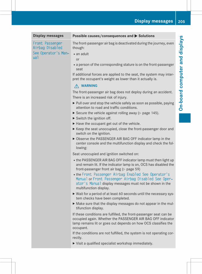
Display messages Possible causes/consequences and M Solutions
Front PassengerAirbag DisabledSee Operator's Manхual
The front-passenger air bag is deactivated during the journey, eventhough:Ran adultor
Ra person of the corresponding stature is on the front-passengerseat
If additional forces are applied to the seat, the system may inter-pret the occupant's weight as lower than it actually is.
G WARNINGThe front-passenger air bag does not deploy during an accident.There is an increased risk of injury.X Pull over and stop the vehicle safely as soon as possible, payingattention to road and traffic conditions.X Secure the vehicle against rolling away (Y page 145).X Switch the ignition off.X Have the occupant get out of the vehicle.X Keep the seat unoccupied, close the front-passenger door andswitch on the ignition.X Observe the PASSENGER AIR BAG OFF indicator lamp in thecenter console and the multifunction display and check the fol-lowing:
Seat unoccupied and ignition switched on:Rthe PASSENGER AIR BAG OFF indicator lamp must then light upand remain lit. If the indicator lamp is on, OCS has disabled thefront-passenger front air bag (Y page 59)
Rthe Front Passenger Airbag Enabled See Operator'sManual or Front Passenger Airbag Disabled See Operхator's Manual display messages must not be shown in themultifunction display.X Wait for a period of at least 60 seconds until the necessary sys-tem checks have been completed.X Make sure that the display messages do not appear in the mul-tifunction display.
If these conditions are fulfilled, the front-passenger seat can beoccupied again. Whether the PASSENGER AIR BAG OFF indicatorlamp remains lit or goes out depends on how OCS classifies theoccupant.If the conditions are not fulfilled, the system is not operating cor-rectly.X Visit a qualified specialist workshop immediately.
Display messages 205
On-b
oard
com
pute
rand
disp
lays
Z

Display messages Possible causes/consequences and M Solutions
Front PassengerAirbag EnabledSee Operator's Manхual
The front-passenger air bag is enabled during the journey, eventhough:Ra child, a small adult or an object weighing less than the sys-tem's weight threshold is located on the front-passenger seator
Rthe front-passenger seat is unoccupiedThe system may detect objects or forces applying additionalweight on the seat.
G WARNINGThe air bag may deploy unintentionally.There is an increased risk of injury.X Pull over and stop the vehicle safely as soon as possible, payingattention to road and traffic conditions.X Secure the vehicle against rolling away (Y page 145).X Switch the ignition off.X Open the front-passenger door.X Remove the child and the child restraint system from the front-passenger seat.X Make sure that there are no objects on the seat adding to theweight.The system may otherwise detect the additional weight andinterpret the seat occupant's weight as greater than it actuallyis.X Keep the seat unoccupied, close the front-passenger door andswitch on the ignition.X Observe the PASSENGER AIR BAG OFF indicator lamp in thecenter console and the multifunction display and check the fol-lowing:
Seat unoccupied and ignition switched on:Rthe PASSENGER AIR BAG OFF indicator lamp must then light upand remain lit. If the indicator lamp is on, OCS (Occupant Clas-sification System) has disabled the front-passenger air bag(Y page 59)
Rthe Front Passenger Airbag Enabled See Operator'sManual or Front Passenger Airbag Disabled See Operхator's Manual display messages must not be shown in themultifunction display.X Wait for a period of at least 60 seconds until the necessary sys-tem checks have been completed.X Make sure that the display messages do not appear in the mul-tifunction display.
206 Display messagesOn
-boa
rdco
mpu
tera
nddi
spla
ys
Display messages Possible causes/consequences and M SolutionsIf these conditions are fulfilled, the front-passenger seat can beoccupied again. Whether the PASSENGER AIR BAG OFF indicatorlamp remains lit or goes out depends on how OCS classifies theoccupant.If the conditions are not fulfilled, the system is not operating cor-rectly.X Visit a qualified specialist workshop immediately.
Display messages 207
On-b
oard
com
pute
rand
disp
lays
Z

Engine
Display messages Possible causes/consequences and M Solutions
?Coolant Too HotStop Vehicle TurnEngine Off
The coolant is too hot.A warning tone also sounds.
G WARNINGDo not drive when your engine is overheated. This can cause somefluids which may have leaked into the engine compartment tocatch fire.Steam from the overheated engine can also cause serious burnswhich can occur just by opening the hood.There is a risk of injury.X Pull over and stop the vehicle safely and switch off the engine,paying attention to road and traffic conditions.X Secure the vehicle against rolling away (Y page 145).X Wait until the engine has cooled down.X Make sure that the air supply to the engine radiator is notblocked, e.g. by snow, slush or ice.X Do not start the engine again until the display message goes outand the coolant temperature is below 248 ‡ (120 †). Other-wise, the engine could be damaged.X Pay attention to the coolant temperature display.X If the temperature increases again, visit a qualified specialistworkshop immediately.
Under normal operating conditions and with the specified coolantlevel, the coolant temperature may rise to 248 ‡ (120 †).
#Start Engine SeeOperator's Manual
The engine is switched off and the battery charge level is too low.X Switch off electrical consumers that you do not need, such asthe rear window defroster and interior lighting.X Leave the engine running for a few minutes or drive a long dis-tance.The battery is being charged.
208 Display messagesOn
-boa
rdco
mpu
tera
nddi
spla
ys

Driving systems
Display messages Possible causes/consequences and M Solutions
ÁMax. Speed 12 mph
You are exceeding the speed permissible for the selected off-roadlevel.In addition, the vehicle level display appears between the vehicleicon and the display message, and a warning tone sounds.
G WARNINGThe vehicle could tip and rollover.There is a risk of an accident.X Adjust your driving style to the altered handling characteristics.X Only make slight steering movements and avoid fast steeringmovements.X Do not exceed 12 mph (20 km/h) until the vehicle has reachedoff-road level 2.
ACTIVE CURVE SYSхTEM MalfunctionSee Operator's Manхual
The Active Curve System is faulty. The vehicle's handling charac-teristics are severely impaired. A warning tone also sounds.
G WARNINGThere is a risk of an accident.X Drive on carefully.X Adjust your driving style to the altered handling characteristics.X Avoid sudden acceleration around tight corners and fast steer-ing movements.X Do not drive at speeds above 50 mph (80 km/h).X Visit a qualified specialist workshop immediately.
Display messages 209
On-b
oard
com
pute
rand
disp
lays
Z

Tires
Display messages Possible causes/consequences and M Solutions
Check Tire Presхsure Soon
The tire pressure loss warning system has detected a significantloss in pressure.A warning tone also sounds.Possible causes:Ryou have changed the positions of the wheels and tires or instal-led new wheels and tires.
Rthe tire pressure in one or more tires is not correct.
G WARNINGWith tire pressures which are too low, there is a risk of the fol-lowing hazards:Rthey may burst, especially as the load and vehicle speedincrease.
Rthey may wear excessively and/or unevenly, which may greatlyimpair tire traction.
Rthe driving characteristics, as well as steering and braking, maybe greatly impaired.
There is a risk of an accident.X Stop the vehicle without making any sudden steering or brakingmaneuvers. Pay attention to the traffic conditions as you do so.X Secure the vehicle against rolling away (Y page 145).X Check the tires and, if necessary, follow the instructions for aflat tire (Y page 273).X Check the tire pressures and, if necessary, correct the tire pres-sure.X Restart the tire pressure loss warning system when the tirepressure is correct (Y page 297).
Check Tires The tire pressure in one or more tires has dropped significantly.The wheel position is displayed in the multifunction display.A warning tone also sounds.
G WARNINGWith tire pressures which are too low, there is a risk of the fol-lowing hazards:Rthey may burst, especially as the load and vehicle speedincrease.
Rthey may wear excessively and/or unevenly, which may greatlyimpair tire traction.
Rthe driving characteristics, as well as steering and braking, maybe greatly impaired.
210 Display messagesOn
-boa
rdco
mpu
tera
nddi
spla
ys

Display messages Possible causes/consequences and M SolutionsThere is a risk of an accident.X Stop the vehicle without making any sudden steering or brakingmaneuvers. Pay attention to the traffic conditions as you do so.X Secure the vehicle against rolling away (Y page 145).X Check the tires and, if necessary, follow the instructions for aflat tire (Y page 273).X Check the tire pressure (Y page 298).X If necessary, correct the tire pressure.
Warning Tire Malхfunction
The tire pressure in one or more tires has dropped suddenly. Thewheel position is shown in the multifunction display.
G WARNINGIf you drive with a flat tire, there is a risk of the following hazards:Ra flat tire affects the ability to steer or brake the vehicle.Ryou could lose control of the vehicle.Rcontinued driving with a flat tire will cause excessive heat build-up and possibly a fire.
There is a risk of an accident.X Stop the vehicle without making any sudden steering or brakingmaneuvers. Pay attention to the traffic conditions as you do so.X Secure the vehicle against rolling away (Y page 145).X Check the tires and, if necessary, follow the instructions for aflat tire (Y page 273).
Display messages 211
On-b
oard
com
pute
rand
disp
lays
Z
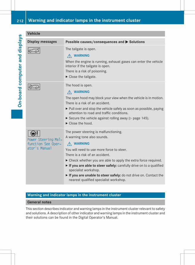
Vehicle
Display messages Possible causes/consequences and M Solutions
A The tailgate is open.
G WARNINGWhen the engine is running, exhaust gases can enter the vehicleinterior if the tailgate is open.There is a risk of poisoning.X Close the tailgate.
? The hood is open.
G WARNINGThe open hood may block your view when the vehicle is in motion.There is a risk of an accident.X Pull over and stop the vehicle safely as soon as possible, payingattention to road and traffic conditions.X Secure the vehicle against rolling away (Y page 145).X Close the hood.
ÐPower Steering Malхfunction See Operхator's Manual
The power steering is malfunctioning.A warning tone also sounds.
G WARNINGYou will need to use more force to steer.There is a risk of an accident.X Check whether you are able to apply the extra force required.X If you are able to steer safely: carefully drive on to a qualifiedspecialist workshop.X If you are unable to steer safely: do not drive on. Contact thenearest qualified specialist workshop.
Warning and indicator lamps in the instrument cluster
General notesThis section describes indicator and warning lamps in the instrument cluster relevant to safetyand solutions. A description of other indicator and warning lamps in the instrument cluster andtheir solutions can be found in the Digital Operator's Manual.
212 Warning and indicator lamps in the instrument clusterOn
-boa
rdco
mpu
tera
nddi
spla
ys
Safety
Seat belts
Problem Possible causes/consequences and M Solutions
ü
After starting theengine, the red seatbelt warning lamp lightsup. In addition, a warn-ing tone sounds for upto 6 seconds.
The driver's seat belt is not fastened.X Fasten your seat belt (Y page 54).The warning tone ceases.
ü
The red seat belt warn-ing lamp lights up afterthe engine starts, assoon as the driver's orthe front-passengerdoor is closed.
The driver or front passenger has not fastened their seat belt.X Fasten your seat belt (Y page 54).The warning lamp goes out.
There are objects on the front-passenger seat.X Remove the objects from the front-passenger seat and stowthem in a secure place.The warning lamp goes out.
ü
The red seat belt warn-ing lamp flashes and anintermittent audiblewarning sounds.
The driver or front passenger has not fastened their seat belt. Thevehicle is being driven faster than 15mph (25 km/h) or has brieflybeen driven faster than 15 mph (25 km/h).X Fasten your seat belt (Y page 54).The warning lamp goes out and the intermittent warning toneceases.
There are objects on the front-passenger seat. The vehicle is beingdriven faster than 15 mph (25 km/h) or has briefly been drivenfaster than 15 mph (25 km/h).X Remove the objects from the front-passenger seat and stowthem in a secure place.The warning lamp goes out and the intermittent warning toneceases.
Warning and indicator lamps in the instrument cluster 213
On-b
oard
com
pute
rand
disp
lays
Z

Safety systems
Problem Possible causes/consequences and M Solutions
$ (USA only)J (Canada only)The red brake systemwarning lamp comes onwhile the engine is run-ning. A warning tonealso sounds.
G WARNINGThe brake boosting effect is malfunctioning and the braking char-acteristics may be affected.There is a risk of an accident.X Pull over and stop the vehicle safely as soon as possible, payingattention to road and traffic conditions. Do not continue drivingunder any circumstances.X Secure the vehicle against rolling away (Y page 145).X Consult a qualified specialist workshop.X Observe the additional display messages in the multifunctiondisplay.
$ (USA only)J (Canada only)The red brake systemwarning lamp comes onwhile the engine is run-ning. A warning tonealso sounds.
There is not enough brake fluid in the brake fluid reservoir.
G WARNINGThe braking effect may be impaired.There is a risk of an accident.X Pull over and stop the vehicle safely as soon as possible, payingattention to road and traffic conditions. Do not continue drivingunder any circumstances.X Secure the vehicle against rolling away (Y page 145).X Do not add brake fluid. Adding more will not remedy the mal-function.X Consult a qualified specialist workshop.X Observe the additional display messages in the multifunctiondisplay.
214 Warning and indicator lamps in the instrument clusterOn
-boa
rdco
mpu
tera
nddi
spla
ys

Problem Possible causes/consequences and M Solutions
!
The yellowABSwarninglamp is lit while theengine is running.
ABS (Anti-lock Braking System) is deactivated due to a malfunc-tion. For this reason, BAS (Brake Assist), BAS PLUS, ESP® (Elec-tronic Stability Program), PRE゙SAFE®, PRE゙SAFE® Brake, COLLI-SIONPREVENTIONASSIST, theHOLD function, hill start assist andESP® trailer stabilization are also deactivated, for example.ATTENTION ASSIST is deactivated.
G WARNINGThe brake system continues to function normally, but without thefunctions listed above. The wheels could therefore lock if youbrake hard, for example.The steerability and braking characteristics may be severely affec-ted. The braking distance in an emergency braking situation canincrease.If ESP® is not operational, ESP® is unable to stabilize the vehicle.There is an increased risk of skidding and an accident.X Observe the additional display messages in the multifunctiondisplay.X Drive on carefully.X Visit a qualified specialist workshop.If the ABS control unit is faulty, there is also a possibility that othersystems, such as the navigation system or the automatic trans-mission, will not be available.
Warning and indicator lamps in the instrument cluster 215
On-b
oard
com
pute
rand
disp
lays
Z

Problem Possible causes/consequences and M Solutions
!
The yellowABSwarninglamp is lit while theengine is running.
ABS is temporarily unavailable. Therefore, BAS, BAS PLUS, ESP®,EBD (electronic brake force distribution), PRE゙SAFE®,PRE゙SAFE® Brake, COLLISION PREVENTION ASSIST, the HOLDfunction, hill start assist, and ESP® trailer stabilization, for exam-ple, are also deactivated.ATTENTION ASSIST is deactivated.Possible causes are:Rself-diagnosis is not yet complete.Rthe on-board voltage may be insufficient.
G WARNINGThe brake system continues to function normally, but without thefunctions listed above. The front and rear wheels could thereforelock if you brake hard, for example.The steerability and braking characteristics may be severely affec-ted. The braking distance in an emergency braking situation canincrease.If ESP® is not operational, ESP® is unable to stabilize the vehicle.There is a risk of an accident.X Carefully drive a suitable distance, making slight steering move-ments at a speed above 12 mph (20 km/h).The functions mentioned above are available again when thewarning lamp goes out.
If the warning lamp is still on:X Observe the additional display messages in the multifunctiondisplay.X Drive on carefully.X Visit a qualified specialist workshop.
216 Warning and indicator lamps in the instrument clusterOn
-boa
rdco
mpu
tera
nddi
spla
ys

Problem Possible causes/consequences and M Solutions
!
The yellowABSwarninglamp is lit while theengine is running. Awarning tone alsosounds.
EBD is malfunctioning. Therefore, ABS, BAS, BAS PLUS, ESP®,PRE゙SAFE®, PRE゙SAFE® Brake, COLLISION PREVENTION ASSIST,the HOLD function, hill start assist and ESP® trailer stabilization,for example, are not available either.ATTENTION ASSIST is deactivated.
G WARNINGThe brake system continues to function normally, but without thefunctions listed above. The front and rear wheels could thereforelock if you brake hard, for example.The steerability and braking characteristics may be severely affec-ted. The braking distance in an emergency braking situation canincrease.If ESP® is not operational, ESP® is unable to stabilize the vehicle.There is an increased risk of skidding and an accident.X Observe the additional display messages in the multifunctiondisplay.X Drive on carefully.X Visit a qualified specialist workshop.
$ (USA only)J (Canada only)֌!
The red brake warninglamp, the yellow ESP®and ESP® OFF warninglamps and the yellowABS warning lamp arelit while the engine isrunning.
ABS and ESP® are malfunctioning. Therefore, BAS, BAS PLUS,PRE゙SAFE®, PRE゙SAFE® Brake, COLLISION PREVENTION ASSIST,the HOLD function, hill start assist and ESP® trailer stabilization,for example, are also not available.ATTENTION ASSIST is deactivated.
G WARNINGThe brake system continues to function normally, but without thefunctions listed above. The front and rear wheels could thereforelock if you brake hard, for example.The steerability and braking characteristics may be severely affec-ted. The braking distance in an emergency braking situation canincrease.If ESP® is not operational, ESP® is unable to stabilize the vehicle.There is an increased risk of skidding and an accident.X Observe the additional display messages in the multifunctiondisplay.X Drive on carefully.X Visit a qualified specialist workshop.
Warning and indicator lamps in the instrument cluster 217
On-b
oard
com
pute
rand
disp
lays
Z

Problem Possible causes/consequences and M Solutions
÷
The yellow ESP® warn-ing lamp flashes whilethe vehicle is in motion.
ESP® or traction control has intervened because there is a risk ofskidding or at least one wheel has started to spin.Cruise control or DISTRONIC PLUS is deactivated.X When pulling away, only depress the accelerator pedal as far asnecessary.X Ease off the accelerator pedal while the vehicle is in motion.X Adapt your driving style to suit the road and weather conditions.X Do not deactivate ESP®.In rare cases (Y page 79), it may be best to deactivate ESP®.Observe the important safety notes on ESP® (Y page 79).
å
The yellow ESP® OFFwarning lamp is lit whilethe engine is running.
ESP® is deactivated.
G WARNING
If ESP® is switched off, ESP® is unable to stabilize the vehicle.There is an increased risk of skidding and an accident.X Reactivate ESP®.In rare cases (Y page 79), it may be best to deactivate ESP®.Observe the important safety notes on ESP® (Y page 79).X Adapt your driving style to suit the road and weather conditions.
If ESP® cannot be activated:X Have ESP® checked at a qualified specialist workshop.
֌
The yellow ESP® andESP® OFF warninglamps are lit while theengine is running.
ESP®, BAS, BAS PLUS, PRE-SAFE®, PRE-SAFE® Brake, COLLISIONPREVENTION ASSIST, the HOLD function, hill start assist andESP® trailer stabilization are not available due to a malfunction.ATTENTION ASSIST is deactivated.
G WARNINGThe brake system continues to function normally, but without thefunctions listed above.The braking distance in an emergency braking situation can thusincrease.If ESP® is not operational, ESP® is unable to stabilize the vehicle.There is an increased risk of skidding and an accident.X Observe the additional display messages in the multifunctiondisplay.X Drive on carefully.X Visit a qualified specialist workshop.
218 Warning and indicator lamps in the instrument clusterOn
-boa
rdco
mpu
tera
nddi
spla
ys

Problem Possible causes/consequences and M Solutions
֌
The yellow ESP® andESP® OFF warninglamps are lit while theengine is running.
ESP®, BAS, PRE-SAFE®, the HOLD function, hill start assist andESP® trailer stabilization are temporarily unavailable.COLLISION PREVENTION ASSIST, BAS PLUS andPRE゙SAFE® Brake may also have failed.ATTENTION ASSIST is deactivated.Self-diagnosis is not yet complete.
G WARNINGThe brake system continues to function normally, but without thefunctions listed above.The braking distance in an emergency braking situation can thusincrease.If ESP® is not operational, ESP® is unable to stabilize the vehicle.There is an increased risk of skidding and an accident.X Carefully drive a suitable distance, making slight steering move-ments at a speed above 12 mph (20 km/h).The functions mentioned above are available again when thewarning lamp goes out.
If the warning lamp is still on:X Observe the additional display messages in the multifunctiondisplay.X Drive on carefully.X Visit a qualified specialist workshop.
6
The red restraint sys-tem warning lamp is litwhile the engine is run-ning.
The restraint system is faulty.
G WARNINGThe air bags or Emergency Tensioning Devices may either be trig-gered unintentionally or, in the event of an accident, may not betriggered.There is an increased risk of injury.X Observe the additional display messages in the multifunctiondisplay.X Drive on carefully.X Have the restraint system checked immediately at a qualifiedspecialist workshop.
For further information about the restraint system, see(Y page 50).
Warning and indicator lamps in the instrument cluster 219
On-b
oard
com
pute
rand
disp
lays
Z

Engine
Problem Possible causes/consequences and M Solutions
?
The red coolant warn-ing lamp comes onwhile the engine is run-ning. A warning tonealso sounds.
The coolant temperature has exceeded 248 ‡ (120 †). The air-flow to the engine radiatormay be blocked or the coolant levelmaybe too low.
G WARNINGThe engine is not being cooled sufficiently and may be damaged.Do not drive when your engine is overheated. This can cause somefluids which may have leaked into the engine compartment tocatch fire.Steam from the overheated engine can also cause serious burnswhich can occur just by opening the hood.There is a risk of injury.X Observe the additional display messages in the multifunctiondisplay.X Pull over and stop the vehicle safely and switch off the engine,paying attention to road and traffic conditions.X Secure the vehicle against rolling away (Y page 145).X Leave the vehicle and keep a safe distance from the vehicle untilthe engine has cooled down.X Check the coolant level and add coolant, observing the warningnotes (Y page 267).X If you need to add coolant more often than usual, have theengine coolant system checked.X Make sure that the air supply to the engine radiator is notblocked, e.g. by snow, slush or ice.X At coolant temperatures below 248 ‡ (120 †), drive to thenearest qualified specialist workshop.X Avoid subjecting the engine to heavy loads, e.g. driving inmoun-tainous terrain, and stop-and-go traffic.
220 Warning and indicator lamps in the instrument clusterOn
-boa
rdco
mpu
tera
nddi
spla
ys

Driving systems
Problem Possible causes/consequences and M Solutions
·
The red distance warn-ing function warninglamp comes on whilethe vehicle is moving. Awarning tone alsosounds.
You are approaching a vehicle or a stationary obstacle in your lineof travel at too high a speed.X Be prepared to brake immediately.X Pay careful attention to the traffic situation. You may have tobrake or take evasive action.
Observe the additional information on DISTRONIC PLUS(Y page 153).Observe the additional information on PRE゙SAFE® Brake(Y page 81).Observe the additional information on the distance warning func-tion of COLLISION PREVENTION ASSIST (Y page 76).
Warning and indicator lamps in the instrument cluster 221
On-b
oard
com
pute
rand
disp
lays
Z

Tires
Problem Possible causes/consequences and M Solutions
h
The yellow tire pressuremonitor warning lamp(pressure loss/malfunction) is lit.
The tire pressure monitor has detected a loss of pressure in atleast one of the tires.
G WARNINGWith tire pressures which are too low, there is a risk of the fol-lowing hazards:Rthey may burst, especially as the load and vehicle speedincrease.
Rthey may wear excessively and/or unevenly, which may greatlyimpair tire traction.
Rthe driving characteristics, as well as steering and braking, maybe greatly impaired.There is a risk of an accident.X Stop the vehicle without making any sudden steering or brakingmaneuvers. Pay attention to the traffic conditions as you do so.X Secure the vehicle against rolling away (Y page 145).X Observe the additional display messages in the multifunctiondisplay.X Check the tires and, if necessary, follow the instructions for aflat tire (Y page 273).X Check the tire pressure (Y page 298).X If necessary, correct the tire pressure.
h
The yellow tire pressuremonitor warning lamp(pressure loss/malfunction) flashes forapproximately oneminute and thenremains lit.
The tire pressure monitor is faulty.
G WARNINGThe system is possibly unable to recognize or register low tirepressure.There is a risk of an accident.X Observe the additional display messages in the multifunctiondisplay.X Visit a qualified specialist workshop.
222 Warning and indicator lamps in the instrument clusterOn
-boa
rdco
mpu
tera
nddi
spla
ys

Useful information ............................ 224General notes .................................... 224Important safety notes ..................... 224Declarations of conformity .............. 225Information on copyright ................. 225Function restrictions ........................ 225COMAND operating system ............. 226Online and Internet functions .......... 232
223
COM
AND

Useful information
i These operating instructions describe allthe standard and optional equipment ofyour COMAND system, as available at thetime of going to print. Country-specific dif-ferences are possible. Please note thatyour COMAND system may not be equip-ped with all the features described. Thisalso applies to safety-related systems andfunctions.
i Read the information on qualified special-ist workshops: (Y page 35).
General notes
The COMAND section in these operatinginstructions describes the basic principles foroperation. More information can be found inthe Digital Operator's Manual.
Important safety notes
G WARNINGModifications to electronic components, theirsoftware as well as wiring can impair theirfunction and/or the function of other net-worked components. In particular, systemsrelevant to safety could also be affected. As aresult, these may no longer function as inten-ded and/or jeopardize the operating safety ofthe vehicle. There is an increased risk of anaccident and injury.Never tamper with the wiring as well as elec-tronic components or their software. Youshould have all work to electrical and elec-tronic equipment carried out at a qualifiedspecialist workshop.
If you make any changes to the vehicle elec-tronics, the general operating permit is ren-dered invalid.
G WARNINGIf you operate information systems and com-munication equipment integrated in the vehi-cle while driving, you will be distracted fromtraffic conditions. You could also lose controlof the vehicle. There is a risk of an accident.Only operate the equipment when the trafficsituation permits. If you are not sure that thisis possible, park the vehicle paying attentionto traffic conditions and operate the equip-ment when the vehicle is stationary.
You must observe the legal requirements forthe country in which you are currently drivingwhen operating COMAND.COMAND calculates the route to the destina-tion without taking account of the following,for example:Rtraffic lightsRstop and yield signsRmerging lanesRparking or stopping in a no parking/nostopping zone
Rother road and traffic rules and regulationsRnarrow bridgesCOMAND can give incorrect navigation com-mands if the actual street/traffic situationdoes not correspond with the digital map'sdata. Digital maps do not cover all areas norall routes in an area. For example, a routemayhave been diverted or the direction of a one-way street may have changed.For this reason, you must always observeroad and traffic rules and regulations duringyour journey. Road and traffic rules and reg-ulations always have priority over the sys-tem's driving recommendations.Navigation announcements are intended todirect you while driving without diverting yourattention from the road and driving.Please always use this feature instead of con-sulting the map display for directions. Look-ing at the icons or map display can distractyou from traffic conditions and driving, andincrease the risk of an accident.
224 Important safety notesCO
MAN
D

Bear in mind that at a speed of only 30 mph(approximately 50 km/h) your vehicle coversa distance of 44 feet (approximately 14 m)per second.This equipment complies with FCC radiationexposure limits set forth for uncontrolledequipment and meets the FCC radio fre-quency (RF) Exposure Guidelines in Supple-ment C to OET65.This equipment has very low levels of RFenergy that is deemed to comply withoutmaximum permissive exposure evaluation(MPE). But it is desirable that it should beinstalled and operated with at least 8 inches(20cm) and more between the radiator and aperson's body (excluding extremities: hands,wrists, feet and legs.)
Declarations of conformity
Vehicle components which receiveand/or transmit radio wavesi USA only: The wireless devices of thisvehicle comply with Part 15 of the FCCRules. Operation is subject to the followingtwo conditions:1) These devices may not cause interfer-ence, and2) These devices must accept any interfer-ence, including interference that maycause undesired operation of the device.Changes or modifications not expresslyapproved by the party responsible for com-pliance could void the user's authority tooperate the equipment.
i Canada only: The wireless devices of thisvehicle comply with Industry Canadalicense-exempt RSS standard(s). Operationis subject to the following two conditions:1) These devices may not cause interfer-ence, and2) These devices must accept any interfer-ence, including interference that maycause undesired operation of the device.
Information on copyright
General informationInformation on licenses for free and OpenSource software used in your vehicle and inthe electronic components can be found onthis website: http://www.mercedes-benz.com/opensource.
Registered trademarksRegistered trademarks:RBluetooth® is a registered trademark ofBluetooth® SIG Inc.
RDTS is a registered trademark of DTS, Inc.RDolby and MLP are registered trademarksof DOLBY Laboratories.
RBabySmart™, ESP® and PRE-SAFE® areregistered trademarks of Daimler AG.
RHomeLink® is a registered trademark ofPrince.
RiPod® and iTunes® are registered trade-marks of Apple Inc.
RLogic7® is a registered trademark of Har-man International Industries.
RMicrosoft® and Windows media® are reg-istered trademarks of Microsoft Corpora-tion.
RSIRIUS is a registered trademark of SiriusXM Radio Inc.
RHD Radio is a registered trademark of iBiq-uity Digital Corporation.
RGracenote® is a registered trademark ofGracenote, Inc.
RZAGATSurvey® and related brands are reg-istered trademarks of ZagatSurvey, LLC.
Function restrictions
For safety reasons, some COMAND functionsare restricted or unavailable while the vehicleis in motion. You will notice this, for examplebecause either you will not be able to select
Function restrictions 225
COM
AND
Z

certain menu items or COMANDwill display amessage to this effect.
COMAND operating system
Overview
: COMAND display (Y page 227); COMAND control panel with a single DVD
drive= COMAND controller (Y page 231)You can use COMAND to operate the follow-ing main functions:Rthe navigation systemRthe audio functionRthe telephone functionRthe video functionRthe system settingsRthe online and Internet functionsRthe Digital Operator's ManualYou can call up the main functions:Rusing the corresponding buttonsRusing themain function bar in the COMANDdisplay
Rusing the remote control
226 COMAND operating systemCO
MAN
D

COMAND display
Display overview
Example display for radio
: Status bar Shows the time and the current settings for tele-phone operation.
; Calls up the audio menu Highlights the active Audio main function. The tri-angle indicates that this main function has aselectable submenu.
= Main function bar You can call up the desired main function from themain function bar.When the main function is activated, it is identifi-able by the white lettering.
? Display/selection window Shows the content of the active Audio main func-tion in radio mode.
A Radio menu bar Shows the other functions of the active Audiomain function in radio mode.
COMAND operating system 227
COM
AND
Z

Menu overview
Navi Audio Telephone Video System Symbol ®
Route settings FM/AMradio (usingHD Radio™)
Telephone Video DVD Calls up thesystemmenu
Calls up theDigitalOperator'sManual
Map settings Satelliteradio
Addressbook
AUX Calls upCOMANDand Internet
Personal POIs Disc Calls up theweatherservice SIR-IUSWeather
Messages(street nameannouncements,acoustic informa-tion during calls,audio fadeout,reserve fuel level)
Memorycard
Calls up theMercedes-Benz Mobilewebsite
O Activates/deactivates alter-native routes
MUSICREGISTER
Avoids an area USB stor-age device
SIRIUS service BluetoothAudio
Map version Media Inter-face
AUX
228 COMAND operating systemCO
MAN
D

System menu overview
System Time SPLITVIEW Consump-tion
Seat Display off
Display settings OSwitchesthe auto-matic timesettingson/off
OperatesCOMANDfunctionsfrom thepassengerside
Calls up thefuel con-sumptiondisplay
Changesthe driver/front-passengerseat set-tings
Switchesoff the dis-play
Text reader speed Sets thetime zone
Voice-operatedcontrol settings
Switches tosummertime
Rear view camera Manualtime setting
Language Sets thetime/dateformat
Favorites button
Activates/deacti-vates Bluetooth®
Automatic volumeadjustment
Imports/exportsdata
Resets COMAND
i Delete yourpersonal datausing this func-tion, for examplebefore sellingyour vehicle.
If equipped with the rear view camera: when the function is activated and COMAND isswitched on, the image from the rear view camera is automatically shown in the COMANDdisplay when reverse gear is engaged.
i If the 360° Cameramenu item is displayed, Display Off can be called up under System.
COMAND operating system 229
COM
AND
Z
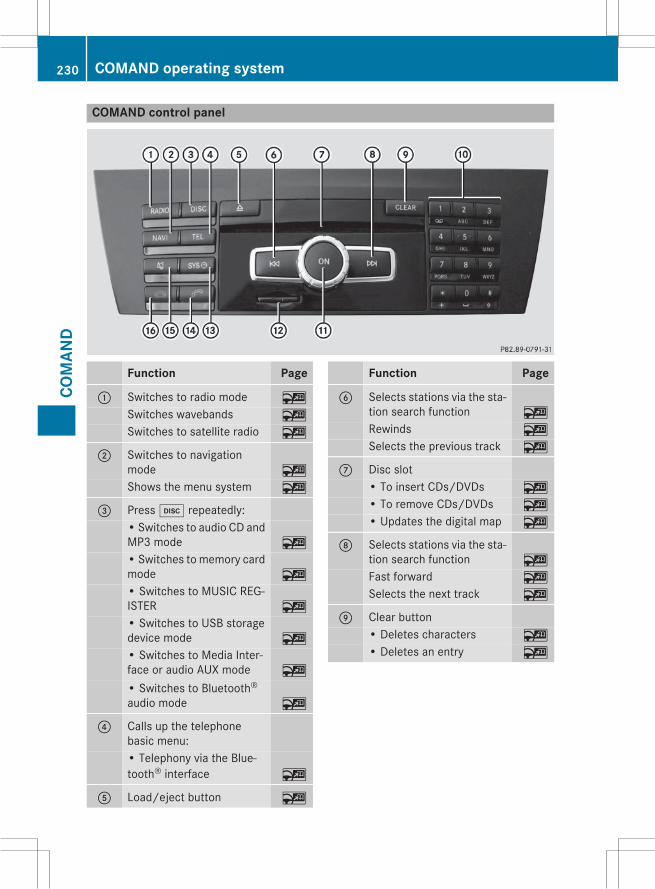
COMAND control panel
Function Page
: Switches to radio mode ~
Switches wavebands ~
Switches to satellite radio ~
; Switches to navigationmode ~
Shows the menu system ~
= Pressh repeatedly:• Switches to audio CD andMP3 mode ~
• Switches tomemory cardmode ~
• Switches to MUSIC REG-ISTER ~
• Switches to USB storagedevice mode ~
• Switches to Media Inter-face or audio AUX mode ~
• Switches to Bluetooth®audio mode ~
? Calls up the telephonebasic menu:• Telephony via the Blue-tooth® interface ~
A Load/eject button ~
Function Page
B Selects stations via the sta-tion search function ~
Rewinds ~
Selects the previous track ~
C Disc slot• To insert CDs/DVDs ~
• To remove CDs/DVDs ~
• Updates the digital map ~
D Selects stations via the sta-tion search function ~
Fast forward ~
Selects the next track ~
E Clear button• Deletes characters ~
• Deletes an entry ~
230 COMAND operating systemCO
MAN
D

Function Page
F Number pad• Selects stations via thestation presets ~
• Stores stations manually ~
• Mobile phone authoriza-tion ~
• Telephone number entry ~
• Sends DTMF tones ~
• Character entry ~
• Selects a location for theweather forecast from thememory ~
z Displays the currenttrack being played ~
g Selects stations byentering the frequencymanually ~
g Selects a track ~
G Switches COMAND on/off ~
Adjusts the volume ~
Function Page
H SD memory card slot ~
I Calls up the system menu ~
J Accepts a call ~
Dials a number ~
Redial ~
Accepts a waiting call ~
K Switches the sound on oroff ~
Switches the microphoneon/off ~
Cancels the text messageread-aloud function ~
Switches off navigationannouncements ~
L Rejects a call ~
Ends an active call ~
Rejects a waiting call ~
COMAND controller
Overview
: COMAND controllerYou can use the COMAND controller to selectthe menu items in the COMAND display.
You can:Rcall up menus or listsRscroll within menus or lists andRexit menus or lists
Operation
Example: operating the COMAND controller
COMAND operating system 231
COM
AND
Z

The COMAND controller can be:Rpressed briefly or pressed and heldWRturned clockwise or counter-clockwisecVd
Rslid left or right XVYRslid forwards or backwards ZVÆRslid diagonally aVb
Example of operationIn the instructions, operating sequences aredescribed as follows:X Press the$ button.Radio mode is activated.X Select Radio by slidingVÆ and turningcVd the COMAND controller and pressWto confirm.X Confirm Station List by pressingW.The station list appears.
Buttons on the COMAND controller
Overview
: Back button (Y page 232); Clear button (Y page 232)= Seat function button? Favorites buttonIf your vehicle does not have the seat functionbutton, it will have two Favorites buttons.For AMG vehicles: the COMAND controller isconfigured with the: and; buttons.
Back buttonYou can use thek button to exit amenu orto call up the basic display of the currentoperating mode.X To exit the menu: briefly press thekback button.COMAND changes to the next higher menulevel in the current operating mode.X To call up the basic display: press andhold thek back button.COMAND changes to the basic display ofthe current operating mode.
Clear buttonX To delete individual characters: brieflypress the2 clear button.X To delete an entire entry: press and holdthe2 clear button.
Seat function buttonYou can use theT button to call up thefollowing seat functions:RMulticontour seat (with 4-way lumbar sup-port)
RActivemulticontour seat (dynamic seat andmassage function)
RBalance (seat heating distribution)
Favorites buttonYou can assign predefined functions tothe; favorites button and call them up bypressing the button.
Online and Internet functions
Information in the Digital Operator'sManualIn the Digital Operator's Manual you will findinformation on the following topics:ROnline and Internet functionsRGoogle™ local searchRDestination/route download
232 Online and Internet functionsCO
MAN
D

RWeather displayRInternet
General notes
Conditions for access
G WARNINGIf you operate information systems and com-munication equipment integrated in the vehi-cle while driving, you will be distracted fromtraffic conditions. You could also lose controlof the vehicle. There is a risk of an accident.Only operate the equipment when the trafficsituation permits. If you are not sure that thisis possible, park the vehicle paying attentionto traffic conditions and operate the equip-ment when the vehicle is stationary.
You must observe the legal requirements forthe country in which you are currently drivingwhen operating COMAND.USA only:To use COMAND Mercedes-Benz Apps andInternet access, the following conditionsmust be fulfilled:Rmbrace is activated and operationalRmbrace is activated for COMANDMercedes-Benz Apps and Internet access
Priority of connections: an emergency callhas the highest priority. When a service call,e.g. a breakdown service call or the MB InfoCall, is active, an emergency call can still beinitiated.A service call, on the other hand, has priorityover a current Internet connection. Therefore,you cannot establish an Internet connectionduring a service call.
i The availability of individual COMANDMercedes-Benz Apps may vary dependingon the country.
i The terms of use are shown whenCOMAND is used for the first time and thenonce a year thereafter. Only read and
accept the terms of use when the vehicle isstationary.
i Internet pages cannot be shown on thedriver's side while the vehicle is in motion.
Canada only:The COMAND Mercedes-Benz Apps and theInternet access are available via the Blue-tooth® interface.In order to use the functions, the followingconditions are necessary:RThe mobile phone supports the DUN Blue-tooth® profile (Dial-Up Networking) and isconnected to COMAND via the Bluetooth®interface. The DUN Bluetooth® profile ena-bles themobile phone to establish a dial-upconnection to the Internet.
RYou need a valid mobile service contractwith a data option, which is used to calcu-late the associated connection costs.
RThe access data of the mobile phone net-work provider must be set on COMAND forthe connected mobile phone (Y page 235).
i If the connected mobile phone supportsthe PAN Bluetooth profile (Personal AreaNetwork), you can use the automatic con-figuration function (Y page 235).
i You can obtain more detailed informationabout suitable mobile phones on the Inter-net at http://www.mercedes-benz.com/connect or from your author-ized Mercedes-Benz Center.
i If you use incorrect access data, addi-tional costs may be incurred. This can hap-pen when you use details that are differentfrom the contract or details from anothercontract/data package.
i The availability of individual Mercedes-Benz Apps may vary depending on thecountry.
i The terms of use are shown whenCOMAND is used for the first time and thenonce a year thereafter. Only read and
Online and Internet functions 233
COM
AND
Z

accept the terms of use when the vehicle isstationary.
i Internet pages cannot be shown on thedriver's side while the vehicle is in motion.
Connection difficulties while the vehi-cle is in motion (Canada only)The following could be the cause of call dis-connection:Rinsufficient GSM/UMTS network coverageRthe vehicle has moved into a GSM cell withno free channels
Rthe SIM card used is not compatible withthe network available
Ryou are using a mobile phone with "Twin-card" and the mobile phone with the sec-ond SIM card is logged into the network atthe same time
Function restrictions (Canada only)You will not be able to use the mobile phone,will no longer be able to use themobile phone,or you may have to wait before using it, in thefollowing situations:Rwhen the mobile phone is switched offRif the Bluetooth® function is switched off inCOMAND
Rif the Bluetooth® function is switched off onthe mobile phone while you are using Blue-tooth® interface telephony
Rif the mobile phone has not logged on to amobile phone network
Rif neither themobile phone network nor themobile phone allow simultaneous use of aphone and an Internet connection
i It is possible that you may not be able toreceive calls when an Internet connectionis active. This depends on themobile phoneand the mobile phone network used.
Roaming (Canada only)When you are driving your vehicle in a differ-ent country and using COMAND and Internetfunctions, additional costs may be incurred(roaming fees). When you are in a differentcountry, your SIM card must be enabled fordata roaming. If your mobile phone networkprovider does not have a data roaming agree-ment with the roaming partner, it may not bepossible to establish an Internet connection.Deactivate this function on your mobilephone if youwant to avoid data roamingwhenyou are in a different country.
Setting access data (Canada only)
IntroductionTo use online and Internet functions, youneed Internet access data for the connectedmobile phone. You can obtain this from yourmobile phone network provider.A selected/manually set mobile phone net-work provider is only valid for the mobilephone connected when the selection/settingis made. The mobile phone network provideris set automatically upon reconnection.
i When you are driving your vehicle in a dif-ferent country and using the online andInternet functions on COMAND, you mayincur additional costs (roaming fees).
i While initializing the mobile phone for theInternet connection, access data which isalready on the mobile phone may be over-written. You should therefore check thesettings on the mobile phone (see themobile phone operating instructions).
i Adjust the access data settings when thevehicle is stationary. You may otherwise bedistracted from the traffic conditions,cause an accident and injure yourself andothers.
234 Online and Internet functionsCO
MAN
D

Selecting/setting Internet access data
Calling up mobile network providersX Select the® icon in the main function barby turning cVd the COMAND controllerand pressW to confirm.The carousel view appears.
X Select Settings by sliding ÆV and turningcVd the COMAND controller and pressWto confirm.When you connect the mobile phone toCOMAND for the first time, there is nomobile phone network provider preset.Provider: is followed by the words NotSelected.If amobile phone is connected and amobilephone network provider has been selected,the name of the mobile phone network isshown after Provider:.X PressW the COMAND controller.The list of mobile phone network providersappears.
In order to set the access data of the mobilephone network provider you can:Rselect the predefined access data of themobile phone network provider(Y page 236)
Rconfigure automatically – this option onlyappears in the list of providers if the con-nected mobile phone supports the Blue-tooth® PAN (Personal Area Network) pro-file (Y page 235).
Rmanually set the access data of the mobilephone network provider (Y page 237)
Configuring access data automatically
Requirement: your telephone must be con-nected to COMAND via Bluetooth® and mustsupport the Bluetooth® PAN profile.Option 1 if your telephone is not yet config-ured for Internet access:X Select the® icon in the main function barby sliding ZV and turning cV d theCOMAND controller and pressW to con-firm.You will see a message informing you thatautomatic configuration is possible.X Select Yes and pressW to confirm.
Option 2:X In the list of mobile phone network provid-ers, select Autom. Configuration<Device_name> by turning cVd theCOMAND controller and pressW to con-firm (Y page 235).The configuration data is transferred fromthe mobile phone. If the configuration is
Online and Internet functions 235
COM
AND
Z
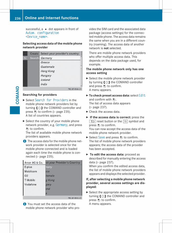
successful, a# dot appears in front ofAutom. configuration<Device_name>.
Selecting access data of the mobile phonenetwork provider
Searching for providersX Select Search for Providers in themobile phone network providers list byturning cVd the COMAND controller andpressW to confirm (Y page 235).A list of countries appears.X Select the country of your mobile phonenetwork provider, e.g. Germany, and pressW to confirm.The list of available mobile phone networkproviders appears.i The access data for themobile phone net-work provider is selected once for themobile phone connected and is loadedagain each time the mobile phone is con-nected (Y page 235).
i You must set the access data of themobile phone network provider who pro-
vides the SIM card and the associated datapackage (access settings) for the connec-tedmobile phone. The access data remainsthe same when you are in a different coun-try (roaming). The access data of anothernetwork is not selected.There are mobile phone network providerswho offer multiple access data. Thisdepends on the data package used, forexample.
The mobile phone network only has oneaccess settingX Select the mobile phone network providerby turning cVd the COMAND controllerand pressW to confirm.A menu appears.X To check preset access data: select Editand confirm withW.The list of access data appears(Y page 237).X Check the access data.X If the access data is correct: press the% reset button or the& symbol andpressW to confirm.You can now accept the access data of themobile phone network provider.X Select Save and pressW to confirm.The list of mobile phone network providersappears; the access data of the providerhas been accepted.X To edit the access data: proceed asdescribed for manually entering the accessdata (Y page 237).When you confirm the edited access data,the list of mobile phone network providersappears and displays the selected provider.
If, after selecting a mobile phone networkprovider, several access settings are dis-played:X Select the appropriate access setting byturning cVd the COMAND controller andpressW to confirm.A menu appears.
236 Online and Internet functionsCO
MAN
D

X To check access settings: select Editand pressW to confirm.The list of access data appears(Y page 237).X Check the access data.X If the access data is correct: press the% reset button or the& symbol andpressW to confirm.You can now accept the access data of themobile phone network provider.X Select Save and pressW to confirm.The list of mobile phone network providersappears; the access data of the providerhas been accepted.X To edit the access data: proceed asdescribed in "Manually setting the accessdata of themobile phone network provider"(Y page 237).When you confirm the edited access data,the list of mobile phone network providersappears and displays the selected provider.
The currently selected access settings (# dotin front of the entry) are used for the connec-ted mobile phone.X To return to the carousel view: press the% back button twice.
orX PressW the COMAND controller and thenthe% back button.
Manually setting the access data of themobile phone network provider
List of access data (new provider)Calling up the list of access dataX Confirm Create New Provider in the listof mobile phone network providers bypressingW the COMAND controller.The list of access data appears. The stand-ard name Provider <x> is automaticallyentered into the Provider: field. You cannow make the entries.
i The access data of the mobile phone net-work provider is set once for the connectedmobile phone.
Online and Internet functions 237
COM
AND
Z

Explanation of the access data
Input field Meaning
Provider: Name of the provider tobe displayed in the list ofmobile phone networkproviders. The name canbe freely selected.The standard entry isProvider <x>.
Tel. Number: Access number for estab-lishing the connection
i The access numberdepends on the mobilephone used. For GSM/UMTS mobile phones,*99***1# is used as astandard.
AccessPoint:
APNnetwork access point(Access Point Name)You can obtain this infor-mation from your mobilephone network provider.
i Entry is not necessaryfor all mobile phonenetwork providers andmobile phones.
User ID: The user identificationcan be obtained from yourmobile phone networkprovider.
i Entry is not necessaryfor all mobile phonenetwork providers.
Password: The password can beobtained from yourmobile phone networkprovider.
i Entry is not necessaryfor all mobile phonenetwork providers.
Input field Meaning
DNS Address: The DNS addresses(Domain Name Service)can be negotiated auto-matically or entered man-ually. The required infor-mation can be obtainedfrom your mobile phonenetwork provider.
i Most mobile phonenetwork providers sup-port the Automaticfunction. If you selectedthe Manual option, youare usually required toenter a DNS address.
DNS1:DNS2:
Fields for entering theDNS server addressesmanually. The addresscan be obtained from yourmobile phone networkprovider.
Establishing/ending the connection
Establishing the connectionPreconditions for establishing a connectioncan be found under "General notes"(Y page 233).X Option 1: select the® icon in the mainfunction bar by turning cVd the COMANDcontroller and pressW to confirm.The carousel view appears.X Turn cVd or slide XVY the COMAND con-troller until the Mercedes-Benz Appspanel or a favorite is brought to the front, ifthese have been previously created.X Option 2: enter a web address(Y page 240).
238 Online and Internet functionsCO
MAN
D

X For both options, pressW the COMANDcontroller.The Internet connection is established. Anactive Internet connection is identified withsymbol:. The example shows themenu inthe Google™ Local Search function.X To cancel the connection: while the con-nection is being established, confirm Canхcel by pressingW.
orX Press the~ button on COMAND or onthe multifunction steering wheel.
Ending the connectionUS only: you cannot cancel the connectionyourself.The Internet connection is automatically ter-minated if the system does not recognize anyuser input within a five-minute time period.
i The~ button is inoperative.Canada only:
X Press the~ button on COMAND or onthe multifunction steering wheel.
orX Select the scissors symbol on the bottomright of the carousel view and pressW toconfirm.
i If themobile phone Internet connection iscanceled, COMAND tries to reconnect. Youshould therefore always close the connec-tion on COMAND or via the multifunctionsteering wheel.
Internet radio
General notesA good Internet connection is required totransmit audio data efficiently. To ensure thebest-possible reception, your mobile phoneshould be connected to the vehicle's exteriorantenna via the phone bracket (optional).Bear in mind that a relatively large volume ofdata can be transmitted when using the Inter-net radio. An average 128kbit per seconddata transfer rate can transfer 56MB of datain one hour.The data transfer rate of a station is displayedwhile receiving data.
Calling up the Internet radio
X Select the® icon in the main function barby sliding ZV and turning cV d the
Online and Internet functions 239
COM
AND
Z
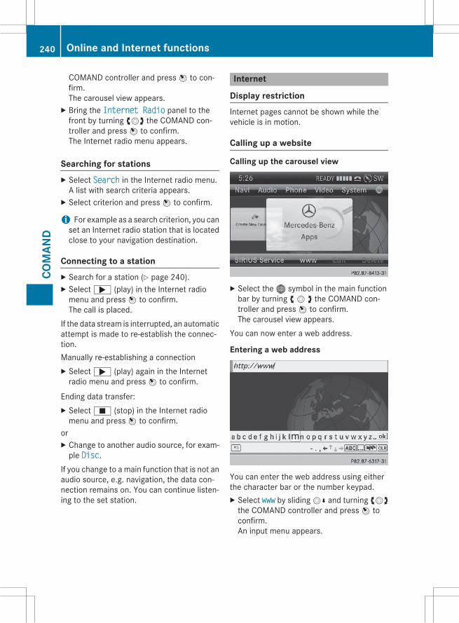
COMAND controller and pressW to con-firm.The carousel view appears.X Bring the Internet Radio panel to thefront by turning cVd the COMAND con-troller and pressW to confirm.The Internet radio menu appears.
Searching for stationsX Select Search in the Internet radio menu.A list with search criteria appears.X Select criterion and pressW to confirm.
i For example as a search criterion, you canset an Internet radio station that is locatedclose to your navigation destination.
Connecting to a stationX Search for a station (Y page 240).X Select; (play) in the Internet radiomenu and pressW to confirm.The call is placed.
If the data stream is interrupted, an automaticattempt is made to re-establish the connec-tion.Manually re-establishing a connectionX Select; (play) again in the Internetradio menu and pressW to confirm.
Ending data transfer:X SelectÉ (stop) in the Internet radiomenu and pressW to confirm.
orX Change to another audio source, for exam-ple Disc.
If you change to a main function that is not anaudio source, e.g. navigation, the data con-nection remains on. You can continue listen-ing to the set station.
Internet
Display restrictionInternet pages cannot be shown while thevehicle is in motion.
Calling up a website
Calling up the carousel view
X Select the® symbol in the main functionbar by turning c V d the COMAND con-troller and pressW to confirm.The carousel view appears.
You can now enter a web address.
Entering a web address
You can enter the web address using eitherthe character bar or the number keypad.X Select www by slidingVÆ and turning cVdthe COMAND controller and pressW toconfirm.An input menu appears.
240 Online and Internet functionsCO
MAN
D

X To enter using the character bar: enterthe web address in the input line.As soon as the first letter has been enteredin the input line, a list appears below it. Thelist shows web addresses which begin withthe letters you have entered and webaddresses which have already been calledup.The list is empty the first time you call it up.X After entering the web address, select the¬ symbol by slidingVÆ and turningcVd the COMAND controller and pressWto confirm.The website is called up.
Navigating the website
Overview
Step Result
X Turn cVd thecontroller.
Navigates from oneitem that can beselected (e.g. link,text field or selec-tion list) to the nextand highlights therespective elementon the website.
Sliding the control-ler:X Left or right XVYX Up or down ZVÆX Diagonally aVb
Moves the pointeron the page.
X PressW the con-troller.
Calls up themenu oropens the selecteditem.
X Press%. Calls up the previ-ous page.
X Pressj. Closes the Internetbrowser. If severalwindows are open,the current windowis closed.
Online and Internet functions 241
COM
AND
Z

242

Useful information ............................ 244Stowage areas ................................... 244Features ............................................. 254
243
Stow
age
and
feat
ures
Useful information
i This Operator's Manual describes allmodels and all standard and optional equip-ment of your vehicle available at the time ofpublication of the Operator's Manual.Country-specific differences are possible.Please note that your vehicle may not beequipped with all features described. Thisalso applies to safety-related systems andfunctions.
i Read the information on qualified special-ist workshops (Y page 35).
Stowage areas
Loading guidelines
G WARNINGIf objects, luggage or loads are not secured ornot secured sufficiently, they could slip, tipover or be flung around and thereby hit vehicleoccupants. There is a risk of injury, particu-larly in the event of sudden braking or a sud-den change in direction.Always store objects so that they cannot beflung around. Secure objects, luggage orloads against slipping or tipping before thejourney.
G WARNINGCombustion engines emit poisonous exhaustgases such as carbonmonoxide. If the tailgateis open when the engine is running, particu-larly if the vehicle is moving, exhaust fumescould enter the passenger compartment.There is a risk of poisoning.Turn off the engine before opening the tail-gate. Never drive with the tailgate open.
G WARNINGThe exhaust tail pipe and tail pipe trim canbecome very hot. If you come into contactwith these parts of the vehicle, you could burnyourself. There is a risk of injury.
Always be particularly careful around theexhaust tail pipe and the tail pipe trim. Allowthese components to cool down before touch-ing them.
The gross vehicle weight (GVW) is the vehicleweight including fuel, vehicle tool kit, sparewheel, installed accessories, vehicle occu-pants and luggage/cargo.The gross load limit and the gross vehicleweight rating (GVWR) for your vehicle mustnever be exceeded. The gross load limit andthe GVWR are specified on the vehicle iden-tification plate on the B-pillar of the driver'sdoor (Y page 301).The load must also be distributed so that theweight on each axle never exceeds the grossaxle weight rating (GAWR) for the front andrear axles. The specifications for GVWR andGAWR are on the vehicle identification plateon the B-pillar of the driver's door(Y page 301).Observe the notes on loading the vehicle(Y page 301).The handling characteristics of a laden vehi-cle are dependent on the distribution of theload within the vehicle. For this reason, youshould observe the following notes whentransporting a load:RNever exceed the maximum permissiblegross vehicle weight or the gross axleweight rating of the vehicle (including occu-pants).
RThe cargo compartment is the preferredplace to carry objects.
RPosition heavy loads as far forwards as pos-sible and as low down in the cargo com-partment as possible.
RThe load must not protrude above theupper edge of the seat backrests.
RAlways place the load against the rear orfront seat backrests. Make sure that theseat backrests are securely locked intoplace.
RAlways place the load behind unoccupiedseats if possible.
244 Stowage areasSt
owag
ean
dfe
atur
es
RUse the cargo tie-down rings and the parcelnets to transport loads and luggage.
RUse cargo tie-down rings and fasteningmaterials appropriate for the weight andsize of the load.
RHook in the cargo net when loading.RSecure the load with sufficiently strong andwear-resistant tie-downs. Pad sharp edgesfor protection.
Stowage spaces
Important safety notes
G WARNINGIf objects in the passenger compartment arestowed incorrectly, they can slide or bethrown around and hit vehicle occupants.There is a risk of injury, particularly in theevent of sudden braking or a sudden changein direction.RAlways stow objects so that they cannot bethrown around in such situations.
RAlways make sure that objects do not pro-trude from stowage spaces, parcel nets orstowage nets.
RClose the lockable stowage spaces whiledriving.
RStow and secure objects that are heavy,hard, pointy, sharp-edged, fragile or toolarge in the cargo compartment.
Observe the loading guidelines (Y page 244).
Information in the Digital Operator'sManualIn the Digital Operator's Manual you will findinformation on the following topics:RGlove boxRStowage compartment under the armrestREyeglasses compartment
RStowage compartment in the front centerconsole
RStowage compartment in the rear centerconsole
Stowage net
G WARNINGVehicles with the Occupant ClassificationSystem (OCS):If the gross weight of the objects in the stow-age net on the back of the front-passengerseat is greater than 4.4 lb (2 kg), OCS cannotcorrectly assess the occupant's weight cate-gory. The front-passenger front air bag coulddeploy without cause, or may fail to deploy inthe event of an accident. This poses anincreased risk of injury or even fatal injury.Never exceed the permissible gross weight of4.4 lb (2 kg). Stow and secure heavy objects inthe cargo compartment.
Stowage nets are located in the front-passenger footwell and on the back of thedriver's and the front-passenger seat.Observe the loading guidelines (Y page 244)and the safety notes regarding stowagespaces (Y page 245).
Through-loading facility in the rearIf objects or loads are not securedwhen beingtransported in the through-loading facility,they could slip or be thrown around andthereby hit vehicle occupants.Observe the loading guidelines (Y page 244)and the safety notes regarding stowagespaces (Y page 245).
Stowage areas 245
Stow
age
and
feat
ures
Z

The through-loading facility is opened fromthe cargo compartment.X Release the seat backrests in the secondrow of seats and tilt them in the cargo/loadposition. You can find information aboutthis in the Digital Operator's Manual.X Fold down the rear seat armrest.X Pull the center head restraint on the rearbench seat into the uppermost position(Y page 106).X Slide release catch: to the left and swingflap; to the left until it is lying on the rearside of the rear bench seat.
X Push cover= forward until it is lying on therear seat armrest.
Cargo compartment enlargement
Important safety notes
G WARNINGIf the rear bench seat/rear seat and seatbackrest are not engaged they could fold for-
wards, e.g. when braking suddenly or in theevent of an accident.RThe vehicle occupant would thereby bepushed into the seat belt by the rear benchseat/rear seat or by the seat backrest. Theseat belt can no longer offer the intendedlevel of protection and could even causeinjuries.
RObjects or loads in the trunk/cargo com-partment cannot be restrained by the seatbackrest.
There is an increased risk of injury.Before every trip, make sure that the seatbackrests and the rear bench seat/rear seatare engaged.
Make sure that the seat backrest and the seatcushion are correctly engaged in position.
! Fold the seat cushion upwards beforefolding the rear bench seat forward. Other-wise, the backrests may be damaged.When the backrest is folded forwards, thefront seats should not be moved to theirrearmost position. Otherwise, the frontseats and the rear bench seat could bedamaged.
! The backrest is heavy. Therefore, takecare when folding it down. Make sure thatthe head restraints are pushed all the wayin so that the backrests and seat cushionsare not damaged.
Observe the loading guidelines (Y page 244).The left-hand and right-hand rear seat backr-ests can be folded forwards separately toincrease the cargo compartment capacity.
246 Stowage areasSt
owag
ean
dfe
atur
es

Folding the rear bench seat forwards
If the driver's or front-passenger seat is setfor a larger person, it may not be possible tofold the rear bench seat forwards. In thiscase, move the front seats as far forward aspossible.X Move the head restraints to the lowestposition. You can find information aboutthis in the Digital Operator's Manual.X Fold seat cushion: upwards.
X Pull release handle; upwards in the direc-tion of the arrow until the backrest is fullyreleased.X Fold the backrest forwards until it reachesthe cargo compartment position.
X Guide seat belts; under respectiveclips:.
Folding the rear bench seat back
X Fold seat backrest; back until it engages.Make sure not to trap the seat belt whiledoing so.X Swing seat cushion: back.X Pull up and adjust the head restraints ifnecessary. You can find information aboutthis in the Digital Operator's Manual.
Securing cargo
Cargo tie-down rings
General notesG WARNINGThe Top Tether anchorages cannot secure aload. If you secure a load with the Top Tetheranchorages, the Top Tether anchorages couldbe pulled out during braking, abrupt changesin direction or in the event of an accident. The
Stowage areas 247
Stow
age
and
feat
ures
Z
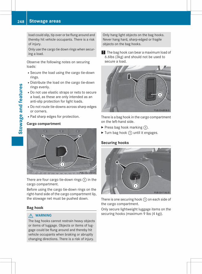
load could slip, tip over or be flung around andthereby hit vehicle occupants. There is a riskof injury.Only use the cargo tie down rings when secur-ing a load.
Observe the following notes on securingloads:RSecure the load using the cargo tie-downrings.
RDistribute the load on the cargo tie-downrings evenly.
RDo not use elastic straps or nets to securea load, as these are only intended as ananti-slip protection for light loads.
RDo not route tie-downs across sharp edgesor corners.
RPad sharp edges for protection.
Cargo compartment
There are four cargo tie-down rings: in thecargo compartment.Before using the cargo tie-down rings on theright-hand side of the cargo compartment lip,the stowage net must be pushed down.
Bag hook
G WARNINGThe bag hooks cannot restrain heavy objectsor items of luggage. Objects or items of lug-gage could be flung around and thereby hitvehicle occupants when braking or abruptlychanging directions. There is a risk of injury.
Only hang light objects on the bag hooks.Never hang hard, sharp-edged or fragileobjects on the bag hooks.
! The bag hook can bear amaximum load of6.6lbs (3kg) and should not be used tosecure a load.
There is a bag hook in the cargo compartmenton the left-hand side.X Press bag hook marking:.X Turn bag hook: until it engages.
Securing hooks
There is one securing hook: on each side ofthe cargo compartment.Only secure lightweight luggage items on thesecuring hooks (maximum 9 lbs (4 kg)).
248 Stowage areasSt
owag
ean
dfe
atur
es

Cargo compartment cover
Important safety notes
G WARNINGOn its own, the cargo compartment covercannot secure or restrain heavy objects,items of luggage and heavy loads. You couldbe hit by an unsecured load during suddenchanges in direction, braking or in the event ofan accident. There is an increased risk ofinjury or even fatal injury.Always store objects so that they cannot beflung around. Secure objects, luggage orloads against slipping or tipping over, e.g. byusing tie downs, even if you are using thecargo compartment cover.
! When loading the vehicle, make sure thatyou do not stack the load in the cargo com-partment higher than the lower edge of theside windows. Do not place heavy objectson top of the cargo compartment cover.
A cargo compartment cover or a combinedcargo cover and net (cargo compartmentcover with cargo net) is installed, dependingon equipment, behind the rear bench seatbackrest.
Extending/retracting the cargo com-partment cover
X To extend: pull the cargo compartmentcover back by grab handle: and clip it intoretainers; on the left and right.X To retract: unhook the cargo compartmentcover from left-hand and right-hand retain-ers;.X Guide cargo compartment cover forwardsby grab handle: until it is completely rol-led up.
Removing/installing the cargo com-partment cover (without integratedcargo net)
X To remove: make sure that cargo com-partment cover: is rolled up.X Push end cap= of cargo compartmentcover: in the direction of the arrow on theright or left-hand side.X Push cargo compartment cover: intoopposite anchorage;.X Remove cargo compartment cover:.X To install: if installed, remove the protec-tive caps from the side panels of the seatrow in which the cargo compartment coveris to be installed. Use a suitable objecthere, e.g. a coin.X Install the protective caps to the side pan-els of the other seat row.X Place cargo compartment cover: intoanchorage; on the right or left-hand side.X Push in opposite end cap= of cargo com-partment cover: in the direction of thearrow and insert cargo compartmentcover: into opposite anchorage;.
Stowage areas 249
Stow
age
and
feat
ures
Z

Removing/installing the combinedcargo cover and net (cargo compart-ment cover with integrated cargo net)
You can install and remove the combinedcargo cover and net from the cargo compart-ment.X Make sure that the cargo net and the cargocompartment cover are rolled up.X To remove: press button;.X Swing the combined cargo cover and net inthe direction of the arrow.X First, detach the combined cargo cover andnet from left-hand catch: and thenremove it from right-hand fixture=.X To install: push the combined cargo coverand net up to the stop into right-hand fix-ture=.X Place the combined cargo cover and netinto the left-hand fixture and push it intocatch: until the combined cargo coverand net engages audibly.
X Make sure that red lock status indicator?is no longer visible. The combined cargo
cover and net will otherwise not be lockedin place.
Cargo net in combined cargo coverand net
Important safety notes
G WARNINGOn its own, the cargo net cannot secure orrestrain heavy objects, items of luggage andheavy loads. You could be hit by an unsecuredload during sudden changes in direction,braking or in the event of an accident. There isan increased risk of injury or even fatal injury.Always store objects so that they cannot beflung around. Secure objects, luggage orloads against slipping or tipping over, e.g. byusing tie downs, even if you are using thecargo net.
It is important to use a cargo net if you loadthe vehicle with small objects above the seatbackrests. For safety reasons, always use acargo net when transporting loads.
Attaching the cargo net
X Pull the cargo net up by tab: and hook itinto eyelets; using both hands.
250 Stowage areasSt
owag
ean
dfe
atur
es

Coat hooks on the tailgate
: Coat hook
EASY-PACK load-securing kit
Components and storageThe EASY-PACK load-securing kit allows youto use your cargo compartment for a varietyof purposes. The accessory parts are locatedunder the cargo compartment floor.X Open the trunk floor (Y page 252).
EASY-PACK load-securing kit accessory parts: Bag containing the brackets and luggage
holder; Telescopic rod
Inserting the brackets into the loadingrail
X Insert bracket: into the center of loadingrail?.X Press release button; and pushbracket: into the desired position in load-ing rail?.X Let go of release button;.X Press locking button=.Bracket: is locked in loading rail?.X If necessary, fold cargo tie-down ringAupwards.
Luggage holder
! Only use the luggage holder to securecargo with a maximum weight of 15.4 lbs(7 kg) andwith dimensions that the luggageholder can safely and securely contain.
The luggage holder can be used to securelight loads against the side wall of the cargocompartment to prevent them from movingaround.
Stowage areas 251
Stow
age
and
feat
ures
Z

X To install: insert two bracketsA into theleft or right loading rail (Y page 251).X Press release button: of the luggageholder and pull the strap out slightly.X Insert luggage holder; into bracketsAand, while doing so, press release button= and push the luggage holder downwardsuntil it engages.X Press release button: of the luggageholder and pull the strap out in the directionof the arrow.X Place the load between the strap and thecargo compartment side wall.X Using one hand, press locking button: ofthe luggage holder.X With your other hand, let the strap go slowlyuntil the load is secured.X Make sure that locking button? on brack-etsA is pressed.This keeps bracketsA in place on theloading rail.X To remove: press release button= onrespective bracketA and remove luggageholder; by pulling upwards and out.
Telescopic rod
The telescopic rod can be used to secure theload against the rear seats to prevent it frommoving around.X To install: insert one bracket; into boththe left and the right loading rails and slideit to the desired position (Y page 251).X Insert telescopic rod: into brackets;and, while doing so, press release but-
ton? and push the rod downwards until itengages.X Make sure that locking button= on brack-ets; is pressed.This keeps brackets; in place on theloading rail.X To remove: press release button? onrespective bracket; and remove tele-scopic rod: by pulling it upwards and out.
Stowage well under the cargo com-partment floor
Important safety notes
G WARNINGIf you drivewhen the cargo compartment flooris open, objects could be flung around, thusstriking vehicle occupants. There is a risk ofinjury, particularly in the event of suddenbraking or a sudden change in direction.Always close the cargo compartment floorbefore a journey.
A removable insert under the cargo compart-ment floor contains the parts of the EASY-PACK load-securing kit. The tire-change toolkit is stored beneath this insert.
Opening/closing the cargo compart-ment floor
252 Stowage areasSt
owag
ean
dfe
atur
es

X To open: holding the ribbing, press han-dle: downwards;.Handle: folds up.X Swing the cargo compartment floorupwards using handle: until it restsagainst the cargo compartment cover.
X Fold out hook= on the underside of thecargo compartment floor in the direction ofthe arrow.
X Attach hook= to the cargo compart-ment's upper seal?.X To close: detach hook= from the cargocompartment's upper seal?.X Fasten hook= to the bracket on theunderside of the cargo compartment floor.X Fold the cargo compartment floor down.X Press the cargo compartment floordown; until it engages.
i To remove the cargo compartment floor,undo the press studs below the cargo com-partment floor. When you re-install thecargo compartment floor, fasten it with thepress studs.
Roof carrier
Important safety notes
G WARNINGWhen you load the roof, the center of gravityof the vehicle rises and the driving character-istics change. If you exceed themaximum roofload, the driving characteristics, as well assteering and braking, will be greatly impaired.There is a risk of an accident.Never exceed the maximum roof load andadjust your driving style.
! Mercedes-Benz recommends that youonly use roof carriers that have been testedand approved for Mercedes-Benz vehicles.This helps to prevent damage to the vehi-cle.Position the load on the roof carrier in sucha way that the vehicle will not sustain dam-age even when it is in motion.Depending on the vehicle equipment,ensure that when the roof carrier is instal-led you can:Rraise the sliding sunroof fullyRopen the panorama roof with power tilt/sliding panel fully
Ropen the tailgate fullyYouwill find information on themaximum roofload in the "Technical data" section(Y page 346).An incorrectly secured roof carrier or roofload may become detached from the vehicle.You must therefore ensure that you observethe roof carrier manufacturer's installationinstructions.
Stowage areas 253
Stow
age
and
feat
ures
Z

Attaching the roof carrier
X Secure the roof carrier to roof rails:. Indoing so, observe the manufacturer'sinstallation instructions.
Features
Information in the Digital Operator'sManualIn the Digital Operator's Manual you will findinformation on the following topics:RCup holderRRoller sunblinds on the rear side windowsRAshtrayRCigarette lighterR12 V socketsR115 V socketRInfrared reflective windshield
Sun visors
Overview
G WARNINGIf themirror cover of the vanitymirror is foldedup when the vehicle is in motion, you could beblinded by incident light. There is a risk of anaccident.Always keep the mirror cover folded downwhile driving.
: Mirror light; Bracket= Retaining clip, e.g. for a car park ticket? Vanity mirrorA Mirror cover
Information in the Digital Operator'sManualIn the Digital Operator's Manual you will findinformation on the following topics:RVanity mirror in the sun visorRGlare from the side
mbrace
Information in the Digital Operator'sManualIn the Digital Operator's Manual you will findinformation on the following topics:RDownloading destinations in COMANDRSearch and SendRVehicle remote openingRVehicle remote closingRStolen vehicle recovery serviceRVehicle remote malfunction diagnosisRDownloading routesRSpeed alertRGeo fencingRTriggering the vehicle alarm
254 FeaturesSt
owag
ean
dfe
atur
es
General notesYou must have a license agreement to acti-vate the mbrace service. Make sure that yoursystem is activated and operational. To log in,press theï MB Info call button. If any ofthe steps mentioned are not carried out, thesystem may not be activated.If you have questions about the activation,contact one of the following telephone hot-lines:RUSA:Mercedes-BenzCustomer AssistanceCenter at 1-800-FOR-MERCedes(1-800-367-6372) or 1-866-990-9007
RCanada: Customer Service at1-888-923-8367
Shortly after successfully registering with theservice, a user ID and passwordwill be sent toyou by post.USA only: you can use this password to logonto the mbrace area under "Owners Online"at http://www.mbusa.com.The system is available if:Rit has been activated and is operationalRthe correspondingmobile phone network isavailable for transmitting data to the Cus-tomer Center
Ra service subscription is availableRthe starter battery is sufficiently charged
i Determining the location of the vehicle ona map is only possible if:RGPS reception is available.Rthe vehicle position can be forwarded tothe Customer Assistance Center.
The mbrace systemTo adjust the volume during a call, proceed asfollows:X Press theW orX button on the mul-tifunction steering wheel.
orX Use the volume controller of the audio sys-tem/COMAND.
The system offers various services, e.g.:RAutomatic and manual emergency callRRoadside Assistance callRMB Info callUSA only: you can find information and adescription of all available features under"Owners Online" at http://www.mbusa.com.
System self-testAfter you have switched on the ignition, thesystem carries out a self-diagnosis.A malfunction in the system has been detec-ted if one of the following occurs:RThe indicator lamp in the SOS button doesnot come on during the system self-test.
RThe indicator lamp in theF RoadsideAssistance button does not light up duringself-diagnosis of the system.
RThe indicator lamp in theïMB Info callbutton does not light up during self-diag-nosis of the system.
RThe indicator lamp in one or more of thefollowing buttons continues to light up redafter the system self-diagnosis:- SOS button- F Roadside Assistance call button- ï MB Info call button
RAfter the system self-diagnosis, the Inopхerative or Service Not Activatedmessage appears in the multifunction dis-play.
If a malfunction is indicated as outlinedabove, the systemmay not operate as expec-ted. In the event of an emergency, help willhave to be summoned by other means.Have the system checked at the nearestauthorized Mercedes-Benz Center or contactthe following service hotlines:RUSA:Mercedes-BenzCustomer AssistanceCenter at 1-800-FOR-MERCedes(1-800-367-6372) or 1-866-990-9007
RCanada: Customer Service at1-888-923-8367
Features 255
Stow
age
and
feat
ures
Z

Emergency call
Important safety notesG WARNINGIt can be dangerous to remain in the vehicle,even if you have pressed the SOS button in anemergency if:Ryou see smoke inside or outside of the vehi-cle, e.g. if there is a fire after an accident
Rthe vehicle is on a dangerous section ofroad
Rthe vehicle is not visible or cannot easily beseen by other road users, particularly whendark or in poor visibility conditions
There is a risk of an accident and injury.Leave the vehicle immediately in this or simi-lar situations as soon as it is safe to do so.Move to a safe location along with other vehi-cle occupants. In such situations, secure thevehicle in accordance with national regula-tions, e. g. with a warning triangle.
You must have a license agreement to acti-vate the mbrace service. Make sure that yoursystem is activated and operational. To reg-ister, press theï MB Info call button. Ifany of the steps mentioned are not carriedout, the system may not be activated.If you have questions about the activation,contact one of the following telephone hot-lines:RUSA:Mercedes-BenzCustomer AssistanceCenter at 1-800-FOR-MERCedes(1-800-367-6372) or 1-866-990-9007
RCanada: Customer Service at1-888-923-8367
General notesAnemergency call is dialed automatically if anair bag or Emergency Tensioning Device istriggered.
i You cannot end an automatically trig-gered emergency call yourself.
An emergency call can also be initiated man-ually.
As soon as the emergency call has been ini-tiated, the indicator lamp in the SOS buttonflashes. The multifunction display shows theConnecting Call message.The audio output is muted.Once the connection has been made, theCall Connected message appears in themultifunction display.All important information on the emergency istransmitted, for example:Rcurrent location of the vehicle (as deter-mined by the GPS system)
Rvehicle identification numberRinformation on the severity of the accidentShortly after the emergency call has been ini-tiated, a voice connection is automaticallyestablished between the Customer Assis-tance Center and the vehicle occupants.RIf the vehicle occupants respond, theMercedes-Benz Customer Assistance Cen-ter attempts to getmore information on theemergency.
RIf there is no response from the vehicleoccupants, an ambulance is immediatelysent to the vehicle.
If no voice connection can be established tothe Mercedes-Benz Customer AssistanceCenter, the systemhas been unable to initiatean emergency call.This can occur, for example, if the relevantmobile phone network is not available. Theindicator lamp in the SOS button flashes con-tinuously.The Call Failed message appears in themultifunction display and must be confirmed.In this case, summon assistance by othermeans.
256 FeaturesSt
owag
ean
dfe
atur
es

Making an emergency call
X To initiate an emergency call manually:press cover: briefly to open.X Press SOS button; briefly.The indicator lamp in SOS button;flashes until the emergency call is conclu-ded.X Wait for a voice connection to theMercedes-Benz Customer Assistance Cen-ter.X After the emergency call, close cover:.
i If the mobile phone network is unavaila-ble, mbrace will not be able to make theemergency call. If you leave the vehicleimmediately after pressing the SOS button,you will not know whether mbrace placedthe emergency call. In this case, alwayssummon assistance by other means.
Roadside Assistance button
X Press Roadside Assistance button:.This initiates a call to the Mercedes-BenzCustomer Assistance Center.
The indicator lamp in Roadside Assistancebutton: flashes while the call is active.The multifunction display shows the Conхnecting Callmessage. The audio outputis muted.
If a connection can be made, the Call Conхnectedmessage appears in themultifunctiondisplay.If a mobile phone network and GPS receptionare available, the system transfers data to theMercedes-Benz Customer Assistance Center,for example:Rcurrent location of the vehicleRvehicle identification number
i The audio system or COMAND displayindicates that a call is active. During thecall, you can change to the navigationmenuby pressing the NAVI button on COMAND,for example.Voice output is not available.
A voice connection is established betweenthe Mercedes-Benz Customer AssistanceCenter and the vehicle occupants.From the vehicle remote malfunction diagno-sis, the Mercedes-Benz Customer AssistanceCenter can ascertain the nature of the prob-lem. Information on the vehicle remote mal-function diagnosis can be found in the DigitalOperator's Manual.The Mercedes-Benz Customer AssistanceCenter either sends a qualified Mercedes-Benz technician or makes arrangements foryour vehicle to be transported to the nearestauthorized Mercedes-Benz Center.You may be charged for services such asrepair work and/or towing.Further details are available in your mbracemanual.
Features 257
Stow
age
and
feat
ures
Z

i The system has not been able to initiate aRoadside Assistance call, if:Rthe indicator lamp for Roadside Assis-tance call button: is flashing continu-ously.
Rno voice connection to the Mercedes-Benz Customer Assistance Center wasestablished.
This can occur if the relevant mobile phonenetwork is not available, for example.The Call Failed message appears in themultifunction display.X To end a call: press the~ button on themultifunction steering wheel.
orX Press the corresponding button for endinga phone call on the audio system or onCOMAND.
MB Info call button
X Press MB Info call button:.This initiates a call to the Mercedes-BenzCustomer Assistance Center.The indicator lamp inMB Info call button:flasheswhile the connection is beingmade.The multifunction display shows the Conхnecting Callmessage. The audio systemis muted.
If a connection can be made, the Call Conхnectedmessage appears in themultifunctiondisplay.
If a mobile phone network and GPS receptionare available, the system transfers data to theMercedes-Benz Customer Assistance Center,for example:Rcurrent location of the vehicleRvehicle identification number
i The audio system or COMAND displayindicates that a call is active. During thecall, you can change to the navigationmenuby pressing the NAVI button on COMAND,for example.Voice output is not available.
A voice connection is established betweenthe Mercedes-Benz Customer AssistanceCenter and the vehicle occupants.You receive information about operating yourvehicle, about the nearest authorizedMercedes-Benz Center and about other prod-ucts and services from Mercedes-Benz.USA only: you can find further information onthe mbrace system under "Owners Online" athttp://www.mbusa.com.
i The system has not been able to initiatean MB Info call, if:Rthe indicator lamp in MB Info call but-ton: is flashing continuously.
Rno voice connection to the Mercedes-Benz Customer Assistance Center wasestablished.
This can occur if the relevant mobile phonenetwork is not available, for example.The Call Failed message appears in themultifunction display.X To end a call: press the~ button on themultifunction steering wheel.
orX Press the corresponding button for endinga phone call on the audio system or onCOMAND.
258 FeaturesSt
owag
ean
dfe
atur
es
Call priorityWhen service calls are active, e.g. RoadsideAssistance or MB Info calls, an emergencycall can still be initiated. In this case, an emer-gency call will take priority and override allother active calls.The indicator lamp of the respective buttonflashes until the call is ended.An emergency call can only be terminated bythe Mercedes-Benz Customer AssistanceCenter.All other calls can be ended by pressing:Rthe~ button on themultifunction steer-ing wheel
Rthe corresponding button on the audio sys-tem or on COMAND for ending a telephonecall
i When a call is initiated, the audio systemis muted. The mobile phone is no longerconnected to COMAND. However, if youwant to use your mobile phone, do so onlywhen the vehicle is stationary and in a safelocation.
Garage door opener
General notes
The HomeLink® garage door opener integra-ted in the rear-viewmirror allows you to oper-ate up to three different door and gate sys-tems.Use the integrated garage door opener onlyon garage doors that:Rhave safety stop and reverse features andRmeet current U.S. federal safety standardsOnce programed, the integrated garage dooropener in the rear-viewmirror will assume thefunction of the garage door system's remotecontrol. Please also read the operatinginstructions for the garage door system.When programming a garage door opener,park the vehicle outside the garage. Do notrun the engine while programming.
Certain garage door drives are incompatiblewith the integrated garage door opener. If youhave difficulty programing the integratedgarage door opener, contact an authorizedMercedes-Benz Center.Alternatively, you can call the following tele-phone assistance services:RUSA:Mercedes-BenzCustomer AssistanceCenter at 1-800-FOR-MERCedes
RCanada: Customer Service at1-800-387-0100
RHomeLink® hotline 1-800-355-3515 (freeof charge)
More information on HomeLink® and/orcompatible products is also available onlineat http://www.homelink.com.Notes on the declaration of conformity(Y page 34).USA: FCC ID: CB2HMIHL4Canada: IC: 279B-HMIHL4
Important safety notes
G WARNINGWhen you operate or program the garage doorwith the integrated garage door opener, per-sons in the range of movement of the garagedoor can become trapped or struck by thegarage door. There is a risk of injury.When using the integrated garage dooropener, always make sure that nobody iswithin the range of movement of the garagedoor.
G WARNINGCombustion engines emit poisonous exhaustgases such as carbon monoxide. Inhalingthese exhaust gases leads to poisoning. Thereis a risk of fatal injury. Therefore never leavethe engine running in enclosed spaces with-out sufficient ventilation.
Features 259
Stow
age
and
feat
ures
Z

Programming
Programming buttonsPay attention to the "Important safety notes"(Y page 259).
Garage door remote controlA is not inclu-ded with the integrated garage door opener.X Turn the SmartKey to position 2 in the igni-tion lock (Y page 131).X Select one of buttons; to? to use tocontrol the garage door drive.X To start programming mode: press andhold one of buttons; to? on the inte-grated garage door opener.The garage door opener is now in program-ming mode. After a short time, indicatorlamp: lights up yellow.Indicator lamp: lights up yellow as soonas button;,= or? is programmed forthe first time. If the selected button hasalready been programmed, indicatorlamp: will only light up yellow after tenseconds have elapsed.X Release button;,= or?. Indicatorlamp: flashes yellow.X To program the remote control: pointgarage door remote controlA towardsbuttons; to? on the rear-view mirror ata distance of 2 to 8 inches (5 to 20 cm).X Press and hold buttonB on remote controlA until indicator lamp: lights up green.When indicator lamp: lights up green:programming is finished.When indicator lamp: flashes green: pro-gramming was successful. The next step is
to synchronize the rolling code(Y page 260).X Release buttonB on remote controlA forthe garage door drive system.If indicator lamp: lights up red: repeat theprograming procedure for the correspond-ing button on the rear-view mirror. Whendoing so, vary the distance between remotecontrolA and the rear-view mirror.The required distance between remotecontrolA and the integrated garage dooropener depends on the garage door drivesystem. Several attempts might be neces-sary. You should test every position for atleast 25 seconds before trying anotherposition.
Synchronizing the rolling codePay attention to the "Important safety notes"(Y page 259).If the garage door system uses a rolling code,you will also have to synchronize the garagedoor system with the integrated garage dooropener in the rear-view mirror. To do this youwill need to use the programming button onthe door drive control panel. The program-ming button may be positioned at differentlocations depending on the manufacturer. Itis usually located on the door drive unit on thegarage ceiling.Familiarize yourself with the garage doordrive operating instructions, e.g. under "Pro-gramming of additional remote controls",before carrying out the following steps.Your vehicle must be within reach of thegarage door or gate opener drive. Make surethat neither your vehicle nor any persons/objects are present within the sweep of thedoor or gate.X Turn the SmartKey to position 2 in the igni-tion lock (Y page 131).X Get out of the vehicle.X Press the programming button on the doordrive unit.Usually, you now have 30 seconds to ini-tiate the next step.
260 FeaturesSt
owag
ean
dfe
atur
es

X Get into the vehicle.X Press previously programmed button;,= or? on the integrated garage dooropener until the door closes.The rolling code synchronization is thencomplete.
Notes on programming the remote con-trolCanadian radio frequency laws require a"break" (or interruption) of the transmissionsignals after broadcasting for a few seconds.Therefore, these signals may not last longenough for the integrated garage dooropener. The signal is not recognized duringprogramming. Comparable with Canadianlaw, some U.S. garage door openers also fea-ture a "break".Proceed as follows:Rif you live in CanadaRif you have difficulties programming thegarage door opener (regardless of whereyou live) when using the programmingstepsX Press and hold one of buttons; to? onthe integrated garage door opener.After a short time, indicator lamp: lightsup yellow.X Release the button.Indicator lamp: flashes yellow.X Press buttonB of garage door remotecontrolA for two seconds, then release itfor two seconds.X Press buttonB again for two seconds.X Repeat this sequence on buttonB ofremote controlA until indicator lamp:lights up green.When indicator lamp: lights up green:programming is finished.
When indicator lamp: flashes green: pro-gramming was successful. The next step isto synchronize the rolling code.X Release buttonB of remote controlA ofthe garage door drive.If indicator lamp: lights up red: repeat theprogramming process for the correspond-ing button on the rear-view mirror. Whendoing so, vary the distance between remotecontrolA and the rear-view mirror.The required distance between remotecontrolA and the integrated garage dooropener depends on the garage door drivesystem. Several attempts might be neces-sary. You should test every position for atleast 25 seconds before trying anotherposition.
Problems when programmingIf you are experiencing problems programingthe integrated garage door opener on therear-view mirror, take note of the followinginstructions:RCheck the transmitter frequency used bygarage door drive remote controlA andwhether it is supported. The transmitterfrequency can usually be found on the backof the garage door drive remote control.The integrated garage door opener is com-patible with devices that have units whichoperate in the frequency range of 280 to433 MHz.
RReplace the batteries in garage doorremote controlA. This increases the like-lihood that garage door remote controlAwill transmit a strong and precise signal tothe integrated garage door opener.
RWhen programming, hold remote controlA at varying distances and angles from thebuttonwhich you are programming. Try var-ious angles at a distance between 2and12 inches (5to 30 cm) or at the same anglebut at varying distances.
RIf another remote control is available for thesame garage door drive, repeat the sameprogramming steps with this remote con-
Features 261
Stow
age
and
feat
ures
Z
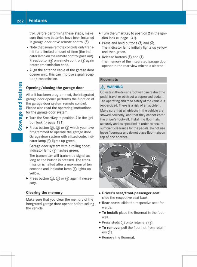
trol. Before performing these steps, makesure that new batteries have been installedin garage door drive remote controlA.
RNote that some remote controls only trans-mit for a limited amount of time (the indi-cator lamp on the remote control goes out).Press buttonB on remote controlA againbefore transmission ends.
RAlign the antenna cable of the garage dooropener unit. This can improve signal recep-tion/transmission.
Opening/closing the garage doorAfter it has been programmed, the integratedgarage door opener performs the function ofthe garage door system remote control.Please also read the operating instructionsfor the garage door system.X Turn the SmartKey to position 2 in the igni-tion lock (Y page 131).X Press button;,= or? which you haveprogrammed to operate the garage door.Garage door system with a fixed code: indi-cator lamp: lights up green.Garage door system with a rolling code:indicator lamp: flashes green.The transmitter will transmit a signal aslong as the button is pressed. The trans-mission is halted after a maximum of tenseconds and indicator lamp: lights upyellow.X Press button;,= or? again if neces-sary.
Clearing the memoryMake sure that you clear the memory of theintegrated garage door opener before sellingthe vehicle.
X Turn the SmartKey to position 2 in the igni-tion lock (Y page 131).X Press and hold buttons; and?.The indicator lamp initially lights up yellowand then green.X Release buttons; and?.The memory of the integrated garage dooropener in the rear-view mirror is cleared.
Floormats
G WARNINGObjects in the driver's footwell can restrict thepedal travel or obstruct a depressed pedal.The operating and road safety of the vehicle isjeopardized. There is a risk of an accident.Make sure that all objects in the vehicle arestowed correctly, and that they cannot enterthe driver's footwell. Install the floormatssecurely and as specified in order to ensuresufficient clearance for the pedals. Do not useloose floormats and do not place floormats ontop of one another.
X Driver's seat/front-passenger seat:slide the respective seat back.X Rear seats: slide the respective seat for-wards.X To install: place the floormat in the foot-well.X Press studs: onto retainers;.X To remove: pull the floormat from retain-ers;.X Remove the floormat.
262 FeaturesSt
owag
ean
dfe
atur
es

Useful information ............................ 264Engine compartment ........................ 264ASSYST PLUS .................................... 268Care .................................................... 268
263
Mai
nten
ance
and
care

Useful information
i This Operator's Manual describes allmodels and all standard and optional equip-ment of your vehicle available at the time ofpublication of the Operator's Manual.Country-specific differences are possible.Please note that your vehicle may not beequipped with all features described. Thisalso applies to safety-related systems andfunctions.
i Read the information on qualified special-ist workshops (Y page 35).
Engine compartment
Hood
Important safety notes
G WARNINGIf the hood is unlatched, it may open up whenthe vehicle is in motion and block your view.There is a risk of an accident.Never unlatch the hood while driving.
G WARNINGWhen opening and closing the hood, it maysuddenly fall into the closed position. There isa risk of injury to persons within range ofmovement of the hood.Open and close the hood only when no one iswithin its range of movement.
G WARNINGOpening the hood when the engine is over-heated or when there is a fire in the enginecompartment could expose you to hot gasesor other service products. There is a risk ofinjury.Let an overheated engine cool down beforeopening the hood. If there is a fire in theengine compartment, keep the hood closedand contact the fire department.
G WARNINGThe engine compartment contains movingcomponents. Certain components, such asthe radiator fan, may continue to run or startagain suddenly when the ignition is off. Thereis a risk of injury.If you need to do any work inside the enginecompartment:Rswitch off the ignitionRnever reach into the area where there is arisk of danger from moving components,such as the fan rotation area
Rremove jewelry and watchesRkeep items of clothing and hair, for exam-ple, away from moving parts
G WARNINGThe ignition system and the fuel injection sys-tem work under high voltage. If you touchcomponents which are under voltage, youcould get an electric shock. There is a risk ofinjury.Never touch components of the ignition sys-tem or fuel injection system when the ignitionis switched on.
Opening the hood
G WARNINGCertain components in the engine compart-ment, such as the engine, radiator and partsof the exhaust system, can become very hot.Working in the engine compartment poses arisk of injury.Where possible, let the engine cool down andtouch only the components described in thefollowing.
G WARNINGWhen the hood is open and the windshieldwipers are set inmotion, you can be injured bythe wiper linkage. There is a risk of injury.Always switch off the windshield wipers andthe ignition before opening the hood.
264 Engine compartmentM
aint
enan
cean
dca
re

! Make sure that the windshield wipers arenot folded away from the windshield. Youcould otherwise damage the windshieldwipers or the hood.
X Make sure that the windshield wipers areturned off.X Pull release lever: on the hood.The hood is released.
X Reach into the gap, pull hood catch han-dle; up and lift the hood.If you lift the hood by approximately 15 in(40 cm), the hood is opened and held openautomatically by the gas-filled strut.
Closing the hoodX Lower the hood and let it fall from a heightof approximately 8 in (20 cm).X Check that the hood has engaged properly.If the hood can be raised slightly, it is notproperly engaged. Open it again and closeit with a little more force.
RadiatorVehicles with a diesel engine: do not coverthe radiator, for examplewith awinter front orbug cover. The readings of the on-board-diag-nostic system may otherwise be inaccurate.Some of these readings are required by lawand must be accurate at all times.
Engine oil
General notesDepending on your driving style, the vehicleconsumes up to 0.9 US qt (0.8 liters) of oil per600 miles (1,000 km). The oil consumptionmay be higher than this when the vehicle isnew or if you frequently drive at high enginespeeds.Depending on the engine, the oil dipstick maybe in a different location.When checking the oil level:Rpark the vehicle on a level surface.Rthe engine should be switched off forapproximately five minutes if the engine isat normal operating temperature.
Rif the engine is not at normal operatingtemperature, e.g. if the engine was onlystarted briefly, wait about 30 minutesbefore carrying out the measurement.
Checking the oil level using the oil dip-stick
G WARNINGCertain components in the engine compart-ment, such as the engine, radiator and partsof the exhaust system, can become very hot.Working in the engine compartment poses arisk of injury.Where possible, let the engine cool down andtouch only the components described in thefollowing.
Engine compartment 265
Mai
nten
ance
and
care
Z
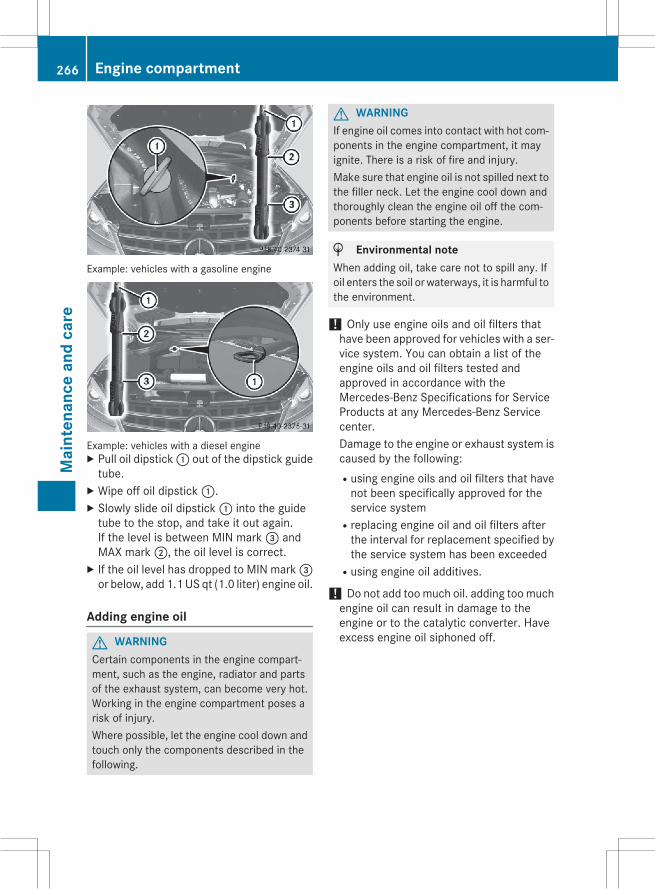
Example: vehicles with a gasoline engine
Example: vehicles with a diesel engineX Pull oil dipstick: out of the dipstick guidetube.X Wipe off oil dipstick:.X Slowly slide oil dipstick: into the guidetube to the stop, and take it out again.If the level is between MIN mark= andMAX mark;, the oil level is correct.X If the oil level has dropped to MIN mark=or below, add 1.1US qt (1.0 liter) engine oil.
Adding engine oil
G WARNINGCertain components in the engine compart-ment, such as the engine, radiator and partsof the exhaust system, can become very hot.Working in the engine compartment poses arisk of injury.Where possible, let the engine cool down andtouch only the components described in thefollowing.
G WARNINGIf engine oil comes into contact with hot com-ponents in the engine compartment, it mayignite. There is a risk of fire and injury.Make sure that engine oil is not spilled next tothe filler neck. Let the engine cool down andthoroughly clean the engine oil off the com-ponents before starting the engine.
H Environmental noteWhen adding oil, take care not to spill any. Ifoil enters the soil or waterways, it is harmful tothe environment.
! Only use engine oils and oil filters thathave been approved for vehicles with a ser-vice system. You can obtain a list of theengine oils and oil filters tested andapproved in accordance with theMercedes-Benz Specifications for ServiceProducts at any Mercedes-Benz Servicecenter.Damage to the engine or exhaust system iscaused by the following:Rusing engine oils and oil filters that havenot been specifically approved for theservice system
Rreplacing engine oil and oil filters afterthe interval for replacement specified bythe service system has been exceeded
Rusing engine oil additives.
! Do not add toomuch oil. adding toomuchengine oil can result in damage to theengine or to the catalytic converter. Haveexcess engine oil siphoned off.
266 Engine compartmentM
aint
enan
cean
dca
re

Example: engine oil capX Turn cap: counter-clockwise and removeit.X Add engine oil.If the oil level is at or below theMINmark onthe oil dipstick, add 1.1 US qt (1.0 l) ofengine oil.X Replace cap: on the filler neck and turnclockwise.Ensure that the cap locks into placesecurely.X Check the oil level again with the oil dip-stick (Y page 265).
Further information on engine oil(Y page 342).
Additional service products
Checking coolant level
G WARNINGCertain components in the engine compart-ment, such as the engine, radiator and partsof the exhaust system, can become very hot.Working in the engine compartment poses arisk of injury.Where possible, let the engine cool down andtouch only the components described in thefollowing.
G WARNINGThe engine cooling system is pressurized, par-ticularly when the engine is warm. Whenopening the cap, you could be scalded by hotcoolant spraying out. There is a risk of injury.
Let the engine cool down before opening thecap. Wear eye and hand protection whenopening the cap. Open the cap slowly half aturn to allow pressure to escape.
X Park the vehicle on a level surface.Only check the coolant level when the vehi-cle is on a level surface and the engine hascooled down.X Turn the SmartKey to position 2 in the igni-tion lock (Y page 131).On vehicles with KEYLESS-GO, press theStart/Stop button twice (Y page 132).X Check the coolant temperature gauge inthe multifunction display.The coolant temperature must be below158 ‡ (70 †).X Turn the SmartKey to position
0 (Y page 131) in the ignition lock.X Slowly turn cap: half a turn counter-clockwise to allow excess pressure toescape.X Turn cap: further counter-clockwise andremove it.If the coolant is at the level ofmarker bar=in the filler neck when cold, there is enoughcoolant in coolant expansion tank;.If the coolant level is approximately 0.6 in(1.5 cm) above marker bar= in the fillerneck when warm, there is enough coolantin expansion tank;.X If necessary, add coolant that has been tes-ted and approved by Mercedes-Benz.X Replace cap: and turn it clockwise as faras it will go.
Engine compartment 267
Mai
nten
ance
and
care
Z
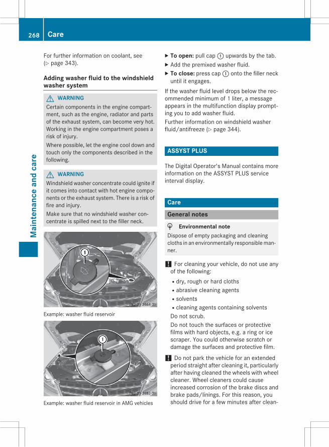
For further information on coolant, see(Y page 343).
Adding washer fluid to the windshieldwasher system
G WARNINGCertain components in the engine compart-ment, such as the engine, radiator and partsof the exhaust system, can become very hot.Working in the engine compartment poses arisk of injury.Where possible, let the engine cool down andtouch only the components described in thefollowing.
G WARNINGWindshield washer concentrate could ignite ifit comes into contact with hot engine compo-nents or the exhaust system. There is a risk offire and injury.Make sure that no windshield washer con-centrate is spilled next to the filler neck.
Example: washer fluid reservoir
Example: washer fluid reservoir in AMG vehicles
X To open: pull cap: upwards by the tab.X Add the premixed washer fluid.X To close: press cap: onto the filler neckuntil it engages.
If the washer fluid level drops below the rec-ommended minimum of 1 liter, a messageappears in the multifunction display prompt-ing you to add washer fluid.Further information on windshield washerfluid/antifreeze (Y page 344).
ASSYST PLUS
The Digital Operator's Manual contains moreinformation on the ASSYST PLUS serviceinterval display.
Care
General notes
H Environmental noteDispose of empty packaging and cleaningcloths in an environmentally responsibleman-ner.
! For cleaning your vehicle, do not use anyof the following:Rdry, rough or hard clothsRabrasive cleaning agentsRsolventsRcleaning agents containing solventsDo not scrub.Do not touch the surfaces or protectivefilms with hard objects, e.g. a ring or icescraper. You could otherwise scratch ordamage the surfaces and protective film.
! Do not park the vehicle for an extendedperiod straight after cleaning it, particularlyafter having cleaned the wheels with wheelcleaner. Wheel cleaners could causeincreased corrosion of the brake discs andbrake pads/linings. For this reason, youshould drive for a few minutes after clean-
268 CareM
aint
enan
cean
dca
re

ing. Braking heats the brake discs and thebrake pads/linings, thus drying them. Thevehicle can then be parked.
Regular care of your vehicle is a condition forretaining the quality in the long term.Use care products and cleaning agents rec-ommended and approved by Mercedes-Benz.
Exterior care
Automatic car wash
G WARNINGBraking efficiency is reduced after washingthe vehicle. There is a risk of an accident.After the vehicle has been washed, brakecarefully while paying attention to the trafficconditions until full braking power is restored.
! Before driving into an automatic carwash,make sure that it is suitable for the dimen-sions of the vehicle. In particular, makesure that:Rthere is enough ground clearancebetween the vehicle underbody and theguide rails of the automatic car wash.
Rthe clearance width of the automatic carwash is sufficient, particularly the widthof the guide rails.
Ryou enter the automatic car washstraight and in the center of the guiderails in order to avoid damaging the tiresor wheel rims.
Fold in the exterior mirrors before the vehi-cle is washed. The exterior mirrors couldotherwise be damaged.
! If DISTRONIC PLUS or the HOLD functionis activated, the vehicle brakes automati-cally in certain situations. To prevent dam-age to the vehicle, deactivate DISTRONICPLUS and the HOLD function in the follow-ing or other similar situations:Rwhen towing the vehicleRin the car wash
! Never clean your vehicle in a TouchlessAutomatic Car Wash as these use specialcleaning agents. These cleaning agents candamage the paintwork or plastic parts.
! Make sure that:Rthe side windows and the sliding sunroofare fully closed.
Rthe ventilation/heating is switched off(the OFF button has been pressed).
Rthe windshield wiper switch is in position0.
Otherwise, the vehicle might be damaged.
! In car washes with a towing mechanism,make sure that the automatic transmissionis in transmission positionN, otherwise thevehicle could be damaged.RVehicles with a SmartKey:Do not remove the SmartKey from theignition lock. Do not open the driver'sdoor or front-passenger door when theengine is switched off. Otherwise, theautomatic transmission selects parkposition P automatically and locks thewheels. You can prevent this by shiftingthe automatic transmission to N before-hand.
RVehicles with KEYLESS-GO:Do not open the driver's door or front-passenger door when the engine isswitched off. Otherwise, the automatictransmission selects park position Pautomatically and locks the wheels.
Observe the following to make sure that theautomatic transmission stays in position N:X Make sure the vehicle is stationary and theignition is switched off.X Turn the SmartKey to position 2 in the igni-tion lock (Y page 131).Use the SmartKey instead of the Start/Stop button on vehicles with KEYLESS-GO.X Depress and hold the brake pedal.X Shift the automatic transmission to posi-tion N.
Care 269
Mai
nten
ance
and
care
Z

X Release the brake pedal.X Release the electric parking brake.X Switch off the ignition and leave the Smart-Key in the ignition lock.
You can wash the vehicle in an automatic carwash from the very start.If the vehicle is very dirty, pre-wash it beforecleaning it in an automatic car wash.After using an automatic car wash, wipe offwax from the windshield and the wiperblades. This will prevent smears and reducewiping noises caused by residue on the wind-shield.
Information in the Digital Operator'sManualIn the Digital Operator's Manual you will findinformation on the following topics:RWashing by handRPower washersRCleaning the wheelsRCleaning the paintworkRMatte finish careRCleaning the windowsRCleaning wiper bladesRCleaning the exterior lightingRCleaning the mirror turn signalsRCleaning the sensorsRCleaning the rear view cameraRCleaning the exhaust pipesRCleaning the trailer tow hitch
Interior careIn the Digital Operator's Manual you will findinformation on the following topics:RCleaning the displayRCleaning Night View Assist PlusRCleaning the plastic trimRCleaning the steering wheel and gear orselector lever
RCleaning genuine wood and trim strips
RCleaning the seat coversRCleaning the seat beltsRCleaning the headliner and carpets
270 CareM
aint
enan
cean
dca
re

Useful information ............................ 272Where will I find...? ........................... 272Flat tire .............................................. 273Battery (vehicle) ................................ 277Jump-starting .................................... 281Towing and tow-starting .................. 283Fuses .................................................. 286
271
Road
side
Assi
stan
ce

Useful information
i This Operator's Manual describes allmodels and all standard and optional equip-ment of your vehicle available at the time ofpublication of the Operator's Manual.Country-specific differences are possible.Please note that your vehicle may not beequipped with all features described. Thisalso applies to safety-related systems andfunctions.
i Read the information on qualified special-ist workshops (Y page 35).
Where will I find...?
Vehicle tool kit
General notesThe vehicle tool kit can be found in the stow-age well under the cargo compartment floor.
i Apart from certain country-specific varia-tions, the vehicles are not equipped with atire-change tool kit. Some tools for chang-ing a wheel are specific to the vehicle. Formore information on which tools arerequired to perform awheel change on yourvehicle, consult a qualified specialist work-shop.Tools required for changing a wheel mayinclude, for example:RJackRWheel chockRLug wrenchRRatchet wrenchRAlignment bolt
Vehicles with a TIREFIT kit
Example: vehicle tool kit: Lug wrench; Jack= Alignment bolt? Tire inflation compressorA Tire sealant filler bottleB Folding wheel chockC Towing eyeD Ratchet wrenchUse the TIREFIT kit (Y page 274).
Vehicles with a "Minispare" emergencyspare wheel
Example: vehicles with AIRMATIC and trailer towhitch: Folding wheel chock; Lug wrench= Alignment bolt? Towing eyeA JackB Ratchet wrench
272 Where will I find...?Ro
adsi
deAs
sist
ance

X Lift the cargo compartment floor upwards(Y page 252).X Remove "Minispare" emergency sparewheel (Y page 331).
Flat tire
Preparing the vehicleYour vehicle may be equipped with:RMOExtended tires (tires with run-flat prop-erties)Vehicle preparation is not necessary onvehicles with MOExtended tires
Ra TIREFIT kitRan emergency spare wheel (only for certaincountries)
Information on changing/mounting a wheel(Y page 312).X Stop the vehicle on solid, non-slippery andlevel ground, as far away as possible fromtraffic.X Switch on the hazard warning lamps.X Secure the vehicle against rolling away(Y page 145).X If possible, bring the front wheels into thestraight-ahead position.X Vehicles with the AIRMATIC package:make sure that highway level is selected(Y page 162).X Switch off the engine.X Vehicles without KEYLESS-GO: removethe SmartKey from the ignition lock.X Vehicles with KEYLESS-GO: open thedriver's door.The on-board electronics now have status0. This is the same as the SmartKey havingbeen removed.X Vehicles with KEYLESS-GO: remove theStart/Stop button from the ignition lock(Y page 132).X All occupants must get out of the vehicle.Make sure that they are not endangered asthey do so.
X Make sure that no one is near the dangerarea while a wheel is being changed. Any-one who is not directly assisting in thewheel change should, for example, standbehind the barrier.X Get out of the vehicle. Pay attention to traf-fic conditions when doing so.X Close the driver's door.X Unload heavy luggage.
i Only operate the tire inflation compressorusing a 12 V socket, even if the ignition isturned off (Y page 254).An emergency cut-out ensures that the on-board voltage does not drop too low. If theon-board voltage is too low, the power tothe sockets is automatically cut. Thisensures that there is sufficient power tostart the engine.
MOExtended tires (tires with run-flatproperties)
General notesWith MOExtended tires (tires with run flatcharacteristics), you can continue to driveyour vehicle even if there is a total loss ofpressure in one or more tires. The affectedtiremust not showany clearly visible damage.You can recognize MOExtended tires by theMOExtended marking which appears on thesidewall of the tire. You will find this markingnext to the tire size designation, the load-bearing capacity and the speed index(Y page 306).MOExtended tires may only be used in con-junction with an active tire pressure losswarning systemorwith an active tire pressuremonitor.If a pressure loss warning messageappears in the multifunction display:Robserve the instructions in the displaymes-sages (Y page 210).
Rcheck the tire for damage.RIf driving on, observe the following notes.
Flat tire 273
Road
side
Assi
stan
ce

The driving distance possible in run-flat modeis approximately 50 miles (80 km) when thevehicle is partially laden and approximately18 miles (30 km) when the vehicle is fullyladen.In addition to the vehicle load, the driving dis-tance possible depends upon:Rvehicle speedRroad conditionRoutside temperatureThe driving distance possible in run-flat modemay be reduced by extreme driving condi-tions/maneuvers, or it can be increasedthrough a moderate style of driving.The driving distance possible in run-flat modeis counted from themoment the tire pressureloss warning appears in the multifunction dis-play.You must not exceed a maximum speed of50 mph (80 km/h).
i When replacing one or all tires, make surethat you use only tires:RsizeRtype andRmarked "MOExtended"If a tire has gone flat and cannot bereplaced with a MOExtended tire, a stand-ard tire may be used as a temporary meas-ure. Make sure that you use the proper sizeand type (summer or winter tire).
i Vehicles equippedwithMOExtended tiresare not equipped with a TIREFIT kit at thefactory. It is therefore recommended thatyou additionally equip your vehicle with aTIREFIT kit if you mount tires that do notfeature run-flat properties, e.g. winter tires.A TIREFIT kit may be obtained from a quali-fied specialist workshop.
Important safety notes
G WARNINGWhen driving in emergency mode, the drivingcharacteristics deteriorate, e.g. when corner-
ing, accelerating quickly and when braking.There is a risk of an accident.Do not exceed the stated maximum speed.Avoid abrupt steering and driving maneuvers,and driving over obstacles (curbs, potholes,off-road). This applies in particular to a ladenvehicle.Stop driving in emergency mode if:Ryou hear banging noises.Rthe vehicle starts to shake.Ryou see smoke and smell rubber.RESP® is intervening constantly.Rthere are tears in the sidewalls of the tire.After driving in emergency mode, have thewheel rims checked at a qualified specialistworkshop with regard to their further use. Thedefective tire must be replaced in every case.
TIREFIT kit
Important safety notesTIREFIT is a tire sealant.You can use TIREFIT to seal punctures of up to0.16 in (4 mm), particularly those in the tiretread. You can use TIREFIT at outside tem-peratures down to Ò4 ‡ (Ò20 †).
G WARNINGIn the following situations, the tire sealant isunable to provide sufficient breakdown assis-tance, as it is unable to seal the tire properly:Rthere are cuts or punctures in the tire largerthan those mentioned above.
Rthe wheel rim is damaged.Ryou have driven at very low tire pressures oron a flat tire.
There is a risk of an accident.Do not drive the vehicle. Contact a qualifiedspecialist workshop.
G WARNINGThe tire sealant is harmful and causes irrita-tion. It must not come into contact with your
274 Flat tireRo
adsi
deAs
sist
ance

skin, eyes or clothing or be swallowed. Do notinhale TIREFIT fumes. Keep tire sealant awayfrom children. There is a risk of injury.If you come into contact with the tire sealant,observe the following:RRinse off the tire sealant from your skinimmediately with water.
RIf the tire sealant comes into contact withyour eyes, immediately rinse them thor-oughly with clean water.
RIf tire sealant is swallowed, immediatelyrinse your mouth out thoroughly and drinkplenty of water. Do not induce vomiting,and seek medical attention immediately.
RImmediately change out of clothing whichhas come into contact with tire sealant.
RIf an allergic reaction occurs, seek medicalattention immediately.
! Do not operate the tire inflation compres-sor for longer than eight minutes at a timewithout a break. It may otherwise overheat.The tire inflation compressor can be oper-ated again once it has cooled down.
Comply with the manufacturer’s safetyinstructions on the sticker on the tire inflationcompressor.
Using the TIREFIT kit
TIREFIT sticker, 2-part
X Do not remove any foreign objects whichhave penetrated the tire, e.g. screws ornails.X Remove the tire sealant bottle, the accom-panying TIREFIT sticker and the tire infla-tion compressor from the stowage wellunderneath the cargo compartment floor(Y page 272).X Affix part: of the TIREFIT sticker to theinstrument cluster within the driver's fieldof vision.X Affix part; of the TIREFIT sticker near thevalve on the wheel with the defective tire.
X Pull plug?with the cable and hoseA outof the housing.X Screw hoseA onto flangeB of tire seal-ant bottle:.X Place tire sealant bottle: head down-wards into recess; of the tire inflationcompressor.
X Remove the cap from valveC on the faultytire.X Screw filler hoseD onto valveC.
Flat tire 275
Road
side
Assi
stan
ce
Z

X Insert connector? into a 12 V socket(Y page 254) in your vehicle.X Turn the SmartKey to position 1 in the igni-tion lock (Y page 131).X Press on/off switch= on the tire inflationcompressor to I.The tire inflation compressor is switchedon. The tire is inflated.i First, tire sealant is pumped into the tire.The pressure can briefly rise to approx-imately 500 kPa (5 bar/73 psi).Do not switch off the tire inflation com-pressor during this phase.X Allow the tire inflation compressor to runfor five minutes. The tire should then haveattained a pressure of at least 180 kPa(1.8 bar/26 psi).
If a pressure of 180 kPa (1.8 bar/26 psi) hasbeen attained after five minutes, see "Tirepressure reached" (Y page 276).If a tire pressure of 180 kPa (1.8 bar/26 psi)has not been attained after five minutes, see"Tire pressure not reached" (Y page 276).If tire sealant leaks out, allow it to dry. It canthen be removed like a layer of film.If your clothes are soiled with tire sealant,have them cleaned with perchloroethylene ata dry cleaner as soon as possible.
Tire pressure not reachedIf a pressure of 180 kPa (1.8 bar/26 psi) hasnot been attained after five minutes:X Switch off the tire inflation compressor.X Unscrew the filler hose from the valve ofthe faulty tire.X Very slowly drive forwards or reverseapproximately 30 ft (10 m).X Pump up the tire again.After a maximum of five minutes the tirepressuremust be at least 180 kPa (1.8 bar/26 psi).
G WARNINGIf the required tire pressure is not reachedafter the specified time, the tire is too badlydamaged. The tire sealant cannot repair thetire in this instance. Damaged tires and a tirepressure that is too low can significantlyimpair the vehicle's braking and driving char-acteristics. There is a risk of accident.Do not continue driving. Contact a qualifiedspecialist workshop.
Tire pressure reached
G WARNINGA tire temporarily sealed with tire sealantimpairs the driving characteristics and is notsuitable for higher speeds. There is a risk ofaccident.You should therefore adapt your driving styleaccordingly and drive carefully. Do not exceedthe specified maximum speed with a tire thathas been repaired using tire sealant.
The maximum speed for a tire sealed with tiresealant is 50 mph (80 km/h). The upper partof the TIREFIT sticker must be affixed to theinstrument cluster in the driver's field ofvision.
! Residue from the tire sealant may comeout of the filler hose after use. This couldcause stains.Therefore, place the filler hose in the plasticbag which contained the TIREFIT kit.
H Environmental noteHave the used tire sealant bottle disposed ofprofessionally, e.g. at a qualified specialistworkshop.
If a tire pressure of 180 kPa (1.8 bar/26 psi)has been attained after five minutes:X Switch off the tire inflation compressor.X Unscrew the filler hose from the valve ofthe faulty tire.X Stow the tire sealant bottle and the tireinflation compressor.
276 Flat tireRo
adsi
deAs
sist
ance
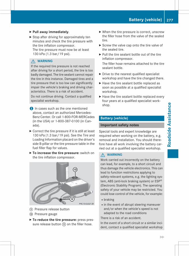
X Pull away immediately.X Stop after driving for approximately tenminutes and check the tire pressure withthe tire inflation compressor.The tire pressure must now be at least130 kPa (1.3 bar/19 psi).
G WARNINGIf the required tire pressure is not reachedafter driving for a short period, the tire is toobadly damaged. The tire sealant cannot repairthe tire in this instance. Damaged tires and atire pressure that is too low can significantlyimpair the vehicle's braking and driving char-acteristics. There is a risk of accident.Do not continue driving. Contact a qualifiedspecialist workshop.
i In cases such as the one mentionedabove, contact an authorized Mercedes-Benz Center. Or call 1-800-FOR-MERCedes(in the USA) or 1-800-387-0100 (in Can-ada).X Correct the tire pressure if it is still at least130 kPa (1.3 bar/19 psi). See the Tire andLoading Information placard on the driver'sside B-pillar or the tire pressure table in thefuel filler flap for values.X To increase the tire pressure: switch onthe tire inflation compressor.
E Pressure release buttonF Pressure gaugeX To reduce the tire pressure: press pres-sure release buttonE on the filler hose.
X When the tire pressure is correct, unscrewthe filler hose from the valve of the sealedtire.X Screw the valve cap onto the tire valve ofthe sealed tire.X Pull the tire sealant bottle out of the tireinflation compressor.The filler hose remains attached to the tiresealant bottle.X Drive to the nearest qualified specialistworkshop and have the tire changed there.X Have the tire sealant bottle replaced assoon as possible at a qualified specialistworkshop.X Have the tire sealant bottle replaced everyfour years at a qualified specialist work-shop.
Battery (vehicle)
Important safety notesSpecial tools and expert knowledge arerequired when working on the battery, e.g.removal and installation. You should there-fore have all work involving the battery car-ried out at a qualified specialist workshop.
G WARNINGWork carried out incorrectly on the batterycan lead, for example, to a short circuit andthus damage the vehicle electronics. This canlead to function restrictions applying tosafety-relevant systems, e.g. the lighting sys-tem, ABS (anti-lock braking system) or ESP®(Electronic Stability Program). The operatingsafety of your vehicle may be restricted. Youcould lose control of the vehicle, for example:RbrakingRin the event of abrupt steering maneuverand/or when the vehicle's speed is notadapted to the road conditions
There is a risk of an accident.In the event of a short circuit or a similar inci-dent, contact a qualified specialist workshop
Battery (vehicle) 277
Road
side
Assi
stan
ce
Z

immediately. Do not drive any further. Youshould have all work involving the battery car-ried out at a qualified specialist workshop.
i For further information about ABS andESP®, see (Y page 74) and (Y page 78).
G WARNINGElectrostatic build-up can lead to the creationof sparks, which could ignite the highly explo-sive gases of a battery. There is a risk of anexplosion.Before handling the battery, touch the vehiclebody to remove any existing electrostaticbuild-up.
The highly flammable gasmixture formswhencharging the battery as well as when jump-starting.Always make sure that neither you nor thebattery is electrostatically charged. A build-up of electrostatic charge can be caused, forexample:Rby wearing clothing made from syntheticfibers
Rdue to friction between clothing and seatsRif you push or pull the battery across thecarpet or other synthetic materials
Rif you wipe the battery with a cloth
G WARNINGDuring the charging process, a battery produ-ces hydrogen gas. If a short circuit occurs orsparks are created, the hydrogen gas canignite. There is a risk of an explosion.RMake sure that the positive terminal of aconnected battery does not come into con-tact with vehicle parts.
RNever placemetal objects or tools on a bat-tery.
RIt is important that you observe the descri-bed order of the battery terminals whenconnecting and disconnecting a battery.
RWhen jump-starting, make sure that thebattery poles with identical polarity areconnected.
RIt is particularly important to observe thedescribed order when connecting and dis-connecting the jumper cables.
RNever connect or disconnect the batteryterminals while the engine is running.
G WARNINGBattery acid is caustic. There is a risk of injury.Avoid contact with skin, eyes or clothing. Donot inhale any battery gases. Do not lean overthe battery. Keep children away from batter-ies. Wash away battery acid immediately withplenty of clean water and seek medical atten-tion.
H Environmental noteBatteries contain dangeroussubstances. It is against thelaw to dispose of them withthe household rubbish. Theymust be collected separatelyand recycled to protect theenvironment.Dispose of batteries in anenvironmentally friendlymanner. Take dischargedbatteries to a qualified spe-cialist workshop or a specialcollection point for used bat-teries.
! Have the battery checked regularly at aqualified specialist workshop.Observe the service intervals in the Main-tenance Booklet or contact a qualified spe-cialist workshop for more information.
! You should have all work involving thebattery carried out at a qualified specialistworkshop. In the exceptional case that it isnecessary for you to disconnect the batteryyourself, make sure that:Ryou switch off the engine and remove theSmartKey. On vehicles with KEYLESS-GO, ensure that the ignition is switchedoff. Check that all the indicator lamps inthe instrument cluster are off. Otherwise,
278 Battery (vehicle)Ro
adsi
deAs
sist
ance

electronic components, such as thealternator, may be damaged.
Ryou first remove the negative terminalclamp and then the positive terminalclamp. Never swap the terminal clamps.Otherwise, the vehicle's electronic sys-tem may be damaged.
Rthe transmission is locked in position Pafter disconnecting the battery. The vehi-cle is secured against rolling away. Youcan then no longer move the vehicle.
The battery and the cover of the positiveterminal clamp must be installed securelyduring operation.
Comply with safety precautions and take pro-tective measures when handling batteries.
Risk of explosion.
Fire, open flames and smoking areprohibited when handling the bat-tery. Avoid creating sparks.
Battery acid is caustic. Avoid con-tact with skin, eyes or clothing.Wear suitable protective clothing,especially gloves, apron and face-guard.Rinse any acid spills immediatelywith clear water. Contact a physi-cian if necessary.Wear eye protection.
Keep children away.
Observe this Operator's Manual.
For safety reasons, Mercedes-Benz recom-mends that you only use batteries which havebeen tested and approved for your vehicle byMercedes-Benz. These batteries provide
increased impact protection to prevent vehi-cle occupants from suffering acid burnsshould the battery be damaged in the event ofan accident.In order for the battery to achieve the maxi-mum possible service life, it must always besufficiently charged.The vehicle battery, like other batteries, candischarge over time if you do not use thevehicle. In this case, have the battery discon-nected at a qualified specialist workshop. Youcan also charge the battery with a chargerrecommended by Mercedes-Benz. Contact aqualified specialist workshop for further infor-mation.Have the battery condition of charge checkedmore frequently if you use the vehicle mainlyfor short trips or if you leave it standing idlefor a lengthy period. Consult a qualified spe-cialist workshop if you wish to leave yourvehicle parked for a long period of time.
i Remove the SmartKey if you park thevehicle and do not require any electricalconsumers. The vehicle will then use verylittle energy, thus conserving batterypower.
Charging the battery
G WARNINGDuring charging and jump-starting, explosivegases can escape from the battery. There is arisk of an explosion.Particularly avoid fire, open flames, creatingsparks and smoking. Ensure there is sufficientventilation while charging and jump-starting.Do not lean over a battery.
G WARNINGBattery acid is caustic. There is a risk of injury.Avoid contact with skin, eyes or clothing. Donot inhale any battery gases. Do not lean overthe battery. Keep children away from batter-ies. Wash away battery acid immediately with
Battery (vehicle) 279
Road
side
Assi
stan
ce
Z

plenty of clean water and seek medical atten-tion.
G WARNINGA discharged battery can freeze at tempera-tures below freezing point. When jump-start-ing the vehicle or charging the battery, gasescan escape from the battery. There is a risk ofan explosion.Allow the frozen battery to thaw out beforecharging it or jump-starting.
! Only use battery chargers with a maxi-mum charging voltage of 14.8 V.
! Only charge the battery using the jump-starting connection point.
If, at low temperatures, the indicator lamps/warning lamps in the instrument cluster donot light up, it is highly likely that the dis-charged battery has frozen. In this case youmay neither jump-start the vehicle nor chargethe battery. The service life of a thawed-outbattery may be shorter. The starting charac-teristics can be impaired, particularly at lowtemperatures. Have the thawed-out batterychecked at a qualified specialist workshop.Never charge a battery still installed in thevehicle unless a battery charger unitapproved byMercedes-Benz is being used. Anaccessory battery charge unit specially adap-ted for Mercedes-Benz vehicles and testedand approved by Mercedes-Benz is available.It permits the charging of the battery in itsinstalled position. Contact an authorizedMercedes-Benz Center for further informa-tion and availability. Charge the battery inaccordance with the separate instructions forthe battery charger.The jump-starting connection point is in theengine compartment (Y page 281).Read the battery charger's operating instruc-tions before charging the battery.X Open the hood.X Connect the battery charger to the positiveterminal and ground point in the same
order as when connecting the donor bat-tery in the jump-starting procedure(Y page 281).
280 Battery (vehicle)Ro
adsi
deAs
sist
ance

Jump-starting
For the jump-starting procedure, use only the jump-starting connection point, consisting of apositive terminal and a ground point, in the engine compartment.
G WARNINGBattery acid is caustic. There is a risk of injury.Avoid contact with skin, eyes or clothing. Do not inhale any battery gases. Do not lean over thebattery. Keep children away from batteries. Wash away battery acid immediately with plenty ofclean water and seek medical attention.
G WARNINGDuring charging and jump-starting, explosive gases can escape from the battery. There is a riskof an explosion.Particularly avoid fire, open flames, creating sparks and smoking. Ensure there is sufficient ven-tilation while charging and jump-starting. Do not lean over a battery.
G WARNINGDuring the charging process, a battery produces hydrogen gas. If a short circuit occurs or sparksare created, the hydrogen gas can ignite. There is a risk of an explosion.RMake sure that the positive terminal of a connected battery does not come into contact withvehicle parts.
RNever place metal objects or tools on a battery.RIt is important that you observe the described order of the battery terminals when connectingand disconnecting a battery.
RWhen jump-starting, make sure that the battery poles with identical polarity are connected.RIt is particularly important to observe the described order when connecting and disconnectingthe jumper cables.
RNever connect or disconnect the battery terminals while the engine is running.
G WARNINGA discharged battery can freeze at temperatures below freezing point. When jump-starting thevehicle or charging the battery, gases can escape from the battery. There is a risk of an explosion.Allow the frozen battery to thaw out before charging it or jump-starting.
! Vehicles with a gasoline engine: avoid repeated and lengthy starting attempts. Other-wise, the catalytic converter could be damaged by non-combusted fuel.
If the indicator/warning lamps do not light up at low temperatures, it is very likely that thedischarged battery has frozen. In this case you may neither jump-start the vehicle nor chargethe battery. The service life of a thawed-out batterymay be shorter. The starting characteristicscan be impaired, particularly at low temperatures. Have the thawed-out battery checked at aqualified specialist workshop.
Jump-starting 281
Road
side
Assi
stan
ce
Z

Do not start the vehicle using a rapid charging device. If your vehicle's battery is discharged,the engine can be jump-started from another vehicle or from a second battery using jumpercables. Observe the following points:RThe battery is not accessible in all vehicles. If the other vehicle's battery is not accessible,jump-start the vehicle using a second battery or a jump-starting device.
RVehicles with a gasoline engine: only jump-start the vehicle when the engine and exhaustsystem are cold.
RDo not start the engine if the battery is frozen. Let the battery thaw first.ROnly jump-start from batteries with a 12 V voltage rating.ROnly use jumper cables which have a sufficient cross-section and insulated terminal clamps.RIf the battery is fully discharged, leave the battery that is being used to jump-start connectedfor a few minutes before attempting to start. This charges the battery slightly.
RMake sure that the two vehicles do not touch.Make sure that:Rthe jumper cables are not damaged.Rbare parts of the terminal clamp do not come into contact with other metal parts while thejumper cables are connected to the battery.
Rthe jumper cables cannot come into contact with parts which can move when the engine isrunning, such as the V-belt pulley or the fan.X Secure the vehicle by applying the electric parking brake.X Shift the transmission to position P.X Turn the SmartKey to position 0 in the ignition lock and remove it (Y page 131). On vehicleswith KEYLESS-GO, make sure the ignition is switched off (Y page 132). All indicator lampsin the instrument cluster must be off.X Switch off all electrical consumers, e.g. rear window defroster, lighting, etc.X Open the hood.
(Example)
282 Jump-startingRo
adsi
deAs
sist
ance

Position numberB identifies the charged battery of the other vehicle or an equivalent jump-starting device.X Slide cover: of positive terminal; in the direction of the arrow.X Connect positive terminal; on your vehicle to positive terminal= of donor batteryBusing the jumper cable, always begin with positive terminal; on your own vehicle first.X Start the engine of the donor vehicle and run it at idling speed.X Connect negative terminal? of donor batteryB to ground pointA of your vehicle usingthe jumper cable, connecting the jumper cable to battery of other vehicleB first.X Start the engine.X Before disconnecting the jumper cables, let the engine run for several minutes.X First, remove the jumper cables from ground pointA and negative terminal?, then frompositive clamp; and positive terminal=. Begin each time at the contacts on your ownvehicle first.X Close cover: of positive terminal; after removing the jumper cables.X Have the battery checked at a qualified specialist workshop.
i Jump-starting is not considered to be a normal operating condition.
i Jumper cables and further information regarding jump-starting can be obtained at anyqualified specialist workshop.
Towing and tow-starting
Important safety notes
G WARNINGFunctions relevant to safety are restricted orno longer available if:Rthe engine is not running.Rthe brake system or the power steering ismalfunctioning.
Rthere is a malfunction in the voltage supplyor the vehicle's electrical system.
If your vehicle is being towed, much moreforce may be necessary to steer or brake.There is a risk of an accident.In such cases, use a tow bar. Before towing,make sure that the steering moves freely.
G WARNINGYou can no longer steer the vehicle if thesteering wheel lock has been engaged. Thereis a risk of an accident.Always switch off the ignitionwhen towing thevehicle with a tow cable or a tow bar.
G WARNINGWhen towing or tow-starting another vehicleand its weight is greater than the permissiblegross weight of your vehicle, the:Rthe towing eye could detach itselfRthe vehicle/trailer combination could roll-over.
There is a risk of an accident.When towing or tow-starting another vehicle,its weight should not be greater than the per-missible gross weight of your vehicle.
i Details on the permissible gross vehicleweight of your vehicle can be found on thevehicle identification plate (Y page 336).
! If DISTRONIC PLUS or the HOLD functionis activated, the vehicle brakes automati-cally in certain situations. To prevent dam-age to the vehicle, deactivate DISTRONICPLUS and the HOLD function in the follow-ing or other similar situations:Rwhen towing the vehicleRin the car wash
Towing and tow-starting 283
Road
side
Assi
stan
ce
Z

! Make sure that the electric parking brakeis released. If the electric parking brake isfaulty, visit a qualified specialist workshop.
! Only secure the tow rope or tow bar at thetowing eyes. Otherwise, the vehicle couldbe damaged.
! Do not use the trailer tow hitch for recov-ery or towing. Do not use the towing eye forrecovery. this could damage the vehicle. Ifin doubt, have the vehicle recovered usinga crane.
! When towing, pull away slowly andsmoothly. Pull the towed vehicle as straightas possible and not at an acute angle.Excessive tractive power could damage thevehicles.
i When towing, it is preferable to use a rigidtowing bar as opposed to a tow rope. A rigidtowing bar helps to keep the tractive powerlow.
! When towing vehicles with KEYLESS-GO,use the key instead of the Start/Stop but-ton. Otherwise, the automatic transmissionmay shift to position P when the driver's orfront-passenger door are opened, whichcould lead to damage to the transmission.
! Do not tow with sling-type equipment.This could damage the vehicle.
! Vehicles with differential locks: makesure the differential locks are in automaticmode. When towing, the differential locksmust not be switched on. The transmissionmay otherwise be damaged.
! The vehicle can be towed a maximum of30 miles (50km). The towing speed of30 mph (50 km/h) must not be exceeded.If the vehicle has to be towed more than30miles (50km), the entire vehicle must beraised and transported.
It is better to have the vehicle transportedthan to have it towed away.
If the vehicle has suffered transmission dam-age, have it transported on a transporter ortrailer.The automatic transmission must be in posi-tion N when the vehicle is being towed.The battery must be connected and charged.Otherwise, you:Rcannot turn the SmartKey to position 2 inthe ignition lock
Rcannot release the electric parking brakeRcannot shift the automatic transmission toposition N
i Deactivate the automatic locking feature(Y page 197). You could otherwise belocked out when pushing or towing thevehicle.
Installing/removing the towing eye
Installing the towing eye
Example: towing eye mounting covers
The brackets for the screw-in towing eyes arelocated in the bumpers. They are at the frontand at the rear, behind the covers.
284 Towing and tow-startingRo
adsi
deAs
sist
ance

X Remove the towing eye from the vehicletool kit (Y page 272).X To open the cover at the front: press themark on cover: inwards in the directionof the arrow.X To open the cover at the rear: insert aflat, blunt object into the cutout and levercover; out of the bumper.X Take cover: or; off the opening.X Screw in and tighten the towing eye clock-wise to the stop.
Removing the towing eyeX Unscrew and remove the towing eye.X Attach cover: or; to the bumper andpress until it engages.X Place the towing eye in the vehicle tool kit.
Towing a vehicle with both axles onthe groundIt is important that you observe the safetyinstructions when towing away your vehicle(Y page 283).The automatic transmission automaticallyshifts to positionPwhen you open the driver'sor front-passenger door or when you removethe SmartKey from the ignition lock.In order to ensure that the automatic trans-mission stays in position N when towing thevehicle, you must observe the followingpoints:X Make sure that the vehicle is stationary andthe SmartKey in the ignition lock is in posi-tion 0.X Turn the SmartKey to position 2 in the igni-tion lock.On vehicles with KEYLESS-GO, use theSmartKey instead of the Start/Stop button(Y page 132).X Depress and hold the brake pedal.X Shift the automatic transmission to posi-tion N.
X Release the brake pedal.X Release the electric parking brake.X Leave the SmartKey in position 2 in theignition lock.X Switch on the hazard warning lamps(Y page 110).i In order to signal a change of directionwhen towing the vehicle with the hazardwarning lamps switched on, use the com-bination switch as usual. In this case, onlythe indicator lamps for the direction oftravel flash. After resetting the combina-tion switch, the hazard warning lamp startsflashing again.
Towing the vehicle with the rear axleraised! The ignition must be switched off if youare towing the vehicle with the rear axleraised. Intervention by ESP® could other-wise damage the brake system.
Only possible for vehicles without4MATIC.X Switch on the hazard warning lamps(Y page 110).X Bring the front wheels into the straight-ahead position.X Turn the SmartKey to position 0 in the igni-tion lock and remove the SmartKey fromthe ignition lock.X When leaving the vehicle, take the Smart-Key or the KEYLESS-GO key with you.
When towing your vehicle with the rear axleraised, it is important that you observe thesafety instructions (Y page 283).
Transporting the vehicle! You may only secure the vehicle by thewheels, not by parts of the vehicle such asaxle or steering components. Otherwise,the vehicle could be damaged.
Towing and tow-starting 285
Road
side
Assi
stan
ce
Z
The towing eye can be used to pull the vehicleonto a trailer or transporter for transportingpurposes.X Turn the SmartKey to position 2 in the igni-tion lock.X Shift the automatic transmission to posi-tion N.
As soon as the vehicle has been loaded:X Prevent the vehicle from rolling away byapplying the electric parking brake.X Shift the automatic transmission to posi-tion P.X Turn the SmartKey to position 0 in the igni-tion lock and remove it.X Secure the vehicle.
Information on 4MATIC vehicles! Vehicles with 4MATIC must not be towedwith either the front or the rear axle raised,as doing so will damage the transmission.
If the vehicle has transmission damage ordamage to the front or rear axle, have it trans-ported on a transporter or trailer.In the event of damage to the electricalsystemIf the battery is defective, the automatictransmission will be locked in position P. Toshift the automatic transmission to positionN, you must provide power to the vehicle'selectrical system in the same way as whenjump-starting (Y page 281).Have the vehicle transported on a transporteror trailer.
Tow-starting (emergency enginestarting)! Vehicles with automatic transmissionmust not be tow-started. You could other-wise damage the automatic transmission.
i You can find information on "Jump-start-ing" under (Y page 281).
Fuses
Important safety notes
G WARNINGIf you manipulate or bridge a faulty fuse or ifyou replace it with a fuse with a higher amper-age, the electric cables could be overloaded.This could result in a fire. There is a risk of anaccident and injury.Always replace faulty fuses with the specifiednew fuses having the correct amperage.
! For the fuse boxes in the engine compart-ment and under the rear bench seat, onlyuse fuses with the suffix "S". Otherwise,components or systems could be dam-aged.
The fuses in your vehicle serve to close downfaulty circuits. If a fuse blows, all the compo-nents on the circuit and their functions stopoperating.Blown fuses must be replaced with fuses ofthe same rating, which you can recognize bythe color and value. The fuse ratings are listedin the fuse allocation chart.If a newly inserted fuse also blows, have thecause traced and rectified at a qualified spe-cialist workshop, e.g. an authorizedMercedes-Benz Center.
Before changing a fuseObserve the important safety notes(Y page 286)X Secure the vehicle against rolling away(Y page 145).X Switch off all electrical consumers.X Turn the SmartKey to position 0 in the igni-tion lock and remove it (Y page 131). Onvehicles with KEYLESS-GO, make sure theignition is switched off (Y page 132).All indicator lamps in the instrument clustermust be off.
286 FusesRo
adsi
deAs
sist
ance

The fuses are located in various fuse boxes:RFuse box on the front-passenger side of thedashboard
RFuse box in the engine compartment on theright-hand side of the vehicle, when viewedin the direction of travel
RFuse box under the rear bench seatThe fuse allocation chart is located in the fusebox under the rear bench seat (Y page 288).
Dashboard fuse boxObserve the important safety notes(Y page 286)
! Do not use a pointed object such as ascrewdriver to open the cover in the dash-board. You could damage the dashboard orthe cover.
! Make sure that no moisture can enter thefuse box when the cover is open.
! When closing the cover, make sure that itis lying correctly on the fuse box. Moistureseeping in or dirt could otherwise impairthe operation of the fuses.
X Open the front-passenger door.X To open: pull cover: outwards in thedirection of the arrow and remove it.X To close: clip in cover: on the front of thedashboard.X Fold cover: inwards until it engages.
Fuse box in the engine compartmentPay attention to the important safety notes(Y page 286).
G WARNINGWhen the hood is open and the windshieldwipers are set inmotion, you can be injured bythe wiper linkage. There is a risk of injury.Always switch off the windshield wipers andthe ignition before opening the hood.
! Make sure that no moisture can enter thefuse box when the cover is open.
! When closing the cover, make sure that itis lying correctly on the fuse box. Moistureseeping in or dirt could otherwise impairthe operation of the fuses.
X Open the hood.X Use a dry cloth to remove any moisturefrom the fuse box.X To open: open clamps;.X Fold up cover: in the direction of thearrow and remove it.X To close: check whether the seal is lyingcorrectly in cover:.X Insert cover: at the side of the fuse boxinto the retainers.X Fold down cover: and close clamps;.X Close the hood.
Fuses 287
Road
side
Assi
stan
ce
Z

Fuse box under the rear bench seatPay attention to the important safety notes(Y page 286).
! Make sure that no moisture can enter thefuse box when the cover is open.
! When closing the cover, make sure that itis lying correctly on the fuse box. Moistureseeping in or dirt could otherwise impairthe operation of the fuses or the covercould be damaged by the rear bench seat.
X Fold the right-hand rear bench seat forward(Y page 246).X To open: lift and fold out carpet: in thedirection of the arrow.
X Release clamps; by pressing them in thedirection of the arrow.X Fold cover= up in the direction of thearrow and remove it.i The fuse allocation chart is located undercover=.
X To close: insert cover= into the retainerson the side of the fuse box.X Fold down cover= until clamps; engageaudibly.X Fold the right-hand rear bench seat back(Y page 246).
288 FusesRo
adsi
deAs
sist
ance
Useful information ............................ 290Important safety notes ..................... 290Operation ........................................... 290Winter operation ............................... 292Tire pressure ..................................... 293Loading the vehicle .......................... 301All about wheels and tires ............... 304Changing a wheel .............................. 312Wheel and tire combinations ........... 317Emergency spare wheel ................... 330
289
Whe
els
and
tires
Useful information
i This Operator's Manual describes allmodels and all standard and optional equip-ment of your vehicle available at the time ofpublication of the Operator's Manual.Country-specific differences are possible.Please note that your vehicle may not beequipped with all features described. Thisalso applies to safety-related systems andfunctions.
i Read the information on qualified special-ist workshops (Y page 35).
Important safety notes
G WARNINGIf wheels and tires of the wrong size are used,the wheel brakes or suspension componentsmay be damaged. There is a risk of an acci-dent.Always replace wheels and tires with thosethat fulfill the specifications of the originalpart.When replacing wheels, make sure to use thecorrect:RdesignationRmodelWhen replacing tires, make sure to use thecorrect:RdesignationRmanufacturerRmodel
G WARNINGA flat tire severely impairs the driving, steer-ing and braking characteristics of the vehicle.There is a risk of accident.Tires without run-flat characteristics:Rdo not drive with a flat tire.Rimmediately replace the flat tire with youremergency spare wheel or spare wheel, orconsult a qualified specialist workshop.
Tires with run-flat characteristics:Rpay attention to the information and warn-ing notices on MOExtended tires (tires withrun-flat characteristics).
Accessories that are not approved for yourvehicle by Mercedes-Benz or that are notbeing used correctly can impair operatingsafety.Before purchasing and using non-approvedaccessories, visit a qualified specialist work-shop and inquire about:RsuitabilityRlegal stipulationsRfactory recommendationsInformation on the sizes and types of wheelsand tires for your vehicle can be found under"Wheel/tire combinations" (Y page 317).Tire pressure information can be found:Ron the vehicle's Tire and Loading Informa-tion placard on the B-pillar
Ron the tire pressure label on the fuel fillerflap
Rin the "Tire pressure" section
Operation
Information on drivingCheck the tire pressure when the vehicle isheavily laden and adjust prior to a trip.While driving, pay attention to vibrations,noises and unusual handling characteristics,e.g. pulling to one side. This may indicate thatthe wheels or tires are damaged. If you sus-pect that a tire is defective, reduce yourspeed immediately. Stop the vehicle as soonas possible to check the wheels and tires fordamage. Hidden tire damage could also becausing the unusual handling characteristics.If you find no signs of damage, have the tiresand wheels checked at a qualified specialistworkshop.When parking your vehicle, make sure thatthe tires do not get deformed by the curb or
290 OperationW
heel
san
dtir
es

other obstacles. If it is necessary to drive overcurbs, speed humps or similar elevations, tryto do so slowly and at an obtuse angle. Oth-erwise, the tires, particularly the sidewalls,may be damaged.
Regular checking of wheels and tires
G WARNINGDamaged tires can cause tire inflation pres-sure loss. As a result, you could lose control ofyour vehicle. There is a risk of accident.Check the tires regularly for signs of damageand replace any damaged tires immediately.
Regularly check the wheels and tires of yourvehicle for damage at least once a month, aswell as after driving off-road or on roughroads. Damaged wheels can cause a loss oftire pressure. Pay particular attention to dam-age such as:Rcuts in the tiresRpuncturesRtears in the tiresRbulges on tiresRdeformation or severe corrosion on wheelsRegularly check the tire tread depth and thecondition of the tread across the whole widthof the tire (Y page 291). If necessary, turn thefront wheels to full lock in order to inspect theinner side of the tire surface.All wheels must have a valve cap to protectthe valve against dirt and moisture. Do notmount anything onto the valve other than thestandard valve cap or other valve capsapproved by Mercedes-Benz for your vehicle.Do not use any other valve caps or systems,e.g. tire pressure monitoring systems.Regularly check the pressure of all the tiresparticularly prior to long trips. Adjust the tirepressure as necessary (Y page 293).Observe the notes on the emergency sparewheel (Y page 330).
The service life of tires depends, among otherthings, on the following factors:Rdriving styleRtire pressureRdistance covered
Notes on tire tread
G WARNINGInsufficient tire tread will reduce tire traction.The tire is no longer able to dissipate water.This means that on wet road surfaces, the riskof hydroplaning increases, in particular wherespeed is not adapted to suit the driving con-ditions. There is a risk of accident.If the tire pressure is too high or too low, tiresmay exhibit different levels of wear at differ-ent locations on the tire tread. Thus, youshould regularly check the tread depth andthe condition of the tread across the entirewidth of all tires.Minimum tire tread depth for:RSummer tires:â in (3 mm)RM+S tires:ã in (4 mm)For safety reasons, replace the tires beforethe legally prescribed limit for the minimumtire tread depth is reached.
Marking: indicates where the bar indicatorfor tread wear (arrow) is integrated into thetire tread.Treadwear indicators (TWI) are required bylaw. Six indicators are positioned on the tiretread. They are visible once a tread depth of
Operation 291
Whe
els
and
tires
Z

approximatelyá in (1.6 mm) has beenreached. If this is the case, the tire is so wornthat it must be replaced.
Selecting, mounting and replacingtires
ROnly mount tires and wheels of the sametype and make.Exception: it is permissible to install a dif-ferent type or make in the event of a flattire. Observe here the "MOExtended tires(tires with run-flat characteristics)" section(Y page 273).
ROnly mount tires of the correct size ontothe wheels.
RBreak in new tires at moderate speeds forthe first 60miles (100 km). They only reachtheir full performance after this distance.
RDo not drive with tires which have too littletread depth, as this significantly reducesthe traction on wet roads (hydroplaning).
RReplace the tires after six years at the lat-est, regardless of wear.
Observe the notes on the emergency sparewheel (Y page 330).
MOExtended tires (tires with run-flatproperties)With MOExtended tires (tires with run flatcharacteristics), you can continue to driveyour vehicle even if there is a total loss ofpressure in one or more tires.MOExtended tires may only be used in con-junction with an active tire pressure losswarning systemorwith an active tire pressuremonitor and on wheels specifically tested byMercedes-Benz.Notes on driving with MOExtended tires witha flat tire (Y page 273).
i Vehicles equippedwithMOExtended tiresare not equipped with a TIREFIT kit at thefactory. It is therefore recommended thatyou additionally equip your vehicle with a
TIREFIT kit if you mount tires that do notfeature run-flat properties, e.g. winter tires.A TIREFIT kit can be obtained from a quali-fied specialist workshop.
Winter operation
General notesYou can find information about this in theDigital Operator's Manual.
Driving with summer tiresAt temperatures below 45‡ (+7†), summertires lose elasticity and therefore traction andbraking power. Change the tires on your vehi-cle to M+S tires. Using summer tires at verycold temperatures could cause cracks toform, thereby damaging the tires perma-nently. Mercedes-Benz cannot acceptresponsibility for this type of damage.
G WARNINGDamaged tires can cause tire inflation pres-sure loss. As a result, you could lose control ofyour vehicle. There is a risk of accident.Check the tires regularly for signs of damageand replace any damaged tires immediately.
M+S tires
G WARNINGM+S tires with a tire tread depth of less thanã in (4 mm) are not suitable for use in winterand do not provide sufficient traction. There isa risk of an accident.M+S tires with a tread depth of less thanã in(4 mm) must be replaced immediately.
Further information can be found in the Digi-tal Operator's Manual.
292 Winter operationW
heel
san
dtir
es

Snow chains
G WARNINGIf snow chains are installed to the frontwheels, they may drag against the vehiclebody or chassis components. This couldcause damage to the vehicle or the tires.There is a risk of an accident.To avoid hazardous situations:Rnever install snow chains to the frontwheels
Ralways install snow chains in pairs to therear wheels.
Further information can be found in the Digi-tal Operator's Manual.
Tire pressure
Tire pressure specifications
Important safety notes
G WARNINGUnderinflated or overinflated tires pose thefollowing risks:Rthe tires may burst, especially as the loadand vehicle speed increase.
Rthe tires may wear excessively and/orunevenly, which may greatly impair tiretraction.
Rthe driving characteristics, as well as steer-ing and braking, may be greatly impaired.
There is a risk of an accident.Follow recommended tire inflation pressuresand check the pressure of all the tires includ-ing the spare wheel:Rmonthly, at leastRif the load changesRbefore beginning a long journeyRunder different operating conditions, e.g.off-road driving
If necessary, correct the tire pressure.
i The specifications on the sample Tire andLoading Information placard and tire pres-sure tables are examples. Tire pressurespecifications are vehicle-specific and maydeviate from the data shown here. The tirepressure specifications that are valid foryour vehicle can be found on the Tire andLoading Information placard and tire pres-sure table on the vehicle.
General notesThe recommended tire pressures for the tiresmounted at the factory can be found on thelabels described here.Operation with the emergency sparewheel (Y page 330).Operation with a trailer: the applicablevalue for the rear tires is the maximum tirepressure value stated in the table inside thefuel filler flap.Further information on tire pressures can beobtained at a qualified specialist workshop.
Tire and Loading Information placard
: Recommended tire pressuresThe Tire and Loading Information placard ison the B-pillar on the driver's side(Y page 301).The Tire and Loading Information placard con-tains the recommended tire pressures forcold tires. The recommended tire pressuresare valid for the maximum permissible loadand up to the maximum permissible vehiclespeed.
Tire pressure 293
Whe
els
and
tires
Z
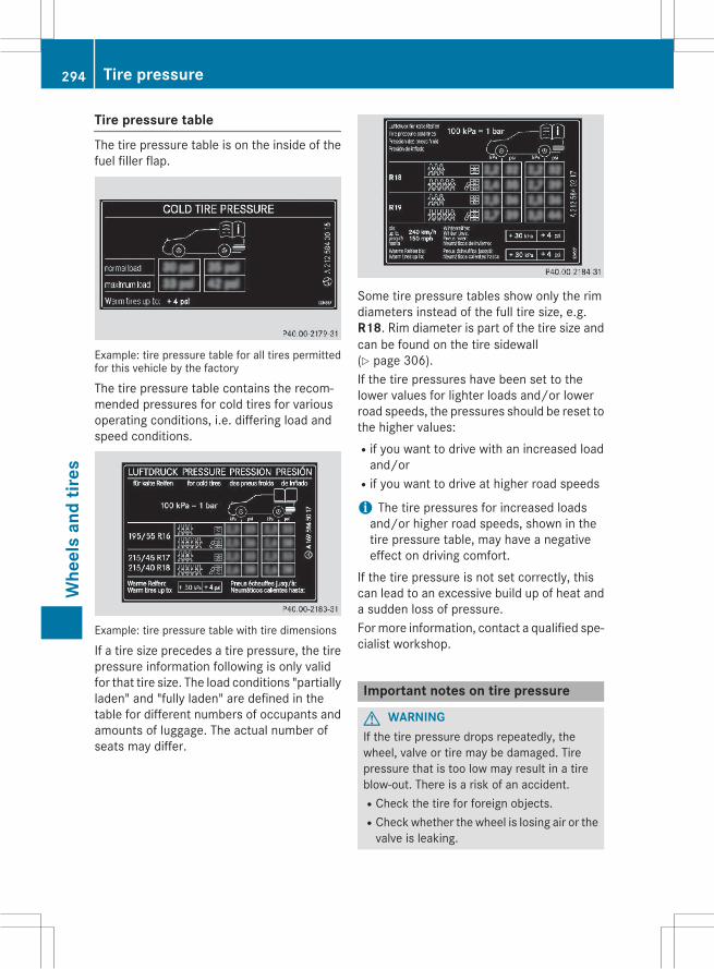
Tire pressure tableThe tire pressure table is on the inside of thefuel filler flap.
Example: tire pressure table for all tires permittedfor this vehicle by the factory
The tire pressure table contains the recom-mended pressures for cold tires for variousoperating conditions, i.e. differing load andspeed conditions.
Example: tire pressure table with tire dimensions
If a tire size precedes a tire pressure, the tirepressure information following is only validfor that tire size. The load conditions "partiallyladen" and "fully laden" are defined in thetable for different numbers of occupants andamounts of luggage. The actual number ofseats may differ.
Some tire pressure tables show only the rimdiameters instead of the full tire size, e.g.R18. Rim diameter is part of the tire size andcan be found on the tire sidewall(Y page 306).If the tire pressures have been set to thelower values for lighter loads and/or lowerroad speeds, the pressures should be reset tothe higher values:Rif you want to drive with an increased loadand/or
Rif you want to drive at higher road speeds
i The tire pressures for increased loadsand/or higher road speeds, shown in thetire pressure table, may have a negativeeffect on driving comfort.
If the tire pressure is not set correctly, thiscan lead to an excessive build up of heat anda sudden loss of pressure.Formore information, contact a qualified spe-cialist workshop.
Important notes on tire pressure
G WARNINGIf the tire pressure drops repeatedly, thewheel, valve or tire may be damaged. Tirepressure that is too low may result in a tireblow-out. There is a risk of an accident.RCheck the tire for foreign objects.RCheck whether the wheel is losing air or thevalve is leaking.
294 Tire pressureW
heel
san
dtir
es

If you are unable to rectify the damage, con-tact a qualified specialist workshop.
G WARNINGIf you fit unsuitable accessories onto tirevalves, the tire valves may be overloaded andmalfunction, which can cause tire pressureloss. Due to their design, retrofitted tire pres-sure monitors keep the tire valve open. Thiscan also result in tire pressure loss. There is arisk of an accident.Only screw the standard valve cap or othervalve caps approved by Mercedes-Benz foryour vehicle onto the tire valve.
Use a suitable pressure gauge to check thetire pressure. The outer appearance of a tiredoes not permit any reliable conclusion aboutthe tire pressure. On vehicles equipped withthe electronic tire pressure monitoring sys-tem, the tire pressure can be checked usingthe on-board computer.The tire temperature and pressure increasewhen the vehicle is in motion. This is depend-ent on the driving speed and the load.Therefore, you should only correct tire pres-sures when the tires are cold.The tires are cold:Rif the vehicle has been parked withoutdirect sunlight on the tires for at least threehours and
Rif the vehicle has not been driven furtherthan 1 mile (1.6 km)
The tire temperature changes depending onthe outside temperature, the vehicle speedand the tire load. If the tire temperaturechanges by 18 ‡ (10 †), the tire pressurechanges by approximately 10 kPa (0.1 bar/1.5 psi). Take this into account when check-ing the pressure of warm tires. Only correctthe tire pressure if it is too low for the currentoperating conditions. If you check the tirepressure when the tires are warm, the result-ing value will be higher than if the tires werecold. This is normal. Do not reduce the tire
pressure to the value specified for cold tires.The tire pressure would otherwise be too low.Observe the recommended tire pressures forcold tires:Ron the Tire and Loading Information placardon the B-pillar on the driver's side
Rin the tire pressure table on the inside of thefuel filler flap
Rprinted in yellow on the rim of the emer-gency/collapsible spare wheel (dependingon vehicle equipment)
Underinflated or overinflated tires
Underinflated tires
G WARNINGTires with pressure that is too low can over-heat and burst as a consequence. In addition,they also suffer from excessive and/or irreg-ular wear, which can severely impair the brak-ing properties and the driving characteristics.There is a risk of an accident.Avoid tire pressures that are too low in all thetires, including the spare wheel.
Underinflated tires may:Roverheat, leading to tire defectsRadversely affect handlingRwear excessively and/or unevenlyRhave an adverse effect on fuel consumption
Overinflated tires
G WARNINGTires with excessively high pressure can burstbecause they are damaged more easily byroad debris, potholes etc. In addition, theyalso suffer from irregular wear, which canseverely impair the braking properties and thedriving characteristics. There is a risk of anaccident.Avoid tire pressures that are too high in all thetires, including the spare wheel.
Tire pressure 295
Whe
els
and
tires
Z

Overinflated tires may:Rincrease the braking distanceRadversely affect handlingRwear excessively and/or unevenlyRhave an adverse effect on ride comfortRbe more susceptible to damage
Maximum tire pressures
: Example: maximum permissible tire pres-sure
Never exceed the maximum permissible tireinflation pressure. Always observe the rec-ommended tire pressure for your vehiclewhen adjusting the tire pressure(Y page 293).
i The actual values for tires are vehicle-specific and may deviate from the values inthe illustration.
Checking the tire pressures
Important safety notesObserve the notes on tire pressure(Y page 293).Information on air pressure for the tires onyour vehicle can be found:Ron the vehicle's Tire and Loading Informa-tion placard on the B-pillar
Ron the tire pressure label on the fuel fillerflap
Rin the "Tire pressure" section
Checking tire pressures manuallyTo determine and set the correct tire pres-sure, proceed as follows:X Remove the valve cap of the tire that is tobe checked.X Press the tire pressure gauge securely ontothe valve.X Read the tire pressure and compare it withthe recommended value on the Tire andLoading Information placard (Y page 293).X If the tire pressure is too low, increase it tothe recommended value.X If the tire pressure is too high, release air bypressing down the metal pin in the valve.Use the tip of a pen, for example. Then,check the tire pressure again using the tirepressure gauge.X Screw the valve cap onto the valve.X Repeat these steps for the other tires.
Tire pressure loss warning system
General notesWhile the vehicle is in motion, the tire pres-sure loss warning system monitors the settire pressure using the rotational speed of thewheels. This enables the system to detectsignificant pressure loss in a tire. If the speedof rotation of a wheel changes as a result of aloss of pressure, a corresponding warningmessage will appear in the multifunction dis-play.You can recognize the tire pressure losswarn-ing by the Run Flat Indicator ActivePress 'OK' to Restart message whichappears in the Service menu of the multi-function display. Information on the messagedisplay can be found in the "Restarting the tirepressure loss warning system" section(Y page 297).
296 Tire pressureW
heel
san
dtir
es

Important safety notesThe tire pressure warning system does notwarn you of an incorrectly set tire pressure.Observe the notes on the recommended tirepressure (Y page 293).The tire pressure loss warning does notreplace the need to regularly check the tirepressure. An even loss of pressure on severaltires at the same time cannot be detected bythe tire pressure loss warning system.The tire pressure monitor is not able to warnyou of a sudden loss of pressure, e.g. if thetire is penetrated by a foreign object. In theevent of a sudden loss of pressure, bring thevehicle to a halt by braking carefully. Avoidabrupt steering maneuvers.The function of the tire pressure loss warningsystem is limited or delayed if:Rsnow chains are mounted on your vehicle'stires.
Rroad conditions are wintry.Ryou are driving on sand or gravel.Ryou adopt a very sporty driving style (cor-nering at high speeds or driving with highrates of acceleration).
Ryou are towing a very heavy or large trailer.Ryou are driving with a heavy load (in thevehicle or on the roof).
Restarting the tire pressure loss warn-ing systemRestart the tire pressure loss warning systemif you have:Rchanged the tire pressureRchanged the wheels or tiresRmounted new wheels or tiresX Before restarting, make sure that the tirepressures are set properly on all four tiresfor the respective operating conditions.The recommended tire pressures can befound on the Tire and Loading Informationplacard on the B-pillar on the driver's sideor the tire pressure table on the fuel fillerflap.
The tire pressure loss warning system canonly give reliable warnings if you have setthe correct tire pressure. If an incorrect tirepressure is set, these incorrect values willbe monitored.X Also observe the notes in the section on tirepressures (Y page 293).X Make sure that the SmartKey is in position
2 in the ignition lock (Y page 131).X Press the=or;button on the steer-ing wheel to select the Service menu.X Press the9 or: button to selectTire Pressure.X Press thea button.The Run Flat Indicator activeRestart with OKmessage appears in themultifunction display.
If you wish to confirm the restart:X Press thea button.The Tire Pressure Now OK? messageappears in the multifunction display.X Press the9 or: button to selectYes.X Press thea button.The Run Flat Indicator Restartedmessage appears in the multifunction dis-play.After a teach-in period, the tire pressureloss warning system will monitor the settire pressures of all four tires.
If you wish to cancel the restart:X Press the% button.orX When the Tire Pressure Now OK? mes-sage appears, press the9 or: but-ton to select Cancel.X Press thea button.The tire pressure values stored at the lastrestart will continue to be monitored.
Tire pressure 297
Whe
els
and
tires
Z
Tire pressure monitor
General notesIf a tire pressuremonitor is installed, the vehi-cle's wheels have sensors that monitor thetire pressures in all four tires. The tire pres-sure monitor warns you if the pressure dropsin one or more of the tires. The tire pressuremonitor only functions if the correspondingsensors are installed in all wheels.Information on tire pressures is displayed inthe multifunction display. After a fewminutesof driving, the current tire pressure of eachtire is shown in the Servicemenu of the mul-tifunction display, see illustration (example).
For information on the message display, referto the "Checking the tire pressure electroni-cally" section (Y page 299).
Important safety notes
G WARNINGEach tire, including the spare (if provided),should be checked at least once a monthwhen cold and inflated to the pressure rec-ommended by the vehicle manufacturer onthe Tire and Loading Information placard onthe driver's door B-pillar or the tire pressurelabel on the inside of the fuel filler flap. If yourvehicle has tires of a different size than thesize indicated on the Tire and Loading Infor-mation placard or the tire pressure label, youshould determine the proper tire pressure forthose tires.As an added safety feature, your vehicle hasbeen equippedwith a tire pressuremonitoringsystem (TPMS) that illuminates a low tire pres-sure telltale when one or more of your tiresare significantly underinflated. Accordingly,
when the low tire pressure telltale illuminates,you should stop and check your tires as soonas possible, and inflate them to the properpressure. Driving on a significantly underin-flated tire causes the tire to overheat and canlead to tire failure. Underinflation alsoreduces fuel efficiency and tire tread life, andmay affect the vehicle's handling and stop-ping ability.Please note that the TPMS is not a substitutefor proper tire maintenance, and it is the driv-er's responsibility to maintain correct tirepressure, even if underinflation has notreached the level to trigger illumination of theTPMS low tire pressure telltale.USA only:Your vehicle has also been equipped with aTPMS malfunction indicator to indicate if thesystem is not operating properly. The TPMSmalfunction indicator is combined with thelow tire pressure telltale. When the systemdetects a malfunction, the warning lamp willflash for approximately a minute and thenremain continuously illuminated. Thissequencewill be repeated every time the vehi-cle is started as long as the malfunctionexists.When themalfunction indicator is illuminated,the systemmay not be able to detect or signallow tire pressure as intended. TPMS malfunc-tions may occur for a variety of reasons,including the mounting of incompatiblereplacement or alternate tires or wheels onthe vehicle that prevent the TPMS from func-tioning properly. Always check the TPMSmal-function telltale after replacing one or moretires or wheels on your vehicle to ensure thatthe replacement or alternate tires and wheelsallow the TPMS to continue to function prop-erly.
It is the driver's responsibility to set the tirepressure to that recommended for cold tireswhich is suitable for the operating situation(Y page 293). Note that the correct tire pres-sure for the current operating situation mustfirst be taught-in to the tire pressure monitor.
298 Tire pressureW
heel
san
dtir
es
If there is a substantial loss of pressure, thewarning threshold for the warning message isaligned to the reference values taught-in.Restart the tire pressuremonitor after adjust-ing the pressure of the cold tires(Y page 300). The current pressures aresaved as new reference values. As a result, awarning message will appear if the tire pres-sure drops significantly.The tire pressure monitor does not warn youof an incorrectly set tire pressure. Observethe notes on the recommended tire pressure(Y page 293).The tire pressure monitor is not able to warnyou of a sudden loss of pressure, e.g. if thetire is penetrated by a foreign object. In theevent of a sudden loss of pressure, bring thevehicle to a halt by braking carefully. Avoidabrupt steering maneuvers.The tire pressure monitor has a yellow warn-ing lamp in the instrument cluster for indicat-ing a pressure loss or malfunction. Whetherthe warning lamp flashes or lights up indi-cates whether a tire pressure is too low or thetire pressure monitor is malfunctioning:Rif the warning lamp is lit continuously, thetire pressure on one or more tires is signif-icantly too low. The tire pressure monitor isnot malfunctioning.
Rif the warning lamp flashes for around aminute and then remains lit constantly, thetire pressure monitor is malfunctioning.
i In addition to the warning lamp, a mes-sage appears in the multifunction display.Observe the information on display mes-sages (Y page 210).
It may take up to ten minutes for a malfunc-tion of the tire pressure monitor to be shown.The malfunction is first indicated by the tirepressure warning lamp flashing for approx-imately one minute and then remaining lit.When the malfunction has been rectified, thetire pressure warning lamp goes out after afew minutes of driving.
The tire pressure values indicated by the on-board computer may differ from those meas-ured at a gas station with a pressure gauge.The tire pressures shown by the on-boardcomputer refer to those measured at sealevel. At high altitudes, the tire pressure val-ues indicated by a pressure gauge are higherthan those shown by the on-board computer.In this case, do not reduce the tire pressures.The operation of the tire pressuremonitor canbe affected by interference from radio trans-mitting equipment (e.g. radio headphones,two-way radios) that may be being operatedin or near the vehicle.
Checking the tire pressure electroni-callyX Make sure that the SmartKey is in position
2 in the ignition lock (Y page 131).X Press the=or;button on the steer-ing wheel to select the Service menu.X Press the9 or: button to selectTire Pressure.X Press thea button.The current tire pressure of each tire isshown in the multifunction display.
If the vehicle has been parked for longer than20 minutes, the Tire pressure will bedisplayed after driving a fewminutes message appears.After a teach-in process, the tire pressuremonitor automatically detects new wheels ornew sensors. As long as a clear allocation ofthe tire pressure values to the individualwheels is not possible, the Tire PressureMonitor Active display message is showninstead of the tire pressure display. The tirepressures are already being monitored.
i If an emergency spare wheel is mounted,the system may continue to show the tirepressure of the wheel that has beenremoved for a few minutes. If this occurs,note that the value displayed for the posi-tion where the spare wheel is mounted is
Tire pressure 299
Whe
els
and
tires
Z

not the same as the current tire pressure ofthe emergency spare wheel.
Tire pressure monitor warning mes-sagesIf the tire pressuremonitor detects a pressureloss in one or more tires, a warning messageis shown in the multifunction display and theyellow tire pressure monitor warning lampcomes on.RIf the Please Correct Tire Pressuremessage appears in the multifunction dis-play, the tire pressure in at least one tire istoo low and must be corrected at the nextopportunity.
RIf the Check Tiresmessage appears in themultifunction display, the tire pressure inone or more tires has dropped significantlyand the tires must be checked.
RIf the Warning Tire Malfunction mes-sage appears in the multifunction display,the tire pressure in one or more tires hasdropped suddenly and the tires must bechecked.
i If the wheel positions on the vehicle arerotated, the tire pressures may be dis-played for the wrong positions for a shorttime. This is rectified after a few minutes ofdriving, and the tire pressures are displayedfor the correct positions.
Restarting the tire pressure monitorWhen you restart the tire pressuremonitor, allexisting warning messages are deleted andthe warning lamps go out. The monitor usesthe currently set tire pressures as the refer-ence values formonitoring. Inmost cases, thetire pressure monitor will automaticallydetect the new reference values after youhave changed the tire pressure. However, youcan also define reference values manually asdescribed here. The tire pressure monitorthen monitors the new tire pressure values.X Set the tire pressure to the value recom-mended for the corresponding driving sit-
uation on the Tire and Loading Informationplacard on the driver's sideB-pillar (Y page 293).Additional tire pressure values for differentloads can also be found on the tire pressuretable on the inside of the fuel filler flap(Y page 293).X Make sure that the tire pressure is correcton all four wheels.X Make sure that the SmartKey is in position
2 in the ignition lock.X Press the=or;button on the steer-ing wheel to select the Service menu.X Press the9 or: button to selectTire Pressure.X Press thea button.The multifunction display shows the cur-rent tire pressure for the individual tires orthe Tire pressure will be displayedafter driving a few minutes mes-sage.X Press the: button.The Use current pressures as newreference values message appears inthe multifunction display.
If you wish to confirm the restart:X Press thea button.The Tire Press. Monitor Restartedmessage appears in the multifunction dis-play.After driving for a few minutes, the systemchecks whether the current tire pressuresare within the specified range. The new tirepressures are then accepted as referencevalues and monitored.
If you wish to cancel the restart:X Press the% button.The tire pressure values stored at the lastrestart will continue to be monitored.
Radio type approval for the tire pres-sure monitorIn certain countries, a radio type approval forthe tire pressure monitor may be required.
300 Tire pressureW
heel
san
dtir
es

The radio type approval number for the tirepressuremonitor can be found in the "Wheelsand tires" section of the Digital Operator'sManual.
Loading the vehicle
Instruction labels for tires and loads
G WARNINGOverloaded tires can overheat, causing ablowout. Overloaded tires can also impair thesteering and driving characteristics and leadto brake failure. There is a risk of accident.Observe the load rating of the tires. The loadrating must be at least half of the GAWR ofyour vehicle. Never overload the tires byexceeding the maximum load.
Two instruction labels on your vehicle showthe maximum possible load.(1) The Tire and Loading Information placard
is on the B-pillar on the driver's side. TheTire and Loading Information placardshows themaximum permissible numberof occupants and the maximum permis-sible vehicle load. It also contains detailsof the tire sizes and corresponding pres-sures for tires mounted at the factory.
(2) The vehicle identification plate is on theB-pillar on the driver's side. The vehicleidentification plate informs you of thegross vehicle weight rating. It is made upof the vehicle weight, all vehicle occu-pants, the fuel and the cargo. You canalso find information about themaximumgross axle weight rating on the front andrear axle.The maximum gross axle weight rating isthe maximum weight that can be carriedby one axle (front or rear axle). Neverexceed the maximum load or the maxi-mum gross axle weight rating for thefront or rear axle.
: B-pillar, driver's side
Maximum permissible gross vehicleweight rating
X Specification for maximum gross vehicleweight: is listed in the Tire and LoadingInformation placard: "The combined weightof occupants and cargo should neverexceed XXX kilograms or XXX lbs."
The gross weight of all vehicle occupants,load and luggage must not exceed the speci-fied value.
i The specifications shown on the Tire andLoading Information placard in the illustra-tion are examples. The maximum permis-sible gross vehicle weight rating is vehicle-specific and may differ from that in theillustration. You can find the validmaximum
Loading the vehicle 301
Whe
els
and
tires
Z

permissible gross vehicle weight rating foryour vehicle on the Tire and Loading Infor-mation placard.
Number of seats
Maximum number of seats: indicates themaximum number of occupants allowed totravel in the vehicle. This information can befound on the Tire and Loading Informationplacard.
i The specifications shown on the Tire andLoading Information placard in the illustra-tion are examples. The number of seats isvehicle-specific and can differ from thedetails shown. The number of seats in yourvehicle can be found on the Tire and Load-ing Information placard.
Determining the correct load limit
Step-by-step instructionsThe following steps have been developed asrequired of all manufacturers under Title 49,Code of U.S. Federal Regulations, Part 575pursuant to the "National Traffic and MotorVehicle Safety Act of 1966".X Step 1: Locate the statement "The com-bined weight of occupants and cargoshould never exceed XXX kg or XXX lbs." on
your vehicle’s Tire and Loading Informationplacard.X Step 2: Determine the combined weight ofthe driver and passengers that will be ridingin your vehicle.X Step 3: Subtract the combined weight ofthe driver and passengers from XXX kilo-grams or XXX lbs.X Step 4: The resulting figure equals theavailable amount of cargo and luggage loadcapacity. For example, if the "XXX" amountequals 1400 lbs and there will be five150-lb passengers in your vehicle, theamount of available cargo and luggage loadcapacity is 650 lbs (1400 - 750 (5 x 150) =650 lbs).X Step 5:Determine the combined weight ofluggage and cargo being loaded on thevehicle. That weight may not safely exceedthe available cargo and luggage load capa-city calculated in step 4.
302 Loading the vehicleW
heel
san
dtir
es
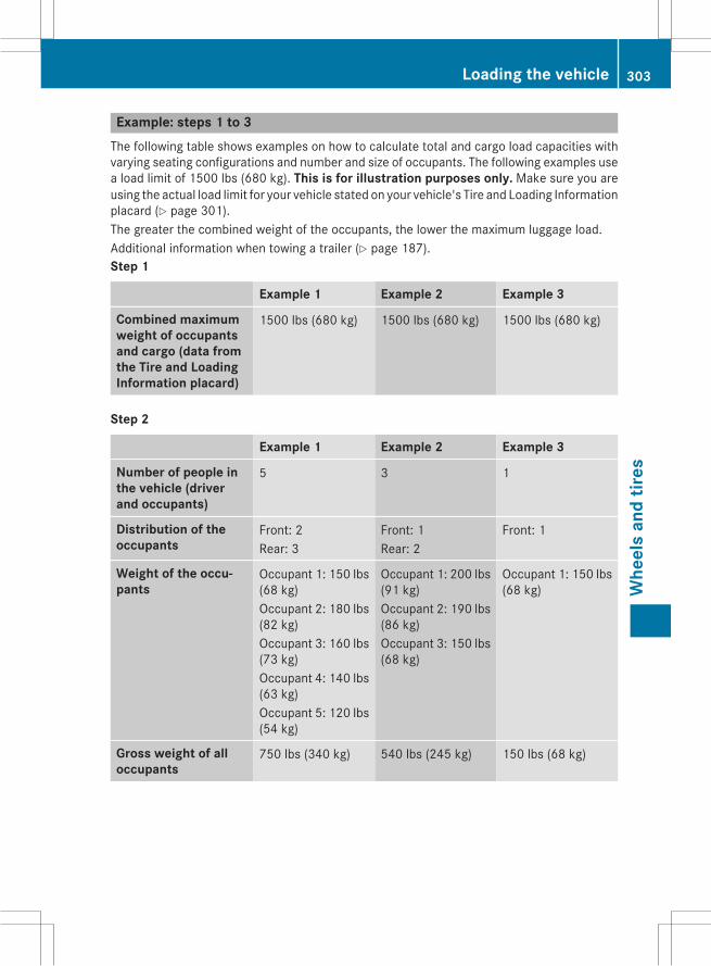
Example: steps 1 to 3The following table shows examples on how to calculate total and cargo load capacities withvarying seating configurations and number and size of occupants. The following examples usea load limit of 1500 lbs (680 kg). This is for illustration purposes only. Make sure you areusing the actual load limit for your vehicle stated on your vehicle's Tire and Loading Informationplacard (Y page 301).The greater the combined weight of the occupants, the lower the maximum luggage load.Additional information when towing a trailer (Y page 187).Step 1
Example 1 Example 2 Example 3
Combined maximumweight of occupantsand cargo (data fromthe Tire and LoadingInformation placard)
1500 lbs (680 kg) 1500 lbs (680 kg) 1500 lbs (680 kg)
Step 2
Example 1 Example 2 Example 3
Number of people inthe vehicle (driverand occupants)
5 3 1
Distribution of theoccupants
Front: 2Rear: 3
Front: 1Rear: 2
Front: 1
Weight of the occu-pants
Occupant 1: 150 lbs(68 kg)Occupant 2: 180 lbs(82 kg)Occupant 3: 160 lbs(73 kg)Occupant 4: 140 lbs(63 kg)Occupant 5: 120 lbs(54 kg)
Occupant 1: 200 lbs(91 kg)Occupant 2: 190 lbs(86 kg)Occupant 3: 150 lbs(68 kg)
Occupant 1: 150 lbs(68 kg)
Gross weight of alloccupants
750 lbs (340 kg) 540 lbs (245 kg) 150 lbs (68 kg)
Loading the vehicle 303
Whe
els
and
tires
Z

Step 3
Example 1 Example 2 Example 3
Permissible load(maximum gross vehi-cle weight rating fromthe Tire and LoadingInformation placardminus the grossweight of all occu-pants)
1500 lbs (680 kg) Ò750 lbs (340 kg) =750 lbs (340 kg)
1500 lbs (680 kg) Ò540 lbs (245 kg)=960 lbs (435 kg)
1500 lbs (680 kg) Ò150 lbs (68 kg) =1350 lbs (612 kg)
Vehicle identification plateEven if you have calculated the total cargocarefully, you should still make sure that thegross vehicle weight rating and the gross axleweight rating are not exceeded. Details canbe found on the vehicle identification plate onthe B-pillar on the driver's side of the vehicle(Y page 301).Permissible Gross Vehicle Weight Rating(GVWR): the gross weight of the vehicle, allpassengers, load and trailer load/noseweight(if applicable) must not exceed the permissi-ble gross vehicle weight.Gross Axle Weight Rating (GAWR): themaximum permissible weight that can be car-ried by one axle (front or rear axle).To ensure that your vehicle does not exceedthe maximum permissible values (gross vehi-cle weight and maximum gross axle weightrating), have your loaded vehicle (includingdriver, occupants, cargo, and full trailer load ifapplicable) weighed on a suitable vehicleweighbridge.
Trailer load/noseweightThe trailer load/noseweight affects the grossweight of the vehicle. If a trailer is attached,the trailer load/noseweight is included in theload along with occupants and luggage. Thetrailer load/noseweight is usually approx-imately 8% of the gross weight of the trailerand its cargo.
All about wheels and tires
Uniform Tire Quality Grading Stand-ards
Overview of Tire Quality Grading Stand-ards
Uniform Tire Quality Grading Standards areU.S. government specifications. Their pur-pose is to provide drivers with uniform relia-ble information on tire performance data. Tiremanufacturers have to grade tires using threeperformance factors:: treadwear grade,;traction grade and= temperature grade.These regulations do not apply to Canada.Nevertheless, all tires sold in North Americaare provided with the corresponding qualitygrading markings on the sidewall of the tire.Quality grades can be found, where applica-ble, on the tire sidewall between the treadshoulder and maximum tire width.
304 All about wheels and tiresW
heel
san
dtir
es

Example:RTreadwear grade: 200RTraction grade: AARTemperature grade: AAll passenger car tires must conform to thestatutory safety requirements in addition tothese grades.
i The actual values for tires are vehicle-specific and may deviate from the values inthe illustration.
TreadwearThe treadwear grade is a comparative ratingbased on thewear rate of the tire when testedunder controlled conditions on a specifiedU.S. government course. For example, a tiregraded 150 would wear one and one-halftimes as well on the government course as atire graded 100.The relative performance of tires dependsupon the actual conditions of their use, how-ever, and may depart significantly from thenorm due to variations in driving habits, ser-vice practices and differences in road char-acteristics and climate conditions.
Traction
G WARNINGThe traction grade assigned to this tire isbased on straight-ahead braking tractiontests, and does not include acceleration, cor-nering, hydroplaning, or peak traction char-acteristics.
! Avoid wheelspin. This can lead to damageto the drive train.
The traction grades – from highest to lowest –are AA, A, B and C. Those grades representthe tire's ability to stop on wet pavement asmeasured under controlled conditions onspecified government test surfaces of asphaltand concrete. A tire marked C may have poortraction performance.
The safe speed on a wet, snow covered or icyroad is always lower than on dry road surfa-ces.You should pay special attention to road con-ditions when temperatures are around freez-ing point.Mercedes-Benz recommends a minimumtread depth ofã in (4 mm) on all four wintertires. Observe the legally required minimumtire tread depth (Y page 291).Winter tires canreduce the braking distance on snow-coveredsurfaces in comparison with summer tires.The braking distance is still much further thanon surfaces that are not icy or covered withsnow. Take appropriate care when driving.Further information on winter tires (M+Stires) can be found in the Digital Operator'sManual.
Temperature
G WARNINGThe temperature grade for this tire is estab-lished for a tire that is properly inflated andnot overloaded. Excessive speed, underinfla-tion, or excessive loading, either separately orin combination, can cause excessive heatbuild-up and possible tire failure.
The temperature grades are A (the highest), B,and C. They represent the tire's resistance tothe generation of heat and its ability to dissi-pate heat when tested under controlled con-ditions on a specified indoor laboratory testwheel. Sustained high temperature can causethe material of the tire to degenerate andreduce tire life, and excessive temperaturecan lead to sudden tire failure. The grade Ccorresponds to a level of performance whichall passenger car tires must meet under theFederal Motor Vehicle Safety Standard No.109. Grades B and A represent higher levelsof performance on the laboratory test wheelthan the minimum required by law.
All about wheels and tires 305
Whe
els
and
tires
Z

Tire labeling
Overview
: Uniform Tire Quality Grading Standard(Y page 310)
; DOT, Tire Identification Number(Y page 309)
= Maximum tire load (Y page 308)? Maximum tire pressure (Y page 296)A ManufacturerB Tire material (Y page 309)C Tire size designation, load-bearing capa-
city and speed rating (Y page 306)D Load index (Y page 308)E Tire nameThe markings described above are on the tirein addition to the tire name (sales designa-tion) and the manufacturer's name.
i Tire data is vehicle-specific and may devi-ate from the data in the example.
Tire size designation, load-bearingcapacity and speed rating
G WARNINGExceeding the stated tire load-bearing capa-city and the approved maximum speed couldlead to tire damage or the tire bursting. Thereis a risk of accident.
Therefore, only use tire types and sizesapproved for your vehicle model. Observe thetire load rating and speed rating required foryour vehicle.
: Tire width; Nominal aspect ratio in %= Tire code? Rim diameterA Load bearing indexB Speed ratingGeneral: depending on the manufacturer'sstandards, the size imprinted in the tire wallmay not contain any letters or may containone letter that precedes the size description.If there is no letter preceding the size descrip-tion (as shown above): these are passengervehicle tires according to European manufac-turing standards.If "P" precedes the size description: these arepassenger vehicle tires according to U.S.manufacturing standards.If "LT" precedes the size description: theseare light truck tires according to U.S. manu-facturing standards.If "T" precedes the size description: these arecompact emergency spare wheels at high tirepressure, to be used only temporarily in anemergency.Tire width: tire width: shows the nominaltire width in millimeters.Height-width ratio: aspect ratio; is thesize ratio between the tire height and tirewidth and is shown in percent. The aspect
306 All about wheels and tiresW
heel
san
dtir
es

ratio is calculated by dividing the tire width bythe tire height.Tire code: tire code= specifies the tire type."R" represents radial tires; "D" representsdiagonal tires; "B" represents diagonal radialtires.Optionally, tires with a maximum speed ofover 149 mph (240 km/h) may have "ZR" inthe size description, depending on the man-ufacturer (e.g. 245/40 ZR 18).Rim diameter: rim diameter? is the diam-eter of the bead seat, not the diameter of therim flange. The rim diameter is specified ininches (in).Load-bearing index: load-bearing indexAis a numerical code that specifies the maxi-mum load-bearing capacity of a tire.Do not overload the tires by exceeding thespecified load limit. The maximum permissi-ble load can be found on the vehicle's Tire andLoading Information placard on the B-pillar onthe driver's side (Y page 301).Example:Load-bearing index 91 indicates a maximumload of 1,356 lb (615 kg) that the tires canbear. For further information on themaximumtire load in kilograms and lbs, see(Y page 308).For further information on the load bearingindex, see "Load index" (Y page 308).Speed rating: speed ratingB specifies theapproved maximum speed of the tire.
i Tire data is vehicle-specific and may devi-ate from the data in the example.
Regardless of the speed rating, alwaysobserve the speed limits. Drive carefully andadapt your driving style to the traffic condi-tions.Summer tires
Index Speed rating
Q up to 100 mph (160 km/h)
R up to 106 mph (170 km/h)
Index Speed rating
S up to 112 mph (180 km/h)
T up to 118 mph (190 km/h)
H up to 130 mph (210 km/h)
V up to 149 mph (240 km/h)
W up to 168 mph (270 km/h)
Y up to 186 mph (300 km/h)
ZR...Y up to 186 mph (300 km/h)
ZR...(..Y) over 186 mph (300 km/h)
ZR over 149 mph (240 km/h)
ROptionally, tires with a maximum speed ofover 149mph (240 km/h)may have "ZR" inthe size description, depending on themanufacturer (e.g. 245/40 ZR18).The service specification is made up ofload-bearing indexA and speed ratingB.
RIf the size description of your tire includes"ZR" and there are no service specifica-tions, ask the tire manufacturer in order tofind out the maximum speed.If a service specification is available, themaximum speed is limited according to thespeed rating in the service specification.Example: 245/40 ZR18 97 Y. In this exam-ple, "97 Y" is the service specification. Theletter "Y" represents the speed rating. Themaximum speed of the tire is limited to186 mph (300 km/h).
RThe size description for all tires with maxi-mum speeds of over 186 mph (300 km/h)must include "ZR", and the service specifi-cationmust be given in parentheses. Exam-ple: 275/40 ZR 18 (99 Y). Speed rating"(Y)" indicates that the maximum speed ofthe tire is over 186 mph (300 km/h). Askthe tire manufacturer about the maximumspeed.
All about wheels and tires 307
Whe
els
and
tires
Z
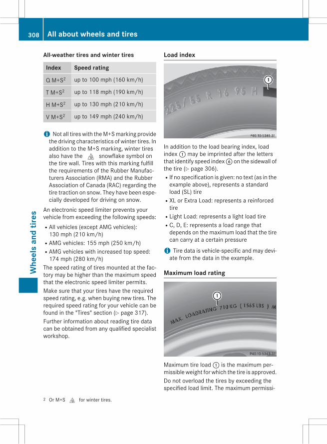
All-weather tires and winter tires
Index Speed rating
Q M+S2 up to 100 mph (160 km/h)
T M+S2 up to 118 mph (190 km/h)
H M+S2 up to 130 mph (210 km/h)
V M+S2 up to 149 mph (240 km/h)
i Not all tires with theM+Smarking providethe driving characteristics of winter tires. Inaddition to the M+S marking, winter tiresalso have thei snowflake symbol onthe tire wall. Tires with this marking fulfillthe requirements of the Rubber Manufac-turers Association (RMA) and the RubberAssociation of Canada (RAC) regarding thetire traction on snow. They have been espe-cially developed for driving on snow.
An electronic speed limiter prevents yourvehicle from exceeding the following speeds:RAll vehicles (except AMG vehicles):130 mph (210 km/h)
RAMG vehicles: 155 mph (250 km/h)RAMG vehicles with increased top speed:174 mph (280 km/h)
The speed rating of tires mounted at the fac-tory may be higher than the maximum speedthat the electronic speed limiter permits.Make sure that your tires have the requiredspeed rating, e.g. when buying new tires. Therequired speed rating for your vehicle can befound in the "Tires" section (Y page 317).Further information about reading tire datacan be obtained from any qualified specialistworkshop.
Load index
In addition to the load bearing index, loadindex: may be imprinted after the lettersthat identify speed indexB on the sidewall ofthe tire (Y page 306).RIf no specification is given: no text (as in theexample above), represents a standardload (SL) tire
RXL or Extra Load: represents a reinforcedtire
RLight Load: represents a light load tireRC, D, E: represents a load range thatdepends on the maximum load that the tirecan carry at a certain pressure
i Tire data is vehicle-specific and may devi-ate from the data in the example.
Maximum load rating
Maximum tire load: is the maximum per-missible weight for which the tire is approved.Do not overload the tires by exceeding thespecified load limit. The maximum permissi-
2 Or M+Si for winter tires.
308 All about wheels and tiresW
heel
san
dtir
es
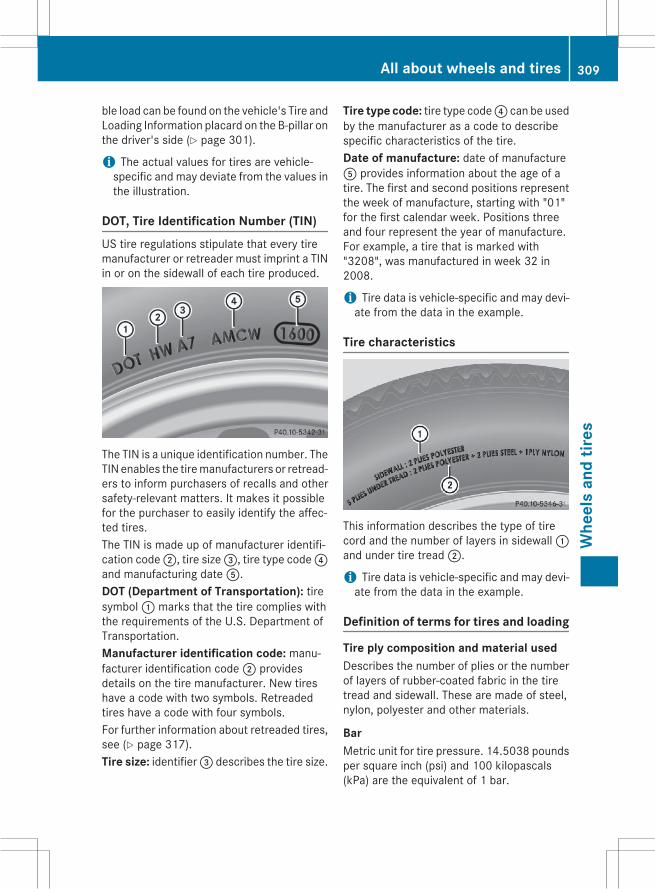
ble load can be found on the vehicle's Tire andLoading Information placard on the B-pillar onthe driver's side (Y page 301).
i The actual values for tires are vehicle-specific and may deviate from the values inthe illustration.
DOT, Tire Identification Number (TIN)US tire regulations stipulate that every tiremanufacturer or retreader must imprint a TINin or on the sidewall of each tire produced.
The TIN is a unique identification number. TheTIN enables the tiremanufacturers or retread-ers to inform purchasers of recalls and othersafety-relevant matters. It makes it possiblefor the purchaser to easily identify the affec-ted tires.The TIN is made up of manufacturer identifi-cation code;, tire size=, tire type code?and manufacturing dateA.DOT (Department of Transportation): tiresymbol: marks that the tire complies withthe requirements of the U.S. Department ofTransportation.Manufacturer identification code: manu-facturer identification code; providesdetails on the tire manufacturer. New tireshave a code with two symbols. Retreadedtires have a code with four symbols.For further information about retreaded tires,see (Y page 317).Tire size: identifier= describes the tire size.
Tire type code: tire type code? can be usedby the manufacturer as a code to describespecific characteristics of the tire.Date of manufacture: date of manufactureA provides information about the age of atire. The first and second positions representthe week of manufacture, starting with "01"for the first calendar week. Positions threeand four represent the year of manufacture.For example, a tire that is marked with"3208", was manufactured in week 32 in2008.
i Tire data is vehicle-specific and may devi-ate from the data in the example.
Tire characteristics
This information describes the type of tirecord and the number of layers in sidewall:and under tire tread;.
i Tire data is vehicle-specific and may devi-ate from the data in the example.
Definition of terms for tires and loading
Tire ply composition and material usedDescribes the number of plies or the numberof layers of rubber-coated fabric in the tiretread and sidewall. These are made of steel,nylon, polyester and other materials.
BarMetric unit for tire pressure. 14.5038 poundsper square inch (psi) and 100 kilopascals(kPa) are the equivalent of 1 bar.
All about wheels and tires 309
Whe
els
and
tires
Z

DOT (Department of Transportation)DOT-marked tires fulfill the requirements ofthe U S Department of Transportation.
Normal occupant weightThe number of occupants for which the vehi-cle is designed multiplied by 68 kilograms(150 lbs).
Uniform Tire Quality Grading StandardsA uniform standard to grade the quality oftireswith regards to tread quality, tire tractionand temperature characteristics. The qualitygrading assessment is made by the manufac-turer following specifications from the U.S.government. The ratings are molded into thesidewall of the tire.
Recommended tire pressuresThe recommended tire pressure applies tothe tires mounted at the factory.The Tire and Loading Information placard con-tains the recommended tire pressures forcold tires on a fully loaded vehicle and for themaximum permissible vehicle speed.The tire pressure table contains the recom-mended pressures for cold tires for variousoperating conditions, i.e. differing load andspeed conditions.
Increased vehicle weight due to optionalequipmentThe combined weight of all standard andoptional equipment available for the vehicle,regardless of whether it is actually installedon the vehicle or not.
RimThis is the part of the wheel on which the tireis mounted.
GAWR (Gross Axle Weight Rating)The GAWR is the maximum gross axle weightrating. The actual load on an axle must neverexceed the gross axle weight rating. Thegross axle weight rating can be found on thevehicle identification plate on the B-pillar onthe driver's side.
Speed ratingThe speed rating is part of the tire identifica-tion. It specifies the speed range forwhich thetire is approved.
GTW (Gross Trailer Weight)TheGTW is theweight of a trailer including theweight of the load, luggage, accessories etc.on the trailer.
GVW (Gross Vehicle Weight)The gross vehicle weight includes the weightof the vehicle including fuel, tools, the sparewheel, accessories installed, occupants, lug-gage and the drawbar noseweight, if applica-ble. The gross vehicleweightmust not exceedthe gross vehicle weight rating GVWR asspecified on the vehicle identification plate onthe B-pillar on the driver's side.
GVWR (Gross Vehicle Weight Rating)The GVWR is the maximum permissible grossweight of a fully loaded vehicle (the weight ofthe vehicle including all accessories, occu-pants, fuel, luggage and the drawbar nose-weight, if applicable). The gross vehicleweight rating is specified on the vehicle iden-tification plate on the B-pillar on the driver'sside.
Maximum loaded vehicle weightThe maximum weight is the sum of:Rthe curb weight of the vehicleRthe weight of the accessoriesRthe load limitRthe weight of the factory installed optionalequipment
Kilopascal (kPa)Metric unit for tire pressure. 6.9 kPa corre-sponds to 1 psi. Another unit for tire pressureis bar. 100 kilopascals (kPa) are the equiva-lent of 1 bar.
Load indexIn addition to the load-bearing index, the loadindexmay also be imprinted on the sidewall of
310 All about wheels and tiresW
heel
san
dtir
es

the tire. This specifies the load-bearing capa-city more precisely.
Curb weightThe weight of a vehicle with standard equip-ment including the maximum capacity of fuel,oil and coolant. It also includes the air-condi-tioning system and optional equipment ifthese are installed in the vehicle, but does notinclude passengers or luggage.
Maximum load ratingThe maximum load rating is the maximumpermissible weight in kilograms or lbs forwhich a tire is approved.
Maximum permissible tire pressureMaximum permissible tire pressure for onetire.
Maximum load on one tireMaximum load on one tire. This is calculatedby dividing themaximum axle load of one axleby two.
PSI (pounds per square inch)A standard unit of measure for tire pressure.
Aspect ratioRelationship between tire height and tirewidth in percent.
Tire pressureThis is pressure inside the tire applying anoutward force to each square inch of the tire'ssurface. The tire pressure is specified inpounds per square inch (psi), in kilopascal(kPa) or in bar. The tire pressure should onlybe corrected when the tires are cold.
Cold tire pressureThe tires are cold:Rif the vehicle has been parked withoutdirect sunlight on the tires for at least threehours and
Rif the vehicle has not been driven furtherthan 1 mile (1.6 km)
TreadThe part of the tire that comes into contactwith the road.
BeadThe tire bead ensures that the tire sitssecurely on the wheel. There are several steelwires in the bead to prevent the tire fromcoming loose from the wheel rim.
SidewallThe part of the tire between the tread and thebead.
Weight of optional extrasThe combined weight of those optional extrasthat weigh more than the replaced standardparts and more than 2.3 kg (5 lbs). Theseoptional extras, such as high-performancebrakes, level control, a roof rack or a high-performance battery, are not included in thecurb weight and the weight of the accesso-ries.
TIN (Tire Identification Number)This is a unique identifier which can be usedby a tire manufacturer to identify tires, forexample for a product recall, and thus identifythe purchasers. The TIN is made up of themanufacturer's identity code, tire size, tiretype code and the manufacturing date.
Load bearing indexThe load bearing index (also load index) is acode that contains themaximum load bearingcapacity of a tire.
TractionTraction is the result of friction between thetires and the road surface.
TWR (Tongue Weight Rating)The TWR specifies the maximum permissibleweight that the ball coupling of the trailer towhitch can support.
All about wheels and tires 311
Whe
els
and
tires
Z

Treadwear indicatorsNarrow bars (tread wear bars) that are dis-tributed over the tire tread. If the tire tread islevel with the bars, the wear limit ofá in(1.6 mm) has been reached.
Occupant distributionThe distribution of occupants in a vehicle attheir designated seating positions.
Total load limitNominal load and luggage load plus 68 kg(150 lbs) multiplied by the number of seats inthe vehicle.
Changing a wheel
Flat tireThe "Breakdown assistance" section(Y page 273) contains information and noteson how to deal with a flat tire. Information ondriving with MOExtended tires in the event ofa flat tire can be found under "MOExtendedtires (tires with run-flat characteristics"(Y page 273).Vehicles with an emergency spare wheel:in the event of a flat tire, mount the emer-gency spare wheel according to the descrip-tion under "Mounting a wheel" (Y page 313).
Rotating the wheels
G WARNINGInterchanging the front and rear wheels mayseverely impair the driving characteristics ifthe wheels or tires have different dimensions.The wheel brakes or suspension componentsmay also be damaged. There is a risk of acci-dent.Rotate front and rearwheels only if thewheelsand tires are of the same dimensions.
! On vehicles equipped with a tire pressuremonitor, electronic components are loca-ted in the wheel.
Tire-mounting tools should not be usednear the valve. This could damage the elec-tronic components.Only have tires changed at a qualified spe-cialist workshop.
Always observe the instructions and safetynotes in the "Mounting a wheel" section(Y page 313).The wear patterns on the front and rear tiresdiffer, depending on the operating conditions.Rotate the wheels before a clear wear patternhas formed on the tires. Front tires typicallywear more on the shoulders and the rear tiresin the center.If your vehicle's tire configuration allows, youcan rotate the wheels according to the inter-vals in the tire manufacturer's warranty bookin your vehicle documents. If no warrantybook is available, the tires should be rotatedevery 3,000 to 6,000 miles (5,000 to10,000 km), or earlier if tire wear requires. Donot change the direction of wheel rotation.Clean the contact surfaces of the wheel andthe brake disc thoroughly every time a wheelis rotated. Check the tire pressure and, if nec-essary, restart the tire pressure loss warningsystem or the tire pressure monitor.
Direction of rotationTires with a specified direction of rotationhave additional benefits, e.g. if there is a riskof hydroplaning. These advantages can onlybe gained if the tires are installed correspond-ing to the direction of rotation.An arrow on the sidewall of the tire indicatesits correct direction of rotation.
Storing wheelsStorewheels that are not being used in a cool,dry and preferably dark place. Protect thetires from oil, grease, gasoline and diesel.
312 Changing a wheelW
heel
san
dtir
es

Mounting a wheel
Preparing the vehicleX Vehicle with emergency spare wheel:when mounting the emergency sparewheel in the event of a flat tire, follow theadditional notes on vehicle preparationunder "Flat tire" (Y page 273).X Stop the vehicle on solid, non-slippery andlevel ground.X Unload heavy luggage.X Apply the electric parking brake manually.X Bring the front wheels into the straight-ahead position.X Shift the transmission to position P.X Vehicles with the AIRMATIC package:make sure that highway level is selected(Y page 162).X Switch off the engine.X Vehicles without KEYLESS-GO: removethe SmartKey from the ignition lock.X Vehicles with KEYLESS-GO: open thedriver's door.The on-board electronics now have status0. This is the same as the SmartKey havingbeen removed.X Vehicles with KEYLESS-GO: remove theStart/Stop button from the ignition lock(Y page 132).X If included in the vehicle equipment,remove the tire-change tool kit from thevehicle.X Secure the vehicle to prevent it from rollingaway.
i Apart from certain country-specific varia-tions, vehicles are not equipped with a tire-change tool kit. For information on whichtools are required to perform a wheelchange on your vehicle, consult an author-ized Mercedes-Benz Center.
Necessary wheel-changing tools caninclude, for example:RJackRWheel chockRLug wrench
Securing the vehicle to prevent it fromrolling away
If your vehicle is equippedwith awheel chock,it can be found in the tire-change tool kit(Y page 272).The folding wheel chock is an additionalsafety measure to prevent the vehicle fromrolling away, for example when changing awheel.X Fold both plates upwards:.X Fold out lower plate;.X Guide the lugs on the lower plate fully intothe openings in base plate=.
X On level ground: place chocks or othersuitable items under the front and rear ofthe wheel that is diagonally opposite thewheel you wish to change.
Changing a wheel 313
Whe
els
and
tires
Z

X On light downhill gradients: placechocks or other suitable items in front ofthe wheels of the front and rear axle.
Raising the vehicle
G WARNINGIf you do not position the jack correctly at theappropriate jacking point of the vehicle, thejack could tip over with the vehicle raised.There is a risk of injury.Only position the jack at the appropriate jack-ing point of the vehicle. The base of the jackmust be positioned vertically, directly underthe jacking point of the vehicle.
! AMG vehicles with "Minispare" emer-gency spare wheel: use the "Minispare"emergency spare wheel only on the rearaxle. If you mount the "Minispare" emer-gency spare wheel on the front axle, thiscould result in damage to the brake system.If a tire on the front axle is defective, anintact wheel from the rear axlemust first bereplaced with the "Minispare" emergencyspare wheel. The faulty wheel on the frontaxle may only then be replaced by theundamaged wheel from the rear axle.Make sure to note the placard on the"Minispare" emergency spare wheel.
! The jack is designed exclusively for jack-ing up the vehicle at the jacking points.Otherwise, your vehicle could be damaged.
Observe the following when raising the vehi-cle:RTo raise the vehicle, only use the vehicle-specific jack that has been tested andapproved by Mercedes-Benz. If used incor-rectly, the jack could tip over with the vehi-cle raised.
RThe jack is designed only to raise and holdthe vehicle for a short time while a wheelis being changed. It is not suited for per-forming maintenance work under the vehi-cle.
RAvoid changing the wheel on uphill anddownhill slopes.
RBefore raising the vehicle, secure it fromrolling away by applying the parking brakeand inserting wheel chocks. Do not disen-gage the parking brake while the vehicle israised.
RThe jack must be placed on a firm, flat andnon-slip surface. On a loose surface, alarge, flat, load-bearing underlay must beused. On a slippery surface, a non-slipunderlay must be used, e.g. rubber mats.
RDo not use wooden blocks or similarobjects as a jack underlay. Otherwise, thejack will not be able to achieve its load-bearing capacity due to the restrictedheight.
RMake sure that the distance between theunderside of the tires and the ground doesnot exceed 1.2 in (3 cm).
RDo not place your hands or feet under theraised vehicle.
RDo not lie under the vehicle.RDo not start the engine when the vehicle israised.
RNever open or close a door or the tailgatewhen the vehicle is raised.
RMake sure that no persons are present inthe vehicle when the vehicle is raised.
314 Changing a wheelW
heel
san
dtir
es
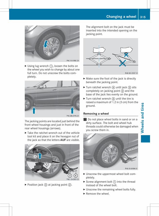
X Using lug wrench:, loosen the bolts onthe wheel you wish to change by about onefull turn. Do not unscrew the bolts com-pletely.
The jacking points are located just behind thefront wheel housings and just in front of therear wheel housings (arrows).X Take the ratchet wrench out of the vehicletool kit and place it on the hexagon nut ofthe jack so that the letters AUF are visible.
X Position jack= at jacking point;.
The alignment bolt on the jack must beinserted into the intended opening on thejacking point.
X Make sure the foot of the jack is directlybeneath the jacking point.X Turn ratchet wrench? until jack= sitscompletely on jacking point; and thebase of the jack lies evenly on the ground.X Turn ratchet wrench? until the tire israised a maximum of 1.2 in (3 cm) from theground.
Removing a wheel
! Do not place wheel bolts in sand or on adirty surface. The bolt and wheel hubthreads could otherwise be damaged whenyou screw them in.
X Unscrew the uppermost wheel bolt com-pletely.X Screw alignment bolt: into the threadinstead of the wheel bolt.X Unscrew the remaining wheel bolts fully.X Remove the wheel.
Changing a wheel 315
Whe
els
and
tires
Z

Mounting a new wheel
G WARNINGOiled or greased wheel bolts or damagedwheel bolts/hub threads can cause the wheelbolts to come loose. As a result, you couldlose a wheel while driving. There is a risk ofaccident.Never oil or greasewheel bolts. In the event ofdamage to the threads, contact a qualifiedspecialist workshop immediately. Have thedamaged wheel bolts or hub threadsreplaced/renewed. Do not continue driving.
G WARNINGIf you tighten the wheel bolts or wheel nutswhen the vehicle is raised, the jack could tipover. There is a risk of injury.Only tighten the wheel bolts or wheel nutswhen the vehicle is on the ground.
! To prevent damage to the paintwork, holdthe wheel securely against the wheel hubwhile screwing in the first wheel bolt.
Always pay attention to the instructions andsafety notes in the "Changing a wheel" sec-tion (Y page 312).Only use wheel bolts that have been designedfor the wheel and the vehicle. For safety rea-sons, Mercedes-Benz recommends that youonly use wheel bolts which have beenapproved forMercedes-Benz vehicles and therespective wheel.
! Always use wheel bolts; to mount the"Minispare" emergency spare wheel. Usingother wheel bolts to mount the "Minispare"emergency spare wheel could damage thebrake system.
: Wheel bolts for all wheels supplied by thefactory
; Wheel bolts for the collapsible sparewheel
X Clean the wheel and wheel hub contactsurfaces.X Slide the wheel to be mounted onto thealignment bolt and push it on.X Tighten the wheel bolts until they are fin-ger-tight.X Unscrew the alignment bolt.X Tighten the last wheel bolt until it is finger-tight.
Lowering the vehicle
G WARNINGThe wheels could work loose if the wheel nutsand bolts are not tightened to the specifiedtightening torque. There is a risk of accident.Have the tightening torque immediatelychecked at a qualified specialist workshopafter a wheel is changed.
316 Changing a wheelW
heel
san
dtir
es
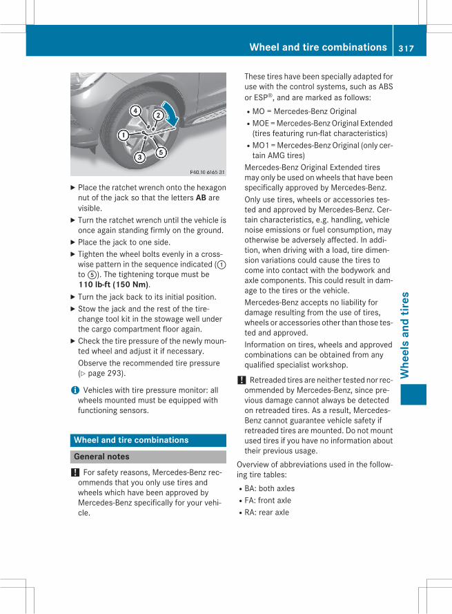
X Place the ratchet wrench onto the hexagonnut of the jack so that the letters AB arevisible.X Turn the ratchet wrench until the vehicle isonce again standing firmly on the ground.X Place the jack to one side.X Tighten the wheel bolts evenly in a cross-wise pattern in the sequence indicated (:toA). The tightening torque must be110 lb-ft (150 Nm).X Turn the jack back to its initial position.X Stow the jack and the rest of the tire-change tool kit in the stowage well underthe cargo compartment floor again.X Check the tire pressure of the newly moun-ted wheel and adjust it if necessary.Observe the recommended tire pressure(Y page 293).
i Vehicles with tire pressure monitor: allwheels mounted must be equipped withfunctioning sensors.
Wheel and tire combinations
General notes! For safety reasons, Mercedes-Benz rec-ommends that you only use tires andwheels which have been approved byMercedes-Benz specifically for your vehi-cle.
These tires have been specially adapted foruse with the control systems, such as ABSor ESP®, and are marked as follows:RMO = Mercedes-Benz OriginalRMOE=Mercedes-BenzOriginal Extended(tires featuring run-flat characteristics)
RMO1=Mercedes-Benz Original (only cer-tain AMG tires)
Mercedes-Benz Original Extended tiresmay only be used on wheels that have beenspecifically approved by Mercedes-Benz.Only use tires, wheels or accessories tes-ted and approved by Mercedes-Benz. Cer-tain characteristics, e.g. handling, vehiclenoise emissions or fuel consumption, mayotherwise be adversely affected. In addi-tion, when driving with a load, tire dimen-sion variations could cause the tires tocome into contact with the bodywork andaxle components. This could result in dam-age to the tires or the vehicle.Mercedes-Benz accepts no liability fordamage resulting from the use of tires,wheels or accessories other than those tes-ted and approved.Information on tires, wheels and approvedcombinations can be obtained from anyqualified specialist workshop.
! Retreaded tires are neither tested nor rec-ommended by Mercedes-Benz, since pre-vious damage cannot always be detectedon retreaded tires. As a result, Mercedes-Benz cannot guarantee vehicle safety ifretreaded tires are mounted. Do not mountused tires if you have no information abouttheir previous usage.
Overview of abbreviations used in the follow-ing tire tables:RBA: both axlesRFA: front axleRRA: rear axle
Wheel and tire combinations 317
Whe
els
and
tires
Z

The recommended pressures for variousoperating conditions can be found:Ron the Tire and Loading Information placardwith the recommended tire pressures onthe B-pillar on the driver's side
Rin the tire pressure table on the inside of thefuel filler flap
Observe the notes on recommended tirepressures under various operating conditions(Y page 293).Check tire pressures regularly, and only whenthe tires are cold. Comply with the mainte-nance recommendations of the tire manufac-turer in the vehicle document wallet.Notes on the vehicle equipment – alwaysequip the vehicle with:Rtires of the same size on a given axle (left/right)
Rthe same type of tires at a given time (sum-mer tires, winter tires, MOExtended tires)
Vehicles equipped withMOExtended tires arenot equipped with a TIREFIT kit at the factory.It is therefore recommended that you addi-tionally equip your vehicle with a TIREFIT kit ifyou mount tires that do not feature run-flatproperties, e.g. winter tires. A TIREFIT kit maybe obtained from a qualified specialist work-shop.
i Not all wheel and tire combinations areavailable at the factory for all countries.
i The following pages contain informationon approved wheel rims and tire sizes forequipping your vehicle with winter tires.Winter tires are not available at the factoryas standard equipment or optional extras.If you want to equip your vehicle withapproved winter tires, it may be necessaryto obtain wheel rims in the correspondingsize. The size of the approved winter tiresmay differ from the standard tires. This isdependent on the model and the equip-ment installed at the factory.The tires and wheel rims, as well as furtherinformation, can be obtained at a qualifiedspecialist workshop.
318 Wheel and tire combinationsW
heel
san
dtir
es

Tires
ML 250 BlueTEC 4MATIC
Summer tiresR 18
Tires Alloy wheels
BA: 255/55 R 18 105 V BA: 8.0 J x 18 H2Wheel offset: 2.20 in (56 mm)
BA: 255/55 R 18 105 V BA: 8.0 J x 18 H2Wheel offset: 2.22 in (56.5 mm)
R 19
Tires Alloy wheels
BA: 225/50 R 19 103 W3Available as MOExtendedtires.
BA: 8.0 J x 19 H2Wheel offset: 2.20 in (56 mm)
BA: 255/50 R 19 103 W3, 4 BA: 8.5 J x 19 H2Wheel offset: 2.32 in (59 mm)
BA: 255/50 R 19 103 W3, 4 BA: 8.5 J x 19 H2Wheel offset: 2.44 in (62 mm)
R 20
Tires Alloy wheels
BA: 265/45 R 20 104 Y3, 4 BA: 9.0 J x 20 H2Wheel offset: 2.24 in (57 mm)
R 21
Tires Alloy wheels
BA: 265/40 R 21 105 Y XL4, 5, 6 BA: 9.0 J x 21 H2Wheel offset: 2.09 in (53 mm)
34 Use of snow chains not permitted. Observe the notes in the "Snow chains" section.5 Observe the notes on "Large wheels" under "General notes" in the "Wheel/tire combinations" section.6 Only for vehicles with air suspension.
Wheel and tire combinations 319
Whe
els
and
tires
Z
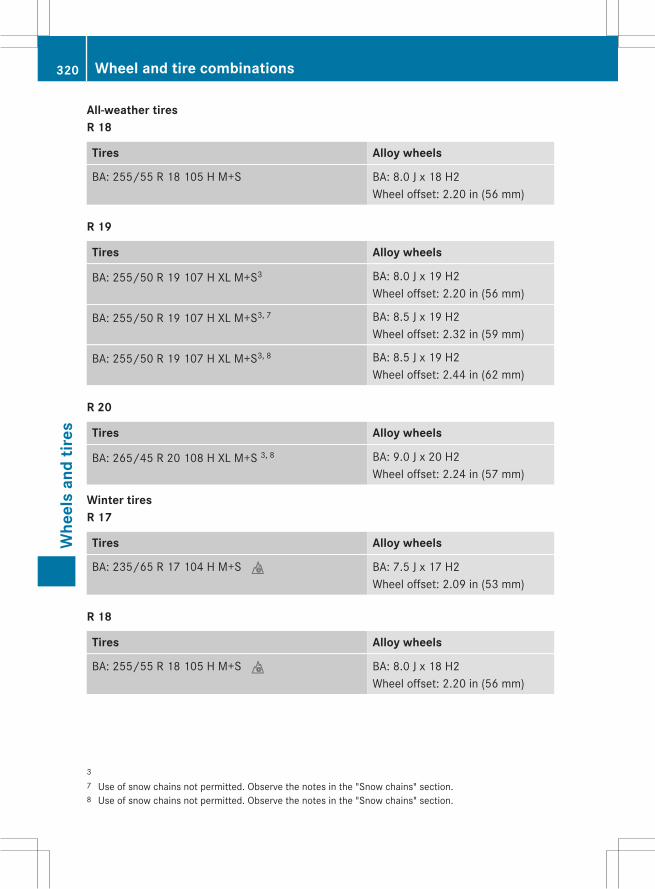
All-weather tiresR 18
Tires Alloy wheels
BA: 255/55 R 18 105 H M+S BA: 8.0 J x 18 H2Wheel offset: 2.20 in (56 mm)
R 19
Tires Alloy wheels
BA: 255/50 R 19 107 H XL M+S3 BA: 8.0 J x 19 H2Wheel offset: 2.20 in (56 mm)
BA: 255/50 R 19 107 H XL M+S3, 7 BA: 8.5 J x 19 H2Wheel offset: 2.32 in (59 mm)
BA: 255/50 R 19 107 H XL M+S3, 8 BA: 8.5 J x 19 H2Wheel offset: 2.44 in (62 mm)
R 20
Tires Alloy wheels
BA: 265/45 R 20 108 H XL M+S 3, 8 BA: 9.0 J x 20 H2Wheel offset: 2.24 in (57 mm)
Winter tiresR 17
Tires Alloy wheels
BA: 235/65 R 17 104 H M+Si BA: 7.5 J x 17 H2Wheel offset: 2.09 in (53 mm)
R 18
Tires Alloy wheels
BA: 255/55 R 18 105 H M+Si BA: 8.0 J x 18 H2Wheel offset: 2.20 in (56 mm)
37 Use of snow chains not permitted. Observe the notes in the "Snow chains" section.8 Use of snow chains not permitted. Observe the notes in the "Snow chains" section.
320 Wheel and tire combinationsW
heel
san
dtir
es
R 19
Tires Alloy wheels
BA: 225/50 R 19 103 W3 BA: 8.5 J x 19 H2Wheel offset: 2.44 in (62 mm)
BA: 255/50 R 19 107 H XL M+Si3 BA: 8.0 J x 19 H2Wheel offset: 2.20 in (56 mm)
BA: 255/50 R 19 107 H XL M+Si3, 4 BA: 8.5 J x 19 H2Wheel offset: 2.32 in (59 mm)
R 20
Tires Alloy wheels
BA: 265/45 R 20 108 V XL M+Si4 BA: 9.0 J x 20 H2Wheel offset: 2.05 in (52 mm)
ML 350
Summer tiresR 21
Tires Alloy wheels
BA: 265/40 R 21 105 Y XL4, 5, 6 BA: 9.0 J x 21 H2Wheel offset: 2.09 in (53 mm)
All-weather tiresR 18
Tires Alloy wheels
BA: 255/55 R 18 105 H M+S BA: 8.0 J x 18 H2Wheel offset: 2.20 in (56 mm)
34 Use of snow chains not permitted. Observe the notes in the "Snow chains" section.5 Observe the notes on "Large wheels" under "General notes" in the "Wheel/tire combinations" section.6 Only for vehicles with air suspension.
Wheel and tire combinations 321
Whe
els
and
tires
Z
R 19
Tires Alloy wheels
BA: 255/50 R 19 107 H XL M+S3 BA: 8.0 J x 19 H2Wheel offset: 2.20 in (56 mm)
BA: 255/50 R 19 107 H XL M+S3, 8 BA: 8.5 J x 19 H2Wheel offset: 2.32 in (59 mm)
BA: 255/50 R 19 107 H XL M+S3, 8 BA: 8.5 J x 19 H2Wheel offset: 2.44 in (62 mm)
R 20
Tires Alloy wheels
BA: 265/45 R 20 108 H XL M+S 3, 8 BA: 9.0 J x 20 H2Wheel offset: 2.24 in (57 mm)
Winter tiresR 18
Tires Alloy wheels
BA: 255/55 R 18 105 H M+Si BA: 8.0 J x 18 H2Wheel offset: 2.20 in (56 mm)
R 19
Tires Alloy wheels
BA: 225/50 R 19 103 W3 BA: 8.5 J x 19 H2Wheel offset: 2.44 in (62 mm)
BA: 255/50 R 19 107 H XL M+Si3 BA: 8.0 J x 19 H2Wheel offset: 2.20 in (56 mm)
BA: 255/50 R 19 107 H XL M+Si3, 8 BA: 8.5 J x 19 H2Wheel offset: 2.32 in (59 mm)
R 20
Tires Alloy wheels
BA: 265/45 R 20 108 V XL M+Si4 BA: 9.0 J x 20 H2Wheel offset: 2.05 in (52 mm)
38 Use of snow chains not permitted. Observe the notes in the "Snow chains" section.4 Use of snow chains not permitted. Observe the notes in the "Snow chains" section.
322 Wheel and tire combinationsW
heel
san
dtir
es

ML 350 4MATIC
Summer tiresR 21
Tires Alloy wheels
BA: 265/40 R 21 105 Y XL4, 5, 6 BA: 9.0 J x 21 H2Wheel offset: 2.09 in (53 mm)
All-weather tiresR 19
Tires Alloy wheels
BA: 255/50 R 19 107 H XL M+S3 BA: 8.0 J x 19 H2Wheel offset: 2.20 in (56 mm)
BA: 255/50 R 19 107 H XL M+S3, 8 BA: 8.5 J x 19 H2Wheel offset: 2.32 in (59 mm)
BA: 255/50 R 19 107 H XL M+S3, 8 BA: 8.5 J x 19 H2Wheel offset: 2.44 in (62 mm)
R 20
Tires Alloy wheels
BA: 265/45 R 20 108 H XL M+S 3, 8 BA: 9.0 J x 20 H2Wheel offset: 2.24 in (57 mm)
Winter tiresR 18
Tires Alloy wheels
BA: 255/55 R 18 105 H M+Si BA: 8.0 J x 18 H2Wheel offset: 2.20 in (56 mm)
4 Use of snow chains not permitted. Observe the notes in the "Snow chains" section.5 Observe the notes on "Large wheels" under "General notes" in the "Wheel/tire combinations" section.6 Only for vehicles with air suspension.38 Use of snow chains not permitted. Observe the notes in the "Snow chains" section.
Wheel and tire combinations 323
Whe
els
and
tires
Z

R 19
Tires Alloy wheels
BA: 225/50 R 19 103 W3 BA: 8.5 J x 19 H2Wheel offset: 2.44 in (62 mm)
BA: 255/50 R 19 107 H XL M+Si3 BA: 8.0 J x 19 H2Wheel offset: 2.20 in (56 mm)
BA: 255/50 R 19 107 H XL M+Si3, 8 BA: 8.5 J x 19 H2Wheel offset: 2.32 in (59 mm)
R 20
Tires Alloy wheels
BA: 265/45 R 20 108 V XL M+Si4 BA: 9.0 J x 20 H2Wheel offset: 2.05 in (52 mm)
ML 350 BlueTEC 4MATIC
Summer tiresR 21
Tires Alloy wheels
BA: 265/40 R 21 105 Y XL4, 5, 6 BA: 9.0 J x 21 H2Wheel offset: 2.09 in (53 mm)
All-weather tiresR 19
Tires Alloy wheels
BA: 255/50 R 19 107 H XL M+S3 BA: 8.0 J x 19 H2Wheel offset: 2.20 in (56 mm)
BA: 255/50 R 19 107 H XL M+S3, 8 BA: 8.5 J x 19 H2Wheel offset: 2.32 in (59 mm)
BA: 255/50 R 19 107 H XL M+S3, 8 BA: 8.5 J x 19 H2Wheel offset: 2.44 in (62 mm)
38 Use of snow chains not permitted. Observe the notes in the "Snow chains" section.4 Use of snow chains not permitted. Observe the notes in the "Snow chains" section.5 Observe the notes on "Large wheels" under "General notes" in the "Wheel/tire combinations" section.6 Only for vehicles with air suspension.
324 Wheel and tire combinationsW
heel
san
dtir
es

R 20
Tires Alloy wheels
BA: 265/45 R 20 108 H XL M+S 3, 8 BA: 9.0 J x 20 H2Wheel offset: 2.24 in (57 mm)
Winter tiresR 18
Tires Alloy wheels
BA: 255/55 R 18 105 H M+Si BA: 8.0 J x 18 H2Wheel offset: 2.20 in (56 mm)
R 19
Tires Alloy wheels
BA: 255/50 R 19 107 H XL M+Si3 BA: 8.0 J x 19 H2Wheel offset: 2.20 in (56 mm)
BA: 255/50 R 19 107 H XL M+Si3, 8 BA: 8.5 J x 19 H2Wheel offset: 2.32 in (59 mm)
R 20
Tires Alloy wheels
BA: 265/45 R 20 108 V XL M+Si4 BA: 9.0 J x 20 H2Wheel offset: 2.05 in (52 mm)
ML 400
Summer tiresR 21
Tires Alloy wheels
BA: 265/40 R 21 105 Y XL4, 5, 6 BA: 9.0 J x 21 H2Wheel offset: 2.09 in (53 mm)
38 Use of snow chains not permitted. Observe the notes in the "Snow chains" section.4 Use of snow chains not permitted. Observe the notes in the "Snow chains" section.5 Observe the notes on "Large wheels" under "General notes" in the "Wheel/tire combinations" section.6 Only for vehicles with air suspension.
Wheel and tire combinations 325
Whe
els
and
tires
Z

All-weather tiresR 19
Tires Alloy wheels
BA: 255/50 R 19 107 H XL M+S3 BA: 8.0 J x 19 H2Wheel offset: 2.20 in (56 mm)
BA: 255/50 R 19 107 H XL M+S3, 8 BA: 8.5 J x 19 H2Wheel offset: 2.32 in (59 mm)
BA: 255/50 R 19 107 H XL M+S3, 8 BA: 8.5 J x 19 H2Wheel offset: 2.44 in (62 mm)
R 20
Tires Alloy wheels
BA: 265/45 R 20 108 H XL M+S 3, 8 BA: 9.0 J x 20 H2Wheel offset: 2.24 in (57 mm)
Winter tiresR 18
Tires Alloy wheels
BA: 255/55 R 18 105 H M+Si BA: 8.0 J x 18 H2Wheel offset: 2.20 in (56 mm)
R 19
Tires Alloy wheels
BA: 255/50 R 19 107 H XL M+Si3 BA: 8.0 J x 19 H2Wheel offset: 2.20 in (56 mm)
BA: 255/50 R 19 107 H XL M+Si3, 8 BA: 8.5 J x 19 H2Wheel offset: 2.32 in (59 mm)
R 20
Tires Alloy wheels
BA: 265/45 R 20 108 V XL M+Si4 BA: 9.0 J x 20 H2Wheel offset: 2.05 in (52 mm)
38 Use of snow chains not permitted. Observe the notes in the "Snow chains" section.4 Use of snow chains not permitted. Observe the notes in the "Snow chains" section.
326 Wheel and tire combinationsW
heel
san
dtir
es
ML 400 4MATIC
Summer tiresR 21
Tires Alloy wheels
BA: 265/40 R 21 105 Y XL4, 5, 6 BA: 9.0 J x 21 H2Wheel offset: 2.09 in (53 mm)
All-weather tiresR 19
Tires Alloy wheels
BA: 255/50 R 19 107 H XL M+S3 BA: 8.0 J x 19 H2Wheel offset: 2.20 in (56 mm)
BA: 255/50 R 19 107 H XL M+S3, 8 BA: 8.5 J x 19 H2Wheel offset: 2.32 in (59 mm)
BA: 255/50 R 19 107 H XL M+S3, 8 BA: 8.5 J x 19 H2Wheel offset: 2.44 in (62 mm)
R 20
Tires Alloy wheels
BA: 265/45 R 20 108 H XL M+S 3, 8 BA: 9.0 J x 20 H2Wheel offset: 2.24 in (57 mm)
Winter tiresR 18
Tires Alloy wheels
BA: 255/55 R 18 105 H M+Si BA: 8.0 J x 18 H2Wheel offset: 2.20 in (56 mm)
4 Use of snow chains not permitted. Observe the notes in the "Snow chains" section.5 Observe the notes on "Large wheels" under "General notes" in the "Wheel/tire combinations" section.6 Only for vehicles with air suspension.38 Use of snow chains not permitted. Observe the notes in the "Snow chains" section.
Wheel and tire combinations 327
Whe
els
and
tires
Z

R 19
Tires Alloy wheels
BA: 255/50 R 19 107 H XL M+Si3 BA: 8.0 J x 19 H2Wheel offset: 2.20 in (56 mm)
BA: 255/50 R 19 107 H XL M+Si3, 8 BA: 8.5 J x 19 H2Wheel offset: 2.32 in (59 mm)
R 20
Tires Alloy wheels
BA: 265/45 R 20 108 V XL M+Si4 BA: 9.0 J x 20 H2Wheel offset: 2.05 in (52 mm)
ML 550 4MATIC
Summer tiresR 21
Tires Alloy wheels
BA: 265/40 R 21 105 Y XL4, 5, 6 BA: 9.0 J x 21 H2Wheel offset: 2.09 in (53 mm)
All-weather tiresR 19
Tires Alloy wheels
BA: 255/50 R 19 107 H XL M+S3, 8 BA: 8.5 J x 19 H2Wheel offset: 2.32 in (59 mm)
BA: 255/50 R 19 107 H XL M+S3, 8 BA: 8.5 J x 19 H2Wheel offset: 2.44 in (62 mm)
R 20
Tires Alloy wheels
BA: 265/45 R 20 108 H XL M+S 3, 8 BA: 9.0 J x 20 H2Wheel offset: 2.24 in (57 mm)
38 Use of snow chains not permitted. Observe the notes in the "Snow chains" section.4 Use of snow chains not permitted. Observe the notes in the "Snow chains" section.5 Observe the notes on "Large wheels" under "General notes" in the "Wheel/tire combinations" section.6 Only for vehicles with air suspension.
328 Wheel and tire combinationsW
heel
san
dtir
es
Winter tiresR 19
Tires Alloy wheels
BA: 255/50 R 19 107 H XL M+Si3 BA: 8.0 J x 19 H2Wheel offset: 2.20 in (56 mm)
BA: 255/50 R 19 107 H XL M+Si3, 8 BA: 8.5 J x 19 H2Wheel offset: 2.32 in (59 mm)
R 20
Tires Alloy wheels
BA: 265/45 R 20 108 V XL M+Si4 BA: 9.0 J x 20 H2Wheel offset: 2.05 in (52 mm)
ML 63 AMG 4MATIC
Summer tiresR 20
Tires Alloy wheels
BA: 265/45 ZR 20 108 Y XL8 BA: 9.0 J x 20 H2Wheel offset: 1.61 in (41 mm)
R 21
Tires Alloy wheels
BA: 295/35 ZR 21 107 Y XL8 BA: 10.0 J x 21 H2Wheel offset: 2.20 in (56 mm)
Winter tiresR 20
Tires Alloy wheels
BA: 255/45 R 20 105 V XL M+Si BA: 9.0 J x 20 H2Wheel offset: 1.61 in (41 mm)
38 Use of snow chains not permitted. Observe the notes in the "Snow chains" section.4 Use of snow chains not permitted. Observe the notes in the "Snow chains" section.
Wheel and tire combinations 329
Whe
els
and
tires
Z
R 21
Tires Alloy wheels
BA: 295/35 R 21 107 V XL M+Si8 BA: 10.0 J x 21 H2Wheel offset: 2.20 in (56 mm)
Emergency spare wheel
Important safety notes
G WARNINGThe wheel or tire size as well as the tire type ofthe spare wheel or emergency spare wheeland the wheel to be replaced may differ.Mounting an emergency spare wheel mayseverely impair the driving characteristics.There is a risk of an accident.To avoid hazardous situations:Radapt your driving style accordingly anddrive carefully.
Rnever mount more than one spare wheel oremergency spare wheel that differs in size.
Ronly use a spare wheel or emergency sparewheel of a different size briefly.
Rdo not switch ESP® off.Rhave a spare wheel or emergency sparewheel of a different size replaced at thenearest qualified specialist workshop.Observe that the wheel and tire dimensionsas well as the tire type must be correct.
! AMG vehicles with "Minispare" emer-gency spare wheel: use the "Minispare"emergency spare wheel only on the rearaxle. If you mount the "Minispare" emer-gency spare wheel on the front axle, thiscould result in damage to the brake system.If a tire on the front axle is defective, anintact wheel from the rear axlemust first bereplaced with the "Minispare" emergencyspare wheel. The faulty wheel on the frontaxle may only then be replaced by theundamaged wheel from the rear axle.
Make sure to note the placard on the"Minispare" emergency spare wheel.
When using an emergency spare wheel orspare wheel of a different size, you must notexceed the maximum speed of 50 mph(80 km/h).Snow chains must not be mounted on emer-gency spare wheels.
General notesMounting the emergency spare wheel isdescribed under "Mounting a wheel"(Y page 313).You should regularly check the pressure ofthe emergency spare wheel, particularly priorto long trips, and correct the pressure as nec-essary (Y page 293). The value on the wheelor as given in the "Wheels and tires" section isvalid (Y page 333).An emergency spare wheel may also bemounted against the direction of rotation.Observe the time restriction on use as well asthe speed limitation specified on the emer-gency spare wheel.Replace the tires after six years at the latest,regardless of wear. This also applies to theemergency spare wheel.
i When you are driving with the collapsiblespare wheel mounted, the tire pressureloss warning system or the tire pressuremonitor cannot function reliably. Onlyrestart the tire pressure loss warning sys-tem/the tire pressure monitor when thedamaged wheel has been replaced with anew wheel.
8 Use of snow chains not permitted. Observe the notes in the "Snow chains" section.
330 Emergency spare wheelW
heel
san
dtir
es

Vehicles with tire pressure monitor:after mounting an emergency spare wheel,the system may still display the tire pres-sure of the removed wheel for a fewminutes. The value displayed for the moun-ted emergency spare wheel is not the sameas the current tire pressure of the emer-gency spare wheel.
Removing the emergency spare wheel
Emergency spare wheel (example: vehicle withoutlockable cargo compartment floor)
The "Minispare" emergency spare wheel canbe found in the stowage well under the cargocompartment floor.X Lift the cargo compartment floor up(Y page 252).X Vehicles with trailer tow hitch: removethe ball coupling stowage tray(Y page 188).X Vehicles without a lockable cargo com-
partment floor: turn emergency sparewheel retainer; counter-clockwise andremove it.X Remove "Minispare" emergency sparewheel:.
Vehicles with a lockable cargo compartment floorX Vehicles with a lockable cargo compart-
ment floor: remove the contents of stow-age tray;.X Turn the central retaining screw of stowagetray; and "Minispare" emergency sparewheel: counter-clockwise and remove it.X Remove stowage well;.X Remove "Minispare" emergency sparewheel:.
On vehicles with a Bang & Olufsen sound sys-tem, the "Minispare" emergency spare wheelis packed in the emergency spare wheel bag.The emergency spare wheel bag is secured tothe cargo tie-down rings in the cargo com-partment.X To remove the emergency spare wheel:open the tailgate.X Detach fastening straps;.X Unhook retaining spring hooks: and=of fastening straps; from the cargo tie-down rings.
Emergency spare wheel 331
Whe
els
and
tires
Z

X Remove the emergency spare wheel bagwith the "Minispare" emergency sparewheel.X Open the emergency spare wheel bag andremove the "Minispare" emergency sparewheel.X To stow the emergency spare wheel:place the "Minispare" emergency sparewheel into the emergency spare wheel bagand close the emergency spare wheel bag.X Place the emergency spare wheel bag withthe "Minispare" emergency spare wheelinto the cargo compartment with the car-rying strap at the back.X Hook retaining spring hooks: and= offastening straps; into the cargo tie-downrings.X Tighten fastening straps;.Always observe the instructions and safetynotes in the "Mounting a wheel" section(Y page 313).
332 Emergency spare wheelW
heel
san
dtir
es

Technical data
All models (except the ML 550 4MATIC and ML 63 AMG 4MATIC)
"Minispare" emergency spare wheel
Tires Alloy wheels
T 155/90 R18 113 MTire pressure: 420 kPa (4.2 bar/61 psi)
4.0 B x 18 H2Wheel offset: 1.58 in (40 mm)
T 155/80 R19 114 M9
Tire pressure: 420 kPa (4.2 bar/61 psi)4.5 B x 19 H2Wheel offset: 1.58 in (40 mm)
ML 550 4MATIC
"Minispare" emergency spare wheel
Tires Alloy wheels
T 155/80 R19 114 MTire pressure: 420 kPa (4.2 bar/61 psi)
4.5 B x 19 H2Wheel offset: 1.58 in (40 mm)
ML 63 AMG 4MATIC
"Minispare" emergency spare wheel
Tires Alloy wheels
T 155/80 R19 114 MTire pressure: 420 kPa (4.2 bar/61 psi)
4.5 B x 19 H2Wheel offset: 1.58 in (40 mm)
9 Only for vehicles with air suspension (Code 489).
Emergency spare wheel 333
Whe
els
and
tires
Z

334

Useful information ............................ 336Information regarding technicaldata .................................................... 336Identification plates ......................... 336Service products and filling capaci-ties ..................................................... 337Vehicle data ....................................... 346Vehicle data for off-road driving ...... 347Trailer tow hitch ................................ 349
335
Tech
nica
ldat
a

Useful information
i This Operator's Manual describes allmodels and all standard and optional equip-ment of your vehicle available at the time ofpublication of the Operator's Manual.Country-specific differences are possible.Please note that your vehicle may not beequipped with all features described. Thisalso applies to safety-related systems andfunctions.
i Read the information on qualified special-ist workshops (Y page 35).
Information regarding technical data
i The data stated here specifically refers toa vehicle with standard equipment. Consultan authorized Mercedes-Benz Center forthe data for all vehicle variants and trimlevels.
Identification plates
Vehicle identification plate with vehi-cle identification number (VIN)
X Open the driver's door.You will see vehicle identification plate:.
Example: vehicle identification plate (USA only); Paint code= VIN
Example: vehicle identification plate (Canada only); Paint code= VIN
i The data shown on the vehicle identifica-tion plate is used only as an example. Thisdata is different for every vehicle and candeviate from the data shown here. You canfind the data applicable to your vehicle onthe vehicle identification plate.
336 Identification platesTe
chni
cald
ata

Vehicle identification plate with vehi-cle identification number (VIN)
X Open the front right-hand door.X Open cover: in the direction of the arrowand remove it.You will see the VIN.
The VIN can also be found in the followinglocations:Ron the lower edge of the windshield(Y page 337)
Ron the vehicle identification plate(Y page 336)
Engine number
: Emission control information plate,including the certification of both federaland Californian emissions standards
; Engine number (stamped into the crank-case)
= VIN (on the lower edge of the windshield)
Service products and filling capaci-ties
Important safety notes
G WARNINGService products may be poisonous and haz-ardous to health. There is a risk of injury.Comply with instructions on the use, storageand disposal of service products on the labelsof the respective original containers. Alwaysstore service products sealed in their originalcontainers. Always keep service products outof the reach of children.
H Environmental noteDispose of service products in an environ-mentally responsible manner.
Service products include the following:RFuelsRExhaust gas aftertreatment additives, e.g.DEF
RLubricants (e.g. engine oil, transmission oil)RCoolantRBrake fluidRWindshield washer fluidRClimate control system refrigerantComply with all valid regulations with respectto handling, storing, and disposing of servicefluids.Components and service products must bematched. You should therefore only use prod-ucts that have been tested and approved byMercedes-Benz.Information on tested and approved productscan be obtained at an authorized Mercedes-Benz Center or on the Internet athttp://bevo.mercedes-benz.com.You can recognize service products approvedby Mercedes-Benz by the following inscrip-tion on the containers:RMB-Freigabe (e.g. MB-Freigabe 229.51)RMB Approval (e.g. MB Approval 229.51)
Service products and filling capacities 337
Tech
nica
ldat
a
Z

Other designations or recommendations indi-cate a level of quality or a specification inaccordance with an MB Sheet Number (e.g.MB 229.5). They have not necessarily beenapproved by Mercedes-Benz.
Fuel
Important safety notes
G WARNINGFuel is highly flammable. If you handle fuelincorrectly, there is a risk of fire and explo-sion.You must avoid fire, open flames, creatingsparks and smoking. Switch off the engineand, if applicable, the auxiliary heating beforerefueling.
G WARNINGFuel is poisonous and hazardous to health.There is a risk of injury.You must make sure that fuel does not comeinto contact with your skin, eyes or clothingand that it is not swallowed. Do not inhale fuelvapors. Keep fuel away from children.If you or others come into contact with fuel,observe the following:RWash away fuel from skin immediatelyusing soap and water.
RIf fuel comes into contact with your eyes,immediately rinse them thoroughly withclean water. Seek medical assistance with-out delay.
RIf fuel is swallowed, seek medical assis-tance without delay. Do not induce vomit-ing.
RImmediately change out of clothing whichhas come into contact with fuel.
Tank capacity
Model Total capa-city
All models 24.6 US gal(93.0 l)
Model Of whichreserve
AMG vehicles Approx.3.7 US gal(14.0 l)
All other models Approx.3.2 US gal(12.0 l)
Gasoline
Fuel grade! Do not use diesel to refuel vehicles with agasoline engine. Do not switch on the igni-tion if you accidentally refuel with thewrong fuel. Otherwise, the fuel will enterthe fuel system. Even small amounts of thewrong fuel could result in damage to thefuel system and the engine. Notify a quali-fied specialist workshop and have the fueltank and fuel lines drained completely.
! Only refuel using unleaded premiumgrade gasoline with at least 91 AKI/95 RON.
! Only use the fuel recommended. Operat-ing the vehicle with other fuels can lead toengine failure.
! Do not use the following:RE85 (gasoline with 85% ethanol)RE100 (100% ethanol)RM15 (gasoline with 15% methanol)RM30 (gasoline with 30% methanol)RM85 (gasoline with 85% methanol)RM100 (100% methanol)
338 Service products and filling capacitiesTe
chni
cald
ata
RGasoline with metalliferous additivesRDieselDo not mix such fuels with the fuel recom-mended for your vehicle. Do not use addi-tives. Otherwise, engine damage mayoccur. This does not include cleaning addi-tives for the removal and prevention of res-idue build-up. Gasoline may only be mixedwith cleaning additives recommended byMercedes-Benz; see "Additives". You canobtain further information from any author-ized Mercedes-Benz Center.
! To ensure the longevity and full perform-ance of the engine, only premium-gradeunleaded gasoline must be used.If standard unleaded gasoline is unavaila-ble and you have to refuel with unleadedgasoline of a lower grade, observe the fol-lowing precautions:ROnly fill the fuel tank to half full with reg-ular unleaded gasoline and fill the restwith premium-grade unleaded gasolineas soon as possible.
RDo not drive at the maximum speed.RAvoid sudden acceleration and enginespeeds over 3,000 rpm.
Youwill usually find information about the fuelgrade on the pump. If you cannot find thelabel on the pump, ask the staff for assis-tance.
i For further information, consult a quali-fied specialist workshop or visithttp://www.mbusa.com (USA only).
i E10 fuel contains up to 10% bioethanol.Your vehicle is E10-compatible. You canrefuel your vehicle using E10 fuel.
As a temporarymeasure, if the recommendedfuel is not available, you may also use regularunleaded gasoline with an octane rating of87 AKI/91 RON. This may reduce engine per-formance and increase fuel consumption.Avoid driving at full throttle and sudden accel-eration. Never refuel using fuel with a lowerAKI.
Information on refueling (Y page 140).
Additives! Operating the engine with fuel additivesadded later can lead to engine failure. Donot mix fuel additives with fuel. This doesnot include additives for the removal andprevention of residue buildup. gasolinemust only be mixed with additives recom-mended by Mercedes-Benz. Comply withthe instructions for use on the productlabel. More information about recommen-ded additives can be obtained from anyauthorized Mercedes-Benz Center.
Mercedes-Benz recommends that you usebranded fuels that have additives.The quality of the fuel available in some coun-tries may not be sufficient. Residue couldbuild up in the injection system as a result. Insuch cases, and in consultation with anauthorized Mercedes-Benz Center, the gaso-line may be mixed with the cleaning additiverecommended by Mercedes-Benz. You mustobserve the notes and mixing ratios specifiedon the container.
Diesel
Fuel gradeG WARNINGIf you mix diesel fuel with gasoline, the flashpoint is lower than that of pure diesel fuel.When the engine is running, exhaust systemcomponents could overheat without beingnoticed. There is a risk of fire.Never refuel with gasoline. Nevermix gasolinewith diesel fuel.
! Refuel only using diesel fuel that con-forms to European standard EN 590 or anequivalent specification. Fuel that does notconform to EN 590 can lead to increasedwear and damage the engine and exhaustsystem.
Service products and filling capacities 339
Tech
nica
ldat
a
Z

! Do not use the following:Rmarine dieselRheating oilRbio-dieselRvegetable oilRgasolineRparaffinRkeroseneDo not mix such fuels with diesel fuel anddo not use any special additives. Other-wise, engine damage may occur.
! Vehicles with diesel particle filters: incountries outside the EU, only use low sul-fur Euro diesel with a sulfur content ofunder 50 ppm. Otherwise, the emissioncontrol system could be damaged.
! Vehicles without a diesel particle fil-ter: in countries where only diesel fuel witha high sulfur content is available, you willneed to carry out your vehicle's oil changeat shorter intervals. Further information onoil change intervals can be obtained at aqualified specialist workshop.
Youwill usually find information about the fuelgrade on the pump. If you cannot find thelabel on the pump, ask the staff for assis-tance.Information on refueling (Y page 140).
Bio-diesel – FAME (fatty acid methyl ester)Mercedes-Benz USA approves the use of bio-diesel B5 for all BlueTEC diesel engines. Theconcentration of bio-diesel in the ULSD maynot exceed 5% by volume.Pure bio-diesel and diesel fuel with a higherpercentage of bio-diesel, such as B20, candamage the engine and the fuel system. Forthis reason, they are not approved.For more information, consult the gas stationstaff. The bio-diesel B5 label on the gasolinepumpmust clearly state that the standard forULSD has been fulfilled. If the label is notclear, do not refuel the vehicle.
Do not refuel your vehicle with fuels unlessthey have been approved by Mercedes-Benz.Information on refueling (Y page 140).
Low outside temperaturesi Diesel fuel with improved cold flow prop-erties is available during thewintermonths.Further information about fuel propertiescan be obtained from oil companies, e.g. atgas stations.
Flexible Fuel vehicles
Important safety notesG WARNINGFuel is highly flammable. If you handle fuelincorrectly, there is a risk of fire and explo-sion.You must avoid fire, open flames, creatingsparks and smoking. Switch off the engineand, if applicable, the auxiliary heating beforerefueling.
G WARNINGFuel is poisonous and hazardous to health.There is a risk of injury.You must make sure that fuel does not comeinto contact with your skin, eyes or clothingand that it is not swallowed. Do not inhale fuelvapors. Keep fuel away from children.If you or others come into contact with fuel,observe the following:RWash away fuel from skin immediatelyusing soap and water.
RIf fuel comes into contact with your eyes,immediately rinse them thoroughly withclean water. Seek medical assistance with-out delay.
RIf fuel is swallowed, seek medical assis-tance without delay. Do not induce vomit-ing.
RImmediately change out of clothing whichhas come into contact with fuel.
340 Service products and filling capacitiesTe
chni
cald
ata

Flexible Fuel vehicles can be refueledwith thefollowing fuel types:Rpremium-grade unleaded gasolineRE85 fuelRa mixture of E85 fuel and premium-gradeunleaded gasoline
i Flexible Fuel vehicles can be recognizedby the Ethanol up to E85 sticker on theinside of the fuel filler flap.
Fuel consumptionThe energy content of E85 fuel is less thanthat of the same amount of premium-gradegasoline. The amount of fuel consumed whenoperating the vehicle with E85 fuel is there-fore higher than with premium-grade gaso-line.
MaintenanceInform your authorized Mercedes-Benz Cen-ter that you are operating or have operatedthe vehicle with E85 fuel.
Low outside temperaturesIf the outside temperature is below 32 ‡(0†), the starting procedure can take notice-ably longer when operating with E85 fuel.E85 fuel is not suitable for use at outsidetemperatures under -4 ‡ (-20 †).
DEF
Important safety notesComply with the important safety notes forservice products when handling DEF(Y page 337).DEF is a water-soluble fluid for the exhaustgas aftertreatment of diesel engines. It is:Rnot poisonousRcolorless and odorlessRnot flammableWhen you open the DEF container, smallamounts of ammonia vapor may be released.
Ammonia vapors have a pungent odor and areparticularly irritating to the skin, to mucousmembranes and to the eyes. You may expe-rience a burning sensation in your eyes, noseand throat. Coughing and watering of theeyes are possible.Do not inhale ammonia vapors. Fill the DEFtank only in well-ventilated areas.
Low outside temperaturesDEF freezes at a temperature of approx-imately 12‡ (-11†). The vehicle is deliveredfrom the factory equipped with a DEF pre-heating system. Winter operation can thus beguaranteed even at temperatures below 12‡(-11 †).
Additives
! Only use DEF in accordance with ISO22241. Do not use additives with DEF anddo not dilute DEF with water. This maydestroy the BlueTEC exhaust gas after-treatment system.
Purity
! Impurities in DEF (e.g. due to other ser-vice products, cleaning agents or dust) leadto:Rincreased emission valuesRdamage to the catalytic converterRengine damageRmalfunctions in the BlueTEC exhaust gasaftertreatment system
Assuring the purity of DEF is particularlyimportant with respect to avoiding malfunc-tions in the BlueTEC exhaust gas aftertreat-ment system.If DEF is pumped out of the DEF tank, e.g.during repair work, it must not be returned tothe tank. The purity of the fluid can no longerbe guaranteed.
Service products and filling capacities 341
Tech
nica
ldat
a
Z

Filling capacities
Model Total capacity
ML 250 BlueTEC4MATICML 350 Blue-TEC 4MATIC
7.3 US gal(27.5 l)
Engine oil
General notes
! Never use engine oil or an oil filter of aspecification other than is necessary to ful-fill the prescribed service intervals. Do notchange the engine oil or oil filter in order toachieve longer replacement intervals thanthose prescribed. You could otherwisecause engine damage or damage to theexhaust gas aftertreatment.Follow the instructions in the service inter-val display regarding the oil change. Other-wise, you may damage the engine and theexhaust gas aftertreatment.
When handling engine oil, observe the impor-tant safety notes on service products(Y page 337).The engine oils are matched to the perform-ance of Mercedes-Benz engines and serviceintervals. You should therefore only useengine oils and oil filters that are approved forvehicles with maintenance systems.For a list of approved engine oils and oil filters,consult an authorized Mercedes-Benz Cen-ter. Or visit the websitehttp://bevo.mercedes-benz.com.The table shows which engine oils have beenapproved for your vehicle.
Model Enginemodel
MBApproval
ML 350 276 229.5
ML 350 4MATIC 276 229.5
ML 400 276 229.5
Model Enginemodel
MBApproval
ML 400 4MATIC 276 229.5
ML 550 4MATIC 278 229.5
ML 250 BlueTEC4MATIC
651 228.51,229.31,229.51,229.52
ML 350 Blue-TEC 4MATIC
642 228.51,229.31,229.51,229.52
AMG vehicles 157 229.5
Use only SAE 0W-40 or SAE 5W-40 engine oilsfor AMG vehicles.
i MB approval is indicated on the oil con-tainers.
Filling capacitiesThe following values refer to an oil changeincluding the oil filter.
Model Capacity
ML 550 4MATIC 9.0 US qt (8.5 l)
ML 250 BlueTEC4MATIC
6.9 US qt (6.5 l)
ML 350 Blue-TEC 4MATIC
8.5 US qt (8.0 l)
AMG vehicles 9.0 US qt (8.5 l)
All other models 7.4 US qt (7.0 l)
Additives
! Do not use any additives in the engine oil.This could damage the engine.
342 Service products and filling capacitiesTe
chni
cald
ata
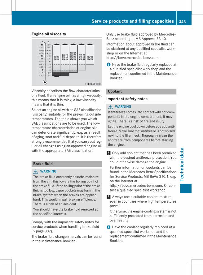
Engine oil viscosity
Viscosity describes the flow characteristicsof a fluid. If an engine oil has a high viscosity,this means that it is thick; a low viscositymeans that it is thin.Select an engine oil with an SAE classification(viscosity) suitable for the prevailing outsidetemperatures. The table shows you whichSAE classifications are to be used. The low-temperature characteristics of engine oilscan deteriorate significantly, e.g. as a resultof aging, soot and fuel deposits. It is thereforestrongly recommended that you carry out reg-ular oil changes using an approved engine oilwith the appropriate SAE classification.
Brake fluid
G WARNINGThe brake fluid constantly absorbs moisturefrom the air. This lowers the boiling point ofthe brake fluid. If the boiling point of the brakefluid is too low, vapor pockets may form in thebrake system when the brakes are appliedhard. This would impair braking efficiency.There is a risk of an accident.You should have the brake fluid renewed atthe specified intervals.
Comply with the important safety notes forservice products when handling brake fluid(Y page 337).The brake fluid change intervals can be foundin the Maintenance Booklet.
Only use brake fluid approved by Mercedes-Benz according to MB Approval 331.0.Information about approved brake fluid canbe obtained at any qualified specialist work-shop or on the Internet athttp://bevo.mercedes-benz.com.
i Have the brake fluid regularly replaced ata qualified specialist workshop and thereplacement confirmed in theMaintenanceBooklet.
Coolant
Important safety notes
G WARNINGIf antifreeze comes into contact with hot com-ponents in the engine compartment, it mayignite. There is a risk of fire and injury.Let the engine cool down before you add anti-freeze.Make sure that antifreeze is not spillednext to the filler neck. Thoroughly clean theantifreeze from components before startingthe engine.
! Only add coolant that has been premixedwith the desired antifreeze protection. Youcould otherwise damage the engine.Further information on coolants can befound in the Mercedes-Benz Specificationsfor Service Products, MB BeVo 310.1, e.g.on the Internet athttp://bevo.mercedes-benz.com. Or con-tact a qualified specialist workshop.
! Always use a suitable coolant mixture,even in countries where high temperaturesprevail.Otherwise, the engine cooling system is notsufficiently protected from corrosion andoverheating.
i Have the coolant regularly replaced at aqualified specialist workshop and thereplacement confirmed in theMaintenanceBooklet.
Service products and filling capacities 343
Tech
nica
ldat
a
Z
Complywith the important safety precautionsfor service products when handling coolant(Y page 337).The coolant is a mixture of water and anti-freeze/corrosion inhibitor. It performs thefollowing tasks:Rcorrosion protectionRantifreeze protectionRraising the boiling pointIf the coolant has antifreeze protection downto -35‡ (-37†), the boiling point of the cool-ant during operation is approximately 266 ‡(130 †).The antifreeze/corrosion inhibitor concentra-tion in the engine cooling system should:Rbe at least 50%. This will protect the enginecooling system against freezing down toapproximately -35 ‡ (-37 †).
Rnot exceed 55% (antifreeze protectiondown to -49 ‡ [-45 †]). Otherwise, heatwill not be dissipated as effectively.
Mercedes-Benz recommends an antifreeze/corrosion inhibitor concentrate in accord-ance with MB Specifications for Service Prod-ucts 310.1.
i When the vehicle is first delivered, it is fil-led with a coolant mixture that ensuresadequate antifreeze and corrosion protec-tion.
i The coolant is checked with every main-tenance interval at a qualified specialistworkshop.
Filling capacities
Model Capacity
ML 400 Approx. 10.9 US qt(10.3 l)
ML 400 4MATIC Approx. 10.3 US qt(9.7 l)
ML 550 4MATIC Approx. 12.0 US qt(11.4 l)
Model Capacity
ML 250 BlueTEC4MATIC
Approx. 10.7 US qt(10.1 l)
ML 350 Blue-TEC 4MATIC
Approx. 12.2 US qt(11.5 l)
AMG vehicles Approx. 13.1 US qt(12.4 l)
All other models Approx. 11.1 US qt(10.5 l)
Windshield washer system
Important safety notes
G WARNINGWindshield washer concentrate could ignite ifit comes into contact with hot engine compo-nents or the exhaust system. There is a risk offire and injury.Make sure that no windshield washer con-centrate is spilled next to the filler neck.
! Do not add distilled or de-ionized water tothe washer fluid container. Otherwise, thelevel sensor may be damaged.
! Only MB SummerFit and MB WinterFitwasher fluid should be mixed together. Thespray nozzles may otherwise becomeblocked.
When handling washer fluid, observe theimportant safety notes on service products(Y page 337).At temperatures above freezing:X Fill the washer fluid reservoir with amixtureof water and windshield washer fluid, e.g.MB SummerFit.
Add 1 part MB SummerFit to 100 parts water.At temperatures below freezing:X Fill the washer fluid reservoir with amixtureof water and washer fluid, e.g. MB Winter-Fit.
344 Service products and filling capacitiesTe
chni
cald
ata

For the correct mixing ratio refer to theinformation on the antifreeze reservoir.
i Add windshield washer fluid, e.g. MBSummerFit or MB WinterFit, to the washerfluid all year round.
Climate control system refrigerant
Important safety notesThe climate control system of your vehicle isfilled with refrigerant R゙134a.The instruction label regarding the refrigeranttype used can be found on the radiator crossmember.
! Only the refrigerant R゙134a and the PAGoil approved by Mercedes-Benz may beused. The approved PAG oil may not bemixed with any other PAG oil that is notapproved for R-134a refrigerant. Other-wise, the climate control system may bedamaged.
Service work, such as topping up refrigerantor replacing components, may only be carriedout by a qualified specialist workshop. Allapplicable regulations must be adhered to,SAE standard J639 included.Always have work on the climate control sys-tem carried out at a qualified specialist work-shop.
Refrigerant instruction label
Example: refrigerant instruction label: Warning symbol; Refrigerant filling capacity= Applicable standards? PAG oil part numberA Type of refrigerantWarning symbol: advises you about:Rpossible dangersRhaving service work carried out at a quali-fied specialist workshop
Filling capacitiesMissing values were not available at time ofgoing to print.
AMG vehicles Capacity
Refrigerant
PAG oil
All other models Capacity
Refrigerant 37.0 ± 0.4 oz(1050 ± 10 g)
PAG oil 4.9 ± 0.4 oz(140 ± 10 g)
Service products and filling capacities 345
Tech
nica
ldat
a
Z
Vehicle data
General notesPlease note that for the specified vehicledata:Rthe heights specified may vary as a resultof:- tires- load- condition of the suspension- optional equipment
Roptional equipment reduces the maximumpayload.
Observe the information relating to level con-trol:RAIRMATIC package (Y page 162)RON&OFFROAD package (Y page 159)
Dimensions and weights
:
Openingheight
;
Max.headroom
AMG vehicles 84.6 in -87.0 in
(2148mm -2211 mm)
79.0 in(2006 mm)
All other mod-els with:
:
Openingheight
;
Max.headroom
Steel suspen-sion
86.4 in(2195 mm)
78.2 in(1987 mm)
AIRMATICpackage
84.3 in -87.2 in
(2140mm -2215 mm)
76.0 in -79.0 in
(1931mm -2006 mm)
ON&OFF-ROAD pack-age
84.3 in -88.4 in
(2140mm -2245 mm)
76.0 in -80.2 in
(1931mm -2036 mm)
AMG vehicles
Vehicle length 189.6 in(4817 mm)
Vehicle width includingexterior mirrors
84.3 in(2141 mm)
Maximum vehicle height 71.4 in(1815 mm)
Minimum vehicle height 69.0 in(1752 mm)
Wheelbase 114.8 in(2915 mm)
Maximum ground clear-ance
9.2 in(233 mm)
Minimum ground clear-ance
6.8 in(172 mm)
Turning radius 38.7 ft(11.80 m)
Maximum roof load 220 lb(100 kg)
346 Vehicle dataTe
chni
cald
ata
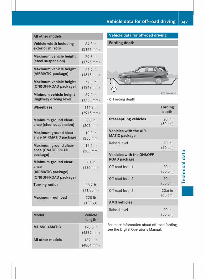
All other models
Vehicle width includingexterior mirrors
84.3 in(2141 mm)
Maximum vehicle height(steel suspension)
70.7 in(1796 mm)
Maximum vehicle height(AIRMATIC package)
71.6 in(1818 mm)
Maximum vehicle height(ON&OFFROAD package)
72.8 in(1848 mm)
Minimum vehicle height(highway driving level)
69.2 in(1758 mm)
Wheelbase 114.8 in(2915 mm)
Minimum ground clear-ance (steel suspension)
8.0 in(202 mm)
Maximum ground clear-ance (AIRMATIC package)
10.0 in(255 mm)
Maximum ground clear-ance (ON&OFFROADpackage)
11.2 in(285 mm)
Minimum ground clear-ance(AIRMATIC package)(ON&OFFROAD package)
7.1 in(180 mm)
Turning radius 38.7 ft(11.80 m)
Maximum roof load 220 lb(100 kg)
Model Vehiclelength
ML 550 4MATIC 190.5 in(4839 mm)
All other models 189.1 in(4804 mm)
Vehicle data for off-road driving
Fording depth
: Fording depth
Fordingdepth
Steel-sprung vehicles 20 in(50 cm)
Vehicles with the AIR-MATIC package
Raised level 20 in(50 cm)
Vehicles with the ON&OFF-ROAD package
Off-road level 1 20 in(50 cm)
Off-road level 2 20 in(50 cm)
Off-road level 3 23.6 in(60 cm)
AMG vehicles
Raised level 20 in(50 cm)
For more information about off-road fording,see the Digital Operator's Manual.
Vehicle data for off-road driving 347
Tech
nica
ldat
a
Z

Approach/departure angle
All vehicles (except vehicles with AMGbodystyling)
: ;
Steel-sprung vehi-cles
26° 25°
Vehicles with theAIRMATIC package
Highway level 23° 23°
Raised level 30° 28°
Vehicles with theON&OFFROADpackage
Highway level 23° 23°
Off-road level 1 26° 25°
Off-road level 2 30° 28°
Off-road level 3 31° 29°
AMG vehicles
Highway level (insports mode withthe AMG adaptivesuspension systemactivated)
19° 21°
Raised level 23° 24°
Vehicles with AMG bodystyling
: ;
Steel-sprungvehicles
25° 25°
Vehicles with theAIRMATIC pack-age
Highway level 22° 22°
Raised level 28° 27°
Vehicles with theON&OFFROADpackage
Highway level 22° 22°
Off-road level 1 25° 24°
Off-road level 2 28° 27°
Off-road level 3 29° 29°
For further information about approach/departure angles, see the Digital Operator'sManual.
Maximum gradient-climbing capabil-ityNote that the vehicle's gradient-climbingcapability depends on the off-road conditionsand the road surface conditions.Vehicles with the ON&OFFROAD package:the maximum gradient climbing ability is100% when the LOW RANGE off-road gear isselected.Vehicles without the ON&OFFROAD pack-age: the maximum gradient climbing ability is80%.Accelerate carefully and make sure that thewheels do not spin when driving on steep ter-rain.
i If the load on the front axle is reducedwhen pulling away on a steep uphill slope,the front wheels have a tendency to spin.
348 Vehicle data for off-road drivingTe
chni
cald
ata

4ETS recognizes this and brakes thewheels accordingly. The rear wheel torqueis increased, making it easier to drive off.
For further information about maximum gra-dient-climbing capability, see the DigitalOperator's Manual.
Trailer tow hitch
Mounting dimensions! If you have a trailer tow hitch retrofitted,changes to the cooling system and drivetrain may be necessary, depending on thevehicle type.If you have a trailer tow hitch retrofitted,observe the anchorage points on the chas-sis frame.
: Anchorage points for the trailer tow hitch; Rear axle center line
Trailer tow hitch 349
Tech
nica
ldat
a
Z
Trailer loads
Trailer loads, trailer drawbar noseweights and axle loadsMissing values were not available at time of going to print.
ML 250 BlueTEC 4MATIC
Permissible trailer load, unbraked
Permissible trailer load, braked (at a min-imum gradient-climbing capability of12% from a standstill)
6613 lbs (3000 kg)
Maximum drawbar noseweight (thedrawbar noseweight is not included inthe trailer load)
529 lbs (240 kg)
Permissible rear axle load when towing atrailer
3637 lbs (1650 kg)
ML 350 and ML 400
Permissible trailer load, unbraked
Permissible trailer load, braked (at a min-imum gradient-climbing capability of12% from a standstill)
6613 lbs (3000 kg)
Maximum drawbar noseweight (thedrawbar noseweight is not included inthe trailer load)
529 lbs (240 kg)
Permissible rear axle load when towing atrailer
3527 lbs (1600 kg)
ML 350 4MATIC, ML 400 4MATIC andML 550 4MATIC
Permissible trailer load, unbraked
Permissible trailer load, braked (at a min-imum gradient-climbing capability of12% from a standstill)
7198 lbs (3265 kg)
Maximum drawbar noseweight (thedrawbar noseweight is not included inthe trailer load)
575 lbs (261 kg)
Permissible rear axle load when towing atrailer
3527 lbs (1600 kg)
350 Trailer tow hitchTe
chni
cald
ata

ML 63 AMG 4MATIC
Permissible trailer load, unbraked
Permissible trailer load, braked (at a min-imum gradient-climbing capability of12% from a standstill)
6724 lbs (3050 kg)
Maximum drawbar noseweight (thedrawbar noseweight is not included inthe trailer load)
309 lbs (140 kg)
Permissible rear axle load when towing atrailer
3858 lbs (1750 kg)
ML 350 BlueTEC 4MATIC
Permissible trailer load, unbraked
Permissible trailer load, braked (at a min-imum gradient-climbing capability of12% from a standstill)
7198 lbs (3265 kg)
Maximum drawbar noseweight (thedrawbar noseweight is not included inthe trailer load)
575 lbs (261 kg)
Permissible rear axle load when towing atrailer
3637 lbs (1650 kg)
The actual noseweight may not be higher than the value which is given. The value can be foundon the trailer tow hitch or trailer identification plates. The lowest weight applies.The maximum permissible trailer drawbar noseweight is the maximum weight with which thetrailer drawbar can be loaded. Limit for Mercedes-Benz-approved trailer couplings.
Ball position of the ball coupling When choosing a ball coupling, the dimen-sions stated in the illustration must not beexceeded.
Trailer tow hitch 351
Tech
nica
ldat
a
Z

352