Mercedes-Benz G-Class 2016 SUV Owner's Manual PDF ...
261
Disclaimer The following version of the Owner‘s Manual describes all models, series and special equipment of your vehicle. Country-specific language variations are possible. Please note that your vehicle might not be equipped with all the described functions. This also affects safety-relevant systems and functions. Please contact your authorised Mercedes-Benz dealership if you would like to receive a printed Owner‘s Manual for other vehicle models and vehicle model years. The online Owner‘s Manual is the current and valid version. It is possible that deviations affecting your specific vehicle could not be taken into account as Mercedes-Benz constantly adapts its vehicles according to the latest technology and makes changes to the form and the equipment. Please also read the printed Owner‘s Manual, supplementary documents and the digital Owner‘s Manual in the vehicle. Copyright All rights reserved. All texts, images and graphics are subject to copyright and other laws for the protection of intellectual property. They may not be copied or changed for any commercial use or for the purpose of being passed on nor used on other webistes.
-
Upload
khangminh22 -
Category
Documents
-
view
1 -
download
0
Transcript of Mercedes-Benz G-Class 2016 SUV Owner's Manual PDF ...

Disclaimer
Das folgende PDF-Dokument für dieses Fahrzeugmodell bezieht sich in allen Sprachversionen nur auf die Fahrzeuge, die für den deutschen Markt bestimmt sind und die den deutschen Vorschriften entsprechen. Bitte wenden Sie sich an Ihren autorisierten Mercedes-Benz Servicestützpunkt, um ein gedrucktes Exemplar für andere Fahrzeugmodelle und Fahrzeugmodelljahre zu erhalten.
Dieses PDF-Dokument stellt die aktuelle Version dar. Mögliche Abweichungen zu Ihrem konkreten Fahrzeug könnten nicht berücksichtigt sein, da Mercedes-Benz seine Fahrzeuge ständig dem neuesten Stand der Technik anpasst, sowie Änderungen in Form und Ausstattung vornimmt. Bitte beachten Sie daher, dass dieses PDF-Dokument in keinem Fall das gedruckte Exemplar ersetzt, das mit dem Fahrzeug ausgeliefert wurde.
Internal use only
Disclaimer
All language versions of the following PDF document for this vehicle model relate solely to vehicles intended for sale on the German market and which correspond to German regulations.
Please contact your authorised Mercedes-Benz Service Centre to obtain a printed version for other vehicle models and vehicle model years. This PDF document is the latest version. Possible variations to your vehicle may not be taken into account as Mercedes-Benz constantly updates their vehicles to the state of the art and introduces changes in design and equipment. Please therefore note that this PDF document in no way replaces the printed version which was delivered with your vehicle.
Internal use only
Disclaimer
The following version of the Owner‘s Manual describes all models, series and special equipment of your vehicle. Country-specific language variations are possible. Please note that your vehicle might not be equipped with all the described functions. This also affects safety-relevant systems and functions. Please contact your authorised Mercedes-Benz dealership if you would like to receive a printed Owner‘s Manual for other vehicle models and vehicle model years.
The online Owner‘s Manual is the current and valid version. It is possible that deviations affecting your specific vehicle could not be taken into account as Mercedes-Benz constantly adapts its vehicles according to the latest technology and makes changes to the form and the equipment.
Please also read the printed Owner‘s Manual, supplementary documents and the digital Owner‘s Manual in the vehicle.
CopyrightAll rights reserved. All texts, images and graphics are subject to copyright and other laws for the protection of intellectual property. They may not be copied or changed for any commercial use or for the purpose of being passed on nor used on other webistes.


Welcome to the world of Mercedes-BenzBefore you drive off for the first time, read thisOwner's Manual carefully and familiarise your-self with your vehicle. For your own safety and alonger vehicle life, follow the instructions andwarning notices in this manual. Disregardingthem may result in damage to the vehicle orpersonal injury.The equipment or model designation of yourvehicle may vary according to:RmodelRorderRcountry variantRavailabilityThe illustrations in thismanual show a left-hand-drive vehicle. On right-hand-drive vehicles, thelayout of components and controls differsaccordingly.Mercedes-Benz is constantly updating its vehi-cles to the state of the art.Mercedes-Benz therefore reserves the right tointroduce changes in the following areas:RdesignRequipmentRtechnical featuresConsequently, the description may differ fromyour vehicle in some cases.The following are integral parts of the vehicle:RPrinted Owner's ManualRService BookletREquipment-dependent supplementsKeep these documents in the vehicle at alltimes. If you sell the vehicle, always pass alldocuments on to the new owner.
Please note that the Mercedes-Benz Guides appmay not yet be available in your country.
4635840105Z102 É4635840105Z102tËÍ

Index ....................................................... 4
Introduction ......................................... 20Environmental protection ...................... 20Genuine Mercedes-Benz parts ............... 20Owner's Manual ..................................... 21Operating safety .................................... 21QR code for rescue cards ...................... 24Data stored in the vehicle ...................... 24Copyright information ............................ 24
At a glance ........................................... 25Cockpit .................................................. 25Instrument cluster ................................. 26Multifunction steering wheel ................. 27Centre console ...................................... 28Overhead control panel ......................... 30
Safety ................................................... 31Occupant safety .................................... 31Children in the vehicle ........................... 38Pets in the vehicle ................................. 52Driving safety systems ........................... 52Protection against theft ......................... 56
Opening and closing ........................... 57Key ........................................................ 57Doors ..................................................... 61Rear door ............................................... 63Side windows ......................................... 64Sliding sunroof ....................................... 65
Seats, steering wheel and mirrors .... 67Correct driver's seat position ................ 67Seats ..................................................... 67Steering wheel ....................................... 71Mirrors ................................................... 73
Lights and windscreen wipers ........... 74Exterior lighting ..................................... 74Interior lighting ...................................... 77Replacing bulbs ..................................... 78Windscreen wipers ................................ 81
Climate control .................................... 84Overview of the climate control sys-tem ........................................................ 84Operating the climate control system .... 85Air vents ................................................ 93
Driving and parking ............................ 95Running-in notes .................................... 95Driving ................................................... 95Automatic transmission ....................... 101Refuelling ............................................. 108Parking ................................................ 113Driving tips .......................................... 115Driving systems ................................... 122Off-road driving systems ...................... 124Towing a trailer .................................... 127
On-board computer and displays .... 131Important safety notes ........................ 131Displays and operation ........................ 131Menus and submenus ......................... 133Display messages ................................ 141Warning and indicator lamps on theinstrument cluster ............................... 155
Multimedia system ........................... 165Introduction ......................................... 165At a glance .......................................... 167System settings ................................... 171Radio ................................................... 176Media .................................................. 177Telephone ............................................ 178Navigation ........................................... 181
Stowing and features ....................... 198Loading guidelines ............................... 198Stowage areas ..................................... 199Features .............................................. 206
Maintenance and care ...................... 211Engine compartment ........................... 211Service ................................................ 215Care ..................................................... 216
2 Contents

Breakdown assistance ..................... 222Where will I find...? .............................. 222Flat tyre ............................................... 224Battery (vehicle) .................................. 224Jump-starting ....................................... 227Towing away and tow-starting ............. 229Fuses ................................................... 232
Wheels and tyres .............................. 235Important safety notes ........................ 235Operation ............................................ 235Winter operation .................................. 236Tyre pressure ....................................... 238Changing a wheel ................................ 243Wheel and tyre combinations .............. 246
Technical data ................................... 248Information on technical data .............. 248Vehicle electronics .............................. 248Identification plates ............................. 249Service products and capacities .......... 250Vehicle data ......................................... 254Off-road driving vehicle data ................ 255Trailer tow hitch ................................... 256
Contents 3

1, 2, 3 ...4ETS (Electronic Traction System)
see ETS/4ETS (Electronic Trac-tion System)
12 V socketsee Socket (12 V)
AABS (Anti-lock Braking System)
Display message ............................ 142Function/notes ................................ 52Warning lamp ................................. 158
Activating/deactivating air-recir-culation mode ...................................... 89ADAPTIVE BRAKE ................................. 56Adaptive brake lights .......................... 53AdBlue®
Additive ......................................... 252Display message ............................ 148Filling capacity ............................... 252Important safety notes .................. 251Low outside temperatures ............. 252Purity ............................................. 252Topping up ..................................... 111
Additives (engine oil) ........................ 253Adjusting the seat ............................... 69AF (alternative frequency) ................ 177Air conditioning
Windscreen heating ......................... 88Air filter (white display message) .... 148Air vents
Important safety notes .................... 93Rear ................................................. 94Setting ............................................. 93Setting the centre air vents ............. 94Setting the side air vents ................. 94
Air-conditioning systemsee Climate control
AirbagIntroduction ..................................... 36PASSENGER AIR BAG OFF indica-tor lamp ........................................... 32
AirbagsFront airbag (driver, frontpassenger) ....................................... 37Important safety guidelines ............. 36
Triggering ......................................... 37Alarm
ATA (Anti-Theft Alarm system) ......... 56Switching off (ATA) .......................... 56Switching the function on/off(ATA) ................................................ 56
All-wheel driveTransfer case ................................. 124
Approach/departure angle .............. 121Aquaplaning ....................................... 117Ashtray ............................................... 208Assembly tool
General notes ................................ 210Radio aerial .................................... 210
Assistance display (on-board com-puter) .................................................. 137Assistance menu (on-board com-puter) .................................................. 137ASSYST service interval display
Service messages .......................... 216ATA (Anti-Theft Alarm system)
Activating/deactivating ................... 56Function ........................................... 56Switching off the alarm .................... 56
Audio AUX jack .................................. 178AUTO lights
Display message ............................ 145see Lights
Automatic engine start (ECOstart/stop function) ...................................... 99Automatic engine switch-off (ECOstart/stop function) ............................ 98Automatic headlamp mode ................ 75Automatic transmission
Display message ............................ 153Drive position (ECO start/stopfunction) ........................................ 103Drive programs .............................. 104Driving tips .................................... 103Emergency running mode .............. 108Engaging drive position .................. 103Engaging neutral ............................ 102Engaging reverse gear ................... 102Engaging the park position ............ 102Important safety notes .................. 101Kickdown ....................................... 104Manual shifting .............................. 106
4 Index

Neutral (ECO start/stop func-tion) ............................................... 102Overview ........................................ 101Problem (fault) ............................... 108Program selector button ................ 104Pulling away ..................................... 97Selector lever ................................ 101Shift ranges ................................... 105Steering wheel gearshift paddles ... 104Trailer towing ................................. 104Transmission position display ........ 101
Automatic transmission emer-gency running mode ......................... 108Auxiliary heating
Activating/deactivating ................... 90Activating/deactivating (on thecentre console) ................................ 90Display message ............................ 154Important safety notes .................... 89Malfunction ...................................... 93Problem (display message) .............. 93Remote control ................................ 90Setting ........................................... 139
Auxiliary heating/ventilationSetting the departure time ............... 92
Auxiliary ventilationActivating/deactivating ................... 90Activating/deactivating (on thecentre console) ................................ 90Problem (display message) .............. 93Remote control ................................ 90
Axle load, permissible (trailer tow-ing) ...................................................... 256
BBackrest (display message) ............. 154BAS (Brake Assist System) ................. 53Battery
Changing (auxiliary heatingremote control) ................................ 92
Battery (key)Checking .......................................... 59Important safety notes .................... 59Replacing ......................................... 59
Battery (vehicle)Charging ........................................ 226Display message ............................ 147
Important safety notes .................. 224Jump starting ................................. 227Overview ........................................ 224
Belt tensionerActivation ......................................... 37
Belt warning ......................................... 36BlueTEC
see AdBlue®BlueTEC (AdBlue®) ............................. 251Bluetooth®
Activating audio mode ................... 178Activating/deactivating ................. 174Connecting automatically .............. 175Connecting devices ....................... 175Connection requirements .............. 174Pairing code ................................... 175Pairing devices ............................... 174Unpairing a device ......................... 175
BonnetClosing ........................................... 212Display message ............................ 153Important safety notes .................. 211Opening ......................................... 211
BrakeEBD .................................................. 55
Brake fluidDisplay message ............................ 144Notes ............................................. 253
Brake force distributionsee EBD (electronic brake forcedistribution)
Brake lampReplacing bulbs ............................... 80
Brake lampsAdaptive ........................................... 53Display message ............................ 145
BrakesABS .................................................. 52BAS .................................................. 53Brake fluid (notes) ......................... 253Display message ............................ 142Driving tips .................................... 115HOLD function ............................... 122Important safety notes .................. 115Parking brake ................................ 114Warning lamp ................................. 157
Index 5

Breakdownsee Flat tyresee Towing away
Brightness control (instrumentcluster lighting) ................................... 26Bulbs
Brake lamp ...................................... 79Parking lamp (rear) .......................... 79Rear foglamp ................................... 79Reversing lamp ................................ 79Tail lamp .......................................... 79Turn signal lamp (front) .................... 79Turn signal lamp (rear) ..................... 79see Replacing bulbs
Bumper (steel) ................................... 210
CCalling up a fault
see Display messagesCar wash (care) ................................. 217Care
Automatic car wash ....................... 217Carpets .......................................... 221Display ........................................... 220Exhaust pipe .................................. 219Exterior lighting ............................. 219General notes ................................ 216High-pressure cleaner .................... 218Interior ........................................... 220Paint .............................................. 218Plastic trim .................................... 220Roof lining ...................................... 221Seat belt ........................................ 221Seat cover ..................................... 220Selector lever ................................ 220Steering wheel ............................... 220Trim pieces .................................... 220Washing by hand ........................... 217Wheels ........................................... 218Windows ........................................ 219Wiper blades .................................. 219Wooden load compartment floor ... 221Wooden trim .................................. 220
Central lockingAutomatic locking (on-board com-puter) ............................................. 139Locking/unlocking (key) .................. 57
Centre consoleLower section .................................. 29Overview .......................................... 28Upper section .................................. 28
Changing bulbsParking lamp (rear) .......................... 80
Changing gears .................................. 103Child
Restraint system .............................. 40Child seat
Automatic recognition ..................... 42Forward-facing restraint system ...... 45ISOFIX .............................................. 40On the front-passenger seat ............ 43Problem (malfunction) ..................... 46Rearward-facing restraint system .... 44Recommendations ........................... 49Suitable positions ............................ 46Top Tether ....................................... 41
Child seat lock ..................................... 39Child-proof locks
Important safety notes .................... 51Rear doors ....................................... 51
Childrenchild seat lock .................................. 39
Children in the vehicleImportant safety notes .................... 38
Cigarette lighter ................................ 209Cleaning ............................................. 166
Trailer tow hitch ............................. 220Climate control
Auxiliary heating/ventilation ............ 89Controlling automatically ................. 86Cooling with air dehumidification ..... 85Demisting the windows .................... 87Demisting the windscreen ............... 87ECO start/stop function .................. 85Important safety notes .................... 84Indicator lamp .................................. 86Notes on using THERMATIC auto-matic climate control ....................... 85Overview of systems ........................ 84Problem with the rear windowheating ............................................. 88Problems with "cooling with airdehumidification" ............................. 86Setting the air distribution ............... 86Setting the air vents ........................ 93
6 Index

Setting the airflow ........................... 87Setting the temperature .................. 86Switching air-recirculation modeon/off .............................................. 89Switching on/off .............................. 85Switching residual heat on/off ........ 89Switching the rear window heat-ing on/off ........................................ 88Switching the ZONE functionon/off .............................................. 87THERMATIC automatic climatecontrol (2-zone) ............................... 84
Clock (on-board computer) ............... 138Cockpit
Overview .......................................... 25COMAND display
Cleaning ......................................... 220Combination switch ............................ 76Constant headlamp mode
see Daytime driving lightsConsumption statistics (on-boardcomputer) .......................................... 134Coolant (engine)
Checking the level ......................... 215Display message ............................ 146Notes ............................................. 253Temperature gauge ........................ 131Warning lamp ................................. 162
Coolingsee Climate control
Copyright ............................................. 24Correct use ........................................ 165Cup holder
Important safety notes .................. 206
DData
see Technical dataDate (on-board computer) ................ 138Daytime driving lights
Display message ............................ 145Switching on/off (on-board com-puter) ............................................. 138Switching on/off (switch) ................ 74
Declaration of conformity (multi-media system) ................................... 165Declarations of conformity ................. 22
Delayed switch-offExterior lighting (on-board com-puter) ............................................. 138Interior lighting .............................. 139
DestinationEntering ......................................... 182Entering by address ....................... 182Entering from destination mem-ory ................................................. 183Entering from the last destina-tions .............................................. 183Entering using the map .................. 184Route guidance .............................. 187Saving ............................................ 187Selecting from points of interest ... 183
Diagnostics connection ...................... 23Diesel .................................................. 251Diesel particle filter .......................... 115Differential lock
Disengaging ................................... 127Front axle ...................................... 126General notes ................................ 125Rear axle ........................................ 126Transfer case ................................. 126
Differential locks ............................... 125Engaging ........................................ 126Terrain ........................................... 125
Digital speedometer ......................... 134Dipped-beam headlamp
Switching on/off .............................. 74Dipped-beam headlamps
Display message ............................ 145Setting for driving abroad (sym-metrical) .......................................... 74
Display messageASSYST service interval display ..... 215Driving systems ............................. 149
Display messagesCalling up (on-board computer) ..... 141Engine ............................................ 146General information ....................... 141Hiding (on-board computer) ........... 141Key ................................................ 155Lights ............................................. 145Safety systems .............................. 142Tyres .............................................. 150Vehicle ........................................... 153
Index 7

DoorAutomatic locking (on-board com-puter) ............................................. 139Automatic locking (switch) ............... 62Central locking/unlocking (key) ...... 57Display message ............................ 153Emergency locking ........................... 62Emergency unlocking ....................... 62Important safety notes .................... 61Opening (from the inside) ................ 61
DoorsOverview .......................................... 61
Drive programDisplay ........................................... 101
Drive programsAutomatic transmission ................. 104
Driver's doorsee Door
Driver's seatDisplay message ............................ 154
Driving abroadSymmetrical dipped beam ............... 74
Driving downhill ................................ 122Driving in mountainous terrain
Approach/departure angle ............ 121Driving downhill ............................. 122Gradient-climbing capability(maximum) ..................................... 122
Driving off-roadDriving downhill ............................. 122see Off-road driving
Driving on flooded roads .................. 117Driving safety system
EBD (electronic brake force distri-bution) ............................................. 55
Driving safety systemsABS (Anti-lock Braking System) ....... 52ADAPTIVE BRAKE ............................. 56Adaptive brake lights ....................... 53BAS (Brake Assist System) .............. 53ESP® (Electronic Stability Pro-gram) ............................................... 53Important safety guidelines ............. 52Overview .......................................... 52
Driving systemsDisplay message ............................ 149HOLD function ............................... 122
Driving tipsAquaplaning ................................... 117Automatic transmission ................. 103Brakes ........................................... 115Downhill gradient ........................... 116Driving abroad ................................. 74Driving in winter ............................. 118Driving on flooded roads ................ 117Driving on sand .............................. 121Driving on wet roads ...................... 117Driving over obstacles ................... 121Fuel ................................................ 115General .......................................... 115Gravel roads .................................. 121Icy road surfaces ........................... 118Important safety notes .................... 95Limited braking efficiency on sal-ted roads ....................................... 116New brake disks ............................ 116New brake pads/linings ................ 116Off-road driving .............................. 119Off-road fording ............................. 117Pulling away on slippery surfaces .. 117Running-in tips ................................. 95Snow chains .................................. 237Subjecting brakes to a load ........... 116Symmetrical dipped beam ............... 74The first 1500 km ............................ 95Towing a trailer .............................. 128Travelling uphill .............................. 121Tyre ruts ........................................ 121Wet road surface ........................... 116
EEASY-ENTRY feature
Activating/deactivating ................. 140Function/notes ................................ 72
EASY-EXIT featureFunction/notes ................................ 72Switching on/off ........................... 140
EBD (electronic brake force distri-bution)
Display message ............................ 143Function/notes ................................ 55
ECO start/stop functionDeactivating/activating ................... 98General information ......................... 97
8 Index

Electromagnetic compatibilityDeclaration of conformity ................ 22
Emergency call 999 or 112 .............. 179Emergency key
Unlocking the driver's door .............. 62Emergency key element
Function/notes ................................ 58General notes .................................. 58Inserting .......................................... 59Locking vehicle ................................ 62Removing ......................................... 58
Emergency releaseDriver's door .................................... 62
Emergency unlockingVehicle ............................................. 62
EngineDisplay message ............................ 146ECO start/stop function .................. 97Engine number ............................... 250Jump-starting ................................. 227Running irregularly ......................... 100Starting problems .......................... 100Starting the engine with the key ...... 96Stopping ........................................ 114Tow-starting (vehicle) ..................... 232Warning lamp (engine diagnos-tics) ............................................... 162
Engine electronicsNotes ............................................. 248Problem (fault) ............................... 100
Engine oilAdditives ........................................ 253Checking the oil level ..................... 213Checking the oil level using thedipstick .......................................... 213Checking the oil level using theon-board computer ........................ 213Display message ............................ 147Filling capacity ............................... 253General notes ................................ 252Notes about oil grades ................... 252Notes on oil level/consumption .... 213Topping up ..................................... 213
Entering an address .......................... 182Entering the town .............................. 182Environmental protection
Returning an end-of-life vehicle ....... 20
ESP® (Electronic Stability Pro-gram)
Characteristics ................................. 54Deactivating/activating ................... 54Display message ............................ 142Function/notes ................................ 53General notes .................................. 53Important safety guidelines ............. 54Trailer stabilisation .......................... 55Warning lamp ................................. 159
ETS/4ETS (Electronic Traction Sys-tem) ...................................................... 54Exhaust
see Exhaust pipeExhaust pipe
Cleaning ......................................... 219Exterior lighting
Cleaning ......................................... 219see Lights
FFactory settings ................................ 173Fault message
see Display messagesFile formats ........................................ 178Filler cap
see Fuel filler flapFire extinguisher ............................... 222First-aid kit ......................................... 222Fitting a wheel
Fitting a wheel ............................... 245Lowering the vehicle ...................... 246Preparing the vehicle ..................... 243Raising the vehicle ......................... 244Removing a wheel .......................... 245Securing the vehicle against roll-ing away ........................................ 244
Flat tyreChanging a wheel/fitting thespare wheel ................................... 243Preparing the vehicle ..................... 224
Folding the seat backrest (rear)forwards/back .................................. 201Frequencies
Mobile phone ................................. 248Two-way radio ................................ 248
Index 9

Front-passenger seatDisplay message ............................ 154
FuelConsumption statistics .................. 134Displaying the range ...................... 134Driving tips .................................... 115Fuel gauge ....................................... 26Important safety notes .................. 250Low outside temperatures ............. 251Premium-grade unleaded petrol ..... 251Problem (malfunction) ................... 110Quality (diesel) ............................... 251Refuelling ....................................... 108Tank content/reserve fuel ............. 251
Fuel filler flapClosing ........................................... 109Emergency release ........................ 110Opening ......................................... 109
Fuel filter (white display message) .. 148Fuel level
Calling up the range (on-boardcomputer) ...................................... 134Gauge .............................................. 26
Fuel tankCapacity ........................................ 251Problem (malfunction) ................... 110
Fuel/water separatorService ........................................... 216
Fuse allocation chart ........................ 233Fuse box
Dashboard ..................................... 233Front-passenger footwell ............... 233Luggage compartment ................... 233Transmission tunnel ....................... 233
FusesAllocation chart ............................. 233Before changing ............................. 232Dashboard fuse box ....................... 233Fuse allocation chart ..................... 233Fuse box in the front-passengerfootwell .......................................... 233Fuse box in the luggage compart-ment .............................................. 233Fuse box in the transmission tun-nel ................................................. 233Important safety notes .................. 232
GGenuine Mercedes-Benz parts ........... 20Glove compartment .......................... 199GPS reception .................................... 181
HHazard warning lamps ........................ 76Head restraints
Adjusting ......................................... 69Adjusting (rear) ................................ 70Fitting/removing (rear) .................... 70
HeadlampCleaning system (function) .............. 75Cleaning system (notes) ................ 254
Headlamp flasher ................................ 76Headlamps
Misting up ........................................ 76see Automatic headlamp mode
Heatingsee Climate control
High-pressure cleaners .................... 218HOLD function
Activating ....................................... 123Activation conditions ..................... 123Deactivating ................................... 123Function/notes ............................. 122General notes ................................ 122
Horn ...................................................... 25
IIgnition lock
see Key positionsImmobiliser .......................................... 56Indicator and warning lamp
Restraint system ............................ 161Indicator and warning lamps
Coolant .......................................... 162Engine diagnostics ......................... 162
Indicator lampsDisplay message ............................ 145
Insect protection on the radiator .... 212Instrument cluster
Overview .......................................... 26Warning and indicator lamps ........... 26
Instrument cluster lighting .............. 131
10 Index

Interior lighting ................................... 77Automatic control system ................ 77Delayed switch-off (on-boardcomputer) ...................................... 139Luggage compartment lighting ........ 78Manual control ................................. 77Overview .......................................... 77Reading lamp ................................... 78Rear interior lighting ........................ 78
iPod® and iPhone®Audio playback .............................. 178
ISOFIX child seat securing system .... 40
JJack
Declaration of conformity ................ 22Pump lever ..................................... 244Storage location ............................ 223Using ............................................. 244
Jump starting (engine) ...................... 227
KKey
Changing the battery ....................... 59Checking the battery ....................... 59Display message ............................ 155Door central locking/unlocking ....... 57Emergency key element ................... 58Important safety notes .................... 57Loss ................................................. 60Modifying the programming ............. 58Overview .......................................... 57Positions (ignition lock) .................... 96Problem (malfunction) ..................... 60Starting the engine .......................... 96
Key positionsKey .................................................. 96
LLanguage (on-board computer) ........ 138Lashing eyelets ................................. 203Licence plate lamp (display mes-sage) ................................................... 145Light sensor (display message) ....... 145
LightsActivating/deactivating the inte-rior lighting delayed switch-off ....... 139Automatic headlamp mode .............. 75Combination switch ......................... 76Dipped-beam headlamps ................. 74Driving abroad ................................. 74General notes .................................. 74Hazard warning lamps ..................... 76Headlamp flasher ............................. 76Light switch ..................................... 74Main-beam headlamps ..................... 76Misted up headlamps ....................... 76Parking lamps .................................. 75Rear foglamp ................................... 75Side lamps ....................................... 75Switching the daytime drivinglights on/off (on-board com-puter) ............................................. 138Switching the daytime drivinglights on/off (switch) ....................... 74Switching the exterior lightingdelayed switch-off on/off (on-board computer) ............................ 138Switching the surround lightingon/off (on-board computer) .......... 138Turn signals ..................................... 76see Interior lightingsee Replacing bulbs
Loading guidelines ............................ 198Locking
see Central lockingLocking (doors)
Automatic ........................................ 62Emergency locking ........................... 62From inside (central locking but-ton) .................................................. 62
Locking centrallysee Central locking
Locking verification signal (on-board computer) ............................... 139LOW RANGE off-road gear ................ 124Luggage compartment cover
Fitting/removing ........................... 204Important safety notes .................. 203Notes/function .............................. 203Opening and closing ...................... 203
Index 11

Luggage compartment enlarge-ment
Important safety notes .................. 200
MM+S tyres ........................................... 237Main-beam headlamps
Display message ............................ 145Switching on/off .............................. 76
Map (navigation)Updating ........................................ 197
Media modeSwitching on .................................. 177
Memory card (audio) ......................... 135Mercedes-Benz Service Centre
see Qualified specialist workshopMessage memory (on-board com-puter) .................................................. 141Messages
see Display messagesMirrors
Sun visor ........................................ 208see Exterior mirrorssee Rear-view mirror
Mobile phoneFrequencies ................................... 248Installation ..................................... 248Menu (on-board computer) ............ 136Transmission output (maximum) .... 248
Modifying the programming (key) ..... 58MP3
Operating ....................................... 135Multifunction display
Function/notes ............................. 133Permanent display ......................... 137
Multifunction steering wheelOperating the on-board computer .. 132Overview .......................................... 27
Multimedia systemCopyright ....................................... 166Important safety notes .................. 165Overview ........................................ 167Switching on and off ...................... 170
Mute function .................................... 170
NNavigation
Cancelling/continuing route guid-ance ............................................... 186Changing the route ........................ 185Entering a destination .................... 182Entering a destination using themap ............................................... 184Entering an address ....................... 182Entering characters ....................... 182GPS reception ................................ 181Important safety notes .................. 181Menu (on-board computer) ............ 134Route settings ............................... 189Selecting a destination from thelist of last destinations ................... 183Setting the map display ................. 192Switching on .................................. 182
Navigation announcementsRepeating ...................................... 187
Notes on running in a new vehicle .... 95
OOccupant safety
Airbags ............................................ 36Belt warning ..................................... 36Children in the vehicle ..................... 38Important safety notes .................... 31PASSENGER AIRBAG indicatorlamp ................................................. 32Pets in the vehicle ........................... 52Restraint system introduction .......... 31Restraint system warning lamp ........ 31Seat belts ........................................ 32
Odometersee Total distance recordersee Trip meter
Off-roadDifferential locks ............................ 125
Off-road drivingChecklist after driving off-road ...... 120Checklist before driving off-road .... 120Driving on sand .............................. 121General information ....................... 119Important safety notes .................. 119Travelling uphill .............................. 121
12 Index

Off-road fording ................................. 117Off-road system
Permanent all-wheel drive ............. 123On-board computer
Assistance menu ........................... 137Audio menu ................................... 135Convenience submenu .................. 140Display messages .......................... 141Factory setting submenu ............... 141Heating submenu ........................... 139Important safety notes .................. 131Instrument cluster submenu .......... 137Light submenu ............................... 138Menu overview .............................. 133Message memory .......................... 141Navigation menu ............................ 134Operation ....................................... 132Selecting the language .................. 138Service menu ................................. 137Settings menu ............................... 137Standard display ............................ 133Telephone menu ............................ 136Time ............................................... 138Time/Date submenu ..................... 138Trip menu ...................................... 133Vehicle submenu ........................... 139
Operating instructionsVehicle equipment ........................... 21
Operating safetyDeclaration of conformity ................ 22Important safety note ...................... 21
Operating systemsee On-board computer
Operating the touchscreenConfirming the selection ................ 170Introduction ................................... 170Moving the road map (map view) ... 171Selecting a menu item ................... 170
Outside temperature display ........... 131Overhead control panel ...................... 30
PPaint code .......................................... 249Paintwork (cleaning instructions) ... 218Parking ............................................... 113
Engaging park position .................. 102Important safety notes .................. 113
Parking brake ................................ 114Switching off the engine ................ 114
Parking brakeDisplay message ............................ 143Emergency braking ........................ 114Operating ....................................... 114Warning lamp ................................. 157
Parking lampsDisplay message ............................ 145Switching on/off .............................. 75
PASSENGER AIR BAG OFFIndicator lamp .................................. 32Problems (malfunctions) .................. 46
Permanent all-wheel driveOff-road system ............................. 123
Petrol .................................................. 251Pets in the vehicle ............................... 52Plastic trim (cleaning instruc-tions) .................................................. 220Power supply (trailer) ....................... 129Program selector button .................. 104Protection against theft
ATA (Anti-Theft Alarm system) ......... 56Immobiliser ...................................... 56
Protection of the environmentGeneral notes .................................. 20
Pulling awayAutomatic transmission ................... 97General notes .................................. 97Trailer .............................................. 97
QQR code
Mercedes-Benz Guide App ................. 1Rescue card ..................................... 24
Qualified specialist workshop ........... 23
RRadiator cover ................................... 212Radio
Calling up stored stations .............. 176Overview ........................................ 176Radio Data System ........................ 177Searching for a station .................. 176Selecting a station ......................... 135Setting a station ............................ 176
Index 13

Station list ..................................... 176Storing stations manually .............. 176Switching on .................................. 176Switching to alternative frequen-cies ................................................ 177
Radio aerialAssembly tool ................................ 210Removing ....................................... 210Removing the radio aerial .............. 210Securing ........................................ 210Securing the radio aerial ................ 210
Radio-based vehicle componentsDeclaration of conformity ................ 22
Rear bench seatFolding forward .............................. 202
Rear compartmentSetting the air vents ........................ 94
Rear doorDisplay message ............................ 153Important safety notes .................... 63
Rear foglampChanging the bulb ............................ 81Display message ............................ 145Switching on/off .............................. 75
Rear seat benchFolding into an upright position ..... 202
Rear window heatingProblem (fault) ................................. 88Switching on/off .............................. 88
Rear window wiperReplacing the wiper blade ................ 82Switching on/off .............................. 82
RefuellingAdBlue® ......................................... 111Fuel gauge ....................................... 26Important safety notes .................. 108Refuelling process ......................... 109see Fuel
Remote controlAuxiliary heating/ventilation ............ 90Changing the batteries (auxiliaryheating) ........................................... 92
Replacing bulbsBrake lamp ...................................... 80Important safety notes .................... 78Overview of bulb types .................... 79Rear fog lamp .................................. 81Reversing lamp ................................ 81
Tail lamp .......................................... 80Turn signal (rear) .............................. 80Turn signals (front) ........................... 80
Rescue card ......................................... 24Reserve (fuel tank)
see FuelReserve fuel
Display message ............................ 147Warning lamp ................................. 162
Residual heatSwitching on/off .............................. 89
Restraint systemDisplay message ............................ 144Introduction ..................................... 31Warning lamp ................................. 161Warning lamp (function) ................... 31
Rev counter ........................................ 131Reversing lamp
Replacing bulbs ............................... 81Reversing lamp (display message) .. 145Roof carrier ........................................ 206Roof lining and carpets (cleaninginstructions) ...................................... 221Roof load (maximum) ........................ 254Route
Creating ......................................... 184Deleting ......................................... 186Display route info ........................... 189Displaying alternative routes ......... 186Editing ........................................... 185Setting route options ..................... 189
Route guidanceChanging a route ........................... 185Display ........................................... 187Lane recommendations ................. 188Route info ...................................... 189Traffic reports ................................ 196
Route guidance active ...................... 135
SSafety
Children in the vehicle ..................... 38see Occupant safety
Safety netDetaching and storing .................... 206Important safety information ......... 204Releasing ....................................... 206
14 Index

with luggage compartmentenlargement .................................. 205without luggage compartmentenlargement .................................. 204
SD functionImportant safety notes .................. 177Inserting a memory card ................ 177Selecting ........................................ 177
SD memory cardEjecting .......................................... 177Inserting ........................................ 177
SeatCorrect driver's seat position ........... 67
Seat backrestFolding back .................................. 201
Seat beltCentre rear-compartment seat ........ 34Correct usage .................................. 33
Seat beltsCleaning ......................................... 221Fastening ......................................... 34Important safety guidelines ............. 32Introduction ..................................... 32Releasing ......................................... 35Warning lamp ................................. 155Warning lamp (function) ................... 36
Seat heatingMalfunction indicator lamp .............. 71
SeatsAdjusting the head restraint ............ 69Cleaning the cover ......................... 220Important safety notes .................... 67Overview .......................................... 67Switching seat heating on/off ......... 70
Securing a load .................................. 202Selector lever
Cleaning ......................................... 220Service menu (on-board com-puter) .................................................. 137Service products
AdBlue® special additives .............. 251Brake fluid ..................................... 253Coolant (engine) ............................ 253Engine oil ....................................... 252Fuel ................................................ 250Important safety notes .................. 250Notes ............................................. 250Washer fluid ................................... 254
SettingTime ............................................... 138
Setting the air distribution ................. 86Setting the date ................................. 172Setting the day design ...................... 172Setting the night design ................... 172Setting the time ................................. 172Setting the waveband ....................... 176Settings
Date ............................................... 138Factory (on-board computer) ......... 141Language ....................................... 138On-board computer ....................... 137
Shift ranges ....................................... 105Short journeys (diesel particle fil-ter) ...................................................... 115Side lamps
Switching on/off .............................. 75Side windows
Important safety notes .................... 64Opening/closing .............................. 64Overview .......................................... 64
Sliding sunroofImportant safety information ........... 65Opening/closing .............................. 65Operating manually .......................... 65Problem (malfunction) ..................... 66
Snow chains ...................................... 237Socket (12 V)
Front-passenger footwell ............... 209General notes ................................ 209Luggage compartment ................... 209Rear compartment ......................... 209
Sound settingsEqualiser ........................................ 171Loudness ....................................... 171
Spare fuses ........................................ 233Spare wheel
Spare wheel bracket at the rear .... 223Specialist workshop ............................ 23Speedometer
Digital ............................................ 134In the Instrument cluster ................. 26Selecting a display unit .................. 137
Starting the engineImportant safety notes .................... 96
Index 15

StationsSaving ............................................ 176Saving manually ............................. 176Setting ........................................... 176
Steering (display message) .............. 154Steering wheel
Adjusting (electrically) ..................... 72Buttons (on-board computer) ......... 132Cleaning ......................................... 220Gearshift paddles ........................... 104Important safety notes .................... 71
Steering wheel gearshift paddles .... 104Stowage areas ................................... 199Stowage compartment
Door stowage compartment .......... 200Map pockets .................................. 200
Stowage compartmentsArmrest (underneath) .................... 200Cup holder ..................................... 206Glove compartment ....................... 199Important safety information ......... 199
Stowage net ....................................... 200Stowage space
Stowage net ................................... 200Summer tyres
In winter ........................................ 237Sun visor ............................................ 207Surround lighting (on-board com-puter) .................................................. 138System language
Setting ........................................... 173System settings
Bluetooth® settings ....................... 174Date ............................................... 171Display ........................................... 172Displaying information ................... 173Language ....................................... 173Self diagnosis ................................ 173Time ............................................... 171
Systems settingsAudio source volumes .................... 173Button tones .................................. 172Standby time ................................. 172
TTail lamp
Replacing bulbs ............................... 80
Tail lampsDisplay message ............................ 145
Technical dataCapacities ...................................... 250Drawbar load (maximum) ............... 256Information .................................... 248Trailer loads ................................... 256Vehicle data ................................... 254
TelephoneAccepting a call ............................. 136Accepting a call (multimedia sys-tem) ............................................... 179Call disconnection ......................... 179Call lists ......................................... 181Emergency call 112 ....................... 179Important safety notes .................. 178Menu (on-board computer) ............ 136Number from the phone book ........ 136Phone book .................................... 180Redialling ....................................... 136Rejecting a call (multimedia sys-tem) ............................................... 179Rejecting/ending a call ................. 136Using the telephone ....................... 179see Mobile phone
TemperatureCoolant .......................................... 131Outside temperature ...................... 131Setting (climate control) .................. 86
Tilt/sliding sunroofsee Sliding sunroof
Tone settingsBalance and fader .......................... 171
Top Tether ............................................ 41Total distance recorder .................... 133Tow-starting
Emergency engine starting ............ 232Important safety notes .................. 229
TowingImportant safety notes .................. 229In the event of malfunctions .......... 231
Towing a trailerAxle load, permissible .................... 256Pulling away with a trailer ................ 97Trailer tow hitch ............................. 256
Towing awayWith both axles on the ground ....... 230
16 Index

Towing eyeFront .............................................. 230Rear ............................................... 230
Traffic reportsOverview list .................................. 188Showing on the map ...................... 188Switching on/off ........................... 196
Trailer7-pin connector ............................. 130Power supply ................................. 129
Trailer couplingsee Towing a trailer
Trailer loadsTechnical data ............................... 256
Trailer towingCleaning the trailer tow hitch ......... 220Coupling up a trailer ...................... 129Decoupling a trailer ....................... 129Driving tips .................................... 128ESP® ................................................ 55Important safety notes .................. 127Lights display message .................. 145Shift range ..................................... 104Trailer loads ................................... 256
Transfer caseGeneral notes ................................ 124Shift range ..................................... 124Shifting .......................................... 124Shifting (general notes) .................. 124Shifting (important safety notes) ... 124Shifting to neutral .......................... 125Switching off the off-road gearratio ............................................... 124Switching on the off-road gearratio ............................................... 124
Transmissionsee Automatic transmission
Transmission positions .................... 103Transport (vehicle) ............................ 231Travelling uphill
Brow of hill ..................................... 122Trim pieces (cleaning instruc-tions) .................................................. 220Trip computer (on-board com-puter) .................................................. 134Trip meter
Calling up ....................................... 133
Resetting (on-board computer) ...... 134Turn signal lamp
Replacing bulbs (rear) ...................... 80Turn signals
Replacing bulbs (front) ..................... 80Switching on/off .............................. 76
Two-way radioFrequencies ................................... 248Installation ..................................... 248Transmission output (maximum) .... 248
Type identification platesee Vehicle identification plate
Tyre pressureCalling up (on-board computer) ..... 239Display message ............................ 150Recommended ............................... 238
Tyre pressure monitorChecking the tyre pressure elec-tronically ........................................ 240Function/notes ............................. 239General notes ................................ 239Important safety notes .................. 240Radio type approval for the tyrepressure monitor ........................... 241Restarting ...................................... 241Warning lamp ................................. 164Warning message .......................... 240
TyresChanging a wheel .......................... 243Checking ........................................ 235Direction of rotation ...................... 243Display message ............................ 150Important safety notes .................. 235Information on driving .................... 235Replacing ....................................... 243Service life ..................................... 236Snow chains .................................. 237Storing ........................................... 243Summer tyres in winter ................. 237Tyre size (data) .............................. 246Tyre tread ...................................... 236Wheel and tyre combinations ........ 246see Flat tyre
UUnladen weight ................................. 254
Index 17

UnlockingEmergency unlocking ....................... 62From inside the vehicle (centralunlocking button) ............................. 62
Updating the digital map .................. 197USB (audio)
Connecting a device ...................... 177Selecting ........................................ 177
VVanity mirror
Sun visor ........................................ 208Vehicle
Correct use ...................................... 23Data acquisition ............................... 24Display message ............................ 153Electronics ..................................... 248Equipment ....................................... 21Implied warranty .............................. 23Individual settings .......................... 137Leaving parked up ......................... 115Locking (in an emergency) ............... 62Locking (key) ................................... 57Lowering ........................................ 246Parking .......................................... 113Pulling away ..................................... 97Raising ........................................... 244Registration ..................................... 23Securing from rolling away ............ 244Tow-starting ................................... 232Towing ........................................... 229Transporting .................................. 231Unlocking (in an emergency) ........... 62Unlocking (key) ................................ 57Vehicle data ................................... 254
Vehicle data ....................................... 254Vehicle data (off-road driving)
Approach/departure angle ............ 255Fording depth ................................ 255Maximum gradient climbing abil-ity .................................................. 255
Vehicle dimensions ........................... 254Vehicle emergency locking ................ 62Vehicle identification number
see VINVehicle identification plate .............. 249Vehicle tool kit .................................. 223
Vehicle tool kit pocket ...................... 223Vehicle weights ................................. 254Ventilation
Setting the airflow ........................... 87VIN
Type plate ...................................... 249Volume
Adjusting ....................................... 170
WWarning and indicator lamps
ABS ................................................ 158Brakes ........................................... 157ESP® .............................................. 159ESP® OFF ....................................... 160Fuel tank ........................................ 162General notes ................................ 155Overview .......................................... 26Parking brake ................................ 157PASSENGER AIR BAG OFF ............... 32Reserve fuel ................................... 162Seat belt ........................................ 155Tyre pressure monitor ................... 164
Warning triangle ................................ 222Washer fluid
Display message ............................ 154Wheel and tyre combinations
Tyres .............................................. 246Wheel bolt tightening torque ........... 246Wheels
Changing a wheel .......................... 243Changing/replacing ....................... 243Checking ........................................ 235Cleaning ......................................... 218Fitting a new wheel ........................ 245Fitting a wheel ............................... 243Important safety notes .................. 235Information on driving .................... 235Removing a wheel .......................... 245Snow chains .................................. 237Storing ........................................... 243Tightening torque ........................... 246Wheel size/tyre size ...................... 246
Winch ................................................. 210Windscreen
Demisting ........................................ 87Windscreen heating ............................ 88
18 Index

Windscreen washer fluidsee Windscreen washer system
Windscreen washer systemNotes ............................................. 254Topping up ..................................... 215
Windscreen wipersProblem (malfunction) ..................... 83Rear window wiper .......................... 82Replacing the wiper blades .............. 82Switching on/off .............................. 81
Winter operationImportant safety notes .................. 236Overview ........................................ 236Radiator cover ............................... 212Slippery road surfaces ................... 118Snow chains .................................. 237Summer tyres ................................ 237
Winter tyresM+S tyres ...................................... 237
Wiper bladesCleaning ......................................... 219Important safety notes .................... 82Replacing ......................................... 82
Wooden load compartment floor(cleaning instructions) ...................... 221Wooden trim (cleaning instruc-tions) .................................................. 220
Index 19

Environmental protection
General notes
H Environmental noteDaimler's declared policy is one of compre-hensive environmental protection.Our objectives are to use the natural resour-ces which form the basis of our existence onthis planet sparingly and in a manner whichtakes the requirements of both nature andhumanity into consideration.You too can help to protect the environmentby operating your vehicle in an environmen-tally-responsible manner.Fuel consumption and the rate of engine,transmission, brake and tyre wear depend onthe following factors:Roperating conditions of your vehicleRyour personal driving styleYou can influence both factors. Therefore,please bear the following in mind:Operating conditions:Ravoid short trips, as these increase fuelconsumption.Robserve the correct tyre pressure.Rdo not carry any unnecessary weight in thevehicle.Rremove the roof rack once you no longerneed it.Ra regularly serviced vehicle will contributeto environmental protection. You shouldtherefore adhere to the service intervals.Rall maintenance work should be carried outat a qualified specialist workshop.
Personal driving style:Rdo not depress the accelerator pedal whenstarting the engine.Rdo notwarmup the enginewhen the vehicleis stationary.Rdrive carefully and maintain a safe distancefrom the vehicle in front.Ravoid frequent, sudden acceleration andbraking.
Rchange gear in good time and use each gearonly up toÔ of its maximum engine speed.Rswitch off the engine in stationary traffic.Rmonitor the vehicle's fuel consumption.
Returning an end-of-life vehicleEU countries only:Mercedes-Benz will take back your end-of-lifevehicle for environmentally friendly disposal inaccordance with the European Union (EU) End-Of-Life Vehicles Directive.A network of return points and disassemblyplants has been established for you to returnyour vehicle. You can leave it at any of thesepoints free of charge. This makes an importantcontribution to closing the recycling circle andconserving resources.For further information about the recycling anddisposal of end-of-life vehicles, and the take-back conditions, please visit the nationalMercedes-Benz website for your country.
Genuine Mercedes-Benz parts
H Environmental noteDaimler AG also supplies reconditionedassemblies and parts which are of the samequality as new parts. For these, the same war-ranty applies as for new parts.
! Airbags and seat belt tensioners, as well ascontrol units and sensors for these restraintsystems, may be installed in the followingareas of your vehicle:RdoorsRdoor pillarsRdoor sillsRseatsRdashboardRinstrument clusterRcentre consoleDo not install accessories such as audio sys-tems in these areas. Do not carry out repairsor welding. You could impair the operatingefficiency of the restraint systems.
20 Introduction

Have accessories retrofitted at a qualifiedspecialist workshop.
You could jeopardise the operating safety ofyour vehicle if you use parts, tyres andwheels aswell as accessories relevant to safety that havenot been approved by Mercedes-Benz. Thiscould lead to malfunctions in safety-relevantsystems, e.g. the brake system. Use only genu-ine Mercedes-Benz parts or parts of equal qual-ity. Use only tyres, wheels and accessories thathave been specifically approved for your vehi-cle.Mercedes-Benz tests genuine parts and conver-sion parts and accessories that have been spe-cifically approved for your vehicle for their reli-ability, safety and suitability. Despite ongoingmarket research, Mercedes-Benz is unable toassess other parts. Mercedes-Benz thereforeaccepts no responsibility for the use of suchparts in Mercedes-Benz vehicles, even if theyhave been officially approved or independentlyapproved by a testing centre.In Germany, certain parts are officially approvedfor installation or modification only if they com-ply with legal requirements. This also applies tosome other countries. All genuine Mercedes-Benz partsmeet the approval requirements. Theuse of non-approved parts may invalidate thevehicle's general operating permit.This is the case:Rif they cause a change of the vehicle type fromthat for which the vehicle's general operatingpermit was grantedRif other road users could be endangeredRif the emission or noise levels are adverselyaffected
Always specify the vehicle identification number(VIN) (Y page 249) when ordering genuineMercedes-Benz parts.
Owner's Manual
Vehicle equipmenti This Owner's Manual describes all models,standard and optional equipment for yourvehicle thatwere available at the time of goingto press. Country-specific differences arepossible. Note that your vehicle may not befitted with all features described. This is alsothe case for systems and functions relevant tosafety. Therefore, the equipment on your
vehicle may differ from that in the descrip-tions and illustrations.
The original purchase contract documentationfor your vehicle contains a list of all of the sys-tems in your vehicle.Should you have any questions concerningequipment and operation, please consult aMercedes-Benz Service Centre.The Owner's Manual and Service Booklet areimportant documents and should be kept in thevehicle.
Operating safety
Important safety notes
G WARNINGIf you do not have the prescribed service/maintenance work or necessary repairs car-ried out, this could result in malfunctions orsystem failures. There is a risk of an accident.Always have the prescribed service/mainte-nance work as well as necessary repairs car-ried out at a qualified specialist workshop.
G WARNINGFlammable material such as leaves, grass ortwigsmay ignite if they come into contact withhot parts of the exhaust system. There is a riskof fire.When driving off road or on unpaved roads,check the vehicle's underside regularly. Inparticular, remove parts of plants or otherflammable materials which have becometrapped. In the case of damage, contact aqualified specialist workshop.
G WARNINGModifications to electronic components, theirsoftware as well as wiring could affect theirfunction and/or the operation of other net-worked components. This could in particularalso be the case for systems relevant tosafety. They might not function properly any-more and/or jeopardise the operationalsafety of the vehicle. There is an increasedrisk of an accident and injury.
Introduction 21
Z

Do not attempt to modify the wiring as well aselectronic components or their software.Always have work on electrical and electroniccomponents carried out at a qualified special-ist workshop.
If you make any changes to the vehicle elec-tronics, the general operating permit is ren-dered invalid.
! There is a risk of damage to the vehicle if:Rthe vehicle becomes stuck, e.g. on a highkerb or an unpaved roadRyou drive too quickly over an obstacle, e.g.a kerb, slowing thresholds or a pothole inthe roadRa heavy object strikes the underbody orparts of the chassis
In situations like this, the body, underbody,chassis parts, wheels or tyres could be dam-aged without the damage being visible. Com-ponents damaged in this way can unexpect-edly fail or, in the case of an accident, no lon-ger withstand the strain they are designed towithstand.If the underbody panelling is damaged, com-bustible materials such as leaves, grass ortwigs can gather between the underbody andthe underbody panelling. If these materialscome into contact with hot parts of theexhaust system, they can catch fire.In such situations, have the vehicle checkedand repaired immediately at a qualified spe-cialist workshop. If, on continuing your jour-ney, you notice that driving safety is impaired,stop the vehicle immediately, paying atten-tion to road and traffic conditions. In suchcases, consult a qualified specialist work-shop.
Declarations of conformity
Wireless vehicle componentsThe following information applies to all compo-nents of the vehicle and the information sys-tems and communication devices integrated inthe vehicle that receive and/or transmit radiowaves.The components of this vehicle that receiveand/or transmit radio waves are compliant withthe basic requirements and all other relevant
conditions of Directive 1999/5/EC. You canobtain further information from any Mercedes-Benz Service Centre.
Electromagnetic compatibilityThe electromagnetic compatibility of the vehiclecomponents has been checked and certifiedaccording to the currently valid version of Reg-ulation ECE-R 10.
JackCopy and translation of the original declarationof conformity:EC declaration of conformity2006/42/ECWeWEBER-HYDRAULIK GMBHHeilbronner Straße 30 — 74363 Güglingendeclare that the product "Weber hydraulic bottlejack", types:A AD ADX AH AHX AL AT ATD ATDX ATG ATNATGX ATPX ATQ AXCapacity: 2,000 to 100,000 kgSerial no.: from year of manufacture 01/2010complies with the relevant essential health andsafety requirements of the EC Directive onMachinery.This EC declaration of conformity becomes inva-lid:Rin the event of modifications or repairs per-formed by an unqualified personRif the products are used in such a way thatdoes not comply with intended applicationslisted in the operating instructionsRthe required regular checks are not per-formed
Relevant EU Directives: EC Directive on Machi-nery 2006/42/ECApplicable standards: ISO 11530Quality assurance: DIN EN ISO 9001:2000Güglingen, 01.07.2013
[signature] [signature]
Manager Representative ofTechnical
WEBER-HYDRAULIKGmbH
Documentation
WEBER-HYDRAULIK GMBH
22 Introduction

Heilbronner Straße 30 — 74363 Güglingen
Diagnostics connectionThe diagnostics connection is used for connect-ing diagnostic equipment at a qualified special-ist workshop.
G WARNINGIf you connect equipment to a diagnosticsconnection in the vehicle, it may affect theoperation of vehicle systems. As a result, theoperating safety of the vehicle could be affec-ted. There is a risk of an accident.Only connect equipment to a diagnostics con-nection in the vehicle, which is approved foryour vehicle by Mercedes-Benz.
G WARNINGObjects in the driver's footwell can impedepedal travel or block a pedal which isdepressed. This jeopardises safe operation ofthe vehicle. There is a risk of an accident.Stow all objects in the vehicle safely, so thatthey cannot reach the driver's footwell. Makesure the floormats and carpets are properlysecured so that they cannot slip and obstructthe pedals. Do not lay several floormats orcarpets on top of one another.
! If the engine is switched off and equipmenton the diagnostics connection is used, thestarter battery may discharge.
Connecting equipment to the diagnostics con-nection can lead to emissions monitoring infor-mation being reset, for example. This may leadto the vehicle failing tomeet the requirements ofthe next emissions test during the main inspec-tion.
Qualified specialist workshopA qualified specialist workshop has the neces-sary special skills, tools and qualifications tocorrectly carry out any necessary work on yourvehicle. This particularly applies to work rele-vant to safety.
Always have the following work carried out at aqualified specialist workshop:Rwork relevant to safetyRservice and maintenance workRrepair workRmodifications, installations and conversionsRwork on electronic componentsMercedes-Benz recommends that you use aMercedes-Benz Service Centre.
Vehicle registrationMercedes-Benz may ask its Service Centres tocarry out technical inspections on certain vehi-cles. The quality or safety of the vehicle isimproved as a result of the inspection.Mercedes-Benz can inform you about vehicleinspections only if it has your registration data.It is possible that your vehicle has not yet beenregistered in your name in the following cases:Rif your vehicle was not purchased at anauthorised specialist dealer.Rif your vehicle has not yet been inspected at aMercedes-Benz Service Centre.
It is advisable to register your vehicle with aMercedes-Benz Service Centre.Inform Mercedes-Benz as soon as possibleabout any change in address or vehicle owner-ship. You can do this at a Mercedes-Benz Ser-vice Centre, for example.
Correct useIf you remove any warning stickers, you or oth-ers could fail to recognise certain dangers.Leave warning stickers in position.Observe the following information when drivingyour vehicle:Rthe safety notes in this manualRtechnical data for the vehicleRtraffic rules and regulationsRlaws and safety standards pertaining tomotorvehicles
Implied warranty! Follow the instructions in this manual aboutthe proper operation of your vehicle as well as
Introduction 23
Z

about possible vehicle damage. Damage toyour vehicle that arises from culpable contra-ventions against these instructions are notcovered either by Mercedes-Benz impliedwarranty or by the New or Used-Vehicle War-ranty.
QR code for rescue cards
The QR code is secured in the fuel filler flap andon the opposite side on the B-pillar. In the eventof an accident, rescue services can use the QRcode to quickly find the appropriate rescue cardfor your vehicle. The current rescue card con-tains, in a compact form, the most importantinformation about your vehicle, e.g. the routingof the electric cables.You can find more information underwww.mercedes-benz.de/qr-code.
Data stored in the vehicle
Many of the electronic components in your vehi-cle can store data.These data memories temporarily or perma-nently store technical information about:Rthe vehicle's operating stateReventsRfaultsIn general, this technical information docu-ments the state of a component, a module, asystem or the surroundings.These include, for example:Roperating conditions of systemcomponents –for example, fluid levelsRstatus messages concerning the vehicle andits individual components – for example,wheel rotational speed, vehicle speed, decel-eration in movement, lateral acceleration,accelerator pedal positionRmalfunctions and defects in important systemcomponents, for example, lights, brakesRvehicle reactions and operating conditions inspecial driving situations – for example, air-bag deployment, intervention of stability con-trol systemsRambient conditions – for example, outsidetemperature
These data are of an exclusively technical natureand can be used to:Rassist in detecting and rectifying faults anddefectsRanalyse vehicle functions, e.g. after an acci-dentRoptimise vehicle functionsThe data cannot be used to trace the vehicle'smovements.When your vehicle is serviced, technical infor-mation can be read from the event datamemoryand fault data memory.Services include, for example:Rrepair servicesRservice processesRwarranty eventsRquality assuranceThe information is read out by employees of theservice network (including the manufacturer)using special diagnostic testers. You can obtainmore information there, if required.After a fault has been rectified, the informationis deleted from the fault memory or is continu-ally overwritten.During vehicle operation, certain situations mayarise in which these technical data – in conjunc-tion with other information and, if applicable,after consultation with an approved assessor –may be linked to an individual person.Examples include:Raccident reportsRdamage to the vehicleRwitness statementsFurther additional functions that have been con-tractually agreed upon with the customer allowcertain vehicle data to be conveyed by the vehi-cle as well. The additional functions include, forexample, vehicle location in the event of anemergency.
Copyright information
Information on licences for free and open-source software used in your vehicle can befound on the data carrier in your vehicle docu-ment wallet and, including updates, on the fol-lowing website:http://www.mercedes-benz.com/opensource
24 Introduction

Cockpit
Function Page
: Combination switch 76
; Steeringwheel gearshift pad-dles 104
= Instrument cluster 26
? Horn
A Climate control system 84
Function Page
B Ignition lock 96
C Adjusts the steering wheel 71
D Light switch 74
E Opens the bonnet 211
Cockpit 25
Ataglance

Instrument cluster
i Instrument cluster with speedometer(km/h)
Function Page
: SpeedometerIndicator and warning lamps:÷ ESP® 159å ESP® OFF 159! ABS 158J Brakes (yellow) 157L Dipped-beam head-lamps 74T Side lamps 75K Main-beam headlamps 76J Brakes (red) 157· Distance warninglamp is inoperative
; #! Turn signals 76
= Multifunction display 133
Function Page
? Rev counter 131Indicator and warning lamps:R Rear foglamp 75; Engine diagnostics 162h Tyre pressure monitor 1646 Restraint system 31ü Seat belts 155% Diesel engine: preglow 96
A Coolant temperature gauge 131Indicator and warning lamps:? Coolant 162
B Fuel gauge displayIndicator and warning lamps:8 Fuel reserve with fuelfiller flap location indicator(right-hand side) 162
C Instrument cluster lighting 131
26 Instrument clusterAt
aglance

Multifunction steering wheel
Function Page
: Multifunction display 133
; Multimedia system display
= ?
Switches sound on/off
? ~
Rejects or ends a call 1366
Makes or accepts a callSwitches to the redial mem-oryWX
Adjusts the volume
Function Page8
Switches sound on/off
A =;
Selects a menu 1329:
Selects a submenu or scrollsthrough lists 132a
Confirms the selection 132Hides display messages 141
B %
Back 132
Multifunction steering wheel 27
Ataglance

Centre console
Centre console, upper section
Function Page
: Multimedia system 165
; c Seat heating 70
= è ECO start/stop func-tion 97
? £ Hazard warning lamps 76
Function Page
A 4 5 PASSENGER AIR-BAG OFF indicator lamp 32
B å ESP® 54
C & Auxiliary heating 89
28 Centre consoleAt
aglance

Centre console, lower section
Function Page
D Stowage compartment/ashtray 208
E Automatic transmissionselector lever 101
F Selects park position 102
G + Activates/deactivatesthe off-road gear ratio 124
H Stowage compartment 199
I Stowage compartment 199
Function Page
J Cigarette lighter 209
K Locks/unlocks the vehicle 62
L z Switches the frontwindscreen heating on/off 88
M Ú Selects the drive pro-gram 104
N Parking brake 114
Centre console 29
Ataglance

Overhead control panel
Function Page
: p Switches the left-hand reading lamp on/off 77
; c Switches the front interior lighting on 77
= u Switches the luggage compartment/rear interior lightingon/off 77
? | Switches the front interior lighting/automatic interiorlighting control off 77
A p Switches the right-hand reading lamp on/off 77
B ¡ Opens/closes the sliding sunroof 65
C Rear-view mirror 73
30 Overhead control panelAt
aglance

Occupant safety
Introduction to the restraint systemThe restraint system can reduce the risk of vehi-cle occupants coming into contact with parts ofthe vehicle's interior in the event of an accident.The restraint system can also reduce the forcestowhich vehicle occupants are subjected duringan accident.The restraint system includes the:Rseat belt systemRairbagsRchild restraint systemRchild seat securing systemThe components of the restraint system work inconjunction with each other. They can only offerprotection if all vehicle occupants always:Rhave the seat belt correctly fastened(Y page 33)Rhave the seat and head restraint adjustedproperly (Y page 67)
As the driver, you must also make sure that thesteering wheel is also adjusted properly.Observe the information on the correct driver'sseat position (Y page 67).In addition, youmustmake sure that the airbagscan inflate properly if they are deployed(Y page 36).An airbag supplements a correctly worn seatbelt. As an additional safety device, the airbagincreases the level of protection for vehicleoccupants in the event of an accident. The air-bags are not deployed, for example, in the eventof an accident in which sufficient protection isoffered by the seat belt. In addition, only thoseairbags, which in the applicable accident situa-tions offer additional protection, are deployed inthe event of an accident. However, the seat beltand airbag generally do not protect againstobjects penetrating the vehicle from the out-side.Information on how the restraint system oper-ates can be found under "Deployment of belttensioners and airbags" (Y page 37).See "Children in the vehicle" for information onchildren travelling with you in the vehicle as wellas on child restraint systems (Y page 38).
Important safety notes
G WARNINGIf the restraint system is modified, it may nolonger work as intended. The restraint systemmay then not perform its intended protectivefunction by failing in an accident or triggeringunexpectedly, for example. There is anincreased risk of injury, possibly even fatal.Nevermodify parts of the restraint system.Donot attempt to modify the wiring as well aselectronic components or their software.
If it is necessary to adjust the vehicle to accom-modate a person with disabilities, contact aqualified specialist workshop. Mercedes-Benzrecommends that you use a Mercedes-BenzService Centre for this.
Restraint system warning lampThe functions of the restraint system arechecked after the ignition is switched on and atregular intervals while the engine is running.Therefore, malfunctions can be detected ingood time.The 6 restraint system warning lamp on theinstrument cluster lights up when the ignition isswitched on. It goes out no later than a few sec-onds after the vehicle is started. The compo-nents of the restraint system are in operationalreadiness.Amalfunction has occurred if the 6 restraintsystem warning lamp:Rdoes not light up after the ignition is switchedonRdoes not go out after a few seconds with theengine runningRlights up again while the engine is running
G WARNINGIf the restraint system is malfunctioning,restraint system components may be trig-gered unintentionally or may not deploy asintended during an accident. This may affectthe seat belt tensioner or airbag, for example.This poses an increased risk of injury or evenfatal injury.
Occupant safety 31
Safety
Z

Have the restraint system checked andrepaired immediately at a qualified specialistworkshop.
PASSENGER AIR BAG OFF indicatorlamp
PASSENGER AIR BAG OFF indicator lamp: ispart of the automatic child seat recognition onthe front-passenger seat.A permanently lit PASSENGER AIR BAG OFFindicator lamp informs you that the front-passenger front airbag is disabled.Depending on the person in the front-passengerseat, the front-passenger front airbag must beeither disabled or enabled; see the followingpoints. You must make sure of this both beforeand during a journey.RChildren in a child restraint system:whether the front-passenger front airbag isenabled or disabled depends on the installedchild restraint system and the age and size ofthe child. Therefore, make sure that you readthe notes on "Children in the vehicle"(Y page 38). There, you will also find infor-mation on rearward or forward-facing childrestraint systems on the front-passengerseat.RAll other persons: the PASSENGER AIR BAGOFF indicator lamp must be off. Make surethat you read the notes on "Seat belts"(Y page 32) and "Airbags" (Y page 36).There, you can also find information on thecorrect seat position.
Observe the information on automatic child seatrecognition in the front-passenger seat(Y page 42).
Seat belts
IntroductionA correctly worn seat belt is the most effectivemeans of restraining the movement of vehicleoccupants in the event of a collision or if thevehicle overturns. This reduces the risk of vehi-cle occupants coming into contact with parts ofthe vehicle interior or being ejected from it. Theseat belt also helps to keep the vehicle occu-pants in the best position in relation to the air-bag being deployed.The seat belt system consists of:Rseat beltsRbelt tensioners for the front seat belts and theouter seat belts in the rearRbelt force limiters for the front seat belts andthe outer seat belts in the rear
If the seat belt is pulled quickly or sharply by thebelt sash guide, the inertia reel locks. The beltstrap cannot be pulled out any further.The belt tensioner tightens the seat belt in theevent of a collision so that it fits tightly acrossyour body. However, it does not pull the vehicleoccupants back in the direction of the seatbackrest.The belt tensioner does not, however, correct anincorrect seat position or correct the routing ofa seat belt that is worn incorrectly.If the seat belt is also fitted with a belt forcelimiter and this is triggered, the force exerted bythe seat belt on the vehicle occupant is reduced.The belt force limiters on the front seats aresynchronised with the front airbags, which takeon a part of the deceleration force. This canreduce the forces to which the vehicle occu-pants are subjected during an accident.
! If the co-driver's seat is not occupied, do notengage the seat belt tongue in the buckle onthe co-driver's seat. Otherwise, the belt ten-sioner could be triggered in the event of anaccident and would have to be replaced.
Important safety notes
G WARNINGIf the seat belt is worn incorrectly, it cannotperform its intended protective function. Fur-thermore, an incorrectly worn seat belt cancause additional injuries, e.g. in the event of
32 Occupant safetySafety

an accident, heavy braking or suddenchanges of direction. There is an increasedrisk of injury, possibly even fatal.Always ensure that all vehicle occupants havetheir seat belts fastened correctly and are sit-ting properly.
G WARNINGThe seat belt does not offer the intended levelof protection if you have not moved the back-rest to an almost vertical position. When brak-ing or in the event of an accident, you couldslide underneath the seat belt and sustainabdomen or neck injuries, for example. Thisposes an increased risk of injury or even fatalinjury.Adjust the seat properly before beginningyour journey. Always ensure that the backrestis in an almost vertical position and that theshoulder section of your seatbelt is routedacross the centre of your shoulder.
G WARNINGPersons under 1.50 m tall cannot wear theseat belts correctly without an additional suit-able restraint system. If the seat belt is wornincorrectly, it cannot perform its intendedprotective function. Furthermore, an incor-rectly worn seat belt can cause additionalinjuries, e.g. in the event of an accident, heavybraking or sudden changes of direction. Thereis an increased risk of injury, possibly evenfatal.Always secure persons less than 1.50m tall inadditional suitable restraint systems.
If a child younger than twelve years old andunder 1.50 m in height is travelling in the vehi-cle:RAlways secure the child in a child restraintsystem suitable for this Mercedes-Benz vehi-cle. The child restraint systemmust be appro-priate to the age, weight and size of the child.RBe sure to observe the instructions and safetynotes on "Children in the vehicle"(Y page 38) in addition to the manufactur-er's operating and installation instructions forthe child restraint system.
G WARNINGSeat belts cannot protect as intended, if:Rthey are damaged, have been modified, areextremely dirty, bleached or dyedRthe seat belt buckle is damaged orextremely dirtyRmodifications have been made to the belttensioners, belt anchorages or inertia reels
Seat belts may sustain non-visible damage inan accident, e.g. due to glass splinters. Modi-fied or damaged seat belts can tear or fail, forexample in the event of an accident. Modifiedseat belt tensioners may be deployed unin-tentionally or not function as intended. Thereis an increased risk of injury, possibly evenfatal.Never modify seat belts, seat belt tensioners,seat belt anchorages and inertia reels. Ensurethat seat belts are not damaged or worn andare clean. After an accident, have the seatbelts checked immediately at a qualified spe-cialist workshop.
Mercedes-Benz recommends that you only useseat belts that have been approved specificallyfor your vehicle by Mercedes-Benz. Otherwise,your vehicle's general operating permit could beinvalidated.
Correct seat belt useObserve the safety notes on the seat belt(Y page 32).All vehicle occupants must be wearing the seatbelt correctly before beginning the journey. Alsomake sure that all vehicle occupants are alwayswearing the seat belt correctly while the vehicleis in motion.When fastening a seat belt, always make surethat:Rthe seat belt buckle tongue is inserted onlyinto the belt buckle belonging to that seatRthe seat belt is pulled tight across the bodyAvoid wearing bulky clothing, e.g. a wintercoat.Rthe seat belt is not twistedOnly then can any forces that occur be dis-tributed across the surface of the seat belt.
Occupant safety 33
Safety
Z

Rthe shoulder section of the belt is routedacross the centre of the shoulderThe shoulder section of the seat belt shouldnot touch your neck or be routed under yourarm or behind your back.Rthe lap belt is taut and passes across the lapas low down as possibleThe lap belt must always be routed acrossyour hip joints and never across your abdo-men. This applies particularly to pregnantwomen. If necessary, press the lap belt downinto your hip joints and pull tight with theshoulder section of the belt.Rthe seat belt is not routed across sharp, poin-ted or fragile objectsIf you have such items located on or in yourclothing, e.g. pens, keys or spectacles, storethese in a suitable place.Ronly one person is using a seat beltInfants and children must never travel sittingon the lap of a vehicle occupant. In the eventof an accident, they could be crushedbetween the vehicle occupant and seat belt.Robjects are never secured with a seat belt ifthe seat belt is also being used by one of thevehicle's occupantsAlso ensure that no objects are placedbetween a person and the seat. e.g. a cush-ion.
Seat belts are intended only to secure andrestrain vehicle occupants. Always observe the"Loading guidelines" for securing objects, lug-gage or loads (Y page 198).
Fasten the seat beltsObserve the safety notes on the seat belt(Y page 32) and the information on the correctuse of the seat belt (Y page 33).If a passenger is wearing the centre rear seatbelt, also observe the information on the seatbelt for the centre rear seat (Y page 34).
Basic illustrationX Adjust the seat (Y page 67).The seat backrest must be in an almostupright position.
X Pull the seat belt smoothly out of belt sashguide= and engage belt tongue; into beltbuckle:.
X If necessary, pull upwards on the seat belt infront of your chest so that the belt sits tightlyacross your body.
All seat belts in the vehicle with the exception ofthe driver's seat belt are equipped with a childseat lock, to which a child restraint system canbe secured. You can find further informationunder "Child seat lock" (Y page 39).
Seat belt for the centre rear seat
G WARNINGWhen the three-point seat belt for the centrerear seat is not in use, it may be thrownaround while driving, e.g. when braking or inan accident. There is a risk of injury.When the three-point seat belt for the centrerear seat is not in use, always secure both beltbuckle tongues in the retainer.
34 Occupant safetySafety

: Retainer for seat belt tongues; Belt buckle for fixed belt tongue= Release button for fixed belt tongue? Fixed belt tongueA Belt buckle for movable belt tongueB Release button for movable belt tongueC Movable belt tongue
X Pull both seat belt tongues? andC fromretainer:.
X Pull the seat belt smoothly from the belt outletand engage fixed belt tongue? in beltbuckle;.
X To fasten the seat belt: pull the seat beltsmoothly from the belt outlet and engagemovable belt tongueC in belt buckleA.
X If necessary, pull upwards on the shouldersection of the seat belt to tighten the beltacross your body.
Releasing seat belts! Make sure that the seat belt is fully rolled up.Otherwise, the seat belt or belt tongue will betrapped in the door or in the seat mechanism.This could damage the door, the door trimpanel and the seat belt. Damaged seat belts
Occupant safety 35
Safety
Z

can no longer fulfil their protective functionand must be replaced. Visit a qualified spe-cialist workshop.
X Press release button in belt buckle, hold belttongue firmly and guide the seat belt back.
Seat belt warning for the driver andfront-passengerThe 7 seat belt warning lamp in the instru-ment cluster is a reminder that all vehicle occu-pants must wear their seat belts. It may light upcontinuously or flash. In addition, awarning tonemay sound.The 7 seat belt warning lamp goes out andthewarning tone ceaseswhen the driver and thefront passenger have fastened their seat belts.
Airbags
IntroductionThe installation location of an airbag is identifiedby the AIRBAG symbol.An airbag supplements a correctly worn seatbelt. It is not a replacement for the seat belt. Theairbag offers additional protection in corre-sponding accident situations.Not all airbags are deployed in an accident. Thedifferent airbag systems work independently ofeach other (Y page 37).However, no system available today can com-pletely eliminate injuries and fatalities.It is also not possible to completely rule out arisk of injury caused by an airbag due to thespeed at which the airbag must be deployed.
Important safety notes
G WARNINGIf you deviate from the correct seat position,the airbag cannot perform its intended pro-tective function and can even cause addi-tional injuries when deployed. There is anincreased risk of serious or even fatal injuries.
In order to avoid such risks, always ensurethat all vehicle occupants:Rfasten their seatbelts correctly, includingpregnant womenRare seated correctly and maintain the fur-thest possible distance from the airbagsRobserve the following notesAlways ensure that there are no objects loca-ted between the airbag and the vehicle occu-pant.
RAdjust the seats properly before beginningyour journey. Always make sure that the seatis in an almost upright position. The headrestraint must be as close as possible to theback of your head.RMove the driver's and front-passenger seatsas far back as possible. The driver's seat posi-tionmust allow the vehicle to be driven safely.RHold the steering wheel only by the rim. Thisallows the airbag to be fully deployed.RAlways lean against the backrest while driv-ing. Do not lean forwards. You may otherwisebe in the deployment area of the airbag.RAlways keep your feet in the footwell in frontof the seat. Do not put your feet on the dash-board, for example. Your feet may otherwisebe in the deployment area of the airbag.RAlways secure persons less than 1.50m tall insuitable restraint systems. Up to this height,the seat belt cannot be worn correctly.
If a child is travelling in your vehicle, alsoobserve the following notes:RAlways secure children under twelve years ofage and less than 1.50 m tall in suitable childrestraint systems.RChild restraint systems should preferably befitted to the rear seats.RSecure a child to the front-passenger seatonly when the front-passenger front airbag isdisabled, and then only in a rearward-facingchild restraint system. If the PASSENGER AIRBAGOFF indicator lamp is permanently lit, thefront-passenger front airbag is disabled(Y page 32).RBe sure to observe the instructions and safetynotes on "Children in the vehicle"(Y page 38) and on the "Child restraint sys-tem on the front-passenger seat"(Y page 43) in addition to the manufactur-
36 Occupant safetySafety

er's operating and installation instructions forthe child restraint system.
Objects in the vehicle interior may preventthe airbag from functioning correctly. Beforestarting your journey and to avoid risks resultingfrom the speed of the airbag as it deploys, makesure that:Rthere are no people, animals or objectsbetween the vehicle occupants and an airbagRno accessories, such as cup holders, areattached to the vehicle within the deploymentarea of an airbag, e.g. to the steering wheel ordoorsRno heavy, sharp-edged or fragile objects are inthe pockets of your clothing. Store suchobjects in a suitable place.
G WARNINGIf you modify an airbag cover or affix objectssuch as stickers to it, the airbag can no longerfunction correctly. There is an increased riskof injury.Never modify an airbag cover or affix objectsto it.
Front airbags! Do not place heavy objects on the front-passenger seat. This could cause the systemto identify the seat as being occupied. In theevent of an accident, the restraint systems onthe front-passenger side may be triggeredand have to be replaced.
Driver's airbag: deploys in front of the steer-ing wheel. Front-passenger front airbag;deploys in front of and above the glove com-partment.
When deployed, the front airbags offer addi-tional head and thorax protection for the occu-pants in the front seats.A permanently lit PASSENGER AIR BAG OFFindicator lamp informs you that the front-passenger front airbag is disabled (Y page 32).
Deployment of belt tensioners andair-bags
Important safety notes
G WARNINGAfter the airbag deploys, the airbag parts arehot. There is a risk of injury.Do not touch the airbag parts. Have adeployed airbag replaced at a qualified spe-cialist workshop as soon as possible.
G WARNINGPyrotechnical belt tensioners which havebeen triggered are no longer operational andtherefore cannot protect as intended. There isan increased risk of injury, possibly even fatal.Have pyrotechnic belt tensioners which havebeen triggered replaced at a qualified special-ist workshop immediately.
Mercedes-Benz recommends that you have thevehicle towed to a qualified specialist workshopafter an accident. Take this into account, par-ticularly if a seat belt tensioner was triggered oran airbag was deployed.If the belt tensioners are triggered or an airbag isdeployed, you will hear a bang, and a smallamount of powder may also be released. The6 restraint system warning lamp lights up.Only in rare cases will the bang affect your hear-ing. In general, the powder released is not haz-ardous to health but may cause short-termbreathing difficulties to persons suffering fromasthmaor other pulmonary conditions. Providedit is safe to do so, you should leave the vehicleimmediately or open the window in order to pre-vent breathing difficulties.
Occupant safety 37
Safety
Z

OperationDuring the first stage of a collision, the restraintsystem control unit evaluates important physi-cal data relating to vehicle deceleration or accel-eration, such as:RdurationRdirectionRintensityBased on the evaluation of this data, therestraint system control unit triggers the seatbelt tensioners in the event of a head-on or rearcollision.A seat belt tensioner can be triggered only if:Rthe ignition is switched onRthe components of the restraint system areoperational. You can find further informationunder: "Restraint system warning lamp"(Y page 31)Rthe seat belt buckle tongue has engaged inthe belt buckle of the respective front seat
The seat belt tensioners in the rear compart-ment are triggered independently of the lockstatus of the seat belts.If the restraint system control unit detects ahigh-severity accident, in certain head-on colli-sions, additional components of the restraintsystem are deployed independently of eachother:Rdriver's airbagRfront-passenger front airbagDepending on the person in the front-passengerseat, the front-passenger front airbag is eitherdisabled or enabled. The front-passenger frontairbag can be deployed in an accident only if thePASSENGER AIR BAG OFF indicator lamp is off.Observe the information on the PASSENGERAIRBAG OFF indicator lamp (Y page 32).Your vehicle has a two-stage driver's airbag. Inthe first deployment stage, the driver's airbag isfilled with enough propellant gas to reduce therisk of injuries. The driver's airbag is fullydeployed if the second deployment stage is acti-vated within a few milliseconds.The activation threshold for the seat belt ten-sioners and airbags is determined based on theevaluation of the vehicle's rate of decelerationor acceleration at various points in the vehicle.This process is pre-emptive in nature. The trig-gering/deployment process should take placein good time at the start of the collision.
The rate of vehicle deceleration or accelerationand the direction of the force are essentiallydetermined by:Rthe distribution of forces during the collisionRthe collision angleRthe deformation characteristics of the vehicleRthe characteristics of the object with whichthe vehicle has collided
Factors that can be seen and measured onlyafter a collision has occurred do not play a deci-sive role in the deployment of an airbag. Nor dothey provide an indication of airbag deployment.The vehicle may be deformed significantly with-out an airbag being deployed. This is the case ifonly parts that are relatively easily deformed areaffected and the rate of deceleration is not high.Conversely, an airbag may be deployed eventhough the vehicle suffers only minor deforma-tion. This is the case if, for example, very rigidvehicle parts such as longitudinal body mem-bers are hit, and sufficient deceleration occursas a result.If the restraint systemcontrol unit detects a sideimpact or if the vehicle overturns, the applicablecomponents of the restraint system are activa-ted independently of each other depending onthe apparent type of accident.RFront seat belt tensioners, if the systemdetermines that deployment can offer addi-tional protection for the vehicle occupants inthis situationRRear seat belt tensioners in certain situationsif the vehicle overturns
i Not all airbags are deployed in an accident.The different airbag systems work independ-ently of each other.How the airbag system works is determinedby the severity of the accident detected,especially the vehicle deceleration or accel-eration, and the apparent type of accident:Rfrontal collisionRside impactRoverturn
Children in the vehicle
Important safety notesAccident statistics show that children securedon the rear seats are safer than children securedon the front-passenger seat. For this reason,
38 Children in the vehicleSafety

Mercedes-Benz strongly advises that you installthe child restraint system on a rear seat. Chil-dren are generally better protected there.If a child younger than twelve years old andunder 1.50 m in height is travelling in the vehi-cle:Ralways secure the child in a child restraintsystem suitable for Mercedes-Benz vehicles.The child restraint system must be appropri-ate to the age, weight and size of the child.Rbe sure to observe the instructions and safetynotes in this section in addition to the childrestraint system manufacturer's installationinstructions.
G WARNINGIf you leave children unattended in the vehi-cle, they may be able to set the vehicle inmotion if, for example, they:Rrelease the parking brakeRshift the automatic transmission out of parkposition PRstart the engineIn addition, they may operate vehicle equip-ment and become trapped. There is a risk ofan accident and injury.When leaving the vehicle, always take the keywith you and lock the vehicle. Never leavechildren unattended in the vehicle.
G WARNINGIf persons (particularly children) are exposedto heat or cold for a prolonged period, there isa risk of serious or even fatal injuries. Neverleave persons (particularly children) unatten-ded in the vehicle.
G WARNINGIf the child restraint system is placed in directsunlight, the parts could become very hot.Children could be suffer burns by touchingthese parts, in particular on the metallic partsof the child restraint system. There is a risk ofinjury.If you and your child leave the vehicle, alwaysmake sure that the child restraint system isnot in direct sunlight. Cover it with a blanket,
for example. If the child restraint system hasbeen exposed to direct sunlight, leave it tocool down before securing the child in it.Never leave children unattended in the vehi-cle.
Always ensure that all vehicle occupants havetheir seat belts fastened correctly and are sittingproperly. Particular attention must be paid tochildren.Observe the safety notes on the seat belt(Y page 32) and the information on the correctuse of the seat belt (Y page 33).
Child seat lock
G WARNINGIf the seat belt is released while driving, thechild restraint system will no longer besecured properly. The child seat lock is disa-bled and the inertia real draws in a portion ofthe seat belt. The seat belt cannot be imme-diately refastened. There is an increased riskof injury, possibly even fatal.Stop the vehicle immediately, paying atten-tion to road and traffic conditions. Reactivatethe child seat lock and secure the childrestraint system properly.
All seat belts except the driver's seat belt areequipped with a child seat lock. When enabled,the child seat lock function ensures that the seatbelt does not slacken once the child restraintsystem is secured.Installing a child restraint system:X Always comply with the child restraint systemmanufacturer's installation instructions.
X Pull the seat belt smoothly out of the belt sashguide.
X Engage the seat belt tongue in the belt buckle.Activating the child seat lock:X Pull the seat belt out fully and let the inertiareel retract it again.While the seat belt is retracting, you shouldhear a ratcheting sound. The child seat lockfunction is enabled.
X Push the child seat restraint system down sothat the seat belt is tight and does not loosen.
Children in the vehicle 39
Safety
Z

Removing a child restraint system and deacti-vating the child seat lock:X Always comply with the child restraint systemmanufacturer's installation instructions.
X Press the release button of the belt buckle,hold the belt tongue firmly and guide it backtowards the belt sash guide.The child seat lock function is deactivated.
Child restraint systemObserve the instructions for correct use of thechild restraint system (Y page 46).For safety reasons, Mercedes-Benz recom-mends that you use only a child restraint systemrecommended by Mercedes-Benz(Y page 49).
G WARNINGIf the child restraint system is incorrectly fit-ted on the seat position suitable for this pur-pose, it cannot perform its intended protec-tive function. In the event of an accident,sharp braking or a sudden change in direction,the child may not be held securely. There is anincreased risk of serious or even fatal injuries.Observe the manufacturer's installationinstructions and the correct use for the childrestraint system. Make sure that the entiresurface of the child restraint system is restingon the seat surface. Never place objectsunder or behind the child restraint system,e.g. cushions. Only use child restraint sys-tems with the original cover designed forthem. Only replace damaged covers with gen-uine covers.
G WARNINGIf the child restraint system is fitted incor-rectly or is not secured, it can come loose inthe event of an accident, heavy braking or asudden change in direction. The childrestraint system could be thrown about, strik-ing vehicle occupants. There is an increasedrisk of injury, possibly even fatal.Always fit child restraint systems properly,even if they are not being used. Make sure
that you observe the child restraint systemmanufacturer's installation instructions.
Further information on stowing objects, luggageand loads securely can be found under "Loadingguidelines" (Y page 198).
G WARNINGChild restraint systems or their securing sys-tems that have been damaged or subjected toa load in an accident cannot perform theirintended protective function. In the event ofan accident, sharp braking or a suddenchange in direction, the child may not be heldsecurely. There is an increased risk of seriousor even fatal injuries.Immediately replace child restraint systemsthat have been damaged or subjected to aload in an accident. Have the child restraintsecuring systems checked in a qualified spe-cialist workshop before fitting a child restraintsystem again.
The securing systems of child restraint systemsare:Rthe seat belt systemRthe ISOFIX securing ringsRthe Top Tether anchoragesIf circumstances require you to fit a childrestraint system to the front-passenger seat, besure to observe the information on "Childrestraint systems on the front-passenger seat"(Y page 43). Information on disabling thefront-passenger front airbag can also be foundthere.Observe the warning labels in the vehicle inte-rior and on the child restraint system.
i It is advisable to use Mercedes-Benz careproducts to clean child restraint systems rec-ommended by Mercedes-Benz. Informationcan be obtained at a qualified specialist work-shop.
ISOFIX child seat securing system
G WARNINGISOFIX child restraint systems do not offersufficient protective effect for children whose
40 Children in the vehicleSafety

weight is greater than 22 kg who are securedusing the safety belt integrated in the childrestraint system. The child could, for example,not be restrained correctly in the event of anaccident. This poses an increased risk ofinjury or even fatal injury.If the child weighs more than 22 kg, only useISOFIX child restraint systems with which thechild is also securedwith the vehicle seat belt.Also secure the child restraint systemwith theTop Tether belt, if available.
When fitting a child restraint system, be sure toobserve the manufacturer's installation andoperating instructions and the instructions forcorrect use of the child restraint system(Y page 46).Before every trip, make sure that the ISOFIXchild restraint system is engaged correctly inboth ISOFIX securing rings.
! When fitting the child restraint system,make sure that the seat belt for the centreseat does not get trapped. Otherwise, theseat belt could be damaged.
X Install the ISOFIX child restraint system onboth ISOFIX securing rings:.
ISOFIX is a standardised securing system forspecially designed child restraint systems onthe rear seats. The ISOFIX securing rings for twoISOFIX child restraint systems are fitted on theleft and right of the rear seats.Non-ISOFIX child seats may also be used andcan be installed using the vehicle's seat beltsystem.When fitting a child restraint system, besure to observe the manufacturer's installationand operating instructions and the instructionsfor correct use of the child restraint system(Y page 46).
Top Tether
IntroductionTop Tether provides an additional connectionbetween the child restraint system secured withISOFIX and the vehicle. It helps reduce the riskof injury even further. If the child restraint sys-tem is fitted with a Top Tether belt, this shouldalways be used.
Important safety notes
G WARNINGIf the rear seat backrests are not locked, theycould fold forwards in the event of an acci-dent, heavy braking or sudden changes ofdirection. As a result, child restraint systemscannot perform their intended protectivefunction. Rear seat backrests that are notlocked can also cause additional injuries, e.g.in the event of an accident. This poses anincreased risk of injury or even fatal injury.Always lock rear seat backrests after fitting aTop Tether belt. Adjust the rear seat backr-ests so that they are positioned upright.
Make sure that the backrest in the rear com-partment engages fully. To do so, pull firmly onthe seat backrest.
Top Tether anchorages
Top Tether anchorages; are on the luggagecompartment floor.
Children in the vehicle 41
Safety
Z

X Remove the safety net (Y page 206).X Remove the luggage compartment cover(Y page 204).
X Move the head restraint upwards.X Fit the ISOFIX child restraint system with TopTether. Always comply with the child restraintsystem manufacturer's installation instruc-tions when doing so.
X Route Top Tether belt= under the headrestraint between the two head restraint bars.
X Hook Top Tether hook: of Top Tether belt= into Top Tether anchorage;.Make sure that Top Tether belt= is not twis-ted.
X Tension Top Tether belt=. Always complywith the child restraint system manufactur-er's installation instructions when doing so.
X If necessary, move the head restraint backdown again slightly (Y page 70). Make surethat you do not interfere with the correct rout-ing of Top Tether belt=.
Automatic child seat recognition onthe front-passenger seat
G WARNINGElectronic devices on the front-passengerseat can affect the function of the automaticchild seat recognition, for example:RlaptopRmobile phoneRtransponder cards such as ski passes oraccess passes
The front-passenger front airbag could deployunintentionally or not function as intended
during an accident. This poses an increasedrisk of injury or even fatal injury.Do not place any of the devices mentionedabove or similar devices on the front-passenger seat. Be aware of the status of thefront-passenger front airbag both before andduring the journey.
The sensor system for the automatic child seatrecognition in the front-passenger seat detectswhether a special Mercedes-Benz child restraintsystem with transponders has been fitted. Inthis case, the PASSENGER AIR BAG OFF indica-tor lamp lights up and remains lit. The front-passenger front airbag is disabled.
i If the front-passenger front airbag is disa-bled by the automatic child seat recognition,the following remains enabled on the front-passenger side:Rthe belt tensioner
G WARNINGIf you secure a child in a child restraint systemon the front-passenger seat and thePASSENGER AIR BAG OFF indicator lamp isoff, the front-passenger front airbag candeploy in the event of an accident. The childcould be struck by the airbag. This poses anincreased risk of injury or even fatal injury.Make sure that the front-passenger front air-bag has been disabled. The PASSENGER AIR-BAG OFF indicator lamp must be lit.
G WARNINGIf the PASSENGERAIRBAGOFF indicator lampis lit, the front-passenger front airbag is disa-bled. It will not be deployed in the event of anaccident and cannot perform its intended pro-tective function. A person in the front-passenger seat could then, for example, comeinto contact with the vehicle's interior, espe-cially if the person is sitting too close to thedashboard. This poses an increased risk ofinjury or even fatal injury.In this case the front-passenger seat may notbe used. Youmay only transport a child on thefront-passenger seat if they are seated in asuitable rearward or forward-facing child
42 Children in the vehicleSafety

restraint system. Always observe the infor-mation about suitable positioning of the childrestraint system in this Owner's Manual aswell as the child restraint system manufac-turer's installation instructions.
G WARNINGIf you secure a child in a forward-facing childrestraint system on the front-passenger seatand you position the front-passenger seat tooclose to the dashboard, in the event of anaccident, the child could:Rcome into contact with the vehicle's inte-rior if the PASSENGER AIR BAG OFF indi-cator lamp is lit, for exampleRbe struck by the airbag if the PASSENGERAIR BAG OFF indicator lamp is off
This poses an increased risk of injury or evenfatal injury.Move the front-passenger seat as far back aspossible. Always make sure that the shoulderbelt strap is correctly routed from the vehiclebelt sash guide to the shoulder belt guide onthe child restraint system. The shoulder beltstrap must be routed forwards and down-wards from the belt sash guide. If necessary,adjust the belt sash guide and the front-passenger seat accordingly. Always observethe information about suitable positioning ofthe child restraint system in this Owner'sManual as well as the child restraint systemmanufacturer's installation instructions.
i Ensure that your vehicle is equipped withautomatic child seat recognition for the front-passenger seat (Y page 43). If this is not thecase, always install a child restraint systemona suitable rear seat (Y page 46).
PASSENGER AIR BAG OFF indicator lamp:shows you whether the front-passenger frontairbag is disabled.X Turn the key to position2 in the ignitionlock.The system carries out a self-diagnosis.
The PASSENGER AIR BAG OFF indicator lampmust light up for approximately six seconds.If, after the system self-test, thePASSENGER AIR BAG OFF indicator lamp:Rlights up, the front-passenger front airbag isdisabled. It will then not be deployed in theevent of an accident.Ris not lit, the sensor system did not detect achild restraint system with transponder forautomatic child seat recognition. If, in thecase of an accident, all deployment criteriaare met, the front-passenger front airbag isdeployed.
Child restraint system on the front-passenger seat
General notesAccident statistics show that children securedin the rear seats are safer than children securedin the front seats. For this reason, Mercedes-Benz strongly advises that you fit a childrestraint system on a rear seat.Vehicles with automatic child seat recogni-tion on the co-driver's seat: if it is absolutelynecessary to fit a child restraint system to theco-driver's seat, always observe the notes on"Automatic child seat recognition on the co-driver's seat" (Y page 43).
Children in the vehicle 43
Safety
Z

You can thus avoid the risks that could arise asa result of:Ra child restraint system that is not detectedby the automatic child seat recognition's sen-sor systemRthe unintentional disabling of the co-driver'sfront airbagRthe unsuitable positioning of the childrestraint system, e.g. too close to the dash-board
Please observe the warning notice on the co-driver's sun visor, see the illustration.
G WARNINGIf you secure a child in a child restraint systemon the front-passenger seat and thePASSENGER AIR BAG OFF indicator lamp isoff, the front-passenger front airbag candeploy in the event of an accident. The childcould be struck by the airbag. This poses anincreased risk of injury or even fatal injury.Make sure that the front-passenger front air-bag has been disabled. The PASSENGER AIR-BAG OFF indicator lamp must be lit.
NEVER use a rearward-facing child restraint on aseat protected by an ACTIVE AIRBAG in front ofit, DEATH or SERIOUS INJURY to the CHILD canoccur.
Vehicles without automatic child seatrecognition on the co-driver's seat
If the co-driver's seat of your vehicle is notequipped with automatic child seat recognition,this is indicated by a special sticker. The stickeris affixed to the side of the dashboard on the co-driver's side. The sticker is visible when youopen the co-driver's door.The PASSENGER AIR BAG OFF indicator lamplights up briefly when the key is turned to posi-tion2 in the ignition lock. It has no function,however, and does not indicate that the co-driv-er's seat is equipped with automatic child seatrecognition.Always fit the rearward-facing restraint systemto a suitable rear seat in this case (Y page 46).Observe the following information under "Rear-ward-facing child restraint system"(Y page 44) and "Forward-facing childrestraint system" (Y page 45) and on suitablepositioning of the child restraint system(Y page 46).
Rearward-facing child restraint system
Warning symbol for a rearward-facing childrestraint system.
44 Children in the vehicleSafety

If it is absolutely necessary to fit a rearward-facing child restraint system to the co-driver'sseat, you must always make sure that the co-driver's front airbag is deactivated. The co-driv-er's front airbag is only disabled if thePASSENGER AIR BAG OFF indicator lamp is litcontinuously (Y page 32).Always observe the information about suitablepositioning of the child restraint system(Y page 46) as well as the child restraint sys-tem manufacturer's installation and operatinginstructions.
Forward-facing child restraint systemIf it is absolutely necessary to secure a child in aforward-facing child restraint system on the co-driver's seat, you must always move the co-driv-er's seat as far back as possible. The base of thechild restraint system must lie fully on the co-
driver's seat cushion. The backrest of the childrestraint system must lie as flat against the co-driver's seat backrest as possible. The childrestraint system may not touch the roof or beput under strain by the head restraint. Adjust theangle of the seat backrest and the head restraintposition accordingly. Always make sure that theshoulder belt strap is correctly routed from thevehicle belt sash guide to the shoulder beltguide on the child restraint system. The shoul-der belt strap must be routed forwards anddownwards from the vehicle belt sash guide. Ifnecessary, adjust the co-driver's seat accord-ingly.Always observe the information about suitablepositioning of the child restraint system(Y page 46) as well as the child restraint sys-tem manufacturer's installation and operatinginstructions.
Children in the vehicle 45
Safety
Z

Problems with automatic child seat recognition
Problem Possible causes/consequences and MM Solutions
The PASSENGER AIRBAG OFF indicator lampon the centre console islit.
A special Mercedes-Benz child restraint systemwith a transponder forautomatic child seat recognition has been fitted to the front-passenger seat. The front-passenger front airbag has therefore beendisabled as desired.
G WARNINGThere is no child restraint system fitted to the front-passenger seat.Automatic child seat recognition ismalfunctioning, for example due toelectronic devices on the front-passenger seat.There is a risk of injury.X Remove electronic equipment from the front-passenger seat, e.g.:RlaptopRmobile phoneRa card with a transponder, such as a ski pass or access pass
If the PASSENGER AIR BAG OFF indicator lamp remains lit, the front-passenger seat may not be used.X Consult a qualified specialist workshop.
When you switch theignition on, the 6restraint systemwarninglamp lights up and/orthe PASSENGER AIRBAG OFF indicator lampdoes not light up briefly.
G WARNINGAutomatic child seat recognition is malfunctioning.Do not install a child restraint system on the front-passenger seat.It is recommended that you fit the child restraint system to a suitablerear seat.X Consult a qualified specialist workshop.X Please also refer to the notes about the restraint system warninglamp (Y page 161).
Suitable positioning of the childrestraint system
IntroductionOnly child restraint systems that are approved inaccordance with ECE standard ECE R44 are per-mitted for use in the vehicle."Universal" category child restraint systems canbe recognised by their orange approval label andthe text "Universal".
Example: approval label on the child restraintsystem
"Universal" category child restraint systems canbe used on the seats indicated with U or Laccording to the tables "Suitability of the seatsfor attaching belted child restraint systems" or
46 Children in the vehicleSafety

"Suitability of the seats for attaching an ISOFIXchild restraint system".Semi-universal child restraint systems are indi-cated by the text "semi-universal" on theapproval label. These can be used if the vehicleand the seat are listed in the child restraint sys-temmanufacturer's vehicle model list. For moreinformation, contact the child restraint systemmanufacturer or visit their website.Child restraint system on the front-passenger seat – if it is absolutely necessary tosecure a child in a child restraint system on thefront-passenger seat:X Always pay attention to the instructions under"Child restraint system on the front-passenger seat" (Y page 43).There you will find instructions on how to cor-rectly route the shoulder belt strap from the
belt sash guide to the shoulder belt guide onthe child restraint system (Y page 45).
X Move the front-passenger seat as far back aspossible and into the lowest position.
X Move the backrest to an almost vertical posi-tion.The entire base of the child restraint systemmust always rest on the seat cushion of thefront-passenger seat. The backrest of aforward-facing child restraint systemmust, asfar as possible, rest flat against the backrestof the front-passenger seat. The childrestraint systemmust not touch the roof or beput under strain by the head restraint. Adjustthe angle of the seat backrest and the headrestraint position accordingly. Also observethe child restraint system manufacturer'sinstallation instructions.
Suitability of the seats for attaching belt-secured child restraint systemsIf you use a baby car seat of category 0 or 0+ or a rearward-facing child restraint system of categoryI on a rear seat, you must adjust the driver's or front-passenger seat so that the seat does not touchthe child restraint system.If you use a category I, forward-facing child restraint system, you should remove the head restraintfrom the respective seat, if possible (Y page 70). The backrest of the child restraint system must,as far as possible, lie flat against the backrest of the seat.Make sure that the child's feet do not touch the front seat. If necessary, move the front seat forwardslightly.For certain child restraint systems in weight categories II or III, this can mean that the area of useis restricted. The maximum size setting of the child restraint system may not be possible due topossible contact with the roof.Always observe the notes in the "Child restraint system" section (Y page 40) and the child restraintsystem manufacturer's installation instructions.When you remove the child restraint system, you must replace the head restraints again immedi-ately (Y page 70). All vehicle occupants must adjust their head restraints correctly before begin-ning the journey.Legend for the table:X Seat that is unsuitable for children in this weight category.U Suitable for child restraint systems in the "Universal" category that are approved for use in this
weight category.L Suitable for child restraint systems as recommended; see the "Recommended child restraint
systems" table (Y page 49).
Children in the vehicle 47
Safety
Z

Weight category Front-passenger seat Rear seat
Front-passengerfront airbagenabled
Front-passenger frontairbag disa-
bled1
Left, right
0 up to 10 kg X U U
0+ up to 13 kg X U U
I 9 kg to 18 kg L U U
II 15 kg to 25 kg L U U
III 22 kg to 36 kg L U U
Suitability of the seats for attaching ISOFIX child restraint systemsIf you use a baby car seat of category 0 or 0+ or a rearward-facing child restraint system of categoryI on a rear seat, you must adjust the driver's or front-passenger seat so that the seat does not touchthe child restraint system.If you use a category I, forward-facing child restraint system, you should remove the head restraintfrom the respective seat, if possible (Y page 70). The backrest of the child restraint system must,as far as possible, lie flat against the backrest of the seat.Always observe the notes in the "Child restraint system" section (Y page 40) and the child restraintsystem manufacturer's installation instructions.Make sure that the child's feet do not touch the front seat. If necessary, move the front seat forwardslightly.For certain child restraint systems in weight categories II or III, this can mean that the area of useis restricted. The maximum size setting of the child restraint system may not be possible due topossible contact with the roof.When you remove the child restraint system, you must replace the head restraints again immedi-ately (Y page 70). All vehicle occupants must adjust their head restraints correctly before begin-ning the journey.Legend for the table:X ISOFIX position that is not suitable for ISOFIX child restraint systems in this weight category
and/or size category.IUF Suitable for forward-facing ISOFIX child seat securing systems that belong to the "Universal"
category and are approved for use in this weight category.IL Suitable for ISOFIX child restraint systems as recommended; see the following table of "Rec-
ommended child restraint systems" (Y page 49).The child restraint system manufacturer will also recommend a suitable ISOFIX child restraintsystem. For this, your vehicle and the seat must be listed in the child restraint system manu-facturer's model list. For more information, contact the child restraint systemmanufacturer orvisit their website.
1 The vehicle is equipped with automatic child seat recognition in the front-passenger seat. A "Universal"category child restraint system with a transponder for automatic child seat recognition must be fitted. ThePASSENGER AIR BAG OFF indicator lamp must be lit.
48 Children in the vehicleSafety

Weight category Size category Equipment Rear seat left,right
Carry cot F ISO/L1 X
G ISO/L2 X
0 up to 10 kgup to approximately 6 months
E ISO/R1 IL
0+ up to 13 kgup to approximately 15 months
E ISO/R1 IL
D ISO/R2 IL
C ISO/R3 IL2
I 9 to 18 kgbetween approximately 9 monthsand 4 years
D ISO/R2 IL
C ISO/R3 IL2
B ISO/F2 IUF
B1 ISO/F2X IUF
A ISO/F3 IUF
The child restraint system must not touch the roof or be put under strain by the head restraints.Adjust the head restraint position accordingly. Also observe the child restraint system manufac-turer's installation instructions.
Recommended child restraint systems
General notesAlways observe the information in "Child restraint systems on the front-passenger seat" (Y page 43)and in "Suitable positioning of the child restraint system" (Y page 46).You can obtain further information about the correct child restraint system fromanyMercedes-BenzService Centre.
2 If you are using a child restraint systemof size category C (ISO/R3),move the front seat to the highest positionandmove the backrest to an upright position. Make sure that the front seat backrest does not rest against thechild restraint system.
Children in the vehicle 49
Safety
Z

Recommended child restraint systems for attaching with the vehicle seat belt
Weight catego-ries
Manu-facturer
Type Approval num-ber(E1 ...)
Order num-ber(A 000 ...)3
Automaticchild seatrecognition
Category 0:up to 10 kgup to approx-imately 6 months
BritaxRömer
BABYSAFEplus II
04 301146 970 20 00970 36 00
Yes
Category 0+:up to 13 kgup to approx-imately 15 months
BritaxRömer
BABYSAFEplus II
04 301146 970 20 00970 36 00
Yes
Category I:9 kg to 18 kgbetween approx-imately 9 monthsand 4 years
BritaxRömer
DUO plus 03 301133 970 16 00 No
970 37 00 Yes
Category II/III:15 kg to 36 kgbetween approx-imately 4 years and12 years
BritaxRömer
KIDFIX 04 301198 970 19 00 No
970 38 00 Yes
KIDFIXXP
04 301304 970 61 00 Yes
Recommended "Universal" or "Semi-Universal" category ISOFIX child restraintsystems
Weightcategories
Size cate-gory
Manufac-turer
Type Approvalnumber(E1 ...)
Ordernumber3
Automaticchild seatrecogni-tion
Category0+:up to 13 kg
E BritaxRömer
BABY-SAFEplus4
04 301146 B6 6 868224
No
Category I:9 kg to18 kg
B1 BritaxRömer
DUO plus 03 30113304 301133
A 000 97016 00
No
04 301133 A 000 97037 00
Yes
3 Colour code 9H95.4 The child restraint system may only be fitted to the left-hand or right-hand rear seat.
50 Children in the vehicleSafety

Child-proof locks
Important safety notes
G WARNINGIf children are travelling in the vehicle, theycould:Ropen doors, thus endangering other peopleor road usersRexit the vehicle and be caught by oncomingtrafficRoperate vehicle equipment and becometrapped, for example
There is a risk of an accident and injury.Always activate the child-proof locks andoverride feature if children are travelling in thevehicle. When leaving the vehicle, always takethe key with you and lock the vehicle. Neverleave children unattended in the vehicle.
Child-proof locks for the rear doors(Y page 51).Observe the important safety notes on the dou-ble-lock function (Y page 57).
G WARNINGIf you leave children unattended in the vehi-cle, they may be able to set the vehicle inmotion if, for example, they:Rrelease the parking brakeRshift the automatic transmission out of parkposition PRstart the engineIn addition, they may operate vehicle equip-ment and become trapped. There is a risk ofan accident and injury.When leaving the vehicle, always take the keywith you and lock the vehicle. Never leavechildren unattended in the vehicle.
G WARNINGIf persons (particularly children) are exposedto heat or cold for a prolonged period, there isa risk of serious or even fatal injuries. Neverleave persons (particularly children) unatten-ded in the vehicle.
G WARNINGIf the child restraint system is placed in directsunlight, the parts could become very hot.Children could be suffer burns by touchingthese parts, in particular on the metallic partsof the child restraint system. There is a risk ofinjury.If you and your child leave the vehicle, alwaysmake sure that the child restraint system isnot in direct sunlight. Cover it with a blanket,for example. If the child restraint system hasbeen exposed to direct sunlight, leave it tocool down before securing the child in it.Never leave children unattended in the vehi-cle.
Child-proof locks for the rear side doorsand rear doorYou can secure each door individually with thechild-proof locks on the rear doors. A doorsecured with a child-proof lock cannot beopened from inside the vehicle. When the vehi-cle is unlocked, the door can be opened from theoutside.
X To activate: press the child-proof lock leverdown in the direction of arrow;.
X Make sure that the child-proof lock is workingproperly.
X To deactivate: press the child-proof locklever up in the direction of arrow:.
Children in the vehicle 51
Safety
Z

Pets in the vehicle
G WARNINGIf you leave animals unsupervised or unse-cured in the vehicle, they may push a buttonor a switch, for example.They could:Ractivate vehicle equipment and becometrapped, for exampleRswitch vehicle systems on or off, thusendangering other road users
In the event of an accident, sudden braking orabrupt changes of direction, unsecured ani-mals could be flung around the vehicle, injur-ing the vehicle occupants. There is a risk of anaccident and injury.Never leave animals unattended in the vehi-cle. Always secure animals correctly during ajourney, e.g. in an animal transport box.
Driving safety systems
Driving safety systems overviewIn this section, you will find information aboutthe following driving safety systems:RABS (Anti-lock Braking System)(Y page 52)RBAS (Brake Assist System) (Y page 53)RAdaptive brake lights (Y page 53)RESP® (Electronic Stability Program)(Y page 53)REBD (electronic brake force distribution)(Y page 55)RADAPTIVE BRAKE (Y page 56)
Important safety notesIf you fail to adapt your driving style or if you areinattentive, the driving safety systems can nei-ther reduce the risk of an accident nor overridethe laws of physics. Driving safety systems aremerely aids designed to assist driving. You areresponsible for maintaining the distance to thevehicle in front, for vehicle speed, for braking ingood time, and for staying in lane. Always adaptyour driving style to suit the prevailing road and
weather conditions andmaintain a safe distancefrom the vehicle in front. Drive carefully.The driving safety systems described work aseffectively as possible only when there is ade-quate contact between the tyres and the roadsurface. Pay particular attention to the informa-tion regarding tyres, recommended minimumtyre tread depths etc. in the "Wheels and tyres"section (Y page 235).In wintry driving conditions, always use wintertyres (M+S tyres) and, if necessary, snowchains. Only in this way will the driving safetysystems described in this section work as effec-tively as possible.
ABS (Anti-lock Braking System)
General informationABS regulates brake pressure in such a way thatthe wheels do not lock when you brake. Thisallows you to continue steering the vehiclewhenbraking.The yellow ! ABSwarning lamp in the instru-ment cluster lights up when the ignition isswitched on. It goes out when the engine is run-ning.ABS works from a speed of about 8 km/h,regardless of road-surface conditions. ABSworks on slippery surfaces, even when youbrake only gently.
Important safety notesi Observe the "Important safety notes" sec-tion (Y page 52).
G WARNINGIf ABS is faulty, the wheels could lock whenbraking. The steerability and braking charac-teristics may be severely impaired. Addition-ally, further driving safety systems are deac-tivated. There is an increased danger of skid-ding and accidents.Drive on carefully. Have ABS checked imme-diately at a qualified specialist workshop.
If ABS is malfunctioning, other systems, includ-ing driving safety systems, will also becomeinoperative. Observe the information on the ABSwarning lamp (Y page 158) and display mes-
52 Driving safety systemsSafety

sages which may be shown in the instrumentcluster (Y page 142).
BrakingX If ABS intervenes: continue to depress thebrake pedal with force until the braking sit-uation is over.
X To make a full brake application: depressthe brake pedal with full force.
If ABS intervenes when braking, you will feel apulsing in the brake pedal.The pulsating brake pedal can be an indicationof hazardous road conditions; this serves as areminder to take extra care while driving.
Off-road ABSAn ESP® system specifically suited to off-roadterrain is activated automatically once the off-road program is activated.At speeds below 60 km/h, the front wheels lockcyclically during braking. The digging-in effectachieved in the process reduces the stoppingdistance during off-road driving. This limitssteering capability.
BAS (Brake Assist System)
General informationBAS operates in emergency braking situations.If you depress the brake pedal quickly, BASautomatically boosts the braking force, thusshortening the stopping distance.
Important safety notesi Observe the "Important safety notes" sec-tion (Y page 52).
G WARNINGIf BAS is malfunctioning, the braking distancein an emergency braking situation isincreased. There is a risk of accident.In an emergency braking situation, depressthe brake pedal with full force. ABS preventsthe wheels from locking.
BrakingX Keep the brake pedal depressed firmly untilthe emergency braking situation is over.ABS prevents the wheels from locking.
The brakes will function as usual once yourelease the brake pedal. BAS is deactivated.
Adaptive brake lightsThe adaptive brake lights warn following trafficin an emergency braking situation by:Rflashing brake lampsRactivating the hazard warning lampsIf you brake sharply from a speed of more than50 km/h or if braking is assisted by BAS, thebrake lamps flash rapidly. In this way, traffictravelling behind you is warned in an even morenoticeable manner.If you brake sharply from a speed of more than70 km/h to a standstill, the hazard warninglamps are activated automatically. If the brakesare applied again, the brake lamps light up con-tinuously. The hazard warning lamps switch offautomatically if you travel faster than 10 km/h.You can also switch off the hazard warninglamps using the hazard warning button(Y page 76).
ESP® (Electronic Stability Program)
General notesi Observe the "Important safety notes" sec-tion (Y page 52).
ESP®monitors driving stability and traction, i.e.power transmission between the tyres and theroad surface.If ESP® detects that the vehicle is deviating fromthe direction desired by the driver, one or morewheels are braked to stabilise the vehicle. Theengine output is also modified to keep the vehi-cle on the desired course within physical limits.ESP® assists the driver when pulling away onwet or slippery roads. ESP® can also stabilisethe vehicle during braking.
Driving safety systems 53
Safety
Z

4ETS (Electronic Traction System)i Observe the "Important safety notes" sec-tion (Y page 52).
4ETS traction control is part of ESP®.4ETS traction control is no longer active above aspeed of approximately 60 km/h.Traction control brakes the drive wheels indi-vidually if they spin. This enables you to pullaway and accelerate on slippery surfaces, e.g. ifthe road surface is slippery on one side. In addi-tion, more drive torque is transferred to thewheel or wheels with traction.Traction control remains active if you deactivateESP®.
Important safety notesi Observe the "Important safety notes" sec-tion (Y page 52).
G WARNINGIf ESP® is malfunctioning, ESP® is unable tostabilise the vehicle. In addition, other drivingsafety systems are switched off. This increa-ses the risk of skidding and an accident.Drive on carefully. Have ESP® checked at aqualified specialist workshop.
! Only operate the vehicle for a maximum often seconds on a brake dynamometer. Switchoff the ignition.Application of the brakes by ESP® may oth-erwise destroy the brake system.
! A function or performance test should onlybe carried out on a twin-axle dynamometer.Before you operate the vehicle on such adynamometer, please consult a qualifiedworkshop. You could otherwise damage thedrive train or the brake system.
If the å ESP® OFF warning lamp lights upcontinuously, ESP® is deactivated.If the ÷ ESP® warning lamp lights up contin-uously, ESP® is not available due to a malfunc-tion.Observe the information on warning lamps(Y page 159) and display messages which maybe displayed in the instrument cluster(Y page 142).
Use only wheels with the recommended tyresizes. Only then will ESP® function properly.If differential locks are switched on, ABS, BASand ESP® switch off automatically.
Characteristics of ESP®
General informationIf the ÷ ESP warning lamp goes out beforeyou begin the journey, ESP® is automaticallyactive.If ESP® intervenes, the÷ ESP®warning lampflashes on the instrument cluster.If ESP® intervenes:X Do not deactivate ESP® under any circum-stances.
X When pulling away, depress the acceleratorpedal only as far as is necessary.
X Adapt your driving style to suit the prevailingroad and weather conditions.
ECO start/stop functionThe ECO start/stop function switches theengine off automatically if the vehicle stopsmoving. When the vehicle pulls away again, theengine starts automatically. ESP® remains in itspreviously selected status, e.g. if ESP® wasdeactivated before the engine was automati-cally switched off.
Deactivating/activating ESP®
Important safety notesi Observe the "Important safety notes" sec-tion (Y page 52).
You can select between the following ESP® sta-tuses:RESP® is activatedRESP® is deactivated
G WARNINGIf you deactivate ESP®, ESP® no longer sta-bilises the vehicle. There is an increased riskof skidding and an accident.Only deactivate ESP® in the situations descri-bed in the following.
54 Driving safety systemsSafety

It may be best to deactivate ESP® in the follow-ing situations:Rwhen snow chains are usedRin deep snowRon sand or gravelRoff-roadSpinning the wheels results in a cutting action,which enhances traction.Activate ESP® as soon as the situations descri-bed above no longer apply. ESP® will otherwisenot be able to stabilise the vehicle if the vehiclestarts to skid or a wheel starts to spin.
Deactivating/activating ESP®
X To deactivate: press button: until theåwarning lamp lights up in the instrumentcluster.
X To activate: press button: until the åwarning lamp goes out in the instrument clus-ter.
Characteristics when ESP® is deactivatedIf ESP® is deactivated and one or more wheelsstart to spin, the ÷ ESP® warning lamp onthe instrument cluster flashes. In such situa-tions, ESP® will not stabilise the vehicle.If you deactivate ESP®:RESP® no longer improves driving stabilityRengine torque is no longer limited and thedrive wheels may start to spinRtraction control is still activatedRESP® still provides support when you brakefirmlyRand are driving at a speed above 60 km/h,ESP® still intervenes when one wheel reachesits grip limit even though it is deactivated
Trailer stabilisation
General informationIf your vehicle/trailer combination begins tolurch, ESP® assists you in this situation. ESP®slows the vehicle down by braking and limitingthe engine output until the vehicle/trailer com-bination has stabilised.
Important safety notesG WARNINGIf road and weather conditions are poor,trailer stabilisation will not be able to preventthe vehicle/trailer combination from swerv-ing. Trailers with a high centre of gravity cantip over before ESP® can detect this. There isa risk of an accident.Always adapt your driving style to the prevail-ing road and weather conditions.
If your vehicle/trailer combination begins tolurch, you can stabilise the vehicle/trailer com-bination only by depressing the brake firmly.Trailer stabilisation is active above speeds ofabout 60 km/h.ESP® trailer stabilisation does not work if ESP®is deactivated or disabled because of amalfunc-tion.
EBD (electronic brake force distribu-tion)
General informationEBD monitors and controls the brake pressureon the rear wheels to improve driving stabilitywhile braking.
Important safety notesi Observe the "Important safety notes" sec-tion (Y page 52).
G WARNINGIf EBD is malfunctioning, the rear wheels canlock, e.g. under full braking. This increases therisk of skidding and an accident.You should therefore adapt your driving styleto the different handling characteristics. Have
Driving safety systems 55
Safety
Z
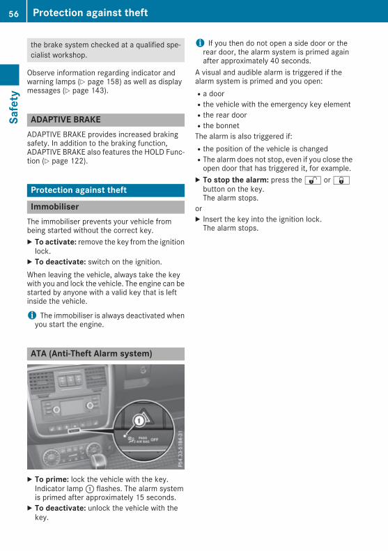
the brake system checked at a qualified spe-cialist workshop.
Observe information regarding indicator andwarning lamps (Y page 158) as well as displaymessages (Y page 143).
ADAPTIVE BRAKEADAPTIVE BRAKE provides increased brakingsafety. In addition to the braking function,ADAPTIVE BRAKE also features the HOLD Func-tion (Y page 122).
Protection against theft
ImmobiliserThe immobiliser prevents your vehicle frombeing started without the correct key.X To activate: remove the key from the ignitionlock.
X To deactivate: switch on the ignition.When leaving the vehicle, always take the keywith you and lock the vehicle. The engine can bestarted by anyone with a valid key that is leftinside the vehicle.
i The immobiliser is always deactivated whenyou start the engine.
ATA (Anti-Theft Alarm system)
X To prime: lock the vehicle with the key.Indicator lamp: flashes. The alarm systemis primed after approximately 15 seconds.
X To deactivate: unlock the vehicle with thekey.
i If you then do not open a side door or therear door, the alarm system is primed againafter approximately 40 seconds.
A visual and audible alarm is triggered if thealarm system is primed and you open:Ra doorRthe vehicle with the emergency key elementRthe rear doorRthe bonnetThe alarm is also triggered if:Rthe position of the vehicle is changedRThe alarm does not stop, even if you close theopen door that has triggered it, for example.
X To stop the alarm: press the% or&button on the key.The alarm stops.
orX Insert the key into the ignition lock.The alarm stops.
56 Protection against theftSafety

Key
Important safety notes
G WARNINGIf children are left unsupervised in the vehicle,they can:Ropen doors and endanger other persons orroad usersRclimb out and be injured by the trafficRoperate vehicle equipment and, for exam-ple, trap themselves.
Children could also set the vehicle in motion,for example by:Rreleasing the parking brakeRshifting the automatic transmission out ofpark position PRstarting the engine.There is a risk of an accident and injury.When leaving the vehicle, always take the keywith you and lock the vehicle. Never leavechildren unattended in the vehicle. Alwayskeep the key out of reach of children.
G WARNINGIf you attach heavy or large objects to the key,the key could be unintentionally turned in theignition lock. This could cause the engine tobe switched off. There is a risk of an accident.Do not attach any heavy or large objects to thekey. Remove any bulky keyrings before insert-ing the key into the ignition lock.
! Keep the key away from strong magneticfields. Otherwise, the remote control functioncould be affected.Strong magnetic fields can occur in the vicin-ity of powerful electrical installations.
Do not keep the key:Rwith electronic devices, e.g. a mobile phoneor another keyRwith metallic objects, e.g. coins or metal foilRinside metallic objects, e.g. a metal caseThis can impair the key's function.
A check that periodically establishes a radioconnection between the vehicle and the keydetermines whether a valid key is in the vehicle.This occurs, for example:Rduring engine startRduring drivingUnited Kingdom only:
G WARNINGWhen the double locks are activated, thedoors can no longer be opened from theinside. People in the vehicle can no longer getout, e.g. in hazardous situations. There is arisk of injury.Therefore, do not leave any people unsuper-vised in the vehicle, particularly children, eld-erly people or people in need of special assis-tance. Do not activate the double lock whenpeople are in the vehicle.
If the vehicle has been locked from the outside,the double lock function is activated as stand-ard. It is then not possible to open the doorsfrom inside the vehicle. You can deactivate thedouble lock function by deactivating the interiormotion sensor (see Digital Owner's Manual).The doors can then be opened from the insideafter the vehicle has been locked from the out-side. The anti-theft alarm system is triggered ifthe door is opened from the inside. Switch offthe alarm (Y page 56).
Key functions
: & Locks the vehicle; % Unlocks the vehicle
Key 57
Openingandclosing
Z

The key centrally locks/unlocks:Rthe doorsRthe rear doorRthe fuel filler flapX To unlock centrally: press the% button.If you do not open the vehicle within approx-imately 40 seconds of unlocking:Rthe vehicle locks againRprotection against theft is reactivated
X To lock centrally: press the& button.
i If the& button is pressed when the driv-er's door is open, the rear side door on thedriver's side is not locked either.
During unlocking, the turn signals flash once.During locking, they flash three times.You can also set an audible signal to confirmthat the vehicle has been locked. The audiblesignal can be activated or deactivated using theon-board computer (Y page 139).Only when all the components have been lockedis the visual or audible locking confirmationissued.When the surround lighting is activated via theon-board computer, it lights up when it is darkafter the vehicle is unlocked with the key(Y page 138).
Changing the settings of the lockingsystemYou can change the settings of the locking sys-tem. This means that only the driver's door andthe fuel filler flap are unlocked when the vehicleis unlocked. This is useful if you frequently travelalone.X To change the setting: press and hold downthe% and& buttons simultaneouslyfor about six seconds until the battery indica-tor lamp flashes twice (Y page 59).
If the setting of the locking system is changedwithin the signal range of the vehicle, pressingthe& or% button:Rlocks orRunlocks the vehicle
The key now functions as follows:X To unlock the driver's door and fuel fillerflap: press the% button once.
X To unlock centrally: press the% buttontwice.
X To lock centrally: press the& button.X To restore the factory settings: press andhold down the% and& buttons simul-taneously for approximately six seconds untilthe battery check lamp flashes twice(Y page 59).
Emergency key element
General notesIf the vehicle can no longer be unlocked with thekey, use the emergency key element.If you use the emergency key element to unlockand open the driver's door, the anti-theft alarmsystem will be triggered. Switch off the alarm(Y page 56).If you unlock the vehicle using the emergencykey element, the fuel filler flap will not beunlocked automatically.X To unlock the fuel filler flap: insert the keyinto the ignition lock.
Removing the emergency key element
X Push release catch: in the direction of thearrow and, at the same time, remove emer-gency key element; from the key.
Further information on locking/unlocking thedriver's door (Y page 62).
58 KeyOp
eningandclosing

Inserting the emergency key elementX Push emergency key element; completelyinto the key until it engages and releasecatch: is back in its basic position.
Key battery
Important safety notes
G WARNINGBatteries contain toxic and corrosive substan-ces. If batteries are swallowed, it can result insevere health problems. There is a risk of fatalinjury.Keep batteries out of the reach of children. Ifa battery is swallowed, seekmedical attentionimmediately.
H Environmental noteBatteries contain pollutants.It is illegal to dispose of themwith the household rubbish.They must be collected sep-arately and disposed of in anenvironmentally responsiblerecycling system.Dispose of batteries in anenvironmentally responsiblemanner. Take dischargedbatteries to a qualified spe-cialist workshop or to a col-lection point for used batter-ies.
Mercedes-Benz recommends that you have thebatteries replaced at a qualified specialist work-shop.
Checking the battery
X Press the& or% button.The battery is working properly if batterycheck lamp: lights up briefly.The battery is discharged if battery checklamp: does not light up briefly.
X Replace the battery (Y page 59).If the key battery is checked within the signalreception range of the vehicle, pressing the& or% button:Rlocks orRunlocks the vehicle
i You can obtain a battery from any qualifiedspecialist workshop.
Replacing the batteryYou require a CR 2025 3 V button cell battery.X Take the emergency key element out of thekey (Y page 58).
X Press emergency key element; into theopening in the key in the direction of the arrowuntil battery compartment cover: opens.When doing so, do not hold battery compart-ment cover: shut.
X Remove battery compartment cover:.
Key 59
Openingandclosing
Z

X Repeatedly tap the key against your palmuntilbattery= falls out.
X Insert the new battery with the positive ter-minal facing upwards. Use a lint-free cloth todo so.
X Make sure that the surface of the battery isfree of lint, grease and other contamination.
X Insert the front tabs of battery compartmentcover: into the housing and then press toclose it.
X Insert emergency key element; into the key(Y page 59).
X Check the function of all key buttons on thevehicle.
Problems with the key
Problem Possible causes/consequences and MM Solutions
You can no longer lock orunlock the vehicle usingthe key.
The key battery is weak or discharged.X Check the key battery (Y page 59) and replace if necessary(Y page 59).
If this does not work:X Lock or unlock the vehicle using the emergency key element(Y page 62).
There is interference from a powerful source of radio waves.X Lock or unlock the vehicle using the emergency key element(Y page 62).
The key is faulty.X Lock or unlock the vehicle using the emergency key element(Y page 62).
X Have the key checked at a qualified specialist workshop.
The engine cannot bestarted using the key.
The on-board voltage is too low.X Switch off non-essential consumers, e.g. seat heating or interiorlighting, and try to start the engine again.
If this does not work:X Check the starter battery and charge it if necessary (Y page 226).orX Jump-start the vehicle (Y page 227).orX Consult a qualified specialist workshop.
60 KeyOp
eningandclosing

Problem Possible causes/consequences andMM Solutions
You have lost a key. X Have the key deactivated at a qualified specialist workshop.X Report the loss immediately to the vehicle insurers.X If necessary, have the locks changed as well.
You have lost the emer-gency key element.
X Report the loss immediately to the vehicle insurers.X If necessary, have the locks changed as well.
Doors
Important safety notes
G WARNINGIf children are left unsupervised in the vehicle,they can:Ropen doors and endanger other persons orroad usersRclimb out and be injured by the trafficRoperate vehicle equipment and, for exam-ple, trap themselves.
Children could also set the vehicle in motion,for example by:Rreleasing the parking brakeRshifting the automatic transmission out ofpark position PRstarting the engine.There is a risk of an accident and injury.When leaving the vehicle, always take the keywith you and lock the vehicle. Never leavechildren unattended in the vehicle. Alwayskeep the key out of reach of children.
United Kingdom only:
G WARNINGWhen the double locks are activated, thedoors can no longer be opened from theinside. People in the vehicle can no longer getout, e.g. in hazardous situations. There is arisk of injury.Therefore, do not leave any people unsuper-vised in the vehicle, particularly children, eld-erly people or people in need of special assis-tance. Do not activate the double lock whenpeople are in the vehicle.
If the vehicle has been locked from the outside,the double lock function is activated as stand-ard. It is then not possible to open the doorsfrom inside the vehicle. You can deactivate thedouble lock function by deactivating the interiormotion sensor (see Digital Owner's Manual).The doors can then be opened from the insideafter the vehicle has been locked from the out-side. The anti-theft alarm system is triggered ifthe door is opened from the inside. Switch offthe alarm (Y page 56).
Unlocking and opening the doorsfrom the insideYou can open a door from inside the vehicleeven if it has been locked. You can only open therear doors from inside the vehicle if they are notsecured by the child-proof locks (Y page 51). Ifthe vehicle has previously been locked with thekey, opening a door from the inside will triggerthe anti-theft alarm system. Switch off the alarm(Y page 56).
: To unlock; To lock= Door handleX Slide latch: upwards.The door is unlocked and can be opened.
X Pull door handle= and open the door.
Doors 61
Openingandclosing
Z
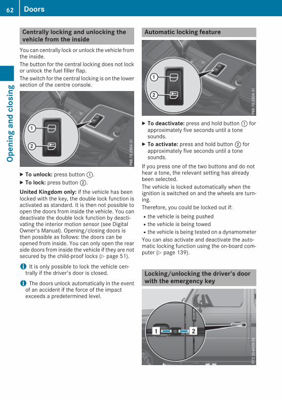
Centrally locking and unlocking thevehicle from the insideYou can centrally lock or unlock the vehicle fromthe inside.The button for the central locking does not lockor unlock the fuel filler flap.The switch for the central locking is on the lowersection of the centre console.
X To unlock: press button:.X To lock: press button;.United Kingdom only: if the vehicle has beenlocked with the key, the double lock function isactivated as standard. It is then not possible toopen the doors from inside the vehicle. You candeactivate the double lock function by deacti-vating the interior motion sensor (see DigitalOwner's Manual). Opening/closing doors isthen possible as follows: the doors can beopened from inside. You can only open the rearside doors from inside the vehicle if they are notsecured by the child-proof locks (Y page 51).
i It is only possible to lock the vehicle cen-trally if the driver's door is closed.
i The doors unlock automatically in the eventof an accident if the force of the impactexceeds a predetermined level.
Automatic locking feature
X To deactivate: press and hold button: forapproximately five seconds until a tonesounds.
X To activate: press and hold button; forapproximately five seconds until a tonesounds.
If you press one of the two buttons and do nothear a tone, the relevant setting has alreadybeen selected.The vehicle is locked automatically when theignition is switched on and the wheels are turn-ing.Therefore, you could be locked out if:Rthe vehicle is being pushedRthe vehicle is being towedRthe vehicle is being tested on a dynamometerYou can also activate and deactivate the auto-matic locking function using the on-board com-puter (Y page 139).
Locking/unlocking the driver's doorwith the emergency key
62 DoorsOp
eningandclosing

X Insert the emergency key element into thelock of the driver's door as far as it will go.
X To unlock: turn the emergency key elementanti-clockwise as far as it will go to position1.
X To lock: turn the emergency key elementclockwise as far as it will go to position2.
Right-hand-drive vehicle: turn the emergencykey element in the opposite direction in bothcases.If you use the emergency key element to unlockand open the driver's door, the anti-theft alarmsystem will be triggered. Switch off the alarm(Y page 56).
Rear door
Important safety notes
G WARNINGCombustion engines emit poisonous exhaustgases such as carbon monoxide. If the reardoor is open when the engine is running, par-ticularly if the vehicle is moving, exhaustfumes could enter the passenger compart-ment. There is a risk of poisoning.Turn off the engine before opening the reardoor. Never drive with the rear door open.
G WARNINGIf objects, luggage or loads are not secured ornot secured sufficiently, they could slip, tipover or be flung around and thereby hit vehicleoccupants. There is a risk of injury, especiallywhen braking or abruptly changing directions.Always store objects so that they cannot beflung around. Secure objects, luggage orloads against slipping or tipping before thejourney.
G WARNINGDo not leave children unsupervised in thevehicle. They could open the rear door frominside the vehicle and endanger themselvesand others.
! The tailgate swings out to the side whenopened. Therefore, make sure that there issufficient clearance.
Do not leave the key in the luggage compart-ment. You may otherwise be inadvertentlylocked out.Stow luggage or loads preferably in the luggagecompartment. Observe the loading guidelines(Y page 198).
Opening from the outsideThe rear door must be unlocked before it can beopened.X Press the% button on the key.
X Press release button: and pull door han-dle;.
X Open the rear door.
Opening from the inside
: To unlock; To lock= Door handle
Rear door 63
Openingandclosing
Z

X Slide latch: upwards.The door is unlocked.
X Pull door handle=.
i If the child-proof locks are used to securethe rear door, you cannot open it from insidethe vehicle, even when it has been unlocked(Y page 51).
Closing from the outsideX Push the rear door closed from outside thevehicle.
X Lock the vehicle with the& button on thekey.
Closing from inside the vehicle
: To unlock; To lock= Door handleX Secure the rear door with the child-prooflocks if necessary (Y page 51).
X Pull the rear door closed using the handleunderneath the rear window.
X Push the latch downwards;.The rear door is locked.
Side windows
Important safety notes
G WARNINGIf children are left unsupervised in the vehicle,they can:Ropen doors and endanger other persons orroad usersRclimb out and be injured by the trafficRoperate vehicle equipment and, for exam-ple, trap themselves.
Children could also set the vehicle in motion,for example by:Rreleasing the parking brakeRshifting the automatic transmission out ofpark position PRstarting the engine.There is a risk of an accident and injury.When leaving the vehicle, always take the keywith you and lock the vehicle. Never leavechildren unattended in the vehicle. Alwayskeep the key out of reach of children.
Opening and closing the side win-dowsThe side windows can be opened and closed byhand.
Example: driver's sideX To open: turn window crank: clockwise.X To close: turn window crank: anti-clock-wise.
64 Side windowsOp
eningandclosing

i On the front-passenger side, the windowcrank must be turned in the opposite direc-tion.
Sliding sunroof
Important safety notes
G WARNINGWhile opening and closing the sliding sunroof,body parts in close proximity could becometrapped. There is a risk of injury.Make sure that no body parts are in closeproximity during the opening and closing pro-cedures.If somebody becomes trapped:Rrelease the switch immediately, orRduring automatic operation, press theswitch briefly in any direction
The opening or closing procedure will be stop-ped.
G WARNINGIf children operate the sliding sunroof theycould become trapped, particularly if they areleft unsupervised. There is a risk of injury.When leaving the vehicle, always take the keywith you and lock the vehicle. Never leavechildren unattended in the vehicle.
! Only open the panorama sliding sunroof if itis free of snow and ice. Otherwise, malfunc-tions may occur.Do not allow anything to protrude from thesliding sunroof. Otherwise, the seals could bedamaged.
Resonance noises can occur in addition to theusual airflow noises when the sliding sunroof isopen. They are caused by minor pressure fluc-tuations in the vehicle interior. Change the posi-tion of the sliding sunroof or open a side windowslightly to reduce or eliminate these noises.
Opening and closing the sliding sun-roof
: To raise; To open= To close/lowerX Turn the key to position1 or2 in the igni-tion lock.
X Press or pull the¡ switch in the corre-sponding direction.
X To open automatically: press the¡ switch beyond the point of resistance inthe direction of arrow;.The sliding sunroof opens completely.
X To interrupt automatic operation: press orpull the¡ switch again.
Automatic operation is only available whenopening.
i The sliding sunroof cannot be raised when aroof rack is fitted.
Operating the sliding sunroof man-uallyThe actuator motor for the sliding sunroof islocated on the left-hand side of the luggagecompartment, behind the rear panel trim.
Sliding sunroof 65
Openingandclosing
Z

Removing the rear panel trimX Open the rear door.X Remove edge protection: on the door pillarin the direction of arrow;.
X Pull back rear panel trim= in the direction ofarrow? until the electrical connection canbe reached.
X Disconnect the electrical connection.X Completely remove rear panel trim=.
Opening/closing the sliding sunroof manuallyX Remove wheel wrenchA from the vehicletool kit (Y page 223).
X Place wheel wrenchA onto the hexagon nutof the actuator motor.
X To open: turn wheel wrenchA anti-clock-wise.
X To close: turn wheel wrenchA clockwise.
Fitting the rear panel trimX Connect the electrical connection.X Insert rear panel trim=.Hook tabsC of rear panel trim= into vehi-cle side wallB.
X Insert edge protection:.X Close the rear door.
Problems with the sliding sunroof
G WARNINGYou could be severely or even fatally injured when closing the sliding sunroof with increasedclosing force or if the anti-entrapment feature is deactivated. Make sure that nobody can becometrapped when closing the sliding sunroof.
Problem Possible causes/consequences andMM Solutions
The sliding sunroof can-not be closed and youcannot see the cause.
If the sliding sunroof is obstructed during closing and reopens againslightly:X Immediately after it blocks, pull the¡ switch down again to thepoint of resistance until the sliding sunroof is closed.
If the sliding sunroof is obstructed again during closing and reopensagain slightly:X Immediately after it blocks, pull the¡ switch down again to thepoint of resistance until the sliding sunroof is closed.
If the sliding sunroof will still not open or close due to a malfunction, consult a qualified specialistworkshop.
66 Sliding sunroofOp
eningandclosing

Correct driver's seat position
: Steering wheel; Seat belts= BackrestX Observe the safety guidelines on seat adjust-ment (Y page 67).
X Make sure that seat= is correctly adjusted.Adjusting the seats (Y page 69)
When adjusting the seat, make sure that:Ryou are as far away from the driver's airbag aspossibleRyou are sitting in a normal upright positionRyou can fasten the seat belt properlyRyou have moved the backrest to an almostvertical positionRyou can depress the pedals properlyX Check whether the head restraint is adjustedcorrectly (Y page 69).When doing so, ensure that you have adjustedthe head restraint so that the back of yourhead is supported at eye level by the centre ofthe head restraint.
X Observe the safety guidelines on steeringwheel adjustment (Y page 67).
X Make sure that steering wheel: is adjustedcorrectly.Adjusting the steering wheel electrically(Y page 72).
When adjusting the steering wheel, make surethat:Ryou can hold the steering wheel with yourarms slightly bentRyou can move your legs freelyRyou can see all the displays in the instrumentcluster clearly
X Observe the safety guidelines for seat belts(Y page 32).
X Check whether you have fastened seatbelt; properly (Y page 34).
The seat belt should:Rfit snugly across your bodyRbe routed across the middle of your shoulderRbe routed across your hips in the pelvic areaX Before starting off, adjust the rear-viewmirrorand the exterior mirrors so that you have agood view of road and traffic conditions(Y page 73).
Seats
Important safety notes
G WARNINGIf children adjust the seats, they couldbecome trapped, especially if they are unat-tended. There is a risk of injury.When leaving the vehicle, always take the keywith you and lock the vehicle. Never leavechildren unattended in the vehicle.
The seats can be adjusted when there is no keyin the ignition lock.
G WARNINGWhen adjusting a seat, you or another vehicleoccupant could become trapped by the guiderail of the seat, for instance. There is a risk ofinjury.Make sure that no one has any part of theirbody within the sweep of the seat whenadjusting it.
Observe the safety notes on "Airbags"(Y page 36) and "Children in the vehicle"(Y page 38).
Seats 67
Seats,steerin
gwheelandmirrors
Z

G WARNINGYou could lose control of the vehicle whiledriving if you:Radjust the driver's seat, steering wheel ormirrorsRfasten the seat beltThere is a risk of an accident.Adjust the driver's seat, head restraint, steer-ing wheel and mirrors and fasten your seatbelt before starting the engine.
G WARNINGThe head restraints cannot provide the inten-ded protection unless they are fitted andadjusted correctly. There is an increased riskof injury to the head and neck in the event ofan accident or sudden braking, for example.Always drive with the head restraints fitted.Ensure that the centre of the head restraintssupport the back of each vehicle occupant'shead at eye level before driving off.
Make sure that you do not interchange the headrestraints of the front and rear seats whenadjusting the head restraints. Otherwise, youcannot adjust the height and angle of the headrestraints correctly.Adjust the head restraint so that it is as close aspossible to your head.
G WARNINGIf the driver's seat is not correctly engaged, itcould unexpectedly move while driving. Thiscould cause you to lose control of the vehicle.There is a risk of an accident.Always ensure that the driver's seat isengaged before starting the vehicle.
G WARNINGIf you adjust the seat height carelessly, you orother vehicle occupants could be trapped andthereby injured. Children in particular couldaccidentally press the electrical seat adjust-ment buttons and become trapped. There is arisk of injury.While moving the seats, make sure that yourhands or other body parts do not get under the
lever assembly of the seat adjustment sys-tem.
G WARNINGWhen adjusting a seat, you or another vehicleoccupant could become trapped by the guiderail of the seat, for instance. There is a risk ofinjury.Make sure that no one has any part of theirbody within the sweep of the seat whenadjusting it.
G WARNINGIf the seat belt is not in the seat belt guide, itno longer offers the intended level of protec-tion. An incorrectly fastened seat belt can alsocause additional injuries. This poses anincreased risk of injury or even fatal injury.Before starting a journey, always make surethat the seat belt is in the seat belt guide andall vehicle occupants have fastened their seatbelts properly.
! To avoid damage to the seats and the seatheating, observe the following information:Rdo not spill any liquids on the seats. If liquidis spilled on the seats, dry them as soon aspossible.Rif the seat covers are damp or wet, do notswitch on the seat heating. The seat heat-ing should also not be used to dry the seats.Rclean the seat covers as recommended;see "Interior care".Rdo not transport heavy loads on the seats.Do not place sharp objects on the seatcushions, e.g. knives, nails or tools. Theseats should only be occupied by passen-gers, if possible.Rwhen the seat heating is in operation, donot cover the seats with insulating materi-als, e.g. blankets, coats, bags, seat covers,child seats or booster seats.
! Make sure that there are no objects in thefootwell under or behind the seats whenmov-ing the seats back. There is a risk that theseats and/or the objects could be damaged.
! When the rear bench seat is folded for-wards, the front seats cannot be moved to
68 SeatsSeats,steerin
gwheelandmirrors

their rearmost position. You could otherwisedamage the seats and the rear bench seat.
! Make sure that the sun visor is folded upbefore adjusting the backrest and headrestraint height. The head restraint and sunvisor could otherwise collide when the headrestraint is fully extended.
i If the front door is open, the seats can beadjusted for up to 30 minutes after the igni-tion has been switched off.
i The rear seat head restraints can beremoved (Y page 70).For more information, contact a qualified spe-cialist workshop.
i Further information about enlarging the lug-gage compartment (folding the rear benchseat forwards) (Y page 202).
Adjusting the seats
: Seat cushion angle; Seat height= Backrest angle? Seat fore-and-aft adjustmentX Seat fore-and-aft adjustment: lift lever?and slide the seat forwards or backwards.
X Release lever? again.Ensure that the seat engages audibly.
Adjusting the head restraints
Important safety notes
G WARNINGThe head restraints cannot provide the inten-ded protection unless they are fitted andadjusted correctly. There is an increased riskof injury to the head and neck in the event ofan accident or sudden braking, for example.Always drive with the head restraints fitted.Ensure that the centre of the head restraintssupport the back of each vehicle occupant'shead at eye level before driving off.
Observe the following when adjusting the headrestraints:X Do not interchange the head restraints of thefront and rear seats.Otherwise, you cannot adjust the height andangle of the head restraints correctly.
X Adjust the head restraint so that it is as closeas possible to your head.
Adjusting the head restraint height
X To raise: pull the head restraint up to thedesired position.
X To lower: push release button: in the direc-tion of the arrow and push the head restraintdown to the desired position.
Seats 69
Seats,steerin
gwheelandmirrors
Z

Adjusting the angle of the headrestraints
X Push or pull the lower edge of the headrestraint in the direction of the arrow.
Rear seat head restraints
Important safety notesG WARNINGThe head restraints cannot provide the inten-ded protection unless they are fitted andadjusted correctly. There is an increased riskof injury to the head and neck in the event ofan accident or sudden braking, for example.Always drive with the head restraints fitted.Ensure that the centre of the head restraintssupport the back of each vehicle occupant'shead at eye level before driving off.
Observe the following when adjusting the headrestraints:X Do not interchange the head restraints of thefront and rear seats.Otherwise, you cannot adjust the height andangle of the head restraints correctly.
X Adjust the head restraint so that it is as closeas possible to your head.
Adjusting the rear seat head restraintheight
X If the head restraint is fully lowered, it is nec-essary to press release catch:.
X To raise: pull the head restraint up to thedesired height.
X To lower: press release catch: and pushthe head restraint down until it is in thedesired position.
Fitting/removing the rear seat headrestraintsX To remove: pull the head restraint up to thestop.
X Press release catch: and pull the headrestraint out of the guides.
X To refit: place the head restraint in the guidesof the backrest.i The notches on the guide rodmust be on theleft-hand side when viewed in the direction oftravel.
X Push the head restraint down until you hear itengage in position.
Switching the seat heating on/off
General notes
G WARNINGIf you repeatedly switch on seat heating, theseat cushion and backrest padding maybecome very hot. The health of vehicle occu-pants with limited temperature sensitivity or alimited ability to react to excessively hightemperatures may be affected or they may
70 SeatsSeats,steerin
gwheelandmirrors

even suffer burn-like injuries. There is a risk ofinjury.Therefore, do not switch on the seat heatingrepeatedly.
The red indicator lamps in the button indicatethe heating level you have selected.X Make sure that the key is in position1 or2in the ignition lock.
i If the battery voltage is too low, the seatheating may switch off.
Switching the front seat heating on/off
X To switch on: press button: repeatedlyuntil the desired heating level is set.
X To switch off: press button: repeatedlyuntil all the indicator lamps go out.i The system automatically switches downfrom level 3 to level 2 after approximatelyeight minutes.The system automatically switches downfrom level 2 to level 1 after approximately tenminutes.The system automatically switches offapproximately 35 minutes after it is set tolevel 1.
Problems with the seat heating
Problem Possible causes/consequences and MM Solutions
The seat heating hasswitched off prematurelyor cannot be switchedon.
The on-board voltage is too low because too many electrical consum-ers are switched on.X Switch off electrical consumers that you do not need, such as therear window heating or interior lighting.Once the battery is sufficiently charged, the seat heating can beswitched back on manually.
Steering wheel
Important safety notes
G WARNINGYou could lose control of the vehicle whiledriving if you:Radjust the driver's seat, steering wheel ormirrorsRfasten the seat belt
There is a risk of an accident.Adjust the driver's seat, head restraint, steer-ing wheel and mirrors and fasten your seatbelt before starting the engine.
G WARNINGChildren could become trapped by the steer-ing wheel if they adjust it. There is a risk ofinjury.
Steering wheel 71
Seats,steerin
gwheelandmirrors
Z

When leaving the vehicle, always take the keywith you and lock the vehicle. Never leavechildren unattended in the vehicle.
The electrically adjustable steering wheel canstill be adjusted when there is no key in the igni-tion lock.
Adjusts the steering wheel
: To adjust the steering wheel position (fore-and-aft adjustment)
; To adjust the steering wheel height
i If the driver's door is open, the steeringwheel can be adjusted for up to 30 minutesafter the ignition has been switched off.
i Further related subjects:REASY-ENTRY/EXIT feature (Y page 72)
Steeringwheel EASY-ENTRY/EXIT fea-ture
Important safety notes
G WARNINGWhen the EASY-ENTRY/EXIT feature adjuststhe steering wheel and the driver's seat, youand other vehicle occupants – particularlychildren – could become trapped. There is arisk of injury.While the EASY-ENTRY/EXIT feature is mak-ing adjustments, make sure that no one hasany body parts in the sweep of the seat andthe steering wheel.
If someone is trapped:Rpress one of the memory function positionbuttons, orRpress one of the memory function memorybuttons, orRmove the switch for steering wheel adjust-ment in the opposite direction to that inwhich the steering wheel is moving.
The adjustment process is stopped.
G WARNINGIf you drive off while the EASY-ENTRY/EXITfeature is making adjustments, you could losecontrol of the vehicle. There is a risk of anaccident.Always wait until the adjustment process iscomplete before driving off.
! Do not activate the EASY-ENTRY/EXIT fea-ture, if the seat backrest is reclined too farbackwards. This can damage the front or rearseats. You must first move the backrest to avertical position.
The EASY-ENTRY/EXIT feature makes getting inand out of your vehicle easier.You can activate and deactivate the EASY-ENTRY/EXIT feature in the on-board computer(Y page 140).
Position of the steering wheel when theEASY-ENTRY/EXIT feature is activeThe steering wheel moves upwards and towardsthe dashboard if:Ryou remove the key from the ignition lock orRyou open the driver's door and the key is inposition 0 or 1 in the ignition lock
i The steering wheel only moves upwards andtowards the dashboard if it has not alreadyreached the upper steering limiter.
Position of the steering wheel for driv-ingThe steering wheel is moved to the previouslyset position if:Rthe driver's door is closed andRyou insert the key into the ignition lock
72 Steering wheelSeats,steerin
gwheelandmirrors

The last position of the steering column is storedwhen you switch off the ignition.
Mirrors
Rear-view mirror
G WARNINGElectrolyte may escape if the glass in an auto-matic anti-dazzle mirror breaks. The electro-lyte is harmful and causes irritation. It mustnot come into contact with your skin, eyes,respiratory organs or clothing or be swal-lowed. There is a risk of injury.If you come into contact with the electrolyte,observe the following:RRinse off the electrolyte from your skinimmediately with water.RImmediately rinse the electrolyte out ofyour eyes thoroughly with clean water.RIf the electrolyte is swallowed, immediatelyrinse your mouth out thoroughly. Do notinduce vomiting.RIf electrolyte comes into contact with yourskin or hair or is swallowed, seek medicalattention immediately.RImmediately change out of clothing whichhas come into contact with electrolyte.RIf an allergic reaction occurs, seek medicalattention immediately.
X Adjust the rear-view mirror in such a way thatyou have a good view of road and traffic con-ditions behind you.
The rear-view mirror automatically goes intoanti-dazzle mode if:Rthe ignition is switched onRincident light from headlamps strikes the sen-sor in the rear-view mirror
The rear-viewmirror does not go into anti-dazzlemode if reverse gear is engaged or if the interiorlighting is switched on.
Exterior mirrors
Adjusting the exterior mirrorsmanuallyX Adjust the exterior mirrors in such a way thatyou can get a good overview of road and traf-fic conditions.
Mirrors 73
Seats,steerin
gwheelandmirrors
Z

Exterior lighting
General notesFor reasons of safety, Mercedes-Benz recom-mends that you drive with lights switched oneven during the daytime. In some countries,operation of the headlamps varies due to legalrequirements and voluntary recommendations.
Driving abroad
Converting to symmetrical dippedbeamWhen driving in countries where vehicles aredriven on the opposite side of the road to thecountry in which the vehicle is registered, theheadlamps must be switched to symmetricaldipped beam. This prevents oncoming trafficfrom being dazzled. Symmetrical lights do notilluminate as large an area of the edge of thecarriageway.Have the headlamps switched at a qualified spe-cialist workshop as close to the border as pos-sible before driving in these countries.
Converting to asymmetrical dippedbeam after returningHave the headlamps switched back to asym-metrical dipped beam at a qualified specialistworkshop as soon as possible after crossing theborder again.
Light switch
Operation
1 W Left-hand parking lamps2 X Right-hand parking lamps
3 T Side lamps, licence plate and instru-ment cluster lighting
4Ã Automatic headlampmode, controlledby the light sensor
5 L Dipped-beam/main-beam headlampsB R Rear foglampIf you hear a warning tone when you leave thevehicle, the lights may still be switched on.X Turn the light switch to theà position.The exterior lighting, except the side lamps/parking lamps, switches off automatically if you:Rremove the key from the ignition lockRopen the driver's door with the key in positionu in the ignition lock
Dipped-beam headlamps
G WARNINGWhen the light switch is set toÃ, thedipped-beamheadlampsmay not be switchedon automatically if there is fog, snow or othercauses of poor visibility due to the weatherconditions such as spray. There is a risk of anaccident.In such situations, turn the light switch toL.
When the ignition is switched on and the lightswitch is in the L position, the side lampsand dipped-beam headlamps are switched oneven if the light sensor does not sense darkambient light conditions. This is advantageouswhen there is fog or rain.X To switch on the dipped-beamheadlamps:turn the key in the ignition lock to position2or start the engine.
X Turn the light switch to the L position.The green L indicator lamp on the instru-ment cluster lights up.
Daytime driving lightsYou can set the Daytime driving lightsDaytime driving lightsfunction via the on-board computer(Y page 138).X To switch on the daytime driving lights:switch on the Daytime driving lightsDaytime driving lightsfunction via the on-board computer.
74 Exterior lightingLightsandwindscreenwipers

Automatic headlamp mode
G WARNINGWhen the light switch is set toÃ, thedipped-beamheadlampsmay not be switchedon automatically if there is fog, snow or othercauses of poor visibility due to the weatherconditions such as spray. There is a risk of anaccident.In such situations, turn the light switch toL.
The automatic headlamp feature is only an aid.The driver is responsible for the vehicle lightingat all times.à is the preferred light switch position.The light setting is automatically selectedaccording to the brightness of the ambient light,but not in the event of poor visibility due toweather conditions such as fog, snow or spray.X To switch on the automatic headlamps:turn the light switch to theà position.With the key in position1 in the ignition lock,the side lamps are switched on or off auto-matically depending on the brightness of theambient light.If you have switched on the Daytime driv‐Daytime driv‐ing lightsing lights function via the on-board com-puter, the daytime driving lights or the sidelamps and dipped-beam headlamps willswitch on or off automatically while theengine is running.When the dipped-beam headlamps areswitched on, the greenL indicator lamp inthe instrument cluster lights up.
Rear foglampThe rear fog lamp improves the visibility of yourvehicle for the traffic behind in the event ofheavy fog. You must observe the legal require-ments for the country in which you are currentlydriving when operating the rear fog lamp.X To switch on the rear fog lamp: turn the keyin the ignition lock to position2 or start theengine.
X Turn the light switch to the L position.X Press the R button.The yellow R indicator lamp on the instru-ment cluster lights up.
Side lamps! When the battery is discharged heavily, theside lamps or parking lamps are automaticallyswitched off to facilitate an engine start.Always park your vehicle safely and in awell litarea, in accordance with the relevant legalstipulations. Avoid using the T side lampsfor periods lasting several hours. Where pos-sible, switch on the right X or left Wparking lamp.
X To switch on: turn the light switch to theT position.The green T indicator lamp on the instru-ment cluster lights up.
Parking lampsSwitching on the parking lamps ensures that thecorresponding side of the vehicle is illuminated.X To switch on the parking lamp: turn the keyto positionu in the ignition lock or removethe key.
X Turn the light switch to the W (left-handside of the vehicle) orX (right-hand side ofthe vehicle) position.
Headlamp cleaning systemThe headlamps are cleaned automatically if the"Wipe with washer fluid" function is operatedten times (Y page 81) while the lights are onand the engine is running. When you switch offthe ignition, the automatic headlamp cleaningsystem is reset and counting is resumed from 0.
Exterior lighting 75
Lightsandwindscreenwipers
Z

Combination switch
: Main-beam headlamps; Turn signal, right= Headlamp flasher? Turn signal, leftX To indicate briefly: press the combinationswitch briefly to the pressure point in thedirection of arrow; or?.The corresponding turn signal flashes threetimes.
X To indicate: press the combination switchbeyond the pressure point in the direction ofarrow; or?.
X To switch on the main-beam headlamps:turn the light switch to the L position.
X Press the combination switch beyond thepressure point in the direction of arrow:.The blue K indicator lamp on the instru-ment cluster lights up when the main-beamheadlamps are switched on.
X To switch off the main-beam headlamps:move the combination switch back to its nor-mal position.The blue K indicator lamp on the instru-ment cluster goes out.
X High-beam flasher: pull the combinationswitch in the direction of arrow=.
Hazard warning lamps
X To switch the hazard warning lamps on/off: press button:.All the indicator lamps will flash when thehazard warning lamps are switched on. If younow switch on an indicator lamp using thecombination switch, only the indicator lampon the corresponding side of the vehicle willflash.
The hazard warning lamps switch on automati-cally if:Ran airbag is deployed orRthe seat belt tensioner is deployed orRthe vehicle decelerates rapidly from a speedof above 70 km/h and comes to a standstill
The hazard warning lamps switch off automati-cally if the vehicle reaches a speed of above10 km/h again after a full brake application.The hazard warning lamps continue to operateeven if the ignition is switched off.
Headlamps misted up on the insideCertain climatic and physical conditions maycause moisture to form in the headlamp. Thismoisture does not affect the functionality of theheadlamp.
76 Exterior lightingLightsandwindscreenwipers

Interior lighting
Overview of interior lighting
Front overhead control panel
: p Switches the left-hand front readinglamp on/off
; t Switches the luggage compartment/rear interior lighting on/off
= p Switches the right-hand front readinglamp on/off
? | Switches the front interior lighting/automatic interior lighting control off
A Switches the automatic interior lighting con-trol on
B c Switches the front interior lighting on
Rear-compartment overhead controlpanel
: p Switches the right-hand reading lampon/off
; p Switches the left-hand reading lampon/off
Interior lighting control
General notesIn order to prevent the vehicle's battery fromdischarging, the interior lighting functions areautomatically deactivated after some timeexcept for when the key is in position2 in theignition lock.The brightness of the instrument cluster lightingmay be set using the controller on the instru-ment cluster (Y page 131).
Automatic interior lighting controlX To switch on: move switchB to the centreposition (Y page 77).
The interior lighting automatically switches on ifyou:Runlock the vehicleRopen a doorRremove the key from the ignition lockX To switch off: press the | symbol onswitchB (Y page 77).
The interior lighting remains switched off even ifyou:Runlock the vehicleRopen a doorRremove the key from the ignition lockThe interior lighting is switched on for a shorttime when the key is removed from the ignitionlock. You can activate this delayed switch-offusing the on-board computer (Y page 139).The front interior light switches on when youopen a front door. The rear interior lighting andluggage compartment lighting switch on whenyou open a rear side door or the rear door.
i If a door remains open and the key is not inthe ignition lock, the interior lighting switchesoff after approximately 30 minutes.
Manual interior lighting control
Front interior lighting! If the interior lighting has been switched onmanually, it will not be switched off automat-ically.This can cause the starter battery to dis-charge.
Interior lighting 77
Lightsandwindscreenwipers
Z

Make sure that the interior lighting does notremain switched on too long after the enginehas been switched off.
X To switch on: press the c symbol onswitchB (Y page 77).
X To switch off: move switchB to the centreposition (Y page 77).
Reading lampsX To switch on/off: press the respective pbutton (Y page 77).
Rear interior lightingX To switch on/off: press the t button(Y page 77).i When you open a rear side door, the rearinterior lighting switches on. Then, you cannotswitch it off using the t button.If you leave the front doors open for a longtime, switch the rear interior lighting off. Inthis way, you can avoid draining the battery.
Luggage compartment lightingX To switch on/off: press the t button(Y page 77).i If you open the rear door, the luggage com-partment lighting switches on. Then, you can-not switch it off using the t button.If you leave the rear door open for a long time,switch the luggage compartment lighting off.In thisway, you can avoid draining the battery.
Switching off/on with the rear door open:X To switch off: press lock; down in thedirection of the arrow until it engages.The luggage compartment lighting goes out.
X To switch on: press lock cylinder: on thedoor handle.The luggage compartment lighting functionsagain in the usual manner.
Do not close the rear door when lock; isengaged at the bottom.
Reading lamp
G WARNINGIf the reading lamp is plugged in while thevehicle is in motion, it may cause injuries inthe event of a sudden change in direction,braking or an accident, for example.There is a risk of injury.Before starting a journey, always make surethat the reading lamp is not plugged in and isstowed safely.
X Stop the vehicle, paying attention to road andtraffic conditions.
X Remove reading lamp: from the stowagecompartment in the front-passenger door.
X Insert plug of reading lamp: into the 12 Vsocket.
X To switch on/off: press button;.i Depending on the design of the readinglamp, button; is either on the top or bottomof the housing.
Replacing bulbs
Important safety notes
G DANGERXenon bulbs are under high voltage. You canget an electric shock if you remove the coverof the xenon bulb and touch the electricalcontacts. There is a risk of fatal injury.Never touch the parts or the electrical con-tacts of the xenon bulb. Always have work on
78 Replacing bulbsLightsandwindscreenwipers
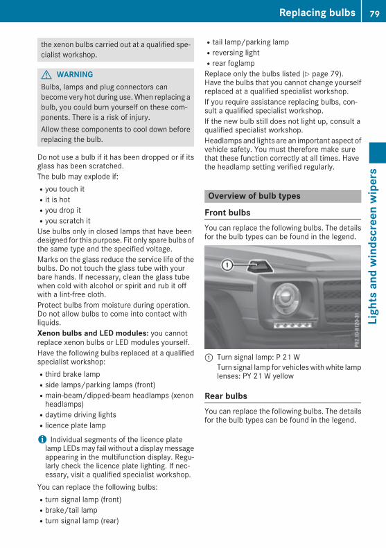
the xenon bulbs carried out at a qualified spe-cialist workshop.
G WARNINGBulbs, lamps and plug connectors canbecome very hot during use.When replacing abulb, you could burn yourself on these com-ponents. There is a risk of injury.Allow these components to cool down beforereplacing the bulb.
Do not use a bulb if it has been dropped or if itsglass has been scratched.The bulb may explode if:Ryou touch itRit is hotRyou drop itRyou scratch itUse bulbs only in closed lamps that have beendesigned for this purpose. Fit only spare bulbs ofthe same type and the specified voltage.Marks on the glass reduce the service life of thebulbs. Do not touch the glass tube with yourbare hands. If necessary, clean the glass tubewhen cold with alcohol or spirit and rub it offwith a lint-free cloth.Protect bulbs from moisture during operation.Do not allow bulbs to come into contact withliquids.Xenon bulbs and LED modules: you cannotreplace xenon bulbs or LED modules yourself.Have the following bulbs replaced at a qualifiedspecialist workshop:Rthird brake lampRside lamps/parking lamps (front)Rmain-beam/dipped-beam headlamps (xenonheadlamps)Rdaytime driving lightsRlicence plate lamp
i Individual segments of the licence platelamp LEDsmay fail without a displaymessageappearing in the multifunction display. Regu-larly check the licence plate lighting. If nec-essary, visit a qualified specialist workshop.
You can replace the following bulbs:Rturn signal lamp (front)Rbrake/tail lampRturn signal lamp (rear)
Rtail lamp/parking lampRreversing lightRrear foglampReplace only the bulbs listed (Y page 79).Have the bulbs that you cannot change yourselfreplaced at a qualified specialist workshop.If you require assistance replacing bulbs, con-sult a qualified specialist workshop.If the new bulb still does not light up, consult aqualified specialist workshop.Headlamps and lights are an important aspect ofvehicle safety. You must therefore make surethat these function correctly at all times. Havethe headlamp setting verified regularly.
Overview of bulb types
Front bulbsYou can replace the following bulbs. The detailsfor the bulb types can be found in the legend.
: Turn signal lamp: P 21 WTurn signal lamp for vehicleswithwhite lamplenses: PY 21 W yellow
Rear bulbsYou can replace the following bulbs. The detailsfor the bulb types can be found in the legend.
Replacing bulbs 79
Lightsandwindscreenwipers
Z

: Tail lamp/parking lamp: R 5 W; Brake lamp/tail lamp: P 21/5 W= Turn signal: PY 21 W yellow? Reversing lamp: P 21 WA Rear foglamp: P 21 W
Replacing front bulbs
Turn signals! Do not fasten the screws too tightly. Youcould otherwise damage the lens.
X Switch off the lights.X Unscrew screws:.X Remove lens;.
X Turn bulb= anti-clockwise, applying slightpressure, and pull it out of the bulb holder.
X Insert the new bulb into the bulb holder and,applying slight pressure, turn it clockwiseuntil it engages.
X Fit lens;.X Replace and tighten screws:.
Replacing rear bulbs
Tail lamps! When fitting the lens, make sure that theseal is positioned correctly.
! Do not fasten the screws too tightly. Youcould otherwise damage the lens.
X Switch off the lights.X Unscrew screws:.X Remove lens;.
= Turn signals? Brake/tail lampA Tail lamp/parking lamp
80 Replacing bulbsLightsandwindscreenwipers

X Turn the respective bulb anti-clockwise,applying slight pressure, and pull it out of thebulb holder.
X Insert the new bulb into the bulb holder and,applying slight pressure, turn it clockwiseuntil it engages.
X Fit lens;.X Tighten screws:.
Reversing lamp/rear foglamp! Do not fasten the screws too tightly. Youcould otherwise damage the lens.
X Switch off the lights.X Unscrew screws:.X Remove lens;.
X Turn bulb= anti-clockwise, applying slightpressure, and pull it out of the bulb holder.
X Insert the new bulb into the bulb holder and,applying slight pressure, turn it clockwiseuntil it engages.
X Fit lens;.X Tighten screws:.
Windscreen wipers
Switching the windscreen wipers on/off! Do not operate the windscreen wipers whenthe windscreen/rear window is dry, as thiscould damage the wiper blades. Moreover,dust that has collected on the windscreen/rear window can scratch the glass if wipingtakes place when the windscreen/rear win-dow is dry.If it is necessary to operate the windscreenwipers/rear window wiper in dry weatherconditions, always use washer fluid.
! If the windscreen wipers leave smears onthewindscreen/rear window after the vehiclehas been washed in an automatic car wash,thismay be due towax or other residue. Cleanthe windscreen/rear window with washerfluid after an automatic car wash.
1 $ Windscreen wipers off2 Ä Intermittent wiping, normal3 Å Intermittent wiping, frequent4 ° Continuous wipe, slow5 ¯ Continuous wipe, fastB í Single wipe
î Wipes with washer fluidX Turn the key to position1 or2 in the igni-tion lock.
X Turn the combination switch to the corre-sponding position.
When the windscreen wipers are switched onand you stop the vehicle, the windscreen wiperswipe more slowly.Intermittent wiping is interrupted if you stop thevehicle and open a front door. This protectspeople getting into and out of the vehicle frombeing sprayed with water.
Windscreen wipers 81
Lightsandwindscreenwipers
Z

Switching the rear window wiper on/off
: è Switch2 b Wipes with washer fluid3 I Switches on intermittent wiping4 0 Switches off intermittent wiping5 b Wipes with washer fluidX Turn the key to position1 or2 in the igni-tion lock.
X Turn switch: on the combination switch tothe corresponding position.When the rear window wiper is switched on,the icon appears in the instrument cluster.
The rear window wiper comes on automaticallyif you shift the automatic transmission to posi-tionk while the windscreen wipers are on.
Replacing the wiper blades
Important safety notes
G WARNINGIf the windscreen wipers begin to move whileyou are changing the wiper blades, you can betrapped by the wiper arm. There is a risk ofinjury.Always switch off the windscreen wipers andignition before changing the wiper blades.
! To avoid damaging the windscreen wiperblades, make sure that you touch only thewiper arm of the windscreen wiper.
! Never open the bonnet if a windscreenwiper arm has been folded away from thewindscreen.
Never fold a windscreen wiper arm without awiper blade back onto the windscreen/rearwindow.Hold the windscreen wiper arm firmly whenyou change the wiper blade. If you release thewindscreen wiper arm without a wiper bladeand it falls onto the windscreen, the wind-screen may be damaged by the force of theimpact.Mercedes-Benz recommends that you havethe wiper blades changed at a qualified spe-cialist workshop.
Removing the wiper blade
X Remove the key from the ignition lock.X Fold wiper arm: away from the windscreenuntil it engages.
X Position wiper blade; at right angles.X Press locking spring?.X Slide wiper blade;with hinge piece= fromwiper arm:.
Fitting the wiper blade
82 Windscreen wipersLightsandwindscreenwipers

X Slide wiper arm: into new wiper blade;with fitting=.
X Engage spring clip? into the end of thewiperarm.
X Make sure that wiper blade; is seated cor-rectly.
X Fold wiper arm: back onto the windscreen.
Problems with the windscreen wipers
Problem Possible causes/consequences andMM Solutions
The windscreen wipersare jammed.
Leaves or snow, for example, are obstructing windscreen wiper move-ment. The wiper motor has been deactivated.X Switch off the engine.X Remove the key from the ignition lock.X Remove the cause of the obstruction.X Switch the windscreen wipers back on.
The windscreen wipersfail completely.
The windscreen wiper drive is malfunctioning.X Select another wiper speed on the combination switch.X Have the windscreen wipers checked at a qualified specialist work-shop.
The windscreen washerfluid from the spray noz-zles no longer hits thecentre of the wind-screen.
The spray nozzles are misaligned.X Have the spray nozzles adjusted at a qualified specialist workshop.
Windscreen wipers 83
Lightsandwindscreenwipers
Z

Overview of the climate control sys-tem
General notesObserve the settings recommended on the fol-lowing pages. Otherwise, the windows couldmist up.To prevent the windows from misting up:Rswitch off climate control only brieflyRactivate air-recirculation mode only brieflyRactivate the "Cooling with dehumidification"functionRactivate the "Windscreen demisting" functionbriefly, if required
Climate control regulates the temperature andthe humidity in the vehicle interior and filtersundesirable substances out of the air.
The "Cooling with air dehumidification" functionis available only when the engine is running.Optimum operation is only achieved when thesidewindows and the sliding sunroof are closed.Climate comfortmay be adversely affected if thesliding sunroof is open for a long period of time.Set the temperature manually if the sliding sun-roof is open.The "Residual heat" function can be switched onor off only when the ignition is switched off(Y page 89).The integrated filter can filter out most particlesof dust and completely filters out pollen. A clog-ged filter reduces the amount of air supplied tothe vehicle interior. Depending on the operatingconditions and environmental influences, theinterval for replacing the filter may be shorterthan specified.
Control panel for THERMATIC automatic climate control (dual-zone)
: To set the temperature, left (Y page 86); To demist the windscreen (Y page 87)= To switch the ZONE function on/off (Y page 87)? To activate/deactivate cooling with air dehumidification (Y page 85)
To switch the residual heat on/off (Y page 89)A To switch the rear window heating on/off (Y page 88)B To set the temperature, right (Y page 86)C To activate/deactivate air-recirculation mode (Y page 89)D To set the air distribution (Y page 86)E To increase the airflow (Y page 87)F To reduce the airflow (Y page 87)G To switch climate control on/off (Y page 85)
84 Overview of the climate control systemClimatecontrol

H DisplayI To set climate control to automatic mode (Y page 86)
Information on using THERMATICautomatic climate control
Optimum use of automatic climate con-trolThe following contains notes and recommenda-tions on how best to use THERMATIC automaticclimate control.RActivate climate control using theà andÁ buttons. The indicator lamps in theà andÁ buttons light up.RSet the temperature to 22 †.RUse the "Windscreen demisting" function onlybriefly until the windscreen is clear again.RUse the "Air-recirculationmode" function onlybriefly, e.g. if there are unpleasant outsideodours or when in a tunnel. The windowscould otherwise mist up as no fresh air isdrawn into the vehicle in air-recirculationmode.RUse the ZONE function to adopt the temper-ature settings on the driver's side for thefront-passenger side as well. The indicatorlamp in theá button goes out.
ECO start/stop functionDuring automatic engine switch-off, the climatecontrol operates only at a reduced capacity. If
you require the full climate control output, youcan switch off the ECO start/stop function bypressing the ECO button (Y page 98).
Operating the climate control system
Switching the climate control on/off
General notesWhen climate control is switched off, the airsupply and air circulation are also switched off.The windows could mist up. Therefore, switchoff climate control only briefly.Switch on climate control primarily using theà button (Y page 86).
Activating/deactivatingX Turn the key to position2 (Y page 96) inthe ignition lock.
X To switch on: press theà button.The indicator lamp in theà button lightsup. Airflow and air distribution are set to auto-matic mode.
X To switch off: press the^ button.The indicator lamp in the^ button lightsup.
Activating/deactivating cooling with air dehumidification
General notesIf you deactivate the "Cooling with dehumidification" function, the air inside the vehicle will not becooled during warm weather. The air inside the vehicle will also not be dehumidified. The windowscanmist upmore quickly. Therefore, only deactivate the "Coolingwith air dehumidification" functionbriefly.The "Cooling with dehumidification" function is available only when the engine is running.The air inside the vehicle is cooled and dehumidified according to the temperature selected.Condensationmay drip from the underside of the vehiclewhen coolingmode is active. This is normaland not a sign that there is a malfunction.
Operating the climate control system 85
Climatecontrol

Activating/deactivatingX To activate: press theÁ button.The indicator lamp in theÁ button lights up.
X To deactivate: press theÁ button.The indicator lamp in theÁ button goes out. The coolingwith air dehumidification function hasa delayed switch-off feature.
Problems with the "Cooling with dehumidification" function
Problem Possible causes/consequences andMM Solutions
The indicator lamp in the¿ orÁ buttonflashes three times orremains off. The coolingwith air dehumidificationfunction cannot be acti-vated.
The cooling with dehumidification function has been deactivated dueto a malfunction.X Consult a qualified specialist workshop.
Setting climate control to automaticmode
General notesIn automaticmode, the set temperature ismain-tained at a constant level. The system automat-ically regulates the temperature of the dis-pensed air, the airflow and the air distribution.Automatic mode works best when cooling withair dehumidification is also activated. If desired,cooling with air dehumidification can be deacti-vated.
Automatic controlX Turn the key to position2 (Y page 96) inthe ignition lock.
X Set the desired temperature.X To activate: press theà button.The indicator lamp in theà button lightsup. Automatic air distribution and airflow areactivated.
X To deactivate: press the_ button.orX Press theI orK button.The indicator lamp in theà button goesout.
X To switch to manual mode:press the_button.
Setting the temperatureDifferent temperatures can be set for the driv-er's and front-passenger sides.X Turn the key to position2 (Y page 96) inthe ignition lock.
X Adjust control: orB (Y page 84) to thedesired temperature.Change the temperature setting only in smallincrements. Start at 22 †.
Setting the air distribution
Air distribution settingsP Directs the airflow through the centre
and side air ventsO Directs the airflow through the footwell
air ventsS Directs the airflow through the centre
and side air vents as well as the footwellair vents
¯ Directs the airflow through the demistervents
a Directs the airflow through the footwelland demister vents
86 Operating the climate control systemClimatecontrol

SettingsX Turn the key to position2 (Y page 96) inthe ignition lock.
X Press the_ button repeatedly until thedesired symbol appears in the display.
Setting the airflowX Turn the key to position2 (Y page 96) inthe ignition lock.
X To increase: press theK button.X To reduce: press theI button.
i The airflow from the rear-compartmentvents and the centre vents is the same.
Switching the ZONE function on/offX To switch on: press theá button.The indicator lamp in theá button lightsup.The temperature setting for the driver's sideis not adopted for the front-passenger sideand the rear compartment. The temperaturefor the front-passenger side and the rear com-partment is set separately.
X To switch off: press theá button.The indicator lamp in theá button goesout.The temperature setting for the driver's sideis adopted for the front-passenger side andthe rear compartment.
Demisting the windscreen
General notesYou can use this function to defrost the wind-screen or to demist the inside of the windscreenand the side windows.Switch off the "Windscreen demisting" functionas soon as the windscreen is clear again.
Switching on/offX Turn the key to position2 (Y page 96) inthe ignition lock.
X To switch on: press the¬ button.The indicator lamp in the¬ button lightsup.The climate control system switches to thefollowing functions:Rcooling with air dehumidificationRhigh airflowRhigh temperatureRair distribution to the windscreen and frontside windowsRair-recirculation mode off
X To switch off: press the¬ button.The indicator lamp in the¬ button goesout. The previous settings are reactivated.The cooling with air dehumidification functionremains on. Air-recirculation mode remainsdeactivated.
orX Press theà button.The indicator lamp in the¬ button goesout. Airflow and air distribution are set toautomatic mode.
orX Turn control: orB clockwise or anti-clock-wise (Y page 84).
orX Press theK orI button.
Demisting the windows
Windows misted up on the insideX Activate theÁ cooling with air dehumidi-fication function.
X Activate theà automatic mode.X If the windows continue to mist up, activatethe "Windscreen demisting" function(Y page 87).
i You should only select this setting until thewindscreen is clear again.
Operating the climate control system 87
Climatecontrol

Windows misted up on the outsideX Switch on the windscreen wipers (Y page 81).X Press the_ button repeatedly until theP orO symbol appears in the display.
i You should only select this setting until thewindscreen is clear again.
i If you clean the windows regularly, they donot mist up as quickly.
Switching windscreen heating on/off
X Turn the key to position2 (Y page 96) inthe ignition lock.
X To switch on: press button;.Indicator lamp: lights up.
X To switch off: press button;.Indicator lamp: goes out.
At outside temperatures above 10 † the wind-screen heating cannot be switched on. Indicator
lamp: lights up briefly when you attempt toswitch it on and then goes out again.Thewindscreen heating has a high current draw.You should therefore switch it off as soon as thewindscreen is clear. Otherwise the windscreenheating switches itself off automatically after10 minutes.If the battery voltage is too low, the windscreenheating may switch off. Indicator lamp:flashes when the windscreen heating has beenswitched off automatically. The windscreenheating will automatically switch back on assoon as there is sufficient voltage again.
Switching the rear window heatingon/off
General notesThe rear window heating has a high currentdraw. You should therefore switch it off as soonas the window is clear. The rear window heatingotherwise switches off automatically after sev-eral minutes.If the battery voltage is too low, the rear windowheating may switch off.
Activating/deactivatingX Turn the key to position2 (Y page 96) inthe ignition lock.
X Press the¤ button.The indicator lamp in the¤ button lightsup or goes out.
Problems with the rear window heating
Problem Possible causes/consequences andMM Solutions
The indicator lamp in the¤ button flashes.
the on-board voltage is too lowX Switch off any consumers that are not required, e.g. reading lamps,interior lighting or the seat heating.
The rear window heatinghas switched off prema-turely or cannot beswitched on.
The battery has not been sufficiently charged.X Switch off any consumers that are not required, e.g. reading lamps,interior lighting or the seat heating.
88 Operating the climate control systemClimatecontrol

Activating/deactivating air-recircula-tion mode
General notesIf you activate air-recirculation mode, the win-dows can mist up more quickly, particularly atlow temperatures. Use air-recirculation modeonly briefly to prevent the windows frommistingup.
Activating/deactivatingX Turn the key to position2 (Y page 96) inthe ignition lock.
X To activate: press thed button.The indicator lamp in thed button lightsup.i Air-recirculation mode is automatically acti-vated at high levels of pollution or at high out-side temperatures. When air-recirculationmode is activated automatically, the indicatorlamp in thed button is not lit.Outside air is added after about 30 minutes.
X To deactivate: press thed button.The indicator lamp in thed button goesout.i Air-recirculation mode is deactivated auto-matically:Rafter approximately five minutes at outsidetemperatures below approximately 5 †Rafter approximately five minutes if "Coolingwith air dehumidification" is deactivatedRafter approximately 30 minutes at outsidetemperatures above approximately 5 †
Switching the residual heat on/off
General notesIt is possible to make use of the residual heat ofthe engine to continue heating the stationaryvehicle for up to 30minutes after the engine hasbeen switched off. The heating time depends onthe set interior temperature.
Switching on/offX Turn the key to positiong (Y page 96) inthe ignition lock or remove it.
X To switch on: press theÁ button.The indicator lamp in theÁ button lightsup.i The blowerwill run at a low speed regardlessof the airflow setting.
i If you switch on the residual heat function athigh temperatures, only the ventilation will beactivated.
X To switch off: press theÁ button.The indicator lamp in theÁ button goesout.
Residual heat is switched off automatically:Rafter approximately 30 minutesRwhen the ignition is switched onRif the battery voltage dropsRif the coolant temperature is too lowRwhen the auxiliary heating is switched on
Auxiliary heating
Important safety notes
G DANGERIf the exhaust pipe is blocked or sufficientventilation is not possible, toxic exhaustfumes can enter the vehicle, especially car-bon monoxide. This is the case, e.g. inenclosed spaces, or if the vehicle is stuck insnow. There is a risk of fatal injuries.You should switch off the auxiliary heating inenclosed spaces which do not have an extrac-tion system, e.g. a garage. If the vehicle isstuck in snow and youmust leave the auxiliaryheating running, keep the exhaust pipe andthe area around the vehicle clear of snow. Toguarantee a sufficient supply of fresh air, opena window on the side of the vehicle away fromthe wind.
G WARNINGWhen the auxiliary heating is switched on,parts of the vehicle can become very hot.
Operating the climate control system 89
Climatecontrol
Z

Flammable materials such as leaves, grass ortwigs may ignite if they come into contactwith:Rhot parts of the exhaust systemRthe exhaust gas itselfThere is a risk of fire.When the auxiliary heating is switched on,make sure that:Rno flammable materials come into contactwith hot vehicle componentsRthe exhaust gas can escape from theexhaust pipe unhinderedRthe exhaust gas does not come into contactwith flammable materials.
! Operating the auxiliary heating/ventilationdraws on the vehicle battery. After you haveheated or ventilated the vehicle amaximumoftwo times, drive for a longer distance.
i Switch the auxiliary heating on regularly –once a month – for about ten minutes.
The auxiliary heating heats the air in the vehicleinterior to the set temperature. This occurswith-out using the heat of the running engine. Theauxiliary heating is operated directly using thevehicle's fuel. For this reason, the fuel tank levelmust be above the reserve range to ensure thatthe auxiliary heating functions.The auxiliary heating or auxiliary ventilationautomatically adjusts to changes in tempera-ture and weather conditions. For this reason,the auxiliary heating could switch from ventila-tion mode to heating mode or from heatingmode to ventilation mode.The auxiliary heating switches off automaticallyafter 30 minutes. This time period can bealtered. To do this, consult a qualified specialistworkshop.You cannot use the auxiliary ventilation to coolthe vehicle interior to a temperature lower thanthe outside temperature.
Before switching onX Turn the key to position2 (Y page 96) inthe ignition lock.
X Set the desired temperature.Auxiliary heating or auxiliary ventilation can alsobe switched on if the manually set climate con-
trol is activated. Optimumcomfort is attained bysetting the system to automatic mode. Set thetemperature to 22 †.The auxiliary heating or auxiliary ventilation canbe switched on/off using the button on thecentre console or the remote control.The on-board computer can be used to specifyup to three departure times, one of which maybe preselected (Y page 139).
Switching the auxiliary heating/venti-lation on/off using the centre consolebutton
The colours of the indicator lamps on button:have the following meanings:RBlue: auxiliary ventilation activatedRRed: auxiliary heating activatedRYellow: departure time preselected(Y page 139)
X To switch on the auxiliary heating or aux-iliary ventilation: press button:.The red or blue indicator lamp in button:lights up.
X To switch off the auxiliary heating or aux-iliary ventilation: press button:.The red or blue indicator lamp in button:goes out.
Switching the auxiliary heating/venti-lation on/off using the remote control
General notesYour vehicle comes with one remote control.You may use two additional remote controls foryour vehicle. For more information, please con-tact a qualified specialist workshop.Store the remote control for the auxiliary heat-ing so that the auxiliary heating cannot be acti-
90 Operating the climate control systemClimatecontrol

vated unintentionally. In particular, ensure thatthe remote control for the auxiliary heating iskept out of the reach of children.The remote control has a range of approximately300 metres. This range is reduced by:Rsources of radio interferenceRsolid objects between the remote control andthe vehicleRthe remote control being in an unfavourableposition in relation to the vehicleRtransmitting from an enclosed spaceIf the remote control battery is low, the batterysymbol on the left of the display is shown asempty. Replace the remote control battery andobserve the important safety notes when doingso (Y page 92).
Activating/deactivating the auxiliaryheating or auxiliary ventilation
Remote control: Display; u Activates the auxiliary heating or aux-
iliary ventilationChecks the status
= . Sets the departure time? ^ Deactivates the auxiliary heating or
auxiliary ventilationA , Sets the departure timeX To activate: press and hold theu button.ON is shown on the remote control display.
X To deactivate: press and hold the^ but-ton.OFF is shown on the remote control display.
Checking the status of the auxiliary heat-ing or auxiliary ventilationX Briefly press theu button.
The following messages may appear on the dis-play:
Display Meaning
The auxiliary heating orauxiliary ventilation isdeactivated.
The auxiliary ventilation isactivated. The number onthe display shows theremaining time (inminutes) for the auxiliaryventilation.
The auxiliary heating isactivated. The number onthe display shows theremaining time (inminutes) for the auxiliaryheating.
A departure time has beenactivated. The departuretime appears on the dis-play.
A departure time has beenactivated. The auxiliaryventilation is currentlyactivated. The number onthe display shows theremaining time (inminutes) for the auxiliaryventilation. If the vehicle isnot started after this time,the running time isincreased by five minutes.
A departure time has beenactivated. The auxiliaryheating is currently activa-ted. The number on thedisplay shows the remain-ing time (in minutes) forthe auxiliary heating. If thevehicle is not started afterthis time, the running timeis increased by fiveminutes.
If the engine has not yet reached operating tem-perature when it is started, the auxiliary heatingrunning time is increased. The auxiliary heatingcontinues to run until the operating temperatureis reached. If this is the case, they symbol
Operating the climate control system 91
Climatecontrol
Z

appears on the remote control display and therunning time is zero minutes.
Setting the departure timeMake sure that the time set in the vehicle iscorrect before setting the departure time . Oth-erwise, the auxiliary heating may activate at thewrong time and at an unsuitable location. Whensetting the departure time, also observe theimportant safety notes (Y page 89).X Briefly press theu button.X Press the, or. button repeatedlyuntil the time to be changed appears on thedisplay.
X Press theu and^ buttons at the sametime.TheÎ symbol on the remote control displayflashes.
X Press the, or. button to set thedesired departure time.i The longer you press the, or. but-ton, the faster the time changes.
X Press theu and^ buttons at the sametime.The new departure time is stored.
Activating the set departure timeX Briefly press theu button.X Press the, or. button repeatedlyuntil the desired departure time appears onthe display.
X Press theu button.TheÍ symbol, the departure time and,depending on the selected departure time,the letter A, B or C appears on the display.
Deactivating the set departure timeX Briefly press theu button.The status of the auxiliary heating is shown onthe display.
X Press the. button.The first departure time stored appears on thedisplay.
X Press the^ button.OFF is shown on the remote control display.
Replacing the batteries in the remotecontrol
Important safety notesG WARNINGBatteries contain toxic and corrosive substan-ces. If batteries are swallowed, it can result insevere health problems. There is a risk of fatalinjury.Keep batteries out of the reach of children. Ifa battery is swallowed, seekmedical attentionimmediately.
H Environmental noteBatteries contain pollutants.It is illegal to dispose of themwith the household rubbish.They must be collected sep-arately and disposed of in anenvironmentally responsiblerecycling system.Dispose of batteries in anenvironmentally responsiblemanner. Take dischargedbatteries to a qualified spe-cialist workshop or to a col-lection point for used batter-ies.
Replacing the battery
A CR2450 lithium battery is required whenreplacing the battery.X Press a pointed object into recess;.X Slide battery cover: backwards in the direc-tion of the arrow.
92 Operating the climate control systemClimatecontrol

X Insert new battery=with the lettering facingupwards.
X Slide battery cover: onto the remote con-trol in the opposite direction to the arrow untilit engages.
X Use the remote control to check the vehicle'sauxiliary heating functions.
Problems with the auxiliary heating/ventilation
Problem Possible causes/consequences andMM Solutions
FAIL¨ The signal transmission between the transmitter and the vehicle isfaulty.X Change your position in relation to the vehicle, moving closer ifnecessary.
FAIL The auxiliary heating or auxiliary ventilation cannot be switched on orhas switched itself off.The starter battery is not sufficiently charged.X Charge the starter battery.
The fuel level has dropped into the reserve range.X Refuel at the nearest filling station.
The auxiliary heating or auxiliary ventilation is faulty.X Have the auxiliary heating or auxiliary ventilation checked at aqualified specialist workshop.
The auxiliary heating or auxiliary ventilation was started more thantwice when the engine was switched off.X Switch on the engine and let it run for more than 10 seconds.
The battery symbol onthe left of the remotecontrol display is shownas empty.
The remote control battery is discharged.X Replace the remote control battery (Y page 92).
Air vents
Important safety notes
G WARNINGVery hot or very cold air can flow from the airvents. This could result in burns or frostbite inthe immediate vicinity of the air vents. Thereis a risk of injury.Make sure that all vehicle occupants alwaysmaintain a sufficient distance to the air out-lets. If necessary, redirect the airflow toanother area of the vehicle interior.
In order to ensure the direct flow of fresh airthrough the air vents into the vehicle interior,please observe the following notes:Rkeep the air inlet between thewindscreen andthe bonnet free of blockages, such as ice,snow or leavesRnever cover the vents or ventilation grilles inthe vehicle interior
i For virtually draught-free ventilation, adjustthe sliders of the air vents to the centre posi-tion.
i If the automatic climate control regularlydeviates from the selected temperature or is
Air vents 93
Climatecontrol
Z

uncomfortable due to drafts, proceed as fol-lows:X Open the side air vents.X Open the centre air vents.X Open the rear air vents.X Set the temperature to 22 †.The automatic climate control adjusts tothe set temperature.
Adjusting the air ventsAir vents are located:Ron the left and right-hand side of the dash-boardRin the middle of the dashboardRin the rear-compartment centre console
Side air vents: Side window demister vent; Adjustable side air vent= Thumbwheel for side air ventX To open or close: turn control= to the leftor right.
Setting the rear-compartment airvents
X To open or close:turn thumbwheel: up ordown.
X To set the air direction: slide thumb-wheel; for the corresponding rear-com-partment air vent to the right, left, up or down.
94 Air ventsClimatecontrol

Running-in notes
Important safety notesIn certain driving and driving safety systems, thesensors adjust automatically while a certain dis-tance is being driven after the vehicle has beendelivered or after repairs. Full system effective-ness is not reached until the end of this teach-inprocess.Brake pads/linings and discs that either are newor have been replaced achieve optimum brakingeffect only after several hundred kilometres ofdriving. Compensate for the reduced brakingeffect by applying greater force to the brakepedal.
The first 1500 kmThe more you treat the engine with sufficientcare at the start, the more satisfied you will bewith the engine performance later on.RDrive at varying vehicle speeds and enginespeeds for the first 1500 kmRAvoid overstraining the vehicle during thisperiod, e.g. driving at full throttleRWhen shifting gearsmanually, shift up in goodtime, before the rev counter needle reachesÔof theway to the red area of the rev counterdisplayRDo not shift down a gear manually in order tobrakeRTry to avoid depressing the accelerator pedalbeyond the pressure point (kickdown)
After 1500 km, you may gradually bring thevehicle up to full road and engine speeds.You should also observe these notes on running-in if the engine or parts of the drive train on yourvehicle have been replaced.Always observe the maximum permissiblespeed.
Driving
Important safety notes
G WARNINGObjects in the driver's footwell can impedepedal travel or block a pedal which is
depressed. This jeopardises safe operation ofthe vehicle. There is a risk of an accident.Stow all objects in the vehicle safely, so thatthey cannot reach the driver's footwell. Makesure the floormats and carpets are properlysecured so that they cannot slip and obstructthe pedals. Do not lay several floormats orcarpets on top of one another.
G WARNINGUnsuitable footwear can hinder correct usageof the pedals, e.g.:Rshoes with thick solesRshoes with high heelsRslippersThere is a risk of an accident.Wear suitable footwear to ensure correctusage of the pedals.
G WARNINGIf you switch off the ignition while driving,safety-relevant functions are only availablewith limitations, or not at all. This could affect,for example, the power steering and the brakeboosting effect. You will require considerablymore effort to steer and brake. There is a riskof an accident.Do not switch off the ignition while driving.
G WARNINGIf the parking brake has not been fullyreleased when driving, the parking brake can:Roverheat and cause a fireRlose its hold function.There is a risk of fire and an accident. Releasethe parking brake fully before driving off.
! Warm up the engine quickly. Do not use theengine's full performance until it has reachedoperating temperature.Only set the automatic transmission to therespective drive positions when the vehicle isstationary.Where possible, avoid spinning the drivewheels when pulling away on slippery roads.Otherwise, you could damage the drive train.
Driving 95
Drivingandparking
Z

! Avoid high engine speeds when the engineis cold. The engine's service life could other-wise be significantly shortened. Do not usethe engine's full performance until it hasreached operating temperature.
Key positions
g To remove the key1 Power supply for some consumers, such as
the windscreen wipers2 Ignition (power supply for all consumers)
and drive position3 Starting the vehicleYou can only remove the key if:Rthe key is in positiong in the ignition lockRthe automatic transmission selector lever isinj
Starting the vehicle
Important safety notes
G WARNINGIf children are left unsupervised in the vehicle,they can:Ropen doors and endanger other persons orroad usersRclimb out and be injured by the trafficRoperate vehicle equipment and, for exam-ple, trap themselves.
Children could also set the vehicle in motion,for example by:Rreleasing the parking brakeRshifting the automatic transmission out ofpark position PRstarting the engine.There is a risk of an accident and injury.When leaving the vehicle, always take the keywith you and lock the vehicle. Never leavechildren unattended in the vehicle. Alwayskeep the key out of reach of children.
G WARNINGCombustion engines emit poisonous exhaustgases such as carbon monoxide. Inhalingthese exhaust gases leads to poisoning. Thereis a risk of fatal injury. Therefore never leavethe engine running in enclosed spaces with-out sufficient ventilation.
G WARNINGFlammable materials introduced throughenvironmental influence or by animals canignite if in contact with the exhaust system orparts of the engine that heat up. There is a riskof fire.Carry out regular checks to make sure thatthere are no flammable foreign materials inthe engine compartment or in the exhaustsystem.
! Do not depress the accelerator when start-ing the engine.
Starting procedureX Shift the automatic transmission to positionj.i You can also start the engine when the auto-matic transmission is in positioni.
X Make sure that the parking brake is applied.X Turn the key to position2 (Y page 96) in theignition lock.The% preglow indicator lamp on theinstrument cluster lights up.
X When the% preglow indicator lamp goesout, turn the key to position3 (Y page 96)
96 DrivingDrivingandparking
and release it as soon as the engine is run-ning.
You can start the engine without preglow if theengine is warm.You can also use the touch-start function. To dothis, turn the key to position3 (Y page 96) andrelease it immediately. The engine then startsautomatically.
Pulling away
General notes
G WARNINGIf the engine speed is above the idling speedand you engage transmission position D or R,the vehicle could pull away suddenly. There isa risk of an accident.When engaging transmission position D or R,always firmly depress the brake pedal and donot simultaneously accelerate.
! If a warning tone sounds and the ReleaseReleasepark. brakepark. brake message appears in the multi-function display, the parking brake is stillapplied. Release the parking brake.
Depress the accelerator carefully when pullingaway.You can open the doors from the inside at anytime.You can also deactivate the automatic lockingfeature (Y page 139).It is possible to shift the transmission from posi-tionj to the desired position only if youdepress the brake pedal. Only then is the selec-tor lever lock released.
i Upshifts take place at higher engine speedsafter a cold start. This helps the catalytic con-verter to reach its operating temperaturemore quickly.
Pulling away with a trailerTo ensure that you do not roll backwards whenpulling away on an uphill slope, apply the park-ing brake.
X Depress the brake pedal and keep itdepressed.
X Shift the automatic transmission to positionh ork.i Always wait until the shifting process iscomplete before driving off.
X Release the parking brake (Y page 114).X Release the brake pedal.X Carefully depress the accelerator pedal.
ECO start/stop function
Important safety notes
G WARNINGIf the engine is switched off automatically andyou exit the vehicle, the engine is restartedautomatically. The vehicle may begin moving.There is a risk of accident and injury.If you wish to exit the vehicle, always turn offthe ignition and secure the vehicle againstrolling away.
General notesThe ECO start/stop function switches theengine off automatically if the vehicle stopsmoving.When the vehicle pulls away again, the enginestarts automatically. The ECO start/stop func-tion thereby helps you to reduce the fuel con-sumption and emissions of your vehicle.The ECO start/stop function is activated eachtime the engine is switched on.The ECO start/stop function is only available indrive program E.The system is operational if all conditions forautomatic engine switch-off have been fulfilled(Y page 98) and theè ECO symbol isshown in green in the multifunction display.If the conditions for automatic engine switch-off(Y page 98) are not all fulfilled, theè ECOsymbol is shown in yellow in the multifunctiondisplay.If the ECO start/stop function has been man-ually deactivated (Y page 98) or a malfunctionhas caused the system to be deactivated, theè ECO symbol is not displayed.
Driving 97
Drivingandparking
Z

Deactivating/activating the ECO start/stop function
X To deactivate: in drive program E, press but-ton:.
orX Switch to drive program S orM(Y page 104).Indicator lamp; on button: and theèECO symbol in the multifunction display goout.
X To activate: press button:.Indicator lamp; lights up. If drive program Sor M is active, the automatic transmissionswitches to drive program E.If all conditions for automatic engine switch-off (Y page 98) are fulfilled, theè ECOsymbol is shown in green in the multifunctiondisplay.If the conditions for automatic engine switch-off (Y page 98) are not all fulfilled, theèECO symbol is shown in yellow. If this is thecase, the ECO start/stop function is not avail-able.
i If indicator lamp; is off, the ECO start/stop function has been deactivated manuallyor as the result of a malfunction. The enginewill then not be switched off automaticallywhen the vehicle stops.
i The stop/start function is automaticallyactivated each time you start the engine withthe ignition key.
Automatic engine switch-offIf the vehicle is braked to a standstill with thetransmission inh ori, the ECO start/stopfunction switches off the engine automatically.
The ECO start/stop function is operational andtheè ECO symbol is shown in green in themultifunction display, if:Rthe indicator lamp in theè ECO button islit greenRthe transfer case is in the HIGH RANGE on-road positionRthe vehicle is stationaryRthe outside temperature and atmospheric airpressure are within the range that is suitablefor the systemRthe engine is at normal operating temperatureRthe set temperature for the vehicle interiorhas been reachedRthe battery is sufficiently chargedRthe system does not detect moisture on thewindscreen when the air-conditioning systemis switched onRthe bonnet is closedRthe driver's door is closed and the driver'sseat belt is fastened
If the conditions for automatic engine switch-offare not all fulfilled, theè ECO symbol isshown in yellow.
i If you shift the transmission from R toD, theECO start/stop function is available againonce theè ECO symbol reappears ingreen in the multifunction display.
i The number of consecutive automaticengine stops is unlimited.
i You can also activate the HOLD functionwhen the vehicle is stationary if the enginehas been switched off automatically. It is thennot necessary to continue applying thebrakes during the automatic stop phase.When you depress the accelerator pedal, theengine starts automatically and the brakingeffect of the HOLD function is deactivated.Depress the accelerator pedal gently, as theengine must be started first.
i During automatic engine switch-off, the cli-mate control system only operates at areduced capacity. If you require full climatecontrol capacity, the ECO start/stop functioncan be deactivated by pressing the ECO but-ton (Y page 98).
98 DrivingDrivingandparking
Automatic engine startThe engine is started automatically if:Rgeneral:
- you switch off the ECO start/stop functionby pressing the ECO button
- you release the brakes when in transmis-sion positionh ori, when the HOLDfunction is inactive
Rdriver-induced:- you release the brakes when in transmis-sion positionh ori
- you depress the accelerator pedal- you engage reverse geark- you move the transmission out of positionj
- you switch to drive program S or M- you unfasten your seat belt or open thedriver's door
Rsystem-induced:- the vehicle starts to roll- the brake system requires this- the temperature in the vehicle interior devi-ates from the set range
- the system detects moisture on the wind-screen when the air-conditioning system isswitched on
- the battery's charge status is too low
i Shifting the transmission to positionjdoes not start the engine.
Driving 99
Drivingandparking
Z

Problems with the engine
Problem Possible causes/consequences and MM Solutions
The engine does notstart. The starter motorcan be heard.
RThe engine electronics are malfunctioning.RThe fuel supply is malfunctioning.X Turn the key back to positiong in the ignition lock before attempt-ing to start the engine again.
X Restart the engine (Y page 96). Avoid excessively long and frequentattempts to start the engine, as this (Y page 96) will drain the bat-tery.
If the engine does not start after several attempts:X Consult a qualified specialist workshop.
The engine does notstart. The starter motorcan be heard. The yellowreserve fuel warninglamp is lit and the needleof the fuel gauge shows0.
The fuel tank is empty.X Refuel the vehicle.X Bleed the fuel system (Y page 110).
The engine does notstart. You cannot hearthe starter motor.
The on-board voltage is too low because the battery is too weak ordischarged.X Jump-start the vehicle (Y page 227).If the engine does not start despite attempts to jump-start it:X Consult a qualified specialist workshop.
The starter motor was exposed to excessively high thermal load.X Allow the startermotor to cool down for approximately twominutes.X Try to start the engine again.If the engine still does not start:X Consult a qualified specialist workshop.
The coolant temperaturedisplay is showing morethan 120 †. A displaymessage may alsoappear in the multifunc-tion display and a warn-ing tone may sound.
The coolant level is too low. The coolant is too hot and the engine is notbeing cooled sufficiently.X Stop as soon as possible and allow the engine and the coolant tocool down.
X Check the coolant level (Y page 215). Observe the warning notesas you do so and top up the coolant if necessary.
If the coolant level is correct, the radiator fan may be faulty. The cool-ant is too hot and the engine is not being cooled sufficiently.X If the coolant temperature is below 120†, you can continue drivingto the nearest qualified specialist workshop.
X Avoid heavy loads on the engine as you do so, e.g. driving in moun-tainous terrain and stop-start traffic.
100 DrivingDrivingandparking

Automatic transmission
Important safety notes
G WARNINGIf the engine speed is above the idling speedand you engage transmission position D or R,the vehicle could pull away suddenly. There isa risk of an accident.When engaging transmission position D or R,always firmly depress the brake pedal and donot simultaneously accelerate.
G WARNINGThe automatic transmission switches to neu-tral positionNwhen you switch off the engine.The vehicle may roll away. There is a risk of anaccident.After switching off the engine, always switchto parking positionP. Prevent the parked vehi-cle from rolling away by applying the parkingbrake.
i Bear in mind that power transmissionbetween the engine and the transmission isinterrupted when the engine is switched off.For this reason, shift the automatic transmis-sion to P when the engine is switched off andthe vehicle is stationary. Apply the parkingbrake to prevent the vehicle from rollingaway.
Selector lever
Overview of transmission positions! If the engine speed is too high or if the vehi-cle is rolling, do not shift the transmissiondirectly from D to R, from R to D or directly toP.Do not open the driver's door while the vehi-cle is inmotion. At low speeds in transmissionposition D or R, park position P is otherwiseengaged automatically.The transmission could be damaged.
: P button: park position with parking lockk Reverse geari Neutralh DriveAfter you select a transmission position, theselector lever returns to its original position.The current transmission position P, R, N or Dappears in the transmission position display inthe multifunction display.
Transmission position and drive pro-gram display! If the transmission position display in themultifunction display is not working, youshould pull away carefully to check whetherthe desired transmission position is engaged.Select transmission position D. Do notrestrict the shift range.
Current transmission position: and drive pro-gram; appear in the multifunction display.When the selector lever is in position D, you caninfluence the gearshifts made by the automatictransmission by:Rrestricting the shift rangeRchanging gear yourself
Automatic transmission 101
Drivingandparking
Z

Shifting to park position PX Make sure that the vehicle is stationary.X Depress the brake pedal and keep itdepressed.
X Press the P button in the centre console.If you depress the brake pedal and push theselector lever forwards or back to the first pointof resistance, park position P is disengaged. Thetransmission shifts to neutral N.
Shifting to reverse gear R! Only move the automatic transmission tok when the vehicle is stationary.
X Make sure that the vehicle is stationary.X Depress the brake pedal and keep itdepressed.
X Push the selector lever forwards past the firstpoint of resistance.The transmission position R is engaged.
If you engage reverse gear and the ECO start/stop function is activated, the engine startsautomatically (Y page 97).
Shifting to neutral N
G WARNINGIf children are left unsupervised in the vehicle,they can:Ropen doors and endanger other persons orroad usersRclimb out and be injured by the trafficRoperate vehicle equipment and, for exam-ple, trap themselves.
Children could also set the vehicle in motion,for example by:Rreleasing the parking brakeRshifting the automatic transmission out ofpark position PRstarting the engine.There is a risk of an accident and injury.When leaving the vehicle, always take the keywith you and lock the vehicle. Never leavechildren unattended in the vehicle. Alwayskeep the key out of reach of children.
X Make sure that the vehicle is stationary.X Depress the brake pedal and keep itdepressed.
X Push the selector lever forwards or pull it backto the first point of resistance, depending onthe current transmission position.The automatic transmission shifts into N.
When the engine is switched off, the automatictransmission shifts to N automatically.If the vehicle is braked to a standstill in neutralN, the ECO start/stop function switches off theengine automatically (Y page 97).
Staying in neutral (N)
G WARNINGIf children are left unsupervised in the vehicle,they can:Ropen doors and endanger other persons orroad usersRclimb out and be injured by the trafficRoperate vehicle equipment and, for exam-ple, trap themselves.
Children could also set the vehicle in motion,for example by:Rreleasing the parking brakeRshifting the automatic transmission out ofpark position PRstarting the engine.There is a risk of an accident and injury.When leaving the vehicle, always take the keywith you and lock the vehicle. Never leavechildren unattended in the vehicle. Alwayskeep the key out of reach of children.
X Make sure that the vehicle is stationary.X Make sure that the ignition is switched on.X Depress the brake pedal and keep itdepressed.
X Shift neutral N.X Release the brake pedal.X Make sure that the parking brake is released.X Switch off the ignition and leave the key in theignition lock.
102 Automatic transmissionDrivingandparking

Shifting to drive position DX Make sure that the vehicle is stationary.X Depress the brake pedal and keep itdepressed.
X Push the selector lever back past the firstpoint of resistance.The automatic transmission shifts into D.
If the vehicle is braked to a standstill in trans-mission positionD, the ECO start/stop functionswitches off the engine automatically(Y page 97).
Transmission positions
B ParkThis safeguards the vehicle againstrolling away when stopped.Only shift the transmission into posi-tion P when the vehicle is stationary(Y page 101). The parking lockshould not be used as a brake whenparking. Always apply the parkingbrake in addition to the parking lockin order to secure the vehicle.The key can only be removed if thetransmission is in position P. Whenthere is no key in the ignition lock, theselector lever is locked in position P.
C Reverse gearOnly shift the transmission into posi-tion R when the vehicle is stationary.
A ! Coasting in neutrali maycause damage to the drive train.
NeutralDo not shift the transmission to Nwhile driving. Otherwise, the auto-matic transmission could be dam-aged.No power is transmitted from theengine to the drive wheels.Releasing the brakes will allow you tomove the vehicle freely, e.g. to pushit or tow it.If ESP® is deactivated or faulty andthe vehicle is in danger of skiddinge.g. on icy roads: shift the transmis-sion to position N.If you engage the transfer case, shiftbriefly into N(Y page 124).
7 DriveThe automatic transmission changesgear automatically. All forward gearsare available.
Changing gearThe automatic transmission shifts through theindividual gears automatically when it is in trans-mission position D. Gearshifting is determinedby:Ra shift range restriction, if selectedRthe position of the transfer case (HIGHRANGE or LOW RANGE)Rthe position of the accelerator pedalRthe road speed
Driving tips
Accelerator pedal positionYour driving style influences how the automatictransmission shifts gear:Rlittle throttle: early upshiftsRmore throttle: late upshifts
Automatic transmission 103
Drivingandparking
Z
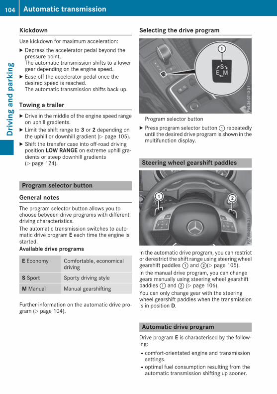
KickdownUse kickdown for maximum acceleration:X Depress the accelerator pedal beyond thepressure point.The automatic transmission shifts to a lowergear depending on the engine speed.
X Ease off the accelerator pedal once thedesired speed is reached.The automatic transmission shifts back up.
Towing a trailerX Drive in the middle of the engine speed rangeon uphill gradients.
X Limit the shift range to 3 or 2 depending onthe uphill or downhill gradient (Y page 105).
X Shift the transfer case into off-road drivingposition LOW RANGE on extreme uphill gra-dients or steep downhill gradients(Y page 124).
Program selector button
General notesThe program selector button allows you tochoose between drive programs with differentdriving characteristics.The automatic transmission switches to auto-matic drive program E each time the engine isstarted.Available drive programs
E Economy Comfortable, economicaldriving
S Sport Sporty driving style
M Manual Manual gearshifting
Further information on the automatic drive pro-gram (Y page 104).
Selecting the drive program
Program selector buttonX Press program selector button: repeatedlyuntil the desired drive program is shown in themultifunction display.
Steering wheel gearshift paddles
In the automatic drive program, you can restrictor derestrict the shift range using steeringwheelgearshift paddles: and;(Y page 105).In the manual drive program, you can changegears manually using steering wheel gearshiftpaddles: and; (Y page 106).You can only change gear with the steeringwheel gearshift paddles when the transmissionis in position D.
Automatic drive programDrive program E is characterised by the follow-ing:Rcomfort-orientated engine and transmissionsettings.Roptimal fuel consumption resulting from theautomatic transmission shifting up sooner.
104 Automatic transmissionDrivingandparking

Rthe vehicle pulls away more gently in forwardand reverse gears unless the acceleratorpedal is depressed fully.Rincreased sensitivity. This improves drivingstability on slippery road surfaces, for exam-ple.Rthe automatic transmission shifts up sooner.This results in the vehicle being driven atlower engine speeds and the wheels beingless likely to spin.
Drive program S is characterised by the follow-ing:Rsporty engine and transmission settings.Rthe vehicle pulls away in first gear.Rthe automatic transmission shifts up later.Rfuel consumption may be higher as a result ofthe later automatic transmission shift points.
Shift ranges
IntroductionWhen the automatic transmission is in positionD, it is possible to restrict or derestrict the shiftrange.The shift range selected is shown in the multi-function display. The automatic transmissionshifts only as far as the selected gear.Driving situations
= To use the engine's braking effect
5 To use the engine's braking effectThis setting is particularly suited fordriving:Ron steep mountain roadsRin mountainous terrainRin arduous conditions
4 The braking effect of the engine canbe utilised on extremely steep down-hill gradients and long downhillstretches.
Restricting the shift rangeX Pull the left-hand steering wheel gearshiftpaddle (Y page 104).The automatic transmission shifts down onegear and restricts the shift range to the rele-vant gear.
To protect against engine damage, the auto-matic transmission:Rdoes not shift down if doing so would causethe engine to exceed the maximum enginespeedRshifts up, even if the shift range is restricted,if the maximum engine speed for the shiftrange is reached and you continue to accel-erate
Derestricting the shift rangeX Pull the right-hand steering wheel gearshiftpaddle (Y page 104).The automatic transmission shifts up onegear and restricts the shift range to the rele-vant gear.
Clearing the shift range restrictionX Pull and hold the right-hand steering wheelgearshift paddle (Y page 104) until transmis-sion position D is shown in the multifunctiondisplay.The automatic transmission shifts from thecurrent shift range directly to D.
Selecting the ideal shift rangeX Pull the left-hand steering wheel gearshiftpaddle and hold it in position (Y page 104).The automatic transmission shifts to the gearwhich allows optimum acceleration anddeceleration. To do this, the automatic trans-mission shifts down one or more gears.
The automatic transmission cannot shift downbeyond second gear. To shift into first gear, youmust pull the left-hand steering wheel gearshiftpaddle.
Automatic transmission 105
Drivingandparking
Z

Manual gearshifting
Temporary setting
X To activate: shift the selector lever to posi-tion D.
X Pull steering wheel gearshift paddle: or;.The temporary setting will remain active for acertain amount of time. Under certain condi-tions, the minimum amount of time is extended,e.g. in the case of lateral acceleration, during anoverrun phase or when driving on steep terrain.X To deactivate: pull steering wheel gearshiftpaddle; and hold it in place.
orX Use the lever to switch the transmission posi-tion.
orX Change the drive program.
Shifting gears
X To shift up: pull steering wheel gearshift pad-dle;.The automatic transmission shifts up to thenext gear.
X To shift down: pull steering wheel gearshiftpaddle:.The automatic transmission shifts down tothe next gear.Automatic downshifting occurs when coast-ing.If the engine would exceed the maximumengine speed when shifting down, the auto-matic transmission protects against enginedamage by not shifting down.
Gearshift recommendation
The gearshift recommendation assists you inadopting a fuel-efficient driving style. The rec-ommended gear is shown on the multifunctiondisplay.X When gearshift recommendation: is shownon themultifunction display of the instrumentcluster, shift to recommended gear;.
Manual drive program
General informationInmanual drive programM, you can change gearyourself by using the steering wheel gearshiftpaddles. The transmission must be in positionDto do this. The gear currently selected andengaged is shown in the multifunction display.Manual drive program M differs from drive pro-grams C and S with regard to spontaneity,responsiveness and smoothness of gearchanges.
106 Automatic transmissionDrivingandparking

Activating the manual drive programX Shift the transmission to position D.X Press the program selector button repeatedlyuntil drive program M appears in the multi-function display.
Upshifting! When the engine limiting speed is reached,the fuel supply is cut to prevent the enginefrom overrevving. Always make sure that theengine speed does not reach the red area ofthe rev counter. There is otherwise a risk ofengine damage.
X When gearshift recommendation: appearson the multifunction display, pull the right-hand steering wheel gearshift paddle(Y page 104).The automatic transmission shifts to recom-mended gear;.
In transfer case position HIGH RANGE: theautomatic transmission shifts up automatically
when the limiting speed of the engine isreached.In transfer case position LOW RANGE: theautomatic transmission does not shift up auto-matically when the limiting speed of the engineis reached.
DownshiftingX Pull the left-hand steering wheel gearshiftpaddle (Y page 104).The automatic transmission shifts down tothe next gear.
If you slow down or stop without shifting down,the automatic transmission automatically shiftsdown.
Selecting the optimum gear for maxi-mum accelerationX Pull the left-hand steering wheel gearshiftpaddle until the transmission selects the opti-mum gear for the current speed.
Deactivating the manual drive programX Press the program selector button repeatedlyuntil E or S is shown in the multifunction dis-play.
Automatic transmission 107
Drivingandparking
Z

Problems with the automatic transmission
Problem Possible causes/consequences and MM Solutions
The transmission hasproblems shifting gear.
The transmission is losing oil.X Have the transmission checked at a qualified specialist workshopimmediately.
The acceleration abilityis deteriorating.The transmission no lon-ger shifts gear.
The transmission is in emergency mode.It is possible to shift to second gear and reverse gear only.X Stop.X Shift the transmission to position P.X Turn the key to positiong in the ignition lock.X Wait at least ten seconds before restarting the engine.X Shift the transmission to position D or R.If D is selected, the transmission shifts to second gear; if R isselected, the transmission shifts to reverse gear.
X Have the transmission checked at a qualified specialist workshopimmediately.
A warning tone sounds. You have:Rswitched off the engineRopened the driver's doorRnot shifted the selector lever to position PX Shift the selector lever to position P.
Refuelling
Important safety notes
G WARNINGFuel is highly flammable. If you handle fuelincorrectly, there is a risk of fire and explo-sion.You must avoid fire, naked flames, creatingsparks and smoking. Switch off the engineand, if applicable, the auxiliary heating beforerefuelling.
G WARNINGFuels are poisonous and hazardous to health.There is a danger of injury.Do not swallow fuel or let it come into contactwith skin, eyes or clothing. Do not inhale fuelvapours. Keep fuels out of the reach of chil-dren.
If you or others come into contact with fuel,observe the following:RWash the fuel off any affected areas of skinwith water and soap immediately.RIf you get fuel in your eyes, rinse them thor-oughly with clean water immediately. Seekimmediate medical attention.RIf fuel is swallowed, seek immediate medi-cal attention. Do not induce vomiting.RChange any clothing that has come intocontact with fuel immediately.
G WARNINGElectrostatic charge can cause sparks andthereby ignite fuel vapours. There is a risk offire and explosion.Always touch the vehicle body before openingthe fuel filler flap or touching the fuel pump
108 RefuellingDrivingandparking

nozzle. This discharges any electrostaticcharge that may have built up.
Do not get back into the vehicle during the refu-elling process; otherwise, electrostatic chargecould build up again.
G WARNINGIf you mix diesel fuel with petrol, the flashpoint of this fuel mixture is lower than that ofpure diesel fuel. When the engine is running,components in the exhaust system may over-heat unnoticed. There is a risk of fire.Never refuel with petrol. Never add petrol todiesel fuel.
! Do not use petrol to refuel vehicles with adiesel engine. Do not switch on the ignition ifyou accidentally refuel with the wrong fuel.Otherwise, fuel can enter the fuel system.Even small amounts of the wrong fuel couldresult in damage to the fuel system and theengine. The repair costs are high. Notify aqualified specialist workshop and have thefuel tank and fuel lines drained completely.
! Overfilling the fuel tank could damage thefuel system.
! Take care not to spill any fuel on paintedsurfaces. You could otherwise damage thepaintwork.
! Use a filter when adding fuel from a fuel can.The fuel lines and/or the fuel injection systemcould otherwise be blocked by particles fromthe fuel can.
If you overfill the fuel tank, some fuel may sprayout when you remove the fuel pump nozzle.Further information on fuel and fuel quality(Y page 250).
Refuelling
General informationObserve the important safety notes(Y page 108).If you unlock/lock the vehicle from the outside,the fuel filler flap also unlocks/locks.The position of the8 fuel filler cap is dis-played on the instrument cluster. The arrownext
to the filling pump indicates the side of the vehi-cle.
Opening the fuel filler flap
: To open the fuel filler flap; Tyre pressure table= Instruction label on the fuel type to be refu-
elled? To insert the fuel filler capX Turn the fuel filler cap anti-clockwise andremove it.
X Insert the fuel filler cap into the holderbracket on the inside of filler flap?.i AdBlue® vehicles do not have a bracket onthe inside of the filler flap.
X Completely insert the filler neck of the fuelpump nozzle into the tank and refuel.
X Fill the tank only until the pump nozzleswitches off.
Do not add any more fuel after the pump stopsfilling for the first time. Otherwise, fuel may leakout.The filler neck is designed for refuelling at dieselfilling pumps.
Closing the fuel filler flapX Replace the cap on the filler neck and turnclockwise until it engages audibly.
X Close the fuel filler flap.Close the fuel filler flap before locking the vehi-cle.
Refuelling 109
Drivingandparking
Z

Fuel filler flap emergency release
The emergency release is located in the luggagecompartment, on the right-hand side whenviewed in the direction of travel, behind the rearwall trim.X Open the rear door.X Pull off edge protection;.X Remove rear wall trim:.
X Pull emergency release= in the direction ofthe arrow.The fuel filler flap is released.
X Open the fuel filler flap (Y page 109).
Problems with the fuel and fuel tank
Problem Possible causes/consequences andMM Solutions
Fuel is leaking from thevehicle.
G WARNINGThe fuel line or the fuel tank is faulty.There is a risk of fire or explosion.X Apply the parking brake.X Turn the key to positiong (Y page 96) immediately and remove it.X Do not restart the engine under any circumstances.X Consult a qualified specialist workshop.
The engine does notstart.
The fuel tank of a vehicle with a diesel engine has been run completelydry.X Refuel the vehicle with at least 5 litres of diesel.X Switch on the ignition for approximately 10 seconds(Y page 96).X Start the engine continuously for up to 40 seconds until it runssmoothly.
If the engine does not start:X Switch on the ignition for approximately 10 seconds(Y page 96).X Start the engine continuously for up to 40 seconds until it runssmoothly.
If the engine does not start after three attempts:X Consult a qualified specialist workshop.
110 RefuellingDrivingandparking

AdBlue®
General notesTo function properly, BlueTEC exhaust gas after-treatment must be operated with the reducingagent AdBlue®.When the supply of AdBlue® is almost used up,the Refill AdBlue See Owner's ManualRefill AdBlue See Owner's Manualmessage is shown in themultifunction display. Awarning tone also sounds.If the Refill AdBlue No start in X kmRefill AdBlue No start in X kmmessage is shown in the multifunction display,you can still drive the vehicle over the distanceshown. If AdBlue® is not topped up, you willsubsequently be unable to start the engine.When you see the warning message, it is rec-ommended that you fill the AdBlue® reservoirwith 10 litres of AdBlue®. This ensures that theAdBlue® supply will last until the next regularservice due date.Further information about BlueTEC exhaust gasaftertreatment and about AdBlue® canbe obtained from any Mercedes-Benz ServiceCentre.
i You can also have the AdBlue® tank refilledat a qualified specialist workshop.
If the outside temperature is lower than Ò11 †,it may be difficult to top up. If AdBlue® is frozenand there is an active warning indicator, toppingup may not be possible. Park the vehicle in awarm place, e.g. in a garage, until AdBlue® hasbecome liquid again. Topping up is then possibleagain. Alternatively, have the AdBlue® tank refil-led at a qualified specialist workshop.Before driving your vehicle outside Europe, havethe AdBlue® supply checked at a qualified spe-cialist workshop.Further information about BlueTEC exhaust gasaftertreatment and about AdBlue® canbe obtained from any Mercedes-Benz ServiceCentre.
Important safety notesAdBlue® is a water-soluble fluid for the exhaustgas aftertreatment of diesel engines. It is:Rnon-toxicRcolourless and odourlessRnon-flammable
If you open the AdBlue® tank, small amounts ofammonia vapour may be released.Ammonia vapours have a pungent odour and areparticularly irritating to the skin, mucous mem-branes and eyes. You may experience a burningsensation in your eyes, nose and throat. Youmay also experience coughing and watery eyes.Do not inhale any ammonia vapours that may bereleased. Fill the AdBlue® tank only in well-ven-tilated areas.Do not swallow AdBlue® or let it come into con-tact with skin, eyes or clothing. Keep AdBlue®away from children.If you or others come into contact with AdBlue®,observe the following:Rimmediately rinse AdBlue® off your skin withsoap and water.Rif AdBlue® comes into contact with your eyes,immediately rinse them thoroughly with cleanwater. Seek medical attention immediately.Rif AdBlue® is swallowed, immediately rinseyour mouth out thoroughly. Drink plenty ofwater. Seek medical attention immediately.Rchange immediately out of clothing that hascome into contact with AdBlue®.
! Only use AdBlue® in accordance withISO 22241. Do not mix any additives withAdBlue®, and do not dilute AdBlue® withwater. This may destroy the BlueTEC exhaustgas aftertreatment system.
! In order to fill the AdBlue® tank, the vehiclemust be parked on a level surface. TheAdBlue® tank can only be filled as intendedwith the vehicle parked on a level surface.Fluctuations in capacity will thus be avoided.Filling a vehicle standing on an uneven sur-face is not permitted. There is a danger ofoverfilling, which can cause damage to Blue-TEC exhaust gas aftertreatment components.
! Surfaces which have come into contact withAdBlue® while refilling should be rinsedimmediately with water, or remove AdBlue®with a moist cloth and cold water. If AdBlue®has already crystallised, use a sponge andcold water to clean the area. AdBlue® residuecrystallises after a certain amount of time andsoils the affected surfaces.
! AdBlue® is not a fuel additive and must notbe added to the fuel tank. If AdBlue® is added
Refuelling 111
Drivingandparking
Z
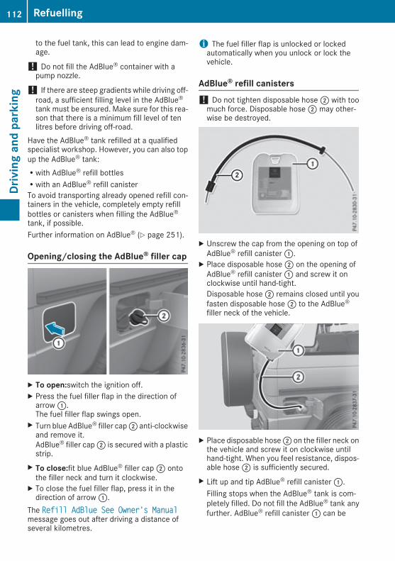
to the fuel tank, this can lead to engine dam-age.
! Do not fill the AdBlue® container with apump nozzle.
! If there are steep gradients while driving off-road, a sufficient filling level in the AdBlue®tank must be ensured. Make sure for this rea-son that there is a minimum fill level of tenlitres before driving off-road.
Have the AdBlue® tank refilled at a qualifiedspecialist workshop. However, you can also topup the AdBlue® tank:Rwith AdBlue® refill bottlesRwith an AdBlue® refill canisterTo avoid transporting already opened refill con-tainers in the vehicle, completely empty refillbottles or canisters when filling the AdBlue®tank, if possible.Further information on AdBlue® (Y page 251).
Opening/closing the AdBlue® filler cap
X To open:switch the ignition off.X Press the fuel filler flap in the direction ofarrow:.The fuel filler flap swings open.
X Turn blue AdBlue® filler cap; anti-clockwiseand remove it.AdBlue® filler cap; is secured with a plasticstrip.
X To close:fit blue AdBlue® filler cap; ontothe filler neck and turn it clockwise.
X To close the fuel filler flap, press it in thedirection of arrow:.
The Refill AdBlue See Owner's ManualRefill AdBlue See Owner's Manualmessage goes out after driving a distance ofseveral kilometres.
i The fuel filler flap is unlocked or lockedautomatically when you unlock or lock thevehicle.
AdBlue® refill canisters! Do not tighten disposable hose; with toomuch force. Disposable hose; may other-wise be destroyed.
X Unscrew the cap from the opening on top ofAdBlue® refill canister:.
X Place disposable hose; on the opening ofAdBlue® refill canister: and screw it onclockwise until hand-tight.Disposable hose; remains closed until youfasten disposable hose; to the AdBlue®filler neck of the vehicle.
X Place disposable hose; on the filler neck onthe vehicle and screw it on clockwise untilhand-tight. When you feel resistance, dispos-able hose; is sufficiently secured.
X Lift up and tip AdBlue® refill canister:.Filling stops when the AdBlue® tank is com-pletely filled. Do not fill the AdBlue® tank anyfurther. AdBlue® refill canister: can be
112 RefuellingDrivingandparking
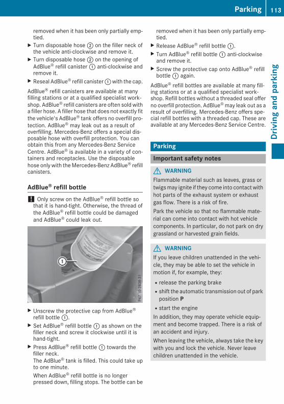
removed when it has been only partially emp-tied.
X Turn disposable hose; on the filler neck ofthe vehicle anti-clockwise and remove it.
X Turn disposable hose; on the opening ofAdBlue® refill canister: anti-clockwise andremove it.
X Reseal AdBlue® refill canister:with the cap.AdBlue® refill canisters are available at manyfilling stations or at a qualified specialist work-shop. AdBlue® refill canisters are often sold witha filler hose. A filler hose that does not exactly fitthe vehicle's AdBlue® tank offers no overfill pro-tection. AdBlue® may leak out as a result ofoverfilling. Mercedes-Benz offers a special dis-posable hose with overfill protection. You canobtain this from any Mercedes-Benz ServiceCentre. AdBlue® is available in a variety of con-tainers and receptacles. Use the disposablehose only with theMercedes-Benz AdBlue® refillcanisters.
AdBlue® refill bottle! Only screw on the AdBlue® refill bottle sothat it is hand-tight. Otherwise, the thread ofthe AdBlue® refill bottle could be damagedand AdBlue® could leak out.
X Unscrew the protective cap from AdBlue®refill bottle:.
X Set AdBlue® refill bottle: as shown on thefiller neck and screw it clockwise until it ishand-tight.
X Press AdBlue® refill bottle: towards thefiller neck.The AdBlue® tank is filled. This could take upto one minute.When AdBlue® refill bottle is no longerpressed down, filling stops. The bottle can be
removed when it has been only partially emp-tied.
X Release AdBlue® refill bottle:.X Turn AdBlue® refill bottle: anti-clockwiseand remove it.
X Screw the protective cap onto AdBlue® refillbottle: again.
AdBlue® refill bottles are available at many fill-ing stations or at a qualified specialist work-shop. Refill bottles without a threaded seal offerno overfill protection. AdBlue®may leak out as aresult of overfilling. Mercedes-Benz offers spe-cial refill bottles with a threaded cap. These areavailable at any Mercedes-Benz Service Centre.
Parking
Important safety notes
G WARNINGFlammable material such as leaves, grass ortwigsmay ignite if they come into contact withhot parts of the exhaust system or exhaustgas flow. There is a risk of fire.Park the vehicle so that no flammable mate-rial can come into contact with hot vehiclecomponents. In particular, do not park on drygrassland or harvested grain fields.
G WARNINGIf you leave children unattended in the vehi-cle, they may be able to set the vehicle inmotion if, for example, they:Rrelease the parking brakeRshift the automatic transmission out of parkposition PRstart the engineIn addition, they may operate vehicle equip-ment and become trapped. There is a risk ofan accident and injury.When leaving the vehicle, always take the keywith you and lock the vehicle. Never leavechildren unattended in the vehicle.
Parking 113
Drivingandparking
Z

To ensure that the vehicle is safeguardedagainst rolling away unintentionally:Rthe parking brake must be appliedRthe transmissionmust be in positionP and thekey must be removed from the ignition lockRthe transfer case must not be in the neutralpositionRon uphill or downhill gradients, turn the frontwheels towards the kerbRthe empty vehicle must be secured at thefront axle with a wheel chock or similarobject, for example, on uphill or downhill gra-dientsRa laden vehicle must also be secured at therear axle with a wheel chock or similar object,for example, on uphill or downhill gradients
Switching off the engine
G WARNINGThe automatic transmission switches to neu-tral positionNwhen you switch off the engine.The vehicle may roll away. There is a risk of anaccident.After switching off the engine, always switchto parking positionP. Prevent the parked vehi-cle from rolling away by applying the parkingbrake.
X Shift the automatic transmission to positionP.
X Turn the key to position 0in the ignition lockand remove it.The immobiliser is activated.
X Firmly apply the parking brake.X Turn the steering wheel until the steeringwheel lock engages.
If you switch the engine off with the transmis-sion in position R or D, the automatic transmis-sion shifts to N automatically.If you then open the driver's door or the front-passenger door or remove the key from the igni-tion, the automatic transmission shifts to Pautomatically.If you switch off the engine while the transmis-sion is in positionN, the automatic transmissionremains in N even if a door is opened. The auto-matic transmission only automatically shifts
into neutral N when you switch off the engineusing the key.
Parking brake
G WARNINGIf you must brake the vehicle with the parkingbrake, the braking distance is considerablylonger and the wheels could lock. This increa-ses the risk of skidding and an accident.Only use the parking brake to brake the vehi-cle when the service brake is faulty. Do notapply the parking brake too firmly. If thewheels lock, release the parking brake untilthe wheels begin turning again.
G WARNINGIf you leave children unattended in the vehi-cle, they may be able to set the vehicle inmotion if, for example, they:Rrelease the parking brakeRshift the automatic transmission out of parkposition PRstart the engineIn addition, they may operate vehicle equip-ment and become trapped. There is a risk ofan accident and injury.When leaving the vehicle, always take the keywith you and lock the vehicle. Never leavechildren unattended in the vehicle.
The brake lights do not light up when you brakethe vehicle with the parking brake.If you pull away with the parking brake applied,a warning tone sounds.
114 ParkingDrivingandparking

X To apply: pull parking brake lever; upfirmly.When the ignition is switched on, the redJindicator lamp in the instrument cluster lightsup.
X To release: pull parking brake lever;slightly.
X Press release button: and guide parkingbrake; down to the stop.TheJ indicator lamp in the instrumentcluster goes out.
The vehicle can also be braked during an emer-gency by using the parking brake.X To brake in an emergency: press and holdrelease button: and carefully pull parkingbrake lever; upwards.
If you drive on wet roads or dirt-covered surfa-ces, road salt and/or dirt could get into theparking brake.In order to prevent corrosion and a reduction inthe braking power of the parking brake, observethe following:Rpull the parking brake upwards with releasebutton: depressed from time to time beforebeginning a journeyRdrive for approximately 100 mat a maximumspeed of 20 km/h
Parking up the vehicleIf you leave the vehicle parked up for longer thanfour weeks, the battery may be damaged byexhaustive discharging.If you leave the vehicle parked up for longer thansix weeks, it may suffer from lack of use.X Contact a qualified specialist workshop andseek advice.i You can obtain information on trickle charg-ers from a qualified specialist workshop.
Driving tips
General driving tips
Important safety notes
G WARNINGIf you switch off the ignition while driving,safety-relevant functions are only available
with limitations, or not at all. This could affect,for example, the power steering and the brakeboosting effect. You will require considerablymore effort to steer and brake. There is a riskof an accident.Do not switch off the ignition while driving.
Drive sensibly – save fuelObserve the following tips to save fuel:X The tyres should always be inflated to the rec-ommended tyre pressure.
X Remove unnecessary loads.X Remove roof carriers when they are not nee-ded.
X Warm up the engine at low engine speeds.X Avoid frequent acceleration or braking.X Have all service and maintenance work car-ried out at the specified intervals.
Fuel consumption also increaseswhen driving incold weather, in stop-start traffic, on short jour-neys and in hilly terrain.
Short journeys! Vehicleswith a diesel particle filter: if thevehicle is mostly driven for short distances, itis possible that malfunctions may occur dur-ing the automatic cleaning of the diesel par-ticle filter. This may lead to fuel collecting inthe engine oil and cause engine failure. There-fore, if you frequently drive short distances,you should take a 20 minute trip on a motor-way or rural road at least every 500km.
Brakes
Important safety notes
G WARNINGIf you shift down on a slippery road surface inan attempt to increase the engine's brakingeffect, the drive wheels could lose their grip.This increases the risk of skidding and havingan accident.Do not shift down for additional engine brak-ing on a slippery road surface.
Driving tips 115
Drivingandparking
Z

G WARNINGIf you select the LOW RANGE off-road gear ona slippery road surface, the wheels could losetraction:Rif you release the accelerator pedal whenthe vehicle is in motionRif Off-road ABS intervenes when brakingIf the wheels lose traction, it will no longer bepossible to steer the vehicle. This increasesthe risk of skidding and having an accident.Never select the LOW RANGE off-road gearwhen driving on slippery road surfaces.
Information on the parking brake (Y page 114).
Downhill gradientsShift to a lower gear in good time on long andsteep downhill gradients.Take particular note of this when driving a ladenvehicle and when towing a trailer.This will use the braking effect of the engine, soless braking will be required to maintain thevehicle speed. This relieves the load on thebrake system and prevents the brakes fromoverheating and wearing too quickly.
Heavy and light loads
G WARNINGThe braking system can overheat if you leaveyour foot on the brake pedal while driving.This increases the braking distance and couldeven cause the braking system to fail. There isa risk of an accident.Never use the brake pedal as a footrest. Donot simultaneously depress both the brakepedal and the accelerator pedal while driving.
! Depressing the brake pedal constantlyresults in excessive and premature wear tothe brake pads.
If heavy demands are made on the brakes, donot park the vehicle immediately. Drive on for ashort while. This allows the airflow to cool thebrakes more quickly.If the brakes have been used only moderately,you should occasionally test their effectiveness.To do this, brake more firmly from a higher
speed while paying attention to the traffic con-ditions. This improves the grip of the brakes.
Wet road surfacesIf driving in heavy rain for a prolonged period oftime without braking, there may be a delayedreaction from the brakes when braking for thefirst time. This may also occur after the vehiclehas been washed.You have to depress the brake pedal morefirmly. Maintain a greater distance from thevehicle in front.After driving on a wet road or having the vehiclewashed, brake firmly while paying attention tothe traffic conditions. This will warm up thebrake discs, thereby drying them more quicklyand protecting them against corrosion.
Limited braking performance on salt-treated roadsIf you drive on salt-treated roads, a layer of saltmay form on the brake discs and pads. This canincrease the braking distance considerably.RIn order to prevent any salt build-up, apply thebrakes occasionally while paying attention tothe traffic conditions.RCarefully depress the brake pedal at the endof the journey and when starting the nextjourney.RMaintain a much greater distance to the vehi-cle in front.
New brake discs and brake pads/liningsBrake pads/linings and discs that either are newor have been replaced achieve optimum brakingeffect only after several hundred kilometres ofdriving. Compensate for the reduced brakingeffect by applying greater force to the brakepedal.For safety reasons, Mercedes-Benz recom-mends only fitting the following brake discs andbrake pads/linings:Rbrake discs that have been approved byMercedes-BenzRbrake pads/linings that have been approvedbyMercedes-Benz or that are of an equivalentstandard of quality
Other brake discs or brake pads/linings cancompromise the safety of your vehicle.
116 Driving tipsDrivingandparking

Always replace all brake discs and brake pads/linings on an axle at the same time. Always fitnew brake pads/linings when replacing brakediscs.The vehicle is equipped with lightweight brakediscs to which the wheel assembly with rim andthreaded connection is matched.The use of brake discs other than thoseapproved by Mercedes-Benz may alter trackwidth and is subject to approval, if applicable.When handling the brake discs, shock-typeloads such as those experiencedwhen changingwheels, can lead to a reduction in comfort whendriving with lightweight brake discs. Avoidshock-type loads on the lightweight brake discs,particularly on the brake plate.
Driving on slippery surfaces! Where possible, avoid spinning the drivewheels when pulling away on slippery roads.You could otherwise damage the drive train.This type of damage is not covered by theterms of the Mercedes-Benz warranty.
X Engage the differential locks if necessary(Y page 126).
Driving on wet roads
AquaplaningIf water has accumulated to a certain depth onthe road surface, there is a danger of aquaplan-ing occurring, even if:Ryou are driving at low speedsRthe tyres have adequate tread depthFor this reason, drive in the following manner inthe event of heavy rain or in conditions in whichaquaplaning can occur:Rlower your speedRavoid tyre rutsRavoid sudden steering movementsRbrake carefully
Driving on flooded roads! Bear in mind that vehicles travelling in frontor in the opposite direction createwaves. Thismay cause the maximum permissible waterdepth to be exceeded.
These notes must be observed under all cir-cumstances. You could otherwise damagethe engine, the electronics or the transmis-sion.
If you must drive on stretches of road on whichwater has collected, please bear in mind that:Rin the case of standing water, the water levelmust be no higher than the lower edge of thevehicle bodyRyou should drive no faster than walking pace
Off-road fording! Under no circumstances should you accel-erate before entering the water. The bowwave could cause water to enter and damagethe engine and neighbouring assemblies.
! Do not open any of the vehicle's doors whilefording. Otherwise, water could get into thevehicle interior and damage the vehicle'selectronics and interior equipment.
i You may only drive through fresh water.RObserve the safety notes (Y page 119) andgeneral notes (Y page 119) on driving off-roadREstablish how deep the water is and the char-acteristics of the body of water before fordingRSwitch off automatic climate controlRVehicles with auxiliary heating/ventila-tion: switch the auxiliary heating/ventilationoffRShift the transfer case to the LOW RANGEoff-road driving position (Y page 124)REngage the differential locks if necessary(Y page 119)RAvoid high engine speedsREnter and exit the water at a flat place and ata steady walking paceRDrive slowly and at a constant speed throughthe waterREnsure that a bow wave does not form as youdriveRDo not stop and do not switch off the engine.Water offers a high degree of resistance, theground is slippery and, in some cases, unsta-ble. Therefore, it is difficult and dangerous topull away in waterRClean any mud from the tyre tread after ford-ingRApply the brakes to dry them after fording
Driving tips 117
Drivingandparking
Z

Always observe the fording depth values(Y page 255).
Parking the vehicle after heavy loadson the engine! Vehicles with a diesel engine: your vehi-cle's exhaust gas turbocharger may get veryhot under heavy engine load, e.g. during:Rtrailer towingRlonger motorway journeys at high speedRlonger journeys through mountainous ter-rain
X Let the engine run for approximately anothertwo minutes while the vehicle is stationarybefore switching off the engine.This way, the exhaust gas turbocharger cancool down more effectively.
Winter driving
G WARNINGIf you shift down on a slippery road surface inan attempt to increase the engine's brakingeffect, the drive wheels could lose their grip.This increases the risk of skidding and havingan accident.Do not shift down for additional engine brak-ing on a slippery road surface.
G WARNINGIf you select the LOW RANGE off-road gear ona slippery road surface, the wheels could losetraction:Rif you release the accelerator pedal whenthe vehicle is in motionRif Off-road ABS intervenes when brakingIf the wheels lose traction, it will no longer bepossible to steer the vehicle. This increasesthe risk of skidding and having an accident.Never select the LOW RANGE off-road gearwhen driving on slippery road surfaces.
G DANGERIf the exhaust pipe is blocked or adequateventilation is not possible, poisonous gasessuch as carbon monoxide (CO) may enter thevehicle. This is the case, e.g. if the vehiclebecomes trapped in snow. There is a risk offatal injury.If you leave the engine or the auxiliary heatingrunning, make sure the exhaust pipe and areaaround the vehicle are clear of snow. Toensure an adequate supply of fresh air, open awindow on the side of the vehicle that is notfacing into the wind.
Have your vehicle winterproofed at a qualifiedspecialist workshop at the onset of winter.You should drive particularly carefully on slip-pery road surfaces. Avoid sudden acceleration,steering and braking manoeuvres.If the vehicle threatens to skid or cannot bestopped when moving at low speed:X Shift the automatic transmission to positionN.
X Try to bring the vehicle under control by usingcorrective steering.
The outside temperature indicator is notdesigned to serve as an ice-warning device andis therefore unsuitable for that purpose.Changes in the outside temperature are dis-played after a short delay.Indicated temperatures just above the freezingpoint do not guarantee that the road surface isfree of ice. The roadmay still be icy, especially inwooded areas or on bridges. The vehicle couldskid if you fail to adapt your driving style. Alwaysadapt your driving style and drive at a speed tosuit the prevailing weather conditions.You should pay special attention to road condi-tions when temperatures are around freezingpoint.Further information on driving with snow chains(Y page 237).Further information on driving with summertyres (Y page 237).Observe the notes in the "Winter operation" sec-tion (Y page 236).
118 Driving tipsDrivingandparking

Off-road driving
Important safety notes
G WARNINGIf you drive on a steep incline at an angle orturn on a steep incline, the vehicle could slipsideways, tip and overturn. There is a risk ofan accident.When driving on an incline, drive into the lineof fall (upwards or downwards in a straightline) and do not turn.
G WARNINGFlammable material such as leaves, grass ortwigsmay ignite if they come into contact withhot parts of the exhaust system. There is a riskof fire.When driving off road or on unpaved roads,check the vehicle's underside regularly. Inparticular, remove parts of plants or otherflammable materials which have becometrapped. In the case of damage, contact aqualified specialist workshop.
! There is a risk of damage to the vehicle if:Rthe vehicle becomes stuck, e.g. on a highkerb or an unpaved roadRyou drive too quickly over an obstacle, e.g.a kerb, slowing thresholds or a pothole inthe roadRa heavy object strikes the underbody orparts of the chassis
In situations like this, the body, underbody,chassis parts, wheels or tyres could be dam-aged without the damage being visible. Com-ponents damaged in this way can unexpect-edly fail or, in the case of an accident, no lon-ger withstand the strain they are designed towithstand.If the underbody panelling is damaged, com-bustible materials such as leaves, grass ortwigs can gather between the underbody andthe underbody panelling. If these materialscome into contact with hot parts of theexhaust system, they can catch fire.In such situations, have the vehicle checkedand repaired immediately at a qualified spe-cialist workshop. If, on continuing your jour-ney, you notice that driving safety is impaired,
stop the vehicle immediately, paying atten-tion to road and traffic conditions. In suchcases, consult a qualified specialist work-shop.
! If there are steep gradients while driving off-road, a sufficient filling level in the AdBlue®tank must be ensured. Make sure for this rea-son that there is a minimum fill level of tenlitres before driving off-road.
When driving off-road, substances such as sand,mud and water or water mixed with oil may getinto the brakes. This may lead to a reduction inbraking performance or total brake failure as aresult of increased wear. The braking charac-teristics will vary depending on the substancesthat get into the brakes. Clean the brakes afterdriving off-road. If you notice grinding noises ora reduction in braking performance, have thebrake system checked at a qualified specialistworkshop immediately. Adapt your driving styleto the altered braking characteristics.Driving off-road increases the possibility of dam-age to the vehicle, which may cause assembliesor systems to fail. Adapt your driving style to theconditions of the terrain. Drive carefully. Havevehicle damage rectified immediately at a quali-fied specialist workshop.Do not shift into transmission position N whendriving off-road. You could lose control of thevehicle if you attempt to brake the vehicle usingthe service brake. If the gradient is too steep foryour vehicle, back up in reverse gear.
General notes
H Environmental noteProtection of the environment is of primaryimportance. Treat nature with respect.Observe all prohibiting signs.
Read this section before driving your vehicle off-road. Practise by driving over more gentle off-road terrain first.The following driving systems are speciallyadapted to off-road driving:R4ETS (Y page 54)ROff-road ABSRtransfer case (Y page 124)Rdifferential locks (Y page 125)
Driving tips 119
Drivingandparking
Z

Observe the following notes:Rstop the vehicle before you drive off-road and,if necessary, shift the transfer case to theLOW RANGE off-road driving position(Y page 124)Rengage the differential locks if necessary(Y page 126)
i ABS, 4ETS, ESP® and BAS are deactivatedwhile the differential locks are engaged. Thisallows the front wheels to lock briefly, so thatthey can dig into a loose surface. However,please note that locked wheels skid and canno longer steer.RMake sure that items of luggage and loads arestowed safely and are well secured(Y page 203).RTo avoid damaging the vehicle, make surethere is always sufficient ground clearance.RAlways keep the engine running and in gearwhen driving on a downhill gradient.RAlways keep the engine running and in gearwhen driving on a slope.RDrive slowly and evenly, if necessary at walk-ing pace.REnsure that the wheels are in contact with theground at all times.RDrive with extreme care on unknown off-roadroutes where visibility is poor. For safety rea-sons, get out of the vehicle first and surveythe off-road route.RCheck the depth ofwater before fording riversand streams.RWatch out for obstacles.RAlways keep the doors, the rear door, the sidewindows and the sliding sunroof closed whilethe vehicle is in motion.RDo not deviate from marked routes.RMatch your speed to the terrain. The rougher,steeper ormore ruts on the terrain, the sloweryour speed should be.RDo not jump with the vehicle. This will inter-rupt the vehicle's propulsion.RAvoid high engine speeds. Drive at appropri-ate engine speeds.RAlways check the vehicle for damage after off-road driving.
Do not use the HOLD function when driving off-road, on steep uphill or downhill gradients or onslippery or loose surfaces. The HOLD functioncannot hold the vehicle on such surfaces.
You can obtain further information about retro-fitting special all-terrain tyres from a qualifiedspecialist workshop.
Checklist before off-road drivingX Engine oil level: check the engine oil and topit up if necessary.When driving on steep gradients, the oil levelmust be sufficiently high to ensure a correctoil supply in the vehicle.
X Have the AdBlue® level checked at a qualifiedspecialist workshop (Y page 111).
X Tyre-change tool kit: check that the jack isworking and make sure that the wheelwrench, a robust tow cable and a foldingspade are in the vehicle.
X Wheels and tyres: check the tyre treaddepth and tyre pressure.
X Check for damage and remove any foreignobjects, e.g. small stones, from the wheels/tyres.
X Replace any missing valve caps.X Replace dented or damaged wheels. Alsocheck the spare wheel.
X Wheels: dented or bent wheels can lead to aloss of tyre pressure and damage to the tyrebead. Before driving off-road, check thewheels and replace them if necessary.
Checklist after off-road driving! If you detect damage to the vehicle afterdriving off-road, have the vehicle checkedimmediately at a qualified specialist work-shop.
Driving over rough terrain places greaterdemands on your vehicle than driving on normalroads. After driving off-road, check the vehicle.This allows you to detect damage promptly andreduce the risk of an accident to yourself andother road users.X Shift the transfer case to the on-road positionHIGH RANGE (Y page 124).
X Disengage the differential locks(Y page 127).
X Clean the headlamps and rear lights andcheck for damage.
X Clean the front and rear licence plates.X Clean the wheels and tyres with a water jetand remove any foreign objects.
120 Driving tipsDrivingandparking

X Clean the wheels, wheel arches and the vehi-cle underside with a water jet; check for anyforeign objects and damage.
X Check whether twigs or other parts of plantshave become trapped. These increase the riskof fire and can damage fuel pipes, brakehoses or the rubber bellows of the axle jointsand propeller shafts.
X After the trip, examine without fail the entireundercarriage,wheels, tyres, bodywork struc-ture, brakes, steering, chassis and exhaustsystem for damage.
X After driving in sand, mud, gravel, water orsimilar dirty conditions, have the followingchecked and cleaned:Rbrake discsRwheelsRbrake padsRaxle joints
X If you notice strong vibrations after off-roaddriving, check for foreign objects in thewheels and drive train and, if necessary,remove them. Foreign objects can disturb thebalance and cause vibrations.
Driving on sandObserve the following rules when driving onsand:Rshift the transfer case to the LOWRANGE off-road driving position (Y page 124).Ravoid high engine speeds.RShift the automatic transmission to a lowgear.Rdrive quickly to overcome the rolling resist-ance. Otherwise, the vehicle could dig itselfinto the sand.Rdrive in the tracks of other vehicles if possible.When doing so, make sure that:- the tyre ruts are not too deep- the sand is firm enough- your vehicle has sufficient ground clear-ance
Tyre ruts and unpaved roads! Check that the ruts are not too deep andthat your vehicle has sufficient clearance.Otherwise, your vehicle could be damaged orbottom out and get stuck.
Observe the following rules when driving alongruts in off-road terrain or on roads with loosegravel:Rshift the transfer case to the LOWRANGE off-road driving position (Y page 124)Ravoid high engine speedsRobserve the safety notes (Y page 119) and thegeneral notes (Y page 119) on off-road drivingRshift the automatic transmission to a low gearRdrive slowlyRwhere ruts are too deep, drive with thewheelson one side on the middle section of turf ifpossible
Driving over obstacles! Obstacles could damage the floor of thevehicle or components of the chassis. Askpassengers for guidance when driving overlarge obstacles. Any damage to the vehiclealways increases the risk of an accident.
! Drive with particular care when driving overan obstacle while driving up or down a steepslope.The vehicle could otherwise tilt and slide side-ways or tip over.
Observe the following rules when driving overtree stumps, large stones and other obstacles:Robserve the safety notes (Y page 119) and thegeneral notes (Y page 119) on off-road drivingRshift the transfer case to the LOWRANGE off-road driving position (Y page 124)Ravoid high engine speedsRshift the automatic transmission to a low gearRmake sure that you have enough groundclearance before driving across an obstacleRdrive very slowlyRtry to drive straight over the centre of obsta-cles: front wheel first, then rear wheel
Travelling uphill
Approach/departure angle
G WARNINGIf you drive on a steep incline at an angle orturn on a steep incline, the vehicle could slipsideways, tip and overturn. There is a risk ofan accident.
Driving tips 121
Drivingandparking
Z

When driving on an incline, drive into the lineof fall (upwards or downwards in a straightline) and do not turn.
Always observe the approach/departure anglevalues (Y page 255).RObserve the safety notes (Y page 119) andgeneral notes (Y page 119) on driving off-road.RFollow the line of fall when driving on slopesand steep inclines.RBefore driving on extreme uphill and extremedownhill gradients, set the transfer case tothe LOW RANGE off-road driving position(Y page 124).REngage the differential locks if necessary(Y page 126).RDrive slowly.RAccelerate gently and make sure that thewheels are gripping.RAvoid high engine speeds, except when driv-ing on sandy andmuddy routes with high driv-ing resistance.RUse the braking power of the engine whendriving down a slope. Observe the enginespeed; do not overrev the engine.RShift the automatic transmission to a low gearappropriate for tackling an uphill gradient or along, steep downhill gradient.
The HOLD function assists you when pullingaway and manoeuvring on a slope or hillside(Y page 122).
Maximum gradient-climbing capabilityAlways observe the maximum gradient climbingability values (Y page 255).
HilltopsWhen driving up an uphill gradient, slightlyreduce pressure on the accelerator immediatelybefore reaching the brow of the hill. Make use ofthe vehicle's own impetus to travel over thebrow.This style of driving prevents:Rthe vehicle from lifting off the ground on thebrow of a hillRloss of tractionRthe vehicle from travelling too quickly downthe other side
Driving downhillRDrive slowly.RDo not drive at an angle down steep inclines.Steer into the line of fall and drive with thefront wheels aligned straight forwards. Oth-erwise, the vehicle could slip sideways, tipand overturn.RBefore tackling steep downhill gradients, shiftthe automatic transmission to a low gear.By doing so, you will use the braking effect ofthe engine to reduce the speed. If this is notsufficient, brake gently. When doing so, makesure that the vehicle is facing in the directionof the line of fall.RObserve the notes on driving in mountainousterrain (Y page 122).RCheck that the service brake is working nor-mally after a long downhill stretch.
When driving at speeds below60 km/h, off-roadABS is activated and the front wheels lock cycli-cally during braking. The digging-in effect ach-ieved in the process reduces the stopping dis-tance during off-road driving. This limits steeringcapability.
Driving systems
HOLD function
General notesThe HOLD function can assist the driver in thefollowing situations:Rwhen pulling away, especially on steep slopesRwhen manoeuvring on steep slopesRwhen waiting in trafficThe vehicle is kept stationary without the driverhaving to depress the brake pedal.The braking effect is cancelled and the HOLDfunction deactivated when you depress theaccelerator pedal to pull away.Do not use the HOLD function when driving off-road, on steep uphill or downhill gradients or onslippery or loose surfaces. The HOLD functioncannot hold the vehicle on such surfaces.
122 Driving systemsDrivingandparking

Important safety notes
G WARNINGWhen leaving the vehicle, it can still roll awaydespite being braked by the HOLD function if:Rthere is a malfunction in the system or inthe voltage supplyRthe HOLD function is deactivated by theaccelerator pedal being depressed, e.g. bya vehicle occupantRthe electrical system in the engine com-partment, the battery or the fuses are tam-pered withRthe battery is disconnectedThere is a risk of an accident.Before leaving the vehicle, always deactivatethe HOLD function and secure the vehiclefrom rolling away.
Deactivating the HOLD function (Y page 123).
Activation conditionsYou can activate the HOLD function if:Rthe vehicle is stationaryRthe engine is running or if it has been auto-matically switched off by the ECO start/stopfunctionRthe driver's door is closed or if your seat beltis fastenedRthe parking brake is releasedRthe transmission is in position D, R or N
Activating the HOLD functionX Make sure that the activation conditions aremet.
X Depress the brake pedal.X Quickly depress the brake pedal further untilë appears in the multifunction display.The HOLD function is activated. You canrelease the brake pedal.
If depressing the brake pedal the first time doesnot activate the HOLD function, wait briefly andthen try again.
Deactivating the HOLD functionThe HOLD function is deactivated automaticallyif:Ryou depress the accelerator and the trans-mission is in position D or R.Rthe transmission is in positionj.Ryou depress the brake pedal again with a cer-tain amount of pressure untilë disap-pears from the multifunction display.
On steep uphill or downhill inclines or if there isa malfunction, the transmission may also beautomatically shifted into position P.
Permanent all-wheel drive! Never tow the vehicle with one axle raised.This may damage the transfer case. Damageof this sort is not covered by the Mercedes-Benz implied warranty. All wheels mustremain either on the ground or be fully raised.Observe the instructions for towing the vehi-cle with all wheels in full contact with theground.
! When testing the parking brake, operate thevehicle only briefly (for a maximum of ten sec-onds) on a brake test dynamometer. Whendoing this, turn the key to position 0 or 1 inthe ignition. Failure to do this can cause dam-age to the drive train or the brake system.
! A function or performance test should onlybe carried out on a twin-axle dynamometer.Before you operate the vehicle on such adynamometer, please consult a qualifiedworkshop. You could otherwise damage thedrive train or the brake system.
The all-wheel drive system ensures that all fourwheels are permanently driven. The all-wheeldrive system improves vehicle traction togetherwith ESP® and 4ETS if a drive wheel spins due toinsufficient grip.Only when you use winter tyres (M+S tyres) inwintry driving conditions and, if necessary, snowchains (Y page 237). Only in this way can themaximum effect of all-wheel drive be achieved.Information about driving off-road (Y page 119).
Driving systems 123
Drivingandparking
Z

Off-road driving systems
Transfer case
General notesThe vehicle has permanent all-wheel drive. Thefront and rear axles are constantly driven.Further information on driving off-road(Y page 119).
Shift ranges
HIGHRANGE
Position for all normal on-road driving conditions.
LOW RANGE Low-range position for drivingoff-road.Also for use on steep uphill ordownhill gradients, especiallywhen towing a trailer.The vehicle travels aroundhalf the speed of on-road driv-ing range HIGH RANGE. Thetractive power is correspond-ingly higher.
Shifting the transfer case
General notes
: Current shift range
: Indicator lamp; LOW RANGE button
Important safety notesG WARNINGIf you do not wait for the transfer case gearchange process to complete, the transfercase could remain in the neutral position. Thepower transmission to the driven wheels isthen interrupted. There is a danger of thevehicle rolling away unintentionally. There is arisk of an accident.Wait until the transfer case shift process iscompleted.
Do not switch off the enginewhile changing gearand do not shift the automatic transmission toanother gear.Always wait for the gear change process fromHIGH RANGE to LOW RANGE and from LOWRANGE to HIGH RANGE to complete. Do notswitch off the enginewhile changing gear and donot shift the automatic transmission to anothergear.
Activating the off-road gear ratio! Proceed with the shifting process onlywhen:Rthe engine is runningRthe vehicle is rollingRthe automatic transmission is in selectorlever positioniRyou are not driving faster than 40 km/hYou could otherwise damage the transfercase.
X Make sure the ECO start/stop function isswitched off (Y page 98).
X Press LOW RANGE button;.Once the shifting procedure has been com-pleted, the LOW RANGELOW RANGE transfer case positionis shown in the multifunction display.Indicator lamp: lights up.
X Shift the automatic transmission to positionD.
Deactivating the off-road gear ratio! Proceed with the shifting process onlywhen:Rthe engine is runningRthe vehicle is rolling
124 Off-road driving systemsDrivingandparking

Rthe automatic transmission is in selectorlever positioniRyou are not driving faster than 70 km/hYou could otherwise damage the transfercase.
X Press button;.Once the shifting procedure has been com-pleted, the HIGHHIGH RANGERANGE transfer case positionis shown in the multifunction display.Indicator lamp: goes out.
If the shifting procedure is unsuccessful, themultifunction display may show the followingmessages:RTC shift conditions not fulfilledTC shift conditions not fulfilledOne or more shift conditions has not beenmet.RTC neutral onTC neutral onThe transfer case has cancelled the shiftingprocedure and is in position N.RTC shift cancelledTC shift cancelledThe transfer case has cancelled the gearchange process.
X Repeat the gear change process.Make sure all conditions for gear changing aremet.RTC malfunction Visit workshopTC malfunction Visit workshopThe transfer case is faulty.
X Do not shift the transfer case.X Have the vehicle checked as soon as possibleat a qualified specialist workshop.
Shifting to neutralG WARNINGIf you do not wait for the transfer case gearchange process to complete, the transfercase could remain in the neutral position. Thepower transmission to the driven wheels isthen interrupted. There is a danger of thevehicle rolling away unintentionally. There is arisk of an accident.Wait until the transfer case shift process iscompleted.
X Turn the key to position 2 in the ignition lock.X Apply the parking brake.X Depress the brake pedal.
X Shift the automatic transmission to positionN.
X Press and hold LOW RANGE button; forapproximately ten seconds.When the shift procedure is complete, themultifunction display shows the TCTC NeutralNeutralonon message for five seconds.
If the shifting procedure is unsuccessful, themultifunction display may show the followingmessages (Y page 149).If the transfer case is inNeutral, the key is in theignition lock and you open the driver's door, theTC Neutral onTC Neutral on message appears in the multi-function display. If you then release the parkingbrake, a warning tone will sound.
Differential locks
General notes
G WARNINGWhen the differential locks are engaged, ABS,4ETS, ESP® and BAS are deactivated. Thiscould cause the wheels to lock and increasesthe braking distance. There is a risk of anaccident.Disengage the differential locks immediatelyon firm surfaces with good grip.
! To prevent damage to the transfer case, youmay only operate the vehicle on a roller dyna-mometer (single-axle roller dynamometer) if:Rthe axle that is not being driven is raised.orRthe corresponding propeller shaft is dis-connected and the transfer case differen-tial lock is engaged.
Otherwise, the transfer case can be damaged.Differential locks improve the traction of thevehicle.Your vehicle is equipped with a differential lockeach for:Rthe transfer case: this controls the balancebetween the front and rear axlesRthe rear axle: this controls the balancebetween the wheels on the rear axleRthe front axle: this controls the balancebetween the wheels on the front axle
Off-road driving systems 125
Drivingandparking
Z

Engaging the differential locks
General notesThe switches are at the top of the centre con-sole.
: Function indicator lamps (red); Differential lock for the front axle= Differential lock for the transfer case? Differential lock for the rear axleA Activation indicator lamps (yellow)Engage the differential locks:Roff-roadRto deactivate ABS, 4ETS, ESP® and BAS whenoff-roadRwhen fordingFurther information on driving off-road(Y page 119).You can engage the differential locks in the fol-lowing order:=,?,;.
Important safety notesG WARNINGIf you engage the differential locks when driv-ing on a firm, high-traction surface, the steer-ability of the vehicle is severely impaired. Youcould lose control of the vehicle, especiallywhen activating on a bend. There is a risk of anaccident.Disengage the differential locks immediatelyon a firm, high-traction surface.
G WARNINGWhen the differential locks are engaged, ABS,4ETS, ESP® and BAS are deactivated. Thiscould cause the wheels to lock and increases
the braking distance. There is a risk of anaccident.Disengage the differential locks immediatelyon firm surfaces with good grip.
! Only engage the differential locks when:Ryou are driving at walking paceRthe drive wheels are not spinningRyou are not driving on a firm road surface
Differential lock for the transfer caseX To engage: press switch=.The yellow indicator lamp under switch=lights up.The å warning lamp in the instrumentcluster lights up.If the differential is locked, the red functionindicator lamp above switch= lights up.In the multifunction display, you see theDifferential locks active ABS andDifferential locks active ABS andESP not availableESP not availableThe å!÷ warning lamps light up inthe instrument cluster.The differential lock for the transfer case isengaged.4ETS, ESP®, BAS and ABS are deactivated.
Vehicle steerability is severely restricted. Drivecarefully and accelerate gently for optimumtraction.You can now engage the differential lock for rearaxle? and front axle; as required.
Differential lock for the rear axleX To engage: press switch?.Yellow activation indicator lampA lights upfirst, followed by red function indicatorlamp: of switch?.The differential lock for the rear axle isengaged.
Differential lock for the front axleX To engage: press switch;.The yellow activation indicator lamp lights upfirst, followed by the red function indicatorlamp.The differential lock for the front axle isengaged.
126 Off-road driving systemsDrivingandparking

Disengaging the differential locksYou can disengage the differential locks in thefollowing order:;,?,=.X To simultaneously disengage all differen-tial locks: press switch=.Yellow activation indicator lampsA and redfunction indicator lamps: go out.After approximately three seconds of normaldriving, ABS, 4ETS, ESP® and BAS are activa-ted.The Differential locks active ABSDifferential locks active ABSand ESP not availableand ESP not available message disap-pears in the multifunction display and theå ! ÷ warning lamps in the instru-ment cluster go out.
X Shift the transfer case to the HIGH RANGEon-road position (Y page 124).
If red function indicator lamps: do not go outwhen disengaging the differential locks:X Observe the traffic situation.X Make slight steering movements while thevehicle is in motion.Red function indicator lamps: go out whenthe differential locks are disengaged.
Towing a trailer
Important safety notes
G WARNINGThe braking system can overheat if you leaveyour foot on the brake pedal while driving.This increases the braking distance and couldeven cause the braking system to fail. There isa risk of an accident.Never use the brake pedal as a footrest. Donot simultaneously depress both the brakepedal and the accelerator pedal while driving.
G WARNINGYou could lose control of the vehicle/trailercombination if it begins to swerve. The vehi-cle/trailer combination could even overturn.There is a risk of an accident.On no account should you attempt tostraighten out the vehicle/trailer combina-tion by increasing speed. Decrease your
speed and do not countersteer. Brake if nec-essary.
G WARNINGIf the ball coupling is not fitted correctly andthe bolts supplied are not tightened to thespecified tightening torque, the trailer couldcome loose. There is a risk of an accident.Always fit the ball coupling as described.Observe the specified tightening torque whenfitting the coupling.
G WARNINGIf the maximum permissible load for a carriersystem is exceeded, the carrier could comeloose from the vehicle and endanger otherroad users. There is a risk of an accident andinjury.Never exceed the maximum permissible loadwhen using a carrier.
! If you have a trailer tow hitch retrofitted,changes to the engine cooling systemmay benecessary, depending on the vehicle type.If you have a trailer tow hitch retrofitted,observe the anchorage points on the chassis.
Retrofitting a trailer tow hitch is only permissibleif a trailer load is specified in your vehicle docu-ments. If this is not the case, then the vehicle isnot approved for towing a trailer.For more information, please contact a qualifiedspecialist workshop.Exceeding the maximum permissible nose-weight of the trailer drawbar on the ball couplingmay cause damage.Damage may be caused to the following:Rtowing vehicleRtrailerRball couplingRtrailer tow hitchThe vehicle/trailer combination could becomeunstable.The vehicle/trailer combination could alsobecomeunstable if the noseweight used is lowerthan the minimum permissible noseweight.
Towing a trailer 127
Drivingandparking
Z

To avoid hazardous situations:Rmake sure to check the noseweight beforeeach journeyRthe noseweight should be as close as possibleto the maximum noseweightRdo not exceed the maximum permissiblenoseweightRthe noseweight must not be lower than theminimum permissible noseweight
Make sure that the following values are notexceeded:Rthe permissible noseweightRthe permissible trailer loadRthe permissible rear axle load of the towingvehicleRthe maximum permissible gross vehicleweight of both the towing vehicle and thetrailer
When reversing the towing vehicle, make surethere is nobody between the trailer and the vehi-cle.The applicable permissible values, which mustnot be exceeded, can be found:Rin your vehicle documentsRon the type plates for the trailerRon the vehicle identification plateIf the values differ, the lowest value applies.You will find the values approved by the manu-facturer on the identification plates and for thetowing vehicle under "Technical data"(Y page 256).When reversing the towing vehicle, make surethere is nobody between the trailer and the vehi-cle.Couple and uncouple the trailer carefully. If youdo not couple the trailer to the towing vehiclecorrectly, the trailer could become detached.When towing a trailer, your vehicle's handlingcharacteristics will be different from when driv-ing without a trailer.The vehicle/trailer combination:Ris heavierRis restricted in its acceleration and gradient-climbing capabilityRhas an increased braking distanceRis affected more by strong crosswindsRdemands more sensitive steeringRhas a larger turning circle
This can impair the vehicle's handling charac-teristics. Adapt your driving style accordingly.Maintain a safe distance. Drive carefully.When towing a trailer, always adjust your speedto the current road and weather conditions. Donot exceed the maximum permissible speed foryour vehicle/trailer combination.
Notes on towing a trailer
General notesWhen towing a trailer, set the tyre pressure onthe rear axle of the towing vehicle for a maxi-mum load. Further information on the tyre pres-sure table in the fuel filler flap (Y page 109).The height of the ball coupling changes with theload of the vehicle. If necessary, use a trailerwith a height-adjustable drawbar.You will find permissible trailer loads under"Technical data" (Y page 256).
Driving tipsX Observe the information on ESP® trailer sta-bilisation (Y page 55).
X On long and steep downhill gradients, selectshift range1,2 or3(Y page 105) in good time.
X If necessary, shift the transfer case to LOWRANGE (Y page 124).This will use the braking effect of the engine,so less braking will be required to maintainthe vehicle speed. This relieves the load onthe brake system and prevents the brakesfrom overheating and wearing too quickly. Ifyou need additional braking, depress thebrake pedal repeatedly rather than continu-ously.
The maximum permissible speed for vehicle/trailer combinations depends on the type oftrailer. Before beginning the journey, check thetrailer's documents to see what the maximumpermitted speed is. Observe the maximum per-missible speed in the relevant country.For certain Mercedes-Benz vehicles, the maxi-mum permissible rear axle load is increasedwhen towing a trailer. See the "Technical data"section to find out whether this applies to yourvehicle (Y page 256). In the event of increasedrear axle load, the car/trailer combination maynot exceed a maximum speed of 100 km/h forreasons concerning the operating permit. This
128 Towing a trailerDrivingandparking

also applies in countries in which the maximumpermissible speed for car/trailer combinationsis greater than 100 km/h.When towing a trailer, your vehicle's handlingcharacteristics will be different to when drivingwithout a trailer and the vehicle will consumemore fuel.
Driving tipsRMaintain a greater distance to the vehicle infront than when driving without a trailer.RAvoid braking abruptly. If possible, brake gen-tly at first to allow the trailer to run on. Then,increase the braking force rapidly.RThe values given for gradient-climbing capa-bilities from a standstill refer to sea level.When driving in mountainous areas, note thatthe power output of the engine, and conse-quently the vehicle's gradient-climbing capa-bility from a standstill, decrease with increas-ing altitude.
If the trailer swings from side to side:X Do not accelerate under any circumstances.X Do not countersteer.X Brake, if necessary.
Coupling up a trailer! Do not connect the trailer brake system (ifthe trailer is fitted with one) directly to thetowing vehicle's hydraulic brake system,since this is equipped with an anti-lock brak-ing system. Otherwise, neither the brakes onthe towing vehicle nor the brakes on thetrailer will work.
Observe the maximum permissible trailerdimensions (width and length).X Apply the vehicle's parking brake.X Make sure that the automatic transmission isin transmission position P.
X Position the trailer on a level surface behindthe vehicle.
X Couple up the trailer.X Establish the electrical connection betweenthe vehicle and the trailer.
X Check that the trailer lighting system is work-ing.
X Push the combination switch upwards anddownwards and check whether the corre-
sponding turn signal indicator on the trailer isflashing.
A connected trailer is only detected when theelectrical connection is established correctlyand when the lighting system is working prop-erly. The function of other systems, such asESP® also depends on this.
Uncoupling a trailer
G WARNINGIf you uncouple a trailer with an engaged over-run brake, you could trap your hand betweenthe vehicle and the trailer drawbar. This posesa risk of injury.Do not uncouple a trailer with an engagedoverrun brake.
! Do not disconnect a trailer with an engagedoverrun brake. Otherwise, your vehicle couldbe damaged by the rebounding of the overrunbrake.
X Apply the parking brake.X Make sure that the automatic transmission isin transmission position P.
X Secure the vehicle and trailer against rollingaway.
X Close all doors, including the rear door.X Remove the trailer cable.X Uncouple the trailer.
Trailer power supply! You can connect accessories with a maxi-mum power consumption of 180 W to thepermanent power supply.Youmust not charge a trailer battery using thepower supply.
The trailer socket of your vehicle is equipped atthe factory with a permanent power supply.The permanent power supply is supplied viatrailer socket pin 9.You can find more information about installingthe trailer electrics at a qualified specialist work-shop.
Towing a trailer 129
Drivingandparking
Z

Trailer with 7-pin connector
General notesTrailer with 7-pin connector: you can connectto the 13-pin socket on the ball coupling usingan adapter or, if necessary, an adapter cable.Both can be obtained at a qualified specialistworkshop.
Fitting the adapter! Make sure that there is sufficient cable playso that the cable cannot become detachedwhen cornering.
X Open the socket cover.X Insert the connector with lug: intogroove; on the socket and turn it clockwiseto the stop.
X Let the cover engage.X If you are using an adapter cable, secure thecable to the trailer with cable ties.
130 Towing a trailerDrivingandparking

Important safety notes
G WARNINGOperating the integrated information systemsand communications equipment in the vehiclewhile driving will distract you from traffic con-ditions. You could then lose control of thevehicle. There is a risk of an accident.Only operate these devices if road traffic con-ditions permit. If you are unsure about thesurrounding conditions, pull over to a safelocation and make entries only while the vehi-cle is stationary.
Youmust observe the legal requirements for thecountry in which you are currently driving whenoperating the on-board computer.
G WARNINGIf the instrument cluster has failed or mal-functioned, you may not recognise functionrestrictions relevant to safety. The operatingsafety of your vehicle may be impaired. Thereis a risk of an accident.Drive on carefully. Have the vehicle checkedat a qualified specialist workshop immedi-ately.
If the operating safety of your vehicle isimpaired, park the vehicle safely as soon as pos-sible. Contact a qualified specialist workshop.
! If a blackout lighting setting has been selec-ted, the instrument cluster lighting isswitched off.The instrument cluster and the display do notshow any information.
The on-board computer shows only displaymes-sages or warnings from certain systems on themultifunction display. You should thereforemake sure your vehicle is operating safely at alltimes.For an overview, see the instrument cluster illus-tration (Y page 26).
Displays and operation
Instrument cluster lightingThe brightness control knob is located on thebottom left of the instrument cluster(Y page 26).X Turn the brightness control knob clockwise oranti-clockwise.
i The light sensor on the instrument clusterautomatically controls the brightness of themultifunction display.In daylight, the displays in the instrumentcluster are not lit.
Rev counter! Do not drive in the overrevving range. Doingso will damage the engine.
The red band in the rev counter indicates theengine's overrevving range.The fuel supply is interrupted to protect theengine when the red band is reached.
Outside temperature displayYou should pay special attention to road condi-tions when temperatures are around freezingpoint.Bear in mind that the outside temperature dis-play indicates the measured air temperatureand not the road surface temperature.The outside temperature display is in the multi-function display (Y page 133).Changes in the outside temperature are dis-played after a short delay.
Coolant temperature display
G WARNINGIf you open the bonnet while the engine isoverheating or while there is a fire in theengine compartment, you could come intocontact with hot gases or other leaking ser-vice products. There is a danger of injury.Allow an overheating engine to cool downbefore opening the bonnet. If there is a fire in
Displays and operation 131
On-board
computerand
displays
Z

the engine compartment, leave the bonnetclosed and notify the fire brigade.
The coolant temperature gauge is in the instru-ment cluster on the right-hand side (Y page 26).Under normal operating conditions and with thespecified coolant level, the coolant temperaturemay rise to 120 †.At high outside temperatures and when drivinginmountainous terrain, the coolant temperaturemay rise to the end of the scale.
Operating the on-board computer
Overview
: Multifunction display; Switches sound on/off= Right control panel? Left control panelA Back buttonX To activate the on-board computer: turnthe key to position 1 in the ignition lock(Y page 96).
You can control the multifunction display andthe settings in the on-board computer using thebuttons on the multifunction steering wheel.
Left control panel
=
;
RCalls up the menu and menu bar
9
:
Press briefly:RScrolls through listsRSelects a submenu or functionRIn the AudioAudio menu: selects theprevious or next station, when thepreset list or station list is active,or an audio trackRIn the TelTel (telephone) menu:switches to the phone book andselects a name or telephone num-ber
9
:
Press and hold:RIn the AudioAudio menu: selects a pre-set list or a station list in thedesired frequency range
a RConfirms selection/display mes-sageRIn the TelTel (Telephone) menu:switches to the telephone bookand starts dialling the selectednumber
Right control panel
~ RRejects or ends a call
6 RMakes or accepts a callRSwitches to the redial memory
WX
RAdjusts the volume
8 RMute
? RMute
132 Displays and operationOn
-board
computerand
displays
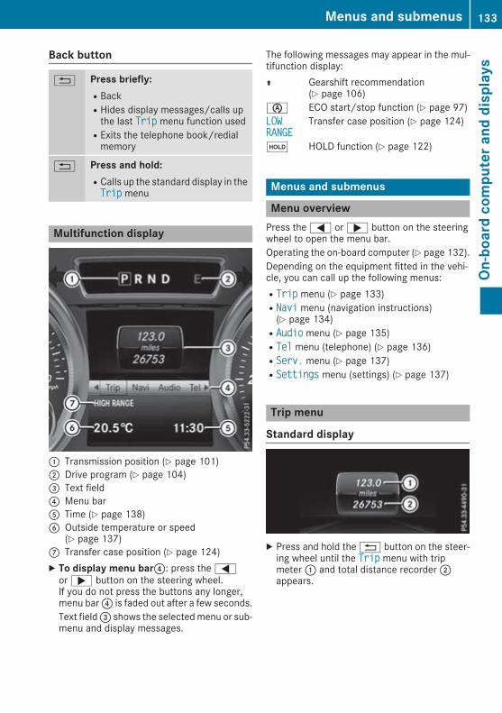
Back button
% Press briefly:RBackRHides display messages/calls upthe last TripTrip menu function usedRExits the telephone book/redialmemory
% Press and hold:RCalls up the standard display in theTripTrip menu
Multifunction display
: Transmission position (Y page 101); Drive program (Y page 104)= Text field? Menu barA Time (Y page 138)B Outside temperature or speed
(Y page 137)C Transfer case position (Y page 124)X To display menu bar?: press the=or; button on the steering wheel.If you do not press the buttons any longer,menu bar? is faded out after a few seconds.Text field= shows the selectedmenu or sub-menu and display messages.
The following messages may appear in the mul-tifunction display:Z Gearshift recommendation
(Y page 106)è ECO start/stop function (Y page 97)LOWLOWRANGERANGE Transfer case position (Y page 124)
ë HOLD function (Y page 122)
Menus and submenus
Menu overviewPress the= or; button on the steeringwheel to open the menu bar.Operating the on-board computer (Y page 132).Depending on the equipment fitted in the vehi-cle, you can call up the following menus:RTripTrip menu (Y page 133)RNaviNavi menu (navigation instructions)(Y page 134)RAudioAudio menu (Y page 135)RTelTel menu (telephone) (Y page 136)RServ.Serv. menu (Y page 137)RSettingsSettings menu (settings) (Y page 137)
Trip menu
Standard display
X Press and hold the% button on the steer-ing wheel until the TripTrip menu with tripmeter: and total distance recorder;appears.
Menus and submenus 133
On-board
computerand
displays
Z

Trip computer "From start" or "Fromreset"
: Distance; Driving time= Average speed? Average fuel consumptionX Press the= or; button on the steeringwheel to select the TripTrip menu.
X Press the9 or: button to selectFrom startFrom start or From resetFrom reset.The values in the FromFrom startstart submenu are cal-culated from the start of a journey whilst thevalues in the From resetFrom reset submenu are calcu-lated from the last time the submenu was reset(Y page 134).In the following cases, the From startFrom start tripcomputer is automatically reset:Rthe ignition has been switched off for morethan four hoursR999 hours have been exceededR9,999 kilometres have been exceededThe From resetFrom reset trip computer is automaticallyreset if the value exceeds 9,999 hours or99,999 kilometres.
Range
: Approximate rangeX Press the= or; button on the steeringwheel to select the TripTrip menu.
X Press the9 or: button to select theapproximate range.
The approximate range that can be covered iscalculated according to your current drivingstyle and the amount of fuel in the tank. If there
is only a small amount of fuel left in the fuel tank,a vehicle being refuelledC appears insteadof the approximate range.
Digital speedometerX Press the= or; button on the steeringwheel to select the TripTrip menu.
X Press the9 or: button to select thedigital speedometer.A gearshift recommendation Z can also bedisplayed in the multifunction display.Observe the information on gearshift recom-mendation Z when shifting manually(Y page 106).
Resetting valuesX Press the= or; button on the steeringwheel to select the TripTrip menu.
X Press the9 or: button to select thefunction that you wish to reset.
X Pressa.X Press the: button to select YesYes and pressa to confirm.
You can reset the values of the following func-tions:RTrip meterR"From start" trip computerR"From reset" trip computer
Navigation menu
Displaying navigation instructionsIn the NaviNavi menu, the multifunction displayshows navigation instructions.For more information on navigation, see themultimedia system (Y page 181).X Switch on the multimedia system.X Press the= or; button on the steeringwheel to select the NaviNavi menu.
134 Menus and submenusOn
-board
computerand
displays

Route guidance not active
: Direction of travel; Current road
Route guidance active
: Road to which the change of direction leads; Distance to change of direction and visual
distance display= Current road? Change-of-direction symbolWhen a change of direction is announced, youwill see change-of-direction symbol? and dis-tance graphic;. This shortens towards the topof the display as you approach the point of theannounced change of direction.
Other status indicators of the naviga-tion system
The navigation system displays additional infor-mation and the vehicle status.Possible displays:RNew Route...New Route... or Calculating Route...Calculating Route...A new route is calculated.RUnnamed roadUnnamed road
The vehicle position is inside the area of thedigital map, but the road is not recognised,e.g. new roads, car parks or private land.RO
You have reached the destination or an inter-mediate destination.
Audio menu
Selecting a radio station
: Active station list; Station with preset positionThe multifunction display shows station; withstation frequency or station name. The presetposition is only displayed in addition if station;has been stored.X Switch on the multimedia system and selectradio.
X Press the= or; button on the steeringwheel to select the AudioAudio menu.
X To select a preset list or station list: pressand briefly hold the9 or: button untilthe preset list or station list is shown in thedesired frequency range.
X To select a station: briefly press9or:.
Operating audio devices or media
Menus and submenus 135
On-board
computerand
displays
Z

Audio files from various audio players or mediacan be played, depending on the equipment fit-ted in the vehicle.X Switch on the multimedia system and selectmedia mode.
X Press the= or; button on the steeringwheel to select the AudioAudio menu.
X Press the= or; button to select nextor previous track:.If track information is saved on the audioplayer or media, the multifunction display willshow the title of the track.
Telephone menu
Introduction
G WARNINGOperating the integrated information systemsand communications equipment in the vehiclewhile driving will distract you from traffic con-ditions. You could then lose control of thevehicle. There is a risk of an accident.Only operate these devices if road traffic con-ditions permit. If you are unsure about thesurrounding conditions, pull over to a safelocation and make entries only while the vehi-cle is stationary.
When using the phone, you must observe thelegal requirements for the country in which youare currently driving.X Switch on the mobile phone (see the manu-facturer's operating instructions).
X Switch on the multimedia system(Y page 170).
X Establish a Bluetooth® connection to themul-timedia system (Y page 175).The multifunction display shows the name ofthe telephone and the mobile phone networkprovider.
X Press the= or; button on the steeringwheel to select the TelTel menu.
You can obtain further information about suita-ble mobile phones and connecting mobilephones via Bluetooth®:Ron the internet at http://www.mercedes-benz.com/connectRat any Mercedes-Benz Service Centre
Accepting a callIf someone calls you when you are in the TelTelmenu, a display message appears in the multi-function display.You can accept a call at any time irrespective ofthe selected menu.X Press the6 button on the steering wheelto accept an incoming call.
Rejecting or ending a callX Press the~ button on the steering wheel.You can end or reject a call even if you are not inthe TelTel menu.Dialling a number from the phone bookX Press the= or; button on the steeringwheel to select the TelTel menu.
X Press the9,: ora button toswitch to the phone book.
X Authorise access to the phone book on thephone.
X Press the9 or: button to select thedesired name.
X If only one telephone number is stored fora name: press the6 ora button tostart dialling.
orX If more than one number is stored for aname:press the6 ora button to dis-play the numbers.
X Press the9 or: button to select thenumber you want to dial.
X Press the6 ora button to start dial-ling.
orX To exit the telephone book: press the%button.
RediallingThe on-board computer saves the last names ornumbers dialled in the redial memory.X Press the= or; button on the steeringwheel to select the TelTel menu.
X Press the6 button to switch to the redialmemory.
X Press the9 or: button to select thedesired name or number.
136 Menus and submenusOn
-board
computerand
displays

X Press the6 ora button to start dial-ling.
orX To exit the redial memory: press the%button.
Assistance menu
IntroductionIn the Assist.Assist. menu, you have the followingoptions:RShowing the assistance graphic(Y page 137)
Showing the assistance graphicX Press the= or; button on the steeringwheel to select the Assist.Assist. menu.
X Press9 or: to select AssistanceAssistancegraphicgraphic.X Pressa.The display is inoperative.
Service menuIn the Serv.Serv. menu, you have the followingoptions:RCalling up display messages (Y page 141)RChecking the tyre pressure electronically(Y page 240)RCalling up the service due date(Y page 216)RChecking the engine oil level (Y page 213)
Settings menu
IntroductionIn the SettingsSettings menu, you have the followingoptions:RChanging the instrument cluster settings(Y page 137)RChanging the time/date settings(Y page 138)RChanging the light settings (Y page 138)RChanging the vehicle settings (Y page 139)RChanging the auxiliary heating settings(Y page 139)
RChanging the convenience settings(Y page 140)RRestoring the factory settings (Y page 141)
Instrument cluster
Selecting the unit ofmeasurement for dis-tanceThe Display unit Speed-/odometer:Display unit Speed-/odometer: func-tion allows you to choose whether certain dis-plays appear in kilometres or miles in the mul-tifunction display.You can determine whether the multifunctiondisplay shows certain messages in miles or kil-ometres.X Press the= or; button on the steeringwheel to select the SettingsSettings menu.
X Press the: or9 button to select theInstrument clusterInstrument cluster submenu.X Pressa to confirm.X Press the: or9 button to select theDisplay unit Speed-/odometerDisplay unit Speed-/odometer function.You will see the selected setting: kmkm or MilesMiles.
X Pressa to save the setting.The selected unit of measurement for distanceapplies to the following:Rdigital speedometer in the TripTrip menuRthe total distance recorder and the trip meterRtrip computerRcurrent consumption and the rangeRthe navigation instructions in the NaviNavi menuRASSYST service interval display
Selecting permanent displayYou can determine whether the multifunctiondisplay permanently shows your speed or theoutside temperature.X Press the= or; button on the steeringwheel to select the SettingsSettings menu.
X Press the: or9 button to select theInstrument clusterInstrument cluster submenu.X Pressa to confirm.X Press the: or9 button to select thePermanent display:Permanent display: function.You will see the selected setting: outsideoutsidetemperaturetemperature or Dig. speedo [mph]Dig. speedo [mph].
X Pressa to save the setting.
i The speed is displayed in mph.
Menus and submenus 137
On-board
computerand
displays
Z

i Vehicles for the United Kingdom: this func-tion is unavailable.
Selects languageX Press the= or; button on the steeringwheel to select the SettingsSettings menu.
X Press the: or9 button to select theInstrument clusterInstrument cluster submenu.X Pressa to confirm.X Press: or9 to select the Language:Language:function.You will see the current setting.
X Pressa to confirm.X Press the: or9 button to change thesetting.
X Pressa to store the entry.
Time/date
Setting the dateX Press the= or; button on the steeringwheel to select the SettingsSettings menu.
X Press: or9 to select the Time/DateTime/Datesubmenu.
X Pressa to confirm.X Press: or9 to select the Date:Date: func-tion.You will see the current setting.
X To set the date: pressa again.X Press= or; to switch between theday, month and year.
X Press: or9 to set the day, month oryear.
X Pressa to store the entry.The display shows the selected date.
Setting the timeX Press the= or; button on the steeringwheel to select the SettingsSettings menu.
X Press: or9 to select the Time/DateTime/Datesubmenu.
X Pressa to confirm.X Press: or9 to select the Time:Time: func-tion.You will see the current setting.
X To set the time: pressa again.X Press= or; to switch between hoursand minutes.
X Press: or9 to set the hours orminutes.
X Pressa to store the entry.The display shows the selected time.
Lights
Setting the daytime driving lightsThe Daytime driving lightsDaytime driving lights function canonly be switched on with the engine switchedoff.X Press the= or; button on the steeringwheel to select the SettingsSettings menu.
X Press the: or9 button to select theLightsLights submenu.X Pressa to confirm.X Press the: or9 button to select theDaytime driving lightsDaytime driving lights function.If the DaytimeDaytime drivingdriving lightslights function hasbeen switched on, the cone of light and theW symbol are shown in red in the multi-function display.
X Pressa to save the setting.Further information on daytime driving lights(Y page 74).
Surround lighting and exterior lightingdelayed switch-offX Press the= or; button on the steeringwheel to select the SettingsSettings menu.
X Press the: or9 button to select theLightsLights submenu.X Pressa to confirm.X Press the: or9 button to select theSurround lightingSurround lighting function.When the Surround lightingSurround lighting function hasbeen activated, the cone of light is shown inred in the multifunction display.
X Pressa to save the setting.Activating exterior lighting delayed switch-offtemporarily:X Before leaving the vehicle, turn the key toposition 0 in the ignition lock (Y page 96).
X Turn the key to position 2 in the ignition lock(Y page 96).Exterior lighting delayed switch-off is deacti-vated.
Exterior lighting delayed switch-off is reactiva-ted the next time you start the engine.
138 Menus and submenusOn
-board
computerand
displays

i Depending on your vehicle's equipment,when the surround lighting and exterior light-ing delayed switch-off are on, the followinglight up:Rside lampsRdipped-beam headlamps
Switching the interior lighting delayedswitch-off on/offIf you activate the LightingLighting delayeddelayed sw.-offsw.-offfunction, the interior lighting remains on for20 seconds after you remove the key from theignition lock.X Press the= or; button on the steeringwheel to select the SettingsSettings menu.
X Press the: or9 button to select theLightsLights submenu.X Pressa to confirm.X Press the: or9 button to select theLighting delayed sw.-offLighting delayed sw.-off function.If the Lighting delayed sw.-offLighting delayed sw.-off functionhas been activated, the vehicle interior is dis-played in red in the multifunction display.
X Pressa to save the setting.
Vehicle
Activating/deactivating the automaticlocking featureIf you activate the Automatic door locksAutomatic door locksfunction, the vehicle is centrally locked above aspeed of approximately 15 km/h.X Press the= or; button on the steeringwheel to select the SettingsSettings menu.
X Press the: or9 button to select theVehicleVehicle submenu.X Pressa to confirm.X Press the: or9 button to select theAutomatic door locksAutomatic door locks function.When the AutomaticAutomatic doordoor lockslocks function isactivated, the vehicle doors are displayed inred in the multifunction display.
X Pressa to save the setting.For further information on the automatic lockingfeature; see (Y page 62).
Activating/deactivating the acousticlocking confirmationIf you switch on the AcousticAcoustic LockLock function, anacoustic signal sounds when you lock the vehi-cle.X Press the= or; button on the steeringwheel to select the SettingsSettings menu.
X Press the: or9 button to select theVehicleVehicle submenu.X Pressa to confirm.X Press the: or9 button to select theAcoustic LockAcoustic Lock function.If the Acoustic LockAcoustic Lock function is activated,the& symbol in the multifunction displaylights up red.
X Pressa to save the setting.
Heating
Auxiliary heating departure timeG DANGERIf the exhaust pipe is blocked or sufficientventilation is not possible, toxic exhaustfumes can enter the vehicle, especially car-bon monoxide. This is the case, e.g. inenclosed spaces, or if the vehicle is stuck insnow. There is a risk of fatal injuries.You should switch off the auxiliary heating inenclosed spaces which do not have an extrac-tion system, e.g. a garage. If the vehicle isstuck in snow and youmust leave the auxiliaryheating running, keep the exhaust pipe andthe area around the vehicle clear of snow. Toguarantee a sufficient supply of fresh air, opena window on the side of the vehicle away fromthe wind.
G WARNINGWhen the auxiliary heating is switched on,parts of the vehicle can become very hot.Flammable materials such as leaves, grass ortwigs may ignite if they come into contactwith:Rhot parts of the exhaust systemRthe exhaust gas itselfThere is a risk of fire.
Menus and submenus 139
On-board
computerand
displays
Z

When the auxiliary heating is switched on,make sure that:Rno flammable materials come into contactwith hot vehicle componentsRthe exhaust gas can escape from theexhaust pipe unhinderedRthe exhaust gas does not come into contactwith flammable materials.
! Operating the auxiliary heating/ventilationdraws on the vehicle battery. After you haveheated or ventilated the vehicle amaximumoftwo times, drive for a longer distance.
Only vehicles with auxiliary heating have thisfunction (Y page 89).In the HeatingHeating submenu, you can select astored departure time or change a departuretime.The auxiliary heating timer function calculatesthe switch-on time according to the outsidetemperature so that the vehicle is preheated bythe departure time. When the departure time isreached, the auxiliary heating continues to heatfor a further five minutes and then switches off.The auxiliary heating selects the temperaturesetting of the THERMATIC automatic climatecontrol.You can switch the auxiliary heating on or off byusing the& auxiliary heating button on thecentre console or the remote control.
Selecting the departure time or deactivat-ing a selected departure timeX Press the= or; button on the steeringwheel to select the SettingsSettings menu.
X Press the: or9 button to select theHeatingHeating submenu.X Pressa to confirm.You will see the selected setting.
X Pressa to confirm.X Press the: or9 button to select oneof the three departure times or TimerTimer offoff (notimer active).
X Pressa to confirm.If a departure time is selected, the yellowindicator lamp lights up on the& auxiliaryheating button.
Changing the departure timeX Press the= or; button on the steeringwheel to select the SettingsSettings menu.
X Press the: or9 button to select theHeatingHeating submenu.X Pressa to confirm.You will see the selected setting.
X Pressa to confirm.X Press the: or9 button to selectChange AChange A, Change BChange B or Change CChange C.X Pressa to confirm.You can now change the departure time.
X Press the= or; button to select thedisplay to be changed: hours, minutes.
X Press the: or9 button to set theselected display.
X Pressa to store the entry.The yellow indicator lamp on the& auxili-ary heating button lights up.
Comfort
Activating/deactivating the EASY-ENTRY/EXIT featureG WARNINGWhen the EASY-ENTRY/EXIT feature adjuststhe steering wheel, you and other vehicleoccupants – particularly children – couldbecome trapped. There is a risk of injury.While the EASY-ENTRY/EXIT feature is mak-ing adjustments, make sure that no one hasany body parts in the sweep of the steeringwheel.If someone is trapped:Rpress one of the memory function positionbuttons, orRmove the switch for steering wheel adjust-ment in the opposite direction to that inwhich the steering wheel is moving.
The adjustment process is stopped.
X Press the= or; button on the steeringwheel to select the SettingsSettings menu.
X Press the: or9 button to select theConvenienceConvenience submenu.X Pressa to confirm.
140 Menus and submenusOn
-board
computerand
displays

X Press the: or9 button to select theEasy Entry/ExitEasy Entry/Exit function.If the EasyEasy Entry/ExitEntry/Exit function is activated,the vehicle steering wheel appears in red inthe multifunction display.
X Pressa to save the setting.Further information on the EASY-ENTRY/EXITfeature (Y page 72).
Resetting to factory settingsX Press the= or; button on the steeringwheel to select the SettingsSettings menu.
X Press the: or9 button to select theFactory settingFactory setting submenu.X Pressa to confirm.The ResetReset allall settings?settings? display messageappears.
X Press the: or9 button to select NoNo orYesYes.X Pressa to confirm the selection.If you have selected YesYes and confirmed, themultifunction display shows a confirmationmessage.
Display messages
Introduction
General notesDisplay messages appear in the multifunctiondisplay.Displaymessageswith graphic symbols are sim-plified in the Owner's Manual and may differfrom the symbols in the multifunction display.Please respond in accordance with the displaymessages and follow the additional notes in thisOwner's Manual.Certain display messages are accompanied byan audiblewarning tone or a continuouswarningtone.
When you stop and park the vehicle, pleaseobserve the notes on:RHOLD function (Y page 122)RParking (Y page 113)
Hiding display messagesX Press thea or% button on the steeringwheel.The multifunction display hides the displaymessage.
High-priority display messages are shown in redin the multifunction display. Some high-prioritydisplay messages cannot be hidden.The multifunction display shows these mes-sages continuously until the causes for themes-sages have been remedied.
Message memory menuThe on-board computer saves certain displaymessages in themessage memory. You cancall up the display messages:X Press the= or; button on the steeringwheel to select the Serv.Serv. menu.If there are display messages, the multifunc-tion display shows 2 messages2 messages, for example.
X Press the9 or: button to select theentry, e.g. 2 messages2 messages.
X Pressa to confirm.X Press the9 or: button to scrollthrough the display messages.
When the ignition is switched off, all displaymessages are deleted apart from some high-priority display messages. Once the causes ofthe high-priority display messages have beenrectified, these display messages are deleted aswell.
Display messages 141
On-board
computerand
displays
Z

Safety systems
Display messages Possible causes/consequences and MM Solutions
!÷ABS, ESP defectiveABS, ESP defectiveVisit workshopVisit workshop
ABS (Anti-lock Braking System) and ESP® (Electronic Stability Pro-gram) are temporarily unavailable.Other driving and driving safety systems may also be malfunctioning.In addition, the ÷ and ! warning lamps light up in the instru-ment cluster.Possible causes:Rself-diagnosis is not yet completeRthe on-board voltage may be insufficient
G WARNINGThe brake system continues to function normally, but without thefunctions listed above. The wheels could therefore lock if you brakehard, for example.The steerability and braking characteristics may be severely affected.The braking distancemay increase in an emergency braking situation.If ESP® is not operational, ESP® is unable to stabilise the vehicle.There is an increased risk of skidding and/or accident.X Carefully drive on a suitable stretch of road, making gentle steeringmovements at speeds of above 20 km/h.If the display message disappears, the functions mentioned aboveare available again.
If the display message still appears:X Drive on carefully.X Consult a qualified specialist workshop.
!÷currently unavaila‐currently unavaila‐bleble SeeSee Owner'sOwner's Man‐Man‐ualual
ABS and ESP® are malfunctioning.Other driving and driving safety systems may also be malfunctioning.In addition, the ÷ and ! warning lamps light up in the instru-ment cluster.
G WARNINGThe brake system continues to function normally, but without thefunctions listed above. The wheels could therefore lock if you brakehard, for example.The steerability and braking characteristics may be severely affected.The braking distancemay increase in an emergency braking situation.If ESP® is not operational, ESP® is unable to stabilise the vehicle.There is an increased risk of skidding and/or accident.X Drive on carefully.X Consult a qualified specialist workshop immediately.
142 Display messagesOn
-board
computerand
displays

Display messages Possible causes/consequences andMM Solutions
÷ESPESP defectivedefective VisitVisitworkshopworkshop
ESP® is malfunctioning.Other driving and driving safety systems may also be malfunctioning.The ÷ warning lamp also lights up on the instrument cluster.The self-diagnosis function, for example, may not be complete.
G WARNINGThe brake system continues to function normally, but without thefunctions listed above.The braking distance may thus increase in an emergency braking sit-uation.If ESP® is not operational, ESP® is unable to stabilise the vehicle.There is an increased risk of skidding and/or accident.X Carefully drive on a suitable stretch of road, making gentle steeringmovements at speeds of above 20 km/h.If the display message disappears, the functions mentioned aboveare available again.
If the display message still appears:X Drive on carefully.X Consult a qualified specialist workshop.
!÷JABS,ABS, ESP,ESP, EBDEBD defec‐defec‐tive Visit workshoptive Visit workshop
EBD (electronic brake force distribution), ABS and ESP® are faulty.Other driving and driving safety systems may also be malfunctioning.In addition, the ÷,J and ! warning lamps light up in theinstrument cluster and a warning tone sounds.
G WARNINGThe brake system continues to function normally, but without thefunctions listed above. The front and rear wheels could therefore lockif you brake hard, for example.The steerability and braking characteristics may be severely affected.The braking distancemay increase in an emergency braking situation.If ESP® is not operational, ESP® is unable to stabilise the vehicle.There is an increased risk of skidding and/or accident.X Drive on carefully.X Consult a qualified specialist workshop immediately.
JRelease parkingRelease parkingbrakebrake
You are driving with the parking brake applied. A warning tone alsosounds.X Release the parking brake.
Display messages 143
On-board
computerand
displays
Z

Display messages Possible causes/consequences andMM Solutions
JCheck brake fluidCheck brake fluidlevellevel
There is insufficient brake fluid in the brake fluid reservoir.In addition, theJ warning lamp in the instrument cluster lights upand a warning tone sounds.
G WARNINGBraking efficiency may be impaired.There is a risk of an accident.X Stop the vehicle safely as soon as possible, paying attention to roadand traffic conditions. Do not continue driving.
X Secure the vehicle against rolling away (Y page 113).X Consult a qualified specialist workshop.X Do not top up the brake fluid. This does not correct the fault.
#CheckCheck brakebrake padpad wearwear
The brake pads/linings have reached their wear limit.X Consult a qualified specialist workshop.
6Restraint sys. mal‐Restraint sys. mal‐function Consultfunction Consultworkshopworkshop
The restraint system is malfunctioning. The 6 warning lamp alsolights up in the instrument cluster.
G WARNINGThe airbags or belt tensioners may either be triggered unintentionallyor, in the event of an accident, may not be triggered.This poses an increased risk of injury.X Consult a qualified specialist workshop.Further information about the restraint system (Y page 31).
6Front left malfunc‐Front left malfunc‐tion Consult work‐tion Consult work‐shopshoporFront rightFront rightmalfunctionmalfunction ConsultConsultworkshopworkshop
The restraint system hasmalfunctioned at the front on the left or right.The 6 warning lamp also lights up in the instrument cluster.
G WARNINGThe airbags or belt tensioners may either be triggered unintentionallyor, in the event of an accident, may not be triggered.This poses an increased risk of injury.X Consult a qualified specialist workshop.
144 Display messagesOn
-board
computerand
displays

Display messages Possible causes/consequences andMM Solutions
6Rear left malfunc‐Rear left malfunc‐tion Consult work‐tion Consult work‐shopshop or Rear rightRear rightmalfunctionmalfunction ConsultConsultworkshopworkshop
The rear left-hand or right-hand restraint system has malfunctioned.The 6 warning lamp also lights up in the instrument cluster.
G WARNINGThe airbags or belt tensioners may either be triggered unintentionallyor, in the event of an accident, may not be triggered.This poses an increased risk of injury.X Consult a qualified specialist workshop.
6RearRear centrecentre malfunc‐malfunc‐tion Consult work‐tion Consult work‐shopshop
The rear centre restraint systemhasmalfunctioned. The6warninglamp also lights up in the instrument cluster.
G WARNINGThe airbags or belt tensioners may either be triggered unintentionallyor, in the event of an accident, may not be triggered.This poses an increased risk of injury.X Consult a qualified specialist workshop.
Lights
Display messages Possible causes/consequences andMM Solutions
bLeft dipped beamLeft dipped beam(example)
The bulb in question is faulty.X Consult a qualified specialist workshop.orX Check whether you are permitted to replace the bulb yourself(Y page 78).
i LED light bulbs: the display message for the corresponding lampappears only when all the LEDs in the lamp have failed.
bMalfunctionMalfunction SeeSee Own‐Own‐er's Manualer's Manual
The exterior lighting is faulty.X Consult a qualified specialist workshop.
bAUTO lights inoper‐AUTO lights inoper‐ativeative
The light sensor is faulty.X Consult a qualified specialist workshop.
bRemove keyRemove key
You have inserted the key into the ignition lock.X Remove the key from the ignition lock.
bSwitch off lightsSwitch off lights
The lights are still switched on when you leave the vehicle. A warningtone also sounds.X Turn the light switch to theà position.
Display messages 145
On-board
computerand
displays
Z

Engine
Display messages Possible causes/consequences andMM Solutions
+Top up coolant SeeTop up coolant SeeOwner's ManualOwner's Manual
The coolant level is too low.X Top up the coolant, observing the warning notes before doing so(Y page 215).
X Have the coolant system checked at a qualified specialist workshopif the coolant needs topping up more often than usual.
? The fan motor is faulty.X If the coolant temperature is below 120 †, drive on to the nearestqualified specialist workshop.
X Avoid putting the engine under heavy loads as you do so, e.g. drivingin mountainous terrain and stop-start traffic.
?Coolant Stop vehi‐Coolant Stop vehi‐cle Switch enginecle Switch engineoffoff
The coolant is too hot.A warning tone also sounds.
G WARNINGNever drive with an overheated engine. Driving when your engine hasoverheated can cause any fluids that may have leaked into the enginecompartment to catch fire.In addition, steam from an overheated engine can cause seriousburns, which can occur just by opening the bonnet.There is a risk of injury.X Stop the vehicle immediately, paying attention to road and trafficconditions, and switch off the engine.
X Secure the vehicle against rolling away (Y page 113).X Leave the vehicle and keep a safe distance from the vehicle until theengine has cooled down.
X Make sure that the air supply to the engine radiator is not blocked,e.g. by frozen slush.
X Donot start the engine again until the displaymessage goes out andthe coolant temperature is below 120†. The enginemay otherwisebe damaged.
X Pay attention to the coolant temperature gauge.X If the temperature increases again, consult a qualified specialistworkshop immediately.
Under normal operating conditions and with the specified coolantlevel, the coolant temperature may rise to 120 †.
146 Display messagesOn
-board
computerand
displays

Display messages Possible causes/consequences andMM Solutions
The poly-V-belt may have torn.X Stop the vehicle immediately, paying attention to road and trafficconditions, and switch off the engine.
X Check the poly-V-belt.If the poly-V-belt is torn:
! Do not continue driving. The engine could otherwise overheat.X Consult a qualified specialist workshop.If the poly-V-belt is OK:X Wait until the display message disappears before restarting theengine. The engine may otherwise be damaged.
X Pay attention to the coolant temperature gauge.X Consult a qualified specialist workshop.
# The battery is no longer being charged.A warning tone also sounds.Possible causes:Rfaulty alternatorRtorn poly-V-beltRa malfunction in the electronicsX Stop the vehicle immediately, paying attention to road and trafficconditions, and switch off the engine.
X Open the bonnet.X Check whether the poly-V-belt is torn.If the poly-V-belt is torn:
! Do not continue driving. The engine could otherwise overheat.X Consult a qualified specialist workshop.If the poly-V-belt is OK:X Consult a qualified specialist workshop.
4CheckCheck eng.eng. oiloil lev.lev.whenwhen nextnext refuellingrefuelling
The engine oil level has dropped to the minimum level.A warning tone also sounds.X Check the oil level when next refuelling, at the latest (Y page 213).X If necessary, top up the engine oil (Y page 213).X Have the engine checked at a qualified specialist workshop if theengine oil needs topping up more often than usual.
8Reserve fuel levelReserve fuel level
The fuel level has dropped into the reserve range.Operation of the auxiliary heating is deactivated if the fuel level dropsinto the reserve range.X Refuel at the nearest filling station.
Display messages 147
On-board
computerand
displays
Z

Display messages Possible causes/consequences andMM Solutions
C There is very little fuel in the fuel tank.Operation of the auxiliary heating is deactivated.X You must refuel at the nearest filling station.
¸ReplaceReplace airair cleanercleanerelementelement
Vehicles with a diesel engine: the engine air filter is dirty and mustbe replaced.X Consult a qualified specialist workshop.
!Clean the fuel fil‐Clean the fuel fil‐terter
Vehicles with a diesel engine: there is water in the fuel filter. Thewater must be drained off.X Consult a qualified specialist workshop.
ØRefill AdBlue SeeRefill AdBlue SeeOwner's ManualOwner's Manual
The AdBlue® level has fallen below the reserve range. A warning tonealso sounds.X Have AdBlue® refilled as soon as possible at a qualified specialistworkshop.
orX Refill AdBlue® yourself as soon as possible (Y page 111).
ØRefill AdBlue NoRefill AdBlue Nostart in .. kmstart in .. km
The AdBlue® level is only sufficient for the indicated distance. A warn-ing tone also sounds.X Have AdBlue® refilled as soon as possible at a qualified specialistworkshop.
orX Refill AdBlue® yourself immediately (Y page 111).
ØRefill AdBlue Eng.Refill AdBlue Eng.start not possiblestart not possible
The AdBlue® tank is empty. A warning tone also sounds. You can nolonger start the engine.X Consult a qualified specialist workshop immediately.orX Refill AdBlue® yourself immediately (Y page 111).
ØCheck AdBlue SeeCheck AdBlue SeeOwner's ManualOwner's Manual
The AdBlue® system is malfunctioning. A warning tone also sounds.X Consult a qualified specialist workshop.
ØEng. start not pos‐Eng. start not pos‐sible in ..kmsible in ..km
The AdBlue® system is malfunctioning. A warning tone also sounds.X Consult a qualified specialist workshop immediately.
ØEng. start not pos‐Eng. start not pos‐siblesible
The AdBlue® system is malfunctioning. A warning tone also sounds.You can no longer start the engine.X Consult a qualified specialist workshop immediately.
148 Display messagesOn
-board
computerand
displays

Driving systems
Display messages Possible causes/consequences andMM Solutions
TCTC shiftshift conditionsconditionsnot fulfillednot fulfilledApply the brake/Apply the brake/parking brakeparking brake
The parking brake is not applied and the brake is not depressed. Thetransfer case has cancelled the gearshift process and is in Neutral.There is no connection between the engine and the drive wheels.X Stop the vehicle safely as soon as possible, paying attention to roadand traffic conditions.
X Depress the brake and apply the parking brake.X Shift the automatic transmission into neutral position N.X Make sure all conditions for gear changing are met (Y page 124).X Repeat the gearshift process.
TC malfunctionTC malfunctionVisitVisit workshopApplyworkshopApplyparking brake toparking brake toparkpark
The transfer case is faulty.X Do not shift the transfer case.X When parking, safeguard the vehicle against rolling away(Y page 113).
X Have the vehicle checked at a qualified specialist workshop.
TC shift cancelledTC shift cancelledReactivateReactivate
The transfer case has not performed the gearshift process.X Repeat the gearshift process.X Make sure all conditions for gear changing are met (Y page 124).
TCTC shiftshift conditionsconditionsnot fulfillednot fulfilledMax. speed 40 km/hMax. speed 40 km/h
You have exceeded the maximum speed for the gearshift process.X Drive more slowly.X Repeat the gearshift process.
TCTC shiftshift conditionsconditionsnot fulfillednot fulfilledSelect NEUTRAL gearSelect NEUTRAL gear
One or more shift conditions has not been met.X Shift the automatic transmission into neutral position N.X Repeat the gearshift process.
TCTC shiftshift conditionsconditionsnot fulfillednot fulfilledMax. speed 70 km/hMax. speed 70 km/h
You have exceeded the maximum speed for the gearshift process.X Drive more slowly.X Repeat the gearshift process.
LOW RANGELOW RANGEOnOn
The transfer case is in off-road driving position LOW RANGE.
HIGH RANGEHIGH RANGEOnOn
The transfer case is in on-road position HIGH RANGE.
Differential lockDifferential lockonly available inonly available inLOW RANGELOW RANGEThe LOW RANGE button was pressed. The transfer case is in off-roaddriving position LOW RANGE and a differential lock is engaged.X Disengage the differential lock (Y page 125).X Repeat the gearshift process.
Display messages 149
On-board
computerand
displays
Z

Display messages Possible causes/consequences andMM Solutions
TC NEUTRALTC NEUTRALOnOn
The transfer case is in position Neutral.A warning tone also sounds when the driver's door is open and thebrake pedal is not depressed.X Close the driver's door.X Secure the vehicle against rolling away (Y page 113).X Switch the transfer case depending on the driving situation(Y page 124).
Preselected differ‐Preselected differ‐ential lockential lockESP unavailableESP unavailable
A differential lock was engaged. The differential gear system has notyet locked the respective differential. The activation indicator lamp(yellow) (Y page 125) on the switch lights up.ESP® is unavailable.ABS is still available.
Differential lockDifferential lockactiveactiveABSABS andand ESPESP unavail‐unavail‐ableable
A differential lock was engaged and the differential gear system hasnot yet locked the respective differential. The yellow activation indi-cator lamp and red function indicator lamp (Y page 125) on the switchlights up.ABS and ESP® are unavailable.
Tyres
Display messages Possible causes/consequences andMM Solutions
Tyre pressure dis‐Tyre pressure dis‐played after a fewplayed after a fewminutes of drivingminutes of drivingThe tyre pressure monitor is measuring the tyre pressure.X Drive on.The tyre pressures appear in the multifunction display after youhave been driving for a few minutes.
TyreTyre press.press. monitormonitorinoperativeinoperative The tyre pressure monitor is faulty.X Consult a qualified specialist workshop.
TyreTyre press.press. monitormonitorinoperative Noinoperative Nowheel sensorswheel sensorsThe wheels fitted do not have suitable tyre pressure sensors. The tyrepressure monitor is deactivated.X Fit wheels with suitable tyre pressure sensors.The tyre pressure monitor is activated after driving for a fewminutes.
150 Display messagesOn
-board
computerand
displays

Display messages Possible causes/consequences andMM Solutions
Check tyresCheck tyres The tyre pressure in one or more tyres has dropped significantly. Thewheel position is shown in the multifunction display.A warning tone also sounds.
G WARNINGUnderinflated tyres pose the following risks:Rthe tyres may burst, especially as the load and vehicle speedincreaseRthe tyresmay wear excessively and/or unevenly, whichmay greatlyimpair tyre tractionRthe driving characteristics, as well as steering and braking, may begreatly impaired
There is a risk of an accident.X Stop the vehicle without making any sudden steering or brakingmanoeuvres. Pay attention to the traffic conditions as you do so.
X Secure the vehicle against rolling away (Y page 113).X If there is a flat tyre, inspect the tyres (Y page 224).X Check the tyre pressure (Y page 239).X If necessary, correct the tyre pressure.
Warning tyre defectWarning tyre defect The tyre pressure in one or more tyres has dropped suddenly. Thewheel position is shown in the multifunction display.A warning tone also sounds.
G WARNINGIf you drive with a flat tyre, there is a risk of the following hazards:Ra flat tyre impairs the ability to steer or brake the vehicleRyou could lose control of the vehicleRcontinued driving with a flat tyre will cause excessive heat build-upand possibly a fire
There is a risk of an accident.X Stop the vehicle without making any sudden steering or brakingmanoeuvres. Pay attention to the traffic conditions as you do so.
X Secure the vehicle against rolling away (Y page 113).X If there is a flat tyre, inspect the tyres (Y page 224).
Rectify tyre pres‐Rectify tyre pres‐suresure The tyre pressure is too low in at least one of the tyres, or the tyrepressure difference between the wheels is too great.X Check the tyre pressures at the next opportunity (Y page 239).X If necessary, correct the tyre pressure.X Restart the tyre pressure monitor (Y page 241).
Wheel sensor(s)Wheel sensor(s)missingmissing There is no signal from the tyre pressure sensor of one or several tyres.The pressure of the affected tyre does not appear in the multifunctiondisplay.X Have the faulty tyre pressure sensor replaced at a qualified spe-cialist workshop.
Display messages 151
On-board
computerand
displays
Z

Display messages Possible causes/consequences andMM Solutions
TyreTyre press.press. monitormonitorcurrently unavaila‐currently unavaila‐blebleNo signals can be received from the tyre pressure sensors due tostrong RF interference. The tyre pressure monitor is temporarily mal-functioning.X Drive on.The tyre pressure monitor restarts automatically as soon as thecause has been rectified.
hTyre pressure Cau‐Tyre pressure Cau‐tion, tyre malfunc‐tion, tyre malfunc‐tiontion
The tyre pressure in one or more tyres has dropped suddenly. Thewheel position is shown on the multifunction display.A warning tone also sounds.
G WARNINGIf you drive with a flat tyre, there is a risk of the following hazards:Ra flat tyre impairs the ability to steer or brake the vehicleRyou could lose control of the vehicleRcontinued driving with a flat tyre will cause excessive heat build-upand possibly a fireThere is a risk of an accident.
X Stop the vehicle without making any sudden steering or brakingmanoeuvres. Pay attention to the traffic conditions as you do so.
X Secure the vehicle against rolling away (Y page 113).X If there is a flat tyre, inspect the tyres (Y page 224).
hTyreTyre pressurepressure CheckChecktyre(s)tyre(s)
The tyre pressure in one or more tyres has dropped significantly. Thewheel position is shown on the multifunction display.A warning tone also sounds.
G WARNINGUnderinflated tyres pose the following risks:Rthe tyres may burst, especially as the load and vehicle speedincreaseRthe tyresmay wear excessively and/or unevenly, whichmay greatlyimpair tyre tractionRthe driving characteristics, as well as steering and braking, may begreatly impairedThere is a risk of an accident.
X Stop the vehicle without making any sudden steering or brakingmanoeuvres. Pay attention to the traffic conditions as you do so.
X Secure the vehicle against rolling away (Y page 113).X If there is a flat tyre, inspect the tyres (Y page 224).X Check the tyre pressure (Y page 239).X If necessary, correct the tyre pressure.
hRectify tyre pres‐Rectify tyre pres‐suresure
The tyre pressure is too low in at least one of the tyres, or the tyrepressure difference between the wheels is too great.X Check the tyre pressures at the next opportunity (Y page 239).X If necessary, correct the tyre pressure.
152 Display messagesOn
-board
computerand
displays

Vehicle
Display messages Possible causes/consequences andMM Solutions
To start theTo start theengine, shift toengine, shift toeither P or Neither P or NYou have attempted to start the engine with the transmission in posi-tion R or D.X Shift the transmission to position P or N.
Auxiliary batteryAuxiliary batterymalfunctionmalfunction The auxiliary battery for the automatic transmission is no longer beingcharged.X Consult a qualified specialist workshop at the next opportunity.X Until then, set the automatic transmission to position P before youswitch off the engine.
X Before leaving the vehicle, apply the parking brake.
ApplyApply brakebrake toto dese‐dese‐lect Park (P) posi‐lect Park (P) posi‐tiontionYou have attempted to move the transmission selector lever to posi-tion D, R or N without depressing the brake pedal.X Depress the brake pedal.
Apply brake toApply brake toselect Rselect R You have attempted to shift from position D to position R withoutapplying the brake.X Depress the brake pedal.X Shift the transmission to position R.
A The rear door is open.
G WARNINGWhen the engine is running, exhaust gases can enter the vehicle inte-rior if the tailgate is open.There is a risk of poisoning.X Close the rear door.
? The bonnet is open.A warning tone also sounds.
G WARNINGThe open bonnet may then block your view when the vehicle is inmotion.There is a risk of an accident.X Stop the vehicle safely as soon as possible, paying attention to roadand traffic conditions.
X Secure the vehicle against rolling away (Y page 113).X Close the bonnet.
C At least one door is open.A warning tone also sounds.X Close all doors.
Display messages 153
On-board
computerand
displays
Z

Display messages Possible causes/consequences andMM Solutions
^RearRear leftleft seatseat back‐back‐rest notrest notlockedlockedorFront rightFront rightseat backrest notseat backrest notlockedlocked
G WARNINGThe driver's or front-passenger seat backrest is not engaged.X Push the backrest back until it engages.
DPower steering mal‐Power steering mal‐function See Own‐function See Own‐er's Manualer's Manual
The power steering assistance is faulty.A warning tone also sounds.
G WARNINGYou will need to use more force to steer.There is a risk of an accident.X Check whether you are able to apply the extra steering forcerequired.
X If you are able to steer safely: carefully drive on to a qualifiedspecialist workshop.
X If you are unable to steer safely: do not drive on. Contact thenearest qualified specialist workshop.
&inoperativeinoperative BatteryBatterylowlow
You have attempted to switch on the auxiliary heating or to activate adeparture time using the on-board computer after operating the aux-iliary heating twice.X Let the engine run for ten seconds.The auxiliary heating is operational again.
The on-board voltage is too low. The auxiliary heating has switcheditself off or cannot be switched on (Y page 89).X Drive for a considerable distance.The battery charges. The auxiliary heating is operational again assoon as the on-board electrical system voltage is sufficient.
&inoperative Refuelinoperative Refuelvehiclevehicle
There is too little fuel in the fuel tank. The auxiliary heating cannot beswitched on (Y page 89).X Refuel at the nearest filling station.
&inoperativeinoperative SeeSee Own‐Own‐er's Manualer's Manual
The auxiliary heating is temporarily malfunctioning or faulty.X When the vehicle is on a level surface and the engine has cooleddown, make up to four attempts to switch on the auxiliary heating,waiting several minutes between each attempt (Y page 89).
X If the auxiliary heating does not switch on, consult a qualified spe-cialist workshop.
¥Top up washer fluidTop up washer fluid
The washer fluid level in the washer fluid reservoir has dropped belowthe minimum.X Top up the washer fluid (Y page 215).
154 Display messagesOn
-board
computerand
displays

Key
Display messages Possible causes/consequences andMM Solutions
ÂKeyKey doesdoes notnot belongbelongto vehicleto vehicle
You have put the wrong key in the ignition lock.X Use the correct key.
ÂReplace keyReplace key
The key needs to be replaced.X Consult a qualified specialist workshop.
Warning and indicator lamps on theinstrument cluster
General notesSome systems carry out a self-diagnosis whenthe ignition is switched on. A number of warning
and indicator lamps might temporarily light upor flash during this. This behaviour is non-criti-cal. These warning and indicator lamps indicatea malfunction only if they light up or flash afterthe engine is started or during a journey.
Safety
Seat belts
Warning/indicatorlamp
NN Signal typePossible causes/consequences andMM Solutions
ü NOnly for certain countries: the red seat belt warning lamp lights up for 6 secondsafter the engine starts.The seat belt warning lamp reminds the driver and front passenger to fasten theirseat belts.X Fasten your seat belt (Y page 34).
ü N Only for certain countries: the red seat belt warning lamp lights up after theengine starts. In addition, a warning tone sounds for up to 6 seconds.The driver's seat belt is not fastened.X Fasten your seat belt (Y page 34).The warning tone ceases.
Warning and indicator lamps on the instrument cluster 155
On-board
computerand
displays
Z
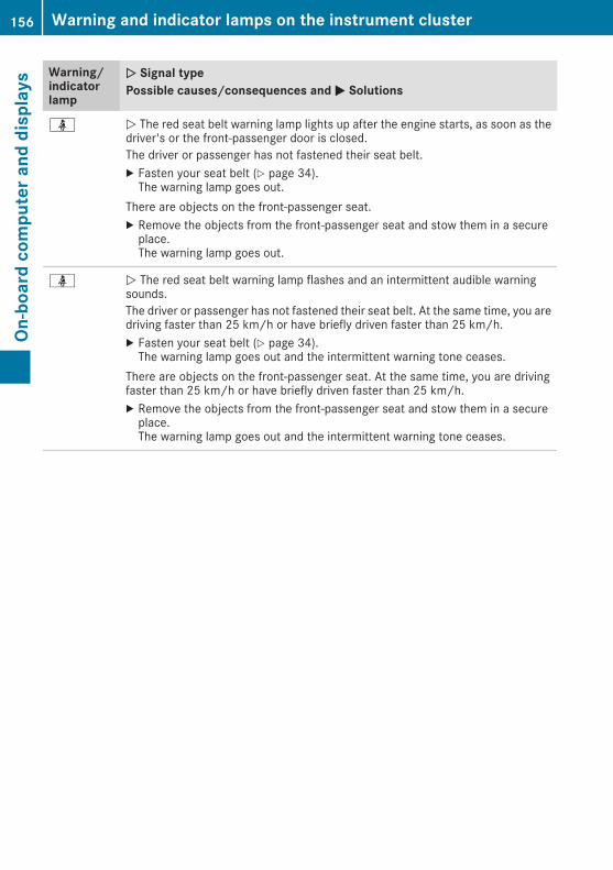
Warning/indicatorlamp
NN Signal typePossible causes/consequences andMM Solutions
ü N The red seat belt warning lamp lights up after the engine starts, as soon as thedriver's or the front-passenger door is closed.The driver or passenger has not fastened their seat belt.X Fasten your seat belt (Y page 34).The warning lamp goes out.
There are objects on the front-passenger seat.X Remove the objects from the front-passenger seat and stow them in a secureplace.The warning lamp goes out.
ü N The red seat belt warning lamp flashes and an intermittent audible warningsounds.The driver or passenger has not fastened their seat belt. At the same time, you aredriving faster than 25 km/h or have briefly driven faster than 25 km/h.X Fasten your seat belt (Y page 34).The warning lamp goes out and the intermittent warning tone ceases.
There are objects on the front-passenger seat. At the same time, you are drivingfaster than 25 km/h or have briefly driven faster than 25 km/h.X Remove the objects from the front-passenger seat and stow them in a secureplace.The warning lamp goes out and the intermittent warning tone ceases.
156 Warning and indicator lamps on the instrument clusterOn
-board
computerand
displays

Safety systems
Warning/indicatorlamp
NN Signal typePossible causes/consequences and MM Solutions
J N The red brake system warning lamp is lit while the engine is running.A warning tone also sounds.
G WARNINGThe brake system is malfunctioning and the braking characteristics may be affec-ted.There is a risk of an accident.X If the multifunction display shows a display message, please observe this.X Drive on carefully.X Consult a qualified specialist workshop.
J N The yellow brake system warning lamp is lit while the engine is running.A warning tone also sounds.
G WARNINGThe brake boosting effect ismalfunctioning and the braking characteristicsmay beaffected.There is a risk of an accident.X Stop the vehicle safely as soon as possible, paying attention to road and trafficconditions. Do not continue driving.
X Secure the vehicle against rolling away (Y page 113).X Consult a qualified specialist workshop.X Observe the additional display messages on the multifunction display.
J N The yellow brake system warning lamp is lit while the engine is running.A warning tone also sounds.There is an insufficient amount of brake fluid in the fluid reservoir.
G WARNINGBraking efficiency may be impaired.There is a risk of an accident.X Stop the vehicle safely as soon as possible, paying attention to road and trafficconditions. Do not continue driving.
X Secure the vehicle against rolling away (Y page 113).X Do not top up the brake fluid. Topping up will not correct the fault.X Consult a qualified specialist workshop.X Observe the additional display messages on the multifunction display.
J N The red brake system warning lamp is lit while the vehicle is in motion.You are driving with the parking brake applied.X Release the parking brake.The warning lamp goes out and the warning tone ceases.
Warning and indicator lamps on the instrument cluster 157
On-board
computerand
displays
Z

Warning/indicatorlamp
NN Signal typePossible causes/consequences andMM Solutions
! N The red ABS warning lamp is lit while the engine is running.The ABS (Anti-lock Braking System) is malfunctioning.An additional warning tone indicates that EBD (electronic brake force distribution)is malfunctioning.Other driving and driving safety systems may also be malfunctioning.
G WARNINGThe brake system continues to function normally, but without the functions listedabove. The front and rear wheels could therefore lock if you brake hard, for exam-ple.The steerability and braking characteristics may be severely affected. The brakingdistance may increase in an emergency braking situation.If ESP® is not operational, ESP® is unable to stabilise the vehicle.There is an increased risk of skidding and/or accident.X Observe the additional display messages on the multifunction display.X Drive on carefully.X Consult a qualified specialist workshop immediately.If the ABS control unit is faulty, there is also a possibility that other systems, suchas the navigation system or the automatic transmission, will be unavailable.
! N The red ABS warning lamp is lit while the engine is running.ABS is temporarily unavailable.Other driving and driving safety systems may also be unavailable.Possible causes:Rself-diagnosis is not yet completeRthe on-board voltage may be insufficient
G WARNINGThe brake system continues to function normally, but without the functions listedabove. The wheels could therefore lock if you brake hard, for example.The steerability and braking characteristics may be severely affected. The brakingdistance may increase in an emergency braking situation.If ESP® is not operational, ESP® is unable to stabilise the vehicle.There is a risk of an accident.X Carefully drive on a suitable stretch of road, making gentle steering movementsat speeds of above 20 km/h.The functions mentioned above are available again when the warning lamp goesout.
If the warning lamp is still on:X Observe the additional display messages on the multifunction display.X Drive on carefully.X Consult a qualified specialist workshop.
158 Warning and indicator lamps on the instrument clusterOn
-board
computerand
displays

Warning/indicatorlamp
NN Signal typePossible causes/consequences andMM Solutions
! N The red ABS warning lamp is lit while the engine is running.You have engaged the differential locks. ABS is deactivated.X Disengage the differential locks.Subsequently ABS is reactivated.
J÷!
N The yellow ESP® and ABS brake system warning lamps are lit while the engineis running.ABS and ESP® are malfunctioning.Other driving and driving safety systems may also be malfunctioning.
G WARNINGThe brake system continues to function normally, but without the functions listedabove. The front and rear wheels could therefore lock if you brake hard, for exam-ple.The steerability and braking characteristics may be severely affected. The brakingdistance may increase in an emergency braking situation.If ESP® is not operational, ESP® is unable to stabilise the vehicle.There is an increased risk of skidding and/or accident.X Observe the additional display messages on the multifunction display.X Drive on carefully.X Consult a qualified specialist workshop immediately.
÷ N The yellow ESP® warning lamp flashes while the vehicle is in motion.ESP® or traction control has intervened due to a risk of skidding or because at leastone wheel has started to spin.Cruise control is deactivated.X Depress the accelerator pedal only as far as necessary when pulling away.X Accelerate more gently while the vehicle is in motion.X Adapt your driving style to suit the road and weather conditions.X Do not deactivate ESP®.In rare cases (Y page 54) it may be better to deactivate ESP®.Observe the important safety notes on ESP® (Y page 54).
Warning and indicator lamps on the instrument cluster 159
On-board
computerand
displays
Z

Warning/indicatorlamp
NN Signal typePossible causes/consequences andMM Solutions
å N The yellow ESP® OFF warning lamp is lit while the engine is running.ESP® is deactivated.
G WARNINGIf ESP® is deactivated, ESP® is unable to stabilise the vehicle.Further driving systems or driving safety systems are thus restricted.There is an increased risk of skidding and/or accident.X Reactivate ESP®.In rare cases (Y page 54) it may be better to deactivate ESP®.Observe the important safety notes on ESP® (Y page 54).
X Adapt your driving style to suit the road and weather conditions.If ESP® cannot be activated:X Drive on carefully.X Have ESP® checked at a qualified specialist workshop.
÷å N The yellow ESP® and ESP®OFFwarning lamps are lit while the engine is running.ESP® is malfunctioning.Other driving and driving safety systems may also be malfunctioning.
G WARNINGThe brake system continues to function normally, but without the functions listedabove.The braking distance may thus increase in an emergency braking situation.If ESP® is not operational, ESP® is unable to stabilise the vehicle.There is an increased risk of skidding and/or accident.X Observe the additional display messages on the multifunction display.X Drive on carefully.X Consult a qualified specialist workshop immediately.
160 Warning and indicator lamps on the instrument clusterOn
-board
computerand
displays

Warning/indicatorlamp
NN Signal typePossible causes/consequences andMM Solutions
÷å N The yellow ESP® and ESP®OFFwarning lamps are lit while the engine is running.ESP® is temporarily unavailable.Other driving and driving safety systems may also be unavailable.
G WARNINGThe brake system continues to function normally, but without the functions listedabove.The braking distance may thus increase in an emergency braking situation.If ESP® is not operational, ESP® is unable to stabilise the vehicle.There is an increased risk of skidding and/or accident.X Carefully drive on a suitable stretch of road, making gentle steering movementsat speeds of above 20 km/h.The functions mentioned above are available again when the warning lamp goesout.
If the warning lamp is still on:X Observe the additional display messages on the multifunction display.X Drive on carefully.X Consult a qualified specialist workshop.
å N The yellow ESP® OFF warning lamp is lit while the engine is running.The differential lock is engaged. ABS, ESP®, 4ETS and BAS have been deactivated.X Disengage the differential lock.ESP®, 4ETS and BAS are subsequently reactivated.
X Observe the additional display messages on the multifunction display.
6 N The red restraint system warning lamp is lit while the engine is running.The restraint system is malfunctioning.
G WARNINGThe airbags or belt tensioners may either be triggered unintentionally or, in theevent of an accident, may not be triggered.This poses an increased risk of injury.X Observe the additional display messages on the multifunction display.X Drive on carefully.X Contact a qualified specialist workshop immediately and have the restraint sys-tem checked.
Further information about the restraint system (Y page 31).
Warning and indicator lamps on the instrument cluster 161
On-board
computerand
displays
Z

Engine
Warning/indicatorlamp
NN Signal typePossible causes/consequences andMM Solutions
; N The yellow engine diagnostics warning lamp lights up while the engine is run-ning.There may be a fault with the following, for example:Rengine managementRfuel injection systemRexhaust systemRfuel systemThe emission limit values may be exceeded and the engine may be running inemergency mode.X Consult a qualified specialist workshop immediately.Vehicles with a diesel engine: the fuel tank has been run dry (Y page 110).X Start the engine three to four times after refuelling.If the yellow engine diagnostics warning lamp goes out, emergency mode iscancelled. The vehicle does not have to be checked.
8 N The yellow reserve fuel warning lamp lights up while the engine is running.The fuel level has dropped into the reserve range.Operation of the auxiliary heating is deactivated if the fuel level drops into thereserve range.X Refuel at the nearest filling station.
% NOn diesel engine vehicles, the preglow indicator lamp does not light upwhen thekey is in position 2 (Y page 96).The preglow system is malfunctioning.X Consult a qualified specialist workshop immediately.
? N The red coolant warning lamp lights up while the engine is running and thecoolant temperature display is at the start of the scale.The temperature sensor for the coolant temperature gauge is malfunctioning.The coolant temperature is no longer being monitored. The engine could be dam-aged if the coolant temperature is too high.X Stop the vehicle immediately, paying attention to road and traffic conditions,and switch off the engine. Do not continue driving.
X Secure the vehicle against rolling away (Y page 113).X Consult a qualified specialist workshop.
162 Warning and indicator lamps on the instrument clusterOn
-board
computerand
displays

Warning/indicatorlamp
NN Signal typePossible causes/consequences andMM Solutions
? N The red coolant warning lamp lights up while the engine is running.The coolant level is too low.If the coolant level is correct, the airflow to the engine radiator may be blocked orthe electric engine radiator fan may be malfunctioning.The coolant is too hot and the engine is not being cooled sufficiently.X Observe the additional display messages on the multifunction display.X Stop the vehicle immediately, paying attention to road and traffic conditions,and switch off the engine.
X Secure the vehicle against rolling away (Y page 113).X Leave the vehicle and keep a safe distance from the vehicle until the engine hascooled down.
X Check the coolant level and top up the coolant, making sure to observe thewarning notes (Y page 215).
X If you have to top up the coolant frequently, have the engine cooling systemchecked.
X Make sure that the air supply to the engine radiator is not blocked, e.g. by frozenslush.
X Do not start the engine again until the coolant temperature is below 120†. Theengine may otherwise be damaged.
X Drive to the nearest qualified specialist workshop.X Avoid heavy loads on the engine as you do so, e.g. driving inmountainous terrainand stop-start traffic.
? N The red coolant warning lamp lights up while the engine is running.The coolant temperature has exceeded 120 †. The airflow to the engine radiatormay be blocked or the coolant level may be too low.
G WARNINGThe engine is not being cooled sufficiently and may be damaged.Never drive with an overheated engine. Driving when your engine has overheatedcan cause any fluids that may have leaked into the engine compartment to catchfire.In addition, steam from an overheated engine can cause serious burns, which canoccur just by opening the bonnet.There is a risk of injury.X Observe the additional display messages on the multifunction display.X Stop the vehicle immediately, paying attention to road and traffic conditions,and switch off the engine.
X Secure the vehicle against rolling away (Y page 113).X Leave the vehicle and keep a safe distance from the vehicle until the engine hascooled down.
X Check the coolant level and top up the coolant, making sure to observe thewarning notes (Y page 215).
X If you have to top up the coolant frequently, have the engine cooling systemchecked.
Warning and indicator lamps on the instrument cluster 163
On-board
computerand
displays
Z

Warning/indicatorlamp
NN Signal typePossible causes/consequences andMM Solutions
X Make sure that the air supply to the engine radiator is not blocked, e.g. by frozenslush.
X If the coolant temperature is below 120 †, you can continue driving to thenearest qualified specialist workshop.
X Avoid heavy loads on the engine as you do so, e.g. driving inmountainous terrainand stop-start traffic.
Tyres
Warning/indicatorlamp
NN Signal typePossible causes/consequences andMM Solutions
h N The yellow tyre pressure monitor warning lamp (pressure loss/malfunction) islit.The tyre pressure monitor has detected a loss of pressure in at least one of thetyres.
G WARNINGUnderinflated tyres pose the following risks:Rthe tyres may burst, especially as the load and vehicle speed increaseRthe tyres may wear excessively and/or unevenly, which may greatly impair tyretractionRthe driving characteristics, as well as steering and braking, may be greatlyimpairedThere is a risk of an accident.
X Stop the vehicle without making any sudden steering or braking manoeuvres.Pay attention to the traffic conditions as you do so.
X Secure the vehicle against rolling away (Y page 113).X Observe the additional display messages on the multifunction display.X Check the tyres and, if necessary, follow the instructions for a flat tyre(Y page 224).
X Check the tyre pressure (Y page 239).X If necessary, correct the tyre pressure.
h N The yellow tyre pressure monitor warning lamp (pressure loss/malfunction)flashes for approximately one minute and then remains lit.The tyre pressure monitor is faulty.
G WARNINGThe system is possibly unable to detect or register low tyre pressure.There is a risk of an accident.X Observe the additional display messages on the multifunction display.X Consult a qualified specialist workshop immediately.
164 Warning and indicator lamps on the instrument clusterOn
-board
computerand
displays

Introduction
Operating safety
Important safety notes
G WARNINGOperating the integrated information systemsand communications equipment in the vehiclewhile driving will distract you from traffic con-ditions. You could then lose control of thevehicle. There is a risk of an accident.Only operate these devices if road traffic con-ditions permit. If you are unsure about thesurrounding conditions, pull over to a safelocation and make entries only while the vehi-cle is stationary.
Observe the legal requirements for the countryyou are in.The navigation system calculates the route tothe destination without taking account of thefollowing, for example:Rtraffic lightsRstop and give way signsRparking or stopping restrictionsRroad narrowingRother road and traffic rules and regulationsThe multimedia system may provide incorrectnavigation announcements if the surroundingsdo not correspond to the data on the digital map(for example, a route may have been diverted orthe direction of a one-way street may havechanged).For this reason, you must always observe roadand traffic rules and regulations during yourjourney. Road and traffic rules and regulationsalways have priority over the system's drivingrecommendations.Remember that even at a speed of 50 km/h,your vehicle covers a distance of 14 m per sec-ond.When using the device please follow:Rthe safety notes in this manualRtraffic rules and regulationsRlaws and safety standards pertaining tomotorvehicles
G WARNINGModifications to electronic components, theirsoftware as well as wiring could affect theirfunction and/or the operation of other net-worked components. This could in particularalso be the case for systems relevant tosafety. They might not function properly any-more and/or jeopardise the operationalsafety of the vehicle. There is an increasedrisk of an accident and injury.Do not attempt to modify the wiring as well aselectronic components or their software.Always have work on electrical and electroniccomponents carried out at a qualified special-ist workshop.
Correct useThe multimedia system can be used for the fol-lowing:Rto receive radio stationsRto play back audio files on memory cards andother data carriersRto make calls via the Bluetooth® functionRfor navigation
Declaration of conformity
Radio type approval
Introduction 165
Multim
ediasystem
Z

Copyright information
Registered trademarks
Bluetooth® technology is a standard for short-range wireless data transmissions up to approx-imately 10 metres.Bluetooth® is a registered trademark of Blue-tooth Special Interest Group (SIG) Inc.
An SD card is a digital storage medium.SD cards carry the logo displayed above. Thislogo is a registered trademark of SanDisk Cor-poration.
CleaningTo clean, use a slightly damp cloth. The clothmust be soft and lint-free. For stubborn dirt, youcan use a mild cleaning agent. In particular, donot clean the display with alcohol, acid or anabrasive cleaning agent.
166 IntroductionMultim
ediasystem

At a glance
Operating system
Multimedia system with navigationFunction Page
: Microphone
; Light sensor 172
= NAVISelects navigation 182
? MAPCalls up map viewRepeats last navigation mes-sage 187
A Back buttonGoes back to the previousview
B USB port 177
C AUX port 178
D V Control knobTurn:Changes the adjustmentvalueHighlights the menu itemPress:Selects a highlighted menuitem
E Touchscreen 170
Function Page
F V On/off knobPress and hold:Switches themultimedia sys-tem on/off 170Turn:Adjusts the volume 170Press briefly:Switches the mute functionon/off 170Interrupts a traffic report
G RESETRestarts the multimedia sys-tem 173
H Slot for microSD card 177
I PHONESelects the telephone func-tion 178
J MEDIASelects audio source 177iPod®/iPhone® 178USB device 177SD card 177Bluetooth® audio source 178AUX function 178
At a glance 167
Multim
ediasystem
Z

Function Page
K TUNERSelects the radio 176Sets the waveband 176
168 At a glanceMultim
ediasystem

Multimedia system without navigationFunction Page
: Microphone
; Light sensor 172
= Plays back next track
? Plays back previous track
A Back buttonGoes back to the previousview
B USB port 177
C AUX port 178
D V Control knobTurn:Changes the adjustmentvalueHighlights the menu itemPress:Selects a highlighted menuitem
E Touchscreen 170
Function Page
F V On/off knobPress and hold:Switches themultimedia sys-tem on/off 170Turn:Adjusts the volume 170Press briefly:Switches the mute functionon/off 170Interrupts a traffic report
G RESETRestarts the multimedia sys-tem 173
H Slot for microSD card 177
I PHONESelects the telephone func-tion 178
J MEDIASelects audio source 177iPod®/iPhone® 178USB device 177SD card 177Bluetooth® audio source 178AUX function 178
At a glance 169
Multim
ediasystem
Z

Function Page
K TUNERSelects the radio 176Sets the waveband 176
Display overview
: Status bar; Main display field= Sound settings? To call up system settingsA To call up options
Basic functions
Switching on and offThe multimedia system is switched on and offautomatically togetherwith the ignition. You canalso switch the multimedia system on or offmanually.X To switch on or off manually: press andhold the on/off knob.i If you switch on the multimedia systemwhile the ignition is switched off, it will switchitself off automatically after some time. If youwish to switch on the multimedia systemagain, you must turn the ignition to position 2or briefly start the vehicle.
Adjusting the volumeX Turn the on/off knob.
Switching the mute function on and offX Press the on/off knob briefly.The sound is switched on/off.
Operating the touchscreen
IntroductionThe basic operating functions of thetouchscreen are given below as an example.
Selecting a menu item
X Touch the touchscreen with one finger.X Swipe up, down, to the left or right.The selection on the touchscreen movesaccording to the direction of the movements.
You can navigate in lists or menus in this way.
Confirming the selection
X Tap the screen with one finger.A menu is opened, an option is selected or anapplication is started.
170 At a glanceMultim
ediasystem

Moving the map (map view)
X Press the touchscreen with one finger.
X Swipe in any direction.The map is moved in the direction of move-ment.
System settings
Sound settings
Setting the equaliser
Using the EqualizerEqualizer, you can adjust treble,middle and bass frequencies.X Call up the sound settings.X Select EqualizerEqualizer.X Select the desired setting:
RPopPopRRockRockRClassicalClassicalRJazzJazzRCustomCustomIf you select CustomCustom, a menu appears.
X Set the desired values using arrows:.The value set is stored.
Setting the centre and balance
CenterCenter and BalanceBalance can be used to shift thesurround sound inside the vehicle outwards, tothe centre and to the right or left.X Call up the sound settings.X Select CenterCenter or BalanceBalance.X Set the desired value using arrows:.X To save settings: select;.The menu is exited.
Switching loudness on/offIf this function is activated, treble and bass fre-quencies are higher.X Call up the sound settings.X Select LoudnessLoudness.The # dot indicates that the function is acti-vated.
Time and date settings
Setting the time formatX Select¯.X Select Date/TimeDate/Time.X Select 12h mode12h mode or 24h mode24h mode.Depending on the previous setting, the set-ting switches to 24h mode24h mode or 12h mode12h mode.The displayed setting is applied.
System settings 171
Multim
ediasystem
Z

Setting the dateX Select¯.X Select Date/TimeDate/Time.X Select the date.An input menu appears.
X Set the date using the arrows.
Setting the timeX Select¯.X Select Date/TimeDate/Time.X Select the time.An input menu appears.
X Set the time using the arrows.
Synchronising the timeThe following functions are available:RRDSRDS: if this function is activated, the time willbe regularly compared with the RDS5 timesignal and adjusted if necessaryRGPSGPS: if this function is activated, the time willbe regularly compared with the GPS6 timesignal and adjusted if necessaryRManuallyManually: if this function is activated, thetime set manually is maintained
X Select¯.X Select Time synchronizingTime synchronizing.X Select the desired setting.The# dot indicates the current setting.
Adjusting the standby timeIf this function is activated, the multimedia sys-tem remains in standby mode for the set timeafter the ignition has been switched off. If theignition is switched on again during this set time,the navigation system, for example, is availableagain immediately.X Select¯.X Select StandbyStandby.X Select the desired setting, 5 minutes5 minutes, 1515minutesminutes, 30 minutes30 minutes or OffOff.The # dot indicates the current setting.
Switching the button tone on/offX Select¯.X Select Key toneKey tone.X The # dot indicates that the function is acti-vated.
Switching the AM waveband on/offIn order to select the AM waveband in radiooperation, the AM-TunerAM-Tuner must be activated inthe system settings.X To switch the AMwaveband on/off: select¯.
X Select AM-TunerAM-Tuner.The # dot indicates that the function is acti-vated.
Display settingsThe multimedia system includes an optimiseddisplay design for day and night mode.X Select¯.X Select Day/night modeDay/night mode.X Select the desired setting.The # dot indicates the current setting.With the AutoAuto setting, the display design isautomatically adapted to the brightness ofthe ambient light.After selecting CustomCustom, a day mode bright-ness scale appears.
X Set the desired brightness using the arrows.X Select Saveý.A night mode brightness scale appears.
X Set the desired brightness using the arrows.X Select Saveý.
Control settingsThe function of the control knob in navigationmode can be set in a multimedia system withnavigation.The control knob can be set so that turning:Rzooms in or out of the mapRjumps to the next or previous station or track
5 Radio Data System.6 Global Positioning System.
172 System settingsMultim
ediasystem

X Select¯.X Select Controller settingController setting.X Select the desired setting.The # dot indicates the current setting.i If the Change station/titleChange station/title function isactive and the navigation system is running inthe front, zooming into or out of the map isonly possible via the touchscreen.
i In the 3D display, you can only zoom out ofthe map up to a certain scale. If you zoom outbeyond this scale, the map switches to a 2Ddisplay.
Setting the system languageX Select¯.X Select the LanguageLanguage.A list of available languages appears.
X Select the desired language.The # dot indicates the active language.
Raising or lowering the volume ofaudio sourcesYou can raise or lower the volume of individualaudio sources relative to the volume set on themultimedia system. For example, you can settraffic reports to play back louder than the cur-rently set volume.X Select¯.X Select VolumeVolume.X Select the desired audio source.A menu appears.
X Set the desired value using the arrows.X Select Saveý.The menu is closed.
Starting a self diagnosisThe self-diagnosis checks whether radio andGPS signals are being received and whether allloudspeakers are emitting sound.X Select¯.X Select Self-diagnosisSelf-diagnosis.The diagnostics display appears.
X Select TESTTEST.The self diagnosis starts.
Calling up version informationX Select¯.X Select Version infoVersion info.Information on the software status of themul-timedia system is displayed.
Resetting the multimedia system
Resetting to factory settingsThis function returns the settings of the multi-media system to the factory settings. This willdelete all personal settings.X Select¯.X Select Factory resetFactory reset.A prompt appears asking whether you wish toreset the multimedia system.
X To reset: select YESYES.The multimedia system is reset to its factorysettings.
Restarting the multimedia systemIn the following cases, restarting themultimediasystem may be useful:Rif the multimedia system is not operating cor-rectlyRif malfunctions occurRif the vehicle is displayed at an incorrect loca-tion on the map
There are two methods of restarting the multi-media system.Method 1: restart using the on/off knobX Remove any devices that may be connectedto the multimedia system.
X Press and hold the on/off knob for five sec-onds.The multimedia system restarts.
Method 2: restart using the RESET button on thefront of the deviceX Remove any devices that may be connectedto the multimedia system.
X Switch off the ignition.X Using a pointed object, press the RESET but-ton on the front of the multimedia system.The multimedia system restarts.
System settings 173
Multim
ediasystem
Z

Bluetooth® settings
Requirements for a Bluetooth® connec-tionYou can connect Bluetooth®-compatible mobilephones and other audio equipment to the mul-timedia system.To do so, the following conditions must be met:Rmobile phones must support Hands Free Pro-file 1.0 or aboveRthe Bluetooth® device must be located insidethe vehicle in the vicinity of the multimediasystemRevery Bluetooth® device must have its ownBluetooth® name, which you can assign your-selfRBluetooth® must be activated on both themultimedia system and on the respectiveBluetooth® deviceRthe Bluetooth® device must be visible for themultimedia systemRthe Bluetooth® devicemust support the audioprofile A2DP
i You can obtain further information aboutsuitable mobile phones:Rat a qualified specialist workshopRon the Internet at http://www.mercedes-benz.com/connect
Activating or deactivating the Blue-tooth® functionSwitching on the Bluetooth® function on themultimedia system is a requirement for:Rtelephony with a Bluetooth®-capable mobilephoneRaudio playback with a Bluetooth®-capablemobile device
X Press the PHONE button.X Select O.A menu appears.
X Select BluetoothBluetooth.The # dot indicates that the function isswitched on.
Searching for and pairing with a Blue-tooth® deviceWhen using your Bluetooth® device with themultimedia system for the first time, you mustsearch for the Bluetooth® device and then pairit.Depending on the Bluetooth® device used, apairing code has to be entered into the Blue-tooth® device or a prompt confirmed on theBluetooth® device.There are two options for the search:Ron the Bluetooth® device, search for the mul-timedia systemRon the multimedia system, search for theBluetooth® device
i Searching on the Bluetooth® device for themultimedia system is, in most cases, easier.
Starting the search on the Bluetooth® deviceX Press the PHONE button.A list appears with Bluetooth® devices thathave already been paired.
X Start a search for other Bluetooth® devices onthe Bluetooth® device (see the manufactur-er's operating instructions).i The Bluetooth® name "MB Bluetooth" hasbeen set as the default for the multimediasystem.
X Select the multimedia system on the Blue-tooth® device.
Starting the search on the multimedia systemX Press the PHONE button.A list appears with Bluetooth® devices thathave already been paired.
X Select Add new deviceAdd new device.A message appears. The multimedia systemsearches for available Bluetooth® devices.If Bluetooth® devices are available, theseappear in a list. If no Bluetooth® devices areavailable, a message appears that no Blue-tooth® device has been found.
174 System settingsMultim
ediasystem

X Select the desired Bluetooth® device from thelist.
X To pair a Bluetooth®device: enter the pair-ing code on the Bluetooth® device or confirmthe prompt.If the pairing process was successful, theBluetooth® device is automatically connectedto the multimedia system.i The pairing code is set to "1234" as default.
i You can pair a maximum of 15 Bluetooth®devices at one time.
Connecting paired Bluetooth® devicesAn already paired Bluetooth® device can be con-nected with the multimedia system either man-ually or automatically.When the Auto connectAuto connect function is switchedon, the multimedia system connects automati-cally to paired Bluetooth® devices nearby(Y page 175).Connecting manuallyX Press the PHONE button.A list appears with Bluetooth® devices thathave already been paired.
X Select the desired Bluetooth® device from thelist.The Bluetooth® device is connected to themultimedia system.
Ending a Bluetooth® connection
X Press the PHONE button.The phone menu appears.
X Select:.The Bluetooth® connection between the mul-timedia system and the Bluetooth® device isdisconnected.
Unpairing a Bluetooth® deviceRequirement: no Bluetooth® devices are con-nected to the multimedia system.X Press the PHONE button.A list appears with Bluetooth® devices thathave already been paired.
X Select the desired Bluetooth® device from thelist.
X Select æ.Amessage appears informing you that all datawill be deleted.
X Select YESYES.The Bluetooth® device is unpaired anddeleted from the list of paired Bluetooth®devices.
Switching automatic connection on/offWhen this function is switched on, the multime-dia system connects automatically to pairedBluetooth® devices.Requirements for an automatic connection:Rthe Bluetooth® device is already pairedRBluetooth® is activated on the multimediasystem and on the Bluetooth® device
X Press the PHONE button.X Select O.A menu appears.
X Select Auto connectAuto connect.The # dot indicates that the function is acti-vated.
Changing the pairing codeThe pairing code is set to "1234" as default. Youcan set any four-digit pairing code you wish.X Press the PHONE button.X Select O.X Select Pairing codePairing code.X Enter the desired pairing code.X To confirm the pairing code:select Y.
Changing a Bluetooth® nameThe Bluetooth® name "MB Bluetooth" has beenset as the default for the multimedia system.You can choose any name you wish.
System settings 175
Multim
ediasystem
Z

X Press the PHONE button.X Select O.X Select BT nameBT name.X Enter the desired Bluetooth® name.X To save a Bluetooth®name: select OKOK.X To delete individual characters: select¨.
X To switch to number entry: selectG.i The newBluetooth® name of themultimediasystem does not appear on the Bluetooth®devices that have already been paired. Inorder for the new Bluetooth® name to appear,Bluetooth® devices already paired must beunpaired (Y page 175). In addition, the mul-timedia system must be deleted from the listof paired devices on the Bluetooth® device(see the manufacturer's operating instruc-tions). The Bluetooth® device must then bepaired once more (Y page 174).
Radio
Radio display overview
: Waveband display (AM/FM); Stereo display, AF and TA= To change stations? PresetA Radio textB To call up optionsC Channel nameD To call up the list of stations
Switching on the radioX Press the TUNER button.The radio display appears.
You will hear the last station set on the wave-band selected last.
Setting a station
Setting the wavebandX In radio mode, keep pressing the TUNER but-ton until the desired waveband is set.
Setting a station using the stationsearch functionX In radio mode, keep pressing the TUNER but-ton until the desired waveband is set.
X Press and hold the arrows.The next available station is played.
Setting a channel from the channel listThe station list automatically shows the stationscurrently available on the chosen waveband.X In radio mode, keep pressing the TUNER but-ton until the desired waveband is set.
X Call up the station list.X Select the desired station from the list.
Setting a presetX In radio mode, keep pressing the TUNER but-ton until the desired waveband is set.
X Press the arrows briefly and repeatedly untilthe desired preset is set.
orX Select O.X Select PresetsPresets.The list of presets appears.
X Select the desired station from the list.
Save stationX Set the desired station.X Tap the station name.The list of presets appears.
X Press and hold the desired preset.The SaveSave successfulsuccessfulmessage appears. Thestation is stored.
The multimedia system can store 30 stations ineach waveband, AM and FM.
176 RadioMultim
ediasystem

Switching alternative frequencieson/offIf this function is switched on, the multimediasystem tries to ensure the best possible recep-tion, using alternative frequencies where nec-essary. In doing so, regional programmes aretaken into account. In addition, the switchingbehaviour is affected by environmental condi-tions and reception conditions and may, there-fore, change. Poor reception conditions couldlead to undesired and disruptive frequencychanges. In this case, switch off AFAF stationtracking.This function is available in the FM waveband.X Select O in radio mode.X Select AF (Alternative Frequency)AF (Alternative Frequency).The # dot indicates that the function isswitched on.
Switching traffic announcements on/offWhen the function is activated, the multimediasystem switches to a station broadcasting traf-fic reports for the duration of a traffic report:Rif a station without traffic reports is switchedonRif another audio source is switched onX Select O in radio mode.X Select TA (Traffic Announcement)TA (Traffic Announcement).The # dot indicates that the function isswitched on.
This function is available in the FM waveband.
Media
Activating media modeX Press the MEDIA button.The list of audio sources appears. Availableaudio sources are highlighted.
X Select the desired audio source.
USB device and memory card
Important safety notes
G WARNINGSD cards are small parts. They can be swal-lowed and cause choking. This poses anincreased risk of injury or even fatal injury.Keep the SD card out of the reach of children.If a SD card is swallowed, seek medical atten-tion immediately.
Connecting a USB deviceX Connect the USB device to the USB port withthe contacts facing down.
Inserting and removing an SD card
Inserting an SD cardX Insert the SD card into the SD card slot withthe contacts at the front and facing down-wards.
Removing an SD cardX Press the SD card.X Remove the SD card.
Activating audio playback from an SDcard or USB devicei The multimedia system supports USB devi-ces and microSD cards up to a maximumcapacity of 32 GB.
X Press the MEDIA button.X Select USB StickUSB Stick or SD cardSD card.The folder structure of the selected audiosource appears.
X Select the required folder.X Select the required track.Playback of the audio file starts. The audiofiles are played in the order inwhich theyweresaved to the data medium.
Media 177
Multim
ediasystem
Z

Display overview
: Album; Track= Current track number and total number of
tracks? To play back previous or next trackA Total track lengthB To fast forward or rewind and progress barC To pause or start playbackD To set repeat mode (repeat all, repeat track
or repeat folder)E To switch random playback on or offF Info
Activating iPod® or iPhone® audioplaybacki iPod® and iPhone® are registered trade-marks of Apple Inc., Cupertino, California,USA.
X Press the MEDIA button.X Select iPod/iPhoneiPod/iPhone.X Select a category.X Select the required track.Playback of the audio file starts.
Activating audio playback from aBluetooth® deviceRequirement: the Bluetooth® audio device ispaired and connected to themultimedia system.X Press the MEDIA button.X Select BT audiostreamingBT audiostreaming.X SelectÌ.Playback of the audio file starts.
Playing back an external audio sourcevia the AUX socketX Connect an external audio source to the AUXsocket.
X Press the MEDIA button.X Select Aux-InAux-In.The Aux is playingAux is playing display appears.i You cannot operate the external audiodevice using the multimedia system. If youwant to select a track, for example, you mustdo so on the external audio device when thevehicle is stationary.
Supported data formatsThe multimedia system supports the followingfile formats:R.flacR.m4aR.mp3R.oggR.wavR.wma
Telephone
Important safety notes
G WARNINGOperating mobile communications equip-ment while driving distracts you from payingattention to traffic conditions. This could alsocause you to lose control of the vehicle. Thereis a risk of an accident.Use this device only when the vehicle is sta-tionary.
Observe the legal requirements of the country inwhich you are currently driving.
Bluetooth® telephonyTelephony via the multimedia system is availa-ble in conjunction with a Bluetooth®-capablephone.
178 TelephoneMultim
ediasystem

Call disconnected while the vehicle isin motionThe following could be the cause of call discon-nection:Rthe GSM7 network coverage is insufficientRthe vehicle has moved into a GSM cell with nofree channelsRthe SIM card used is not compatible with thenetwork availableRyou are using a mobile phone with "Twincard"and the mobile phone with the second SIMcard is already logged on to the network
999 or 112 emergency callMaking emergency calls without entering a PINis only possible using the mobile phone.The 999 or 112 emergency call number is apublic service. Any misuse is punishable by law.
Telephone operation
RequirementsThe following conditions must be fulfilled inorder to make calls using the multimedia sys-tem:Rthe Bluetooth® function of the multimediasystem is activatedRthe Bluetooth® function of the mobile phoneis activatedRthe mobile phone is paired and connected tothe multimedia system
Phone display overview
: Currently connected mobile phone; Charge status of the mobile phone= Signal strength of themobile phone network? Bluetooth® display
Accepting a callWhen a call is received, the current audio sourceis muted. If the phone number of the caller issent, it appears in the display. If the phone num-ber is saved in the phone book, the contact'sname is also displayed.X Select2.
Rejecting a callX Selectx.
Ending a callX Selectx.
Making a callX Press the PHONE button.X Select DialDial.An input menu appears.
X Select the numbers of the phone numbersequentially.
X Select2.The number is dialled.
Using rediallingX Press the PHONE button.X Select Last dialed numbersLast dialed numbers.
7 Global System for Mobile Communication – D network.
Telephone 179
Multim
ediasystem
Z

X Select the desired entry.X Select2.The number is dialled.
Switching automatic answering on/offWhen this function is switched on, incomingcalls are answered automatically.X Press the PHONE button.X Select O.X Select Auto answerAuto answer.The # dot indicates that the function isswitched on.
Using direct diallingX When a telephone number appears in amenu:select a telephone number.The number is dialled.
Functions available during a call
: Active call; Switches the microphone on/off= Ends a call? Enters digitsA Transfers a call from the hands-free system
to the mobile phone
Switching microphone functionsAn internal microphone is located at the front ofthe multimedia system device. There is also anexternal microphone in the vehicle. It is possibleto switch between the internal and externalmicrophones.X Press the PHONE button.X Select O.
X Select MicrophoneMicrophone.X Select internalinternal or externalexternal.Depending on the previous setting, the set-ting is switched to externalexternal or internalinternal.
Telephone book
Synchronising the phone bookAfter a Bluetooth® connection has been estab-lished, the multimedia system attempts totransfer the phone book of the mobile phone. Ifthe phone book is not transferred automatically,the phone book transfer can be started man-ually. Depending on the mobile phone, up to1,250 phone book entries can be transferred. Ifthe phone book contains more entries than this,only the first 1,250 phone book entries aretransferred.X Press the PHONE button.X Select O.X Select Phone book synchronisationPhone book synchronisation.X Confirm any prompts that appear on themobile phone.The transfer process is started.
Sorting the phone bookX Press the PHONE button.X Select O.X Select Sort phone bookSort phone book.X Select the desired FirstFirst namename or LastLast namenamesorting criterion.
Calling up contactsX Press the PHONE button.X Select Phone bookPhone book.X Select the desired contact.X If several phone numbers are stored for onecontact, select the desired number.The number is dialled.
Searching for a contactX Press the PHONE button.X Select Phone bookPhone book.X Selectè.An input menu appears.
X Enter the desired contact.
180 TelephoneMultim
ediasystem

X Selectè.X Select the contact.X If several phone numbers are stored for onecontact, select the desired number.The number is dialled.
Deleting a phone bookX Press the PHONE button.X Select O.X Select Delete phone bookDelete phone book.A prompt appears asking whether the phonebook should be deleted.
X Select YESYES.The phone book is deleted.
Call lists
Transferring call listsIf your mobile phone supports the Bluetooth®profile PBAP (Phone Book Access Profile), thecall lists of the mobile phone appear in the mul-timedia system. When connecting the mobilephone, you may have to confirm the request forthe PBAP Bluetooth® profile.
Displaying call listsX Press the PHONE button.X Select Last dialed numbersLast dialed numbers, ReceivedReceivedcallscalls or Missed callsMissed calls.Depending on your selection, a list appearswith your most recently dialled phone num-bers, received calls or missed calls.
Dialling phone numbers from a call listX Press the PHONE button.X Select Last dialed numbersLast dialed numbers, ReceivedReceivedcallscalls or Missed callsMissed calls.X Select the desired entry.The number is dialled.
Navigation
Important safety notes
G WARNINGOperating the integrated information systemsand communications equipment in the vehiclewhile driving will distract you from traffic con-ditions. You could then lose control of thevehicle. There is a risk of an accident.Only operate these devices if road traffic con-ditions permit. If you are unsure about thesurrounding conditions, pull over to a safelocation and make entries only while the vehi-cle is stationary.
Youmust observe the legal requirements for thecountry in which you are driving when operatingthe system.The multimedia system calculates the route tothe destination without taking account of thefollowing, for example:Rtraffic lightsRstop and give way signsRparking or stopping restrictionsRroad narrowingRother road and traffic rules and regulationsThe multimedia system may provide incorrectdriving recommendations if the surroundings donot correspond to the data on the digital map(for example, a route may have been diverted orthe direction of a one-way street may havechanged).For this reason, you must always observe roadand traffic rules and regulations during yourjourney. Road and traffic rules and regulationsalways have priority over the system's drivingrecommendations.
GPS receptionPosition finding and route guidance take placeusing GPS (Global Positioning System). Correctfunctioning of the navigation system depends,amongst other things, on GPS reception. In cer-tain situations, GPS reception may be impaired,there may be interference or there may be noreception at all, e.g. in tunnels or multi-storeycar parks.
Navigation 181
Multim
ediasystem
Z

Switching to navigation modeX Press the NAVI button.The main menu appears.
Entering the destination
Entering characters
: Entry line; Results list= To delete characters? To hide the keypadA To cancel an entryX Enter characters using the keypad.Results matching the current entry appear inresults list;.
X To hide the keypad and switch to theresults list: select keypad symbol?.
X To cancel the entry: selectA.X To complete the entry: select the entry fromthe results list.
Entering a destination by address
Address entry optionsYou can, for example:Renter a town or postcode, street and housenumberRenter a town or postcode and streetRenter a town or postcode and centreRenter a town or postcode, street and junction
i You can enter any of the towns, streets,postcodes, etc. that are stored in the digitalmap. However, postcodes are not availablefor some countries. Country and town are suf-ficient to start navigating. You can entereither a town or a postcode. The street and
house number complete the destinationaddress.
Entering an addressThis example shows how to enter an address inthe form of a country, town, street and housenumber or a crossing street.X Press the NAVI button.The main menu appears.
X Select New RouteNew Route.X Select AddressAddress.X To enter the country: select the input line forCountryCountry in the input menu for addresses.An input menu appears.
X Enter the desired country.The results list appears below the input line.
X To hide the keypad: select the keypad sym-bol.
X Select the desired country from the resultslist.The country appears in the address inputmenu.
X To enter the town: select the input line forTown or PostcodeTown or Postcode in the input menu foraddresses.An input menu appears.
X Select the desired town.The results list appears below the input line.
X Proceed as described in "Entering a country".X To select the centre of the town as a des-tination: select Go to TownGo to Town.The location is shown on the map.
orX To enter the street: select the input line forStreetStreet in the input menu for addresses.An input menu appears.
X Enter the desired street.The results list appears below the input line.
X Proceed as described in "Entering a country".X To complete the address entry withoutfurther address details: select Go toGo toStreetStreet.The location is shown on the map.
orX To enter the house number or crossingstreet: select HouseHouse numbernumber oror crossingcrossingstreetstreet.An input menu appears.
182 NavigationMultim
ediasystem

X Enter the desired house number or crossingstreet.The results list appears below the input line.
X To complete the address entry: select theaddress in the results list.The location is shown on the map.
X Select Select as DestinationSelect as Destination.The route is being calculated.
X To start route guidance: select StartStart Nav‐Nav‐igationigation.
Selecting a destination from points ofinterest (POI)X Press the NAVI button.The main menu appears.
X Select New RouteNew Route.X Select PlacesPlaces.A list with preset categories appears.
X Select the desired category.A list of points of interest appears.
orX Select Search by Name or CategorySearch by Name or Category.X Select Around HereAround Here.X Select the area inwhich the point of interest isto be found.If a destination is selected, AlongAlong RouteRoute andAround DestinationAround Destination can be selected.
X If In a TownIn a Town has been selected: enter thetown.
X Select the desired main category.X Select the desired subcategory.A list of points of interest appears.
X Select the desired POI.The location is shown on the map.
X Select Select as DestinationSelect as Destination.The route is being calculated.
X To start route guidance: select StartStart Nav‐Nav‐igationigation.
Selecting a destination from the desti-nation memoryAt least one location must be saved in "SavedLocation".X Press the NAVI button.The main menu appears.
X Select New RouteNew Route.X Select Saved LocationSaved Location.The list of saved locations appears.
orX Select★.The list of saved locations appears.
X Select the desired location.The location is shown on the map.
X Select Select as DestinationSelect as Destination.The route is being calculated.
X To start route guidance: select StartStart Nav‐Nav‐igationigation.
Selecting a destination from the list oflast destinationsX Press the NAVI button.The main menu appears.
X Select New RouteNew Route.X Select Last DestinationsLast Destinations.The list of your last destinations appears.
X Select the desired destination.The location is shown on the map.
X Select Select as DestinationSelect as Destination.The route is being calculated.
X To start route guidance: select StartStart Nav‐Nav‐igationigation.
Selecting a destination from the savedroutesRequirement: at least one route must be savedin "Saved Routes".X Press the NAVI button.The main menu appears.
X Select New RouteNew Route.X Select Saved RoutesSaved Routes.The list of saved routes appears.
X Select the desired route.The route list appears.
X To start route calculation:select Calcu‐Calcu‐late Routelate Route.
X To start route guidance: select StartStart Nav‐Nav‐igationigation.
Entering a destination using coordi-natesX Press the NAVI button.The main menu appears.
X Select New RouteNew Route.X Select CoordinatesCoordinates.X Enter the desired latitude.
Navigation 183
Multim
ediasystem
Z

X Select OKOK.X Enter the desired longitude.X Select Go!Go!The location is shown on the map.
X Select Select as DestinationSelect as Destination.The route is being calculated.
X To start route guidance: select StartStart Nav‐Nav‐igationigation.
Selecting adestination fromall possibledestinationsX Press the NAVI button.The main menu appears.
X Select New RouteNew Route.X Select Search in AllSearch in All.A menu appears. The currently selectedsearch area is displayed on the right.
X Enter the name, address or category of thedestination you are searching for.
X Selectè.A list of possible destinations appears.The search results appear in the right-handcolumn, filtered by category, e.g. Last des‐Last des‐tinationstinations.
X Select the desired category.A list of destinations in the selected categoryappears.
X Select the desired destination.The location is shown on the map.
X Select Select as DestinationSelect as Destination.The route is being calculated.
X To start route guidance: select StartStart Nav‐Nav‐igationigation.
Selecting a destination using the mapX Press the MAP button.The map view appears.
X Move the map to the desired position.X Select the desired point on the map.The cursor appears.
X Select Select as DestinationSelect as Destination.The route is being calculated.
X To start route guidance: select StartStart Nav‐Nav‐igationigation.
Routes
Creating a new routeX Press the NAVI button.The main menu appears.
X Select Multipoint RouteMultipoint Route.The route list appears.
X Select the DestinationDestination.X Enter the desired destination.The location is shown on the map.
X Select Select as DestinationSelect as Destination.The route list appears.
X To add intermediate destinations:selectadd waypointadd waypoint.
X Enter the desired destination.The location is shown on the map.
X Select select as waypointselect as waypoint.The route list appears.
X To start route calculation:select Calcu‐Calcu‐late Routelate Route.
X To start route guidance: select StartStart Nav‐Nav‐igationigation.
Saving the routeX Create the route.X To start route calculation:select Calcu‐Calcu‐late Routelate Route.The route overview appears.
X Select3.X Select Save RouteSave Route.X Select Y.The route is saved under "Saved Routes".
Saving the active route:X SelectS.The main menu appears.
X Select Route SummaryRoute Summary.X Select3.X Select Save RouteSave Route.X Select Y.The route is saved under "Saved Routes".
Renaming saved routes:X Press the NAVI button.The main menu appears.
X Select New RouteNew Route.X Select Saved RoutesSaved Routes.The list of saved routes appears.
X Select3.
184 NavigationMultim
ediasystem

X Select EditEdit.X Select the desired route.A menu appears.
X Select RenameRename.X Enter the desired name.X Select Y.
Changing the saved routeX Press the NAVI button.The main menu appears.
X Select New RouteNew Route.X Select Saved RoutesSaved Routes.The list of saved routes appears.
X Select the desired route.The route list appears.
X To change the order of the destinations:select the desired route.A menu appears.
X Select Move UpMove Up or Move DownMove Down.The destination is moved one position up ordown the route list.
X To delete single destinations: select thedesired destination.A menu appears.
X Select DeleteDelete.The destination is deleted from the route list.
X To add an intermediate destination:selectadd waypointadd waypoint where you intend to add theintermediate destination.
X Enter the desired destination.The location is shown on the map.
X Select select as waypointselect as waypoint.The route list appears.
X To enter a new final destination:selectFinal DestinationFinal Destination.
X Enter the desired destination.The location is shown on the map.
X Select Select as DestinationSelect as Destination.The route list appears.
X To start route calculation:select Calcu‐Calcu‐late Routelate Route.
X To start route guidance: select StartStart Nav‐Nav‐igationigation.
Changing the active route
Adding an intermediate destinationX SelectS.The main menu appears.
X Select add waypointadd waypoint.X Enter the desired destination.The location is shown on the map.
X Select select as waypointselect as waypoint.Avoiding special sections on the routeX SelectS.The main menu appears.
X Select Detours & AlternativesDetours & Alternatives.X Select Avoid Special SectionsAvoid Special Sections.A list of special sections appears.
X Select the desired special section.The multimedia system calculates an alterna-tive route excluding the selected special sec-tion.
X To select an alternative route: selectacceptaccept.
Avoiding specific roads on the routeX SelectS.The main menu appears.
X Select Detours & AlternativesDetours & Alternatives.X Select Avoid Specific RoadAvoid Specific Road.A list of the roads on the route appears.
X Select the desired road.The multimedia system calculates an alterna-tive route excluding the selected road.
X To select an alternative route: selectacceptaccept.
Avoiding the route aheadX SelectS.The main menu appears.
X Select Detours & AlternativesDetours & Alternatives.X Select Avoid route aheadAvoid route ahead.The map appears. The route ahead is high-lighted.
X UseW orX to select the length of theroute to be avoided.The new route appears.
X To select an alternative route: selectAvoidAvoid.
Navigation 185
Multim
ediasystem
Z

Restoring the original routeX SelectS.The main menu appears.
X Select Detours & AlternativesDetours & Alternatives.X Select Restore Original RouteRestore Original Route.Showing alternative routesThis function is available when a route has beencalculated or during active route guidance.X Route guidance activated: selectS.The main menu appears.
X Select Detours & AlternativesDetours & Alternatives.X Select Alternative RoutesAlternative Routes.Alternative routes are displayed.
orX Route calculated: select AlternativesAlternatives.Alternative routes are displayed.
X To show alternative routes on the map:select one of the routes.
X To show further alternatives: select MoreMoreResultsResults.
X To select the alternative route: selectSelectSelect.
X To start route guidance: select StartStart Nav‐Nav‐igationigation.
Pausing and resuming active routeguidanceX To pause route guidance: press the NAVIbutton.The main menu appears.
X SelectË.The Guidance pausedGuidance paused message appears.
X To resume route guidance: select Con‐Con‐tinue Guidancetinue Guidance.
orX Select; in the main menu.
Deleting the next intermediate destina-tion or active routeX SelectS.The main menu appears.
X Select Delete WaypointDelete Waypoint.A query appears.
X To delete the entire route: select deletedeleterouteroute.Route guidance is cancelled. The active routeis deleted.
X To delete the next intermediate destina-tion: select Delete WaypointDelete Waypoint.The next intermediate destination is deleted.The multimedia system recalculates theroute.
Deleting the saved route
Deleting a single saved routeX Press the NAVI button.The main menu appears.
X Select New RouteNew Route.X Select Saved RoutesSaved Routes.The list of saved routes appears.
X Select4.X Select EditEdit.X Select the desired route.A menu appears.
X Select DeleteDelete.Deleting all saved routesX Press the NAVI button.The main menu appears.
X Select New RouteNew Route.X Select Saved RoutesSaved Routes.The list of saved routes appears.
X Select4.X Select EditEdit.X Select a route.A menu appears.
X Select Delete AllDelete All.Defining a new starting pointThe current vehicle position is the standardstarting point for route guidance. The startingpoint may be changed.This function can be used to plan a route, forexample.X Press the NAVI button.The main menu appears.
X Select Multipoint RouteMultipoint Route.The route list appears.
X Select Current GPS PositionCurrent GPS Position.X Select Set Starting PointSet Starting Point.A message appears.
186 NavigationMultim
ediasystem

X Select OKOK.X Enter the desired starting point.The location is shown on the map.
X Select Select as DestinationSelect as Destination.The route list appears.
X If desired, enter the destination as well asintermediate destinations.
X Select Calculate RouteCalculate Route.The route appears on the map.
X To start route guidance: select StartStart Nav‐Nav‐igationigation.
X To resumestandard route guidance: selectthe starting point.
X Select DeleteDelete.A message appears.
X Select OKOK.The current vehicle position is restored as thestarting point for route guidance.
Starting route simulationA route can be simulated using this function.X Create the route.X To start route calculation:select Calcu‐Calcu‐late Routelate Route.The route overview appears.
X Select4.X Select SimulationSimulation.The simulation begins.
X To skip back to the previous change ofdirection: selectC.
X To skip forward to the next change ofdirection: selectD.
X To interrupt the simulation: selectË.X To increase the simulation speed: select1x.The simulation speed is increased 4-fold, 8-fold or 16-fold.
X To end the simulation: select X.
Saving the destinationX Enter the desired destination.The location is shown on the map.
X Select4.X Select Save LocationSave Location.X Select Y.The destination is saved in SavedSaved LocationLocation.
During route guidance
Navigation announcementsNavigation messages should guide you duringthe journey without distracting you from trafficconditions or driving. Always use this functionas a guide instead of the map display. The sym-bols or the map display could distract you fromtraffic conditions and driving.
Repeating navigation announcementsX Press the MAP button.The map view appears.
X Press the MAP button again.The multimedia system repeats the previousnavigation message.
Display during route guidance
: Current vehicle position; Current distance to destination= Current driving time to destination? Estimated time of arrival at the destination
Changing direction
: Next change of direction and distance tochange of direction
; Change of direction after the next= Next road or town
Navigation 187
Multim
ediasystem
Z

The symbol indicating the change of directionalso indicates the type of change of direction,e.g. a left turn. If another change of direction willbe required immediately after you have changeddirection, the change of direction after the nextis indicated by a smaller symbol.
Lane recommendations
: Recommended lane; Non-recommended laneIf the digital map contains the relevant data, themultimedia system can display lane recommen-dations on multi-lane roads for the next changeof direction. Lane recommendations are indica-ted at the bottom of themap using small arrows.The recommended lane is highlighted.
: Recommended lane; Non-recommended laneIf additional information is available, the arrowsare replaced by traffic signs. The traffic signsindicate possible destinations and the numberof the road that leads to the recommended lane.The signs which lead to the recommended laneare highlighted during active route guidance.
Traffic events on the mapRoad sections affected by traffic events areshown on themap in a different colour. The typeof traffic event is indicated by a symbol.
: Traffic event symbolX Press the MAP button.The map view appears.
X Select the traffic event symbol.X Select Traffic SummaryTraffic Summary.X Select Traffic EventsTraffic Events.A list of all traffic events appears.
X Select a traffic event.The traffic event details appear.
Displaying useful information.The following functions are availableRWhere Am IWhere Am I: indicates the current vehiclepositionRHelp NearbyHelp Nearby: indicates predefined POI cat-egories, such as nearby workshopsRCountry InformationCountry Information: provides informa-tion on the selected country, e.g. maximumpermissible speedsRTrip MonitorTrip Monitor: provides statistic trip data,e.g. the average speedRSunrise & SunsetSunrise & Sunset: indicates the time ofsunrise and sunset at the current vehicle posi-tionRGPS InformationGPS Information: provides information onGPS signal strength and the location of satel-lites
X Press the NAVI button.The main menu appears.
X Select Useful InformationUseful Information.X Select the desired information.
188 NavigationMultim
ediasystem

Adjusting navigation settings
Defining the route calculation settings
Taking settings into account during routecalculationi Depending on local conditions, the multi-media system may not always be able to takeinto account all settings. The calculated routemay include ferry connections, for example,even though "Avoid ferries" is enabled.
Setting the vehicle profileX Press the NAVI button.The main menu appears.
X Select SettingsSettings.X Select Route PreferencesRoute Preferences.X Select VehicleVehicle.X Select the type of vehicle.X To create a new profile: select Add Pro‐Add Pro‐filefile.
X Select the type of vehicle.X Set the vehicle factor.
Setting the route planning methodThe following functions are available:RFastFast: the multimedia system calculates aroute with the shortest possible journey timeREasyEasy: the multimedia system calculates theeasiest possible route, e.g. with as few turnsas possibleRShortShort: the multimedia system calculates aroute covering the shortest distanceRGreenGreen: the multimedia system calculates aroute covering the most economical distance
X Press the NAVI button.The main menu appears.
X Select SettingsSettings.X Select Route PreferencesRoute Preferences.X Select Route Planning MethodRoute Planning Method.A menu appears.
X Select the desired function.The Y tick mark indicates the activatedfunction.
Setting the navigation modeIf the Off-roadOff-road function is activated, a straightline to the driving destination is calculated whendriving off-road.
X Press the NAVI button.The main menu appears.
X Select SettingsSettings.X Select Route PreferencesRoute Preferences.X Select Navigation ModeNavigation Mode.A menu appears.
X Select the desired function.The Y tick mark indicates the activatedfunction.
Setting road typesThe following functions are available:RMotorwaysMotorways: when this function is activated,motorways are taken into account duringroute calculationRRoadRoad WithWith PeriodPeriod ChargeCharge: when this func-tion is activated, roads for which there is atime-dependent usage fee are taken intoaccount during route calculationRRoad With Per-use TollRoad With Per-use Toll: when this func-tion is activated, roads for which there is adistance-dependent usage fee are taken intoaccount during route calculationRFerriesFerries: when this function is activated, fer-ries are taken into account during route cal-culationRCar Shuttle TrainsCar Shuttle Trains: when this function isactivated, motorails are taken into accountduring route calculationRUnpaved RoadsUnpaved Roads: when this function is acti-vated, unpaved roads are taken into accountduring route calculation
X Press the NAVI button.The main menu appears.
X Select SettingsSettings.X Select Route PreferencesRoute Preferences.X Select the desired function.The function is activated or deactivated.
Defining the sound output settings
Adjusting the volume for sound outputUsing this function, the volume of signal tonesand voice output can be adjusted in relation toradio and media volume.The following functions are available:RMasterMaster: adjusts the volume of all sound out-putRVoiceVoice: adjusts the volume of voice outputs
Navigation 189
Multim
ediasystem
Z

RAlertsAlerts: adjusts the volume of acoustic warn-ingsRDingDing: adjusts the volume of the attentiontone. The attention tone is output before nav-igation announcementsRKeysKeys: adjusts the volume of the button tonesX Press the NAVI button.The main menu appears.
X Select SettingsSettings.X Select SoundSound.X Select the desired function.A menu appears.
X Adjust the desired volume.
Activating/deactivating sound outputsThe following functions are available:RVoice GuidanceVoice Guidance: when this function is acti-vated, voice instructions are outputREarly Indication of ManoeuvresEarly Indication of Manoeuvres: whenthis function is activated, the multimedia sys-tem announces impending changes of direc-tion immediately. When this function is deac-tivated, the multimedia system announcesimpending changes of direction only justbefore the change of direction.RAnnounce Route SummaryAnnounce Route Summary: when this func-tion is activated, themultimedia system readsout a route summary during route searchRAnnounceAnnounce CountryCountry InfoInfo: when this functionis activated, the multimedia system reads outcountry information when reaching a countryborderRAnnounceAnnounce TrafficTraffic InfoInfo: when this functionis activated, the multimedia system reads outtraffic information receivedRAnnounce System MessagesAnnounce System Messages: when thisfunction is activated, the multimedia systemreads out system messages
X Press the NAVI button.The main menu appears.
X Select SettingsSettings.X Select SoundSound.X Select the desired function.The function is activated or deactivated.
Adjusting the verbosity level of voiceinstructionsThe following functions are available:RMinimalMinimal: voice instructions are output oncedirectly before the next change of directionRMediumMedium: voice instructions are output whenapproaching the next change of direction andimmediately beforehandRVerboseVerbose: voice instructions are output at arelatively far distance from the next change ofdirection, when approaching the change ofdirection and immediately beforehand
X Press the NAVI button.The main menu appears.
X Select SettingsSettings.X Select SoundSound.X Select Verbosity LevelVerbosity Level.A menu appears.
X Select the desired function.The Y tick mark indicates the activatedfunction.
Reading out street namesX Press the NAVI button.The main menu appears.
X Select SettingsSettings.X Select SoundSound.X Select Say Road Names in Native Lan‐Say Road Names in Native Lan‐guage Areaguage Area or Say Road Names in For‐Say Road Names in For‐eign Language Areaeign Language Area.A menu appears.
X Select the desired function.The Y tick mark indicates the activatedfunction.
Defining warning settings
Speed warningsIf the digital map includes relevant data, themultimedia system can issue a warning whenyou exceed the maximum permissible speed.This function is not available in all countries andregions. The display of the maximum permissi-ble speed may differ from the actual traffic sit-uation, e.g. due to erroneous map data.
190 NavigationMultim
ediasystem

Setting warnings for speed limitsThe following functions are available:RWarn When SpeedingWarn When Speeding:
- Audio and VisualAudio and Visual: if the vehicle speedexceeds the maximum permissible speed,the multimedia system issues an audibleand a visual warning
- DisplayDisplay: if the vehicle speed exceeds themaximum permissible speed, the multime-dia system issues a visual warning
- DisabledDisabled: themultimedia system does notissue a warning
RSpeed Limit Always VisibleSpeed Limit Always Visible: if this func-tion is activated, the maximum permissiblespeed appears in the multimedia systemROutside Towns: %d%% of the SpeedOutside Towns: %d%% of the SpeedLimitLimit: if the vehicle speed increases up tothe set percentage of the permissible maxi-mum speed, the multimedia system issues awarningRWithin Towns: %d%% of the SpeedWithin Towns: %d%% of the SpeedLimitLimit: if the vehicle speed increases up tothe set percentage of the permissible maxi-mum speed, the multimedia system issues awarning
X Press the NAVI button.The main menu appears.
X Select SettingsSettings.X Select WarningsWarnings.X Select Speed LimitSpeed Limit.X To set the warning type: select WarnWarn WhenWhenSpeedingSpeeding.A menu appears.
X Select the desired function.The Y tick indicates the activated function.
X To switch the speed limit display on or off:select Speed Limit Always VisibleSpeed Limit Always Visible.The function is activated or deactivated.
X To define how far the speed limit may beexceeded: select Outside Towns: %d%%Outside Towns: %d%%ofof thethe SpeedSpeed LimitLimit or WithinWithin Towns:Towns: %d%d%% of the Speed Limit%% of the Speed Limit.A menu appears.
X Set the desired percentage.
Setting warnings for alert pointsIf this function is activated and the vehicle isapproaching an alert point, the multimedia sys-tem issues a warning. An alert point is an arearequiring the driver to be especially attentive,e.g. a railway crossing or a school.
i This function is not permitted in all countriesand regions. Observe the legal requirementsfor the country you are in.
The following functions are available:RWarning TypeWarning Type:
- Audio and VisualAudio and Visual: if the vehicle isapproaching an alert point, the multimediasystem issues an audible and a visual warn-ing
- VisualVisual: if the vehicle is approaching analert point, the multimedia system issues avisual warning
RAudio WarningAudio Warning:- Only When SpeedingOnly When Speeding: if the vehicle isapproaching an alert point and exceeds themaximum permissible speed in the proc-ess, the multimedia system issues an audi-ble warning
- When ApproachingWhen Approaching: if the vehicle isapproaching an alert point, the multimediasystem issues an audible warning. If thevehicle exceeds the maximum permissiblespeed, the multimedia system issues a dif-ferent audible warning
X Press the NAVI button.The main menu appears.
X Select SettingsSettings.X Select WarningsWarnings.X Select Alert PointsAlert Points.X Select Alert Point WarningsAlert Point Warnings.The function is activated or deactivated.If the function is activated, a messageappears.
X To activate the function: select ActivateActivate.X If you do not wish to activate the function:select CancelCancel.
X To set a warning: select Alert TypesAlert Types.A menu appears.
X Select the desired alert point.X Select Warning TypeWarning Type or Audio WarningAudio Warning.X Select the desired function.The Y tick indicates the activated function.
i The digital mapmay include a permissible orexpected maximum speed for some alertpoints. In this case, the audible warning maydiffer when you exceed or drop below themaximum permissible speed.
Navigation 191
Multim
ediasystem
Z

Setting warnings on the mapWhen the function is activated, warnings appearon the map.X Press the NAVI button.The main menu appears.
X Select SettingsSettings.X Select WarningsWarnings.X Select Road SignsRoad Signs.The function is activated or deactivated.
X Select the desired alert point.X To set a warning: select Warning TypeWarning Type.A menu appears.
X Select the desired function.The Y tick indicates the activated function.
X To set the distance: select DistanceDistance.A menu appears.
X Set the desired distance from the alert point.
Defining the settings the navigationview
Setting the map displaySetting zoom and degree of inclinationX Press the NAVI button.The main menu appears.
X Select SettingsSettings.X Select Navigation ViewNavigation View.X Select Map AppearanceMap Appearance.X Select ViewpointViewpoint.A menu appears.
X Select the desired setting.The Y tick indicates the active function.
Setting the display coloursThe multimedia system includes an optimiseddisplay design for day and night mode.X Press the NAVI button.The main menu appears.
X Select SettingsSettings.X Select Navigation ViewNavigation View.X Select Map AppearanceMap Appearance.X Select Colour modeColour mode.X Select the desired setting.The Y tick indicates the activated function.With the AutoAuto setting, the display design isautomatically adapted to the brightness ofthe ambient light.
Setting the map coloursX Press the NAVI button.The main menu appears.
X Select SettingsSettings.X Select Navigation ViewNavigation View.X Select Map AppearanceMap Appearance.X Select Day Map ColoursDay Map Colours or Night MapNight MapColoursColours.X Select the desired map colour using thearrows.
Activating or deactivating 3D display ofobjects on the mapThe following types of 3D objects are available:RLandmarksLandmarks: 3D display of prominent orknown objectsRBuildingsBuildings: 3D display of the buildings in atownR3D Terrain3D Terrain: 3D display of the surroundingarea
X Press the NAVI button.The main menu appears.
X Select SettingsSettings.X Select Navigation ViewNavigation View.X Select Map AppearanceMap Appearance.X Select LandmarksLandmarks, BuildingsBuildings or 3D Ter‐3D Ter‐rainrain.The function is activated or deactivated.
Activating or deactivating route recordingIf this function is activated, the towns throughwhich the vehicle is driven are recorded.X Press the NAVI button.The main menu appears.
X Select SettingsSettings.X Select Navigation ViewNavigation View.X Select Map AppearanceMap Appearance.X Select Track logsTrack logs.The function is activated or deactivated.
Activating or deactivating the display ofPOI symbols on the mapX Press the NAVI button.The main menu appears.
X Select SettingsSettings.X Select Navigation ViewNavigation View.X Select Map AppearanceMap Appearance.
192 NavigationMultim
ediasystem

X Select Place MarkersPlace Markers.X Select the desired POI.A menu appears.
X Select View on MapView on Map.The Y tick indicates the activated function.
orX Select Select SubcategoriesSelect Subcategories.The subcategories are displayed.
X Select the desired subcategory.If the subcategory symbol is blue, it is dis-played on the map.
Setting data fields on the mapYou can set which details are displayed on themap during active route guidance or with routeguidance inactive.X Press the NAVI button.The main menu appears.
X Select SettingsSettings.X Select Navigation ViewNavigation View.X Select Data FieldsData Fields.X Select FirstFirst, SecondSecond, ThirdThird or WithoutWithoutRouteRoute.X Select the desired setting.The Y tick indicates the activated function.
Displaying the route progress barThe progress bar shows a simplified view of thevehicle's current location on the route. The pro-gress bar also shows intermediate destinationsand traffic messages on the route.X Press the NAVI button.The main menu appears.
X Select SettingsSettings.X Select Navigation ViewNavigation View.X Select Route Progress BarRoute Progress Bar.The function is activated or deactivated.
Activating or deactivating MotorwayServicesIf you are driving on a motorway with this func-tion activated, you can call up information onpetrol stations or restaurants, for example.X Press the NAVI button.The main menu appears.
X Select SettingsSettings.X Select Navigation ViewNavigation View.X Select Offer Motorway ServicesOffer Motorway Services.The function is activated or deactivated.
Displaying points of interest (POI) nearmotorway exitsYou can set which POI categories near motor-way exits appear on themap, e.g. filling stations.X Press the NAVI button.The main menu appears.
X Select SettingsSettings.X Select Navigation ViewNavigation View.X Select Services DisplayedServices Displayed.The currently set POI categories are dis-played.
X Select the POI category you wish to change.The list of POI categories appears.
X Select the desired POI category.A menu appears.
X Select SelectSelect.The POI category is displayed near motorwayexits on the map.
orX Select Select SubcategoriesSelect Subcategories.The list of subcategories appears.
X Select further subcategories as desired.
Activating or deactivating the automaticoverviewRDuring active route guidance: when thevehicle is approaching a junction, the mapand viewing angles are enlarged. Thisway, thenext change of direction is easier to identify. Ifthe next junction is still at some distance, themap and viewing angle are minimised.RWith route guidance inactive:the map isenlarged or minimised depending on vehiclespeed.
X Press the NAVI button.The main menu appears.
X Select SettingsSettings.X Select Navigation ViewNavigation View.X Select Automatic OverviewAutomatic Overview.The function is activated or deactivated.
Activating or deactivating the display oftraffic signsIf this function is activated, lane recommenda-tions are displayed using traffic signs. The trafficsigns indicate possible destinations and thenumber of the road that leads to the recom-mended lane.
Navigation 193
Multim
ediasystem
Z

X Press the NAVI button.The main menu appears.
X Select SettingsSettings.X Select Navigation ViewNavigation View.X Select SignpostsSignposts.The function is activated or deactivated.
Activating or deactivating junction viewIf the digital map includes relevant data, a 3Dview appears as you approach a motorway exitor a complex junction.X Press the NAVI button.The main menu appears.
X Select SettingsSettings.X Select Navigation ViewNavigation View.X Select Junction ViewJunction View.The function is activated or deactivated.
Activating or deactivating tunnel viewIf this function is activated, a tunnel viewappears instead of a map when you drivethrough a tunnel. The remaining distance to betravelled in the tunnel is also displayed.X Press the NAVI button.The main menu appears.
X Select SettingsSettings.X Select Navigation ViewNavigation View.X Select Tunnel ViewTunnel View.The function is activated or deactivated.
Activating or deactivating congestiondetour for motorway journeysIf this function is activated and there is a dangerof stationary traffic, the multimedia system sug-gests an alternative route. The multimedia sys-tem calculates the alternative route startingfrom the next motorway exit.X Press the NAVI button.The main menu appears.
X Select SettingsSettings.X Select Navigation ViewNavigation View.X Select Offer Congestion Detour OnOffer Congestion Detour OnHighwaysHighways.The function is activated or deactivated.
Activating or deactivating the "Offer real-time alternative routes" functionIf this function is activated, the multimedia sys-tem can suggest alternative routes for journeyson normal roads. The multimedia system calcu-
lates the alternative route starting from the nextjunction.X Press the NAVI button.The main menu appears.
X Select SettingsSettings.X Select Navigation ViewNavigation View.X Select Offer Real-time AlternativeOffer Real-time AlternativeRoutesRoutes.The function is activated or deactivated.
Activating or deactivating the "Offer park-ing around destination" functionIf this function is activated as the vehicle isapproaching the destination, different car parksappear on the map.X Press the NAVI button.The main menu appears.
X Select SettingsSettings.X Select Navigation ViewNavigation View.X Select Offer Parking Around Destina‐Offer Parking Around Destina‐tiontion.The function is activated or deactivated.
X To select a parking area during route guid-ance: select í.A map showing the different car parksappears.
X Select the desired car park.
Activating or deactivating the "Offer hintsupon detour" functionIf the function is activated and the vehicle leavesthe calculated route on a motorway:Rthe multimedia system offers POIs in thevicinity of the motorway exit, e.g. filling sta-tionsRthemultimedia system offers a list with avoid-able sections, e.g. toll roads
X Press the NAVI button.The main menu appears.
X Select SettingsSettings.X Select Navigation ViewNavigation View.X Select Offer Hints Upon DetourOffer Hints Upon Detour.The function is activated or deactivated.
194 NavigationMultim
ediasystem
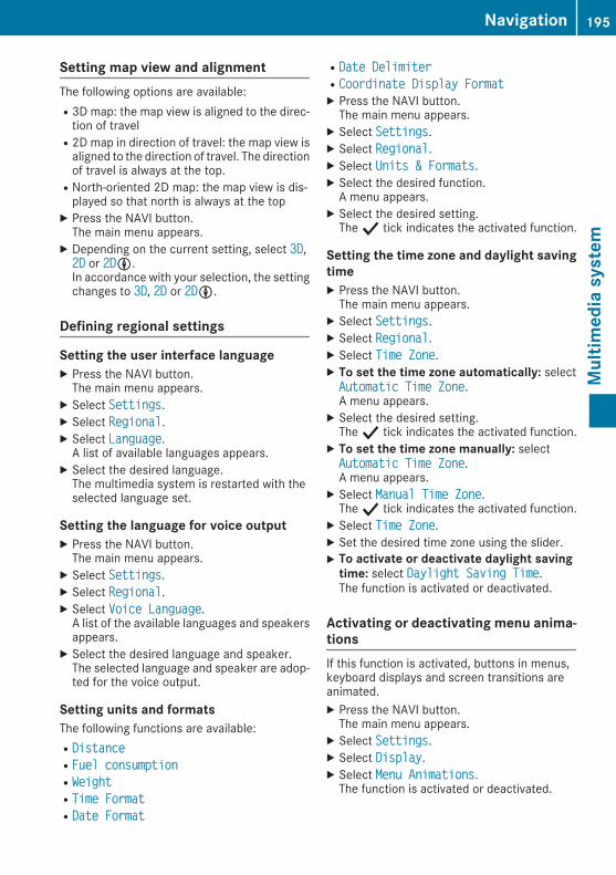
Setting map view and alignmentThe following options are available:R3D map: the map view is aligned to the direc-tion of travelR2D map in direction of travel: the map view isaligned to the direction of travel. The directionof travel is always at the top.RNorth-oriented 2D map: the map view is dis-played so that north is always at the top
X Press the NAVI button.The main menu appears.
X Depending on the current setting, select 3D3D,2D2D or 2D2DLL.In accordance with your selection, the settingchanges to 3D3D, 2D2D or 2D2DLL.
Defining regional settings
Setting the user interface languageX Press the NAVI button.The main menu appears.
X Select SettingsSettings.X Select RegionalRegional.X Select LanguageLanguage.A list of available languages appears.
X Select the desired language.The multimedia system is restarted with theselected language set.
Setting the language for voice outputX Press the NAVI button.The main menu appears.
X Select SettingsSettings.X Select RegionalRegional.X Select Voice LanguageVoice Language.A list of the available languages and speakersappears.
X Select the desired language and speaker.The selected language and speaker are adop-ted for the voice output.
Setting units and formatsThe following functions are available:RDistanceDistanceRFuel consumptionFuel consumptionRWeightWeightRTime FormatTime FormatRDate FormatDate Format
RDate DelimiterDate DelimiterRCoordinate Display FormatCoordinate Display FormatX Press the NAVI button.The main menu appears.
X Select SettingsSettings.X Select RegionalRegional.X Select Units & FormatsUnits & Formats.X Select the desired function.A menu appears.
X Select the desired setting.The Y tick indicates the activated function.
Setting the time zone and daylight savingtimeX Press the NAVI button.The main menu appears.
X Select SettingsSettings.X Select RegionalRegional.X Select Time ZoneTime Zone.X To set the time zone automatically: selectAutomatic Time ZoneAutomatic Time Zone.A menu appears.
X Select the desired setting.The Y tick indicates the activated function.
X To set the time zone manually: selectAutomatic Time ZoneAutomatic Time Zone.A menu appears.
X Select Manual Time ZoneManual Time Zone.The Y tick indicates the activated function.
X Select Time ZoneTime Zone.X Set the desired time zone using the slider.X To activate or deactivate daylight savingtime: select Daylight Saving TimeDaylight Saving Time.The function is activated or deactivated.
Activating or deactivating menu anima-tionsIf this function is activated, buttons in menus,keyboard displays and screen transitions areanimated.X Press the NAVI button.The main menu appears.
X Select SettingsSettings.X Select DisplayDisplay.X Select Menu AnimationsMenu Animations.The function is activated or deactivated.
Navigation 195
Multim
ediasystem
Z

Defining the traffic settings
Traffic events/real-time traffic events(TMC)The Traffic Message Channel (TMC) providesreal-time traffic reports. The multimedia systemreceives TMC traffic event messages, which aretaken into consideration for traffic-dependentroute guidance. Traffic event messages are acti-vated by default.
i TMC is not available in all regions and coun-tries.
If there are traffic events on the route, the mul-timedia system issues a message and recalcu-lates the route.
Activating or deactivating traffic eventmessage receptionIf the TMC receiver is switched on, traffic eventmessages are received.X Press the NAVI button.The main menu appears.
X Select SettingsSettings.X Select TrafficTraffic.X Select TrafficTraffic.The function is activated or deactivated.
Selecting the data source for real-timetraffic event messagesThis function is available if the TMC receiver isswitched on.X Press the NAVI button.The main menu appears.
X Select SettingsSettings.X Select TrafficTraffic.X Select Data SourceData Source.A menu appears.
X Select the desired data source.The Y tick indicates the activated function.
Activating or deactivating real-time trafficevent messagesX Press the NAVI button.The main menu appears.
X Select SettingsSettings.X Select TrafficTraffic.X Select Use Real-time TrafficUse Real-time Traffic.The function is activated or deactivated.
Activating or deactivating the "Show traf-fic info" functionX Press the NAVI button.The main menu appears.
X Select SettingsSettings.X Select TrafficTraffic.X Select Show Traffic InfoShow Traffic Info.A menu appears.
X Select the desired setting.The Y tick indicates the activated function.
Activating or deactivating the "Show freetraffic flow" functionX Press the NAVI button.The main menu appears.
X Select SettingsSettings.X Select TrafficTraffic.X Select ShowShow FreeFree TrafficTraffic FlowFlow AsAs WellWell.The function is activated or deactivated.
Activating or deactivating the "Use his-torical traffic" functionX Press the NAVI button.The main menu appears.
X Select SettingsSettings.X Select TrafficTraffic.X Select Use Historical TrafficUse Historical Traffic.The function is activated or deactivated.
Setting the "Time saving" function whenrecalculating a routeYou can specify aminimumamount of time to besaved before the multimedia system calculatesa new route, when there are traffic events on thecurrent route.X Press the NAVI button.The main menu appears.
X Select SettingsSettings.X Select TrafficTraffic.X Select Offer detour if it saves atOffer detour if it saves atleast:least:.A menu appears.
X Set the minimum amount of time to be saved.
Activating or deactivating the "Confirmdetours manually" functionIf this function is activated, the multimedia sys-tems will prompt you to confirm the actionbefore recalculating the route.
196 NavigationMultim
ediasystem

X Press the NAVI button.The main menu appears.
X Select SettingsSettings.X Select TrafficTraffic.X Select Confirm Detours ManuallyConfirm Detours Manually.The function is activated or deactivated.
Defining the trip monitor settingsThe following functions are available:REnableEnable auto-savingauto-saving: if this function is acti-vated, the multimedia system saves statistictrip dataRSaveSave TrackTrack LogLog: if this function is activated,the multimedia system saves track logs forthe route
X Press the NAVI button.The main menu appears.
X Select SettingsSettings.X Select Trip MonitorTrip Monitor.X To activate or deactivate the "Enableauto-saving" function: select EnableEnableauto-savingauto-saving.The function is activated or deactivated.
X To activate or deactivate the "Save tracklog" function: select Save Track LogSave Track Log.The function is activated or deactivated.
Starting the configuration wizardX Press the NAVI button.The main menu appears.
X Select SettingsSettings.X Select Start Configuration WizardStart Configuration Wizard.The Configuration Wizard starts and guidesyou through configuration.
Updating the digital mapThe digital maps generated by themap softwarebecome outdated in the same way as conven-tional road maps. Optimal route guidance canonly be provided by the navigation system inconjunction with the most up-to-date map soft-ware. You can update the digital map. Findmoreinformation on updating at: http://www.kraemerautomotive.com/mercedesg350dprofessional/update
Navigation 197
Multim
ediasystem
Z

Loading guidelines
G WARNINGIf objects, luggage or loads are not secured ornot secured sufficiently, they could slip, tipover or be flung around and thereby hit vehicleoccupants. There is a risk of injury, especiallywhen braking or abruptly changing directions.Always store objects so that they cannot beflung around. Secure objects, luggage orloads against slipping or tipping before thejourney.
G WARNINGIf you load the vehicle unevenly, driving char-acteristics such as steering and brakingbehaviour may be severely impaired. There isa risk of an accident.Load the vehicle evenly. Secure the load sothat it cannot slip.
G WARNINGThe exhaust tail pipe and tail pipe trim canbecome very hot. If you come into contactwith these parts of the vehicle, you could burnyourself. There is a risk of injury.Always be particularly careful around theexhaust tail pipe and the tail pipe trim. Allowthese components to cool down before touch-ing them.
G WARNINGCombustion engines emit poisonous exhaustgases such as carbon monoxide. If the reardoor is open when the engine is running, par-ticularly if the vehicle is moving, exhaustfumes could enter the passenger compart-ment. There is a risk of poisoning.Turn off the engine before opening the reardoor. Never drive with the rear door open.
Driving, braking and steering characteristicschange depending on:Rtype of loadRweightRthe centre of gravity of the loadYou should therefore load your vehicle as shownin the illustrations.Observe the following notes when transportinga load:Rnever exceed themaximumpermissible grossvehicle weight or the permissible axle loadsfor the vehicle (including occupants).Rposition heavy loads as far forwards as pos-sible and as low down in the luggage com-partment as possible.Rthe load must not protrude above the upperedge of the seat backrests.Ralways place the load against the backrests ofthe front seats or rear seats.Ralways place the load behind unoccupiedseats if possible.Rif possible, always transport the load in theload compartment with the seat backrestsfolded up and engaged.Ruse the lashing eyelets and the luggage netsto transport loads and luggage.Ronly use lashing eyelets and fastening com-ponents that are suitable for the weight andsize of the load.
198 Loading guidelinesStow
ingandfeatures

If the rear bench seat is not occupied:X Insert the belt tongues into buckles: of theopposite seat belt in a diagonal pattern.
X Secure the load with sufficiently tear-resist-ant and wear-resistant lashing material.
X Pad any sharp edges.Lashing material that has been checked inaccordance with applicable standards is availa-ble at any qualified specialist workshop.
Stowage areas
Stowage compartments
Important safety notes
G WARNINGIf you transport objects in the vehicle interiorand these are not adequately secured, theycould slip or be flung around and therebystrike vehicle occupants. In addition, cupholders, open stowage spaces and mobilephone brackets may not always be able tohold the objects placed in them in the event ofan accident. There is a risk of injury, particu-larly in the event of sharp braking or suddenchanges of direction.RAlways stow objects in such a way that theycannot be tossed about in these or similarsituations.RAlways make sure that objects do not proj-ect from stowage spaces, luggage nets orstowage nets.
REnsure that closable stowage spaces areshut before beginning your journey.RAlways stow and secure heavy, hard, poin-ted, sharp-edged, fragile or outsize objectsin the load compartment.
Observe the loading guidelines (Y page 198).
Front stowage compartments
Glove compartment
X To open: pull handle: and open glove com-partment flap;.
X To close: fold glove compartment flap;upwards until it engages.
1 Glove compartment unlocked2 Glove compartment lockedX To lock: insert the emergency key elementinto the lock (Y page 58) and turn it 90°clockwise to position2.
X To unlock: insert the emergency key elementinto the lock (Y page 58) and turn it 90° anti-clockwise to position1.
The glove compartment can only be locked andunlocked using the emergency key element.
Stowage areas 199
Stow
ingandfeatures
Z

Door stowage compartment
: Door stowage compartmentThere is an additional compartment located onthe driver's door trim.
Stowage compartment under the armrestand in the centre console
: Small stowage compartment; Release button for the armrestX To open: press release button;.X Fold armrest upwards.X To close: fold armrest downwards.The armrest engages audibly.
Rear stowage compartments
Map pockets
: Map pockets
Stowage netsThe following additional stowage areas are avail-able in the vehicle:Rstowage net in the front-passenger footwellRmap pockets on the back of the driver's andfront-passenger seatRstowage net on the left-hand side in the lug-gage compartment
Observe the loading guidelines (Y page 198)and the safety notes regarding stowage spaces(Y page 199).
Enlarging the luggage compartment
Important safety notes
G WARNINGIf the rear bench seat/rear seat and seatbackrest are not engaged they could fold for-wards, e.g. when braking suddenly or in theevent of an accident.RThe vehicle occupant would thereby bepushed into the seat belt by the rear benchseat/rear seat or by the seat backrest. Theseat belt cannot protect as intended andcould result in additional injury.RObjects or loads in the boot/luggage com-partment cannot be restrained by the seatbackrest.
This poses an increased risk of injury.
200 Stowage areasStow
ingandfeatures

Before every trip, make sure that the seatbackrests and the rear bench seat/rear seatare engaged before every trip.
G WARNINGCombustion engines emit poisonous exhaustgases such as carbon monoxide. If the reardoor is open when the engine is running, par-ticularly if the vehicle is moving, exhaustfumes could enter the passenger compart-ment. There is a risk of poisoning.Turn off the engine before opening the reardoor. Never drive with the rear door open.
Observe the loading guidelines (Y page 198).The left-hand and right-hand rear bench seatscan be folded forward to increase the capacityof the rear compartment. You can:Rfold the seat backrests forwardRfold the rear bench seat completely forward
Folding the seat backrest forwards
X Remove the head restraints (Y page 70).Head restraints may be removed and stowed,e.g. in the luggage compartment. Store headrestrains so that they cannot be flung around.
X Pull release: in the direction of the arrow.The corresponding seat backrest is released.
X Fold the backrest forwards.
; Seat backrest folded forwards
Folding back the seat backrest! Make sure that the seat belt does notbecome trapped when folding the rear seatbackrest back. Otherwise, it could be dam-aged.
X Pull release lever:.The corresponding seat backrest is released.
X Fold seat backrest; back in the direction ofthe arrow until it engages.
X Fit the head restraints (Y page 70).
Stowage areas 201
Stow
ingandfeatures
Z

Rear bench seat
Folding the rear bench seat forwards
X Fold the backrest forwards (Y page 201).X Pull the release in the direction of arrow:.The corresponding rear bench seat isreleased.
X Fold rear bench seat; forwards.
; Rear bench seat folded forwards
Folding the rear bench seat into anupright positionG WARNINGIf the rear bench seat/rear seat and seatbackrest are not engaged they could fold for-wards, e.g. when braking suddenly or in theevent of an accident.RThe vehicle occupant would thereby bepushed into the seat belt by the rear benchseat/rear seat or by the seat backrest. Theseat belt cannot protect as intended andcould result in additional injury.RObjects or loads in the boot/luggage com-partment cannot be restrained by the seatbackrest.
This poses an increased risk of injury.Before every trip, make sure that the seatbackrests and the rear bench seat/rear seatare engaged before every trip.
X Fold the rear bench seat back.The seat catch engages audibly.
X Fold the backrest backwards (Y page 201).X Fit the head restraints (Y page 70).
Securing a load
Important safety notesDistribute the load on the lashing eyelets evenly.Do not tamper with or repair lashing points,lashing eyelets or lashing material. Have main-tenance work as well as modifications, installa-tions and conversions carried out at a qualifiedspecialist workshop (Y page 23).Observe the following notes on securing loads:RObserve the loading guidelines (Y page 198).RSecure the load using the lashing eyelets.RDistribute the load on the lashing eyeletsevenly.RDo not use elastic straps or nets to secure aload. These are only intended as anti-slip pro-tection for light loads.RUse only lashing material with a minimumtensile strength of Fperm = 600 daN and anelongation of approximately 7%.RDo not route lashing materials across sharpedges or corners.RPad sharp edges for protection.ROnly use lashing material that has beenchecked in accordance with applicable stand-ards, e.g. lashing nets or lashing straps.RFill the spaces between the load and the loadcompartment walls and the wheel mountingsin a form-locking way. Only use dimensionallystable transportation aids for this, such aschocks, wooden fixings or padding.
202 Stowage areasStow
ingandfeatures

Lashing eyelets in the luggage compart-ment
: Lashing eyelets in the luggage compartment
Securing rails in thewood luggage-com-partment floor
Using themounting elements, additional lashingeyelets or installations available in the accesso-ries can be secured in various positions to thewood floor in the luggage compartment. Themounting elements are enclosed with the vehi-cle documents.X To fit the mounting element: insert mount-ing element; into securing rail= in thedirection of the arrow.
X Move mounting element; into the desiredposition.
X Tighten cap nut: of the mounting element.Mounting element; is attached.
Luggage compartment cover
Important safety notes
G WARNINGOn its own, the luggage compartment covercannot secure or restrain heavy objects,items of luggage and heavy loads. You couldbe hit by an unsecured load during suddenchanges in direction, braking or in the event ofan accident. There is an increased risk ofinjury or even fatal injury.Always store objects so that they cannot beflung around. Secure objects, luggage orloads against slipping or tipping over, e.g. byusing lashing material, even if you are usingthe luggage compartment cover.
! When loading the vehicle, make sure thatyou do not stack the load in the luggage com-partment higher than the lower edge of theside windows. Do not place heavy objects ontop of the luggage compartment cover.
The luggage compartment cover is securedbehind the rear bench seat backrest.
Opening and closing the luggage com-partment cover
X To open: pull luggage compartment cover:back and clip it into the retainers on the leftand right of the rear door.
X To close: unclip luggage compartmentcover: and guide it forwards until it is com-pletely rolled up.
Luggage compartment cover: consists of tworoller blinds. You can cover the entire luggagecompartment even if the rear bench seat is fol-ded down.
Stowage areas 203
Stow
ingandfeatures
Z

Fitting/removing the luggage compart-ment cover
X To remove:make sure that luggage compart-ment cover; is rolled up.
X Slide catch: on both sides to the centre ofthe vehicle.
X Swing luggage compartment cover;upwards.
X To fit: slide catches: to the centre of thevehicle.
X Insert luggage compartment cover; into therecesses of the side trim panel.
X Press the left- and right-hand side of luggagecompartment cover; downward until theluggage compartment cover engages.
X Slide catches: towards the side trim panel.
Safety net
Important safety notes
G WARNINGOn its own, the safety net cannot secure orrestrain heavy objects, items of luggage andheavy loads. You could be hit by an unsecuredload during sudden changes in direction,braking or in the event of an accident. There isan increased risk of injury or even fatal injury.Always store objects so that they cannot beflung around. Secure objects, luggage orloads against slipping or tipping over, e.g. byusing lashing material, even if you are usingthe safety net.
It is important to use a safety net if you load thevehicle with small objects above the seat backr-
ests. For safety reasons, always use a safety netwhen transporting a load.Damaged safety nets can no longer fulfil theirprotective function andmust be replaced. Visit aqualified specialist workshop.
Safety net without luggage compart-ment enlargement
X Open the rear door.X Fold the rear bench seat forward, withoutfolding the seat backrest forward beforehand(Y page 202).
X Hook safety net: into retainers; on bothsides.
X Tensioning buckles= of tensioningstraps?must point in the direction of travel.
X Set tensioning straps? to the length forlashing eyeletsB using tensioning buckles=.
204 Stowage areasStow
ingandfeatures

X Engage hooksA in lashing eyeletsB.X Pull the loose ends of tensioning straps? totension the safety net.
X Fold the rear bench seat forward into anupright position (Y page 202).The safety net is tensioned by the rear benchseat.
X After driving a short distance, check the ten-sion of the safety net and retighten it if nec-essary.
Safety net with luggage compartmentenlargement
X Fold the rear bench seat forward(Y page 202).
X Hook safety net: into retainers; on bothsides.
X Set tensioning straps? to the length forlashing eyeletsB using tensioning buckles=.Tensioning buckles= of tensioningstraps? must point in the direction of theluggage compartment.
X Engage hooksA in lashing eyeletsB.X Pull the loose ends of tensioning straps?tight, until the safety net is adequately ten-sioned.
X After driving a short distance, check the ten-sion of the safety net and retighten it if nec-essary.
Stowage areas 205
Stow
ingandfeatures
Z

Releasing the safety net
Safety net attachment (example: with luggagecompartment enlargement)X Raise tensioning buckles= into the horizon-tal position.Tensioning straps? are loosened.
X Unhook hookA from lashing eyeletsB.
Unhooking the safety netX Unhook safety net: from bracket;.
Storing the safety netX Roll up the safety net and secure it using theVelcro strips included.
X Place the safety net behind the rear benchseat.
Roof carrier
Important safety notes
G WARNINGWhen a load is transported on the roof, thevehicle's centre of gravity rises and the han-dling changes. If you exceed the maximumroof load, the handling as well as steering andbraking characteristics are severely affected.There is a risk of an accident.Always observe the maximum roof load andadapt your driving style.
! Mercedes-Benz recommends that you onlyuse roof carriers that have been tested andapproved for Mercedes-Benz vehicles. Thishelps to prevent damage to the vehicle.
Position the load on the roof carrier in such away that the vehicle will not sustain damageeven when it is in motion.Make sure that the sliding sunroof can be fullyraised, depending on the vehicle's equip-ment.
If the vehicle is not fitted with a roof carrier atthe factory, always observe the roof carrierman-ufacturer's installation instructions. An incor-rectly secured roof carrier or roof load maybecome detached from the vehicle.
Roof carrier with a ladder
If the vehicle has a roof carrier: fitted at thefactory, the roof carrier may be walked on forloading and unloading. The maximum permissi-ble roof load of 150 kg may be exceeded by amaximum of 90 kg for loading and unloading.Use step= on the rear bumper and ladder;on the right-hand side of the rear of the vehiclewhen ascending and descending. The laddercan bear a maximum load of 90 kg.Pay particular attention. Please note that dirt,rain, ice or snow reduce the safety of your foot-ing.For safety reasons, only have the roof carrierand ladder removed and fitted at a qualifiedspecialist workshop.
Features
Cup holders
Important safety notes
G WARNINGIf you transport objects in the vehicle interiorand these are not adequately secured, they
206 FeaturesStow
ingandfeatures

could slip or be flung around and therebystrike vehicle occupants. In addition, cupholders, open stowage spaces and mobilephone brackets may not always be able tohold the objects placed in them in the event ofan accident. There is a risk of injury, particu-larly in the event of sharp braking or suddenchanges of direction.RAlways stow objects in such a way that theycannot be tossed about in these or similarsituations.RAlways make sure that objects do not proj-ect from stowage spaces, luggage nets orstowage nets.REnsure that closable stowage spaces areshut before beginning your journey.RAlways stow and secure heavy, hard, poin-ted, sharp-edged, fragile or outsize objectsin the load compartment.
G WARNINGThe cup holder cannot secure a drinks con-tainer in place during a journey. If you use acup holder during a journey, the drinks con-tainer could be flung around and liquid couldbe spilt. Vehicle occupants could come intocontact with the liquid and, in particular, bescalded by hot liquid. You could be distractedfrom the traffic situation and lose control ofthe vehicle. There is a risk of an accident andinjury.Only use the cup holder when the vehicle isstationary. Only place containers of a suitablesize in the cup holder. Seal the container, inparticular when it contains hot liquid.
! Only use the cup holders for containers ofthe right size and which have lids. The drinkscould otherwise spill.
Observe the loading guidelines (Y page 198).
Cup holders in the glove compartment
X Open the glove compartment (Y page 199).
Sun visors
Overview
: Sun visor; Retainer= Mirror cover? Mirror lights
Features 207
Stow
ingandfeatures
Z

Vanity mirror in the sun visor
: Sun visor; Retainer= Mirror cover? Mirror lightsMirror lights? will only function if sun visor:is clipped into retainer;.X Fold down sun visor:.X Fold up mirror cover=.Mirror lights? are switched on automati-cally.
Glare from the side
: Sun visor; Retainer= Mirror cover? Mirror lightsX Fold down sun visor:.X Pull sun visor: out of retainer;.X Swing sun visor: to the side.
Stowage compartment/ashtray
Stowage compartment/ashtray in thecentre console
G WARNINGIf you engage transmission position D whenremoving the ashtray insert, the vehicle canroll away. There is a risk of an accident.Always switch off the engine first and safe-guard the vehicle against rolling away byapplying the parking brake.
: Cover; InsertOn new vehicles, insert; is stored in the glovecompartment. Fit the insert before using theashtray.X To open: press cover: and then release it.The ashtray opens.
X To remove the insert:make sure that theengine is switched off and that the parkingbrake has been applied to safeguard the vehi-cle against rolling away.
X Move the selector lever toi.X Press cover: downwards.Insert; is released.
X Pull insert; upwards and remove it.X To refit the insert: replace insert; fromabove.
X Press insert; downwards.Insert; audibly engages.
X To close: fold down cover: completely.If the dipped-beam headlamps are switched on,the ashtray is illuminated.
208 FeaturesStow
ingandfeatures

Cigarette lighter
G WARNINGYou can burn yourself if you touch the hotheating element or the socket of the cigarettelighter.In addition, flammable materials can ignite if:Rthe hot cigarette lighter fallsRa child holds the hot cigarette lighter toobjects, for example
There is a risk of fire and injury.Always hold the cigarette lighter by the knob.Always make sure that the cigarette lighter isout of reach of children. Never leave childrenunattended in the vehicle.
X Press in cigarette lighter:.Cigarette lighter:will pop out automaticallywhen the heating element is red-hot.
You can use the cigarette lighter socket foraccessories up to 180 W (Y page 209).
12 V sockets
General notes! If you are simultaneously using all threesockets in the vehicle, make sure that you donot exceed the maximum current draw of45 A. Otherwise, you will overload the fuses.
The sockets can be used for accessories with amaximum current draw of 180 W (15 A) each,e.g. chargers for mobile phones.If you use the sockets for long periods when theengine is switched off, the battery may dis-charge.
X Turn the key to position2 in the ignitionlock.
Socket in the front-passenger footwell
X Lift up the cover of the socket.The cigarette lighter socket can be also used(Y page 209). It can also be used if the key hasbeen removed from the ignition lock.
Socket in the rear compartment
X Lift up the cover of the socket.
Socket in the luggage compartment
Features 209
Stow
ingandfeatures
Z

The socket is located in the luggage compart-ment on the left-hand-side when viewed in thedirection of travel, next to the rear door.X Lift up the cover of the socket.
Assembly tool
General notes
Assembly tool: on the vehicle key ring makesscrewing and unscrewing the aerial on the rightwing easier.
Removing/fastening the aerial
X To unscrew the aerial: place assemblytool: on aerial;.
X Use assembly tool: to unscrew aerial;.X Remove assembly tool: from aerial;.X Unscrew aerial; from the aerial base byhand to the left.
X To tighten the aerial: screw the aerial intothe aerial base by hand to the right.
X Place assembly tool: on aerial;.X Using assembly tool:, tighten aerial; byturning it clockwise.
X Remove assembly tool: from aerial;.
WinchOnly vehicles with a front bumper made of steelare suitable and prepared for the installation ofa winch.For safety reasons, Mercedes-Benz recom-mends that you have retrofitting of a winch car-ried out at a qualified specialist workshop. Youcan obtain further information from aMercedes-Benz Service Centre.
: Holes for the installation of a winch
210 FeaturesStow
ingandfeatures

Engine compartment
Bonnet
Important safety notes
G WARNINGAn unlocked bonnet may open up when thevehicle is inmotion and block your view. Thereis a risk of an accident.Never unlock the bonnet when driving. Beforeevery trip, ensure that the bonnet is locked.
G WARNINGWhen being opened and closed, the bonnetmay suddenly fall into the closed position.There is a risk of injury to persons in the rangeof movement of the bonnet.Open and close the bonnet only when nobodyis in the range of movement.
G WARNINGIf you open the bonnet while the engine isoverheating or while there is a fire in theengine compartment, you could come intocontact with hot gases or other leaking ser-vice products. There is a danger of injury.Allow an overheating engine to cool downbefore opening the bonnet. If there is a fire inthe engine compartment, leave the bonnetclosed and notify the fire brigade.
G WARNINGThe ignition system and the fuel injection sys-tem operate with a high voltage. If you touchthe live components, you could receive anelectric shock. There is a danger of injury.Never touch components of the ignition sys-tem or the fuel injection system when theignition is switched on.
G WARNINGThere are moving components in the enginecompartment. Certain components may con-tinue to move or suddenly move again evenafter the ignition has been switched off, e.g.the radiator fan. There is a risk of injury.
If you have to carry out work in the enginecompartment:Rswitch off the ignitionRnever touch the dangerous areas surround-ing moving components, e.g. the rotationarea of the fanRremove jewellery and watchesRkeep items of clothing and hair, for exam-ple, away from moving parts.
Do not touch the diagnostics socket when theignition is switched on.
Opening the bonnet
G WARNINGCertain components in the engine compart-ment could be very hot, e.g. the engine, theradiator and parts of the exhaust system.There is a risk of injury when accessing theengine compartment.As far as possible, allow the engine to cooldown and only touch the components descri-bed in the following.
G WARNINGWhen the bonnet is open, and the windscreenwipers are set inmotion, you can be injured bythe wiper linkage. There is a risk of injury.Always switch off the windscreen wipers andthe ignition before opening the bonnet.
! Make sure that the windscreen wipers arenot folded away from the windscreen. Other-wise, you could damage the windscreen wip-ers or the bonnet.
Engine compartment 211
Maintenance
andcare
Z

The bonnet release lever is in the footwell on theleft-hand side of the vehicle when viewed in thedirection of travel.X Make sure that the windscreen wipers areswitched off.
X Pull bonnet release lever:.The bonnet is released.
X Lift the bonnet slightly.X Push bonnet catch; in the direction of thearrow and lift the bonnet.The bonnet is opened and held open auto-matically by the gas-filled strut.
Closing the bonnetX Lower the bonnet and let it fall from a heightof approximately 20 cm.
X Check that the bonnet has engaged properly.If the bonnet can be raised slightly, it is notproperly engaged. Open it again and close itwith a little more force.
RadiatorDo not cover up the radiator. Do not use thermalmats, insect protection covers or anything sim-ilar. Otherwise, the values of the European on-board diagnostics may be affected. Some ofthese values are required by law and mustalways be correct.
Engine oil
Important safety notes
G WARNINGCertain components in the engine compart-ment could be very hot, e.g. the engine, the
radiator and parts of the exhaust system.There is a risk of injury when accessing theengine compartment.As far as possible, allow the engine to cooldown and only touch the components descri-bed in the following.
G WARNINGThere are moving components in the enginecompartment. Certain components may con-tinue to move or suddenly move again evenafter the ignition has been switched off, e.g.the radiator fan. There is a risk of injury.If you have to carry out work in the enginecompartment:Rswitch off the ignitionRnever touch the dangerous areas surround-ing moving components, e.g. the rotationarea of the fanRremove jewellery and watchesRkeep items of clothing and hair, for exam-ple, away from moving parts.
G WARNINGIf engine oil comes into contact with hot com-ponents in the engine compartment, it mayignite. There is a risk of fire and injury.Make sure that engine oil does not spill outover the filler neck. Allow the engine to cooldown and thoroughly clean the componentsthat have come into contact with engine oilbefore you start the engine.
G WARNINGIf you open the bonnet while the engine isoverheating or while there is a fire in theengine compartment, you could come intocontact with hot gases or other leaking ser-vice products. There is a danger of injury.Allow an overheating engine to cool downbefore opening the bonnet. If there is a fire inthe engine compartment, leave the bonnetclosed and notify the fire brigade.
212 Engine compartmentMaintenance
andcare

Notes on oil levelDepending on your driving style, the vehicleconsumes up to 0.8 litres of oil per 1,000 km.The oil consumption may be higher than thiswhen the vehicle is new or if you frequently driveat high engine speeds.To check the oil level:Rpark the vehicle on a level surfaceRthe engine should be switched off for approx-imately five minutes if the engine is at normaloperating temperatureRif the engine is not at normal operating tem-perature, e.g. if the engine was only startedbriefly, wait approximately 30 minutes beforecarrying out the measurement
Checking the oil level using the oil dip-stick
X Pull dipstick: out of the dipstick tube.X Wipe off dipstick:.X Slowly slide oil dipstick: into the guide tubeto the stop and take it out again after approx-imately three seconds.If the level is between MIN mark= and MAXmark;, the oil level is correct.
X If the oil level has dropped to MIN mark= orbelow, top up with 1.0 l of engine oil.
Checking the oil level using the on-board computerX Make sure that the key is in position2 in theignition lock.
X Press9 or: on the steering wheel toselect the following message: Engine oilEngine oillevel Measuring now Measurementlevel Measuring now Measurementaccurate only if vehicle is levelaccurate only if vehicle is level
The measurement takes a few seconds. You willsee one of the following messages in the multi-function display:REngine oil level OKEngine oil level OKRAdd 1.1 litres eng. oil when nextAdd 1.1 litres eng. oil when nextrefuellingrefuellingX Top up the oil if necessary.If the engine is at normal operating temperatureand the Engine oil Reduce oil levelEngine oil Reduce oil level dis-play appears, too much oil has been added.X Have excess oil siphoned off.If the Switch ignition on to checkSwitch ignition on to checkengine oil levelengine oil level message appears:X Turn the key to position2 in the ignition lock(Y page 96).
If the Waiting period for engine oilWaiting period for engine oillevel not observedlevel not observed message appears:X If the engine is at normal operating tem-perature: repeat the measurement afterapproximately five minutes.
X If the engine is not at normal operatingtemperature: e.g. if the engine was only star-ted briefly, repeat the measurement afterapproximately 30 minutes.
If the Engine oil level Not when engineEngine oil level Not when engineonon message appears:X Switch off the engine.X If the engine is at normal operating tem-perature:wait approximately five minutesbefore carrying out the measurement.
X If the engine is not at normal operatingtemperature: e.g. if the engine was only star-ted briefly, wait approximately 30 minutesbefore carrying out the measurement.
If you wish to cancel the measurement, pressthe9 or: button on the multifunctionsteering wheel.
Topping up engine oil! Use only engine oils and oil filters that areapproved for vehicleswith a service system. Alist of the engine oils and oil filters that havebeen tested and approved in accordance withMercedes-Benz Specifications for ServiceProducts is available at any Mercedes-BenzService Centre.
Engine compartment 213
Maintenance
andcare
Z

The following cause engine failure or damageto the exhaust system:RUse of engine oils and oil filters that havenot been expressly approved for the servicesystemRReplacement of engine oil and oil filter afterthe replacement interval specified by theservice system has expiredRUse of engine oil additives
! Do not add too much oil. If the oil level isabove the "max" mark on the dipstick, toomuch oil has been added. This can lead todamage to the engine or the catalytic con-verter. Have excess oil siphoned off.
H Environmental noteWhen topping up the oil, take care not to spillany. If oil enters the soil or waterways, it isharmful to the environment.
X Turn cap: anti-clockwise and remove it.X Top upwith the amount of engine oil required.Observe the specifications in the on-board com-puter when doing so or fill carefully to the max-imum mark on the oil dipstick.The difference between the minimum mark andthe maximummark on the oil dipstick is approx-imately 2.0 litres.X Replace cap: on the filler neck and turnclockwise.Make sure that the cap locks securely intoplace.
For further information on engine oil, see(Y page 252).
Other service products
Important safety notes
G WARNINGCertain components in the engine compart-ment could be very hot, e.g. the engine, theradiator and parts of the exhaust system.There is a risk of injury when accessing theengine compartment.As far as possible, allow the engine to cooldown and only touch the components descri-bed in the following.
G WARNINGThere are moving components in the enginecompartment. Certain components may con-tinue to move or suddenly move again evenafter the ignition has been switched off, e.g.the radiator fan. There is a risk of injury.If you have to carry out work in the enginecompartment:Rswitch off the ignitionRnever touch the dangerous areas surround-ing moving components, e.g. the rotationarea of the fanRremove jewellery and watchesRkeep items of clothing and hair, for exam-ple, away from moving parts.
G WARNINGThe cooling system is pressurised, particu-larly when the engine is warm. If you open thecap, you could be scalded if hot coolantsprays out. There is a risk of injury.Let the engine cool down before you open thecap. Wear gloves and eye protection. Openthe cap slowly to release the pressure.
G WARNINGIf you open the bonnet while the engine isoverheating or while there is a fire in theengine compartment, you could come intocontact with hot gases or other leaking ser-vice products. There is a danger of injury.
214 Engine compartmentMaintenance
andcare

Allow an overheating engine to cool downbefore opening the bonnet. If there is a fire inthe engine compartment, leave the bonnetclosed and notify the fire brigade.
Checking the coolant level
Example: checking the coolant levelX Park the vehicle on a level surface.Check the coolant level only if the vehicle ison a level surface and the engine has cooleddown.
X Turn the key to position2 in the ignition lock(Y page 96).
X Check the coolant temperature display in theinstrument cluster.The coolant temperature must be below70 †.
X Slowly turn cap: half a turn anti-clockwiseand allow excess pressure to escape.
X Turn cap: further anti-clockwise andremove it.If the coolant is at the level of marker bar=in the filler neck when cold, there is enoughcoolant in coolant expansion tank;.If the coolant level is approximately 1.5 cmabove marker bar= in the filler neck whenwarm, there is enough coolant in coolantexpansion tank;.
X If necessary, top up with coolant that hasbeen tested and approved byMercedes-Benz.
X Replace cap: and turn it clockwise as far asit will go.
Further information on coolant (Y page 253).
Topping up the windscreen washer sys-tem/headlamp cleaning system
G WARNINGIf windscreen washer concentrate comes intocontact with hot components of the engine orthe exhaust system, it can ignite. There is arisk of fire and injury.Make sure the windscreen washer concen-trate does not come into contact with the fillerneck.
Example: topping up the windscreen washersystem
X To open: pull cap: upwards by the tab andopen.
X Top up with the premixed washer fluid.X To close: press cap: onto the filler neckuntil it engages.
The washer fluid reservoir is used for both thewindscreen washer system and the headlampcleaning system.If the washer fluid level drops below the recom-mended minimum of 3.5 litres, a messageappears in the multifunction display promptingyou to top up the washer fluid (Y page 154).Further information on washer fluid(Y page 254).
Service
ASSYST service interval display
Service messagesYou can obtain up-to-date information concern-ing the servicing of your vehicle from a qualifiedspecialist workshop, e.g. a Mercedes-Benz Ser-vice Centre.
Service 215
Maintenance
andcare
Z

The ASSYST service interval display informs youof the next service due date.If a service due date has been exceeded, youalso hear a warning tone.The multifunction display shows a service mes-sage for a few seconds, e.g.:Service A in 999,999 kmService A in 999,999 kmService A in .. daysService A in .. daysService A dueService A dueService A overdue by 999,999 kmService A overdue by 999,999 kmService A overdue by .. daysService A overdue by .. daysMaintaining the time-dependent service sched-ule:X Call up and note down the service due datebefore disconnecting the battery.
orX After reconnecting the battery, subtract thebattery disconnection periods from the ser-vice date shown on the display.
The symbol and the letter indicate which type ofservice is due:¯ Minor service AA± Major service BBThe ASSYST service interval display does nottake into account any periods of time duringwhich the battery is connected.
Hiding service messagesX To hide the service message, press the%back button on the multifunction steeringwheel (Y page 132).
Displaying service messagesUse the buttons on the multifunction steeringwheel.X Switch the ignition on.X Press= or; to select the standarddisplay menu on the steering wheel(Y page 133).
X Press9 or: to select the ASSYST ser-vice interval display.The¯ or± service symbol and the ser-vice due date are displayed.
Special service requirementsThe prescribed service interval is based on nor-mal operation of the vehicle. Service work willneed to be performedmore often if the vehicle isoperated under arduous conditions or increasedloads, for example:Rregular city drivingwith frequent intermediatestopsRif the vehicle is primarily used to travel shortdistancesRfor frequent operation in mountainous terrainor on poor road surfacesRif the engine is often left idling for long periodsIn these or similar operating conditions, have,for example, the air filter, engine oil and oil filterchanged more frequently. The tyres must bechecked more frequently if the vehicle is oper-ated under increased loads. Further informationcan be obtained at a qualified specialist work-shop, e.g. a Mercedes-Benz Service Centre.
Fuel/water separator! If you continue driving without having thefuel/water separator serviced, this couldcause damage to the engine. Any resultingdamage is not covered by the warranty.
H Environmental noteDispose of service products in an environ-mentally-responsible manner.
If the fuel/water separator needs servicing:Rthe! CleanClean thethe fuelfuel filterfiltermessageis shown in the multifunction displayRa warning tone soundsX Consult a qualified specialist workshop.
Care
General notes! For cleaning your vehicle, do not use any ofthe following:Rdry, rough or hard clothsRabrasive cleaning agentsRsolventsRcleaning agents containing solventsDo not scrub.
216 CareMaintenance
andcare

Do not touch the surfaces or protective filmswith hard objects, e.g. a ring or ice scraper.You could otherwise scratch or damage thesurfaces and protective film.
! Do not park up your vehicle for a long periodof time immediately after cleaning, particu-larly after cleaning the wheel rim with wheelcleaner. Wheel cleaner may lead to increasedcorrosion of the brake discs and pads. Youshould therefore drive for a few minutes aftercleaning. By heating up the brakes, the brakediscs and pads dry. The vehicle can then beparked up for a long period of time.
H Environmental noteDispose of empty packaging and cleaningcloths in an environmentally responsibleman-ner.
Regular care of your vehicle is a condition forretaining quality in the long term.Use care products and cleaning agents recom-mended and approved by Mercedes-Benz.
Washing the vehicle and cleaning thepaintwork
Automatic car wash
G WARNINGBraking efficiency is reduced after the vehiclehas been washed. There is a risk of an acci-dent.After washing the vehicle, brake carefullywhile paying attention to the traffic conditionsin order to restore full braking efficiency.
! When the HOLD function is activated, thevehicle brakes automatically in certain situa-tions.To avoid damage to the vehicle, deactivatethe HOLD function in the following or similarsituations:Rwhen towing awayRin a car wash
! Make sure that the automatic car wash issuitable for the size of the vehicle. Fold in theexterior mirrors before the vehicle is washed.The exterior mirrors could otherwise be dam-aged.
! Make sure that the automatic transmissionis in position N when washing your vehicle ina tow-through car wash. The vehicle could bedamaged if the transmission is in anotherposition.
! Make sure:Rthe side windows and sliding sunroof areclosed completely.Rthe blower is switched offRthe windscreen wiper switch is at position0
The vehicle could otherwise be damaged.You can wash the vehicle in an automatic carwash from the very start.If the vehicle is very dirty, wash off excess dirtbefore cleaning the vehicle in an automatic carwash.After using an automatic car wash, wipe off thewax from the windscreen and the windscreenwiper blades. This will prevent smears andreduce wiping noises caused by residue on thewindscreen.
Washing by handIn some countries, washing by hand is onlyallowed at specially equipped washing bays.Observe the legal requirements for each indi-vidual country.When using the vehicle in winter, remove alltraces of road salt deposits carefully and assoon as possible.When washing the underside of the vehicle, alsoclean the insides of the wheels.X Do not use hot water and do not wash thevehicle in direct sunlight.
X Use a soft sponge to clean.X Use a mild cleaning agent, such as a carshampoo approved by Mercedes-Benz.
X Thoroughly hose down the vehicle with a gen-tle jet of water.
X Do not point thewater jet directly towards theair inlet.
X Use plenty of water and rinse out the spongefrequently.
X Rinse the vehicle with clean water and drythoroughly with a chamois.
X Do not let the cleaning agent dry on the paint-work.
Care 217
Maintenance
andcare
Z

High-pressure cleaner
G WARNINGThe water jet of circular-jet nozzles (dirt grind-ers) can cause damage not visible from theoutside to tyres or chassis components. Com-ponents damaged in this way can unexpect-edly fail. There is a risk of an accident.Do not use high-pressure cleaners with circu-lar-jet nozzles to clean the vehicle. Have dam-aged tyres or chassis components replacedimmediately.
! Alwaysmaintain a distance of at least 30 cmbetween the vehicle and the high-pressurecleaner nozzle. Information about the correctdistance is available from the equipmentmanufacturer.Move the high-pressure cleaner nozzlearound when cleaning your vehicle.Do not aim directly at any of the following:RtyresRdoor gaps, roof gaps, joints etc.Relectrical componentsRbatteryRplug connectorsRlampsRsealsRtrim elementsRventilation slotsDamage to seals or electrical componentscan lead to leaks or failures.
! Vehicles with decorative film: parts of yourvehicle are covered with a decorative film.Maintain a distance of at least 70 cm betweenthe parts of the vehicle covered with the filmand the nozzle of the high pressure cleaner.Information about the correct distance isavailable from the equipment manufacturer.Move the high-pressure cleaner nozzlearound whilst cleaning.
Cleaning the paintwork! Do not affix:RstickersRfilmsRmagnetic plates or similar items
to painted surfaces. You could otherwisedamage the paintwork.
Scratches, corrosive deposits, areas affected bycorrosion and damage caused by inadequatecare cannot always be completely repaired. Insuch cases, visit a qualified specialist workshop.X Remove impurities immediately, where pos-sible, whilst avoiding rubbing too hard.
X Soak insect remains with insect remover andrinse off the treated areas afterwards.
X Soak bird droppings with water and rinse offthe treated areas afterwards.
X Remove coolant, brake fluid, tree resins, oils,fuels and greases by rubbing gently with acloth soaked in petroleum ether or lighterfluid.
X Use tar remover to remove tar stains.X Use silicone remover to remove wax.
Cleaning vehicle parts
Cleaning the wheels
G WARNINGThe water jet of circular-jet nozzles (dirt grind-ers) can cause damage not visible from theoutside to tyres or chassis components. Com-ponents damaged in this way can unexpect-edly fail. There is a risk of an accident.Do not use high-pressure cleaners with circu-lar-jet nozzles to clean the vehicle. Have dam-aged tyres or chassis components replacedimmediately.
! Do not use acidic wheel cleaning productsto remove brake dust. This could damagewheel bolts and brake components.
! Do not park up your vehicle for a long periodof time immediately after cleaning, particu-larly after cleaning the wheel rim with wheelcleaner. Wheel cleaner may lead to increasedcorrosion of the brake discs and pads. Youshould therefore drive for a few minutes aftercleaning. By heating up the brakes, the brakediscs and pads dry. The vehicle can then beparked up for a long period of time.
218 CareMaintenance
andcare

Cleaning the windows
G WARNINGIf the windscreen wipers are set in motionwhen cleaning the windscreen or wiperblades, you could become trapped. There is adanger of injury.Always switch off the windscreen wipers andthe ignition before cleaning the windscreen orwiper blades.
! Do not use dry cloths, abrasive cleaningagents, solvents or solvent-based cleaningagents to clean the inside of the windows/windscreen. Do not touch the inside of thewindows/windscreen with hard items suchas an ice scraper or a ring. Otherwise, thewindows/windscreen could be damaged.
! Clean the water drainage channels of thewindscreen and the rear window at regularintervals. Deposits such as leaves, petals andpollen may under certain circumstances pre-vent water from draining away. This can leadto corrosion damage and damage to elec-tronic components.
X Clean the inside and outside of the windowswith a damp cloth and a cleaning agent that isrecommended and approved by Mercedes-Benz.
Cleaning the wiper blades
G WARNINGIf the windscreen wipers are set in motionwhen cleaning the windscreen or wiperblades, you could become trapped. There is adanger of injury.Always switch off the windscreen wipers andthe ignition before cleaning the windscreen orwiper blades.
! Do not pull on the wiper blade. Otherwise,the wiper blade could be damaged.
! Do not clean wiper blades too often and donot rub them too hard. Otherwise, the graph-ite coating could be damaged. This couldcause wiper noise.
! Hold the wiper arm securely when foldingback. The windscreen could be damaged ifthe wiper arm hits against it suddenly.
X Fold the wiper arms away from the wind-screen.
X Clean the wiper blades carefully using a dampcloth.
X Fold thewindscreenwipers back again beforeswitching on the ignition.
Cleaning the exterior lighting! Only use cleaning agents or cleaning clothsthat are suitable for plastic lenses. Unsuitablecleaning agents or cleaning cloths couldscratch or damage the plastic lenses of theexterior lighting.
X Clean the plastic lenses of the exterior light-ing using a wet sponge and a mild cleaningagent, e.g. Mercedes-Benz car shampoo orcleaning cloths.
Cleaning the exhaust pipe
G WARNINGThe exhaust tail pipe and tail pipe trim canbecome very hot. If you come into contactwith these parts of the vehicle, you could burnyourself. There is a risk of injury.Always be particularly careful around theexhaust tail pipe and the tail pipe trim. Allowthese components to cool down before touch-ing them.
! Do not clean the exhaust pipe with acid-based cleaning agents, such as sanitarycleanser or wheel cleaner.
Impurities combined with the effects of road gritand corrosive environmental factors may causeflash rust to form on the surface. You canrestore the original shine of the exhaust pipe bycleaning it regularly, especially in winter andafter washing the vehicle.X Clean the exhaust pipe with a care producttested and approved by Mercedes-Benz.
Care 219
Maintenance
andcare
Z

Cleaning the trailer tow hitch! Do not clean the ball coupling with a high-pressure cleaner. Do not use solvents.
! Please note the care instructions in thetrailer coupling manufacturer's operatinginstructions.
H Environmental noteDispose of oily and greasy cloths in an envi-ronmentally-responsible manner.
The ball coupling must be cleaned if it becomesdirty or corroded.X Remove rust, e.g. with a wire brush.X After cleaning, lightly oil or grease the ballcoupling.
X Check that the vehicle's trailer tow hitch isworking properly.
You can also have the maintenance work on theball coupling and the trailer tow hitch carried outby a qualified specialist workshop.
Interior care
Cleaning the display! For cleaning, do not use any of the following:Ralcohol-based thinner or petrolRabrasive cleaning agentsRcommercially-available household cleaningagents
These may damage the display surface. Donot put pressure on the display surface whencleaning. This could lead to irreparable dam-age to the display.
X Before cleaning the display, make sure that itis switched off and has cooled down.
X Clean the display surface using a commer-cially available microfibre cloth and TFT/LCDdisplay cleaner.
X Dry the display surface using a dry microfibrecloth.
Cleaning the plastic trim
G WARNINGCare products and cleaning agents containingsolvents can cause surfaces in the cockpit to
become porous. This could result in plasticparts breaking away when the airbags aredeployed. There is a danger of injury.Do not use care products and cleaning agentscontaining solvents to clean the cockpit.
! Never attach the following to plastic surfa-ces:RstickersRfilmsRperfume oil container or similarYou could otherwise damage the plastic.
! Do not allow cosmetics, insect repellent orsunscreen to come in contact with the plastictrim. This maintains the high-quality look ofthe surfaces.
X Wipe the plastic trim with a damp, lint-freecloth, e.g. a microfibre cloth.
X Heavy soiling: use care and cleaning prod-ucts recommended and approved byMercedes-Benz.The surface may change colour temporarily.Wait until the surface is dry again.
Cleaning the steering wheel and selec-tor leverX Thoroughly wipe with a damp cloth or useleather care agents that have been recom-mended and approved by Mercedes-Benz.
Cleaning wood trim and trim elements! Do not use solvent-based cleaning agentssuch as tar remover, wheel cleaners, polishesor waxes. There is otherwise a risk of damag-ing the surface.
X Wipe the wood trim and trim elements with adamp, lint-free cloth, e.g. a microfibre cloth.
X Heavy soiling: use care and cleaning prod-ucts recommended and approved byMercedes-Benz.
Cleaning the seat covers
General notes! Clean cloth covers with a microfibre clothmoistened with a solution containing 1%detergent (e.g. washing-up liquid). Rub care-
220 CareMaintenance
andcare

fully, and always wipe entire seat sections toavoid leaving visible lines. Leave the seat todry afterwards. Cleaning results depend onthe type of dirt and how long it has been there.
Note that regular care is essential to make surethat the appearance and comfort of the coversare retained over time.
Cleaning the seat belts
G WARNINGSeat belts may be severely weakened ifbleached or coloured. This may lead to theseat belts, for example, tearing or failing in anaccident. There is an increased risk of injury,possibly even fatal.Never bleach or colour seat belts.
! Do not clean the seat belts using chemicalcleaning agents. Do not dry the seat belts attemperatures above 80 † or in direct sun-light.
X Use clean, lukewarmwater and soap solution.
Cleaning the wood luggage-compart-ment floor! For cleaning and treating the wooden lug-gage compartment floor, do not use any of thefollowing:Rmicrofibre clothRhousehold cleaning agentsRcommercially available furniture polishes,sprays or similar itemsRsteam cleanersOtherwise, the surface of thewooden luggagecompartment floor will be damaged.
! Do not apply self-adhesive films or maskingstrips to the wooden luggage compartmentfloor; the solvent residue and plasticisers con-tained in them may destroy the paintwork.
Use a lint-free cotton cloth to remove dust, dirtand fingerprints. If necessary, dampen the lint-free cotton cloth with a small amount of clearwater.Use wood oil recommended and approved byMercedes-Benz to treat and protect the woodenluggage compartment floor. This revitalises thewooden surface and increases the resilience ofthe wood.
To apply the wood oil:X Using the sanding pad that comes with thecare set, sand the wooden surface in thedirection of the grain.
X Clean off the wood dust.X Using a cotton cloth, distribute a thin layer ofwood oil evenly over the wooden surfaceusing a simple wiping motion. Always wipealong the grain.
X Then, using a second cotton cloth, apply theremaining wood oil.A new protective coat forms within approx-imately four hours.
A second treatment with the wood oil is recom-mended for extremely worn wooden luggagecompartment floor surfaces.
Cleaning the roof lining and carpetsX Roof lining: if it is very dirty, use a soft brushor dry shampoo.
X Carpets: use the carpet and textile cleaningagents recommended and approved byMercedes-Benz.
Care 221
Maintenance
andcare
Z

Where will I find...?
Warning triangle
Removing the warning triangle
The warning triangle is secured under the rearbench seat.X Open retainers;.X Remove warning triangle:.
Setting up the warning triangle
X Fold feet= down and out to the side.X Fold side reflectors; upwards to form a tri-angle and lock them at the top using securingknob:.
First-aid kit
The first-aid kit is located in the stowage com-partment of the right-hand door.X Remove first-aid kit: from the stowagecompartment.
Check the expiry date on the first-aid kit at leastonce a year. Replace the contents if necessary,and replace any missing items.
Fire extinguisher! Keep the stowage compartment closedwhile the vehicle is in motion. It may other-wise be damaged.
The fire extinguisher is located in the stowagecompartment under the driver's seat.X Pull handle: upwards.X Open stowage compartment; forwards inthe direction of the arrow.
X Remove the fire extinguisher from the stow-age compartment.
Have the fire extinguisher refilled after each useand checked every one or two years. It may oth-erwise fail in an emergency.
222 Where will I find...?Breakdow
nassistance
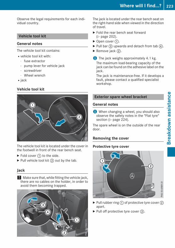
Observe the legal requirements for each indi-vidual country.
Vehicle tool kit
General notesThe vehicle tool kit contains:Rvehicle tool kit with:
- fuse extractor- pump lever for vehicle jack- screwdriver- Wheel wrenchRjack
Vehicle tool kit
The vehicle tool kit is located under the cover inthe footwell in front of the rear bench seat.X Fold cover: to the side.X Pull vehicle tool kit; out by the tab.
Jack! Make sure that, while fitting the vehicle jack,there are no cables on the holder, in order toavoid them becoming trapped.
The jack is located under the rear bench seat onthe right-hand side when viewed in the directionof travel.X Fold the rear bench seat forward(Y page 202).
X Open cover:.X Pull bar= upwards and detach from tab?.X Remove jack;.
i The jack weighs approximately 4.1 kg.The maximum load-bearing capacity of thejack can be found on the adhesive label on thejack.The jack is maintenance-free. If it develops afault, please contact a qualified specialistworkshop.
Exterior spare wheel bracket
General notesi When changing a wheel, you should alsoobserve the safety notes in the "Flat tyre"section (Y page 224).
The spare wheel is on the outside of the reardoor.
Removing the cover
Protective tyre cover
X Pull rubber ring: of protective tyre cover;apart.
X Pull off protective tyre cover;.
Where will I find...? 223
Breakdow
nassistance

Removing the spare wheel
The spare wheel is heavy. Observe this whenremoving the spare wheel.X Remove wheel nuts:.X Remove the spare wheel.
Fitting the wheelAfter changing a wheel:X Secure the damaged wheel on the sparewheel bracket with wheel nuts:. Whendoing so, make sure that the wheel cannotcome loose.
X Cover the wheel with the tyre protectioncover.
X For safety reasons, regularly check to ensurethat the wheel is securely fastened.
Flat tyre
Preparing the vehicleX Stop the vehicle as far away as possible fromtraffic on solid, non-slippery and level ground.
X Switch on the hazard warning lamps.X Secure the vehicle against rolling away(Y page 113).
X If possible, bring the front wheels into thestraight-ahead position.
X Switch off the engine.X Remove the key from the ignition lock.The steering wheel lock is active as soon asthe key is removed.
X Make sure that the passengers are not endan-gered as they get out of the vehicle. Makesure that no one is near the danger area whilea wheel is being changed. Anyone who is not
directly assisting in the wheel change should,for example, stand behind the barrier.
X Get out of the vehicle. Pay attention to trafficconditions when doing so.
X Close the driver's door.X Place the warning triangle a suitable distanceaway (Y page 222). Observe legal require-ments.
Battery (vehicle)
Important safety notesWork on the battery, e.g. removing or fitting,requires specialist knowledge and the use ofspecial tools. Therefore, always have work onthe battery carried out at a qualified specialistworkshop.
G WARNINGWork carried out incorrectly on the batterycan lead, for example, to a short circuit andthus damage the vehicle electronics. This canlead to function restrictions applying tosafety-relevant systems, e.g the lighting sys-tem, the ABS (anti-lock braking system) or theESP® (Electronic Stability Program). The oper-ating safety of your vehicle may be restricted.You could lose control of the vehicle, forexample:Rwhen brakingRin the event of abrupt steering manoeuvresand/or when the vehicle's speed is notadapted to the road conditions
There is a risk of an accident.In the event of a short circuit or a similar inci-dent, contact a qualified specialist workshopimmediately. Do not drive any further. Alwayshave work on the battery carried out at aqualified specialist workshop.
Further information about ABS (Y page 52) andESP® (Y page 54).
G WARNINGElectrostatic build-up can lead to the creationof sparks, which could ignite the highly explo-
224 Battery (vehicle)Breakdow
nassistance

sive gases of a battery. There is a risk of anexplosion.Before handling the battery, touch the vehiclebody to remove any existing electrostaticbuild-up.
The highly flammable gas mixture is createdwhile the battery is charging and when jump-starting.Always make sure that neither you nor the bat-tery is electrostatically charged. Electrostaticcharge is created, for example:Rby wearing synthetic-fibre clothingRby friction between clothing and the seatRif you pull or push the battery across carpet orother synthetic materialsRif you rub the battery with a cloth
G WARNINGDuring the charging process, a battery produ-ces hydrogen gas. If a short circuit occurs orsparks are created, the hydrogen gas canignite. There is a risk of an explosion.RMake sure that the positive terminal of aconnected battery does not come into con-tact with vehicle parts.RNever placemetal objects or tools on a bat-tery.RIt is important that you observe the descri-bed order of the battery terminals whenconnecting and disconnecting a battery.RWhen jump-starting, make sure that thebattery poles with identical polarity areconnected.RIt is particularly important to observe thedescribed order when connecting and dis-connecting the jump leads.RNever connect or disconnect the batteryterminals while the engine is running.
G WARNINGBattery acid is caustic. There is a risk of injury.Avoid contact with the skin, eyes or clothing.Do not breathe in any battery gases. Do notlean over the battery. Keep the batteries outof the reach of children. Immediately rinse off
battery acid thoroughly with plenty of cleanwater and seek medical attention at once.
H Environmental noteBatteries contain pollutants.It is illegal to dispose of themwith the household rubbish.They must be collected sep-arately and disposed of in anenvironmentally responsiblerecycling system.Dispose of batteries in anenvironmentally responsiblemanner. Take dischargedbatteries to a qualified spe-cialist workshop or to a col-lection point for used batter-ies.
! Have the battery checked regularly at aqualified specialist workshop.Observe the service intervals in the ServiceBooklet or contact a qualified specialist work-shop for more information.
! Always have work on the batteries carriedout at a qualified specialist workshop.Should it, in exceptional circumstances, beabsolutely necessary to disconnect the 12-volt battery yourself, please observe the fol-lowing:RSecure the vehicle to prevent it from rollingawayRSwitch off the ignitionRDisconnect the negative terminal first andthen the positive terminal
The transmission is locked in positionjafter disconnecting the battery.After the work is completed, securely refit thebattery and the positive terminal cover.
Comply with safety precautions and take pro-tective measures when handling batteries.
Risk of explosion.
Fire, naked flames and smoking areprohibited when handling the bat-tery. Avoid creating sparks.
Battery (vehicle) 225
Breakdow
nassistance
Z

Battery acid is caustic.Avoid contact with the skin, eyes andclothing.
Wear eye protection.
Keep children at a safe distance.
Observe this Owner's Manual.
For safety reasons, Mercedes-Benz recom-mends that you use only batteries that havebeen tested and approved for your vehicle byMercedes-Benz. These batteries provideincreased impact protection to prevent the vehi-cle occupants from suffering acid burns shouldthe battery be damaged in the event of an acci-dent.In order for the battery to achieve the maximumpossible service life, it should always be suffi-ciently charged.Like other batteries, the vehicle battery maydischarge over time if you do not use the vehicle.In such cases, have the battery disconnected ata qualified specialist workshop. However, youcan also charge the battery with a charger rec-ommended by Mercedes-Benz. For more infor-mation, please contact a qualified specialistworkshop.Have the battery charge checked more fre-quently if you use the vehicle mainly for shorttrips or if you leave it standing idle for an exten-ded period. Consult a qualified specialist work-shop if you wish to leave your vehicle parked upfor a long period of time.When you park the vehicle, remove the key if youdo not require any electrical consumers. Thevehicle will then use very little energy, thus con-serving battery power.
i If the power supply has been interrupted,e.g. due to a discharged battery, you will haveto set the clock .
Charging the battery! Only use battery chargers with a maximumcharging voltage of 14.8 V.
G WARNINGDuring charging and jump-starting, explosivegases can escape from the battery. There is arisk of an explosion.Particularly avoid fire, naked flames, creatingsparks and smoking. Ensure there is sufficientventilation while charging and jump-starting.Do not lean over a battery.
G WARNINGBattery acid is caustic. There is a risk of injury.Avoid contact with the skin, eyes or clothing.Do not breathe in any battery gases. Do notlean over the battery. Keep the batteries outof the reach of children. Immediately rinse offbattery acid thoroughly with plenty of cleanwater and seek medical attention at once.
G WARNINGA discharged battery can freeze at tempera-tures below freezing point. When jump-start-ing the vehicle or charging the battery, gasescan escape from the battery. There is a risk ofan explosion.Allow the frozen battery to thaw out beforecharging it or jump-starting.
! Only charge the battery using the jump-startconnection point.
The jump-starting connection point is in theengine compartment (Y page 227).X Open the bonnet.X Connect the battery charger to the positiveterminal and earth point in the same order aswhen connecting the donor battery in thejump-starting procedure (Y page 227).
Keep away from fire and naked flames. Do notlean over the battery. Never charge the batteryif it is still fitted to the vehicle, unless you areusing a battery charger that has been tested andapproved by Mercedes-Benz. A battery chargerunit specially adapted for Mercedes-Benz vehi-cles and tested and approved by Mercedes-Benz is available as an accessory. This device
226 Battery (vehicle)Breakdow
nassistance

permits charging of the battery while it is fitted.Contact a Mercedes-Benz Service Centre forinformation and availability. Read the batterycharger's operating instructions before charg-ing the battery.If thewarning and indicator lamps do not light upon the instrument cluster when temperaturesare low, it is probably because the discharged
battery has frozen. In this case, you may neitherjump-start the vehicle nor charge the battery.The service life of a battery that has beenthawed may be reduced. The starting charac-teristics may be impaired, especially at low tem-peratures. Have the thawed battery checked ata qualified specialist workshop.
Jump-starting
For the jump-starting procedure, use only the jump-starting connection point, consisting of a pos-itive terminal and an earth point, in the engine compartment.
G WARNINGBattery acid is caustic. There is a risk of injury.Avoid contact with the skin, eyes or clothing. Do not breathe in any battery gases. Do not lean overthe battery. Keep the batteries out of the reach of children. Immediately rinse off battery acidthoroughly with plenty of clean water and seek medical attention at once.
G WARNINGDuring charging and jump-starting, explosive gases can escape from the battery. There is a riskof an explosion.Particularly avoid fire, naked flames, creating sparks and smoking. Ensure there is sufficientventilation while charging and jump-starting. Do not lean over a battery.
G WARNINGDuring the charging process, a battery produces hydrogen gas. If a short circuit occurs or sparksare created, the hydrogen gas can ignite. There is a risk of an explosion.RMake sure that the positive terminal of a connected battery does not come into contact withvehicle parts.RNever place metal objects or tools on a battery.RIt is important that you observe the described order of the battery terminals when connectingand disconnecting a battery.RWhen jump-starting, make sure that the battery poles with identical polarity are connected.RIt is particularly important to observe the described order when connecting and disconnectingthe jump leads.RNever connect or disconnect the battery terminals while the engine is running.
G WARNINGA discharged battery can freeze at temperatures below freezing point. When jump-starting thevehicle or charging the battery, gases can escape from the battery. There is a risk of an explosion.Allow the frozen battery to thaw out before charging it or jump-starting.
If the warning and indicator lamps do not light up on the instrument cluster when temperatures arelow, it is probably because the discharged battery has frozen. In this case, you may neither jump-start the vehicle nor charge the battery. The service life of a battery that has been thawed may be
Jump-starting 227
Breakdow
nassistance
Z

reduced. The starting characteristics may be impaired, especially at low temperatures. Have thethawed battery checked at a qualified specialist workshop.Do not use a rapid charging device to start the vehicle. If your vehicle's battery is discharged, theengine can be jump-started from another vehicle or from a second battery using jump leads.Observe the following points:RThe battery is not accessible in all vehicles. If the other vehicle's battery is not accessible, jump-start the vehicle using a donor battery or a jump-starting device.RDo not start the engine if the battery is frozen. Let the battery thaw first.RJump-starting may be performed only using batteries with a nominal voltage of 12 V.RUse only jump leads that have a sufficient cross-section and insulated terminal clamps.RIf the battery is fully discharged, leave the battery that is being used to jump-start connected fora few minutes before attempting to start. This charges the empty battery a little.RMake sure that the two vehicles do not touch.Make sure that:RThe jump leads are not damaged.RNon-insulated parts of the terminal clamps do not come into contact with other metal parts whilethe jump leads are connected to the battery.RThe jump leads cannot come into contact with parts that can move when the engine is running,such as the V-belt pulley or the fan.
X Apply the parking brake.X Shift the automatic transmission to position P.X Make sure that the ignition is switched off. All indicator lamps on the instrument cluster must beoff.
X Switch off all electrical consumers, e.g. rear window heating, lighting etc.X Open the bonnet.
Position numberB identifies the charged battery of the other vehicle or an equivalent jump-startingdevice.The jump-starting connection point consists of contacts; and=.
228 Jump-startingBreakdow
nassistance

X Lift up cover: of positive terminal; in the direction of the arrow.X Connect positive terminal; on your vehicle to positive terminal? of donor batteryB using thejump lead, Always begin with positive terminal; on your own vehicle first.
X Start the engine of the donor vehicle and run it at idling speed.X Connect negative terminalA of donor batteryB to earth point= of your vehicle using the jumplead, connecting the jump lead to donor batteryB first.
X Start the engine.X Before disconnecting the jump leads, let the engines run for several minutes.X First, remove the jump leads from earth point= and negative terminalA, then from positiveterminal; and positive terminal?. Each time, begin at the contacts on your own vehicle.
X Close cover: of positive terminal; after removing the jump leads.X Have the battery checked at a qualified specialist workshop.Jump-starting is not considered to be a normal operating condition.
i Jump-starting cables and further information regarding jump-starting can be obtained at anyqualified specialist workshop.
Towing away and tow-starting
Important safety notes
G WARNINGSafety-relevant functions are restricted or notavailable if:Rthe engine is not running.Rthe brake system or the power steering ismalfunctioningRthe voltage supply or the vehicle's electricalsystem is malfunctioning.
If your vehicle is towed, significantly greaterforce may be required to steer the vehicle orto brake. There is a risk of an accident.In such circumstances, use a towing bar.Make sure that the steering is moving freelybefore towing.
G WARNINGIf the steering wheel lock is engaged, the vehi-cle can no longer be steered. There is a risk ofan accident.Always switch on the ignition when towingwith a tow rope or a towing bar.
G WARNINGWhen towing or tow-starting another vehicleand its weight is greater than the permissiblegross weight of your vehicle, the:Rtowing eye may be torn offRcar/trailer combination may swerve oreven overturn
There is a risk of an accident.When towing or tow-starting another vehicle,its weight should not be greater than the per-missible gross weight of your vehicle.
Details on the permissible gross vehicle weightof your vehicle can be found on the vehicle iden-tification plate (Y page 249).
! You may tow the vehicle for a maximum of50km. A towing speed of 50 km/h must notbe exceeded.For towing distances over 50 km, the entirevehicle must be lifted up and transported.
! Only secure the tow cable or towing bar tothe towing eyes. You could otherwise damagethe vehicle.
! Observe the following points when towingwith a tow rope:RSecure the tow rope on the same side onboth vehicles.RMake sure that the tow rope is not longerthan legally permitted.Mark the tow rope inthe middle, e.g. with a white cloth
Towing away and tow-starting 229
Breakdow
nassistance
Z

(30 x 30 cm). This will make other roadusers aware that a vehicle is being towed.ROnly secure the tow cable to the towingeyes or, if available, to the trailer tow hitch.RObserve the brake lamps of the towingvehicle while driving. Alwaysmaintain a dis-tance a distance so that the tow rope doesnot sag.RDo not use steel cables or chains to towyour vehicle. You could otherwise damagethe vehicle.
! Do not use the trailer tow hitch for recoveryor towing. Do not use the towing eye forrecovery. This could damage the vehicle. If indoubt, have the vehicle recovered using acrane.
! When towing, pull away slowly andsmoothly. If the tractive power is too high, thevehicles could be damaged.
! Your vehicles is equipped with an automatictransmission. Therefore, you must not havethe vehicle tow-started. The transmissionmay otherwise be damaged.
Observe the legal requirements in each individ-ual country when towing.It is better to have the vehicle transported thanto have it towed.If the transfer case can be shifted into the Neu-tral position, you can tow away the vehicle.If the transfer case cannot be shifted into theNeutral position, you can tow away the vehiclewith one axle raised. Please bear the following inmind:Rremove the propeller shaft from between thetransfer case and the rolling axle.Rturn the key to position1 in the ignition lock.The battery must be connected and charged.Otherwise, you:Rcannot turn the key to position2 in the igni-tion lockRcannot shift the automatic transmission topositioni
Towing eyes
Towing eyes, front
: Towing eyes, front
Towing eye, rear
Towing eyes: are located at the rear on the leftand right-hand side beneath the bumper.
Towing the vehicle away with allwheels on the groundIt is important that you observe the safetyinstructions when towing away your vehicle(Y page 229).The automatic transmission automatically shiftsto positionPwhen you open the driver's or front-passenger door or when you remove the keyfrom the ignition lock. In order to ensure that theautomatic transmission stays in position Nwhen towing away the vehicle, you mustobserve the following points:X Make sure that the vehicle is stationary.X Turn the key to position2 in the ignitionlock.
230 Towing away and tow-startingBreakdow
nassistance

X When the vehicle is stationary, depress thebrake pedal and keep it depressed.
X Shift the transfer case to position Neutral(Y page 125).
X Shift the automatic transmission to positionN.
X Leave the key in position2 in the ignitionlock.
X Release the brake pedal.X Release the parking brake.X Switch on the hazard warning lamps(Y page 76).
In order to signal a change of direction whentowing the vehicle with the hazard warninglamps switched on, use the combination switchas usual. In this case, only the turn signals forthe desired direction flash. When you reset thecombination switch, the hazard warning lampsstart flashing again.
i The automatic transmission can onlychange gear when the battery has sufficientcharge.If you cannot shift the automatic transmissionto position N, the propeller shafts to thedriven axles must be removed.
Transporting the vehicle
! When the vehicle is loaded for transport, thefront and rear axlesmust be stationary and onthe same transportation vehicle. Positioningover the connection point of the transportvehicle is not permitted. The drive train mayotherwise be damaged.
! You may only secure the vehicle by thewheels, not by parts of the vehicle such asaxle or steering components. Otherwise, thevehicle could be damaged.
The towing eye or trailer tow hitch can be usedto pull the vehicle onto a trailer or transporter ifyou wish to transport it.X Turn the key to position2 in the ignitionlock.
X Shift the transfer case to position Neutral(Y page 125).
X Shift the automatic transmission to positionN.
As soon as the vehicle is loaded:X Apply the parking brake.X Shift the automatic transmission to positionP.
X Turn the key to positionu in the ignition lockand remove it.
X Secure the vehicle.
Recovering a vehicle that has becomestuck! When recovering a vehicle that has becomestuck, pull it as smoothly and evenly as pos-sible. If the tractive power is too high, thevehicles could be damaged.
If the drive wheels get trapped on loose ormuddy ground, recover the vehicle with theutmost care, especially so if the vehicle is laden.Never attempt to recover a vehicle with a trailerattached.Pull out the vehicle backwards, if possible, usingthe tracks it made before it became stuck.
Towing in the event of malfunctions
General notes! If you are removing the propeller shaft, useM10 nuts as spacers on the M8 bolts andsecure them with M8 nuts.New self-locking nuts must be used when thepropeller shafts are refitted.
It is important that you observe the safetyinstructions when towing away your vehicle(Y page 229).
i Consult a Mercedes-Benz Service Centreand seek advice.
Towing away and tow-starting 231
Breakdow
nassistance
Z

In the event of damage to the engine,transmission or electrical systemX Shift the transfer case to neutral positionNeutral (Y page 125).
X Shift the automatic transmission to positionN.
In the event of damage to the transfercaseHave the propeller shafts between the axles andthe transfer case removed.
In the event of damage to the front axleHave the propeller shaft between the rear axleand the transfer case removed.Then have the vehicle towed away with the frontaxle raised.
In the event of damage to the rear axleHave the propeller shaft between the front axleand the transfer case removed.Then have the vehicle towed with the rear axleraised and wheel rollers under the front axle.
Tow-starting (emergency enginestarting)! Do not tow-start vehicles with automatictransmission. You could otherwise damagethe automatic transmission.
You can find information on "Jump-starting"under (Y page 227).
Fuses
Important safety notes
G WARNINGIf you manipulate, bridge or replace a faultyfuse with a fuse of a higher amperage, theelectric cables could be overloaded. This mayresult in a fire. There is a risk of an accidentand injury.Always replace faulty fuseswith specified newfuses of the correct amperage.
The fuses in your vehicle disconnect faulty cir-cuits. If a fuse blows, all the components in thecircuit and their functions will fail.Blown fuses must be replaced with fuses of thesame rating, which you can recognise by thecolour and fuse rating. The fuse ratings are listedin the fuse allocation chart (Y page 233).If the newly inserted fuse also blows, have thecause traced and rectified at a qualified special-ist workshop, e.g. a Mercedes-Benz ServiceCentre.
! Only use fuses that have been approved forMercedes-Benz vehicles and which have thecorrect fuse rating for the system concerned.Otherwise, components or systems could bedamaged.
! Make sure that no moisture can enter thefuse box when the cover is open.
! When closing the cover, make sure that it islying correctly on the fuse box.Moisture seep-ing in or dirt could otherwise impair the oper-ation of the fuses.
Before replacing a fuseObserve the important safety notes(Y page 232).X Switch off the engine.X Switch off all electrical consumers.X Remove the key from the ignition lock.All indicator lamps on the instrument clustermust be off.
X Secure the vehicle against rolling away(Y page 113).
The fuses are located in various fuse boxes:RMain fuse box on the front-passenger side ofthe dashboardRFuse box in the front-passenger footwellRFuse box in the transmission tunnelRFuse box in the luggage compartmentThe fuse allocation chart and the spare fuses arein the fuse box on the dashboard on the front-passenger side (Y page 233).The fuse extractor is in the vehicle tool kit(Y page 223).
232 FusesBreakdow
nassistance

Dashboard fuse box! Do not use a pointed object such as a screw-driver to open the cover in the dashboard. Youcould damage the dashboard or the cover.
X Open the front-passenger door.X To open: pull cover: outwards in the direc-tion of the arrow and remove it.
X To close: clip in cover: on the front of thedashboard.
X Fold cover: inwards until it engages.
Fuse box in the front-passenger foot-well
X Unscrew screws:.X Fold up cover; in the direction of the arrow.
= Fuse box
Fuse box in the transmission tunnel
X Move the front-passenger seat as far forwardas possible (Y page 69).
X To open: unscrew screws:.X Remove cover; in the direction of thearrow.
X To close: clip in cover;.X Fit cover; with screws:.
Fuse box in the luggage compartment
Fuses 233
Breakdow
nassistance
Z

X Open the rear door.X To open: unscrew screws:.X Fold out cover; in the direction of the arrowand remove.
234 FusesBreakdow
nassistance
Important safety notes
G WARNINGIf wheels and tyres of the wrong size are used,the wheel brakes or suspension componentsmay be damaged. There is a risk of an acci-dent.Always replace wheels and tyres with thosethat fulfil the specifications of the originalpart.When replacing wheels, make sure to fit thecorrect:RdesignationRtypeWhen replacing tyres, make sure to fit thecorrect:RdesignationRmanufacturerRtype
G WarningA flat tyre severely impairs the driving, steer-ing and braking characteristics of the vehicle.There is a risk of an accident.Do not drive with a flat tyre. Immediatelyreplace the flat tyre with your spare wheel, orconsult a qualified specialist workshop.
Accessories that are not approved for your vehi-cle by Mercedes-Benz or are not being used cor-rectly can impair the operating safety.Before purchasing and using non-approvedaccessories, visit a qualified specialist work-shop and enquire about:RsuitabilityRlegal stipulationsRfactory recommendationsFurther information regarding wheels and tyrescan be found under "Wheel/tyre combinations"(Y page 246).You can ask for information regarding permittedwheel/tyre combinations at a Mercedes-BenzService Centre.
Information on tyre pressure can be found:Ron the tyre pressure table in the fuel filler flap(Y page 109)Runder "Tyre pressure" (Y page 238)Modification work on the brake system andwheels is not permitted, nor is the use of spacerplates or brake dust shields. This invalidates thegeneral operating permit for the vehicle.
i Further information onwheels and tyres canbe obtained at any qualified specialist work-shop.
Operation
Information on drivingWhen the vehicle is heavily laden, check the tyrepressures and adjust them prior to a trip.While driving, pay attention to vibrations, noisesand unusual handling characteristics, e.g. pull-ing to one side. This may indicate that thewheels or tyres are damaged. If you suspect thata tyre is defective, reduce your speed immedi-ately. Stop the vehicle as soon as possible tocheck the wheels and tyres for damage. Hiddentyre damage could also be causing the unusualhandling characteristics. If you find no signs ofdamage, have the tyres andwheels checked at aqualified specialist workshop.When parking your vehicle, make sure not tosquash the tyre. If you cannot avoid driving overobstacles, e.g. kerbs, do so slowly and at anobtuse angle only. You could otherwise damagethe wheel rims and tyres.
Regular checking of wheels and tyres
G WARNINGDamaged tyres can cause tyre inflation pres-sure loss. As a result, you could lose control ofyour vehicle. There is a risk of accident.Check the tyres regularly for signs of damageand replace any damaged tyres immediately.
Check wheels and tyres for damage at leastonce a month. Check wheels and tyres afterdriving off-road or on rough roads. Damagedwheels can cause a loss of tyre pressure.
Operation 235
Wheelsandtyres
Z

Pay particular attention to damage such as:Rcuts in the tyresRpuncturesRtears in the tyresRbulges on the tyresRdeformation or severe corrosion on thewheels
Regularly check the tyre tread depth and thecondition of the tread across the whole width ofthe tyre (Y page 236). In order to inspect theinner side of the tyre surface, turn the steeringwheel to full lock.All wheels must have a valve cap to protect thevalve against dirt and moisture. Do not fit any-thing onto the valve other than the standardvalve cap or a valve cap approved by Mercedes-Benz for your vehicle. Do not fit any other valvecaps or systems, e.g. tyre pressure monitors.You should regularly check the pressure of allyour tyres including the spare wheel, particu-larly prior to long trips. Adjust the tyre pressureas necessary (Y page 238).The service life of a tyre depends on various fac-tors, including the following:Rdriving styleRtyre pressureRmileage
Notes on the tyre tread
G WARNINGInsufficient tyre tread will reduce tyre trac-tion. The tyre is no longer able to dissipatewater. This means that on wet road surfaces,the risk of aquaplaning increases, in particularwhere speed is not adapted to suit the drivingconditions. There is a risk of accident.If the tyre pressure is too high or too low, tyresmay exhibit different levels of wear at differ-ent locations on the tyre tread. Thus, youshould regularly check the tread depth andthe condition of the tread across the entirewidth of all tyres.Minimum tyre tread depth for:Rsummer tyres: 3 mmRM+S tyres: 4 mm
For safety reasons, replace the tyres beforethe legally prescribed limit for the minimumtyre tread depth is reached.
Selecting, fitting and replacing tyres
G WARNINGExceeding the stated tyre load-bearing capa-city and the approved maximum speed couldlead to tyre damage or the tyre bursting. Thereis a risk of accident.Therefore, only use tyre types and sizesapproved for your vehicle model. Observe thetyre load rating and speed rating required foryour vehicle.
Pay special attention to country-specificrequirements for tyre approval. These require-ments may stipulate a specific tyre type for yourvehicle. Furthermore, the use of a specific tyretype in certain regions and areas of operationcan be highly beneficial. You can find furtherinformation regarding tyres at specialist tyreretailers, at qualified specialist workshops or atany Mercedes-Benz Service Centre.RUse only tyres and wheels of the same typeand make.RFit only tyres of the correct size onto thewheels.RRun in new tyres at moderate speeds for thefirst 100 km. They reach their full perform-ance only after this distance.RDo not drive with tyres that have too littletread depth. This significantly reduces trac-tion on wet roads (aquaplaning).RReplace the tyres after six years at the latest,regardless of wear. This also applies to thespare wheel.
Winter operation
General notesHave your vehicle winterproofed at a qualifiedspecialist workshop at the onset of winter.Observe the notes in the "Changing a wheel"section (Y page 243).
236 Winter operationWheelsandtyres

Driving with summer tyresAt temperatures below+7†, summer tyres loseelasticity and therefore traction and brakingpower. Change the tyres on your vehicle toM+S tyres. Using summer tyres at very coldtemperatures could cause tears to form,thereby damaging the tyres permanently.Mercedes-Benz cannot accept responsibility forthis type of damage.
G WARNINGDamaged tyres can cause tyre inflation pres-sure loss. As a result, you could lose control ofyour vehicle. There is a risk of accident.Check the tyres regularly for signs of damageand replace any damaged tyres immediately.
M+S tyres
G WARNINGM+S tyres with a tyre tread depth of less than4mmare not suitable for use in winter as theydo not provide sufficient traction. There is arisk of accident.M+S tyres with a tread depth of less than4 mm must be replaced.
G WARNINGThe wheel or tyre size as well as the tyre typeof the spare wheel and the wheel to bereplaced may differ. Driving characteristicscan be severely impaired when you fit thespare wheel. There is a risk of an accident.To prevent risks:Radapt your driving style accordingly anddrive carefullyRnever fit more than one spare wheel thatdiffers from the wheel to be changedRonly use a spare wheel that differs from thewheel to be changed for a brief periodRdo not switch ESP® offRhave a spare wheel of a different sizereplaced at the nearest qualified specialistworkshop. You must make sure that the
wheel and tyre dimensions as well as thetyre type are correct.
Do not exceed a maximum speed of 80 km/h ifa spare wheel of a different size is fitted.At temperatures below+7†, usewinter tyres orall-season tyres. Both types of tyre are identifiedby the M+S marking.Only winter tyres bearing thei snowflakesymbol in addition to the M+S marking providethe best possible grip in wintry road conditions.Only these tyres will allow driving safety sys-tems such as ABS and ESP® to function opti-mally in winter. These tyres have been devel-oped specifically for driving in snow.UseM+S tyres of the samemake and tread on allwheels to maintain safe handling characteris-tics.Always observe the maximum permissiblespeed specified for the M+S tyres you have fit-ted.If you fit M+S tyres that have a lower maximumpermissible speed than that of the vehicle, affixan appropriate warning label in the driver's fieldof vision. This can be obtained at a qualifiedspecialist workshop.When you have fitted the M+S tyres:X Check the tyre pressures (Y page 238).X Restart the tyre pressure monitor(Y page 241).
Snow chains
G WARNINGIf you drive too fast with snow chains fitted,they may snap. As a result, you could injureothers and damage the vehicle. There is a riskof an accident.Observe the maximum permissible speed foroperation with snow chains.
! Before fitting the snow chains, check themfor damage. Damaged or worn snow chainsmay snap and damage the following compo-nents:RwheelRwheel housingRwheel suspension
Winter operation 237
Wheelsandtyres
Z

Therefore, only use snow chains that are inperfect condition. Observe the manufactur-er's installation instructions.
For safety reasons, Mercedes-Benz recom-mends that you use only snow chains that havebeen approved for Mercedes-Benz or that are ofan equivalent standard of quality. For moreinformation, please contact a qualified special-ist workshop.If you wish to fit snow chains, please bear thefollowing points in mind:Rsnow chains cannot be fitted to all wheel/tyrecombinations. Observe the informationregarding permitted wheel/tyre combina-tions (Y page 246)Rfit the snow chains on all four wheels for max-imum tractive power and driving stability.Snow chains must always be fitted in pairs; ifyou only have two snow chains, fit these onthe rear wheels. The vehicle then remainsmore stable under brakingRuse snow chains only if the road surface iscompletely snow-covered. Remove the snowchains as soon as possible when you come toa road that is not snow-coveredRlocal regulations may restrict the use of snowchains. Observe the appropriate regulations ifyou wish to fit snow chainsRdo not exceed the maximum permissiblespeed of 50 km/h
You may wish to deactivate ESP® when pullingaway with snow chains fitted (Y page 54). Thisallows thewheels to spin in a controlledmanner,achieving increased propulsive force (cut).
Tyre pressure
Tyre pressure specifications
Important safety notes
G WARNINGUnderinflated or overinflated tyres pose thefollowing risks:Rthe tyres may burst, especially as the loadand vehicle speed increase.Rthe tyres may wear excessively and/orunevenly, which may greatly impair tyretraction.Rthe driving characteristics, as well as steer-ing and braking, may be greatly impaired.
There is a risk of an accident.Observe the recommended tyre pressure andcheck the tyre pressure of all the tyres includ-ing the spare wheel:Rat least every two weeksRwhen the load changesRbefore embarking on a longer journeyRfor changed operating conditions, e.g. off-road driving
If necessary, correct the tyre pressure.
G WARNINGIf you fit unsuitable accessories onto tyrevalves, the tyre valves may be overloaded andmalfunction, which can cause tyre pressureloss. Due to their design, retrofitted tyre pres-sure monitors keep the tyre valve open. Thiscan also result in tyre pressure loss. There is arisk of accident.Only screw standard valve caps or valve capsspecifically provided by Mercedes-Benz foryour vehicle onto the tyre valve.
G WARNINGIf the tyre pressure drops repeatedly, thewheel, valve or tyre may be damaged. Tyrepressure that is too low may result in a tyreblow-out. There is a risk of accident.
238 Tyre pressureWheelsandtyres

RCheck the tyre for foreign objects.RCheck whether the wheel is losing air or thevalve is leaking.
If you are unable to rectify the damage, con-tact a qualified specialist workshop.
H Environmental noteCheck the tyre pressure regularly, at leastevery 14 days.
The recommended tyre pressures for variousoperating conditions can be found on the tyrepressure table on the fuel filler flap(Y page 109).Operation with a trailer: the applicable valuefor the rear axle is the maximum value stated inthe tyre pressure table.The tyre pressure table may also state tyre pres-sures for different load conditions. These aredefined in the table as different numbers of pas-sengers and amounts of luggage. The actualnumber of seats may differ from this.If tyre sizes are not specified, the tyre pressuresstated on the tyre pressure information labelapply for all tyres approved for this vehicle.
If one or more tyre sizes precedes a tyre pres-sure, the following tyre pressure information isvalid only for that tyre size.Use a suitable pressure gauge to check the tyrepressure. The outer appearance of a tyre doesnot give any reliable indication of the tyre pres-sure.You can also check the tyre pressure using theon-board computer.If possible, correct tyre pressures only when thetyres are cold.
The tyres are cold:Rif the vehicle has been parked with the tyresout of direct sunlight for at least three hoursandRif the vehicle has not been driven further than1.6 km
Depending on the outside temperature, thevehicle speed and the load on the tyres, the tyretemperature and thus the tyre pressure changesby approximately 10 kPa (0.1 bar/1.5 psi) per10†. Take this into account when checking thepressure of warm tyres. Correct the tyre pres-sure only if it is too low for the current operatingcondition.Driving with a tyre pressure that is too high ortoo low can:Rshorten the service life of the tyresRcause increased tyre damageRhave a negative effect on handling character-istics and thus driving safety (e.g. aquaplan-ing)
The tyre pressure values given for low loads areminimum values that offer you good drivingcomfort characteristics.However, you can also use the values given forhigher loads. These are permissible and will notadversely affect the running of the vehicle.
Tyre pressure monitor
General notesIf a tyre pressure monitor is fitted, the vehicle'swheels have sensors fitted that monitor the tyrepressures in all four tyres. The tyre pressuremonitor warns you if the pressure drops in oneor more of the tyres. The tyre pressure monitorfunctions only if the corresponding sensors arefitted to all wheels.Information on tyre pressures is shown on themultifunction display. After a few minutes ofdriving, the current tyre pressure of each wheelis shown in the Serv.Serv. menu.
Tyre pressure 239
Wheelsandtyres
Z

For further information on displaying this mes-sage, refer to the "Checking the tyre pressureelectronically" section (Y page 240).
Important safety notesIt is the driver's responsibility to set the tyrepressure to the recommended cold tyre pres-sure suitable for the operating situation(Y page 238). Note that the correct tyre pres-sure for the current operating situation mustfirst be learnt by the tyre pressure monitor. If asubstantial loss of pressure occurs, the warningthreshold for the warning message is aligned tothe learnt reference values. Restart the tyrepressure monitor after adjusting to the cold tyrepressure (Y page 241). The current pressuresare saved as new reference values. This ensuresthat a warning message appears only if the tyrepressure drops significantly.The tyre pressure monitor does not warn you ofan incorrectly set tyre pressure. Observe thenotes on the recommended tyre pressure(Y page 238).The tyre pressure monitor is not able to warnyou of a sudden loss of pressure, e.g. if the tyreis penetrated by a foreign object. In this event,bring the vehicle to a halt by braking carefully.Avoid abrupt steering manoeuvres.The tyre pressure monitor has a yellowhwarning lamp on the instrument cluster for indi-cating a pressure loss or malfunction. Depend-ing on how thewarning lamp flashes or lights up,a tyre pressure that is too low or amalfunction inthe tyre pressure monitor is indicated:Rif theh warning lamp is lit continuously,the tyre pressure on one or more tyres is sig-nificantly too low. The tyre pressure monitoris not malfunctioning.Rif theh warning lamp flashes for around aminute and then remains lit constantly, thetyre pressure monitor is malfunctioning.
In addition to thehwarning lamp, amessageappears in the multifunction display. Observethe information on display messages(Y page 150).It may take up to ten minutes for a malfunctionof the tyre pressure monitor to be indicated. Amalfunction will be indicated by theh tyrepressure warning lamp flashing for approx-imately oneminute and then remaining lit. Whenthe fault has been rectified, theh tyre pres-sure warning lamp goes out after driving for afew minutes.
The tyre pressure values indicated by the on-board computer may differ from those meas-ured at a filling station using a pressure gauge.The tyre pressures shown by the on-board com-puter refer to those measured at sea level. Athigh altitudes, the tyre pressure values indica-ted by a pressure gauge are higher than thoseshown by the on-board computer. In this case,do not reduce the tyre pressures.The operation of the tyre pressure monitor canbe affected by interference from radio transmit-ting equipment (e.g. cordless headphones, two-way radios) that may be being operated in ornear the vehicle.
Checking the tyre pressure electroni-callyX Make sure that the key is in position 2 in theignition lock.
X Press the= or; button on the steeringwheel to select the Serv.Serv. menu.
X Press the9 or: button to selectTyre pressureTyre pressure.X Press thea button.The multifunction display shows the currenttyre pressure of each wheel.
If the vehicle has been parked for over20 minutes, the Tyre pressures will beTyre pressures will bedisplayeddisplayed after aafter a fewfew minutesminutes ofof driv‐driv‐inging message appears.After a teach-in period, the tyre pressure moni-tor automatically detects new wheels or newsensors. As long as a clear allocation of the tyrepressure values to the individual wheels is notpossible, the TyreTyre pressurepressure monitormonitor activeactivedisplay message is shown instead of the tyrepressure display. The tyre pressures are alreadybeing monitored.If a spare wheel is fitted, the system may con-tinue to show the tyre pressure of the wheel thathas been removed for a few minutes. Pleasenote that in this case, the value displayed for thereplaced wheel does not indicate the currenttyre pressure of the spare wheel.
Warning messages of the tyre pressuremonitorIf the tyre pressure monitor detects a pressureloss in one or more tyres, a warning message isshown on the multifunction display. The yellowh tyre pressure warning lamp then lights up.
240 Tyre pressureWheelsandtyres

RIf the Rectify tyre pressureRectify tyre pressure messageappears in the multifunction display, the tyrepressure in at least one tyre is too low. Thetyre pressure must be corrected when theopportunity arises.RIf the CheckCheck tyre(s)tyre(s)message appears in themultifunction display, the tyre pressure in atleast one tyre has dropped significantly. Thetyres must be checked.RIf the Warning tyre defectWarning tyre defect messageappears in the multifunction display, the tyrepressure in at least one tyre has dropped sud-denly. The tyres must be checked.
Observe the instructions and safety notes in thedisplay messages in the "Tyres" section(Y page 150).If the position of the wheels on the vehicle ischanged, the tyre pressuresmay be displayed inthe wrong positions for a short time. After a fewminutes of driving, this is rectified and the tyrepressures are displayed in the correct positions.
Restarting the tyre pressure monitorWhen you restart the tyre pressure monitor, allexisting warning messages are deleted and theh warning lamp goes out. The monitor usesthe currently set tyre pressures as the referencevalues for monitoring. In most cases, the tyrepressure monitor will automatically detect thenew reference values after you have changedthe tyre pressure. However, you can also setreference values manually as described here.The tyre pressure monitor then monitors thenew tyre pressure values.X Use the table on the inside of the fuel filler flapto ensure that the tyre pressure is set cor-rectly in all four tyres for the current operatingconditions.Observe the notes on tyre pressure(Y page 238).
X Make sure that the key is in position 2 in theignition lock.
X Press the= or; button on the steeringwheel to select the Serv.Serv. menu.
X Press the9 or: button to selectTyre pressureTyre pressure.X Press thea button.The multifunction display shows the currenttyre pressure for each tyre or the TyreTyre pres‐pres‐
suressures willwill bebe displayeddisplayed after aafter a fewfewminutes of drivingminutes of driving message appears.X Press the: button.The UseUse currentcurrent pressurespressures asas newnew ref‐ref‐erenceerence valuesvaluesmessage appears in the mul-tifunction display.
If you wish to confirm the restart:X Press thea button.The TyreTyre press.press. monitormonitor restartedrestartedmes-sage appears in the multifunction display.After you have driven for a few minutes, thesystem checks whether the current tyre pres-sures are within the specified range. The newtyre pressures are then accepted as refer-ence values and monitored.
If you wish to cancel the restart:X Press the% button.The tyre pressure values stored at the lastrestart will continue to be monitored.
Radio type approval for the tyre pres-sure monitor
country Radio type approval number
Argentina Schrader GG4Numero de Registro CNC:H-12338
Brazil see below
AbuDhabi,Dubai,UnitedArab Emi-rates
TRAREGISTERED NO:ER0099792/12.DEALER NO: DA0047074/10
EuropeanUnion
Hereby, Schrader ElectronicsLtd., declares that this TPMS is incompliance with the essentialrequirements and other provi-sions of directive 1999/5/EC.The declaration of conformitymay be consulted at [email protected]
Tyre pressure 241
Wheelsandtyres
Z

country Radio type approval number
Jordan Kingdom of JordanType approval for Tyre Pressuresensor.Manufacturer: Schrader Elec-tronics Ltd.Model: GG4Type Approval Number:TRC/LPD/2012/190Model: MC34MA4Type Approval Number:TRC/LPD/2011/158
Malaysia RAQP/26A/0313S/S(13-0323)
Morocco AGREE PAR L'ANRT MAROCNumero d'agrement: MR 10216ANRT 2012Date d'agrement: 23/11/2012
Mexico IFT: RLVSCMR14-0815IFT: RCPSCMR14-0621
Moldova
Philip-pines
NTCType Approved.No: ESD-1306871C
Serbia
Singapore Complies with IDA StandardsDA 103365
country Radio type approval number
SouthAfrica
TA-2012/1540 ApprovedTA-2011/1370 Approved
Ukraine
Schrader Electronics цімстверджує, що обладнанняРадіопередавач моделі GG4системи контролю тиску в шиніавтомобіля відповідає вимогамТехнічного регламентурадіообладнання ітелекомунікаційного кінцевого(термінального) обладнання(Постанова КМУ № 679 від 24червня 2009 р.) Деклараціявідповідності знаходиться насайті Schrader Electronics танадається за запитом наелектрону адресу[email protected] Electronics цімстверджує, що обладнанняРадіопередавач моделіMC34MA4 системи контролютиску в шині автомобілявідповідає вимогам Технічногорегламенту радіообладнання ітелекомунікаційного кінцевого(термінального) обладнання(Постанова КМУ № 679 від 24червня 2009 р.) Деклараціявідповідності знаходиться насайті Schrader Electronics танадається за запитом наелектрону адресу[email protected]
242 Tyre pressureWheelsandtyres

Brazil
Este equipamento opera emcaráter secundário,isto é, não tem direito à proteção contra inter-ferência prejudicial, mesmo de estações domesmo tipo, e não pode causar interferência asistemas operando em caráter primário.
Changing a wheel
Flat tyreYou can find information on what to do in theevent of a flat tyre under "Breakdown assis-tance" (Y page 224).
Interchanging the wheels
G WARNINGInterchanging the front and rear wheels mayseverely impair the driving characteristics ifthewheels or tyres have different dimensions.The wheel brakes or suspension componentsmay also be damaged. There is a risk of acci-dent.Interchange front and rear wheels only if thewheels and tyres are of the same dimensions.
! On vehicles fitted with a tyre pressure mon-itor, electronic components are located in thewheel.Tyre-fitting tools should not be applied in thearea of the valve, as this could damage theelectronic components.Only have tyres changed at a qualified spe-cialist workshop.
Interchanging front and rear wheels of differingdimensions can render the general operatingpermit invalid.Always pay attention to the instructions andsafety notes under "Changing a wheel"(Y page 243).
The wear patterns on the front and rear tyresdiffer depending on the operating conditions.Interchange the wheels before a clear wear pat-tern has formed on the tyres. Front tyres typi-cally wear more on the shoulders, while reartyres wear more in the centre.On vehicles that have front and rear wheels ofthe same size, you can interchange the wheelsevery 5,000 to 10,000 km depending on thedegree of tyre wear. Ensure that the direction ofrotation is maintained.Clean the contact surfaces of the wheel and thebrake disc thoroughly every time a wheel isinterchanged. Check the tyre pressure and reac-tivate the tyre pressure monitor if necessary(Y page 241).
Direction of rotationTyres with a specified direction of rotation haveadditional benefits, e.g. if there is a risk of aqua-planing. You will only gain these benefits if thecorrect direction of rotation is observed.An arrow on the sidewall of the tyre indicates itscorrect direction of rotation.Youmay fit the sparewheel against the directionof rotation. Observe the time restriction on useas well as the speed limitation specified on thespare wheel.
Storing wheelsStore tyres that are not being used in a cool, dryand preferably dark place. Protect the tyresagainst oil, grease, petrol and diesel.
Fitting a wheel
Preparing the vehicle
G WARNINGIf you remove the spare wheel from the sparewheel bracket, the weight distribution of thevehicle changes. If you have already raisedthe vehicle, the jack could tip over. There is arisk of injury.Remove the sparewheel from the sparewheelbracket before raising the vehicle.
Changing a wheel 243
Wheelsandtyres
Z

X Stop the vehicle on solid, non-slippery andlevel ground.
X Apply the parking brake.X Move the front wheels to the straight-aheadposition.
X Shift the automatic transmission to positionP.
X Switch off the engine.X If a trailer is coupled to the vehicle, uncoupleit.
X Remove the vehicle tools and jack from thevehicle (Y page 223).
X Remove the sparewheel from the sparewheelbracket (Y page 223).
X Secure the vehicle against rolling away.
Securing the vehicle against rollingawayX Place chocks or other suitable items underthe front and rear of the wheel that is diago-nally opposite the wheel you wish to change.
Raising the vehicle
G WARNINGIf you do not position the jack correctly at theappropriate jacking point of the vehicle, thejack could tip over with the vehicle raised.There is a risk of injury.Only position the jack at the appropriate jack-ing point of the vehicle. The base of the jackmust be positioned vertically, directly underthe jacking point of the vehicle.
! Only position the jack at the appropriatejacking point of the vehicle. Otherwise, youcould damage the vehicle.
Observe the followingwhen raising the vehi-cle:RUse only the vehicle-specific jack that hasbeen tested and approved by Mercedes-Benzto raise the vehicle. If the jack is used incor-rectly, it could tip over while the vehicle israised.RThe jack is designed only to raise the vehiclefor a short time while a wheel is beingchanged. It is not permissible to use it to per-form maintenance work under the vehicle.
RAvoid changing the wheel on uphill and down-hill slopes.RBefore raising the vehicle, secure it againstrolling away by applying the parking brake andpositioning wheel chocks. Do not release theparking brake while the vehicle is raised.RThe jack must be placed on a firm, flat andnon-slip surface. On a loose surface, a large,flat load-bearing underlay must be used. On aslippery surface, a non-slip underlay must beused, e.g. use a rubber mat on tiles.RDo not use wooden blocks or similar objectsas a jack underlay. Otherwise, the jackwill notbe able to achieve its load-bearing capacitydue to the restricted height.REnsure that the distance between the under-side of the tyre and the ground does notexceed 3 cm.RDo not place your hands or feet under theraised vehicle.RDo not lie under the raised vehicle.RDo not start the engine when the vehicle israised.RDo not open or close a door when the vehicleis raised.REnsure that no persons are present in thevehicle when raising the vehicle.
X Using wheel wrench:, loosen the bolts onthe wheel you wish to change by about onefull turn. Do not unscrew the bolts completely.
244 Changing a wheelWheelsandtyres

X Assemble the pump lever for the jack from thevehicle tool kit.
X Turn lowering screw= on the jack clockwiseas far as it will go using notch; on the pumplever.Pressure release screw= is closed.i Do not turn pressure release screw= bymore than one to two revolutions. Otherwise,hydraulic fluid could escape.
X Position jackA vertically under the jackingpoint of axle carrier tube?.
X Keep pumping until axle carrier tube? sitssecurely in the recess of jackA and the baseof the jack lies evenly on the ground.
Ensure that the jack is located vertically underthe jacking point.
X Raise the vehicle by pumping until the tyre isno more than 3 cm off the ground.
Removing a wheel! Do not place wheel bolts in sand or dirt. Thethreads of the wheel bolts and wheel hubscould otherwise be damaged when the boltsare tightened.
When fitting/removing wheels, and for as longas the wheels are removed, avoid applying anyexternal force on the brake discs. This couldimpair the level of comfort when braking.X Unscrew the wheel bolts.X Remove the wheel.
Fitting a new wheel
G WARNINGOiled or greased wheel bolts/wheel nuts aswell as damaged wheel bolts/wheel nutthreads or wheel hub/wheel bolt threadscould cause the wheel bolts/wheel nuts toloosen. As a result, you could lose a wheelwhile driving. There is a risk of an accident.Never oil or greasewheel bolts/wheel nuts. Inthe event of damage to the threads, contact aqualified specialist workshop immediately.Have damaged wheel screws/wheel nuts/wheel bolts or the damaged wheel hub threadreplaced. Do not drive any further.
G WARNINGIf you tighten the wheel bolts or wheel nutswhen the vehicle is raised, the jack could tipover. There is a risk of injury.Only tighten the wheel bolts or wheel nutswhen the vehicle is on the ground.
It is imperative to observe the instructions andsafety notes on "Changing a wheel"(Y page 243).Only use wheel bolts that have been designedfor the wheel and the vehicle. For safety rea-sons, Mercedes-Benz recommends that youonly use wheel bolts which have been approved
Changing a wheel 245
Wheelsandtyres
Z

for Mercedes-Benz vehicles and the respectivewheel.X Clean the wheel and wheel hub contact sur-faces.
X Place the new wheel on the wheel hub andpush it on.
X Tighten the wheel bolts until they are finger-tight.
Lowering the vehicle
G WARNINGThe wheels could work loose if the wheel nutsand bolts are not tightened to the specifiedtightening torque. There is a risk of accident.Have the tightening torque immediatelychecked at a qualified specialist workshopafter a wheel is changed.
X Slowly open the pressure release screw onthe jack using the pump lever by approx-imately one full turn and carefully lower thevehicle (Y page 244).
X You can put the jack aside.
X Tighten the wheel bolts evenly in a crosswisepattern in the sequence indicated (: toA).The specified tightening torque is 130 Nm.
X Dismantle the pump lever.X Push the jack piston back in and close thedrain plug.
X Use the nuts to secure the faulty wheel to thespare wheel bracket (Y page 223).
X Stow the jack and the vehicle tools in thevehicle again.
X Check the tyre pressure of the newly fittedwheel and adjust it if necessary.Observe the recommended tyre pressure(Y page 238).
If you are driving with the emergency sparewheel fitted, the tyre pressure monitor cannotfunction reliably. Restart the tyre pressure mon-itor only once the defective wheel has beenreplaced with a new wheel.All fitted wheels must be equipped with func-tioning sensors for the tyre pressure monitor.
Wheel and tyre combinations
You can ask for information regarding permittedwheel/tyre combinations at a Mercedes-BenzService Centre.
! For safety reasons, Mercedes-Benz recom-mends that you only use tyres, wheels andaccessories which have been approved byMercedes-Benz for your vehicle. These arespecially adapted to the various driving safetysystems, such as ABS or ESP®.Only use the tyres, wheels and accessoriestested and recommended byMercedes-Benz.Certain characteristics, such as handling,vehicle noise emissions, fuel consumption,etc. may otherwise be adversely affected.Other wheel sizes may cause the tyres tocome into contact with the vehicle body andaxle components, when under load. This mayresult in damage to the tyre or the vehicle.Mercedes-Benz is not responsible for anydamage caused by using tyres, wheels oraccessories other than those recommended.Information on tyres, wheels and permissiblecombinations can be obtained at a qualifiedspecialist workshop.
! Retreaded tyres are neither tested nor rec-ommended by Mercedes-Benz, since previ-ous damage cannot always be detected onretreaded tyres. As a result, Mercedes-Benzcannot guarantee vehicle safety if retreadedtyres are fitted. Do not fit used tyres if youhave no information about their previoususage.
! Large wheels: the lower the section widthfor a certain wheel size, the lower the ridecomfort is on poor road surfaces. Roll comfortand suspension comfort are reduced and therisk of damage to the wheels and tyres as aresult of driving over obstacles increases.
The recommended tyre pressures for variousoperating conditions can be found on the tyre
246 Wheel and tyre combinationsWheelsandtyres
pressure table on the fuel filler flap. Furtherinformation on tyre pressure (Y page 238).Check tyre pressures regularly and only whenthe tyres are cold.Notes on vehicle tyres:Ralways fit the vehicle with tyres of the samesize on a given axle (left/right)Ralways fit the same type of tyres on your vehi-cle at a given time (summer tyres, wintertyres, all-weather tyres, all-terrain tyres)
Wheel and tyre combinations 247
Wheelsandtyres
Z

Information on technical data
i The technical data were determined inaccordance with EU Directives. All data applyto the vehicle's standard equipment. The datamay therefore differ for vehicles with optionalequipment. You can obtain further informa-tion from a Mercedes-Benz Service Centre.
Vehicle electronics
Tampering with the engine electron-ics! Only have work carried out on the engineelectronics and its associated parts, such ascontrol units, sensors, actuating componentsand connector leads, at a qualified specialistworkshop. Vehicle components may other-wise wear more quickly and the vehicle'soperating permit may be invalidated.
Fitting two-way radios and mobilephones (RF transmitters)
G WARNINGIf RF transmitters are tampered with or notproperly retrofitted, the electromagnetic radi-ation they emit can interfere with the vehicleelectronics. This may jeopardise the opera-tional safety of the vehicle. There is a risk of anaccident.You should have all work on electrical andelectronic components carried out at a quali-fied specialist workshop.
G WARNINGIf you operate RF transmitters incorrectly inthe vehicle, the electromagnetic radiationcould interfere with the vehicle electronics,e.g.:Rif the RF transmitter is not connected to anexterior aerialRthe exterior aerial has been fitted incor-rectly or is not a low-reflection type
This could jeopardise the operating safety ofthe vehicle. There is a risk of an accident.
Have the low-reflection exterior aerial fitted ata qualified specialist workshop. When oper-ating RF transmitters in the vehicle, alwaysconnect them to the low-reflection exterioraerial.
! The operating permit may be invalidated ifthe instructions for installation and use of RFtransmitters are not observed.In particular, the following conditionsmust becomplied with:Ronly approved wavebands may be used.Robserve the maximum permissible outputin these wavebands.Ronly approved aerial positions may beused.
Excessive levels of electromagnetic radiationmay cause damage to your health and to thehealth of others. The use of an exterior aerialtakes into consideration the scientific discus-sion surrounding the possible health risk posedby electromagnetic fields.
Approved aerial positions: Front roof area; Rear wingsWhen fitting an aerial on the front roof area ofvehicles with a sliding sunroof, observe thesweeping range of the roof.On the rear wings, it is recommended that youposition the aerial on the side of the vehicleclosest to the centre of the road.Use Technical Specification ISO/TS 21609(Road Vehicles – "EMC guidelines for installa-tion of aftermarket radio frequency transmittingequipment") when retrofitting RF transmitters(radio frequency). Comply with the legal require-ments for add-on parts.If your vehicle has fittings for two-way radioequipment, use the power supply or aerial con-
248 Vehicle electronicsTechnicaldata

nections intended for use with the basic fittings.Be sure to observe the manufacturer's addi-tional instructions when installing.Deviations in respect of wavebands, maximumtransmission outputs or aerial positionsmust beapproved by Mercedes-Benz.Themaximum transmission output (PEAK) at thebase of the aerial must not exceed the followingvalues:
Waveband Maximumtransmission
output
Short wave3 - 54 MHz
100 W
4 m waveband68 - 87.5 MHz
30 W
2 m waveband144 - 174 MHz
50 W
Trunked radio/Tetra380 - 460 MHz
10 W
70 cm waveband400 - 460 MHz
35 W
Mobile communications(2G/3G/4G)
10 W
The following can be used in the vehicle withoutrestrictions:RRF transmitters with a maximum transmis-sion output of up to 100 mWRRF transmitters with transmitter frequenciesin the 380 – 410 MHz waveband and a maxi-mum transmission output of up to 2 W(trunked radio/Tetra)RMobile phones (2G/3G/4G)There are no restrictions when positioning theaerial on the outside of the vehicle for the fol-lowing wavebands:RTrunked radio/TetraR70 cm wavebandR2G/3G/4G
Identification plates
Vehicle identification plate with vehi-cle identification number (VIN)
X Open the front left-hand door.You will see vehicle identification plate:.
Vehicle identification plate (example: vehi-cles with a trailer tow hitch)
: Vehicle manufacturer; EU type approval number (for certain coun-
tries only)= VIN? Maximum gross vehicle weight (kg)A Maximum gross weight of vehicle combina-
tion (kg) (for certain countries only)B Permissible front axle load (kg)C Permissible rear axle load (kg)D Paint codeE Model year (only for certain countries)
i The data shown on the vehicle identificationplate are sample data. The data are differentfor every vehicle and may differ from the datashown here. You can find the data applicableto your vehicle on the vehicle's identificationplate.
Identification plates 249
Technicaldata
Z

Vehicle identification number (VIN)
: VINThe VIN can also be found on the vehicle iden-tification plate (Y page 249).For certain countries only: the VIN can also befound on the lower edge of the windscreen.
Engine numberThe engine number is stamped into the crank-case. You can obtain further information fromany qualified specialist workshop.
Service products and capacities
Important safety notes
G WARNINGService product can be poisonous and haz-ardous to health. There is a risk of injury.Observe the instructions on the respectiveoriginal container when using, storing and dis-posing off service products. Always store ser-vice products in the sealed original container.Always keep service products out of the reachof children.
H Environmental noteDispose of service products in an environ-mentally-responsible manner.
Service products include the following:RfuelsRexhaust gas aftertreatment additive, e.g.AdBlue®Rlubricants (e.g. engine oil, transmission oil)
RcoolantRbrake fluidRwindscreen washer fluidRclimate control system refrigerantComponents and service products must bematched. Use only products recommended byMercedes-Benz. Damage caused by the use ofproducts that have not been recommended isnot covered by the Mercedes-Benz warranty orgoodwill gestures. They are listed in thisMercedes-Benz Owner's Manual in the appro-priate section.You can identify service products approved byMercedes-Benz by the following inscriptions onthe container:RMB-Freigabe (e. g. MB-Freigabe 229.51)RMB Approval (e. g. MB Approval 229.51)Other designations or recommendations indi-cate a level of quality or a specification inaccordance with an MB Sheet Number (e.g. MB229.5). They have not necessarily beenapproved by Mercedes-Benz.Other designations, for example:R0W-30R5W-30R5W-40You can obtain further information at any quali-fied specialist workshop or on the Internet athttp://bevo.mercedes-benz.com.
Fuel
Important safety notes
G WARNINGFuel is highly flammable. If you handle fuelincorrectly, there is a risk of fire and explo-sion.You must avoid fire, naked flames, creatingsparks and smoking. Switch off the engineand, if applicable, the auxiliary heating beforerefuelling.
G WARNINGFuels are poisonous and hazardous to health.There is a danger of injury.Do not swallow fuel or let it come into contactwith skin, eyes or clothing. Do not inhale fuel
250 Service products and capacitiesTechnicaldata

vapours. Keep fuels out of the reach of chil-dren.If you or others come into contact with fuel,observe the following:RWash the fuel off any affected areas of skinwith water and soap immediately.RIf you get fuel in your eyes, rinse them thor-oughly with clean water immediately. Seekimmediate medical attention.RIf fuel is swallowed, seek immediate medi-cal attention. Do not induce vomiting.RChange any clothing that has come intocontact with fuel immediately.
Tank capacity
Model Total capa-city
G 350 d PROFESSIONAL Approx.96.0 l
Model Of whichreserve fuel
G 350 d PROFESSIONAL Approx.14.0 l
Diesel
Fuel gradeG WARNINGIf you mix diesel fuel with petrol, the flashpoint of this fuel mixture is lower than that ofpure diesel fuel. When the engine is running,components in the exhaust system may over-heat unnoticed. There is a risk of fire.Never refuel with petrol. Never add petrol todiesel fuel.
! When refuelling, only use diesel fuel thatconforms to the European standard EN590 oris of equivalent quality. Fuel that does notconform to EN590 can lead to increasedwearas well as damage to the engine and exhaustsystem.
! Do not use the following:Rmarine dieselRheating oilRbio-dieselRvegetable oilRpetrolRparaffinRkeroseneDo not mix such fuels with diesel fuel and donot use any special additives. Otherwise,engine damage may occur.
! Vehicles with diesel particle filters: incountries outside the EU, only use low sulphurEuro diesel with a sulphur content of under50 ppm. Otherwise, the emission control sys-tem could be damaged.
You will usually find information about the fuelquality on the pump. If you cannot find the labelon the petrol pump, ask the filling station staff.Information on refuelling (Y page 109).
Low outside temperaturesIn winter months, diesel fuel with an improvedcold flow quality is available. In Europe, theEN 590 standard defines various climate-dependent temperature categories. Malfunc-tions can be avoided by refuelling with dieselfuel that corresponds to the climatic specifica-tions outlined in EN 590. At unusually low out-side temperatures, it is possible that the flowcharacteristics of the diesel fuel could be insuf-ficient. Accordingly, diesel fuel from warmerareasmay not be suitable for operation in colderclimatic conditions.
i Further information on country-specific fuelproperties and fuel types with low-tempera-ture resistance can be obtained from oil com-panies, e.g. at filling stations.
AdBlue®
Important safety notesComply with the important safety notes for ser-vice products when handling AdBlue®(Y page 250).
Service products and capacities 251
Technicaldata
Z

AdBlue® is a water-soluble fluid for the exhaustgas aftertreatment of diesel engines. It is:Rnon-toxicRcolourless and odourlessRnon-flammableIf you open the AdBlue® tank, small amounts ofammonia vapour may be released.Ammonia vapours have a pungent odour and areparticularly irritating to the skin, mucous mem-branes and eyes. You may experience a burningsensation in your eyes, nose and throat. Youmay also experience coughing and watery eyes.Do not inhale any ammonia vapours that may bereleased. Fill the AdBlue® tank only in well-ven-tilated areas.
Low outside temperaturesAdBlue® freezes at a temperature of approx-imately -11 †. The vehicle is delivered from thefactory equipped with an AdBlue® preheatingsystem. Winter operation can thus be guaran-teed even at temperatures below -11 †.
Additives! Only use AdBlue® in accordance with ISO22241. Do not use additives with AdBlue®and do not dilute AdBlue® with water. Thismay destroy the BlueTEC exhaust gas after-treatment system.
Purity! Impurities in AdBlue® (e.g. due to other ser-vice products, cleaning agents or dust) leadto:Rincreased emission valuesRdamage to the catalytic converterRengine damageRmalfunctions in the BlueTEC® exhaust gasaftertreatment system
Assuring the purity of AdBlue® is particularlyimportant with regard to avoiding malfunctionsin the BlueTEC exhaust gas aftertreatment sys-tem.If AdBlue® is pumped out of the AdBlue® tank,e.g. during repair work, do not use this fluid torefill the tank. The purity of the fluid can no lon-ger be guaranteed.
Filling capacities
Model Total capacity
G 350 d PROFES-SIONAL
15.0 l
Engine oil
General notes
When handling engine oil, observe the importantsafety notes on service products (Y page 250).The quality of the engine oil is decisive for thefunction and service life of an engine. Afterextensive tests, Mercedes-Benz approvesengine oils that correspond to the current tech-nical standard.Therefore, only Mercedes-Benz-approvedengine oils may be used in Mercedes-Benzengines.Further information on tested and approvedengine oils can be obtained from any Mercedes-Benz Service Centre. Mercedes-Benz recom-mends that you have the oil change carried outat a qualified specialist workshop. Mercedes-Benz approval is indicated on the oil containerby the inscription „MB-Freigabe“ or „MBApproval“ and the corresponding designation,e.g. MB-Freigabeor MB Approval 229.51.You can call up an overview of approved engineoils on the Internet athttp://bevo.mercedes-benz.com by enteringthe designation, e.g. 229.5.The table shows which engine oils have beenapproved for your vehicle.
Model MB-Freigabe orMB Approval
G 350 d PROFESSIONAL 229.51, 229.52
252 Service products and capacitiesTechnicaldata

i If the engine oils listed on the table are notavailable, you may top up with the followingengine oils until the next oil change:RMB-Freigabe or MB-Approval 229.3, 229.5or ACEA C3
It may be used only once and the topping-upquantity must not exceed 1.0 l.
Filling capacitiesThe following values refer to an oil change,including the oil filter.
Model Replacementamount
G 350 d PROFESSIONAL 12.5 l
Additives! Do not use any additives with the engine oil.This could damage the engine.
Brake fluid
G WARNINGThe brake fluid continuously absorbs mois-ture from the air. This results in the boilingpoint of the brake fluid lowering. If the boilingpoint of the brake fluid is too low, vapourpockets may form when the brakes are sub-jected to a heavy load. This would impair brak-ing efficiency. There is a risk of an accident.Have the brake fluid renewed at the prescri-bed intervals.
Comply with the important safety notes for ser-vice products when handling brake fluid(Y page 250).Only use brake fluid approved by Mercedes-Benz according to MB-Freigabe or MB-Approval331.0.Information about approved brake fluid can beobtained at any qualified specialist workshop oron the Internet athttp://bevo.mercedes-benz.com.
i Have the brake fluid regularly replaced at aqualified specialist workshop in accordancewith the replacement intervals and thereplacement confirmed in the service report.
Coolant
Important safety notes
G WARNINGIf antifreeze comes into contact with hot com-ponents in the engine compartment, it mayignite. There is a risk of fire and injury.Let the engine cool down before you top upthe antifreeze. Make sure that antifreeze isnot spilled next to the filler neck. Thoroughlyclean the antifreeze from components beforestarting the engine.
! Only add coolant that has been premixedwith the desired antifreeze protection. Youcould otherwise damage the engine.Further information on coolants can be foundin the Mercedes-Benz Specifications for Ser-vice Products, MB Specifications for ServiceProducts 310.1, e.g. on the Internet athttp://bevo.mercedes-benz.com. Or contacta qualified specialist workshop.
! Always use a suitable coolant mixture, evenin countries where high temperatures prevail.Otherwise, the engine cooling system is notsufficiently protected from corrosion andoverheating.
i Have the coolant regularly replaced at aqualified specialist workshop and the replace-ment confirmed in the service report.
Comply with the important safety notes for ser-vice products when handling coolant(Y page 250).The coolant is a mixture of water and anti-freeze/anti-corrosion additive. It is responsiblefor the following:Ranti-corrosion protectionRantifreeze protectionRraising the boiling pointIf antifreeze/corrosion inhibitor is present in thecorrect concentration, the boiling point of thecoolant will be around 130 †.
Service products and capacities 253
Technicaldata
Z

The antifreeze/corrosion inhibitor concentra-tion in the engine cooling system should:Rbe at least 50%. This will protect the enginecooling system against freezing down toapproximately -37 †.Rnot exceed 55% (antifreeze protection downto -45 †). Heat will otherwise not be dissipa-ted as effectively.
Mercedes-Benz recommends an antifreeze/corrosion inhibitor in accordance with MB Spec-ifications for Service Products 310.1.
i When the vehicle is first delivered, it is filledwith a coolant mixture that ensures adequateantifreeze and corrosion protection.
i The coolant is checked at specified intervalsat a qualified specialist workshop.
Windscreen and headlamp cleaningsystem
Important safety notes
G WARNINGIf windscreen washer concentrate comes intocontact with hot components of the engine orthe exhaust system, it can ignite. There is arisk of fire and injury.Make sure the windscreen washer concen-trate does not come into contact with the fillerneck.
! Do not use distilled or de-ionised water inthe washer fluid reservoir. Otherwise, thelevel sensor may be damaged.
! Only the washer fluids SummerFit and Win-terFit can be mixed. Otherwise, the sprayingnozzles could become blocked.
Do not use distilled or de-ionised water. Other-wise, the level sensor may give a false reading.When handling washer fluid, observe the impor-tant safety notes on service products(Y page 250).At temperatures above freezing:X Fill thewasher fluid reservoir with amixture ofwater and washer fluid, e.g. MB SummerFit.
Mix 1 part MB SummerFit to 100 parts water.
At temperatures below freezing:X Fill the washer fluid reservoir with amixture ofwater and washer fluid, e.g. MB WinterFit.For the correct mixing ratio, refer to the infor-mation on the antifreeze reservoir.
i Add washer fluid concentrate, e.g. MB Sum-merFit or MB WinterFit, to the washer fluid allyear round.
Vehicle data
General notesPlease note that for the specified vehicle data:Rthe heights specified may vary as a result of:
- tyres- load- condition of the suspension- items of optional equipmentRitems of optional equipment reduce the max-imum payloadRvehicle-specific weight information can befound on the vehicle identification plate(Y page 249)Ronly for certain countries: you can find vehi-cle-specific vehicle data in the COC docu-ments (CERTIFICATE OF CONFORMITY).These documents are delivered with yourvehicle.
Dimensions and weights
254 Vehicle dataTechnicaldata

G 350 d PROFESSIONAL
: Distance to top edge 1976 mm
; Distance to lower edge 771 mm
= Range of movement 1010 mm
G 350 d PROFESSIONAL
Vehicle length 4764 mm
Vehicle width includingexterior mirrors
2055 mm
Vehicle width excludingexterior mirrors
1875 mm
Vehicle height 1980 mm
Vehicle height with roofcarrier installed at the fac-tory
2030 mm
Wheelbase 2850 mm
Minimum ground clear-ance
245 mm
Maximum roof load 150 kg
Off-road driving vehicle data
Fording depth! The depth of water must not exceed thevalue specified in the table. Note that thepossible fording depth is less in flowingwater.
The table shows fording depth: when thevehicle is loaded and ready to drive.Ready to drive means: a full tank, all fluids top-ped up and the driver is in the vehicle.
Model Fording depth
G 350 d PROFES-SIONAL
60 cm
Further information about off-road fording(Y page 117).
Approach/departure angle
The table shows front approach/departureangle: and rear approach/departure angle;when the vehicle is loaded and ready to drive.This information only provides an indication. Therespective approach and departure angles varyaccording to the vehicle tyres and optionalequipment.Steel sprung vehicles, loaded and ready to drivemeans: a full tank, all fluids topped up and thedriver is in the vehicle.
:: ;;
G 350 d PROFES-SIONAL
38° 39°
Further information on approach/departureangles (Y page 121).
Maximum gradient-climbing capabil-ityNote that the vehicle's gradient-climbing capa-bility depends on the off-road conditions and theroad surface conditions.On good road surfaces and with the LOWRANGE gear engaged, the maximum gradient-climbing capability is 100%.
Off-road driving vehicle data 255
Technicaldata
Z

Carefully depress the accelerator pedal andmake sure that the wheels do not spin whendriving on steep terrain.
i If the load on the front axle is reduced whenpulling away on a steep uphill slope, the frontwheels have a tendency to spin. 4ETS recog-nises this and brakes the wheels accordingly.The rear wheel torque is increased and it iseasier to pull away.
Further information on the maximum gradientclimbing ability (Y page 122).
Trailer tow hitch
Permissible trailer load, braked (at aminimum gradient-climbing capabil-ity of 12% from a standstill)
Model
G 350 d PROFES-SIONAL
3200 kg
Permissible trailer load, unbraked
Model
G 350 d PROFES-SIONAL
750 kg
Maximum drawbar load! Use a drawbar noseweight as close as pos-sible to the maximum permissible nose-weight. Do not use a noseweight of less than50kg, otherwise the trailer may come loose.Note that the payload and the rear axle loadare reduced by the actual payload.
The drawbar load reduces the permissible over-all load and rear axle load.The drawbar load acts from above onto the ballhead on the trailer tow hitch.The drawbar load is not included in the trailerload.
Model Permissible nose-weight
G 350 d PROFES-SIONAL
140 kg
You can secure carrier systems, e.g. bicycleracks or load-bearing devices, to the ball cou-pling. The maximum payload of 75 kg applieswhen carrier systems are attached to the ballcoupling.
Permissible rear axle load duringtrailer towing
Model Permissible axleload
G 350 d PROFES-SIONAL
1900 kg
256 Trailer tow hitchTechnicaldata