Mercedes-Benz C-Class 2007 Saloon Owner's Manual PDF ...
377
Disclaimer The following version of the Owner‘s Manual describes all models, series and special equipment of your vehicle. Country-specific language variations are possible. Please note that your vehicle might not be equipped with all the described functions. This also affects safety-relevant systems and functions. Please contact your authorised Mercedes-Benz dealership if you would like to receive a printed Owner‘s Manual for other vehicle models and vehicle model years. The online Owner‘s Manual is the current and valid version. It is possible that deviations affecting your specific vehicle could not be taken into account as Mercedes-Benz constantly adapts its vehicles according to the latest technology and makes changes to the form and the equipment. Please also read the printed Owner‘s Manual, supplementary documents and the digital Owner‘s Manual in the vehicle. Copyright All rights reserved. All texts, images and graphics are subject to copyright and other laws for the protection of intellectual property. They may not be copied or changed for any commercial use or for the purpose of being passed on nor used on other webistes.
-
Upload
khangminh22 -
Category
Documents
-
view
2 -
download
0
Transcript of Mercedes-Benz C-Class 2007 Saloon Owner's Manual PDF ...

Disclaimer
Das folgende PDF-Dokument für dieses Fahrzeugmodell bezieht sich in allen Sprachversionen nur auf die Fahrzeuge, die für den deutschen Markt bestimmt sind und die den deutschen Vorschriften entsprechen. Bitte wenden Sie sich an Ihren autorisierten Mercedes-Benz Servicestützpunkt, um ein gedrucktes Exemplar für andere Fahrzeugmodelle und Fahrzeugmodelljahre zu erhalten.
Dieses PDF-Dokument stellt die aktuelle Version dar. Mögliche Abweichungen zu Ihrem konkreten Fahrzeug könnten nicht berücksichtigt sein, da Mercedes-Benz seine Fahrzeuge ständig dem neuesten Stand der Technik anpasst, sowie Änderungen in Form und Ausstattung vornimmt. Bitte beachten Sie daher, dass dieses PDF-Dokument in keinem Fall das gedruckte Exemplar ersetzt, das mit dem Fahrzeug ausgeliefert wurde.
Internal use only
Disclaimer
All language versions of the following PDF document for this vehicle model relate solely to vehicles intended for sale on the German market and which correspond to German regulations.
Please contact your authorised Mercedes-Benz Service Centre to obtain a printed version for other vehicle models and vehicle model years. This PDF document is the latest version. Possible variations to your vehicle may not be taken into account as Mercedes-Benz constantly updates their vehicles to the state of the art and introduces changes in design and equipment. Please therefore note that this PDF document in no way replaces the printed version which was delivered with your vehicle.
Internal use only
Disclaimer
The following version of the Owner‘s Manual describes all models, series and special equipment of your vehicle. Country-specific language variations are possible. Please note that your vehicle might not be equipped with all the described functions. This also affects safety-relevant systems and functions. Please contact your authorised Mercedes-Benz dealership if you would like to receive a printed Owner‘s Manual for other vehicle models and vehicle model years.
The online Owner‘s Manual is the current and valid version. It is possible that deviations affecting your specific vehicle could not be taken into account as Mercedes-Benz constantly adapts its vehicles according to the latest technology and makes changes to the form and the equipment.
Please also read the printed Owner‘s Manual, supplementary documents and the digital Owner‘s Manual in the vehicle.
CopyrightAll rights reserved. All texts, images and graphics are subject to copyright and other laws for the protection of intellectual property. They may not be copied or changed for any commercial use or for the purpose of being passed on nor used on other webistes.


Thank you for choosing Mercedes-Benz.Before you drive off, familiarise yourself withyour vehicle and read the Owner's Manual.This will help you to obtain the maximumpleasure from your vehicle and to avoidendangering yourself and others.Items of optional equipment are marked withan asterisk *.The equipment in your vehicle may vary,depending on the model, the ordered items,the country specifications and availability.The illustrations in this Owner's Manual showa left-hand-drive vehicle. The arrangement ofthe switches, levers, stowage compartments,etc. will differ accordingly in a right-hand-drive vehicle.Mercedes-Benz is constantly updating itsvehicles to the state of the art and thereforereserves the right to introduce changes indesign, equipment and technical features atany time. You cannot, therefore, base anyclaims on the data, illustrations or descrip-tions in this Owner's Manual.Please consult a Mercedes-Benz ServiceCentre if you have any questions.TheOwner'sManual, Brief Instructions,Main-tenance/Service Booklet and equipment-related supplements belong with the vehicle.You should always keep them in the vehicle
and pass them on to the new owner if you sellthe vehicle.The technical documentation team atDaimlerChrysler AG wishes you safe andpleasant motoring.
i You can get to know the important fea-tures of your vehicle in German and inEnglish in the interactive Owner's Manualon the Internet at:www.mercedes-benz.de/betriebsanlei-tung
204_AKB; 2; 3, en-GBmkalafa,
2007-06-26T23:11:51+02:00 - Seite 1

2
Index . . . . . . . . . . . . . . . . . . . . . . . . . . . . 3
Introduction . . . . . . . . . . . . . . . . . . . . . 17
At a glance . . . . . . . . . . . . . . . . . . . . . . 21
Safety . . . . . . . . . . . . . . . . . . . . . . . . . . 45
Controls . . . . . . . . . . . . . . . . . . . . . . . . 75
Operation . . . . . . . . . . . . . . . . . . . . . . 203
Practical advice . . . . . . . . . . . . . . . . . 231
Technical data . . . . . . . . . . . . . . . . . . 335
Contents
204_AKB; 2; 3, en-GBmkalafa,
2007-06-26T23:11:51+02:00 - Seite 2

3
1, 2, 3 ...7G–TRONIC . . . . . . . . . . . . . . . . . . . . . 119
AABS . . . . . . . . . . . . . . . . . . . . . . . . . . . . 67
Display message (luxury multi-function steering wheel) . . . . 248, 251Display message (multi-functionsteering wheel) . . . . . . . . . . . . . . . 238Warning lamp . . . . . . . . . . . . . . . . . 279
AccelerationTechnical data . . . . . . . . . . . . . . . . 344
AccidentNotes . . . . . . . . . . . . . . . . . . . . . . . 287
Active Light System . . . . . . . . . . . . . 106Adaptive brake lamps . . . . . . . . . . . . . 68Additional speedometer
Activating/deactivating (on-board computer, luxury multi-function steering wheel) . . . . . . . . 141
ADVANCED AGILITY package withsports mode . . . . . . . . . . . . . . . . . . . . 152ADVANCED AGILITY package withsporty driving mode
Indicator lamp . . . . . . . . . . . . . . . . 276Airbag
Activation . . . . . . . . . . . . . . . . . . . . . 47Control unit . . . . . . . . . . . . . . . . . . . 47Driver's . . . . . . . . . . . . . . . . . . . . . . . 50
Driver's knee airbag . . . . . . . . . . . . . 51Front . . . . . . . . . . . . . . . . . . . . . . . . 50Front passenger . . . . . . . . . . . . . . . . 50PASSENGER AIRBAGOFFwarninglamp . . . . . . . . . . . . . . . . . . . . . . . 277Sidebags . . . . . . . . . . . . . . . . . . . . . 51System . . . . . . . . . . . . . . . . . . . . . . . 49Windowbags . . . . . . . . . . . . . . . . . . . 52
Air cleanerDisplay message . . . . . . . . . . . . . . 267
Air-conditioning systemsee Thermatic
Air-recirculation modeConvenience opening/closingfeature . . . . . . . . . . . . . . . . . . . . . . 163Thermatic . . . . . . . . . . . . . . . . . . . . 162Thermotronic . . . . . . . . . . . . . . . . . 170
Air ventsAdjusting . . . . . . . . . . . . . . . . . . . . 157Centre air vents . . . . . . . . . . . . . . . 157Overview . . . . . . . . . . . . . . . . . . . . 156Rear-compartment air vents . . . . . 157Side air vents . . . . . . . . . . . . . . . . . 157
Antifreeze concentration . . . . . . . . . 370Anti-lock braking system
see ABSAnti-theft alarm system
see ATAAnti-theft systems . . . . . . . . . . . . . . . . 70Ashtray . . . . . . . . . . . . . . . . . . . . . . . . 197
ASSYST PLUS . . . . . . . . . . . . . . . . . . . 226ATA . . . . . . . . . . . . . . . . . . . . . . . . . . . . 71
Switching off the alarm . . . . . . 71, 286Audible warning signal . . . . . . . . . . . 286Audio
On-board computer (luxury multi-function steering wheel) . . . . . . . . 137
AUTO lightsDisplay message . . . . . . . . . . . . . . 255
Automatic car wash . . . . . . . . . . . . . 227Automatic transmission
Changing gear yourself . . . . . . . . . 119Display in the speedometer . . . . . . 118Driving tips . . . . . . . . . . . . . . . . . . . 120Emergency running mode . . . . . . . 292Malfunction . . . . . . . . . . . . . . . . . . 292One-touch gearshifting . . . . . . . . . 119Program selector button . . . . . . . . 120Releasing the parking lock man-ually . . . . . . . . . . . . . . . . . . . . . . . . 303Selector lever positions . . . . . . . . . 118Shift ranges . . . . . . . . . . . . . . . . . . 119Trailer towing . . . . . . . . . . . . . . . . . 120
Axle load, maximum permissible. . . . . . . . . . . . . . . . . . . . . . . . . . 356, 357
Index
204_AKB; 2; 3, en-GBmkalafa,
2007-06-26T23:11:51+02:00 - Seite 3

4
BBag hook . . . . . . . . . . . . . . . . . . . . . . . 185Ball coupling
Folding in . . . . . . . . . . . . . . . . . . . . 223Folding out . . . . . . . . . . . . . . . . . . . 220
BAS . . . . . . . . . . . . . . . . . . . . . . . . . . . . 68Battery
Changing (key) . . . . . . . . . . . . . . . . 304Changing (KEYLESS GO key) . . . . . 304Charging . . . . . . . . . . . . . . . . . . . . . 327Checking (key) . . . . . . . . . . . . . . . . 304Checking (KEYLESS GO key) . . . . . 304Check lamp (key) . . . . . . . . . . . . . . 304Check lamp (KEYLESS GO key). . . . . . . . . . . . . . . . . . . . . . . . . 79, 304Disconnecting . . . . . . . . . . . . . . . . 326Display message . . . . . . . . . . 249, 268Maintenance (vehicle) . . . . . . . . . . 324Reconnecting . . . . . . . . . . . . . . . . . 328Removing/fitting . . . . . . . . . . . . . . 327Vehicle battery . . . . . . . . . . . . . . . . 324
Belt force limitersActivation . . . . . . . . . . . . . . . . . . . . . 47
Belt height adjustment . . . . . . . . . . . 100Belt tensioners
Activation . . . . . . . . . . . . . . . . . . . . . 47Belt warning . . . . . . . . . . . . . . . . . . . . 100
BonnetBonnet catch . . . . . . . . . . . . . . . . . 207Display message . . . . . . . . . . . . . . 247Opening/closing . . . . . . . . . . . . . . 206
Bonnet release leverRelease lever . . . . . . . . . . . . . . . . . 207
BootEmergency release . . . . . . . . . . . . . 301Locking separately . . . . . . . . . . . . . . 82Opening/closing . . . . . . . . . . . . . . . 80
Boot lidDisplay message . . . . . . . . . . . . . . 247
BrakeWarning lamp . . . . . . . . . . . . . . . . . 280
Brake Assistsee BAS
Brake fluid . . . . . . . . . . . . . . . . . . . . . 370Display message (luxury multi-function steering wheel) . . . . . . . . 250Display message (multi-functionsteering wheel) . . . . . . . . . . . . . . . 242
Brake lampsAdaptive . . . . . . . . . . . . . . . . . . . . . . 68Display message . . . . . . . . . . . . . . 258
Brake systemDisplay message . . . . . . . . . . . . . . 250Parking brake . . . . . . . . . . . . . . . . . 116
BulbBrake lamp . . . . . . . . . . . . . . . 310, 311Dipped-beam headlamps . . . . . . . . 308
Main-beam headlamps . . . . . . . . . . 309Parking lamp . . . . . . . . . . . . . . . . . 309Rear foglamp . . . . . . . . . . . . . 310, 311Replacing . . . . . . . . . . . . . . . . 307, 310Reversing lamp . . . . . . . . . . . 310, 311Side lamp . . . . . . . . . . . . . . . . . . . . 309Side marker lamp. . . . . . . . . . . . . . . . . . . . . . . 310, 311Tail lamp . . . . . . . . . . . . . . . . 310, 311Turn signal lamp . . . . . . 309, 310, 311see Lamp
BulbsOverview . . . . . . . . . . . . . . . . . . . . 306
CCare . . . . . . . . . . . . . . . . . . . . . . . . . . . 227
Automatic car wash . . . . . . . . . . . . 227Headlamps . . . . . . . . . . . . . . . . . . . 228High-pressure cleaners . . . . . . . . . 228Parktronic . . . . . . . . . . . . . . . . . . . 230Plastic trim . . . . . . . . . . . . . . . . . . . 229Rear window . . . . . . . . . . . . . . . . . 228Side windows . . . . . . . . . . . . . . . . . 228Trailer tow hitch . . . . . . . . . . . . . . . 230
CD player/CD changerOperation (on-board computer,luxury multi-function steeringwheel) . . . . . . . . . . . . . . . . . . . . . . 137
Index
204_AKB; 2; 3, en-GBmkalafa,
2007-06-26T23:11:51+02:00 - Seite 4

5
Central lockingAutomatic (on-board computer,luxury multi-function steeringwheel) . . . . . . . . . . . . . . . . . . . . . . 143Key . . . . . . . . . . . . . . . . . . . . . . . . . . 76KEYLESS GO . . . . . . . . . . . . . . . . . . 78
Central locking/unlocking button . . . 80Central unlocking
Key . . . . . . . . . . . . . . . . . . . . . . . . . . 76KEYLESS GO . . . . . . . . . . . . . . . . . . 78
Centre consoleLower section . . . . . . . . . . . . . . . . . . 39Upper section . . . . . . . . . . . . . . . . . . 38
Changing a wheelsee Flat tyre
Child-proof locksRear doors . . . . . . . . . . . . . . . . . . . . 66Side windows (rear) . . . . . . . . . . . . . 66
ChildrenFastening seat belts . . . . . . . . . . . . . 64In the vehicle . . . . . . . . . . . . . . . . . . 53Restraint systems . . . . . . . . . . . . . . 54
Child seatAutomatic recognition . . . . . . . . . . . 55Automatic recognition (malfunc-tion) . . . . . . . . . . . . . . . . . . . . . . . . 278Display message . . . . . . . . . . . . . . 245Integrated . . . . . . . . . . . . . . . . . . . . 63ISOFIX . . . . . . . . . . . . . . . . . . . . . . . 61
Recommendations . . . . . . . . . . . . . . 60Suitable positions . . . . . . . . . . . . . . 57
Cigarette lighter . . . . . . . . . . . . . . . . 197Cockpit
Overview . . . . . . . . . . . . . . . . . . . . . 24Collapsible wheel
Technical data . . . . . . . . . . . . . . . . 354Combined luggage cover and net . . 190Constant headlamp mode
see Daytime driving lightsConvenience closing . . . . . . . . . . . . . 112Convenience opening/closing feature
Air-recirculation mode (Thermatic) 163Air-recirculation mode(Thermotronic) . . . . . . . . . . . . . . . . 170
Coolant . . . . . . . . . . . . . . . . . . . . . . . . 209Checking the level . . . . . . . . . . . . . 209Display message . . . . . . . . . . . . . . 251Display message (multi-functionsteering wheel) . . . . . . . . . . . . . . . 243Mixture ratio . . . . . . . . . . . . . . . . . 368Temperature gauge . . . . . . . . . . . . 123
Cooling with dehumidificationThermatic . . . . . . . . . . . . . . . . . . . . 163Thermotronic . . . . . . . . . . . . . . . . . 171
Cornering lightDisplay message . . . . . . . . . . . . . . 253
Cruise control . . . . . . . . . . . . . . . . . . 145Display message . . . . . . . . . . . . . . 246
Cup holder . . . . . . . . . . . . . . . . . . . . . 179
DDashboard
see Instrument clusterDate
Entering (on-board computer,multi-function steering wheel) . . . . 129Setting (on-board computer,luxury multi-function steeringwheel) . . . . . . . . . . . . . . . . . . . . . . 142
Daytime driving lampsOn-board computer (luxury multi-function steering wheel) . . . . . . . . 143
Daytime driving lights . . . . . . . . . . . . 103Diesel
Low outside temperatures . . . . . . . 206Diesel engine
Winter driving . . . . . . . . . . . . . . . . . 206Digital speedometer . . . . . . . . . . . . . 135Dipped-beam headlamps
Automatic headlamp mode . . . . . . 103Display message . . . . . . . . . . . . . . 253Symmetrical . . . . . . . . . . . . . . . . . . 220
Display message . . . . . . . . . . . . . . . . 236ABS (luxury multi-function steer-ing wheel) . . . . . . . . . . . . . . . 248, 251ABS (multi-function steeringwheel) . . . . . . . . . . . . . . . . . . . . . . 238Air cleaner . . . . . . . . . . . . . . . . . . . 267Battery . . . . . . . . . . . . . . . . . . 249, 268
Index
204_AKB; 2; 3, en-GBmkalafa,
2007-06-26T23:11:51+02:00 - Seite 5

6
Bonnet . . . . . . . . . . . . . . . . . . . . . . 247Boot lid . . . . . . . . . . . . . . . . . . . . . . 247Brake . . . . . . . . . . . . . . . . . . . . . . . 250Brake fluid (luxury multi-functionsteering wheel) . . . . . . . . . . . . . . . 250Brake fluid (multi-function steer-ing wheel) . . . . . . . . . . . . . . . . . . . . 242Child seat . . . . . . . . . . . . . . . . . . . . 245Coolant . . . . . . . . . . . . . . . . . . . . . 251Coolant (multi-function steeringwheel) . . . . . . . . . . . . . . . . . . . . . . 243Cruise control . . . . . . . . . . . . . . . . 246Door . . . . . . . . . . . . . . . . . . . . . . . . 247Door (luxury multi-function steer-ing wheel) . . . . . . . . . . . . . . . . . . . . 269Door (multi-function steeringwheel) . . . . . . . . . . . . . . . . . . . . . . 245Electronic brake-power distribu-tion (luxury multi-function steer-ing wheel) . . . . . . . . . . . . . . . . . . . . 251Electronic brake-power distribu-tion (multi-function steeringwheel) . . . . . . . . . . . . . . . . . . . . . . 239ESP . . . . . . . . . . . . . . . . . . . . . . . . . 240ESP (luxury multi-function steer-ing wheel) . . . . . . . . . . . . . . . . . . . . 248ESP (multi-function steeringwheel) . . . . . . . . . . . . . . . . . . . . . . 238Fuel filter (luxury multi-functionsteering wheel) . . . . . . . . . . . . . . . 251
Fuel filter (multi-function steeringwheel) . . . . . . . . . . . . . . . . . . . . . . 242Intelligent Light System (luxurymulti-function steering wheel) . . . . 261Key . . . . . . . . . . . . . . . . . . . . . . . . . 268Key (multi-function steeringwheel) . . . . . . . . . . . . . . . . . . . . . . 244Lights (multi-function steeringwheel) . . . . . . . . . . . . . . . . . . . . . . 243Parking brake . . . . . . . . . . . . . . . . . 250PRESAFE . . . . . . . . . . . . . . . . . . . . 245Rear seat backrest (luxury multi-function steering wheel) . . . . . . . . 270Rear seat backrest (multi-functionsteering wheel) . . . . . . . . . . . . . . . 245Reserve fuel . . . . . . . . . . . . . . . . . . 274Selector lever . . . . . . . . . . . . . . . . . 242Service . . . . . . . . . . . . . . . . . . . . . . 226SPEEDTRONIC . . . . . . . . . . . . . . . . 246SRS . . . . . . . . . . . . . . . . . . . . . . . . 271Trailer (luxury multi-functionsteering wheel) . . . . . . . . . . . . . . . 249Trailer (multi-function steeringwheel) . . . . . . . . . . . . . . . . . . . . . . 241Tyre pressure . . . . . . . . . . . . . . . . . 243Washer fluid . . . . . . . . . . . . . . . . . . 275Windowbags (luxury multi-func-tion steering wheel) . . . . . . . . . . . . 274Windowbags (multi-functionsteering wheel) . . . . . . . . . . . . . . . 246
DoorAutomatic locking . . . . . . . . . . . . . . 79Display message . . . . . . . . . . . . . . 247Display message (luxury multi-function steering wheel) . . . . . . . . 269Display message (multi-functionsteering wheel) . . . . . . . . . . . . . . . 245Emergency locking . . . . . . . . . . . . . 301Emergency unlocking . . . . . . . . . . . 300Opening (from the inside) . . . . . . . . 79
Door control panelOverview . . . . . . . . . . . . . . . . . . . . . 41
Drinks holdersee Cup holder
Driver's airbag . . . . . . . . . . . . . . . . . . . 50Driver's door
Unlocking (KEYLESS GO) . . . . . . . . . 78Driver's knee airbag . . . . . . . . . . . . . . 51Driver's seat position . . . . . . . . . . . . 101Driving abroad . . . . . . . . . . . . . . . . . . 220Driving safety system . . . . . . . . . . . . . 67
ABS . . . . . . . . . . . . . . . . . . . . . . . . . 67Adaptive brake lamps . . . . . . . . . . . 68BAS . . . . . . . . . . . . . . . . . . . . . . . . . 68EBV . . . . . . . . . . . . . . . . . . . . . . . . . 70ESP . . . . . . . . . . . . . . . . . . . . . . . . . . 68
Driving system . . . . . . . . . . . . . . . . . . 145ADVANCED AGILITY package withsports mode . . . . . . . . . . . . . . . . . . 152Cruise control . . . . . . . . . . . . . . . . 145
Index
204_AKB; 2; 3, en-GBmkalafa,
2007-06-26T23:11:51+02:00 - Seite 6

7
Hill start assist . . . . . . . . . . . . . . . . 151Parktronic . . . . . . . . . . . . . . . . . . . 153Speedtronic . . . . . . . . . . . . . . . . . . 148
Driving tipBraking . . . . . . . . . . . . . . . . . . . . . . 217Driving abroad . . . . . . . . . . . . . . . . 220Driving on wet roads . . . . . . . . . . . 219Fording . . . . . . . . . . . . . . . . . . . . . . 219Trailer towing . . . . . . . . . . . . . . . . . 222Winter . . . . . . . . . . . . . . . . . . . . . . 217
DVD Audio/VideoOperation (on-board computer,luxury multi-function steeringwheel) . . . . . . . . . . . . . . . . . . . . . . 137
EEasy-entry/exit
On-board computer (luxury multi-function steering wheel) . . . . . . . . 144
Easy-entry feature . . . . . . . . . . . . . . . . 93Easy-exit feature . . . . . . . . . . . . . . . . . 93Easy-Pack fix kit . . . . . . . . . . . . . . . . 191EASY-PACK tailgate . . . . . . . . . . . . . . . 82EBV . . . . . . . . . . . . . . . . . . . . . . . . . . . . 70
Display message (luxury multi-function steering wheel) . . . . . . . . 251Display message (multi-functionsteering wheel) . . . . . . . . . . . . . . . 239
Electrical/electronic equipmentRetrofitting . . . . . . . . . . . . . . . . . . . 337
Electronic brake-power distributionsee EBV
Electronic Stability Programsee ESP
Electronic Traction Supportsee ETS
e mark . . . . . . . . . . . . . . . . . . . . . . . . . 337Emergency engine starting . . . . . . . 331Emergency key element
Lost . . . . . . . . . . . . . . . . . . . . . . . . 296Emergency locking
Vehicle . . . . . . . . . . . . . . . . . . . . . . 301Emergency release
Fuel filler flap . . . . . . . . . . . . . . . . . 302Emergency running mode
Automatic transmission . . . . . . . . . 292Emergency unlocking
Boot . . . . . . . . . . . . . . . . . . . . . . . . 301Tailgate . . . . . . . . . . . . . . . . . . . . . 302Vehicle . . . . . . . . . . . . . . . . . . . . . . 300
EngineRunning irregularly . . . . . . . . . . . . . 291Starting problems . . . . . . . . . . . . . 290Starting with KEYLESS GO . . . . . . . 114Starting with the key . . . . . . . . . . . 113Technical data . . . . . . . . . . . . . . . . 341
Engine diagnostic warning lamp . . . 282
Engine electronics . . . . . . . . . . . . . . . 337Malfunction . . . . . . . . . . . . . . . . . . 290
Engine number . . . . . . . . . . . . . . . . . . 340Engine oil . . . . . . . . . . . . . . . . . . . . . . 367
Checking the oil level (dipstick) . . . 208Consumption . . . . . . . . . . . . . . . . . 208Display message . . . . . . . . . . . . . . 267Filler neck . . . . . . . . . . . . . . . . . . . 209Topping up . . . . . . . . . . . . . . . . . . . 209
ESP . . . . . . . . . . . . . . . . . . . . . . . . . . . . 68Activating/deactivating . . . . . . . . . . 69Display message . . . . . . . . . . . . . . 240Display message (luxury multi-function steering wheel) . . . . . . . . 248Display message (multi-functionsteering wheel) . . . . . . . . . . . . . . . 238Trailer stabilising . . . . . . . . . . . . . . . 69Warning lamp . . . . . . . . . . . . . . 68, 279
ETS . . . . . . . . . . . . . . . . . . . . . . . . . . . . 69Exterior mirror parking position
Storing . . . . . . . . . . . . . . . . . . . . 95, 97Exterior mirrors
Adjusting . . . . . . . . . . . . . . . . . . . . . 94Anti-dazzle mode (automatic) . . . . . 95Folding in/out (automatically) . . . . . 95Folding in/out (electrically) . . . . . . . 94Folding in (on-board computer,luxury multi-function steeringwheel) . . . . . . . . . . . . . . . . . . . . . . 144Malfunction . . . . . . . . . . . . . . . . . . 295
Index
204_AKB; 2; 3, en-GBmkalafa,
2007-06-26T23:11:51+02:00 - Seite 7

8
Parking position . . . . . . . . . . . . . 95, 97Resetting . . . . . . . . . . . . . . . . . . . . . 94Storing settings . . . . . . . . . . . . . . . . 96
Exterior viewOverview . . . . . . . . . . . . . . . . . . . . . 22
FFastening seat belts
Children . . . . . . . . . . . . . . . . . . . . . . 64Fire extinguisher . . . . . . . . . . . . . . . . 233First-aid kit . . . . . . . . . . . . . . . . . . . . . 233Flat tyre
MOExtended run-flat system . . . . . 323Preparing the vehicle . . . . . . . . . . . 313TIREFIT kit . . . . . . . . . . . . . . . . . . . 314
Floormat . . . . . . . . . . . . . . . . . . . . . . . 201Foglamps
Display message . . . . . . . . . . . . . . 263Fog lamps (extended range) . . . . . . . 107Fording . . . . . . . . . . . . . . . . . . . . . . . . 219Frequencies
Telephone . . . . . . . . . . . . . . . . . . . 338Front airbag . . . . . . . . . . . . . . . . . . . . . 50Front-passenger airbag . . . . . . . . . . . . 50Fuel . . . . . . . . . . . . . . . . . . . . . . . . . . . 360
Diesel . . . . . . . . . . . . . . . . . . . . . . . 205Loss . . . . . . . . . . . . . . . . . . . . . . . . 288Petrol . . . . . . . . . . . . . . . . . . . . . . . 205
Fuel consumption . . . . . . . . . . . 361, 362
Fuel filler flapEmergency release . . . . . . . . . . . . . 302Opening/closing . . . . . . . . . . . . . . 204
Fuel filterDisplay message (luxury multi-function steering wheel) . . . . . . . . 251Display message (multi-functionsteering wheel) . . . . . . . . . . . . . . . 242
Fuel lineMalfunction . . . . . . . . . . . . . . . . . . 288
Fuel remainingCalling up (on-board computer,luxury multi-function steeringwheel) . . . . . . . . . . . . . . . . . . . . . . 134
Fuel tankMalfunction . . . . . . . . . . . . . . . . . . 288
Fuse allocation chart . . . . . . . . . . . . 333Fuse box
Boot . . . . . . . . . . . . . . . . . . . . . . . . 334Dashboard . . . . . . . . . . . . . . . . . . . 333Engine compartment . . . . . . . . . . . 333Luggage compartment . . . . . . . . . . 334
Fuses . . . . . . . . . . . . . . . . . . . . . . . . . . 332
GGearshift program
Manual . . . . . . . . . . . . . . . . . . . . . . 121Genuine Mercedes-Benz parts . . . . . 336Glove compartment . . . . . . . . . . . . . . 193
Gross vehicle weight, maximumpermissible . . . . . . . . . . . . . . . . 356, 357
HHeadlamp
Misting up . . . . . . . . . . . . . . . . . . . 294Headlamp mode (automatic) . . . . . . 103Headlamps
Cleaning . . . . . . . . . . . . . . . . . . . . . 228Cleaning system . . . . . . . . . . . . . . . 106
Head restraintAdjusting (front) . . . . . . . . . . . . . 87, 89Adjusting (rear) . . . . . . . . . . . . . . . . 89NECK-PRO . . . . . . . . . . . . . . . . . . . . 53Removing (rear) . . . . . . . . . . . . . . . . 90Resetting triggered headrestraints . . . . . . . . . . . . . . . . . . . . 303
Heatingsee Thermatic
High-pressure cleaners . . . . . . . . . . . 228Hill start assist . . . . . . . . . . . . . . . . . 151
IImmobiliser . . . . . . . . . . . . . . . . . . . . . 70Indicator and warning lamp
Brakes (red) . . . . . . . . . . . . . . . . . . 280Engine diagnostic . . . . . . . . . . . . . . 282ESP . . . . . . . . . . . . . . . . . . . . . 68, 279LIM . . . . . . . . . . . . . . . . . . . . . . . . . 146
Index
204_AKB; 2; 3, en-GBmkalafa,
2007-06-26T23:11:51+02:00 - Seite 8

9
PASSENGER AIRBAG OFF . . . . 55, 277Reserve fuel . . . . . . . . . . . . . . . . . . 285Seat belt . . . . . . . . . . . . . . . . . . . . . 283SRS . . . . . . . . . . . . . . . . . . . . . 47, 283
Indicator and warning lamps . . . . . . 279Indicator lamp
see Indicator and warning lampInstrument cluster . . . . . . . . . . . . . . 123
On-board computer (luxury multi-function steering wheel) . . . . . . . . 141Overview (luxury multi-functionsteering wheel) . . . . . . . . . . . . . . . . . 32Overview (multi-function steeringwheel) . . . . . . . . . . . . . . . . . . . . . . . 28Selecting the language (on-boardcomputer, luxury multi-functionsteering wheel) . . . . . . . . . . . . . . . 141
Instrument lighting . . . . . . . . . . . . . . 123Integrated child seat . . . . . . . . . . . . . . 63Intelligent Light System . . . . . . . . . . 106
Display message (luxury multi-function steering wheel) . . . . . . . . 261On-board computer (luxury multi-function steering wheel) . . . . . . . . 142
Interior lighting . . . . . . . . . . . . . . . . . 107Automatic control . . . . . . . . . . . . . 107Manual control . . . . . . . . . . . . . . . . 107On-board computer (luxury multi-function steering wheel) . . . . . . . . 143Reading lamp . . . . . . . . . . . . . . . . . 107
Interior lighting delayed switch-offOn-board computer (luxury multi-function steering wheel) . . . . . . . . 143
Interior motion sensor . . . . . . . . . . . . 72ISOFIX
Child seat securing system . . . . . . . 61
JJack . . . . . . . . . . . . . . . . . . . . . . . . . . . 234
Operation . . . . . . . . . . . . . . . . . . . . 320Jump-starting . . . . . . . . . . . . . . . . . . . 328
Jump leads . . . . . . . . . . . . . . . . . . . 328
KKey . . . . . . . . . . . . . . . . . . . . . . . . . . . . 76
Changing the battery . . . . . . . . . . . 304Checking the battery . . . . . . . . . . . 304Convenience closing . . . . . . . . . . . 112Display message . . . . . . . . . . . . . . 268Display message (multi-functionsteering wheel) . . . . . . . . . . . . . . . 244Factory setting . . . . . . . . . . . . . . 76, 77Loss . . . . . . . . . . . . . . . . . . . . . . . . 296Malfunction . . . . . . . . . . . . . . . . . . 296Modifying the programming . . . . . . . 76
KEYLESS GO . . . . . . . . . . . . . . . . . . . . . 77Button . . . . . . . . . . . . . . . . . . . . . . . 85Changing the battery . . . . . . . . . . . 304Checking the battery . . . . . . . . . . . 304
Closing the boot lid automatically . . 84Convenience closing . . . . . . . . . . . 113Display message . . . . . . . . . . . . . . 268Display message (multi-functionsteering wheel) . . . . . . . . . . . . . . . 244Factory settings . . . . . . . . . . . . . . . . 78Losing the key . . . . . . . . . . . . . . . . 299Malfunction . . . . . . . . . . . . . . . . . . 298Modifying the programming . . . . . . . 78Starting the engine . . . . . . . . . . . . 114
Key positionsKey . . . . . . . . . . . . . . . . . . . . . . . . . . 85KEYLESS GO . . . . . . . . . . . . . . . . . . 85
Kickdown . . . . . . . . . . . . . . . . . . 120, 122
LLamps
see Indicator and warning lampLanguage
Selecting (on-board computer,luxury multi-function steeringwheel) . . . . . . . . . . . . . . . . . . . . . . 141
Lashing eyelets . . . . . . . . . . . . . . . . . 182Licence plate lighting
Display message . . . . . . . . . . . . . . 262Lighting
see LightsLights
Cornering light function . . . . . . . . . 106Dipped-beam headlamps . . . . . . . . 103
Index
204_AKB; 2; 3, en-GBmkalafa,
2007-06-26T23:11:51+02:00 - Seite 9

10
Display message . . . . . . . . . . . . . . 266Display message (multi-functionsteering wheel) . . . . . . . . . . . . . . . 243Front foglamp . . . . . . . . . . . . . . . . 103Hazard warning lamps . . . . . . . . . . 105Headlamp flasher . . . . . . . . . . . . . . 104Headlamp range . . . . . . . . . . . . . . . 105Light switch . . . . . . . . . . . . . . . . . . 102Main-beam headlamps . . . . . . . . . . 104Rear foglamp . . . . . . . . . . . . . . . . . 103Turn signals . . . . . . . . . . . . . . . . . . 104
LIM indicator lamp . . . . . . . . . . . . . . 146Loadcompartment load,maximum. . . . . . . . . . . . . . . . . . . . . . . . . . 356, 357Loading guidelines . . . . . . . . . . . . . . 182Locking
Automatic . . . . . . . . . . . . . . . . . . . . . 79Emergency locking . . . . . . . . . . . . . 301From the inside (central lockingbutton) . . . . . . . . . . . . . . . . . . . . . . . 80
Luggage compartment enlarge-ment . . . . . . . . . . . . . . . . . . . . . . . . . . 187Luggage compartment floor
opening/closing . . . . . . . . . . . . . . . 184stowage well, under . . . . . . . . . . . . 184
Luggage cover . . . . . . . . . . . . . . . . . . 189Luggage holder (EASY-PACK load-securing kit) . . . . . . . . . . . . . . . . . . . . 192Luggage net
Front-passenger footwell . . . . . . . . 181
Lumbar support . . . . . . . . . . . . . . . . . . 89Luxury multi-function steeringwheel . . . . . . . . . . . . . . . . . . . . . . 37, 130
MMain-beam headlamps
Display message . . . . . . . . . . . . . . 261Maintenance
Battery . . . . . . . . . . . . . . . . . . . . . . 324Manual gearshift program . . . . . . . . 121Manual transmission . . . . . . . . . . . . . 117Maximum speed
Technical data . . . . . . . . . . . . . . . . 343Memory function . . . . . . . . . . . . . . . . . 96Menu (luxury multi-function steer-ing wheel)
Audio . . . . . . . . . . . . . . . . . . . . . . . 137Menu overview . . . . . . . . . . . . . . . . 132Navigation . . . . . . . . . . . . . . . . . . . 135Service . . . . . . . . . . . . . . . . . . . . . . 140Telephone . . . . . . . . . . . . . . . . . . . 138Trip computer . . . . . . . . . . . . . . . . 133
Menu (multi-function steering wheel)Entering the time/date . . . . . . . . . 129Menu overview . . . . . . . . . . . . . . . . 127Message memory . . . . . . . . . . . . . . 128Standard display . . . . . . . . . . . . . . 128Trip computer . . . . . . . . . . . . . . . . 128
Menu On-board computer (luxurymulti-function steering wheel) . . . . . 140Message
see Display messageMinispare emergency spare wheel
Technical data . . . . . . . . . . . . . . . . 354Mirror
Sun visor . . . . . . . . . . . . . . . . . . . . 196Mobile phone . . . . . . . . . . . . . . . . . . . 199
Bracket . . . . . . . . . . . . . . . . . . . . . 199Installation . . . . . . . . . . . . . . . . . . . 337On-board computer (luxury multi-function steering wheel) . . . . . . . . 138
Modifying the programmingKey . . . . . . . . . . . . . . . . . . . . . . . . . . 76KEYLESS GO key . . . . . . . . . . . . . . . 78
MOExtended run-flat system* . 212, 323Mono function
Thermatic . . . . . . . . . . . . . . . . . . . . 161Thermotronic . . . . . . . . . . . . . . . . . 169
Motorway mode . . . . . . . . . . . . . . . . . 106MP3
Operation (on-board computer,luxury multi-function steeringwheel) . . . . . . . . . . . . . . . . . . . . . . 137
Multi-contour seat . . . . . . . . . . . . . . . . 90Multi-function display . . . . . . . . . . . . 123
Luxury multi-function steeringwheel . . . . . . . . . . . . . . . . . . . . . . . 131Multi-function steering wheel . . . . 126
Index
204_AKB; 2; 3, en-GBmkalafa,
2007-06-26T23:11:51+02:00 - Seite 10

11
Multi-function steering wheel . . 36, 125Multi-function steering wheel (12-button)
see Luxury multi-function steering wheel
NNavigation
On-board computer (luxury multi-function steering wheel) . . . . . . . . 135
NECK-PRO head restraint . . . . . . . . . . 53Resetting triggered NECK-PROhead restraints . . . . . . . . . . . . . . . . 303
OOn-board computer . . . . . . . . . . 125, 129On-board computer (luxury multi-function steering wheel)
Audio menu . . . . . . . . . . . . . . . . . . 137Convenience submenu . . . . . . . . . . 144Display messages . . . . . . . . . . . . . 236Factory setting submenu . . . . . . . . 144Instrument cluster submenu . . . . . 141Lights submenu . . . . . . . . . . . . . . . 142Navigation menu . . . . . . . . . . . . . . 135Overview . . . . . . . . . . . . . . . . . . . . 132Service menu . . . . . . . . . . . . . . . . . 140Settings menu . . . . . . . . . . . . . . . . 140Standard display submenu . . . . . . . 133Telephone menu . . . . . . . . . . . . . . 138
Time/date submenu . . . . . . . . . . . 142Trip computer menu . . . . . . . . . . . . 133Vehicle submenu . . . . . . . . . . . . . . 143
On-board computer (multi-func-tion steering wheel)
Display messages . . . . . . . . . . . . . 236Message memory . . . . . . . . . . . . . . 128Overview . . . . . . . . . . . . . . . . . . . . 127Standard display . . . . . . . . . . . . . . 128Time/date . . . . . . . . . . . . . . . . . . . 129Trip computer . . . . . . . . . . . . . . . . 128
One-touch gearshifting . . . . . . . . . . . 119Operating system
see On-board computerOutside temperature display . . . . . . 124Overhead control panel
Overview . . . . . . . . . . . . . . . . . . . . . 40
PPaint code number . . . . . . . . . . . . . . 339Panorama sliding sunroof . . . . . . . . . 176
Opening/closing . . . . . . . . . . . . . . 176Rain-closing feature . . . . . . . . . . . . 178Raising/lowering . . . . . . . . . . . . . . 177Resetting . . . . . . . . . . . . . . . . . . . . 178
Parking . . . . . . . . . . . . . . . . . . . . . . . . 116Parking aid . . . . . . . . . . . . . . . . . . . . . . 95
Parktronic . . . . . . . . . . . . . . . . . . . 153
Parking brake . . . . . . . . . . . . . . . . . . . 116Display message . . . . . . . . . . . . . . 250
Parking lampsDisplay message . . . . . . . . . . . . . . 264
Parking lockReleasing manually (automatictransmission) . . . . . . . . . . . . . . . . . 303
Parking positionExterior mirror . . . . . . . . . . . . . . . . . 95
Parktronic . . . . . . . . . . . . . . . . . . . . . . 153Activating/deactivating . . . . . . . . . 155Malfunction . . . . . . . . . . . . . . . . . . 293Range of the sensors . . . . . . . . . . . 153Trailer towing . . . . . . . . . . . . . . . . . 155Warning display . . . . . . . . . . . . . . . 154
PASSENGER AIRBAG OFF warninglamp . . . . . . . . . . . . . . . . . . . . . . . 55, 277Performance . . . . . . . . . . . . . . . . . . . 343Permanent display
On-board computer (luxury multi-function steering wheel) . . . . . . . . 142
Permanent Speedtronic . . . . . . . . . . 151Petrol
Minimum grade . . . . . . . . . . . . . . . 205Plastic trim
Cleaning . . . . . . . . . . . . . . . . . . . . . 229Power supply (trailer) . . . . . . . . . . . . 225Power windows
see Side window
Index
204_AKB; 2; 3, en-GBmkalafa,
2007-06-26T23:11:51+02:00 - Seite 11

12
PRESAFEDisplay message . . . . . . . . . . . . . . 245
PRE-SAFE® . . . . . . . . . . . . . . . . . . . . . . 52PRESAFE® system . . . . . . . . . . . . . . . . 52Program selector button
Automatic transmission . . . . . . . . . 120Pulling away . . . . . . . . . . . . . . . . . . . . 115
RRadio
Selecting a station (on-boardcomputer, luxury multi-functionsteering wheel) . . . . . . . . . . . . . . . 137see separate operating instructions
Rain-closing featurePanorama sliding sunroof . . . . . . . 178Sliding/tilting sunroof . . . . . . . . . . 175
Rain sensorWindscreen wipers . . . . . . . . . . . . . 109
RangeCalling up (on-board computer,luxury multi-function steeringwheel) . . . . . . . . . . . . . . . . . . . . . . 134
Rear-compartment air conditioningThermotronic . . . . . . . . . . . . . . . . . 172
Rear foglampDisplay message . . . . . . . . . . . . . . 263
Rear seat backrestDisplay message (luxury multi-function steering wheel) . . . . . . . . 270Display message (multi-functionsteering wheel) . . . . . . . . . . . . . . . 245Folding forwards/back . . . . . 186, 188
Rear seat belt status indicator . . . . 100Rear vents
Thermotronic . . . . . . . . . . . . . . . . . 172Rear-view mirror
Adjusting . . . . . . . . . . . . . . . . . . . . . 93Anti-dazzle (manual) . . . . . . . . . . . . . 93Anti-dazzle mode (automatic) . . . . . 95
Rear windowCleaning . . . . . . . . . . . . . . . . . . . . . 228
Rear window blind . . . . . . . . . . . . . . . 196Rear window heating
Switching on/off . . . . . . . . . . . . . . 173Rear window wiper . . . . . . . . . . . . . . 109
Replacing the wiper blade . . . . . . . 313Refuelling . . . . . . . . . . . . . . . . . . . . . . 204Replacing the wiper blades . . . . . . . 312Reserve fuel . . . . . . . . . . . . . . . . . . . . 360
Display message . . . . . . . . . . . . . . 274Fuel tank . . . . . . . . . . . . . . . . . . . . 360Warning lamp . . . . . . . . . . . . . . . . . 285
Residual heat/auxiliary ventilationThermotronic . . . . . . . . . . . . . . . . . 171
Restraint systemAirbags . . . . . . . . . . . . . . . . . . . . . . . 49
Restraint systemsFor children . . . . . . . . . . . . . . . . . . . 54
Rev counter . . . . . . . . . . . . . . . . . . . . 124Reverse gear
Engaging (automatic transmission) 118Engaging (manual transmission) . . 117
Reversing lampDisplay message . . . . . . . . . . . . . . 265
Roller sunblindOpening/closing . . . . . . . . . . . . . . 177Rear side window . . . . . . . . . . . . . . 196Rear window . . . . . . . . . . . . . . . . . 196
Roof load, maximum . . . . . . . . . 356, 357Roof rack . . . . . . . . . . . . . . . . . . . . . . 181Route guidance
On-board computer (luxury multi-function steering wheel) . . . . . . . . 135
SSafety net . . . . . . . . . . . . . . . . . . . . . . 189Seat
Adjusting . . . . . . . . . . . . . . . . . . 87, 88correct driver's seat position . . . . . 101Storing settings . . . . . . . . . . . . . . . . 96
Seat beltAdjusting the height . . . . . . . . . . . . 100Display message . . . . . . . . . . . . . . 100Fastening . . . . . . . . . . . . . . . . . . . . . 98Warning lamp . . . . . . . . . . . . . 100, 283
Index
204_AKB; 2; 3, en-GBmkalafa,
2007-06-26T23:11:51+02:00 - Seite 12

13
Seat heating . . . . . . . . . . . . . . . . . . . . . 91Securing a load . . . . . . . . . . . . . . . . . 182Selector lever
Display message . . . . . . . . . . . . . . 242Positions . . . . . . . . . . . . . . . . . . . . 118
ServiceCalling up the due date (on-boardcomputer) . . . . . . . . . . . . . . . . . . . 226Display Message . . . . . . . . . . . . . . 226On-board computer (luxury multi-function steering wheel) . . . . . . . . 140
Service indicator . . . . . . . . . . . . . . . . 226Service products . . . . . . . . . . . . . . . . 360
Brake fluid . . . . . . . . . . . . . . . . . . . 370Coolant . . . . . . . . . . . . . . . . . . . . . 368Windscreen washer fluid . . . . . . . . 371
SettingsCalling up a stored setting . . . . . . . . 97Factory (key) . . . . . . . . . . . . . . . 76, 77Factory (KEYLESS GO) . . . . . . . . . . . 78Factory (on-board computer,luxury multi-function steeringwheel) . . . . . . . . . . . . . . . . . . . . . . 144On-board computer (luxury multi-function steering wheel) . . . . . . . . 140
Shift rangesAutomatic transmission . . . . . . . . . 119Display in the speedometer . . . . . . 118
Sidebags . . . . . . . . . . . . . . . . . . . . . . . . 51
Side windowFault . . . . . . . . . . . . . . . . . . . . . . . . 295Opening/closing . . . . . . . . . . . . . . 110
Side windowsCleaning . . . . . . . . . . . . . . . . . . . . . 228
Ski rack . . . . . . . . . . . . . . . . . . . . . . . . 181Sliding/tilting sunroof . . . . . . . . . . . 173
Rain closing feature . . . . . . . . . . . . 175Resetting . . . . . . . . . . . . . . . . . . . . 175
Snow chains . . . . . . . . . . . . . . . . . . . . 217Socket
Cockpit . . . . . . . . . . . . . . . . . . . . . . 198Luggage compartment . . . . . . . . . . 199Rear compartment . . . . . . . . . . . . . 198
Spare wheelFitting . . . . . . . . . . . . . . . . . . . . . . . 319Storage location . . . . . . . . . . . . . . . 234Technical data . . . . . . . . . . . . . . . . 354
SpeedTechnical data . . . . . . . . . . . . . . . . 343
Speed limiterSpeedtronic . . . . . . . . . . . . . . . . . . 148
SpeedometerDigital (on-board computer, luxurymulti-function steering wheel) . . . . 135Segments . . . . . . . . . . . . . . . . . . . . 124Selecting display units (on-boardcomputer, luxury multi-functionsteering wheel) . . . . . . . . . . . . . . . 141
Speedtronic . . . . . . . . . . . . . . . . . . . . 148Display message . . . . . . . . . . . . . . 246Permanent . . . . . . . . . . . . . . . . . . . 151Variable . . . . . . . . . . . . . . . . . . . . . 149
SRS . . . . . . . . . . . . . . . . . . . . . . . . . . . . 47Display message . . . . . . . . . . . . . . 271Warning lamp . . . . . . . . . . . . . . 47, 283
Standard displayOn-board computer (luxury multi-function steering wheel) . . . . . . . . 133On-board computer (multi-func-tion steering wheel) . . . . . . . . . . . . 128
Stationsee Radio
Steering wheelAdjusting . . . . . . . . . . . . . . . . . . . . . 92Buttons (on-board computer,luxury multi-function steeringwheel) . . . . . . . . . . . . . . . . . . . . . . 130Buttons (on-board computer,multi-function steering wheel) . . . . 125Storing settings . . . . . . . . . . . . . . . . 96
Steering wheel gearshift paddles . . 121Stowage compartment . . . . . . . . . . . 193
Armrest (under) . . . . . . . . . . . . . . . 195Centre console . . . . . . . . . . . . . . . . 194Dashboard (at the top) . . . . . . . . . . 194Glove compartment . . . . . . . . . . . . 193Rear seat armrest . . . . . . . . . . . . . 195
Index
204_AKB; 2; 3, en-GBmkalafa,
2007-06-26T23:11:51+02:00 - Seite 13

14
Stowage compartmentsOverview . . . . . . . . . . . . . . . . . . . . . 42
Stowage wellBoot floor (underneath) . . . . . . . . . 184
Submenu (luxury multi-functionsteering wheel)
Convenience submenu . . . . . . . . . . 144Factory setting . . . . . . . . . . . . . . . . 144Instrument cluster . . . . . . . . . . . . . 141Lights . . . . . . . . . . . . . . . . . . . . . . 142Standard display . . . . . . . . . . . . . . 133Time/date . . . . . . . . . . . . . . . . . . . 142Vehicle . . . . . . . . . . . . . . . . . . . . . . 143
Summer opening . . . . . . . . . . . . . . . . 111Sun visor . . . . . . . . . . . . . . . . . . . . . . . 195Supplemental Restraint System
see SRSSupplemental Restraint System (SRS)
Warning lamp . . . . . . . . . . . . . . . . 283Surround lighting
On-board computer (luxury multi-function steering wheel) . . . . . . . . 143
Switching off the alarmATA . . . . . . . . . . . . . . . . . . . . . . . . . . 71
TTailgate
Emergency unlocking . . . . . . . . . . . 302Limiting the opening angle . . . . . . . . 85
Opening/closing (automatically). . . . . . . . . . . . . . . . . . . . . . . . . . 82, 83Opening/closing (manually) . . . . . . . 80
Tail lampDisplay message . . . . . . . . . . 259, 266
Tail lampsChanging . . . . . . . . . . . . . . . . . . . . 310Display message . . . . . . . . . . . . . . 266
Tank capacity . . . . . . . . . . . . . . . . . . . 360Technical data
Acceleration . . . . . . . . . . . . . . . . . . 344Engine . . . . . . . . . . . . . . . . . . . . . . 341Speed . . . . . . . . . . . . . . . . . . . . . . . 343Trailer loads . . . . . . . . . . . . . . . . . . 359Tyres . . . . . . . . . . . . . . . . . . . . . . . 348Vehicle dimensions . . . . . . . . . . . . 355Vehicle weights . . . . . . . . . . . . . . . 355Wheels . . . . . . . . . . . . . . . . . . . . . . 348
Telephonesee Mobile phone
Telephone compartment . . . . . . . . . 195Telescopic rod (Easy-Pack fix kit) . . 192Temperature
Outside temperature . . . . . . . . . . . 124Setting (rear-compartment con-trol panel) . . . . . . . . . . . . . . . . . . . . 172
ThermaticActivating/deactivating . . . . . . . . . 160Air-recirculation mode . . . . . . . . . . 162Automatic air conditioning control . 160
Control panel . . . . . . . . . . . . . . . . . 158Cooling with dehumidification . . . . 163Demisting the windscreen . . . . . . . 162Indicator lamp . . . . . . . . . . . . . . . . 277Setting the air distribution . . . . . . . 161Setting the airflow . . . . . . . . . . . . . 161Setting the temperature . . . . . . . . . 161Windows misted up . . . . . . . . . . . . 162
ThermotronicActivating/deactivating . . . . . . . . . 167Air-recirculation mode . . . . . . . . . . 170Controlling the air conditioningautomatically . . . . . . . . . . . . . . . . . 168Control panel . . . . . . . . . . . . . . . . . 165Cooling with dehumidification . . . . 171Demisting the windscreen . . . . . . . 169Indicator lamp . . . . . . . . . . . . . . . . 277Rear-compartment air condition-ing . . . . . . . . . . . . . . . . . . . . . . . . . 172Rear vents . . . . . . . . . . . . . . . . . . . 172Residual heat/auxiliary ventilation 171Setting the air distribution . . . . . . . 168Setting the airflow . . . . . . . . . . . . . 169Setting the temperature . . . . . . . . . 168Windows misted up . . . . . . . . . . . . 169
Through-loading feature . . . . . . . . . . 186Tightening torque . . . . . . . . . . . . . . . 322
Index
204_AKB; 2; 3, en-GBmkalafa,
2007-06-26T23:11:51+02:00 - Seite 14

15
TimeEntering (on-board computer,multi-function steering wheel) . . . . 129Setting . . . . . . . . . . . . . . . . . . . . . . 124Setting (on-board computer,luxury multi-function steeringwheel) . . . . . . . . . . . . . . . . . . . . . . 142
TIREFIT kitUsing . . . . . . . . . . . . . . . . . . . . . . . 314
TopTether . . . . . . . . . . . . . . . . . . . . . . . 62Total distance recorder
Resetting the trip meter . . . . . . . . . 123Tow-away protection . . . . . . . . . . . . . . 71Towing . . . . . . . . . . . . . . . . . . . . . . . . 331Towing eye
Fitting . . . . . . . . . . . . . . . . . . . . . . . 330Removing . . . . . . . . . . . . . . . . . . . . 332
Tow-starting . . . . . . . . . . . . . . . . . . . . 331Trailer
7-pin connector . . . . . . . . . . . . . . . 225Display message . . . . . . . . . . . . . . 254Display message (luxury multi-function steering wheel) . . . . . . . . 249Display message (multi-functionsteering wheel) . . . . . . . . . . . . . . . 241Power supply . . . . . . . . . . . . . . . . . 225
Trailer loadsTechnical data . . . . . . . . . . . . . . . . 359
Trailer tow hitch . . . . . . . . . . . . . . . . 220Notes on care . . . . . . . . . . . . . . . . 230
Trailer towingDriving tips . . . . . . . . . . . . . . . . . . . 222ESP . . . . . . . . . . . . . . . . . . . . . . . . . . 69Mounting dimensions . . . . . . . . . . . 358Parktronic . . . . . . . . . . . . . . . . . . . 155
Transmission output (maximum)Telephone/two-way radio . . . . . . . 337
Transport (vehicle) . . . . . . . . . . . . . . 332Trip computer
On-board computer (luxury multi-function steering wheel) . . . . . . . . 133On-board computer (multi-func-tion steering wheel) . . . . . . . . . . . . 128
Trip meter . . . . . . . . . . . . . . . . . . . . . . 128Resetting . . . . . . . . . . . . . . . . 123, 128
Turn signal lampsDisplay message . . . . . . . . . . 254, 256
Two-way radioInstallation . . . . . . . . . . . . . . . . . . . 337
Tyre grip . . . . . . . . . . . . . . . . . . . . . . . 219Tyre pressure . . . . . . . . . . . . . . . . . . 213
Display message . . . . . . . . . . . . . . 243Tyre pressure loss warning system 214Tyre pressures
Table . . . . . . . . . . . . . . . . . . . . . . . 347Tyres
Direction of rotation . . . . . . . . . . . . 212General notes . . . . . . . . . . . . . . . . . 210Technical data . . . . . . . . . . . . . . . . 348
Tyre tread . . . . . . . . . . . . . . . . . . . . . . 212
UUnladen weight . . . . . . . . . . . . . 356, 357Unlocking
Emergency unlocking . . . . . . . . . . . 300from the inside (central unlockingbutton) . . . . . . . . . . . . . . . . . . . . . . . 80
VVariable Speedtronic . . . . . . . . . . . . . 149Vehicle
Emergency unlocking . . . . . . . 300, 301Individual settings . . . . . . . . . . . . . 140Leaving parked up . . . . . . . . . . . . . 299Towing . . . . . . . . . . . . . . . . . . . . . . 331Tow-starting . . . . . . . . . . . . . . . . . . 331Transporting . . . . . . . . . . . . . . . . . . 332
Vehicle battery . . . . . . . . . . . . . . . . . 324Vehicle dimensions . . . . . . . . . . . . . . 355Vehicle electronics . . . . . . . . . . . . . . 337Vehicle identification plates . . . . . . 339Vehicle tool kit . . . . . . . . . . . . . . . . . . 234Vehicle weights . . . . . . . . . . . . . . . . . 355
WWarning and indicator lamp
ABS (yellow) . . . . . . . . . . . . . . . . . . 279Warning signal
Audible . . . . . . . . . . . . . . . . . . . . . . 286
Index
204_AKB; 2; 3, en-GBmkalafa,
2007-06-26T23:11:51+02:00 - Seite 15

16
Warning triangle . . . . . . . . . . . . . . . . 232Washer fluid
Display message . . . . . . . . . . . . . . 275Wearing seat belts . . . . . . . . . . . . . . . . 98Wheel bolts
Tightening torque . . . . . . . . . . . . . . 322Wheels
General notes . . . . . . . . . . . . . . . . . 210Interchanging . . . . . . . . . . . . . . . . . 215Technical data . . . . . . . . . . . . . . . . 348
Windowbags . . . . . . . . . . . . . . . . . . . . . 52Display message (luxury multi-function steering wheel) . . . . . . . . 274Display message (multi-functionsteering wheel) . . . . . . . . . . . . . . . 246
WindowsCleaning . . . . . . . . . . . . . . . . . . . . . 228Cleaning the windscreen . . . . . . . . 228Misted up (Thermatic) . . . . . . . . . . 162Misted up (Thermotronic) . . . . . . . 169Side windows . . . . . . . . . . . . . . . . . 110
Windows misted upThermatic . . . . . . . . . . . . . . . . . . . . 162Thermotronic . . . . . . . . . . . . . . . . . 169
WindscreenCleaning . . . . . . . . . . . . . . . . . . . . . 228
Windscreen washer fluid . . . . . . . . . 371Topping up . . . . . . . . . . . . . . . . . . . 210
Windscreen washer fluid reservoir. . . . . . . . . . . . . . . . . . . . . . . . . . 210, 371
Windscreen washer reservoirCapacity . . . . . . . . . . . . . . . . . . . . . 371
Windscreen washer system . . . . . . . 371Windscreen wipers . . . . . . . . . . . . . . 108
Cleaning . . . . . . . . . . . . . . . . . . . . . 228Malfunction . . . . . . . . . . . . . . . . . . 294Replacing the wiper blades . . . . . . 312
Winter diesel . . . . . . . . . . . . . . . . . . . 206Winter driving . . . . . . . . . . . . . . 216, 217Winter tyres . . . . . . . . . . . . . . . . . . . . 216
Limit speed (on-board computer,luxury multi-function steeringwheel) . . . . . . . . . . . . . . . . . . . . . . 151
Index
204_AKB; 2; 3, en-GBmkalafa,
2007-06-26T23:11:51+02:00 - Seite 16

Protection of the environment
17
Protection of the environment
H Environmental noteDaimlerChrysler's declared policy is one ofintegrated environmental protection.The objectives are for the natural resourceswhich form the basis of our existence onthis planet to be used sparingly and in amanner which takes the requirements ofboth nature and humanity into account.You too can help to protect the environ-ment by operating your vehicle in an envi-ronmentally-responsible manner.Fuel consumption and the rate of engine,transmission, brake and tyre wear dependon the following factors:ROperating conditions of your vehicleRYour personal driving styleYou can influence both factors.You should bear the following in mind:Operating conditionsRAvoid short trips as these increase fuelconsumption.
RMake sure that the tyre pressures arealways correct.
RDo not carry any unnecessary weight.
RKeep an eye on the vehicle's fuel con-sumption.
RRemove roof racks once you no longerneed them.
RA regularly serviced vehicle will contrib-ute to environmental protection. Youshould therefore adhere to the serviceintervals.
RAlways have maintenance work carriedout at a qualified specialist workshop,e.g. a Mercedes-Benz Service Centre.
Personal driving styleRDo not depress the accelerator pedalwhen starting the engine.
RDo not warm up the engine with the vehi-cle stationary.
RDrive carefully and maintain a safe dis-tance from the vehicle in front.
RAvoid frequent, sudden acceleration.RChange gear in good time and use eachgear only up to 2/3 of itsmaximumenginespeed.
RSwitch off the engine in stationary traffic.
Returning used vehiclesMercedes-Benz will take back yourMercedes-Benz to dispose of it in an environ-mentally-responsible manner, in accordancewith the European Union (EU) End of LifeVehicles Directive.The End of Life Vehicles Directive applies tovehicles of up to 3.5 t gross vehicle weight, inaccordance with national regulations. Forseveral years, Mercedes-Benz has beenmeeting all the legal requirements for adesign which allows for recycling and re-use.There is a network of return points and dis-assembly plants which can recycle your vehi-cle in an environmentally-responsible man-ner. The options for recycling vehicles andparts are constantly being developed andimproved. This means that your Mercedes-Benz will also continue to meet even theincreased recycling quotas in the future ingood time. You can obtain further informationfrom your nationalMercedes-Benz homepageor your national hotline number.
Introduction
204_AKB; 2; 3, en-GBmkalafa,
2007-06-26T23:11:51+02:00 - Seite 17

Operating safety
18
Operating safety
Safety notes
G Risk of accident and injuryAll work on the vehicle and, in particular,work relevant to safety or on safety-relatedsystems must be carried out at a qualifiedspecialist workshop. The specialist work-shop must have the necessary specialistknowledge and tools to carry out the workrequired. Mercedes-Benz recommendsthat you use a Mercedes-Benz ServiceCentre for this purpose.
G Risk of accident and injurySome safety systems only function whenthe engine is running. You should thereforenever switch off the engine when driving.Otherwise the safety systems of your vehi-cle may no longer protect you and otherpersons as intended. In addition, there isthe danger that youmay lose control of yourvehicle and thus cause an accident.
G Risk of accident and injuryWork carried out incorrectly, or alterationsmade to the vehicle, e.g. rerouting of cablesunder coverings, could cause the safetysystems of your vehicle to stop working
properly. The safety systems would thus nolonger protect you and other persons asintended. In addition, there is the dangerthat you may lose control of your vehicleand thus cause an accident.All work and alterations to the vehicle, e.g.installations ormodifications, should there-fore be carried out at a qualified specialistworkshop.
G Risk of accidentIf you drive over obstacles at high speed orif the vehicle bottoms out in rough terrain,it could cause heavy impacts to the vehicleunderbody, tyres or wheels. This couldcause your vehicle to be damaged, which inturn might lead to an accident. This alsoapplies to vehicles which are equipped withunderbody protection.You should therefore drive over obstaclesslowly and prevent the vehicle from bot-toming out when driving off-road. If neces-sary, have your vehicle inspected at aqualified specialist workshop.
G Risk of accidentIf work on electronic equipment and itssoftware is carried out incorrectly, thisequipment could stop working. The elec-
tronic systems are networked via interfa-ces. Tampering with these electronic sys-tems could cause malfunctions in systemswhich have not been modified. Malfunc-tions such as these can seriously jeopard-ise the vehicle's operating safety andtherefore your own safety.You should thus have all work and modifi-cations to electronic components carriedout at a qualified specialist workshop.
Vehicle registrationMercedes-Benz may ask its Service Centresto carry out technical inspections on certainvehicles to improve their quality or safety.If you did not purchase your vehicle from anauthorised specialist dealer and your vehiclehas never been inspected at a Mercedes-Benz Service Centre, it is possible that yourvehicle is not registered in your name withMercedes-Benz. Mercedes-Benz can onlyinform you about vehicle checks if it has yourregistration data.It is advisable to register your vehicle with aMercedes-Benz Service Centre.
Introduction
204_AKB; 2; 3, en-GBmkalafa,
2007-06-26T23:11:51+02:00 - Seite 18

Operating safety
19
Inform Mercedes-Benz as soon as possibleabout any change in address or vehicle own-ership.
Correct useObserve the following informationwhen usingyour vehicle:RThe safety notes in this manualRThe “Technical data” section in this manualRNational road traffic regulationsRNational road traffic licensing regulations
G Risk of injuryVarious warning stickers are affixed to yourvehicle. Their purpose is to draw your atten-tion, and the attention of others, to variousdangers. Therefore, do not remove anywarning stickers unless the sticker clearlystates that you may do so.If you remove the warning stickers, you orothers could be injured by failing to recog-nise certain dangers.
Introduction
204_AKB; 2; 3, en-GBmkalafa,
2007-06-26T23:11:51+02:00 - Seite 19

20
204_AKB; 2; 3, en-GBmkalafa,
2007-06-26T23:11:51+02:00 - Seite 20

21
Exterior view ....................................... 22Cockpit ................................................. 24Instrument cluster (4-buttonmulti-function steering wheel) .......... 28Instrument cluster (12-buttonluxury multi-function steeringwheel) .................................................. 32Multi-function steering wheel ............ 36Centre console .................................... 38Overhead control panel ...................... 40Door control panel .............................. 41Stowage compartments ..................... 42
At a glance
204_AKB; 2; 3, en-GBmkalafa,
2007-06-26T23:11:51+02:00 - Seite 21

Exterior view
22
Exterior view
At a glance
204_AKB; 2; 3, en-GBmkalafa,
2007-06-26T23:11:51+02:00 - Seite 22

Exterior view
23
Function Page
1 Boot
Opening and closing 80
Spare wheel 234
Vehicle tool kit 234
Battery (depending on theengine) 324
Rear window heating 173
Rear lights 306
4 Opening and closing thedoors 76
5 Demisting the windscreen 162
Cleaning the windows 228
6 Sliding/tilting sunroof* 173
Panorama sliding sunroof* 176
7 Exterior mirrors 94
Function Page
8 Windscreen wipers, opera-tion 108
Cleaning the wiper blades 228
Replacing the wiper blades 312
9 Opening the bonnet 206
Engine oil 208
Coolant 209
Battery (depending on theengine) 324
a Front lights 306
b Fitting the front towing eye 329
c Tyres and wheels 210
Checking the tyre pressure 213
Flat tyre, fitting the sparewheel 313
d Fitting the rear towing eye 329
Function Page
e Fuel filler flap 204
Fuel requirements 204
At a glance
* optional
204_AKB; 2; 3, en-GBmkalafa,
2007-06-26T23:11:51+02:00 - Seite 23
2
3

Cockpit
24
Cockpit
Left-hand-drive vehicles
At a glance
204_AKB; 2; 3, en-GBmkalafa,
2007-06-26T23:11:51+02:00 - Seite 24

Cockpit
25
Function Page
1 Automatic transmission*:steering wheel gearshiftpaddles* 121
2 Cruise control lever*:
• Cruise control* 145
• Speedtronic* 148
3 Instrument cluster 28
4 Multi-function steeringwheel 36
Luxurymulti-function steer-ing wheel* 37
5 Horn
6 Parktronic* warning dis-play 154
Function Page
7 Overhead control panel 40
8 Locks/unlocks the glovecompartment 193
9 Centre console 38
a Ignition lock 85
KEYLESS GO button* 85
b Adjusts the steering wheelmanually 92
c Adjusts the steering wheelelectrically* 92
Function Page
d Combination switch: 104
• Main-beam headlamps 104
• Turn signals 104
• Windscreen wipers 108
• Estate: rear windowwiper 109
e Opens the bonnet 206
f Parking brake 116
g Releases the parking brake 116
h Light switch 102
h Door control panel 41
k Adjusts the headlamprange 105
At a glance
* optional
204_AKB; 2; 3, en-GBmkalafa,
2007-06-26T23:11:51+02:00 - Seite 25

Cockpit
26
Right-hand-drive vehicles
At a glance
204_AKB; 2; 3, en-GBmkalafa,
2007-06-26T23:11:51+02:00 - Seite 26

Cockpit
27
Function Page
1 Overhead control panel 40
2 Parktronic* warning dis-play 154
3 Cruise control lever:
• Cruise control* 145
• Speedtronic* 148
4 Instrument cluster 32
5 Multi-function steeringwheel 36
Luxurymulti-function steer-ing wheel* 37
6 Horn
7 Automatic transmission*:steering wheel gearshiftpaddles* 121
8 Adjusts the headlamprange 105
9 Light switch 102
Function Page
a Door control panel 41
b Releases the parking brake 116
c Opens the bonnet 206
d Ignition lock 85
KEYLESS GO button* 85
e Adjusts the steering wheelmanually 92
f Adjusts the steering wheelelectrically* 92
g Combination switch: 104
• Main-beam headlamps 104
• Turn signals 104
• Windscreen wipers 108
• Estate: rear windowwiper 109
h Parking brake 116
Function Page
j Centre console 38
k Locks/unlocks the glovecompartment 193
At a glance
* optional
204_AKB; 2; 3, en-GBmkalafa,
2007-06-26T23:11:51+02:00 - Seite 27

Instrument cluster (4-button multi-function steering wheel)
28
Instrument cluster (4-button multi-function steering wheel)
Kilometres
At a glance
204_AKB; 2; 3, en-GBmkalafa,
2007-06-26T23:11:51+02:00 - Seite 28

Instrument cluster (4-button multi-function steering wheel)
29
Function Page
1 Reserve fuel warning lamp 285
2 Coolant warning lamp 281
3 Turn signal indicator lamp 104
4 ESP® warning lamp 279
5 ABS warning lamp 279
6 Engine diagnostic warninglamp 282
7 Turn signal indicator lamp 104
8 Rev counter 124
9 Gearshift program display* 120
Function Page
a Automatic transmission*:selector lever position dis-play 118
Manual transmission: out-side temperature 124
Manual transmission withSpeedtronic*: stored limitspeed1 148
b Status indicator, right
c Diesel engine: preglow indi-cator lamp 114
d SRS warning lamp 283
e Multi-function display 126
f Total distance recorder
g Trip meter 123
Outside temperature 1
h Speedometer
Function Page
j Brake system warning lamp 280
k Seat belt warning lamp 283
l Coolant temperature gauge 123
m Automatic transmission*:outside temperature 2 124
Vehicles withSpeedtronic*: stored limitspeed 148
n Status indicator, left
o Clock 124
p Brightness control 123
q Fuel gauge
r Main-beam indicator lamp 104
1 Only vehicles for the United Kingdom2 Vehicles for the United Kingdom: the speed in km/h is always shown instead of the outside temperature.
At a glance
* optional
204_AKB; 2; 3, en-GBmkalafa,
2007-06-26T23:11:51+02:00 - Seite 29

Instrument cluster (4-button multi-function steering wheel)
30
Miles
At a glance
204_AKB; 2; 3, en-GBmkalafa,
2007-06-26T23:11:51+02:00 - Seite 30

Instrument cluster (4-button multi-function steering wheel)
31
Function Page
1 Reserve fuel warning lamp 285
2 Coolant warning lamp 281
3 Turn signal indicator lamp 104
4 ESP® warning lamp 279
5 ABS warning lamp 279
6 Engine diagnostic warninglamp 282
7 Turn signal indicator lamp 104
8 Rev counter 124
9 Gearshift program display* 120
Function Page
a Automatic transmission*:selector lever position dis-play 118
Manual transmission: out-side temperature 124
Manual transmission withSpeedtronic*: stored limitspeed3 148
b Status indicator, right
c Diesel engine: preglow indi-cator lamp 114
d SRS warning lamp 283
e Multi-function display 126
f Total distance recorder
g Trip meter 123
Outside temperature 3
h Speedometer
Function Page
j Brake system warning lamp 280
k Seat belt warning lamp 283
l Coolant temperature gauge 123
m Automatic transmission*:outside temperature 4 124
Vehicles withSpeedtronic*: stored limitspeed 148
n Status indicator, left
o Clock 124
p Brightness control 123
q Fuel gauge
r Main-beam indicator lamp 104
3 Only vehicles for the United Kingdom.4 Vehicles for the United Kingdom: the speed in km/h is always shown instead of the outside temperature.
At a glance
* optional
204_AKB; 2; 3, en-GBmkalafa,
2007-06-26T23:11:51+02:00 - Seite 31

Instrument cluster (12-button luxury multi-function steering wheel)
32
Instrument cluster (12-button luxury multi-function steering wheel)
Kilometres
At a glance
204_AKB; 2; 3, en-GBmkalafa,
2007-06-26T23:11:51+02:00 - Seite 32

Instrument cluster (12-button luxury multi-function steering wheel)
33
Function Page
1 Turn signal indicator lamp 104
2 ESP® warning lamp 279
3 Speedometer 124
4 Segments 124
5 Multi-function display 131
6 Turn signal indicator lamp 104
7 Diesel engine: preglow indi-cator lamp 114
8 Rev counter 124
9 SRS warning lamp 283
a ABS warning lamp 279
b Seat belt warning lamp 283
Function Page
c Outside temperature 124
Automatic transmission*:additional speedometer 141
Vehicles for the UnitedKingdom with automatictransmission*: additionalspeedometer 141
d Automatic transmission*:outside temperature 141
e Gearshift program display* 120
f Manual transmission: addi-tional speedometer 141
Selector lever indicator* 118
g Clock 124
h Total distance recorder
j Trip meter 123
k Main-beam indicator lamp 104
l Coolant temperature gauge 123
Function Page
m Coolant warning lamp 281
n Brake system warning lamp 280
o Engine diagnostic warninglamp 282
p Brightness control 123
q Reserve fuel warning lamp 285
r Fuel gauge
At a glance
* optional
204_AKB; 2; 3, en-GBmkalafa,
2007-06-26T23:11:51+02:00 - Seite 33

Instrument cluster (12-button luxury multi-function steering wheel)
34
Miles
At a glance
204_AKB; 2; 3, en-GBmkalafa,
2007-06-26T23:11:51+02:00 - Seite 34

Instrument cluster (12-button luxury multi-function steering wheel)
35
Function Page
1 Turn signal indicator lamp 104
2 ESP® warning lamp 279
3 Speedometer 124
4 Segments 124
5 Multi-function display 131
6 Turn signal indicator lamp 104
7 Diesel engine: preglow indi-cator lamp 114
8 Rev counter 124
9 SRS warning lamp 283
a ABS warning lamp 279
b Seat belt warning lamp 283
Function Page
c Outside temperature 124
Automatic transmission*:additional speedometer 141
Vehicles for the UnitedKingdom with automatictransmission*: additionalspeedometer 141
d Automatic transmission*:outside temperature 141
e Gearshift program display* 120
f Manual transmission: addi-tional speedometer 141
Selector lever indicator* 118
g Clock 124
h Total distance recorder
j Trip meter 123
k Main-beam indicator lamp 104
l Coolant temperature gauge 123
Function Page
m Coolant warning lamp 281
n Brake system warning lamp 280
o Engine diagnostic warninglamp 282
p Brightness control 123
q Reserve fuel warning lamp 285
r Fuel gauge
At a glance
* optional
204_AKB; 2; 3, en-GBmkalafa,
2007-06-26T23:11:51+02:00 - Seite 35

Multi-function steering wheel
36
Multi-function steering wheel
Multi-function steering wheel (4 but-tons)
Function Page
1 Multi-function display 126
Operates the on-boardcomputer 125
2 æ
• Increases the volume
• Sets the time/date
3 ç
• Decreases the volume
• Sets the time/date
Function Page
4 í Selects submenu orbrowse lists
Confirms selection
5 è Jumps from menu tomenu
At a glance
204_AKB; 2; 3, en-GBmkalafa,
2007-06-26T23:11:51+02:00 - Seite 36

Multi-function steering wheel
37
Luxury multi-function steeringwheel* (12 buttons)
Function Page
1 Multi-function display 131
Operates the on-boardcomputer 130
2 Adjusts the volume
æ Increases the volume
ç Decreases the vol-ume
Telephone* operation
s Accepts a call
t Rejects or ends a call
F Mute
3 ! Switches on voicecontrol*
Function Page
4 L Selects the nexthigher menu level (back)/deactivates the voice con-trol system*
5 Selects a submenu orscrolling in lists
$ Up
% Down
Bar for calling up andselecting menus
& Right
( Left
# Selection and mes-sage confirmation
At a glance
* optional
204_AKB; 2; 3, en-GBmkalafa,
2007-06-26T23:11:51+02:00 - Seite 37

Centre console
38
Centre console
Upper sectionFunction Page
1 Switches the hazard warn-ing lamps on/off 105
2 ATA indicator lamp* 71
3 5 PASSENGER AIRBAGOFF warning lamp 5 55
4 Deactivates/activatesESP® 69
5 Controls COMAND APS*and the audio system*; seethe respective operatinginstructions
6 Switches the seat heating*on the right-hand front seaton/off 91
7 Activates/deactivatesParktronic* 153
8 Saloon: rolls the rear win-dow blind* up/down 196
Function Page
9 Switches ADVANCED AGIL-ITY package with sportsmode* on/off 152
a Controls Thermatic 158
Controls Thermotronic* 165
Switches the rear windowheating on/off 173
b Switches the seat heating*on the left-hand front seaton/off 91
i The layout of the buttons may differdepending on the equipment in the vehicle.
5 The warning lamp also lights up briefly when you turn the key to position 2 in the ignition lock on vehicles which do not have automatic child seat recognition on thefront-passenger seat*. It has no function, however, and does not indicate that the front-passenger seat is equipped with automatic child seat recognition*.
At a glance
* optional
204_AKB; 2; 3, en-GBmkalafa,
2007-06-26T23:11:51+02:00 - Seite 38

Centre console
39
Lower section Function Page
1 Opens the ashtray* 197
Cigarette lighter* 197
Socket 198
2 Manual transmission: gearlever 117
Automatic transmission*:selector lever 118
3 Opens the stowage com-partment 194
Opens the cup holder 179
4 Opens the stowage com-partment 195
5 COMAND/Audio control-ler*: see the operatinginstructions for the HeadUnit
6 Automatic transmission*:selects the gearshift pro-gram 120
i The layout of the buttons may differdepending on the equipment in the vehicle.
At a glance
* optional
204_AKB; 2; 3, en-GBmkalafa,
2007-06-26T23:11:51+02:00 - Seite 39

Overhead control panel
40
Overhead control panel Function Page
1 ¦Switches the rear inte-rior lighting on/off 107
2 ¥Switches the auto-matic interior lighting on/off 107
3 XSwitches the right-hand reading lamp on/off 107
4 Deactivates tow-away pro-tection* 71
5 Rear-view mirror 93
Function Page
6 Opens/closes the sliding/tilting sunroof* 173
Opens/closes the pano-rama sliding sunroof* 176
7 Deactivates the interiormotion sensor* 72
8 XSwitches the left-handreading lamp on/off 107
9 ðSwitches the frontinterior lighting on/off 107
At a glance
* optional
204_AKB; 2; 3, en-GBmkalafa,
2007-06-26T23:11:51+02:00 - Seite 40

Door control panel
41
Door control panel Function Page
1 Opens the door 79
2 Stores settings for the seat,exterior mirrors and steer-ing wheel* 96
3 Selects the left-hand exte-rior mirror 94
4 Folds the exterior mirrorsin/out* 94
5 Selects the right-hand exte-rior mirror 94
6 Adjusts the exterior mirrors 94
7 Opens/closes the frontwindows 110
8 Opens/closes the rear win-dows 110
9 Override switch for the rearwindows 66
Function Page
a Saloon: unlocks the boot lid 81
Estate with EASY-PACK tail-gate*: opens and closes thetailgate 84
b Adjusts the seat electri-cally* 88
c Locks/unlocks the door 80
At a glance
* optional
204_AKB; 2; 3, en-GBmkalafa,
2007-06-26T23:11:51+02:00 - Seite 41

Stowage compartments
42
Stowage compartments
At a glance
204_AKB; 2; 3, en-GBmkalafa,
2007-06-26T23:11:51+02:00 - Seite 42

Stowage compartments
43
Function Page
1 Glove compartment 193
2 Door stowage pocket
3 Map pocket
4 Door stowage pocket
5 Stowage well under theboot floor 184
6 Open stowage space inboot
7 Door stowage pocket
8 Map pocket
9 Door stowage pocket
a Sun visor card clip 195
b Stowage compartment ontop of the dashboard 194
c Luggage net in the front-passenger footwell 181
Function Page
d Socket 198
Ashtray* 197
Cigarette lighter* 197
e Stowage compartment inthe centre console 194
Cup holder in the centreconsole* 179
f Stowage compartmentunder the armrest 195
g Stowage compartment inthe rear* 195
Ashtray* 197
h Cup holder in the rear seatarmrest 180
j Stowage compartment inthe rear seat armrest 195
At a glance
* optional
204_AKB; 2; 3, en-GBmkalafa,
2007-06-26T23:11:51+02:00 - Seite 43

Stowage compartments
44
Estate
Function Page
1 Stowage well underneaththe luggage compartmentfloor 184
2 Coat hook on the tailgate 186
3 Bag hooks 185
4 Luggage net
5 Folding box
6 Accessories for EASY-PACKload-securing feature* 191
7 Intermediate floor underthe luggage compartmentfloor
8 Luggage net
9 Bag hooks 185
At a glance
* optional
204_AKB; 2; 3, en-GBmkalafa,
2007-06-26T23:11:51+02:00 - Seite 44

45
Occupant safety .................................. 46Driving safety systems ....................... 67Anti-theft systems .............................. 70
Safety
204_AKB; 2; 3, en-GBmkalafa,
2007-06-26T23:11:51+02:00 - Seite 45

Occupant safety
46
Occupant safetySeat belts, together with belt tensioners, beltforce limiters and airbags, are coordinatedrestraint systems. They reduce the risk ofinjury in critical driving situations and therebyincrease your driving safety. However, seatbelts and airbags are generally unable to pre-vent injuries caused by objects penetratingthe vehicle from the outside.To ensure that the restraint systems candeliver their full potential protection, youshould ensure that:Rthe seat and head restraint are adjustedproperly (Y page 86)
Rthe seat belt has been fastened properly(Y page 98)
Rthe airbags can inflate properly if they aredeployed (Y page 49)
Rthe steering wheel is adjusted properly(Y page 92)
Rthe restraint systems have not been modi-fied
i An airbag increases the protection ofvehicle occupants wearing a seat belt.However, airbags are only an additionalrestraint system which complements, but
does not replace, the seat belt. All vehicleoccupants must wear their seat belt cor-rectly at all times, even if the vehicle isequipped with airbags. This is because – onthe one hand – airbags are not deployed inall types of accident, as in some situationsairbag deployment would not increase theprotection afforded to vehicle occupants,provided they are wearing their seat beltcorrectly.On the other hand, airbag deployment onlyprovides increased protection if the seatbelt is worn correctly, because:Rthe seat belt helps to keep the vehicleoccupant in the best position in relationto the airbag
Rfor example, in a head-on collision, theseat belt can more adequately preventthe occupant from being propelledtowards the force of the impact, and isthus better suited to prevent injury
Thus, in accident situations where an air-bag is deployed, it only provides protectionin addition to the seat belt if the seat beltis being worn correctly.
G Risk of injuryThe restraint systemmay not work as inten-ded if the following components have beenmodified or work on these components hasnot been performed correctly:Rrestraint system, consisting of the seatbelts and anchorages, belt tensioners,belt force limiters, airbags
RwiringRnetworked electronic systemsAirbags or belt tensioners could then fail,e.g. in the event of an accident in which thedeceleration force would normally be highenough to trigger the systems, or theycould be triggered unintentionally. Nevercarry out any modifications on the restraintsystems. Never tamper with electroniccomponents and their software.
G Risk of accident and injuryAlways have maintenance work carried outat a qualified specialist workshop whichhas the necessary specialist knowledgeand tools to carry out the work required.Mercedes-Benz recommends that you usea Mercedes-Benz Service Centre for thispurpose.
Safety
204_AKB; 2; 3, en-GBmkalafa,
2007-06-26T23:11:51+02:00 - Seite 46

Occupant safety
47
In particular, work relevant to safety or onsafety-related systems must be carried outat a qualified specialist workshop. If thiswork is not carried out correctly, the oper-ating safety of your vehicle may be affec-ted. There is a risk of an accident and injury.
SRS (Supplemental Restraint System)The SRS reduces the risk of occupants com-ing into contact with the vehicle's interior inthe event of an accident.The SRS consists of:RThe SRS warning lamp=RBelt tensionersRBelt force limitersRAirbags
The SRS warning lamp==The SRS functions are checked regularlywhen you turn on the ignition and when theengine is running. Malfunctions can thereforebe detected in good time.The= warning lamp in the instrumentcluster lights up when you switch on the igni-
tion and goes out a few seconds after theengine is started.G Risk of injuryIf SRS is malfunctioning, individual systemsmay be activated unintentionally or not betriggered in the event of an accident withheavy braking.A malfunction has occurred if the=warning lamp:Rdoes not light up when you switch on theignition
Rdoes not go out after the engine has beenrunning for a few seconds
Rlights up again once the engine is runningIn this case, have SRS checked immedi-ately at a qualified specialist workshop.
Triggering of belt tensioners, belt forcelimiters and airbagsIn the event of a collision, the sensor in theairbag control unit evaluates important phys-ical data such as duration, direction and forceof the vehicle deceleration or acceleration.Based on the evaluation of this data anddepending on the vehicle's rate of longitudi-nal deceleration in a collision, in the first
stage the airbag control unit pre-emptivelytriggers the belt tensioners.The front airbags are only deployed if there isan even higher rate of vehicle deceleration ina longitudinal direction.If your vehicle is fitted with adaptive dual-stage front airbags, the front airbag is filledwith enough gas to reduce the risk of injuriesat the first deployment threshold. The frontairbag is only fully inflated if a second thresh-old is reached within a few milliseconds dueto the control unit having detected furtherdeceleration.
i The front belt tensioners can only be trig-gered if the belt tongue is correctlyengaged in the seat belt buckle.
Criteria for triggering belt tensioners andairbagsIn the first stages of a collision, the sensor inthe airbag control unit evaluates physicaldata such as duration, direction and rate ofvehicle deceleration or acceleration in orderto determine whether it is necessary to trig-ger the belt tensioners and/or airbags.The belt tensioner and airbag triggeringthresholds are variable and are adapted to therate of deceleration of the vehicle. This proc-ess is pre-emptive in nature as the airbag
Safety
204_AKB; 2; 3, en-GBmkalafa,
2007-06-26T23:11:51+02:00 - Seite 47
Z

Occupant safety
48
must be deployed during – and not at the endof – the collision.
i Airbags are not deployed in all types ofaccident. They are controlled by complexsensor technology and evaluation logic.This process is pre-emptive in nature asairbag deployment must take place duringthe impact and must be adapted to providecalculated, additional protection for thevehicle occupants. Not all airbags aredeployed in an accident.The different airbag systems work inde-pendently of each other. However, thedeployment of each individual system willdepend on the type of accident determinedby the control system in the first stages ofthe collision (head-on collision, side impactand overturn) and the extent of the acci-dent (in particular, the vehicle's rate ofdeceleration or acceleration).
The rate of vehicle deceleration or accelera-tion and the direction of the force are basi-cally determined by:Rthe distribution of forces during the colli-sion
Rthe collision angle
Rthe deformation characteristics of the vehi-cle
Rthe characteristics of the object with whichthe vehicle has collided, e.g. the other vehi-cle
Factorswhich can only be seen andmeasuredafter the collision has taken place do not playa decisive role in the deployment of an airbag,nor do they provide an indication of it.The vehicle may be considerably deformedwithout an airbag being deployed if, for exam-ple, only relatively easily deformable partssuch as the bonnet or wings have been hit andthe required rate of deceleration has not beenreached. It is also possible that airbags maybe deployed even though the vehicle is onlyslightly deformed if, for example, very rigidvehicle parts such as the longitudinal mem-bers are hit in an accident and the rate ofdeceleration is sufficient.
Belt tensioners, belt force limitersThe front seat belts and the outer seat beltsin the rear are equipped with belt tensioners.
! Do not engage the seat belt tongue in thebuckle on the front-passenger seat if theseat is not occupied. Otherwise the belt
tensioner could be activated in an emer-gency.
If the seat belt is also equipped with a beltforce limiter, the force exerted by the seatbelt on the seat occupant is reduced.Belt tensioners tighten the seat belts in anaccident, pulling themclose against the body.
i Belt tensioners do not correct incorrectseat positions or incorrectly fastened seatbelts.Belt tensioners do not pull occupants backtowards the backrest.
The front belt force limiters are synchronisedwith the front airbags, which spread theforces exerted by the belt force limiters onthe occupant over a greater area.When the ignition is switched on, the belt ten-sioner is triggered:Ronly if the restraint systems are operational(the= warning lamp lights up after theignition is switched on and goes out oncethe engine is running)(Y page 47)
Rfor each three-point seat belt in the front ofthe vehicle when the belt tongue isengaged in the buckle
Rin the event of a head-on or rear-end colli-sion if the vehicle decelerates or acceler-
Safety
204_AKB; 2; 3, en-GBmkalafa,
2007-06-26T23:11:51+02:00 - Seite 48

Occupant safety
49
ates rapidly in a longitudinal directionduring the initial stages of the collision
When the belt tensioners are triggered, youwill hear a bang, which will not cause anyharm to your hearing, and a small amount ofpowdermay also be released. The=warn-ing lamp lights up.G Risk of injuryIf the seat belt tensioners have been trig-gered, they provide no additional protec-tion in the event of another accident.Therefore, have belt tensioners which havebeen triggered replaced at a qualified spe-cialist workshop.Comply with safety regulations when dis-posing of belt tensioners. Any Mercedes-Benz Service Centre can provide details ofthese regulations.
AirbagsAirbag deployment slows down and restrictsthe movement of the vehicle occupant.When the airbags are triggered, you will heara bang, which will not cause any harm to yourhearing, and a small amount of powder mayalso be released. The= warning lamplights up.
The SRS/AIRBAG symbol indicates the loca-tion of the airbags.G Risk of injuryAirbags provide additional protection; theyare not, however, a substitute for the seatbelts.Observe the following notes to reduce therisk of serious or even fatal injury if an air-bag is deployed:RVehicle occupants — in particular preg-nant woman — must wear their seat beltcorrectly at all times and lean backagainst their backrest, which should bepositioned as close to the vertical as pos-sible. The head restraint must supportthe back of the seat occupant's head atabout eye level.
RAlways secure children less than1.50 m tall or under 12 years of age insuitable child restraint systems.
RAll vehicle occupants must select a seatposition that is as far away from the air-bag as possible. The driver's seat posi-tion must allow the vehicle to be drivensafely. The driver's chest should be as faraway from themiddle of the driver's frontairbag cover as possible.
RMove the front-passenger seat as farback as possible, in particular, if a childis secured in a child restraint system onthe seat.
RVehicle occupants – in particular, chil-dren – must not lean their head into thearea of the window in which the sidebag/windowbag is deployed.
RRearward-facing child restraint systemsmust not be fitted to the front-passengerseat unless the front-passenger front air-bag has been disabled. On the front-passenger seat, the front-passengerfront airbag is only deactivated if a childrestraint system with automatic childseat recognition is fitted to the front-passenger seat*. The5 PASSENGERAIRBAG OFF warning lamp must be litconstantly.If either the rearward-facing childrestraint system or the front-passengerseat* of your vehicle does not have auto-matic child seat recognition, childrenmust be secured in a child restraint sys-tem on a suitable seat in the rear. If yousecure a forward-facing child restraintsystem to the front-passenger seat, you
Safety
* optional
204_AKB; 2; 3, en-GBmkalafa,
2007-06-26T23:11:51+02:00 - Seite 49
Z

Occupant safety
50
must move the front-passenger seat asfar back as possible.
RMake sure there are no heavy or sharp-edged objects in pockets of clothing.
RDo not lean forwards, e.g. over the coverof the driver's front airbag, particularlywhen the vehicle is in motion.
RDo not put your feet on the dashboard.ROnly hold the steering wheel by the rim.This allows the airbag to inflate fully. Youcould be injured if the airbag is deployedand you are holding the inside of thesteering wheel.
RDo not lean on the doors from inside thevehicle.
RMake sure that there are no people, ani-mals or objects between the vehicleoccupants and the area of deployment ofthe airbag.
RDo not place any objects between theseat backrest and the door.
RDo not hang any hard objects, for exam-ple coat hangers, on the grab handles orcoat hooks.
RDo not attach accessories, e.g. cup hold-ers, to the doors.
It is not possible to rule out the risk of inju-ries caused by an airbag due to the highspeed at which the airbag is required todeploy.
G Risk of injuryThe airbag's functionality can only be guar-anteed if the following parts are not cov-ered and no badges or stickers areattached to them:RPadded steering wheel bossRKnee airbag cover below the steering col-umn
RFront-passenger front airbag coverROuter side of front seatsRSide panel next to the rear seat backrest
G Risk of injuryWhen an airbag deploys, a small amount ofpowder is released. The powdery dust maycause short term breathing difficulties topersons suffering from asthma or pulmo-nary problems.In order to prevent possible breathing dif-ficulties you should leave the vehicle assoon as it is safe to do so. You can also openthe window to allow fresh air to enter the
interior. The powder does not constitute ahealth hazard and does not indicate thatthere is a fire in the vehicle.
G Risk of injuryThe airbag parts are hot after the airbag hasbeen triggered. Do not touch them, other-wise you may burn yourself.Occupants are not protected by the airbagsin the event of another accident. Have theairbags checked at a qualified specialistworkshop.
Front airbagsThe front airbags are designed to increaseprotection for the driver's and front-passeng-er's head and chest.The driver's front airbag and front-passengerfront airbag are deployed:Rat the start of an accident with a high rateof vehicle acceleration or deceleration in alongitudinal direction
Rif the system determines that airbagdeployment can offer additional protectionto that provided by the seat belt
Rif the seat belt is fastened
Safety
204_AKB; 2; 3, en-GBmkalafa,
2007-06-26T23:11:51+02:00 - Seite 50

Occupant safety
51
Rindependently of other airbags in the vehi-cle
Rexcept when the vehicle overturns, unlessthe system detects a high rate of vehicledeceleration in a longitudinal direction
1 Driver's front airbag2 Front-passenger front airbagDriver's front airbag1 deploys in front of thesteering wheel; front-passenger front airbag2 deploys in front of and above the glovecompartment.In vehicles with automatic child seat recog-nition in the front-passenger seat*, front-passenger front airbag2 is only deployed ifthe5 PASSENGER AIRBAG OFF warninglamp in the centre console is not lit(Y page 55). This means that a child
restraint system with automatic child seatrecognition* has not been fitted to the front-passenger seat or has been fitted incorrectly.
Driver's knee airbagi The driver's knee airbag is only availablefor certain countries.
The driver's knee airbag can help reduce therisk of injury to the knees and lower legs.
1 Driver's knee airbagDriver's knee airbag1 is always deployedalong with the driver's front airbag andinflates underneath the steering column.
SidebagsG Risk of injuryIf you wish to use seat covers, Mercedes-Benz recommends that, for safety reasons,you only use seat covers that have beenapproved for Mercedes-Benz vehicles. Theseat covers must be equipped with a spe-cial tear seam for sidebags. Otherwise, asidebagmay not deploy correctly and couldfail to provide the intended protection in theevent of an accident. These seat covers canbe obtained from a Mercedes-Benz ServiceCentre.
G Risk of injurySensors to control the airbags are locatedin the doors. Therefore, do not make anymodifications to the doors or door trims,e.g. retrofitting loudspeakers. Damage tothe doors can affect how the sidebags oper-ate.
The sidebags are intended to offer additionalprotection for the thorax when activated.However, they do not protect the head, neckand arms.
Safety
* optional
204_AKB; 2; 3, en-GBmkalafa,
2007-06-26T23:11:51+02:00 - Seite 51
Z

Occupant safety
52
1 Front sidebag2 Rear sidebag* in the side trim next to the
backrestThe sidebag inflates next to the backrest sidecushions.Sidebags1 and2 are triggered:Ron the side on which an impact occursRat the start of an accident with a high rateof lateral vehicle deceleration or accelera-tion, e.g. in a side impact
Rindependently of the use of the seat beltRindependently of the front airbagsRindependently of the belt tensioners
WindowbagsThe purpose of the windowbags is to enhancethe level of protection for the head (but notchest or arms) of the vehicle occupants onthe side of the vehicle on which the impactoccurs.The windowbags are integrated into the sideof the roof frame. They are located betweenthe front door (A-pillar) and the rear door (C-pillar).
1 WindowbagWindowbags1 are deployed:Rat the start of an accident with a high rateof vehicle acceleration or deceleration in alateral direction
Ron the side on which an impact occursRindependently of the front airbags
Rregardless of whether the front-passengerseat is occupied
Rindependently of the use of the seat beltRif the vehicle overturns and the systemdetermines that windowbag deploymentcan offer additional protection to that pro-vided by the seat belt
PRE-SAFE® system*The PRE-SAFE® system takes pre-emptivemeasures to protect you in certain hazardoussituations.PRE-SAFE® intervenes in the event of:REmergency braking situations, e.g. if BASBrake Assist intervenes
RCritical situations involving driving dynam-ics, e.g. if the vehicle oversteers or under-steers due to physical limits being excee-ded
Safety
* optional
204_AKB; 2; 3, en-GBmkalafa,
2007-06-26T23:11:51+02:00 - Seite 52

Occupant safety
53
If you are driving faster than approximately35 km/h, PRE-SAFE® takes the followingmeasures in the aforementioned situations:RIt tensions the front seat belts.ROn vehicles with the memory package*: itadjusts the front-passenger seat to a morefavourable position.
RIf the vehicle skids, it closes the sliding/tilting sunroof* or panorama sliding/tiltingsunroof* and the side windows, leaving asmall gap.
If the hazardous situation passes withoutresulting in an accident, PRE-SAFE® releasesthe belt pretensioning. You can then readjustthe front-passenger seat and, on vehicleswith the memory package*, the sides win-dows and the sliding/tilting sunroof* or pan-orama sliding/tilting sunroof*.If the seat belts are not released:X Move the backrest or the seat back slightlyuntil the belt tension is reduced.The locking mechanism releases.
G Risk of injuryMake sure that nobody can become trap-ped as you adjust the seat.
! Make sure that there are no objects in thefootwell or behind the seatswhen adjustingthe seats. You could otherwise damage theseats and the objects.
NECK-PRO head restraintNECK-PRO head restraints are designed toincrease protection to the driver's and front-passenger's head and neck. To this end, thehead restraints on the driver's and front-passenger seats are moved forwards andupwards in the event of a rear-end collision inthe direction of travel. This provides betterhead support.G Risk of injuryHead restraint covers prevent the NECK-PRO head restraints from triggering cor-rectly. Consequently, the NECK-PRO headrestraints cannot provide the intended levelof protection. Do not use head restraintcovers.
If the NECK-PRO head restraints are triggeredin an accident, you must reset the headrestraints on the driver's and front-passengerseats (Y page 303). Head restraints that havebeen triggered are tilted forwards.
Children in the vehicleIf a child is travelling in your vehicle, securethe child, preferably on a suitable seat in therear, using a child restraint system appropri-ate to the size and age of the child and rec-ommended for Mercedes-Benz vehicles. Ifpossible you should do this on a suitable rearseat.You can obtain information about the correctchild restraint system from any Mercedes-Benz Service Centre.
i It is advisable to use Mercedes-Benz careproducts to clean child restraint systems.You can obtain information about this fromany Mercedes-Benz Service Centre.
G Risk of injuryDo not leave children unsupervised in thevehicle, even if they are secured in a childrestraint system. They could be injured onparts of the vehicle. They could be seriouslyor even fatally injured by prolonged expo-sure to extreme heat or cold.Do not expose the child restraint system todirect sunlight. The metallic parts of thechild restraint systemcould heat up and thechild could be burned by them.
Safety
* optional
204_AKB; 2; 3, en-GBmkalafa,
2007-06-26T23:11:51+02:00 - Seite 53
Z

Occupant safety
54
If the children open a door, they could injureothers. They could get out and injure them-selves or be injured by a passing vehicle.An unsecured or incorrectly positioned loadincreases the risk of injury to the child inthe event of:Ran accidentRa braking manoeuvreRa sudden change of directionDo not carry heavy or hard objects insidethe vehicle unless they are secured. Youwill find further information under "Loadingguidelines" in the index.
Child restraint systemsMercedes-Benz recommends that you onlyuse the child restraint systems listed on(Y page 60).G Risk of injuryTo reduce the risk of serious or even fatalinjury to the child in the event of an acci-dent, braking or sudden change in direc-tion:RChildren less than 1.50 m tall and undertwelve years of age must always be
secured in special child restraint systemson a suitable seat. This is necessarybecause the seat belts are not designedfor children.
RDo not secure children under twelveyears of age on the front-passenger seat.Exception: the vehicle is fitted with auto-matic child seat recognition on the front-passenger seat* and the child is securedin a child restraint systemwith automaticchild seat recognition.
RIf you fit a child restraint system to thefront-passenger seat, youmust move thefront-passenger seat as far back as pos-sible.
RNever allow children to travel sitting onthe lap of another occupant. Due to theforces occurring in the event of an acci-dent, heavy braking or sudden change indirection, it would not be possible torestrain the child. The child would bethrown against parts of the vehicle inte-rior and be seriously or even fatallyinjured.
G Risk of injuryIf a child restraint system is not fitted prop-erly to a suitable seat in the vehicle, itcannot provide its protective function. Itwould not be possible to restrain the childin the event of an accident, sudden brakingor a sudden change in direction. The childcould be seriously or even fatally injured.For this reason, observe the manufac-turer’s installation instructions and correctuse when fitting the child restraint system.Child restraint systems should preferablybe fitted to the rear seats. The child is gen-erally better protected there.The entire base of the child restraint systemmust always be resting on the seat cushion.For this reason you should never placeobjects, e.g. a cushion, under the childrestraint system.Only use child restraint systems with theoriginal cover designed for them. Onlyreplace damaged covers with genuineMercedes-Benz covers.Only use child restraint systemswhich havebeen approved for use in Mercedes-Benzvehicles.
Safety
* optional
204_AKB; 2; 3, en-GBmkalafa,
2007-06-26T23:11:51+02:00 - Seite 54

Occupant safety
55
Child seat on the front-passenger seat
Warning sticker on the front-passenger sun visor
Warning symbol for a rearward-facing childrestraint system
G Risk of injuryIf the front-passenger front airbag is notdisabled:RThe child secured in a child restraint sys-tem on the front-passenger seat could beinjured seriously or even fatally if thefront-passenger front airbag is deployedin an accident, especially if it is near thefront-passenger front airbag when it istriggered.
RYou must not secure a child in a rear-ward-facing child restraint system on thefront-passenger seat. Only secure a rear-ward-facing child restraint system on asuitable rear seat.
RYou must move the front-passenger seatto the rearmost position if you wish tosecure a child in a forward-facing childrestraint system on the front-passengerseat.
The front-passenger front airbag is not dis-abled:Ron vehicles without automatic child seatrecognition in the front-passenger seat*
Ron vehicles with automatic child seat rec-ognition on the front-passenger seat* if
there is no child restraint system withautomatic child seat recognition fitted tothe front-passenger seat.
Rif the5 PASSENGER AIRBAG OFFwarning lamp on the centre console isnot lit on vehicles with automatic childseat recognition on the front-passengerseat*.
To draw attention to this danger, there is anappropriate warning sticker on the dash-board as well as on both sides of the sunvisor on the front-passenger side.Information about recommended childrestraint systems is available at anyMercedes-Benz Service Centre.
Automatic child seat recognition on thefront-passenger seat*If your vehicle does not have automatic childseat recognition on the front-passenger seat,this is indicated by a special sticker.The sticker is affixed to the side of the dash-board on the front-passenger side. It is visiblewhen you open the front-passenger door.The indicator lamp is located on the centreconsole.
Safety
* optional
204_AKB; 2; 3, en-GBmkalafa,
2007-06-26T23:11:51+02:00 - Seite 55
Z

Occupant safety
56
1 PASSENGER AIRBAG OFF warning lamp5
The front-passenger seat sensor system forchild restraint systems automatically detectswhether a special Mercedes-Benz child seatwith automatic child seat recognition hasbeen fitted. If this is the case, the5PASSENGER AIRBAG OFF warning lamp onthe centre console lights up. The front-passenger front airbag has been disabled.G Risk of injuryIf the5PASSENGER AIRBAG OFF warn-ing lamp does not light up when the childrestraint system is fitted, the front-passenger front airbag has not been disa-bled. If the front-passenger front airbag is
inflated, the child could be seriously or evenfatally injured.Proceed as follows:RDo not use a rearward-facing childrestraint system on the front-passengerseat.
RFit a rearward-facing child restraint sys-tem on a suitable rear seat.
orROnly use a forward-facing child seat onthe front-passenger seat and move thefront-passenger seat to its rearmostposition.
RHave the automatic child seat recogni-tion checked at a qualified specialistworkshop.
To ensure that the automatic child seat rec-ognition on the front-passenger seat func-tions correctly, never place objects, e.g. acushion, under the child restraint system.The entire base of the child restraint systemmust always be resting on the seat cushion.An incorrectly fitted child restraint systemcannot perform its intended protective
function in the event of an accident, andcould even lead to injuries.
i The windowbag, the sidebag and the belttensioner on the front-passenger side arestill active even if the front-passenger frontairbag is disabled.
G Risk of injuryDo not place items of electronic equipmenton the front-passenger seat, e.g.:Rlaptops, if switched onRmobile phonesRcards with transponders, e.g. ski passesor access passes
as signals from electronic equipment cancause interference in the automatic childseat recognition sensor system. This cancause the system to malfunction. It couldcause the5 PASSENGER AIRBAG OFFwarning lamp to light up evenwhen no childseat with automatic child seat recognitionhas been fitted. The front-passenger frontairbag would not be triggered in an acci-dent. It may also be that the5 PASSENGER AIRBAG OFF warninglamp does not light up briefly when you turnthe key to position 2 in the ignition lock.
Safety
204_AKB; 2; 3, en-GBmkalafa,
2007-06-26T23:11:51+02:00 - Seite 56

Occupant safety
57
Positioning the child restraint system properly
Weight categories andages
Child restraint systemon the front-passengerseat
Child restraint systemon the left-hand andright-hand rear seats
Child restraint systemon the centre rear seatwithout through-load-ing feature*
Child restraint systemonthe centre rear seat withthrough-loading fea-ture*
Group 0: up to 10 kgUp to approximately 9months
Vehicles with automaticchild seat recognition onthe front-passengerseat*: as recommended6
Universal or as recom-mended
As recommended As recommended
Group 0+: up to 13 kgUp to approximately 18months
Group I: 9 to 18 kgBetween approximately 8months and 4 years
Universal7 or as recom-mended
Universal or as recom-mended
Universal or as recommen-ded
Group II/III: 15 to 36 kgBetween approximately 3½and 12 years
6 Only use child restraint systems with automatic child seat recognition7 Move the front-passenger seat to its rearmost position
Safety
* optional
204_AKB; 2; 3, en-GBmkalafa,
2007-06-26T23:11:51+02:00 - Seite 57

Occupant safety
58
"Universal" category child restraint systemscan be recognised by their orange approvallabel.
Example of an approval label on the child restraintsystem
Safety
204_AKB; 2; 3, en-GBmkalafa,
2007-06-26T23:11:51+02:00 - Seite 58

Occupant safety
59
ISOFIX* child seat securing system
Weightcategory
Carry-cot 0: up to10 kg
0+: up to 13 kg I: 9 to 18 kg
Size cate-gory
F G E E D C D C B B1 A
Equip-ment
ISO/L1 ISO/L2 ISO/R1 ISO/R1 ISO/R2 ISO/R3 ISO/R2 ISO/R3 ISO/F2 ISO/F2X ISO/F3
Rearbenchseat, leftand right
X8 X8 IL9 IL9 IL9 IL9 IL9 IL9 IUF10 IUF10 IUF10
8 X: this position is unsuitable9 IL: as recommended, see the following table of ISOFIX child seat securing systems10 IUF: suitable for forward-facing ISOFIX child seat securing systems that belong to the Universal category and are approved for use in this weight category
Safety
* optional
204_AKB; 2; 3, en-GBmkalafa,
2007-06-26T23:11:51+02:00 - Seite 59

Occupant safety
60
Recommended child restraint systems
Weight categories andages
Manufacturer Type Approval number DaimlerChryslerorder number
Automatic child seatrecognition
Group 0: up to 10 kgUp to approximately 9months
Britax-Römer BABY SAFE PLUS E1 03 301146 A 000 970 10 00 Yes
Group 0+: up to 13 kgUp to approximately 18months
Britax-Römer BABY SAFE PLUS E1 03 301146 A 000 970 10 00 Yes
Group I: 9 to 18 kgBetween approximately 8months and 4 years
Britax-Römer DUO PLUS E1 03 301133 A 000 970 11 00 Yes
A 000 970 16 00 No 11
Group II/III: 15 to 36 kgBetween approximately3½ and 12 years
Britax-Römer KID E1 03 301148 A 000 970 12 00 Yes
A 000 970 17 00 No 11
11 For child restraint systems without automatic child seat recognition, move the front-passenger seat to the rearmost position.
Safety
204_AKB; 2; 3, en-GBmkalafa,
2007-06-26T23:11:51+02:00 - Seite 60

Occupant safety
61
ISOFIX* child seat securing system
Weight class Weight cate-gory
Manufacturer Type Type approvalnumber
Category DaimlerChrysler order num-ber
Automaticchild seat rec-ognition
A 9 to 18 kg - - - - - -
B 9 to 18 kg - - - - - -
B1 9 to 18 kg Britax-Römer DUO PLUS E1 03 301133 Universal A 000 970 1100
Yes
C 9 to 18 kg - - - - - -
up to 13 kg
D 9 to 18 kg - - - - - -
up to 13 kg
E up to 10 kg - - - - - -
up to 13 kg Britax-Römer BABY SAFEISOFIX PLUS
E1 04 301146 Universal B6 6 86 8224 No
F up to 10 kg - - - - - -
G up to 10 kg - - - - - -
Safety
* optional
204_AKB; 2; 3, en-GBmkalafa,
2007-06-26T23:11:51+02:00 - Seite 61
Z

Occupant safety
62
ISOFIX child seat securing system in therearISOFIX is a standardised securing system forspecially designed child restraint systems inthe rear. There are securing rings for two childrestraint systems on the left and right-handrear seats between the seat cushions and thebackrest.G Risk of injuryA child restraint system secured by the ISO-FIX child seat securing system does notprovide sufficient protection for childrenweighing more than 22 kg. For this reason,do not secure children weighing more than22 kg in a child restraint system secured bythe ISOFIX child seat securing system. Ifthe child weighs more than 22 kg, securethe child restraint system using a lap-shoul-der belt.
G Risk of injuryIf a child restraint system is not fitted prop-erly to a suitable seat in the vehicle, itcannot provide its protective function. Itwould not be possible to restrain the childin the event of an accident, sudden brakingor a sudden change in direction. The childcould be seriously or even fatally injured.
For this reason, observe the manufac-turer’s installation instructions and correctuse when fitting the child restraint system.On the rear seats, only use child restraintsystems with an ISOFIX child seat securingsystem which have been recommended foruse in Mercedes-Benz vehicles.An incorrectly fitted child restraint systemcould come loose and seriously or evenfatally injure the child or other vehicle occu-pants. When fitting the child restraint sys-tem, make sure that it is engaged in thesecuring rings on both sides.
G Risk of injuryPlease note that child restraint systemscannot provide a protective function if theyor their retaining systems are damaged orhave been subjected to a load in an acci-dent. The child secured in this system couldbe injured seriously or even fatally in theevent of an accident, sudden braking or asudden change in direction.Youmust therefore have child restraint sys-tems that are damaged or have been sub-jected to a heavy load in an accidentchecked immediately along with theiranchorages at a qualified specialist work-shop.
! When fitting the child restraint system,make sure that the seat belt for the middleseat does not get trapped. It could other-wise be damaged.
Illustration showing a vehicle with through-loadingfeature in the rear bench seat*1 Securing rings
TopTetherTopTether provides an additional connectionbetween the child restraint system securedwith ISOFIX and the rear seat. It helps reducethe risk of injury even further.The two TopTether anchorage points are loca-ted on the rear shelf behind the outer headrestraints.
Safety
* optional
204_AKB; 2; 3, en-GBmkalafa,
2007-06-26T23:11:51+02:00 - Seite 62

Occupant safety
63
Saloon1 Head restraint2 Cover5 TopTether anchorage
Estate1 Head restraint5 TopTether anchorage
3 TopTether belt* for the ISOFIX childrestraint system4 TopTether hook*5 Tether anchorage
X Move head restraint1 upwards.X Guide TopTether belt*3 under headrestraint1between the twohead restraintrods.
X Saloon: fold cover2 of TopTether anchor-age5 up.
X All: hook TopTether hook*4 into Top-Tether anchorage5.
X Saloon: fold cover2 of TopTether anchor-age5 down.
X All: move head restraints1 back downagain slightly if necessary (Y page 89).
Make sure that you do not interferewith thecorrect routing of TopTether belt*3.
X Fit the ISOFIX child restraint system withTopTether*. Comply with the manufactur-er's installation instructions.
Integrated child seat*The child seats are integrated on the right andleft-hand sides of the seat cushion of the rearbench seat. In connection with the side headrestraints (Y page 65) they comply with thelegal requirements of ECE R 44.04.Mercedes-Benz recommends the integratedchild seat for children from approximatelytwo to twelve years or with a body weight of12.5 kg to 36 kg.For children between approximately two andfour years of age or weighing betweenapproximately 12.5 kg and 18 kg, you mustalso use a padded table which has been spe-cially approved for the integrated child seat.
Safety
* optional
204_AKB; 2; 3, en-GBmkalafa,
2007-06-26T23:11:51+02:00 - Seite 63
Z
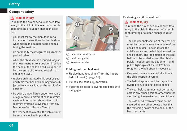
Occupant safety
64
G Risk of injuryTo reduce the risk of serious or even fatalinjury to the child in the event of an acci-dent, braking or sudden change in direc-tion:Ryou must follow the manufacturer'sinstallation instructions for the child seatwhen fitting the padded table and fas-tening the seat belt.
Rdo not modify the integrated child seat orpadded table
Rwhen the child seat is occupied, adjustthe head restraint to a position in whichthe back of the child's head is supportedby the centre of the head restraint atabout eye level.
Rreplace an integrated child seat or pad-ded table that has been damaged or sub-jected to a heavy load as the result of anaccident
Rbe aware that children under two yearsof age require a different child restraintsystem. Information about other childrestraint systems is available from anyMercedes-Benz Service Centre.
Rthe rear seat backrest in the vehiclemustbe securely locked in position.
1 Side head restraints2 Seat belt guide3 Release handle
Folding out the child seatX Fit side head restraints1 for the integra-ted child seat (Y page 65).
X Pull release handle3 forwards.X Push the child seat upwards and back untilit engages.
Fastening a child's seat beltG Risk of injuryTo reduce the risk of serious or even fatalinjury to the child in the event of an acci-dent, braking or sudden change in direc-tion:RThe shoulder belt section of the seat beltmust be routed across the middle of thechild's shoulder – never across thechild's neck – and pulled tight against thechild's chest. The lap section of the seatbelt must be routed across the child'spelvis – not across the abdomen – andpulled tight against the child's body;retighten the belt strap if necessary.
ROnly ever secure one child at a time inthe child restraint system.
RThe belt strap must not be trapped ortwisted or rub against sharp edges.
RThe seat belt strap must not be routedacross any other position other than theseat belt guide marked on the child seat.
RThe side head restraints must not besecured at any other points other thanthe fastening points at the back of thehead restraints.
Safety
204_AKB; 2; 3, en-GBmkalafa,
2007-06-26T23:11:51+02:00 - Seite 64
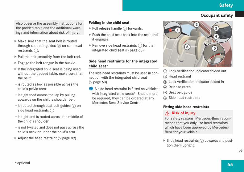
Occupant safety
65
Also observe the assembly instructions forthe padded table and the additional warn-ings and information about risk of injury.
X Make sure that the seat belt is routedthrough seat belt guides2 on side headrestraints1.
X Pull the belt smoothly from the belt reel.X Engage the belt tongue in the buckle.X If the integrated child seat is being usedwithout the padded table, make sure thatthe belt:
Ris routed as low as possible across thechild's pelvic area
Ris tightened across the lap by pullingupwards on the child's shoulder belt
Ris routed through seat belt guides2 onside head restraints1
Ris tight and is routed across the middle ofthe child's shoulder
Ris not twisted and does not pass across thechild's neck or under the child's arm
X Adjust the head restraint (Y page 89).
Folding in the child seatX Pull release handle3 forwards.X Push the child seat back into the seat untilit engages.
X Remove side head restraints1 for theintegrated child seat (Y page 65).
Side head restraints for the integratedchild seat*The side head restraints must be used in con-nection with the integrated child seat(Y page 63).
i A side head restraint is fitted on vehicleswith integrated child seats*. Should morebe required, they can be ordered at anyMercedes-Benz Service Centre.
1 Lock verification indicator folded out2 Head restraint3 Lock verification indicator folded in4 Release catch5 Seat belt guide6 Side head restraints
Fitting side head restraintsG Risk of injuryFor safety reasons, Mercedes-Benz recom-mends that you only use head restraintswhich have been approved by Mercedes-Benz for your vehicle.
X Slide head restraints2 upwards and posi-tion them upright.
Safety
* optional
204_AKB; 2; 3, en-GBmkalafa,
2007-06-26T23:11:51+02:00 - Seite 65
Z

Occupant safety
66
X Slide side head restraints6 to the centreon both head restraint rods until theyengage.The right and left lock verification indica-tors3must be folded in. The red surfacesare no longer visible.
X Slide head restraints2 downwards(Y page 89) until they rest on the upperedge of side head restraints6.
X Route the seat belt through seat belt guide5.
Removing the side head restraintsX Take the seat belt out of seat belt guide5.
X Move head restraint2 upwards.X Press left and right release buttons4 andpull forward side head restraints6 toremove them.The left and right lock verification indica-tors1 fold out briefly.
X Adjust head restraints2 (Y page 89).
i On vehicles with TIREFIT kit, you can storethe side head restraints in the stowagecompartment under the boot/luggage
compartment floor (Y page 184)/(Y page 184).
Child-proof locksIf children are travelling in the vehicle, you canactivate the child-proof locks for the rear.
Child-proof locks for the rear doorsThe child-proof locks on the rear doors enableyou to secure each door individually. You can-not open a locked door from the inside. Youcan open the door from the outside if thevehicle is unlocked.G Risk of injuryActivate the child-proof locks on the reardoors and deactivate the rear-compart-ment window controls when children aretravelling in the vehicle. The children couldotherwise open doors or windows while thevehicle is in motion, injuring themselvesand others.
Saloon shown as an example1 To activate2 To deactivate
X To activate: press locking lever upwards1.
X Check the function of the child-proof locks.
X To deactivate: press locking lever down-wards2.
Child-proof locks for the rear windowsG Risk of injuryActivate the child-proof locks on the reardoors and deactivate the rear-compart-ment window controls when children aretravelling in the vehicle. The children couldotherwise open doors or windows while the
Safety
204_AKB; 2; 3, en-GBmkalafa,
2007-06-26T23:11:51+02:00 - Seite 66

Driving safety systems
67
vehicle is in motion, injuring themselvesand others.
1 Indicator lamp2 Button
X To activate: press button2.Indicator lamp1 lights up. The rear sidewindows can only be operated using theswitches on the driver's door.
X To deactivate: press button2.Indicator lamp1 goes out. You can oper-ate the rear side windows using theswitches in the rear compartment.
Driving safety systemsIn this section, you will find information aboutthe following driving safety systems:RABS (Anti-lock Braking System)RBAS (Brake Assist System)RAdaptive brake lampsRESP® (Electronic Stability Program)REBV (electronic brake-power distribution)
i In wintry road conditions, use winter tyres(M+S tyres) and snow chains if necessary. .
G Risk of accidentThe risk of an accident is significantlyincreased by driving too fast. This is partic-ularly the case when cornering on wet andslippery roads and when driving too closeto the vehicle in front.The driving safety systems described in thissection cannot reduce this risk or overridethe laws of physics.For this reason, always adapt your drivingstyle to suit the prevailing road andweatherconditions. Maintain sufficient distancefrom other road users and objects on theroad.
ABS (Anti-lock Braking System)ABS regulates brake pressure in such a waythat the wheels do not lock when you brake.This allows you to continue steering the vehi-cle when braking.ABS works from a speed of about 8 km/hupwards, regardless of road surface condi-tions. ABS works on slippery surfaces, evenwhen you only brake gently.G Risk of accidentDo not depress the brake pedal severaltimes in quick succession (pumping).Depress the brake firmly and evenly. Pump-ing the brake pedal reduces the brakingeffect.
BrakingIf ABS intervenes when braking, you will feela pulsing in the brake pedal.If ABS intervenes:X Continue to depress the brake pedal withforce until the braking situation is over.
For full braking application:X Depress the brake pedal with maximumforce.
Safety
204_AKB; 2; 3, en-GBmkalafa,
2007-06-26T23:11:51+02:00 - Seite 67

Driving safety systems
68
G Risk of accidentIf ABS is faulty, the wheels could lock whenbraking. This limits the steerability of thevehicle when braking and the braking dis-tance may increase.If ABS is deactivated due to a malfunction,then BAS and ESP are also deactivated.
BAS (Brake Assist)BAS operates in emergency braking situa-tions. If you depress the brake pedal quickly,BAS automatically boosts the braking force,thus shortening the stopping distance.X Keep the brake pedal firmly depressed untilthe emergency braking situation is over.ABS prevents the wheels from locking.
The brakes will function as usual once yourelease the brake pedal. BAS is deactivated.G Risk of accidentIf BAS has malfunctioned, the braking sys-tem remains available with full brake boost-ing effect. However, braking force is notautomatically increased in emergencybraking situations and the stopping dis-tance may increase.
Adaptive brake lampsi Adaptive brake lamps are only available incertain countries.
If you brake sharply from a speed of morethan 50 km/h or if braking is assisted by BAS,the brake lamps flash rapidly. In this way,traffic travelling behind you is warned in aneven more noticeable manner.If you brake from a speed of more than70 km/h and bring the vehicle to a halt, thehazard warning lamps switch on automati-cally once the vehicle is stationary and thebrake lamps light up constantly if you depressthe brake pedal again. The hazard warninglamps switch off automatically if you travelfaster than 10 km/h again.
ESP® (Electronic Stability Program)ESP® monitors driving stability and traction,i.e. power transmission between the tyresand the road surface.If ESP® detects that the vehicle is deviatingfrom the direction desired by the driver, oneor more wheels are braked to stabilise thevehicle. The engine output is also modified, ifnecessary, to keep the vehicle on the desiredcourse within the laws of physics. ESP assiststhe driver when pulling away on wet or slip-pery roads. ESP® can also stabilise the vehi-cle during braking.When ESP® intervenes, thev warninglamp flashes in the instrument cluster.G Risk of accidentIf thev warning lamp in the instrumentcluster flashes, proceed as follows:RDo not deactivate ESP® under any cir-cumstances.
ROnly depress the accelerator pedal as faras necessary when pulling away.
RAdapt your driving style to suit the pre-vailing road and weather conditions.
The vehicle could otherwise go into a skid.
Safety
204_AKB; 2; 3, en-GBmkalafa,
2007-06-26T23:11:51+02:00 - Seite 68

Driving safety systems
69
ESP® cannot reduce the risk of an accidentif you drive too fast. ESP® cannot overridethe laws of physics.
! If the vehicle is to be towed with the frontor rear axle raised, the ignition must beswitched off (key in position 0 or 1 in theignition lock). Application of the brakes byESP® could otherwise destroy the brakesystem on the front or rear axle.
! Vehicles with 4MATIC* may not be towedwith the front or rear axle raised.
i Only use wheels with the recommendedtyre sizes. Only then will ESP® functionproperly.
ESP® trailer stabilisingIf your trailer begins to lurch, you can onlystabilise the vehicle/trailer combination bydepressing the brake firmly.In this situation, ESP® assists you and detectsif the trailer begins to snake. ESP® slows thevehicle down by braking and limiting theengine output until the vehicle/trailer com-bination has stabilised.
Trailer stabilising is active from about65 km/h.G Risk of accidentIf the road and weather conditions are bad,trailer stabilising will not be able to preventthe trailer from lurching or reduce the riskof accident. Trailers with a high centre ofgravity can tip over before ESP® can detectthis.
Trailer stabilising does not work if ESP® isdeactivated or switched off because of a mal-function.
ETS (Electronic Traction Support)Traction control is part of ESP®.Traction control brakes the drive wheels indi-vidually if they spin. This enables you to pullaway and accelerate on slippery surfaces, forexample if the road surface is slippery on oneside.Traction control remains active when youdeactivate ESP®.G Risk of accidentTraction control cannot reduce the risk ofan accident if you drive too fast. Tractioncontrol cannot override the laws of physics.
Deactivating/activating ESP®
ESP® is activated automatically when theengine is running.It may be best to deactivate ESP® in the fol-lowing situations:Rwhen using snow chainsRin deep snowRon sand or gravel
G Risk of accidentActivate ESP® as soon as the reason fordeactivation is longer present. ESP® willotherwise not be able to stabilise the vehi-cle if the vehicle starts to skid or a wheelstarts to spin.
If you deactivate ESP®:RESP® no longer improves driving stability.RThe engine's torque is no longer limited andthe drive wheels can spin. The spinning ofthewheels results in a cutting action, whichprovides better grip.
RTraction control is still activated.RESP® still provides support when youbrake.
Safety
* optional
204_AKB; 2; 3, en-GBmkalafa,
2007-06-26T23:11:51+02:00 - Seite 69

Anti-theft systems
70
i If ESP® is deactivated and one or morewheels start to spin, thevwarning lampin the instrument cluster flashes. ESP®then does not stabilise the vehicle.
1 To deactivate/activate ESP®
X To deactivate: press button1.Thev warning lamp in the instrumentcluster lights up.
G Risk of accidentIf thev warning lamp in the instrumentcluster is permanently lit when the engineis running, ESP® is deactivated or not avail-able due to a malfunction. The risk of yourvehicle skidding is then increased in certainsituations.
You should therefore always adapt yourdriving style to suit the prevailing road andweather conditions.
X To activate: press button1.Thev warning lamp in the instrumentcluster goes out.
EBV (electronic brake-power distribu-tion)EBV monitors and controls the brake pres-sure on the rear wheels to improve drivingstability under braking.G Risk of accidentIf EBV is malfunctioning, the brake systemis still available with full brake boostingeffect. However, the rear wheels can stilllock, e.g. under full braking. This couldcause you to lose control of your vehicleand cause an accident. You should there-fore adapt your driving style to the differenthandling characteristics.
Anti-theft systems
ImmobiliserThe immobiliser prevents your vehicle frombeing started without the correct key.
Activating the immobiliserX With the key: remove the key from theignition lock.
X With KEYLESS GO*: press the KEYLESSGO button on the dashboard.The engine switches off.
Deactivating the immobiliserX With the key: turn the key to position 2 inthe ignition lock.
X With KEYLESS GO*: press the KEYLESSGO button on the dashboard twice withoutdepressing the brake.
i The immobiliser is always deactivatedwhen you start the engine.
Safety
* optional
204_AKB; 2; 3, en-GBmkalafa,
2007-06-26T23:11:51+02:00 - Seite 70

Anti-theft systems
71
ATA* (anti-theft alarm system)A visual and audible alarm is triggered if thealarm system is primed and you open:Ra doorRa door or the boot lid with the emergencykey element
Rthe boot lid/tailgateRthe bonnetThe alarm is not switched off even if you closea door again.
1 Indicator lamp
X To activate: lock the vehicle with the keyor, if the vehicle has KEYLESS GO*, bytouching the outside door handle.Indicator lamp1 flashes. The alarm sys-tem is primed after approximately 15 sec-onds.
X Todeactivate: unlock the vehicle using thekey or, on vehicles with KEYLESS GO*, byopening the door/boot lid/tailgate.
Switching off the alarmX With the key: insert the key into the igni-tion lock.The alarm is switched off.
orX Press theŒ or‹ button on the key.The alarm is switched off.
X With KEYLESS GO*: grasp the outsidedoor handle. The key must be outside thevehicle.The alarm is switched off.
orX Press the KEYLESS GO button on the dash-board. The key must be inside the vehicle.The alarm is switched off.
Tow-away protection*An audible and visual alarm is triggered if yourvehicle's angle of inclination is altered whiletow-away protection is primed.
i The tow-away protection alarm is trig-gered if the vehicle is jacked up on one side,for example.
Priming tow-away protectionX Lock the vehicle with the key or, if the vehi-cle has KEYLESS GO*, by touching the out-side door handle.Tow-away protection is primed afterapproximately 30 seconds.
Deactivating tow-away protectionWhen you unlock your vehicle using the keyor KEYLESS GO*, tow-away protection isautomatically deactivated.
Safety
* optional
204_AKB; 2; 3, en-GBmkalafa,
2007-06-26T23:11:51+02:00 - Seite 71
Z

Anti-theft systems
72
Deactivate tow-away protection manually ifyour vehicle:Ris being transportedRis being loaded, e.g. onto a ferry or cartransporter
Ris being parked on a movable surface, e.g.split-level garages
This will prevent false alarms.
1 To deactivate tow-away protection2 Indicator lamp
X Remove the key from the ignition lock.
X Press button1.Indicator lamp2 lights up briefly.
X Lock the vehicle with the key or, if the vehi-cle has KEYLESS GO*, by touching the out-side door handle.
i Tow-away protection remains deactiva-ted until you unlock and lock the vehicleagain.
Interior motion sensor*A visual and audible alarm is triggered if yourvehicle is locked and a movement is detectedin the vehicle interior, e.g. if someone breaksyour vehicle's side windows or reaches intothe vehicle interior.
Priming the interior motion sensorX Make sure that the side windows and thesliding/tilting sunroof*/panorama slid-ing/tilting sunroof* are closed.This will prevent false alarms.
X Lock the vehicle with the key or, if the vehi-cle has KEYLESS GO*, by touching the out-side door handle.The interior motion sensor is primed afterapproximately 30 seconds.
i Do not leave anything, e.g. mascots,hanging on the rear-view mirror or on thegrasp handles on the roof lining. Thesecould otherwise trigger false alarms.
Deactivating the interior motion sensorDeactivate the interior motion sensor if youlock your vehicle and:Rpeople or animals remain in the vehicleRthe windows remain openRthe sliding/tilting sunroof*/panoramasliding/tilting sunroof* remains open
This will prevent false alarms.
1 To deactivate the interior motion sensor2 Indicator lamp
Safety
* optional
204_AKB; 2; 3, en-GBmkalafa,
2007-06-26T23:11:51+02:00 - Seite 72

Anti-theft systems
73
X Remove the key from the ignition lock.X Press button1.Indicator lamp2 flashes briefly.
G Risk of injuryDo not leave children unsupervised in thevehicle. They could open the doors, releasethe parking brake or injure themselves onmoving parts, thus endangering them-selves and others.
i The interior motion sensor remains deac-tivated until you unlock and lock the vehicleagain.
Safety
204_AKB; 2; 3, en-GBmkalafa,
2007-06-26T23:11:51+02:00 - Seite 73

74
204_AKB; 2; 3, en-GBmkalafa,
2007-06-26T23:11:51+02:00 - Seite 74

75
Opening and closing ........................... 76Key positions ....................................... 85Seats .................................................... 86Steering wheel .................................... 92Mirrors ................................................. 93Memory functions* ............................. 96Seat belts ............................................. 98Lights ................................................. 102Windscreen wipers ........................... 108Side windows .................................... 110Driving and parking .......................... 113Transmission ..................................... 117
Instrument cluster ............................ 123On-board computer (vehicles withmulti-function steering wheel, 4buttons) ............................................. 125On-board computer (vehicles withthe luxury multi-function steeringwheel*, 12 buttons) .......................... 129Driving systems ................................ 145Air vents ............................................ 156Thermatic .......................................... 158Thermotronic* ................................... 165Rear window heating ........................ 173Sliding sunroof .................................. 173Loading and stowing ........................ 179Features ............................................. 195
Controls
204_AKB; 2; 3, en-GBmkalafa,
2007-06-26T23:11:51+02:00 - Seite 75

Opening and closing
76
Opening and closing
KeyThe vehicle's equipment includes two keyswith remote control. Each key contains anemergency key element.The key is configured at the factory to cen-trally lock and unlock the following:RThe doorsRThe boot lid/tailgateRThe fuel filler flap
G Risk of accidentNever leave children unsupervised in thevehicle. They could open even a lockeddoor from the inside or start the vehicle ifthe key is left in it and thereby endangerthemselves and others. You should there-fore take the key with you when leaving thevehicle, even if you are only leaving it for ashort time.
1j Locking button2i Unlocking button for the boot lid/
tailgate*3k Unlocking button4 Battery check lamp
i You can also open and close the side win-dows and the sliding/tilting sunroof* or thepanorama sliding sunroof* with the key(Y page 111).
Factory settingsX To unlock centrally: press thek but-ton.The turn signals flash once. The lockingknobs in the doors pop up. The anti-theftalarm system* is deactivated.
When it is dark, the surround lighting alsocomes on if it is activated in the on-boardcomputer.
i If you do not open either a door or theboot lid/tailgate after you have unlockedthe vehicle, it will relock automatically afterapproximately 40 seconds.
X To lock centrally: press thej button.The turn signals flash three times if thedoors and boot lid/tailgate are closed. Thelocking knobs in the doors drop down. Theanti-theft alarm system* and the immobil-iser are primed.
Individual settingsYou can change the setting of the lockingsystem in such a way that pressing thek button only unlocks the driver's doorand the fuel filler flap. This is useful if you fre-quently travel on your own.X To change the setting: press and hold downthek andj buttons simultaneouslyfor approximately six seconds until batterycheck lamp flashes twice.
Controls
* optional
204_AKB; 2; 3, en-GBmkalafa,
2007-06-26T23:11:51+02:00 - Seite 76

Opening and closing
77
The key now functions as follows:X To unlock the driver's door: press thek button once.
X To unlock centrally: press thek but-ton twice.
X To lock centrally: press thej button.
Restoring the factory settingsX Press thek andj buttons simulta-neously for approximately six seconds untilthe battery check lamp flashes twice.
KEYLESS GO key*If you are carrying the KEYLESS GO key onyour person, you can use the KEYLESS GOfunctions of your vehicle. The KEYLESS GOkey should not be more than one metre awayfrom the vehicle. However, you can also usethe KEYLESS GO key like a normal key withremote control.When you pull the door handle, the followingunlock centrally if the factory settings havenot been changed:
RThe doorsRThe boot lid/tailgateRThe fuel filler flapIf you press the button in the handle of theboot lid/tailgate, only the boot/luggage com-partment of your vehicle is unlocked.G Risk of accidentNever leave children unsupervised in thevehicle. They could:ROpen a door from the inside at any time,even if it has been locked
RStart the vehicle if a valid KEYLESS GOkey is in the vehicle and they press theKEYLESS GO button on the ignition lock
RRelease the electric parking brakeThey could endanger themselves and oth-ers. Switch off the engine and take theKEYLESS GO key with you, even if you areonly leaving the vehicle for a short time.
1j Locking button2i Unlocking button for the boot lid/
tailgate*3k Unlocking button4 Battery check lamp
i You can also use the KEYLESS GO key toopen and close the side windows and thesliding/tilting sunroof* or the panoramasliding sunroof* (Y page 111).
i If the vehicle has been parked for a longtime, the sensor surfaces are deactivatedautomatically. Pull on the door handle tounlock the door and switch on the ignitiononce to reactivate the sensors.
Controls
* optional
204_AKB; 2; 3, en-GBmkalafa,
2007-06-26T23:11:51+02:00 - Seite 77

Opening and closing
78
Important notesRIf the KEYLESS GO key is removed from thevehicle (in luggage or an article of clothing,for instance), it will no longer be possibleto lock or start the vehicle.
RIf the KEYLESS GO key is removed from thevehicle while the engine is running, e.g. ifthe front passenger leaves the vehicle withthe KEYLESS GO key, the following mes-sage will appear in the multi-function dis-play as you pull away: Key not detec-ted.
RIf the KEYLESS GO key is in the vehicle, thevehicle can be started at any time. If youhave left the KEYLESS GO key in the vehi-cle, you will see the following message inthe multi-function display when you lockthe vehicle: Key still in vehicle.
Factory settingsX To unlock centrally: pull the door handle.The turn signals flash once. The lockingknobs in the doors pop up. The anti-theftalarm system* is deactivated.When it is dark, the surround lighting alsocomes on if it is activated in the on-boardcomputer.
i If you do not open either a door or theboot lid/tailgate after you have unlockedthe vehicle, it will relock automatically afterapproximately 40 seconds.
i It is possible that the vehicle may be inad-vertently unlocked if the KEYLESS GO keyis within a maximum of one metre of thevehicle and the door handle is splashed bya gush of water or if you are cleaning thedoor handle.
1 Sensor surface on the door handle
X To lock centrally: touch sensor surface1 on the door handle.The turn signals flash three times. The lock-ing knobs in the doors drop down. The anti-
theft alarm system* and the immobiliserare primed.
Individual settingsYou can change the setting of the lockingsystem. When you now grasp the door handleon the driver's door, you will only unlock thedriver's door and the fuel filler flap. This isuseful if you frequently travel on your own.X To change the settings: press and holdthek andj buttons of the keysimultaneously for approximately six sec-onds until the battery check lamp flashestwice.
The KEYLESS GO key will now function as fol-lows:X To unlock the driver's door: Pull the doorhandle on the driver's door.
X To unlock centrally: Pull the door handleon the front-passenger door or on the reardoors.
X To lock centrally: touch sensor surface1 on the door handle.
Controls
* optional
204_AKB; 2; 3, en-GBmkalafa,
2007-06-26T23:11:51+02:00 - Seite 78

Opening and closing
79
Restoring the factory settingsX Press thek andj buttons on thekey simultaneously for approximately sixseconds until the battery check lampflashes twice.
Locking from the luggage compartment(Estate with remote boot locking*)On vehicles with KEYLESS GO* and EASY-PACK tailgate*, you can close the tailgateautomatically and thereby centrally lock yourvehicle (Y page 84).
Opening the doors from the insideYou can open a door from the inside at anytime, even if it has been locked.
1 Locking knob2 Door handle
X Pull door handle2.If the door is locked, locking knob1 popsup. The door is unlocked and can beopened.
Automatic locking featureThe vehicle will lock automatically once youhave pulled away.On vehicles with a luxurymulti-function steer-ing wheel you can also activate and deacti-vate the automatic locking via the on-boardcomputer (Y page 143).
i The vehicle is locked automatically whenthe ignition is switched on and the wheelsbegin to turn. There is therefore a risk ofbeing locked out when the vehicle is beingpushed or tested on a dynamometer.
Switching on/off
1 To switch off2 To switch on
Controls
* optional
204_AKB; 2; 3, en-GBmkalafa,
2007-06-26T23:11:51+02:00 - Seite 79

Opening and closing
80
X To switch off: press the1 button untilyou hear a tone.
X To switch on: press the2 button until youhear a tone.
Locking/unlocking the vehicle fromthe insideYou can centrally lock or unlock the vehiclefrom the inside. This feature may be useful if,for example, you wish to unlock the front-passenger door from the inside or lock thevehicle before you pull away.G Risk of accidentDo not leave children unsupervised in thevehicle. They could open a door from theinside – even if it is locked – and therebyendanger themselves and others.
i You cannot unlock the vehicle centrallyfrom the inside if the vehicle has beenlocked from the outside using the key orthe KEYLESS GO key*.
i It is only possible to lock the vehicle cen-trally if the front-passenger door is closed.
1 To unlock2 To lock
X To unlock: press button1.X To lock: press button2.
Boot/luggage compartment
G Risk of poisoningIf the engine is running and the boot lid/tailgate is open, exhaust fumes can enterthe interior of the vehicle. This could poisonyou. Therefore make sure that the boot lid/tailgate is always closed when the engineis running.
! The boot lid/tailgate swings upwards andout when it is opened. Therefore, make
sure that there is enough space above andbehind the boot lid/tailgate.
Opening from the outsideYou can only open the boot lid/tailgate if youhave unlocked it first.X To unlock centrally: press thek but-ton on the key.
To open the boot lid (Saloon)1 Release button in the handle
Controls
* optional
204_AKB; 2; 3, en-GBmkalafa,
2007-06-26T23:11:51+02:00 - Seite 80

Opening and closing
81
To open the tailgate (Estate)1 Release button in the handle
X Push release button in handle1.X Raise the boot lid/tailgate.
Opening from the outside using the key(Saloon)You can unlock and open the boot lid simul-taneously with the key when the vehicle isstationary.X Press and hold thei button on the keyuntil the boot lid opens.
Closing from the outside
G Risk of injuryMake sure that nobody can become trap-ped as you close the boot lid/tailgate.
i Do not leave the key in the boot/luggagecompartment. You could otherwise lockyourself out.
Closing the boot lid from the outside (Saloon)1 Recess
Closing the tailgate from the outside (Estate)1 Handle
X Saloon: pull down the boot lid usingrecess1.
X Estate: pull down the tailgate usingrecess1.
X Lock the vehicle with thej button onthe key or using KEYLESS GO*.
Opening from the inside (Saloon)You can unlock and open the boot simulta-neously from the driver's seat if the vehicle isstationary.
Controls
* optional
204_AKB; 2; 3, en-GBmkalafa,
2007-06-26T23:11:51+02:00 - Seite 81
Z

Opening and closing
82
1 Remote unlocking button
X Press remote unlocking button1 until theboot lid opens.
Locking the boot separately (Saloon)You can lock the boot separately12. If you thenunlock the vehicle centrally, the boot remainslocked and can not be opened.X Close the boot lid.X Remove the emergency key element fromthe key (Y page 300).
$ Basic setting% Separate locking
X Insert the emergency key element into theboot lock to the stop.
X Turn the emergency key element clockwiseto position%.
X Pull off the emergency key element.
Luggage compartment (Estate withEASY-PACK tailgate*)On vehicles with the EASY-PACK tailgate*,the tailgate opens and closes automatically.You can stop the automatic opening and clos-ing process at any time:Rby pushing the remote operating switch atthe driver's seat again
Rby pressing thei button on the keyRby pressing the button in the handle of thetailgate
Rby pressing the closing button on the tail-gate
If you have stopped the tailgate in an inter-mediate position, then open or close the tail-gate fully using the automatic function.A tone sounds when the tailgate opens orcloses.G Risk of poisoningIf the engine is running and the tailgate isopen, exhaust fumes can enter the interiorof the vehicle. This could poison you. There-fore make sure that the tailgate is alwaysclosed when the engine is running.
12 Not available in all countries
Controls
* optional
204_AKB; 2; 3, en-GBmkalafa,
2007-06-26T23:11:51+02:00 - Seite 82

Opening and closing
83
! The tailgate swings upwards and outwhen it is opened. Therefore, make surethat there is enough space above andbehind the tailgate.
i When the tailgate is fully opened, you canalso close it manually.
! If the tailgate is opened automatically,wait a short time before closing the tailgateagain manually.
Opening from the outsideYou can only open the tailgate after unlockingit first.X To unlock centrally: press thek but-ton on the key.
To open the tailgate1 Release button in the handle
X Press the button in handle1 and thenrelease it.The tailgate opens.
i If you hold down the button in han-dle1, you can open the tailgate manually.If you release the button, the tailgate opensfully.
Opening from the outside using the keyYou can unlock and open the tailgate simul-taneously with the key when the vehicle isstationary.X Press and hold thei button on the keyuntil the tailgate opens.
Closing from outside (without KEYLESSGO*)You can lock the tailgate from outside usingthe closing button inside the tailgate.G Risk of injuryMonitor the tailgate closing procedure tomake sure that nobody can become trap-ped. To stop the closing procedure, pressthe closing button in the tailgate again orpress thei button on the key.
i Do not leave the key in the luggage com-partment. You could otherwise lock your-self out.
1 Closing button
Controls
* optional
204_AKB; 2; 3, en-GBmkalafa,
2007-06-26T23:11:51+02:00 - Seite 83

Opening and closing
84
X Press closing button1.The tailgate closes automatically.
Closing and locking centrally from out-side (using KEYLESS GO*)You can close the tailgate from outside usingthe closing button in the tailgate or, using theKEYLESS GO button*, you can close the bootand simultaneously lock the vehicle centrally.G Risk of injuryMonitor the tailgate closing procedure tomake sure that nobody can become trap-ped. To stop the closing procedure, pressthe closing button in the tailgate again orpress thei button on the key.
i Do not leave the key in the luggage com-partment. You could otherwise lock your-self out.
1 Closing button2 KEYLESS GO button*
X To close: press closing button1.X To close and lock centrally: press KEY-LESS GO button*2.
i The tailgate cannot be locked if a KEY-LESS GO key* is left inside the luggagecompartment.
Opening and closing from the insideYou can only open and close the tailgate fromthe driver's seat when the vehicle is station-ary.
G Risk of injuryMonitor the tailgate closing procedure tomake sure that nobody can become trap-ped. Release the remote operating switchto stop the closing procedure.
1 Remote operating switch
X To open: press and hold the upper sectionof remote operating switch1 until the tail-gate opens.
X To close: make sure the key is in posi-tion 1 in the ignition lock.
X Press the lower section of remote operat-ing switch1 until the tailgate is closed.
Controls
* optional
204_AKB; 2; 3, en-GBmkalafa,
2007-06-26T23:11:51+02:00 - Seite 84

Key positions
85
Restricting the tailgate opening angleYou can limit the opening angle of the tailgatewithin the upper half of its opening range. Thiscould be useful, for example, if there is insuf-ficient clearance above the tailgate.
ActivatingX To open the tailgate: press and releasethe button in the handle.
X To stop theopeningprocedure:press thebutton in the handle again or pressthei button on the key.
X Press and hold the closing button in thetailgate until you hear a brief tone.The limited opening angle is activated. Thetailgate then stops in the stored positionwhen opened.
i If youwant to open the tailgate fully, pressthe button in the handle of the tailgateagain after it has stopped at the set angle.The stored position is retained.
DeactivatingX Press and hold the closing button in thetailgate until you hear two brief tones.
Key positions
Key
Ignition lock
} To remove the key$ Power supply for some consumers, such
as the windscreen wipers% Ignition (power supply for all consumers)
and drive position& To start the engine
i Even if the key is not for the vehicle inquestion, it will still turn in the ignition lock.The ignition is not switched on. The enginecannot be started.
KEYLESS GO*If you press the KEYLESS GO button repeat-edly without depressing the brake pedal, itsfunction corresponds to the different keypositions in the ignition lock.If you depress the brake pedal and press theKEYLESS GO button, the engine starts imme-diately.
i In order for the engine to be started usingthe KEYLESS GO button, the KEYLESS GOkey must be in the vehicle.
i If there is a key in the ignition lock, it haspriority over the KEYLESS GO function.
1 KEYLESS GO button
Controls
* optional
204_AKB; 2; 3, en-GBmkalafa,
2007-06-26T23:11:51+02:00 - Seite 85

Seats
86
If you have not yet pressed KEYLESS GO but-ton1, this corresponds to position 0 or nokey in the ignition lock.X Position 1: press KEYLESS GO button1once.It is now possible to switch on the wind-screen wipers, for example.
i If you now press KEYLESS GO button1twice, and the driver's door is open, thepower supply is disconnected again.
X Position 2 (ignition): press KEYLESS GObutton1 twice.
i If you now press KEYLESS GO button1once and the driver's door is open, thepower supply is disconnected again.
Removing the KEYLESS GO buttonYou can detach the KEYLESS GO button fromthe ignition lock and start the vehicle with akey as usual.
1 KEYLESS GO button2 Ignition lock
i If you switch back to the KEYLESS GOfunction, the system requires 2 seconds'recognition time before you can use theKEYLESS GO button as usual.
i You do not need to remove the KEYLESSGO button from the ignition lock when youleave the vehicle.
SeatsYou will find information about folding downthe rear bench seat in the following sections:RThrough-loading feature in the rear benchseat (Saloon) (Y page 186)
RLuggage compartment enlargement(Estate) (Y page 187)
Depending on the vehicle's equipment, theseat adjustments can be made either man-ually/electrically or electrically*.G Risk of injuryThe seats can still be adjusted when thereis no key in the ignition lock. For this rea-son, children should never be left unsuper-vised in the vehicle. They could becometrapped by a seat adjustment movement.
G Risk of accidentOnly adjust the driver's seat when the vehi-cle is stationary. You will otherwise be dis-tracted from the road and traffic conditionsand you could lose control of the vehicle asa result of the seat moving. This couldcause an accident.
Controls
* optional
204_AKB; 2; 3, en-GBmkalafa,
2007-06-26T23:11:51+02:00 - Seite 86

Seats
87
G Risk of injuryMake sure that nobody can become trap-ped as you adjust the seat.Observe the notes concerning the airbagsystem.Secure children as recommended; see the"Children in the vehicle" section.
! When youmove the seats, make sure thatthere are no objects in the footwell orbehind the seats. Otherwise, you coulddamage the seats and the objects.
i It is not possible to remove the headrestraints from the front seats, or, in vehi-cles without the through-loading feature,the head restraints on the rear bench seats.
Adjusting the seats manually andelectrically
1 Backrest angle2 Seat height3 Seat cushion angle4 Seat fore-and-aft adjustment
Seat fore-and-aft adjustmentX Lift handle4 and slide the seat forwardsor backwards.
X Release handle4 again.Make sure that you hear the seat click intoposition.
Backrest angleX Slide the button forwards or back in thedirection of arrow1.
Seat heightX Slide the button up or down in the directionof arrow2.
Seat cushion angleAdjust the angle so that your thighs are lightlysupported.X Turn thumbwheel3 in the desired direc-tion.
Head restraint height
G Risk of injuryMake sure that the central area of the headrestraint supports the back of your head atabout eye level. You could seriously injureyour neck if your head is not correctly sup-ported by the head restraint in the event ofan accident. Never travel without a cor-rectly adjusted and engaged head restraint.
Controls
204_AKB; 2; 3, en-GBmkalafa,
2007-06-26T23:11:51+02:00 - Seite 87

Seats
88
1 Release catch
X To raise: pull the head restraint up to thedesired position.
X To lower: press release button1 in thedirection of the arrow and push the headrestraint down to the desired position.
Head restraint position
X Push or pull the head restraint in the direc-tion of the arrow.
Adjusting the seat electrically*
1 Head restraint height2 Seat cushion angle3 Seat height4 Seat fore-and-aft adjustment5 Backrest angle
Seat fore-and-aft adjustmentX Slide the button forwards or back in thedirection of arrow4.
Seat heightX Slide the button up or down in the directionof arrow3.
Controls
* optional
204_AKB; 2; 3, en-GBmkalafa,
2007-06-26T23:11:51+02:00 - Seite 88

Seats
89
Seat cushion angleAdjust the angle so that your thighs are lightlysupported.X Slide the button up or down in the directionof arrow2.
Backrest angleX Slide the button forwards or back in thedirection of arrow5.
Head restraint height
G Risk of injuryMake sure that the central area of the headrestraint supports the back of your head atabout eye level. You could seriously injureyour neck if your head is not correctly sup-ported by the head restraint in the event ofan accident. Never travel without a cor-rectly adjusted and engaged head restraint.
X Slide the button up or down in the directionof arrow1.
Head restraint position
X Push or pull the head restraint in the direc-tion of the arrow.
Lumbar supportThe lumbar support for the driver's seat canbe adjusted to provide optimum support foryour back.
1 Adjustment lever
X Move adjustment lever1 in the directionof the arrow until the desired backrest con-tour is achieved.
Rear seat head restraints
Adjusting the head restraint height
G Risk of injuryMake sure that the central area of the headrestraint supports the back of your head atabout eye level. You could seriously injureyour neck if your head is not correctly sup-ported by the head restraint in the event ofan accident. Never travel without a cor-rectly adjusted and engaged head restraint.
Controls
204_AKB; 2; 3, en-GBmkalafa,
2007-06-26T23:11:51+02:00 - Seite 89

Seats
90
1 Release catch
X Higher: pull the head restraint up to thedesired height.
X Lower: press release catch1 and pushthe head restraint down until it is in thedesired position.
Adjusting the angle of the outer headrestraintsX Pull or push the top of the head restraintuntil it is in the desired position.
Fitting/removing the rear bench seathead restraints (vehicles with through-loading feature*)
G Risk of injuryOccupants should only travel sitting onseats which have the head restraints instal-led. This reduces the risk of injury to thepassengers in the rear in the event of anaccident.
1 Release catch
X Release the rear seat backrest and fold itslightly forwards (Y page 186).
X To remove: pull the head restraint up tothe stop.
X Press release catch1 and pull the headrestraint out of the guides.
X To refit: insert the head restraint so thatthe notches on the bar are on the left whenviewed in the direction of travel.
X Push the head restraint down until you hearit click it into place.
X Fold back the rear seat backrest until itengages (Y page 186).
Multi-contour seat*You can adjust the contour of the front seatbackrests individually to provide optimumsupport for your back.
1 Thigh cushion2 Lumbar region support3 Upper back support4 Backrest side cushions
Controls
* optional
204_AKB; 2; 3, en-GBmkalafa,
2007-06-26T23:11:51+02:00 - Seite 90

Seats
91
X Make sure that the key is in position 2 inthe ignition lock.
X Thigh cushion: use button1 to adjust thethigh cushion to the desired position.
X Backrest contour in the lumbar region:use button2 to adjust the lumbar regionsupport to the desired position.
X Backrest contour for the upper back:use button3 to adjust the backrest con-tour to the desired position.
X Backrest side bolsters: use button4 toadjust the backrest side bolsters to thedesired position.
i If, after a certain amount of time, the seatno longer has the desired contour, repeatthe adjustment.
Seat heating*The three red indicator lamps in the buttonindicate the heating level you have selected.
1 Seat heating
i The system automatically switches downfrom level 3 to level 2 after approximatelyfive minutes.The system automatically switches downfrom level 2 to level 1 after approximatelyten minutes.The system automatically switches offapproximately 20 minutes after it is set tolevel 1.
X Make sure that the key is in position 1 or2 in the ignition lock.
X To switch on: press button1 repeatedlyuntil the desired heating level is set.
X To switch off: press button1 repeatedlyuntil all the indicator lamps go out.
i If the battery voltage is too low, the seatheating may switch off. One or more indi-cator lamps will then light up once.
Controls
* optional
204_AKB; 2; 3, en-GBmkalafa,
2007-06-26T23:11:51+02:00 - Seite 91

Steering wheel
92
Steering wheelDepending on the vehicle equipment, you canadjust the steering wheel either manually orelectrically*.G Risk of injuryThe electrically adjustable steeringwheel* can be adjusted when the key isremoved from the ignition lock. Therefore,do not leave children unsupervised in thevehicle as they could become trapped asthe steering wheel is adjusted.
G Risk of accidentOnly adjust the steering wheel when thevehicle is stationary and do not pull awayuntil the steering wheel adjustment mech-anism is locked in position. You might oth-erwise drive without the steering wheeladjustment mechanism being locked inposition. As a result you could be distractedfrom road and traffic conditions by an unex-pected movement of the steering wheeland thereby cause an accident.However, the steerability of the vehicle isnot affected.
When you adjust the steering wheel, makesure that:
Rthe steering wheel can be reached withyour arms slightly bent
Ryou can move your legs freelyRyou can see all the displays in the instru-ment cluster clearly
Adjusting the steering wheel man-ually
1 Release catch2 Height adjustment3 Fore-and-aft adjustment
X Fold release catch1 down completely.The steering column is unlocked.
X Set the desired steering wheel position.
X Fold release catch1 up completely.The steering wheel is locked in position.
Adjusting the steering wheel electri-cally*
1 Steering column height2 Steering column fore-and-aft adjustment
X Press the lever in the direction of arrow1 or2 until the steering wheel hasmoved into the desired position.
You can find more information under:REASY-ENTRY feature (Y page 93)RStoring settings (Y page 96)
Controls
* optional
204_AKB; 2; 3, en-GBmkalafa,
2007-06-26T23:11:51+02:00 - Seite 92

Mirrors
93
Easy-entry/exit feature*The EASY-ENTRY feature makes getting inand out of your vehicle easier.The steering wheel swings upwards whenyou:Rremove the key from the ignition lockRopen the driver's door when the key is inthe ignition lock or in position 1
The steering wheel is moved automatically tothe position previously set when the key isinserted into the ignition lockwith the driver'sdoor closed.G Risk of injuryMake sure that nobody can become trap-ped when you activate the easy-entry/exitfeature.If there is a risk of becoming trapped, stopthe adjustment procedure. To halt the pro-cedure:Rpress the steering-column adjustmentswitch
Rpress one of the memory function posi-tion buttons
The steering column stops moving immedi-ately.
Never leave children unsupervised in thevehicle. They could open the driver's doorand thereby unintentionally activate theeasy-entry feature and become trapped.
The most recent position of the steeringwheel is stored.You can activate and deactivate the EASY-ENTRY feature using the on-board computer(Y page 144).
MirrorsBefore starting off, adjust the mirrors in sucha way that you can get a good overview ofroad and traffic conditions.
Rear-view mirrorX Adjust the rear-view mirror manually.
Rear-view mirror (manual anti-dazzle)
1 Anti-dazzle switch
X Anti-dazzle mode: flick anti-dazzle switch1 forwards or back.
Controls
* optional
204_AKB; 2; 3, en-GBmkalafa,
2007-06-26T23:11:51+02:00 - Seite 93

Mirrors
94
Exterior mirrors
G Risk of accidentThe exterior mirrors reduce the size of theimage. Objects are actually closer thanthey appear. You could misjudge the dis-tance from vehicles driving behind andcause an accident, e.g. when changinglane. For this reason, make sure of theactual distance from the vehicle drivingbehind by glancing over your shoulder.
The convex exterior mirrors give a larger fieldof vision.At low outside temperatures, the exterior mir-rors are heated automatically.
Adjusting the exterior mirrors
1 Left-hand exterior mirror2 Right-hand exterior mirror3 Adjustment button
X Make sure that the key is in position 1 or2 in the ignition lock.
X Press button1 for the left-hand exteriormirror or button2 for the right-hand exte-rior mirror.The indicator lamp in the correspondingbutton lights up in red.The indicator lamp goes out again aftersome time. You can only adjust the selec-ted mirror using adjustment button3 aslong as the indicator lamp is lit.
X Press adjustment buttons3 up, down, orto the left and right until you have adjustedthe exterior mirror to the correct position.
Folding the exterior mirrors in or outelectrically*
1 To fold the exterior mirrors in or out
X Make sure that the key is in position 1 or2 in the ignition lock.
X Briefly press button1.Both exterior mirrors fold in or out.
Resetting the exterior mirrorsIf the battery has been disconnected or hasbecome discharged, the exterior mirrorsmust be reset. Otherwise, the mirrors will not
Controls
* optional
204_AKB; 2; 3, en-GBmkalafa,
2007-06-26T23:11:51+02:00 - Seite 94

Mirrors
95
fold in when you select the "Fold in mirrorswhen locking" function in the on-board com-puter (Y page 144).X Make sure that the key is in position 1 inthe ignition lock.
X Briefly press button1.
Automatically folding exterior mirrorsin or out*If the "Fold in mirrors when locking" functionis activated in the on-board computer(Y page 144),Rthe exterior mirrors fold in automatically assoon as you lock the vehicle from the out-side
Rthe exterior mirrors fold out again automat-ically as soon as you unlock the vehicle andthen open the driver's or front-passengerdoor
i If you have activated the function and foldin the exteriormirrors using button1, theywill not be folded out automatically. Youcan then only fold out the exterior mirrorsusing button1.
Automatic anti-dazzle mirrors*The rear-view mirror and the exterior mirroron the driver's side automatically go into anti-dazzle mode if the ignition is switched on andincident light fromheadlamps strikes the sen-sor in the rear-view mirror.The mirrors do not go into anti-dazzle mode ifreverse gear is engaged and the interior light-ing is switched on.G Risk of accidentIf the incident light from headlamps cannotstrike the sensor in the rear-viewmirror, forinstance when the rear window blind* isextended, the mirrors' automatic anti-daz-zle function will not operate.Incident light could then dazzle you. Thismay prevent you from observing the trafficconditions, thereby causing an accident. Inthis case, adjust the rear-view mirror man-ually.
G Risk of injuryElectrolyte may escape if the glass in anautomatic anti-dazzle mirror breaks.Electrolyte is an aggressive irritant andmust not be allowed to come into contactwith your skin, eyes or respiratory organs.
If electrolyte comes into contact with youreyes or skin, rinse thoroughly with cleanwater immediately. Consult a doctor if nec-essary.
! If electrolyte comes into contact with thevehicle paintwork, immediately rinse offthe undried liquid completely with cleanwater. It will otherwise result in damage tothe paintwork.
Parking aid*The exterior mirror on the front-passengerside moves into the parking position as soonas you engage reverse gear.
Controls
* optional
204_AKB; 2; 3, en-GBmkalafa,
2007-06-26T23:11:51+02:00 - Seite 95
Z

Memory functions*
96
1 Exterior mirror on the driver's side2 Exterior mirror on the front-passenger
side3 Adjustment button
X Make sure that the parking position for theexterior mirror on the front-passenger sideis stored with the memory function(Y page 97).
X Make sure that the key is in position 2 inthe ignition lock.
X Engage reverse gear.The indicator lamp in the mirror selectorbutton of the most recently adjusted exte-rior mirror lights up.
X Make sure that button2 for the exteriormirror on the front-passenger side ispressed.The exterior mirror on the front-passengerside moves to the stored parking position.
The exterior mirror on the front-passengerside moves back to its original position:Ras soon as you exceed a speed of10 km/h
Rabout ten seconds after you have disen-gaged reverse gear
Rif you press button1 for the exterior mir-ror on the driver's side
Memory functions*
Storing settingsYou can store up to three different settingsusing the memory button.The following settings are stored as a singlememory preset:RPosition of the seat, backrest and headrestraint
RDriver's side: steering wheel positionRDriver's side: exterior mirror positionRFront-passenger side: exterior mirror posi-tion
G Risk of injuryThe memory function* can also be usedwhen the key has been removed. For thisreason, children should never be left unsu-pervised in the vehicle. They could other-wise become trapped when moving theseat or the steering wheel.
G Risk of accidentOnly activate the memory function on thedriver’s side when the vehicle is stationary.You could otherwise be distracted from thetraffic conditions by the steering wheel and
Controls
* optional
204_AKB; 2; 3, en-GBmkalafa,
2007-06-26T23:11:51+02:00 - Seite 96

Memory functions*
97
seat moving of their own accord and causean accident.
M Memory button1, 2, 3 Storage position buttons
X Adjust the seat (Y page 86).X On the driver's side, also adjust the steer-ing wheel (Y page 92) and the mirrors(Y page 93).
X Press the M memory button.X Press one of storage position buttons 1, 2or 3 within three seconds.The settings are stored in the selected pre-set position. A tone sounds when the set-tings have been completed.
Calling up a stored setting
G Risk of accidentOnly activate the memory function on thedriver’s side when the vehicle is stationary.You could otherwise be distracted from thetraffic conditions by the steering wheel andseat moving of their own accord and causean accident.
X Press and hold relevant storage positionbutton 1, 2 or 3 until the seat, steeringwheel and mirrors are in the stored posi-tion.
i The setting procedure is interrupted assoon as you release the storage positionbutton.
! If you want to move the seat from the fullyreclined position to a stored seat position,first raise the backrest using the seatswitch. The seat could otherwise be dam-aged.
Storing a parking positionTo make it easier to park, you can store thefront-passenger side exterior mirror positionin such a way that you can see the rear wheelon that side as soon as you engage reversegear.You can store a parking position for the exte-rior mirror on the front-passenger side usingthe memory button.Youwill find information about using the exte-rior mirror's parking position in the "Parkingaid" section (Y page 95).
1 Exterior mirror on the driver's side2 Exterior mirror on the front-passenger
side3 Adjustment button4 Memory button
Controls
* optional
204_AKB; 2; 3, en-GBmkalafa,
2007-06-26T23:11:51+02:00 - Seite 97

Seat belts
98
X Make sure that the vehicle is stationary andthat the key is in position 2 in the ignitionlock.
X Press button2 for the exterior mirror onthe front-passenger side.
X Use adjustment button3 to adjust theexterior mirror to a position which allowsyou to see the rear wheel and the kerb.
X Press memory button M4.X Press one of the arrows on adjustment but-ton3 within three seconds.The parking position is stored if the exteriormirror does not move.
i If the mirror moves out of position, repeatthe steps. You can adjust the exterior mir-ror again after storing the setting.
Seat beltsSeat belts are the most effective means ofrestraining the movement of vehicle occu-pants in the event of an accident. Thisreduces the risk of vehicle occupants cominginto contact with the vehicle interior.
Wearing seat belts
G Risk of injuryA seat belt which is not worn correctly, orwhich has not been engaged in the seat beltbuckle correctly, cannot perform its inten-ded protective function. Under certain cir-cumstances this could cause severe oreven fatal injuries.Make sure that all occupants – in particular,pregnant women – wear their seat belt cor-rectly at all times.RThe seat belt must pass closely over yourbody and must not be twisted. Youshould therefore avoid wearing bulkyclothing (e.g. a winter coat). The shoulderbelt section must be routed across themiddle of your shoulder – on no accountacross your neck or under your arm – andpulled tight against your upper body. Thelap belt must always pass across your lap
as low down as possible, i.e. over yourhip joints – not across your abdomen. Ifnecessary, tighten the belt strap by pull-ing it down slightly and retighten in thedirection of the inertia reel.
RDo not route the belt strap across sharpor fragile objects, especially if these arelocated on or in your clothing, e.g. spec-tacles, pencils, keys, etc. The seat beltstrap could be damaged and tear in anaccident and you or other vehicle occu-pants could be injured.
ROnly one person should use each seatbelt at any one time. On no accountshould children travel sitting on your lapor the lap of another occupant, as itwould not be possible to restrain thechild in the event of an accident, brakingor a sudden change in direction, whichcould result in severe or even fatal inju-ries to the child and other occupants.
RPersons less than 1.50 m tall cannotwear the seat belts correctly. For thisreason, secure persons less than 1.50 mtall in specially designed, suitablerestraint systems.
RChildren less than 1.50 m tall or under12 years of age cannot wear the seat
Controls
204_AKB; 2; 3, en-GBmkalafa,
2007-06-26T23:11:51+02:00 - Seite 98

Seat belts
99
belts properly. Therefore, always securethese children in suitable child restraintsystems on suitable vehicle seats. Youcan find more information under "Chil-dren in the vehicle" in the "Safety" sec-tion of the Owner's Manual. Follow themanufacturer's installation instructionswhen fitting the child restraint system.
RDonot secure any objectswith a seat beltif the seat belt is also being used by oneof the vehicle's occupants.
G Risk of injuryThe seat belt does not offer the intendedlevel of protection unless the backrest isalmost vertical. Under certain circumstan-ces this could cause severe or even fatalinjuries.Before starting a journey, make sure thatthe seat is properly adjusted and that thebackrest is almost vertical.
G Risk of injuryA dirty or damaged seat belt or a seat beltthat has been subjected to a load in anaccident or modified no longer offers theintended level of protection. Under certain
circumstances this could cause severe oreven fatal injuries.For this reason, check regularly that theseat belts are not damaged or dirty.Always have damaged seat belts or seatbelts that have been subjected to a load inan accident replaced at a qualified special-ist workshop. Choose a qualified specialistworkshop which has the necessary special-ist knowledge and tools for the workrequired. Mercedes-Benz recommendsthat you use a Mercedes-Benz ServiceCentre for this purpose.For safety reasons, Mercedes-Benz recom-mends that you only use seat belts whichhave been approved by Mercedes-Benz foryour vehicle.
1 Belt sash guide2 Belt tongue3 Buckle4 Release button
Routing the beltX Adjust the seat and backrest to an almostupright position (Y page 86).
X Pull the belt smoothly through belt sashguide1.
X Route the belt over the centre of the shoul-der without twisting it.
Controls
204_AKB; 2; 3, en-GBmkalafa,
2007-06-26T23:11:51+02:00 - Seite 99
Z
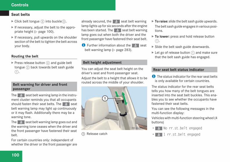
Seat belts
100
X Click belt tongue2 into buckle3.X If necessary, adjust the belt to the appro-priate height (Y page 100).
X If necessary, pull upwards on the shouldersection of the belt to tighten the belt acrossyour body.
Routing the beltX Press release button4 and guide belttongue2 back towards belt sash guide1.
Belt warning for driver and frontpassengerThe< seat belt warning lamp in the instru-ment cluster reminds you that all occupantsshould fasten their seat belts. The< seatbelt warning lamp may light up continuouslyor it may flash. Additionally there may be awarning tone.The< seat belt warning lamp goes out andthe warning tone ceases when the driver andthe front passenger have fastened their seatbelt.For certain countries only: independent ofwhether the driver or the front passenger are
already secured, the< seat belt warninglamp lights up for six seconds after the enginehas been started. The< seat belt warninglamp goes out when both the driver and thefront passenger have fastened their seat belt.
i Further information about the< seatbelt warning lamp (Y page 283).
Belt height adjustmentYou can adjust the seat belt height on thedriver's seat and front-passenger seat.Adjust the belt to a height that allows it to berouted across the middle of your shoulder.
1 Release catch
X To raise: slide the belt sash guide upwards.The belt sash guide engages in various posi-tions.
X To lower: press and hold release button1.
X Slide the belt sash guide downwards.X Let go of release button1 and make surethat the belt sash guide has engaged.
Rear seat belt status indicatori The status indicator for the rear seat beltsis only available for certain countries.
The status indicator for the rear seat beltstells you how many of the belt tongues areinserted into the seat belt buckles. This ena-bles you to see whether the occupants havefastened their seat belts.You can see the following messages in themulti-function display:Vehicles withmulti-function steeringwheel (4buttons)R< No rr.st.belt engaged
R< 1 rr.st.belt engaged
Controls
204_AKB; 2; 3, en-GBmkalafa,
2007-06-26T23:11:51+02:00 - Seite 100

Seat belts
101
R< 2 rr.st.belts engaged
R< 3 rr.st.belts engaged
Vehicles with a luxury multi-function steeringwheel* (12 buttons)R< No rear seat belt engaged
R< 1 rear seat belt engaged
R< 2 rear seat belts engaged
R< 3 rear seat belts engaged
You will see the rear seat belt status indicatorin the multi-function display for about 30 sec-onds when you pull away and drive above9 km/h or when the rear-seat passengersfasten or release their seat belts.
Correct driver's seat position
1 Steering wheel2 Seat belt3 Seat
X Check whether seat3 and the headrestraint are adjusted properly(Y page 86).
Make sure that:Ryou are as far away from the driver's frontairbag as possible
Ryou are sitting in a normal upright posi-tion
Ryou can fasten the seat belt properlyRyou have moved the backrest to analmost vertical position
Ryou have set the seat angle so that yourthighs are lightly supported
Ryou can depress the pedals properlyRyou have adjusted the head restraint sothat the back of your head is supportedat eye level by the central area of thehead restraint
X Check whether steering wheel1 is adjus-ted properly (Y page 92).Make sure that:Ryou can hold the steeringwheel with yourarms slightly bent
Ryou can move your legs freelyRyou can see all the displays in the instru-ment cluster clearly
X Check whether you have fastened seat belt2 properly (Y page 98).
Controls
* optional
204_AKB; 2; 3, en-GBmkalafa,
2007-06-26T23:11:51+02:00 - Seite 101
Z

Lights
102
It should:Rfit snugly across your bodyRbe routed across the middle of yourshoulder
Rrouted in your pelvic area across the hipjoints
Lights
Light switchFor reasons of safety, Mercedes-Benz recom-mends that you drive with the lights switchedon even during the daytime. In some coun-tries, daytime use of headlamps varies due tolegal requirements and self-imposed obliga-tions. In these countries, dipped-beam head-lamps are switched on when the ignition isswitched on.Vehicles with a luxury multi-function steeringwheel*: you can use the on-board computerto change this setting in countries where day-time driving lights are not legally required; seethe section on daytime driving lights(Y page 140).
i If you drive in countries in which trafficdrives on the opposite side of the road tothe country where the vehicle is registered,oncoming traffic may be dazzled by theasymmetrical dipped-beam headlamps.Have the headlamps changed to symmet-rical dipped beam when driving in thesecountries. You can obtain informationabout this from anyMercedes-Benz ServiceCentre.
$a Left-hand parking lamp%g Right-hand parking lamp&M Lights off/daytime driving lights*(* Automatic headlamp mode/day-
time driving lights*)C Side lamps, licence plate and instru-
ment lighting*B Dipped-beam headlamps or main-
beam headlamps,¥ Front foglamps.† Rear foglamp
i The exterior lighting automaticallyswitches off when you remove the key fromthe ignition lock or open the door while theignition is switched off.
Controls
* optional
204_AKB; 2; 3, en-GBmkalafa,
2007-06-26T23:11:51+02:00 - Seite 102

Lights
103
! Switch off the side lamps or parking lampwhen you leave the vehicle. This preventsthe battery from discharging.
Dipped-beam headlampsX Make sure that the key is in position 2 ofthe ignition lock or that the engine is run-ning.
X To switch on: turn the light switch toB.The dipped-beam headlamps, parkinglamps and licence plate lamps are switchedon. The parking lamp indicator lamp next tothe light switch is lit.
i On some country-specific vehiclemodels,the dipped-beam headlamps come on assoon as the ignition is switched on.
Daytime driving lights*On vehicles with a luxurymulti-function steer-ing wheel*, you can set the daytime drivinglights using the on-board computer(Y page 143).
X To switch on: turn the light switch toM or*.The dipped-beam headlamps, side lampsand licence plate lighting are switched onwhen the engine is running.
Automatic headlamp modeThe side lamps, dipped-beam headlamps andlicence plate lighting are switched on or offautomatically, depending on the brightness ofthe ambient light.G Risk of accidentIf the light switch is set to*the head-lamps may temporarily switch off due toexposure to light, or the lights may notcomeon automatically if it is foggy. This canendanger yourself and others. Therefore,turn the light switch toB in the dark orin fog.The automatic headlamp feature is only anaid. The driver is responsible for the vehiclelighting at all times.
G Risk of accidentWhen it is dark or foggy, turn the lightswitch quickly from* toB. You
could otherwise cause an accident if theheadlamps were to switch off temporarily.
X To switch on: turn the light switch to*.The side lamps are switched on and offautomatically when the key is in position1 in the ignition lock.The dipped-beam headlamps, side lampsand licence plate lighting are switched onautomatically when the engine is running.When the parking lamp or dipped-beamheadlamps are switched on, the indicatorlamp next to the light switch lights up.
Front foglamps/rear foglamp
G Risk of accidentIf you suspect that driving conditions will befoggy, turn the light switch toB beforeyou start your journey. Otherwise, yourvehicle may not be visible and you couldtherefore endanger yourself and others.
G Risk of accidentWhen it is dark or foggy, turn the lightswitch quickly from* toB. You
Controls
* optional
204_AKB; 2; 3, en-GBmkalafa,
2007-06-26T23:11:51+02:00 - Seite 103
Z

Lights
104
could otherwise cause an accident if theheadlamps were to switch off temporarily.
i When the light switch is set to* youcannot switch on the front or rear fog-lamps.
X Make sure that the key is in position 2 inthe ignition lock.
X To switch on the front foglamps: turn thelight switch to theB orC position.
X Pull the light switch out to the first stop.The¥ green indicator lamp next to thelight switch lights up.
X To switch on the rear foglamp: turn thelight switch to theB position.
X Pull the light switch out to the second stop.The† yellow indicator lamp next to thelight switch lights up.
X To switch off the front foglamps/rearfoglamp: push in the light switch to thestop.The corresponding indicator lamp goes out.
Combination switch (turn signals,main-beam headlamps and headlampflasher)
Turn signals
Combination switch1 To indicate a right turn2 To indicate a left turn
X To switch on: press the combinationswitch in the direction of arrow1 or2.The corresponding turn signal indicatorlamp in the instrument cluster flashes.
i If you onlywish to indicate aminor changeof direction, press the combination switchbriefly in the appropriate direction. The cor-responding turn signal flashes three times.
Main-beam headlamps/headlamp flas-her
Combination switch1 Main-beam headlamps2 Headlamp flasher
Main-beam headlampsX Turn the light switch toB or*.X To switch on: press the combinationswitch in the direction of arrow1.Themain-beam indicator lamp in the instru-ment cluster lights up.
X To switch off: move the combinationswitch back to its normal position.Themain-beam indicator lamp in the instru-ment cluster goes out.
Controls
204_AKB; 2; 3, en-GBmkalafa,
2007-06-26T23:11:51+02:00 - Seite 104

Lights
105
Headlamp flasherX To switch on: briefly pull the combinationswitch in the direction of arrow2.
Hazard warning lamps
1 Hazard warning lamp buttonThe hazard warning lamps still operate if theignition is switched off. They switch on auto-matically if an airbag is deployed or if youbrake sharply and bring the vehicle to a haltfrom a speed of more than 70 km/h.X To activate: press hazard warning lampbutton1.All turn signals flash. If you now activate aturn signal, only those turn signal lamps on
the corresponding side of the vehicle willflash.
X To deactivate: press hazard warning lampbutton1.
i The hazardwarning lamps switch off auto-matically when you drive faster than10 km/h.
Adjusting the headlamp range (vehi-cles with halogen headlamps)The headlamp range control allows you toadjust the cone of light from the headlampsaccording to how your vehicle is laden.You can only adjust the headlamp rangewhilethe engine is running.
1 Thmubwheel for headlamp range
Position Load
0 Front seats occupied
1 Front and rear seats occupied
2 Front and rear seats occu-pied, boot laden
3 Front seats occupied andmaximum rear axle load hasbeen reached, for example,when towing a trailer.
X Turn thumbwheel for headlamp range1 tothe position which corresponds to the loadin your vehicle.
Controls
204_AKB; 2; 3, en-GBmkalafa,
2007-06-26T23:11:51+02:00 - Seite 105

Lights
106
Headlamp cleaning system*i The headlamps are cleaned automaticallyif the "Wipe with windscreen washer fluid"function is operated while the lights are onand the engine is running. The headlampsare cleaned again every tenth time thewindscreen is wiped with washer fluid.When the ignition is switched off, the auto-matic headlamp cleaning feature is resetand counting resumes from 0.
Intelligent Light System* (vehicleswith bi-xenon headlamps*)The Intelligent Light System adapts the light-ing of the front headlamps to the prevailingdriving conditions so that the road is illumi-nated better.On vehicles with a luxurymulti-function steer-ing wheel* you can activate or deactivate thefunction using the on-board computer .
i The Intelligent Light System is only activewhen it is dark.
The Intelligent Light System comprises:RActive light functionRCornering light function
RMotorway modeRExtended range foglamps
Active light functionFor the active light function, the dipped-beamheadlamps swivel horizontally. The swivelangle changes according to the respectivedriving situation.
i The active light function is not activewhen the vehicle is stationary.
Cornering light functionSpecially designed headlamps light up thearea into which you are driving when turningcorners.The cornering lights only light up:Rwhen it is darkRat speeds below 40 km/hRwhen the front foglamps are switched off
Switching onX Make sure that the engine is running.X Switch on the dipped-beam headlamps.
X Switch on the turn signal.The cornering light on the same side as theturn signal comes on, even if you turn thesteering wheel in the opposite directionafter indicating.
orX Turn the steering wheel in the requireddirection.When in a forward gear: the cornering lighton the inside of the bend comes on.When in reverse gear: the cornering light onthe outside of the bend comes on.
Switching offX Switch off the turn signal.
i The cornering light is activated until youturn the steeringwheel back to the straight-ahead position and the turn signal switchesoff. The cornering light may remain lit for ashort time, but nomore than threeminutes.It then goes out, even if the turn signal isstill switched on.
Motorway modeMotorway mode optimises the illumination ofthe road by:
Controls
* optional
204_AKB; 2; 3, en-GBmkalafa,
2007-06-26T23:11:51+02:00 - Seite 106

Lights
107
Rcontrolling the brightnessRadapting the headlamp rangesMotorway mode is activated if you are drivingfaster than 110 km/h and do not make anylarge steering movements for 1000 m. Yourvehicle then has two additional sources oflight inside the headlamps.
Extended range foglampsThe extended range foglamps reduce theglare experienced by the driver and improvethe illumination of the left-hand edge of thecarriageway when driving on the right-handside of the carriageway. In countries with left-hand traffic, the light source for the extendedrange foglamp function is in the front right-hand lamp cluster.X To switch on: switch on the rear foglamp.The front foglamps and the rear foglampare switched on. The extended range fog-lamps are activated if you are driving slowerthan 70 km/h.
X To switch off: switch off the rear foglamp.
i The extended range foglamps are deacti-vated automatically at speeds above100 km/h.
Interior lighting
Front overhead control panel
1¦To switch the rear interior lightingon/off2¥To switch the automatic function
on/off3XTo switch the right-hand reading
lamp on/off4ðTo switch the front interior lighting
on/off5XTo switch the left-hand reading lamp
on/off
Automatic functionX To switch on/off: press the¥ button.Button¥ pops up or goes down.
The interior lighting switches on if it is darkwhen you:Runlock the vehicleRopen a doorRopen the boot/luggage compartmentRremove the key from the ignition lockThe interior lighting switches off after a delay.You can set the delayed switch-off using theon-board computer.
i If the door is left open, the interior lightinggoes out after approximately five minutes.
Manual control
Front interior lightingX To switch on/off: press theð button.
Rear interior lightingX To switch on/off: press the¦ button.
Front reading lampsX To switch on/off: press theX button.
Controls
204_AKB; 2; 3, en-GBmkalafa,
2007-06-26T23:11:51+02:00 - Seite 107

Windscreen wipers
108
Rear-compartment overhead controlpanel
Rear-compartment reading lamps*Vehicles with the AVANTGARDE* or ELE-GANCE* design and equipment line areequipped with reading lamps in the rear com-partment. Vehicles with the CLASSIC designand equipment line are only equipped withreading lamps in the rear compartment inconjunction with the sports package*.
1XTo switch the right-hand readinglamp on/off2XTo switch the left-hand reading lamp
on/off3 Left-hand reading lamp4 Interior lighting5 Right-hand reading lamp
X To switch on/off: press theX button. Windscreen wipers
Switching the windscreen wipers on/off
Combination switch1 To switch on the windscreen wipers2 Single wipe/towipe thewindscreen using
washer fluidSettings:
M Windscreen wipers off
U Intermittent wipe, low(on vehicles with a rain sensor*:rain sensor set to low sensitivity)
Controls
* optional
204_AKB; 2; 3, en-GBmkalafa,
2007-06-26T23:11:51+02:00 - Seite 108

Windscreen wipers
109
V Intermittent wipe, high(on vehicles with a rain sensor*:rain sensor set to high sensitivity)
u Continuous wipe, slow
t Continuous wipe, fast
! Vehicles with a rain sensor*:If the windscreen becomes dirty in dryweather conditions, the windscreen wipersmay be activated inadvertently. This couldthen damage the windscreen wiper bladesor scratch the windscreen.For this reason, you should always switchoff the windscreen wipers in dry weather.
X Make sure that the key is in position 1 or2 in the ignition lock.The various wiper settings can be selectedas follows:
Single wipeX Briefly press the combination switch to thepressure point in the direction of arrow2.
Wiping the windscreen using washerfluidX Press the combination switch beyond thepressure point in the direction of arrow2.
Intermittent wipe/rain sensor*X Turn the combination switch in the direc-tion of arrow1 to positionU orV.The windscreen wipers will wipe at regularintervals. On vehicles with a rain sensor*the appropriate wiping frequency is setautomatically according to the intensity ofthe rain.
Continuous wipeX Depending on the intensity of the rain, turnthe combination switch in the direction ofarrow1 to positionu ort.
Switching off the windscreen wipersX Turn the combination switch to positionM.
Rear window wiper (Estate)
Combination switch1 Switch% To wipe the rear window using washer
fluid& To switch on intermittent wiping( To switch off intermittent wiping) To wipe the rear window using washer
fluid
Intermittent wipeX Make sure that the key is in position 1 inthe ignition lock.
Controls
* optional
204_AKB; 2; 3, en-GBmkalafa,
2007-06-26T23:11:51+02:00 - Seite 109
Z

Side windows
110
X To switch on: turn switch1 to position&.The symbol for the rear window wiperappears in the instrument cluster.
X To switch off: turn switch1 to position(.The symbol for the rear windowwiper in theinstrument cluster goes out.
Wiping the rear window using washerfluidX Make sure that the key is in position 1 inthe ignition lock.
X Turn switch1 to position% or posi-tion) and hold it there until the rearwindow has been cleaned.The rear window is wiped for a further fiveseconds after the switch is released.
Side windows
Opening/closing the side windows
G Risk of injuryMake sure that nobody can become trap-ped between the side window and the doorframe as a side window is opened. Do nottouch or lean against the side window dur-ing the opening procedure. You couldbecome trapped between the side windowand the door frame as the window movesdown. If danger threatens, release theswitch or pull the switch upwards to closethe side window again.
G Risk of injuryMake sure that nobody can become trap-ped as you close a side window. If dangerthreatens, release the switch or press theswitch a second time to open the side win-dow again.
G Risk of injuryNever leave children unsupervised in thevehicle. Always take the key with you whenleaving the vehicle, even if you only leave itfor a short time.
G Risk of injuryDo not leave children unsupervised in thevehicle, even if they are secured in a childrestraint system. The children could:Rbe seriously or even fatally injured onparts of the vehicle
Rbe seriously or even fatally injured byprolonged exposure to extremely high orextremely low temperatures
If children open a door, they could:Rseriously or even fatally injure other peo-ple
Rget out of the vehicle, thereby injuringthemselves or be seriously or even fatallyinjured by a passing vehicle
Activate the child-proof locks if children aretravelling in the vehicle. They could other-wise open doors or windows while the vehi-cle is in motion and thereby injure them-selves or others.
i It is also possible to open and close theside windows from the outside using the"Summer opening" (Y page 111) and "Con-venience closing" (Y page 112) featuresrespectively.
Controls
204_AKB; 2; 3, en-GBmkalafa,
2007-06-26T23:11:51+02:00 - Seite 110

Side windows
111
You can disable the controls for the rearside windows from the driver's seat(Y page 66).
i If PRE-SAFE® has been activated, the sidewindows close automatically, leaving asmall gap.
The switches for all side windows are locatedon the driver's door. There is also a switch oneach door for the respective window.
Switches on the driver's door1 Front left2 Front right3 Rear right4 Rear left
X Make sure that the key is in position 2 inthe ignition lock.
i When the key is turned to position 0 orremoved from the ignition lock, it is stillpossible to operate the windows until thedriver's or front-passenger door is opened,but for no more than five minutes.
X To open or close: press the switch downor pull it up beyond the pressure point andhold it until the corresponding window is inthe desired position.
X To open or close fully: press the switchdownor pull it up beyond the pressure pointand release it.
X To stop: briefly press the switch down orpull it up.
Closing with increased force and withoutthe anti-entrapment functionG Risk of injuryMake sure that nobody can become trap-ped and a serious or even fatal injury is notcaused as you close a side window withincreased force or without the anti-entrap-ment function.
If a side window locks up during closing andhas reopened again slightly:X Immediately after the window locks up, pullthe switch upwards until the window is fullyclosed.The side window is closed with more force.
If a side window locks up again during closingand has reopened again slightly:X Immediately after the window locks up, pullthe switch upwards until the window is fullyclosed.The side window is closed without the anti-entrapment function.
Summer openingYou can ventilate the vehicle before a journey.To do this, you can use the key to simultane-ously:ROpen the side windowsRopen the sliding/tilting sunroof* or thepanorama sliding sunroof* and the rollersunblinds*
i The "Summer opening" function can onlybe operated via the key.
Controls
* optional
204_AKB; 2; 3, en-GBmkalafa,
2007-06-26T23:11:51+02:00 - Seite 111

Side windows
112
X Point the tip of the key at the driver's doorhandle.
X Unlock the vehicle by pressing thekbutton.
X Press and hold thek button until theside windows and the sliding/tilting sun-roof* or panorama sliding sunroof* are inthe desired position.
If the roller sunblinds* of the panorama slid-ing sunroof* are closed, the roller sun-blinds* are opened first.X Press and hold thek button again untilthe panorama sliding sunroof* is in thedesired position.
Convenience closingWhen you lock the vehicle, you can close theside windows and the sliding/tilting sun-roof* or the panorama sliding sunroof* simul-taneously.On vehicles with a panorama sliding sun-roof* you can then close the roller sun-blinds*.G Risk of injuryMake sure nobody is trapped when usingthe Convenience closing feature. Proceedas follows if there is a risk of entrapment:With the key:RRelease thej button.RPress and hold thek button until theside windows and the sliding/tilting sun-roof* or the panorama sliding sunroof*open again.
With KEYLESS GO*:RRelease the sensor surface on the doorhandle.
RPull the door handle immediately andhold it.
The side windows and the sliding/tiltingsunroof* or the panorama sliding sun-roof* open.
With the key
X Point the tip of the key at the driver's doorhandle.
X Lock the vehicle with thej button.X Keep the button pressed until the side win-dows and the sliding/tilting sunroof* orpanorama sliding sunroof* are fully closed.
X Check that all the side windows and thesliding/tilting sunroof* or panorama slid-ing sunroof* are closed.
Controls
* optional
204_AKB; 2; 3, en-GBmkalafa,
2007-06-26T23:11:51+02:00 - Seite 112

Driving and parking
113
On vehicles with a panorama sliding sun-roof*:X Press and hold thej button again untilthe roller sunblinds* of the panorama slid-ing sunroof* close.
With KEYLESS GO*:
1 Sensor surface on the door handle
X Touch the sensor surface on door han-dle1 until the side windows and the slid-ing/tilting sunroof* or panorama slidingsunroof* are fully closed.
i Make sure you only touch sensor surface1.
X Check that all the side windows and thesliding/tilting sunroof* or panorama slid-ing sunroof* are closed.
On vehicles with a panorama sliding sun-roof*:X Touch the sensor surface on door handle1 again until the roller sunblinds of thepanorama sliding sunroof* close.
Driving and parking
Starting the engine
G Risk of accidentDo not keep any objects in the driver's foot-well. If you use a floormat or carpet in thedriver's footwell, make sure that they arecorrectly secured and that there is suffi-cient clearance for the pedals.Objects could otherwise get between thepedals in the event of sudden braking oracceleration. You may then no longer beable to brake, change gear or accelerate asintended. Thismay result in an accident andinjury.
G Risk of poisoningNever leave the engine running in enclosedspaces. The exhaust gases contain carbonmonoxide. Inhaling exhaust fumes consti-tutes a health hazard and could lead to lossof consciousness or even death.
! Do not depress the accelerator pedalwhen starting the engine.
i If you depress the brakewhen starting theengine, pedal travel will be unusually longand there will be less pedal resistance.
Controls
* optional
204_AKB; 2; 3, en-GBmkalafa,
2007-06-26T23:11:51+02:00 - Seite 113

Driving and parking
114
Manual transmission
X Shift to neutral.X Depress the parking brake (Y page 116).Further information about the manual trans-mission (Y page 117).
Automatic transmission*
P Park position (selector lever lock)R Reverse gearN NeutralD Drive position
X Before starting, make sure P is selected.
i The engine can also be started when theselector lever is in position N.
Further information about the automatictransmission (Y page 118).
Starting the engine with the key
i Vehicles with automatic transmission*:You can also use the "touch-start" function.To do this, turn the key to position 3 and
release it immediately. The engine thenstarts automatically.
X To start a petrol engine: turn the key toposition 3 in the ignition lock and release itas soon as the engine is running.
X To start a diesel engine: turn the key toposition 2 in the ignition lock .Theq preglow indicator lamp in theinstrument cluster lights up.
X When theq preglow indicator lampgoes out, turn the key to position 3 andrelease it as soon as the engine is running.
i You can start the engine without preglowif the engine is warm.
Starting the engine with KEYLESS GO*
G Risk of injuryYour vehicle can be started using a validKEYLESSGO key*. For this reason, childrenshould never be left unsupervised in thevehicle. Always take the KEYLESS GOkey* with you when leaving the vehicle,even if you are only leaving it for a shorttime.
Controls
* optional
204_AKB; 2; 3, en-GBmkalafa,
2007-06-26T23:11:51+02:00 - Seite 114

Driving and parking
115
The KEYLESS GO button can be used to startthe vehicle without inserting the key in theignition lock.
1 KEYLESS GO button
X Depress the brake pedal.The selector lever lock is released.
X Petrol engine: press KEYLESS GO button1 once.The engine starts automatically.
X Diesel engine: press KEYLESS GO button1 once.Preglow is activated and the engine startsautomatically.
i You can start the engine without preglowif the engine is warm:
X Press and hold KEYLESS GO button1 until the engine is running.
Pulling away! Warm up the engine quickly. Do not usethe engine's full performance until it hasreached operating temperature.Only change into reverse gear when thevehicle is stationary.Where possible, avoid spinning the drivewheels when pulling away on slipperyroads. You could otherwise damage thedrive train.
i The vehicle will lock itself centrally onceyou have pulled away. The locking knobs inthe doors drop down.You can open the doors from the inside atany time.You can also deactivate the automatic lock-ing feature (Y page 143).
Manual transmissionX Depress the clutch pedal.X Shift to either first or reverse gear.
X Slowly release the clutch pedal anddepress the accelerator pedal.
! Change gear in good time and avoid spin-ning the wheels. You could otherwise dam-age the vehicle.
Automatic transmission*i It is only possible to move the selectorlever to the desired position if you depressthe brake pedal. Only then is the selectorlever lock released.
X Depress the brake pedal and hold it down.X Pull the parking brake release handle torelease the parking brake.
X Move the selector lever to position D or R.
i Wait for the shift process to completebefore pulling away.
X Release the brake pedal.X Carefully depress the accelerator pedal.
i Upshifts take place at higher enginespeeds after a cold start. This helps thecatalytic converter to reach its operatingtemperature more quickly.
Controls
* optional
204_AKB; 2; 3, en-GBmkalafa,
2007-06-26T23:11:51+02:00 - Seite 115

Driving and parking
116
Parking
G Risk of accidentOnly remove the key from the ignition lockwhen the vehicle is stationary since youcannot steer the vehicle with the keyremoved.Never leave children unsupervised in thevehicle. They could release the parkingbrake. This could lead to a serious or fatalaccident.
G Risk of fireMake sure that the exhaust system doesnot under any circumstances come intocontact with easily ignitable material suchas dry grass or petrol. The material couldotherwise ignite and set the vehicle on fire.
Parking brake
1 Release handle2 Parking brake
X To release: depress the brake pedal andkeep it depressed.On vehicles with automatic transmission*the selector lever lock is released.
X Pull release handle1.X The3 indicator lamp in the instrumentcluster goes out.
X To apply: depress parking brake2 firmly.The3 indicator lamp in the instrumentcluster lights up if the engine is running.
i On steep slopes, turn the front wheelstowards the kerb.
Stopping the engine
G Risk of accidentIf the engine is not running, there is nopower assistance for the steering andbrakes. Steering and braking then takesmuch more effort.As a result, you might lose control of thevehicle, cause an accident and injure your-self and others.Do not switch off the engine while driving.
Vehicles with manual transmissionX Shift to either first or reverse gear.X Turn the key to position 0 in the ignitionlock and remove it.The immobiliser is activated.
Vehicles with automatic transmission*X Move the selector lever to P.
With the keyX Turn the key to position 0 in the ignitionlock and remove it.The immobiliser is activated.
Controls
* optional
204_AKB; 2; 3, en-GBmkalafa,
2007-06-26T23:11:51+02:00 - Seite 116

Transmission
117
i The key can only be removed when theselector lever is in position P.
With KEYLESS GO*X Press the KEYLESS GO button .The engine stops and all the lamps in theinstrument cluster go out . The status of theon-board electronics corresponds to keyposition 1.
Transmission
G Risk of accidentThe movement of the pedals must not beimpaired in any way. Do not keep anyobjects in the driver's footwell. Make surethat floormats or carpets are correctlysecured and that there is sufficient clear-ance for the pedals.
G Risk of accidentDo not change down for additional enginebraking on a slippery road surface. Thiscould cause the drive wheels to lose theirgrip and the vehicle could skid. This couldcause you to lose control of your vehicleand cause an accident.
Manual transmission
! When shifting between 5th and 6th gear,you must press the shift lever to the right.You could otherwise shift unintentionallyinto 3rd or 4th gear and damage the trans-mission.Do not exceed the maximum speed for theindividual gears.If you shift down at too high a speed (trans-mission braking), this can cause the engineto overspeed, leading to engine damage.
Engaging reverse gear! Only engage reverse gear when the vehi-cle is stationary, otherwise the transmis-sion could be damaged.
Controls
* optional
204_AKB; 2; 3, en-GBmkalafa,
2007-06-26T23:11:51+02:00 - Seite 117

Transmission
118
X Move the gear lever firmly to the leftbeyond the point of resistance and thenforwards.
Automatic transmission*
1 Selector lever position/shift range2 Gearshift program (S/C) or (S/C/M)*The current shift range and gearshift program(S/C) or (S/C/M)* appear in the display ofthe speedometer.When the selector lever is in position D, youcan influence the gearshifts made by theautomatic transmission by:Rrestricting the shift rangeRchanging gear yourself
Selector lever positions
ì Park positionPrevents the vehicle from rollingawaywhen stopped. Onlymove theselector lever toPwhen the vehicleis stationary.
i The key can only be removedwhen the selector lever is in posi-tion P. If the key is removed fromthe ignition lock, the selectorlever is locked in position P.
í Reverse gearOnly move the selector lever to Rwhen the vehicle is stationary.
Controls
* optional
204_AKB; 2; 3, en-GBmkalafa,
2007-06-26T23:11:51+02:00 - Seite 118

Transmission
119
ë NeutralReleasing the brakes will allow youto move the vehicle freely, e.g. topush it or tow it.Do not move the selector lever toN while you are driving. The auto-matic transmission could other-wise be damaged.If ESP® is deactivated or faulty:only move the selector lever to N ifthe vehicle is in danger of skidding,e.g. on icy roads.
ê DriveThe automatic transmissionchanges gear automatically. Allforward gears are available.
One-touch gearshiftingWhen the selector lever is in position D, youcan perform gearshifts yourself, even on vehi-cles with automatic transmission.X To shift up: press the selector lever brieflyto the right towards D+.The automatic transmission shifts up to thenext gear, depending on the gearshift pro-
gram selected. This also extends the shiftrange.
X To shift down: press the selector leverbriefly to the left towards D–.The automatic transmission shifts down tothe next gear, depending on the gear cur-rently selected. This also restricts the shiftrange.
i To prevent the engine from overrevving,the automatic transmission does not shiftdown if you push the selector lever towardsD– while driving at too high a speed.
X To derestrict the shift range: press andhold the selector lever towards D+ until Dis shown once more in the display.The automatic transmission shifts from thecurrent shift range directly to D.
X To select the most effective shiftrange: press and hold the selector lever tothe left towards D–.The automatic transmission will shift to arange which allows ideal acceleration anddeceleration. To do this, the automatictransmission will shift down one or moregears.
Shift rangesWhen the selector lever is in position D, it ispossible to restrict or derestrict the shiftrange for the automatic transmission.X Briefly press the selector lever to the righttowards D+ or to the left towards D–.The shift range selected is shown in thespeedometer display. The automatic trans-mission shifts only as far as the selectedgear.
i If the maximum engine speed for the shiftrange is reached and you continue to accel-erate, the automatic transmission shifts upin order to avoid engine overspeed even ifthe shift range is restricted.
Driving situation
è The braking effect of the engine canbe utilised in this position.
Controls
204_AKB; 2; 3, en-GBmkalafa,
2007-06-26T23:11:51+02:00 - Seite 119

Transmission
120
ç To use the braking effect of theengine on downhill gradients andfor driving:Ron steep mountain roadsRin mountainous terrainRin arduous conditions
æ To use the braking effect of theengine on extremely steep downhillgradients and long downhillstretches.
Program selector button
1 Program selector button
S Sport For all normal driving con-ditions
C Comfort For comfort mode
! Only press program selector button1when the selector lever is in position P, Nor D.
X Press program selector button1 repeat-edly until the letter (C/S) for the desiredgearshift program appears in the speed-ometer display.
Comfort mode C is characterised by the fol-lowing:Rthe vehicle pulling away more gently inforward and reverse gears, unless theaccelerator pedal is depressed fully.
Ran increase in traction. This improves thedriving stability of the vehicle on slipperyroad surfaces, for example.
Rthe automatic transmission shifting upsooner; consequently, the vehicle is drivenat lower engine speeds and the wheels areless likely to spin.
Driving tips
Accelerator pedal positionYour style of driving influences how the auto-matic transmission shifts gear:Rlittle throttle: early upshiftsRmore throttle: late upshifts
KickdownUse kickdown for maximum acceleration.X Depress the accelerator pedal beyond thepressure point.The transmission shifts to a lower geardepending on the engine speed.
X Ease off on the accelerator pedal once thedesired speed is reached.The automatic transmission shifts back up.
Trailer towingX Drive in the middle of the engine speedrange on uphill gradients.
X Shift down to shift range 3 or 2(Y page 119) depending on the incline ofthe uphill or downhill gradient, even ifcruise control* is activated.
Controls
* optional
204_AKB; 2; 3, en-GBmkalafa,
2007-06-26T23:11:51+02:00 - Seite 120

Transmission
121
Steering wheel gearshift paddles*and manual gearshift program*
Steering wheel gearshift paddlesIt is possible to shift gear using either thesteering wheel gearshift paddles or the selec-tor lever.
1 Left-hand paddle: to shift down2 Right-hand paddle: to shift up
UpshiftingX Pull right-hand paddle2.The automatic transmission shifts up to thenext gear. If you are not driving in the man-ual gearshift program M, then the shiftrange will be extended.
DownshiftingG Risk of accidentDo not change down for additional enginebraking on a slippery road surface. Thiscould cause the drive wheels to lose theirgrip and the vehicle could skid.
X Pull left-hand paddle1.The automatic transmission shifts down tothe next gear. If you are not driving in themanual gearshift program M, the shiftrange will be restricted.
i When the selector lever is in position P,N or R, you cannot change gear using thesteering wheel gearshift paddles.Vehicles without the ADVANCED AGILITYpackagewith sportsmode*: ifmanual gear-shift program M is selected and you startthe engine again, the automatic transmis-sion changes to an automatic gearshift pro-gram. If automatic gearshift program S orC has been selected, the automatic trans-mission will resume the relevant gearshiftprogram when you restart the engine.Vehicles with the ADVANCED AGILITYpackagewith sportsmode*: ifmanual gear-shift program M is selected and you startthe engine again, your selection is deleted.
Manual gearshift programIn the manual gearshift program M, you canchange gear using the steering wheel gear-shift paddles or the selector lever. The man-ual gearshift program M can be selectedusing the program selector button.
1 Program selector buttonVehicles without the ADVANCED AGILITYpackage with sports mode*
S Sport For all normal driving con-ditions
C Comfort For comfort mode
M Manual For manual gearshifting
Controls
* optional
204_AKB; 2; 3, en-GBmkalafa,
2007-06-26T23:11:51+02:00 - Seite 121

Transmission
122
i On vehicles with the ADVANCED AGILITYpackage with sports mode*, the programS or C is selected via the sport button(Y page 152).
X To activate: press program selector but-ton1 repeatedly until M appears in thedisplay.
If the selector lever is in position D, you canshift up or down through the gears. The gearcurrently selected and engaged is shown inthe display.X To deactivate (vehicles with theADVANCED AGILITY package withsports mode*): press program selectorbutton1 repeatedly, until S or C appears.To deactivate (vehicles without theADVANCED AGILITY package withsports mode*): press program selectorbutton1.M can no longer be seen in the display.
UpshiftingX Press the selector lever briefly to the righttowards D+.
or
X Pull the right-hand paddle on the steeringwheel (Y page 121).The automatic transmission shifts up to thenext gear.
DownshiftingG Risk of accidentDo not change down for additional enginebraking on a slippery road surface. Thiscould cause the drive wheels to lose theirgrip and the vehicle could skid.
X Press the selector lever briefly to the lefttowards D-.
orX Pull the left-hand paddle on the steeringwheel (Y page 121).The automatic transmission shifts down tothe next gear.
i For maximum acceleration, pull the left-hand gearshift paddle until the transmis-sion selects the optimum gear dependingon the speed.
KickdownYou can also use kickdown for maximumacceleration in manual gearshift program M.
X Depress the accelerator pedal beyond thepressure point.The transmission shifts to a lower geardepending on the engine speed.
i It is not possible to shift gears using thesteering wheel gearshift paddles duringkickdown.
Controls
* optional
204_AKB; 2; 3, en-GBmkalafa,
2007-06-26T23:11:51+02:00 - Seite 122

Instrument cluster
123
Instrument clusterYou will find an illustration of the instrumentcluster in the "At a glance" section(Y page 28).G Risk of accidentNo messages can be displayed if instru-ment cluster and/or the multi-function dis-play fail.Thismeans that youwill not see informationabout the driving situation, such as thespeed, outside temperature, warning/indi-cator lamps, display messages or systemfailures. The vehicle's handling character-istics may be affected. Adjust your drivingstyle and speed accordingly.Immediately consult a qualified specialistworkshop which has the necessary special-ist knowledge and tools to carry out thework required. Mercedes-Benz recom-mends that you use a Mercedes-BenzService Centre for this purpose. In particu-lar, work relevant to safety or on safety-related systems must be carried out at aqualified specialist workshop.
Activating the multi-function displayX Switch on the ignition.The multi-function display is also activatedwhen you switch on the lights or open thedriver's door.
Adjusting the instrument clusterlighting
1 Brightness controlX Brighter or dimmer: turn clockwise oranti-clockwise.
Coolant temperature gaugeThe coolant temperature gauge is in theinstrument cluster on the left-hand side. Thecoolant temperaturemay rise to 120†undernormal operating conditions and if the con-centration of antifreeze/corrosion inhibitor iscorrect. The coolant temperature may rise tothe top end of the scale at high outside tem-peratures and on long uphill stretches.
Resetting the trip meterVehicles with a 4-button multi-functionsteering wheel: you can reset the trip meterin the standard display menu(Y page 128).Vehicles with a 12-button luxury multi-function steering wheel*: you can find the"Reset values" function in the Trip menu inthe on-board computer (Y page 135).
Controls
* optional
204_AKB; 2; 3, en-GBmkalafa,
2007-06-26T23:11:51+02:00 - Seite 123

Instrument cluster
124
ClockIn vehicles without audio equipment* or withAudio 20*, you can set the time using the on-board computer.Vehicles with a 4-button multi-function steer-ing wheel (Y page 129)Vehicles with a 12-button luxury multi-func-tion steering wheel* (Y page 142)
i Vehicles with a navigation system*(Audio 50 APS* or COMAND APS*): yournavigation system* receives the time froma GPS satellite. You must set the time zoneonce on your Audio 50 APS* or COMANDAPS*. Refer to the separate OperatingInstructions for notes on how to do this.
Speedometer with segments (vehi-cles with luxury multi-function steer-ing wheel*, 12 buttons)The segments in the speedometer indicatewhich speed range is available.Cruise control* mode:The segments light up from the stored speedto the maximum speed.Variable Speedtronic* mode:The segments light up from the start of thescale to the selected limit speed.
Rev counterThe red band in the rev counter indicates theengine's overrevving range. The fuel supply isinterrupted to protect the engine when thered band is reached.
! Do not drive in the overrevving range.Doing so will damage the engine.
H Environmental noteAvoid driving at high engine speeds, as thisincreases your vehicle's consumptionunnecessarily and pollutes the environ-ment through increased emissions.
Outside temperature display
G Risk of accidentThe road surface may be icy, especially inwooded areas or on bridges, even if tem-peratures are just above freezing point. Thevehicle could skid if you fail to adapt yourdriving style. You should therefore alwaysadapt your driving style and speed to suitthe weather conditions.
There is a short delay before a change in out-side temperature is displayed.
Controls
* optional
204_AKB; 2; 3, en-GBmkalafa,
2007-06-26T23:11:51+02:00 - Seite 124

On-board computer (vehicles with multi-function steering wheel, 4 buttons)
125
On-board computer (vehicles withmulti-function steering wheel, 4 but-tons)The on-board computer is activated as soonas you turn the key to position2 in the ignitionlock. You can use the on-board computer tocall up information relating to your vehicleand to make and/or adjust settings.G Risk of accidentOnly use the on-board computer when roadand traffic conditions permit. You wouldotherwise be distracted and unable to con-centrate properly on driving, and couldcause an accident.
Multi-function steering wheel (4 but-tons)Use the buttons on the multi-function steer-ing wheel to operate the on-board computer.
1 Multi-function display
2 æRIncreases the volumeRSets the date/time
3 çRDecreases the volumeRSets the date/time
4 í
RSelects a submenuRScrolls through listsRConfirms a selection
5 è Selects a menu
You can imagine the menus as if they werearranged in a circle.X Press theè button repeatedly to call upindividual menus in sequence.
X Press theí button repeatedly to call upthe functions within a menu in sequence.
Controls
204_AKB; 2; 3, en-GBmkalafa,
2007-06-26T23:11:51+02:00 - Seite 125

On-board computer (vehicles with multi-function steering wheel, 4 buttons)
126
Multi-function displayThe multi-function display shows you values
and settings as well as any display messagesthat may have been generated.
1 Multi-function display
Controls
204_AKB; 2; 3, en-GBmkalafa,
2007-06-26T23:11:51+02:00 - Seite 126

On-board computer (vehicles with multi-function steering wheel, 4 buttons)
127
Menus and submenus
Controls
204_AKB; 2; 3, en-GBmkalafa,
2007-06-26T23:11:51+02:00 - Seite 127

On-board computer (vehicles with multi-function steering wheel, 4 buttons)
128
Function
1 Standard display (Y page 128)Shows the standard display or resetsthe trip meter
2 Trip computer (Y page 128)Shows the trip computer from thestart of the journey or resets it
3 Range
4 Digital speedometer
5 Message memory (Y page 128)
6 Service (Y page 226)Calls up the service due date
7 Tyre pressure loss warning sys-tem*
8 Time/date(Y page 129)
The number of menus shown depends on theoptional equipment in the vehicle.Use the buttons on the multi-function steer-ing wheel.
Basic displayThe basic setting shows the trip meter andthe total distance recorder in the multi-func-tion display. This is the standard display.X Press theè button repeatedly until thestandard display appears.
orX Press and hold theè button until thestandard display appears.
1 Trip meter2 Total distance recorder
X To reset the trip meter: press and holdtheí button until the value has beenreset.
Trip computerX Press theè button repeatedly until thetrip computer appears.
1 Kilometres2 Average speed3 Time4 Average fuel consumption
X To reset the trip computer: press andhold theí button until the values havebeen reset.
Message memoryThe on-board computer stores certain displaymessages. You can call up display messagesin this menu.G Risk of accidentThe on-board computer only records anddisplays messages and warnings from cer-tain systems. For this reason, you shouldalways make sure that your vehicle is safeto drive. You could otherwise cause an acci-dent by driving an unsafe vehicle.
Controls
* optional
204_AKB; 2; 3, en-GBmkalafa,
2007-06-26T23:11:51+02:00 - Seite 128

On-board computer (vehicles with the luxury multi-function steering wheel*, 12 buttons)
129
X Press theè button repeatedly until the"Message memory" menu appears.If there are no display messages, you willsee No messages. If there are messages,the 2 Messages display, for instance, willappear in the multi-function display.
X Press theí button to scroll through thedisplay messages.
i The possible display messages areexplained in the "Practical advice" section(Y page 236).All display messages are deleted when youturn off the ignition.
Time/dateThis menu is only available on vehicles with-out audio equipment or with Audio 20*.X Press theè button repeatedly until the"Time/date" menu appears.
X To set: use theí button to select thedisplay you want to change: hour, minutes,day, month, year.
X Pressæ andç to set the selecteddisplay.
X To save: press theí button.The next display is selected.
On-board computer (vehicles with theluxury multi-function steeringwheel*, 12 buttons)The on-board computer is activated as soonas you turn the key to position2 in the ignitionlock. You can use the on-board computer tocall up information relating to your vehicleand to make and/or adjust settings.G Risk of accidentOnly use the on-board computer when roadand traffic conditions permit. You wouldotherwise be distracted and unable to con-centrate properly on driving, and couldcause an accident.
Controls
* optional
204_AKB; 2; 3, en-GBmkalafa,
2007-06-26T23:11:51+02:00 - Seite 129

On-board computer (vehicles with the luxury multi-function steering wheel*, 12 buttons)
130
Luxury multi-function steering wheel(12 buttons)Use the buttons on the luxury multi-functionsteering wheel to operate the on-board com-puter.
1 Multi-function display
2 Adjusting the volumeæ Increases the volumeç Decreases the volume
Telephone operation*s Accepts a callt Rejects or ends a callF Mute
3 ! Activates voice control*
4 L Selects the nextmenu level up(back)/deactivates voice con-trol*
5 Selecting the submenu or scrollingthrough lists$ Up% DownSelecting the line for menus andselecting menus& Right( Left# Confirms selection and mes-
sages
Several functions are combined thematicallyin the menus. For example, the Settingsmenu contains functions for adjusting set-tings on your vehicle. Or you can use a func-tion to look up information or to changesettings for your vehicle.You can imagine the menus as if they werearranged in a circle.X To select the standard display: press andhold theL button until the standard
Controls
* optional
204_AKB; 2; 3, en-GBmkalafa,
2007-06-26T23:11:51+02:00 - Seite 130

On-board computer (vehicles with the luxury multi-function steering wheel*, 12 buttons)
131
display with the total distance recorder andtrip meter appears.
orX Press theL button repeatedly until thestandard display with the total distancerecorder and trip meter appears.
X To hide a display message: press the# orL button.The on-board computer stores certain dis-play messages. Calling up display mes-sages (Y page 140).
Multi-function displayThe description field on the multi-functiondisplay shows you values and settings as well
as any display messages that may have beengenerated.
1 Description field2 Line for menus
X To show the line for menus22: press the( or& button.
Controls
* optional
204_AKB; 2; 3, en-GBmkalafa,
2007-06-26T23:11:51+02:00 - Seite 131

On-board computer (vehicles with the luxury multi-function steering wheel*, 12 buttons)
132
Menus and submenus
Controls
* optional
204_AKB; 2; 3, en-GBmkalafa,
2007-06-26T23:11:51+02:00 - Seite 132

On-board computer (vehicles with the luxury multi-function steering wheel*, 12 buttons)
133
Function
1 Trip menu (Y page 133)RDisplays the standard display orresets the trip meter (Y page 133)
RDisplays or resets the trip computerfrom start (Y page 134)
RDisplays or resets the trip computerfrom reset (Y page 134)
RCalls up the range (Y page 134)RDigital speedometer (Y page 135)
2 Nav* menu (navigation details)(Y page 135)
3 Audio* menu (Y page 137)RSelects a radio station(Y page 137)
ROperates the CD player/CDchanger*/DVD changer*/DVDaudio*/MP3 (Y page 137)
ROperates the DVDvideo* (Y page 138)
4 Tel* menu (telephone) (Y page 138)
Function
5 Service menu (Y page 140)RCalls up display messages(Y page 140)
RTyre pressureRASSYST PLUS (Y page 226)
6 Settings menu (Y page 140)RSelects submenu (Y page 140)RResets to factory settings(Y page 144)
The number of menus shown depends on theoptional equipment in the vehicle.The Audio*, Nav* and Tel* menus are dis-played slightly differently in vehicles withaudio equipment* and vehicles withCOMAND APS*. The examples given in thisOwner's Manual apply to vehicles equippedwith COMAND APS*.
Trip menui Menu overview (Y page 132), using theon-board computer (Y page 130).
Use the buttons on the luxury multi-functionsteering wheel.X Press( or& to select the Tripmenu.
Basic displayX In the Trip menu, select the standard dis-play with total distance recorder and triprecorder submenu.
orX Press theL button repeatedly until thestandard display appears.
orX Press and hold theL button until thestandard display appears.
Controls
* optional
204_AKB; 2; 3, en-GBmkalafa,
2007-06-26T23:11:51+02:00 - Seite 133

On-board computer (vehicles with the luxury multi-function steering wheel*, 12 buttons)
134
1 Trip meter2 Total distance recorder
i Reset the trip meter (Y page 135).
Trip computer from startThe values in the From start submenu referto the start of the journey.X Press$ or% to select Fromstart.
1 Kilometres2 Time
3 Average speed4 Average fuel consumption
The From start trip computer is automati-cally reset if the trip is interrupted for longerthan 4 hours. It is automatically reset if thetrip exceeds 999 hours or 9,999 kilometres.
i Reset the trip computer (Y page 135).
Trip computer from resetThe values in the From reset submenu referto the last time the submenu was reset.X Press$ or% to select Fromreset.
1 Kilometres2 Time3 Average speed4 Average fuel consumption
The From reset trip computer is automati-cally reset if the trip exceeds 9,999 hours or99,999 kilometres.
i Reset the trip computer (Y page 135).
Calling up the rangeX Press$ or% to select the Rangesubmenu.The multi-function display shows the esti-mated distance that can be covered by thevehicle, based on your current driving styleand the amount of fuel remaining in thetank.
1 Estimated rangeOnce the reserve tank fuel is about halfempty, only the refuelling symbol appears.
Controls
* optional
204_AKB; 2; 3, en-GBmkalafa,
2007-06-26T23:11:51+02:00 - Seite 134

On-board computer (vehicles with the luxury multi-function steering wheel*, 12 buttons)
135
Digital speedometerX Press$ or% to select the digitalspeedometer.
1 Digital speedometer
ResettingYou can reset the following functions:RTrip meterRTrip computer from startRTrip computer from reset
X Press$ or% to select the functionthat you wish to reset.
X Press#.
Example illustrationX Press% to select Yes and press#to confirm.
Navigation* menui Menu overview (Y page 132), using theon-board computer (Y page 130).
The multi-function display shows navigationinstructions in the Nav menu.Use the buttons on the luxury multi-functionsteering wheel.X Press( or& to select the Navmenu.
Route guidance inactive
1 Direction of travel2 Current roadThe road you are currently driving on onlyappears if it is still in the Audio 50 APS* orCOMAND APS* memory.
Route guidance active
No manoeuvre announced
1 Distance to destination2 Distance to next manoeuvre3 Current road4 Symbol for "follow the road's course"
Controls
* optional
204_AKB; 2; 3, en-GBmkalafa,
2007-06-26T23:11:51+02:00 - Seite 135

On-board computer (vehicles with the luxury multi-function steering wheel*, 12 buttons)
136
Manoeuvre announced without change oflane
1 Road into which the manoeuvre leads2 Distance to manoeuvre and graphical dis-
tance display3 Symbol for manoeuvreWhen amanoeuvre is announced, youwill seethe symbol for the manoeuvre and beside it agraphical distance display2. This decreasesas you approach the announced manoeuvre.
Manoeuvre announced with change oflaneLane recommendations are only displayed ifthe relevant data is available on the digitalmap.
1 Road into which the manoeuvre leads2 Distance to manoeuvre and graphical dis-
tance display3 Lane recommendation4 Symbol for manoeuvreOn multiple-lane roads, a lane recommenda-tion3 may be shown for the next manoeu-vre. Additional lanes may be added during amanoeuvre.
Lane recommendation display1 Uninterrupted lane2 New lane during a manoeuvre3 Lane recommended for the manoeuvreFor more information on lane recommenda-tions, see the separate Operating Instruc-tions for Audio 50 APS* and COMANDAPS*.
Navigation status indicators in the multi-function displayWhen route guidance is activated, the follow-ing messages may appear:R<: you have reached the destination.RNew route...: a new route is being calcu-lated.
Controls
* optional
204_AKB; 2; 3, en-GBmkalafa,
2007-06-26T23:11:51+02:00 - Seite 136

On-board computer (vehicles with the luxury multi-function steering wheel*, 12 buttons)
137
ROff map or Off road: the vehicle positionis outside the area of the digital map (off-map position).
RNo route: no route to the selected desti-nation could be calculated.
For more information, see the separate Oper-ating Instructions for Audio 50 APS* andCOMAND APS*.
Audio* menui Menu overview (Y page 132), using theon-board computer (Y page 130).
Use the functions in the Audiomenu to oper-ate the audio equipment*. If no audio equip-ment* is switched on, the multi-functiondisplay will show the Audio off message.Use the buttons on the luxury multi-functionsteering wheel.X Press( or& to select the Audiomenu.
Selecting a radio stationX Switch on the audio equipment* orCOMAND APS* and select the radio; seethe separate Operating Instructions.
1 Waveband2 StationX To select a stored station: briefly pressthe% or the$ button.
orX To select the next or previous station:press and hold the% or the$ but-ton.
i DAB* radio mode 13 (Digital Audio Broad-casting); see the separate operatinginstructions for the audio equipment* orCOMAND APS*.
i You can only change the waveband andstore new stations using COMAND APS*.
Operating the CD player/CD changer*/DVD changer*/DVD audio*/MP3X Switch on the audio equipment* orCOMAND APS* and select the CD player orDVD audio or MP3; see the separate Oper-ating Instructions.
Illustration showing the CD player1 Current trackX To select the next or previous track:briefly press the% or the$ button.
orX To search for the next or previoustrack: press and hold the% or the$ button.
13 Only for certain countries.
Controls
* optional
204_AKB; 2; 3, en-GBmkalafa,
2007-06-26T23:11:51+02:00 - Seite 137

On-board computer (vehicles with the luxury multi-function steering wheel*, 12 buttons)
138
i If you are playing a CD or DVD with trackinformation, the multi-function displayshows the name and number of the track.The title is displayed for MP3s.
Operating the DVD video*X Switch on COMAND APS* and select DVDvideo; see the separate Operating Instruc-tions.
1 Current sceneX To select the next or previous scene:briefly press the% or the$ button.
orX To search for the next or previousscene: press and hold the% or the$ button.
Tel* menuFunctions and displays are dependent on theoptional equipment installed in your vehicle.
i Menu overview (Y page 132), using theon-board computer (Y page 130).
You can use the functions in the Telmenu tooperate your mobile phone if you have inser-ted it into the mobile phonebracket* (Y page 199).
i If you have a Bluetooth mobile phone, youcan set up a Bluetooth connection to theaudio equipment* or COMAND APS*; seethe separate Operating Instructions.
Use the buttons on the luxury multi-functionsteering wheel.X Switch on the audio equipment* orCOMAND APS* and select the radio; seethe separate Operating Instructions.
X Press( or& to select the Telmenu.
Mobile phone on
PIN code not yet enteredThe Please enter PIN message appears inthe multi-function display.
X Enter the PIN using the mobile phone, Lin-guatronic*, the audio equipment* orCOMAND APS*.Themobile phone will search for a network.During this time, No network appears inthe multi-function display.
Mobile phone ready to receiveThe multi-function display shows the name ofthe GSM network provider.
Accepting a callIf someone calls you while you are in theTel menu, the following message appears inthe multi-function display:
X Presss to answer a call.
You can also accept a call if you have notselected the Tel menu.
Controls
* optional
204_AKB; 2; 3, en-GBmkalafa,
2007-06-26T23:11:51+02:00 - Seite 138

On-board computer (vehicles with the luxury multi-function steering wheel*, 12 buttons)
139
Rejecting or ending a callX Presst.
You can also reject or end a call if you havenot selected the Tel menu.
Dialling a number from the phone bookFor information on entering new phone num-bers in the phone book, see the respectiveOperating Instructions for the mobile phone,the audio equipment* or COMAND APS*.If your mobile phone is able to receive calls,you can search for and dial a number from thephone book in the audio equipment* orCOMAND APS* at any time.X Copy the phone book of your mobile phoneto the audio equipment* or COMANDAPS*; see the separate Operating Instruc-tions for the audio equipment* or COMANDAPS*.
X Press%,$ or# to call up thephone book.
X Press% or$ to select the name youare searching for.To scroll rapidly, press and hold the%or the$ button for longer than 1 sec-
ond. After four seconds, the rapid scrollspeeds up.The rapid scroll stops when you release thebutton or reach the end of the list.
X If only one telephone number is storedfor a name: presss or# to startdialling.The Connecting call... message andthe telephone number dialled appear in themulti-function display. The name alsoappears, provided it is stored in the phonebook. The dialled number is stored in theNOS. DIALLED list.If a call is connected, the phone book entryappears in the multi-function display.
orX If there is more than one number for aparticular name: presss or# todisplay the numbers.
X Press% or$ to select the numberyou want to dial.
X Presss or# to start dialling.The Connecting call... message andthe telephone number dialled appear in themulti-function display. The name alsoappears, provided it is stored in the phone
book. The dialled number is stored in theNOS. DIALLED list.If a call is connected, the phone book entryappears in the multi-function display.
orX If you do not want to make a call: press thet button.
RediallingThe on-board computer stores the mostrecently dialled names and numbers from themobile phone.X Press thes button to go to the mostrecently dialled number or name in theredial menu.
X Press% or$ to select the numberor name you are looking for.
X Presss or# to start dialling.
Controls
* optional
204_AKB; 2; 3, en-GBmkalafa,
2007-06-26T23:11:51+02:00 - Seite 139

On-board computer (vehicles with the luxury multi-function steering wheel*, 12 buttons)
140
Service menui Menu overview (Y page 132), using theon-board computer (Y page 130).
In the Service menu, you can:Rcall up display messages (Y page 140)Rrestart the tyre pressure loss warning sys-tem (Y page 214)
Rcall up the service due date (Y page 226)
Calling up display messagesThe on-board computer stores certain displaymessages. You can call up display messagesin this menu.G Risk of accidentThe on-board computer only records anddisplays messages and warnings from cer-tain systems. For this reason, you shouldalways make sure that your vehicle is safe
to drive. You could otherwise cause an acci-dent by driving an unsafe vehicle.
Use the buttons on the luxury multi-functionsteering wheel.X Press( or& to select the Servicemenu.
X Press% or$ to select the Mes-sages submenu.
X Press# to confirm.If there are messages, the following mes-sage may appear in the multi-function dis-play, for example: 2 messages.
X Press% or$ to scroll through themessages.
i The possible display messages areexplained in the "Practical advice" section(Y page 236).All display messages are deleted when youturn off the ignition.
Settings menui Menu overview (Y page 132), using theon-board computer (Y page 130).
In the Settings menu, you can:Rchange the instrument cluster settings(Y page 141)
Rchange the time/date settings(Y page 142)
Rchange the light settings (Y page 142)Rchange the vehicle settings (Y page 143)Rchange the convenience settings(Y page 144)
Rrestore the factory settings (Y page 144)Use the buttons on the luxury multi-functionsteering wheel.X Press( or& to select the Set-tings menu.
Controls
* optional
204_AKB; 2; 3, en-GBmkalafa,
2007-06-26T23:11:51+02:00 - Seite 140

On-board computer (vehicles with the luxury multi-function steering wheel*, 12 buttons)
141
Instrument clusterThe Instrument cluster menu containsthe following functions:RUnits for speed and distanceRLanguageRDig. speedo, on vehicles withmanual trans-mission
RPermanent display*, on vehicles with auto-matic transmission
Selecting the units for speed and distanceThe Display Unit Speed-/Odometer func-tion allows you to choose whether certaindisplays appear in mph or km/h.The selected units apply to:RThe total distance recorder and the tripmeter
RThe trip computerRThe digital speedometer in the Trip menuRCruise control*RSpeedtronic*
X Press% or$ to select the Instru-ment cluster submenu.
X Press# to confirm.
X Press% or$ to select the DisplayUnit Speed-/Odometer function.You will see the selected setting: km ormiles.
X Press# to change the selected setting.
Selecting the languageThis menu is only available on vehicles with-out audio equipment.
i Vehicles with Audio 20*, Audio 50 APS*or COMANDAPS*: this function is not avail-able, since the language of the audio equip-ment is used.
The Language function allows you to selectthe language for the instrument cluster.X Press% or$ to select the Instru-ment cluster submenu.
X Press# to confirm.X Press% or$ to select the Lan-guage function.You will see the selected language.
X Press# to see the list of languages.X Press% or$ to select the desiredlanguage:
RGermanREnglishRFrenchRItalianRSpanishRDutchRDanishRSwedishRPortugueseRTurkishRRussian
X Press# to save the selected language.
Activating or deactivating the additionalspeedometer on vehicles with manualtransmissioni Vehicles for the United Kingdom: thismenu is not available.
The Speedometer (mph) function allows youto select whether the multi-function displayshows the speed in mph.X Press% or$ to select the Instru-ment cluster submenu.
X Press# to confirm.
Controls
* optional
204_AKB; 2; 3, en-GBmkalafa,
2007-06-26T23:11:51+02:00 - Seite 141
Z

On-board computer (vehicles with the luxury multi-function steering wheel*, 12 buttons)
142
X Press% or$ to select the Dig.speedo (mph) function.You will see the selected setting: On orOff.
X Press# to change the selected setting.
Selecting the permanent display* on vehi-cles with automatic transmission*i Vehicles for the United Kingdom: thismenu is not available.
The Permanent display function allows youto choose whether the multi-function displayalways shows the outside temperature or thespeed in mph.X Press% or$ to select the Instru-ment cluster submenu.
X Press# to confirm.X Press% or$ to select the Perma-nent display function.You will see the selected setting: Outsidetemperature or Speedometer (mph).
X Press# to change the selected setting.
Time/dateThis menu is only available on vehicles with-out audio equipment or with Audio 20*.
i Vehicles with Audio 50 APS* or COMANDAPS*: this function is not available, sincethe time/date of the audio equipment* isused.
The Time/date menu allows you to set thetime and the date.X Press% or$ to select the Time/Date submenu.
X Press# to confirm.
Setting the timeX Press% or$ to select the Timefunction.You will see the time currently set.
X Press# to change it.X Press( or& to select the display tobe changed: hours, minutes.
X Press% and$ to set the selecteddisplay.
X Press# to store the entry.
Setting the dateX Press% or$ to select the Datefunction.You will see the date currently set.
X Press# to change it.X Press( or& to select the display tobe changed: day, month, year.
X Press% and$ to set the selecteddisplay.
X Press# to store the entry.
LightsThe Lights menu contains the followingfunctions:RIntelligent Light SystemRDaytime driving lampsRSurround lightingRInterior lighting delayed switch-off
Switching the Intelligent Light System*on/offWhen you activate Intell. Light System,you activate the following functions:
Controls
* optional
204_AKB; 2; 3, en-GBmkalafa,
2007-06-26T23:11:51+02:00 - Seite 142

On-board computer (vehicles with the luxury multi-function steering wheel*, 12 buttons)
143
RMotorway modeRActive light functionRExtended range foglamps
X Press% or$ to select the Lightsubmenu.
X Press# to confirm.X Press% or$ to select the Intell.Light System function.You will see the selected setting: On orOff.
X Press# to change the selected setting.
Switching the daytime driving lights on/offIf you have activated the Daylight drivinglights function and the light switch is in theM or* position, the parking lamp,dipped-beam headlamps and licence platelighting are switched on automatically whenthe engine is running.In countries where daytime driving lamps arelegally required, On is the factory setting.X Press% or$ to select the Lightsubmenu.
X Press# to confirm.
X Press% or$ to select the Daytimedriving lamps function.You will see the selected setting: On orOff.
X Press# to change the selected setting.
Switching the surround lighting on or offIf you activate the Surround lighting func-tion and you unlock the vehicle with the keywhen it is dark, the following will light up:RThe side lampsRThe tail lampsRThe licence plate lightingRThe front foglampsThe surround lighting switches off automati-cally after 40 seconds or if the driver's dooris opened.X Press% or$ to select the Lightsubmenu.
X Press# to confirm.X Press% or$ to select the Surroundlighting function.You will see the selected setting: On orOff.
X Press# to change the selected setting.
Activating or deactivating the interiorlighting delayed switch-offIf you activate the Interior lightingdelay sw. off function and pull the key outof the ignition lock, the interior lightingremains on for around 10 seconds if it is dark.X Press% or$ to select the Lightsubmenu.
X Press# to confirm.X Press% or$ to select the InteriorLighting Delay function.You will see the selected setting: On orOff.
X Press# to change the selected setting.
VehicleIn the Vehiclemenu, you can activate/deac-tivate the automatic locking feature or set thepermanent Speedtronic with Speed limit(winter tyres) function (Y page 151).
Activating/deactivating automatic doorlockingIf you select the Automatic Door Lock func-tion, the vehicle is centrally locked above aspeed of around 15 km/h.
Controls
* optional
204_AKB; 2; 3, en-GBmkalafa,
2007-06-26T23:11:51+02:00 - Seite 143
Z

On-board computer (vehicles with the luxury multi-function steering wheel*, 12 buttons)
144
You will find further information on automaticlocking in the "Automatic locking" section(Y page 79).X Press% or$ to select the Vehiclesubmenu.
X Press# to confirm.X Press% or$ to select the Auto-matic Door Lock function.You will see the selected setting: On orOff.
X Press# to change the selected setting.
ConvenienceIn the Conveniencemenu, you can activate/deactivate the easy-entry/exit feature* andthe "Fold in mirrors when locking" function.
Activating or deactivating the easy-entry/exit feature*You can use the Easy-Entry/Exit functionto activate or deactivate the easy-entry/exitfeature (Y page 93).G Risk of injuryWhen the easy-entry/exit feature is active,the steering wheel moves. There is a risk ofoccupants becoming trapped. Before acti-
vating the easy-entry feature, make surethat nobody can become trapped.Do not leave children unsupervised in thevehicle, even if they are secured in a childrestraint system. The children could openthe driver's door and thereby unintention-ally activate the easy-entry feature andbecome trapped.
X Press% or$ to select the Conve-nience submenu.
X Press# to confirm.X Press% or$ to select the easy-entry/exit feature.You will see the selected setting: On orOff.
X Press# to change the selected setting.
Activating or deactivating the "Fold inmirrors when locking*" functionIf you activate the Fold in mirrors whenlocking function, the exterior mirrors fold inwhen you lock the vehicle. When you switchon the ignition, the exterior mirrors fold outagain.If you have switched the function on and youfold in the exterior mirrors using the button
on the door (Y page 94), they will not fold outwhen the ignition is switched on. The exteriormirrors can then only be folded out using thebutton on the door.X Press% or$ to select the Conve-nience submenu.
X Press# to confirm.X Press% or$ to select the Fold inmirrors when locking function.You will see the selected setting: On orOff.
X Press# to change the selected setting.
Restoring the factory settingsMost of the submenus can be restored to thedefault settings in the Factory Settingmenu.For safety reasons, not all functions are reset:the Speed limit (winter tyres) functionin permanent Speedtronic can only be set inthe Vehicle menu. The Daytime drivinglamps function in the Light menu is onlyreset if the vehicle is stationary.X Press% or$ to select the Factorysetting submenu.
X Press# to confirm.
Controls
* optional
204_AKB; 2; 3, en-GBmkalafa,
2007-06-26T23:11:51+02:00 - Seite 144

Driving systems
145
X Press% or$ to select Reset allsettings? Select No or Yes.
X Select Yes if you want to reset all the set-tings.
X Press# to confirm the selection.The multi-function display shows a confir-mation message.
Driving systemsYour vehicle's driving systems are describedon the following pages:RCruise control* and Speedtronic*, whichyou can use to control the speed of thevehicle
RHill start assist, which makes pulling awayon steep uphill gradients easier
RADVANCED AGILITY package with sportsmode*
R4MATIC* (permanent four-wheel drive)RParktronic*, which assists you in parkingand manoeuvring
The ABS, BAS, adaptive brake lights, ESP®and EBV (electronic brake-power distribution)driving safety systems are described in the"Driving safety systems" section(Y page 67).
Cruise control*Cruise control maintains a constant roadspeed for you. It brakes automatically in orderto avoid exceeding the set speed. On long andsteep downhill gradients, especially if thevehicle is laden or towing a trailer, you mustshift to a lower gear in good time or selectshift range1,2 or3 in vehicleswith automatictransmission*. In this way you will make useof the braking effect of the engine, whichrelieves the load on the brake system andprevents the brakes from overheating andwearing too quickly.G Risk of accidentDo not change down for additional enginebraking on a slippery road surface. Thiscould cause the drive wheels to lose theirgrip and the vehicle could skid.
Use cruise control only if road and traffic con-ditions make it appropriate to maintain asteady speed for a prolonged period. You canstore any road speed above 30 km/h.G Risk of accidentCruise control cannot take account of roadand traffic conditions.
Controls
* optional
204_AKB; 2; 3, en-GBmkalafa,
2007-06-26T23:11:51+02:00 - Seite 145
Z

Driving systems
146
Always pay attention to traffic conditionseven when cruise control is activated.Cruise control is only an aid designed toassist driving. You are responsible for thevehicle's speed and for braking in goodtime.
G Risk of accidentDo not use cruise control:Rin road and traffic conditions which donot allow you to maintain a constantspeed (e.g. heavy traffic or windingroads). You could otherwise cause anaccident.
Ron slippery roads. Braking or accelerat-ing could cause the drive wheels to losetraction and the vehicle could then skid.
Rwhen there is poor visibility, e.g. due tofog, heavy rain or snow
Cruise control display in speedometer(vehicles with 12-button luxury multi-function steering wheel*)When cruise control is activated, the seg-ments light up in the multi-function displayfrom the set speed to the maximum speed.
1 Segments
Cruise control leverYou can operate cruise control and variableSpeedtronic with the cruise control lever.The LIM indicator lamp on the cruise controllever indicates which system you have selec-ted:RLIM indicator lamp off:Cruise control is selected
RLIM indicator lamp lit:Variable Speedtronic is selected
1 To store the current speed or a higherspeed2 LIM indicator lamp3 To select the current or last stored speed4 To store the current speed or a lower
speed5 To switch between cruise control and var-
iable Speedtronic6 To deactivate cruise controlWhen cruise control is activated, the storedspeed is displayed in the multi-function dis-play for five seconds. In vehicles with the 4-button multi-function steering wheel, thestored speed is then permanently displayedin the status indicator together with theÑ symbol.
Controls
* optional
204_AKB; 2; 3, en-GBmkalafa,
2007-06-26T23:11:51+02:00 - Seite 146

Driving systems
147
Selecting cruise controlX Checkwhether LIM indicator lamp2 is off.If it is off, cruise control is already selected.If it is not, press the cruise control lever inthe direction of arrow5.LIM indicator lamp2 in the cruise controllever is off. Cruise control is selected.
Storing and maintaining the currentspeedYou can store the current speed if you aredriving faster than 30 km/h.X Accelerate the vehicle to the desiredspeed.
X Press the cruise control lever briefly to thepressure point, either upwards1 or down-wards4.
X Remove your foot from the acceleratorpedal.Cruise control is activated. The vehicleautomatically maintains the stored speed.
i Cruise control may be unable to maintainthe stored speed on uphill gradients. Thestored speed is resumed when the gradientevens out. Cruise control maintains the
stored speed on downhill gradients byautomatically applying the brakes.Vehicles with manual transmission:RAlways drive at adequate but not exces-sive engine speeds.
RChange gear in good time.RIf possible, do not change down severalgears at a time.
Selecting the current or last storedspeed
G Risk of accidentOnly select a stored speed if you knowwhatthat speed is and whether it is suitable forthe current situation. Otherwise, suddenacceleration or braking could endanger youor others.
X Pull the cruise control lever briefly towardsyou3.
X Remove your foot from the acceleratorpedal.Cruise control is activated and adjusts thevehicle's speed to the last speed stored.
Setting a speedX Press the cruise control lever beyond pres-sure point1 for a higher speed or down4 for a lower speed.
X Keep the cruise control lever pressed untilthe desired speed is reached.
X Release the cruise control lever.The new speed is stored.
i Cruise control is not deactivated if youdepress the accelerator pedal. For exam-ple, if you accelerate briefly to overtake,cruise control adjusts the vehicle's speedto the last speed stored after you have fin-ished overtaking.
i Deceleration of the vehicle by means ofthe cruise control lever is assisted by auto-matic application of the brakes.Vehicles with automatic transmission*:On long downhill gradients, the automatictransmission shifts down as a furthermeas-ure.
Controls
* optional
204_AKB; 2; 3, en-GBmkalafa,
2007-06-26T23:11:51+02:00 - Seite 147

Driving systems
148
Making adjustments in 1 km/h incre-mentsX Briefly press the cruise control lever up topressure point1 for a higher speed ordown4 for a lower speed.The last speed stored is increased orreduced.
Making adjustments in 10 km/h incre-mentsX Briefly press the cruise control lever upbeyond pressure point1 for a higherspeed or down4 for a lower speed.The last speed stored is increased orreduced.
Deactivating cruise controlThere are several ways to deactivate cruisecontrol:X Briefly press the cruise control lever for-wards6.
orX Brake.or
X Briefly press the cruise control lever in thedirection of arrow5.Variable Speedtronic is selected. LIM indi-cator lamp2 in the cruise control leverlights up.
Cruise control is automatically deactivated if:Ryou depress the parking brakeRyou are driving at less than 30 km/hRESP® (Y page 68) is intervening or if youdeactivate ESP®
Rwith a vehicle with manual transmission,you change into neutral or if the clutch isdepressed for longer than 6 seconds
Ryoumove the selector lever toN in vehicleswith automatic transmission* while driving
If cruise control is deactivated, you will heara warning tone. You see the Cruise controloffmessage in the multi-function display forapproximately five seconds.
i The last speed stored is cleared when youswitch off the engine.
Speedtronic*Speedtronic brakes automatically so that youdo not exceed the set speed. On long andsteep downhill gradients, especially if thevehicle is laden or towing a trailer, you mustshift to a lower gear in good time or selectshift range1,2 or3 in vehicleswith automatictransmission*. In this way you will make useof the braking effect of the engine, whichrelieves the load on the brake system andprevents the brakes from overheating andwearing too quickly. If you need additionalbraking, depress the brake pedal repeatedlyrather than continuously.G Risk of accidentNever depress the brake pedal continu-ously while the vehicle is in motion, e.g.never cause the brakes to rub by applyingconstant slight pedal pressure. This causesthe brake system to overheat, increasesthe braking distance and can lead to thebrakes failing completely.
G Risk of accidentDo not change down for additional enginebraking on a slippery road surface. Thiscould cause the drive wheels to lose theirgrip and the vehicle could skid.
Controls
* optional
204_AKB; 2; 3, en-GBmkalafa,
2007-06-26T23:11:51+02:00 - Seite 148

Driving systems
149
You can set a variable or permanent limitspeed:RVariable for speed limits, e.g. in built-upareas
RPermanent for long-term speed restric-tions, e.g. for driving on winter tyres(Y page 151)
G Risk of accidentSpeedtronic is only an aid designed toassist driving. You are responsible for thevehicle's speed and for braking in goodtime.
i The speed indicated in the speedometermay differ slightly from the limit speedstored.
Variable SpeedtronicYou can operate cruise control* and variableSpeedtronic with the cruise control lever.The LIM indicator lamp on the cruise controllever indicates which system you have selec-ted:RLIM indicator lamp off:Cruise control* is selected
RLIM indicator lamp lit:
Variable Speedtronic is selectedYou can use the cruise control lever to restrictthe speed to any speed above 30 km/h whilethe engine is running.
1 To store the current speed or a higherspeed2 LIM indicator lamp3 To select the current or last stored speed4 To store the current speed or a lower
speed5 To switch between cruise control* and
variable Speedtronic6 To deactivate variable Speedtronic
Selecting variable SpeedtronicX Checkwhether LIM indicator lamp2 is on.If it is on, variable Speedtronic is alreadyselected.If it is not, press the cruise control lever inthe direction of arrow5.LIM indicator lamp2 in the cruise controllever lights up. Variable Speedtronic isselected.
G Risk of accidentIf there is a change of drivers, advise thenew driver of the limit speed stored.Only use variable Speedtronic if you aresure that you will not have to acceleratesuddenly to a speed above that stored asthe limit speed, otherwise you could causean accident.You can only exceed the limit speed storedif you deactivate variable Speedtronic:Rusing the cruise control leverRif you depress the accelerator pedalbeyond the pressure point (kickdown)
It is not possible to deactivate variableSpeedtronic by braking.
Controls
* optional
204_AKB; 2; 3, en-GBmkalafa,
2007-06-26T23:11:51+02:00 - Seite 149

Driving systems
150
Storing the current speedYou can use the cruise control lever to restrictthe speed to any speed above 30 km/h whilethe engine is running.X Press the cruise control lever briefly to thepressure point, either upwards1 or down-wards4.The current speed is stored. For five sec-onds, the multi-function display shows thestored speed, e.g. Limit 100 km/h.Vehicles with the 4-button multi-functionsteering wheel: the stored speed is perma-nently displayed in the status indicator, e.g.LIM 100 km/h.Vehicles with a 12-button luxury multi-function steering wheel*: the segmentsfrom the start of the scale up to the storedspeed light up in the speedometer.
Selecting the current or last storedspeedX Pull the cruise control lever briefly towardsyou3.
Making adjustments in 1 km/h incre-mentsX Briefly press the cruise control lever up topressure point1 for a higher speed ordown4 for a lower speed.
orX Keep the cruise control lever pressed to thepressure point until the desired speed isset. Press the cruise control lever up1 fora higher speed or down4 for a lowerspeed.
Making adjustments in 10 km/h incre-mentsX Briefly press the cruise control leverbeyond pressure point1 for a higherspeed or down4 for a lower speed.
orX Keep the cruise control lever pressedbeyond the pressure point until the desiredspeed is set. Press the cruise control leverup1 for a higher speed or down4 for alower speed.
Deactivating variable SpeedtronicThere are several ways to deactivate variableSpeedtronic:X Briefly press the cruise control lever for-wards6.
orX Briefly press the cruise control lever in thedirection of arrow5.LIM indicator lamp2 in the cruise controllever goes out. Variable Speedtronic isdeactivated.Cruise control* is selected.
Variable Speedtronic is automatically deacti-vated if you depress the accelerator pedalbeyond the pressure point (kickdown) andyour current speed does not differ by morethan 20 km/h from the stored speed. You willhear a warning tone if this is the case.G Risk of accidentIt is not possible to deactivate variableSpeedtronic by braking.
i The last speed stored is cleared when youswitch off the engine.
Controls
* optional
204_AKB; 2; 3, en-GBmkalafa,
2007-06-26T23:11:51+02:00 - Seite 150

Driving systems
151
Permanent Speedtronic (vehicleswith a12-button luxury multi-function steer-ing wheel*)i Permanent Speedtronic is only availablefor certain countries.
You can use the on-board computer to limitthe speed permanently to a value between160 km/h (e.g. for driving with winter tyres)and the maximum speed.Shortly before the stored speed is reached, itis displayed in the multi-function display.You cannot exceed the stored limit speed,even if you depress the accelerator pedalbeyond the pressure point (kickdown).
Setting permanent SpeedtronicX Press( or& to highlight the Set-tings menu and select with#.
X Press% or$ to highlight the Vehi-cle submenu and select with#.
X Press% or$ to select the Limitspeed (winter tyres) function.You can see the current setting.
X To change this, press#.
X Press% or$ to select the desiredsetting.The following settings can be selected:ROffPermanent Speedtronic is deactivated.
RA limit speed between 230 km/h and160 km/h in increments of 10 km/h
X Press# to save the entry.
Hill start assistHill start assist helps you when pulling awayon uphill gradients. It causes the vehicle to beheld for a short time after you have removedyour foot from the brake pedal. This allowsyou enough time to move your foot from thebrake pedal to the accelerator pedal and pullaway without the vehicle rolling backwards.G Risk of accidentNever leave the vehicle if it is being brakedby the hill start assist function. After aroundone second the hill start assist function willno longer brake your vehicle and it can rollaway.
X Depress the brake pedal.X Make sure that:Ra forward or reverse gear is engaged onvehicles with manual transmission
Reither D or R is selected on vehicles withautomatic transmission*
X When pulling away, also make sure that:Rin vehicles with manual transmission youslowly release the clutch pedal, take your
Controls
* optional
204_AKB; 2; 3, en-GBmkalafa,
2007-06-26T23:11:51+02:00 - Seite 151
Z

Driving systems
152
foot off the brake pedal and carefullydepress the accelerator pedal
Rin vehicles with automatic transmis-sion* you take your foot off the brakepedal and carefully depress the acceler-ator pedal
i Once you have taken your foot off thebrake pedal, the vehicle is held for aroundone second.
Hill start assist does not function:Rif you are pulling away on a level surface ora downhill gradient
Rin vehicles with automatic transmission* ifthe gear selector lever is in the N position
Rif the vehicle is secured with the parkingbrake
Rif ESP® is defective
ADVANCED AGILITY package withsports mode*The most important part of the ADVANCEDAGILITY package with sports mode is theadjustable suspension system. This automat-ically controls and adapts the suspension tothe respective driving situation.The calibration of the suspension dependson:Ryour driving styleRthe road surface conditionsRyour individual selection; see also the fol-lowing description
If your vehicle is equipped with automatictransmission*, the ADVANCED AGILITY pack-age with sports mode also includes steering-wheel gearshift paddles* with a manualgearshift program* (Y page 121).
1 Indicator lamp2 Button
X Start the engine.
Sports tuningThe heightened tension of the suspensiontuning in sports mode ensures even bettercontact with the road. Select this mode whenemploying a sporty driving style, e.g. on wind-ing secondary roads.Your selection remains stored until youswitch off the engine.X Press button2.Indicator lamp1 lights up. Sports suspen-sion tuning is selected. Depending on theengine, the accelerator pedal is moreresponsive. On vehicles with automatic
Controls
* optional
204_AKB; 2; 3, en-GBmkalafa,
2007-06-26T23:11:51+02:00 - Seite 152

Driving systems
153
transmission*, gearshift program S isselected.
Comfort tuningIn comfort mode, the driving characteristicsof your vehicle are more comfortable. Selectthis mode if you prefer a more comfortabledriving style, but also when driving fast onstraight roads, e.g. motorways.X Press button2.Indicator lamp1 goes out. The comforta-ble suspension tuning is selected. On vehi-cles with automatic transmission*, gear-shift program C is selected.
Parktronic*
G Risk of accidentParktronic is only an aid andmay not detectall obstacles. It does not relieve you of theresponsibility to pay attention.You are always responsible for safety andmust continue to pay attention to yourimmediate surroundings when parking andmanoeuvring. You could otherwise endan-ger yourself and others.
G Risk of injuryMake sure that no persons or animals arein the manoeuvring range. Otherwise, theycould be injured.
Parktronic is an electronic parking aid. It indi-cates visually and audibly the distancebetween your vehicle and an object.Parktronic is automatically activated whenyou switch on the ignition and release theparking brake.Parktronic is deactivated at speeds above18 km/h. It is reactivated at lower speeds.Parktronic monitors the area around yourvehicle using six sensors in the front bumperand four sensors in the rear bumper.
1 Sensors in the front bumper
Range of the sensorsThe sensors must be free of dirt, ice andslush, otherwise they may not function cor-rectly. Clean the sensors regularly, takingcare not to scratch or damage them.
Side view: Saloon shown as an example
Top view: Saloon shown as an example
Controls
* optional
204_AKB; 2; 3, en-GBmkalafa,
2007-06-26T23:11:51+02:00 - Seite 153

Driving systems
154
Front sensors
Centre Approximately 100 cm
Corners Approximately 60 cm
Rear sensors
Centre Approximately 120 cm
Corners Approximately 80 cm
! Pay particular attention to objects aboveor below the sensors when parking, suchas flower pots or trailer towbars. Parktronicdoes not detect such objects when they arein the immediate vicinity of the vehicle. Youcould damage the vehicle or the objects.Ultrasonic sources such as an automaticcar wash, a lorry's compressed-air brakesor a pneumatic drill could cause Parktronicto malfunction.
Minimum distance
Centre Approximately 20 cm
Corners Approximately 15 cm
If there is an obstacle within this range, allwarning displays light up and a tone sounds.If the distance falls below the minimum clear-ance, it may no longer be shown.
Warning displaysThe warning displays show the distancebetween the sensors and the obstacle. Thewarning display for the front area is locatedon the dashboard above the centre air vents.The warning display for the rear area is in theroof trim at the rear.
Front area warning display1 Left-hand side of the vehicle2 Right-hand side of the vehicle3 Indicator segments
The warning display for each side of the vehi-cle is divided into five yellow and two redsegments. Parktronic is operational if yellowindicator segments3 light up.The gear lever or selector lever position*determines which warning display is active:Manual transmission:
Gear lever in Warning display
Forwards gearorNeutral
Front area activated
Reverse gear Rear and front areasactivated
Automatic transmission*:
Selector lever at Warning display
D Front area activated
R or N Rear and front areasactivated
P No areas activated
Controls
* optional
204_AKB; 2; 3, en-GBmkalafa,
2007-06-26T23:11:51+02:00 - Seite 154

Driving systems
155
One or more segments light up as the vehicleapproaches an obstacle, depending on thevehicle's distance from the obstacle.From the:Rsixth segment onwards, you will hear anintermittent warning tone for approxi-mately two seconds
Rseventh segment onwards, you will hear awarning tone for approximately two sec-onds. You have reached the minimum dis-tance.
Activating/deactivating Parktronic
1 Indicator lamp2 To activate/deactivate ParktronicIf indicator lamp1 is on, Parktronic is deac-tivated.
i Parktronic is automatically activatedwhen you turn the key to position 2 in theignition lock.
Trailer towing*Parktronic is deactivated for the rear areawhen you establish an electrical connectionbetween your vehicle and the trailer.
! Fold in the ball coupling if the trailer towhitch is not required. The minimum detec-tion range of Parktronic to an obstaclerefers to the bumper, not the ball coupling.
Controls
* optional
204_AKB; 2; 3, en-GBmkalafa,
2007-06-26T23:11:51+02:00 - Seite 155

Air vents
156
Air vents
Air vents
1 Thumbwheel for centre air vent, left2 Centre air vent, left3 Centre air vent, right4 Thumbwheel for centre air vent, right5 Side window demister vent, right6 Side air vent, right7 Thumbwheel for side air vent, right
8 Control panel (Thermatic orThermotronic*)9 Side air vent, lefta Thumbwheel for side air ventb Side window demister vent, left
G Risk of injuryVery hot or very cold air can flow from theair vents. This could cause burns or frost-bite to bare skin in the immediate vicinityof the vents. Keep bare skin away fromthese air outlets. If necessary, use the air
Controls
* optional
204_AKB; 2; 3, en-GBmkalafa,
2007-06-26T23:11:51+02:00 - Seite 156

Air vents
157
distribution controller to direct the airflowaway to a different area of the vehicle inte-rior.
Please observe the following notes to ensurethat the air can flow freely through the airvents:RKeep the air inlet on the bonnet free ofblockage, such as ice or snow, to guaranteethe supply of fresh air into the vehicle inte-rior.
RNever cover the vents or air inlet and outletgrilles in the vehicle interior.
Opening/closing the air ventsi Position the sliders for the centre airvents in the central position to provide vir-tually draught-free ventilation.
Centre air ventsX To open or close: turn thumbwheels1and4 upwards or downwards.Centre air vents2 and3 are opened orclosed.
Side air ventsX To open or close: turn thumbwheels7anda upwards or downwards.Centre air vents6 and9 are opened orclosed.
Rear-compartment air vents
Rear-compartment air vents*1 Thumbwheel for rear-compartment air
vents2 Rear-compartment air vent, right3 Rear-compartment air vent, left
X To open or close: turn thumbwheel1upwards or downwards.
Controls
* optional
204_AKB; 2; 3, en-GBmkalafa,
2007-06-26T23:11:51+02:00 - Seite 157

Thermatic
158
Thermatic
Control panel
Function Recommendation/information
1 Adjusts the temperature, left i It is best to set the temperature to 22 °C. (Y page 161)
2 ´Activates/deactivates Thermatic i Switch on THERMATIC. (Y page 160)
3 zMono function (Y page 161)
Controls
204_AKB; 2; 3, en-GBmkalafa,
2007-06-26T23:11:51+02:00 - Seite 158

Thermatic
159
Function Recommendation/information
4 2 Activates/deactivates cooling with dehumidifica-tion
i Switch on cooling with dehumidification. The indica-tor lamp in the button is lit.
(Y page 163)
5 yActivates/deactivates the demisting function forthe windscreen
i Only use the demisting function until the misted-upwindscreen is clear again.
(Y page 162)
6 Adjusts the temperature, right i It is best to set the temperature to 22 °C. (Y page 161)
7 , Activates/deactivates Thermatic i Only use this operating mode for a short time, e.g. ina tunnel. Otherwise, the windows can mist up due tolack of fresh air.
(Y page 162)
8 ¯ Switches the rear window heating on/off i At very low temperatures, the rear window heating isonly switched on once the vehicle interior has warmedup.
(Y page 173)
9 QIncreases the airflow (Y page 161)
a ·Reduces the airflow (Y page 161)
b Display
c ZSets the air distribution (Y page 161)
d UControls the air conditioning automatically i Switch on the automatic air conditioning. The indica-tor lamp in the button is lit.
(Y page 160)
Controls
204_AKB; 2; 3, en-GBmkalafa,
2007-06-26T23:11:51+02:00 - Seite 159

Thermatic
160
General notesThermatic is only operational when theengine is running. Optimum operation is onlyachieved when you drive with the side win-dows and sliding/tilting sunroof*/panoramasliding sunroof* closed.You can allow the air-conditioning system toadjust automatically or you can adjust it man-ually.In automatic mode, Thermatic cools or heatsthe vehicle interior according to:RThe selected temperatureRThe outside temperatureRThe intensity of the sunlight
i Ventilate the vehicle for a brief periodduring warm weather, e.g. using the sum-mer opening feature (Y page 111). Thishelps you to achieve the desired interiortemperature more quickly.
The integrated filter filters out most particlesof dust and completely filters out pollen.
i A clogged filter reduces the amount of airsupplied to the vehicle interior. For this rea-son, you should always observe the intervalfor replacing the filter, which is specified inthe Service Booklet. As it depends on envi-
ronmental conditions, e.g. heavy air pollu-tion, the interval may be slightly shorterthan stated in the Service Booklet.
G Risk of accidentFollow the settings recommended on thefollowing pages for heating or cooling. Thewindows could otherwise mist up. This mayprevent you from observing the traffic con-ditions, thereby causing an accident.
Activating/deactivating ThermaticThermatic is only operational when theengine is running.X To activate: press the´ button.The indicator lamp in the´ button goesout. The previously selected settings comeinto effect again.
orX Press theU button.The indicator lamp in theU button is lit.Airflow and air distribution are set to auto-matic mode.
X To deactivate: press the´ button.The indicator lamp in the´ button is lit.
i Select this settingwhen you drivewith theside windows or the sliding/tilting sun-roof*/panorama sliding sunroof* open, forexample. When Thermatic is deactivated,the air supply and air circulation are alsoswitched off. Only select this setting brieflywhen the side windows and the sliding/tilting sunroof*/panorama sliding sun-roof* are closed, otherwise the windowsmay mist up.
Controlling the air conditioning auto-maticallyi If you have set the air-conditioning sys-tem to automatic, you only need to set thetemperature. In automatic mode, the air-flow and air distribution do not need to beadjusted. The cooling with dehumidifica-tion function is switched on in automaticmode. If necessary, cooling with dehumid-ification can be deactivated.
X Make sure that the key is in position 2 inthe ignition lock.
X Set the desired temperature.
Controls
* optional
204_AKB; 2; 3, en-GBmkalafa,
2007-06-26T23:11:51+02:00 - Seite 160

Thermatic
161
X To activate: press theU button.The indicator lamp in the button is lit. Air-flow and air distribution are set to auto-matic mode.
X To deactivate: press theU button.The indicator lamp in theU button is off.Automatic air distribution and airflow aredeactivated.
Setting the temperatureDifferent temperatures can be set for thedriver's and front-passenger sides.X To increase or reduce the airflow: turnthumbwheels1 and6 clockwise or anti-clockwise. Only change the temperaturesetting in small increments. Start at 22 °C.
i If you turn the temperature thumbwheelon one side of the vehicle fully to the rightor left, you will increase or reduce the tem-perature on the other side of the vehicle atthe same time.
Setting the air distribution manuallyYou can also direct the airflow manually forthe entire vehicle.The symbols for the air distribution have thefollowing meanings:
Symbol Meaning
{ Directs the airflow through thedemister vents to the wind-screen and side windows
a Directs the airflow through thecentre and side air vents
Y Directs the airflow into the frontand rear footwells
i You can also set combinations of air dis-tribution positions.
X Press theZ button repeatedly until thedesired setting appears in the display.The indicator lamp in theU button goesoff. The automatic control is deactivatedand the air distribution is controlledaccording to the selected setting.
Setting the airflow manuallyYou can also set the airflow manually for theentire vehicle.X To increase/reduce: press theQ ortheÏ button.The airflow level set is shown in displayb. The indicator lamp in theU buttongoes out. Automatic air distributionremains activated.
Mono functionYou can use the mono function to adopt thesettings configured for temperature and airdistribution on the driver's side for the front-passenger side.X To activate: press thez button.The indicator lamp in thez button lightsup.
X To deactivate: press thez button.The indicator lamp in thez button goesout.
Controls
204_AKB; 2; 3, en-GBmkalafa,
2007-06-26T23:11:51+02:00 - Seite 161

Thermatic
162
Demistingi You should only select the demistingfunction until the windscreen is clear again.
i Do not make any other settings when thedemisting function is activated.
You can use the following settings to demistthe windscreen, e.g. when it is covered withfrost:X To activate: press they button.The indicator lamp in they button is lit.Thermatic automatically switches to thefollowing functions:RCooling with dehumidification onRHigh airflowRHigh temperatureRAir distribution to the windscreen andfront side windows
RAir-recirculation mode off
i You can change the settings for temper-ature and airflow. The other settings of thedemisting function are retained.
X To deactivate: press they button.The indicator lamp in they button goesoff. The previously selected settings come
into effect again. Cooling with dehumidifi-cation remains active. Air-recirculationmode remains deactivated.
orX Press theU button.The indicator lamp in theU button is lit.The indicator lamp in they button goesoff. Airflow and air distribution are set toautomatic mode.
Windows misted up
Windows misted up on the insideX Activate automatic mode (Y page 160).If the windows are still misted up:X Activate the demisting function(Y page 162).
Windscreen misted up on the outsideX Switch on the windscreen wipers.X Close the centre air vents.X Press theZ button repeatedly until theY ora setting appears in displayb.
i You should only select this setting untilthe windscreen is clear again.
Air-recirculation modeYou can deactivate the flow of fresh air ifunpleasant odours are entering the vehiclefrom outside. No more fresh air will be takenin and the air inside the vehicle will be recir-culated.G Risk of accidentOnly switch over to air-recirculation modebriefly at low outside temperatures. Other-wise, the windows could mist up, thusimpairing visibility and endangering your-self and others. Thismay obstruct your viewof the traffic situation, thereby causing anaccident.
X To activate: press the, button.The indicator lamp in the, button is lit.
i Air-recirculation mode is activated auto-matically at high outside temperatures.When air-recirculation mode is activatedautomatically, the indicator lamp inthe, button goes off.
Controls
204_AKB; 2; 3, en-GBmkalafa,
2007-06-26T23:11:51+02:00 - Seite 162

Thermatic
163
Outside air is added after about 30minutes.
X To deactivate: press the, button.The indicator lamp in the, button is off.
i Air-recirculation mode switches off auto-matically:Rafter approximately five minutes at out-side temperatures below approximately5 °C
Rafter approximately five minutes if thecooling with dehumidification function isdeactivated
Rafter approximately 30 minutes at out-side temperatures above approximately5 °C
Air-recirculation mode with the conve-nience opening/closing feature
G Risk of injuryMake sure that nobody can become trap-ped between the side window and the doorframe as the side windows are opened andclosed. Do not place objects or lean againstthe side window when it is being opened orclosed. You or the objects could be drawn
in or become trapped between the sidewindow and the door frame as the windowmoves. If there is a risk of entrapment,release the, button. If necessary, pressthe switch that stops, opens or closes theside window in the opposite direction.Make sure that nobody can become trap-ped when you open or close the sliding/tilting sunroof*/panorama sliding sun-roof*. If there is a risk of entrapment,release the, button. If necessary, pressthe switch that stops, opens or closes thesliding/tilting sunroof* or panorama slidingsunroof* in the opposite direction.
X Convenience closing: press and holdthe, button until the side windows andthe sliding/ tilting sunroof*/panoramasliding sunroof* close.The indicator lamp in the, button is lit.Air-recirculation mode is activated.
X Convenience opening: press and holdthe, button until the side windows andthe sliding/ tilting sunroof*/panoramasliding sunroof* open.The indicator lamp in the, button is off.Air-recirculation mode is deactivated. Theside windows and the sliding/tilting sun-
roof* or panorama sliding sunroof* are intheir previous positions.
i If you open the side windows or the slid-ing/tilting sunroof* or panorama slidingsunroof* manually after closing using theconvenience closing feature, it will remainin this position when opened using the con-venience opening feature.
Cooling with air-dehumidification
G Risk of accidentIf you turn off cooling with dehumidifica-tion, the vehicle will not be cooled or dehu-midified during warmer weather condi-tions. The windows could mist up morequickly. This may prevent you from observ-ing the traffic conditions, thereby causingan accident.
H Environmental noteThe cooling system uses the refrigerantR134A. This refrigerant does not damagethe earth's ozone layer.
i Condensation may drip from the under-side of the vehicle when Thermatic is incooling mode.
Controls
* optional
204_AKB; 2; 3, en-GBmkalafa,
2007-06-26T23:11:51+02:00 - Seite 163

Thermatic
164
Cooling with dehumidification is operationalwhen the engine is running, and cools accord-ing to the interior temperature selected. Theair inside the vehicle is also dried, therebypreventing the windows from misting up.X To activate: press theœ button.The indicator lamp in theœ button is lit.
X To deactivate: press theœ button.The indicator lamp in theœ button is off.The cooling with dehumidification functionhas a delayed switch-off feature.
Controls
204_AKB; 2; 3, en-GBmkalafa,
2007-06-26T23:11:51+02:00 - Seite 164

Thermotronic*
165
Thermotronic*
Control panel
Function Recommendation/information
1 Adjusts the temperature, left i It is best to set the temperature to 22 °C. (Y page 168)
2 UControls the air conditioning automatically i Switch on the automatic air conditioning. The indica-tor lamp in theU button is lit.
(Y page 168)
Controls
* optional
204_AKB; 2; 3, en-GBmkalafa,
2007-06-26T23:11:51+02:00 - Seite 165
Z

Thermotronic*
166
Function Recommendation/information
3 ´Activates/deactivates Thermotronic i Switch on THERMOTRONIC. The indicator lamp in the´ button is off.
(Y page 167)
4 zMono function (Y page 169)
5 œ Switches cooling with dehumidification on/off i Switch on cooling with dehumidification. The indica-tor lamp in theœ button is lit.
(Y page 171)
6 T Activates/deactivates the residual heat/auxiliaryventilation
i After you have turned the ignition off, you can usethe residual heat to heat the vehicle interior, or you canventilate the vehicle interior.
(Y page 171)
7 yActivates/deactivates the demisting function forthe windscreen
i Only use the demisting function until the misted-upwindscreen is clear again.
(Y page 169)
8 Adjusts the temperature, right i It is best to set the temperature to 22 °C. (Y page 168)
9 ¯ Switches the rear window heating on/off i At very low temperatures, the rear window heating isonly switched on once the vehicle interior has warmedup.
(Y page 173)
a ZAdjusts the air distribution, right (Y page 168)
b QIncreases the airflow (Y page 169)
c ·Reduces the airflow (Y page 169)
Controls
* optional
204_AKB; 2; 3, en-GBmkalafa,
2007-06-26T23:11:51+02:00 - Seite 166

Thermotronic*
167
Function Recommendation/information
d Display
e ZAdjusts the air distribution, left (Y page 168)
f , Activates/deactivates air-recirculation mode i Only use this operating mode for a short time, e.g. ina tunnel. Otherwise, the windows can mist up due tolack of fresh air.
(Y page 170)
General notesOptimum operation of Thermotronic is onlyachieved when you drive with the side win-dows and sliding/tilting sunroof*/panoramasliding/tilting sunroof* closed.You can allow the air-conditioning system toadjust automatically or you can adjust it man-ually.In automatic mode, Thermotronic cools orheats the vehicle interior according to:RThe selected temperatureRThe outside temperatureRThe intensity of the sunlight
i Ventilate the vehicle for a brief periodduring warm weather, e.g. using the sum-mer opening feature (Y page 111). This
helps you to achieve the desired interiortemperature more quickly.
The integrated filter filters out most particlesof dust and completely filters out pollen.
i A clogged filter reduces the amount of airsupplied to the vehicle interior. For this rea-son, you should always observe the intervalfor replacing the filter, which is specified inthe Service Booklet. As it depends on envi-ronmental conditions, e.g. heavy air pollu-tion, the interval may be slightly shorterthan stated in the Service Booklet.
G Risk of accidentFollow the settings recommended on thefollowing pages for heating or cooling. Thewindows could otherwise mist up. This may
prevent you from observing the traffic con-ditions, thereby causing an accident.
Activating/deactivatingThermotronicX Make sure that the key is in position 2 inthe ignition lock.
X To activate: press the´ button.The indicator lamp in the´ button is off.The previously selected settings come intoeffect again.
orX Press theU button.The indicator lamp in theU button is lit.Airflow and air distribution are set to auto-matic mode.
Controls
* optional
204_AKB; 2; 3, en-GBmkalafa,
2007-06-26T23:11:51+02:00 - Seite 167

Thermotronic*
168
X To deactivate: press the´ button.The indicator lamp in the´ button is lit.
i When Thermotronic is deactivated, the airsupply and air circulation are also switchedoff. Select this setting when you drive withthe side windows or the sliding/tilting sun-roof*/panorama sliding sunroof* open, forexample. Select this setting only briefly ifthe side windows and the sliding/tiltingsunroof*/panorama sliding/tilting sun-roof* are closed, otherwise the windowsmay mist up.
Controlling the air conditioning auto-maticallyi If you switch the air conditioning to auto-matic mode, you will only rarely need toadjust the temperature, airflow or air dis-tribution. The coolingwith dehumidificationfunction is switched on in automatic mode.If necessary, cooling with dehumidificationcan be deactivated.
X Make sure that the key is in position 2 inthe ignition lock.
X Set the desired temperature.
X To activate: press theU button.The indicator lamp in theU button is lit.Airflow and air distribution are set to auto-matic mode.
X To deactivate: press theU button.The indicator lamp in theU button is off.Automatic air distribution and airflow aredeactivated.
Setting the temperatureDifferent temperatures can be set for thedriver's and front-passenger sides.X To increase or reduce the airflow: turnthumbwheels1 and8 clockwise or anti-clockwise. Only change the temperaturesetting in small increments. Start at 22 °C.
i If you turn the temperature thumbwheelon one side of the vehicle fully to the rightor left, you will increase or reduce the tem-perature on the other side of the vehicle atthe same time.
Setting the air distribution manuallyYou can select different air distribution set-tings for the driver's and front-passenger sidemanually.The symbols for the air distribution have thefollowing meanings:
Symbol Meaning
{ Directs the airflow through thedemister vents to the wind-screen and side windows
a Directs the airflow through thecentre and side air vents
Y Directs the airflow into the frontand rear footwells
X To set the air distribution: press one oftheZ buttons repeatedly until thedesired symbol appears in displayd.The indicator lamp in theU button goesoff. The automatic control is deactivatedand the air distribution is controlledaccording to the selected setting.
i You can also set combinations of air dis-tribution positions.
Controls
* optional
204_AKB; 2; 3, en-GBmkalafa,
2007-06-26T23:11:51+02:00 - Seite 168

Thermotronic*
169
Setting the airflow manuallyYou can also set the airflow manually for theentire vehicle.X To increase/reduce: press theQ ortheÏ button.The indicator lamp in theU button goesout. Automatic air distribution remains acti-vated.
Mono functionYou can use the mono function to adopt thesettings configured for temperature, air dis-tribution and airflow on the driver's side forthe front-passenger side and the rear com-partment.X To activate: press thez button.The indicator lamp in thez button lightsup.
X To deactivate: press thez button.The indicator lamp in thez button goesout.
Demistingi You should only select the demistingfunction until the windscreen is clear again.
You can use the following settings to demistthe windscreen, e.g. when it is covered withfrost:X To switch on: press they button.The indicator lamp in they buttoncomes on.Thermotronic automatically switches tothe following functions:RCooling with dehumidification onRHigh airflowRHigh temperatureRAir distribution to the windscreen andfront side windows
RAir-recirculation mode off
i You can modify the settings for tempera-ture, airflow and air distribution. The othersettings of the demisting function areretained.
X To deactivate: press they button.The indicator lamp in they button goesoff. The previously selected settings come
into effect again. Cooling with dehumidifi-cation remains active.
orX Press theU button.The indicator lamp in they button goesoff. The indicator lamp in theU buttonis lit. Airflow and air distribution are set toautomatic mode.
Windows misted up
Windows misted up on the insideYou can use the following settings to demistthe windscreen, e.g. when it is covered withfrost:X Activate automatic mode (Y page 168).If the windows are still misted up:X Activate the demisting function(Y page 169).
Windscreen misted up on the outsideX Switch on the windscreen wipers.X Close the centre air vents.
Controls
* optional
204_AKB; 2; 3, en-GBmkalafa,
2007-06-26T23:11:51+02:00 - Seite 169
Z

Thermotronic*
170
X Press theZ button repeatedly until theY ora setting appears in displayd.
i You should only select this setting untilthe windscreen is clear again.
Air-recirculation modeYou can deactivate the flow of fresh air ifunpleasant odours are entering the vehiclefrom outside. No more fresh air will be takenin and the air inside the vehicle will be recir-culated.G Risk of accidentOnly switch over to air-recirculation modebriefly at low outside temperatures. Other-wise, the windows could mist up, thusimpairing visibility and endangering your-self and others. Thismay obstruct your viewof the traffic situation, thereby causing anaccident.
X To activate: briefly press the, button.The indicator lamp in the, button is lit.
i Air-recirculation mode is activated auto-matically at high outside temperatures.When air-recirculation mode is activated
automatically, the indicator lamp inthe, button goes off.Outside air is added after about 30minutes.
X To deactivate: press the, button.The indicator lamp in the, button is off.
i Air-recirculation mode switches off auto-matically:Rafter approximately five minutes at out-side temperatures below approximately7 °C
Rafter approximately five minutes if thecooling with dehumidification function isdeactivated
Rafter approximately 30 minutes at out-side temperatures above approximately5 °C
Air-recirculation mode with conveni-ence opening/closing feature
G Risk of injuryMake sure that nobody can become trap-ped between the side window and the doorframe as the side windows are opened and
closed. Do not place objects or lean againstthe side window when it is being opened orclosed. You or the objects could be drawnin or become trapped between the sidewindow and the door frame as the windowmoves. If there is a risk of entrapment,release the, button. If necessary, pressthe switch that stops, opens or closes theside window in the opposite direction.Make sure that nobody can become trap-ped when you open or close the sliding/tilting sunroof*/panorama sliding sun-roof*. If there is a risk of entrapment,release the, button. If necessary, pressthe switch that stops, opens or closes thesliding/tilting sunroof* or panorama slidingsunroof* in the opposite direction.
X Convenience closing: press and holdthe, button until the side windows andthe sliding/ tilting sunroof*/panoramasliding sunroof* close.The indicator lamp in the, button is lit.Air-recirculation mode is activated.
X Convenience opening: press and holdthe, button until the side windows andthe sliding/ tilting sunroof*/panorama
Controls
* optional
204_AKB; 2; 3, en-GBmkalafa,
2007-06-26T23:11:51+02:00 - Seite 170

Thermotronic*
171
sliding sunroof* move back into their pre-vious position.The indicator lamp in the, button is off.Air-recirculation mode is deactivated.
i If you open a side window or the sliding/tilting sunroof* or panorama sliding sun-roof* manually after closing using the con-venience closing feature, it will remain inthis position when opened using the con-venience opening feature.
Residual heat/auxiliary ventilationIt is possible to make use of the residual heatof the engine to continue heating the station-ary vehicle for up to 30 minutes after theengine has been switched off. The heatingtime depends on the coolant temperature andon the interior temperature that has been set.
i If you activate residual heat at high tem-peratures, only the ventilation is activated.
i The blower will run at a low speed regard-less of the airflow setting.
X Make sure the key is in position 0 in theignition lock or that it has been removed.
X To activate: press theT button.The indicator lamp in theT button is lit.The REST display message in the display islit.
X To deactivate: press theT button.The indicator lamp in theT button is off.The REST display message in the display isnot lit.
i The residual heat/auxiliary ventilation isautomatically deactivated after about 30minutes, or when:Rthe ignition is switched onRthe battery voltage dropsRthe coolant temperature is too low
Cooling with air-dehumidification
G Risk of accidentIf you deactivate the cooling function withair dehumidification, the vehicle will not becooled in warm weather and the air will notbe dehumidified. The windows could mistupmore quickly. Thismay prevent you fromobserving the traffic conditions, therebycausing an accident.
H Environmental noteThe cooling system uses the refrigerantR134A. This refrigerant does not damagethe earth's ozone layer.
i Condensation may drip from the under-side of the vehicle when Thermatic is incooling mode.
Cooling with dehumidification is operationalwhen the engine is running, and cools accord-ing to the interior temperature selected. Theair inside the vehicle is also dried, therebypreventing the windows from misting up.X To activate: press theœ button.The indicator lamp in theœ button is lit.The cooling with dehumidification functionis activated.
Controls
* optional
204_AKB; 2; 3, en-GBmkalafa,
2007-06-26T23:11:51+02:00 - Seite 171
Z

Thermotronic*
172
X To deactivate: press theœ button.The indicator lamp in theœ button is off.The cooling with dehumidification functionhas a delayed switch-off feature.
Rear-compartment air conditioningThe rear-compartment air conditioning canbe operated using the rear-compartment con-trol panel. You can set the temperature andthe airflow.The rear-compartment control panel is loca-ted in the rear centre console.
Rear-compartment control panel Thermotronic1 Thumbwheel for rear-compartment air
vents2 Rear-compartment air vent, right3QÏTo increase/reduce the airflow
4 Display5$%To increase/reduce the tem-
perature6 Rear-compartment air vent, left
Adjusting the rear-compartment airventsX To open or close: turn thumbwheel1upwards or downwards.
Setting the temperatureX To increase/reduce: press the$ orthe% button. Only change the temper-ature setting in small increments. Start at22 °C.The temperature set is shown in display4.
i The rear-compartment air conditioningdoes not cool the air if the cooling functionhas been deactivated on the front controlpanel.
Setting the airflowYou can set the airflow for the entire rearcompartment.
X To increase/reduce: press theQ ortheÏ button.
Controls
* optional
204_AKB; 2; 3, en-GBmkalafa,
2007-06-26T23:11:51+02:00 - Seite 172

Sliding sunroof
173
Rear window heating
G Risk of accidentClear all windows of ice or snow before set-ting off. Impaired visibility could otherwiseendanger yourself and others.
i The rear window heating has a high cur-rent draw. Therefore, switch it off as soonas the rear window is free of snow and ice,as it only switches itself off automaticallyafter between fifteen and thirty minutes.
i If the battery voltage is too low, the rearwindow heating may switch off.
X Make sure that the key is in position 2 inthe ignition lock.
X To switch on/off: press the¯ button.The indicator lamp in the¯ switch is litor off.
Sliding sunroof
Sliding/tilting sunroof*
G Risk of injuryNever leave children unsupervised in thevehicle. They could operate the sliding/tilt-ing sunroof and injure themselves. Alwaystake the key with you when leaving thevehicle, even if you only leave it for a shorttime.
G Risk of injuryMake sure that nobody can become trap-ped when you are opening and closing thesliding/tilting sunroof. If danger threatens,release the switch and push it briefly in anydirection to stop the sliding/tilting sunroof.
G Risk of injuryThe glass in the sliding/tilting sunroofcould break in an accident. If you are notwearing a seat belt, there is a risk that youcould be thrown through the opening in theevent of the vehicle overturning. Therefore,always wear a seat belt to reduce the riskof injuries.
! Only open the sliding/tilting sunroof if itis free of snow and ice. Otherwise, mal-functions may occur.Do not allow anything to protrude from thesliding/tilting sunroof. The seals could oth-erwise be damaged.
i Resonance noises can occur in additionto the usual airflow noises when the slid-ing/tilting sunroof is open. They are causedby minor pressure fluctuations in the vehi-cle interior.Change the position of the sliding/tiltingsunroof or open a side window slightly toreduce or eliminate these noises.
i It is also possible to open and close thesliding/tilting sunroof from the outsideusing the "Summer opening" (Y page 111)and "Convenience closing" (Y page 112)features respectively.
i If PRE-SAFE® has been activated, the slid-ing/tilting sunroof closes automatically,leaving a small gap open.
Controls
* optional
204_AKB; 2; 3, en-GBmkalafa,
2007-06-26T23:11:51+02:00 - Seite 173

Sliding sunroof
174
1 To open2 To close/lower3 To raise
X Make sure the key is in position 1 or 2 inthe ignition lock.
OpeningX To open manually: press and hold theswitch in the direction of arrow1 until thesliding/tilting sunroof and the cover are inthe desired position.
X To open fully: press the switch brieflybeyond the pressure point in the directionof arrow1 and release it.
X To stop: push or pull the switch in anydirection.
ClosingX To close manually: pull and hold theswitch in the direction of arrow2 until thesliding/tilting sunroof has moved to thedesired position.
X To close fully: pull the switch brieflybeyond the pressure point in the directionof arrow2 and release it.
X To stop: push or pull the switch in anydirection.
X Close the cover manually if necessary(Y page 175).
Closing with increased force and withoutthe anti-entrapment functionG Risk of injuryMake sure that nobody can become trap-ped and a serious or even fatal injury is notcaused as you close the sliding/tilting sun-roof with increased force or without theanti-entrapment function.
If the sliding/tilting sunroof locks up duringclosing:X Immediately after it locks up, pull theswitch again to the pressure point in the
direction of arrow2 until the sliding/tilt-ing sunroof is closed.The sliding/tilting sunroof is closed withmore force.
If the sliding/tilting sunroof locks up duringclosing again:X Immediately after it locks up, pull theswitch again to the pressure point in thedirection of arrow2 until the sliding/tilt-ing sunroof is closed.The sliding/tilting sunroof is closedwithoutthe anti-entrapment function.
RaisingThe sliding/tilting sunroof can be raised atthe rear for ventilation.X To raise manually: press and hold theswitch in the direction of arrow3 until thesliding/tilting sunroof has moved to thedesired position.
X To raise fully: press the switch brieflybeyond the pressure point in the directionof arrow3 and release it.
X To stop: push or pull the switch in anydirection.
Controls
204_AKB; 2; 3, en-GBmkalafa,
2007-06-26T23:11:51+02:00 - Seite 174

Sliding sunroof
175
Lowering and closingX To lower manually: pull and hold theswitch in the direction of arrow2 until thesliding/tilting sunroof has moved to thedesired position.
X To lower fully: pull the switch brieflybeyond the pressure point in the directionof arrow2 and release it.
X To stop: push or pull the switch in anydirection.
Rain-closing feature*When the key is in position 0 in the ignitionlock or is removed, the sliding/tilting sunroofcloses automatically:RIf it starts to rainRAt extreme outside temperaturesRAfter 6 hoursRIf there is amalfunction in the power supplyThe rear of the sliding/tilting sunroof is thenraised in order to ventilate the interior of thevehicle.
i The sliding/tilting sunroof is openedslightly again if it is obstructed while being
closed by the rain-closing feature. The rain-closing feature is then deactivated.
i The sliding/tilting sunroof does not closeif:RIt is raised at the rearRIt is blockedRNo rain is falling on the windscreen (e.g.because the vehicle is under a bridge orin a carport)
Opening and closing the coverThe cover functions as a sunblind. When youopen the sliding/tilting sunroof, the covermoves back with it.When the sliding/tilting sunroof is closed orraised at the rear, you can open or close thecover manually.
Resetting the sliding/tilting sunroofReset the sliding/tilting sunroof if it does notopen smoothly:
Sliding/tilting sunroof operation1 To open2 To close/lower3 To raise
X Make sure the key is in position 1 or 2 inthe ignition lock.
X Press and hold the switch in the directionof arrow3 until the sliding/tilting sunroofis fully raised at the rear.
X Keep the switch pressed for an additionalsecond.
X Make sure that the sliding/tilting sunroofcan be opened or closed fully again(Y page 174).
X If this is not the case, visit a qualified spe-cialist workshop.
Controls
* optional
204_AKB; 2; 3, en-GBmkalafa,
2007-06-26T23:11:51+02:00 - Seite 175

Sliding sunroof
176
Panorama sliding sunroof*
Panorama sliding sunroof
G Risk of injuryMake sure that nobody can become trap-pedwhen closing the panorama sliding sun-roof. If danger threatens, release the switchand push it briefly in any direction to stopthe panorama sliding sunroof.
G Risk of injuryThe glass in the panorama sliding sunroofcould break in an accident. If you are notwearing a seat belt, there is a risk that youcould be thrown through the opening in theevent of the vehicle overturning. Therefore,always wear a seat belt to reduce the riskof injuries.
! Only open the panorama sliding sunroofif it is free of snow and ice. Otherwise, mal-functions may occur.Do not allow anything to protrude from thepanorama sliding sunroof. The seals couldotherwise be damaged.
i When the panorama sliding sunroof isopen, resonance noises may occur as well
as the usual airflow noises. They are causedby minor pressure fluctuations in the vehi-cle interior. Change the position of the pan-orama sliding sunroof or open a sidewindow slightly to reduce or eliminatethese noises.
i It is also possible to open and close thepanorama sliding sunroof from the outsideusing the "Summer opening" (Y page 111)and the "Convenience clos-ing" (Y page 112) features respectively.
The switch is located on the overhead controlpanel at the front.
1 To open2 To close/lower3 To raise
X Make sure that the key is in position 1 or2 in the ignition lock.
OpeningX To open manually: press and hold theswitch in the direction of arrow1 until thepanorama sliding sunroof has moved to thedesired position.
X To open fully: press the switch brieflybeyond the pressure point in the directionof arrow1 and release it.
X To stop: push or pull the switch in anydirection.
ClosingX To close manually: press and hold theswitch in the direction of arrow2 until thepanorama sliding sunroof has moved to thedesired position.
X To close fully: pull the switch brieflybeyond the pressure point in the directionof arrow2 and release it.
X To stop: push or pull the switch in anydirection.
Controls
* optional
204_AKB; 2; 3, en-GBmkalafa,
2007-06-26T23:11:51+02:00 - Seite 176

Sliding sunroof
177
Closing with increased force and withoutthe anti-entrapment functionG Risk of injuryMake sure that nobody can become trap-ped and a serious or even fatal injury is notcaused as you close the panorama slidingsunroof with increased force or without theanti-entrapment function.
If the panorama sliding sunroof locks up dur-ing closing:X Immediately after it locks up, pull theswitch again to the pressure point in thedirection of arrow2 until the panoramasliding sunroof is closed.The panorama sliding sunroof is closedwith more force.
If the panorama sliding sunroof locks up dur-ing closing again:X Immediately after it locks up, pull theswitch again to the pressure point in thedirection of arrow2 until the panoramasliding sunroof is closed.The panorama sliding sunroof is closedwithout the anti-entrapment function.
RaisingThe panorama sliding sunroof can be raisedat the rear for ventilation.X To raise manually: press and hold theswitch in the direction of arrow3 until thepanorama sliding sunroof has moved to thedesired position.
X To raise fully: briefly press the switchbeyond the pressure point in the directionof arrow3 and release it.
X To stop: push or pull the switch in anydirection.
Lowering and closingX To lower manually: press and hold theswitch in the direction of arrow2 until thepanorama sliding sunroof has moved to thedesired position.
X To lower fully: briefly pull the switchbeyond the pressure point in the directionof arrow2 and release it.
X To stop: push or pull the switch in anydirection.
Roller sunblindsThe roller sunblinds provide protection fromthe sun. The two roller sunblinds can only beopened and closed together when the pano-rama sliding sunroof is closed.G Risk of injuryMake sure that nobody can become trap-ped as you open or close the roller sun-blinds.
The switch is on the overhead control panel.
1 To open2 To close3 To open
X Make sure that the key is in position 1 or2 in the ignition lock.
Controls
204_AKB; 2; 3, en-GBmkalafa,
2007-06-26T23:11:51+02:00 - Seite 177

Sliding sunroof
178
OpeningX To open manually: press the switch in thedirection of arrow1 or3 until the rollersunblinds have moved to the desired posi-tion.
X To open fully: briefly press the switchbeyond the pressure point in the directionof arrow1 or3.
X To stop: push or pull the switch in anydirection.
ClosingX To close manually: pull the switch in thedirection of arrow2 or until the roller sun-blinds have moved to the desired position.
X To close fully: briefly pull the switchbeyond the pressure point in the directionof arrow2.
X To stop: push or pull the switch in anydirection.
Rain-closing feature*When the key is in position 0 in the ignitionlock or is removed, the panorama sliding sun-roof closes automatically:
Rif it starts to rainRat extreme outside temperaturesRafter 6 hoursRif there is amalfunction in the power supplyThe panorama sliding sunroof remains raisedat the rear in order to allow ventilation of thevehicle interior.
i The panorama sliding sunroof does notclose if:Rit is raised at the rearRit is blockedRno rain is fallingwithin the field of the rainsensor in the windscreen (e.g. becausethe vehicle is under a bridge or in a car-port)
Resetting the panorama sliding sunroofand the roller sunblindsReset the panorama sliding sunroof and theroller sunblinds if the panorama sliding sun-roof or the roller sunblinds do not opensmoothly.
1 To open2 To close/lower3 To raise
X Make sure that the key is in position 1 or2 in the ignition lock.
X Pull and hold the switch to the pressurepoint in the direction of arrow2 and holdit until the roller sunblinds are fully closed.
X Keep the switch pulled for an additionalsecond.
X Press and hold the switch to the pressurepoint in the direction of arrow1 and holdit until the roller sunblinds are fully opened.
X Press the switch to the pressure point inthe direction of arrow1 and hold it until
Controls
* optional
204_AKB; 2; 3, en-GBmkalafa,
2007-06-26T23:11:51+02:00 - Seite 178

Loading and stowing
179
the panorama sliding sunroof is open about10 cm.
X Pull the switch to the pressure point in thedirection of arrow2 and hold it until thepanorama sliding sunroof is fully closed.
X Keep the switch pulled for an additionalsecond.
X Check that the panorama sliding sunroofcan be fully automatically opened again(Y page 176).
X If this is not the case, consult a qualifiedspecialist workshop.
Loading and stowing
Cup holder
G Risk of injuryKeep the cup holder closed while the vehi-cle is in motion. Otherwise, vehicle occu-pants could be injured by objects beingthrown around if you:Rbrake sharplyRchange direction suddenlyRhave an accidentOnly use the cup holders for containers ofthe right size and which have lids. Other-wise, the drinks could spill.Cup holders should not be used for hotdrinks. Otherwise, you may scald yourself.
Cup holder* in the centre console
1 Cup holder2 Cover
X To open: slide cover2 back.
Controls
* optional
204_AKB; 2; 3, en-GBmkalafa,
2007-06-26T23:11:51+02:00 - Seite 179

Loading and stowing
180
Fitting/removing the cup holder
Removing
1 Driver's side groove2 Front-passenger side groove3 Retainer
X Carefully pry off groove2 on the front-passenger side with a suitable tool untilretainer3 is visible.
X Pull the cup holder slightly upwards untilthe stop.
X Carefully pry off groove1 on the driver'sside with a suitable tool. At the same time,pull the cup holder upwards a little until thestop.
X Alternately pry the groove on driver's side1 and front-passenger side2. Simulta-
neously pull the cup holder upwards until itcan be removed.
Fitting
1 Wedge-shaped upper section of the cupholder2 Left and right grooves3 Left and right tongues
X Insert left and right grooves2 of the cupholder into side tongues3. Simultane-ously insert the cup holder in such a waythat the wedge of the upper section of cupholder1 faces forwards.
X Press the cup holder down until it engageson the front-passenger side.
Cup holder in the rear seat armrest
1 Release button2 Cup holder
X To open: fold down the rear seat armrest.X Lift the cover of the rear seat armrest.X Press release button1.Cup holder2 folds out to the front.
X Fold the cover of the rear seat armrest backdown again if necessary.
X To close: lift the cover of the rear seat arm-rest.
X Fold cup holder2 back until it engages.
Controls
204_AKB; 2; 3, en-GBmkalafa,
2007-06-26T23:11:51+02:00 - Seite 180

Loading and stowing
181
Roof rack system*
G Risk of accident and injuryAn incorrectly secured roof rack, ski rackor load could work loose from the vehicle.These objects may then be thrown aroundand can injure you or others or cause anaccident. Follow the roof rack/ski rackmanufacturers' installation instructionsand special instructions for use.The roof load raises the vehicle's centre ofgravity, thereby affecting vehicle handling.You must always observe the maximumroof load of 100 kg. Always adapt your driv-ing style to the prevailing road, traffic andweather conditions and drive with particu-lar care if the roof is laden.
i Mercedes-Benz roof racks have been spe-cially developed and tested in accordancewith Mercedes-Benz standards. These roofracks comply with DIN standard 75302 andare additionally subjected to crash anddurability tests.
! Mercedes-Benz recommends that youonly use roof rack systems which havebeen tested and approved for Mercedes-
Benz vehicles. This helps to prevent dam-age to the vehicle.Position the load on the roof rack in such away that the vehicle is not damaged, evenwhen it is in motion.Make sure that, depending on the vehicle'sequipment, you can raise the sliding/tiltingsunroof* or panorama sliding/tilting sun-roof* fully and open the boot lid/tailgatefully.
Saloon
1 Covers
! To avoid damaging or scratching the cov-ers, do not use metallic or hard objects toopen them.
X Open covers1 carefully in the direction ofthe arrow.
X Fold covers1 upwards.X Only secure the roof rack to the anchoragepoints under covers1.Observe the manufacturer's installationinstructions.
EstateX Secure the roof rack to the roof rails.Observe the manufacturer's installationinstructions.
Luggage net in the front-passengerfootwell
G Risk of injuryOnly place lightweight objects in the lug-gage net. Do not use it to transport heavy,sharp-edged or fragile objects. The luggagenet cannot secure the objects sufficientlyin the event of an accident.
Controls
* optional
204_AKB; 2; 3, en-GBmkalafa,
2007-06-26T23:11:51+02:00 - Seite 181

Loading and stowing
182
Loading guidelinesThe handling characteristics of a laden vehi-cle are dependent on the distribution of theload within the vehicle. You should thereforeload your vehicle as shown in the illustrations.
Distribution of the load within the vehicle: Saloon
Distribution of the load within the vehicle: Estate
Observe the following notes when transport-ing a load:RWhen transporting a load, never exceed themaximum permissible gross vehicle weightor the permissible axle loads for the vehicle(including occupants).
RPosition heavy loads as far forwards and aslow in the boot or luggage compartment aspossible.
RThe load must not protrude above theupper edge of the backrests.
RAlways place the load against the front orrear seat backrests.
RAlways place the load behind unoccupiedseats if possible.
RSecure the load with sufficiently strong andwear-resistant load restraints. Pad sharpedges for protection.
i Load restraints are available at any quali-fied specialist workshop, e.g. a Mercedes-Benz Service Centre.
Securing a load
Lashing eyelets
G Risk of injuryDistribute the load on the lashing eyeletsevenly.Otherwise, vehicle occupants could beinjured by objects being thrown around ifyou:Rbrake sharplyRchange direction suddenlyRhave an accidentPlease observe the loading guidelines.
Observe the following points or guidelineswhen securing loads:RSecure the load using the lashing eyelets.RDo not use elastic straps or nets to securea load as these are only intended as an anti-slip protection for light loads.
RIf you are using tensioning straps, only usestraps with a minimum permissible tensilestrength of 600 daN and a percentage elon-gation of approximately 7%.
RDo not route lashingmaterials across sharpedges or corners.
Controls
204_AKB; 2; 3, en-GBmkalafa,
2007-06-26T23:11:51+02:00 - Seite 182

Loading and stowing
183
RPad sharp edges for protection.RLoad the anchorages evenly.RUse all the lashing eyelets if possible.RDo not overload the lashing eyelets if youare using tensioning devices.
RPlease read and observe the operatinginstructions for the lashing material used.
There are four lashing eyelets in the boot orluggage compartment.
Saloon1 Lashing eyelets
Estate, vehicle without EASY-PACK load-securingkit*1 Lashing eyelets
Estate, vehicle with EASY-PACK load-securingkit*1 Lashing eyelets2 Mounting elements3 Lashing eyelets
X Saloon, Estate with EASY-PACK load-securing kit*: secure the load to lashingeyelets1.
X Estate with EASY-PACK load-securingkit*: insert mounting elements2 andslide to the desired position(Y page 191).
X Secure the load to lashing eyelets1,3.
Controls
* optional
204_AKB; 2; 3, en-GBmkalafa,
2007-06-26T23:11:51+02:00 - Seite 183

Loading and stowing
184
Stowage well under the boot floor(Saloon)TIREFIT, the vehicle tool kit, etc. are locatedin the stowage well.
1 Handle
X To open: pull handle1 upwards.
1 Handle2 Rain trough
X Hook handle1 into rain trough2.
! Unhook the handle before closing theboot, as you could otherwise damage thehandle.
Stowage well under the luggage com-partment floor (Estate)
G Risk of injuryDo not carry heavy or hard objects underthe luggage compartment floor if it is openand the objects are not secured.Otherwise, you and other vehicle occu-pants could be injured by objects beingthrown around the vehicle in the event ofsharp braking, a sudden change in directionor an accident.
A removable insert under the luggage com-partment floor contains the parts of the EASY-PACK load-securing kit* and a folding box.TIREFIT, the vehicle tool kit, etc. are storedbeneath this insert.
Controls
* optional
204_AKB; 2; 3, en-GBmkalafa,
2007-06-26T23:11:51+02:00 - Seite 184

Loading and stowing
185
1 Handle2 To press the handle down
X To open: open the tailgate.X Holding the ribbing, press handle1 down-wards2.Handle1 folds upwards.
X Swing the luggage compartment floorupwards using handle1 until it restsagainst the luggage compartment cover.
X To close: fold the luggage compartmentfloor down.
X Press the luggage compartment floor downuntil it engages.
Bag hook
G Risk of injuryOnly hang light loads on the bag holders.Do not use them to transport heavy, sharp-edged or fragile objects. When brakingsharply, changing direction quickly or in theevent of an accident, the bag hooks will notsecure the items sufficiently, which canresult in injury to yourself or others.
! The bag hook can bear a maximum loadof 5 kg. Do not use it to secure a load.
SaloonThere is a bag hook on each side of the boot.
1 Bag hook
Estate
1 Bag hook
X To open: press bag hook1 (arrow).Bag hook1 slides out.
X To close: press bag hook1 until itengages.
Controls
204_AKB; 2; 3, en-GBmkalafa,
2007-06-26T23:11:51+02:00 - Seite 185

Loading and stowing
186
Coat hooks on the tailgate
G Risk of injuryThe tailgate may close if too great a load isplaced on the coat hooks.This could cause you or others to be trap-ped and injured.If you use the coat hooks, only hang lightclothing on them. Make sure that nobodycan become trapped.
1 Coat hooks
Through-loading feature in the rearbench seat* (Saloon)The left-hand and right-hand rear seat backr-ests can be folded down to increase the bootcapacity.G Risk of injuryDo not carry heavy or hard objects insidethe vehicle or in the boot unless they aresecured.Otherwise, you and other vehicle occu-pants could be injured by objects beingthrown around the vehicle in the event ofsharp braking, a sudden change in directionor an accident.
G Risk of poisoningAlways drive with the boot lid closed.Exhaust fumes could otherwise enter thevehicle interior.
Folding the rear seat backrest forwardsThe release handles are at the top of the booton the left- and right-hand sides.
1 Rear seat backrest release handle
X Open the boot/luggage compartment.X Pull right-hand or left-hand release handle1 on the rear seat backrest.The corresponding rear seat backrest isunlocked.
X Fully insert the rear seat backrest headrestraints .
X If necessary, move the driver's or front-passenger seat forward.
Controls
* optional
204_AKB; 2; 3, en-GBmkalafa,
2007-06-26T23:11:51+02:00 - Seite 186

Loading and stowing
187
2 Rear seat backrest
X Fold rear seat backrest2 forward.X If necessary, move the driver's or front-passenger seat back.
Folding the rear seat backrest back
1 Rear seat backrest
X If necessary, move the driver's or front-passenger seat forward.
! Make sure that the seat belt does notbecome trapped.
X Swing rear seat backrest1 back until itengages.
G Risk of injuryMake sure that the rear seat backrest iscorrectly engaged in position. Otherwise,vehicle occupants could be injured byobjects being thrown around if you:
Rbrake sharplyRchange direction suddenlyRhave an accidentIf the rear seat backrest is not engaged, theappropriate display will be shown in theinstrument cluster.
i You should always engage the rear seatbackrests if you do not need the through-loading feature. This will prevent access tothe boot from the vehicle interior.
X Adjust the head restraints if necessary .X If necessary, move the driver's or front-passenger seat back.
Enlarging the luggage compartment(Estate)The left and right sides of the rear seat back-rest can be folded down to increase the lug-gage compartment capacity.If the combined luggage cover and net is fit-ted with the luggage compartment cover andsafety net, you can only fold the right rear seatbackrest forwards individually, or both backr-ests together if you first fold the right rearseat backrest forwards.
Controls
204_AKB; 2; 3, en-GBmkalafa,
2007-06-26T23:11:51+02:00 - Seite 187
Z

Loading and stowing
188
G Risk of injuryDo not carry heavy or hard objects insidethe vehicle or in the luggage compartmentunless they are secured.Otherwise, you and other vehicle occu-pants could be injured by objects beingthrown around the vehicle in the event ofsharp braking, a sudden change in directionor an accident.When using the extended luggage compart-ment always clip in the safety net.
G Risk of poisoningAlways drive with the tailgate closed.Exhaust fumes could otherwise enter thevehicle interior.
Folding the rear seat backrest forwards
1 Rear seat backrest2 Release lever for the rear seat backrest
X Fully insert the rear seat backrest headrestraints .
X If necessary, move the driver's or front-passenger seat forward.
X Pull left-hand or right-hand release catch2 of the rear seat backrest forwards.The corresponding rear seat backrest1 isunlocked.
X Fold rear seat backrest1 forwards.X If necessary, move the driver's or front-passenger seat back.
Folding the rear seat backrest back
1 Rear seat backrest2 Lock verification indicator3 Release lever for the rear seat backrest
X If necessary, move the driver's or front-passenger seat forward.
! Make sure that the seat belt does notbecome trapped.
X Swing rear seat backrest1 back until itengages.Red lock verification indicator2 is no lon-ger visible.
Controls
204_AKB; 2; 3, en-GBmkalafa,
2007-06-26T23:11:51+02:00 - Seite 188
G Risk of injury
When transporting objects in the luggagecompartment, the combined luggage co-ver and net must be attached to the rearseat backrest.

Loading and stowing
189
G Risk of injuryMake sure that the backrest is correctlylocked in position. The red lock verificationindicators on the left and right sides shouldno longer be visible. If they are visible, thebackrests are not locked in position.Occupants could then be injured in theevent of an accident, e.g. by objects beingthrown forwards out of the luggage com-partment.
X Adjust the head restraints if necessary .X If necessary, move the driver's or front-passenger seat back.
Luggage compartment cover andsafety net (Estate)The luggage compartment cover and thesafety net are attached to the rear bench seatbackrest as a combined luggage cover andnet.
Safety net
G Risk of injuryThe safety net cannot secure heavy loads.You should therefore always lash down theload.You could otherwise be injured by objectswhich have not been sufficiently securedbeing thrown around in the event of sharpbraking, a sudden change of direction or anaccident.
G Risk of injuryIn the event of sharp braking, a suddenchange of direction, or an accident, lightloads can be thrown about.This could result in injury to yourself or oth-ers.Therefore, if you are transporting lightloads, use the safety net.
Safety net without luggage compartmentenlargement
1 Tab2 Retainers
X Pull the safety net up by tab1 and hook itinto retainers2.
Controls
204_AKB; 2; 3, en-GBmkalafa,
2007-06-26T23:11:51+02:00 - Seite 189
G Risk of injury
When transporting objects in the luggagecompartment, the combined luggage co-ver and net must be attached to the rearseat backrest.

Loading and stowing
190
Safety net with luggage compartmentenlargement
1 Tab2 Retainers
X Fold the left and right rear seat backrestforwards (Y page 188).
X Move the safety net up by tab1 and hookit into retainers2.
Luggage compartment cover
Pulling out the luggage compartmentcover
1 Cover shield2 Grab handle
X Position cover shield1 horizontally.X Pull the luggage cover back using grab han-dle2 until it engages in the guides on theleft and right sides.
Rolling up the luggage compartmentcover
1 Cover shield2 Grab handle
X Press lightly on grab handle2.The luggage compartment cover rolls upautomatically.
X If necessary, fold cover shield1 upwardsor downwards to the detent.
Removing the combined luggage coverand netX Make sure that the safety net and the lug-gage compartment cover are rolled up.
X Fold the left and right rear seat backrestforwards (Y page 188).
Controls
204_AKB; 2; 3, en-GBmkalafa,
2007-06-26T23:11:51+02:00 - Seite 190

Loading and stowing
191
1 Guide rail2 Combined luggage cover and net
X Push combined luggage cover and net2to the left until it extends out of guide rails1.
X Remove combined luggage cover and net2.
EASY-PACK load-securing kit*(Estate)The EASY-PACK load-securing kit allows youto use your luggage compartment for a varietyof purposes. The accessory parts are locatedunder the luggage compartment floor.X Open the luggage compartment floor(Y page 184).
EASY-PACK load-securing kit accessory parts1 Brackets2 Luggage holders3 Telescopic rod
Inserting the brackets into the loadingrail
1 Bracket2 Release button3 Locking button4 Loading rail5 Lashing eyelet
X Insert bracket1 into the front of loadingrail4.
X Press release button2 and push bracket1 in loading rail4 into the desired posi-tion.
X Let go of release button2.X Press locking button3.Bracket1 is locked in loading rail4.
Controls
* optional
204_AKB; 2; 3, en-GBmkalafa,
2007-06-26T23:11:51+02:00 - Seite 191
Z

Loading and stowing
192
X If necessary, fold lashing eyelet5upwards.
G Risk of injuryDistribute the load on the lashing eyeletsevenly.Otherwise, vehicle occupants could beinjured by objects being thrown around ifyou:Rbrake sharplyRchange direction suddenlyRhave an accidentPlease observe the loading guidelines.
Luggage holderThe luggage holder can be used to securelight loads against the side wall of the luggagecompartment to prevent them from movingaround.
1 Release button2 Luggage holder3 Release button4 Locking button5 Brackets
X To install: insert two brackets5 into theleft or right loading rail (Y page 191).
X Press release button1 of the luggageholder and pull the belt out slightly.
X Insert luggage holder2 into brackets5and press down until it engages.
X Press release button1 of the luggageholder and pull the belt out slightly in thedirection of the arrow.
X Place the load between the belt and theluggage compartment side wall.
X Using one hand, press locking button1 ofthe luggage holder.
X With your other hand, slowly extend thebelt around the load until it is secure.
X Make sure that locking button4 on brack-ets5 is pressed.This keeps brackets5 in place on theloading rail.
X To remove: press release button3 onrespective bracket5 and remove luggageholder2 by pulling upwards and out.
Telescopic rodThe telescopic rod can be used to secure theload against the rear seats to prevent it frommoving around.
Controls
204_AKB; 2; 3, en-GBmkalafa,
2007-06-26T23:11:51+02:00 - Seite 192

Loading and stowing
193
1 Telescopic rod2 Brackets3 Locking button4 Release button
X To install: insert one bracket2 into boththe left and the right loading rails and slideit to the desired position (Y page 191).
X Insert telescopic rod1 into brackets2and press downwards until they engage.
X Make sure that locking button3 on brack-ets2 is pressed.This keeps brackets2 in place on theloading rail.
X To remove: press release button4 onrespective bracket2 and remove tele-scopic rod1 by pulling upwards and out.
Stowage compartments
G Risk of injuryThe stowage compartmentsmust be closedwhen items are stored in them. Luggagenets are not designed to secure heavyitems of luggage.You or other vehicle occupants could beinjured by objects being thrown around ifyou:Rbrake sharplyRchange direction suddenlyRhave an accidentSharp-edged and fragile objects must notbe carried in the luggage net.Do not place hard objects in the map pock-ets. Objects must not protrude from themap pockets.
Glove compartment
1 Handle2 Glove compartment lid
X To open: pull handle1 and open glovecompartment lid2.
X To close: fold glove compartment cover2 up until it engages.
Controls
204_AKB; 2; 3, en-GBmkalafa,
2007-06-26T23:11:51+02:00 - Seite 193

Loading and stowing
194
$ To unlock% To lock
X To lock: insert the emergency key element(Y page 300) into the lock and turn it 90°clockwise to position%.
X To unlock: insert the emergency key ele-ment (Y page 300) into the lock and turnit 90° anti-clockwise to position$.
i Vehicles with audio equipment* orCOMANDAPS*: the AUX jack is in the glovecompartment.
Stowage compartment on top of thedashboard
1 Stowage compartment2 Button
X To open: press button2.Stowage compartment1 opens.
i On vehicles with Audio 20*, Audio 50*and COMAND APS*, the audio display isunder the cover.
Stowage compartment in the centreconsole
1 Cover
X To open: slide cover1 back.
Controls
* optional
204_AKB; 2; 3, en-GBmkalafa,
2007-06-26T23:11:51+02:00 - Seite 194

Features
195
Stowage compartment/telephonecompartment under the armrest
1 Right-hand button2 Left-hand button
X To open: press left-hand button2 or right-hand button1.The stowage compartment opens.
i A small and a large stowage compartmentare located under the armrest. The smallstowage compartment can be removed foremptying. The telephone bracket* is loca-ted in the large stowage compartment.
Stowage compartment in the rear seatarmrest
1 Cover2 Rear seat armrest
X Fold down rear seat armrest2.X Fold cover1 of the rear seat armrestupwards.
Features
Sun visors
G Risk of accidentKeep the mirrors in the sun visors coveredwhile driving. You could otherwise be daz-zled by bright lights, impairing your view oftraffic conditions. As a result you couldcause an accident.
1 Mirror light2 Retainer3 Retaining clip, e.g. for a car park ticket4 Vanity mirror5 Mirror cover
Controls
* optional
204_AKB; 2; 3, en-GBmkalafa,
2007-06-26T23:11:51+02:00 - Seite 195

Features
196
Mirror in the sun visorMirror light1 only comes on if the sun visoris clipped into retainer2 and mirror cover5 has been folded up.
Glare from the sideX Fold down the sun visor.X Pull the sun visor from retainer2.X Swing the sun visor to the side.
Roller sunblinds* for the rear sidewindows
1 Tab2 Retainers
X To extend: pull the roller sunblind out bytab1 and hook it onto retainers2 at thetop of the window.
! Always guide the roller sunblind by hand.Do not let it snap back suddenly, as thiswould damage the automatic roller mech-anism.
! If you drive with the roller sunblind exten-ded and the window open, the roller sun-blind may pop out of the retainer andsuddenly spring back if you drive at highspeeds, e.g. on the motorway. This coulddamage the inertia reel. Therefore, eitherclose the window or retract the roller sun-blind before driving at high speeds.
Rear window blind* (Saloon)
1 Button for rear window blind
! Make sure that the rear window blind canmove freely. Otherwise, the blind or otherobjects could be damaged.
X To extend or retract: briefly press button1.The rear window blind fully extends or fullyretracts.
Controls
* optional
204_AKB; 2; 3, en-GBmkalafa,
2007-06-26T23:11:51+02:00 - Seite 196

Features
197
Ashtray* (vehicles with ashtray andcigarette lighter*)
Ashtray in the cockpit
1 Cover2 To remove the insert3 Ashtray
X To open: slide cover1 forwards until itengages.
X To remove the insert: touch the insert onthe ribbing at the side and lift it up and out2.
X To replace the insert: press the insert intothe holder until it clicks into place.
X To close: briefly press cover1 at thefront.The cover moves back.
Ashtray in the rear compartment
1 Insert2 Ashtray3 Release button
X To open: pull ashtray2 out by its topedge.
X To remove the insert: press release but-ton3 and remove the insert upwards.
X To replace the insert: press insert1 intothe holder until it engages.
Cigarette lighter* (vehicles with ash-tray and cigarette lighter*)
G Risk of injury and fireOnly hold the hot cigarette lighter by itsknob. Otherwise, you might burn yourself.Make sure that children travelling in thevehicle are not able to injure themselves onthe hot cigarette lighter or cause a fire withit.
1 Cover2 Cigarette lighter
X Make sure that the key is in position 2 inthe ignition lock.
X Slide cover1 forwards until it engages.
Controls
* optional
204_AKB; 2; 3, en-GBmkalafa,
2007-06-26T23:11:51+02:00 - Seite 197
Z

Features
198
X Press in cigarette lighter2.Cigarette lighter2 will pop out automati-cally when the heating element is red-hot.
12V socketYou can use the socket for accessories up toa maximum of 180 W.
Dashboard socket*The socket is installed in vehicles with audioequipment* or COMAND APS*.
1 Socket
X Open the glove compartment(Y page 193).
X Lift up the cover of socket1.
An additional socket is fitted in the centreconsole in vehicles without an ashtray withcigarette lighter*.
1 Cover2 Socket
X To open: slide cover1 forwards until itengages.
X Lift up the cover of socket2.X To close: briefly press cover1 at thefront.The cover moves back.
Socket in the rear compartment*A socket is fitted in the centre console in therear compartment in vehicles with an ashtraywith cigarette lighter*.
1 Socket2 Stowage compartment
X Pull stowage compartment2 out usingthe handle edge.
X Lift up the cover of socket1.
Controls
* optional
204_AKB; 2; 3, en-GBmkalafa,
2007-06-26T23:11:51+02:00 - Seite 198

Features
199
Power socket in the luggage compart-ment (Estate)
1 Socket
X Lift up the cover of socket1.
Mobile phone*
G Risk of accidentObserve the legal requirements of thecountry in which you are currently drivingregarding operating mobile communica-tions equipment in a vehicle.If it is permitted by law to operate commu-nications equipment while the vehicle is inmotion, you must only do so when the traf-fic situation allows. You could otherwise be
distracted from the traffic conditions,cause an accident and injure yourself andothers.Two-way radios and fax equipment usedwithout low-reflection exterior aerials caninterfere with the vehicle's electronics andthereby jeopardise the operating safety ofthe vehicle and your safety. Youmust there-fore only use this equipment if it is correctlyconnected to a separate reflection-freeexterior aerial.
G Risk of injuryExcessive electromagnetic radiation maycause damage to your health and the healthof others. Using an exterior aerial takes intoaccount current scientific discussionsrelating to the possible health hazards thatmay result from electromagnetic fields.
i In order to ensure optimum signal qualityfor mobile phones and to minimise mutualinterference between the vehicle electron-ics andmobile phones,Mercedes-Benz rec-ommends the use of an approved exterioraerial. An exterior aerial conducts the elec-tromagnetic fields generated by a wirelessdevice to the exterior of the vehicle; thefield strength within the vehicle interior is
lower than in a vehicle that does not havean exterior aerial.
i There are various mobile phone bracketsthat may be fitted to your vehicle; in somecases these are country-specific. You canobtain these mobile phone brackets from aqualified specialist workshop, e.g. aMercedes-Benz Service Centre.The functions and services available whenyou use the phone depend on your mobilephone model and service provider.
The mobile phone bracket is in the armrest.X Open the telephone compartment(Y page 195).
Inserting the mobile phone into themobile phone bracketIf themobile phone is inserted into themobilephone bracket, you can only speak to the per-son you are calling using the hands-free sys-tem.
! Do not attempt to remove the mobilephone and the telephone bracket together.You could otherwise damage the mobilephone bracket.
Controls
* optional
204_AKB; 2; 3, en-GBmkalafa,
2007-06-26T23:11:51+02:00 - Seite 199

Features
200
X Remove the cover of the aerial plug fromthe back of the mobile phone and stow it ina safe place.
Example illustration1 To engage the mobile phone2 Connector contact3 Mobile phone bracket
X Slide the lower end of the mobile phoneinto connector contact2 in mobile phonebracket3.
X Push the top part of the mobile phone inthe direction of arrow1 until it engages inmobile phone bracket3.The mobile phone is connected to thehands-free system and to the luxury multi-function steering wheel*.
The battery is charged depending on thecharge status and the position of the key inthe ignition lock. The charging process isshown in the mobile phone display.
X For information on copying the mobilephone's telephone book to the audio equip-ment* or COMAND APS*, see the separateOperating Instructions for the audio equip-ment* or COMAND APS*.
You can operate the telephone using thes andt buttons on the luxury multi-function steering wheel*. You can controlother mobile phone functions via the on-board computer (Y page 138).
i When you take the key out of the ignitionlock, themobile phone stays on but you canno longer use the hands-free system.If you are making a call and you would liketo take the key out of the ignition lock, firstremove themobile phone from the bracket.Otherwise the call will be terminated.
Removing the mobile phone from themobile phone bracket
Example illustration1 To release the mobile phone2 Mobile phone bracket
X Press the release catch in the direction ofarrow1 and remove the mobile phoneupwards from mobile phone bracket2.
Fitting a differentmobile phone bracketIf you require a different mobile phonebracket for your mobile phone, remove theexistingmobile phone bracket and then fit thenew one.
Controls
* optional
204_AKB; 2; 3, en-GBmkalafa,
2007-06-26T23:11:51+02:00 - Seite 200

Features
201
Removing the existing mobile phonebracket
Example illustration1 To release the mobile phone bracket2 To remove the mobile phone bracket3 Mobile phone bracket
X Press the release button in the direction ofarrow1 and remove mobile phonebracket3 in the direction of arrow2.
Fitting a different mobile phone bracket
Example illustration1 Contact plate2 Recesses3 Mobile phone bracket
X Insert mobile phone bracket3 intorecesses2 of contact plate1.
X Slide mobile phone bracket3 forwardsuntil it engages.
Floormat* on the driver's side
G Risk of accidentMake sure that there is sufficient clearancearound the pedals when floormats areused, and that the floormats are properlysecured.The floormats must be secured at all timesusing retainers and studs.Before you drive off, make sure that thefloormats are secure and rectify if neces-sary. A floormat which is not properlysecured can slip and thereby interfere withthe movement of the pedals.Do not place floormats on top of oneanother.
Controls
* optional
204_AKB; 2; 3, en-GBmkalafa,
2007-06-26T23:11:51+02:00 - Seite 201

Features
202
1 Retainers2 Studs
X Slide seat backwards.X To fit: place the floormat in position.X Press retainer1 onto stud2.
X To remove: pull floormat off studs2.X Remove the floormat.
Controls
204_AKB; 2; 3, en-GBmkalafa,
2007-06-26T23:11:51+02:00 - Seite 202

203
The first 1,500 km ............................ 204Refuelling ........................................... 204Engine compartment ........................ 206Tyres and wheels .............................. 210Winter driving ................................... 216Driving tips ........................................ 217Driving abroad ................................... 220Trailer towing* .................................. 220Service ............................................... 226Care .................................................... 227
Operation
204_AKB; 2; 3, en-GBmkalafa,
2007-06-26T23:11:51+02:00 - Seite 203
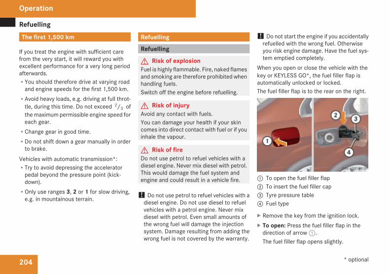
Refuelling
204
The first 1,500 km
If you treat the engine with sufficient carefrom the very start, it will reward you withexcellent performance for a very long periodafterwards.RYou should therefore drive at varying roadand engine speeds for the first 1,500 km.
RAvoid heavy loads, e.g. driving at full throt-tle, during this time. Do not exceed 2/3 ofthe maximum permissible engine speed foreach gear.
RChange gear in good time.RDo not shift down a gear manually in orderto brake.
Vehicles with automatic transmission*:RTry to avoid depressing the acceleratorpedal beyond the pressure point (kick-down).
ROnly use ranges 3, 2 or 1 for slow driving,e.g. in mountainous terrain.
Refuelling
Refuelling
G Risk of explosionFuel is highly flammable. Fire, naked flamesand smoking are therefore prohibited whenhandling fuels.Switch off the engine before refuelling.
G Risk of injuryAvoid any contact with fuels.You can damage your health if your skincomes into direct contact with fuel or if youinhale the vapour.
G Risk of fireDo not use petrol to refuel vehicles with adiesel engine. Never mix diesel with petrol.This would damage the fuel system andengine and could result in a vehicle fire.
! Do not use petrol to refuel vehicles with adiesel engine. Do not use diesel to refuelvehicles with a petrol engine. Never mixdiesel with petrol. Even small amounts ofthe wrong fuel will damage the injectionsystem. Damage resulting from adding thewrong fuel is not covered by the warranty.
! Do not start the engine if you accidentallyrefuelled with the wrong fuel. Otherwiseyou risk engine damage. Have the fuel sys-tem emptied completely.
When you open or close the vehicle with thekey or KEYLESS GO*, the fuel filler flap isautomatically unlocked or locked.The fuel filler flap is to the rear on the right.
1 To open the fuel filler flap2 To insert the fuel filler cap3 Tyre pressure table4 Fuel type
X Remove the key from the ignition lock.X To open: Press the fuel filler flap in thedirection of arrow1.The fuel filler flap opens slightly.
Operation
* optional
204_AKB; 2; 3, en-GBmkalafa,
2007-06-26T23:11:51+02:00 - Seite 204

Refuelling
205
X Open the fuel filler flap.X Turn the fuel filler cap to the left andremove it.
X Insert the fuel filler cap into the holderbracket on the inside of filler flap2.
X Only fill the tank until the pump nozzleswitches off.
! Overfilling the tank could damage the fuelsystem.
X Replace the fuel filler cap and turn it to theright. You will hear the fuel filler cap lock.
X Close the fuel filler flap.
i Vehicles with a diesel engine:If you have run the tank completely dry, itwill be necessary to bleed the fuel system(Y page 289).
Petrol (EN 228)! Refuel using only unleaded premiumgrade petrol with a minimum octane num-ber of 95 RON/85 MON conforming toEuropean standard EN 228.You could otherwise impair engine outputor damage the engine.You will find further information about pet-rol under "Technical data" in the index.
i As a temporary measure, only when therecommended fuel is not available, youmay also use regular unleaded petrol,91 RON/82.5 MON. This may reduce per-formance and increase petrol consump-tion. Avoid driving at full throttle.In some countries, the available petrol qual-ity may not be sufficient and could causecoking around the inlet valve. In thesecases, and in consultation with aMercedes-Benz Service Centre, the petrolmay be mixed with the additive recommen-ded by Mercedes-Benz (part no.A000989254510). You must observe thenotes and mixing ratios given on the con-tainer.
Diesel (EN 590)! Only use diesel that complies with theEN 590 European standard.You could otherwise impair engine outputor damage the engine.You will find further information about die-sel under "Technical data" in the index.
! When refuelling vehicles with a diesel par-ticle filter in countries outside the EU, onlylow-sulphur Euro diesel with less than0.005 percent sulphur content by weightshould be used. In countries in which dieselwith a higher sulphur content is available(e.g. 0.035 percent by weight), the engineoil should be renewed at more frequentintervals. More information about intervalsfor changing the engine oil can be obtainedfrom any Mercedes-Benz Service Centre.
! Using fuel that does not comply with EN590 can increase wear and damage theengine and the exhaust system. Do not usethe following:RMarine dieselRHeating oilRBio-diesel
Operation
204_AKB; 2; 3, en-GBmkalafa,
2007-06-26T23:11:51+02:00 - Seite 205
Z

Engine compartment
206
RVegetable oilRPetrolRPetroleumRKeroseneDo not add such fuels to diesel fuel and donot use any special additives (exception:flow improvers – see "Low outside temper-atures").Damage caused by the use of unapprovedfuels or additives is not covered by the war-ranty.
Low outside temperaturesThe flow properties of diesel may be insuffi-cient at low ambient temperatures.To prevent operating problems, diesel fuelwith improved cold flow qualities is availableduring the winter months. Your vehicle mustbe refuelled with this winter diesel at temper-atures of -5 °C or below.You can use this winter diesel at tempera-tures down to about -20 °Cwithout problems.If only summer diesel fuel or less cold-resist-ant winter diesel fuel (e.g. in Mediterraneanregions) is available, you should add anamount of flow improver to the fuel corre-sponding to the outside temperature.
Mix the additive with the diesel in good time,before the flow properties of the dieselbecome insufficient. Otherwise,malfunctionscan only be rectified by heating the entire fuelsystem, e.g. by parking the vehicle in a heatedgarage.G Risk of fireDo not use petrol to refuel vehicles with adiesel engine. Never mix diesel with petrol.This would damage the fuel system andengine and could result in a vehicle fire.
Flow improverThe effectiveness of a flow improver is notguaranteedwith every fuel. Observe the infor-mation provided by the manufacturer whenusing a flow improver. Only use flow improv-ers that have been tested and approved byMercedes-Benz. Information about flowimprovers that have been tested andapproved by Mercedes-Benz can be obtainedfrom any Mercedes-Benz Service Centre.
Engine compartment
Bonnet
G Risk of accidentDo not pull the release lever while the vehi-cle is in motion. The bonnet could other-wise open.
Opening
G Risk of injuryThere is a risk of injury if the bonnet is open,even if the engine is not running.Some engine components can becomevery hot.To avoid the risk of burns, only touch thosecomponents described in theOwner’sMan-ual and observe the relevant safety notes.
G Risk of injuryThe radiator fan between the radiator andthe engine can start automatically, even ifthe key has been removed from the ignitionlock. For this reason you must not reachinto the turning area of the fan. You couldotherwise sustain an injury.Vehicles with a petrol engine:
Operation
204_AKB; 2; 3, en-GBmkalafa,
2007-06-26T23:11:51+02:00 - Seite 206

Engine compartment
207
The electronic ignition system uses highvoltage. For this reason you must nevertouch components of the ignition system(ignition coil, ignition cable, spark plug con-nector, test socket) when:Rthe engine is runningRthe engine is being startedRthe ignition is switched on and the engineis being cranked by hand
Vehicles with a diesel engine:The electronic injection control uses highvoltage. Therefore, never touch fuel injec-tion system components when:Rthe engine is runningRthe engine is being startedRthe ignition is switched on
X Make sure that the windscreen wipers areswitched off.
G Risk of injuryThe windscreen wipers and wiper rodscould be set in motion.When the bonnet is open, you or otherscould be injured by the wiper rods.
Make sure that the windscreen wipers areswitched off and that the key has beenpulled out of the ignition lock before open-ing the bonnet.
The bonnet release lever is located in thedriver's footwell above the parking brake.
1 Bonnet release lever
X Pull release lever1.The bonnet is released.
! Make sure that the windscreen wipersare not folded away from the windscreen.You could otherwise damage the wind-screen wipers or the bonnet.
The handle for opening the bonnet is locatedabove the radiator grille.
1 Bonnet catch handle
X Reach into the gap, pull bonnet catch han-dle1 up and lift the bonnet.
Closing
G Risk of injuryMake sure that nobody can become trap-ped as you close the bonnet.
X Lower the bonnet and let it fall from aheight of approximately 20 cm. The bonnetengages into place.
Operation
204_AKB; 2; 3, en-GBmkalafa,
2007-06-26T23:11:51+02:00 - Seite 207

Engine compartment
208
Engine oilDepending on how it is driven, the vehicleconsumes a maximum of 0.8 l oil per 1,000km. The oil consumption may be higher thanthis when the vehicle is new or if you fre-quently drive at high engine speeds. You canonly estimate the oil consumption after youhave driven a considerable distance.You will find further information about engineoil in the "Technical data" section(Y page 336).
Checking the engine oil levelBefore checking the engine oil level the fol-lowing conditions for the vehicle should bemet:RIt should be parked on level groundRThe engine should be switched off for atleast five minutes if the engine was at nor-mal operating temperature
RThe engine should be switched off for atleast 30 minutes if the engine was not atoperating temperature (i.e. if you only star-ted the engine briefly)
Using the oil dipstick
Illustration: vehicle with a petrol engine1 Oil dipstick2 Upper mark3 Lower mark
Example illustration of a vehicle with a dieselengine1 Oil dipstick2 Upper mark3 Lower mark
X Pull oil dipstick1 out of the oil dipsticktube.
X Wide off oil dipstick1.X Insert oil dipstick1into the oil dipsticktube to the stop, and take it out again.The oil level is correct if the level is betweenlower mark3 and upper mark2.
X Top up the oil if necessary (Y page 209).
i The difference in quantity between lowermark3 and upper mark2 is approxi-mately 2 litres.
Operation
204_AKB; 2; 3, en-GBmkalafa,
2007-06-26T23:11:51+02:00 - Seite 208

Engine compartment
209
Topping up the engine oil
Illustration: vehicle with a petrol engine1 Cover
Example illustration of a vehicle with a dieselengine1 Cover
X Unscrew cap1 and remove it.X Top up by the amount of oil required.
! Do not add too much oil. If too much oilis added, there is a risk of damage to theengine or the catalytic converter.
X Screw cap1 onto the filler neck.
H Environmental noteWhen topping up the oil, take care not tospill any. Oil must not be allowed to escapeinto the soil or waterways. You would oth-erwise be damaging the environment.
Coolant
G Risk of injuryThe cooling system is pressurised. There-fore, only unscrew the cap once the enginehas cooled down. This means the coolanttemperature gauge must display less than70 °C. You could otherwise be scalded byescaping hot coolant.
Coolant consists of water and antifreeze/cor-rosion inhibitor. Only check the coolant levelwhen the vehicle is on a level surface and theengine has cooled down.
Checking the coolant levelThe expansion tank is located in the enginecompartment on the right-hand side of thevehicle.
1 Cover2 Expansion tank3 Marker bar
X Slowly turn cap1 by half a turn anti-clock-wise to allow excess pressure to escape.
X Turn cap1 further anti-clockwise andremove it.There is sufficient coolant in expansiontank2 if the coolant is level with markerbar3 in the filler neck when cold orapproximately 1.5 cm higher when hot.
X Top up the coolant if necessary.
Operation
204_AKB; 2; 3, en-GBmkalafa,
2007-06-26T23:11:51+02:00 - Seite 209
Z

Tyres and wheels
210
X Replace cap1 and tighten all the way tothe stop.
Youwill find further information about coolantin the "Technical data" section(Y page 368).
Windscreen washer system/head-lamp cleaning system*The washer fluid reservoir is located in theengine compartment on the left-hand side ofthe vehicle. The headlamp cleaning system*is also supplied from the washer fluid reser-voir.
1 Cover
X Add windscreen washer concentrate to thewasher fluid all year round.
G Risk of fireWindscreen washer concentrate is highlyflammable. Fire, naked flames and smokingare prohibited when windscreen washerconcentrate is being handled.
Use:Ra windscreen washer fluid additivesuch as MB Summerwash to preventsmearing (for temperatures above freez-ing).
Ra windscreen washer fluid additive withantifreeze properties such as MB Winter-wash (if there is a risk of frost).
X Mix the windscreen washer fluid in a con-tainer beforehand. Adapt the mixing ratioto the outside temperatures.
! Only use windscreen washer fluid whichis suitable for plastic lamp lenses. Unsuit-able windscreen washer fluid could dam-age the plastic lamp lenses of the head-lamps.
X To open: pull cap1 upwards by the tab.X To close: press cap1 onto the filler neckuntil it clicks into place.
Tyres and wheels
Points to remember! For safety reasons, Mercedes-Benz rec-ommends that you only use tyres andwheels which have been approved byMercedes-Benz specifically for your vehi-cle. These tyres have been specially adap-ted for use with the control systems, suchas ABS or ESP, and are marked as follows:RMO = Mercedes-Benz OriginalRMOE=Mercedes-BenzOriginal Extended(with run-flat characteristics)
Mercedes-Benz Original Extended tyresshould only be used on wheels that havebeen specifically approved by Mercedes-Benz.If you use other tyres and wheels,Mercedes-Benz cannot accept any respon-sibility for damage that may result fromthis. Further information about tyres,wheels and approved combinations can beobtained from any Mercedes-Benz ServiceCentre.If you use tyres other than those tested andrecommended for Mercedes-Benz vehi-cles, characteristics such as handling, vehi-cle noise emissions and fuel consumption
Operation
* optional
204_AKB; 2; 3, en-GBmkalafa,
2007-06-26T23:11:51+02:00 - Seite 210

Tyres and wheels
211
may be adversely affected. In addition, thewheels may come into contact with thebody or the axle components when heavilyloaded or when driving with snow chains.This could result in damage to the tyres orthe vehicle.
! Retreaded tyres are neither tested norrecommended by Mercedes-Benz, sinceprevious damage cannot always be detec-ted on retreaded tyres. As a result,Mercedes-Benz cannot guarantee vehiclesafety if retreaded tyres are fitted. Do notfit used tyres if you have no informationabout their previous usage.
G Risk of accidentIf wheels or tyres other than those whichhave been tested are fitted:Rthe brakes or chassis components couldbe damaged
Rwheel and tyre clearances can no longerbe guaranteed
This could cause an accident.
Modification work on the brake system andwheels is not permitted, nor is the use ofspacer plates or brake dust shields. This inva-lidates the General Operating Permit for thevehicle.
Notes on selecting, fitting and replacingtyresROnly fit tyres and wheels of the same typeand make.
ROnly fit tyres of the correct size onto thewheels.
RAfter fitting new tyres, run them in at mod-erate speeds for the first 100 km as theyonly reach their full performance after thisdistance.
RFit new tyres on the front wheels first iftyres of the same size are required on thefront and rear wheels.
RReplace the tyres after six years at the lat-est, regardless of wear. This also applies tothe spare wheel.
RDo not drive with tyres which have too littletread depth as this significantly reducesthe traction on wet roads (aquaplaning).
! Store tyres that are not being used in acool, dry and preferably dark place. Protectthe tyres against oil, grease, petrol and die-sel.
Notes on regularly inspecting wheelsand tyresRRegularly check the wheels and tyres ofyour vehicle for damage (e.g. cuts, punctu-res, tears, bumps on tyres and deforma-tion, cracks or severe corrosion onwheels),at least every 14 days, as well as after off-road trips or after travelling on rough roads.Damaged wheels could cause a loss of tyrepressure.
RRegularly check the tyre tread depth andthe condition of the tread across the wholewidth of the tyre (Y page 212). If neces-sary, turn the front wheels to full lock inorder to inspect the inner side of the tyresurface.
RAll wheels must have a valve cap to protectthe valve against dirt and moisture.
RRegularly check the pressure of all yourtyres (including the spare tyre*), particu-larly prior to long trips, and correct thepressure as necessary (Y page 213).
Notes on drivingRWhile driving, pay attention to vibrations,noises and unusual handling characteris-tics, e.g. pulling to one side. This may indi-
Operation
* optional
204_AKB; 2; 3, en-GBmkalafa,
2007-06-26T23:11:51+02:00 - Seite 211

Tyres and wheels
212
cate that the wheels or tyres are damaged.If you suspect that a tyre is defective,reduce your speed and stop the vehicle assoon as possible to check the wheels andtyres for damage. Hidden tyre damagecould also be causing the unusual handlingcharacteristics. If you find no signs of dam-age, have the wheels and tyres inspectedat a specialist workshop, for example at aMercedes-Benz Service Centre.
RWhen parking your vehicle, make sure thatthe tyres do not get deformed by the kerbor other obstacles. If it is necessary to driveover kerbs, speed humps or similar, try todo so slowly and at an obtuse angle. Oth-erwise, the tyres, particularly the sidewalls,could get damaged.
Direction of rotation
Direction of rotationTyres with a specified direction of rotationhave additional benefits, e.g. if there is a riskof aquaplaning. You will only gain these ben-efits if the correct direction of rotation isobserved.An arrow on the sidewall of the tyre indicatesits correct direction of rotation.
i You may fit a spare tyre* against thedirection of rotation.
MOExtended run-flat system*The MOExtended run-flat system* allows youto continue driving the vehicle even when oneor more tyres lose all air pressure.The MOExtended run-flat system* may onlybe used in combination with the tyre pressureloss warning system and only on wheels spe-cifically tested and approved by Mercedes-Benz.
i Vehicles with MOExtended run-flat sys-tem* are not equipped with the TIREFITkit*.14
It is therefore recommended to additionallyequip your vehicle with the TIREFIT kit*when fitting tyres that do not feature run-flat properties, e.g. winter tyres.
i A TIREFIT kit* is available from any quali-fied specialist workshop, e.g. a Mercedes-Benz Service Centre.
You will find notes on driving with a flat tyrein the "Practical advice" section(Y page 323).
Tyre tread
G Risk of accidentBear in mind that:Rtyre grip decreases rapidly on wet roadswhen the tread depth is less than 3 mm.You should thus replace tyres that haveinsufficient tread.
Rwinter tyres should be replaced when thetread depth is 4 mm or less because oth-erwise they no longer provide adequategrip.
Rthe tread on a tyre may not wear evenly.You should thus regularly check the tread
14 Only for certain countries.
Operation
* optional
204_AKB; 2; 3, en-GBmkalafa,
2007-06-26T23:11:51+02:00 - Seite 212

Tyres and wheels
213
depth and the condition of the treadacross the entire width of all tyres. If nec-essary, turn the steering wheel so thatyou can see the tyre tread more easily.
You could otherwise lose control of thevehicle and cause an accident due to thereduced grip of the tyres on the road.
Tyre pressures
G Risk of accidentTyre pressure that is either too high or toolow has a negative effect on the vehicle’sactive safety, which could lead you to causean accident. You should therefore regularlycheck the pressure of all your tyres (includ-ing the spare tyre*), particularly prior tolong trips, and correct the pressure as nec-essary.
To test tyre pressure, use a suitable pressuregauge. The outer appearance of a tyre doesnot permit any reliable conclusion about thetyre pressure.If the vehicle is to be heavily laden or drivenat high speeds, the tyre pressure must beadapted according to the specifications givenin the fuel filler flap (Y page 204).
Use the highest specified tyre pressure forthe spare wheel*.G Risk of accidentShould the tyre pressure drop repeatedly:RCheck the tyre for foreign bodies.RCheck whether the wheel is losing air orthe valve is leaking.
Tyre pressure that is too low has a negativeeffect on the vehicle’s active safety, whichcould lead to your causing an accident.
Tyre pressure changes by approximately0.1 bar for every 10 °C change in ambienttemperature.If you measure the tyre pressure in enclosedspaces where the temperature differs fromthe outside temperature, you will have to cor-rect the measured value accordingly.When the vehicle is driven, the tyre tempera-ture, and with it the tyre pressure, willincrease depending on the road speed andthe load on the tyres.Therefore, you should only correct tyre pres-sures when the tyres are cold.The pressure of warm tyres should only becorrected if it is too low for the current oper-ating conditions.
You will find a table of tyre pressures for var-ious operating conditions on the inside ofyour vehicle's fuel filler flap.Driving with tyre pressure that is too high ortoo low can:Rshorten the service life of the tyresRcause increased tyre damageRhave a negative effect on handling charac-teristics (e.g. by causing aquaplaning)
i The tyre pressure values given for lowloads are minimum values which offer yougood ride comfort characteristics.You can, however, also use the values givenfor higher loads. These are permissible andwill not adversely affect the running of thevehicle.Also check the tyre pressure of the sparewheel*.
H Environmental noteCheck the tyre pressure regularly, and atleast every 14 days.
Operation
* optional
204_AKB; 2; 3, en-GBmkalafa,
2007-06-26T23:11:51+02:00 - Seite 213

Tyres and wheels
214
Tyre pressure loss warning system
G Risk of accidentThe tyre pressure loss warning system*does not warn you of an incorrectly set tyrepressure. The table on the inside of the fuelfiller flap will help you decide whether thetyre pressures should be corrected.The tyre pressure loss warning system*does not replace the need to regularlycheck your vehicle's tyre pressures, sincean even loss of pressure on several tyres atthe same time cannot be detected by thetyre pressure loss warning system*.The tyre pressure loss warning system* isnot able to warn you of a sudden loss ofpressure, e.g. following penetration by aforeign object.In the event of a sudden loss of pressure,bring the vehicle to a halt by braking care-fully. Do not make any sudden steeringmovements when doing so.
While the vehicle is in motion, the tyre pres-sure loss warning system* monitors the settyre pressure using the rotational speed ofthe wheels. This enables the system to detectsignificant pressure loss in a tyre. If the speedof rotation of a wheel changes as a result of
a loss of pressure, a corresponding warningmessage will appear in the multi-function dis-play.The function of the tyre pressure loss warningsystem* is limited or delayed if:Rsnow chains are fitted to your vehicle'styres
Rroad conditions are wintryRyou are driving on sand or gravelRyou adopt a very sporty driving style (cor-nering at high speeds or driving with highrates of acceleration)
Ryou are towing a very heavy or large trailerRyou are driving with a heavy load (in thevehicle or on the roof)
Restarting the tyre pressure loss warn-ing system*Restart the tyre pressure loss warning sys-tem* if you have:Rchanged the tyre pressureRchanged the wheels or tyresRfitted new wheels or tyres
X Before restarting, consult the table of tyrepressures on the inside of the fuel filler flap
to ensure that the tyre pressure in all fourtyres is set correctly for the operating con-ditions concerned.
X Also observe the notes in the section ontyre pressures (Y page 213).
G Risk of accidentThe tyre pressure losswarning system* canonly give reliable warnings if you have setthe correct tyre pressure.If an incorrect tyre pressure is set, theseincorrect values will be monitored.A tyre with insufficient pressure results inan instability of the vehicle when driving,thus increasing the risk of an accident.
Configuring with the multi-function steer-ing wheelX Make sure that the key is in position 2 inthe ignition lock.
X Pressè to select Tyre pressuremenu: R .
X Press theí button.The following appears in the multi-functiondisplay: RFI active Reactivate: R
Operation
* optional
204_AKB; 2; 3, en-GBmkalafa,
2007-06-26T23:11:51+02:00 - Seite 214

Tyres and wheels
215
X Press theí button.The following appears in the multi-functiondisplay: Tyre press. OK?Yes+ Cancel-
To confirm the restart of the tyre pressureloss warning system:X Press the+ button.The following appears in the multi-functiondisplay: Run Flat Indicator restar-ted.After a teach-in period, the tyre pressureloss warning system* will monitor the settyre pressures of all four tyres.
orTo cancel the restart of the tyre pressureloss warning system:X Press the- button.The previous settings will not be changed.
Configuring with the luxury multi-func-tion steering wheel*X Make sure that the key is in position 2 inthe ignition lock.
X Press( or& to select the Servicemenu.
X Press$ or% to select Tyre pres-sure.
X Press#.The following appears in the multi-functiondisplay: Run Flat Indicator activeRestart with OK
X Press#.The following appears in the multi-functiondisplay: Tyre press. now OK?
To confirm the restart of the tyre pressureloss warning system:X Press$ or% to select Yes.X Press#.The following appears in the multi-functiondisplay: Run Flat Indicator restartedAfter a teach-in period, the tyre pressureloss warning system* will monitor the settyre pressures of all four tyres.
orTo cancel the restart of the tyre pressureloss warning system:X Press$ or% to select Cancel.X Press#.The previous settings will not be changed.
Interchanging the wheels
G Risk of accidentInterchange the front and rear wheels onlyif they have the samedimensions, for exam-ple size, offset, etc.After every wheel interchange/change,have the tightening torque checked at aqualified specialist workshop that has thenecessary specialist knowledge and toolsto carry out the work required. Mercedes-Benz recommends that you use aMercedes-Benz Service Centre for this pur-pose. In particular, work relevant to safetyor on safety-related systems must be car-ried out at a qualified specialist workshop.The wheels could work loose if they are nottightened to a tightening torque of130 Nm.For safety reasons, Mercedes-Benz recom-mends that you only use wheel bolts of thecorrect size which have been approved forMercedes-Benz vehicles.
The wheels may be interchanged every 5,000km to 10,000 km depending on the degree oftyre wear, provided that the vehicle has thesame size front and rear tyres. Do not reversethe direction of tyre rotation.
Operation
* optional
204_AKB; 2; 3, en-GBmkalafa,
2007-06-26T23:11:51+02:00 - Seite 215
Z

Winter driving
216
The wear patterns on the front and rear tyresdiffer depending on the operating conditions.Interchange the wheels before a clear wearpattern has formed on the tyres. The fronttyres typically wear more on the shouldersand the rear tyres in the centre.Clean the contact surfaces of the wheel andthe brake disc thoroughly every time a wheelis interchanged. Check the tyre pressure and,if necessary, restart the tyre pressure losswarning system*.
Winter drivingHave your vehicle winterproofed at a qualifiedspecialist workshop, e.g. at a Mercedes-BenzService Centre, at the onset of winter.
Winter tyresUse winter tyres at temperatures below +7 °C and on snow or ice-covered roads. Onlythen can the effect of the ABS, ESP ® and4MATIC* driving systems be ensured in win-ter too.Use winter tyres of the same make and treadon all wheels to maintain safe handling char-acteristics.G Risk of accidentYou must replace winter tyres with a treaddepth of less than 4 mm immediately. Theyare no longer suitable for winter use, in par-ticular because they do not provide suffi-cient grip. This could cause you to losecontrol of your vehicle and cause an acci-dent.
Always observe the maximum permittedspeed specified for the winter tyres you havefitted. If you fit winter tyres which have alower maximum permitted speed than that of
the vehicle, affix an appropriate warning signin the driver's field of vision. This can beobtained at a qualified specialist workshop,e.g. from a Mercedes-Benz Service Centre.In such circumstances, you should also usepermanent Speedtronic* 15 to restrict themaximum speed of the vehicle to the maxi-mum permissible speed for winter tyres(Y page 148).G Risk of accidentIf you fit the spare wheel* when driving withwinter tyres, bear in mind that driving sta-bility will be impaired owing to unstablecornering characteristics caused by the dif-ferent tyres. You should therefore adaptyour driving style and drive carefully.Have the spare wheel* replaced at thenearest qualified specialist workshopwhich has the necessary specialist knowl-edge and tools to carry out the workrequired. Mercedes-Benz recommendsthat you use a Mercedes-Benz ServiceCentre for this purpose. In particular, workrelevant to safety or on safety-related sys-tems must be carried out at a qualifiedspecialist workshop.
15 Only available for certain countries.
Operation
* optional
204_AKB; 2; 3, en-GBmkalafa,
2007-06-26T23:11:51+02:00 - Seite 216

Driving tips
217
Snow chainsFor safety reasons, Mercedes-Benz recom-mends that you only use snow chains whichhave been specially approved for your vehicleby Mercedes-Benz or are of a correspondingstandard of quality.
! Information about the use of snow chaincompatible AMG winter tyres is applicablefor AMG tyres. Use of snow chains is onlypermissible with these tyres.
If you intend to fit snow chains, please bearthe following points in mind:RSnow chains cannot be fitted on all wheel/tyre combinations.
RSnow chains cannot be fitted to emergencyspare wheels, e.g. on a "Minispare" emer-gency spare wheel.
RAlways fit snow chains on both the rearwheels, even on vehicles with 4MATIC*.Comply with the manufacturer's installa-tion instructions.
! If snow chains are fitted to the frontwheels, they may come into contact withthe bodywork and axle components whenthe vehicle is in motion and damage thetyre or the vehicle.
Do not exceed the maximum permissiblespeed of 50 km/h.
i You may wish to deactivate ESP® whenpulling away with snow chains fitted(Y page 68). This way you can allow thewheels to spin in a controlled manner, ach-ieving an increased driving force (cuttingaction).
Winter driving
G Risk of accidentDo not shift down for additional enginebraking on a slippery road surface. Thiscould cause the drive wheels to lose theirgrip and the vehicle could skid.
You should drive particularly carefully on slip-pery road surfaces. Avoid sudden accelera-tion, steering and braking manoeuvres.If the vehicle threatens to skid or cannot bestopped when moving at low speed:X Vehicles withmanual transmission: engageneutral.
X Vehicles with automatic transmission*:shift the selector lever to N.
X Try to bring the vehicle under control usingcorrective steering.
Driving tips
Rolling with the engine switched off
G Risk of accidentNever switch the engine off while the vehi-cle is in motion.There is no power assistance for the steer-ing and the service brake when the engineis not running.You will require considerably more effort tosteer and brake and you could thereforelose control of the vehicle and cause anaccident.
Braking
G Risk of accidentDo not change down for additional enginebraking on a slippery road surface. Thiscould cause the drive wheels to lose theirgrip and the vehicle could skid.
G Risk of accidentMake sure that other road users are notendangered by your braking.
Operation
* optional
204_AKB; 2; 3, en-GBmkalafa,
2007-06-26T23:11:51+02:00 - Seite 217

Driving tips
218
Downhill gradientsOn long and steep downhill stretches, espe-cially if the vehicle is laden or towing a trailer,you must shift to a lower gear in good time or,on vehicles with automatic transmission*,select shift range 1, 2 or 3.i This also applies if you have activatedcruise control* or Speedtronic*.
This uses the braking effect of the engine andyou will not have to brake to such an extentto maintain the same speed. This relieves theload on the brake system and prevents thebrakes from overheating and wearing tooquickly. If you need additional braking,depress the brake pedal repeatedly ratherthan continuously.
Heavy and light loadsIf the brakes have been subjected to a heavyload, do not stop the vehicle immediately, butdrive on for a short while. This allows the air-flow to cool the brakes more quickly.G Risk of accidentNever depress the brake pedal continu-ously while the vehicle is in motion, e.g.never cause the brakes to rub by applying
constant slight pedal pressure. This causesthe brake system to overheat, increasesthe braking distance and can lead to thebrakes failing completely.
If the brakes have been used onlymoderately,you should occasionally test their effective-ness. To do this, brake more firmly from ahigher speed. This improves the grip of thebrakes.
Wet roadsIf you drive for a long time in the rain withoutbraking, there may be a delayed reactionwhen you first brake and you will have todepress the pedal harder.You must therefore maintain a greater dis-tance from the vehicle in front.Brake firmly after driving on a wet road. Thisway the brake discs will becomewarm, dryingmore quickly, which will protect them againstcorrosion.
Limited braking performance on saltedroads
G Risk of accidentThe layer of salt on the brake discs and thebrake linings may cause a delay in the brak-ing effect, resulting in a significantly longerbraking distance, which could lead to anaccident.To avoid this danger, you should:Roccasionally brake carefully when youare driving on salted roads, so that anylayer of salt that may have started tobuild up on the brake discs and the brakelinings is removed without putting otherroad users at risk.
Rmaintain a greater distance to the vehicleahead and drive with particular care
Rcarefully apply the brakes at the end of atrip and immediately after commencing anew trip, so that salt residues areremoved from the brake disc.
New brake liningsFor safety reasons, Mercedes-Benz recom-mends that you have only brake pads/liningsfitted to your vehicle that have been approved
Operation
* optional
204_AKB; 2; 3, en-GBmkalafa,
2007-06-26T23:11:51+02:00 - Seite 218

Driving tips
219
for Mercedes-Benz vehicles or which corre-spond to an equivalent quality standard.Brake pads/linings which have not beenapproved for Mercedes-Benz or which whichare not of an equivalent quality could affectyour vehicle's operating safety.G Risk of accidentNew brake linings only reach their optimumbraking effect after several hundred kilo-metres of driving. Before this optimumbraking effect is reached, you should com-pensate for the reduced braking effect byapplying greater pressure when braking.This also applies after the brake discs or thebrake linings have been replaced.
Tyre grip
G Risk of accidentWhereas the vehicle can be fully controlledat a certain speed on dry roads, you mustreduce your speed on wet or icy roads toachieve the same road safety. Otherwiseyou could cause an accident.Pay particular attention to the road condi-tions at temperatures around freezingpoint.
If ice has formed on the road surface (e.g.from fog), a light film of water rapidly formson the ice when you brake, considerablyreducing tyre grip. Drive with particularcare in such weather conditions.
Driving on wet roadsIf water has accumulated to a certain depthon the road surface, there is a danger of aqua-planing occurring, even if:Ryou drive at low speedsRthe tyres have adequate tread depthFor this reason, do not drive in tyre ruts, andbrake carefully.
Driving on flooded roadsIf you have to drive on stretches of road onwhich water has collected, please bear inmind that:Rthe maximum permitted still water depth is25 cm.
Ryou should drive no faster than at walkingpace.
! Bear in mind that vehicles travelling infront or in the opposite direction createwaves. This may cause the maximum per-missible water depth to be exceeded.You must observe these notes, otherwisedamage may occur to the engine, electricsand transmission.
Operation
204_AKB; 2; 3, en-GBmkalafa,
2007-06-26T23:11:51+02:00 - Seite 219

Trailer towing*
220
Driving abroadAnextensiveMercedes-Benz Service networkis also available in other countries. You canobtain the relevant workshop directoriesfrom any Mercedes-Benz Service Centre.Only low-octane fuel is available in certaincountries.You can find further information about fuelgrades on (Y page 204).
Symmetrical dipped beamIf your journey takes you to countries wherevehicles are driven on the opposite side of theroad to the country in which the vehicle isregistered, your headlampsmust be switchedto symmetrical dipped beam. Oncoming traf-fic will be dazzled less.X Have the headlamps switched over at aqualified specialist workshop, e.g. aMercedes-Benz Service Centre.
G Risk of accidentHave your headlamps switched back toasymmetrical dipped beam if you visit acountry in which traffic drives on the sameside of the road as in the country in whichyour vehicle was registered. You may oth-
erwise dazzle the oncoming traffic andcould cause an accident.
Trailer towing*
Folding out the ball couplingPlease also observe the notes on the restric-ted function of Parktronic* when towing atrailer on (Y page 155).Before you can tow a trailer with your vehicle,you must fold out the ball coupling.The release wheel is located behind the left-hand side trim panel in the boot/luggagecompartment.G Risk of accidentMake sure that the ball coupling isengaged, either in its folded out or foldedin position, and that the indicator lamp isoff.Do not turn the release wheel when a traileris coupled up. The trailer might otherwisebecome detached.
Operation
* optional
204_AKB; 2; 3, en-GBmkalafa,
2007-06-26T23:11:51+02:00 - Seite 220

Trailer towing*
221
Saloon1 Handle2 Cover
Estate1 Handle2 Cover
X To open: turn handle1 anti-clockwise.X Fold cover2 down.
1 Indicator lamp2 Release wheel for the trailer tow hitch
X Pull out release wheel2.X Turn release wheel2 anti-clockwise.The ball coupling disengages and folds outfrom under the rear bumper. Indicator lamp1 flashes.
X Press the ball coupling in the direction ofthe arrow by hand until it engages in a ver-tical position.Indicator lamp1 goes out. The powersocket folds away automatically.Vehicles with a 4-button multi-functionsteering wheel: the message Trailerhitch Check lock mech. is shown in themulti-function display until the ball cou-pling has engaged.Vehicles with a luxury multi-functionsteering wheel* (12 buttons): the mes-sage Trailer hitch Check lockmech. is shown in the multi-function dis-play until the ball coupling is engaged.
X Make sure that the ball of the ball couplingis clean and that, depending on the trailer
Operation
* optional
204_AKB; 2; 3, en-GBmkalafa,
2007-06-26T23:11:51+02:00 - Seite 221
Z

Trailer towing*
222
specification, it is greased or dry (withoutgrease) when used.
Notes on towing a trailer
G Risk of accidentWhen reversing the vehicle towards thetrailer, make sure there is nobody betweenthe trailer and the vehicle.Couple and uncouple the trailer carefully. Ifyou do not couple the trailer to the towingvehicle correctly, the trailer could becomedetached.Make sure that the following values are notexceeded:RThe permitted trailer drawbar nose-weight
RThe permitted trailer loadRThe permitted rear axle load of the towingvehicle
RThe maximum permissible gross vehicleweight of both the towing vehicle and thetrailer
You will find the applicable permissible val-ues which must not be exceeded in thevehicle documents.
You will find the values approved by themanufacturer on the vehicle identificationplates and those for the towing vehicle inthe “Technical data” section.
The maximum permissible trailer drawbarnoseweight on the ball coupling is 75 kg.However, the weight must not exceed the fig-ure given on the trailer hitch and trailer iden-tification plates. The lowest weight applies.
! Use a noseweight as close as possible tothe maximum permissible noseweight. Donot use a noseweight of less than 50 kg,otherwise the trailer may come loose.Bear in mind that the payload and the rearaxle load are reduced by the actual nose-weight.
i The height of the ball coupling changeswith the load of the vehicle. If necessary,use a trailer with a height-adjustable draw-bar.
Coupling up a trailer
G Risk of injuryDo not connect a trailer with an engagedoverrun brake. Otherwise, your hand could
become trapped between the bumper anddrawbar.
! Do not uncouple a trailer with overrunbrake between the bumper and drawbar,otherwise your vehicle could be damagedby the spring action of the overrun brake.
X Position the trailer level behind the vehicle.X Couple up the trailer.X Establish the electrical connectionbetween the vehicle and the trailer.
Driving tipsIn Germany, the maximum permitted speedfor vehicle/trailer combinations is 80 km/h.
! Amaximum speed of 80 km/h should notbe exceeded, even in countries wherehigher speeds are permitted for vehicle/trailer combinations.
When towing a trailer, your vehicle's handlingcharacteristics will be different in comparisonto when driving without a trailer.The vehicle/trailer combination:Ris heavierRis restricted in its acceleration and gradi-ent-climbing capability
Operation
* optional
204_AKB; 2; 3, en-GBmkalafa,
2007-06-26T23:11:51+02:00 - Seite 222

Trailer towing*
223
Rhas an increased braking distanceRis affected more by strong crosswindsRdemands more sensitive steeringRconsumes more fuelOn long and steep downhill gradients youmust select a lower gear in good time, or onvehicleswith automatic transmission*, selectthe shift range 1, 2 or 3.i This also applies if you have activatedcruise control* or Speedtronic*.
This uses the braking effect of the engine andyou will not have to brake to such an extentto maintain the same speed. This relieves theload on the brake system and prevents thebrakes from overheating and wearing tooquickly. If you need additional braking,depress the brake pedal repeatedly ratherthan continuously.G Risk of accidentNever depress the brake pedal continu-ously while the vehicle is in motion, e.g.never cause the brakes to rub by applyingconstant slight pedal pressure. This causesthe brake system to overheat, increasesthe braking distance and can lead to thebrakes failing completely.
Driving tipsRMaintain a greater distance from the vehi-cle in front than when driving without atrailer.
RAvoid braking abruptly. If possible, brakegently at first to allow the trailer to run on.Then increase the braking force rapidly.
RThe values given for gradient-climbingcapabilities from a standstill refer to sealevel. When driving in mountainous areas,note that the power output of the engineand with it its gradient-climbing capabilitydecrease with increasing altitude.
If the trailer swings from side to side:X Do not accelerate.X Do not counter-steer.X Brake if necessary.
G Risk of accidentOn no account should you attempt to drawthe vehicle/trailer combination out byincreasing speed.
Folding in the ball couplingi Fold in the ball coupling when you are notusing the trailer tow hitch.
G Risk of injuryMake sure that no persons or animals arein the pivoting range of the ball coupling.Otherwise, they could be injured.
The release wheel is located behind the sidetrim panel in the boot/luggage compartment.
Saloon1 Handle2 Cover
Operation
* optional
204_AKB; 2; 3, en-GBmkalafa,
2007-06-26T23:11:51+02:00 - Seite 223

Trailer towing*
224
Estate1 Handle2 Cover
X To open: turn handle1 anti-clockwise.X Fold cover2 down.
1 Indicator lamp2 Release wheel for the trailer tow hitch
X Pull out release wheel2.X Turn release wheel2 anti-clockwise.The ball coupling disengages and folds outfrom under the rear bumper. Indicator lamp1 flashes.
X Press the ball coupling in the direction ofthe arrow by hand until it engages behindthe bumper.Indicator lamp1 goes out and the mes-sage in the multi-function display disap-pears.
Operation
* optional
204_AKB; 2; 3, en-GBmkalafa,
2007-06-26T23:11:51+02:00 - Seite 224

Trailer towing*
225
Trailer power supplyWhen delivered from the factory, your vehi-cle's trailer socket outlet is equipped with apermanent power supply and a power supplythat is switched on via the ignition lock.The permanent power supply is supplied viatrailer socket pin 9.The power supply that is switched on via theignition lock is supplied via trailer socket pin10.
! You can connect consumers with a powerrating of up to 240 W to the permanentpower supply and up to 180W to the powersupply that is switched on via the ignitionlock.You must not charge a trailer battery usingthe power supply.
You can obtain further information aboutinstalling the trailer electrics from a qualifiedspecialist workshop, e.g. a Mercedes-BenzService Centre.X To switch the switched power supply onor off: turn the key in the ignition lock toposition 2 or 0, respectively.
Trailer with 7-pin connectorIf your trailer has a 7-pin connector, you canconnect it to the 13-pin socket on the ballcoupling using an adapter or, if necessary, anadapter cable. Both of these can be obtainedat a qualified specialist workshop, e.g. at aMercedes-Benz Service Centre.
Fitting the adapter
1 Connector with lug2 Socket with groove
X Open the socket cover.X Insert the connector with lug1 intogroove2 on the socket and turn the con-nector clockwise to the stop.
X Make the cover engage.
X If you are using an adapter cable, securethe cable to the trailer with cable ties.
! Make sure that there is sufficient cableplay so that the cable cannot becomedetached when cornering.
Operation
* optional
204_AKB; 2; 3, en-GBmkalafa,
2007-06-26T23:11:51+02:00 - Seite 225

Service
226
Service
Active Service SystemASSYST PLUS, the Active Service System,tells you when the next service is due.Services that are due appear in the multi-function display:Next service A in ... daysNext service A in ... kmService A due
Service message in a vehicle with a luxury multi-function steering wheel*
The letter indicates which service must becarried out. A stands for a minor service andB for a major service. A number or anotherletter may be displayed after the letter. Thisfigure indicates any necessary additionalmaintenance work to be performed. If youreport this displayed information to a quali-fied specialist workshop, for example a
Mercedes-Benz Service Centre, they caninform you of the costs the service will incur.ASSYST PLUS does not record any periods oftime during which the battery is disconnec-ted. In order to maintain the time-dependentservice schedule, you should call up theservice due date and make a note of it beforeyou disconnect the battery. The other optionis to subtract the battery-disconnection peri-ods from the service date shown on the dis-play.
Fading out the service messageX Multi-function steering wheel (4 but-tons): pressí.
X Luxury multi-function steering wheel*(12 buttons): pressL.
orX Press the# button.
Missing the service due dateOne of the following messages, for example,will appear in the multi-function display:Service A overdue by ... daysService A overdue by ... km
A qualified specialist workshop, e.g. aMercedes-Benz Service Centre, will reset theservice indicator after the necessary servicework has been carried out.
i If you fail to have the service performedby the specified date, you may be contra-vening the relevant laws, your warrantymay be invalidated and ex gratia claims andMobiloLife services may be refused.
Calling up the service due date
Multi-function steering wheel (4 buttons)X Switch on the ignition.X Select the ASSYST PLUS menu by pressingè.
Vehicles with a luxury multi-functionsteering wheel* (12 buttons)X Switch on the ignition.X Press( or& to select the Servicemenu.
X Press$ or% to select the ASSYSTPLUS submenu and confirm with#.The service due date appears in the display.
Operation
* optional
204_AKB; 2; 3, en-GBmkalafa,
2007-06-26T23:11:51+02:00 - Seite 226

Care
227
Care
Notes on careRegular and proper care maintains the valueof your vehicle.
i It is advisable to use Mercedes-Benz careproducts.
Scratches, corrosive deposits, areas affectedby corrosion and damage caused by inade-quate care cannot always be completelyrepaired. In such cases, visit a qualified spe-cialist workshop immediately, e.g. aMercedes-Benz Service Centre.Repair damage caused by loose chippingsand remove the following substances imme-diately, whilst avoiding rubbing too hard:RSoak insect remains with insect removerand rinse off afterwards.
RSoak bird droppings with water and rinseoff afterwards.
RRemove tree resin, oils, fuels and grease byrubbing gently with a cloth soaked in clean-ing or lighter fluid.
RUse silicone remover to remove wax.RUse tar remover to remove tar stains.
H Environmental noteDispose of empty packaging, cleaningcloths and polishing wads in an environ-mentally-responsible manner.
! Do not affix:RstickersRfilmsRmagnetic plates or similarto painted surfaces, otherwise you coulddamage the paintwork.
Vehicle care! Do not park the vehicle for a long periodof time directly after cleaning, especially ifthe wheels have just been cleaned with awheel cleaner. Wheel cleaners could causerapid corrosion of the brake discs andbrake pads/linings. After cleaning, parkthe vehicle when it is at normal operatingtemperature.
Automatic car washYou can wash the vehicle in an automatic carwash from the very start,
! Do not use high pressure car wash sys-tems. The strong water jet could damagepainted parts or attachments.
! Do not use a brush-free automatic carwash that uses chemical agents to washthe vehicle.
but preferably one without brushes.If the vehicle is very dirty, prewash it beforecleaning it in an automatic car wash.
! Make sure that the automatic car wash issuitable for the size of the vehicle. Fold inthe exterior mirrors before the vehicle iswashed. There is otherwise a risk of dam-age to the exterior mirrors.
! Make sure the side windows are com-pletely closed, the ventilation/heaterblower is fully turned off and the wind-screen wiper switch is set to 0. The rainsensor may otherwise be activated, forinstance, leading to inadvertent wipersweeps being triggered. This could causedamage to the vehicle.
After using an automatic car wash, wipe offwax from the windscreen and the wiperblades. This will prevent smears and reducewiping noises caused by residue on the wind-screen.
Operation
204_AKB; 2; 3, en-GBmkalafa,
2007-06-26T23:11:51+02:00 - Seite 227

Care
228
High-pressure cleaners
G Risk of accidentDo not use high-pressure cleaners with cir-cular-jet nozzles (dirt grinders) to cleanyour vehicle or - especially - the tyres. Youcould otherwise damage the tyres andcause an accident.
! Observe the instructions issued by theequipment manufacturer concerning thedistance to be maintained between thenozzle of the high-pressure cleaner and thevehicle (at least 30 cm).Move the high-pressure cleaner nozzlearound when cleaning your vehicle.Do not aim directly at any of the following:RTyresRDoor jointRElectrical componentsRBatteryRConnectorsRBulbsRSealsDamaged seals or electrical componentscan lead to failures or leaks.
Cleaning the wiper blades and the out-side of the windscreen
G Risk of injuryTurn the key to position 0 in the ignitionlock before cleaning the windscreen or thewiper blades. There is otherwise a risk ofthe windscreen wipers being set in motionand causing injury.
! Only fold the windscreen wipers awayfrom the windscreen when vertical, other-wise you will damage the bonnet.
X Fold the wiper arms away from the wind-screen until you feel them engage.
X Clean thewindscreen and thewiper blades.X Fold the windscreen wipers back againbefore the ignition is switched on.
! Do not clean the wiper blades too often,as otherwise the coating may come off.This could cause wiper noise.
Cleaning the windows! Do not use dry cloths, abrasive products,solvents or cleaning agents containing sol-vents to clean the inside of the windows.
Clean the insides of the windows with adamp cloth or commercially-available glasscleaner. Avoid touching the inside of therear windscreen and the side windows withhard objects, e.g. ice scrapers or rings. Youcould otherwise cause damage to the win-dows, rear window heating or aerial on therear window.
i Anti-glare film retrofitted to the insides ofthe windows could interfere with radio ormobile phone reception, especially if it isconductive or metal-coated film. Informa-tion about anti-glare film can be obtainedfrom any Mercedes-Benz Service Centre.
Cleaning the headlampsX Clean the headlamp lenses with a wetsponge.
! Only use washer fluid which is suitablefor plastic lenses. Unsuitable washer fluidcould damage the plastic lenses of theheadlamps.Therefore, do not use the following:RDry clothsRAbrasive cleaning agents
Operation
204_AKB; 2; 3, en-GBmkalafa,
2007-06-26T23:11:51+02:00 - Seite 228

Care
229
RSolventsRCleaning agents containing solventYou could otherwise scratch or damage thesurface of the lenses.
Plastic trim! Do not use dry, coarse or hard cloths anddo not scrub. Doing so will scratch or dam-age the surfaces.
X Wipe plastic parts with a damp, lint-freecloth (e.g. a microfibre cloth).
X Light soiling: use a low-foaming soap (e.g.a light liquid hand soap) diluted in water.
X Heavy soiling: use a cleaning agent that issolvent-free and non-corrosive. Mercedes-Benz recommends that you use aMercedes-Benz cleaning product for thispurpose.
Cleaning the steering wheel boss anddashboardX Moisten a clean lint-free cloth with water.X Clean the plastic parts and the dashboard.X If particularly dirty, use a mild detergent.
G Risk of injuryDo not use cleaners and cockpit caresprays containing solvents to clean thecockpit and steering wheel boss. Cleanerscontaining solvents cause the surface tobecome porous and in the event of an air-bag being triggered, plastic parts that havebecome loose could cause considerableinjuries.
Leather upholstery*! CleaningRClean genuine leather covers using adamp cloth, then wipe these down after-wards using a dry cloth. When doing this,make sure that the leather does notbecome soaked. For leather care, youshould use leather care foam A 001 98659 71 10. You can purchase this at anyMercedes-Benz Service Centre.
RClean artificial leather coverswith a clothmoistened with a solution containing 1%detergent (e. g. Pril).
RClean fabric covers with a micro-fibrecloth moistened with a solution contain-ing 1% detergent (e.g. Pril). When clean-ing, take care not to rub too vigorously
and always wipe entire seat sections toavoid leaving visible lines. Leave the seatto dry afterwards. Cleaning resultsdepend on the type of dirt and how longit has been there.
RClean Alcantara covers with a dampcloth. Make sure you wipe entire seatsections to avoid leaving visible lines.
i Note that leather covers are subject to anatural ageing process because they are anatural product and may react in differentways (e.g. increased formation of wrinkles)to certain environmental influences (suchas high humidity, intense heat).Note that regular care is essential to ensurethat the quality (both appearance and com-fort) of the covers is retained in the longterm.
Cleaning the wooden trim*X Moisten a clean lint-free cloth with water.X Clean the wooden trim.X If particularly dirty, use a mild detergent.
Operation
* optional
204_AKB; 2; 3, en-GBmkalafa,
2007-06-26T23:11:51+02:00 - Seite 229

Care
230
! Do not use cleaning agents containingsolvents because these can damage thewooden trim.
Cleaning Parktronic*The sensors are located in the front and rearbumpers.
1 Parktronic* sensors in the front bumper
X Clean the sensors in the bumper withwater, car shampoo and a soft cloth.
! Do not use dry, coarse or hard cloths anddo not scrub. You will otherwise scratch ordamage the sensors. If you intend to use ahigh-pressure cleaner or a steam cleaner toclean the sensors, observe the instructionsissued by the equipment manufacturer
concerning the distance to be maintainedbetween the nozzle of the high-pressurecleaner and the vehicle.
Trailer coupling*The ball coupling must be cleaned if itbecomes dirty or corroded.X Remove any rust using a wire brush.X Remove dirt with a clean, lint-free cloth ora brush.
! Do not clean the ball coupling with a high-pressure cleaner. Do not use solvents.
1 Ball neck head
X After cleaning, lightly oil or grease ball cou-pling1.
X Check the function of the trailer tow hitchon the vehicle.
i Maintenance on the ball coupling andtrailer coupling can also be performed byany Mercedes-Benz Service Centre.
H Environmental noteDispose of oily and greasy cloths in an envi-ronmentally-responsible manner.
Operation
* optional
204_AKB; 2; 3, en-GBmkalafa,
2007-06-26T23:11:51+02:00 - Seite 230

231
Where will I find...? ........................... 232Display messages ............................. 236Troubleshooting ................................ 276Locking/unlocking in an emer-gency ................................................. 300Resetting triggered NECK-PROhead restraints .................................. 303Changing the batteries ..................... 304Changing the bulbs ........................... 305Replacing the wiper blades .............. 312Flat tyre ............................................. 313Battery ............................................... 324Jump-starting .................................... 328Towing and tow-starting .................. 329Fuses .................................................. 332
Practical advice
204_AKB; 2; 3, en-GBmkalafa,
2007-06-26T23:11:51+02:00 - Seite 231

Where will I find...?
232
Where will I find...?
Warning triangle
SaloonThe warning triangle is secured on the insideof the boot lid.
1 Warning triangle
X Turn lever in the direction of the arrow.X Remove warning triangle1.
EstateThe warning triangle is located in the stowagespace under the luggage compartment floor.
1 Warning triangle
X Raise the luggage compartment cover(Y page 184).
X Remove warning triangle1 from the stow-age compartment.
i On vehicles with the "Minispare" emer-gency spare wheel*(Y page 235), thewarning triangle is located in the stowagewell under the luggage compartment floor.
i On vehicles with the EASY-PACK load-securing kit*(Y page 191), the warning tri-
angle is located in the stowage well underthe luggage compartment floor.
Setting up the warning triangle
1 Retainer2 Side reflectors3 Feet
X Fold feet3 down and out to the side.X Pull side reflectors2 upwards to form atriangle and lock them at the top usingretainer1.
Practical advice
* optional
204_AKB; 2; 3, en-GBmkalafa,
2007-06-26T23:11:51+02:00 - Seite 232
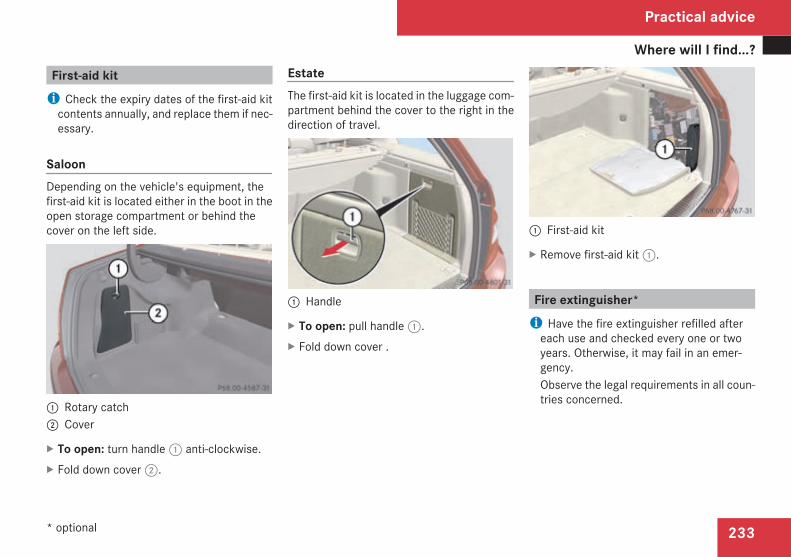
Where will I find...?
233
First-aid kiti Check the expiry dates of the first-aid kitcontents annually, and replace them if nec-essary.
SaloonDepending on the vehicle's equipment, thefirst-aid kit is located either in the boot in theopen storage compartment or behind thecover on the left side.
1 Rotary catch2 Cover
X To open: turn handle1 anti-clockwise.X Fold down cover2.
EstateThe first-aid kit is located in the luggage com-partment behind the cover to the right in thedirection of travel.
1 Handle
X To open: pull handle1.X Fold down cover .
1 First-aid kit
X Remove first-aid kit1.
Fire extinguisher*i Have the fire extinguisher refilled aftereach use and checked every one or twoyears. Otherwise, it may fail in an emer-gency.Observe the legal requirements in all coun-tries concerned.
Practical advice
* optional
204_AKB; 2; 3, en-GBmkalafa,
2007-06-26T23:11:51+02:00 - Seite 233

Where will I find...?
234
The fire extinguisher is located underneaththe front of the driver's seat.
1 Tab2 Fire extinguisher
X Pull tab1 upwards.X Remove fire extinguisher2.
Vehicle tool kit, TIREFIT kit, jack,spare wheel* and "Minispare" emer-gency spare wheel*The vehicle tool kit, TIREFIT kit etc. can befound on the left of the stowage well underthe boot/luggage compartment floor.X Saloon: open the stowage well under thefloor of the boot (Y page 184).
X Estate: open the stowage well under thefloor of the luggage compartment(Y page 184).
The vehicle tool kit contains:RA towing eyeRA wheel wrenchRA folding wheel chockRSpare fusesRA pair of gloves
G Risk of injuryThe jack is designed only to raise and holdthe vehicle for a short time while a wheelis being changed.If you are carrying out work on the vehicle,you must use stands.Make sure that the jack is placed on a firm,non-slip and level surface. Do not use
wooden blocks or similar objects as a jackunderlay. Otherwise the jack will not beable to achieve its load-bearing capacitydue to the restricted height.Do not start the engine at any time while awheel is being changed.Do not lie under the vehicle when it is beingsupported by the jack. If you do not raisethe vehicle as described, it could slip off thejack (e.g. if the engine is started or a dooror the boot lid is opened or closed) and youcould be seriously injured.Do not lie under the vehicle when it is beingsupported by the jack. If you do not raisethe vehicle as described, it could slip off thejack (e.g. if the engine is started or a dooror the boot lid/tailgate is opened or closed)and you could be seriously injured.
i When using the jack, you should alsoobserve the safety notes in the "Flat tyre"section (Y page 313).
Practical advice
* optional
204_AKB; 2; 3, en-GBmkalafa,
2007-06-26T23:11:51+02:00 - Seite 234

Where will I find...?
235
Vehicles with a TIREFIT kit
1 TIREFIT kit2 Electric air pump3 Towing eye4 Folding wheel chock5 Jack
Removing the jackX Open Velcro fastener.X Remove jack5.
Vehicleswith sparewheel/"Minispare"emergency spare wheel*X Saloon: lift up the floor of the boot(Y page 184).
X Estate: lift up the floor of the luggage com-partment (Y page 184).
1 Stowage well
X Remove stowage well1.
Removing the spare wheel/"Minispare"emergency spare wheel*
1 Vehicle tool kit tray2 Stowage well3 Spare wheel/"Minispare" emergency
spare wheel *
X Remove vehicle tool kit tray1.X Turn stowage well2 anti-clockwise andremove it.
X Remove spare wheel/"Minispare" emer-gency spare wheel*3.
Practical advice
* optional
204_AKB; 2; 3, en-GBmkalafa,
2007-06-26T23:11:51+02:00 - Seite 235

Display messages
236
Setting up the folding wheel chockThe folding wheel chock serves as an addi-tional measure for securing the vehicle, e.g.when a wheel is being changed.
1 To fold the plates upwards2 To fold out the lower plate3 To insert the plate
X Fold both plates1 upwards.X Fold out lower plate2.X Guide the lugs on the lower plate fully intothe openings in base plate3.
Display messages
NotesThe on-board computer shows warnings ormalfunctions in the multi-function display.Certain display messages are accompaniedby a warning tone or a continuous tone.The multi-function display shows high prioritydisplay messages in red. In the followingtables, these display messages are printed inred.Please respond in accordance with the dis-play messages and follow the additionalnotes in this Owner's Manual.
Vehicles with multi-function steeringwheel (4-button)Use theí button on the multi-functionsteering wheel to fade out low-priority mes-sages. You cannot fade out display messagesof the highest priority. The multi-function dis-play shows these messages continuouslyuntil the causes for the messages have beenremedied.The on-board computer saves some displaymessages. Calling up display messages(Y page 128).
For some display messages, the_ symbolappears in the multi-function display. Moredetailed information on these display mes-sages can be found below under "Text mes-sages" or "Symbol messages".
Vehicles with a luxury multi-functionsteering wheel* (12-button)Use theL or the# button on the luxurymulti-function steering wheel to fade out low-priority messages. You cannot fade out dis-play messages of the highest priority. Themulti-function display shows thesemessagescontinuously until the causes for the mes-sages have been remedied.The on-board computer saves some displaymessages. Calling up display messages(Y page 140).
All vehicles
G Risk of accidentNo messages can be displayed if instru-ment cluster and/or the multi-function dis-play fail.Thismeans that youwill not see informationabout the driving situation, such as thespeed, outside temperature, warning/indi-
Practical advice
* optional
204_AKB; 2; 3, en-GBmkalafa,
2007-06-26T23:11:51+02:00 - Seite 236

Display messages
237
cator lamps, display messages or systemfailures. The vehicle's handling character-istics may be affected. Adjust your drivingstyle and speed accordingly.Immediately consult a qualified specialistworkshop which has the necessary special-ist knowledge and tools to carry out thework required. Mercedes-Benz recom-mends that you use a Mercedes-BenzService Centre for this purpose. In particu-
lar, work relevant to safety or on safety-related systems must be carried out at aqualified specialist workshop.
Before starting a journey, check that thewarning and indicator lamps are operatingcorrectly.X Turn the key to position 2 in the ignitionlock.
or
X Press the KEYLESS GO button* twice.All warning and indicator lamps (except forthe main-beam indicator lamp and the turnsignal indicator lamps) light up and themulti-function display is activated.
The following tables contain all the displaymessages. To make it easier for you to findthe relevant display message, the displaymessages are divided into text messages(Y page 237) and symbol messages(Y page 247).
Text messages
G Risk of accident and injuryAlways have maintenance work carried out at a qualified specialist workshop which has the necessary specialist knowledge and tools tocarry out the work required.Mercedes-Benz recommends that you use a Mercedes-Benz Service Centre for this purpose.In particular, work relevant to safety or on safety-related systems must be carried out at a qualified specialist workshop. The operatingsafety of the vehicle can be affected if this work is carried out incorrectly. There is a risk of accident and injury.
Vehicles with 4-button multi-function steering wheel: text messages are listed in the left-hand column under "Display messages".Vehicles with 12-button luxury multi-function steering wheel: text messages are listed in the right-hand column under "Display mes-sages".
Practical advice
* optional
204_AKB; 2; 3, en-GBmkalafa,
2007-06-26T23:11:51+02:00 - Seite 237
Display messages
238
Display messages Possible cause/consequence Possible solution
Max. speed120km/hOnly for certaincountries
You have exceeded the speed limit. X Drive more slowly.
ABS and ESPinoperative
G Risk of accidentABS, ESP®, BAS, PRE–SAFE®*, hill startassist and ESP® trailer stabilisation aretemporarily unavailable. It is possible thatthe self diagnosis is not yet complete. Thev warning lamp also lights up in theinstrument cluster.The brake system continues to functionnormally, but without the functions listedabove.
X Drive a short distance with gentle bends at aspeed above 20 km/h.The display message disappears when ABS,ESP®, BAS, PRE-SAFE®*, hill start assist andESP® trailer stabilisation are available again.
ABS and ESPinoperative
G Risk of accidentABS, ESP®, BAS, PRE–SAFE®*, hill startassist and ESP® trailer stabilisation areunavailable due to undervoltage. Thev warning lamp also lights up in theinstrument cluster.The brake system continues to functionnormally, but without the functions listedabove.
X Drive on carefully.X Visit a qualified specialist workshop.
Practical advice
* optional
204_AKB; 2; 3, en-GBmkalafa,
2007-06-26T23:11:51+02:00 - Seite 238

Display messages
239
Display messages Possible cause/consequence Possible solution
ABS and ESPinoperative
G Risk of accidentABS, ESP®, BAS, PRE–SAFE®*, hill startassist and ESP® trailer stabilisation areunavailable due to a malfunction. Thev warning lamp also lights up in theinstrument cluster.The brake system continues to functionnormally, but without the functions listedabove.
X Drive on carefully.X Visit a qualified specialist workshop.
EBV, ABS, ESPinoperative
G Risk of accidentEBV, ABS, ESP®, BAS, PRE–SAFE®*, hillstart assist and ESP® trailer stabilisationare unavailable due to a malfunction. Inaddition, thev warning lamp in theinstrument cluster lights up and a warningtone sounds.The brake system continues to functionnormally, but without the functions listedabove.
X Drive on carefully.X Visit a qualified specialist workshop immedi-ately.
Practical advice
* optional
204_AKB; 2; 3, en-GBmkalafa,
2007-06-26T23:11:51+02:00 - Seite 239
Z

Display messages
240
Display messages Possible cause/consequence Possible solution
ESP inoperative ESP inoperativeSee Owner's Manual
G Risk of accidentESP®, BAS, PRE–SAFE®*, hill start assistand ESP® trailer stabilisation are unavail-able due to a malfunction. Thevwarn-ing lamp also lights up in the instrumentcluster.The brake system continues to functionnormally, but without the functions listedabove.
X Drive on carefully.X Visit a qualified specialist workshop.
ESP inoperative ESP currentlyunavail. See Own-er's Manual
G Risk of accidentESP®, BAS, PRE–SAFE®*, hill start assistand ESP® trailer stabilisation are tempo-rarily unavailable. It is possible that theself diagnosis is not yet complete. Thev warning lamp also lights up in theinstrument cluster. The brake system con-tinues to function normally, but withoutthe functions listed above.
X Drive a short distance with gentle bends at aspeed above 20 km/h.The display message disappears when ESP®,ABS, BAS, PRE–SAFE®*, hill start assist andESP® trailer stabilisation are available again.
Practical advice
* optional
204_AKB; 2; 3, en-GBmkalafa,
2007-06-26T23:11:51+02:00 - Seite 240

Display messages
241
Display messages Possible cause/consequence Possible solution
ESP inoperative ESP currentlyunavail. See Own-er's Manual
ESP®, BAS, PRE–SAFE®*, hill start assistand ESP® trailer stabilisation are unavail-able due to undervoltage. It is possiblethat the battery is not being charged. Thev warning lamp also lights up in theinstrument cluster. The brake system con-tinues to function normally, but withoutthe functions listed above.
X Drive on carefully.X Visit a qualified specialist workshop.
ESP inoperative ESP currentlyunavail. See Own-er's Manual
If this display message appears and thev warning lamp flashes at the sametime, this means that ETS has been deac-tivated to prevent the brakes on the drivewheels from overheating.
ETS switches on again as soon as the brakes havecooled down. The display message disappearsand thev warning lamp goes out.
Trailer hitchCheck lockmech.
The trailer tow hitch* is not correctlyengaged. A warning tone also sounds.
X Stop the vehicle. Pay attention to the trafficconditions as you do so.
X Allow the ball coupling to engage in the endposition (Y page 220).
Practical advice
* optional
204_AKB; 2; 3, en-GBmkalafa,
2007-06-26T23:11:51+02:00 - Seite 241
Z

Display messages
242
Display messages Possible cause/consequence Possible solution
Check brakefluid level
G Risk of accidentThere is insufficient brake fluid in thebrake fluid reservoir. In addition, the3warning lamp in the instrument clus-ter lights up and a warning tone sounds.
X Pull over as soon as it is safe to do so.X Do not continue driving under any circumstan-ces.
X Consult the nearest qualified specialist work-shop.
X Do not top up the brake fluid. This will not rec-tify the malfunction.
PShift to P
PShift to P
You have switched off the engine with theKEYLESSGO*button and opened the driv-er's door.You have attempted to lock the vehicle.
X Move the selector lever to P.The engine can be started again.
To startengine, shiftto either P orN
To start engine,shift to either Por N
You have attempted to start the enginewhile the selector lever is not in positionP or N.
X Move the selector lever to P or N.
Clean the fuelfilter
X Visit a qualified specialist workshop.
Practical advice
* optional
204_AKB; 2; 3, en-GBmkalafa,
2007-06-26T23:11:51+02:00 - Seite 242

Display messages
243
Display messages Possible cause/consequence Possible solution
Top up coolant The coolant level is too low. X Top up the coolant, observing the warningnotes (Y page 209).
X Have the coolant system checked at a qualifiedspecialist workshop if the coolant needs top-ping up more often than usual.
Switch offlights orremove key
The light switch has been set to the* position or the daytime driving lightsare switched on and you have notremoved the key. The parking lampsremain switched on. In addition, a warningtone sounds.
X Remove the key from the ignition lock.orX Set the light switch to theM position.
Check tyres Tyre pressureCheck tyres
The tyre pressure losswarning systemhasdetected a significant pressure loss. Awarning tone also sounds.
X Stop the vehicle without making any suddensteering or braking manoeuvres. Pay attentionto the traffic conditions as you do so.
X Check the tyres.X Check the tyre pressure and correct it if nec-essary (Y page 213).
X Repair or change the faulty wheel as necessary(Y page 313).
X Then restart the tyre pressure loss warningsystem once the tyre pressure is correct(Y page 214).
Practical advice
204_AKB; 2; 3, en-GBmkalafa,
2007-06-26T23:11:51+02:00 - Seite 243
Z

Display messages
244
Display messages Possible cause/consequence Possible solution
Run Flat Indi-cator inopera-tive
Run Flat Indicatorinoperative
The tyre pressure loss warning system isdeactivated due to a malfunction.
X Have the tyre pressure loss warning systemchecked at a qualified specialist workshop.
Check tyresRestart system
Check tyre pres-sures then restartRun Flat Indicator
There was a tyre pressure warning mes-sage.
X Make sure that the pressure is correct for alltyres (Y page 213).
X Then restart the tyre pressure loss warningsystem (Y page 214).
Key not detec-ted
The KEYLESSGO* key cannot be detectedwhile the engine is running because it iseither not in the vehicle or because thereis strong radio interference. In addition, awarning tone sounds.Once the engine has been switched off,you will no longer be able to lock the vehi-cle centrally or start the engine.
X Stop the vehicle as soon as the traffic condi-tions permit.
X Locate the KEYLESS GO* key or operate thevehicle using the key in the ignition lock.
Key not detec-ted
The KEYLESS GO* key cannot be detec-ted.
X Change the location of the KEYLESS GO key*within the vehicle.
X Operate the vehicle using the key in the ignitionlock if necessary.
Key does notbelong to vehi-cle
You have put the wrong key in the ignitionlock.
X Use the correct key.
Practical advice
* optional
204_AKB; 2; 3, en-GBmkalafa,
2007-06-26T23:11:51+02:00 - Seite 244

Display messages
245
Display messages Possible cause/consequence Possible solution
Close doors tolock vehicle
Not all doors were closed as you attemp-ted to lock the vehicle. A warning tonealso sounds.
X Close all doors and lock the vehicle again.
Rear left seatbackr. notlockedorRear right seatbackr. notlocked
The right-hand or left-hand rear seat back-rest is not engaged. In addition, a warningtone sounds.
X Fully engage the rear seat backrest(Y page 186).
PRE-SAFE inop-erative
PRE-SAFE inopera-tive See Owner'sManual
Important functions of PRE-SAFE®* havefailed. All other occupant safety systems,e.g. airbags, remain available.
X Visit a qualified specialist workshop.
Child seatposition
Child seat in wrongposition See Own-er's Manual
Vehicles with automatic child seat recog-nition in the front-passenger seat*: thechild seat is not positioned correctly.
X Position the child seat correctly.
Child seatposition
Child seat in wrongposition See Own-er's Manual
Vehicles with automatic child seat recog-nition in the front-passenger seat*: thechild seat recognition sensor is faulty.
X Have the sensor checked at a qualified spe-cialist workshop.
Practical advice
* optional
204_AKB; 2; 3, en-GBmkalafa,
2007-06-26T23:11:51+02:00 - Seite 245
Z

Display messages
246
Display messages Possible cause/consequence Possible solution
Left windowbagmalfunc-tion:wkshporRight windowbagmalfunc-tion:wkshp
The left-hand or right-hand windowbag isfaulty. The= warning lamp also lightsup in the instrument cluster.
X Visit a qualified specialist workshop.
Cruise ctrl. /LIM inoperative
Cr. control andSPEEDTRONIC inop-erative
Cruise control* and Speedtronic* areinoperative. A warning tone also sounds.
X Have Speedtronic* and cruise control*checked at a qualified specialist workshop.
Cruise control- - - km/h
Cruise control- - - km/h
A condition for activating cruise control*has not been met. You have tried to storea speed below 30 km/h, for example. Awarning tone also sounds.
X If conditions permit, drive faster than30 km/h and store the speed.
X Check the conditions for activating cruise con-trol*:RESP® must be activated.RThe parking brake must be released.RIn vehicles with automatic transmission*,the selector lever must be in position D.
Practical advice
* optional
204_AKB; 2; 3, en-GBmkalafa,
2007-06-26T23:11:51+02:00 - Seite 246

Display messages
247
Symbol messages
G Risk of accident and injuryAlways have maintenance work carried out at a qualified specialist workshop which has the necessary specialist knowledge and tools tocarry out the work required.Mercedes-Benz recommends that you use a Mercedes-Benz Service Centre for this purpose.In particular, work relevant to safety or on safety-related systems must be carried out at a qualified specialist workshop. The operatingsafety of the vehicle can be affected if this work is carried out incorrectly. There is a risk of accident and injury.
Display messages Possible cause/consequence Possible solution
120 km/h Maximum speedexceededOnly for certain coun-tries
You have exceeded the speed limit. X Drive more slowly.
Ê The boot lid is open. X Close the boot lid.
Y G Risk of accidentVehicles with an anti-theft alarm sys-tem*: you are driving with the bonnetopen.
X Stop immediately and safely when traffic con-ditions allow.
X Close the bonnet.
V At least one door is open. The displaysymbol shows you which doors are open.A warning tone also sounds.
X Close the doors.
Practical advice
* optional
204_AKB; 2; 3, en-GBmkalafa,
2007-06-26T23:11:51+02:00 - Seite 247
Z

Display messages
248
Display messages Possible cause/consequence Possible solution
- ABS and ESP cur-rently unavailableSee Owner's Manual
G Risk of accidentABS, ESP®, BAS, PRE–SAFE®*, hill startassist and ESP® trailer stabilisation aretemporarily unavailable. It is possible thatthe self diagnosis is not yet complete. Thev warning lamp also lights up in theinstrument cluster.The brake system continues to functionnormally, but without the functions listedabove.
X Drive a short distance with gentle bends at aspeed above 20 km/h.The display message disappears when ABS,ESP®, BAS, PRE–SAFE®*, hill start assist andESP® trailer stabilisation are available again.
- ABS and ESP cur-rently unavailableSee Owner's Manual
G Risk of accidentABS, ESP®, BAS, PRE–SAFE®*, hill startassist and ESP® trailer stabilisation areunavailable due to undervoltage. Thev warning lamp also lights up in theinstrument cluster.The brake system continues to functionnormally, but without the functions listedabove.
X Drive on carefully.X Visit a qualified specialist workshop.
Practical advice
* optional
204_AKB; 2; 3, en-GBmkalafa,
2007-06-26T23:11:51+02:00 - Seite 248

Display messages
249
Display messages Possible cause/consequence Possible solution
- ABS and ESP inoper-ative See Owner'sManual
G Risk of accidentABS, ESP®, BAS, PRE–SAFE®*, hill startassist and ESP® trailer stabilisation areunavailable due to a malfunction. Thev warning lamp also lights up in theinstrument cluster.The brake system continues to functionnormally, but without the functions listedabove.
X Drive on carefully.X Visit a qualified specialist workshop.
\ Trailer tow hitchCheck lock mecha-nism
The trailer tow hitch* is not correctlyengaged. A warning tone also sounds.
X Stop the vehicle. Pay attention to the trafficconditions as you do so.
X Allow the ball coupling to engage in the endposition (Y page 220).
# The battery is not being charged. Possiblecauses:Rfaulty alternatorRtorn poly-V-beltRmalfunction in the electronics
X Stop immediately and safely when traffic con-ditions allow and check the poly-V-belt.
X If it has torn: do not drive on. Contact thenearest qualified specialist workshop.
X If it is not damaged: have the vehicle checkedas soon as possible at a qualified specialistworkshop.
Practical advice
* optional
204_AKB; 2; 3, en-GBmkalafa,
2007-06-26T23:11:51+02:00 - Seite 249
Z

Display messages
250
Display messages Possible cause/consequence Possible solution
2 4-button multi-functionsteering wheel:Brake wear12-button luxury multi-function steeringwheel:Brake wear
The brake pads/linings have reachedtheir wear limit.
X Have the brake pads/linings replaced as soonas possible at a qualified specialist workshop.
3 Check brake fluidlevel
G Risk of accidentThere is insufficient brake fluid in thebrake fluid reservoir. In addition, the3 warning lamp lights up in the instru-ment cluster.
X Pull over as soon as it is safe to do so.X Do not continue driving under any circumstan-ces.
X Consult the nearest qualified specialist work-shop.
X Do not top up the brake fluid. This will not rec-tify the malfunction.
Î 4-button multi-functionsteering wheel:Release park.brake12-button luxury multi-function steeringwheel:Release parkingbrake
You are driving with the parking brake on.A warning tone also sounds.
X Release the parking brake.
Practical advice
204_AKB; 2; 3, en-GBmkalafa,
2007-06-26T23:11:51+02:00 - Seite 250

Display messages
251
Display messages Possible cause/consequence Possible solution
3 EBV, ABS, ESP inop-erative See Own-er's Manual
G Risk of accidentEBV, ABS, ESP®, BAS, PRE–SAFE®*, hillstart assist and ESP® trailer stabilisationare unavailable due to a malfunction. Inaddition, thev warning lamp in theinstrument cluster lights up and a warningtone sounds.The brake system continues to functionnormally, but without the functions listedabove.
X Drive on carefully.X Visit a qualified specialist workshop immedi-ately.
ñ Clean the fuel fil-ter
X Visit a qualified specialist workshop.
D 4-button multi-functionsteering wheel:Stop vehicleEngine off12-button luxury multi-function steeringwheel:Coolant Stop vehi-cle Switch engineoff
The coolant is too hot. In addition, theDwarning lamp in the instrument clus-ter lights up and a warning tone sounds.
X Stop the vehicle. Pay attention to the trafficconditions as you do so.
X Switch off the engine.X Wait until the display message disappearsbefore restarting the engine. There is other-wise a risk of engine damage.
X Observe the coolant temperature gauge.X If the temperature increases again, visit a quali-fied specialist workshop immediately.
Practical advice
* optional
204_AKB; 2; 3, en-GBmkalafa,
2007-06-26T23:11:51+02:00 - Seite 251
Z

Display messages
252
Display messages Possible cause/consequence Possible solution
D 4-button multi-functionsteering wheel:Stop vehicleEngine off12-button luxury multi-function steeringwheel:Coolant Stop vehi-cle Switch engineoff
The poly-V-belt may have torn. A warningtone also sounds.
X Stop the vehicle. Pay attention to the trafficconditions as you do so.
X Switch off the engine.X Check the poly-V-belt.X If it is not damaged: do not start the engineagain until the displaymessage goes out. Thereis otherwise a risk of engine damage.
X If it has torn: do not drive on. Contact thenearest qualified specialist workshop.
D The radiator's electric fan has failed. X If the coolant temperature is less than 120 †you can continue driving to the nearest quali-fied specialist workshop.
X In doing so, avoid heavy loads on the engine(e.g. driving in mountainous terrain) and stop-and-go driving.
H Top up coolant SeeOwner's Manual
The coolant level is too low. X Top up the coolant, observing the warningnotes (Y page 209).
X Have the coolant system checked at a qualifiedspecialist workshop if the coolant needs top-ping up more often than usual.
Practical advice
204_AKB; 2; 3, en-GBmkalafa,
2007-06-26T23:11:51+02:00 - Seite 252

Display messages
253
Display messages Possible cause/consequence Possible solution
. 4-button multi-functionsteering wheel:Left corner. lightorRight corner.light12-button luxury multi-function steeringwheel:Left corneringlightorRight corneringlight
The left-hand and/or right-hand corneringlamp* is faulty.
X Visit a qualified specialist workshop.
. 4-button multi-functionsteering wheel:Left dipped beamorRight dipped beam12-button luxury multi-function steeringwheel:Left dipped beamorRight dipped beam
The right-hand or left-hand dipped-beamheadlamp is faulty.
X Halogen headlamps: replace the bulb as soonas possible (Y page 305).
X Bi-xenon headlamps*: visit a qualified spe-cialist workshop as soon as possible.
Practical advice
* optional
204_AKB; 2; 3, en-GBmkalafa,
2007-06-26T23:11:51+02:00 - Seite 253
Z

Display messages
254
Display messages Possible cause/consequence Possible solution
. 4-button multi-functionsteering wheel:Trailer left turnsig.orTrailer rt.turnsig.12-button luxury multi-function steeringwheel:Trailer left turnsig.orTrailer rt. turnsig.
The left-hand or right-hand trailer turn sig-nal is faulty.
X Replace the bulb as soon as possible.
. 4-button multi-functionsteering wheel:Trailer brake lamp12-button luxury multi-function steeringwheel:Trailer brake lamp
The trailer brake lamp is faulty. X Replace the bulb as soon as possible.
Practical advice
204_AKB; 2; 3, en-GBmkalafa,
2007-06-26T23:11:51+02:00 - Seite 254

Display messages
255
Display messages Possible cause/consequence Possible solution
. 4-button multi-functionsteering wheel:Trailer left taillamporTrailer rt. taillamp12-button luxury multi-function steeringwheel:Trailer left taillamporTrailer right taillamp
The left-hand or right-hand trailer tail lampis faulty.
X Replace the bulb as soon as possible.
. 4-button multi-functionsteering wheel:AUTO lights inop-erative12-button luxury multi-function steeringwheel:AUTO lights inop-erative
The light sensor is faulty. Daytime drivinglights are switched on.
X Use the light switch to switch the lighting on/off (Y page 102).
Practical advice
204_AKB; 2; 3, en-GBmkalafa,
2007-06-26T23:11:51+02:00 - Seite 255
Z

Display messages
256
Display messages Possible cause/consequence Possible solution
. 4-button multi-functionsteering wheel:Rear left turn sig-nalorRear right turnsignal12-button luxury multi-function steeringwheel:Rear left turn sig-nalorRear right turnsignal
The rear left-hand or rear right-hand turnsignal is faulty. In vehicles with LEDs, thisdisplay message will only appear if all theLEDs fail.
X Vehicles without LEDs: replace the bulb assoon as possible (Y page 305).Vehicles with LEDs: visit a qualified specialistworkshop as soon as possible.
Practical advice
204_AKB; 2; 3, en-GBmkalafa,
2007-06-26T23:11:51+02:00 - Seite 256

Display messages
257
Display messages Possible cause/consequence Possible solution
. 4-button multi-functionsteering wheel:Left mirror turnsignalorRight mirror turnsignal12-button luxury multi-function steeringwheel:Left mirror turnsignalorRight mirror turnsignal
The turn signal lamp on the left-hand orright-hand exterior mirror is faulty. Thisdisplay message will only appear if allLEDs have failed.
X Visit a qualified specialist workshop as soon aspossible.
Practical advice
204_AKB; 2; 3, en-GBmkalafa,
2007-06-26T23:11:51+02:00 - Seite 257
Z

Display messages
258
Display messages Possible cause/consequence Possible solution
. 4-button multi-functionsteering wheel:Front left turnsignalorFront right turnsignal12-button luxury multi-function steeringwheel:Front left turnsignalorFront right turnsignal
The front left-hand or right-hand turn sig-nal is faulty.
X Replace the bulb as soon as possible(Y page 305).
. 4-button multi-functionsteering wheel:Third brake lamp12-button luxury multi-function steeringwheel:Third brake lamp
The third brake lamp is faulty. This displaymessage will only appear if all LEDs havefailed.
X Visit a qualified specialist workshop as soon aspossible.
Practical advice
204_AKB; 2; 3, en-GBmkalafa,
2007-06-26T23:11:51+02:00 - Seite 258

Display messages
259
Display messages Possible cause/consequence Possible solution
. 4-button multi-functionsteering wheel:Tail/brake lamp,leftorTail/brake lamp,right12-button luxury multi-function steeringwheel:Left-hand taillamp/brake lamporRight-hand taillamp/brake lamp
The left-hand or right-hand tail lamp/brake lamp is faulty.
X Replace the bulb as soon as possible(Y page 305).
Practical advice
204_AKB; 2; 3, en-GBmkalafa,
2007-06-26T23:11:51+02:00 - Seite 259
Z

Display messages
260
Display messages Possible cause/consequence Possible solution
. 4-button multi-functionsteering wheel:Left-hand brakelamporRight-hand brakelamp12-button luxury multi-function steeringwheel:Left-hand brakelamporRight-hand brakelamp
The left-hand or right-hand brake lamp isfaulty.
X Replace the bulb as soon as possible(Y page 305).
Practical advice
204_AKB; 2; 3, en-GBmkalafa,
2007-06-26T23:11:51+02:00 - Seite 260

Display messages
261
Display messages Possible cause/consequence Possible solution
. 4-button multi-functionsteering wheel:Left main beamorRight main beam12-button luxury multi-function steeringwheel:Left main beamorRight main beam
The left-hand or right-hand main-beamheadlamp is faulty.
X Replace the bulb as soon as possible(Y page 305).
. Intell. Light Sys-tem inoperative
The Intelligent Light System* is faulty. Thelights remain available without the Intelli-gent Light System*.
X Visit a qualified specialist workshop.
Practical advice
* optional
204_AKB; 2; 3, en-GBmkalafa,
2007-06-26T23:11:51+02:00 - Seite 261
Z

Display messages
262
Display messages Possible cause/consequence Possible solution
. 4-button multi-functionsteering wheel:Left licence platelamporRight licenceplate lamp12-button luxury multi-function steeringwheel:Left licence platelamporRight licenceplate lamp
The left-hand or right-hand licence platelamp is faulty.
X Visit a qualified specialist workshop as soon aspossible.
Practical advice
204_AKB; 2; 3, en-GBmkalafa,
2007-06-26T23:11:51+02:00 - Seite 262

Display messages
263
Display messages Possible cause/consequence Possible solution
. 4-button multi-functionsteering wheel:Left foglamporRight foglamp12-button luxury multi-function steeringwheel:Left foglamporRight foglamp
The front left-hand or right-hand foglampis faulty.
X Visit a qualified specialist workshop as soon aspossible.
. 4-button multi-functionsteering wheel:Rear left foglamporRear right foglamp12-button luxury multi-function steeringwheel:Rear left foglamporRear right foglamp
The left-hand or right-hand rear foglamp isfaulty.
X Replace the bulb as soon as possible(Y page 305).
Practical advice
204_AKB; 2; 3, en-GBmkalafa,
2007-06-26T23:11:51+02:00 - Seite 263
Z

Display messages
264
Display messages Possible cause/consequence Possible solution
. 4-button multi-functionsteering wheel:Front left parkinglamporFront right park-ing lamp12-button luxury multi-function steeringwheel:Front left parkinglamporFront right park-ing lamp
The front left-hand or right-hand parkinglamp is faulty.
X Replace the bulb as soon as possible(Y page 305).
Practical advice
204_AKB; 2; 3, en-GBmkalafa,
2007-06-26T23:11:51+02:00 - Seite 264

Display messages
265
Display messages Possible cause/consequence Possible solution
. 4-button multi-functionsteering wheel:Left revers. lamporRight revers. lamp12-button luxury multi-function steeringwheel:Left revers. lamporRight revers. lamp
The left-hand or right-hand reversing lampis faulty.
X Replace the bulb as soon as possible(Y page 305).
Practical advice
204_AKB; 2; 3, en-GBmkalafa,
2007-06-26T23:11:51+02:00 - Seite 265
Z

Display messages
266
Display messages Possible cause/consequence Possible solution
. 4-button multi-functionsteering wheel:Left-hand taillamporRight-hand taillamp12-button luxury multi-function steeringwheel:Left-hand taillamporRight-hand taillamp
The left-hand or right-hand tail lamp isfaulty.
X Replace the bulb as soon as possible(Y page 305).
. 4-button multi-functionsteering wheel:Switch off lights12-button luxury multi-function steeringwheel:Switch off lights
You did not switch off the lights whenleaving the vehicle. A warning tone alsosounds.
X Turn the light switch toM.
Practical advice
204_AKB; 2; 3, en-GBmkalafa,
2007-06-26T23:11:51+02:00 - Seite 266

Display messages
267
Display messages Possible cause/consequence Possible solution
. Switch off lightsor remove key
The light switch is set to the* positionor the daytime driving lights are switchedon and you have not removed the key. Theside lamps remain switched on. A warningtone also sounds.
X Remove the key from the ignition lock.orX Turn the light switch toM.
ò 4-button multi-functionsteering wheel:Replace aircleaner12-button luxury multi-function steeringwheel:Replace aircleaner
The engine air filter must be replaced. X Visit a qualified specialist workshop.
N 4-button multi-functionsteering wheel:Check eng. oillevel12-button luxury multi-function steeringwheel:Check eng. oil lev.when next refuel-ling
The engine oil level has dropped to a crit-ical level.
X Check the engine oil level (Y page 208) and topup the engine oil if necessary.
X Have the engine checked for leaks if the engineoil needs topping up more often than usual.
Practical advice
204_AKB; 2; 3, en-GBmkalafa,
2007-06-26T23:11:51+02:00 - Seite 267
Z

Display messages
268
Display messages Possible cause/consequence Possible solution
I 4-button multi-functionsteering wheel:Change battery12-button luxury multi-function steeringwheel:Change key batter-ies
The KEYLESS GO* key batteries are dis-charged.
X Change the batteries (Y page 304).
I Key not detected The KEYLESS GO key* is not detectedwhile the engine is running because it isnot inside the vehicle or because of strongradio interference. A warning tone alsosounds.Once the engine is switched off, you willno longer be able to lock the vehicle cen-trally or start the engine.
X Stop the vehicle. Pay attention to the trafficconditions as you do so.
X Locate the KEYLESS GO key* or operate thevehicle using the key in the ignition lock.
I Key not detected The KEYLESS GO* key cannot be detec-ted.
X Change the location of the KEYLESS GO key*within the vehicle.
X Operate the vehicle using the key in the ignitionlock if necessary.
Practical advice
* optional
204_AKB; 2; 3, en-GBmkalafa,
2007-06-26T23:11:51+02:00 - Seite 268

Display messages
269
Display messages Possible cause/consequence Possible solution
I 4-button multi-functionsteering wheel:Key still in vehi-cle12-button luxury multi-function steeringwheel:Key still in vehi-cle
The KEYLESSGOkey*was detected in thevehicle when you attempted to lock thevehicle.
X Remove the KEYLESS GO key* from the vehi-cle.
I 4-button multi-functionsteering wheel:You need a new key12-button luxury multi-function steeringwheel:Replace key
The key no longer functions. X Visit a qualified specialist workshop.
I Key does not belongto vehicle
You have put the wrong key in the ignitionlock.
X Use the correct key.
I Close doors to lockvehicle
Not all doors were closed as you attemp-ted to lock the vehicle. A warning tonealso sounds.
X Close all doors and lock the vehicle again.
Practical advice
* optional
204_AKB; 2; 3, en-GBmkalafa,
2007-06-26T23:11:51+02:00 - Seite 269
Z

Display messages
270
Display messages Possible cause/consequence Possible solution
I 4-button multi-functionsteering wheel:Insert key12-button luxury multi-function steeringwheel:Remove startingbutton, theninsert key
KEYLESS GO* has malfunctioned or isfaulty. A warning tone also sounds.
X Pull out the KEYLESS GO* button from the igni-tion lock (Y page 86).
X Start your vehicle using the KEYLESS GO* keyin the ignition lock.
? Rear left seatbackrest notlockedorRear right seatbackrest notlocked
The rear seat backrest is not engaged onthe left-hand or right-hand side. A warningtone also sounds.
X Fully engage the rear seat backrest(Y page 186).
Practical advice
* optional
204_AKB; 2; 3, en-GBmkalafa,
2007-06-26T23:11:51+02:00 - Seite 270

Display messages
271
Display messages Possible cause/consequence Possible solution
= 4-button multi-functionsteering wheel:Malfunction -Work-shop-12-button luxury multi-function steeringwheel:Restraint sys.malfunction Con-sult workshop
The SRS (Supplemental Restraint System)is faulty. The= warning lamp alsolights up in the instrument cluster.
X Visit a qualified specialist workshop.
Practical advice
204_AKB; 2; 3, en-GBmkalafa,
2007-06-26T23:11:51+02:00 - Seite 271
Z

Display messages
272
Display messages Possible cause/consequence Possible solution
= 4-button multi-functionsteering wheel:FL malfunc. -Work-shop-orFR malfunc. -Work-shop-12-button luxury multi-function steeringwheel:Front left mal-function ConsultworkshoporFront right mal-function Consultworkshop
The SRS (Supplemental Restraint System)is malfunctioning at the front left or thefront right. The= warning lamp alsolights up in the instrument cluster.
X Visit a qualified specialist workshop.
Practical advice
204_AKB; 2; 3, en-GBmkalafa,
2007-06-26T23:11:51+02:00 - Seite 272

Display messages
273
Display messages Possible cause/consequence Possible solution
= 4-button multi-functionsteering wheel:RL malfunc. -Work-shop-orRR malfunc. -Work-shop-12-button luxury multi-function steeringwheel:Rear left malfunc-tion Consult work-shoporRear right mal-function Consultworkshop
The SRS (Supplemental Restraint System)is malfunctioning at the rear left or therear right. The= warning lamp alsolights up in the instrument cluster.
X Visit a qualified specialist workshop.
Practical advice
204_AKB; 2; 3, en-GBmkalafa,
2007-06-26T23:11:51+02:00 - Seite 273
Z

Display messages
274
Display messages Possible cause/consequence Possible solution
= 4-button multi-functionsteering wheel:R.cent.malf. -Workshop-12-button luxury multi-function steeringwheel:Rear centre mal-function Consultworkshop
The rear centre SRS (SupplementalRestraint System) is faulty. The=warning lamp also lights up in the instru-ment cluster.
X Visit a qualified specialist workshop.
= Left windowbagmalfunction Con-sult workshoporRight windowbagmalfunction Con-sult workshop
The left-hand or right-hand windowbag isfaulty. The= warning lamp also lightsup in the instrument cluster.
X Visit a qualified specialist workshop.
W 4-button multi-functionsteering wheel:Reserve fuel level12-button luxury multi-function steeringwheel:Reserve fuel level
The level of fuel has fallen below thereserve range.
X Refuel at the nearest filling station.
Practical advice
204_AKB; 2; 3, en-GBmkalafa,
2007-06-26T23:11:51+02:00 - Seite 274

Display messages
275
Display messages Possible cause/consequence Possible solution
W 4-button multi-functionsteering wheel:Top up washer fluid12-button luxury multi-function steeringwheel:Top up washer fluid
The washer fluid level in the washer fluidreservoir has dropped below the mini-mum.
X Top up the washer fluid (Y page 210).
Practical advice
204_AKB; 2; 3, en-GBmkalafa,
2007-06-26T23:11:51+02:00 - Seite 275

Troubleshooting
276
TroubleshootingG Risk of accident and injuryAlways have maintenance work carried out at a qualified specialist workshop which has the necessary specialist knowledge and tools tocarry out the work required.Mercedes-Benz recommends that you use a Mercedes-Benz Service Centre for this purpose.In particular, work relevant to safety or on safety-related systems must be carried out at a qualified specialist workshop. The operatingsafety of the vehicle can be affected if this work is carried out incorrectly. There is a risk of accident and injury.
Indicator and warning lamps in switches and buttons
Problem Possible cause/consequence Suggested solutions
The seat heating* has switcheditself off prematurely or cannotbe switched on.
There is insufficient voltagebecause toomany consumers areswitched on.
X Switch off consumers that are not required, e.g. reading lamps,interior lighting, etc.The seat heating* will automatically switch back on as soon asthere is sufficient voltage again.
The warning lamp on the sportbutton of the ADVANCEDAGILITYpackage with sports mode* is lit.
If you select comfortable modeand the indicator lamp does notgo out, the ADVANCED AGILITYpackage with sports mode* isfaulty.
X Visit a qualified specialist workshop.
Practical advice
* optional
204_AKB; 2; 3, en-GBmkalafa,
2007-06-26T23:11:51+02:00 - Seite 276

Troubleshooting
277
Problem Possible cause/consequence Suggested solutions
The indicator lamp in the2button on the Thermatic/Thermotronic* control panel is onor flashes when you press thebutton. The cooling system can-not be switched on.
The cooling system is losingrefrigerant.
X Visit a qualified specialist workshop.
The rear-window heating hasswitched itself off prematurely orcannot be switched on.
There is insufficient voltagebecause toomany consumers areswitched on.
X Switch off consumers that are not required, e.g. reading lamps,interior lighting, etc.The rear-window heating will automatically switch back on as soonas there is sufficient voltage again.
Vehicles with automatic childseat recognition on the front-passenger seat*:The5/ indicator lamp onthe centre console is lit.
A special Mercedes-Benz childseat with automatic child seatrecognition has been fitted to thefront-passenger seat. The front-passenger airbag has thereforebeen disabled.
Practical advice
* optional
204_AKB; 2; 3, en-GBmkalafa,
2007-06-26T23:11:51+02:00 - Seite 277
Z

Troubleshooting
278
Problem Possible cause/consequence Suggested solutions
Vehicles with automatic childseat recognition on the front-passenger seat*:The5/ indicator lamp onthe centre console is lit.
G Risk of injuryThere is no child seat fitted to thefront-passenger seat. The auto-matic child seat recognition onthe front-passenger seat is faulty.
X Remove electronic equipment from the front-passenger seat, e.g.:RNotebooksRMobile phonesRCards with transponders, e.g. ski passes or access passes
If the5/ indicator lamp remains lit:X Visit a qualified specialist workshop.
Practical advice
* optional
204_AKB; 2; 3, en-GBmkalafa,
2007-06-26T23:11:51+02:00 - Seite 278

Troubleshooting
279
Indicator and warning lamps in the instrument cluster
Problem Possible cause/consequence Suggested solutions
- The yellow ABS warninglamp lights up while theengine is running.
G Risk of accidentABS, ESP®, BAS, PRE–SAFE®*,hill start assist and ESP® trailerstabilisation are unavailable dueto a malfunction.The brake system continues tofunction normally, but withoutthe functions listed above. Thewheels could therefore lock if youbrake hard, for example.
X Drive on carefully.X Observe the additional messages in the multi-function display(Y page 236).
X Visit a qualified specialist workshop as soon as possible.
v The yellow ESP® warninglamp lights up while theengine is running.
G Risk of accidentESP® is deactivated. ESP® willnot stabilise the vehicle if it startsto skid or if a wheel starts to spin.
X Reactivate ESP® (Y page 68).Exceptions (Y page 68).
X Adapt your driving style to suit the road and weather conditions.
G Risk of accidentESP® is not available due to amalfunction. ESP® will not stabi-lise the vehicle if it starts to skidor if a wheel starts to spin.
X Observe the additional messages in the multi-function display(Y page 236).
X Drive on carefully.X Visit a qualified specialist workshop.
Practical advice
* optional
204_AKB; 2; 3, en-GBmkalafa,
2007-06-26T23:11:51+02:00 - Seite 279
Z

Troubleshooting
280
Problem Possible cause/consequence Suggested solutions
v The yellow ESP® warninglamp flashes while thevehicle is in motion.
G Risk of accidentESP® or traction control hasintervened because at least onewheel has started to spin.Cruise control* is switched off.
X Only depress the accelerator pedal as far as necessary when pull-ing away.
X Release the accelerator pedal while you are driving.X Adapt your driving style to suit the road and weather conditions.X Do not deactivate ESP®.Exceptions (Y page 68).
G Risk of accidentAt least one tyre is spinning andETS is deactivated to prevent thebrakes on the drive wheels fromoverheating.
X Observe the additional messages in the multi-function display(Y page 236).
ETS switches back on again as soon as the brakes have cooled down.The display message disappears and thev warning lamp goesout.
3 The red brake systemwarning lamp lights upwhile you are driving. Youwill also hear a warningtone.
You are driving with the parkingbrake on.
X Release the parking brake (Y page 116).The warning lamp goes out and the warning tone ceases.
Practical advice
* optional
204_AKB; 2; 3, en-GBmkalafa,
2007-06-26T23:11:51+02:00 - Seite 280

Troubleshooting
281
Problem Possible cause/consequence Suggested solutions
3 The red brake systemwarning lamp lights upwhile the engine is run-ning. You will also hear awarning tone.
G Risk of accidentThere is insufficient brake fluid inthe fluid reservoir.
X Do not continue driving under any circumstances.X Consult a qualified specialist workshop immediately.X Observe the additional messages in the multi-function display(Y page 236).
X Under no circumstances should you top up the brake fluid. This willnot rectify the fault.
D The red coolant warninglamp lights up while theengine is running and thecoolant temperaturegauge is at the start of thescale.
The sensor for the coolant tem-perature gauge is faulty.The coolant is too hot. The engineis not being cooled sufficientlyand may be damaged.
X Do not continue driving under any circumstances.X Consult a qualified specialist workshop.
Practical advice
204_AKB; 2; 3, en-GBmkalafa,
2007-06-26T23:11:51+02:00 - Seite 281
Z

Troubleshooting
282
Problem Possible cause/consequence Suggested solutions
D The red coolant warninglamp lights up while theengine is running. You willalso hear a warning tone.
The coolant temperature hasexceeded 130 †. The engine isnot being cooled sufficiently andmay be damaged.The coolant level may be too low.
X Stop the vehicle as soon as possible. Pay attention to the trafficconditions as you do so.
X Allow the engine and coolant to cool.X Check the coolant level. Observe the warning notes(Y page 209). Top up the coolant if necessary.
X Have the coolant system checked at a qualified specialist work-shop if the coolant needs topping up more often than usual.
If the coolant level is correct, the radiator fan may be faulty. In thiscase:X Do not continue driving under any circumstances.X Consult a qualified specialist workshop.
± The yellowengine diagnos-tic warning lamp lights upwhile the engine is run-ning.
Vehicles with a diesel engine: thefuel tank has run dry.
X Start the engine three to four times after refuelling.Emergency running mode is cancelled. The vehicle need not bechecked.
Practical advice
204_AKB; 2; 3, en-GBmkalafa,
2007-06-26T23:11:51+02:00 - Seite 282

Troubleshooting
283
Problem Possible cause/consequence Suggested solutions
± The yellowengine diagnos-tic warning lamp lights upwhile the engine is run-ning.
There may be a malfunction:Rin the fuel injection system orRin the exhaust system orRin the ignition system (on vehi-cles with a petrol engine)
The emission limit values may beexceeded and the engine may berunning in emergency mode.
X Have the vehicle checked as soon as possible at a qualified spe-cialist workshop.
= The red SRS warning lamplights up while the engineis running.
G Risk of injuryThe restraint systems are faulty.The airbags or belt tensionersmay either be triggered uninten-tionally or, in the event of an acci-dent, not be triggered at all.
X Visit a qualified specialist workshop immediately.
< The red seat belt warninglamp lights up for 6 sec-onds after the enginestarts up.16
The seat belt warning lampreminds the driver and frontpassenger to fasten their seatbelts.
X Fasten your seat belt (Y page 98).
16 Only for certain countries
Practical advice
204_AKB; 2; 3, en-GBmkalafa,
2007-06-26T23:11:51+02:00 - Seite 283
Z

Troubleshooting
284
Problem Possible cause/consequence Suggested solutions
< You will hear a warningtone for a maximum of 6seconds after the engine isstarted. 16
G Risk of injuryThe driver's seat belt is not fas-tened.
X Fasten your seat belt (Y page 98).The warning tone ceases.
< The red seat belt warninglamp lights up after start-ing the engine, as soon asthe driver's door or thefront-passenger door isclosed.
G Risk of injuryThe driver or front passenger hasnot fastened their seat belt.
X Fasten your seat belt (Y page 98).The warning lamp goes out.
G Risk of injuryThere are objects on the front-passenger seat.
X Remove the objects from the front-passenger seat and stow themin a secure place.The warning lamp goes out.
16 Only for certain countries
Practical advice
204_AKB; 2; 3, en-GBmkalafa,
2007-06-26T23:11:51+02:00 - Seite 284

Troubleshooting
285
Problem Possible cause/consequence Suggested solutions
< The red seat belt warninglamp flashes and you hearan intermittent warningtone.
G Risk of injuryEither the driver's or the frontpassenger's seat belt is not fas-tened and you are driving fasterthan 25 km/h or have drivenfaster than 25 km/h for a shorttime.
X Fasten your seat belt (Y page 98).The warning lamp goes out and the intermittent warning toneceases.
G Risk of injuryThere are objects on the front-passenger seat and you are driv-ing faster than 25 km/h or havedriven faster than 25 km/h for ashort time.
X Remove the objects from the front-passenger seat and stow themin a secure place.The warning lamp goes out and the intermittent warning toneceases.
4 The yellow reserve fuelwarning lamp lights upwhile the engine is run-ning.
The level of fuel has fallen belowthe reserve range.
X Refuel at the nearest filling station.
Practical advice
204_AKB; 2; 3, en-GBmkalafa,
2007-06-26T23:11:51+02:00 - Seite 285

Troubleshooting
286
Warning tones
Problem Possible cause/consequence Suggested solutions
The anti-theft alarm system* issuddenly triggered.
You have opened the vehicleusing the emergency key elementwithout deactivating the anti-theft alarm system* first.
Key:X Press theŒ or the‹ button.
orX Insert the key into the ignition lock.The alarm is deactivated.
KEYLESS GO*:X Grasp the exterior door handle. The KEYLESS GO key* must beoutside the vehicle.The alarm is deactivated.
orX Press the KEYLESS GO button* on the dashboard. The KEYLESSGO key* must be inside the vehicle.The alarm is deactivated.
You hear a warning tone. A message appears in the multi-function display.
X See the explanations for the display message (Y page 236).
You hear a warning tone. You are driving with the parkingbrake on.
X Release the parking brake.
Practical advice
* optional
204_AKB; 2; 3, en-GBmkalafa,
2007-06-26T23:11:51+02:00 - Seite 286

Troubleshooting
287
Problem Possible cause/consequence Suggested solutions
You hear a warning tone. You have opened the driver'sdoor and forgotten to switch offthe lights.
X Turn the light switch toM or*.
You hear a warning tone. G Risk of injuryThe driver or front passenger hasnot fastened their seat belt.
X Fasten your seat belt (Y page 98).
Accident
Problem Possible cause/consequence Suggested solutions
Fuel is leaking from the vehicle. G Risk of fireThe fuel line or the fuel tank hasbeen damaged.
X Switch off the ignition immediately.X Remove the ignition key.X Do not restart the engine under any circumstances.The leaking fuel creates a risk of fire or explosion.X Consult a qualified specialist workshop.
You are unable to determine theextent of the damage.
X Consult a qualified specialist workshop.
You cannot detect any damage. X Start the engine as normal.
Practical advice
204_AKB; 2; 3, en-GBmkalafa,
2007-06-26T23:11:51+02:00 - Seite 287
Z

Troubleshooting
288
Problem Possible cause/consequence Suggested solutions
The NECK-PRO head restraintson the driver's and front-passenger seats have been trig-gered.
Your vehicle has been involved ina rear-end collision.
X Reset the NECK-PRO head restraints (Y page 303).
Fuel and fuel tank
Problem Possible cause/consequence Suggested solutions
Fuel is leaking from the vehicle. G Risk of fireThe fuel line or the fuel tank isdefective.
X Turn the key to position 0 in the ignition lock immediately andremove it.
X Do not restart the engine under any circumstances.The leaking fuel creates a risk of fire or explosion.X Consult a qualified specialist workshop.
The fuel filler flap cannot beopened.
The fuel filler flap is not released. X Unlock the vehicle (Y page 300).
The opening mechanism is jam-med.
X Release the fuel filler flap by hand (Y page 302).X Consult a qualified specialist workshop.
Practical advice
204_AKB; 2; 3, en-GBmkalafa,
2007-06-26T23:11:51+02:00 - Seite 288

Troubleshooting
289
Problem Possible cause/consequence Suggested solutions
The fuel tank has been run com-pletely dry on a vehicle with adiesel engine.
There is air in the fuel system. X Refuel the vehicle.X Switch on the ignition for approximately 10 seconds (key in posi-tion 2 in the ignition lock).
X Start the engine continuously for up to 40 seconds until it runssmoothly.The fuel system is now free of air.
If the engine does not start:X Wait two minutes.X Repeat the starting procedure for up to 40 seconds.If the engine still does not start:X Consult a qualified specialist workshop.
Practical advice
204_AKB; 2; 3, en-GBmkalafa,
2007-06-26T23:11:51+02:00 - Seite 289

Troubleshooting
290
Engine
Problem Possible cause/consequence Suggested solutions
The engine will not start. You canhear the starter motor operating.
RThere may be a malfunction inthe engine electronics.
RThere may be a malfunction inthe fuel supply.
X Turn the key back to position 0 in the ignition lock before the nextstarting attempt.
X Try to start the engine again (Y page 113). When doing so, remem-ber that excessively long and frequent attempts to start the enginewill drain the battery.
If the engine does not start after several attempts:X Consult a qualified specialist workshop.
Vehicles with a diesel engine:The engine will not start. You canhear the starter motor operating.The reserve fuel warning lamp ison and the fuel gauge shows 0.
The fuel tank has been run dry. X Refuel the vehicle.X Bleed the fuel system (Y page 289).
The engine will not start. You can-not hear the starter motor oper-ating.
The on-board voltage is too lowbecause the starter battery is tooweak or discharged.
X Jump-start the vehicle (Y page 328).If the engine does not start despite attempting to jump-start it:X Consult a qualified specialist workshop.
Practical advice
204_AKB; 2; 3, en-GBmkalafa,
2007-06-26T23:11:51+02:00 - Seite 290

Troubleshooting
291
Problem Possible cause/consequence Suggested solutions
Vehicles with a petrol engine:The engine is not runningsmoothly and is misfiring.
The engine electronics or amechanical component of theengine control unit have beendamaged.
X Only depress the accelerator pedal slightly.X Have the cause rectified immediately at a qualified specialist work-shop.Otherwise, non-combusted fuelmay get into the catalytic converterand damage it.
A coolant temperature of over120 °C is displayed. The coolantwarning lamp may also be on anda warning signal may sound(Y page 123).
The coolant level is too low. Thecoolant is too hot and the engineis no longer being cooled suffi-ciently.
X Stop as soon as possible and allow the engine and the coolant tocool down.
X Check the coolant level (Y page 209). Observe the warning notesas you do so and top up the coolant if necessary.
If the coolant level is correct, theradiator fan may be faulty. Thecoolant is too hot and the engineis no longer being cooled suffi-ciently.
X If the coolant temperature is less than 120°C, you can continuedriving to the nearest qualified specialist workshop.
X Avoid heavy loads on the engine as you do so, e.g. when driving onmountain roads and stop/start driving.
Practical advice
204_AKB; 2; 3, en-GBmkalafa,
2007-06-26T23:11:51+02:00 - Seite 291

Troubleshooting
292
Automatic transmission*
Problem Possible cause/consequence Suggested solutions
The transmission has problemsshifting gear
The transmission is losing oil. X Have the transmission checked at a qualified specialist workshopimmediately.
The acceleration ability is deteri-orating.The transmission no longerchanges gear.
The transmission is in emergencymode.It is only possible to shift into2nd gear and reverse gear.
X Stop the vehicle.X Move the selector lever to P.X Turn the key to position 0 in the ignition lock.X Wait at least 10 seconds before restarting the engine.X Move the selector lever to position D or R.If D is selected, the transmission shifts into 2nd gear; if R is selec-ted, the transmission shifts into reverse gear.
X Have the transmission checked at a qualified specialist workshopimmediately.
Practical advice
* optional
204_AKB; 2; 3, en-GBmkalafa,
2007-06-26T23:11:51+02:00 - Seite 292

Troubleshooting
293
Parktronic*
Problem Possible cause/consequence Suggested solutions
Only the red segments in theParktronic warning display are lit.You also hear a warning tone forapproximately two seconds.Parktronic is deactivated afterapproximately 20 seconds andthe indicator lamp in the Park-tronic button lights up.
Parktronic has malfunctionedand has switched itself off.
X If problems persist, have Parktronic checked at a qualified spe-cialist workshop.
Only the red segments in theParktronic warning display are lit.Parktronic is deactivated afterapproximately 20 seconds.
The Parktronic sensors are dirtyor there is interference.
X Clean the Parktronic sensors (Y page 230).X Switch the ignition back on.
Only the red segments in theParktronic warning display are lit.Parktronic is deactivated afterapproximately 20 seconds.
The problemmay be caused by anexternal source of radio or ultra-sound waves.
X See if Parktronic functions in a different location.
Practical advice
* optional
204_AKB; 2; 3, en-GBmkalafa,
2007-06-26T23:11:51+02:00 - Seite 293

Troubleshooting
294
Headlamps and turn signals
Problem Possible cause/consequence Suggested solutions
The headlamps or the turn signalsin the exterior mirrors are mistedup on the inside.
Air humidity is very high. X Drive with the headlamps switched on.The headlamps are demisted after a short distance.
The headlamp housing is notsealed and moisture has beenable to enter.
X Have the headlamps checked at a qualified specialist workshop.
Windscreen wipers
Problem Possible cause/consequence Suggested solutions
The windscreen wipers are jam-med.
Leaves or snow, for example,maybe obstructing the windscreenwiper movement. The wipermotor has been deactivated.
X For safety reasons, you should remove the key from the ignitionlock.
X Remove the cause of the obstruction.X Switch the windscreen wipers back on.
The windscreen wipers fail com-pletely.
The windscreen wiper drive ismalfunctioning.
X Select another wiper speed on the combination switch.X Have the windscreen wipers checked at a qualified specialist work-shop.
Practical advice
204_AKB; 2; 3, en-GBmkalafa,
2007-06-26T23:11:51+02:00 - Seite 294

Troubleshooting
295
Windows
Problem Possible cause/consequence Suggested solutions
A side window will not close. An object has become trappedbetween thewindowand the doorframe.
X Remove the object(s).X Close the side window.
There are objects in the windowguide rail which are preventingthe window from being raised.
X Remove the obstacles.X Close the side window.
You cannot see the cause. X Close the side window with increased force or without the anti-entrapment function (Y page 111).
Mirrors
Problem Possible cause/consequence Suggested solutions
An exterior mirror has beenpushed out of position.
Vehicles with exterior mirrors that cannot be folded in/out electri-cally:X Push the mirror into the correct position manually.Vehicles with exterior mirrors that can be folded in/out electrically*:X Press the mirror-folding button* (Y page 94) repeatedly until youhear a distinct click.The mirror housing is engaged again and you can adjust the mirroras usual (Y page 94).
Practical advice
* optional
204_AKB; 2; 3, en-GBmkalafa,
2007-06-26T23:11:51+02:00 - Seite 295

Troubleshooting
296
Key
Problem Possible cause/consequence Suggested solutions
You cannot lock or unlock thevehicle using the key.
The key batteries are dischargedor nearly discharged.
X Point the tip of the key at the driver's door handle from close rangeand try to open the vehicle again.
If this does not work:X Lock or unlock the vehicle using the emergency key element(Y page 300).
X Check the key batteries (Y page 304) and replace them if neces-sary (Y page 304).
The key is faulty. X Lock or unlock the vehicle using the emergency key element(Y page 300).
X Have the key checked at a qualified specialist workshop.
The battery charge indicator lampof the key does not go on duringthe test.
The key batteries are discharged. X Change the batteries (Y page 304).
You have lost a key. X Have the key cancelled at a Mercedes-Benz Service Centre.X Report the loss immediately to the vehicle insurers.X If necessary, have the manual locks changed too.
You have lost the emergency keyelement.
X Report the loss immediately to the vehicle insurers.X If necessary, have the manual locks changed too.
Practical advice
204_AKB; 2; 3, en-GBmkalafa,
2007-06-26T23:11:51+02:00 - Seite 296

Troubleshooting
297
Problem Possible cause/consequence Suggested solutions
The engine cannot be startedusing the key.
The on-board voltage is too low. X Switch off non-essential consumers, e.g. seat heating* or interiorlighting, and try to start the engine again.
If this does not work:X Check the starter battery and recharge it if necessary(Y page 326).
orX Jump-start the vehicle (Y page 328).orX Consult a qualified specialist workshop.
The engine cannot be startedusing the key.
The steering lock is mechanicallyblocked.
X Remove the key and reinsert it into the ignition lock. At the sametime, turn the steering wheel in both directions.
Practical advice
* optional
204_AKB; 2; 3, en-GBmkalafa,
2007-06-26T23:11:51+02:00 - Seite 297

Troubleshooting
298
KEYLESS GO*
Problem Possible cause/consequence Suggested solutions
You cannot lock or unlock thevehicle using the KEYLESS GOkey.
The KEYLESS GO key batteriesare discharged or nearly dis-charged.
X Lock or unlock the vehicle using the remote control function of thekey. Point the tip of the key at the driver's door handle from closerange and try to open the vehicle again.
If this does not work:X Lock or unlock the vehicle using the emergency key element(Y page 300).
X Check the KEYLESS GO key batteries (Y page 304) and replacethem if necessary (Y page 304).
There is a fault with KEYLESS GO. X Lock or unlock the vehicle using the remote control function of thekey. To do this, point the tip of the key at the driver's door handlefrom close range and try to open the vehicle again.
X Have the KEYLESS GO key checked at a qualified specialist work-shop.
There is interference from a pow-erful source of radio waves.
X Lock or unlock the vehicle using the emergency key element(Y page 300).
The battery check lamp in theKEYLESS GO key does not lightup when tested.
The KEYLESS GO key batteriesare discharged.
X Change the batteries (Y page 304).
Practical advice
* optional
204_AKB; 2; 3, en-GBmkalafa,
2007-06-26T23:11:51+02:00 - Seite 298

Troubleshooting
299
Problem Possible cause/consequence Suggested solutions
The vehicle cannot be startedusing the KEYLESS GO key andthe KEYLESSGObutton. The KEY-LESS GO key is in the vehicle.
A door is open. The key thereforecannot be detected so easily.
X Close the door and try to start the vehicle again.
You did not depress the brakewhen starting the engine.
X Depress the brake pedal and press the KEYLESS GO button.
There is interference from a pow-erful source of radio waves.
X Start your vehicle using the KEYLESS GO key in the ignition lock.
You have lost the KEYLESS GOkey.
X Have the KEYLESS GO key cancelled at a Mercedes-Benz ServiceCentre.
X Report the loss immediately to the vehicle insurers.X If necessary, have the manual locks changed too.
Parking up the vehicle
Problem Possible cause/consequence Suggested solutions
The vehicle is to be left parked upfor longer than six weeks.
X Visit a qualified specialist workshop and seek advice.X Disconnect the battery (Y page 326).
Practical advice
204_AKB; 2; 3, en-GBmkalafa,
2007-06-26T23:11:51+02:00 - Seite 299

Locking/unlocking in an emergency
300
Locking/unlocking in an emergency
Emergency keyIf the vehicle can no longer be unlocked orlocked with the key or the KEYLESS GOkey*, use the emergency key element.If you use the emergency key element tounlock and open the driver's door or the bootlid, the anti-theft alarm system* will be trig-gered (Y page 71).There are several ways to turn off the alarm:X Press thek orj button on the key.orX Insert the key into the ignition lock.orX Press the KEYLESS GO but-ton* (Y page 85).
orX Lock or unlock the vehicle using KEYLESSGO*.
If you unlock the vehicle using the emergencykey element, the fuel filler flap will not beunlocked automatically.X To unlock the fuel filler flap: insert thekey in the ignition lock.
Releasing and removing the emergencykey element
1 Release catch2 Emergency key element
X Push release catch1 in the direction ofthe arrow and at the same time removeemergency key element2 from the key.
Unlocking the vehicleIf the vehicle can no longer be unlocked cen-trally with the key or the KEYLESS GO key*:X Remove the emergency key element fromthe key (Y page 300).
$ To unlock
X Insert the emergency key element fully intothe lock of the driver's door.
X Turn the emergency key element anti-clockwise to position$.The door is unlocked.
i On right-hand-drive vehicles, turn theemergency key element clockwise.
X Turn the emergency key element back andremove it.
Practical advice
* optional
204_AKB; 2; 3, en-GBmkalafa,
2007-06-26T23:11:51+02:00 - Seite 300

Locking/unlocking in an emergency
301
Locking the vehicleIf the vehicle can no longer be locked cen-trally with the key or the KEYLESS GO key*:X Open the driver's door.X Close the front-passenger door, the reardoors and the boot lid/tailgate.
X Press the central locking button(Y page 80).
X Check whether the locking knobs on thedoors are still visible. Press the lockingknobs down by hand if necessary.
X Remove the emergency key element fromthe key (Y page 300).
$ To lock
X Insert the emergency key element fully intothe lock of the driver's door.
X Turn the emergency key element clockwiseas far as it will go to position$.
i On right-hand-drive vehicles, turn theemergency key element anti-clockwise.
X Turn the emergency key element back andremove it.
X Check whether the doors and the boot lid/tailgate are locked.
Opening the boot! The boot lid swings upwards whenopened. Therefore, make sure that there isenough space above the boot lid.
If the boot can no longer be unlocked with thekey or the KEYLESS GO key*:X Remove the emergency key element fromthe key (Y page 300).
Boot lock$ Basic position% Unlocking the boot
X Insert the emergency key element fully intothe boot lock.
X Turn the emergency key element anti-clockwise as far as it will go to position%.The boot is unlocked.
X Turn the emergency key element back tobasic position$ and remove it.
Practical advice
* optional
204_AKB; 2; 3, en-GBmkalafa,
2007-06-26T23:11:51+02:00 - Seite 301

Locking/unlocking in an emergency
302
Opening the tailgateIf the tailgate cannot be opened, use theemergency release on the inside of the tail-gate.X Take the emergency key element out of thekey (Y page 300).
1 Opening in trim2 Emergency key element
! The tailgate swings upwards and to therear when opened. Therefore, make surethat there is sufficient clearance above andbehind the tailgate.
X Insert emergency key element2 intoopening in trim1.
X Turn emergency key element2 90° clock-wise.
X Push emergency key element2 in thedirection of arrow and open the tailgate.
Emergency fuel filler flap release
G Risk of injuryThe corners of the vehicle walls may besharp-edged. You could injure yourselfwhile carrying out an emergency release ofthe fuel filler flap. Avoid contact with theedges of the vehicle walls.
The emergency release is located in theboot/luggage compartment, behind the fusebox on the right-hand side when viewed in thedirection of travel.X Open the tailgate/boot lid.X Open the fuse box in the boot/luggagecompartment (Y page 334).
1 Release cord (example illustration from aSaloon)
X Pull release cord1 .The fuel filler flap is unlocked.
X Open the fuel filler flap.
Practical advice
204_AKB; 2; 3, en-GBmkalafa,
2007-06-26T23:11:51+02:00 - Seite 302

Resetting triggered NECK-PRO head restraints
303
Releasing the parking lock manually(vehicles with automatic transmis-sion*)In the event of an electrical fault, it is possibleto release the selector lever lock manually tomove it out of position P, e.g. if you wish totow the vehicle away.
1 Selector lever cover2 Release button
X Depress the parking brake firmly.X Press selector lever cover1 to the left andremove it upwards.
X Press release button2 down and simul-taneously move the selector lever out ofposition P.The selector lever can now bemoved freelyuntil it is returned to position P.
Resetting triggered NECK-PRO headrestraints
If the NECK-PRO head restraints are triggeredin an accident, you must reset the headrestraints on the driver's and front-passengerseats. Otherwise, the additional protectionwill not be available in the event of anotherrear-end collision. You can recognise whenhead restraints have been triggered by thefact that they have been moved forwards andcan no longer be adjusted.Mercedes-Benz recommends that you haveNECK-PROhead restraints checked at a quali-fied specialist workshop, e.g. a Mercedes-Benz Service Centre, following a rear-endcollision.
i This work requires a lot of strength; if youhave difficulty resetting the headrestraints, have this work carried out at aqualified specialist workshop, e.g. aMercedes-Benz Service Centre.
Practical advice
* optional
204_AKB; 2; 3, en-GBmkalafa,
2007-06-26T23:11:51+02:00 - Seite 303

Changing the batteries
304
1 To fold back2 To push back3 To push down
X Push the head restraint cushion backwardsby the lower part as far as it will go2.
X Push the head restraint cushion down intothe guide as far as it will go3.
X Firmly press back the head restraint cush-ion until it engages1.
Changing the batteries
NotesIt is advisable to have the batteries replacedat a qualified specialist workshop, e.g. at aMercedes-Benz Service Centre.G Risk of poisoningBatteries contain toxic and caustic sub-stances. For this reason, keep batteriesaway from children.If a battery is swallowed, consult a doctorimmediately.
H Environmental noteDo not dispose of batteries with the house-hold rubbish. They contain highly toxic sub-stances.Take discharged batteries to a qualifiedspecialist workshop, e.g. a Mercedes-BenzService Centre, or to a special collectionpoint for old batteries.
Key or KEYLESS GO key*
Checking the batteriesX Press thej ork button.The batteries are in order if the batterycharge indicator lamp goes on briefly.
Changing the batteriesYou require two CR 2025 3V cell batteries.X Remove the emergency key element fromthe key (Y page 300).
1 Emergency key element2 Battery tray
Practical advice
* optional
204_AKB; 2; 3, en-GBmkalafa,
2007-06-26T23:11:51+02:00 - Seite 304

Changing the bulbs
305
X Insert emergency key element1 into theopening in the key and push in the directionof the arrow.Battery tray2 is released.
X Pull battery tray2 out of the key.
1 Batteries
X Remove old batteries1 from the batterytray.
X Insert the new batteries beneath the con-tact spring with the positive terminal facingupwards. Use a lint-free cloth to do so.
X Push the battery tray back into the keyhousing until the battery tray engages.
X Check the function of all key buttons on thevehicle.
Changing the bulbs
Notes on changing bulbsBulbs and lamps are an important aspect ofvehicle safety. You must therefore make surethat all bulbs function correctly at all times.G Risk of injuryBulbs and lamps can be very hot. Youshould therefore allow them to cool downbefore you change them. Otherwise, youcould be burned if you touch them.Keep bulbs out of the reach of children.Otherwise, they could damage them, forexample, and injure themselves.Never use a bulb which has been dropped.Such a bulb may explode and injure you.H7 bulbs are pressurised and could explodewhen you change them, particularly if theyare very hot. You should therefore wear eyeprotection and gloves when you are chang-ing them.
G Risk of injuryXenon bulbs carry a high voltage. You couldget an electric shock and be seriously oreven fatally injured if you touch the electriccontacts on xenon bulbs. Therefore, neverremove the cover from xenon bulbs.
Do not change xenon bulbs yourself, buthave them replaced at a qualified specialistworkshop which has the necessary special-ist knowledge and tools to carry out thework required.Mercedes-Benz recommends that you usea Mercedes-Benz Service Centre for thispurpose. In particular, work relevant tosafety or on safety-related systemsmust becarried out at a qualified specialist work-shop.
Practical advice
204_AKB; 2; 3, en-GBmkalafa,
2007-06-26T23:11:51+02:00 - Seite 305

Changing the bulbs
306
Overview
Saloon
Estate
Front bulbs
Bulb Type
1 Additional turnsignal lamp
LED
2 Side lamp/park-ing lamp
2 x W 5 W–BV
3 Turn signal lamp(front)
PY 21 W
4 Dipped-beamheadlamp
H7 55 WorD1S 35 W* 17
5 Main-beamheadlamp
H7 55 W
6 Front foglamp H11 55 W
17 Vehicles with bi-xenon headlamps*: always have these bulbs changed at a qualified specialist workshop, e.g. a Mercedes-Benz Service Centre.
Practical advice
* optional
204_AKB; 2; 3, en-GBmkalafa,
2007-06-26T23:11:51+02:00 - Seite 306

Changing the bulbs
307
Rear bulbs
Bulb Type
7 Third brake lamp LED
8 Side markerlampRear foglamp
W 5 WP 21 W
9 Turn signal(rear)
PY 21 WorLED* 18
a Brake lamp/taillamp
2 x P 21 W
b Reversing lamp P 21 WorW 16 W19 (Estate)
c Licence platelighting
W 5 W
Before changing bulbsRUse only the bulb types specified here.RTo prevent a short-circuit, switch off thelights before changing a bulb.
ROnly hold bulbs with a clean, lint-free cloth.RDo not work with wet or greasy fingers.RIf the new bulb still does not light up, con-sult a qualified specialist workshop, e.g. aMercedes-Benz Service Centre.
RHave the following bulbs changed at aqualified specialist workshop, e.g. aMercedes-Benz Service Centre:- the additional turn signal lamps in theexterior mirrors
- the turn signal lamp* (vehicles with lightpackage*)
- the third brake lamp- the front foglamps- the bi-xenon bulbs- the licence plate lighting
i Due to the location of the front head-lamps, it is best to have the bulbs changed
at a qualified specialist workshop, e.g. aMercedes-Benz Service Centre.
i Have the headlamp setting checked reg-ularly at a qualified specialist workshop,e.g. a Mercedes-Benz Service Centre.
Changing the front bulbs
Halogen headlamps (left-hand side, right mirrorimage)1 Bulb holder for turn signal2 Housing cover for parking lamp3 Housing cover for parking lamp4 Housing cover for main-beam headlamp5 Housing cover for dipped-beam headlamp
18 Vehicles with light package*: always have the LEDs changed at a qualified specialist workshop, e.g. a Mercedes-Benz Service Centre.19 Only vehicles without LED turn signal lamps are equipped with these bulb types
Practical advice
* optional
204_AKB; 2; 3, en-GBmkalafa,
2007-06-26T23:11:51+02:00 - Seite 307

Changing the bulbs
308
Bi-xenon headlamp* (left-hand side, right mirrorimage)1 Bulb holder for turn signal2 Housing cover for parking lamp3 Housing cover for parking lamp4 Housing cover for main-beam headlamp5 Housing cover for dipped-beam headlamp
(bi-xenon headlamps)
Halogen headlamps (left-hand side, right mirrorimage)6 Bulb holder for parking lamp7 Bulb holder for parking lamp8 Bulb holder for main-beam headlamp9 Bulb holder for dipped-beam headlamp
Bi-xenon headlamp* (left-hand side, right mirrorimage)6 Bulb holder for parking lamp7 Bulb holder for parking lamp8 Bulb holder for main-beam headlamp
Replacing dipped-beam headlamps(vehicles with halogen headlamps)X Switch off the lights.X Open the bonnet.X Turn housing cover5 anti-clockwise andremove it.
X Disconnect the connector from the bulb.X Gently push in retaining spring of lampholder9 and detach it downwards.
Practical advice
* optional
204_AKB; 2; 3, en-GBmkalafa,
2007-06-26T23:11:51+02:00 - Seite 308

Changing the bulbs
309
X Remove the bulb from the bulb holder,holding the base (not the glass tube).
X Insert the new bulb so that the base fits flatinto the recess in the bulb holder.
X Clip in the retaining spring of bulbholder9.
X Attach the connector to the bulb.X Put on the housing cover and turn it clock-wise until it clips into place.
Replacing the bulbs in the main-beamheadlamps
8 Bulb holder for main-beam headlamp
X Switch off the lights.X Open the bonnet.
X Turn housing cover4 anti-clockwise andremove it.
X Push down the lamp on the connector untilit is released.
X Remove the bulb from bulb holder8, hold-ing the base (not the glass tube).
X Disconnect the connector from the bulb.X Attach the connector to the new bulb.X Put the bulb in at the bottom and push it upuntil it clips into place, so that the base fitsflush in the recess on the bulb holder.
X Put on the housing cover and turn it clock-wise until it clips into place.
Changing the bulbs in the side lampsand parking lampsX Switch off the lights.X Open the bonnet.X Turn housing cover2 or3 anti-clockwiseand remove it.
X Pull out bulb holder 6 or7with the bulb.X Pull the bulb out of the bulb holder.X Push the new bulb into the bulb holder.
X Insert the bulb holder into the headlampand push it in.
X Put on the housing cover and turn it clock-wise until it clips into place.
Replacing the turn signal lampsX Switch off the lights.X Open the bonnet.X Turn bulb holder1 anti-clockwise andremove it along with the bulb.
X Turn the bulb anti-clockwise, applyingslight pressure, and remove it from the bulbholder.
X Insert the new bulb into the bulb holder andturn it clockwise.
Practical advice
204_AKB; 2; 3, en-GBmkalafa,
2007-06-26T23:11:51+02:00 - Seite 309

Changing the bulbs
310
Bulb holder for turn signal1 Mark2 Retainer
X Place bulb holder in the headlamp so thatretainer2 is upright and mark1 is at thetop.
X Turn bulb holder clockwise until it engages.
Changing the rear bulbs
Tail lamps
SaloonX Switch off the lights.X Open the boot.
Saloon1 Retaining clips
X Remove the side panel.orX Open the left-hand* or right-hand stowagecompartment in the boot.
X Press retaining clips1 together and pullthe bulb holder with the bulb out a shortdistance.
X Vehicles with LED turn signals: discon-nect the cables of the LED turn signal fromthe connectors of the bulb holder.
X Remove the bulb holder with the bulb.
Saloon: bulb holder without LED turn signal (right-hand side, left mirror image)1 Rear foglamp/side marker lamp2 Side marker lamp3 Turn signal lamp4 Parking lamp/brake lamp/tail lamp5 Brake lamp/tail lamp6 Reversing lamp
Practical advice
* optional
204_AKB; 2; 3, en-GBmkalafa,
2007-06-26T23:11:51+02:00 - Seite 310

Changing the bulbs
311
X Rear foglamp/turn signal/parkinglamp/brake lamp/tail lamp/reversinglamp: press the respective lamp back-wards and turn it out of the bulb holder inan anti-clockwise direction.
X Side marker lamp: pull bulb2 out of thebulb holder.
X Rear foglamp/turn signal/parkinglamp/brake lamp/tail lamp/reversinglamp: insert the new bulb in the bulb holderand turn in a clockwise direction.
X Side marker lamp: insert the new bulb inthe bulb holder and press in.
X Vehicles with LED turn signals: connectthe cables of the LED turn signal to theconnectors of the bulb holder.
X Reinsert the bulb holder and lock in posi-tion.
X Close the side trim panel.
EstateX Switch off the lights.X Open the luggage compartment.
Estate1 Retaining clips
X Remove the side panel.
X Press retaining clips1 together and pullthe bulb holder with the bulb out a shortdistance.
X Vehicles with LED turn signals: discon-nect the cables of the LED turn signal fromthe connectors of the bulb holder.
X Remove the bulb holder with the bulb.
Estate: bulb holder without LED turn signal (right-hand side, left mirror image)1 Rear foglamp/side marker lamp2 Side marker lamp3 Turn signal lamp4 Parking lamp/brake lamp/tail lamp5 Brake lamp/tail lamp6 Reversing lamp
X Rear foglamp/turn signal lamp/parkinglamp/brake lamp/tail lamp: press therespective lamp backwards and turn it outof the bulb holder in an anti-clockwisedirection.
X Side marker lamp/reversing lamp:remove bulb2/6 from the bulb holder.
X Rear foglamp/turn signal lamp/parkinglamp/brake lamp/tail lamp: insert the
Practical advice
204_AKB; 2; 3, en-GBmkalafa,
2007-06-26T23:11:51+02:00 - Seite 311
Z

Replacing the wiper blades
312
new bulb in the bulb holder and turn in aclockwise direction.
X Side marker lamp/reversing lamp:insert the new bulb in the bulb holder andpress in.
X Vehicles with LED turn signals: connectthe cables of the LED turn signal to theconnectors of the bulb holder.
X Reinsert the bulb holder and lock in posi-tion.
X Close the side trim panel.
Replacing the wiper blades
Windscreen wiper blades
G Risk of accidentThe windscreen will no longer be properlywiped if the wiper blades are worn. Thismay prevent you from observing the trafficconditions, thereby causing an accident.Replace the wiper blades twice a year, ide-ally in spring and autumn.
G Risk of accidentThe wiper arms could start moving andcause an injury if you leave the windscreenwipers switched on.Remove the key from the ignition lockbefore replacing the wiper blades.
! Make sure you touch only the wiper armof the windscreen wiper to avoid damagingthe windscreen wiper blades.
RemovingX Remove the key.X Fold the wiper arm away from the wind-screen until it engages.
X Set the wiper blade at right angles to thewiper arm.
X Remove the wiper blade from the retaineron the wiper arm in the direction of thearrow.
FittingX Slide the new wiper blade into the retaineron the wiper arm in the opposite directionto the arrow.
X Turn the wiper blade parallel to the wiperarm.
X Fold the wiper arm back onto the wind-screen.
Practical advice
204_AKB; 2; 3, en-GBmkalafa,
2007-06-26T23:11:51+02:00 - Seite 312

Flat tyre
313
Rear window wiper blade (Estate)
Removing
G Risk of injuryThe wiper arm could be set in motion andinjure you if the windscreen wipers areswitched on.Remove the key from the ignition lockbefore replacing the wiper blade.
1 Wiper arm2 Wiper blade
X Remove the key from the ignition lock.X Fold the wiper arm away from the rear win-dow until it engages.
X Position wiper blade2 at a right angle towiper arm1.
X Hold wiper arm1 and press wiperblade2 in the direction of the arrow untilit releases.
X Remove wiper blade2.
FittingX Slide the new wiper blade2 onto wiperarm1.
X Hold wiper arm1 and press wiper blade2 in the opposite direction to the arrowuntil it engages.
X Make sure that wiper blade2 is seatedcorrectly.
X Position wiper blade2 parallel to wiperarm1 and fold it back onto the rear win-dow.
Flat tyreYour vehicle may be equipped with:Ra TIREFIT kit (Y page 235)Ra "Minispare" emergency spare wheel*Ra spare wheel* (Y page 235)Rthe MOExtended run-flat sys-tem* (Y page 323)
Preparing the vehiclei Vehicle preparation is not necessary onvehicles with MOE tyres.
X Stop your vehicle as far away from trafficas possible on solid, non-slippery, levelground.
X Switch on the hazard warning lamps.X Firmly depress the parking brake.X All occupants must get out of the vehicle.Make sure that they are not endangered asthey do so.
Vehicles with manual transmissionX Shift to either first or reverse gear.
Practical advice
* optional
204_AKB; 2; 3, en-GBmkalafa,
2007-06-26T23:11:51+02:00 - Seite 313

Flat tyre
314
Vehicles with automatic transmission*X Move the selector lever to P.
For all vehiclesX Place the warning triangle (Y page 232) orwarning lamps at a suitable distance.Observe legal requirements.
G Risk of injuryThe jack is designed only to raise and holdthe vehicle for a short time while a wheelis being changed.If you are carrying out work on the vehicle,you must use stands.Make sure that the jack is placed on a firm,non-slip and level surface. Do not usewooden blocks or similar objects as a jackunderlay. Otherwise the jack will not beable to achieve its load-bearing capacitydue to the restricted height.Do not start the engine at any time while awheel is being changed.Do not lie under the vehicle when it is beingsupported by the jack. If you do not raisethe vehicle as described, it could slip off thejack (e.g. if the engine is started or a door
or the boot lid/tailgate is opened or closed)and you could be seriously injured.
Using the TIREFIT kitYou can use the TIREFIT kit to seal smallpunctures, particularly those in the tyre tread.You can use TIREFIT in outdoor temperaturesdown to -20 °C.G Risk of accidentIn the following situations, your safety is atparticular risk and TIREFIT is unable to pro-vide breakdown assistance:Rif there are cuts or punctures in the tyregreater than 4 mm
Rif the wheel rim is damagedRif you have driven at very low tyre pres-sures or on a flat tyre
Do not drive any further. Consult a qualifiedspecialist workshop which has the neces-sary specialist knowledge and tools to carryout the work required.Mercedes-Benz recommends that you usea Mercedes-Benz Service Centre for thispurpose. In particular, work relevant tosafety or on safety-related systemsmust be
carried out at a qualified specialist work-shop.
X Do not remove any foreign objects whichhave penetrated the tyre, e.g. screws ornails.
X Remove TIREFIT, the accompanying "max.80 km/h“ and the electric air pump fromthe stowage compartment in the boot floor(Saloon) or the luggage compartment floor(Estate) (Y page 232).
1 Driver's field of vision sticker2 Wheel sticker
X Affix part1 of the sticker within the driv-er's field of vision.
X Affix part2 of the sticker near the valveon the wheel with the defective tyre.
Practical advice
* optional
204_AKB; 2; 3, en-GBmkalafa,
2007-06-26T23:11:51+02:00 - Seite 314

Flat tyre
315
G Risk of injuryTIREFIT must not come into contact withyour skin, eyes or clothing.RIf TIREFIT comes into contact with youreyes or skin, immediately rinse thor-oughly with clean water.
RChange out of clothing which has comeinto contact with TIREFIT immediately.
RIf an allergic reaction occurs, consult adoctor immediately.
Keep TIREFIT away from children.RIf TIREFIT is swallowed, immediatelyrinse your mouth out thoroughly withwater and drink plenty of water.
RDo not induce vomiting. Consult a doctorimmediately.
RDo not inhale TIREFIT fumes.
i If TIREFIT leaks out, allow it to dry. It canthen be removed like a layer of film.If you get TIREFIT on your clothing, have itcleaned as soon as possiblewith perchloro-ethylene.
G Risk of injuryComply with the manufacturer's safetyinstructions shown on the sticker on theelectric air pump.
i Your vehicle may have been equippedwith two different air pumps. Version 1 canbe identified by the flap, behind which thehose with the pressure gauge and cable arelocated; version 2 has a pressure gaugeintegrated in the electric air pump.
Version 1
Version 11 TIREFIT sealant filler bottle2 Flap3 Recess
4 On/off switch5 Electric connector with cable6 Air pump hose7 Flange
X Open flap2 on the electric air pump.X Pull connector5 and air pump hose6from the housing.
X Screw air pump hose6 onto flange7 ofTIREFIT filler bottle1.
X Place TIREFIT sealant filler bottle1 headdownwards into recess3 of the electricair pump.
8 Filler hose9 Valve
Practical advice
204_AKB; 2; 3, en-GBmkalafa,
2007-06-26T23:11:51+02:00 - Seite 315
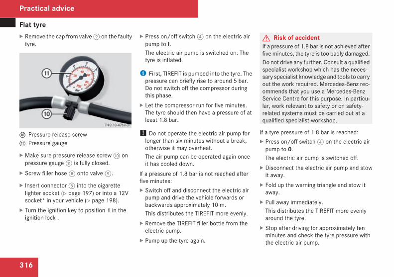
Flat tyre
316
X Remove the cap from valve9 on the faultytyre.
a Pressure release screwb Pressure gauge
X Make sure pressure release screwa onpressure gaugeb is fully closed.
X Screw filler hose8 onto valve9.
X Insert connector5 into the cigarettelighter socket (Y page 197) or into a 12Vsocket* in your vehicle (Y page 198).
X Turn the ignition key to position 1 in theignition lock .
X Press on/off switch4 on the electric airpump to I.The electric air pump is switched on. Thetyre is inflated.
i First, TIREFIT is pumped into the tyre. Thepressure can briefly rise to around 5 bar.Do not switch off the compressor duringthis phase.
X Let the compressor run for five minutes.The tyre should then have a pressure of atleast 1.8 bar.
! Do not operate the electric air pump forlonger than six minutes without a break,otherwise it may overheat.The air pump can be operated again onceit has cooled down.
If a pressure of 1.8 bar is not reached afterfive minutes:X Switch off and disconnect the electric airpump and drive the vehicle forwards orbackwards approximately 10 m.This distributes the TIREFIT more evenly.
X Remove the TIREFIT filler bottle from theelectric pump.
X Pump up the tyre again.
G Risk of accidentIf a pressure of 1.8 bar is not achieved afterfiveminutes, the tyre is too badly damaged.Do not drive any further. Consult a qualifiedspecialist workshop which has the neces-sary specialist knowledge and tools to carryout the work required. Mercedes-Benz rec-ommends that you use a Mercedes-BenzService Centre for this purpose. In particu-lar, work relevant to safety or on safety-related systems must be carried out at aqualified specialist workshop.
If a tyre pressure of 1.8 bar is reached:X Press on/off switch4 on the electric airpump to 0.The electric air pump is switched off.
X Disconnect the electric air pump and stowit away.
X Fold up the warning triangle and stow itaway.
X Pull away immediately.This distributes the TIREFIT more evenlyaround the tyre.
X Stop after driving for approximately tenminutes and check the tyre pressure withthe electric air pump.
Practical advice
204_AKB; 2; 3, en-GBmkalafa,
2007-06-26T23:11:51+02:00 - Seite 316

Flat tyre
317
G Risk of accidentIf the tyre pressure is now lower than1.3 bar, the tyre is too badly damaged. Donot drive any further. Consult a qualifiedspecialist workshop which has the neces-sary specialist knowledge and tools to carryout the work required. Mercedes-Benz rec-ommends that you use a Mercedes-BenzService Centre for this purpose. In particu-lar, work relevant to safety or on safety-related systems must be carried out at aqualified specialist workshop.
X If the tyre pressure is still at least 1.3 bar,correct it (see fuel filler flap for values).To increase the tyre pressure: switch onthe electric air pump.To reduce the tyre pressure: open pres-sure release screwa on pressuregaugeb.
X Drive to the nearest workshop and have thetyre changed there.
X Have the TIREFIT kit replaced as soon aspossible at a qualified specialist workshop,e.g. at a Mercedes-Benz Service Centre.
G Risk of accidentDo not exceed the maximum speed of 80km/h.The “max. 80 km/h” stickermust be affixedwithin the driver's field of vision.The vehicle's handling characteristics maybe affected.
H Environmental noteHave the used TIREFIT kit disposed of pro-fessionally, e.g. at a Mercedes-BenzService Centre.
X Have the TIREFIT kit replaced every fouryears at a qualified specialist workshop,e.g. a Mercedes-Benz Service Centre.
Version 2
1 TIREFIT sealant filler bottle2 Recess3 On/off switch4 Electric connector with cable5 Air pump hose6 Flange
X Pull connector4 and air pump hose5from the housing.
X Screw air pump hose5 onto flange6 ofTIREFIT filler bottle1.
X Place TIREFIT sealant filler bottle1 headdownwards into recess2 of the electricair pump.
Practical advice
204_AKB; 2; 3, en-GBmkalafa,
2007-06-26T23:11:51+02:00 - Seite 317

Flat tyre
318
7 Valve8 Filler hose
X Remove the cap from valve7 on the faultytyre.
X Screw filler hose8 onto valve7.
X Insert connector4 into the cigarettelighter socket (Y page 197) or into a 12Vsocket* in your vehicle (Y page 198).
X Turn the ignition key to position 1 in theignition lock .
X Press on/off switch3 on the electric airpump to I.The electric air pump is switched on. Thetyre is inflated.
i First, TIREFIT is pumped into the tyre. Thepressure can briefly rise to around 5 bar.Do not switch off the compressor duringthis phase.
X Let the compressor run for five minutes.The tyre should then have a pressure of atleast 1.8 bar.
! Do not operate the electric air pump forlonger than six minutes without a break,otherwise it may overheat.The air pump can be operated again onceit has cooled down.
If a pressure of 1.8 bar is not reached afterfive minutes:X Switch off and disconnect the electric airpump and drive the vehicle forwards orbackwards approximately 10 m.This distributes the TIREFIT more evenly.
X Remove the sealant filler bottle from theelectric pump.
X Pump up the tyre again.
G Risk of accidentIf a pressure of 1.8 bar is not achieved afterfiveminutes, the tyre is too badly damaged.
Do not drive any further. Consult a qualifiedspecialist workshop which has the neces-sary specialist knowledge and tools to carryout the work required. Mercedes-Benz rec-ommends that you use a Mercedes-BenzService Centre for this purpose. In particu-lar, work relevant to safety or on safety-related systems must be carried out at aqualified specialist workshop.
If a tyre pressure of 1.8 bar is reached:X Press 0 on the electric air pump switch.The electric air pump is switched off.
X Disconnect the electric air pump and stowit away.
X Fold up the warning triangle and stow itaway.
X Pull away immediately.This distributes the TIREFIT more evenlyaround the tyre.
X Stop after driving for approximately tenminutes and check the tyre pressure withthe electric air pump.
G Risk of accidentIf the tyre pressure is now lower than1.3 bar, the tyre is too badly damaged. Donot drive any further. Consult a qualified
Practical advice
204_AKB; 2; 3, en-GBmkalafa,
2007-06-26T23:11:51+02:00 - Seite 318

Flat tyre
319
specialist workshop which has the neces-sary specialist knowledge and tools to carryout the work required. Mercedes-Benz rec-ommends that you use a Mercedes-BenzService Centre for this purpose. In particu-lar, work relevant to safety or on safety-related systems must be carried out at aqualified specialist workshop.
9 Pressure release buttona Pressure gauge
X If the tyre pressure is still at least 1.3 bar,correct it (see fuel filler flap for values).To increase the tyre pressure: switch onthe electric air pump.To reduce the tyre pressure: press yellowpressure release button9 next to pres-sure gaugea.
X Drive to the nearest workshop and have thetyre changed there.
X Have the TIREFIT kit replaced as soon aspossible at a qualified specialist workshop,e.g. at a Mercedes-Benz Service Centre.
G Risk of accidentDo not exceed the maximum speed of 80km/h.The “max. 80 km/h” stickermust be affixedwithin the driver's field of vision.The vehicle's handling characteristics maybe affected.
H Environmental noteHave the used TIREFIT kit disposed of pro-fessionally, e.g. at a Mercedes-BenzService Centre.
X Have the TIREFIT kit replaced every fouryears at a qualified specialist workshop,e.g. a Mercedes-Benz Service Centre.
Changingawheel and fitting the sparewheel*
G Risk of accidentThe wheel dimensions and tyre size of thespare wheel*, the emergency sparewheel* and standard wheels may differfrom one another.Your vehicle's handling characteristics willbe altered when a "Minispare"/collapsibleemergency spare wheel* is fitted. Adaptyour style of driving accordingly.The “Minispare”/collapsible emergencyspare wheel* must only be used as a tem-porary measure. Do not exceed the maxi-mum speed of 80 km/h and do notdeactivate ESP®.
G Risk of accidentHave the “Minispare”/collapsible emer-gency spare wheel* or the spare wheel*replaced with a new wheel as soon as pos-sible at a qualified specialist workshopwhich has the necessary specialist knowl-edge and tools to carry out the workrequired. Mercedes-Benz recommendsthat you use a Mercedes-Benz ServiceCentre for this purpose. In particular, work
Practical advice
* optional
204_AKB; 2; 3, en-GBmkalafa,
2007-06-26T23:11:51+02:00 - Seite 319
Z

Flat tyre
320
relevant to safety or on safety-related sys-tems must be carried out at a qualifiedspecialist workshop.Never drive the vehicle with more than one“Minispare”/collapsible emergency sparewheel* fitted.
Preparing the vehicleX Prepare the vehicle as described(Y page 313).
X Place thewheels in the straight-ahead posi-tion.
X Take out the following from the stowagearea beneath the boot/luggage compart-ment floor:RThe "Minispare" emergency sparewheel* or the spare wheel*, if present
RThe vehicle tool kit and jack.
X Secure the vehicle to prevent it from rollingaway.On level ground: place chocks or similarunder the front and rear of the wheel thatis diagonally opposite the wheel you wishto change.
Securing a vehicle on level ground (example illus-tration)
X On downhill gradients: place chocks orsimilar behind both wheels of the otheraxle.
Securing a vehicle on slight downhill slope (exam-ple illustration)
Raising the vehicle
Steel wheel with wheel trim
X Vehicles with steel wheels: carefullyreach into two wheel trim openings andremove the wheel trim.
Practical advice
* optional
204_AKB; 2; 3, en-GBmkalafa,
2007-06-26T23:11:51+02:00 - Seite 320

Flat tyre
321
X Using the wheel wrench, loosen the wheelbolts on the wheel you wish to change byabout one full turn. Do not unscrew thebolts completely.
G Risk of accidentIf you fail to position the jack correctly, thevehicle may:Rslip off the jackRinjure you or othersRbe damagedIt is thus important to ensure that the jackis positioned correctly in the respectivejacking points. Before positioning the jack,remove any dirt that may have collected inthe jacking points.
The jacking points for the jack are locatedbehind thewheel housings of the front wheelsand in front of the wheel housings of the rearwheels (arrows).
1 Jacking point2 Jack
X Position jack2 at jacking point1.
X Make sure that the base of the jack is posi-tioned directly under the jacking point.
X Turn the crank until the tyre is raised amaximum of 3 cm from the ground.
X Unscrew the wheel bolts.
! Do not place wheel bolts in sand or on adirty surface. This could cause damage tothe bolt and wheel hub threads.
X Remove the wheel.
Fitting a new wheel
G Risk of accidentReplace damaged or corroded wheel bolts.Never oil or grease wheel bolts.
Practical advice
204_AKB; 2; 3, en-GBmkalafa,
2007-06-26T23:11:51+02:00 - Seite 321

Flat tyre
322
G Risk of accidentIf a wheel hub thread is damaged, you mustnot drive the vehicle any further. Consult aqualified specialist workshopwhich has thenecessary specialist knowledge and toolsto carry out the work required. Mercedes-Benz recommends that you use aMercedes-Benz Service Centre or Service24h for this purpose. In particular, work rel-evant to safety or on safety-related systemsmust be carried out at a qualified specialistworkshop.
G Risk of accidentOnly use wheel bolts that have beendesigned for the wheel and the vehicle. Forsafety reasons, Mercedes-Benz recom-mends that you only use wheel bolts whichhave been approved for Mercedes-Benzvehicles. Other bolts could work loose.Do not tighten the wheel bolts completelywhile the vehicle is still jacked up. The vehi-cle could topple off the jack.
X Clean the wheel and wheel hub contactsurfaces.
X Place the "Minispare" emergency sparewheel* or the spare wheel onto the wheelhub and push it on.
X Tighten the wheel bolts until they are fin-ger-tight.
Lowering the vehicleX Lower the vehicle. To do this, turn the crankof the jack anti-clockwise until the vehicleis standing firmly on the ground again.
X Place the jack to one side.
1 –5 Wheel bolts
X Tighten the wheel bolts evenly in a cross-wise pattern in the sequence indica-ted (1 to5). The tightening torque mustbe 130 Nm.
G Risk of accidentHave the tightening torque checked imme-diately after awheel is changed. Thewheelscould work loose if they are not tightenedto a tightening torque of 130 Nm.
Practical advice
* optional
204_AKB; 2; 3, en-GBmkalafa,
2007-06-26T23:11:51+02:00 - Seite 322

Flat tyre
323
X Turn the jack back to its initial position andstore it and the rest of the vehicle tool kitin the boot/luggage compartment.
Vehicles with the "Minispare" emergencyspare wheel*:X Transport the faulty wheel in the boot/lug-gage compartment.
orX Depending on the size of the wheel, youmay also be able to secure the faulty wheelin the spare wheel well. In this case, youwill have to remove the stowagewell casingfrom the spare wheel well and stow itsecurely in the boot/luggage compart-ment.
MOExtended run-flat system*The MOExtended run-flat system* must onlybe used in conjunction with the tyre pressureloss warning system*.
! Themaximumpermissible distancewhichcan be driven in run-flat mode depends onthe load in the vehicle. It is 50 km if thevehicle is partially laden and 30 km if fullyladen.
The maximum permissible distance whichcan be driven in run-flat mode is countedfrom the moment the tyre pressure losswarning appears in the multi-function dis-play.You must not exceed a maximum speed of80 km/h.
i Vehicles featuring the MOExtended run-flat system* are not equipped with theTIREFIT kit*.It is therefore recommended to additionallyequip your vehicle with the TIREFIT kit*when fitting tyres that do not feature run-flat properties, e.g. winter tyres.
i A TIREFIT kit* is available from any quali-fied specialist workshop, e.g. a Mercedes-Benz Service Centre.
G Risk of accidentThe handling characteristics of your vehicledeteriorate in run-flat mode, for example:Rwhen corneringRwhen brakingRwhen accelerating rapidlyAdapt your driving style accordingly andavoid sudden changes in direction and sud-
den acceleration, as well as driving overobstacles (i.e. kerbs, potholes), and drivingoff-road. This is particularly the case whenthe vehicle is heavily laden.The maximum permissible distance thatcan be driven in run-flat mode depends toa large extent on the loads placed on thevehicle. It can be shorter due to highspeeds, a heavy load, sudden accelerationand/or manoeuvring, the road surface con-dition, outside temperature, etc., or furtherif you drive carefully and conservatively.Do not continue to drive in run-flat mode if:Ryou hear banging noisesRthe vehicle starts to shakeRyou see smoke and smell rubberRESP® is intervening constantlyRthere are tears in the sidewalls of the tyreAfter driving in run-flat mode, you musthave the rims checked for damage at aqualified specialist workshopwhich has thenecessary specialist knowledge and toolsto carry out the work required. The faultytyre must be replaced in every case.Mercedes-Benz recommends that you usea Mercedes-Benz Service Centre for this
Practical advice
* optional
204_AKB; 2; 3, en-GBmkalafa,
2007-06-26T23:11:51+02:00 - Seite 323
Z

Battery
324
purpose. In particular, work relevant tosafety or on safety-related systemsmust becarried out at a qualified specialist work-shop.
i On a vehicle with MOExtended tyres*,only MOExtended spare tyres* should beused. These must be of the size specifiedfor the vehicle
Battery
Notes on the batteryIn order for the battery to achieve the maxi-mum possible service life, it must always besufficiently charged.Have the battery charge checked more fre-quently if you use the vehicle mainly for shorttrips or if you leave it standing idle for alengthy period.To prevent damage from corrosion, onlyreplace the battery with one that has a centralventilation cover.Consult a Mercedes-Benz Service Centre ifyou wish to leave your vehicle parked up fora long period of time.G Risk of injuryComply with safety precautions and takeprotective measures when handling batter-ies.
Risk of explosion
Fire, naked flames andsmoking are prohibitedwhen handling the bat-tery. Avoid creatingsparks.
Battery acid is caustic.Avoid contact with theskin, eyes or clothing.Wear suitable protectiveclothing, in particular,gloves, an apron and facemask.Immediately rinse acidsplashes off with cleanwater. Consult a doctor ifnecessary.Wear eye protection.
Keep children away.
Observe this Owner'sManual.
H Environmental noteDo not dispose of batteries with the house-hold rubbish. Dispose of defective batteriesin an environmentally responsible manner.Take them to a Mercedes-Benz Service
Practical advice
* optional
204_AKB; 2; 3, en-GBmkalafa,
2007-06-26T23:11:51+02:00 - Seite 324

Battery
325
Centre or a special collection point for oldbatteries.
G Risk of injuryMercedes-Benz recommends that, forsafety reasons, you only use batterieswhich have been tested and approved foryour vehicle by Mercedes-Benz. These bat-teries provide increased impact protectionto prevent vehicle occupants from sufferingacid burns should the battery be damagedin the event of an accident.To prevent acid burns, observe the follow-ing safety notes when handling batteries:RDo not lean over batteries.RDo not place any metal objects on a bat-tery. You could otherwise cause a shortcircuit and the battery's highly flammablegas mixture could ignite.
RMake sure that you do not create elec-trostatic charge, e.g. by wearing syn-thetic clothing or as a result of friction onfabrics. You should not therefore pull orslide the battery over carpets or othersynthetic materials.
RNever touch the battery first. To dis-charge a possible electrostatic charge,
step out of the vehicle first and touch thebodywork.
RDo not wipe the battery using a cloth. Thebattery may explode as a result of elec-trostatic charge or through the creationof sparks.
! Switch the engine off and remove the keybefore unscrewing or disconnecting theterminal clamps from the battery. You mayotherwise destroy electronic componentssuch as the alternator.Have the starter battery checked and, ifnecessary, replaced at a qualified specialistworkshop, e.g. a Mercedes-Benz ServiceCentre, every two years or at least every20,000 km.
i Mercedes-Benz recommends that youhave all work involving the battery, e.g.removing, charging and replacing, carriedout at a qualified specialist workshop, e.g.a Mercedes-Benz Service Centre.
Installation location of the batteryDepending on its engine type, your vehicle isequipped with a battery in the engine com-partment or boot/luggage compartment. It is
located on the right-hand side (direction oftravel) in front of the bulkhead or on the right-hand side in the spare wheel well.
1 Cover2 Clamps
Practical advice
204_AKB; 2; 3, en-GBmkalafa,
2007-06-26T23:11:51+02:00 - Seite 325

Battery
326
Battery in the engine compartment1 Battery2 Positive terminal3 Negative terminal4 Breather hose
Battery in the boot1 Positive terminal2 Battery3 Negative terminal4 Breather hose
Disconnecting the battery
G Risk of accidentIf the battery is disconnected:Rthere is no brake boosting effect and youwill need to applymore pressure to brakeand the brake pedal travel will be longer;
you may have to depress the brake pedalwith full force
Ryou can no longer turn the key in the igni-tion and with KEYLESS GO*, pressing theKEYLESS GO button* on the selectorlever will have no effect
Rthe selector lever is locked in position Pon vehicles with automatic transmis-sion*
! Always disconnect the battery in thesequence described below. Never swap theterminal clamps. You may otherwise dam-age the vehicle electronics.
Vehicles with the battery in the enginecompartment:X Firmly depress the parking brake and shiftthe selector lever to position P on vehicleswith automatic transmission*.
X Switch off all electrical consumers.X Turn the key to position 0 in the ignitionlock and remove it.
X Open the bonnet.X Remove the retaining clamps on the cover.X Remove the negative terminal clamp fromthe battery.
Practical advice
* optional
204_AKB; 2; 3, en-GBmkalafa,
2007-06-26T23:11:51+02:00 - Seite 326

Battery
327
X Remove the cover from the positive termi-nal clamp.
X Remove the positive terminal clamp fromthe battery.
X Disconnect the breather hose.Vehicles with the battery in the boot/lug-gage compartment:X Firmly depress the parking brake and shiftthe selector lever to position P on vehicleswith automatic transmission*.
X Switch off all electrical consumers.X Turn the key to position 0 in the ignitionlock and remove it.
X Open the boot/luggage compartment.X Remove the negative terminal clamp fromthe battery.
X Remove the cover from the positive termi-nal clamp.
X Remove the positive terminal clamp fromthe battery.
X Disconnect the breather hose.
Removing the batteryX Disconnect the battery (Y page 326).X Loosen the screw which holds the batteryin place.
X Remove the battery.
Charging and fitting the battery
G Risk of injuryOnly charge the installed battery with a bat-tery charger which has been tested andapproved byMercedes-Benz. These batterychargers allow the battery to be chargedwhile it is still installed. Otherwise, the vehi-cle's electronic system may be damaged.Only charge the battery in a well-ventilatedarea. As the battery is being charged, gasescan escape and generateminor explosions.This may injure you and other persons orcause damage to the paintwork or acid cor-rosion on the vehicle.You can obtain information about batterychargers which allow the battery to becharged when still installed from a qualifiedspecialist workshop, e.g. a Mercedes-BenzService Centre.
G Risk of injuryThere is a risk of acid burns during thecharging process due to the gases whichescape from the battery. Do not lean overthe battery during the charging process.
! Only use battery chargers with a maxi-mum charging voltage of 14.8 V.
X Charge the battery. Observe the notes inthe operating instructions for your batterycharger.
X Refit the charged battery.To do this, follow the steps described in"Removing the battery" (Y page 327) inreverse order.
G Risk of injuryBattery acid is caustic. Avoid contact withthe skin, eyes or clothing.
Practical advice
* optional
204_AKB; 2; 3, en-GBmkalafa,
2007-06-26T23:11:51+02:00 - Seite 327

Jump-starting
328
Reconnecting the battery! Always reconnect the battery in thesequence described below. Never swap theterminal clamps. You may otherwise dam-age the vehicle electronics.
X Switch off all electrical consumers.X Connect the positive terminal clamp andsecure the cover.
X Connect the negative terminal clamp.X Connect the breather hose. Make sure thata cell cap is fitted between the battery andthe breather hose.
X Close the boot/luggage compartment.
i If the battery power supply has been inter-rupted (e.g. if it has been reconnected), youmust carry out the following tasks:RReset the function for folding the exteriormirrors in/out automatically* by foldingthe mirrors out once (Y page 94).
Jump-starting
Jump-starting your vehicleIf your vehicle's battery is discharged, theengine can be jump-started from anothervehicle or from an external battery using jumpleads.Observe the following points:RJump-starting must only be performedwhen the engine and catalytic converterare cold.
RDo not start the engine if the battery hasfrozen. Thaw the battery out first.
RJump-starting may only be performed from12V batteries.
ROnly use jump leads which are protectedagainst polarity reversal and which have asufficient cross-section and insulated ter-minal clamps.
i Jump leads which are protected againstpolarity reversal and further informationabout jump-starting can be obtained fromany Mercedes-Benz Service Centre.
! Avoid repeated and lengthy startingattempts.
Never start the vehicle using a rapid batterycharger.
G Risk of injuryThere is a risk of acid burns when jump-starting a vehicle due to the gases whichescape from the battery. Do not lean overthe battery while the engine is being jump-started.
G Risk of explosionGases escaping from the battery duringjump-starting may cause minor explosions.Avoid creating sparks. Keep naked flamesaway from the battery, and do not smoke.Comply with safety precautions and takeprotective measures when handling batter-ies. You will find these under “Battery” inthe index.
X Make sure that the two vehicles do nottouch.
X Depress the parking brake.
X Manual transmission: engage neutral.X Automatic transmission*: move theselector lever to P.
X All vehicles: switch off all electric consum-ers.
Practical advice
* optional
204_AKB; 2; 3, en-GBmkalafa,
2007-06-26T23:11:51+02:00 - Seite 328

Towing and tow-starting
329
The positive and negative contacts are loca-ted on the front bulkhead on the right-handside of the vehicle.
1 Positive terminal of donor battery2 Cover3 Positive contact on your vehicle4 Negative contact on your vehicle5 Negative terminal of donor battery
X Slide cap2 of positive contact3 in thedirection of the arrow.
X Attaching the jump-start cable to the donorbattery first, connect positive terminal1of the donor battery and positive contacton your vehicle3.
X Start the engine of the donor vehicle andrun it at idling speed.
X Attaching the jump-start cable to the donorbattery first, connect negative terminal5of the donor battery and negative contacton your vehicle4.
X Start the engine.X Electrical consumers can be switched onagain. Do not switch the lights on however,as this will overload the battery.
X First disconnect the jump lead from nega-tive terminals4 and5, then frompositiveterminals1 and3.
X Have the battery checked at a qualifiedspecialist workshop, e.g. a Mercedes-BenzService Centre.
Towing and tow-starting
Points to remember
G Risk of accidentIf you tow the vehicle, you must use a rigidtowing bar if:Rthe engine is not runningRthere is a brake system malfunctionRthe voltage supply or the vehicle's elec-trical system is damaged
There is no power assistance for the steer-ing when the engine is not running.
It is better to have the vehicle transportedthan to have it towed.When towing, observe the legal requirementsin all countries concerned.
! You may tow the vehicle for a maximumof 50 km. A towing speed of 50 km/h mustnot be exceeded.With towing distances over 50 km, theentire vehicle needs to be lifted up andtransported.
! Only secure the tow cable or towing barto the towing eyes. You may otherwisedamage the vehicle.
Practical advice
204_AKB; 2; 3, en-GBmkalafa,
2007-06-26T23:11:51+02:00 - Seite 329

Towing and tow-starting
330
RVehicles with an automatic transmission*must not be tow-started.
RIf the engine does not start, try jump-start-ing it (Y page 328).
RIf it is not possible to jump-start the vehicle,have it towed to the nearest qualified spe-cialist workshop, e.g. a Mercedes-BenzService Centre.
RIf the vehicle has suffered transmissiondamage, only tow it with the propeller shaftdisconnected.
RThe selector lever must be in position N onvehicles with automatic transmission*.
RIf you are towing the vehicle over a consid-erable distance, this may only be done withthe rear axle raised.
RThe ignition must be switched off if you aretowing the vehicle with the front/rear axleraised. Intervention by ESP® could other-wise damage the brake system.
RVehicles with 4MATIC* may not be towedwith the front or rear axle raised.
RBefore towing the vehicle, make sure thatthe battery is connected and charged. Oth-erwise:
- You cannot switch on the ignition- You cannot move the selector leverto N (on vehicles with automatic trans-mission*)
- You have no support when braking
i Switch off the automatic locking featurebefore the vehicle is towed. You could oth-erwise be locked out when pushing or tow-ing the vehicle.Deactivate tow-away protection beforetowing (Y page 71).
Fitting the towing eyeVehicles with a trailer coupling: your vehi-cle does not have a rear threaded socket formounting the towing eye. If you intend to usethe vehicle for towing, fold out the ball cou-pling and secure the towline to it(Y page 220).
Opening the front coverThe fixtures for the removable towing eyesare located in the bumpers. They are located
at the front and rear under the covers on theright-hand side of the vehicle.
Front bumper1 Cover
X Press the mark on cover1 inwards.X Take cover1 off the opening but do notremove it.
Practical advice
* optional
204_AKB; 2; 3, en-GBmkalafa,
2007-06-26T23:11:51+02:00 - Seite 330

Towing and tow-starting
331
Opening the rear cover
Rear bumper1 Cover
X Press the mark on cover1 inwards.X Take cover1 off the opening but do notremove it.
Securing the towing eyeX Take the towing eye and the wheel wrenchfrom the vehicle tool kit (Y page 234).
X Screw in the towing eye clockwise to thestop.
X Insert the wheel wrench handle into thetowing eye and tighten.
Towing the vehicle! Vehicles with 4MATIC* may not be towedwith the front or rear axle raised.
! If the vehicle is to be towed with the frontor rear axle raised, the ignition must beswitched off (key in position 0 or 1 in theignition lock). Application of the brakes byESP® could otherwise destroy the brakesystem on the front or rear axle.
Vehicles with manual transmissionX Turn the key to position 2 in the ignitionlock.
X Shift to neutral.
Vehicles with automatic transmission*X Turn the key to position 2 in the ignitionlock.
X Move the selector lever to N.
Tow-starting (emergency enginestarting)Please note:RVehicles with an automatic transmission*must not be tow-started.
RThe battery must be connected.RThe engine and catalytic converter must becold.
RAvoid repeated and lengthy startingattempts.
Vehicles with manual transmissionX Turn the key to position 2 in the ignitionlock.
X Shift to neutral.X Tow the vehicle or let it roll.X Shift to a suitable gear and bring the clutchpedal up slowly. Do not depress the accel-erator pedal.The engine is started.
Practical advice
* optional
204_AKB; 2; 3, en-GBmkalafa,
2007-06-26T23:11:51+02:00 - Seite 331

Fuses
332
Removing the towing eyeX Take the wheel wrench from the vehicletool kit (Y page 234).
X Insert the wheel wrench handle into thetowing eye and turn it anti-clockwise.
X Unscrew the towing eye.
X Replace the cover and press it until itengages.
X Return the towing eye and the wheelwrench to the vehicle tool kit.
Transporting the vehicleThe towing eyes can be used to pull the vehi-cle onto a trailer or transporter for transport-ing purposes.
! Only lash the vehicle down by the wheelsor wheel rims, not by parts of the vehiclesuch as axle or steering components. Thevehicle could otherwise be damaged.
Vehicles with manual transmissionX Shift to neutral.
Vehicles with automatic transmission*X Turn the key to position 2 in the ignitionlock.
X Move the selector lever to N.
Fuses
Notes on changing fusesThe fuses in your vehicle serve to close downfaulty circuits. If a fuse blows, all the compo-nents on the circuit and their functions willfail.
i Blown fuses must be replaced with fusesof the same rating (which can be recog-nised by the colour and amperage) andwhich have the amperage specified in thefuse allocation chart. A Mercedes-BenzService Centre will be happy to advise you.
G Risk of fireOnly use fuses that have been approved forMercedes-Benz vehicles and which havethe correct amperage for the system con-cerned. Do not attempt to repair or bridgefaulty fuses. A circuit overload could other-wise cause a fire. Have the cause tracedand rectified at a qualified specialist work-shop, e.g. aMercedes-Benz Service Centre.
If the newly inserted fuse also blows, have thecause traced and rectified at a qualified spe-cialist workshop, e.g. a Mercedes-BenzService Centre.
Practical advice
* optional
204_AKB; 2; 3, en-GBmkalafa,
2007-06-26T23:11:51+02:00 - Seite 332

Fuses
333
! Only use fuses that have been approvedfor Mercedes-Benz vehicles and whichhave the correct amperage for the systemconcerned. Otherwise, components or sys-tems could be damaged.
The fuses are located in various fuse boxes:RDashboard fuse box* on driver's sideRFuse box in the engine compartment on thedriver's side
RFuse box in the boot/luggage compart-ment on the right-hand side of the vehicle
Fuse allocation chartThe fuse allocation chart is located with thevehicle tool kit (Y page 234) in the stowagecompartment under the boot/luggage com-partment floor. The fuse amperage is alsoindicated there.
Before changing a fuseX Park the vehicle.X Switch off all electrical consumers.X Remove the key from the ignition lock.
Fuse box in the dashboard*
1 Cover2 To remove the cover3 To release the cover
X To open: open the driver’s door.X Pull out cover1 slightly at the bottom3.
X Pull cover1 outwards and remove it2.
X To close: clip in cover1 at the front.
X Fold cover1 inwards until it engages.X Close the driver's door.
Fuse box in the engine compartmentX Make sure that the windscreen wipers areturned off.
G Risk of injuryMake sure that the windscreen wipers areturned off and the key is pulled out of theignition lock before you open the cover ofthe fuse box. Otherwise, the windscreenwipers and their wiper rods above the covercould be set in motion. This could lead toparts of the body being trapped by thewiper rods.
X To open: open the bonnet (Y page 206).
Practical advice
* optional
204_AKB; 2; 3, en-GBmkalafa,
2007-06-26T23:11:51+02:00 - Seite 333

Fuses
334
1 Clamps2 Line
X Remove moisture from the fuse box usinga dry cloth.
X Unclip line2 from the lid.X Fold clamps1 upwards.X Lift off the fuse box cover towards the frontof the vehicle.
X To close: check whether the rubber seal ispositioned correctly in the lid.
X Insert the lid into the retainer at the rear ofthe fuse box.
X Press the lid down and secure with clamps1.
X Clip line2 onto the lid.
X Close the bonnet (Y page 206).
Fuse box in the boot (Saloon)X To open: open the boot lid.
1 Locking mechanism2 Side trim panel
X Turn locking mechanism1.X Fold side trim panel2 downwards.
Fuse box in the luggage compartment(Estate)X To open: open the tailgate.
1 Handle
X Pull handle1.X Fold side trim panel downwards.
Practical advice
204_AKB; 2; 3, en-GBmkalafa,
2007-06-26T23:11:51+02:00 - Seite 334

335
Introduction to technical data ......... 336Genuine Mercedes-Benz parts ......... 336Vehicle electronics ........................... 337Vehicle identification plates ............ 339Engine ................................................ 341Performance ...................................... 343Tyres and wheels .............................. 347Vehicle dimensions .......................... 355Vehicle weights ................................. 355Trailer coupling* ............................... 358Service products and capacities ..... 360
Technical data
204_AKB; 2; 3, en-GBmkalafa,
2007-06-26T23:11:51+02:00 - Seite 335

Genuine Mercedes-Benz parts
336
Introduction to technical data
i The technical data was determined inaccordance with EU directives. All dataapplies to the vehicle's standard equip-ment. The data may therefore differ forvehicles with optional equipment. You canobtain further information from aMercedes-Benz Service Centre.
Genuine Mercedes-Benz parts
Mercedes-Benz tests genuine parts and con-version parts and accessories which havebeen specifically approved for your vehicle fortheir reliability, safety and suitability.Despite ongoing market research, Mercedes-Benz is unable to evaluate other parts.Mercedes-Benz therefore accepts no respon-sibility for the use of such parts in Mercedes-Benz vehicles, even if they have beenindependently or officially approved.In Germany and someother countries, certainparts are only officially approved for installa-tion or modification if they comply with legalrequirements. All genuine Mercedes-Benzparts meet this requirement.Observe the suitability of replacement partsfor your vehicle. In many countries, certainparts which result in a modification to thevehicle could invalidate the vehicle's generaloperating permit.
This is the case if:Rthey cause a change of the vehicle typefrom that for which the vehicle's generaloperating permit was granted
Rother road users could be endangeredRthe emission or noise levels are adverselyaffected
The use of non-approved parts could affectyour vehicle's operating safety. Mercedes-Benz therefore recommends genuineMercedes-Benz parts and conversion partsand accessories that have been approved foryour vehicle.H Environmental noteDaimlerChrysler also supplies recondi-tioned assemblies and parts which are ofthe same quality as new parts. For these,the same liability for material defectsapplies as with new parts.
Genuine Mercedes-Benz parts and approvedconversion parts and accessories are availa-ble from Mercedes-Benz Service Centres.There, you can also receive advice about tech-nical modifications and have the parts pro-fessionally fitted.Always quote the vehicle identification num-ber and the engine number when ordering
Technical data
204_AKB; 2; 3, en-GBmkalafa,
2007-06-26T23:11:51+02:00 - Seite 336

Vehicle electronics
337
genuine parts. You will find these numbers onthe vehicle data card in the Service Bookletor on your vehicle's identification plates(Y page 339).
Vehicle electronics
Tampering with the engine electron-ics
G Risk of accidentOnly have work on the engine electronicsand related components carried out at aqualified specialist workshopwhich has thenecessary specialist knowledge and toolsto carry out the work required. Mercedes-Benz recommends that you use aMercedes-Benz Service Centre for this pur-pose. In particular, work relevant to safetyor on safety-related systems must be car-ried out at a qualified specialist workshop.The vehicle's roadworthiness could other-wise be affected.
! Only have work done on the engine elec-tronics and its associated parts, such ascontrol units, sensors and connector leads,carried out at a qualified specialist work-shop, e.g. a Mercedes-Benz ServiceCentre. Otherwise, vehicle componentsmaywearmore quickly and the vehiclemaylose its liability for material defects and itsoperating permit.
Retrofitting electrical and electronicequipmentElectrical and electronic equipment can jeop-ardise the operating safety of your vehicle. Ifequipment of this kind is retrofitted, it mustbe type-approved and bear the e mark. Thee mark may be obtained from the equipmentmanufacturer or an authorised testing centre.
! Damage or consequential damage arisingfrom fitting equipment not approvedbyMercedes-Benz is not covered under theMercedes-Benz liability for materialdefects.
If you wish to install two-way radios in thevehicle, you must obtain formal approval.Mercedes-Benz approves the installation oftwo-way radios if such equipment is installedprofessionally and a low-reflection exterioraerial is used.The transmission output of the two-way radiomust not exceed the maximum transmissionoutputs listed.G Risk of accidentTwo-way radios may interfere with the vehi-cle electronics and thereby jeopardise theoperational safety of the vehicle and yourown safety if:
Technical data
204_AKB; 2; 3, en-GBmkalafa,
2007-06-26T23:11:51+02:00 - Seite 337
Z

Vehicle electronics
338
Rthey do not have an exterior aerialRthe exterior aerial is not a low-reflectionaerial
Rthe exterior aerial has been fitted incor-rectly
G Risk of injuryExcessive electromagnetic radiation mayalso cause damage to your health and thehealth of others. Using an exterior aerialtakes into account current scientific dis-cussions relating to the possible health haz-ards that may result from electromagneticfields.For this reason, only have the exterior aerialfitted at a qualified specialist workshopwhich has the necessary specialist knowl-edge and tools to carry out the workrequired. Mercedes-Benz recommendsthat you use a Mercedes-Benz ServiceCentre for this purpose. In particular, workrelevant to safety or on safety-related sys-tems must be carried out at a qualifiedspecialist workshop.
i To ensure optimum reception quality formobile phones and two-way radios in thevehicle, and to minimise mutual influences
between the vehicle electronics andmobilephones/two-way radios, Mercedes-Benzrecommends the use of approved exterioraerials. An attached exterior aerial has theeffect that the electromagnetic fields trans-mitted by a wireless device are conductedto the exterior of the vehicle; the fieldstrength within the vehicle interior is lowerthan in a vehicle that does not have anexterior aerial.
Frequency range Maximum trans-mission output(watts)
Short wave (< 50MHz)
100
4 m waveband 20
2 m waveband 50
70 cm waveband 35
25 cm waveband 10
! If electrical or electronic equipmentwhich does not fulfil these conditions isretrofitted, the vehicle's general operatingpermit may be invalidated (EU Directive
95/54/EC – the Automotive EMC Direc-tive).
Technical data
204_AKB; 2; 3, en-GBmkalafa,
2007-06-26T23:11:51+02:00 - Seite 338
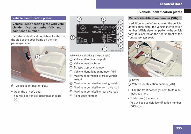
Vehicle identification plates
339
Vehicle identification plates
Vehicle identification plate with vehi-cle identification number (VIN) andpaint code numberThe vehicle identification plate is located onthe side of the door frame on the front-passenger side.
1 Vehicle identification plate
X Open the driver's door.You will see vehicle identification plate1.
Vehicle identification plate (example)1 Vehicle identification plate2 Vehicle manufacturer3 EU type approval number4 Vehicle identification number (VIN)5 Maximum permissible gross vehicle
weight6 Maximum permissible towing weight7 Maximum permissible front axle load8 Maximum permissible rear axle load9 Paint code number
Vehicle identification number (VIN)In addition to the information on the vehicleidentification plate, the vehicle identificationnumber (VIN) is also stamped onto the vehiclebody. It is located on the floor in front of thefront-passenger seat.
1 Cover2 Vehicle identification number (VIN)
X Slide the front-passenger seat to its rear-most position.
X Fold cover1 upwards.You will see vehicle identification number(VIN)2.
Technical data
204_AKB; 2; 3, en-GBmkalafa,
2007-06-26T23:11:51+02:00 - Seite 339

Vehicle identification plates
340
Engine numberThe engine number is stamped on the engineblock (crankcase). More information can beobtained from any Mercedes-Benz ServiceCentre.
Technical data
204_AKB; 2; 3, en-GBmkalafa,
2007-06-26T23:11:51+02:00 - Seite 340

Engine
341
Engine
C 180Kompressor
C 200Kompressor
C 230 C 280 C 350
Rated output 115 kW (157 bhp) 135 kW (184 bhp) 150 kW (204 bhp) 170 kW (231 bhp) 200 kW (272 bhp)
At engine speed 5,200 rpm 5,500 rpm 6,100 rpm 6,000 rpm 6,000 rpm
Rated torque 230 Nm 250 Nm 245 Nm 300 Nm 350 Nm
At engine speed 2,800 – 4,600 rpm 2,800 – 5,000 rpm 2,900 – 5,500 rpm 2,500 – 5,000 rpm 2,400 – 5,000rpm
Number of cylin-ders
4 4 6 6 6
Displacement 1,796 cm3 1,796 cm3 2,496 cm3 2,996 cm3 3,498 cm3
Maximum enginespeed
6,450 rpm 6,450 rpm 6,500 rpm 6,500 rpm 6,500 rpm
Technical data
204_AKB; 2; 3, en-GBmkalafa,
2007-06-26T23:11:51+02:00 - Seite 341

Engine
342
C 200 CDI C 220 CDI C 320 CDI
Rated output 100 kW (136 bhp) 125 kW (170 bhp) 165 kW (224 bhp)
At engine speed 3,600 – 4,200 rpm (3,400 –4,200 rpm20)
3,800 rpm 3,800 rpm
Rated torque 270 Nm (300 Nm20) 400 Nm 510 Nm
At engine speed 1,600 – 3,400 rpm (1,600 –3,000 rpm20)
2,000 rpm 1,600 – 2,800 rpm
Number of cylin-ders
4 4 6
Displacement 2,148 cm3 2,148 cm3 2,987 cm3
Maximum enginespeed
5,000 rpm 5,000 rpm 4,500 rpm
20 Vehicles with automatic transmission*
Technical data
* optional
204_AKB; 2; 3, en-GBmkalafa,
2007-06-26T23:11:51+02:00 - Seite 342

Performance
343
Performance
Speeds
Manual transmission
Maximumspeed
C 180Kompressor
C 200Kompressor
C 230 C 280
Saloon 223 km/h21 235 km/h21 240 km/h 250 km/h
Estate 218 km/h21 228 km/h21 232 km/h 242 km/h21
Maximumspeed
C 200 CDI C 220 CDI C 320 CDI
Saloon 215 km/h 229 km/h 250 km/h
Estate 208 km/h 224 km/h 245 km/h
21 The maximum speed is already reached in 5th gear.
Technical data
204_AKB; 2; 3, en-GBmkalafa,
2007-06-26T23:11:51+02:00 - Seite 343

Performance
344
Automatic transmission*
Maximum speed C 180Kompressor
C 200Kompressor
C 230 C 280 C 280 4MATIC
Saloon 220 km/h 230 km/h 233 km/h 246 km/h 243 km/h
Estate 215 km/h 225 km/h 227 km/h 240 km/h –
Maximum speed C 350 C 350 4MATIC C 200 CDI C 220 CDI C 320 CDI C 320 CDI4MATIC
Saloon 250 km/h 250 km/h 213 km/h 228 km/h 250 km/h 250 km/h
Estate 250 km/h – 204 km/h 220 km/h 244 km/h 244 km/h
Acceleration from 0 to 100 km/h
C 180 Kompressor C 200 Kompressor C 230 C 280
6-speed manualtransmission
Saloon 9.5 seconds 8.6 seconds 8.4 seconds 7.3 seconds
Estate 9.8 seconds 8.8 seconds 8.6 seconds 7.5 seconds
5-speed automatictransmission*
Saloon 9.9 seconds 8.8 seconds – –
Estate 10.2 seconds 9.0 seconds – –
Technical data
* optional
204_AKB; 2; 3, en-GBmkalafa,
2007-06-26T23:11:51+02:00 - Seite 344

Performance
345
C 180 Kompressor C 200 Kompressor C 230 C 280
7-speed automatictransmission*
Saloon – – 8.6 seconds 7.2 seconds
Estate – – 7.5 seconds
C 280 4MATIC C 3503 C 350 4MATIC
6-speed manualtransmission
Saloon – – –
Estate – –
7-speed automatictransmission*
Saloon 7.3 seconds 6.4 seconds 6.3 seconds
Estate – 6.5 seconds –
C 200 CDI C 220 CDI C 320 CDI C 320 CDI 4MATIC
6-speed manualtransmission
Saloon 10.4 seconds 8.5 seconds 7.7 seconds –
Estate 10.8 seconds 7.9 seconds –
5-speed automatictransmission*
Saloon 10.2 seconds 8.5 seconds – –
Estate 10.6 seconds 8.8 seconds – –
Technical data
* optional
204_AKB; 2; 3, en-GBmkalafa,
2007-06-26T23:11:51+02:00 - Seite 345
8.9 seconds
–
8.9 seconds

Performance
346
C 200 CDI C 220 CDI C 320 CDI C 320 CDI 4MATIC
7-speed automatictransmission*
Saloon – – 6.9 seconds 6.7 seconds
Estate – –
Technical data
* optional
204_AKB; 2; 3, en-GBmkalafa,
2007-06-26T23:11:51+02:00 - Seite 346
7.1 seconds 7.1 seconds

Tyres and wheels
347
Tyres and wheels! For safety reasons, Mercedes-Benz rec-ommends that you only use tyres whichhave been approved by Mercedes-Benzspecifically for your vehicle. These tyres arespecially adapted for use with the controlsystems, such as ABS or ESP®, and aremarked as follows:RMO = Mercedes-Benz OriginalRMOE=Mercedes-BenzOriginal Extended(with run-flat characteristics)
If you use other tyres, Mercedes-Benz can-not accept any responsibility for damagewhich may occur. Information about tyrescan be obtained from any Mercedes-BenzService Centre.
! If you fit tyres other than those tested andrecommended by Mercedes-Benz, charac-teristics such as handling, noise levels andfuel consumption, etc. may be adverselyaffected. In addition, when driving with aload, dimensional variations and differenttyre deformation characteristics couldcause the tyres to make contact with thebodywork and axle components. This couldresult in damage to the tyres or the vehicle.
i Further information about tyres andwheels can be obtained from anyMercedes-Benz Service Centre.You will find a table of tyre pressures on theinside of your vehicle's fuel filler flap . Youwill find further information about tyre pres-sures in the "Operation" section(Y page 213).
Technical data
204_AKB; 2; 3, en-GBmkalafa,
2007-06-26T23:11:51+02:00 - Seite 347

Tyres and wheels
348
Tyres
Saloon
C 180 KOMPRESSOR /C 200 CDI
C 200 KOMPRESSOR / C 230 / C 280 /C 280 4MATIC / C 220 CDI
C 350 / C 350 4MATIC /C 320 CDI / C 320 CDI 4MATIC
Bothaxles
Summer tyres 195/60 R16 89V – –
Winter tyres 195/60 R16 89H M+S – –
Wheels 6J x 16 H2 ET 39 – –
Bothaxles
Summer tyres 205/55 R16 91V 205/55 R16 91V –
Winter tyres 205/55 R16 91H M+S 205/55 R16 91H M+S –
Wheels 7J x 16 H2 ET 43 7J x 16 H2 ET 43 –
Bothaxles
Summer tyres 225/50 R16 92V 225/50 R16 92V –
Winter tyres 225/50 R16 92H M+S 225/50 R16 92H M+S –
Wheels 7.5J x 16 H2 ET 53 7.5J x 16 H2 ET 53 –
Bothaxles
Summer tyres 225/45 R17 91W 225/45 R17 91W 225/45 R17 91W
Winter tyres 225/45 R17 91H M+S 225/45 R17 91H M+S 225/45 R17 91H M+S
Alloy wheels 7.5J x 17 H2 ET 47 7.5J x 17 H2 ET 47 7.5J x 17 H2 ET 47
Technical data
204_AKB; 2; 3, en-GBmkalafa,
2007-06-26T23:11:51+02:00 - Seite 348

Tyres and wheels
349
Estate
C 180 KOMPRESSOR /C 200 CDI
C 200 KOMPRESSOR / C 230/C 280 / C 220 CDI
C 350 / C 320 CDI /C 320 CDI 4MATIC
Both axles Summer tyres 205/55 R16 91V 205/55 R16 91W –
Winter tyres 205/55 R16 91H M+S 205/55 R16 91H M+S –
Wheels 7J x 16 H2 ET 43 7J x 16 H2 ET 43 –
Both axles Summer tyres 225/50 R16 92V 225/50 R16 92W –
Winter tyres 225/50 R16 92H M+S 225/50 R16 92H M+S –
Wheels 7.5J x 16 H2 ET 53 7.5J x 16 H2 ET 53 –
Both axles Summer tyres 225/45 R17 91W 225/45 R17 91W 225/45 R17 91Y
Winter tyres 225/45 R17 91H M+S 225/45 R17 91H M+S 225/45 R17 91H M+S
Alloy wheels 7.5J x 17 H2 ET 47 7.5J x 17 H2 ET 47 7.5J x 17 H2 ET 47
Technical data
204_AKB; 2; 3, en-GBmkalafa,
2007-06-26T23:11:51+02:00 - Seite 349

Tyres and wheels
350
Mixed tyres
All models except the Estate:C 350 / C 320 CDI / C 320 CDI 4MATIC
Estate: C 350 / C 320 CDI / C 320 CDI 4MATIC
Front axle Summer tyres 225/45 R17 91W 225 / 45 R17 91Y
Alloy wheels 7.5J x 17 H2 ET 47 7.5J x 17 H2 ET 47
Rear axle Summer tyres 24 245/40 R17 91W 245 / 40 R17 91Y
Light-alloywheels
8.5J x 17 H2 ET 58 8.5J x 17 H2 ET 58
24 Snow chains not permitted
Technical data
204_AKB; 2; 3, en-GBmkalafa,
2007-06-26T23:11:51+02:00 - Seite 350

Tyres and wheels
351
AMG equipment*
All models
Front axle Summer tyres 225/45 R 17 94Y XL
Alloy wheels 7.5J x 17 H2 ET 47
Rear axle 25 Summer tyres 245/40 R 17 95Y XL
Alloy wheels 8.5J x 17 H2 ET 58
Front axle Summer tyres 225/40 R 18 92Y XL
Alloy wheels 8J x 18 H2 ET 50
Rear axle 25 Summer tyres 255/35 R 18 94Y XL
Alloy wheels 8.5J x 18 H2 ET 54
25 Use of snow chains not possible
Technical data
204_AKB; 2; 3, en-GBmkalafa,
2007-06-26T23:11:51+02:00 - Seite 351

Tyres and wheels
352
Sports package*
All models except the Estate:C 350 / C 320 CDI / C 320 CDI 4MATIC
Estate: C 350 / C 320 CDI /C 320 CDI 4MATIC
Front axle Summer tyres 225/45 R17 91W 225 / 45 R17 91Y
Winter tyres 225/45 R17 91H M+S 225/45 R17 91H M+S
Alloy wheels 7.5J x 17 H2 ET 47 7.5J x 17 H2 ET 47
Rear axle Summer tyres 245/40 R17 91W 26 245 / 40 R17 91Y26
Light-alloy wheels 8.5J x 17 H2 ET 58 8.5J x 17 H2 ET 58
Winter tyres 225/45 R17 91H M+S 225/45 R17 91H M+S
Alloy wheels 7.5J x 17 H2 ET 47 7.5J x 17 H2 ET 47
26 Snow chains not permitted
Technical data
204_AKB; 2; 3, en-GBmkalafa,
2007-06-26T23:11:51+02:00 - Seite 352

Tyres and wheels
353
MOExtended tyres*
All models except the Estate:C 350 / C 320 CDI / C 320 CDI 4MATIC
Estate: C 350 / C 320 CDI /C 320 CDI 4MATIC
Front axle Summer tyres27 225/45 R17 91W MOExtended 225/45 R17 91Y MOExtended
Alloy wheels 7.5J x 17 H2 ET 47 7.5J x 17 H2 ET 47
Rear axle Summer tyres27,28 245/40 R17 91W MOExtended 245/40 R17 91Y MOExtended
Wheels 8.5J x 17 H2 ET 58 8.5J x 17 H2 ET 58
Both axles Winter tyres27,29 225/45 R17 91H M+S MOExtended 225/45 R17 91H M+S MOExtended
Alloy wheels 7.5J x 17 H2 ET 47 7.5J x 17 H2 ET 47
27 Tyres with run-flat characteristics only with tyre pressure loss warning system or tyre pressure monitor* activated.28 Snow chains not permitted.29Winter tyres for retrofitting. Only certain tyre brands are approved. Ask your Mercedes-Benz Service Centre for more information.
Technical data
* optional
204_AKB; 2; 3, en-GBmkalafa,
2007-06-26T23:11:51+02:00 - Seite 353

Tyres and wheels
354
Spare wheel*Your vehicle may be equipped with TIREFIT, a "Minispare" emergency spare wheel* or a spare wheel*, depending on the country, the engineand the wheels fitted.
C 180 KOMPRESSOR /C 200 KOMPRESSOR / C 230 / C 280 /C 280 4MATIC / C 200 CDI / C 220 CDI
C 280 SportC 350 / C 350 4MATICC 320 CDI / C 320 CDI 4MATIC
“Minispare” emergencyspare wheel* 30
Tyres T 125/90 R16 99M T 125/80 R17 99M
Tyre pressure 4.2 bar 4.2 bar
Wheels 3.5B x 16 H2 ET 20 3.5B x 17 H2 ET 20
30 Use of snow chains not possible
Technical data
* optional
204_AKB; 2; 3, en-GBmkalafa,
2007-06-26T23:11:51+02:00 - Seite 354

Vehicle weights
355
Vehicle dimensions
C 180 KOMPRESSORC 200 CDI
C 200 KOMPRESSOR
C 230C 280
C 220 CDI
C 350C 320 CDI
C 280 4MATIC C 350 4MATIC31C 320 CDI 4MATIC
Vehicle length(ECE)
Saloon 4,581 mm 4,581 mm 4,581 mm 4,581 mm 4,581 mm
Estate 4,596 mm 4,596 mm 4,596 mm – 4,596 mm
Vehicle widthincluding exte-rior mirrors
Saloon 2,020 mm 2,020 mm 2,020 mm 2,020 mm 2,020 mm
Estate 2,020 mm 2,020 mm 2,020 mm – 2,020 mm
Vehicle height Saloon 1,447 mm 1,444 mm 1,448 mm 1,445 mm 1,449 mm
Estate 1,459 mm 1,459 mm 1,463 mm – 1,463 mm
Wheelbase Saloon 2,760 mm 2,760 mm 2,760 mm 2,760 mm 2,760 mm
Estate 2,760 mm 2,760 mm 2,760 mm – 2,760 mm
Vehicle weights
The unladen weight includes the driver (68 kg), luggage (7 kg) and all fluids (fuel tank 90% full). Items of optional equipment increase theunladen weight and reduce the maximum payload.
31 Saloons only.
Technical data
204_AKB; 2; 3, en-GBmkalafa,
2007-06-26T23:11:51+02:00 - Seite 355

Vehicle weights
356
C 180 Kompressor C 200 Kompressor
C 230 C 280 C 280 4MATIC
Unladen weight(in accordancewith EC directive)
Saloon 1,485 kg 1,490 kg 1,540 kg 1,555 kg 1,635 kg
Estate 1,535 kg 1,540 kg 1,585 kg 1,600 kg –
Maximum per-missible grossvehicle weight
Saloon 1,970 kg 1,975 kg 2,025 kg 2,040 kg 2,120 kg
Estate 2,065 kg 2,070 kg 2,115 kg 2,130 kg –
Maximum per-missible frontaxle load
Saloon 945 kg 945 kg 975 kg 985 kg 1,065 kg
Estate 955 kg 955 kg 985 kg 995 kg –
Maximum per-missible rear axleload
Saloon 1,055 kg 1,060 kg 1,080 kg 1,085 kg 1,085 kg
Estate 1,150 kg 1,155 kg 1,170 kg 1,175 kg –
Towing a trailer Saloon 1,095 kg 1,100 kg 1,120 kg 1,125 kg 1,125 kg
Estate 1,190 kg 1,195 kg 1,210 kg 1,215 kg –
Maximum roofload
100 kg 100 kg 100 kg 100 kg 100 kg
Maximum lug-gage compart-ment load 32
100 kg 100 kg 100 kg 100 kg 100 kg
32 The maximum permissible rear axle load must not be exceeded.
Technical data
204_AKB; 2; 3, en-GBmkalafa,
2007-06-26T23:11:51+02:00 - Seite 356

Vehicle weights
357
C 350 C 350 4MATIC C 200 CDI C 220 CDI C 320 CDI C 320 CDI4MATIC
Unladen weight(in accordancewith EC directive)
Saloon 1,610 kg 1,670 kg 1,560 kg 1,585 kg 1,700 kg 1,760 kg
Estate 1,655 kg – 1,605 kg 1,630 kg 1,750 kg 1,810 kg
Maximum per-missible grossvehicle weight
Saloon 2,095 kg 2,155 kg 2,045 kg 2,070 kg 2,185 kg 2,245 kg
Estate 2 185 kg – 2,135 kg 2,160 kg 2,280 kg 2,340 kg
Maximum per-missible frontaxle load
Saloon 1,020 kg 1,085 kg 985 kg 995 kg 1,070 kg 1,135 kg
Estate 1,030 kg – 995 kg 1,005 kg 1,095 kg 1,160 kg
Maximum per-missible rear axleload
Saloon 1,105 kg 1,100 kg 1,090 kg 1,105 kg 1,145 kg 1,140 kg
Estate 1,195 kg – 1,180 kg 1,195 kg 1,225 kg 1,220 kg
Towing a trailer Saloon 1,145 kg 1,140 kg 1,130 kg 1,145 kg 1,185 kg 1,180 kg
Estate 1,23 kg – 1,220 kg 1,235 kg 1,265 kg 1,260 kg
Maximum roofload
100 kg 100 kg 100 kg 100 kg 100 kg 100 kg
Maximum lug-gage compart-ment load 33
100 kg 100 kg 100 kg 100 kg 100 kg 100 kg
33 The maximum permissible rear axle load must not be exceeded.
Technical data
204_AKB; 2; 3, en-GBmkalafa,
2007-06-26T23:11:51+02:00 - Seite 357
5
,

Trailer coupling*
358
Trailer coupling*
Mounting dimensions
G Risk of accidentOnly have a trailer tow hitch retrofitted at aqualified specialist workshopwhich has thenecessary specialist knowledge and toolsto carry out the work required. Mercedes-Benz recommends that you use aMercedes-Benz Service Centre for this pur-pose. In particular, work relevant to safetyor on safety-related systems must be car-ried out at a qualified specialist workshop.
! If you have a trailer tow hitch retrofitted,changes to the cooling systemmay be nec-essary, depending on the vehicle type.If you have a trailer tow hitch retrofitted,observe the anchorage points on the chas-sis frame.
Saloon
Anchorage points for the trailer tow hitch1 Anchorage points2 Overhang dimension3 Rear axle centre lineFor trailer tow hitches fitted at the factory, theoverhang dimension is 1,151.3 mm.
Estate
Anchorage points for the trailer tow hitch1 Anchorage points2 Overhang dimension3 Rear axle centre lineFor trailer tow hitches fitted at the factory, theoverhang dimension is 1,178.8 mm.
Technical data
* optional
204_AKB; 2; 3, en-GBmkalafa,
2007-06-26T23:11:51+02:00 - Seite 358

Trailer coupling*
359
Trailer loads
C 180 Kompressor C 200 Kompressor Other models
Permissible trailer load, unbraked SaloonManual transmissionAutomatic transmis-sion
740 kg750 kg
745 kg750 kg
750 kg750 kg
Estate 750 kg 750 kg 750 kg
Permissible trailer load, braked34 Saloon 1,700 kg 1,800 kg 1,800 kg
Estate 1,700 kg 1,800 kg 1,800 kg
Maximum drawbar noseweight35 Saloon 75 kg 75 kg 75 kg
Estate 75 kg 75 kg 75 kg
34 At a minimum gradient-climbing capability of 12% from a standstill35 The drawbar noseweight is not included in the trailer load.
Technical data
* optional
204_AKB; 2; 3, en-GBmkalafa,
2007-06-26T23:11:51+02:00 - Seite 359

Service products and capacities
360
Service products and capacities
Notes on service products and capaci-tiesService products are:RFuels (e.g. petrol, diesel)RLubricants (e.g. engine oil, transmission oil)RCoolantRBrake fluidRWindscreen washer fluidMercedes-Benz recommends that you onlyuse those products which have been testedand specially approved by Mercedes-Benz foryour vehicle and are listed in the Mercedes-Benz Owner's Manual in the relevant chaptersince:Rparts and service products are matchedRdamage caused by the use of non-approvedservice products is not covered by the lia-bility for material defects
You can recognise service products approvedby Mercedes-Benz by the following inscrip-tion on the containers:RMB-Freigabe (e.g. MB-Freigabe 229.51)RMB Approval (e.g. MB Approval 229.51)
Other designations or recommendations thatrelate to a level of quality or a specification inaccordance with an MB Approval have notnecessarily been approved by Mercedes-Benz.You can obtain further information from anyMercedes-Benz Service Centre.G Risk of injuryWhen handling, storing and disposing ofany service products, please observe therelevant regulations, as you could other-wise endanger yourself and others.Keep service products away from children.To protect your health, do not allow serviceproducts to come into contact with youreyes or open wounds. See a doctor imme-diately if any service product is swallowed.
H Environmental noteDispose of service products in an environ-mentally-responsible manner.
Fuels
G Risk of explosionFuel is highly flammable. Fire, naked flamesand smoking are therefore prohibited whenhandling fuels.Switch off the engine before refuelling.
G Risk of injuryDo not allow fuel to come into contact withskin or clothing.Allowing fuels to come into direct contactwith your skin or inhaling fuel vapours isdamaging to your health.
Tank capacity
Total capacity 66 l
Of which reservefuel
Approximately 8 l
! Do not use petrol to refuel vehicles with adiesel engine. Do not use diesel to refuelvehicles with a petrol engine. Never mixdiesel with petrol. Even small amounts ofthe wrong fuel will damage the injection
Technical data
204_AKB; 2; 3, en-GBmkalafa,
2007-06-26T23:11:51+02:00 - Seite 360

Service products and capacities
361
system. Damage resulting from adding thewrong fuel is not covered by the warranty.
More information about refuelling and fuelscan be found in the "Operation" section.
Notes on fuel consumptionThe vehicle will use more fuel than usual inthe following situations:
RAt very low temperaturesRIn urban trafficROn short tripsRWhen towing a trailerRIn mountainous terrain
! Do not use any special additives, as theycan cause malfunctions and engine dam-age. Damages resulting from the use ofsuch additives are not covered by theMercedes-Benz warranty.
H Environmental noteCO2 (carbon dioxide) is the gas which sci-entists believe to be principally responsiblefor global warming (the greenhouse effect).
Your vehicle's CO2 emissions are directlyrelated to fuel consumption and thereforedepend on:Refficient use of the fuel by the engineRdriving styleRother non-technical factors, such as envi-ronmental influences or road conditions
You can minimise your vehicle's CO2 emis-sions by driving carefully and having it serv-iced regularly.
Technical data
204_AKB; 2; 3, en-GBmkalafa,
2007-06-26T23:11:51+02:00 - Seite 361

Service products and capacities
362
Fuel consumptionThe information does not refer to a single vehicle, but is to be used to compare the different vehicle types.
Manual transmis-sion36
C 180 Kompressor C 200 Kompressor C 230 C 280
Urban Saloon 10.5 – 10.7 l/100 km 10.5 – 10.7 l/100 km 13.3 – 13.5 l/100km
13.4 – 13.6 l/100 km
Estate
Extra–urban Saloon 5.6 – 5.8 l/100 km 5.8 – 6.0 l/100 km 6.7 – 6.9 l/100 km 6.8 – 7.0 l/100 km
Estate
Overall (NEDC) Saloon 7.4 – 7.6 l/100 km 7.6 – 7.8 l/100 km 9.1 – 9.3 l/100 km 9.2 – 9.4 l/100 km
Estate
CO2 emissions Saloon
Estate
36Missing values were not available at time of printing.
Technical data
204_AKB; 2; 3, en-GBmkalafa,
2007-06-26T23:11:51+02:00 - Seite 362
177 - 182 g/km 180 - 185 g/km 216 - 221 g/km 220 - 225 g/km
10.7 - 10.8 l/100 km 10.7 - 10.9 l/100 km 13.4 - 13.6 l/100 km 13.6 - 13 8 l/100 km
5.9 - 6.0 l/100 km 6.9 - 7.1 l/100 km
7.7 - 7.8 l/100 km 7.8 - 8.0 l/100 km 9.3 - 9.5 l/100 km 9.4 - 9.6 l/100 km
6.0 - 6.2 l/100 km 7.0 - 7.2 l/100 km
183 - 185 g/km 184 - 189 g/km 221 - 226 g/km 22 - 229 g/km4
.

Service products and capacities
363
Manual trans-mission37
C 200 CDI C 220 CDI C 320 CDI
Urban Saloon 7.7 – 8.2 l/100 km 7.9 – 8.2 l/100 km 9.2 – 9.5 l/100 km
Estate
Extra–urban Saloon 4.5 – 4.9 l/100 km 4.7 – 4.9 l/100 km 5.5 – 5.8 l/100 km
Estate
Overall (NEDC) Saloon 5.7 – 6.1 l/100 km 5.9 – 6.1 l/100 km 6.9 – 7.2 l/100 km
Estate
CO2 emissions Saloon
Estate
37Missing values were not available at time of printing.
Technical data
204_AKB; 2; 3, en-GBmkalafa,
2007-06-26T23:11:51+02:00 - Seite 363
149 -160 g/km 156 - 160 g/km 182 - 191 g/km
7.9 - 8.1 l/100 km 8.1 l/100 km
4.8 - 5.0 l/100 km 4.9 - 5.0 l/100 km 5.9 - 6.2 l/100 km
6.1 l/100 km
9.7 - 10.0 l/100 km
6.0 - 6.1 l/100 km 7 1 - 7 4 l/100 km
157 -161 g/km 159 - 161 g/km 18 - 19 g/km8 8
. .

Service products and capacities
364
Automatictransmis-sion*38
C 180 Kompressor C 200 Kompressor C 230
Urban Saloon 10.7 – 10.9 l/100 km 11.0 – 11.2 l/100 km 13.1 – 13.3 l/100 km
Estate
Extra–urban Saloon 5.8 – 6.0 l/100 km 6.1 – 6.3 l/100 km 6.8 – 7.0 l/100 km
Estate
Overall(NEDC)
Saloon 7.6 – 7.8 l/100 km 7.9 – 8.1 l/100 km 9.1 – 9.3 l/100 km
Estate
CO2 emis-sions
Saloon
Estate
38Missing values were not available at time of printing.
Technical data
* optional
204_AKB; 2; 3, en-GBmkalafa,
2007-06-26T23:11:51+02:00 - Seite 364
11.2 - 11.3 l/100 km 11.2 - 11.4 l/100 km 13.4 - 13.6 l/100 km
6.4 - 6,6 l/100 km 6.9 - 7.1 l/100 km
9.3 - 9.5 l/100 km
6.3 - 6,4 l/100 km
8.1 - 8.2 l/100 km 8.1 - 8.3 l/100 km
192 - 194 g/km 193 - 198 g/km 221 - 226 g/km
180 - 185 g/km 187 - 192 g/km 217 - 222 g/km

Service products and capacities
365
Automatictransmis-sion*39
C 280 C 350 C 280 4MATIC C 350 4MATIC
Urban Saloon 13.3 – 13.5 l/100 km 13.9 – 14.2 l/100 km 13.4 – 13.6 l/100 km 14.5 l/100 km
Estate — —
Extra–urban Saloon 6.9 – 7.1 l/100 km 7.3 – 7.6 l/100 km 7.2 – 7.4 l/100 km 7.5 l/100 km
Estate — —
Overall(NEDC)
Saloon 9.2 – 9.4 l/100 km 9.7 – 10.0 l/100 km 9.4 – 9.6 l/100 km 10.0 l/100 km
Estate — —
CO2 emis-sions
Saloon 224 - 229 g/km 239 g/km
Estate — —
39Missing values were not available at time of printing.
Technical data
* optional
204_AKB; 2; 3, en-GBmkalafa,
2007-06-26T23:11:51+02:00 - Seite 365
219 - 224 g/km 232 - 239 g/km
13.4 - 13.6 l/100 km 14.5 - 14.8 l/100 km
7.3 - 7.6 l/100 km
9.4 - 9.6 l/100 km 9.9 - 10.2 l/100 km
7.1 - 7.3 l/100 km
224 - 229 g/km 23 - 2 /km5 42 g

Service products and capacities
366
Automatictransmis-sion*40
C 200 CDI C 220 CDI C 320 CDI C 320 CDI4MATIC
Urban Saloon 9.0 – 9.2 l/100 km 9.1 – 9.2 l/100 km 10.0 – 10.3 l/100 km
Estate
Extra–urban Saloon 5.0 – 5.3 l/100 km 5.1 – 5.3 l/100 km 5.9 – 6.2 l/100 km
Estate
Overall(NEDC)
Saloon 6.5 – 6.7 l/100 km 6.6 – 6.7 l/100 km 7.3 – 7.6 l/100 km
Estate
CO2 emis-sions
Saloon
Estate
40Missing values were not available at time of printing.
Technical data
* optional
204_AKB; 2; 3, en-GBmkalafa,
2007-06-26T23:11:51+02:00 - Seite 366
171 - 177 g/km 173 - 177 g/km 193 - 201 g/km
9.0 l/100 km 9.2 l/100 km 10.2 - 10.5 l/100 km
5.3 l/100 km 5.3 - 5.5 l/100 km
6.7 l/100 km 6.8 l/100 km 7.5 - 7.8 l/100 km
6.2 - 6.5 l/100 km
176 g/km 178 - 180 g/km 199 - 209 g/km
10.3 - 10.5 l/100 km
7.7 - 8.0 l/100 km
10.4 - 10.7 l/100 km
7 8 - 8 1 l/100 km
6.3 - 6.6 l/100 km
- 2 g/
6.2 - 6.6 l/100 km
202 - 211 g/km
205 15 km
. .

Service products and capacities
367
Engine oilA list of engine oils tested and approved in accordance with the Mercedes-Benz Specifications for Service Products is available from anyMercedes-Benz Service Centre. Approval by Mercedes-Benz is also often indicated by the MB sheet number on the oil container. The tableshows which MB Sheet number applies to which engine:
C 180 KompressorC 200 Kompressor
C 230 C 280C 280 4MATIC
C 350C 350 4MATIC
MB sheet number 229.5 229.5 229.5
With a diesel particle filter C 200 CDI C 220 CDI C 320 CDIC 320 CDI 4MATIC
MB sheet number 228.51/229.31/229.51 228.51/229.31/229.51 228.51/229.31/229.51
Without a diesel particle filter41
C 200 CDI C 220 CDI C 320 CDIC 320 CDI 4MATIC
MB sheet number 228.3/228.5/228.51229.3/229.31/229.5/229.51
228.3/228.5/228.51229.3/229.31/229.5/229.51
228.3/228.5/228.51229.3/229.31/229.5/229.51
41 Only for certain countries
Technical data
204_AKB; 2; 3, en-GBmkalafa,
2007-06-26T23:11:51+02:00 - Seite 367
Z

Service products and capacities
368
i In the unusual event that the:Rengine oil brandRgrade (MB sheet number)RSAE classification (viscosity)corresponding to the oil used in your engineis not available, you can use another min-eral or synthetic engine oil approved byMercedes-Benz.
Mixing oils reduces the advantages ofhigh–grade engine oil.
! Do not use lubricant additives, since theylead to increased wear and damage to themechanical assemblies. The use of lubri-cant additives will result in a restriction ofyour warranty.
! Engine oils for vehicles without a dieselparticle filter may also be used temporarilyin vehicles with a diesel particle filter if theengine oil listed is not available. You mustthen have an oil change carried out as soonas possible.
CapacitiesThe following values indicate the various total engine capacities.
Engine with oil filter C 180 KompressorC 200 Kompressor
C 230C 280C 350
C 280 4MATICC 350 4MATICC 320 CDI
C 320 CDI 4MATIC
C 200 CDIC 220 CDI
Replacement amount 5.5 l 8.0 l 8.0 l 6.5 l
Technical data
204_AKB; 2; 3, en-GBmkalafa,
2007-06-26T23:11:51+02:00 - Seite 368

Service products and capacities
369
CoolantThe coolant is a mixture of water and anti-freeze/corrosion inhibitor. It performs thefollowing tasks:RAnti-corrosion protectionRAntifreeze protectionRRaising the boiling point
i When the vehicle is first delivered, it istopped up with a coolant that will ensureadequate antifreeze and corrosion protec-tion.
! Only top up with coolant that has beenpremixed with the desired quantity of anti-freeze protection. You could otherwisedamage the engine.There is more information about coolantand topping it up on Mercedes-Benz Spec-ifications for Service Products Sheet310.1.
! Always use a suitable coolant mixture,even in countries where high temperaturesprevail.Otherwise, the cooling system will not besufficiently protected from corrosion, andthe boiling point will be too low.
If antifreeze/corrosion inhibitor is present inthe correct concentration, the boiling point ofthe coolant will be around 130 °C.The antifreeze/corrosion inhibitor concentra-tion in the cooling system should:Rbe at least 50%. This will protect the coolingsystem against freezing down to around-37 °C.
Rnot exceed 55% (antifreeze protectiondown to -45 °C), otherwise heat will not beeffectively dissipated.
If the vehicle is losing coolant, top it up withequal amounts of water and antifreeze/cor-rosion inhibitor. Mercedes-Benz recom-mends an antifreeze/corrosion inhibitorwhich has been approved forMercedes-Benz.
! The cooling system contains a lifetimesupply which must be renewed after 15years, or after 250,000 km at the latest.Have the renewal confirmed in the ServiceBooklet.The warranty is only valid if you top up withan antifreeze/corrosion inhibitor whichhas been approved by Mercedes-Benz.
Technical data
204_AKB; 2; 3, en-GBmkalafa,
2007-06-26T23:11:51+02:00 - Seite 369

Service products and capacities
370
CapacitiesThe following values indicate the total cooling system capacities.
C 180 KOMPRESSORC 200 KOMPRESSOR
C 230C 280C 350
C 280 4MATICC 350 4MATIC
C 200 CDIC 220 CDI
C 320 CDIC 320 CDI 4MATIC
Coolant 3.8 l 4.8 l 6.0 l 5.7 l
Amount of antifreeze/corrosion inhibitor required for antifreeze protection
Down to -37 °C(approximately 50%)
1.9 l 2.4 l 3.0 l 2.9 l
Down to -45 °C(approximately 55%)
2.1 l 2.7 l 3.5 l 3.1 l
Technical data
204_AKB; 2; 3, en-GBmkalafa,
2007-06-26T23:11:51+02:00 - Seite 370

Service products and capacities
371
Brake fluidOver a period of time, the brake fluid absorbsmoisture from the air; this lowers its boilingpoint.G Risk of accidentIf the boiling point of the brake fluid is toolow, vapour pockets may form in the brakesystem when the brakes are applied hard(e.g. when driving downhill). This wouldimpair braking efficiency.Have the brake fluid renewed every twoyears with a brake fluid that has beenapproved by Mercedes-Benz and have thisconfirmed in the Service Booklet.
i There is usually a notice in the enginecompartment to remind you when the nextbrake fluid change is due.
Windscreen washer systemThe washer fluid reservoir holds approxi-mately 4.0 litres.The headlamp cleaning system* and thewindscreen washer system are both suppliedfrom the washer fluid reservoir.X At temperatures above freezing point:Top up the washer fluid reservoir with amixture of water and windscreen washerconcentrate (Y page 210).
X At temperatures below freezing point:Top up the washer fluid reservoir with amixture of water, antifreeze and wind-screen washer concentrate (Y page 210).Adapt the mixing ratio to the outside tem-peratures.
G Risk of fireWindscreen washer concentrate is highlyflammable. Fire, naked flames and smokingare prohibited when windscreen washerconcentrate is being handled.
Technical data
* optional
204_AKB; 2; 3, en-GBmkalafa,
2007-06-26T23:11:51+02:00 - Seite 371

372
204_AKB; 2; 3, en-GBmkalafa,
2007-06-26T23:11:51+02:00 - Seite 372