A molecular dynamics implementation of the 3D Mercedes-Benz water model
Upload
khangminh22Category
view
0download
0
Digital – in the vehicle Vehicle document walletFamiliarize yourself with the con‐tents of the Operator's Manualdirectly via the vehicle's multi‐media system (menu item "Vehi‐cle information"). Start with thequick guide or broaden yourknowledge with practical tips.
Here you can find comprehen‐sive information about operatingyour vehicle and about servicesand guarantees in printed form.
É2235845404YËÍ2235845404
Order no. P223 0181 13 Part no. 223 584 54 04Edition F 2021
S-ClassOperator's Manual
Mercedes-BenzMerce
des-B
enz
S-Clas
s

Publication detailsInternetFurther information about Mercedes-Benz vehi‐cles and about Mercedes‑Benz AG can be foundon the following websites:https://www.mbusa.com (USA only)https://www.mercedes-benz.ca (Canada only)
Documentation team©Mercedes‑Benz AG: Not to be reprinted, trans‐lated or otherwise reproduced, in whole or inpart, without written permission fromMercedes‑Benz AG.
Vehicle manufacturerMercedes‑Benz AGMercedesstraße 12070372 StuttgartGermany
Front passenger airbag warning
Airbag warning sticker for USA and Canada
& WARNING Risk of injury or death if theco-driver airbag is enabled
If the co-driver airbag is enabled, a child onthe co-driver seat may be struck by the co-driver airbag during an accident.NEVER use a rearward-facing child restraintsystem on a seat with an ENABLED FRONTAIRBAG; DEATH or SERIOUS INJURY to theCHILD can occur.
Observe the chapter "Children in the vehicle".
As at 06.07.20

Thank you for purchasing a Mercedes-BenzBefore you first drive off, read this Operator'sManual carefully and familiarize yourself withyour vehicle. For your own safety and a longeroperating lifespan of the vehicle, follow theinstructions and warning notices in this Opera‐tor's Manual. Disregarding them may lead todamage to the vehicle or injury to people.Damage to the vehicle resulting from the disre‐gard of the instructions is not covered by theMercedes-Benz Limited Warranty.The standard equipment and product descriptionof your vehicle may vary and depends on the fol‐lowing factors:R ModelR OrderR National versionR Availability
Mercedes-Benz reserves the right to introducechanges in the following areas:R DesignR Equipment
R Technical features
The equipment in your vehicle may therefore dif‐fer from that shown in the descriptions and illus‐trations.The following documents are integral parts ofthe vehicle:R Printed Operator's ManualR Maintenance BookletR Equipment-dependent Supplements
Keep these documents in the vehicle at alltimes. If you sell the vehicle, always pass all ofthe documents on to the new owner.Mercedes-Benz USA, LLCMercedes-Benz Canada, Inc.A Daimler Company
2235845404
2235845404

Symbols ........................................................ 5
At a glance .................................................... 6Cockpit ........................................................... 6Indicator and warning lamps (standard) ......... 8Indicator and warning lamps (with drivercamera): ....................................................... 12Overhead control panel ................................ 16Door operating unit and seat adjustment ..... 18Control settings in the rear passengercompartment ................................................ 20Emergencies and breakdowns ...................... 22
Digital Operator's Manual ......................... 24Calling up the Digital Operator's Manual ...... 24
General notes ............................................. 25Protection of the environment ...................... 25Genuine Mercedes-Benz parts ...................... 25Operator's Manual ........................................ 26Touch-sensitive controls ............................... 27Service and vehicle operation ....................... 27Operating safety ........................................... 28
Declaration of conformity for wirelessvehicle components ..................................... 30Diagnostics connection ................................ 31Qualified specialist workshop ....................... 32Correct use of the vehicle ............................ 33Notes for persons with electronic medi‐cal aids ......................................................... 33Problems with your vehicle ........................... 33Reporting safety defects ............................... 34Limited Warranty .......................................... 35QR code for rescue card ............................... 35Data storage ................................................. 35Copyright ...................................................... 40
Occupant safety ......................................... 41Restraint system ........................................... 41Seat belts ..................................................... 43Airbags ......................................................... 48PRE-SAFE® system ....................................... 58Automatic measures after an accident ......... 60Safely transporting children in the vehi‐cle ................................................................ 60Notes on pets in the vehicle .......................... 74
Opening and closing .................................. 75SmartKey ...................................................... 75Doors ............................................................ 80Trunk ............................................................ 84Side windows ................................................ 91Sliding sunroof ............................................. 95Roller sun blinds ......................................... 100Anti-theft protection ................................... 102
Seats and stowing ................................... 105Notes on the correct driver's seat posi‐tion ............................................................. 105Seats .......................................................... 105Steering wheel ............................................ 125Easy entry and exit feature ......................... 127Memory function ........................................ 128Memory function in the rear passengercompartment .............................................. 130Stowage areas ............................................ 133Cup holder .................................................. 144Sockets ....................................................... 144Refrigerator box .......................................... 147Wireless charging of the mobile phoneand connection with the exterior antenna .. 149
2 Contents

Installing and removing the floor mats ........ 152
Light and visibility ................................... 154Exterior lighting .......................................... 154Interior lighting ........................................... 164Windshield wiper and windshield washersystem ........................................................ 167Mirrors ........................................................ 171Area permeable to radio waves on thewindshield ................................................... 174Infrared-reflective windshield function ........ 174
Climate control ......................................... 175Overview of climate control systems .......... 175Operating the climate control system ......... 176
Driving and parking ................................. 187Driving ........................................................ 187DYNAMIC SELECT switch ............................ 198Automatic transmission .............................. 201Function of the 4MATIC .............................. 205Refueling .................................................... 205Parking ....................................................... 207
Driving and driving safety systems .............. 215Vehicle towing instructions ......................... 272
Driver display ........................................... 273Notes on the driver display ......................... 273Notes on the 3D driver display ................... 273Operating the driver display ........................ 273Menus on the driver display ........................ 274Head-up Display ......................................... 275Vehicles with a 48 V on-board electricalsystem (EQ Boost technology) .................... 278Overview of status displays on the driverdisplay ........................................................ 279
MBUX multimedia system ...................... 280Overview and operation .............................. 280System settings .......................................... 294Navigation and traffic ................................. 297Telephone ................................................... 304Mercedes me and apps .............................. 307Mercedes-Benz emergency call system ...... 314Radio & media ............................................. 317Sound settings ........................................... 323
Maintenance and care ............................. 324ASSYST PLUS service interval display ......... 324Engine compartment .................................. 325Cleaning and care ....................................... 330
Breakdown assistance ............................ 337Emergency .................................................. 337Flat tire ....................................................... 338Battery (vehicle) ......................................... 344Tow starting or towing away ....................... 350Electrical fuses ........................................... 354
Wheels and tires ...................................... 358Notes on noise or unusual handling char‐acteristics ................................................... 358Notes on regularly inspecting wheels andtires ............................................................ 358Notes on snow chains ................................ 359Activating or deactivating snow chainmode .......................................................... 359Tire pressure .............................................. 360Loading the vehicle .................................... 365Tire labeling ................................................ 369Definition of terms for tires and loading ..... 374
Contents 3

Changing a wheel ....................................... 377Emergency spare wheel .............................. 386
Technical data .......................................... 387Notes on technical data .............................. 387Vehicle electronics ..................................... 387Radio operating permits for vehicle com‐ponents ...................................................... 389Vehicle identification plate, VIN andengine number overview ............................ 466Operating fluids .......................................... 468Vehicle data ................................................ 476
Display messages and warning/indi‐cator lamps ............................................... 478Display messages ....................................... 478Warning and indicator lamps ...................... 530
Index ......................................................... 548
4 Contents

In this Operator's Manual, you will find the fol‐lowing symbols:
& DANGER Danger due to not observingthe warning notices
Warning notices draw your attention to haz‐ards that may endanger your health or life, orthe health or life of others.# Observe the warning notices.
+ ENVIRONMENTAL NOTE Environmentaldamage due to failure to observe envi‐ronmental notes
Environmental notes include information onenvironmentally responsible behavior or envi‐ronmentally responsible disposal.# Observe environmental notes.
* NOTE Damage to property due to failureto observe notes on material damage
Notes on material damage inform you ofrisks which may lead to your vehicle beingdamaged.
# Observe notes on material damage.
% These symbols indicate useful instructionsor further information that could be helpfulto you.
# Instruction(/ page) Further information on a topicDisplay Messages in the central display4 Highest menu level, which is to be
selected in the multimedia system5 Relevant submenus, which are to be
selected in the multimedia system* Indicates a cause
Symbols 5

Left-hand-drive vehicles
6 At a glance – Cockpit

1 Light switch → 154
2 Steering wheel gearshift paddles → 203
3 Combination switch → 155
4 Driver display → 273
5 DIRECT SELECT lever → 201
6ü Start/stop button → 188
è ECO start/stop function → 196
7 Central display → 280
8 Glove box → 135
9 Storage compartment → 135
A Control panel for:
÷ DYNAMIC SELECT switch → 199
c Active Parking Assist → 267
\ Quick vehicle access
ú Fingerprint sensor → 280
Ü Switching the MBUX multimedia systemon/off
→ 280
a Switching sound on/off → 280
ø Adjusting the volume → 280
B £ Hazard warning light system → 156
C Control panel for the MBUX multimedia sys‐tem
→ 282
D Adjusting the steering wheel → 125
ý Switching the steering wheel heateron/off
→ 126
E Control panel:
Driver display → 273
H Active Distance Assist DISTRONIC → 226
F Diagnostics connection → 31
G M Opening the hood → 325
H ! Electric parking brake → 211
At a glance – Cockpit 7
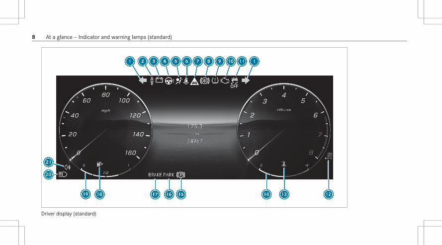
Driver display (standard)
8 At a glance – Indicator and warning lamps (standard)

1 #! Turn signal lights → 155
2ä Suspension (red) → 542
ä Suspension (yellow) → 542
3 # Electrical malfunction → 535
4Ù Power steering (red) → 533
Ù Power steering (yellow) → 533
Ù Rear-axle steering (red) → 533
Ù Rear-axle steering (yellow) → 533
5 6 Restraint system → 531
6 ü Seat belt → 531
7L Distance warning → 542
8 ! ABS → 543
9 h Tire pressure monitoring system → 546
A ; Check Engine → 535
B å ESP® OFF → 543
÷ ESP® → 543
CH Mercedes me connect → 546
Dÿ Coolant temperature → 535
E Coolant temperature display
F ! Electric parking brake (yellow) → 539
G Electric parking brake (red) → 539
F USA only
! Canada only
H Brakes (red) → 539
$ USA only
J Canada only
é Recuperative Brake System, USA only → 539
J Brakes (yellow), Canada only → 539
I 8 Reserve fuel with fuel filler flap locationindicator
→ 535
J Fuel level
K K High beam → 155
L Low beam → 154
At a glance – Indicator and warning lamps (standard) 9

T Parking lamps → 154 L R Rear fog light → 155
10 At a glance – Indicator and warning lamps (standard)


Driver display with driver camera
12 At a glance – Indicator and warning lamps (with driver camera):

1 #! Turn signal lights → 155
2 ü Seat belt → 531
3L Distance warning → 542
4 6 Restraint system → 531
5 h Tire pressure monitoring system → 546
6 å ESP® OFF → 543
÷ ESP® → 543
7 ! ABS → 543
8H Mercedes me connect → 546
9ÿ Coolant temperature → 535
A Coolant temperature display
B ! Electric parking brake (yellow) → 539
C Electric parking brake (red) → 539
F USA only
! Canada only
D Brakes (red) → 539
$ USA only
J Canada only
é Recuperative Brake System, USA only → 539
J Brakes (yellow), Canada only → 539
E 8 Reserve fuel with fuel filler flap locationindicator
→ 535
F Fuel level
G R Rear fog lamp → 155
H K High beam → 155
L Low beam → 154
T Parking lamps → 154
I # Electrical malfunction → 535
J ; Check Engine → 535
KÙ Power steering (red) → 533
Ù Power steering (yellow) → 533
Ù Rear axle steering (red) → 533
Ù Rear axle steering (yellow) → 533
At a glance – Indicator and warning lamps (with driver camera): 13

Lä Suspension (red) → 542 ä Suspension (yellow) → 542
14 At a glance – Indicator and warning lamps (with driver camera):


16 At a glance – Overhead control panel

1 Sun visors
2 c Switches the front interior lightingon/off
→ 164
3 u Switches the rear interior lightingon/off
→ 164
4; me button → 309
5D Opens/closes the panorama roof withpower tilt/sliding panel rear roller sunblind
→ 95
6 | Switches automatic interior lighting con‐trol on/off
→ 164
7 G SOS button → 309
8 p Switches the right-hand reading lampon/off
→ 164
9 3 Opens/closes the panorama roof withpower tilt/sliding panel
→ 95
3 Opens/closes the panorama roof withpower tilt/sliding panel front roller sunblind
→ 95
A Indicator lamps:
PASSENGER AIR BAG → 53
REAR SEAT AIR BAG → 58
B Inside rearview mirror → 172
C p Switches the left-hand reading lampon/off
→ 164
At a glance – Overhead control panel 17

18 At a glance – Door operating unit and seat adjustment

1ßÜ Locks/unlocks the vehicle → 80
2 Adjusts the seats electrically → 105
3w Switches the seat heating on/off → 123
4 s Switches the seat ventilation on/off → 125
5 w Adjusts the front passenger seat fromthe driver's seat
→ 108
6 Operates the memory function → 129
7 Í Operates the outside mirrors → 171
8 W Opens/closes the right side window → 91
9 W Opens/closes the rear right side win‐dow
→ 91
A p Opens/closes the trunk lid → 84
BD Rear window roller sunblind → 100
CS Child safety lock for the rear side win‐dows
→ 73
D Opens the door → 80
E W Opens/closes the rear left side window → 91
F W Opens/closes the left side window → 91
G Adjusts the head restraints → 117
H Seat adjustment using the multimedia system → 121
At a glance – Door operating unit and seat adjustment 19

Vehicles with a reclining rear seat
20 At a glance – Control settings in the rear passenger compartment

1 Climate control rear operating unit → 176
2 Electronics compartment in the center con‐sole
115 V socket → 145
3j Sets the fully reclined position → 112
4V Selects the front passenger seat → 109
5 s Switches the rear seat ventilationon/off
→ 125
6w Switches the rear seat heating on/off → 123
7 Adjusts the reclining rear seats electrically → 111
8a Resets the standard seat adjustmentsettings
→ 112
9 Memory function in the rear passenger com‐partment
→ 131
A Storage box in the seat backrest
Refrigerator box → 147
B Storage compartment in the rear armrest
C MBUX rear tablet bracket
D Cup holder
At a glance – Control settings in the rear passenger compartment 21

22 At a glance – Emergencies and breakdowns

1 B-pillar with:
QR code for accessing the rescue card → 35
2 Safety vests → 337
3; me button → 309
G SOS button → 309
4 Checking and refilling operating fluids → 468
Starting assistance → 348
5 Tow-starting or towing away → 351
6 Flat tire → 338
7 £ Hazard warning light system → 156
8 Fuel filler flap with:
information label on fuel type → 205
Information label for tire pressure → 361
QR code for accessing the rescue card → 35
9 Tow-starting or towing away → 351
A First-aid kit → 338
B TIREFIT kit → 340
C Warning triangle → 338
At a glance – Emergencies and breakdowns 23

Calling up the Digital Operator's ManualMultimedia system:4© 5 Settings 5 Info5 Operator's Manual5 Open Digital Operator's ManualThe Digital Operator's Manual describes thefunctions and operation of the vehicle and themultimedia system.# Select one of the following menu items in the
Digital Operator's Manual:R Quick start: find the first steps towards set‐
ting up your vehicle.R Tips: find information that prepares you for
certain everyday situations with your vehicle.R Animations: watch animations of the vehicle
functions.R Messages: receive additional information
about the messages in the driver display.R Language: select the language for the Digital
Operator's Manual.
You can search for keywords using the searchfield Search, in order to find quick answers toquestions about the operation of the vehicle.
1 Menu2 Search3 Back4 Contents section
Some sections in the Digital Operator's Manual,such as warning notes, can be expanded andcollapsed.Additional methods of calling up the DigitalOperator's Manual:Driver display: call up brief information as dis‐play messages in the instrument clusterMBUX Voice Assistant: call up via the voicecontrol systemGlobal search: call up search results for con‐tents of the Digital Operator's Manual in thehome screenFor safety reasons, the Digital Operator's Man‐ual is deactivated while driving.% With automatic content updates, you can
always keep the Digital Operator's Manualup to date. This function is country-depend‐ent.
24 Digital Operator's Manual

Protection of the environment
+ ENVIRONMENTAL NOTE Environmentaldamage due to operating conditions andpersonal driving style
The pollutant emission of the vehicle isdirectly related to the way you operate thevehicle.Operate your vehicle in an environmentallyresponsible manner to help protect the envi‐ronment. Please observe the following rec‐ommendations on operating conditions andpersonal driving style.Operating conditions:# Make sure that the tire pressure is cor‐
rect.# Do not carry any unnecessary weight
(e.g. roof luggage racks once you nolonger need them).
# Adhere to the service intervals.A regularly serviced vehicle will contrib‐ute to environmental protection.
# Always have maintenance work carriedout at a qualified specialist workshop.
Personal driving style:# Do not depress the accelerator pedal
when starting the engine.# Do not warm up the engine while the
vehicle is stationary.# Drive carefully and maintain a suitable
distance from the vehicle in front.# Avoid frequent, sudden acceleration
and braking.# Change gear in good time and use each
gear only up toÔ of its maximumengine speed.
# Switch off the engine in stationary traf‐fic, e.g. by using the ECO start/stopfunction.
# Drive fuel-efficiently. Observe the ECOdisplay for a fuel-efficient driving style.
Environmental issues and recommendationsIt is recommended that you re-use or recyclematerials instead of just disposing of them.The relevant environmental guidelines and regu‐lations serve to protect the environment andmust be strictly observed.
Genuine Mercedes-Benz parts
+ ENVIRONMENTAL NOTE Environmentaldamage due to not using recycled recon‐ditioned components
Mercedes‑Benz AG offers recycled recondi‐tioned components and parts with the samequality as new parts. The same entitlementfrom the Limited Warranty is valid as for newparts.# Use recycled reconditioned compo‐
nents and parts fromMercedes‑Benz AG.
General notes 25

* NOTE Impairment of the operating effi‐ciency of the restraint systems frominstalling accessory parts or from repairsor welding
Airbags and Emergency Tensioning Devices,as well as control units and sensors for therestraint systems, may be installed in the fol‐lowing areas of your vehicle:R DoorsR Door pillarsR Door sillsR SeatsR CockpitR Instrument clusterR Center consoleR Lateral roof frame
# Do not install accessory parts such asaudio systems in these areas.
# Do not carry out repairs or welding.
# Have aftermarket installation of acces‐sories carried out at a qualified special‐ist workshop.
You could jeopardize the operating safety of yourvehicle if you use parts, tires and wheels as wellas accessories relevant to safety which have notbeen approved by Mercedes-Benz. Safety-rele‐vant systems, e.g. the brake system, may mal‐function. Only use Mercedes-Benz GenuinePartsor parts of equal quality. Only use tires, wheelsand accessories that have been specificallyapproved for your vehicle model.Mercedes-Benz GenuineParts are subject tostrict quality inspections. Each part has beenspecially developed, manufactured or selectedfor Mercedes-Benz vehicles and adapted tothem. Therefore, only Mercedes-Benz Genuine‐Parts should be used.More than 300,000 different Mercedes-BenzGenuineParts are available for Mercedes-Benzmodels.All authorized Mercedes-Benz Centers maintaina supply of Mercedes-Benz GenuineParts for
necessary service and repair work. In addition,strategically located parts delivery centers pro‐vide for quick and reliable parts service.Always specify the vehicle identification number(VIN) (/ page 466) when ordering Mercedes-Benz GenuineParts.
Operator's ManualThis Operator's Manual describes all models andall standard and optional equipment available foryour vehicle at the time of this Operator's Man‐ual going to press. Country-specific differencesare possible. Note that your vehicle may not beequipped with all features described. This is alsothe case for systems and functions relevant tosafety. Therefore, the equipment on your vehiclemay differ from that in the descriptions and illus‐trations.The original purchase agreement for your vehiclecontains a list of all of the systems in your vehi‐cle.Should you have any questions concerningequipment and operation, please consult anauthorized Mercedes-Benz Center.
26 General notes

The Operator's Manual and Maintenance Bookletare important documents and should be kept inthe vehicle.
Touch-sensitive controlsIn addition to conventional switches and but‐tons, your vehicle is equipped with touch-sensi‐tive controls.These are located in the following areas of yourvehicle:R Roof and door control panelR Climate controlR Steering wheelR MBUX multimedia system
The controls have touch-sensitive user interfacesurfaces. The surfaces are controlled by press‐ing or swiping to adjust settings or to triggerfunctions, for example.In the area of the touchscreen, you also receivehaptic feedback in the form of a pulse or a vibra‐tion, or the surface structure changes on the
touch-sensitive user interface surface, for exam‐ple.You receive haptic feedback in the following sit‐uations, for example:R When pressing a button on the user interface
surfaceR When scrolling in a list or tableR When reaching a new area on the user inter‐
face surface, e.g. a pop-up window
When handling touch-sensitive user interfacesurfaces, observe the following points to avoidproblems operating:R Do not affix stickers or similar objects on the
surfaces.R Keep the surfaces protected from moisture
and wet conditions.R Keep the surfaces free of dust and dirt.
Some touch-sensitive control elements have asymbol and integrated indicator lamps. Whenoperating, make sure to press on the symbol ofthe control element.
Service and vehicle operationVehicle operation outside the USA or Canada
When you are abroad with your vehicle, observethe following points:R Service points or replacement parts may not
be available immediately.R Unleaded fuel may not be available for vehi‐
cles with a catalytic converter. Leaded fuelmay cause damage to the catalytic converter.R The fuel may have an extremely low octane
number. Unsuitable fuel can cause enginedamage.
Some Mercedes-Benz models are available inEurope through our European Delivery Program.For more information, please consult an author‐ized Mercedes‑Benz service center, or write toone of the following address:In the USA:Mercedes-Benz USA, LLCEuropean Delivery DepartmentOne Mercedes-Benz DriveSandy Springs, GA 30328
General notes 27

In Canada:Mercedes-Benz Canada, Inc.European Delivery Department98 Vanderhoof AvenueToronto, Ontario M4G 4C9
Maintenance
Your customer advisor confirms the service inthe service report.
Roadside Assistance
The Mercedes-Benz Roadside Assistance Pro‐gram offers technical help in the case of abreakdown. Your calls to the toll-free RoadsideAssistance Hotline are answered by our agents24 hours a day, 365 days a year.1-800-FOR-MERCedes (1-800-367-6372) (USA)1-800-387-0100 (Canada)You can find further information in theMercedes-Benz Roadside Assistance Programbrochure (USA) or the "Roadside Assistance"
section in the Service and Warranty booklet(Canada). You will find both in the vehicle docu‐ment wallet.
Change of address or change of ownership
In the event of a change of address, please sendus the "Notification of address change" in theService and Guarantee booklet or simply call theMercedes-Benz Customer Assistance Center(USA) on the hotline number1-800-FOR-MERCedes (1-800-367-6372) or Cus‐tomer Service (Canada) on 1-800-387-0100. Wecan then reach you in a timely fashion, if neces‐sary.If you sell your Mercedes, please leave all litera‐ture in the vehicle so that it is available to thenext owner. If you have purchased a used vehi‐cle, please send us the "Notice of Purchase ofUsed Car" in the Service and Guarantee bookletor simply call the Mercedes-Benz CustomerAssistance Center (USA) at the hotline number1-800-FOR-MERCedes (1-800-367-6372) or Cus‐tomer Service (Canada) at 1-800-387-0100.
Possible danger due to substances hazard‐ous to health
In compliance with Proposition 65 ("Prop65"),the following detachable label has been added toeach vehicle sold in California:
Operating safety
& WARNING Risk of accident due to mal‐functions or system failures
To avoid malfunctions or system failures:# Always have the prescribed service and
maintenance work as well any required
28 General notes

repairs carried out at a qualified spe‐cialist workshop.
& WARNING Risk of accident or injury dueto incorrect modifications on electroniccomponent parts
Modification of electronic components, theirsoftware or wiring could impair their functionand/or the function of other networked com‐ponent parts or safety-relevant systems.This can endanger the operating safety of thevehicle.# Never tamper with the wiring and elec‐
tronic component parts or their soft‐ware.
# You should have all work on electricaland electronic components carried outat a qualified specialist workshop.
Observe the "On-board electronics" section in"Technical data".
& WARNING Risk of fire due to flammablematerials on hot parts of the exhaustsystem
Flammable material such as leaves, grass ortwigs may ignite if they come into contactwith hot parts of the exhaust system.# When driving on unpaved roads or off-
road, regularly check the vehicle under‐side.
# Remove trapped plants or other flam‐mable material, in particular.
# If there is damage, consult a qualifiedspecialist workshop immediately.
* NOTE Damage to the vehicle due to driv‐ing too fast and due to impacts to thevehicle underbody or suspension compo‐nents
In the following situations, in particular, thereis a risk of damage to the vehicle:R The vehicle becomes grounded, e.g. on a
high curb or an unpaved roadR The vehicle is driven too fast over an
obstacle, e.g. a curb, speed bump or pot‐holeR A heavy object strikes the underbody or
suspension components
In situations such as these, damage to thebody, underbody, suspension components,wheels or tires may not be visible. Compo‐nents damaged in this way can unexpectedlyfail or, in the case of an accident, may no lon‐ger absorb the resulting force as intended.If the underbody paneling is damaged, flam‐mable materials such as leaves, grass ortwigs can collect between the underbody and
General notes 29

the underbody paneling. These materials mayignite if they come into contact with hotparts of the exhaust system.# Have the vehicle checked and repaired
immediately at a qualified specialistworkshop.
or# If driving safety is impaired while con‐
tinuing your journey, pull over and stopthe vehicle immediately, while payingattention to road and traffic conditions,and contact a qualified specialist work‐shop.
Vehicles with a 48 V on-board electrical sys‐tem (EQ Boost technology)
& DANGER Risk of fatal injury by touchingdamaged high-voltage components
Vehicles with a 48 V on-board electrical sys‐tem contain individual high-voltage compo‐nents. These high-voltage components areunder high voltage.
If you modify component parts of these high-voltage components or touch damaged com‐ponent parts, you may be electrocuted.High voltage components may be damagedin an accident, although the damage may notbe visible.# Never perform modifications to compo‐
nent parts of high-voltage components.# Never touch damaged component parts
of high-voltage components.# Never touch component parts of high-
voltage components after an accident.
Vehicles with a 48 V on-board electrical systemcontain high voltage components. These compo‐nents are marked with a high voltage label:
All work on high voltage components must becarried out at a qualified specialist workshop.
Declaration of conformity for wireless vehi‐cle componentsUSA: "Radio based devices of this vehicle com‐ply with Part 15 of the FCC Rules. Operation issubject to the following two conditions: 1) Thesedevices may not cause harmful interference, and2) These devices must accept any interferencereceived, including interference that may causeundesired operation. Changes or modificationsnot expressly approved by the party responsible
30 General notes

for compliance could void the user's authority tooperate the equipment."Canada: "This vehicle contains license-exempttransmitter(s)/receiver(s) that comply with Inno‐vation, Science and Economic Development Can‐ada’s RSS(s). Operation is subject to the follow‐ing two conditions: (1) These devices may notcause interference, and (2) These devices mustaccept any interference, including interferencethat may cause undesired operation of thedevice."
Charging unit for wireless charging of mobiledevices (WMI)This equipment complies with FCC and IC radia‐tion exposure limits set forth for an uncontrolledenvironment. This equipment should be installedand operated with a minimum distance of 0 cm(in contact) between the radiator and yourbody. This transmitter must not be co-located oroperating with any other antenna or transmitter.USA: "Wireless charging system for mobile devi‐ces (Model: D-WMI2015A): This Device complieswith Part 18 of the FCC Rules."
The name and address of the party responsibleis:Continental Automotive Systems US Inc.2400 Executive Hills DriveAuburn Hills, MI 48326-2980United States of America
Diagnostics connectionThe diagnostics connection is a technical inter‐face in the vehicle. It is used, for example, withinthe scope of repair and maintenance work or forreading out vehicle data by a specialist work‐shop. Diagnostic devices should therefore onlybe connected by a qualified specialist workshop.
& WARNING Risk of accident due to con‐necting devices to the diagnostics con‐nection
If you connect devices to the diagnosticsconnection of the vehicle, the function ofvehicle systems and operating safety may beimpaired.
# For safety reasons, we recommend thatyou only use and connect productsapproved by your authorized Mercedes-Benz Center.
& WARNING Risk of accident due toobjects in the driver's footwell
Objects in the driver's footwell may impedepedal travel or block a depressed pedal.This jeopardizes the operating and roadsafety of the vehicle.# Stow all objects in the vehicle securely
so that they cannot get into the driver'sfootwell.
# Always install the floor mats securelyand as prescribed in order to ensurethat there is always sufficient room forthe pedals.
# Do not use loose floor mats and do notplace floor mats on top of one another.
General notes 31

* NOTE Battery discharging from usingdevices connected to the diagnosticsconnection
Using devices at the diagnostics connectiondrains the battery.# Check the charge level of the battery.# If the charge level is low, charge the
battery, e.g. by driving a considerabledistance.
Connecting and using another device with thediagnostics connection can have the followingeffects:R Malfunctions in the vehicle systemR Permanent damage to vehicle components
Please refer to the warranty terms and condi‐tions for this matter.
Moreover, connecting equipment to the diagnos‐tics connection can lead to emissions monitor‐ing information being reset, for example. Thismay lead to the vehicle failing to meet therequirements of the next emissions inspectionduring the main inspection.
Qualified specialist workshopAn authorized Mercedes-Benz Center is a quali‐fied specialist workshop. It has the necessaryspecial skills, tools and qualifications to cor‐rectly carry out the work required on your vehi‐cle. This particularly applies to safety-relevantworks.Always have the following work carried out onyour vehicle at a qualified specialist workshop:R Safety-relevant worksR Service and maintenance workR Repair workR Modifications as well as installations and
conversionsR Work on electronic components
32 General notes

R Vehicles with 48 V on-board electricalsystem (EQ boost technology): work onhigh voltage components of the 48 V on-board electrical system
Mercedes‑Benz recommends an authorizedMercedes‑Benz Center.
Correct use of the vehicleIf you remove any warning stickers, you or otherscould fail to recognize certain dangers. Leavewarning stickers in position.Observe the following information in particularwhen driving your vehicle:R the safety notes in this manualR technical data for the vehicleR traffic rules and regulationsR laws and safety standards pertaining to
motor vehicles
Notes for persons with electronic medicalaidsMercedes‑Benz AG cannot, despite carefullydeveloping vehicle systems, completely rule outthe interaction of vehicle systems with electronicmedical aids such as cardiac pacemakers.In addition, there are components installed inthe vehicle that, regardless of the operating sta‐tus of the vehicle, can generate magnetic fieldson a par with permanent magnets. These fieldscan be found, for example, in the area aroundthe multimedia and sound system or also in thearea of the seats, depending on the vehicleequipment.For this reason, the following can occur in isola‐ted cases, depending on the aids used:R Medical aids malfunctioningR Adverse health effects
Observe the notes and warnings of the manufac‐turer of the medical aids; if in doubt, contact thedevice manufacturer and/or your doctor. If thereis continuing uncertainty concerning the possi‐bility of medical aids malfunctioning,
Mercedes‑Benz AG recommends using only fewelectrical vehicle systems and/or maintaining adistance from the components.Only have repairs and maintenance work in thearea of the following components carried out bya qualified specialist workshop:R Vehicle components carrying live voltageR Transmission antennaR Multimedia system and sound system
If you have any queries or suggestions, consult aqualified specialist workshop.
Problems with your vehicleIf you should experience a problem with yourvehicle, particularly one that you believe mayaffect its safe operation, we urge you to contactan authorized Mercedes-Benz Center immedi‐ately to have the problem diagnosed and recti‐fied. If the problem is not resolved to your satis‐faction, please discuss the problem again withan authorized Mercedes-Benz Center or, if nec‐essary, contact us at one of the followingaddresses:
General notes 33

In the USA:Mercedes-Benz USA, LLCCustomer Assistance CenterOne Mercedes-Benz DriveSandy Springs, GA 30328In Canada:Mercedes-Benz Canada, Inc.Customer Relations Department98 Vanderhoof AvenueToronto, Ontario M4G 4C9
Reporting safety defects
USA only:The following text is published as required ofmanufacturers under Title 49, Code of U.S. Fed‐eral Regulations, Part 575 pursuant to the"National Traffic and Motor Vehicle Safety Act of1966".If you believe that your vehicle has a defectwhich could cause a crash or could cause injuryor death, you should immediately inform the
National Highway Traffic Safety Administration(NHTSA) in addition to notifying Mercedes-BenzUSA, LLC.If NHTSA receives similar complaints, it mayopen an investigation, and if it finds that a safetydefect exists in a group of vehicles, it may ordera recall and remedy campaign. However, NHTSAcannot become involved in individual problemsbetween you, your dealer, or Mercedes-BenzUSA, LLC.To contact NHTSA, you may call the VehicleSafety Hotline toll-free at 1-888-327-4236(TTY: 1-800-424-9153); go to the https://www.safercar.gov/; or write to: Administrator,NHTSA, 400 Seventh Street, SW., Washington,DC 20590,: USA.You can also obtain other information aboutmotor vehicle safety from: https://www.safercar.gov
Canada only:The following text is published as required ofmanufacturers under subsection 18.4 (4) of theMotor Vehicle Safety Regulations.
If you believe that your vehicle has a defectwhich could cause a crash or could cause injuryor death, you should immediately inform Trans‐port Canada in addition to notifying Mercedes-Benz Canada Inc.If Transport Canada received similar complaints,it may open an investigation, and if it finds that asafety defect exists in a group of vehicles, it mayorder a recall and remedy campaign. However,Transport Canada cannot become involved inindividual problems between you, your dealer orMercedes-Benz Canada Inc.To contact Transport Canada, you may call theDefect Investigations and Recalls Division toll-free in Canada at 1-800-333-0510 or819-994-3328in the Gatineau-Ottawa area orinternationally; you may also go to the followingwebsites for more information:R English: https://www.tc.gc.ca/recallsR French: https://www.tc.gc.ca/rappels
34 General notes

Limited Warranty
* NOTE Damage to the vehicle arisingfrom violation of these operating instruc‐tions.
Damage to the vehicle can arise from viola‐tion of these operating instructions.This damage is not covered either by theMercedes-Benz implied warranty or by theNew‑ or Used-Vehicle Warranty.# Follow the instructions in these operat‐
ing instructions on proper operation ofyour vehicle as well as on possible vehi‐cle damage.
QR code for rescue cardQR codes are attached in the fuel filler flap andon the opposite side on the B-pillar. In the eventof an accident, rescue services can use the QRcode to quickly find the appropriate rescue cardfor your vehicle. The current rescue card con‐tains the most important information about your
vehicle in a compact form, e.g. the routing of theelectric lines.Further information can be obtained at https://www.mercedes-benz.de/qr-code.
Data storageData processing in the vehicle
Electronic control unitsElectronic control units are installed in your vehi‐cle. Control units process data which, for exam‐ple, they receive from vehicle sensors, generatethemselves or exchange between themselves.Some control units are required for the safeoperation of your vehicle, some assist you whendriving, such as driver assistance systems, whileothers enable convenience or infotainment func‐tions.The following provides you with general informa‐tion regarding data processing in the vehicle.Additional information regarding exactly whichdata in your vehicle are collected, saved andtransmitted to third parties and for what pur‐pose, can be found in the information directly
related to the functional characteristics in ques‐tion in their respective operating instructions.This information is also available online and,depending on the vehicle equipment, digitally.
Personal dataEvery vehicle is identified by a unique vehicleidentification number. Depending on the coun‐try, this vehicle identification number can beused by, for example, governmental authoritiesto determine the identity of the owner. There areother possibilities to use data collected from thevehicle to identify the owner or driver, such asthe license plate number.Therefore, data generated or processed by con‐trol units may be attributable to a person or,under certain conditions, become attributable toa person. Depending on which vehicle data areavailable, it may be possible to make inferencesabout, for example, your driving behavior, yourlocation, your route or your use patterns.
Legal requirements regarding the disclosureof dataIf legally required to do so, manufacturers are, inindividual cases, legally obliged to provide gov‐
General notes 35

ernmental entities, upon request and to theextent required, data stored by the manufac‐turer. For example, this may be the case duringthe investigation of a criminal offense.Governmental entities are themselves, in individ‐ual cases and within the applicable legal frame‐work, authorized to read out data from the vehi‐cle. In the case of an accident, information thatcan help with an investigation can, therefore, betaken from the airbag control unit, for example.
Operational data in the vehicleThis is data regarding the operation of the vehi‐cle, which have been processed by control units.This includes the following data, for example:R Vehicle status information such as the speed,
longitudinal acceleration, lateral accelera‐tion, number of wheel revolutions or the fas‐tened seat belts displayR Ambient conditions, such as temperature,
rain sensor or distance sensor
Generally, the use of these data is temporary;they will not be stored beyond the period ofoperation and will only be processed within the
vehicle itself. Control units often contain datamemories for vehicle SmartKeys, for example.Their use permits the temporary or permanentdocumentation of technical information aboutthe vehicle's operating state, component loads,maintenance requirements and technical eventsor malfunctions.Depending on the vehicle equipment, the follow‐ing data are stored:R Operating status of system components,
such as fill levels, tire pressure or batterystatusR Malfunctions or faults in important system
components, such as lights or brakesR System reactions in special driving situa‐
tions, such as airbag deployment or the inter‐vention of stability control systemsR Information on events leading to vehicle
damage
In certain cases, it may be required to store datathat would have otherwise been used only tem‐porarily. This may be the case if the vehicle hasdetected a malfunction, for example.
If you use services, such as repair services andmaintenance work, stored operational data aswell as the vehicle identification number can beread out and used. They can be read out byservice network employees, such as workshopsand manufacturers or third parties, such asbreakdown services. The same is true in thecase of warranty claims and quality assurancemeasures.In general, the readout is performed via thelegally prescribed port for the diagnostics con‐nection in the vehicle. The operational data thatare read out document technical states of thevehicle or of individual components and assist inthe diagnosis of malfunctions, compliance withwarranty obligations and quality improvement.To that end, these data, in particular informationabout component loads, technical events, mal‐functions and other faults may be transmittedalong with the vehicle identification number tothe manufacturer. Furthermore, the manufac‐turer is subject to product liability. For this rea‐son the manufacturer also uses operational datafrom the vehicle, for example, for recalls. These
36 General notes

data can also be used to examine the custom‐er's warranty and guarantee claims.Fault memories in the vehicle can be reset by aservice outlet or at your request as part of repairor maintenance work.
Convenience and infotainment functionsYou can store convenience settings and individ‐ual settings in the vehicle and change or resetthem at any time.Depending on the vehicle equipment, thisincludes the following settings, for example:R Seat and steering wheel positionsR Suspension and climate control settingsR Individual settings, such as interior lighting
Depending on the selected equipment, you canimport data into vehicle infotainment functionsyourself.Depending on the vehicle equipment, thisincludes the following data, for example:R Multimedia data, such as music, films or pho‐
tos for playback in an integrated multimediasystem
R Address book data for use in connection withan integrated hands-free system or an inte‐grated navigation systemR Entered navigation destinationsR Data about the use of Internet services
These data for convenience and infotainmentfunctions may be saved locally in the vehicle orthey may be located on a device which you haveconnected to the vehicle, such as a smartphone,USB flash drive or MP3 player. If you haveentered these data yourself, you can delete themat any time.This data is transmitted from the vehicle to thirdparties only at your request. This applies, in par‐ticular, when you use online services in accord‐ance with the settings that you have selected.
Smartphone integration (e.g. Android Auto orApple CarPlay®)If your vehicle is accordingly equipped, you canconnect your smartphone or another mobile enddevice to the vehicle. You can then control themby means of the control elements integrated inthe vehicle. Images and audio from the smart‐
phone can be output via the multimedia system.Certain information is simultaneously transfer‐red to your smartphone. Depending on the typeand integration, this includes position data, day/night mode and other general vehicle statuses.For more information please consult the Opera‐tor's Manual of the vehicle/infotainment system.This integration allows the use of selectedsmartphone apps, such as navigation or musicplayer apps. There is no further interactionbetween the smartphone and the vehicle; in par‐ticular, vehicle data is not directly accessible.The type of additional data processing is deter‐mined by the provider of the app being used.Which settings you can make, if any, depends onthe specific app and the operating system ofyour smartphone.
Online services
Wireless network connectionIf your vehicle has a wireless network connec‐tion, it enables data to be exchanged betweenyour vehicle and additional systems. The wire‐less network connection is made possible by the
General notes 37

vehicle's own transmitter and receiver or by amobile end device that you have brought into thevehicle, for example, a smartphone. Online func‐tions can be used via the wireless network con‐nection. This includes online services and appli‐cations/apps provided to you by the manufac‐turer or by other providers.
Manufacturer's servicesRegarding the manufacturer's online services,the individual functions are described by themanufacturer in a suitable place, for example, inthe Operator's Manual or on the manufacturer'swebsite, where the relevant data protectioninformation is also given. Personal data may beused for the provision of online services. Dataare exchanged via a secure connection, such asthe manufacturer's designated IT systems. Anypersonal data which are collected, processedand used, other than for the provision of serv‐ices, is done so exclusively on the basis of legalpermission. This is the case, for example, for alegally prescribed emergency call system, a con‐tractual agreement or when consent has beengiven.
You can have services and functions, some ofwhich are subject to a fee, activated or deactiva‐ted. This excludes legally prescribed functionsand services, such as an emergency call system.
Third party servicesIf you use online services from other providers(third parties), these services are the responsi‐bility of the provider in question and subject tothat provider's data protection conditions andterms of use. As a general rule, the manufac‐turer has no influence on the contentexchanged.For this reason, when services are provided bythird parties, please ask the service provider inquestion for information about the type, extentand purpose of the collection and use of per‐sonal data.
Data protection rights
Depending on your country or the equipmentand range of functions of your vehicle as well asthe services you use and the services on offer,you are entitled to different data protectionrights. Further information on data protection
and your data protection rights can either befound on the manufacturer's website or you willreceive this information as part of the variousservices and service offers. There you will alsofind the contact information for the manufac‐turer and its data protection officers.At a workshop, for example, with the support ofa specialist and possibly for a fee, you can havedata read out which is stored only locally in thevehicle.
MBUX multimedia system/Mercedes meconnect
If the vehicle is equipped with the MBUX multi‐media system or Mercedes me connect, addi‐tional data about the vehicle's operation, the useof the vehicle in certain situations, and the loca‐tion of the vehicle may be compiled by theMBUX multimedia system or Mercedes me con‐nect.For additional information, please refer to the"MBUX multimedia system" section and/or theMercedes me connect Terms and Conditions.
38 General notes

Event data recorders
USA only:This vehicle is equipped with an event datarecorder (EDR). The main purpose of an EDR isto record, in certain crash or near crash-like sit‐uations, such as an airbag deployment or hittinga road obstacle, data that will assist in under‐standing how a vehicle's systems performed.The EDR is designed to record data related tovehicle dynamics and safety systems for a shortperiod of time, typically 30 seconds or less.The EDR in this vehicle is designed to recordsuch data as:R How various systems in your vehicle were
operatingR Whether or not the driver and front
passenger seat belts were buckled/fastenedR How far (if at all) the driver was depressing
the accelerator and/or brake pedal andR How fast the vehicle was traveling
This data can help provide a better understand‐ing of the circumstances in which accidents andinjuries occur. NOTE: EDR data is recorded by
your vehicle only if a non-trivial crash situationoccurs; no data is recorded by the EDR undernormal driving conditions and no personal data(e.g. name, gender, age and accident location) isrecorded. However, other parties, such as lawenforcement, could combine EDR data with thetype of personally identifying data routinelyacquired during a crash investigation.To read data recorded by an EDR, special equip‐ment is required, and access to the vehicle orthe EDR is needed. In addition to the vehiclemanufacturer, other parties that have the specialequipment, such as law enforcement, can readthe information by accessing the vehicle or theEDR.EDR data may be used in civil and criminal mat‐ters as a tool in accident reconstruction, acci‐dent claims and vehicle safety. Since the CrashData Retrieval (CDR) tool that is used to extractdata from the EDR is commercially available,Mercedes-Benz USA, LLC ("MBUSA") expresslydisclaims any and all liability arising from theextraction of this information by unauthorizedMercedes-Benz personnel.
MBUSA will not share EDR data with others with‐out the consent of the vehicle owner or, if thevehicle is leased, without the consent of the les‐see. Exceptions to this representation includeresponses to subpoenas by law enforcement; byfederal, state or local government; in connectionwith or arising out of litigation involving MBUSAor its subsidiaries and affiliates; or, as requiredby law.Warning: The EDR is a component of theRestraint System Module. Tampering with, alter‐ing, modifying or removing the EDR componentmay result in a malfunction of the Restraint Sys‐tem Module and other systems.State laws or regulations regarding EDRs thatconflict with federal regulation are pre-empted.This means that in the event of such conflict, thefederal regulation governs. As of December2016, 17 states have enacted laws relating toEDRs.
General notes 39

CopyrightFree and open source software
Information on license for free and open-sourcesoftware used in your vehicle can be found onthe data carrier in your vehicle document walletand with updates on the following website:https://www.mercedes-benz.com/opensource
Registered trademarks
R Bluetooth® is a registered trademark of Blue‐tooth SIG, Inc.R DTS™ is a registered trademark of DTS, Inc.R Dolby® and MLP™ are registered trademarks
of DOLBY Laboratories.R ESP® and PRE-SAFE® are registered trade‐
marks of Daimler AG.R HomeLink® is a registered trademark of Gen‐
tex Corporation.R iPod® and iTunes® are registered trademarks
of Apple Inc.
R Burmester® is a registered trademark ofBurmester Audiosysteme GmbH.R Microsoft® and Windows Media® are regis‐
tered trademarks of Microsoft Corporation.R SIRIUS® is a registered trademark of Sirius
XM Radio Inc.R HD Radio™ is a registered trademark of iBiq‐
uity Digital Corporation.R Gracenote® is a registered trademark of
Gracenote, Inc.R ZAGAT Survey® and related brands are regis‐
tered trademarks of Zagat Survey, LLC.
40 General notes

Restraint systemProtection provided by the restraint system
The restraint system includes the following com‐ponents:R Seat belt systemR AirbagsR Child restraint systemR Child seat securing systems
The restraint system can help prevent the vehi‐cle occupants from coming into contact withparts of the vehicle interior in the event of anaccident. In the event of an accident, therestraint system can also reduce the forces towhich the vehicle occupants are subjected.A seat belt can only provide the best level of pro‐tection if it is worn correctly. Depending on thedetected accident situation, Emergency Tension‐ing Devices and/or airbags supplement the pro‐tection offered by a correctly worn seat belt.Emergency Tensioning Devices and/or airbagsare not deployed in every accident.
In order for the restraint system to provide theintended level of protection, each vehicle occu‐pant must observe the following information:R Fasten seat belts correctly.R Sit in an almost upright seat position with
their back against the seat backrest.R Sit with their feet resting on the floor, if pos‐
sible.R Always secure persons under 5 ft (1.50 m)
tall in an additional restraint system suitablefor Mercedes-Benz vehicles.
However, no system available today can com‐pletely eliminate injuries and fatalities in everyaccident situation. In particular, the seat beltand airbag generally do not protect againstobjects penetrating the vehicle from the outside.It is also not possible to completely rule out therisk of injury caused by the airbag deploying.
Reduced restraint system protection
& WARNING Risk of injury or death due tomodifications to the restraint system
Vehicle occupants may no longer be protec‐ted as intended if alterations are made to therestraint system.# Never alter the parts of the restraint
system.# Never tamper with the wiring or any
electronic component parts or theirsoftware.
If it is necessary to modify the vehicle to accom‐modate a person with disabilities, contact anauthorized Mercedes-Benz Center for details.USA only: for details, contact our CustomerAssistance Center on 1-800-FOR-MERCedes(1‑800‑367‑6372).
Restraint system functionality
When the ignition is switched on, a self-test isperformed, during which the 6 restraint sys‐
Occupant safety 41
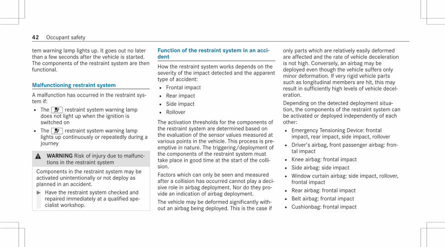
tem warning lamp lights up. It goes out no laterthan a few seconds after the vehicle is started.The components of the restraint system are thenfunctional.
Malfunctioning restraint system
A malfunction has occurred in the restraint sys‐tem if:R The 6 restraint system warning lamp
does not light up when the ignition isswitched onR The 6 restraint system warning lamp
lights up continuously or repeatedly during ajourney
& WARNING Risk of injury due to malfunc‐tions in the restraint system
Components in the restraint system may beactivated unintentionally or not deploy asplanned in an accident.# Have the restraint system checked and
repaired immediately at a qualified spe‐cialist workshop.
Function of the restraint system in an acci‐dent
How the restraint system works depends on theseverity of the impact detected and the apparenttype of accident:R Frontal impactR Rear impactR Side impactR Rollover
The activation thresholds for the components ofthe restraint system are determined based onthe evaluation of the sensor values measured atvarious points in the vehicle. This process is pre-emptive in nature. The triggering/deployment ofthe components of the restraint system musttake place in good time at the start of the colli‐sion.Factors which can only be seen and measuredafter a collision has occurred cannot play a deci‐sive role in airbag deployment. Nor do they pro‐vide an indication of airbag deployment.The vehicle may be deformed significantly with‐out an airbag being deployed. This is the case if
only parts which are relatively easily deformedare affected and the rate of vehicle decelerationis not high. Conversely, an airbag may bedeployed even though the vehicle suffers onlyminor deformation. If very rigid vehicle partssuch as longitudinal members are hit, this mayresult in sufficiently high levels of vehicle decel‐eration.Depending on the detected deployment situa‐tion, the components of the restraint system canbe activated or deployed independently of eachother:R Emergency Tensioning Device: frontal
impact, rear impact, side impact, rolloverR Driver's airbag, front passenger airbag: fron‐
tal impactR Knee airbag: frontal impactR Side airbag: side impactR Window curtain airbag: side impact, rollover,
frontal impactR Rear airbag: frontal impactR Belt airbag: frontal impactR Cushionbag: frontal impact
42 Occupant safety

R PRE-SAFE® Impulse Side: side impact
The front passenger airbag can only be deployedin an accident if the PASSENGER AIR BAG OFFindicator lamp is off. If the front passenger seatis occupied, make sure, both before and duringthe journey, that the status of the frontpassenger airbag is correct (/ page 53).
& WARNING Risk of burns from hot air bagcomponents
The air bag parts are hot after an air bag hasbeen deployed.# Do not touch the air bag parts.# Have a deployed air bag replaced at a
qualified specialist workshop as soonas possible.
Mercedes-Benz recommends that you have thevehicle towed to a qualified specialist workshopafter an accident. Take this into account, partic‐ularly if an Emergency Tensioning Device is trig‐gered or an airbag deployed.
If the Emergency Tensioning Devices are trig‐gered or an airbag is deployed, you will hear abang, and a small amount of powder may also bereleased:R The bang will not generally affect your hear‐
ing.R In general, the powder released is not haz‐
ardous to health but may cause short-termbreathing difficulties to persons sufferingfrom asthma or other pulmonary conditions.Provided it is safe to do so, leave the vehicleimmediately or open the window in order toprevent breathing difficulties.
Airbags and pyrotechnic Emergency TensioningDevices contain perchlorate material, which mayrequire special handling or environmental pro‐tection measures. National guidelines regardingwaste disposal must be observed. In California,see https://dtsc.ca.gov/. Using the searchfunction, you will find information on perchlo‐rate, for example.
Seat beltsProtection provided by the seat belt
Always fasten your seat belt correctly beforestarting a journey. A seat belt can only providethe best level of protection if it is worn correctly.
& WARNING Risk of injury or death due toincorrectly fastened seat belt
If the seat belt is not worn correctly, it can‐not perform its intended protective function.In addition, an incorrectly fastened seat beltcan also cause injuries, for example, in theevent of an accident or when braking orchanging direction suddenly.# Always ensure that all vehicle occu‐
pants have their seat belts fastenedcorrectly and are sitting properly.
Always observe the instructions about the cor‐rect driver's seat position and adjusting the seat(/ page 105).
Occupant safety 43

In order for the correctly worn seat belt to pro‐vide the intended level of protection, each vehi‐cle occupant must observe the following infor‐mation:R The seat belt must not be twisted and must
fit tightly and snugly across the body.R The seat belt must be routed across the cen‐
ter of the shoulder and as low down acrossthe hips as possible.R The shoulder section of the seat belt should
not touch your neck nor be routed underyour arm or behind your back.R Avoid wearing bulky clothing, e.g. a winter
coat.R Push the lap belt down as far as possible
across your hips and pull tight with the shoul‐der section of the belt. Never route the lapbelt across your abdomen.Pregnant women must also take particularcare with this.R Never route the seat belt across sharp, poin‐
ted, abrasive or fragile objects.
R Only one person should use each seat belt atany one time. Never allow babies and chil‐dren to travel sitting on the lap of anothervehicle occupant.R Never secure objects with a seat belt if the
seat belt is also being used by one of thevehicle's occupants. Always observe theinstructions for loading the vehicle whensecuring objects, luggage or loads(/ page 133).Also ensure that no objects, e.g. a cushion,are ever placed between a person and theseat.
The seat belts on the following seats are equip‐ped with a special seat belt retractor:R Front passenger seatR Rear seats
Activate or deactivate the special seatbeltretractor (/ page 65).If children are traveling in the vehicle, be sure toobserve the instructions and safety notes on"Children in the vehicle" (/ page 61).
Limitations of the protection provided by theseat belt
& WARNING Risk of injury or death due toan incorrect seat position
The seat belt does not offer the intendedlevel of protection if you have not moved theseat backrest to an almost vertical position.In particular, you could slip beneath the seat‐belt and become injured.# Adjust the seat properly before begin‐
ning your journey.# Always ensure that the seat backrest is
in an almost vertical position and thatthe shoulder belt is routed across thecenter of your shoulder.
& WARNING Risk of injury or death whenadditional restraint systems are not usedfor persons with a smaller stature
Persons under 5 ft (1.50 m ) tall cannot wearthe seat belt correctly without a suitableadditional restraint system.
44 Occupant safety

# Always secure persons under 5 ft(1.50 m) tall in a suitable restraint sys‐tem.
& WARNING Risk of injury or death due toblocked seat belt buckle or seat beltanchorage
Objects next to the front seat that block theseat belt buckle or the moving seat beltanchorage on the front seat impair the func‐tion of the Emergency Tensioning Devices.# Before starting the journey, make sure
that there are no objects around theseat belt buckle or between the frontseat and door.
& WARNING Risk of injury or death due todamaged or modified seat belts
Seat belts cannot provide protection in thefollowing situations:R The seat belt is damaged, has been modi‐
fied, is extremely dirty, bleached or dyed
R The seat belt buckle is damaged orextremely dirtyR Modifications have been made to the
Emergency Tensioning Device, seat beltanchorage or seat belt retractor
Seat belts may sustain non-visible damage inan accident, e.g. due to glass splinters.Modified or damaged seat belts could tear orfail in the event of an accident, for example.Modified Emergency Tensioning Devicescould accidentally trigger or fail to functionas intended.# Never modify the seat belt system, for
example the seat belt, seat belt buckle,Emergency Tensioning Device, seat beltanchorage and seat belt retractor.
# Make sure that the seat belts areundamaged, not worn and clean.
# Always have the seat belts checkedimmediately after an accident at aqualified specialist workshop.
Only use seat belts which have been approvedfor your vehicle by Mercedes-Benz.
& WARNING Risk of injury or death fromdeployed pyrotechnic Emergency Ten‐sioning Devices
Pyrotechnic Emergency Tensioning Devicesthat have been deployed are no longer opera‐tional and are unable to perform their inten‐ded protective function.# Therefore, have deployed pyrotechnic
Emergency Tensioning Devices immedi‐ately replaced at a qualified specialistworkshop.
Mercedes-Benz recommends that you have thevehicle towed to a qualified specialist workshopafter an accident.
* NOTE Damage caused by trapping theseat belt
If an unused seat belt is not fully retracted, itmay become trapped in the door or in theseat mechanism.
Occupant safety 45

# Always ensure that an unused seat beltis fully retracted.
Information on the beltbag in the rear seatbelt
The BELTBAG identification indicates that a rearseat belt is equipped with a beltbag.When activated, the beltbag increases the pro‐tected area of the vehicle occupant's ribcage.
& WARNING Risk of injury or death due touse of a non-approved child restraint sys‐tem
In an accident, the beltbag may damage anon-approved child restraint system or achild restraint system which has not beenapproved for use in conjunction with the belt‐bag.# Therefore, always use LATCH or ISOFIX
to fasten a child seat equipped with anintegrated restraint system.
# For vehicles equipped with the optionalrear seat-belt airbags ("beltbag"), only
use a Mercedes-Benz approved boosterseat with integrated backrest.
# Never use an airbag equipped seat beltto fasten a front- or rear-facing childseat or a non-approved booster seat.
# Please contact an authorizedMercedes-Benz Center for informationon approved child restraint systems.
Fastening and adjusting seat belts
If the seat belt is pulled quickly or sharply, theseat belt retractor locks. The seat belt strap can‐not be pulled out any further.Vehicles with illuminated design seat beltbuckles: the illuminated seat belt buckle makesfastening your seat belt easier in certain situa‐tions, for example, when ambient light condi‐tions are poor.% The illumination on the seat belt buckle does
not indicate that the seat belt buckle is func‐tioning correctly.
# Always engage seat belt tongue2 of theseat belt into seat belt buckle1 of the cor‐responding seat.
# Press and hold the seat belt outlet releaseand slide seat belt outlet3 into the desiredposition.
# Let go of the seat belt outlet release andensure that seat belt outlet3 locks intoposition.
46 Occupant safety

% A seat belt can only provide the best level ofprotection if it is worn correctly. Observe thenotes on fastening the seat belt(/ page 43).
* NOTE Deployment of the EmergencyTensioning Device and side air bag whenthe front passenger seat is unoccupied
If the seat belt tongue is engaged in the seatbelt buckle of the unoccupied frontpassenger seat, the Emergency TensioningDevice and the side air bag may also deployin the event of an accident along with othersystems.# Only one person should use each seat
belt at any one time.
Seat belt adjustment function
Vehicles with PRE-SAFE®: After a front seatbelt has been fastened, the automatic seat beltadjustment may apply a certain tightening force.Do not hold the seat belt tightly while it isadjusting.
You can activate and deactivate the seat beltadjustment function using the multimedia sys‐tem (/ page 47).
Activating/deactivating seat belt adjustmentvia the multimedia system
Multimedia system:4© 5 Settings 5 Vehicle5 Occupant Protection# Activate or deactivate Belt adjustment.
Releasing seat belts
# Press the release button in the seat beltbuckle and guide the seat belt back with theseat belt tongue.
Seat belt warning function for the driver andfront passenger
The ü seat belt warning lamp in the driver'sdisplay is a reminder that all vehicle occupantsmust wear their seat belts correctly.
The ü seat belt warning lamp lights up for sixseconds every time the vehicle is started.In addition, a warning tone may sound.When the driver's and front passenger's doorsare closed and the driver and front passengerhave fastened their seat belts, the seat beltwarning goes out.In the following cases, the seat belt warninglights up during a journey if:R The vehicle speed exceeds 15 mph
(25 km/h) and the driver's or frontpassenger seat belt is not fastened.R The driver or front passenger unfastens their
seat belt while the vehicle is in motion.
Occupant safety 47

AirbagsOverview of airbags
Driver's/front passenger seat:1 Knee airbag2 Driver's airbag3 Front passenger airbag4 Window curtain airbag5 Side airbag
Rear seats:4 Window curtain airbag6 Side airbag7 Rear airbag
The installation location of an airbag is identifiedby the AIRBAG symbol. An additional arrow sym‐bolM indicates the installation location for cer‐tain airbags.When enabled, an airbag can provide additionalprotection for the respective vehicle occupant.Potential protection provided by each airbag:R Knee airbag: thigh, knee and lower leg
R Driver's airbag, front passenger airbag: headand ribcageR Window curtain airbag: headR Side airbag: ribcage, also pelvis for front seat
occupantsR Rear airbag: head
Information on child restraint systems onthe front passenger seat
& WARNING Risk of injury or death if theco-driver airbag is enabled
If the co-driver airbag is enabled, a child onthe co-driver seat may be struck by the co-driver airbag during an accident.NEVER use a rearward-facing child restraintsystem on a seat with an ENABLED FRONTAIRBAG; DEATH or SERIOUS INJURY to theCHILD can occur.
When installing a child restraint system on thefront passenger seat, observe the vehicle-spe‐cific information (/ page 70). Also, alwaysobserve the notes on rearward-facing or
48 Occupant safety

forward-facing child restraint systems on thefront passenger seat.
Information on automatic front passengerairbag shutoffThe front passenger airbag can only be deployedin an accident if the PASSENGER AIR BAG OFFindicator lamp is off. If the front passenger seatis occupied, make sure, both before and duringthe journey, that the status of the frontpassenger airbag is correct (/ page 53).
* NOTE Important points to remember ifthe front passenger seat is unoccupied
In an accident, the components of therestraint system may deploy unnecessarilyon the front passenger side if:R There are heavy objects on the front
passenger seat.R The seat belt tongue is engaged in the
seat belt buckle of the front passengerseat and the front passenger seat isunoccupied.
# Stow objects in a suitable place.
# Only one person should use each seatbelt at any one time.
Depending on the detected accident situation,the window curtain airbag on the frontpassenger side may deploy. The airbag isdeployed regardless of whether the frontpassenger seat is occupied.
Information on the rear airbagAlways observe the information on the rear air‐bag, especially in the following situations:R A person is sitting on the outer rear seat.R You install a child restraint system on the
outer rear seat.R You stow objects behind the front seats.
Before beginning the journey, observe the infor‐mation on the rear airbag (/ page 56). Beaware of the status of the respective rear airbagdepending on the situation both before and dur‐ing the journey (/ page 58).
Information on the cushionbag in the reclin‐ing rear seatThe cushionbag offers additional occupant pro‐tection in the event of frontal impacts. Whenenabled, the cushionbag deploys under the seatcushion. This helps prevent the vehicle occupantfrom slipping off the seat cushion.If you install a child restraint system on thereclining rear seat, always observe the additionalnotes (/ page 64).
Protective capacity of the airbags
Depending on the accident situation, an airbagmay supplement the protection offered by a cor‐rectly fastened seat belt.
& WARNING Risk of injury or death due toan incorrect seat position
If you deviate from the correct seat position,the airbag cannot perform its intended pro‐tective function.
Occupant safety 49

Each vehicle occupant must make sure of thefollowing:R Fasten seat belts correctly. Pregnant
women must take particular care toensure that the lap belt never lies acrossthe abdomen.R Adopt the correct seat position and keep
as far away as possible from the airbags.R Observe the following information.
# Always make sure that there are noobjects between the airbag and vehicleoccupant.
To avoid the risks resulting from the deploymentof an airbag, each vehicle occupant mustobserve the following information in particular:R Before starting your journey, adjust your seat
correctly; the driver's seat and frontpassenger seat should be moved as far backas possible.When doing so, always observe the informa‐tion on the correct driver's seat position(/ page 105).
Vehicles with rear airbag: always observethe information on the rear airbag when therear seat is occupied (/ page 56). Thevehicle occupants should sit as far back fromthe airbags as possible and keep an equaldistance to them.R Only hold the steering wheel by the steering
wheel rim. This allows the airbag to be fullydeployed.R Always lean against the seat backrest when
the vehicle is in motion. Do not lean forwardsor against the door or side window. You mayotherwise be in the deployment area of theairbags.R The occupants must always keep their feet
on the floor. Do not put your feet on thecockpit, for example. Your feet may other‐wise be in the deployment area of the airbag.Vehicles with rear airbag: always observethe information on the rear airbag when therear seat is occupied (/ page 56).R If children are traveling in the vehicle,
observe the additional notes (/ page 61).R Always store and secure objects correctly.
Objects in the vehicle interior may prevent anairbag from functioning correctly. Each vehicleoccupant must always make sure of the follow‐ing in particular:R There are no people, animals or objects
between the vehicle occupants and an air‐bag.Vehicles with rear airbag: also observe theinformation on the rear airbag (/ page 56).R There are no objects between the seat, door
and door pillar (B-pillar).R There are no hard objects, e.g. coat hangers,
hanging on the grab handles or coat hooks.R There are no accessory parts, such as mobile
navigation devices, mobile phones or cupholders, within the deployment area of an air‐bag, e.g. on the cockpit, on the door, on theside window or on the side trim.In addition, no connecting cables, tensioningstraps or retaining straps must be routed orattached to the vehicle within the deploy‐ment area of an airbag. Always comply withthe accessory manufacturer's installation
50 Occupant safety

instructions and, in particular, the notes onsuitable places for installation.R There are no heavy, sharp-edged or fragile
objects in the pockets of your clothing. Storesuch objects in a suitable place.
Limited protection provided by airbags
& WARNING Risk of injury due to modifi‐cations to the cover of an airbag
If you modify the cover of an airbag or affixobjects such as stickers to it, the airbag mayno longer function correctly.# Never modify the cover of an airbag and
do not affix objects to it.
The installation location of an airbag is identifiedby the AIRBAG symbol (/ page 48).
& WARNING Risk of injury or death due tothe use of unsuitable seat covers
Due to unsuitable seat covers, the airbagscannot protect vehicle occupants as inten‐ded.In addition, the operation of the automaticfront passenger airbag shutoff could berestricted.# You should only use seat covers that
have been approved for the correspond‐ing seats by Mercedes-Benz.
& WARNING Risk of injury due to malfunc‐tioning sensors in the door
The function of the airbags can be impaireddue to modifications or incorrect work per‐formed on the doors or door trim, or if thedoors are damaged.# Never modify the doors or parts of the
doors.
# Always have work on the doors or doortrim carried out at a qualified specialistworkshop.
& WARNING Risk of injury due to deployedairbag
A deployed airbag no longer offers any pro‐tection.# Have the vehicle towed to a qualified
specialist workshop in order to have thedeployed airbag replaced.
Have deployed airbags replaced immediately.
Status of the front passenger front airbag
Function of the automatic front passengerairbag shutoffThe automatic front passenger airbag shutoff isable to detect whether the front passenger seatis occupied by a person or a child restraint sys‐tem. The front passenger airbag is enabled ordisabled accordingly.
Occupant safety 51

& WARNING Risk of injury or death due toobjects under the co-driver seat
Objects trapped under the co-driver seat caninterfere with the function of the automaticco-driver airbag shutoff or damage the sys‐tem.# Do not store any objects under the co-
driver seat.# When the co-driver seat is occupied,
make sure that no objects are trappedunder the co-driver seat.
When installing a child restraint system on thefront passenger seat, always make sure of thefollowing:R Ensure that the child restraint system is posi‐
tioned correctly (/ page 60).R Always comply with the child restraint sys‐
tem manufacturer's installation instructions.R Never place objects (e.g. cushions) under or
behind the child restraint system.R Fully retract the seat cushion length adjust‐
ment.
R The entire base of the child restraint systemmust always rest on the sitting surface of thefront passenger seat.R The backrest of the forward-facing child
restraint system must, as far as possible, beresting on the seat backrest of the frontpassenger seat.R The child restraint system must not touch the
roof or be put under strain by the headrestraints. Adjust the seat backrest inclina‐tion and the head restraint setting accord‐ingly.
& WARNING Risk of injury or death due toobjects between the seat surface andthe child restraint system
Objects between the sitting surface and thechild restraint system could affect the func‐tion of the automatic co-driver airbag shut‐off.# Do not place any objects between the
sitting surface and the child restraintsystem.
# The entire base of the child restraintsystem must always rest on the sittingsurface of the co-driver seat.
# The backrest of the forward-facing childrestraint system must, as far as possi‐ble, be resting on the seat backrest ofthe co-driver seat.
# Always comply with the child restraintsystem manufacturer's installationinstructions.
A person on the front passenger seat mustobserve the following information:R Fasten seat belts correctly (/ page 43).R Sit in an almost upright seat position with
their back against the seat backrest.R Sit with their feet resting on the floor, if pos‐
sible.
The front passenger airbag may otherwise bedisabled by mistake, for example, in the follow‐ing situations:R The front passenger transfers their weight by
supporting themselves on a vehicle armrest.
52 Occupant safety

R The front passenger sits in such a way thattheir weight is raised from the sitting sur‐face.
& WARNING Risk of injury or death due toa disabled front passenger airbag
The front passenger airbag is disabled whenthe PASSENGER AIR BAG OFF indicator lampis lit.A person in the front passenger seat couldthen, for example, come into contact withthe vehicle interior, especially if the person issitting too close to the cockpit.If the front passenger seat is occupied,always ensure that:R The classification of the person in the
front passenger seat is correct and thefront passenger airbag is enabled or disa‐bled in accordance with the person in thefront passenger seat.R The front passenger seat has been moved
as far back as possible.R The person is seated correctly.
# Both before and during the journey,ensure that the status of the frontpassenger airbag is correct.
If the front passenger seat is occupied, the clas‐sification of the person or child restraint systemon the front passenger seat takes place after thefront passenger airbag shutoff self-test. ThePASSENGER AIR BAG indicator lamps display thestatus of the front passenger airbag.Always observe the notes on the function of thePASSENGER AIR BAG indicator lamps(/ page 53).
Function of the PASSENGER AIR BAG indica‐tor lamps
Self-test of automatic front passenger airbagshutoffWhen the ignition is switched on, a self-test isperformed during which the two PASSENGERAIR BAG ON and OFF indicator lamps light upsimultaneously.
Occupant safety 53

The status of the front passenger airbag is dis‐played via the PASSENGER AIR BAG indicatorlamps after the self-test:R ON is lit: the front passenger airbag may
deploy during an accident.The indicator lamp goes out after approx‐imately 60 seconds.R ON and OFF are not lit: the front passenger
airbag may deploy during an accident.R OFF is lit: the front passenger airbag is disa‐
bled. It will then not be deployed in the eventof an accident.
If the PASSENGER AIR BAG ON indicator lamp isoff, only the PASSENGER AIR BAG OFF indicatorlamp shows the status of the front passengerairbag. The PASSENGER AIR BAG OFF indicatorlamp may be lit continuously or be off.If the PASSENGER AIR BAG OFF indicator lampand the 6 restraint system warning lamplight up simultaneously, the front passenger seatmay not be used. Also in this case, do not installa child restraint system on the front passengerseat. Have the automatic front passenger airbag
shutoff checked and repaired immediately at aqualified specialist workshop.
Status displayIf the front passenger seat is occupied, ensure,both before and during the journey, that the sta‐tus of the front passenger airbag is correct forthe current situation.After installing a rearward-facing childrestraint system on the front passengerseat: PASSENGER AIR BAG OFF must be lit con‐tinuously.
& WARNING Risk of injury or death whenusing a rearward-facing child restraintsystem while the front passenger airbagis enabled
If you secure a child in a rearward-facingchild restraint system on the front passengerseat and the PASSENGER AIR BAG OFF indi‐cator lamp is off, the front passenger airbagcan deploy in the event of an accident.The child could be struck by the airbag.
Always ensure that the front passenger air‐bag is disabled. The PASSENGER AIR BAGOFF indicator lamp must be lit.NEVER use a rearward-facing child restraintsystem on a seat with an ENABLED FRONTAIRBAG. This can result in the DEATH of orSERIOUS INJURY to the CHILD.
When installing a child restraint system on thefront passenger seat, observe the vehicle-spe‐cific information (/ page 70).Depending on the child restraint system and thestature of the child, the PASSENGER AIR BAGOFF indicator lamp may be off. In this case, donot install the rearward-facing child restraintsystem on the front passenger seat.Instead, install the rearward-facing childrestraint system on a suitable rear seat.After installing a forward-facing childrestraint system on the front passengerseat: depending on the child restraint systemand the stature of the child, PASSENGER AIRBAG OFF may be lit continuously or be off.Always observe the following information.
54 Occupant safety

& WARNING Risk of injury or death due toincorrect positioning of the forward-facing child restraint system
If you secure a child in a forward-facing childrestraint system on the front passenger seatthat is positioned too close to the cockpit, inthe event of an accident, the child could:R come into contact with the vehicle inte‐
rior if the PASSENGER AIR BAG OFF indi‐cator lamp is lit, for exampleR be struck by the airbag if the PASSENGER
AIR BAG OFF indicator lamp is off.
# Always move the front passenger seatas far back as possible and fully retractthe seat cushion length adjustment.While doing so, always make sure thatthe shoulder belt strap is correctlyrouted from the seat belt outlet of thevehicle to the shoulder belt guide onthe child restraint system. The shoulderbelt strap must be routed forwards anddownwards from the seat belt outlet. Ifnecessary, adjust the seat belt outlet
and the front passenger seat accord‐ingly.
# Always comply with the child restraintsystem manufacturer's installationinstructions.
When installing a child restraint system on thefront passenger seat, observe the vehicle-spe‐cific information (/ page 70).If a person is sitting on the front passengerseat: PASSENGER AIR BAG OFF may be lit con‐tinuously or be off, depending on the person'sstature.A person on the front passenger seat mustalways observe the following information:R If the front passenger seat is occupied by an
adult or a person with a stature correspond‐ing to that of an adult, the PASSENGER AIRBAG OFF indicator lamp must be off. Thisindicates that the front passenger airbag isenabled.If the PASSENGER AIR BAG OFF indicatorlamp is lit continuously, an adult or person
with a build corresponding to that of an adultmust not use the front passenger seat.Instead, they should use a rear seat.R If the front passenger seat is occupied by a
person of smaller stature (e.g. a teenager orsmall adult), the PASSENGER AIR BAG OFFindicator lamp is either lit continuously orremains off, depending on the classification.- If the PASSENGER AIR BAG OFF indicator
lamp is off: move the front passengerseat as far back as possible, or the per‐son of smaller stature should use a rearseat.
- If the PASSENGER AIR BAG OFF indicatorlamp is lit continuously: the person ofsmaller stature should not use the frontpassenger seat.
& WARNING Risk of injury or death whenthe PASSENGER AIR BAG OFF indicatorlamp is lit
If the PASSENGER AIR BAG OFF indicatorlamp remains lit after the self-test, the frontpassenger airbag is disabled.
Occupant safety 55

If the front passenger seat is occupied,always ensure that:R The classification of the person in the
front passenger seat is correct and thefront passenger airbag is enabled or disa‐bled in accordance with the person in thefront passenger seat.R The person is seated properly with a cor‐
rectly fastened seat belt.R The front passenger seat has been moved
as far back as possible.
Be sure to also observe the following furtherrelated subjects:R Child restraint system on the front passenger
seat (/ page 70)
Information on the rear airbag
Points to remember when the rear seat isoccupiedThe rear airbag offers the occupants on theouter rear seats additional occupant protectionin the event of certain types frontal impacts.
When triggered, the rear airbag deploys betweenthe rear seat occupant and the front seat. Therear airbag can help prevent the occupants onthe rear seats from coming into contact withparts of the vehicle interior in the event of anaccident.To avoid the risks resulting from the deploymentof an airbag, observe the following information:R Inform persons on the rear seats about the
rear airbag in the front seat.R A person sitting on the rear seat must adopt
the correct seat position and sit as far backfrom the rear airbag as possible. Adjust thefront seats when necessary so that vehicleoccupants are sitting as far back from theairbag as possible and at an equal distanceto them.R Observe the notes on airbag protection
(/ page 49).
To avoid risks resulting from the deployment ofthe airbag, vehicle occupants on the outer rearseats must observe the following information inparticular:R The occupants must always keep their feet
on the floor. Otherwise, feet and legs ofoccupants may be in the deployment area ofthe rear airbag.If an occupant's feet cannot reach the floor,they must adopt the correct seat positionand let their legs hang down the front of theseat.R The feet or legs of the person on the rear
seat must not rest against the seat backrestof the front seat, for example. Otherwise,their feet and legs are in the deploymentarea of the rear airbag. This should be takeninto consideration especially if you are travel‐ing with a child on the rear seat.If you are traveling with a child in the left orright rear seat, observe the vehicle-specificinformation: (/ page 69). Also, alwaysobserve the notes on rearward-facing or
56 Occupant safety
forward-facing child restraint systems on theleft and right rear seats.R Make sure that the covers for the rear air‐
bags are not damaged.R Observe the notes on limitations to the pro‐
tection provided by airbags (/ page 51).
& WARNING Risk of injury due to a dam‐aged rear airbag cover
If a rear airbag cover is damaged, the rearairbag can no longer function correctly andcan even cause additional injuries whendeployed.# Before starting a journey, make sure the
covers for the rear airbags are not dam‐aged. If a rear airbag cover is damaged,disable the rear airbag. Have a dam‐aged rear airbag cover replaced at aqualified specialist workshop as soonas possible.
You can disable or enable the rear airbag via themultimedia system (/ page 58).
Objects behind the front seatObjects in the deployment area of the rear air‐bags may prevent the rear airbags from function‐ing correctly.
& WARNING Risk of injury due to objectsplaced in front of the rear airbag cover
Objects in front of the rear airbag cover canhinder or prevent the correct deployment ofthe rear airbag which is integrated into thefront seat.The rear airbag can potentially deploy in anuncontrolled manner and can cause addi‐tional injury to the person on the front seat.# Always stow and secure objects cor‐
rectly.
Observe the notes on loading the vehicle(/ page 133).
Disabling/enabling the rear airbagIf, after consideration of the notes and instruc‐tions in this Operator's Manual, you deem theadditional occupant protection provided by the
rear airbag unnecessary, the rear airbag can bedisabled.The rear airbags should be disabled in the follow‐ing situations in particular:R A rearward-facing child restraint system is
secured on the left or right rear seat.R The person in the rear seat, for example a
child, cannot sit in the correct seat position.Their feet and legs are potentially in thedeployment area of the rear airbag.R Due to the position of the front seats, an
occupant's legs, for example, are in thedeployment area of the rear airbag.R Objects are stored behind the front seat
which are in the deployment area of the rearairbags.
You can disable or enable the rear airbag via themultimedia system (/ page 58).
Occupant safety 57

Function of the REAR SEAT AIR BAG indicatorlamps
l Left rear seatk Right rear seat
When the ignition is switched on, a self-test isperformed during which the REAR SEAT AIR BAGON and OFF indicator lamps light up simultane‐ously.
After the self-test, the status of the rear airbagfor the left and right rear seat is displayed viathe REAR SEAT AIR BAG indicator lamps:R ON is lit: the rear airbag may deploy during
an accident.The indicator lamp goes out after approx‐imately 60 seconds.R ON and OFF are off: the rear airbag may
deploy during an accident.R OFF is lit: the rear airbag is disabled. It will
then not be deployed in the event of an acci‐dent.
If the REAR SEAT AIR BAG ON indicator lamp isoff, only the REAR SEAT AIR BAG OFF indicatorlamp shows the status of the rear airbag. TheREAR SEAT AIR BAG OFF indicator lamp may belit continuously or be off.
Enabling/disabling the rear airbag via themultimedia systemMultimedia system:4© 5 Settings 5 Vehicle5 Occupant Protection# Enable or disable the desired rear airbag
under Rear Airbags.
PRE-SAFE® systemPRE-SAFE® (anticipatory occupant protec‐tion)
PRE-SAFE® is able to detect certain critical driv‐ing situations and implement pre-emptive meas‐ures to protect the vehicle occupants.
PRE-SAFE® can implement the following meas‐ures independently of each other:R Tightening the seat belts on the driver's seat
and front passenger seat.R Closing the side windows.R Vehicles with sliding sunroof: Close the
sliding sunroof.
58 Occupant safety

R Vehicles with memory function: move thefront passenger seat to a more favorableseat position.R Vehicles with memory function in the
rear passenger compartment: move theouter rear seats to a more favorable seatposition.R Vehicles with multicontour seat: increase
the air pressure in the seat side bolsters ofthe seat backrest.R PRE-SAFE® Sound: provided that the multi‐
media system is switched on, generates abrief noise signal to stimulate the innate pro‐tective mechanism of a person's hearing.
* NOTE Damage caused by objects in thefootwell or behind the seat
The automatic adjustment of the seat posi‐tion may result in damage to the seat and/orthe object.# Stow objects in a suitable place.
Reversing the PRE-SAFE® system measures
If an accident did not occur, the pre-emptivemeasures that were taken are reversed.You will need to perform certain settings your‐self.# If the seat belt pre-tensioning is not reduced,
move the seat backrest back slightly.The locking mechanism releases.
Function of PRE-SAFE® PLUS (anticipatoryoccupant protection plus)
PRE-SAFE® PLUS can detect certain impacts,particularly an imminent rear impact, and takepre-emptive measures to protect the vehicleoccupants. These measures cannot necessarilyprevent an imminent impact.
PRE-SAFE® PLUS can implement the followingmeasures independently of each other:R Tightening the seat belts on the driver's seat
and front passenger seat.R Increasing brake pressure when the vehicle
is stationary. This brake application is can‐
celed automatically when the vehicle pullsaway.
If an accident did not occur, the pre-emptivemeasures that were taken are reversed.
System limitsThe system will not initiate any action in the fol‐lowing situations:R When backing up
The system will not initiate any braking applica‐tion in the following situations:R Whilst driving
orR When entering or exiting a parking space
while using Active Parking Assist
Function of PRE-SAFE® Impulse Side
If an imminent side impact is detected, PRE-SAFE® Impulse Side can pre-emptively move thefront seat vehicle occupant's upper bodytowards the center of the vehicle. It does this byrapidly inflating an air cushion in the outer seat
Occupant safety 59

side bolster of the seat backrest on the side onwhich the impact is anticipated. This increasesthe distance between the door and the vehicleoccupant.
If PRE-SAFE® Impulse Side has been deployed oris faulty, the PRE-SAFE Impulse Side InoperativeSee Operator's Manual(/ page 479) displaymessage appears.
Automatic measures after an accidentDepending on the type and severity of the acci‐dent, and depending on the vehicle's equipment,the following measures can be implemented, forexample:R Automatic braking (post-collision brake)R Activating the hazard warning lightsR Triggering an automatic emergency call
(/ page 314)R Switching off the engine
To restart the vehicle, switch the ignition offand switch it back on (/ page 188).Depending on the type and severity of the
accident, it is possible that the vehicle canno longer be started.R Switching off the fuel supplyR Unlocking the vehicle doorsR Lowering the side windowsR Displaying the emergency guide in the cen‐
tral displayR Switching on the interior lighting
Function of the post-collision brakeDepending on the accident situation, the post-collision brake can minimize the severity of a fur‐ther collision or even avoid it.If an accident is detected, the post-collisionbrake can implement automatic braking. Whenthe vehicle has come to a standstill, the electricparking brake is automatically applied.The driver can cancel automatic braking by tak‐ing the following actions:R Braking more strongly than automatic brak‐
ingR Fully depressing the accelerator pedal with
force
Safely transporting children in the vehicleAlways observe when children are travelingin the vehicle
% Also strictly observe the safety notes for thespecific situation. In this way you can recog‐nize potential risks and avoid dangers if chil‐dren are traveling in the vehicle(/ page 61).
Be diligentBear in mind that negligence when securing achild in the child restraint system may have seri‐ous consequences. Always be diligent in secur‐ing a child carefully before every journey.To improve protection for children younger than12 years old or under 5 ft (1.50 m) in height,Mercedes-Benz recommends you observe thefollowing information:R Always secure the child in a child restraint
system suitable for this Mercedes-Benz vehi‐cle.R The child restraint system must be appropri‐
ate to the age, weight and size of the child.
60 Occupant safety

R The vehicle seat must be suitable for instal‐ling a child restraint system.
Accident statistics show that children securedon the rear seats are generally safer than chil‐dren secured on the front seats. For this reason,Mercedes-Benz strongly advises that you installa child restraint system on a rear seat.
The generic term child restraint systemThe generic term child restraint system is usedin this Operator's Manual. A child restraint sys‐tem is, for example:R a baby car seatR a rearward-facing child seatR a forward-facing child seatR a child booster seat with a backrest and seat
belt guideMercedes-Benz recommends using a childbooster seat with a backrest.
The child restraint system must be appropriateto the age, weight and size of the child.
Observe laws and legal requirementsAlways observe the legal requirements whenusing a child restraint system in the vehicle.
Observe standards for child restraint sys‐temsAll child restraint systems must meet the follow‐ing standards:R U.S. Federal Motor Vehicle Safety Standards
213 and 225R Canadian Motor Vehicle Safety Standards
213 and 210.2
Confirmation that the child restraint systemcomplies with the standards can be found on aninstruction label on the child restraint system.This confirmation can also be found in the instal‐lation instructions that are included with thechild restraint system.
Detecting risks, avoiding danger
Securing systems for child restraint systemsin the vehicleOnly use the following securing systems for childrestraint systems:R The LATCH-type (ISOFIX) securing ringsR The vehicle's seat belt systemR The Top Tether anchorages
Installing a LATCH-type (ISOFIX) child restraintsystem is preferred.Simply attaching to the securing rings on thevehicle can reduce the risk of installing the childrestraint system incorrectly.When securing a child with the integrated seatbelt of the LATCH-type (ISOFIX) child restraintsystem, always comply with the permissiblegross weight for the child and child restraint sys‐tem (/ page 66).A booster seat may be necessary to achieveproper seat belt positioning for children over40 lbs (18 kg) in weight or until they reach a
Occupant safety 61

height where a three-point seat belt can beinstalled properly without a booster seat.Mercedes-Benz recommends a suitable childbooster seat with a backrest and seat belt guide.
Advantage of a rearward-facing childrestraint systemIt is preferable to transport a baby or a smallchild in a suitable rearward-facing child restraintsystem. In this case, the child sits in the oppo‐site direction to the direction of travel and facesbackwards.Babies and small children have comparativelyweak neck muscles in relation to the size andweight of their head. The risk of injury to the cer‐vical spine during an accident can be reduced ina rearward-facing child restraint system.
Always secure a child restraint system cor‐rectly
& WARNING Risk of injury or death due toincorrect installation of the childrestraint system
The child can then not be protected orrestrained as intended.# Be sure to comply with the manufactur‐
er's installation instructions for thechild restraint system and its correctuse.
# Make sure that the entire base of thechild restraint system always rests onthe sitting surface of the seat.
# Never place objects (e.g. cushions)under or behind the child restraint sys‐tem.
# Use child restraint systems only withthe original cover designed for them.
# Always replace damaged covers withgenuine covers.
& WARNING Risk of injury or death due tounsecured child restraint systems in thevehicle
If the child restraint system is incorrectlyinstalled or not secured, it can come loose.The child restraint system could be flungaround and hit vehicle occupants.# Always install child restraint systems
correctly, even when not in use.# Always comply with the child restraint
system manufacturer's installationinstructions.
R Always observe the child restraint systemmanufacturer's installation and operatinginstructions as well as the vehicle-specificinformation:- Installing the LATCH-type (ISOFIX) child
restraint system on the rear seat(/ page 66).
- Securing the child restraint system withthe seat belt on the rear seat(/ page 69).
62 Occupant safety

- Securing the child restraint system withthe seat belt on the front passenger seat(/ page 71). Observe the specificinstructions for the rearward-facing andforward-facing child restraint systems(/ page 70).If the front passenger seat is occupied,ensure, both before and during the jour‐ney, that the status of the frontpassenger airbag is correct for the cur‐rent situation (/ page 53).
R Observe the warning labels in the vehicleinterior and on the child restraint system.R Also secure Top Tether if present.
Do not modify the child restraint system
& WARNING Risk of injury due to modifi‐cations to the child restraint system
The child restraint system can no longerfunction properly. This poses an increasedrisk of injury.# Never modify a child restraint system.
# Only affix accessories which have beenspecially approved for this childrestraint system by the child restraintsystem's manufacturer.
Only use child restraint systems which are inproper working condition
& WARNING Risk of injury or death causedby the use of damaged child restraintsystems
Child restraint systems or their retaining sys‐tems that have been subjected to stress inan accident may not be able to perform theirintended protective function.It may be the case that the child cannot beproperly restrained.# Always immediately replace child
restraint systems that have been dam‐aged or involved in an accident.
# Have the securing systems for the childrestraint systems checked at a qualifiedspecialist workshop before installing achild restraint system again.
Avoid direct sunlight
& WARNING Risk of burns when the childseat is exposed to direct sunlight
If the child restraint system is exposed todirect sunlight or heat, parts could heat up.Children could suffer burns from these parts,particularly on the metallic parts of the childrestraint system.# Always make sure that the child
restraint system is not exposed todirect sunlight.
# Protect the child restraint system, e.g.with a blanket.
# If the child restraint system has beenexposed to direct sunlight, allow it tocool before securing a child in it.
# Never leave children unattended in thevehicle.
Occupant safety 63
Observe when stopping or parking
& WARNING Risk of accident and injurydue to children left unattended in thevehicle
If children are left unsupervised in the vehi‐cle, they could, in particular:R open doors, thereby endangering other
persons or road users.R get out and be struck by oncoming traf‐
fic.R operate vehicle equipment and become
trapped, for example.
In addition, the children could also set thevehicle in motion, for example by:R releasing the parking brake.R changing the transmission position.R starting the vehicle.
# Never leave children unattended in thevehicle.
# When leaving the vehicle, always takethe SmartKey with you and lock thevehicle.
# Keep the vehicle SmartKey out of reachof children.
& WARNING Danger to life due to expo‐sure to extreme heat or cold in the vehi‐cle
If people, particularly children, are exposedto extreme temperatures over an extendedperiod of time, there is a risk of seriousinjury or danger to life.# Never leave persons, children in partic‐
ular, unattended in the vehicle.
Overview of suitable seats in the vehicle forinstalling a child restraint system
Left/right rear seatPreferred securing system:® LATCH-type (ISOFIX) child seat anchor
¯ Also secure Top Tether if present(/ page 68).
Alternative securing system:7 Vehicle seat belt
Be sure to observe:R If the rear seat is occupied, ensure, both
before and during the journey, that the statusof the rear airbag is correct for the currentsituation (/ page 58).
Front passenger seatSecuring system:7 Vehicle seat belt
Be sure to observe:R If the front passenger seat is occupied,
ensure, both before and during the journey,that the status of the front passenger airbagis correct for the current situation(/ page 53).R Observe the notes on automatic front
passenger airbag shutoff (/ page 51)
64 Occupant safety

Center rear seatSecuring system:7 Vehicle seat belt¯ Also secure Top Tether if present
(/ page 68).
Activating or deactivating the special seatbelt retractor
& WARNING Risk of injury or death if aseat belt is unfastened while the vehicleis in motion
If the seat belt is released while the vehicle isin motion, the child safety lock is deactivatedand the child restraint system is no longercorrectly secured. The seat belt is drawn inslightly by the inertia reel and cannot beimmediately closed again.# Stop the vehicle immediately in accord‐
ance with the traffic conditions.
# Activate the special seal belt retractoragain and correctly secure the childrestraint system.
When enabled, the special seat belt retractorensures that the seat belts of the frontpassenger seat and rear seats do not slackenonce the child restraint system is secured.The seat belts on the following seats are equip‐ped with a special seat belt retractor:R Front passenger seatR Rear seats
Installing a child restraint system:# When installing a child restraint system,
always observe the manufacturer's installa‐tion and operating instructions as well as theinformation in this Operator's Manual.
# Pull the seat belt smoothly from the seat beltoutlet.
# Engage the seat belt tongue in the seat beltbuckle.
Activating the special seat belt retractor:# Pull the seat belt out fully and let the inertia
reel retract it again.When the special seat belt retractor is activa‐ted, you will hear a ratcheting sound.
# Push the child restraint system down untilthe seat belt sits tightly.
Deactivating the special seat belt retractor:# Press the release button of the seat belt
buckle.# Hold the seat belt tongue and guide back to
the seat belt outlet.
Occupant safety 65

Installing a LATCH-type (ISOFIX) childrestraint system on the rear seat
Installing a LATCH-type (ISOFIX) childrestraint system on the rear seat
& WARNING Risk of injury or death if thepermissible gross mass of the child andchild restraint system together is excee‐ded.
Too much load may be placed on the LATCH-type (ISOFIX) child restraint system and thechild may not be restrained correctly in theevent of an accident, for example.# If the child and the child restraint sys‐
tem together weigh more than the per‐missible gross mass of 73 lb (33 kg ),only use a LATCH-type (ISOFIX) childrestraint system with which the child issecured with the vehicle seat belt.
# Also secure the child restraint systemwith the Top Tether belt, if available.
Always comply with the information about themass of the child restraint system:R in the manufacturer's installation and operat‐
ing instructions for the child restraint systemusedR on a label on the child restraint system, if
present
Regularly check that the permissible gross massof the child and child restraint system is stillcomplied with.When installing a child restraint system, observethe following:O Always observe the correct use of the seats
and consider their suitability for attaching achild restraint system.
O Always comply with the manufacturer'sinstallation and operating instructions forthe child restraint system used.
O Make sure that the child's feet do not touchthe front seat. If necessary, move the frontseat slightly forwards.
® When installing a LATCH-type (ISOFIX)child restraint system, also observe the follow‐ing:O When using a baby car seat in weight
group 0/0+ and a rearward-facing childrestraint system in weight group I on arear seat: adjust the front seat so that theseat does not touch the child restraint sys‐tem.
O When using a forward-facing childrestraint system in weight group I:remove the head restraint from the respec‐tive seat, if possible. In addition, the back‐rest of the child restraint system must lie asflat as possible against the backrest of thevehicle seat.After the child restraint system has beenremoved, replace the head restraints againimmediately and adjust them correctly.
O If the head restraint of the child seat cannotbe fully extended when it is installed in thevehicle, this will result in restrictions on themaximum size setting for child restraint sys‐tems in weight group 2 or 3.
66 Occupant safety

Contact with the roof when the headrestraint is fully extended and locked inplace will not result in any restrictions onuse.
O The child restraint system must not be putunder strain between the roof and the seatcushion and/or be installed facing thewrong direction. Where possible, adjust theseat cushion inclination accordingly.
O The child restraint system must not be putunder strain by the head restraint. Adjustthe head restraints as appropriate.
Before every journey, make sure that the LATCH-type (ISOFIX) child restraint system is engagedcorrectly in both mounting brackets in the vehi‐cle.
* NOTE Damage to the seat belt for thecenter seat during installation of thechild restraint system
# Make sure that the seat belt is not trap‐ped.
# Vehicles with reclining rear seats: Tilt thebackrest of the reclining rear seat backslightly before the LATCH-type (ISOFIX) childrestraint system is installed.
# Fold upholstered lining1 upwards.# Pull the tab on upholstered lining1
upwards and position it on the supportingsurface.Upholstered lining1 will remain foldedupwards.
# Attach the LATCH-type (ISOFIX) childrestraint system to both mounting brackets2 in the vehicle.
# To close, fold upholstered lining1 upwards.# Lift the tab from the support surface and
slide it back into the upholstery slot between
Occupant safety 67

the seat backrest and seat cushion. Closethe upholstery flap.
# Vehicles with reclining rear seats: Returnthe reclining rear seat backrest to an uprightposition.The reclining rear seat backrest must be incontact with the child restraint system.
Securing Top Tether
& WARNING Risk of injury or death fromadjusting the seat after installing a childrestraint system
Vehicles with electrically adjustable rearbench seats:The following may occur:R The Top Tether belt may sit either too
loose or too tightR The child restraint system may be loose,
incorrectly positioned or damaged andthen not perform its intended protectivefunction.
# Never adjust the seat after the childrestraint system has been installed.
¯ If the child restraint system is equippedwith a Top Tether belt:The risk of injury may be reduced by TopTether. The Top Tether belt enables anadditional connection between the childrestraint system attached with LATCH-type (ISOFIX) and the vehicle.
# If necessary, slide head restraint1 upwards(/ page 118).
# Remove cover2 of Top Tether anchorage3.
# Install the LATCH-type (ISOFIX) child restraintsystem with Top Tether. In doing so, complywith the child restraint system manufactur‐er's installation instructions.
68 Occupant safety

# Guide Top Tether belt4 under headrestraint1 between the two head restraintbars.
# Hook Top Tether hook5 of Top Tether belt4 into Top Tether anchorage3 withouttwisting.
# Tension Top Tether belt4. In doing so, com‐ply with the child restraint system manufac‐turer's installation instructions.
# If necessary, slide head restraint1 down‐wards (/ page 118). Make sure that you donot interfere with the correct routing of TopTether belt4.
Vehicles with rear airbag
Notes on rearward-facing and forward-facingchild restraint systems on the left and rightrear seat
Sticker visible when the rear door is open
When installing a child restraint system, the rearairbag can be disabled.
If using a forward-facing child restraint sys‐tem with enabled rear airbag: make sure thatthe child's feet are not placed in front of the rearairbag cover or on the seat backrest. The child'slegs can otherwise be thrown up if the rear air‐bag is deployed.
Enabling/disabling the rear airbagThe rear airbag can be enabled or disabled viathe multimedia display (/ page 58).
Securing the child restraint system with theseat belt
Securing the child restraint system with theseat belt on the rear seat
When installing a belt-secured childrestraint system, observe the following:O Always comply with the manufacturer's
installation and operating instructions forthe child restraint system used.
O When using a weight category 0/0+baby car seat and a weight category Irearward-facing child restraint systemon a rear seat: adjust the front seat so that
Occupant safety 69

the seat does not touch the child restraintsystem.
O When using a weight category I forward-facing child restraint system: remove thehead restraint from the respective seat, ifpossible.After the child restraint system has beenremoved, replace the head restraints againimmediately and adjust them correctly.
O The backrest of the forward-facing childrestraint system must, as far as possible, beresting on the seat backrest of the rearseat.
O If the head restraint of the child seat cannotbe fully extended when it is installed in thevehicle, this will result in restrictions on themaximum size setting for child restraint sys‐tems in weight category 2 or 3.Contact with the roof when the headrestraint is fully extended and locked inplace will not result in any restrictions onuse.
O The child restraint system must not be putunder strain between the roof and the seat
cushion and/or be installed facing thewrong direction. Where possible, adjust theseat cushion inclination accordingly.
O The child restraint system must not be putunder strain by the head restraint. Adjustthe head restraints as appropriate.
O Make sure that the child's feet do not touchthe front seat. If necessary, move the frontseat slightly forwards.
The seat belts on the following seats are equip‐ped with a child seat safety feature:R Front passenger seatR Rear seats
When enabled, the child seat safety featureensures that the seat belts of the frontpassenger seat and rear seats do not slackenonce the child restraint system is secured(/ page 65).# Install the child restraint system.
The entire base of the child restraint systemmust always rest on the sitting surface of therear seat.
# Always make sure that the shoulder beltstrap is correctly routed from the seat beltoutlet of the vehicle to the shoulder beltguide on the child restraint system.The shoulder belt strap must be routedforward from the seat belt outlet.
Notes on rearward-facing and forward-facingchild restraint systems on the frontpassenger seat
& WARNING Risk of injury or death whenusing a rearward-facing child restraintsystem while the front passenger airbagis enabled
If you secure a child in a rearward-facingchild restraint system on the front passengerseat and the PASSENGER AIR BAG OFF indi‐cator lamp is off, the front passenger airbagcan deploy in the event of an accident.The child could be struck by the airbag.Always ensure that the front passenger air‐bag is disabled. The PASSENGER AIR BAGOFF indicator lamp must be lit.
70 Occupant safety

NEVER use a rearward-facing child restraintsystem on a seat with an ENABLED FRONTAIRBAG. This can result in the DEATH of orSERIOUS INJURY to the CHILD.
Observe the specific instructions for the rear‐ward-facing and forward-facing child restraintsystems (/ page 71).Always observe the status of the front passengerairbag on the PASSENGER AIR BAG OFF indica‐tor lamp:R When using a rearward-facing child restraint
system on the front passenger seat, the frontpassenger airbag must always be disabled.This is only the case if the PASSENGER AIRBAG OFF indicator lamp is lit continuously(/ page 53).R If the PASSENGER AIR BAG OFF indicator
lamp is off, the front passenger airbag is ena‐bled. The front passenger airbag may deployduring an accident.
Securing the child restraint system with theseat belt on the front passenger seatWhen installing a belt-secured child restraintsystem on the front passenger seat, alwaysobserve the following:O Observe the notes on rearward-facing and
forward-facing child restraint systems onthe front passenger seat (/ page 70).
O Observe the child restraint system manufac‐turer's installation and operating instruc‐tions.
O When using a forward-facing child restraintsystem in weight category I: remove thehead restraint from the respective seat, ifpossible.After the child restraint system has beenremoved, replace the head restraints againimmediately and adjust them correctly.
O The backrest of the forward-facing childrestraint system must, as far as possible, beresting on the seat backrest of the frontpassenger seat.
O If the head restraint of the child seat cannotbe fully extended when it is installed in the
vehicle, this will result in restrictions on themaximum size setting for child restraint sys‐tems in weight category II or III.Contact with the roof when the headrestraint is fully extended and locked inplace will not result in any restrictions onuse.
O The child restraint system must not be putunder strain between the roof and the seatcushion and/or be installed facing thewrong direction.
O The child restraint system must not be putunder strain by the head restraint. Adjustthe head restraints as appropriate.
O Never place objects (e.g. cushions) under orbehind the child restraint system.
The seat belt on the front passenger side isequipped with a special seat belt retractor.When enabled, the special seat belt retractorensures that the seat belt does not slacken oncethe child seat is secured (/ page 65).
Occupant safety 71

# Set the front passenger seat as far back aspossible and move the seat into the highestposition if possible.
# Fully retract the seat cushion length adjust‐ment.
# Adjust the seat cushion inclination so thatthe front edge of the seat cushion is in thehighest position and the back edge of theseat cushion is in the lowest position.
# Set the seat backrest to the most verticalposition possible.
# Install the child restraint system.The entire base of the child restraint systemmust always rest on the sitting surface of thefront passenger seat.
# Always make sure that the shoulder beltstrap is correctly routed from the seat beltoutlet of the vehicle to the shoulder beltguide on the child restraint system.The shoulder belt strap must be routed for‐wards and downwards from the seat belt out‐let.
# If necessary, adjust the seat belt outlet andthe front passenger seat accordingly.
Child safety locks
Activating/deactivating the child safety lockfor the rear doors
& WARNING Risk of accident and injurydue to children left unattended in thevehicle
If children are left unsupervised in the vehi‐cle, they could, in particular:R Open doors, thereby endangering other
persons or road users.R Get out and be struck by oncoming traf‐
fic.R Operate vehicle equipment and become
trapped, for example.
In addition, the children could also set thevehicle in motion, for example by:R Releasing the parking brake.R Changing the transmission position.R Starting the vehicle.
# Never leave children unattended in thevehicle.
# When leaving the vehicle, always takethe SmartKey with you and lock thevehicle.
# Keep the vehicle SmartKey out of reachof children.
& WARNING Danger to life due to expo‐sure to extreme heat or cold in the vehi‐cle
If people, particularly children, are exposedto extreme temperatures over an extendedperiod of time, there is a risk of seriousinjury or danger to life.# Never leave persons, children in partic‐
ular, unattended in the vehicle.
72 Occupant safety

& WARNING Risk of accident and injurydue to children left unattended in thevehicle
If children are traveling in the vehicle, theycould, in particular:R Open doors, thereby endangering other
persons or road usersR Get out and be struck by oncoming trafficR Operate vehicle equipment and become
trapped, for example
# Always activate the child safety locksinstalled if children are traveling in thevehicle.
# Never leave children unattended in thevehicle.
# When leaving the vehicle, always takethe SmartKey with you and lock thevehicle.
There are child safety locks for the rear doorsand the rear side windows.
The child safety lock on the rear doors secureseach door separately. The doors can no longerbe opened from the inside.
# Press the lever in direction1 (activate) or2 (deactivate).
# Make sure that the child safety locks areworking properly.
Activating/deactivating the child safety lockfor the rear side windows
# To activate/deactivate: press button2.The rear side window can be opened orclosed as follows:R Indicator lamp1 is lit: via the switch on
the driver's door
Occupant safety 73

R Indicator lamp1 is off: via the switch onthe corresponding rear door or driver'sdoor
When the child safety lock is activated, the con‐trols in the rear compartment are disabled for:R The rear side windowsR The adjustment of the front passenger seat
from the rear compartmentR The roller sunblinds:
- of the rear side windows- of the rear window- in the roof
Notes on pets in the vehicle
& WARNING Risk of accident and injurydue to animals left unsecured or unat‐tended in the vehicle
If you leave animals in the vehicle unatten‐ded or unsecured, they could possibly pressbuttons or switches.
An animal may:R Activate vehicle equipment and become
trapped, for exampleR Switch systems on or off and endanger
other road users
Unsecured animals may be thrown around inthe vehicle in the event of an accident orsudden steering and braking maneuvers andinjure vehicle occupants in the process.# Never leave animals in the vehicle unat‐
tended.# Always correctly secure animals while
driving, e.g. using a suitable animal car‐rier.
74 Occupant safety

SmartKeyOverview of SmartKey functions
& WARNING Risk of accident and injurydue to children left unattended in thevehicle
If children are left unsupervised in the vehi‐cle, they could, in particular:R open doors, thereby endangering other
persons or road users.R get out and be struck by oncoming traf‐
fic.R operate vehicle equipment and become
trapped, for example.
In addition, the children could also set thevehicle in motion, for example by:R releasing the parking brake.R changing the transmission position.R starting the vehicle.
# Never leave children unattended in thevehicle.
# When leaving the vehicle, always takethe SmartKey with you and lock thevehicle.
# Keep the vehicle SmartKey out of reachof children.
* NOTE Damage to the SmartKey causedby magnetic fields
# Keep the SmartKey away from strongmagnetic fields.
SmartKey with panic alarm1 Opens/closes the trunk lid
2 Unlocks (with embossed surface)3 Locks4 Indicator lamp5 Panic alarm
% If indicator lamp4 does not light up afterpressing theÜ ors button, the bat‐tery is weak or possibly discharged. Replacethe battery as soon as possible.
Replace the SmartKey battery (/ page 77).The SmartKey locks and unlocks the followingcomponents:R DoorsR Fuel filler flapR Trunk lid
If the vehicle is not opened within approximately40 seconds after unlocking, it locks again. Anti-theft protection is armed again.Do not keep the SmartKey together with elec‐tronic devices or metal objects. This can affectthe SmartKey's functionality.
Opening and closing 75

Indicator lamp of the vehicle locking system
Indicator lamp1 in the trim on the driver's sideflashes when the vehicle is locked from outside.Indicator lamp1 remains off if the vehicle islocked from inside or while the vehicle is inmotion.
Activating/deactivating the acoustic lockingverification signal
Multimedia system:4© 5 Settings 5 Vehicle5 Opening/closing# Activate or deactivate Acoustic Lock.
Activating/deactivating the panic alarm
Requirements:R The ignition is switched off.
# To activate: press button1 for approx‐imately one second.A visual and audible alarm is triggered.
# To deactivate: briefly press button1 again.or# Press the start/stop button on the cockpit,
with the SmartKey inside the vehicle.
Changing the unlocking settings
Possible unlocking functions of the SmartKey:R Central unlockingR Unlocking the driver's door and fuel filler flap
# To switch between settings: press theÜ ands buttons simultaneously forapproximately six seconds until the indicatorlamp flashes twice.
Options if the unlocking function for the driver'sdoor and fuel filler flap has been selected:R To unlock the vehicle centrally: press theÜ button twice.R Vehicles with KEYLESS-GO: if you touch
the inner surface of the door handle on the
76 Opening and closing

driver's door, only the driver's door and fuelfiller flap are unlocked.
Deactivating the SmartKey functions
Vehicles with KEYLESS-GO: Deactivate theSmartKey functions to protect your vehicle fromunauthorized access. This can be useful whenyou park your vehicle on busy streets or in park‐ing spaces not in plain view, for example. Youmust reactivate the key functions to use KEY‐LESS-GO again.If you do not use the vehicle or a SmartKey foran extended period of time, you can reduce theenergy consumption of the respective SmartKey.To do so, deactivate the SmartKey functions.# To deactivate: press thes button on the
SmartKey twice in quick succession.The SmartKey indicator lamp flashes twicebriefly and lights up once.
# To activate: press any button on the Smart‐Key.
% When the vehicle is started with the Smart‐Key in the marked space of the center con‐
sole, the SmartKey functions are automati‐cally activated (/ page 188).
Removing/inserting the emergency key
Removing the emergency key
# Press release button1.Emergency key2 is pushed out slightly.
# Fully remove emergency key2.
Inserting the emergency key
# Insert emergency key2 at marking3 untilit engages.
% You can use emergency key2 to attach theSmartKey to a key ring.
Replacing the SmartKey battery
& DANGER Risk of fatal injuries due toswallowing batteries
Batteries contain toxic and corrosive sub‐stances. Swallowing batteries may cause
Opening and closing 77

severe internal burns to occur within twohours.There is a risk of fatal injury.# Keep batteries out of the reach of chil‐
dren.# If the cover and/or cap of the battery
compartment does not close securely,do not use the SmartKey any longer andkeep out of the reach of children.
# If batteries are swallowed, seek medicalattention immediately.
+ ENVIRONMENTAL NOTE Environmentaldamage due to improper disposal of bat‐teries
Batteries contain pollutants. It isillegal to dispose of them with the householdrubbish.
#
Dispose of batteries in anenvironmentally responsible manner.Take discharged batteries to a qualifiedspecialist workshop or to a collectionpoint for used batteries.
Requirements:R You require a CR 2032 3 V cell battery.
Mercedes-Benz recommends that you have thebattery replaced at a qualified specialist work‐shop.# Remove the emergency key (/ page 77).
# Press emergency key2 into the opening inthe SmartKey in the direction of the arrowuntil cover1 opens. When doing so, do nothold cover1 closed.
78 Opening and closing

# Insert emergency key2 into the openingand lift up covering3 and remove it.
# Repeatedly tap the SmartKey against yourpalm until battery4 falls out of the Smart‐Key.
# Insert the new battery with the positive polefacing upwards. Use a lint-free cloth to do so.
# Make sure that the surface of the battery isfree of lint, grease and other impurities.
# Insert the front tabs of covering3 into thehousing and then press on both sides toclose it.
# Make sure that covering3 is completelyclosed.
# Insert the front tabs of cover1 into thehousing and then press until it is completelyclosed.
# Insert the emergency key again (/ page 77).
Problems with the SmartKey, troubleshoot‐ing
You can no longer lock or unlock the vehiclePossible causes:R The SmartKey battery is weak or discharged.
# Check the battery using the battery checklamp (/ page 75).
# Replace the SmartKey battery, if necessary(/ page 77).
# Use the replacement SmartKey.# Use the emergency key to lock or unlock
(/ page 83).# Have the SmartKey checked at a qualified
specialist workshop.
There is interference from a powerful radiosignal sourceThe SmartKey function is impaired by, for exam‐ple:R High voltage power linesR Mobile phonesR Electronic devices (notebooks, tablets)
R Shielding due to metal objects or inductionloops for electrical gate systems or auto‐matic barriers
# Make sure that there is sufficient distancebetween the SmartKey and the potentialsource of interference.
You have lost a SmartKey# Have the SmartKey deactivated at a qualified
specialist workshop.# If necessary, have the mechanical lock
replaced as well.
Opening and closing 79

DoorsUnlocking/opening the doors from the inside
# To unlock and open a front door: pull doorhandle1.
# To unlock a rear door: pull the rear doorhandle.
# To open a rear door: pull the rear door han‐dle again.
Centrally locking and unlocking the vehiclefrom the inside
# To unlock: press button1.# To lock: press button2.
The red indicator lamp on button2 lightsup once the vehicle is locked.
% The buttons are also on the front passengerand rear doors.
This does not lock or unlock the fuel filler flap.The vehicle is not unlocked:R If you have locked the vehicle using the
SmartKey.R If you have locked the vehicle using KEY‐
LESS-GO.
Locking/unlocking the vehicle with KEY‐LESS-GO
Requirements:R The SmartKey is outside the vehicle.R The distance between the SmartKey and the
vehicle does not exceed 3 ft (1 m).R The driver's door and the door at which the
door handle is used are closed.
In the following cases, the door handles areextended:R When the vehicle is unlockedR When the vehicle SmartKey is detectedR When a door is opened
80 Opening and closing

In the following cases, the door handles areretracted:R When the vehicle is lockedR When pulling awayR After waiting for a time
* NOTE Damage to the vehicle caused byunintentionally opening the trunk lid or adoor
R When using an automatic car washR When using a high pressure cleaner
# Deactivate the SmartKey functions inthese situations.
or# Make sure that the SmartKey is at a
minimum distance of 10 ft (3 m) (powerwasher) or 20 ft (6 m) (automatic carwash) away from the vehicle.
Observe the following information:R Information on washing the vehicle in a car
wash (/ page 330)
R Notes on using a power washer(/ page 331)
# To unlock the vehicle: touch the inner sur‐face of door handle1.
% If the door handle is not extended, touchsensor surface2 to unlock.
# To lock the vehicle: touch recessed sensorsurface3.
# Convenience closing: touch recessed sen‐sor surface3 for an extended period.
% Further information on convenience closing(/ page 93).
Opening and closing 81

Problems with KEYLESS-GO, troubleshooting
You can no longer lock or unlock the vehicleusing KEYLESS-GOPossible causes:R The SmartKey functions have been deactiva‐
ted.R The SmartKey battery is weak or discharged.
# Activate the SmartKey functions(/ page 77).
# Check the battery using the indicator lamp(/ page 75).
# Replace the SmartKey battery, if necessary(/ page 77).
# Use the replacement SmartKey.# Use the emergency key to lock or unlock
(/ page 83).# Have the vehicle and SmartKey checked at a
qualified specialist workshop.
There is interference from a powerful radiosignal source.The KEYLESS-GO function is impaired by, forexample:R High voltage power linesR Mobile phonesR Electronic devices (notebooks, tablets)R Shielding due to metal objects or induction
loops for electrical gate systems or auto‐matic barriers
# Make sure that there is sufficient distancebetween the SmartKey and the potentialsource of interference.
Activating or deactivating the automaticlocking feature
Multimedia system:4© 5 Settings 5 Vehicle5 Locking Function% The vehicle is locked automatically when the
ignition is switched on and the wheels areturning faster than walking pace.
# Switch Automatic Door Lock on or off.In the following situations, there is a danger ofbeing locked out when the function is activated:R While the vehicle is being tow-started or
pushedR If the vehicle is being tested on a roller dyna‐
mometer
Power closing function
& WARNING Risk of becoming trappedwhen the doors close automatically
Body parts or objects can become trapped,causing injuries.# Ensure that no body parts or objects
are in the closing area.# Automatic closing of the doors can be
canceled by pulling the outer or innerdoor handle.
If you push the door into the lock to the firstdetent position, the power closing function willautomatically pull the door into the lock.
82 Opening and closing

% If the vehicle is locked from the outside, orwhile pulling away, an automatic closing ofthe doors can be triggered.
Locking/unlocking the vehicle with theemergency key
Unlocking a left-hand vehicle door with theemergency keyVehicles without KEYLESS-GO# Remove the emergency key (/ page 77).
# Pull and hold the door handle.# To unlock: insert the emergency key into the
lock cylinder.# Turn the emergency key counter-clockwise to
position1.# Remove the emergency key and release the
door handle.
Vehicles with KEYLESS-GO
# Remove the emergency key (/ page 77).
# If the door handle is retracted: press thefront area of door handle1.The door handle folds slightly outward.
# Pull and hold the door handle.
Opening and closing 83

# If the door handle is extended: slightly pulland hold the door handle.
# To unlock: insert the emergency key into thelock cylinder.
# Turn the emergency key counter-clockwise toposition1.
# Remove the emergency key and release thedoor handle.
Locking the doors
# Insert a suitable object, e.g. the emergencykey, into opening1 on the door lock.
# To lock the left-hand side of the vehicle:turn the emergency key clockwise as far as itwill go.
# To lock the right-hand side of the vehicle:turn the emergency key counter-clockwise asfar as it will go.
If the locked door is then closed, it can no longerbe opened from the outside.
TrunkOpening the trunk lid
& DANGER Risk of exhaust gas poisoning
Combustion engines emit poisonous exhaustgases such as carbon monoxide. Exhaustgases can enter the vehicle interior if thetrunk lid is open when the engine is running,especially if the vehicle is in motion.# Always switch off the engine before
opening the trunk lid.# Never drive with the trunk lid open.
84 Opening and closing

* NOTE Damage to the trunk lid by obsta‐cles above the vehicle
The trunk lid swings upwards when it isopened.# Therefore, make sure that there is suffi‐
cient clearance above the trunk lid.
# Pull the trunk lid handle.# Vehicles with HANDS-FREE ACCESS: Make
a kicking movement with your foot below thebumper (/ page 88).
Vehicles with trunk lid convenience closing
# Pull trunk lid remote operating switch1.# Press and hold theH button on the
SmartKey.
# If the trunk lid is stopped in an intermediateposition, pull it upwards. Release it as soonas it begins to open.With the trunk lid opening height restrictionactivated, manually pull the stopped trunk lidupwards.
If an obstacle obstructs the trunk lid during theautomatic opening process, blockage detectionwill stop the trunk lid. The automatic blockagedetection function is only an aid and is not asubstitute for your attentiveness.
Closing the trunk lid
& WARNING Risk of injury from unsecureditems in the vehicle
If objects, luggage or loads are not securedor not secured sufficiently, they could slip,tip over or be thrown around and thereby hitvehicle occupants.There is a risk of injury, particularly in theevent of sudden braking or a sudden changein direction.
Opening and closing 85

# Always stow objects in such a way thatthey cannot be thrown around.
# Before the journey, secure objects, lug‐gage or loads against slipping or tippingover.
Observe the notes on loading the vehicle.Note on closing the trunk lid: your vehicle isequipped with automatic SmartKey recognition.If a SmartKey belonging to the vehicle is detec‐ted in the vehicle, the trunk lid will not belocked.This depends on the following conditions:R You have closed the trunk lid and the vehicle
was locked beforehand.R A second SmartKey belonging to the vehicle
is not detected outside the vehicle.
The trunk lid will then not be locked and will popopen again.Automatic SmartKey recognition is only an aidand is not a substitute for your attentiveness.
# Before locking, ensure that at least oneSmartKey belonging to the vehicle is outsidethe vehicle.
# Pull the trunk lid downwards using the han‐dle recess and push it closed.
% If you lightly push the trunk lid closed, thepower closing function will automatically pullthe trunk lid into the lock.
Vehicles with trunk lid convenience closing
& WARNING Risk of becoming trappedduring automatic closing of the trunk lid
Parts of the body could become trapped.There may be people in the closing area.# Make sure that nobody is in the vicinity
of the closing area.# Use one of the following options to stop
the closing process:R Press theH button on the
SmartKey.R Press or pull the remote operating
switch on the driver's door.
R Press the closing or locking buttonon the trunk lid.R Pull the trunk lid handle.
# Vehicles with HANDS-FREE ACCESS: it isalso possible to stop the closing process bymaking a kicking movement below the rearbumper.
# Pull the trunk lid handle. Release it as soonas it begins to close.
# If the trunk lid is stopped in an intermediateposition, push it downwards.The trunk lid will continue to close.
86 Opening and closing

# Press trunk lid remote operating switch1. # Press closing button1 on the trunk lid.
Vehicles with KEYLESS-GO# Press locking button2 on the trunk lid.
If a SmartKey is detected outside the vehicle,the trunk lid will close and the vehicle will belocked.
# With the trunk lid completely open, press andhold theH button on the SmartKey. The
SmartKey must be in the vicinity of the vehi‐cle.
Vehicles with HANDS-FREE ACCESS# With the trunk lid completely open, make a
kicking movement with your foot below thebumper (/ page 88).
Trunk lid automatic reversing functionThe trunk lid is equipped with automatic block‐age detection with a reversing function. If anobstacle obstructs the trunk lid during the auto‐matic closing process, it will automatically openagain. The automatic reversing function is onlyan aid and is not a substitute for your attentive‐ness.# During the closing process, make sure that
no body parts are in the closing area.
& WARNING Risk of becoming trappeddespite reversing function
The reversing function will not react:R to soft, light and thin objects, e.g. fingersR towards the end of the closing procedure
Opening and closing 87

In these situations in particular, the reversingfunction cannot prevent someone being trap‐ped.# Ensure that no body parts are in the
closing area.# If someone is trapped, use one of the
following options:R Press theH button on the
SmartKey.R Press the remote operating switch
on the driver's door.R Press the closing or locking button
on the trunk lid.R Pull the trunk lid handle.
HANDS-FREE ACCESS function
With HANDS-FREE ACCESS you can open, closeor interrupt trunk lid movement by performing akicking movement under the rear bumper.The kicking movement triggers the opening orclosing process alternately.Observe the notes when opening (/ page 84)and closing (/ page 85) the trunk lid.
% A warning tone sounds while the trunk lid isopening or closing.
& WARNING Risk of burns caused by a hotexhaust system
The vehicle exhaust system can become veryhot. If you use HANDS-FREE ACCESS, youcould burn yourself by touching the exhaustsystem.# Always ensure that you only make a
kicking movement within the detectionrange of the sensors.
* NOTE Damage to the vehicle caused byunintentionally opening the trunk lid or adoor
R When using an automatic car washR When using a high pressure cleaner
# Deactivate the SmartKey functions inthese situations.
or
88 Opening and closing

# Make sure that the SmartKey is at aminimum distance of 10 ft (3 m) (powerwasher) or 20 ft (6 m) (automatic carwash) away from the vehicle.
When making the kicking movement, make surethat you are standing firmly on the ground. Youcould otherwise lose your balance, e.g. on ice.Observe the following notes:R The SmartKey is behind the vehicle.R Stand at least 12 in (30 cm) away from the
vehicle while performing the kicking move‐ment.R Do not come into contact with the bumper
while making the kicking movement.R Do not carry out the kicking movement too
slowly.R The kicking movement must be towards the
vehicle and back again.
1 Detection range of the sensors
If several consecutive kicking movements arenot successful, wait ten seconds.
System limitsThe system may be impaired or may not functionin the following cases:R The sensors are dirty, e.g. due to road salt or
snow.R The kicking movement is made using a pros‐
thetic leg.
The trunk lid could be opened or closed uninten‐tionally, in the following situations:R A person's arms or legs are moving in the
sensor detection range, e.g. when polishingthe vehicle or picking up objects.R Objects are moved or placed behind the vehi‐
cle, e.g. tensioning straps or luggage.R Clamping straps, tarps or other coverings are
pulled over the bumper.R A protective mat with a length reaching over
the trunk sill down into the detection rangeof the sensors is used.R The protective mat is not secured correctly.
Deactivate the SmartKey functions (/ page 77)or do not carry the SmartKey about your personin such situations.
Opening and closing 89

Switching separate trunk locking on and off
Multimedia system:4© 5 Settings 5 Vehicle5 Opening/closing
Switching separate trunk locking on# Select Block Trunk Access.# Create a PIN.# Press OK to confirm the PIN.# Enter the PIN again and confirm it.
The trunk will remain locked if you unlock thevehicle centrally.
% If an accident has been detected, the trunkwill unlock even if separate locking isswitched on.
% You can open the trunk with the emergencykey even while trunk lock is active. Separatetrunk locking will remain active.
Switching separate trunk locking off# Select Block Trunk Access.
# Enter the PIN.If the PIN is correct, separate trunk lockingwill be switched off and the PIN deleted.
Resetting the PINIf you have forgotten the PIN, you can switch offseparate trunk locking with the emergency key.# Select Block Trunk Access.# Confirm Forget PIN?.# Unlock the trunk within 3 minutes with the
emergency key.Separate trunk locking will be switched offand the PIN deleted.
Unlocking and opening the trunk from insidewith the emergency release
Requirements:R The 12 V vehicle battery is connected and
charged.
# Press emergency release button1 briefly.
Unlocking the trunk lid using the emergencykey
# Take the emergency key out of the SmartKey(/ page 77).
# Insert the emergency key into the trunk lockas far as it will go.
90 Opening and closing
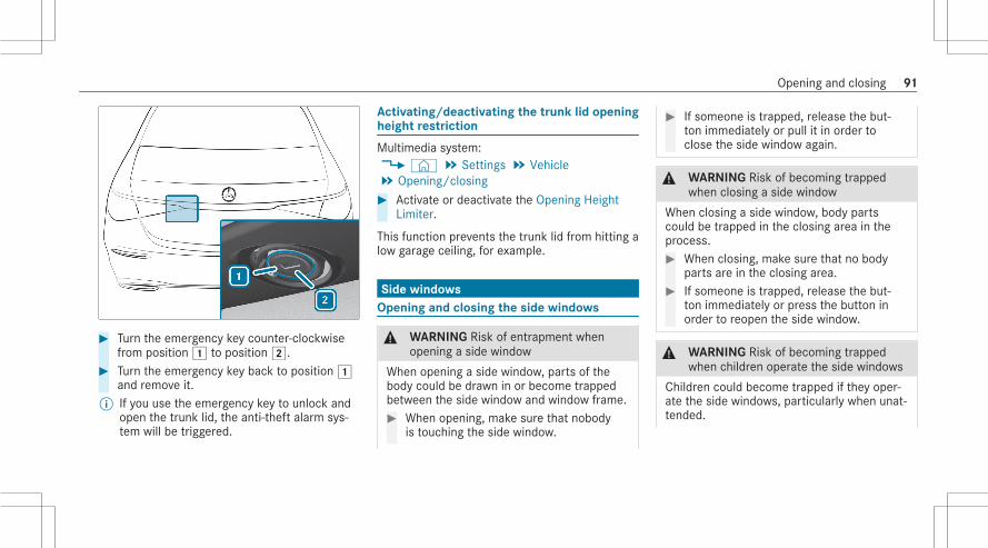
# Turn the emergency key counter-clockwisefrom position1 to position2.
# Turn the emergency key back to position1and remove it.
% If you use the emergency key to unlock andopen the trunk lid, the anti-theft alarm sys‐tem will be triggered.
Activating/deactivating the trunk lid openingheight restriction
Multimedia system:4© 5 Settings 5 Vehicle5 Opening/closing# Activate or deactivate the Opening Height
Limiter.
This function prevents the trunk lid from hitting alow garage ceiling, for example.
Side windowsOpening and closing the side windows
& WARNING Risk of entrapment whenopening a side window
When opening a side window, parts of thebody could be drawn in or become trappedbetween the side window and window frame.# When opening, make sure that nobody
is touching the side window.
# If someone is trapped, release the but‐ton immediately or pull it in order toclose the side window again.
& WARNING Risk of becoming trappedwhen closing a side window
When closing a side window, body partscould be trapped in the closing area in theprocess.# When closing, make sure that no body
parts are in the closing area.# If someone is trapped, release the but‐
ton immediately or press the button inorder to reopen the side window.
& WARNING Risk of becoming trappedwhen children operate the side windows
Children could become trapped if they oper‐ate the side windows, particularly when unat‐tended.
Opening and closing 91

# Activate the child safety lock for therear passenger compartment side win‐dows.
# When leaving the vehicle, always takethe SmartKey with you and lock thevehicle.
# Never leave children unattended in thevehicle.
Requirements:R The power supply or the ignition is switched
on.
1 Closes2 Opens
The buttons on the driver's door take prece‐dence.# To start automatic operation: press the
W button beyond the point of resistanceor pull and release it.
# To interrupt automatic operation: press orpull theW button again.
When the vehicle is switched off, you can con‐tinue to operate the side windows.This function is available for around four minutesor until a front door is opened.% Vehicles with electric roller sunblinds on
rear doors on the left and right: The but‐tons for the rear side windows also open andclose the roller sunblinds (/ page 100).
Automatic reversing function of the side win‐dowsIf an obstacle impedes a side window during theclosing process, the side window will open againautomatically. The automatic reversing functionis only an aid and is not a substitute for yourattentiveness.# During the closing process, make sure that
no body parts are in the closing area.
92 Opening and closing

& WARNING Risk of becoming trappeddespite there being reversing protectionon the side window
The reversing function does not react:R To soft, light and thin objects, e.g. fin‐
gers.R During resetting.
The reversing function cannot prevent some‐one from becoming trapped in these situa‐tions.# During the closing process, make sure
that no body parts are in the closingarea.
# If someone becomes trapped, press theW button to open the side windowagain.
Convenience opening (ventilating the vehiclebefore starting a journey)
& WARNING Risk of entrapment whenopening a side window
When opening a side window, parts of thebody could be drawn in or become trappedbetween the side window and window frame.# When opening, make sure that nobody
is touching the side window.# Release the button immediately if
somebody becomes trapped.
# Press and hold theÜ button on theSmartKey.The following functions are performed:R The vehicle is unlocked.R The side windows are opened.R The panoramic sliding roof is opened.R The seat ventilation of the driver's seat is
switched on.
% If the roller sunblinds of the panoramic slid‐ing sunroof are closed, the roller sunblindsare opened first.
% If the roller sunblinds of the rear doors areclosed, the roller sunblinds are opened first.
# To interrupt convenience opening: releasetheÜ button.
# To continue convenience opening: pressand hold theÜ button again.
Convenience closing (closing the vehiclefrom outside)
& WARNING Risk of entrapment due to notpaying attention during convenienceclosing
When the convenience closing feature isoperating, parts of the body could becometrapped in the closing area of the side win‐dow and the sliding sunroof.# When the convenience closing feature
is operating, monitor the entire closing
Opening and closing 93

process and make sure that no bodyparts are in the closing area.
# Press and hold thes button on theSmartKey.The following functions are performed:R The vehicle is locked.R The side windows are closed.R The panoramic sliding roof is closed.
# To interrupt convenience closing: releasethes button.
# To continue convenience closing: pressand hold thes button again.
% Convenience closing also functions withKEYLESS-GO (/ page 80).
Resolving problems with the side windows
& WARNING Risk of becoming trapped orfatally injured if reversing protection isnot activated
If you close a side window again immediatelyafter it has been blocked, the side windowwill close with increased or maximum force.The reversing function is then not active andbody parts may become trapped.# Make sure that no parts of the body are
in the closing area.# To stop the closing process, release the
button or press the button again toreopen the side window.
A side window cannot be closed and you can‐not see the cause.# Check to see whether any objects are in the
window guide.# Adjust the side windows.
Adjusting the side windows
If a side window is obstructed during closing andreopens again immediately:# Immediately after this, pull and hold the cor‐
responding button again until the side win‐dow has closed and hold the button for atleast one more second (re-adjustment).The side window will be closed without theautomatic reversing function.
If the side window is obstructed again andreopens again immediately:# Immediately after this, pull and hold the cor‐
responding button again until the side win‐dow has closed and hold the button for atleast one more second (follow-up adjust‐ment).The side window will be closed without theautomatic reversing function.
The side windows cannot be opened orclosed using the convenience opening fea‐ture.Possible cause:R The SmartKey battery is weak or discharged.
94 Opening and closing

# Check the battery using the indicator lamp(/ page 75).
# Replace the SmartKey battery, if necessary(/ page 77).
Sliding sunroofOpening and closing the sliding sunroof
% The term "sliding sunroof" refers to the pan‐orama roof with power tilt/sliding panel.
& WARNING Risk of becoming trappedwhen the sliding sunroof is being openedand closed
Body parts may become trapped in the rangeof movement.# During the opening and closing proc‐
ess, make sure that no body parts arein the sweep of the sliding sunroof.
# If someone is trapped, release the con‐trol panel immediately.
or
# Touch the control panel during auto‐matic operation.The opening/closing process will bestopped.
& WARNING Risk of becoming trapped ifthe sliding sunroof is operated by chil‐dren
Children operating the sliding sunroof couldget caught in the moving parts, particularly ifunattended.# Never leave children unattended in the
vehicle.# When leaving the vehicle, always take
the key with you and lock the vehicle.
& WARNING Risk of becoming trappedwhen the roller sunblind is being openedand closed
Body parts may become trapped betweenthe roller sunblind and frame or sliding roof.
# During the opening or closing process,make sure that no body parts are in theroller sunblind's range of movement.
# If someone is trapped, release the con‐trol panel immediately.
or# Touch the control panel during auto‐
matic operation.The opening/closing process will bestopped.
* NOTE Malfunction due to snow and ice
Snow and ice may cause the sliding sunroofto malfunction.# Open the sliding sunroof only if it is free
of snow and ice.
* NOTE Damage caused by protrudingobjects
Objects that protrude from the sliding sun‐roof may damage the sealing strips.
Opening and closing 95

# Do not allow anything to protrude fromthe sliding sunroof.
* NOTE Damage to panorama roof withpower tilt/sliding panel caused by roofluggage rack
If the panorama roof with power tilt/slidingpanel is opened when a roof luggage rack isinstalled, the panorama roof with power tilt/sliding panel may be damaged by the roofluggage rack.# Do not open the panorama roof with
power tilt/sliding panel if a roof luggagerack is installed.
The sliding sunroof and the front roller sunblindare operated using control panel1.The panorama roof with power tilt/sliding panelcan be operated only when the roller sunblind isopen.# To open: swipe backwards across control
panel1 and hold.
# To close: swipe forwards across controlpanel1 and hold.
# To raise or lower: press control panel1briefly.
# To start automatic operation: swipe for‐wards or backwards across control panel1.
# To cancel automatic operation: press con‐trol panel1 again.The opening/closing process will be stop‐ped.
96 Opening and closing

Operating the rear roller sunblind from thefront
# To open or close: press button1.# To stop: press button1 again.
If you stop the opening or closing process, theroller sunblind will first be closed again when theprocess is resumed.
Operating the rear roller sunblind from therear passenger compartment
# To open/close manually: push or pull but‐ton1 to the point of resistance and hold ituntil the roller sunblind has reached thedesired position.
# To open/close fully: push or pull button1beyond the point of resistance and release it.
Automatic reversing function of the slidingsunroofIf an obstacle obstructs the sliding sunroof dur‐ing the closing process, the sliding sunroof willopen again automatically. The automatic revers‐ing function is only an aid and is not a substitutefor your attentiveness.# During the closing process, make sure that
no body parts are in the closing area.
& WARNING Risk of becoming trappeddespite reversing function
The reversing function will not react:R to soft, light and thin objects, e.g. fingers.R towards the end of the closing procedure.R during resetting.R when you close the sliding sunroof again
manually immediately after automaticreversing.
# During the closing process, make surethat no body parts are in the closingarea.
Opening and closing 97

# If someone is trapped, release the con‐trol panel immediately.
or# Touch the control panel during auto‐
matic closing.The closing process will be stopped.
Automatic reversing function of the rollersunblindsIf an obstacle obstructs a roller sunblind duringthe closing process, the roller sunblind will openagain automatically. The automatic reversingfunction is only an aid and is not a substitute foryour attentiveness.# When closing the roller sunblinds, make sure
that no body parts are in the range of move‐ment.
& WARNING Risk of becoming trappeddespite reversing function
In particular, the reversing function does notreact to soft, light and thin objects, e.g. fin‐gers.
# When closing the roller sunblind, makesure that no body parts are in the rangeof movement.
# If someone is trapped, release the con‐trol panel immediately.
or# Touch the control panel during auto‐
matic closing.The closing process will be stopped.
Automatic functions of the sliding sunroof
% The term "sliding sunroof" refers to the pan‐orama roof with power tilt/sliding panel.
Rain closing function when drivingVehicles with a panorama roof with powertilt/sliding panel: If it starts to rain, the raisedsliding sunroof will automatically be loweredwhile the vehicle is in motion.
Automatic lowering functionVehicles with a panorama roof with powertilt/sliding panel: If the sliding sunroof is raisedat the rear, it will automatically be lowered
slightly at higher speeds. At low speeds, it willbe raised again automatically.
& WARNING Risk of becoming trapped byautomatic lowering of the sliding sunroof
At higher speeds, the raised sliding sunroofwill automatically be lowered slightly at therear.# Make sure that nobody reaches into the
sliding sunroof's range of movementwhile the vehicle is in motion.
# If somebody becomes trapped, brieflypush the sliding sunroof button for‐wards or backwards.
Rectifying problems with the sliding sunroof
& WARNING Risk of becoming trapped orfatal injuries when the sliding sunroof isclosed again
If you close the sliding sunroof again immedi‐ately after it has been blocked or reset, the
98 Opening and closing

sliding sunroof closes with increased or max‐imum force.# Make sure that no parts of the body are
in the closing area.# If someone is trapped, release the con‐
trol panel immediately.or# Touch the control panel during auto‐
matic closing.The closing process will be stopped.
The sliding sunroof cannot be closed and youcannot see the cause.% The term "sliding sunroof" refers to the pan‐
orama roof with power tilt/sliding panel.If the sliding sunroof is obstructed during closingand reopens again slightly:# Immediately after automatic reversing, swipe
forwards across the control panel(/ page 95) and hold until the sliding sun‐roof is closed.The sliding sunroof will be closed withincreased force.
If the sliding sunroof is obstructed again andopens again slightly:# Repeat the previous step.
The sliding sunroof will be closed again withincreased force.
The sliding sunroof or the front roller sun‐blind is not operating smoothly.# Reset the sliding sunroof and the roller sun‐
blind.
Resetting the sliding sunroof and the rollersunblind# Repeatedly swipe forwards across the con‐
trol panel (/ page 95) and hold until thesliding sunroof is completely closed.
# Press and hold the control panel for anothersecond.
# Press and hold the control panel until thefront roller sunblind is completely closed.
# Press and hold the control panel for anothersecond.
# Use automatic operation to fully open andthen close the sliding sunroof.
The rear roller sunblind is not operatingsmoothly.# Reset the rear roller sunblind.
Resetting the rear roller sunblind
# Pull and hold button1 repeatedly until therear roller sunblind is fully closed.
# Pull button1 for another second.
Opening and closing 99

# Use automatic operation to fully open andthen close the rear roller sunblind.
Roller sun blindsExtending or retracting the roller sunblindson the rear side windows
The roller sunblinds for the rear side windowscan be operated with the buttons for the sidewindows.
1 Rear left side window/roller sunblind2 Rear right side window/roller sunblind
# To close fully: pull the corresponding buttonwhen the side window is closed or is in theprocess of closing.
# To open fully: press the corresponding but‐ton.
Extending or retracting the rear windowroller sunblind
& WARNING Risk of becoming trappedwhen extending or retracting the rollersunblind
Body parts may become trapped in the rollersunblind's range of movement.# Ensure there are no body parts in the
range of movement.# If someone becomes trapped, briefly
press the button again.The opening or closing process willbriefly be stopped. The roller sunblindwill then return to its starting position.
Extending or retracting from the driver'sseat
* NOTE Damage caused by objects
Objects can cause the roller sunblind to mal‐function.# Do not store objects on the rear shelf.
100 Opening and closing

# Ensure that the roller sunblind canmove freely.
# Press button1.% Depending on the model, button1 is loca‐
ted on the door control panel on the driver'sside.
Extending or retracting from the rearpassenger compartment
* NOTE Damage caused by objects
Objects can cause the roller sunblind to mal‐function.# Do not store objects on the rear shelf.# Ensure that the roller sunblind can
move freely.
# To extend: pull switch1.# To retract: press switch1.
When the child safety lock for the rear side win‐dows is activated, switch1 cannot be oper‐ated.
Opening and closing 101

Anti-theft protectionFunction of the immobilizer
The immobilizer prevents your vehicle from beingstarted without the correct SmartKey.The immobilizer is automatically activated whenthe ignition is switched off and deactivated whenthe ignition is switched on.When leaving the vehicle, always take the Smart‐Key with you and lock the vehicle. Anyone canstart the engine if a valid SmartKey has been leftinside the vehicle.% In the event the engine cannot be started
(yet the vehicle’s battery is charged), thesystem is not operational. Contact anauthorized Mercedes-Benz Center or call1-800-FOR-MERCedes (in the USA) or1-800-387-0100 (in Canada).
ATA (anti-theft alarm system)
Function of the ATA systemIf the ATA system is armed, a visual and audiblealarm is triggered in the following situations:R when a door is openedR when the trunk lid is openedR when the hood is openedR when interior protection is triggered
(/ page 103)R when the tow-away alarm is triggered
(/ page 103)
The ATA system is armed automatically afterapproximately ten seconds in the following situa‐tions:R after locking the vehicle with the SmartKeyR after locking the vehicle using KEYLESS-GO
Indicator lamp1 flashes when the ATA systemis armed.The ATA system is deactivated automatically inthe following situations:R after unlocking the vehicle with the SmartKeyR after unlocking the vehicle using KEYLESS-
GO
102 Opening and closing

R after pressing the start/stop button with theSmartKey in the storage compartment(/ page 188)
% When the Mercedes‑Benz emergency callsystem is active and the alarm stays on formore than 30 seconds, a message is auto‐matically sent to the Customer AssistanceCenter (/ page 315).
% In the case of severe battery discharging,the anti-theft alarm system is automaticallydeactivated to facilitate the next enginestart.
Deactivating the ATA# Press theÜ,s orH button on the
SmartKey.or# Press the start/stop button with the Smart‐
Key in the marked space (/ page 188)
Deactivating the alarm using KEYLESS-GO# With the SmartKey outside the vehicle, touch
the inner surface of the door handle.
Function of the tow-away alarm
% This function may not be available in allcountries.
An audible and visual alarm is triggered if analteration to your vehicle's angle of inclination isdetected while the tow-away alarm is armed.The tow-away alarm is automatically armed afterapproximately 60 seconds:R After locking the vehicle with the SmartKeyR After locking the vehicle using KEYLESS-GO
The tow-away alarm is only armed when the fol‐lowing components are closed:R DoorsR Trunk lid
The tow-away alarm is automatically deactiva‐ted:R After pressing theÜ orH button on
the SmartKeyR After pressing the start/stop button with the
SmartKey in the storage compartment(/ page 188)
R After unlocking the vehicle using KEYLESS-GOR When using HANDS-FREE ACCESS
Information on collision detection on a parkedvehicle (/ page 213).
Arming/disarming the tow-away alarm
Multimedia system:4© 5 Settings 5 Vehicle5 Opening/closing 5 Vehicle Protection# Arm or disarm Tow-away Protection.The tow-away alarm is armed again in the follow‐ing cases:R The vehicle is unlocked again.R A door is opened.R The vehicle is locked again.
Function of the interior motion sensor
% This function may not be available in allcountries.
Opening and closing 103

When the interior motion sensor is activated, avisual and audible alarm is triggered if move‐ment is detected in the vehicle interior.The interior motion sensor is activated automati‐cally after approximately ten seconds:R After locking the vehicle with the SmartKeyR After locking the vehicle using KEYLESS-GO
The interior motion sensor is only activatedwhen the following components are closed:R DoorsR Trunk lid
The interior motion sensor is automatically deac‐tivated:R After pressing theÜ orH button on
the SmartKeyR After pressing the start/stop button with the
SmartKey in the marked space (/ page 188)R After unlocking the vehicle using KEYLESS-
GOR When using HANDS-FREE ACCESS
The following situations can lead to a falsealarm:R Moving objects such as mascots in the vehi‐
cle interiorR When a side window is openR When a panoramic sliding sunroof is open
Activating/deactivating the interior motionsensor
Multimedia system:4© 5 Settings 5 Vehicle5 Opening/closing 5 Vehicle Protection# Activate or deactivate Interior Motion Sen-
sor.The Interior motion sensor is activated again inthe following cases:R The vehicle is unlocked again.R A door is opened.R The vehicle is locked again.
104 Opening and closing

Notes on the correct driver's seat position
& WARNING Risk of accident due toadjusting the vehicle settings while thevehicle is in motion
You could lose control of the vehicle in thefollowing situations in particular:R If you adjust the driver's seat, the head
restraint, the steering wheel or the mirrorwhile the vehicle is in motionR If you fasten your seat belt while the vehi‐
cle is in motion
# Before starting the engine: In particular,adjust the driver's seat, head restraint,steering wheel and mirror, and fastenyour seat belt.
Ensure the following when adjusting steeringwheel1, seat belt2 and driver's seat3:R You are sitting as far away from the driver's
airbag as possible, taking the followingpoints into consideration:R You are sitting in an upright positionR Your thighs are slightly supported by the seat
cushionR Your legs are not fully extended and you can
depress the pedals properlyR The back of your head is supported at eye
level by the center of the head restraint
R You can hold the steering wheel with yourarms slightly bentR You can move your legs freelyR You can see all the displays on the instru‐
ment cluster clearlyR You have a good overview of the traffic con‐
ditionsR Your seat belt sits snugly against your body
and passes across the center of your shoul‐der and across your hips in the pelvic area
SeatsAdjusting the front seat electrically
& WARNING Risk of becoming trapped ifthe seats are adjusted by children
Children could become trapped if they adjustthe seats, particularly when unattended.# When leaving the vehicle, always take
the SmartKey with you and lock thevehicle.
Seats and stowing 105

# Never leave children unattended in thevehicle.
You can adjust the seats when the ignition isswitched off.
& WARNING Risk of becoming trappedwhen adjusting the seat
When you adjust a seat, you or other vehicleoccupants could become trapped, e.g. on theseat guide rail.# When adjusting a seat, make sure that
no one has any part of their body withinthe sweep of the seat.
Observe the safety notes on "Airbags" and "Chil‐dren in the vehicle".
& WARNING Risk of accident due toadjusting the vehicle settings while thevehicle is in motion
You could lose control of the vehicle in thefollowing situations in particular:R If you adjust the driver's seat, the head
restraint, the steering wheel or the mirrorwhile the vehicle is in motionR If you fasten your seat belt while the vehi‐
cle is in motion
# Before starting the engine: In particular,adjust the driver's seat, head restraint,steering wheel and mirror, and fastenyour seat belt.
& WARNING Risk of becoming trapped ifthe seat height is adjusted carelessly
If you adjust the seat height carelessly, youor other vehicle occupants could be trappedand thereby injured.
Children in particular could accidentallypress the electrical seat adjustment buttonsand become trapped.# While moving the seats, make sure that
hands or other body parts do not getunder the lever assembly of the seatadjustment system.
& WARNING Risk of injury due to incor‐rectly adjusted head restraints
If head restraints have not been adjustedcorrectly, there is an increased risk of injuryin the head and neck area, e.g. in the eventof an accident or sudden braking.# Before driving off, make sure for every
vehicle occupant that the center of thehead restraint supports the back of thehead at about eye level.
Adjust the head restraint fore-and-aft position sothat it is as close as possible to the back of yourhead.
106 Seats and stowing

& WARNING Risk of injury or death due toan incorrect seat position
The seat belt does not offer the intendedlevel of protection if you have not moved theseat backrest to an almost vertical position.In particular, you could slip beneath the seat‐belt and become injured.# Adjust the seat properly before begin‐
ning your journey.# Always ensure that the seat backrest is
in an almost vertical position and thatthe shoulder belt is routed across thecenter of your shoulder.
& WARNING Risk of injury due to exces‐sive strain on the grab handle
If you apply your full body weight to the grabhandle or pull it abruptly, the grab handlemay be damaged or become loose from itsanchorage.
# Use the grab handles only to stabilizethe seating position or to assist in get‐ting in and out of the seat.
& WARNING Risk of injury or death due toobjects under the co-driver seat
Objects trapped under the co-driver seat caninterfere with the function of the automaticco-driver airbag shutoff or damage the sys‐tem.# Do not store any objects under the co-
driver seat.# When the co-driver seat is occupied,
make sure that no objects are trappedunder the co-driver seat.
* NOTE Damage to the seats when movingthe seats back
The seats may be damaged by objects whenmoving the seats back.
# When moving the seats back, makesure that there are no objects in thefootwell, under or behind the seats.
The switches for adjusting the seats do notmove. You will therefore receive no direct feed‐back on the switch while pressing the switch.Feedback is provided only by the movement ofthe seat.
Seats and stowing 107

1 Head restraint fore-and-aft position (vehicleswith an EASY ADJUST luxury head restraint)
2 Head restraint height3 Seat height4 Seat cushion inclination5 Seat cushion length6 Seat fore-and-aft position7 Seat backrest inclination
# Save the settings with the memory function(/ page 129).
% The head restraint height will be adjustedautomatically when you adjust the seatheight or the seat fore-and-aft position.
% Vehicles with EASY ADJUST luxury headrestraints: The fore-and-aft position of thehead restraint will be adjusted automaticallywhen you adjust the backrest angle.
Adjusting the front passenger seat electri‐cally from the driver's seat
You can call up the following functions for thefront passenger seat:R Seat adjustmentR Seat heatingR Seat ventilationR Memory function
108 Seats and stowing
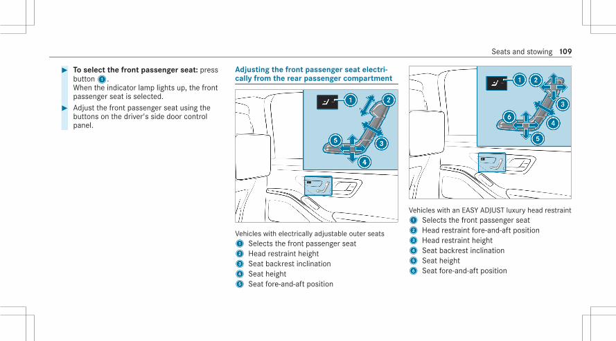
# To select the front passenger seat: pressbutton1.When the indicator lamp lights up, the frontpassenger seat is selected.
# Adjust the front passenger seat using thebuttons on the driver's side door controlpanel.
Adjusting the front passenger seat electri‐cally from the rear passenger compartment
Vehicles with electrically adjustable outer seats1 Selects the front passenger seat2 Head restraint height3 Seat backrest inclination4 Seat height5 Seat fore-and-aft position
Vehicles with an EASY ADJUST luxury head restraint1 Selects the front passenger seat2 Head restraint fore-and-aft position3 Head restraint height4 Seat backrest inclination5 Seat height6 Seat fore-and-aft position
Seats and stowing 109

Vehicles with seat for chauffeur mode and longwheelbase1 Selects the front passenger seat2 Head restraint fore-and-aft position3 Head restraint height4 Seat backrest inclination5 Seat height6 Front passenger seat footrest7 Seat fore-and-aft position
The footrest can be adjusted only when one ofthe following conditions has been fulfilled:R Depending on the equipment, the front
passenger seat is in one of the followingpositions:- Vehicles without leg rest: the front
passenger seat has moved into a randomposition.
- Vehicles with leg rest: the frontpassenger seat has been moved fullyforward.
R The front passenger seat is in the position forchauffeur mode.
# Adjust the rear seat (/ page 110).# Adjust the reclining rear seat (/ page 111).# To select the front passenger seat: press
button1.When the indicator lamp lights up, the frontpassenger seat is selected.
# Adjust the front passenger seat using thebuttons on the door operating unit in the rearpassenger compartment.
% You can use the rear-compartment childsafety lock to disable this function(/ page 73).
Adjusting the rear seats electrically
& WARNING Risk of injury or death due toan incorrect seat position
The seat belt does not offer the intendedlevel of protection if you have not moved theseat backrest to an almost vertical position.In particular, you could slip beneath the seat‐belt and become injured.# Adjust the seat properly before begin‐
ning your journey.# Always ensure that the seat backrest is
in an almost vertical position and thatthe shoulder belt is routed across thecenter of your shoulder.
The switches for adjusting the seats do notmove. You will therefore receive no direct feed‐back on the switch while pressing the switch.
110 Seats and stowing

Feedback is provided only by the movement ofthe seat.You can electrically adjust only the outer seats inthe rear passenger compartment.
1 Fore-and-aft position of the head restraint(vehicles with active multicontour seat)
2 Head restraint height
3 Seat backrest inclination4 Combined seat cushion inclination and
length
# Save the settings with the memory function(/ page 131).
Adjusting the reclining rear seats electrically
The reclining rear seat is available in long-wheel‐base vehicles equipped with "Executive seats".In vehicles without a reclining rear seat, the but‐ton for setting the angle and fore-and-aft posi‐tion of the leg rest has no function.The reclining rear seat is on the front passengerside.
1 Fore-and-aft position of the head restraint(vehicles with active multicontour seat)
2 Head restraint height3 Seat backrest inclination4 Combined seat cushion inclination and
length5 Fore-and-aft position of the leg rest6 Angle of the leg rest
Seats and stowing 111

# Save the settings with the memory function(/ page 131).
% The leg rest will fold down if overloaded. Ifthis is the case, fold up the leg rest andengage it.
% Vehicles with a long wheelbase and theChauffeur/Rear Seat Memory Package alsohave a footrest. This is located on the lowerpart of the front passenger seat backrest(/ page 115).
Setting the fully reclined position
# To set the fully reclined position: pressbutton1.R The rear seat will move into the fully
reclined position.R The front passenger seat will move into
the position for chauffeur mode.
R The footrest will move out from under thefront passenger seat.R If available, the leg rest will rise.
# To restore the standard seat settings:press button1.
% You can use the rear-compartment childsafety lock to disable this function(/ page 73).
112 Seats and stowing

% The leg rest will fold down if overloaded. Ifthis is the case, fold up the leg rest andengage it.
Chauffeur mode
Information on chauffeur mode
& WARNING Risk of injury due to incor‐rectly adjusted head restraints
If head restraints have not been adjustedcorrectly, there is an increased risk of injuryin the head and neck area, e.g. in the eventof an accident or sudden braking.# Before driving off, make sure for every
vehicle occupant that the center of thehead restraint supports the back of thehead at about eye level.
Adjust the head restraint fore-and-aft position sothat it is as close as possible to the back of yourhead.
& WARNING Risk of injury or death due toobjects under the co-driver seat
Objects trapped under the co-driver seat caninterfere with the function of the automaticco-driver airbag shutoff or damage the sys‐tem.# Do not store any objects under the co-
driver seat.# When the co-driver seat is occupied,
make sure that no objects are trappedunder the co-driver seat.
* NOTE Damage to objects in the luggagenet of the front passenger footwell whenadjusting the front passenger seat to thechauffeur position
Objects in the luggage net in the frontpassenger footwell can become damagedwhen the front passenger seat is adjusted tothe chauffeur position.# Remove the objects from the luggage
net.
* NOTE Damage to the seats when movingthe seats back
The seats may be damaged by objects whenmoving the seats back.# When moving the seats back, make
sure that there are no objects in thefootwell, under or behind the seats.
The switches for adjusting the seats do notmove. You will therefore receive no direct feed‐back on the switch while pressing the switch.Feedback is provided only by the movement ofthe seat.Observe the following:R Adjust the front passenger seat for chauffeur
mode before the journey
For chauffeur mode, the following settings aremade for the front passenger seat:R The seat is moved forwardsR The backrest is tilted forwardsR The head restraint is folded forwards
Seats and stowing 113

The front passenger seat will automatically movefrom the chauffeur position back into the normalposition in the following situations:R The front passenger seat is adjusted using
the buttons in the door operating unit on thefront passenger sideR The front passenger seat belt is fastenedR An occupant is detected on the front
passenger seatR The front passenger seat backrest is adjus‐
ted rearwards.R The front passenger seat is moved in the
fore-and-aft direction out of the chauffeurarea
Positioning the front passenger seat forchauffeur mode
Requirements:R The front passenger seat is not occupied.R The front passenger seat belt is not inserted
in the buckle.
1 Selects the front passenger seat2 Sets the seat fore-and-aft position
# To select the front passenger seat: pressbutton1.When the indicator lamp lights up, the frontpassenger seat is selected.
114 Seats and stowing

Setting the chauffeur position# Push button2 forwards and hold it in this
position.The front passenger seat will move forwardand stop at the threshold of the area forchauffeur mode.
# Release button2.# Push button2 forward and hold it again
until the front passenger seat is in the posi‐tion for chauffeur mode.The front passenger seat head restraint willfold forwards. The front passenger seat willmove forward.
% If the front passenger seat is already at thethreshold to the area for chauffeur mode,the position for chauffeur mode will be setimmediately.
# Save the settings with the memory function(/ page 131).
% You can use the rear passenger compart‐ment child safety lock to disable this func‐tion (/ page 73).
Using the footrest on the front passengerseat
Requirements:R Depending on the equipment, the front
passenger seat is in one of the followingpositions:- Vehicles without leg rest: the front
passenger seat has moved into a randomposition.
- Vehicles with leg rest: the frontpassenger seat has been moved fullyforward.
R The front passenger seat is in the position forchauffeur mode.
Using the footrestThe footrest is located on the lower part of thefront passenger seat backrest.
# Push button1 towards the rear.The footrest will move out from under thefront passenger seat.
# Push the extended footrest upwards withyour foot until it releases.
# Allow the footrest to lower.The footrest will position itself on the floor.
Seats and stowing 115

Storing the footrest
# Push the footrest upwards with your footuntil it engages.
# Push button1 forwards.The footrest will retract underneath the frontpassenger seat.
Moving the front passenger seat into thenormal position (chauffeur mode)
# To select the front passenger seat: pressbutton1.When the indicator lamp lights up, the frontpassenger seat is selected.
Setting the normal position# Push button3 towards the rear and hold it
in this position.The front passenger seat will move to thethreshold of the area for chauffeur mode.
116 Seats and stowing
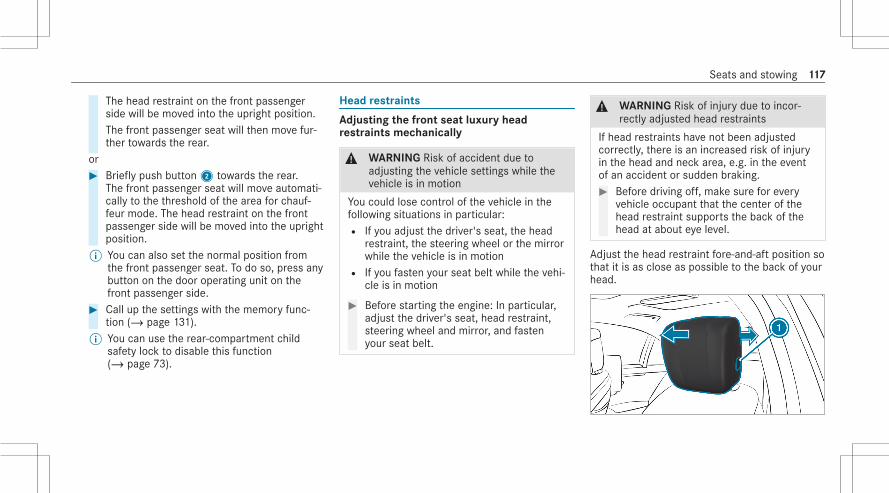
The head restraint on the front passengerside will be moved into the upright position.The front passenger seat will then move fur‐ther towards the rear.
or# Briefly push button2 towards the rear.
The front passenger seat will move automati‐cally to the threshold of the area for chauf‐feur mode. The head restraint on the frontpassenger side will be moved into the uprightposition.
% You can also set the normal position fromthe front passenger seat. To do so, press anybutton on the door operating unit on thefront passenger side.
# Call up the settings with the memory func‐tion (/ page 131).
% You can use the rear-compartment childsafety lock to disable this function(/ page 73).
Head restraints
Adjusting the front seat luxury headrestraints mechanically
& WARNING Risk of accident due toadjusting the vehicle settings while thevehicle is in motion
You could lose control of the vehicle in thefollowing situations in particular:R If you adjust the driver's seat, the head
restraint, the steering wheel or the mirrorwhile the vehicle is in motionR If you fasten your seat belt while the vehi‐
cle is in motion
# Before starting the engine: In particular,adjust the driver's seat, head restraint,steering wheel and mirror, and fastenyour seat belt.
& WARNING Risk of injury due to incor‐rectly adjusted head restraints
If head restraints have not been adjustedcorrectly, there is an increased risk of injuryin the head and neck area, e.g. in the eventof an accident or sudden braking.# Before driving off, make sure for every
vehicle occupant that the center of thehead restraint supports the back of thehead at about eye level.
Adjust the head restraint fore-and-aft position sothat it is as close as possible to the back of yourhead.
Seats and stowing 117

# To move forwards: pull the head restraintforwards.
# To move backwards: press release knob1and push the head restraint backwards.
Attaching and removing the additional cush‐ion of the front-seat luxury head restraint
# Position head restraint2 as far forwards aspossible.
# To attach the additional cushion: open Vel‐cro strip4 on the back of additional cush‐ion1.
# Guide Velcro strip4 between head restraint2 and strip3.
# Close Velcro strip4.# Change the position of the additional
cushion: move additional cushion1 up ordown.
# To remove additional cushion: open Velcrostrip4 of additional cushion1.
# Remove additional cushion1.
Lowering the rear seat head restraints elec‐trically from the front compartmentMultimedia system:4© 5ß 5y
# Pressü.
Adjusting the outer rear seat head restraintsmanually
# To raise: pull the head restraint upwards andlet it engage.
# To lower: press release knob1 in the direc‐tion of the arrow.
# Push the head restraint down and let itengage.
118 Seats and stowing

Adjusting the outer luxury head restraints ofthe rear seats manually
# To adjust the angle of the head restraint:pull or push the head restraint in the direc‐tion of arrow1.
Attaching and removing the additional cush‐ion of the head restraint in the rearpassenger compartment (individual seats)
# Position head restraint2 as far forwards aspossible.
# To attach the additional cushion: open Vel‐cro strip4 on the back of additional cush‐ion1.
# Guide Velcro strip4 between head restraint2 and strip3.
# Close Velcro strip4.# To change the position of the additional
cushion: move additional cushion1 up ordown.
# To remove additional cushion: open Velcrostrip4 of additional cushion1.
# Remove additional cushion1.
Attaching heated additional cushionIn vehicles with electrically adjustable headrestraints, you can heat the additional cushion.# Attach the additional cushion to the head
restraint as described.# Move the head restraint to the very top.
Seats and stowing 119

# Push press-studs2 on the additional stripinto counterpieces1 on the head restraint.
# Move the head restraint to the desiredheight.
# To switch neck heating from the addi‐tional cushion on/off: make sure thatpress-studs2 on the additional strip arecorrectly pushed into counterpieces1 onthe head restraint.
# Ensure that the "Couple neck heat to seatheating" function is active (/ page 121).
# Activate or deactivate the seat heating(/ page 123).
Folding the center head restraint into posi‐tion and folding it back manually
# To fold into position: pull the head restraintupwards until it engages.
# To fold back: press button1.# Fold down the head restraint completely.
The center head restraint has a usage positionand a non-usage position. The usage position isthe upright position in which the head restraintis locked; the non-usage position is the positionin which the head restraint is folded downwards.When the center seat is used, the head restraintmust be in the upright, locked usage position.
120 Seats and stowing

Configuring the seat settings
Multimedia system:4© 5 Comfort 5 Seat
Adjusting the air cushions.# On the corresponding menu, adjust the air
cushions for Lumbar, Shoulders or Side Bol-sters.
Setting the seat heating balance# Select Heating Settings.# Select Seat Heating Balance.# Adjust the heat distribution for the desired
seat.% The seat heating balance can be set in the
Seat Climate Control menu in the rearpassenger compartment.
Coupling neck heat to seat heating# Select Additional Neck Warmer.
# Switch the function for the desired seat on oroff.If the function is active, the neck heat of theadditional cushion has been coupled to theseat heating.
Setting automatic seat adjustment
& WARNING Risk of becoming trappedduring adjustment of the driver's seatafter calling up a driver profile
Selecting a user profile may trigger anadjustment of the driver's seat to the posi‐tion saved under the user profile. You orother vehicle occupants could be injured inthe process.# Make sure that when the position of
driver's seat is being adjusted using themultimedia system, no people or bodyparts are in the seat's range of move‐ment.
If there is a risk of someone becoming trap‐ped, stop the adjustment process immedi‐ately:# a) Tap the warning message on the cen‐
tral display.or# b) Press a memory position button or a
seat adjustment switch on the driver'sdoor.The adjustment process will be stop‐ped.
Multimedia system:4© 5 Comfort 5 Seat5 Automatic Seat Positioning
Adjusting driver's seat and steering wheelposition to body sizeThe vehicle calculates a suitable driver's seatand steering wheel position on the basis of thedriver's body size and sets this directly.# To set the unit of measurement: select cm
or ft/in.
Seats and stowing 121

# Set the size using the scale.# Select Start Positioning.
The driver's seat and steering wheel positionis adjusted to the body size that has beenset.
% If the driver's seat and steering wheel posi‐tion calculated by the vehicle is not practicalor comfortable, it can be manually changedat any time via the control buttons.The exterior mirrors are not set via this func‐tion. Instead, they have to be set manuallyvia the operating switches.
% You can also configure these settings via theMercedes me user account for your userprofile. By synchronizing the profiles in thevehicle and the Mercedes me connect pro‐files, you can carry over these settings foryour vehicle. Further information about syn‐chronizing user profiles .
Setting automatic adjustment of the lateralsupport (active multicontour seat)
Multimedia system:4© 5 Comfort 5 Seat# Select Dynamic Multicontour Seat.
With this function, the lateral support of theactive multicontour seat is automatically adjus‐ted to the driving and cornering dynamics of thevehicle.# Select the desired setting.
Overview of massage programs
R Hot Relaxing Back: Based on hot stone mas‐sage, the program combines heat and mas‐sage. It starts by massaging the back. Inaddition, warm pressure points becomenoticeable, starting in the pelvic area.R Hot Relaxing Shoulders Combination of heat
and massage. It starts by massaging theshoulders. In addition, warm pressure pointsbecome noticeable, starting in the pelvicarea.
R Activating Massage Activating massage withupward-moving massage waves.R Classic Massage Relaxing back massage.R Wave Massage Regenerating massage via
massage waves across the back and in theseat cushion.R Mobilizing Massage Mobilizing Massage with
upward-moving massage waves. Can pro‐mote slower, deeper respiration. This canimprove the supply of oxygen to cells and thebrain.R Workout, Backrest and Workout, Cushion
These programs require your cooperation.Alternating between tensing and releasinghelps to improve blood flow to your muscles.Press against a pressure point as soon asyou feel it to activate back, abdominal andleg muscles.R Deep Waves: Wave-like movements in the
cushion can promote blood flow and meta‐bolic processes in the lower back and legs.R Deep Workout: Connect the Workout, Back-
rest to the Workout, Cushion. The vibratingmassage in the cushion intensifies the effec‐
122 Seats and stowing
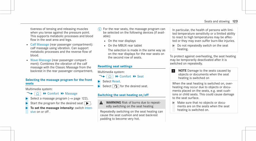
tiveness of tensing and releasing muscleswhen you tense against the pressure point.This supports metabolic processes and bloodflow in the seat area and legs.R Calf Massage (rear passenger compartment):
calf massage using vibration. Can supportmetabolic processes and the reverse flow ofblood.R Wave Massage (rear passenger compart‐
ment): Combines the vibration of the calfmassage with the Classic Massage from thebackrest in the rear passenger compartment.
Selecting the massage program for the frontseats
Multimedia system:4© 5 Comfort 5 Massage# Select a massage program (/ page 122).# Start the program for the desired seat;.# To set the massage intensity: switch Inten-
sive on or off .
% For the rear seats, the massage program canbe selected on the following devices (if avail‐able):R On the rear displaysR On the MBUX rear tablet
The selection is made in the same way ason the rear displays for the rear seats onthe second row of seats.
Resetting seat settings
Multimedia system:4© 5 Comfort 5 Seat# Select Reset.# Selectß for the desired seat.
Switching the seat heating on/off
& WARNING Risk of burns due to repeat‐edly switching on the seat heating
Repeatedly switching on the seat heating cancause the seat cushion and seat backrestpadding to become very hot.
In particular, the health of persons with limi‐ted temperature sensitivity or a limited abilityto react to high temperatures may be affec‐ted or they may even suffer burn-like injuries.# Do not repeatedly switch on the seat
heating.
To protect against overheating, the seat heatingmay be temporarily deactivated after it isswitched on repeatedly.
* NOTE Damage to the seats caused byobjects or documents when the seatheating is switched on
When the seat heating is switched on, over‐heating may occur due to objects or docu‐ments placed on the seats, e.g. seat cush‐ions or child seats. This could cause damageto the seat surface.# Make sure that no objects or docu‐
ments are on the seats when the seatheating is switched on.
Seats and stowing 123

Requirements:R The power supply is switched on.
# Press button1 repeatedly until the desiredheating level is set.Depending on the heating level, up to threeindicator lamps will light up. If all indicatorlamps are off, the seat heating is switchedoff.
% The seat heating will automatically switchdown from the three heating levels after 8,
10 and 20 minutes until the seat heatingswitches off.
% If you switch the power supply off and onagain within 20 minutes, the previous settingof the seat heating for the driver's seat willremain active.
% You can set the distribution of the heatedsections among the seat cushions and seatbackrests on the front and rear seats usingthe multimedia system (/ page 124).
% Vehicles with the Warmth Comfort Package:you can adjust the heating of the center con‐sole and door armrests using the multimediasystem (/ page 124).
Setting the panel heating
Multimedia system:4© 5 Comfort 5 Seat5 Heating Settings 5 Panel HeatingWhen the seat heating is switched on, the armr‐ests, the center panels of the doors and the cen‐ter console can be heated.
124 Seats and stowing

# Switch the function for the desired seats onor off.
Switching the seat ventilation on/off
Requirements:R The power supply is switched on.
# Press button1 repeatedly until the desiredblower setting has been reached.Depending on the blower setting, up to threeindicator lamps will light up. If all indicatorlamps are off, the seat ventilation is switchedoff.
% If you switch the power supply off and onagain within 20 minutes, the previous seat
ventilation setting for the driver's seat willremain active.
Steering wheelAdjusting the steering wheel electrically
& WARNING Risk of accident due toadjusting the vehicle settings while thevehicle is in motion
You could lose control of the vehicle in thefollowing situations in particular:R If you adjust the driver's seat, the head
restraint, the steering wheel or the mirrorwhile the vehicle is in motionR If you fasten your seat belt while the vehi‐
cle is in motion
# Before starting the engine: In particular,adjust the driver's seat, head restraint,steering wheel and mirror, and fastenyour seat belt.
Seats and stowing 125

& WARNING Risk of entrapment for chil‐dren when adjusting the steering wheel
Children could injure themselves if theyadjust the steering wheel.# Never leave children unattended in the
vehicle.# When leaving the vehicle, always take
the SmartKey with you and lock thevehicle.
The steering wheel can be adjusted when thepower supply is disconnected.
1 To move up2 To move back3 To move down4 To move forward
# Save the settings with the memory function(/ page 129).
Switching the steering wheel heater on/off
Requirements:R The power supply or the ignition is switched
on.
# Push the switch into position1 or2.If indicator lamp3 lights up, the steeringwheel heater is switched on.
126 Seats and stowing

When you switch the ignition off, the steeringwheel heater will switch off.
Coupling the steering wheel heater to theseat heating
Requirements:R The power supply or the ignition is switched
on.
Multimedia system:4© 5 Comfort 5 Seat5 Heating Settings# Tap on Additional Steering Wheel Heating.
The steering wheel heater will be coupled tothe seat heating.
When the function has been activated, the steer‐ing wheel heater is automatically activated anddeactivated when you switch the switch the seatheating on and off.
Easy entry and exit featureUsing the easy entry and exit feature
& WARNING Risk of accident when pullingaway during the adjustment process forthe easy exit feature
You could lose control of the vehicle.# Always wait until the adjustment proc‐
ess is complete before pulling away.
& WARNING Risk of becoming trappedduring adjustment of the easy entry andexit feature
You and other vehicle occupants couldbecome trapped.# Ensure that no one has a body part in
the sweep of the seat or steering wheel.# Move the adjustment lever of the steer‐
ing wheel if there is a risk of becomingtrapped by the steering wheel.The adjustment process is stopped.
# If there is a risk of becoming trapped bythe driver's seat, press the seat adjust‐ment switches.The adjustment process is stopped.
You can stop the adjustment process by press‐ing one of the memory function positionswitches.
& WARNING Risk of becoming trapped ifchildren activate the easy entry and exitfeature‑
Children could become trapped if they acti‐vate the easy entry‑ and exit feature, particu‐larly when unattended.# Never leave children unattended in the
vehicle.# When leaving the vehicle, always take
the SmartKey with you and lock thevehicle.
In order to use the easy entry and exit feature,the automatic seat adjustment function musthave been switched on (/ page 121).
Seats and stowing 127

If the easy entry and exit feature is active, thesteering wheel will move upwards and the driv‐er's seat will move back in the following situa‐tions:R You switch the ignition off with the driver's
door openR You open the driver's door with the ignition
switched off
% The steering wheel will then move upwardsonly if it is not already as high as it will go.The driver's seat will then move backwardsonly if it is not already at the rear of the seatadjustment range.
The steering wheel and the driver's seat willmove back to the last drive position in the fol‐lowing cases:R You switch the power supply or the ignition
on when the driver's door is closedR You close the driver's door with the ignition
switched on
The last drive position will be saved when:R You switch the ignition off.
R You call up the seat settings via the memoryfunction.R you save the seat settings via the memory
function.
If you press one of the memory function memoryposition switches, the adjustment process willbe stopped.
Setting the easy entry and exit feature
Requirements:R The automatic seat adjustment has been
activated (/ page 121).
Multimedia system:4© 5 Settings 5 Vehicle 5 Comfort5 Easy Entry And Exit Feature# Select Steering Wheel & Seat, Steering
Wheel Only or Off.% If you are using an individual user profile,
this information is used for the easy entryand exit feature. This will cause the driver'sseat and steering wheel to move into thecorrect position automatically .
Memory functionFunction of the memory function
& WARNING Risk of an accident if thememory function is used while driving
If you use the memory function on the driv‐er's side while driving, you could lose controlof the vehicle as a result of the adjustmentsbeing made.# Only use the memory function on the
driver's side when the vehicle is station‐ary.
& WARNING Risk of entrapment whenadjusting the seat with the memory func‐tion
When the memory function adjusts the seat,you and other vehicle occupants – particu‐larly children – could become trapped.# During the adjusting process of the
memory function, ensure that no body
128 Seats and stowing
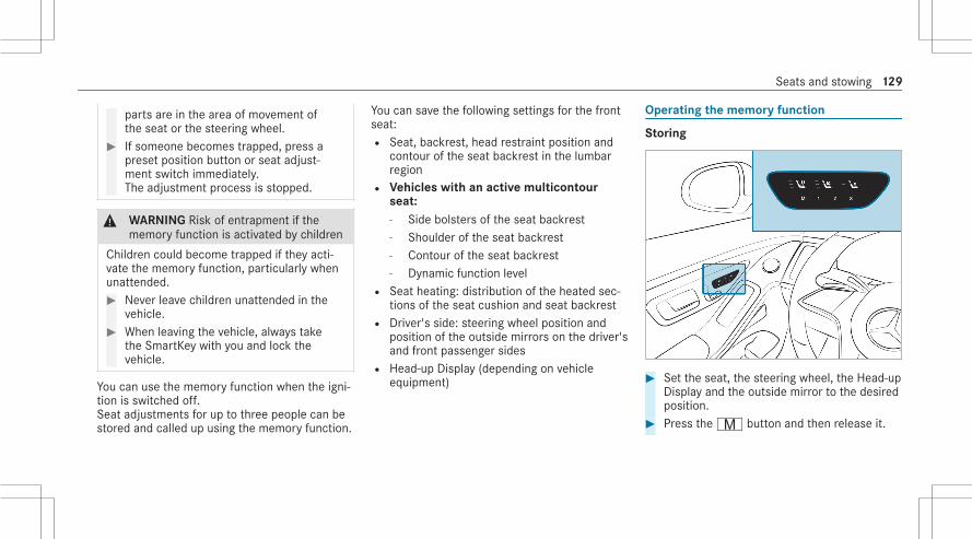
parts are in the area of movement ofthe seat or the steering wheel.
# If someone becomes trapped, press apreset position button or seat adjust‐ment switch immediately.The adjustment process is stopped.
& WARNING Risk of entrapment if thememory function is activated by children
Children could become trapped if they acti‐vate the memory function, particularly whenunattended.# Never leave children unattended in the
vehicle.# When leaving the vehicle, always take
the SmartKey with you and lock thevehicle.
You can use the memory function when the igni‐tion is switched off.Seat adjustments for up to three people can bestored and called up using the memory function.
You can save the following settings for the frontseat:R Seat, backrest, head restraint position and
contour of the seat backrest in the lumbarregionR Vehicles with an active multicontour
seat:- Side bolsters of the seat backrest- Shoulder of the seat backrest- Contour of the seat backrest- Dynamic function levelR Seat heating: distribution of the heated sec‐
tions of the seat cushion and seat backrestR Driver's side: steering wheel position and
position of the outside mirrors on the driver'sand front passenger sidesR Head-up Display (depending on vehicle
equipment)
Operating the memory function
Storing
# Set the seat, the steering wheel, the Head-upDisplay and the outside mirror to the desiredposition.
# Press theV button and then release it.
Seats and stowing 129

# Press one of the preset position buttons4,T orU within three seconds.An acoustic signal sounds. The settings arestored.
# To call up: press the preset position button4,T orU.The seat is moved to the stored position.After releasing the button, the front seat,outside mirror, Head-up Display and steeringcolumn continue to move into the storedposition automatically.
% Driver's seat: to call up a stored positionwhile driving, you must press and hold thepreset position button.
Memory function in the rear passengercompartmentFunction of the memory function in the rearpassenger compartment
Operating the rear seatRear seat settings for up to three people can bestored and called up using the memory functionin the rear compartment.
You can save the following settings for the rearseat:R Position of the seat, backrest and head
restraintR Vehicles with active multicontour seats:
The seat side bolsters of the seat backrest aswell as the contour of the seat backrest inthe lumbar regionR Seat heating: distribution of the heated sec‐
tions of the seat cushion and seat backrest
Operating the front passenger seat and rearseatFront passenger seat adjustments and rear seatadjustments for up to three people can bestored and called up using the memory functionin the rear compartment.You can save the following settings for the frontpassenger seat:R Position of the seat, backrest and head
restraint
You can save the following settings for the rearseat:R Position of the seat, backrest and head
restraintR Vehicles with active multicontour seats:
The seat side bolsters of the seat backrest aswell as the contour of the seat backrest inthe lumbar regionR Seat heating: distribution of the heated sec‐
tions of the seat cushion and seat backrest
The following settings are also stored to a mem‐ory position, if the indicator lamp in thevbutton lights up:R Position of the footrest of the front
passenger seat, if availableR Position of the screen, if available
Using the preset position buttons, you alwaysstore the current setting of each seat.
130 Seats and stowing

Operating the rear seat via the memory func‐tion in the rear passenger compartment
Storing
# Press button1.The rear seat is selected if the indicator lampin the button does not light up.
# Adjust the rear seat using the buttons in thedoor control panel (/ page 110).
Example: vehicles without a reclining rear seat
# Press theV button and then release it.# Vehicles without reclining rear seat: Press
one of the preset position buttons4,T orU within three seconds.The settings are stored.
# Vehicles with reclining rear seat: Pressone of the preset position buttons4 orT within three seconds.The settings are stored.
% Vehicles with reclining rear seat: You can‐not store any settings on thej andabuttons for adjusting the reclined and stand‐ard positions.
Calling up# Press button1.
The rear seat is selected if the indicator lampin the button does not light up.
# Vehicles without reclining rear seat: Presspreset position button4,T orU.The seat is moved to the stored position.After releasing the button, the rear seat isautomatically moved into the stored position.
# Vehicles with reclining rear seat: Pressone of preset position buttons4 orT.The seat is moved to the stored position.After releasing the button, the rear seat isautomatically moved into the stored position.
Seats and stowing 131
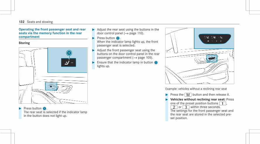
Operating the front passenger seat and rearseats via the memory function in the rearcompartment
Storing
# Press button1.The rear seat is selected if the indicator lampin the button does not light up.
# Adjust the rear seat using the buttons in thedoor control panel (/ page 110).
# Press button1.When the indicator lamp lights up, the frontpassenger seat is selected.
# Adjust the front passenger seat using thebuttons on the door control panel in the rearpassenger compartment (/ page 105).
# Ensure that the indicator lamp in button1lights up.
Example: vehicles without a reclining rear seat
# Press theV button and then release it.# Vehicles without reclining rear seat: Press
one of the preset position buttons4,T orU within three seconds.The settings for the front passenger seat andthe rear seat are stored in the selected pre‐set position.
132 Seats and stowing

# Vehicles with reclining rear seat: Pressone of the preset position buttons4 orT within three seconds.The settings for the front passenger seat andthe rear seat are stored in the selected pre‐set position.
% Vehicles with reclining rear seat: You can‐not store any settings on thej andabuttons for adjusting the reclined and stand‐ard positions.
Calling up# Press button1.
When the indicator lamp lights up, the frontpassenger seat is selected.
# Vehicles without reclining rear seat: Pressone of preset position buttons4,T orU.The seat is moved to the stored position.After releasing the button, the front seat andrear seat are moved automatically into thestored position.
# Vehicles with reclining rear seat: Pressone of preset position buttons4 orT.The seat is moved to the stored position.After releasing the button, the front seat andrear seat are moved automatically into thestored position.
% The preset positions in the area for chauffeurmode can only be set when the conditionsfor chauffeur mode are fulfilled(/ page 113).
% You can use the rear-compartment childsafety lock to disable this function(/ page 73).
Stowage areasNotes on loading the vehicle
& DANGER Risk of exhaust gas poisoning
Combustion engines emit poisonous exhaustgases such as carbon monoxide. Exhaustgases can enter the vehicle interior if thetrunk lid is open when the engine is running,especially if the vehicle is in motion.
# Always switch off the engine beforeopening the trunk lid.
# Never drive with the trunk lid open.
Objects in the deployment area of an airbag mayprevent the airbag from functioning correctly.Observe the notes on protection provided by theairbag (/ page 49).Vehicles with rear airbag: Also observe thenotes on the rear airbag (/ page 56).
& WARNING Risk of injury from unsecureditems in the vehicle
If objects, luggage or loads are not securedor not secured sufficiently, they could slip,tip over or be thrown around and thereby hitvehicle occupants.There is a risk of injury, particularly in theevent of sudden braking or a sudden changein direction.# Always stow objects in such a way that
they cannot be thrown around.
Seats and stowing 133

# Before the journey, secure objects, lug‐gage or loads against slipping or tippingover.
& WARNING Risk of injury due to objectsbeing stowed incorrectly
If objects in the vehicle interior are stowedincorrectly, they can slide or be thrownaround and hit vehicle occupants. In addi‐tion, cup holders, open storage spaces andmobile phone brackets cannot always retainall objects they contain.There is a risk of injury, particularly in theevent of sudden braking or a sudden changein direction.# Always stow objects in such a way that
they cannot be thrown around in suchsituations.
# Always make sure that objects do notprotrude from storage spaces, parcelnets or storage nets.
# Close the lockable storage spacesbefore starting a journey.
# Always stow and secure heavy, hard,pointed, sharp-edged, fragile or bulkyobjects in the trunk.
Observe the notes on the cup holders.Vehicles with automatic front passenger air‐bag shutoff: Objects trapped under the frontpassenger seat may interfere with the functionof the automatic front passenger airbag shutoffor damage the system. Please observe the noteson the function of the automatic front passengerairbag shutoff (/ page 51).
* NOTE Damage to the rear armrest due tobody weight
When folded out, the rear armrest can bedamaged by body weight.# Do not sit or support yourself on the
rear seat armrest.
& WARNING ‑ Risk of accident or injurywhen using the cup holder while thevehicle is moving
The cup holder cannot secure containerswhile the vehicle is moving.If you use a cup holder while the vehicle ismoving, the container may be flung aroundand liquids may be spilled. The vehicle occu‐pants may come into contact with the liquidand if it is hot, they could be scalded. Youcould be distracted from traffic conditionsand you may lose control of the vehicle.# Only use the cup holder when the vehi‐
cle is stationary.# Only use the cup holder for containers
of the right size.# Close the container, particularly if the
liquid is hot.
* NOTE Damage to the cup holder
When the rear armrest is folded back the cupholder could become damaged.
134 Seats and stowing

# Only fold the rear armrest back whenthe cup holder is closed.
* NOTE Damage to the stowage compart‐ment under the ashtray due to intenseheat
The stowage compartment under the ashtrayis not heat resistant and could be damaged ifyou rest a lit cigarette on it.# Make sure that the ashtray is fully
engaged.
& WARNING ‑ Risk of fire and injury fromhot cigarette lighter
You can burn yourself if you touch the hotheating element or the socket of the ciga‐rette lighter.In addition, flammable materials may igniteif:R you drop the hot cigarette lighterR a child holds the hot cigarette lighter to
objects, for example
# Always hold the cigarette lighter by theknob.
# Always make sure that the cigarettelighter is out of reach of children.
# Never leave children unattended in thevehicle.
& WARNING Risk of burns from the tail‐pipe and tailpipe trims
The exhaust tailpipe and tailpipe trims canbecome very hot. If you come into contactwith these parts of the vehicle, you couldburn yourself.# Always be particularly careful around
the tailpipe and the tailpipe trims andsupervise children especially closely inthis area.
# Allow vehicle parts to cool down beforetouching them.
The driving characteristics of your vehicle aredependent on the distribution of the load withinthe vehicle. You should bear the following inmind when loading the vehicle:R Never exceed the permissible gross mass or
the gross axle weight rating for the vehicle(including occupants). The values are speci‐fied on the vehicle identification plate on thevehicle's B-pillar.R The load must not protrude above the upper
edge of the seat backrests.R Always place the load behind unoccupied
seats if possible.R Secure the load using the parcel net hooks.
Distribute the load on the parcel net hooksevenly.
Stowage spaces in the vehicle interior
Overview of the front storage compartments
Seats and stowing 135
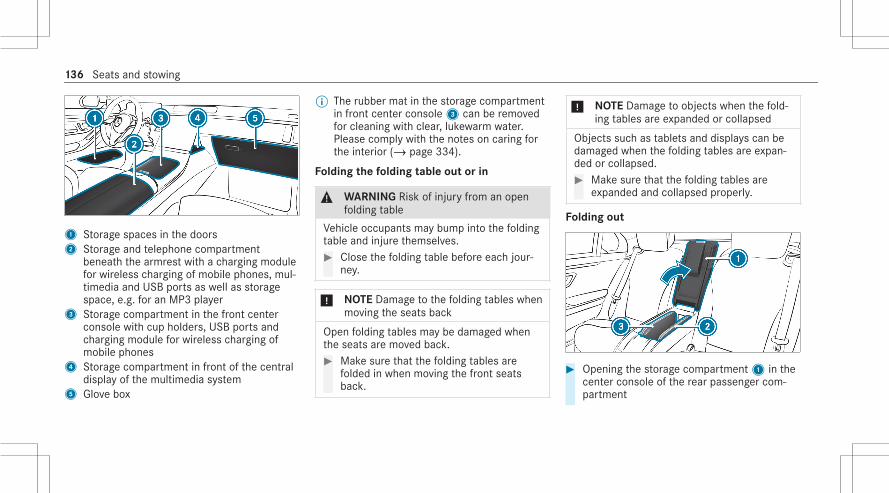
1 Storage spaces in the doors2 Storage and telephone compartment
beneath the armrest with a charging modulefor wireless charging of mobile phones, mul‐timedia and USB ports as well as storagespace, e.g. for an MP3 player
3 Storage compartment in the front centerconsole with cup holders, USB ports andcharging module for wireless charging ofmobile phones
4 Storage compartment in front of the centraldisplay of the multimedia system
5 Glove box
% The rubber mat in the storage compartmentin front center console3 can be removedfor cleaning with clear, lukewarm water.Please comply with the notes on caring forthe interior (/ page 334).
Folding the folding table out or in
& WARNING Risk of injury from an openfolding table
Vehicle occupants may bump into the foldingtable and injure themselves.# Close the folding table before each jour‐
ney.
* NOTE Damage to the folding tables whenmoving the seats back
Open folding tables may be damaged whenthe seats are moved back.# Make sure that the folding tables are
folded in when moving the front seatsback.
* NOTE Damage to objects when the fold‐ing tables are expanded or collapsed
Objects such as tablets and displays can bedamaged when the folding tables are expan‐ded or collapsed.# Make sure that the folding tables are
expanded and collapsed properly.
Folding out
# Opening the storage compartment1 in thecenter console of the rear passenger com‐partment
136 Seats and stowing

# Pull folding table2 up and forwards by han‐dle recess3 and swing it outwards.
# Fold the table panels apart.% The table panels can be rotated forwards or
backwards to bring them into a comfortableposition for the vehicle occupants in the rearpassenger compartment.
# To fold in: fold the table panels together andswing in the folding table.
Removing the handset from the rear storagecompartment
Vehicles with electrically adjustable outer rearseats
# Fold down the rear armrest.# Open the storage compartment in the rear
armrest .# Tap handset1.
Handset1 will rise.# Remove handset1.
Vehicles with individual rear seats
# Open the storage box in the rear-compart‐ment backrest.
# Press button1.# Remove the handset.
Overview of the parcel net hooks
Observe the following notes:R Secure the load using the parcel net hooks.R Do not use elastic straps or nets to secure a
load. These are intended only as anti-slip pro‐tection for light loads.R Do not route tie downs across sharp edges
or corners.R Pad sharp edges for protection.
Depending on the equipment installed, the trunkcontains up to four parcel net hooks.
Seats and stowing 137

1 Parcel net hooks
Opening the through-loading feature in therear passenger compartment
Requirements:R The loading flap is unlocked (/ page 139).
Vehicles with individual rear seats Vehicles with electrically adjustable outer rearseats
# Vehicles with electrically adjustableouter seats: Fold down the rear armrest.
# Pull handle1 and fold down cover2.The storage box in the rear-compartmentbackrest will be opened.
138 Seats and stowing

Vehicles with individual rear seats Vehicles with electrically adjustable outer rearseats
# Slide release catch2 in the handle recessof loading flap1 upwards.Loading flap1 will be unlocked.
# Push loading flap1 with release catch2up as far back as possible until the flap locksin the highest position.The through-loading feature in the rearpassenger compartment will be opened.
If the through-loading feature is to be used as astorage compartment again:# Fold down loading flap1 and lock it in the
trunk (/ page 139).
Locking the through-loading feature in thetrunk
Requirements:R The refrigerator box is removed.
Seats and stowing 139

# Slide the release catch on loading flap1 inthe trunk to the right.The loading flap is locked.
Using the bag hooks
& WARNING Risk of injury when using baghooks with heavy objects
The bag hooks cannot restrain heavy objectsor items of luggage.Objects or items of luggage may be flungaround and hit vehicle occupants.# Only hang light objects on the bag
hooks.# Never hang hard, sharp-edged or fragile
objects on the bag hooks.# Pull bag hook2 down by tab1.% Observe the notes on loading the vehicle
(/ page 133).
EASY-PACK trunk box
Adjusting the height of the EASY-PACK trunkbox to any position
& WARNING Risk of becoming trappedand injured when raising the floor
Your hands may become trapped on theframe of the EASY-PACK trunk box andobjects may be thrown upwards.# Ensure that your hands are not in the
range of movement of the floor.# If someone becomes trapped, carefully
push the center of the floor downward.# Remove all objects from the floor
before raising it.
& WARNING Risk of becoming trappedwhen pressing the EASY-PACK trunk boxin
Your hands may become trapped when youare pressing the trunk box into the retractedposition. Children, in particular, may injurethemselves when doing so.
140 Seats and stowing

# Ensure that your hands are not in therange of movement of the EASY-PACKtrunk box.
# When leaving the vehicle, always takethe SmartKey with you and lock thevehicle.
# Never leave children unattended in thevehicle.
* NOTE Damage to the extended EASY-PACK trunk box
The EASY-PACK trunk box may be damagedwhen it is extended.# Do not place any objects on or press
down on the EASY-PACK trunk boxframe.
# Do not close the trunk lid when theEASY-PACK trunk box is extended.
* NOTE Damage to the EASY-PACK trunkbox by objects
Objects that are sharp-edged, pointed, frag‐ile, rounded or heavy and objects that rollcan damage the EASY-PACK trunk box and bethrown out.# Do not transport objects that are sharp-
edged, pointed, rounded or fragile andobjects that roll in the EASY-PACK trunkbox.
# Always stow and secure such objectsoutside of the box in the trunk.
# Always observe the maximum permittedload of the EASY-PACK trunk box.
# Do not use the EASY-PACK trunk boxwhen the rear seats are folded for‐wards.
The maximum permitted load of the EASY-PACKtrunk box is 22 lbs (10 kg). To prevent the boxfrom being overloaded, the box floor will loweronto the trunk floor when the load reachesapproximately 11 lbs (5 kg).
# To remove: pull handle2 on the box.# To increase the load capacity: push the
center of floor1 downwards to the desiredposition and box size.
# To reduce the load capacity: press button3.
# To store: push the box in completely usinghandle2 until it locks in place.
Seats and stowing 141

% Observe the notes on cleaning the EASY-PACK trunk box (/ page 334).
Installing and removing the EASY-PACK trunkbox
Installing
# Turn rotating catches6 outward.# Insert retainers3 of box1 into holes2.# Raise box1 in the direction of the arrow
and press hooks5 into the anchorages ofrear shelf4.
# Turn rotating catches6 inward.
Removing
# Turn rotating catches6 outward.# Lower box1 in the direction of the arrow
and pull it out of the anchorages on the rearshelf.
# Pull box1 back out of the openings in thedirection of the arrow.
142 Seats and stowing

Attaching a roof luggage rack
& WARNING Risk of accident due toexceeding the maximum roof load
The vehicle center of gravity and the usualdriving characteristics as well as the steeringand braking characteristics alter.If you exceed the maximum roof load, thedriving characteristics, as well as steeringand braking, will be greatly impaired.# Never exceed the maximum roof load
and adjust your driving style.
You will find information on the maximum roofload in the "Technical data" section.
* NOTE Vehicle damage from non-approved roof luggage racks
The vehicle could be damaged by roof lug‐gage racks that have not been tested andapproved by Mercedes-Benz.# Only use roof luggage racks tested and
approved for Mercedes-Benz.
# Depending on the vehicle equipment,ensure that when the roof luggage rackis installed, the trunk lid can be fullyopened.
# Position the load on the roof luggagerack in such a way that the vehicle willnot sustain damage even when it is inmotion.
* NOTE Damage to panorama roof withpower tilt/sliding panel caused by roofluggage rack
If the panorama roof with power tilt/slidingpanel is opened when a roof luggage rack isinstalled, the panorama roof with power tilt/sliding panel may be damaged by the roofluggage rack.# Do not open the panorama roof with
power tilt/sliding panel if a roof luggagerack is installed.
* NOTE Damage to the covers
The covers may be damaged and scratchedwhen being opened.# Do not use metallic or hard objects.
# Carefully fold covers1 upwards in thedirection of the arrow.
Seats and stowing 143
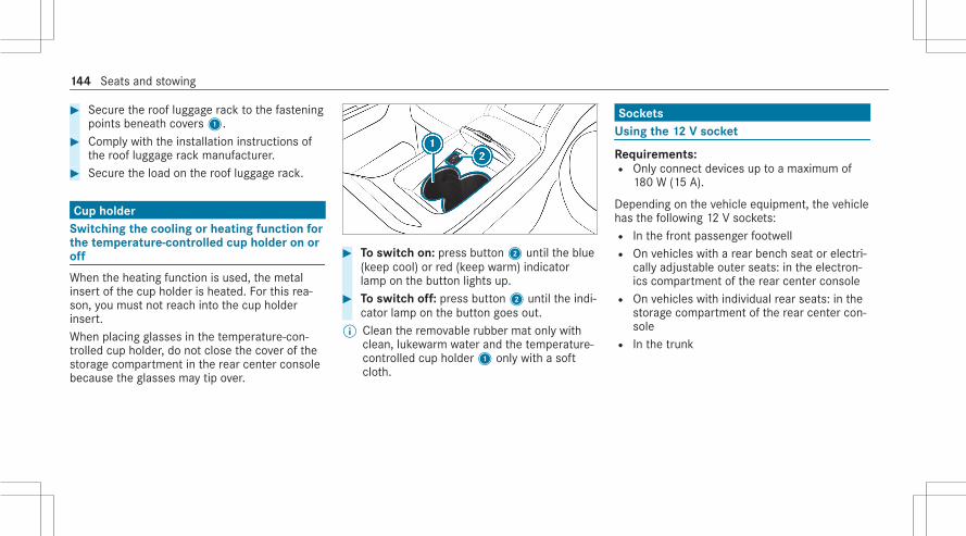
# Secure the roof luggage rack to the fasteningpoints beneath covers1.
# Comply with the installation instructions ofthe roof luggage rack manufacturer.
# Secure the load on the roof luggage rack.
Cup holderSwitching the cooling or heating function forthe temperature-controlled cup holder on oroff
When the heating function is used, the metalinsert of the cup holder is heated. For this rea‐son, you must not reach into the cup holderinsert.When placing glasses in the temperature-con‐trolled cup holder, do not close the cover of thestorage compartment in the rear center consolebecause the glasses may tip over.
# To switch on: press button2 until the blue(keep cool) or red (keep warm) indicatorlamp on the button lights up.
# To switch off: press button2 until the indi‐cator lamp on the button goes out.
% Clean the removable rubber mat only withclean, lukewarm water and the temperature-controlled cup holder1 only with a softcloth.
SocketsUsing the 12 V socket
Requirements:R Only connect devices up to a maximum of
180 W (15 A).
Depending on the vehicle equipment, the vehiclehas the following 12 V sockets:R In the front passenger footwellR On vehicles with a rear bench seat or electri‐
cally adjustable outer seats: in the electron‐ics compartment of the rear center consoleR On vehicles with individual rear seats: in the
storage compartment of the rear center con‐soleR In the trunk
144 Seats and stowing

Example: 12 V socket in the rear center con‐sole
# Fold up socket cap1.# Insert the plug of the device.
If you have connected a device to the 12 Vsocket, leave the cover of the storage compart‐ment open.
Using the 115 V socket in the rear passengercompartment
& DANGER Risk of fatal injury due to dam‐aged connecting cables or sockets
You could receive an electric shock if theconnecting cable or the 115 V power socketis pulled out of the trim or is damaged orwet.# Use only connecting cables that are dry
and free of damage.# When the ignition is switched off, make
sure that the 115 V power socket is dry.# Immediately have the 115 V power
socket checked or replaced at a quali‐fied specialized workshop if it is dam‐aged or has been pulled out of the trim.
# Never plug the connecting cable into a115 V power socket that is damaged orhas been pulled out of the trim.
& DANGER Risk of fatal injury due to incor‐rect handling of the socket
You could receive an electric shock in partic‐ular:R If you reach into the socket.R If you insert unsuitable devices or objects
into the socket.
# Do not reach into the socket.# Only connect suitable devices to the
socket.
Requirements:R Only connect devices with a suitable plug
which conforms to the standards specific tothe country you are in.R Do not use multiple socket outlets.
% Only devices up to a maximum of 150 watts(1.3 A) can be connected.
Seats and stowing 145

Vehicles with a rear bench seat or electricallyadjustable outer seats in the rear passenger com‐partment
Vehicles with individual rear seats
# Vehicles with a rear bench seat or electri‐cally adjustable outer seats: Open theelectronics compartment in the rear centerconsole.
# Vehicles with individual rear seats: Openthe storage compartment in the rear centerconsole.
# Open flap3.# Insert the plug of the device into 115 V
socket2.When the on-board electrical system voltageis sufficient, indicator lamp1 lights up.
USB port in the rear passenger compartment
Depending on the vehicle equipment, the vehiclehas the following USB ports in the rearpassenger compartment:R On vehicles with individual rear seats: in the
storage compartment of the rear passengercompartment center console .R On vehicles with a rear bench seat or electri‐
cally adjustable outer rear seats: in the elec‐tronics compartment in the rear passengercompartment center console .R On vehicles with a rear bench seat or electri‐
cally adjustable outer rear seats: in the stor‐age compartment in the rear armrest .
% These USB ports in the rear passenger com‐partment can be used to charge a mobileend device.
146 Seats and stowing

You can charge a USB device, such as a mobilephone, at the USB ports using a suitable charg‐ing cable. Depending on the vehicle equipment,the devices can be charged with up to 20 V (5 A)when the ignition is switched on.
Refrigerator boxUsing the refrigerator box
& WARNING Risk of fire due to a coveredvent grille on the refrigerator box
If you cover the vent grille for the refrigeratorbox, it may overheat.# Always make sure that the vent grille is
not covered.
The vent grille for the refrigerator box is in thetrunk.The refrigerator box can bear a maximum load of7.7 lb (3.5 kg).The upper compartment of the refrigerator boxcan accommodate, for example, plastic bottleswith a maximum capacity of 17 fl. oz. (0.5 liters)
and cans with a capacity of up to 11 fl. oz.(0.33 liters)If you do not need to use the refrigerator box foran extended period, you should switch it off,defrost it and clean it. After doing so, leave thelid open for a time.The refrigerator box will reduce its cooling capa‐city or switch off in the following cases:R Too many electrical consumers are turned
on.R The starter battery is not sufficiently
charged.
If this is the case, the indicator lamps will flashon the button for switching the refrigerator boxon and off. The cooling function will automati‐cally switch back on as soon as there is suffi‐cient voltage.
Example: vehicles with individual rear seats
# Vehicles with electrically adjustable outerseats: fold down the rear armrest.
# Pull handle1 on the storage box and folddown cover2 of the storage box.
Seats and stowing 147

Example: vehicles with individual rear seats
# To open: pull the handle on refrigerator box1 and fold down the cover of the refrigera‐tor box.
# To switch on: press button2 repeatedlyuntil an indicator lamp (low cooling) lights upor two indicator lamps (high cooling) light up.
# To switch off: press button2 repeatedlyuntil both indicator lamps go out.
Removing or installing the refrigerator box
Installing
# Remove cover cap1.
# Open loading flap2 in the rear passengercompartment until the loading flap locks inthe highest position (/ page 138).
# Pull upwards and hold handle7.The connection to refrigerator box4 isunlocked.
148 Seats and stowing

# Slide the refrigerator box with handle7 upinto the open through-loading feature.Connection4 and the electrical contacts ofrefrigerator box3 are inserted into sockets5 and6 of the through-loading feature.
# Once the refrigerator box has been connec‐ted in the vehicle, push down handle7.The refrigerator box is locked.
Removing# Pull up and hold handle7.# Pull the refrigerator box with handle7 up
out of sockets5 and6 of the though-load‐ing compartment.Connection4 and the electrical contacts ofrefrigerator box3 are separated from sock‐ets5 and6 of the through-loading fea‐ture.
Opening and closing the stowage compart‐ment of the refrigerator box in the trunk
# To open: pull the stowage compartment inrefrigerator box1 out by the handle back‐wards in the direction of the arrow.Stowage compartment1 is open.
# To close: slide the stowage compartment inrefrigerator box1 forwards in the directionof the arrow.Stowage compartment1 is closed.
Wireless charging of the mobile phone andconnection with the exterior antennaNotes on wirelessly charging the mobilephone
& WARNING Risk of injury due to objectsbeing stowed incorrectly
If objects in the vehicle interior are stowedincorrectly, they can slide or be thrownaround and hit vehicle occupants. In addi‐tion, cup holders, open stowage spaces andmobile phone receptacles cannot alwaysretain all objects within.There is a risk of injury, particularly in theevent of sudden braking or a sudden changein direction.# Always stow objects so that they can‐
not be thrown around in such situa‐tions.
# Always make sure that objects do notprotrude from stowage spaces, parcelnets or stowage nets.
Seats and stowing 149

# Close the lockable stowage spacesbefore starting a journey.
# Always stow and secure heavy, hard,pointed, sharp-edged, fragile or bulkyobjects in the trunk/cargo compart‐ment.
Observe the notes on loading the vehicle.
& WARNING Risk of fire from placingobjects in the mobile phone storagecompartment
Placing other objects in the mobile phonestorage compartment could constitute a firehazard.# Apart from a mobile phone, do not
place any other objects in the mobilephone storage compartment, especiallythose made of metal.
* NOTE Damage to objects caused byplacing them in the mobile phone stor‐age compartment
If objects are placed in the mobile phonestorage compartment, they may be damagedby electromagnetic fields.# Do not place credit cards, data storage
devices, ski passes or other objectssensitive to electromagnetic fields inthe mobile phone storage compart‐ment.
* NOTE Damage to the mobile phonestowage compartment caused by liquids
If liquids enter the mobile phone stowagecompartment, the compartment may bedamaged.# Ensure that no liquids enter the mobile
phone stowage compartment.
Always observe the notes for persons with elec‐tronic medical aids (/ page 33).
R Depending on the vehicle equipment, themobile phone is connected to the vehicle'sexterior antenna via the charging module.R The charging function and wireless connec‐
tion of the mobile phone to the vehicle'sexterior antenna are only available if the igni‐tion is switched on.R Small mobile phones may not be able to be
charged in every position of the mobilephone storage compartment.R Large mobile phones which do not rest flat in
the mobile phone storage compartment maynot be able to be charged or connected withthe vehicle's exterior antenna.R The mobile phone may heat up during the
charging process. This may also depend onthe applications (apps) currently open in thebackground.R To ensure more efficient charging and con‐
nection with the vehicle's exterior antenna,remove the protective cover from the mobilephone. Protective covers which are neces‐sary for wireless charging are an exception.
150 Seats and stowing

Wirelessly charging a mobile phone in thefront
Requirements:R The mobile phone is suitable for wireless
charging.A list of compatible mobile phones can befound at: https://www.mercedes-benz-mobile.com/
Depending on the vehicle's equipment, the vehi‐cle has the following options for wirelesslycharging the mobile phone in the cockpit:R In the front storage compartmentR In the storage compartment of the cockpit
armrest
Example: wirelessly charging the mobile phone inthe front storage compartment
# Place the mobile phone as close to the cen‐ter of mat1 as possible with the displayfacing upwards.
Wirelessly charging a mobile phone in thefront storage compartment: when a messageis shown in the multimedia system, the mobilephone is being charged. In addition, malfunc‐tions during the mobile phone's charging proc‐ess are shown in the multimedia system display.Wirelessly charging the mobile phone in thecenter console below the armrest: the mobilephone is charging when the indicator lamp is lit
up. In addition, malfunctions during the mobilephone's charging process are shown by the indi‐cator lamp flashing three times.% The mat can be removed for cleaning, e.g.
using clean, lukewarm water.
Wirelessly charging a mobile phone in therear passenger compartment
Requirements:R The mobile phone is suitable for wireless
charging.A list of compatible mobile phones can befound at: https://www.mercedes-benz-mobile.com/
Seats and stowing 151

Example: vehicles with individual rear seats
# Open the storage compartment in the rearcenter console.
# Place the mobile phone as close to the cen‐ter of mat1 as possible with the displayfacing upwards.When the indicator lamp at the front of themobile phone system lights up, the mobilephone is being charged. In addition, malfunc‐tions during the mobile phone's chargingprocess are shown by the indicator lampflashing three times.
% The mat can be removed for cleaning, e.g.using clean, lukewarm water.
% Observe the notes on loading the vehicle(/ page 133).
Installing and removing the floor mats
& WARNING Risk of accident due toobjects in the driver's footwell
Objects in the driver's footwell may impedepedal travel or block a depressed pedal.This jeopardizes the operating and roadsafety of the vehicle.# Stow all objects in the vehicle securely
so that they cannot get into the driver'sfootwell.
# Always install the floor mats securelyand as prescribed in order to ensurethat there is always sufficient room forthe pedals.
# Do not use loose floor mats and do notplace floor mats on top of one another.
Installing floor mats
# Slide the corresponding seat backwards andlay the floor mat in the footwell such that itfits.
# Press studs1 onto holders2.# Adjust the corresponding seat.
152 Seats and stowing

Removing floor mats# Slide the corresponding seat backwards and
pull the floor mat off holders2.# Adjust the corresponding seat.
Seats and stowing 153

Exterior lightingInformation about lighting systems and yourresponsibility
The various lighting systems of the vehicle areonly aids. The driver of the vehicle is responsiblefor correct vehicle illumination in accordancewith the prevailing light and visibility conditions,legal requirements and traffic situation.
Light switch
Operating light switches
1 W Left-hand standing lamps2 X Right-hand standing lamps3 T Parking lamps and license plate lamp4 Ã Automatic driving lights (preferred light
switch position)
5 L Low beam/high beam6 R Switches the rear fog lamp on or off
When low beam is activated, the T indicatorlamp for the parking lamps will be deactivatedand replaced by the L low-beam indicatorlamp.# Always park your vehicle safely using suffi‐
cient lighting, in accordance with the rele‐vant legal stipulations.
* NOTE Battery discharging by operatingthe standing lights
Operating the standing lights over a period ofhours puts a strain on the battery.# Where possible, switch on the
right X or left W parking light.
If the battery is insufficiently charged, the stand‐ing lamps or parking lamps will be switched offautomatically to facilitate the next engine start.
154 Light and visibility
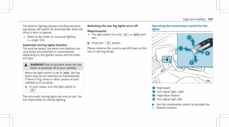
The exterior lighting (except standing and park‐ing lamps) will switch off automatically when thedriver's door is opened.R Observe the notes on surround lighting
(/ page 164).
Automatic driving lights functionThe parking lamps, low beam and daytime run‐ning lamps are switched on automaticallydepending on the ignition status and the ambi‐ent light.
& WARNING Risk of accident when the lowbeam is switched off in poor visibility
When the light switch is set toÃ, the lowbeam may not be switched on automaticallyif there is fog, snow or other causes of poorvisibility such as spray.# In such cases, turn the light switch to
L.
The automatic driving lights are only an aid. Youare responsible for vehicle lighting.
Switching the rear fog lights on or off
Requirements:R The light switch is in the L orà posi‐
tion.
# Press the R button.
Please observe the country-specific laws on theuse of rear fog lamps.
Operating the combination switch for thelights
1 High beam2 Turn signal light, right3 High-beam flasher4 Turn signal light, left
# Use the combination switch to activate thedesired function.
Light and visibility 155

Switching on high beam# Turn the light switch to the L orÃ
position.# Push the combination switch in the direction
of arrow1.When the high beam is activated, the Lindicator lamp for low beam will be deactiva‐ted and replaced by the K indicator lampfor high beam.
Switching off high beam# Push the combination switch in the direction
of arrow1 or pull it in the direction of arrow3.
High-beam flasher# Pull the combination switch in the direction
of arrow3.
Turn signal light# To indicate briefly: push the combination
switch briefly to the point of resistance in thedirection of arrow2 or4.The corresponding turn signal light will flashthree times.
# To indicate permanently: push the combi‐nation switch beyond the point of resistancein the direction of arrow2 or4.Vehicles with Active Lane Change Assist:R A turn signal indicator activated by the
driver may continue to operate for theduration of the lane change.R If the driver indicated directly beforehand
but a lane change was not immediatelypossible, the turn signal indicator mayactivate automatically.
Activating/deactivating the hazard warninglights
# Press button1.The hazard warning lights will switch on auto‐matically if:R The airbag has been deployed.
156 Light and visibility

Adaptive functions MULTIBEAM LED and DIG‐ITAL LIGHT
Intelligent Light System functionIn this system, the headlamps adapt to the driv‐ing and weather situation. It also provides exten‐ded functions for improved illumination of theroad.% The availability of the functions is dependent
on the country.The system comprises the following functions:R Active headlamps (/ page 157)R Cornering light (/ page 157)R Highway mode (/ page 158)R Enhanced fog light function (/ page 158)R Bad weather light (/ page 158)R City lighting (/ page 158)R Topographical compensation (vehicles with
DIGITAL LIGHT) (/ page 158)
The system is active only when it is dark.
Active headlamps function
Functions of the active headlamps:R The headlamps follow the steering move‐
ments.R Relevant areas are better illuminated during
a journey.
The functions are active when the low beam isswitched on.Depending on the vehicle's equipment, thecourse of the lane in which you are driving willalso be evaluated and the active headlampsfunction will adjust the light in advance.
Cornering light function
The cornering light improves the illumination ofthe road over a wide angle in the turning direc‐tion, enabling better visibility on tight curves, forexample. It can be activated only when the lowbeam is switched on.The function is active in the following cases:R At speeds below 25 mph (40 km/h) when
the turn signal light is switched on or thesteering wheel is turnedR At speeds between 25 mph (40 km/h) and
43 mph (70 km/h) and when the steeringwheel is turned
Light and visibility 157

Roundabout and intersection function: thecornering light will be activated on both sidesbased on an evaluation of the vehicle's currentnavigation position. It will remain active untilafter the vehicle has left the roundabout or theintersection.
Highway mode function (Canada)Highway mode increases the range and bright‐ness of the cone of light, enabling better visibil‐ity.
The function is active if a freeway journey isdetected by means of:R The vehicle's speed
R The multifunction cameraR Or the navigation system
The function is not active in the following cases:R At speeds below 50 mph (80 km/h)
Enhanced fog light function (Canada)The enhanced fog light function reduces reflec‐tions and improves the illumination of the edgeof the road.
The function is automatically activated under thefollowing conditions:R At speeds below 43 mph (70 km/h) and
when the rear fog light is switched on.
The function is automatically deactivated underthe following conditions:R At speeds above 62 mph (100 km/h) after
activation.R When the rear fog light is switched off.
Function of the bad weather light (Canada)The bad weather light reduces reflections inrainy conditions by dimming individual LEDs inthe headlamps. The driver and other road usersare blinded less as a result.
The city lighting function (Canada)City lighting improves the illumination of road‐sides in urban areas using a broad distribution oflight.The function is active in the following cases:R At low speedsR In illuminated parts of urban areas
Function of the topographical compensationBased on map data, the lighting systemresponds pre-emptively to different road heights.This means that the headlamp range remains vir‐
158 Light and visibility
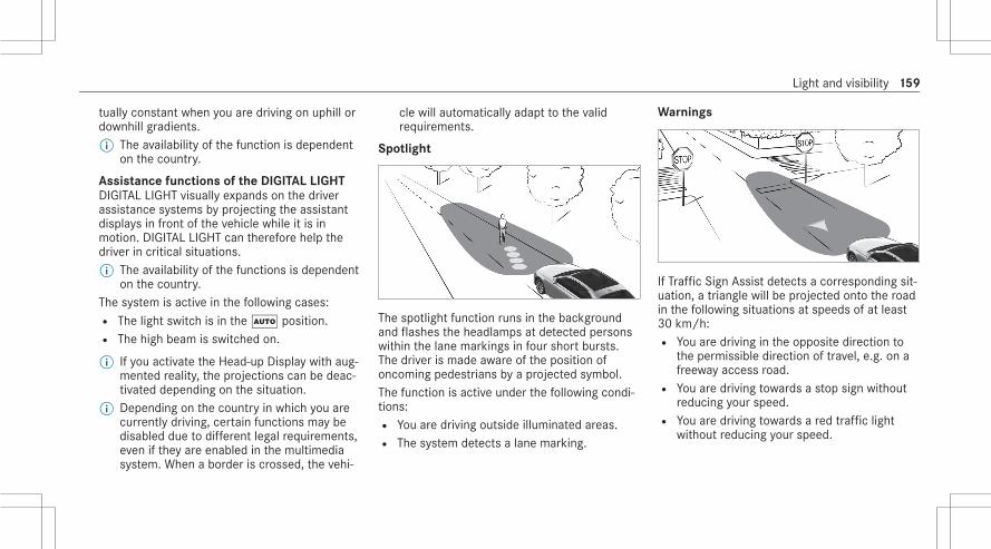
tually constant when you are driving on uphill ordownhill gradients.% The availability of the function is dependent
on the country.
Assistance functions of the DIGITAL LIGHTDIGITAL LIGHT visually expands on the driverassistance systems by projecting the assistantdisplays in front of the vehicle while it is inmotion. DIGITAL LIGHT can therefore help thedriver in critical situations.% The availability of the functions is dependent
on the country.The system is active in the following cases:R The light switch is in theà position.R The high beam is switched on.
% If you activate the Head-up Display with aug‐mented reality, the projections can be deac‐tivated depending on the situation.
% Depending on the country in which you arecurrently driving, certain functions may bedisabled due to different legal requirements,even if they are enabled in the multimediasystem. When a border is crossed, the vehi‐
cle will automatically adapt to the validrequirements.
Spotlight
The spotlight function runs in the backgroundand flashes the headlamps at detected personswithin the lane markings in four short bursts.The driver is made aware of the position ofoncoming pedestrians by a projected symbol.The function is active under the following condi‐tions:R You are driving outside illuminated areas.R The system detects a lane marking.
Warnings
If Traffic Sign Assist detects a corresponding sit‐uation, a triangle will be projected onto the roadin the following situations at speeds of at least30 km/h:R You are driving in the opposite direction to
the permissible direction of travel, e.g. on afreeway access road.R You are driving towards a stop sign without
reducing your speed.R You are driving towards a red traffic light
without reducing your speed.
Light and visibility 159
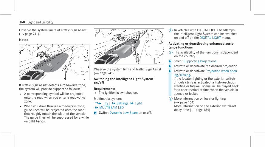
Observe the system limits of Traffic Sign Assist(/ page 241).
Notes
If Traffic Sign Assist detects a roadworks zone,the system will provide support as follows:R A corresponding symbol will be projected
onto the road when you enter a roadworkszone.R When you drive through a roadworks zone,
guide lines will be projected onto the roadthat roughly match the width of the vehicle.The guide lines will be suppressed for a whileon tight bends.
Observe the system limits of Traffic Sign Assist(/ page 241).
Switching the Intelligent Light Systemon/off
Requirements:R The ignition is switched on.
Multimedia system:4© 5 Settings 5 Light5 MULTIBEAM LED# Switch Dynamic Low Beam on or off.
% In vehicles with DIGITAL LIGHT headlamps,the Intelligent Light System can be switchedon and off on the DIGITAL LIGHT menu.
Activating or deactivating enhanced assis‐tance functions% The availability of the functions is dependent
on the country.# Select Supporting Projections.# Activate or deactivate the desired projection.# Activate or deactivate Projection when open-
ing/closing.If the locator lighting or the exterior switch-off delay time is activated, a high-resolutiongreeting or farewell scene will be played backfor a short period of time when the vehicle isopened or locked.
% More information on locator lighting(/ page 164)More information on the exterior switch-offdelay time (/ page 164)
160 Light and visibility

Adaptive Highbeam Assist
Adaptive Highbeam Assist function
& WARNING Risk of accident despiteAdaptive Highbeam Assist
Adaptive Highbeam Assist does not react to:R Road users without lights, e.g. pedes‐
triansR Road users with poor lighting, e.g.
cyclistsR Road users whose lighting is obstructed,
e.g. by a barrier
On very rare occasions, Adaptive HighbeamAssist may fail to recognize other road userswith their own lighting, or may recognizethem too late.In these, or in similar situations, the auto‐matic high beam will not be deactivated orwill be activated despite the presence ofother road users.
# Always observe the road and trafficconditions carefully and switch off thehigh beam in good time.
Adaptive Highbeam Assist cannot take intoaccount road, weather or traffic conditions.Detection may be restricted in the followingcases:R In poor visibility, e.g. fog, heavy rain or snowR If there is dirt on the sensors or the sensors
are obscured
Adaptive Highbeam Assist is only an aid. You areresponsible for adjusting the vehicle's lighting tothe prevailing light, visibility and traffic condi‐tions. Adaptive Highbeam Assist automatically
switches between the following types of light:R Low beamR High beam
At speeds greater than 19 mph (30 km/h):R If no other road users are detected, the high
beam will switch on automatically.
Light and visibility 161

The high beam will switch off automatically inthe following cases:R At speeds below 16 mph (25 km/h)R If other road users are detectedR If street lighting is sufficient
% The system's optical sensor is locatedbehind the windshield near the overheadcontrol panel.
Switching Adaptive Highbeam Assist on/off
Switching on# Turn the light switch to the à position.# Switch on the high beam using the combina‐
tion switch.If Adaptive Highbeam Assist is activated,the _ indicator lamp will light up on thedriver's display.
Switching off# Switch off the high beam using the combina‐
tion switch.
Adaptive Highbeam Assist Plus
Adaptive Highbeam Assist Plus function(Canada)
& WARNING Risk of accident despiteAdaptive Highbeam Assist Plus
Adaptive Highbeam Assist Plus does notreact to:R Road users without lights, e.g. pedes‐
triansR Road users with poor lighting, e.g.
cyclistsR Road users whose lighting is obstructed,
e.g. by a barrier
On very rare occasions, Adaptive HighbeamAssist Plus may fail to recognize other roadusers with their own lighting, or may recog‐nize them too late.In these, or in similar situations, the auto‐matic high beam will not be deactivated orwill be activated despite the presence ofother road users.
# Always observe the road and trafficconditions carefully and switch off thehigh beam in good time.
Adaptive Highbeam Assist Plus cannot take intoaccount road, weather or traffic conditions.Detection may be restricted in the followingcases:R In poor visibility, e.g. fog, heavy rain or snowR If there is dirt on the sensors or the sensors
are obscured
Adaptive Highbeam Assist Plus is only an aid.You are responsible for adjusting the vehicle'slighting to the prevailing light, visibility and traf‐fic conditions.
162 Light and visibility

Adaptive Highbeam Assist Plus automaticallyswitches between the following types of light:R Low beamR Partial high beamR High beamR ULTRA RANGE Highbeam (only vehicles with
DIGITAL LIGHT)
ULTRA RANGE Highbeam increases the bright‐ness of the cone of light to the legally permittedmaximum.Partial high beam does not include other roadusers in the high beam area. It does not blindthem but enables full high beam illumination forthe driver apart from the excluded vehicles.At speeds below 16 mph (25 km/h) or whenthere is sufficient street lighting:R The partial high beam and the high beam will
be switched off automatically.
At speeds greater than 19 mph (30 km/h):R If no other road users are detected, the high
beam will switch on automatically.R If other road users are detected, the partial
high beam will switch on automatically.
At speeds above 25 mph (40 km/h):R If no other road users are detected on a
straight road, ULTRA RANGE Highbeam willbe switched on automatically.R If other road users are detected, the partial
high beam will switch on automatically.
R If highly reflective signs are detected, ULTRARANGE Highbeam will be switched off auto‐matically.
% The system's optical sensor is locatedbehind the windshield near the overheadcontrol panel.
Switching Adaptive Highbeam Assist Pluson/off (Canada)
Switching on# Turn the light switch to the à position.# Switch on the high beam using the combina‐
tion switch.When the high beam is switched on automat‐ically in the dark, the _ indicator lampwill light up on the driver's display.
Switching off# Switch off the high beam using the combina‐
tion switch.
Light and visibility 163

Switching the daytime running lamps on/off
Multimedia system:4© 5 Settings 5 Light5 MULTIBEAM LED# Switch the daytime running lamps on/off.% In vehicles with DIGITAL LIGHT headlamps,
the Intelligent Light System can be switchedon and off in the DIGITAL LIGHT menu.
Setting the exterior lighting switch-off delaytime
Requirements:R The light switch is in theà position.
Multimedia system:4© 5 Settings 5 Light5 Interior/exterior lighting5 External Lighting Delay# Set the switch-off delay time.
When the vehicle's engine is switched off,the exterior lighting will be activated for theset time.
Activating/deactivating the locator lighting
Requirements:R The light switch is in theà position.
Multimedia system:4© 5 Settings 5 Light5 Interior/Exterior Lighting# Activate or deactivate Locator Lighting.
When the function is activated, the exterior light‐ing will light up for 40 seconds after the vehicleis unlocked. When you start the vehicle, thelocator lighting is switched off and automaticdriving lights are activated.
Interior lightingAdjusting the interior lighting
1c Switches the front interior lightingon/off
2u Switches the rear interior lightingon/off
3| Switches automatic interior lightingcontrol on/off
# To switch reading lamps on/off: hold yourhand under the respective reading lamp4or5.
164 Light and visibility

Control panel inside the grab handle (rearpassenger compartment)
1p Reading lamp on the respective side ofthe vehicle
2u Rear interior lighting
# To switch reading lamps on: press button1.The reading lamp, the interior lighting in thegrab handle and the dome lamp on therespective side of the vehicle will light up.
# To switch reading lamps off: press button1 once or twice.After pressing it once, the interior lighting inthe grab handle and the dome lamp on therespective side of the vehicle will go out.After pressing it twice, the reading lamp onthe respective side of the vehicle will go out.
# To switch the rear interior lighting on/off: press button2.The reading lamps, the interior lighting in thegrab handle and the dome lamps on bothsides of the vehicle will light up or go out.
Adjusting the ambient lighting
Multimedia system:4© 5 Settings 5 Comfort5 Ambient Lighting
Setting the color# Select Color.# Select Monochrome or Multi-color.# Set the desired color or color combination.
Adjusting the brightness# Select Brightness.# Adjust the brightness.% Depending on the ambient light, the ambient
lighting will automatically switch betweenday and night modes.
Activating the brightness for zones# Select Brightness.# Switch off Link Zones .
The Direct, Indirect and Accent zones can beset separately.
% The Light band zone can also be set for vehi‐cles with active ambient lighting.
Activating effects
& WARNING Risk of an accident despiteactivated effects of ambient lighting andactive ambient lighting
To use the Warning Assistance effects, therespective functions must be activated in thedriver assist menu.
Light and visibility 165

# Make sure that the functions andassists are switched on.
% The exit warning system is only an aid.Further notes on driving systems and yourresponsibility: (/ page 215)
# Select Effects.# Activate the desired effect.% Depending on the vehicle equipment, differ‐
ent effects are available:Operating feedback effects:R Climate: If changes are made to the tempera‐
ture setting in the vehicle, the color of theambient lighting will change briefly.R Voice Assistant: For vehicles with active
ambient lighting, the voice assistant is visu‐ally animated.
Warning assistance effects:R Warning When Exiting: If an object is detec‐
ted in the blind spot while you are getting outof the vehicle, the ambient lighting in theaffected door will flash red.
Further information on the exit warning(/ page 247).R Active Lane Keeping Assist: If there is a
warning from Active Lane Keeping Assist, theactive ambient lighting will flash red.Further information on Active Lane KeepingAssist: (/ page 250).R Active Brake Assist: If there is an Active
Brake Assist warning, the active ambientlighting in the center of the dashboard willflash bright red.Further information on Active Brake Assist(/ page 236).R Active Blind Spot Assist: In vehicles with
active ambient lighting, the ambient lightingon the affected side will flash red if there is awarning from Active Blind Spot Assist.Further information on Active Blind SpotAssist (/ page 247).
GreetingR When you get into the vehicle, a special color
animation will play.
Multi-color AnimationR The chosen color combination will change at
predefined intervals.
% In vehicles with active ambient lighting, ananimation will be played.
% The desired operating feedback and warningassistance can be activated or deactivatedvia the´ symbol. Depending on theequipment, different operating feedback andwarning assistance effects are available.
% If the brightness is set to a low level, warninganimations will be displayed at a higherbasic brightness.
166 Light and visibility

Switching the interior lighting switch-offdelay time on/off
Multimedia system:4© 5 Settings 5 Light5 Interior/exterior lighting5 Interior Lighting Delay# Switch Interior Lighting Delay on or off.
When this function is active, the interior light‐ing will light up for a short time after thevehicle is locked.
Windshield wiper and windshield washersystemSwitching the windshield wipers on/off
1 g Windshield wipers off2 Ä Automatic wiping, normal3 Å Automatic wiping, frequent
4 ° Continuous wiping, slow5 ¯ Continuous wiping, fast
# Turn the combination switch to the corre‐sponding position1 -5.
# Single wipe/washing: push the button onthe combination switch in the direction ofarrow1.R í Single wipeR î Wiping with washer fluid
Vehicles with MAGIC VISION CONTROL: inposition2 or3 , the windshield washing proc‐ess is automatically triggered if dirt is detectedon the windshield unless the Check Washer Fluidmessage is being displayed.
Cleaning the windshield intensivelyFor heavy soiling, you can clean the windshieldintensively from an outside temperature of 41°F(5°C).# In a stationary vehicle, turn the combination
switch to position1,2 or3.
Light and visibility 167

# Press the button on the combination switchin the direction of arrow1 and hold it forapproximately two seconds.The wiper arms will move into the replace‐ment position and washer fluid will be distrib‐uted on the windshield.After approximately 30 seconds, the wiperarms will move back again and wipe thewindshield several times. Intensive cleaninghas now finished.
Replacing the windshield wiper blades
& WARNING Risk of becoming trapped ifthe windshield wipers are switched onwhile wiper blades are being replaced
If the windshield wipers begin to move whileyou are changing the wiper blades, you canbe trapped by the wiper arm.# Always switch off the windshield wipers
and the ignition before changing thewiper blades.
Moving the wiper arms into the replacementposition# Switch the ignition on and then off again
immediately.# Within around 15 seconds, press and hold
the î button on the combination switchfor approximately three seconds(/ page 167).The wiper arms will move into the replace‐ment position.
Removing the wiper blades# Fold the wiper arms away from the wind‐
shield.
# Hold the wiper arm with one hand. With theother hand, turn the wiper blade away fromthe wiper arm in the direction of arrow1 asfar as it will go.
# Slide catch2 in the direction of arrow3until it engages in the removal position.
# Remove the wiper blade from the wiper armin the direction of arrow4.
168 Light and visibility

Installing the wiper blades
# Insert the new wiper blade into the wiperarm in the direction of arrow1.
# Slide catch2 in the direction of arrow3until it engages in the locking position.
# Make sure that the wiper blade is seated cor‐rectly.
# Fold the wiper arms back onto the wind‐shield.
# Switch on the ignition.# Press the î button on the combination
switch.The wiper arms will return to the originalposition.
# Switch the ignition off.
Maintenance display
# Remove protective film1 from the mainte‐nance display on the tip of the newly instal‐led wiper blades.
When the color of the maintenance displaychanges from black to yellow, the wiper bladesshould be replaced.
Light and visibility 169

% The duration until the color changes variesdepending on the usage conditions.
Replacing the windshield wiper blades(MAGIC VISION CONTROL)
Moving the wiper arms into the replacementposition# Switch off the ignition.# Within around 15 seconds, press the î
button on the combination switch(/ page 167).The wiper arms will move into the replace‐ment position.
Removing the wiper blades
# To bring the wiper blade into position tobe removed: hold the wiper arm firmly inone hand. With the other hand, turn thewiper blade in the direction of arrow1beyond the point of resistance.The wiper blade will engage in the removalposition with a click.
# To remove the wiper blade: press releaseknob2, pull the wiper blade in the directionof arrow3 and remove.
Installing the wiper blades
# Push the new wiper blade onto the wiper armin the direction of arrow1 until releaseknob2 engages.
170 Light and visibility

# Press the wiper blade onto the wiper arm inthe direction of arrow3 beyond the point ofresistance.The wiper blade will engage with a noticeableclick and move freely again.
# Fold the wiper arm back onto the windshield.
MirrorsOperating the outside mirrors
& WARNING Risk of accident due toadjusting the vehicle settings while thevehicle is in motion
You could lose control of the vehicle in thefollowing situations in particular:R If you adjust the driver's seat, the head
restraint, the steering wheel or the mirrorwhile the vehicle is in motionR If you fasten your seat belt while the vehi‐
cle is in motion
# Before starting the engine: In particular,adjust the driver's seat, head restraint,
steering wheel and mirror, and fastenyour seat belt.
& WARNING Risk of accident due to mis‐judgment of distance when using thefront-passenger mirror
The outside mirror on the front passengerside reflects objects on a smaller scale. Theobjects in view are in fact closer than theyappear.# Therefore, always look over your shoul‐
der in order to ensure that you areaware of the actual distance betweenyou and the road users driving behindyou.
Adjusting the outside mirrors
# Use button2 or4 to select the desiredmirror.
% In vehicles with MBUX Interior Assistant anddriver camera, the required outside mirrorcan also be preselected automatically via anatural head movement to the left or right(/ page 288).
Light and visibility 171

# Use button1 to adjust the position of theselected mirror.
Folding the outside mirrors in/out# Briefly press button3.% If the battery has been disconnected or has
discharged, the outside mirrors must bemoved briefly using button3. Only then willthe automatic mirror folding function workproperly.
Engaging the outside mirrorsIf an outside mirror has been forcibly disen‐gaged, proceed as follows.# Press and hold button3.
You will hear a click and the mirror will audi‐bly click into place. The outside mirror willnow be set to the correct position.
Automatic anti-glare mirrors function
& WARNING Risk of acid burns and poi‐soning due to the anti-glare mirror elec‐trolyte
Electrolyte may escape if the glass in anautomatic anti-glare mirror breaks.The electrolyte is hazardous to health andcauses irritation. It must not come into con‐tact with your skin, eyes, respiratory organsor clothing or be swallowed.# If you come into contact with electro‐
lyte, observe the following:R Immediately rinse the electrolyte
from your skin with water and seekmedical attention.R If electrolyte comes into contact
with your eyes, immediately rinsethem thoroughly with clean waterand seek medical attention.R If the electrolyte is swallowed,
immediately rinse your mouth outthoroughly. Do not induce vomiting.Seek medical attention immediately.
R Immediately change out of clothingwhich has been contaminated withelectrolyte.R If an allergic reaction occurs, seek
medical attention immediately.
The inside rearview mirror and the outside mir‐ror on the driver's side will automatically go intoanti-glare mode if light from a headlamp hits thesensor on the inside rearview mirror.
System limitsThe system will not go into anti-glare mode if:R The engine is switched off.R Reverse gear is engaged.R The interior lighting is switched on.
Front-passenger outside mirror parking posi‐tion function
The parking position makes parking easier.
172 Light and visibility

The front-passenger outside mirror will swiveldownwards in the direction of the rear wheel onthe front passenger's side when:R The parking position is stored (/ page 173).R The front-passenger mirror is selected.R Reverse gear is engaged.
The front-passenger outside mirror will moveback to its original position when:R You shift the transmission to another trans‐
mission position.R You are traveling at a speed greater than
9 mph (15 km/h).R You press the button for the outside mirror
on the driver's side.
Storing the parking position of the front-passenger outside mirror using reverse gear
Storing
# Select the front-passenger outside mirrorusing button2.
# Engage reverse gear.# Move the front-passenger outside mirror into
the desired parking position using button1.
Calling up# Select the front-passenger outside mirror
using button2.# Engage reverse gear.
The front-passenger outside mirror will moveinto the stored parking position.
Activating/deactivating the automatic mirrorfolding function
Multimedia system:4© 5 Settings 5 Vehicle5 Opening/closing# Switch Automatic Mirror Folding on or off.
Light and visibility 173

Area permeable to radio waves on thewindshield
Radio-controlled equipment, such as toll sys‐tems, can be mounted only on areas1 of thewindshield that are permeable to radio waves.Areas permeable to radio waves1 are best visi‐ble from outside the vehicle when the windshieldis illuminated with an external light source.Note this position for vehicles with:R Windshield heatingR Infrared reflective windshield
Infrared-reflective windshield functionThe infrared-reflective windshield is coated andreduces the build-up of heat in the vehicle inte‐rior.The coating shields the vehicle interior fromradio waves.
174 Light and visibility

Overview of climate control systemsNotes on climate control
An interior air filter in combination with the pre‐filter in the engine compartment must always beused so that the air conditioning system, pollu‐tion level monitoring and the air filtration workcorrectly. Make sure that the filter is installedcorrectly and the filter housing in the enginecompartment is closed correctly using the capand always tightly sealed when in operation. Usefilters recommended and approved byMercedes-Benz. Always have service work car‐ried out at a qualified specialist workshop.
Overview of the control panel for 3-zoneautomatic climate control 1 s Increases the temperature
20 Switches the synchronization functionon/off (/ page 178)
3
Switches climate control on/off(/ page 176)
4 ¿ Switches the A/C function on/off(/ page 177)
5 ¬ Defrosts the windshield6 g Switches air-recirculation mode on/off
(/ page 178)7 ¤ Switches the rear window heater
on/off8 J Increases the airflow or switches on
climate control (/ page 176)9 r Reduces the temperatureA Ã Sets climate control to automatic
mode, right (/ page 177)B± Calls up the air conditioning menu
(/ page 177)C Ã Sets climate control to automatic
mode, left (/ page 177)D I Reduces the airflow or switches off cli‐
mate control(/ page 176)
Climate control 175

Overview of the rear operating unit
Example: USA1 Sets air distribution to the center and side
air vents in the rear passenger compart‐ment, left
2 Sets the temperature in the rear passengercompartment, left
3 Sets the airflow in the rear passenger com‐partment, left, or switches climate controlon/off (/ page 177)
4 Switches climate control on/off(/ page 177)Switches residual heat on/off (/ page 179)
5 Sets the airflow in the rear passenger com‐partment, right, or switches climate controlon/off (/ page 177)
6 Sets the temperature in the rear passengercompartment, right
7 Sets air distribution to the center and sideair vents in the rear passenger compart‐ment, right
8 Sets rear climate control to automatic mode,right
9 Sets the air distribution to the rearpassenger compartment footwell vents, right
A Synchronization is activated (/ page 178)B Sets the air distribution to the rear
passenger compartment footwell vents, leftC Sets rear climate control to automatic mode,
left
The settings for the second row of seats can beconfigured via the rear operating unit, the multi‐media system (/ page 178) or the MBUX reartablet depending on the vehicle's equipment.
Operating the climate control systemSwitching climate control on/off
Switching on climate control# Set the airflow to level 1 or higher viaJ
on the climate bar on the central displayor# PressÃ,s,r or±.
Switching off climate control# Set the airflow to level 0 viaI on the cli‐
mate bar on the central displayor#
Press .If climate control is switched off, the windowsmay fog up more quickly. Switch climate controloff only briefly.
176 Climate control

Switching climate control on/off via the rearoperating unit
# To switch on: press button4.or# Set the airflow to level 1 or higher using but‐
tons3 and5.or# Press buttons2,6,8 orC.# To switch off: press button4.or# Set the airflow to level 0 using buttons3
and5.% If rear climate control is switched off via but‐
ton4, OFF will be shown on the rear dis‐play.
Calling up the air conditioning menu
The air conditioning menu can be called up viathe air conditioning line. The air conditioning lineis always shown on the lower edge of the centraldisplay.
# Select the Climate Menu entry in the air con‐ditioning line.The First Row of Seats menu is opened.
Activating/deactivating the A/C function viathe multimedia system
Multimedia system:4 Climate Menu 5 First Row of SeatsDepending on the external conditions, improvedcooling and dehumidification of the interior airare supported when the A/C function is activa‐ted.# Select A/C (A/C).
Setting climate control to automatic
In automatic mode, the set vehicle interior tem‐perature is controlled automatically and main‐tained at a constant level by the air supply.# Press AUTO on the climate bar on the central
display.
% You can increase or reduce the airflow bypressingK on the climate bar on the mul‐timedia system.
# To switch to manual operation: switch offautomatic mode or adjust an aspect of airdistribution, e.g.P.
Setting the air distribution
Multimedia system:4 Climate Menu# Select First Row of Seats or Second Row of
Seats.# To set the air distribution: select¯,P
orO.# Set the airflow.% Several air distribution options can be selec‐
ted at the same time, for example to set theclimate control for the windshield and thefootwells simultaneously. However, at leastone zone is always active.The¯ climate control for the windshieldcan only be selected for the first seat row.
Climate control 177

Setting the footwell temperature
Multimedia system:4 Climate Menu# Set^ the footwell temperature.
Setting rear climate control (multimedia sys‐tem)
Multimedia system:4 Climate Menu
Setting the temperature# Select Second Row of Seats.# Set the temperature.
Setting the airflow# Select Second Row of Seats.# Set the airflow.
Controlling the rear climate control automat‐ically# Select AUTO.
Deactivating rear climate control# Select REAR OFF.
Activating/deactivating the climate controlsynchronization function via the multimediasystem
Multimedia system:4 Climate MenuClimate control can be set centrally using thesynchronization function. The driver's settingsfor temperature, airflow and air distribution willbe adopted automatically for all climate zones.# Select First Row of Seats.# Select SYNC (SYNC).
Removing condensation from the windows
Windows fogged up on the inside# Pressà on the climate bar of the central
display.# If the windows remain fogged up: press¬
on the climate bar of the central display.
Windows fogged up on the outside# Switch on the windshield wipers.# Press theà button.
Switching air-recirculation mode on/off
# Pressg on the climate bar on the centraldisplay.The interior air will be recirculated.
Air-recirculation mode automatically switches tofresh air mode after a while.% If air-recirculation mode is switched on, the
windows may fog up more quickly. Switch onair-recirculation mode only briefly.
Switching residual heat on/off
Requirements:R The residual heat function is available.R The vehicle is parked.R The coolant temperature must be sufficiently
high.
178 Climate control

It is possible to make use of the residual heatfrom the engine to continue heating or ventilat‐ing the front compartment of the vehicle forapproximately 30 minutes, depending on thetemperature set.# To switch on: select Residual Heat on the
climate bar on the central display.
Residual heat will be switched off automatically.
Switching residual heat on/off via the rearoperating unit
Requirements:R The residual heat function is available.R The vehicle is parked.R The coolant temperature must be sufficiently
high.
When the residual heat of the engine is activatedin the rear passenger compartment, you canheat or ventilate the front and rear passengercompartments for approximately 15 minutes.# Press button4.
Activating/deactivating ionization
Multimedia system:4 Climate Menu 5 Air QualityIonization improves the quality of the vehicle'sinterior air. Ionization of the interior air is odor‐less.# Select Ionization.% The function can only be performed if the
AUTO mode is activated or the air distribu‐tion is set to the side air vent. The function isrestricted if the side air vents on the driver'sside are closed.
Fragrance system
Setting the fragrance system
Requirements:R The climate control system is switched on.R The glove box is closed.R A flacon is inserted.
Multimedia system:4 Climate Menu 5 Air QualityThe fragrance system distributes a pleasant fra‐grance throughout the vehicle interior from a fla‐con located in the glove box.# Select Fragrance.# Keep pressing until the desired intensity is
reached.
Inserting or removing the flacon of the fra‐grance system
& WARNING Risk of injury from liquid per‐fume
If children open the flacon, they could drinkthe liquid perfume or it could come into con‐tact with their eyes.# Do not leave children unattended in the
vehicle.# Consult a doctor immediately if liquid
perfume has been drunk.
Climate control 179

# If liquid perfume comes into contactwith your eyes or skin, rinse your eyeswith clean water.
# If symptoms continue, consult a doctor.
+ ENVIRONMENTAL NOTE Environmentaldamage due to improper disposal of fullflacons
Full flacons must not be disposedof with household waste.#
Full flacons must be taken toa harmful substance collection point.
1 Cap2 Flacon
# To insert: slide the flacon into the holder asfar as it will go.
# To remove: after opening the glove box, waitfor approximately seven seconds and pull outthe flacon.
If you do not use genuine Mercedes-Benz interiorperfumes, observe the manufacturers' safetynotices on the perfume packaging.Dispose of the genuine Mercedes-Benz interiorperfume flacon when it is empty and do not refillit.
Refillable flacon# Unscrew the cap of the empty flacon.# Fill the flacon with a maximum of 0.5 fl. oz.
(15 ml).# Screw the cap back on to the flacon.
Always refill the empty refillable flacon with thesame perfume. Observe the separate informa‐tion sheet with the flacon.
Information on the windshield heater
& WARNING Risk of burns from touchingthe windshield when the windshieldheater is switched on
The windshield can become very hot whenthe windshield heater is switched on.
180 Climate control

The health of persons with limited tempera‐ture sensitivity or a limited ability to react tohigh temperatures may be affected or theymay even suffer burn-like injuries.# Do not touch the windshield while the
windshield heater is switched on.# Allow the windshield to cool down
before touching it.
The windshield heater will be enabled automati‐cally if¬ is activated on the climate bar onthe central display.After the vehicle is started, the windshieldheater is switched on automatically as required.
Pre-entry climate control for departure time
Pre-entry climate control for departure timefunction
& WARNING Danger to life due to expo‐sure to extreme heat or cold in the vehi‐cle
If people, particularly children, are exposedto extreme temperatures over an extendedperiod of time, there is a risk of seriousinjury or danger to life.# Never leave persons, children in partic‐
ular, unattended in the vehicle.
& WARNING Risk of burns due to repeat‐edly switching on the seat heating
Repeatedly switching on the seat heating cancause the seat cushion and seat backrestpadding to become very hot.In particular, the health of persons with limi‐ted temperature sensitivity or a limited abilityto react to high temperatures may be affec‐ted or they may even suffer burn-like injuries.
# Do not repeatedly switch on the seatheating.
To protect against overheating, the seat heatingmay be temporarily deactivated after it isswitched on repeatedly.% This function is available only in vehicles
with a 48 V on-board electrical system (EQBoost technology).
The air inside the vehicle can be heated, ventila‐ted or cooled to the set temperature when thevehicle is parked.When the vehicle is connected to power supplyequipment, priority is given to charging the 48 Vbattery to a specified minimum charge.The running time of pre-entry climate controlmay be reduced under the following conditions:R The vehicle is not connected to power supply
equipment.R The 48 V battery is not fully charged.
With active pre-entry climate control, the chargelevel of the 48 V battery may be reduced, even ifthe charging cable connector is connected.
Climate control 181

If present, seat ventilation is activated in coolingand ventilation mode.If present, the following functions are activatedin heating mode:R Seat heatingR Steering wheel heaterR Panel heatingR Mirror heaterR Rear window heatingR Windshield heating
When the set temperature is changed, climatecontrol mode will automatically be updated andswitched from heating mode to ventilation orcooling mode, from cooling mode to ventilationor heating mode or from ventilation mode toheating or cooling mode.
Setting pre-entry climate control for depar‐ture timeMultimedia system:4 Climate Menu 5 Pre-entry Climate Ctrl.
Setting a single departure time# Select the pen icon next to Departure Time.# Select or set a departure time and press OK
to confirm.
Setting the week profile# Select the pen icon next to Departure Time.# Set the desired departure time, e.g. every
day at 08:00, and mark as Week Profile.# Press OK to confirm.
Selecting seats# Select Driver, Passenger, Rear Left or Rear
Right.Pre-entry climate control will take place forthe selected seats.
Activating/deactivating pre-entry climatecontrol for departure time
Requirements:R The 48 V battery is charged sufficiently.R The function has been activated via the mul‐
timedia system.
# To activate: set the departure time(/ page 182).Pre-entry climate control for departure timeswitches on a maximum of 55 minutesbefore the selected departure time. It willremain active for another five minutes if thedeparture is delayed.
# To deactivate: push the& button up ordown.
If present, the following functions will remainactive once the vehicle has been started:R Seat heatingR Seat ventilationR Panel heating
182 Climate control

Activating/deactivating immediate pre-entryclimate control
& WARNING Danger to life due to expo‐sure to extreme heat or cold in the vehi‐cle
If people, particularly children, are exposedto extreme temperatures over an extendedperiod of time, there is a risk of seriousinjury or danger to life.# Never leave persons, children in partic‐
ular, unattended in the vehicle.
& WARNING Risk of burns due to repeat‐edly switching on the seat heating
Repeatedly switching on the seat heating cancause the seat cushion and seat backrestpadding to become very hot.In particular, the health of persons with limi‐ted temperature sensitivity or a limited abilityto react to high temperatures may be affec‐ted or they may even suffer burn-like injuries.
# Do not repeatedly switch on the seatheating.
To protect against overheating, the seat heatingmay be temporarily deactivated after it isswitched on repeatedly.% Immediate pre-entry climate control is avail‐
able only in vehicles with a 48 V on-boardelectrical system (EQ Boost technology).
Air conditioning of the vehicle interior can con‐tinue for up to 50 minutes, e.g. if the journey isinterrupted.
# Set the temperature using the w arrowson the climate bar on the central display.
# Press button1.The red or blue indicator lamp on button1will light up or go out.
The colors of the indicator lamp have the follow‐ing meanings:R Blue: stationary ventilation is switched on.
Climate control 183

R Red: the stationary heater is switched on.R Yellow: the departure time is preselected.
Air vents
Adjusting the front air vents
& WARNING Risk of burns and frostbitedue to being too close to the air vents
Very hot or very cold air can flow from the airvents.# Make sure that all vehicle occupants
always maintain a sufficient distancefrom the air vents.
# If necessary, direct the airflow toanother area of the vehicle interior.
To guarantee the flow of fresh air through the airvents into the vehicle interior, comply with thefollowing:R Always keep the vents and vent grilles in the
vehicle interior free.R Keep the air inlet free of residue build-up
(/ page 330).
# To open the center and side air vents:press button1.The three indicator lamps on the button willlight up. The air vents will be opened com‐pletely.
# To close the center and side air vents:press button1 again.The three indicator lamps on the button willgo out one by one. The air vents will beclosed completely.
# To adjust the airflow direction of the sideair vents: hold outer side air vent2 in thecenter and move it up or down or to the leftor right.
# To adjust the airflow direction of the cen‐ter air vent: hold air vent3 in the centerand move it up or down or to the left or right.
Adjusting the rear air vents
& WARNING Risk of burns and frostbitedue to being too close to the air vents
Very hot or very cold air can flow from the airvents.# Make sure that all vehicle occupants
always maintain a sufficient distancefrom the air vents.
# If necessary, direct the airflow toanother area of the vehicle interior.
184 Climate control

Adjusting the rear air vents in the centerconsole
# To open the rear air vents: press but‐ton1.The air vents will be opened completely andthe three indicator lamps on the button willlight up.
# To close the rear air vents: press but‐ton1 again.The three indicator lamps on the button willgo out one by one. The air vents will beclosed completely.
# To adjust the airflow direction of the rearair vents: hold air vent2 in the center andmove it up or down or to the left or right.
Adjusting the side air vents in the rearpassenger compartment
# To open the side air vents in the rearpassenger compartment: press button1.If the button is flush with the side trim, theside air vent is open.
# To close the side air vents in the rearpassenger compartment: press button1again.If the button protrudes from the side trim,the side air vent is closed.
# To adjust the airflow direction of the sideair vents: hold air vent2 in the center andmove it up or down or to the left or right.
Opening or closing the air vent in the glovebox
* NOTE Damage to temperature-sensitiveobjects in the glove box
Temperature-sensitive objects stored in theglove box may be damaged by the air ventlocated inside it.# Close the air vent when you heat the
vehicle.
Climate control 185

# At high outside temperatures, open theair vent and switch on the A/C func‐tion.
The automatic climate control must be switchedon to cool the glove box.
1 Air vent controller2 Air vent
# To open or close: turn controller1 to theright or left.
186 Climate control

DrivingSwitching on the power supply or ignition
& WARNING Risk of accident and injurydue to children left unattended in thevehicle
If children are left unsupervised in the vehi‐cle, they could, in particular:R open doors, thereby endangering other
persons or road users.R get out and be struck by oncoming traf‐
fic.R operate vehicle equipment and become
trapped, for example.
In addition, the children could also set thevehicle in motion, for example by:R releasing the parking brake.R changing the transmission position.R starting the vehicle.
# Never leave children unattended in thevehicle.
# When leaving the vehicle, always takethe SmartKey with you and lock thevehicle.
# Keep the vehicle SmartKey out of reachof children.
Requirements:R The SmartKey is in the vehicle and is recog‐
nized.R The brake pedal is not depressed.
# To switch on the power supply: press but‐ton1 once.You can activate the windshield wipers, forexample.
The power supply is switched off again if the fol‐lowing conditions are met:R You open the driver's door.R You press button1 twice more.
Driving and parking 187

# To switch on the ignition: press button1twice.The indicator lamps appear on the driver dis‐play.
The ignition is switched off again if one of thefollowing conditions is met:R You do not start the vehicle within
15 minutes and the transmission is in posi‐tionj or the electric parking brake isapplied.R You press button1 once.
Starting the vehicle
Starting the vehicle with the start/stop but‐ton
& DANGER Risk of death caused byexhaust gases
Combustion engines emit poisonous exhaustgases such as carbon monoxide. Inhalingthese exhaust gases is hazardous to healthand leads to poisoning.
# Never leave the engine or, if present,the auxiliary heating running in anenclosed space without sufficient venti‐lation.
& WARNING Risk of fire due to flammablematerial in the engine compartment orthe exhaust system
Flammable materials may ignite.# Therefore, check regularly that there
are no flammable materials in theengine compartment or on the exhaustsystem.
Requirements:R The SmartKey is in the vehicle and is recog‐
nized.
# Shift the transmission to positionj ori.# Depress the brake pedal and press button1 once.
# If the vehicle does not start: switch off non-essential consumers and press button1once.
# If the vehicle still does not start and the dis‐play message Place the Key in the MarkedSpace See Operator's Manual also appearsin the driver display: start the vehicle withthe SmartKey in the marked space (emer‐gency operation mode) (/ page 188).
% You can switch off the engine while driving.By pressing button1 for about three sec‐onds or by pressing button1 three timeswithin three seconds. Be sure to observe thesafety notes under "Driving tips"(/ page 192).
Observe any information regarding display mes‐sages that can be displayed in the driver display.
Starting the vehicle with the SmartKey in themarked space (emergency operation mode)If the vehicle does not start and the display mes‐sage Place the Key in the Marked Space SeeOperator's Manual appears in the driver display,you can start the vehicle in emergency operationmode.
188 Driving and parking

# Make sure that cup holder2 is empty.# Remove SmartKey1 from the key ring.# Place SmartKey1 in cup holder2.
The vehicle will start after a short time.If SmartKey1 is removed from cup holder2, the engine continues running. For furtherengine starts, however, SmartKey1 mustbe located in cup holder2 during the entirejourney.
# Have SmartKey1 checked at a qualifiedspecialist workshop.
If the vehicle does not start:# Leave SmartKey1 in cup holder2.
# Depress the brake pedal and start the vehi‐cle using the start/stop button.
% You can also switch on the power supply orthe ignition with the start/stop button.
Observe any information regarding display mes‐sages that can be displayed in the driver display.
Starting the vehicle via Remote Online Serv‐ices
Cooling or heating the vehicle interior beforestarting the journeyEnsure the following before starting the engine:R the legal stipulations in the area where your
vehicle is parked allow engine starting viasmartphone.R it is safe to start and run the engine where
your vehicle is parked.R the fuel tank is sufficiently full.R the starter battery is sufficiently charged.
Charging the starter battery before startingthe journeyIf the vehicle battery is discharged, you canreceive a message on your smartphone. You canthen start the vehicle with the smartphone tocharge the battery. The vehicle is automaticallyswitched off after ten minutes.Ensure the following before starting the engine:R The legal stipulations in the area where your
vehicle is parked allow engine starting viasmartphone.R It is safe to start and run the engine where
your vehicle is parked.R The fuel tank is sufficiently full.
Starting the vehicle (Remote Online)
& WARNING Risk of crushing or entrap‐ment due to unintentional starting of theengine
Limbs could be crushed or trapped if theengine is started unintentionally duringservice or maintenance work.
Driving and parking 189

# Always secure the engine against unin‐tentional starting before carrying outmaintenance or repair work.
Requirements:R Park positionj is selected.R The anti-theft alarm system is not activated.R The panic alarm is not activated.R The hazard warning light system is switched
off.R The hood is closed.R The doors are closed and locked.R The windows and sliding sunroof are closed.
# Start the vehicle using the smartphone.After every engine start, the engine runs forten minutes.
You can carry out a maximum of two consecu‐tive starting attempts. You must start the vehicleonce with the SmartKey before trying to startthe engine again with the smartphone. You canstop the vehicle again at any time.
% Further information can be found in thesmartphone app.
Securing the engine against starting beforecarrying out maintenance or repair work:# Switch on the hazard warning light system.or# Unlock the doors.or# Open a side window or the sliding sunroof.
Breaking-in notes
To preserve the engine during the first1000 miles (1500 km):R Drive at varying road speeds and engine
speeds.R Do not drive at speeds greater than 85 mph
(140 km/h).R Drive the vehicle in drive programA
or;.R Shift to the next highest gear at the very lat‐
est when the needle reaches the last thirdbefore the red area in the tachometer.
R Do not shift down a gear manually in order tobrake.R Avoid overstraining the vehicle, e.g. driving at
full throttle.R Do not depress the accelerator pedal past
the pressure point (kickdown).R Only increase the engine speed gradually and
accelerate the vehicle to full speed after1000 miles (1500 km).
This also applies when the engine or parts of thedrivetrain have been replaced.Please also observe the following breaking-innotes:R In certain driving and driving safety systems,
the sensors adjust automatically while a cer‐tain distance is being driven after the vehiclehas been delivered or after repairs. Full sys‐tem effectiveness is not reached until theend of this teach-in process.R Brakepads, brake discs and tires that are
either new or have been replaced only ach‐ieve optimum braking effect and grip afterseveral hundred kilometers of driving. Com‐
190 Driving and parking
pensate for the reduced braking effect byapplying greater force to the brake pedal.
Notes on optimized acceleration
If all necessary requirements and activation con‐ditions are fulfilled, the best possible accelera‐tion can be achieved from a standstill.Do not use the optimized acceleration on publicroads. Individual wheels could spin and youcould lose control of the vehicle. There is anincreased risk of skidding and/or accident.Be sure to observe the safety notes and informa‐tion on ESP® (/ page 218).
Pulling away with optimized acceleration
& WARNING Risk of skidding and havingan accident from wheels spinning
When you use optimized acceleration, indi‐vidual wheels could spin and you could losecontrol of the vehicle.
If ESP® is deactivated, there is a risk of skid‐ding and accident.# Make sure that no persons or obstacles
are in the close vicinity of your vehicle.
Requirements:R The vehicle has been broken in
(/ page 190).R The vehicle and tires are in good condition.R You are on a high-grip roadway.R The engine and transmission are at normal
operating temperature.
* NOTE Increased wear due to optimizedacceleration
When pulling away with optimized accelera‐tion, all components of the drivetrain aresubjected to a very high load.This can lead to increased component wear.# Do not always pull away with optimized
acceleration.
# Engage theh drive position (/ page 203).
# Move the steering wheel to the straight-ahead position.
# Select the sportiest available drive programB orC(/ page 199).
# Deactivate ESP® (/ page 219).# Depress and hold the brake pedal firmly with
your left foot.# With your right foot, fully depress the accel‐
erator pedal.# After no more than five seconds, take your
left foot quickly off the brake, but keep theaccelerator pedal depressed.The vehicle pulls away at maximum accelera‐tion.
# Switch on ESP® once the acceleration proce‐dure is complete.
Ending optimized acceleration# Remove your foot from the accelerator pedal.# Reactivate the ESP®.
Driving and parking 191

% After you pull away with optimized accelera‐tion, components of the drivetrain canbecome very hot, which means that opti‐mized acceleration values may be reachedagain only after a few minutes.
Notes on driving
& WARNING Risk of accident due toobjects in the driver's footwell
Objects in the driver's footwell may impedepedal travel or block a depressed pedal.This jeopardizes the operating and roadsafety of the vehicle.# Stow all objects in the vehicle securely
so that they cannot get into the driver'sfootwell.
# Always install the floor mats securelyand as prescribed in order to ensurethat there is always sufficient room forthe pedals.
# Do not use loose floor mats and do notplace floor mats on top of one another.
& WARNING Risk of accident due to incor‐rect footwear
Incorrect footwear includes, for example:R Shoes with platform solesR Shoes with high heelsR Slippers
# Always wear suitable footwear so thatyou can operate the pedals safely.
& WARNING Risk of accident if the ignitionis switched off while driving
If you switch off the ignition while driving,safety functions are restricted or no longeravailable.You will need to use considerably more forceto steer and brake, for example.# Do not switch off the ignition while driv‐
ing.
& DANGER Risk of death caused byexhaust gases
Combustion engines emit poisonous exhaustgases such as carbon monoxide. Inhalingthese exhaust gases is hazardous to healthand leads to poisoning.# Never leave the engine or, if present,
the auxiliary heating running in anenclosed space without sufficient venti‐lation.
& WARNING Risk of skidding and of anaccident due to shifting down on slipperyroad surfaces
If you shift down on slippery road surfaces toincrease the engine braking effect, the drivewheels may lose traction.# Do not shift down on slippery road sur‐
faces to increase the engine brakingeffect.
192 Driving and parking

& DANGER Risk of fatal injury due to poi‐sonous exhaust gases
If the tailpipe is blocked or sufficient ventila‐tion is not possible, poisonous exhaust gasessuch as carbon monoxide may enter the vehi‐cle. This is the case when the vehiclebecomes stuck in snow, for example.# Keep the tailpipe and the area around
the vehicle free from snow when theengine or the stationary heater are run‐ning.
# Open a window on the side of the vehi‐cle facing away from the wind to ensurean adequate supply of fresh air.
& WARNING Risk of accident and injurydue to being under the influence of alco‐hol and drugs while driving
Drinking and driving and/or taking drugs anddriving are very dangerous combinations.Even a small amount of alcohol or drugs canaffect your reflexes, perceptions and judg‐ment.
The possibility of a serious or even fatal acci‐dent are greatly increased when you drink ortake drugs and drive.# Do not drink or take drugs and drive or
allow anyone to drive who has beendrinking or taking drugs.
& WARNING Risk of accident due to thebrake system overheating
If you leave your foot on the brake pedalwhen driving, the brake system may over‐heat.This increases the braking distance and thebrake system may even fail.# Never use the brake pedal as a footrest.# Do not depress the brake pedal and the
accelerator pedal at the same timewhile driving.
* NOTE Engine damage due to excessivelyhigh engine speeds
The engine will be damaged if you drive withthe engine in the overrevving range.# Do not drive with the engine in the over‐
revving range.
* NOTE Wearing out the brake linings bycontinuously depressing the brake pedal
# Do not depress the brake pedal contin‐uously whilst driving.
# To use the braking effect of the engine,shift to a lower gear in good time.
* NOTE Damage to the drivetrain andengine when pulling away
# Do not warm up the engine while thevehicle is stationary. Pull away immedi‐ately.
# Avoid high engine speeds and driving atfull throttle until the engine has reachedits operating temperature.
Driving and parking 193

* NOTE Damage to the catalytic converterdue to non-combusted fuel
The engine is not running smoothly and ismisfiring.Non-combusted fuel may get into the cata‐lytic converter.# Only depress the accelerator pedal
slightly.# Have the cause rectified immediately at
a qualified specialist workshop.
Notes on driving with a roof load, trailer orfully laden vehicleWhen driving with a loaded roof luggage rack ortrailer as well as with a fully laden or fully occu‐pied vehicle, the vehicle's driving and steeringcharacteristics change.You should bear the following in mind:R Do not exceed the permissible roof load and
towing capacity. Also observe the technicaldata in the printed Operator's Manual.R Evenly distribute the roof load, and place
heavy objects at the bottom. Also comply
with the notes on loading the vehicle(/ page 133).R Drive attentively, and avoid suddenly pulling
away, braking and steering as well as rapidcornering.
Notes on driving on salt-treated roadsThe braking effect is limited on salt-treatedroads.Therefore, observe the following notes:R Due to salt build-up on the brake discs and
brakepads, the braking distance can increaseconsiderably or result in braking only on onesideR Maintain a much greater safe distance to the
vehicle in front
To remove salt build-up:R Brake occasionally while paying attention to
the traffic conditionsR Carefully depress the brake pedal at the end
of the journey and when starting the nextjourney
Notes on hydroplaningHydroplaning can take place once a certainamount of water has accumulated on the roadsurface.Observe the following notes during heavy precip‐itation or in conditions in which hydroplaningmay occur:R Reduce speedR Avoid tire rutsR Avoid sudden steering movementsR Brake carefully
% Also observe the notes on regularly checkingwheels and tires (/ page 358).
Notes on driving through water on the roadsurfaceWater which has entered into the vehicle candamage the engine, electrics and transmission.Water can also enter the air intake of the engineand cause engine damage.
194 Driving and parking

Observe the following if you must drive throughwater:R The water, when calm, may only reach the
lower edge of the vehicle body.R Drive at a maximum speed of 6 mph
(10 km/h); water can otherwise enter thevehicle interior or engine compartment.R Vehicles traveling in front, or oncoming vehi‐
cles, can create waves which may exceed themaximum permissible depth of the water.
The braking effect of the brakes is reduced afterfording. Brake carefully while paying attention tothe traffic conditions until braking power hasbeen fully restored.
Function of rear axle steering
The rear axle steering is an electromechanicalauxiliary steering on the rear axle which adjuststhe steering of the rear wheels according to theposition of the front wheels, depending on thespeed. This results in greater maneuverabilityand improved driving stability, e.g. when corner‐ing.
Rear axle steering has the following characteris‐tics:R Reduced steering effort and turning radius
resulting in reduced parking effortR Improved driving stability, e.g. when corner‐
ingR More direct steering resulting in improved
handling of the vehicle
Observe the notes on snow chains(/ page 359) and on activating snow chainmode.
ECO start/stop function
Operation of the ECO start/stop function% The ECO start/stop function is not available
in all drive programs, depending on theengine. Observe the status display in thedriver display for this.
The engine is switched off automatically in thefollowing situations if all vehicle conditions foran automatic engine stop are met:R You brake the vehicle to a standstill in trans‐
mission positionh ori.R Vehicles with a 48 V on-board electrical
system: You depress the brake pedal whentraveling at a low speed.
If the system has detected one of the followingsituations, the engine will not stop:R You stop at a stop sign and there is no vehi‐
cle in front of you.R The vehicle that stopped in front of you
starts up again.R You maneuver, turn the steering wheel
sharply or engage reverse gear.
% If the system detects an intelligent stopinhibitor, for example, a stop sign, the enginewill not stop.If you activate the HOLD function or engagethe park positionj, the engine can beswitched off in spite of an intelligent stopinhibitor.
Driving and parking 195

The engine is restarted automatically if:R You engage transmission positionh ork.R You depress the accelerator pedal.R An automatic engine start is required by the
vehicle.R You release the brake pedal.R Vehicles with a 48 V on-board electrical
system:- You release the brake pedal on a downhill
gradient and the vehicle does not roll.- The vehicle rolls on a downhill gradient
and does not automatically enter glidemode at 15 mph (20 km/h).
ECO start/stop function symbols in the driverdisplay:R Theè symbol (green) appears when the
vehicle is at a standstill: the engine wasswitched off by the ECO start/stop function.R Theç symbol (yellow) appears when the
vehicle is at a standstill: not all vehicle condi‐tions for an engine stop have been met.
R Neither theè norç symbol appearswhen the vehicle is at a standstill: an intelli‐gent stop inhibitor was detected, for exam‐ple, a stop sign.R Thes symbol appears: the ECO start/
stop function is deactivated or there is a mal‐function.
If the engine was switched off by the ECO start/stop function and you leave the vehicle, a warn‐ing tone sounds and the engine is not restarted.In addition, the following display messageappears in the driver display:Vehicle Ready to Drive Switch the Ignition OffBefore ExitingIf you do not switch off the ignition, it is auto‐matically switched off after three minutes.
Deactivating or activating the ECO start/stop function
# Press button1.A display appears in the driver display whenswitching the ECO start/stop functionoff/on.
% A continuouss display appears in thedriver display while the ECO start/stop func‐tion is deactivated.
196 Driving and parking

ECO display function
The ECO display shows an evaluation of yourdriving style on the driver display depending onthe situation. This enables you to check the effi‐ciency of your driving style and adjust it if neces‐sary. The ECO Display menu shows a ball1that will roll forwards or backwards on a stylizedroad in the direction of travel according to thedriving characteristics.Above and below the road, lines mark the areafor an efficient driving style3. Ball1 will lightup in green if it is rolling within these lines. Out‐side the lines, the ball will light up in orange.
The ECO display assesses the following criteriafor an economical driving style:R Coasting at the right timeR Consistent speedR Moderate acceleration
% The overall assessment of your driving style"from start" is given as a percentage2 anddisplayed next to the ECO display. Theassessment starts at 0% and can reach amaximum of 100%.
% You can call up the ECO Display function viathe Classic and Exclusive menus(/ page 274).
ECO Assist function
Vehicles with a 48 V on-board electrical sys‐tem (EQ Boost technology)% ECO Assist is active only in drive pro‐
grams; andA.ECO Assist analyzes data for the vehicle's expec‐ted route. This allows the system to optimallyadjust the driving style for the route ahead, save
fuel and recuperate. If the system detects anevent ahead and the vehicle nears the event,ECO Assist will calculate the optimum speed formaximum fuel economy and recuperative energybased on the distance, speed and downhill gradi‐ent.
ECO Assist display on the driver's display on theAssistance menu1 Route event ahead2 "Foot off the accelerator" recommendation
If a route event that can be dealt with more effi‐ciently by adjusting your driving style is detectedahead, corresponding symbol1 will be dis‐played.
Driving and parking 197

In addition, theý symbol will be displayeduntil you take your foot off the accelerator oruntil you have passed the route event.Symbol1 will disappear as soon as ECO Assistcannot identify any further recommendationsfrom the route ahead.
The following route events can be detected byECO Assist:3 Roundabout4 S-curve5 Sharp curve6 T-intersection7 Downhill gradient
8 Vehicle in front9 Speed limit
% Only route event8 "vehicle in front" will bedisplayed in drive programA.
System limitsIf the calculated route is adhered to when routeguidance is active, ECO Assist will operate withgreater accuracy. The basic function is alsoavailable without active route guidance. Not allinformation and traffic situations can be fore‐seen. The quality depends on the map data.ECO Assist is only an aid. The driver is responsi‐ble for keeping a safe distance from the vehiclein front, for vehicle speed and for braking ingood time.The system may be impaired or may not functionin the following situations:R If there is poor visibility, e.g. due to insuffi‐
cient illumination of the road, highly variableshade conditions, rain, snow, fog or heavyspray.R If there is glare, e.g. from oncoming traffic,
direct sunlight or reflections.
R If the windshield is dirty in the area of themultifunction camera, or if the camera is fog‐ged up, damaged or covered.R If the traffic signs are hard to detect, e.g. due
to dirt, snow or insufficient lighting, orbecause they are covered.R If the information in the navigation system's
digital map is incorrect or out-of-date.R If the signs are ambiguous, e.g. road signs in
roadworks or in adjacent lanes.
DYNAMIC SELECT switchFunction of the DYNAMIC SELECT button
% Depending on the engine and equipment,the vehicle has different drive programs.
Use the DYNAMIC SELECT switch to changebetween the following drive programs.The chosen drive program appears in the driverdisplay.= IndividualR individual settings
198 Driving and parking

B Sport+R very sporty driving style with lowered sus‐
pensionR emphasizes the vehicle's own oversteering
and understeering characteristics for a moreactive driving styleR only suitable for good road conditions, a dry
road surface and a clear stretch of road
C SportR sporty driving style with lowered suspensionR still sporty, but with an emphasis on stabilityR allows the sporty driver a more active driving
styleR only suitable for good road conditions, a dry
road surface and a clear stretch of road
A ComfortR comfortable and economical drivingR balance between traction and stabilityR recommended for all road conditions
; EcoR particularly economical drivingR balance between traction and stabilityR recommended for all road conditions
Depending on the drive program, the followingsystems change their characteristics:R drive
- engine and transmission management- Active Distance Assist DISTRONIC- availability of glide modeR ESP®
R suspension- suspension and damping- vehicle levelR steering
Selecting the drive program
# Press DYNAMIC SELECT button1 on theleft or right.The chosen drive program appears in the dis‐play of the button.
Driving and parking 199
Configuring DYNAMIC SELECT (multimediasystem)
Multimedia system:4© 5 Settings 5 Vehicle5 DYNAMIC SELECT
Setting drive program I# Select Individual.# Select and set a category.
Switching the reset display on/off# Switch Request at Start on or off.
Function on: the next time the vehicle is starteda prompt appears asking whether the last activedrive program should be restored. If the ECOstart/stop function was deactivated, an addi‐tional prompt appears asking if the functionshould remain deactivated.% The prompt appears only if the previously
active settings deviate from the standardsettings.
Function off: the next time the vehicle is star‐ted theA drive program is set automatically.
The ECO start/stop function is activated auto‐matically.
Displaying vehicle data
Multimedia system:4© 5 Info# Select Vehicle.
The vehicle data is displayed.
Displaying engine data
Multimedia system:4© 5 Info# Select Engine.
The engine data is displayed.% The actual (maximum) values that can be
achieved for engine output and engine tor‐que may deviate from the certified valueswithin the country-specific guidelines forpermissible tolerances (basis: UN-ECE No.85 or country-specific guidelines).
Variables that can influence this are, forexample:R Sea levelR fuel gradeR Outside temperatureR Operating temperature of the engine
% The values displayed serve only as orienta‐tion. The values for engine output andengine torque shown in the central displaymay deviate from the actual values.
Calling up the fuel consumption indicator
Multimedia system:4© 5 Info# Select Consumption.
The current and average consumption is dis‐played.
200 Driving and parking

Automatic transmissionDIRECT SELECT lever
Function of the DIRECT SELECT lever
& WARNING Risk of accident due to incor‐rect gearshifting
If the engine speed is higher than the idlespeed and you engage the transmission posi‐tionh ork, the vehicle may acceleratesharply.# If you engage the transmission position
h ork when the vehicle is at astandstill, always depress the brakepedal firmly and do not accelerate atthe same time.
& WARNING Risk of accident and injurydue to children left unattended in thevehicle
If children are left unsupervised in the vehi‐cle, they could, in particular:R open doors, thereby endangering other
persons or road users.R get out and be struck by oncoming traf‐
fic.R operate vehicle equipment and become
trapped, for example.
In addition, the children could also set thevehicle in motion, for example by:R releasing the parking brake.R changing the transmission position.R starting the vehicle.
# Never leave children unattended in thevehicle.
# When leaving the vehicle, always takethe SmartKey with you and lock thevehicle.
# Keep the vehicle SmartKey out of reachof children.
Use the DIRECT SELECT lever to switch thetransmission position. The current transmissionposition is shown in the driver display.
j Park positionk Reverse gear
Driving and parking 201

i Neutralh Drive position
Engaging reverse gear R# Depress the brake pedal and push the
DIRECT SELECT lever upwards past the firstpoint of resistance.
Engaging neutral N# Depress the brake pedal and push the
DIRECT SELECT lever up or down to the firstpoint of resistance.
% To shift into neutrali with the ignition on,push the selector lever up or down for sev‐eral seconds to the first point of resistance.
Subsequently releasing the brake pedal willallow you to move the vehicle freely, e.g. to pushit or tow it away.
Proceed as follows if you want the automatictransmission to remain in neutralii, even ifthe ignition is switched off or the driver'sdoor is opened:# Depress the brake pedal and engage neutral
i when the vehicle is at a standstill.
# Release the brake pedal.# Switch the ignition off.
The Risk of Vehicle Rolling Away N ActivatedManually No Automatic Change to P messageappears on the driver's display.% If you then exit the vehicle leaving the
SmartKey in the vehicle, the automatic trans‐mission remains in neutrali.
The park positionj is automatically re-engagedas soon as one of the following conditions ismet:R You switch to transmission positionh or
k.R You press thej button.
Engaging park position P# Observe the notes on parking the vehicle
(/ page 207).# Depress the brake pedal until the vehicle
comes to a standstill.
# When the vehicle is at a standstill, press but‐tonj.When the transmission position displayshowsj, the park position is engaged. If notransmission position displayj appears,secure the vehicle to prevent it from rollingaway.
% Depending on the situation, it may take ashort time untilj is engaged. Therefore,always pay attention to the transmissionposition display.
Park positionj is engaged automatically if oneof the following conditions is met:R You switch off the ignition when the vehicle
is stationary and the transmission position ish ork.R You open the driver's door when the vehicle
is at a standstill or when driving at a very lowspeed and the transmission position ish ork.R You switch off the engine and bring the vehi‐
cle to a standstill when the vehicle is rollingand the transmission position ish ork.
202 Driving and parking

R You switch off the engine, bring the vehicleto a standstill and open the driver's doorwhen the vehicle is stationary or when thevehicle is rolling and the transmission posi‐tion isi.R Engaging park positionj automatically is
required by the vehicle.
% To maneuver with an open driver's door,open the driver's door while at a standstilland engage transmission positionh orkagain.
Engaging drive position D# Depress the brake pedal and push the
DIRECT SELECT lever down past the firstpoint of resistance.
When the automatic transmission is in transmis‐sion positionh, it shifts the gears automati‐cally. This depends, among other things, on thefollowing factors:R The selected drive programR The position of the accelerator pedalR The driving speed
Manual gearshifting
When the automatic transmission is shifted topositionh, you can manually shift it with thesteering wheel gearshift paddle. If permitted, theautomatic transmission shifts to a higher orlower gear depending on the steering wheelgearshift paddle being pulled.You have two options to manually shift the auto‐matic transmission:R Temporary settingR Permanent setting
The gears shift automatically when manual gear‐shifting is deactivated.
Temporary setting:# To activate: pull steering wheel gearshift
paddle1 or2.Manual gearshifting is activated for a shorttime. The transmission position displayshowsp and the current gear.
% How long the manual gearshifting stays acti‐vated is dependent on various factors.Manual gearshifting can be automaticallydeactivated in the following cases:R Changing the drive programR Restarting the vehicleR When the transmission positionh is
engaged againR Driving style
# To shift up: pull steering wheel gearshiftpaddle2.
# To shift down: pull steering wheel gearshiftpaddle1.
# To deactivate: pull steering wheel gearshiftpaddle2 and hold it in place.The transmission position display showsh.
Driving and parking 203

Permanent setting:# Change to drive program=(/ page 199).# Select drive settingp (/ page 200).
Gearshift recommendation
The gearshift recommendation assists you inadopting an economical driving style.
# If gearshift recommendation1 appearsnext to the transmission position display,shift to the recommended gear.
Using kickdown
# Maximum acceleration: depress the accel‐erator pedal beyond the pressure point.
To protect against engine overrev, the automatictransmission shifts up to the next gear whenmaximum engine speed has been reached.
Glide mode function
With an anticipatory driving style, Glide modehelps you to reduce fuel consumption.Glide mode is characterized by the following:R The combustion engine is disconnected from
the drivetrain and continues to run in neutral.R The transmission position displayh is
shown in green.R Vehicles with 48 V on-board electrical
system (EQ Boost technology): The com‐bustion engine can be switched off. All of thevehicle functions remain active.
Glide mode is activated if the following condi‐tions are met:R Drive program; is selected.R The speed is within a suitable range.R The road's course is suitable, e.g. no steep
uphill or downhill inclines or tight bends.R You do not depress the accelerator or brake
pedal (except for light brake applications).
% Glide mode can also be activated if you haveselected the "Eco" setting for the drive in thedrive program=.
Glide mode is deactivated again if one of theconditions is no longer met.Glide mode can also be prevented by the follow‐ing parameters:R InclineR Downhill gradientR TemperatureR HeightR SpeedR Operating status of the engine
204 Driving and parking

R Traffic situation
Function of the 4MATIC4MATIC ensures that all four wheels are driven.Together with ESP® and 4ETS, 4MATIC improvesthe traction of your vehicle whenever a drivenwheel spins due to insufficient traction.If you fail to adapt your driving style, 4MATIC canneither reduce the risk of an accident nor over‐ride the laws of physics. 4MATIC cannot takeaccount of road, weather and traffic conditions.4MATIC is only an aid. You are responsible espe‐cially for maintaining a safe distance from thevehicle in front, for vehicle speed, for braking ingood time and for staying in lane.% In wintry road conditions, the maximum
effect of 4MATIC can be achieved only if youuse winter tires (M+S tires), with snowchains if necessary.
RefuelingRefueling the vehicle
& WARNING Risk of fire or explosion fromfuel
Fuels are highly flammable.# Fire, open flames, smoking and creation
of sparks must be avoided.# Switch off the ignition and, if available,
the stationary heater, before and whilerefueling the vehicle.
& WARNING Risk of injury from fuels
Fuels are poisonous and hazardous to yourhealth.# Do not swallow fuel or let it come into
contact with skin, eyes or clothing.# Do not inhale fuel vapor.# Keep children away from fuel.# Keep doors and windows closed during
the refueling process.
If you or other people come into contact withfuel, observe the following:# Immediately rinse fuel off your skin with
soap and water.# If fuel comes into contact with your
eyes, immediately rinse them thor‐oughly with clean water. Seek medicalattention immediately.
# If you swallow fuel, seek medical atten‐tion immediately. Do not induce vomit‐ing.
# Change immediately out of clothing thathas come into contact with fuel.
& WARNING Risk of fire and explosion dueto electrostatic charge
Electrostatic charge can ignite fuel vapor.# Before you open the fuel filler cap or
take hold of the pump nozzle, touch themetallic vehicle body.
Driving and parking 205

# To avoid creating another electrostaticcharge, do not get into the vehicle againduring the refueling process.
* NOTE Damage caused by the wrong fuel
Vehicles with a gasoline engine:Even small amounts of the wrong fuel couldresult in damage to the fuel system, theengine and the emission control system.# Only refuel with low-sulfur gasoline.
This fuel may contain up to 10% ethanol. Yourvehicle is suitable for use with E10 fuel.Never refuel with one of the following fuels:R DieselR Gasoline with more than 10% ethanol by
volume, e.g. E15, E85, E100R Gasoline with more than 3% methanol by
volume, e.g. M15, M30, M85, M100R Gasoline with additives containing metal
If you have accidentally refueled with thewrong fuel:# Do not switch the ignition on.# Consult a qualified specialist workshop.
* NOTE Do not use diesel to refuel vehi‐cles with a gasoline engine
If you have accidentally refueled with thewrong fuel:R Do not switch the ignition on. Otherwise
fuel can enter the engine.Even small amounts of the wrong fuelcould result in damage to the fuel systemand the engine. The repair costs are high.
# Consult a qualified specialist workshop.# Have the fuel tank and fuel lines
drained completely.
* NOTE Damage to the fuel system causedby overfilled fuel tanks
# Only fill the fuel tank until the pumpnozzle switches off.
If you have added too much fuel because of adefective filling pump, for instance:# Do not switch the ignition on.# Consult a qualified specialist workshop.
* NOTE Fuel may spray out when youremove the fuel pump nozzle
# Only fill the fuel tank until the pumpnozzle switches off.
Requirements:R The vehicle is unlocked.
% Do not get into the vehicle again during therefueling process. Otherwise, electrostaticcharge could build up again.
Observe the notes on operating fluids and fuel.
206 Driving and parking

Only refuel with fuel that has at least the octanenumber specified in the information label in thefuel filler flap. Otherwise, engine output can bereduced and fuel consumption increased.
1 Fuel filler flap2 Bracket for fuel filler cap3 Tire pressure table
4 QR code for rescue card5 Fuel type
# Press the back area of fuel filler flap1.# Turn the fuel filler cap counter-clockwise and
remove it.# Insert the fuel filler cap from above into
bracket2.# Completely insert the pump nozzle into the
tank filler neck, hook in place and refuel.# Only fill the fuel tank until the pump nozzle
switches off.# Replace the cap on the filler neck and turn
clockwise until it engages audibly.# Close fuel filler flap1.
ParkingParking the vehicle
& WARNING Risk of accident and injurycaused by an insufficiently secured vehi‐cle rolling away
If the vehicle is not securely parked suffi‐ciently, it can roll away in an uncontrolledway even at a slight downhill gradient.# On uphill or downhill gradients, turn the
front wheels so that the vehicle rollstowards the curb if it starts moving.
# Apply the parking brake.# Switch the transmission to positionj.
& WARNING Risk of fire caused by hotexhaust system parts
Flammable materials such as leaves, grass ortwigs may ignite.# Park the vehicle so that no flammable
material can come into contact with hotvehicle components.
Driving and parking 207

# In particular, do not park on dry grass‐land or harvested grain fields.
& WARNING Risk of accident and injurydue to children left unattended in thevehicle
If children are left unsupervised in the vehi‐cle, they could, in particular:R open doors, thereby endangering other
persons or road users.R get out and be struck by oncoming traf‐
fic.R operate vehicle equipment and become
trapped, for example.
In addition, the children could also set thevehicle in motion, for example by:R releasing the parking brake.R changing the transmission position.R starting the vehicle.
# Never leave children unattended in thevehicle.
# When leaving the vehicle, always takethe SmartKey with you and lock thevehicle.
# Keep the vehicle SmartKey out of reachof children.
* NOTE Damage to the vehicle due to itrolling away
# Always secure the vehicle against roll‐ing away.
# Bring the vehicle to a standstill by pressingthe brake pedal.
# On gradients, turn the front wheels so thatthe vehicle will roll towards the curb if itstarts moving.
# Apply the electric parking brake.
208 Driving and parking

# Engage transmission positionj in a station‐ary vehicle with the brake pedal applied(/ page 202).
# Switch off the engine and the ignition bypressing button1.
# Release the service brake slowly.# Get out of the vehicle and lock it.% When you park the vehicle, you can still
operate the side windows and the panoramicsliding sunroof for approximately fourminutes if the driver's door is closed.
Garage door opener
Programming buttons for the garage dooropener
& DANGER Risk of death caused byexhaust gases
Combustion engines emit poisonous exhaustgases such as carbon monoxide. Inhalingthese exhaust gases is hazardous to healthand leads to poisoning.
# Never leave the engine or, if present,the auxiliary heating running in anenclosed space without sufficient venti‐lation.
& WARNING Risk of injury when openingor closing a door with the garage dooropener
When you operate or program the door withthe integrated garage door opener, personsin the range of movement of the door maybecome trapped or be struck by the door.# Always make sure that nobody is within
the range of movement of the door.
Only operate the following doors using thegarage door opener:R Doors with a safety stop and reversing fea‐
tureR Doors which conform to the current U.S.
safety standards
Requirements:R The vehicle has been parked outside the
garage or outside the range of movement ofthe door.R The engine is switched off.R The ignition is switched on.
% The garage door opener function is alwaysavailable when the ignition is switched on.
Driving and parking 209

# Check if the transmitter frequency of theremote control has the frequency range of280 to 868 MHz.Radio equipment approval number:R NZLMUAHL5 (USA)R 4112A-MUAHL5 (Canada)
# Press and hold button1,2 or3 that youwish to program.Indicator lamp4 flashes yellow.
% It can take up to 20 seconds before the indi‐cator lamp flashes yellow.
# Release the previously pressed button.Indicator lamp4 continues to flash yellow.
# Point remote control5 from a distance of0.4 in (1 cm) to 3 in (8 cm) towards button1,2 or3.
# Press and hold button6 of remote control5 until one of the following signals appears:R Indicator lamp4 lights up green contin‐
uously. Programming is complete.R Indicator lamp4 flashes green. Pro‐
gramming was successful. Additionally,
synchronization of the rolling code withthe door system must also be carried out.
# If indicator lamp4 does not light up or flashgreen: repeat the procedure.
# Release all of the buttons.% The remote control for the door drive is not
included in the scope of delivery of thegarage door opener.
Synchronizing the rolling code
Requirements:R The door system uses a rolling code.R The vehicle must be within range of the
garage door or door drive.R The vehicle as well as persons and objects
are located outside the range of movementof the door.
# Press the programming button on the doordrive unit.Initiate the next step within approximately30 seconds.
# Press previously programmed button1,2or3 repeatedly until the door closes.When the door closes, programming is com‐pleted.
% Please also read the operating instructionsfor the door drive.
Troubleshooting when programming theremote control# Check if the transmitter frequency of remote
control5 is supported.# Replace the batteries in remote control5.# Hold remote control5 at various angles
from a distance of 0.4 in (1 cm) to 3 in(8 cm) front of the inside rearview mirror.You should test every position for at least25 seconds before trying another position.
# Hold remote control5 at the same anglesat various distances in front of the inside rearview mirror. You should test every positionfor at least 25 seconds before trying anotherposition.
210 Driving and parking
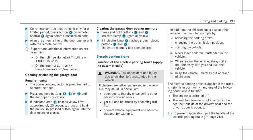
# On remote controls that transmit only for alimited period, press button6 on remotecontrol5 again before transmission ends.
# Align the antenna line of the door opener unitwith the remote control.
% Support and additional information on pro‐gramming:R On the toll free HomeLink® Hotline on
1-800-355-3515R On the Internet at https://
www.homelink.com/mercedes
Opening or closing the garage door
Requirements:R The corresponding button is programmed to
operate the door.
# Press and hold buttons1,2 or3 untilthe door opens or closes.
# If indicator lamp4 flashes yellow afterapproximately 20 seconds: press and holdthe previously pressed button again until thedoor opens or closes.
Clearing the garage door opener memory# Press and hold buttons1 and3.
Indicator lamp4 lights up yellow.# If indicator lamp4 flashes green: release
buttons1 and3.The entire memory has been deleted.
Electric parking brake
Function of the electric parking brake (apply‐ing automatically)
& WARNING Risk of accident and injurydue to children left unattended in thevehicle
If children are left unsupervised in the vehi‐cle, they could, in particular:R open doors, thereby endangering other
persons or road users.R get out and be struck by oncoming traf‐
fic.R operate vehicle equipment and become
trapped, for example.
In addition, the children could also set thevehicle in motion, for example by:R releasing the parking brake.R changing the transmission position.R starting the vehicle.
# Never leave children unattended in thevehicle.
# When leaving the vehicle, always takethe SmartKey with you and lock thevehicle.
# Keep the vehicle SmartKey out of reachof children.
The electric parking brake is applied if the trans‐mission is in positionj and one of the follow‐ing conditions is fulfilled:R The engine is switched off.R The seat belt tongue is not inserted in the
seat belt buckle of the driver's seat and thedriver's door is opened.
% To prevent application: pull the handle of theelectric parking brake (/ page 212).
Driving and parking 211

In the following situations, the electric parkingbrake is also applied:R Active Distance Assist DISTRONIC is bringing
the vehicle to a standstill.R The HOLD function is keeping the vehicle sta‐
tionary.R Active Parking Assist is keeping the vehicle
stationary.
This is the case if one of the following conditionsis also fulfilled:R The engine is switched off.R The seat belt tongue is not inserted in the
seat belt buckle of the driver's seat and thedriver's door is opened.R There is a system malfunction.R The power supply is insufficient.R The vehicle is stationary for a lengthy period.
When the electric parking brake is applied, theredF (USA) or! (Canada) indicator lamplights up in the driver's display.
The electric parking brake is not automaticallyapplied if the engine is switched off by the ECOstart/stop function.
Electric parking brake function (releasingautomatically)The electric parking brake is released when thefollowing conditions are fulfilled:R The driver's door is closed.R The engine is running.R The transmission is in positionh ork and
you depress the accelerator pedal or youshift from transmission positionj toh ork when on level ground with the driver'sdoor closed.R If the transmission is in positionk, the
trunk lid must be closed.R The seat belt tongue is inserted into the seat
belt buckle of the driver's seat.If the seat belt tongue is not inserted into theseat belt buckle of the driver's seat, one ofthe following conditions must be fulfilled:- You shift from transmission positionj.
- You have previously driven at speedsgreater than 2 mph (3 km/h).
When the electric parking brake is released, theredF (USA) or! (Canada) indicator lampin the driver's display goes out.
Applying/releasing the electric parkingbrake manually
Applying
212 Driving and parking

# Push handle1.The redF (USA) or! (Canada) indica‐tor lamp lights up in the driver display.
% The electric parking brake is only securelyapplied if the indicator lamp is lit continu‐ously.
Releasing# Switch on the ignition.# Pull handle1.
The redF (USA) or! (Canada) indica‐tor lamp in the driver display goes out.
Emergency braking# Press and hold handle1.
As long as the vehicle is driving, the PleaseRelease Parking Brake message is displayedand the red! indicator lamp flashes.When the vehicle has been braked to astandstill, the electric parking brake isapplied. The redF (USA) or! (Can‐ada) indicator lamp lights up in the driver dis‐play.
Information on collision detection on aparked vehicle
If a collision is detected when the tow-awayalarm is armed on a locked vehicle, you willreceive a notification in the multimedia systemwhen you switch on the ignition.You will receive information about the followingpoints:R The area of the vehicle that may have been
damaged.R The force of the impact.
The following situations can lead to inadvertentactivation:R The parked vehicle is moved, e.g. in a two-
story garage.
% Deactivate the tow-away alarm in order toprevent inadvertent activation. If you deacti‐vate the tow-away alarm, collision detectionwill also be deactivated.You can permanently deactivate collisiondetection via the multimedia system(/ page 213).
% If the battery is severely discharged, thefunction for detecting a collision on a parkedvehicle is automatically deactivated to facili‐tate the next engine start.
System limitsDetection may be restricted in the following sit‐uations:R The vehicle is damaged without impact, e.g.
if an outside mirror is torn off or the paint isdamaged by a keyR An impact occurs at low speedR The electric parking brake is not applied
Setting collision detection on a parked vehi‐cle
Multimedia system:4© 5 Settings 5 Vehicle5 Opening/closing 5 Vehicle Protection# Activate or deactivate the function under Col-
lision detection.
Driving and parking 213

% A maximum of three incidents can be regis‐tered. Up to 15 photos are taken for everyincident. In the event of another incident, thephotos of the first incident will be overwrit‐ten if they have not been deleted already.
Activating or deactivating the collision pho‐tos functionPlease note possible legal restrictions in somecountries regarding automatic recording of thevehicle surroundings.# Activate or deactivate Collision photos.
Transferring the collision photos with theMercedes me app# Select Upload Collision Photos.# Scan the QR code on the central display with
the Mercedes me app.The encrypted collision photos will then beuploaded to Mercedes me.
% Any device that can scan QR codes can beused to view the collision photos in theMercedes me app.
Copying the collision photos to a USB flashdrive# Connect a USB flash drive .# Select Manage Collision Photos.# Select Copy (USB).
All collision photos are copied to the USBflash drive.
% To ensure secure operation, only use FAT32or exFAT formatted USB storage devices.
Deleting collision photos# Select Manage Collision Photos.# Select Delete.
All collision photos will be deleted.
Notes on parking the vehicle for an extendedperiod
If you leave the vehicle parked for longer than sixweeks, it may suffer damage through disuse.The 12 V battery may also be impaired or dam‐aged by heavy discharging.% Further information can be obtained at a
qualified specialist workshop.
Standby mode (extension of the starter bat‐tery's period out of use)
Standby mode function% This function is not available for all models.If standby mode is activated, energy loss will beminimized during extended periods of non-oper‐ation.Standby mode is characterized by the following:R The starter battery is preserved.R The maximum non-operational time appears
in the driver's display.R The connection to online services is interrup‐
ted.
If the following conditions are fulfilled, standbymode can be activated or deactivated using themultimedia system:R The engine is switched off.R The ignition is switched on.
Exceeding the vehicle's displayed non-opera‐tional time may cause inconvenience; i.e. it can‐not be guaranteed that the starter battery willreliably start the engine.
214 Driving and parking
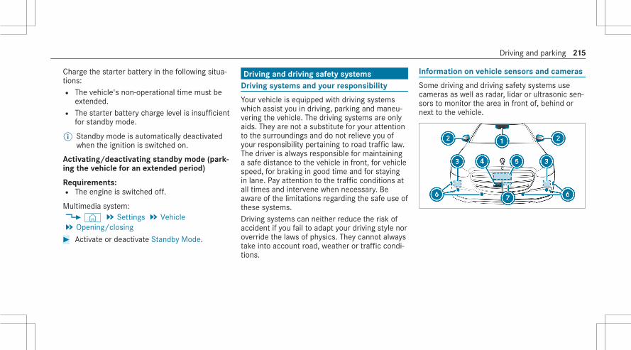
Charge the starter battery in the following situa‐tions:R The vehicle's non-operational time must be
extended.R The starter battery charge level is insufficient
for standby mode.
% Standby mode is automatically deactivatedwhen the ignition is switched on.
Activating/deactivating standby mode (park‐ing the vehicle for an extended period)
Requirements:R The engine is switched off.
Multimedia system:4© 5 Settings 5 Vehicle5 Opening/closing# Activate or deactivate Standby Mode.
Driving and driving safety systemsDriving systems and your responsibility
Your vehicle is equipped with driving systemswhich assist you in driving, parking and maneu‐vering the vehicle. The driving systems are onlyaids. They are not a substitute for your attentionto the surroundings and do not relieve you ofyour responsibility pertaining to road traffic law.The driver is always responsible for maintaininga safe distance to the vehicle in front, for vehiclespeed, for braking in good time and for stayingin lane. Pay attention to the traffic conditions atall times and intervene when necessary. Beaware of the limitations regarding the safe use ofthese systems.Driving systems can neither reduce the risk ofaccident if you fail to adapt your driving style noroverride the laws of physics. They cannot alwaystake into account road, weather or traffic condi‐tions.
Information on vehicle sensors and cameras
Some driving and driving safety systems usecameras as well as radar, lidar or ultrasonic sen‐sors to monitor the area in front of, behind ornext to the vehicle.
Driving and parking 215

% The radar and lidar sensors are integratedbehind the bumpers and/or behind theMercedes star.
1 Multifunction camera2 Cameras in the outside mirrors3 Ultrasonic sensors4 Front camera5 Rear view camera
& WARNING Risk of accident due torestricted detection performance of vehi‐cle sensors and cameras
If the area around vehicle sensors or cam‐eras is covered, damaged or dirty, certaindriving and safety systems cannot functioncorrectly. There is a risk of an accident.# Keep the area around vehicle sensors
or cameras clear of any obstructionsand clean.
# Have damage to the bumper, radiatorgrille or stone chipping in the area ofthe front and rear windows repaired ata qualified specialist workshop.
Particularly, keep the areas around the sensorsand cameras free of dirt, ice or slush(/ page 333). The sensors and cameras mustnot be covered and the detection ranges aroundthem must be kept free. Do not attach additionallicense plate brackets, advertisements, stickers,foils or foils to protect against stone chippings inthe detection range of the sensors and cameras.
Make sure that there are no overhanging loadsprotruding into the detection range.If there is damage to a bumper or the radiatorgrille, or after an impact, have the function ofthe sensors checked at a qualified specialistworkshop. Have damage or stone chipping in thearea of the cameras on the front and rear win‐dows repaired at a qualified specialist workshop.
Overview of driving systems and drivingsafety systems
R ABS (Anti-lock Braking System)(/ page 217)R BAS (Brake Assist System) (/ page 217)R ESP® (Electronic Stability Program)
(/ page 218)R ESP® Crosswind Assist (/ page 219)R ESP® trailer stabilizationR EBD (Electronic Brakeforce Distribution)
(/ page 219)R STEER CONTROL (/ page 219)R HOLD function (/ page 220)
216 Driving and parking

R Hill Start Assist (/ page 221)R ATTENTION ASSIST (/ page 221)R Traffic Sign Assist (/ page 241)R Traffic light view (/ page 244)R AIRMATIC (/ page 253)
Driving Assistance packageR Active Distance Assist DISTRONIC
(/ page 223)R Active Speed Limit Assist (country-depend‐
ent) (/ page 227)R Route-based speed adaptation (country-
dependent) (/ page 228)R Active Brake Assist (/ page 236)R Active Steering Assist (country-dependent)
(/ page 230)R Active Emergency Stop Assist (country-
dependent) (/ page 233)R Active Lane Change Assist (country-depend‐
ent) (/ page 234)R Active Stop-and-Go Assist (country-depend‐
ent) (/ page 230)
R Active Blind Spot Assist with exit warning(/ page 247)R Active Lane Keeping Assist (/ page 250)R PRE-SAFE® Impulse Side (/ page 59)
Parking PackageR Rear view camera (/ page 255)R Surround view camera (/ page 257)R Parking Assist PARKTRONIC (/ page 261)R Active Parking Assist (/ page 265)
Function of ABS
The Anti-lock Brake System (ABS) regulates thebrake pressure in critical driving situations:R During braking, e.g. at full brake application
or insufficient tire traction, the wheels areprevented from locking.R Vehicle steerability while braking is ensured.
If ABS intervenes when braking, you will feel apulsing in the brake pedal. The pulsating brakepedal can be an indication of hazardous road
conditions and can serve as a reminder to takeextra care while driving.
Function of BAS
The Brake Assist System (BAS) supports youremergency braking situation with additionalbrake force.If you depress the brake pedal quickly, BAS isactivated:R BAS automatically boosts the brake pres‐
sure.R BAS can shorten the braking distance.R ABS prevents the wheels from locking.
The brakes will function as usual once yourelease the brake pedal. BAS is deactivated.
Driving and parking 217

Function of ESP® (Electronic Stability Pro‐gram)
& WARNING Risk of skidding if ESP® isdeactivated
If you deactivate ESP®, ESP® cannot carryout vehicle stabilization.# ESP® should only be deactivated in the
following situations.
ESP® can monitor and improve driving stabilityand traction in the following situations, withinphysical limits:R When pulling away on a wet or slippery road.R When braking.
If the vehicle deviates from the direction desiredby the driver, ESP® can stabilize the vehicle byintervening in the following ways:R One or more wheels are braked.R The engine output is adapted according to
the situation.
When ESP® is deactivated, the å warninglamp lights up continuously:R Driving stability will no longer be improved.R The drive wheels could spin.R ETS/4ETS traction control is still active.
% When ESP® is deactivated, you are still assis‐ted by ESP® when braking.
When the ÷ warning lamp flashes, one orseveral wheels has reached its grip limit:R Adapt your driving style to suit the current
road and weather conditions.R Do not deactivate ESP®.R Only depress the accelerator pedal as far as
is necessary when pulling away.
Deactivate ESP® in the following situations toimprove traction:R When using snow chains.R In deep snow.R On sand or gravel.
% Spinning the wheels results in a cuttingaction, which enhances traction.
If the ÷ ESP® warning lamp lights up continu‐ously, ESP® is not available due to a malfunction.Observe the following information:R Warning and indicator lamps (/ page 530)R Display messages (/ page 478)
ETS/4ETS (Electronic Traction System)ETS/4ETS traction control is part of ESP® andmakes it possible to pull away and accelerate ona slippery road.ETS/4ETS can improve the vehicle's traction byintervening in the following ways:R The drive wheels are braked individually if
they spin.R More drive torque is transferred to the wheel
or wheels with traction.
Influence of drive programs on ESP®
The drive programs enable ESP® to adapt to dif‐ferent weather and road conditions as well asthe driver's preferred driving style. Depending onthe selected drive program, the appropriate
218 Driving and parking

ESP® mode will be activated. You can select thedrive programs using the DYNAMIC SELECTswitch (/ page 199).
Function of ESP® Crosswind Assist
ESP® Crosswind Assist detects sudden gusts ofside wind and helps the driver to keep the vehi‐cle in the lane:R ESP® Crosswind Assist is active at vehicle
speeds between approx. 47 mph (75 km/h)and 125 mph (200 km/h) when drivingstraight ahead or cornering slightly.R The vehicle is stabilized by means of individ‐
ual brake application on one side.
Activating/deactivating ESP® (Electronic Sta‐bility Program)
Multimedia system:4© 5ß 5y
% ESP® can only be activated/deactivatedusing quick access when at least one otherfunction is available in quick access. ESP®
can otherwise be found in the Assistancemenu.
# Select ESP.# Select On or å Off.
ESP® is deactivated if the å ESP® OFF warn‐ing lamp lights up continuously in the instrumentcluster.Observe any information on warning lamps anddisplay messages which may be shown in theinstrument cluster.
Function of EBD
Electronic Breakforce Distribution (EBD) is char‐acterized by the following:R Monitoring and regulating the brake pressure
on the rear wheels.R Improved driving stability when braking,
especially on bends.
Function of STEER CONTROL
STEER CONTROL assists you by transmitting anoticeable steering force to the steering wheel inthe direction required for vehicle stabilization.This steering recommendation is given in the fol‐lowing situations:R Both right wheels or both left wheels are on
a wet or slippery road surface when youbrakeR The vehicle starts to skid
System limitsSTEER CONTROL may be impaired or may notfunction in the following situations:R ESP® is deactivated.R ESP® is malfunctioning.R The steering is malfunctioning.
If ESP® is malfunctioning, you will be assistedfurther by the electric power steering.
Driving and parking 219

HOLD function
HOLD functionThe HOLD function holds the vehicle at a stand‐still without requiring you to depress the brakepedal, e.g. while waiting in traffic.The HOLD function is only an aid. The responsi‐bility for the vehicle safely standing still remainswith the driver.
System limitsThe HOLD function is only intended to provideassistance when driving and is not a sufficientmeans of safeguarding the vehicle against rollingaway when stationary.R The incline must not be greater than 30%.
Activating/deactivating the HOLD function
& WARNING Risk of an accident due to theHOLD function being active when youleave the vehicle
If the vehicle is only braked with the HOLDfunction it could, in the following situations,roll away:R If there is a malfunction in the system or
in the power supply.R If the HOLD function is deactivated by
depressing the accelerator pedal or brakepedal, e.g. by a vehicle occupant.
# Always secure the vehicle against roll‐ing away before you leave it.
Requirements:R The vehicle is stationary.R The driver's door is closed or the seat belt on
the driver's side is fastened.R The engine is running or has been automati‐
cally switched off by the ECO start/stopfunction.
R The electric parking brake is released.R Active Distance Assist DISTRONIC is deacti‐
vated.R The transmission is in positionh,k ori.
Activating the HOLD function# Depress the brake pedal, and after a short
time quickly depress further until theëdisplay appears in the driver's display.
# Release the brake pedal.
Deactivating the HOLD function# Depress the accelerator pedal to pull away.or# Depress the brake pedal until theë dis‐
play disappears from the driver's display.The HOLD function is deactivated in the follow‐ing situations:R Active Distance Assist DISTRONIC is activa‐
ted.R The transmission is shifted to positionj.R The vehicle is secured with the electric park‐
ing brake.
220 Driving and parking

In the following situations, the vehicle is held bytransmission positionj and/or by the electricparking brake:R The seat belt is unfastened and the driver's
door is opened.R The vehicle is switched off.R There is a malfunction in the system or the
power supply is insufficient.
In addition, the Brake Immediately message mayappear in the driver's display and a horn tonemay sound at regular intervals.# Immediately depress the brake pedal firmly
until the warning message disappears.The HOLD function is deactivated.
# Additionally secure the vehicle against rollingaway.
Function of Hill Start Assist
Hill Start Assist holds the vehicle for a shorttime when pulling away on a hill under the fol‐lowing conditions:R The transmission is in positionh ork.
R The electric parking brake is released.
This gives you enough time to move your footfrom the brake pedal to the accelerator pedaland depress it before the vehicle begins to rollaway.
& WARNING Risk of accident and injurydue to the vehicle rolling away
After a short time, Hill Start Assist no longerholds the vehicle.# Swiftly move your foot from the brake
pedal to the accelerator pedal. Do notleave the vehicle when it is being heldby Hill Start Assist.
ATTENTION ASSIST
Function of ATTENTION ASSIST with micro‐sleep detection% The microsleep detection subfunction is only
available in combination with the driver cam‐era.
ATTENTION ASSIST assists you on long, monoto‐nous journeys, e.g. on highways and trunk roads.If indicators of fatigue or increasing lapses inconcentration on the part of the driver aredetected, the system suggests taking a break.ATTENTION ASSIST is only an aid. It cannotalways detect fatigue or lapses in concentrationin time. The system is not a substitute for a well-rested and attentive driver. On long journeys,take regular breaks in good time that allow foradequate recuperation.You can choose between two settings:R Standard: normal system sensitivity.R Sensitive: increased system sensitivity: the
driver is warned earlier and the attentionlevel detected by the system is adaptedaccordingly.
If drowsiness or increasing lapses in concentra‐tion are detected, the ATTENTION ASSIST: Takea Break! warning appears in the driver display.You can acknowledge the message and take abreak where necessary. If you do not take abreak and ATTENTION ASSIST continues todetect increasing lapses in concentration, you
Driving and parking 221

will be warned again after a minimum of15 minutes.
The following information is displayed in thedriver display:R The length of the journey since the last breakR The attention level determined by ATTENTION
ASSIST:- The more segments2 of the circle dis‐
played, the higher the detected attentionlevel.
- Fewer segments2 are displayed in thecircle as the attention level decreases.
R Microsleep detection1 status:
- Deactivated: display1 is hidden.- Activated but not operational: display1
is gray.- Activated and operational: display1 is
green.
If ATTENTION ASSIST is unable to calculate theattention level and cannot issue a warning, theSystem Suspended message appears.If the system, which uses the driver camera,detects indicators of microsleep, the ATTEN-TION ASSIST Nodding Off Take a Break! warningmessage appears in the driver display and awarning tone sounds simultaneously. This warn‐ing message must be confirmed by Touch Con‐trol. It is recommended that you take a breakimmediately.If a warning is given in the driver display, themultimedia system offers to search for a restarea. You can select a rest area and start naviga‐tion to this rest area.ATTENTION ASSIST with microsleep detection isactivated automatically when the engine is
restarted. The last selected sensitivity levelremains stored.
System limitsATTENTION ASSIST is active in the 37 mph(60 km/h) to 124 mph (200 km/h) speed range.The microsleep detection function is available ata speed of 12.5 mph (20 km/h) and above.Particularly in the following situations, ATTEN‐TION ASSIST only functions in a restricted man‐ner and warnings may be delayed or not occur:R If you have been driving for less than approx‐
imately 30 minutes.R If the road condition is poor (uneven road
surface or potholes).R If there is a strong side wind.R If you adopt a sporty driving style (high cor‐
nering speeds or high rates of acceleration).R If the Steering Assist function of Active Dis‐
tance Assist DISTRONIC is active.R If the clock is set to the incorrect time.R If you change lanes and vary your speed fre‐
quently In active driving situations.
222 Driving and parking

Microsleep detection also does not functionwhen the driver camera cannot detect the eyesof the driver, as a result of the following factors,for example:R The driver's eyes are covered due to the
steering column position, for example.R Poor ambient light.R Some types of eyeglasses or sunglasses.R The driver's line of vision is outside the driver
camera's field of vision.
Also observe any information regarding displaymessages that can be displayed in the driver dis‐play.The tiredness and alertness assessment ofATTENTION ASSIST with microsleep detection isreset and restarted when continuing the journeyin the following situations:R If you switch off the engine.R If you unfasten your seat belt and open the
driver's door (e.g. to change drivers or take abreak).
Setting ATTENTION ASSISTMultimedia system:4© 5 Settings 5 Assistance5 Assistance 5 ATTENTION ASSIST
Setting the sensitivity# Tap the current setting.# Select Standard or Sensitive.
Activating/deactivating the microsleepwarning# Activate/deactivate Microsleep Warning.
Active Distance Assist DISTRONIC
Function of Active Distance AssistDISTRONICActive Distance Assist DISTRONIC maintains theset speed on free-flowing roads. If vehicles infront are detected, the set distance is main‐tained, if necessary, until the vehicle comes to ahalt. The vehicle accelerates or brakes depend‐ing on the distance to the vehicle in front andthe set speed. The speed and distance to the
vehicle in front are set and saved using thesteering wheel.Active Distance Assist DISTRONIC is available inthe 15 mph (20 km/h) to 130 mph (210 km/h)speed range.Other features of Active Distance AssistDISTRONIC:R Adjusts the driving style depending on the
selected drive program (fuel-saving, comfort‐able or dynamic) (/ page 198)R Initiates acceleration to the stored speed if
the turn signal indicator is switched on tochange to the overtaking laneR Reacts to stationary vehicles detected in
urban speed ranges (except bicycles andmotorcycles)R Takes one-sided overtaking restrictions into
account on highways or on multi-lane roadswith separate roadways (country-dependent)
Additional function available in certain coun‐tries: if Active Distance Assist DISTRONIC hasbraked the vehicle to a standstill, it can automat‐ically follow the vehicle in front when driving off
Driving and parking 223

again within 30 seconds. If a critical situation isdetected in the surrounding area when drivingoff, such as a person in the vehicle path, a visualand acoustic warning is given indicating that thedriver must now take control of the vehicle. Thevehicle is not accelerated any further.Active Distance Assist DISTRONIC is ready topull away when the greenç vehicle symbolflashes cyclically.Observe the notes on driving systems and yourresponsibility; you may otherwise fail to recog‐nize dangers (/ page 215).
Driver display in the Assistancemenu
1 Vehicle in front2 Distance indicator3 Set specified distance
Vehicle detected in front1 is highlighted ingreen. It may also be in the lane to the left ofyour vehicle in situations where it is not permit‐ted to overtake on the right, for example on high‐ways.
Permanent status displayRç (white): Active Distance Assist
DISTRONIC selected, specified distance set
Rç (green): Active Distance AssistDISTRONIC active, specified distance set andvehicle detected
The stored speed is shown under the permanentstatus display and highlighted on the speedome‐ter. When Active Distance Assist DISTRONIC ispassive, the status display is grayed out.If the speed of the vehicle in front or the speedadjustment is less than the stored speed due tothe route event ahead, the segments in thespeedometer light up.When the set specified distance is increased ordecreased, theÒ display briefly appearsunder the vehicle in the permanent status dis‐play.% On highways or high-speed major roads, the
greenç vehicle symbol is displayed cycli‐cally when the vehicle is ready to pull away.
% If you depress the accelerator pedal beyondthe setting of the Active Distance AssistDISTRONIC, the system is switched to pas‐sive mode. Theç Suspended messageappears on the driver display.
224 Driving and parking

System limitsThe system may be impaired or may not functionin the following situations, for example:R In snow, rain, fog, heavy spray, if there is
glare, in direct sunlight or in greatly varyingambient light.R The windshield in the area of the camera is
dirty, fogged up, damaged or covered.R If the radar sensors are dirty or covered.R In parking garages or on roads with steep
uphill or downhill gradients.R If there are narrow vehicles in front, such as
bicycles or motorcycles.
In addition, on slippery roads, braking or accel‐erating can cause one or several wheels to losetraction and the vehicle could then skid.Do not use Active Distance Assist DISTRONIC inthese situations.
& WARNING Risk of accident from acceler‐ation or braking by Active DistanceAssist DISTRONIC
Active Distance Assist DISTRONIC may accel‐erate or brake in the following cases, forexample:R If the vehicle pulls away using Active Dis‐
tance Assist DISTRONIC.R If the stored speed is called up and is
considerably faster or slower than thecurrently driven speed.R If Active Distance Assist DISTRONIC no
longer detects a vehicle in front or doesnot react to relevant objects.
# Always carefully observe the traffic con‐ditions and be ready to brake at alltimes.
# Take into account the traffic situationbefore calling up the stored speed.
& WARNING Risk of accident due to insuf‐ficient deceleration by Active DistanceAssist DISTRONIC
Active Distance Assist DISTRONIC brakesyour vehicle with up to 50% of the possibledeceleration. If this deceleration is not suffi‐cient, Active Distance Assist DISTRONICalerts you with a visual and acoustic warning.# Adjust your speed and maintain a suita‐
ble distance from the vehicle in front.# Brake the vehicle yourself and/or take
evasive action.
& WARNING Risk of accident if detectionfunction of Active Distance AssistDISTRONIC is impaired
Active Distance Assist DISTRONIC does notreact or has a limited reaction:R when driving on a different lane or when
changing lanes
Driving and parking 225

R to pedestrians, animals, bicycles or sta‐tionary vehicles, or unexpected obstaclesR to complex traffic conditionsR to oncoming vehicles and crossing traffic
As a result, Active Distance AssistDISTRONIC may neither give warnings norintervene in such situations.# Always observe the traffic conditions
carefully and react accordingly.
Operating Active Distance Assist DISTRONIC
Requirements:R The electric parking brake is released.R ESP® is activated and is not intervening.R The transmission is in positionh.R All the doors are closed.R Check of the radar sensor system has been
successfully completed.R Snow chain mode is not active
(/ page 359).
J Adopts the stored/detected speed± Deactivates the variable limiter/Active
Distance Assist DISTRONIC1 Increases/decreases the speedK Increases/decreases the specified dis‐
tanceH Activates/deactivates Active Distance
Assist DISTRONIC
# To operate Active Distance AssistDISTRONIC: press the respective buttonwith only one finger or swipe on the controlpanel.
Activating/deactivating Active DistanceAssist DISTRONIC# PressH.
Activating Active Distance Assist DISTRONIC# To activate without a stored speed: on
control panel1 pressM on the uppersection orN on the lower section orJ. Remove your foot from the acceleratorpedal.
or# To activate with a stored speed: pressJ. Remove your foot from the acceleratorpedal.The current speed is stored and maintainedby the vehicle.
226 Driving and parking

Increasing or reducing the speed# To increase the stored speed: swipe upwards
from the bottom of control panel1.R The stored speed is increased by 1 mph
(1 km/h).# To decrease the stored speed: swipe down‐
wards from the top of control panel1.R The stored speed is decreased by 1 mph
(1 km/h).or# Briefly pressM on the upper section orN on the lower section of control panel1.The stored speed is increased or reduced by5 mph (10 km/h).
or# Accelerate the vehicle to the desired speed.# PressM on the upper section of control
panel1.
Adopting the limit speed shown in the driverdisplay# Activate Active Distance Assist DISTRONIC.
# PressJ.The limit speed displayed in the driver displayis adopted as the stored speed. The vehicleadapts its speed to that of the vehicle infront, but only up to the stored speed.
Pulling away with Active Distance AssistDISTRONIC# Activate Active Distance Assist DISTRONIC
and remove your foot from the brake pedal.# PressJ.or# Depress the accelerator pedal briefly and
firmly.The functions of Active Distance AssistDISTRONIC continue to be carried out.
Reducing or increasing the specified dis‐tance from the vehicle in front# PressK.
TheÒ display appears under theçstatus display.The specified distance is reduced by onelevel.
If the lowest level is already selected, theselection jumps to the highest level.
Deactivating Active Distance AssistDISTRONIC
& WARNING Risk of an accident due toActive Distance Assist DISTRONIC beingactive when you leave the driver's seat
If you leave the driver's seat while the vehicleis being braked by Active Distance AssistDISTRONIC only, the vehicle can roll away.# Always deactivate Active Distance
Assist DISTRONIC and secure the vehi‐cle to prevent it from rolling awaybefore you leave the driver's seat.
# Press±.% If you brake, deactivate ESP® or if ESP®
intervenes, Active Distance AssistDISTRONIC is deactivated.
Function of Active Speed Limit AssistIf speed limit change between 12 mph(20 km/h) and 80 mph (130 km/h) is detected
Driving and parking 227

and the automatic adoption of speed limits isactive, it will be automatically adopted as thestored speed (/ page 230).The driven speed is adjusted when the vehicle islevel with the traffic sign at the latest. In thecase of signs indicating entry into an urban area,the speed is adapted according to the speedpermitted within the urban area. The speed limitdisplay in the driver display is always updatedwhen the vehicle is level with the traffic sign.If you are driving on German highways and thereis no speed limit, the system uses the speedstored on an unlimited stretch of road as therecommended speed. If you do not alter thestored speed on an unlimited stretch of road, therecommended speed is 80 mph (130 km/h).If Active Distance Assist DISTRONIC has beenput into passive mode by pressing the accelera‐tor pedal, only speed limits which are higherthan the set speed are adopted.The maximum permissible speed does not takethe road condition and current weather and traf‐fic conditions into account. Adjust your speedaccordingly, when necessary.
Observe the notes on driving systems and yourresponsibility; you may otherwise fail to recog‐nize dangers (/ page 215).
System limitsThe system limits of Traffic Sign Assist apply tothe detection of traffic signs (/ page 241).Speed limits below 12 mph (20 km/h) are notautomatically adopted by the system as thestored speed. Temporary speed restrictions (e.g.for a certain time or due to weather conditions)cannot be properly detected by the system. Themaximum permissible speed applying to a vehi‐cle with a trailer is not detected by the system.Adjust the speed in these situations.
& WARNING Risk of accident due to ActiveSpeed Limit Assist adapting the vehicle'sspeed
The speed adopted by Active Speed LimitAssist may be too high or incorrect in someindividual cases, such as:R at speed limits below 12 mph (20 km/h)
R in wet conditions or in fogR when towing a trailer
# Ensure that the driven speed complieswith traffic regulations.
# Adjust the driving speed to suit currenttraffic and weather conditions.
Function of route-based speed adaptationWhen Active Distance Assist DISTRONIC is acti‐vated, the vehicle speed will be adapted accord‐ingly to the route events ahead. Depending onthe drive program selected, the vehicle negoti‐ates a route event ahead in a fuel-saving, com‐fortable or dynamic manner. When the routeevent has been passed, the vehicle acceleratesagain to the stored speed. The set distance tothe vehicle in front, vehicles detected ahead andspeed restrictions ahead are taken into account.Route-based speed adaptation can be activatedin the multimedia system (/ page 230).The following route events are taken intoaccount:R Curves
228 Driving and parking
R RoundaboutsR T-intersectionsR Turns and exitsR Traffic jams ahead (only with Live Traffic )
Also, the speed is reduced if the turn signal indi‐cator to change lanes is switched on and one ofthe following situations is detected:R Turning off at intersectionsR Driving on slowing-down lanesR Driving on lanes adjacent to slowing-down
lanes
The driver is responsible for choosing the rightspeed and observing other road users. Thisapplies in particular to intersections, round‐abouts and traffic lights, as route-based speedadaptation does not brake the vehicle to a stand‐still.If a corresponding route event is detected whileroute guidance is active, the first speed adjust‐ment is carried out automatically. If the turn sig‐nal indicator is switched on, the selected route is
confirmed and further speed adjustment is acti‐vated.Speed adaptation is canceled in the followingcases:R If the turn signal indicator is switched off
before the route event and it is thereforeassumed that the route event is not relevantto the driver.R If the driver depresses the accelerator or
brake pedal during the process.
System limitsRoute-based speed adaptation does not takeright of way regulations into account. The driveris responsible for complying with road trafficregulations and driving at a suitable speed.In difficult conditions, the speed selection madeby the system may not always be suitable:R Unclear roadsR Road narrowingR Varying maximum permissible speeds in indi‐
vidual lanes, for example at toll stationsR Wet road surfaces, snow or ice
In these situations the driver must interveneaccordingly.
& WARNING Risk of accident in spite ofroute-based speed adaptation
Route-based speed adaptation can malfunc‐tion or be temporarily unavailable in the fol‐lowing situations:R If the driver does not follow the calcula‐
ted routeR If map data is not up-to-date or availableR In the event of roadworksR In bad weather or road conditionsR If the accelerator pedal is depressedR In the event of electronically displayed
speed limitations
# Adapt the speed to the traffic situation.
Driving and parking 229

Setting Active Distance Assist DISTRONICdriving styles
Requirements:R Active Distance Assist DISTRONIC is activa‐
ted.
Multimedia system:4© 5 Settings 5 Assistance5 Driving 5 Active Distance Assist
Selecting a driving style# Select DYNAMIC SELECT based , Dynamic or
Comfort.
Setting speed adaptation# Select When cornering etc. or For limits.
When these functions are active, the vehiclespeed is adjusted according to a route eventahead or to speed limits detected by TrafficSign Assist.
% When one of the following systems is active,the detected speed can be manually adoptedas the speed limit:R Active Distance Assist DISTRONIC
R Variable limiter
Further information about Active DistanceAssist DISTRONIC (/ page 226).
% Further information on speed adaptation(/ page 228).
Function of Active Traffic Jam AssistActive Traffic Jam Assist helps you when in traf‐fic jams on multi-lane roads with separate road‐ways by automatically pulling away within60 seconds and with moderate steering maneu‐vers. It orients itself using the vehicle in frontand lane markings. Active Traffic Jam Assistautomatically maintains a safe distance from thevehicle in front and vehicles cutting in.Active Traffic Jam Assist requires you, as thedriver, to keep your hands on the steering wheelat all times so that you are able to intervene atany time to correct the course of the vehicle andkeep it in lane.Observe the notes on driving systems and yourresponsibility; you may otherwise fail to recog‐nize dangers (/ page 215).
Active Traffic Jam Assist activates automaticallywhen all of the following conditions are met:R You are in a traffic jam on a freeway or high-
speed major road.R Active Distance Assist DISTRONIC is activa‐
ted and active (/ page 226).R Active Steering Assist is activated and active
(/ page 232).R You are traveling no faster than 35 mph
(60 km/h).
When Active Traffic Jam Assist is active the¬status display appears in the driver display.
System limitsThe system limitations of Active Distance AssistDISTRONIC and Active Steering Assist apply toActive Traffic Jam Assist (/ page 230).
Active Steering Assist
Function of Active Steering AssistActive Steering Assist is only available up to aspeed of 130 mph (210 km/h). The system helpsyou to stay in the center of the lane by means of
230 Driving and parking

moderate steering interventions. Depending onthe speed driven, Active Steering Assist uses thevehicles ahead and lane markings as a refer‐ence.% Depending on the country, in the lower
speed range Active Steering Assist can usethe surrounding traffic as a reference. If nec‐essary, Active Steering Assist can then alsoprovide assistance when driving away fromthe center of the lane.
If the detection of lane markings and vehiclesahead is impaired, Active Steering Assistswitches to passive mode. The system providesno support in this case.
Permanent status display in the driver dis‐playØ Gray: activated and passiveØ Green: activated and activeØ Red, flashing: prompt to the driver to
actively confirm or transition from activeto passive status, system limit detected
% During the transition from active to passivestatus, theØ symbol is shown as
enlarged and flashing. Once the system ispassive, theØ symbol is shown as gray inthe driver display.
Contact detectionThe driver is required to keep their hands on thesteering wheel at all times and be able to inter‐vene at any time to correct the course of thevehicle and keep it in lane. The driver mustexpect a change from active to passive mode orvice versa at any time.
If the system detects that the driver has notsteered the vehicle for a considerable period oftime or has removed their hands from the steer‐ing wheel, an optical warning is given first. Dis‐
play message1 appears in the driver display. Ifthe driver still does not steer the vehicle, orgives no confirmation to the system, a warningtone sounds in addition to the visual warningmessage.If the driver does not react to this warning for aconsiderable period, an emergency stop is initi‐ated (/ page 233).The warning is not issued or is stopped as soonas the system detects that the driver hastouched the steering wheel.Touch detection may be limited or inoperative inthe following situations:R The driver is wearing gloves.R There is a steering wheel cover on the steer‐
ing wheel.
If Active Steering Assist detects that a systemlimit has been reached, a visual warning isissued and a warning tone sounds.Observe the notes on driving systems and yourresponsibility; you may otherwise fail to recog‐nize dangers (/ page 215).
Driving and parking 231

System limitsActive Steering Assist has a limited steering tor‐que for lateral guidance. In some cases, thesteering intervention is not sufficient to keep thevehicle in the lane.The system may be impaired or may not functionin the following instances:R There is poor visibility, e.g. due to snow, rain,
fog, heavy spray, greatly varying ambientlight or strong shadows on the road.R There is glare, e.g. from oncoming traffic,
direct sunlight or reflections.R Insufficient road illumination.R The windshield is dirty, fogged up, damaged
or covered in the vicinity of the camera, e.g.by a sticker.R No, or several, unclear lane markings are
present for one lane, or the markings changequickly, for example, in a construction areaor at intersections.R The lane markings are worn away, dark or
covered up, e.g. by dirt or snow.
R If the distance to the vehicle in front is tooshort and thus the lane markings cannot bedetected.R The road is narrow and winding.R There are obstacles on the lane or projecting
out into the lane, such as object markers.
The system does not provide assistance in thefollowing conditions:R On very tight curves and when turning.R When crossing intersections.R At roundabouts or toll plazas.R When actively changing lane without switch‐
ing on the turn signal indicator.R When the tire pressure is too low.
& WARNING Risk of accident if ActiveSteering Assist unexpectedly stops func‐tioning
If the system limits of Active Steering Assistare reached there is no guarantee that thesystem will remain active or will keep thevehicle in lane.
# Always keep your hands on the steeringwheel and observe the traffic carefully.
# Always steer the vehicle paying atten‐tion to traffic conditions.
& WARNING Risk of accident if ActiveSteering Assist unexpectedly intervenes
The detection of lane markings and objectsmay malfunction and cause unexpectedsteering interventions.# Steer according to traffic conditions.
Activating/deactivating Active SteeringAssist
Requirements:R ESP® is activated, but is not intervening.R Active Distance Assist DISTRONIC is activa‐
ted.
Multimedia system:4© 5 Settings 5 Assistance5 Driving# SelectØ Act. Steering Asst. .
232 Driving and parking

Function of Active Emergency Stop Assist
Active Emergency Stop Assist uses touch sen‐sors to monitor whether the driver holds thesteering wheel and initiates an emergency stop ifnecessary.If Active Steering Assist is deactivated, theaccelerator and brake pedal are monitored aswell as the steering wheel. A warning is issuedwhen the steering wheel is not being held orwhen a pedal is not depressed, and the vehicleis in danger of leaving the lane.
If the system detects that the driver has notsteered the vehicle for a considerable period oftime or has removed their hands from the steer‐
ing wheel, visual warning1 is issued. If thedriver still does not steer the vehicle, or gives noconfirmation to the system, a warning tonesounds in addition to the visual warning mes‐sage.Also observe the instructions on the contactdetection of Active Steering Assist(/ page 230).Active Emergency Stop Assist issues the follow‐ing warnings in order:R Display message1 appears in the driver
display.R In addition to display1 a warning tone
sounds.R The Beginning Emergency Stop message
appears in the driver display, a continuouswarning tone sounds, the vehicle no longeraccelerates, and there is a slight, repeatedtensioning of the seat belt.R The vehicle speed is reduced in increments
until it is at a standstill. Sharp brake impul‐ses are also produced.
Depending on the country, a lane change to theadjacent right-hand lane is carried out, if possi‐ble.% It is only possible to change across one lane
and only into the right-hand lane, and notonto the hard shoulder.
Depending on the country, the hazard warninglights are switched on when automatic braking isinitiated.When the vehicle is stationary, the followingactions are carried out:R The vehicle is secured with the electric park‐
ing brake.R Active Distance Assist DISTRONIC is endedR The vehicle is unlocked.R If possible, an emergency call is placed to
the Mercedes-Benz emergency call center
Before automatic braking is initiated, you cancancel Active Emergency Stop Assist by steer‐ing.
Driving and parking 233

You can cancel the intervention by Active Emer‐gency Stop Assist after automatic braking is ini‐tiated by one of the following actions:R Accelerating or braking: the emergency stop
is canceled, but the warning message, warn‐ing tone and power steering remain activeR Steering: power-assisted steering is can‐
celed, the warning message and warningtone remain active and the vehicle continuesto be braked
% Active Emergency Stop Assist can initiate anemergency stop a maximum of three timeswithin one ignition cycle. After this ActiveSteering Assist and Active Emergency StopAssist are deactivated for that ignition cycle.
System limitsIf Active Lane Keeping Assist does not detectlane markings, Active Emergency Stop Assist isnot active.
For the detection of vehicles and other obsta‐cles, observe the system limits of the followingfunctions:R Active Distance Assist DISTRONIC
(/ page 223)R Active Steering Assist (/ page 230)R Active Lane Change Assist (/ page 234)
Active Lane Change Assist
Function of Active Lane Change AssistActive Lane Change Assist supports the driverwhen changing lanes and is activated by indicat‐ing briefly.For this, the following conditions must be fulfil‐led:R You are on a freeway or high-speed major
road.R The vehicle speed is between approximately
45 mph (70 km/h) and 110 mph (180 km/h).R The adjacent lane is separated by a broken
lane marking.
R No vehicle or obstacle is detected in theadjacent lane.R Active Lane Change Assist is selected in the
multimedia system.R Active Distance Assist DISTRONIC and Active
Steering Assist are switched on and active.
234 Driving and parking

Driver display in the Assistancemenu
1 Green arrow: lane change initiated2 Red arrow: lane change canceled
When Active Lane Change Assist is available, the± display appears along with green arrows inthe driver display. If the system has been activa‐ted but is not currently available, the± dis‐
play appears along with gray arrows in the driverdisplay.If no vehicle or obstacle is detected in the adja‐cent lane and a lane change is permitted, thelane change begins after the driver has indicatedbriefly. The lane change is shown to the driverwith a flashing green arrow next to the±steering wheel symbol. Green arrow1 is dis‐played in the appropriate adjacent lane in theAssistance menu in the driver display. The LaneChange to the Left message, for example, alsoappears.If a lane change is not possible directly after thedriver has activated the turn signal indicatorbecause an obstacle has been detected, forexample, the arrow will also flash in green nextto the± steering wheel symbol and the adja‐cent lane will continue to be monitored. Whenthe lane becomes free, a lane change will be car‐ried out and the Lane Change to the Left mes‐sage, for example, appears in the driver display.If the green arrows stop flashing, the lanechange must be activated again.
Active Lange Change Assist can be canceled invarious situations, including the following:R Change in the surrounding conditions (e.g.
detected obstacle).R The driver steers with too much force or in
the opposite direction.R The driver moves the turn signal indicator in
the opposite direction.R Active Distance Assist DISTRONIC or Active
Steering Assist is deactivated.R The vehicle cannot make the lane change as
planned.
Cancellation of Active Lane Change Assist is dis‐played as follows:R The arrow in the selected direction of travel
turns red.R A corresponding message appears on the
driver display.R In certain circumstances a warning tone
sounds.
Driving and parking 235

& WARNING Risk of accident when chang‐ing lane to an occupied adjacent lane
Lane Change Assist cannot always clearlydetect if the adjacent lane is free.The lane change might be initiated althoughthe adjacent lane is not free.# Before changing lanes, make sure that
the neighboring lane is free and there isno danger to other road users.
# Monitor the lane change.
& WARNING Risk of accident if LaneChange Assist unexpectedly stops func‐tioning
If the system limitations for Lane ChangeAssist have been reached, there is no guar‐antee that the system will remain active.Lane Change Assist cannot then assist youby applying steering torque.# Always monitor the lane change and
keep your hands on the steering wheel.
Observe the traffic conditions and steerand/or brake if necessary.
System limitsThe system limitations of Active Steering Assistapply to Active Lane Change Assist(/ page 230).The system may also be impaired or may notfunction in the following situations:R The sensors are damaged, covered or dirty
(/ page 215).R The exterior lighting shows a malfunction.R The system does not detect a suitable road,
for example, in tight curves.R The vehicle is on a construction site.
% The Active Lane Change Assist sensorsadjust automatically while a certain distanceis being driven after the vehicle has beendelivered. Active Lane Change Assist isunavailable or only partially available duringthis teach-in process, and no arrows are dis‐played next to theØ Active SteeringAssist symbol.
Observe the notes on driving systems and yourresponsibility; you may otherwise fail to recog‐nize dangers (/ page 215).
Selecting Active Lane Change AssistMultimedia system:4© 5 Settings 5 Assistance5 Driving# Select the function.
Active Brake Assist
Function of Active Brake AssistActive Brake Assist consists of the followingfunctions:R Distance warning functionR Autonomous braking functionR Situation-dependent braking assistanceR Evasive Steering Assist (country-specific)
Active Brake Assist can help you to minimize therisk of a collision with vehicles, cyclists orpedestrians or to reduce the effects of such acollision.
236 Driving and parking

If Active Brake Assist has detected a risk of colli‐sion, a warning tone sounds and theL dis‐tance warning lamp lights up.
In the Assistance menu, an insufficient distance1 to the vehicle in front is displayed in red. Ifyou further reduce the distance, the vehicle infront is also highlighted in red. When the systemdetects a risk of collision, red radar waves2appear in front of the vehicle.
Vehicles with PRE-SAFE®: depending on thecountry, an additional haptic warning occurs inthe form of slight, repeated tensioning of theseat belt.
% Vehicles with active ambient lighting: ifWarning Support is activated, the ActiveBrake Assist warning is also accompanied byambient lighting (/ page 165).
If you do not react to the warning, autonomousbraking can be initiated in critical situations.In particularly critical situations, Active BrakeAssist can also initiate autonomous brakingdirectly. In this case, the warning lamp and warn‐ing tone occur simultaneously with the brakingapplication.If you apply the brake yourself in a critical situa‐tion or apply the brake during autonomous brak‐ing, situation-dependent braking assistanceoccurs. The brake pressure increases up to max‐imum full-stop braking if necessary.
If autonomous braking or situation-dependentbraking assistance has occurred, pop up1appears in the driver display and then automati‐cally goes out after a short time.If the autonomous braking function or the situa‐tion-dependent braking assistance is triggered,additional preventive measures for occupantprotection (PRE-SAFE®) may also be initiated.
Driving and parking 237

& WARNING Risk of an accident caused bylimited detection performance of ActiveBrake Assist
Active Brake Assist cannot always clearlyidentify objects and complex traffic situa‐tions.Active Brake Assist is only an aid. The driveris responsible for maintaining a sufficientlysafe distance to the vehicle in front, vehiclespeed and for braking in good time.# Always pay careful attention to the traf‐
fic situation; do not rely on Active BrakeAssist alone.
# Be prepared to brake or swerve if nec‐essary.
% If Active Brake Assist is deactivated,æappears in the driver display.If the system is unavailable or the functionsare restricted,Ä appears.
Also observe the system limits of Active BrakeAssist.
The individual subfunctions are available inthe following speed ranges:The distance warning function issues a warningin the following situations:R From approximately 4 mph (7 km/h), if your
vehicle is critically close to a vehicle, cyclistor pedestrian, you will hear an intermittentwarning tone and theL distance warninglamp lights up in the driver's display.
Vehicles with PRE-SAFE®: depending onthe country, an additional haptic warningoccurs in the form of slight, repeated ten‐sioning of the seat belt.
If possible, brake immediately or maneuver toavoid the obstacle.
Distance warning functionThe distance warning function can assist you bymeans of an intermittent warning tone and awarning lamp:R At speeds up to approximately 155 mph
(250 km/h) when approaching vehiclesahead.
R At speeds up to approximately 75 mph(120 km/h) when approaching crossing vehi‐cles, pedestrians and cyclists.R At speeds up to approximately 62 mph
(100 km/h) when approaching stationaryvehicles.R At speeds up to approximately 50 mph
(80 km/h) when approaching cyclists ahead.R At speeds up to approximately 43 mph
(70 km/h) when approaching stationarypedestrians and cyclists.
Autonomous braking functionThe autonomous braking function can intervenefrom speeds of approximately 4 mph (7 km/h):R At speeds up to approximately 155 mph
(250 km/h) when approaching vehiclesahead.R At speeds up to approximately 75 mph
(120 km/h) when approaching crossing vehi‐cles, pedestrians and cyclists.R At speeds up to approximately 62 mph
(100 km/h) when approaching stationaryvehicles.
238 Driving and parking

R At speeds up to approximately 50 mph(80 km/h) when approaching cyclists ahead.R At speeds up to approximately 43 mph
(70 km/h) when approaching stationarypedestrians and cyclists.
Situation-dependent braking assistanceSituation-dependent braking assistance canintervene from speeds of approximately 4 mph(7 km/h):R At speeds up to approximately 155 mph
(250 km/h) when approaching vehiclesahead.R At speeds up to approximately 75 mph
(120 km/h) when approaching crossing vehi‐cles, pedestrians and cyclists.R At speeds up to approximately 62 mph
(100 km/h) when approaching stationaryvehicles.R At speeds up to approximately 50 mph
(80 km/h) when approaching cyclists ahead.R At speeds up to approximately 43 mph
(70 km/h) when approaching stationarypedestrians and cyclists.
Canceling a brake application of Active BrakeAssistYou can cancel a brake application of ActiveBrake Assist at any time by:R Fully depressing the accelerator pedal or
with kickdown.R Releasing the brake pedal.
Active Brake Assist may cancel the brake appli‐cation when one of the following conditions isfulfilled:R You maneuver to avoid the obstacle.R There is no longer a risk of collision.R An obstacle is no longer detected in front of
your vehicle.
Reaction to oncoming road usersActive Brake Assist can also react to detectedoncoming road users:R Reaction up to speeds of approximately
62 mph (100 km/h)R Warning for oncoming road users through
acoustic warning and warning lamp
R Autonomous braking application in order toreduce the severity of an accident
Evasive Steering Assist
& WARNING Risk of accident despite Eva‐sive Steering Assist
Evasive Steering Assist cannot always recog‐nize objects or complex traffic situationsclearly.Moreover, the steering support provided byEvasive Steering Assist is not sufficient toavoid a collision.# Always pay careful attention to the traf‐
fic situation; do not rely on EvasiveSteering Assist alone.
# Be prepared to brake or swerve if nec‐essary.
# End the support by actively steering innon-critical situations.
# Drive at an appropriate speed if thereare pedestrians close to the path ofyour vehicle.
Driving and parking 239

Evasive Steering Assist has the following charac‐teristics:R Detection of pedestrians, cyclists and vehi‐
cles.R Assistance through power-assisted steering if
it detects a swerving maneuver.R Activation by an abrupt steering movement
during a swerving maneuver.R Assistance during swerving and straightening
of the vehicle.R Reaction from a speed of approximately
13 mph (20 km/h) up to a speed of approx‐imately 68 mph (110 km/h).
The steering support of Evasive Steering Assistcan be canceled at any time by counter steering.
System limitsFull system performance is not available for afew seconds after switching on the ignition orafter driving off.If the system is unavailable or the functions arerestricted, theÄ warning lamp appears in thedriver's display.
The system may be impaired or may not func‐tion, particularly in the following situations:R In snow, rain, fog, heavy spray, if there is
glare, in direct sunlight or in greatly varyingambient light.R If the sensors are dirty, fogged up, damaged
or covered. (/ page 215)R If the sensors are impaired due to interfer‐
ence from other radar sources, e.g. strongradar reflections in parking garages.R If a loss of tire pressure or a faulty tire has
been detected and displayed.R In complex traffic situations where objects
cannot always be clearly identified.R If pedestrians, cyclists or vehicles move
quickly into the sensor detection range.R If road users are hidden by other objects or
are located close to other objects.R If the typical outline of a pedestrian or cyclist
cannot be distinguished from the back‐ground.
R If a pedestrian or cyclist is not detected assuch, e.g. due to special clothing or otherobjects.R If the driver's seat belt is not fastened.R On curves with a tight radius.
% The Active Brake Assist sensors adjust auto‐matically while a certain distance is beingdriven after the vehicle has been delivered.Active Brake Assist is unavailable or onlypartially available during the teach-in proc‐ess.
Setting Active Brake Assist
Requirements:R The ignition is switched on.
Multimedia system:4© 5 Settings 5 Assistance5 Avoid collision 5 Active Brake Assist# Select the desired setting.
The setting is retained when the engine isnext started.
240 Driving and parking

Deactivating Active Brake Assist% It is recommended that you always leave
Active Brake Assist activated.# Select Off.
The distance warning function, the autono‐mous braking function and the Evasive Steer‐ing Assist are deactivated.When the engine is next started, the mediumsetting is automatically selected.
% If Active Brake Assist is deactivated, theæ symbol appears in the status bar of themultifunction display.
Traffic Sign Assist
Function of Traffic Sign AssistTraffic Sign Assist detects traffic signs with themultifunction camera and compares this withinformation in the digital navigation map. Itassists you by displaying detected speed limitsand overtaking restrictions in the driver displayand in the head-up display. The system can issuea warning when you exceed the maximum per‐missible speed.
In some countries, the system can provide youwith further functions and can warn you whenyou are approaching pedestrian crossings orwhen you are about to drive past stop signs orred lights unintentionally.The camera also detects and analyzes trafficsigns with a restriction indicated by an additionalsign (e.g. when wet).Traffic Sign Assist only visualizes selected signsin the driver display. Actual traffic signs andspeed limits have priority over traffic signs andspeed limits shown in the driver display.Also observe the following information:R Select a speed adapted to the traffic, sur‐
roundings and weather conditionsR Observe actual traffic signsR Observe applicable traffic rules and regula‐
tions
Observe the notes on driving systems and yourresponsibility; you may otherwise fail to recog‐nize dangers (/ page 215).
Messages in the driver display
1 Permissible speed2 Permissible speed when there is a restriction3 Additional sign with restriction
The system can show up to two traffic signs inthe driver display simultaneously. The systemalways prioritizes displaying speed limits. Up toone traffic sign with a maximum permissiblespeed can be shown in the head-up display. Iftwo speed signs are shown in the driver display,for example, when speed limits are detected, thevalue of left-hand speed limit1 is transmittedto the limiter or Active Distance Assist
Driving and parking 241
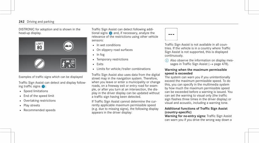
DISTRONIC for adoption and is shown in thehead-up display.
Examples of traffic signs which can be displayed
Traffic Sign Assist can detect and display follow‐ing traffic signs1:R Speed limitationsR End of the speed limitR Overtaking restrictionsR Play streetsR Recommended speeds
Traffic Sign Assist can detect following addi‐tional signs3 and, if necessary, analyze therelevance of the restrictions using other vehiclesensors:R In wet conditionsR On slippery road surfacesR In fogR Temporary restrictionsR ExitsR Limits for vehicle/trailer combinations
Traffic Sign Assist also uses data from the digitalstreet map in the navigation system. Therefore,when you leave or enter a municipality or changeroads, on a freeway exit or entry road for exam‐ple, or after you turn at an intersection, the dis‐play in the driver display can be updated withouta traffic sign having been detected.If Traffic Sign Assist cannot determine the cur‐rently applicable maximum permissible speed(e.g. due to missing signs), the following displayappears in the driver display:
Traffic Sign Assist is not available in all coun‐tries. If the vehicle is in a country where TrafficSign Assist is not supported, this is displayedcontinuously.% Also observe the information on display mes‐
sages in Traffic Sign Assist (/ page 478).
Warning when the maximum permissiblespeed is exceededThe system can warn you if you unintentionallyexceed the maximum permissible speed. To dothis, you can specify in the multimedia systemby how much the maximum permissible speedcan be exceeded before a warning is issued. Youcan set the warning to visual only (the trafficsign flashes three times in the driver display) orvisual and acoustic, including a warning tone.
Additional functions of Traffic Sign Assist(country-specific)Warning for no-entry signs: Traffic Sign Assistcan warn you if you drive the wrong way down a
242 Driving and parking
section of road, for example on freeway entryroads or one-way streets.Warning at pedestrian crossings: if youapproach pedestrian crossings, provided thatpedestrians are in the danger zone or are movingtowards it, Traffic Sign Assist can warn you up toa speed of approximately 44 mph (70 km/h).Warning at stop signs: Traffic Sign Assist canwarn you up to a speed of approximately 44 mph(70 km/h) if you are about to drive past a stopsign unintentionally. For this to be possible, thesigns must be clear, for example if the systemdetects more than one stop sign, or a stop signcan be confirmed using the digital navigationmap. No warning can be issued if several differ‐ent signs are detected.Warning at red lights: Traffic Sign Assist canwarn you up to a speed of approximately 44 mph(70 km/h) if you are about to drive through a redlight unintentionally.The following conditions must be fulfilled:R Several traffic lights have been detected.R All traffic lights detected are red.
R At least one of the red traffic lights detectedis on the front passenger side beside thevehicle's own lane.R The traffic lights are in the following
sequence (from top to bottom): red, yellow,green.
% If the function is available, you can activateor deactivate the warnings at pedestriancrossings, stop signs and red lights in theTraffic Sign Assist menu under Further Warn-ings (/ page 244).
%
System limitsThe system may be impaired or may not functionparticularly in the following situations:R If visibility is poor, e.g. due to insufficient illu‐
mination of the road, highly variable shadeconditions, rain, snow, fog, swirling dust orheavy spray.R If there is glare, e.g. from oncoming traffic,
direct sunlight or reflections.
R If the windshield in the area of the multifunc‐tion camera is dirty, or if the camera is fog‐ged up, damaged or covered.R If traffic signs are difficult to detect, e.g. due
to dirt, snow, ice, insufficient lighting or driv‐ing too close to the vehicle in front, orbecause they are covered, faded, damaged,badly positioned or twisted.R Active traffic signs with LED displays may not
be detected correctly or at all due to techni‐cal factors, such as transmission frequency.R If the information on the navigation system's
digital map is incorrect, incomplete or out ofdate.R If signs or the road layout is ambiguous, e.g.
traffic signs in roadworks, at exits andramps, in adjacent lanes or parallel roads.R If signs do not conform to the standard.R If signs or road layouts are specific to the
country and deviate from the route guidancein the navigation system, e.g. at or beyondconstruction sites.
Driving and parking 243

R After sharp turns and tight bends, when traf‐fic signs are outside the camera's field ofvision.R If you overtake vehicles with traffic signs
which are affixed or attached to them.
Setting Traffic Sign AssistMultimedia system:4© 5 Settings 5 Assistance5 Assistance 5 Traffic Sign Assist
Activating or deactivating the speed warning# Activate or deactivate Speed Limit Warning.
Setting the type of warning# Select´ next to Speed Limit Warning.# Select Visual & Audible or Visual.
Setting the warning thresholdThis value determines the speed at which awarning is issued when exceeded.# Set the desired speed under Warning Thresh-
old.
Activating or deactivating further functionsof Traffic Sign Assist# Activate or deactivate Further Warnings.
The available functions are activated or deac‐tivated.
Setting the type of warning for further func‐tions# Select´ next to Further Warnings.# Select Visual & Audible or Visual.
Traffic light view
Information on the traffic light viewThe traffic light view supports the driver whenwaiting in front of a red light by displaying thecamera image on the central display. The cam‐era image is displayed when the driver is the firstvehicle in front of the red light and faded outwhen the vehicle drives off.
Displaying traffic light view
Requirements:R The Traffic Light View option is switched on.R A traffic light view is available.
Multimedia system:4© 5 Settings 5 Assistance5 Assistance 5 Traffic Light View% This function is not available in all countries.If the vehicle is in first position at a traffic light,the camera image with traffic light view is shownin the central display.When the vehicle pulls away, the camera imageis faded out.# ActivateD or deactivateE Traffic
Light View.
Using other available functions# Select´.# Select On Request or Automatic.
If On Request is set and a traffic light view isavailable, the Tap Here for Traffic Light Viewmessage is displayed. The camera image isshown after confirmation of the message.If Automatic is set, the camera image is auto‐matically displayed when the traffic light viewis available.
244 Driving and parking

Overview of the traffic light data service
& WARNING Risk of an accident or injurydue to distraction, incorrect or missingdata
The traffic light information display is an aidand cannot replace the observation of theactual driving situation.# Keep the actual traffic situation con‐
stantly in view when approaching a traf‐fic light and when changing lanes.
# Avoid prolonged viewing of the Instru‐ment Display and Head-up Display.
The traffic lights and countdown of the remain‐ing time1 until the next green phase areshown in the driver display.
Example representation in the driver display
The display is hidden about five seconds beforethe traffic lights change to green.% The display also goes out in the following
cases:R When turning off before the intersection
into a cross or side streetR When turning before the intersection
% The direction arrows are displayed depend‐ing on the following functions:R A turn signal is setR A lane is recommended during active
route guidance
If neither function is active, the remainingtime until the next green phase for the lanestraight ahead is displayed.
% Use of the traffic light information servicerequires the regular transmission of vehiclepositions and driving directions toMercedes-Benz. The data is immediatelyanonymized by Mercedes-Benz and forwar‐ded to the provider of the traffic light infor‐mation service. The vehicle positions anddriving directions are deleted after a veryshort time (a few seconds) and are not per‐manently saved.If you do not want to transmit the vehiclepositions and driving directions, you havethe following options:R You deactivate the service in the
Mercedes me portal.R You have the service deactivated at an
authorized Mercedes-Benz Center.% This traffic light data service is only available
in certain cities and regions.
Driving and parking 245
The function is supported under the followingconditions:R The vehicle is equipped with a multimedia
system featuring navigation and a communi‐cation module with an activated, integratedSIM card.R You have a user account for the Mercedes
me Portal.R The vehicle has been connected with the
user account.R The navigation services option is available,
subscribed to and activated in the Mercedesme Portal.R The traffic light data service is within the
scope of the navigation service.
The current vehicle position and the direction oftravel are transmitted via the communicationmodule and aligned with the data from the traf‐fic light data service provider. The provider gath‐ers data from traffic lights which transmit theirchanging phases. When the vehicle approachesan intersection with networked traffic lights,data is transmitted to the vehicle.
A set turn signal left or right and lane recom‐mendations during active route guidance aretaken into account for the display.The service is for information purposes only andis not linked to any other vehicle functions, sys‐tems or components. Please note that the dis‐played data is not available in all traffic areasand may be incorrect.Certain light signal systems automatically adapttheir switching times to the current traffic situa‐tion. This can lead to a sudden change in thecountdown display.The driver display is shown after selecting theAssistance menu. If another menu is selected,the traffic light countdown is not displayed.Also observe the following information:R select a speed adapted to the traffic, sur‐
roundings and weather conditionsR observe actual traffic signsR observe applicable traffic rules and regula‐
tions
Observe the notes on driving systems and yourresponsibility; you may otherwise fail to recog‐nize dangers.
System limitsThe display does not appear in the following sit‐uations, for example:R There is no traffic light data available.R The time remaining until the next green
phase is less than ten seconds.R Emergency vehicles or local public transport
are located in the vicinity of the intersection.R The data transmission from the vehicle has
been interrupted.R Light signal systems are located in a con‐
struction site area or are being maintained.R The light signal system is malfunctioning.R The subscription to the service has expired.
246 Driving and parking

Active Blind Spot Assist with exit warning
Function of Active Blind Spot Assist with exitwarningActive Blind Spot Assist uses radar sensors tomonitor the area up to 130 ft (40 m) behind and10 ft (3 m) next to your vehicle.The system can detect vehicles traveling fromspeeds of approximately 8 mph (12 km/h) andissue a warning if they move into the monitoringrange.Status display in the driver's display¸ Gray: the system is activated but inopera‐
tive.¸ Green: the system is activated and opera‐
tional.
Driver display in the Assistance menu
If a vehicle is detected within the monitoringrange, the red warning lamp lights up in the cor‐responding outside mirror. In the Assistancemenu, the lamp in outside mirror1 also lightsup red, and the lane in which the vehicle isdetected is hatched out.If a vehicle is detected in the monitoring rangeand you switch on the turn signal indicator in thecorresponding direction, a warning tone soundstwice and the warning lamp flashes red in therespective outside mirror. Red radar waves2are displayed next to your vehicle in the assis‐tance graphic.
If the turn signal indicator remains on, the dis‐play in the outside mirror flashes for all otherdetected vehicles, but no further warning tonesounds. If you overtake a vehicle quickly, nowarning is given.% Vehicles with active ambient lighting: if
Warning Support is activated, the ActiveBlind Spot Assist warning is also accompa‐nied by ambient lighting (/ page 165).
Observe the notes on driving systems and yourresponsibility; you may otherwise fail to recog‐nize dangers (/ page 215).
& WARNING Risk of accident despiteActive Blind Spot Assist
Active Blind Spot Assist does not react to thefollowing:R if you overtake a vehicle too closely so
that it is in the blind spot areaR if vehicles traveling at a much faster
speed approach and then overtake
Active Blind Spot Assist may not give warn‐ings or intervene in such situations.
Driving and parking 247

# Always pay careful attention to the traf‐fic situation and maintain a safe dis‐tance at the side of the vehicle.
Exit warningThe exit warning is an additional function ofActive Blind Spot Assist and can warn vehicleoccupants attempting to leave the stationaryvehicle about approaching vehicles.
& WARNING Risk of accident despite exitwarning
The exit warning neither reacts to stationaryobjects nor to vehicles approaching you at agreatly differing speed.The exit warning cannot warn drivers in thesesituations.# Always pay particular attention to the
traffic situation when opening the doorsand make sure there is sufficient clear‐ance.
If a vehicle is detected in the monitoring range,the red warning lamp lights up in the corre‐sponding outside mirror.If a vehicle occupant pulls the door handle onthe side of the warning, a warning tone soundstwice and the ambient lighting in the respectivedoor and the warning lamps in the correspond‐ing outside mirror flash red.Vehicles with MBUX Interior Assistant: thevisual warning begins as soon as the hand of avehicle occupant moves in to the area of thedoor.% Vehicles with ambient lighting or active
ambient lighting: theWarning Support ofthe ambient lighting can be activated anddeactivated (/ page 165).
% The warning assistance can differ dependingon the equipment and may vary according tothe setting.
The exit warning is only available when ActiveBlind Spot Assist is activated and up to a maxi‐mum of three minutes after the ignition hasbeen switched off. The exit warning is no longer
available once the warning lamp in the outsidemirror flashes three times.The exit warning is only an aid and not a substi‐tute for the attention of vehicle occupants. Theresponsibility for opening and closing the doorsand for leaving the vehicle remains with the vehi‐cle occupants.
System limitsActive Blind Spot Assist may be limited in the fol‐lowing situations, in particular:R if there is dirt on the sensors or the sensors
are obscuredR in poor visibility, e.g. due to fog, heavy rain or
snowR if there are narrow vehicles, e.g. bicycles or
motorbikesR if the road has very wide or narrow lanesR if vehicles are not driving in the center of
their lane
Warnings may be issued in error when drivingclose to crash barriers or similar continuous laneborders. Always make sure that there is suffi‐
248 Driving and parking

cient distance to the side for other traffic orobstacles.Warnings may be interrupted when driving along‐side long vehicles, for example trucks, for a pro‐longed time.Active Blind Spot Assist is not operational whenreverse gear is engaged.Additionally, the exit warning may be limited inthe following situations:R when the sensors are covered by adjacent
vehicles in narrow parking spacesR when people approach the vehicleR in the event of stationary or slowly moving
objects
Function of the brake application of ActiveBlind Spot AssistIf Active Blind Spot Assist detects a risk of a sideimpact in the monitoring range, a course-cor‐recting brake application is carried out. This isdesigned to help you avoid a collision.The course-correcting brake application is availa‐ble in the speed range between approximately20 mph (30 km/h) and 125 mph (200 km/h).
& WARNING Risk of accident despitebrake application of Active Blind SpotAssist
A course-correcting brake application cannotalways prevent a collision.# Always steer, brake or accelerate your‐
self, especially if Active Blind SpotAssist warns you or makes a course-correcting brake application.
# Always maintain a safe distance at thesides.
& WARNING Risk of accident despiteActive Blind Spot Assist
Active Blind Spot Assist does not react in thefollowing situations:R If you overtake vehicles at a high speed.R If vehicles approach and overtake you at
a greatly different speed.
Active Blind Spot Assist may not give warn‐ings or intervene in such situations.
# Always pay careful attention to the traf‐fic situation and maintain a safe dis‐tance at the side of the vehicle.
If a course-correcting brake application occurs,the red warning lamp flashes in the outside mir‐ror and a warning tone sounds. In addition, a dis‐play1 indicating the danger of a side collisionappears in the driver's display.In rare cases, the system may make an inappro‐priate brake application. This brake applicationmay be interrupted at any time if you steerslightly in the opposite direction or accelerate.
Driving and parking 249

System limitsEither a course-correcting brake applicationappropriate to the driving situation, or none atall, may occur especially in the following situa‐tions:R Vehicles or obstacles, e.g. crash barriers, are
located on both sides of your vehicle.R A vehicle approaches too closely on the side.R You have adopted a sporty driving style with
high cornering speeds.R You brake or accelerate significantly.R A driving safety system intervenes, e.g. ESP®
or Active Brake Assist.R ESP® is deactivated.R A loss of tire pressure or a faulty tire is
detected.
Activating/deactivating Active Blind SpotAssistMultimedia system:4© 5 Settings 5 Assistance5 Avoid collision 5 Active Blind Spot Assist# Select Active Blind Spot Assist.# Select On or Off.
Active Lane Keeping Assist
Function of Active Lane Keeping AssistActive Lane Keeping Assist monitors the area infront of your vehicle by means of the multifunc‐tion camera (/ page 215) and can warn youbefore you leave your lane unintentionally. Thesystem can guide you back into your lanethrough a course-correcting steering interven‐tion and additionally warns you with vibrationpulses in the steering wheel. Active Lane Keep‐ing Assist is available in the speed rangebetween 37 mph (60 km/h) and 124 mph(200 km/h).
The system can intervene in the following situa‐tions:R Active Lane Keeping Assist detects a lane
marking.R One of your front wheels goes over a lane
marking.
If you activate the turn signal indicator, a steer‐ing intervention does not occur on the corre‐sponding side.If the system detects an obstacle, such asanother vehicle in the adjacent lane, a steeringintervention occurs regardless of the turn signalindicator. If you leave the lane without using theturn signal indicator, but an obstacle is detectedin your lane, a steering intervention does notoccur.
250 Driving and parking

Display1 will appear in the driver display and awarning tone will sound in the following situa‐tions:R A steering intervention by Active Lane Keep‐
ing Assist lasts longer than approximately tenseconds.R The system carries out two or more steering
interventions within approximately threeminutes without any steering interventionfrom the driver.
In the Active Lane Keeping Assist settings, youcan set the sensitivity of the system and set thelevel of support. Additionally, you can setwhether the system should react to discontinu‐
ous lane markings or only continuous lane mark‐ings (/ page 253).
Status displays for Active Lane KeepingAssistï White: Active Lane Keeping Assist is
deactivated.ï Yellow: there is a malfunction. Please
also observe the display messages.ð Gray: Active Lane Keeping Assist is acti‐
vated, but not operating.ð Green: Active Lane Keeping Assist is
activated and operating. If the system isoperational on only one side, the lanemarking is shown in green on the corre‐sponding side.
ð Red: Active Lane Keeping Assist has gui‐ded you back into your lane with acourse-correcting steering intervention.The status display will flash if there isalso a haptic warning in the steeringwheel. The lane marking is shown in redonly on the side for which there is awarning.
Vehicles without Driving AssistancePackage: if both lane markings aresimultaneously shown in red in the statusdisplay, Active Lane Keeping Assist hasinitiated an emergency stop(/ page 233).
Active Lane Change Assist display in the"Assistance" menu
If the front wheel of the vehicle drives over adetected lane marking, this will be highlightedred in the Assistance menu in the driver's dis‐play.
Driving and parking 251

% Vehicles with active ambient lighting: ifWarning Support is activated, the ActiveLane Keeping Assist warning is also accom‐panied by ambient lighting (/ page 165).
System limitsIn the following situations, no lane-correctingsteering intervention occurs but rather a warningin the steering wheel, depending on the situa‐tion:R You clearly and actively steer, brake or accel‐
erate.R If a driving safety system intervenes, such as
ESP®, Active Brake Assist or Active BlindSpot Assist.R You have adopted a sporty driving style with
high cornering speeds or high rates of accel‐eration.R When ESP® is deactivated.R If a loss of tire pressure or a faulty tire has
been detected and displayed.
The system may be impaired or may not functionparticularly in the following situations:R If there is poor visibility, e.g. due to insuffi‐
cient illumination of the road, if there arehighly variable shade conditions or in rain,snow, fog or heavy spray.R If there is glare, e.g. from oncoming traffic,
the sun or reflections.R If the windshield in the area of the multifunc‐
tion camera is dirty, or if the camera is fog‐ged up, damaged or covered.R If there are no lane markings, or several
unclear lane markings are present for onelane, e.g. around roadworks.R If the lane markings are worn, dark or cov‐
ered.R If the distance to the vehicle in front is too
short and thus the lane markings cannot bedetected.R If the lane markings change quickly, e.g.
lanes branch off, cross one another ormerge.R If the road is very narrow and winding.
Observe the notes on driving systems and yourresponsibility; you may otherwise fail to recog‐nize dangers (/ page 215).
Activating/deactivating Active Lane KeepingAssistMultimedia system:4© 5 Settings 5 Assistance5 Avoid collision5 Active Lane Keeping Assist# Switch the function on or off.
Alternatively, Active Lane Keeping Assist can beactivated and deactivated in the Assistancemenu.% After starting the engine, the settings are
country-specific.
252 Driving and parking

Setting Active Lane Keeping AssistMultimedia system:4© 5 Settings 5 Assistance5 Avoid collision5 Active Lane Keeping Assist
Setting the sensitivity# Select´.# Select Early, Med. or Late.
The last selected setting will be adopted the nexttime the engine is started.% The standard setting for this function is
dependent on the country.
Activating or deactivating assistance on dis‐continuous lane markings# Select Advanced Support.
The last selected setting will be adopted the nexttime the engine is started.% The standard setting for this function is
dependent on the country.
AIRMATIC
Function of AIRMATICAIRMATIC is an air suspension system with varia‐ble damping for improved driving comfort. Theall-round level control system ensures the bestpossible suspension and constant ground clear‐ance, even with a laden vehicle. When driving atspeed, the vehicle is lowered automatically toimprove driving safety and to reduce fuel con‐sumption. You also have the option of manuallyadjusting the vehicle level.AIRMATIC includes the following componentsand functions:R Air suspension with automatic all-round level
controlR Speed-dependent lowering to reduce fuel
consumptionR Increased vehicle level for greater ground
clearance, selected via the multimedia sys‐temR ADS PLUS (Adaptive Damping System with
constant damping force adjustment)
Suspension setting depending on the driveprogramDrive programC andB:R The suspension setting is firmer.R The vehicle is set to low level -1.R The vehicle is lowered to low level -2 when
driving at speeds above 75 mph (120 km/h).R When driving at speeds below 50 mph
(80 km/h), the vehicle is raised again to lowlevel -1.
Drive programA and;:R The suspension setting is comfortable.R The vehicle is set to the normal level.R The vehicle is lowered to low level -1 when
driving at speeds above 75 mph (120 km/h).R The vehicle is lowered to low level -2 when
driving at speeds above 100 mph(160 km/h).R When driving at speeds below 75 mph
(120 km/h), the vehicle is raised again to lowlevel -1.
Driving and parking 253

R When driving at speeds below 50 mph(80 km/h), the vehicle is raised again to thenormal level.
Setting the vehicle level
& WARNING Risk of accident becausevehicle level is too high
Driving characteristics may be impaired.The vehicle can drift outwards, for example,when steering or cornering.# Choose a vehicle level which is suited
to the driving style and the road surfaceconditions.
& WARNING Risk of entrapment from vehi‐cle lowering
When lowering the vehicle, people couldbecome trapped if their limbs are betweenthe vehicle body and the tires or underneaththe vehicle.# Make sure no one is underneath the
vehicle or in the immediate vicinity of
the wheel arches when the vehicle isbeing lowered.
& WARNING Risk of becoming trappeddue to the vehicle lowering
Vehicles with AIRMATIC or level control:when you unload luggage or leave the vehi‐cle, the vehicle first rises slightly and thenreturns to the set level shortly afterwards.You or anyone else in the vicinity of thewheel arches or the underbody could thusbecome trapped.The vehicle can also be lowered after beinglocked.# When leaving the vehicle, make sure
that nobody is in the vicinity of thewheel arches or the underbody.
* NOTE Damage due to vehicle lowering
Parts of the body could be damaged whenthe vehicle is lowered.
# Make sure that there are no obstaclessuch as curbs underneath or in theimmediate vicinity of the body when thevehicle is being lowered.
Requirements:R The vehicle has been started.R The vehicle is not moving faster than 37 mph
(60 km/h).R When the trailer socket is contacted (trailer/
bicycle rack): the vehicle is not moving fasterthan 19 mph (30 km/h).
Multimedia system:4© 5ß 5y
Raising the vehicle# Selectt.
The indicator lamp lights up continuously.The vehicle is raised to off-road level +1.
Your selection is saved. The off-road level +1 setremains stored even after the ignition has beenswitched off.
254 Driving and parking

The vehicle is lowered again in the following sit‐uations:R When driving faster than 50 mph (80 km/h).R When driving briefly between 37 mph
(60 km/h) and 50 mph (80 km/h).R After selecting a different drive program
using the DYNAMIC SELECT switch.In this case, the vehicle is adjusted to theheight of the active drive program.R When the trailer socket is contacted (trailer/
bicycle rack): the vehicle is moving fasterthan 19 mph (30 km/h).
Lowering the vehicle# Selectt.
The indicator lamp goes out.The vehicle is adjusted to the height of theactive drive program.
% In the Sport drive program, only the normalvehicle level is possible when the trailersocket is contacted (trailer/bicycle rack).
Rear view camera
Function of the rear view cameraThe rear view camera monitors the area behindyour vehicle. When you engage reverse gear, theimage from the rear view camera is automati‐cally shown in the central display.The rear view camera is only an aid. It is not asubstitute for your attention to the surroundings.The responsibility for safe maneuvering andparking remains with you. Make sure that thereare no persons, animals or objects etc., in themaneuvering area while maneuvering and park‐ing.% The area behind the vehicle is displayed as a
mirror image, as in the inside rearview mir‐ror. Camera Viewsmenu (top view)
1 Menu Parking Assist2 Rear view camera with top view3 Wide-angle view4 To activate/deactivate Parking Assist
PARKTRONIC (/ page 264)5 Warning display of Parking Assist
PARKTRONIC (/ page 261)
Driving and parking 255

6 Guide lines at a distance of approximately1.6 ft (0.5 m), 3.3 ft (1.0 m), 5 ft (1.5 m) and9.9 ft (3.0 m) from the rear area
7 Path marking the course the tires will takewith the current steering wheel angle(dynamic)
8 Driven surface depending on the currentsteering wheel angle (dynamic)
9 Guide line at a distance of approximately1.0 ft (0.3 m) from the rear area
% When Active Parking Assist is active, lanemarkings7 are displayed in green(/ page 265).
Wide-angle view
System limitsIf the system is not ready for operation, the Sys-tem Inoperative message appears in the centraldisplay.
The rear view camera will not function or willonly partially function in the following situations:R You are driving forwards at a speed greater
than approximately 10 mph (16 km/h).R The trunk lid is open.R The weather conditions are poor, e.g. heavy
rain, snow, fog, storm or spray.R The ambient light conditions are poor, e.g. at
night or if light is shining into the camera.R The camera lens is obstructed, dirty or fog‐
ged up. Observe the notes on cleaning therear view camera (/ page 333).R The camera or rear of your vehicle is dam‐
aged. In this case, have the camera and itsposition and setting checked at a qualifiedspecialist workshop.
% Do not use the rear view camera in thesetypes of situations. You could otherwiseinjure others or collide with objects whenparking the vehicle.
The field of vision and other functions of the rearview camera may be restricted due to additional
256 Driving and parking

accessories on the rear of the vehicle (e.g.license plate bracket or bicycle rack).% The contrast of the display may be impaired
by direct sunlight or by other light sources,e.g. when driving out of a garage. In thiscase, pay particular attention.
% Have the display repaired or replaced if, forexample, pixel errors considerably restrict itsuse.
Surround view camera
Function of the surround view cameraThe surround view camera is a system that con‐sists of four cameras which cover the immediatesurroundings of the vehicle. The cameras assistyou when you are parking, for example, or atexits with reduced visibility.If this function is activated, the image from therear view camera is automatically displayed inthe central display when reverse gear is selec‐ted .
The surround view camera includes the followingcameras and evaluates their images:R Rear view cameraR Front cameraR Two side cameras in the outside mirrors
The cameras are only an aid and may show a dis‐torted view of obstacles, show them incorrectlyor not show them at all. They are not a substi‐tute for your attention to the surroundings. Theresponsibility for safe maneuvering and parkingremains with you. Make sure that there are nopersons, animals or objects etc., in the maneu‐vering area while maneuvering and parking.
Menu overview Camera Views
1 Menu Parking Assist2 Top view with image from the front camera3 Top view with image from the rear view cam‐
era4 3D view, left-hand side of the vehicle5 3D view, right-hand side of the vehicle6 3D auto view
Driving and parking 257

7 To activate/deactivate Parking AssistPARKTRONIC (/ page 264)
8 To set the GPS activation point(/ page 261)
9 To switch between standard and wide-angleview
% In all views, the Parking Assist PARKTRONICwarning display is shown (/ page 261).
Function of the guide lines
1 Guide lines at a distance of approximately1.6 ft (0.5 m), 3.3 ft (1.0 m), 5 ft (1.5 m) and9.9 ft (3.0 m) from the rear area
2 Path marking the course the tires will takewith the current steering wheel angle(dynamic)
3 Driven surface depending on the currentsteering wheel angle (dynamic)
4 Guide line at a distance of approximately1.0 ft (0.3 m) from the rear area
% When Active Parking Assist is active, lanesand guide lines are displayed in greeninstead of yellow (/ page 265).
Top view with image from the front or rearview cameraIf this function is activated, the image from therear view camera is automatically displayed inthe central display when reverse gear is selec‐ted .
1 Warning display of Parking AssistPARKTRONIC (/ page 261)
2 Your vehicle from above3 Lane indicating the route the vehicle will
take at the current steering wheel angle
258 Driving and parking

3D view, left/right-hand side of the vehicle
* NOTE Risk of accident due to objectsbeing severely distorted in the display ornot displayed at all
Due to the projection of the cameras,objects in the 3D views may be severely dis‐torted when displayed or not displayed at all.# Make sure that there are no persons,
animals or objects etc. in the maneu‐vering area while maneuvering andparking.
1 Display of Parking Assist PARKTRONIC(/ page 261)
In the 3D view, left/right-hand side of the vehi‐cle, the virtual camera moves to the respectiveside of the vehicle. When you change the trans‐mission position, the view is automatically adap‐ted.
3D auto view% The area behind the vehicle is not displayed
as a mirror image as is usual in the 3Dviews.
1 Display of Parking Assist PARKTRONIC(/ page 261)
2 Guide lines
In the 3D auto view, the virtual camera moves tothe standard perspective, facing forward fromthe rear above the roof. The view changes auto‐matically when approaching obstacles.If you touch the touchscreen, the view changesto 3D view with free rotation. You can turn, tiltand zoom the views by touch.
Driving and parking 259

Wide-angle view
1 Display of Parking Assist PARKTRONIC(/ page 261)
2 To switch between standard and wide-angleview
System limitsIf the system is not ready for operation, the Sys-tem Inoperative message appears in the centraldisplay.
The surround view camera will not function orwill only partially function in the following situa‐tions:R You are driving forwards at a speed greater
than approximately 10 mph (16 km/h).R The doors are open.R An outside mirror is not completely folded
out.R The trunk lid is open.R The weather conditions are poor, e.g. heavy
rain, snow, fog, storm or spray.R The ambient light conditions are poor, e.g. at
night or if light is shining into the camera.R The camera lens is obstructed, dirty or fog‐
ged up.R If cameras or vehicle components in which
the cameras are installed are damaged. Inthis event, have the cameras, their positionsand their setting checked at a qualified spe‐cialist workshop.
% Do not use the surround view camera undersuch circumstances. You could otherwise
injure others or collide with objects whenparking the vehicle.
For technical reasons, the standard height of thevehicle may be altered if the vehicle is carrying aheavy load and can result in inaccuracies in theguide lines and in the display of the generatedimages.The field of vision and other functions of thecamera system may be restricted due to addi‐tional attachments on the vehicle (e.g. licenseplate bracket, bicycle rack).% The contrast of the display may be impaired
by abrupt, direct sunlight or by other lightsources, e.g. when driving out of a garage. Inthis case, pay particular attention.
% Have the display repaired or replaced if, forexample, pixel errors considerably restrict itsuse.
See the notes on cleaning the surround viewcamera (/ page 333).
260 Driving and parking

Calling up the surround view camera viewsusing the button
# Press button1.# Select the Camera Views menu.# In the multimedia system, select the desired
view (/ page 257).
Selecting a view for the surround view cam‐era (reverse gear)# Shift to reverse gear.# Select the desired view in the multimedia
system (/ page 257).
Surround view camera with GPS - managingactivation positionsMultimedia system:4© 5 Settings 5 Assistance5 Camera
Renaming an activation position% You can determine activation positions in the
Camera Views menu. (/ page 257)# Select an activation position.# Select´.# Enter a name and confirm.
The activation position is saved under thenew name.
Deleting an activation position# Select Manage Activation Positions.# Select an activation position.
# SelectE.# Confirm the prompt.
The activation position is deleted.
Opening the camera cover of the rear viewcameraMultimedia system:4© 5 Settings 5 Assistance5 Camera# Select Open Camera Cover.% The camera cover closes automatically after
some time or after an ignition cycle.
Parking Assist PARKTRONIC
Function of Parking Assist PARKTRONICParking Assist PARKTRONIC is an electronicparking assistance system which monitors thearea surrounding your vehicle and shows you thedistance between the vehicle and a detectedobstacle visually and audibly.The passive side impact protection also warnsyou of obstacles to the side. These must bedetected beforehand by the sensors in the front
Driving and parking 261

or rear bumper while driving by them. If yousteer in the direction of a detected obstacle andthere is a risk of a lateral collision, a warning isissued. The passive side impact protection canbe activated and deactivated via the multimediasystem.In order for front or rear obstacles to the side tobe displayed, the vehicle must first travel a dis‐tance of at least half a vehicle length. Once thevehicle has traveled one vehicle length, obsta‐cles on all sides can be shown.Parking Assist PARKTRONIC is only an aid. It isnot a substitute for your attention to the sur‐roundings. The responsibility for safe maneuver‐ing and parking remains with you. Make surethat there are no persons, animals or objects inthe maneuvering area while maneuvering andparking in/exiting parking spaces.
Messages in the central display
Vehicles with surround view camera
Vehicles with rear view camera
As soon as Parking Assist PARKTRONIC is opera‐tional, the respective areas of the display areshown in blue.1 Operational, front and rear2 Operational, all around3 Operational, all around and obstacle detec‐
ted
The color of the display changes depending onthe distance to the detected obstacle:R Blue: > 3.3 ft (1 m) (no obstacles detected)R Yellow: approx. 3.3 ft (1 m) - 2.2 ft (0.7 m)R Orange: approx. 2.2 ft (0.7 m) - 1.2 ft
(0.4 m)R Red: < 1.2 ft (0.4 m)
Vehicles with surround view camera: theboundary line shifts dynamically depending onthe position and distance of the obstacles detec‐ted.Depending on the distance to the obstacledetected, an intermittent warning tone alsosounds. You can set the timing of the warningsin the multimedia system. In the Warn Early set‐
262 Driving and parking

ting, the system warns you from a distance of3.3 ft (1 m), in the standard setting only from1.2 ft (0.4 m).
Vehicles with surround view camera
Vehicles with rear view camera
If you are not in the Camera & Parking menu andan obstacle in the vehicle path is detected, atspeeds below 8 mph (12 km/h) (vehicles with‐out Active Parking Assist) or 11 mph (18 km/h)(vehicles with Active Parking Assist), pop up win‐dow1 appears in the central display.
Optionally, obstacles detected by Parking AssistPARKTRONIC from a distance of approximately3.3 ft (1.0 m) in front2 and 2.2 ft (0.7 m) onsides3 can also be displayed in the Head-upDisplay.
System limitsParking Assist PARKTRONIC does not necessa‐rily take into account the following obstacles:R Obstacles below the detection range, e.g.
persons, animals or objects.R Obstacles above the detection range, e.g.
overhanging loads, overhangs or loadingramps of trucks.
Driving and parking 263

R Pedestrians or animals approaching the vehi‐cle from the side.R Objects placed next to the vehicle.
Obstacles on the sides are not shown in the fol‐lowing situations, for example:R You park the vehicle and switch off the igni‐
tion.R You open the doors.
After the engine is restarted, obstacles must bedetected again by driving past them before anew warning can be issued.Also observe the system limits of the followingsystems:R Rear view camera (/ page 255)R Surround view camera (/ page 257)
Observe the information on vehicle sensors andcameras; the system otherwise cannot functionproperly (/ page 215).
Problems with Parking Assist PARKTRONICIf the Parking Assist PARKTRONIC display lightsup red for approximately 3 seconds and then
goes out, and theé symbol appears in thedriver display, Parking Assist PARKTRONIC mayhave been deactivated due to signal interfer‐ence. Start the vehicle again and check if Park‐ing Assist PARKTRONIC is working at a differentlocation.If a warning tone also sounds, it may be due toone of the following causes:R The sensors are dirty: clean the sensors
and observe the notes on care of vehicleparts (/ page 333).R Parking Assist PARKTRONIC has been
deactivated due to a malfunction: restartthe vehicle. If the problem persists, consult aqualified specialist workshop.
Activating/deactivating Parking AssistPARKTRONIC
* NOTE Risk of an accident from objectsat close range
Parking Assist PARKTRONIC may not detectcertain objects at close range.
# When parking or maneuvering the vehi‐cle, pay particular attention to anyobjects which are above or below thesensors, e.g. flower pots or drawbars.The vehicle or other objects could oth‐erwise be damaged.
Requirements:R The camera menu is open.R Or: Active Parking Assist is active.R Or: the PARKTRONIC pop-up window
appears.
# Tap= in the central display.
If the indicator lamp is lit, Parking AssistPARKTRONIC is active. If the indicator lamp isnot lit or theé symbol appears in the instru‐ment cluster, Parking Assist PARKTRONIC is notactive.% Parking Assist PARKTRONIC is automatically
activated when the engine is started.Alternatively, Parking Assist PARKTRONIC can beactivated or deactivated in the quick accessmenu.
264 Driving and parking
Setting the warning tones of Parking AssistPARKTRONICMultimedia system:4© 5 Settings 5 Assistance5 Parking
Setting the volume or pitch of the warningtones# Set the desired level under Volume or Tone
Pitch.
Activating/deactivating audio fadeout# Activate or deactivate Audio Fadeout.
The volume of the currently playing mediasource is reduced during a Parking AssistPARKTRONIC warning tone.
or# Switch Audio Fadeout When in R on or off.
The volume of the currently playing mediasource is reduced when reverse gear isengaged.
Setting the time of the warnings# Select Time of Warning.# Set the time for the warning.
Active Parking Assist
Function of Active Parking AssistActive Parking Assist is an electronic parkingassistance system, which uses ultrasound withthe assistance of the rear view camera and sur‐round view camera. When you are driving for‐wards up to approximately 22 mph (35 km/h),the system automatically measures parkingspaces on both sides of the vehicle.Active Parking Assist offers the following func‐tions:Vehicles with rear view cameraR Parking in parking spaces parallel to the roadR Backing up into parking spaces perpendicu‐
lar to the road
Vehicles with surround view cameraR Parking in parking spaces parallel to the roadR Parking in parking spaces perpendicular to
the road (optionally either forwards orreverse)
R Parking in parking spaces that can only bedetected as such due to markings (for exam‐ple at the roadside)R Exiting a parking space parallel to the roadR Exiting a parking space perpendicular to the
road (optionally either left or right)
Active Parking Assist is only an aid. It is not asubstitute for your attention to the surroundings.The responsibility for safe maneuvering andparking remains with you. Make sure that nopersons, animals or objects etc. are in themaneuvering range.If Active Parking Assist is available, theÇmessage appears in the driver display. When thesystem detects parking spaces,È appears.The arrows show on which side of the roaddetected parking spaces are located. They arethen shown in the central display.The parking space can be selected as desired.Depending on the location of the parking space,the parking direction (rearwards or forwards)can also be selected as desired.When Active Parking Assist is activated, the turnsignal indicators are activated based on the cal‐
Driving and parking 265

culated path of your vehicle. When you areentering or exiting a parking space, the proce‐dure is assisted by acceleration, braking, steer‐ing and gear changes.To start the parking procedure, press thecbutton (/ page 267).Active Parking Assist will be canceled in the fol‐lowing situations:R You deactivate Parking Assist PARKTRONIC.R You press thec button again.R You begin steering.R You engage transmission positionj.R ESP® intervenes.R You open the driver's door.
System limitsIf the exterior lighting is malfunctioning, ActiveParking Assist is not available.Also observe the system limits of the followingsystems:R Rear view camera (/ page 255)R Surround view camera (/ page 257)
Objects located above or below the detectionrange of Active Parking Assist, such as over‐hanging loads, overhangs or loading ramps oftrucks or the borders of parking spaces, are notdetected during measurement of the parkingspace. These are also then not taken intoaccount when calculating the parking procedure.In some circumstances, Active Parking Assistmay therefore guide you into the parking spaceprematurely or brake too late.Certain environmental conditions, such as snow‐fall or heavy rain, may lead to a parking spacebeing measured inaccurately. Parking spacesthat are partially occupied by trailer drawbarsmight not be identified as such or be measuredincorrectly. Only use Active Parking Assist onlevel, high-grip ground.
& WARNING Risk of accident due toobjects located above or below thedetection range of Active Parking Assist
If there are objects above or below thedetection range, the following situations mayarise:R Active Parking Assist may steer too early.R The vehicle may not stop in front of these
objects.
This could cause a collision.# In these situations, do not use Active
Parking Assist.
Active Parking Assist can also display unsuitableparking spaces, e.g. parking spaces in whichparking is not permitted or parking spaces onunsuitable surfaces.Do not use Active Parking Assist in the followingsituations:R In extreme weather conditions such as ice,
packed snow or in heavy rain.
266 Driving and parking

R When transporting a load that protrudesbeyond the vehicle.R If the parking space is on a steep downhill or
uphill gradient.R When snow chains are installed.R Directly after a tire change or when spare
tires are installed.R If the tire pressure is too low or too high.R If the suspension is out of alignment, e.g.
after bottoming out on a curb.R On steep inclines of more than approximately
15%.
Parking with Active Parking Assist
# Press button1.
# Select Parking Assistance menu2.
Parking spaces3 detected by the system areshown in the central display.
Driving and parking 267
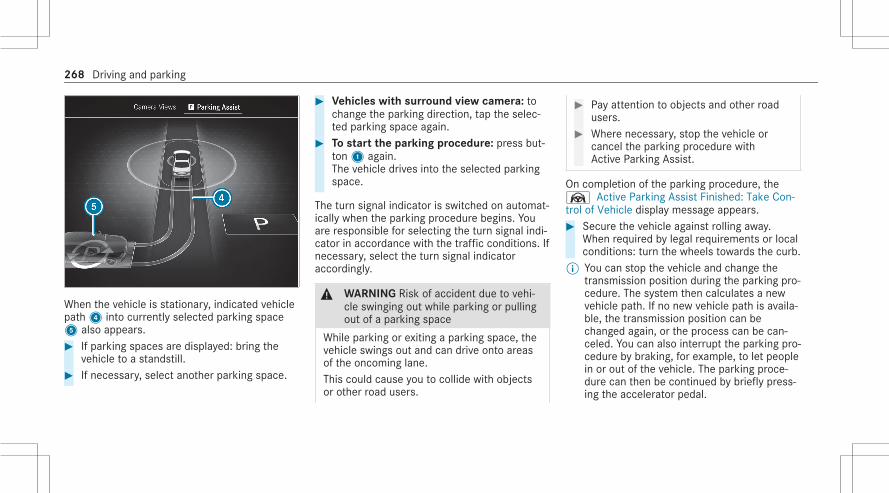
When the vehicle is stationary, indicated vehiclepath4 into currently selected parking space5 also appears.# If parking spaces are displayed: bring the
vehicle to a standstill.# If necessary, select another parking space.
# Vehicles with surround view camera: tochange the parking direction, tap the selec‐ted parking space again.
# To start the parking procedure: press but‐ton1 again.The vehicle drives into the selected parkingspace.
The turn signal indicator is switched on automat‐ically when the parking procedure begins. Youare responsible for selecting the turn signal indi‐cator in accordance with the traffic conditions. Ifnecessary, select the turn signal indicatoraccordingly.
& WARNING Risk of accident due to vehi‐cle swinging out while parking or pullingout of a parking space
While parking or exiting a parking space, thevehicle swings out and can drive onto areasof the oncoming lane.This could cause you to collide with objectsor other road users.
# Pay attention to objects and other roadusers.
# Where necessary, stop the vehicle orcancel the parking procedure withActive Parking Assist.
On completion of the parking procedure, theØ Active Parking Assist Finished: Take Con-trol of Vehicle display message appears.# Secure the vehicle against rolling away.
When required by legal requirements or localconditions: turn the wheels towards the curb.
% You can stop the vehicle and change thetransmission position during the parking pro‐cedure. The system then calculates a newvehicle path. If no new vehicle path is availa‐ble, the transmission position can bechanged again, or the process can be can‐celed. You can also interrupt the parking pro‐cedure by braking, for example, to let peoplein or out of the vehicle. The parking proce‐dure can then be continued by briefly press‐ing the accelerator pedal.
268 Driving and parking

Exiting a parking space with Active ParkingAssist
Requirements:R The vehicle is equipped with a surround view
camera.R The vehicle has been parked with Active
Parking Assist.
# Start the vehicle.# Press button1.
# Select Parking Assistance menu2.# If necessary, change direction of exit3.# To start exiting the parking space: press
button1 again.# If necessary, change the transmission posi‐
tion. Observe any messages displayed in thedriver display and central display.The vehicle moves out of the parking space.
The turn signal indicator is automaticallyswitched on when exiting a parking space beginsand switched off when it is completed. You areresponsible for selecting the turn signal indicatorin accordance with the traffic conditions. If nec‐essary, select the turn signal indicator accord‐ingly.After the parking space has been exited, a warn‐ing tone and theØ Active Parking Assist Fin-ished: Take Control of Vehicle message promptyou to take control of the vehicle. You have toaccelerate, brake, steer and change gear your‐self again.If you do not react to the prompt to take controlof the vehicle, the system will brake the vehicleto a standstill.
Maneuvering assistance
Function of Drive Away AssistDrive Away Assist can reduce the severity of animpact when pulling away. If the system detectsan obstacle in the direction of travel, the vehi‐cle's speed is briefly reduced to approximately1 mph (2 km/h).
Driving and parking 269

A risk of collision may arise in the following sit‐uations, for example:R If the driver mixes up the accelerator and
brake pedals.R If the driver engages an incorrect gear.R If the driver depresses the accelerator pedal
with too much force.
Drive Away Assist is active under the followingconditions:R If the vehicle was stationary and the trans‐
mission position was changed tok orh.R If the vehicle has rolled less than approx‐
imately 3.3 ft (1.0 m) since being at a stand‐still.R If the detected obstacle is less than approx.
3.3 ft (1.0 m) away.
% You can activate and deactivate Drive-awayAssist (/ page 272).
If a critical situation is detected, the followingsymbol appears red in the selected view in theCamera & Parking menu:
% If Drive Away Assist is not available, thesame symbol appears in gray. If the Camera& Parking menu is not opened in the centraldisplay, the symbol and pop-up of ParkingAssist PARKTRONIC both appear.
Drive Away Assist is only an aid. It is not a sub‐stitute for your attention to the surroundings.The responsibility for safe maneuvering andparking remains with you. Make sure that nopersons, animals or objects etc. are in themaneuvering range.
& WARNING Risk of accident caused bylimited detection performance of DriveAway Assist
Drive Away Assist cannot always clearly iden‐tify objects and traffic situations.# Always pay careful attention to the traf‐
fic situation; do not rely on Drive AwayAssist alone.
# Be prepared to brake or swerve as nec‐essary, provided the traffic situationpermits and that it is safe to take eva‐sive action.
System limitsThe system limits of Active Parking Assist apply(/ page 265).On uphill gradients, the performance of DriveAway Assist is restricted.
Function of cross traffic warningThe cross traffic warning can warn you of cross‐ing traffic when you are backing up out of aparking space. The radar sensors in the bumperalso monitor the area adjacent to the vehicle.The cross traffic warning is automatically activewhen you reverse at a speed of less than approx‐imately 6 mph (10 km/h).If a critical situation is detected, the followingsymbol appears red in the selected view in theCamera & Parking menu:
270 Driving and parking

The vehicle can be automatically braked.% If the cross traffic warning is not available,
the same symbol appears in gray. If theCamera & Parking menu is not opened in thecentral display, the symbol and pop-up ofParking Assist PARKTRONIC both appear.
The cross traffic warning is only an aid and not asubstitute for your attention to the surroundings.The responsibility for safe maneuvering andparking remains with you. Make sure that nopersons, animals or objects etc. are in themaneuvering range.
& WARNING Risk of accident caused bylimited detection performance of thecross traffic warning
The cross traffic warning cannot alwaysclearly identify objects and traffic situations.
# Always pay careful attention to the traf‐fic situation; do not rely on the crosstraffic warning alone.
# Be prepared to brake or swerve as nec‐essary, provided the traffic situationpermits and that it is safe to take eva‐sive action.
System limitsThe system limits of Active Parking Assist apply(/ page 265).If the radar sensors are obstructed by vehiclesor other objects, detection is not possible.In the following situations, the cross traffic warn‐ing is not available:R On inclines
Maneuvering brake functionThe maneuvering brake function can prevent col‐lisions with pedestrians when the vehicle isbacking up at slow speeds. If the rear view cam‐era detects a person in the vehicle path, thevehicle can be braked to a standstill.
The maneuvering brake function can interveneunder the following conditions:R The vehicle is backing up at a speed slower
than 6 mph (10 km/h).R The camera image is shown in the central
display (/ page 261).
% You can activate and deactivate the maneu‐vering brake function (/ page 272).
If the maneuvering brake function is triggered,the following symbol appears in red in the selec‐ted view in the Camera & Parking menu:
% If the maneuvering brake function is notavailable, the same symbol appears in gray.If the Camera & Parking menu is not openedin the central display, the symbol and pop-upof Parking Assist PARKTRONIC both appear.
The maneuvering brake function is only an aid. Itis not a substitute for your attention to the sur‐roundings. The responsibility for safe maneuver‐
Driving and parking 271

ing and parking remains with you. Make surethat no persons, animals or objects etc. are inthe maneuvering range.
& WARNING Risk of accident caused bylimited detection by the maneuveringbrake function
The maneuvering brake function cannotalways clearly detect people. Other obstaclesare not detected by the function.In these cases, the function may brakeunnecessarily or not brake at all.# Always pay careful attention to the traf‐
fic situation; do not rely on the maneu‐vering brake function alone.
# Be ready to brake.
System limitsObserve the system limits of the following func‐tions:R Active Parking Assist (/ page 265)R Surround view camera (/ page 257)R Rear view camera (/ page 255)
The maneuvering brake function is not availablein the following situations:R On inclines
Activating/deactivating maneuvering assis‐tanceMultimedia system:4© 5 Settings 5 Assistance5 Parking# Select Maneuvering Assistance.# Activate or deactivate the desired maneuver‐
ing assistance.% Maneuvering assistance systems must be
active for the function of Drive Away Assist(/ page 269) and the maneuvering brakefunction (/ page 271).
Vehicle towing instructionsThe vehicle is not suitable for the use of tow barsystems that are used for flat towing or dinghytowing, for example. Attaching and using tow barsystems can lead to damage on the vehicle.When you are towing a vehicle with tow bar sys‐
tems, safe driving characteristics cannot beguaranteed for the towing vehicle or the towedvehicle. The vehicle-trailer combination mayswerve from side to side. Comply with the per‐mitted towing methods (/ page 350) and theinstructions for towing with both axles on theground (/ page 351).
272 Driving and parking

Notes on the driver display
& WARNING Risk of accident due to adriver display malfunction
If the driver display has failed or malfunc‐tioned, the function restrictions applying tosafety relevant systems are not visible.The operating safety of your vehicle may beimpaired.# Drive on carefully.# Have the vehicle checked immediately
at a qualified specialist workshop.
If the operating safety of your vehicle isimpaired, park the vehicle immediately andsafely. Contact a qualified specialist workshop.The driver display shows basic information suchas speed, engine speed, fuel level and coolanttemperature.Additional functions available to you include thefollowing:R Different menus, for Assistance and Naviga‐
tion
R Status displays for the driver assistance sys‐temsR Display messagesR Indicator and warning lampsR Information on Consumption and range
The menu contents and settings can be individu‐ally adjusted and set.
Notes on the 3D driver displayThe 3D driver display enables a spatial represen‐tation of the content of the driver display. It is aprerequisite that the driver be recorded by thedriver camera.
System limitsThe system may be impaired or may not functionin the following situations:R The driver camera is deactivated or is not
working.R The driver is outside the detection range of
the driver camera.
R The operating conditions are not in place,e.g. if the outside temperature is too low ortoo high.
Operating the driver display
& WARNING Risk of distraction from infor‐mation systems and communicationsequipment
If you operate information and communica‐tion equipment integrated in the vehiclewhen driving, you will be distracted from thetraffic situation. This could also cause you tolose control of the vehicle.# Only operate this equipment when the
traffic situation permits.# If you cannot be sure of this, stop the
vehicle whilst paying attention to roadand traffic conditions and operate theequipment with the vehicle stationary.
Observe the legal requirements for the countryin which you are currently driving when operat‐ing the driver display.
Driver display 273

Scrolling on the menu bar
1 Back button2 Main menu button3 Touch Control
The content of the driver display is controlledusing the control elements on the left side of thesteering wheel. Touch Control3 is used to navi‐gate in a vertical and horizontal direction with
one finger. Confirm the selection by pressing theTouch Control.% To operate Touch Control3 in the most
effective way, use the tip of your thumb ifpossible. You can also set the sensitivity ofthe Touch Control on the central display(/ page 294).
# Briefly press main menu button2.# Select a menu by swiping to the left or right
on Touch Control3.# Press Touch Control3 to confirm.
Menus on the driver displayNotes on the menus on the driver display
& WARNING Risk of distraction from infor‐mation systems and communicationsequipment
If you operate information and communica‐tion equipment integrated in the vehiclewhen driving, you will be distracted from thetraffic situation. This could also cause you tolose control of the vehicle.
# Only operate this equipment when thetraffic situation permits.
# If you cannot be sure of this, stop thevehicle whilst paying attention to roadand traffic conditions and operate theequipment with the vehicle stationary.
Observe the legal requirements for the countryin which you are currently driving when operat‐ing the driver display.The following menus can be called up via themenu bar on the driver display:R UnderstatedR SportR ExclusiveR ClassicR NavigationR AssistanceR Service
In some of these menus, you can choosebetween different display content on the centerdisplay area.
274 Driver display

In most of the menus, you can use Options toconfigure further settings for the menu-specificdisplay content.% You can find further information about the
possible settings and selections on themenus in the Digital Operator's Manual.
Head-up DisplayFunction of the Head-up Display
The Head-up Display projects various contentinto the driver's field of vision, for example.You can use the Head-up Display menu bar toselect different contexts, e.g.:R MinimalR SportR StandardR Augmented realityR ECO displayR SettingsR Head-up Display
The following image shows an example of thecontext with augmented reality.
Head-up Display with navigation and aug‐mented reality (10x5°)
1 Navigation instructions2 Augmented reality navigation instructions3 Navigation status displays, such as remain‐
ing distance to the destination, expectedtime of arrival
4 Active Lane Keeping Assist status5 Steer Assist status6 Current speed
7 Set speed in the driver assistance system(e.g. Active Distance Assist DISTRONIC)
8 Detected traffic signs (Traffic Sign Assist)
When you receive a call, the6 Call Waitingmessage will appear on the Head-up Display.
System limitsVisibility is particularly influenced by the follow‐ing conditions:R Seat positionR Image position settingR Ambient lightR Wet road surfacesR Objects on the display coverR Polarization in sunglasses
Driver display 275

Function of the Head-up Display with aug‐mented reality
& WARNING Risk of accident and injurydue to distraction as well as incorrectrepresentation or interpretation of thedisplay
When driving, you should not base youractions on the augmented reality display ofthe Head-up Display.# Always keep an eye on the actual traffic
situation.# Avoid looking at the augmented reality
display of the Head-up Display for anextended period of time.
& WARNING Risk of accident and injurydue to imprecise positioning of addi‐tional information
The additional information from the augmen‐ted reality display is not a substitute forobserving the actual driving situation.
# Always keep an eye on the actual trafficsituation when carrying out all drivingmaneuvers.
The Head-up Display with augmented realityprojects content into the driver's field of vision,such as:R Information from and visualization of the nav‐
igation systemR Information and visualization of the driver
assistance systems, e.g. Active DistanceAssist DISTRONICR Information from the menus of the driver dis‐
play
Head-up Display with augmented reality(example)
1 Marker of the detected vehicle in front(Active Distance Assist DISTRONIC)
2 Change-of-direction arrows for the route(navigation)
3 Status line for driver assistance systems
The marker of the detected vehicle in front andthe change-of-direction arrows for the route aredynamic displays. The vehicle marker stays withthe vehicle in front, and Active Distance Assistregulates your speed based on this. The change-of-direction arrows point the way calculated bythe navigation system.
276 Driver display

System limitsRoute guidance with augmented reality is notavailable in some situations, e.g. in the event ofpoor satellite reception or roads that have notbeen digitized.Visibility is influenced by the following condi‐tions:R Driver camera and multifunction camera
recordingR The extent to which the windshield in the
area of the multifunction camera is dirty, or ifthe camera is fogged up, damaged orobscured.
Further system limits of the Head-up Display(/ page 275).
Operating the Head-up Display
Selecting display content of the Head-up Dis‐play via the menu bar of the driver display# Press theò main menu button on the
left.
# To select the menu bar of the Head-upDisplay: swipe upwards on the left-handTouch-Control.
# To switch between types of display con‐tent on the Head-up Display: swipe to theleft or right on the left-hand Touch Control.The Head-up Display shows a preview of theselected display contents after each swipe.
# Press thea button to confirm the desiredcontent.
Switching back to the driver display# Press theG orò button.
Setting the position and brightness# On the menu bar of the Head-up Display,
select the Settings menu by swiping to theleft or right.
# Press the left-hand Touch Control.The current position and brightness settingswill be displayed graphically on the Head-upDisplay as well as on the driver display.
# To adjust the position: swipe upwards ordownwards on the left-hand Touch Control.
# To adjust the brightness: swipe to the rightor left on the left-hand Touch Control.The settings configured for position andbrightness will be saved automatically.
# Press theG ora button to exit thesettings.
% Vehicles with augmented reality func‐tion: when the position is adjusted, the sta‐tus bar will be moved upward and the displayarea reduced. This may impair visibility ofthe augmented reality slightly.
Driver display 277

Selecting the Head-up Display with augmen‐ted reality
# Press theò main menu button on theleft.
# To select the menu bar of the Head-upDisplay: swipe upwards on the left-handTouch-Control.
or# Press and hold thea button.# To select the Head-up Display with aug‐
mented reality: swipe to the left or right onthe left-hand Touch-Control to activate thedesired content.
Switching the Head-up Display on/off
Driver display:4©
Switching on# Swipe upwards on the left-hand Touch Con‐
trol.Head-up Display will appear.
# Press left-hand Touch Controla.
Switching off# Swipe upwards on the left-hand Touch Con‐
trol.# Select Head-up Display by swiping on the
left-hand Touch Control.# Press left-hand Touch Controla.
Setting the Head-up Display in the multime‐dia system
Multimedia system:4© 5ß 5y
Switching the 3D display for the driver dis‐play on or off# Select 3D Driver Display.
The 3D display of the driver display isswitched on or off.
% The 3D display for the driver display is onlyactivated when the driver camera detectsthe driver. Otherwise, the driver displayswitches from the 3D display to the 2D dis‐play (/ page 273).
Switching the Head-up Display on/off# Select Head-up Display.
The Head-up Display is activated or deactiva‐ted.
Vehicles with a 48 V on-board electricalsystem (EQ Boost technology)
1 POWER shows the electric drive support.2 CHARGE shows the recuperation power of
the electric motor.
õ shows the drive system's operational read‐iness.
278 Driver display

Overview of status displays on the driverdisplayThe status displays for the driving and drivingsafety systems can be found in areas1 to4.
Y Pedestrian detection (only on assistancedisplay)
Ç Active Parking Assist is available(/ page 267)
È Active Parking Assist has detected a park‐ing space (/ page 267)
é Parking Assist PARKTRONIC deactivated(/ page 264)
ç Active Distance Assist DISTRONIC(/ page 223)
Ò Specified distance for Active DistanceAssist DISTRONIC (/ page 223)
æ Active Brake Assist switched off(/ page 240)
Ä Active Brake Assist impaired or not func‐tioning (/ page 240)
Ø Active Steering Assist (/ page 230)± Active Lane Change Assist (/ page 234)ð Active Lane Keeping Assist (/ page 250)Z Active Blind Spot Assist (only on assis‐
tance display) (/ page 249)° Haptic accelerator pedal (/ page 197)è ECO start/stop function (/ page 195)ë HOLD function (/ page 220)_ Adaptive Highbeam Assist (/ page 161)
Adaptive Highbeam Assist Plus(/ page 162)
¬ Active Stop-and-Go Assist (/ page 230)
Vehicles with Traffic Sign Assist: Detectedinstructions and traffic signs (/ page 241).
Driver display 279

Overview and operationNotes on the MBUX multimedia system
& WARNING Risk of distraction from infor‐mation systems and communicationsequipment
If you operate information and communica‐tion equipment integrated in the vehiclewhen driving, you will be distracted from thetraffic situation. This could also cause you tolose control of the vehicle.# Only operate this equipment when the
traffic situation permits.# If you cannot be sure of this, stop the
vehicle whilst paying attention to roadand traffic conditions and operate theequipment with the vehicle stationary.
You must observe the legal requirements for thecountry in which you are currently driving whenoperating the multimedia system.
Overview of the MBUX multimedia system
1 Touch Control and control panel for theMBUX multimedia systemMBUX stands for Mercedes-Benz User Expe‐rience.• Operating Touch Control
2 Central display with touch functionality• Home screen overview• Operating the touchscreen
3 Control panel with fingerprint sensorú,switches the MBUX multimedia system on oroffÜ, switches the mute function on oroffa and adjusts the volumeø
Further operating options:R Conducting a dialog with the MBUX Voice
Assistant.R Operating functions contact-free with the
MBUX Interior Assistant.The interaction then follows intelligently,reactively or with hand or head movements.R If the vehicle is equipped with a driver cam‐
era, functions can be triggered via "Look &Answer".
% You can find further information about oper‐ation as well as about applications and serv‐ices in the Digital Operator's Manual.
Anti-theft protectionThis device is equipped with technical provisionsto protect it against theft. Further information onprotection against theft can be obtained at anauthorized Mercedes-Benz Center.
280 MBUX multimedia system

Home screen overview
1 Status line2 Calls up user profile settings and switches
user3 Using the global search4 Calls up the Control Center (pull down)5 Calls up favorites6 Displays in the status line
7 Calls up applications8 Quick-access to application9 Global menuG Calls up previous menu© Calls up the home screenû Previous track or previous radio sta‐tionü Next track or next radio stationActive call: display of the call duration
In the image, the applications are arranged as acarousel. Pressing and holding on© arrangesthe applications in a grid. This presentation isalso used by a smartphone, for example.The following functions are called up in the Con‐trol Center:R Notifications CenterR Content sharing menuR FavoritesR Vehicle quick-access
Content sharing menu
Example: showing displays1 Calls up a menu2 Central display with active content (cover
display)3 Displays animation for content sharing4Ä Bluetooth® headphones connected to
the right rear display
MBUX multimedia system 281

5 Rear displays with active content (cover dis‐play)
6 MBUX rear tablet
To share content, drag a display and drop it overanother display.To control media playback, tap a display.
Operating the MBUX multimedia system
Using Touch Control
1© Shows the home screen2 Touch Control
=9Ì: swipe in the directionof the arrow (navigate)a Press (confirm)
3G Returns to the previous display4 6 Makes or accepts a call5 ~ Rejects or ends a call6 Increase volume: swipe upwards
Reduce volume: swipe down8 Switch off the sound: press
7ß Calls up favorites (press briefly) oradds favorites (press and hold)
8£ Starts the MBUX Voice Assistant
You can navigate through menus and lists via thetouch-sensitive surface of Touch Control2using a single-finger swipe, for example:# To enter a character: select a character
using the keyboard and press on Touch Con‐trol2.
# To select a menu option: scroll in a list andpress Touch Control2.
# To move the digital map: swipe in anydirection.
Using the touchscreen
1 Fingerprint sensor2 Switches the MBUX multimedia system on or
off3 Switches the mute function on/off4 To adjust the volume
Press ± orq or swipe over the button
282 MBUX multimedia system

# To select a menu item or entry: tap on asymbol or an entry.
# To increase the map scale: tap twicequickly with one finger.
# To reduce the map scale: tap with two fin‐gers.
# To enter characters with the keypad: tapon a button.
# To navigate in menus: swipe up, down, leftor right.
# To use handwriting to enter characters:write the character with one finger on thetouchscreen.
# To zoom in and out of the map: move twofingers together or apart.
# To enlarge or reduce the size of a sectionof a website: move two fingers together orapart.
# To turn the digital map: turn counter-clock‐wise or clockwise using two fingers.
# To move the digital map: touch thetouchscreen and move your finger in anydirection.
# To save the destination in the digitalmap: touch the touchscreen and hold until amessage is shown.
# To call up the home screen: swipe up withthree fingers in an application.
# To set the volume on a scale: touch thetouchscreen and move the finger to the leftor right.
# To call up a global menu in the applica‐tions: touch the touchscreen and hold untilthe Options menu appears.
Function of the MBUX Voice Assistant
Using the MBUX Voice Assistant, vehicle func‐tions and various areas of the MBUX multimediasystem can be operated by voice input. TheMBUX Voice Assistant is operational approx‐imately half a minute after switching on the igni‐tion and can be operated from all seats. Further
information and examples of voice commandscan be found in the Digital Operator's Manual.You can use the MBUX Voice Assistant to oper‐ate the following functions depending on thevehicle equipment:R TelephoneR Text message and e-mailR NavigationR Radio, media, TVR Vehicle functionsR Online functions
Full functionality of the voice control system isonly available for you with activation of onlinevoice control .
Conducting a dialog
Starting a dialog# Say "Hey Mercedes" to activate the MBUX
Voice Assistant. Voice activation must beswitched on in the multimedia system.
or
MBUX multimedia system 283

# Press the£ button on the multifunctionsteering wheel.A blue line appears in the MBUX multimediasystem. The dialog can be started.
For the dialog with the MBUX Voice Assistant,you can use complete sentences of colloquiallanguage as voice commands. Voice activationcan also be directly combined with a voice com‐mand, e.g. "Hey Mercedes, how fast can Idrive?".
Calling up help# For information about the MBUX Voice
Assistant: say "Hey Mercedes, what canyou do?"
# Digital Operator's Manual: "Show me theOperator's Manual". The full extent of theDigital Operator's Manual is available whenthe vehicle is stationary.
Operating functions (examples)# To operate the navigation: "Search for an
Asian restaurant, but not Japanese, in SouthLondon."
# To operate the phone: "Call my father."
# To change the system language to Eng‐lish (short command): "Change languageto English".
# To operate the radio: "Show me the list ofradio stations."
# To operate media: "Switch on random play-back."
# To operate vehicle functions: "Switch theseat heating to level 2."
# To operate online functions: "What's thetime in Sydney?"
# To ask a question about the vehicle: "Do Ihave Blind Spot Assist?"
Overview of the MBUX Interior Assistant
& WARNING Risk of injury from the cam‐era's laser radiation
This product uses a classification 1 laser sys‐tem. If the housing is opened or damaged,laser radiation may damage your retina.# Do not open the housing.
# Always have maintenance work andrepairs carried out by a qualified spe‐cialist workshop.
This product complies with the requirements ofthe FDA 21 CFR 1040.10 and 1040.11 withexception of the variations according to the FDALaser Notice No. 50 from 24. June 2007.% The camera records image data for the appli‐
cations, for example body, head and handdetection.The camera converts the image data directlyinto meta data. No image data is saved inthe process. The data is only processed inthe vehicle and is not transmitted from thevehicle.The MBUX Interior Assistant is automaticallyactivated whenever the engine is started.You can set the functions individually orswitch the Interior Assistant on or off.
284 MBUX multimedia system

The most recently active settings are storedin your user profile. If you switch off the Inte‐rior Assistant, for example, this setting willbe adopted in your user profile. However youdo not change any other active user profilein which the Interior Assistant is switchedon.
The MBUX Interior Assistant detects the pres‐ence of the front vehicle occupants using a 3Dlaser camera. The Assistant interprets naturalhand, head and body movements contextually orupon the explicit request of the vehicle occu‐pants. The Assistant can thus automatically trig‐ger vehicle interior functions and assist appropri‐ately to the situation.The Assistant recognizes driver and frontpassenger interactions.
Cameras1 are located in the overhead controlpanel.The Assistant supports vehicle and infotainmentfunctions at three interaction levels:R INTELLIGENT
The Assistant recognizes vehicle occupantsautomatically and activates functions.R REACTIVE
The Assistant recognizes the natural bodylanguage of a vehicle occupant and carriesout functions automatically, appropriate tothe situation.R CONTACTLESS
The vehicle occupant actively requests afunction using a hand movement or pose.
The Assistant offers functions for the following:R SAFETY
The Assistant supports vehicle occupantswith the use of restraint systems.R COMFORT
The Assistant enhances comfort by automat‐ing functions inside the vehicle and support‐ing natural interaction with the vehicle.R INFOTAINMENT
Operating options or information are high‐lighted and/or shown on the central displayas your hand approaches. The vehicle occu‐pants can carry out a favorite function with ahand pose.
System limits, display messages and notesfor rectificationThe error messages are shown in the central dis‐play.
MBUX multimedia system 285

The system may be impaired or may not functionin the following situations:R The camera in the overhead control panel
may heat up due to operating conditions. Asa result the camera may switch off tempora‐rily, particularly during longer periods ofoperation and at high outside temperatures.Do not touch or cover the camera and waituntil the camera has cooled down and isavailable again.The Interior Assistant is temporarily unavaila-ble. You will be informed as soon as the func-tion is available again. message appears.You receive a message when the camera isavailable again.R The camera is covered or dirty, fogged up or
scratched.Wait until the camera has cooled downbefore cleaning the camera cover.The Interior Assistant is temporarily unavaila-ble. Please refer to the Operator's Manualmessage appears.
Clean the outside of the camera cover with adry or damp cotton cloth. Do not use micro‐fiber cloths. Do not remove the cover whencleaning.R A vehicle occupant is very large. Clothing
being worn (gloves, hat, scarf, color of cloth‐ing) or objects carried on a person, for exam‐ple a watch with a large face, are affectingthe camera view. Or the detection range ofthe camera is restricted.The Availability of the Interior Assistant islimited for the driver. Please see the Opera-tor's Manual message appears.Keep the camera's field of vision clear.R The camera is not operational.
The Interior Assistant unavailable. Pleasevisit a workshop. message appears.Consult an authorized Mercedes-Benz Cen‐ter.
Anticipatory exit warning (SAFETY/reactive)
Requirements:R The vehicle is equipped with Active Blind
Spot Assist with exit warning.R Active Blind Spot Assist is activated
(/ page 250).R The vehicle is equipped with active ambient
lighting or ambient lighting.
% Observe the information on the system limitsof Active Blind Spot Assist with exit warning(/ page 247).
The function can warn vehicle occupants about apossible collision with an approaching vehicle orbicycle when they exit the vehicle.As soon as the driver or front passenger movestheir hand towards the door handle, dependingon the vehicle equipment, the following warningsare issued:R The active ambient lighting or ambient light‐
ing flashes red.R The warning lamp in the outside mirror
flashes red.
286 MBUX multimedia system

R When the door is opened, a warning tonesounds.
% The visual warning is thus already givenbefore the door is opened.
% Further information on Active Blind SpotAssist with exit warning (/ page 247) andon ambient lighting (/ page 165).
Switching the reading light and search lightand on or off
Requirements:R For the reading light: the driver's and front
passenger's hand movement takes placeunder the inside rearview mirror.R For the search light: the function is availa‐
ble in the vehicle when it is dark.R The front passenger seat is not occupied or a
child is sitting in a child restraint system.R The hand movement is made by the driver in
the interaction area above the frontpassenger seat.
Switching the reading light on and off
Carrying out operation of the reading light for thedriver and front passenger
# Move your hand up and down vertically underthe inside review mirror.The reading light is switched on or off.
Switching the search light on and off
Interaction area for activating the search light
# To switch on: reach across the frontpassenger seat with a hand.The search light is switched on automaticallyfor the driver.
# To switch off: take a hand back away fromthe front passenger seat.The search light is switched off again.
MBUX multimedia system 287

Automatic preselection of the outside mirror(COMFORT/reactive)
Until now, to set the outside mirror the desiredmirror had to be selected using a preselectionbutton in the driver's door.With the MBUX Interior Assistant, the mirror tobe set is preselected automatically by the natu‐ral movement of your head to the left or right.When the hand touches the button for adjustingthe outside mirror, the LED under the button ofthe preselected mirror side lights up.Use the button to set the position of the activeoutside mirror.% Preselection of the outside mirror using but‐
tons is still possible. Further information onadjusting the outside mirrors (/ page 171).
% The driver camera is also used for this appli‐cation.
Calling up favorites with the V pose (INFO‐TAINMENT/contactless)
Requirements:R At least one favorite has been saved in the
favorites list.R The favorite has been connected with the
MBUX Interior Assistant.R The area for detecting the favorites pose (V
pose) is above the center console in front ofthe central display.R The V pose is held for a brief time.
The V pose makes it easier to call up favorites.The front vehicle occupants can associate theirown favorite with the V-pose. Some examplesinclude a navigation destination, a radio stationor a massage program for a seat.% If a favorite has not yet been saved and con‐
nected with the MBUX Interior Assistant, themultimedia system will assist you.
Implementation of the V-pose above the storagecompartment of the center console at the height ofthe central display
# Position your hand above the storage com‐partment of the center console at the heightof the central display. The back of your handis facing upwards. In doing so, your indexand middle finger are spread to form a V.
288 MBUX multimedia system

With your other fingers bent inwards. Brieflyhold the V pose.The favorite is called up.
Function of the driver camera
The driver camera is in the driver's display or inthe 3D driver display.The driver camera detects the following charac‐teristics:R Head positionR Viewing directionR Eyelid closure characteristicsR Driver's face
% The driver camera records image data forapplications such as ATTENTION ASSIST andfacial recognition, for example.The camera converts the image data directlyinto meta data. No image data is saved inthe process. The data is only processed inthe vehicle and is not transmitted from thevehicle.The camera is activated automatically eachtime the engine is started.
The driver camera must be set up for face detec‐tion before use. Teaching-in biometric data(/ page 291).
System limitsThe system may be impaired or may not functionin the following situations:R The camera is covered or dirty, fogged up or
scratched.R The driver's face and/or eyes are covered.R The driver is wearing glasses that block infra‐
red.
Display messagesIn the following situations display messages maybe shown:R The driver camera is inoperative.
The camera is faulty.The Driver Camera Inoperative See Opera-tor's Manual message appears.R The driver camera cannot capture the posi‐
tion of your head.
The Change the steering wheel/ seat posi-tion until 6 dots are visible on the upperedge of the screen. message appears.R The view of the driver camera is reduced or
restricted.The Driver Camera View Currently RestrictedSee Operator's Manual message appears.
Notes on carePlease comply with the notes on caring for theinterior (/ page 334).
Switching the driver camera on or off
Multimedia system:4© 5 Settings 5 System5 Intelligent Assistance# Select On or Off.When the driver camera is switched off, the fol‐lowing functions are not available or limited:R The 3D driver displayR The MBUX augmented reality Head-up Dis‐
play (/ page 275)
MBUX multimedia system 289

R The microsleep detection of ATTENTIONASSIST (/ page 221)R The facial recognition
This function serves as sensor input forauthentication and unlocking of the user pro‐file and protected applications(/ page 291).R Multimodality
This function activates the MBUX VoiceAssistant with eye control, e.g. for the confir‐mation of a display message by voice.
Information on users, suggestions and favor‐ites
& WARNING Risk of becoming trappedduring adjustment of the driver's seatafter calling up a driver profile
Selecting a user profile may trigger anadjustment of the driver's seat to the posi‐tion saved under the user profile. You orother vehicle occupants could be injured inthe process.
# Make sure that when the position ofdriver's seat is being adjusted using themultimedia system, no people or bodyparts are in the seat's range of move‐ment.
If there is a risk of someone becoming trap‐ped, stop the adjustment process immedi‐ately:# a) Tap the warning message on the cen‐
tral display.or# b) Press a memory position button or a
seat adjustment switch on the driver'sdoor.The adjustment process will be stop‐ped.
The driver's seat is equipped with an access pre‐venter.If the driver's door is open, the driver's seat willnot be set after calling up the driver's profile.
User profiles and user-specific contentPrerequisites for the vehicle owner:R You have a Mercedes me user account.R You have a Mercedes me PIN.R You have agreed to the terms of use.
User profiles save personal settings. If the vehi‐cle is used by several people, a person canchange their profile settings without changingthe settings of other users.You can individualize a user profile in the vehicleusing the set-up assistant or using the settingsin your user profile. Some settings, e.g. theMercedes me PIN and a profile photo are madein the Mercedes me app or in the Mercedes mePortal.User-specific content and applications with per‐sonal data are protected by different levels ofsecurity. To access protected content, theMercedes me PIN and, depending on the vehicleequipment, biometric sensors can be used.
290 MBUX multimedia system

% The security level is set by the multimediasystem and calculated from the combinationof all sensor inputs. Some security levelscannot be turned off.
% When a user profile is activated, the follow‐ing personalized comfort systems, for exam‐ple, can be adjusted or their settings loaded:R SeatR Ambient lightR Outside mirrorsR BlindsR Air conditioning adjustment
If the user profile is activated when drivingthen the driver's seat position will not beadjusted.
Depending on the vehicle equipment you can, asa user, save the following settings, for example:R Driver's seat, steering wheel and mirror set‐
tingsR Climate controlR Ambient lightingR Radio (including station list)
R Suggestions and favorites
SuggestionsThe vehicle can learn the habits of the driver. Itthen makes suggestions regarding navigationdestinations, phone numbers and music prefer‐ences. The requirements for that are the selec‐tion of a user, your consent to the recording ofdata and sufficient collected data.
FavoritesFavorites offer you quick access to frequentlyused applications. 100 favorites are available intotal.
Configuring users, suggestions and favorites
Requirements:R To use the set-up assistant: the vehicle is sta‐
tionary.
Multimedia system:4© 5f 5 Change User
Adding a user# Selectf Add User .
A QR code is loaded.# Scan the displayed QR code with the
Mercedes me app or any QR code scanneron a mobile device. If the Mercedes me appis not yet installed on your mobile device,you will be directed to the store of yourmobile device.
# Follow the directions in the app.The vehicle is connected with your Mercedesme user account. This automatically createsyour user profile in the vehicle.If only your user profile is available, it will beloaded automatically.If more than one user profile is available, youwill be directed to the user selection.When the vehicle is stationary, the set-upassistant starts automatically after userselection.
MBUX multimedia system 291

Selecting user options# Select Settings.# To configure suggestions: select Sugges-
tion Settings.# Select Suggestions.# Switch the options on or off.
If an option is switched on and sufficientdata has been gathered, suggestions basedon your user behavior will be offered to you.
# For intelligent multimodality: select Multi-modality.If the option is active, the MBUX Voice Assis‐tant can be activated in certain situations.
# To switch the learning function off for24 h: switch on Deactivate 24h IntelligentLearning.
# To delete cumulated suggestions: selectReset Suggestion History.
# Select Ja (Yes).
Protecting user-specific content and applica‐tionsIf you add a new user, access protection isalready activated for the user profile. TheMercedes me PIN and, depending on the vehicleequipment, biometric sensors are available foraccess. Biometric sensors must be taught in inthe vehicle. The authentication process thentakes all taught-in and available sensors intoaccount.The following user-specific content and applica‐tions are protected, for example:R User selection and user profile settingsR The teaching-in of biometric sensorsR Suggestions
The data and determination of the mostprobable navigation destinations, mediasources, radio stations, contacts and mes‐sages are protected.R ENERGIZING COACH
The recorded health data and their evaluationare protected.R Mercedes me connect store
The purchase of services is protected.
# Switch Protect Content on or off.# Switch Access Protection on or off.% When access protection is switched off, your
user profile can be accessed and changedfrom every vehicle seat.
% Access protection is switched on or off on avehicle-specific basis.
Teaching in, editing and deleting biometricdataThe biometric data models are saved in the sen‐sors in the vehicle. If recognition has beentaught-in, this sensor serves as a contributoryfactor for authentication on the multimedia sys‐tem.# Select Biometric Data.# Select Fingerprint Recognition, Facial Recog-
nition or Voice Recognition.
% If necessary, authenticate yourself on themultimedia system.
# Select Configure.
292 MBUX multimedia system

# To use fingerprint: place and lift your fingerseveral times on the fingerprint sensor underthe touchscreen .The finger is scanned. If the scanning proce‐dure is successful, a message appears on thecentral display. You can unlock your user pro‐file and protected applications with your fin‐ger print.
# To use face recognition: close the driver'sdoor or fasten the driver's seat belt.
# Look at the driver display for about five sec‐onds.Your face is scanned. A message in the driverdisplay shows whether facial recognition wassuccessful or not. You can unlock your userprofile and protected applications with thefacial scan.
# To use voice recognition: speak the sen‐tence shown on the central display and fol‐low the instructions of the voice assistant.If the voice recognition was successful, amessage appears on the central display. Youcan unlock your user profile and protectedapplications with voice input.
% Avoid background or disturbing noises dur‐ing voice recognition.
# To delete biometric data: select Delete.# Select Ja (Yes).
Selecting a user% When you call up your driver profile, the driv‐
er's seat and the steering wheel can be set.You can cancel the setting process with thefollowing actions:R Tap on the Tap Here to Cancel message
in the central display.R Press one of the seat operating buttons
in the driver's door.# Select Change User.# Select a user.# When requested to do so, authenticate with
the Mercedes me PIN or a taught-in biomet‐ric characteristic.The user profile is loaded and activated.
% If you select Continue Without Selecting aUser, no specific settings for the user profileare loaded.
Adding favorites from categories# Select©.# Selectß.# Selectr.# SelectW Create New Favorite.# Select the category.# Select a favorite.
Linking favorites with the MBUX InteriorAssistant V pose# Select©.# Selectß.# Selectr.# Select Driver or Passenger.# Select the category.# Select a favorite.
MBUX multimedia system 293

System settingsOverview of the system settings menu
In the system settings menu, you can make set‐tings in the following menus and control ele‐ments:R Display
- Display brightnessR Control elements
- Keyboard language and handwriting rec‐ognition
- Touchpad sensitivity- Sensitivity of the Touch Controls- Haptic operation for the touchscreenR MBUX Voice AssistantR MBUX Interior AssistantR Sound
- Entertainment- Navigation and traffic announcements- Telephone- Voice amplification
R Connectivity- Wi-Fi, Bluetooth, NFCR MBUX rear tablet child-proof lockR Time & dateR LanguageR Units for distanceR Updating softwareR System Reset
Overview of software updates
Important software updates may be necessaryfor the security of your multimedia system'sdata. Install these updates, or else the securityof your multimedia system cannot be ensured.The multimedia system displays a correspondingmessage when a software update is available.If the Automatic Online Update option is active,software updates are downloaded automatically.If the option is deactivated, you will be informedof new software updates once. The softwareupdates are available for downloading for a limi‐ted period of time.
Carrying out a software update:R You can start online software updates via the
communication module.R You can start software updates via a Wi-Fi
hotspot.R You can start map updates from an external
medium.
% To complete software updates via the com‐munication module, the vehicle must be con‐nected with the Internet and a Mercedes meuser account.
% To complete software updates via Wi-Fi, thevehicle must be connected to an external Wi-Fi hotspot.
A software update consists of three steps:R Downloading or copying of the data required
for installationR Installation of the downloaded software
updateR Activation of the downloaded software
update.
294 MBUX multimedia system

% It may be necessary to restart the MBUXmultimedia system after completion of asoftware update.
% While some software updates are beingdownloaded, the multimedia system cannotbe operated and the vehicle functions maybe restricted.
% Some software updates require a safe vehi‐cle status for the installation to be comple‐ted. They may only be carried out in a safelyparked vehicle with the ignition switched off.
% For software updates requiring a safe vehiclestatus: when the last installation step isreached, a message appears in the centraldisplay after the ignition is switched off. Fol‐low the step-by-step instructions in the cen‐tral display to complete the installation.
Availability of the driver display and centraldisplayDuring the installation of software updates, it isnot possible to use the vehicle, central displayand driver display. You may receive the followingdisplay messages when an installation is run‐ning:
% The display message does not appear everytime a software update is installed.
In rare cases, an error can occur during theinstallation. The multimedia system automati‐cally attempts to restore the previous version.If it is not possible to restore the previous ver‐sion, the display messages shown above appearevery time the engine is started.
Failure of the central displayIf the central display fails or the display messageshown above is shown continuously, several sys‐tems such as the rear view camera,PARKTRONIC or climate control are no longer
available. Drive on carefully and consult a spe‐cialist workshop as soon as possible.
Failure of the driver displayIf the driver display fails or there is a malfunc‐tion, you may not recognize limitations in thefunctions of systems relevant to safety or thespeed display, for example. The operating safetyof the vehicle may be impaired. Drive on care‐fully and have the vehicle checked at a qualifiedspecialist workshop immediately (/ page 487).Further information about software updates canbe found at https://me.secure.mercedes-benz.com.
Setting up a Wi-Fi hotspot
Requirements:R Wi-Fi is activated on the multimedia system
and the communication device to be connec‐ted.R The communication device to be connected
supports at least one of the types of connec‐tion described.
MBUX multimedia system 295

The connection types shown depend on thedevice to be connected. The function mustbe supported by the multimedia system andby the device to be connected. The type ofconnection established must be selected onthe multimedia system and on the device tobe connected.
% Some functions may first need to be activa‐ted on the communication device being con‐nected. More detailed information can befound in the manufacturer's operatinginstructions.
% The use of the vehicle data tariff by externaldevices is not available in all countries.
Multimedia system:4© 5 Settings 5 System5 Internet and Bluetooth# Select Wi-Fi.
The controller is to the right: Wi-Fi isswitched on.
When Wi-Fi is switched on, you can connect themultimedia system with external hotspots or
make it available as a hotspot for external devi‐ces.When Wi-Fi is switched off, it is not possible toestablish a hotspot connection.When Wi-Fi is switched off, no connection canbe established with the MBUX rear tablet.% The availability of the functions is dependent
on the country.% The vehicle's data volume is used for data
connection via the multimedia system. Datavolumes can be purchased via the Mercedesme Portal.The data tariff of the mobile communicationdevice is used for the data connection via anexternal communication device.
Using the multimedia system as a Wi-Fi hot‐spot# Select MBUX Hotspot.# Select one of the following connection
options.Connecting using a QR codeRequirement: an app for scanning the QR code isinstalled on the device being connected.
Alternatively: the device being connected has anintegrated QR code scanner (see manufacturer'soperating instructions).# Scan the QR code shown.
The Wi-Fi connection is established.Connecting using NFC# Activate NFC on the device to be connected.# Hold the device to be connected to the NFC
interface when the NFC symbol appears inthe status line.
# Follow the instructions on the device.The Wi-Fi connection is established.
Connecting using a security key# Select the vehicle from the device to be con‐
nected. The vehicle is displayed with theMBUX XXXXX network name.
# Enter the security key which is shown in thecentral display on the device to be connec‐ted.
# Confirm the entry.Generating a new security key# Select the security key in the MBUX Hotspot
menu.
296 MBUX multimedia system

# Confirm the prompt with Yes.A new security key is generated.
A connection will be established with the newlycreated security key.% When a new security key is generated, all
existing Wi-Fi connections are then discon‐nected. If the Wi-Fi connections are being re-established, the new security key must beentered.
Using a mobile communication device as aWi-Fi hotspot (tethering)An external Wi-Fi hotspot is accessed for theInternet connection of the multimedia system.The data tariff of the mobile communicationdevice via Purchased Data Plan is used for thedata connection.% This function is country-dependent.# Select the Set Up option in the Internet and
Bluetooth menu.# Select Connect to the Internet.# Select one of the following connection
options.Setting up an Internet connection via Wi-Fi
% The Wi-Fi function on the mobile phone andInternet access via Wi-Fi must be activated(see the manufacturer's operating instruc‐tions).
# Select Search for Internet access.# Select the network.# Log in to the Wi-Fi network.or# Select the mobile phone with theö Wi-Fi
symbol in the Internet device manager.Setting up an Internet connection via Blue‐tooth®
% The mobile phone must support the Blue‐tooth® profile PAN (Personal Area Network).
# Select Search for Internet access.In the list displayed, all mobile phonesalready known to the multimedia system areshown. New devices can be set up using thephone application.
# Connect the mobile phone using Bluetooth®.or
# Select the mobile phone with the\ Blue‐tooth® symbol in the Internet device man‐ager.
Navigation and trafficNotes on navigation
Route guidance with augmented reality
& WARNING Risk of accident and injury asa result of distraction, incorrect depic‐tion or wrong interpretation of the dis‐play
The camera image of the augmented realitydisplay is not suitable as a guide for driving.# Always keep an eye on the actual traffic
situation.# Avoid extended observation of the cam‐
era image.
MBUX multimedia system 297
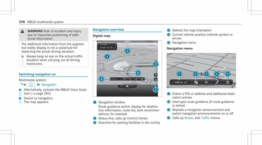
& WARNING Risk of accident and injurydue to imprecise positioning of addi‐tional information
The additional information from the augmen‐ted reality display is not a substitute forobserving the actual driving situation.# Always keep an eye on the actual traffic
situation when carrying out all drivingmaneuvers.
Switching navigation on
Multimedia system:4© 5 Navigation# Alternatively, activate the MBUX Voice Assis‐
tant (/ page 283).# Switch to navigation.
The map appears.
Navigation overview
Digital map
1 Navigation windowRoute guidance active: display for destina‐tion information, route list, lane recommen‐dations, for example
2 Status line, calls up Control Center3 Searches for parking facilities in the vicinity
4 Selects the map orientation5 Current vehicle position (vehicle symbol or
arrow)6 Navigation menu
Navigation menu
1 Enters a POI or address and additional desti‐nation entries
2 Interrupts route guidance (if route guidanceis active)
3 Repeats a navigation announcement andswitch navigation announcements on or off
4 Calls up Route, and Traffic menus
298 MBUX multimedia system
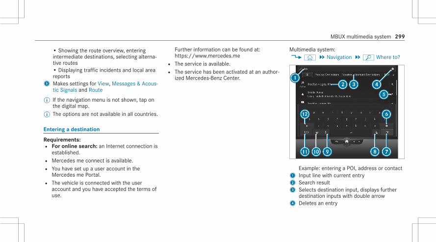
• Showing the route overview, enteringintermediate destinations, selecting alterna‐tive routes• Displaying traffic incidents and local areareports
5 Makes settings for View, Messages & Acous-tic Signals and Route
% If the navigation menu is not shown, tap onthe digital map.
% The options are not available in all countries.
Entering a destination
Requirements:R For online search: an Internet connection is
established.R Mercedes me connect is available.R You have set up a user account in the
Mercedes me Portal.R The vehicle is connected with the user
account and you have accepted the terms ofuse.
Further information can be found at:https://www.mercedes.meR The service is available.R The service has been activated at an author‐
ized Mercedes-Benz Center.
Multimedia system:4© 5 Navigation 5ª Where to?
Example: entering a POI, address or contact1 Input line with current entry2 Search result3 Selects destination input, displays further
destination inputs with double arrow4 Deletes an entry
MBUX multimedia system 299

5 Adopts the search result in the input line andcontinues the search
6 Deletes the last character entered7 Hides the keypad8 Switches to handwriting recognition9 Starts the MBUX Voice AssistantA Sets the written languageB Switches to digits and special charactersC Switches to upper-case or lower-case letters
# Enter the destination in1. The entries canbe made in any order.The search results are displayed in a list.
% Online search results for POIs may containadditional information, for example openingtimes and prices. The information is provi‐ded by an online map service.This online function is not available in allcountries.
% You can enter a destination as a 3 wordaddress from what3words. This option is notavailable in all countries.
# Hide the keyboard witha.
# Select the destination in the list.The route is calculated.
% Observe the notes on the MBUX multimediasystem (/ page 280).
Calculating a route and using settings forroute guidance
1 Saves a destination as a favorite2 Selects a parking space in the vicinity of the
destination3 Calculates the route and starts route guid‐
ance
300 MBUX multimedia system

4 Calls up the route overview5 Selects a point of interest in the vicinity of
the destination
# To call up the detailed display with desti‐nation address: pull the bar above the¥symbol upwards.Depending on the destination selection andavailability, online content, for example rat‐ings, prices and weather information, isshown.
# To share a destination: selectÇ Share .This option allows you to scan the displayedQR code.
Adding an intermediate destination to theexisting route or starting a new route guid‐ance# Select¦ Add .
The selected destination address is set asthe next intermediate destination. Routeguidance begins.
or
# Select¥ Replace Route .The selected destination address is set as anew destination. Route guidance begins.
Selecting a route type# SelectZ in the navigation menu
(/ page 298).# Select Route.
The route is calculated as a fast route with ashort journey time. The trailer mode can beused if a trailer has been coupled with thevehicle. If available, you can select onlineroutes. Traffic announcements for the routeare taken into account via Reroute Based onTrafficr.
% Trailer mode and online routes are not availa‐ble in all countries and for all vehicles.
Calculating alternative routes# SelectZ in the navigation menu.# Select View.# Activate Route Overview after Start.
Alternative routes are calculated for everyroute.
Selecting alternative routes% If Route Overview after Start has been
switched on and a route has been calcula‐ted, the function is available.
# Select¡ in the navigation menu.# Select Alternative Routes.# When the alternative routes have been calcu‐
lated, display the route in the navigation win‐dow by swiping to the right or left.
# Select Start.
Activating a commuter route% A user profile has been created and Allow
Destination Suggestions has been activatedin the user options (/ page 291). Routeguidance is not active.
# SelectZ in the navigation menu.# Select Route.# Activate Activate Commuter Route.
The navigation system automatically detectsthat the vehicle is on a commuter route.
MBUX multimedia system 301

For the daily commuter route, traffic inci‐dents on the route are also reported whendriving without active route guidance.
# To select or delete a commuter route:selectStart or¨.
Avoiding or using route sections, e.g. high‐ways or ferries# SelectZ in the navigation menu.# Select Route.# Select Avoid Options.# Activate or deactivate the avoid option.
Activating route guidance with augmentedreality# Tap on¨ in the map.
The indicator lamp lights up blue.The video image of the augmented realitycamera is shown on the central displaybefore a turning maneuver. The video imageincludes additional information.
# To return to the navigation map: tap on¨ again.The indicator lamp is not lit.
Showing property information for route guid‐ance with augmented realityRoad guidance with augmented reality is activa‐ted.# SelectZ in the navigation menu.# Select View.# Select Augmented Reality Video.# Activate Street Names and House Numbers.
During route guidance, the activated optionsare shown as additional information in thecamera image.
Using map functions
Multimedia system:4© 5 Navigation
Increasing map scale# When the map is shown, tap twice quickly
with one finger on the central display.
Decreasing map scale# When the map is displayed, tap the central
display with two fingers.
Moving the map# When the map is displayed, swipe in any
direction with one finger on the central dis‐play.
# To reset the map to the current vehicleposition: select\ Center .
Selecting map orientation# Tap repeatedly on theÄ compass symbol
on the map.The map orientations changes in this order:R The 3D map view is aligned to the direc‐
tion of travel.R The 2D map view is aligned to the direc‐
tion of travel.R The 2D map view is displayed so that
north is always at the top.R The map shows the complete route.
Using services
Requirements:R There is an Internet connection.
302 MBUX multimedia system

R Mercedes me connect is available.R You have set up a user account in the
Mercedes me Portal.R The vehicle is connected to a user account
and you have accepted the conditions of usefor the service.Further information can be found at:https://www.mercedes.meR The service is available.R The service has been activated at an author‐
ized Mercedes-Benz Center.
Multimedia system:4© 5 Navigation
Showing traffic information# SelectZ in the navigation menu.# Select View.# Select Map Symbols.
# Activate Traffic Incidents and Free FlowingTraffic.Traffic incidents, for example roadworks,local area reports (e.g. fog) and warning mes‐sages, are shown on the route.The traffic delay is displayed for the currentroute. The smallest value for the display fortraffic delays is a minute.
Displaying hazard warningsIf hazard warnings are available these can beshown as symbols on the map. The displaydepends on the settings for the Traffic Incidentsoption.# Set the option usingZ.
If the option is activated, all of the symbolsare shown.If the option is deactivated, the symbols areonly shown when there is a hazard warning.
The following hazards may be shown on themap:R Accidents and breakdownsR Fog and iceR Hazards reported manually
R Vehicle with active hazard warning lightR Mobile roadworks
Displaying online map contents# SelectZ in the navigation menu.# Select View.# Select Map Symbols.# Switch on an online service, e.g. Weather.
Current weather information is displayed onthe navigation map, e.g. temperature orcloud cover.The service information is not shown in allmap scales, e.g. weather symbols or gas sta‐tion prices.
MBUX multimedia system 303

TelephoneTelephony
Notes on telephony
& WARNING Risk of distraction from oper‐ating integrated communication equip‐ment while the vehicle is in motion
If you operate communication equipmentintegrated in the vehicle when driving, youcould be distracted from the traffic situation.This could also cause you to lose control ofthe vehicle.# Only operate this equipment when the
traffic situation permits.# If you cannot be sure of this, stop the
vehicle whilst paying attention to roadand traffic conditions and operate theequipment with the vehicle stationary.
& WARNING Risk of an accident fromoperating mobile communication equip‐ment while the vehicle is in motion
Mobile communications devices distract thedriver from the traffic situation. This couldalso cause the driver to lose control of thevehicle.# As the driver, only operate mobile com‐
munications devices when the vehicle isstationary.
# As a vehicle occupant, only use mobilecommunications devices in the areasintended for this purpose, e.g. in therear passenger compartment.
You must observe the legal requirements for thecountry in which you are currently driving whenoperating mobile communication equipment inthe vehicle.
& WARNING Risk of injury due to objectsbeing stowed incorrectly
If objects in the vehicle interior are stowedincorrectly, they can slide or be thrownaround and hit vehicle occupants. In addi‐tion, cup holders, open stowage spaces andmobile phone receptacles cannot alwaysretain all objects within.There is a risk of injury, particularly in theevent of sudden braking or a sudden changein direction.# Always stow objects so that they can‐
not be thrown around in such situa‐tions.
# Always make sure that objects do notprotrude from stowage spaces, parcelnets or stowage nets.
# Close the lockable stowage spacesbefore starting a journey.
# Always stow and secure heavy, hard,pointed, sharp-edged, fragile or bulkyobjects in the trunk/cargo compart‐ment.
304 MBUX multimedia system

Observe the additional information on stowingmobile communications devices correctly:R Loading the vehicle (/ page 133)Bluetooth® connectionThe menu view and the available functions in thetelephone menu are in part dependent on theBluetooth® profile of the connected mobilephone. If the mobile phone supports all the fol‐lowing Bluetooth® profiles, the full range of fea‐tures is available:R PBAP (Phone Book Access Profile)
- The contacts on the mobile phone areshown automatically on the multimediasystem.
R MAP (Message Access Profile)- The mobile phone message functions can
be used on the multimedia system.R HFP (hands-free profile)
- Wireless telephony is available on themultimedia system.
R SAP (SIM Access Profile)
- The car telephone has access to the SIMcard data and dials into the mobile phonenetwork via the exterior antenna.
Irrespective of this, Bluetooth® audio functional‐ity can by used with any mobile radio unit.For information on the range of functions of themobile radio unit to be connected, see the man‐ufacturer's operating instructions.Network connection:The following cases can lead to the call beingdisconnected while the vehicle is in motion:R You switch into a transmission/reception
station, in which no communication channelis free.R The SIM card used is not compatible with the
network availableR A mobile phone with "Twincard" is logged
into the network with the second SIM card atthe same time
The multimedia system supports calls in HDVoice® for improved speech quality. A require‐ment for this is that the mobile phone and the
mobile phone network provider of the personyou are calling support HD Voice® .Depending on the quality of the connection, thevoice quality may fluctuate.Further information can be obtained from anauthorized Mercedes-Benz Center or at:https://www.mercedes-benz.com/connect
MBUX multimedia system 305
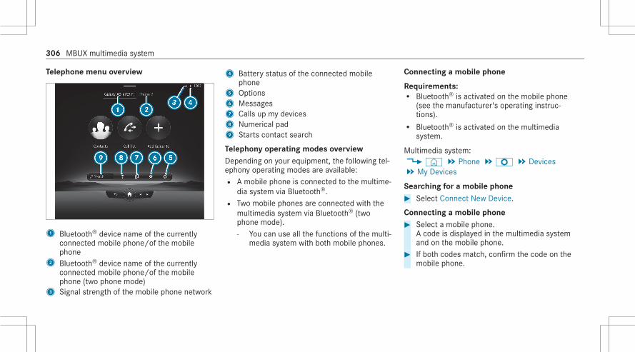
Telephone menu overview
1 Bluetooth® device name of the currentlyconnected mobile phone/of the mobilephone
2 Bluetooth® device name of the currentlyconnected mobile phone/of the mobilephone (two phone mode)
3 Signal strength of the mobile phone network
4 Battery status of the connected mobilephone
5 Options6 Messages7 Calls up my devices8 Numerical pad9 Starts contact search
Telephony operating modes overviewDepending on your equipment, the following tel‐ephony operating modes are available:R A mobile phone is connected to the multime‐
dia system via Bluetooth®.R Two mobile phones are connected with the
multimedia system via Bluetooth® (twophone mode).- You can use all the functions of the multi‐
media system with both mobile phones.
Connecting a mobile phone
Requirements:R Bluetooth® is activated on the mobile phone
(see the manufacturer's operating instruc‐tions).R Bluetooth® is activated on the multimedia
system.
Multimedia system:4© 5 Phone 5Z 5 Devices5 My Devices
Searching for a mobile phone# Select Connect New Device.
Connecting a mobile phone# Select a mobile phone.
A code is displayed in the multimedia systemand on the mobile phone.
# If both codes match, confirm the code on themobile phone.
306 MBUX multimedia system

Functions in the telephony menuIn the telephony menu you have the followingfunctions, for example:R Making calls, e.g.:
- R Accept a call- k End Call- Answering a call with a message- i Conference- Accepting or rejecting a waiting callR Managing contacts, e.g.:
- Downloading mobile phone contacts- Managing the format of a contact's name- Deleting favoritesR Receiving and sending messages, e.g.:
- Using the read-aloud function- Dictating a new message
Mercedes me and appsMercedes me connect
Information on Mercedes me connectMercedes me connect consists of multiple serv‐ices.You can use the following services via the multi‐media system and the overhead control panel,for example:R Accident and Breakdown Management (me
button or situation-dependent display in themultimedia system)R Mercedes-Benz emergency call system (auto‐
matic emergency call and SOS button)
The Mercedes me connect Accident and Break‐down Management and the Mercedes-Benzemergency call center are available to youaround the clock.The me button and the SOS button can be foundon the vehicle's overhead control panel(/ page 309).
You can also call the Mercedes-Benz CustomerCenter using the multimedia system(/ page 309).Please note that Mercedes me connect is aMercedes-Benz service. In emergencies, first callthe national emergency services using thestandard national emergency service telephonenumbers. In emergencies, you can also use theMercedes-Benz emergency call system(/ page 314).Please note the Mercedes me connect terms ofuse and the data protection information forMercedes me connect. You can find these inyour Mercedes me user account.Further information about Mercedes me connectservices can be obtained in the Mercedes mePortal: https://me.secure.mercedes-benz.com
Information on Mercedes me connect Acci‐dent and Breakdown ManagementThe Accident and Breakdown Management caninclude the following functions:R Supplement to the Mercedes-Benz emer‐
gency call system (/ page 314)
MBUX multimedia system 307

If necessary, the contact person at theMercedes-Benz emergency call center for‐wards the call to Mercedes me connect Acci‐dent and Breakdown Management. Forward‐ing the call is however not possible in allcountries.R Breakdown assistance by a technician on
location and/or the towing away of the vehi‐cle to the nearest authorized Mercedes-BenzCenterYou may be charged for these services.R Addition to the emergency guide after auto‐
matic accident or breakdown detection(/ page 310)In the event of a breakdown or accident, fur‐ther vehicle data is sent which enables opti‐mal support by the Mercedes-Benz CustomerCenter and the authorized service partner orbreakdown assistance.R Addition to the Mercedes me connect
service TelediagnosticsWith the Telediagnostics function, specificwear and failure reports are recorded by theservice provider, in so far as these can be
clearly interpreted and are available throughthe monitoring of components that are sub‐ject to diagnostics.If your vehicle detects a breakdown or threatof a breakdown, you may be prompted viathe multimedia system to contact theMercedes-Benz Customer Center for furtherhelp. This prompt in the multimedia systemonly appears when the vehicle is stationary.
% These services are subject to technicalrestrictions such as the mobile phone cover‐age, mobile network quality and the ability ofthe processing systems to interpret thetransferred data. In some circumstances,this can result in delays or the failure of theinformation to appear in the multimedia sys‐tem.
More information about Mercedes me connectservices can be obtained in the Mercedes mePortal: https://me.secure.mercedes-benz.com
Data transferred during Mercedes me con‐nect call servicesThe data transferred during a Mercedes me con‐nect call depends on:R The reason for initiation of the callR The service that is selected in the voice con‐
trol systemR The activated Mercedes me connect services
You can find out which data is transferred whenusing the services in the currently validMercedes me connect terms of use and the dataprotection information for Mercedes me con‐nect. You can find these in your Mercedes meuser account.
308 MBUX multimedia system

Mercedes me calls
Making a call via the overhead control panel
1 me button for service or information calls2 SOS button cover3 SOS button (emergency call system)
Making a Mercedes me call# Press me button1.
Making an emergency call# To open the cover of SOS button2, press it
briefly.# Press and hold SOS button3 for at least
one second.
If a Mercedes me call is active, an emergencycall can still be triggered. This has priority overall other active calls.
Information about the Mercedes me callusing the me buttonA call to the Mercedes-Benz Customer Centerhas been initiated via the me button in the over‐head control panel or the multimedia system(/ page 309).Using the voice dialog system you access thedesired service:R Accident and Breakdown ManagementR Mercedes-Benz Customer Center for general
information about the vehicle
You can find information on the following topics:R Activation of Mercedes me connectR Operating the vehicle
R Nearest authorized Mercedes-Benz CenterR Other products and services from Mercedes-
Benz
Data is transferred during the connection to theMercedes-Benz Customer Center (/ page 311).
Calling the Mercedes-Benz Customer Centerusing the multimedia system
Requirements:R Access to a GSM network is available.R The contract partner's GSM network cover‐
age is available in the respective region.R The ignition must be switched on so that
vehicle data can be transferred automati‐cally.
Multimedia system:4© 5 Phone 5©
# Call Mercedes me connect.After confirmation, the multimedia systemsends the required vehicle data. The datatransfer is shown in the central display.
MBUX multimedia system 309

Then, you can select a service and be connectedto a specialist at the Mercedes-Benz CustomerCenter.
Calling the Mercedes-Benz Customer Centerafter automatic accident or breakdowndetection
Requirements:R The vehicle has detected an accident or
breakdown situation.R The vehicle is stationary.R The hazard warning lights are switched on.
% This function is not available in all countries.The vehicle can detect accident or breakdownsituations under certain circumstances.In the event an accident or breakdown is detec‐ted, the emergency guide shows safety notes inthe multimedia system display.After quitting the emergency guide display onthe multimedia system, a prompt appears askingwhether you would like to get support from theMercedes-Benz Customer Center.
# Select Call.R After your agreement, or if the Mercedes
me connect service "Accident and Break‐down Management" is active, the vehicledata is transferred automatically(/ page 307).R The Mercedes-Benz Customer Center
takes your call and organizes the break‐down and accident assistance.
You may be charged for these services.% Depending on the severity of the accident,
an automatic emergency call can be initi‐ated. This has priority over all other activecalls.
% In addition, if the Mercedes me connectservice "Telediagnostics" is active, a similarprompt can appear after a delay in the eventof a breakdown. If you are already in contactwith the Mercedes-Benz Customer Center orhave already received support, this promptcan be ignored or declined.
% If you answer the prompt for support fromthe Mercedes-Benz Customer Center with
Call Later, the message will be hidden andappear again later.The prompt triggered by the Mercedes meconnect service "Telediagnostics", can eitherbe confirmed or declined. After beingdeclined, this will not be shown again.
Arranging a service appointment via aMercedes me callIf you have activated the maintenance manage‐ment service, relevant vehicle data is transferredautomatically to the Mercedes-Benz CustomerCenter. You will then receive individual recom‐mendations regarding the maintenance of yourvehicle.Regardless of whether you have consented tothe maintenance management service, the multi‐media system reminds you after a certainamount of time that a service is due. A promptappears asking if you would like to make anappointment.# To arrange a service appointment: select
Call.After your agreement, the vehicle data istransferred and the Mercedes-Benz Cus‐
310 MBUX multimedia system

tomer Center takes your preferred appoint‐ment date. The information is then sent toyour desired service outlet.This will contact you to confirm the appoint‐ment and if necessary consult about thedetails.
% If you select Call Later after the service mes‐sage appears, the message is hidden andreappears at a later time.
Transferred data during a Mercedes me callIf you initiate a service call using Mercedes me,data is transferred to enable targeted advice andan efficient service.The following requirements must be fulfilled forthe transfer of the data:R The ignition is switched on.R The required data transfer technology is sup‐
ported by the mobile phone network pro‐vider.R The quality of the mobile connection is suffi‐
cient.
Multi-stage transfer depends on the followingfactors:R Reason for the initiation of the callR The available mobile phone transmission
technology.R The activated Mercedes me connect serv‐
ices.R The service selected in the voice control sys‐
tem.
Data transfer if Mercedes me connect serv‐ices are not activatedIf no Mercedes me connect services are activa‐ted, the following data is transferred:R Vehicle identification numberR Time of the callR Reason for the initiation of the callR Confirmation of the data protection promptR Country indicator of the vehicleR Set language for the multimedia systemR Telephone number of the communication
platform installed in the vehicle
If a call is made for a service appointment viathe service reminder, the following data is alsotransmitted:R Current mileage and maintenance data
If a call is made after automatic accident orbreakdown detection using the multimedia sys‐tem, the following data is also transmitted:R Current mileage and maintenance dataR Current vehicle location
If Accident and Breakdown Management iscalled via the voice control system, the followingdata can also be called up from the vehicle bythe Mercedes-Benz Customer Center:R Current vehicle location
Data processingThe data transmitted within the scope of the callis deleted from the processing system after thecall is finished, in so far as this data is not beingused for other activated Mercedes me connectservices.The incident-specific data is processed andstored in the Mercedes-Benz Customer Center
MBUX multimedia system 311

and, if required to process the incident, forwar‐ded to the service partner authorized by theMercedes-Benz Customer Center. Please takenote of the data protection information on theMercedes me Internet page https://www.mercedes.me or in the recorded messageimmediately after calling the Mercedes-BenzCustomer Center.% The recorded message is not available in
every country.
Overview of the Mercedes me & Apps menu
When you log in with a user account to theMercedes me Portal, then services and offersfrom Mercedes-Benz will be available to you.For more information consult an authorizedMercedes-Benz Center or visit the Mercedes meportal: https://me.secure.mercedes-benz.com% Make sure you always keep the Mercedes
me apps updated.You can call up the menu using Apps in the mul‐timedia system.
In the Apps menu, the following options can beavailable:R Connecting the vehicle with the Mercedes
me user accountR Deleting a connection between a Mercedes
me user account and the vehicleR Calling up the Mercedes me servicesR Calling up apps such as, In-Car Office or the
web browser depending on availability
Web browser overview
1 Search2 To refresh/stop3 Previous website4 Options5 Settings
312 MBUX multimedia system
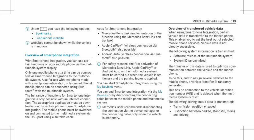
% Under Ä you have the following options:R BookmarksR Load mobile website
% Websites cannot be shown while the vehicleis in motion.
Overview of smartphone integration
With Smartphone Integration, you can use cer‐tain functions on your mobile phone via the mul‐timedia system display.Only one mobile phone at a time can be connec‐ted via Smartphone Integration to the multime‐dia system. Also for use with two phone modewith smartphone integration, only one additionalmobile phone can be connected using Blue‐tooth® with the multimedia system.The full range of functions for Smartphone Inte‐gration is only possible with an Internet connec‐tion. The appropriate application must be down‐loaded on the mobile phone to use SmartphoneIntegration. The mobile phone must be switchedon and connected to the multimedia system viathe USB port using a suitable cable.
Apps for Smartphone IntegrationR Mercedes-Benz Link (implementation of the
function using the Mercedes-Benz Link con‐trol box)R Apple CarPlay® (wireless connection via
Bluetooth® also possible)R Android Auto (wireless connection via Blue‐
tooth® also possible)
% For safety reasons, the first activation ofMercedes-Benz Link, Apple CarPlay® orAndroid Auto on the multimedia systemmust be carried out when the vehicle is sta‐tionary and the parking brake is applied.
You can start Smartphone Integration using theMy Devices menu.You can end Smartphone Integration via the MyDevices or by disconnecting the connectingcable between the mobile phone and multimediasystem.% Mercedes-Benz recommends disconnecting
the connection via the device manager orthe connecting cable only when the vehicleis stationary.
Overview of transferred vehicle dataWhen using Smartphone Integration, certainvehicle data is transferred to the mobile phone.This enables you to get the best out of selectedmobile phone services. Vehicle data is notdirectly accessible.The following system information is transmitted:R Software release of the multimedia systemR System ID (anonymized)
The transfer of this data is used to optimize com‐munication between the vehicle and the mobilephone.To do this, and to assign several vehicles to themobile phone, a vehicle identifier is randomlygenerated.This has no connection to the vehicle identifica‐tion number (VIN) and is deleted when the multi‐media system is reset .The following driving status data is transmitted:R Transmission position engagedR Distinction between parked, standstill, rolling
and driving
MBUX multimedia system 313

R Day/night mode of the instrument clusterR Drive type
The transfer of this data is used to alter howcontent is displayed to correspond to the drivingsituation.The following position data is transmitted:R CoordinatesR SpeedR Compass directionR Acceleration direction
This data is used by the mobile phone toimprove the accuracy of the navigation (e.g. forcontinuation in a tunnel).
Mercedes-Benz emergency call systemInformation on the Mercedes-Benz emer‐gency call system
Your vehicle is equipped with the Mercedes-Benzemergency call system ("eCall"). This feature canhelp save lives in the event of an accident. eCall
in no way replaces assistance provided fromdialing 911.Mercedes-Benz eCall only functions in areaswhere mobile phone coverage is available fromthe wireless service providers. Insufficient net‐work coverage from the wireless service provid‐ers may result in an emergency call not beingtransmitted.eCall is a standard feature in your Mercedes-Benz vehicle. In order to function as intended,the system relies on the transmission of datadetailed in the Transmitted Data section that fol‐lows (/ page 316).To disable eCall, a customer must visit anauthorized Mercedes-Benz Service departmentto deactivate the vehicle's communication mod‐ule.Deactivation of this module prevents theactivation of any and all Mercedes me con‐nect services. After the deactivation ofeCall, automatic emergency call and manualemergency call will not be available.The ignition must be switched on before an auto‐matic emergency call can be made.
% eCall is activated at the factory.% eCall can be deactivated by an authorized
Mercedes-Benz dealer. Please note that inthe event ownership of the vehicle is trans‐ferred to another owner in its deactivatedstate, eCall will remain deactivated unlessthe new owner visits an authorizedMercedes-Benz dealership to reactivate thesystem.
Overview of the Mercedes-Benz emergencycall system
eCall can help to reduce the time between anaccident and the arrival of emergency servicesat the site of the accident. It helps locate anaccident site in places that are difficult toaccess. However, even if a vehicle is equippedwith eCall, this does not mean the system is ON.As such, eCall does not replace dialing 911 in theevent of an accident.An emergency call can be made automatically(/ page 315) or manually (/ page 315). Onlymake emergency calls if you or others are inneed of rescue.
314 MBUX multimedia system

Only make emergency calls if you or others arein need of rescue. Do not make an emergencycall in the event of a breakdown or a similar sit‐uation.
Triggering an automatic Mercedes-Benzemergency call
Requirements:R The ignition is switched on.R The starter battery is sufficiently charged.
The Mercedes-Benz emergency call system trig‐gers an emergency call automatically in the fol‐lowing cases:R After activation of the restraint systems such
as airbags or Emergency Tensioning Devicesafter an accident.R After an automatically initiated emergency
stop by Active Emergency Stop Assist.
The emergency call has been made:R A voice connection is made to the Mercedes-
Benz emergency call center.
R A message with accident data is transmittedto the Mercedes-Benz emergency call center.The Mercedes-Benz emergency call centercan transmit the vehicle position data to oneof the emergency call centers.
The SOS button in the overhead control panelflashes until the emergency call is finished.It is not possible to immediately end an auto‐matic emergency call.If no connection can be made to the emergencyservices either, a corresponding messageappears in the media display.# Dial the local emergency number on your
mobile phone.If an emergency call has been initiated:R Remain in the vehicle if the road and traffic
conditions permit you to do so until a voiceconnection is established with the emer‐gency call center operator.R Based on the call, the operator decides
whether it is necessary to call rescue teamsand/or the police to the accident site.
R If no vehicle occupant answers, an ambu‐lance is sent to the vehicle immediately.
Triggering a manual Mercedes-Benz emer‐gency call
# To use the SOS button in the overheadcontrol panel: press the SOS button at leastone second long (/ page 309).
or# To use voice control: use the voice com‐
mands of the MBUX Voice Assistant.The emergency call has been made:R A voice connection is made to the Mercedes-
Benz emergency call center.R A message with accident data is transmitted
to the Mercedes-Benz emergency call center.The Mercedes-Benz emergency call centercan transmit the vehicle position data to oneof the emergency call centers.R Remain in the vehicle if the road and traffic
conditions permit you to do so until a voice
MBUX multimedia system 315

connection is established with the emer‐gency call center operator.R Based on the call, the operator decides
whether it is necessary to call rescue teamsand/or the police to the accident site.
If no connection can be made to the emergencyservices, a corresponding message appears inthe central display.# Dial the local emergency number on your
mobile phone.
Ending an unintentionally triggered manualMercedes-Benz emergency call# Select~ on the multifunction steering
wheel. Depress the button for several sec‐onds.
Data transfer of the Mercedes-Benz emer‐gency call system
In the event of an automatic or manual emer‐gency call the following data is transmitted, forexample:R Vehicle's GPS position data
R GPS position data on the route (a few300 feet (100 meters) before the incident)R Direction of travelR Vehicle identification numberR Vehicle drive typeR Number of people determined to be in the
vehicleR Whether Mercedes me connect is available
or notR Whether the emergency call was initiated
manually or automaticallyR Time of the accidentR Language setting on the multimedia system
Data transmitted is vehicle information. For anyquestions about the collection, use and sharingof the eCall system data, please contact MBU‐SA's Customer Assistance Center at 800-FOR-MERC.For Canada, please contact MBC's CustomerAssistance Center at 1-800-387-0100.Customer requests for covered informationshould be submitted via the same channels.
For accident clarification purposes, the followingmeasures can be taken up to an hour after theemergency call has been initiated:R The current vehicle position can be called up.R A voice connection to the vehicle occupants
can be established
316 MBUX multimedia system

Radio & mediaOverview of the symbols and functions in the media menu
Symbol Designation Function
6 Play Select to start or continue playback.
8 Rest Select to pause the playback.
: Repeat a track Select to repeat the current track or the active playlist.R Select once: the active playlist is repeated.R Select twice: the current track is repeated.R Select three times: the function is deactivated.
9 Random playback Select to play back the tracks in random order.
û/ü Skip forwards/back Select to skip to the next or to the previous track.
Ä Additional options Select to show additional options.
5 Categories Select to show or search through available categories (e.g. playback lists, albums,artists, etc.).
ª Search Select to search in the active menu. You can search for artists, genres or moods,for example.
MBUX multimedia system 317

Symbol Designation Function
Z Settings Select to make settings.
© Home Select to return to the home screen.
j Messaging Select to call up messaging.
2 Full screen Select to switch to full screen mode.
The following functions and settings are availa‐ble in the media menu:R Connecting external data storage media with
the multimedia system (e.g. using USB orBluetooth®)R Playing back audio or video files
318 MBUX multimedia system

Overview of the symbols and functions in the radio menu
Symbol Designation Function
© Home Select to return to the home screen.
j Messaging Select to call up messaging.
û/ü Skip forwards/back Select to skip to the next or to the previous station.
Z Settings Select to have further options shown.The setting options are country-dependent.
HD HD radio® Select to switch the HD Radio® function on or off.This function is not available in all countries.
4 Station list Select to have the station list shown.
ª Search Select to search in the active menu. You can search for artists, genres or moods,for example.
Additional functions of TuneIn Radio% A relatively large volume of data can be
transmitted when using TuneIn Radio.
MBUX multimedia system 319

Symbol Designation Function
Z Settings The following additional settings are available inthe TuneIn Radio menu:R Selecting streamR Logging on to or out of the TuneIn account
ß Favourites Select during playback to save the station cur‐rently set as a favorite.
6/8 Play/Pause Select to start, stop or continue playback.
4 Browse Select to choose a category and then a radiostation.
Additional functions of the satellite radioSIRIUS XM® satellite radio offers more than 175digital-quality radio channels providing 100%commercial-free music, sports, news and enter‐tainment, for example. SIRIUS XM® satelliteradio employs a fleet of high-performance satel‐
lites to broadcast around the clock throughoutthe USA and Canada. The satellite radio programis available for a monthly fee. Information aboutthis can be obtained from a Sirius XM® ServiceCenter and at https://www.siriusxm.com (USA)or https://www.siriusxm.ca (Canada).
% Sirius, XM and all related marks and logosare trademarks of Sirius XM Radio Inc. andits subsidiaries. All other marks, channelnames and logos are the property of theirrespective owners. All rights reserved.
320 MBUX multimedia system

Symbol Designation Function
Z Settings The following additional settings are available inthe satellite radio menu:R Activate child safety lock to lock channels
with adult contentR Set alarm programming for music and sport
alertsR Create TuneMix lists to listen to music seam‐
lessly
6 Play Select to start or continue playback.
8 Rest Select to pause the playback.
Depending on the frequency band selected, dif‐ferent functions are available to you.Select the desired frequency band in the radiomenu head runner.
Calling up TuneIn Radio
Requirements:R There is a user account at https://
www.mercedes.me.R The vehicle is linked to the Mercedes me
user account.R The TuneIn Radio service is activated in the
Mercedes me portal.
R The data volume is available.Depending on the country, data volume mayneed to be purchased.R A fast Internet connection for data transmis‐
sion free of interference.
% Data volume can be purchased directlyfrom a mobile phone network provider viathe Mercedes me Portal.
MBUX multimedia system 321

% The functions and services are country-dependent. For more information, consult anauthorized Mercedes-Benz Center.
Multimedia system:4© 5 Radio# Select TuneIn Radio.
The TuneIn menu appears. The last stationset starts playing.
% The connection quality depends on the localmobile phone reception.
Setting up satellite radio
Requirements:R Satellite radio equipment is available.R Registration with a satellite radio provider
has been completed.R If registration is not included when purchas‐
ing the system, your credit card details willbe required to activate your account.
Multimedia system:4© 5Þ Radio 5 SiriusXM5Z
# Select Service Information.The service information screen appearsshowing the radio ID and the current sub‐scription status.
# Establish a telephone connection.# Follow the service staff's instructions.
The activation process may take up to tenminutes.
% You can also have the satellite service acti‐vated online. To do so, please visit https://www.siriusxm.com (USA) or https://www.siriusxm.ca (Canada).
Music and sport alerts
Multimedia system:4© 5Þ Radio 5 SiriusXM5Z 5 Alerts
Setting music and sport alertsThis function enables you to program an alert foryour favorite artists, tracks or sporting events.Music alerts can be saved whilst a track is beingplayed and sport alerts can be saved during alive game. You can also specify sport alerts viathe menu option. The system then continuouslysearches through all the channels.# Set a music or sports alert, to be informed of
matches in the live program.
Activating messages for a category# Select a category and activateD.
Adding messages for a category# Select a category and add a messageW.# Select Artist Alerts or Song Alerts in the dia‐
log window.The message is set for the activated O trackand artist. If a match is found, a prompt
322 MBUX multimedia system

appears asking whether you wish to changeto the station.
Deleting messages in a category# Select a category, mark the desired mes‐
sages and deleteE.or# Do not mark any messages and delete all
entriesE.
Sound settingsOverview of functions in the sound menu
The setting options and functions availabledepend on the sound system installed. You canfind out which sound system is installed in yourvehicle in the Digital Operator's Manual.
Standard sound systemThe following functions are available:R Equalizer:
- Treble, mid-range and bassR Balance and faderR Volume:
- Automatic adjustment
Burmester® 3D-surround sound system andBurmester® high-end 4D surround soundsystemThe following functions are available:R Equalizer:
- Treble, mid-range and bassR Balance and faderR Sound focusR VIP seat (Burmester® high-end 4D surround
sound system)R Sound profilesR Volume:
- Automatic adjustment
MBUX multimedia system 323

ASSYST PLUS service interval displayFunction of the ASSYST PLUS service intervaldisplay
The ASSYST PLUS service interval display on thedriver display provides information on theremaining time or distance before the nextservice due date.You can hide this service display using the backbutton on the left-hand side of the steeringwheel.Depending on how the vehicle is used, theASSYST PLUS service interval display mayshorten the service interval, e.g. in the followingcases:R Mainly short-distance drivingR When the engine is often left idling for long
periodsR In the event of frequent cold start phases
Mercedes-Benz recommends avoiding suchoperating conditions.You can obtain information concerning the serv‐icing of your vehicle from a qualified specialist
workshop, e.g. an authorized Mercedes-BenzCenter.
Displaying the service due date
Driver display:4 ServiceThe next service due date is displayed.# To exit the display: press the back button
on the left-hand side of the steering wheel.Bear in mind the following related topic:R Operating the driver display (/ page 273).
Information on regular maintenance work
* NOTE Premature wear through failure toobserve service due dates
Maintenance work which is not carried out atthe right time or incompletely can lead toincreased wear and damage to the vehicle.# Adhere to the prescribed service inter‐
vals.
# Always have the prescribed mainte‐nance work carried out at a qualifiedspecialist workshop.
Special service requirements
The prescribed service interval is based on nor‐mal operation of the vehicle. Maintenance workwill need to be performed more often if the vehi‐cle is operated under arduous conditions orincreased loads.The ASSYST PLUS service interval display is onlyan aid. The driver of the vehicle bears responsi‐bility as regards to whether maintenance workneeds to be performed more often than speci‐fied based on the actual operating conditionsand/or loads.Examples of arduous operating conditions:R regular city driving with frequent intermedi‐
ate stopsR mainly short-distance drivingR frequent operation in mountainous terrain or
on poor road surfaces
324 Maintenance and care

R when the engine is often left idling for longperiodsR operation in particularly dusty conditions
and/or if air-recirculation mode is frequentlyused
In these or similar operating conditions, have theinterior air filter, engine air cleaner, engine oiland oil filter etc. changed more frequently. Thetires must be checked more frequently if thevehicle is operated under increased loads. Fur‐ther information can be obtained at a qualifiedspecialist workshop.
Battery disconnection periods
The ASSYST PLUS service interval display cancalculate the service due date only when thebattery is connected.# Display the service due date on the driver
display and note it down before disconnect‐ing the battery (/ page 324).
Engine compartmentOpening and closing the hood
& WARNING Risk of accident due to driv‐ing with the hood unlocked
The hood may open and block your view.# Never release the hood when driving.# Before every trip, ensure that the hood
is locked.
& WARNING Risk of accident and injurywhen opening and closing the hood
The hood may suddenly drop into the endposition.There is a risk of injury for anyone in thehood's range of movement.# Do not open or close the hood if there
is a person in the hood's range of move‐ment.
& WARNING Risk of burns when openingthe hood
If you open the hood when the engine hasoverheated or when there is a fire in theengine compartment, the following situationsmay occur:R You could come into contact with hot
gases.R You could come into contact with other
hot, escaping operating fluids.
# Before opening the hood, allow theoverheated engine to cool down.
# In the event of a fire in the engine com‐partment, keep the hood closed andcall the fire service.
& WARNING Risk of injury due to movingparts
Components in the engine compartment maycontinue running or start up suddenly, even ifthe ignition is switched off.
Maintenance and care 325

Make sure of the following before performingtasks in the engine compartment:# Switch the ignition off.# Never reach into the danger zone sur‐
rounding moving components, e.g. therotation area of the fan.
# Remove jewelery and watches.# Keep items of clothing and hair away
from moving parts.
& WARNING Risk of injury from touchingcomponents under voltage
The ignition system and the fuel injectionsystem work under high voltage. You couldreceive an electric shock.# Never touch components of the ignition
system or the fuel injection systemwhen the ignition is switched on.
& WARNING Risk of burns from hot com‐ponent parts in the engine compartment
Certain component parts in the engine com‐partment can be very hot, e.g. the engine,the cooler and parts of the exhaust system.# Allow the engine to cool down and only
touch component parts described inthe following.
& WARNING Risk of injury from using thewindshield wipers while the engine hoodis open
When the engine hood is open and the wind‐shield wipers are set in motion, you can betrapped by the wiper linkage.# Always switch off the windshield wipers
and ignition before opening the enginehood.
Opening the hood
# Pull on handle1 twice.The hood will be released and open slightly.
# Then lift the hood by hand.
326 Maintenance and care

Closing the hood
* NOTE Damage to the hood
If the hood is closed manually, there is a riskof dents.# Do not close the hood manually.
# Lower the hood to a height of around 8 in(20 cm) and then allow it to fall, applying alittle force as you let it go.
# If the hood can still be lifted slightly, openthe hood again and close it with a little moreforce until it engages correctly.
Engine oil
Checking the engine oil level with the driverdisplay
Requirements:R The engine has been warmed up.R The vehicle is parked on a level surface.R The engine is running at idle speed.R The hood is closed.
The engine oil level is determined during driving.Determining the engine oil level can take up to30 minutes with a normal driving style and evenlonger with an active driving style.Driver display:4 ServiceThe engine oil level is shown.One of the following messages will appear onthe driver display:R Engine Oil Level Measuring Now…: measure‐
ment of the oil level is not yet possible.
# Repeat the request after a maximum of30 minutes' driving.R Engine Oil Level OK and the bar display for
indicating the oil level on the driver display isgreen and is between "min" and "max": theoil level is correct.
R Engine Oil Level Refill 1,0 liq.gal. and the bardisplay for indicating the oil level on thedriver display is yellow and is below "min":
# Add 1.1 US qt (1 l) of engine oil.
R Engine Oil Level Reduce and the bar displayfor indicating the oil level on the driver dis‐play is yellow and is above "max":
# Drain off any excess engine oil that has beenadded. To do so, consult a qualified specialistworkshop.R For Engine Oil Level Switch On Ignition# Switch on the ignition to check the engine oil
level.R Engine Oil Level System Inoperative: The oil
level sensor is defective or not connected.
# Consult a qualified specialist workshop.R Engine Oil Level Currently Unavailable# Close the hood.
Refilling engine oil
& WARNING Risk of burns from hot com‐ponent parts in the engine compartment
Certain component parts in the engine com‐partment can be very hot, e.g. the engine,the cooler and parts of the exhaust system.
Maintenance and care 327

# Allow the engine to cool down and onlytouch component parts described inthe following.
& WARNING Risk of fire and injury fromengine oil
If engine oil comes into contact with hotcomponent parts in the engine compart‐ment, it may ignite.# Make sure that no engine oil is spilled
next to the filler opening.# Allow the engine to cool off and thor‐
oughly clean the engine oil from compo‐nent parts before starting the vehicle.
* NOTE Engine damage caused by anincorrect oil filter, incorrect oil or addi‐tives
# Do not use engine oils or oil filterswhich do not correspond to the specifi‐cations explicitly prescribed for theservice intervals.
# Follow the instructions on the serviceinterval display for changing the engineoil and observe the prescribed changeintervals.
# Do not use additives.
* NOTE Damage caused by refilling toomuch engine oil
Too much engine oil can damage the engineor the catalytic converter.# Have excess engine oil removed at a
qualified specialist workshop.
% Depending on driving style, the vehicle con‐sumes up to 0.9 US qt (0.8 liter) of oil per600 miles (1000 km). The oil consumptionmay be higher than this when the vehicle isnew or if you frequently drive at high enginespeeds.
% Depending on the engine, the cap may beinstalled in the engine compartment in dif‐ferent locations.
# Turn cap1 counter-clockwise and removeit.
# Add engine oil.# Replace cap1 and turn it clockwise until it
engages.# Check the oil level again (/ page 327).
328 Maintenance and care

Checking the coolant level
& WARNING Risk of burns from hot com‐ponent parts in the engine compartment
Certain component parts in the engine com‐partment can be very hot, e.g. the engine,the cooler and parts of the exhaust system.# Allow the engine to cool down and only
touch component parts described inthe following.
& WARNING Risk of scalding from hotcoolant
If you open the cap, you could be scalded.# Let the motor cool down before opening
the cap.# When opening the cap, wear protective
gloves and safety glasses.# Open the cap slowly to release pres‐
sure.
# Only have the coolant checked or refilled at aqualified specialist workshop.
Refilling the windshield washer system
& WARNING Risk of burns from hot com‐ponent parts in the engine compartment
Certain component parts in the engine com‐partment can be very hot, e.g. the engine,the cooler and parts of the exhaust system.# Allow the engine to cool down and only
touch component parts described inthe following.
& WARNING ‑ Risk of fire and injury fromwindshield washer concentrate
Windshield washer concentrate is highlyflammable. It could ignite if it comes intocontact with hot engine component parts orthe exhaust system.# Make sure that no windshield washer
concentrate spills out next to the filleropening.
# Remove cap1 by the tab.# Refill washer fluid.% Further information about the windshield
washer fluid (/ page 474)
Maintenance and care 329

Keeping the air-water duct free
# Keep the area between the hood and thewindshield free of deposits, e.g. ice, snowand leaves.
Cleaning and careNotes on washing the vehicle in a car wash
& WARNING Risk of accident due toreduced braking effect after washing thevehicle
The braking effect is reduced after washingthe vehicle.# After the vehicle has been washed,
brake carefully while paying attention tothe traffic conditions until the brakingeffect has been fully restored.
* NOTE Damage from automatic braking
If one of the following functions is switchedon, the vehicle brakes automatically in cer‐tain situations:R Active Brake AssistR Active Distance Assist DISTRONICR HOLD functionR Active Parking Assist
To avoid damage to the vehicle, deactivatethese systems in the following or similar sit‐uations:# During towing# In a car wash
* NOTE Damage due to unsuitable carwash
# Before driving into a car wash makesure that the car wash is suitable forthe vehicle dimensions.
# Ensure there is sufficient ground clear‐ance between the underbody and theguide rails of the car wash.
# Ensure that the clearance width of thecar wash, in particular the width of theguide rails, is sufficient.
To avoid damage to your vehicle when using acar wash, ensure the following beforehand:R Active Distance Assist DISTRONIC is deacti‐
vated.R the HOLD function is switched off.R the surround view camera or the rear view
camera is switched off.R the vehicle is locked and the door handles
retracted.R the side windows and sliding sunroof are
completely closed.R the blower for the ventilation/heating is
switched off.R the windshield wiper switch is in positiong.R the SmartKey is at a minimum distance of
20 ft (6 m) away from the vehicle. Otherwise,
330 Maintenance and care

the trunk lid or a door could open uninten‐tionally.R for car washes with a conveyor system:
- neutrali is engaged.- the vehicle is locked from inside.R do not make any hand movements in the
area of the overhead control panel or deacti‐vate (/ page 294) the Sliding Sunroof andRoller Sunblind option in the settings for theMBUX Interior Assistant.
% If, after the car wash, you remove the waxfrom the windshield and wiper rubbers, thiswill prevent smearing and reduce wipernoise.
Notes on using a power washer
& WARNING Risk of an accident whenusing power washers with round-spraynozzles
The water jet can cause externally invisibledamage.
Components damaged in this way may unex‐pectedly fail.# Do not use a power washer with round-
spray nozzles.# Have damaged tires or chassis parts
replaced immediately.
To avoid damage to your vehicle, observe the fol‐lowing when using a power washer:R the SmartKey is at a minimum distance of
10 ft (3 m) away from the vehicle. Otherwise,the trunk lid or a door could open uninten‐tionally.R maintain a distance of at least 11.8 in
(30 cm) to the vehicle.R vehicles with decorative foil: parts of your
vehicle are covered with a decorative foil.Maintain a distance of at least 27.6 in(70 cm) between the foil-covered parts of thevehicle and the nozzle of the power washer.Move the power washer nozzle around whilstcleaning. The water temperature of thepower washer must not exceed 140°F(60°C).
R observe the information on the correct dis‐tance in the equipment manufacturer's oper‐ating instructions.R do not direct the nozzle of the power washer
directly at sensitive parts, e.g. tires, gaps,electrical components, batteries, light sour‐ces and ventilation slits.
Washing the vehicle by hand
* NOTE Engine damage due to wateringress
# Take care not to point the water jetdirectly towards the air inlet grille belowthe hood.
Observe the legal requirements, e.g. in a numberof countries, washing by hand is only permittedin specially designated wash bays.# Use a mild cleaning agent, e.g. car shampoo.# Wash the vehicle with lukewarm water using
a soft car sponge. When doing so, do notexpose the vehicle to direct sunlight.
Maintenance and care 331

# Carefully hose the vehicle off with water anddry using a chamois.
% Observe the notes on the care of vehicleparts (/ page 333).
Notes on paintwork/matte finish paintworkcare
Observe the notes on cleaning and care to avoiddamaging the paintwork and interfering with thedriver assistance systems.
PaintR Insect remains: soak with insect remover and
rinse off the treated areas afterwards.R Bird droppings: soak with water and rinse off
afterwards.R Tree resin, oils, fuels and greases: remove by
rubbing gently with a cloth soaked in petro‐leum ether or lighter fluid.R Coolant and brake fluid: remove with a damp
cloth and clean water.R Tar stains: use tar remover.R Wax: use silicone remover.
R Do not attach stickers, films or similar mate‐rials. Only have film attached to the bumperat a qualified specialist workshop.R Remove dirt immediately, where possible.
Matte finishR Only use care products approved for
Mercedes-Benz.R Do not attach stickers, films or similar mate‐
rials. Only have film attached to the bumperat a qualified specialist workshop.R Do not polish the vehicle and alloy wheels.R Only use car washes that correspond to the
latest engineering standards.R Do not use car wash programs with a final
hot wax treatment.R Do not use paint cleaners, buffing or polish‐
ing products, gloss preservers, e.g. wax.
In the event of paintwork damage:R Always have paintwork repairs carried out at
a qualified specialist workshop.R Make sure the radar sensors function
(/ page 215).
Notes on cleaning decorative foils
Observe the notes on matte finish care in thechapter "Notes on paintwork/matte finish paint‐work care" (/ page 332). They also apply tomatte decorative foils.Observe the notes on cleaning decorative foils toavoid vehicle damage.
CleaningR For cleaning, use plenty of water and a mild
cleaning agent without additives or abrasivesubstances, e.g. a car shampoo approved forMercedes-Benz.R Remove dirt immediately, where possible,
whilst avoiding rubbing too hard. There isotherwise a risk of damaging the decorativefoil irreparably.R If there is dirt on the finish or if the decora‐
tive foil is dull: use the Paint Cleaner recom‐mended and approved for Mercedes-Benz.R Insect remains: soak with insect remover and
rinse off the treated areas afterwards.R Bird droppings: soak with water and rinse off
afterwards.
332 Maintenance and care

R To prevent water stains, dry a foil-wrappedvehicle with a soft, absorbent cloth afterevery car wash.
Avoiding damage to the decorative foilR The service life and color of decorative foils
are impaired by:- Sunlight- Temperature, e.g. hot air blower- Weather conditions- Stone chippings and dirt- Chemical cleaning agents- Oily productsR Do not use polish on matte decorative foil.
Polishing will have the effect of shining thefoil-wrapped surface.R Do not treat matte or structured decorative
foils with wax. Permanent stains may occur.
Scratches, corrosive deposits, areas affected bycorrosion and damage caused by incorrect carecannot always be completely repaired. In suchcases, visit a qualified specialist workshop.
You can obtain more information on care andcleaning products from the manufacturer.In the case of foil-wrapped surfaces, optical dif‐ferences may occur between the surfaces thatwere not protected by a decorative foil afterremoving a decorative foil.% Have work or repairs to decorative foils car‐
ried out at a qualified specialist workshop,e.g. at an authorized Mercedes-Benz Center.
Notes on care of vehicle parts
& WARNING Risk of entrapment if thewindshield wipers are switched on whilethe windshield is being cleaned
If the windshield wipers are set in motionwhile you are cleaning the windshield orwiper blades, you can be trapped by thewiper arm.# Always switch off the windshield wipers
and the ignition before cleaning thewindshield or wiper blades.
& WARNING Risk of burns from the tail‐pipe and tailpipe trims
The exhaust tailpipe and tailpipe trims canbecome very hot. If you come into contactwith these parts of the vehicle, you couldburn yourself.# Always be particularly careful around
the tailpipe and the tailpipe trims andsupervise children especially closely inthis area.
# Allow vehicle parts to cool down beforetouching them.
To avoid damage to the vehicle, observe thenotes on cleaning and care of the following vehi‐cle parts:
Wheels and rimsR Use water and acid-free alloy wheel cleaners.R Do not use acidic alloy wheel cleaners to
remove brake dust. This could damage wheelbolts and brake components.R To avoid corrosion of the brake discs and
brakepads, drive the vehicle for a few
Maintenance and care 333

minutes after cleaning before parking it. Thebrake discs and brakepads warm up and dryout.
WindowsR Clean the windows inside and outside with a
damp cloth and with a cleaning agent recom‐mended for Mercedes-Benz.R Do not use dry cloths or abrasive or solvent-
based cleaning agents to clean the inside ofwindows.
% Remove external fogging or dirt on the wind‐shield in front of the multifunction camera.Otherwise, driving systems and drivingsafety systems may be impaired or not avail‐able (/ page 215).
Wiper bladesR Move the wiper arms into the replacement
position (/ page 168).R With the wiper arms folded out, clean the
wiper blades with a damp cloth.R Do not clean the wiper blades too often.
Exterior lightingR Clean the lenses with a wet sponge and mild
cleaning agent, e.g. car shampoo.R Only use cleaning agents or cleaning cloths
that are suitable for plastic lenses.
SensorsR Clean the sensors in the front and rear
bumpers with a soft cloth and car shampoo(/ page 215).R When using a power washer, maintain a mini‐
mum distance of 11.8 in (30 cm).
Rear view camera and surround view cameraR Open the camera cover with the multimedia
system (/ page 261).R Use clean water and a soft cloth to clean the
camera lens.R Do not use a power washer.
TailpipesR Clean with a cleaning agent recommended
for Mercedes-Benz, especially in the winterand after washing the vehicle.R Do not use acidic cleaning agents.
Notes on care of the interior
& WARNING Risk of injury from plasticparts breaking off after the use of sol‐vent-based care products
Care and cleaning products containing sol‐vents can cause surfaces in the cockpit tobecome porous. When the airbags aredeployed, plastic parts may break away.# Do not use any care or cleaning prod‐
ucts containing solvents to clean thecockpit.
& WARNING Risk of injury or death frombleached seat belts
Bleaching or dyeing seat belts can severelyweaken them.This can, for example, cause seat belts totear or fail in an accident.# Never bleach or dye seat belts.
To avoid damage to the vehicle, observe the fol‐lowing notes on cleaning and care:
334 Maintenance and care

Seat beltsR Clean with lukewarm and soapy water.R Do not use chemical cleaning agents.R Do not dry by heating them to over 176°F
(80°C) or exposing them to direct sunlight.
DisplayR Switch off the display and let it cool down.R Clean the surface carefully with a microfiber
cloth and a suitable display care product(TFT-LCD).R Do not use any other agents.
Plastic trimR Clean with a damp microfiber cloth.R For heavy soiling: use a cleaner recommen‐
ded for Mercedes-Benz.R Do not attach stickers, films or similar mate‐
rials.R Do not allow cosmetics, insect repellent or
sun cream to come in contact with the plas‐tic trim.
Real wood and trim elementsR Clean with a microfiber cloth.
R Black piano-lacquer look: clean with a dampcloth and soapy water.R For heavy soiling: use a cleaner recommen‐
ded for Mercedes-Benz.R Do not use solvent-based cleaning agents,
polishes or waxes.
HeadlinerR Clean with a brush or dry shampoo.
CarpetR Use a carpet and textile cleaning agent rec‐
ommended for Mercedes-Benz.
Steering wheel made of genuine leather orDINAMICA
* NOTE Damage caused by wrong cleaners
# Do not use solvent-based cleaningagents such as tar remover or wheelcleaner; neither should you use pol‐ishes or waxes. Otherwise you maydamage the finish.
R Clean with a damp cloth and 1% soapy watersolution and then wipe with a dry cloth.
R For heavy soiling: use a cleaner recommen‐ded for Mercedes-Benz.R Leather care: use a leather care agent that
has been recommended for Mercedes-Benz.R Do not allow the leather to become too
damp.R Do not use a microfiber cloth.
% Leather is a natural product. It has naturalsurface properties, such as differences instructure, marks caused by growth andinjury or subtle color differences.
Genuine leather seat coversR Clean with a damp cloth and then wipe with a
dry cloth.R Leather care: use a leather care agent that
has been recommended for Mercedes-Benz.R Do not allow the leather to become too
damp.R Do not use a microfiber cloth.
DINAMICA seat coversR Clean with a damp cloth.R Do not use a microfiber cloth.
Maintenance and care 335

Fabric seat coversR Clean with a damp microfiber cloth and 1%
soapy water and allow to dry.
EASY-PACK trunk boxR Clean with a damp cloth.R Do not use any alcohol-based thinners, gaso‐
line or abrasive cleaning agents.
336 Maintenance and care

EmergencyRemoving the safety vest
The safety vests are located in storage spaces inthe front door.
# Take the safety vest bag out of storage space1.
# Open the safety vest bag and pull out thesafety vest.
% Safety vests can also be stored in the reardoor storage spaces.
1 Maximum number of washes2 Maximum wash temperature3 Do not bleach4 Do not iron5 Do not tumble dry6 Do not dry clean7 This is a class 2 vest
The requirements defined by the legal standardare only fulfilled in the following cases:R The safety vest is the correct sizeR The safety vest is fully closed whilst being
worn
Replace the safety vest in the following cases:R The reflective strips are damaged or dirt on
the reflective strips can no longer beremovedR The maximum number of washes is exceededR The fluorescence has faded
Breakdown assistance 337

Warning triangle
Removing the warning triangle
# Push both sides of warning triangle holder1 in the direction of the arrow and open it.
# Remove warning triangle2.
Setting up the warning triangle
# Fold side reflectors1 upwards to form a tri‐angle and attach at the top using upperpress-stud2.
# Fold legs3 down and out to the side.
First-aid kit (soft sided)
First-aid kit (soft sided)1 is located on theright-hand side of the trunk and is secured withVelcro strip2.
Flat tireNotes in the event of a flat tire
& WARNING Risk of accident due to a flattire
A flat tire severely affects the driving charac‐teristics as well as the steering and brakingof the vehicle.Tires without run-flat characteristics:# Do not drive with a flat tire.# Change the flat tire immediately with an
emergency spare wheel or spare wheel.
338 Breakdown assistance

Alternatively, consult a qualified spe‐cialist workshop.
Tires with run-flat characteristics:# Observe the information and warning
notes on MOExtended tires (run-flattire).
In the event of a flat tire, the following optionsare available depending on your vehicle's equip‐ment:R Vehicles with MOExtended tires: it is pos‐
sible to continue the journey for a shortperiod of time. Make sure you observe thenotes on MOExtended tires (run-flat tires)(/ page 339).R Vehicles with a TIREFIT kit: you can repair
the tire so that it is possible to continue thejourney for a short period of time. To do this,use the TIREFIT kit (/ page 340).R Vehicles with Mercedes me connect: you
can make a call for breakdown assistance viathe overhead control panel in the case of abreakdown (/ page 309).
R All vehicles: change the wheel(/ page 380).
% The emergency spare wheel is only availablein certain countries.
Notes on MOExtended tires (run-flat tires)
& WARNING Risk of accident when drivingin limp-home mode
When driving in emergency mode the han‐dling characteristics are impaired.# Do not exceed the specified maximum
speed of the MOExtended tires.# Avoid any abrupt steering and driving
maneuvers as well as driving overobstacles (curbs, pot holes, off-road).This applies, in particular, to a loadedvehicle.
# Stop driving in the emergency mode ifyou notice:R Banging noise
R Vehicle vibrationR Smoke which smells like rubberR Continuous ESP® interventionR Cracks in the tire side walls
# After driving in emergency mode, havethe rims checked by a qualified special‐ist workshop with regard to their furtheruse.
# The defective tire must be replaced inevery case.
With MOExtended tires (run-flat tires), you cancontinue to drive your vehicle even if there is atotal loss of pressure in one or more tires. How‐ever, the tire affected must not show any clearlyvisible damage.You can recognize MOExtended tires by theMOExtended marking which appears on the sidewall of the tire.Vehicles with tire pressure monitoring sys‐tem: MOExtended tires may only be used in con‐junction with an activated tire pressure monitor‐ing system.
Breakdown assistance 339

If a pressure loss warning message appears inthe driver's display, proceed as follows:R Check the tire for damage.R If driving on, observe the following notes.
Driving distance possible in emergencymode after the pressure loss warning:
Load condition Driving distance pos‐sible in emergency
mode
Partially laden 50 miles (80 km)
Fully laden 19 miles (30 km)
The driving distance possible in emergencymode may vary depending on the driving style.Observe the maximum permissible speed of50 mph (80 km/h).If a tire has been punctured and cannot bereplaced with an MOExtended tire, you can use astandard tire as a temporary measure.
TIREFIT kit storage location
Depending on the vehicle's equipment, the stor‐age bag for the TIREFIT kit is located in the cargocompartment or on the left side of the stowagenet. Comply with the loading guidelines(/ page 133).
Using the TIREFIT kit
Requirements:R Tire sealant bottle and tire inflation compres‐
sor (/ page 340)R TIREFIT stickerR Gloves (depending on the vehicle equipment)
You can use TIREFIT tire sealant to seal perfora‐tion damage of up to 0.16 in (4 mm), particularlythose in the tire contact surface. You can useTIREFIT in outside temperatures down to -4 °F(-20 °C).
& WARNING Risk of accident when usingtire sealant
The tire sealant may be unable to seal thetire properly, especially in the followingcases:R There are large cuts or punctures in the
tire (larger than damage previously men‐tioned)R The wheel rims have been damagedR After journeys with very low tire pressure
or with flat tires
# Do not continue driving.# Consult a qualified specialist workshop.
& WARNING Risk of injury and poisoningfrom tire sealant
The tire sealant is harmful and causes irrita‐tion. Do not allow it to come into contactwith the skin, eyes or clothing, and do notswallow it. Do not inhale tire sealant fumes.Keep the tire sealant away from children.
340 Breakdown assistance

If you come into contact with the tire sealant,observe the following:# Rinse off the tire sealant from your skin
immediately using water.# If tire sealant gets into your eyes, thor‐
oughly rinse out the eyes using cleanwater.
# If tire sealant has been swallowed,immediately rinse out the mouth thor‐oughly and drink plenty of water. Do notinduce vomiting and seek medicalattention immediately.
# Change out of any clothes contamina‐ted with tire sealant immediately.
# If allergic reactions occur, seek medicalattention immediately.
* NOTE Overheating due to the tire infla‐tion compressor running too long
# Do not run the tire inflation compressorfor longer than ten minutes withoutinterruption.
Comply with the manufacturer's safety notes onthe sticker on the tire inflation compressor.Have the tire sealant bottle replaced at a quali‐fied specialist workshop every five years.# Do not remove any foreign objects which
have entered the tire.
# Affix part1 of the TIREFIT sticker to theinstrument cluster within the driver's field ofvision.
# Affix part2 of the TIREFIT sticker near thevalve on the wheel with the faulty tire.
# Pull plug6 with the cable and hose5 outof the tire inflation compressor housing.
# Push the plug of hose5 into flange4 oftire sealant bottle3 until the plug engages.
# Place tire sealant bottle3 head downwardsinto recess2 of the tire inflation compres‐sor.
Breakdown assistance 341
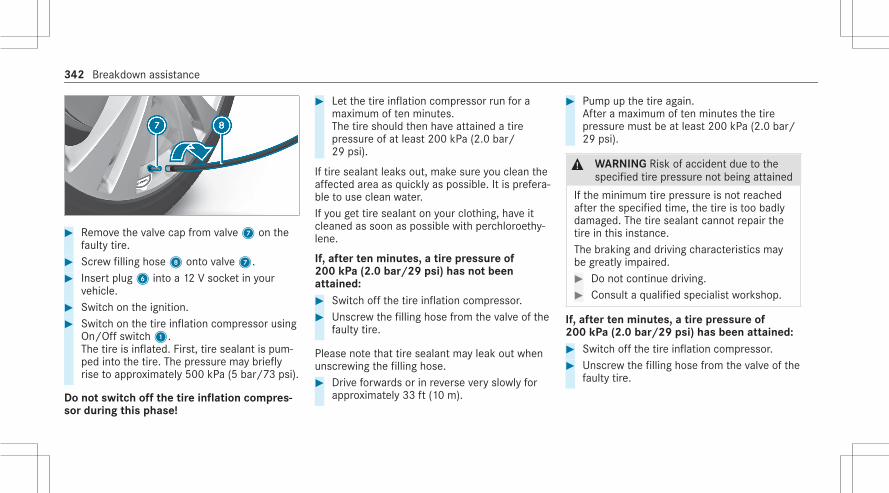
# Remove the valve cap from valve7 on thefaulty tire.
# Screw filling hose8 onto valve7.# Insert plug6 into a 12 V socket in your
vehicle.# Switch on the ignition.# Switch on the tire inflation compressor using
On/Off switch1.The tire is inflated. First, tire sealant is pum‐ped into the tire. The pressure may brieflyrise to approximately 500 kPa (5 bar/73 psi).
Do not switch off the tire inflation compres‐sor during this phase!
# Let the tire inflation compressor run for amaximum of ten minutes.The tire should then have attained a tirepressure of at least 200 kPa (2.0 bar/29 psi).
If tire sealant leaks out, make sure you clean theaffected area as quickly as possible. It is prefera‐ble to use clean water.If you get tire sealant on your clothing, have itcleaned as soon as possible with perchloroethy‐lene.
If, after ten minutes, a tire pressure of200 kPa (2.0 bar/29 psi) has not beenattained:# Switch off the tire inflation compressor.# Unscrew the filling hose from the valve of the
faulty tire.
Please note that tire sealant may leak out whenunscrewing the filling hose.# Drive forwards or in reverse very slowly for
approximately 33 ft (10 m).
# Pump up the tire again.After a maximum of ten minutes the tirepressure must be at least 200 kPa (2.0 bar/29 psi).
& WARNING Risk of accident due to thespecified tire pressure not being attained
If the minimum tire pressure is not reachedafter the specified time, the tire is too badlydamaged. The tire sealant cannot repair thetire in this instance.The braking and driving characteristics maybe greatly impaired.# Do not continue driving.# Consult a qualified specialist workshop.
If, after ten minutes, a tire pressure of200 kPa (2.0 bar/29 psi) has been attained:# Switch off the tire inflation compressor.# Unscrew the filling hose from the valve of the
faulty tire.
342 Breakdown assistance

& WARNING Risk of accident from drivingwith sealed tires
A tire temporarily sealed with tire sealantimpairs the handling characteristics and isnot suitable for higher speeds.# Adapt your driving style accordingly and
drive carefully.# Do not exceed the maximum speed
limit with a tire that has been repairedusing tire sealant.
# Observe the maximum permissible speed fora tire sealed with tire sealant 50 mph(80 km/h).
* NOTE Staining caused by leaking tiresealant
After use, excess tire sealant may leak outfrom the filling hose.# Therefore, place the filling hose in the
plastic bag that contained the TIREFITkit.
+ ENVIRONMENTAL NOTE Environmentalpollution caused by environmentally irre‐sponsible disposal
Tire sealant contains pollutants.# Have the tire sealant bottle disposed of
professionally, e.g. at an authorizedMercedes-Benz Center.
# Store the tire sealant bottle and the tire infla‐tion compressor.
# Pull away immediately.# Stop driving after approximately ten minutes
and check the tire pressure using the tireinflation compressor.The tire pressure must now be at least130 kPa (1.3 bar/19 psi).
& WARNING Risk of accident due to thespecified tire pressure not being attained
If the specified tire pressure is not reached,the tire is too badly damaged. The tire seal‐ant cannot repair the tire in this instance.
The braking and driving characteristics maybe greatly impaired.# Do not continue driving.# Consult a qualified specialist workshop.
In cases such as the one mentioned above, con‐tact an authorized Mercedes-Benz Center. Orcall 1-800-FOR-MERCedes (in the USA) or1-800-387-0100 (in Canada).# Correct the tire pressure if it is still at least
130 kPa (1.3 bar/19 psi). See the Tire andLoading Information placard on the B‑pillaron the driver's side or the tire pressure tablein the fuel filler flap for values.
# To increase the tire pressure: switch onthe tire inflation compressor.
Breakdown assistance 343

# To reduce the tire pressure: press pressurerelease button1 next to manometer2.
# When the tire pressure is correct, unscrewthe filling hose from the valve of the sealedtire.
# Screw the valve cap onto the valve of thesealed tire.
# Pull the tire sealant bottle out of the tireinflation compressor.The filling hose stays on the tire sealant bot‐tle.
# Drive to the nearest qualified specialist work‐shop and have the tire, tire sealant bottleand filling hose replaced there.
Battery (vehicle)Notes on the 12 V battery
& WARNING Risk of an accident due towork carried out incorrectly on the bat‐tery
Work carried out incorrectly on the batterycan, for example, lead to a short circuit. Thiscan restrict functions relevant for safety sys‐tems and impair the operating safety of yourvehicle.You could lose control of the vehicle in thefollowing situations in particular:R When brakingR In the event of abrupt steering maneuvers
and/or when the vehicle's speed is notadapted to the road conditions
# In the event of a short circuit or a simi‐lar incident, contact a qualified special‐ist workshop immediately.
# Do not drive on.
# Always have work on the battery carriedout at a qualified specialist workshop.
R Further information on ABS (/ page 217)R Further information on ESP® (/ page 218)
For safety reasons, Mercedes-Benz recommendsthat you only use batteries which have been tes‐ted and approved for your vehicle by Mercedes-Benz.
All vehicles except vehicles with a lithium-ion battery
& WARNING Risk of explosion due to elec‐trostatic charge
Electrostatic charge can ignite the highlyexplosive gas mixture in the battery.# To discharge any electrostatic charge
that may have built up, touch the metalvehicle body before handling the bat‐tery.
344 Breakdown assistance

The highly flammable gas mixture is createdwhile the battery is charging and during startingassistance.
& WARNING Danger of chemical burnsfrom the battery acid
Battery acid is caustic.# Avoid contact with the skin, eyes or
clothing.# Do not lean over the battery.# Do not inhale battery gases.# Keep children away from the battery.# Immediately rinse battery acid off thor‐
oughly with plenty of clean water andseek medical attention immediately.
All vehicles
+ ENVIRONMENTAL NOTE Environmentaldamage caused by improper disposal ofbatteries
Batteries contain pollutants. It isillegal to dispose of them with the householdrubbish.#
Dispose of batteries in anenvironmentally responsible manner.Take discharged batteries to a qualifiedspecialist workshop or to a collectionpoint for used batteries.
If you have to disconnect the 12 V battery, con‐tact a qualified specialist workshop.Comply with safety notes and take protectivemeasures when handling batteries.
Risk of explosion.
Fire, open flames and smoking areprohibited when handling the battery.Avoid creating sparks.
Electrolyte or battery acid is corro‐sive. Avoid contact with the skin, eyesor clothing. Wear suitable protectiveclothing, in particular gloves, anapron and a face mask. Immediatelyrinse electrolyte or acid splashes offwith clean water. Consult a doctor ifnecessary.Wear safety glasses.
Keep children away.
Breakdown assistance 345

Observe this Operator's Manual.
Observe the following if you do not intend to usethe vehicle over an extended period of time:R Activate standby mode.R Alternatively: connect the battery to a bat‐
tery charger approved by Mercedes-Benz orconsult a qualified specialist workshop todisconnect the battery.
Notes on starting assistance and chargingthe 12 V battery
Vehicles with a lithium-ion batteryWhen charging the battery and during startingassistance, always use the jump-start connec‐tion point in the engine compartment.
* NOTE Damage to the battery from over‐voltage
When charging using a battery charger with‐out a maximum charging voltage, the batteryor the on-board electronics may be damaged.# Only use battery chargers with a maxi‐
mum charging voltage of 14.8 V.
All other vehiclesWhen charging the battery and during startingassistance, always use the jump-start connec‐tion point in the engine compartment.
* NOTE Damage to the battery from over‐voltage
When charging using a battery charger with‐out a maximum charging voltage, the batteryor the on-board electronics may be damaged.# Only use battery chargers with a maxi‐
mum charging voltage of 14.8 V.
& WARNING Risk of explosion from hydro‐gen gas igniting
There is a danger of hydrogen gas ignitingwhen charging the battery if there is a shortcircuit or sparks start to form.# Make sure that the positive terminal of
the connected battery does not comeinto contact with vehicle parts.
# Never place metal objects or tools on abattery.
# The described order of the batteryclamps must be observed when con‐necting and disconnecting the battery.
# When giving starting assistance, alwaysmake sure that you only connect bat‐tery terminals with identical polarity.
# During starting assistance, you mustobserve the described order for con‐necting and disconnecting the jumpercable.
# Do not connect or disconnect the bat‐tery clamps while the engine is running.
346 Breakdown assistance

& WARNING Risk of explosion duringcharging process and starting assistance
During the charging process and startingassistance, the battery may release an explo‐sive gas mixture.# Avoid fire, open flames, creating sparks
and smoking.# Make sure there is sufficient ventila‐
tion.# Do not lean over a battery.
& WARNING Risk of explosion from a fro‐zen battery
A discharged battery may freeze at tempera‐tures slightly above or below freezing point.During starting assistance or battery charg‐ing, battery gas can be released.# Always allow a battery to thaw before
charging it or performing starting assis‐tance.
If the indicator/warning lamps in the instrumentcluster do not light up at low temperatures, it isvery likely that the discharged battery has fro‐zen. In this case you may neither jump-start thevehicle nor charge the battery.The service life of a battery that has beenthawed may be dramatically shortened. Thestarting characteristics may be impaired, espe‐cially at low temperatures.It is recommended that you have a thawed bat‐tery checked at a qualified specialist workshop.
All vehicles
* NOTE Damage caused by numerous orextended attempts to start the engine
Numerous or extended attempts to start theengine may damage the catalytic converterdue to non-combusted fuel.# Avoid numerous and extended attempts
to start the engine.
Observe the following points during startingassistance and when charging the battery:R Only use undamaged jumper cables/charg‐
ing cables with a sufficient cross-section andinsulated terminal clamps.R Non-insulated parts of the terminal clamps
must not come into contact with other metalparts while the jumper cable/charging cableis connected to the battery/jump-start con‐nection point.R The jumper cable/charging cable must not
come into contact with any parts which maymove when the engine is running.R Always make sure that neither you nor the
battery is electrostatically charged.R Keep away from fire and open flames.R Do not lean over the battery.
Observe the additional following points whencharging the battery:R Only use battery chargers tested and
approved for Mercedes-Benz.R Read the battery charger's operating instruc‐
tions before charging the battery.
Breakdown assistance 347

Observe the additional following points duringstarting assistance:R Starting assistance may only be provided
using vehicles, batteries or other jump startdevices with a nominal voltage of 12 V.R The vehicles must not touch.R Vehicles with a gasoline engine: jump-
start the vehicle only when the engine andexhaust system are cold.
Starting assistance and charging the 12 Vbattery
Preparing starting assistance/the chargingprocess# Secure the vehicle by applying the electric
parking brake.# Select transmission positionj.# Switch off the ignition and all electrical con‐
sumers.# Open the hood.
# Open cover1.# Slide protective cover2 of positive contact3 on the jump-starting connection point inthe direction of the arrow.
Starting assistance
# Connect the positive contacts of the vehicleswith the jumper cable. Start with your ownvehicle first.
# Start the engine of the donor vehicle and runit at idling speed.
# Connect negative terminal4 of the donorbattery to the ground point of your vehicle
348 Breakdown assistance

using the jumper cable. Start with the donorvehicle first.
# Start the engine of your own vehicle.# Let the engines run for several minutes.# Before disconnecting the jumper cables,
switch on an electrical consumer in your ownvehicle, e.g. the rear window heater or thelighting.
When starting assistance has finished:# First remove the jumper cable from the
ground point of your own vehicle and thenegative terminal of the donor battery, thenremove the jumper cable from the positivecontacts of both vehicles. Always start withyour own vehicle first.
# Close protective cover2 of positive contact3 and close cover1.
Further information can be obtained at a quali‐fied specialist workshop.
Charging the 12 V battery# Connect the positive contacts of the vehicle
and the charger with the charging cable.Start with the vehicle first.
# Connect the negative contact of the chargerand ground point4 on the vehicle with thecharging cable. Start with the charger first.
# Start the charging process.
When the charging process is complete:# Remove the charging cable from ground
point4 on the vehicle and the negative con‐tact of the charger first and then from thepositive contacts on the vehicle and charger.Always start with the vehicle first.
# Close protective cover2 of positive contact3 and close cover1.
Replacing the 12 V battery
# Observe the notes on the 12 V battery(/ page 344).
Mercedes-Benz recommends that you have the12 V battery replaced at a qualified specialist
workshop, e.g. at an authorized Mercedes-BenzCenter.Observe the following notes if you want toreplace the battery yourself:R Always replace a faulty battery with a battery
which meets the specific vehicle require‐ments.The vehicle is equipped with an AGM technol‐ogy battery (Absorbent Glass Mat) or a lith‐ium-ion battery. Full vehicle functionality isonly guaranteed with an AGM battery or lith‐ium-ion battery. For safety reasons,Mercedes-Benz recommends that you onlyuse batteries which have been tested andapproved for your vehicle by Mercedes-Benz.R Carry over detachable parts, such as vent
hoses, elbow fitting or terminal covers fromthe battery being replaced.R Make sure that the vent hose is always con‐
nected to the original opening on the side ofthe battery.Install any existing or supplied cell caps.Otherwise, gases or battery acid couldescape.
Breakdown assistance 349

R Make sure that detachable parts are recon‐nected in the same way.
Tow starting or towing awayPermitted towing methods
* NOTE Damage from automatic braking
If one of the following functions is switchedon, the vehicle brakes automatically in cer‐tain situations:R Active Brake AssistR Active Distance Assist DISTRONICR HOLD functionR Active Parking Assist
To avoid damage to the vehicle, deactivatethese systems in the following or similar sit‐uations:# During towing# In a car wash
Mercedes-Benz recommends transporting yourvehicle in the case of a breakdown, rather thantowing it away.For towing, use a tow rope or tow bar with bothaxles on the ground. Do not use tow bar systems(/ page 272).
* NOTE Damage to the vehicle due to tow‐ing away incorrectly
# Observe the instructions and notes ontowing away.
Towing with a raised axle: towing should beperformed by a towing company.
Vehicles with rear wheel drive
Permitted towing methods
Both axles onthe ground
Yes, maximum 31 miles(50 km) at 31 mph (50 km/h)
Front axleraised
No
Rear axleraised
Yes, if the steering wheel isfixed in the center positionwith a steering wheel lock
4MATIC vehicles
Permitted towing methods
Both axles onthe ground
Yes, maximum 31 miles(50 km) at 31 mph (50 km/h)
Front axleraised
No
Rear axleraised
No
350 Breakdown assistance

Towing the vehicle with both axles on theground
# Observe the notes on the permitted towingmethods (/ page 350).
# Make sure that the battery is connected andcharged.
When the battery is discharged, the followingactions cannot be performed:R The engine cannot be startedR The electric parking brake cannot be
released or appliedR The automatic transmission cannot be shif‐
ted to positioni orj
% If the automatic transmission cannot be shif‐ted to positioni or the driver's display inthe instrument cluster does not show any‐thing, have the vehicle transported away(/ page 352). A towing vehicle with liftingequipment is required for vehicle transporta‐tion.
* NOTE Damage due to towing away atexcessively high speeds or over long dis‐tances
The drivetrain could be damaged when tow‐ing at excessively high speeds or over longdistances.# A towing speed of 30 mph (50 km/h)
must not be exceeded.# A towing distance of 30 miles (50 km)
must not be exceeded.
& WARNING Risk of accident when towinga vehicle which is too heavy
If another vehicle is tow-started or towedaway, its weight must not exceed the permis‐sible gross mass of your own vehicle, other‐wise the following could occur:R The towing eye may become detached.R The vehicle/trailer combination may
swerve or even rollover.
# If another vehicle is tow-started ortowed away, its weight must not exceed
the permissible gross mass of your ownvehicle.
If a vehicle must be tow-started or towed away,its weight must not exceed the permissible grossmass of the towing vehicle.# Information on the permissible gross mass of
the vehicle can be found on the vehicle iden‐tification plate (/ page 466).
# Do not open the driver's door or frontpassenger door, otherwise the automatictransmission automatically shifts to positionj.
# Install the towing eye (/ page 353).# Fasten the tow bar.
* NOTE Damage due to incorrect connec‐tion of the tow bar
# Only connect the tow rope or tow bar tothe towing eyes.
# Deactivate the automatic locking mecha‐nism .
Breakdown assistance 351
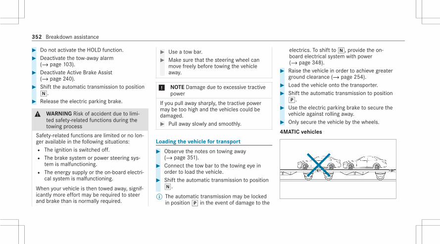
# Do not activate the HOLD function.# Deactivate the tow-away alarm
(/ page 103).# Deactivate Active Brake Assist
(/ page 240).# Shift the automatic transmission to position
i.# Release the electric parking brake.
& WARNING Risk of accident due to limi‐ted safety-related functions during thetowing process
Safety-related functions are limited or no lon‐ger available in the following situations:R The ignition is switched off.R The brake system or power steering sys‐
tem is malfunctioning.R The energy supply or the on-board electri‐
cal system is malfunctioning.
When your vehicle is then towed away, signif‐icantly more effort may be required to steerand brake than is normally required.
# Use a tow bar.# Make sure that the steering wheel can
move freely before towing the vehicleaway.
* NOTE Damage due to excessive tractivepower
If you pull away sharply, the tractive powermay be too high and the vehicles could bedamaged.# Pull away slowly and smoothly.
Loading the vehicle for transport
# Observe the notes on towing away(/ page 351).
# Connect the tow bar to the towing eye inorder to load the vehicle.
# Shift the automatic transmission to positioni.
% The automatic transmission may be lockedin positionj in the event of damage to the
electrics. To shift toi, provide the on-board electrical system with power(/ page 348).
# Raise the vehicle in order to achieve greaterground clearance (/ page 254).
# Load the vehicle onto the transporter.# Shift the automatic transmission to position
j.# Use the electric parking brake to secure the
vehicle against rolling away.# Only secure the vehicle by the wheels.
4MATIC vehicles
352 Breakdown assistance

# Make sure that the front and rear axles cometo rest on the same transportation vehicle.
* NOTE Damage to the drivetrain due toincorrect positioning
# Do not position the vehicle above theconnection point of the transport vehi‐cle.
Towing eye storage location
Towing eye1 is located under the trunk floor.
Depending on the vehicle equipment, the towingeye may be located at another position in thetrunk.
Installing the towing eye
# Press the mark on cover1 inwards andremove.
# Screw in the towing eye clockwise as far as itwill go and tighten.
# Make sure that cover1 engages in thebumper when you remove the towing eye.
* NOTE Damage to the vehicle due toincorrect use of the towing eye
When a towing eye is used to recover a vehi‐cle, the vehicle may be damaged in the proc‐ess.# Only use the towing eye to tow away or
tow start the vehicle.
Tow-starting the vehicle (emergency enginestart)
* NOTE Damage to the automatic trans‐mission due to tow-starting
Tow-starting the vehicle can damage theautomatic transmission.# Do not tow-start the vehicle.
# Do not tow-start the vehicle.
Breakdown assistance 353

Electrical fusesNotes on electrical fuses
& WARNING Risk of accident and injurydue to overloaded lines
If you manipulate or bridge a faulty fuse or ifyou replace it with a fuse with a higheramperage, the electric line could be overloa‐ded.This could result in a fire.# Always replace faulty fuses with speci‐
fied new fuses containing the correctamperage.
* NOTE Damage due to incorrect fuses
Electrical components or systems may bedamaged by incorrect fuses, or their func‐tionality may be significantly impaired.# Only use fuses that have been approved
by Mercedes-Benz and which have thecorrect fuse rating.
Blown fuses must be replaced with fuses of thesame rating, which you can recognize by thecolor and fuse rating. The fuse ratings and fur‐ther information to be observed can be found inthe fuse assignment diagram.Fuse assignment diagram: in the vehicle docu‐ment wallet.
* NOTE Damage or malfunctions causedby moisture
Moisture may cause damage to the electricalsystem or cause it to malfunction.# When the fuse box is open, make sure
that no moisture can enter the fusebox.
# When closing the fuse box, make surethat the seal of the lid is positioned cor‐rectly on the fuse box.
If the newly inserted fuse also blows, have thecause traced and rectified at a qualified special‐ist workshop.Ensure the following before replacing a fuse:R The vehicle is secured against rolling away.
R All electrical consumers are switched off.R The ignition is switched off.
The electrical fuses are located in the followingfuse boxes:R Fuse box in the engine compartment on the
driver's side (/ page 354)R Fuse box on the driver's side of the cockpit
(/ page 356)R Fuse box in the front passenger footwell
(/ page 357)R Fuse box in the trunk on the right-hand side
of the vehicle, when viewed in the directionof travel (/ page 357)
Opening and closing the fuse box in theengine compartment
Requirements:R Observe the notes on electrical fuses
(/ page 354).R Have the following tools readily available:
- A dry cloth
354 Breakdown assistance

- A screwdriver with an appropriate head
Opening% Depending on the vehicle equipment, access
to the fuse box may be limited. Mercedes-Benz recommends consulting a qualifiedspecialist workshop, e.g. an authorizedMercedes-Benz Center.
& WARNING Risk of injury from using thewindshield wipers while the engine hoodis open
When the engine hood is open and the wind‐shield wipers are set in motion, you can betrapped by the wiper linkage.# Always switch off the windshield wipers
and ignition before opening the enginehood.
# Release the rotary catches on cover1 andpull the cover up and out.
# Remove any existing moisture from the fusebox using a dry cloth.
# Depending on the vehicle equipment, theremay be an electrical component2 on thefuse box lid. If present, unscrew screw3and put the component to the side withoutdisconnecting the electrical connection.
# If present, release hoses4 from the retain‐ing clips on the fuse box and vehicle body.
Breakdown assistance 355

# If present, release hoses5 from the retain‐ing clips in the engine compartment andvehicle body.
# Unscrew screws6 and fold out bar7.
# Unscrew screws8 and remove fuse box lid9 to the side.
Closing# Check whether the seal is positioned cor‐
rectly in lid9.# Place lid9 on the fuse box and tighten
screws8.# Fold back bar7 and tighten screws6.
# If present, engage hoses5 in the retainingclips in the engine compartment and vehiclebody.
# If present, engage hoses4 in the retainingclips on the fuse box and vehicle body.
# If present, insert electrical component2into the holder on the fuse box lid andtighten screws3.
# Insert cover1 and engage the rotarycatches.
Opening and closing the fuse box in thecockpit
Requirements:R Observe the notes on electrical fuses
(/ page 354).
356 Breakdown assistance

# Open cover1 in the direction of the arrowand remove it.
Opening and closing the fuse box in the frontpassenger footwell
Requirements:R Observe the notes on electrical fuses
(/ page 354).
# Open cover1 in the direction of the arrowand remove it.
Opening and closing the fuse box in thetrunk
Requirements:R Observe the notes on electrical fuses
(/ page 354).
# Fold cover1 down in the direction of thearrow.
Breakdown assistance 357

Notes on noise or unusual handling charac‐teristicsMake sure there are no vibrations, noises orunusual handling characteristics when the vehi‐cle is in motion. This may indicate that thewheels or tires are damaged. Hidden tire dam‐age could also be causing the unusual handlingcharacteristics.If you suspect that a tire is malfunctioning,reduce your speed immediately and have thetires and wheels checked at a qualified specialistworkshop.
Notes on regularly inspecting wheels andtires
& WARNING Risk of injury through dam‐aged tires
Damaged tires can cause tire pressure loss.# Check the tires regularly for signs of
damage and replace any damaged tiresimmediately.
& WARNING Risk of hydroplaning due toinsufficient tire tread
Insufficient tire tread will result in reducedtire grip.In heavy rain or slush the risk of hydroplaningis increased, in particular where speed is notadapted to suit the conditions.# Thus, you should regularly check the
tread depth and the condition of thetread across the entire width of all tires.
Minimum tread depth for:R Summer tires:â in (3 mm)R M+S tires:ãin (4 mm)
# For safety reasons, replace the tiresbefore the legally-prescribed limit forthe minimum tread depth is reached.
Carry out the following checks on all wheels reg‐ularly, at least once a month or as required, forexample, prior to a long journey or driving off-road:R Check the tire pressure (/ page 360).
R Visually inspect wheels and tires for damage.R Check the valve caps.R Visual check of the tire tread depth and the
tire contact surface across the entire width.The minimum tread depth for summer tires isâ in (3 mm) and for winter tiresã in(4 mm).
Six marks1 show where the bar indicators(arrow) are integrated into the tire tread. Theyare visible once a tire tread depth of approx‐imatelyá in (1.6 mm) has been reached.
358 Wheels and tires

Notes on snow chains
& WARNING Risk of accident due to incor‐rect mounting of snow chains
If you have mounted snow chains to the frontwheels, the snow chains may drag againstthe vehicle body or chassis components.This could cause damage to the vehicle orthe tires.# Never mount snow chains on the front
wheels.# Only mount snow chains on the rear
wheels in pairs.
* NOTE Damage to components of thevehicle body or chassis due to mountedsnow chains
If you mount snow chains to the front wheelsof 4MATIC vehicles, you may damage compo‐nents of the vehicle body or chassis.# Only mount snow chains to the rear
wheels of 4MATIC vehicles.
Observe the following notes when using snowchains:R Snow chains are only permissible for certain
wheel/tire combinations. You can obtaininformation about this from an authorizedMercedes-Benz Center.R For safety reasons, only use snow chains that
have been specifically approved for yourvehicle by Mercedes-Benz, or snow chainswith the same quality standard.R If snow chains are installed, the maximum
permissible speed is 30 mph (50 km/h).R Vehicles with Active Parking Assist: Do
not use Active Parking Assist when snowchains are installed.R Vehicles with level control: If snow chains
are installed, only drive at raised vehicle level(/ page 254).R Vehicles with rear axle steering: If snow
chains are installed, only drive with snowchain mode active (/ page 359).
% You can deactivate ESP® to pull away(/ page 219). This allows the wheels tospin, achieving an increased driving force.
Activating or deactivating snow chain modeMultimedia system:4© 5ß 5y
# Activate or deactivate Snow Chain Mode.
When the function is active, the vehicle behavesas if snow chains were mounted. For example,the maximum steering movement of the rearwheels is limited.Additionally, parts of the driving and drivingsafety systems are not available when snowchain mode is active.
Wheels and tires 359

Tire pressureNotes on tire pressure
& WARNING Risk of accident due to insuf‐ficient or excessive tire pressure
Tires with either too low or too high a pres‐sure present the following hazards:R the tires could burstR the tires could wear excessively and/or
unevenlyR the driving characteristics as well as
steering and braking characteristics maybe severely impaired
# Observe the recommended tire pres‐sures and check the tire pressure of alltires including the spare wheel:R monthlyR if altering the load on the vehicleR prior to long journeysR if the operating conditions change, for
example when driving off-road
# Adjust the tire pressure where neces‐sary.
Tire pressure which is too high or too low can:R Shorten the service life of the tires.R Cause increased tire damage.R Adversely affect driving characteristics and
thus driving safety, e.g. due to hydroplaning.
& WARNING Risk of accident due to toolow a tire pressure
Tires with pressure that is too low can over‐heat and burst as a consequence.In addition, they also suffer from irregularwear, which can significantly impair the brak‐ing properties and the handling characteris‐tics.# Avoid excessively low tire pressure.
Tire pressure which is too low can cause:R Tire faults as a result of overheatingR Impaired handling characteristicsR Irregular wear
R Increased fuel consumption
& WARNING Risk of accident due to toohigh a tire pressure
Tires with excessively high pressure canburst.In addition, they also suffer from irregularwear, which can significantly impair the brak‐ing properties and the handling characteris‐tics.# Avoid excessively high tire pressures.
Tire pressure which is too high can cause:R Increased braking distanceR Impaired handling characteristicsR Irregular wearR Impaired driving comfortR Susceptibility to damage
360 Wheels and tires

& WARNING Risk of accident due to repea‐ted pressure drop in the tires
The wheels, valves or tires could be dam‐aged.Too low a tire pressure can lead to the tiresbursting.# Examine the tires for foreign objects.# Check whether the tire has a puncture
or the valve has a leak.# If you are unable to rectify the damage,
contact a qualified specialist workshop.
You can find information on tire pressure for thevehicle's factory-installed tires on the followinglabels:R Tire and Loading Information placard on the
B‑pillar of your vehicle (/ page 365).R Tire pressure table on the inside of the fuel
filler flap (/ page 361).
Observe the maximum tire pressure(/ page 371).
Use a suitable pressure gauge to check the tirepressure. The outer appearance of a tire doesnot permit any reliable conclusion about the tirepressure.Only correct tire pressure when the tires arecold. Conditions for cold tires:R The vehicle has been parked with the tires
out of direct sunlight for at least three hours.R The vehicle has traveled less than 1 mile
(1.6 km).
The vehicle's tires heat up when driving. As thetemperature of the tires increases, so too doesthe tire pressure.Vehicles with tire pressure monitoring sys‐tem: You can also see the tire pressure in thedriver display.The tire pressure recommended for increasedload/speed in the tire pressure table can affectthe ride comfort.
& WARNING Risk of accident due tounsuitable accessories on tire valves
If you mount unsuitable accessories onto tirevalves, the tire valves may be overloaded andmalfunction, which can cause tire pressureloss.# Only screw standard valve caps or valve
caps specifically approved byMercedes-Benz for your vehicle ontothe tire valve.
Tire pressure table
The tire pressure table is on the inside of thefuel filler flap.% The data shown in the images is example
data.
Wheels and tires 361

If one or more tire sizes precede a tire pressure,the following tire pressure information is onlyvalid for those tire sizes and their respectiveload condition.The load conditions "partially laden" and "fullyladen" are defined in the table for different num‐bers of passengers and amounts of luggage. Theactual number of seats may differ from this.
Some tire pressure tables only show the rimdiameter instead of the complete tire size, e.g.R18. The rim diameter is part of the tire size andcan be found on the tire side wall (/ page 372).R Tire and Loading Information placard
(/ page 365)R Maximum tire pressure (/ page 371)
Checking the tire pressure manually
# Read the tire pressure recommended for thecurrent operating conditions from the Tireand Loading Information placard or the tirepressure table. Observe the notes on tirepressure.
# Remove the valve cap of the tire to bechecked.
# Press the tire pressure gauge securely ontothe valve.
# Read the tire pressure.# If the tire pressure is lower than the recom‐
mended value, increase the tire pressure tothe recommended value.
# If the tire pressure is higher than the recom‐mended value, release air. To do so, pressdown the metal pin in the valve, e.g. usingthe tip of a pen, for example. Then check thetire pressure again using the tire pressuregauge.
# Screw the valve cap onto the valve.Further related subjects:R Notes on tire pressure (/ page 360)
362 Wheels and tires

R Tire pressure table (/ page 361)R Tire and Loading Information placard
(/ page 365)
Tire pressure monitoring system
Function of the tire pressure monitoring sys‐tem
& DANGER Risk of accident due to incor‐rect tire pressure
Each tire, including the spare (if provided),should be checked monthly when cold andthen inflated to the inflation pressure recom‐mended by the vehicle manufacturer on thevehicle placard or tire inflation pressurelabel. (If your vehicle has tires of a differentsize than the size indicated on the vehicleplacard or tire inflation pressure label, youshould determine the proper tire inflationpressure for these tires.)As an added safety feature, your vehicle hasbeen equipped with a tire pressure monitor‐ing system (TPMS) that illuminates a low tire
pressure telltale when one or more of yourtires is significantly underinflated. Accord‐ingly, if the low tire pressure telltale illumi‐nates, you should stop and check your tiresas soon as possible, and inflate them to theproper pressure. Driving on a significantlyunderinflated tire causes the tire to overheatand can lead to tire failure. Underinflationalso reduces fuel efficiency and tire treadlife, and may affect the vehicle's handlingand stopping ability. Please note that theTPMS is not a substitute for proper tire main‐tenance, and it is the driver's responsibilityto maintain correct tire pressure, even ifunderinflation has not reached the level totrigger illumination of the TPMS low tire pres‐sure telltale.Your vehicle has also been equipped with aTPMS malfunction indicator to indicate whenthe system is not operating properly. TheTPMS malfunction indicator is combined withthe low tire pressure telltale. When the sys‐tem detects a malfunction, the indicatorlamp will flash for approximately a minute
and then remain continuously illuminated.This sequence will continue upon subsequentvehicle start-ups as long as the malfunctionexists.When the malfunction indicator is illumina‐ted, the system may not be able to detect orsignal low tire pressure as intended. TPMSmalfunctions may occur for a variety of rea‐sons, including the installation of incompati‐ble replacement or alternate tires or wheelson the vehicle that prevent the TPMS fromfunctioning properly.Always check the TPMS malfunction telltaleafter replacing one or more tires or wheelson your vehicle to ensure that the replace‐ment or alternate tires and wheels allow theTPMS to continue to function properly.
The system checks the tire pressure and the tiretemperature of the tires installed on the vehicleby means of a tire pressure sensor.The tire pressure and the tire temperatureappear on the driver display (/ page 364).
Wheels and tires 363

If there is a substantial pressure loss or if thetire temperature is excessive, you will be warnedwith display messages (/ page 524) or theh warning lamp in the instrument cluster(/ page 546).The tire pressure monitoring system is only anaid. It is the driver's responsibility to set the tirepressure to the recommended cold tire pressuresuitable for the operating situation.In most cases, the tire pressure monitoring sys‐tem will automatically update the new referencevalues after you have changed the tire pressure.You can, however, also update the reference val‐ues by restarting the tire pressure monitoringsystem manually (/ page 364).
System limitsThe system may be impaired or may not functionparticularly in the following situations:R The tire pressure has been set incorrectlyR Sudden pressure loss caused by a foreign
object penetrating the tire, for exampleR There is a malfunction caused by another
radio signal source
Checking the tire pressure with the tire pres‐sure monitoring system
Requirements:R The ignition is switched on.
Driver display:4© 5 ServiceOne of the following displays appears:R Current tire pressure of each wheel:
R Tire pressure displayed after driving for afew minutes.R Tire Pressure Monitor Active: the teach-in
process of the system is not yet complete.
The tire pressures are already being moni‐tored.
# Compare the tire pressure with the recom‐mended tire pressure for the current operat‐ing condition (/ page 361). Observe thenotes on tire temperature (/ page 360).
% The values displayed in the driver displaymay deviate from those of the tire pressuregauge as they refer to sea level. At high ele‐vations, the tire pressure values indicated bya pressure gauge are higher than thoseshown by the driver display. In this case, donot reduce the tire pressure.
Bear in mind the following related topic:R Notes on tire pressure (/ page 360)
Restarting the tire pressure monitoring sys‐tem
Requirements:R The recommended tire pressure is correctly
set for the respective operating status oneach of the four wheels (/ page 360).
364 Wheels and tires

Restart the tire pressure monitoring system inthe following situations:R The tire pressure has changed.R The wheels or tires have been changed or
newly installed.
Driver display:4© 5 Service# Select Tire Pressure and confirm witha.
The driver display shows the Use currentpressures as new reference values? mes‐sage.
# Select Yes and confirm the restart witha.The driver display shows the Tire PressureMonitor Restarted message.Current warning messages are deleted andthe yellowh warning lamp goes out.After you have been driving for a fewminutes, the system checks whether the cur‐rent tire pressures are within the specifiedrange. The current tire pressures are thenaccepted as reference values and monitored.
Bear in mind the following related topic:R Notes on tire pressure (/ page 360)
Loading the vehicleNotes on Tire and Loading Information plac‐ard
& WARNING Risk of accident from overloa‐ded tires
Overloaded tires may overheat and burst as aconsequence. Overloaded tires can alsoimpair the steering and handling characteris‐tics and lead to brake failure.# Observe the load rating of the tires.# The load rating must be at least half the
permissible axle load of the vehicle.# Never overload the tires by exceeding
the maximum load.
The Tire and Loading Information placard is onthe B-pillar on the driver's side of the vehicle.
1 Tire and Loading Information placard
Wheels and tires 365

% The data shown in the illustration is exampledata.
The Tire and Loading Information placard showsthe following information:R Maximum number of seats2 according to
the maximum number of people permitted totravel in the vehicle.
R Maximum permissible load3 comprises thegross weight of all vehicle occupants, loadand luggage.R Recommended tire pressure1 for cold
tires. The recommended tire pressures arevalid for the maximum permissible load andup to the maximum permissible vehiclespeed.
Please also note:R Information on permissible weights and loads
on the vehicle identification plate(/ page 466).R Information on tire pressure in the tire pres‐
sure table (/ page 361).
Further related subjects:R Determining the maximum permissible load
(/ page 366)R Notes on tire pressure (/ page 360).
Steps for Determining Correct Load Limit
The following steps have been developed asrequired of all manufacturers under Title 49,
Code of U.S. Federal Regulations, Part 575, pur‐suant to the "National Traffic and Motor VehicleSafety Act of 1966".# (1): Locate the statement "The combined
weight of occupants and cargo should neverexceed XXX kg or XXX lbs." on your vehicle'splacard.
# (2): Determine the combined weight of thedriver and passengers that will be riding inyour vehicle.
# (3): Subtract the combined weight of thedriver and passengers from XXX kg orXXX lbs.
# (4): The resulting figure equals the availableamount of cargo and luggage load capacity.For example, if the "XXX" amount equals1400 lbs. and there will be five occupants150 lb passengers in your vehicle, theamount of available cargo and luggage loadcapacity is 650 lbs. (1400 - 750 (5 x 150) =650 lbs.)
# (5): Determine the combined weight of lug‐gage and cargo being loaded on the vehicle.That weight may not safely exceed the availa‐
366 Wheels and tires

ble cargo and luggage load capacity calcula‐ted in step 4.
# (6): If your vehicle will be towing a trailer,load from your trailer will be transferred toyour vehicle. Consult this manual to deter‐mine how this reduces the available cargoand luggage load capacity of your vehicle.
% Not all vehicles are permitted to tow atrailer. Towing a trailer is only permitted if atrailer-hitch is installed. Please consult anauthorized Mercedes-Benz dealer if you haveany questions about towing a trailer withyour vehicle.
Even if you have calculated the total load care‐fully, you should still make sure that the maxi‐mum permissible gross weight and the maxi‐
mum gross axle weight rating of your vehicle arenot exceeded. Details can be found on the vehi‐cle identification plate.# Have your loaded vehicle – including driver,
occupants and load – weighed on a vehicleweighbridge.The measured values may not exceed themaximum permissible values stated on thevehicle identification plate.
Further related subjects:R Calculation example for determining the max‐
imum load (/ page 367)R Tire and Loading Information placard
(/ page 365)R Tire pressure table (/ page 361)
R Vehicle identification plate (/ page 466)
Calculation example for determining themaximum load
The following table shows examples of how tocalculate total and load capacities with varyingseating configurations and different numbersand sizes of occupants. The following examplesuse a maximum load of 1500 lbs (680 kg). Thisis for illustration purposes only. Make sureyou are using the actual load limit for your vehi‐cle stated on your vehicle's Tire and LoadingInformation placard (/ page 365).The higher the weight of all the occupants, thesmaller the maximum load for luggage.
Step 1
Example 1 Example 2
Combined maximum weight of occupants andload (data from the Tire and Loading Informationplacard)
1500 lbs (680 kg) 1500 lbs (680 kg)
Wheels and tires 367

Step 2
Example 1 Example 2
Number of people in the vehicle (driver andoccupants)
5 1
Distribution of the occupants Front: 2Rear: 3
Front: 1
Weight of occupants Occupant 1: 150 lbs (68 kg)Occupant 2: 180 lbs (82 kg)Occupant 3: 160 lbs (73 kg)Occupant 4: 140 lbs (63 kg)Occupant 5: 120 lbs (54 kg)
Occupant 1: 200 lbs (91 kg)
Total weight of all occupants 750 lbs (340 kg) 200 lbs (91 kg)
Step 3
Example 1 Example 2
Permissible load (maximum gross vehicle weightrating from the Tire and Loading Informationplacard minus the gross weight of all occupants)
1500 lbs (680 kg) Ò 750 lbs (340 kg) = 750 lbs(340 kg)
1500 lbs (680 kg) Ò 200 lbs (91 kg) = 1300 lbs(589 kg)
368 Wheels and tires

Tire labelingOverview of tire labeling
1 Uniform Tire Quality Grading Standards(/ page 369)
2 DOT (Department of Transportation), (TIN)Tire Identification Number (/ page 370)
3 Maximum tire load (/ page 371)4 Maximum tire pressure (/ page 371)
5 Manufacturer6 Characteristics of the tire (/ page 372)7 Tire size designation, load-bearing capacity,
speed rating and load index (/ page 372)8 Tire name
% The data shown in the illustration is exampledata.
Tire Quality Grading
In accordance with the US Department of Trans‐portation's "Uniform Tire Quality Grading Stand‐ards", tire manufacturers are required to gradetheir tires on the basis of the following three per‐formance factors:
1 Tread wear grade2 Traction grade3 Temperature grade
% The data shown in the illustration is exampledata.
% The classification is not legally stipulated forCanada, but it is generally stated.
Tread wear gradeThe treadwear grade is a comparative ratingbased on the wear rate of the tire when testedunder controlled conditions on a specified gov‐ernment test course. For example, a tire graded150 would wear one and one-half (1\1/2) times
Wheels and tires 369

as well on the government course as a tire gra‐ded 100.The relative performance of tires depends uponthe actual conditions of their use, however, andmay depart significantly from the norm due tovariations in driving habits, service practices anddifferences in road characteristics and climateconditions.
Traction grade
& DANGER Risk of accident due to inade‐quate traction
The traction grade assigned to this tire isbased on straight-ahead braking tractiontests.# Always adapt your driving style and
drive at a speed to suit the prevailingtraffic and weather conditions.
* NOTE Damage to the drivetrain fromwheelspin
# Avoid wheelspin.
The traction grades, from highest to lowest, areAA, A, B and C. Those grades represent the tire'sability to stop on wet pavement as measuredunder controlled conditions on specified govern‐ment test surfaces of asphalt and concrete. Atire marked C may have poor traction perform‐ance.
Temperature grade
& WARNING Risk of accident from tireoverheating and tire failure
Excessive speed, underinflation, or excessiveloading, either separately or in combination,can cause excessive heat build-up and possi‐ble tire failure.# Observe the recommended tire pres‐
sure.# Regularly check the pressure of all the
tires.# Adjust the tire pressure, if necessary.
The temperature grades are A (the highest), Band C, representing the tire's resistance to thegeneration of heat and its ability to dissipate
heat when tested under controlled conditions ona specified indoor laboratory test wheel. Sus‐tained high temperature can cause the materialof the tire to degenerate and reduce tire life, andexcessive temperature can lead to sudden tirefailure. The grade C corresponds to a level ofperformance which all passenger car tires mustmeet under the Federal Motor Safety StandardNo. 109. Grades B and A represent higher levelsof performance on the laboratory test wheelthan the minimum required by law.
DOT, Tire Identification Number (TIN)
US tire regulations stipulate that every tire man‐ufacturer or retreader must imprint a TIN in oron the side wall of each tire produced.
370 Wheels and tires

% The data shown in the image is exampledata.
The TIN is a unique identification number toidentify tires and comprises the following:R DOT (Department of Transportation): tire
symbol marks1 indicating that the tirecomplies with the requirements of the USDepartment of Transportation.R Manufacturer identification code: manu‐
facturer identification code2 containsdetails of the tire manufacturer. New tireshave a code with two symbols. Retreadedtires have a code with four symbols. Furtherinformation on retreaded tires (/ page 377).
R Tire size: identifier3 describes the tiresize.R Tire type code: tire type code4 can be
used by the manufacturer as a code todescribe specific characteristics of the tire.R Manufacturing date: manufacturing date5 provides information about the age of atire. The 1st and 2nd positions represent thecalendar week and the 3rd and 4th positionsstate the year of manufacture (e.g. "3208"represents the 32nd week of 2008).
Information on the maximum tire load
% The data shown in the image is exampledata.
Maximum tire load1 is the maximum permissi‐ble weight for which the tire is approved.Do not overload the tires by exceeding the speci‐fied load limit. The maximum permissible loadcan be found on the vehicle's Tire and LoadingInformation placard on the B-pillar on the driv‐er's side (/ page 365).
Specifications for maximum tire pressure
% The data shown in the illustration is exampledata.
Wheels and tires 371

Never exceed maximum tire pressure1 speci‐fied for the tire. Always observe the recommen‐ded tire pressure for your vehicle when adjustingthe tire pressure (/ page 361).
Information on tire characteristics
% The data shown in the image is exampledata.
This information describes the type of tire cordand the number of layers in side wall1 andunder tire tread2.
Tire size designation, load-bearing capacity,speed rating and load index
& WARNING Risk of injury through exceed‐ing the specified tire load-bearing capa‐city or the permissible speed rating
Exceeding the specified tire load rating orthe permissible speed rating may lead to tiredamage and to the tires bursting.# Therefore, only use tire types and sizes
approved for your vehicle model.# Observe the tire load rating and speed
rating required for your vehicle.
1 First letter(s)2 Nominal tire width in millimeters3 Aspect ratio in %4 Tire code5 Rim diameter6 Load-bearing index7 Speed rating8 Load index
% The data shown in the illustration is exampledata.
Information about reading tire data can beobtained from any qualified specialist workshop.
372 Wheels and tires

First letter(s)11:R Without: passenger vehicle tires according to
European manufacturing standards.R "P": passenger vehicle tires according to US
manufacturing standards.R "LT": light truck tires according to US manu‐
facturing standards.R "T": compact emergency spare wheels with
high tire pressure that are only designed fortemporary use in an emergency.
Aspect ratio33:Ratio between tire height and tire width in per‐cent (tire height divided by tire width).
Tire code44 (tire type):R "R" radial tireR "D": bias ply tireR "B": bias belted tiresR "ZR": radial tire with a maximum speed above
149 mph (240 km/h) (optional)
Rim diameter55:The diameter of the bead seat (not the diameterof the rim flange). The rim diameter is specifiedin inches (in).
Load-bearing index66:Numerical code that specifies the maximumload-bearing capacity of a tire (e.g. "91" corre‐sponds to 1356 lbs (615 kg)).The load-bearing capacity of the tire must be atleast half the gross axle weight rating of yourvehicle. Do not overload the tires by exceedingthe specified load limit.See also:R Maximum permissible load on the Tire and
Loading Information placard (/ page 365)R Maximum tire load (/ page 371)R Load index
Speed rating77:Specifies the approved maximum speed of thetire.
% An electronic speed limiter prevents yourvehicle from exceeding a speed of 130 mph(210 km/h).
Make sure that your tires have the requiredspeed rating. You can obtain information on therequired speed rating from an authorizedMercedes-Benz Center.
Summer tires
Index Speed rating
Q up to 100 mph (160 km/h)
R up to 106 mph (170 km/h)
S up to 112 mph (180 km/h)
T up to 118 mph (190 km/h)
H up to 130 mph (210 km/h)
V up to 149 mph (240 km/h)
W up to 168 mph (270 km/h)
Y up to 186 mph (300 km/h)
Wheels and tires 373

Index Speed rating
ZR...Y1 up to 186 mph (300 km/h)
ZR...(..Y)1 over 186 mph (300 km/h)
ZR1 over 149 mph (240 km/h)
R Specifying the speed rating as the "ZR" indexin tire code4 is optional for tires up to186 mph (300 km/h).R If your tire code4 includes "ZR" and there
is no speed rating7, find out what the max‐imum speed is from the tire manufacturer.R If load-bearing index6 and speed rating7
are in brackets, the maximum speed rating ofyour tire is above 186 mph (300 km/h). Tofind out the maximum speed, ask the tiremanufacturer.
All-weather tires and winter tires
Index Speed rating
Q M+S2 up to 100 mph (160 km/h)
T M+S2 up to 118 mph (190 km/h)
H M+S2 up to 130 mph (210 km/h)
V M+S2 up to 149 mph (240 km/h)
Winter tires bear thei snowflake symboland fulfill the requirements of the Rubber Manu‐facturers Association (RMA) and the RubberAssociation of Canada (RAC) regarding the tiretraction on snow.
Load index88:R No specification given: standard load (SL)
tireR "XL" or "Extra Load": extra load tire or rein‐
forced tireR "Light Load": light load tire
R "C", "D", "E": a load range that depends onthe maximum load that the tire can carry at acertain pressure
Definition of terms for tires and loadingTire structure and characteristics: describesthe number of layers or the number of rubber-coated belts in the tire contact surface and thetire wall. These are made of steel, nylon, poly‐ester and other materials.Bar: metric unit for tire pressure.14.5038 pounds per square inch (psi) and100 kilopascal (kPa) is the equivalent of one bar.DOT (Department of Transportation): DOT-marked tires fulfill the requirements of theUS Department of Transportation.Average weight of the vehicle occupants: thenumber of vehicle occupants for which the vehi‐cle is designed, multiplied by 150 lb (68 kg).
1 "ZR" stated in the tire code.2 Or "M+Si" for winter tires.
374 Wheels and tires

Uniform Tire Quality Grading Standards: auniform standard to grade the quality of tireswith regard to tread quality, tire traction andtemperature characteristics. The quality gradingassessment is made by the manufacturer follow‐ing specifications from the U.S. government. Thequality grade of a tire is imprinted on the sidewall of the tire.Recommended tire pressure: the recommen‐ded tire pressure is the tire pressure specifiedfor the tires mounted to the vehicle at the fac‐tory.The tire and information table contains the rec‐ommended tire pressures for cold tires, the max‐imum permissible load and the maximum per‐missible vehicle speed.The tire pressure table contains the recommen‐ded tire pressures for cold tires under variousoperating conditions, i.e. loading and/or speedof the vehicle.Increased vehicle weight due to optionalequipment: the combined weight of all standardand optional equipment available for the vehicle,
regardless of whether it is actually installed onthe vehicle or not.Rim: the part of the wheel on which the tire isinstalled.GAWR (Gross Axle Weight Rating): the GAWRis the maximum permissible axle load. Theactual load on an axle must never exceed thegross axle weight rating. The gross axle weightrating can be found on the vehicle identificationplate on the B‑pillar on the driver's side.Speed rating: the speed rating is part of the tireidentification. It specifies the speed range forwhich a tire is approved.GVW (Gross Vehicle Weight): the gross vehicleweight comprises the weight of the vehicleincluding fuel, tools, the spare wheel, accesso‐ries installed, occupants, luggage and the trailerdrawbar noseweight, if applicable. The grossvehicle weight must not exceed the gross vehicleweight rating GVWR as specified on the vehicleidentification plate on the B‑pillar on the driver'sside.GVWR (Gross Vehicle Weight Rating): theGVWR is the maximum permitted gross weight
of the fully laden vehicle (weight of the vehicleincluding all accessories, occupants, fuel, lug‐gage and the trailer drawbar noseweight if appli‐cable). The gross vehicle weight rating is speci‐fied on the vehicle identification plate on theB‑pillar on the driver's side.Maximum weight of the laden vehicle: themaximum weight is the sum of the curb weightof the vehicle, the weight of the accessories, themaximum load and the weight of optional equip‐ment installed at the factory.Kilopascal (kPa): metric unit for tire pressure.6.9 kPa corresponds to 1 psi. Another unit fortire pressure is bar. 100 kilopascal (kPa) equals1 bar.Load index: in addition to the load-bearingindex, the load index may also be imprinted onthe side wall of the tire. This specifies the load-bearing capacity of the tire more precisely.Curb weight: the weight of a vehicle with stand‐ard equipment including the maximum capacityof fuel, oil and coolant. It also includes the airconditioning system and optional equipment if
Wheels and tires 375

these are installed on the vehicle, but does notinclude passengers or luggage.Maximum tire load: the maximum tire load isthe maximum permissible weight in kilograms orlbs for which a tire is approved.Maximum permissible tire pressure: maxi‐mum permissible tire pressure for one tire.Maximum load on one tire: maximum load onone tire. This is calculated by dividing the maxi‐mum axle load of one axle by two.PSI (pounds per square inch): standard unit ofmeasurement for tire pressure.Aspect ratio: ratio between tire height and tirewidth in percent.Tire pressure: pressure inside the tire applyingan outward force to every square inch of the tire.The tire pressure is specified in pounds persquare inch (psi), in kilopascals (kPa) or in bar.The tire pressure should only be corrected whenthe tires are cold.Cold tire pressure: the tires are cold when thevehicle has been parked for at least 3 hours
without direct sunlight on the tires or the vehiclehas been driven for less than 1 mile (1.6 km).Tire contact surface: the part of the tire thatcomes into contact with the road.Tire bead: the purpose of the tire bead is toensure that the tire sits securely on the wheelrim. There are several wire cores in the tire beadto prevent the tire from changing length on thewheel rim.Side wall: the part of the tire between the treadand the tire bead.Weight of optional equipment: the combinedweight of the optional equipment weighing morethan the replaced standard parts and more than5 lbs (2.3 kg). This optional equipment, such ashigh-performance brakes, level control system, aroof luggage rack or high-performance batteries,is not included in the curb weight and the weightof the accessories.TIN (Tire Identification Number): a uniqueidentification number which can be used by atire manufacturer to identify tires, for example,in a product recall, and thus identify the pur‐chasers. The TIN is made up of the manufactur‐
er's identity code, tire size, tire type code andthe manufacturing date.Load-bearing index: the load-bearing index is acode that contains the maximum load-bearingcapacity of a tire.Traction: traction is the grip resulting from fric‐tion between the tires and the road surface.Wear indicator: narrow bars (tread wear bars)that are distributed over the tire contact surface.If the tire tread is level with the bars, the wearlimit of 1/16 in (1.6 mm) has been reached.Distribution of vehicle occupants: distributionof vehicle occupants over designated seat posi‐tions in a vehicle.Maximum permissible payload weight: nomi‐nal load and luggage load plus 150 lb (68 kg)multiplied by the number of seats in the vehicle.
376 Wheels and tires

Changing a wheelNotes on selecting, installing and replacingtires
& WARNING Risk of accident due to incor‐rect dimensions of wheels and tires
If wheels and tires of the wrong size areinstalled, the wheel brakes or wheel suspen‐sion components may be damaged.# Always replace wheels and tires with
those that fulfill the specifications ofthe original part.
When replacing wheels, make sure to fit thecorrect:R DesignationR Model
When replacing tires, make sure to install thecorrect:R DesignationR ManufacturerR Model
& WARNING Risk of injury through exceed‐ing the specified tire load-bearing capa‐city or the permissible speed rating
Exceeding the specified tire load rating orthe permissible speed rating may lead to tiredamage and to the tires bursting.# Therefore, only use tire types and sizes
approved for your vehicle model.# Observe the tire load rating and speed
rating required for your vehicle.
* NOTE Vehicle and tire damage throughtire types and sizes that have not beenapproved
For safety reasons, only use tires, wheelsand accessories which have been speciallyapproved by Mercedes-Benz for your vehicle.These tires are specially adapted to the con‐trol systems, such as ABS, ESP® and4MATIC, and marked as follows:R MO = Mercedes-Benz Original
R MOE = Mercedes-Benz Original Extended(run-flat tire only for certain wheels)R MO1 = Mercedes-Benz Original (only cer‐
tain AMG tires)
Certain characteristics, such as handling,vehicle noise emissions, consumption, etc.may otherwise be adversely affected. Fur‐thermore, other tire sizes could result in thetires rubbing against the body and axle com‐ponents when loaded. This could result indamage to the tire or the vehicle.Only use tires, wheels and accessories thathave been checked and recommended byMercedes-Benz.
* NOTE Risk to driving safety from retrea‐ded tires
Retreaded tires are neither tested nor recom‐mended by Mercedes-Benz, since previousdamage cannot always be detected onretreaded tires.For this reason driving safety cannot be guar‐anteed.
Wheels and tires 377

# Do not use used tires if you have noinformation about their previous usage.
* NOTE Possible damage to wheels or tireswhen driving over obstacles
Large wheels have a lower tire section width.The lower the tire section width, the greateris the risk of damage to wheels or tires whendriving over obstacles.# Avoid obstacles or drive particularly
carefully.
* NOTE Possible wheel and tire damagewhen parking on curbs or in potholes
Parking on curbs or in potholes may damagethe wheels and tires.# If possible, park only on flat surfaces.# Avoid curbs and potholes when parking.
* NOTE Damage to electronic componentparts from the use of tire-mounting tools
Vehicles with a tire pressure monitoringsystem: Electronic component parts arelocated in the wheel. Tire-mounting toolsshould not be used in the area of the valve.This could otherwise damage the electroniccomponent parts.# Have the tires changed at a qualified
specialist workshop only.
* NOTE Damage to summer tires at lowambient temperatures
At low ambient temperatures, tears couldform when driving with summer tires, caus‐ing permanent damage to the tire.# At temperatures below 45 °F (7 °C) use
i M+S- tires.
Accessory parts that are not approved for yourvehicle by Mercedes-Benz or are not being usedcorrectly can impair the operating safety.
Before purchasing and using non-approvedaccessories, visit a qualified specialist workshopand inquire about:R SuitabilityR Legal stipulationsR Factory recommendations
& WARNING Risk of accident with highperformance tires
The special tire tread in combination with theoptimized tire compound means that the riskof skidding and hydroplaning on wet roads isincreased.In addition, the tire grip is greatly reduced ata low outside temperature and tire runningtemperature.# Switch on the ESP® and adapt your
driving style accordingly.# Usei M+S tires at outside temper‐
atures of less than 50 °F (10 °C).# Only use the tires for their intended pur‐
pose.
378 Wheels and tires

Observe the following when selecting, installingand replacing tires:R Furthermore, the use of certain tire types in
certain regions and areas of operation canbe highly beneficial.R Only use tires and wheels of the same type
(summer tires, winter tires, MOExtendedtires) and the same make.R Only install wheels of the same size on one
axle (left and right).It is only permissible to install a differentwheel size in the event of a flat tire in orderto drive to the specialist workshop.R Vehicles with a tire pressure monitoring
system: All installed wheels must be equip‐ped with functioning sensors for the tirepressure monitoring system.R At temperatures below 45°F (7°C) use win‐
ter tires or all-season tires markedi M+Sfor all wheels.Winter tires provide the best possible grip inwintry road conditions.
R For M+S tires, only use tires with the sametread.R Observe the maximum permissible speed for
the M+S tires installed.If the tire's maximum speed is below that ofthe vehicle, this must be indicated by anappropriate label in the driver's field ofvision.R Break in new tires at moderate speeds for
the first 60 miles (100 km).R Replace the tires after six years at the latest,
regardless of wear.R When replacing with tires that do not fea‐
ture run-flat characteristics: vehicles withMOExtended tires are not equipped with aTIREFIT kit at the factory. Equip the vehiclewith a TIREFIT kit after replacing with tiresthat do not feature run-flat characteristics,e.g. winter tires.
For more information on wheels and tires, con‐tact a qualified specialist workshop.
Be sure to also observe the following furtherrelated subjects:R Notes on tire pressure (/ page 360)R Tire and Loading Information placard
(/ page 365)R Tire size designation, load-bearing capacity,
speed rating and load index (/ page 372)R Tire pressure table (/ page 361)R Notes on the emergency spare wheel
(/ page 386)
Notes on rotating wheels
& WARNING Risk of injury through differ‐ent wheel sizes
Rotating the front and rear wheels canseverely impair the driving characteristics.The wheel brakes or suspension componentsmay also be damaged.# Rotate front and rear wheels only if the
wheels and tires are of the same dimen‐sions.
Wheels and tires 379

The wear patterns on the front and rear wheelsdiffer:R Front wheels wear more on the tire shoulderR Rear wheels wear more in the center of the
tire
Do not drive with tires that have too little treaddepth. This significantly reduces traction on wetroads (hydroplaning).On vehicles that have the same size front andrear wheels, rotate the wheels according to theintervals in the tire manufacturer's warrantybook in your vehicle documents. If this is notavailable, rotate the tires every3000 to 6000 miles (5000 to 10,000 km),depending on the wear. Ensure that the directionof rotation is maintained.Observe the instructions and safety notes on"Changing a wheel" when doing so(/ page 380).
Notes on storing wheels
When storing wheels, observe the followingnotes:R After removing wheels, store them in a cool,
dry and preferably dark place.R Protect the tires from contact with oil, grease
or fuel.
Overview of the tire-change tool kit
Apart from some country-specific variants, vehi‐cles are not equipped with a tire-change tool kit.For more information on which tire-changingtools are required and approved for performing awheel change on your vehicle, consult a qualifiedspecialist workshop.Required tire-changing tools may include, forexample:R JackR ChockR Lug wrench
The tire-change tool kit is located in tool bag1on the trunk floor.
The tool bag contains:R JackR GlovesR Lug wrenchR Alignment boltR Folding chockR Ratchet for jack
Preparing the vehicle for a wheel change
Requirements:R The required tire-change tool kit is available.
If your vehicle is not equipped with the tire-
380 Wheels and tires

change tool kit, consult a qualified specialistworkshop to find out about suitable tools.R The vehicle is not on a slope.R The vehicle is on solid, non-slippery and level
ground.
# Apply the electric parking brake manually.# Move the front wheels to the straight-ahead
position.# Shift the transmission to positionj.# Vehicles with level control system: Set the
normal vehicle level (/ page 254).# Switch off the engine.# Make sure that the engine cannot be started.# Place chocks or other suitable items under
the front and rear of the wheel that is diago‐nally opposite the wheel you wish to change.
# Remove the hub cap if necessary(/ page 381).
# Raise the vehicle (/ page 381).
Removing and installing the wheel trim/hubcaps
Requirements:R The vehicle is prepared for a wheel change
(/ page 380).
Aluminum hub cap
# To remove: position socket2 from the tire-change tool kit on hub cap1.
# Position wheel wrench3 on socket2.# Using wheel wrench3, turn hub cap1
counter-clockwise and remove it.
# To install: follow the instructions above inreverse order.
% Specified tightening torque: 18 lb-ft(25 Nm).
Raising the vehicle when changing a wheel
Requirements:R There are no persons in the vehicle.R The vehicle has been prepared for a wheel
change (/ page 380).R The hub caps have been removed
(/ page 381).
Important notes on using the jack:R Use only a vehicle-specific jack that has
been approved by Mercedes-Benz to raisethe vehicle.R The jack is only designed for raising and
holding the vehicle for a short time while awheel is being changed and not for mainte‐nance work under the vehicle.R The jack must be placed on a firm, flat and
non-slip surface.
Wheels and tires 381

R The foot of the jack must be positioned verti‐cally under the jack support point.
Rules of conduct when the vehicle is raised:R Never place your hands and/or feet under
the vehicle.R Never lie under the vehicle.R Do not start the engine and do not release
the electric parking brake.R Do not open or close any doors or the trunk
lid.
# Using the lug wrench, loosen the wheel boltson the wheel you wish to change by aboutone full turn. Do not unscrew the bolts com‐pletely.
Position of jack support points
& WARNING Risk of injury from incorrectpositioning of the jack
If you do not position the jack correctly atthe appropriate jacking point of the vehicle,the jack could tip with the vehicle raised.# Only position the jack at the appropri‐
ate jacking point of the vehicle. Thebase of the jack must be positionedvertically under the jacking point of thevehicle.
382 Wheels and tires

* NOTE Vehicle damage from the jack
If you do not position the jack correctly atthe appropriate jack support point of thevehicle, the jack could tip over with the vehi‐cle raised.# The jack is designed exclusively for
jacking up the vehicle at the jack sup‐port points.
# Take the ratchet wrench out of the tire-change tool kit and place it on the hexagonnut of the jack so that the letters "AUF" arevisible.
# Position support2 of jack4 on jack sup‐port point1.
# Turn ratchet wrench3 clockwise until jacksupport2 sits completely on jack supportpoint1 and the base of the jack lies evenlyon the ground.
# Continue to turn ratchet wrench3 until thetire is raised a maximum of 1.2 in (3 cm) offthe ground.
# Loosen and remove the wheel (/ page 383).
Removing a wheel
Requirements:R The vehicle is raised.
When changing a wheel, avoid applying any forceto the brake discs, as this could impair the levelof comfort when braking.
* NOTE Damage to threading from dirt onwheel bolts
# Do not place wheel bolts in sand or ona dirty surface.
# Unscrew the uppermost wheel bolt com‐pletely.
Wheels and tires 383

# Screw alignment bolt1 into the threadinstead of the wheel bolt.
# Unscrew the remaining wheel bolts com‐pletely.
# Remove the wheel.
Installing a new wheel
& WARNING Risk of accident from losing awheel
Oiled, greased or damaged wheel bolt/wheelnut threads or wheel hub/wheel mounting
bolt threads can cause the wheel bolts/wheel nuts to come loose.# Never oil or grease the threads.# In the event of damage to the threads,
contact a qualified specialist workshopimmediately.
# Have the damaged wheel bolts or dam‐aged hub threads replaced.
# Do not continue driving.
# Observe the information on the choice oftires (/ page 377).
For tires with a specified direction of rotation, anarrow on the side wall of the tire indicates thecorrect direction of rotation. Observe the direc‐tion of rotation when installing.# Slide the wheel to be mounted onto the
alignment bolt and push it on.
& WARNING Risk of injury from tighteningwheel bolts and nuts
If you tighten the wheel bolts or wheel nutswhen the vehicle is raised, the jack could tip.# Only tighten wheel bolts or wheel nuts
when the vehicle is on the ground.
# Be sure to observe the instructions andsafety notes on "Changing a wheel"(/ page 377).
# For safety reasons, only use wheel boltswhich have been approved by Mercedes-Benz and for the wheel in question.
* NOTE Damage to paintwork of the wheelrim when screwing on the first wheel bolt
If the wheel has too much play when screw‐ing in the first wheel bolt, the wheel rim paintcan be damaged.# Press the wheel firmly against the
wheel hub when screwing on the firstwheel bolt.
384 Wheels and tires

# Tighten the wheel bolts evenly in a diagonalpattern in the order indicated until they arefinger-tight.
# Unscrew and remove the alignment bolt.# Tighten the last wheel bolt until it is finger-
tight.# Lower the vehicle (/ page 385).
Lowering the vehicle after a wheel change
Requirements:R The new wheel has been installed
(/ page 384).
* NOTE Risk of trapping the jack
If the AIRMATIC system has released airwhen raising the vehicle, the jack canbecome trapped when the vehicle is lowered.# Start the engine. This adapts the vehi‐
cle level.# Remove the jack from under the vehi‐
cle.
# To lower the vehicle: place the ratchet ontothe hexagon nut of the jack so that the let‐ters "AB" are visible and turn counter-clock‐wise.
# Tighten the wheel bolts evenly in a diagonalpattern in the order indicated1 to5 withan initial maximum force of 59 lb-ft (80 Nm).
# Tighten the wheel bolts evenly in a diagonalpattern in the order indicated1 to5 tothe specified tightening torque of 111 lb-ft(150 Nm).
& WARNING Risk of accident due to incor‐rect tightening torque
The wheels could come loose if the wheelbolts or wheel nuts are not tightened to theprescribed torque.# Ensure that the wheel bolts or wheel
nuts are tightened to the prescribedtightening torque.
# If you are not sure, do not move thevehicle. Contact a qualified specialistworkshop and have the tightening tor‐que checked immediately.
# Check the tire pressure of the newly installedwheel and adjust it if necessary.
# Vehicles with a tire pressure monitoringsystem: Restart the tire pressure monitoringsystem (/ page 364).Exception: the new wheel is an emergencyspare wheel.
Wheels and tires 385

Emergency spare wheelNotes on the emergency spare wheel
& WARNING Risk of accident caused byincorrect wheel and tire dimensions
The wheel or tire size and the tire type of theemergency spare wheel or spare wheel andthe wheel to be replaced may differ. Theemergency spare wheel or spare wheel cansignificantly impair driving characteristics ofthe vehicle.To prevent hazardous situations:# Adapt your driving style accordingly and
drive carefully.# Never install more than one emergency
spare wheel or spare wheel that differsin size.
# Only use an emergency spare wheel orspare wheel of a different size briefly.
# Do not switch off ESP®.# Have the emergency spare wheel or
spare wheel of a different size replacedat the nearest qualified specialist work‐
shop. The new wheel must have thecorrect dimensions.
% The emergency spare wheel is secured in theemergency spare wheel bag in the trunk.
Observe the following notes on installing anemergency spare wheel:R Check the tire pressure of the emergency
spare wheel installed. Correct the pressureas necessary.R The maximum permissible speed with an
emergency spare wheel installed is 50 mph(80 km/h).R Do not equip the emergency spare wheel
with snow chains.R Replace the emergency spare wheel after six
years at the latest, regardless of wear.R Use the wheel bolts that are included with
the emergency spare wheel.Specified tightening torque: 96 lb-ft(130 Nm)
% Vehicles with a tire pressure monitoringsystem: If an emergency spare wheel is
installed, the tire pressure monitoring sys‐tem cannot function reliably. For a fewminutes after an emergency spare wheel isinstalled, the system may still display the tirepressure of the removed wheel. Only restartthe system again when the emergency sparewheel has been replaced with a new wheel.
Be sure to also observe the following furtherrelated subjects:R Notes on tire pressure (/ page 360)R Tire and Loading Information placard
(/ page 365)R Tire pressure table (/ page 361)R Notes on installing tires (/ page 377)
386 Wheels and tires

Notes on technical dataThe data stated only applies to vehicles withstandard equipment. You can obtain furtherinformation from an authorized Mercedes-BenzCenter.
Vehicle electronicsTwo-way radios
Notes on installing two-way radios
& WARNING Risk of accident due toimproper work on two-way radios
If two-way radios are manipulated or retrofit‐ted incorrectly, the electromagnetic radiationfrom the two-way radios can interfere withthe vehicle electronics and jeopardize theoperating safety of the vehicle.# You should have all work on electrical
and electronic components carried outat a qualified specialist workshop.
& WARNING Risk of accident due toimproper operation of two-way radios
If you use two-way radios in the vehicleimproperly, their electromagnetic radiationcan disrupt the vehicle's electronics. This isthe case in the following situations, in partic‐ular:R The two-way radio is not connected to an
exterior antenna.R The exterior antenna is installed incor‐
rectly or is not a low-reflection antenna.
This could jeopardize the operating safety ofthe vehicle.# Have the low-reflection exterior
antenna installed at a qualified special‐ist workshop.
# When operating two-way radios in thevehicle, always connect them to thelow-reflection exterior antenna.
* NOTE Invalidation of the operating per‐mit due to failure to comply with theinstructions for installation and use
The operating permit may be invalidated ifthe instructions for installation and use oftwo-way radios are not observed.# Only use approved frequency bands.# Observe the maximum permissible out‐
put power in these frequency bands.# Only use approved antenna positions.
Technical data 387

1 Rear roof area
On vehicles with a panoramic sliding sunroof,installing an antenna to the roof area is not per‐mitted.Use Technical Specification ISO/TS 21609 (RoadVehicles – "EMCs for installation of aftermarketradio frequency transmitting equipment") when
retrofitting two-way radios. Comply with thelegal requirements for detachable parts.If your vehicle has installations for two-way radioequipment, use the power supply and antennaconnectors provided in the pre-installation.Observe the manufacturer's supplements wheninstalling.
Two-way radio transmission outputThe maximum transmission output (PEAK) at thebase of the antenna must not exceed the valuesin the following table:
Frequency band and maximum transmissionoutput
Frequency band Maximum transmis‐sion output
2 m frequency band144 - 174 MHz
50 W
Terrestrial TrunkedRadio (TETRA)380 - 460 MHz
10 W
Frequency band Maximum transmis‐sion output
70 cm frequencyband430 - 470 MHz
35 W
Two-way radio2G
2 W
Two-way radio3G/4G/5G
0.5 W
The following devices can be used in the vehiclewithout restrictions:R Two-way radios with a maximum transmis‐
sion output of up to 100 mWR Two-way radios with transmitter frequencies
in the 380 - 420 MHz frequency band and amaximum transmission output of up to 2 W(TETRA)R Mobile phones (2G/3G/4G/5G)
388 Technical data

There are no restrictions when positioning theantenna on the outside of the vehicle for the fol‐lowing frequency bands:R TETRAR 2G/3G/4G/5G
Radio operating permits for vehicle compo‐nents
Overview of manufacturers
Manu‐factur‐er'sabbrevi‐ateddesigna‐tion
Manufacturer information
ADC ADC Automotive Distance ControlSystems GmbH, Peter-Dornier-Straße 10, 88131 Lindau, Germany
Bosch Robert Bosch GmbH, Daimler‐straße 6, 71229 Leonberg, Ger‐many
Manu‐factur‐er'sabbrevi‐ateddesigna‐tion
Manufacturer information
Conti‐nentalAntenna
Continental Advanced AntennaGmbH, Römerring 1, 31137 Hilde‐sheim, Germany
Conti‐nentalAutomo‐tive
Continental Automotive GmbH,Siemensstraße 12, 93055 Regens‐burg, Germany
Gentex Gentex Corporation, 600 NorthCentennial Street, Zeeland MI49464, USA
HELLA HELLA KGaA Hueck & Co., Rix‐becker Straße 75, 59552 Lipp‐stadt, Germany
Manu‐factur‐er'sabbrevi‐ateddesigna‐tion
Manufacturer information
Hirsch‐mann
Hirschmann Car CommunicationGmbH, Stuttgarter Straße 45-51,72654 Neckartenzlingen, Germany
Huf Bao‐long
Huf Baolong Electronics BrettenGmbH, Gewerbestraße 40, 75015Bretten, Germany
HUF HUF Hülsbeck & Fürst GmbH &Co. KG, Steeger Straße 17, 42551Velbert, Germany
KATHREIN
KATHREIN Automotive GmbH &Co. KG, Römerring 1, 31137 Hilde‐sheim, Germany
LEO‐POLDKOSTAL
LEOPOLD KOSTAL GmbH & Co.KG, Hauert 11, 44227 Dortmund,Germany
Technical data 389

Manu‐factur‐er'sabbrevi‐ateddesigna‐tion
Manufacturer information
MAR‐QUARDT
MARQUARDT GmbH, Schloßstraße16, 78604 Rietheim-Weilheim,Germany
MetaSystem
Meta System S.P.A., Via T. Galim‐breti 5, 42124 Reggio Emilia, Italy
Pana‐sonic
Panasonic Automotive SystemsEurope GmbH, Robert-Bosch-Straße 27, 63225 Langen, Ger‐many
Schrader Schrader Electronics Ltd., 11 Tech‐nology Park, Belfast Road, AntrimBT41 1QS, Northern Ireland, Uni‐ted Kingdom
Manu‐factur‐er'sabbrevi‐ateddesigna‐tion
Manufacturer information
Veoneer Veoneer Sweden AB, Wallentinsvä‐gen 22, 44737 Vårgårda, Sweden
WITTE-Velbert
WITTE-Velbert GmbH & Co. KG,Hoeferstr. 3-15, 42551 Velbert,Germany
Argentina
Manu‐facturer
Model desig‐nation
Radio equip‐ment approvalnumber
ADC ARS4-A (radarsensor)
C-18005
ADC ARS4-B (radarsensor)
C-17908
ADC ARS4-C (radarsensor)
C-23776
Bosch MRR1Rear(radar sensor)
C-21798
Bosch MRRe14FCR(radar sensor)
C-20030
Bosch FR5CPCCF(radar sensor)
H-23855
390 Technical data

Manu‐facturer
Model desig‐nation
Radio equip‐ment approvalnumber
Continen‐talAntenna
RKE213E1(antennaamplifier)
H-15475
Continen‐talAntenna
RKE223E1(antennaamplifier)
H-24637
Continen‐tal Auto‐motive
CMKG1 (lock‐ing system)
H-24376
Continen‐tal Auto‐motive
MARS Keyless(locking sys‐tem)
H-17929
HELLA DM4 (lockingsystem)
H-17845
Manu‐facturer
Model desig‐nation
Radio equip‐ment approvalnumber
Hirsch‐mann
920287A(locking sys‐tem)
H-15694
Hirsch‐mann
920287B(locking sys‐tem)
H-15695
Huf Bao‐long
TSSRE4A (tirepressure mon‐itor sensor)
H-20027
HUF HUF14632(locking sys‐tem)
H-15541
Manu‐facturer
Model desig‐nation
Radio equip‐ment approvalnumber
HUF HUF4761(locking sys‐tem)
H-11545
LEOPOLDKOSTAL
KK1 (lockingsystem)
H-16874
MAR‐QUARDT
DC12A (lock‐ing system)
H-17689
MAR‐QUARDT
DC12B (lock‐ing system)
H-21034
MAR‐QUARDT
DC12K (lock‐ing system)
H-21035
MAR‐QUARDT
MS2 (lockingsystem)
H-17598
Technical data 391

Manu‐facturer
Model desig‐nation
Radio equip‐ment approvalnumber
MAR‐QUARDT
MS4 (lockingsystem)
H-23101
MAR‐QUARDT
MS5 (lockingsystem)
H-24933
MAR‐QUARDT
MK1 (lockingsystem)
H-17213
MAR‐QUARDT
MK2 (lockingsystem)
H-17212
MAR‐QUARDT
3350.38(locking sys‐tem)
H-23166
MAR‐QUARDT
MU1 (lockingsystem)
H-23102
Manu‐facturer
Model desig‐nation
Radio equip‐ment approvalnumber
MAR‐QUARDT
MU2 (lockingsystem)
H-24936
Schrader AG5SP4 (tirepressure mon‐itor sensor)
H-4788
Schrader GG4T (tirepressure mon‐itor sensor)
H-20495
Schrader DG6W2D4(tire pressuremonitor sen‐sor)
H-20959
Veoneer 77V12BSM(radar sensor)
C-23670
Manu‐facturer
Model desig‐nation
Radio equip‐ment approvalnumber
Veoneer 77V12CRN(radar sensor)
C-23672
Veoneer 77GHzMMRV1 (radarsensor)
EXPENACOM9967/2017
WITTE-Velbert
SDHTAG3NFC(locking sys‐tem)
H-24664
392 Technical data

Australia
Manu‐fac‐turer
Model desig‐nation
Radio equipmentapproval number
HufBao‐long
TSSRE4A (tirepressure moni‐tor sensor)
HufBao‐long
TSSSG4G6(tire pressuremonitor sen‐sor)
HufBao‐long
TSSSG4G6b(tire pressuremonitor sen‐sor)
Manu‐fac‐turer
Model desig‐nation
Radio equipmentapproval number
Schrader
AG5SP4 (tirepressure moni‐tor sensor)
Schrader
GG4T (tirepressure moni‐tor sensor)
Schrader
DG6W2D4(tire pressuremonitor sen‐sor)
Bahamas
Man‐ufac‐turer
Modeldesigna‐tion
Radio equipmentapproval number
Veon‐eer
77V12BSM (radarsensor)
FCC ID: WU877V12BSM
Veon‐eer
77V12CRN (radarsensor)
FCC ID: WU877V12CRN
Technical data 393

Belarus
Manu‐facturer
Model des‐ignation
Radio equipmentapproval number
Continen‐talAntenna
RKE223E1(antennaamplifier)
Continen‐tal Auto‐motive
CMKG1(locking sys‐tem)
Continen‐tal Auto‐motive
MARS Key‐less (lockingsystem)
Manu‐facturer
Model des‐ignation
Radio equipmentapproval number
HELLA DM4 (lock‐ing system)
MAR‐QUARDT
DC12A(locking sys‐tem)
MAR‐QUARDT
DC12B(locking sys‐tem)
MAR‐QUARDT
DC12K(locking sys‐tem)
Manu‐facturer
Model des‐ignation
Radio equipmentapproval number
MAR‐QUARDT
MS2 (lock‐ing system)
MAR‐QUARDT
MS4 (lock‐ing system)
MAR‐QUARDT
MS5 (lock‐ing system)
MAR‐QUARDT
MK1 (lock‐ing system)
394 Technical data

Manu‐facturer
Model des‐ignation
Radio equipmentapproval number
MAR‐QUARDT
MK2 (lock‐ing system)
MAR‐QUARDT
MU1 (lock‐ing system)
Botswana
Manu‐facturer
Model desig‐nation
Radio equip‐ment approvalnumber
ADC ARS4-A (radarsensor)
BOCRA/TA/2018/2026
ADC ARS4-B (radarsensor)
BOCRA/TA/2019/4582
Bosch FR5CPCCF(radar sensor)
BOCRA/TA/2019/4975
Bosch MRR1Rear(radar sensor)
BOCRA/TA/2017/3788
Continen‐talAntenna
RKE213E1(antennaamplifier)
BOCRA/TA/2017/4387
Continen‐talAntenna
RKE223E1GNS (antennaamplifier)
BOCRA/TA/2017/5050
Manu‐facturer
Model desig‐nation
Radio equip‐ment approvalnumber
Continen‐tal Auto‐motive
CMKG1 (lock‐ing system)
BOCRA/TA/2019/5075
Continen‐tal Auto‐motive
MARS Keyless(locking sys‐tem)
BOCRA/TA/2019/4661
HELLA DM4 (lockingsystem)
BOCRA/TA/2019/4662
Hirsch‐mann
920287A(locking sys‐tem)
BOCRA/TA/2019/4724
Hirsch‐mann
920287B(locking sys‐tem)
BOCRA/TA/2019/4723
Huf Bao‐long
TSSRE4A (tirepressure moni‐tor sensor)
No. 20233
Technical data 395

Manu‐facturer
Model desig‐nation
Radio equip‐ment approvalnumber
HUF HUF4761(locking sys‐tem)
BOCRA/TA/2019/4664
LEOPOLDKOSTAL
KK1 (lockingsystem)
BOCRA/TA/2019/4593
MAR‐QUARDT
DC12A (lock‐ing system)
BOCRA/TA/2019/4389
MAR‐QUARDT
DC12B (lock‐ing system)
BOCRA/TA/2019/4388
MAR‐QUARDT
DC12K (lock‐ing system)
BOCRA/TA/2019/4390
MAR‐QUARDT
MS2 (lockingsystem)
BOCRA/TA/2019/5135
MAR‐QUARDT
MS4 (lockingsystem)
BOCRA/TA/2019/4758
Manu‐facturer
Model desig‐nation
Radio equip‐ment approvalnumber
MAR‐QUARDT
MS5 (lockingsystem)
BOCRA/TA/2020/5473
MAR‐QUARDT
MK1 (lockingsystem)
BOCRA/TA/2019/4359
MAR‐QUARDT
MK2 (lockingsystem)
BOCRA/TA/2019/4360
MAR‐QUARDT
3350.38 (lock‐ing system)
BOCRA/TA/2019/4687
MAR‐QUARDT
MU1 (lockingsystem)
BOCRA/TA/2019/4759
Schrader AG5SP4 (tirepressure moni‐tor sensor)
No. 1967
Veoneer 77V12BSM(radar sensor)
BOCRA/TA/2019/4975
Manu‐facturer
Model desig‐nation
Radio equip‐ment approvalnumber
Veoneer 77V12CRN(radar sensor)
BOCRA/TA/2019/4980
WITTE-Velbert
SDHTAG3NFC(locking sys‐tem)
BOCRA/TA/20205342
396 Technical data

Brazil
Manu‐facturer
Model des‐ignation
Radio equipmentapproval number
ADC ARS4-C(radar sen‐sor)
06783-19-02496
Bosch FR5CPCCF(radar sen‐sor)
06351-19-03745
Continen‐talAntenna
RKE213E1(antennaamplifier)
3691-15-5298
Continen‐tal Auto‐motive
CMKG1(locking sys‐tem)
00325-20-02149
Manu‐facturer
Model des‐ignation
Radio equipmentapproval number
Continen‐tal Auto‐motive
MARS Key‐less (lockingsystem)
03189-17-02856
HELLA DM4 (lock‐ing system)
04689-17-05364
Hirsch‐mann
920287A(locking sys‐tem)
1855-12-5762
Hirsch‐mann
920287B(locking sys‐tem)
1787-12-8058
HUF HUF14632(locking sys‐tem)
03627-15-06643
Manu‐facturer
Model des‐ignation
Radio equipmentapproval number
HUF HUF4761(locking sys‐tem)
00053-13-06643
MAR‐QUARDT
DC12A (lock‐ing system)
01333-17-02930
MAR‐QUARDT
DC12B (lock‐ing system)
01395-11-02930
MAR‐QUARDT
DC12K (lock‐ing system)
01392-11-02930
MAR‐QUARDT
MS2 (lockingsystem)
00616-17-02930
MAR‐QUARDT
MS4 (lockingsystem)
06218-19-02930
Technical data 397

Manu‐facturer
Model des‐ignation
Radio equipmentapproval number
MAR‐QUARDT
3350.38(locking sys‐tem)
03149-19-02930
MAR‐QUARDT
MK1 (lockingsystem)
03756-15-02930
MAR‐QUARDT
MK2 (lockingsystem)
03757-15-02930
Veoneer 77V12BSM(radar sen‐sor)
06468-19-12386
Manu‐facturer
Model des‐ignation
Radio equipmentapproval number
Veoneer 77V12CRN(radar sen‐sor)
06352-19-12386
WITTE-Velbert
SDHTAG3NFC (lockingsystem)
00616-17-02930
Brunei Darussalam
Manu‐facturer
Model desig‐nation
Radio equip‐ment approvalnumber
ADC ARS4-C (radarsensor)
DRQ-D-JATI-07-2000-1090000DTA-004005
Bosch FR5CPCCF(radar sensor)
DRQ-D-JATI-07-2000-109000DTA-004222
Bosch LRR3 (radarsensor)
DRQ-D-MAJU-02-2011-111083-LPD-31820
398 Technical data

Manu‐facturer
Model desig‐nation
Radio equip‐ment approvalnumber
Bosch MRR1Rear(radar sensor)
DRQ-DMAJU-02-2011-11108 3-LPD-31504
Bosch MRRe14FCR(radar sensor)
DTA-000793
Continen‐talAntenna
RKE213E1(antennaamplifier)
DRQ-D-JATI-07-2000-109000DTA-001661
Continen‐talAntenna
RKE223E1GNS (antennaamplifier)
DRQ-D-JATI-07-2000-109000DTA-004998
Manu‐facturer
Model desig‐nation
Radio equip‐ment approvalnumber
Continen‐tal Auto‐motive
CMKG1 (lock‐ing system)
DRQ-D-JATI-07-2000-109000DTA-005043
Continen‐tal Auto‐motive
MARS Keyless(locking sys‐tem)
DRQ-D-MAJU-02-2011-111083-LPD-39004
HELLA DM4 (lockingsystem)
DRQ-DJATI-07-2000-109000DTA-000351
Manu‐facturer
Model desig‐nation
Radio equip‐ment approvalnumber
Hirsch‐mann
920287A(locking sys‐tem)
DRQ-DJATI-07-2000-109000DTA-001661
Hirsch‐mann
920287B(locking sys‐tem)
DRQ-DMAJU-02-2011-111083DTA-000794
Huf Bao‐long
TSSRE4A (tirepressure moni‐tor sensor)
DTA No. 000310
Technical data 399

Manu‐facturer
Model desig‐nation
Radio equip‐ment approvalnumber
Huf Bao‐long
TSSSG4G6(control unit)(tire pressuremonitor sen‐sor)
DTA No. 000311
Huf Bao‐long
TSSSG4G6b(control unit)(tire pressuremonitor sen‐sor)
DTA No. 003757
HUF HUF14632(locking sys‐tem)
DRQ-DJATI-07-2000-8916- LPD-30012
Manu‐facturer
Model desig‐nation
Radio equip‐ment approvalnumber
HUF HUF4761(locking sys‐tem)
DRQ-D-JATI-07-2000-109000DTA-006138
LEOPOLDKOSTAL
KK1 (lockingsystem)
DRQ-DMAJU-02-2011-111083-LPD-30419
MAR‐QUARDT
DC12A (lock‐ing system)
DRQ-DJATI-07-2000-8916-LPD-38937
MAR‐QUARDT
DC12B (lock‐ing system)
DRQ-D-JATI-07-2000-109000DTA-000068
Manu‐facturer
Model desig‐nation
Radio equip‐ment approvalnumber
MAR‐QUARDT
DC12K (lock‐ing system)
DRQ-D-JATI-07-2000-109000DTA-000066
MAR‐QUARDT
MS2 (lockingsystem)
DRQ-DJATI-07-2000-8916- LPD-38890
MAR‐QUARDT
MS4 (lockingsystem)
DRQ-DJATI-07-2000-109000DTA-003525
MAR‐QUARDT
MS5 (lockingsystem)
DRQ-D-JATI-07-2000-109000DTA-005850
400 Technical data

Manu‐facturer
Model desig‐nation
Radio equip‐ment approvalnumber
MAR‐QUARDT
MK1 (lockingsystem)
DRQ-DJATI-07-2000-8916- LPD-33567
MAR‐QUARDT
MK2 (lockingsystem)
DRQ-DJATI-07-2000-8916- LPD-33568
MAR‐QUARDT
3350.38 (lock‐ing system)
DRQ-DJATI-07-2000-109000DTA-003662
MAR‐QUARDT
MU1 (lockingsystem)
DRQ-DJATI-07-2000-109000DTA-003524
Manu‐facturer
Model desig‐nation
Radio equip‐ment approvalnumber
MAR‐QUARDT
MU2 (lockingsystem)
DRQ-D-JATI-07-2000-109000DTA-005843
Schrader AG5SP4 (tirepressure moni‐tor sensor)
DRQ-D-QAFAUTO-05-2003-1089 4-LPD-29559DRQDJATI-07-2000-8916LPD-29665
Schrader DG6W2D4(tire pressuremonitor sen‐sor)
DTA-001514
Manu‐facturer
Model desig‐nation
Radio equip‐ment approvalnumber
Schrader MFR (controlunit) (tire pres‐sure monitorsensor)
DTA No. 003893
Veoneer 77V12BSM(radar sensor)
DRQ-D-JATI-07-2000-109000DTA-004000
Veoneer 77V12CRN(radar sensor)
DRQ-D-JATI-07-2000-109000DTA-003999
Technical data 401

Manu‐facturer
Model desig‐nation
Radio equip‐ment approvalnumber
Veoneer 77GHzMMRV1 (radarsensor)
DRQ-D-JATI-07-2000-8916-LPD-30870
WITTE-Velbert
SDHTAG3NFC(locking sys‐tem)
DRQ-D-JATI-07-2000-109000DTA-005628
Ghana
Manu‐facturer
Model desig‐nation
Radio equip‐ment approvalnumber
NCA APPROVED
ADC ARS4-B(radar sensor)
1R3-1M-7E1-160
ADC ARS4-C(radar sensor)
ZRO-1H-7E3-152
Bosch FR5CPCCF(radar sensor)
ZR0-M8-7E3-230
Continen‐talAntenna
RKE213E1(antennaamplifier)
ZRO-M8-7E3-X53
Continen‐talAntenna
RKE223E1GNS (antennaamplifier)
ZRO-M8-7E3-225
Continen‐tal Auto‐motive
CMKG1 (lock‐ing system)
ZRO-M8-7E3-277
Manu‐facturer
Model desig‐nation
Radio equip‐ment approvalnumber
Continen‐tal Auto‐motive
MARS Key‐less (lockingsystem)
BR3-1M-GE2-16A
HELLA DM4 (lockingsystem)
BR3-1M-GE2-157
Hirsch‐mann
920287A(locking sys‐tem)
ZRO-M8-7E3-X45
Hirsch‐mann
920287B(locking sys‐tem)
ZRO-M8-7E3-X47
HUF HUF4761(locking sys‐tem)
EX6-6M-GE2-16C
LEOPOLDKOSTAL
KK1 (lockingsystem)
ZRO-M8-7E3-X49
402 Technical data
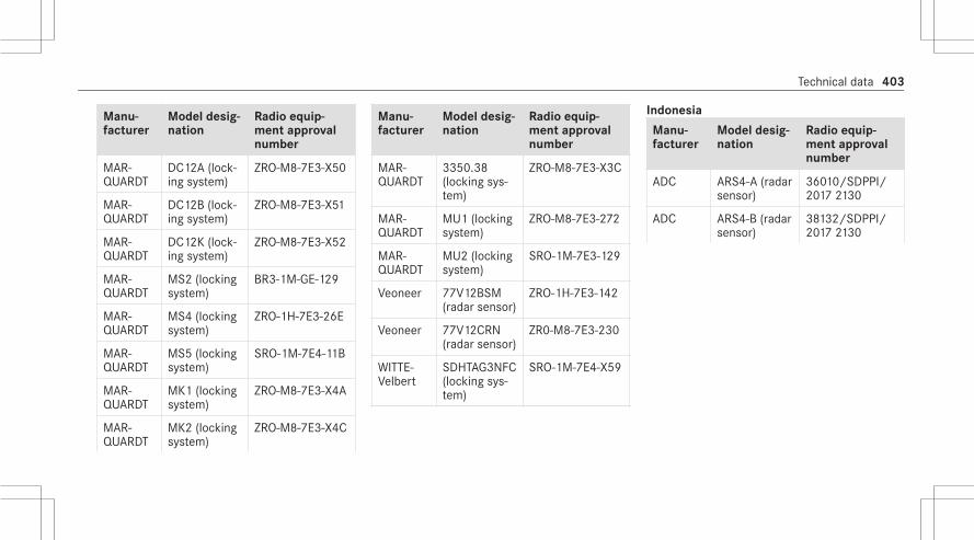
Manu‐facturer
Model desig‐nation
Radio equip‐ment approvalnumber
MAR‐QUARDT
DC12A (lock‐ing system)
ZRO-M8-7E3-X50
MAR‐QUARDT
DC12B (lock‐ing system)
ZRO-M8-7E3-X51
MAR‐QUARDT
DC12K (lock‐ing system)
ZRO-M8-7E3-X52
MAR‐QUARDT
MS2 (lockingsystem)
BR3-1M-GE-129
MAR‐QUARDT
MS4 (lockingsystem)
ZRO-1H-7E3-26E
MAR‐QUARDT
MS5 (lockingsystem)
SRO-1M-7E4-11B
MAR‐QUARDT
MK1 (lockingsystem)
ZRO-M8-7E3-X4A
MAR‐QUARDT
MK2 (lockingsystem)
ZRO-M8-7E3-X4C
Manu‐facturer
Model desig‐nation
Radio equip‐ment approvalnumber
MAR‐QUARDT
3350.38(locking sys‐tem)
ZRO-M8-7E3-X3C
MAR‐QUARDT
MU1 (lockingsystem)
ZRO-M8-7E3-272
MAR‐QUARDT
MU2 (lockingsystem)
SRO-1M-7E3-129
Veoneer 77V12BSM(radar sensor)
ZRO-1H-7E3-142
Veoneer 77V12CRN(radar sensor)
ZR0-M8-7E3-230
WITTE-Velbert
SDHTAG3NFC(locking sys‐tem)
SRO-1M-7E4-X59
Indonesia
Manu‐facturer
Model desig‐nation
Radio equip‐ment approvalnumber
ADC ARS4-A (radarsensor)
36010/SDPPI/2017 2130
ADC ARS4-B (radarsensor)
38132/SDPPI/2017 2130
Technical data 403

Manu‐facturer
Model desig‐nation
Radio equip‐ment approvalnumber
ADC ARS4-C (radarsensor)
68676/SDPPI/2020
Dilarang melaku‐kan perubahanspesifikasi yangdapat menimbul‐kan gangguanfisik dan/atauelektromagnetikterhadap lingkun‐gan sekitarnya
Manu‐facturer
Model desig‐nation
Radio equip‐ment approvalnumber
Bosch LRR3 (radarsensor)
40556/SDPPI/2018
Bosch MRR1Rear(radar sensor)
34538/SDPPI/2017
Bosch MRRe14FCR(radar sensor)
53078/SDPPI/2017PLG3612
Manu‐facturer
Model desig‐nation
Radio equip‐ment approvalnumber
Bosch FR5CPCCF(radar sensor)
67882/SDPPI/2020
Dilarang melaku‐kan perubahanspesifikasi yangdapat menimbul‐kan gangguanfisik dan/atauelektromagnetikterhadap lingkun‐gan sekitarnya
404 Technical data

Manu‐facturer
Model desig‐nation
Radio equip‐ment approvalnumber
Continen‐talAntenna
RKE213E1(antennaamplifier)
41771/I/SDPPI/2018 5205
Manu‐facturer
Model desig‐nation
Radio equip‐ment approvalnumber
Continen‐talAntenna
RKE223E1GNS (antennaamplifier)
66185/ SDPPI/2020 10325
Dilarang melaku‐kan perubahanspesifikasi yangdapat menimbul‐kan gangguanfisik dan/atauelektromagnetikterhadap lingkun‐gan sekitarnya
Manu‐facturer
Model desig‐nation
Radio equip‐ment approvalnumber
Continen‐tal Auto‐motive
D-WMI2020A(control unit)
66678/ SDPPI/2020 7163
Dilarang melaku‐kan perubahanspesifikasi yangdapat menimbul‐kan gangguanfisik dan/atauelektromagnetikterhadap lingkun‐gan sekitarnya
Technical data 405

Manu‐facturer
Model desig‐nation
Radio equip‐ment approvalnumber
Continen‐tal Auto‐motive
CMKG1 (lock‐ing system)
66911/ SDPPI/2020 7163
Dilarang melaku‐kan perubahanspesifikasi yangdapat menimbul‐kan gangguanfisik dan/atauelektromagnetikterhadap lingkun‐gan sekitarnya
Manu‐facturer
Model desig‐nation
Radio equip‐ment approvalnumber
Continen‐tal Auto‐motive
MARS Keyless(locking sys‐tem)
69379/SDPPI/2020 7163
Dilarang melaku‐kan perubahanspesifikasi yangdapat menimbul‐kan gangguanfisik dan/atauelektromagnetikterhadap lingkun‐gan sekitarnya
HELLA DM4 (lockingsystem)
52221/SDPPI/2017 6051
Manu‐facturer
Model desig‐nation
Radio equip‐ment approvalnumber
Hirsch‐mann
920287A(locking sys‐tem)
29510/SDPPI/2016 3159
Hirsch‐mann
920287B(locking sys‐tem)
28238/SDPPI/2016 3159
Huf Bao‐long
TSSRE4A (tirepressure mon‐itor sensor)
52166/SDPPI/2017 3533
HUF HUF14632(locking sys‐tem)
41618/SDPPI/2018 3533
HUF HUF4761(locking sys‐tem)
26742/SDPPI/2015 3533
KATHREIN
RKE213E1(locking sys‐tem)
41771/SDPPI/2018 5205
406 Technical data

Manu‐facturer
Model desig‐nation
Radio equip‐ment approvalnumber
LEOPOLDKOSTAL
KK1 (lockingsystem)
41121/SDPPI/2018 5125
Manu‐facturer
Model desig‐nation
Radio equip‐ment approvalnumber
MAR‐QUARDT
DC12A (lock‐ing system)
67373/SDPPI/2020 7163
Dilarang melaku‐kan perubahanspesifikasi yangdapat menimbul‐kan gangguanfisik dan/atauelektromagnetikterhadap lingkun‐gan sekitarnya
Manu‐facturer
Model desig‐nation
Radio equip‐ment approvalnumber
MAR‐QUARDT
DC12B (lock‐ing system)
59840/SDPPI/2019 7163
Dilarang melaku‐kan perubahanspesifikasi yangdapat menimbul‐kan gangguanfisik dan/atauelektromagnetikterhadap lingkun‐gan sekitarnya
Technical data 407

Manu‐facturer
Model desig‐nation
Radio equip‐ment approvalnumber
MAR‐QUARDT
DC12K (lock‐ing system)
59838/SDPPI/2019 7163
Dilarang melaku‐kan perubahanspesifikasi yangdapat menimbul‐kan gangguanfisik dan/atauelektromagnetikterhadap lingkun‐gan sekitarnya
Manu‐facturer
Model desig‐nation
Radio equip‐ment approvalnumber
MAR‐QUARDT
MS2 (lockingsystem)
67372/SDPPI/2020 7163
Dilarang melaku‐kan perubahanspesifikasi yangdapat menimbul‐kan gangguanfisik dan/atauelektromagnetikterhadap lingkun‐gan sekitarnya
Manu‐facturer
Model desig‐nation
Radio equip‐ment approvalnumber
MAR‐QUARDT
MS4 (lockingsystem)
64126/SDPPI/2019 7163
Dilarang melaku‐kan perubahanspesifikasi yangdapat menimbul‐kan gangguanfisik dan/atauelektromagnetikterhadap lingkun‐gan sekitarnya
408 Technical data

Manu‐facturer
Model desig‐nation
Radio equip‐ment approvalnumber
MAR‐QUARDT
MS5 (lockingsystem)
69077/SDPPI/2020 7163
Dilarang melaku‐kan perubahanspesifikasi yangdapat menimbul‐kan gangguanfisik dan/atauelektromagnetikterhadap lingkun‐gan sekitarnya
Manu‐facturer
Model desig‐nation
Radio equip‐ment approvalnumber
MAR‐QUARDT
MK1 (lockingsystem)
40283/SDPPI/2018 2208
Dilarang melaku‐kan perubahanspesifikasi yangdapat menimbul‐kan gangguanfisik dan/atauelektromagnetikterhadap lingkun‐gan sekitarnya
Manu‐facturer
Model desig‐nation
Radio equip‐ment approvalnumber
MAR‐QUARDT
MK2 (lockingsystem)
40282/SDPPI/2018 2208
Dilarang melaku‐kan perubahanspesifikasi yangdapat menimbul‐kan gangguanfisik dan/atauelektromagnetikterhadap lingkun‐gan sekitarnya
Technical data 409

Manu‐facturer
Model desig‐nation
Radio equip‐ment approvalnumber
MAR‐QUARDT
3350.38(locking sys‐tem)
62233/SDPPI/2019 7163
Dilarang melaku‐kan perubahanspesifikasi yangdapat menimbul‐kan gangguanfisik dan/atauelektromagnetikterhadap lingkun‐gan sekitarnya
Manu‐facturer
Model desig‐nation
Radio equip‐ment approvalnumber
Schrader GG4T (tirepressure mon‐itor sensor)
54083/SDPPI/2017 PLG3612
Schrader AG5SP4-D(tire pressuremonitor sen‐sor)
38892/SDPPI/2018 3612
Schrader DG6W2D4(tire pressuremonitor sen‐sor)
57058/SDPPI/2018 PLG3612
Schrader MC34MA4(tire pressuremonitor sen‐sor)
25626/SDPPI/2015 PLG3612
Veoneer 77GHzMMRV1(radar sensor)
40524/R/I/SDPPI/2018
Manu‐facturer
Model desig‐nation
Radio equip‐ment approvalnumber
Veoneer 77V12CRN(radar sensor)
66830/SDPPI/2020 7163
Dilarang melaku‐kan perubahanspesifikasi yangdapat menimbul‐kan gangguanfisik dan/atauelektromagnetikterhadap lingkun‐gan sekitarnya
410 Technical data

Manu‐facturer
Model desig‐nation
Radio equip‐ment approvalnumber
Veoneer 77V12BSM(radar sensor)
66792/SDPPI/2020 7163
Dilarang melaku‐kan perubahanspesifikasi yangdapat menimbul‐kan gangguanfisik dan/atauelektromagnetikterhadap lingkun‐gan sekitarnya
Manu‐facturer
Model desig‐nation
Radio equip‐ment approvalnumber
Pana‐sonic
DAIRSE 63550/SDPPI/2019
Dilarang melaku‐kan perubahanspesifikasi yangdapat menimbul‐kan gangguanfisik dan/atauelektromagnetikterhadap lingkun‐gan sekitarnya
Jamaica
Manufac‐turer
Modeldesigna‐tion
Radio equipmentapproval number
Continen‐tal Auto‐motive
CMKG1(lockingsystem)
SMA – CMKG1
MAR‐QUARDT
DC12A(lockingsystem)
SMA - DC12A
MAR‐QUARDT
DC12B(lockingsystem)
SMA - DC12B
MAR‐QUARDT
DC12K(lockingsystem)
SMA - DC12K
MAR‐QUARDT
MS2 (lock‐ing sys‐tem)
SMA - MS2
Technical data 411

Manufac‐turer
Modeldesigna‐tion
Radio equipmentapproval number
MAR‐QUARDT
MS4 (lock‐ing sys‐tem)
SMA - MS4
MAR‐QUARDT
MS5 (lock‐ing sys‐tem)
SMA - MS5
MAR‐QUARDT
MK1 (lock‐ing sys‐tem)
SMA - MK1
MAR‐QUARDT
MK2 (lock‐ing sys‐tem)
SMA - MK2
MAR‐QUARDT
3350.38(lockingsystem)
SMA - 3350.38
Manufac‐turer
Modeldesigna‐tion
Radio equipmentapproval number
MAR‐QUARDT
MU1 (lock‐ing sys‐tem)
SMA - MU1
MAR‐QUARDT
MU2 (lock‐ing sys‐tem)
SMA - MU2
Jordan
Manufac‐turer
Model designation Radioequipmentapprovalnumber
ADC ARS4-A (radar sen‐sor)
TRC/LPD/2014/126
ADC ARS4-B (radar sen‐sor)
TRC/LPD/2014/248
Manufac‐turer
Model designation Radioequipmentapprovalnumber
ADC ARS4-C (radar sen‐sor)
T/4/11/11/6676
Bosch FR5CPCCF (radarsensor)
T/4/11/11/6645
Bosch LRR3 (radar sensor) TRC/LPD/2009/15
Bosch MRR1Rear (radarsensor)
TRC/LPD/2014/73
Bosch MRRe14FCR (radarsensor)
TRC/LPD/2017/254
Continen‐talAntenna
RKE213E1 (antennaamplifier)
T/4/11/11/7046
412 Technical data

Manufac‐turer
Model designation Radioequipmentapprovalnumber
Continen‐talAntenna
RKE223E1GNS(antenna amplifier)
T/4/11/11/9682
Continen‐tal Auto‐motive
CMKG1 (lockingsystem)
T/4/11/11/1799
Continen‐tal Auto‐motive
MARS Keyless(locking system)
TRC/LPD/2017/183
Gentex EUROII (conveni‐ence system)
TRC/LPD/2014/258
Gentex MUAHL 5 (conveni‐ence system)
TRC/LPD/2015/299
HELLA DM4 (locking sys‐tem)
T/4/11/11/6459
Manufac‐turer
Model designation Radioequipmentapprovalnumber
Hirsch‐mann
920287A (lockingsystem)
T/4/11/11/10883
Hirsch‐mann
920287B (lockingsystem)
TRC/LPD/2012/53
Huf Bao‐long
TSSRE4A (tire pres‐sure monitor sen‐sor)
TRC/LPD/2017/421
Huf Bao‐long
TSSSG4G6 (controlunit) (tire pressuremonitor sensor)
TRC/LPD/2017/422
Huf Bao‐long
TSSSG4G6b (con‐trol unit) (tire pres‐sure monitor sen‐sor)
TRC/LPD/2017/175
Manufac‐turer
Model designation Radioequipmentapprovalnumber
HUF HUF14632 (lockingsystem)
T/4/11/11/4355
HUF HUF4761 (lockingsystem)
TRC/LPD/2012/144
LEOPOLDKOSTAL
KK1 (locking sys‐tem)
TRC/LPD/2015/102
MAR‐QUARDT
DC12A (locking sys‐tem)
T/4/11/11/1899
MAR‐QUARDT
DC12B (locking sys‐tem)
T/4/11/11/10892
MAR‐QUARDT
DC12K (locking sys‐tem)
T/4/11/11/10891
Technical data 413

Manufac‐turer
Model designation Radioequipmentapprovalnumber
MAR‐QUARDT
MS2 (locking sys‐tem)
T/4/11/11/6412
MAR‐QUARDT
MS4 (locking sys‐tem)
TRC/LPD/2019/127
MAR‐QUARDT
MS5 (locking sys‐tem)
T/4/11/11/3509
MAR‐QUARDT
MK1 (locking sys‐tem)
T/4/11/11/11020
MAR‐QUARDT
MK2 (locking sys‐tem)
T/4/11/11/11021
MAR‐QUARDT
3350.38 (lockingsystem)
T/4/11/11/1973
Manufac‐turer
Model designation Radioequipmentapprovalnumber
MAR‐QUARDT
MU1 (locking sys‐tem)
T/4/11/11/2511
MAR‐QUARDT
MU2 (locking sys‐tem)
T/4/11/11/4462
Schrader AG5SP4-D (tirepressure monitorsensor)
TRC/LPD/2019/21
Schrader MFR (control unit)(tire pressure moni‐tor sensor)
TRC/LPD/2019/184
Schrader GG4T (tire pressuremonitor sensor)
TRC/LPD/2017/456
Schrader DG6W2D4 (tirepressure monitorsensor)
TRC/LPD/2018/139
Manufac‐turer
Model designation Radioequipmentapprovalnumber
Schrader MC34MA4 (tirepressure monitorsensor)
TRC/LPD/2011/158
Veoneer 77V12BSM (radarsensor)
T/4/11/11/5557
Veoneer 77V12CRN (radarsensor)
T/4/11/11/5556
Veoneer 77GHz MMRV1(radar sensor)
TRC/LPD/2015/161
WITTE-Velbert
SGHTAG3NFC(locking system)
T/4/11/11/2635
414 Technical data

Canada
Man‐ufac‐turer
Modeldesigna‐tion
Radio equipmentapproval number
ADC ARS4-C(radar sen‐sor)
IC: 4135A-ARS4C
Bosch
FR5CPCCF(radar sen‐sor)
IC: 3887A-FR5CPCCF
Veoneer
77V12BSM(radar sen‐sor)
IC: 8436B-77V12BSM
Veoneer
77V12CRN(radar sen‐sor)
IC: 8436B-77V12CRN
Malaysia
Manufac‐turer
Model designa‐tion
Radioequipmentapprovalnumber
ADC ARS4-C (radar sen‐sor)
SQASI/TA/19/2872
Bosch FR5CPCCF (radarsensor)
CIDF15000490
Bosch LRR3 (radar sen‐sor)
RALM/35A/0716/S(16-2324)
Bosch MRR1Rear (radarsensor)
RALM/66A/0618/S(18-2468)
Manufac‐turer
Model designa‐tion
Radioequipmentapprovalnumber
Bosch MRRe14FCR (radarsensor)
RALM/45A/0517/S(17-1576)
Continen‐talAntenna
RKE213E1(antenna amplifier)
RAUU/28C/0915/S(15-2703)
Continen‐talAntenna
RKE223E1GNS(antenna amplifier)
RDDK/34B/1219/S(19-5319)
Continen‐tal Auto‐motive
CMKG1 (lockingsystem)
RFCP/13A/0220/S(20-0197)
Technical data 415
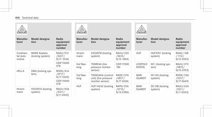
Manufac‐turer
Model designa‐tion
Radioequipmentapprovalnumber
Continen‐tal Auto‐motive
MARS Keyless(locking system)
RAAU/51C/0417/S(17-1034)CIDF15000578
HELLA DM4 (locking sys‐tem)
RDDK/41A/0717/S(17-2269)CIDF15000578
Hirsch‐mann
920287A (lockingsystem)
RAUU/63A/0311/S(11-0432)
Manufac‐turer
Model designa‐tion
Radioequipmentapprovalnumber
Hirsch‐mann
920287B (lockingsystem)
RAUU/22C/0615/S(15-1864)
Huf Bao‐long
TSSRE4A (tirepressure monitorsensor)
CIDF17000184
Huf Bao‐long
TSSSG4G6 (controlunit) (tire pressuremonitor sensor)
RAQP/57A/0817/S(17-2424)
HUF HUF14632 (lockingsystem)
RAYN/25A/0715/S(15-2385)
Manufac‐turer
Model designa‐tion
Radioequipmentapprovalnumber
HUF HUF4761 (lockingsystem)
RAAU/16B/1112/S(12-2053)
LEOPOLDKOSTAL
KK1 (locking sys‐tem)
RAUU/27C/0815/S(15-2953)
MAR‐QUARDT
DC12A (lockingsystem)
RDDK/33A/0317/S(17-0669)
MAR‐QUARDT
DC12B (lockingsystem)
RAUU/62A/0311/S(11-0263)
416 Technical data

Manufac‐turer
Model designa‐tion
Radioequipmentapprovalnumber
MAR‐QUARDT
DC12K (lockingsystem)
RAUU/62A/0311/S(11-0264)
MAR‐QUARDT
MS2 (locking sys‐tem)
RDDK/31A/0217/S(17-0405)
MAR‐QUARDT
MS4 (locking sys‐tem)
RDDK/25B/1019/S(19-0943)
MAR‐QUARDT
MS5 (locking sys‐tem)
RGLO/02A/0720/S(20-2580)
Manufac‐turer
Model designa‐tion
Radioequipmentapprovalnumber
MAR‐QUARDT
MK1 (locking sys‐tem)
RAAU/14C/0615/S(15-1057)
MAR‐QUARDT
MK2(locking sys‐tem)
RAAU/12C/0515/S(15-1059)
MAR‐QUARDT
3350.38(lockingsystem)
RDDK/17B/0819/S(19-1082)
MAR‐QUARDT
MU2(locking sys‐tem)
RGLO/01A/0720/S(20-2579)
Manufac‐turer
Model designa‐tion
Radioequipmentapprovalnumber
Meta Sys‐tem
ITS/TPS (interiormotion sensor)
RAVG/18Q/0212/S(11-2068)
Meta Sys‐tem
MUW II (interiormotion sensor)
RAVG/17Q/0212/S(11-2067)
Schrader AG5SP4-D (tirepressure monitorsensor)
RCDD/03A/0615/S(19-2094)
Schrader MFR (control unit)(tire pressure mon‐itor sensor)
RAQP/62A/0419/S(19-1694)
Technical data 417

Manufac‐turer
Model designa‐tion
Radioequipmentapprovalnumber
Veoneer 77GHz MMRV1(radar sensor)
RALM/31A/0316/S(16-0727)
Veoneer 77V12BSM (radarsensor)
SQASI/TA/19/2980
Veoneer 77V12CRN (radarsensor)
SQASI/TA/19/2982
WITTE-Velbert
SDHTAG3NFC(locking system)
RDDK/43B/0420/S(20-1749)
Morocco
Manufac‐turer
Model designa‐tion
Radio equip‐mentapprovalnumber
AGREE PARL’ANRTMAROC
ADC ARS4-A (radarsensor)
MR 9490ANTR2014-07-23
ADC ARS4-B (radarsensor)
MR 9778ANTR2014-11-11
ADC ARS4-C (radarsensor)
MR 20231ANTR 2019
Bosch FR5CPCCF (radarsensor)
MR 20575ANTR 2019
Bosch LRR3 (radar sen‐sor)
MR 5371ANTR2010-02-02
Manufac‐turer
Model designa‐tion
Radio equip‐mentapprovalnumber
Bosch MRR1Rear (radarsensor)
MR 9186ANTR2014-04-22
Bosch MRRe14FCR(radar sensor)
MR 13900ANTR2017-05-04
Continen‐talAntenna
RKE213E1(antenna ampli‐fier)
MR 10631ANTR2015-07-16
Continen‐talAntenna
RKE223E1GNS(antenna ampli‐fier)
MR 21174ANTR2019-10-14
Continen‐tal Auto‐motive
CMKG1 (lockingsystem)
MR 21701ANTR2019-12-05
418 Technical data

Manufac‐turer
Model designa‐tion
Radio equip‐mentapprovalnumber
Continen‐tal Auto‐motive
MARS Keyless(locking system)
MR 13681ANTR2017-04-04
HELLA DM4 (locking sys‐tem)
MR 14426ANTR2017-07-28
Hirsch‐mann
920287A (lockingsystem)
MR 6700ANTR2011-11-16
Hirsch‐mann
920287B (lockingsystem)
MR 7260ANTR2012-06-13
Huf Bao‐long
TSSRE4A (tirepressure sensor)(tire pressuremonitor sensor)
MR 14320ANTR2017-07-07
Manufac‐turer
Model designa‐tion
Radio equip‐mentapprovalnumber
Huf Bao‐long
TSSSG4G6 (con‐trol unit) (tirepressure monitorsensor)
MR 14319ANTR2017-07-07
Huf Bao‐long
TSSSG4G6b(control unit) (tirepressure monitorsensor)
MR 19561ANTR2019-04-26
HUF HUF14632 (lock‐ing system)
MR 10506ANTR2015-06-22
HUF HUF4761 (lockingsystem)
MR 7829ANTR2013-02-14
LEOPOLDKOSTAL
KK1 (locking sys‐tem)
MR 10697ANTR2015-08-05
Manufac‐turer
Model designa‐tion
Radio equip‐mentapprovalnumber
MAR‐QUARDT
DC12A (lockingsystem)
MR 13429ANTR2017-03-03
MAR‐QUARDT
DC12B (lockingsystem)
MR 6698ANTR2011-11-16
MAR‐QUARDT
DC12K (lockingsystem)
MR 6699ANTR2011-11-16
MAR‐QUARDT
MS2 (locking sys‐tem)
MR 13300ANTR2017-02-15
MAR‐QUARDT
MS4 (locking sys‐tem)
MR 19199ANTR2019-03-25
Technical data 419

Manufac‐turer
Model designa‐tion
Radio equip‐mentapprovalnumber
MAR‐QUARDT
MS5 (locking sys‐tem)
MR 23805ANRT22/04/2020
MAR‐QUARDT
MK1 (locking sys‐tem)
MR 10645ANTR2015-07-21
MAR‐QUARDT
MK2 (locking sys‐tem)
MR 10987ANTR2015-10-22
MAR‐QUARDT
3350.38 (lockingsystem)
MR 18817ANTR2019-02-12
MAR‐QUARDT
CMKG1 (lockingsystem)
MR 21701ANTR2019-12-05
Manufac‐turer
Model designa‐tion
Radio equip‐mentapprovalnumber
MAR‐QUARDT
MU1 (locking sys‐tem)
MR 19200ANTR2019-03-25
MAR‐QUARDT
MU2 (locking sys‐tem)
MR 23804ANRT22/04/2020
Schrader AG5SP4-D (tirepressure sensor)(tire pressuremonitor sensor)
MR 10216ANTR2015-03-18
Schrader MFR (controlunit) (tire pres‐sure monitor sen‐sor)
MR 19527ANTR2019-04-30
Schrader GG4T (tire pres‐sure monitor sen‐sor)
MR 14777ANRT2017-09-20
Manufac‐turer
Model designa‐tion
Radio equip‐mentapprovalnumber
Schrader DG6W2D4 (tirepressure monitorsensor)
MR 16355ANTR2018-04-19
Schrader MC34MA4 (tirepressure monitorsensor)
MR 6706ANTR2011-11-17
Veoneer 77GHz MMRV1(radar sensor)
MR 10436ANTR 2015
Veoneer 77V12BSM (radarsensor)
MR 20097ANTR 2019
Veoneer 77V12CRN (radarsensor)
MR 20149ANTR 2019
WITTE-Vel‐bert
SDHTAG3NFC(locking system)
MR 23310ANRT10/03/2020
420 Technical data

Mexico
Manufac‐turer
Model desig‐nation
Radio equip‐ment approvalnumber
ADC ARS4-A (radarsensor)
IFETEL:RCPCOAR14-1191
ADC ARS4-B (radarsensor)
IFETEL:RLVCOAR15-0008
ADC ARS4-C (radarsensor)
IFETEL:RLVCOR19-1062
Bosch FR5CPCCF(radar sensor)
IFETEL:RCPBOFR19-1356
Manufac‐turer
Model desig‐nation
Radio equip‐ment approvalnumber
Bosch LRR3 (radarsensor)
IFETEL:RCPBOLR09-0828
Bosch MRR1Rear(radar sensor)
IFETEL:RCPBOMR14-0922
Bosch MRRe14FCR(radar sensor)
IFETEL:RCPBOMR17-0598
Continen‐talAntenna
RKE213E1(antennaamplifier)
IFETEL:RLVKARK15-1741
Manufac‐turer
Model desig‐nation
Radio equip‐ment approvalnumber
Continen‐talAntenna
RKE223E1(antennaamplifier)
IFETEL:RLVCORK19-2174
Continen‐tal Auto‐motive
CMKG1 (lock‐ing system)
IFETEL:RCPCOCM19-2315
Continen‐tal Auto‐motive
MARS Keyless(locking sys‐tem)
IFETEL:RLVDAMA18-1827
Gentex EURO II (con‐venience sys‐tem)
IFETEL:RCPJOHO07-598-A9
Technical data 421

Manufac‐turer
Model desig‐nation
Radio equip‐ment approvalnumber
Gentex MUAHL 5(conveniencesystem)
IFETEL:RCPGEMU15-0448
HELLA DM4 (lockingsystem)
IFETEL:RLVHEDM17-10
Hirsch‐mann
920287A(locking sys‐tem)
IFETEL:RLVHI9211-0472
Hirsch‐mann
920287B(locking sys‐tem)
IFETEL:RLVHI9212-0608
Huf Bao‐long
TSSRE4A (tirepressure mon‐itor sensor)
IFETEL:RLVHUTS17-0806
Manufac‐turer
Model desig‐nation
Radio equip‐ment approvalnumber
HUF HUF14632(locking sys‐tem)
IFETEL:RLVHUHU15-1204
HUF HUF4761(locking sys‐tem)
IFETEL:RLVHUHU12-1587
LEOPOLDKOSTAL
KK1 (lockingsystem)
IFETEL:RLVKOKK15-0891
MAR‐QUARDT
DC12A (lock‐ing system)
IFETEL:RLVMEDC17-0348
Manufac‐turer
Model desig‐nation
Radio equip‐ment approvalnumber
MAR‐QUARDT
DC12B (lock‐ing system)
IFETEL:RLVMADC11-0446
MAR‐QUARDT
DC12K (inte‐rior motionsensor)
IFETEL:RLVMADC11-0446
MAR‐QUARDT
MS2 (lockingsystem)
IFETEL:RLVMAMS17-0222
MAR‐QUARDT
MS4 (lockingsystem)
IFETEL:RLVMAMS19-0449
422 Technical data

Manufac‐turer
Model desig‐nation
Radio equip‐ment approvalnumber
MAR‐QUARDT
MS5 (lockingsystem)
IFETEL:RLVMEMS20-0957
MAR‐QUARDT
MK1 (lockingsystem)
IFETEL:RLVMAMK15-1042
MAR‐QUARDT
MK2 (lockingsystem)
IFETEL:RLVMAMK15-1043
MAR‐QUARDT
3350.38(locking sys‐tem)
IFETEL:RCPMA3319-0530
Manufac‐turer
Model desig‐nation
Radio equip‐ment approvalnumber
MAR‐QUARDT
MU1 (lockingsystem)
IFETEL:RCPMAMU19-1342
Meta Sys‐tem
ITS/TPS (inte‐rior motionsensor)
IFETEL:IFT/223/UCS/DG-AUSE/4871/2016
Meta Sys‐tem
MUW II (inte‐rior motionsensor)
IFETEL:IFT/223/UCS/DG-AUSE/5064/2016
Schrader AG5SP4-D(tire pressuremonitor sen‐sor)
IFETEL:RCPSCAG15-0627
Manufac‐turer
Model desig‐nation
Radio equip‐ment approvalnumber
Schrader MFR (tirepressure mon‐itor sensor)
IFETEL:RLVSCMF15-0959
Schrader GG4T (tirepressure mon‐itor sensor)
IFETEL:RLVSCGG17-1665
Schrader DG6W2D4(tire pressuremonitor sen‐sor)
IFETEL:RLVSCDG18-04
Schrader MC34MA4(tire pressuremonitor sen‐sor)
IFETEL:RCPSCMR14-062
Technical data 423

Manufac‐turer
Model desig‐nation
Radio equip‐ment approvalnumber
Veoneer 77GHzMMRV1(radar sensor)
IFETEL:RLVAU7717-0744
Veoneer 77V12BSM(radar sensor)
IFETEL:RLVVE7719-1063
Veoneer 77V12CRN(radar sensor)
IFETEL:RCPVE7719-0998
WITTE-Velbert
SDHTAG3NFC(locking sys‐tem)
IFETEL:RCPWISD20-0943
Moldova
Manufac‐turer
Model desig‐nation
Radio equip‐ment approvalnumber
ADC ARS4-C(radar sensor)
MD OC TIP 024A6632-19
Bosch FR5CPCCF(radar sensor)
MD OC TIP 024A6560-19
Bosch LRR3 (radarsensor)
MD OC TIP 024A6227-18
Bosch MRR1Rear(radar sensor)
MD OC TIP 024A5957-17
Bosch MRRe14FCR(radar sensor)
MD OC TIP 024A6004-18
Manufac‐turer
Model desig‐nation
Radio equip‐ment approvalnumber
Continen‐talAntenna
RKE213E1(antennaamplifier)
MD OC TIP 024A6500-19
Continen‐talAntenna
RKE223E1GNS (antennaamplifier)
MD OC TIP 024A6648-19
Continen‐tal Auto‐motive
CMKG1 (lock‐ing system)
MD OC TIP 024A6671-20
Continen‐tal Auto‐motive
MARS Key‐less (lockingsystem)
MD OC TIP 024A5876-17
HELLA DM4 (lockingsystem)
MD 0C TIP 024A6761-20
424 Technical data

Manufac‐turer
Model desig‐nation
Radio equip‐ment approvalnumber
Hirsch‐mann
920287A(locking sys‐tem)
MD OC TIP 024A6652-20
Hirsch‐mann
920287B(locking sys‐tem)
MD OC TIP 024A6514-19
HUF HUF4761(locking sys‐tem)
MD OC TIP 024A6449-19
LEOPOLDKOSTAL
KK1 (lockingsystem)
MD OC TIP 024A6440-19
MAR‐QUARDT
DC12A (lock‐ing system)
MD OC TIP 024A6684-20
Manufac‐turer
Model desig‐nation
Radio equip‐ment approvalnumber
MAR‐QUARDT
DC12B (lock‐ing system)
MD OC TIP 024A6253-18
MAR‐QUARDT
DC12K (lock‐ing system)
MD OC TIP 024A6252-18
MAR‐QUARDT
MS2 (lockingsystem)
MD OC TIP 024A6444-19
MAR‐QUARDT
MS4 (lockingsystem)
MD OC TIP 024A6569-19
MAR‐QUARDT
MS5 (lockingsystem)
MO OC TIP 024A6774-20
MAR‐QUARDT
MK1 (lockingsystem)
MD OC TIP 024A6551-19
Manufac‐turer
Model desig‐nation
Radio equip‐ment approvalnumber
MAR‐QUARDT
MK2 (lockingsystem)
MD OC TIP 024A6552-19
MAR‐QUARDT
3350.38(locking sys‐tem)
MD OC TIP 024A6398-19
MAR‐QUARDT
MU1 (lockingsystem)
MD OC TIP 024A6570-19
MAR‐QUARDT
MU2 (lockingsystem)
MD OC TIP 024A6773-20
Veoneer 77GHzMMRV1(radar sensor)
MD OC TIP 024A5678-16
Technical data 425

Manufac‐turer
Model desig‐nation
Radio equip‐ment approvalnumber
Veoneer 77V12BSM(radar sensor)
MD OC TIP 024A6508-19
Veoneer 77V12CRN(radar sensor)
MD OC TIP 024A6506-19
WITTE-Velbert
SDHTAG3NFC (lockingsystem)
MD OC TIP 024A6753-20
Mongolia
Manu‐facturer
Model des‐ignation
Radio equipmentapproval number
Continen‐tal Auto‐motive
CMKG1(locking sys‐tem)
A19000633
Continen‐tal Auto‐motive
MARS Key‐less (lockingsystem)
A18000328
HELLA DM4 (lock‐ing system)
A18000329
MAR‐QUARDT
DC12A (lock‐ing system)
A19000400
MAR‐QUARDT
DC12B (lock‐ing system)
A19000371
Manu‐facturer
Model des‐ignation
Radio equipmentapproval number
MAR‐QUARDT
DC12K (lock‐ing system)
A19000372
MAR‐QUARDT
MS2 (lockingsystem)
A19000289
MAR‐QUARDT
MS4 (lockingsystem)
A19000516
MAR‐QUARDT
MS5 (lockingsystem)
A20000085
MAR‐QUARDT
MK1 (lockingsystem)
A19000374
MAR‐QUARDT
MK2 (lockingsystem)
A19000374
426 Technical data

Manu‐facturer
Model des‐ignation
Radio equipmentapproval number
MAR‐QUARDT
MU1 (lock‐ing system)
A19000517
MAR‐QUARDT
MU2 (lock‐ing system)
A20000086
Niger
Manufac‐turer
Model des‐ignation
Radio equipmentapproval number
Continen‐talAntenna
RKE213E1(antennaamplifier)
029/ARCEP/DG/19
Continen‐tal Auto‐motive
MARS Key‐less (lockingsystem)
083/ARCEP/DG/19
Manufac‐turer
Model des‐ignation
Radio equipmentapproval number
HELLA DM4 (lock‐ing system)
082/ARCEP/DG/19
Hirsch‐mann
920287A(locking sys‐tem)
097/ARCEP/DG/19
Hirsch‐mann
920287B(locking sys‐tem)
098/ARCEP/DG/19
HUF HUF4761(locking sys‐tem)
053/ARCEP/DG/19
KATHREIN RKE213E1(locking sys‐tem)
029/ARCEP/DG/19
LEOPOLDKOSTAL
KK1 (lockingsystem)
037/ARCEP/DG/19
Manufac‐turer
Model des‐ignation
Radio equipmentapproval number
MAR‐QUARDT
DC12A(locking sys‐tem)
010/ARCEP/DG/19
MAR‐QUARDT
DC12B(locking sys‐tem)
008/ARCEP/DG/19
MAR‐QUARDT
DC12K(locking sys‐tem)
009/ARCEP/DG/19
MAR‐QUARDT
MS2 (lock‐ing system)
014/ARCEP/DG/19
MAR‐QUARDT
MS4 (lock‐ing system)
HOMO-0096/ARCEP/DG/2019
MAR‐QUARDT
MK1 (lock‐ing system)
034/ARCEP/DG/19
MAR‐QUARDT
MK2 (lock‐ing system)
035/ARCEP/DG/19
Technical data 427

Manufac‐turer
Model des‐ignation
Radio equipmentapproval number
MAR‐QUARDT
3350.38(locking sys‐tem)
015/ARCEP/DG/19
MAR‐QUARDT
MU1 (lock‐ing system)
HOMO-0095/ARCEP/DG/2019
Nigeria
Manufac‐turer
Model desig‐nation
Radio equip‐ment approvalnumber
ADC ARS4-A (radarsensor)
NCC/TSNI/WN/TA/CERT/AB00388/2015
ADC ARS4-B (radarsensor)
NCC/TSNI/WN/TA/CERT/2062/2018
Manufac‐turer
Model desig‐nation
Radio equip‐ment approvalnumber
ADC ARS4-C (radarsensor)
NCC/TSNI/WN/TA/CERT/3078/2019
Bosch FR5CPCCF(radar sensor)
NCC/TSNI/WN/TA/CERT/3282/2019
Bosch MRR1Rear(radar sensor)
NCC/TSNI/WN/TA/CERT/2089/2018
Bosch MRRe14FCR(radar sensor)
NCC/TSNI/WN/TA/CERT/2042/2018
Manufac‐turer
Model desig‐nation
Radio equip‐ment approvalnumber
Continen‐talAntenna
RKE213E1(antennaamplifier)
NCC/TSNI/WN/TA/CERT/0865/2015
Continen‐talAntenna
RKE223E1GNS (antennaamplifier)
NCC/TSNI/WN/TA/CERT/3372/2020
Continen‐tal Auto‐motive
CMKG1 (lock‐ing system)
NCC/TSNI/WN/TA/CERT/3440/2020
Continen‐tal Auto‐motive
MARS Keyless(locking sys‐tem)
NCC/TSNI/WN/TA/CERT/1670/2017
428 Technical data

Manufac‐turer
Model desig‐nation
Radio equip‐ment approvalnumber
HELLA DM4 (lockingsystem)
NCC/TSNI/WN/TA/CERT/1830/2017
Hirsch‐mann
920287A(locking sys‐tem)
NCC/TSNI/WN/TA/CERT/3100/2019
Hirsch‐mann
920287B(locking sys‐tem)
NCC/TSNI/WN/TA/CERT/3101/2019
HUF HUF14632(locking sys‐tem)
NCC/TSNI/WN/TA/CERT/0829/2015
Manufac‐turer
Model desig‐nation
Radio equip‐ment approvalnumber
HUF HUF4761(locking sys‐tem)
NCC/TSNI/WN/TA/CERT/2884/2019
LEOPOLDKOSTAL
KK1 (lockingsystem)
NCC/TSNI/WN/TA/CERT/0823/2015
MAR‐QUARDT
DC12A (lock‐ing system)
NCC/TSNI/WN/TA/CERT/1714/2017
MAR‐QUARDT
DC12B (lock‐ing system)
NCC/TSNI/WN/TA/CERT/2627/2019
Manufac‐turer
Model desig‐nation
Radio equip‐ment approvalnumber
MAR‐QUARDT
DC12K (lock‐ing system)
NCC/TSNI/WN/TA/CERT/2626/2019
MAR‐QUARDT
MS2 (lockingsystem)
NCC/TSNI/WN/TA/CERT/1667/2017
MAR‐QUARDT
MS4 (lockingsystem)
NCC/TSNI/WN/TA/CERT/3212/2019
MAR‐QUARDT
MS5 (lockingsystem)
NCC/TSNI/WN/TA/CERT/3635/2020
Technical data 429

Manufac‐turer
Model desig‐nation
Radio equip‐ment approvalnumber
MAR‐QUARDT
MK1 (lockingsystem)
NCC/TSNI/WN/TA/CERT/0739/2015
MAR‐QUARDT
MK2 (lockingsystem)
NCC/TSNI/WN/TA/CERT/0740/2015
MAR‐QUARDT
3350.38(locking sys‐tem)
NCC/TSNI/WN/TA/CERT/2882/2019
Manufac‐turer
Model desig‐nation
Radio equip‐ment approvalnumber
Veoneer 77V12BSM(radar sensor)
NCC/TSNI/WN/TA/CERT/3069/2019
Veoneer 77V12CRN(radar sensor)
NCC/TSNI/WN/TA/CERT/3068/2019
Oman
Manu‐facturer
Model designation Radioequip‐mentapprovalnumber
ADC ARS4-A (radar sen‐sor)
TRA/TA-R/2016/14D080134
ADC ARS4-B (radar sen‐sor)
TRA/TA-R/2210/14D080134
ADC ARS4-C (radar sen‐sor)
TRA/TA-R/7769/19D172338
430 Technical data

Manu‐facturer
Model designation Radioequip‐mentapprovalnumber
Bosch FR5CPCCF (radarsensor)
TRA/TA-R/7983/19D172338
Bosch LRR3 (radar sensor) TRA/TA-R/1049/09
Bosch MRR1Rear (radar sen‐sor)
TRA/TA-R/1849/14
Bosch MRRe14FCR (radarsensor)
TRA/TA-R/4353/17
Manu‐facturer
Model designation Radioequip‐mentapprovalnumber
Continen‐talAntenna
RKE213E1 (antennaamplifier)
TRA/TA-R/2715/15D090258
Continen‐talAntenna
RKE223E1GNS(antenna amplifier)
TRA/TA-R/8337/19
Continen‐tal Auto‐motive
CMKG1 (locking sys‐tem)
TRA/TA-R/8642/19D172338
Continen‐tal Auto‐motive
MARS Keyless (lock‐ing system)
TRA/TA-R/4158/17D080134
Manu‐facturer
Model designation Radioequip‐mentapprovalnumber
HELLA DM4 (locking system) TRA/TA-R/4548/17D080134
Hirsch‐mann
920287A (lockingsystem)
TRA/TA-R/0210/11D080353
Hirsch‐mann
920287B (lockingsystem)
TRA/TA-R/0655/12D080353
Huf Bao‐long
TSSRE4A (tire pres‐sure monitor sensor)
TRA R/4516/17D100428
Technical data 431

Manu‐facturer
Model designation Radioequip‐mentapprovalnumber
Huf Bao‐long
TSSSG4G6 (tire pres‐sure monitor sensor)
TRA R/4515/17D100428
Huf Bao‐long
TSSSG4G6b (tirepressure monitor sen‐sor)
TRA R/7506/19D100428
HUF HUF14632 (lockingsystem)
TRA/TA-R/2665/15
HUF HUF4761 (locking sys‐tem)
TRA/TA-R/0920/12
LEOPOLDKOSTAL
KK1 (locking system) TRA/TA-R/3129/16
Manu‐facturer
Model designation Radioequip‐mentapprovalnumber
MAR‐QUARDT
DC12A (locking sys‐tem)
TRA/TA-RD/4056/17D100428
MAR‐QUARDT
DC12B (locking sys‐tem)
TRA/TA-R/0227/11D080353
MAR‐QUARDT
DC12K (locking sys‐tem)
TRA/TA-R/0228/11D080353
MAR‐QUARDT
MS2 (locking system) TRA/TA-R/4136/17D080134
Manu‐facturer
Model designation Radioequip‐mentapprovalnumber
MAR‐QUARDT
MS4 (locking system) TRA/TA-R/7316/19D172249
MAR‐QUARDT
MS5 (locking system) TRA/TA-R/9324/20D100428
MAR‐QUARDT
MK1 (locking system) TRA/TA-R/2848/15D080353
MAR‐QUARDT
MK2 (locking system) TRA/TA-R/2900/15D080353
432 Technical data

Manu‐facturer
Model designation Radioequip‐mentapprovalnumber
MAR‐QUARDT
3350.38 (locking sys‐tem)
TRA/TA-R/7051/19D172249
MAR‐QUARDT
MU1 (locking system) TRA/TA-R/7353/19D172249
MAR‐QUARDT
MU2 (locking system) TRA/TA-R/9325/20D100428
Schrader AG5SP4-D (tire pres‐sure monitor sensor)
TRA R/2380/15D080134
Manu‐facturer
Model designation Radioequip‐mentapprovalnumber
Schrader MFR (tire pressuremonitor sensor)
TRA R/7464/19D090258
Schrader GG4T (tire pressuremonitor sensor)
TRA TA-R/4686/17D080134
Schrader DG6W2D4 (tire pres‐sure monitor sensor)
TRA TA-R/5511/18D172249
Veoneer 77GHz MMRV1 (radarsensor)
TRA/TA-R/2706/15
Manu‐facturer
Model designation Radioequip‐mentapprovalnumber
Veoneer 77V12BSM (radarsensor)
TRA R/7706/19D172338
Veoneer 77V12CRN (radarsensor)
TRA R/7707/19D172338
WITTE-Velbert
SDHTAG3NFC (lock‐ing system)
TRA/TA-R/9150/20
Technical data 433

Pakistan
Manufac‐turer
Model desig‐nation
Radio equip‐mentapprovalnumber
ADC ARS4-A(radar sen‐sor)
9.9014/2019
ADC ARS4-B(radar sen‐sor)
9.1048/2018
ADC ARS4-C(radar sen‐sor)
9.9389/2019
Bosch FR5CPCCF(radar sen‐sor)
9.198/2020
Manufac‐turer
Model desig‐nation
Radio equip‐mentapprovalnumber
ContinentalAntenna
RKE213E1(antennaamplifier)
9.142/2016
ContinentalAntenna
RKE223E1GNS (antennaamplifier)
9.100169/2019
ContinentalAutomotive
CMKG1 (lock‐ing system)
9.100175/2019
ContinentalAutomotive
MARS Key‐less (lockingsystem)
9.213/2017
HELLA DM4 (lockingsystem)
9.409/2017
Manufac‐turer
Model desig‐nation
Radio equip‐mentapprovalnumber
Hirschmann 920287A(locking sys‐tem)
9.845/2013
Hirschmann 920287B(locking sys‐tem)
9.846/2013
HUF HUF14632(locking sys‐tem)
9.598/2015
HUF HUF4761(locking sys‐tem)
9.790/2013
434 Technical data

Manufac‐turer
Model desig‐nation
Radio equip‐mentapprovalnumber
LEOPOLDKOSTAL
KK1 (lockingsystem)
9.118/2016
MARQUARDT DC12A (lock‐ing system)
9.131/2017
MARQUARDT DC12B (lock‐ing system)
9.829/2013
MARQUARDT DC12K (lock‐ing system)
9.830/2013
MARQUARDT MS2 (lockingsystem)
9.133/2017
MARQUARDT MS4 (lockingsystem)
9.100171/2019
Manufac‐turer
Model desig‐nation
Radio equip‐mentapprovalnumber
MARQUARDT MK1 (lockingsystem)
9.486/2015
MARQUARDT MK2 (lockingsystem)
9.497/2015
MARQUARDT MU1 (lockingsystem)
9.100170/2019
Veoneer 77GHzMMRV1(radar sen‐sor)
9.9284/2019
Manufac‐turer
Model desig‐nation
Radio equip‐mentapprovalnumber
Veoneer 77V12BSM(radar sen‐sor)
9.9391/2019
Veoneer 77V12CRN(radar sen‐sor)
9.9391/2019
Technical data 435

Paraguay
Manu‐facturer
Model des‐ignation
Radio equipmentapproval number
ADC ARS4-A(radar sen‐sor)
2019-05-I-0271
ADC ARS4-B(radar sen‐sor)
2019-07-I-0353
ADC ARS4-C(radar sen‐sor)
2019-11-I-0602
Bosch FR5CPCCF(radar sen‐sor)
2019-09-I-0508
Manu‐facturer
Model des‐ignation
Radio equipmentapproval number
Bosch MRRe14FCR(radar sen‐sor)
2017-06-I-0000162
Bosch MRR1Rear(radar sen‐sor)
2019-05-I-000236
Conti‐nentalAntenna
RKE213E1(antennaamplifier)
2016-02-I-0000038
Conti‐nentalAntenna
RKE223E1GNS (antennaamplifier)
2019-12-I-0656
Manu‐facturer
Model des‐ignation
Radio equipmentapproval number
Conti‐nentalAutomo‐tive
CMKG1(locking sys‐tem)
2020-02-I-0110
Conti‐nentalAutomo‐tive
MARS Key‐less (lockingsystem)
2017-05-I-0000136
HELLA DM4 (lockingsystem)
2017-08-I_0000261
Hirsch‐mann
920287A(locking sys‐tem)
2016-5-I-000134 y2011-06-I-0059
436 Technical data

Manu‐facturer
Model des‐ignation
Radio equipmentapproval number
Hirsch‐mann
920287B(locking sys‐tem)
2017-04-I-0000119y 2012-05-I-0096
Huf Bao‐long
TSSRE4A(tire pressuremonitor sen‐sor)
2017-09-I-0000328
HUF HUF14632(locking sys‐tem)
2020-06-I-0284 y2015-08-I-0000226
HUF HUF4761(locking sys‐tem)
2017-12-I-0000409 y2012-10-I-0178
Manu‐facturer
Model des‐ignation
Radio equipmentapproval number
LEO‐POLDKOSTAL
KK1 (lockingsystem)
2015-06-I-0000181
MAR‐QUARDT
DC12A (lock‐ing system)
2017-07-I-0000199
MAR‐QUARDT
DC12B (lock‐ing system)
2016-5-I-000144 y2011-06-I-0067
MAR‐QUARDT
DC12K (lock‐ing system)
2016-5-I-000143 y2011-06-I-0068
MAR‐QUARDT
MS2 (lockingsystem)
2017-04-I-0000101
MAR‐QUARDT
MS4 (lockingsystem)
2019-10-I-0581
Manu‐facturer
Model des‐ignation
Radio equipmentapproval number
MAR‐QUARDT
MK1 (lockingsystem)
2020-07-I-0390 y2015-07-I-0000200
MAR‐QUARDT
MK2 (lockingsystem)
2020-07-I-0391 y2015-07-I-0000201
MAR‐QUARDT
3350.38(locking sys‐tem)
2019-04-I-000216
Technical data 437

Manu‐facturer
Model des‐ignation
Radio equipmentapproval number
Pana‐sonic
DAIRSE Importer:Condor S.A.C.ICasa Central, J.B.Gorostiaga 315 yGuaraníes, Asun‐ción, Paraguay,(595 21) 5697000, sac@con‐dor.com.py
Schrader AG5SP4-D(tire pressuremonitor sen‐sor)
2015-04-I-0000150
Manu‐facturer
Model des‐ignation
Radio equipmentapproval number
Veoneer 77GHzMMRV1(radar sen‐sor)
2015-07-I-000194
Veoneer 77V12BSM(radar sen‐sor)
2019-07-I-0399
Veoneer 77V12CRN(radar sen‐sor)
2019-07-I-0398
WITTE-Velbert
SDHTAG3NFC (lockingsystem)
2020-06-I-0326
Philippines
Manu‐facturer
Model des‐ignation
Radio equipmentapproval number
ADC ARS4-A(radar sen‐sor)
ESD-1409466C
ADC ARS4-B(radar sen‐sor)
ESD-1409834C
ADC ARS4-C(radar sen‐sor)
ESD-1920226C
Bosch FR5CPCCF(radar sen‐sor)
ESD-1920531C
438 Technical data

Manu‐facturer
Model des‐ignation
Radio equipmentapproval number
Bosch MRR1Rear(radar sen‐sor)
ESD-1408917C
Bosch MRRe14FCR(radar sen‐sor)
ESD-1716172C
Veoneer 77V12BSM(radar sen‐sor)
ESD-1920160C
Veoneer 77V12CRN(radar sen‐sor)
ESD-1920162C
Manu‐facturer
Model des‐ignation
Radio equipmentapproval number
Veoneer 77GHzMMRV1(radar sen‐sor)
ESD-1510921C
Schrader AG5SP4-D(tire pressuremonitor sen‐sor)
ESD-1510376C
Conti‐nentalAntenna
RKE213E1(antennaamplifier)
ESD-1511856C
Conti‐nentalAntenna
RKE223E1GNS (antennaamplifier)
ESD-1921015C
Manu‐facturer
Model des‐ignation
Radio equipmentapproval number
Conti‐nentalAutomo‐tive
CMKG1(locking sys‐tem)
ESD-2021556C
Conti‐nentalAutomo‐tive
MARS Key‐less (lockingsystem)
ESD-1714865C
HELLA DM4 (lockingsystem)
ESD-1715539C
Hirsch‐mann
920287A(locking sys‐tem)
ESD-1105246C
Technical data 439

Manu‐facturer
Model des‐ignation
Radio equipmentapproval number
Hirsch‐mann
920287B(locking sys‐tem)
ESD-1206044C
Huf Bao‐long
TSSRE4A(tire pressuremonitor sen‐sor)
ESD-1715393C
HUF HUF14632(locking sys‐tem)
ESD-1511236C
HUF HUF4761(locking sys‐tem)
ESD-1206521C
Manu‐facturer
Model des‐ignation
Radio equipmentapproval number
LEO‐POLDKOSTAL
KK1 (lockingsystem)
ESD-1510698C
MAR‐QUARDT
DC12A (lock‐ing system)
ESD-1714489C
MAR‐QUARDT
DC12B (lock‐ing system)
ESD-1105216C
MAR‐QUARDT
DC12K (lock‐ing system)
ESD-1105215C
MAR‐QUARDT
MS2 (lockingsystem)
ESD-1715652C
MAR‐QUARDT
MS4 (lockingsystem)
ESD-1919133C
Manu‐facturer
Model des‐ignation
Radio equipmentapproval number
MAR‐QUARDT
MS5 (lockingsystem)
ESD-2022426C
MAR‐QUARDT
MK1 (lockingsystem)
ESD-1510644C
MAR‐QUARDT
MK2 (lockingsystem)
ESD-1510645C
MAR‐QUARDT
3350.38(locking sys‐tem)
ESD-1919198C
MAR‐QUARDT
MU1 (lockingsystem)
ESD-1919146C
440 Technical data

Manu‐facturer
Model des‐ignation
Radio equipmentapproval number
MAR‐QUARDT
MU2 (lockingsystem)
ESD-2022425C
WITTE-Velbert
SDHTAG3NFC (lockingsystem)
ESD-2022599C
Zambia
Manu‐facturer
Model des‐ignation
Radio equipmentapproval number
Conti‐nentalAntenna
RKE213E1(antennaamplifier)
ZMB/ZICTA/TA/2019/3/11
Conti‐nentalAutomo‐tive
MARS Key‐less (lockingsystem)
ZMB/ZICTA/TA/2019/3/3
HELLA DM4 (lock‐ing system)
ZMB/ZICTA/TA/2019/3/4
Hirsch‐mann
920287A(locking sys‐tem)
ZMB/ZICTA/TA/2019/7/12
Manu‐facturer
Model des‐ignation
Radio equipmentapproval number
Hirsch‐mann
920287B(locking sys‐tem)
ZMB/ZICTA/TA/2019/7/11
HUF HUF4761(locking sys‐tem)
ZMB/ZICTA/TA/2018/12/18
LEOPOLDKOSTAL
KK1 (lockingsystem)
ZMB/ZICTA/TA/2019/3/48
MAR‐QUARDT
DC12A(locking sys‐tem)
ZMB/ZICTA/TA/2019/5/16
MAR‐QUARDT
DC12B(locking sys‐tem)
ZMB/ZICTA/TA/2019/5/17
Technical data 441

Manu‐facturer
Model des‐ignation
Radio equipmentapproval number
MAR‐QUARDT
DC12K(locking sys‐tem)
ZMB/ZICTA/TA/2019/5/18
MAR‐QUARDT
MS2 (lock‐ing system)
ZMB/ZICTA/TA/2018/9/30
MAR‐QUARDT
MS4 (lock‐ing system)
ZMB/ZICTA/TA/2019/7/123
MAR‐QUARDT
MK1 (lock‐ing system)
ZMB/ZICTA/TA/2019/3/20
MAR‐QUARDT
MK2 (lock‐ing system)
ZMB/ZICTA/TA/2019/3/21
MAR‐QUARDT
3350.38(locking sys‐tem)
ZMB/ZICTA/TA/2019/3/6
Manu‐facturer
Model des‐ignation
Radio equipmentapproval number
MAR‐QUARDT
MU1 (lock‐ing system)
ZMB/ZICTA/TA/2019/7/124
Veoneer 77V12BSM(radar sen‐sor)
ZMB/ZICTA/TA/2019/6/59
Veoneer 77V12CRN(radar sen‐sor)
ZMB/ZICTA/TA/2019/6/60
Serbia
Manufac‐turer
Model desig‐nation
Radio equip‐ment approvalnumber
ADC ARS4-A (radarsensor)
И011 14
ADC ARS4-B (radarsensor)
И011 14
ADC ARS4-C (radarsensor)
И011 1434540-328/19-3
Bosch FR5CPCCF(radar sensor)
И0111934540-400/19-04
Bosch LRR3 (radarsensor)
1-06-3454-190/09
442 Technical data

Manufac‐turer
Model desig‐nation
Radio equip‐ment approvalnumber
Bosch MRR1Rear(radar sensor)
34540-840/17-3
Bosch MRRe14FCR(radar sensor)
P1617068100
Continen‐talAntenna
RKE213E1(antennaamplifier)
И005 18P1618107600
Continen‐talAntenna
RKE223E1GNS (antennaamplifier)
И005 19P1619151300
Continen‐tal Auto‐motive
CMKG1 (lock‐ing system)
И005 20P1620007300
Manufac‐turer
Model desig‐nation
Radio equip‐ment approvalnumber
Continen‐tal Auto‐motive
MARS Keyless(locking sys‐tem)
И005 17P1617052600
Gentex EURO II (con‐venience sys‐tem)
И005 14P1614085200
HELLA DM4 (lockingsystem)
И005 20P1620100100
Hirsch‐mann
920287A(locking sys‐tem)
И005 18P1618084500
Hirsch‐mann
920287B(locking sys‐tem)
И005 18P1618084400
Manufac‐turer
Model desig‐nation
Radio equip‐ment approvalnumber
Huf Bao‐long
TSSRE4A (tirepressuremonitor sen‐sor)
И005 17
Huf Bao‐long
TSSSG4G6(tire pressuremonitor sen‐sor)
И005 17
Huf Bao‐long
TSSSG4G6b(tire pressuremonitor sen‐sor)
И005 19
HUF HUF14632(locking sys‐tem)
И005 18P1618104600
Technical data 443

Manufac‐turer
Model desig‐nation
Radio equip‐ment approvalnumber
HUF HUF4761(locking sys‐tem)
И005 18P1618156300
LEOPOLDKOSTAL
KK1 (lockingsystem)
И005 18P1618080200
MAR‐QUARDT
DC12A (lock‐ing system)
И005 17P1620044700
MAR‐QUARDT
DC12B (lock‐ing system)
И011 11
MAR‐QUARDT
DC12K (lock‐ing system)
И011 11
MAR‐QUARDT
MS2 (lockingsystem)
И011 17
Manufac‐turer
Model desig‐nation
Radio equip‐ment approvalnumber
MAR‐QUARDT
MS4 (lockingsystem)
И005 19P1619129100
MAR‐QUARDT
MS5 (lockingsystem)
И005 20P1620062300
MAR‐QUARDT
MK1 (lockingsystem)
34540-306/18-3
MAR‐QUARDT
MK2 (lockingsystem)
34540-304/18-3
MAR‐QUARDT
3350.38(locking sys‐tem)
34540-124/19-5
Manufac‐turer
Model desig‐nation
Radio equip‐ment approvalnumber
MAR‐QUARDT
MU1 (lockingsystem)
И005 19P1619129200
MAR‐QUARDT
MU2 (lockingsystem)
И005 20P1620062200
Meta Sys‐tem
MUW II (inte‐rior motionsensor)
И011 19P1619045500
Schrader AG5SP4-D(tire pressuremonitor sen‐sor)
И005 15
444 Technical data

Manufac‐turer
Model desig‐nation
Radio equip‐ment approvalnumber
Schrader MFR (tirepressuremonitor sen‐sor)
И005 19
Schrader GG4T (tirepressuremonitor sen‐sor)
И005 17
Schrader DG6W2D4(tire pressuremonitor sen‐sor)
И005 18
Manufac‐turer
Model desig‐nation
Radio equip‐ment approvalnumber
Schrader MC34MA4(tire pressuremonitor sen‐sor)
И011 11
Veoneer 77GHzMMRV1(radar sensor)
И011 1834540-483/18-3
Veoneer 77V12BSM(radar sensor)
34540-327/19-6
Veoneer 77V12CRN(radar sensor)
34540-325/19-5
WITTE-Velbert
SDHTAG3NFC(locking sys‐tem)
И005 20P1620047900
Singapore
Manufac‐turer
Model desig‐nation
Radio equip‐ment approvalnumber
ADC ARS4-A (radarsensor)
DA103365
ADC ARS4-B (radarsensor)
DA103365
ADC ARS4-C (radarsensor)
DA103365
Bosch FR5CPCCF(radar sensor)
N3368-19
Bosch LRR3 (radarsensor)
N0380-15
Bosch MRR1Rear(radar sensor)
N0871-19
Bosch MRRe14FCR(radar sensor)
N1699-17
Technical data 445

Manufac‐turer
Model desig‐nation
Radio equip‐ment approvalnumber
Continen‐talAntenna
RKE213E1(antennaamplifier)
N2681-20DA105282
Continen‐talAntenna
RKE223E1GNS(antennaamplifier)
N4939-19DA107248
Continen‐tal Auto‐motive
CMKG1 (lock‐ing system)
N4774-19DA103365
Continen‐tal Auto‐motive
MARS Keyless(locking sys‐tem)
N1298-17DA103365
HELLA DM4 (lockingsystem)
N3010-17DA103365
Hirsch‐mann
920287A(locking sys‐tem)
N0812-11DA103365
Manufac‐turer
Model desig‐nation
Radio equip‐ment approvalnumber
Hirsch‐mann
920287B(locking sys‐tem)
N1231-12DA103365
HUF Bao‐long
TSSRE4A (tirepressure moni‐tor sensor)
DA103787
HUF Bao‐long
TSSSG4G6(tire pressuremonitor sen‐sor)
DA103787
HUF Bao‐long
TSSSG4G6b(tire pressuremonitor sen‐sor)
DA28467
HUF HUF14632(locking sys‐tem)
N1934-20DA105282
Manufac‐turer
Model desig‐nation
Radio equip‐ment approvalnumber
HUF HUF4761(locking sys‐tem)
N2797-12DA103365
LEOPOLDKOSTAL
KK1 (lockingsystem)
N2292-15DA103365
MAR‐QUARDT
DC12A (lock‐ing system)
N1138-17DA103787
MAR‐QUARDT
DC12B (lock‐ing system)
N0793-16DA103365
MAR‐QUARDT
DC12K (lock‐ing system)
N0726-16DA103365
MAR‐QUARDT
MS2 (lockingsystem)
N1067-17DA103787
446 Technical data
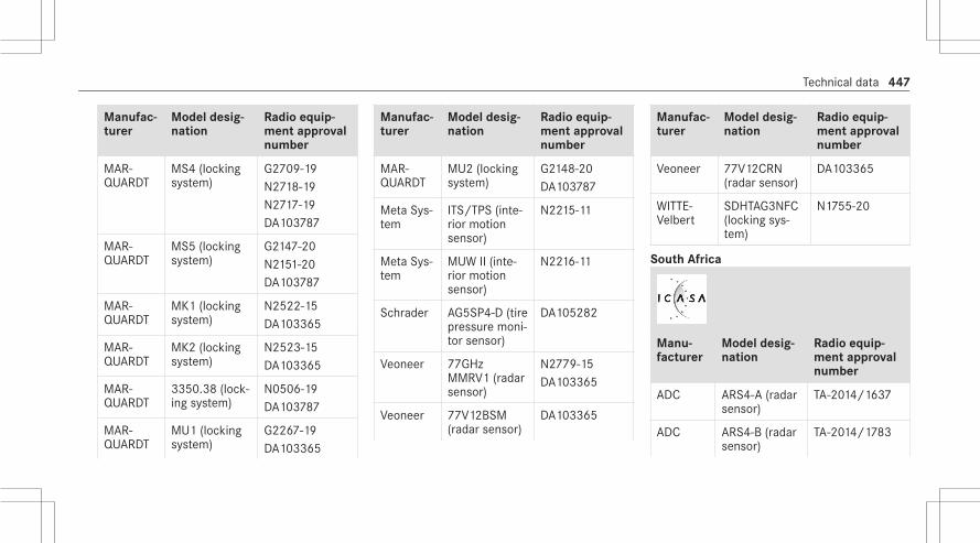
Manufac‐turer
Model desig‐nation
Radio equip‐ment approvalnumber
MAR‐QUARDT
MS4 (lockingsystem)
G2709-19N2718-19N2717-19DA103787
MAR‐QUARDT
MS5 (lockingsystem)
G2147-20N2151-20DA103787
MAR‐QUARDT
MK1 (lockingsystem)
N2522-15DA103365
MAR‐QUARDT
MK2 (lockingsystem)
N2523-15DA103365
MAR‐QUARDT
3350.38 (lock‐ing system)
N0506-19DA103787
MAR‐QUARDT
MU1 (lockingsystem)
G2267-19DA103365
Manufac‐turer
Model desig‐nation
Radio equip‐ment approvalnumber
MAR‐QUARDT
MU2 (lockingsystem)
G2148-20DA103787
Meta Sys‐tem
ITS/TPS (inte‐rior motionsensor)
N2215-11
Meta Sys‐tem
MUW II (inte‐rior motionsensor)
N2216-11
Schrader AG5SP4-D (tirepressure moni‐tor sensor)
DA105282
Veoneer 77GHzMMRV1 (radarsensor)
N2779-15DA103365
Veoneer 77V12BSM(radar sensor)
DA103365
Manufac‐turer
Model desig‐nation
Radio equip‐ment approvalnumber
Veoneer 77V12CRN(radar sensor)
DA103365
WITTE-Velbert
SDHTAG3NFC(locking sys‐tem)
N1755-20
South Africa
Manu‐facturer
Model desig‐nation
Radio equip‐ment approvalnumber
ADC ARS4-A (radarsensor)
TA-2014/1637
ADC ARS4-B (radarsensor)
TA-2014/1783
Technical data 447

Manu‐facturer
Model desig‐nation
Radio equip‐ment approvalnumber
ADC ARS4-C (radarsensor)
TA-2019/1595
Bosch FR5CPCCF(radar sensor)
TA-2019/1200
Bosch MRR1Rear(radar sensor)
TA-2014/212
Bosch MRRe14FCR(radar sensor)
TA-2017/2013
Bosch LRR3 (radarsensor)
1965/007009/07
Continen‐talAntenna
RKE213E1(antennaamplifier)
TA-2015/1438
Manu‐facturer
Model desig‐nation
Radio equip‐ment approvalnumber
Continen‐talAntenna
RKE223E1(antennaamplifier)
TA-2020/043
Continen‐tal Auto‐motive
CMKG1 (lock‐ing system)
TA-2019/5405
Continen‐tal Auto‐motive
MARS Keyless(locking sys‐tem)
TA-2016/3500
Gentex EURO II (con‐venience sys‐tem)
TA-2005/614
Manu‐facturer
Model desig‐nation
Radio equip‐ment approvalnumber
Gentex MUAHL 5(conveniencesystem)
TA-2015/1386
HELLA DM4 (lockingsystem)
TA-2017/2518
Hirsch‐mann
920287A(locking sys‐tem)
TA-2011/374
Hirsch‐mann
920287B(locking sys‐tem)
TA-2013/1262
Huf Bao‐long
TSSRE4A (tirepressure moni‐tor sensor)
TA-2017/1393
448 Technical data
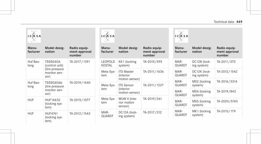
Manu‐facturer
Model desig‐nation
Radio equip‐ment approvalnumber
Huf Bao‐long
TSSSG4G6(control unit)(tire pressuremonitor sen‐sor)
TA-2017/1391
Huf Bao‐long
TSSSG4G6b(tire pressuremonitor sen‐sor)
TA-2019/1440
HUF HUF14632(locking sys‐tem)
TA-2015/1077
HUF HUF4761(locking sys‐tem)
TA-2012/1543
Manu‐facturer
Model desig‐nation
Radio equip‐ment approvalnumber
LEOPOLDKOSTAL
KK1 (lockingsystem)
TA-2015/595
Meta Sys‐tem
ITS Master(interiormotion sensor)
TA-2011/1636
Meta Sys‐tem
ITS Sensor(interiormotion sensor)
TA-2011/1227
Meta Sys‐tem
MUW II (inte‐rior motionsensor)
TA-2019/261
MAR‐QUARDT
DC12A (lock‐ing system)
TA-2017/312
Manu‐facturer
Model desig‐nation
Radio equip‐ment approvalnumber
MAR‐QUARDT
DC12B (lock‐ing system)
TA-2011/370
MAR‐QUARDT
DC12K (lock‐ing system)
TA-2012/1542
MAR‐QUARDT
MS2 (lockingsystem)
TA-2016/3314
MAR‐QUARDT
MS4 (lockingsystem)
TA-2019/843
MAR‐QUARDT
MS5 (lockingsystem)
TA-2020/5765
MAR‐QUARDT
MK1 (lockingsystem)
TA-2015/179
Technical data 449

Manu‐facturer
Model desig‐nation
Radio equip‐ment approvalnumber
MAR‐QUARDT
MK2 (lockingsystem)
TA-2015/180
MAR‐QUARDT
3350.38 (lock‐ing system)
TA-2018/3985
Schrader AG5SP4-D(tire pressuremonitor sen‐sor)
TA-2015/072
Schrader MFR (tire pres‐sure monitorsensor)
TA-2019/273
Schrader GG4T (tirepressure moni‐tor sensor)
TA-2017/3884
Manu‐facturer
Model desig‐nation
Radio equip‐ment approvalnumber
Schrader DG6W2D4(tire pressuremonitor sen‐sor)
TA-2017/2933
Schrader MC34MA4(tire pressuremonitor sen‐sor)
TA-2011/1370
Veoneer 77GHzMMRV1 (radarsensor)
TA-2015/2087
Veoneer 77V12BSM(radar sensor)
TA-2019/1380
Manu‐facturer
Model desig‐nation
Radio equip‐ment approvalnumber
Veoneer 77V12CRN(radar sensor)
TA-2019/1382
WITTE-Velbert
SDHTAG3NFC(locking sys‐tem)
TA-2020/055
450 Technical data

South Korea
Man‐ufac‐turer
Modeldesigna‐tion
Radio equipmentapproval number
HUF HUF14632 (lock‐ing sys‐tem)
MSIP-CRM-HHF-HUF-14632
MAR‐QUARDT
MU1(lockingsystem)
R-R-MQU-MU1
Thailand
Manu‐facturer
Model des‐ignation
Radio equipmentapproval number
ADC ARS4-C(radar sen‐sor)
A57013-19
Bosch FR5CPCCF(radar sen‐sor)
A57008-19
Bosch LRR3 (radarsensor)
A57006-15
Bosch MRR1Rear(radar sen‐sor)
A57005-14
Bosch MRRe14FCR(radar sen‐sor)
A57003-17
Manu‐facturer
Model des‐ignation
Radio equipmentapproval number
Conti‐nentalAntenna
RKE213E1(antennaamplifier)
SDoC
Conti‐nentalAntenna
RKE223E1GNS (antennaamplifier)
SDoC
Conti‐nentalAutomo‐tive
CMKG1(locking sys‐tem)
SDoC
Conti‐nentalAutomo‐tive
MARS Key‐less (lockingsystem)
SDoC
Technical data 451

Manu‐facturer
Model des‐ignation
Radio equipmentapproval number
HELLA DM4 (lockingsystem)
SDoC
Hirsch‐mann
920287A(locking sys‐tem)
SDoC
Hirsch‐mann
920287B(locking sys‐tem)
SDoC
HUF HUF14632(locking sys‐tem)
SDoC
HUF HUF4761(locking sys‐tem)
SDoC
Manu‐facturer
Model des‐ignation
Radio equipmentapproval number
LEO‐POLDKOSTAL
KK1 (lockingsystem)
SDoC
MAR‐QUARDT
DC12A (lock‐ing system)
SDoC
MAR‐QUARDT
DC12B (lock‐ing system)
SDoC
MAR‐QUARDT
DC12K (lock‐ing system)
SDoC
MAR‐QUARDT
MS2 (lockingsystem)
SDoC
MAR‐QUARDT
MS4 (lockingsystem)
SDoC
Manu‐facturer
Model des‐ignation
Radio equipmentapproval number
MAR‐QUARDT
MS5 (lockingsystem)
SDoCA75004-20
MAR‐QUARDT
MK1 (lockingsystem)
SDoC
MAR‐QUARDT
MK2 (lockingsystem)
SDoC
MAR‐QUARDT
3350.38(locking sys‐tem)
SDoC
MAR‐QUARDT
MU1 (lockingsystem)
A75002-20
MAR‐QUARDT
MU2 (lockingsystem)
A75005-20
452 Technical data

Manu‐facturer
Model des‐ignation
Radio equipmentapproval number
MetaSystem
MUW II (inte‐rior motionsensor)
RF test report:149852-2R1TRFEMCEMC test report:149852-1R1TRFEMCSafety report:149852TRFSAF
Veoneer 77GHzMMRV1(radar sen‐sor)
A57008-16
Veoneer 77V12BSM(radar sen‐sor)
A57004-19
Manu‐facturer
Model des‐ignation
Radio equipmentapproval number
Veoneer 77V12CRN(radar sen‐sor)
A57004-19
WITTE-Velbert
SDHTAG3NFC (lockingsystem)
SDoC
Togo
Manu‐facturer
Model des‐ignation
Radio equipmentapproval number
Continen‐talAntenna
RKE213E1(antennaamplifier)
No. 024/19
Continen‐tal Auto‐motive
MARS Key‐less (lockingsystem)
No. 040/19
HELLA DM4 (lock‐ing system)
No. 039/19
Hirsch‐mann
920287A(locking sys‐tem)
No. 089/19
Hirsch‐mann
920287B(locking sys‐tem)
No. 088/19
HUF HUF4761(locking sys‐tem)
No. 041/19
Technical data 453

Manu‐facturer
Model des‐ignation
Radio equipmentapproval number
KATHREIN
RKE213E1(locking sys‐tem)
No. 024/19
LEOPOLDKOSTAL
KK1 (lockingsystem)
No. 060/19
MAR‐QUARDT
DC12A(locking sys‐tem)
No. 055/19
MAR‐QUARDT
DC12B(locking sys‐tem)
No. 057/19
MAR‐QUARDT
DC12K(locking sys‐tem)
No. 056/19
MAR‐QUARDT
MS2 (lock‐ing system)
No. 008/19
MAR‐QUARDT
MS4 (lock‐ing system)
No. 101/19
Manu‐facturer
Model des‐ignation
Radio equipmentapproval number
MAR‐QUARDT
MK1 (lock‐ing system)
No. 021/19
MAR‐QUARDT
MK2 (lock‐ing system)
No. 022/19
MAR‐QUARDT
3350.38(locking sys‐tem)
No. 016/20
MAR‐QUARDT
MU1 (lock‐ing system)
No. 100/19
Ukraine
Manu‐facturer
Model designa‐tion
Radioequipmentapprovalnumber
ADC ARS4-A (radarsensor)
UA RF:1CONT0004
ADC ARS4-B (radarsensor)
UA RF:1CONT0001
ADC ARS4-C (radarsensor)
UA.TR.109.R.0017-19
Bosch FR5CPCCF (radarsensor)
UA RF:1BOSC0009
Bosch LRR3 (radar sen‐sor)
UA.TR.109.R.0031-19
454 Technical data

Manu‐facturer
Model designa‐tion
Radioequipmentapprovalnumber
Bosch MRR1Rear (radarsensor)
UA.TR.109.R.0598-18
Bosch MRRe14FCR(radar sensor)
UA.TR.109.R.0030-19
Continen‐talAntenna
RKE213E1(antenna amplifier)
UKR.355-123/19
Continen‐talAntenna
RKE223E1GNS(antenna amplifier)
UA.R.TR.052.682-19
Continen‐tal Auto‐motive
CMKG1 (lockingsystem)
UA1.001.021175-20-TE
Manu‐facturer
Model designa‐tion
Radioequipmentapprovalnumber
Continen‐tal Auto‐motive
MARS Keyless(locking system)
RTS.UKR.355-34/18
Gentex EURO II (conveni‐ence system)
UA1.001.008806-15
HELLA DM4 (locking sys‐tem)
UA.TR.109.R.0325-18
Hirsch‐mann
920287A (lockingsystem)
UKR.355-7/20
Hirsch‐mann
920287B (lockingsystem)
UKR.355-8/20
Manu‐facturer
Model designa‐tion
Radioequipmentapprovalnumber
Huf Bao‐long
TSSRE4A (tirepressure monitorsensor)
UA1.001.018568-19-TE
Huf Bao‐long
TSSSG4G6 (con‐trol unit) (tire pres‐sure monitor sen‐sor)
UA1.001.018586-19-TE
Huf Bao‐long
TSSSG4G6b (con‐trol unit) (tire pres‐sure monitor sen‐sor)
UA1.001.019289-19-TE
HUF HUF14632 (lock‐ing system)
UKR.355-113/19
Technical data 455

Manu‐facturer
Model designa‐tion
Radioequipmentapprovalnumber
HUF HUF4761 (lockingsystem)
UA1.001.018653-19-TE
LEOPOLDKOSTAL
KK1 (locking sys‐tem)
1O094.006682-19
MAR‐QUARDT
DC12A (lockingsystem)
UA.R.TR.052.307-19
MAR‐QUARDT
DC12B (lockingsystem)
UA.R.TR.052.308-19
MAR‐QUARDT
DC12K (lockingsystem)
UA.R.TR.052.309-19
MAR‐QUARDT
MS2 (locking sys‐tem)
UA1.001.019129-19-TE
Manu‐facturer
Model designa‐tion
Radioequipmentapprovalnumber
MAR‐QUARDT
MS4 (locking sys‐tem)
UA.R.TR.052.528-19
MAR‐QUARDT
MK1 (locking sys‐tem)
UA1.001.019233-19-TE
MAR‐QUARDT
MK2 (locking sys‐tem)
UA1.001.019234-19-TE
MAR‐QUARDT
3350.38 (lockingsystem)
UA1.001.018888-19-TE
Schrader AG5SP4 (tire pres‐sure monitor sen‐sor)
UA.TR. 028
Manu‐facturer
Model designa‐tion
Radioequipmentapprovalnumber
Veoneer 77V12BSM (radarsensor)
UA RF:1VEON2BSM
Veoneer 77V12CRN (radarsensor)
UA RF:1VEON2CRN
456 Technical data

Manu‐facturer
Model designa‐tion
Radioequipmentapprovalnumber
Veoneer 77GHz MMRV1(radar sensor)
TEC/ DoCNo VEON‐EER.UKR.355-3/19NKRZi No-UA RF:2VEONMRV1
WITTE-Velbert
SDHTAG3NFC(locking system)
UA.R.TR.052.120-20
Uzbekistan
Manu‐facturer
Model des‐ignation
Radio equipmentapproval number
HELLA DM4 (lock‐ing system)
UZ.SMT.01.319.2581135
MAR‐QUARDT
MS2 (lock‐ing system)
UZ.SMT.01.319.2550607
MAR‐QUARDT
MS4 (lock‐ing system)
UZ.SMT.01.319.2581337
MAR‐QUARDT
MS5 (lock‐ing system)
UZ.SMT.01.319.2581337
United Arab Emirates
Manu‐fac‐turer
Model designa‐tion
Radio equip‐ment approvalnumber
ADC ARS4-A (radarsensor)
TRAER58296/17,DA40068
ADC ARS4-B (radarsensor)
TRAER61136/18,DA40068/15
ADC ARS4-C (radarsensor)
TRAER77062/19,DA40068
Bosch FR5CPCCF (radarsensor)
TRAER74533/19,DA36758/14
Technical data 457

Manu‐fac‐turer
Model designa‐tion
Radio equip‐ment approvalnumber
Conti‐nentalAntenna
RKE213E1(antenna ampli‐fier)
TRAER64693/18,DA36975/14
Conti‐nentalAntenna
RKE223E1GNS(antenna ampli‐fier)
TRAE76442/19,DA65993/17
Conti‐nentalAuto‐motive
CMKG1 (lockingsystem)
TRAER77964/20,DA0018994/09
Manu‐fac‐turer
Model designa‐tion
Radio equip‐ment approvalnumber
Conti‐nentalAuto‐motive
MARS Keyless(locking system)
TRAER56005/15,DA44932/15
Gentex MUAHL 5 (conve‐nience system)
TRAER41849/15,DA35176/14
HELLA DM4 (locking sys‐tem)
TRAER56616/17,DA44932/15
Hirsch‐mann
920287A (lockingsystem)
TRAER52213/17,DA35219/14
Manu‐fac‐turer
Model designa‐tion
Radio equip‐ment approvalnumber
Hirsch‐mann
920287B (lockingsystem)
TRAER42011/5,DA35219/14
HufBao‐long
TSSRE4A (tirepressure monitorsensor)
TRAER57806/17,DA36976/14
HufBao‐long
TSSSG4G6 (con‐trol unit) (tirepressure monitorsensor)
TRAER57807/17,DA36976/14
HufBao‐long
TSSSG4G6b (con‐trol unit) (tirepressure monitorsensor)
TRAER7307/19,DA0086237/12
458 Technical data

Manu‐fac‐turer
Model designa‐tion
Radio equip‐ment approvalnumber
HUF HUF14632 (lock‐ing system)
TRAER63716/18,DA36976/14
HUF HUF4761 (lockingsystem)
TRAER55496/17,DA36976/14
LEO‐POLDKOSTAL
KK1 (locking sys‐tem)
TRAER62622/18
MAR‐QUARDT
DC12A (lockingsystem)
TRAER53465/17,DA0018994/09
Manu‐fac‐turer
Model designa‐tion
Radio equip‐ment approvalnumber
MAR‐QUARDT
DC12B (lockingsystem)
TRAER0067828/11,DA0018994/09
MAR‐QUARDT
DC12K (lockingsystem)
TRAER0067829/11,DA0018994/09
MAR‐QUARDT
MS2 (locking sys‐tem)
TRAER52668/17,DA0018994/09
Manu‐fac‐turer
Model designa‐tion
Radio equip‐ment approvalnumber
MAR‐QUARDT
MS4 (locking sys‐tem)
TRAER71616/19,DA0018994/09
MAR‐QUARDT
MS5 (locking sys‐tem)
TRAER80720/20,DA0018994/09
MAR‐QUARDT
MK1 (locking sys‐tem)
TRAER64145/18,DA0018994/09
Technical data 459

Manu‐fac‐turer
Model designa‐tion
Radio equip‐ment approvalnumber
MAR‐QUARDT
MK2 (locking sys‐tem)
TRAER64146/18,DA0018994/09
MAR‐QUARDT
3350.38 (lockingsystem)
TRAER69280/19,0018994/09
MAR‐QUARDT
MU1 (locking sys‐tem)
TRAER71833/19,DA0018994/09
MAR‐QUARDT
MU2 (locking sys‐tem)
TRAER81329/20,DA0018994/09
Manu‐fac‐turer
Model designa‐tion
Radio equip‐ment approvalnumber
Schrader
AG5SP4-D (tirepressure monitorsensor)
TRAER37156/15,DA0047074/10
Schrader
GG4T (tire pres‐sure monitor sen‐sor)
TRAER57985/17,DA0047074/10
Schrader
DG6W2D4 (tirepressure monitorsensor)
TRAER960528/18,DA0047074/10
Manu‐fac‐turer
Model designa‐tion
Radio equip‐ment approvalnumber
Schrader
MC34MA4 (tirepressure monitorsensor)
TRAER37066/15,DA0047074/10
Veon‐eer
77GHz MMRV1(radar sensor)
TRAER39759/15,DA0020858
Veon‐eer
77V12BSM (radarsensor)
ER72324/19
460 Technical data

Manu‐fac‐turer
Model designa‐tion
Radio equip‐ment approvalnumber
Veon‐eer
77V12CRN (radarsensor)
ER72323/19
WITTE-Velbert
SDHTAG3NFC(locking system)
TRAER79695/20,DA0018994/09
United States
Man‐ufac‐turer
Modeldesigna‐tion
Radio equipmentapproval number
Bosch
FR5CPCCF(radar sen‐sor)
FCC ID: NF3-FR5CPCCF
Veoneer
77V12BSM(radar sen‐sor)
FCC ID: WU877V12BSM
Vietnam
Manu‐facturer
Model desig‐nation
Radio equip‐ment approvalnumber
Bosch FR5CPCCF(radar sen‐sor)
234/CVT-TT3
Continen‐talAntenna
RKE213E1(antennaamplifier)
C0274151118AF04A2
Continen‐talAntenna
RKE223E1GNS (antennaamplifier)
C0007100120AF04A2
Technical data 461

Manu‐facturer
Model desig‐nation
Radio equip‐ment approvalnumber
Continen‐tal Auto‐motive
CMKG1 (lock‐ing system)
Suntech VietNamTechnology Com‐pany LimitedC0001070120AF04A2
Continen‐tal Auto‐motive
MARS Key‐less (lockingsystem)
Mercedes-BenzVietnam Com‐pany LimitedB0748240419AF04A2
Manu‐facturer
Model desig‐nation
Radio equip‐ment approvalnumber
HELLA DM4 (lockingsystem)
Suntech VietNamTechnology Com‐pany LimitedB0625050419AF04A2
Huf Bao‐long
TSSRE4A (tirepressuremonitor sen‐sor)
C0112200717AF04A2
MAR‐QUARDT
DC12A (lock‐ing system)
Suntech VietNamTechnology Com‐pany LimitedC0048080319AF04A2
Manu‐facturer
Model desig‐nation
Radio equip‐ment approvalnumber
MAR‐QUARDT
DC12B (lock‐ing system)
Suntech VietNamTechnology Com‐pany LimitedC0050080319AF04A2
MAR‐QUARDT
DC12K (lock‐ing system)
Suntech VietNamTechnology Com‐pany LimitedC0049080319AF04A2
462 Technical data

Manu‐facturer
Model desig‐nation
Radio equip‐ment approvalnumber
MAR‐QUARDT
MS2 (lockingsystem)
Suntech VietNamTechnology Com‐pany LimitedC0035150219AF04A2
MAR‐QUARDT
MS4 (lockingsystem)
Suntech VietNamTechnology Com‐pany LimitedC0231240919AF04A2
Manu‐facturer
Model desig‐nation
Radio equip‐ment approvalnumber
MAR‐QUARDT
MS5 (lockingsystem)
Suntech VietNamTechnology Com‐pany LimitedC0141140520AF04A2
MAR‐QUARDT
MK1 (lockingsystem)
Suntech VietNamTechnology Com‐pany LimitedC0021180119AF04A2
Manu‐facturer
Model desig‐nation
Radio equip‐ment approvalnumber
MAR‐QUARDT
MK2 (lockingsystem)
Suntech VietNamTechnology Com‐pany LimitedC0022180119AF04A2
MAR‐QUARDT
3350.38(locking sys‐tem)
Suntech VietNamTechnology Com‐pany LimitedC0076150319AF04A2
Schrader AG5SP4 (tirepressuremonitor sen‐sor)
C0002050119AF042A
Technical data 463

Manu‐facturer
Model desig‐nation
Radio equip‐ment approvalnumber
Schrader GG4T (tirepressuremonitor sen‐sor)
C0170191017AF04A2
Schrader DG6W2D4(tire pressuremonitor sen‐sor)
C0078070518AF04A2
Veoneer 77V12BSM(radar sen‐sor)
A47/CVT-TT3
Veoneer 77V12CRN(radar sen‐sor)
A48/CVT-TT3
Eurasian Economic Union
Manu‐facturer
Model desig‐nation
Radio equip‐ment approvalnumber
ADC ARS4-A (radarsensor)
—
ADC ARS4-B (radarsensor)
—
ADC ARS4-C (radarsensor)
EAЭC N RU Д-DE.PA01.B.87137/19
Bosch FR5CPCCF(radar sensor)
—
Bosch LRR3 (radarsensor)
—
Manu‐facturer
Model desig‐nation
Radio equip‐ment approvalnumber
Bosch MRR1Rear(radar sensor)
—
Bosch MRRe14FCR(radar sensor)
—
Bosch FR5CPCCF(radar sensor)
EAЭC N RU Д-DE.PA01.B.77223/19
Continen‐talAntenna
RKE213E1(antennaamplifier)
—
Continen‐talAntenna
RKE223E1GNS(antennaamplifier)
—
464 Technical data

Manu‐facturer
Model desig‐nation
Radio equip‐ment approvalnumber
Continen‐tal Auto‐motive
MARS Keyless(locking sys‐tem)
—
HELLA DM4 (lockingsystem)
—
Hirsch‐mann
920287A (lock‐ing system)
—
Hirsch‐mann
920287B (lock‐ing system)
—
Huf Bao‐long
TSSRE4A (tirepressure moni‐tor sensor)
—
Manu‐facturer
Model desig‐nation
Radio equip‐ment approvalnumber
Huf Bao‐long
TSSSG4G6(tire pressuremonitor sen‐sor)
—
Huf Bao‐long
TSSSG4G6b(tire pressuremonitor sen‐sor)
—
HUF HUF4761 (lock‐ing system)
—
HUF HUF14632(locking sys‐tem)
—
Manu‐facturer
Model desig‐nation
Radio equip‐ment approvalnumber
LEOPOLDKOSTAL
KK1 (lockingsystem)
—
MAR‐QUARDT
DC12A (lockingsystem)
—
MAR‐QUARDT
DC12B (lockingsystem)
—
MAR‐QUARDT
DC12K (lockingsystem)
—
MAR‐QUARDT
MS2 (lockingsystem)
—
MAR‐QUARDT
MS4 (lockingsystem)
—
Technical data 465

Manu‐facturer
Model desig‐nation
Radio equip‐ment approvalnumber
MAR‐QUARDT
MS5 (lockingsystem)
—
MAR‐QUARDT
MK1 (lockingsystem)
—
MAR‐QUARDT
MK2 (lockingsystem)
—
MAR‐QUARDT
3350.38 (lock‐ing system)
—
MAR‐QUARDT
MU1 (lockingsystem)
—
Schrader AG5SP4-D (tirepressure moni‐tor sensor)
—
Manu‐facturer
Model desig‐nation
Radio equip‐ment approvalnumber
Veoneer 77GHz MMRV1(radar sensor)
—
Veoneer 77V12BSM(radar sensor)
EAЭC N RU Д-US.ЭM03.B.00100/19
Veoneer 77V12CRN(radar sensor)
EAЭC N RU Д-US.ЭM03.B.00102/19
WITTE-Velbert
SDHTAG3NFC(locking sys‐tem)
—
Vehicle identification plate, VIN and enginenumber overview
Vehicle identification plate
466 Technical data

Vehicle identification plate (USA only)1 Maximum permissible gross vehicle weight2 Maximum permissible front axle load3 Maximum permissible rear axle load4 Paint code5 VIN (vehicle identification number)
Vehicle identification plate (Canada only)1 Maximum permissible gross vehicle weight2 Maximum permissible front axle load3 Maximum permissible rear axle load4 Paint code5 VIN (vehicle identification number)
The maximum permissible gross vehicle weightis made up of the vehicle weight, all vehicleoccupants, the fuel and the load. The maximumgross axle weight rating is the maximum weightthat can be carried on one axle (front or rearaxle).
Never exceed the maximum permissible grossvehicle weight or the maximum gross axleweight rating for the front or rear axle.
VIN in the engine compartment
1 VIN (vehicle identification number)
Technical data 467

Additional plates
1 Plate with information about emissions test‐ing, including confirmation of emissionsguidelines at the U.S. federal level as well asfor California
2 VIN (vehicle identification number)3 Engine number (stamped into the crankcase)
Operating fluidsNotes on operating fluids
& WARNING Risk of injury from operatingfluids harmful to your health
Operating fluids may be poisonous and harm‐ful to your health.# Observe the text on the original con‐
tainers when using, storing or disposingof operating fluids.
# Always store operating fluids sealed intheir original containers.
# Always keep children away from operat‐ing fluids.
+ ENVIRONMENTAL NOTE Environmentalpollution caused by environmentally irre‐sponsible disposal
# Dispose of operating fluids in an envi‐ronmentally responsible manner.
Operating fluids include the following:R FuelsR LubricantsR CoolantR Brake fluidR Windshield washer fluidR Climate control system refrigerant
Only use products approved by Mercedes-Benz.Damage caused by the use of products that havenot been approved is not covered by theMercedes-Benz warranty or goodwill gestures.The operating fluids approved by Mercedes-Benzcan be identified by the following inscriptions onthe container:You can identify operating fluids approved byMercedes-Benz by the following inscriptions onthe container:R MB-Freigabe (e.g. MB-Freigabe 229.51)R MB-Approval (e.g. MB-Approval 229.51)
468 Technical data

Further information on approved operating flu‐ids:R In the Mercedes-Benz Specifications for
Operating Fluids by entering the designation- At https://bevo.mercedes-benz.com- In the Mercedes-Benz BeVo appR At a qualified specialist workshop
& WARNING Risk of fire or explosion fromfuel
Fuels are highly flammable.# Fire, open flames, smoking and creation
of sparks must be avoided.# Switch off the ignition and, if available,
the stationary heater, before and whilerefueling the vehicle.
& WARNING Risk of injury from fuels
Fuels are poisonous and hazardous to yourhealth.
# Do not swallow fuel or let it come intocontact with skin, eyes or clothing.
# Do not inhale fuel vapor.# Keep children away from fuel.# Keep doors and windows closed during
the refueling process.
If you or other people come into contact withfuel, observe the following:# Immediately rinse fuel off your skin with
soap and water.# If fuel comes into contact with your
eyes, immediately rinse them thor‐oughly with clean water. Seek medicalattention immediately.
# If you swallow fuel, seek medical atten‐tion immediately. Do not induce vomit‐ing.
# Change immediately out of clothing thathas come into contact with fuel.
Fuel
Notes on fuel grades for vehicles with a gas‐oline engineObserve the notes on operating fluids(/ page 468).
* NOTE Damage caused by the wrong fuel
Even small amounts of the wrong fuel couldresult in damage to the fuel system, theengine and the emission control system.# Only refuel with low-sulfur gasoline.
This fuel may contain up to 10% ethanol byvolume. Your vehicle is suitable for use withE10 fuel.Never refuel with one of the following fuels:R DieselR Gasoline with more than 10% ethanol by
volume, e.g. E15, E85, E100R Gasoline with more than 3% methanol by
volume, e.g. M15, M30, M85, M100R Gasoline with additives containing metal
Technical data 469

If you have accidentally refueled with thewrong fuel:# do not switch the ignition on.# Consult a qualified specialist workshop.
If the available fuel is not sufficiently low in sul‐fur, this can produce unpleasant odors.Only refuel with fuel that has at least the octanenumber specified in the information label in thefuel filler flap (/ page 205).If you want maximum engine output: onlyrefuel with premium-grade unleaded gasolinewith an octane number of at least 91 AKI/95 RON.As a temporary measure, if the recommendedfuel is not available, you may also use regularunleaded gasoline with an octane number of atleast 87 AKI/91 RON.
* NOTE Premature wear through unleadedregular gasoline
Unleaded regular gasoline can cause theengine to wear more quickly and impair lon‐gevity and performance.If unleaded premium grade gasoline isunavailable and you have to refuel usingunleaded regular gasoline with 87 AKI/91 RON:# Only fill the fuel tank to half full with
unleaded regular gasoline and top up assoon as possible with unleaded pre‐mium grade gasoline.
# Do not drive at the maximum speed.# Avoid sudden acceleration and engine
speeds over 3000 rpm.
This may reduce engine output and increase fuelconsumption. Never refuel using gasoline with alower octane number.Further information on fuel is available at the fol‐lowing locations:R At a gas station
R At a qualified specialist workshopR On the https://www.mbusa.com (USA only)
Notes on additives in gasolineObserve the notes on operating fluids(/ page 468).
* NOTE Damage from use of unsuitableadditives
Even small amounts of the wrong additivemay lead to malfunctions occurring.# Only add cleaning additives recommen‐
ded by Mercedes-Benz to the fuel.
Mercedes-Benz recommends that you usebrand-name fuels with additives.In some countries, the fuel available may nothave sufficient additives. Residue could build upin the fuel injection system as a result. In thiscase, in consultation with an authorizedMercedes-Benz Center, mix the fuel with thecleaning additive recommended by Mercedes-Benz. Observe the notes and mixing ratios indi‐cated on the tank.
470 Technical data

Information on fuel grades for vehicles witha diesel engine
General notesObserve the notes on operating fluids(/ page 468).
& WARNING Risk of fire from fuel mixture
If you mix diesel fuel with gasoline, the flashpoint of the fuel mixture is lower than that ofpure diesel fuel.# Never refuel using gasoline in diesel
engines.# Never mix gasoline with diesel fuel.
* NOTE Damage caused by the wrong fuel
Even small amounts of the wrong fuel couldresult in damage to the fuel system, theengine and the emission control system.Vehicles with a diesel particulate filter
# Only refuel using sulfur-free diesel fuelthat conforms to European standardEN 590, or an equivalent specification.In countries without sulfur-free dieselfuel, refuel using only low-sulfur dieselfuel with a sulfur content less than50 ppm.
Vehicle without diesel particulate filter:# Refuel using only diesel fuel with a sul‐
fur content less than 500 ppm.# Only refuel using sulfur-free diesel fuel.
Never refuel with one of the following fuels:R GasolineR Marine dieselR Heating oilR Pure fatty acid methyl ester or vegetable
oilR Paraffin or kerosene
If you have accidentally refueled with thewrong fuel:
# Do not switch the ignition on.# Consult a qualified specialist workshop.
The recommended fuel grade for your vehiclecan be found on the information label in the fuelfiller flap (/ page 205).
Information on low outside temperaturesRefuel your vehicle with as much winter dieselfuel as possible at the beginning of winter.Before changing over to winter diesel fuel, thefuel tank should be empty, if possible. Keep thefuel level low for the first refueling with winterdiesel fuel, e.g. to reserve level. The fuel tankcan be filled as usual when next refueling.Further information on fuel is available at the fol‐lowing locations:R At a gas stationR At a qualified specialist workshopR On the https://www.mbusa.com (USA only)
Technical data 471

Tank content and reserve fuel
Model Total capacity
S 580 4MATIC 80.3 US qt(76.0 liters)
Of which reserve
S 580 4MATIC 8.5 US qt (8.0 l)
Engine oil
Notes on engine oilObserve the notes on operating fluids(/ page 468).
* NOTE Engine damage caused by anincorrect oil filter, incorrect oil or addi‐tives
# Do not use engine oils or oil filters otherthan those which meet the specifica‐tions necessary for the prescribedservice intervals.
# Do not alter the engine oil or oil filter inorder to achieve longer change intervalsthan prescribed.
# Do not use additives.# Have the engine oil changed after the
prescribed intervals.
Mercedes-Benz recommends that you have theoil change carried out at a qualified specialistworkshop.
Quality and capacity of engine oil
MB-Freigabe or MB-Approval
Model Engine oil specifica‐tions
S 580 4MATIC 229.52229.61*
* Recommended for lowest possible fuel con‐sumption (lowest SAE viscosity class in eachcase; observe possible restrictions of theapproved SAE viscosity classes).To achieve the lowest possible fuel consumption,it is recommended to use the engine oil specifi‐cations marked in the table for the lowest SAEviscosity class. Possible restrictions of theapproved SAE viscosity classes must beobserved.The following values refer to an oil change,including the oil filter.Missing values were not available at time ofgoing to print.
472 Technical data

Model Capacity
S580 4MATIC 9.0 US qt (8.5 liters)
Notes on brake fluid
Observe the notes on operating fluids(/ page 468).
& WARNING Risk of an accident due tovapor pockets forming in the brake sys‐tem
The brake fluid constantly absorbs moisturefrom the air. This lowers the boiling point ofthe brake fluid. If the boiling point is too low,vapor pockets may form in the brake systemwhen the brakes are applied hard.This causes the braking effect to beimpaired.# Have the brake fluid renewed at the
specified intervals.
Have the brake fluid regularly replaced at aqualified specialist workshop.
Only use a brake fluid approved by Mercedes-Benz according to MB-Freigabe or MB-Approval331.0.
Coolant
Notes on coolantObserve the notes on operating fluids(/ page 468).
& WARNING ‑ Risk of fire and injury fromantifreeze
If antifreeze comes into contact with hotcomponent parts in the engine compart‐ment, it may ignite.# Allow the engine to cool down before
adding antifreeze.# Make sure that no antifreeze spills out
next to the filler opening.# Thoroughly clean off any antifreeze
from component parts before startingthe vehicle.
* NOTE Damage caused by incorrect cool‐ant
# Only use coolant that has been pre‐mixed with the required antifreeze pro‐tection.
Information on coolant is available at the fol‐lowing locations:R In the Mercedes-Benz Specifications for
Operating Fluids 310.1- At https://bevo.mercedes-benz.com- In the Mercedes-Benz BeVo appR At a qualified specialist workshop
* NOTE Overheating at high outside tem‐peratures
If an inappropriate coolant is used, theengine cooling system is not sufficiently pro‐tected against overheating and corrosion athigh outside temperatures.# Always use coolant approved by
Mercedes-Benz.
Technical data 473

# Observe the instructions in theMercedes-Benz Specifications for Oper‐ating Fluids 310.1.
Have the coolant regularly replaced at a qualifiedspecialist workshop.Proportion of antifreeze concentrate in theengine cooling system:R A minimum of 50% (antifreeze protection
down to approximately -35°F (-37°C))R A maximum of 55% (antifreeze protection
down to -49°F (-45°C))
Coolant capacityMissing values were not available at time ofgoing to print.
Model Capacity
S 580 4MATIC 16.1 US qt(15.2 liters)
Notes on windshield washer fluid
Observe the notes on operating fluids(/ page 468).
& WARNING ‑ Risk of fire and injury fromwindshield washer concentrate
Windshield washer concentrate is highlyflammable. It could ignite if it comes intocontact with hot engine component parts orthe exhaust system.# Make sure that no windshield washer
concentrate spills out next to the filleropening.
* NOTE Damage to the exterior lightingdue to unsuitable windshield washer fluid
Unsuitable windshield washer fluid may dam‐age the plastic surface of the exterior light‐ing.# Only use windshield washer fluid which
is also suitable for use on plastic surfa‐ces, e.g. MB SummerFit or MB Winter‐Fit.
* NOTE Blocked spray nozzles caused bymixing windshield washer fluids
# Do not mix MB SummerFit and MB Win‐terFit with other windshield washer flu‐ids.
Do not use distilled or de-ionized water. Other‐wise, the fill level sensor may be triggered erro‐neously.Recommended windshield washer fluid:R Above freezing point: e.g. MB SummerFitR Below freezing point: e.g. MB WinterFit
For the correct mixing ratio, refer to the informa‐tion on the antifreeze container.Mix washer fluid with windshield washer fluid allyear round.
Refrigerant
Notes on refrigerantObserve the notes on operating fluids(/ page 468).
474 Technical data

* NOTE Damage due to incorrect refriger‐ant
If a non-approved refrigerant is used, the cli‐mate control system may be damaged.# USA: use only R‑134a refrigerant.# Canada: use only R‑1234yf refrigerant.
* NOTE Damage to the climate controlsystem due to incorrect refrigerant com‐pressor oil
# Only use refrigerant compressor oil thathas been approved by Mercedes-Benz.
# Do not mix the approved refrigerantcompressor oil with a different refriger‐ant compressor oil.
Work on the climate control system may be car‐ried out only by a qualified specialist workshop.All applicable regulations, as well as SAE stand‐ard J639, must be adhered to.The information label for the climate control sys‐tem regarding the refrigerant type and the refrig‐
erant compressor oil (PAG oil) is located on theinside of the hood.
Information label (example – USA/China)1 Hazard and service warning symbols2 Refrigerant filling capacity3 Applicable standards4 PAG oil part number5 GWP (global warming potential) of the refrig‐
erant used6 Refrigerant type
Information label (example – Canada)1 Hazard and service warning symbols2 Refrigerant filling capacity3 Applicable standards4 PAG oil part number5 GWP (global warming potential) of the refrig‐
erant used6 Refrigerant type
Symbols1 indicate the following:R Possible dangersR Having maintenance work carried out at a
qualified specialist workshop
Technical data 475

Filling capacity for refrigerant and PAG oilMissing values were not available at time ofgoing to print.
Model Refrigerant
Canada: S 5804MATIC
23.6 ± 0.4 oz(670 ± 10 g)
USA: S 580 4MATIC 24.7 ± 0.4 oz(700 ± 10 g)
Model PAG oil
USA, Canada: S 5804MATIC
4.9 ± 0.4 oz(140 ± 10 g)
Vehicle dataVehicle dimensions
The heights specified may vary as a result of thefollowing factors:R TiresR LoadR Condition of the suspension
R Optional equipment
Height when opened
Model 11 Heightwhenopened
S 580 4MATIC 73.0 in(1855 mm)
Vehicle dimensions
S 580 4MATIC
Vehicle length 208.2 in(5289 mm)
Vehicle width including out‐side mirrors
83.0 in(2109 mm)
Vehicle height 59.2 in(1503 mm)
Wheelbase 126.6 in(3216 mm)
Turning radius 40.98 ft(12.49 m)
Weights and loads
Please note the following for the specified vehi‐cle data:R Items of optional equipment increase the
curb weight and reduce the payload.
Missing values were not available at time ofgoing to print.
476 Technical data
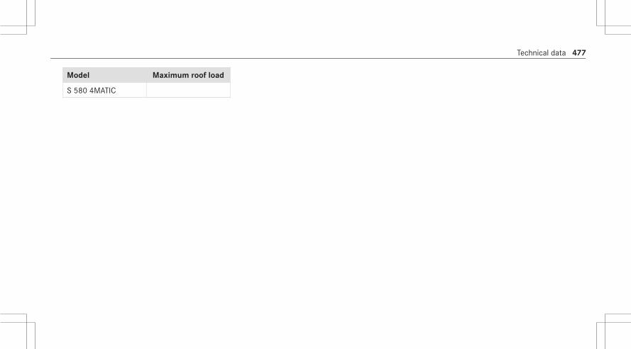
Model Maximum roof load
S 580 4MATIC
Technical data 477

Display messagesIntroduction
Notes about display messagesDisplay messages appear on the driver display.Display messages with graphics are simplified inthe Operator's Manual and may differ from theappearance on the driver display. The driver dis‐play shows high-priority display messages in red.Certain display messages are accompanied by awarning tone.Please act in accordance with the display mes‐sages and follow the additional notes in theOperator's Manual.For some display messages, a symbol will alsobe shown:R Õ Further informationR¨ Hide display message
With the left-hand Touch Control, you can selectthe respective symbol by swiping to the left orright. Press theÕ symbol to show further infor‐mation on the central display. Press the¨symbol to hide the display message.
You can hide low-priority display messages bypressing theG back button or the left-handTouch Control. The display messages will thenbe stored in the message memory.Rectify the cause of a display message asquickly as possible.High-priority display messages cannot be hid‐den. The driver display shows these display mes‐sages continuously until the cause of the displaymessage has been rectified.
Calling up saved display messagesDriver display:4 Service 5 Message Memory: XXIf there are no display messages, No Messageswill appear on the driver display.# Scroll through the display messages by swip‐
ing upwards or downwards on the left-handTouch Control.
# To exit the message memory: press theback buttonG.
478 Display messages and warning/indicator lamps

Occupant safety
Display messages Possible causes/consequences andMM Solutions
6Restraint System Malfunc-tion Service Required
* The restraint system is malfunctioning (/ page 42).
& WARNING Risk of injury due to malfunctions in the restraint system
Components in the restraint system may be activated unintentionally or not deploy as planned in an accident.# Have the restraint system checked and repaired immediately at a qualified specialist workshop.
6Front Left MalfunctionService Required (example)
* The corresponding restraint system is malfunctioning (/ page 42).
& WARNING Risk of injury due to malfunctions in the restraint system
Components in the restraint system may be activated unintentionally or not deploy as planned in an accident.# Have the restraint system checked and repaired immediately at a qualified specialist workshop.
6Left Window Airbag Mal-function ServiceRequired (example)
* The corresponding restraint system is malfunctioning (/ page 42).
& WARNING Risk of injury or fatal injury due to a malfunction in the window curtain airbag
The window curtain airbag might be triggered unintentionally or might not be triggered at all in the event of anaccident.# Have the window curtain airbag checked and repaired immediately at a qualified specialist workshop.
Display messages and warning/indicator lamps 479

Display messages Possible causes/consequences andMM Solutions
Front Passenger Airbag Dis-abled See Operator's Man-ual
* The front passenger airbag has been disabled even though an adult or a person of adult stature is on the frontpassenger seat. If additional forces are applied to the seat, the weight the system detects may be too low.
& WARNING Risk of injury or fatal injury due to a disabled front passenger airbag
If the front passenger airbag is disabled, the front passenger airbag will not be deployed in the event of an acci‐dent and cannot perform its intended protective function.A person in the front passenger seat could then, for example, come into contact with the vehicle's interior,especially if the person is sitting too close to the cockpit.# Make sure, both before and during the journey, that the status of the front passenger airbag is correct.
# Stop the vehicle immediately in accordance with the traffic conditions.# Make sure that no objects are trapped under the front passenger seat.# Check the status of the automatic front passenger airbag actuation (/ page 53).# If necessary, consult a qualified specialist workshop immediately.
Front Passenger AirbagEnabled See Operator'sManual
* The front passenger airbag will be enabled while the vehicle is in motion in the following situations:R Even when a child, a person of smaller stature or an object weighing less than the system weight threshold is
located on the front passenger seatR Even when the front passenger seat is not occupied
The system may detect objects or forces that are adding to the weight applied to the seat.
480 Display messages and warning/indicator lamps

Display messages Possible causes/consequences andMM Solutions
& WARNING Risk of injury or death when using a child restraint system while the front passenger airbag isenabled
If you secure a child in a child restraint system on the front passenger seat and the front passenger airbag isenabled, the front passenger airbag can deploy in the event of an accident.The child could be struck by the airbag.# Ensure, both before and during the journey, that the status of the front passenger airbag is correct.
NEVER use a rearward facing child restraint on a seat protected by an ACTIVE AIRBAG in front of it, DEATH orSERIOUS INJURY to the CHILD can occur.
# Stop the vehicle immediately in accordance with the traffic conditions.# Make sure that no objects are trapped under the front passenger seat.# Check the status of automatic front passenger airbag actuation (/ page 53).# If necessary, consult a qualified specialist workshop immediately.
PRE-SAFE Inoperative SeeOperator's Manual
* The PRE‑SAFE® functions are malfunctioning.# Consult a qualified specialist workshop.
PRE-SAFE Impulse SideInoperative See Operator'sManual
* The PRE‑SAFE® Impulse Side system is malfunctioning or inoperative after having already been triggered.# Consult a qualified specialist workshop.
Display messages and warning/indicator lamps 481

SmartKey
Display messages Possible causes/consequences andMM Solutions
ÁObtain a New Key
* Have SmartKey replaced.# Consult a qualified specialist workshop.
ÁReplace Key Battery
* The SmartKey battery is discharged.# Replace the battery (/ page 77).
ÁKey Not Detected (whitedisplay message)
* The SmartKey is currently undetected.# Change the location of the SmartKey in the vehicle.# If the SmartKey is still not recognized, place it in the marked space for starting with the SmartKey
(/ page 188).
482 Display messages and warning/indicator lamps

Display messages Possible causes/consequences andMM Solutions
ÁKey Not Detected (red dis‐play message)
* The SmartKey cannot be detected and may no longer be in the vehicle.The SmartKey is no longer in the vehicle and you switch off the engine:R You can no longer start the engine.R You cannot centrally lock the vehicle.
# Ensure that the SmartKey is in the vehicle.
If the SmartKey detection function has a malfunction due to a strong radio signal source:# Stop the vehicle immediately in accordance with the traffic conditions.# Place the SmartKey in the marked space for starting the engine with the SmartKey (/ page 188).
ÁDon't Forget Your Key
* A warning tone also sounds. This message reminds you to take your SmartKey with you when you leave the vehicle.
Place the Key in theMarked Space See Opera-tor's Manual
* SmartKey detection is malfunctioning.# Change the location of the SmartKey in the vehicle.# Place the SmartKey in the marked space for starting the engine with the SmartKey (/ page 188).
Display messages and warning/indicator lamps 483

Lights
Display messages Possible causes/consequences andMM Solutions
:Check Left LowBeam (example)
* The corresponding light source is defective.# Drive on carefully.# Visit a qualified specialist workshop immediately.% LED light sources: the display message for the corresponding light appears only when all the light-emitting
diodes in the light are faulty.
:Malfunction See Opera-tor’s Manual
* The exterior lighting is malfunctioning.# Consult a qualified specialist workshop.
:Automatic Headlamp ModeInoperative
* The light sensor for automatic driving lights is malfunctioning.# Consult a qualified specialist workshop.
484 Display messages and warning/indicator lamps
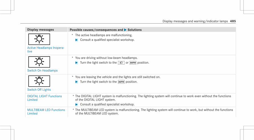
Display messages Possible causes/consequences andMM Solutions
:Active Headlamps Inopera-tive
* The active headlamps are malfunctioning.# Consult a qualified specialist workshop.
:Switch On Headlamps
* You are driving without low-beam headlamps.# Turn the light switch to the L orà position.
:Switch Off Lights
* You are leaving the vehicle and the lights are still switched on.# Turn the light switch to theà position.
DIGITAL LIGHT FunctionsLimited
* The DIGITAL LIGHT system is malfunctioning. The lighting system will continue to work even without the functionsof the DIGITAL LIGHT system.# Consult a qualified specialist workshop.
MULTIBEAM LED FunctionsLimited
* The MULTIBEAM LED system is malfunctioning. The lighting system will continue to work, but without the functionsof the MULTIBEAM LED system.
Display messages and warning/indicator lamps 485

Display messages Possible causes/consequences andMM Solutions# Consult a qualified specialist workshop.
Adaptive Highbeam AssistCurrently Unavailable SeeOperator's Manual
* Adaptive Highbeam Assist is temporarily unavailable.Once the cause of the problem is no longer present, the system will be available again. The Adaptive HighbeamAssist Now Available display message will appear.# Drive on.# Operate the high beam manually until Adaptive High Beam Assist is available again.
Adaptive Highbeam AssistInoperative
* Adaptive Highbeam Assist is malfunctioning.# Consult a qualified specialist workshop.
Adaptive Highbeam AssistPlus Currently UnavailableSee Operator's Manual
* Adaptive Highbeam Assist Plus is temporarily unavailable.Once the cause of the problem is no longer present, the system will be available again. The Adaptive HighbeamAssist Plus Available Again display message will appear.# Drive on.# Operate the high beam manually until Adaptive High Beam Assist Plus is available again.
Adaptive Highbeam AssistPlus Inoperative
* Adaptive Highbeam Assist Plus is malfunctioning.# Stop the vehicle in accordance with the traffic conditions and restart the engine.# If the display message still appears, consult a qualified specialist workshop.
Hazard Warning Light Mal-function
* The hazard warning lamp switch is malfunctioning.# Consult a qualified specialist workshop.
486 Display messages and warning/indicator lamps

Vehicle
Display messages Possible causes/consequences andMM Solutions
* The driver display is inoperative due to a failed software update.The display message is shown every time the engine is started.
& WARNING Risk of accident due to a driver display malfunction
If the driver display has failed or malfunctioned, the function restrictions applying to safety relevant systems arenot visible.The operating safety of your vehicle may be impaired.# Drive on carefully.# Have the vehicle checked immediately at a qualified specialist workshop.
If the operating safety of your vehicle is impaired, park the vehicle immediately and safely. Contact a qualified spe‐cialist workshop.If the driver display fails, you may not recognize function restrictions affecting systems relevant to safety or thespeed display, for example. The operating safety of the vehicle may be impaired (/ page 294).# Have the vehicle checked by a qualified specialist workshop immediately.
Display messages and warning/indicator lamps 487

Display messages Possible causes/consequences andMM Solutions
dVehicle Ready to DriveSwitch the Ignition OffBefore Exiting
* You are leaving the vehicle when it is in a ready-to-drive state.# When you leave the vehicle, switch off the ignition, secure the vehicle against rolling away and take the Smart‐
Key with you.# If you do not leave the vehicle, switch off the electrical consumers, e.g. the seat heating. Otherwise, the 12 V
battery may discharge and it will then be possible to start the vehicle only with the aid of a second battery(starting assistance).
ÙSteering Malfunction DriveCarefully Service Required
* A power steering malfunction has occurred. Steering characteristics may be impaired as a result.# Drive on carefully.# Consult a qualified specialist workshop.
ÙSteering MalfunctionIncreased Physical EffortSee Operator's Manual
* The power steering assistance is malfunctioning.
& WARNING Risk of an accident due to altered steering characteristics
If the power assistance of the steering fails partially or completely, you will need to use more force to steer.# If safe steering is possible, drive on carefully.# Visit or consult a qualified specialist workshop immediately.
488 Display messages and warning/indicator lamps

Display messages Possible causes/consequences andMM Solutions
ÙSteering Malfunction StopImmediately See Opera-tor's Manual
* The steering is malfunctioning. Steering capability is significantly impaired.
& WARNING Risk of accident if steering capability is impaired
If the steering does not function as intended, the vehicle's operating safety is jeopardized.# Pull over and stop the vehicle safely as soon as possible, paying attention to road and traffic conditions.
Do not continue driving under any circumstances.# Consult a qualified specialist workshop.
ÙRear Axle Steering Cur-rently Malfunctioning
* The rear axle steering is temporarily unavailable. The turning radius may increase.# Stop the vehicle in accordance with the traffic conditions and restart the engine.
If the display message does not disappear:# Drive on carefully.# Consult a qualified specialist workshop.
ÙRear Axle Steering Malfunc-tion Service Required
* The rear axle steering is malfunctioning.The rear axle has no steering capability.The steering wheel may be tilted when you drive in a straight line.# Adapt your speed and drive on carefully.# Consult a qualified specialist workshop immediately.
Display messages and warning/indicator lamps 489

Display messages Possible causes/consequences andMM Solutions
ÙRear Axle Steering Malfunc-tion Stop Immediately
* The rear axle steering is malfunctioning.The rear axle has no steering capability.The steering wheel may tilt considerably when you drive in a straight line.Depending on the steering wheel's tilting position, the steering wheel will also vibrate and a continuous warningtone will sound.
& WARNING Risk of accident if steering capability is impaired
If the steering does not function as intended, the vehicle's operating safety is jeopardized.# Pull over and stop the vehicle safely as soon as possible, paying attention to road and traffic conditions.
Do not continue driving under any circumstances.# Consult a qualified specialist workshop.
# When stopping, bear the enlarged vehicle width in mind.
Snow Chain Mode Maxi-mum Speed Exceeded
* The maximum permissible speed for snow chain mode has been exceeded.# Drive more slowly.
C* At least one door is open.# Close all doors.
490 Display messages and warning/indicator lamps

Display messages Possible causes/consequences andMM Solutions
M* The hood is open.
& WARNING Risk of accident due to driving with the hood unlocked
The hood may open and block your view.# Never release the hood when driving.# Before every trip, ensure that the hood is locked.
# Stop the vehicle immediately, paying attention to road and traffic conditions.# Close the hood.
N* The trunk lid is open.
& DANGER Risk of exhaust gas poisoning
Combustion engines emit poisonous exhaust gases such as carbon monoxide. Exhaust gases can enter thevehicle interior if the trunk lid is open when the engine is running, especially if the vehicle is in motion.# Always switch off the engine before opening the trunk lid.# Never drive with the trunk lid open.
# Close the trunk lid.
Ambient Lighting WarningSupport Inoperative
* The ambient lighting may not provide full visual warning support.# Lock the vehicle and unlock it again after a few minutes.
Display messages and warning/indicator lamps 491

Display messages Possible causes/consequences andMM Solutions# If the display message appears regularly, contact a qualified specialist workshop.
¥Check Washer Fluid
* The washer fluid level in the washer fluid reservoir has dropped below the minimum.# Add washer fluid (/ page 329).
¥Intensive Cleaning Activa-ted for 30 Seconds
* Intensive cleaning of the windshield has been activated (/ page 167).
Engine
Display messages Possible causes/consequences andMM Solutions
To switch engine off, pressand hold Start/Stop but-ton for at least 3 secondsor press 3 times.
* You have pressed the start/stop button while the vehicle is in motion.# Information about switching off the engine while driving (/ page 188).
492 Display messages and warning/indicator lamps

Display messages Possible causes/consequences andMM Solutions
+Check Coolant Level SeeOperator's Manual
* The coolant level is too low.
* NOTE Engine damage due to insufficient coolant
# Avoid long journeys with insufficient coolant.
# Add coolant (/ page 329).# Have the engine cooling system checked at a qualified specialist workshop.
ÿCoolant Too Hot Stop Vehi-cle Turn Engine Off
* The coolant is too hot.# Stop the vehicle immediately in accordance with the traffic conditions and switch off the engine.
& WARNING Risk of burns when opening the hood
If you open the hood when the engine has overheated or when there is a fire in the engine compartment, thefollowing situations may occur:R You could come into contact with hot gases.R You could come into contact with other hot, escaping operating fluids.
# Before opening the hood, allow the overheated engine to cool down.# In the event of a fire in the engine compartment, keep the hood closed and call the fire service.
# Wait until the engine has cooled down.
Display messages and warning/indicator lamps 493
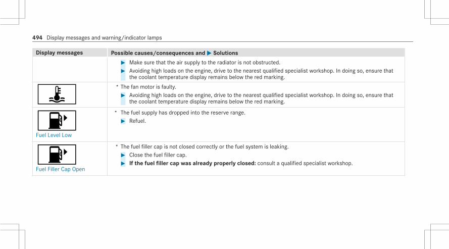
Display messages Possible causes/consequences andMM Solutions# Make sure that the air supply to the radiator is not obstructed.# Avoiding high loads on the engine, drive to the nearest qualified specialist workshop. In doing so, ensure that
the coolant temperature display remains below the red marking.
ÿ* The fan motor is faulty.# Avoiding high loads on the engine, drive to the nearest qualified specialist workshop. In doing so, ensure that
the coolant temperature display remains below the red marking.
8Fuel Level Low
* The fuel supply has dropped into the reserve range.# Refuel.
8Fuel Filler Cap Open
* The fuel filler cap is not closed correctly or the fuel system is leaking.# Close the fuel filler cap.# If the fuel filler cap was already properly closed: consult a qualified specialist workshop.
494 Display messages and warning/indicator lamps

Transmission
Display messages Possible causes/consequences andMM Solutions
Shift to P Only When Vehi-cle Is Stationary
* It is possible to select the park positionj only if the vehicle is stationary.# To stop, depress the brake pedal.# Shift the transmission to park positionj when the vehicle is stationary.
Depress Brake to Shiftfrom P
* You have attempted to shift the transmission out of park positionj and into another transmission position.# Depress the brake pedal.# Select transmission positionh,k or neutrali.
To Deselect P or NDepress Brake and StartEngine
* You have attempted to shift the transmission out of park positionj or neutrali and into another transmissionposition.# Depress the brake pedal.# Start the engine.# Change the transmission position.
Depress Brake to Shift to Dor R
* You have attempted to select transmission positionh ork.# Depress the brake pedal.# Select transmission positionh ork.
Depress Brake to Shift to R * You have attempted to select transmission positionk.# Depress the brake pedal.# Select transmission positionk.
Display messages and warning/indicator lamps 495

Display messages Possible causes/consequences andMM Solutions
Apply Brake To ParkService Required
* A malfunction has occurred in the emergency power supply to park positionj.# Consult a qualified specialist workshop.# Until then, always select park positionj manually before you switch off the engine.# Before leaving the vehicle, apply the electric parking brake.
Risk of Vehicle RollingAway Driver's Door OpenPosition P Not Selected
* The driver's door is not fully closed and transmission positionh,k or neutrali is selected.The vehicle may roll away.# Select park positionj when switching off the vehicle.
Risk of Vehicle RollingAway Apply Brake to Park
* The transmission is malfunctioning. Park positionj cannot be selected.# Park the vehicle safely.# Use the electric parking brake to secure the vehicle against rolling away.# On gradients, turn the front wheels so that the vehicle will roll towards the curb if it starts moving.
Risk of Vehicle RollingAway N Activated ManuallyNo Automatic Change to P
* While the vehicle was at a standstill or driving at very low speed, neutrali was engaged with the engine runningor the ignition switched on.
* NOTE Damage to the vehicle due to it rolling away
When the ignition is being switched off or the driver's door opened, automatic engagement of park positionjis deactivated.The vehicle may roll away.
496 Display messages and warning/indicator lamps

Display messages Possible causes/consequences andMM Solutions
# Be ready to brake.# Do not leave the vehicle unattended.
# Depress the brake pedal until the vehicle is stationary.# Engage park positionj when the vehicle is stationary with the brake pedal depressed.# To continue driving with the brake pedal depressed, select transmission positionh ork.
N Automatically ActivatedPlease Shift to Transmis-sion Position Again
* Neutrali was automatically engaged when the vehicle was rolling or being driven.% When you open the driver's door in neutrali, park positionj will be engaged automatically.# Depress the brake pedal until the vehicle comes to a standstill.# Engage park positionj when the vehicle is stationary with the brake pedal depressed.# To continue driving with the brake pedal depressed, select transmission positionh ork.
Reversing Not PossibleService Required
* The transmission is malfunctioning. The transmission positionk cannot be selected.# Consult a qualified specialist workshop.
Transmission MalfunctionStop
* The transmission is malfunctioning. The transmission shifts to neutrali automatically.# Stop the vehicle immediately in accordance with the traffic conditions.# Depress the brake pedal.# Engage park positionj.# Consult a qualified specialist workshop.
Display messages and warning/indicator lamps 497

Display messages Possible causes/consequences andMM Solutions
Service Required Do NotChange Transmission Posi-tion
* The transmission is malfunctioning. It is no longer possible to change the transmission position.# If transmission positionh is selected, consult a qualified specialist workshop and do not change the transmis‐
sion position.# For all other transmission positions, park the vehicle safely.# Consult a qualified specialist workshop or breakdown service.
Stop Vehicle Leave EngineRunning Wait TransmissionCooling
* The transmission is overheating. Pulling away may be temporarily impaired or not possible.# Stop the vehicle immediately in accordance with the traffic conditions. Do not continue driving under any cir‐
cumstances.# Leave the engine running.# Wait until the display message disappears before pulling away.
Auxiliary Battery Malfunc-tion
* There is a malfunction in the auxiliary battery.# Consult a qualified specialist workshop.# Until then, always select park positionj manually before you switch off the engine.# Before leaving the vehicle, apply the electric parking brake.
498 Display messages and warning/indicator lamps

Brakes
Display messages Possible causes/consequences andMM Solutions
F(USA only)
!(Canada only)Parking Brake See Opera-tor's Manual
* The yellow! indicator lamp is lit. The electric parking brake is malfunctioning.To apply:# Switch the ignition off and switch it back on.# Apply the electric parking brake manually (/ page 212).
If it is not possible to apply the electric parking brake:# Consult a qualified specialist workshop.# Where necessary, also secure the parked vehicle against rolling away.
* The yellow! indicator lamp and the redF (USA only) or! (Canada only) indicator lamp are lit. The elec‐tric parking brake is malfunctioning.To release:# Switch the ignition off and switch it back on.# Release the electric parking brake manually (/ page 212).or# Release the electric parking brake automatically (/ page 212).If it is still not possible to release the electric parking brake:# Do not continue driving. Consult a qualified specialist workshop.
Display messages and warning/indicator lamps 499
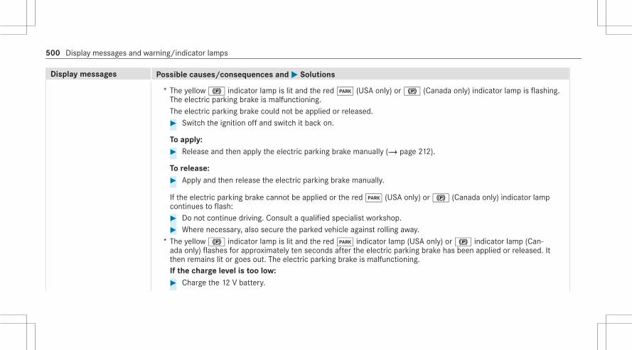
Display messages Possible causes/consequences andMM Solutions
* The yellow! indicator lamp is lit and the redF (USA only) or! (Canada only) indicator lamp is flashing.The electric parking brake is malfunctioning.The electric parking brake could not be applied or released.# Switch the ignition off and switch it back on.
To apply:# Release and then apply the electric parking brake manually (/ page 212).
To release:# Apply and then release the electric parking brake manually.
If the electric parking brake cannot be applied or the redF (USA only) or! (Canada only) indicator lampcontinues to flash:# Do not continue driving. Consult a qualified specialist workshop.# Where necessary, also secure the parked vehicle against rolling away.
* The yellow! indicator lamp is lit and the redF indicator lamp (USA only) or! indicator lamp (Can‐ada only) flashes for approximately ten seconds after the electric parking brake has been applied or released. Itthen remains lit or goes out. The electric parking brake is malfunctioning.If the charge level is too low:# Charge the 12 V battery.
500 Display messages and warning/indicator lamps

Display messages Possible causes/consequences andMM Solutions
To apply:# Apply the electric parking brake manually.
If it is not possible to apply the electric parking brake:# Consult a qualified specialist workshop.# Where necessary, also secure the parked vehicle against rolling away.
To release:# If the conditions for automatic release are fulfilled and the electric parking brake is not released automatically,
release the electric parking brake manually (/ page 212).
If it is still not possible to release the electric parking brake:# Do not continue driving. Consult a qualified specialist workshop.
Display messages and warning/indicator lamps 501

Display messages Possible causes/consequences andMM Solutions
F(USA only)
!(Canada only)Please Release ParkingBrake
* The redF indicator lamp (USA only) or! indicator lamp (Canada only) is flashing.The electric parking brake is applied while you are driving:R A condition for automatic release of the electric parking brake has not been fulfilled (/ page 212).R You are performing emergency braking using the electric parking brake (/ page 213).
# Check the conditions for automatic release of the electric parking brake.# Release the electric parking brake manually.
502 Display messages and warning/indicator lamps

Display messages Possible causes/consequences andMM Solutions
F(USA only)
!(Canada only)Turn On the Ignition toRelease the Parking Brake
* The redF (USA only) or! indicator lamp (Canada only) is lit.You have attempted to release the electric parking brake with the ignition switched off.# Switch on the ignition.
$(USA only)
J(Canada only)Brake Immediately
* A malfunction has occurred while the HOLD function was activated.A horn may also sound at regular intervals.You cannot start the engine.# Immediately depress the brake pedal firmly until the display message disappears.
You can restart the engine.
Display messages and warning/indicator lamps 503

Display messages Possible causes/consequences andMM Solutions
$(USA only)
J(Canada only)Check Brake Fluid Level
* There is insufficient brake fluid in the brake fluid reservoir.
& WARNING Risk of an accident due to low brake fluid level
If the brake fluid level is too low, the braking effect and the braking characteristics may be impaired.# Pull over and stop the vehicle safely as soon as possible, paying attention to road and traffic conditions.
Do not continue driving under any circumstances.# Consult a qualified specialist workshop.# Do not add brake fluid.
#Check Brake Pads SeeOperator's Manual
* The brakepads have reached the wear limit.# Consult a qualified specialist workshop.
504 Display messages and warning/indicator lamps

Driving systems
Display messages Possible causes/consequences andMM Solutions
ëOff
* The HOLD function is deactivated because the vehicle is slipping or a condition for activation is not fulfilled.# Reactivate the HOLD function later or check the activation conditions for the HOLD function (/ page 220).
éATTENTION ASSIST Inoper-ative
* ATTENTION ASSIST is malfunctioning.# Consult a qualified specialist workshop.
éATTENTION ASSIST: Take aBreak!
* ATTENTION ASSIST has detected fatigue or an increasing lack of concentration on the part of the driver(/ page 221).# If necessary, take a break.
Display messages and warning/indicator lamps 505

Display messages Possible causes/consequences andMM Solutions
PATTENTION ASSIST Nod-ding Off Take a Break!
* ATTENTION ASSIST has detected indicators of microsleep (/ page 221).A warning tone will also sound.# It is recommended that you take a break immediately.# Press the left-hand Touch Control and acknowledge the display message.
ç- - - mph
* Active Distance Assist DISTRONIC cannot be activated as not all activation conditions are fulfilled.# Comply with the activation conditions of Active Distance Assist DISTRONIC (/ page 226).
çSuspended
* If you depress the accelerator pedal beyond the Active Distance Assist DISTRONIC setting, the system will switchto passive mode (/ page 223).
çOff
* Active Distance Assist DISTRONIC was deactivated. If a warning tone also sounds, Active Distance AssistDISTRONIC has deactivated automatically (/ page 226).
506 Display messages and warning/indicator lamps

Display messages Possible causes/consequences andMM Solutions
Active Distance Assist Cur-rently Unavailable SeeOperator's Manual
* Active Distance Assist DISTRONIC is temporarily unavailable.The ambient conditions are outside the system limits (/ page 223).As soon as the ambient conditions are within the system limits, the system will become available again.# Drive on.
Active Distance Assist Inop-erative
* Active Distance Assist DISTRONIC is malfunctioning.Other driving systems and driving safety systems may also be malfunctioning.# Consult a qualified specialist workshop.
Active Distance Assist NowAvailable
* Active Distance Assist DISTRONIC is operational again.# Switch on Active Distance Assist DISTRONIC (/ page 226).
Active Steering Assist Cur-rently Unavailable SeeOperator's Manual
* Active Steering Assist is temporarily unavailable.The ambient conditions are outside the system limits (/ page 230).As soon as the ambient conditions are within the system limits, the system will become available again.# Drive on.# Check the tire pressure if necessary.
Active Steering Assist Inop-erative
* Active Steering Assist is malfunctioning. Active Distance Assist DISTRONIC remains available.# Consult a qualified specialist workshop.
Display messages and warning/indicator lamps 507

Display messages Possible causes/consequences andMM Solutions
Active Steering Assist Cur-rently Unavailable Due toMultiple Emergency Stops
* Active Steering Assist is temporarily unavailable due to multiple emergency stops.# Take over the steering and stop in accordance with the traffic conditions.# Switch the ignition off and switch it back on.
Active Steering Assist is available once more.
ØBeginning Emergency Stop
* Your hands are not on the steering wheel. The Active Steering Assist will initiate an emergency stop (/ page 230).# Put your hands on the steering wheel.
Information on canceling an emergency stop (/ page 233).
Ø* Active Steering Assist has reached the system limits (/ page 230).You have not steered independently for a considerable period of time.# Take over the steering and drive on in accordance with the traffic conditions.
Active Emergency StopAssist Currently Unavaila-ble See Operator's Manual
* Active Emergency Stop Assist is temporarily unavailable.# Consult a qualified specialist workshop.
Active Emergency StopAssist Inoperative
* Active Emergency Stop Assist is malfunctioning.# Consult a qualified specialist workshop.
508 Display messages and warning/indicator lamps

Display messages Possible causes/consequences andMM Solutions
Active Lane Change AssistCurrently Unavailable SeeOperator's Manual
* Active Lane Change Assist is temporarily unavailable.The ambient conditions are outside the system limits (/ page 234).As soon as the ambient conditions are within the system limits, the system will become available again.# Drive on.
Active Lane Change AssistInoperative
* Active Lane Change Assist is malfunctioning.# Consult a qualified specialist workshop.
Active Stop & Go AssistCurrently Unavailable SeeOperator's Manual
* Active Stop-and-Go Assist is temporarily unavailable. Active Distance Assist DISTRONIC and Active Steering Assistare still available.The ambient conditions are outside the system limits (/ page 223).As soon as the ambient conditions are within the system limits, the system will become available again.# Drive on.
Active Stop & Go AssistInoperative See Operator'sManual
* Active Stop-and-Go Assist is malfunctioning.Active Stop-and-Go Assist has been deactivated. Active Distance Assist DISTRONIC and Active Steering Assist arestill available.# Consult a qualified specialist workshop.
Traffic Sign Assist Cur-rently Unavailable SeeOperator's Manual
* Traffic Sign Assist is temporarily unavailable.Once the cause of the problem is no longer present, the system will be available again.# Drive on.
Display messages and warning/indicator lamps 509

Display messages Possible causes/consequences andMM Solutions
Traffic Sign Assist Inopera-tive
* Traffic Sign Assist is malfunctioning.# Stop the vehicle in accordance with the traffic conditions and restart the engine.# If the display message still appears, consult a qualified specialist workshop.
Active Blind Spot AssistCurrently Unavailable SeeOperator's Manual
* Active Blind Spot Assist is temporarily unavailable.The system limits have been reached (/ page 247).Once the cause of the problem is no longer present, the system will be available again.# Drive on.or# If the display message does not disappear, stop the vehicle in accordance with the traffic conditions and restart
the engine.
Active Blind Spot AssistInoperative
* Active Blind Spot Assist is malfunctioning.# Consult a qualified specialist workshop.
Active Lane Keeping AssistCurrently Unavailable SeeOperator's Manual
* Active Lane Keeping Assist is temporarily unavailable.The ambient conditions are outside the system limits (/ page 250).As soon as the ambient conditions are within the system limits, the system will become available again.# Drive on.
Active Lane Keeping AssistInoperative
* Active Lane Keeping Assist is malfunctioning.# Consult a qualified specialist workshop.
510 Display messages and warning/indicator lamps

Display messages Possible causes/consequences andMM Solutions
¸ðçÄCurrently UnavailableRadar Dirty
* Front and corner radar sensors and/or lidar (hereafter "sensors") are malfunctioning. Possible causes:R The sensors are dirtyR Heavy rain or snowR Extended country driving without other traffic, e.g. in the desert
Driving systems and driving safety systems may be malfunctioning or temporarily unavailable. The brake system,steering and drive system will continue to function normally.# Drive on.
Once the causes of the problem are no longer present, the driving systems and driving safety systems will be avail‐able again and the corresponding symbols will be switched off.If the display message does not disappear:# Stop the vehicle in accordance with the traffic conditions.# Clean all sensor covers from outside (/ page 215).# Restart the engine.
Display messages and warning/indicator lamps 511

Display messages Possible causes/consequences andMM Solutions
áðĬÔCurrently Unavailable Cam-era Dirty
* The view of the multifunction camera is restricted. Possible causes:R Dirt on the windshield in the field of vision of the multifunction cameraR Heavy rain, snow or fogR Condensation on the inside of the windshield: in certain weather conditions, condensation can form on the
inside of the windshield during cold times of year in particular.
% This condensation on the windshield is removed automatically within a short time with the aid of a heater. Therestriction is temporary.
Driving systems and driving safety systems may be malfunctioning or temporarily unavailable. The brake system,steering and drive system will continue to function normally.# Drive on.
Once the causes of the problem are no longer present, the driving systems and driving safety systems will be avail‐able again and the corresponding symbols will be switched off.If the display message does not disappear:# Stop the vehicle in accordance with the traffic conditions.# Clean the windshield, especially in the position of the multifunction camera (/ page 215).# Restart the engine.
Driver Camera View Cur-rently Restricted See Oper-ator's Manual
* The visibility of the driver camera is reduced. Possible causes:R Objects or stickers are projecting into the driver camera’s field of vision.
512 Display messages and warning/indicator lamps

Display messages Possible causes/consequences andMM Solutions
R The driver camera is dirty.
# Keep the driver camera's field of vision free.# Clean the driver camera if necessary. Please comply with the notes on caring for the interior (/ page 334).
Change the steeringwheel/ seat position until6 dots are visible on theupper edge of the screen.
* The driver camera cannot capture your line of sight.# Change the steering wheel and seat position until six dots are visible on the top edge of the screen.
Driver Camera InoperativeSee Operator's Manual
* The driver camera is malfunctioning.# Consult a qualified specialist workshop.
äMalfunction Drive at Max.50 mph
* AIRMATIC is functioning only to a limited extent. The vehicle's handling characteristics may be affected.
* NOTE The tires on the front axle or the fenders could be damaged by large steering movements
# Avoid large steering movements while driving and listen for scraping sounds.# If you hear scraping sounds, pull over and stop the vehicle in accordance with the traffic conditions, and
set a higher vehicle level if possible.
# Drive in a manner appropriate for the current level, but do not exceed 50 mph (80 km/h).# Consult a qualified specialist workshop.
Display messages and warning/indicator lamps 513

Display messages Possible causes/consequences andMM Solutions
¢Maximum Speed 12mph
* AIRMATIC is functioning only to a limited extent. The vehicle's handling characteristics may be affected.# The current level is too high. Do not drive at speeds greater than 12 mph (20 km/h).# Consult a qualified specialist workshop.
ÉSTOP Vehicle Level TooLow
* You have pulled away despite the vehicle level being too low.# Stop the vehicle in accordance with the traffic conditions.
The vehicle will be raised to the selected vehicle level.# Wait until the display message disappears before pulling away.
If the display message does not disappear and a warning tone also sounds, AIRMATIC is malfunctioning:# Do not drive at speeds greater than 50 mph (80 km/h) and consult a qualified specialist workshop immediately.
* NOTE The tires on the front axle or the fenders could be damaged by large steering movements
# Avoid large steering movements while driving and listen for scraping sounds.# If you hear scraping sounds, pull over and stop the vehicle in accordance with the traffic conditions, and
set a higher vehicle level if possible.
# Set a higher vehicle level (/ page 254).Depending on the malfunction, the vehicle will be raised.
514 Display messages and warning/indicator lamps

Display messages Possible causes/consequences andMM Solutions
ÉVehicle Rising Please Wait
* The vehicle level is too low. The vehicle will be raised to the selected vehicle level.# Wait until the display message disappears before pulling away.
Active Parking Assist Limi-ted Availability of Maneu-vering Assistance SeeOperator's Manual
* Active Parking Assist’s maneuvering assistance is temporarily unavailable or only partially available.# Clean all sensors of the parking and camera system (/ page 333).# If the display message still appears, consult a qualified specialist workshop.
PARKTRONIC InoperativeSee Operator's Manual
* Parking Assist PARKTRONIC is malfunctioning.Once the cause of the problem is no longer present, the system will be available again.# Continue driving while paying attention to the vehicle's surroundings.or# Stop the vehicle in accordance with the traffic conditions and restart the engine.# If the display message still appears, consult a qualified specialist workshop.
Active Parking Assist andPARKTRONIC InoperativeSee Operator's Manual
* Active Parking Assist and Parking Assist PARKTRONIC are malfunctioning.Once the cause of the problem is no longer present, the system will be available again.# Continue driving while paying attention to the vehicle's surroundings.or
Display messages and warning/indicator lamps 515

Display messages Possible causes/consequences andMM Solutions# Stop the vehicle in accordance with the traffic conditions and restart the engine.# If the display message still appears, consult a qualified specialist workshop.
Driving safety systems
Display messages Possible causes/consequences andMM Solutions
!÷Currently Unavailable SeeOperator's Manual
* ABS and ESP® are temporarily unavailable.Other driving systems and driving safety systems (e.g. BAS) may also be temporarily unavailable.The brake system will continue to operate normally. The braking distance in an emergency braking situation canincrease.
& WARNING Risk of skidding if ABS and ESP® are malfunctioning
The wheels may lock during braking and ESP® does not perform any vehicle stabilization.The steerability and braking characteristics are heavily impaired and the braking distance may increase. In addi‐tion, other driving safety systems are switched off.# Drive carefully on a suitable stretch of road, making slight steering movements at a speed above 19 mph
(30 km/h).# If the display message does not disappear, consult a qualified specialist workshop immediately. Drive care‐
fully.
516 Display messages and warning/indicator lamps

Display messages Possible causes/consequences andMM Solutions
!÷Inoperative See Operator'sManual
* ABS and ESP® are malfunctioning.Other driving systems and driving safety systems (e.g. BAS) may also be malfunctioning.The brake system will continue to operate normally. The braking distance in an emergency braking situation canincrease.
& WARNING Risk of skidding if ABS and ESP® are malfunctioning
The wheels may block during braking and ESP® does not perform any vehicle stabilization.The steerability and braking characteristics are heavily impaired and the braking distance may increase. In addi‐tion, other driving safety systems are switched off.# Drive on carefully.# Have ABS and ESP® checked immediately at a qualified specialist workshop.
÷Currently Unavailable SeeOperator's Manual
* ESP® is temporarily unavailable.Other driving systems and driving safety systems (e.g. BAS) may also be malfunctioning.
& WARNING Risk of skidding if ESP is malfunctioning®
If ESP® is malfunctioning, ESP® cannot carry out vehicle stabilization. In addition, other driving safety systemsare switched off.
Display messages and warning/indicator lamps 517

Display messages Possible causes/consequences andMM Solutions
# Drive carefully on a suitable stretch of road, making slight steering movements at a speed above 19 mph(30 km/h).
# If the display message does not disappear, consult a qualified specialist workshop immediately. Drive care‐fully.
÷Inoperative See Operator'sManual
* ESP® is malfunctioning.Other driving systems and driving safety systems (e.g. BAS) may also be malfunctioning.The brake system will continue to operate normally. The braking distance in an emergency braking situation canincrease.
& WARNING Risk of skidding if ESP® is malfunctioning
If ESP® is malfunctioning, ESP® cannot carry out vehicle stabilization. In addition, other driving safety systemsare switched off.# Drive on carefully.# Have ESP® checked at a qualified specialist workshop.
518 Display messages and warning/indicator lamps

Display messages Possible causes/consequences andMM Solutions
T!÷Inoperative See Operator'sManual
* EBD, ABS and ESP® are malfunctioning.Other driving systems and driving safety systems (e.g. BAS) may also be malfunctioning.
& WARNING Risk of skidding if EBD, ABS and ESP® are malfunctioning
The wheels may block during braking and ESP® does not perform any vehicle stabilization.The steerability and braking characteristics are heavily impaired and the braking distance may increase. In addi‐tion, other driving safety systems are switched off.# Drive on carefully.# Have the brake system checked immediately at a qualified specialist workshop.
Active Brake Assist Func-tions Currently Limited SeeOperator's Manual
* Vehicles with the Driving Assistance Package or Blind Spot Assist: Active Brake Assist with cross-traffic func‐tion, Evasive Steering Assist or PRE‑SAFE® PLUS are temporarily unavailable or only partially available.The ambient conditions are outside the system limits (/ page 236).# Drive on.
As soon as the ambient conditions are within the system limits, the system will become available again.# If the display message does not disappear, stop the vehicle in accordance with the traffic conditions and restart
the engine.
Display messages and warning/indicator lamps 519

Display messages Possible causes/consequences andMM Solutions
Active Brake Assist Func-tions Limited See Opera-tor's Manual
* Vehicles with the Driving Assistance Package: Active Brake Assist with cross-traffic function, Evasive SteeringAssist or PRE‑SAFE® PLUS are temporarily unavailable or only partially available.# Consult a qualified specialist workshop.
Mercedes me connect
Display messages Possible causes/consequences andMM Solutions
Device Detected at Diag-nostics Connection SeeOperator's Manual
* The vehicle functions for fault detection are restricted.At least one of the main functions of the Mercedes me connect system is malfunctioning.# Observe the notes on the diagnostics connection (/ page 31).# Consult a qualified specialist workshop.
GInoperative
* At least one of the main functions of the Mercedes me connect system or of the SOS emergency call system ismalfunctioning.# Consult a qualified specialist workshop.
520 Display messages and warning/indicator lamps

Battery
Display messages Possible causes/consequences andMM Solutions
#12 V On-board ElectricalSystem Service Required
* The 12 V on-board electrical system is malfunctioning.# Consult a qualified specialist workshop immediately.
#Stop Vehicle See Opera-tor's Manual
* The 12 V battery is no longer being charged and the charge level is too low.
* NOTE Possible engine damage if you continue driving
# Do not continue driving under any circumstances.# Consult a qualified specialist workshop.
# Stop the vehicle immediately in accordance with the traffic conditions. Do not continue driving under any cir‐cumstances.
# Switch off the engine.# Consult a qualified specialist workshop.
Display messages and warning/indicator lamps 521

Display messages Possible causes/consequences andMM Solutions
#Switch on the engine tocharge the 12 V battery.
* The engine is off and the charge level of the 12 V battery is too low.# Switch off electrical consumers that are not required.
To charge the 12 V battery:# Leave the engine running for a few minutes, or drive an extended distance.
#Stop the vehicle. Leave theengine running to chargethe 12 V battery.
* The 12 V battery charge level is too low.# Stop the vehicle immediately in accordance with the traffic conditions. Do not continue driving under any cir‐
cumstances.# Leave the engine running.# If the display goes out: you can drive on.# If the display message does not disappear: consult a qualified specialist workshop.
ÛStop Vehicle See Opera-tor's Manual
* The 48 V on-board electrical system is malfunctioning.# Stop the vehicle immediately in accordance with the traffic conditions. Do not continue driving.# Switch off the engine.# Consult a qualified specialist workshop.
522 Display messages and warning/indicator lamps

Display messages Possible causes/consequences andMM Solutions
Û48 V Battery See Opera-tor's Manual
* The 48 V on-board electrical system has function restrictions. The availability of convenience functions may berestricted.# Visit a qualified specialist workshop immediately.
ÝPlease Wait Charging 48 VBattery…
* The 48 V battery is discharged. You have switched on the ignition while the 12 V battery was being charged with asuitable charger or while another vehicle was providing starting assistance.The discharged 48 V battery is charged automatically via the voltage converter. After a few minutes, the driver dis‐play will show the Engine Can Now Be Started display message.# Start the engine.# Drive the vehicle for a while to charge the 12 V battery and the 48 V battery after disconnecting the charger
from the vehicle.
If the Engine Can Now Be Started display message does not appear after a few minutes:# Try to start the engine again.# If the engine does not start, consult a qualified specialist workshop.
Cannot Start Engine SeeOperator's Manual
* The charge level of the 48 V battery is too low. You can no longer start the engine.# Switch off electrical consumers that are not required.
Display messages and warning/indicator lamps 523

Display messages Possible causes/consequences andMM Solutions# Connect a suitable charger approved for Mercedes-Benz with sufficient charge output to the jump-start connec‐
tion point of the 12 V battery (/ page 348).The 48 V battery is charged via the voltage converter in the vehicle.
Engine Can Now Be Started * The 48 V battery has been charged automatically via the voltage converter.# Start the engine and drive the vehicle for a while to charge the 12 V battery and the 48 V battery.
Tire pressure monitor
Display messages Possible causes/consequences andMM Solutions
Tire Press. Monitor Cur-rently Unavailable
* There is interference from a powerful radio signal source As a result, no signals from the tire pressure sensors arebeing received. The tire pressure monitoring system is temporarily unavailable.The tire pressure monitoring system will restart automatically as soon as the cause has been rectified.# Drive on.
Tire Press. Monitor Inopera-tive
* The tire pressure monitoring system is malfunctioning.
& WARNING There is a risk of an accident if the tire pressure monitoring system is malfunctioning
The tire pressure monitoring system cannot issue a warning if there is pressure loss in one or more of the tires.Tires with insufficient tire pressure may impair the driving characteristics as well as steering and braking.# Have the tire pressure monitoring system checked at a qualified specialist workshop.
524 Display messages and warning/indicator lamps

Display messages Possible causes/consequences andMM Solutions
Tire Pressure Monitor Inop-erative No Wheel Sensors
* The wheels installed do not have suitable tire pressure sensors. The tire pressure monitoring system is deactivated.# Install wheels with suitable tire pressure sensors.
hWheel Sensor(s) Missing
* There is no signal from the tire pressure sensor of one or more wheels. No pressure value is displayed for the affec‐ted tire.# Have the faulty tire pressure sensor replaced at a qualified specialist workshop.
hCheck Tires
* The tire pressure in one or more tires has dropped significantly.The wheel position is displayed. A warning tone will also sound.
& WARNING Risk of an accident due to insufficient tire pressure
R The tires can burst.R The tires can wear excessively and/or unevenly.R The driving characteristics as well as the steering and braking may be greatly impaired.
You could then lose control of the vehicle.# Observe the recommended tire pressures.# Adjust the tire pressure if necessary.
# Stop the vehicle in accordance with the traffic conditions.# Check the tire pressure (/ page 360) and the tires.
Display messages and warning/indicator lamps 525

Display messages Possible causes/consequences andMM Solutions
hPlease Correct Tire Pres-sure
* The tire pressure is too low in at least one of the tires, or the difference in tire pressure between the individualwheels is too great.# Check the tire pressure and add air, if necessary.# When the tire pressure is correct, restart the tire pressure monitor (/ page 364).
hWarning Tire Malfunction
* The tire pressure in one or more tires has dropped suddenly. The wheel position will be displayed.
& WARNING Risk of an accident from driving with a flat tire
R The tires can overheat and be damaged.R The driving characteristics as well as the steering and braking characteristics may be greatly impaired.
You could then lose control of the vehicle.# Do not drive with a flat tire.# Do not exceed the maximum permissible driving distance in emergency mode and the maximum permissi‐
ble speed with a flat MOExtended tire.# Observe the notes on flat tires.
Notes in the event of a flat tire (/ page 338).# Stop the vehicle in accordance with the traffic conditions.# Check the tires.
526 Display messages and warning/indicator lamps

Display messages Possible causes/consequences andMM Solutions
Tires Overheated * At least one tire is overheating. The affected tires are displayed in red. At temperatures close to the limit value, thetires are displayed in yellow.
& WARNING Risk of an accident from driving with overheated tires
Overheated tires can burst.# Reduce speed so that the tires cool down.
Decrease Speed * At least one tire is overheating. The affected tires are displayed in red. At temperatures close to the limit value, thetires are displayed in yellow.
& WARNING Risk of an accident from driving with overheated tires
Overheated tires can burst.# Reduce speed so that the tires cool down.
Display messages and warning/indicator lamps 527

Engine oil
Display messages Possible causes/consequences andMM Solutions
5Check Engine Oil Level(Add 1 quart)
* The engine oil level has dropped to the minimum level.
* NOTE Engine damage caused by driving with insufficient engine oil
# Avoid long journeys with insufficient engine oil.
# When next refueling, add 1.1 US qt (1 l) of engine oil (/ page 327).
Notes on engine oil (/ page 472).
5Engine Oil Level Reduce OilLevel
* The engine oil level is too high.
* NOTE Engine damage caused by driving with excess engine oil
# Avoid long journeys with excess engine oil.
# Consult a qualified specialist workshop immediately and have the engine oil level reduced.
5Engine Oil Level Low StopVehicle Turn Engine Off
* The engine oil level is too low.
* NOTE Engine damage caused by driving with insufficient engine oil
# Avoid long journeys with insufficient engine oil.
528 Display messages and warning/indicator lamps

Display messages Possible causes/consequences andMM Solutions# Stop the vehicle immediately in accordance with the traffic conditions. Do not continue driving under any cir‐
cumstances.# Switch off the engine.# Add 1.1 US qt (1 l) of engine oil (/ page 327).# Check the engine oil level.
Notes on engine oil (/ page 472).
5Engine Oil Pressure StopVehicle Switch Off Engine
* The oil pressure is too low.
* NOTE Engine damage caused by driving with insufficient oil pressure
# Avoid driving with insufficient oil pressure.
# Stop the vehicle immediately in accordance with the traffic conditions. Do not continue driving under any cir‐cumstances.
# Consult a qualified specialist workshop.
5Engine Oil Level Cannot BeMeasured
* The electrical connection to the oil level sensor has been interrupted or the oil level sensor is faulty.# Consult a qualified specialist workshop.
Display messages and warning/indicator lamps 529

Warning and indicator lampsOverview of indicator and warning lamps
Some systems will perform a self-test when theignition is switched on. Some indicator andwarning lamps may briefly light up or flash. Thisbehavior is non-critical. These indicator andwarning lamps indicate a malfunction only if theylight up or flash after the engine has been star‐ted or during a journey.
Driver display
Driver display with driver camera
Indicator and warning lamps:6 Restraint system (/ page 531)ü Seat belt (/ page 531)Ù Power steering (yellow)
(/ page 533)Ù Power steering (red) (/ page 533)Ù Rear axle steering (yellow)
(/ page 533)Ù Rear axle steering (red)
(/ page 533)ÿ Coolant temperature (/ page 535)
; Check Engine (/ page 535)# Electrical malfunction (/ page 535)8 Reserve fuel with fuel filler flap loca‐
tion indicator (/ page 535)F USA: electric parking brake (red)
(/ page 539)! Canada: electric parking brake (red)
(/ page 539)! Electric parking brake (yellow)
(/ page 539)é USA: Recuperative Brake System
(/ page 539)J Canada: brakes (yellow)
(/ page 539)$ USA: brakes (red) (/ page 539)J Canada: brakes (red) (/ page 539)L Distance warning (/ page 542)ä AIRMATIC (/ page 542)! ABS (/ page 543)÷ ESP® (/ page 543)å ESP® OFF (/ page 543)
530 Display messages and warning/indicator lamps
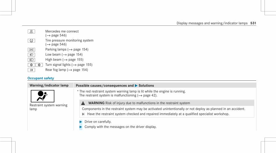
H Mercedes me connect(/ page 546)
h Tire pressure monitoring system(/ page 546)
T Parking lamps (/ page 154)L Low beam (/ page 154)K High beam (/ page 155)#! Turn signal lights (/ page 155)R Rear fog lamp (/ page 154)
Occupant safety
Warning/indicator lamp Possible causes/consequences andMM Solutions
6Restraint system warninglamp
* The red restraint system warning lamp is lit while the engine is running.The restraint system is malfunctioning (/ page 42).
& WARNING Risk of injury due to malfunctions in the restraint system
Components in the restraint system may be activated unintentionally or not deploy as planned in an accident.# Have the restraint system checked and repaired immediately at a qualified specialist workshop.
# Drive on carefully.# Comply with the messages on the driver display.
Display messages and warning/indicator lamps 531
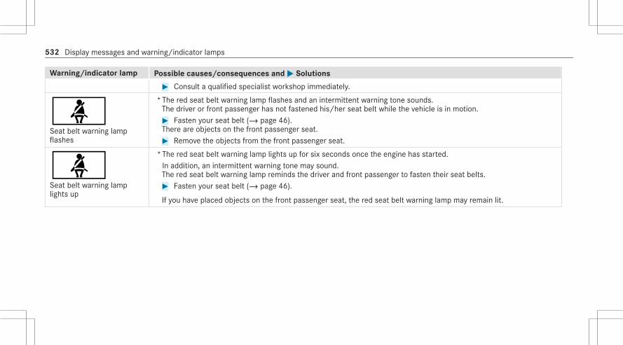
Warning/indicator lamp Possible causes/consequences andMM Solutions# Consult a qualified specialist workshop immediately.
üSeat belt warning lampflashes
* The red seat belt warning lamp flashes and an intermittent warning tone sounds.The driver or front passenger has not fastened his/her seat belt while the vehicle is in motion.# Fasten your seat belt (/ page 46).There are objects on the front passenger seat.# Remove the objects from the front passenger seat.
üSeat belt warning lamplights up
*The red seat belt warning lamp lights up for six seconds once the engine has started.In addition, an intermittent warning tone may sound.The red seat belt warning lamp reminds the driver and front passenger to fasten their seat belts.# Fasten your seat belt (/ page 46).
If you have placed objects on the front passenger seat, the red seat belt warning lamp may remain lit.
532 Display messages and warning/indicator lamps

Vehicle
Warning/indicator lamp Possible causes/consequences andMM Solutions
ÙPower steering warninglamp (yellow)
* The yellow power steering warning lamp is lit when the engine is running.The power assistance or the steering itself is malfunctioning.# Note the messages on the driver display.
ÙPower steering warninglamp (red)
* The red power steering warning lamp is lit while the engine is running.The power assistance or the steering itself is malfunctioning.
& WARNING Risk of accident if steering capability is impaired
If the steering does not function as intended, the vehicle's operating safety is jeopardized.# Pull over and stop the vehicle safely as soon as possible, paying attention to road and traffic conditions. Do
not continue driving under any circumstances.# Consult a qualified specialist workshop.
# Note the messages on the driver display.
Display messages and warning/indicator lamps 533

Warning/indicator lamp Possible causes/consequences andMM Solutions
ÙRear axle steering warninglamp (yellow)
* The yellow rear axle steering warning lamp is lit while the engine is running.The rear axle steering is malfunctioning.# Note the messages on the driver display.
ÙRear axle steering warninglamp (red)
* The red rear axle steering warning lamp is lit while the engine is running.The rear axle steering is malfunctioning.
& WARNING Risk of accident if steering capability is impaired
If the steering does not function as intended, the vehicle's operating safety is jeopardized.# Pull over and stop the vehicle safely as soon as possible, paying attention to road and traffic conditions. Do
not continue driving under any circumstances.# Consult a qualified specialist workshop.
# Note the messages on the driver display.
534 Display messages and warning/indicator lamps
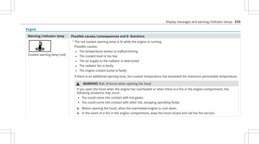
Engine
Warning/indicator lamp Possible causes/consequences andMM Solutions
ÿCoolant warning lamp (red)
* The red coolant warning lamp is lit while the engine is running.Possible causes:R The temperature sensor is malfunctioningR The coolant level is too lowR The air supply to the radiator is obstructedR The radiator fan is faultyR The engine coolant pump is faulty
If there is an additional warning tone, the coolant temperature has exceeded the maximum permissible temperature.
& WARNING Risk of burns when opening the hood
If you open the hood when the engine has overheated or when there is a fire in the engine compartment, thefollowing situations may occur:R You could come into contact with hot gases.R You could come into contact with other hot, escaping operating fluids.
# Before opening the hood, allow the overheated engine to cool down.# In the event of a fire in the engine compartment, keep the hood closed and call the fire service.
Display messages and warning/indicator lamps 535
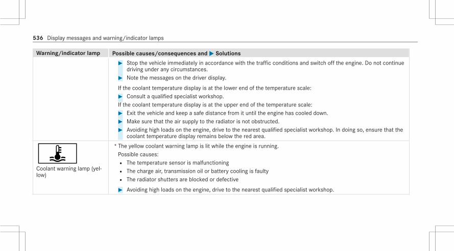
Warning/indicator lamp Possible causes/consequences andMM Solutions# Stop the vehicle immediately in accordance with the traffic conditions and switch off the engine. Do not continue
driving under any circumstances.# Note the messages on the driver display.
If the coolant temperature display is at the lower end of the temperature scale:# Consult a qualified specialist workshop.If the coolant temperature display is at the upper end of the temperature scale:# Exit the vehicle and keep a safe distance from it until the engine has cooled down.# Make sure that the air supply to the radiator is not obstructed.# Avoiding high loads on the engine, drive to the nearest qualified specialist workshop. In doing so, ensure that the
coolant temperature display remains below the red area.
ÿCoolant warning lamp (yel‐low)
* The yellow coolant warning lamp is lit while the engine is running.Possible causes:R The temperature sensor is malfunctioningR The charge air, transmission oil or battery cooling is faultyR The radiator shutters are blocked or defective
# Avoiding high loads on the engine, drive to the nearest qualified specialist workshop.
536 Display messages and warning/indicator lamps

Warning/indicator lamp Possible causes/consequences andMM Solutions
;Engine diagnosis warninglamp
* The yellow Check Engine warning lamp is lit while the engine is running.A malfunction has occurred in the engine, the exhaust system or the fuel system.The emission limit values may be exceeded and the engine may be in emergency mode.In some states, legal requirements stipulate that you must immediately consult a qualified specialist workshop assoon as the yellow Check Engine warning lamp lights up.# Have the vehicle checked as soon as possible at a qualified specialist workshop.
#Electrical malfunction warn‐ing lamp
* The red electrical fault warning lamp is lit.There is a fault in the electrics.# Note the messages on the driver's display.
8Fuel reserve warning lampflashes
* The yellow fuel reserve warning lamp lights up while you are driving.There has been pressure loss in the fuel system. The fuel filler cap is not closed correctly or the fuel system is leak‐ing.# Close the fuel filler cap.
If the fuel filler cap has already been closed correctly:# Consult a qualified specialist workshop.
Display messages and warning/indicator lamps 537

Warning/indicator lamp Possible causes/consequences andMM Solutions
8Fuel reserve warning lamplights up
* The yellow fuel reserve warning lamp lights up while the engine is running.The fuel supply has dropped into the reserve range.# Refuel.
538 Display messages and warning/indicator lamps

Brakes
Warning/indicator lamp Possible causes/consequences andMM Solutions
FElectric parking brake indi‐cator lamp (red) (USA only)
!Electric parking brake indi‐cator lamp (red) (Canadaonly)
!The electric parking brake(yellow) indicator lamp
*The red electric parking brake indicator lamp flashes or is lit.The yellow electric parking brake indicator lamp also lights up in the event of a malfunction.# Note the messages on the driver's display.
Display messages and warning/indicator lamps 539

Warning/indicator lamp Possible causes/consequences andMM Solutions
éRecuperative Brake Systemwarning lamp (USA only)
JBrakes warning lamp (yel‐low) (Canada only)
*The yellow é warning lamp (USA only) or the yellowJ brakes warning lamp (Canada only) is lit while theengine is running.
& WARNING Risk of an accident due to a brake system malfunction
If the brake system is malfunctioning, braking characteristics may be impaired.# Drive on carefully.# Have the brake system checked immediately at a qualified specialist workshop.
The hill start assist may be malfunctioning.# Adjust your speed and drive on carefully, leaving a suitable distance to the vehicle in front.# If the driver's display shows a display message, observe it.# Consult a qualified specialist workshop.
540 Display messages and warning/indicator lamps

Warning/indicator lamp Possible causes/consequences andMM Solutions
$Brake warning lamp (USAonly)
JBrake system warning lamp(Canada only)
* The red brake system warning lamp is lit while the engine is running.Possible causes:R The brake force boosting is malfunctioning and the braking characteristics may be affected.R There is insufficient brake fluid in the brake fluid reservoir.
# Note the messages on the driver's display.
& WARNING Risk of accident and injury if brake force boosting is malfunctioning
If brake force boosting is malfunctioning, increased brake pedal force may be necessary for braking. The brakingcharacteristics may be impaired. The braking distance can increase in emergency braking situations.# Stop in a safe location immediately. Do not continue driving.# Consult a qualified specialist workshop.
& WARNING Risk of an accident due to low brake fluid level
If the brake fluid level is too low, the braking effect and the braking characteristics may be impaired.# Pull over and stop the vehicle safely as soon as possible, paying attention to road and traffic conditions. Do
not continue driving under any circumstances.# Consult a qualified specialist workshop.# Do not add brake fluid.
Display messages and warning/indicator lamps 541

Driving systems
Warning/indicator lamp Possible causes/consequences andMM Solutions
LWarning lamp for distancewarning function
* The red distance warning lamp lights up while the vehicle is in motion.The distance to the vehicle in front is too small for the speed selected.If there is an additional warning tone, you are approaching an obstacle at too high a speed.# Be prepared to brake immediately.# Increase the distance.
Function of Active Brake Assist (/ page 236).
äSuspension warning lamp(yellow)
* The yellow AIRMATIC warning lamp is lit.A malfunction has occurred in AIRMATIC.# Note the messages on the driver display.
äSuspension warning lamp(red)
* The red AIRMATIC warning lamp is lit.A malfunction has occurred in AIRMATIC.
* NOTE The vehicle's driving characteristics will have changed significantly.
# Consult a qualified specialist workshop.
# Note the messages on the driver display.
542 Display messages and warning/indicator lamps

Warning/indicator lamp Possible causes/consequences andMM Solutions# Consult a qualified specialist workshop.
ÄActive Brake Assist warninglamp
* The Active Brake Assist yellow warning lamp is lit.The system is restricted or unavailable.# Note the messages on the driver display.
Driving safety systems
Warning/indicator lamp Possible causes/consequences andMM Solutions
!ABS warning lamp
* The yellow ABS warning lamp is lit while the engine is running.ABS is malfunctioning.If there is an additional warning tone, EBD is malfunctioning.Other driving systems and driving safety systems may also be malfunctioning.# Note the messages on the driver's display.
& WARNING There is a risk of skidding if EBD or ABS is malfunctioning
The wheels may lock during braking.
Display messages and warning/indicator lamps 543

Warning/indicator lamp Possible causes/consequences andMM Solutions
The steerability and braking characteristics are heavily impaired and the braking distance may increase. In addi‐tion, other driving safety systems are switched off.# Drive on carefully.# Have the brake system checked immediately at a qualified specialist workshop.
÷ESP® warning lamp flashes
* The yellow ESP® warning lamp flashes while the vehicle is in motion.One or more wheels has reached its grip limit (/ page 218).# Adapt your driving style to suit the road and weather conditions.
÷ESP® warning lamp lightsup
* The yellow ESP® warning lamp is lit while the engine is running.ESP® is malfunctioning.Other driving systems and driving safety systems (e.g. BAS) may also be malfunctioning.# Comply with the messages on the driver's display.
& WARNING Risk of skidding if ESP® is malfunctioning
If ESP® is malfunctioning, ESP® cannot carry out vehicle stabilization. In addition, other driving safety systemsare switched off.# Drive on carefully.# Have ESP® checked at a qualified specialist workshop.
544 Display messages and warning/indicator lamps

Warning/indicator lamp Possible causes/consequences andMM Solutions
åESP® OFF warning lamp
* The yellow ESP® OFF warning lamp is lit while the engine is running.ESP® is deactivated.Other driving systems and driving safety systems may also be inoperative.
& WARNING Risk of skidding when driving with ESP® deactivated
ESP® does not act to stabilize the vehicle. The availability of further driving safety systems is also limited.# Drive on carefully.# Deactivate ESP® only for as long as the situation requires.
If ESP® cannot be activated, ESP® is malfunctioning.# Have ESP® checked immediately at a qualified specialist workshop.
# Observe the notes on deactivating ESP® (/ page 218).
Display messages and warning/indicator lamps 545

Mercedes me connect
Warning/indicator lamp Possible causes/consequences andMM Solutions
HMercedes me connectwarning lamp
*At least one of the main functions of the Mercedes me connect system or of the SOS emergency call system is mal‐functioning.# Consult a qualified specialist workshop.
Tire pressure monitor
Warning/indicator lamp Possible causes/consequences andMM Solutions
hTire pressure monitoringsystem warning lampflashes
*The yellow tire pressure monitor warning lamp (pressure loss/malfunction) flashes for approximately one minute andthen remains lit.The tire pressure monitor is malfunctioning.
& WARNING There is a risk of an accident if the tire pressure monitoring system is malfunctioning
The tire pressure monitoring system cannot issue a warning if there is pressure loss in one or more of the tires.Tires with insufficient tire pressure may impair the driving characteristics as well as steering and braking.# Have the tire pressure monitoring system checked at a qualified specialist workshop.
546 Display messages and warning/indicator lamps

Warning/indicator lamp Possible causes/consequences andMM Solutions
hTire pressure monitoringsystem warning lamp lightsup
*The yellow tire pressure monitoring system warning lamp (pressure loss/malfunction) is lit.The tire pressure monitoring system has detected tire pressure loss in at least one of the tires.
& WARNING Risk of an accident due to insufficient tire pressure
R The tires can burst.R The tires can wear excessively and/or unevenly.R The driving characteristics as well as the steering and braking may be greatly impaired.
You could then lose control of the vehicle.# Observe the recommended tire pressures.# Adjust the tire pressure if necessary.
# Stop the vehicle in accordance with the traffic conditions.# Check the tire pressure and the tires.
Display messages and warning/indicator lamps 547

1, 2, 3 ...3D driver display
Function/notes..................................... 2733D instrument cluster
see 3D driver display4MATIC
Function................................................ 20512 V battery
see Battery (vehicle)48 V on-board electrical system
see EQ Boost technology115 V socket
see Socket (115 V)360° Camera
Opening the camera cover (rear viewcamera)................................................. 261Selecting a view..................................... 261
AA/C function
Activating/deactivating (MBUX mul‐timedia system)..................................... 177
ABS (Anti-lock Braking System)............... 217
Accelerationsee Kickdown
Accident and Breakdown Manage‐ment
Mercedes me connect........................... 307Acoustic locking verification signal
Activating/deactivating........................... 76Activating a commuter route................... 300Active Blind Spot Assist
Activating/deactivating......................... 250Brake application................................... 249Function................................................ 247System limitations................................. 247
Active Brake AssistFunction/notes..................................... 236Setting................................................... 240
Active Distance Assist DISTRONICActive Emergency Stop Assist............... 233Active Lane Change Assist.................... 234Calling up a speed................................. 226Function................................................ 223Increasing/decreasing speed................ 226Requirements........................................ 226Route-based speed adaptation.............. 228
Steering wheel buttons......................... 226Storing a speed..................................... 226Switching off/deactivating.................... 226Switching on/activating........................ 226System limitations................................. 223
Active Emergency Stop Assist................. 233Active Lane Change Assist
Activating/deactivating......................... 236Function................................................ 234
Active Lane Keeping AssistActivating/deactivating......................... 252Activating/deactivating the warning..... 253Function................................................ 250Setting the sensitivity............................ 253System limits......................................... 250
Active light function.................................. 157Active Parking Assist
Cross traffic warning............................. 270Drive Away Assist.................................. 269Exiting a parking space......................... 269Function................................................ 265Maneuvering brake function.................. 271Parking.................................................. 267System limitations................................. 265
548 Index

Active Service System PLUSsee ASSYST PLUS
Active Speed Limit AssistDisplay.................................................. 227Function................................................ 227
Active Steering AssistActivating/deactivating......................... 232Active Emergency Stop Assist............... 233Active Lane Change Assist.................... 234Function................................................ 230System limits......................................... 230
Active Traffic Jam AssistFunction................................................ 230
Adaptive cruise controlsee Active Distance Assist DISTRONIC
Adaptive Highbeam AssistFunction................................................. 161Switching on/off................................... 162
Adaptive Highbeam Assist PlusActivating/deactivating......................... 163Function................................................ 162
AdditivesEngine oil............................................... 472Fuel....................................................... 470
Additives (engine oil)see Additives
Additives (fuel)see Fuel
ADS PLUS damping systemsee AIRMATIC
Adverse weather light............................... 158After-sales service center
see ASSYST PLUSAir bag
Reduced protection................................. 51Air conditioning menu
Calling up.............................................. 177Air distribution
Setting................................................... 175Setting (MBUX multimedia system)....... 177
Air freshener systemsee Perfume atomizer
Air inletsee Air-water duct
Air pressuresee Tire pressure
Air suspensionsee AIRMATIC
Air ventsAdjusting (front).................................... 184Adjusting (rear)...................................... 184Glove box.............................................. 185
Air ventssee Air vents
Air-conditioning systemsee Climate control
Air-recirculation mode.............................. 178Air-water duct
Keeping free.......................................... 330Airbag
Activation................................................ 42Belt airbag............................................... 46Cushionbag............................................. 48Front airbag (driver, front passenger)...... 48Installation locations............................... 48Knee airbag............................................. 48Overview................................................. 48PASSENGER AIR BAG indicator lamp....... 53Protection................................................ 49Rear airbag.............................................. 48
Index 549

REAR SEAT AIR BAG indicator lamps....... 58Side airbag.............................................. 48Window curtain airbag............................. 48
AirflowSetting................................................... 175
AIRMATICSetting................................................... 254Suspension........................................... 253
Alarmsee Panic alarm
Alarm systemsee ATA (anti-theft alarm system)
All-wheel drivesee 4MATIC
Alternative routesee Route
Ambient lightingSetting (MBUX multimedia system)....... 165
Android Autosee Smartphone integration
AnimalsPets in the vehicle.................................... 74
Anti-lock braking systemsee ABS (Anti-lock Braking System)
Anti-skid chainssee Snow chains
Anti-theft protectionImmobilizer............................................ 102
Anti-theft protectionsee ATA (anti-theft alarm system)
Anticipatory occupant protectionsee PRE-SAFE® (anticipatory occu‐pant protection)see PRE-SAFE® PLUS (anticipatoryoccupant protection plus)
Apple CarPlay®see Smartphone integration
Assistance systemssee Driving safety system
ASSYST PLUSBattery disconnection periods.............. 325Displaying the service due date............. 324Function/notes..................................... 324Regular maintenance work.................... 324Special service requirements................ 324
ATA (anti-theft alarm system)Activating/deactivating the interiormotion sensor....................................... 104Arming/disarming the tow-awayalarm..................................................... 103Deactivating the alarm.......................... 103Function................................................ 102Function of the interior motion sensor.. 103The tow-away alarm function................. 103
ATTENTION ASSISTSetting................................................... 223System limits......................................... 221
ATTENTION ASSIST with microsleepdetection
Function................................................ 221Attention assistant
see ATTENTION ASSIST with micro‐sleep detection
Augmented realityFunction on the Head-up Display........... 276
Authorized Mercedes-Benz Centersee Qualified specialist workshop
Authorized workshopsee Qualified specialist workshop
550 Index
Automatic distance controlsee Active Distance Assist DISTRONIC
Automatic driving lights........................... 155Automatic engine start (ECO start/stop function)............................................ 195Automatic engine stop (ECO start/stop function)............................................ 195Automatic front passenger front air‐bag shutoff
Function of the automatic frontpassenger front airbag shutoff................. 51PASSENGER AIR BAG indicator lamp....... 53
Automatic front passenger front air‐bag shutoff
see Automatic front passenger frontairbag shutoff
Automatic lateral support adjustmentSetting................................................... 122
Automatic measures after an accident..... 60Automatic mirror folding function
Activating/deactivating......................... 173Automatic seat adjustment
Setting................................................... 121
Automatic transmissionDIRECT SELECT lever............................. 201Drive program display............................ 199Drive programs...................................... 198DYNAMIC SELECT button...................... 198Engaging drive position......................... 203Engaging neutral................................... 202Engaging park position.......................... 202Engaging reverse gear........................... 202Kickdown.............................................. 204Manual gearshifting............................... 203Steering wheel paddle shifters.............. 203Transmission position display................ 201Transmission positions.......................... 201
BBag hook.................................................... 140BAS (Brake Assist System)....................... 217Battery
see Battery (vehicle)Battery (SmartKey)
Replacing................................................. 77Battery (vehicle)
Charging................................................ 348
Charging (Remote Online)..................... 189Notes.................................................... 344Notes (starting assistance andcharging)............................................... 346Replacing.............................................. 349Starting assistance................................ 348
Beltsee Seat belt
Belt airbagActivation................................................ 42Function/notes....................................... 46
Blindsee Roller sunblind
Blowersee Climate control
Brake Assist Systemsee BAS (Brake Assist System)
Brake fluidNotes..................................................... 473
Brake force distributionEBD (electronic brake force distribu‐tion)....................................................... 219
Index 551

BrakesABS (Anti-lock Braking System)............. 217Active Brake Assist................................ 236BAS (Brake Assist System)..................... 217Driving tips............................................ 192EBD (electronic brake force distribu‐tion)....................................................... 219HOLD function...................................... 220Limited braking effect (salt-treatedroads).................................................... 192New/replaced brakepads/brakediscs...................................................... 190Notes on breaking-in a new vehicle....... 190Post-collision brake................................. 60
Braking assistancesee BAS (Brake Assist System)
BreakdownChanging a wheel.................................. 380Overview of the help functions................ 22Roadside Assistance............................... 28Tow-starting.......................................... 353Towing away.......................................... 351Transporting the vehicle........................ 352
Breakdownsee Flat tire
CCalls
Mercedes me........................................ 309Camera
see Driver camerasee Rear view camerasee Surround view camera
Car keysee SmartKey
Car washsee Care
Car wash (care)......................................... 330Car-to-X-Communication
Displaying hazard warnings................... 302Care
Air-water duct........................................ 330Automatic car wash............................... 330Carpet................................................... 334Decorative foil....................................... 332Display.................................................. 334EASY-PACK trunk box............................ 334Exterior lighting..................................... 333Headliner............................................... 334
Paintwork.............................................. 332Plastic trim............................................ 334Power washer........................................ 331Real wood/trim elements..................... 334Rear view camera.................................. 333Seat belt................................................ 334Seat cover............................................. 334Sensors................................................. 333Steering wheel...................................... 334Surround view camera.......................... 333Tailpipes................................................ 333Washing by hand................................... 331Wheels/rims......................................... 333Windows................................................ 333Wiper blades......................................... 333
Carpet (Care)............................................. 334Change of address...................................... 28Change of ownership.................................. 28Changing a wheel
Preparation........................................... 380Raising the vehicle................................. 381
Changing a wheelsee Emergency spare wheel
552 Index

Changing gearsManually................................................ 203
Changing hub caps.................................... 381Charging
Battery (vehicle).................................... 348Mobile phone (wireless)......................... 149USB port................................................ 146
Chauffeur modeInformation............................................ 113Moving the front passenger seat intothe chauffeur position............................ 114Moving the front passenger seat intothe normal position................................ 116
Child safety lockRear doors............................................... 72Rear side windows................................... 73
Child seatAttaching (notes)..................................... 64Basic instructions.................................... 60Front-passenger seat (notes)................... 70LATCH-type (ISOFIX) (installing).............. 66Notes on risks and dangers..................... 61Rear airbag.............................................. 69Securing on the front passenger seat...... 71
Securing on the rear seat........................ 69Top Tether............................................... 68
ChildrenAvoiding dangers in the vehicle................ 61Basic instructions.................................... 60Special seat belt retractor....................... 65
ChockStorage location.................................... 380
Chocksee Chock
City lighting............................................... 158Cleaning
see CareClimate control
Activating/deactivating......................... 176Activating/deactivating (rear operat‐ing unit)................................................. 177Activating/deactivating the A/Cfunction (MBUX multimedia system)...... 177Activating/deactivating the synchro‐nization function (MBUX multimediasystem).................................................. 178Air-recirculation mode........................... 178Automatic control.................................. 177
Calling up the air conditioning menu..... 177Control panel for 3-zone automaticclimate control....................................... 175Defrosting the windshield...................... 175Filling capacity for PAG oil..................... 476Front air vents....................................... 184Glove box air vent.................................. 185Immediate pre-entry climate control..... 183Information on the windshield heater.... 180Inserting/removing the flacon (fra‐grance system)...................................... 179Ionization............................................... 179Note....................................................... 175Pre-entry climate control at depar‐ture time................................................ 181Rear air vents........................................ 184Rear operating unit................................ 176Refrigerant............................................. 474Refrigerant filling capacity..................... 476Removing condensation from thewindows................................................ 178Residual heat......................................... 178Residual heat (rear operating unit)........ 179Setting (MBUX multimedia system)....... 177Setting the air distribution..................... 175Setting the airflow................................. 175
Index 553

Setting the fragrance system................. 179Setting the temperature........................ 175Switching the rear window heateron/off.................................................... 175Ventilating the vehicle (convenienceopening).................................................. 93
CockpitOverview................................................... 6
Coffee cup symbolsee ATTENTION ASSIST with micro‐sleep detection
Collision detection (parked vehicle)Information............................................ 213
Combination switch.................................. 155Consumption indicator
Calling up.............................................. 200Content sharing menu
Overview............................................... 281Control elements
Touch-sensitive........................................ 27Convenience closing................................... 93Convenience opening.................................. 93
Coolant (engine)Capacity................................................. 474Check level............................................ 329Notes..................................................... 473
Coolingsee Climate control
CopyrightsLicense.................................................... 40Trademarks............................................. 40
Cornering light........................................... 157Crosswind Assist
Function/notes...................................... 219Cup holder
Switching the cooling/heating func‐tion on/off............................................ 144
Cushionbag.................................................. 48Customer Assistance Center (CAC)........... 33Customer Relations Department............... 33
DDashboard
see Cockpit
Data acquisitionVehicle.................................................... 35
Data protection rightsData storage............................................ 38
Data storageData protection rights............................. 38Electronic control units........................... 35Online services........................................ 37Vehicle.................................................... 35
Daytime running lamp modesee Daytime running lights
Daytime running lightsSwitching on/off................................... 164
Deactivating the alarm (ATA).................... 103Dealership
see Qualified specialist workshopDeclaration of conformity
Wireless vehicle components.................. 30Decorative foil (cleaning instructions).... 332Definitions (tires and loading).................. 374Destination entry
Entering a POI or address...................... 299
554 Index

Detecting inattentivenesssee ATTENTION ASSIST
Diagnostics connection.............................. 31Diesel
Low outside temperatures..................... 471Notes..................................................... 471
DIGITAL LIGHTAssistance functions............................. 159Cornering light....................................... 157Intelligent Light System......................... 157Switching the Intelligent Light Sys‐tem on/off............................................ 160Topographical compensation................. 158
Digital Operator's Manual........................... 24Dinghy towing
see Tow-bar systemDIRECT SELECT lever
Engaging drive position......................... 203Engaging neutral................................... 202Engaging park position.......................... 202Engaging park position automatically.... 202Engaging reverse gear........................... 202Function................................................ 201
Display (care)............................................. 334Display (driver display)
Messages in the driver display.............. 279Display (MBUX multimedia system)
Home screen......................................... 281Operating the touchscreen.................... 282Settings................................................. 278
Display messageCalling up (driver display)...................... 478Notes..................................................... 478
Display messagesç - - - mph....................................... 506# 12 V On-board Electrical Sys‐tem Service Required............................ 521Û 48 V Battery See Operator'sManual.................................................. 523: Active Headlamps Inoperative...... 485é ATTENTION ASSIST Inoperative.... 505P ATTENTION ASSIST NoddingOff Take a Break!................................... 506
é ATTENTION ASSIST: Take aBreak!.................................................... 505: Automatic Headlamp ModeInoperative............................................ 484Ø Beginning Emergency Stop........... 508$ Brake Immediately....................... 503$ Check Brake Fluid Level............... 504# Check Brake Pads See Opera‐tor's Manual.......................................... 504+ Check Coolant Level See Oper‐ator's Manual........................................ 4935 Check Engine Oil Level (Add 1quart).................................................... 528: Check Left Low Beam (exam‐ple)........................................................ 484h Check Tires.................................. 525¥ Check Washer Fluid..................... 492ÿ Coolant Too Hot Stop VehicleTurn Engine Off..................................... 493
Index 555

á Currently Unavailable CameraDirty....................................................... 512¸ Currently Unavailable RadarDirty....................................................... 511! Currently Unavailable SeeOperator's Manual................................. 516÷ Currently Unavailable SeeOperator's Manual................................. 517Á Don't Forget Your Key.................. 4835 Engine Oil Level Cannot BeMeasured.............................................. 5295 Engine Oil Level Low Stop Vehi‐cle Turn Engine Off................................ 5285 Engine Oil Level Reduce OilLevel...................................................... 5285 Engine Oil Pressure Stop Vehi‐cle Switch Off Engine............................ 5296 Front Left Malfunction ServiceRequired (example)................................ 4798 Fuel Filler Cap Open..................... 494
8 Fuel Level Low.............................. 494! Inoperative See Operator'sManual................................................... 517÷ Inoperative See Operator'sManual................................................... 518T Inoperative See Operator'sManual................................................... 519G Inoperative................................... 520¥ Intensive Cleaning Activatedfor 30 Seconds...................................... 492Á Key Not Detected (red displaymessage)............................................... 483Á Key Not Detected (white dis‐play message)....................................... 4826 Left Window Airbag Malfunc‐tion Service Required (example)............ 479ä Malfunction Drive at Max. 50mph....................................................... 513: Malfunction See Operator’sManual.................................................. 484
¢ Maximum Speed 12mph............... 514Á Obtain a New Key......................... 482ç Off................................................ 506ë Off................................................ 505F Parking Brake See Operator'sManual.................................................. 499h Please Correct Tire Pressure........ 526F Please Release Parking Brake...... 502Ý Please Wait Charging 48 V Bat‐tery…..................................................... 523Ù Rear Axle Steering CurrentlyMalfunctioning...................................... 489Ù Rear Axle Steering MalfunctionService Required................................... 489Ù Rear Axle Steering MalfunctionStop Immediately.................................. 490Á Replace Key Battery..................... 4826 Restraint System MalfunctionService Required................................... 479
556 Index

Ù Steering Malfunction DriveCarefully Service Required.................... 488Ù Steering Malfunction IncreasedPhysical Effort See Operator's Manual.. 488Ù Steering Malfunction StopImmediately See Operator's Manual..... 489# Stop the vehicle. Leave theengine running to charge the 12 Vbattery................................................... 522É STOP Vehicle Level Too Low......... 514# Stop Vehicle See Operator'sManual.................................................. 521Û Stop Vehicle See Operator'sManual.................................................. 522ç Suspended................................... 506: Switch Off Lights.......................... 485: Switch On Headlamps.................. 485# Switch on the engine to chargethe 12 V battery.................................... 522
F Turn On the Ignition to Releasethe Parking Brake.................................. 503d Vehicle Ready to Drive Switchthe Ignition Off Before Exiting............... 488É Vehicle Rising Please Wait............ 515h Warning Tire Malfunction............. 526h Wheel Sensor(s) Missing.............. 525Active Blind Spot Assist CurrentlyUnavailable See Operator's Manual....... 510Active Blind Spot Assist Inoperative....... 510Active Brake Assist Functions Cur‐rently Limited See Operator's Manual.... 519Active Brake Assist Functions Limi‐ted See Operator's Manual................... 520Active Distance Assist CurrentlyUnavailable See Operator's Manual....... 507Active Distance Assist Inoperative........ 507Active Distance Assist Now Available.... 507
Active Emergency Stop Assist Cur‐rently Unavailable See Operator'sManual.................................................. 508Active Emergency Stop Assist Inop‐erative................................................... 508Active Lane Change Assist CurrentlyUnavailable See Operator's Manual...... 509Active Lane Change Assist Inopera‐tive........................................................ 509Active Lane Keeping Assist CurrentlyUnavailable See Operator's Manual....... 510Active Lane Keeping Assist Inopera‐tive......................................................... 510Active Parking Assist andPARKTRONIC Inoperative See Opera‐tor's Manual........................................... 515Active Parking Assist Limited Availa‐bility of Maneuvering Assistance SeeOperator's Manual................................. 515
Index 557

Active Steering Assist CurrentlyUnavailable Due to Multiple Emer‐gency Stops........................................... 508Active Steering Assist CurrentlyUnavailable See Operator's Manual....... 507Active Steering Assist Inoperative......... 507Active Stop & Go Assist CurrentlyUnavailable See Operator's Manual...... 509Active Stop & Go Assist InoperativeSee Operator's Manual.......................... 509Adaptive Highbeam Assist CurrentlyUnavailable See Operator's Manual...... 486Adaptive Highbeam Assist Inoperative.. 486Adaptive Highbeam Assist Plus Cur‐rently Unavailable See Operator'sManual.................................................. 486Adaptive Highbeam Assist Plus Inop‐erative................................................... 486Ambient Lighting Warning SupportInoperative............................................ 491
Apply Brake To Park Service Required... 496Auxiliary Battery Malfunction................ 498Cannot Start Engine See Operator'sManual.................................................. 523Change the steering wheel/ seatposition until 6 dots are visible onthe upper edge of the screen................. 513Decrease Speed.................................... 527Depress Brake to Shift from P............... 495Depress Brake to Shift to D or R........... 495Depress Brake to Shift to R................... 495Device Detected at Diagnostics Con‐nection See Operator's Manual............. 520DIGITAL LIGHT Functions Limited.......... 485Driver Camera Inoperative See Oper‐ator's Manual......................................... 513Driver Camera View CurrentlyRestricted See Operator's Manual......... 512Engine Can Now Be Started.................. 524
Front Passenger Airbag Disabled SeeOperator's Manual................................ 480Front Passenger Airbag Enabled SeeOperator's Manual................................ 480Hazard Warning Light Malfunction........ 486MULTIBEAM LED Functions Limited...... 485N Automatically Activated PleaseShift to Transmission Position Again..... 497PARKTRONIC Inoperative See Opera‐tor's Manual........................................... 515Place the Key in the Marked SpaceSee Operator's Manual.......................... 483PRE-SAFE Impulse Side InoperativeSee Operator's Manual.......................... 481PRE-SAFE Inoperative See Opera‐tor's Manual.......................................... 481Reversing Not Possible ServiceRequired................................................ 497Risk of Vehicle Rolling Away ApplyBrake to Park......................................... 496
558 Index

Risk of Vehicle Rolling Away Driver'sDoor Open Position P Not Selected....... 496Risk of Vehicle Rolling Away N Acti‐vated Manually No AutomaticChange to P........................................... 496Service Required Do Not ChangeTransmission Position............................ 498Shift to P Only When Vehicle Is Sta‐tionary................................................... 495Snow Chain Mode Maximum SpeedExceeded............................................... 490Stop Vehicle Leave Engine RunningWait Transmission Cooling.................... 498Tire Press. Monitor CurrentlyUnavailable............................................ 524Tire Press. Monitor Inoperative.............. 524Tire Pressure Monitor Inoperative NoWheel Sensors...................................... 525Tires Overheated................................... 527
To Deselect P or N Depress Brakeand Start Engine.................................... 495To switch engine off, press and holdStart/Stop button for at least 3 sec‐onds or press 3 times........................... 492Traffic Sign Assist Currently Unavail‐able See Operator's Manual.................. 509Traffic Sign Assist Inoperative................ 510Transmission Malfunction Stop............. 497
Distance controlsee Active Distance Assist DISTRONIC
DISTRONICsee Active Distance Assist DISTRONIC
DoorChild safety lock (rear doors)................... 72Locking/unlocking (emergency key)....... 83Opening (from inside).............................. 80Power closing function............................ 82Unlocking (from inside)........................... 80
Door control panel...................................... 18Door control panel (rear passengercompartment).............................................. 20
DOT, Tire Identification Number (TIN)..... 370Drawbar
see Tow-bar systemDrinking and driving.................................. 192Drive Away Assist...................................... 269Drive position
Inserting................................................ 203Drive program display............................... 199Drive programs
see DYNAMIC SELECTDriver camera
Activating/deactivating......................... 289Overview............................................... 289
Driver display48 V on-board electrical system............ 278Displaying the service due date............. 324EQ Boost technology............................. 278Function/notes..................................... 273Notes on menus.................................... 274Operating.............................................. 273Overview of displays.............................. 279
Driver display with driver camera.............. 12
Index 559

Driver's displayIndicator/warning lamps....................... 530
Driver's seatsee Seat
Driving safety systemABS (Anti-lock Braking System)............. 217Active Brake Assist................................ 236BAS (Brake Assist System)..................... 217Cameras................................................ 215EBD (electronic brake force distribu‐tion)....................................................... 219ESP® Crosswind Assist.......................... 219Overview................................................ 216Radar and ultrasonic sensors................ 215Responsibility........................................ 215STEER CONTROL................................... 219
Driving systemsee Active Blind Spot Assistsee Active Distance Assist DISTRONICsee Active Emergency Stop Assistsee Active Lane Change Assistsee Active Lane Keeping Assistsee Active Parking Assistsee Active Speed Limit Assistsee Active Steering Assist
see AIRMATICsee ATTENTION ASSIST with micro‐sleep detectionsee Driving safety systemsee HOLD functionsee Parking Assist PARKTRONICsee Rear view camerasee Surround view camerasee Traffic Sign Assist
Driving tipsDrinking and driving.............................. 192General driving tips............................... 192Notes on breaking-in a new vehicle....... 190Optimized acceleration.......................... 191
Drowsiness detectionsee ATTENTION ASSIST with micro‐sleep detection
Dynamic handling control systemsee ESP® (Electronic Stability Program)
DYNAMIC SELECTConfiguring drive program I................... 200Displaying engine data.......................... 200Displaying vehicle data.......................... 200Drive program display............................ 199
Drive programs...................................... 198Function................................................ 198Operating (DYNAMIC SELECT switch).... 199Selecting the drive program.................. 199
EE10............................................................. 469Easy entry feature
Function/notes..................................... 127Setting................................................... 128
Easy exit featureFunction/notes..................................... 127Setting................................................... 128
EASY-PACK trunk boxAdjusting the height to any position...... 140Care...................................................... 334Installing/removing............................... 142
EBD (electronic brake force distribu‐tion)
Function/notes...................................... 219ECO Assist
Function/notes...................................... 197
560 Index

ECO displayFunction................................................ 197
ECO start/stop functionAutomatic engine start.......................... 195Automatic engine stop........................... 195Method of operation.............................. 195Switching off/on................................... 196
Electric parking brakeApplying automatically........................... 211Applying/releasing manually................. 212Emergency braking................................ 213Releasing automatically......................... 212
Electronic Stability Programsee ESP® (Electronic Stability Program)
EmergencyFirst-aid kit (soft sided)......................... 338Overview of the help functions................ 22Reflective safety vest............................. 337Removing the warning triangle.............. 338Setting up the warning triangle............. 338
Emergency braking.................................... 213Emergency braking
see BAS (Brake Assist System)
Emergency engine start........................... 353Emergency key
Locking/unlocking the doors.................. 83Emergency operation mode
Starting the vehicle............................... 188Emergency release
Trunk lid (from inside).............................. 90Emergency spare wheel
Notes.................................................... 386Emergency Tensioning Devices
Activation................................................ 42Engine
ECO start/stop function........................ 195Engine number...................................... 466Starting (emergency operation mode)... 188Starting (Remote Online)....................... 189Starting (start/stop button).................. 188Starting assistance................................ 348Switching off (start/stop button).......... 207
Engine dataDisplaying.............................................. 200
Engine number.......................................... 466
Engine oilAdditives................................................ 472Capacity................................................ 472Checking the oil level with the driverdisplay................................................... 327MB-Freigabe or MB-Approval................. 472Quality................................................... 472Topping up............................................. 327
EQ boostQualified specialist workshop.................. 32
EQ Boost technologyNotes..................................................... 278Operating safety...................................... 28
ESC (Electronic Stability Control)see ESP® (Electronic Stability Program)
ESP®Crosswind Assist................................... 219
ESP® (Electronic Stability Program)Activating/deactivating......................... 219Function/notes...................................... 218
Exterior lightingCare...................................................... 333
Index 561

Exterior lightingsee Lights
Exterior mirrorsAutomatic mirror folding function.......... 173Automatic preselection (MBUX Inte‐rior Assistant)........................................ 288Folding in/out........................................ 171Operating the memory function............. 129Parking position..................................... 172Setting................................................... 171
FFatigue detection
see ATTENTION ASSIST with micro‐sleep detection
FavoritesAdding................................................... 291
First-aid kit (soft sided)............................ 338Flacon
Inserting/removing............................... 179Flat tire
Changing a wheel.................................. 380MOExtended tires.................................. 339Notes.................................................... 338
TIREFIT kit............................................. 340Flat towing
see Tow-bar systemFloor mats.................................................. 152Fog light (extended range)....................... 158Foil covering
Radar and ultrasonic sensors................ 215Folding table.............................................. 136Footrest
Rear passenger seat.............................. 115Fragrance
see Perfume atomizerFree software.............................................. 40Frequencies
Two-way radio....................................... 388Front airbag (driver, front passenger)....... 48Front passenger seat
Adjusting from the driver's seat............ 108Adjusting from the rear passengercompartment........................................ 109
Front passenger seatsee Seat
FuelAdditives............................................... 470Diesel.................................................... 471E10........................................................ 469Fuel reserve........................................... 472Gasoline................................................ 469Low outside temperatures..................... 471Quality (diesel)....................................... 471Quality (gasoline).................................. 469Refueling............................................... 205Sulfur content....................................... 469Tank content.......................................... 472
Function seatsee Door control panel
Function seat (rear passenger com‐partment)
see Seat (rear passenger compartment)Fuses
Before replacing a fuse.......................... 354Dashboard fuse box.............................. 356Fuse assignment diagram..................... 354Fuse box in the engine compartment.... 354Fuse box in the front-passenger foot‐well........................................................ 357Fuse box in the trunk............................. 357
562 Index

Notes.................................................... 354Fuses
see Fuses
GGarage door opener
Clearing the memory............................. 211Programming buttons............................ 209Resolving problems............................... 210Synchronizing the rolling code............... 210
Garage door openersOpening/closing the door...................... 211
Gasoline..................................................... 469Gearshift recommendation...................... 204Genuine parts.............................................. 25Glide mode................................................. 204Glove box
Air vent.................................................. 185
HHandbrake
see Electric parking brake
Handling characteristics (unusual)......... 358HANDS-FREE ACCESS................................. 88Handset
Stowage compartment (rearpassenger compartment)...................... 137
Hazard warning lights............................... 156Hazardous substances
Information.............................................. 28Head restraint
Activating/deactivating neck heating.... 119Attaching/removing the additionalcushion (front)....................................... 118Attaching/removing the additionalcushion (rear passenger compart‐ment)..................................................... 119Front (luxury head restraint).................. 117Rear (folding into position/foldingback mechanically)................................ 120Rear passenger compartment(adjusting).............................................. 118Rear passenger compartment (lower‐ing from the front).................................. 118Rear passenger compartment (luxuryhead restraint)....................................... 119
Head-up DisplayAugmented reality................................. 276Function................................................ 275Operating.............................................. 277Operating (with augmented reality)....... 278Operating the memory function............. 129Switching on/off................................... 278
Headlampssee Automatic driving lights
Headliner (care)......................................... 334Heating
see Climate controlHelp call
see Mercedes-Benz emergency call systemHigh beam
Activating/deactivating......................... 155High beam
see Adaptive Highbeam AssistHigh-beam flasher..................................... 155High-beam headlamps
Adaptive Highbeam Assist Plus............. 162Highway mode........................................... 158
Index 563

Hill start assist.......................................... 221HOLD function
Function/notes..................................... 220Switching on/off................................... 220
Home screen (central display)Overview............................................... 281
HoodOpening/closing................................... 325
IIdentification plate
Engine................................................... 466Refrigerant............................................. 474Vehicle.................................................. 466
IgnitionSwitching on (Start/Stop button).......... 187
Ignition keysee SmartKey
Immediate pre-entry climate control...... 183Immobilizer................................................ 102Indicator lamp
see Indicator/warning lamp
Indicator/warning lampOverview............................................... 530
Individual drive programConfiguring........................................... 200Selecting............................................... 199
Inside rearview mirrorAnti-glare mode (automatic).................. 172
Inside rearview mirrorsee Outside mirrors
Inspectionsee ASSYST PLUS
Instrument clustersee Driver display
Intelligent Light SystemActivating/deactivating......................... 160Active light function............................... 157Adaptive Highbeam Assist..................... 161Adaptive Highbeam Assist Plus............. 162Adverse weather light............................ 158Assistance functions............................. 159City lighting........................................... 158Cornering light....................................... 157Fog light (extended range)..................... 158Highway mode....................................... 158
Overview................................................ 157Topographical compensation................. 158
Interior lightingAdjusting............................................... 164Ambient lighting.................................... 165Reading lamp......................................... 164Switch-off delay time............................. 167
Interior motion sensorActivating/deactivating......................... 104Function................................................ 103
Internet radiosee TuneIn
IonizationActivating/deactivating (MBUX mul‐timedia system)..................................... 179
iPhone®see Smartphone integration
JJack
Storage location.................................... 380Jump-start connection
General notes........................................ 346
564 Index

KKEYLESS-GO
Deactivating............................................ 77Locking/unlocking the vehicle................ 80Problem................................................... 82Unlocking setting..................................... 76
KickdownUsing..................................................... 204
Knee airbag.................................................. 48
LLabeling (tires)
see Tire labelingLamp
see Interior lightingLamps (driver's display)
see Indicator/warning lampLane detection (automatic)
see Active Lane Keeping AssistLane Keeping Assist
see Active Lane Keeping Assist
LATCH-type (ISOFIX) child seatanchor
Installing.................................................. 66Level control system
see AIRMATICLight switch
Overview............................................... 154Lighting
see Interior lightingsee Lights
LightsActive light function............................... 157Adaptive Highbeam Assist..................... 161Adaptive Highbeam Assist Plus............. 162Adverse weather light............................ 158Automatic driving lights......................... 155City lighting........................................... 158Combination switch............................... 155Cornering light....................................... 157Fog light (extended range)..................... 158Hazard warning lights............................ 156High beam............................................. 155High-beam flasher................................. 155Highway mode....................................... 158
Intelligent Light System......................... 157Light switch........................................... 154Low-beam headlamps........................... 154Parking lights......................................... 154Rear fog lamp........................................ 154Responsibility for lighting systems........ 154Setting the exterior lighting switch-off delay time........................................ 164Standing lights....................................... 154Switching the Intelligent Light Sys‐tem on/off............................................ 160Switching the locator lighting on/off..... 164Turn signal light..................................... 155
Limited WarrantyVehicle.................................................... 35
Live Traffic InformationSwitching the traffic information dis‐play on.................................................. 302
Load index (tires)...................................... 372Load-bearing capacity (tires)................... 372Loading
Bag hook............................................... 140Definitions............................................. 374Notes..................................................... 133
Index 565

Roof luggage rack.................................. 143Loading guidelines.................................... 133Loading information table........................ 365Loads
Securing................................................ 133Locator lighting
Activating/deactivating......................... 164Locking/unlocking
Activating/deactivating the auto‐matic locking feature............................... 82Emergency key........................................ 83KEYLESS-GO........................................... 80Unlocking/opening the doors fromthe inside................................................ 80
Low-beam headlampsSwitching on/off................................... 154
Lubricant additivessee Additives
LuggageNet hooks.............................................. 137Securing................................................ 133
MMAGIC VISION CONTROL
Windshield wipers................................. 170Maintenance
Vehicle.................................................... 28Maintenance
see ASSYST PLUSMalfunction
Restraint system..................................... 42Malfunction message
see Display messageManeuvering assistance
Activating/deactivating......................... 272Cross traffic warning............................. 270Drive Away Assist.................................. 269
Maneuvering brake function.................... 271Maneuvering brake function
see Protection against collisionMap
Displaying online map contents............ 302Displaying weather information............. 302Moving.................................................. 302Selecting the map orientation............... 302
Setting the map scale............................ 302Massage program
Overview............................................... 122Resetting the settings............................ 123
Massage programsSelecting the front seats....................... 123
Massage settingsResetting............................................... 123
Maximum load rating................................ 371Maximum permissible load
Calculation example.............................. 367Determining.......................................... 366
Maximum tire pressure............................ 371MBUX Interior Assistant
Anticipatory exit warning....................... 286Automatic preselection of the out‐side mirror............................................. 288Switching the reading light for thedriver and front passenger on/offcontact-free........................................... 287Switching the search light for thedriver on/off......................................... 287
566 Index

MBUX Interior Assistant (multimedia system)Calling up favorites with the V pose...... 288Operating a function with the favor‐ites pose............................................... 288Overview............................................... 284
MBUX multimedia systemActivating/deactivating snow chainmode..................................................... 359Activating/deactivating standby mode.. 215Collision detection (parked vehicle)....... 213Configuring display settings.................. 278Configuring drive program I................... 200Driver camera........................................ 289Home screen......................................... 281Notes.................................................... 280Operating the touchscreen.................... 282Overview............................................... 280Setting route-based speed adaptation.. 230Setting the footwell temperature........... 178Setting the rear climate control............. 178
MBUX Voice AssistantFunction................................................ 283Voice prompting.................................... 283
Mechanical keyInserting/removing................................. 77
Unlocking the trunk lid............................ 90Media
Overview of the functions and sym‐bols........................................................ 317
Medical aids................................................. 33Memory function
Function................................................ 128Head-up Display — Calling up storedsettings................................................. 129Head-up Display — Storing settings....... 129Operating.............................................. 129Outside mirrors — Calling up storedsettings................................................. 129Outside mirrors — Storing settings........ 129Seat — Calling up stored settings........... 129Seat — Storing settings.......................... 129Steering wheel — Calling up savedsettings................................................. 129Steering wheel — Saving settings........... 129
Memory function in the rearpassenger compartment
Function................................................ 130Operating rear seats.............................. 131
Operating the front passenger seatand rear seats....................................... 132
Menus (driver display)Notes..................................................... 274
Mercedes me appInformation............................................ 312
Mercedes me callsArranging a service appointment........... 310Calling the Mercedes-Benz CustomerCenter................................................... 309Calling the Mercedes-Benz CustomerCenter after automatic accident orbreakdown detection............................. 310Information............................................ 309Making a call via the overhead con‐trol panel............................................... 309Transferred data..................................... 311
Mercedes me connectAccident and Breakdown Manage‐ment...................................................... 307Information............................................ 307Transferred data.................................... 308
Mercedes-Benz emergency call systemAutomatic emergency call..................... 315
Index 567

Information............................................ 314Information on data transfer.................. 316Manual emergency call.......................... 315Overview................................................ 314
Message (driver display)see Display message
Message memory...................................... 478Mirrors
see Exterior mirrorsMobile phone
Wireless charging (rear passengercompartment)........................................ 151
Mobile phonesee Smartphone integrationsee Telephone
Model seriessee Vehicle identification plate
MOExtended tires..................................... 339MULTIBEAM LED
Intelligent Light System......................... 157Multimedia system
Collision detection (parked vehicle)....... 213
Coupling the steering wheel heaterto the seat heating................................ 127Enabling/disabling the rear airbag.......... 58
Multimedia systemsee MBUX Interior Assistant (multi‐media system)see MBUX multimedia system
NNavigation
Notes..................................................... 297Overview............................................... 298Switching on......................................... 298
Navigationsee Destination entrysee Mapsee Route
NeutralInserting................................................ 202
Nodding offsee ATTENTION ASSIST with micro‐sleep detection
Notes on breaking-in a new vehicle......... 190
OOccupant safety
see Airbagsee Automatic front passenger frontairbag shutoffsee Automatic measures after an accidentsee Child seatsee Pets in the vehiclesee Post-collision brakesee PRE-SAFE® (anticipatory occu‐pant protection)see PRE-SAFE® Impulse Sidesee PRE-SAFE® PLUS (anticipatoryoccupant protection plus)see Rear airbagsee Restraint systemsee Seat belt
Oilsee Engine oil
On-board diagnostics interfacesee Diagnostics connection
Online servicesData storage............................................ 37
568 Index

Open-source software................................ 40Opening the trunk lid using your foot
HANDS-FREE ACCESS............................. 88Operating fluids
Additives (fuel)...................................... 470Brake fluid............................................. 473Coolant (engine).................................... 473Engine oil............................................... 472Fuel (diesel)........................................... 471Fuel (gasoline)....................................... 469Notes.................................................... 468Refrigerant (air conditioning system)..... 474Windshield washer fluid......................... 474
Operating safety48 V on-board electrical system.............. 28Declaration of conformity (wirelessvehicle components)............................... 30EQ Boost technology............................... 28Information.............................................. 28
Operator's ManualVehicle equipment................................... 26
Operator's Manual (digital)......................... 24Optimized acceleration
Activating............................................... 191
Outside mirrorsAnti-glare mode (automatic).................. 172
Overhead control panelOverview.................................................. 16
PPaint code.................................................. 466Paintwork (cleaning instructions)........... 332Panel heating
Setting................................................... 124Panic alarm
Activating/deactivating........................... 76Panorama roof with power tilt/slidingpanel
see Sliding sunroofParcel net hooks........................................ 137Park position
Inserting................................................ 202Selecting automatically......................... 202
Parkingsee Electric parking brake
Parking aidsee Parking Assist PARKTRONIC
Parking Assist PARKTRONICActivating.............................................. 264Adjusting warning tones........................ 265Function................................................. 261Switching off......................................... 264System limitations................................. 261
Parking assistance systemssee Active Parking Assist
Parking brakesee Electric parking brake
Parking for an extended period................ 214Parking lights............................................. 154Parking position
Exterior mirrors..................................... 172Storing the position of the front-passenger outside mirror usingreverse gear........................................... 173
PASSENGER AIR BAG status displaysee Automatic front passenger frontairbag shutoff
Index 569

PayloadCalculation example.............................. 367Determining the maximum.................... 366
Perfumesee Perfume atomizer
Perfume atomizerInserting/removing the flacon............... 179Setting................................................... 179
Perfume vialsee Perfume atomizer
Period out of useActivating/deactivating standby mode.. 215Standby mode function.......................... 214
Permitted towing methods...................... 350Pets in the vehicle....................................... 74Plastic trim (Care)..................................... 334Post-collision brake..................................... 60Power closing function
Door........................................................ 82Trunk lid.................................................. 85
Power supplySwitching on (Start/Stop button).......... 187
Power washer (care)................................. 331Pre-entry climate control (immediate).... 183Pre-entry climate control at depar‐ture time
Function................................................. 181Setting................................................... 182Switching on/off................................... 182
PRE-SAFE® (anticipatory occupantprotection)
Function.................................................. 58PRE-SAFE® Sound................................... 58Reversing measures................................ 59
PRE-SAFE® Impulse SideActivation................................................ 42Function.................................................. 59
PRE-SAFE® PLUS (anticipatory occu‐pant protection plus)
Function.................................................. 59Reversing measures................................ 59
Preventative occupant protection sys‐tem
see PRE-SAFE® (anticipatory occu‐pant protection)
see PRE-SAFE® PLUS (anticipatoryoccupant protection plus)
ProfileNotes.................................................... 290
Programsee DYNAMIC SELECT
Protecting the environmentNotes....................................................... 25
Protection against collision...................... 271Protection against collision
see Drive Away AssistPulling away
see Driving tips
QQR code
Rescue card............................................ 35Qualified specialist workshop................... 32
RRadar and ultrasonic sensors
Damage................................................. 215
570 Index

RadioOverview of the functions and sym‐bols........................................................ 319
Radio operating permits........................... 389Rain-closing feature
Sliding sunroof........................................ 98Reading lamp
see Interior lightingReading light
Switching on/off with hand move‐ments.................................................... 287
Real wood (Care)....................................... 334Rear airbag
Activating/deactivating........................... 58Points to remember when the rearseat is occupied...................................... 56REAR SEAT AIR BAG indicator lamps....... 58
Rear axle steering..................................... 195Rear climate control
Setting (MBUX multimedia system)....... 178Rear doors (child safety lock).................... 72
Rear fog lampSwitching on/off................................... 155
Rear passenger compartment seatSeats..................................................... 110
REAR SEAT AIR BAG status displaysee Rear airbag
Rear view cameraActivating using GPS (surround viewcamera)................................................. 261Care...................................................... 333Function........................................ 255, 257Opening the camera cover (360°Camera)................................................. 261Setting (surround view camera)............. 261
Rear view camerasee Surround view camera
Rear windowRoller sunblind....................................... 100
Rear window heater.................................. 175Reflective safety vest............................... 337Refrigerant (air conditioning system)
Notes..................................................... 474
Refrigerator boxRemoving/installing.............................. 148Stowage compartment.......................... 149Using..................................................... 147
RefuelingRefueling the vehicle............................. 205
Remote OnlineCharging the starter battery.................. 189Cooling/heating the vehicle interior...... 189Starting the vehicle............................... 189
Reporting safety defects............................ 34Rescue card................................................. 35Reserve
Fuel....................................................... 472Residual heat
Rear operating unit................................ 179Restraint system
Basic instructions for children................. 60Function in an accident........................... 42Functionality............................................ 41Malfunction............................................. 42Protection................................................ 41Reduced protection................................. 41
Index 571

Self-test................................................... 41Warning lamp........................................... 41
Reverse gearInserting................................................ 202
Rims (care)................................................. 333Roadside Assistance (breakdown)............ 28Roll away protection
see HOLD functionRoller sunblind
Rear window.......................................... 100Side windows (electric)......................... 100Sliding sunroof........................................ 95
Roof load.................................................... 476Roof luggage rack
Loading................................................. 143Securing................................................ 143
RouteActivating a commuter route................. 300Calculating............................................ 300Selecting a type.................................... 300Selecting an alternative route............... 300
Route guidance with augmented real‐ity
Activating.............................................. 300Displaying street names and housenumbers................................................ 300
Route-based speed adaptationFunction................................................ 228Setting................................................... 230
Run-flat characteristicsMOExtended tires.................................. 339
SSafety systems
see Driving safety systemSatellite radio
Logging in.............................................. 322Setting music and sport alerts.............. 322
Search lightSwitching on/off with hand move‐ments.................................................... 287
SeatAdjusting (electrically)........................... 105Adjusting a reclining rear seat................ 111
Adjusting the front passenger seatfrom the rear passenger compart‐ment...................................................... 109Automatic seat adjustment.................... 121Configuring the settings......................... 121Correct driver's seat position................ 105Massage program overview................... 122Operating the memory function............. 129Panel heating......................................... 124Rear passenger compartment footrest.. 115Resetting the settings............................ 123Setting automatic lateral supportadjustment............................................ 122Setting options........................................ 18Setting the fully reclined position........... 112Workout program overview.................... 122
Seatsee Chauffeur modesee Front passenger seat
Seat (rear passenger compartment)Setting options........................................ 20
Seat beltCare...................................................... 334Protection................................................ 43
572 Index
Seat belt adjustmentActivating/deactivating........................... 47Function.................................................. 47
Seat belt warningsee Seat belts
Seat beltsActivating/deactivating seat beltadjustment.............................................. 47Adjusting the height................................ 46Belt airbag............................................... 46Fastening................................................. 46Reduced protection................................. 44Releasing................................................. 47Seat belt adjustment (function)............... 47Warning lamp.......................................... 47
Seat cover (Care)....................................... 334Seat heating
Activating/deactivating......................... 123Seat ventilation
Activating/deactivating......................... 125Seats
Rear passenger compartment(adjusting electrically)............................ 110
Selecting a gearsee Changing gears
Selector leversee DIRECT SELECT lever
Self-testAutomatic front passenger front air‐bag shutoff.............................................. 53
Sensors (care)........................................... 333Service center
see Qualified specialist workshopService interval display
see ASSYST PLUSSetting the footwell temperature
Setting................................................... 178Setting the map scale
see MapShift paddles
see Steering wheel paddle shiftersShifting gears
Gearshift recommendation................... 204Side airbag................................................... 48
Side windowsChild safety lock in the rearpassenger compartment......................... 73Closing using the SmartKey.................... 93Convenience closing............................... 93Convenience opening.............................. 93Opening with the SmartKey..................... 93Opening/closing...................................... 91Problem................................................... 94Roller sunblind (electric)........................ 100
Size designation (tires)............................. 372Sliding sunroof
Automatic features.................................. 98Closing.................................................... 95Closing using the SmartKey.................... 93Opening................................................... 95Opening with the SmartKey..................... 93Problem................................................... 98Rain-closing feature................................. 98
SmartKeyAcoustic locking verification signal.......... 76Battery.................................................... 77Deactivating functions............................. 77Energy consumption................................ 77Features.................................................. 75
Index 573

Key ring attachment................................ 77Mechanical key........................................ 77Overview................................................. 75Panic alarm.............................................. 76Problem................................................... 79Unlocking setting..................................... 76
Smartphonesee Smartphone integrationsee Telephone
Smartphone integrationOverview................................................ 313
Snow chain modeActivating/deactivating......................... 359
Snow chains.............................................. 359Socket (12 V)
Rear passenger compartment............... 144Socket (115 V)
Rear passenger compartment............... 145Software update
System updates..................................... 294Sound
PRE-SAFE® Sound................................... 58Wheels and tires.................................... 358
Sound menuFunctions overview............................... 323
Spare wheelsee Emergency spare wheel
Special seat belt retractor.......................... 65Specialist workshop.................................... 32Speed index (tires).................................... 372Standby mode
Activating/deactivating......................... 215Function................................................. 214
Standing lights.......................................... 154Start-off assist
see Optimized accelerationStart/stop button
Parking the vehicle................................ 207Starting the vehicle............................... 188Switching on the power supply orignition.................................................. 187
Start/stop functionsee ECO start/stop function
Starter batteryCharging (Remote Online)..................... 189
Starting assistancesee Jump-start connection
Starting the enginesee Vehicle
Starting-off aidsee Hill start assist
STEER CONTROLFunction/notes...................................... 219
SteeringRear axle steering.................................. 195
Steering wheelAdjusting (electrically)........................... 125Care...................................................... 334Operating the memory function............. 129Steering wheel heater............................ 126
Steering wheel heaterCoupling to seat heating........................ 127Switching on/off................................... 126
Steering wheel paddle shifters................ 203Storage areas
see Storage spaceStorage compartments
see Storage space
574 Index

Storage spaceArmrest................................................. 135Center console...................................... 135Door...................................................... 135Glove box............................................... 135USB ports.............................................. 135
Stowage compartmentHandset (rear passenger compart‐ment)..................................................... 137Parcel net hooks.................................... 137
Sulfur content........................................... 469Surround View
see Surround view cameraSurround view camera
Activating using GPS (rear view cam‐era)........................................................ 261Button.................................................... 261Care...................................................... 333Function................................................ 257Setting (rear view camera)..................... 261
SuspensionSetting the suspension level (AIR‐MATIC).................................................. 254
Suspensionsee AIRMATIC
Suspension level (AIRMATIC)Setting................................................... 254
Switch-off delay timeExterior.................................................. 164Interior................................................... 167
Synchronization functionActivating/deactivating (MBUX mul‐timedia system)..................................... 178
System settingsOverview of the system settingsmenu..................................................... 294
TTailpipes (care).......................................... 333Tank content
Fuel....................................................... 472Reserve (fuel)........................................ 472
Technical dataInformation............................................ 387Radio operating permits........................ 389
TelephoneConnecting a mobile phone (Passkey)... 306Connecting a mobile phone (SecureSimple Pairing)...................................... 306Functions in the telephone menu.......... 307Notes.................................................... 304Operating modes................................... 306Telephone menu overview..................... 306Wireless charging (mobile phone inthe rear passenger compartment)......... 151
Telephony operating modesBluetooth® Telephony............................ 306
Temperature............................................... 175Temperature grade.................................... 369Through-loading feature
Locking.................................................. 139Through-loading feature in the rearpassenger compartment
Opening................................................. 138TIN (Tire Identification Number).............. 370Tire and Loading Information placard..... 365Tire characteristics................................... 372
Index 575

Tire inflation compressorsee TIREFIT kit
Tire information table............................... 365Tire labeling
Characteristics...................................... 372DOT, Tire Identification Number (TIN).... 370Load index............................................. 372Load-bearing capacity........................... 372Maximum tire load................................. 371Maximum tire pressure.......................... 371Overview............................................... 369Speed rating.......................................... 372Temperature grade................................ 369Tire Quality Grading............................... 369Tire size designation.............................. 372Traction grade....................................... 369Tread wear grade................................... 369
Tire load (maximum)................................. 371Tire pressure
Checking (manually).............................. 362Checking (tire pressure monitoringsystem)................................................. 364Maximum............................................... 371Notes.................................................... 360
Restarting the tire pressure monitor‐ing system............................................. 364Tire pressure monitoring system(function)............................................... 363Tire pressure table................................. 361TIREFIT kit............................................. 340
Tire pressure monitorChecking the tire pressure.................... 364Checking the tire temperature.............. 364Function................................................ 363Restarting.............................................. 364
Tire pressure table.................................... 361Tire Quality Grading.................................. 369Tire temperature
Checking (tire pressure monitoringsystem)................................................. 364Tire pressure monitoring system(function)............................................... 363
Tire tread................................................... 358Tire-change tool kit
Overview............................................... 380TIREFIT kit
Storage location.................................... 340
Using..................................................... 340Tires
Characteristics...................................... 372Checking............................................... 358Checking the tire pressure (manually)... 362Checking the tire pressure (tire pres‐sure monitoring system)........................ 364Definitions............................................. 374DOT, Tire Identification Number (TIN).... 370Flat tire.................................................. 338Installing................................................ 384Load index............................................. 372Load-bearing capacity........................... 372Maximum tire load................................. 371Maximum tire pressure.......................... 371MOExtended tires.................................. 339Noise..................................................... 358Notes on installing................................. 377Overview of tire labeling........................ 369Removing.............................................. 383Replacing...................................... 377, 380Replacing the wheel trim....................... 381Restarting the tire pressure monitor‐ing system............................................. 364Rotating................................................. 379
576 Index
Selection............................................... 377Snow chains.......................................... 359Speed rating.......................................... 372Storing.................................................. 380Temperature grade................................ 369Tire and Loading Information placard.... 365Tire pressure (notes)............................. 360Tire pressure monitoring system(function)............................................... 363Tire pressure table................................. 361Tire Quality Grading............................... 369Tire size designation.............................. 372TIREFIT kit............................................. 340Traction grade....................................... 369Tread wear grade................................... 369Unusual handling characteristics.......... 358
Toll systemWindshield............................................. 174
Toolsee Vehicle tool kit
Top Tether.................................................... 68Touch Control
Driver display......................................... 273Operating.............................................. 282
Touch-sensitive controls............................. 27Touchscreen
Operating.............................................. 282Tow-away alarm
Activating/deactivating......................... 103Function................................................ 103
Tow-bar system......................................... 272Tow-starting............................................... 353Towing away............................................... 351Towing eye
Installing................................................ 353Storage location.................................... 353
Towing methods........................................ 350Traction grade........................................... 369Traffic information
Switching on the display....................... 302Traffic Light Assistant
Traffic light data service........................ 245Traffic light data service
Messages on the driver's display........... 245Traffic light view
Activating/deactivating......................... 244
Information............................................ 244Traffic Sign Assist
Function/notes...................................... 241Setting................................................... 244System limitations................................. 241
Transmission position display.................. 201Transporting
Loading guidelines................................. 133Vehicle.................................................. 352
Tread wear grade...................................... 369Trim element (Care).................................. 334Trunk box
see EASY-PACK trunk boxTrunk lid
Activating/deactivating the trunk lidopening height restriction........................ 91Closing.................................................... 85Emergency release (from inside)............. 90HANDS-FREE ACCESS............................. 88Locking separately.................................. 90Opening................................................... 84Opening dimensions.............................. 476Power closing function............................ 85
Index 577

Unlocking (mechanical key)..................... 90TuneIn
Calling up.............................................. 321Turn signal indicator................................. 155Turn signal light
Activating/deactivating......................... 155Two-way radios
Frequencies........................................... 388Notes on installation............................. 387Transmission output (maximum)........... 388
UUnlocking
see Locking/unlockingUnlocking setting........................................ 76Updates
Important system updates.................... 294USB port
Rear passenger compartment............... 146User profiles
Adding a user........................................ 291Selecting user options........................... 291
VVehicle
Activating/deactivating standby mode.. 215Collision detection (parking).................. 213Correct use............................................. 33Data acquisition...................................... 35Data storage............................................ 35Diagnostics connection........................... 31Equipment............................................... 26Limited Warranty..................................... 35Locking (automatically)........................... 82Locking (from inside)............................... 80Locking/unlocking (emergency key)....... 83Locking/unlocking (KEYLESS-GO)........... 80Lowering............................................... 385Maintenance........................................... 28Medical aids............................................ 33Parking for an extended period.............. 214Problem notification................................ 33QR code rescue card............................... 35Qualified specialist workshop.................. 32Raising................................................... 381Standby mode function.......................... 214Starting (emergency operation mode)... 188Starting (Remote Online)....................... 189
Starting (start/stop button).................. 188Switching off (start/stop button).......... 207Towing................................................... 272Unlocking (from inside)........................... 80Ventilating (convenience opening)........... 93
Vehicle dataDisplaying (DYNAMIC SELECT).............. 200Roof load............................................... 476Turning circle......................................... 476Vehicle height........................................ 476Vehicle length........................................ 476Vehicle width......................................... 476Wheelbase............................................. 476
Vehicle data storageEvent data recorders............................... 39MBUX multimedia system/Mercedesme connect............................................. 38
Vehicle dimensions................................... 476Vehicle electronics
Notes..................................................... 387Two-way radios...................................... 387
Vehicle identification numbersee VIN
578 Index

Vehicle identification platePaint code............................................. 466VIN........................................................ 466
Vehicle interiorCooling or heating (Remote Online)....... 189
Vehicle keysee SmartKey
Vehicle maintenancesee ASSYST PLUS
Vehicle operationOutside the USA or Canada..................... 27
Vehicle tool kitTIREFIT kit............................................. 340Towing eye............................................ 353
VentilatingConvenience opening.............................. 93
Ventilationsee Climate control
Ventssee Air vents
VINIdentification plate................................ 466Seat....................................................... 466
Windshield............................................ 466Vision
Removing condensation from thewindows................................................ 178Windshield heater.................................. 180
WWarning lamp
see Indicator/warning lampWarning system
see ATA (anti-theft alarm system)Warning triangle
Removing.............................................. 338Setting up.............................................. 338
Warning/indicator lamp! ABS warning lamp........................ 543Ä Active Brake Assist warninglamp...................................................... 543J Brake system warning lamp(Canada only)......................................... 541$ Brake warning lamp (USA only).... 541
J Brakes warning lamp (yellow)(Canada only)........................................ 540ÿ Coolant warning lamp (red).......... 535ÿ Coolant warning lamp (yellow)..... 536! Electric parking brake indicatorlamp (red) (Canada only)....................... 539F Electric parking brake indicatorlamp (red) (USA only)............................ 539# Electrical malfunction warninglamp...................................................... 537; Engine diagnosis warning lamp.... 537
å ESP® OFF warning lamp............... 545
÷ ESP® warning lamp flashes.......... 544
÷ ESP® warning lamp lights up........ 5448 Fuel reserve warning lampflashes................................................... 5378 Fuel reserve warning lamplights up................................................ 538H Mercedes me connect warninglamp...................................................... 546
Index 579

Ù Power steering warning lamp(red)...................................................... 533Ù Power steering warning lamp(yellow).................................................. 533Ù Rear axle steering warninglamp (red).............................................. 534Ù Rear axle steering warninglamp (yellow)......................................... 534é Recuperative Brake Systemwarning lamp (USA only)....................... 5406 Restraint system warning lamp.... 531ü Seat belt warning lamp flashes.... 532ü Seat belt warning lamp lightsup.......................................................... 532ä Suspension warning lamp (red).... 542ä Suspension warning lamp (yel‐low)....................................................... 542! The electric parking brake (yel‐low) indicator lamp................................ 539
h Tire pressure monitoring sys‐tem warning lamp flashes..................... 546h Tire pressure monitoring sys‐tem warning lamp lights up................... 547L Warning lamp for distancewarning function................................... 542REAR SEAT AIR BAG................................ 58
Warning/indicator lampsPASSENGER AIR BAG.............................. 53
Warranty...................................................... 35Washer fluid
see Windshield washer fluidWashing by hand (care)............................ 331Water tank
see Air-water ductWeather information................................. 302Web browsers
Overview................................................ 312Wheel change
Lowering the vehicle............................. 385Mounting a new wheel.......................... 384
Removing a wheel................................. 383Removing/installing hub caps............... 381
Wheel rotation........................................... 379Wheels
Care...................................................... 333Checking............................................... 358Checking the tire pressure (manually)... 362Checking the tire pressure (tire pres‐sure monitoring system)........................ 364Definitions............................................. 374DOT, Tire Identification Number (TIN).... 370Flat tire.................................................. 338Installing................................................ 384Load index............................................. 372Load-bearing capacity........................... 372Maximum tire load................................. 371Maximum tire pressure.......................... 371MOExtended tires.................................. 339Noise..................................................... 358Notes on installing................................. 377Overview of tire labeling........................ 369Removing.............................................. 383Replacing...................................... 377, 380Replacing the hub cap........................... 381
580 Index

Restarting the tire pressure monitor‐ing system............................................. 364Rotating................................................. 379Selection............................................... 377Snow chains.......................................... 359Speed rating.......................................... 372Storing.................................................. 380Temperature grade................................ 369Tire and Loading Information placard.... 365Tire characteristics................................ 372Tire pressure (notes)............................. 360Tire pressure monitoring system(function)............................................... 363Tire pressure table................................. 361Tire Quality Grading............................... 369Tire size designation.............................. 372TIREFIT kit............................................. 340Traction grade....................................... 369Tread wear grade................................... 369Unusual handling characteristics.......... 358
Wi-FiConfiguring........................................... 295
Window curtain airbag............................... 48Window lifter
see Side windows
WindowsCare...................................................... 333
Windowssee Side windows
WindshieldDefrosting.............................................. 175Infrared reflective.................................. 174Radio waves........................................... 174Replacing the wiper blades.................... 168Replacing wiper blades (MAGICVISION CONTROL)................................. 170
Windshieldsee Windshield
Windshield heater..................................... 180Windshield heater
see Windshield heaterWindshield washer fluid
Notes..................................................... 474Windshield washer system
Topping up............................................. 329Windshield wipers
Activating/deactivating......................... 167Replacing the wiper blades.................... 168
Replacing wiper blades (MAGICVISION CONTROL)................................. 170
Winter operationActivating/deactivating snow chainmode..................................................... 359Snow chains.......................................... 359
Wiper bladesCare...................................................... 333Replacing............................................... 168Replacing (MAGIC VISION CONTROL).... 170
Wireless chargingFunction/notes..................................... 149Mobile phone......................................... 151Mobile phone (rear passenger com‐partment)............................................... 151
Wireless vehicle componentsDeclaration of conformity........................ 30
Workout programOverview............................................... 122
Workshopsee Qualified specialist workshop
Index 581


Copyright © 2022 FDOKUMEN