C-Class - Mercedes-Benz Canada
330
C-Class Operator's Manual Order no. P205 0002 13 Part no. 205 584 67 02 Edition A 2015 É2055846702fËÍ 2055846702 C-Class Operator's Manual
-
Upload
khangminh22 -
Category
Documents
-
view
2 -
download
0
Transcript of C-Class - Mercedes-Benz Canada

C-ClassOperator's Manual
Order no. P205 0002 13 Part no. 205 584 67 02 Edition A 2015
É2055846702fËÍ2055846702
C-Clas
sOperat
or'sM
anual

Publication detailsInternet
Further information about Mercedes-Benzvehicles and about Daimler AG can be foundon the following websites:http://www.mbusa.com (USA only)http://www.mercedes-benz.ca (Canadaonly)
Editorial office
©Daimler AG: not to be reprinted, translatedor otherwise reproduced, in whole or in part,without written permission from Daimler AG.
Vehicle manufacturer
Daimler AGMercedesstraße 13770327 StuttgartGermany
SymbolsRegistered trademarks:RBluetooth® is a registered trademark of
Bluetooth SIG Inc.RDTS is a registered trademark of DTS, Inc.RDolby and MLP are registered trademarks
of DOLBY Laboratories.RBabySmart™, ESP® and PRE-SAFE® are
registered trademarks of Daimler AG.RHomeLink® is a registered trademark of
Johnson Controls.RiPod® and iTunes® are registered trade-
marks of Apple Inc.RBurmester® is a registered trademark of
Burmester Audiosysteme GmbH.RMicrosoft® and Windows media® are reg-
istered trademarks of Microsoft Corpora-tion.
RSIRIUS is a registered trademark of SiriusXM Radio Inc.
RHD Radio is a registered trademark of iBiq-uity Digital Corporation.
RGracenote® is a registered trademark ofGracenote, Inc.
RZAGATSurvey® and related brands are reg-istered trademarks of ZagatSurvey, LLC.
In this Operator's Manual you will find the fol-lowing symbols:
G WARNINGWarning notes make you aware of dangerswhich could pose a threat to your health orlife, or to the health and life of others.
H Environmental noteEnvironmental notes provide you with infor-mation on environmentally aware actions ordisposal.
! Notes on material damage alert you todangers that could lead to damage to yourvehicle.
i Practical tips or further information thatcould be helpful to you.
X This symbol indicates an instructionthat must be followed.
X Several of these symbols in succes-sion indicate an instruction with sev-eral steps.
(Ypage)
This symbol tells you where you canfind more information about a topic.
YY This symbol indicates a warning or aninstruction that is continued on thenext page.
Disхplay
This text indicates a message in themultifunction/COMAND/Audio dis-play.
~ This symbol tells you that you can findfurther information in the DigitalOperator's Manual.
As at 12.06.2014

Welcome to the world of Mercedes-BenzWe urge you to read this Operator's Manualcarefully and familiarize yourself with thevehicle before driving. For your own safetyand a longer vehicle life, follow the instruc-tions and warning notices in this manual.Ignoring them could result in damage to thevehicle or personal injury to you or others.Vehicle damage caused by failure to followinstructions is not covered by the Mercedes-Benz Limited Warranty.This Operator's Manual provides informationon the most important functions of your vehi-cle.Additional information on convenience func-tions can be found in COMAND in your DigitalOperator's Manual.The equipment or product designation of yourvehicle may vary depending on:RmodelRorderRcountry specificationRavailabilityMercedes-Benz therefore reserves the rightto introduce changes in the following areas:RdesignRequipmentRtechnical featuresThe equipment in your vehicle may thereforediffer from that shown in the descriptions andillustrations.The following are integral components of thevehicle:RDigital Operator's ManualROperator's ManualRMaintenance BookletREquipment-dependent supplementsKeep these documents in the vehicle at alltimes. If you sell the vehicle, always pass alldocuments on to the new owner.You can also use the C゙Class Guide smart-phone App:
Apple® iOS
Android™
Please note that the Mercedes-Benz GuidesApp may not yet be available in your country.The technical documentation team atDaimler AG wishes you safe and pleasantmotoring.Mercedes-Benz USA, LLCMercedes-Benz Canada, Inc.A Daimler Company
2055846702 É2055846702fËÍ


Index ....................................................... 4
Digital Operator's Manual .................. 23
Introduction ......................................... 25
At a glance ........................................... 33
Safety ................................................... 43
Opening and closing ........................... 83
Seats, steering wheel and mirrors .. 105
Lights and windshield wipers .......... 111
Climate control ................................. 121
Driving and parking .......................... 127
On-board computer and displays .... 175
Audio 20/COMAND .......................... 209
Stowage and features ...................... 235
Maintenance and care ...................... 253
Breakdown assistance ..................... 261
Wheels and tires ............................... 281
Technical data ................................... 319
Contents 3

1, 2, 3 ...4ETS (Electronic Traction System)
see ETS/4ETS (Electronic Trac-tion System)
4MATIC (permanent four-wheeldrive) .................................................. 15812 V socket
see Sockets360° camera
Cleaning ......................................... 260Function/notes ............................. 163
AABS (Anti-lock Braking System)
Display message ............................ 183Function/notes ................................ 69Warning lamp ................................. 199
AccidentAutomaticmeasures after an acci-dent ................................................. 62
Activating/deactivating coolingwith air dehumidification ................. 125Active Blind Spot Assist
Activating/deactivating (on-board computer) ............................ 181Display message ............................ 182
Active Lane Keeping AssistActivating/deactivating (on-board computer) ............................ 181Display message ............................ 182Function/information .................... 172
Active Parking AssistCanceling ....................................... 161Detecting parking spaces .............. 161Display message ............................ 182Exiting a parking space .................. 161Function/notes ............................. 160Important safety notes .................. 160Parking .......................................... 161
ADAPTIVE BRAKE ................................. 78Adaptive Brake Assist
Function/notes ................................ 74Adaptive Damping System
Function/notes ............................. 157Adaptive Highbeam Assist
Display message ............................ 182
Function/notes ............................. 113Switching on/off ........................... 114
Additives (engine oil) ........................ 324Address book
see also Digital Operator's Man-ual .................................................. 210
AGILITY SELECT switchAutomatic transmission ................. 134
Air bagsDeployment ..................................... 59Display message ............................ 190Front air bag (driver, frontpassenger) ....................................... 52Important safety notes .................... 50Introduction ..................................... 50Knee bag .......................................... 52Occupant Classification System(OCS) ............................................... 53PASSENGER AIR BAG indicatorlamps ............................................... 45Side impact air bag .......................... 52Window curtain air bag .................... 53
Air ventsSetting ........................................... 125
Air-conditioning systemsee Climate control
AIRMATICFunction/notes ............................. 156
AIRPANEL (cleaning instructions) .... 260Alarm
ATA (Anti-Theft Alarm system) ......... 81Switching off (ATA) .......................... 81Switching the function on/off(ATA) ................................................ 81
Alarm systemsee ATA (Anti-Theft Alarm system)
AMGAdaptive sport suspension sys-tem ................................................ 157
AMG sports exhaust system ............ 134Animals in the vehicle ......................... 68Anti-lock braking system
see ABS (Anti-lock Braking System)Anti-Theft Alarm system
see ATA (Anti-Theft Alarm system)Ashtray ....................................... 243, 244
4 Index

Assistance display (on-board com-puter) .................................................. 181ASSYST PLUS
Displaying a service message ........ 258Hiding a service message .............. 258Notes ............................................. 258Resetting the service interval dis-play ................................................ 258Service message ............................ 258Special service requirements ......... 258
ATA (Anti-Theft Alarm system)Activating/deactivating ................... 81Function ........................................... 81Switching off the alarm .................... 81
ATTENTION ASSISTActivating/deactivating ................. 181Display message ............................ 182Function/notes ............................. 165
Audio 20Display ........................................... 213
Authorized Mercedes-Benz Centersee Qualified specialist workshop
Authorized workshopsee Qualified specialist workshop
AUTO lightsDisplay message ............................ 182
Automatic car wash (care) ............... 258Automatic engine start (ECO start/stop function) .................................... 134Automatic engine switch-off (ECOstart/stop function) .......................... 134Automatic headlamp mode .............. 112Automatic transmission
Accelerator pedal position ............. 138AGILITY SELECT switch .................. 134Changing gear ............................... 138DIRECT SELECT lever ..................... 137Display message ............................ 182Drive program ................................ 138Drive program display .................... 138Driving tips .................................... 138DYNAMIC SELECT switch .............. 135Emergency running mode .............. 138Engaging drive position .................. 137Engaging neutral ............................ 137Engaging park position automati-cally ............................................... 137
Engaging reverse gear ................... 137Engaging the park position ............ 137Kickdown ....................................... 138Manual shifting .............................. 138Oil temperature (on-board com-puter, AMG vehicles) ..................... 181Overview ........................................ 136Problem (malfunction) ................... 138Pulling away ................................... 132Starting the engine ........................ 132Steering wheel paddle shifters ...... 138Transmission position display(DIRECT SELECT lever) ................... 138Transmission positions .................. 138
Automatic transmission emer-gency mode ....................................... 138
BBack button ....................................... 215Backup lamp
Changing bulbs .............................. 117Bag hook ............................................ 240BAS (Brake Assist System) ................. 70BAS PLUS with Cross-Traffic Assist(Brake Assist PLUS with Cross-Traffic Assist)
Function/notes ................................ 70Important safety notes .................... 70
Battery (SmartKey)Checking .......................................... 87Important safety notes .................... 87Replacing ......................................... 87
Battery (vehicle)Charging ........................................ 270Important safety notes .................. 268Jump starting ................................. 272
Beltsee Seat belts
Blind Spot AssistActivating/deactivating (on-board computer) ............................ 181Display message ............................ 182Notes/function .............................. 167see Active Blind Spot Assist
Bluetooth®
Connecting another mobilephone ............................................ 229
Index 5

Entering the passcode ................... 227Searching for a mobile phone ........ 227see also Digital Operator's Man-ual .................................................. 210Telephony ...................................... 225
Box (trunk) ......................................... 241Brake Assist
see BAS (Brake Assist System)Brake fluid
Display message ............................ 186Notes ............................................. 325
Brake force distributionsee EBD (electronic brake forcedistribution)
Brake lampsDisplay message ............................ 182
BrakesABS .................................................. 69Adaptive Brake Assist ...................... 74BAS .................................................. 70BAS PLUS with Cross-TrafficAssist ............................................... 70Brake fluid (notes) ......................... 325Display message ............................ 183EBD .................................................. 78High-performance brake system .... 144Hill start assist ............................... 133HOLD function ............................... 154Important safety notes .................. 144Maintenance .................................. 144Parking brake ................................ 142Riding tips ...................................... 144Warning lamp ................................. 198
Breakdownsee Flat tiresee Towing away
Brightness control (instrumentcluster lighting) ................................... 34Buttons and controller ...................... 215Buttons on the steering wheel ......... 177
CCalifornia
Important notice for retail cus-tomers and lessees .......................... 27
Calling up a malfunctionsee Display messages
Carsee Vehicle
Car keysee SmartKey
Care360° camera ................................. 260AIRPANEL ...................................... 260Car wash ........................................ 258Carpets .......................................... 260Display ........................................... 260Exhaust pipe .................................. 260Exterior lights ................................ 260Gear or selector lever .................... 260Interior ........................................... 260Matte finish ................................... 260Notes ............................................. 258Paint .............................................. 260Plastic trim .................................... 260Power washer ................................ 260Rear view camera .......................... 260Roof lining ...................................... 260Seat belt ........................................ 260Seat cover ..................................... 260Sensors ......................................... 260Trim pieces .................................... 260Washing by hand ........................... 260Wheels ........................................... 260Windows ........................................ 260Wiper blades .................................. 260Wooden trim .................................. 260
Cargo tie down rings ......................... 240CD
see also Digital Operator's Man-ual .................................................. 210
CD player/CD changer (on-boardcomputer) .......................................... 181Center console
Lower section ............................ 39, 40Upper section .................................. 38
Central lockingLocking/unlocking (SmartKey) ........ 85
Changing bulbsHigh-beam headlamps ................... 116Low-beam headlamps .................... 116Opening and closing the side trimpanels ............................................ 117Reversing lamps ............................ 117Turn signals (front) ......................... 117
6 Index

Turn signals (rear) .......................... 117Child
Restraint system .............................. 64Child seat
Forward-facing restraint system ...... 67LATCH-type (ISOFIX) child seatanchors ............................................ 65On the front-passenger seat ............ 66Rearward-facing restraint system .... 67Top Tether ....................................... 65
Child-proof locksImportant safety notes .................... 67Rear doors ....................................... 68
ChildrenSpecial seat belt retractor ............... 63
Cigarette lighter ........................ 243, 244Cleaning
Mirror turn signal ........................... 260Climate control
3-zone automatic control panel ..... 124Control panel for dual-zone auto-matic climate control ..................... 123Controlling automatically ............... 125Cooling with air dehumidification .. 125Defrosting the windows ................. 125Defrosting the windshield .............. 125General notes ................................ 122Indicator lamp ................................ 125Ionization ....................................... 125Overview of systems ...................... 122Perfume atomizer .......................... 125Problem with the rear windowdefroster ........................................ 125Problems with cooling with airdehumidification ............................ 125Rear control panel ......................... 124Refrigerant ..................................... 326Refrigerant filling capacity ............. 327Setting the air distribution ............. 125Setting the airflow ......................... 125Setting the climate mode ............... 125Setting the temperature ................ 125Switching air-recirculation modeon/off ............................................ 125Switching on/off ........................... 125Switching residual heat on/off ...... 125Switching the rear windowdefroster on/off ............................ 125
Switching the synchronizationfunction on and off ........................ 125
CockpitOverview .......................................... 34see Instrument cluster
COLLISION PREVENTION ASSISTPLUS
Activating/deactivating ................. 181Display message ............................ 182Operation/notes .............................. 72
COMANDController ...................................... 215Display ........................................... 213
COMAND displayCleaning instructions ..................... 214
Combination switch .......................... 113Connecting a USB device
see also Digital Operator's Man-ual .................................................. 210
Consumption statistics (on-boardcomputer) .......................................... 181Convenience box ............................... 241Convenience closing feature .............. 97Convenience opening feature ............ 97Coolant (engine)
Checking the level ......................... 257Display message ............................ 192Filling capacity ............................... 326Important safety notes .................. 325Temperature gauge ........................ 176Warning lamp ................................. 204
Coolingsee Climate control
Copyright ............................................. 32Cornering light function
Display message ............................ 182Function/notes ............................. 113
Crash-responsive emergency light-ing ....................................................... 114Crosswind Assist ................................. 77Cruise control
Activation conditions ..................... 146Cruise control lever ....................... 146Deactivating ................................... 146Display message ............................ 182Driving system ............................... 145Function/notes ............................. 145
Index 7

General notes ................................ 145Important safety notes .................. 145Selecting ........................................ 146Setting a speed .............................. 146Storing and maintaining currentspeed ............................................. 146
Cup holderImportant safety notes .......... 243, 244Rear compartment ................. 243, 244Temperature controlled ......... 243, 244
Customer Assistance Center(CAC) ..................................................... 30Customer Relations Department ....... 30
DData
see Technical dataDaytime running lamps
Display message ............................ 182Function/notes ............................. 112Switching on/off (on-board com-puter) ............................................. 181
Declarations of conformity ................. 29Diagnostics connection ...................... 29Digital Operator's Manual
Help ................................................. 23Introduction ..................................... 23
Digital speedometer ......................... 181DIRECT SELECT lever
Automatic transmission ................. 137Display
Notes about cleaning ..................... 214see Display messagessee Warning and indicator lamps
Display (cleaning instructions) ........ 260Display messages
ASSYST PLUS ................................ 258Calling up (on-board computer) ..... 182Engine ............................................ 192General notes ................................ 182Hiding (on-board computer) ........... 182Introduction ................................... 182KEYLESS-GO .................................. 182Lights ............................................. 182Safety systems .............................. 183SmartKey ....................................... 182Tires ............................................... 193
Vehicle ........................................... 195Distance recorder ............................. 181
see Odometersee Trip odometer
Distance warning (warning lamp) .... 205Distance warning function
Function/notes ................................ 72DISTRONIC PLUS
Activating ....................................... 148Activation conditions ..................... 148Cruise control lever ....................... 148Deactivating ................................... 150Display message ............................ 182Displays in the multifunction dis-play ................................................ 150Driving tips .................................... 151Driving with DISTRONIC PLUS ....... 149Function/notes ............................. 146Important safety notes .................. 147Setting the specified minimumdistance ......................................... 150Stopping ........................................ 150with Steering Assist and Stop&GoPilot ............................................... 152
Door control panelOverview .......................................... 42
DoorsAutomatic locking (switch) ............... 88Central locking/unlocking(SmartKey) ....................................... 85Display message ............................ 182Emergency locking ........................... 89Emergency unlocking ....................... 89Important safety notes .................... 88Opening (from inside) ...................... 88
Drinking and driving ......................... 143Drive program
Automatic transmission ................. 138Drive programs
Display (DIRECT SELECT lever) ...... 138Driver's door
see DoorsDriving abroad
Mercedes-Benz Service ................. 258Driving Assistance PLUS package ... 169Driving on flooded roads .................. 144
8 Index

Driving safety systemsABS (Anti-lock Braking System) ....... 69ADAPTIVE BRAKE ............................. 78Adaptive Brake Assist ...................... 74BAS (Brake Assist System) .............. 70BAS PLUS with Cross-TrafficAssist ............................................... 70COLLISION PREVENTION ASSISTPLUS ................................................ 72Distance warning function ............... 72EBD (electronic brake force distri-bution) ............................................. 78ESP® (Electronic Stability Pro-gram) ............................................... 74ETS/4ETS (Electronic TractionSystem) ........................................... 75Important safety information ........... 69Overview .......................................... 69PRE-SAFE® Brake ............................. 78STEER CONTROL ............................. 80
Driving systems360°camera .................................. 163Active Blind Spot Assist ................. 169Active Lane Keeping Assist ............ 172Active Parking Assist ..................... 160AIRMATIC ...................................... 156AMG adaptive sport suspensionsystem ........................................... 157ATTENTION ASSIST ........................ 165Blind Spot Assist ............................ 167Cruise control ................................ 145DISTRONIC PLUS ........................... 146DISTRONIC PLUS with SteeringAssist and Stop&Go Pilot ............... 152Driving Assistance Plus package ... 169HOLD function ............................... 154Lane Keeping Assist ...................... 168Lane Tracking package .................. 166PARKTRONIC ................................. 159RACE START (AMG vehicles) .......... 156Rear view camera .......................... 161
Driving tipsAMG ceramic brakes ..................... 144Automatic transmission ................. 138Brakes ........................................... 144Break-in period .............................. 128DISTRONIC PLUS ........................... 151Downhill gradient ........................... 144
Drinking and driving ....................... 143Driving in winter ............................. 144Driving on flooded roads ................ 144Driving on wet roads ...................... 144Exhaust check ............................... 143Fuel ................................................ 143General .......................................... 143Hydroplaning ................................. 144Icy road surfaces ........................... 144Limited braking efficiency on sal-ted roads ....................................... 144Snow chains .................................. 285Subjecting brakes to a load ........... 144The first 1000 miles (1500 km) ..... 128Wet road surface ........................... 144
DVD audioOperating (on-board computer) ..... 181
DVD videoOperating (on-board computer) ..... 181see also Digital Operator's Man-ual .................................................. 210
DYNAMIC SELECT switchAutomatic transmission ................. 135
EEASY-ENTRY feature
Function/notes ............................. 109EASY-EXIT feature
Function/notes ............................. 109EASY-PACK trunk box ....................... 241EBD (electronic brake force distri-bution)
Display message ............................ 186Function/notes ................................ 78
ECO displayFunction/notes ............................. 144
ECO start/stop functionAutomatic engine start .................. 134Automatic engine switch-off .......... 134Deactivating/activating ................. 134General information ....................... 133Important safety notes .................. 133Introduction ................................... 133
Electronic Stability Programsee ESP® (Electronic Stability Program)
Index 9

EmergencyAutomaticmeasures after an acci-dent ................................................. 62
Emergency releaseDriver's door .................................... 89Trunk ............................................... 96Vehicle ............................................. 89
Emergency Tensioning DevicesActivation ......................................... 59
Emissions controlService and warranty information .... 26
EngineCheck Engine warning lamp ........... 195Display message ............................ 192ECO start/stop function ................ 133Engine number ............................... 321Irregular running ............................ 134Jump-starting ................................. 272Starting problems .......................... 134Starting the engine with theSmartKey ....................................... 132Starting with the Start/Stop but-ton ................................................. 132Switching off .................................. 142Tow-starting (vehicle) ..................... 277
Engine electronicsProblem (malfunction) ................... 134
Engine oilAdding ........................................... 256Additives ........................................ 324Checking the oil level ..................... 255Checking the oil level using thedipstick .......................................... 255Display message ............................ 182Filling capacity ............................... 324General notes ................................ 324Notes about oil grades ................... 324Notes on oil level/consumption .... 255Temperature (on-board computer,AMG vehicles) ................................ 181Viscosity ........................................ 324
Entering an addresssee also Digital Operator's Man-ual .................................................. 210
ESP® (Electronic Stability Pro-gram)
Activating/deactivating (exceptAMG vehicles) .................................. 75
Activating/deactivating (on-board computer, except AMGvehicles) ........................................ 181Characteristics ................................. 75Crosswind Assist ............................. 77Deactivating/activating (buttonin AMG vehicles) .............................. 76Display message ............................ 183ETS/4ETS ........................................ 75Function/notes ................................ 74General notes .................................. 74Important safety information ........... 75Warning lamp ................................. 201
ETS/4ETS (Electronic Traction Sys-tem) ...................................................... 75Exhaust check ................................... 143Exhaust pipe (cleaning instruc-tions) .................................................. 260Exterior lighting
see LightsExterior mirrors
Adjusting ....................................... 109Dipping (automatic) ....................... 109Folding in/out (automatically) ....... 109Folding in/out (electrically) ........... 109Out of position (troubleshooting) ... 109Setting ........................................... 109Storing settings (memory func-tion) ............................................... 109Storing the parking position .......... 109
Eyeglasses compartment ................. 237
FFavorites
Adding ........................................... 221Deleting ......................................... 221Overview ........................................ 221
Features ............................................. 243Filler cap
see Fuel filler flapFlat tire
Changing a wheel/mounting thespare wheel ................................... 304MOExtended tires .......................... 264Preparing the vehicle ..................... 264TIREFIT kit ...................................... 265
Floormats ........................................... 252
10 Index

FuelAdditives ........................................ 323Consumption information .............. 323Consumption statistics .................. 181Displaying the current consump-tion ................................................ 181Displaying the range ...................... 181Driving tips .................................... 143Fuel gauge ....................................... 35Grade (gasoline) ............................ 322Important safety notes .................. 322Problem (malfunction) ................... 141Refueling ........................................ 138Tank content/reserve fuel ............. 322
Fuel filler flapOpening ......................................... 139
Fuel levelCalling up the range (on-boardcomputer) ...................................... 181
Fuel tankCapacity ........................................ 322Problem (malfunction) ................... 141
FusesAllocation chart ............................. 279Before changing ............................. 277Dashboard fuse box ....................... 277Fuse box in the engine compart-ment .............................................. 278Fuse box in the front-passengerfootwell .......................................... 278Fuse box in the trunk ..................... 279Important safety notes .................. 277
GGarage door opener
Clearing the memory ..................... 252General notes ................................ 249Important safety notes .................. 249Opening/closing the garage door .. 251Programming (button in the rear-view mirror) ................................... 249Synchronizing the rolling code ....... 250
Gasoline ............................................. 322Gear indicator (on-board com-puter, AMG vehicles) ......................... 181Gear or selector lever (cleaningguidelines) ......................................... 260
Genuine parts ...................................... 25Glove box ........................................... 237Google™ Local Search
see also Digital Operator's Man-ual .................................................. 210
HHANDS-FREE ACCESS .......................... 93Handwriting recognition
Touchpad ....................................... 218Hazard warning lamps ...................... 112Head restraints
Adjusting ....................................... 108Adjusting (manually) ...................... 108Adjusting (rear) .............................. 108Installing/removing (rear) .............. 108
Head-up displayAdjusting the brightness ................ 181Displays and operating .................. 179Function/notes ............................. 178Important safety notes .................. 178Setting the position ....................... 181Storing settings (memory func-tion) ............................................... 109Switching the display on/off ......... 181
HeadlampsCleaning system (notes) ................ 326Fogging up ..................................... 112see Automatic headlamp mode
Heatingsee Climate control
High-beam headlampsAdaptive Highbeam Assist ............. 113Changing bulbs .............................. 116Display message ............................ 182Switching on/off ........................... 113
Hill start assist .................................. 133HOLD function
Activating ....................................... 155Activation conditions ..................... 155Deactivating ................................... 155Function/notes ............................. 154General notes ................................ 154
Home addresssee also Digital Operator's Man-ual .................................................. 210
Index 11

HoodClosing ........................................... 255Display message ............................ 195Important safety notes .................. 254Opening ......................................... 254
Horn ...................................................... 34Hydroplaning ..................................... 144
IIgnition lock
see Key positionsImmobilizer .......................................... 80Indicator and warning lamps
COLLISION PREVENTION ASSISTPLUS .............................................. 205
Indicator lampssee Warning and indicator lamps
Indicatorssee Turn signals
Insect protection on the radiator .... 255Instrument cluster
Overview .......................................... 35Warning and indicator lamps ........... 36
Instrument cluster lighting .............. 176Intelligent Light System
Display message ............................ 182Interior lighting
Automatic control .......................... 114Emergency lighting ........................ 114Manual control ............................... 114Overview ........................................ 114Reading lamp ................................. 114
iPod®
see also Digital Operator's Man-ual .................................................. 210
JJack
Using ............................................. 305Jump starting (engine) ...................... 272
KKey positions
SmartKey ....................................... 129Start/Stop button .......................... 130
KEYLESS-GODeactivation ..................................... 85Display message ............................ 182Locking ............................................ 85Removing the Start/Stop button ... 131Unlocking ......................................... 85
KickdownDriving tips .................................... 138
Knee bag .............................................. 52
LLamps
see Warning and indicator lampsLane Keeping Assist
Activating/deactivating ................. 169Activating/deactivating (on-board computer) ............................ 181Display message ............................ 182Function/information .................... 168see Active Lane Keeping Assist
Lane Tracking package ..................... 166LATCH-type (ISOFIX) child seatanchors ................................................ 65License plate lamp (display mes-sage) ................................................... 182Light function, active
Display message ............................ 182Light sensor (display message) ....... 182Lights
Adaptive Highbeam Assist ............. 113Automatic headlamp mode ............ 112Cornering light function ................. 113General notes ................................ 112Hazard warning lamps ................... 112High beam flasher .......................... 113High-beam headlamps ................... 113Light switch ................................... 112Low-beam headlamps .................... 112Parking lamps ................................ 112Rear fog lamp ................................ 112Setting exterior lighting ................. 112Standing lamps .............................. 112Switching the daytime runninglamps on/off (on-board com-puter) ............................................. 181Switching the spotlight on/off ....... 181Turn signals ................................... 113
12 Index

Loading guidelines ............................ 236Locking
see Central lockingLocking (doors)
Automatic ........................................ 88Emergency locking ........................... 89From inside (central locking but-ton) .................................................. 88
Locking centrallysee Central locking
Low-beam headlampsChanging bulbs .............................. 116Display message ............................ 182Switching on/off ........................... 112
Lumbar supportAdjusting the 4-way lumbar sup-port ................................................ 108
MM+S tires ............................................ 285Malfunction message
see Display messagesMatte finish (cleaning instruc-tions) .................................................. 260mbrace
Call priority .................................... 248Display message ............................ 182Emergency call .............................. 246General notes ................................ 244MB info call button ........................ 248Roadside Assistance button .......... 247Self-test ......................................... 245System .......................................... 245
Mechanical keyFunction/notes ................................ 86Inserting .......................................... 87Locking vehicle ................................ 89Removing ......................................... 86Unlocking the driver's door .............. 89
Memory card (audio) ......................... 181Memory function ............................... 109Mercedes-Benz Intelligent Drive
360°camera .................................. 163Active Blind Spot Assist ................. 169Active Lane Keeping Assist ............ 172Active Parking Assist ..................... 160ATTENTION ASSIST ........................ 165
Blind Spot Assist ............................ 167DISTRONIC PLUS ........................... 146DISTRONIC PLUS with SteeringAssist and Stop&Go Pilot ............... 152General notes ................................ 145Lane Keeping Assist ...................... 168PARKTRONIC ................................. 159PRE-SAFE® (anticipatory occu-pant protection) ............................... 61PRE-SAFE® PLUS (anticipatoryoccupant protection PLUS) .............. 61Rear view camera .......................... 161
Message memory (on-board com-puter) .................................................. 182Messages
see Display messagessee Warning and indicator lamps
Mirrorssee Exterior mirrorssee Rear-view mirrorsee Vanity mirror (in the sun visor)
Mobile phoneAuthorizing .................................... 227Connecting (Bluetooth® inter-face) .............................................. 225Connecting another mobilephone ............................................ 229De-authorizing ............................... 229
Modifying the programming(SmartKey) ........................................... 86MOExtended tires .............................. 264Mounting wheels
Lowering the vehicle ...................... 309Mounting a new wheel ................... 308Preparing the vehicle ..................... 304Raising the vehicle ......................... 305Removing a wheel .......................... 308Securing the vehicle against roll-ing away ........................................ 305
MP3Operation ....................................... 181see also Digital Operator's Man-ual .................................................. 210see separate operating instructions
Multifunction displayFunction/notes ............................. 176Permanent display ......................... 181
Index 13

Multifunction steering wheelOperating the on-board computer .. 177Overview .......................................... 37
Music filessee also Digital Operator's Man-ual .................................................. 210
NNavigation
Menu (on-board computer) ............ 181see also Digital Operator's Man-ual .................................................. 210Showing/hiding the menu ............. 223see separate operating instructions
Notes on breaking-in a new vehi-cle ....................................................... 128
OOccupant Classification System(OCS)
Conditions ....................................... 53Faults ............................................... 58Operation ......................................... 54System self-test ............................... 56
Occupant safetyAutomaticmeasures after an acci-dent ................................................. 62Children in the vehicle ..................... 62Important safety notes .................... 45Introduction to the restraint sys-tem .................................................. 44Occupant Classification System(OCS) ............................................... 53PASSENGER AIR BAG indicatorlamps ............................................... 45Pets in the vehicle ........................... 68PRE-SAFE® (anticipatory occu-pant protection) ............................... 61PRE-SAFE® PLUS (anticipatoryoccupant protection PLUS) .............. 61Restraint system warning lamp ........ 45Seat belt .......................................... 46
OCSConditions ....................................... 53Faults ............................................... 58Operation ......................................... 54
System self-test ............................... 56Odometer ........................................... 181Oil
see Engine oilOn-board computer
Assistance graphic menu ............... 181Display messages .......................... 182Displaying a service message ........ 258DISTRONIC PLUS ........................... 150Factory settings submenu ............. 181Head-up display ............................. 178Important safety notes .................. 176Lighting submenu .......................... 181Media menu ................................... 181Menu overview .............................. 181Message memory .......................... 182Navigation menu ............................ 181Operation ....................................... 177Radio menu ................................... 181Service menu ................................. 181Standard display ............................ 181Video DVD operation ..................... 181
Online and Internet functionsEnding the connection ................... 231Establishing a connection .............. 231
Opening and closing the side trimpanels ................................................. 117Operating safety
Declaration of conformity ................ 29Important safety notes .................... 28
Operating systemsee On-board computer
OperationDigital Operator's Manual ................ 23
Operator's ManualOverview .......................................... 26Vehicle equipment ........................... 26
Outside temperature display ........... 176Overhead control panel ...................... 41Override feature
Rear side windows ........................... 68
PPaint code number ............................ 320Paintwork (cleaning instructions) ... 260Panic alarm .......................................... 44
14 Index

Panorama roof with power tilt/sliding panel
Important safety notes .................... 98Opening/closing ............................ 100Problem (malfunction) ................... 103Resetting ....................................... 102
ParkingImportant safety notes .................. 141Parking brake ................................ 142Position of exterior mirror, front-passenger side ............................... 109Rear view camera .......................... 161Switching off the engine ................ 142see PARKTRONIC
Parking aidsee Exterior mirrorssee PARKTRONICsee Rear view camera
Parking assistancesee PARKTRONIC
Parking brakeDisplay message ............................ 182Electric parking brake .................... 142
Parking lampsSwitching on/off ........................... 112
PARKTRONICDeactivating/activating ................. 160Driving system ............................... 159Function/notes ............................. 159Important safety notes .................. 159Problem (malfunction) ................... 160Range of the sensors ..................... 159Warning display ............................. 160
PASSENGER AIR BAGDisplay message ............................ 190Indicator lamps ................................ 45Problems (malfunction) .................. 190
Pets in the vehicle ............................... 68Phone book
see also Digital Operator's Man-ual .................................................. 210
Phone callDialing ........................................... 230
Plastic trim (cleaning instruc-tions) .................................................. 260Power washers .................................. 260Power windows
see Side windows
PRE-SAFE® (anticipatory occupantprotection)
Operation ......................................... 61PRE-SAFE® Brake
Activating/deactivating ................. 181Function/notes ................................ 78Important safety notes .................... 78Warning lamp ................................. 205
PRE-SAFE® PLUS (anticipatoryoccupant protection PLUS)
Operation ......................................... 61Protection against theft
ATA (Anti-Theft Alarm system) ......... 81Immobilizer ...................................... 80
Protection of the environmentGeneral notes .................................. 25
Pulling awayAutomatic transmission ................. 132General notes ................................ 132Hill start assist ............................... 133
QQR code
Mercedes-Benz Guide App ................. 1Rescue card ..................................... 31
Qualified specialist workshop ........... 29Quick access for audio and tele-phone
Changing the audio source ............ 220Changing the station/musictrack .............................................. 220Sending DTMF tones ...................... 220
RRACE START (AMG vehicles) ............. 156Radiator cover ................................... 255Radio
Displaying radio text ...................... 233Overview ........................................ 232Selecting a station ......................... 181Setting the waveband .................... 232Switching on .................................. 232see separate operating instructions
Radio modesee also Digital Operator's Man-ual .................................................. 210
Index 15

Radio-wave reception/transmis-sion in the vehicle
Declaration of conformity ................ 29Reading lamp ..................................... 114Rear compartment
Setting the airflow ......................... 125Setting the temperature ................ 125
Rear fog lampDisplay message ............................ 182Switching on/off ........................... 112
Rear lampssee Lights
Rear seat (folding the backrest for-wards/back) ...................................... 238Rear seats
Folding the backrest forwards/back ............................................... 238
Rear view cameraCleaning instructions ..................... 260Function/notes ............................. 161Switching on/off ........................... 162
Rear window blind .................... 243, 244Rear window defroster
Problem (malfunction) ................... 125Switching on/off ........................... 125
Rear-view mirrorAnti-glare (manual) ........................ 109Dipping (automatic) ....................... 109
Reflective safety jacket .................... 262Refrigerant (air-conditioning sys-tem)
Important safety notes .................. 326Refueling
Fuel gauge ....................................... 35Important safety notes .................. 138Refueling process .......................... 139see Fuel
Remote controlGarage door opener ....................... 249Programming (garage dooropener) .......................................... 249
Replacing bulbsImportant safety notes .................. 115Overview of bulb types .................. 115Removing/replacing the cover(front wheel arch) .......................... 116
Reporting safety defects .................... 30
Rescue card ......................................... 31Reserve (fuel tank)
see FuelReserve fuel
Display message ............................ 182Warning lamp ................................. 195
Residual heat (climate control) ........ 125Restraint system
Display message ............................ 187Introduction ..................................... 44Warning lamp ................................. 203Warning lamp (function) ................... 45
Reversing featurePanorama sliding sunroof ................ 99Roller sunblinds ............................. 101Side windows ................................... 97Sliding sunroof ................................. 99Trunk lid ........................................... 90
Reversing lamps (display mes-sage) ................................................... 182Roadside Assistance (breakdown) .... 27Roller sunblind
Panorama roof with power tilt/sliding panel .................................. 101Rear side windows ................. 243, 244Rear window .......................... 243, 244
Roller sunblinds (panorama roofwith power tilt/sliding panel)
Operating ....................................... 102Roof
Display message ............................ 182Roof carrier ........................................ 242Roof lining and carpets (cleaningguidelines) ......................................... 260Roof load (maximum) ........................ 327Route (navigation)
see Route guidance (navigation)Route guidance
see also Digital Operator's Man-ual .................................................. 210
Route guidance (navigation) ............ 181
SSafety
Children in the vehicle ..................... 62see Operating safety
16 Index

Safety systemsee Driving safety systems
SD memory cardsee also Digital Operator's Man-ual .................................................. 210
Search & Sendsee also Digital Operator's Man-ual .................................................. 210
Seat beltsAdjusting the driver's and front-passenger seat belt ......................... 49Adjusting the height ......................... 48center rear-compartment seat ......... 49Cleaning ......................................... 260Correct usage .................................. 48Fastening ......................................... 48Important safety guidelines ............. 46Introduction ..................................... 46Releasing ......................................... 49Warning lamp ................................. 196Warning lamp (function) ................... 50
SeatsAdjusting (electrically) ................... 108Adjusting (manually and electri-cally) .............................................. 108Adjusting the 4゙way lumbar sup-port ................................................ 108Adjusting the head restraint .......... 108Cleaning the cover ......................... 260Correct driver's seat position ........ 106Important safety notes .................. 107Seat heating .................................. 108Seat heating problem .................... 109Seat ventilation .............................. 108Seat ventilation problem ................ 108Storing settings (memory func-tion) ............................................... 109Switching seat heating on/off ....... 108Switching seat ventilation on/off .. 108
Securing cargo .................................. 240Selecting stations
Radio ............................................. 233Selector lever
see Automatic transmissionSensors (cleaning instructions) ....... 260Service menu (on-board com-puter) .................................................. 181
Service productsBrake fluid ..................................... 325Coolant (engine) ............................ 325Engine oil ....................................... 324Fuel ................................................ 321Important safety notes .................. 321Refrigerant (air-conditioning sys-tem) ............................................... 326Washer fluid ................................... 326
Setting the air distribution ............... 125Setting the airflow ............................ 125Setting the date/time format
see also Digital Operator's Man-ual .................................................. 210
Setting the languagesee also Digital Operator's Man-ual .................................................. 210
Setting the timesee also Digital Operator's Man-ual .................................................. 210
SettingsFactory (on-board computer) ......... 181On-board computer ....................... 181
Side impact air bag ............................. 52Side marker lamp (display mes-sage) ................................................... 182Side windows
Cleaning ......................................... 260Convenience closing feature ............ 97Convenience opening feature .......... 97Important safety information ........... 97Opening/closing (all) ....................... 97Opening/closing (front) ................... 97Problem (malfunction) ..................... 98Resetting ......................................... 97
SIRIUS servicessee also Digital Operator's Man-ual .................................................. 210
Ski and snowboard bag .................... 237Sliding sunroof
Opening/closing .............................. 99Resetting ....................................... 100see Panorama roof with powertilt/sliding panel
SmartKeyChanging the battery ....................... 87Changing the programming ............. 86
Index 17

Checking the battery ....................... 87Display message ............................ 182Door central locking/unlocking ....... 85Important safety notes .................... 84KEYLESS-GO start function .............. 86Loss ................................................. 88Mechanical key ................................ 86Overview .......................................... 84Positions (ignition lock) ................. 129Problem (malfunction) ..................... 88Starting the engine ........................ 132
SMSsee also Digital Operator's Man-ual .................................................. 210
Snow chains ...................................... 285Sockets
Center console ...................... 243, 244General notes ........................ 243, 244Rear compartment ................. 243, 244Trunk ..................................... 243, 244
Special seat belt retractor .................. 63Specialist workshop ............................ 29Speed, controlling
see Cruise controlSpeedometer
In the Instrument cluster ................. 35Segments ...................................... 176Selecting the unit of measure-ment .............................................. 181see Instrument cluster
SPORT handling modeActivating/deactivating (AMGvehicles) .......................................... 76Warning lamp ................................. 203
Sports exhaust systemsee AMG sports exhaust system
Standing lampsDisplay message ............................ 182Switching on/off ........................... 112
Start/Stop buttonStarting the engine ........................ 132
Start/stop functionsee ECO start/stop function
Starting (engine) ................................ 131STEER CONTROL .................................. 80Steering
Warning lamps ............................... 207
Steering (display message) .............. 195Steering Assist and Stop&Go Pilot(DISTRONIC PLUS)
Display message ............................ 182Steering assistant STEER CON-TROL
see STEER CONTROLSteering wheel
Adjusting (electrically) ................... 109Adjusting (manually) ...................... 109Button overview ............................... 37Buttons (on-board computer) ......... 177Important safety notes .................. 109Paddle shifters ............................... 138Storing settings (memory func-tion) ............................................... 109
Steering wheel (cleaning instruc-tions) .................................................. 260Steering wheel paddle shifters ........ 138Stowage areas ................................... 236Stowage compartments
Armrest (under) ............................. 237Center console .............................. 237Cup holders ........................... 243, 244Door ............................................... 237Eyeglasses compartment ............... 237Glove box ....................................... 237Important safety information ......... 236Map pockets .................................. 237Rear ............................................... 237Stowage net ................................... 237see Stowage areas
Stowage net ....................................... 237Stowage well beneath the trunkfloor .................................................... 242Summer tires
In winter ........................................ 284Sun visor ............................................ 243Suspension tuning
AIRMATIC ...................................... 157AMG adaptive sport suspensionsystem ........................................... 157
Switching air-recirculation modeon/off ................................................. 125
TTachometer ........................................ 176
18 Index

Tail lampsDisplay message ............................ 182see Lights
Tank contentFuel gauge ....................................... 35
Technical dataCapacities ...................................... 321Information .................................... 320Tires/wheels ................................. 309Vehicle data ................................... 327
TelephoneAccepting a call ............................. 230Accepting a call (multifunctionsteering wheel) .............................. 181Authorizing a mobile phone (con-necting) ......................................... 227Connecting a mobile phone (gen-eral information) ............................ 225De-authorizing (disconnecting) amobile phone ................................. 229Ending an active call ...................... 230Entering phone numbers ................ 230Establishing the connection fromthe mobile phone ........................... 228Making a call ................................. 230Number from the phone book ........ 181Reconnecting a mobile phoneautomatically ................................. 229Redialing ........................................ 181Rejecting a call .............................. 230Rejecting/ending a call ................. 181see also Digital Operator's Man-ual .................................................. 210Switching between mobilephones ........................................... 229Using the telephone ....................... 230
Telephone numberEntering ......................................... 230
TemperatureEngine oil (on-board computer,AMG vehicles) ................................ 181Setting (climate control) ................ 125Transmission oil (on-board com-puter, AMG vehicles) ..................... 181
Through-loading feature ................... 238Tire pressure
Calling up (on-board computer) ..... 288Checking manually ........................ 288
Display message ............................ 193Maximum ....................................... 288Not reached (TIREFIT) .................... 267Notes ............................................. 287Reached (TIREFIT) .......................... 267Recommended ............................... 285
Tire pressure loss warning systemGeneral notes ................................ 292Important safety notes .................. 292Restarting ...................................... 292
Tire pressure monitorChecking the tire pressure elec-tronically ........................................ 290Function/notes ............................. 288General notes ................................ 288Important safety notes .................. 289Radio type approval for the tirepressure monitor ........................... 291Restarting ...................................... 291Warning lamp ................................. 206Warning message .......................... 290
TIREFIT kit .......................................... 265Tires
Aspect ratio (definition) ................. 303Average weight of the vehicleoccupants (definition) .................... 302Bar (definition) ............................... 301Changing a wheel .......................... 304Characteristics .............................. 301Checking ........................................ 283Curb weight (definition) ................. 303Definition of terms ......................... 301Direction of rotation ...................... 304Display message ............................ 193Distribution of the vehicle occu-pants (definition) ............................ 304DOT (Department of Transporta-tion) (definition) ............................. 302DOT, Tire Identification Number(TIN) ............................................... 301GAWR (Gross Axle Weight Rating)(definition) ..................................... 302General notes ................................ 309GVW (Gross Vehicle Weight) (def-inition) ........................................... 302GVWR (Gross Vehicle Weight Rat-ing) (definition) .............................. 302Important safety notes .................. 282
Index 19

Increased vehicle weight due tooptional equipment (definition) ...... 302Information on driving .................... 282Kilopascal (kPa) (definition) ........... 302Labeling (overview) ........................ 298Load bearing index (definition) ...... 303Load index ..................................... 300Load index (definition) ................... 302Maximum load on a tire (defini-tion) ............................................... 303Maximum loaded vehicle weight(definition) ..................................... 302Maximum permissible tire pres-sure (definition) ............................. 303Maximum tire load ......................... 300Maximum tire load (definition) ....... 303MOExtended tires .......................... 284Optional equipment weight (defi-nition) ............................................ 303PSI (pounds per square inch) (def-inition) ........................................... 303Replacing ....................................... 304Service life ..................................... 284Sidewall (definition) ....................... 303Snow chains .................................. 285Speed rating (definition) ................ 302Storing ........................................... 304Structure and characteristics(definition) ..................................... 301Summer tires in winter .................. 284Temperature .................................. 297TIN (Tire Identification Number)(definition) ..................................... 303Tire bead (definition) ...................... 303Tire pressure (definition) ................ 303Tire pressures (recommended) ...... 302Tire size (data) ............................... 309Tire size designation, load-bearingcapacity, speed rating .................... 298Tire tread ....................................... 283Tire tread (definition) ..................... 303Total load limit (definition) ............. 304Traction ......................................... 297Traction (definition) ....................... 303Tread wear ..................................... 297Uniform Tire Quality GradingStandards ...................................... 296
Uniform Tire Quality GradingStandards (definition) .................... 302Wear indicator (definition) ............. 303Wheel and tire combination ........... 311Wheel rim (definition) .................... 302see Flat tire
Top Tether ............................................ 65Touchpad
Calling up quick access for audioand telephone ................................ 217Changing the audio source ............ 220Changing the station/musictrack .............................................. 220Character suggestions ................... 219Deleting characters ....................... 219Entering a space ............................ 219Entering characters ....................... 218Favorites ........................................ 221Gesture control .............................. 216Handwriting recognition ................ 218Operating the touchpad ................. 216Overview ........................................ 216Quick access for audio and tele-phone ............................................ 220Switching input line ....................... 219
Tow-startingEmergency engine starting ............ 277Important safety notes .................. 274
Towing awayImportant safety guidelines ........... 274Installing the towing eye ................ 275Notes for 4MATIC vehicles ............ 276Removing the towing eye ............... 276With both axles on the ground ....... 276With the rear axle raised ................ 276
Towing eye ......................................... 263Traffic reports
see also Digital Operator's Man-ual .................................................. 210
Traffic Sign AssistActivating/deactivating the warn-ing function .................................... 181Display message ............................ 182
Transfer case ..................................... 138Transmission
see Automatic transmissionTransmission position display ......... 138
20 Index

Transmission position display(DIRECT SELECT lever) ...................... 138Transporting the vehicle .................. 276Trim pieces (cleaning instruc-tions) .................................................. 260Trip computer (on-board com-puter) .................................................. 181Trip odometer
Calling up ....................................... 181Trunk
Emergency release .......................... 96Important safety notes .................... 90Locking separately ........................... 95Opening (automatically frominside) .............................................. 95Opening (automatically from out-side) ................................................. 92Opening/closing (automaticallyfrom inside) ...................................... 94Opening/closing (automaticallyfrom outside) ................................... 91Opening/closing (from outside,HANDS-FREE ACCESS) .................... 93Opening/closing (manually fromoutside) ............................................ 91
Trunk lidDisplay message ............................ 182Obstacle recognition ........................ 90Opening dimensions ...................... 327Opening/closing .............................. 90
Trunk load (maximum) ...................... 327Turn signals
Changing bulbs (front) ................... 117Changing bulbs (rear) .................... 117Display message ............................ 182Switching on/off ........................... 113
TVsee Separate operating instructions
Type identification platesee Vehicle identification plate
UUnlocking
Emergency unlocking ....................... 89From inside the vehicle (centralunlocking button) ............................. 88
VVanity mirror (in the sun visor) ........ 244Vehicle
Correct use ...................................... 30Data acquisition ............................... 31Display message ............................ 195Equipment ....................................... 26Limited Warranty ............................. 30Loading .......................................... 293Locking (in an emergency) ............... 89Locking (SmartKey) .......................... 85Lowering ........................................ 309Maintenance .................................... 27Operating safety .............................. 28Parking .......................................... 141Parking for a long period ................ 142Pulling away ................................... 132Raising ........................................... 305Reporting problems ......................... 30Securing from rolling away ............ 305Towing away .................................. 274Transporting .................................. 276Unlocking (in an emergency) ........... 89Unlocking (SmartKey) ...................... 85Vehicle data ................................... 327
Vehicle dataRoof load (maximum) ..................... 327Trunk load (maximum) ................... 327
Vehicle dimensions ........................... 327Vehicle emergency locking ................ 89Vehicle identification number
see VINVehicle identification plate .............. 320Vehicle level
AIRMATIC ...................................... 157Vehicle maintenance
see ASSYST PLUSVehicle tool kit .................................. 263Video
see also Digital Operator's Man-ual .................................................. 210
Video (DVD) ........................................ 181VIN
Engine compartment ..................... 320Voice Control System
see Separate operating instructions
Index 21

WWarning and indicator lamps
ABS ................................................ 199Brakes ........................................... 198Check Engine ................................. 195Coolant .......................................... 204Distance warning ........................... 205ESP® .............................................. 201ESP® OFF ....................................... 202General notes ................................ 195Overview .......................................... 36PASSENGER AIR BAG ...................... 45Reserve fuel ................................... 195Restraint system ............................ 203Seat belt ........................................ 196SPORT handling mode ................... 203Steering ......................................... 207Tire pressure monitor .................... 206
Warranty .............................................. 26Washer fluid
Display message ............................ 182Wheel and tire combinations
Tires ............................................... 311Wheel bolt tightening torque ........... 309Wheel chock ...................................... 305Wheels
Changing a wheel .......................... 304Checking ........................................ 283Cleaning ......................................... 260General notes ................................ 309Important safety notes .................. 282Information on driving .................... 282Interchanging/changing ................ 304Mounting a new wheel ................... 308Mounting a wheel .......................... 304Removing a wheel .......................... 308Snow chains .................................. 285Storing ........................................... 304Tightening torque ........................... 309Wheel size/tire size ....................... 309
Window curtain air bagDisplay message ............................ 188Operation ......................................... 53
Windowssee Side windows
WindshieldDefrosting ...................................... 125
Windshield washer fluidsee Windshield washer system
Windshield washer systemAdding washer fluid ....................... 257Notes ............................................. 326
Windshield wipersProblem (malfunction) ................... 120Replacing the wiper blades ............ 118Switching on/off ........................... 118
Winter drivingImportant safety notes .................. 284Slippery road surfaces ................... 144Snow chains .................................. 285
Winter operationRadiator cover ............................... 255Summer tires ................................. 284
Winter tiresM+S tires ....................................... 285
Wiper bladesCleaning ......................................... 260Important safety notes .................. 118Replacing ....................................... 118Replacing (windshield) ................... 118
Wooden trim (cleaning instruc-tions) .................................................. 260Workshop
see Qualified specialist workshop
22 Index

Introduction
The printedOperator'sManual provides infor-mation about the safe operation of your vehi-cle. The Digital Operator's Manual addition-ally describes further functions and equip-ment installed in your vehicle. The vehiclefunctions and functions of Audio 20 orCOMAND are described in the Digital Opera-tor's Manual. You can call up the Digital Oper-ator's Manual via Audio 20 or COMAND.
i You will not incur any costs when callingup the Digital Operator's Manual. The Dig-ital Operator's Manual works without con-necting to the Internet.
There are three ways to access the topics ofthe Digital Operator's Manual:RVisual searchThe visual search allows you to explore yourvehicle "virtually". Starting from either thevehicle exterior view or interior view, youcan access many of the different topicscovered by the Digital Operator's Manual.To access the vehicle interior section,select the "Vehicle interior" view.
RKeyword searchThe keyword search allows you to searchfor a keyword by entering characters. Fur-ther information can be found in the DigitalOperator's Manual in the "Audio 20" or"COMAND" section under the "Characterentry (telephony)" keyword.
RContentsYou can select individual sections in thecontents.
i The Digital Operator's Manual is deacti-vated for safety reasons while driving.
Operation
Calling up the Digital Operator's Man-ualX Press theØ button in the center con-sole.The overview relating to the vehicleappears.X Select the "Operator's Manual" menu itemby turning3 or pressing7 the con-troller.X Confirm7 themessage about thewarningand safety notes.The basic menu for the Digital Operator'sManual appears.
Operating the Digital Operator's Man-ual
General notesPlease observe the information about theoperation of the controller (Y page 215).
Content pagesThe content pages can be accessed bymeansof a visual search, a keyword search or usingthe contents.
X To scroll forwards/backwards: turn3 the controller.X To display in full-screen or animation:slide8 the controller to the left:.
Digital Operator's Manual 23
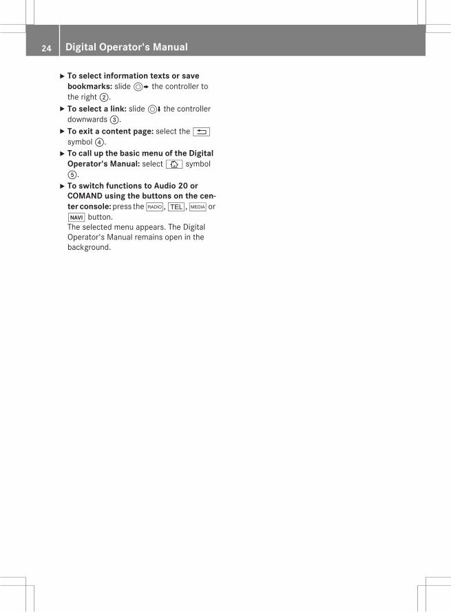
X To select information texts or savebookmarks: slide9 the controller tothe right;.X To select a link: slide6 the controllerdownwards=.X To exit a content page: select the%symbol?.X To call up the basic menu of the Digital
Operator's Manual: selectÞ symbolA.X To switch functions to Audio 20 or
COMAND using the buttons on the cen-ter console:press the$,%,ÕorØ button.The selected menu appears. The DigitalOperator's Manual remains open in thebackground.
24 Digital Operator's Manual

Protection of the environment
General notes
H Environmental noteDaimler's declared policy is one of compre-hensive environmental protection.The objectives are for the natural resourcesthat form the basis of our existence on thisplanet to be used sparingly and in a mannerthat takes the requirements of both natureand humanity into account.You too can help to protect the environmentby operating your vehicle in an environmen-tally responsible manner.Fuel consumption and the rate of engine,transmission, brake and tire wear are affectedby these factors:Roperating conditions of your vehicleRyour personal driving styleYou can influence both factors. You shouldbear the following in mind:Operating conditions:Ravoid short trips as these increase fuel con-sumption.
Ralways make sure that the tire pressuresare correct.
Rdo not carry any unnecessary weight.Rremove roof racks once you no longer needthem.
Ra regularly serviced vehicle will contributeto environmental protection. You shouldtherefore adhere to the service intervals.
Ralways have service work carried out at aqualified specialist workshop.
Personal driving style:Rdo not depress the accelerator pedal whenstarting the engine.
Rdo notwarmup the enginewhen the vehicleis stationary.
Rdrive carefully and maintain a safe distancefrom the vehicle in front.
Ravoid frequent, sudden acceleration andbraking.
Rchange gear in good time and use each gearonly up toÔ of its maximum engine speed.
Rswitch off the engine in stationary traffic.Rkeep an eye on the vehicle's fuel consump-tion.
Environmental concerns and recom-mendationsWherever the operating instructions requireyou to dispose of materials, first try to regen-erate or re-use them. Observe the relevantenvironmental rules and regulations whendisposing of materials. In this way you willhelp to protect the environment.
Genuine Mercedes-Benz parts
H Environmental noteDaimler AG also supplies reconditionedmajorassemblies and parts which are of the samequality as new parts. They are covered by thesame Limited Warranty entitlements as newparts.
! Air bags and Emergency Tensioning Devi-ces, as well as control units and sensors forthese restraint systems, may be installed inthe following areas of your vehicle:RdoorsRdoor pillarsRdoor sillsRseatsRcockpitRinstrument clusterRcenter consoleDo not install accessories such as audiosystems in these areas. Do not carry outrepairs or welding. You could impair theoperating efficiency of the restraint sys-tems.Have aftermarket accessories installed at aqualified specialist workshop.
Introduction 25
Z

You could jeopardize the operating safety ofyour vehicle if you use parts, tires and wheelsas well as accessories relevant to safetywhich have not been approved by Mercedes.This could lead to malfunctions in safety-rel-evant systems, e.g. the brake system. Useonly genuine Mercedes-Benz parts or parts ofequal quality. Only use tires, wheels andaccessories that have been specificallyapproved for your vehicle.Genuine Mercedes-Benz parts are subject tostrict quality control. Every part has been spe-cifically developed, manufactured or selectedfor and adapted to Mercedes-Benz vehicles.Only genuine Mercedes-Benz parts shouldtherefore be used.More than 300,000 different genuineMercedes-Benz parts are available forMercedes-Benz models.All authorized Mercedes-Benz Centers main-tain a supply of genuineMercedes-Benz partsfor necessary service and repair work. In addi-tion, strategically located parts delivery cen-ters provide quick and reliable parts service.Always specify the vehicle identification num-ber (VIN) when ordering genuine Mercedes-Benz parts (Y page 320).
Operator's Manual
Vehicle equipmentThis Operator's Manual describes all modelsand all standard and optional equipment ofyour vehicle available at the time of going toprint. Country-specific differences are possi-ble. Bear in mind that your vehicle may notfeature all functions described here. This alsoapplies to safety-relevant systems and func-tions. The equipment in your vehicle maytherefore differ from that shown in thedescriptions and illustrations.The original purchase agreement lists all sys-tems installed in your vehicle.Should you have any questions concerningequipment and operation, please consult anauthorized Mercedes-Benz Center.
The Operator's Manual and MaintenanceBooklet are important documents and shouldbe kept in the vehicle.
Service and vehicle operation
WarrantyThe implied warranty for your vehicle appliesin accordance with the warranty terms andconditions in the Service and Warranty Infor-mation booklet.Your authorized Mercedes-Benz Center willreplace and repair all factory-installed parts inaccordancewith the followingwarranty termsand conditions:RNew Vehicle Limited WarrantyREmission System WarrantyREmission Performance WarrantyRCalifornia, Connecticut, Maine, Massachu-setts, New York, Pennsylvania, RhodeIsland and Vermont Emission Control Sys-tem Warranty
RState warranty enforcement laws (lemonlaws)
Replacement parts and accessories are cov-ered by the Mercedes-Benz Parts and Acces-sories warranties. These are available at anyauthorized Mercedes-Benz Center.
i Should you lose your Service and War-ranty Information booklet, have an author-ized Mercedes-Benz Center arrange for areplacement. The new Service and War-ranty Information booklet will be posted toyou.
26 Introduction

Information for customers in Califor-niaUnder California law you may be entitled to areplacement of your vehicle or a refund of thepurchase price or lease price, if after a rea-sonable number of repair attemptsMercedes-Benz USA, LLC and/or its author-ized repair or service facilities fail to fix one ormore substantial defects or malfunctions inthe vehicle that are covered by its expresswarranty. During the period of 18 monthsfrom original delivery of the vehicle or theaccumulation of 18,000miles (approximately29,000 km) on the odometer of the vehicle,whichever occurs first, a reasonable numberof repair attempts is presumed for a retailbuyer or lessee if one or more of the followingoccurs:(1) the same substantial defect or malfunc-
tion results in a condition that is likely tocause death or serious bodily injury if thevehicle is driven, that defect or malfunc-tion has been subject to repair two ormore times, and you have directly noti-fied Mercedes-Benz USA, LLC in writingof the need for its repair,
(2) the same substantial defect or malfunc-tion of a less serious nature than cate-gory (1) has been subject to repair four ormore times and you have directly notifiedus in writing of the need for its repair, or
(3) the vehicle is out of service by reason ofrepair of the same or different substantialdefects or malfunctions for a cumulativetotal of more than 30 calendar days.
Please send your written notice to:Mercedes-Benz USA, LLCCustomer Assistance CenterOne Mercedes DriveMontvale, NJ 07645-0350
MaintenanceThe Service and Warranty Booklet describesall the necessary maintenance work whichshould be done at regular intervals.Always have the Service and Warranty Book-let with you when you bring the vehicle to anauthorized Mercedes-Benz Center. The ser-vice advisor will record every service for youin the Service and Warranty Booklet.
Roadside AssistanceThe Mercedes-Benz Roadside AssistanceProgramoffers technical help in the event of abreakdown. Calls to the toll-free RoadsideAssistance Hotline are answered by ouragents 24 hours a day, 365 days a year.1-800-FOR-MERCedes(1-800-367-6372)(USA)1-800-387-0100 (Canada)For additional information, refer to theMercedes-Benz Roadside Assistance Pro-gram brochure (USA) or the "Roadside Assis-tance" section in the Service and Warrantybooklet (Canada). You will find both in yourvehicle literature portfolio.
Change of address or change of own-ershipIn the event of a change of address, pleasesend us the "Notification of Address Change"in the Service and Guarantee booklet or sim-ply call the Mercedes-Benz Customer Assis-tance Center (USA) at the hotline number1-800-FOR-MERCedes(1-800-367-6372) orCustomer Service Center (Canada) at1-800-387-0100. This will assist us in con-tacting you in a timely manner should theneed arise.If you sell your Mercedes, please leave theentire literature in the vehicle so that it isavailable to the next owner.If you have purchased a used car, please sendus the "Notification of Used Car Purchase" in
Introduction 27
Z
the Service and Guarantee booklet or simplycall the Mercedes-Benz Customer AssistanceCenter (USA) at the hotline number1-800-FOR-MERCedes(1-800-367-6372) orCustomer Service (Canada) at1-800-387-0100.
Vehicle operation outside the USAand CanadaIf you plan to operate your vehicle in foreigncountries, please be aware that:Rservice facilities or replacement parts maynot be readily available.
Runleaded fuel for vehicles with a catalyticconvertermay not be available. Leaded fuelmay cause damage to the catalytic con-verter.
Rthe fuel may have a considerably loweroctane rating. Unsuitable fuel can causeengine damage.
Some Mercedes-Benz models are availablefor delivery in Europe through our EuropeanDelivery Program. For details, consult anauthorized Mercedes-Benz Center or write toone of the following addresses.In the USAMercedes-Benz USA, LLCEuropean Delivery DepartmentOne Mercedes DriveMontvale, NJ 07645-0350In CanadaMercedes-Benz Canada, Inc.European Delivery Department98 Vanderhoof AvenueToronto, Ontario M4G 4C9
Operating safety
Important safety notes
G WARNINGIf you do not have the prescribed service/maintenance work or any required repairs
carried out, this can result in malfunctions orsystem failures. There is a risk of an accident.Always have the prescribed service/mainte-nance work as well as any required repairscarried out at a qualified specialist workshop.
G WARNINGFlammable material such as leaves, grass ortwigsmay ignite if they come into contactwithhot parts of the exhaust system. There is a riskof fire.When driving off road or on unpaved roads,check the vehicle's underside regularly. Inparticular, remove parts of plants or otherflammable materials which have becometrapped. In the case of damage, contact aqualified specialist workshop.
G WARNINGModifications to electronic components, theirsoftware as well as wiring can impair theirfunction and/or the function of other net-worked components. In particular, systemsrelevant to safety could also be affected. As aresult, these may no longer function as inten-ded and/or jeopardize the operating safety ofthe vehicle. There is an increased risk of anaccident and injury.Never tamper with the wiring as well as elec-tronic components or their software. Youshould have all work to electrical and elec-tronic equipment carried out at a qualifiedspecialist workshop.
! There is a risk of damage to the vehicle if:Rthe vehicle becomes stuck, e.g. on a highcurb or an unpaved road
Ryou drive too fast over an obstacle, e.g. acurb or a hole in the road
Ra heavy object strikes the undercarriageor parts of the chassis
In situations like this, the body, the under-carriage, chassis parts, wheels or tirescould be damaged without the damagebeing visible. Components damaged in thisway can unexpectedly fail or, in the case of
28 Introduction

an accident, no longer withstand the strainthey are designed to.If the underbody paneling is damaged,combustible materials such as leaves,grass or twigs can gather between theunderbody and the underbody paneling. Ifthese materials come in contact with hotparts of the exhaust system, they can catchfire.In such situations, have the vehiclechecked and repaired immediately at aqualified specialist workshop. If on con-tinuing your journey you notice that drivingsafety is impaired, pull over and stop thevehicle immediately, paying attention toroad and traffic conditions. In such cases,consult a qualified specialist workshop.
Declarations of conformity
Vehicle components which receiveand/or transmit radio wavesUSA: "The wireless devices of this vehiclecomply with Part 15 of the FCC Rules. Oper-ation is subject to the following two condi-tions: 1) These devices may not cause harm-ful interference, and 2) These devices mustaccept any interference received, includinginterference that may cause undesired oper-ation. Changes ormodifications not expresslyapproved by the party responsible for com-pliance could void the user’s authority tooperate the equipment."Canada: "The wireless devices of this vehiclecomply with Industry Canada license-exemptRSS standard(s). Operation is subject to thefollowing two conditions: (1) These devicesmay not cause interference, and (2) Thesedevicesmust accept any interference, includ-ing interference that may cause undesiredoperation of the device."
Diagnostics connectionThe diagnostics connection is only intendedfor the connection of diagnostic equipment ata qualified specialist workshop.
G WARNINGIf you connect equipment to the diagnosticsconnection in the vehicle, it may affect theoperation of the vehicle systems. As a result,the operating safety of the vehicle could beaffected. There is a risk of an accident.Do not connect any equipment to a diagnos-tics connection in the vehicle.
G WARNINGObjects in the driver's footwell can restrict thepedal travel or obstruct a depressed pedal.The operating and road safety of the vehicle isjeopardized. There is a risk of an accident.Make sure that all objects in the vehicle arestowed correctly, and that they cannot enterthe driver's footwell. Install the floormatssecurely and as specified in order to ensuresufficient clearance for the pedals. Do not useloose floormats and do not place floormats ontop of one another.
! If the engine is switched off and equip-ment on the diagnostics connection isused, the starter battery may discharge.
Connecting equipment to the diagnosticsconnection can lead to emissions monitoringinformation being reset, for example. Thismay lead to the vehicle failing to meet therequirements of the next emissions test dur-ing the main inspection.
Qualified specialist workshopAn authorized Mercedes-Benz Center is aqualified specialist workshop. It has the nec-essary specialist knowledge, tools and quali-fications to correctly carry out the workrequired on your vehicle. This is especially thecase for work relevant to safety.
Introduction 29
Z

Observe the notes in the Maintenance Book-let.Always have the following work carried out atan authorized Mercedes-Benz Center:Rwork relevant to safetyRservice and maintenance workRrepair workRalterations, installation work and modifica-tions
Rwork on electronic components
Correct useIf you remove any warning stickers, you orothers could fail to recognize certain dangers.Leave warning stickers in position.Observe the following information when driv-ing your vehicle:Rthe safety notes in this manualRthe vehicle technical dataRtraffic rules and regulationsRlaws and safety standards pertaining tomotor vehicles
Problems with your vehicleIf you should experience a problem with yourvehicle, particularly one that you believe mayaffect its safe operation, we urge you to con-tact an authorized Mercedes-Benz Centerimmediately to have the problem diagnosedand rectified. If the problem is not resolved toyour satisfaction, please discuss the problemagain with a Mercedes-Benz Center or con-tact us at one of the following addresses.In the USACustomer Assistance CenterMercedes-Benz USA, LLCOne Mercedes DriveMontvale, NJ 07645-0350In CanadaCustomer Relations DepartmentMercedes-Benz Canada, Inc.
98 Vanderhoof AvenueToronto, Ontario M4G 4C9
Reporting safety defectsUSA only:The following text is published as required ofmanufacturers under Title 49, Code of U.S.Federal Regulations, Part 575 pursuant to the"National Traffic andMotor Vehicle Safety Actof 1966".If you believe that your vehicle has a defectwhich could cause a crash or could causeinjury or death, you should immediatelyinform the National Highway Traffic SafetyAdministration (NHTSA) in addition to notify-ing Mercedes-Benz USA, LLC.If NHTSA receives similar complaints, it mayopen an investigation, and if it finds that asafety defect exists in a group of vehicles, itmay order a recall and remedy campaign.However, NHTSA cannot become involved inindividual problems between you, yourdealer, or Mercedes-Benz USA, LLC.To contact NHTSA, you may call the VehicleSafety Hotline toll-free at1-888-327-4236(TTY: 1-800-424-9153); goto http://www.safercar.gov; or write to:Administrator, NHTSA, 400 Seventh Street,SW., Washington, DC 20590.You can also obtain other information aboutmotor vehicle safety fromhttp://www.safercar.gov
Limited Warranty! Follow the instructions in this manualabout the proper operation of your vehicleas well as about possible vehicle damage.Damage to your vehicle that arises fromculpable contraventions against theseinstructions is not covered either by theMercedes-Benz Limited Warranty or by theNew or Used-Vehicle Warranty.
30 Introduction

QR codes for the rescue card
The QR codes are secured in the fuel filler flapand on the opposite side on the B-pillar. In theevent of an accident, rescue services can usethe QR code to quickly find the appropriaterescue card for your vehicle. The current res-cue card contains the most important infor-mation about your vehicle in a compact form,e.g. the routing of the electric cables.You can findmore information under https://portal.aftersales.i.daimler.com/public/content/asportal/en/communication/informationen_fuer/QRCode.html.
Data stored in the vehicle
Data recordingThis vehicle is capable of recording diagnosticinformation relating to vehicle operation,mal-functions, and user settings. This may includeinformation about the performance or statusof various systems, including but not limitedto, engine, throttle, steering or brake sys-tems, that is stored and can be read out withsuitable devices, particularly when the vehi-cle is serviced. The data obtained is used toproperly diagnose and service your vehicle orto further optimize and develop vehicle func-tions.
COMAND/mbraceIf the vehicle is equipped with COMAND ormbrace, additional data about the vehicle’soperation, the use of the vehicle in certainsituations, and the location of the vehiclemaybe compiled through COMAND or thembracesystem.For additional information please refer to theCOMAND User Manual and/or the mbraceTerms and Conditions.
Event data recordersThis vehicle is equipped with an event datarecorder (EDR). The main purpose of an EDRis to record data that will assist in under-standing how a vehicle’s systems performedin certain crash or near crash-like situations,such as during air bag deployment or whenhitting a road obstacle. The EDR is designedto record data related to vehicle dynamicsand safety systems for a short period of time,typically 30 seconds or less.The EDR in this vehicle is designed to recordsuch data as:Rhow various systems in your vehicle areoperating
Rwhether or not the driver and passengerseat belts are fastened
Rhow far (if at all) the driver is depressing theaccelerator and/or brake pedal and
Rhow fast the vehicle is travelingThis data can help provide a better under-standing of the circumstances in whichcrashes and injuries occur. NOTE: EDR data isrecorded by your vehicle only if a non-trivialcrash situation occurs; no data is recorded bythe EDR under normal driving conditions andno personal data (e.g., name, gender, age,and crash location) are recorded. However,other parties, such as law enforcement, cancombine the EDR data with the type of per-sonal identification data routinely acquiredduring a crash investigation.To read data recorded by an EDR, specialequipment is required, and access to the vehi-cle or the EDR is needed. In addition to thevehicle manufacturer, other parties that havethe special equipment, such as law enforce-ment, can read the information by accessingthe vehicle or the EDR.EDR data may be used in civil and criminalmatters as a tool in accident reconstruction,accident claims, and vehicle safety. Since theCrash Data Retrieval CDR tool that is used toextract data from the EDR is commerciallyavailable, Mercedes-Benz USA, LLC
Introduction 31
Z

("MBUSA") expressly disclaims any and all lia-bility arising from the extraction of this infor-mation by unauthorized Mercedes-Benz per-sonnel.MBUSA will not share EDR data with otherswithout the consent of the vehicle owners or,if the vehicle is leased, without the consent ofthe lessee. Exceptions to this representationinclude responses to subpoenas by lawenforcement; by federal, state or local gov-ernment; in connection with or arising out oflitigation involving MBUSA or its subsidiariesand affiliates; or, as required by law.Warning: The EDR is a component of theRestraint System Module. Tampering with,altering, modifying or removing the EDR com-ponent may result in a malfunction of theRestraint System Module and other systems.State laws or regulations regarding EDRs thatconflict with federal regulation are pre-emp-ted. This means that in the event of such con-flict, the federal regulation governs. As ofFebruary 2013, 13 states have enacted lawsrelating to EDRs.
Information on copyright
General informationInformation on license for free and open-source software used in your vehicle and itselectronic components is available on the fol-lowing website:http://www.mercedes-benz.com/opensource
32 Introduction

Cockpit ................................................. 34Instrument cluster .............................. 35Multifunction steering wheel ............. 37Center console .................................... 38Overhead control panel ...................... 41Door control panel .............................. 42
33
Ata
glan
ce

Cockpit
Function Page
: Steering wheel paddleshifters ~
; Combination switch 113
= Horn
? Instrument cluster 35
A DIRECT SELECT lever 137
B Climate control systems 122
C Overhead control panel 41
D Control panel for Audio 20/COMAND and vehicle func-tions 38
E Ignition lock 129Start/Stop button 130
F Adjusts the steering wheel ~
G Cruise control lever 146
Function Page
H Electric parking brake 142
I Diagnostics connection 29
J Opens the hood 254
K Light switch 112
L Control panel for:Activating Steering Assist ~
Switching on Active LaneKeeping Assist 172c PARKTRONIC ~
Deactivating PARKTRONIC ~
Switching on the360° cam-era 163Switching on the head-updisplay 178Vehicles without a driverassistance system: map/coin holder
34 CockpitAt
agl
ance

Instrument cluster
Displays
Function Page
: SpeedometerSpeedometer segments ~
; Multifunction display ~
= Tachometer ~
? Coolant temperature dis-play ~
Function Page
A Fuel gageFuel filler flap location indi-cator8: the fuel fillercap is on the right-handside.
i Information on displaying the outsidetemperature in the multifunction displaycan be found under "Outside temperaturedisplay" in the Digital Operator's Manual.
Instrument cluster 35
Ata
glan
ce

Warning and indicator lamps
Function Page
: å ESP® OFF 201
; ÷ ESP® 201
= · Distance warning 205
? Ð Power steering 207
A #! Turn signals ~
B ! Electric parking brake(yellow) ~
C ! ABS 199
D ; Check Engine 195
E Electric parking brake (red) ~
F USA only! Canada only
F Brakes (red) 198$ USA onlyJ Canada only
G ? Coolant 204
Function Page
H M SPORT handlingmode in AMG vehicles 203
I J Brakes (yellow) 198
J 6 Restraint system 44
K ü Seat belt 196
L K High-beam head-lamps ~
M L Low-beam head-lamps ~
N 8 Reserve fuel ~
O T Parking lamps,license plate lamps andinstrument cluster lighting 112
P N Fog lamps ~
Q R Rear fog lamp ~
R h Tire pressure monitor 206
36 Instrument clusterAt
agl
ance
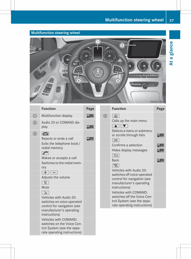
Multifunction steering wheel
Function Page
: Multifunction display ~
; Audio 20 or COMAND dis-play ~
= ~
Rejects or ends a call ~
Exits the telephone book/redial memory6
Makes or accepts a callSwitches to the redialmem-oryWX
Adjusts the volume8
Muteó
Vehicles with Audio 20:switches on voice-operatedcontrol for navigation (seemanufacturer's operatinginstructions)Vehicles with COMAND:switches on the Voice Con-trol System (see the sepa-rate operating instructions)
Function Page
? ò
Calls up the main menu9:
Selects amenu or submenuor scrolls through lists ~
a
Confirms a selection ~
Hides display messages ~
%
Back ~
ñ
Vehicles with Audio 20:switches off voice-operatedcontrol for navigation (seemanufacturer's operatinginstructions)Vehicles with COMAND:switches off the Voice Con-trol System (see the sepa-rate operating instructions)
Multifunction steering wheel 37
Ata
glan
ce

Center console
Center console, upper section
Function Page
: Climate control systems 122
; £ Hazard warninglamps ~
= Vehicle functions button ~
? Telephone button ~
A PASSENGER AIR BAG indi-cator lamp 45ATA indicator lamp 81
Function Page
B Analog clock (not availableon all equipment levels)
C Media button ~
D Radio button ~
E Navigation button ~
F þ Inserts or ejects a CDor DVD ~
38 Center consoleAt
agl
ance

Center console, lower section
Function Page
: Stowage compartment ~
Ashtray ~
Cigarette lighter ~
Socket ~
Cup holder ~
; Adjusts the volume/mute ~
= Switches audio orCOMAND on or off ~
? u Rear window rollersunblind ~
A Touchpad (see the separateoperating instructions)
B Stowage compartment ~
Function Page
C è ECO start/stop func-tion ~
D É Sets the vehicle level ~
E AGILITY SELECT switch ~
F Back button (see the sepa-rate operating instructions)
G Audio or COMAND control-ler (see the separate oper-ating instructions)
H g Switches to the favor-ites button (see the sepa-rate operating instructions)
Center console 39
Ata
glan
ce

Center console, lower section (AMG vehicles)
Function Page
: Ashtray ~
Cigarette lighter ~
Socket ~
Cup holder ~
; Adjusts the volume/mute(see the separate operatinginstructions)
= Adjusts the volume of theAMG sports exhaust sys-tem 134
? è ECO start/stop func-tion ~
A Touchpad (see the separateoperating instructions)
B Stowage compartment ~
C Activates or deactivatesESP® 76Activates or deactivatesSPORT handling mode 76
Function Page
D AMG adaptive sport sus-pension system (suspen-sion setting) 157
E Manual gearshifting (per-manent setting) ~
F DYNAMIC SELECT switch(selects the drive program) 135
G Back button (see the sepa-rate operating instructions)
H Audio 20 or COMAND con-troller (see the separateoperating instructions)
I g Switches to the favor-ites button (see the sepa-rate operating instructions)
40 Center consoleAt
agl
ance

Overhead control panel
Function Page
: p Switches the left-hand reading lamp on/off ~
; | Switches the auto-matic interior lighting con-trol on/off ~
= G SOS button (mbracesystem) 246
? c Switches the frontinterior lighting on/off ~
A u Switches the rearinterior lighting on/off ~
B p Switches the right-hand reading lamp on/off ~
C ï MB Info call button(mbrace system) 248
D Eyeglasses compartment ~
Function Page
E 3 Opens/closes thepanorama roof with powertilt/sliding panel 100Opens/closes the rollersunblinds 101
F Rear-view mirror ~
G Buttons for the garage dooropener 249
H Microphone for mbrace(emergency call system),telephone and the VoiceControl System; see theseparate operating instruc-tions
I F Roadside Assistancecall button (mbrace sys-tem) 247
Overhead control panel 41
Ata
glan
ce

Door control panel
Function Page
: r4 5 =Stores settings for the seat,exterior mirrors and steer-ing wheel ~
; Adjusts the seats electri-cally ~
= c Seat heating ~
? s Seat ventilation ~
A Opens the door ~
B %& Unlocks/locksthe vehicle ~
C W Opens/closes therear left side window ~
D WOpens/closes the leftside window ~
Function Page
E 7Zª\Adjusts and folds the exte-rior mirrors in/out electri-cally ~
F W Opens/closes theright side window ~
G W Opens/closes therear right side window ~
H n Override feature forthe controls in the rearcompartment 68
I p Opens/closes thetrunk lid 94
42 Door control panelAt
agl
ance

Useful information .............................. 44Panic alarm .......................................... 44Occupant safety .................................. 44Children in the vehicle ........................ 62Pets in the vehicle ............................... 68Driving safety systems ....................... 69Protection against theft ..................... 80
43
Safe
ty

Useful information
i This Operator's Manual describes allmodels and all standard and optional equip-ment of your vehicle available at the time ofpublication of the Operator's Manual.Country-specific differences are possible.Please note that your vehicle may not beequipped with all features described. Thisalso applies to safety-related systems andfunctions.
i Read the information on qualified special-ist workshops (Y page 29).
Panic alarm
X To activate: press! button: for atleast one second.A visual and audible alarm is triggered if thealarm system is armed.X To deactivate: press! button:again.
orX Insert the SmartKey into the ignition lock.or, in vehicles with KEYLESS-GO start-func-tion or KEYLESS゙GOX Press the Start/Stop button.The SmartKey must be in the vehicle.
Occupant safety
Restraint system: introductionThe restraint system can reduce the risk ofvehicle occupants coming into contact withparts of the vehicle's interior in the event ofan accident. The restraint system can alsoreduce the forces to which vehicle occupantsare subjected during an accident.The restraint system comprises:RSeat belt systemRAir bagsRChild restraint systemRChild seat securing systemsThe components of the restraint systemworkin conjunction with each other. They can onlydeploy their protective function if, at all times,all vehicle occupants:Rhave fastened their seat belts correctly(Y page 48)
Rhave adjusted their seat and head restraintproperly (Y page 107).
As the driver, you also have to make sure thatthe steering wheel is adjusted correctly.Observe the information relating to the cor-rect driver's seat position (Y page 106).You also have tomake sure that an air bag caninflate properly if deployed (Y page 50).An air bag supplements a correctly worn seatbelt. As an additional safety device, the airbag increases the level of protection for vehi-cle occupants in the event of an accident. Forexample, if, in the event of an accident, theprotection offered by the seat belt is suffi-cient, the air bags are not deployed. When anaccident occurs, only the air bags thatincrease protection in that particular accidentsituation are deployed. However, seat beltsand air bags generally do not protect againstobjects penetrating the vehicle from the out-side.Information on restraint system operationcan be found under "Triggering of the Emer-gency Tensioning Devices and air bags"(Y page 59).
44 Occupant safetySa
fety

For more information about children travelingwith you in the vehicle and on child restraintsystems, see "Children in the vehicle"(Y page 62).
Important safety notes
G WARNINGModifications to the restraint system maycause it to no longer work as intended. Therestraint system may then not perform itsintended protective function andmay fail in anaccident or trigger unexpectedly, for example.This poses an increased risk of injury or evenfatal injury.Never modify parts of the restraint system.Never tamper with the wiring, the electroniccomponents or their software.If it is necessary tomodify an air bag system toaccommodate a person with disabilities, con-tact an authorized Mercedes-Benz Center fordetails. USA only: for further information con-tact our Customer Assistance Center at1-800-FOR-MERCedes (1゙800゙367゙6372).
Restraint system warning lampThe functions of the restraint system arechecked after the ignition is switched on andat regular intervals while the engine is run-ning. Therefore, malfunctions can be detec-ted in good time.The6 restraint system warning lamp inthe instrument cluster lights upwhen the igni-tion is switched on. It goes out no later than afew seconds after the vehicle is started. Thecomponents of the restraint system are inoperational readiness.A malfunction has occurred if the6restraint system warning lamp:Rdoes not light up after the ignition isswitched on
Rdoes not go out after a few seconds withthe engine running
Rlights up again while the engine is running
G WARNINGIf restraint system is malfunctioning, restraintsystem components may be triggered unin-tentionally or might not be triggered at all inthe event of an accident with a high rate ofvehicle deceleration. This can affect the Emer-gency Tensioning Device or air bag, for exam-ple. This poses an increased risk of injury oreven fatal injury.Have the restraint system checked andrepaired in a qualified specialist workshop assoon as possible.
PASSENGER AIR BAG indicator lamp
PASSENGER AIR BAG ON indicator lamp:and PASSENGER AIR BAG OFF indicatorlamp; are part of the Occupant Classifica-tion System (OCS).The indicator lamps display the status of thefront-passenger front air bag.RPASSENGER AIR BAG ON lights up: thefront-passenger front air bag is enabled. If,in the event of an accident, all deploymentcriteria are met, the front-passenger frontair bag is deployed.
RPASSENGER AIR BAG OFF lights up: thefront-passenger front air bag is deactiva-ted. It will then not be deployed in the eventof an accident.
Occupant safety 45
Safe
ty
Z

Depending on the person in the front-passenger seat, the front-passenger front airbag must either be deactivated or enabled;see the following points. You must make sureof this both before and during a journey.RChildren in a child restraint system:whether the front-passenger front air bag isenabled or deactivated depends on theinstalled child restraint system, and the ageand size of the child. Therefore, be sure toobserve the notes on the "Occupant Clas-sification System (OCS)" (Y page 53) andon "Children in the vehicle" (Y page 62).There youwill also find instructions on rear-ward and forward-facing child restraint sys-tems on the front-passenger seat.
RAll other persons: depending on the clas-sification of the person in the front-passenger seat, the front-passenger frontair bag is enabled or deactivated(Y page 53). Be sure to observe the noteson "Seat belts“ (Y page 46) and "Air bags"(Y page 50). There you can also find infor-mation on the correct seat position.
Seat belts
IntroductionSeat belts are the most effective means ofrestricting the movement of vehicle occu-pants in the event of an accident or the vehi-cle rolling over. This reduces the risk of vehi-cle occupants coming into contact with partsof the vehicle interior or being ejected fromthe vehicle. Furthermore, the seat belt helpsto keep the vehicle occupant in the best posi-tion in relation to the air bag.The seat belt system comprises:RSeat beltsREmergency Tensioning Devices for thefront seat belts and the outer seat belts inthe rear
RSeat belt force limiters for the front seatbelts and the outer seat belts in the rear
If the seat belt is pulled out of the belt outletquickly or with a jerky movement, the beltretractor locks. The belt strap cannot beextracted any further.The Emergency Tensioning Device tightensthe seat belt in an accident, pulling the beltclose against the body. However it does notpull the vehicle occupant back in the directionof the backrest.The Emergency Tensioning Device does notcorrect an incorrect seat position or the rout-ing of an incorrectly fastened seat belt.When triggered, a seat belt force limiter helpsto reduce the force exerted by the seat belt onthe vehicle occupant.The seat belt force limiters for the front seatsare synchronized with the front air bags,which absorb part of the deceleration force.This can reduce the force exerted on the vehi-cle occupants during an accident.
! If the front-passenger seat is unoccupied,do not insert the belt tongue into the buckleof the front-passenger seat. This may oth-erwise lead to the triggering of the Emer-gency Tensioning Device in the event of anaccident, which will then need to bereplaced.
Important safety notesThe use of seat belts and child restraint sys-tems is required by law in:Rall 50 statesRthe U.S. territoriesRthe District of ColumbiaRall Canadian provincesEven where this is not required by law, allvehicle occupants should correctly fastentheir seat belts before starting the journey.
G WARNINGIf the seat belt is incorrectly fastened, it can-not protect as intended. Furthermore, anincorrectly fastened seat belt can cause addi-tional injury, for example, in an accident, dur-ing braking or when abruptly changing direc-
46 Occupant safetySa
fety

tion. This poses an increased risk of injury oreven fatal injury.Make sure that all vehicle occupants areseated properly with a correctly fastened seatbelt.
G WARNINGThe seat belt does not offer the intended levelof protection if you have not moved the back-rest to an almost vertical position. When brak-ing or in the event of an accident, you couldslide underneath the seat belt and sustainabdomen or neck injuries, for example. Thisposes an increased risk of injury or even fatalinjury.Adjust the seat properly before beginningyour journey. Always ensure that the backrestis in an almost vertical position and that theshoulder section of your seat belt is routedacross the center of your shoulder.
G WARNINGPersons under 5 ft (1.50 m) in height cannotfasten the seat belt correctly without an addi-tional suitable restraint system. If the seatbelt is incorrectly fastened, it cannot protectas intended. Furthermore, an incorrectly fas-tened seat belt can cause additional injury, forexample, in an accident, during braking or anabrupt change of direction. This poses anincreased risk of injury or even fatal injury.For this reason, always secure persons under5 ft (1.50 m) in height in suitable restraintsystems.
If a child younger than twelve years old andunder 5 ft (1.50 m) in height is traveling in thevehicle:Ralways secure the child in a child restraintsystem suitable for this Mercedes-Benzvehicle. The child restraint system must beappropriate to the age, weight and size ofthe child
Ralways observe the instructions and safetynotes in the "Children in the vehicle" sec-tion of this Operator's Manual
(Y page 62) in addition to the childrestraint system manufacturer's installa-tion instructions
Rbe sure to observe the instructions andsafety notes on the "Occupant classifica-tion system (OCS)" (Y page 53)
G WARNINGThe seat belts may not perform their intendedprotective function if:Rthey are damaged, modified, extremelydirty, bleach or dyed
Rthe seat belt buckle is damaged orextremely dirty
Rthe Emergency Tensioning Devices, beltanchorages or inertia reels have beenmodi-fied
Seat belts may sustain non-visible damage inan accident, e.g. due to glass splinters. Modi-fied or damaged seat belts may tear or fail,e.g. in an accident. Modified Emergency Ten-sioning Devices could accidentally trigger orfail to deploy when necessary. This poses anincreased risk of injury or even fatal injury.Never modify the seat belts, Emergency Ten-sioning Devices, belt anchorages or inertiareels. Make sure that the seat belts areundamaged, not worn out and clean. Follow-ing an accident, have the seat belts checkedimmediately at a qualified specialist work-shop.
Only use seat belts that have been approvedfor your vehicle by Mercedes-Benz. Any suchmodifications could invalidate the vehicle'sgeneral operating permit.Vehicles with AMG Performance seats:these seats are designed for the standardthree-point seat belt. If you install anothermulti-point seat belt, e.g. sport or racing seatbelts, the restraint system cannot provide thebest level of protection.
G WARNINGIf you feed seat belts through the opening inthe seat backrest, the seat backrest may bedamaged or may even break in the event of an
Occupant safety 47
Safe
ty
Z

accident. This poses an increased risk ofinjury or even fatal injury.Only use the standard three-point seat belt.Never modify the seat belt system.
Proper use of the seat beltsObserve the safety notes on the seat belt(Y page 46).All vehicle occupants must be wearing theseat belt correctly before beginning the jour-ney. Also make sure that all vehicle occu-pants are always wearing the seat belt cor-rectly while the vehicle is in motion.When fastening the seat belt, always makesure that:Rthe seat belt tongue is only inserted to thebelt buckle belonging to that seat.
Rthe seat belt is tight across your body.Avoid wearing bulky clothing, e.g. a wintercoat.
Rthe seat belt is not twisted.Only then can the forces which occur bedistributed over the area of the belt.
Rthe shoulder section of the belt is alwaysrouted across the center of your shoulder.The shoulder section of the belt must notcome into contact with your neck or berouted under your arm. Where possible,adjust the seat belt to the appropriateheight.
Rthe lap belt passes tightly and as low downas possible across your lap.The lap belt must always be routed acrossyour hip joints and not across your abdo-men. This applies particularly to pregnantwomen. If necessary, push the lap beltdown to your hip joint and pull it tight usingthe shoulder section of the belt.
Rthe seat belt is not routed across sharp,pointed or fragile objects.If you have such items located on or in yourclothing, e.g. pens, keys or eyeglasses,store these in a suitable place.
Ronly one person is using a seat belt at atime.Infants and children must never travel sit-ting on the lap of a vehicle occupant. In theevent of an accident, they could be crushedbetween the vehicle occupant and seatbelt.
Robjects are never secured with a seat belt ifthe seat belt is also being used by one of thevehicle's occupants.
Seat belts are only intended to secure andrestrain vehicle occupants. Always observethe "Loading guidelines" for securing objects,luggage or loads (Y page 236).
Fastening and adjusting the seat beltsObserve the safety notes on the seat belt(Y page 46) and the notes on correct use ofseat belts (Y page 48).If the center rear seat belt is being used, alsoobserve the information about the seat beltfor the center rear seat (Y page 49).
X Adjust the seat (Y page 106).The seat backrest must be in an almostvertical position.X Pull the seat belt smoothly from belt outlet= and engage belt tongue; into beltbuckle:.The seat belt on the driver’s seat and thefront-passenger seat may be tightened
48 Occupant safetySa
fety

automatically, see "Belt adjustment"(Y page 49).X If necessary, pull upwards on the shouldersection of the seat belt to tighten the beltacross your body.
The shoulder section of the seat belt mustalways be routed across the center of theshoulder. Adjust the belt outlet if necessary.X To raise: slide the belt outlet upwards.The belt outlet will engage in various posi-tions.X To lower: hold belt outlet release: andslide belt outlet downwards.X Let go of belt outlet release: in thedesired position and make sure that thebelt outlet engages.
All seat belts except the driver's seat belt areequipped with a special seat belt retractor tosecurely fasten child restraint systems in thevehicle. Further information can be foundunder "Special seat belt retractor"(Y page 63).
Seat belt for the center rear seatIf the left-hand rear seat backrest is foldeddown and back up again, the rear center seatbelt may lock. The seat belt can then not bepulled out.X To release the rear center seat belt: pullthe seat belt out approximately 1 in(25 mm) at the belt outlet on the backrestand then release it again.The seat belt is retracted and released.
Releasing seat belts
! Make sure that the seat belt is fully rolledup. Otherwise, the seat belt or belt tonguewill be trapped in the door or in the seatmechanism. This could damage the door,the door trim panel and the seat belt. Dam-aged seat belts can no longer fulfill theirprotective function and must be replaced.Visit a qualified specialist workshop.
X Press release button:, hold belttongue; firmly and guide it back towardsbelt outlet=.
Seat belt adjustmentThe seat-belt adjustment is an integral part ofthe PRE-SAFE® convenience function. Thisfunction adjusts the driver's and front-passenger seat belt to the upper body of theoccupants.The belt strap is tightened slightly when:Rthe belt tongue is engaged in the buckleand
Rthe ignition is switched onThe seat-belt adjustment will apply a certainretraction force if any slack is detectedbetween the vehicle occupant and the seatbelt. Do not hold on to the seat belt tightlywhile it is adjusting.
Occupant safety 49
Safe
ty
Z

You can switch the seat-belt adjustment onand off using COMAND or Audio 20. Informa-tion on activating and deactivating the seat-belt adjustment function can be found in theDigital Operator's Manual or in the separateCOMAND or Audio 20 operating instructions.
Belt warning for the driver and frontpassengerThe7 seat belt warning lamp in the instru-ment cluster is a reminder that all vehicleoccupants must wear their seat belts. It maylight up continuously or flash. In addition,there may be a warning tone.Regardless of whether the driver's seat belthas already been fastened, the7 seat beltwarning lamp lights up for six seconds eachtime the engine is started. If, aftersix seconds, the driver or front-passengerseat belt has not been fastened and the doorsare closed, the7 seat belt warning lamplights up. As soon as the driver's and front-passenger seat belts are fastened or a frontdoor is opened again, the7 seat beltwarning lamp goes out.If the driver's seat belt is not fastened afterthe engine is started, an additional warningtone will sound. This warning tone stops aftersix seconds or when the driver's seat belt isfastened.If the vehicle's speed exceeds 15 mph(25 km/h) once and the driver's and front-passenger seat belts are not fastened, awarning tone sounds. A warning tone alsosounds with increasing intensity for60 seconds or until the driver or frontpassenger have fastened their seat belts.If the driver or front passenger unfasten theirseat belts during the journey, the seat beltwarning is activated again.
i For more information on the7 seatbelt warning lamp, see "Warning and indi-cator lamps in the instrument cluster, seatbelts" (Y page 196).
Air bags
IntroductionThe installation point of an air bag can be rec-ognized by the AIR BAG symbol.An air bag complements the correctly fas-tened seat belt. It is no substitute for the seatbelt. The air bag provides additional protec-tion in applicable accident situations.Not all air bags are deployed in an accident.The different air bag systems function inde-pendently from one another (Y page 59).However, no system available today can com-pletely eliminate injuries and fatalities.It is also not possible to rule out a risk of injurycaused by an air bag due to the high speed atwhich the air bag must be deployed.
Important safety notes
G WARNINGIf you do not sit in the correct seat position,the air bag cannot protect as intended andcould even cause additional injury whendeployed. This poses an increased risk ofinjury or even fatal injury.To avoid hazardous situations, always makesure that all of the vehicle's occupants:Rhave fastened their seat belts correctly,including pregnant women
Rare sitting correctly andmaintain the great-est possible distance to the air bags
Rfollow the following instructionsAlways make sure that there are no objectsbetween the air bag and the vehicle's occu-pants.
RAdjust the seats properly before beginningyour journey. Always make sure that theseat is in an almost upright position. Thecenter of the head restraint must supportthe head at about eye level.
RMove the driver's and front-passengerseats as far back as possible. The driver'sseat position must allow the vehicle to bedriven safely.
50 Occupant safetySa
fety

ROnly hold the steering wheel on the out-side. This allows the air bag to be fullydeployed.
RAlways lean against the backrest while driv-ing. Do not lean forwards or lean againstthe door or side window. You may other-wise be in the deployment area of the airbags.
RAlways keep your feet in the footwell infront of the seat. Do not put your feet on thedashboard, for example. Your feet may oth-erwise be in the deployment area of the airbag.
RFor this reason, always secure persons lessthan 5 ft (1.50 m) tall in suitable restraintsystems. Up to this height, the seat beltcannot be worn correctly.
If a child is traveling in your vehicle, alsoobserve the following notes:RAlways secure children under twelve yearsof age and less than 5 ft (1.50 m) tall insuitable child restraint systems.
RChild restraint systems should be installedon the rear seats.
ROnly secure a child in a rearward-facingchild restraint system on the front-passenger seat when the front-passengerfront air bag is deactivated. If thePASSENGER AIR BAGOFF indicator lamp ispermanently lit, the front-passenger frontair bag is deactivated (Y page 45).
RAlways observe the instructions and safetynotes on the "Occupant Classification Sys-tem (OCS)" (Y page 53) and on "Childrenin the vehicle" (Y page 62) in addition tothe child restraint system manufacturer'sinstallation instructions.
Objects in the vehicle interior may pre-vent an air bag from functioning correctly.Before starting your journey and to avoid risksresulting from the speed of the air bag as itdeploys, make sure that:Rthere are no people, animals or objectsbetween the vehicle occupants and an airbag.
Rthere are no objects between the seat, doorand B-pillar.
Rno hard objects, e.g. coat hangers, hang onthe grab handles or coat hooks.
Rno accessories, such as cup holders, areattached to the vehicle within the deploy-ment area of an air bag, e.g. to doors, sidewindows, rear side trim or side walls.
Rno heavy, sharp-edged or fragile objectsare in the pockets of your clothing. Storesuch objects in a suitable place.
G WARNINGIf you modify the air bag cover or affix objectssuch as stickers to it, the air bag can no longerfunction correctly. There is an increased riskof injury.Never modify an air bag cover or affix objectsto it.
G WARNINGSensors to control the air bags are located inthe doors. Modifications or work not per-formed correctly to the doors or door panel-ing, as well as damaged doors, can lead to thefunction of the sensors being impaired. The airbags might therefore not function properlyany more. Consequently, the air bags cannotprotect vehicle occupants as they aredesigned to do. There is an increased risk ofinjury.Never modify the doors or parts of the doors.Always have work on the doors or door pan-eling carried out at a qualified specialist work-shop.
Occupant safety 51
Safe
ty
Z


The side impact air bag on the front-passenger side (front) deploys under the fol-lowing conditions:Rthe OCS system detects that the front-passenger seat is occupied or
Rthe belt tongue is engaged in the beltbuckle of the front-passenger seat
If the belt tongue is engaged in the beltbuckle, the side impact air bag on the front-passenger side deploys if an appropriate acci-dent situation occurs. In this case, deploy-ment is independent of whether the front-passenger seat is occupied or not.
Window curtain air bags
Window curtain air bags: are integratedinto the side of the roof frame and deployed inthe area from the A-pillar to the C-pillar.When deployed, the window curtain air bagenhances the level of protection for the head.However, it does not protect the chest orarms.In the event of a side impact, the window cur-tain air bag is deployed on the side on whichthe impact occurs.If the system determines that they can offeradditional protection to that provided by theseat belt, a window curtain air bag may bedeployed in other accident situations(Y page 59).
Occupant Classification System(OCS)
IntroductionThe Occupant Classification System (OCS)categorizes the person in the front-passengerseat. Depending on that result, the front-passenger front air bag is either enabled ordeactivated.The system does not deactivate:Rthe side impact air bagRthe window curtain air bagRthe Emergency Tensioning Devices
PrerequisitesTo be classified correctly, the front passengermust sit:Rwith the seat belt fastened correctlyRin an almost upright position with theirback against the seat backrest
Rwith their feet resting on the floor, if possi-ble
If the front passenger does not observe theseconditions, OCS may produce a false classi-fication, e.g. because the front passenger:Rtransfers their weight by supporting them-selves on a vehicle armrest
Rsits in such a way that their weight is raisedfrom the seat cushion
If it is absolutely necessary to install a childrestraint system on the front-passenger seat,be sure to observe the correct positioning ofthe child restraint system. Never placeobjects under or behind the child restraintsystem, e.g. cushions. Fully retract the seatcushion length. The entire base of the childrestraint systemmust always rest on the seatcushion of the front-passenger seat. Thebackrest of the forward-facing child restraintsystemmust lie as flat as possible against thebackrest of the front-passenger seat.The child restraint systemmust not touch theroof or be subjected to a load by the headrestraint. Adjust the angle of the seat back-
Occupant safety 53
Safe
ty
Z

rest and the head restraint position accord-ingly.Only then can OCS be guaranteed to functioncorrectly. Always observe the child restraintsystem manufacturer's installation instruc-tions.
Occupant Classification System opera-tion (OCS)
: PASSENGER AIR BAG ON indicator lamp; PASSENGER AIR BAG OFF indicator lampThe indicator lamps inform you whether thefront-passenger front air bag is deactivated orenabled.X Press the Start/Stop button once or twice,or turn the key to position 1 or 2 in theignition lock.The system carries out self-diagnostics.
The PASSENGER AIR BAG OFF andPASSENGER AIR BAG ON indicator lampsmust light up simultaneously for approx-imately six seconds.The indicator lamps display the status of thefront-passenger front air bag.RPASSENGER AIR BAG ON lights up: thefront-passenger front air bag is enabled. If,in the event of an accident, all deploymentcriteria are met, the front-passenger frontair bag is deployed.
RPASSENGER AIR BAG OFF lights up: thefront-passenger front air bag is deactiva-ted. It will then not be deployed in the eventof an accident.
If the status of the front-passenger front airbag changes while the vehicle is in motion, anair bag displaymessage appears in the instru-ment cluster (Y page 190). When the front-passenger seat is occupied, always pay atten-tion to the PASSENGER AIR BAG ON andPASSENGERAIRBAGOFF indicator lamps. Beaware of the status of the front-passengerfront air bag both before and during the jour-ney.
G WARNINGIf the PASSENGER AIR BAG OFF indicatorlamp is lit, the front-passenger front air bag isdisabled. It will not be deployed in the event ofan accident and cannot perform its intendedprotective function. A person in the front-passenger seat could then, for example, comeinto contact with the vehicle's interior, espe-cially if the person is sitting too close to thedashboard. This poses an increased risk ofinjury or even fatal injury.When the front-passenger seat is occupied,always ensure that:Rthe classification of the person in the front-passenger seat is correct and the front-passenger front air bag is enabled or disa-bled in accordance with the person in thefront-passenger seat
Rthe front-passenger seat has been movedback as far back as possible.
Rthe person is seated correctly.Make sure, both before and during the jour-ney, that the status of the front-passengerfront air bag is correct.
G WARNINGIf you secure a child in a rearward-facing childrestraint system on the front-passenger seatand the PASSENGER AIR BAG ON indicatorlamp is lit up, the front-passenger front air bagmay deploy in an accident. The child could bestruck by the air bag. This poses an increasedrisk of injury or even fatal injury.
54 Occupant safetySa
fety

Make sure that the front-passenger front airbag has been disabled. The PASSENGER AIRBAG OFF indicator lamp must be lit.
If the PASSENGER AIR BAG OFF indicatorlamp remains off and/or the PASSENGER AIRBAGON indicator lamp lights up, do not installa rearward-facing child restraint system onthe front-passenger seat. You can find moreinformation on OCS under "Problemswith theOccupant Classification System"(Y page 58).
G WARNINGIf you secure a child in a forward-facing childrestraint system on the front-passenger seatand you position the front-passenger seat tooclose to the dashboard, in the event of anaccident, the child could:Rcome into contact with the vehicle's inte-rior if the PASSENGER AIR BAG OFF indi-cator lamp is lit, for example
Rbe struck by the air bag if the PASSENGERAIR BAG ON is lit up
This poses an increased risk of injury or evenfatal injury.Always move the front-passenger seat as farback as possible and fully retract the seatcushion length. Always make sure that theshoulder belt strap is correctly routed fromthe vehicle belt sash guide to the shoulderbelt guide on the child restraint system. Theshoulder belt strap must be routed forwardsand downwards from the vehicle belt sashguide. If necessary, adjust the vehicle beltsash guide and the front-passenger seataccordingly. Always observe the childrestraint system manufacturer's installationinstructions.
If OCS determines that:Rthe front-passenger seat is unoccupied, thePASSENGER AIR BAG OFF indicator lamplights up after the system self-test and
remains lit. This indicates that the front-passenger front air bag is deactivated.
Rthe front-passenger seat is occupied by achild of up to 12 months old in a standardchild restraint system, the PASSENGER AIRBAG OFF indicator lamp lights up after thesystem self-test and remains lit. This indi-cates that the front-passenger front air bagis deactivated.But in the case of a 12-month-old child in astandard child restraint system, thePASSENGER AIR BAG ON can light up per-manently after the system self-test. Thisindicates that the front-passenger front airbag is activated. The result of the classifi-cation is dependent on, among other fac-tors, the child restraint system and thechild's stature. It is recommended that youinstall the child restraint system on a suit-able rear seat.
Rthe front-passenger seat is occupied by aperson of smaller stature (e.g. a teenageror small adult), either the PASSENGER AIRBAG ON or PASSENGER AIR BAG OFF indi-cator lamp lights up and remains lit afterthe system self-test depending on theresult of the classification.- If the PASSENGER AIR BAG ON indicatorlamp lights up, move the front-passengerseat as far back as possible. Alterna-tively, a person of smaller stature can siton a rear seat.
- If the PASSENGERAIR BAGOFF indicatorlamp is lit, a person of smaller statureshould not use the front-passenger seat.
Rthe front-passenger seat is occupied by anadult or a person of a stature correspond-ing to that of an adult, the PASSENGER AIRBAG ON indicator lamp lights up after thesystem self-test and remains lit. This indi-cates that the front-passenger front air bagis activated.
If children are traveling in the vehicle, be sureto observe the notes on "Children in the vehi-cle" (Y page 62).
Occupant safety 55
Safe
ty
Z

When OCS is malfunctioning, the red6restraint system warning lamp in the instru-ment cluster and the PASSENGER AIR BAGOFF indicator lamp light up simultaneously.The front-passenger front air bag is deactiva-ted in this case and does not deploy during anaccident. Have the system checked by quali-fied technicians as soon as possible. Consultan authorized Mercedes-Benz Center. Thefront-passenger seat should only be repairedat an authorized Mercedes-Benz Center.If the front-passenger seat, the seat cover orthe seat cushion is damaged, have the nec-essary repair work carried out at an author-ized Mercedes-Benz Center.For safety reasons, Mercedes-Benz recom-mends that you only use seat accessoriesthat have been approved by Mercedes-Benz.If the driver's air bag deploys, this does notmean that the front-passenger front air bagwill also deploy. The Occupant ClassificationSystem (OCS) categorizes the occupant in thefront-passenger seat. Depending on thatresult, the front-passenger front air bag iseither enabled or deactivated.
System self-test
G DANGERIf both the PASSENGER AIR BAG OFF andPASSENGER AIR BAG ON indicator lamps donot light up during the system self-test, thesystem is malfunctioning. The front-passenger front air bag might be triggeredunintentionally or might not be triggered at allin the event of an accident with high deceler-ation. This poses an increased risk of injury oreven fatal injury.In this case the front-passenger seat may notbe used. Do not install a child restraint systemon the front-passenger seat. Have the Occu-pant Classification System (OCS) checkedand repaired immediately at a qualified spe-cialist workshop.
G DANGERIf the PASSENGER AIR BAG OFF indicatorlamp remains lit after the system self-test, thefront-passenger front air bag is disabled. It willnot be deployed in the event of an accident. Inthis case, the front-passenger front air bagcannot perform its intended protective func-tion, e.g. when a person is seated in the front-passenger seat.That person could, for example, come intocontact with the vehicle's interior, especiallyif the person is sitting too close to the dash-board. This poses an increased risk of injury oreven fatal injury.When the front-passenger seat is occupied,always ensure that:Rthe classification of the person in the front-passenger seat is correct and the front-passenger front air bag is enabled or disa-bled in accordance with the person in thefront-passenger seat
Rthe person is seated properly with a cor-rectly fastened seatbelt
Rthe front-passenger seat has been movedback as far back as possible
If the PASSENGER AIR BAG OFF indicatorlamp remains lit when it should not, the front-passenger seat may not be used. Do notinstall a child restraint system on the front-passenger seat. Have the Occupant Classifi-cation System (OCS) checked and repairedimmediately at a qualified specialist work-shop.
G WARNINGObjects between the seat surface and thechild restraint system could affect OCS oper-ation. This could result in the front-passengerair bag not functioning as intended during anaccident. This poses an increased risk ofinjury or even fatal injury.Do not place any objects between the seatsurface and the child restraint system. Theentire base of the child restraint system mustalways rest on the seat cushion of the front-passenger seat. The backrest of the forward-
56 Occupant safetySa
fety

facing child restraint system must, as far aspossible, be resting on the backrest of thefront-passenger seat. Always comply with thechild restraint system manufacturer's instal-lation instructions.
After the system self-test, the PASSENGERAIR BAG OFF or PASSENGER AIR BAG ONindicator lamp display the status of the front-passenger front air bag (Y page 54).For more information about the OCS, see"Problems with the Occupant ClassificationSystem" (Y page 58).
Occupant safety 57
Safe
ty
Z

Problems with the Occupant Classification System (OCS)Be sure to observe the notes on "System self-test" (Y page 56).
Problem Possible causes/consequences and M Solutions
The PASSENGER AIRBAG OFF indicatorlamp lights up andremains lit, eventhough the front-passenger seat is occu-pied by an adult or aperson of a stature cor-responding to that of anadult.
The classification of the person on the front-passenger seat isincorrect.X Make sure the conditions for a correct classification of the per-son on the front-passenger seat are met (Y page 53).X If the PASSENGER AIR BAG OFF indicator lamp remains lit, thefront-passenger seat may not be used.X Have OCS checked as soon as possible at an authorizedMercedes-Benz Center.
The PASSENGER AIRBAG OFF indicatorlamp does not light upand/or does not stayon.The front-passengerseat is:RunoccupiedRoccupied by theweight of a child upto 12 months old in achild restraint sys-tem
OCS is malfunctioning.X Make sure there is nothing between the seat cushion and thechild seat.X Make sure that the entire base of the child restraint system restson the seat cushion of the front-passenger seat. The backrest ofthe forward-facing child restraint systemmust lie as flat as pos-sible against the backrest of the front-passenger seat. If nec-essary, adjust the position of the front-passenger seat.X Make sure that the seat cushion length is fully retracted.X When installing the child restraint system, make sure that theseat belt is tight. Do not pull the seat belt tight using the front-passenger seat adjustment. This could result in the seat belt andthe child restraint system being pulled too tightly.X Check for correct installation of the child restraint system.Make sure that the head restraint does not apply a load to thechild restraint system. If necessary, adjust the head restraintaccordingly.X Make sure that no objects are applying additional weight ontothe seat.X If the PASSENGER AIR BAGOFF indicator lamp remains off and/or the PASSENGER AIR BAG ON indicator lamp lights up, do notinstall a child restraint system on the front-passenger seat. It isrecommended that you install the child restraint system on asuitable rear seat.X Have OCS checked as soon as possible at an authorizedMercedes-Benz Center.
58 Occupant safetySa
fety
Deployment of Emergency TensioningDevices and air bags
Important safety notes
G WARNINGThe air bag parts are hot after an air bag hasbeen deployed. There is a risk of injury.Do not touch the air bag parts. Have adeployed air bag replaced at a qualified spe-cialist workshop as soon as possible.
G WARNINGA deployed air bag no longer offers any pro-tection and cannot provide the intended pro-tection in an accident. There is an increasedrisk of injury.Have the vehicle towed to a qualified special-ist workshop in order to have a deployed airbag replaced.
It is important for your safety and that of yourpassenger to have deployed air bags replacedand to have any malfunctioning air bagsrepaired. This will help to make sure the airbags continue to perform their protectivefunction for the vehicle occupants in theevent of a crash.
G WARNINGPyrotechnic Emergency Tensioning Devicesthat have been deployed are no longer opera-tional and are unable to perform their inten-ded protective function. This poses anincreased risk of injury or even fatal injury.Therefore, have pyrotechnic Emergency Ten-sioning Devices which have been triggeredimmediately replaced at a qualified specialistworkshop.
An electric motor is used by PRE-SAFE® totrigger the tightening of the seat belt in haz-ardous situations. This procedure is reversi-ble.If Emergency Tensioning Devices are trig-gered or air bags are deployed, you will hear abang, and a small amount of powder may also
be released. The6 restraint system warn-ing lamp lights up.Only in rare cases will the bang affect yourhearing. The powder that is released gener-ally does not constitute a health hazard, but itmay cause short-term breathing difficulties inpeople with asthma or other respiratory prob-lems. To avoid this, youmay wish to get out ofthe vehicle or open the windows as soon as itis safe to do so.Air bags and pyrotechnic Emergency Tension-ing Devices (ETDs) contain perchlorate mate-rial, which may require special handling andregard for the environment. National guide-lines must be observed during disposal. InCalifornia, see www.dtsc.ca.gov/HazardousWaste/Perchlorate/index.cfm.
Method of operationDuring the first stage of a collision, therestraint system control unit evaluates impor-tant physical data relating to vehicle deceler-ation or acceleration, such as:RdurationRdirectionRintensityBased on the evaluation of this data, therestraint system control unit triggers theEmergency Tensioning Devices during a fron-tal or rear collision.An Emergency Tensioning Device can only betriggered, if:Rthe ignition is switched onRthe components of the restraint system areoperational; see "Restraint system warninglamp" (Y page 45)
Rthe belt tongue is engaged in the buckle onthe respective front-passenger seat
The Emergency Tensioning Devices in therear compartment are triggered independ-ently of the lock status of the seat belts.If the restraint system control unit detects amore severe accident, further components of
Occupant safety 59
Safe
ty
Z

the restraint system are activated independ-ently of each other in certain frontal collisionsituations:RFront air bags and driver's knee bagRWindow curtain air bag, if the system deter-mines that deployment can offer additionalprotection to that provided by the seat belt
The front-passenger front air bag is activatedor deactivated depending on the person onthe front-passenger seat. The front-passenger front air bag can only deploy in anaccident if the PASSENGER AIR BAG ON indi-cator lamp is lit. Observe the information onthe PASSENGER AIR BAG indicator lamps(Y page 45).Your vehicle has two-stage front air bags.During the first deployment stage, the frontair bag is filled with propellant gas to reducethe risk of injuries. The front air bag is fullydeployed with the maximum amount of pro-pellant gas if a second deployment thresholdis reached within a few milliseconds.The activation threshold of the EmergencyTensioning Devices and the air bag are deter-mined by evaluating the rate of vehicle decel-eration or acceleration which occurs at vari-ous points in the vehicle. This process is pre-emptive in nature. Deployment should takeplace in good time at the start of the collision.The rate of vehicle deceleration or accelera-tion and the direction of the force are essen-tially determined by:Rthe distribution of forces during the colli-sion
Rthe collision angleRthe deformation characteristics of the vehi-cle
Rthe characteristics of the object with whichthe vehicle has collided
Factorswhich can only be seen andmeasuredafter a collision has occurred do not play adecisive role in the deployment of an air bag.Nor do they provide an indication of air bagdeployment.
The vehicle can be deformed considerably,without an air bag being deployed. This is thecase if only parts which are relatively easilydeformed are affected and the rate of decel-eration is not high. Conversely, air bags maybe deployed even though the vehicle suffersonly minor deformation. This is the case if, forexample, very rigid vehicle parts such as lon-gitudinal bodymembers are hit, and sufficientdeceleration occurs as a result.If the restraint system control unit detects aside impact or if the vehicle rolls over, theapplicable components of the restraint sys-tem are activated independently of eachother depending on the apparent type of acci-dent.RSide impact air bags on the side of impact,independently of the Emergency Tension-ing Device and the use of the seat belt onthe driver's seat and outer seats in the sec-ond rowThe side impact air bag on the front-passenger side (front) deploys under thefollowing conditions:- the OCS system detects that the front-passenger seat is occupied or
- the belt tongue is engaged in the beltbuckle of the front-passenger seat
RWindow curtain air bag on the side ofimpact, independently of the use of theseat belt and independently of whether thefront-passenger seat is occupied
RFront Emergency Tensioning Devices, if thesystem determines that deployment canoffer additional protection for the vehicleoccupants in this situation
RWindow curtain air bags on the driver's andfront-passenger side in certain situationswhen the vehicle rolls over, if the systemdetermines that deployment can offer addi-tional protection to that provided by theseat belt
i Not all air bags are deployed in an acci-dent. The different air bag systems workindependently of each other.
60 Occupant safetySa
fety

How the air bag system works is deter-mined by the severity of the accident detec-ted, especially the vehicle deceleration oracceleration and the apparent type of acci-dent:Rfrontal collisionRside impactRrollover
PRE-SAFE® (anticipatory occupantprotection system)
Introduction
PRE-SAFE® takes preemptive measures toprotect occupants in certain hazardous sit-uations.
Important safety notes
! Make sure that there are no objects in thefootwell or behind the seats. There is a dan-ger that the seats and/or objects could bedamaged when PRE-SAFE® is activated.
Despite your vehicle being equipped with thePRE-SAFE® system, the possibility of per-sonal injuries occurring as a result of an acci-dent cannot be eliminated. Always adapt yourdriving style to suit the prevailing road andweather conditions and maintain a safe dis-tance from the vehicle in front. Drive care-fully.
Function
PRE-SAFE® intervenes:Rin emergency braking situations, e.g. whenBAS is activated
Rin critical driving situations, e.g. when phys-ical limits are exceeded and the vehicleundersteers or oversteers severely
Rvehicles with the Driving Assistance pack-age: when a driver assistance system inter-venes powerfully or the radar sensor sys-tem detects an imminent danger of colli-sion in certain situations
PRE-SAFE® takes the following measuresdepending on the hazardous situation detec-ted:Rthe front seat belts are pre-tensioned.Rif the vehicle skids, the sliding sunroof andthe side windows are closed so that only asmall gap remains. The panorama roof withpower tilt/sliding panel is completelyclosed.
Rvehicles with the memory function for thefront-passenger seat: the front-passengerseat is adjusted if it is in an unfavorableposition.
If the hazardous situation passes withoutresulting in an accident, PRE-SAFE® slackensthe belt pre-tensioning. All settings made byPRE-SAFE® can then be reversed.If the seat belt pre-tensioning is not reduced:X Move the seat backrest or seat backslightly when the vehicle is stationary.The seat belt pre-tensioning is reduced andthe locking mechanism is released.
The seat-belt adjustment is an integral part ofthe PRE-SAFE® convenience function. Youwill find information on the convenience func-tion under "Belt adjustment" (Y page 49).
PRE-SAFE® PLUS (anticipatory occu-pant protection system PLUS)
Introduction
PRE-SAFE® PLUS is only available in vehicleswith the Driving Assistance package.Using the radar sensor system, PRE-SAFE®PLUS is able to detect that a head-on or rear-end collision is imminent. In certain hazard-ous situations, PRE-SAFE® PLUS takes pre-emptive measures to protect the vehicleoccupants.
Important safety notes
The intervention of PRE-SAFE® PLUS cannotprevent an imminent collision.
Occupant safety 61
Safe
ty
Z

The driver is not warned about the interven-tion of PRE-SAFE® PLUS.PRE-SAFE® PLUS does not intervene if thevehicle is backing up.PRE-SAFE® PLUS does not perform brakingactions while the vehicle is in motion or whenParking Guidance is active.
Function
PRE-SAFE® PLUS intervenes in certain situa-tions if the radar sensor system detects animminent head-on or rear-end collision.PRE-SAFE® PLUS takes the following meas-ures depending on the hazardous situationdetected:Rif the radar sensor system detects that ahead-on collision is imminent, the seatbelts are pre-tensioned.
Rif the radar sensor system detects that arear-end collision is imminent:- the brake pressure is increased if thedriver applies the brakes when the vehi-cle is stationary.
- the seat belts are pre-tensioned.The PRE-SAFE® PLUS braking application iscanceled:Rif the accelerator pedal is depressed whena gear is engaged
Rif the risk of a collision passes or is no lon-ger detected
Rif DISTRONIC PLUS indicates an intentionto pull away
If the hazardous situation passes withoutresulting in an accident, the original settingsare restored.
Automatic measures after an acci-dentImmediately after an accident, the followingmeasures are implemented, depending onthe type and severity of the impact:Rthe hazard warning lamps are activatedRthe emergency lighting is activatedRthe vehicle doors are unlockedRthe front side windows are loweredRvehicles with a memory function: the elec-trically adjustable steering wheel is raised
Rthe engine is switched off and the fuel sup-ply is cut off
Rvehicles with mbrace: automatic emer-gency call
Children in the vehicle
Important safety notesAccident statistics show that childrensecured in the rear seats are safer than chil-dren secured in the front-passenger seat. Forthis reason, Mercedes-Benz strongly advisesthat you install a child restraint system on arear seat. Children are generally better pro-tected there.If a child under 12 years of age and under 5 ft(1.50 m) in height is traveling in the vehicle:Ralways secure the child in a child restraintsystem suitable for Mercedes-Benz vehi-cles. The child restraint system must beappropriate to the age, weight and size ofthe child
Rbe sure to observe the instructions andsafety notes in this section in addition tothe child restraint system manufacturer'sinstallation instructions
Rbe sure to observe the instructions andsafety notes on the "Occupant classifica-tion system (OCS)" (Y page 53)
62 Children in the vehicleSa
fety

G WARNINGIf you leave children unsupervised in the vehi-cle, they could set it inmotion by, for example:Rrelease the parking brake.Rshift the automatic transmission out of theparking position P.
Rstart the engine.In addition, they may operate vehicle equip-ment and become trapped. There is a risk ofan accident and injury.When leaving the vehicle, always take theSmartKeywith you and lock the vehicle. Neverleave children unsupervised in the vehicle.
G WARNINGIf persons, particularly children are subjectedto prolonged exposure to extreme heat orcold, there is a risk of injury, possibly evenfatal. Never leave children unattended in thevehicle.
G WARNINGIf the child restraint system is subjected todirect sunlight, parts may get very hot. Chil-dren may burn themselves on these parts,particularly on the metal parts of the childrestraint system. There is a risk of injury.If you leave the vehicle, taking the child withyou, always ensure that the child restraintsystem is not exposed to direct sunlight. Pro-tect it with a blanket, for example. If the childrestraint system has been exposed to directsunlight, let it cool down before securing thechild in it. Never leave children unattended inthe vehicle.
Always ensure that all vehicle occupants havetheir seat belts fastened correctly and are sit-ting properly. Particular attention must bepaid to children.Observe the safety notes on the seat belt(Y page 46) and the notes on correct use ofseat belts (Y page 48).A booster seat may be necessary to achieveproper seat belt positioning for children over
41 lbs (18 kg) until they reach a height wherea three-point seat belt fits properly without abooster seat.
Special seat belt retractor
G WARNINGIf the seat belt is released while driving, thechild restraint system will no longer besecured properly. The special seat belt retrac-tor is disabled and the inertia real draws in aportion of the seat belt. The seat belt cannotbe immediately refastened. There is anincreased risk of injury, possibly even fatal.Stop the vehicle immediately, paying atten-tion to road and traffic conditions. Reactivatethe special seat belt retractor and secure thechild restraint system properly.
All seat belts except the driver's seat belt areequipped with a special seat belt retractor.When activated, the special seat belt retrac-tor ensures that the seat belt will not slackenonce the child restraint system has beensecured.Installing a child restraint system:X Always comply with the child restraint sys-tem manufacturer's installation instruc-tions.X Pull the seat belt smoothly from the beltoutlet.X Engage the seat belt tongue in the beltbuckle.
Activating the special seat belt retractor:X Pull the seat belt out fully and let the inertiareel retract it again.While the seat belt is retracting, you shouldhear a ratcheting sound. The special seatbelt retractor is activated.X Push the child seat restraint system downso that the seat belt is tight and does notloosen.
Children in the vehicle 63
Safe
ty
Z

Removing a child restraint system and deac-tivating the special seat belt retractor:X Always comply with the child restraint sys-tem manufacturer's installation instruc-tions.X Press the release button of the belt buckle,hold the belt tongue firmly and guide it backtowards the belt outlet.The special seat belt retractor is deactiva-ted.
Child restraint systemThe use of seat belts and child restraint sys-tems is required by law in:Rall 50 statesRthe U.S. territoriesRthe District of ColumbiaRall Canadian provincesYou can obtain further information about thecorrect child restraint system from anyauthorized Mercedes-Benz Center.
G WARNINGIf the child restraint system is installed incor-rectly on a suitable seat, it cannot protect asintended. The child cannot then be restrainedin the event of an accident, heavy braking orsudden changes of direction. There is anincreased risk of injury, possibly even fatal.Make sure that you observe the child restraintsystem manufacturer's installation instruc-tions and the notes on use. Please ensure,that the base of the child restraint system isalways resting completely on the seat cush-ion. Never place objects, e.g. cushions, underor behind the child restraint system. Only usechild restraint systems with the original coverdesigned for them. Only replace damagedcovers with genuine covers.
G WARNINGIf the child restraint system is installed incor-rectly or is not secured, it can come loose inthe event of an accident, heavy braking or a
sudden change in direction. The childrestraint system could be thrown about, strik-ing vehicle occupants. There is an increasedrisk of injury, possibly even fatal.Always install child restraint systems prop-erly, even if they are not being used. Makesure that you observe the child restraint sys-tem manufacturer's installation instructions.
You will find further information on stowingobjects, luggage or loads under "Loadingguidelines" (Y page 236).
G WARNINGChild restraint systems or their securing sys-tems which have been damaged or subjectedto a load in an accident can no longer protectas intended. The child cannot then berestrained in the event of an accident, heavybraking or sudden changes of direction. Thereis an increased risk of injury, possibly evenfatal.Replace child restraint systems which havebeen damaged or subjected to a load in anaccident as soon as possible. Have the secur-ing systems on the child restraint systemchecked at a qualified specialist workshop,before you install a child restraint systemagain.
The securing systems of child restraint sys-tems are:Rthe seat belt systemRthe LATCH-type (ISOFIX) securing ringsRthe Top Tether anchoragesIf it is absolutely necessary to carry a child onthe front-passenger seat, be sure to observethe information on the "Occupant Classifica-tion System (OCS)" (Y page 53). There youwill also find information on deactivating thefront-passenger front air bag.
64 Children in the vehicleSa
fety

All child restraint systems must meet the fol-lowing standards:RU.S. Federal Motor Vehicle Safety Stand-ards 213 and 225
RCanadian Motor Vehicle Safety Standards213 and 210.2
Confirmation that the child restraint systemcorresponds to the standards can be foundon an instruction label on the child restraintsystem. This confirmation can also be foundin the installation instructions that are inclu-ded with the child restraint system.Observe thewarning labels in the vehicle inte-rior and on the child restraint system.
LATCH-type (ISOFIX) child seat secur-ing system
G WARNINGLATCH-type (ISOFIX) child restraint systemsdo not offer sufficient protective effect forchildren whose weight is greater than 48 lbs(22 kg) who are secured using the safety beltintegrated in the child restraint system. In theevent of an accident, a child might not berestrained correctly. This poses an increasedrisk of injury or even fatal injury.If the child weighs more than 48 lbs (22 kg),only use LATCH-type (ISOFIX) child restraintsystems with which the child is also securedwith the vehicle seat belt. Also secure thechild restraint system with the Top Tetherbelt, if available.
Always comply with the manufacturer'sinstallation and operating instructions for thechild restraint system used.Before every trip, make sure that the LATCH-type (ISOFIX) child restraint system isengaged correctly in both LATCH-type (ISO-FIX) securing rings
! When installing the child restraint system,make sure that the seat belt for the middleseat does not get trapped. The seat beltcould otherwise be damaged.
: LATCH-type (ISOFIX) securing ringsVehicles with rear seat armrest: adjust therear seat armrest so that LATCH-type (ISO-FIX) securing rings: for the LATCH-type(ISOFIX) child restraint system are accessi-ble.X Install the LATCH-type (ISOFIX) childrestraint system on both LATCH-type (ISO-FIX) securing rings:.
ISOFIX is a standardized securing system forspecially designed child restraint systems onthe rear seats. LATCH-type (ISOFIX) securingrings: for two LATCH-type (ISOFIX) childrestraint systems are installed on the left andright rear seats.Non-LATCH-type (ISOFIX) child seats mayalso be used and can be installed using thevehicle's seat belt system. Install the childseat according to the manufacturer's instruc-tions.
Top Tether
IntroductionTop Tether provides an additional connectionbetween the child restraint system securedwith a LATCH-type (ISOFIX) child seat mountand the vehicle. This helps reduce the risk ofinjury even further. If the child restraint sys-tem is equipped with a Top Tether belt, thisshould always be used.
Children in the vehicle 65
Safe
ty
Z

Important safety notes
G WARNINGIf the rear seat backrests are not locked, theycould fold forwards in the event of an acci-dent, heavy braking or sudden changes ofdirection. As a result, child restraint systemscannot perform their intended protectivefunction. Rear seat backrests that are notlocked can also cause additional injuries, e.g.in the event of an accident. This poses anincreased risk of injury or even fatal injury.Always lock rear seat backrests after instal-ling a Top Tether belt. Observe the lock veri-fication indicator.
If the rear seat backrest is not engaged andlocked, this will be shown in themultifunctiondisplay in the instrument cluster. A warningtone also sounds.
Top Tether anchorages
Top Tether anchorage points= are installedin the rear compartment behind the headrestraints on the parcel shelf.X Move head restraint: upwards.X Fold up cover; of Top Tether anchorage=.X Install the LATCH-type (ISOFIX) childrestraint system with Top Tether. Alwayscomply with the child restraint systemmanufacturer's installation instructionswhen doing so.
X Route Top Tether beltA under headrestraint:between the twohead restraintbars.X Hook Top Tether hook? of Top Tether beltA into Top Tether anchorage=.Make sure that Top Tether beltA is nottwisted.X Tension Top Tether beltA. Always complywith the child restraint systemmanufactur-er's installation instructionswhen doing so.X Fold down cover; of Top Tether anchor-age=.X Move head restraint: back down againslightly if necessary . Make sure that you donot interfere with the correct routing of TopTether beltA.
Child restraint system on the front-passenger seat
General notesAccident statistics show that childrensecured in the rear seats are safer than chil-dren secured in the front-passenger seat. Forthis reason, Mercedes-Benz strongly advisesthat you install the child restraint system on arear seat.If it is absolutely necessary to install a childrestraint system on the front-passenger seat,be sure to observe the instructions and safetynotes on the "OccupantClassification System(OCS)" (Y page 53).
66 Children in the vehicleSa
fety

You can thus avoid the risks that could ariseas a result of:Ran incorrectly categorized person in thefront-passenger seat
Rthe unintentional deactivation of the front-passenger front air bag
Rthe unsuitable positioning of the childrestraint system, e.g. too close to the dash-board
Rearward-facing child restraint systemIf it is absolutely necessary to install a rear-ward-facing child restraint system on thefront-passenger seat, always make sure thatthe front-passenger front air bag is deactiva-ted. Only if the PASSENGER AIR BAG OFFindicator lamp is permanently lit (Y page 45)is the front-passenger front air bag deactiva-ted.Always observe the child restraint systemmanufacturer's installation and operatinginstructions.
Forward-facing child restraint systemIf it is absolutely necessary to install aforward-facing child restraint system on thefront-passenger seat, always move the front-passenger seat as far back as possible. Fullyretract the seat cushion length. The entirebase of the child restraint system mustalways rest on the seat cushion of the front-passenger seat. The backrest of the childrestraint system must lie as flat as possibleagainst the backrest of the front-passengerseat. The child restraint system must nottouch the roof or be subjected to a load by thehead restraint. Adjust the angle of the seatbackrest and the head restraint positionaccordingly. Alwaysmake sure that the shoul-der belt strap is correctly routed from thevehicle belt outlet to the shoulder belt guideon the child restraint system. The shoulderbelt strapmust be routed forwards and down-wards from the vehicle belt outlet. If neces-sary, adjust the vehicle belt outlet and thefront-passenger seat accordingly.
Always observe the child restraint systemmanufacturer's installation and operatinginstructions.
Child-proof locks
Important safety notes
G WARNINGIf children are traveling in the vehicle, theycould:Ropen doors, thus endangering other peopleor road users
Rexit the vehicle and be caught by oncomingtraffic
Roperate vehicle equipment and becometrapped
There is a risk of an accident and injury.Always activate the child-proof locks andoverride feature if children are traveling in thevehicle. When leaving the vehicle, always takethe key with you and lock the vehicle. Neverleave children unattended in the vehicle.
Override feature for:Rthe rear doors (Y page 68)Rthe rear side windows (Y page 68)
G WARNINGIf you leave children unsupervised in the vehi-cle, they could set it inmotion by, for example:Rrelease the parking brake.Rshift the automatic transmission out of theparking position P.
Rstart the engine.In addition, they may operate vehicle equip-ment and become trapped. There is a risk ofan accident and injury.When leaving the vehicle, always take theSmartKeywith you and lock the vehicle. Neverleave children unsupervised in the vehicle.
Children in the vehicle 67
Safe
ty
Z

G WARNINGIf persons, particularly children are subjectedto prolonged exposure to extreme heat orcold, there is a risk of injury, possibly evenfatal. Never leave children unattended in thevehicle.
G WARNINGIf the child restraint system is subjected todirect sunlight, parts may get very hot. Chil-dren may burn themselves on these parts,particularly on the metal parts of the childrestraint system. There is a risk of injury.If you leave the vehicle, taking the child withyou, always ensure that the child restraintsystem is not exposed to direct sunlight. Pro-tect it with a blanket, for example. If the childrestraint system has been exposed to directsunlight, let it cool down before securing thechild in it. Never leave children unattended inthe vehicle.
Child-proof locks for the rear doors
You secure each door individually with thechild-proof locks on the rear doors. A doorsecured with a child-proof lock cannot beopened from inside the vehicle. When thevehicle is unlocked, the door can be openedfrom the outside.
X To activate: press the child-proof locklever up in the direction of arrow:.X Make sure that the child-proof locks areworking properly.X To deactivate: press the child-proof locklever down in the direction of arrow;.
Override feature for the rear side win-dows
X To activate/deactivate: press button;.If indicator lamp: is lit, operation of therear side windows is disabled. Operation isonly possible using the switches in the driv-er's door. If indicator lamp: is off, oper-ation is possible using the switches in therear compartment.
Pets in the vehicle
G WARNINGIf you leave animals unattended or unsecuredin the vehicle, they could press buttons orswitches, for example.As a result, they could:Ractivate vehicle equipment and becometrapped, for example
Ractivate or deactivate systems, therebyendangering other road users
Unsecured animals could also be flung aroundthe vehicle in the event of an accident or sud-den steering or braking, thereby injuring vehi-cle occupants. There is a risk of an accidentand injury.
68 Pets in the vehicleSa
fety

Never leave animals unattended in the vehi-cle. Always secure animals properly duringthe journey, e.g. use a suitable animal trans-port box.
Driving safety systems
Overview of driving safety systemsIn this section, you will find information aboutthe following driving safety systems:RABS (Anti-lock Braking System)(Y page 69)
RBAS (Brake Assist System) (Y page 70)RBAS PLUS with Cross-Traffic Assist (Brake
Assist System PLUS with Cross-TrafficAssist) (Y page 70)
RCOLLISION PREVENTION ASSIST PLUS(distance warning function and AdaptiveBrake Assist) (Y page 72)
RESP® (Electronic Stability Program)(Y page 74)
REBD (Electronic Brake force Distribution)(Y page 78)
RADAPTIVE BRAKE (Y page 78)RPRE-SAFE® Brake (Y page 78)RSTEER CONTROL (Y page 80)
Important safety notesIf you fail to adapt your driving style or if youare inattentive, the driving safety systems canneither reduce the risk of an accident noroverride the laws of physics. Driving safetysystems are merely aids designed to assistdriving. You are responsible for the distanceto the vehicle in front, for vehicle speed andfor braking in good time. Always adapt yourdriving style to suit the prevailing road,weather and traffic conditions and maintain asafe distance from the vehicle in front. Drivecarefully.The driving safety systems described onlywork as effectively as possible when there is
adequate contact between the tires and theroad surface. Pay particular attention to theinformation regarding tires, recommendedminimum tire tread depths etc. in the "Wheelsand tires" section (Y page 282).Inwintry driving conditions, always usewintertires (M+S tires) and if necessary, snowchains. Only in this way will the driving safetysystems described in this section work aseffectively as possible.
ABS (Anti-lock Braking System)
General informationABS regulates brake pressure in such a waythat the wheels do not lock when you brake.This allows you to continue steering the vehi-cle when braking.The!ABSwarning lamp in the instrumentcluster lights up when the ignition is switchedon. It goes out when the engine is running.
Important safety notes
i Observe the "Important safety notes" sec-tion (Y page 69).
G WARNINGIf ABS is faulty, the wheels could lock whenbraking. The steerability and braking charac-teristics may be severely impaired. Addition-ally, further driving safety systems are deac-tivated. There is an increased danger of skid-ding and accidents.Drive on carefully. Have ABS checked imme-diately at a qualified specialist workshop.
When ABS is malfunctioning, other systems,including driving safety systems, will alsobecome inoperative. Observe the informationon the ABS warning lamp (Y page 199) anddisplay messages which may be shown in theinstrument cluster (Y page 183).ABS works from a speed of about 5 mph(8 km/h), regardless of road-surface condi-tions. ABS works on slippery surfaces, evenwhen you only brake gently.
Driving safety systems 69
Safe
ty
Z

BrakingX If ABS intervenes: continue to depress thebrake pedal vigorously until the braking sit-uation is over.X To make a full brake application:depress the brake pedal with full force.
If ABS intervenes when braking, you will feel apulsing in the brake pedal.The pulsating brake pedal can be an indica-tion of hazardous road conditions, and func-tions as a reminder to take extra care whiledriving.
BAS (Brake Assist System)
General informationBAS operates in emergency braking situa-tions. If you depress the brake pedal quickly,BAS automatically boosts the braking force,thus shortening the stopping distance.
Important safety notes
i Observe the "Important safety notes" sec-tion (Y page 69).
G WARNINGIf BAS is malfunctioning, the braking distancein an emergency braking situation isincreased. There is a risk of an accident.In an emergency braking situation, depressthe brake pedal with full force. ABS preventsthe wheels from locking.
BrakingX Keep the brake pedal firmly depressed untilthe emergency braking situation is over.ABS prevents the wheels from locking.
The brakes will function as usual once yourelease the brake pedal. BAS is deactivated.
BAS PLUS (Brake Assist SystemPLUS) with Cross-Traffic Assist
General information
i Observe the "Important safety notes" sec-tion (Y page 69).
BAS PLUS is only available on vehicles withthe Driving Assistance package.For BAS PLUS to assist you when driving, theradar sensor system and the camera systemmust be operational.With the help of a sensor system and a cam-era system, BAS PLUS can detect obstacles:Rthat are in the path of your vehicle for anextended period of time
Rthat cross the path of your vehicleIn addition, pedestrians in the path of yourvehicle can be detected.BAS PLUS detects pedestrians by using typi-cal characteristics such as the body contoursand posture of a person standing upright.If the radar sensor system or the camera sys-tem is malfunctioning, BAS PLUS functionsare restricted or no longer available. Thebrake system is still available with completebrake boosting effect and BAS.
i Observe the restrictions described in the"Important safety notes" sec-tion“ (Y page 70).
BAS PLUS can help you tominimize the risk ofa collision with a vehicle or a pedestrian andreduce the effects of such a collision. If BASPLUS detects a danger of collision, you areassisted when braking.
Important safety notes
G WARNINGBAS PLUS cannot always clearly identifyobjects and complex traffic situations.In such cases, BAS PLUS may:Rintervene unnecessarilyRnot interveneThere is a risk of an accident.
70 Driving safety systemsSa
fety

Always pay careful attention to the traffic sit-uation and be ready to brake. Terminate theintervention in a non-critical driving situation.
G WARNINGBAS PLUS does not react:Rto small people, e.g. childrenRto animalsRto oncoming vehiclesRwhen corneringAs a result, BAS PLUSmay not intervene in allcritical situations. There is a risk of an acci-dent.Always pay careful attention to the traffic sit-uation and be ready to brake.
In the event of snowfall or heavy rain, the rec-ognition can be impaired.Recognition by the radar sensor system isalso impaired in the event of:Rthere is dirt on the sensors or anything elsecovering the sensors
Rthere is interference by other radar sourcesRthere are strong radar reflections, forexample in parking garages
Ra narrow vehicle traveling in front, e.g. amotorbike
Ra vehicle traveling in front on a different lineRvehicles quickly moving into the radar sen-sor system detection range
Recognition by the camera system is alsoimpaired in the event of:Rdirt on the camera or if the camera is cov-ered
Rthere is glare on the camera system, e.g.from the sun being low in the sky
RdarknessRif:
- pedestrians move quickly, e.g. into thepath of the vehicle
- the camera system no longer recognizesa pedestrian as a person due to specialclothing or other objects
- a pedestrian is concealed by otherobjects
- the typical outline of a person is not dis-tinguishable from the background
Following damage to the front end of the vehi-cle, have the configuration and operation ofthe radar sensors checked at a qualified spe-cialist workshop. This also applies to colli-sions at low speeds where there is no visibledamage to the front of the vehicle.Following damage to the windshield, have theconfiguration and operation of the camerasystemchecked at a qualified specialist work-shop.
FunctionTo avoid a collision, BAS PLUS calculates thebrake force necessary if:Ryou approach an obstacle, andRBAS PLUS has detected a risk of collisionWhen driving at a speed under 20 mph(30 km/h): if you depress the brake pedal,BAS PLUS is activated. The increase in brakepressure will be carried out at the last possi-ble moment.When driving at a speed above 20 mph(30 km/h): if you depress the brake pedalsharply, BAS PLUS automatically raises thebrake pressure to a value adapted to the traf-fic situation.BAS PLUS provides braking assistance in haz-ardous situations with vehicles in front withina speed range between 4 mph (7 km/h) and155 mph (250 km/h).
Driving safety systems 71
Safe
ty
Z

At speeds of up to approximately 44 mph(70 km/h), BAS PLUS can react to:Rstationary objects in the path of your vehi-cle, e.g. stopped or parked vehicles
Rpedestrians in the path of your vehicleRobjects crossing your path and that arerecognized in the detection range of thesensors
i If BAS PLUS demands particularly highbraking force, preventative passenger pro-tection measures (PRE-SAFE®) are activa-ted simultaneously.X Keep the brake pedal depressed until theemergency braking situation is over.ABS prevents the wheels from locking.
BAS PLUS is deactivated and the brakes func-tion as usual again, if:Ryou release the brake pedal.Rthere is no longer a risk of collision.Rno obstacle is detected in front of yourvehicle.
Ryou depress the accelerator pedal.Ryou activate kickdown.
COLLISION PREVENTION ASSISTPLUS
General informationCOLLISION PREVENTION ASSIST PLUS con-sists of a distance warning function with anautonomous braking function and AdaptiveBrake Assist.COLLISION PREVENTION ASSIST PLUS canhelp you to minimize the risk of a front-endcollision with a vehicle ahead or reduce theeffects of such a collision.If COLLISION PREVENTION ASSIST PLUSdetects that there is a risk of a collision, youwill be warned visually and acoustically. If youdo not react to the visual and audible collisionwarning, autonomous braking can be initiatedin critical situations. If you apply the brakeyourself in a critical situation, the COLLISION
PREVENTION ASSIST PLUS adaptive BrakeAssist assists you.
Activating or deactivatingCOLLISION PREVENTION ASSIST PLUS isactivated after every ignition cycle. You canactivate or deactivate COLLISION PREVEN-TION ASSIST PLUS in the on-board computer(Y page 181). When deactivated, the dis-tance warning function and the autonomousbraking function are also deactivated.If COLLISION PREVENTION ASSIST PLUS isdeactivated, theæ symbol appears in theassistance graphics display.
Important safety notesIn particular, the detection of obstacles canbe impaired if:Rthere is dirt on the sensors or anything elsecovering the sensors
Rthere is snow or heavy rainRthere is interference by other radar sourcesRthere are strong radar reflections, forexample in parking garages
Ra narrow vehicle traveling in front, e.g. amotorbike
Ra vehicle traveling in front on a different lineRnew vehicles or after a service on the COL-LISION PREVENTION ASSIST PLUS systemObserve the notes in the section on break-ing-in (Y page 128).
Following damage to the front end of the vehi-cle, have the configuration and operation ofthe radar sensor checked at a qualified spe-cialist workshop. This also applies to colli-sions at low speeds where there is no visibledamage to the front of the vehicle.
Distance warning function
General informationThe distancewarning function can help you tominimize the risk of a front-end collision witha vehicle ahead or reduce the effects of such
72 Driving safety systemsSa
fety

a collision. If the distance warning functiondetects that there is a risk of a collision, youwill be warned visually and acoustically.
Important safety notesi Observe the "Important safety notes" sec-tion for driving safety systems (Y page 69).
G WARNINGThe distance warning function does not react:Rto people or animalsRto oncoming vehiclesRto crossing trafficRwhen corneringThus, the distance warning function cannotprovide a warning in all critical situations.There is a risk of an accident.Always pay careful attention to the traffic sit-uation and be ready to brake.
G WARNINGThe distance warning function cannot alwaysclearly identify objects and complex trafficsituations.In such cases, the distance warning functionmay:Rgive an unnecessary warningRnot give a warningThere is a risk of an accident.Always pay careful attention to the traffic sit-uation and do not rely solely on the distancewarning function.
FunctionStarting at a speed of around 4mph (7 km/h),the distance warning function warns you ifyou rapidly approach a vehicle in front. Anintermittent warning tone will then sound,and the· distance warning lamp will lightup in the instrument cluster.X Brake immediately in order to increase thedistance from the vehicle in front.
orX Take evasive action, provided it is safe to doso.
Due to the nature of the system, particularlycomplicated but non-critical driving condi-tions may also cause the system to display awarning.With the help of the radar sensor system, thedistance warning function can detect obsta-cles that are in the path of your vehicle for anextended period of time.Up to a speed of around 44 mph (70 km/h),the distance warning function can also reactto stationary obstacles, such as stopped orparked vehicles.
Autonomous braking functionIf the driver does not react to the distancewarning signal in a critical situation, COLLI-SION PREVENTION ASSIST PLUS can assistwith the autonomous braking function.The autonomous braking function:Rgives the driver more time to react to criti-cal driving situations
Rcan help the driver to avoid an accident orRreduces the effects of an accidentVehicles without DISTRONIC PLUS: theautonomous braking function is available inthe following speed ranges:R4 - 65 mph (7 - 105 km/h) for movingobjects
R4 - 31 mph (7 - 50 km/h) for stationaryobjects
Vehicles with DISTRONIC PLUS: the auton-omous braking function is available in the fol-lowing speed ranges:R4 - 124 mph (7 - 200 km/h) for movingobjects
R4 - 31 mph (7 - 50 km/h) for stationaryobjects
If the autonomous braking function requires aparticularly high braking force, preventativepassenger protection measures (PRE-SAFE®)are activated simultaneously.
Driving safety systems 73
Safe
ty
Z

Adaptive Brake Assist
i Observe the "Important safety notes" sec-tion (Y page 69).
Adaptive Brake Assist provides braking assis-tance in hazardous situations at speedsabove 4 mph (7 km/h). It uses radar sensortechnology to assess the traffic situation.
G WARNINGAdaptive Brake Assist cannot always clearlyidentify objects and complex traffic situa-tions.In such cases, Adaptive Brake Assist can:Rintervene unnecessarilyRnot interveneThere is a risk of an accident.Always pay careful attention to the traffic sit-uation and be ready to brake. Terminate theintervention in a non-critical driving situation.
G WARNINGAdaptive Brake Assist does not react:Rto people or animalsRto oncoming vehiclesRto crossing trafficRwhen corneringAs a result, the Adaptive Brake Assist may notintervene in all critical conditions. There is arisk of an accident.Always pay careful attention to the traffic sit-uation and be ready to brake.
Due to the nature of the system, particularlycomplicated but non-critical driving condi-tions may also cause Brake Assist to inter-vene.If adaptive Brake Assist is not available due toa malfunction in the radar sensor system, thebrake system remains available with fullbrake boosting effect and BAS.With the help of adaptive Brake Assist, thedistance warning signal can detect obstaclesthat are in the path of your vehicle for anextended period of time.
If adaptive Brake Assist detects a risk of col-lision with the vehicle in front, it calculatesthe braking force necessary to avoid a colli-sion. If you apply the brakes forcefully, adap-tive Brake Assist will automatically increasethe braking force to a level suitable for thetraffic conditions.X Keep the brake pedal depressed until theemergency braking situation is over.ABS prevents the wheels from locking.
The brakes will work normally again if:Ryou release the brake pedal.Rthere is no longer any danger of a collision.Rno obstacle is detected in front of yourvehicle.
Adaptive Brake Assist is then deactivated.If adaptive Brake Assist demands particularlyhigh braking force, preventative passengerprotection measures (PRE-SAFE®) are activa-ted simultaneously.Up to a speed of approximately 155 mph(250 km/h), adaptive Brake Assist is capableof reacting to moving objects that havealready been detected as such at least onceover the period of observation.Up to a speed of approximately 44 mph(70 km/h), adaptive Brake Assist reacts tostationary obstacles.
ESP® (Electronic Stability Program)
General notes
i Observe the "Important safety notes" sec-tion (Y page 69).
ESP® monitors driving stability and traction,i.e. power transmission between the tires andthe road surface.If ESP® detects that the vehicle is deviatingfrom the direction desired by the driver, oneor more wheels are braked to stabilize thevehicle. The engine output is also modified tokeep the vehicle on the desired course withinphysical limits. ESP® assists the driver when
74 Driving safety systemsSa
fety

pulling away on wet or slippery roads. ESP®can also stabilize the vehicle during braking.
ETS/4ETS (Electronic Traction System)
i Observe the "Important safety notes" sec-tion (Y page 69).
ETS traction control is part of ESP®. On vehi-cles with 4MATIC, 4ETS is part of ESP®.Traction control brakes the drive wheels indi-vidually if they spin. This enables you to pullaway and accelerate on slippery surfaces, forexample if the road surface is slippery on oneside. In addition, more drive torque is trans-ferred to the wheel or wheels with traction.Traction control remains active, even if youdeactivate ESP®.
Important safety notes
i Observe the "Important safety notes" sec-tion (Y page 69).
G WARNINGIf ESP® is malfunctioning, ESP® is unable tostabilize the vehicle. Additionally, further driv-ing safety systems are deactivated. Thisincreases the risk of skidding and an accident.Drive on carefully. Have ESP® checked at aqualified specialist workshop.
When towing the vehicle with the rear axleraised, observe the notes on ESP®(Y page 276).ESP® is only deactivated if theå warninglamp is lit continuously.If the÷ warning lamp lights up continu-ously, ESP® is not available due to a malfunc-tion.Observe the information on warning lamps(Y page 201) and display messages whichmay be shown in the instrument cluster(Y page 183).Only use wheels with the recommended tiresizes. Only then will ESP® function properly.
Characteristics of ESP®
General informationIf the÷ ESP warning lamp goes out beforebeginning the journey, ESP® is automaticallyactive.If ESP® intervenes, the÷ ESP® warninglamp flashes in the instrument cluster.If ESP® intervenes:X Do not deactivate ESP® under any circum-stances.X Only depress the accelerator pedal as far asnecessary when pulling away.X Adapt your driving style to suit the prevail-ing road and weather conditions.
ECO start/stop functionThe ECO start/stop function switches theengine off automatically when the vehiclestops moving. The engine starts automati-callywhen the driverwants to pull away again.ESP® remains in its previously selected sta-tus.Example: if ESP®was deactivated beforethe engine was switched off, ESP® remainsdeactivated when the engine is switched onagain.
Deactivating/activating ESP® (exceptAMG vehicles)
Important safety notesi Observe the "Important safety notes" sec-tion (Y page 69).
You can select between the following sta-tuses of ESP:RESP® is activated.RESP® is deactivated.
G WARNINGIf you deactivate ESP®, ESP® no longer sta-bilizes the vehicle. There is an increased riskof skidding and an accident.Only deactivate ESP® in the situations descri-bed in the following.
Driving safety systems 75
Safe
ty
Z

It may be best to deactivate ESP® in the fol-lowing situations:Rwhen using snow chainsRin deep snowRon sand or gravel
i Activate ESP® as soon as the situationsdescribed above no longer apply. ESP® willotherwise not be able to stabilize the vehi-cle if the vehicle starts to skid or a wheelstarts to spin.
! Avoid spinning the driven wheels for anextended period with ESP® deactivated.You could otherwise damage the drivetrain.
Deactivating/activating ESP®
You can deactivate or activate ESP® via theon-board computer (Y page 181).ESP® deactivated:Theå ESP® OFF warning lamp in theinstrument cluster lights up.ESP® activated:Theå ESP® OFF warning lamp in theinstrument cluster goes out.
Characteristics when ESP® is deactivatedIf ESP® is deactivated and one ormorewheelsstart to spin, the÷ ESP® warning lamp inthe instrument cluster flashes. In such situa-tions, ESP® will not stabilize the vehicle.If you deactivate ESP®:RESP® no longer improves driving stability.Rengine torque is no longer limited and thedrive wheels are able to spin.The spinning of the wheels results in a cut-ting action for better traction on loose sur-faces.
Rtraction control is still activated.RESP® still provides support when youbrake.
Deactivating/activating ESP® (AMGvehicles)
Important safety notesi Observe the "Important safety notes" sec-tion (Y page 69).
You can select between the following statesof ESP®:RESP® is activated.RSPORT handling mode is activated.RESP® is deactivated.
G WARNINGWhen SPORT handling mode is activated,there is a greater risk of skidding and acci-dents.Only activate SPORT handling mode in the sit-uations described in the following.
G WARNINGIf you deactivate ESP®, ESP® no longer sta-bilizes the vehicle. There is an increased riskof skidding and an accident.Only deactivate ESP® in the situations descri-bed in the following.
! Avoid spinning the driven wheels for anextended period with ESP® deactivated.You could otherwise damage the drivetrain.
In the following situations, it may be better toactivate SPORT handling mode or deactivateESP®:Rwhen using snow chainsRin deep snowRon sand or gravelRon designated roads when the vehicle'sown oversteering and understeering char-acteristics are desired
Driving in SPORT handling mode or withoutESP® requires an extremely qualified andexperienced driver.
i Activate ESP® as soon as the situationsdescribed above no longer apply. ESP® willotherwise not be able to stabilize the vehi-
76 Driving safety systemsSa
fety

cle if the vehicle starts to skid or a wheelstarts to spin.
Deactivating/activating ESP®
X To activate SPORT handling mode:briefly press button:.TheM SPORT handling mode warninglamp in the instrument cluster lights up.The SPORT handling mode messageappears in the multifunction display.X To deactivate SPORT handling mode:briefly press button:.TheM SPORT handling mode warninglamp in the instrument cluster goes out.X To deactivate ESP®: press button: untiltheå ESP® OFF warning lamp lights upin the instrument cluster.The÷ OFFmessage appears in the mul-tifunction display.X To activate ESP®: briefly press button:.Theå ESP® OFF warning lamp in theinstrument cluster goes out. The÷ESP® ONmessage appears in themultifunc-tion display.
Characteristics of activated SPORT han-dling modeIf SPORT handling mode is activated and oneor more wheels start to spin, the÷ ESP®warning lamp in the instrument clusterflashes. ESP® only stabilizes the vehicle to alimited degree.
When SPORT handling mode is activated:RESP® only improves driving stability to alimited degree.
Rtraction control is still activated.Rengine torque is only restricted to a limiteddegree, and the drive wheels are able tospin.The spinning of the wheels results in a cut-ting action for better traction on loose sur-faces.
RESP® still provides support when you brakefirmly.
Characteristics when ESP® is deactivatedIf ESP® is deactivated and one ormorewheelsstart to spin, the÷ ESP® warning lamp inthe instrument cluster does not flash. In suchsituations, ESP® will not stabilize the vehicle.If you deactivate ESP®:RESP® no longer improves driving stability.Rthe driven wheels can spin.The spinning of the wheels results in a cut-ting action for better traction on loose sur-faces.
Rtraction control is still activated.RPRE-SAFE® is no longer available, nor is itactivated if you brake firmly and ESP®intervenes.
RPRE-SAFE® Brake is no longer available, itis also not activated if you brake firmly andESP® intervenes.
RESP® still provides support when you brakefirmly.
Crosswind Assist
General informationStrong crosswinds can cause your vehicle todeviate from a straight course. The crosswinddriving assistance function integrated intoESP® significantly reduces these effects.ESP® intervenes automatically according tothe direction and intensity of the crosswindsaffecting your vehicle.
Driving safety systems 77
Safe
ty
Z

ESP intervenes with stabilizing braking toassist you in keeping the vehicle in the lane.Crosswind Assist is active at vehicle speedsabove 50 mph (80 km/h) when drivingstraight ahead or cornering gently.
Important safety notesCrosswind Assist does not work if ESP® isdeactivated or disabled because of a mal-function.
EBD (electronic brake force distribu-tion)
General informationEBD monitors and controls the brake pres-sure on the rear wheels to improve drivingstability while braking.
Important safety notes
i Observe the "Important safety notes" sec-tion (Y page 69).
G WARNINGIf EBD is malfunctioning, the rear wheels canlock, e.g. under full braking. This increases therisk of skidding and an accident.You should therefore adapt your driving styleto the different handling characteristics. Havethe brake system checked at a qualified spe-cialist workshop.
Observe information regarding indicator andwarning lamps (Y page 199) as well as dis-play messages (Y page 186).
ADAPTIVE BRAKEADAPTIVE BRAKE enhances braking safetyand offers increased braking comfort. In addi-tion to the braking function, ADAPTIVEBRAKEalso has the HOLD function (Y page 154) andhill start assist (Y page 133).
PRE-SAFE® Brake
General information
i Pay attention to the important safetynotes in the "Driving safety systems" sec-tion (Y page 69).
PRE゙SAFE® Brake is only available for vehi-cles with the Driving Assistance package.For PRE-SAFE® Brake to assist you when driv-ing, the radar sensor system and the camerasystem must be switched on and be opera-tional.With the help of the radar sensor system andthe camera system, PRE-SAFE® Brake candetect obstacles that are in front of your vehi-cle for an extended period of time.In addition, pedestrians in the path of yourvehicle can be detected.PRE-SAFE® Brake detects pedestrians usingtypical characteristics such as the body con-tours and posture of a person standingupright.Observe the restrictions described in the"Important safety notes" sec-tion“ (Y page 78).PRE-SAFE® Brake can help you to minimizethe risk of a collision with a vehicle ahead or apedestrian, and reduce the effects of such acollision. If PRE-SAFE® Brake has detected arisk of collision, you will be warned visuallyand acoustically as well as by automatic brak-ing.
Important safety notes
G WARNINGPRE-SAFE® Brake will initially brake your vehi-cle by a partial application of the brakes if adanger of collision is detected. There may bea collision unless you brake yourself. Evenafter subsequent full application of the brakesa collision cannot always be avoided, partic-ularly when approaching at too high a speed.There is a risk of an accident.
78 Driving safety systemsSa
fety

Always apply the brakes yourself and try totake evasive action, provided it is safe to doso.
G WARNINGPRE-SAFE® Brake cannot always clearly iden-tify objects and complex traffic conditions.In these cases, PRE-SAFE® Brake may:Rgive an unnecessary warning and thenbrake the vehicle
Rnot give a warning or interveneThere is a risk of an accident.Always pay particular attention to the trafficsituation and be ready to brake, especially ifPRE-SAFE® Brake warns you. Terminate theintervention in a non-critical driving situation.
In order to maintain the appropriate distanceto the vehicle in front and thus prevent a col-lision, you must apply the brakes yourself.PRE-SAFE® Brake can also brake the vehicleautomatically under the following conditions:Rthe driver and front-passenger have theirseat belts fastenedand
Rthe vehicle speed is between approx-imately 4 mph (7 km/h) and 124 mph(200 km/h)
At a speed of up to approximately 44 mph(70 km/h), PRE-SAFE®Brake can also detect:Rstationary objects in the path of your vehi-cle, e.g. stopped or parked vehicles
Rpedestrians in the path of your vehicle
G WARNINGPRE-SAFE® Brake does not react:Rto small people, e.g. childrenRto animalsRto oncoming vehiclesRto crossing trafficRwhen cornering
As a result, PRE-SAFE® Brake may neithergive warnings nor intervene in all critical sit-uations. There is a risk of an accident.Always pay careful attention to the traffic sit-uation and be ready to brake.
In the event of snowfall or heavy rain, the rec-ognition can be impaired.Recognition by the radar sensor system isalso impaired in the event of:Rthere is dirt on the sensors or anything elsecovering the sensors
Rthere is interference by other radar sourcesRthere are strong radar reflections, forexample in parking garages
Ra narrow vehicle traveling in front, e.g. amotorbike
Ra vehicle traveling in front on a different linerelative to the center of your vehicle
Recognition by the camera system is alsoimpaired in the event of:Rdirt on the camera or if the camera is cov-ered
Rthere is glare on the camera system, e.g.from the sun being low in the sky
RdarknessRif:
- pedestrians move quickly, e.g. into thepath of the vehicle
- the camera system no longer recognizesa pedestrian as a person due to specialclothing or other objects
- a pedestrian is concealed by otherobjects
- the typical outline of a person is not dis-tinguishable from the background
Following damage to the front end of the vehi-cle, have the configuration and operation ofthe radar sensors checked at a qualified spe-cialist workshop. This also applies to colli-sions at low speeds where there is no visibledamage to the front of the vehicle.Following damage to the windshield, have theconfiguration and operation of the camera
Driving safety systems 79
Safe
ty
Z

systemchecked at a qualified specialist work-shop.
FunctionX To activate/deactivate: activate or deac-tivate PRE-SAFE® Brake in the on-boardcomputer (Y page 181).If the PRE-SAFE®Brake is not activated, theæ symbol appears in the multifunctiondisplay.
Starting at a speed of around 4mph (7 km/h),this function warns you if you rapidlyapproach a vehicle in front. An intermittentwarning tone will then sound and the·distance warning lamp will light up in theinstrument cluster.X Brake immediately to defuse the situation.orX Take evasive action provided it is safe to doso.
If there is an increased risk of collision, pre-ventive passenger protectionmeasures (PRE-SAFE®) are activated.If the risk of collision with the vehicle in frontremains and you do not brake, take evasiveaction or accelerate significantly, the vehiclemay perform automatic emergency braking,up to the point of full brake application. Auto-matic emergency braking is not performeduntil immediately prior to an imminent acci-dent.You can prevent the intervention of the PRE-SAFE® Brake at any time by:Rdepressing the accelerator pedal further.Ractivating kickdown.Rreleasing the brake pedal.The braking action of PRE-SAFE® Brake isended automatically if:Ryou maneuver to avoid the obstacle.Rthere is no longer a risk of collision.Rthere is no longer an obstacle detected infront of your vehicle.
STEER CONTROL
General informationSTEER CONTROL helps you by transmitting anoticeable steering force to the steeringwheel in the direction required for vehiclestabilization.This steering assistance is provided in partic-ular if:Rboth right wheels or both left wheels are ona wet or slippery road surface when youbrake.
Rthe vehicle starts to skid.
Important safety notes
i Observe the "Important safety notes" sec-tion (Y page 69).
No steering support is provided from STEERCONTROL, if:RESP® is malfunctioning.Rthe lighting is faulty.If ESP® is malfunctioning, you will be assistedfurther by the electrical power steering.
Protection against theft
ImmobilizerThe immobilizer prevents your vehicle frombeing started without the correct SmartKey.X To activate with the SmartKey: removethe SmartKey from the ignition lock.X To activate with KEYLESS-GO start-
function or KEYLESS-GO: switch the igni-tion off and open the driver's door.X To deactivate: switch on the ignition.When leaving the vehicle, always take theSmartKey with you and lock the vehicle. Any-one can start the engine if a valid SmartKeyhas been left inside the vehicle.
i The immobilizer is always deactivatedwhen you start the engine.
80 Protection against theftSa
fety

In the event that the engine cannot be star-ted (yet the vehicle's battery is charged),the system is not operational. Contact anauthorized Mercedes-Benz Center or call1-800-FOR-MERCedes (in the USA) or1-800-387-0100 (in Canada).
ATA (anti-theft alarm system)
X To arm: lock the vehicle with the SmartKeyor KEYLESS-GO.Indicator lamp: flashes. The alarm sys-tem is armed after approximately15 seconds.X To disarm: unlock the vehicle with theSmartKey or KEYLESS-GO.
orX Insert the SmartKey into the ignition lock.
A visual and audible alarm is triggered if thealarm system is armed and you open:Ra doorRthe vehicle with the mechanical keyRthe trunk lidRthe hoodX To turn the alarm off with the SmartKey:press the% or& button on theSmartKey.The alarm is switched off.
orX Vehicles with KEYLESS-GO start-func-
tion or KEYLESS-GO: remove the Start/
Stop button from the ignition lock(Y page 130).X Insert the SmartKey into the ignition lock.The alarm is switched off.X To stop the alarm using KEYLESS-GO:grasp the outside door handle. The Smart-Key must be outside the vehicle.The alarm is switched off.
orX Press the Start/Stop button on the dash-board. The SmartKey must be inside thevehicle.The alarm is switched off.
The alarm is not switched off, even if youclose the open door that triggered it, forexample.
i If the alarm continues for more than30 seconds, the mbrace emergency callsystem automatically notifies the Cus-tomer Assistance Center. This is doneeither by text message or data connection.The emergency call system sends a mes-sage or establishes a data connection pro-vided that:Ryou have subscribed to the mbrace ser-vice.
Rthe mbrace service has been activatedproperly.
Rthe necessary mobile phone network isavailable.
Protection against theft 81
Safe
ty
Z

82

Useful information .............................. 84SmartKey ............................................. 84Doors .................................................... 88Trunk .................................................... 90Side windows ...................................... 97Sliding sunroof .................................... 98
83
Open
ing
and
clos
ing

Useful information
i This Operator's Manual describes allmodels and all standard and optional equip-ment of your vehicle available at the time ofpublication of the Operator's Manual.Country-specific differences are possible.Please note that your vehicle may not beequipped with all features described. Thisalso applies to safety-related systems andfunctions.
i Read the information on qualified special-ist workshops (Y page 29).
SmartKey
Important safety notes
G WARNINGIf children are left unsupervised in the vehicle,they could:Ropen the doors, thus endangering otherpeople or road users.
Rget out and disrupt traffic.Roperate the vehicle's equipment.Additionally, children could set the vehicle inmotion if, for example, they:Rrelease the parking brake.Rshifting the automatic transmission out ofpark position P
RStart the engine.There is a risk of an accident and injury.When leaving the vehicle, always take theSmartKeywith you and lock the vehicle. Neverleave children or animals unattended in thevehicle. Always keep the SmartKey out ofreach of children.
G WARNINGIf you attach heavy or large objects to theSmartKey, the SmartKey could be uninten-tionally turned in the ignition lock. This couldcause the engine to be switched off. There is arisk of an accident.
Do not attach any heavy or large objects to theSmartKey. Remove any bulky key rings beforeinserting the SmartKey into the ignition lock.
! Keep the SmartKey away from strongmagnetic fields. Otherwise, the remotecontrol function could be affected.Strong magnetic fields can occur in thevicinity of powerful electrical installations.
Do not keep the SmartKey:Rwith electronic devices, e.g. a mobilephone or another SmartKey.
Rwith metallic objects, e.g. coins or metalfoil.
Rinside metallic objects, e.g. a metal case.This can affect the functionality of theSmartKey.
Vehicles with KEYLESS-GO start function:do not keep the SmartKey on the parcel shelfor in the trunk. Otherwise, the SmartKey maynot be detected, e.g. when starting the engineusing the Start/Stop button.A checkwhich periodically establishes a radioconnection between the vehicle and theSmartKey determines whether a valid Smart-Key is in the vehicle. This occurs, for example:Rwhen starting the engineRwhilst drivingRwhen the external door handles aretouched
Rduring convenience closing
84 SmartKeyOp
enin
gan
dcl
osin
g

SmartKey functions
: & To lock the vehicle; F To open/close the trunk lid= % To unlock the vehicleX To unlock centrally: press button=.If you do not open the vehicle withinapproximately 40 seconds of unlocking:Rthe vehicle is locked again.Rprotection against theft is reactivated.X To unlock centrally: press button=.If you do not open the vehicle withinapproximately 40 seconds of unlocking,the vehicle will lock again.X To lock centrally: press button:.The SmartKey centrally locks/unlocks:Rthe doorsRthe trunk lidRthe fuel filler flapThe turn signals flash once when unlockingand three times when locking.You can also set an audible signal to confirmthat the vehicle has been locked. The audiblesignal can be activated and deactivated viaCOMAND or Audio 20 (see the separate oper-ating instructions).When the locator lighting is activated viaCOMAND or Audio 20, it lights up when it isdark after the vehicle is unlocked with theremote control (see the separate operatinginstructions).
X To open the trunk lid automaticallyfrom outside the vehicle: press and holdbutton; until the trunk lid opens.X To open the trunk lid automatically
from outside the vehicle: if the SmartKeyis located in close proximity to the vehicle:press theF button on the SmartKey.You can release the button as soon as thetrunk lid starts to close.
KEYLESS-GO
General notesBear inmind that the engine can be started byany of the vehicle occupants if there is aSmartKey in the vehicle.
Locking/unlocking centrallyYou can start, lock or unlock the vehicle usingKEYLESS-GO. To do this, you only need carrythe SmartKey with you. You can combine thefunctions of KEYLESS-GOwith those of a con-ventional SmartKey. Unlock the vehicle byusing KEYLESS-GO, for instance, and lock itusing the& button on the SmartKey.The driver's door and the door at which thehandle is used, must both be closed. TheSmartKey must be outside the vehicle. Whenlocking or unlocking with KEYLESS-GO, thedistance between the SmartKey and the cor-responding door handle must not be greaterthan 3 ft (1 m).A checkwhich periodically establishes a radioconnection between the vehicle and theSmartKey determines whether a valid Smart-Key is in the vehicle. This occurs, for example:Rwhen starting the engineRwhilst drivingRwhen the external door handles aretouched
Rduring convenience closing
SmartKey 85
Open
ing
and
clos
ing
Z
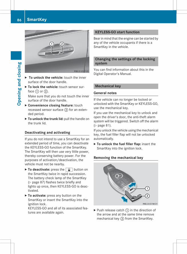
X To unlock the vehicle: touch the innersurface of the door handle.X To lock the vehicle: touch sensor sur-face: or;.Make sure that you do not touch the innersurface of the door handle.X Convenience closing feature: touchrecessed sensor surface; for an exten-ded period.X To unlock the trunk lid: pull the handle onthe trunk lid.
Deactivating and activatingIf you do not intend to use a SmartKey for anextended period of time, you can deactivatethe KEYLESS-GO function of the SmartKey.The SmartKey will then use very little power,thereby conserving battery power. For thepurposes of activation/deactivation, thevehicle must not be nearby.X To deactivate: press the& button onthe SmartKey twice in rapid succession.The battery check lamp of the SmartKey(Y page 87) flashes twice briefly andlights up once, then KEYLESS-GO is deac-tivated.X To activate: press any button on theSmartKey or insert the SmartKey into theignition lock.KEYLESS-GO and all of its associated fea-tures are available again.
KEYLESS-GO start functionBear inmind that the engine can be started byany of the vehicle occupants if there is aSmartKey in the vehicle.
Changing the settings of the lockingsystemYou can find information about this in theDigital Operator's Manual.
Mechanical key
General notesIf the vehicle can no longer be locked orunlocked with the SmartKey or KEYLESS-GO,use the mechanical key.If you use the mechanical key to unlock andopen the driver's door, the anti-theft alarmsystem will be triggered. Switch off the alarm(Y page 81).If you unlock the vehicle using themechanicalkey, the fuel filler flap will not be unlockedautomatically.X To unlock the fuel filler flap: insert theSmartKey into the ignition lock.
Removing the mechanical key
X Push release catch: in the direction ofthe arrow and at the same time removemechanical key; from the SmartKey.
86 SmartKeyOp
enin
gan
dcl
osin
g

For further information about:Runlocking the driver's door (Y page 89)Runlocking the trunk (Y page 96)Rlocking the vehicle (Y page 89)
Inserting the mechanical keyX Push mechanical key; completely intothe SmartKey until it engages and releasecatch: is back in its basic position.
SmartKey battery
Important safety notes
G WARNINGBatteries contain toxic and corrosive substan-ces. If batteries are swallowed, it can result insevere health problems. There is a risk of fatalinjury.Keep batteries out of the reach of children. Ifa battery is swallowed, seekmedical attentionimmediately.
H Environmental noteBatteries contain dangeroussubstances. It is against thelaw to dispose of them withthe household rubbish. Theymust be collected separatelyand recycled to protect theenvironment.Dispose of batteries in anenvironmentally friendlymanner. Take dischargedbatteries to a qualified spe-cialist workshop or a specialcollection point for used bat-teries.
The SmartKey batteries contain perchloratematerial, which may require special handlingand regard for the environment. Nationalguidelines must be observed during disposal.In California, see www.dtsc.ca.gov/
HazardousWaste/Perchlorate/index.cfm.Mercedes-Benz recommends that you havethe batteries replaced at a qualified specialistworkshop.
Checking the battery
X Press the& or% button.The battery is working properly if batterycheck lamp: lights up briefly.The battery is discharged if battery checklamp: does not light up briefly.X Change the battery (Y page 87).If the key battery is checked within the signalreception range of the vehicle, pressing the& or% button:Rlocks orRunlocks the vehicle
i You can obtain a battery from any quali-fied specialist workshop.
Replacing the batteryYou require a CR 2025 3 V cell battery.X Take the mechanical key out of the Smart-Key (Y page 86).
SmartKey 87
Open
ing
and
clos
ing
Z

X Pressmechanical key; into the SmartKeyopening in the direction of the arrow untilbattery compartment cover: opens. Donot hold battery compartment cover:closed while doing so.X Remove battery compartment cover:.
X Repeatedly tap the SmartKey against yourpalm until battery= falls out.X Insert the new battery with the positive ter-minal facing upwards. Use a lint-free clothto do so.X Make sure that the surface of the battery isfree of lint, grease and other contaminants.X Insert the front tabs of battery compart-ment cover: into the housing first andthen press to close it.X Insert mechanical key; into the Smart-Key.X Check the function of all SmartKey buttonson the vehicle.
Problems with the SmartKeyYou can find information about this in theDigital Operator's Manual.
Doors
Important safety notes
G WARNINGIf children are left unsupervised in the vehicle,they could:Ropen the doors, thus endangering otherpeople or road users.
Rget out and disrupt traffic.Roperate the vehicle's equipment.Additionally, children could set the vehicle inmotion if, for example, they:Rrelease the parking brake.Rshifting the automatic transmission out ofpark position P
RStart the engine.There is a risk of an accident and injury.When leaving the vehicle, always take theSmartKeywith you and lock the vehicle. Neverleave children or animals unattended in thevehicle. Always keep the SmartKey out ofreach of children.
You should preferably place luggage or loadsin the trunk. Observe the loading guidelines(Y page 236).
Information in the Digital Operator'sManualIn the Digital Operator's Manual you will findinformation on the following topics:RUnlocking and opening doors from theinside
RCentrally locking and unlocking the vehiclefrom the inside
RAutomatic locking feature
88 DoorsOp
enin
gan
dcl
osin
g

Unlocking the driver's door (mechan-ical key)If the vehicle can no longer be locked orunlocked with the SmartKey or KEYLESS-GO,use the mechanical key.X Take the mechanical key out of the Smart-Key (Y page 86).
X Insert the mechanical key into opening:in the protective cap.X Pull and hold the door handle.X Pull the protective cap on the mechanicalkey as straight as possible away from thevehicle until it releases.X Release the door handle.
X Insert the mechanical key into the lock ofthe driver's door as far as it will go.X Turn themechanical key counter-clockwiseas far as it will go to position1.The locking knob pops up and the doorunlocks.
X Turn the mechanical key back and removeit.X Insert the mechanical key into the Smart-Key (Y page 86).X Carefully press the protective cap onto thelock cylinder until it engages and is seatedfirmly. Do not pull the door handle whendoing so.
If you use the mechanical key to unlock andopen the driver's door, the anti-theft alarmsystem will be triggered. Switch off the alarm(Y page 81).
Locking the vehicle (mechanical key)If the vehicle can no longer be locked with theSmartKey or KEYLESS-GO, use the mechani-cal key.X Open the driver's door.X Close the front-passenger door, the reardoors and the trunk lid.X Press the locking button (Y page 88).X Check whether the locking knobs on thefront-passenger door and the rear doorsare still visible. Press down the lockingknobs by hand, if necessary.X Close the driver's door.X Take the mechanical key out of the Smart-Key (Y page 86).
X Insert the mechanical key into opening:in the protective cap.X Pull and hold the door handle.
Doors 89
Open
ing
and
clos
ing
Z

X Pull the protective cap on the mechanicalkey as straight as possible away from thevehicle until it releases.X Release the door handle.
X Insert the mechanical key into the lock ofthe driver's door as far as it will go.X Turn themechanical key clockwise as far asit will go to position1.The locking knob drops down and the driv-er's door is locked.X Turn the mechanical key back and removeit.X Insert the mechanical key into the Smart-Key (Y page 86).X Make sure that the doors and the trunk lidare locked.X Carefully press the protective cap onto thelock cylinder until it engages and is seatedfirmly. Do not pull the door handle whendoing so.
If you lock the vehicle as described above, thefuel filler flap is not locked. The anti-theftalarm system is not armed.
Trunk
Important safety notes
G WARNINGCombustion engines emit poisonous exhaustgases such as carbon monoxide. Exhaustgases can enter the vehicle interior if thetrunk lid is open when the engine is running,
especially if the vehicle is in motion. There is arisk of poisoning.Always switch off the engine before openingthe trunk lid. Never drive with the trunk lidopen.
G WARNINGIf objects, luggage or loads are not secured ornot secured sufficiently, they could slip, tipover or be flung around and thereby hit vehicleoccupants. There is a risk of injury, particu-larly in the event of sudden braking or a sud-den change in direction.Always store objects so that they cannot beflung around. Secure objects, luggage orloads against slipping or tipping before thejourney.
! The trunk lid swings upwards whenopened. Therefore, make sure that there issufficient clearance above the trunk lid.
The opening dimensions of the trunk lid canbe found in the "Vehicle data" section(Y page 327).
i You can limit the opening angle of thetrunk lid in COMAND or Audio 20 (see sep-arate operating instructions).
Do not leave the SmartKey in the trunk. Youcould otherwise lock yourself out.You should preferably place luggage or loadsin the trunk. Observe the loading guidelines(Y page 236).
Obstacle recognition with trunk lidreversing feature
Vehicles with trunk lid remote closingfeature: the trunk lid is equipped with auto-matic obstacle detection with reversing fea-ture. If a solid object blocks or restricts thetrunk lid when automatically opening, thisprocedure is stopped. If a solid object blocksor restricts the trunk lid when automaticallyclosing, the trunk lid opens again automati-cally. The automatic obstacle recognition
90 TrunkOp
enin
gan
dcl
osin
g

with reversing feature is only an aid. It is not asubstitute for your attentiveness when open-ing and closing the trunk lid.
G WARNINGThe reversing feature does not react:Rto soft, light and thin objects, e.g. small fin-gers
Rover the last 1/3 in (8 mm) of the closingmovement
This means that the reversing feature cannotprevent someone being trapped in these sit-uations. There is a risk of injury.Make sure that no body parts are in closeproximity during the closing procedure.If somebody becomes trapped:Rpress theF button on the SmartKey, orRpull or press the remote operating switchon the driver's door or
Rpress the closing or locking button on thetrunk lid, or
Rpull on the trunk lid handle
Vehicles with HANDS-FREE ACCESS: it isalso possible to stop the closing process byperforming a kicking movement under therear bumper.
Opening and closing manually
Opening
X Press theF button on the SmartKey.orX Pull handle:.The trunk lid opens.
Closing
X Pull the trunk lid down using recess: andpush it closed.X Lock the vehicle if necessary with the&button on the SmartKey or with KEYLESS-GO (Y page 85).
Opening and closing automaticallyfrom outside
Important safety notes
G WARNINGParts of the body could become trapped dur-ing automatic closing of the trunk lid. More-over, people, e.g. children, may be standing inthe closing area or may enter the closing areaduring the closing process. There is a risk ofinjury.Make sure that nobody is in the vicinity of theclosing area during the closing process.Use one of the following options to stop theclosing process:Rpress theF button on the SmartKey.Rpull or press the remote operating switchon the driver's door.
Trunk 91
Open
ing
and
clos
ing
Z

Rpress the closing or locking button on thetrunk lid.
Rpull the trunk lid handle
Vehicles with HANDS-FREE ACCESS: it isalso possible to stop the closing process byperforming a kicking movement under therear bumper.
G WARNINGCombustion engines emit poisonous exhaustgases such as carbon monoxide. Exhaustgases can enter the vehicle interior if thetrunk lid is open when the engine is running,especially if the vehicle is in motion. There is arisk of poisoning.Always switch off the engine before openingthe trunk lid. Never drive with the trunk lidopen.
! The trunk lid swings upwards whenopened. Therefore, make sure that there issufficient clearance above the trunk lid.
The opening dimensions of the trunk lid canbe found in the "Vehicle data" section(Y page 327).
OpeningYou can open the trunk lid automaticallyusing the SmartKey or the handle in the trunklid.X Press and hold theF button on theSmartKey until the trunk lid opens.
orX If the trunk lid is unlocked, pull the trunk lidhandle and let it go again immediately.
Closing
X Press closing button: on the trunk lid.Vehicles with trunk lid remote closingfeature and KEYLESS-GO:when the driver'sdoor is closed you can simultaneously closethe trunk lid and lock the vehicle. The KEY-LESS-GO key must be in the rear detectionrange of the vehicle.X Press locking button; in the trunk lid.If KEYLESS-GO detects a SmartKey outsidethe vehicle, the trunk lid closes and thevehicle is locked.
If KEYLESS-GO detects a SmartKey in thetrunk, the trunk lid opens again after it isclosed.If KEYLESS-GO detects a second SmartKeyoutside the vehicle, the trunk lid remainsclosed.If KEYLESS-GO detects a SmartKey in thetrunk before the closing procedure starts, thetrunk lid remains open.
Opening automatically from outside
Important safety notes
G WARNINGCombustion engines emit poisonous exhaustgases such as carbon monoxide. Exhaustgases can enter the vehicle interior if thetrunk lid is open when the engine is running,especially if the vehicle is in motion. There is arisk of poisoning.
92 TrunkOp
enin
gan
dcl
osin
g

Always switch off the engine before openingthe trunk lid. Never drive with the trunk lidopen.
! The trunk lid swings upwards whenopened. Therefore, make sure that there issufficient clearance above the trunk lid.
The opening dimensions of the trunk lid canbe found in the printed Operator's Manual.
OpeningYou can open the trunk lid automaticallyusing the SmartKey or the handle in the trunklid.X Press and hold theF button on theSmartKey until the trunk lid opens.
orX If the trunk lid is unlocked, pull the trunk lidhandle and let it go again immediately.
HANDS-FREE ACCESS
Important safety notes
G WARNINGThe vehicle's exhaust systemmay be very hot.You could burn yourself by touching theexhaust system if you use HANDS-FREEACCESS. There is a risk of injury. Alwaysensure that you only make the kicking move-ment within the detection range of sensors.
! If the SmartKey is within the rear detec-tion range of KEYLESS-GO, the followingsituations, for example, could lead to theunintentional opening of the trunk:Rusing a car washRusing a power washerMake sure that the SmartKey is at least10 ft (3 m) away from the vehicle.
General notesWith KEYLESS-GO and HANDS-FREEACCESS, you can open or close the trunk lid
or stop the procedure without using yourhands. This is useful if you have your handsfull. To do this, make a kicking movementunder the bumper with your foot.Observe the following points:RCarry your KEYLESS-GO key about yourperson. The KEYLESS-GO key must be inthe rear detection range of the vehicle.
RWhenmaking the kicking movement, makesure that you are standing firmly on theground and that there is sufficient clear-ance to the rear of the vehicle. You couldotherwise lose your balance e.g. on ice.
RAlways ensure that you only make the kick-ingmovementwithin the detection range ofsensors:.
RStand at least 12 in (30 cm) away from therear area while doing so.
RDo not come into contact with the bumperwhile making the kicking movement. Oth-erwise, the sensors may not function cor-rectly.
RHANDS-FREE ACCESS does not functionwhen the engine is started.
RIf a KEYLESS-GO key is within the reardetection range of KEYLESS-GO, HANDS-FREEACCESS could be triggered. The trunklid could thus be opened or closed unin-tentionally, for example, if you:- set something down or lift something upbehind the vehicle.
- polish the rear of the vehicle.Do not carry the KEYLESS-GO key aboutyour person in these situations or in situa-
Trunk 93
Open
ing
and
clos
ing
Z

tions similar to these. This will prevent theunintentional opening/closing of the trunk.
RDirt caused by road salt around sensors:may restrict functionality.
RUsing the HANDS-FREE ACCESS with aprosthetic leg may restrict functionality.
Operation
X To open/close: kick into sensor detectionrange: under the bumper with your foot.You will hear a warning tone while the trunklid is opening or closing.X If the trunk lid does not open/close
after several attempts: wait at least tenseconds and then using your foot kickunder the bumper again.
If you hold your foot under the bumper for toolong, the trunk lid does not open or close.Repeat the leg movement more quickly if thisoccurs.To stop the opening or closing procedure:Rkick with your leg in the sensor detectionrange: under the bumper or
Rpull the handle on the outside of the trunklid or
Rpress the closing button in the trunk lid orRpress theF button on the SmartKeyIf the trunk lid closing procedure has beenstopped:Rmove your foot under the bumper again andthe trunk lid will open.
If the trunk lid opening procedure has beenstopped:Rmove your foot under the bumper again andthe trunk lid will close.
Opening and closing automaticallyfrom inside
Important safety notes
G WARNINGParts of the body could become trapped dur-ing automatic closing of the trunk lid. More-over, people, e.g. children, may be standing inthe closing area or may enter the closing areaduring the closing process. There is a risk ofinjury.Make sure that nobody is in the vicinity of theclosing area during the closing process.Use one of the following options to stop theclosing process:Rpress theF button on the SmartKey.Rpull or press the remote operating switchon the driver's door.
Rpress the closing or locking button on thetrunk lid.
Rpull the trunk lid handle
Vehicles with HANDS-FREE ACCESS: it isalso possible to stop the closing process byperforming a kicking movement under therear bumper.
G WARNINGCombustion engines emit poisonous exhaustgases such as carbon monoxide. Exhaustgases can enter the vehicle interior if thetrunk lid is open when the engine is running,especially if the vehicle is in motion. There is arisk of poisoning.Always switch off the engine before openingthe trunk lid. Never drive with the trunk lidopen.
94 TrunkOp
enin
gan
dcl
osin
g

! The trunk lid swings upwards whenopened. Therefore, make sure that there issufficient clearance above the trunk lid.
The opening dimensions of the trunk lid canbe found in the "Vehicle data" section(Y page 327).
Opening and closing
When the vehicle is stationary, you can closethe trunk lid from the driver's seat. When thevehicle is also unlocked, you can also openthe trunk lid from inside.X To open: pull remote operating switch fortrunk lid: until the trunk lid opens.X To close: press remote operating switchfor trunk lid: until the trunk lid is com-pletely closed.
Opening automatically from inside
Important safety notes
G WARNINGCombustion engines emit poisonous exhaustgases such as carbon monoxide. Exhaustgases can enter the vehicle interior if thetrunk lid is open when the engine is running,especially if the vehicle is in motion. There is arisk of poisoning.Always switch off the engine before openingthe trunk lid. Never drive with the trunk lidopen.
! The trunk lid swings upwards whenopened. Therefore, make sure that there issufficient clearance above the trunk lid.
The opening dimensions of the trunk lid canbe found in the printed Operator's Manual.
Opening
You can open the tailgate from the driver'sseat when the vehicle is stationary andunlocked.X Pull remote operating switch: for the tail-gate until the tailgate opens.
Locking the trunk separatelyYou can lock the trunk separately. If you thenunlock the vehicle centrally, the trunkremains locked and cannot be opened.
Trunk 95
Open
ing
and
clos
ing
Z

Activating the function to lock the trunk sep-arately:X Close the trunk lid.X Open the glove box.X Push the switch to position:.If the vehicle is unlocked centrally, thetrunk remains locked.i You can also lock the glove box(Y page 237).
Deactivating the function to lock the trunkseparately:X Open the glove box.X Push the switch to position;.If the vehicle is unlocked centrally, thetrunk will also be unlocked.
Unlocking the trunk (mechanical key)! The trunk lid swings upwards whenopened. Therefore, make sure that there issufficient clearance above the trunk lid.
If the trunk cannot be unlocked with theSmartKey, KEYLESS-GO or HANDS-FREEACCESS, use the mechanical key.If you use the mechanical key to unlock andopen the trunk lid, the anti-theft alarm systemwill be triggered. Switch off the alarm(Y page 81).X Take the mechanical key out of the Smart-Key (Y page 86).X Insert the mechanical key into the trunk lidlock as far as it will go.
X Turn themechanical key counter-clockwiseas far as it will go from position1 to posi-tion2.The trunk is unlocked.X Turn the mechanical key back to position1 and remove it.X Insert the mechanical key into the Smart-Key (Y page 86).
When you lock the vehicle (Y page 89), thetrunk is also locked.
Trunk emergency releaseYou can unlock the trunk lid from the insidewith the emergency release button.
X Press emergency release button: briefly.The trunk lid unlocks and opens.
The trunk lid can be unlocked with the trunklid emergency release when the vehicle isstationary or while driving.The trunk lid emergency release does notunlock the trunk lid if the battery is discon-nected or discharged.Trunk lid emergency release light:Remergency release button: flashes for30 minutes after the trunk lid is opened
Remergency release button: flashes for60 minutes after the trunk lid is closed
96 TrunkOp
enin
gan
dcl
osin
g

Side windows
Important safety notes
G WARNINGWhile opening the side windows, body partscould become trapped between the side win-dow and the door frame as the side windowmoves. There is a risk of injury.Make sure that nobody touches the side win-dow during the opening procedure. If some-body becomes trapped, release the switch orpull the switch to close the sidewindow again.
G WARNINGWhile closing the side windows, body parts inthe closing area could become trapped. Thereis a risk of injury.When closing make sure that no parts of thebody are in the closing area. If somebodybecomes trapped, release the switch or pressthe switch to open the side window again.
G WARNINGIf children operate the side windows theycould become trapped, particularly if they areleft unsupervised. There is a risk of injury.Activate the override feature for the rear sidewindows. When leaving the vehicle, alwaystake the SmartKey with you and lock the vehi-cle. Never leave children unsupervised in thevehicle.
Side window reversing featureThe side windows are equipped with an auto-matic reversing feature. If a solid objectblocks or restricts a side window from trav-eling upwards during automatic operation,the side window opens again automatically.During the manual closing process, the sidewindow only opens again automatically afterthe corresponding switch is released. Theautomatic reversing feature is only an aid andis no substitute for your attention when clos-ing a side window.
G WARNINGThe reversing feature does not react:Rto soft, light and thin objects, e.g. small fin-gers
Rwhile resettingThis means that the reversing feature cannotprevent someone being trapped in these sit-uations. There is a risk of injury.Make sure that no body parts are in closeproximity during the closing procedure. Ifsomeone becomes trapped, press the switchto open the side window again.
Information in the Digital Operator'sManualIn the Digital Operator's Manual you will findinformation on the following topics:ROpening and closing the side windowsRConvenience openingRConvenience closing featureRResetting the side windows
Side windows 97
Open
ing
and
clos
ing
Z

Problems with the side windows
G WARNINGIf you close a side window again immediately after it has been blocked or reset, the side windowcloses with increased or maximum force. The reversing feature is then not active. Parts of thebody could be trapped in the closing area in the process. This poses an increased risk of injury oreven fatal injury.Make sure that no parts of the body are in the closing area. To stop the closing process, releasethe switch or push the switch again to reopen the side window.
Problem Possible causes/consequences and M Solutions
A side window cannotbe closed because it isblocked by objects, e.g.leaves in the windowguide.
X Remove the objects.X Close the side window.
A side window cannotbe closed and you can-not see the cause.
If a side window is obstructed during closing and reopens againslightly:X Immediately after the window blocks, pull the correspondingswitch again until the side window has closed.The side window is closed with increased force.
If a side window is obstructed again during closing and reopensagain slightly:X Immediately after the window blocks, pull the correspondingswitch again until the side window has closed.The side window is closed without the anti-entrapment feature.
Sliding sunroof
Important safety notesYour vehicle may be equipped with a slidingsunroof or a panorama roof with power tilt/sliding panel. In this section, the term "slidingsunroof" refers to both types of sliding sun-roof.
G WARNINGWhile opening and closing the sliding sunroof,body parts in close proximity could becometrapped. There is a risk of injury.Make sure that no body parts are in closeproximity during the opening and closing pro-cedures.
If somebody becomes trapped:Rrelease the switch immediately, orRduring automatic operation, push theswitch briefly in any direction
The opening or closing procedure will be stop-ped.
G WARNINGIf children operate the sliding sunroof theycould become trapped, particularly if they areleft unsupervised. There is a risk of injury.When leaving the vehicle, always take theSmartKeywith you and lock the vehicle. Neverleave children unsupervised in the vehicle.
98 Sliding sunroofOp
enin
gan
dcl
osin
g

! Only open the sliding sunroof if it is free ofsnow and ice. Otherwise,malfunctionsmayoccur.Do not allow anything to protrude from thesliding sunroof. Otherwise, the seals couldbe damaged.
! The weather can change abruptly. It couldstart to rain or snow. Make sure that thesliding sunroof is closedwhen you leave thevehicle. The vehicle electronics can bedamaged if water enters the vehicle inte-rior.
Resonance noises can occur in addition to theusual airflow noises when the sliding sunroofis open. They are caused by minor pressurefluctuations in the vehicle interior. Changethe position of the sliding sunroof or open aside window slightly to reduce or eliminatethese noises.Only for vehicles with panorama roof withpower tilt/sliding panel:
G WARNINGAt high speeds the raised sliding sunroof auto-matically lowers slightly at the rear. This couldtrap you or other persons. There is a risk ofinjury. Make sure that nobody reaches intothe sweep of the sliding sunroof whilst thevehicle is in motion.If somebody becomes trapped, immediatelypull back the sliding sunroof switch. The slid-ing sunroof lifts during opening.
Sliding sunroof reversing featureYour vehicle may be equipped with a slidingsunroof or a panorama roof with power tilt/sliding panel. In this section, the term "slidingsunroof" refers to both types of sliding sun-roof.The sliding sunroof is equipped with an auto-matic reversing feature. If a solid objectblocks or restricts the sliding sunroof duringthe closing process, the sliding sunroof opensagain automatically. The automatic reversing
feature is only an aid and is no substitute foryour attention when closing the sliding roof.
G WARNINGThe reversing feature does not react:Rto soft, light and thin objects, e.g. small fin-gers
Rover the last 1/6 in (4 mm) of the closingmovement
Rduring resettingRwhen closing the sliding sunroof againman-ually immediately after automatic reversing
This means that the reversing feature cannotprevent someone being trapped in these sit-uations. There is a risk of injury.Make sure that no body parts are in closeproximity during the closing procedure.If somebody becomes trapped:Rrelease the switch immediately, orRpress the switch in any direction during theautomatic closing process
The closing process is stopped.
Operating the sliding sunroof
Opening and closing
Overhead control panel: To raise; To open= To close/lower
Sliding sunroof 99
Open
ing
and
clos
ing
Z

X Turn the SmartKey to position 1 or 2 in theignition lock (Y page 129).X Press or pull the3 switch in the corre-sponding direction.
If you press or pull the3 switch beyondthe point of resistance, automatic operationis started in the corresponding direction. Youcan stop automatic operation by pressing orpulling again.When opening and raising the roof, automaticoperation is only available if the sliding sun-roof is in the closed position.The sun protection cover automatically opensalong with the sliding sunroof. You can openor close the sun protection cover manuallywhen the sliding sunroof is raised or closed.You can continue to operate the sliding sun-roof after switching off the engine or remov-ing the SmartKey from the ignition lock. Thisfunction is available for up to five minutes oruntil the driver's or front-passenger door isopened.
Resetting
! If the sliding sunroof still cannot beopened or closed fully after resetting, con-tact a qualified specialist workshop.
Reset the sliding sunroof if it does not movesmoothly.X Turn the SmartKey to position 1 or 2 in theignition lock.X Raise the sliding sunroof fully at the rear(Y page 99).X Keep the3 switch pressed for anothersecond.X Make sure that the sliding sunroof can befully opened and closed again (Y page 99).X If this is not the case, repeat the stepsabove again.
Operating the panorama roof withpower tilt/sliding panel
Opening and closing
Overhead control panel: To raise; To open= To close/lowerThe panorama roof with power tilt/slidingpanel can only be operated when the rollersunblind is open.X Turn the SmartKey to position 1 or 2 in theignition lock (Y page 129).X Press or pull the3 switch in the corre-sponding direction.
If you press or pull the3 switch beyondthe point of resistance, automatic operationis started in the corresponding direction. Youcan stop automatic operation by pressing orpulling again.If the panorama roof with power tilt/slidingpanel is raised at the rear, it automaticallylowers slightly at higher speeds. The noiselevel in the vehicle interior is reduced as aresult. At low speeds it raises again automat-ically.You can continue to operate the panoramaroof with power tilt/sliding panel after youswitch off the engine or remove the Smart-Key. This function remains active for fiveminutes or until you open a front door.When a roof carrier is mounted the panoramaroof with power tilt/sliding panel cannot beopened. The panorama roof with power tilt/
100 Sliding sunroofOp
enin
gan
dcl
osin
g

sliding panel can still be raised to allow ven-tilation of the vehicle interior. If the panoramaroof with power tilt/sliding panel makes con-tact with a roof carrier approved byMercedes-Benz, the sunroofwill lower slightlybut remain raised at the rear.
Rain-closing featureThe raised sliding sunroof automatically low-ers at the rear when driving if it starts to rain.The sliding sunroof is lowered depending on:Rthe road speed andRthe intensity of the rain.You can manually cancel the automatic clos-ing procedure. Press or pull the3 switchin any direction.To raise the sliding sunroof again, press the3 switch in direction:.The "Rain-closing feature when driving" func-tion is deactivated, until you:Rpress or pull the3 switch in any direc-tion or
Rturn the SmartKey to another position inthe ignition lock (Y page 129).
Operating the roller sunblinds for thepanorama roof with power tilt/slidingpanel
Important safety notes
G WARNINGWhen opening or closing the roller sunblind,parts of the body could be trapped betweenthe roller sunblind and the frame or slidingsunroof. There is a risk of injury.When opening or closing make sure that noparts of the body are in the sweep of the rollersunblind.If somebody becomes trapped:Rrelease the switch immediately, orRduring automatic operation, push theswitch briefly in any direction
The opening or closing procedure will be stop-ped.
The roller sunblinds shield the vehicle interiorfrom sunlight. The roller sunblinds can only beopened and closed when the sliding sunroofis closed.
Roller sunblind reversing featureThe roller sunblinds are equipped with anautomatic reversing feature. If a solid objectblocks or restricts a roller sunblind during theclosing process, the roller sunblind opensagain automatically. However, the automaticreversing feature is only an aid and does notrelieve you of the responsibility of payingattention when closing the roller sunblinds.
G WARNINGThe reversing function does not react in par-ticular to soft, light and thin objects, e.g. smallfingers. This means that the reversing featurecannot prevent someone being trapped inthese situations. There is a risk of injury.When closing the roller sunblind, make surethat no body parts are in the sweep.If somebody becomes trapped:Rrelease the switch immediately, orRpress the switch in any direction during theautomatic closing process
The closing process is stopped.
Sliding sunroof 101
Open
ing
and
clos
ing
Z

Opening and closing the roller sun-blinds
Overhead control panel: To open; To open= To closeYou can only close the roller sunblinds whenthe panorama roof with power tilt/slidingpanel is closed.X Turn the SmartKey to position 1 or 2 in theignition lock (Y page 129).X Press the3 switch in direction:.Both roller sunblinds open, then the pano-rama roof with power tilt/sliding panel israised.X Pull the3 switch in direction;.The sunblinds open.X Pull the3 switch in direction=.The roller sunblinds close when the pano-rama roof with power tilt/sliding panel isclosed.
If you press or pull the3 switch beyondthe point of resistance, automatic operationis started in the corresponding direction. Youcan stop automatic operation by pressing orpulling again.
Resetting the panorama roof withpower tilt/sliding panel or the frontroller sunblind
Reset the panorama roof with power tilt/slid-ing panel or the roller sunblinds if the pano-rama roof with power tilt/sliding panel or thefront roller sunblind does not move smoothly.X Turn the SmartKey to position 1 or 2 in theignition lock (Y page 129).X Pull the3 switch repeatedly to the pointof resistance in the direction of arrow:until the panorama roof with power tilt/sliding panel is fully closed.X Keep the3 switch pulled for an addi-tional second.X Pull the3 switch several times in thedirection of arrow: until the roller sun-blinds are closed.X Keep the3 switch pulled for an addi-tional second.X Make sure that the panorama roof withpower tilt/sliding panel (Y page 100) andthe roller sunblinds (Y page 102) can befully opened and closed again.X If this is not the case, repeat the stepsabove again.
102 Sliding sunroofOp
enin
gan
dcl
osin
g

Problems with the sliding sunroof
G WARNINGIf you close the sliding sunroof again immediately after it has been blocked or reset, the slidingsunroof closes with increased or maximum force. The reversing feature is then not active. Partsof the body could be trapped in the closing area in the process. This poses an increased risk ofinjury or even fatal injury.Make sure that no parts of the body are in the closing area.If somebody becomes trapped:Rrelease the switch immediately, orRpress the switch in any direction during the automatic closing processThe closing process is stopped.
! If the sliding sunroof still cannot be opened or closed as a result of a malfunction, contacta qualified specialist workshop.
Problem Possible causes/consequences and M Solutions
The sliding sunroof orpanorama roof withpower tilt/sliding panelcannot be closed andyou cannot see thecause.
If the sliding sunroof or panorama roof with power tilt/slidingpanel is obstructed during closing and reopens again slightly:X Immediately after it blocks, pull the3 switch down again tothe point of resistance until the sliding sunroof or panorama roofwith power tilt/sliding panel is closed.The sliding sunroof or panorama roof with power tilt/slidingpanel is closed with more force.
If the sliding sunroof or panorama roof with power tilt/slidingpanel is obstructed again during closing and reopens againslightly:X Immediately after it blocks, pull the3 switch down again tothe point of resistance until the sliding sunroof or panorama roofwith power tilt/sliding panel is closed.The sliding sunroof or panorama roof with power tilt/slidingpanel is closed without the anti-entrapment feature.
Sliding sunroof 103
Open
ing
and
clos
ing
Z

104

Useful information ............................ 106Correct driver's seat position .......... 106Seats .................................................. 107Steering wheel .................................. 109Mirrors ............................................... 109Memory function ............................... 109
105
Seat
s,st
eerin
gw
heel
and
mirr
ors

Useful information
i This Operator's Manual describes allmodels and all standard and optional equip-ment of your vehicle available at the time ofpublication of the Operator's Manual.Country-specific differences are possible.Please note that your vehicle may not beequipped with all features described. Thisalso applies to safety-related systems andfunctions.
i Read the information on qualified special-ist workshops (Y page 29).
Correct driver's seat position
G WARNINGYou could lose control of your vehicle if you dothe following while driving:Radjust the driver's seat, head restraint,steering wheel or mirrors
Rfasten the seat beltThere is a risk of an accident.Adjust the driver's seat, head restraint, steer-ing wheel andmirror and fasten your seat beltbefore starting the engine.
X Observe the safety guidelines on seatadjustment (Y page 107).X Make sure that seat= is adjusted prop-erly.Electrical seat adjustment (Y page 108)
When adjusting the seat, make sure that:Ryou are as far away from the driver's air bagas possible
Ryou are sitting in a normal upright positionRyou can fasten the seat belt properlyRyou have moved the backrest to an almostvertical position
Ryou have set the seat cushion angle so thatyour thighs are gently supported
Ryou can depress the pedals properlyRyour legs are not fully extendedX Check whether the head restraint is adjus-ted properly.When doing so, make sure that you haveadjusted the head restraint so that the backof your head is supported at eye level by thecenter of the head restraint.X Observe the safety guidelines on steeringwheel adjustment (Y page 109).X Make sure that steering wheel: is adjus-ted properly.Adjusting the steering wheel manually(Y page 109)Adjusting the steering wheel electrically(Y page 109)
When adjusting the steering wheel, makesure that:Ryou can hold the steering wheel with yourarms slightly bent
Ryou can move your legs freelyRyou can see all the displays in the instru-ment cluster clearlyX Observe the safety guidelines for seat belts(Y page 46).X Check whether you have fastened seatbelt; properly (Y page 48).
106 Correct driver's seat positionSe
ats,
stee
ring
whe
elan
dm
irror
s

The seat belt should:Rfit snugly across your bodyRbe routed across the middle of your shoul-der
Rbe routed in your pelvic area across the hipjointsX Before starting off, adjust the rear-viewmir-ror and the exterior mirrors in such a waythat you have a good view of road and traf-fic conditions (Y page 109).
Seats
Important safety notes
G WARNINGChildren could become trapped if they adjustthe seats, particularly when unattended.There is a risk of injury.When leaving the vehicle, always take theSmartKeywith you and lock the vehicle. Neverleave children unsupervised in the vehicle.
The seats can still be adjusted when there isno SmartKey in the ignition lock.
G WARNINGWhen you adjust a seat, you or other vehicleoccupants could become trapped, e.g. on theseat guide rail. There is a risk of injury.Make sure when adjusting a seat that no onehas any body parts in the sweep of the seat.
Observe the safety notes on "Air bags"(Y page 50) and "Children in the Vehicle"(Y page 62).
G WARNINGIf the driver's seat is not engaged, it couldmove unexpectedly while the vehicle is inmotion. This could cause you to lose control ofthe vehicle. There is a risk of an accident.Always make sure that the driver's seat isengaged before starting the vehicle.
G WARNINGYou could lose control of your vehicle if you dothe following while driving:Radjust the driver's seat, head restraint,steering wheel or mirrors
Rfasten the seat beltThere is a risk of an accident.Adjust the driver's seat, head restraint, steer-ing wheel andmirror and fasten your seat beltbefore starting the engine.
G WARNINGIf you adjust the seat height carelessly, you orother vehicle occupants could be trapped andthereby injured. Children in particular couldaccidentally press the electrical seat adjust-ment buttons and become trapped. There is arisk of injury.While moving the seats, make sure that yourhands or other body parts do not get under thelever assembly of the seat adjustment sys-tem.
G WARNINGIf head restraints are not installed and adjus-ted correctly, they cannot provide protectionas intended. There is an increased risk ofinjury in the head and neck area, e.g. in theevent of an accident or when braking.Always drive with the head restraints instal-led. Before driving off, make sure for everyvehicle occupant that the center of the headrestraint supports the back of the head atabout eye level.
G WARNINGThe seat belt does not offer the intended levelof protection if you have not moved the back-rest to an almost vertical position.When brak-ing or in the event of an accident, you couldslide underneath the seat belt and sustainabdomen or neck injuries, for example. Thisposes an increased risk of injury or even fatalinjury.
Seats 107
Seat
s,st
eerin
gw
heel
and
mirr
ors
Z

Adjust the seat properly before beginningyour journey. Always ensure that the backrestis in an almost vertical position and that theshoulder section of your seat belt is routedacross the center of your shoulder.
! To avoid damage to the seats and the seatheating, observe the following information:Rkeep liquids from spilling on the seats. Ifliquid is spilled on the seats, dry them assoon as possible.
Rif the seat covers are damp or wet, do notswitch on the seat heating. The seatheating should also not be used to drythe seats.
Rclean the seat covers as recommended;see the "Interior care" section.
Rdo not transport heavy loads on theseats. Do not place sharp objects on theseat cushions, e.g. knives, nails or tools.The seats should only be occupied bypassengers, if possible.
Rwhen the seat heating is in operation, donot cover the seats with insulating mate-rials, e.g. blankets, coats, bags, seat cov-ers, child seats or booster seats.
! Make sure that there are no objects in thefootwell under or behind the seats whenmoving the seats back. There is a risk thatthe seats and/or the objects could be dam-aged.
i The rear-compartment head restraintscan be removed (Y page 108).Vehicles without the through-loading fea-ture: the head restraints cannot beremoved from the rear compartment seats.For more information, contact a qualifiedspecialist workshop.
i Further related subjects:RRear bench seat through-loading feature(Y page 238)
Information in the Digital Operator'sManualIn the Digital Operator's Manual you will findinformation on the following topics:RAdjusting the seatsRAdjusting the head restraintsRAdjusting the 4-way lumbar supportRSwitching the seat ventilation on/off
Switching the seat heating on/off
Switching on/off
G WARNINGRepeatedly switching on the seat heating cancause the seat cushion and backrest pads tobecome very hot. The health of persons withlimited temperature sensitivity or a limitedability to react to excessively high tempera-tures may be affected or they may even sufferburn-like injuries. There is a risk of injury.Therefore, do not switch the seat heating onrepeatedly.
The three red indicator lamps in the buttonindicate the heating level you have selected.The system automatically switches downfrom level 3 to level 2 after approximatelyeight minutes.The system automatically switches downfrom level 2 to level 1 after approximately tenminutes.
108 SeatsSe
ats,
stee
ring
whe
elan
dm
irror
s

The system automatically switches offapproximately 20 minutes after it is set tolevel 1.X Turn the SmartKey to position 1 or 2 in theignition lock (Y page 129).X To switch on: press button: repeatedlyuntil the desired heating level is set.X To switch off: press button: repeatedlyuntil all the indicator lamps go out.i If the battery voltage is too low, the seatheating may switch off.
i If drive program E is selected (see DigitalOperator's Manual), the power of the seatheating is reduced.
Problems with the seat heatingYou can find information about this in theDigital Operator's Manual.
Steering wheel
Important safety notes
G WARNINGYou could lose control of your vehicle if you dothe following while driving:Radjust the driver's seat, head restraint,steering wheel or mirrors
Rfasten the seat beltThere is a risk of an accident.Adjust the driver's seat, head restraint, steer-ing wheel andmirror and fasten your seat beltbefore starting the engine.
G WARNINGChildren could injure themselves if theyadjust the steering wheel. There is a risk ofinjury.When leaving the vehicle, always take theSmartKeywith you and lock the vehicle. Neverleave children unsupervised in the vehicle.
The electrically adjustable steering wheel canstill be adjusted when there is no key in theignition lock.
Information in the Digital Operator'sManualIn the Digital Operator's Manual you will findinformation on the following topics:RAdjusting the steering wheelREASY-ENTRY/EXIT feature
Mirrors
In the Digital Operator's Manual you will findinformation on the following topics:RRear-view mirrorRExterior mirrorsRAutomatic anti-glare mirrorsRParking position for the exterior mirror onthe front-passenger side
Memory function
In the Digital Operator's Manual you will findinformation on the following topics:RStoring settingsRCalling up a stored setting
Memory function 109
Seat
s,st
eerin
gw
heel
and
mirr
ors
Z

110
Useful information ............................ 112Exterior lighting ................................ 112Interior lighting ................................. 114Replacing bulbs ................................. 115Windshield wipers ............................ 118
111
Ligh
tsan
dw
inds
hiel
dw
iper
s

Useful information
i This Operator's Manual describes allmodels and all standard and optional equip-ment of your vehicle available at the time ofpublication of the Operator's Manual.Country-specific differences are possible.Please note that your vehicle may not beequipped with all features described. Thisalso applies to safety-related systems andfunctions.
i Read the information on qualified special-ist workshops (Y page 29).
Exterior lighting
General notesFor reasons of safety, Mercedes-Benz recom-mends that you drive with the lights switchedon even during the daytime. In some coun-tries, operation of the headlamps varies dueto legal requirements and self-imposed obli-gations.
Information in the Digital Operator'sManualIn the Digital Operator's Manual you will findinformation on the following topics:RHazard warning lampsRHeadlamps fogged up on the inside
Setting the exterior lighting
Setting optionsExterior lighting can be set using:Rthe light switchRthe combination switch (Y page 113)Rthe on-board computer
Light switch
Operation
1W Left-hand standing lamps2X Right-hand standing lamps3 T Parking lamps, license plate and
instrument cluster lighting4Ã Automatic headlamp mode, control-
led by the light sensor5L Low-beam/high-beam headlampsBR Rear fog lampIf you hear a warning tone when you leave thevehicle, the lights may still be switched on.X Turn the light switch toÃ.The exterior lighting (except the parking/standing lamps) switches off automatically ifyou:Rremove the SmartKey from the ignition lockRopen the driver's door with the SmartKey inposition 0
Information in the Digital Operator's Man-ualIn the Digital Operator's Manual you will findinformation on the following topics:RAutomatic headlamp modeRLow-beam headlampsRRear fog lampRParking lampsRStanding lamps
112 Exterior lightingLi
ghts
and
win
dshi
eld
wip
ers

Combination switch
: High-beam headlamps; Turn signal, right= High-beam flasher? Turn signal, leftIn the Digital Operator's Manual you will findinformation on the following topics:RTurn signalRHigh-beam headlampsRHigh-beam flasher
Cornering light function
The cornering light function improves the illu-mination of the road over a wide angle in thedirection you are turning, enabling better vis-ibility in tight bends, for example. It can onlybe activated when the low-beam headlampsare switched on.
Active:Rif you are driving at speeds below 25 mph(40 km/h) and switch on the turn signal orturn the steering wheel
Rif you are driving at speeds between25 mph (40 km/h) and 45 mph (70 km/h)and turn the steering wheel
The cornering lamp may remain lit for a shorttime, but is automatically switched off afterno more than three minutes.
Adaptive Highbeam Assist
General notes
You can use this function to set the head-lamps to change between low beam and highbeam automatically. The system recognizesvehicles with their lights on, either approach-ing from the opposite direction or traveling infront of your vehicle, and consequentlyswitches the headlamps from high beam tolow beam.The system automatically adapts the low-beam headlamp range depending on the dis-tance to the other vehicle. Once the systemno longer detects any other vehicles, it reac-tivates the high-beam headlamps.
Exterior lighting 113
Ligh
tsan
dw
inds
hiel
dw
iper
s

The system's optical sensor is located behindthe windshield near the overhead controlpanel.
Important safety notes
G WARNINGAdaptive HighbeamAssist does not recognizeroad users:Rwho have no lights, e.g. pedestriansRwho have poor lighting, e.g. cyclistsRwhose lighting is blocked, e.g. by a barrierIn very rare cases, Adaptive Highbeam Assistmay fail to recognize other road users thathave lights, or may recognize them too late. Inthis or similar situations, the automatic high-beam headlamps will not be deactivated oractivated regardless. There is a risk of an acci-dent.Always carefully observe the traffic conditionsand switch off the high-beam headlamps ingood time.
Adaptive Highbeam Assist cannot take intoaccount road, weather or traffic conditions.Adaptive Highbeam Assist is only an aid. Youare responsible for adjusting the vehicle'slighting to the prevailing light, visibility andtraffic conditions.In particular, the detection of obstacles canbe restricted if there is:Rpoor visibility, e.g. due to fog, heavy rain orsnow
Rdirt on the sensors or the sensors areobscured
Switching Adaptive Highbeam Assiston/offX To switch on: turn the light switch toÃ.X Press the combination switch beyond thepressure point in the direction of arrow:.The_ indicator lamp in the multifunc-tion display lights up if it is dark and thelight sensor activates the low-beam head-lamps.
If you are driving at speeds above 25 km/h:If you are driving at speeds above approx-imately 16 mph (25 km/h):The headlamp range is set automaticallydepending on the distance between thevehicle and other road users.If you are driving at speeds above approx-imately 19 mph (30 km/h) and no otherroad users have been detected:The high-beam headlamps are switched onautomatically. TheK indicator lamp inthe instrument cluster also lights up.If you are driving at speeds below approx-imately 16 mph (25 km/h) or other roadusers have been detected or the roads areadequately lit:The high-beam headlamps are switched offautomatically. TheK indicator lamp inthe instrument cluster goes out. The_indicator lamp in the multifunction displayremains lit.X To switch off: move the combinationswitch back to its normal position or movethe light switch to another position.The_ indicator lamp in the instrumentcluster goes out.
Interior lighting
An overview of the interior lighting and theoverhead control panel can be found in the"At a glance" section.In the Digital Operator's Manual you will findinformation on the following topics:RAutomatic interior lighting controlRManual interior lighting controlRCrash-responsive emergency lighting
114 Interior lightingLi
ghts
and
win
dshi
eld
wip
ers

Replacing bulbs
Important safety notes
G WARNINGBulbs, lamps and connectors can get very hotwhen operating. If you change a bulb, youcould burn yourself on these components.There is a risk of injury.Allow these components to cool down beforechanging a bulb.
Do not use a bulb that has been dropped or ifits glass tube has been scratched.The bulb may explode if:Ryou touch itRit is hotRyou drop itRyou scratch itOnly operate bulbs in enclosed lampsdesigned for that purpose. Only install sparebulbs of the same type and the specified volt-age.Marks on the glass tube reduce the servicelife of the bulbs. Do not touch the glass tubewith your bare hands. If necessary, clean theglass tubewhen coldwith alcohol or spirit andrub it off with a lint-free cloth.Protect bulbs from moisture during opera-tion. Do not allow bulbs to come into contactwith liquids.Replace only the bulbs listed (Y page 115).Have the bulbs that you cannot replace your-self changed at a qualified specialist work-shop.If you require assistance changing bulbs, con-sult a qualified specialist workshop.If the new bulb still does not light up, consulta qualified specialist workshop.Bulbs and lamps are an important aspect ofvehicle safety. You must therefore make surethat these function correctly at all times.Have the headlamp setting checked regularly.Vehicles with LED headlamps: the frontand rear light clusters of your vehicle are
equipped with LED light bulbs. Do not replacethe bulbs yourself. Contact a qualified spe-cialist workshop which has the necessaryspecialist knowledge and tools to carry outthe work required.
Overview of bulb typesYou can change the following bulbs. The bulbtype can be found in the legend.
Vehicles with halogen headlamps: Low-beam headlamp: H7 55 W; High-beam headlamp: H7 55 W= Turn signal lamp: PWY 24 W
Tail lamp (halogen headlamps): Turn signal: P 21 W; Backup lamp: W 16 W
Replacing bulbs 115
Ligh
tsan
dw
inds
hiel
dw
iper
s
Z

Replacing front bulbs (vehicles withhalogen headlamps)
Removing and installing the cover in thefront wheel housing
Youmust remove the cover of the front wheelhousing before you can change the front turnsignal lamp.X To remove: switch off the lights.X Turn the front wheels inwards.X Turn rotary knob: 180° outwards until itstops using a suitable object.Cover; is released.X Fold cover; upwards.X To install: insert cover; into the left,right and two lower catches.X Turn rotary knob: 180° inwards until itstops using a suitable object.Cover; is locked.
Low-beam headlamps
X Switch off the lights.X Open the hood.
X Turn housing cover: counter-clockwiseand pull it out.X Turn bulb holder; counter-clockwise andpull it out.X Take the bulb out of bulb holder;.X Insert the new bulb into bulb holder;.X Insert bulb holder; into the lamp and turnit clockwise.X Align housing cover: and turn it clock-wise until it engages.
High-beam headlamps
X Switch off the lights.X Open the hood.X Turn housing cover: counter-clockwiseand pull it out.X Turn bulb holder; counter-clockwise andpull it out.X Take the bulb out of bulb holder;.X Insert the new bulb into bulb holder;.X Insert bulb holder; into the lamp and turnit clockwise.X Align housing cover: and turn it clock-wise until it engages.
116 Replacing bulbsLi
ghts
and
win
dshi
eld
wip
ers

Turn signal
X Remove the cover in the front wheel hous-ing (Y page 116).X Turn housing cover: counter-clockwiseand pull it out.X Turn bulb holder; counter-clockwise,unlock it and pull it out.X Take the bulb out of bulb holder;.X Insert the new bulb into bulb holder;.X Insert bulb holder; into the lamp and turnit clockwise.X Align housing cover: and turn it clock-wise until it engages.X Replace the cover in the front wheel hous-ing (Y page 116).
Changing the rear bulbs
Opening and closing the side trim pan-els
Example: right-hand side trim panel
Youmust open the side trim panel in the trunkbefore you can change the bulbs in the taillamps.X To open: release right or left side trimpanel: at the top and fold it down in thedirection of the arrow.X To close: insert side panel :.
Tail lampsX Switch off the lights.X Open the trunk.X Open the side trim panel (Y page 117).
X Pull out the plug.X Turn fender nut: 90° counter-clockwiseand remove the bulb holder.
X Turn signal lamp;: lightly press the bulbinto the bulb holder, turn it counter-clock-wise and remove it from the bulb holder.X Insert the new bulb into the bulb holder andturn it clockwise.X Backup lamp =: remove the bulb fromthe bulb holder.
Replacing bulbs 117
Ligh
tsan
dw
inds
hiel
dw
iper
s
Z

X Insert the new bulb into the bulb holder.X Re-install bulb holder.X Turn fender nut: 90° clockwise.X Insert the connector.X Close the side trim panel (Y page 117).
Windshield wipers
Switching the windshield wiperson/off
1 $ Windshield wiper off2 Ä Intermittent wipe, low (rain sensor
set to low sensitivity)3 Å Intermittent wipe, high (rain sensor
set to high sensitivity)4 ° Continuous wipe, slow5 ¯ Continuous wipe, fastB í Single wipe
î To wipe with washer fluidIf the wiper blades are worn, the windshieldwill no longer be wiped properly. This couldprevent you from observing the traffic condi-tions.
Replacing the wiper blades
Important safety notes
G WARNINGIf the windshield wipers begin to move whileyou are changing the wiper blades, you couldbe trapped by the wiper arm. There is a risk ofinjury.
Always switch off the windshield wipers andignition before changing the wiper blades.
! Never open the hood/tailgate if a wiperarm has been folded away from the wind-shield/rear window.Never fold awindshieldwiper armwithout awiper blade back onto the windshield/rearwindow.Hold the windshield wiper arm firmly whenyou change the wiper blade. If you releasethe wiper arm without a wiper blade and itfalls onto the windshield/rear window, thewindshield/rear window may be damagedby the force of the impact.Mercedes-Benz recommends that you havethe wiper blades changed at a qualifiedspecialist workshop.
! To avoid damaging the wiper blades,make sure that you touch only the wiperarm of the wiper.
Changing the windshield wiper blades
Adjusting the wiper blades so that theyare verticalOn vehicles without KEYLESS-GO:X Turn the SmartKey to position 1 or 2 in theignition lock (Y page 129).X Set the windshield wiper to position°.X When the wiper arms have reached the ver-tical position, turn the SmartKey to position0 and remove it from the ignition lock.X Fold the wiper arm away from the wind-shield.
On vehicles with KEYLESS-GO:X Switch off the engine.X Remove your foot from the brake pedal.X Set the windshield wiper to the° posi-tion.X Press the Start/Stop button repeatedlyuntil the windshield wiper starts.
118 Windshield wipersLi
ghts
and
win
dshi
eld
wip
ers

X When the wiper arms have reached the ver-tical position, press the Start/Stop button.X Fold the wiper arm away from the wind-shield.
Removing the wiper blades
X Hold on to the wiper arm with one hand.With the other hand, turn wiper blade indirection of arrow: away from the wiperarm as far as it will go.X Slide catch; in the direction of arrow=until it engages in the removal position witha noticeable click.
X Remove the wiper blade in the direction ofarrow? away from the wiper arm.
Installing the wiper blades
X Insert the new wiper blade into the wiperarm in the direction of arrow:.
X Slide catch; in the direction of arrow=until it engages in the locking position witha noticeable click.X Make sure that the wiper blade is seatedcorrectly.X Fold the wiper arm back onto the wind-shield.
X Remove protective film: of the serviceindicator on the tip of the wiper blade.
Windshield wipers 119
Ligh
tsan
dw
inds
hiel
dw
iper
s
Z

If the color of the service indicator changesfrom black to yellow, the wiper blades shouldbe replaced.
i The duration of the color change variesdepending on the terms of use.
Problems with the windshield wipersYou can find information about this in theDigital Operator's Manual.
120 Windshield wipersLi
ghts
and
win
dshi
eld
wip
ers
Useful information ............................ 122Overview of climate control sys-tems ................................................... 122Operating the climate control sys-tems ................................................... 125
121
Clim
ate
cont
rol

Useful information
i This Operator's Manual describes allmodels and all standard and optional equip-ment of your vehicle available at the time ofpublication of the Operator's Manual.Country-specific differences are possible.Please note that your vehicle may not beequipped with all features described. Thisalso applies to safety-related systems andfunctions.
i Read the information on qualified special-ist workshops (Y page 29).
Overview of climate control systems
General notesObserve the settings recommended on thefollowing pages. The windows could other-wise fog up.To prevent the windows from fogging up:Rswitch off climate control only brieflyRswitch on air-recirculation mode onlybriefly
Rswitch on the cooling with air dehumidifi-cation function
Rswitch on the defrost windshield functionbriefly, if required
Climate control regulates the temperatureand air humidity in the vehicle interior. Theinterior filter cleans the air, thus improvingthe interior climate.The "Cooling with air dehumidification" func-tion is only available when the engine is run-ning. Optimum climate control is only ach-ieved with the side windows and roof closed.The residual heat function can only be acti-vated or deactivated if the ignition is switchedoff (see the Digital Operator's Manual, key-word "Residual heat").
i Ventilate the vehicle for a brief periodduring warm weather, e.g. using the con-venience opening feature (see the DigitalOperator's Manual, keyword "Convenience
opening"). This will speed up the coolingprocess and the desired interior tempera-ture will be reached more quickly.
i The integrated filter filters out most par-ticles of dust and soot and completely fil-ters out pollen. It also reduces gaseous pol-lutants and odors. A clogged filter reducesthe amount of air supplied to the vehicleinterior. For this reason, you should alwaysobserve the interval for replacing the filter,which is specified in the MaintenanceBooklet. As it depends on environmentalconditions, e.g. heavy air pollution, theinterval may be shorter than stated in theMaintenance Booklet.
i It is possible that the blower may be acti-vated automatically 60 minutes after theSmartKey has been removed depending onvarious factors, e.g. the outside tempera-ture. The vehicle is then ventilated for30 minutes to dry the climate control sys-tem.
122 Overview of climate control systemsCl
imat
eco
ntro
l

Control panel for dual-zone automatic climate control
: Sets the temperature, left; Sets the air distribution= Sets the airflow
Switches off climate control? Sets climate control to automaticA Defrosts the windshieldB Calls up the Audio 20 or COMAND climate control menuC Switches the rear window defroster on or offD Activating or deactivating synchronizationE Switches air-recirculation mode manually on or offF Switches cooling with air dehumidification on/offG Sets the temperature, right
Overview of climate control systems 123
Clim
ate
cont
rol

Control panel for 3-zone automatic climate control
Canada onlyFront control panel
: Sets the temperature, left; Sets the air distribution, left= Sets the airflow
Switches off climate control? Sets climate control to automaticA Defrosts the windshieldB Calls up the Audio 20 or COMAND climate control menu
Switches the residual heat on or offC Switches the rear window defroster on or offD Switches cooling with air dehumidification on/offE Switches air-recirculation mode manually on or offF Sets the air distribution, rightG Sets the temperature, right
Rear control panelH Sets the temperatureI DisplayJ Sets the airflow
124 Overview of climate control systemsCl
imat
eco
ntro
l

Operating the climate control sys-tems
In the Digital Operator's Manual you will findinformation on the following topics:RActivating/deactivating the air condition-ing
RSwitching cooling with air dehumidificationon/off
RSetting climate control to automaticRAdjusting the climate mode settingsRSetting the temperatureRSetting the air distributionRSetting the airflowRActivating or deactivating the synchroniza-tion function
RDefrosting the windshieldRDefrosting the windowsRSwitching the rear windowdefroster on/offRSwitching air-recirculation mode on/offRSwitching the residual heat on or offRPerfume atomizerRIonizationRSetting the air vents
Operating the climate control systems 125
Clim
ate
cont
rol

126

Useful information ............................ 128Notes on breaking-in a new vehi-cle ....................................................... 128Driving ............................................... 129AGILITY SELECT switch (all vehi-cles except AMG vehicles) ............... 134DYNAMIC SELECT switch (AMGvehicles) ............................................ 135Automatic transmission ................... 136Refueling ............................................ 138Parking ............................................... 141Driving tips ........................................ 143Driving systems ................................ 145
127
Driv
ing
and
park
ing

Useful information
i This Operator's Manual describes allmodels and all standard and optional equip-ment of your vehicle available at the time ofpublication of the Operator's Manual.Country-specific differences are possible.Please note that your vehicle may not beequipped with all features described. Thisalso applies to safety-related systems andfunctions.
i Read the information on qualified special-ist workshops (Y page 29).
Notes on breaking-in a new vehicle
Important safety notesThe sensor system of some driving and driv-ing safety systems adjusts automaticallywhile a certain distance is being driven afterthe vehicle has been delivered or afterrepairs. Full system effectiveness is notreached until the end of this teach-in proce-dure.New and replaced brake pads and discs onlyreach their optimum braking effect after sev-eral hundred kilometers of driving. Compen-sate for this by applying greater force to thebrake pedal.
The first 1000 miles (1500 km)The more you look after the engine when it isnew, the more satisfied you will be with itsperformance in the future.RYou should therefore drive at varying vehi-cle and engine speeds for the first1000 miles (1500 km).
RAvoid heavy loads, e.g. driving at full throt-tle, during this period.
RWhen changing gears manually, change upin good time, before the tachometer needlereachesÔ of the way to the red area of thetachometer.
RDo not manually shift to a lower gear tobrake the vehicle.
RTry to avoid depressing the acceleratorpedal beyond the point of resistance (kick-down).
RAll vehicles (except AMG vehicles): ide-ally, for the first 1,000 miles (1,500 km),drive in program E.
After 1000miles (1500 km), you can increasethe engine speed gradually and acceleratethe vehicle to full speed.Additional breaking-in notes for AMG vehi-cles:RDo not drive faster than 85 mph(140 km/h) for the first 1,000 miles(1,500 km).
ROnly allow the engine to reach a maximumengine speed of 4,500 rpm briefly.
RChange gear in good time.RIdeally, for the first 1,000miles (1,500 km),drive in program C.
You should also observe these notes onbreaking in if the engine or parts of the drivetrain on your vehicle have been replaced.Always observe the maximum permissiblespeed.
AMG vehicles with self-locking rearaxle differentialYour vehicle is equipped with a self-lockingdifferential on the rear axle.For better protection of the differential on therear axle, carry out an oil change:Rafter a breaking-in period of 1,850 miles(3,000 km)
Revery 31,000 miles (50,000 km) or3 years
These oil changes prolong the service life ofthe differential. Have the oil change carriedout at a qualified specialist workshop.
128 Notes on breaking-in a new vehicleDr
ivin
gan
dpa
rkin
g

Driving
Important safety notes
G WARNINGObjects in the driver's footwell can restrict thepedal travel or obstruct a depressed pedal.The operating and road safety of the vehicle isjeopardized. There is a risk of an accident.Make sure that all objects in the vehicle arestowed correctly, and that they cannot enterthe driver's footwell. Install the floormatssecurely and as specified in order to ensuresufficient clearance for the pedals. Do not useloose floormats and do not place floormats ontop of one another.
G WARNINGUnsuitable footwear can hinder correct usageof the pedals, e.g.:Rshoes with thick solesRshoes with high heelsRslippersThere is a risk of an accident.Wear suitable footwear to ensure correctusage of the pedals.
G WARNINGIf you switch off the ignition while driving,safety-relevant functions are only availablewith limitations, or not at all. This could affect,for example, the power steering and the brakeboosting effect. You will require considerablymore effort to steer and brake. There is a riskof an accident.Do not switch off the ignition while driving.
G WARNINGIf the parking brake has not been fullyreleased when driving, the parking brake can:Roverheat and cause a fireRlose its hold function.There is a risk of fire and an accident. Releasethe parking brake fully before driving off.
! Do not warm up the engine with the vehi-cle stationary. Drive off immediately. Avoidhigh engine speeds and driving at full throt-tle until the engine has reached its operat-ing temperature.Only shift the automatic transmission tothe desired drive position when the vehicleis stationary.Where possible, avoid spinning the drivewheels when pulling away on slipperyroads. You could otherwise damage thedrive train.
! AMG vehicles: at low engine oil temper-atures below 68 ‡ (+20 †), the maximumengine speed is restricted in order to pro-tect the engine. To protect the engine andmaintain smooth engine operation, avoiddriving at full throttle when the engine iscold.
SmartKey positions
SmartKey
g To remove the SmartKey1 Power supply for some consumers, such
as the windshield wipers2 Ignition (power supply for all consumers)
and drive position3 To start the engine
i The SmartKey can be turned in the igni-tion lock even if it is not the correct Smart-Key for the vehicle. The ignition is notswitched on. The engine cannot be started.
Driving 129
Driv
ing
and
park
ing
Z

Vehicles with AIRPANEL: you can open theshutters in the radiator trim by turning theSmartKey to position 2 in the ignition lock.After approximately 120 seconds the shut-ters open automatically. Further informationon opening and cleaning the shutters can befound in the Digital Operator's Manual.
Start/Stop button
General notesWhen you insert the Start/Stop button intothe ignition lock, the system needs approx-imately two seconds recognition time. Youcan then use the Start/Stop button.Pressing the Start/Stop button several timesin succession corresponds to the differentkey positions in the ignition lock. This is onlythe case if you are not depressing the brakepedal.If you depress the brake pedal and press theStart/Stop button, the engine starts immedi-ately.A checkwhich periodically establishes a radioconnection between the vehicle and theSmartKey determines whether a valid Smart-Key is in the vehicle. This occurs, for example,when starting the engine.To start the vehicle without actively using theSmartKey:Rthe Start/Stop button must be inserted inthe ignition lock.
Rthe SmartKey must be in the vehicle.Rthe vehicle must not be locked with theSmartKey or KEYLESS-GO (Y page 85).
Do not keep the SmartKey:Rwith electronic devices, e.g. a mobilephone or another SmartKey.
Rwith metallic objects, e.g. coins or metalfoil.
Rinside metallic objects, e.g. a metal case.This can affect the functionality of the Smart-Key.
If you lock the vehicle with the SmartKey'sremote control or with KEYLESS-GO, after ashort time:Ryou will not be able to switch on the ignitionwith the Start/Stop button.
Ryou will not be able to start the engine withthe Start/Stop button until the vehicle isunlocked again.
If you lock the vehicle centrally using the but-ton on the front door (Y page 88), you cancontinue to start the engine with the Start/Stop button.The engine can be switched off while the vehi-cle is in motion by pressing and holding theStart/Stop button for three seconds. Thisfunction operates independently of the ECOstart/stop automatic engine switch-off func-tion.
Key positions with the Start/Stop button
: Start/Stop button; Ignition lockAs soon as the ignition is switched on, all theindicator lamps in the instrument cluster lightup. Further information on situations wherean indicator lamp either fails to go out afterstarting the engine or lights up while driving(Y page 198).If Start/Stop button: has not yet beenpressed, this corresponds to the key beingremoved from the ignition.
130 DrivingDr
ivin
gan
dpa
rkin
g

X To switch on the power supply: pressStart/Stop button: once.The power supply is switched on. You cannow activate the windshield wipers, forexample.
The power supply is switched off again if:Rthe driver's door is opened andRyou press Start/Stop button: twicewhenin this positionX To switch on the ignition: press Start/Stop button: twice.The ignition is switched on.
The ignition is switched off when:Rthe driver's door is opened andRyou press Start/Stop button: twicewhenin this position
= Start/Stop button USA? Start/Stop button Canada
Removing the Start/Stop buttonYou can remove the Start/Stop button fromthe ignition lock and start the vehicle as nor-mal using the SmartKey.It is only possible to switch between Start/Stop button mode and SmartKey operationwhen the transmission is in position P.
X RemoveStart/Stop button: from ignitionlock;.
You do not have to remove the Start/Stopbutton from the ignition lock when you leavethe vehicle. You should, however, always takethe SmartKey with you when leaving the vehi-cle. As long as the SmartKey is in the vehicle:Rthe vehicle can be started using the Start/Stop button
Rthe electrically powered equipment can beoperated
Starting the engine
Important safety notes
G WARNINGIf children are left unsupervised in the vehicle,they could:Ropen the doors, thus endangering otherpeople or road users.
Rget out and disrupt traffic.Roperate the vehicle's equipment.Additionally, children could set the vehicle inmotion if, for example, they:Rrelease the parking brake.Rshifting the automatic transmission out ofpark position P
RStart the engine.There is a risk of an accident and injury.When leaving the vehicle, always take theSmartKeywith you and lock the vehicle. Neverleave children or animals unattended in thevehicle. Always keep the SmartKey out ofreach of children.
G WARNINGCombustion engines emit poisonous exhaustgases such as carbon monoxide. Inhalingthese exhaust gases leads to poisoning. Thereis a risk of fatal injury. Therefore never leavethe engine running in enclosed spaces with-out sufficient ventilation.
Driving 131
Driv
ing
and
park
ing
Z

G WARNINGFlammable materials introduced throughenvironmental influence or by animals canignite if in contact with the exhaust system orparts of the engine that heat up. There is a riskof fire.Carry out regular checks to make sure thatthere are no flammable foreign materials inthe engine compartment or in the exhaustsystem.
! Do not depress the accelerator whenstarting the engine.
General notesThe catalytic converter is preheated for up to30 seconds after a cold start. The sound ofthe engine may change during this time.
Automatic transmissionX Shift the transmission to position P. Youcan find information about this in theDigitalOperator's Manual.The transmission position display in themultifunction display shows P. You can findinformation about this in the Digital Oper-ator's Manual.
i You can start the engine in transmissionposition P and N.
Starting procedure with the SmartKeyTo start the engine using the SmartKeyinstead of the Start/Stop button, pull theStart/Stop button out of the ignition lock.X Turn the SmartKey to position 3 in the igni-tion lock and release it as soon as theengine is running (Y page 129).
If the engine will not start:X Remove the SmartKey from the ignitionlock.X Reinsert the SmartKey into the ignition lockafter a short waiting period.
X Turn the SmartKey to position 2 in the igni-tion lock (Y page 129).The indicator lamps in the instrument clus-ter light up (Y page 195).X Turn the SmartKey to position 3 in the igni-tion lock (Y page 129) and release it assoon as the engine is running.
Starting procedure with the Start/StopbuttonThe Start/Stop button is only available onvehicles with KEYLESS-GO or the KEYLESS-GO start function.The Start/Stop button can be used to startthe vehicle manually without inserting theSmartKey into the ignition lock. The Start/Stop button must be inserted in the ignitionlock and the SmartKeymust be in the vehicle.This mode for starting the engine operatesindependently of the ECO start/stop auto-matic engine start function.You can start the engine if a valid SmartKey isin the vehicle. Switch off the engine andalways take the SmartKey with you whenleaving the vehicle, even if you only leave it fora short time. Pay attention to the importantsafety notes.X Depress the brake pedal and keep itdepressed.X Press the Start/Stop button once(Y page 130).The engine starts.
Pulling away
General notes
G WARNINGIf the engine speed is above the idling speedand you engage transmission position D or R,the vehicle could pull away suddenly. There isa risk of an accident.When engaging transmission position D or R,always firmly depress the brake pedal and donot simultaneously accelerate.
132 DrivingDr
ivin
gan
dpa
rkin
g

Depress the accelerator carefully when pull-ing away.The vehicle locks centrally once you havepulled away. The locking knobs in the doorsdrop down.You can open the doors from the inside at anytime.You can also deactivate the automatic lockingfeature, see the Digital Operator's Manual.It is only possible to shift the transmissionfrom position P to the desired position if youdepress the brake pedal. Only then is theparking lock released. If you do not depressthe brake pedal, theDIRECT SELECT lever canstill be moved but the parking lock remainsengaged.
i Upshifts take place at higher enginespeeds after a cold start. This helps thecatalytic converter to reach its operatingtemperature more quickly.
Information on the automatic release of theelectric parking brake can be found in theDigital Operator's Manual.
Hill start assistHill start assist helps you when pulling awayforwards or in reverse on an uphill gradient. Itholds the vehicle for a short time after youhave removed your foot from the brake pedal.This gives you enough time to move your footfrom the brake pedal to the accelerator pedaland to depress it before the vehicle begins toroll.
G WARNINGAfter a short time, hill start assist will no lon-ger brake your vehicle and it could roll away.There is a risk of an accident and injury.Therefore, quickly move your foot from thebrake pedal to the accelerator pedal. Neverleave the vehicle when it is held by hill startassist.
Hill start assist is not active if:Ryou are pulling away on a level road or on adownhill gradient.
Rthe transmission is in position N.Rthe electric parking brake is applied.RESP® is malfunctioning.
ECO start/stop function
IntroductionThe ECO start/stop function switches theengine off automatically if the vehicle is stop-ped under certain conditions.The engine starts automatically when thedriver wants to pull away again. The ECOstart/stop function thereby helps you toreduce the fuel consumption and emissionsof your vehicle.
Important safety notes
G WARNINGIf the engine is switched off automatically andyou exit the vehicle, the engine is restartedautomatically. The vehicle may begin moving.There is a risk of accident and injury.If you wish to exit the vehicle, always turn offthe ignition and secure the vehicle againstrolling away.
General notes
: ECO start/stop displayThe ECO start/stop function is activatedwhenever you switch on the engine using theSmartKey or the Start/Stop button.If the engine has been switched off automat-ically by the ECO start/stop function, the
Driving 133
Driv
ing
and
park
ing
Z

è ECO symbol is shown in the multifunc-tion display.AMG vehicles: the ECO start/stop functionis only available in drive program C.
Information in the Digital Operator'sManualIn the Digital Operator's Manual you will findinformation on the following topics:RAutomatic engine switch-offRAutomatic engine startRDeactivating or activating the ECO start/stop function
AMG sports exhaust system (AMGvehicles)You can choose between different AMGsports exhaust system volumes using theposition of the exhaust flap.Each time you start the engine with theSmartKey or the Start/Stop button, the qui-etest setting is activated.
Setting the volume:X Press button:.If you select the loudest setting, indicatorlamp lights up;.
You can also adjust the position of theexhaust flap using:Rthe DYNAMIC SELECT switch(Y page 135)
RCOMAND or Audio 20
Problems with the engineYou can find information about this in theDigital Operator's Manual.
AGILITY SELECT switch (all vehiclesexcept AMG vehicles)
Use the AGILITY SELECT switch to change thedrive program. Depending on the drive pro-gram selected the following vehicle charac-teristics will change:Rthe drive (engine and transmission man-agement)
Rthe suspensionRthe steeringRthe availability of the ECO start/stop func-tion
Rthe climate control- the climate control settings- the rear window defroster operationperiod
- the performance of the seat heatingEach time you start the engine using theSmartKey or the Start/Stop button, drive pro-gram C is activated. For further informationabout starting the engine, see (Y page 131).
X Push AGILITY SELECT switch: up ordown, until the desired drive program isselected.The status icon of the selected drive pro-gram is shown in the multifunction display.
134 AGILITY SELECT switch (all vehicles except AMG vehicles)Dr
ivin
gan
dpa
rkin
g
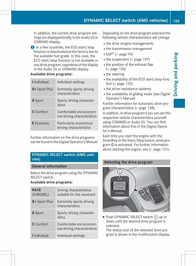
In addition, the current drive program set-tings are displayed briefly in the Audio 20 orCOMAND display.i In a few countries, the ECO start/stopfunction is deactivated at the factory due tothe available fuel grade. In this case, theECO start/stop function is not available inany drive program, regardless of the displayin the Audio 20 or COMAND display.
Available drive programs:
I Individual Individual settings
S+ Sport Plus Extremely sporty drivingcharacteristics
S Sport Sporty driving character-istics
C Comfort Comfortable and econom-ical driving characteristics
E Economy Particularly economicaldriving characteristics
Further information on the drive programscan be found in theDigital Operator'sManual.
DYNAMIC SELECT switch (AMG vehi-cles)
General informationSelect the drive program using the DYNAMICSELECT switch.Available drive programs:
RACE(S゙MODEL)
Driving characteristicssuitable for the racetrack
S+ Sport Plus Extremely sporty drivingcharacteristics
S Sport Sporty driving character-istics
C Comfort Comfortable and econom-ical driving characteristics
I Individual Individual settings
Depending on the drive program selected thefollowing vehicle characteristics will change:Rthe drive (engine management)Rthe transmission managementRESP® (Y page 74)Rthe suspension (Y page 157)Rthe position of the exhaust flap(Y page 134)
Rthe steeringRthe availability of the ECO start/stop func-tion (Y page 133)
Rthe driver assistance systemsRthe availability of gliding mode (see DigitalOperator's Manual)
Further information for automatic drive pro-gram characteristics (Y page 138).In addition, in drive program I you can set therespective vehicle characteristics yourselfusing COMAND or Audio 20. You can findinformation about this in the Digital Opera-tor's Manual.Each time you start the engine with theSmartKey or the Start/Stop button, drive pro-gram C is activated. For further informationabout starting the engine, see (Y page 131).
Selecting the drive program
X Push DYNAMIC SELECT switch: up ordown until the desired drive program isselected.The status icon of the selected drive pro-gram is shown in the multifunction display.
DYNAMIC SELECT switch (AMG vehicles) 135
Driv
ing
and
park
ing
Z

In addition, the current drive program set-tings are displayed briefly in the Audio 20and COMAND display.
You can also change gear yourself using thesteering wheel paddle shifters. For furtherinformation on the manual drive program(Y page 138).
Additional settings
: Position of the exhaust flap (Y page 134); ECO start/stop function (Y page 133)= ESP® (Y page 74)? Suspension (Y page 157)A To permanently activate manual gear-
shifting (Y page 138)When you press buttons: -A the corre-sponding setting is selected. The DYNAMICSELECT switch setting is overwritten.These settings will also be maintained if youchange with the DYNAMIC SELECT switch indrive program RACE (S-MODEL), S+, S or C.To change the corresponding setting with theDYNAMIC SELECT switch, the same settingsmust be selectedwith buttons: -A and theDYNAMIC SELECT switch. This is the case, forexample, when both are set to "Sport" mode.If you switch to drive program I, all storedcharacteristics will be accepted. This is alsothe case if you have previously pressed one ofbuttons: -A.
Automatic transmission
Important safety notes
G WARNINGIf the engine speed is above the idling speedand you engage transmission position D or R,the vehicle could pull away suddenly. There isa risk of an accident.When engaging transmission position D or R,always firmly depress the brake pedal and donot simultaneously accelerate.
G WARNINGThe automatic transmission switches to neu-tral positionNwhen you switch off the engine.The vehicle may roll away. There is a risk of anaccident.After switching off the engine, always switchto parking positionP. Prevent the parked vehi-cle from rolling away by applying the parkingbrake.
Bear in mind that the power transmissionbetween the engine and the transmission isinterrupted when the engine is switched off.For this reason, shift the automatic transmis-sion to P when the engine is switched off andthe vehicle is stationary. Apply the electricparking brake to prevent the vehicle from roll-ing away.
136 Automatic transmissionDr
ivin
gan
dpa
rkin
g

DIRECT SELECT lever
Overview of transmission positions
j Park position with parking lockk Reverse geari Neutralh DriveThe DIRECT SELECT lever is on the right of thesteering column.The DIRECT SELECT lever always returns toits original position. The current transmissionposition P, R, N or D appears in the transmis-sion position display in the multifunction dis-play. You can find information about this inthe Digital Operator's Manual.
Information in the Digital Operator'sManualIn the Digital Operator's Manual you will findinformation on the following topics:REngaging park position PREngaging park position P automaticallyREngaging reverse gear RREngaging drive position D
Shifting to neutral N
G WARNINGIf children are left unsupervised in the vehicle,they could:Ropen the doors, thus endangering otherpeople or road users.
Rget out and disrupt traffic.Roperate the vehicle's equipment.Additionally, children could set the vehicle inmotion if, for example, they:Rrelease the parking brake.Rshifting the automatic transmission out ofpark position P
RStart the engine.There is a risk of an accident and injury.When leaving the vehicle, always take theSmartKeywith you and lock the vehicle. Neverleave children or animals unattended in thevehicle. Always keep the SmartKey out ofreach of children.
X If the transmission is in position D or R:push the DIRECT SELECT lever up or downto the first point of resistance.X If the transmission is in position P: depressthe brake pedal and push the DIRECTSELECT lever up or down to the first point ofresistance.
If you switch the engine off with the trans-mission in position R or D, the automatictransmission shifts to N automatically.With the SmartKey: if you then open thedriver's door or the front-passenger door orremove the SmartKey from the ignition, theautomatic transmission shifts to P automati-cally.With the Start/Stop button: if you thenopen the driver's door or the front-passengerdoor, the automatic transmission shifts to Pautomatically.If you want the automatic transmission toremain in neutral N, e.g. when having the
Automatic transmission 137
Driv
ing
and
park
ing
Z

vehicle cleaned in an automatic car washwitha towing system:Using the SmartKey:X Switch on the ignition.X Depress the brake pedal and keep itdepressed.X Shift to neutral N.X Release the brake pedal.X Release the electric parking brake.X Switch off the ignition and leave the Smart-Key in the ignition lock.
With the Start/Stop button:X Remove the Start/Stop button from theignition lock.X Insert the SmartKey into the ignition lock.X Switch on the ignition.X Depress the brake pedal and keep itdepressed.X Shift to neutral N.X Release the brake pedal.X Release the electric parking brake.X Switch off the ignition and leave the Smart-Key in the ignition lock.
Information in the Digital Operator'sManualIn the Digital Operator's Manual you will findinformation on the following topics:RTransmission position and drive programdisplay
RTransmission positionsRDriving tipsRDrive programsRManual gear shiftingRProblems with the transmission
Transfer caseThis section is only valid for vehicles with 4-wheel drive (4MATIC). Power is always trans-mitted to both axles.
! Performance tests may only be carriedout on a 2-axle dynamometer. The brakesystem or transfer case could otherwise bedamaged. Contact a qualified specialistworkshop for a performance test.
! Since ESP® engages automatically, theignition must be switched off (the Smart-Key or Start/Stop button must be in posi-tion 0 or 1) if:Rthe electric parking brake is being testedon a brake dynamometer
Rthe vehicle is being towed with only oneaxle raised (not permitted for vehicleswith 4MATIC).
The brake system could otherwise be dam-aged.
! Vehicles with 4MATIC must not be towedwith either the front or the rear axle raised,as doing so will damage the transmission.
Refueling
Important safety notes
G WARNINGFuel is highly flammable. If you handle fuelincorrectly, there is a risk of fire and explo-sion.You must avoid fire, open flames, creatingsparks and smoking. Switch off the engineand, if applicable, the auxiliary heating beforerefueling.
G WARNINGFuel is poisonous and hazardous to health.There is a risk of injury.You must make sure that fuel does not comeinto contact with your skin, eyes or clothingand that it is not swallowed. Do not inhale fuelvapors. Keep fuel away from children.
138 RefuelingDr
ivin
gan
dpa
rkin
g

If you or others come into contact with fuel,observe the following:RWash away fuel from skin immediatelyusing soap and water.
RIf fuel comes into contact with your eyes,immediately rinse them thoroughly withclean water. Seek medical assistance with-out delay.
RIf fuel is swallowed, seek medical assis-tance without delay. Do not induce vomit-ing.
RImmediately change out of clothing whichhas come into contact with fuel.
G WARNINGElectrostatic buildup can create sparks andignite fuel vapors. There is a risk of fire andexplosion.Always touch the vehicle body before openingthe fuel filler flap or touching the fuel pumpnozzle. Any existing electrostatic buildup isthereby discharged.
Do not get into the vehicle again during therefueling process. Otherwise, electrostaticcharge could build up again.
! Do not use diesel to refuel vehicles with agasoline engine. Do not switch on the igni-tion if you accidentally refuel with thewrong fuel. Otherwise, the fuel will enterthe fuel system. Even small amounts of thewrong fuel could result in damage to thefuel system and the engine. Notify a quali-fied specialist workshop and have the fueltank and fuel lines drained completely.
! Overfilling the fuel tank could damage thefuel system.
! Take care not to spill any fuel on paintedsurfaces. You could otherwise damage thepaintwork.
! Use a filter when refueling from a fuel can.Otherwise, the fuel lines and/or injectionsystem could be blocked by particles fromthe fuel can.
If you overfill the fuel tank, fuel could sprayout when the fuel pump nozzle is removed.For further information on fuel and fuel quality(Y page 321).
Refueling
General informationPay attention to the important safety notes(Y page 138).If you unlock/lock the vehicle from the out-side, the fuel filler flap also unlocks/locks.The position of the fuel filler cap is displayed8 in the instrument cluster. The arrownext to the filling pump indicates the side ofthe vehicle.
Opening the fuel filler flap
: To open the fuel filler flap; To insert the fuel filler cap= Tire pressure table? Instruction label on the fuel type to be
refueledX Switch off the engine.X Remove the SmartKey from the ignitionlock.
or, in vehicles with KEYLESS-GO start-func-tion or KEYLESS゙GOX Open the driver's door.The on-board electronics now have status0. This is the same as the SmartKey havingbeen removed.
Refueling 139
Driv
ing
and
park
ing
Z
X Press the fuel filler flap in the direction ofarrow:.The fuel filler flap swings up.X Turn the fuel filler cap counterclockwiseand remove it.X Insert the fuel filler cap into the holder onthe inside of fuel filler flap;.X Completely insert the filler neck of the fuelpump nozzle into the tank, hook in placeand refuel.X Only fill the tank until the pump nozzleswitches off.
Do not add any more fuel after the pumpstops filling for the first time. Otherwise, fuelmay leak out.
Closing the fuel filler flapX Replace the cap on the filler neck and turnclockwise until it engages audibly.X Close the fuel filler flap.Close the fuel filler flap before locking thevehicle.If you are driving with the fuel filler cap open,the8 reserve fuel warning lamp flashes. Amessage appears in the multifunction display(Y page 182).
140 RefuelingDr
ivin
gan
dpa
rkin
g

Problems with fuel and the fuel tankThis section provides descriptions of and solutions to safety-relevant problems. Descriptionsof and solutions to further problems can be found in the Digital Operator's Manual.
Problem Possible causes/consequences and M Solutions
Fuel is leaking from thevehicle.
G WARNINGThe fuel line or the fuel tank is faulty.Risk of explosion or fire.X Apply the electric parking brake.X Switch off the engine.X Remove the SmartKey from the ignition lock.or, in vehicles with KEYLESS-GO start-function or KEYLESS゙GOX Open the driver's door.The on-board electronics now have status 0. This is the same asthe SmartKey having been removed.X Do not restart the engine under any circumstances.X Consult a qualified specialist workshop.
Parking
Important safety notes
G WARNINGFlammable material such as leaves, grass ortwigsmay ignite if they come into contactwithhot parts of the exhaust system or exhaustgas flow. There is a risk of fire.Park the vehicle so that no flammable mate-rials come into contact with parts of the vehi-cle which are hot. Take particular care not topark on dry grassland or harvested grainfields.
G WARNINGIf you switch off the ignition while driving,safety-relevant functions are only availablewith limitations, or not at all. This could affect,for example, the power steering and the brakeboosting effect. You will require considerablymore effort to steer and brake. There is a riskof an accident.Do not switch off the ignition while driving.
G WARNINGIf you leave children unsupervised in the vehi-cle, they could set it inmotion by, for example:Rrelease the parking brake.Rshift the automatic transmission out of theparking position P.
Rstart the engine.In addition, they may operate vehicle equip-ment and become trapped. There is a risk ofan accident and injury.When leaving the vehicle, always take theSmartKeywith you and lock the vehicle. Neverleave children unsupervised in the vehicle.
! Always secure the vehicle correctlyagainst rolling away. Otherwise, the vehicleor its drivetrain could be damaged.
To ensure that the vehicle is secured againstrolling away unintentionally:Rthe electric parking brake must be applied.Rthe transmission must be in position P andthe SmartKey must be removed from theignition lock.
Parking 141
Driv
ing
and
park
ing
Z

Rthe front wheels must be turned towardsthe curb on steep uphill or downhill gradi-ents.
Rthe empty vehicle must be secured at thefront axle with a wheel chock or similar, forexample, on uphill or downhill gradients.
Ra laden vehicle must also be secured at therear axle with a wheel chock or similar, forexample, on uphill or downhill gradients.
Switching off the engine
Important safety notes
G WARNINGThe automatic transmission switches to neu-tral positionNwhen you switch off the engine.The vehicle may roll away. There is a risk of anaccident.After switching off the engine, always switchto parking positionP. Prevent the parked vehi-cle from rolling away by applying the parkingbrake.
Information in the Digital Operator'sManualA description of how to switch off the enginecan be found in theDigital Operator'sManual.
Electric parking brake
General notes
G WARNINGIf you leave children unsupervised in the vehi-cle, they could set it inmotion by, for example:Rrelease the parking brake.Rshift the automatic transmission out of theparking position P.
Rstart the engine.In addition, they may operate vehicle equip-ment and become trapped. There is a risk ofan accident and injury.
When leaving the vehicle, always take theSmartKeywith you and lock the vehicle. Neverleave children unsupervised in the vehicle.
The function of the electric parking brake isdependent on the on-board voltage. If the on-board voltage is low or there is a malfunctionin the system, it may not be possible to applythe released parking brake.X If this is the case, only park the vehicle onlevel ground and secure it to prevent it roll-ing away.X Shift the automatic transmission to posi-tion P.
It may not be possible to release an appliedparking brake if the on-board voltage is low orthere is a malfunction in the system. Contacta qualified specialist workshop.The electric parking brake performs a func-tion test at regular intervals while the engineis switched off. The sounds that can be heardwhile this is occurring are normal.
Information in the Digital Operator'sManualIn the Digital Operator's Manual you will findinformation on the following topics:RApplying or releasing manuallyRApplying automaticallyRReleasing automaticallyREmergency braking
Parking the vehicle for a long periodYou can find information about this in theDigital Operator's Manual.
142 ParkingDr
ivin
gan
dpa
rkin
g

Driving tips
General driving tips
Important safety notes
G WARNINGIf you switch off the ignition while driving,safety-relevant functions are only availablewith limitations, or not at all. This could affect,for example, the power steering and the brakeboosting effect. You will require considerablymore effort to steer and brake. There is a riskof an accident.Do not switch off the ignition while driving.
G WARNINGIf you operate mobile communication equip-ment while driving, you will be distracted fromtraffic conditions. You could also lose controlof the vehicle. There is a risk of an accident.Only operate this equipment when the vehicleis stationary.
Observe the legal requirements for the coun-try in which you are driving. Some jurisdic-tions prohibit the driver from using a mobilephone while driving a vehicle.If you make a call while driving, always usehands-freemode. Only operate the telephonewhen the traffic situation permits. If you areunsure, pull over to a safe location and stopbefore operating the telephone.Bear in mind that at a speed of only 30 mph(approximately 50 km/h), the vehicle coversa distance of 44 ft (approximately 14 m) persecond.
Drive sensibly – save fuelObserve the following tips to save fuel:X The tires should always be inflated to therecommended tire pressure.X Remove unnecessary loads.X Remove roof racks when they are not nee-ded.X Warm up the engine at low engine speeds.
X Avoid frequent acceleration or braking.X Have all maintenance work carried out asindicated by the service intervals in theMaintenance Booklet or by the serviceinterval display.
Fuel consumption also increases when driv-ing in cold weather, in stop-start traffic and inhilly terrain.
Drinking and driving
G WARNINGDrinking and driving and/or taking drugs anddriving are very dangerous combinations.Even a small amount of alcohol or drugs canaffect your reflexes, perceptions and judg-ment.The possibility of a serious or even fatal acci-dent is greatly increased when you drink ortake drugs and drive.Do not drink or take drugs and drive or allowanyone to drive who has been drinking or tak-ing drugs.
Emission control
G WARNINGCombustion engines emit poisonous exhaustgases such as carbon monoxide. Inhalingthese exhaust gases leads to poisoning. Thereis a risk of fatal injury. Therefore never leavethe engine running in enclosed spaces with-out sufficient ventilation.
Certain engine systems are designed to keepthe level of poisonous components in exhaustfumes within legal limits.These systems only work at peak efficiency ifthey are serviced exactly in accordance withthe manufacturer's specifications. For thisreason, all work on the enginemust be carriedout by qualified and authorized Mercedes-Benz technicians.The engine settings must not be changedunder any circumstances. Furthermore, allspecific service work must be carried out at
Driving tips 143
Driv
ing
and
park
ing
Z

regular intervals and in accordance with theMercedes-Benz service requirements. Detailscan be found in the Maintenance Booklet.
ECO displayYou can find information about this in theDigital Operator's Manual.
Brakes
Important safety notes
G WARNINGIf you shift down on a slippery road surface inan attempt to increase the engine's brakingeffect, the drive wheels could lose their grip.There is an increased danger of skidding andaccidents.Do not shift down for additional engine brak-ing on a slippery road surface.
Downhill gradientsYou can find information about this in theDigital Operator's Manual.
Heavy and light loads
G WARNINGIf you rest your foot on the brake pedal whiledriving, the braking system can overheat. Thisincreases the stopping distance and can evencause the braking system to fail. There is arisk of an accident.Never use the brake pedal as a footrest. Neverdepress the brake pedal and the acceleratorpedal at the same time.
Further information can be found in the Digi-tal Operator's Manual.
Wet roadsYou can find information about this in theDigital Operator's Manual.
Limited braking performance on salt-treated roadsYou can find information about this in theDigital Operator's Manual.
Servicing the brakesYou can find information about this in theDigital Operator's Manual.
AMG high-performance and ceramicbrakesYou can find information about this in theDigital Operator's Manual.
Driving on wet roads
Information in the Digital Operator'sManualIn the Digital Operator's Manual you will findinformation on the following topics:RHydroplaningRDriving on flooded roads
Winter driving
G WARNINGIf you shift down on a slippery road surface inan attempt to increase the engine's brakingeffect, the drive wheels could lose their grip.There is an increased danger of skidding andaccidents.Do not shift down for additional engine brak-ing on a slippery road surface.
G DANGERIf the exhaust pipe is blocked or adequateventilation is not possible, poisonous gasessuch as carbon monoxide (CO) may enter thevehicle. This is the case, e.g. if the vehiclebecomes trapped in snow. There is a risk offatal injury.If you leave the engine or the auxiliary heatingrunning, make sure the exhaust pipe and area
144 Driving tipsDr
ivin
gan
dpa
rkin
g

around the vehicle are clear of snow. Toensure an adequate supply of fresh air, open awindow on the side of the vehicle that is notfacing into the wind.
Further information can be found in the Digi-tal Operator's Manual.
Driving systems
Mercedes-Benz Intelligent DriveMercedes-Benz Intelligent Drive stands forinnovative driver assistance and safety sys-tems which enhance comfort and support thedriver in critical situations. With these intelli-gent co-ordinated systems Mercedes-Benzhas set a milestone on the path towardsautonomous driving.Mercedes-Benz Intelligent Drive embraces allelements of active and passive safety in onewell thought out system – for the safety of thevehicle occupants and that of other roadusers.Further information on driving safety systems(Y page 69).
Cruise Control
General notesCruise control maintains a constant roadspeed for you. It brakes automatically in orderto avoid exceeding the set speed. Change intoa lower gear in good time on long and steepdownhill gradients. This is especially impor-tant if the vehicle is laden. By doing so, youwill make use of the braking effect of theengine. This relieves the load on the brakesystem and prevents the brakes from over-heating and wearing too quickly.Use cruise control only if road and traffic con-ditions make it appropriate to maintain asteady speed for a prolonged period. You canstore any road speed above 20 mph(30 km/h).
Important safety notesIf you fail to adapt your driving style, cruisecontrol can neither reduce the risk of an acci-dent nor override the laws of physics. Cruisecontrol cannot take into account the road,traffic and weather conditions. Cruise controlis only an aid. You are responsible for the dis-tance to the vehicle in front, for vehicle speed,for braking in good time and for staying inyour lane.Do not use cruise control:Rin road and traffic conditions which do notallow you tomaintain a constant speed, e.g.in heavy traffic or on winding roads
Ron slippery road surfaces. Braking or accel-erating could cause the drivewheels to losetraction and the vehicle could then skid
Rwhen there is poor visibility, e.g. due to fog,heavy rain or snow
If there is a change of drivers, advise the newdriver of the speed stored.
i The speed indicated in the speedometermay differ slightly from the speed stored.
G WARNINGIf you call up the stored speed and it differsfrom the current speed, the vehicle acceler-ates or decelerates. If you do not know thestored speed, the vehicle could accelerate orbrake unexpectedly. There is a risk of an acci-dent.Pay attention to the road and traffic condi-tions before calling up the stored speed. If youdo not know the stored speed, store thedesired speed again.
Driving systems 145
Driv
ing
and
park
ing
Z

Cruise control lever
: To activate or increase speed; To activate or reduce speed= To deactivate cruise control? To activate at the current speed/last
stored speedWhen you activate cruise control, the storedspeed is shown in the multifunction displayfor five seconds. In addition, theé symbolappears in the multifunction display.Speedometer with segments: when cruisecontrol is activated, the segments from thestored speed to the maximum permittedspeed light up.
Information in the Digital Operator'sManualIn the Digital Operator's Manual you will findinformation on the following topics:RStoring and maintaining the current speedRStoring the current speed or calling up thelast stored speed
RSetting a speedRDeactivating cruise control
DISTRONIC PLUS
General notesDISTRONIC PLUS regulates the speed andautomatically helps you maintain the dis-tance to the vehicle detected in front. Vehi-cles are detected with the aid of the radarsensor system. DISTRONIC PLUS brakes
automatically so that the set speed is notexceeded.Change into a lower gear in good time on longand steep downhill gradients. This is espe-cially important if the vehicle is laden. Bydoing so, you will make use of the brakingeffect of the engine. This relieves the load onthe brake system and prevents the brakesfrom overheating and wearing too quickly.If DISTRONIC PLUS detects that there is a riskof a collision, you will be warned visually andacoustically. DISTRONIC PLUS cannot pre-vent a collision without your intervention. Anintermittent warning tone will then sound andthe distance warning lamp will light up in theinstrument cluster. Brake immediately inorder to increase the distance to the vehiclein front or take evasive action provided it issafe to do so.DISTRONIC PLUS operates in range between0 mph (0 km/h) and 120 mph (200 km/h).Do not use DISTRONIC PLUS while driving onroads with steep gradients.As DISTRONIC PLUS transmits radar waves, itcan resemble the radar detectors of theresponsible authorities. You can refer to therelevant chapter in the Operator's Manual ifquestions are asked about this.
i USA only: This device has been approvedby the FCC as a "Vehicular Radar System".The radar sensor is intended for use in anautomotive radar system only. Removal,tampering, or altering of the devicewill voidany warranties, and is not permitted by theFCC. Do not tamper with, alter, or use inany non-approved way.Any unauthorized modification to thisdevice could void the user's authority tooperate the equipment.
i Canada only: This device complies withRSS-210 of Industry Canada. Operation issubject to the following two conditions:1. This device may not cause harmful inter-ference, and
146 Driving systemsDr
ivin
gan
dpa
rkin
g

2. this device must accept any interferencereceived, including interference that maycause undesired operation of the device.Removal, tampering, or altering of thedevice will void any warranties, and is notpermitted. Do not tamper with, alter, or usein any non-approved way.Any unauthorized modification to thisdevice could void the user's authority tooperate the equipment.
Important safety notes
G WARNINGDISTRONIC PLUS does not react to:Rpeople or animalsRstationary obstacles on the road, e.g. stop-ped or parked vehicles
Roncoming and crossing trafficAs a result, DISTRONIC PLUSmay neither givewarnings nor intervene in such situations.There is a risk of an accident.Always pay careful attention to the traffic sit-uation and be ready to brake.
G WARNINGDISTRONIC PLUS cannot always clearly iden-tify other road users and complex traffic sit-uations.In such cases, DISTRONIC PLUS may:Rgive an unnecessary warning and thenbrake the vehicle
Rneither give a warning nor interveneRaccelerate or brake unexpectedlyThere is a risk of an accident.Continue to drive carefully and be ready tobrake, in particular when warned to do so byDISTRONIC PLUS.
G WARNINGDISTRONIC PLUS brakes your vehicle with upto 50% of themaximumpossible deceleration.If this braking force is insufficient, DISTRONIC
PLUS warns you visually and audibly. There isa risk of an accident.In such cases, apply the brakes yourself andtry to take evasive action.
! If DISTRONIC PLUS or the HOLD functionis activated, the vehicle brakes automati-cally in certain situations.To prevent damage to the vehicle, deacti-vate DISTRONIC PLUS and the HOLD func-tion in the following or other similar situa-tions:Rwhen towing the vehicleRin the car wash
If you fail to adapt your driving style,DISTRONIC PLUS can neither reduce the riskof accident nor override the laws of physics.DISTRONIC PLUS cannot take into accountthe road, traffic and weather conditions.DISTRONIC PLUS is only an aid. You areresponsible for the distance to the vehicle infront, for vehicle speed, for braking in goodtime and for staying in your lane.Do not use DISTRONIC PLUS:Rin road and traffic conditions which do notallow you to maintain a constant speed e.g.in heavy traffic or on winding roads
Ron slippery road surfaces. Braking or accel-erating could cause the drivewheels to losetraction and the vehicle could then skid
Rwhen there is poor visibility, e.g. due to fog,heavy rain or snow
DISTRONIC PLUS may not detect narrowvehicles driving in front, e.g. motorcycles, orvehicles driving on a different line.In particular, the detection of obstacles canbe impaired if:Rthere is dirt on the sensors or anything elsecovering the sensors
Rthere is snow or heavy rainRthere is interference by other radar sourcesRthere are strong radar reflections, forexample, in parking garages
Driving systems 147
Driv
ing
and
park
ing
Z

If DISTRONIC PLUS no longer detects a vehi-cle in front, DISTRONIC PLUS may unexpect-edly accelerate the vehicle to the storedspeed.This speed may:Rbe too high if you are driving in a filter laneor an exit lane
Rbe so high in the right lane that you passvehicles driving on the left (left-hand drivecountries)
Rbe so high in the left lane that you passvehicles driving on the right (right-handdrive countries)
If there is a change of drivers, advise the newdriver of the speed stored.
Cruise control lever
: To activate or increase speed; To activate or reduce speed= To deactivate DISTRONIC PLUS? To activate at the current speed/last
stored speedA To set the specified minimum distance
Activating DISTRONIC PLUS
Activation conditionsIn order to activate DISTRONIC PLUS, the fol-lowing conditions must be fulfilled:Rthe engine must be started. It may take upto two minutes after pulling away beforeDISTRONIC PLUS is operational.
Rthe electric parking brake must bereleased.
RESP® must be active, but not intervening.RActive Parking Assist must not be activa-ted.
Rthe transmission must be in position D.Rthe driver's door must be closed when youshift from P to D or your seat belt must befastened.
Rthe front-passenger door and rear doorsmust be closed.
ActivatingX Briefly pull the cruise control lever towardsyou? or press it up: or down;.DISTRONIC PLUS is selected.X To adjust the set speed in 1 mph incre-
ments (1 km/h increments): brieflypress the cruise control lever up: to thepressure point for a higher speed, ordown; for a lower speed.Every time the cruise control lever ispressed up or down, the last speed storedis increased or reduced.
orX To adjust the set speed in 5 mph incre-
ments (10 km/h increments): brieflypress the cruise control lever up: pastthe pressure point for a higher speed, ordown; for a lower speed.Every time the cruise control lever ispressed up or down, the last speed storedis increased or reduced.X Remove your foot from the acceleratorpedal.Your vehicle adapts its speed to that of thevehicle in front, but only up to the desiredstored speed.
i If you do not fully release the acceleratorpedal, the DISTRONIC PLUS Passivemes-sage appears in the multifunction display.The set distance to a slower-moving vehiclein front will then not bemaintained. Youwillbe driving at the speed you determine bythe position of the accelerator pedal.
148 Driving systemsDr
ivin
gan
dpa
rkin
g

You can also activate DISTRONIC PLUS whenstationary. The lowest speed that can be set is20 mph (30 km/h).X Briefly pull the cruise control lever towardsyou? or press it up: or down;.DISTRONIC PLUS is selected.
Activating at the current speed/laststored speedG WARNINGIf you call up the stored speed and it differsfrom the current speed, the vehicle acceler-ates or decelerates. If you do not know thestored speed, the vehicle could accelerate orbrake unexpectedly. There is a risk of an acci-dent.Pay attention to the road and traffic condi-tions before calling up the stored speed. If youdo not know the stored speed, store thedesired speed again.
X Briefly pull the cruise control lever towardsyou?.X Remove your foot from the acceleratorpedal.DISTRONIC PLUS is activated. The firsttime it is activated, the current speed isstored. Otherwise, it sets the vehicle cruisespeed to the previously stored value.
Driving with DISTRONIC PLUS
Pulling away and drivingX If you want to pull away with
DISTRONIC PLUS: remove your foot fromthe brake pedal.X Briefly pull the cruise control lever towardsyou?.
orX Accelerate briefly.Your vehicle pulls away and adapts itsspeed to that of the vehicle in front. If novehicle is detected in front, your vehicleaccelerates to the set speed.
i The vehicle can also pull away when it isfacing an unidentified obstacle or is drivingon a different line from another vehicle. Thevehicle then brakes automatically. There isa risk of an accident. Be ready to brake at alltimes.
If there is no vehicle in front, DISTRONICPLUS operates in the same way as cruisecontrol.If DISTRONIC PLUS detects that the vehicle infront has slowed down, it brakes your vehicle.In this way, the distance you have selected ismaintained.If DISTRONIC PLUS detects a faster-movingvehicle in front, it increases the driving speed.However, the vehicle is only accelerated up tothe speed you have stored.
Selecting the drive programDISTRONIC Plus supports a sporty drivingstyle when you have selected the S or S+driving program (Y page 138). Accelerationbehind the vehicle in front or to the set speedis then noticeably more dynamic. If you haveselected the C or E driving program, the vehi-cle accelerates more gently. This setting isrecommended in stop-and-start traffic.
Changing lanesIf you change to the passing lane, DISTRONICPLUS supports you when:Ryou are driving faster than 45 mph(70 km/h)
Ryou switch on the appropriate turn signalRDISTRONIC PLUS does not detect a dangerof collision
If these conditions are fulfilled, your vehicle isaccelerated. Acceleration will be interruptedif changing lanes takes too long or if the dis-tance between your vehicle and the vehicle infront becomes too small.
i When changing lanes, DISTRONIC PLUSmonitors the left lane on left-hand drivevehicles and the right lane on right-handdrive vehicles.
Driving systems 149
Driv
ing
and
park
ing
Z

StoppingG WARNINGWhen leaving the vehicle, even if it is brakedonly by DISTRONIC PLUS, it could roll away if:Rthere is a malfunction in the system or inthe voltage supply.
RDISTRONIC PLUS has been deactivatedwith the cruise control lever, e.g. by a vehi-cle occupant or from outside the vehicle.
Rthe electrical system in the engine com-partment, the battery or the fuses havebeen tampered with.
Rthe battery is disconnected.Rthe accelerator pedal has been depressed,e.g. by a vehicle occupant.
There is a risk of an accident.If you wish to exit the vehicle, always turn offDISTRONIC PLUS and secure the vehicleagainst rolling away.
For further information on deactivatingDISTRONIC PLUS (Y page 150).If DISTRONIC PLUS detects that the vehicle infront is stopping, it brakes your vehicle until itis stationary.Once your vehicle is stationary, it remainsstationary and you do not need to depress thebrake.
i After a time, the electric parking brakesecures the vehicle and relieves the servicebrake.
i Depending on the specified minimum dis-tance, your vehicle will come to a standstillat a sufficient distance behind the vehicle infront. The specified minimum distance isset using the control on the cruise controllever.
When DISTRONIC PLUS is activated, thetransmission is shifted automatically to posi-tion P if:Rthe driver's seat belt is not fastened and thedriver's door is open.
Rthe engine is switched off, unless it is auto-matically switched off by the ECO start/stop function.
The electric parking brake secures the vehicleautomatically if DISTRONIC PLUS is activatedwhen the vehicle is stationary and:Ra system malfunction occurs.Rthe power supply is not sufficient.If a malfunction occurs, the transmissionmayalso shift into position P automatically.
Information in the Digital Operator'sManualIn the Digital Operator's Manual you will findinformation on the following topics:RSetting a speedRSetting the specified minimum distanceRDISTRONIC PLUS displays in the instru-ment cluster
Deactivating DISTRONIC PLUS
There are several ways to deactivateDISTRONIC PLUS:X Briefly press the cruise control lever for-wards:.
orX Brake, unless the vehicle is stationary
150 Driving systemsDr
ivin
gan
dpa
rkin
g

If you deactivate DISTRONIC PLUS, you willsee the DISTRONIC PLUS Offmessage in themultifunction display for approximately fiveseconds.
i The last speed stored remains stored untilyou switch off the engine.
i DISTRONIC PLUS is not deactivated if youdepress the accelerator pedal.
DISTRONIC PLUS is automatically deactiva-ted if:Ryou engage the electric parking brake or ifthe vehicle is automatically secured withthe electric parking brake
RESP® intervenes or you deactivate ESP®Rthe transmission is in the P, R orN positionRyou pull the cruise control lever towardsyou in order to pull away and the front-passenger door or one of the rear doors isopen
Rthe vehicle has skiddedRyou activate Active Parking AssistIf DISTRONIC PLUS is deactivated, you willhear a warning tone. You will see theDISTRONIC PLUS off message in the multi-function display for approximately five sec-onds.
Tips for driving with DISTRONIC PLUS
General notesPay particular attention in the following trafficsituations:RCornering, going into and coming out of abend
RVehicles traveling on a different lineROther vehicles changing lanesRNarrow vehiclesRObstructions and stationary vehiclesRCrossing vehiclesIn such situations, brake if necessary.DISTRONIC PLUS is then deactivated.
Cornering, going into and coming out of abend
The ability of DISTRONIC PLUS to detect vehi-cles when cornering is limited. Your vehiclemay brake unexpectedly or late.
Vehicles traveling on a different line
DISTRONIC PLUS may not detect vehiclestraveling on a different line. The distance tothe vehicle in front will be too short.
Other vehicles changing lanes
Driving systems 151
Driv
ing
and
park
ing
Z

DISTRONIC PLUS has not detected the vehi-cle cutting in yet. The distance to this vehiclewill be too short.
Narrow vehicles
DISTRONIC PLUS has not yet detected thevehicle in front on the edge of the road,because of its narrow width. The distance tothe vehicle in front will be too short.
Obstructions and stationary vehicles
DISTRONIC PLUS does not brake for obsta-cles or stationary vehicles. If, for example, thedetected vehicle turns a corner and revealsan obstacle or stationary vehicle, DISTRONICPLUS will not brake for these.
Crossing vehicles
DISTRONIC PLUS may mistakenly detectvehicles that are crossing your lane. Activat-ing DISTRONIC PLUS at traffic lights withcrossing traffic, for example, could causeyour vehicle to pull away unintentionally.
DISTRONIC PLUS with Steering Assistand Stop&Go Pilot
General notes
DISTRONIC PLUS with Steering Assist andStop&Go Pilot aids you in keeping the vehiclein the center of the driving lane by means ofmoderate steering interventions at speeds of0 - 125 mph (0 - 200 km/h).It monitors the area in front of your vehicle bymeans of camera system: at the top of thewindshield.In a speed range from 0 - 37 mph(0 - 60 km/h), Stop&Go Pilot focuses on thevehicle in front, taking into account lanemarkings, e.g. when following vehicles in atraffic jam.
152 Driving systemsDr
ivin
gan
dpa
rkin
g

At speeds of more than 37 mph (60 km/h),Steering Assist focuses on clear lane mark-ings (left and right), only focusing on the vehi-cle in front if clear lanemarkings are not pres-ent.Steering Assist and Stop&Go Pilot do not pro-vide any support if these conditions do notexist.DISTRONIC PLUS must be active in order forthe function to be available.
Important safety notesIf you fail to adapt your driving style,DISTRONIC PLUS with Steering Assist andStop&Go Pilot can neither reduce the risk ofan accident nor override the laws of physics.It cannot take account of road, weather andtraffic conditions. DISTRONIC PLUS withSteering Assist and Stop&Go Pilot is only anaid. You are responsible for the distance tothe vehicle in front, for vehicle speed, forbraking in good time and for staying in yourlane.DISTRONIC PLUS with Steering Assist andStop&Go Pilot does not detect road and traf-fic conditions. If you are following a vehiclewhich is driving towards the edge of the road,your vehicle could come into contact with thecurb or other road boundaries. Be particularlyaware of other road users, e.g. cyclists, thatare directly next to your vehicle.Obstacles such as traffic pylons on the lane orprojecting out into the lane are not detected.An inappropriate steering intervention, e.g.after intentionally driving over a lanemarking,can be corrected at any time if you steerslightly in the opposite direction.DISTRONIC PLUS with Steering Assist andStop&Go Pilot cannot continuously keep yourvehicle in lane. In some cases, the steeringintervention is not sufficient to bring the vehi-cle back to the lane. In such cases, you muststeer the vehicle yourself to ensure that itdoes not leave the lane.
The systemmay be impaired or may not func-tion if:Rthere is poor visibility, e.g. due to insuffi-cient illumination of the road, or due tosnow, rain, fog or spray
Rthere is glare, e.g. from oncoming traffic,the sun or reflections (e.g. when the roadsurface is wet)
Rthe windshield is dirty, fogged up, damagedor covered, for instance by a sticker, in thevicinity of the camera
Rthere are no, several or unclear lane mark-ings for a lane, e.g. in areas with road con-struction work
Rthe lane markings are worn away, dark orcovered up, e.g. by dirt or snow
Rthe distance to the vehicle in front is toosmall and the lanemarkings thus cannot bedetected
Rthe lane markings change quickly, e.g.lanes branch off, cross one another ormerge
Rthe road is narrow and windingRthere are strong shadows cast on the roadThe system is switched to passive and no lon-ger assists you by performing steering inter-ventions if:Ryou actively change laneRyou switch on the turn signalRtake your hands off the steeringwheel or donot steer for a prolonged period of time
i Steering Assist and Stop&Go Pilot areactivated again automatically after a lanechange is completed.
Steering Assist and Stop&Go Pilot do not pro-vide any support:Ron very sharp cornersRwhen a loss of tire pressure or a defectivetire has been detected and displayed.
Pay attention also to the important safetynotes for DISTRONIC PLUS (Y page 147).The steering interventions are carried outwith a limited steering moment. The system
Driving systems 153
Driv
ing
and
park
ing
Z

requires the driver to keep his hands on thesteering wheel and to steer himself.If you do not steer yourself or if you take yourhands off the steering wheel for a prolongedperiod of time, the system will first alert youwith a visual warning. A steering wheel sym-bol appears in themultifunction display. If youhave still not started to steer and have nottaken hold of the steering wheel after fiveseconds at the latest, a warning tone alsosounds to remind you to take control of thevehicle. Steering Assist andStop&GoPilot areswitched to passive. DISTRONIC PLUSremains active.
Activating Steering Assist and Stop&GoPilot
X Press button;.Indicator lamp: lights up. The DTR+:Steering Assist. On message appearsin themultifunction display. Steering Assistand Stop&Go Pilot are activated.
Information in the multifunction display
If Steering Assist and Stop&Go Pilot are acti-vated but is not ready for a steering interven-tion, steering wheel symbol: appears ingray. If the system provides you with supportby means of steering interventions, sym-bol: is shown in green.
Deactivating Steering Assist and Stop&GoPilot
X Press button;.Indicator lamp: goes out. The DTR+:Steering Assist. Offmessage appearsin themultifunction display. Steering Assistand Stop&Go Pilot are deactivated.
When DISTRONIC PLUS is deactivated or notavailable, Steering Assist and Stop&Go Pilotare deactivated automatically.
HOLD function
General notesThe HOLD function can assist the driver in thefollowing situations:Rwhen pulling away, especially on steepslopes
Rwhen maneuvering on steep slopesRwhen waiting in trafficThe vehicle is kept stationary without thedriver having to depress the brake pedal.The braking effect is canceled and the HOLDfunction deactivated when you depress theaccelerator pedal to pull away.
154 Driving systemsDr
ivin
gan
dpa
rkin
g

Important safety notes
G WARNINGWhen leaving the vehicle, it can still roll awaydespite being braked by the HOLD function if:Rthere is a malfunction in the system or inthe voltage supply.
Rthe HOLD function has been deactivated bypressing the accelerator pedal or the brakepedal, e.g. by a vehicle occupant.
Rthe electrical system in the engine com-partment, the battery or the fuses havebeen tampered with.
Rthe battery is disconnectedThere is a risk of an accident.If you wish to exit the vehicle, always turn offthe HOLD function and secure the vehicleagainst rolling away.
! If DISTRONIC PLUS or the HOLD functionis activated, the vehicle brakes automati-cally in certain situations.To prevent damage to the vehicle, deacti-vate DISTRONIC PLUS and the HOLD func-tion in the following or other similar situa-tions:Rwhen towing the vehicleRin the car wash
Activation conditionsYou can activate the HOLD function if all ofthe following conditions are fulfilled:Rthe vehicle is stationary.Rthe engine is running or if it has been auto-matically switched off by the ECO start/stop function.
Rthe driver's door is closed or your seat beltis fastened.
Rthe electric parking brake is released.Rthe transmission is in position D, R or N.RDISTRONIC PLUS is deactivated.
Activating the HOLD function
X Make sure that the activation conditionsare met.X Depress the brake pedal.X Quickly depress the brake pedal furtheruntil: appears in the multifunction dis-play.The HOLD function is activated. You canrelease the brake pedal.
i If depressing the brake pedal the firsttime does not activate the HOLD function,wait briefly and then try again.
Deactivating the HOLD functionThe HOLD function is deactivated automati-cally if:Ryou accelerate and the transmission is inposition D or R.
Rthe transmission is in position P.Ryou depress the brake pedal again with acertain amount of pressure until: disap-pears from the multifunction display.
Ryou secure the vehicle using the electricparking brake.
Ryou activate DISTRONIC PLUS.
i After a time, the electric parking brakesecures the vehicle and relieves the servicebrake.
Driving systems 155
Driv
ing
and
park
ing
Z

When the HOLD function is activated, thetransmission is shifted automatically to posi-tion P if:Rthe driver's seat belt is not fastened and thedriver's door is open.
Rthe engine is switched off, unless it is auto-matically switched off by the ECO start/stop function.
The electric parking brake secures the vehicleautomatically if the HOLD function is activa-ted when the vehicle is stationary and:Ra system malfunction occurs.Rthe power supply is not sufficient.If amalfunction occurs, then the transmissionmay be shifted into position P automatically.
RACE START
General notesRACE START enables optimal accelerationfrom a standing start. The precondition forthis is a suitable high-grip road surface.
i RACE START is only available in AMG vehi-cles.
Important safety notesObserve the safety notes for the SPORT han-dling mode (Y page 76).RACE START is intended solely for activationon dedicated race circuits.
Information in the Digital Operator'sManualIn the Digital Operator's Manual you will findinformation on the following topics:RConditions for activationRActivating RACE START
AIRMATIC
General notesAIRMATIC is an air suspension with variabledamping for improved driving comfort. All-round level control ensures the best possiblesuspension and constant ground clearance,even with a laden vehicle. When you drivefast, the vehicle is lowered automatically toimprove driving safety and to reduce fuel con-sumption. There is also the option tomanuallyadjust the vehicle level. AIRMATIC consists oflevel setting, level control and the AdaptiveDamping System ADS.The vehicle level can be set using the AGILITYSELECT switch (Y page 134) or the level but-ton (Y page 157). The setting always corre-sponds to the last selected function.
Important safety notes
G WARNINGWhen the vehicle is being lowered, peoplecould become trapped if their limbs arebetween the vehicle body and the wheels orunderneath the vehicle. There is a risk ofinjury.Make sure no one is underneath the vehicle orin the immediate vicinity of the wheel archeswhen the vehicle is being lowered.
i If one of the doors is open, the vehicle isnot lowered.
156 Driving systemsDr
ivin
gan
dpa
rkin
g

Vehicle level
Setting the raised vehicle level
It is possible to choose between the "Normal"and "Raised" vehicle levels below a speed of50 mph (80 km/h). Select the "Normal" set-ting for normal road surfaces and "Raised" fordriving with snow chains or on particularlypoor road surfaces. Your selection remainsstored even if you remove the SmartKey fromthe ignition lock.X Start the engine.
If indicator lamp; is not lit:X Press button:.Indicator lamp; lights up. The vehicle israised by 0.6 in (15 mm) compared to thenormal level.The Vehicle Rising message appears inthe multifunction display.i The message disappears after ten sec-onds, irrespective of the level reached. Ifnecessary, the vehicle is raised further.
The "Raised level" setting is canceled if you:Rdrive faster than 75 mph (120 km/h).Rdrive for approximately three minutes at aspeed over 50 mph (80 km/h).
The "Raised level" remains active when youare not driving within these speed ranges.
Setting the normal vehicle levelX Start the engine.
If indicator lamp; is lit:X Press button:.Indicator lamp; goes out. The vehicle isadjusted to the height of the currentlyselected drive program (Y page 134).
Suspension tuningIn the Digital Operator's Manual you can findinformation about:RGeneral notesRSports tuningRComfort tuning
AMG adaptive sport suspension sys-tem
General notesThe electronically controlled damping systemworks continuously. This improves drivingsafety and ride comfort.The damping is tuned individually to eachwheel and depends on:Ryour driving style, e.g. sportyRthe road surface condition, e.g. bumpsRyour individual selection of Sport, Sport +or Comfort
The suspension setting is adjusted using thecorresponding button in the center console.
i The mode can also be set using theDYNAMIC SELECT switch (Y page 135).This is only possible if:Rusing the AMG adaptive sport suspen-sion system button on the center con-sole, and
Rusing the DYNAMIC SELECT switch, thesame mode is selected for the chassis.This is the case, for example, when bothare set to Comfort mode.
Each time you start the engine with the igni-tion key or the Start/Stop button, Comfortmode is activated. For further informationabout starting the engine, see (Y page 131).
Driving systems 157
Driv
ing
and
park
ing
Z

Sport mode
The firmer suspension tuning in Sport modeensures even better contact with the road.Select this mode when employing a sportydriving style, e.g. on winding country roads.X Press button:.Indicator lamp= lights up. You have selec-ted Sport mode.The AMG Suspension System SPORTmes-sage appears in the multifunction display .
Sport + modeThe very firm setting of the suspension tuningin Sport + mode ensures the best possiblecontact with the road. Select this mode onlywhen driving on race circuits.If indicator lamps; and= are off:X Press button: twice.Indicator lamps; and= light up. Youhave selected Sport + mode.The AMG Suspension System SPORT +message appears in the multifunction dis-play .
If indicator lamp= lights up:X Press button: once.Second indicator lamp; lights up. Youhave selected Sport + mode.The AMG Suspension System SPORT +message appears in the multifunction dis-play .
Comfort modeIn Comfort mode, the driving characteristicsof your vehicle are more comfortable. Selectthis mode if you favor a more comfortabledriving style, but also when driving fast onstraight roads, e.g. freeways.X Press button: repeatedly until indicatorlamps; and= go out.You have selected Comfort mode.The AMG Suspension System COMFORTmessage appears in the multifunction dis-play .
4MATIC (permanent four-wheel drive)4MATIC ensures that all four wheels are per-manently driven. Together with ESP®, itimproves the traction of your vehicle when-ever a drive wheel spins due to insufficientgrip.If you fail to adapt your driving style, 4MATICcan neither reduce the risk of accident noroverride the laws of physics. 4MATIC cannottake account of road, weather and traffic con-ditions. 4MATIC is only an aid. You areresponsible for the distance to the vehicle infront, for vehicle speed, for braking in goodtime and for staying in your lane.If a drive wheel spins due to insufficient grip:ROnly depress the accelerator pedal as far asnecessary when pulling away.
RAccelerate less when driving.
! Never tow the vehicle with one axleraised. This may damage the transfer case.Damage of this sort is not covered by theMercedes-Benz Limited Warranty. Allwheelsmust remain either on the ground orbe fully raised. Observe the instructions fortowing the vehicle with all wheels in fullcontact with the ground.
i In wintry driving conditions, themaximumeffect of 4MATIC can only be achieved ifyou use winter tires (M+S tires), with snowchains if necessary.
158 Driving systemsDr
ivin
gan
dpa
rkin
g

PARKTRONIC
Important safety notesPARKTRONIC is an electronic parking aid withultrasonic sensors. It monitors the areaaround your vehicle using six sensors in thefront bumper and six sensors in the rearbumper. PARKTRONIC indicates visually andaudibly the distance between your vehicleand an object.PARKTRONIC is only an aid. It is not a replace-ment for your attention to your immediatesurroundings. You are always responsible forsafe maneuvering, parking and exiting a park-ing space. When maneuvering, parking orpulling out of a parking space, make sure thatthere are no persons, animals or objects inthe area in which you are maneuvering.
! When parking, pay particular attention toobjects above or below the sensors, suchas flower pots or trailer drawbars.PARKTRONIC does not detect such objectswhen they are in the immediate vicinity ofthe vehicle. You could damage the vehicleor the objects.The sensorsmay not detect snow and otherobjects that absorb ultrasonic waves.Ultrasonic sources such as an automaticcar wash, the compressed-air brakes on atruck or a pneumatic drill could causePARKTRONIC to malfunction.PARKTRONICmay not function correctly onuneven terrain.
PARKTRONIC is activated automatically whenyou:Rswitch on the ignitionRshift the transmission to position D, R or NPARKTRONIC is deactivated at speeds above11 mph (18 km/h). It is reactivated at lowerspeeds.
Range of the sensors
General notesPARKTRONIC does not take objects into con-sideration that are:Rbelow the detection range, e.g. people, ani-mals or objects.
Rabove the detection range, e.g. overhang-ing loads, truck overhangs or loadingramps.
: Sensors in the front bumper, left-handside (example)
The sensors must be free from dirt, ice orslush. They can otherwise not function cor-
Driving systems 159
Driv
ing
and
park
ing
Z

rectly. Clean the sensors regularly, takingcare not to scratch or damage them(Y page 260).Front sensors
Center Approx. 40 in (approx.100 cm)
Corners Approx. 24 in (approx.60 cm)
Rear sensors
Center Approx. 48 in (approx.120 cm)
Corners Approx. 32 in (approx.80 cm)
Minimum distance
Center Approx. 8 in (approx.20 cm)
Corners Approx. 6 in (approx.15 cm)
If there is an obstacle within this range, therelevant warning displays light up and a warn-ing tone sounds. If the distance falls belowthe minimum, the distance may no longer beshown.
Information in the Digital Operator'sManualIn the Digital Operator's Manual you will findinformation on the following topics:RWarning displaysRDeactivating/activating PARKTRONICRProblems with PARKTRONIC
Active Parking Assist
General notesActive Parking Assist is an electronic parkingaid with ultrasound. It measures the road on
both sides of the vehicle. A parking symbolindicates a suitable parking space. Activesteering intervention and brake applicationcan assist you during parking and when exit-ing a parking space. You may also usePARKTRONIC (Y page 159).
Important safety notesActive Parking Assist is merely an aid. It is nota replacement for your attention to yourimmediate surroundings. You are alwaysresponsible for safe maneuvering, parkingand exiting a parking space. Make sure thatno persons, animals or objects are in themaneuvering range.When PARKTRONIC is switched off, ActiveParking Assist is also unavailable.
G WARNINGIf there are objects above the detection range:RActive Park Assist may steer too earlyRthe vehicle may not stop in front of theseobjects.
You may cause a collision as a result. There isa risk of an accident.If there are objects above the detection range,stop and deactivate Active Parking Assist.
G WARNINGWhile parking or pulling out of a parkingspace, the vehicle swings out and can driveonto areas of the oncoming lane. This couldresult in a collision with another road user.There is a risk of an accident.Pay attention to other road users. Stop thevehicle if necessary or cancel the Active Park-ing Assist parking procedure.
160 Driving systemsDr
ivin
gan
dpa
rkin
g

G WARNINGIf you leave the vehicle when it is only beingbraked by Active Parking Assist it could rollaway if:Rthere is a malfunction in the system or inthe voltage supply.
Rthe electrical system in the engine com-partment, the battery or the fuses havebeen tampered with.
Rthe battery is disconnected.Rthe accelerator pedal has been depressed,e.g. by a vehicle occupant.
There is a risk of an accident.Before leaving the vehicle, always secure itagainst rolling away.
! If unavoidable, you should drive overobstacles such as curbs slowly and not at asharp angle. Otherwise, you may damagethe wheels or tires.
Active Parking Assist may possibly indicateparking spaces which are not suitable forparking, for example:Rwhere parking or stopping is prohibitedRin front of driveways or entrances and exitsRon unsuitable surfacesParking tips:ROn narrow roads, drive as close to the park-ing space as possible.
RParking spaces that are littered or over-grown might be identified or measuredincorrectly.
RParking spaces that are partially occupiedby trailer drawbars might not be identifiedas such or be measured incorrectly.
RSnowfall or heavy rainmay lead to a parkingspace being measured inaccurately.
RPay attention to the PARKTRONIC(Y page 160) warning messages during theparking procedure.
RYou can intervene in the steering procedureto correct it at any time. Active ParkingAssist will then be canceled.
RWhen transporting a load which protrudesfrom your vehicle, you should not useActive Parking Assist.
RNever use Active Parking Assist when snowchains are installed.
RMake sure that the tire pressures arealways correct. This has a direct influenceon the parking characteristics of the vehi-cle.
Use Active Parking Assist for parking spaces:Rparallel or at right angles to the direction oftravel
Rthat are on straight roads, not bendsRthat are on the same level as the road, e.g.not on the pavement
Information in the Digital Operator'sManualIn the Digital Operator's Manual you will findinformation on the following topics:RDetecting parking spacesRParkingRExiting a parking spaceRCanceling Active Parking Assist
Rear view camera
General notes
Rear view camera: is in the trunk lid handle.Rear view camera: is an optical parking andmaneuvering aid. It shows the area behind
Driving systems 161
Driv
ing
and
park
ing
Z

your vehicle with guidelines in the Audio 20 orCOMAND display.The area behind the vehicle is displayed as amirror image, as in the rear view mirror.
i The text shown in the Audio 20 orCOMAND display depends on the languagesetting. The following are examples of rearview camera messages in the Audio 20 orCOMAND display.
Important safety notesThe rear view camera is only an aid. It is not areplacement for your attention to your imme-diate surroundings. You are always responsi-ble for safe maneuvering and parking. Whenmaneuvering or parking,make sure that thereare no persons, animals or objects in the areain which you are maneuvering.Under the following circumstances, the rearview camera will not function, or will functionin a limited manner:Rin heavy rain, snow or fogRat night or in very dark placesRif the camera is exposed to very bright lightRif the area is lit by fluorescent bulbs or LEDlighting (the display may flicker)
Rif there is a sudden change in temperature,e.g. when driving into a heated garage inwinter
Rif the camera lens is dirty or obstructed.Observe the notes on cleaning(Y page 260)
Rif the rear of your vehicle is damaged. In thisevent, have the camera position and settingchecked at a qualified specialist workshop
The field of vision and other functions of therear view camera may be restricted due toadditional accessories on the rear of the vehi-cle (e.g. license plate holder, bicycle rack).
i The rear view camera is protected fromraindrops and dust by means of a flap.When the rear view camera is activated,this flap opens.
The flap closes again when:Ryou have finished the maneuvering proc-ess
Ryou switch off the engineRyou open the trunkObserve the notes on cleaning(Y page 260).For technical reasons, the flap may remainopen briefly after the rear view camera hasbeen deactivated.
! Objects not at ground level may appear tobe further away than they actually are, e.g.:Rthe bumper of a parked vehicleRthe drawbar of a trailerRthe ball coupling of a trailer tow hitchRthe rear section of an HGVRa slanted postUse the guidelines only for orientation.Approach objects no further than the bot-tom-most guideline.
The rear view camera may show a distortedview of obstacles, show them incorrectly ornot at all. The rear view camera does not showobjects in the following positions:Rvery close to the rear bumperRunder the rear bumperRin the area immediately above the tailgatehandle
Activating/deactivating the rear viewcameraX To activate: make sure that the key is inposition 2 in the ignition lock.X Make sure that the Activation by Rgear function is selected in Audio 20 orCOMAND; see the Digital Operator's Man-ual.X Engage reverse gear.The rear view camera flap opens. The areabehind the vehicle is shownwith guide linesin the Audio 20 or COMAND display.
162 Driving systemsDr
ivin
gan
dpa
rkin
g

The image from the rear view camera isavailable throughout the maneuveringprocess.
For further information on the Audio 20 orCOMAND controller, see the Digital Opera-tor's Manual.To deactivate: the rear view camera deacti-vates if you shift the transmission toP or afterdriving forwards a short distance.
Information in the Digital Operator'sManualIn the Digital Operator's Manual you will findinformation on the following topics:RMessages in the Audio 20 or COMAND dis-play
R"Reverse parking" functionR"Wide-angle" functionRObject detection
360° camera
General notesThe 360° camera is a system consisting offour cameras.The system analyzes images from the follow-ing cameras:RRear view cameraRFront cameraRTwo side cameras in the exterior mirrorsThe cameras capture the immediate sur-roundings of the vehicle. The system sup-ports you, for example when parking or ifvision is restricted at an exit.You can show pictures from the 360° camerain full-screen mode or in six different split-screen views on the Audio 20 or COMANDdisplay. A split-screen view also includes atop view of the vehicle. This view is calculatedfrom the data supplied by the installed cam-eras (virtual camera).The six split-screen views are:
Rtop view and picture from the rear viewcamera (130° viewing angle)
Rtop view and image from the front camera(130° viewing angle without displaying themaximum steering wheel angle)
Rtop view and enlarged rear viewRtop view and enlarged front viewRtop view and images from the rear-facingside cameras (rear wheel view)
Rtop view and images from the forward-facing side cameras (front wheel view)
When the function is active and you shift thetransmission fromD or R toN, the guide linesin the Audio 20 or COMAND display are hid-den.When you change between transmissionpositions D and R, you see the previouslyselected front or rear view.
Important safety notesThe 360°camera is only an aid and may showa distorted view of obstacles, show themincorrectly or not at all. The 360°camera isnot a substitute for attentive driving.You are always responsible for safe maneu-vering and parking. When maneuvering orparking, make sure that there are no persons,animals or objects in the area inwhich you aremaneuvering.You are always responsible for safety, andmust always pay attention to your surround-ings when parking and maneuvering. Thisapplies to the areas behind, in front of andbeside the vehicle. You could otherwiseendanger yourself and others.The 360° camera will not function or willfunction in a limited manner:Rif the doors are openRif the exterior mirrors are folded inRin heavy rain, snow or fogRat night or in very dark placesRif the cameras are exposed to very brightlight
Driving systems 163
Driv
ing
and
park
ing
Z

Rif the area is lit by fluorescent bulbs or LEDlighting (the display may flicker)
Rif the camera lenses fog up, e.g. when driv-ing into a heated garage in winter, causinga rapid change in temperature
Rif the camera lenses are dirty or coveredRif the vehicle components in which thecameras are installed are damaged. In thisevent, have the camera position and settingchecked at a qualified specialist workshop.
Do not use the 360° camera in this case. Youcan otherwise injure others or cause damageto objects or the vehicle.Guide lines are always shown at road level.The camera in the rear area is protected bymeans of a flap. This flap opens when the360° camera is activated. Observe the noteson cleaning (Y page 260). For technical rea-sons, the flap may remain open briefly afterthe 360° camera has been deactivated.
Activation conditionsThe 360° camera image can be displayed if:RAudio 20 or COMAND is switched on (seethe Digital Operator's Manual)
Rthe 360° Camera function is switched oni If you are driving faster than at amoderatespeed and you turn on the 360° camera, awarning message appears.The warning message disappears if:Ryou are again driving at a moderatespeed The 360° camera is then activa-ted.
Rthe message is confirmed with the%button.
Switching the 360° camera on and offusing the button
X To switch on: press button:.Depending on whether position D or R isengaged, the following is shown:Ra split screen with top view and theimage from the front camera or
Ra split screen with top view and theimage from the rear view camera
X To switch off: press button:.
Switching on the 360° camera usingAudio 20 or COMANDX To select 360° Camera in the carouselmenu: turn and press the controller.Depending on whether position D or R isengaged, the following is shown:Ra split screen with top view and theimage from the front camera or
Ra split screen with top view and theimage from the rear view camera
Activating the 360° camera usingreverse gearThe 360° camera images can be automati-cally displayed by engaging reverse gear.X Make sure that the key is in position2 in theignition lock.X Make sure that the Activation by Rgear function is selected in Audio 20 or
164 Driving systemsDr
ivin
gan
dpa
rkin
g

COMAND (see the Digital Operator's Man-ual).X To show the 360° camera image: engagereverse gear.The area behind the vehicle is shown in theAudio 20 or COMAND display in split-screen mode. You see the top view of thevehicle and the image from the rear viewcamera.
Information in the Digital Operator'sManualIn the Digital Operator's Manual you will findinformation on the following topics:RSelecting the split-screen view and fullscreen mode
RDisplays in the Audio 20 or COMAND dis-play
R"Wide-angle" function
Exiting 360° camera display modeThe 360° camera display is stoppedRwhen you select transmission positionP, orRwhen you are driving faster than at a mod-erate speed
The view which was active before the 360°camera was displayed appears in theAudio 20 or COMAND display. You can alsostop the 360° camera display split-screenview by selecting the% symbol in the dis-play and then confirming with the COMANDcontroller.
ATTENTION ASSIST
General notesATTENTION ASSIST helps you during long,monotonous journeys, such as on highways.It is active in the 37 mph (60 km/h) to125 mph (200 km/h) range. If ATTEN-TIONASSIST detects typical indicators of fati-gue or increasing lapses in concentration on
the part of the driver, it suggests taking abreak.
Important safety notesATTENTION ASSIST is only an aid to thedriver. It might not always recognize fatigueor increasing inattentiveness in time or fail torecognize them at all. The system is not asubstitute for a well-rested and attentivedriver.The functionality of ATTENTION ASSIST isrestricted and warnings may be delayed ornot occur at all:Rif the length of the journey is less thanapproximately 30 minutes
Rif the road condition is poor, e.g. if the sur-face is uneven or if there are potholes
Rif there is a strong side windRif you have adopted a sporty driving stylewith high cornering speeds or high rates ofacceleration
Rif you are predominantly driving slowerthan 37 mph (60 km/h) or faster than125 mph (200 km/h)
Rif you are driving with the active SteerAssist of DISTRONIC PLUS
Rif the time has been set incorrectlyRin active driving situations, such as whenyou change lanes or change your speed
ATTENTION ASSIST is reset when you con-tinue your journey and starts assessing yourtiredness again if:Ryou switch off the engineRyou take off your seat belt and open thedriver's door, e.g. for a change of drivers orto take a break
Driving systems 165
Driv
ing
and
park
ing
Z
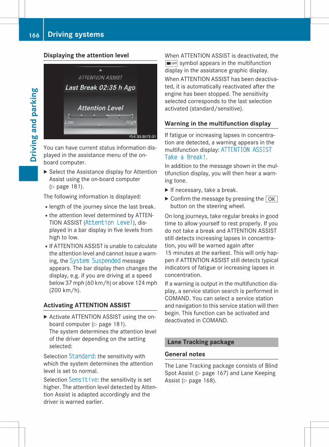
Displaying the attention level
You can have current status information dis-played in the assistance menu of the on-board computer.X Select the Assistance display for AttentionAssist using the on-board computer(Y page 181).
The following information is displayed:Rlength of the journey since the last break.Rthe attention level determined by ATTEN-TION ASSIST (Attention Level), dis-played in a bar display in five levels fromhigh to low.
RIf ATTENTION ASSIST is unable to calculatethe attention level and cannot issue awarn-ing, the System Suspended messageappears. The bar display then changes thedisplay, e.g. if you are driving at a speedbelow37mph (60 km/h) or above 124mph(200 km/h).
Activating ATTENTION ASSISTX Activate ATTENTION ASSIST using the on-board computer (Y page 181).The system determines the attention levelof the driver depending on the settingselected:
Selection Standard: the sensitivity withwhich the system determines the attentionlevel is set to normal.Selection Sensitive: the sensitivity is sethigher. The attention level detected by Atten-tion Assist is adapted accordingly and thedriver is warned earlier.
When ATTENTION ASSIST is deactivated, theé symbol appears in the multifunctiondisplay in the assistance graphic display.When ATTENTION ASSIST has been deactiva-ted, it is automatically reactivated after theengine has been stopped. The sensitivityselected corresponds to the last selectionactivated (standard/sensitive).
Warning in the multifunction displayIf fatigue or increasing lapses in concentra-tion are detected, a warning appears in themultifunction display: ATTENTION ASSISTTake a Break!.In addition to the message shown in the mul-tifunction display, you will then hear a warn-ing tone.X If necessary, take a break.X Confirm the message by pressing theabutton on the steering wheel.
On long journeys, take regular breaks in goodtime to allow yourself to rest properly. If youdo not take a break and ATTENTION ASSISTstill detects increasing lapses in concentra-tion, you will be warned again after15 minutes at the earliest. This will only hap-pen if ATTENTION ASSIST still detects typicalindicators of fatigue or increasing lapses inconcentration.If a warning is output in the multifunction dis-play, a service station search is performed inCOMAND. You can select a service stationand navigation to this service station will thenbegin. This function can be activated anddeactivated in COMAND.
Lane Tracking package
General notesThe Lane Tracking package consists of BlindSpot Assist (Y page 167) and Lane KeepingAssist (Y page 168).
166 Driving systemsDr
ivin
gan
dpa
rkin
g

Blind Spot Assist
General notesBlind Spot Assist monitors the areas on eitherside of the vehicle that are not visible to thedriver with two lateral, rear-facing radar sen-sors. A warning display in the exterior mirrorsdraws your attention to vehicles detected inthe monitored area. If you then switch on thecorresponding turn signal to change lanes,you will also receive a visual and audible col-lision warning.Blind Spot Assist supports you from a speedof approximately 20 mph (30 km/h).
Important safety notesG WARNINGBlind Spot Assist does not react to:Rvehicles overtaken too closely on the side,placing them in the blind spot area
Rvehicles which approach with a large speeddifferential and overtake your vehicle
As a result, Blind Spot Assist may not givewarnings in such situations. There is a risk ofan accident.Always observe the traffic conditions care-fully, and maintain a safe lateral distance.
Blind Spot Assist is only an aid. It may fail todetect some vehicles and is no substitute forattentive driving. Always ensure that there issufficient distance to the side for other roadusers and obstacles.
i USA only:This device has been approved by the FCCas a "Vehicular Radar System". The radarsensor is intended for use in an automotiveradar system only. Removing, tamperingwith, or altering the device will void anywarranties, and is not permitted by theFCC. Do not tamper with, alter, or use inany non-approved way.Any unauthorized modification to thisdevice could void the user’s authority tooperate the equipment.
Radar sensorsThe radar sensors for Blind Spot Assist areintegrated into the rear bumper. Make surethat the bumpers are free from dirt, ice orslush. The sensors must not be covered, forexample by cycle racks or overhanging loads.Following a severe impact or in the event ofdamage to the bumpers, have the function ofthe radar sensors checked at a qualified spe-cialist workshop. Blind Spot Assist may nolonger work properly.
Monitoring areaIn particular, the detection of obstacles canbe impaired if:Rthere is dirt on the sensors or anything elsecovering the sensors
Rthere is poor visibility, e.g. due to fog, heavyrain, snow or spray
Rthere are narrow vehicles, e.g. motorcyclesor bicycles
Rthe road has very wide lanesRthe road has narrow lanesRyou are not driving in the middle of the laneRthere are barriers or similar lane bordersVehicles in the monitoring range are then notindicated.
Blind Spot Assistmonitors the area up to 10 ft(3 m) behind your vehicle and directly next toyour vehicle, as shown in the diagram.
Driving systems 167
Driv
ing
and
park
ing
Z
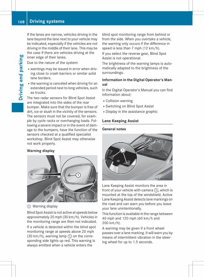
If the lanes are narrow, vehicles driving in thelane beyond the lane next to your vehicle maybe indicated, especially if the vehicles are notdriving in themiddle of their lane. This may bethe case if there are vehicles driving at theinner edge of their lanes.Due to the nature of the system:Rwarnings may be issued in error when driv-ing close to crash barriers or similar solidlane borders.
Rthe warning is canceled when driving for anextended period next to long vehicles, suchas trucks.
The two radar sensors for Blind Spot Assistare integrated into the sides of the rearbumper. Make sure that the bumper is free ofdirt, ice or slush in the vicinity of the sensors.The sensors must not be covered, for exam-ple by cycle racks or overhanging loads. Fol-lowing a severe impact or in the event of dam-age to the bumpers, have the function of thesensors checked at a qualified specialistworkshop. Blind Spot Assist may otherwisenot work properly.
Warning display
: Warning displayBlind Spot Assist is not active at speeds belowapproximately 20mph (30 km/h). Vehicles inthe monitoring range are then not indicated.If a vehicle is detected within the blind spotmonitoring range at speeds above 20 mph(30 km/h), warning lamp: on the corre-sponding side lights up red. This warning isalways emitted when a vehicle enters the
blind spot monitoring range from behind orfrom the side. When you overtake a vehicle,the warning only occurs if the difference inspeed is less than 7 mph (12 km/h).If you select the reverse gear, Blind SpotAssist is not operational.The brightness of the warning lamps is auto-matically adapted to the brightness of thesurroundings.
Information in the Digital Operator's Man-ualIn the Digital Operator's Manual you can findinformation about:RCollision warningRSwitching on Blind Spot AssistRDisplay in the assistance graphic
Lane Keeping Assist
General notes
Lane Keeping Assist monitors the area infront of your vehicle with camera:, which ismounted at the top of the windshield. ActiveLaneKeepingAssist detects lanemarkings onthe road and can warn you before you leaveyour lane unintentionally.This function is available in the range between40 mph and 120 mph (60 km/h and200 km/h).A warning may be given if a front wheelpasses over a lanemarking. It will warn you bymeans of intermittent vibration in the steer-ing wheel for up to 1.5 seconds.
168 Driving systemsDr
ivin
gan
dpa
rkin
g
Important safety notesG WARNINGLane Keeping Assist may not always clearlyrecognize lane markings.In this case, Lane Keeping Assist may:Rgive an unnecessary warningRnot give a warningThere is a risk of an accident.Always pay particular attention to the trafficsituation and stay in lane, in particular ifwarned by Lane Keeping Assist.
G WARNINGThe Lane Keeping Assist warning does notreturn the vehicle to the original lane. There isa risk of an accident.You should always steer, brake or accelerateyourself, in particular if warned by Lane Keep-ing Assist.
If you fail to adapt your driving style, LaneKeeping Assist can neither reduce the risk ofan accident nor override the laws of physics.Lane Keeping Assist cannot take into accountthe road, traffic and weather conditions. LaneKeeping Assist is merely an aid. You areresponsible for the distance to the vehicle infront, for vehicle speed, for braking in goodtime and for staying in your lane.The Lane Keeping Assist does not keep thevehicle in the lane.The systemmay be impaired or may not func-tion if:Rthere is poor visibility, e.g. due to insuffi-cient illumination of the road, or due tosnow, rain, fog or spray
Rthere is glare, e.g. from oncoming traffic,the sun or reflections (e.g. when the roadsurface is wet)
Rthe windshield is dirty, fogged up, damagedor covered, for instance by a sticker, in thevicinity of the camera
Rthere are no, several or unclear lane mark-ings for a lane, e.g. in areas with road con-struction work
Rthe lane markings are worn away, dark orcovered up, e.g. by dirt or snow
Rthe distance to the vehicle in front is toosmall and the lanemarkings thus cannot bedetected
Rthe lane markings change quickly, e.g.lanes branch off, cross one another ormerge
Rthe road is narrow and windingRthere are strong shadows cast on the road
Information in the Digital Operator's Man-ualIn the Digital Operator's Manual you can findinformation about:RActivating/deactivating Lane KeepingAssist
RSelecting Standard or Adaptive setting
Driving Assistance PLUS package
General notesThe Driving Assistance PLUS package con-sists of DISTRONICPLUS (Ypage146), ActiveBlind Spot Assist (Y page 169) and ActiveLane Keeping Assist (Y page 172).
Active Blind Spot Assist
General notesActive Blind Spot Assist uses a radar sensorsystem, pointed toward the rear of the vehi-cle, to monitor the area to the sides of thevehicle which the driver is unable to see. Awarning display in the exterior mirrors drawsyour attention to vehicles detected in themonitored area. If you then switch on the cor-responding turn signal to change lanes, youwill also receive a visual and audible collisionwarning. If a risk of lateral collision is detec-ted, corrective braking may help you avoid acollision. Before a course-correcting brakeapplication, Active Blind Spot Assist evalu-ates the space in the direction of travel and atthe sides of the vehicle. For this, Active Blind
Driving systems 169
Driv
ing
and
park
ing
Z

Spot Assist uses the forward-facing radarsensors.Active Blind Spot Assist supports you from aspeed of approximately 20 mph (30 km/h).
Important safety notesActive Blind Spot Assist is only an aid and isnot a substitute for attentive driving.
G WARNINGActive Blind Spot Assist does not react to:Rvehicles overtaken too closely on the side,placing them in the blind spot area
Rvehicles which approach with a large speeddifferential and overtake your vehicle
As a result, Active Blind Spot Assist may nei-ther give warnings nor intervene in such sit-uations. There is a risk of an accident.Always observe the traffic conditions care-fully, and maintain a safe lateral distance.
i USA only: This device has been approvedby the FCC as a "Vehicular Radar System".The radar sensor is intended for use in anautomotive radar system only. Removal,tampering, or altering of the device will voidany warranties, and is not permitted by theFCC. Do not tamper with, alter, or use inany non-approved way.Any unauthorized modification to thisdevice could void the user's authority tooperate the equipment.
i Canada only: This device complies withRSS-210 of Industry Canada. Operation issubject to the following two conditions:1. This device may not cause harmful inter-ference, and2. This devicemust accept any interferencereceived, including interference that maycause undesired operation of the device.Removal, tampering, or altering of thedevice will void any warranties, and is notpermitted. Do not tamper with, alter, or usein any non-approved way.
Any unauthorized modification to thisdevice could void the user's authority tooperate the equipment.
Radar sensorsThe Active Blind Spot Assist radar sensors areintegrated into the front and rear bumpersand behind a cover in the radiator trim. Makesure that the bumpers and the cover in theradiator grill are free of dirt, ice or slush. Therear sensors must not be covered, e.g. bybicycle racks or overhanging loads. Followinga severe impact or in the event of damage tothe bumpers, have the function of the radarsensors checked at a qualified specialistworkshop. Active Blind Spot Assist may oth-erwise no longer work properly.
Monitoring areaG WARNINGActive Blind Spot Assist does not detect alltraffic situations and road users. There is arisk of an accident.Always make sure that there is sufficient dis-tance on the side for other traffic or obstacles.
Active Blind Spot Assist monitors the area upto 10 ft (3.0 m) behind your vehicle anddirectly next to your vehicle, as shown in thediagram.
170 Driving systemsDr
ivin
gan
dpa
rkin
g

The detection of obstacles can be impaired inthe case of:Rthere is dirt on the sensors or anything elsecovering the sensors
Rpoor visibility, e.g. due to rain, snow orspray
Vehicles in the monitoring range are then notindicated.Active Blind Spot Assist may not detect nar-row vehicles, such as motorcycles or bicy-cles, or may only detect them too late.If the lanes are narrow, vehicles driving in thelane beyond the lane next to your vehicle maybe indicated, especially if the vehicles are notdriving in themiddle of their lane. This may bethe case if there are vehicles at the inner edgeof your lane.Due to the nature of the system:Rwarnings may be issued in error when driv-ing close to crash barriers or similar solidlane borders.
Rwarnings may be interrupted when drivingalongside particularly long vehicles, e.g.trucks, for a prolonged time.
Warning display
: Warning displayActive Blind Spot Assist is not operational atspeeds below approximately 20 mph(30 km/h). Vehicles in the monitoring rangeare then not indicated.If a vehicle is detected within the blind spotmonitoring range at speeds above 20 mph(30 km/h), warning lamp: on the corre-sponding side lights up red. This warning is
always emitted when a vehicle enters theblind spot monitoring range from behind orfrom the side. When you overtake a vehicle,the warning only occurs if the difference inspeed is less than 7 mph (12 km/h).If you select the reverse gear, Active BlindSpot Assist is not operational.The brightness of the warning lamps is auto-matically adapted to the brightness of thesurroundings.
When Active Blind Spot Assist is activated,gray radar waves propagating backwardsappear next to the vehicle in the assistancedisplay in the multifunction display. Above aspeed of 20 mph (30 km/h), the color of theradar waves in the assistance displaychanges to green;. Active Blind Spot Assistis then ready for use.
Visual and acoustic collision warningIf you switch on the turn signals to changelanes and a vehicle is detected in the sidemonitoring range, you receive a visual andacoustic collision warning. You will then heara double warning tone and red warninglamp: flashes. If the turn signal remains on,detected vehicles are indicated by the flash-ing of red warning lamp:. There are no fur-ther warning tones.
Course-correcting brake applicationIf Active Blind Spot Assist detects a risk of alateral collision in the monitoring range, acourse-correcting brake application is carriedout. This is meant to assist you in avoiding acollision.
Driving systems 171
Driv
ing
and
park
ing
Z

G WARNINGA course-correcting brake application cannotalways prevent a collision. There is a risk of anaccident.Always steer, brake or accelerate yourself,especially if Active Blind Spot Assist warnsyou ormakes a course-correcting brake appli-cation. Always maintain a safe distance at thesides.
If a course-correcting brake applicationoccurs, red warning lamp: flashes in theexterior mirror and a dual warning tonesounds. In addition, display; underliningthe danger of a side collision appears in themultifunction display.In very rare cases, the system may make aninappropriate brake application. A course-correcting brake application may be interrup-ted at any time if you steer slightly in theopposite direction or accelerate.The course-correcting brake application isavailable in the speed range between 20 mph(30 km/h) and 120 mph (200 km/h).Either no braking application, or a course-correcting brake application adapted to thedriving situation occurs if:Rthere are vehicles or obstacles, e.g. crashbarriers, located on both sides of your vehi-cle.
Ra vehicle approaches you too closely at theside.
Ryou have adopted a sporty driving stylewithhigh cornering speeds.
Ryou clearly brake or accelerate.
Ra driving safety system intervenes, e.g.ESP® or PRE-SAFE® Brake.
RESP® is switched off.Ra loss of tire pressure or a defective tire isdetected.
Information in the Digital Operator's Man-ualIn the Digital Operator's Manual you can findinformation about:RSwitching on Active Blind Spot Assist
Active Lane Keeping Assist
General notes
Active Lane Keeping Assist monitors the areain front of your vehicle by means of camerasystem: at the top of the windshield. Vari-ous different areas to the front, rear and sideof your vehicle are alsomonitoredwith the aidof the radar sensor system. Active Lane Keep-ing Assist detects lane markings on the roadand can warn you before you leave your laneunintentionally. If you do not react to thewarning, a lane-correcting application of thebrakes can bring the vehicle back into theoriginal lane.If you select km in the Display UnitSpeed-/Odometer: function on the on-boardcomputer (Y page 181), Active Lane KeepingAssist is activated starting at a speed of60 km/h. If the miles display unit is selected,the assistance range begins at 40 mph.
172 Driving systemsDr
ivin
gan
dpa
rkin
g

Important safety notesIf you fail to adapt your driving style, ActiveLane Keeping Assist can neither reduce therisk of accident nor override the laws of phys-ics. Active Lane Keeping Assist cannot takeaccount of road and weather conditions. Itmay not recognize traffic situations. ActiveLane Keeping Assist is only an aid. You areresponsible for the distance to the vehicle infront, for vehicle speed, for braking in goodtime and for staying in your lane.Active Lane Keeping Assist cannot continu-ously keep your vehicle in its lane.
G WARNINGActive Lane Keeping Assist cannot alwaysclearly detect lane markings.In such cases, Active Lane Keeping Assistcan:Rgive an unnecessary warning and thenmake a course-correcting brake applicationto the vehicle
Rnot give a warning or interveneThere is a risk of an accident.Always pay particular attention to the trafficsituation and keep within the lane, especiallyif Active Lane Keeping Assist alerts you. Ter-minate the intervention in a non-critical driv-ing situation.
The systemmay be impaired or may not func-tion if:Rthere is poor visibility, e.g. due to insuffi-cient illumination of the road, or due tosnow, rain, fog or spray
Rthere is glare, e.g. from oncoming traffic,the sun or reflections (e.g. when the roadsurface is wet)
Rthe windshield is dirty, fogged up, damagedor covered, for instance by a sticker, in thevicinity of the camera
Rthe radar sensors in the front or rear bump-ers or the radiator trim are dirty, e.g.obscured by snow
Rthere are no, several or unclear lane mark-ings for a lane, e.g. in areas with road con-struction work
Rthe lane markings are worn away, dark orcovered up, e.g. by dirt or snow
Rthe distance to the vehicle in front is toosmall and the lanemarkings thus cannot bedetected
Rthe lane markings change quickly, e.g.lanes branch off, cross one another ormerge
Rthe road is narrow and windingRthere are strong shadows cast on the roadIf no vehicle is detected in the adjacent laneand broken lane markings are detected, nolane-correcting brake application is made.
Warning vibration in the steering wheelA warning may be given if a front wheelpasses over a lanemarking. It will warn you bymeans of intermittent vibration in the steer-ing wheel for up to 1.5 seconds.
Lane-correcting brake applicationIf you leave your lane, under certain circum-stances the vehicle will brake briefly on oneside. This is meant to assist you in bringingthe vehicle back to the original lane.
G WARNINGA lane-correcting brake application cannotalways bring the vehicle back into the originallane. There is a risk of an accident.Always steer, brake or accelerate yourself,especially if Active Lane Keeping Assist warnsyou or makes a lane-correcting brake appli-cation.
Driving systems 173
Driv
ing
and
park
ing
Z
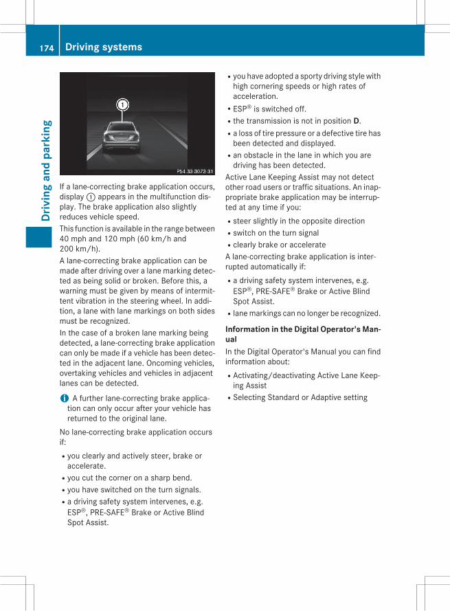
If a lane-correcting brake application occurs,display: appears in the multifunction dis-play. The brake application also slightlyreduces vehicle speed.This function is available in the range between40 mph and 120 mph (60 km/h and200 km/h).A lane-correcting brake application can bemade after driving over a lane marking detec-ted as being solid or broken. Before this, awarning must be given by means of intermit-tent vibration in the steering wheel. In addi-tion, a lane with lane markings on both sidesmust be recognized.In the case of a broken lane marking beingdetected, a lane-correcting brake applicationcan only be made if a vehicle has been detec-ted in the adjacent lane. Oncoming vehicles,overtaking vehicles and vehicles in adjacentlanes can be detected.
i A further lane-correcting brake applica-tion can only occur after your vehicle hasreturned to the original lane.
No lane-correcting brake application occursif:Ryou clearly and actively steer, brake oraccelerate.
Ryou cut the corner on a sharp bend.Ryou have switched on the turn signals.Ra driving safety system intervenes, e.g.ESP®, PRE-SAFE® Brake or Active BlindSpot Assist.
Ryou have adopted a sporty driving stylewithhigh cornering speeds or high rates ofacceleration.
RESP® is switched off.Rthe transmission is not in position D.Ra loss of tire pressure or a defective tire hasbeen detected and displayed.
Ran obstacle in the lane in which you aredriving has been detected.
Active Lane Keeping Assist may not detectother road users or traffic situations. An inap-propriate brake application may be interrup-ted at any time if you:Rsteer slightly in the opposite directionRswitch on the turn signalRclearly brake or accelerateA lane-correcting brake application is inter-rupted automatically if:Ra driving safety system intervenes, e.g.ESP®, PRE-SAFE® Brake or Active BlindSpot Assist.
Rlanemarkings can no longer be recognized.
Information in the Digital Operator's Man-ualIn the Digital Operator's Manual you can findinformation about:RActivating/deactivating Active Lane Keep-ing Assist
RSelecting Standard or Adaptive setting
174 Driving systemsDr
ivin
gan
dpa
rkin
g

Useful information ............................ 176Important safety notes ..................... 176Displays and operation ..................... 176Menus and submenus ...................... 181Display messages ............................. 182Warning and indicator lamps in theinstrument cluster ............................ 195
175
On-b
oard
com
pute
rand
disp
lays

Useful information
i This Operator's Manual describes allmodels and all standard and optional equip-ment of your vehicle available at the time ofpublication of the Operator's Manual.Country-specific differences are possible.Please note that your vehicle may not beequipped with all features described. Thisalso applies to safety-related systems andfunctions.
i Read the information on qualified special-ist workshops (Y page 29).
Important safety notes
G WARNINGIf you operate information systems and com-munication equipment integrated in the vehi-cle while driving, you will be distracted fromtraffic conditions. You could also lose controlof the vehicle. There is a risk of an accident.Only operate the equipment when the trafficsituation permits. If you are not sure that thisis possible, park the vehicle paying attentionto traffic conditions and operate the equip-ment when the vehicle is stationary.
You must observe the legal requirements forthe country in which you are currently drivingwhen operating the on-board computer.
G WARNINGIf the instrument cluster has failed or mal-functioned, you may not recognize functionrestrictions in systems relevant to safety. Theoperating safety of your vehicle may beimpaired. There is a risk of an accident.Drive on carefully. Have the vehicle checkedat a qualified specialist workshop immedi-ately.
If the operating safety of your vehicle isimpaired, pull over as soon as it is safe to doso. Contact a qualified specialist workshop.
The on-board computer only showsmessagesor warnings from certain systems in the mul-tifunction display. You should therefore makesure your vehicle is operating safely at alltimes.For an overview, see the instrument panelillustration (Y page 35).
Displays and operation
Information in the Digital Operator'sManualIn the Digital Operator's Manual you will findinformation on the following topics:RCoolant temperature displayRTachometerRSpeedometer with segmentsRMultifunction displayROutside temperature display
Instrument cluster lighting
The lighting in the instrument cluster, in thedisplays and the controls in the vehicle inte-rior can be adjusted using brightness controlknob:.X Turn brightness control knob: up ordown.If the light switch (Y page 113) is set toÃ,T orL, the brightness isdependent upon the brightness of theambient light.
176 Displays and operationOn
-boa
rdco
mpu
tera
nddi
spla
ys

i The light sensor in the instrument clusterautomatically controls the brightness ofthe multifunction display.In daylight, the displays in the instrumentcluster are illuminated. A dimming functionis not possible in daylight.
Operating the on-board computer
: Multifunction display; Right control panel= Left control panelX To activate the on-board computer: turnthe SmartKey to position 1 in the ignitionlock.
You can control the multifunction display andthe settings in the on-board computer usingthe buttons on the multifunction steeringwheel.
Left control panel
ò RCalls up the main menu
9
:
Press briefly:RScrolls in listsRSelects a menu or functionRIn the Radio or Media menu:opens the track or station listand selects a station, an audiotrack or a video scene
RIn the Telephone Telephonemenu: switches to the phonebook and selects a name or atelephone number
9
:
Press and hold:RRapid scrolling in all listsRIn the Radio or Media menu:selects a station, audio track orvideo scene using rapid scrolling
RIn the Telephone menu: startsrapid scrolling if the phone bookis open
a RIn all menus: confirms the selec-ted entry in the list
RIn the Radio or Media menu:opens the list of available radiosources or media
RIn the Telephone menu:switches to the phone book andstarts dialing the selected num-ber
ñ RVehicles with Audio 20:Switches off voice-operated con-trol for navigation (see manufac-turer's operating instructions)
RVehicles with COMAND:Switches off the Voice ControlSystem (see the separate oper-ating instructions)
Displays and operation 177
On-b
oard
com
pute
rand
disp
lays
Z

% Press briefly:RBackRIn the Radio or Media menu:deselects the track or station listor list of available radio sourcesor media
RHides display messagesRExits the telephone book/redialmemory
% Press and hold:RCalls up the standard display inthe Trip menu
Right control panel
~ RRejects or ends a callRExits the telephone book/redialmemory
6 RMakes or accepts a callRSwitches to the redial memory
WX
RAdjusts the volume
8 RMute
ó RVehicles with Audio 20:Switches on voice-operated con-trol for navigation (see manufac-turer's operating instructions)
RVehicles with COMAND:Switches on the Voice ControlSystem (see the separate oper-ating instructions)
Head-up display
General notesThe head-up display projects informationfrom the navigation system and the driverassistance system above the dashboard intothe driver's field of vision.
A requirement for the display of the contentsis that the following functions are available inthe vehicle and are switched on:RCruise controlRDISTRONIC PLUSRNavigationThe head-up display allows the driver to seeall of the information without having to takehis eyes off the road.
Important safety notesThe head-up display is only an aid and is not asubstitute for attentive driving.The visibility of the head-up display is influ-enced by the following conditions:Rthe driver's seat positionRthe positioning of the display imageRthe general ambient lightRsunglasses with polarization filtersRwet roadsRblocking of sunlight by objects on the dis-play cover
In the event of extreme sunlight, sections ofthe display may fade. This can be reversed byswitching the head-up display off and onagain.
i Vehicles with the head-up display areequipped with a special windshield. Shouldrepairs be necessary, have the windshieldreplaced at a qualified specialist workshop.
178 Displays and operationOn
-boa
rdco
mpu
tera
nddi
spla
ys

Displays and operation
Switching the head-up display on or off
X Press button:.When the head-up display is switched on,the display appears in the driver's field ofvision.
Displays and operation 179
On-b
oard
com
pute
rand
disp
lays
Z

Displays in the head-up display
Content and information for the following systems are shown in the head-up display:: Navigation messages; Current speed= The selected DISTRONIC PLUS speed (Y page 146)
The selected cruise control speed (Y page 145)
: Current engine speed; Current speed= Upshift indicator? Currently selected gear, gearshift options when shifting manuallyA RACETIMERB Lap
180 Displays and operationOn
-boa
rdco
mpu
tera
nddi
spla
ys

In the Settingsmenu, in the submenu head-up display, you have the following settings options:RSwitching other displays on/off (Y page 181)RSetting the position (Y page 181)RSetting the brightness (Y page 181)
Menus and submenus
Menu overviewPress theò button on the steering wheelto call up the list of menus and select a menu.Operating the on-board computer(Y page 177).You can find more information on the individ-ual menus in the Digital Operator's Manual.Depending on the equipment installed in thevehicle, you can call up the following menus:RTrip menuRNavi menu (navigation instructions)RRadio menuRMedia menuRTelephone menuRAssistance Graphic menuRService menuRSettings menuRAMG menu in AMG vehicles
Menus and submenus 181
On-b
oard
com
pute
rand
disp
lays
Z

Display messages
Introduction
General notesThis section describes display messages relevant to safety together with their solutions. Adescription of other messages and their solutions can be found in the Digital Operator's Man-ual.Display messages appear in the multifunction display.Display messages with graphic displays may be shown in simplified form in the Operator'sManual and may therefore differ from the multifunction display.Please respond in accordancewith the displaymessages and follow the additional notes in thisOperator's Manual.With certain display messages, you will also hear a warning tone.You can hide the display messages. The display messages are then stored in the messagememory. Rectify the cause of a display message as soon as possible.When you stop and park the vehicle, please observe the notes on the HOLD function(Y page 154) and parking (Y page 141).
Hides display messagesX Press thea or% button on the steering wheel to hide the display message.The display message is cleared.
The multifunction display shows high-priority display messages in red. Some high-priority dis-play messages cannot be hidden.The multifunction display shows these messages continuously until the causes for the mes-sages have been remedied.
Message memoryThe on-board computer saves certain displaymessages in themessage memory. You can callup the display messages:X Useò on the steering wheel to call up the list of menus.X Press the: or9 button on the steering wheel to select the Service menu.X Confirm by pressinga on the steering wheel.X Press: or9 to select the message memory.If there are no display messages, you will see No Messages in the multifunction display.If there are display messages, the number of messages stored is shown.X Pressa to confirm.X Press the: or9 button to scroll through the display messages.
182 Display messagesOn
-boa
rdco
mpu
tera
nddi
spla
ys

Safety systems
Display messages Possible causes/consequences and M Solutions
!÷Currently Unavailхable See Operaхtor's Manual
ABS (Anti-lock Brake System), ESP® (Electronic Stability Program),BAS (Brake Assist), PRE゙SAFE®, HOLD function, Crosswind Assist,hill start assist, STEER CONTROL, Active Lane Keeping Assist andActive Blind Spot Assist are temporarily unavailable.BAS PLUS, PRE゙SAFE® Brake, PRE゙SAFE® PLUS and COLLISIONPREVENTION ASSIST PLUS may also have failed.In addition, the÷ and! warning lamps light up in theinstrument cluster.ATTENTION ASSIST is deactivated.For example, the on-board voltage may be insufficient.
G WARNINGThe brake system continues to function normally, but without thefunctions listed above. The wheels could therefore lock if youbrake hard, for example.The steerability and braking characteristics may be severely affec-ted. The braking distance in an emergency braking situation canincrease.If ESP® is not operational, ESP® is unable to stabilize the vehicle.There is an increased risk of skidding and an accident.X Drive on carefully.Carefully drive a suitable distance, making slight steering move-ments at a speed above 12 mph (20 km/h).If the display message disappears, the functions mentionedabove are available again.
If the multifunction display still shows the display message:X Drive on carefully.X Visit a qualified specialist workshop.
!÷Inoperative SeeOperator's Manual
ABS, ESP®, BAS, PRE゙SAFE®, HOLD function, Crosswind Assist,hill start assist, STEER CONTROL, Active Lane Keeping Assist andActive Blind Spot Assist are unavailable due to a malfunction.BAS PLUS, PRE゙SAFE® Brake, PRE゙SAFE® PLUS and COLLISIONPREVENTION ASSIST PLUS may also have failed.The$ (USA only) orJ (Canada only),÷ and!warn-ing lamps in the instrument cluster may also light up.ATTENTION ASSIST is deactivated.
G WARNING
Display messages 183
On-b
oard
com
pute
rand
disp
lays
Z

Display messages Possible causes/consequences and M SolutionsThe brake system continues to function normally, but without thefunctions listed above. The wheels could therefore lock if youbrake hard, for example.The steerability and braking characteristics may be severely affec-ted. The braking distance in an emergency braking situation canincrease.If ESP® is not operational, ESP® is unable to stabilize the vehicle.There is an increased risk of skidding and an accident.X Drive on carefully.X Visit a qualified specialist workshop immediately.
÷Inoperative SeeOperator's Manual
ESP®, BAS, PRE゙SAFE®, HOLD function, Crosswind Assist, hillstart assist, STEER CONTROL, Active Lane Keeping Assist andActive Blind Spot Assist are unavailable due to a malfunction.BAS PLUS, PRE゙SAFE® Brake, PRE゙SAFE® PLUS and COLLISIONPREVENTION ASSIST PLUS may also have failed.The÷ warning lamp also lights up in the instrument cluster.ATTENTION ASSIST is deactivated.
G WARNINGThe brake system continues to function normally, but without thefunctions listed above.The braking distance in an emergency braking situation can thusincrease.If ESP® is not operational, ESP® is unable to stabilize the vehicle.There is an increased risk of skidding and an accident.X Drive on carefully.X Visit a qualified specialist workshop.
184 Display messagesOn
-boa
rdco
mpu
tera
nddi
spla
ys
Display messages Possible causes/consequences and M Solutions
÷Currently Unavailхable See Operaхtor's Manual
ESP®, BAS, PRE゙SAFE®, HOLD function, Crosswind Assist, hillstart assist, STEER CONTROL, Active Lane Keeping Assist andActive Blind Spot Assist are unavailable due to a malfunction.BAS PLUS, PRE゙SAFE® Brake, PRE゙SAFE® PLUS and COLLISIONPREVENTION ASSIST PLUS may also have failed.The÷ warning lamp also lights up in the instrument cluster.The self-diagnosis function might not be complete, for example.ATTENTION ASSIST is deactivated.
G WARNINGThe brake system continues to function normally, but without thefunctions listed above. The wheels could therefore lock if youbrake hard, for example.The braking distance in an emergency braking situation can thusincrease.If ESP® is not operational, ESP® is unable to stabilize the vehicle.There is an increased risk of skidding and an accident.X Carefully drive a suitable distance, making slight steering move-ments at a speed above 12 mph (20 km/h).If the display message disappears, the functions mentionedabove are available again.
If the multifunction display still shows the display message:X Drive on carefully.X Visit a qualified specialist workshop.
Display messages 185
On-b
oard
com
pute
rand
disp
lays
Z

Display messages Possible causes/consequences and M Solutions
T!÷Inoperative SeeOperator's Manual
EBD (electronic brake force distribution), ABS, ESP®, BAS,PRE゙SAFE®, HOLD function, Crosswind Assist, hill start assist,STEER CONTROL, Active Lane Keeping Assist and Active BlindSpot Assist are unavailable due to a malfunction.BAS PLUS, PRE゙SAFE® Brake, PRE゙SAFE® PLUS and COLLISIONPREVENTION ASSIST PLUS may also have failed.In addition, the÷ and! warning lamps light up in theinstrument cluster and a warning tone sounds.
G WARNINGThe brake system continues to function normally, but without thefunctions listed above. The front and rear wheels could thereforelock if you brake hard, for example.The steerability and braking characteristics may be severely affec-ted. The braking distance in an emergency braking situation canincrease.If ESP® is not operational, ESP® is unable to stabilize the vehicle.There is an increased risk of skidding and an accident.X Drive on carefully.X Visit a qualified specialist workshop immediately.
$(USA
only)J(Canadaonly)Check Brake FluidLevel
There is not enough brake fluid in the brake fluid reservoir.In addition, the$ (USA only) orJ (Canada only) warninglamp lights up in the instrument cluster and a warning tonesounds.
G WARNINGThe braking effect may be impaired.There is a risk of an accident.X Pull over and stop the vehicle safely as soon as possible, payingattention to road and traffic conditions. Do not continue drivingunder any circumstances.X Secure the vehicle against rolling away (Y page 141).X Consult a qualified specialist workshop.X Do not add brake fluid. This does not correct the malfunction.
186 Display messagesOn
-boa
rdco
mpu
tera
nddi
spla
ys

Display messages Possible causes/consequences and M Solutions
6SRS MalfunctionService Required
The restraint system is faulty. The6 warning lamp also lightsup in the instrument cluster.
G WARNINGThe air bags or Emergency Tensioning Devices may either be trig-gered unintentionally or, in the event of an accident, may not betriggered.There is an increased risk of injury.X Visit a qualified specialist workshop.For further information about the restraint system, see(Y page 44).
6Front Left Malfuncхtion ServiceRequired or FrontRight MalfunctionService Required
The restraint system has malfunctioned at the front on the left orright. The6warning lamp also lights up in the instrument clus-ter.
G WARNINGThe air bags or Emergency Tensioning Devices may either be trig-gered unintentionally or, in the event of an accident, may not betriggered.There is an increased risk of injury.X Visit a qualified specialist workshop.
6Rear Left Malfuncхtion ServiceRequired or RearRight MalfunctionService Required
The rear left-hand or right-hand restraint system has malfunc-tioned. The6 warning lamp also lights up in the instrumentcluster.
G WARNINGThe air bags or Emergency Tensioning Devices may either be trig-gered unintentionally or, in the event of an accident, may not betriggered.There is an increased risk of injury.X Visit a qualified specialist workshop.
6Rear Center Malхfunction ServiceRequired
The rear center restraint system has malfunctioned. The6warning lamp also lights up in the instrument cluster.
G WARNINGThe air bags or Emergency Tensioning Devices may either be trig-gered unintentionally or, in the event of an accident, may not betriggered.There is an increased risk of injury.X Visit a qualified specialist workshop.
Display messages 187
On-b
oard
com
pute
rand
disp
lays
Z

Display messages Possible causes/consequences and M Solutions
6Left Side CurtainAirbag MalfunctionService Requiredor Right Side Curхtain Airbag Malхfunction ServiceRequired
There is a malfunction in the left-hand or right-hand window cur-tain air bag. The6warning lamp also lights up in the instrumentcluster.
G WARNINGThe left or right window curtain air bag may either be triggeredunintentionally or, in the event of an accident, may not be trig-gered.There is an increased risk of injury.X Visit a qualified specialist workshop.
188 Display messagesOn
-boa
rdco
mpu
tera
nddi
spla
ys

Display messages Possible causes/consequences and M Solutions
Front PassengerAirbag DisabledSee Operator's Manхual
The front-passenger air bag is deactivated during the journey, eventhough:Ran adultor
Ra person of the corresponding stature is on the front-passengerseat
If additional forces are applied to the seat, the system may inter-pret the occupant's weight as lower than it actually is.
G WARNINGThe front-passenger air bag does not deploy during an accident.There is an increased risk of injury.X Pull over and stop the vehicle safely as soon as possible, payingattention to road and traffic conditions.X Secure the vehicle against rolling away (Y page 141).X Switch the ignition off.X Have the occupant get out of the vehicle.X Keep the seat unoccupied, close the front-passenger door andswitch on the ignition.X Observe the PASSENGER AIR BAG indicator lamps in the centerconsole and the multifunction display and check the following:Seat unoccupied and ignition switched on:Rthe PASSENGER AIR BAG OFF and PASSENGER AIR BAG ONindicator lamps must light up simultaneously for approx-imately six seconds
Rthe PASSENGER AIR BAG OFF indicator lamp must then lightup and remain lit. If the indicator lamp is on, OCS has disabledthe front-passenger front air bag (Y page 54)
Rthe display messages Front Passenger Airbag EnabledSee Operator's Manual or Front Passenger AirbagDisabled See Operator's Manualmust not appear in themultifunction display.
X Wait for a period of at least 60 seconds until the necessary sys-tem checks have been completed.X Make sure that the display messages do not appear in the mul-tifunction display.
If these conditions are fulfilled, the front-passenger seat can beoccupied again. Whether the PASSENGER AIR BAG OFF or ONindicator lamp remains lit or goes out depends on how OCS clas-sifies the occupant.If the conditions are not fulfilled, the system is not operating cor-rectly.
Display messages 189
On-b
oard
com
pute
rand
disp
lays
Z

Display messages Possible causes/consequences and M SolutionsX Visit a qualified specialist workshop immediately.For further information about the Occupant Classification System,see (Y page 54).
Front PassengerAirbag Enabled SeeOperator's Manual
The front-passenger air bag is enabled during the journey, eventhough:Ra child, a small adult or an object weighing less than the sys-tem's weight threshold is located on the front-passenger seator
Rthe front-passenger seat is unoccupiedThe system may detect objects or forces applying additionalweight on the seat.
G WARNINGThe air bag may deploy unintentionally.There is an increased risk of injury.X Pull over and stop the vehicle safely as soon as possible, payingattention to road and traffic conditions.X Secure the vehicle against rolling away (Y page 141).X Switch the ignition off.X Open the front-passenger door.X Remove the child and the child restraint system from the front-passenger seat.X Make sure that there are no objects on the seat adding to theweight.The system may otherwise detect the additional weight andinterpret the seat occupant's weight as greater than it actuallyis.X Keep the seat unoccupied, close the front-passenger door andswitch on the ignition.X Observe the PASSENGER AIR BAG indicator lamps in the centerconsole and the multifunction display and check the following:Seat unoccupied and ignition switched on:Rthe PASSENGER AIR BAG OFF and PASSENGER AIR BAG ONindicator lamps must light up simultaneously for approx-imately six seconds
Rthe PASSENGER AIR BAG OFF indicator lamp must then lightup and remain lit. If the indicator lamp is on, OCS (OccupantClassification System) has disabled the front-passenger frontair bag (Y page 54)
Rthe display messages Front Passenger Airbag EnabledSee Operator's Manual or Front Passenger Airbag
190 Display messagesOn
-boa
rdco
mpu
tera
nddi
spla
ys

Display messages Possible causes/consequences and M SolutionsDisabled See Operator's Manualmust not appear in themultifunction display.
X Wait for a period of at least 60 seconds until the necessary sys-tem checks have been completed.X Make sure that the display messages do not appear in the mul-tifunction display.
If these conditions are fulfilled, the front-passenger seat can beoccupied again. Whether the PASSENGER AIR BAG OFF or ONindicator lamp remains lit or goes out depends on how OCS clas-sifies the occupant.If the conditions are not fulfilled, the system is not operating cor-rectly.X Visit a qualified specialist workshop immediately.For further information about the Occupant Classification System,see (Y page 54).
Display messages 191
On-b
oard
com
pute
rand
disp
lays
Z

Engine
Display messages Possible causes/consequences and M Solutions
?Coolant Too HotStop Vehicle TurnEngine Off
The coolant is too hot.A warning tone also sounds.
G WARNINGDo not drive when your engine is overheated. This can cause somefluids which may have leaked into the engine compartment tocatch fire.Steam from the overheated engine can also cause serious burnswhich can occur just by opening the hood.There is a risk of injury.X Pull over and stop the vehicle safely and switch off the engine,paying attention to road and traffic conditions.X Secure the vehicle against rolling away (Y page 141).X Wait until the engine has cooled down.X Make sure that the air supply to the engine radiator is notblocked, e.g. by snow, slush or ice.X Do not start the engine again until the display message goes outand the coolant temperature is below 248 ‡ (120 †). Other-wise, the engine could be damaged.X Pay attention to the coolant temperature display.X If the temperature increases again, visit a qualified specialistworkshop immediately.
Under normal operating conditions and with the specified coolantlevel, the coolant temperature may rise to 248 ‡ (120 †).
192 Display messagesOn
-boa
rdco
mpu
tera
nddi
spla
ys

Tires
Display messages Possible causes/consequences and M Solutions
Check Tire Presхsure Soon
Canada only:The tire pressure loss warning system has detected a significantloss in pressure.A warning tone also sounds.Possible causes:Ryou have changed the positions of the wheels and tires or instal-led new wheels and tires.
Rthe tire pressure in one or more tires is not correct.
G WARNINGTire pressures that are too low pose the following hazards:Rthey may burst, especially as the load and vehicle speedincrease.
Rthey may wear excessively and/or unevenly, which may greatlyimpair tire traction.
Rthe driving characteristics, as well as steering and braking, maybe greatly impaired.
There is a risk of an accident.X Stop the vehicle without making any sudden steering or brakingmaneuvers. Pay attention to the traffic conditions as you do so.X Secure the vehicle against rolling away (Y page 141).X Check the tires and, if necessary, follow the instructions for aflat tire (Y page 264).X Check the tire pressures and, if necessary, correct the tire pres-sure.X Restart the tire pressure loss warning system when the tirepressure is correct (Y page 292).
Display messages 193
On-b
oard
com
pute
rand
disp
lays
Z

Display messages Possible causes/consequences and M Solutions
Check Tires The tire pressure in one or more tires has dropped significantly.The wheel position is displayed in the multifunction display.A warning tone also sounds.
G WARNINGTire pressures that are too low pose the following hazards:Rthey may burst, especially as the load and vehicle speedincrease.
Rthey may wear excessively and/or unevenly, which may greatlyimpair tire traction.
Rthe driving characteristics, as well as steering and braking, maybe greatly impaired.
There is a risk of an accident.X Stop the vehicle without making any sudden steering or brakingmaneuvers. Pay attention to the traffic conditions as you do so.X Secure the vehicle against rolling away (Y page 141).X Check the tires and, if necessary, follow the instructions for aflat tire (Y page 264).X Check the tire pressure (Y page 288).X If necessary, correct the tire pressure.
Warning Tire Malхfunction
The tire pressure in one or more tires has dropped suddenly. Thewheel position is shown in the multifunction display.
G WARNINGDriving with a flat tire poses a risk of the following hazards:Ra flat tire affects the ability to steer or brake the vehicle.Ryou could lose control of the vehicle.Rcontinued driving with a flat tire will cause excessive heat build-up and possibly a fire.
There is a risk of an accident.X Stop the vehicle without making any sudden steering or brakingmaneuvers. Pay attention to the traffic conditions as you do so.X Secure the vehicle against rolling away (Y page 141).X Check the tires and, if necessary, follow the instructions for aflat tire (Y page 264).
194 Display messagesOn
-boa
rdco
mpu
tera
nddi
spla
ys

Vehicle
Display messages Possible causes/consequences and M Solutions
M The hood is open. A warning tone also sounds.
G WARNINGThe open hood may block your view when the vehicle is in motion.There is a risk of an accident.X Pull over and stop the vehicle safely as soon as possible, payingattention to road and traffic conditions.X Secure the vehicle against rolling away (Y page 141).X Close the hood.
ÐPower Steering Malхfunction See Operхator's Manual
The power steering is malfunctioning.A warning tone also sounds.
G WARNINGYou will need to use more force to steer.There is a risk of an accident.X Check whether you are able to apply the extra force required.X If you are able to steer safely: carefully drive on to a qualifiedspecialist workshop.X If you are unable to steer safely: do not drive on. Contact thenearest qualified specialist workshop.
ÐSteering Malfuncхtion See Operaхtor's Manual
The electric steering lock is malfunctioning.
G WARNINGThe steering may be locked by the electric steering lock.There is a risk of an accident.X Pull over and stop the vehicle safely as soon as possible, payingattention to road and traffic conditions.X Secure the vehicle against rolling away (Y page 141).X Do not drive on and consult the nearest qualified specialistworkshop.
Warning and indicator lamps in the instrument cluster
General notesThis section describes indicator and warning lamps in the instrument cluster relevant to safetyand solutions. A description of other indicator and warning lamps in the instrument cluster andtheir solutions can be found in the Digital Operator's Manual.
Warning and indicator lamps in the instrument cluster 195
On-b
oard
com
pute
rand
disp
lays
Z

Some systems carry out a self-check when the ignition is switched on. Therefore, some indi-cator and warning lamps may light up or flash temporarily. This behavior is non-critical. Theseindicator and warning lamps only indicate a malfunction if they light up or flash after startingthe engine or while driving.
Safety
Seat belts
Warning/indicatorlamp
N Signal typePossible causes/consequences and M Solutions
ü N After starting the engine, the red seat belt warning lamp lights up for6 seconds.The seat belt warning lamp reminds the driver and front passenger to fastentheir seat belts.X Fasten your seat belt (Y page 48).
ü N After starting the engine, the red seat belt warning lamp lights up. In addi-tion, a warning tone sounds for up to 6 seconds.The driver's seat belt is not fastened.X Fasten your seat belt (Y page 48).The warning tone ceases.
196 Warning and indicator lamps in the instrument clusterOn
-boa
rdco
mpu
tera
nddi
spla
ys

Warning/indicatorlamp
N Signal typePossible causes/consequences and M Solutions
ü N The red seat belt warning lamp lights up after the engine starts, as soon asthe driver's or the front-passenger door is closed.The driver or front passenger has not fastened their seat belt.X Fasten your seat belt (Y page 48).The warning lamp goes out.
There are objects on the front-passenger seat.X Remove the objects from the front-passenger seat and stow them in asecure place.The warning lamp goes out.
ü N The red seat belt warning lamp flashes and an intermittent audible warningsounds.The driver or front passenger has not fastened their seat belt. The vehicle isbeing driven faster than 15 mph (25 km/h) or has briefly been driven fasterthan 15 mph (25 km/h).X Fasten your seat belt (Y page 48).The warning lamp goes out and the intermittent warning tone ceases.
There are objects on the front-passenger seat. The vehicle is being drivenfaster than 15 mph (25 km/h) or has briefly been driven faster than 15 mph(25 km/h).X Remove the objects from the front-passenger seat and stow them in asecure place.The warning lamp goes out and the intermittent warning tone ceases.
Warning and indicator lamps in the instrument cluster 197
On-b
oard
com
pute
rand
disp
lays
Z

Safety systems
Warning/indicatorlamp
N Signal typePossible causes/consequences and M Solutions
$J N$ (USA only),J (Canada only): the red brake system warning lampis lit while the engine is running. A warning tone also sounds.
G WARNINGThe brake boosting effect is malfunctioning and the braking characteristicsmay be affected.There is a risk of an accident.X Pull over and stop the vehicle safely as soon as possible, paying attention toroad and traffic conditions. Do not continue driving under any circumstan-ces.X Secure the vehicle against rolling away (Y page 141).X Consult a qualified specialist workshop.X Observe the additional display messages in the multifunction display.
$J N$ (USA only),J (Canada only): the red brake system warning lampis lit while the engine is running. A warning tone also sounds.There is not enough brake fluid in the brake fluid reservoir.
G WARNINGThe braking effect may be impaired.There is a risk of an accident.X Pull over and stop the vehicle safely as soon as possible, paying attention toroad and traffic conditions. Do not continue driving under any circumstan-ces.X Secure the vehicle against rolling away (Y page 141).X Do not add brake fluid. Adding more will not remedy the malfunction.X Consult a qualified specialist workshop.X Observe the additional display messages in the multifunction display.
198 Warning and indicator lamps in the instrument clusterOn
-boa
rdco
mpu
tera
nddi
spla
ys

Warning/indicatorlamp
N Signal typePossible causes/consequences and M Solutions
! N The yellow ABS warning lamp is lit while the engine is running.ABS (Anti-lock Braking System) is deactivated due to amalfunction. ThereforeBAS (Brake Assist), BAS PLUS, COLLISION PREVENTION ASSIST PLUS, ESP®(Electronic Stability Program), Crosswind Assist, PRE゙SAFE®, PRE゙SAFE®PLUS, PRE゙SAFE® Brake, HOLD function, hill start assist, STEER CONTROL,Active Lane Keeping Assist and Active Blind Spot Assist are also deactivated.ATTENTION ASSIST is deactivated.
G WARNINGThe brake system continues to function normally, but without the functionslisted above. The wheels could therefore lock if you brake hard, for example.The steerability and braking characteristics may be severely affected. Thebraking distance in an emergency braking situation can increase.If ESP® is not operational, ESP® is unable to stabilize the vehicle.There is an increased risk of skidding and an accident.X Observe the additional display messages in the multifunction display.X Drive on carefully.X Visit a qualified specialist workshop.If the ABS control unit is faulty, there is also a possibility that other systems,such as the navigation system or the automatic transmission, will not beavailable.
Warning and indicator lamps in the instrument cluster 199
On-b
oard
com
pute
rand
disp
lays
Z

Warning/indicatorlamp
N Signal typePossible causes/consequences and M Solutions
! N The yellow ABS warning lamp is lit while the engine is running.A warning tone also sounds.EBD is not available due to a malfunction. Therefore ABS, BAS, BAS PLUS,COLLISION PREVENTION ASSIST PLUS, ESP®, Crosswind Assist, PRE゙SAFE®,PRE゙SAFE® PLUS, PRE゙SAFE® Brake, HOLD function, hill start assist, STEERCONTROL, Active Lane Keeping Assist and Active Blind Spot Assist are alsounavailable.ATTENTION ASSIST is deactivated.
G WARNINGThe brake system continues to function normally, but without the functionslisted above. The front and rear wheels could therefore lock if you brake hard,for example.The steerability and braking characteristics may be severely affected. Thebraking distance in an emergency braking situation can increase.If ESP® is not operational, ESP® is unable to stabilize the vehicle.There is an increased risk of skidding and an accident.X Observe the additional display messages in the multifunction display.X Drive on carefully.X Visit a qualified specialist workshop.
200 Warning and indicator lamps in the instrument clusterOn
-boa
rdco
mpu
tera
nddi
spla
ys

Warning/indicatorlamp
N Signal typePossible causes/consequences and M Solutions
$J÷!
N$ (USA only),J (Canada only): the red brake warning lamp and theyellow ESP® and ABS warning lamps are lit while the engine is running.ABS and ESP® are not available due to a malfunction. Therefore BAS, BASPLUS, COLLISION PREVENTION ASSIST PLUS, EBD®, PRE゙SAFE®, PRE゙SAFE®PLUS, PRE゙SAFE® Brake, HOLD function, hill start assist, Crosswind Assist,STEER CONTROL, Active Lane Keeping Assist and Active Blind Spot Assist arealso unavailable.ATTENTION ASSIST is deactivated.
G WARNINGThe brake system continues to function normally, but without the functionslisted above. The front and rear wheels could therefore lock if you brake hard,for example.The steerability and braking characteristics may be severely affected. Thebraking distance in an emergency braking situation can increase.If ESP® is not operational, ESP® is unable to stabilize the vehicle.There is an increased risk of skidding and an accident.X Observe the additional display messages in the multifunction display.X Drive on carefully.X Visit a qualified specialist workshop.
÷ N The yellow ESP® warning lamp is lit while the engine is running.ESP®, BAS, BAS PLUS, COLLISION PREVENTION ASSIST PLUS, PRE゙SAFE®,PRE゙SAFE® PLUS, PRE゙SAFE® Brake, HOLD function, hill start assist, Cross-wind Assist, STEER CONTROL, Active Lane Keeping Assist and Active BlindSpot Assist are unavailable due to a malfunction.ATTENTION ASSIST is deactivated.
G WARNINGThe brake system continues to function normally, but without the functionslisted above.The braking distance in an emergency braking situation can thus increase.If ESP® is not operational, ESP® is unable to stabilize the vehicle.There is an increased risk of skidding and an accident.X Observe the additional display messages in the multifunction display.X Drive on carefully.X Visit a qualified specialist workshop.
Warning and indicator lamps in the instrument cluster 201
On-b
oard
com
pute
rand
disp
lays
Z

Warning/indicatorlamp
N Signal typePossible causes/consequences and M Solutions
å N The yellow ESP® OFF warning lamp is lit while the engine is running or theECO start/stop function is activated.ESP® is deactivated.
G WARNING
If ESP® is switched off, ESP® is unable to stabilize the vehicle.Further driving systems or driving safety systems are thus restricted, e.g.Active Blind Spot Assist. The system does not perform braking actions.There is an increased risk of skidding and an accident.X Reactivate ESP®.In rare cases , it may be best to deactivate ESP®.Observe the important safety notes on ESP® (Y page 75).X Adapt your driving style to suit the road and weather conditions.
If ESP® cannot be activated:X Drive on carefully.X Have ESP® checked at a qualified specialist workshop.
202 Warning and indicator lamps in the instrument clusterOn
-boa
rdco
mpu
tera
nddi
spla
ys

Warning/indicatorlamp
N Signal typePossible causes/consequences and M Solutions
M N Only AMG vehicles: the yellow SPORT handling mode warning lamp is litwhile the engine is running.SPORT handling mode is activated.
G WARNING
When SPORT handling mode is switched on, ESP® is unable to stabilize thevehicle.There is an increased risk of skidding and an accident.X Only switch to SPORT handling mode in accordance with the conditionswritten in the "Activating/deactivating SPORT handling mode" section(Y page 76).
6 N The red restraint system warning lamp is lit while the engine is running.The restraint system is faulty.
G WARNINGThe air bags or Emergency Tensioning Devices may either be triggered unin-tentionally or, in the event of an accident, may not be triggered.There is an increased risk of injury.X Observe the additional display messages in the multifunction display.X Drive on carefully.X Have the restraint system checked immediately at a qualified specialistworkshop.
For further information about the restraint system, see (Y page 44).
Warning and indicator lamps in the instrument cluster 203
On-b
oard
com
pute
rand
disp
lays
Z

Engine
Warning/indicatorlamp
N Signal typePossible causes/consequences and M Solutions
? N The red coolant warning lamp comes on while the engine is running. Awarning tone also sounds.The coolant temperature has exceeded 248 ‡ (120 †). The airflow to theengine radiator may be blocked or the coolant level may be too low.
G WARNINGThe engine is not being cooled sufficiently and may be damaged.Do not drivewhen your engine is overheated. This can cause some fluidswhichmay have leaked into the engine compartment to catch fire.Steam from the overheated engine can also cause serious burns which canoccur just by opening the hood.There is a risk of injury.X Observe the additional display messages in the multifunction display.X Pull over and stop the vehicle safely and switch off the engine, payingattention to road and traffic conditions.X Secure the vehicle against rolling away (Y page 141).X Leave the vehicle and keep a safe distance from the vehicle until the enginehas cooled down.X Check the coolant level and add coolant, observing the warning notes(Y page 257).X If you need to add coolant more often than usual, have the engine coolantsystem checked.X Make sure that the air supply to the engine radiator is not blocked, e.g. bysnow, slush or ice.X At coolant temperatures below248‡ (120†), drive to the nearest qualifiedspecialist workshop.X Avoid subjecting the engine to heavy loads, e.g. driving in mountainousterrain, and stop-and-go traffic.
204 Warning and indicator lamps in the instrument clusterOn
-boa
rdco
mpu
tera
nddi
spla
ys

Driving systems
Warning/indicatorlamp
N Signal typePossible causes/consequences and M Solutions
· N The red distance warning lamp lights up while the vehicle is in motion. Awarning tone also sounds.You are approaching a vehicle or a stationary obstacle in your line of travel attoo high a speed.X Be prepared to brake immediately.X Pay careful attention to the traffic situation. You may have to brake or takeevasive action.
Further information on PRE゙SAFE® Brake (Y page 78).For further information about the distance warning function of COLLISIONPREVENTION ASSIST PLUS, see (Y page 72).
Warning and indicator lamps in the instrument cluster 205
On-b
oard
com
pute
rand
disp
lays
Z

Tires
Warning/indicatorlamp
N Signal typePossible causes/consequences and M Solutions
h N The yellow tire pressure monitor warning lamp (pressure loss/malfunction)is lit.The tire pressure monitor has detected a loss of pressure in at least one of thetires.
G WARNINGWith tire pressures which are too low, there is a risk of the following hazards:Rthey may burst, especially as the load and vehicle speed increase.Rthey may wear excessively and/or unevenly, which may greatly impair tiretraction.
Rthe driving characteristics, as well as steering and braking, may be greatlyimpaired.There is a risk of an accident.X Stop the vehicle withoutmaking any sudden steering or brakingmaneuvers.Pay attention to the traffic conditions as you do so.X Secure the vehicle against rolling away (Y page 141).X Observe the additional display messages in the multifunction display.X Check the tires and, if necessary, follow the instructions for a flat tire(Y page 264).X Check the tire pressure (Y page 288).X If necessary, correct the tire pressure.
h N The yellow tire pressure monitor warning lamp (pressure loss/malfunction)flashes for approximately one minute and then remains lit.The tire pressure monitor is faulty.
G WARNINGThe system is possibly unable to recognize or register low tire pressure.There is a risk of an accident.X Observe the additional display messages in the multifunction display.X Visit a qualified specialist workshop.
206 Warning and indicator lamps in the instrument clusterOn
-boa
rdco
mpu
tera
nddi
spla
ys

Vehicle
Warning/indicatorlamp
N Signal typePossible causes/consequences and M Solutions
Ð N The red power steering warning lamp is lit while the engine is running.The power steering is malfunctioning.A warning tone also sounds.
G WARNINGYou will need to use more force to steer.There is a risk of an accident.X Check whether you are able to apply the extra force required.X If you are able to steer safely: carefully drive on to a qualified specialistworkshop.X If you are unable to steer safely: do not drive on. Contact the nearestqualified specialist workshop.
Warning and indicator lamps in the instrument cluster 207
On-b
oard
com
pute
rand
disp
lays
Z

208

General notes .................................... 210Important safety notes ..................... 210Function restrictions ........................ 211Audio 20/COMAND operating sys-tem ..................................................... 212
209
Audi
o20
/COM
AND

General notes
The Audio 20/COMAND section in theseoperating instructions describes the basicoperating principles.More information can befound in the Digital Operator's Manual.
Important safety notes
G WARNINGModifications to electronic components, theirsoftware as well as wiring can impair theirfunction and/or the function of other net-worked components. In particular, systemsrelevant to safety could also be affected. As aresult, these may no longer function as inten-ded and/or jeopardize the operating safety ofthe vehicle. There is an increased risk of anaccident and injury.Never tamper with the wiring as well as elec-tronic components or their software. Youshould have all work to electrical and elec-tronic equipment carried out at a qualifiedspecialist workshop.
If you make any changes to the vehicle elec-tronics, the general operating permit is ren-dered invalid.
G WARNINGIf you operate information systems and com-munication equipment integrated in the vehi-cle while driving, you will be distracted fromtraffic conditions. You could also lose controlof the vehicle. There is a risk of an accident.Only operate the equipment when the trafficsituation permits. If you are not sure that thisis possible, park the vehicle paying attentionto traffic conditions and operate the equip-ment when the vehicle is stationary.
You must observe the legal requirements forthe country in which you are currently drivingwhen operating Audio 20/COMAND.
Audio 20/COMAND calculates the route tothe destination without taking account of thefollowing, for example:Rtraffic lightsRstop and yield signsRmerging lanesRparking or stopping in a no parking/nostopping zone
Rother road and traffic rules and regulationsRnarrow bridgesAudio 20/COMAND can give incorrect navi-gation commands if the actual street/trafficsituation does not correspond with the digitalmap's data. Digital maps do not cover allareas nor all routes in an area. For example, aroute may have been diverted or the directionof a one-way street may have changed.For this reason, you must always observeroad and traffic rules and regulations duringyour journey. Road and traffic rules and reg-ulations always have priority over the sys-tem's driving recommendations.Navigation announcements are intended todirect you while driving without diverting yourattention from the road and driving.Please always use this feature instead of con-sulting the map display for directions. Look-ing at the icons or map display can distractyou from traffic conditions and driving, andincrease the risk of an accident.Bear in mind that at a speed of only 30 mph(approximately 50 km/h) your vehicle coversa distance of 44 feet (approximately 14 m)per second.This equipment complies with FCC radiationexposure limits set forth for uncontrolledequipment and meets the FCC radio fre-quency (RF) Exposure Guidelines in Supple-ment C to OET65.This equipment has very low levels of RFenergy that is deemed to comply withoutmaximum permissive exposure evaluation(MPE). But it is desirable that it should beinstalled and operated with at least 8 inches(20cm) and more between the radiator and a
210 Important safety notesAu
dio
20/C
OMAN
D

person's body (excluding extremities: hands,wrists, feet and legs.)
Function restrictions
For safety reasons, some functions arerestricted or unavailablewhile the vehicle is inmotion. You will notice this, for example,because either you will not be able to selectcertain menu items or a message will appearto this effect.
Function restrictions 211
Audi
o20
/COM
AND
Z

Audio 20/COMAND operating system
Overview
Components
: Display for Audio 20/COMAND; DVD changer/single DVD drive (COMAND) or single CD drive (Audio 20)= Touchpad? ControllerAudio 20/COMAND consists of:Rthe displayThe COMAND display has 960 x 540 pixels.The Audio 20 display has 800 x 480 pixels.
Rthe DVD changer/single DVD drive (COMAND) or the single CD drive (Audio 20)Rthe buttonsRthe controllerRthe touchpadRports in the center console (2 x USB, SD card slot)An iPod® is connected via USB cable.
The controller and touchpad provide two options for input and function selection.
FunctionsRHD FM radio/HD AM radio/satellite
radioRMediaMedia support: audio CD, MP3 CD, videoDVD (COMAND), two connection options
for USB or Media Interface (e.g. iPod®), SDcard, Bluetooth audio10 GB Media Register on hard drive(COMAND)Music search using all media
RSound systemsYou can select from two sound systems:
212 Audio 20/COMAND operating systemAu
dio
20/C
OMAN
D

Standard sound systemBurmester® surround sound system
RNavigation systemNavigation via the hard drive (COMAND)Navigation via an SD card (Audio 20)Destination entry using keyword search(COMAND)Realistic 3D map with textured city modelsPersonal POIs and routes using SDmemorycard (COMAND)Destination entry using Mercedes-BenzApps (COMAND)Navigation functions, e.g. Drive Informa-tion, Google Maps™ (COMAND)Dynamic route guidancewith traffic reportsvia SIRIUS satellite radio (COMAND)
RCommunicationMessaging functions (text messages,email) for COMANDReading text messages for Audio 20Address book (COMAND)Internet browserMercedes-Benz Apps with Google™ LocalSearch, destination/route download(COMAND), Facebook, Google StreetView™ (COMAND), stock prices, news andmuch moreWiFi interface for the connection of asmartphone to COMANDFor COMAND: WiFi hotspot functionality toconnect a tablet PC or notebook in order toenable access to the Internet using the cus-tomer's mobile phone (COMAND)
RSIRIUS Weather (COMAND)Weather data as an information chart (cur-rent forecast, 5-day preview, detailed infor-mation)Weather data on the weather map such asrain radar data, storm characteristics andthe track of tropical cyclones (hurricanes,typhoons)
RVehicle functionsVehicle settings, e.g. belt adjustment
360° camera (COMAND)Rear view cameraClimate control functions, e.g. climatemodeAGILITY SELECT (individual drive program)
RFavorites functionsFast access to favorites functions using thefavorites button on the controller or on thetouchpad
Display
General notes! Do not use the space in front of the dis-play for storage. Objects placed here coulddamage the display or impair its function.Avoid any direct contact with the displaysurface. Pressure on the display surfacemay result in impairments to the display,which could be irreversible.
Wearing polarized sunglasses may impairyour ability to read the display.The display has an automatic temperature-controlled switch-off feature. The brightnessis automatically reduced if the temperature istoo high. The display may temporarily switchoff completely.
Overview
: Status bar with displays; Cover view= Main display field? Climate control status displayThe example shows the display in SDmemorycard mode in COMAND.
Audio 20/COMAND operating system 213
Audi
o20
/COM
AND
Z

: Status bar with displays; Cover view= Main display field? Climate control status displayThe example shows media playback withaudio CD in Audio 20.
Cleaning instructions! Do not touch the display. The display hasa very sensitive high-gloss surface; there isa risk of scratching. If you have to clean thescreen, however, use a mild cleaning agentand a soft, lint-free cloth.
The display must be switched off and havecooled down before you start cleaning. Cleanthe display screen, when necessary, with acommercially available microfiber cloth andcleaning agent for TFT/LCD displays. Do notapply pressure to the display surface whencleaning it, as this could cause irreversibledamage to the display. Then, dry the surfacewith a dry microfiber cloth.Avoid using alcoholic thinners, gasoline orabrasive cleaning agents. These could dam-age the display surface.
214 Audio 20/COMAND operating systemAu
dio
20/C
OMAN
D

Buttons and controller
Overview
: Telephone, address book (COMAND) and Internet button; Vehicle and system settings button= Adjusts the volume or mutes? Switches Audio 20/COMAND on/offA Favorites buttonB Back buttonC Navigation buttonD Radio buttonE Media button
Back buttonYou can use the% button to exit amenu orto call up the basic display of the currentoperating mode.X To exit the menu: briefly press the%button.Audio 20/COMAND changes to the nexthigher menu level in the current operatingmode.X To call up the basic display: press the% button for longer than two seconds.Audio 20/COMAND changes to the basicdisplay of the current operating mode.
ControllerThe controller in the center console lets you:Rselect menu items on the displayRenter charactersRselect a destination on the mapRsave entriesThe controller can be:Rturned3Rslid left or right1Rslid forwards or back4Rslid diagonally2Rpressed briefly or pressed and held7
Audio 20/COMAND operating system 215
Audi
o20
/COM
AND
Z

TouchpadAlternatively, you can use the touchpad toselect and enter information (Y page 216).
Touchpad
Touchpad overview
! Do not use any sharp objects on thetouchpad. This could damage the touch-pad.
: Touch-sensitive surface; Favorites button= Calls up quick access for audio and tele-
phone? Back buttonUsing the touchpad, you can:Rselect menu items in the display(Y page 216).
Renter characters (handwriting recognition)(Y page 218).
Rcontrol the active audio source(Y page 220).
Rcreate, manage and call up favoritesRenter destinations in navigationRsave entriesFurther information on operating the touch-pad (Y page 216).Do not press your fingers too hard on thetouchpad. This could cause malfunctions.
Operating the touchpad
Selecting a menu item
X Use one finger to touch the touch-sensitivesurface.X Glide your finger up, down, to the left orright.The selection in the display moves inaccordance with the direction of move-ment.
You can navigate in lists or menus in this way.
Confirming your selection
X Use one finger to press the touch-sensitivesurface until you reach the pressure point.A menu, an option or an application is star-ted.
216 Audio 20/COMAND operating systemAu
dio
20/C
OMAN
D

Calling up quick access for audio and tele-phone
X Use two fingers to touch the lower part ofthe touch-sensitive surface.X Glide your fingers up.Quick access is displayed.
Further information on quick access for audioand telephone (Y page 220).
Hiding the quick access for audio and tele-phone
X Use two fingers to touch the touch-sensi-tive surface.X Glide your fingers down.Quick access is hidden.
Operating the control for vehicle andsound settings
X Touch the touch-sensitive surface with twofingers, spaced slightly apart.X Turn both fingers clockwise.The control setting is increased.
orX Turn both fingers counter-clockwise.The control setting is decreased.
Moving the map
X Use one finger to press the touch-sensitivesurface until you reach the pressure point.The crosshair is shown.
Audio 20/COMAND operating system 217
Audi
o20
/COM
AND
Z

X Touch the touch-sensitive surface againwith one finger.X Glide your finger in any direction.The map is moved is the direction of move-ment.
Zooming in on the map
X Touch the touch-sensitive surface with twofingers, spaced slightly apart.X Glide your fingers away from each other.The map scale is magnified.
Zooming out of the map
X Touch the touch-sensitive surface with twofingers, spaced far apart.X Glide your fingers towards each other.The map scale is reduced.
Handwriting recognition
Handwriting recognition overviewYou can use handwriting recognition for text,numbers or characters in any input line.
: Active input line; Enters a space (Y page 219)= Illustration of the touch-sensitive surface? Deletes characters (Y page 219)If the character that you have entered can beinterpreted in different ways, these optionsare displayed. More information on the char-acter suggestions (Y page 219).
: To exit the menu; To return to handwriting recognition= To use the phone book or text templates
(COMAND)? To change the input line or the position of
the cursorA To change the input languageB To finish character entryX To display the menu: press the touchpad.
Entering charactersX Use one finger to draw the desired charac-ter on the touch-sensitive surface.The character recognized is entered in theinput line. You can draw the next characteron the touch-sensitive surface.
218 Audio 20/COMAND operating systemAu
dio
20/C
OMAN
D
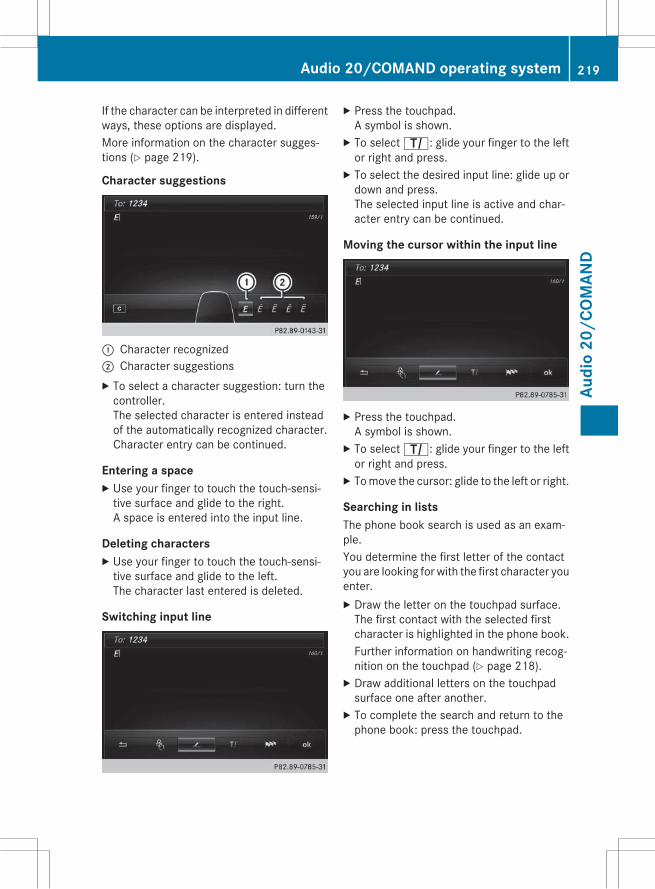
If the character can be interpreted in differentways, these options are displayed.More information on the character sugges-tions (Y page 219).
Character suggestions
: Character recognized; Character suggestionsX To select a character suggestion: turn thecontroller.The selected character is entered insteadof the automatically recognized character.Character entry can be continued.
Entering a spaceX Use your finger to touch the touch-sensi-tive surface and glide to the right.A space is entered into the input line.
Deleting charactersX Use your finger to touch the touch-sensi-tive surface and glide to the left.The character last entered is deleted.
Switching input line
X Press the touchpad.A symbol is shown.X To selectp: glide your finger to the leftor right and press.X To select the desired input line: glide up ordown and press.The selected input line is active and char-acter entry can be continued.
Moving the cursor within the input line
X Press the touchpad.A symbol is shown.X To selectp: glide your finger to the leftor right and press.X Tomove the cursor: glide to the left or right.
Searching in listsThe phone book search is used as an exam-ple.You determine the first letter of the contactyou are looking for with the first character youenter.X Draw the letter on the touchpad surface.The first contact with the selected firstcharacter is highlighted in the phone book.Further information on handwriting recog-nition on the touchpad (Y page 218).X Draw additional letters on the touchpadsurface one after another.X To complete the search and return to thephone book: press the touchpad.
Audio 20/COMAND operating system 219
Audi
o20
/COM
AND
Z

Switching between the controller and thetouchpad as input devicePrerequisite: an input line for text, numbers orcharacters has been selected.X To switch from character entry using
the controller to handwriting recogni-tion on the touchpad: use one finger topress the touchpad.Handwriting recognition on the touchpad isactive.X To switch from handwriting recognition
on the touchpad to character entryusing the controller: press the controller.Character entry using the controller isactive.
Quick access for audio and telephone
Changing the station/music track
Depending on the audio source that is cur-rently activated, you can use this function toselect the next station or music track.X Call up quick access (Y page 217).The current audio source is displayed.X To select the previous or next station/music track: glide to the right or left.The selected station/music track is played.
Changing the audio source
X Call up quick access (Y page 217).The current audio source is displayed.X To display the available audio sources:glide down with one finger.X To select an audio source: glide your fingerto the left or right and press.The selected audio source is played.
Sending DTMF tones
The function is not supported by all mobilephones (see the manufacturer's operatinginstructions).X Call up quick access during a call(Y page 217).X To select the desired characters: glide tothe left or right respectively and press.Every character selected will be transmit-ted immediately.
220 Audio 20/COMAND operating systemAu
dio
20/C
OMAN
D

Favorites
Overview of favorites
: To add a new favorite; To rename a selected favorite= To move a selected favorite? To delete a selected favoriteDisplaying the favorites overviewX Press the favorites button on the controller.orX Press the favorites button on the touchpad.The favorites are displayed.X To show the menu bar: slide6 the con-troller.
Further information on the touchpad(Y page 216).Calling up a favoriteX Press the favorites button on the controller.orX Press the favorites button on the touchpad.The favorites are displayed.X Turn and press the controller.The favorite is called up.
Adding favoritesX Press the favorites button on the controller.orX Press the favorites button on the touchpad.
X To show the menu bar: slide6 the con-troller.X To select Reassign: turn and press thecontroller.The categories for the available favoritesare displayed.X To select a category: turn the controller andpress to confirm.The corresponding favorites are displayed.X To select the desired favorite: turn andpress the controller.X To store the favorite in the desired order:turn and press the controller.The favorite has been added.If a favorite is stored over another favorite,the favorite underneath is deleted.
You can manage a total of 20 favorites.
Deleting favoritesX Press the favorites button on the controller.orX Press the favorites button on the touchpad.X To select the favorite to be deleted: turn thecontroller.X To show the menu bar: slide6 the con-troller.X To select Delete: turn and press the con-troller.X To select Yes: turn and press the controller.The favorite is deleted.
orX To select No: turn and press the controller.The process is canceled.
Audio 20/COMAND operating system 221
Audi
o20
/COM
AND
Z

Calling up vehicle settings
Calling up vehicle settings
Example: calling up vehicle settingsX Press theØ button.The vehicle menu is displayed.X To select Vehicle Settings: press thecontroller.X To select the desired vehicle setting: turnand press the controller.The main area with the setting element isactive.
Selecting a different vehicle setting:X To activate the menu for selecting the vehi-cle setting: slide5 the controller.
Exiting the vehicle settings:X To select&: slide6 and press the con-troller.
Example: setting the EASY-ENTRY/EXIT fea-tureX Press theØ button.The vehicle menu is displayed.X To select Easy Entry/Exit: turn andpress the controller.The setting element is active.X To change the setting: press the controller.You can find further information in the vehicleOperator's Manual.
Navigation
Introduction
Important safety notesG WARNINGIf you operate information systems and com-munication equipment integrated in the vehi-cle while driving, you will be distracted fromtraffic conditions. You could also lose controlof the vehicle. There is a risk of an accident.Only operate the equipment when the trafficsituation permits. If you are not sure that thisis possible, park the vehicle paying attentionto traffic conditions and operate the equip-ment when the vehicle is stationary.
You must observe the legal requirements forthe country in which you are currently drivingwhen operating the navigation system.
General notesAudio 20 is equipped with MARGIN® MAPPILOT (see the manufacturer's operatinginstructions).Further information on navigation usingCOMAND can be found in the Digital Opera-tor's Manual.Among other things, correct functioning ofthe navigation systemdepends onGPS recep-tion. In certain situations, GPS reception maybe impaired, there may be interference orthere may be no reception at all, e.g. in tun-nels or parking garages.
222 Audio 20/COMAND operating systemAu
dio
20/C
OMAN
D

At vehicle speeds of above 5 km/h, dataentries are restricted.
i The functionality of a roof antenna (tele-phone, GPS) may be impaired if roof carri-ers are used.
Switching to navigation modeX Press theß button.The map shows the vehicle's current posi-tion.
Showing/hiding the menuX To show: slide6 the controller when themap appears.X To hide: press the% button.
Destination entry
General notesThe information given relating to destinationentry applies to COMAND. For information onAudio 20, see the manufacturer's operatinginstructions.
Destination entry optionsDestination entry may be blocked while driv-ing, depending on the country specifications.
Address input
Keyword search using fragments of words
From the list of last destinations (up to 50destinations)
Selecting a contact from the address book(contact with navigation dataL)
Selecting a POI (e.g. gas station, restau-rant) for different positions
On the map
Entering intermediate destinations
From the SD memory card: personal POIsand routes
From Mercedes-Benz AppsRequirement:mbracemust be activated forthe Mercedes-Benz Apps
Entering geo-coordinates
Example: address entry
X Show the menu (Y page 223).X To select Destination: turn and press thecontroller.X Select Address Entry.X Enter the address, e.g. as a city, street andhouse number.
Calculating the routeX To confirm Start: press the controller.The route is calculated with the currentroute type.
Selecting a route typeX Show the menu (Y page 223).X To select Options: turn and press the con-troller.X Select Route Settings.X Select a route type.The route type is used for the next routecalculation. If Dynamic Traffic Route orEco Route has been selected, trafficreports on the route are taken into account.i You can map the route to the destinationyourself with up to four intermediate stops.
Route guidanceNavigation announcements and route guid-ance displays guide you to your destination.
Audio 20/COMAND operating system 223
Audi
o20
/COM
AND
Z

The information given relating to destinationentry applies to COMAND. For information onAudio 20, see the manufacturer's operatinginstructions.
i Audio 20/COMAND can give incorrectnavigation commands if the actual street/traffic situation does not correspond withthe digital map's data. Road and trafficrules and regulations always have priorityover system driving recommendations.
Before and during a change of direction, themap is shown on the left side of the displayand a view of the intersection or a 3D imageon the right. Lane recommendations (whitedirectional arrows) may be shown at the bot-tom of the display for multilane roads.Navigation announcementsX To set the volume: turn the thumbwheelduring a navigation announcement.X To activate/deactivate: turn the thumb-wheel during a navigation announcement.
Route informationX Show the menu (Y page 223).X To select Route: turn and press the con-troller.X To display destination information:select Destination Information.X To display the route list: select RouteList.X To display the current position: selectWhere am I?.
Canceling/continuing route guidanceX Press the controller.X To select Destination: turn and press thecontroller.X Select Cancel Active Route Guidanceor Continue Route Guidance.
Real-time traffic reportsThe information given relating to real-timetraffic reports applies to COMAND. For infor-mation on Audio 20, see the manufacturer'soperating instructions.This function is currently not available forCanada.In order to receive real-time traffic reports viasatellite radio, you need to subscribe to SIR-IUS XM Satellite Radio Traffic Message Ser-vice.COMAND can receive traffic reports via sat-ellite radio and take account of these forroute guidance in the navigation system.Received traffic reports are displayed on themap either as text or as symbols.
X To switch to navigation mode: press theØ button.X To show themenu: slide6 the controller.X To select Traffic: turn and press the con-troller.If satellite signals cannot be received orthere are no traffic reports, you will see amessage to this effect.X To close the report: press the controller.
224 Audio 20/COMAND operating systemAu
dio
20/C
OMAN
D

Map functions
General notesThe information given relating to the mapfunctions applies to COMAND. For informa-tion on Audio 20, see the manufacturer'soperating instructions.
Setting the map scaleRequirement: the map is in full screen mode,the menu is faded out (Y page 223).X Turn the controller until the desired scale isset.
Moving the mapRequirement: the map is in full screen mode,the menu is faded out (Y page 223).X Slide1,4 or2 the controller.The crosshair is shown. The map moves inthe corresponding direction under thecrosshair.i Pressing the controller selects a destina-tion in the map.
Selecting map orientationX Show the menu (Y page 223).X To select Options: turn and press the con-troller.X Select Map Orientation.The # dot indicates the current setting.X Turn and press the controller.The map orientation is set.
Building images and elevation modelingIn small map scales (20 m, 50 m), importantbuildings are depicted realistically on themap; other buildings are shown as models.Selected cities located in mountainousregions are realistically depicted using eleva-tion modeling.
Calling up the online map displayRequirement (USA): mbrace is activated forthe Mercedes-Benz Apps.
Requirement (Canada): a mobile phone isconnected via Bluetooth® or USB withCOMAND.X Show the menu (Y page 223).X Slide5 the controller twice.X Press the controller.The navigation menu appears.X Turn the controller until Online Map Disхplay is brought to the front.X Press the controller.The online connection is established. Oncethe connection is established, the GoogleMaps™ map shows the vicinity of the cur-rent vehicle position.
Calling up Drive InformationX Show the menu (Y page 223).X Slide5 the controller twice.X Press the controller.The navigation menu appears.X Turn the controller until Drive Informaхtion is brought to the front.The Starting Drive Information.Please Wait... message appears.You will then see maps with the currentvehicle position and the vicinity of the des-tination in different scales, these are auto-matically displayed one after another.
Connecting and disconnecting amobile phone
Prerequisites
For telephony via the Bluetooth® interface,you require a Bluetooth®-capable mobilephone. The mobile phone must supportHands-Free Profile 1.0 or above.
Audio 20/COMAND operating system 225
Audi
o20
/COM
AND
Z
On Audio 20/COMANDX To activate Bluetooth®: press theØbutton in the center console.The Vehicle menu appears.X To select System Settings: slide6,turn and press the controller to confirm.A menu appears.X To select Activate Bluetooth: turn andpress the controller.This switches Bluetooth® onO or offª.
On the mobile phoneX Switch on the mobile phone and enter thePIN when prompted to do so (see the man-ufacturer's operating instructions).X Activate Bluetooth® and, if necessary,Bluetooth® visibility for other devices (seethemanufacturer's operating instructions).This visibility is for restricted periods oftime on somemobile phones (see the man-ufacturer's operating instructions).X Set the Bluetooth® device name for themobile phone if necessary.
The Bluetooth® device names for all of onemanufacturer's products might be identical.To make it possible to clearly identify yourmobile phone, change the device name (seethe manufacturer's operating instructions).The name can be freely selected.If the mobile phone supports the PBAP(Phone Book Access Profile) and MAP(Message Access Profile) Bluetooth® pro-files, the following information will be trans-mitted after you connect:RPhone bookRCall listsRMessagesThe battery of the mobile phone shouldalways be kept sufficiently charged in order toprevent malfunctions.
i Not all mobile phones available on themarket are equally suitable. You can obtainmore detailed information about suitablemobile phones and about the connection
between the mobile phone and Audio 20/COMAND on the Internet atwww.mercedes-benz-mobile.com.You can also obtain more information bycalling.In the USA, you can get in touch with theMercedes-Benz Customer Assistance Cen-ter on 1-800-FOR-MERCedes(1-800-367-6372).In Canada, you can get in touch with theCustomer Relations Center on1-800-387-0100.
i Some displays (e.g. the signal strength)depend on the supported version of theHands-Free Profile.
Procedure and general informationSearching for and authorizing (connect-ing) a mobile phoneBefore using your mobile phone with Audio20/COMAND for the first time, you will needto search (Y page 227) for the phone andthen authorize it (Y page 227). Depending onthe mobile phone, authorization either takesplace bymeans of Secure Simple Pairing or byentering a passkey. Audio 20/COMANDautomatically makes the system suitable foryour mobile phone available. You can recog-nize Secure Simple Pairing by a code which isdisplayed in Audio 20/COMAND and on themobile phone. You can recognize the passkeysystem by the fact that you have to enter acode on the mobile phone and in Audio 20/COMAND. The mobile phone is always con-nected automatically after authorization.If Audio 20/COMAND does not detect yourmobile phone, this may be due to particularsecurity settings on your mobile phone. Youcan also start the search procedure andauthorization on the mobile phone(Y page 228).Device-specific information on authorizingand connecting Bluetooth®-capable mobilephones can be found on the Internet at
226 Audio 20/COMAND operating systemAu
dio
20/C
OMAN
D

http://www.mercedes-benz.com/connect.You can authorize up to 15 mobile phones.Only one mobile phone can be connected toAudio 20/COMAND at any one time.De-authorizing (disconnecting) a mobilephoneThe connection is terminated automatically ifyou leave the receiver range of Audio 20/COMAND or deactivate Bluetooth® on yourmobile phone.If you no longer want the Bluetooth® connec-tion to be established automatically, themobile phone must be de-authorized (discon-nected) (Y page 229).
Searching for a mobile phone
X To call up the telephone menu: press the% button.X To switch to the menu bar in the telephonemenu: slide6 the controller.X To select Connect Device: turn the con-troller and press to confirm.The device list is displayed.X To select Search for Phones: turn andpress the controller.A message is displayed that Bluetooth®must be activated on the mobile phone andmust be made visible to other devices.X To select Start Search: press the con-troller.The available mobile phones are displayedin the device list.
The duration of the search depends on thenumber of Bluetooth® telephones withinrange and their characteristics.If a new phone is found, it appears in thedevice list with theÏ symbol. You can nowauthorize (connect) the mobile phone found(Y page 227).If the device list is already full, you will berequested to de-authorize a mobile phone(Y page 229).When you call up the device list again, de-authorized devices will be removed from thelist. To update the device list, start the searchagain.Symbols in the device list
Sym-bol
Explanation
Ï New mobile phone found, not yetauthorized.
Ñ Mobile phone is authorized, but isnot connected.
# Mobile phone is authorized andconnected.
Authorizing a mobile phone (connect-ing)
Authorization via Secure Simple PairingOnce Audio 20/COMAND has found yourmobile phone, you can authorize (connect) it.X To select a mobile phone from the devicelist: turn the controller and press to con-firm.A code is displayed in Audio 20/COMANDand on the mobile phone.
The code is the sameX Audio 20/COMAND: select Yes.X Mobile phone: confirm the code. Depend-ing on the mobile phone used, you mayhave to confirm the connection to Audio20/COMAND as well as confirm for thePBAP and MAP Bluetooth® profiles. Theprompt to confirm may take up to two
Audio 20/COMAND operating system 227
Audi
o20
/COM
AND
Z

minutes to be displayed. Youmay also savethe confirmation on the mobile phone (seethemanufacturer's operating instructions).The mobile phone is now authorized andconnected to Audio 20/COMAND. You cannow speak using the hands-free system.
Further information on setting the transmis-sion and reception volume of the mobilephone can be found in the Digital Operator'sManual.The code is differentX Audio 20/COMAND: select No.The process is canceled. Repeat theauthorization.
Authorization via passkey entry (accesscode)Once Audio 20/COMAND has found yourmobile phone, you can authorize (connect) it.X To select the Bluetooth® name of thedesiredmobile phone in the device list: turnand press the controller.The input menu for the passkey is dis-played.The passkey is a one- to sixteen-digit num-ber combination which you can chooseyourself.X Audio 20/COMAND: enter the passkeyusing the character bar.X Select¬ once all the numbers havebeen entered.X Mobile phone: enter the same passkeyand confirm your entry. Depending on themobile phone used, you may have to con-firm the connection to Audio 20/COMANDas well as confirm for the PBAP and MAPBluetooth® profiles. The prompt to confirmmay take up to two minutes to be dis-played. Youmay also save the confirmationon the mobile phone (see the manufactur-er's operating instructions).The mobile phone is now authorized andconnected to Audio 20/COMAND. You cannow speak using the hands-free system.
Further information on setting the transmis-sion and reception volume of the mobilephone can be found in the Digital Operator'sManual.If the Authorization Failed messageappears, you may have entered a differentpasskey or exceeded the prescribed timelimit. Repeat the procedure.
i Some mobile phones require a passkeywith four or more digits.
i If you wish to re-authorize the mobilephone after de-authorizing it, you canchoose another passkey for it.
Establishing the connection from themobile phone
The Bluetooth® device name of Audio 20/COMAND is "MB Bluetooth".X Audio 20/COMAND: call up the telephonemenu.X To switch to the menu bar: slide6 thecontroller.X To select Connect Device: turn the con-troller and press to confirm.The device list is displayed.X To select Connect via Phone: turn andpress the controller.A message is displayed, stating that youcan start the search on your mobile phone.X Mobile phone: start the search for a Blue-tooth® device (see manufacturer's operat-ing instructions).Audio 20/COMAND is displayed with thename "MBBluetooth" in themobile phone'sdevice list.X Select "MB Bluetooth".A prompt appears in the Audio 20/COMAND display asking whether themobile phone should be authorized.X Audio 20/COMAND: select Yes.If No is selected, the procedure is canceled.If your mobile phone supports Secure Sim-ple Pairing, a code is now displayed on bothdevices.
228 Audio 20/COMAND operating systemAu
dio
20/C
OMAN
D

The code is the sameX Audio 20/COMAND: select Yes.X Mobile phone: confirm the code. Depend-ing on the mobile phone used, you mayhave to confirm the connection to Audio20/COMAND as well as confirm for thePBAP and MAP Bluetooth® profiles. Theprompt to confirm may take up to twominutes to be displayed. Youmay also savethe confirmation on the mobile phone (seethemanufacturer's operating instructions).The mobile phone is now authorized andconnected to Audio 20/COMAND. You cannow speak using the hands-free system.
The code is differentX Audio 20/COMAND: select No.The process is canceled. Repeat the pro-cedure.
If your mobile phone does not support SecureSimple Pairing, you can findmore informationabout connecting the mobile phone in theDigital Operator's Manual.
Reconnecting automaticallyAudio 20/COMAND always searches for thelast connected mobile phone.If no connection can be made to the mostrecently connectedmobile phone, the systemsearches for the mobile phone that was con-nected before that one.
Switching between mobile phonesIf you have authorized more than one mobilephone, you can switch between the individualphones.X To call up the telephone menu: press the% button.X To show the menu bar: slide6 the con-troller.
X To select Connect Device: turn the con-troller and press to confirm.The device list is displayed.X To select the desired mobile phone: turnand press the controller.The selected mobile phone is searched forand connected if it is within Bluetooth®range and if Bluetooth® is activated.
Only one mobile phone can be connected atany one time. The currently connectedmobilephone is indicated by the # dot in the devicelist.
i You can only switch to another authorizedmobile phone if you are not currently mak-ing a call.
De-authorizing (disconnecting) a mobilephoneMercedes-Benz USA, LLC recommends De-authorization in Audio 20/COMAND and onthe mobile phone. Subsequent authorizationmay otherwise fail.X To call up the telephone menu: press the% button.X To show the menu bar: slide6 the con-troller.X To select Connect Device: turn the con-troller and press to confirm.X To highlight the desiredmobile phone in thedevice list: turn the controller.X To selectG: slide9 the controller.X To select Deauthorize: turn and press thecontroller.A prompt appears, asking whether youreally wish to de-authorize this device.X To select Yes: turn and press the controller.The mobile phone is de-authorized.
i Before re-authorizing the mobile phone,you should also delete the device name MBBluetooth from your mobile phone's Blue-tooth® list.
Audio 20/COMAND operating system 229
Audi
o20
/COM
AND
Z

Using the telephone
Accepting a callX To select Accept: press the controller.orX Press6 on the multifunction steeringwheel.The call is accepted.
Further information on the functions you canuse during a call can be found in the DigitalOperator's Manual.
i You can also accept the call by voice com-mand using the Voice Control System (seethe separate operating instructions).
i If the phone number of the caller is trans-ferred, it appears in the display. If thephone number is saved in the phone book,the contact's name is also displayed. If thephone number is not transferred,Unknownis shown in the display.
Rejecting a callX To select Reject: turn the controller andpress to confirm.
orX Press~ on the multifunction steeringwheel.
Ending an active callX To select= in the telephone menu: turnand press the controller.
orX Press~ on the multifunction steeringwheel.The active call is ended.
Making a call
Using the telephone menuX To call up the telephone menu: press the% button.X To select all numbers one after the other inthe telephone menu: turn and press thecontroller each time.X To selectw in the telephone menu: turnand press the controller.The call is made.
Using call listsX To call up the telephone menu: press the% button.X To switch to the menu bar: slide6 thecontroller.X To select Call Lists: turn and press thecontroller.X To select Calls Received or CallsDialed: turn and press the controller.The relevant list is displayed.X To select an entry andmake a call: turn andpress the controller.
Using the phone bookX To call up the telephone menu: press the% button.X To select Name in the telephone menu: turnand press the controller.The phone book is displayed with an activecharacter bar.X To select characters: turn the controllerand press to confirm.The first contact with the selected firstcharacter is highlighted in the phone book.X Select the characters of the contact you aresearching for one by one, pressing and con-firming with the controller each time.X To complete the search: slide5 the con-troller repeatedly until the character bardisappears.
or
230 Audio 20/COMAND operating systemAu
dio
20/C
OMAN
D

X To select¬: turn and press the control-ler.The contacts in the phone book are dis-played.X To select a contact: turn and press the con-troller.
If a contact contains more than one phonenumber:X To select a telephone number: turn andpress the controller.
Further information on the phone book can befound in the Digital Operator's Manual.
Establishing/ending an Internet con-nection
Establishing the connectionA connection can be established by:Rentering a web addressRcalling up the Mercedes-Benz mobile web-site
Rcalling up a Mercedes-Benz AppRcalling up a favoriteRestablishing an Internet connection via awireless networking device. The "Allowshared WiFi usage" option must be activa-ted on COMAND for this.
Ending the connectionX Press Cancel in the connections window.Connection status
: Display of existing connection and signalstrength of the mobile phone network
In most cases, the current connection statusis then shown in the status bar when youswitch to another main function.
Detailed connection statusX To call up the telephone menu: press the% button.X To show the main function bar: slide5the controller.X To select TEL/®: turn and press the con-troller.X To select Internet: turn and press thecontroller.The menu with the Internet functions is dis-played.X To switch to the menu bar: slide6 thecontroller.X To select Settings: turn and press thecontroller.X To select Connection Status: turn andpress the controller.The following information is displayed:Rthe volume of transferred dataRconnection statusRthe device name of the mobile phone
Ending the connectionUSA: you cannot cancel the connection your-self. The Internet connection is automaticallyterminated if the system does not recognizeany user input within a five-minute timeperiod.Canada:X To call up the telephone menu: press the% button.X To display the main function bar: slide5the controller.X To select TEL/®: turn and press the con-troller.X To select Internet: turn and press thecontroller.The menu with the Internet functions is dis-played.
Audio 20/COMAND operating system 231
Audi
o20
/COM
AND
Z

X To switch to the menu bar: slide6 thecontroller.X To select the scissors symbol: turn andpress the controller.
If the mobile phone Internet connection iscanceled, Audio 20/COMAND tries to recon-nect. You should therefore always close theconnection on Audio 20/COMAND.
Radio mode
Switching toX Press the$ button.The radio display appears. You will hear thelast station played on the last wavebandselected.
Overview
Example COMAND: Main function bar; Status bar with compass display= Main display field with available stations
and relevant information? Display of radio station selectedA Radio menu barSelecting the main function barX Slide5 the controller.
Selecting the menu barX Slide6 the controller.
Menu optionsX In radio mode: slide6 the controller.The radio menu bar appears.X To select Options: turn and press the con-troller.
The following setting options are availa-ble to you:RTag This Track: saves track informationon an Apple device for a later purchaseoption via iTunes®
RDirect Entry: manual frequency entryRCurrent Station/Channel Listing (FMradio mode): shows the list of currentlyavailable stations
REdit List: stores, rearranges and deletesstations
REdit Station Preset: selects and editsstation presets
RShow Station Information: switchesartist and track display and station nameon/off
RHD Radio: switches HD Radio on/off
Setting the wavebandX Using the button: in radio mode press the$ button.X Turn the controller until the required wave-band is in the center. Press the controller.X Using the radio menu bar: in radio mode,slide6 the controller.X To select Band/Preset: turn and press thecontroller.X Turn the controller until the required wave-band is selected. Press the controller.
232 Audio 20/COMAND operating systemAu
dio
20/C
OMAN
D

Selecting a stationRTo select via the main display field: inradio mode, turn the controller until thedesired station is in the center.
RVia the "Options" menu: using CurrentStation/Channel Listing or DirectEntry select or enter the desired station.
RTo select using the search function: : inradio mode, selectè and enter the firstletters of the desired station using the con-troller.
Radio text/radio text plusThis function is not available in all countries.X To switch on radio text: in radio mode,select Info in the menu bar.Additional information from the currentstation is displayed.
Audio 20/COMAND operating system 233
Audi
o20
/COM
AND
Z

234

Useful information ............................ 236Stowage areas ................................... 236Features ............................................. 243
235
Stow
age
and
feat
ures

Useful information
i This Operator's Manual describes allmodels and all standard and optional equip-ment of your vehicle available at the time ofpublication of the Operator's Manual.Country-specific differences are possible.Please note that your vehicle may not beequipped with all features described. Thisalso applies to safety-related systems andfunctions.
i Read the information on qualified special-ist workshops (Y page 29).
Stowage areas
Loading guidelines
G WARNINGCombustion engines emit poisonous exhaustgases such as carbon monoxide. Exhaustgases can enter the vehicle interior if thetrunk lid is open when the engine is running,especially if the vehicle is in motion. There is arisk of poisoning.Always switch off the engine before openingthe trunk lid. Never drive with the trunk lidopen.
G WARNINGIf objects, luggage or loads are not secured ornot secured sufficiently, they could slip, tipover or be flung around and thereby hit vehicleoccupants. There is a risk of injury, particu-larly in the event of sudden braking or a sud-den change in direction.Always store objects so that they cannot beflung around. Secure objects, luggage orloads against slipping or tipping before thejourney.
G WARNINGThe exhaust tail pipe and tail pipe trim canbecome very hot. If you come into contactwith these parts of the vehicle, you could burnyourself. There is a risk of injury.
Always be particularly careful around theexhaust tail pipe and the tail pipe trim. Allowthese components to cool down before touch-ing them.
The handling characteristics of a laden vehi-cle are dependent on the distribution of theload within the vehicle. For this reason, youshould observe the following notes whentransporting a load:RNever exceed the maximum permissiblegross vehicle weight or the gross axleweight rating for the vehicle (includingoccupants). The values are specified on thevehicle identification plate on the B-pillar ofthe driver's door.
RPosition heavy loads as far forwards as pos-sible and as low down in the trunk as pos-sible.
RThe load must not protrude above theupper edge of the seat backrests.
RAlways place the load behind unoccupiedseats if possible.
RSecure the load with sufficiently strong andwear-resistant tie-downs. Pad sharp edgesfor protection.
Stowage spaces
Important safety notes
G WARNINGIf you do not correctly store objects in thevehicle interior, they can slip or be flungaround, thus striking vehicle occupants.There is a risk of injury, especially when brak-ing or abruptly changing directions.RAlways store objects so that they cannot beflung around in these or in similar situa-tions.
RAlways make sure that objects do not pro-trude from stowage compartments, parcelnets or stowage nets.
236 Stowage areasSt
owag
ean
dfe
atur
es

RClose lockable stowage compartmentswhile driving.
RStow and secure objects that are heavy,hard, pointy, sharp-edged, fragile or toolarge in the trunk.
Observe the loading guidelines (Y page 236).
Information in the Digital Operator'sManualIn the Digital Operator's Manual you will findinformation on the following topics:RGlove boxREyeglasses compartmentRStowage compartment in the center con-sole
RStowage compartment under the armrestRStowage compartments in the doorsRStowage compartment in the rear seat arm-rest
Additional stowage spaceDepending on the equipment, the followingadditional stowage areas are available in thevehicle:Rcard and coin holder in the dashboardabove the light switch (not suitable for hold-ing thin objects such as shopping tokens)
Rthe open stowage compartment in the cen-ter console
Rstowage net in front-passenger footwellRthemap pockets on the back of the driver'sand front-passenger seat
Rthe parcel nets on the left and right-handside in the trunk
Observe the loading guidelines (Y page 236)and the safety notes regarding stowagespaces (Y page 236).
Ski and snowboard bag
Important safety notes
G WARNINGThe skibag in conjunction with the lashingstraps cannot restrain any objects other thanskis.Vehicle occupants could be struck in theevent of sudden braking or an accident, forinstance, if you:Rtransport other heavy or sharp-edgedobjects in the skibag
Rdo not secure the skibag with the lashingstraps
There is a risk of accident and injury.Store only skis in the skibag. Always securethe skibag with the lashing straps so that itcannot move around.
A maximum of four pairs of skis or two snow-boards can be transported in the ski andsnowboard bag.
Securing the ski and snowboard bag inthe trunk
X Fold themiddle rear seat backrest forwards(Y page 238).X Slide the ski and snowboard bag betweenthe two outside rear seat backrests. Ensurethat the wheels of the ski and snowboardbag are in the trunk.X Open the ski/snowboard bag with zip:and place the skis or snowboards inside it.
Stowage areas 237
Stow
age
and
feat
ures
Z

X Close the ski and snowboard bag.X Pull tensioning strap; tight by the looseend until the skis or snowboards are heldfirmly inside the ski/snowboard bag.
X Engage tensioning strap= in a diagonalpattern on hooks? in cargo tie-down ringsA as shown.
Rear bench seat through-loading fea-ture
Important safety notes
G WARNINGIf the rear bench seat/rear seat and seatbackrest are not engaged they could fold for-wards, e.g. when braking suddenly or in theevent of an accident.RThe vehicle occupant would thereby bepushed into the seat belt by the rear benchseat/rear seat or by the seat backrest. Theseat belt can no longer offer the intendedlevel of protection and could even causeinjuries.
RObjects or loads in the trunk cannot berestrained by the seat backrest.
There is an increased risk of injury.Before every trip, make sure that the seatbackrests and the rear bench seat/rear seatare engaged.
Observe the loading guidelines (Y page 236).The outside and the middle rear seat backr-ests can be folded down separately to
increase the trunk capacity. The division ratiois 40% to 20% to 40%.
Folding the rear seat backrests forwardX Vehicles without memory function: if nec-essary, move the driver's or front-passenger seat forward.X Vehicles with memory function: when oneor both parts of the rear seat backrest arefolded forward, the respective front seatmoves forward slightly, when necessary, inorder to avoid contact.X Open the trunk.X Fully insert the rear seat backrest headrestraints.
Left and right seat backrestX Pull right-hand or left-hand rear seat back-rest release handle:.The corresponding rear seat backrest isreleased.Vehicles with memory function: when oneor both parts of the rear seat backrest arefolded forward, the respective front seatmoves forward slightly, when necessary, inorder to avoid contact.
238 Stowage areasSt
owag
ean
dfe
atur
es

Middle rear seat backrestX Pull release lever= forwards.Rear seat backrest; is released.
X Fold corresponding rear seat backrest;forward.X Move the driver's or front-passenger seatback if necessary.
Folding the rear seat backrest back
! Make sure that the seat belt does notbecome trapped when folding the rear seatbackrest back. Otherwise, it could be dam-aged.
Left and right seat backrestX Move the driver's or front-passenger seatforward if necessary.X Fold rear seat backrest: back until itengages.If the rear seat backrest is not engaged andlocked, this will be shown in the multifunc-tion display in the instrument cluster. Awarning tone also sounds.
Middle rear seat backrestX Move the driver's or front-passenger seatforward if necessary.X Fold seat backrest: back until it engages.Red lock status indicator; is no longervisible.X Adjust the head restraints if necessary.X Move the driver's or front-passenger seatback if necessary.
You should always engage the rear seatbackrests if you do not need the through-loading feature. This will prevent unauthor-ized access to the trunk from the vehicle inte-rior.
Stowage areas 239
Stow
age
and
feat
ures
Z

Locking the center rear seat backrest
In order to prevent the trunk from beingaccessed by unauthorized persons, the cen-ter seat backrest can be locked using a catch.The center seat backrest can only be foldedforward together with the left seat backrest.X To lock: fold the left and center seat backr-ests forward.Make sure that the center andleft seat backrests are engaged and joinedtogether.X Slide catch: upwards.The release mechanism of the center seatbackrest is locked.X To unlock: fold back the left and centerrear seat backrests.X Slide catch: downward from inside thetrunk.
Securing cargo
Cargo tie-down rings
General notesObserve the following notes on securingloads:RObserve the loading guidelines(Y page 236).
RSecure the load using the cargo tie-downrings.
RDistribute the load on the cargo tie-downrings evenly.
RDo not use elastic straps or nets to securea load, as these are only intended as ananti-slip protection for light loads.
RDo not route tie-downs across sharp edgesor corners.
RPad sharp edges for protection.
Trunk
Sedan with through-loading feature in therear bench seatX Fold up the cargo tie-down rings next to therear seat backrest and put them throughthe slots in the carpet.
Bag hook
G WARNINGThe bag hooks cannot restrain heavy objectsor items of luggage. Objects or items of lug-gage could be flung around and thereby hitvehicle occupants when braking or abruptlychanging directions. There is a risk of injury.Only hang light objects on the bag hooks.Never hang hard, sharp-edged or fragileobjects on the bag hooks.
! The bag hook can bear amaximum load of6.6lbs (3kg) and should not be used tosecure a load.
240 Stowage areasSt
owag
ean
dfe
atur
es

: Bag hook
EASY-PACK trunk box
Important safety notes
G WARNINGWhen the load surface moves up, your handsmay become trapped on the frame of theEASY-PACK trunk box. There is a risk of injury.When the load surface moves up, make surethat your hands are not within the sweep ofthe load surface. If someone becomes trap-ped, carefully push the center of the load sur-face downward.
! When the EASY-PACK trunk box is pulledout, no objects may be placed on the frameof the box, nor should the frame be pushedfrom above. Otherwise, the box could bedamaged.
! Sharp-edged, pointed or fragile objectscan damage the EASY-PACK trunk box andthen be thrown out. There is a risk of injury.Do not transport sharp-edged, pointed orfragile objects in the EASY-PACK trunk box.Always store and secure these or similarobjects in the trunk outside of the EASY-PACK trunk box.
! If you exceed the maximum permittedload of the EASY-PACK trunk box, objectscan be thrown out of the EASY-PACK trunkbox and strike vehicle occupants. There is arisk of injury, particularly in the event of
sudden braking or a sudden change indirection.Always observe the maximum permittedload of the EASY-PACK trunk box. Alwaysstore and secure heavy objects in the trunkoutside of the EASY-PACK trunk box.
The maximum permitted load of the EASY-PACK trunk box is 22 lbs (10 kg). With a loadof above approximately 11 lbs (5 kg), the bot-tom of the box moves downward until it restson the mat of the trunk floor. Thus, overload-ing of the box is avoided.
Adjusting the height to any position
ExampleX Pull the box out by handle: in the direc-tion of the arrow all the way to the stop.X Lowering the load surface: push the cen-ter of load surface; down by hand in thedirection of the arrow until load surface;has reached the desired position and thebox is the desired size.X To raise the load surface: press switch=.Load surface; of the box moves up auto-matically.X To stow the box: push the box in by han-dle: all the way to the stop.
Stowage areas 241
Stow
age
and
feat
ures
Z

Removing and installing
ExampleX To install: insert retainer; of box: intoslots=
X Raise box: and press hooksA intoanchorage? as far as they will go.X Turn left-hand rotating catchB counter-clockwise and right-hand rotating catchBclockwise by 90°.X To remove: turn left-hand rotating catchB clockwise and right-hand rotating catchB counter-clockwise by 90°.X Move box: downwards and pull it outfrom anchorages?.
Store the EASY-PACK trunk box on a flat sur-face after removal, e.g. on a suitable shelf.
Stowage well under the trunk floor! Unhook the handle before again beforeclosing the trunk lid and clip it in securely toprevent the handle flap from protruding.Otherwise, you could damage the handle.
The TIREFIT kit, the vehicle tool kit, etc. arelocated in the stowage compartment.X To open: pull handle: up.
X Hook handle: into rain trough;.
Roof carrier
Important safety notes
G WARNINGWhen you load the roof, the center of gravityof the vehicle rises and the driving character-istics change. If you exceed themaximum roofload, the driving characteristics, as well assteering and braking, will be greatly impaired.There is a risk of an accident.Never exceed the maximum roof load andadjust your driving style.
Youwill find information on themaximum roofload in the "Technical data" section(Y page 327).
! Mercedes-Benz recommends that youonly use roof carriers that have been tested
242 Stowage areasSt
owag
ean
dfe
atur
es

and approved for Mercedes-Benz vehicles.This helps to avoid damage to the vehicle.Position the load on the roof carrier in sucha way that the vehicle will not sustain dam-age even when it is in motion.Depending on the vehicle equipment,ensure that when the roof carrier is instal-led you can:Rraise the sliding sunroof/panorama roofwith power tilt/sliding panel fully
Ropen the trunk lid fully
! To avoid damaging or scratching the cov-ers, do not use metallic or hard objects toopen them.
An incorrectly secured roof carrier or roofload may become detached from the vehicle.You must therefore ensure that you observethe roof carrier manufacturer's installationinstructions.Vehicles with a panorama roof withpower tilt/sliding panel: the panorama roofwith power tilt/sliding panel cannot beopened if a roof carrier is installed. The pan-orama roof with power tilt/sliding panel canstill be raised to allow ventilation of the vehi-cle interior.If the panorama roof with power tilt/slidingpanel makes contact with a roof carrierapproved by Mercedes-Benz, the sunroof willlower slightly but remain raised at the rear.
Attaching the roof carrier
X Open covers: carefully in the direction ofthe arrow.X Fold covers: upwards.X Only secure the roof carrier to the anchor-age points under covers:.X Observe the manufacturer's installationinstructions.
Features
Information in the Digital Operator'sManualIn the Digital Operator's Manual you will findinformation on the following topics:RCup holderRRear window roller sunblindRRear side window roller sunblindsRAshtrayRCigarette lighterR12 V sockets
Sun visors
Overview
G WARNINGIf themirror cover of the vanitymirror is foldedup when the vehicle is in motion, you could beblinded by incident light. There is a risk of anaccident.Always keep the mirror cover folded downwhile driving.
Features 243
Stow
age
and
feat
ures
Z

: Mirror light; Bracket= Retaining clip, e.g. for a car park ticket? Vanity mirrorA Mirror cover
Information in the Digital Operator'sManualIn the Digital Operator's Manual you will findinformation on the following topics:RVanity mirror in the sun visorRGlare from the side
Rear window roller sunblind
Important safety notes
G WARNINGWhen extending or retracting, parts of thebody could become trapped within the sweepof the roller sunblind. There is a risk of injury.When extending or retracting, make sure thatno one has any parts of the body within thesweep of the roller sunblind. If someonebecomes trapped, briefly press the buttonagain. The opening or closing procedure willbe stopped.
! Make sure that the roller sunblind canmove freely. Otherwise, the roller sunblindor other objects could be damaged.
Extending/retracting the roller sun-blind
X Turn the SmartKey to position 1 or 2 in theignition lock (Y page 129).X To extend or retract: briefly press but-ton:.The roller sunblind fully extends or fullyretracts.X To stop: briefly press button: again.The roller sunblind stops briefly and movesback into the out-of-use position.
mbrace
Information in the Digital Operator'sManualIn the Digital Operator's Manual you will findinformation on the following topics:RCup holderRRear window roller sunblindRRear side window roller sunblindsRAshtrayRCigarette lighterR12 V sockets
General notesThe mbrace system is only available in theUSA.You must have a license agreement to acti-vate the mbrace service. Make sure that yoursystem is activated and operational. To log in,press theï MB Info call button. If any of
244 FeaturesSt
owag
ean
dfe
atur
es

the steps mentioned are not carried out, thesystem may not be activated.If you have questions about the activation,contact one of the following telephone hot-lines:Mercedes-Benz Customer Assistance Centerat 1-800-FOR-MERCedes (1-800-367-6372)or 1-866-990-9007Shortly after successfully registering with thembrace service, a user ID and password willbe sent to you by mail. You can use this pass-word to log onto thembrace area under "Own-ers Online" at http://www.mbusa.com.The system is available if:Rit has been activated and is operationalRthe correspondingmobile phone network isavailable for transmitting data to the Cus-tomer Center
Ra service subscription is availableRthe starter battery is sufficiently chargedDetermining the location of the vehicle on amap is only possible if:RGPS reception is available.Rthe vehicle position can be forwarded tothe Customer Assistance Center.
The mbrace systemTo adjust the volume during a call, proceed asfollows:X Press theW orX button on the mul-tifunction steering wheel.
orX Use the COMAND/Audio 20 volume con-trol.
The system offers various services, e.g.:RAutomatic and manual emergency callRRoadside Assistance callRMB Info callYou can find information and a description ofall available features under "Owners Online"at http://www.mbusa.com.
System self-testAfter you have switched on the ignition, thesystem carries out a self-diagnosis.A malfunction in the system has been detec-ted if one of the following occurs:RThe indicator lamp in the SOS button doesnot come on during the system self-test.
RThe indicator lamp in theF RoadsideAssistance button does not light up duringself-diagnosis of the system.
RThe indicator lamp in theïMB Info callbutton does not light up during self-diag-nosis of the system.
RThe indicator lamp in one or more of thefollowing buttons continues to light up redafter the system self-diagnosis:- SOS button- F Roadside Assistance call button- ï MB Info call button
RThe Inoperative or the Service NotActivated message appears in the multi-function display after the system self-diag-nosis.
If a malfunction is indicated as outlinedabove, the systemmay not operate as expec-ted. In the event of an emergency, help willhave to be summoned by other means.Have the system checked at the nearestauthorized Mercedes-Benz Center or contactthe following service hotlines:Mercedes-Benz Customer Assistance Centerat 1-800-FOR-MERCedes (1-800-367-6372)or 1-866-990-9007
Features 245
Stow
age
and
feat
ures
Z

Emergency call
Important safety notesG WARNINGIt can be dangerous to remain in the vehicle,even if you have pressed the SOS button in anemergency if:Ryou see smoke inside or outside of the vehi-cle, e.g. if there is a fire after an accident
Rthe vehicle is on a dangerous section ofroad
Rthe vehicle is not visible or cannot easily beseen by other road users, particularly whendark or in poor visibility conditions
There is a risk of an accident and injury.Leave the vehicle immediately in this or simi-lar situations as soon as it is safe to do so.Move to a safe location along with other vehi-cle occupants. In such situations, secure thevehicle in accordance with national regula-tions, e. g. with a warning triangle.
General notesObserve the notes on system activation(Y page 244).An emergency call is dialed automatically if anair bag or Emergency Tensioning Device istriggered. You cannot end an automaticallytriggered emergency call yourself.An emergency call can also be initiated man-ually.As soon as the emergency call has been ini-tiated, the indicator lamp in the SOS buttonflashes. The Connecting Call messageappears in the multifunction display.The audio output is muted.Once the connection has been made, theCall Connected message appears in themultifunction display.
All important information on the emergency istransmitted, for example:Rcurrent location of the vehicle (as deter-mined by the GPS system)
Rvehicle identification numberRinformation on the severity of the accidentShortly after the emergency call has been ini-tiated, a voice connection is automaticallyestablished between the Customer Assis-tance Center and the vehicle occupants.RIf the vehicle occupants respond, theMercedes-Benz Customer Assistance Cen-ter attempts to getmore information on theemergency.
RIf there is no response from the vehicleoccupants, an ambulance is immediatelysent to the vehicle.
If no voice connection can be established tothe Mercedes-Benz Customer AssistanceCenter, the systemhas been unable to initiatean emergency call.This can occur, for example, if the relevantmobile phone network is not available. Theindicator lamp in the SOS button flashes con-tinuously.The Call Failed message appears in themultifunction display and must be confirmed.In this case, summon assistance by othermeans.
Making an emergency call
246 FeaturesSt
owag
ean
dfe
atur
es

X To initiate an emergency call manually:press cover: briefly to open.X Press SOS button; briefly.The indicator lamp in SOS button;flashes until the emergency call is conclu-ded.X Wait for a voice connection to theMercedes-Benz Customer Assistance Cen-ter.X After the emergency call, close cover:.If the mobile phone network is unavailable,mbrace will not be able to make the emer-gency call. If you leave the vehicle immedi-ately after pressing the SOS button, you willnot know whether mbrace placed the emer-gency call. In this case, always summon assis-tance by other means.
Roadside Assistance button
X To call Roadside Assistance: press Road-side Assistance button:.This initiates a call to the Mercedes-BenzCustomer Assistance Center.The indicator lamp in Roadside Assistancebutton: flashes while the call is active.The Connecting Callmessage appears inthe multifunction display. The audio outputis muted.
If a connection can be made, the Call Conхnectedmessage appears in themultifunctiondisplay.
If a mobile phone network and GPS receptionare available, the system transfers data to theMercedes-Benz Customer Assistance Center,for example:Rcurrent location of the vehicleRvehicle identification numberThe COMAND/Audio 20 display indicatesthat a call is active. During the call, you canchange to the navigation menu by pressingthe NAVI button in COMAND/Audio 20, forexample.Voice output is not available in this case.A voice connection is established betweenthe Mercedes-Benz Customer AssistanceCenter and the vehicle occupants.From the remote malfunction diagnosis, theMercedes-Benz Customer Assistance Centercan ascertain the nature of the problem. Inthe Digital Operator's Manual, you will findinformation on remote malfunction diagno-sis.The Mercedes-Benz Customer AssistanceCenter either sends a qualified Mercedes-Benz technician or makes arrangements foryour vehicle to be transported to the nearestauthorized Mercedes-Benz Center.You may be charged for services such asrepair work and/or towing.You can findmore information in the separatembrace manual.The system has not been able to initiate aRoadside Assistance call, if:Rthe indicator lamp for Roadside Assistancecall buttonF is flashing continuously.
Rno voice connection to the Mercedes-BenzCustomer Assistance Center was estab-lished.
This can occur if the relevant mobile phonenetwork is not available, for example.The Call Failed message appears in themultifunction display.
Features 247
Stow
age
and
feat
ures
Z

X To end a call: press the~ button on themultifunction steering wheel.
orX Press the corresponding COMAND/Audio20 button for ending a phone call.
MB Info call button
X To call MB Info: press MB Info call but-ton:.This initiates a call to the Mercedes-BenzCustomer Assistance Center.The indicator lamp inMB Info call button:flasheswhile the connection is beingmade.The Connecting Callmessage appears inthe multifunction display. The audio outputis muted.
If a connection can be made, the Call Conхnectedmessage appears in themultifunctiondisplay.If a mobile phone network and GPS receptionare available, the system transfers data to theMercedes-Benz Customer Assistance Center,for example:Rcurrent location of the vehicleRvehicle identification numberThe COMAND/Audio 20 display indicatesthat a call is active. During the call, you canchange to the navigation menu by pressingthe NAVI button in COMAND/Audio 20, forexample.Voice output is not available in this case.A voice connection is established betweenthe Mercedes-Benz Customer AssistanceCenter and the vehicle occupants.
You receive information about operating yourvehicle, about the nearest authorizedMercedes-Benz Center and about other prod-ucts and services from Mercedes-Benz.You can find further information on thembrace system under "Owners Online" athttp://www.mbusa.com.The system has not been able to initiate anMB Info call, if:Rthe indicator lamp in MB Info call buttonï is flashing continuously.
Rno voice connection to the Mercedes-BenzCustomer Assistance Center was estab-lished.
This can occur if the relevant mobile phonenetwork is not available, for example.The Call Failed message appears in themultifunction display.X To end a call: press the~ button on themultifunction steering wheel.
orX Press the corresponding COMAND/Audio20 button for ending a phone call.
Call priorityWhen service calls are active, e.g. RoadsideAssistance or MB Info calls, an emergencycall can still be initiated. In this case, an emer-gency call will take priority and override allother active calls.The indicator lamp of the respective buttonflashes until the call is ended.An emergency call can only be terminated bythe Mercedes-Benz Customer AssistanceCenter.All other calls can be ended by pressing:Rthe~ button on themultifunction steer-ing wheel
Rthe corresponding button in COMAND/Audio 20 to end the voice call
When a call is initiated, the audio system ismuted.
248 FeaturesSt
owag
ean
dfe
atur
es

The mobile phone is no longer connected toCOMAND/Audio 20.However, if you want to use your mobilephone, do so only when the vehicle is station-ary and in a safe location.
Garage door opener
General notes
The HomeLink® garage door opener integra-ted in the rear-viewmirror allows you to oper-ate up to three different door and gate sys-tems.Use the integrated garage door opener onlyon garage doors that:Rhave safety stop and reverse features andRmeet current U.S. federal safety standardsOnce programed, the integrated garage dooropener in the rear-viewmirror will assume thefunction of the garage door system's remotecontrol. Please also read the operatinginstructions for the garage door system.When programming a garage door opener,park the vehicle outside the garage. Do notrun the engine while programming.Certain garage door drives are incompatiblewith the integrated garage door opener. If youhave difficulty programing the integratedgarage door opener, contact an authorizedMercedes-Benz Center.Alternatively, you can call the following tele-phone assistance services:RUSA:Mercedes-BenzCustomer AssistanceCenter at 1-800-FOR-MERCedes
RCanada: Customer Service at1-800-387-0100
RHomeLink® hotline 1-800-355-3515 (freeof charge)
More information on HomeLink® and/orcompatible products is also available onlineat http://www.homelink.com.Notes on the declaration of conformity(Y page 29).
USA: FCC ID: CB2HMIHL4Canada: IC: 279B-HMIHL4
Important safety notes
G WARNINGWhen you operate or program the garage doorwith the integrated garage door opener, per-sons in the range of movement of the garagedoor can become trapped or struck by thegarage door. There is a risk of injury.When using the integrated garage dooropener, always make sure that nobody iswithin the range of movement of the garagedoor.
G WARNINGCombustion engines emit poisonous exhaustgases such as carbon monoxide. Inhalingthese exhaust gases leads to poisoning. Thereis a risk of fatal injury. Therefore never leavethe engine running in enclosed spaces with-out sufficient ventilation.
Programming
Programming buttonsPay attention to the "Important safety notes"(Y page 249).
Garage door remote controlA is not inclu-ded with the integrated garage door opener.X Turn the SmartKey to position 2 in the igni-tion lock (Y page 129).X Select one of buttons; to? to use tocontrol the garage door drive.
Features 249
Stow
age
and
feat
ures
Z

X To start programming mode: press andhold one of buttons; to? on the inte-grated garage door opener.The garage door opener is now in program-ming mode. After a short time, indicatorlamp: lights up yellow.Indicator lamp: lights up yellow as soonas button;,= or? is programmed forthe first time. If the selected button hasalready been programmed, indicatorlamp: will only light up yellow after tenseconds have elapsed.X Release button;,= or?. Indicatorlamp: flashes yellow.X To program the remote control: pointgarage door remote controlA towardsbuttons; to? on the rear-view mirror ata distance of 2 to 8 inches (5 to 20 cm).X Press and hold buttonB on remote controlA until indicator lamp: lights up green.When indicator lamp: lights up green:programming is finished.When indicator lamp: flashes green: pro-gramming was successful. The next step isto synchronize the rolling code(Y page 250).X Release buttonB on remote controlA forthe garage door drive system.If indicator lamp: lights up red: repeat theprograming procedure for the correspond-ing button on the rear-view mirror. Whendoing so, vary the distance between remotecontrolA and the rear-view mirror.The required distance between remotecontrolA and the integrated garage dooropener depends on the garage door drivesystem. Several attempts might be neces-sary. You should test every position for atleast 25 seconds before trying anotherposition.
Synchronizing the rolling codePay attention to the "Important safety notes"(Y page 249).If the garage door system uses a rolling code,you will also have to synchronize the garage
door system with the integrated garage dooropener in the rear-view mirror. To do this youwill need to use the programming button onthe door drive control panel. The program-ming button may be positioned in differentplaces depending on the manufacturer. It isusually located on the door drive unit on thegarage ceiling.Familiarize yourself with the garage doordrive operating instructions, e.g. under "Pro-gramming of additional remote controls",before carrying out the following steps.Your vehicle must be within reach of thegarage door or gate opener drive. Make surethat neither your vehicle nor any persons/objects are present within the sweep of thedoor or gate.X Turn the SmartKey to position 2 in the igni-tion lock (Y page 129).X Get out of the vehicle.X Press the programming button on the doordrive unit.Usually, you now have 30 seconds to ini-tiate the next step.X Get into the vehicle.X Press previously programmed button;,= or? on the integrated garage dooropener until the door closes.The rolling code synchronization is thencomplete.
Notes on programming the remote con-trolCanadian radio frequency laws require a"break" (or interruption) of the transmissionsignals after broadcasting for a few seconds.Therefore, these signals may not last longenough for the integrated garage dooropener. The signal is not recognized duringprogramming. Comparable with Canadianlaw, some U.S. garage door openers also fea-ture a "break".
250 FeaturesSt
owag
ean
dfe
atur
es

Proceed as follows:Rif you live in CanadaRif you have difficulties programming thegarage door opener (regardless of whereyou live) when using the programmingsteps.X Press and hold one of buttons; to? onthe integrated garage door opener.After a short time, indicator lamp: lightsup yellow.X Release the button.Indicator lamp: flashes yellow.X Press buttonB of garage door remotecontrolA for two seconds, then release itfor two seconds.X Press buttonB again for two seconds.X Repeat this sequence on buttonB ofremote controlA until indicator lamp:lights up green.When indicator lamp: lights up green:programming is finished.When indicator lamp: flashes green: pro-gramming was successful. The next step isto synchronize the rolling code.X Release buttonB of remote controlA ofthe garage door drive.If indicator lamp: lights up red: repeat theprogramming process for the correspond-ing button on the rear-view mirror. Whendoing so, vary the distance between remotecontrolA and the rear-view mirror.The required distance between remotecontrolA and the integrated garage dooropener depends on the garage door drivesystem. Several attempts might be neces-sary. You should test every position for atleast 25 seconds before trying anotherposition.
Problems when programmingIf you are experiencing problems programingthe integrated garage door opener on therear-view mirror, take note of the followinginstructions:RCheck the transmitter frequency used bygarage door drive remote controlA andwhether it is supported. The transmitterfrequency can usually be found on the backof the garage door drive remote control.The integrated garage door opener is com-patible with devices that have units whichoperate in the frequency range of 280 to433 MHz.
RReplace the batteries in garage doorremote controlA. This increases the like-lihood that garage door remote controlAwill transmit a strong and precise signal tothe integrated garage door opener.
RWhen programming, hold remote controlA at varying distances and angles from thebuttonwhich you are programming. Try var-ious angles at a distance between 2and12 inches (5to 30 cm) or at the same anglebut at varying distances.
RIf another remote control is available for thesame garage door drive, repeat the sameprogramming steps with this remote con-trol. Before performing these steps, makesure that new batteries have been installedin garage door drive remote controlA.
RNote that some remote controls only trans-mit for a limited amount of time (the indi-cator lamp on the remote control goes out).Press buttonB on remote controlA againbefore transmission ends.
RAlign the antenna cable of the garage dooropener unit. This can improve signal recep-tion/transmission.
Opening/closing the garage doorAfter it has been programmed, the integratedgarage door opener performs the function ofthe garage door system remote control.
Features 251
Stow
age
and
feat
ures
Z

Please also read the operating instructionsfor the garage door system.X Turn the SmartKey to position 2 in the igni-tion lock (Y page 129).X Press button;,= or? which you haveprogrammed to operate the garage door.Garage door system with a fixed code: indi-cator lamp: lights up green.Garage door system with a rolling code:indicator lamp: flashes green.The transmitter will transmit a signal aslong as the button is pressed. The trans-mission is halted after a maximum of tenseconds and indicator lamp: lights upyellow.X Press button;,= or? again if neces-sary.
Clearing the memoryMake sure that you clear the memory of theintegrated garage door opener before sellingthe vehicle.X Turn the SmartKey to position 2 in the igni-tion lock (Y page 129).X Press and hold buttons; and?.The indicator lamp initially lights up yellowand then green.X Release buttons; and?.The memory of the integrated garage dooropener in the rear-view mirror is cleared.
Floormats
G WARNINGObjects in the driver's footwell can restrict thepedal travel or obstruct a depressed pedal.The operating and road safety of the vehicle isjeopardized. There is a risk of an accident.Make sure that all objects in the vehicle arestowed correctly, and that they cannot enterthe driver's footwell. Install the floormatssecurely and as specified in order to ensuresufficient clearance for the pedals. Do not use
loose floormats and do not place floormats ontop of one another.
X Slide the relevant seat back.X To install: place the floormat in the foot-well.X Press studs: onto retainers;.X To remove: pull the floormat off retain-ers;.X Remove the floormat.
252 FeaturesSt
owag
ean
dfe
atur
es

Useful information ............................ 254Engine compartment ........................ 254ASSYST PLUS .................................... 258Care .................................................... 258
253
Mai
nten
ance
and
care

Useful information
i This Operator's Manual describes allmodels and all standard and optional equip-ment of your vehicle available at the time ofpublication of the Operator's Manual.Country-specific differences are possible.Please note that your vehicle may not beequipped with all features described. Thisalso applies to safety-related systems andfunctions.
i Read the information on qualified special-ist workshops (Y page 29).
Engine compartment
Hood
Important safety notes
G WARNINGIf the hood is unlatched, it may open up whenthe vehicle is in motion and block your view.There is a risk of an accident.Never unlatch the hood while driving. Beforeevery trip, ensure that the hood is locked.
G WARNINGWhen opening and closing the hood, it maysuddenly fall into the closed position. There isa risk of injury to persons within range ofmovement of the hood.Open and close the hood only when no one iswithin its range of movement.
G WARNINGOpening the hood when the engine is over-heated or when there is a fire in the enginecompartment could expose you to hot gasesor other service products. There is a risk ofinjury.Let an overheated engine cool down beforeopening the hood. If there is a fire in theengine compartment, keep the hood closedand contact the fire department.
G WARNINGThe engine compartment contains movingcomponents. Certain components, such asthe radiator fan, may continue to run or startagain suddenly when the ignition is off. Thereis a risk of injury.If you need to do any work inside the enginecompartment:Rswitch off the ignitionRnever reach into the area where there is arisk of danger from moving components,such as the fan rotation area
Rremove jewelry and watchesRkeep items of clothing and hair, for exam-ple, away from moving parts
G WARNINGThe ignition system and the fuel injection sys-tem work under high voltage. If you touchcomponents which are under voltage, youcould get an electric shock. There is a risk ofinjury.Never touch components of the ignition sys-tem or fuel injection system when the ignitionis switched on.
Opening the hood
G WARNINGCertain components in the engine compart-ment, such as the engine, radiator and partsof the exhaust system, can become very hot.Working in the engine compartment poses arisk of injury.Where possible, let the engine cool down andtouch only the components described in thefollowing.
G WARNINGWhen the hood is open and the windshieldwipers are set inmotion, you can be injured bythe wiper linkage. There is a risk of injury.Always switch off the windshield wipers andthe ignition before opening the hood.
254 Engine compartmentM
aint
enan
cean
dca
re

! Make sure that the windshield wipers arenot folded away from the windshield. Youcould otherwise damage the windshieldwipers or the hood.
ExampleX Make sure that the windshield wipers areturned off.X Pull release lever: on the hood.The hood is released.
X Reach into the gap, pull hood catch han-dle; up and lift the hood.If you lift the hood by approximately 15 in(40 cm), the hood is opened and held openautomatically by the gas-filled strut.
Closing the hoodX Lower the hood and let it fall from a heightof approximately 8 in (20 cm).X Check that the hood has engaged properly.If the hood can be raised slightly, it is notproperly engaged. Open it again and closeit with a little more force.
RadiatorDo not cover up the radiator, such as with athermal mat or insect protection cover. Thereadings of the on-board-diagnostic systemmay otherwise be inaccurate. Some of thesereadings are required by law and must beaccurate at all times.
Engine oil
General notesDepending on your driving style, the vehicleconsumes up to 0.9 US qt (0.8 liters) of oil per600 miles (1,000 km). The oil consumptionmay be higher than this when the vehicle isnew or if you frequently drive at high enginespeeds.Depending on the engine, the oil dipstick maybe in a different location.When checking the oil level:Rpark the vehicle on a level surface.Rthe engine should be switched off forapproximately five minutes if the engine isat normal operating temperature.
Rif the engine is not at normal operatingtemperature, e.g. if the engine was onlystarted briefly, wait about 30 minutesbefore carrying out the measurement.
Checking the oil level using the oil dip-stick
G WARNINGCertain components in the engine compart-ment, such as the engine, radiator and partsof the exhaust system, can become very hot.Working in the engine compartment poses arisk of injury.Where possible, let the engine cool down andtouch only the components described in thefollowing.
Engine compartment 255
Mai
nten
ance
and
care
Z

ExampleX Pull oil dipstick: out of the dipstick guidetube.X Wipe off oil dipstick:.X Slowly slide oil dipstick: into the guidetube to the stop, and take it out again.If the level is between MIN mark= andMAX mark;, the oil level is correct.X If the oil level has dropped to MIN mark=or below, add 1.0 l of engine oil.X If the oil level has dropped to MIN mark=or below, add 1.1 US qt (1.0 liter) of engineoil.
Adding engine oil
G WARNINGCertain components in the engine compart-ment, such as the engine, radiator and partsof the exhaust system, can become very hot.Working in the engine compartment poses arisk of injury.Where possible, let the engine cool down andtouch only the components described in thefollowing.
G WARNINGIf engine oil comes into contact with hot com-ponents in the engine compartment, it mayignite. There is a risk of fire and injury.Make sure that engine oil is not spilled next tothe filler neck. Let the engine cool down andthoroughly clean the engine oil off the com-ponents before starting the engine.
H Environmental noteWhen adding oil, take care not to spill any. Ifoil enters the soil or waterways, it is harmful tothe environment.
! Only use engine oils and oil filters thathave been approved for vehicles with a ser-vice system. You can obtain a list of theengine oils and oil filters tested andapproved in accordance with theMercedes-Benz Specifications for ServiceProducts at any Mercedes-Benz Servicecenter.Damage to the engine or exhaust system iscaused by the following:Rusing engine oils and oil filters that havenot been specifically approved for theservice system
Rreplacing engine oil and oil filters afterthe interval for replacement specified bythe service system has been exceeded
Rusing engine oil additives.
! Do not add toomuch oil. adding toomuchengine oil can result in damage to theengine or to the catalytic converter. Haveexcess engine oil siphoned off.
ExampleX Turn cap: counter-clockwise and removeit.X Add engine oil.If the oil level is at or below theMINmark onthe oil dipstick, add 1.1 US qt (1.0 l) ofengine oil.
256 Engine compartmentM
aint
enan
cean
dca
re

X Replace cap: on the filler neck and turnclockwise.Ensure that the cap locks into placesecurely.X Check the oil level again with the oil dip-stick (Y page 255).
Further information on engine oil(Y page 324).
Additional service products
Checking coolant level
G WARNINGCertain components in the engine compart-ment, such as the engine, radiator and partsof the exhaust system, can become very hot.Working in the engine compartment poses arisk of injury.Where possible, let the engine cool down andtouch only the components described in thefollowing.
G WARNINGThe engine cooling system is pressurized, par-ticularly when the engine is warm. Whenopening the cap, you could be scalded by hotcoolant spraying out. There is a risk of injury.Let the engine cool down before opening thecap. Wear eye and hand protection whenopening the cap. Open the cap slowly half aturn to allow pressure to escape.
X Park the vehicle on a level surface.
Only check the coolant level when the vehi-cle is on a level surface and the engine hascooled down.X Turn the SmartKey to position 2 in the igni-tion lock (Y page 129).
orX On vehicles with KEYLESS-GO, press theStart/Stop button twice (Y page 130).X Check the coolant temperature display inthe instrument cluster.The coolant temperature must be below158 ‡ (70 †).X Turn the SmartKey to position 0 in the igni-tion lock (Y page 129).
orX On vehicles with KEYLESS-GO, pull theStart/Stop button from the ignition lock(Y page 130).X Slowly turn cap: half a turn counter-clockwise to allow excess pressure toescape.X Turn cap: further counter-clockwise andremove it.If the coolant is at the level ofmarker bar=in the filler neck when cold, there is enoughcoolant in coolant expansion tank;.If the coolant level is approximately 0.6 in(1.5 cm) above marker bar= in the fillerneck when warm, there is enough coolantin expansion tank;.X If necessary, add coolant that has been tes-ted and approved by Mercedes-Benz.X Replace cap: and turn it clockwise as faras it will go.
For further information on coolant, see(Y page 325).
Adding washer fluid to the windshieldwasher system
G WARNINGCertain components in the engine compart-ment, such as the engine, radiator and partsof the exhaust system, can become very hot.
Engine compartment 257
Mai
nten
ance
and
care
Z

Working in the engine compartment poses arisk of injury.Where possible, let the engine cool down andtouch only the components described in thefollowing.
G WARNINGWindshield washer concentrate could ignite ifit comes into contact with hot engine compo-nents or the exhaust system. There is a risk offire and injury.Make sure that no windshield washer con-centrate is spilled next to the filler neck.
X To open: pull cap: upwards by the taband open.X Add the premixed washer fluid.X To close: press cap: onto the filler neckuntil it engages.
If the washer fluid level drops below the rec-ommended minimum of 1 liter, a messageappears in the multifunction display prompt-ing you to add washer fluid.Further information on windshield washerfluid/antifreeze (Y page 326).
ASSYST PLUS
The Digital Operator's Manual contains moreinformation on the ASSYST PLUS serviceinterval display.
Care
General notes
H Environmental noteDispose of empty packaging and cleaningcloths in an environmentally responsibleman-ner.
! For cleaning your vehicle, do not use anyof the following:Rdry, rough or hard clothsRabrasive cleaning agentsRsolventsRcleaning agents containing solventsDo not scrub.Do not touch the surfaces or protectivefilms with hard objects, e.g. a ring or icescraper. You could otherwise scratch ordamage the surfaces and protective film.
! Do not park the vehicle for an extendedperiod straight after cleaning it, particularlyafter having cleaned the wheels with wheelcleaner. Wheel cleaners could causeincreased corrosion of the brake discs andbrake pads/linings. For this reason, youshould drive for a few minutes after clean-ing. Braking heats the brake discs and thebrake pads/linings, thus drying them. Thevehicle can then be parked.
Regular care of your vehicle is a condition forretaining the quality in the long term.Use care products and cleaning agents rec-ommended and approved by Mercedes-Benz.
Exterior care
Automatic car wash
G WARNINGBraking efficiency is reduced after washingthe vehicle. There is a risk of an accident.After the vehicle has been washed, brakecarefully while paying attention to the trafficconditions until full braking power is restored.
258 CareM
aint
enan
cean
dca
re

! If DISTRONIC PLUS or the HOLD functionis activated, the vehicle brakes automati-cally in certain situations.To prevent damage to the vehicle, deacti-vate DISTRONIC PLUS and the HOLD func-tion in the following or other similar situa-tions:Rwhen towing the vehicleRin the car wash
! Never clean your vehicle in a TouchlessAutomatic Car Wash as these use specialcleaning agents. These cleaning agents candamage the paintwork or plastic parts.
! Make sure that:Rthe side windows and the sliding sunroofare fully closed.
Rthe ventilation/heating is switched off(the OFF button has been pressed).
Rthe windshield wiper switch is at position0.
Rthe 360° camera or rear view camera isswitched off.
The vehicle may otherwise be damaged.
! If the SmartKey is within the rear detec-tion range of KEYLESS-GO, the followingsituations, for example, could lead to theunintentional opening of the trunk:Rusing a car washRusing a power washerMake sure that the SmartKey is at least10 ft (3 m) away from the vehicle.
! Make sure that the automatic transmis-sion is in neutral position N when washingyour vehicle in a tow-through car wash. Thevehicle may otherwise be damaged.ROperating with the SmartKey:Do not remove the SmartKey from theignition lock. Do not open the driver'sdoor when the engine is switched off orat very low speeds. Otherwise, when intransmission position D or R the auto-matic transmission will automatically
switch to park position P and block thewheels.
ROperating with the Start/Stop button:Do not open the driver's door when theengine is switched off or at very lowspeeds. Otherwise, when in transmissionposition D or R the automatic transmis-sion will automatically switch to parkposition P and block the wheels.
Observe the following to make sure that theautomatic transmission stays in position Nneutral:Operating with the SmartKey:X Make sure that the ignition is switched on.X Make sure that the vehicle is stationary.X Depress and hold the brake pedal.X Shift to neutral N.X Release the brake pedal.X Release the electric parking brake, if nec-essary.X Switch off the ignition and leave the Smart-Key in the ignition lock.
Operating with the Start/Stop button:X Make sure that the ignition is switched on.X Make sure that the vehicle is stationary.X Depress and hold the brake pedal.X Engage park position P.X Release the brake pedal.X Remove Start/Stop button from ignitionlock (Y page 130).X Insert the SmartKey into the ignition lock.X Switch on the ignition.X Depress and hold the brake pedal.X Shift to neutral N.X Release the brake pedal.X Release the electric parking brake, if nec-essary.X Switch off the ignition and leave the Smart-Key in the ignition lock.
You can wash the vehicle in an automatic carwash from the very start.
Care 259
Mai
nten
ance
and
care
Z
If the vehicle is very dirty, pre-wash it beforecleaning it in an automatic car wash.After using an automatic car wash, wipe offwax from the windshield and the wiperblades. This will prevent smears and reducewiping noises caused by residue on the wind-shield.
Information in the Digital Operator'sManualIn the Digital Operator's Manual you will findinformation on the following topics:RWashing by handRPower washersRCleaning the paintworkRMatte finish careRCleaning the wheelsRCleaning the windowsRCleaning wiper bladesRCleaning the exterior lightingRCleaning the mirror turn signalsRCleaning AIRPANELRCleaning the sensorsRCleaning the rear view cameraRCleaning the 360° cameraRCleaning the exhaust pipe
Interior careIn the Digital Operator's Manual you will findinformation on the following topics:RCleaning the displayRCleaning the plastic trimRCleaning the steering wheel and selectorlever
RCleaning genuine wood and trim stripsRCleaning the seat coversRCleaning the seat beltsRCleaning the headliner and carpets
260 CareM
aint
enan
cean
dca
re

Useful information ............................ 262Where will I find...? ........................... 262Flat tire .............................................. 264Battery (vehicle) ................................ 268Jump-starting .................................... 272Towing and tow-starting .................. 274Fuses .................................................. 277
261
Brea
kdow
nas
sist
ance

Useful information
i This Operator's Manual describes allmodels and all standard and optional equip-ment of your vehicle available at the time ofpublication of the Operator's Manual.Country-specific differences are possible.Please note that your vehicle may not beequipped with all features described. Thisalso applies to safety-related systems andfunctions.
i Read the information on qualified special-ist workshops (Y page 29).
Where will I find...?
Reflective safety jacket
Removing/stowing reflective safetyjackets
The reflective safety jackets are located in thesafety jacket compartments in the stowagecompartments of the front doors. There arealso safety jacket compartments in the stow-age compartments of the rear doors, in whichreflective safety jackets can be stowed.X To remove: pull out safety jacket bag:with the reflective safety jacket by loop;.X Open safety jacket bag: and pull out thereflective safety jacket.X To stow: fold the reflective safety jacket,roll it up and stow it in safety jacket bag:.X Slide safety jacket bag: along the loweredge of the armrest into the safety jacket
compartment. Meanwhile, ensure thatloop; hangs out well within reach.i Remove a new reflective safety jacketfrom its packagingmaterial before sliding itinto the safety jacket compartment. Thepackaging material may otherwise cause itto slip out or make removing it difficult.
Observe the legal requirements in each coun-try.
Notes on the reflective safety jackets
: Maximum number of washes; Maximum wash temperature= Do not bleach? Do not ironA Do not use a laundry dryerB Do not dry-cleanC This is a class 2 vestRThe reflective safety jackets meet therequirements defined by the legal standardonly if:- the correct size is used, and- the reflective safety jackets are fastenedcorrectly.
REnsure before use that the reflective safetyjackets are clean and intact. The specialproperties may otherwise be compro-mised.
RThe reflective safety jackets should bestored in their original packaging in a dryplace away from sources of heat and light.
RThe maximum number of washes specifiedis not the only factor influencing the lifespan of the reflective safety jackets. Their
262 Where will I find...?Br
eakd
own
assi
stan
ce

life span also depends on use, care, stor-age, etc.
RThe reflective safety jackets should be dis-posed of and replaced with new ones:- after 15 washes, and/or- if the reflective strips have becomescratched, and/or
- if the backing material and/or reflectivestrips have become soiled and cannot becleaned off, and/or
- the fluorescence of a reflective safetyvest has faded e.g. due to the effects ofsunlight
RDispose of reflective safety jackets in anenvironmentally responsiblemanner. To doso, contact your local waste disposal com-pany.
Vehicle tool kit
General notesThe towing eye is located in the stowage wellunder the trunk floor.In vehicles with MOExtended tires (tires withrun-flat characteristics) the towing eye islocated in a bracket under the parcel shelf.Apart from certain country-specific varia-tions, the vehicles are not equipped with atire-change tool kit. Some tools for changinga wheel are specific to the vehicle. For moreinformation on which tire changing tools arerequired and approved to perform a wheelchange on your vehicle, consult a qualifiedspecialist workshop.Tools required for changing a wheel mayinclude, for example:RJackRWheel chockRLug wrenchRRatchet wrenchRAlignment bolt
Vehicles with a TIREFIT kit
Example: Tire inflation compressor; Tire sealant filler bottle= Towing eyeX Open the trunk lid.X Lift the trunk floor upwards (Y page 242).X Use the TIREFIT kit (Y page 265).
Vehicles with MOExtended tires (tireswith run-flat characteristics)
: Towing eyeX To remove the towing eye: open the trunklid.X Pull towing eye: to the left and remove it.X To replace the towing eye: slide towingeye: with the thread into the rear end ofthe bracket.X Push towing eye: on the eyelet towardsthe right until it engages in the bracket.
Where will I find...? 263
Brea
kdow
nas
sist
ance

Flat tire
Preparing the vehicleYour vehicle may be equipped with:RMOExtended tires (tires with run-flat prop-erties) (Y page 264)Vehicle preparation is not necessary onvehicles with MOExtended tires
Ra TIREFIT kit (Y page 263)Vehicles equippedwithMOExtended tires arenot equipped with a TIREFIT kit at the factory.It is therefore recommended that you addi-tionally equip your vehicle with a TIREFIT kit ifyou mount tires that do not feature run-flatproperties, e.g. winter tires. A TIREFIT kit maybe obtained from a qualified specialist work-shop.Information on changing/mounting a wheel(Y page 304).X Stop the vehicle on solid, non-slippery andlevel ground, as far away as possible fromtraffic.X Switch on the hazard warning lamps.X Secure the vehicle against rolling away(Y page 141).X If possible, bring the front wheels into thestraight-ahead position.X Switch off the engine.X Remove the SmartKey from the ignitionlock.
or, in vehicles with KEYLESS-GO start-func-tion or KEYLESS゙GOX Open the driver's door.The on-board electronics now have status0. This is the same as the SmartKey havingbeen removed.X Remove the Start/Stop button from theignition lock (Y page 130).X Make sure that the passengers are notendangered as they do so. Make sure thatno one is near the danger area while awheel is being changed. Anyone who is notdirectly assisting in the wheel change
should, for example, stand behind the bar-rier.X Get out of the vehicle. Pay attention to traf-fic conditions when doing so.X Close the driver's door.
MOExtended tires (tires with run-flatproperties)
General notesWith MOExtended tires (tires with run flatcharacteristics), you can continue to driveyour vehicle even if there is a total loss ofpressure in one or more tires. The affectedtiremust not showany clearly visible damage.You can recognize MOExtended tires by theMOExtended marking which appears on thesidewall of the tire. You will find this markingnext to the tire size designation, the load-bearing capacity and the speed index(Y page 298).MOExtended tires may only be used in con-junction with an active tire pressure losswarning systemorwith an active tire pressuremonitor.If a pressure loss warning messageappears in the multifunction display:Robserve the instructions in the displaymes-sages (Y page 193).
Rcheck the tire for damage.Rif driving on, observe the following notes.The driving distance possible in run-flat modeis approximately 50 miles (80 km) when thevehicle is partially laden and approximately18 miles (30 km) when the vehicle is fullyladen.In addition to the vehicle load, the driving dis-tance possible depends upon:Rvehicle speedRroad conditionRoutside temperatureThe driving distance possible in run-flat modemay be reduced by extreme driving condi-
264 Flat tireBr
eakd
own
assi
stan
ce

tions/maneuvers, or it can be increasedthrough a moderate style of driving.The driving distance possible in run-flat modeis counted from themoment the tire pressureloss warning appears in the multifunction dis-play.You must not exceed a maximum speed of50 mph (80 km/h).When replacing one or all tires, pleaseobserve the following specifications for yourvehicle's tires:RsizeRthe type andRthe "MOExtended" markIf a tire has gone flat and cannot be replacedwith a MOExtended tire, a standard tire maybe used as a temporary measure. Make surethat you use the proper size and type (sum-mer or winter tire).Vehicles equipped withMOExtended tires arenot equipped with a TIREFIT kit at the factory.It is therefore recommended that you addi-tionally equip your vehicle with a TIREFIT kit ifyou mount tires that do not feature run-flatproperties, e.g. winter tires. A TIREFIT kit maybe obtained from a qualified specialist work-shop.
Important safety notes
G WARNINGWhen driving in emergency mode, the drivingcharacteristics deteriorate, e.g. when corner-ing, accelerating quickly and when braking.There is a risk of an accident.Do not exceed the stated maximum speed.Avoid abrupt steering and driving maneuvers,and driving over obstacles (curbs, potholes,off-road). This applies in particular to a ladenvehicle.Stop driving in emergency mode if:Ryou hear banging noises.Rthe vehicle starts to shake.Ryou see smoke and smell rubber.
RESP® is intervening constantly.Rthere are tears in the sidewalls of the tire.After driving in emergency mode, have thewheel rims checked at a qualified specialistworkshop with regard to their further use. Thedefective tire must be replaced in every case.
TIREFIT kit
Important safety notesTIREFIT is a tire sealant.You can use TIREFIT to seal punctures of up to0.16 in (4 mm), particularly those in the tiretread. You can use TIREFIT at outside tem-peratures down to Ò4 ‡ (Ò20 †).
G WARNINGIn the following situations, the tire sealant isunable to provide sufficient breakdown assis-tance, as it is unable to seal the tire properly:Rthere are cuts or punctures in the tire largerthan those mentioned above.
Rthe wheel rim is damaged.Ryou have driven at very low tire pressures oron a flat tire.
There is a risk of an accident.Do not drive the vehicle. Contact a qualifiedspecialist workshop.
G WARNINGThe tire sealant is harmful and causes irrita-tion. It must not come into contact with yourskin, eyes or clothing or be swallowed. Do notinhale TIREFIT fumes. Keep tire sealant awayfrom children. There is a risk of injury.If you come into contact with the tire sealant,observe the following:RRinse off the tire sealant from your skinimmediately with water.
RIf the tire sealant comes into contact withyour eyes, immediately rinse them thor-oughly with clean water.
Flat tire 265
Brea
kdow
nas
sist
ance
Z

RIf tire sealant is swallowed, immediatelyrinse your mouth out thoroughly and drinkplenty of water. Do not induce vomiting,and seek medical attention immediately.
RImmediately change out of clothing whichhas come into contact with tire sealant.
RIf an allergic reaction occurs, seek medicalattention immediately.
! Do not operate the tire inflation compres-sor for longer than eight minutes at a timewithout a break. It may otherwise overheat.The tire inflation compressor can be oper-ated again once it has cooled down.
Comply with the manufacturer’s safetyinstructions on the sticker on the tire inflationcompressor.
Using the TIREFIT kit
X Do not remove any foreign objects whichhave penetrated the tire, e.g. screws ornails.X Remove the tire sealant bottle, the accom-panying TIREFIT sticker and the tire infla-tion compressor from the stowage wellunderneath the trunk floor (Y page 263).X Affix part: of the TIREFIT sticker to theinstrument cluster within the driver's fieldof vision.X Affix part; of the TIREFIT sticker near thevalve on the wheel with the defective tire.
X Pull plug?with the cable and hoseA outof the housing.X Insert hoseA onto flangeB of tire sealantbottle:.X Place tire sealant bottle: head down-wards into recess; of the tire inflationcompressor.
X Remove the cap from valveC on the faultytire.X Screw filler hoseD onto valveC.X Insert plug? into the socket of the ciga-rette lighter or into a 12 V power socket inyour vehicle.X Turn the SmartKey to position 1 in the igni-tion lock (Y page 129).X Press on/off switch= on the tire inflationcompressor to I.The tire inflation compressor is switchedon. The tire is inflated.First, tire sealant is pumped into the tire.The pressure can briefly rise to approx-imately 500 kPa (5 bar/73 psi).
266 Flat tireBr
eakd
own
assi
stan
ce

Do not switch off the tire inflation com-pressor during this phase.X Allow the tire inflation compressor to runfor five minutes. The tire should then haveattained a pressure of at least 180 kPa(1.8 bar/26 psi).
If a pressure of 180 kPa (1.8 bar/26 psi) hasbeen attained after five minutes, see "Tirepressure reached" (Y page 267).If a tire pressure of 180 kPa (1.8 bar/26 psi)has not been attained after five minutes, see"Tire pressure not reached" (Y page 267).If tire sealant leaks out, allow it to dry. It canthen be removed like a layer of film.If your clothes are soiled with tire sealant,have them cleaned with perchloroethylene ata dry cleaner as soon as possible.
Tire pressure not reachedIf a pressure of 180 kPa (1.8 bar/26 psi) hasnot been attained after five minutes:X Switch off the tire inflation compressor.X Unscrew the filler hose from the valve ofthe faulty tire.X Very slowly drive forwards or reverseapproximately 30 ft (10 m).X Pump up the tire again.After a maximum of five minutes the tirepressuremust be at least 180 kPa (1.8 bar/26 psi).
G WARNINGIf the required tire pressure is not reachedafter the specified time, the tire is too badlydamaged. The tire sealant cannot repair thetire in this instance. Damaged tires and a tirepressure that is too low can significantlyimpair the vehicle's braking and driving char-acteristics. There is a risk of accident.Do not continue driving. Contact a qualifiedspecialist workshop.
Tire pressure reached
G WARNINGA tire temporarily sealed with tire sealantimpairs the driving characteristics and is notsuitable for higher speeds. There is a risk ofaccident.You should therefore adapt your driving styleaccordingly and drive carefully. Do not exceedthe specified maximum speed with a tire thathas been repaired using tire sealant.
The maximum permissible speed for a tiresealed with tire sealant is 50 mph (80 km/h).The upper part of the TIREFIT sticker must beaffixed to the instrument cluster in the driv-er's field of vision.
! Residue from the tire sealant may comeout of the filler hose after use. This couldcause stains.Therefore, place the filler hose in the plasticbag which contained the TIREFIT kit.
H Environmental noteHave the used tire sealant bottle disposed ofprofessionally, e.g. at a qualified specialistworkshop.
If a tire pressure of 180 kPa (1.8 bar/26 psi)has been attained after five minutes:X Switch off the tire inflation compressor.X Unscrew the filler hose from the valve ofthe faulty tire.X Stow the tire sealant bottle and the tireinflation compressor.X Pull away immediately.X Stop after driving for approximately tenminutes and check the tire pressure withthe tire inflation compressor.The tire pressure must now be at least130 kPa (1.3 bar/19 psi).
G WARNINGIf the required tire pressure is not reachedafter driving for a short period, the tire is toobadly damaged. The tire sealant cannot repair
Flat tire 267
Brea
kdow
nas
sist
ance
Z

the tire in this instance. Damaged tires and atire pressure that is too low can significantlyimpair the vehicle's braking and driving char-acteristics. There is a risk of accident.Do not continue driving. Contact a qualifiedspecialist workshop.
i In cases such as the one mentionedabove, contact an authorized Mercedes-Benz Center. Or call 1-800-FOR-MERCedes(in the USA) or 1-800-387-0100 (in Can-ada).X Correct the tire pressure if it is still at least130 kPa (1.3 bar/19 psi). See the Tire andLoading Information placard on the driver'sside B-pillar or the tire pressure table in thefuel filler flap for values.X To increase the tire pressure: switch onthe tire inflation compressor.
X To reduce the tire pressure: depresspressure release buttonF next to pres-sure gaugeE.X When the tire pressure is correct, unscrewthe filler hose from the valve of the sealedtire.X Screw the valve cap onto the tire valve ofthe sealed tire.X Pull the tire sealant bottle out of the tireinflation compressor.The filler hose remains attached to the tiresealant bottle.X Drive to the nearest qualified specialistworkshop and have the tire changed there.
X Have the tire sealant bottle replaced assoon as possible at a qualified specialistworkshop.X Have the tire sealant bottle replaced everyfour years at a qualified specialist work-shop.
Battery (vehicle)
Important safety notesSpecial tools and expert knowledge arerequired when working on the battery, e.g.removal and installation. You should there-fore have all work involving the battery car-ried out at a qualified specialist workshop.
G WARNINGWork carried out incorrectly on the batterycan lead, for example, to a short circuit andthus damage the vehicle electronics. This canlead to function restrictions applying tosafety-relevant systems, e.g the lighting sys-tem, the ABS (anti-lock braking system) or theESP® (Electronic Stability Program). The oper-ating safety of your vehicle may be restricted.You could lose control of the vehicle, forexample:Rwhen brakingRin the event of abrupt steering maneuversand/or when the vehicle's speed is notadapted to the road conditions
There is a risk of an accident.In the event of a short circuit or a similar inci-dent, contact a qualified specialist workshopimmediately. Do not drive any further. Youshould have all work involving the battery car-ried out at a qualified specialist workshop.
i For further information about ABS andESP®, see (Y page 69) and (Y page 74).
All vehicles except vehicles with a lith-ium-ion battery:
268 Battery (vehicle)Br
eakd
own
assi
stan
ce

G WARNINGElectrostatic build-up can lead to the creationof sparks, which could ignite the highly explo-sive gases of a battery. There is a risk of anexplosion.Before handling the battery, touch the vehiclebody to remove any existing electrostaticbuild-up.
The highly flammable gasmixture formswhencharging the battery as well as when jump-starting.Always make sure that neither you nor thebattery is electrostatically charged. A build-up of electrostatic charge can be caused, forexample:Rby wearing clothing made from syntheticfibers
Rdue to friction between clothing and seatsRif you push or pull the battery across thecarpet or other synthetic materials
Rif you wipe the battery with a cloth
G WARNINGDuring the charging process, a battery produ-ces hydrogen gas. If a short circuit occurs orsparks are created, the hydrogen gas canignite. There is a risk of an explosion.RMake sure that the positive terminal of aconnected battery does not come into con-tact with vehicle parts.
RNever placemetal objects or tools on a bat-tery.
RIt is important that you observe the descri-bed order of the battery terminals whenconnecting and disconnecting a battery.
RWhen jump-starting, make sure that thebattery poles with identical polarity areconnected.
RIt is particularly important to observe thedescribed order when connecting and dis-connecting the jumper cables.
RNever connect or disconnect the batteryterminals while the engine is running.
G WARNINGBattery acid is caustic. There is a risk of injury.Avoid contact with skin, eyes or clothing. Donot inhale any battery gases. Do not lean overthe battery. Keep children away from batter-ies. Wash away battery acid immediately withplenty of clean water and seek medical atten-tion.
All vehicles:
H Environmental noteBatteries contain dangeroussubstances. It is against thelaw to dispose of them withthe household rubbish. Theymust be collected separatelyand recycled to protect theenvironment.Dispose of batteries in anenvironmentally friendlymanner. Take dischargedbatteries to a qualified spe-cialist workshop or a specialcollection point for used bat-teries.
! Have the battery checked regularly at aqualified specialist workshop.Observe the service intervals in the Main-tenance Booklet or contact a qualified spe-cialist workshop for more information.
! You should have all work involving thebattery carried out at a qualified specialistworkshop. In the exceptional case that it isnecessary for you to disconnect the batteryyourself, make sure that:Rsecure the vehicle to prevent it from roll-ing away.
Ryou switch off the engine and remove theSmartKey. Make sure the ignition isswitched off. Check that all the indicatorlamps in the instrument cluster are off.Otherwise, electronic components, suchas the alternator, may be damaged.
Battery (vehicle) 269
Brea
kdow
nas
sist
ance
Z

Ryou first remove the negative terminalclamp and then the positive terminalclamp. Never swap the terminal clamps.Otherwise, the vehicle's electronic sys-tem may be damaged.
Rthe transmission is locked in position Pafter disconnecting the battery. The vehi-cle is secured against rolling away. Youcan then no longer move the vehicle.
The battery and the cover of the positiveterminal clamp must be installed securelyduring operation.
Comply with safety precautions and take pro-tective measures when handling batteries.
Risk of explosion.
Fire, open flames and smoking areprohibited when handling the bat-tery. Avoid creating sparks.
Electrolyte or battery acid is corro-sive. Avoid contact with skin, eyesor clothing.Wear suitable protective clothing,especially gloves, apron and face-guard.Immediately rinse electrolyte oracid splashes off with clean water.Contact a physician if necessary.Wear eye protection.
Keep children away.
Observe this Operator's Manual.
For safety reasons, Mercedes-Benz recom-mends that you only use batteries which havebeen tested and approved for your vehicle byMercedes-Benz. These batteries provideincreased impact protection to prevent vehi-
cle occupants from suffering acid burnsshould the battery be damaged in the event ofan accident.In order for the battery to achieve the maxi-mum possible service life, it must always besufficiently charged.The vehicle battery, like other batteries, candischarge over time if you do not use thevehicle. In this case, have the battery discon-nected at a qualified specialist workshop. Youcan also charge the battery with a chargerrecommended by Mercedes-Benz. Contact aqualified specialist workshop for further infor-mation.Have the battery condition of charge checkedmore frequently if you use the vehicle mainlyfor short trips or if you leave it standing idlefor a lengthy period. Consult a qualified spe-cialist workshop if you wish to leave yourvehicle parked for a long period of time.Remove the SmartKey if you park the vehicleand do not require any electrical consumers.The vehicle will then use very little energy,thus conserving battery power.
Charging the batteryVehicles with a lithium-ion battery:
! Only use battery chargers with a maxi-mum charging voltage of 14.4 V.
All other vehicles:
G WARNINGDuring charging and jump-starting, explosivegases can escape from the battery. There is arisk of an explosion.Particularly avoid fire, open flames, creatingsparks and smoking. Ensure there is sufficientventilation while charging and jump-starting.Do not lean over a battery.
G WARNINGBattery acid is caustic. There is a risk of injury.Avoid contact with skin, eyes or clothing. Donot inhale any battery gases. Do not lean over
270 Battery (vehicle)Br
eakd
own
assi
stan
ce

the battery. Keep children away from batter-ies. Wash away battery acid immediately withplenty of clean water and seek medical atten-tion.
G WARNINGA discharged battery can freeze at tempera-tures below freezing point. When jump-start-ing the vehicle or charging the battery, gasescan escape from the battery. There is a risk ofan explosion.Allow the frozen battery to thaw out beforecharging it or jump-starting.
! Only use battery chargers with a maxi-mum charging voltage of 14.8 V.
All vehicles:
! Only charge the battery using the jump-starting connection point.
The jump-starting connection point is in theengine compartment (Y page 272).X Open the hood.X Connect the battery charger to the positiveterminal and ground point in the sameorder as when connecting the donor bat-tery in the jump-starting procedure(Y page 272).
Never charge the battery if it is still installed inthe vehicle, unless you use a battery chargerwhich has been tested and approved byMercedes-Benz. A battery charger unit spe-cially adapted for Mercedes-Benz vehiclesand tested and approved by Mercedes-Benzis available as an accessory. It permits thecharging of the battery in its installed posi-tion. Contact an authorized Mercedes-BenzCenter for further information and availabil-ity. Read the battery charger's operatinginstructions before charging the battery.All vehicles except vehicles with a lith-ium-ion battery: if the indicator/warninglamps in the instrument cluster do not light upat low temperatures, it is very likely that thedischarged battery has frozen. In this caseyou may neither jump-start the vehicle nor
charge the battery. The service life of athawed-out battery may be shorter. The start-ing characteristics can be impaired, particu-larly at low temperatures. Have the thawed-out battery checked at a qualified specialistworkshop.Vehicles with a lithium-ion battery: at lowtemperatures, do not charge a battery whichhas been removed using a battery charger.Allow the battery to warm up gently first, ifnecessary. Otherwise, the service life can beshortened and the starting characteristicsimpaired, especially at low temperatures.
Battery (vehicle) 271
Brea
kdow
nas
sist
ance
Z

Jump-starting
For the jump-starting procedure, use only the jump-starting connection point, consisting of apositive terminal and a ground point, in the engine compartment.All vehicles except vehicles with a lithium-ion battery:
G WARNINGBattery acid is caustic. There is a risk of injury.Avoid contact with skin, eyes or clothing. Do not inhale any battery gases. Do not lean over thebattery. Keep children away from batteries. Wash away battery acid immediately with plenty ofclean water and seek medical attention.
G WARNINGDuring charging and jump-starting, explosive gases can escape from the battery. There is a riskof an explosion.Particularly avoid fire, open flames, creating sparks and smoking. Ensure there is sufficient ven-tilation while charging and jump-starting. Do not lean over a battery.
G WARNINGDuring the charging process, a battery produces hydrogen gas. If a short circuit occurs or sparksare created, the hydrogen gas can ignite. There is a risk of an explosion.RMake sure that the positive terminal of a connected battery does not come into contact withvehicle parts.
RNever place metal objects or tools on a battery.RIt is important that you observe the described order of the battery terminals when connectingand disconnecting a battery.
RWhen jump-starting, make sure that the battery poles with identical polarity are connected.RIt is particularly important to observe the described order when connecting and disconnectingthe jumper cables.
RNever connect or disconnect the battery terminals while the engine is running.
G WARNINGA discharged battery can freeze at temperatures below freezing point. When jump-starting thevehicle or charging the battery, gases can escape from the battery. There is a risk of an explosion.Allow the frozen battery to thaw out before charging it or jump-starting.
If, at low temperatures, the indicator lamps/warning lamps in the instrument cluster do notlight up, it is highly likely that the discharged battery has frozen. In this case, you may neithercharge the battery nor jump-start the vehicle. The service life of a thawed-out battery may beshorter. The starting characteristics can be impaired, particularly at low temperatures. Havethe thawed-out battery checked at a qualified specialist workshop.All vehicles:
! Avoid repeated and lengthy starting attempts. Otherwise, the catalytic converter could bedamaged by the non-combusted fuel.
272 Jump-startingBr
eakd
own
assi
stan
ce

Do not start the vehicle using a rapid charging device. If your vehicle's battery is discharged,the engine can be jump-started from another vehicle or from a second battery using jumpercables. Observe the following points:RThe battery is not accessible in all vehicles. If the other vehicle's battery is not accessible,jump-start the vehicle using a second battery or a jump-starting device.
RYou may only jump-start the vehicle when the engine and exhaust system are cold.RDo not start the engine if the battery is frozen. Let the battery thaw first.ROnly jump-start from batteries with a 12 V voltage rating.ROnly use jumper cables which have a sufficient cross-section and insulated terminal clamps.RIf the battery is fully discharged, leave the battery that is being used to jump-start connectedfor a few minutes before attempting to start. This charges the battery slightly.
RMake sure that the two vehicles do not touch.Make sure that:Rthe jumper cables are not damaged.Rwhen the jumper cables are connected to the battery, uninsulated sections of the terminalclamp do not come into contact with other metal sections.
Rthe jumper cables cannot come into contact with parts which can move when the engine isrunning, such as the V-belt pulley or the fan.X Secure the vehicle by applying the electric parking brake.X Shift the transmission to position P.X Make sure that the ignition is switched off (Y page 130). All indicator lamps in the instrumentclustermust be off. When using the SmartKey, turn the SmartKey to position0 in the ignitionlock and remove it (Y page 129).X Switch off all electrical consumers, e.g. rear window defroster, lighting, etc.X Open the hood.
Position numberB identifies the charged battery of the other vehicle or an equivalent jump-starting device.
Jump-starting 273
Brea
kdow
nas
sist
ance
Z

X Slide coverA of positive terminal: in the direction of the arrow.X Connect positive terminal: on your vehicle to positive terminal; of donor batteryBusing the jumper cable. Always begin with positive terminal: on your own vehicle first.X Start the engine of the donor vehicle and run it at idling speed.X Connect negative terminal= of donor batteryB to ground point? of your vehicle usingthe jumper cable, connecting the jumper cable to donor batteryB first.X Start the engine.X Before disconnecting the jumper cables, let the engine run for several minutes.X First, remove the jumper cables from ground point? and negative terminal=, then frompositive clamp: and positive terminal;. Begin each time at the contacts on your ownvehicle first.X Close coverA of positive clamp: after removing the jumper cables.X Have the battery checked at a qualified specialist workshop.Jump-starting is not considered to be a normal operating condition.
i Jumper cables and further information regarding jump-starting can be obtained at anyqualified specialist workshop.
Towing and tow-starting
Important safety notes
G WARNINGFunctions relevant to safety are restricted orno longer available if:Rthe engine is not running.Rthe brake system or the power steering ismalfunctioning.
Rthere is a malfunction in the voltage supplyor the vehicle's electrical system.
If your vehicle is being towed, much moreforce may be necessary to steer or brake.There is a risk of an accident.In such cases, use a tow bar. Before towing,make sure that the steering moves freely.
G WARNINGYou can no longer steer the vehicle if thesteering wheel lock has been engaged. Thereis a risk of an accident.Always switch off the ignitionwhen towing thevehicle with a tow cable or a tow bar.
G WARNINGWhen towing or tow-starting another vehicleand its weight is greater than the permissiblegross weight of your vehicle, the:Rthe towing eye could detach itselfRthe vehicle/trailer combination could roll-over.
There is a risk of an accident.When towing or tow-starting another vehicle,its weight should not be greater than the per-missible gross weight of your vehicle.
! When COLLISION PREVENTION ASSISTPLUS, DISTRONIC PLUS or the HOLD func-tion is activated, the vehicle brakes auto-matically in certain situations. To avoiddamage to the vehicle, deactivate thesesystems in the following or similar situa-tions:Rwhen towing the vehicleRin the car wash
! Make sure that the electric parking brakeis released. If the electric parking brake isfaulty, visit a qualified specialist workshop.
274 Towing and tow-startingBr
eakd
own
assi
stan
ce

! Secure the tow rope or tow bar to thetowing eye only. Otherwise, the vehiclecould become damaged.
! Do not use the towing eyes for recoverypurposes as this could damage the vehicle.If in doubt, recover the vehicle with a crane.
! When towing, pull away slowly andsmoothly. If the tractive power is too high,the vehicles could be damaged.
! Shift the automatic transmission toN anddo not open the driver's or front passeng-er's door during towing. The automatictransmission may otherwise shift to posi-tion P, which could damage the transmis-sion.
! Do not tow with sling-type equipment.This could damage the vehicle.
! The vehicle can be towed a maximum of30 miles (50km). The towing speed of30 mph (50 km/h) must not be exceeded.If the vehicle has to be towed more than30miles (50km), the entire vehicle must beraised and transported.
! If you tow or tow-start another vehicle, itsweight must not exceed the maximum per-missible gross vehicle weight of your vehi-cle.
Details on the permissible gross vehicleweight of your vehicle can be found on thevehicle identification plate (Y page 320).It is better to have the vehicle transportedthan to have it towed away.If the vehicle has suffered transmission dam-age, have it transported on a transporter ortrailer.The automatic transmission must be in posi-tion N when the vehicle is being towed. If theautomatic transmission cannot be shifted toposition N, have the vehicle transported on atransporter or trailer.
The battery must be connected and charged.Otherwise, you:Rcannot turn the SmartKey to position 2 inthe ignition lock
Rcannot release the electric parking brakeRcannot shift the automatic transmission toposition N
Disarm the automatic locking feature(Y page 88). You could otherwise be lockedout when pushing or towing the vehicle.
Installing/removing the towing eye
Installing the towing eye
The brackets for the screw-in towing eyes arelocated in the bumpers. They are at the rearand at the front, under covers:.X Remove the towing eye from the vehicletool kit/stowage tray (Y page 263).X Press the mark on cover: inwards andremove.X Screw in the towing eye clockwise as far asit will go and tighten it.
Towing and tow-starting 275
Brea
kdow
nas
sist
ance
Z
Removing the towing eyeX Unscrew and remove the towing eye.X Attach cover: to the bumper and pressuntil it engages.X Place the towing eye in the vehicle tool kit/stowage tray.
Towing the vehicle with the rear axleraised
Only vehicles without 4MATIC can betowed with the rear axle raised.
! Vehicles with 4MATIC must not be towedwith either the front or the rear axle raised,as doing so will damage the transmission.
Vehicles with 4MATIC may either be towedaway with both axles on the ground or be loa-ded up and transported.
! Vehicles with automatic transmissionmust not be towedwith the rear axle raised.The vehicle/trailer combination may oth-erwise swerve or even roll over.
Towing a vehicle with both axles onthe groundThe automatic transmission automaticallyshifts to positionPwhen you open the driver'sor front-passenger door or when you removethe SmartKey from the ignition lock. In orderto ensure that the automatic transmissionstays in position N when towing the vehicle,you must observe the following points:X Make sure that the vehicle is stationary.X Turn the SmartKey to position 2 in the igni-tion lock.X Depress and hold the brake pedal.X Shift the automatic transmission to posi-tion N.X Leave the SmartKey in position 2 in theignition lock.X Release the brake pedal.
X Release the electric parking brake.X Switch on the hazard warning lamps(Y page 112).
In order to signal a change of direction whentowing the vehicle with the hazard warninglamps switched on, use the combinationswitch as usual. In this case, only the indica-tor lamps for the direction of travel flash.After resetting the combination switch, thehazard warning lamp starts flashing again.
Transporting the vehicle! You may only secure the vehicle by thewheels, not by parts of the vehicle such asaxle or steering components. Otherwise,the vehicle could be damaged.
The towing eye can be used to pull the vehicleonto a trailer or transporter for transportingpurposes.X Turn the SmartKey to position 2 in the igni-tion lock.X Shift the automatic transmission to posi-tion N.
As soon as the vehicle has been loaded:X Prevent the vehicle from rolling away byapplying the electric parking brake.X Shift the automatic transmission to posi-tion P.X Turn the SmartKey to position 0 in the igni-tion lock and remove it.X Secure the vehicle.
Notes on 4MATIC vehicles! Vehicles with 4MATIC must not be towedwith either the front or the rear axle raised,as doing so will damage the transmission.
Vehicles with 4MATIC may either be towedaway with both axles on the ground or be loa-ded up and transported.
276 Towing and tow-startingBr
eakd
own
assi
stan
ce

If the vehicle's transmission, front, or rearaxle is damaged, have the vehicle transportedon a truck or trailer.In the event of damage to the electricalsystem: if the battery is defective, the auto-matic transmission will be locked in positionP. To shift the automatic transmission to posi-tion N, you must provide power to the vehi-cle's electrical system in the same way aswhen jump-starting (Y page 272).Have the vehicle transported on a transporteror trailer.
Tow-starting (emergency enginestarting)! Vehicles with automatic transmissionmust not be tow-started. You could other-wise damage the automatic transmission.
i You can find information on "Jump-start-ing" under (Y page 272).
Fuses
Important safety notes
G WARNINGIf you manipulate or bridge a faulty fuse or ifyou replace it with a fuse with a higher amper-age, the electric cables could be overloaded.This could result in a fire. There is a risk of anaccident and injury.Always replace faulty fuses with the specifiednew fuses having the correct amperage.
Blown fuses must be replaced with fuses ofthe same rating, which you can recognize bythe color and value. The fuse ratings are listedin the fuse allocation chart.If a newly inserted fuse also blows, have thecause traced and rectified at a qualified spe-cialist workshop, e.g. an authorizedMercedes-Benz Center.
! Only use fuses that have been approvedfor Mercedes-Benz vehicles and which
have the correct fuse rating for the systemconcerned. Otherwise, components or sys-tems could be damaged.
The fuses in your vehicle serve to close downfaulty circuits. If a fuse blows, all the compo-nents on the circuit and their functions stopoperating.
Before changing a fuseObserve the important safety notes(Y page 277)X Secure the vehicle against rolling away(Y page 141).X Switch off the engine.X Switch off all electrical consumers.X Remove the SmartKey from the ignitionlock.
or, in vehicles with KEYLESS-GO start-func-tion or KEYLESS゙GOX Open the driver's door.The on-board electronics now have status0. This is the same as the SmartKey havingbeen removed.The driver’s door can be closed again.
All indicator lamps in the instrument clustermust be off.The fuses are located in various fuse boxes:RFuse box on the driver's side of the dash-board
RFuse box in the front-passenger footwellRFuse box in the engine compartment on thedriver's side
RFuse box under the trunk floor on the right-hand side of the vehicle, when viewed in thedirection of travel
The fuse allocation chart is on the fuse box inthe trunk (Y page 279).
Dashboard fuse box! Do not use a pointed object such as ascrewdriver to open the cover in the dash-
Fuses 277
Brea
kdow
nas
sist
ance
Z

board. You could damage the dashboard orthe cover.
! Make sure that no moisture can enter thefuse box when the cover is open.
! When closing the cover, make sure that itis lying correctly on the fuse box. Moistureseeping in or dirt could otherwise impairthe operation of the fuses.
X Open the driver's door.X To open: pull out cover: slightly at thebottom in the direction of arrow=.X Fold cover: outwards in the direction ofarrow;.X To close: fold in cover: until it engages.
Fuse box in the front-passenger foot-well! Make sure that no moisture can enter thefuse box when the cover is open.
! When closing the cover, make sure that itis lying correctly on the fuse box. Moistureseeping in or dirt could otherwise impairthe operation of the fuses.
X Open the front-passenger door.X To open: fold cover: out towards the rearand remove it.X To close: clip in cover: at the rear.X Fold cover: forwards until it engages.
Fuse box in the engine compartment
G WARNINGWhen the hood is open and the windshieldwipers are set inmotion, you can be injured bythe wiper linkage. There is a risk of injury.Always switch off the windshield wipers andthe ignition before opening the hood.
! Make sure that no moisture can enter thefuse box when the cover is open.
! When closing the cover, make sure that itis lying correctly on the fuse box. Moistureseeping in or dirt could otherwise impairthe operation of the fuses.
278 FusesBr
eakd
own
assi
stan
ce

X Open the hood.X To open: press safety clips: on the covertogether.X Remove fuse box cover; upwards.
X Use a dry cloth to remove any moisturefrom the fuse box.X Loosen screws=, fold up fuse box lid?and remove it.X To close: check whether the seal is posi-tioned correctly in the lid?.X Insert lid? into the bracket at the rear ofthe fuse box.X Fold down lid? of the fuse box and tightenscrews=.
Fuse box in the trunk! Make sure that no moisture can enter thefuse box when the cover is open.
! When closing the cover, make sure that itis lying correctly on the fuse box. Moistureseeping in or dirt could otherwise impairthe operation of the fuses.
X Open the trunk lid.X Lift the trunk floor upwards (Y page 242).X To open: swing cover: upwards in thedirection of the arrow.X To close: fold down cover: in the oppo-site direction to the arrow.Make sure that the cover is in the recessprovided for it.
i The fuse allocation chart is located in arecess at the side of the fuse box. You canfind the corresponding fuse rating and fusetype on the fuse allocation chart.
Fuses 279
Brea
kdow
nas
sist
ance
Z

280

Useful information ............................ 282Important safety notes ..................... 282Operation ........................................... 282Winter operation ............................... 284Tire pressure ..................................... 285Loading the vehicle .......................... 293All about wheels and tires ............... 296Changing a wheel .............................. 304Wheel and tire combinations ........... 309
281
Whe
els
and
tires

Useful information
i This Operator's Manual describes allmodels and all standard and optional equip-ment of your vehicle available at the time ofpublication of the Operator's Manual.Country-specific differences are possible.Please note that your vehicle may not beequipped with all features described. Thisalso applies to safety-related systems andfunctions.
i Read the information on qualified special-ist workshops (Y page 29).
Important safety notes
G WARNINGIf wheels and tires of the wrong size are used,the wheel brakes or suspension componentsmay be damaged. There is a risk of an acci-dent.Always replace wheels and tires with thosethat fulfill the specifications of the originalpart.When replacing wheels, make sure to use thecorrect:RdesignationRmodelWhen replacing tires, make sure to use thecorrect:RdesignationRmanufacturerRmodel
G WARNINGA flat tire severely impairs the driving, steer-ing and braking characteristics of the vehicle.There is a risk of accident.Tires without run-flat characteristics:Rdo not drive with a flat tire.Rimmediately replace the flat tire with youremergency spare wheel or spare wheel, orconsult a qualified specialist workshop.
Tires with run-flat characteristics:Rpay attention to the information and warn-ing notices on MOExtended tires (tires withrun-flat characteristics).
Accessories that are not approved for yourvehicle by Mercedes-Benz or are not beingused correctly can impair the operatingsafety.Before purchasing and using non-approvedaccessories, visit a qualified specialist work-shop and inquire about:RsuitabilityRlegal stipulationsRfactory recommendationsInformation on the sizes and types of wheelsand tires for your vehicle can be found under"Wheel/tire combinations" (Y page 309).Information on tire pressure can be found:Ron the vehicle's Tire and Loading Informa-tion placard on the B-pillar (Y page 293)
Ron the tire pressure label on the fuel fillerflap (Y page 139)
Runder "Tire pressure" (Y page 285)
Operation
Information on drivingCheck the tire pressure when the vehicle isheavily laden and adjust prior to a trip.While driving, pay attention to vibrations,noises and unusual handling characteristics,e.g. pulling to one side. This may indicate thatthe wheels or tires are damaged. If you sus-pect that a tire is defective, reduce yourspeed immediately. Stop the vehicle as soonas possible to check the wheels and tires fordamage. Hidden tire damage could also becausing the unusual handling characteristics.If you find no signs of damage, have the tiresand wheels checked at a qualified specialistworkshop.When parking your vehicle, make sure thatthe tires do not get deformed by the curb or
282 OperationW
heel
san
dtir
es

other obstacles. If it is necessary to drive overcurbs, speed humps or similar elevations, tryto do so slowly and at an obtuse angle. Oth-erwise, the tires, particularly the sidewalls,may be damaged.
Notes on high performance tires
G WARNINGDue to the special tire tread in combinationwith the optimized rubber compound, there isan increased risk of hydroplaning and skid-ding on a damp or wet road surface. Makesure that ESP® is activated for the corre-sponding road surface conditions.Tire grip is noticeably reduced at low outsidetemperatures and low tire operating temper-atures. This leads to an increased risk of skid-ding and resulting vehicle instability. Use win-ter tires when the outside temperature fallsbelow 10 †.If others use the vehicle with the high per-formance tires installed, you as the vehicleowner must point out the safety guidelinesand/or limitations to these persons.
i Different driving styles may lead to hightire wear and the tires may reach the min-imum tire tread depth after only a shorttime.
Regular checking of wheels and tires
G WARNINGDamaged tires can cause tire inflation pres-sure loss. As a result, you could lose control ofyour vehicle. There is a risk of accident.Check the tires regularly for signs of damageand replace any damaged tires immediately.
Regularly check the wheels and tires of yourvehicle for damage at least once a month, aswell as after driving off-road or on roughroads. Damaged wheels can cause a loss oftire pressure. Pay particular attention to dam-age such as:Rcuts in the tiresRpuncturesRtears in the tiresRbulges on tiresRdeformation or severe corrosion on wheelsRegularly check the tire tread depth and thecondition of the tread across the whole widthof the tire (Y page 283). If necessary, turn thefront wheels to full lock in order to inspect theinner side of the tire surface.All wheels must have a valve cap to protectthe valve against dirt and moisture. Do notmount anything onto the valve other than thestandard valve cap or other valve capsapproved by Mercedes-Benz for your vehicle.Do not use any other valve caps or systems,e.g. tire pressure monitoring systems.Regularly check the pressure of all the tiresparticularly prior to long trips. Adjust the tirepressure as necessary (Y page 285).The service life of tires depends, among otherthings, on the following factors:RDriving styleRTire pressureRDistance covered
Notes on tire tread
G WARNINGInsufficient tire tread will reduce tire traction.The tire is no longer able to dissipate water.This means that on wet road surfaces, the riskof hydroplaning increases, in particular wherespeed is not adapted to suit the driving con-ditions. There is a risk of accident.If the tire pressure is too high or too low, tiresmay exhibit different levels of wear at differ-ent locations on the tire tread. Thus, you
Operation 283
Whe
els
and
tires
Z

should regularly check the tread depth andthe condition of the tread across the entirewidth of all tires.Minimum tire tread depth for:RSummer tires:â in (3 mm)RM+S tires:ã in (4 mm)For safety reasons, replace the tires beforethe legally prescribed limit for the minimumtire tread depth is reached.
Marking: shows where the bar indicator(arrow) for tread wear is integrated into thetire tread.Treadwear indicators (TWI) are required bylaw. Six indicators are positioned on the tiretread. They are visible once a tread depth ofapproximatelyá in (1.6 mm) has beenreached. If this is the case, the tire is so wornthat it must be replaced.
Selecting, mounting and replacingtires
ROnly mount tires and wheels of the sametype and make.Exception: it is permissible to install a dif-ferent type or make in the event of a flattire. Observe the "MOExtended tires (tireswith run-flat characteristics" section(Y page 264).
ROnly mount tires of the correct size ontothe wheels.
RBreak in new tires at moderate speeds forthe first 60miles (100 km). They only reachtheir full performance after this distance.
RDo not drive with tires which have too littletread depth, as this significantly reducesthe traction on wet roads (hydroplaning).
RReplace the tires after six years at the lat-est, regardless of wear.
MOExtended tires (tires with run-flatproperties)With MOExtended tires (tires with run flatcharacteristics), you can continue to driveyour vehicle even if there is a total loss ofpressure in one or more tires.MOExtended tires may only be used in con-junction with an active tire pressure losswarning systemorwith an active tire pressuremonitor and on wheels specifically tested byMercedes-Benz.Notes on driving with MOExtended tires witha flat tire (Y page 264).Vehicles equipped withMOExtended tires arenot equipped with a TIREFIT kit at the factory.It is therefore recommended that you addi-tionally equip your vehicle with a TIREFIT kit ifyou mount tires that do not feature run-flatproperties, e.g. winter tires. A TIREFIT kit canbe obtained from a qualified specialist work-shop.
Winter operation
General notesYou can find information about this in theDigital Operator's Manual.
Driving with summer tiresAt temperatures below 45‡ (+7†), summertires lose elasticity and therefore traction andbraking power. Change the tires on your vehi-cle to M+S tires. Using summer tires at verycold temperatures could cause cracks toform, thereby damaging the tires perma-nently. Mercedes-Benz cannot acceptresponsibility for this type of damage.
284 Winter operationW
heel
san
dtir
es
G WARNINGDamaged tires can cause tire inflation pres-sure loss. As a result, you could lose control ofyour vehicle. There is a risk of accident.Check the tires regularly for signs of damageand replace any damaged tires immediately.
M+S tires
G WARNINGM+S tires with a tire tread depth of less thanã in (4 mm) are not suitable for use in winterand do not provide sufficient traction. There isa risk of an accident.M+S tires with a tread depth of less thanã in(4 mm) must be replaced immediately.
Further information can be found in the Digi-tal Operator's Manual.
Snow chains
G WARNINGIf snow chains are installed to the frontwheels, they may drag against the vehiclebody or chassis components. This couldcause damage to the vehicle or the tires.There is a risk of an accident.To avoid hazardous situations:Rnever install snow chains to the frontwheels
Ralways install snow chains in pairs to therear wheels.
Further information can be found in the Digi-tal Operator's Manual.
Tire pressure
Tire pressure specifications
Important safety notes
G WARNINGUnderinflated or overinflated tires pose thefollowing risks:Rthe tires may burst, especially as the loadand vehicle speed increase.
Rthe tires may wear excessively and/orunevenly, which may greatly impair tiretraction.
Rthe driving characteristics, as well as steer-ing and braking, may be greatly impaired.
There is a risk of an accident.Follow recommended tire inflation pressuresand check the pressure of all the tires includ-ing the spare wheel:Rmonthly, at leastRif the load changesRbefore beginning a long journeyRunder different operating conditions, e.g.off-road driving
If necessary, correct the tire pressure.
The specifications on the sample Tire andLoading Information placard and tire pressuretables are examples. Tire pressure specifica-tions are vehicle-specific and may deviatefrom the data shown here. The tire pressurespecifications that are valid for your vehiclecan be found on the Tire and Loading Infor-mation placard and tire pressure table on thevehicle.
General notesThe recommended tire pressures for the tiresmounted at the factory can be found on thelabels described here.Further information on tire pressures can beobtained at a qualified specialist workshop.
Tire pressure 285
Whe
els
and
tires
Z

Tire and Loading Information placard
: Recommended tire pressuresThe Tire and Loading Information placard ison the B-pillar on the driver's side(Y page 293).The Tire and Loading Information placard con-tains the recommended tire pressures forcold tires. The recommended tire pressuresare valid for the maximum permissible loadand up to the maximum permissible vehiclespeed.
Tire pressure tableThe tire pressure table is on the inside of thefuel filler flap.
Example: tire pressure table for all tires permittedfor this vehicle by the factory
The tire pressure table contains the recom-mended pressures for cold tires for variousoperating conditions, i.e. differing load andspeed conditions.
Example: tire pressure table with tire dimensions
If a tire size precedes a tire pressure, the tirepressure information following is only validfor that tire size. The load conditions "partiallyladen" and "fully laden" are defined in thetable for different numbers of occupants andamounts of luggage. The actual number ofseats may differ.
Some tire pressure tables show only the rimdiameters instead of the full tire size, e.g.R18. Rim diameter is part of the tire size andcan be found on the tire sidewall(Y page 298).If the tire pressures have been set to thelower values for lighter loads and/or lowerroad speeds, the pressures should be reset tothe higher values:Rif you want to drive with an increased loadand/or
Rif you want to drive at higher road speedsThe tire pressures for increased loads and/orhigher road speeds, shown in the tire pres-sure table, may have a negative effect on driv-ing comfort.
286 Tire pressureW
heel
san
dtir
es

If the tire pressure is not set correctly, thiscan lead to an excessive build up of heat anda sudden loss of pressure.Formore information, contact a qualified spe-cialist workshop.
Important notes on tire pressure
G WARNINGIf the tire pressure drops repeatedly, thewheel, valve or tire may be damaged. Tirepressure that is too low may result in a tireblow-out. There is a risk of an accident.RCheck the tire for foreign objects.RCheck whether the wheel is losing air or thevalve is leaking.
If you are unable to rectify the damage, con-tact a qualified specialist workshop.
G WARNINGIf you fit unsuitable accessories onto tirevalves, the tire valves may be overloaded andmalfunction, which can cause tire pressureloss. Due to their design, retrofitted tire pres-sure monitors keep the tire valve open. Thiscan also result in tire pressure loss. There is arisk of an accident.Only screw the standard valve cap or othervalve caps approved by Mercedes-Benz foryour vehicle onto the tire valve.
Use a suitable pressure gauge to check thetire pressure. The outer appearance of a tiredoes not permit any reliable conclusion aboutthe tire pressure. On vehicles equipped withthe electronic tire pressure monitor, the tirepressure can be checked in the on-boardcomputer.The tire temperature and pressure increasewhen the vehicle is in motion. This is depend-ent on the driving speed and the load.Therefore, you should only correct tire pres-sures when the tires are cold.
The tires are cold:Rif the vehicle has been parked with the tiresout of direct sunlight for at least threehours and
Rif the vehicle has not been driven furtherthan 1 mile (1.6 km)
The tire temperature changes depending onthe outside temperature, the vehicle speedand the tire load. If the tire temperaturechanges by 18 ‡ (10 †), the tire pressurechanges by approximately 10 kPa (0.1 bar/1.5 psi). Take this into account when check-ing the pressure of warm tires. Only correctthe tire pressure if it is too low for the currentoperating conditions. If you check the tirepressure when the tires are warm, the result-ing value will be higher than if the tires werecold. This is normal. Do not reduce the tirepressure to the value specified for cold tires.The tire pressure would otherwise be too low.Observe the recommended tire pressures forcold tires:Ron the Tire and Loading Information placardon the B-pillar on the driver's side
Rin the tire pressure table on the inside of thefuel filler flap
Underinflated or overinflated tires
Underinflated tires
G WARNINGTires with pressure that is too low can over-heat and burst as a consequence. In addition,they also suffer from excessive and/or irreg-ular wear, which can severely impair the brak-ing properties and the driving characteristics.There is a risk of an accident.Avoid tire pressures that are too low in all thetires, including the spare wheel.
Underinflated tires may:Roverheat, leading to tire defectsRadversely affect handling
Tire pressure 287
Whe
els
and
tires
Z

Rwear excessively and/or unevenlyRhave an adverse effect on fuel consumption
Overinflated tires
G WARNINGTires with excessively high pressure can burstbecause they are damaged more easily byroad debris, potholes etc. In addition, theyalso suffer from irregular wear, which canseverely impair the braking properties and thedriving characteristics. There is a risk of anaccident.Avoid tire pressures that are too high in all thetires, including the spare wheel.
Overinflated tires may:Rincrease the braking distanceRadversely affect handlingRwear excessively and/or unevenlyRhave an adverse effect on ride comfortRbe more susceptible to damage
Maximum tire pressures
: Example: maximum permissible tire pres-sure
Never exceed the maximum permissible tireinflation pressure. Always observe the rec-ommended tire pressure for your vehiclewhen adjusting the tire pressure(Y page 285).
i The actual values for tires are vehicle-specific and may deviate from the values inthe illustration.
Checking the tire pressures
Important safety notesObserve the notes on tire pressure(Y page 285).Information on air pressure for the tires onyour vehicle can be found:Ron the vehicle's Tire and Loading Informa-tion placard on the B-pillar
Ron the tire pressure label on the fuel fillerflap
Rin the "Tire pressure" section
Checking tire pressures manuallyTo determine and set the correct tire pres-sure, proceed as follows:X Remove the valve cap of the tire that is tobe checked.X Press the tire pressure gauge securely ontothe valve.X Read the tire pressure and compare it tothe recommended value on the Tire andLoading Information placard or the tirepressure table (Y page 285).X If the tire pressure is too low, increase thetire pressure to the recommended value.X If the tire pressure is too high, release air.To do so, press down the metal pin in thevalve, using the tip of a pen for example.Then check the tire pressure again usingthe tire pressure checker.X Screw the valve cap onto the valve.X Repeat these steps for the other tires.
Tire pressure monitor
General notesIf a tire pressuremonitor is installed, the vehi-cle's wheels have sensors that monitor thetire pressures in all four tires. The tire pres-sure monitor warns you if the pressure dropsin one or more of the tires. The tire pressure
288 Tire pressureW
heel
san
dtir
es

monitor only functions if the correspondingsensors are installed in all wheels.Information on tire pressures is displayed inthe multifunction display. After a fewminutesof driving, the current tire pressure of eachtire is shown in the Servicemenu of the mul-tifunction display, see illustration (example).
For information on the message display, referto the "Checking the tire pressure electroni-cally" section (Y page 290).
Important safety notes
G WARNINGEach tire, including the spare (if provided),should be checked at least once every twoweeks when cold and inflated to the pressurerecommended by the vehicle manufactureron the Tire and Loading Information placardon the driver's door B-pillar or the tire pres-sure label on the inside of the fuel filler flap. Ifyour vehicle has tires of a different size thanthe size indicated on the Tire and LoadingInformation placard or, if available, the tirepressure label, you should determine theproper tire pressure for those tires.As an added safety feature, your vehicle hasbeen equippedwith a tire pressuremonitoringsystem (TPMS) that illuminates a low tire pres-sure telltale when one or more of your tiresare significantly underinflated. Accordingly,when the low tire pressure telltale lights up,you should stop and check your tires as soonas possible, and inflate them to the properpressure. Driving on a significantly underin-
flated tire causes the tire to overheat and canlead to tire failure.Underinflation also reduces fuel efficiencyand tire tread life, andmay affect the vehicle'shandling and stopping ability. Please note thatthe TPMS is not a substitute for proper tiremaintenance, and it is the driver's responsi-bility to maintain correct tire pressure, even ifunderinflation has not reached the level totrigger illumination of the TPMS low tire pres-sure telltale.Your vehicle has also been equipped with aTPMS malfunction indicator to indicate whenthe system is not operating properly. TheTPMS malfunction indicator is combined withthe low tire pressure telltale. When the sys-tem detects a malfunction, the warning lampwill flash for approximately a minute and thenremain continuously illuminated. Thissequencewill be repeated every time the vehi-cle is started as long as the malfunctionexists. When the malfunction indicator is illu-minated, the systemmay not be able to detector signal low tire pressure as intended.TPMS malfunctions may occur for a variety ofreasons, including the installation of incom-patible replacement or alternate tires orwheels on the vehicle that prevent the TPMSfrom functioning properly. Always check theTPMS malfunction telltale after replacing oneor more tires or wheels on your vehicle toensure that the replacement or alternate Tiresand wheels allow the TPMS to continue tofunction properly.
It is the driver's responsibility to set the tirepressure to that recommended for cold tireswhich is suitable for the operating situation(Y page 285). Note that the correct tire pres-sure for the current operating situation mustfirst be taught-in to the tire pressure monitor.If there is a substantial loss of pressure, thewarning threshold for the warning message isaligned to the reference values taught-in.Restart the tire pressuremonitor after adjust-ing the pressure of the cold tires(Y page 291). The current pressures are
Tire pressure 289
Whe
els
and
tires
Z

saved as new reference values. As a result, awarning message will appear if the tire pres-sure drops significantly.The tire pressure monitor does not warn youof an incorrectly set tire pressure. Observethe notes on the recommended tire pressure(Y page 285).The tire pressure monitor is not able to warnyou of a sudden loss of pressure, e.g. if thetire is penetrated by a foreign object. In theevent of a sudden loss of pressure, bring thevehicle to a halt by braking carefully. Avoidabrupt steering maneuvers.The tire pressure monitor has a yellow warn-ing lamp in the instrument cluster for indicat-ing a pressure loss or malfunction. Whetherthe warning lamp flashes or lights up indi-cates whether a tire pressure is too low or thetire pressure monitor is malfunctioning:Rif the warning lamp is lit continuously, thetire pressure on one or more tires is signif-icantly too low. The tire pressure monitor isnot malfunctioning.
Rif the warning lamp flashes for around aminute and then remains lit constantly, thetire pressure monitor is malfunctioning.
In addition to the warning lamp, a messageappears in the multifunction display. Observethe information on display messages(Y page 193).It may take up to ten minutes for a malfunc-tion of the tire pressure monitor to be indica-ted. Amalfunction will be indicated by the tirepressure warning lamp flashing for approx-imately one minute and then remaining lit.When the malfunction has been rectified, thetire pressure warning lamp goes out after afew minutes of driving.The tire pressure values indicated by the on-board computer may differ from those meas-ured at a gas station with a pressure gauge.The tire pressures shown by the on-boardcomputer refer to those measured at sealevel. At high altitudes, the tire pressure val-ues indicated by a pressure gauge are higher
than those shown by the on-board computer.In this case, do not reduce the tire pressures.The operation of the tire pressuremonitor canbe affected by interference from radio trans-mitting equipment (e.g. radio headphones,two-way radios) that may be being operatedin or near the vehicle.
Checking the tire pressure electroni-callyX Make sure that the SmartKey is in position
2 in the ignition lock (Y page 129).X Useò on the steering wheel to call upthe list of menus.X Press the9or:button on the steer-ing wheel to select the Service menu.X Press thea button.X Press the9 or: button to selectTire Pressure.X Press thea button.The current tire pressure of each tire isshown in the multifunction display.
If the vehicle has been parked for over20 minutes, the Tire pressure will bedisplayed after driving a fewminutes message appears.After a teach-in process, the tire pressuremonitor automatically detects new wheels ornew sensors. As long as a clear allocation ofthe tire pressure value to the individualwheels is not possible, the Tire PressureMonitor Active display message is showninstead of the tire pressure display. The tirepressures are already being monitored.
Tire pressure monitor warning mes-sagesIf the tire pressuremonitor detects a pressureloss in one or more tires, a warning messageis shown in the multifunction display and theyellow tire pressure monitor warning lampcomes on.RIf the Correct Tire Pressure messageappears in the multifunction display, the
290 Tire pressureW
heel
san
dtir
es
tire pressure in at least one tire is too lowand must be corrected at the next oppor-tunity.
RIf the Check Tiresmessage appears in themultifunction display, the tire pressure inone or more tires has dropped significantlyand the tires must be checked.
RIf the Caution Tire Malfunction mes-sage appears in the multifunction display,the tire pressure in one or more tires hasdropped suddenly and the tires must bechecked.
Observe the instructions and safety notes inthe display messages in the "Tires" section(Y page 193).If the wheel positions on the vehicle are rota-ted, the tire pressures may be displayed forthe wrong positions for a short time. This isrectified after a few minutes of driving, andthe tire pressures are displayed for the cor-rect positions.
Restarting the tire pressure monitorWhen you restart the tire pressuremonitor, allexisting warning messages are deleted andthe warning lamps go out. The monitor usesthe currently set tire pressures as the refer-ence values formonitoring. Inmost cases, thetire pressure monitor will automaticallydetect the new reference values after youhave changed the tire pressure. However, youcan also define reference values manually asdescribed here. The tire pressure monitorthen monitors the new tire pressure values.X Set the tire pressure to the value recom-mended for the corresponding driving sit-uation on the Tire and Loading Informationplacard on the driver's sideB-pillar (Y page 285).Additional tire pressure values for differentloads can also be found on the tire pressuretable on the inside of the fuel filler flap(Y page 285).X Make sure that the tire pressure is correcton all four wheels.
X Make sure that the SmartKey is in position2 in the ignition lock (Y page 129).X Useò on the steering wheel to call upthe list of menus.X Press the9or:button on the steer-ing wheel to select the Service menu.X Press thea button.X Press the9 or: button to selectTire Pressure.X Press thea button.The multifunction display shows the cur-rent tire pressure for the individual tires orthe Tire pressure will be displayedafter driving a few minutes mes-sage.X Press the: button.The Use Current Pressures as NewReference Values message appears inthe multifunction display.
If you wish to confirm the restart:X Press thea button.The Tire Press. Monitor Restartedmessage appears in the multifunction dis-play.After driving for a few minutes, the systemchecks whether the current tire pressuresare within the specified range. The new tirepressures are then accepted as referencevalues and monitored.
If you wish to cancel the restart:X Press the% button.The tire pressure values stored at the lastrestart will continue to be monitored.
Radio type approval for the tire pres-sure monitorIn certain countries, a radio type approval forthe tire pressure monitor may be required.The radio type approval number for the tirepressuremonitor can be found in the "Wheelsand tires" section of the Digital Operator'sManual.
Tire pressure 291
Whe
els
and
tires
Z

Tire pressure loss warning system
General notesWhile the vehicle is in motion, the tire pres-sure loss warning system monitors the settire pressure using the rotational speed of thewheels. This enables the system to detectsignificant pressure loss in a tire. If the speedof rotation of a wheel changes as a result of aloss of pressure, a corresponding warningmessage will appear in the multifunction dis-play.You can recognize the tire pressure losswarn-ing by the Run Flat Indicator ActivePress 'OK' to Restart message whichappears in the Service menu of the multi-function display. Information on the messagedisplay can be found in the "Restarting the tirepressure loss warning system" section(Y page 292).
Important safety notesThe tire pressure warning system does notwarn you of an incorrectly set tire pressure.Observe the notes on the recommended tirepressure (Y page 285).The tire pressure loss warning does notreplace the need to regularly check the tirepressure. An even loss of pressure on severaltires at the same time cannot be detected bythe tire pressure loss warning system.The tire pressure monitor is not able to warnyou of a sudden loss of pressure, e.g. if thetire is penetrated by a foreign object. In theevent of a sudden loss of pressure, bring thevehicle to a halt by braking carefully. Avoidabrupt steering maneuvers.The function of the tire pressure loss warningsystem is limited or delayed if:Rsnow chains are mounted on your vehicle'stires.
Rroad conditions are wintry.Ryou are driving on sand or gravel.
Ryou adopt a very sporty driving style (cor-nering at high speeds or driving with highrates of acceleration).
Ryou are driving with a heavy load (in thevehicle or on the roof).
Restarting the tire pressure loss warn-ing systemRestart the tire pressure loss warning systemif you have:Rchanged the tire pressureRchanged the wheels or tiresRmounted new wheels or tiresX Before restarting, make sure that the tirepressures are set properly on all four tiresfor the respective operating conditions.The recommended tire pressure can befound on the Tire and Loading Informationplacard on the B-pillar. Additionally, a tirepressure table is attached to the fuel fillerflap. The tire pressure loss warning systemcan only give reliable warnings if you haveset the correct tire pressure. If an incorrecttire pressure is set, these incorrect valueswill be monitored.X Also observe the notes in the section on tirepressures (Y page 285).X Make sure that the SmartKey is in position
2 in the ignition lock (Y page 129).X Useò on the steering wheel to call upthe list of menus.X Press the9or:button on the steer-ing wheel to select the Service menu.X Press thea button.X Press the9 or: button to selectTire Pressure.X Press thea button.The Run Flat Indicator ActivePress 'OK' to Restart messageappears in the multifunction display.
292 Tire pressureW
heel
san
dtir
es

If you wish to confirm the restart:X Press thea button.The Tire Pressure Now OK? messageappears in the multifunction display.X Press the9 or: button to selectYes.X Press thea button.The Run Flat Indicator Restartedmessage appears in the multifunction dis-play.After a teach-in period, the tire pressureloss warning system will monitor the settire pressures of all four tires.
If you wish to cancel the restart:X Press the% button.orX If the Tire Pressure Now OK? messageappears, use the9 or: button toselect Cancel.X Press thea button.The tire pressure values stored at the lastrestart will continue to be monitored.
Loading the vehicle
Instruction labels for tires and loads
G WARNINGOverloaded tires can overheat, causing ablowout. Overloaded tires can also impair thesteering and driving characteristics and leadto brake failure. There is a risk of accident.Observe the load rating of the tires. The loadrating must be at least half of the GAWR ofyour vehicle. Never overload the tires byexceeding the maximum load.
Two instruction labels on your vehicle showthe maximum possible load.(1) The Tire and Loading Information placard
is on the B-pillar on the driver's side. TheTire and Loading Information placardshows themaximum permissible numberof occupants and the maximum permis-
sible vehicle load. It also contains detailsof the tire sizes and corresponding pres-sures for tires mounted at the factory.
(2) The vehicle identification plate is on theB-pillar on the driver's side. The vehicleidentification plate informs you of thegross vehicle weight rating. It is made upof the vehicle weight, all vehicle occu-pants, the fuel and the cargo. You canalso find information about themaximumgross axle weight rating on the front andrear axle.The maximum gross axle weight rating isthe maximum weight that can be carriedby one axle (front or rear axle). Neverexceed the maximum load or the maxi-mum gross axle weight rating for thefront or rear axle.
: B-pillar, driver's side
Maximum permissible gross vehicleweight rating
X Specification for maximum gross vehicleweight: is listed in the Tire and Loading
Loading the vehicle 293
Whe
els
and
tires
Z

Information placard: "The combined weightof occupants and cargo should neverexceed XXX kilograms or XXX lbs."
The gross weight of all vehicle occupants,load and luggage must not exceed the speci-fied value.
i The specifications shown on the Tire andLoading Information placard in the illustra-tion are examples. The maximum permis-sible gross vehicle weight rating is vehicle-specific and may differ from that in theillustration. You can find the validmaximumpermissible gross vehicle weight rating foryour vehicle on the Tire and Loading Infor-mation placard.
Number of seats
Maximum number of seats: indicates themaximum number of occupants allowed totravel in the vehicle. This information can befound on the Tire and Loading Informationplacard.
i The specifications shown on the Tire andLoading Information placard in the illustra-tion are examples. The number of seats isvehicle-specific and can differ from thedetails shown. The number of seats in yourvehicle can be found on the Tire and Load-ing Information placard.
Determining the correct load limit
Step-by-step instructionsThe following steps have been developed asrequired of all manufacturers under Title 49,Code of U.S. Federal Regulations, Part 575pursuant to the "National Traffic and MotorVehicle Safety Act of 1966".X Step 1: Locate the statement "The com-bined weight of occupants and cargoshould never exceed XXX kg or XXX lbs." onyour vehicle’s Tire and Loading Informationplacard.X Step 2: Determine the combined weight ofthe driver and passengers that will be ridingin your vehicle.X Step 3: Subtract the combined weight ofthe driver and passengers from XXX kilo-grams or XXX lbs.X Step 4: The resulting figure equals theavailable amount of cargo and luggage loadcapacity. For example, if the "XXX" amountequals 1400 lbs and there will be five150-lb passengers in your vehicle, theamount of available cargo and luggage loadcapacity is 650 lbs (1400 - 750 (5 x 150) =650 lbs).X Step 5:Determine the combined weight ofluggage and cargo being loaded on thevehicle. That weight may not safely exceedthe available cargo and luggage load capa-city calculated in step 4.
294 Loading the vehicleW
heel
san
dtir
es

Example: steps 1 to 3The following table shows examples on how to calculate total and cargo load capacities withvarying seating configurations and number and size of occupants. The following examples usea load limit of 1500 lbs (680 kg). This is for illustration purposes only. Make sure you areusing the actual load limit for your vehicle stated on your vehicle's Tire and Loading Informationplacard (Y page 293).The greater the combined weight of the occupants, the lower the maximum luggage load.Step 1
Example 1 Example 2 Example 3
Combined maximumweight of occupantsand cargo (data fromthe Tire and LoadingInformation placard)
1500 lbs (680 kg) 1500 lbs (680 kg) 1500 lbs (680 kg)
Step 2
Example 1 Example 2 Example 3
Number of people inthe vehicle (driverand occupants)
5 3 1
Distribution of theoccupants
Front: 2Rear: 3
Front: 1Rear: 2
Front: 1
Weight of the occu-pants
Occupant 1: 150 lbs(68 kg)Occupant 2: 180 lbs(82 kg)Occupant 3: 160 lbs(73 kg)Occupant 4: 140 lbs(63 kg)Occupant 5: 120 lbs(54 kg)
Occupant 1: 200 lbs(91 kg)Occupant 2: 190 lbs(86 kg)Occupant 3: 150 lbs(68 kg)
Occupant 1: 150 lbs(68 kg)
Gross weight of alloccupants
750 lbs (340 kg) 540 lbs (245 kg) 150 lbs (68 kg)
Loading the vehicle 295
Whe
els
and
tires
Z
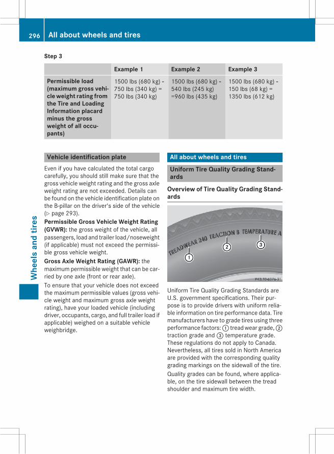
Step 3
Example 1 Example 2 Example 3
Permissible load(maximum gross vehi-cle weight rating fromthe Tire and LoadingInformation placardminus the grossweight of all occu-pants)
1500 lbs (680 kg) Ò750 lbs (340 kg) =750 lbs (340 kg)
1500 lbs (680 kg) Ò540 lbs (245 kg)=960 lbs (435 kg)
1500 lbs (680 kg) Ò150 lbs (68 kg) =1350 lbs (612 kg)
Vehicle identification plateEven if you have calculated the total cargocarefully, you should still make sure that thegross vehicle weight rating and the gross axleweight rating are not exceeded. Details canbe found on the vehicle identification plate onthe B-pillar on the driver's side of the vehicle(Y page 293).Permissible Gross Vehicle Weight Rating(GVWR): the gross weight of the vehicle, allpassengers, load and trailer load/noseweight(if applicable) must not exceed the permissi-ble gross vehicle weight.Gross Axle Weight Rating (GAWR): themaximum permissible weight that can be car-ried by one axle (front or rear axle).To ensure that your vehicle does not exceedthe maximum permissible values (gross vehi-cle weight and maximum gross axle weightrating), have your loaded vehicle (includingdriver, occupants, cargo, and full trailer load ifapplicable) weighed on a suitable vehicleweighbridge.
All about wheels and tires
Uniform Tire Quality Grading Stand-ards
Overview of Tire Quality Grading Stand-ards
Uniform Tire Quality Grading Standards areU.S. government specifications. Their pur-pose is to provide drivers with uniform relia-ble information on tire performance data. Tiremanufacturers have to grade tires using threeperformance factors:: treadwear grade,;traction grade and= temperature grade.These regulations do not apply to Canada.Nevertheless, all tires sold in North Americaare provided with the corresponding qualitygrading markings on the sidewall of the tire.Quality grades can be found, where applica-ble, on the tire sidewall between the treadshoulder and maximum tire width.
296 All about wheels and tiresW
heel
san
dtir
es

Example:RTreadwear grade: 200RTraction grade: AARTemperature grade: AAll passenger car tires must conform to thestatutory safety requirements in addition tothese grades.
i The actual values for tires are vehicle-specific and may deviate from the values inthe illustration.
TreadwearThe treadwear grade is a comparative ratingbased on thewear rate of the tire when testedunder controlled conditions on a specifiedU.S. government course. For example, a tiregraded 150 would wear one and one-halftimes as well on the government course as atire graded 100.The relative performance of tires dependsupon the actual conditions of their use, how-ever, and may depart significantly from thenorm due to variations in driving habits, ser-vice practices and differences in road char-acteristics and climate conditions.
Traction
G WARNINGThe traction grade assigned to this tire isbased on straight-ahead braking tractiontests, and does not include acceleration, cor-nering, hydroplaning, or peak traction char-acteristics.
! Avoid wheelspin. This can lead to damageto the drive train.
The traction grades – from highest to lowest –are AA, A, B and C. Those grades representthe tire's ability to stop on wet pavement asmeasured under controlled conditions onspecified government test surfaces of asphaltand concrete. A tire marked C may have poortraction performance.
The safe speed on a wet, snow covered or icyroad is always lower than on dry road surfa-ces.You should pay special attention to road con-ditions when temperatures are around freez-ing point.Mercedes-Benz recommends a minimumtread depth ofã in (4 mm) on all four wintertires. Observe the legally required minimumtire tread depth (Y page 283).Winter tires canreduce the braking distance on snow-coveredsurfaces in comparison with summer tires.The braking distance is still much further thanon surfaces that are not icy or covered withsnow. Take appropriate care when driving.Further information on winter tires (M+Stires) can be found in the Digital Operator'sManual.
Temperature
G WARNINGThe temperature grade for this tire is estab-lished for a tire that is properly inflated andnot overloaded. Excessive speed, underinfla-tion, or excessive loading, either separately orin combination, can cause excessive heatbuild-up and possible tire failure.
The temperature grades are A (the highest), B,and C. They represent the tire's resistance tothe generation of heat and its ability to dissi-pate heat when tested under controlled con-ditions on a specified indoor laboratory testwheel. Sustained high temperature can causethe material of the tire to degenerate andreduce tire life, and excessive temperaturecan lead to sudden tire failure. The grade Ccorresponds to a level of performance whichall passenger car tires must meet under theFederal Motor Vehicle Safety Standard No.109. Grades B and A represent higher levelsof performance on the laboratory test wheelthan the minimum required by law.
All about wheels and tires 297
Whe
els
and
tires
Z

Tire labeling
Overview
: Uniform Tire Quality Grading Standard(Y page 302)
; DOT, Tire Identification Number(Y page 301)
= Maximum tire load (Y page 300)? Maximum tire pressure (Y page 288)A ManufacturerB Tire material (Y page 301)C Tire size designation, load-bearing capa-
city and speed rating (Y page 298)D Load index (Y page 300)E Tire nameThe markings described above are on the tirein addition to the tire name (sales designa-tion) and the manufacturer's name.
i Tire data is vehicle-specific and may devi-ate from the data in the example.
Tire size designation, load-bearingcapacity and speed rating
G WARNINGExceeding the stated tire load-bearing capa-city and the approved maximum speed couldlead to tire damage or the tire bursting. Thereis a risk of accident.
Therefore, only use tire types and sizesapproved for your vehicle model. Observe thetire load rating and speed rating required foryour vehicle.
: Tire width; Nominal aspect ratio in %= Tire code? Rim diameterA Load bearing indexB Speed ratingGeneral: depending on the manufacturer'sstandards, the size imprinted in the tire wallmay not contain any letters or may containone letter that precedes the size description.If there is no letter preceding the size descrip-tion (as shown above): these are passengervehicle tires according to European manufac-turing standards.If "P" precedes the size description: these arepassenger vehicle tires according to U.S.manufacturing standards.If "LT" precedes the size description: theseare light truck tires according to U.S. manu-facturing standards.If "T" precedes the size description: compactemergency wheels with high tire pressurethat are only designed for temporary use in anemergency.Tire width: tire width: shows the nominaltire width in millimeters.Height-width ratio: aspect ratio; is thesize ratio between the tire height and tirewidth and is shown in percent. The aspect
298 All about wheels and tiresW
heel
san
dtir
es

ratio is calculated by dividing the tire width bythe tire height.Tire code: tire code= specifies the tire type."R" represents radial tires; "D" representsdiagonal tires; "B" represents diagonal radialtires.Optionally, tires with a maximum speed ofover 149 mph (240 km/h) may have "ZR" inthe size description, depending on the man-ufacturer (e.g. 245/40 ZR 18).Rim diameter: rim diameter? is the diam-eter of the bead seat, not the diameter of therim flange. The rim diameter is specified ininches (in).Load-bearing index: load-bearing indexAis a numerical code that specifies the maxi-mum load-bearing capacity of a tire.Do not overload the tires by exceeding thespecified load limit. The maximum permissi-ble load can be found on the vehicle's Tire andLoading Information placard on the B-pillar onthe driver's side (Y page 293).Example:Load-bearing index 91 indicates a maximumload of 1,356 lb (615 kg) that the tires canbear. For further information on themaximumtire load in kilograms and lbs, see(Y page 300).For further information on the load bearingindex, see "Load index" (Y page 300).Speed rating: speed ratingB specifies theapproved maximum speed of the tire.
i Tire data is vehicle-specific and may devi-ate from the data in the example.
Regardless of the speed rating, alwaysobserve the speed limits. Drive carefully andadapt your driving style to the traffic condi-tions.Summer tires
Index Speed rating
Q up to 100 mph (160 km/h)
R up to 106 mph (170 km/h)
Index Speed rating
S up to 112 mph (180 km/h)
T up to 118 mph (190 km/h)
H up to 130 mph (210 km/h)
V up to 149 mph (240 km/h)
W up to 168 mph (270 km/h)
Y up to 186 mph (300 km/h)
ZR...Y up to 186 mph (300 km/h)
ZR...(..Y) over 186 mph (300 km/h)
ZR over 149 mph (240 km/h)
ROptionally, tires with a maximum speed ofover 149mph (240 km/h)may have "ZR" inthe size description, depending on themanufacturer (e.g. 245/40 ZR18).The service specification is made up ofload-bearing indexA and speed ratingB.
RIf the size description of your tire includes"ZR" and there are no service specifica-tions, ask the tire manufacturer in order tofind out the maximum speed.If a service specification is available, themaximum speed is limited according to thespeed rating in the service specification.Example: 245/40 ZR18 97 Y. In this exam-ple, "97 Y" is the service specification. Theletter "Y" represents the speed rating. Themaximum speed of the tire is limited to186 mph (300 km/h).
RThe size description for all tires with maxi-mum speeds of over 186 mph (300 km/h)must include "ZR", and the service specifi-cationmust be given in parentheses. Exam-ple: 275/40 ZR 18 (99 Y). Speed rating"(Y)" indicates that the maximum speed ofthe tire is over 186 mph (300 km/h). Askthe tire manufacturer about the maximumspeed.
All about wheels and tires 299
Whe
els
and
tires
Z

All-weather tires and winter tires
Index Speed rating
Q M+S1 up to 100 mph (160 km/h)
T M+S1 up to 118 mph (190 km/h)
H M+S1 up to 130 mph (210 km/h)
V M+S1 up to 149 mph (240 km/h)
i Not all tires with theM+Smarking providethe driving characteristics of winter tires. Inaddition to the M+S marking, winter tiresalso have thei snowflake symbol onthe tire wall. Tires with this marking fulfillthe requirements of the Rubber Manufac-turers Association (RMA) and the RubberAssociation of Canada (RAC) regarding thetire traction on snow. They have been espe-cially developed for driving on snow.
An electronic speed limiter prevents yourvehicle from exceeding a speed of 130 mph(210 km/h).The speed rating of tires mounted at the fac-tory may be higher than the maximum speedthat the electronic speed limiter permits.Make sure that your tires have the requiredspeed rating, e.g. when buying new tires. Therequired speed rating for your vehicle can befound in the "Tires" section (Y page 309).Further information about reading tire datacan be obtained from any qualified specialistworkshop.
Load index
In addition to the load-bearing index, loadindex: may also be imprinted on the side-wall of the tire. You will find this after the let-ter that identifies the speed rating(Y page 298).RIf no specification is given: no text (as in theexample above), represents a standardload (SL) tire
RXL or Extra Load: represents a reinforcedtire
RLight Load: represents a light load tireRC, D, E: represents a load range thatdepends on the maximum load that the tirecan carry at a certain pressure
i Tire data is vehicle-specific and may devi-ate from the data in the example.
Maximum load rating
Maximum tire load: is the maximum per-missible weight for which the tire is approved.
1 Or M+Si for winter tires.
300 All about wheels and tiresW
heel
san
dtir
es

Do not overload the tires by exceeding thespecified load limit. The maximum permissi-ble load can be found on the vehicle's Tire andLoading Information placard on the B-pillar onthe driver's side (Y page 293).
i The actual values for tires are vehicle-specific and may deviate from the values inthe illustration.
DOT, Tire Identification Number (TIN)US tire regulations stipulate that every tiremanufacturer or retreader must imprint a TINin or on the sidewall of each tire produced.
The TIN is a unique identification number. TheTIN enables the tiremanufacturers or retread-ers to inform purchasers of recalls and othersafety-relevant matters. It makes it possiblefor the purchaser to easily identify the affec-ted tires.The TIN is made up of manufacturer identifi-cation code;, tire size=, tire type code?and manufacturing dateA.DOT (Department of Transportation): tiresymbol: marks that the tire complies withthe requirements of the U.S. Department ofTransportation.Manufacturer identification code: manu-facturer identification code; providesdetails on the tire manufacturer. New tireshave a code with two symbols. Retreadedtires have a code with four symbols.For further information about retreaded tires,see (Y page 282).Tire size: identifier= describes the tire size.
Tire type code: tire type code? can be usedby the manufacturer as a code to describespecific characteristics of the tire.Date of manufacture: date of manufactureA provides information about the age of atire. The first and second positions representthe week of manufacture, starting with "01"for the first calendar week. Positions threeand four represent the year of manufacture.For example, a tire that is marked with"3208", was manufactured in week 32 in2008.
i Tire data is vehicle-specific and may devi-ate from the data in the example.
Tire characteristics
This information describes the type of tirecord and the number of layers in sidewall:and under tire tread;.
i Tire data is vehicle-specific and may devi-ate from the data in the example.
Definition of terms for tires and loading
Tire ply composition and material usedDescribes the number of plies or the numberof layers of rubber-coated fabric in the tiretread and sidewall. These are made of steel,nylon, polyester and other materials.
BarMetric unit for tire pressure. 14.5038 poundsper square inch (psi) and 100 kilopascals(kPa) are the equivalent of 1 bar.
All about wheels and tires 301
Whe
els
and
tires
Z

DOT (Department of Transportation)DOT-marked tires fulfill the requirements ofthe U S Department of Transportation.
Normal occupant weightThe number of occupants for which the vehi-cle is designed multiplied by 68 kilograms(150 lbs).
Uniform Tire Quality Grading StandardsA uniform standard to grade the quality oftireswith regards to tread quality, tire tractionand temperature characteristics. The qualitygrading assessment is made by the manufac-turer following specifications from the U.S.government. The ratings are molded into thesidewall of the tire.
Recommended tire pressuresThe recommended tire pressure applies tothe tires mounted at the factory.The Tire and Loading Information placard con-tains the recommended tire pressures forcold tires on a fully loaded vehicle and for themaximum permissible vehicle speed.The tire pressure table contains the recom-mended pressures for cold tires for variousoperating conditions, i.e. differing load andspeed conditions.
Increased vehicle weight due to optionalequipmentThe combined weight of all standard andoptional equipment available for the vehicle,regardless of whether it is actually installedon the vehicle or not.
RimThis is the part of the wheel on which the tireis mounted.
GAWR (Gross Axle Weight Rating)The GAWR is the maximum gross axle weightrating. The actual load on an axle must neverexceed the gross axle weight rating. Thegross axle weight rating can be found on thevehicle identification plate on the B-pillar onthe driver's side.
Speed ratingThe speed rating is part of the tire identifica-tion. It specifies the speed range forwhich thetire is approved.
GVW (Gross Vehicle Weight)The gross vehicle weight includes the weightof the vehicle including fuel, tools, the sparewheel, accessories installed, occupants, lug-gage and the drawbar noseweight, if applica-ble. The gross vehicleweightmust not exceedthe gross vehicle weight rating GVWR asspecified on the vehicle identification plate onthe B-pillar on the driver's side.
GVWR (Gross Vehicle Weight Rating)The GVWR is the maximum permissible grossweight of a fully loaded vehicle (the weight ofthe vehicle including all accessories, occu-pants, fuel, luggage and the drawbar nose-weight, if applicable). The gross vehicleweight rating is specified on the vehicle iden-tification plate on the B-pillar on the driver'sside.
Maximum loaded vehicle weightThe maximum weight is the sum of:Rthe curb weight of the vehicleRthe weight of the accessoriesRthe load limitRthe weight of the factory installed optionalequipment
Kilopascal (kPa)Metric unit for tire pressure. 6.9 kPa corre-sponds to 1 psi. Another unit for tire pressureis bar. 100 kilopascals (kPa) are the equiva-lent of 1 bar.
Load indexIn addition to the load-bearing index, the loadindexmay also be imprinted on the sidewall ofthe tire. This specifies the load-bearing capa-city more precisely.
302 All about wheels and tiresW
heel
san
dtir
es

Curb weightThe weight of a vehicle with standard equip-ment including themaximum capacity of fuel,oil and coolant. It also includes the air-condi-tioning system and optional equipment ifthese are installed in the vehicle, but does notinclude passengers or luggage.
Maximum load ratingThe maximum load rating is the maximumpermissible weight in kilograms or lbs forwhich a tire is approved.
Maximum permissible tire pressureMaximum permissible tire pressure for onetire.
Maximum load on one tireMaximum load on one tire. This is calculatedby dividing themaximum axle load of one axleby two.
PSI (pounds per square inch)A standard unit of measure for tire pressure.
Aspect ratioRelationship between tire height and tirewidth in percent.
Tire pressureThis is pressure inside the tire applying anoutward force to each square inch of the tire'ssurface. The tire pressure is specified inpounds per square inch (psi), in kilopascal(kPa) or in bar. The tire pressure should onlybe corrected when the tires are cold.
Cold tire pressureThe tires are cold:Rif the vehicle has been parked withoutdirect sunlight on the tires for at least threehours and
Rif the vehicle has not been driven furtherthan 1 mile (1.6 km)
TreadThe part of the tire that comes into contactwith the road.
BeadThe tire bead ensures that the tire sitssecurely on the wheel. There are several steelwires in the bead to prevent the tire fromcoming loose from the wheel rim.
SidewallThe part of the tire between the tread and thebead.
Weight of optional extrasThe combined weight of those optional extrasthat weigh more than the replaced standardparts and more than 5 lbs (2.3 kg). Theseoptional extras, such as high-performancebrakes, level control, a roof rack or a high-performance battery, are not included in thecurb weight and the weight of the accesso-ries.
TIN (Tire Identification Number)This is a unique identifier which can be usedby a tire manufacturer to identify tires, forexample for a product recall, and thus identifythe purchasers. The TIN is made up of themanufacturer's identity code, tire size, tiretype code and the manufacturing date.
Load bearing indexThe load bearing index (also load index) is acode that contains themaximum load bearingcapacity of a tire.
TractionTraction is the result of friction between thetires and the road surface.
Treadwear indicatorsNarrow bars (tread wear bars) that are dis-tributed over the tire tread. If the tire tread islevel with the bars, the wear limit ofá in(1.6 mm) has been reached.
All about wheels and tires 303
Whe
els
and
tires
Z

Occupant distributionThe distribution of occupants in a vehicle attheir designated seating positions.
Total load limitNominal load and luggage load plus 68 kg(150 lbs) multiplied by the number of seats inthe vehicle.
Changing a wheel
Flat tireThe "Breakdown assistance" section(Y page 264) contains information and noteson how to deal with a flat tire. Information ondriving with MOExtended tires in the event ofa flat tire can be found under "MOExtendedtires (tires with run-flat characteristics"(Y page 264).
Rotating the wheels
G WARNINGInterchanging the front and rear wheels mayseverely impair the driving characteristics ifthe wheels or tires have different dimensions.The wheel brakes or suspension componentsmay also be damaged. There is a risk of acci-dent.Rotate front and rearwheels only if thewheelsand tires are of the same dimensions.
! On vehicles equipped with a tire pressuremonitor, electronic components are loca-ted in the wheel.Tire-mounting tools should not be usednear the valve. This could damage the elec-tronic components.Only have tires changed at a qualified spe-cialist workshop.
Always observe the instructions and safetynotes in the "Mounting a wheel" section(Y page 304).The wear patterns on the front and rear tiresdiffer, depending on the operating conditions.
Rotate the wheels before a clear wear patternhas formed on the tires. Front tires typicallywear more on the shoulders and the rear tiresin the center.If your vehicle's tire configuration allows, youcan rotate the wheels according to the inter-vals in the tire manufacturer's warranty bookin your vehicle documents. If no warrantybook is available, the tires should be rotatedevery 3,000 to 6,000 miles (5,000 to10,000 km), or earlier if tire wear requires.Ensure the direction of rotation ismaintained.Clean the contact surfaces of the wheel andthe brake disc thoroughly every time a wheelis rotated. Check the tire pressure and, if nec-essary, restart the tire pressure loss warningsystem (Y page 292) or the tire pressuremonitor (Y page 291).
Direction of rotationTires with a specified direction of rotationhave additional benefits, e.g. if there is a riskof hydroplaning. These advantages can onlybe gained if the tires are installed correspond-ing to the direction of rotation.An arrow on the sidewall of the tire indicatesits correct direction of rotation.
Storing wheelsStorewheels that are not being used in a cool,dry and preferably dark place. Protect thetires from oil, grease, gasoline and diesel.
Mounting a wheel
Preparing the vehicleX Stop the vehicle on solid, non-slippery andlevel ground.X Apply the electric parking brake manually.X Bring the front wheels into the straight-ahead position.X Shift the transmission to position P.
304 Changing a wheelW
heel
san
dtir
es

X Make sure that the vehicle level is set to"Normal" on vehicles with AIRMATIC(Y page 156).X Switch off the engine.X Vehicles without KEYLESS-GO: removethe SmartKey from the ignition lock.X Vehicles with KEYLESS-GO start-func-
tion or KEYLESS-GO: open the driver'sdoor.The on-board electronics now have status0. This is the same as the SmartKey havingbeen removed.X Vehicles with KEYLESS-GO start-func-
tion or KEYLESS-GO: remove the Start/Stop button from the ignition lock(Y page 130).X If included in the vehicle equipment,remove the tire-change tool kit from thevehicle.X Safeguard the vehicle against rolling away.
Securing the vehicle to prevent it fromrolling away
If your vehicle is equippedwith awheel chock,it can be found in the tire-change tool kit(Y page 263).The folding wheel chock is an additionalsafety measure to prevent the vehicle fromrolling away, for example when changing awheel.X Fold both plates upwards:.X Fold out lower plate;.X Guide the lugs on the lower plate fully intothe openings in base plate=.
Securing the vehicle on level groundX On level ground: place chocks or othersuitable items under the front and rear ofthe wheel that is diagonally opposite thewheel you wish to change.
Securing the vehicle on slight downhill gradientsX On light downhill gradients: placechocks or other suitable items in front ofthe wheels of the front and rear axle.
Raising the vehicle
G WARNINGIf you do not position the jack correctly at theappropriate jacking point of the vehicle, thejack could tip over with the vehicle raised.There is a risk of injury.Only position the jack at the appropriate jack-ing point of the vehicle. The base of the jackmust be positioned vertically, directly underthe jacking point of the vehicle.
! The jack is designed exclusively for jack-ing up the vehicle at the jacking points.Otherwise, your vehicle could be damaged.
Changing a wheel 305
Whe
els
and
tires
Z

Observe the following when raising thevehicle:RTo raise the vehicle, only use the vehicle-specific jack that has been tested andapproved by Mercedes-Benz. If used incor-rectly, the jack could tip over with the vehi-cle raised.
RThe jack is designed only to raise and holdthe vehicle for a short time while a wheelis being changed. It is not suited for per-forming maintenance work under the vehi-cle.
RAvoid changing the wheel on uphill anddownhill slopes.
RBefore raising the vehicle, secure it fromrolling away by applying the parking brakeand inserting wheel chocks. Do not disen-gage the parking brake while the vehicle israised.
RThe jack must be placed on a firm, flat andnon-slip surface. On a loose surface, alarge, flat, load-bearing underlay must beused. On a slippery surface, a non-slipunderlay must be used, e.g. rubber mats.
RDo not use wooden blocks or similarobjects as a jack underlay. Otherwise, thejack will not be able to achieve its load-bearing capacity due to the restrictedheight.
RMake sure that the distance between theunderside of the tires and the ground doesnot exceed 1.2 in (3 cm).
RNever place your hands and feet under theraised vehicle.
RDo not lie under the vehicle.RDo not start the engine when the vehicle israised.
RDo not open or close a door or the trunk lidwhen the vehicle is raised.
RMake sure that no persons are present inthe vehicle when the vehicle is raised.
Vehicles with alloy wheels and hub caps:the wheel bolts are covered by a hub cap.Before you can unscrew the wheel bolts, you
must remove the hub cap. Two different var-iants can be installed.
Alloy wheel with plastic hub capVehicles with plastic hub cap:X To remove: turn the center cover of hubcap: counter-clockwise and remove.X To install: before installing, ensure thathub cap: is in the open position. To do so,turn the center cover counter-clockwise.X Put hub cap: in position and turn thecenter cover clockwise until you feel andhear hub cap: engage.X Make sure that hub cap: is installedsecurely.
Alloy wheel with aluminum hub capVehicles with aluminum hub cap:X To remove: take socket; and lug wrench= from the vehicle tool kit (Y page 263).X Position socket; on hub cap:.X Attach lug wrench= to socket; andloosen hub cap: counter-clockwise.X Remove hub cap:.
306 Changing a wheelW
heel
san
dtir
es

X To install: before installing, check hubcap: and the wheel area for soiling andclean if necessary.X Put hub cap: in position and turn until it isin the right position.X Position socket; on hub cap:.X Attach lug wrench= to socket; andtighten hub cap:.The tightening torque must be18 lb-ft (25 Nm).
i Note that the hub cap should be tight-ened to the specified torque of 18 lb-ft(25 Nm). Mercedes-Benz recommendsthat you have the hub cap installed at aqualified specialist workshop.
X Using a lug wrench=, loosen the bolts onthe wheel you wish to change by about onefull turn. Do not unscrew the bolts com-pletely.
The jacking points are located just behind thefront wheel housings and just in front of therear wheel housings (arrows).
AMG vehicles and vehicles with AMGequipment: to protect the vehicle body, thevehicle has covers next to the jacking pointson the outer sills.
X AMG vehicles and vehicles with AMGequipment: fold cover? upwards.
X Position jackB at jacking pointA.
X Make sure the foot of the jack is directlybeneath the jacking point.
Changing a wheel 307
Whe
els
and
tires
Z

X Turn crankC clockwise until jackB sitscompletely on jacking pointA and thebase of the jack lies evenly on the ground.X Turn crankC until the tire is raised a max-imum of 1.2 in (3 cm) from the ground.
Removing a wheel
! AMG vehicle with ceramic brake discs:during removal and repositioning of thewheel, the wheel rim can strike theceramic-brake disc and damage it. There-fore, take precautions and have a secondperson assist you. Alternatively, you canuse a second alignment bolt.
! Do not place wheel bolts in sand or on adirty surface. The bolt and wheel hubthreads could otherwise be damaged whenyou screw them in.
When mounting/removing wheels, and for aslong as the wheels are removed, avoid apply-ing any external force on the brake disks. Thiscould impair the level of comfort when brak-ing.
X Unscrew the uppermost wheel bolt com-pletely.X Screw alignment bolt: into the threadinstead of the wheel bolt.X Unscrew the remaining wheel bolts fully.X Remove the wheel.
Mounting a new wheel
G WARNINGOiled or greased wheel bolts or damagedwheel bolts/hub threads can cause the wheelbolts to come loose. As a result, you couldlose a wheel while driving. There is a risk ofaccident.Never oil or greasewheel bolts. In the event ofdamage to the threads, contact a qualifiedspecialist workshop immediately. Have thedamaged wheel bolts or hub threadsreplaced/renewed. Do not continue driving.
G WARNINGIf you tighten the wheel bolts or wheel nutswhen the vehicle is raised, the jack could tipover. There is a risk of injury.Only tighten the wheel bolts or wheel nutswhen the vehicle is on the ground.
Always pay attention to the instructions andsafety notes in the "Changing a wheel" sec-tion (Y page 304).Only use wheel bolts that have been designedfor the wheel and the vehicle. For safety rea-sons, Mercedes-Benz recommends that youonly use wheel bolts which have beenapproved forMercedes-Benz vehicles and therespective wheel.
! AMG vehicle with ceramic brake discs:during removal and repositioning of thewheel, the wheel rim can strike theceramic-brake disc and damage it. There-fore, take precautions and have a secondperson assist you. Alternatively, you canuse a second alignment bolt.
! To prevent damage to the paintwork, holdthe wheel securely against the wheel hubwhile screwing in the first wheel bolt.
308 Changing a wheelW
heel
san
dtir
es

X Clean the wheel and wheel hub contactsurfaces.X Slide the wheel to be mounted onto thealignment bolt and push it on.X Tighten the wheel bolts until they are fin-ger-tight.X Unscrew the alignment bolt.X Tighten the last wheel bolt until it is finger-tight.
Lowering the vehicle
G WARNINGThe wheels could work loose if the wheel nutsand bolts are not tightened to the specifiedtightening torque. There is a risk of accident.Have the tightening torque immediatelychecked at a qualified specialist workshopafter a wheel is changed.
X Turn the crank of the jack counter-clock-wise until the vehicle is once again standingfirmly on the ground.X Place the jack to one side.
X Tighten the wheel bolts evenly in a cross-wise pattern in the sequence indicated (:toA). The specified tightening torque is96 lb-ft (130 Nm).X Turn the jack back to its initial position.X Stow the jack and the rest of the vehicletools in the trunk again.X AMG vehicles and vehicles with AMG
equipment: insert the cover into the outersill.X Check the tire pressure of the newly moun-ted wheel and adjust it if necessary.Observe the recommended tire pressure(Y page 285).
When you are driving with the collapsiblespare wheel mounted, the tire pressure losswarning system or the tire pressure monitorcannot function reliably. Only restart the tirepressure loss warning system/the tire pres-sure monitor when the damaged wheel hasbeen replaced with a new wheel.Vehicles with a tire pressure control sys-tem: all installed wheels must be equippedwith functioning sensors.
Wheel and tire combinations
General notes! For safety reasons, Mercedes-Benz rec-ommends that you only use tires andwheels which have been approved byMercedes-Benz specifically for your vehi-cle.These tires have been specially adapted foruse with the control systems, such as ABSor ESP®, and are marked as follows:RMO = Mercedes-Benz OriginalRMOE=Mercedes-BenzOriginal Extended(tires featuring run-flat characteristics)
RMO1=Mercedes-Benz Original (only cer-tain AMG tires)
Mercedes-Benz Original Extended tiresmay only be used on wheels that have beenspecifically approved by Mercedes-Benz.
Wheel and tire combinations 309
Whe
els
and
tires
Z

Only use tires, wheels or accessories tes-ted and approved by Mercedes-Benz. Cer-tain characteristics, e.g. handling, vehiclenoise emissions or fuel consumption, mayotherwise be adversely affected. In addi-tion, when driving with a load, tire dimen-sion variations could cause the tires tocome into contact with the bodywork andaxle components. This could result in dam-age to the tires or the vehicle.Mercedes-Benz accepts no liability fordamage resulting from the use of tires,wheels or accessories other than those tes-ted and approved.Information on tires, wheels and approvedcombinations can be obtained from anyqualified specialist workshop.
Overview of abbreviations used in the follow-ing tire tables:RBA: both axlesRFA: front axleRRA: rear axleThe recommended pressures for variousoperating conditions can be found:Ron the Tire and Loading Information placardwith the recommended tire pressures onthe B-pillar on the driver's side
Rin the tire pressure table on the inside of thefuel filler flap
Observe the notes on recommended tirepressures under various operating conditions(Y page 285).Check tire pressures regularly, and only whenthe tires are cold. Comply with the mainte-nance recommendations of the tire manufac-turer in the vehicle document wallet.Notes on the vehicle equipment – alwaysequip the vehicle with:Rtires of the same size on a given axle (left/right)
Rthe same type of tires at a given time (sum-mer tires, winter tires, MOExtended tires)Exception: it is permissible to install a dif-ferent type or make in the event of a flat
tire. Observe the "MOExtended tires (tireswith run-flat characteristics" section(Y page 264).
Vehicles equipped withMOExtended tires arenot equipped with a TIREFIT kit at the factory.It is therefore recommended that you addi-tionally equip your vehicle with a TIREFIT kit ifyou mount tires that do not feature run-flatproperties, e.g. winter tires. A TIREFIT kit maybe obtained from a qualified specialist work-shop.
i Not all wheel and tire combinations areavailable at the factory for all countries.
i On the following pages, you can find infor-mation on approved wheel rims and tiresizes for equipping your vehicle with wintertires. Winter tires are not available at thefactory as standard equipment or optionalextras.If you would like to equip your vehicle withapproved winter tires, you may also, in cer-tain circumstances, require rims of theappropriate size. The size of the approvedwinter tires may deviate from that of thestandard tires. This is dependent on themodel and the equipment installed at thefactory.The tires and wheel rims, as well as furtherinformation, can be obtained at a qualifiedspecialist workshop.
310 Wheel and tire combinationsW
heel
san
dtir
es

Tires
C 300
Summer tiresR 17
Tires Wheels
BA: 225/50 R17 94 W2 BA: 7.0 J x 17 H2Wheel offset: 1.91 in (48.5 mm)
R 18
Tires Wheels
FA: 225/45 R18 95 Y XL3
RA: 245/40 R18 97 Y XL3FA: 7.5 J x 18 H2Wheel offset: 1.73 in (44 mm)RA: 8.5 J x 18 H2Wheel offset: 2.20 in (56 mm)
FA: 225/45 R18 95 Y XL3
RA: 245/40 R18 97 Y XL3, 4FA: 7.5 J x 18 H2Wheel offset: 1.73 in (44 mm)RA: 8.5 J x 18 H2Wheel offset: 1.93 in (49 mm)
R 19
Tires Wheels
FA: 225/40 R19 93 Y XL3
RA: 245/35 R19 93 Y XL3, 4FA: 7.5 J x 19 H2Wheel offset: 1.73 in (44 mm)RA: 8.5 J x 19 H2Wheel offset: 2.22 in (56.5 mm)
FA: 225/40 R19 93 Y XL3
RA: 255/35 R19 96 Y XL3, 4FA: 7.5 J x 19 H2Wheel offset: 1.73 in (44 mm)RA: 8.5 J x 19 H2Wheel offset: 2.05 in (52 mm)
2 Not in conjunction with AMG Line Exterior package (code P31) and sports suspension (code 486).3 Available as MOExtended tires.4 Additional measures necessary (additional wheel-arch extension on rear wheel arch).
Wheel and tire combinations 311
Whe
els
and
tires
Z

All-weather tiresR 17
Tires Wheels
BA: 225/50 R17 94 H M+S3 BA: 7.0 J x 17 H2Wheel offset: 1.91 in (48.5 mm)
R 18
Tires Wheels
FA: 225/45 R18 95 H XL M+S3
RA: 245/40 R18 97 H XL M+S3FA: 7.5 J x 18 H2Wheel offset: 1.73 in (44 mm)RA: 8.5 J x 18 H2Wheel offset: 2.20 in (56 mm)
FA: 225/45 R18 95 Y XL M+S3
RA: 245/40 R18 97 Y XL M+S3FA: 7.5 J x 18 H2Wheel offset: 1.73 in (44 mm)RA: 8.5 J x 18 H2Wheel offset: 1.93 in (49 mm)
Winter tiresR 17
Tires Wheels
BA: 225/50 R17 94 H M+Si3 BA: 7.0 J x 17 H2Wheel offset: 1.91 in (48.5 mm)
R 18
Tires Wheels
BA: 225/45 R18 95 H XL M+Si3 BA: 7.5 J x 18 H2Wheel offset: 1.73 in (44 mm)
C 300 4MATIC
Summer tiresR 17
Tires Wheels
BA: 225/50 R17 94 W2 BA: 7.0 J x 17 H2Wheel offset: 1.91 in (48.5 mm)
3 Available as MOExtended tires.2 Not in conjunction with AMG Line Exterior package (code P31) and sports suspension (code 486).
312 Wheel and tire combinationsW
heel
san
dtir
es

R 18
Tires Wheels
FA: 225/45 R18 95 Y XL3
RA: 245/40 R18 97 Y XL3FA: 7.5 J x 18 H2Wheel offset: 1.73 in (44 mm)RA: 8.5 J x 18 H2Wheel offset: 2.20 in (56 mm)
FA: 225/45 R18 95 Y XL3
RA: 245/40 R18 97 Y XL3, 4FA: 7.5 J x 18 H2Wheel offset: 1.73 in (44 mm)RA: 8.5 J x 18 H2Wheel offset: 1.93 in (49 mm)
R 19
Tires Wheels
FA: 225/40 R19 93 Y XL3
RA: 245/35 R19 93 Y XL3, 4FA: 7.5 J x 19 H2Wheel offset: 1.73 in (44 mm)RA: 8.5 J x 19 H2Wheel offset: 2.22 in (56.5 mm)
FA: 225/40 R19 93 Y XL3
RA: 255/35 R19 96 Y XL3, 4FA: 7.5 J x 19 H2Wheel offset: 1.73 in (44 mm)RA: 8.5 J x 19 H2Wheel offset: 2.05 in (52 mm)
All-weather tiresR 17
Tires Wheels
BA: 225/50 R17 94 H M+S3 BA: 7.0 J x 17 H2Wheel offset: 1.91 in (48.5 mm)
3 Available as MOExtended tires.4 Additional measures necessary (additional wheel-arch extension on rear wheel arch).
Wheel and tire combinations 313
Whe
els
and
tires
Z

R 18
Tires Wheels
FA: 225/45 R18 95 H XL M+S3
RA: 245/40 R18 97 H XL M+S3FA: 7.5 J x 18 H2Wheel offset: 1.73 in (44 mm)RA: 8.5 J x 18 H2Wheel offset: 2.20 in (56 mm)
FA: 225/45 R18 95 Y XL M+S3
RA: 245/40 R18 97 Y XL M+S3FA: 7.5 J x 18 H2Wheel offset: 1.73 in (44 mm)RA: 8.5 J x 18 H2Wheel offset: 1.93 in (49 mm)
Winter tiresR 17
Tires Wheels
BA: 225/50 R17 94 H M+Si3 BA: 7.0 J x 17 H2Wheel offset: 1.91 in (48.5 mm)
R 18
Tires Wheels
BA: 225/45 R18 95 H XL M+Si3 BA: 7.5 J x 18 H2Wheel offset: 1.73 in (44 mm)
C 400 4MATIC
Summer tiresR 17
Tires Wheels
BA: 225/50 R17 94 W2 BA: 7.0 J x 17 H2Wheel offset: 1.91 in (48.5 mm)
3 Available as MOExtended tires.2 Not in conjunction with AMG Line Exterior package (code P31) and sports suspension (code 486).
314 Wheel and tire combinationsW
heel
san
dtir
es

R 18
Tires Wheels
FA: 225/45 R18 95 Y XL3
RA: 245/40 R18 97 Y XL3FA: 7.5 J x 18 H2Wheel offset: 1.73 in (44 mm)RA: 8.5 J x 18 H2Wheel offset: 2.20 in (56 mm)
FA: 225/45 R18 95 Y XL3
RA: 245/40 R18 97 Y XL3, 4FA: 7.5 J x 18 H2Wheel offset: 1.73 in (44 mm)RA: 8.5 J x 18 H2Wheel offset: 1.93 in (49 mm)
R 19
Tires Wheels
FA: 225/40 R19 93 Y XL3
RA: 245/35 R19 93 Y XL3, 4FA: 7.5 J x 19 H2Wheel offset: 1.73 in (44 mm)RA: 8.5 J x 19 H2Wheel offset: 2.22 in (56.5 mm)
FA: 225/40 R19 93 Y XL3
RA: 255/35 R19 96 Y XL3, 4FA: 7.5 J x 19 H2Wheel offset: 1.73 in (44 mm)RA: 8.5 J x 19 H2Wheel offset: 2.05 in (52 mm)
All-weather tiresR 17
Tires Wheels
BA: 225/50 R17 94 H M+S3 BA: 7.0 J x 17 H2Wheel offset: 1.91 in (48.5 mm)
3 Available as MOExtended tires.4 Additional measures necessary (additional wheel-arch extension on rear wheel arch).
Wheel and tire combinations 315
Whe
els
and
tires
Z

R 18
Tires Wheels
FA: 225/45 R18 95 H XL M+S3
RA: 245/40 R18 97 H XL M+S3FA: 7.5 J x 18 H2Wheel offset: 1.73 in (44 mm)RA: 8.5 J x 18 H2Wheel offset: 2.20 in (56 mm)
FA: 225/45 R18 95 Y XL M+S3
RA: 245/40 R18 97 Y XL M+S3FA: 7.5 J x 18 H2Wheel offset: 1.73 in (44 mm)RA: 8.5 J x 18 H2Wheel offset: 1.93 in (49 mm)
Winter tiresR 17
Tires Wheels
BA: 225/50 R17 94 H M+Si3 BA: 7.0 J x 17 H2Wheel offset: 1.91 in (48.5 mm)
R 18
Tires Wheels
BA: 225/45 R18 95 H XL M+Si3 BA: 7.5 J x 18 H2Wheel offset: 1.73 in (44 mm)
C 63 AMG
Summer tiresR 18
Tires Wheels
FA: 245/40 ZR18 97 Y XL5
RA: 265/40 ZR18 101 Y XL5FA: 8.5 J x 18 H2Wheel offset: 1.50 in (38 mm)RA: 9.5 J x 18 H2Wheel offset: 2.20 in (56 mm)
3 Available as MOExtended tires.5 Not in combination with a ceramic brake system.
316 Wheel and tire combinationsW
heel
san
dtir
es

R 19
Tires Wheels
FA: 245/35 ZR19 93 Y XL MO1RA: 265/35 ZR19 98 Y XL MO1
FA: 8.5 J x 19 H2Wheel offset: 1.50 in (38 mm)RA: 9.5 J x 19 H2Wheel offset: 2.20 in (56 mm)
Winter tiresR 18
Tires Wheels
FA: 245/40 R18 97 V XL M+Si5
RA: 265/40 R18 101 V XL M+Si5, 6
FA: 8.5 J x 18 H2Wheel offset: 1.50 in (38 mm)RA: 9.5 J x 18 H2Wheel offset: 2.20 in (56 mm)
R 19
Tires Wheels
FA: 245/35 R19 93 V XL M+Si
RA: 245/35 R19 93 V XL M+Si6FA: 8.5 J x 19 H2Wheel offset: 1.50 in (38 mm)RA: 8.5 J x 19 H2Wheel offset: 2.13 in (54 mm)
FA: 245/35 R19 93 V XL M+Si
RA: 265/35 R19 98 V XL M+Si6FA: 8.5 J x 19 H2Wheel offset: 1.50 in (38 mm)RA: 9.5 J x 19 H2Wheel offset: 2.20 in (56 mm)
C 63 AMG S-Model
Summer tiresR 19
Tires Wheels
FA: 245/35 ZR19 93 Y XL MO1RA: 265/35 ZR19 98 Y XL MO1
FA: 8.5 J x 19 H2Wheel offset: 1.50 in (38 mm)RA: 9.5 J x 19 H2Wheel offset: 2.20 in (56 mm)
5 Not in combination with a ceramic brake system.6 Use of snow chains not permitted. Observe the notes under "Snow chains".
Wheel and tire combinations 317
Whe
els
and
tires
Z

Winter tiresR 19
Tires Wheels
FA: 245/35 R19 93 V XL M+Si
RA: 245/35 R19 93 V XL M+Si6FA: 8.5 J x 19 H2Wheel offset: 1.50 in (38 mm)RA: 8.5 J x 19 H2Wheel offset: 2.13 in (54 mm)
FA: 245/35 R19 93 V XL M+Si
RA: 265/35 R19 98 V XL M+Si6FA: 8.5 J x 19 H2Wheel offset: 1.50 in (38 mm)RA: 9.5 J x 19 H2Wheel offset: 2.20 in (56 mm)
6 Use of snow chains not permitted. Observe the notes under "Snow chains".
318 Wheel and tire combinationsW
heel
san
dtir
es

Useful information ............................ 320Information regarding technicaldata .................................................... 320Identification plates ......................... 320Service products and filling capaci-ties ..................................................... 321Vehicle data ....................................... 327
319
Tech
nica
ldat
a

Useful information
i This Operator's Manual describes allmodels and all standard and optional equip-ment of your vehicle available at the time ofpublication of the Operator's Manual.Country-specific differences are possible.Please note that your vehicle may not beequipped with all features described. Thisalso applies to safety-related systems andfunctions.
i Read the information on qualified special-ist workshops (Y page 29).
Information regarding technical data
i The data stated here specifically refers toa vehicle with standard equipment. Consultan authorized Mercedes-Benz Center forthe data for all vehicle variants and trimlevels.
Identification plates
Vehicle identification plate with vehi-cle identification number (VIN)
X Open the driver's door.You will see vehicle identification plate:.
Example: vehicle identification plate (USA only); VIN= Vehicle model
Example: vehicle identification plate (Canada only); VIN= Paint code
i The data shown on the vehicle identifica-tion plate is used only as an example. Thisdata is different for every vehicle and candeviate from the data shown here. You canfind the data applicable to your vehicle onthe vehicle identification plate.
320 Identification platesTe
chni
cald
ata

Vehicle identification plate with vehi-cle identification number (VIN)
X Slide the right-hand front seat to its rear-most position.X Fold floor covering; upwards.The VIN is visible:.
The VIN can also be found on the vehicleidentification plate (Y page 320).The VIN can also be found at the lower edge ofthe windshield (Y page 321).
Engine number
: Emission control information plate,including the certification of both federaland Californian emissions standards
; Engine number (stamped into the crank-case)
= VIN (on the lower edge of the windshield)
Service products and filling capaci-ties
Important safety notes
G WARNINGService products may be poisonous and haz-ardous to health. There is a risk of injury.Comply with instructions on the use, storageand disposal of service products on the labelsof the respective original containers. Alwaysstore service products sealed in their originalcontainers. Always keep service products outof the reach of children.
H Environmental noteDispose of service products in an environ-mentally responsible manner.
Service products include the following:RFuelsRLubricants (e.g. engine oil, transmission oil)RCoolantRBrake fluidRWindshield washer fluidRClimate control system refrigerantComponents and service products must bematched. Only use products recommendedby Mercedes-Benz. Damage which is causedby the use of products which have not beenrecommended is not covered by theMercedes-Benz warranty or goodwill ges-tures. They are listed in this Mercedes-BenzOperator'sManual in the appropriate section.Information on tested and approved productscan be obtained at an authorized Mercedes-Benz Center or on the Internet athttp://bevo.mercedes-benz.com.You can recognize service products approvedby Mercedes-Benz by the following inscrip-tion on the containers:RMB-Freigabe (e.g. MB-Freigabe 229.51)RMB Approval (e.g. MB Approval 229.51)Other designations or recommendations indi-cate a level of quality or a specification in
Service products and filling capacities 321
Tech
nica
ldat
a
Z

accordance with an MB Sheet Number (e.g.MB 229.5). They have not necessarily beenapproved by Mercedes-Benz.Other identifications, for example:R0 W-30R5 W-30R5 W-40
Fuel
Important safety notes
G WARNINGFuel is highly flammable. If you handle fuelincorrectly, there is a risk of fire and explo-sion.You must avoid fire, open flames, creatingsparks and smoking. Switch off the engineand, if applicable, the auxiliary heating beforerefueling.
G WARNINGFuel is poisonous and hazardous to health.There is a risk of injury.You must make sure that fuel does not comeinto contact with your skin, eyes or clothingand that it is not swallowed. Do not inhale fuelvapors. Keep fuel away from children.If you or others come into contact with fuel,observe the following:RWash away fuel from skin immediatelyusing soap and water.
RIf fuel comes into contact with your eyes,immediately rinse them thoroughly withclean water. Seek medical assistance with-out delay.
RIf fuel is swallowed, seek medical assis-tance without delay. Do not induce vomit-ing.
RImmediately change out of clothing whichhas come into contact with fuel.
Tank capacity
Model Total capacity
All models 17.4 US gal(66.0 l)
Model Of whichreserve
AMG vehicles Approx.2.6 US gal(10.0 l)
All other models Approx.1.8 US gal(7.0 l)
Gasoline
Fuel grade! Do not use diesel to refuel vehicles with agasoline engine. Do not switch on the igni-tion if you accidentally refuel with thewrong fuel. Otherwise, the fuel will enterthe fuel system. Even small amounts of thewrong fuel could result in damage to thefuel system and the engine. Notify a quali-fied specialist workshop and have the fueltank and fuel lines drained completely.
! Only refuel using unleaded premiumgrade gasoline with at least 91 AKI/95 RON.
! Only use the fuel recommended. Operat-ing the vehicle with other fuels can lead toengine failure.
! Do not use the following:RE85 (gasoline with 85% ethanol)RE100 (100% ethanol)RM15 (gasoline with 15% methanol)RM30 (gasoline with 30% methanol)RM85 (gasoline with 85% methanol)RM100 (100% methanol)RGasoline with metalliferous additivesRDiesel
322 Service products and filling capacitiesTe
chni
cald
ata

Do not mix such fuels with the fuel recom-mended for your vehicle. Do not use addi-tives. Otherwise, engine damage mayoccur. This does not include cleaning addi-tives for the removal and prevention of res-idue build-up. Gasoline may only be mixedwith cleaning additives recommended byMercedes-Benz; see "Additives". You canobtain further information from any author-ized Mercedes-Benz Center.
! To ensure the longevity and full perform-ance of the engine, only premium-gradeunleaded gasoline must be used.If standard unleaded gasoline is unavaila-ble and you have to refuel with unleadedgasoline of a lower grade, observe the fol-lowing precautions:ROnly fill the fuel tank to half full with reg-ular unleaded gasoline and fill the restwith premium-grade unleaded gasolineas soon as possible.
RDo not drive at the maximum speed.RAvoid sudden acceleration and enginespeeds over 3,000 rpm.
Youwill usually find information about the fuelgrade on the pump. If you cannot find thelabel on the pump, ask the staff for assis-tance.
i For further information, consult a quali-fied specialist workshop or visithttp://www.mbusa.com (USA only).
i E10 fuel contains up to 10% bioethanol.Your vehicle is E10-compatible. You canrefuel your vehicle using E10 fuel.
C 300 4MATIC: as a temporary measure, ifthe recommended fuel is not available, youmay also use regular unleaded gasoline withan octane rating of 88 AKI/93 RON.All other models: as a temporary measure, ifthe recommended fuel is not available, youmay also use regular unleaded gasoline withan octane rating of 87 AKI/91 RON. This mayreduce engine performance and increase fuelconsumption. Avoid driving at full throttle and
sudden acceleration. Never refuel using fuelwith a lower AKI.Information on refueling (Y page 139).
Additives! Operating the engine with fuel additivesadded later can lead to engine failure. Donot mix fuel additives with fuel. This doesnot include additives for the removal andprevention of residue buildup. gasolinemust only be mixed with additives recom-mended by Mercedes-Benz. Comply withthe instructions for use on the productlabel. More information about recommen-ded additives can be obtained from anyauthorized Mercedes-Benz Center.
Mercedes-Benz recommends that you usebranded fuels that have additives.The quality of the fuel available in some coun-tries may not be sufficient. Residue couldbuild up in the injection system as a result. Insuch cases, and in consultation with anauthorized Mercedes-Benz Center, the gaso-line may be mixed with the cleaning additiverecommended by Mercedes-Benz. You mustobserve the notes and mixing ratios specifiedon the container.
Fuel consumption information
H Environmental noteCO2 (carbon dioxide) is the gas which scien-tists believe to be principally responsible forglobal warming (the greenhouse effect). Yourvehicle's CO2 emissions are directly related tofuel consumption and therefore depend on:Refficient use of the fuel by the engineRdriving styleRother non-technical factors, such as envi-ronmental influences, road conditions ortraffic flow
You can minimize your vehicle's CO2 emis-sions by driving carefully and having it serv-iced regularly.
Service products and filling capacities 323
Tech
nica
ldat
a
Z

The vehiclewill usemore fuel than usual in thefollowing situations:Rat very low outside temperaturesRin city trafficRon short journeysRin mountainous terrain
Engine oil
General notes
! Never use engine oil or an oil filter of aspecification other than is necessary to ful-fill the prescribed service intervals. Do notchange the engine oil or oil filter in order toachieve longer replacement intervals thanthose prescribed. You could otherwisecause engine damage or damage to theexhaust gas aftertreatment.Follow the instructions in the service inter-val display regarding the oil change. Other-wise, you may damage the engine and theexhaust gas aftertreatment.
When handling engine oil, observe the impor-tant safety notes on service products(Y page 321).The engine oils are matched to the perform-ance of Mercedes-Benz engines and serviceintervals. You should therefore only useengine oils and oil filters that are approved forvehicles with maintenance systems.For a list of approved engine oils and oil filters,consult an authorized Mercedes-Benz Cen-ter. Or visit the websitehttp://bevo.mercedes-benz.com.The table shows which engine oils have beenapproved for your vehicle.Missing values were not available at time ofgoing to print.
Model MB Approval
AMG vehicles
All other models 229.5
Use only SAE 0W-40 or SAE 5W-40 engine oilsfor AMG vehicles.
i MB approval is indicated on the oil con-tainers.
Filling capacitiesThe following values refer to an oil changeincluding the oil filter.Missing values were not available at time ofgoing to print.
Model Capacity
AMG vehicles
C 300C 300 4MATIC
7.4 qt (7.0 l)
C 400 4MATIC 6.9 qt (6.5 l)
Additives
! Do not use any additives in the engine oil.This could damage the engine.
Engine oil viscosity
Viscosity describes the flow characteristicsof a fluid. If an engine oil has a high viscosity,this means that it is thick; a low viscositymeans that it is thin.Select an engine oil with an SAE classification(viscosity) suitable for the prevailing outsidetemperatures. The table shows you whichSAE classifications are to be used. The low-temperature characteristics of engine oilscan deteriorate significantly, e.g. as a result
324 Service products and filling capacitiesTe
chni
cald
ata

of aging, soot and fuel deposits. It is thereforestrongly recommended that you carry out reg-ular oil changes using an approved engine oilwith the appropriate SAE classification.
Brake fluid
G WARNINGThe brake fluid constantly absorbs moisturefrom the air. This lowers the boiling point ofthe brake fluid. If the boiling point of the brakefluid is too low, vapor pockets may form in thebrake system when the brakes are appliedhard. This would impair braking efficiency.There is a risk of an accident.You should have the brake fluid renewed atthe specified intervals.
When handling brake fluid, observe theimportant safety notes on service products(Y page 321).The brake fluid change intervals can be foundin the Maintenance Booklet.Only use brake fluid approved by Mercedes-Benz according to MB Approval 331.0.Information about approved brake fluid canbe obtained at any qualified specialist work-shop or on the Internet athttp://bevo.mercedes-benz.com.
i Have the brake fluid regularly replaced ata qualified specialist workshop and thereplacement confirmed in theMaintenanceBooklet.
Coolant
Important safety notes
G WARNINGIf antifreeze comes into contact with hot com-ponents in the engine compartment, it mayignite. There is a risk of fire and injury.Let the engine cool down before you add anti-freeze.Make sure that antifreeze is not spillednext to the filler neck. Thoroughly clean the
antifreeze from components before startingthe engine.
! Only add coolant that has been premixedwith the desired antifreeze protection. Youcould otherwise damage the engine.Further information on coolants can befound in the Mercedes-Benz Specificationsfor Service Products, MB BeVo 310.1, e.g.on the Internet athttp://bevo.mercedes-benz.com. Or con-tact a qualified specialist workshop.
! Always use a suitable coolant mixture,even in countries where high temperaturesprevail.Otherwise, the engine cooling system is notsufficiently protected from corrosion andoverheating.
i Have the coolant regularly replaced at aqualified specialist workshop and thereplacement confirmed in theMaintenanceBooklet.
Complywith the important safety precautionsfor service products when handling coolant(Y page 321).The coolant is a mixture of water and anti-freeze/corrosion inhibitor. It performs thefollowing tasks:Rcorrosion protectionRantifreeze protectionRraising the boiling pointIf the coolant has antifreeze protection downto -35‡ (-37†), the boiling point of the cool-ant during operation is approximately 266 ‡(130 †).The antifreeze/corrosion inhibitor concentra-tion in the engine cooling system should:Rbe at least 50%. This will protect the enginecooling system against freezing down toapproximately -35 ‡ (-37 †).
Rnot exceed 55% (antifreeze protectiondown to -49 ‡ [-45 †]). Otherwise, heatwill not be dissipated as effectively.
Service products and filling capacities 325
Tech
nica
ldat
a
Z

Mercedes-Benz recommends an antifreeze/corrosion inhibitor concentrate in accord-ance with MB Specifications for Service Prod-ucts 310.1.
i When the vehicle is first delivered, it is fil-led with a coolant mixture that ensuresadequate antifreeze and corrosion protec-tion.
i The coolant is checked with every main-tenance interval at a qualified specialistworkshop.
Filling capacities
Model Capacity
AMG vehicles 11.7 US qt (11.1 l)
C 300C 300 4MATIC
8.5 US qt (8.0 l)
C 400 4MATIC 11.5 US qt (10.9 l)
Windshield/headlamp cleaning sys-tem
Important safety notes
G WARNINGWindshield washer concentrate could ignite ifit comes into contact with hot engine compo-nents or the exhaust system. There is a risk offire and injury.Make sure that no windshield washer con-centrate is spilled next to the filler neck.
! Only use washer fluid that is suitable forplastic lamp lenses, e.g. MB SummerFit orMB WinterFit. Unsuitable washer fluidcould damage the plastic lenses of theheadlamps.
! Do not add distilled or de-ionized water tothe washer fluid container. Otherwise, thelevel sensor may be damaged.
! Only MB SummerFit and MB WinterFitwasher fluid should be mixed together. The
spray nozzles may otherwise becomeblocked.
When handling washer fluid, observe theimportant safety notes on service products(Y page 321).At temperatures above freezing:X Fill the washer fluid reservoir with amixtureof water and windshield washer fluid, e.g.MB SummerFit.
Add 1 part MB SummerFit to 100 parts water.At temperatures below freezing:X Fill the washer fluid reservoir with amixtureof water and washer fluid, e.g. MB Winter-Fit.For the correct mixing ratio refer to theinformation on the antifreeze reservoir.
i Add windshield washer fluid, e.g. MBSummerFit or MB WinterFit, to the washerfluid all year round.
Climate control system refrigerant
Important safety notesThe climate control system of your vehicle isfilled with refrigerant R゙134a.The instruction label regarding the refrigeranttype used can be found on the radiator crossmember.
! Only the refrigerant R゙134a and the PAGoil approved by Mercedes-Benz may beused. The approved PAG oil may not bemixed with any other PAG oil that is notapproved for R-134a refrigerant. Other-wise, the climate control system may bedamaged.
Service work, such as topping up refrigerantor replacing components, may only be carriedout by a qualified specialist workshop. Allapplicable regulations must be adhered to,SAE standard J639 included.
326 Service products and filling capacitiesTe
chni
cald
ata

Always have work on the climate control sys-tem carried out at a qualified specialist work-shop.
Refrigerant instruction label
Example: refrigerant instruction label: Warning symbol; Refrigerant filling capacity= Applicable standards? PAG oil part numberA Type of refrigerantWarning symbol: advises you about:Rpossible dangersRhaving service work carried out at a quali-fied specialist workshop
Filling capacities
Model Refrigerant
All models 22.2 ± 0.4 oz(630 ± 10 g)
Model PAG oil
AMG vehicles 4.2 oz(120 g)
All other models 2.8 oz(80 g)
Vehicle data
General notesPlease note that for the specified vehicledata:Rthe heights specified may vary as a resultof:- tires- load- condition of the suspension- optional equipment
Roptional equipment reduces the maximumpayload.
Dimensions and weights
Model : Opening height
AMG vehicles 68.8 in (1748 mm)
C 300 69.6 in (1768 mm)
All other models 69.8 in (1774 mm)
AMG vehicles
Vehicle length 187.2 in (4756mm)
Vehicle widthincluding exteriormirrors
79.5 in (2020 mm)
Vehicle height 56.1 in (1426 mm)
Wheelbase 111.8 in (2840mm)
Turning radius 37.0 ft (11.29 m)
Vehicle data 327
Tech
nica
ldat
a
Z

AMG vehicles
Maximum roof load 165 lb (75 kg)
Maximum trunkload
220 lb (100 kg)
All other models
Vehicle length 184.5 in (4686mm)
Vehicle widthincluding exteriormirrors
79.5 in (2020 mm)
Wheelbase 111.8 in (2840mm)
Turning radius 36.8 ft (11.22 m)
Maximum roof load 165 lb (75 kg)
Maximum trunkload
220 lb (100 kg)
Model Vehicle height
C 300 57.0 in (1447 mm)
All other models 57.2 in (1452 mm)
328 Vehicle dataTe
chni
cald
ata