MEMBRANE TECHNOLOGY FOR THE SEPARATION OF H ...
33
MEMBRANE TECHNOLOGY FOR THE SEPARATION OF H 2 FROM NATURAL GAS Torsten Brinkmann Helmholtz-Zentrum Geesthacht Institute of Polymer Research EERA Joint Programme FCH Virtual, 28.10.2020
-
Upload
khangminh22 -
Category
Documents
-
view
2 -
download
0
Transcript of MEMBRANE TECHNOLOGY FOR THE SEPARATION OF H ...
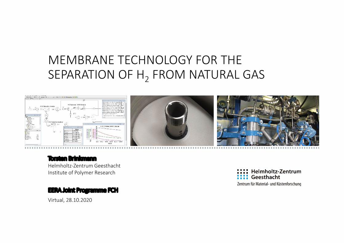
MEMBRANE TECHNOLOGY FOR THE SEPARATION OF H2 FROM NATURAL GAS
Torsten BrinkmannHelmholtz-Zentrum GeesthachtInstitute of Polymer Research
EERA Joint Programme FCHVirtual, 28.10.2020
2
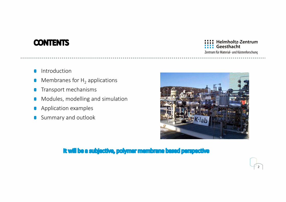
CONTENTS
Introduction
Membranes for H2 applications
Transport mechanismsModules, modelling and simulation
Application examples
Summary and outlook
It will be a subjective, polymer membrane based perspective
3
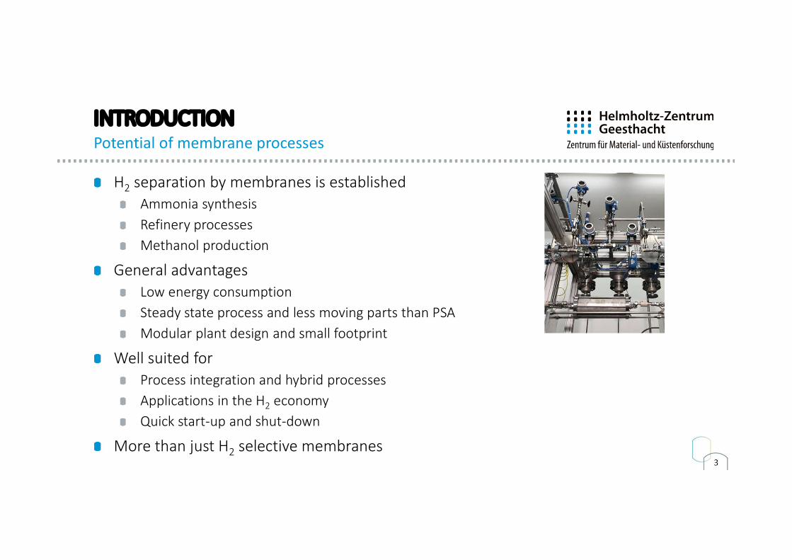
H2 separation by membranes is establishedAmmonia synthesisRefinery processesMethanol production
General advantagesLow energy consumptionSteady state process and less moving parts than PSAModular plant design and small footprint
Well suited for Process integration and hybrid processesApplications in the H2 economyQuick start-up and shut-down
More than just H2 selective membranes
INTRODUCTIONPotential of membrane processes
4
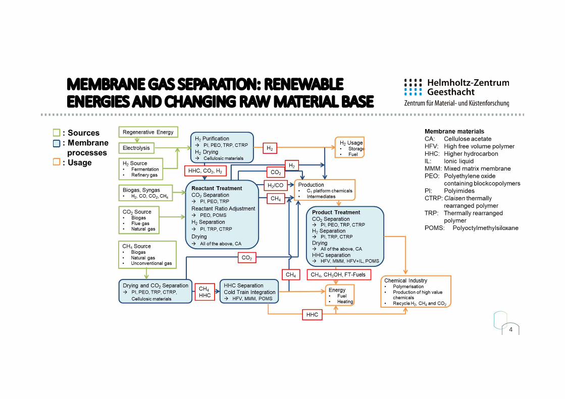
MEMBRANE GAS SEPARATION: RENEWABLE ENERGIES AND CHANGING RAW MATERIAL BASE
5
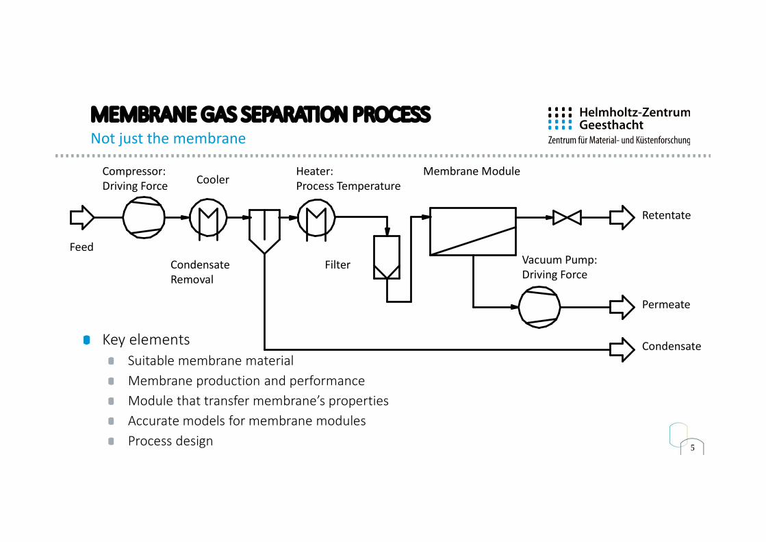
MEMBRANE GAS SEPARATION PROCESSNot just the membrane
Key elementsSuitable membrane materialMembrane production and performanceModule that transfer membrane’s propertiesAccurate models for membrane modulesProcess design
Compressor:Driving Force Cooler
CondensateRemoval
Heater:Process Temperature
Filter
Membrane Module
Vacuum Pump:Driving Force
Feed
Retentate
Permeate
Condensate
6
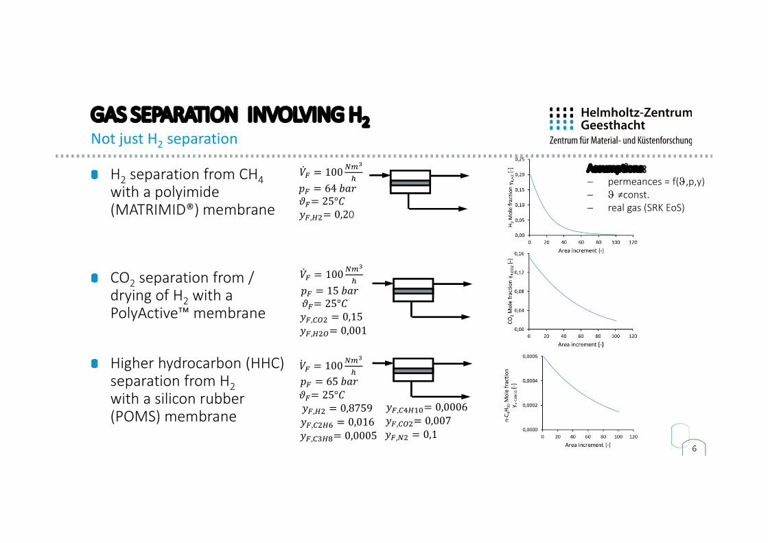
GAS SEPARATION INVOLVING H2Not just H2 separation
H2 separation from CH4with a polyimide (MATRIMID®) membrane
CO2 separation from /drying of H2 with a PolyActive™ membrane
Higher hydrocarbon (HHC) separation from H2with a silicon rubber (POMS) membrane
�̇� = 100
𝑝 = 64 𝑏𝑎𝑟 𝜗 = 25°𝐶 𝑦 , = 0,20
�̇� = 100
𝑝 = 15 𝑏𝑎𝑟 𝜗 = 25°𝐶
𝑦 , = 0,15
𝑦 , = 0,001
�̇� = 100
𝜗 = 25°𝐶𝑦 , = 0,8759
𝑦 , = 0,016
𝑦 , = 0,0005
𝑦 , = 0,0006
𝑦 , = 0,007
𝑦 , = 0,1
Assumptions: permeances = f(J,p,y) J ≠const. real gas (SRK EoS)
𝑝 = 65 𝑏𝑎𝑟
7
CONTENTS
Introduction
Membranes for H2 Applications
Transport mechanismsModules, modelling and simulation
Application examples
Summary and outlook
8
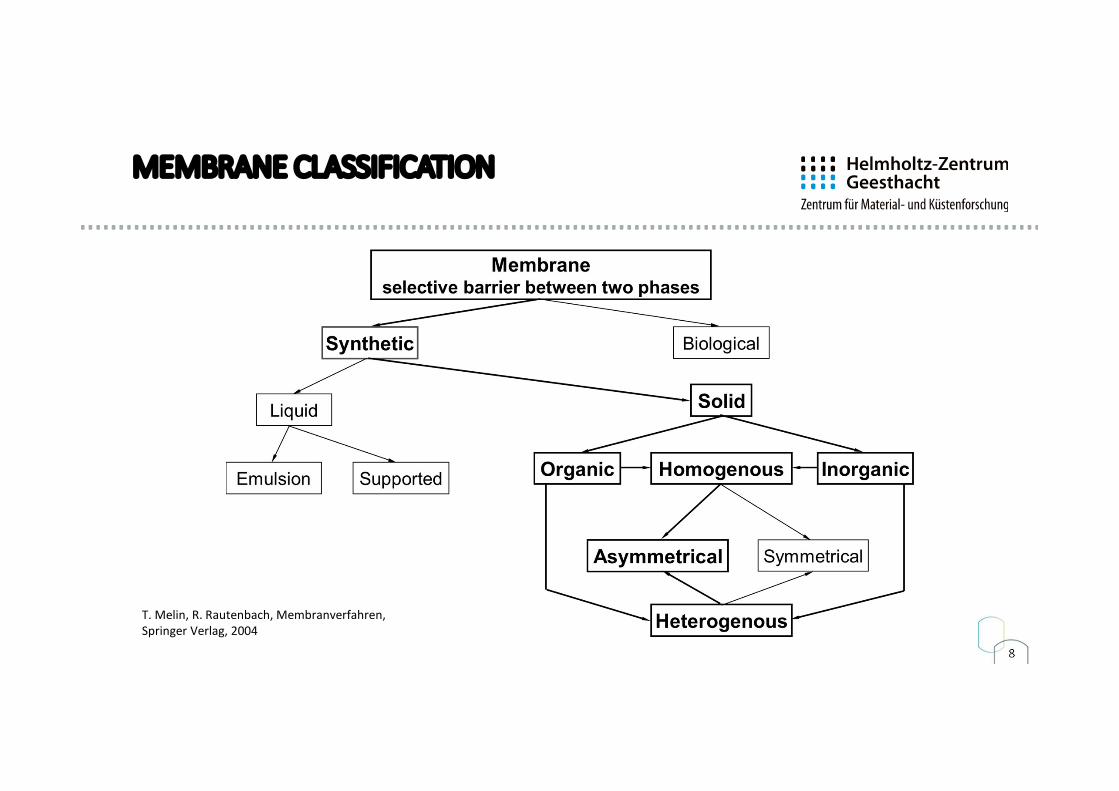
MEMBRANE CLASSIFICATION
T. Melin, R. Rautenbach, Membranverfahren, Springer Verlag, 2004
9
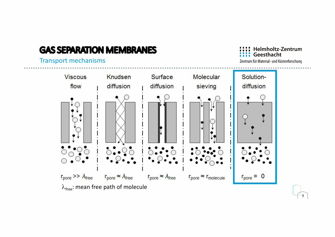
GAS SEPARATION MEMBRANES Transport mechanisms
lfree: mean free path of molecule

10
POLYMERIC MEMBRANE TYPES
Asymmetric membrane Thin film composite membrane
Non-woven Non-wovenPorous support Separation layer Porous support Separation layer
11
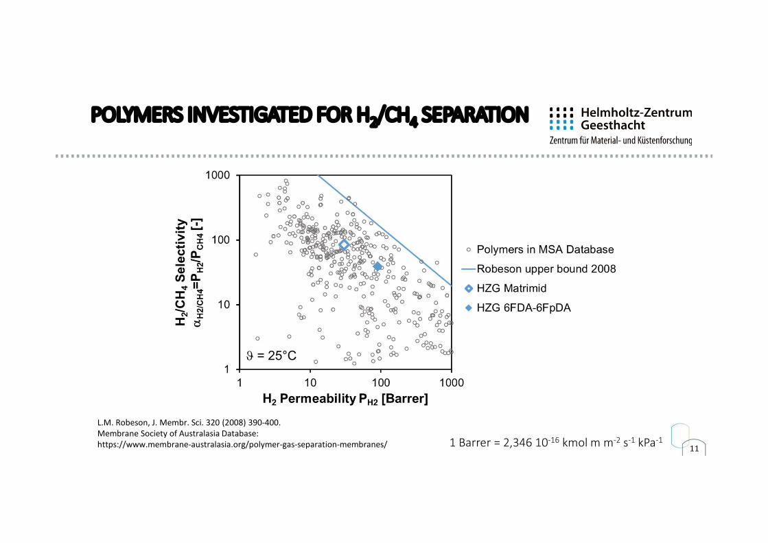
POLYMERS INVESTIGATED FOR H2/CH4 SEPARATION
L.M. Robeson, J. Membr. Sci. 320 (2008) 390-400.Membrane Society of Australasia Database: https://www.membrane-australasia.org/polymer-gas-separation-membranes/ 1 Barrer = 2,346 10-16 kmol m m-2 s-1 kPa-1
J = 25°C
12
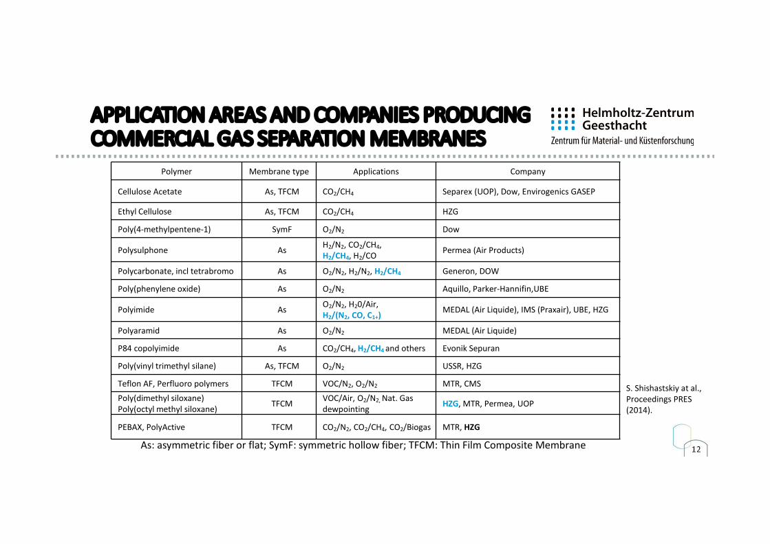
APPLICATION AREAS AND COMPANIES PRODUCING COMMERCIAL GAS SEPARATION MEMBRANES
Polymer Membrane type Applications Company
Cellulose Acetate As, TFCM CO2/CH4 Separex (UOP), Dow, Envirogenics GASEP
Ethyl Cellulose As, TFCM CO2/CH4 HZG
Poly(4-methylpentene-1) SymF O2/N2 Dow
Polysulphone As H2/N2, CO2/CH4, H2/CH4, H2/CO Permea (Air Products)
Polycarbonate, incl tetrabromo As O2/N2, H2/N2, H2/CH4 Generon, DOW
Poly(phenylene oxide) As O2/N2 Aquillo, Parker-Hannifin,UBE
Polyimide As O2/N2, H20/Air, H2/(N2, CO, C1+) MEDAL (Air Liquide), IMS (Praxair), UBE, HZG
Polyaramid As O2/N2 MEDAL (Air Liquide)
P84 copolyimide As CO2/CH4, H2/CH4 and others Evonik Sepuran
Poly(vinyl trimethyl silane) As, TFCM O2/N2 USSR, HZG
Teflon AF, Perfluoro polymers TFCM VOC/N2, O2/N2 MTR, CMS
Poly(dimethyl siloxane) Poly(octyl methyl siloxane) TFCM VOC/Air, O2/N2, Nat. Gas
dewpointing HZG, MTR, Permea, UOP
PEBAX, PolyActive TFCM CO2/N2, CO2/CH4, CO2/Biogas MTR, HZG
As: asymmetric fiber or flat; SymF: symmetric hollow fiber; TFCM: Thin Film Composite Membrane
S. Shishastskiy at al., Proceedings PRES (2014).
13
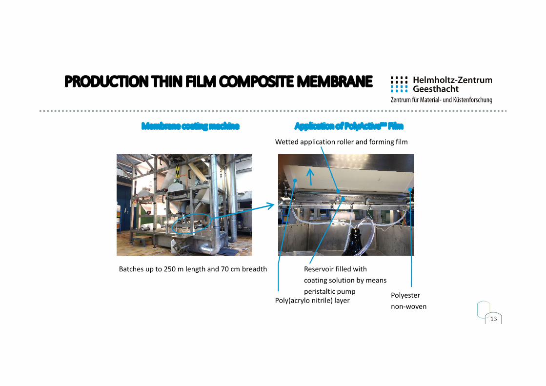
PRODUCTION THIN FILM COMPOSITE MEMBRANE
Membrane coating machine Application of PolyActive™ Film
Batches up to 250 m length and 70 cm breadth
Polyesternon-woven
Poly(acrylo nitrile) layer
Wetted application roller and forming film
Reservoir filled with coating solution by means peristaltic pump
14
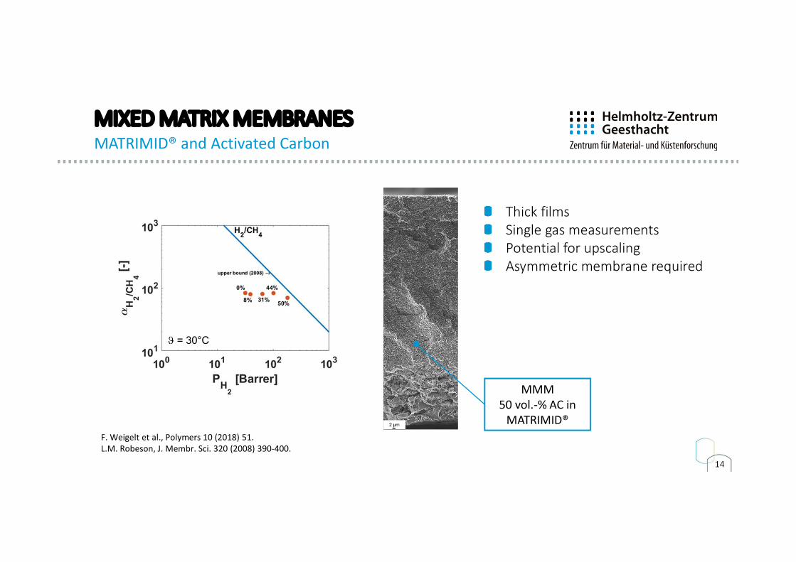
MIXED MATRIX MEMBRANESMATRIMID® and Activated Carbon
Thick filmsSingle gas measurementsPotential for upscalingAsymmetric membrane required
J = 30°C
MMM 50 vol.-% AC in
MATRIMID®F. Weigelt et al., Polymers 10 (2018) 51.L.M. Robeson, J. Membr. Sci. 320 (2008) 390-400.
15
CONTENTS
Introduction
Membranes for H2 Applications
Transport mechanismsModules, modelling and simulation
Application examples
Summary and outlook
16
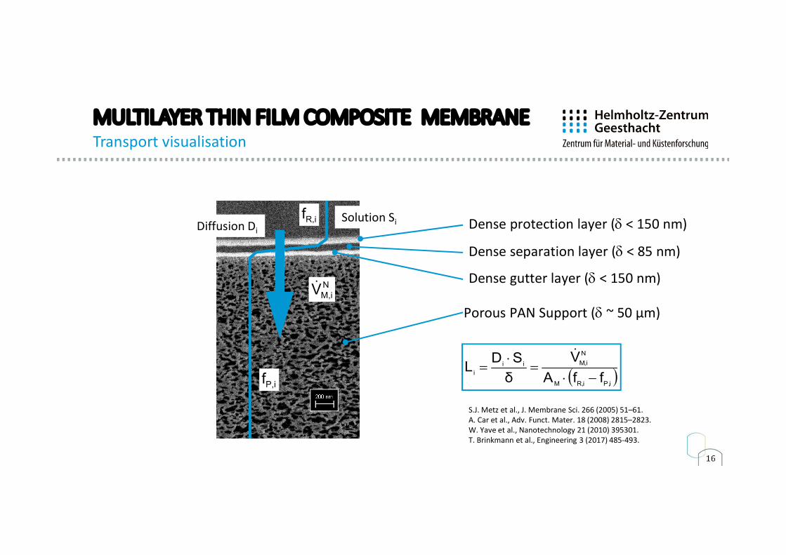
MULTILAYER THIN FILM COMPOSITE MEMBRANETransport visualisation
Lösung
DesorptionKonzentration
Porous PAN Support (d ~ 50 µm)
Dense separation layer (d < 85 nm)
Dense gutter layer (d < 150 nm)
iP,iR,M
N
iM,ii
i ffA
V
δ
SDL
S.J. Metz et al., J. Membrane Sci. 266 (2005) 51–61.A. Car et al., Adv. Funct. Mater. 18 (2008) 2815–2823.W. Yave et al., Nanotechnology 21 (2010) 395301.T. Brinkmann et al., Engineering 3 (2017) 485-493.
NiM,V
iR,f
iP,f
Solution SiDiffusion Di Dense protection layer (d < 150 nm)
17
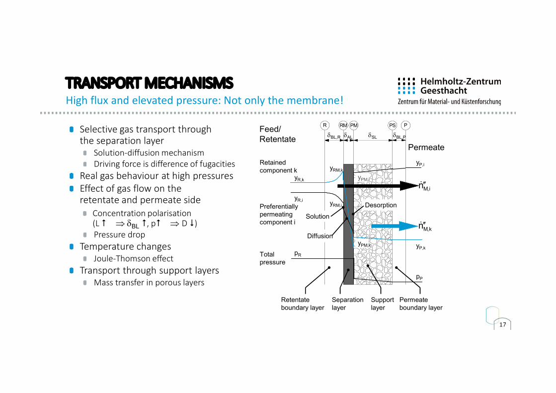
TRANSPORT MECHANISMSHigh flux and elevated pressure: Not only the membrane!
Selective gas transport through the separation layer
Solution-diffusion mechanismDriving force is difference of fugacities
Real gas behaviour at high pressuresEffect of gas flow on the retentate and permeate side
Concentration polarisation(L # dBL #, p# D $)Pressure drop
Temperature changesJoule-Thomson effect
Transport through support layersMass transfer in porous layers
PSR RM PM P
Preferentiallypermeatingcomponent i
Retainedcomponent k
Totalpressure
pR
yR,i
yR,k
pP
yP,i
yP,k
yRM,k
yRM,i
yPM,i
yPM,k
Solution
Desorption
Diffusion
Retentateboundary layer
Separationlayer
Supportlayer
Permeateboundary layer
dBL,R dBL,PdAL dSL
iM,n
kM,n
Feed/Retentate
Permeate
18
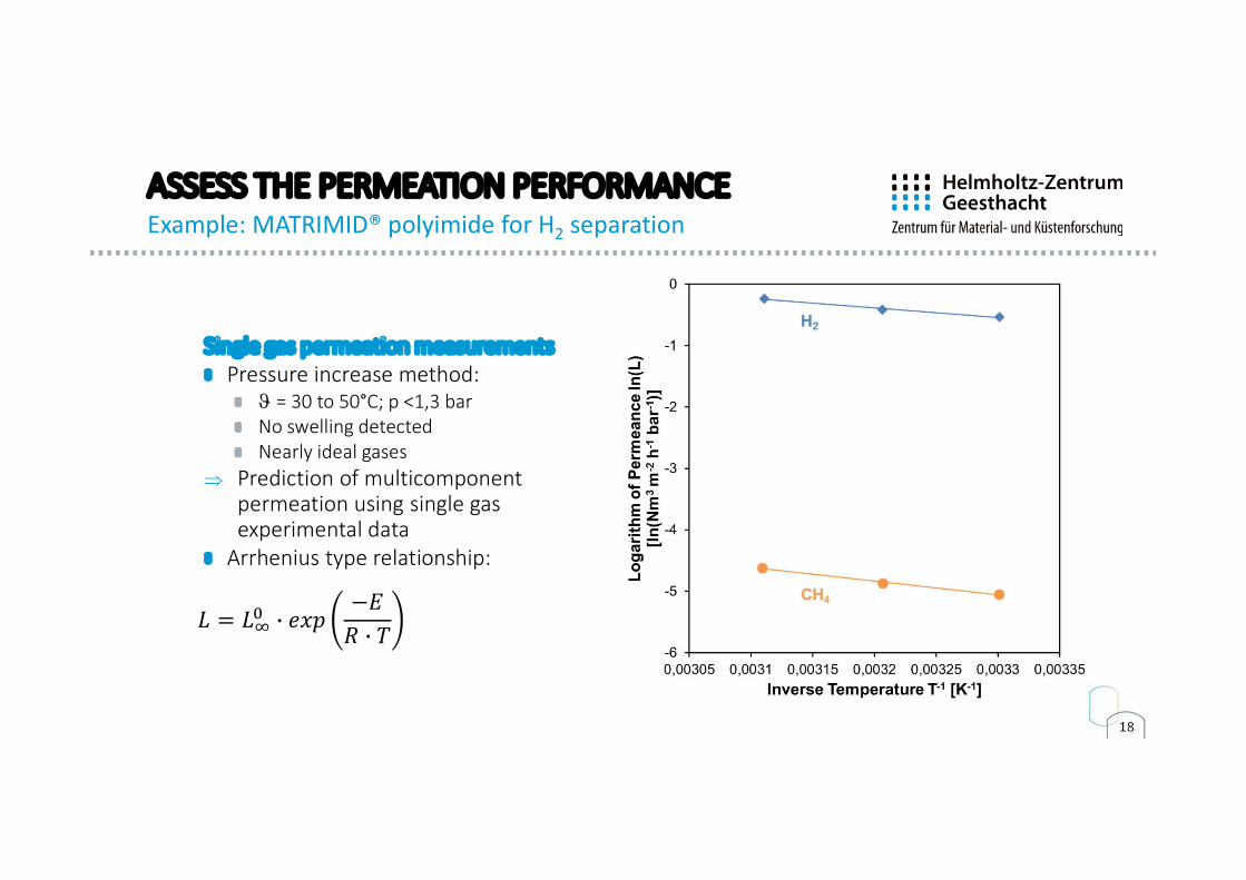
ASSESS THE PERMEATION PERFORMANCEExample: MATRIMID® polyimide for H2 separation
Single gas permeation measurementsPressure increase method:
J = 30 to 50°C; p <1,3 bar No swelling detectedNearly ideal gases
Prediction of multicomponent permeation using single gas experimental data
Arrhenius type relationship:
𝐿 = 𝐿 𝑒𝑥𝑝−𝐸
𝑅 𝑇
19
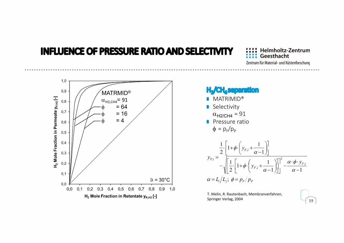
INFLUENCE OF PRESSURE RATIO AND SELECTIVITY
MATRMID®
aH2,CH4= 91f = 64f = 16f = 4
J = 30°C PFji
iFiF
iF
iP
ppLL
yy
y
y
fa
afa
af
af
;
11
11
2
1
1
11
2
1
,
2
,
,
,
T. Melin, R. Rautenbach, Membranverfahren, Springer Verlag, 2004
H2/CH4 separationMATRIMID®SelectivityaH2/CH4 = 91Pressure ratiof = pF/pP

20
CONTENTS
Introduction
Membranes for H2 Applications
Transport mechanismsModules, modelling and simulation
Application examples
Summary and outlook
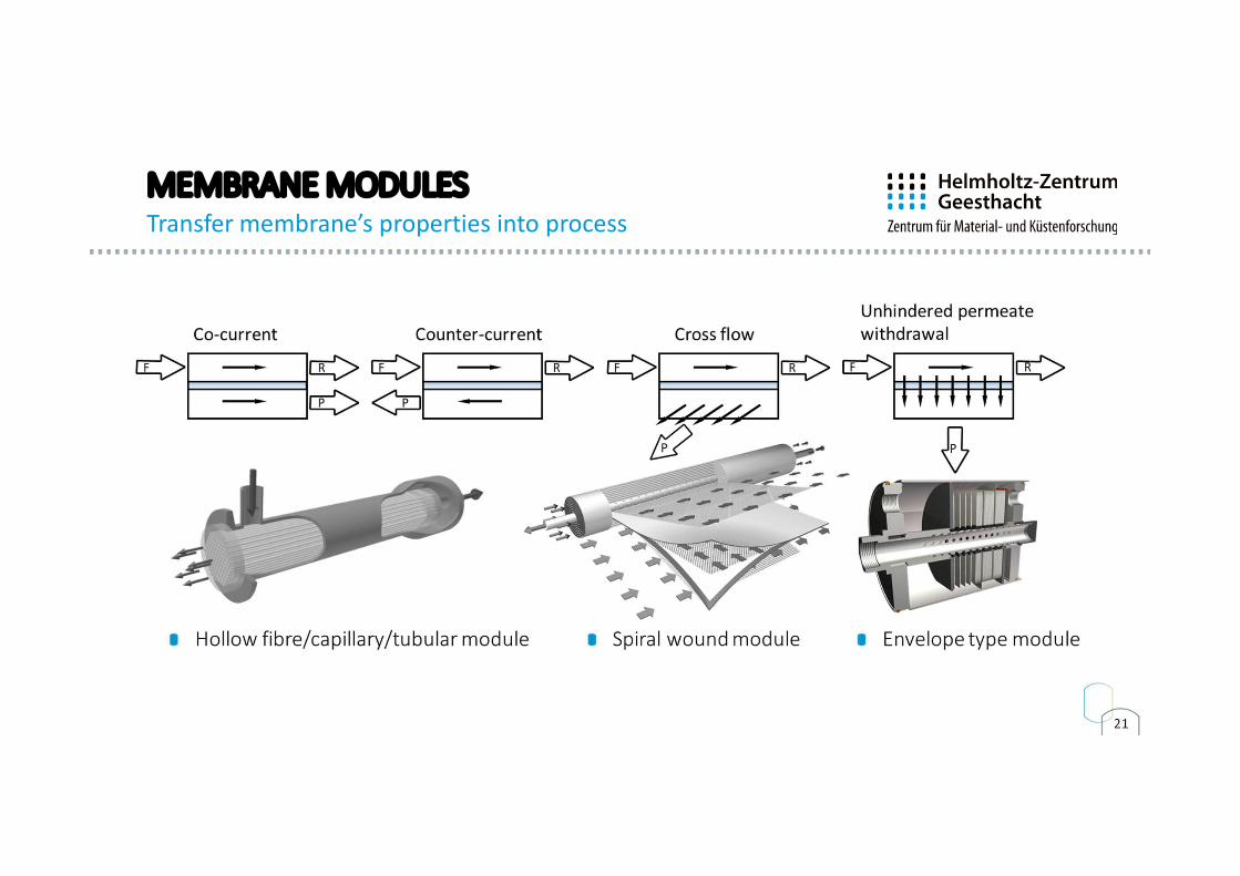
21
MEMBRANE MODULESTransfer membrane’s properties into process
22
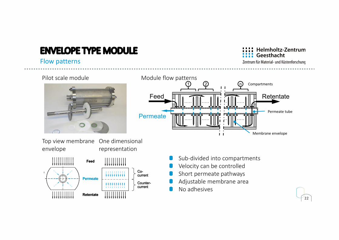
ENVELOPE TYPE MODULEFlow patterns
Feed Retentate
Permeate· · · · · · · · · · · · · · · · · · · ·
1 2 n
· · · · · · · · · · · · · · · · · · · ·
Membrane envelope
Permeate tube
Compartments
Top view membraneenvelope
One dimensionalrepresentation
Retentate
membrane envelope
Feed
Permeate
representation of envelope
Retentate
Co-current
Counter-current
Retentate
membrane envelope
Feed
Permeate
representation of envelope
Retentate
Co-current
Counter-current
Pilot scale module Module flow patterns
Sub-divided into compartmentsVelocity can be controlledShort permeate pathwaysAdjustable membrane areaNo adhesives
23
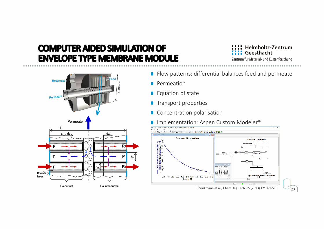
COMPUTER AIDED SIMULATION OF ENVELOPE TYPE MEMBRANE MODULE
Permeate
l
z dz
hR
hP
Boundary layer
dz
Co-current Counter-current
F
F
R
R
P P
Permeate
l
z dz
hR
hP
Boundary layer
dz
Co-current Counter-current
F
F
R
R
P P
Flow patterns: differential balances feed and permeate
Permeation
Equation of state
Transport properties
Concentration polarisation
Implementation: Aspen Custom Modeler®
T. Brinkmann et al., Chem. Ing.Tech. 85 (2013) 1210–1220.
24
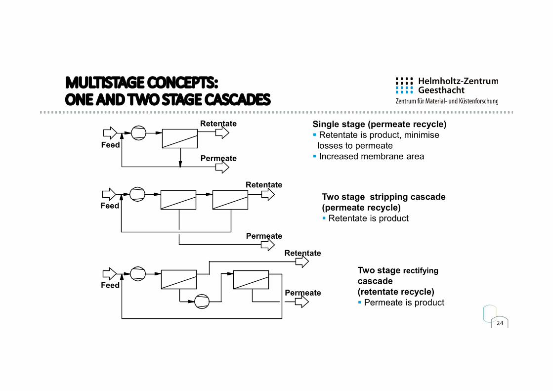
MULTISTAGE CONCEPTS: ONE AND TWO STAGE CASCADES
PermeateFeed
Retentate
Feed
Retentate
Permeate
Feed
Retentate
Permeate
Single stage (permeate recycle) Retentate is product, minimise losses to permeate
Increased membrane area
Two stage stripping cascade(permeate recycle) Retentate is product
Two stage rectifyingcascade(retentate recycle) Permeate is product

25
CONTENTS
Introduction
Permeation model and physical properties
Applications and membranesModules, modelling and simulation
Operational behaviour
Application examplesSummary and outlook
26
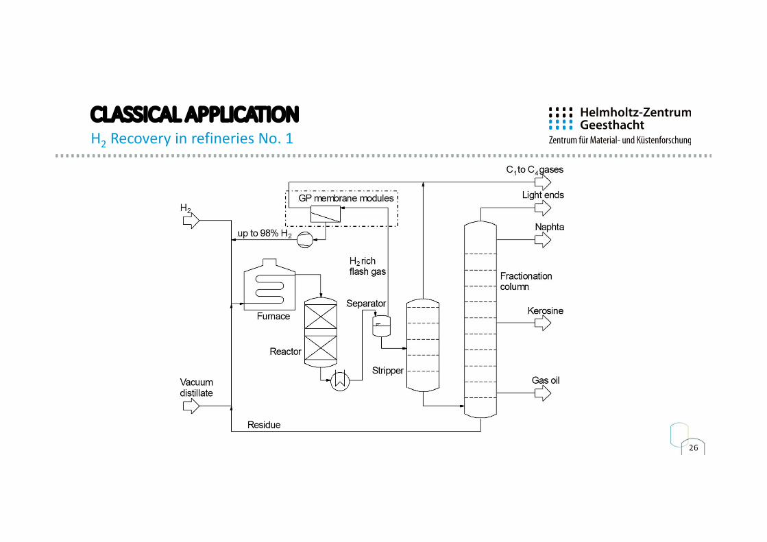
CLASSICAL APPLICATIONH2 Recovery in refineries No. 1
27
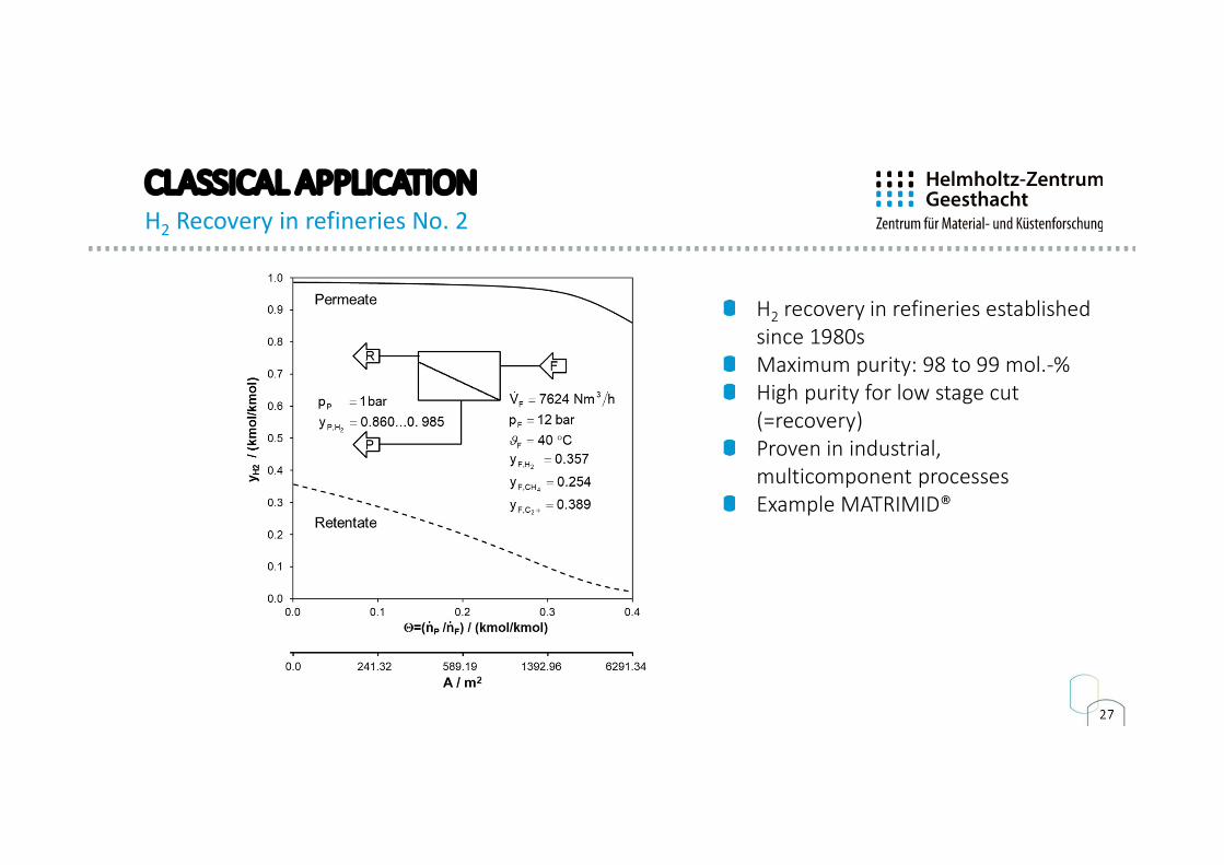
CLASSICAL APPLICATIONH2 Recovery in refineries No. 2
H2 recovery in refineries established since 1980sMaximum purity: 98 to 99 mol.-%High purity for low stage cut (=recovery)Proven in industrial, multicomponent processesExample MATRIMID®
28
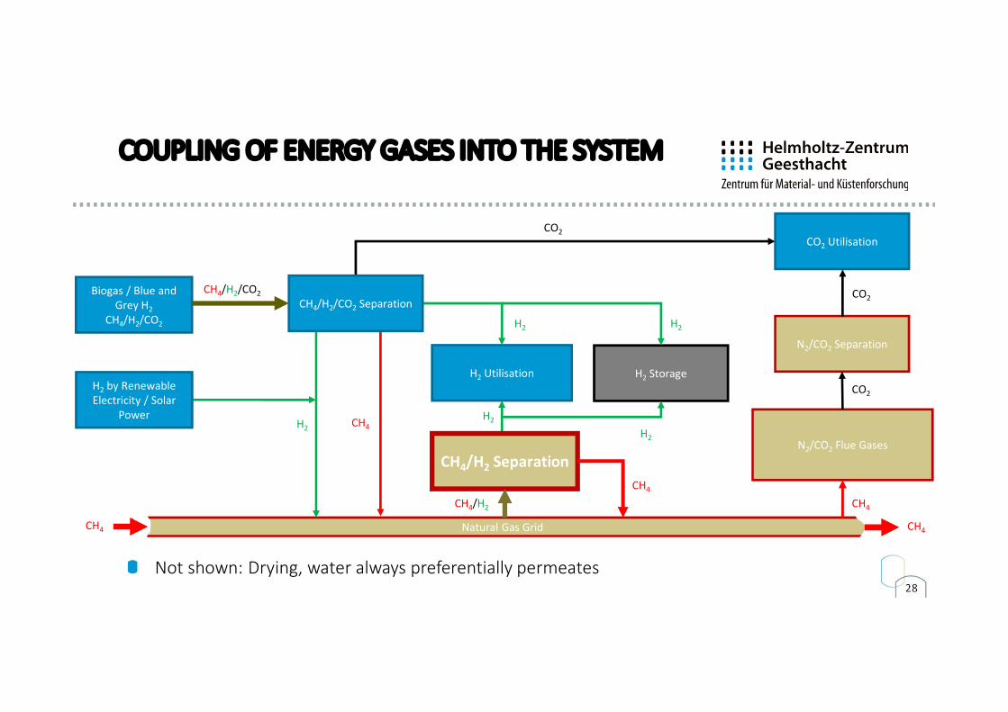
COUPLING OF ENERGY GASES INTO THE SYSTEM
Biogas / Blue and Grey H2
CH4/H2/CO2
N2/CO2 Flue Gases
H2 Utilisation
CO2 Utilisation
Natural Gas Grid
N2/CO2 Separation
CH4/H2 Separation
H2 Storage
CH4/H2/CO2
CO2
CO2
CO2
H2H2
H2
H2 H2
CH4/H2
CH4
CH4
CH4 CH4
CH4
CH4/H2/CO2 Separation
H2 by Renewable Electricity / Solar
Power
Not shown: Drying, water always preferentially permeates
29
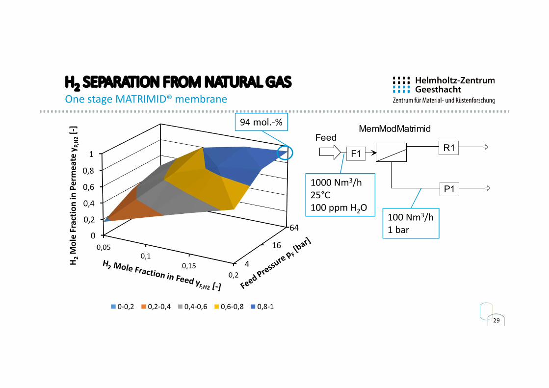
H2 SEPARATION FROM NATURAL GASOne stage MATRIMID® membrane
H2
Mol
e Fr
actio
nin
Per
mea
tey P
,H2
[-]
FeedMemModMatrimid
F1R1
P11000 Nm3/h25°C100 ppm H2O
100 Nm3/h1 bar
94 mol.-%
30
FeedMemModMatrimid
F1R1
P1
Stage2Compr
B6
P2
MemModMatrimid2
FS2
PS2
RS2
Mix
F2
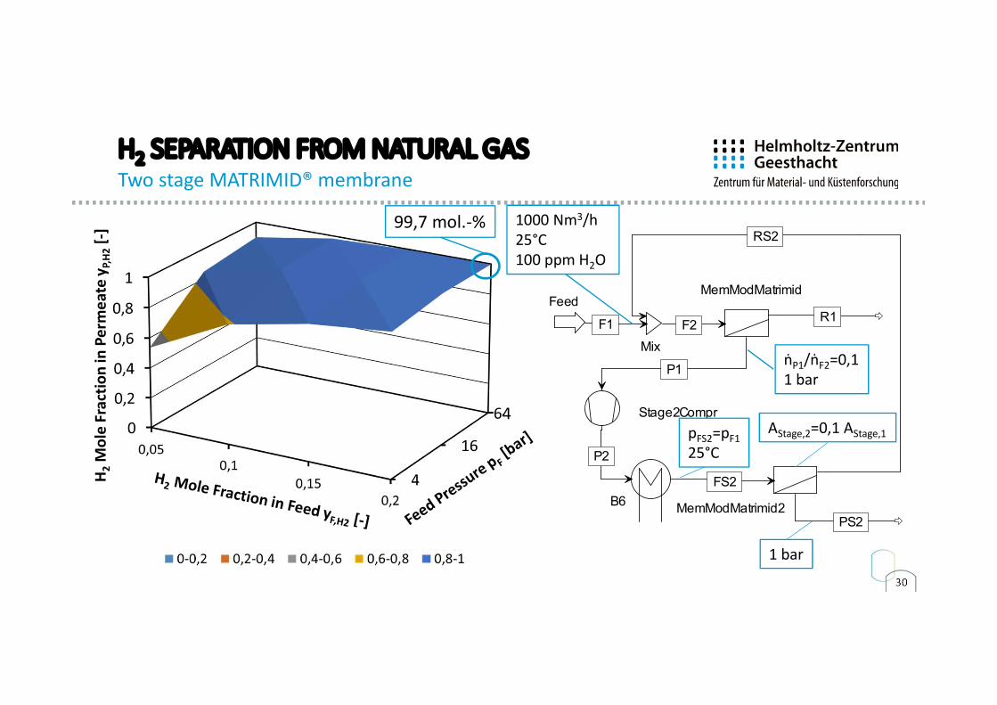
H2 SEPARATION FROM NATURAL GASTwo stage MATRIMID® membrane
H2
Mol
e Fr
actio
nin
Per
mea
tey P
,H2
[-] 1000 Nm3/h
25°C100 ppm H2O
ṅP1/ṅF2=0,11 bar
99,7 mol.-%
4pFS2=pF125°C
AStage,2=0,1 AStage,1
1 bar
31
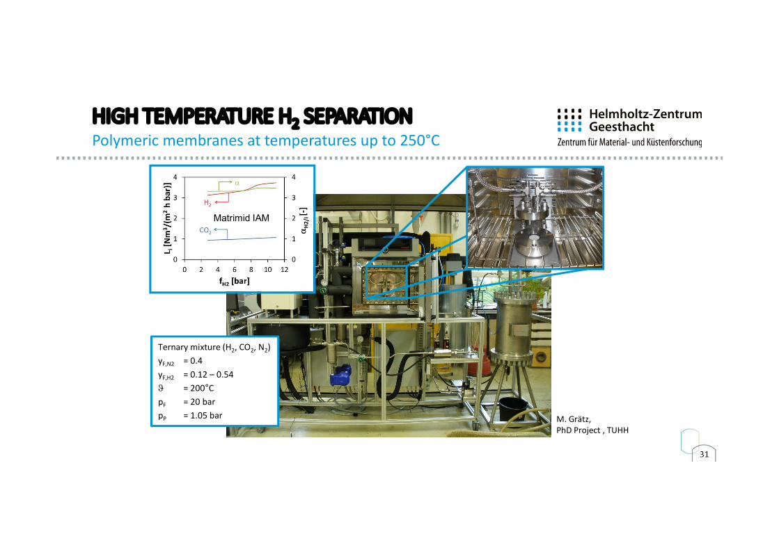
HIGH TEMPERATURE H2 SEPARATIONPolymeric membranes at temperatures up to 250°C
M. Grätz, PhD Project , TUHH
Ternary mixture (H2, CO2, N2)yF,N2 = 0.4yF,H2 = 0.12 – 0.54J = 200°CpF = 20 barpP = 1.05 bar
Matrimid IAM
32
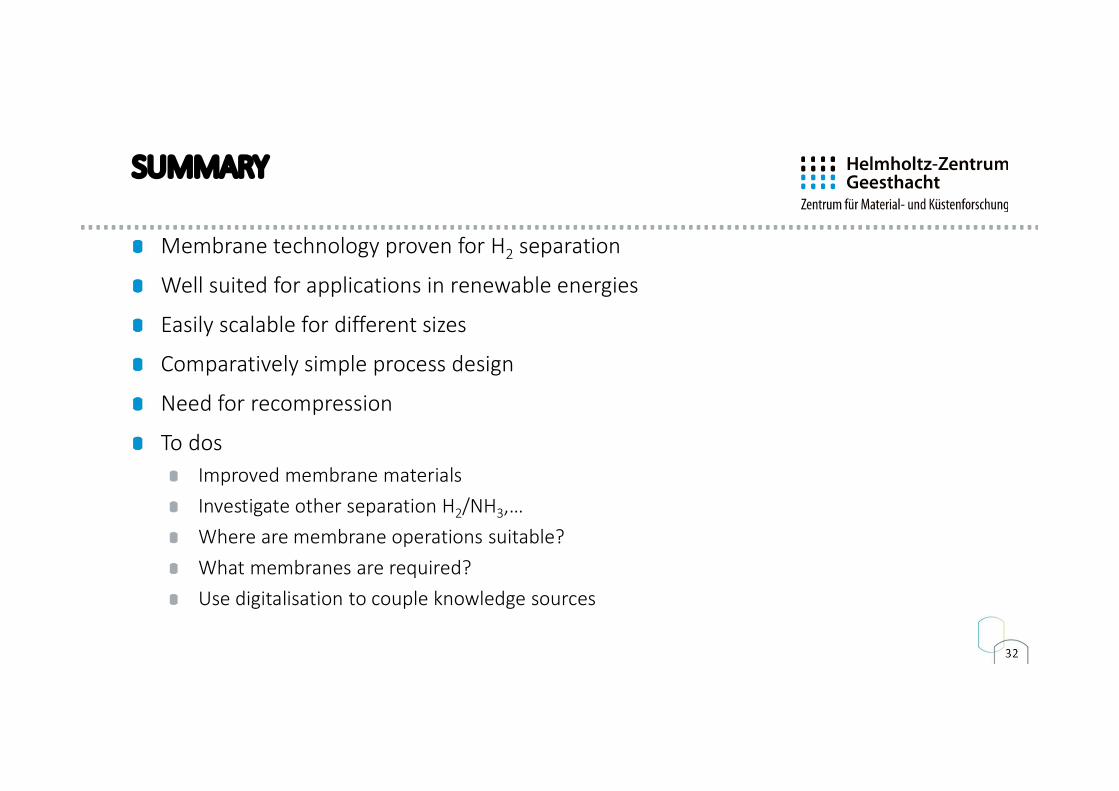
SUMMARY
Membrane technology proven for H2 separation
Well suited for applications in renewable energies
Easily scalable for different sizes
Comparatively simple process design
Need for recompression
To dosImproved membrane materialsInvestigate other separation H2/NH3,…Where are membrane operations suitable?What membranes are required?Use digitalisation to couple knowledge sources
VIELEN DANK!
FOR PEOPLE AND THEIRFUTURE ENVIRONMENT
Torsten BrinkmannInstitut für [email protected]: +49 (0)4152 87 2400
Max-Planck-Str. 121502 Geesthachthttps://polymerforschung.hzg.de
Acknokledgements:Clarisssa AbetzSergey ShishatskiyAlberto Tena
Maria GrätzProkopios GeorgopanosFynn WeigeltThorsten Wolff