MEFI-6-Service-Manual.pdf - Marine Power USA
365
TABLE OF CONTENTS Preface ............................................................. 0-0 Dangers, Warnings, and Cautions ................... 0-3 General Information ....................................... 1-3 General Information ......................................... 1-3 Diagnostic Overview, Starting Point, and Programming .......................... 6-3 Programming and Setup ................................. 6-3 Vehicle Diagnostic Information ......................... 6-4 Engine .............................................................. 9-3 Engine Controls and Fuel - Marine ................. 9-3 Power and Signal Distribution ................... 11-3 Data Communications ................................... 11-3 Wiring Systems ............................................. 11-6 2011 - Marine Engines Manual
-
Upload
khangminh22 -
Category
Documents
-
view
0 -
download
0
Transcript of MEFI-6-Service-Manual.pdf - Marine Power USA

TABLE OF CONTENTSPreface ............................................................. 0-0
Dangers, Warnings, and Cautions ................... 0-3
General Information ....................................... 1-3General Information ......................................... 1-3
Diagnostic Overview, Starting Point,and Programming .......................... 6-3
Programming and Setup ................................. 6-3Vehicle Diagnostic Information ......................... 6-4
Engine .............................................................. 9-3Engine Controls and Fuel - Marine ................. 9-3
Power and Signal Distribution ................... 11-3Data Communications ................................... 11-3Wiring Systems ............................................. 11-6
2011 - Marine Engines Manual

2011 - Marine Engines Manual

DANGERDanger: In order to reduce the chance of death, personal injury and/or propertydamage, carefully observe the instructions that follow:The service manuals of MARINE POWER are intended for use by professional,qualifie technicians. Attempting repairs or service without the appropriatetraining, tools, and equipment could cause death or injury to you or others. Thiscould also damage the vehicle, or cause the vehicle to operate improperly.Proper vehicle service and repair are important to the safety of the servicetechnician and to the safe, reliable operation of all motor vehicles. If you need toreplace a part, use the same part number or an equivalent part. Do not use areplacement part of lesser quality.The service procedures we recommend and describe in this service manual areeffective methods of performing service and repair. Some of the procedures requirethe use of tools that are designed for specifi purposes.Accordingly, any person who intends to use a replacement part, a serviceprocedure, or a tool that is not recommended by MARINE POWER, must firsestablish that there is no jeopardy to personal safety or the safe operation of thevehicle.This manual contains various “Dangers”, “Warnings” and “Cautions” that youmust observe carefully in order to reduce the risk of personal injury during serviceor repair. Improper service or repair may damage the vehicle or render the vehicleunsafe. These “Dangers”, “Warnings” and “Cautions” are not exhaustive. GeneralMotors can not possibly warn of all the potentially hazardous consequences ofyour failure to follow these instructions.This manual covers service procedures to vehicles that are equipped with aSupplemental Inflatabl Restraint. Refer to the “Warnings” in Dangers, Warningsand Cautions in Supplemental Inflatabl Restraint. Refer to Supplemental InflatablRestraint component and wiring location views in Supplemental Inflatabl Restraintbefore performing a service on or around Supplemental Inflatabl Restraintcomponents or wiring. Failure to follow these “Dangers”, “Warnings” and“Cautions” could cause air bag deployment, personal injury, or otherwiseunnecessary Supplemental Inflatabl Restraint repairs.In order to help avoid accidental air bag deployment and personal injury, wheneveryou service a vehicle that requires repair of the Supplemental Inflatabl Restraintand another vehicle system, we recommend that you firs repair the SupplementalInflatabl Restraint, then go on to the other system.
2011 - Marine Engines Manual

2011 Marine ElectronicFuel Injection (EFI)
Service Manual
This manual provides information on the diagnosis, the service procedures, the adjustments,and the specifications for the marine engines.
Because the marine engines cover a broad range of uses, some of the instructions, figures, orreferences contained within this manual may not pertain to every customer or engine application.This information is furnished to ensure completeness and is to be followed only whereappropriate.
The technicians who understand the material in this manual better serve the vehicle owners.
When this manual refers to a brand name, a part number, or a specific tool, you may use anequivalent product in place of the recommended item. All information, illustrations, andspecifications in this manual are based on the latest product information available at the time ofpublication approval. MARINE POWER reserves the right to make changes at any time withoutnotice.
©2011 GENERAL MOTORS LLCALL RIGHTS RESERVEDThe information cutoff date is 01/03/11.
No part of this manual may be reprodu


Section 0Dangers, Warnings, and Cautions
Dangers, Warnings, and Cautions ................0-3Definition of Danger, Warning, Caution,
and Note ....................................................0-3Actions to Take When Working with
Fuel Warning ..............................................0-3Batteries Produce Explosive Gases
Warning .....................................................0-3Battery Disconnect Warning ...........................0-4Camshaft Position Actuator Removal
and Installation Warning .............................0-4Exhaust Service Warning ...............................0-4Fuel Pipe Fitting Warning ..............................0-4Fuel Storage Warning ....................................0-4Fuel System Pressure Warning ......................0-4Gasoline/Gasoline Vapors Warning ................0-4On-Vehicle Fire Extinguisher Warning ............0-4Relieving Fuel Pressure Warning ...................0-4Shop Towel Fuel Leak Warning .....................0-4Clean Spark Plug Recess Caution .................0-5Component Fastener Tightening
Caution ......................................................0-5
Cover and Plug Openings Caution .................0-5Electrical Wiring Routing Caution ...................0-5Excessive Force and Oxygen Sensor
Caution ......................................................0-5Fastener Caution ...........................................0-5Fuel Injector Balance Test Caution ................0-5Fuel Pressure Caution ...................................0-5Fuel Rail Caution ...........................................0-5Handling Electrostatic Discharge
Sensitive Parts Caution ..............................0-5Heated Oxygen and Oxygen Sensor
Caution ......................................................0-6Ignition OFF When Disconnecting
Battery Caution ..........................................0-6J 35616-A Connector Test Adapter Kit
Caution ......................................................0-6Test Lamp to Test Continuity Caution ............0-6Test Probe Caution ........................................0-6Three-Way Catalytic Converter Damage
Caution ......................................................0-6
Table of Contents 0-1
2011 - Marine Engines Manual

BLANK
0-2 Table of Contents
2011 - Marine Engines Manual

Dangers, Warnings, and CautionsDefinitio of Danger, Warning,Caution, and NoteThe diagnosis and repair procedures in a GM ServiceManual contain both general and specific Dangers,Warnings, Cautions, Notes or Importants. GM isdedicated to the presentation of service information thathelps the technician to diagnose and repair the systemsnecessary for the proper operation of the vehicle,however, certain procedures may present a hazard tothe technician if they are not followed in therecommended manner. Dangers, Warnings, Cautionsand Notes or Importants are elements designed toprevent these hazards, however, not all hazards can beforeseen. This information is placed at strategiclocations within the service manual. This information isdesigned to prevent the following from occurring:
• Serious bodily injury or death to the technician• Damage to the vehicle• Unnecessary vehicle repairs• Unnecessary component replacement• Improper repair or replacement of vehicle
components.• Any warning or caution that appears in this service
category is referenced from the individual servicecategories.
DANGER DefineWhen encountering a DANGER, you will be asked totake a necessary action or not to take a prohibitedaction. If a DANGER is not heeded, the followingconsequences may occur:
• Serious bodily injury or death to the technician• Serious bodily injury or death to other technicians
in the workplace area
WARNING DefineWhen encountering a WARNING, you will be asked totake a necessary action or not to take a prohibitedaction. If a WARNING is not heeded, the followingconsequences may occur:
• Serious bodily injury to the technician• Serious bodily injury to other technicians in the
workplace area• Serious bodily injury to the driver and/or
passenger(s) of the vehicle, if the vehicle hasbeen improperly repaired
CAUTION DefineCAUTIONS call special attention to a necessary actionor to a prohibited action. If a CAUTION is notheeded, the following consequences may occur:
• Damage to the vehicle• Unnecessary vehicle repairs• Unnecessary component replacement• Improper operation or performance of the system
or component under repair
• Damage to any systems or components which aredependent upon the proper operation of thesystem or component under repair
• Improper operation or performance of anysystems or components which are dependentupon the proper operation or performance of thesystem or component under repair
• Damage to fasteners, basic tools, or special tools• The leakage of coolant, lubricant, or other vital
fluids
NOTE or IMPORTANT DefineNOTE and IMPORTANT statements emphasize anecessary characteristic of a diagnostic or repairprocedure. NOTE or IMPORTANT statements aredesigned to do the following:
• Clarify a procedure• Present additional information for accomplishing a
procedure• Give insight into the reason or reasons for
performing a procedure in the mannerrecommended
• Present information that will help to accomplish aprocedure in a more effective manner
• Present information that gives the technician thebenefit of past experience in accomplishing aprocedure with greater ease
Actions to Take When Working withFuel WarningWarning: Fuel Vapors can collect while servicingfuel system components in enclosed areas such asthe vessels cabin or engine compartment. Toreduce the risk of fire and increased exposure tovapors:
• Use forced air ventilation such as a fan setoutside of the vessels engine compartment.
• Plug or cap any fuel system openings in orderto reduce fuel vapor formation.
• Clean up any spilled fuel immediately.• Avoid sparks and any source of ignition.• Use signs to alert others in the work area that
fuel system work is in process.
Batteries Produce Explosive GasesWarningWarning: Batteries produce explosive gases.Batteries contain corrosive acid. Batteries supplylevels of electrical current high enough tocause burns. Therefore, in order to reduce the riskof personal injury while working near a battery,observe the following guidelines:
• Always shield your eyes.• Avoid leaning over the battery whenever
possible.
Dangers, Warnings, and Cautions 0-3
2011 - Marine Engines Manual

• Do not expose the battery to open flames orsparks.
• Do not allow battery acid to contact the eyes orthe skin.
− Flush any contacted areas with waterimmediately and thoroughly.
− Get medical help.
Battery Disconnect WarningWarning: Unless directed otherwise, the ignitionand start switch must be in the OFF or LOCKposition, and all electrical loads must be OFFbefore servicing any electrical component.Disconnect the negative battery cable to preventan electrical spark should a tool or equipmentcome in contact with an exposed electricalterminal. Failure to follow these precautions mayresult in personal injury and/or damage to the boator its components.
Camshaft Position ActuatorRemoval and Installation WarningWarning: Do not push or pull on the reluctor wheelof the camshaft position (CMP) actuator duringremoval or installation. The reluctor wheel isretained to the front of the CMP actuator by 3 rollpins. Pushing or pulling on the wheel maydislodge the wheel from the front of the actuator.The actuator return spring is under tensionand may rotate the dislodged reluctor wheel,causing personal injury.
Exhaust Service WarningWarning: In order to avoid being burned, do notservice the exhaust system while it is still hot.Service the system when it is cool.
Fuel Pipe Fitting WarningWarning: Always apply a few drops of cleanengine oil to the male pipe ends before connectingthe fuel pipe fittings in order to reduce the riskof fire and personal injury. This will ensure properreconnection and prevent a possible fuel leak.During normal operation, the O-rings located in thefemale connector will swell and may preventproper reconnection if not lubricated.
Fuel Storage WarningWarning: Do not drain the fuel into an opencontainer. Never store the fuel in an opencontainer due to the possibility of a fire or anexplosion.
Fuel System Pressure WarningWarning: Do not open the fuel system while theengine is running. Allow the fuel system pressureto drop before opening the system. The fuelsystem is under very high pressure. Failure tocomply could result in personal injury.
Gasoline/Gasoline Vapors WarningWarning: Gasoline or gasoline vapors arehighly flammable. A fire could occur if an ignitionsource is present. Never drain or store gasolineor diesel fuel in an open container, due to thepossibility of fire or explosion. Have a dry chemical
(Class B) fire extinguisher nearby.
Fire ExtinguisherWarningWarning: Place a dry chemical (Class B) fireextinguisher nearby before performing any engineservice procedures. Failure to followthese precautions may result in personal injury.
Relieving Fuel Pressure WarningWarning: Remove the fuel tank cap and relieve thefuel system pressure before servicing the fuelsystem in order to reduce the risk of personalinjury. After you relieve the fuel system pressure,a small amount of fuel may be released whenservicing the fuel lines, the fuel injection pump, orthe connections. In order to reduce the risk ofpersonal injury, cover the fuel system componentswith a shop towel before disconnection. Thiswill catch any fuel that may leak out. Place thetowel in an approved container when thedisconnection is complete.
Shop Towel Fuel Leak WarningWarning: Wrap a shop towel around the fuelpressure connection in order to reduce the risk offire and personal injury. The towel will absorbany fuel leakage that occurs during the connection
0-4 Dangers, Warnings, and Cautions
2011 - Marine Engines Manual

of the fuel pressure gauge. Place the towel in anapproved container when the connection ofthe fuel pressure gauge is complete.
Clean Spark Plug Recess CautionNotice: Clean the spark plug recess area beforeremoving the spark plug. Failure to do so could resultin engine damage because of dirt or foreign materialentering the cylinder head, or by the contamination ofthe cylinder head threads. The contaminatedthreads may prevent the proper seating of the newplug. Use a thread chaser to clean the threads of anycontamination.
Component Fastener TighteningCautionCaution: Replacement components must be thecorrect part number for the application. Componentsrequiring the use of the thread locking compound,lubricants, corrosion inhibitors, or sealants areidentified in the service procedure. Some replacementcomponents may come with these coatings alreadyapplied. Do not use these coatings on componentsunless specified. These coatings can affect thefinal torque, which may affect the operation of thecomponent. Use the correct torque specification wheninstalling components in order to avoid damage.
Cover and Plug Openings CautionCaution: Cap the fittings and plug the holes whenservicing the fuel system in order to prevent dirt andother contaminants from entering the open pipesand passages.
Electrical Wiring Routing CautionCaution: Note the correct routing of the electricalwiring. Failure to reinstall the wiring properly couldresult in damage to the wiring.
Excessive Force and OxygenSensor CautionCaution: The oxygen sensor may be difficult toremove when the engine temperature is below 48°C(120°F). Excessive force may damage threads inthe exhaust manifold or the exhaust pipe.
Fastener CautionCaution: Use the correct fastener in the correctlocation. Replacement fasteners must be the correctpart number for that application. Do not use paints,lubricants, or corrosion inhibitors on fasteners,or fastener joint surfaces, unless specified. Thesecoatings affect fastener torque and joint clamping forceand may damage the fastener. Use the correcttightening sequence and specifications when installingfasteners in order to avoid damage to parts andsystems. When using fasteners that are threaded
directly into plastic, use extreme care not to strip themating plastic part(s). Use hand tools only, and do notuse any kind of impact or power tools. Fastenershould be hand tightened, fully seated, and notstripped.
Fuel Injector Balance Test CautionCaution: Do Not repeat any portion of this test beforerunning the engine in order to prevent the enginefrom flooding.
Fuel Pressure CautionCaution: Do not allow the fuel pressure to exceed thespecified value because damage to the fuel pressureregulator or the fuel pressure gauge may result.
Fuel Rail CautionCaution:
• Use care when servicing the fuel systemcomponents, especially the fuel injector electricalconnectors, the fuel injector tips, and theinjector O-rings. Plug the inlet and the outlet portsof the fuel rail in order to prevent contamination.
• Do not use compressed air to clean the fuel railassembly as this may damage the fuel railcomponents.
• Do not immerse the fuel rail assembly in a solventbath in order to prevent damage to the fuel railassembly.
Handling Electrostatic DischargeSensitive Parts CautionCaution: Electrostatic discharge (ESD) can damagemany solid-state electrical components. ESDsusceptible components may or may not be labeledwith the ESD symbol. Handle all electrical componentscarefully. Use the following precautions in order toavoid ESD damage:
• Touch a metal ground point in order to removeyour body’s static charge before servicing anyelectronic component; especially after slidingacross the vehicle seat.
• Do not touch exposed terminals. Terminals mayconnect to circuits susceptible the ESD damage.
• Do not allow tools to contact exposedterminals when servicing connectors.
• Do not remove components from their protectivepackaging until required to do so.
• Avoid the following actions unless required by thediagnostic procedure:
− Jumpering or grounding of the componentsor connectors.
− Connecting test equipment probes tocomponents or connectors. Connectthe ground lead first when using test probes.
• Ground the protective packaging of anycomponent before opening. Do not rest solid-statecomponents on metal workbenches, or on topof TVs, radios, or other electrical devices.
Dangers, Warnings, and Cautions 0-5
2011 - Marine Engines Manual
Heated Oxygen and Oxygen SensorCautionCaution: Do not remove the pigtail from either theheated oxygen sensor (HO2S) or the oxygen sensor(O2S). Removing the pigtail or the connector will affectsensor operation.
Handle the oxygen sensor carefully. Do not drop theHO2S. Keep the in-line electrical connector andthe louvered end free of grease, dirt, or othercontaminants. Do not use cleaning solvents ofany type.
Do not repair the wiring, connector or terminals.Replace the oxygen sensor if the pigtail wiring,connector, or terminal is damaged.
This external clean air reference is obtained by way ofthe oxygen sensor signal and heater wires. Anyattempt to repair the wires, connectors, orterminals could result in the obstruction of the airreference and degraded sensor performance.
The following guidelines should be used whenservicing the heated oxygen sensor:
• Do not apply contact cleaner or other materials tothe sensor or vehicle harness connectors. Thesematerials may get into the sensor causingpoor performance.
• Do not damage the sensor pigtail and harnesswires in such a way that the wires inside areexposed. This could provide a path for foreignmaterials to enter the sensor and causeperformance problems.
• Ensure the sensor or vehicle lead wires are notbent sharply or kinked. Sharp bends or kinkscould block the reference air path throughthe lead wire.
• Do not remove or defeat the oxygen sensorground wire, where applicable. Vehicles that utilizethe ground wired sensor may rely on this groundas the only ground contact to the sensor.Removal of the ground wire will cause poorengine performance.
• Ensure that the peripheral seal remains intact onthe vehicle harness connector in order to preventdamage due to water intrusion. The engineharness may be repaired using Packard’s Crimpand Splice Seals Terminal Repair Kit. Underno circumstances should repairs be soldered sincethis could result in the air reference beingobstructed.
Ignition OFF When DisconnectingBattery CautionCaution: Always turn the ignition OFF whenconnecting or disconnecting battery cables, batterychargers, or jumper cables. Failing to do so maydamage the Powertrain Control Module (PCM) or otherelectronic components.
J 35616-A Connector Test AdapterKit CautionCaution: Use the connector test adapter kit J 35616-Afor any test that requires probing the following items:
• The ECM harness connectors• The electrical center fuse/relay cavities• The component terminals• The component harness connector
Using this kit will prevent damage caused by theimproper probing of connector terminals.
Test Lamp to Test ContinuityCautionCaution: Do not use a test lamp in order to test thecontinuity of the low reference circuit. Damage tothe Engine Control Module (ECM) will result.
Test Probe CautionCaution: Do not insert test equipment probes (DVOMetc.) into any connector or fuse block terminal. Thediameter of the test probes will deform most terminals.A deformed terminal will cause a poor connection,which will result in a system failure. Always usethe J-35616 GM-Approved Terminal Test Kit in orderto front probe terminals. Do not use paper clips orother substitutes to probe terminals.
When using the J-35616 GM-Approved Terminal TestKit, ensure the terminal test adapter choice is thecorrect size for the connector terminal. Do not visuallychoose the terminal test adapter because someconnector terminal cavities may appear larger than theactual terminal in the cavity. Using a largerterminal test adapter will damage the terminal. Referto the J-35616 GM-Approved Terminal Test Kitlabel on the inside of the J-35616 GM-ApprovedTerminal Test Kit for the correct adapter along with theconnector end view for terminal size.
Three-Way Catalytic ConverterDamage CautionCaution: In order to avoid damaging the replacementthree-way catalytic converter, correct the enginemisfire or mechanical fault before replacing thethree-way catalytic converter.
0-6 Dangers, Warnings, and Cautions
2011 - Marine Engines Manual

Section 1
General Information
General Information ........................................1-3Introduction .....................................................1-3
US English/Metric Conversion ........................1-3Decimal and Metric Equivalents .....................1-3Arrows and Symbols ......................................1-4Basic Knowledge and Tools Required ............1-5
Visual/Physical Checks ..................................1-5Electrostatic Discharge Damage .....................1-5Engine Wiring ................................................1-5Fasteners ......................................................1-6Thread Inserts ...............................................1-8Abbreviations and Meanings ..........................1-8
Table of Contents 1-1
2011 - Marine Engines Manual

BLANK
1-2 Table of Contents
2011 - Marine Engines Manual

General InformationIntroduction
US English/Metric Conversion
EnglishMultiply/ Divide
by MetricIn order to calculate English measurement, divide by thenumber in the center column.In order to calculate metric measurement, multiply by thenumber in the center column.
Lengthin 25.4 mm
ft 0.3048m
yd 0.9144
mi 1.609 km
Area
sq in645.2 sq mm
6.45 sq cm
sq ft 0.0929sq m
sq yd 0.8361
Volume
cu in
16,387.0 cu mm
16.387 cu cm
0.0164
Lqt 0.9464
gal 3.7854
cu yd 0.764 cu m
Masslb 0.4536
kg
ton907.18
0.907 tonne (t)
Forcekg F 9.807
newtons (N)oz F 0.2780
lb F 4.448
Accelerationft/s2 0.3048
m/s2
in/s2 0.0254
Torquelb in 0.11298
N·mlb ft 1.3558
Powerhp 0.745 kW
Pressure (Stress)inches of H2O 0.2488
kPalb/sq in 6.895
Energy (Work)Btu 1055.0
J (J= one Ws)lb ft 1.3558
kW hour 3,600,000.0
US English/Metric Conversion (cont’d)
EnglishMultiply/ Divide
by MetricLight
Foot Candle 10.764 lm/m2
Velocitymph 1.6093 km/h
Temperature(°F − 32) 5/9 = °C
°F = (9/5 °C + 32)
Fuel Performance235.215/mpg = 100 km/L
Decimal and Metric EquivalentsFraction (in) Decimal (in) Metric (mm)
1/64 0.015625 0.39688
1/32 0.03125 0.79375
3/64 0.046875 1.19062
1/16 0.0625 1.5875
5/64 0.078125 1.98437
3/32 0.09375 2.38125
7/64 0.109375 2.77812
1/8 0.125 3.175
9/64 0.140625 3.57187
5/32 0.15625 3.96875
11/64 0.171875 4.36562
3/16 0.1875 4.7625
13/64 0.203125 5.15937
7/32 0.21875 5.55625
15/64 0.234375 5.95312
1/4 0.25 6.35
17/64 0.265625 6.74687
9/32 0.28125 7.14375
19/64 0.296875 7.54062
5/16 0.3125 7.9375
21/64 0.328125 8.33437
11/32 0.34375 8.73125
23/64 0.359375 9.12812
3/8 0.375 9.525
25/64 0.390625 9.92187
13/32 0.40625 10.31875
27/64 0.421875 10.71562
7/16 0.4375 11.1125
29/64 0.453125 11.50937
15/32 0.46875 11.90625
31/64 0.484375 12.30312
General Information 1-3
2011 - Marine Engines Manual

Decimal and Metric Equivalents (cont’d)Fraction (in) Decimal (in) Metric (mm)
1/2 0.5 12.7
33/64 0.515625 13.09687
17/32 0.53125 13.49375
35/64 0.546875 13.89062
9/16 0.5625 14.2875
37/64 0.578125 14.68437
19/32 0.59375 15.08125
39/64 0.609375 15.47812
5/8 0.625 15.875
41/64 0.640625 16.27187
21/32 0.65625 16.66875
43/64 0.671875 17.06562
11/16 0.6875 17.4625
45/64 0.703125 17.85937
23/32 0.71875 18.25625
47/64 0.734375 18.65312
3/4 0.75 19.05
49/64 0.765625 19.44687
25/32 0.78125 19.84375
51/64 0.796875 20.24062
13/16 0.8125 20.6375
53/64 0.828125 21.03437
27/32 0.84375 21.43125
55/64 0.859375 21.82812
7/8 0.875 22.225
57/64 0.890625 22.62187
29/32 0.90625 23.01875
59/64 0.921875 23.41562
15/16 0.9375 23.8125
61/64 0.953125 24.20937
31/32 0.96875 24.60625
63/64 0.984375 25.00312
1 1.0 25.4
Arrows and SymbolsThis service manual uses various symbols in order todescribe different service operations.
Legend(1) Front of Vehicle(2) View Detail(3) Ambient Air Mixed with Another Gas or
Indicate Temperature Change(4) Motion or Direction(5) View Angle(6) Dimension (1:2)(7) Ambient/Clean Air Flow or Cool Air Flow(8) Lubrication Point – Oil or Fluid(9) Task Related
(10) Sectioning (1:3)(11) Gas Other Than Ambient Air or Hot Air Flow(12) Lubrication Point – Grease or Jelly(13) Multidirectional Arrow
196216
1-4 General Information
2011 - Marine Engines Manual

Basic Knowledge and ToolsRequiredTo use this manual most effectively, a generalunderstanding of basic electrical circuits and circuittesting tools is required. You should be familiarwith wiring diagrams, the meaning of voltage, ohms,amps and the basic theories of electricity. Youshould also understand what happens if a circuitbecomes open, shorted to ground or shorted tovoltage.To perform system diagnostics, several special toolsand equipment are required. Please becomeacquainted with the tools and their use beforeattempting to diagnose the system. Special tools thatare required for system service are illustrated inthis section.
Visual/Physical Checks
Visual/Physical InspectionA careful visual and physical inspection must beperformed as part of any diagnostic procedure. Thiscan often lead to repairing the condition without furtherdiagnosis. Inspect all vacuum hoses for correctrouting, pinches, cracks or disconnects. Inspect allwires in the engine compartment for properconnections, pinched wires or contact with sharpedges or hot manifolds. The visual/physical inspectionis very important. It must be done carefully andthoroughly.
Electrostatic Discharge DamageElectronic components used in control systems areoften designed to carry very low voltage, and are verysusceptible to damage caused by electrostaticdischarge. It is possible for less than 100 volts ofstatic electricity to cause damage to some electroniccomponents. By comparison, it takes as much as4,000 volts for a person to feel the zap of a staticdischarge.There are several ways a person can becomestatically charged. The most common methods ofcharging are by friction and by induction. An exampleof charging by friction is a person sliding across aseat, in which a charge of as much as 25,000 volts canbuild up. Charging by induction occurs when aperson with well insulated shoes stands near a highlycharged object and momentarily touches ground.Charges of the same polarity are drained off, leavingthe person highly charged with the opposite polarity.Static charges of either type can cause damage.Therefore, it is important to use care when handlingand testing electronic components.
Engine WiringWhen it is necessary to move any of the wiring,whether to lift wires away from their harnesses ormove harnesses to reach some component, take carethat all wiring is replaced in its original position andall harnesses are routed correctly. If clips or retainersbreak, replace them. Electrical problems can resultfrom wiring or harnesses becoming loose and movingfrom their original positions, or from being rerouted.
General Information 1-5
2011 - Marine Engines Manual
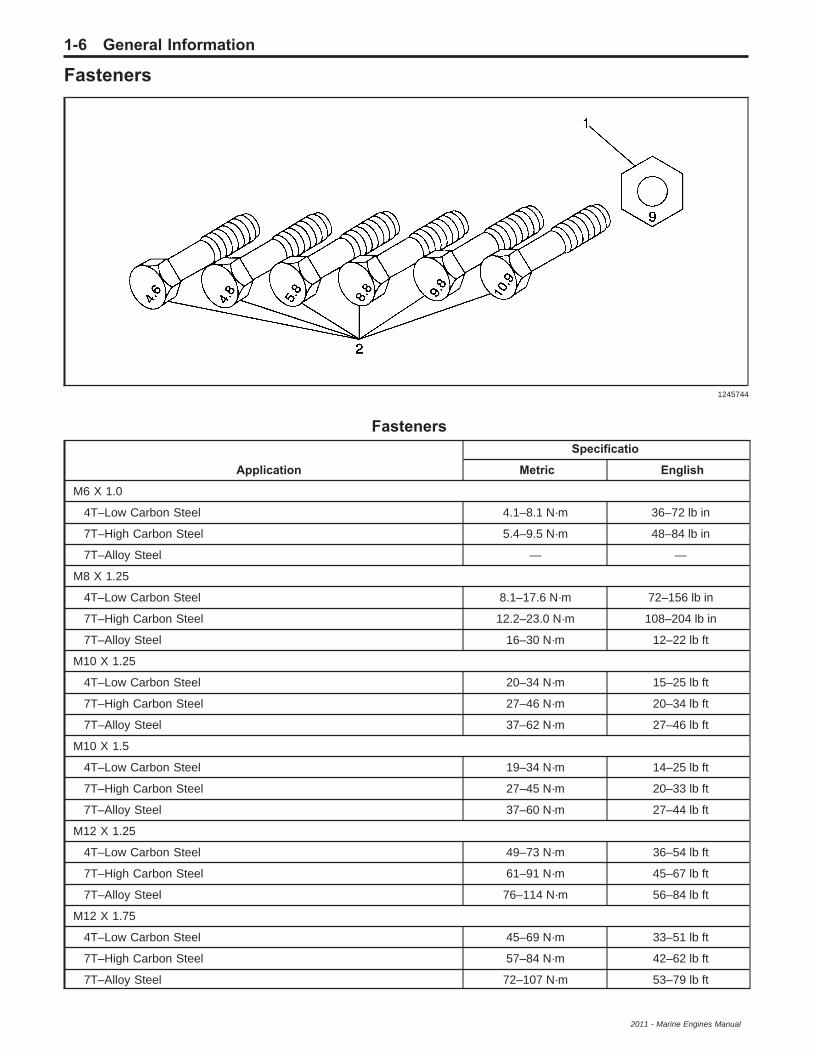
Fasteners
Fasteners
Application
Specificatio
Metric English
M6 X 1.0
4T–Low Carbon Steel 4.1–8.1 N·m 36–72 lb in
7T–High Carbon Steel 5.4–9.5 N·m 48–84 lb in
7T–Alloy Steel — —
M8 X 1.25
4T–Low Carbon Steel 8.1–17.6 N·m 72–156 lb in
7T–High Carbon Steel 12.2–23.0 N·m 108–204 lb in
7T–Alloy Steel 16–30 N·m 12–22 lb ft
M10 X 1.25
4T–Low Carbon Steel 20–34 N·m 15–25 lb ft
7T–High Carbon Steel 27–46 N·m 20–34 lb ft
7T–Alloy Steel 37–62 N·m 27–46 lb ft
M10 X 1.5
4T–Low Carbon Steel 19–34 N·m 14–25 lb ft
7T–High Carbon Steel 27–45 N·m 20–33 lb ft
7T–Alloy Steel 37–60 N·m 27–44 lb ft
M12 X 1.25
4T–Low Carbon Steel 49–73 N·m 36–54 lb ft
7T–High Carbon Steel 61–91 N·m 45–67 lb ft
7T–Alloy Steel 76–114 N·m 56–84 lb ft
M12 X 1.75
4T–Low Carbon Steel 45–69 N·m 33–51 lb ft
7T–High Carbon Steel 57–84 N·m 42–62 lb ft
7T–Alloy Steel 72–107 N·m 53–79 lb ft
1245744
1-6 General Information
2011 - Marine Engines Manual

Fasteners (cont’d)
ApplicationSpecificatio
Metric EnglishM14 X 1.5
4T–Low Carbon Steel 76–115 N·m 56–85 lb ft
7T–High Carbon Steel 94–140 N·m 69–103 lb ft
7T–Alloy Steel 114–171 N·m 84–126 lb ft
M14 X 2.0
4T–Low Carbon Steel 72–107 N·m 53–79 lb ft
7T–High Carbon Steel 88–132 N·m 65–97 lb ft
7T–Alloy Steel 107–160 N·m 79–118 lb ft
M16 X 1.5
4T–Low Carbon Steel 104–157 N·m 77–116 lb ft
7T–High Carbon Steel 136–203 N·m 100–150 lb ft
7T–Alloy Steel 160–240 N·m 118–177 lb ft
M16 X 2.0
4T–Low Carbon Steel 100–149 N·m 74–110 lb ft
7T–High Carbon Steel 129–194 N·m 95–143 lb ft
7T–Alloy Steel 153–229 N·m 113–169 lb ft
M18 X 1.5
4T–Low Carbon Steel 151–225 N·m 111–166 lb ft
7T–High Carbon Steel 195–293 N·m 144–216 lb ft
7T–Alloy Steel 229–346 N·m 169–255 lb ft
M20 X 1.5
4T–Low Carbon Steel 206–311 N·m 152–229 lb ft
7T–High Carbon Steel 270–405 N·m 199–299 lb ft
7T–Alloy Steel 317–476 N·m 234–351 lb ft
M22 X 1.5
4T–Low Carbon Steel 251–414 N·m 185–305 lb ft
7T–High Carbon Steel 363–544 N·m 268–401 lb ft
7T–Alloy Steel 424–636 N·m 313–469 lb ft
M24 X 2.0
4T–Low Carbon Steel 359–540 N·m 265–398 lb ft
7T–High Carbon Steel 431–710 N·m 318–524 lb ft
7T–Alloy Steel 555–831 N·m 409–613 lb ft
*Diameter X pitch in millimeters
General Information 1-7
2011 - Marine Engines Manual
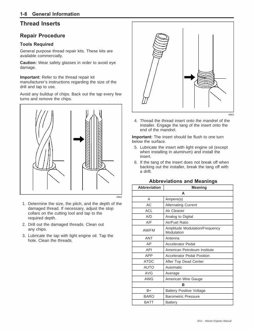
Thread Inserts
Repair ProcedureTools RequiredGeneral purpose thread repair kits. These kits areavailable commercially.
Caution: Wear safety glasses in order to avoid eyedamage.
Important: Refer to the thread repair kitmanufacturer’s instructions regarding the size of thedrill and tap to use.
Avoid any buildup of chips. Back out the tap every fewturns and remove the chips.
1. Determine the size, the pitch, and the depth of thedamaged thread. If necessary, adjust the stopcollars on the cutting tool and tap to therequired depth.
2. Drill out the damaged threads. Clean outany chips.
3. Lubricate the tap with light engine oil. Tap thehole. Clean the threads.
4. Thread the thread insert onto the mandrel of theinstaller. Engage the tang of the insert onto theend of the mandrel.
Important: The insert should be flush to one turnbelow the surface.5. Lubricate the insert with light engine oil (except
when installing in aluminum) and install theinsert.
6. If the tang of the insert does not break off whenbacking out the installer, break the tang off witha drift.
Abbreviations and MeaningsAbbreviation Meaning
AA Ampere(s)
AC Alternating Current
ACL Air Cleaner
A/D Analog to Digital
A/F Air/Fuel Ratio
AM/FM Amplitude Modulation/FrequencyModulation
ANT Antenna
AP Accelerator Pedal
API American Petroleum Institute
APP Accelerator Pedal Position
ATDC After Top Dead Center
AUTO Automatic
AVG Average
AWG American Wire Gauge
BB+ Battery Positive Voltage
BARO Barometric Pressure
BATT Battery
4962
4963
1-8 General Information
2011 - Marine Engines Manual

Abbreviations and Meanings (cont’d)Abbreviation Meaning
BHP Brake Horsepower
BLK Black
BLU Blue
BP Back Pressure
BRN Brown
BTDC Before Top Dead Center
BTU British Thermal Units
C°C Degrees Celsius
CAFE Corporate Average Fuel Economy
CAL Calibration
CAM Camshaft
CAN Controller Area Network
CARB California Air Resources Board
CCP CAN Communication Protocol
CEFI Commercial Electronic Fuel Injection
CM3 Cubic Centimeters
CFM Cubic Feet per Minute
CG Center of Gravity
CID Cubic Inch Displacement
CKP Crankshaft Position
CKT Circuit
C/LTR Cigar Lighter
CL Closed Loop
CLS Coolant Level Switch
CMP Camshaft Position
CO Carbon Monoxide
CO2 Carbon Dioxide
COAX Coaxial
COMM Communication
CONN Connector
CPA Connector Position Assurance
CPS Central Power Supply
CPU Central Processing Unit
CS Charging System
CSFI Central Sequential Fuel Injection
CTP Closed Throttle Position
CU FT Cubic Foot/Feet
CU IN Cubic Inch/Inches
CYL Cylinder(s)
DDB Decibels
DBA Decibels on A-weighted Scale
DC Direct Current, Duty Cycle
DE Drive End
DEC Digital Electronic Controller
DI Distributor Ignition
DIA Diameter
Abbreviations and Meanings (cont’d)Abbreviation Meaning
DEG Degrees
DI Distributor Ignition
DIC Driver Information Center
DIAG Diagnostic
DIST Distributor
DK Dark
DLC Data Link Connector
DMM Digital Multimeter
DOHC Dual Overhead Camshafts
DR, DRVR Driver
DTC Diagnostic Trouble Code
EEC Electrical Center, Engine Control
ECL Engine Coolant Level
ECM Engine Control Module, ElectronicControl Module
ECS Emission Control System
ECT Engine Coolant Temperature
EEPROM Electrically Erasable ProgrammableRead Only Memory
EI Electronic Ignition
E/M English/Metric
EMF Electromotive Force
EMI Electromagnetic Interference
Eng Engine
EOP Engine Oil Pressure
EOT Engine Oil Temperature
EPA Environmental Protection Agency
EPROM Erasable Programmable Read OnlyMemory
ESD Electrostatic Discharge
ESN Electronic Serial Number
EST Electronic Spark Timing
E-STOP Emergency Stop
ETCElectronic Throttle Control, ElectronicTemperature Control, Electronic TimingControl
Exh Exhaust
F°F Degrees Fahrenheit
FC Fan Control
FED Federal All United States exceptCalifornia
FEDS Fuel Enable Data Stream
FI Fuel Injection
FP Fuel Pump
ft Foot/Feet
FT Fuel Trim
FL Fuel Level
FMI Failure Mode Indicator
General Information 1-9
2011 - Marine Engines Manual

Abbreviations and Meanings (cont’d)Abbreviation Meaning
GG Grams, Gravitational Acceleration
GA Gauge
GAL Gallon
GAS Gasoline
GCW Gross Combination Weight
GEN Generator
GL Gear Lubricant
GM General Motors
GM SPO General Motors Service PartsOperations
GND Ground
GOV Governor
GPH Gallons Per Hour
GPM Gallons per Minute
GRN Green
GRY Gray
GVWR Gross Vehicle Weight Rating
HH Hydrogen
H2O Water
Harn Harness
HC Hydrocarbons
H/CMPR High Compression
hex Hexagon, Hexadecimal
Hg Mercury
HI ALT High Altitude
HO2S Heated Oxygen Sensor
HP Horsepower
HPS High Performance System
HPV High Pressure Vapor
HTD Heated
HTR Heater
HZ Hertz
IIAC Idle Air Control
IAT Intake Air Temperature
IC Integrated Circuit, Ignition Control
ICM Ignition Control Module
ID Identification, Inside Diameter
IGN Ignition
IN Inch/Inches
INJ Injection, Injector
I/O Input/Output
IP Instrument Panel
IPC Instrument Panel Cluster
I/PEC Instrument Panel Electrical Center
ISC Idle Speed Control
Abbreviations and Meanings (cont’d)Abbreviation Meaning
ISO International Standards Organization
ISS Input Speed Shaft, Input Shaft Speed
KKAM Keep Alive Memory
KG Kilogram
KHZ Kilohertz
KM Kilometer
KM/H Kilometers per Hour
KPA Kilopascals
KS Knock Sensor
KV Kilovolts
LL Liter
L4 Four Cylinder Engine, In-Line
LB Pound
LB/FT Pound Feet Torque
LB/IN Pound Inch Torque
LCD Liquid Crystal Display
LED Light Emitting Diode
LM Lumens
LR Left Rear
LT Left
LT Light
LT Long Term
MMAF Mass Air Flow
MAP Manifold Absolute Pressure
MAT Manifold Absolute Temperature
MAX Maximum
M/C Mixture Control
MDP Manifold Differential Pressure
MEFI Marine Electronic Fuel Injection
MFI Multiport Fuel Injection
MI Miles
MIL Malfunction Indicator Lamp
MIN Minimum
ML Milliliter
MM Millimeter
MPH Miles per Hour
MS Millisecond
MV Millivolt
NNC Normally Closed
NEG Negative
NEU Neutral
NI Neutral Idle
NLGI National Lubricating Grease Institute
N·m Newton-meter Torque
1-10 General Information
2011 - Marine Engines Manual

Abbreviations and Meanings (cont’d)Abbreviation Meaning
NO Normally Open
NOx Oxides of Nitrogen
NPTC National Pipe Thread Coarse
NPTF National Pipe Thread Fine
NVRAM Non-Volatile Random Access Memory
OO2 Oxygen
O2S Oxygen Sensor
OBD On-Board Diagnostics
OBDM On-Board Diagnostics Marine
OC Oxidation Converter Catalytic
OD Outside Diameter
ODM Output Drive Module
ODO Odometer
OE Original Equipment
OEM Original Equipment Manufacturer
OHC Overhead Camshaft
Ω Ohm
OL Open Loop, Out of Limits
OPT Optional
ORC Oxidation Reduction ConverterCatalytic
ORN Orange
OSS Output Shaft Speed
OZ Ounce(s)
PPC Personal Computer, Pressure Control
PCB Printed Circuit Board
PCM Powertrain Control Module
PCS Pressure Control Solenoid
PCV Positive Crankcase Ventilation
PFI Port Fuel Injection
PID Parameter Identification
P/N Part Number
PNK Pink
PNP Park/Neutral Position
POS Positive, Position
POT Potentiometer Variable Resistor
PPL Purple
PPM Parts per Million
PPS Pedal Position Sensor
PROM Programmable Read Only Memory
PRNDL Park, Reverse, Neutral, Drive, Low
P/S, PS Power Steering
PSP Power Steering Pressure
PSI Pounds per Square Inch
PSIA Pounds per Square Inch Absolute
PSIG Pounds per Square Inch Gauge
Abbreviations and Meanings (cont’d)Abbreviation Meaning
PT Pint
PTC Positive Temperature Coefficient
PWM Pulse Width Modulated
QQDM Quad Driver Module
QT Quart(s)
R
RAM
Random Access Memory,Non-permanent memory device,memory contents are lost when poweris removed.
REF Reference
RH Right Hand
RLY Relay
ROMRead Only Memory, Permanentmemory device, memory contents areretained when power is removed.
RPM Revolutions per Minute Engine Speed
RPO Regular Production Option
RR Right Rear
RT Right
SS Second(s)
SAE Society of Automotive Engineers
SC Supercharger
SCB Supercharger Bypass
SFI Sequential Multiport Fuel Injection
SLV Slave
SOL Solenoid
SO2 Sulfur Dioxide
SP Splice Pack
S/P Series/Parallel
SPN Suspect Parameter Number
SPO Service Parts Operations
SPS Service Programming System, SpeedSignal
SQ FT, FT2 Square Foot/Feet
SQ IN, IN2 Square Inch/Inches
SRI Service Reminder Indicator
ST Scan Tool
SW Switch
SYN Synchronizer
TTAC Throttle Actuator Control
TACH Tachometer
TBI Throttle Body Fuel Injection
TC Turbocharger, Transmission Control
TDC Top Dead Center
TEMP Temperature
TERM Terminal
General Information 1-11
2011 - Marine Engines Manual

Abbreviations and Meanings (cont’d)Abbreviation Meaning
TP Throttle Position
TPA Terminal Positive Assurance
TPS Throttle Position Sensor
TSC Throttle Shift Control
TT Tell Tail Warning Lamp
TV Throttle Valve
TWC Three Way Converter Catalytic
TWC+OC Three Way + Oxidation ConverterCatalytic
U
UART Universal Asynchronous ReceiverTransmitter
U-joint Universal Joint
UV Ultraviolet
VV Volt(s), Voltage
V6 Six-Cylinder Engine, V-Type
V8 Eight-Cylinder Engine, V-Type
Abbreviations and Meanings (cont’d)Abbreviation Meaning
VAC Vacuum
VIO Violet
VIN Vehicle Identification Number
VR Voltage Regulator
V REF Voltage Reference
VSS Vehicle Speed Sensor
WW/ With
WHT White
W/O Without
WOT Wide Open Throttle
W/P Water Pump
W/S Windshield
YYD Yard(s)
YEL Yellow
1-12 General Information
2011 - Marine Engines Manual

Section 6
Diagnostic Overview, Starting Point, andProgramming
Programming and Setup ................................6-3Repair Instructions ..........................................6-3
Engine Control Module Programmingand Setup ..................................................6-3
Vehicle Diagnostic Information .....................6-4Diagnostic Information and Procedures .........6-4
Strategy Based Diagnosis ..............................6-4Diagnostic Procedure Instructions ..................6-5Non-Scan Diagnosis of Driveability
Concerns - No DTCs Set ...........................6-7Engine Control Module (ECM)
Self-Diagnosis ............................................6-8
On-Board Diagnostic System Check ..............6-8Malfunction Indicator Lamp (MIL) ....................6-8Reading Suspect Parameter Numbers ...........6-8Clearing Suspect Parameter Numbers ...........6-8Suspect Parameter Number (SPN) Type
Definitions ..................................................6-9Failure Mode Indicator (FMI) Definitions .......6-10Diagnostic Trouble Code (DTC) List .............6-11Data Link Connector Scan Tools ..................6-22Scan Tool Use with Intermittents ..................6-22Diagnostic Repair Verification .......................6-22
Table of Contents 6-1
2011 - Marine Engines Manual

BLANK
6-2 Table of Contents
2011 - Marine Engines Manual

Programming and SetupRepair InstructionsEngine Control ModuleProgramming and SetupFor step-by-step programming instructions, pleaserefer to the manufacturers guidelines.Review the information below to ensure properprogramming protocol.
Important:• DO NOT program a control module unless you are
directed by a service procedure or you are directedby the manufacturers service bulletin. Programminga control module at any other time will notpermanently correct a customers concern.
• It is essential that the Scan Tool is equipped withthe latest software before performing serviceprogramming.
• Due to the time requirements of programming acontroller, it is recommended that an externalpower source be used to maintain systemvoltage. Stable battery voltage is critical duringprogramming. Any fluctuation, spiking, over voltageor loss of voltage will interrupt programming.
• SPNs may set during programming. Clear DTCsafter programming is complete.
Ensure the following conditions are met beforeprogramming a control module:
• Vehicle system voltage− There is not a charging system concern.
All charging system concerns must berepaired before programming a controlmodule.
− Battery voltage is greater than 12 volts butless than 16 volts. The battery must be fullycharged before programming the controlmodule.
− Turn OFF or disable any system that may puta load on the vehicles battery, such as thefollowing components:
− Engine electrical loads are turned OFF,radio, etc.
• The ignition switch must be in the proper position.Turn ON the ignition, with the engine OFF. DO NOTchange the position of the ignition switch during theprogramming procedure, unless instructed to do so.
• Make certain all tool connections are secure,including the following components and circuits:
− The connection at the data linkconnector (DLC)
− The voltage supply circuits• DO NOT disturb the tool harnesses while
programming. If an interruption occurs during theprogramming procedure, programming failure orcontrol module damage may occur.
• DO NOT turn OFF the ignition if the programmingprocedure is interrupted or unsuccessful. Ensurethat all control module and DLC connections aresecure and the operating software is up to date.Attempt to reprogram the control module.If the control module cannot be programmed,replace the control module.
Programming and Setup 6-3
2011 - Marine Engines Manual

Engine Diagnostic Information
Diagnostic Information and ProceduresStrategy Based DiagnosisThe goal of Strategy Based Diagnosis is to provideguidance when you create a plan of action foreach specific diagnostic situation. Following a similarplan for each diagnostic situation, you will achievemaximum efficiency when you diagnose and repairvehicles. Although each of the Strategy Based
Diagnosis boxes is numbered, you are not required tocomplete every box in order to successfully diagnosea customer concern. The first step of your diagnosticprocess should always be Understand and Verifythe Customers Concern. The final step of yourdiagnostic process should be Repair and verify theFix. Refer to the following chart for the correct StrategyBased Diagnosis.
1. Understand and Verify the Customers Concern:The first part of this step is to obtain as muchinformation as possible from the customer.Are there aftermarket accessories on the vehicle?When does the condition occur? Where doesthe condition occur? How long does the conditionlast? How often does the condition occur?
In order to verify the concern, the technicianshould be familiar with the normal operation of thesystem and refer to the owner or service manualfor any information needed.
2002024
6-4 Engine Diagnostic Information
2011 - Marine Engines Manual
2. Vehicle Operating as Designed: This conditionexists when the vehicle is found to operatenormally. The condition described by the customermay be normal. Explain your findings and theoperation of the system to the customer.
3. Preliminary Checks: Conduct a thorough visualinspection. Review the service history. Detectunusual sounds or odors. Gather diagnostictrouble code (DTC) information in order to achievean effective repair.
4. The Powertrain On Board Diagnostic (OBD)System Check on page 9-64 verifies the properoperation of the system. This will lead thetechnician in an organized approach to diagnostics.
5. Check Bulletins, or Recalls.6. Diagnostic categories:
6.1. Current DTC: Follow the designated DTCdiagnostic in order to make an effectiverepair. Refer to DTC List.
6.2. Symptom - No DTC: Select the appropriatesymptom diagnostic. Follow the diagnosticsteps or suggestions in order to completethe repair. Refer to Symptoms - EngineControls on page 9-199.
6.3. No Published Diagnostics: Analyze theConcern. Develop a plan for the diagnostics.The service manual schematics will helpyou to see system power, ground, input, andoutput circuits. You can also identifysplices and other areas where multiplecircuits are tied together. Look atcomponent locations to see if components,connectors or harnesses may be exposedto extreme temperature, moisture, orcorrosives (salt, battery acid, oil or otherfluids). Utilize the wiring diagrams, systemdescription.
6.4. Intermittent/History DTC: An intermittentcondition is one that does not occurcontinuously, may be difficult to duplicate,and will only occur when certain conditionsare met. Generally, an intermittent iscaused by faulty electrical connectionsand wiring, malfunctioning components,electromagnetic/radio frequencyinterference, driving conditions, oraftermarket equipment. The followingapproaches/tools may prove to be beneficialin locating and repairing an intermittentcondition or history DTC.• Combining technicians knowledge with
the available service information.• Follow the suggestions on Testing for
Intermittent Conditions and PoorConnections on page 11-13.
• Use the available scan tool or digitalmulti-meter.
7. Re-examine the Concern: If a techniciancannot successfully find or isolate the concern,a re-evaluation is necessary. Re-verify theconcern. The concern could be an intermittent ornormal condition.
8. Repair and Verify Fix: After isolating the rootcause, make the repairs and validate for thecorrect operation by performing the DiagnosticRepair Verification. Verifying that the DTCor symptom has been corrected may involvetesting the vehicle.
Diagnostic Procedure InstructionsThe following is an overview of instructions forall 16 categories which may be included in a diagnosticprocedure.
Diagnostic InstructionsA link to the Powertrain On Board Diagnostic (OBD)System Check on page 9-64 is provided here.This procedure should be performed prior toperforming other diagnostic procedures, as thisprevents misdiagnosis where there are integratedsystem dependencies.A link to the Strategy Based Diagnosis on page 6-4 isprovided here. This provides an overview on how atechnician should diagnose a vehicle.A link to the Diagnostic Procedure Instructions onpage 6-5 is provided here. This information isan overview of instructions for all 16 categories whichmay be included in a diagnostic procedure.
DTC DescriptorDescribes what DTCs are diagnosed in this procedure.The DTC number, with Symptom Description whenapplicable, and descriptor are written out.
Diagnostic Fault InformationThe diagnostic Fault Information table identifies eachcircuit that makes up an electrical subsystem andthe associated circuit faults. DTCs and symptomsare listed in the table for all circuit fault modes.This information can be used to diagnose an electricalfault, or as a quick visual aid showing how thedifferent symptoms and DTCs apply for the subsystembeing diagnosed.E
Diagnostic Information 6-5
2011 - Marine Engines Manual

Even though all the DTCs and symptoms are shownin this table it does not mean they will all be diagnosedin the same procedure.An example table from an engine coolanttemperature (ECT) procedure:
CircuitShort toGround
Open/HighResistance
Short toVoltage
SignalPerformance
ECT Sensor Signal 110–4 110–3 110–3* 110–15
Low Reference — 110–3 * —
* Internal ECM or sensor damage may occur if the circuit is shorted to B+.
Typical Scan Tool DataThe Typical Scan Tool Data table identifies a scantool data parameter and its value in reference topotential circuit faults.An example table from an ECT procedure:
ECT SensorCircuit Short to Ground Open Short to Voltage
Operating Conditions: Engine operating in Closed LoopParameter Normal Range: Varies with ambient temperature
ECT Sensor Signal 152°C (305°F) −40°C (−40°F) −40°C (−40°F)*
Low Reference — −40°C (−40°F) −40°C (−40°F)*
* Internal ECM or sensor damage may occur if the circuit is shorted to B+.
Circuit/System DescriptionCircuit/System Description identifies how acircuit/system normally functions.
Conditions for Running the DTCConditions for Running the DTC, identifies whatconditions must be present to allow the diagnosticto run.
Conditions for Setting the DTCConditions for Setting the DTC, identifies thecondition(s) that must be present in order to fail thediagnostic and when to set the DTC.
Action Taken When the DTC SetsActions Taken When the DTC sets, identifies thedefault actions taken when a control modulesets a DTC.
Conditions for Clearing the DTCConditions for Clearing the DTC, identifies theconditions that must be met in order to clear the DTC.
Diagnostic AidsDiagnostic Aids are suggestions which explain othermethods to diagnose the condition. It also providesunique information about the system used to assist thetechnician in finding and repairing a vehicle condition.
Reference InformationReference Information includes links providingadditional information for the diagnostic procedure.
For example:
• Schematic Reference
• Connector End View Reference
• Description and Operation
• Electrical Information Reference
• DTC Type Reference
• Scan Tool Reference
• Special Tools Required
Circuit/System VerificatioThe diagnostic format does not force a technician toany of the 3 diagnostic categories (Circuit/SystemVerification, Circuit/System Testing and ComponentTesting). However, performing the Circuit/SystemVerification category first, aids in determining ifa vehicle condition is current. This category alsoserves to route the technician to another diagnosticprocedure which should be performed first; forexample, a DTC with a higher priority.
6-6 Diagnostic Information
2011 - Marine Engines Manual

Circuit/System Verification is a non-intrusive procedureoutlining how to verify that a system or a portion ofa system is functioning correctly. During the verificationprocess, the vehicle is kept intact and tested as acomplete system. This verification is used to assist thetechnician in determining whether a condition iscurrent or intermittent. When a condition is determinedto be intermittent, a technician can use the link inElectrical Information Reference: Testing forIntermittent Conditions and Poor Connections onpage 11-13.The technician should be able to identify if the fault isoccurring on the input circuit – signal or on theoutput circuit – control when applicable. The technicianwill need to decide from the verification results if thesystem is working correctly or if further diagnosisneeds to be performed in either Circuit/System Testingand/or Component Testing.
Circuit/System TestingThe diagnostic format does not force a technician toany of the 3 diagnostic categories (Circuit/SystemVerification, Circuit/System Testing and ComponentTesting). However, beginning with the Circuit/SystemVerification category aids in determining if a vehiclecondition is current.Circuit/System Testing is a step by step, positive-flow,testing sequence which allows the technician toperform each test step, in sequence, until a fault isdetected. If the result of a test step is achieved,the normal flow is to proceed to the next step. If theresult is NOT achieved, the repair arrow bullet (➢) willidentify what actions need to take place.Intrusive diagnostics are performed to locate thesystem fault. System harness connections aredisconnected from the module or component to testindividual circuit functions. The module or componentwill be used to assist in verifying the circuit function.When a test does not pass, the repair steps (➢)will indicate what circuit faults to test. For example,short to voltage, short to ground or open/highresistance.When testing for individual circuit faults, the technicianis expected to include terminal inspections such asconnection surfaces and terminal tension at boththe harness and component/module. Additionally, atechnician can use the links in Electrical InformationReference: Testing for Intermittent Conditions andPoor Connections on page 11-13 or Circuit Testing onpage 11-6.The control modules and components will also bediagnosed during these test steps. A retest of a controlmodule or component should always be performedbefore replacement. For example, re-connect allcomponents and modules and retest the system toverify the condition still exists before replacing modulesor components.
Component TestingThe diagnostic format does not force a technician toany of the 3 diagnostic categories (Circuit/SystemVerification, Circuit/System Testing and ComponentTesting). However, beginning with the Circuit/SystemVerification category aids in determining if a vehiclecondition is current.Component Testing can offer static and/or dynamiccomponent tests. These tests can be used to verify if acomponent is operating correctly to avoid unnecessaryreplacement.Testing modules in this category will not be offered.In most cases, the module is used to verify the harnesscircuits in the Circuit/System Testing category and aretest of the module should always be performed beforereplacement.
Repair InstructionsRepair Instructions provides a link to DiagnosticRepair Verification on page 6-22. This link describeshow to verify the vehicle is repaired.All links to Repair or Replacement procedures arelocated here.
Repair VerificatioRepair Verification describes how to verify the vehicleis repaired when additional instructions are neededbeyond what is in Diagnostic Repair Verification.
Non-Scan Diagnosis of DriveabilityConcerns - No DTCs SetIf a driveability condition still exists after following thePowertrain OBD system check and reviewing theSymptoms tables, a sensor that is stuck in range maybe the cause. In the case of a sensor or circuitmalfunction, the ECM will replace sensed values withcalibrated default values. This feature allows limitedengine performance until the condition is repaired.If a sensor is stuck within the normal operating range,the condition may go undetected by the ECM, andcould result in a driveability concern. A basicunderstanding of sensor operation is necessary inorder to diagnose a sensor that is stuck in range.An example of a sensor that is stuck in range wouldbe if the coolant sensor is reading 10°C (50°F),but the actual coolant temperature is 66°C (150°F).This condition would cause the ECM to delivermore fuel than is actually required by the engine.This would result in an overly rich condition, and causethe engine to run rough. This condition would notset a diagnostic trouble code (DTC), because the ECTvalue is within the normal operating range. To helpidentify a sensor that is stuck in range, operatethe engine under various conditions, while observingthe appropriate scan tool parameter. The parametervalue should vary as engine temperature, enginespeed, or load is varied.
Vehicle Diagnostic Information 6-7
2011 - Marine Engines Manual

Resistance on a low reference circuit, or signal circuitmay also cause a sensor value to be incorrect.If this condition is suspected, disconnecting the sensorand testing the circuits may isolate the condition.Refer to the appropriate Circuit/System Testingprocedure for the applicable sensor to assist in testingthe circuit.
Engine Control Module (ECM)Self-DiagnosisThe marine engine has electronic controls to reduceexhaust emissions while maintaining excellentdriveability and fuel economy. The engine controlmodule (ECM) is the control center of this system.The ECM performs continuous self diagnosis onnumerous engine and vehicle functions. The ECMconstantly monitors the information from varioussensors and other inputs, and controls the systemsthat affect vehicle performance and emissions. TheECM also performs the diagnostic tests onvarious parts of the system. The ECM can recognizeoperational problems and alert the driver via themalfunction indicator lamp (MIL), or a buzzer.When the ECM detects a malfunction, the ECM stores adiagnostic trouble code (DTC). The problem area isidentified by the particular DTC that is set. The DTCsare identified by two sets of numbers. The first setof numbers is called the Suspect ParameterNumber (SPN). This number identifies the system thathas a condition. The second set of numbers is calledthe Failure Mode Indicator (FMI). This numberidentifies the condition that is occurring at the location.An example of this numbering strategy is as follows:
SPN 66003 FMI 3• SPN 66003 is the Malfunction Indicator
Lamp (MIL) Control Circuit• FMI 3 indicates that the circuit is Shorted to a
VoltageRefer to Failure Mode Indicator (FMI) Definitions onpage 6-10 for further FMI information.
On-Board Diagnostic System CheckAfter performing the visual/physical inspection, thePowertrain On-Board Diagnostic (OBD) System Checkis the starting point for all diagnostic procedures.Refer to Powertrain On Board Diagnostic (OBD)System Check on page 9-64.
Malfunction Indicator Lamp (MIL)The malfunction indicator lamp (MIL) is located in theinstrument panel cluster. The MIL indicates that anemissions related fault has occurred and vehicleservice is required.The following is a list of the modes of operation forthe MIL:
• The MIL illuminates when the ignition is turnedON, with the engine OFF. This is a bulb testto ensure the MIL is able to illuminate.
• The MIL turns OFF after the engine is started if adiagnostic fault is not present.
• The MIL remains illuminated after the engineis started if the control module detects a fault.A diagnostic trouble code (DTC) is stored any timethe control module illuminates the MIL due toan emissions related fault. The MIL turnsOFF after three consecutive ignition cycles inwhich a Test Passed has been reported for thediagnostic test that originally caused the MILto illuminate.
• The MIL flashes if the control module detects amisfire condition which could damage thecatalytic converter.
• When the MIL is illuminated and the engine stalls,the MIL will remain illuminated as long as theignition is ON.
• When the MIL is not illuminated and the enginestalls, the MIL will not illuminate until the ignitionis cycled OFF and then ON.
Reading Suspect ParameterNumbersThe data link connector (DLC) provides the techniciana means of accessing serial data for aid in diagnosis.This connector allows the technician to use a scantool in order to monitor the various serial dataparameters, and to display diagnostic troublecode (DTC) information. The DTCs are displayed onthe scan tool as a SPN. The SPN(s) stored in theECM memory can be retrieved through a hand-helddiagnostic scanner plugged into the DLC, or througha PC based software program that is designed tointerface with the ECM.
Clearing Suspect ParameterNumbers
1. Install scan tool or use PC based software.
2. Engine idling, observe the scan tool diagnostictrouble code (DTC) information.
3. Select clear DTC function.
4. Clear DTC’s.
Important: When clearing DTCs with the scan tool,the ignition must be cycled OFF or the DTCs willnot clear.
5. Ignition OFF for 20 seconds.
6. Engine idling, observe the scan tool DTCinformation. Verify no DTCs reset.
⇒ If any DTCs reset, refer to Powertrain OnBoard Diagnostic (OBD) System Check onpage 9-64 for further diagnosis.
6-8 Vehicle Diagnostic Information
2011 - Marine Engines Manual

Suspect Parameter Number (SPN)Type Definition
Emissions Related SPNsAction Taken When the SPN Sets – Type A
• The control module illuminates the malfunctionindicator lamp (MIL) when the diagnostic runsand fails.
• The control module records the operatingconditions at the time the diagnostic fails. Thecontrol module stores this information in theFreeze Frame/Failure Records.
Action Taken When the SPN Sets – Type B• The control module illuminates the MIL on the
second consecutive ignition cycle that thediagnostic runs and fails.
• The control module records the operatingconditions at the time the diagnostic fails. Thefirst time the diagnostic fails, the control modulestores this information in the Failure Records.If the diagnostic reports a failure on thesecond consecutive ignition cycle, the controlmodule records the operating conditions atthe time of the failure. The control module writesthe operating conditions to the Freeze Frameand updates the Failure Records.
• The following applies to misfire SPNs− If the control module detects a low level or
an emission level misfire condition during2 consecutive trips, the control moduleilluminates the MIL.
− If the control module detects a high level orcatalyst damaging misfire, the controlmodule flashes the MIL at a rate of once persecond.
− If the control module detects a misfire during2 non-consecutive trips, the stored conditionsare compared with the current conditions.The control module illuminates the MIL whenthe following conditions occur:
• The engine load is within a certainpercentage of the previous testthat failed.
• The engine speed is within a certainpercentage of the previous test thatfailed.
• The engine coolant temperature is in thesame range of the previous test thatfailed.
• The following applies to fuel trim SPNs− If the control module detects a fuel trim
condition during 2 consecutive trips, thecontrol module illuminates the MIL.
− If the control module detects a fuel trimcondition during 2 non-consecutive trips,the stored conditions are compared with thecurrent conditions. The control moduleilluminates the MIL when the followingconditions occur:
• The engine load is within a certainpercentage of the previous testthat failed.
• The engine speed is within a certainpercentage of the previous test thatfailed.
• The engine coolant temperature is in thesame range of the previous test thatfailed.
Action Taken When the SPN Sets – Type E• The control module illuminates the MIL on the
third consecutive ignition cycle that the diagnosticruns and fails.
• The control module records the operatingconditions at the time the diagnostic fails.The first time the diagnostic fails, the controlmodule stores this information in the FailureRecords. If the diagnostic reports a failure on thethird consecutive ignition cycle, the controlmodule records the operating conditions at thetime of the failure. The control module writes theoperating conditions to the Freeze Frame andupdates the Failure Records.
Conditions for Clearing the MIL/SPN – Type A,B or Type E
• The control module turns OFF the MIL after3 consecutive ignition cycles that the diagnosticruns and does not fail.
• A current SPN, Last Test Failed, clears when thediagnostic runs and passes.
• A history SPN clears after 40 consecutive warm-upcycles, if no failures are reported by this or anyother emission related diagnostic.
• Clear the MIL and the SPN with a scan tool.
Vehicle Diagnostic Information 6-9
2011 - Marine Engines Manual

Non-Emissions Related SPNsAction Taken When the SPN Sets – Type C
• The control module stores the SPN informationinto memory when the diagnostic runs and fails.
• The Service Vessel Soon (SVS) lamp or buzzer,if equipped, will illuminate.
• The control module records the operatingconditions at the time the diagnostic fails. Thecontrol module stores this information in theFailure Records.
Action Taken When the SPN Sets – Type C1• The control module stores the SPN information
into memory when the diagnostic runs and fails.• The DTC 1 lamp, if equipped, will illuminate.• The control module records the operating
conditions at the time the diagnostic fails. Thecontrol module stores this information in theFailure Records.
Action Taken When the SPN Sets – Type C2• The control module stores the SPN information
into memory when the diagnostic runs and fails.• The DTC 2 lamp, if equipped, will illuminate.• The control module records the operating
conditions at the time the diagnostic fails. Thecontrol module stores this information in theFailure Records.
Action Taken When the SPN Sets – Type C3• The control module stores the SPN information
into memory when the diagnostic runs and fails.• The DTC 3 lamp, if equipped, will illuminate.• The control module records the operating
conditions at the time the diagnostic fails. Thecontrol module stores this information in theFailure Records.
Conditions for Clearing the SPN – Type C• A current SPN Last Test Failed clears when
the diagnostic runs and passes.• A history SPN clears after 40 consecutive warm-up
cycles, if no failures are reported by this or anyother non-emission related diagnostic.
• Clear the SPN with a scan tool.
Failure Mode Indicator (FMI)DefinitionThe DTCs are identified by two sets of numbers.The first set of numbers is called the SuspectParameter Number (SPN). This number identifies thesystem that has a condition. The second set ofnumbers is called the Failure Mode Indicator (FMI).The following is a list of the possible FMIs that may bedisplayed.
Failure Mode Indicator (FMI)Definition
FMI DescriptorFMI 0 Data valid but above normal
FMI 1 Data valid but below normal
FMI 2 Data erratic, intermittent or incorrect
FMI 3 Voltage above normal or shorted high
FMI 4 Voltage below normal or shorted low
FMI 5 Current below normal or open circuit
FMI 6 Current above normal or groundedcircuit
FMI 7 Mechanical system not responding orout of adjustment
FMI 8 Abnormal frequency or pulse width
FMI 9 Abnormal update rate
FMI 10 Abnormal rate of change
FMI 11 Root cause unknown
FMI 12 Bad intelligent device or component
FMI 13 Out of calibration
FMI 14 Special instructions
FMI 15 Data valid but above normal range -Least Severe Level
FMI 16 Data valid but above normal range -Moderate Severe Level
FMI 17 Data valid but below normal range -Least Severe Level
FMI 18 Data valid but below normal range -Moderate Severe Level
FMI 19 Received network data error
FMI 20–30 Reserved for SAE assignment
FMI 31 Not available
6-10 Vehicle Diagnostic Information
2011 - Marine Engines Manual

Diagnostic Trouble Code (DTC) ListThis master DTC list includes all applicable DTCs inalphanumeric order with descriptors.
Diagnostic Trouble Code (DTC) ListSPN FMI DTC Descriptor Diagnostic Procedure
Note: If multiple powertrain SPNs are stored, diagnose the SPNs in the following order:1. Component level SPNs, such as sensor SPNs, solenoid SPNs, and relay SPNs.2. System level SPNs, such as misfire SPNs and fuel trim SPNs.
38 3 Fuel Level Sensor 2 Voltage AboveNormal or Shorted High SPN 38 or 96 on page 9-65
38 4 Fuel Level Sensor 2 Voltage BelowNormal or Shorted Low SPN 38 or 96 on page 9-65
51 0 Throttle Position (TP) Sensor CircuitVoltage Data Valid but Above Normal SPN 51 on page 9-67
51 3 Throttle Position (TP) Sensor CircuitVoltage Above Normal or Shorted High SPN 51 on page 9-67
51 4 Throttle Position (TP) Sensor CircuitVoltage Below Normal or Shorted Low SPN 51 on page 9-67
84 1 Vehicle Speed Sensor Data Valid butBelow Normal SPN 84 on page 9-69
84 2 Vehicle Speed Sensor Data Erratic,Intermittent or Incorrect SPN 84 on page 9-69
84 3 Vehicle Speed Sensor Voltage AboveNormal or Shorted High SPN 84 on page 9-69
84 4 Vehicle Speed Sensor Voltage BelowNormal or Shorted Low SPN 84 on page 9-69
94 3 Fuel Pressure Sensor Voltage AboveNormal or Shorted High SPN 94 on page 9-71
94 4 Fuel Pressure Sensor Voltage BelowNormal or Shorted Low SPN 94 on page 9-71
94 15 Fuel Pressure Data Valid But AboveNormal Range-Least Severe Level SPN 94 on page 9-71
94 17 Fuel Pressure Data Valid But BelowNormal Range-Least Severe Level SPN 94 on page 9-71
96 3 Fuel Level Sensor 1 Voltage AboveNormal or Shorted High SPN 38 or 96 on page 9-65
96 4 Fuel Level Sensor 1 Voltage BelowNormal or Shorted Low SPN 38 or 96 on page 9-65
98 17 Oil Level Data Valid But Below NormalRange-Least Severe Level SPN 98 on page 9-73
100 3 Oil Pressure Sensor Voltage AboveNormal or Shorted High
SPN 100 (3.0L, 4.3L, 5.0L, 5.7L) on page 9-75orSPN 100 (6.0L, 6.2L) on page 9-77
100 4 Oil Pressure Sensor Voltage BelowNormal or Shorted Low
SPN 100 (3.0L, 4.3L, 5.0L, 5.7L) on page 9-75orSPN 100 (6.0L, 6.2L) on page 9-77
100 17Oil Pressure Sensor Data Valid ButBelow Normal Range-LeastSevere Level
SPN 100 (3.0L, 4.3L, 5.0L, 5.7L) on page 9-75orSPN 100 (6.0L, 6.2L) on page 9-77
105 3 Manifold Air Temperature SensorVoltage Above Normal or Shorted High
SPN 105 (3.0L, 4.3L, 5.0L, 5.7L) on page 9-79orSPN 105 (2.4L, 6.0L, 6.2L) on page 9-81
105 4 Manifold Air Temperature SensorVoltage Below Normal or Shorted Low
SPN 105 (3.0L, 4.3L, 5.0L, 5.7L) on page 9-79orSPN 105 (2.4L, 6.0L, 6.2L) on page 9-81
Vehicle Diagnostic Information 6-11
2011 - Marine Engines Manual
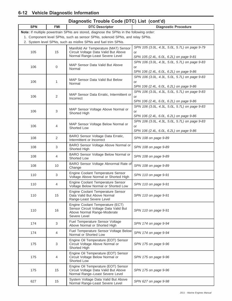
Diagnostic Trouble Code (DTC) List (cont’d)SPN FMI DTC Descriptor Diagnostic Procedure
Note: If multiple powertrain SPNs are stored, diagnose the SPNs in the following order:1. Component level SPNs, such as sensor SPNs, solenoid SPNs, and relay SPNs.2. System level SPNs, such as misfire SPNs and fuel trim SPNs.
105 15Manifold Air Temperature (MAT) SensorCircuit Voltage Data Valid But AboveNormal Range-Least Severe Level
SPN 105 (3.0L, 4.3L, 5.0L, 5.7L) on page 9-79orSPN 105 (2.4L, 6.0L, 6.2L) on page 9-81
106 0 MAP Sensor Data Valid But AboveNormal
SPN 106 (3.0L, 4.3L, 5.0L, 5.7L) on page 9-83orSPN 106 (2.4L, 6.0L, 6.2L) on page 9-86
106 1 MAP Sensor Data Valid But BelowNormal
SPN 106 (3.0L, 4.3L, 5.0L, 5.7L) on page 9-83orSPN 106 (2.4L, 6.0L, 6.2L) on page 9-86
106 2 MAP Sensor Data Erratic, Intermittent orIncorrect
SPN 106 (3.0L, 4.3L, 5.0L, 5.7L) on page 9-83orSPN 106 (2.4L, 6.0L, 6.2L) on page 9-86
106 3 MAP Sensor Voltage Above Normal orShorted High
SPN 106 (3.0L, 4.3L, 5.0L, 5.7L) on page 9-83orSPN 106 (2.4L, 6.0L, 6.2L) on page 9-86
106 4 MAP Sensor Voltage Below Normal orShorted Low
SPN 106 (3.0L, 4.3L, 5.0L, 5.7L) on page 9-83orSPN 106 (2.4L, 6.0L, 6.2L) on page 9-86
108 2 BARO Sensor Voltage Data Erratic,Intermittent or Incorrect SPN 108 on page 9-89
108 3 BARO Sensor Voltage Above Normal orShorted High SPN 108 on page 9-89
108 4 BARO Sensor Voltage Below Normal orShorted Low SPN 108 on page 9-89
108 10 BARO Sensor Voltage Abnormal Rate ofChange SPN 108 on page 9-89
110 3 Engine Coolant Temperature SensorVoltage Above Normal or Shorted High SPN 110 on page 9-91
110 4 Engine Coolant Temperature SensorVoltage Below Normal or Shorted Low SPN 110 on page 9-91
110 15Engine Coolant Temperature SensorData Valid But Above NormalRange-Least Severe Level
SPN 110 on page 9-91
110 16
Engine Coolant Temperature (ECT)Sensor Circuit Voltage Data Valid ButAbove Normal Range-ModerateSevere Level
SPN 110 on page 9-91
174 3 Fuel Temperature Sensor VoltageAbove Normal or Shorted High SPN 174 on page 9-94
174 4 Fuel Temperature Sensor Voltage BelowNormal or Shorted Low SPN 174 on page 9-94
175 3Engine Oil Temperature (EOT) SensorCircuit Voltage Above Normal orShorted High
SPN 175 on page 9-96
175 4Engine Oil Temperature (EOT) SensorCircuit Voltage Below Normal orShorted Low
SPN 175 on page 9-96
175 15Engine Oil Temperature (EOT) SensorCircuit Voltage Data Valid But AboveNormal Range–Least Severe Level
SPN 175 on page 9-96
627 15 System Voltage Data Valid But AboveNormal Range-Least Severe Level SPN 627 on page 9-98
6-12 Vehicle Diagnostic Information
2011 - Marine Engines Manual

Diagnostic Trouble Code (DTC) List (cont’d)SPN FMI DTC Descriptor Diagnostic Procedure
Note: If multiple powertrain SPNs are stored, diagnose the SPNs in the following order:1. Component level SPNs, such as sensor SPNs, solenoid SPNs, and relay SPNs.2. System level SPNs, such as misfire SPNs and fuel trim SPNs.
627 17 System Voltage Data Valid But BelowNormal Range-Least Severe Level SPN 627 on page 9-98
630 13 Cal Memory Out of Calibration SPN 630, 65580, 65581, or 65582 on page 9-99
636 2 Crankshaft Position Sensor Data Erratic,Intermittent or Incorrect
SPN 636 (3.0L, 4.3L, 5.0L, 5.7L) on page 9-100orSPN 636 (6.0L, 6.2L) on page 9-102
636 8 Crankshaft Position Sensor AbnormalFrequency or Pulse Width
SPN 636 (3.0L, 4.3L, 5.0L, 5.7L) on page 9-100orSPN 636 (6.0L, 6.2L) on page 9-102
651 3 Fuel Injector 1 Voltage Above Normal orShorted High
SPN 651, 652, 653, 654, 655, 656, 657, or 658 onpage 9-104
651 5 Fuel Injector 1 Current Below Normal orOpen Circuit
SPN 651, 652, 653, 654, 655, 656, 657, or 658 onpage 9-104
652 3 Fuel Injector 2 Short Voltage AboveNormal or Shorted High
SPN 651, 652, 653, 654, 655, 656, 657, or 658 onpage 9-104
652 5 Fuel Injector 2 Current Below Normal orOpen Circuit
SPN 651, 652, 653, 654, 655, 656, 657, or 658 onpage 9-104
653 3 Fuel Injector 3 Voltage Above Normal orShorted High
SPN 651, 652, 653, 654, 655, 656, 657, or 658 onpage 9-104
653 5 Fuel Injector 3 Current Below Normal orOpen Circuit
SPN 651, 652, 653, 654, 655, 656, 657, or 658 onpage 9-104
654 3 Fuel Injector 4 Voltage Above Normal orShorted High
SPN 651, 652, 653, 654, 655, 656, 657, or 658 onpage 9-104
654 5 Fuel Injector 4 Current Below Normal orOpen Circuit
SPN 651, 652, 653, 654, 655, 656, 657, or 658 onpage 9-104
655 3 Fuel Injector 5 Voltage Above Normal orShorted High
SPN 651, 652, 653, 654, 655, 656, 657, or 658 onpage 9-104
655 5 Fuel Injector 5 Current Below Normal orOpen Circuit
SPN 651, 652, 653, 654, 655, 656, 657, or 658 onpage 9-104
656 3 Fuel Injector 6 Voltage Above Normal orShorted High
SPN 651, 652, 653, 654, 655, 656, 657, or 658 onpage 9-104
656 5 Fuel Injector 6 Current Below Normal orOpen Circuit
SPN 651, 652, 653, 654, 655, 656, 657, or 658 onpage 9-104
657 3 Fuel Injector 7 Voltage Above Normal orShorted High
SPN 651, 652, 653, 654, 655, 656, 657, or 658 onpage 9-104
657 5 Fuel Injector 7 Current Below Normal orOpen Circuit
SPN 651, 652, 653, 654, 655, 656, 657, or 658 onpage 9-104
658 3 Fuel Injector 8 Voltage Above Normal orShorted High
SPN 651, 652, 653, 654, 655, 656, 657, or 658 onpage 9-104
658 5 Fuel Injector 8 Current Below Normal orOpen Circuit
SPN 651, 652, 653, 654, 655, 656, 657, or 658 onpage 9-104
1765 3 Fuel Valve Voltage Above Normal orShorted High
SPN 1765 (High-Side Driver) on page 9-106orSPN 1765 (Low-Side Driver) on page 9-108
1765 4 Fuel Valve Voltage Below Normal orShorted Low
SPN 1765 (High-Side Driver) on page 9-106orSPN 1765 (Low-Side Driver) on page 9-108
1765 5 Fuel Valve Current Below Normal orOpen Circuit
SPN 1765 (High-Side Driver) on page 9-106orSPN 1765 (Low-Side Driver) on page 9-108
Vehicle Diagnostic Information 6-13
2011 - Marine Engines Manual
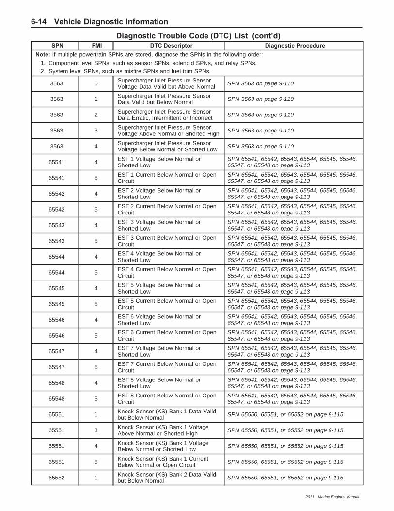
Diagnostic Trouble Code (DTC) List (cont’d)SPN FMI DTC Descriptor Diagnostic Procedure
Note: If multiple powertrain SPNs are stored, diagnose the SPNs in the following order:1. Component level SPNs, such as sensor SPNs, solenoid SPNs, and relay SPNs.2. System level SPNs, such as misfire SPNs and fuel trim SPNs.
3563 0 Supercharger Inlet Pressure SensorVoltage Data Valid but Above Normal SPN 3563 on page 9-110
3563 1 Supercharger Inlet Pressure SensorData Valid but Below Normal SPN 3563 on page 9-110
3563 2 Supercharger Inlet Pressure SensorData Erratic, Intermittent or Incorrect SPN 3563 on page 9-110
3563 3 Supercharger Inlet Pressure SensorVoltage Above Normal or Shorted High SPN 3563 on page 9-110
3563 4 Supercharger Inlet Pressure SensorVoltage Below Normal or Shorted Low SPN 3563 on page 9-110
65541 4 EST 1 Voltage Below Normal orShorted Low
SPN 65541, 65542, 65543, 65544, 65545, 65546,65547, or 65548 on page 9-113
65541 5 EST 1 Current Below Normal or OpenCircuit
SPN 65541, 65542, 65543, 65544, 65545, 65546,65547, or 65548 on page 9-113
65542 4 EST 2 Voltage Below Normal orShorted Low
SPN 65541, 65542, 65543, 65544, 65545, 65546,65547, or 65548 on page 9-113
65542 5 EST 2 Current Below Normal or OpenCircuit
SPN 65541, 65542, 65543, 65544, 65545, 65546,65547, or 65548 on page 9-113
65543 4 EST 3 Voltage Below Normal orShorted Low
SPN 65541, 65542, 65543, 65544, 65545, 65546,65547, or 65548 on page 9-113
65543 5 EST 3 Current Below Normal or OpenCircuit
SPN 65541, 65542, 65543, 65544, 65545, 65546,65547, or 65548 on page 9-113
65544 4 EST 4 Voltage Below Normal orShorted Low
SPN 65541, 65542, 65543, 65544, 65545, 65546,65547, or 65548 on page 9-113
65544 5 EST 4 Current Below Normal or OpenCircuit
SPN 65541, 65542, 65543, 65544, 65545, 65546,65547, or 65548 on page 9-113
65545 4 EST 5 Voltage Below Normal orShorted Low
SPN 65541, 65542, 65543, 65544, 65545, 65546,65547, or 65548 on page 9-113
65545 5 EST 5 Current Below Normal or OpenCircuit
SPN 65541, 65542, 65543, 65544, 65545, 65546,65547, or 65548 on page 9-113
65546 4 EST 6 Voltage Below Normal orShorted Low
SPN 65541, 65542, 65543, 65544, 65545, 65546,65547, or 65548 on page 9-113
65546 5 EST 6 Current Below Normal or OpenCircuit
SPN 65541, 65542, 65543, 65544, 65545, 65546,65547, or 65548 on page 9-113
65547 4 EST 7 Voltage Below Normal orShorted Low
SPN 65541, 65542, 65543, 65544, 65545, 65546,65547, or 65548 on page 9-113
65547 5 EST 7 Current Below Normal or OpenCircuit
SPN 65541, 65542, 65543, 65544, 65545, 65546,65547, or 65548 on page 9-113
65548 4 EST 8 Voltage Below Normal orShorted Low
SPN 65541, 65542, 65543, 65544, 65545, 65546,65547, or 65548 on page 9-113
65548 5 EST 8 Current Below Normal or OpenCircuit
SPN 65541, 65542, 65543, 65544, 65545, 65546,65547, or 65548 on page 9-113
65551 1 Knock Sensor (KS) Bank 1 Data Valid,but Below Normal SPN 65550, 65551, or 65552 on page 9-115
65551 3 Knock Sensor (KS) Bank 1 VoltageAbove Normal or Shorted High SPN 65550, 65551, or 65552 on page 9-115
65551 4 Knock Sensor (KS) Bank 1 VoltageBelow Normal or Shorted Low SPN 65550, 65551, or 65552 on page 9-115
65551 5 Knock Sensor (KS) Bank 1 CurrentBelow Normal or Open Circuit SPN 65550, 65551, or 65552 on page 9-115
65552 1 Knock Sensor (KS) Bank 2 Data Valid,but Below Normal SPN 65550, 65551, or 65552 on page 9-115
6-14 Vehicle Diagnostic Information
2011 - Marine Engines Manual

Diagnostic Trouble Code (DTC) List (cont’d)SPN FMI DTC Descriptor Diagnostic Procedure
Note: If multiple powertrain SPNs are stored, diagnose the SPNs in the following order:1. Component level SPNs, such as sensor SPNs, solenoid SPNs, and relay SPNs.2. System level SPNs, such as misfire SPNs and fuel trim SPNs.
65552 3 Knock Sensor (KS) Bank 2 VoltageAbove Normal or Shorted High SPN 65550, 65551, or 65552 on page 9-115
65552 4 Knock Sensor (KS) Bank 2 VoltageBelow Normal or Shorted Low SPN 65550, 65551, or 65552 on page 9-115
65552 5 Knock Sensor (KS) Bank 2 CurrentBelow Normal or Open Circuit SPN 65550, 65551, or 65552 on page 9-115
65555 1 Change Oil Now–Data Valid but BelowNormal SPN 65555 on page 9-117
65555 18 Change Oil Soon–Data Valid but AboveNormal Range - Least Severe Level SPN 65555 on page 9-117
65558 11 CAN 2 Bus Hardware Fault Root CauseUnknown SPN 65558 or 65559 on page 9-118
65559 11 CAN 1 Bus Hardware Fault Root CauseUnknown SPN 65558 or 65559 on page 9-118
65560 9 CAN Bus Governor Command Lost SPN 65560 on page 9-120
65561 0 Oxygen Sensor Bank A Sensor 1 DataValid But Above Normal
SPN 65561, 65562, 65563, or 65564 onpage 9-122
65561 1 Oxygen Sensor Bank A Sensor 1 DataValid But Below Normal
SPN 65561, 65562, 65563, or 65564 onpage 9-122
65561 3 Oxygen Sensor Bank A Sensor 1Voltage Above Normal or Shorted High
SPN 65561, 65562, 65563, or 65564 onpage 9-122
65561 4 Oxygen Sensor Bank A Sensor 1Voltage Below Normal or Shorted Low
SPN 65561, 65562, 65563, or 65564 onpage 9-122
65561 5 Oxygen Sensor Bank A Sensor 1Current Below Normal or Open Circuit
SPN 65561, 65562, 65563, or 65564 onpage 9-122
65562 0 Oxygen Sensor Bank A Sensor 2 DataValid But Above Normal
SPN 65561, 65562, 65563, or 65564 onpage 9-122
65562 1 Oxygen Sensor Bank A Sensor 2 DataValid But Below Normal
SPN 65561, 65562, 65563, or 65564 onpage 9-122
65562 3 Oxygen Sensor Bank A Sensor 2Voltage Above Normal or Shorted High
SPN 65561, 65562, 65563, or 65564 onpage 9-122
65562 4 Oxygen Sensor Bank A Sensor 2Voltage Below Normal or Shorted Low
SPN 65561, 65562, 65563, or 65564 onpage 9-122
65562 5 Oxygen Sensor Bank A Sensor 2Current Below Normal or Open Circuit
SPN 65561, 65562, 65563, or 65564 onpage 9-122
65563 0 Oxygen Sensor Bank B Sensor 1 DataValid But Above Normal
SPN 65561, 65562, 65563, or 65564 onpage 9-122
65563 1 Oxygen Sensor Bank B Sensor 1 DataValid But Below Normal
SPN 65561, 65562, 65563, or 65564 onpage 9-122
65563 3 Oxygen Sensor Bank B Sensor 1Voltage Above Normal or Shorted High
SPN 65561, 65562, 65563, or 65564 onpage 9-122
65563 4 Oxygen Sensor Bank B Sensor 1Voltage Below Normal or Shorted Low
SPN 65561, 65562, 65563, or 65564 onpage 9-122
65563 5 Oxygen Sensor Bank B Sensor 1Current Below Normal or Open Circuit
SPN 65561, 65562, 65563, or 65564 onpage 9-122
65564 0 Oxygen Sensor Bank B Sensor 2 DataValid But Above Normal
SPN 65561, 65562, 65563, or 65564 onpage 9-122
65564 1 Oxygen Sensor Bank B Sensor 2 DataValid But Below Normal
SPN 65561, 65562, 65563, or 65564 onpage 9-122
65564 3 Oxygen Sensor Bank B Sensor 2Voltage Above Normal or Shorted High
SPN 65561, 65562, 65563, or 65564 onpage 9-122
Vehicle Diagnostic Information 6-15
2011 - Marine Engines Manual

Diagnostic Trouble Code (DTC) List (cont’d)SPN FMI DTC Descriptor Diagnostic Procedure
Note: If multiple powertrain SPNs are stored, diagnose the SPNs in the following order:1. Component level SPNs, such as sensor SPNs, solenoid SPNs, and relay SPNs.2. System level SPNs, such as misfire SPNs and fuel trim SPNs.
65564 4 Oxygen Sensor Bank B Sensor 2Voltage Below Normal or Shorted Low
SPN 65561, 65562, 65563, or 65564 onpage 9-122
65564 5 Oxygen Sensor Bank B Sensor 2Current Below Normal or Open Circuit
SPN 65561, 65562, 65563, or 65564 onpage 9-122
65565 0 Fuel Trim Bank A Data Valid But AboveNormal SPN 65565 or 65566 on page 9-125
65565 1 Fuel Trim Bank A Data Valid But BelowNormal SPN 65565 or 65566 on page 9-125
65566 0 Fuel Trim Bank B Data Valid But AboveNormal SPN 65565 or 65566 on page 9-125
65566 1 Fuel Trim Bank B Data Valid But BelowNormal SPN 65565 or 65566 on page 9-125
65567 8 Oxygen Sensor Bank A Sensor 1Abnormal Frequency or Pulse Width SPN 65567 or 65568 on page 9-127
65567 10 Oxygen Sensor Bank A Sensor 1Abnormal Rate of Change SPN 65567 or 65568 on page 9-127
65568 8 Oxygen Sensor Bank B Sensor 1Abnormal Frequency or Pulse Width SPN 65567 or 65568 on page 9-127
65568 10 Oxygen Sensor Bank B Sensor 1Abnormal Rate of Change SPN 65567 or 65568 on page 9-127
65570 2 Cam Phaser W Data Erratic, Intermittentor Incorrect
SPN 65570 (6.0/6.2L) on page 9-129 or SPN65570, 65571, 65572, or 65573 (2.4L) onpage 9-132
65570 4 Cam Phaser W Voltage Below Normalor Shorted Low
SPN 65570 (6.0/6.2L) on page 9-129 or SPN65570, 65571, 65572, or 65573 (2.4L) onpage 9-132
65570 5 Cam Phaser W Short High or OpenSPN 65570 (6.0/6.2L) on page 9-129 or SPN65570, 65571, 65572, or 65573 (2.4L) onpage 9-132
65570 7Cam Phaser W Accuracy MechanicalSystem Not Responding or Out ofAdjustment
SPN 65570 (6.0/6.2L) on page 9-129 or SPN65570, 65571, 65572, or 65573 (2.4L) onpage 9-132
65571 2 Cam Phaser X Data Erratic, Intermittentor Incorrect
SPN 65570, 65571, 65572, or 65573 (2.4L) onpage 9-132
65571 4 Cam Phaser X Voltage Below Normal orShorted Low
SPN 65570, 65571, 65572, or 65573 (2.4L) onpage 9-132
65571 5 Cam Phaser X Short High or Open SPN 65570, 65571, 65572, or 65573 (2.4L) onpage 9-132
65571 7Cam Phaser X Accuracy MechanicalSystem Not Responding or Out ofAdjustment
SPN 65570, 65571, 65572, or 65573 (2.4L) onpage 9-132
65572 2 Cam Phaser Y Data Erratic, Intermittentor Incorrect
SPN 65570, 65571, 65572, or 65573 (2.4L) onpage 9-132
65572 4 Cam Phaser Y Voltage Below Normal orShorted Low
SPN 65570, 65571, 65572, or 65573 (2.4L) onpage 9-132
65572 5 Cam Phaser Y Short High or Open SPN 65570, 65571, 65572, or 65573 (2.4L) onpage 9-132
65572 7Cam Phaser Y Accuracy MechanicalSystem Not Responding or Out ofAdjustment
SPN 65570, 65571, 65572, or 65573 (2.4L) onpage 9-132
65673 2 Cam Phaser Z Data Erratic, Intermittentor Incorrect
SPN 65570, 65571, 65572, or 65573 (2.4L) onpage 9-132
65673 4 Cam Phaser Z Voltage Below Normal orShorted Low
SPN 65570, 65571, 65572, or 65573 (2.4L) onpage 9-132
6-16 Vehicle Diagnostic Information
2011 - Marine Engines Manual

Diagnostic Trouble Code (DTC) List (cont’d)SPN FMI DTC Descriptor Diagnostic Procedure
Note: If multiple powertrain SPNs are stored, diagnose the SPNs in the following order:1. Component level SPNs, such as sensor SPNs, solenoid SPNs, and relay SPNs.2. System level SPNs, such as misfire SPNs and fuel trim SPNs.
65673 5 Cam Phaser Z Short High or Open SPN 65570, 65571, 65572, or 65573 (2.4L) onpage 9-132
65673 7Cam Phaser Z Accuracy MechanicalSystem Not Responding or Out ofAdjustment
SPN 65570, 65571, 65572, or 65573 (2.4L) onpage 9-132
65580 12 CPU Bad Intelligent Device orComponent SPN 630, 65580, 65581, or 65582 on page 9-99
65581 12 Mhc Failure Bad Intelligent Device orComponent SPN 630, 65580, 65581, or 65582 on page 9-99
65582 2 Nv Ram Failure Data Erratic,Intermittent or Incorrect SPN 630, 65580, 65581, or 65582 on page 9-99
65585 2 Fuel Select Input Data Erratic,Intermittent or Incorrect SPN 65585 on page 9-135
65586 3 Fuel Select Output 1 Voltage AboveNormal or Shorted High SPN 65586 or 65587 on page 9-137
65586 5 Fuel Select Output 1 Current BelowNormal or Open Circuit SPN 65586 or 65587 on page 9-137
65587 3 Fuel Select Output 2 Voltage AboveNormal or Shorted High SPN 65586 or 65587 on page 9-137
65587 5 Fuel Select Output 2 Current BelowNormal or Open Circuit SPN 65586 or 65587 on page 9-137
65590 7 Misfire Mechanical System NotResponding or Out of Adjustment
SPN 65590, 65591, 65592, 65593, 65594, 65595,65596, 65597, 65598, or 65599 on page 9-139
65591 7 Misfire Cylinder 1 Mechanical SystemNot Responding or Out of Adjustment
SPN 65590, 65591, 65592, 65593, 65594, 65595,65596, 65597, 65598, or 65599 on page 9-139
65592 7 Misfire Cylinder 2 Mechanical SystemNot Responding or Out of Adjustment
SPN 65590, 65591, 65592, 65593, 65594, 65595,65596, 65597, 65598, or 65599 on page 9-139
65593 7 Misfire Cylinder 3 Mechanical SystemNot Responding or Out of Adjustment
SPN 65590, 65591, 65592, 65593, 65594, 65595,65596, 65597, 65598, or 65599 on page 9-139
65594 7 Misfire Cylinder 4 Mechanical SystemNot Responding or Out of Adjustment
SPN 65590, 65591, 65592, 65593, 65594, 65595,65596, 65597, 65598, or 65599 on page 9-139
65595 7 Misfire Cylinder 5 Mechanical SystemNot Responding or Out of Adjustment
SPN 65590, 65591, 65592, 65593, 65594, 65595,65596, 65597, 65598, or 65599 on page 9-139
65596 7 Misfire Cylinder 6 Mechanical SystemNot Responding or Out of Adjustment
SPN 65590, 65591, 65592, 65593, 65594, 65595,65596, 65597, 65598, or 65599 on page 9-139
65597 7 Misfire Cylinder 7 Mechanical SystemNot Responding or Out of Adjustment
SPN 65590, 65591, 65592, 65593, 65594, 65595,65596, 65597, 65598, or 65599 on page 9-139
65598 7 Misfire Cylinder 8 Mechanical SystemNot Responding or Out of Adjustment
SPN 65590, 65591, 65592, 65593, 65594, 65595,65596, 65597, 65598, or 65599 on page 9-139
65599 7 Misfire Random Mechanical System NotResponding or Out of Adjustment
SPN 65590, 65591, 65592, 65593, 65594, 65595,65596, 65597, 65598, or 65599 on page 9-139
65601 2 ETC TPS 2 Data Erratic, Intermittent orIncorrect SPN 65601, 65602, or 65610 on page 9-141
65602 2 ETC TPS 1 Data Erratic, Intermittent orIncorrect SPN 65601, 65602, or 65610 on page 9-141
65604 2 ETC PPS 2 Data Erratic, Intermittent orIncorrect SPN 65604, 65605, or 65613 on page 9-144
65605 2 ETC PPS 1 Data Erratic, Intermittent orIncorrect SPN 65604, 65605, or 65613 on page 9-144
65610 2 ETC TPS 1-2 Data Erratic, Intermittentor Incorrect SPN 65601, 65602, or 65610 on page 9-141
65613 2 ETC PPS 1-2 Data Erratic, Intermittentor Incorrect SPN 65604, 65605, or 65613 on page 9-144
Vehicle Diagnostic Information 6-17
2011 - Marine Engines Manual

Diagnostic Trouble Code (DTC) List (cont’d)SPN FMI DTC Descriptor Diagnostic Procedure
Note: If multiple powertrain SPNs are stored, diagnose the SPNs in the following order:1. Component level SPNs, such as sensor SPNs, solenoid SPNs, and relay SPNs.2. System level SPNs, such as misfire SPNs and fuel trim SPNs.
65615 7 ETC Actuation Fault Mechanical SystemNot Responding or Out of Adjustment SPN 65615, 65616, or 65618 on page 9-147
65616 12 ETC Bad Intelligent Device orComponent SPN 65615, 65616, or 65618 on page 9-147
65618 7 ETC Return Fault Mechanical SystemNot Responding or Out of Adjustment SPN 65615, 65616, or 65618 on page 9-147
65620 4 5 Volt Reference A Circuit VoltageBelow Normal or Shorted Low SPN 65620-65623 on page 9-149
65621 4 5 Volt Reference B Circuit VoltageBelow Normal or Shorted Low SPN 65620-65623 on page 9-149
65622 4 5 Volt Reference C Circuit VoltageBelow Normal or Shorted Low SPN 65620-65623 on page 9-149
65623 4 5 Volt Reference D Circuit VoltageBelow Normal or Shorted Low SPN 65620-65623 on page 9-149
65675 11 Catalytic Converter A Efficiency RootCause Unknown SPN 65675 or 65676 on page 9-151
65676 11 Catalytic Converter B Efficiency RootCause Unknown SPN 65675 or 65676 on page 9-151
65690 3 Variable Governor Voltage AboveNormal or Shorted High SPN 65690 on page 9-153
65690 4 Variable Governor Voltage BelowNormal or Shorted Low SPN 65690 on page 9-153
65701 31 General Warning 1 Not Available SPN 65701 or 65702 on page 9-155
65702 31 General Warning 2 Not Available SPN 65701 or 65702 on page 9-155
65710 31 Emergency Stop Warning Not Available SPN 65710 on page 9-157
65723 2 Cam Sensor W Data Erratic, Intermittentor Incorrect
SPN 65723, 65724, 65725, or 65726(3.0/4.3/5.0/5.7L) on page 9-158orSPN 65723, 65724, 65725, or 65726 (2.4/6.0/6.2L)on page 9-160
65723 7 Cam Sensor W Mechanical System NotResponding or Out of Adjustment
SPN 65723, 65724, 65725, or 65726(3.0/4.3/5.0/5.7L) on page 9-158orSPN 65723, 65724, 65725, or 65726 (2.4/6.0/6.2L)on page 9-160
65723 8 Cam Sensor W Abnormal Frequency orPulse Width
SPN 65723, 65724, 65725, or 65726(3.0/4.3/5.0/5.7L) on page 9-158orSPN 65723, 65724, 65725, or 65726 (2.4/6.0/6.2L)on page 9-160
65724 2 Cam Sensor X Data Erratic, Intermittentor Incorrect
SPN 65723, 65724, 65725, or 65726(3.0/4.3/5.0/5.7L) on page 9-158orSPN 65723, 65724, 65725, or 65726 (2.4/6.0/6.2L)on page 9-160
65724 7 Cam Sensor X Mechanical System NotResponding or Out of Adjustment
SPN 65723, 65724, 65725, or 65726(3.0/4.3/5.0/5.7L) on page 9-158orSPN 65723, 65724, 65725, or 65726 (2.4/6.0/6.2L)on page 9-160
6-18 Vehicle Diagnostic Information
2011 - Marine Engines Manual

Diagnostic Trouble Code (DTC) List (cont’d)SPN FMI DTC Descriptor Diagnostic Procedure
Note: If multiple powertrain SPNs are stored, diagnose the SPNs in the following order:1. Component level SPNs, such as sensor SPNs, solenoid SPNs, and relay SPNs.2. System level SPNs, such as misfire SPNs and fuel trim SPNs.
65724 8 Cam Sensor X Abnormal Frequency orPulse Width
SPN 65723, 65724, 65725, or 65726(3.0/4.3/5.0/5.7L) on page 9-158orSPN 65723, 65724, 65725, or 65726 (2.4/6.0/6.2L)on page 9-160
65725 2 Cam Sensor Y Data Erratic, Intermittentor Incorrect
SPN 65723, 65724, 65725, or 65726(3.0/4.3/5.0/5.7L) on page 9-158orSPN 65723, 65724, 65725, or 65726 (2.4/6.0/6.2L)on page 9-160
65725 7 Cam Sensor Y Mechanical System NotResponding or Out of Adjustment
SPN 65723, 65724, 65725, or 65726(3.0/4.3/5.0/5.7L) on page 9-158orSPN 65723, 65724, 65725, or 65726 (2.4/6.0/6.2L)on page 9-160
65725 8 Cam Sensor Y Abnormal Frequency orPulse Width
SPN 65723, 65724, 65725, or 65726(3.0/4.3/5.0/5.7L) on page 9-158orSPN 65723, 65724, 65725, or 65726 (2.4/6.0/6.2L)on page 9-160
65726 2 Cam Sensor Z Data Erratic, Intermittentor Incorrect
SPN 65723, 65724, 65725, or 65726(3.0/4.3/5.0/5.7L) on page 9-158orSPN 65723, 65724, 65725, or 65726 (2.4/6.0/6.2L)on page 9-160
65726 7 Cam Sensor Z Mechanical System NotResponding or Out of Adjustment
SPN 65723, 65724, 65725, or 65726(3.0/4.3/5.0/5.7L) on page 9-158orSPN 65723, 65724, 65725, or 65726 (2.4/6.0/6.2L)on page 9-160
65726 8 Cam Sensor Z Abnormal Frequency orPulse Width
SPN 65723, 65724, 65725, or 65726(3.0/4.3/5.0/5.7L) on page 9-158orSPN 65723, 65724, 65725, or 65726 (2.4/6.0/6.2L)on page 9-160
66002 4 Starter Relay High Side Driver VoltageBelow Normal or Shorted Low SPN 66002 on page 9-162
66002 5 Starter Relay High Side Driver CurrentBelow Normal or Open Circuit SPN 66002 on page 9-162
66003 3 Malfunction Indicator Lamp DriverVoltage Above Normal or Shorted High SPN 66003 on page 9-164
66003 5 Malfunction Indicator Lamp DriverCurrent Below Normal or Open Circuit SPN 66003 on page 9-164
66004 3 Service Vehicle Soon Lamp VoltageAbove Normal or Shorted High SPN 66004 on page 9-166
66004 5 Service Vehicle Soon Lamp CurrentBelow Normal or Open Circuit SPN 66004 on page 9-166
66005 3 Governor Status Lamp Voltage AboveNormal or Shorted High SPN 66005 on page 9-168
66005 5 Governor Status Lamp Current BelowNormal or Open Circuit SPN 66005 on page 9-168
66006 3 DTC Lamp 3 Voltage Above Normal orShorted High SPN 66006, 66008, or 6609 on page 9-172
Vehicle Diagnostic Information 6-19
2011 - Marine Engines Manual

Diagnostic Trouble Code (DTC) List (cont’d)SPN FMI DTC Descriptor Diagnostic Procedure
Note: If multiple powertrain SPNs are stored, diagnose the SPNs in the following order:1. Component level SPNs, such as sensor SPNs, solenoid SPNs, and relay SPNs.2. System level SPNs, such as misfire SPNs and fuel trim SPNs.
66006 5 DTC Lamp 3 Current Below Normal orOpen Circuit SPN 66006, 66008, or 6609 on page 9-172
66007 3 Buzzer Driver Short Voltage AboveNormal or Shorted High SPN 66007 on page 9-170
66007 5 Buzzer Driver Current Below Normal orOpen Circuit SPN 66007 on page 9-170
66008 3 DTC Lamp 1 Voltage Above Normal orShorted High SPN 66006, 66008, or 6609 on page 9-172
66008 5 DTC Lamp 1 Current Below Normal orOpen Circuit SPN 66006, 66008, or 6609 on page 9-172
66009 3 DTC Lamp 2 Voltage Above Normal orShorted High SPN 66006, 66008, or 6609 on page 9-172
66009 5 DTC Lamp 2 Current Below Normal orOpen Circuit SPN 66006, 66008, or 6609 on page 9-172
66010 3 Slow Mode Lamp Voltage Above Normalor Shorted High SPN 66010 on page 9-174
66010 5 Slow Mode Lamp Current Below Normalor Open Circuit SPN 66010 on page 9-174
66011 3 Speed Based Output Voltage AboveNormal or Shorted High SPN 66011 on page 9-176
66011 5 Speed Based Output Current BelowNormal or Open Circuit SPN 66011 on page 9-176
66013 3 Powertrain Relay Voltage Above Normalor Shorted High SPN 66013 or 66014 on page 9-180
66013 5 Powertrain Relay Current Below Normalor Open Circuit SPN 66013 or 66014 on page 9-180
66014 4 Powertrain Relay Contact Voltage BelowNormal or Shorted Low SPN 66013 or 66014 on page 9-180
66017 4 Fuel Pump Relay 1 Voltage BelowNormal or Shorted Low SPN 66017 on page 9-182
66017 5 Fuel Pump Relay 1 Current BelowNormal or Open Circuit SPN 66017 on page 9-182
66018 3 Tachometer Voltage Above Normal orShorted High SPN 66018 on page 9-184
66018 5 Tachometer Current Below Normal orOpen Circuit SPN 66018 on page 9-184
66019 3 Oxygen Sensor Bank A Sensor 1 HeaterVoltage Above Normal or Shorted High
SPN 66019, 66020, 66021, or 66022 onpage 9-186
66019 5 Oxygen Sensor Bank A Sensor 1 HeaterCurrent Below Normal or Open Circuit
SPN 66019, 66020, 66021, or 66022 onpage 9-186
66019 8 Oxygen Sensor Bank A Sensor 1 HeaterAbnormal Frequency or Pulse Width
SPN 66019, 66020, 66021, or 66022 onpage 9-186
66020 3 Oxygen Sensor Bank B Sensor 1 HeaterShorted High
SPN 66019, 66020, 66021, or 66022 onpage 9-186
66020 5 Oxygen Sensor Bank B Sensor 1 HeaterShorted Low or Open
SPN 66019, 66020, 66021, or 66022 onpage 9-186
66020 8 Oxygen Sensor Bank B Sensor 1 HeaterAbnormal Frequency or Pulse Width
SPN 66019, 66020, 66021, or 66022 onpage 9-186
66021 3 Oxygen Sensor Bank A Sensor 2 HeaterVoltage Above Normal or Shorted High
SPN 66019, 66020, 66021, or 66022 onpage 9-186
66021 5 Oxygen Sensor Bank A Sensor 2 HeaterCurrent Below Normal or Open Circuit
SPN 66019, 66020, 66021, or 66022 onpage 9-186
6-20 Vehicle Diagnostic Information
2011 - Marine Engines Manual

Diagnostic Trouble Code (DTC) List (cont’d)SPN FMI DTC Descriptor Diagnostic Procedure
Note: If multiple powertrain SPNs are stored, diagnose the SPNs in the following order:1. Component level SPNs, such as sensor SPNs, solenoid SPNs, and relay SPNs.2. System level SPNs, such as misfire SPNs and fuel trim SPNs.
66021 8 Oxygen Sensor Bank A Sensor 2 HeaterAbnormal Frequency or Pulse Width
SPN 66019, 66020, 66021, or 66022 onpage 9-186
66022 3 Oxygen Sensor Bank B Sensor 2 HeaterVoltage Above Normal or Shorted High
SPN 66019, 66020, 66021, or 66022 onpage 9-186
66022 5 Oxygen Sensor Bank B Sensor 2 HeaterCurrent Below Normal or Open Circuit
SPN 66019, 66020, 66021, or 66022 onpage 9-186
66022 8 Oxygen Sensor Bank B Sensor 2 HeaterAbnormal Frequency or Pulse Width
SPN 66019, 66020, 66021, or 66022 onpage 9-186
66025 4 Fuel Pump Relay 2 Voltage BelowNormal or Shorted Low SPN 66025 on page 9-189
66025 5 Fuel Pump Relay 2 Current BelowNormal or Open Circuit SPN 66025 on page 9-189
66026 7 Shift Interrupt Mechanical System NotResponding or Out of Adjustment SPN 66026 on page 9-191
66030 3 Intercooler Relay Voltage Above Normalor Shorted High SPN 66030 on page 9-193
66030 5 Intercooler Relay Current Below Normalor Open Circuit SPN 66030 on page 9-193
66035 0 Supercharger Boost Control SolenoidData Valid but Above Normal SPN 66035 on page 9-195
66035 3 Supercharger Boost Control SolenoidData Valid but Below Normal SPN 66035 on page 9-195
66035 5 Supercharger Boost Control SolenoidCurrent Below Normal or Open Circuit SPN 66035 on page 9-195
66035 7Supercharger Boost Control SolenoidMechanical System Not Responding orOut of Adjustment
SPN 66035 on page 9-195
66040 3 OEM Output Driver 1 Voltage AboveNormal or Shorted High SPN 66040-66043 on page 9-198
66040 5 OEM Output Driver 1 Current BelowNormal or Open Circuit SPN 66040-66043 on page 9-198
66041 3 OEM Output Driver 2 Voltage AboveNormal or Shorted High SPN 66040-66043 on page 9-198
66041 5 OEM Output Driver 2 Current BelowNormal or Open Circuit SPN 66040-66043 on page 9-198
66042 3 OEM Output Driver 3 Voltage AboveNormal or Shorted High SPN 66040-66043 on page 9-198
66042 5 OEM Output Driver 3 Current BelowNormal or Open Circuit SPN 66040-66043 on page 9-198
66043 3 OEM Output Driver 4 Voltage AboveNormal or Shorted High SPN 66040-66043 on page 9-198
66043 5 OEM Output Driver 4 Current BelowNormal or Open Circuit SPN 66040-66043 on page 9-198
Vehicle Diagnostic Information 6-21
2011 - Marine Engines Manual

Data Link Connector Scan ToolsThe engine control module (ECM) communicatesinformation through the data link connector (DLC).This data is transmitted at a high frequency whichrequires a scan tool or PC based scan programin order to read. With an understanding of the datathat the scan tool displays, and knowledge of thecircuits involved, the scan tool can be very useful indiagnosing a condition. A scan tool does not make theuse of diagnostic procedures unnecessary, nordoes it indicate exactly where the problem is occurringin a particular circuit. Diagnostic procedures containinformation that can only be obtained with a scan toolor PC based scan program.
Scan Tool Use with IntermittentsThe scan tool provides the ability to perform a“wiggle test” on wiring harnesses or componentsunder various conditions, while observing the scan tooldisplay. The scan tool parameters can be observedwhile operating the vehicle under the conditionsfor running a diagnostic trouble code (DTC), or whenthere is an engine driveability condition. If thecondition appears to be related to certain parametersthat can be verified with the scan tool, they shouldbe observed while operating the vehicle. If there doesnot seem to be any correlation between the conditionand any specific circuit, the scan tool can beobserved on each position, for a period of time toverify if there is any change in the parametersthat indicates an intermittent operation.The scan tool can also be used to compare theoperating parameters of a poorly operating enginewith those of a known good engine. For example,a sensor may shift in value but not set a DTC.Comparing the sensor’s readings with those of aknown good identical vehicle may uncover thecondition.
Proper use of the scan tool will save time in diagnosisand prevent the replacement of good parts. It isimportant for the technician to understand the systemthat is being diagnosed, as well as an understandingof the scan tool operation and limitations. Thetechnician should read the tool manufacturer’soperating manual to become familiar with the tool’soperation.
Diagnostic Repair Verificatio1. Install any components or connectors that have
been removed or replaced during diagnosis.2. Perform any adjustment, programming or setup
procedures that are required when a componentor module is removed or replaced.
3. Clear the SPNs.4. Turn OFF the ignition for 60 seconds.5. If the repair was related to a SPN, duplicate the
Conditions for Running the SPN and use theFreeze Frame/Failure Records, if applicable, inorder to verify the SPN does not reset. If the SPNresets or another SPN is present, refer to theDiagnostic Trouble Code (DTC) List on page 6-11and perform the appropriate diagnostic procedure.
6. Observe the Expanded Diagnostic ReadinessData to verify the SPN has run and passed.If the SPN has run and passed, the SPN will notappear in the list. If a SPN diagnostic has notrun, or runs and fails, the SPN will remainin the list.
7. If the repair was symptom related, duplicate theconditions under which the customer concernoccurred to verify the repair. If the customerconcern reoccurs, return to Symptoms - EngineControls on page 9-199 and perform theappropriate symptom diagnostic.
6-22 Vehicle Diagnostic Information
2011 - Marine Engines Manual

Section 9
Engine
Engine Controls and Fuel - Marine ..............9-3Specification ..................................................9-3
Temperature Versus Resistance ....................9-3Altitude Versus Barometric Pressure ..............9-3Ignition System Specifications (2.4L) ..............9-4Ignition System Specifications (3.0L) ..............9-4Ignition System Specifications
(4.3L, 5.0L, or 5.7L) ...................................9-4Ignition System Specifications
(6.0L or 6.2L) .............................................9-4Fastener Tightening Specifications .................9-5
Schematic and Routing Diagrams ..................9-5Engine Controls Schematics ..........................9-6
Visual Identificatio .......................................9-30Engine Control Module Connector End
Views .......................................................9-30Engine Controls Connector End Views .........9-33
Diagnostic Information and Procedures .......9-54Diagnostic Starting Point - Engine
Controls ....................................................9-54Engine Control Module Scan Tool
Information ...............................................9-54Powertrain On Board Diagnostic (OBD)
System Check ..........................................9-64SPN 38 or 96 ..............................................9-65SPN 51 .......................................................9-67SPN 84 .......................................................9-69SPN 94 .......................................................9-71SPN 98 .......................................................9-73SPN 100 (3.0L, 4.3L, 5.0L, 5.7L) .................9-75SPN 100 (6.0L, 6.2L) ...................................9-77SPN 105 (3.0L, 4.3L, 5.0L, 5.7L) .................9-79SPN 105 (2.4L, 6.0L, 6.2L) ..........................9-81SPN 106 (3.0L, 4.3L, 5.0L, 5.7L) .................9-83SPN 106 (2.4L, 6.0L, 6.2L) ..........................9-86SPN 108 ......................................................9-89SPN 110 ......................................................9-91SPN 174 ......................................................9-94SPN 175 ......................................................9-96SPN 627 ......................................................9-98SPN 630, 65580, 65581, or 65582 ..............9-99SPN 636 (3.0L, 4.3L, 5.0L, 5.7L) ...............9-100SPN 636 (6.0L, 6.2L) .................................9-102SPN 651, 652, 653, 654, 655, 656,
657, or 658 ............................................9-104SPN 1765 (High-Side Driver) .....................9-106SPN 1765 (Low-Side Driver) ......................9-108SPN 3563 ..................................................9-110
SPN 65541, 65542, 65543, 65544,65545, 65546, 65547, or 65548 ..............9-113
SPN 65550, 65551, or 65552 ....................9-115SPN 65555 ................................................9-117SPN 65558 or 65559 .................................9-118SPN 65560 ................................................9-120SPN 65561, 65562, 65563, or 65564 .........9-122SPN 65565 or 65566 .................................9-125SPN 65567 or 65568 .................................9-127SPN 65570 (6.0/6.2L) ................................9-129SPN 65570, 65571, 65572,
or 65573 (2.4L) ......................................9-132SPN 65585 ................................................9-135SPN 65586 or 65587 .................................9-137SPN 65590, 65591, 65592, 65593,
65594, 65595, 65596, 65597, 65598,or 65599 .................................................9-139
SPN 65601, 65602, or 65610 ....................9-141SPN 65604, 65605, or 65613 ....................9-144SPN 65615, 65616, or 65618 ....................9-147SPN 65620-65623 ......................................9-149SPN 65675 or 65676 .................................9-151SPN 65690 ................................................9-153SPN 65701 or 65702 .................................9-155SPN 65710 ................................................9-157SPN 65723, 65724, 65725, or 65726
(3.0/4.3/5.0/5.7L) .....................................9-158SPN 65723, 65724, 65725, or 65726
(2.4/6.0/6.2L) ..........................................9-160SPN 66002 ................................................9-162SPN 66003 ................................................9-164SPN 66004 ................................................9-166SPN 66005 ................................................9-168SPN 66007 ................................................9-170SPN 66006, 66008, or 6609 ......................9-172SPN 66010 ................................................9-174SPN 66011 ................................................9-176SPN 66012 ................................................9-178SPN 66013 or 66014 .................................9-180SPN 66017 ................................................9-182SPN 66018 ................................................9-184SPN 66019, 66020, 66021, or 66022 .........9-186SPN 66025 ................................................9-189SPN 66026 ................................................9-191SPN 66030 ................................................9-193SPN 66035 ................................................9-195SPN 66040-66043 ......................................9-198Symptoms - Engine Controls ......................9-199
Table of Contents 9-1
2011 - Marine Engines Manual

Engine Cranks But Does Not Run ..............9-201Run/Crank Relay Diagnosis ........................9-203Supercharger Intercooler Relay
Diagnosis ................................................9-204Boost Control System Diagnosis ................9-205Fuel Pump Electrical Circuit Diagnosis .......9-207Fuel System Diagnosis
(with Returnless Fuel System) ................9-208Fuel System Diagnosis
(without Returnless Fuel System) ............9-210Fuel Injector Diagnosis ...............................9-211Alcohol/Contaminants-in-Fuel Diagnosis ......9-213Distributor Ignition (DI) System
Diagnosis ................................................9-214Electronic Ignition System Diagnosis ..........9-215Slow Mode Switch Diagnosis .....................9-216
Repair Instructions ......................................9-217Engine Control Module Replacement ..........9-217Engine Coolant Temperature Sensor
Replacement ...........................................9-218Manifold Air Temperature Sensor
Replacement ...........................................9-218Manifold Absolute Pressure Sensor
Replacement (without Supercharger) .......9-220Barometric Pressure Sensor
Replacement ...........................................9-221Supercharger Air Inlet Pressure Sensor
Replacement ...........................................9-222Charge Air Bypass Regulator Solenoid
Valve Replacement .................................9-223Supercharger Bypass Valve Actuator
Replacement ...........................................9-224Engine Oil Pressure Sensor
Replacement ...........................................9-225Heated Oxygen Sensor Replacement .........9-226Throttle Position Sensor Replacement
(Non ETC) ..............................................9-227Throttle Body Assembly Replacement ........9-228Fuel Pressure Gauge Installation and
Removal .................................................9-229Fuel Pressure Relief ..................................9-230Fuel Injection Fuel Rail Assembly
Replacement (3.0L) ................................9-230Fuel Injection Fuel Rail Assembly
Replacement (4.3L 5.0L and 5.7L) ..........9-231Fuel Injection Fuel Rail Assembly
Replacement (6.0L and 6.2L) ..................9-234Fuel Injection Fuel Rail Assembly
Replacement (2.4L) ................................9-235Fuel Pressure Regulator Replacement .......9-238Fuel Injector Replacement
(Except 2.4L) ..........................................9-238Fuel Injector Replacement (2.4L) ................9-240Ignition Coil Replacement (3.0L) ................9-241Ignition Coil Replacement
(6.0L and 6.2L) .......................................9-242
Ignition Coil Replacement(4.3L, 5.0L, and 5.7L) .............................9-243
Ignition Coil Replacement (2.4L) ................9-244Spark Plug Wire Inspection ........................9-245Spark Plug Wire Replacement ...................9-245Spark Plug Inspection ................................9-245Spark Plug Replacement ............................9-247Distributor Replacement (3.0L) ...................9-248Distributor Replacement
(4.3L, 5.0L, 5.8L) ....................................9-251Camshaft Retard Offset Adjustment
(3.0L and 4.3L) .......................................9-255Camshaft Retard Offset Adjustment
(5.0L and 5.7L) .......................................9-255Crankshaft Position Sensor
Replacement (3.0L) ................................9-256Crankshaft Position Sensor
Replacement (4.3/5.0/5.7L) .....................9-257Crankshaft Position Sensor
Replacement (6.0/6.2L) ...........................9-258Crankshaft Position Sensor
Replacement (2.4L) ................................9-261Camshaft Position Sensor Replacement
(4.3/5.0/5.7L) ..........................................9-262Camshaft Position Sensor Replacement
(with CMP Actuator) ...............................9-268Camshaft Position Sensor Replacement
(without CMP Actuator) ...........................9-269Camshaft Position Sensor Replacement
(2.4L Intake) ...........................................9-270Camshaft Position Sensor Replacement
(2.4L Exhaust) ........................................9-270Camshaft Position Actuator Magnet
Replacement ...........................................9-271Camshaft Position Actuator Solenoid
Valve Replacement (6.0/6.2L) .................9-272Camshaft Position Actuator Solenoid
Valve Replacement (2.4L) .......................9-274Camshaft Position Actuator Magnet
Cleaning and Inspection .........................9-275Camshaft Position Actuator Solenoid
Valve Inspection .....................................9-276Knock Sensor Replacement
(Except 2.4L) ..........................................9-277Knock Sensor Replacement (2.4L) .............9-278
Description and Operation ..........................9-279Engine Control Module Description .............9-279Throttle Actuator Control (TAC) System
Description .............................................9-279Camshaft Actuator System Description .......9-281Supercharger Description and Operation ....9-282Fuel System Description ............................9-284Electronic Ignition System Description ........9-286Distributor Ignition (DI) System
Description .............................................9-287Special Tools and Equipment .....................9-289
9-2 Table of Contents
2011 - Marine Engines Manual

Engine Controls and Fuel - MarineSpecification
Temperature Versus Resistance°C °F Ohms
Temperature vs Resistance Values (Approximate)
150 302 47
140 284 60
130 266 77
120 248 100
110 230 132
100 212 177
90 194 241
80 176 332
70 158 467
60 140 667
50 122 973
45 113 1,188
40 104 1,459
35 95 1,802
30 86 2,238
25 77 2,796
20 68 3,520
15 59 4,450
10 50 5,670
5 41 7,280
0 32 9,420
−5 23 12,300
−10 14 16,180
−15 5 21,450
−20 −4 28,680
−30 −22 52,700
−40 −40 100,700
Altitude Versus Barometric Pressure
AltitudeMeasured inMeters (m)
AltitudeMeasured in
Feet (ft)
BarometricPressure
Measured inKilopascals
(kPa)Determine your altitude by contacting a local weatherstation or by using another reference source.
4 267 14,000 56–64
3 962 13,000 58–66
3 658 12,000 61–69
3 353 11,000 64–72
3 048 10,000 66–74
2 743 9,000 69–77
2 438 8,000 71–79
2 134 7,000 74–82
Altitude Versus Barometric Pressure(cont’d)
AltitudeMeasured inMeters (m)
AltitudeMeasured in
Feet (ft)
BarometricPressure
Measured inKilopascals
(kPa)1 829 6,000 77–85
1 524 5,000 80–88
1 219 4,000 83–91
914 3,000 87–95
610 2,000 90–98
305 1,000 94–102
0 0 Sea Level 96–104
−305 −1,000 101–105
Engine Controls and Fuel - Marine 9-3
2011 - Marine Engines Manual

Ignition System Specification (2.4L)
ApplicationSpecificatio
Metric EnglishFiring Order 1-3-4-2
Spark Plug Wire Resistance 397–1,337 ohms
Spark Plug Torque 20 N·m 15 lb ft
Spark Plug Gap 1.02 mm 0.40 in
Spark Plug TypeGM P/N 12598004
AC Spark Plug P/N 41-103
Ignition System Specification (3.0L)
ApplicationSpecificatio
Metric EnglishFiring Order 1-3-4-2
Spark Plug Wire Resistance 397–1,337 ohms
Spark Plug Torque 30 N·m 22 lb ft
Spark Plug Gap 1.27 mm 0.050 in
Spark Plug TypeGM P/N 19158043
AC Spark Plug P/N 41-950
Ignition System Specification (4.3L, 5.0L, or 5.7L)
ApplicationSpecificatio
Metric English
Firing Order1-6-5-4-3-2 (4.3L)
1-8-4-3-6-5-7-2 (5.0/5.7L)
Spark Plug Wire Resistance 1,200-1,500 ohms per ft
Spark Plug Torque 15 N·m 11 lb ft
Spark Plug Gap 1.5 mm 0.060 in
Spark Plug TypeGM P/N 12607234
AC Spark Plug P/N 41-993
Ignition System Specification (6.0L or 6.2L)
ApplicationSpecificatio
Metric EnglishFiring Order 1-8-7-2-6-5-4-3
Spark Plug Wire Resistance 397–1,337 ohms
Spark Plug Torque 15 N·m 11 lb ft
Spark Plug Gap 1.02 mm 0.040 in
Spark Plug TypeGM P/N 12571164
AC Spark Plug P/N 41-985
9-4 Engine Controls and Fuel - Marine
2011 - Marine Engines Manual

Fastener Tightening Specification
ApplicationSpecification
Metric EnglishAir Cleaner Housing Screw 3 N·m 27 lb in
Air Cleaner Outlet Duct Clamp 4 N·m 35 lb in
Camshaft Position (CMP) Actuator Magnet Bolts 12 N·m 106 lb in
Camshaft Position (CMP) Actuator Solenoid Valve – First Pass 65 N·m 48 lb ft
Camshaft Position (CMP) Actuator Solenoid Valve – Final Pass 90 degrees
Camshaft Position (CMP) Sensor Bolt 12 N·m 106 lb in
Camshaft Position (CMP) Sensor Wire Harness Bolt 12 N·m 106 lb ft
Chassis Wiring Harness Ground Bolt 18 N·m 13 lb ft
Crankshaft Position (CKP) Sensor Bolt 25 N·m 18 lb ft
Distributor Cap Screws 5 N·m 40 lb in
Distributor Hold Down Bolt 27 N·m 20 lb ft
Distributor Rotor Screws 2 N·m 20 lb in
Engine Coolant Temperature (ECT) Sensor 20 N·m 15 lb ft
Engine Wiring Harness Clip to Generator Bolt 9 N·m 80 lb in
Engine Wiring Harness Bracket Nut 5 N·m 44 lb in
Exhaust Gas Temperature (EGT) Sensor 42 N·m 31 lb ft
Fuel Line Bracket Bolt 12 N·m 106 lb in
Fuel Line Bracket Nut 18 N·m 13 lb ft
Fuel Pipe Bracket to Bellhousing Stud Nut 20 N·m 15 lb ft
Fuel Pressure Sensor 15 N·m 11 lb ft
Fuel Rail Bolt 10 N·m 89 lb in
Fuel Rail Crossover Pipe Retainer Screw 3.8 N·m 34 lb in
Fuel Tank Fill Hose Clamp 2.5 N·m 22 lb in
Heated Oxygen Sensor (HO2S) 42 N·m 31 lb ft
Ignition Coil Bolt 10 N·m 89 lb in
Knock Sensor (KS) Bolt 25 N·m 18 lb ft
Oil Level Indicator Switch 20 N·m 15 lb ft
Oil Pressure Sensor 35 N·m 26 lb ft
Spark Plug 15 N·m 11 lb ft
Supercharger Bolts (In sequence) 25 N·m 18 lb ft
Supercharger Bypass Regulator Solenoid Valve Bracket Bolt 9 N·m 80 lb in
Supercharger Bypass Valve Actuator Bolts 10 N·m 89 lb in
Supercharger Bypass Valve Actuator Cable Bracket Bolts 10 N·m 89 lb in
Supercharger Inlet Air Cooler Bolts 10 N·m 89 lb in
Throttle Body Bolt/Nut 10 N·m 89 lb in
Throttle Body Studs 6 N·m 53 lb in
Schematic and Routing Diagrams
Engine Controls and Fuel - Marine 9-5
2011 - Marine Engines Manual

Engi
neC
ontr
ols
Sche
mat
ics
(Mod
ule
Pow
er,G
roun
d,an
dR
elay
s)
2444
311
9-6 Engine Controls and Fuel - Marine
2011 - Marine Engines Manual
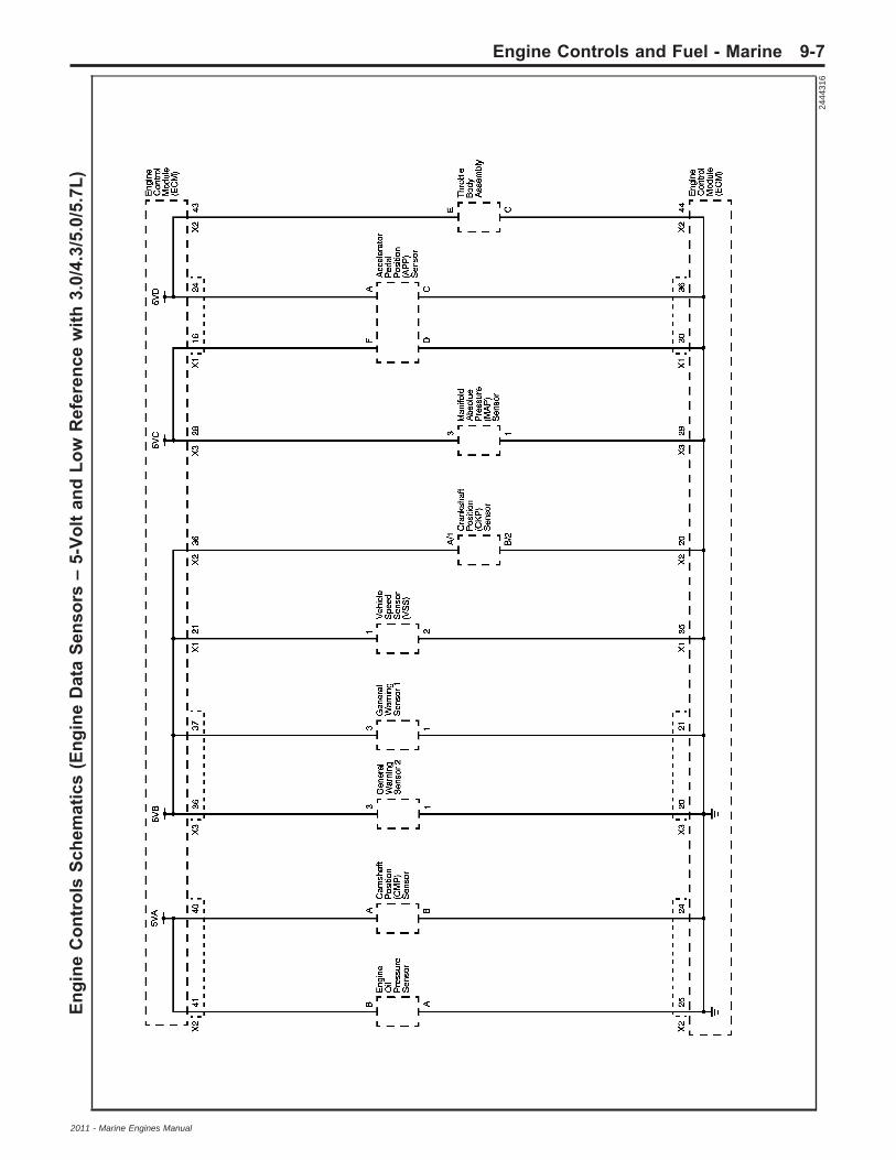
Engi
neC
ontr
ols
Sche
mat
ics
(Eng
ine
Dat
aSe
nsor
s–
5-Vo
ltan
dLo
wR
efer
ence
with
3.0/
4.3/
5.0/
5.7L
)
2444
316
Engine Controls and Fuel - Marine 9-7
2011 - Marine Engines Manual

Engi
neC
ontr
ols
Sche
mat
ics
(Eng
ine
Dat
aSe
nsor
s–
5-Vo
ltan
dLo
wR
efer
ence
with
6.0/
6.2L
)
2444
322
9-8 Engine Controls and Fuel - Marine
2011 - Marine Engines Manual

Engi
neC
ontr
ols
Sche
mat
ics
(Eng
ine
Dat
aSe
nsor
s–
with
3.0/
4.3/
5.0/
5.7L
)
2444
326
Engine Controls and Fuel - Marine 9-9
2011 - Marine Engines Manual

Engi
neC
ontr
ols
Sche
mat
ics
(Eng
ine
Dat
aSe
nsor
s–
with
6.0/
6.2L
)
2444
331
9-10 Engine Controls and Fuel - Marine
2011 - Marine Engines Manual

Engi
neC
ontr
ols
Sche
mat
ics
(Eng
ine
Dat
aSe
nsor
s–
Thro
ttle
Act
uato
rC
ontr
ols)
2444
339
Engine Controls and Fuel - Marine 9-11
2011 - Marine Engines Manual

Engi
neC
ontr
ols
Sche
mat
ics
(Igni
tion
Con
trol
s–
Igni
tion
1)
2444
343
9-12 Engine Controls and Fuel - Marine
2011 - Marine Engines Manual

Engi
neC
ontr
ols
Sche
mat
ics
(Igni
tion
Con
trol
s–
Igni
tion
2)
2444
347
Engine Controls and Fuel - Marine 9-13
2011 - Marine Engines Manual

Engi
neC
ontr
ols
Sche
mat
ics
(Igni
tion
Con
trol
s–
Igni
tion
Syst
em)
2546
166
9-14 Engine Controls and Fuel - Marine
2011 - Marine Engines Manual

Engi
neC
ontr
ols
Sche
mat
ics
(Igni
tion
Con
trol
s–
Dis
trib
utor
Igni
tion
Syst
em)
2444
349
Engine Controls and Fuel - Marine 9-15
2011 - Marine Engines Manual

Engi
neC
ontr
ols
Sche
mat
ics
(Igni
tion
Con
trol
s–
Cam
shaf
t,C
rank
shaf
t,an
dK
nock
Sens
ors
with
3.0/
4.3/
5.0/
5.7L
)
2444
350
9-16 Engine Controls and Fuel - Marine
2011 - Marine Engines Manual

Engi
neC
ontr
ols
Sche
mat
ics
(Igni
tion
Con
trol
s–
Cam
shaf
t,C
rank
shaf
t,an
dK
nock
Sens
ors
with
6.0/
6.2L
)
2444
354
Engine Controls and Fuel - Marine 9-17
2011 - Marine Engines Manual

Engi
neC
ontr
ols
Sche
mat
ics
(Igni
tion
Con
trol
s–
Sens
ors)
2546
165
9-18 Engine Controls and Fuel - Marine
2011 - Marine Engines Manual
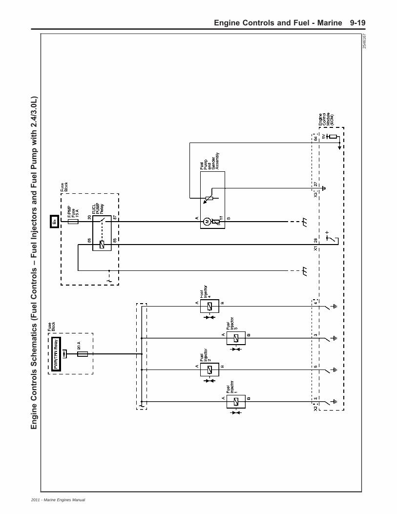
Engi
neC
ontr
ols
Sche
mat
ics
(Fue
lCon
trol
s–
Fuel
Inje
ctor
san
dFu
elPu
mp
with
2.4/
3.0L
)
2546
167
Engine Controls and Fuel - Marine 9-19
2011 - Marine Engines Manual

Engi
neC
ontr
ols
Sche
mat
ics
(Fue
lCon
trol
s–
Fuel
Inje
ctor
san
dFu
elPu
mp
with
4.3L
)
2546
169
9-20 Engine Controls and Fuel - Marine
2011 - Marine Engines Manual

Engi
neC
ontr
ols
Sche
mat
ics
(Fue
lCon
trol
s–
Fuel
Inje
ctor
san
dFu
elPu
mp
with
5.0/
5.7L
)
2546
170
Engine Controls and Fuel - Marine 9-21
2011 - Marine Engines Manual

Engi
neC
ontr
ols
Sche
mat
ics
(Fue
lCon
trol
s–
Fuel
Inje
ctor
san
dFu
elPu
mp
with
6.0/
6.2L
)
2444
357
9-22 Engine Controls and Fuel - Marine
2011 - Marine Engines Manual

Engi
neC
ontr
ols
Sche
mat
ics
(Eng
ine
Dat
aSe
nsor
s–
HO
2S)
2444
359
Engine Controls and Fuel - Marine 9-23
2011 - Marine Engines Manual

Engi
neC
ontr
ols
Sche
mat
ics
(Eng
ine
Dat
aSe
nsor
s–
Engi
neO
ilPr
essu
rew
ith3.
0/4.
3/5.
0/5.
7L)
2444
363
9-24 Engine Controls and Fuel - Marine
2011 - Marine Engines Manual

Engi
neC
ontr
ols
Sche
mat
ics
(Eng
ine
Dat
aSe
nsor
s–
Engi
neO
ilPr
essu
re)
2444
366
Engine Controls and Fuel - Marine 9-25
2011 - Marine Engines Manual

Engi
neC
ontr
ols
Sche
mat
ics
(Eng
ine
Dat
aSe
nsor
s–
Supe
rcha
rger
Boo
stC
ontr
olan
dIn
terc
oole
rR
elay
)
2444
369
9-26 Engine Controls and Fuel - Marine
2011 - Marine Engines Manual

Engi
neC
ontr
ols
Sche
mat
ics
(Cru
ise
Con
trol
,Tac
hom
eter
,and
Vehi
cle
Spee
dSe
nsor
)
2444
372
Engine Controls and Fuel - Marine 9-27
2011 - Marine Engines Manual
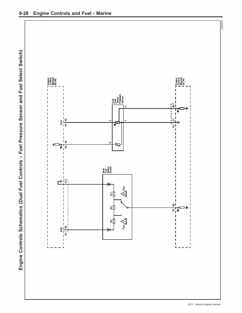
Engi
neC
ontr
ols
Sche
mat
ics
(Dua
lFue
lCon
trol
s–
Fuel
Pres
sure
Sens
oran
dFu
elSe
lect
Switc
h)
2444
376
9-28 Engine Controls and Fuel - Marine
2011 - Marine Engines Manual

Engi
neC
ontr
ols
Sche
mat
ics
(Dua
lFue
lCon
trol
s–
Fuel
Inje
ctio
nC
ontr
ol)
2560
464
Engine Controls and Fuel - Marine 9-29
2011 - Marine Engines Manual

Visual IdentificatioEngine Control Module ConnectorEnd Views
Engine Control Module (ECM) X1
Connector Part InformationHarness: Engine
OEM: 13510837
Service: 88988373
Description: 56-Way F MX123 Series (BK)
Terminal Part InformationPins: 2, 10, 12–14, 16, 24, 26, 28, 30, 34, 38, 40,50, 52
Terminal/Tray: 33467-0003/23
Core/Insulation Crimp: H/H
Release Tool/Test Probe:J-38125-213/J-35616-64B (L-BU)
Pins: 3–5, 11, 18–20, 25, 27, 29, 31, 33, 39, 43, 45, 47,53, 56
Terminal/Tray: 33467-0005/23
Core/Insulation Crimp: Pins: 3–5, 11, 18–20, 25, 27, 29,31, 33, 39, 43, 45, 47, 56 – J/J
Core/Insulation Crimp: Pins: 53 – K/K
Release Tool/Test Probe:J-38125-213/J-35616-64B (L-BU)
Engine Control Module (ECM) J1Pin Wire Circuit Function
1 — — High Speed CAN SerialData Bus 2 (+)
2 — — Pedal Position Sensor 2Signal
3 — — MAF Sensor Signal
4 — — Slave Engine Select
5 — — Governor Mode
6 — — Load Anticipate 1
7 — — Vehicle Speed SensorSignal
Engine Control Module (ECM) J1(cont’d)
Pin Wire Circuit Function8 na — Slow Mode Signal
9 — — Supercharger InletPressure Sensor Signal
10 — — Pedal Position Sensor 1Signal
11 — — Barometric PressureSensor Signal
12 — — Variable GovernorSignal
13 — — Variable Governor LowReference
14 — — Fuel Pump RelayControl - Secondary
15 — — High Speed CAN SerialData Bus 2 (-)
16 — — 5-Volt Reference 1
17 — — Not Available
18 — — Boot Mode
19 — — Ignition 1 Voltage
20 — — Battery Positive Voltage
21 — — Vehicle SpeedSensor 5-Volt Reference
22–25 — — 5-Volt Reference 2
26 — — 5-Volt Reference 1
27 — — Starter Relay ControlHigh Side Driver
28 — — Fuel Pump RelayControl - Primary
29 — — High Speed CAN SerialData Bus (+)
30–32 — — Low Reference
33 — — Emergency Stop Signal
34 — — Shift Interrupt SwitchSignal
35–39 — — Low Reference
40 — — Powertrain Relay CoilControl
41–42 — — Not Available
43 — — High Speed CAN SerialData Bus (-)
44 — — Not Available
45 — — IAT/MAT Sensor Signal
46 — —Exhaust GasTemperature (EGT)Sensor Bank B
47–49 — — Not Available
50 — — TACH–Pull Up
51 — — DTC 1 Lamp Control
52 — — MIL Control
53 — — Speed Based Output
784851
9-30 Engine Controls and Fuel - Marine
2011 - Marine Engines Manual

Engine Control Module (ECM) J1(cont’d)
Pin Wire Circuit Function54 — — Buzzer Control
55 — — Not Used
56 — — Governor Status LampControl
Engine Control Module (ECM) J2
Connector Part InformationHarness: Engine
OEM: 15466079
Service: 88988931
Description: 73-Way F MX123 Series, Sealed (BK)
Terminal Part InformationPins: 11, 24, 29, 40, 43–44, 60, 63, 65
Terminal/Tray: 33467-0003/23
Core/Insulation Crimp: H/H
Release Tool/Test Probe:J-38125-213/J-35616-64B (L-BU)
Pins: 3–5, 11, 18–20, 25, 27, 29, 31, 33, 39, 43, 45, 47,53, 56
Terminal/Tray: 33467-0005/23
Core/Insulation Crimp: Pins: 1–9, 15–20, 25, 28, 33–36,41, 47–50, 52–56, 61, 67–70, 72 – J/J
Core/Insulation Crimp: Pins: 49–50, 69–70 – K/K
Release Tool/Test Probe:J-38125-213/J-35616-64B (L-BU)
Pins: 73
Terminal/Tray: 7116-4152-02/9
Core/Insulation Crimp: A/5
Release Tool/Test Probe: J-38125-11A/J-35616-35 (VT)
Engine Control Module (ECM) J2Pin Wire Circuit Function1 — — Ignition Control (IC) 1
2 — — Fuel Injector 1 Control
3 — — Fuel Injector 8 Control
4 — — Fuel Injector 7 Control
5 — — Fuel Injector 2 Control
6 — — Fuel Injector 6 Control
7 — — Fuel Injector 5 Control
8 — — Fuel Injector 4 Control
9 — — Fuel Injector 3 Control
10 — — Not Used
11 — — Camshaft ActuatorSolenoid Control
12 — — Not Used
13 — — Ignition 2 Voltage
14 — — Tach Driver
15 — — ETC/IAC MotorControl–Open
16 — — ETC/IAC MotorControl–Close
17 — — IC 8
18 — — IC 4
19 — — Electronic SparkTiming (EST) Return 2
20 — — Crank Sensor LowReference
21–25 — — Low Reference
26 — — Not Used
27 — — Oil Temperature SensorLow Reference
28 — — Ignition 1 Voltage
29 — — Camshaft ActuatorSolenoid Low Reference
30 — — Low Reference
31 — — Engine Oil PressureSwitch Signal
32 — —
Exhaust GasRecirculation (EGR)Solenoid Valve or FuelValve High Control
33 — — IC 7
34 — — IC 5
35 — — EST Return
36 — — 5-Volt Reference 2
37–41 — — 5-Volt Reference 1
42 — — Not Used
1590596
Engine Controls and Fuel - Marine 9-31
2011 - Marine Engines Manual

Engine Control Module (ECM) J2(cont’d)
Pin Wire Circuit Function43 — — 5-Volt Reference 2
44 — — TP Sensor 1 and 2 LowReference
45 — — Not Used
46 — — Fuel TemperatureSensor Signal
47 — —Heated Oxygen Sensor(HO2S) Signal - LowBank A Sensor 1
48 — — HO2S Signal - LowBank B Sensor 1
49 — — Knock Sensor (KS) 1Signal - Low
50 — — KS 2 Signal - Low
51 — — Low Reference
52 — — HO2S Heater Control -Bank B Sensor 1
53 — — IC 2
54 — — IC 6
55 — — IC 3
56 — — CKP Sensor Signal
57–59 — — Not Used
60 — — CMP Sensor Signal
61 — — Oil Pressure SensorSignal
62 — — Not Used
63 — — TP Sensor 1 Signal
64 — —EGR Solenoid ValvePosition or Fuel LevelSensor Signal
65 — — TP Sensor 2 Signal
66 — — Engine Oil TemperatureSensor Signal
67 — — HO2S Signal - HighBank A Sensor 1
68 — — HO2S Signal - HighBank B Sensor 1
69 — — KS 1 Signal–High
70 — — KS 2 Signal–High
71 — — Not Used
72 — — HO2S Heater Control -Bank A Sensor 1
73 — — ECM Ground
Engine Control Module (ECM) J3
Connector Part InformationHarness: Engine
OEM: 15482787
Service: 88988372
Description: 73-Way F 64/2.8 Series, Sealed (BK)
Terminal Part InformationPins: 27, 43–44, 55, 63–64
Terminal/Tray: 33467-0003/23
Core/Insulation Crimp: H/H
Release Tool/Test Probe:J-38125-213/J-35616-64B (L-BU)
Pins: 10, 16–17, 28–30, 32, 45–46, 48–49, 65–68
Terminal/Tray: 33467-0005/23
Core/Insulation Crimp: J/J
Release Tool/Test Probe:J-38125-213/J-35616-64B (L-BU)
Engine Control Module (ECM) X3Pin Wire Circuit Function1 — — Load Anticipate Signal 22 — — Crank Request Signal
3–6 — — Not Used
7 — — Intercooler RelayControl
8 — — Service Vessel SoonLamp Control
9 — — DTC 2 Lamp Control
10 — —
EvaporativeEmission (EVAP)Canister Purge Solenoidor Fuel Valve Control
11 — — Not Used
12 — — Slow Mode LampControl
13 — — Not Used14 — — DTC 3 Lamp Control
15 — — Supercharger BoostSolenoid Valve Control
16 — — HO2S Heater ControlBank B Sensor 2
1590596
9-32 Engine Controls and Fuel - Marine
2011 - Marine Engines Manual

Engine Control Module (ECM) J3(cont’d)
Pin Wire Circuit Function17 — — Not Used
18 — — Engine Oil Level SensorSignal
19 — — Not Used20–21 — — Low Reference23–25 — — Not Used26–27 — — Low Reference
28 — — 5-Volt Reference 1
29 — — MAP Sensor LowReference
30 — — ETC Sensor LowReference
31 — — EGT Sensor A LowReference
32 — — HO2S Heater ControlBank A Sensor 2
33 — — Cruise Set/DecreaseSignal
34–35 — — Not Used
36 — — 5-Volt ReferenceGeneral Warning 2
37 — — 5-Volt ReferenceGeneral Warning 1
38–42 — — Not Used43 — — 5-Volt Reference 1
44 — —Fuel Level Sensor 2 orVariable GovernorSignal
45 — — MAP Sensor Signal46 — — ETC Sensor Signal47 — — EGT Sensor Bank A48 — — VSS Signal–High49 — — VSS Signal–Low
50–52 — — Not Used
53 — — Cruise Control ON/OFFSignal
54 — — Cruise Increase Signal55 — — Not Used
56 — — General WarningSensor 1 Signal
57 — — General WarningSensor 2 Signal
58–62 — — Not Used
63 — — Fuel Tank PressureSensor Signal
64 — — Fuel Level SensorSignal - Primary
65 — — HO2S Signal–HighBank B Sensor 2
66 — — HO2S Signal–LowBank B Sensor 2
67 — — HO2S Signal–HighBank A Sensor 2
68 — — HO2S Signal–LowBank A Sensor 2
69–73 — — Not Available
Engine Controls ConnectorEnd Views
Barometric Pressure (BARO) Sensor
Connector Part InformationHarness Type: Engine
OEM Connector: 15365614
Service Connector: 88988583
Description: 3-Way F Kompakt 2.8 Series, Sealed (BK)
Terminal Part InformationTerminated Lead: Pending
Release Tool: J-38125-561
Diagnostic Test Probe: J-35616-35 (VT)
Terminal/Tray: 1928498056/8
Core/Insulation Crimp: E/1
Barometric Pressure (BARO) Sensor
Pin Wire ColorCircuit
No. Function1 — — 5-Volt Reference
2 — — Low Reference
3 — — BARO Sensor Signal
1331443
Engine Controls and Fuel - Marine 9-33
2011 - Marine Engines Manual

Camshaft Actuator Solenoid (6.0/6.2L)
Connector Part InformationOEM: 15472554
Service: 88988610
Description: 2-Way F 0.64 Series Sealed (BK)
Terminal Part InformationTerminal/Tray: 1393364-2/7
Core/Insulation Crimp: K/K
Release Tool/Test Probe: 15315247/J-35616-64B (L-BU)
Camshaft Actuator Solenoid (6.0/6.2L)
Pin Wire ColorCircuit
No. Function
1 — — Camshaft ActuatorSolenoid Control
2 — — Low Reference
Camshaft ActuatorSolenoid - Exhaust (2.4L)
Connector Part InformationOEM: 15336004
Service: 15306187
Description: 2-Way F GT 150 Series Sealed (BK)
Terminal Part InformationTerminal/Tray: 15326267/19
Core/Insulation Crimp: E/4
Release Tool/Test Probe: 15315247/J-35616-2A (GY)
Camshaft ActuatorSolenoid - Exhaust (2.4L)
Pin Wire ColorCircuit
No. Function
A — — Camshaft ActuatorSolenoid Control
B — — Low Reference
Camshaft ActuatorSolenoid - Intake (2.4L)
Connector Part InformationOEM: 15335987
Service: 15306430
Description: 2-Way F GT 150 Series Sealed (BK)
Terminal Part InformationTerminal/Tray: 15326267/19
Core/Insulation Crimp: E/4
Release Tool/Test Probe: 15315247/J-35616-2A (GY)
Camshaft ActuatorSolenoid - Intake (2.4L)
Pin Wire ColorCircuit
No. Function
A — — Camshaft ActuatorSolenoid Control
B — — Low Reference
1673477
646406
646403
9-34 Engine Controls and Fuel - Marine
2011 - Marine Engines Manual

Camshaft Position (CMP)Sensor - Exhaust (2.4L)
Connector Part InformationOEM: 15326808
Service: 15306388
Description: 3-Way F GT 150 Series Sealed (BK)
Terminal Part InformationTerminal/Tray: 12191819/8
Core/Insulation Crimp: E/A
Release Tool/Test Probe: 15315247/J-35616-2A (GY)
Camshaft Position (CMP)Sensor - Exhaust (2.4L)
Pin Wire ColorCircuit
No. FunctionA — — 5-Volt Reference
B — — Low Reference
C — — CMP Sensor Signal
Camshaft Position (CMP)Sensor - Intake (2.4L)
Connector Part InformationOEM: 15326808
Service: 15306388
Description: 3-Way F GT 150 Series Sealed (BK)
Terminal Part InformationTerminal/Tray: 12191819/8
Core/Insulation Crimp: E/A
Release Tool/Test Probe: 15315247/J-35616-2A (GY)
Camshaft Position (CMP)Sensor - Intake (2.4L)
Pin Wire ColorCircuit
No. FunctionA — — 5-Volt Reference
B — — Low Reference
C — — CMP Sensor Signal
Camshaft Position (CMP) Sensor W(3.0/4.3/5.0/5.7L)
Connector Part InformationOEM: 12110293
Service: 12117025
Description: 3-Way F Metri-Pack 150 Series Sealed (BK)
Terminal Part InformationTerminal/Tray: 12048074/2
Core/Insulation Crimp: E/1
Release Tool/Test Probe: 12094429/J-35616-2A (GY)
Camshaft Position (CMP) Sensor W(3.0/4.3/5.0/5.7L)
Pin Wire ColorCircuit
No. FunctionA — — 5-Volt Reference
B — — CMP Sensor Signal
C — — Low Reference
646415
646415
684807
Engine Controls and Fuel - Marine 9-35
2011 - Marine Engines Manual

Camshaft Position (CMP)Sensor W (6.0/6.2L)
Connector Part InformationOEM: 12110293
Service: 12117025
Description: 3-Way F Metri-Pack 150 Series Sealed (BK)
Terminal Part InformationTerminal/Tray: 12048074/2
Core/Insulation Crimp: E/1
Release Tool/Test Probe: 12094429/J-35616-2A (GY)
Camshaft Position (CMP)Sensor W (6.0/6.2L)
Pin Wire ColorCircuit
No. FunctionA — — 5-Volt Reference
B — — Low Reference
C — — CMP Sensor Signal
Crankshaft Position (CKP)Sensor (2.4L)
Connector Part InformationOEM: 31403-3710
Service: 88988337
Description: 3-Way F Mixed 64 Series Sealed (BK)
Terminal Part InformationTerminal/Tray: 33467-0003/23
Core/Insulation Crimp: H/H
Release Tool/Test Probe:J-38125-213/J-35616-64B (L-BU)
Crankshaft Position (CKP) Sensor (2.4L)
Pin Wire ColorCircuit
No. Function1 — — 5-Volt Reference
2 — — Low Reference
3 — — CKP Sensor Signal
Crankshaft Position (CKP)Sensor (3.0/4.3/5.0/5.7L)
Connector Part InformationOEM: 12059595
Service: 88986451
Description: 3-Way F Metri-Pack 150 Series Sealed (BK)
Terminal Part InformationTerminal/Tray: 12048074/2
Core/Insulation Crimp: E/1
Release Tool/Test Probe: 12094429/J-35616-2A (GY)
Crankshaft Position (CKP)Sensor (3.0/4.3/5.0/5.7L)
Pin Wire ColorCircuit
No. FunctionA — — 5-Volt Reference
B — — Low Reference
C — — CKP Sensor Signal
684807
1664596
516611
9-36 Engine Controls and Fuel - Marine
2011 - Marine Engines Manual

Crankshaft Position (CKP)Sensor (6.0/6.2L)
Connector Part InformationOEM: 12059595
Service: 88986451
Description: 3-Way F Metri-Pack 150 Series Sealed (BK)
Terminal Part InformationTerminal/Tray: 12048074/2
Core/Insulation Crimp: E/1
Release Tool/Test Probe: 12094429/J-35616-2A (GY)
Crankshaft Position (CKP)Sensor (6.0/6.2L)
Pin Wire ColorCircuit
No. FunctionA — — CKP Sensor Signal
B — — Low Reference
C — — 5-Volt Reference
Engine Coolant Temperature (ECT)Sensor
Connector Part InformationOEM: 15449028
Service: 88987993
Description: 2-Way F 150 GT Series Sealed (BK)
Terminal Part InformationTerminal/Tray: 15326267/19
Core/Insulation Crimp: E/4
Release Tool/Test Probe: 15315247/J-35616-2A (GY)
Engine Coolant Temperature (ECT)Sensor
Pin Wire ColorCircuit
No. FunctionA — — Low Reference
B — — ECT Sensor Signal
Engine Oil Level Switch
Connector Part InformationOEM: 12052641
Service: 12102747
Description: 2-Way F Metri-Pack 150 Series Sealed (BK)
Terminal Part InformationTerminal/Tray: 12048074/2
Core/Insulation Crimp: E/1
Release Tool/Test Probe: 12094429/J-35616-2A (GY)
Engine Oil Level Switch
Pin Wire ColorCircuit
No. Function
A — — Engine Oil Level SwitchSignal
B — — Ground
516611
1538760
635009
Engine Controls and Fuel - Marine 9-37
2011 - Marine Engines Manual

Engine Oil Pressure (EOP)Sensor (3.0/4.3/5.0/5.7L)
Connector Part InformationOEM: 15477863
Service: 88988301
Description: 3-Way F GT 150 Series Sealed (BK)
Terminal Part InformationTerminal/Tray: 15326267/19
Core/Insulation Crimp: E/4
Release Tool/Test Probe: 15315247/J-35616-2A (GY)
Engine Oil Pressure (EOP)Sensor (4.3/5.0/5.7L)
Pin Wire ColorCircuit
No. FunctionA/1 — — Low Reference
B/2 — — 5-Volt Reference
C/3 — — Engine Oil PressureSensor Signal
Engine Oil Pressure (EOP)Sensor (6.0/6.2L)
Connector Part InformationOEM: 15477863
Service: 88988301
Description: 3-Way F GT 150 Series Sealed (BK)
Terminal Part InformationTerminal/Tray: 15326267/19
Core/Insulation Crimp: E/4
Release Tool/Test Probe: 15315247/J-35616-2A (GY)
Engine Oil Pressure (EOP)Sensor (6.0/6.2L)
Pin Wire ColorCircuit
No. Function
1 — — Engine Oil PressureSensor Signal
2 — — 5-Volt Reference
3 — — Low Reference
Fuel Injector 1 (2.4/6.0/6.2L)
Connector Part InformationOEM: 12602480
Service: 88988313
Description: 2-Way F GT 150 Series, Sealed (GY)
1519475 2212053
1527729
9-38 Engine Controls and Fuel - Marine
2011 - Marine Engines Manual

Terminal Part InformationTerminal/Tray: 12191819/8
Core/Insulation Crimp: E/1
Release Tool/Test Probe: 15315247/J-35616-2A (GY)
Fuel Injector 1 (2.4/6.0/6.2L)
Pin Wire ColorCircuit
No. FunctionA — — Ignition Voltage
B — — Fuel Injector 1 Control
Fuel Injector 2 (2.4/6.0/6.2L)
Connector Part InformationOEM: 12602480
Service: 88988313
Description: 2-Way F GT 150 Series, Sealed (GY)
Terminal Part InformationTerminal/Tray: 12191819/8
Core/Insulation Crimp: E/1
Release Tool/Test Probe: 15315247/J-35616-2A (GY)
Fuel Injector 2 (2.4/6.0/6.2L)
Pin Wire ColorCircuit
No. FunctionA — — Ignition Voltage
B — — Fuel Injector 2 Control
Fuel Injector 3 (2.4/6.0/6.2L)
Connector Part InformationOEM: 12602480
Service: 88988313
Description: 2-Way F GT 150 Series, Sealed (GY)
Terminal Part InformationTerminal/Tray: 12191819/8
Core/Insulation Crimp: E/1
Release Tool/Test Probe: 15315247/J-35616-2A (GY)
Fuel Injector 3 (2.4/6.0/6.2L)
Pin Wire ColorCircuit
No. FunctionA — — Ignition Voltage
B — — Fuel Injector 3 Control
Fuel Injector 4 (2.4/6.0/6.2L)
Connector Part InformationOEM: 12602480
Service: 88988313
Description: 2-Way F GT 150 Series, Sealed (GY)
1527729
1527729
1527729
Engine Controls and Fuel - Marine 9-39
2011 - Marine Engines Manual

Terminal Part InformationTerminal/Tray: 12191819/8
Core/Insulation Crimp: E/1
Release Tool/Test Probe: 15315247/J-35616-2A (GY)
Fuel Injector 4 (2.4/6.0/6.2L)
Pin Wire ColorCircuit
No. FunctionA — — Ignition Voltage
B — — Fuel Injector 4 Control
Fuel Injector 5 (6.0/6.2L)
Connector Part InformationOEM: 12602480
Service: 88988313
Description: 2-Way F GT 150 Series, Sealed (GY)
Terminal Part InformationTerminal/Tray: 12191819/8
Core/Insulation Crimp: E/1
Release Tool/Test Probe: 15315247/J-35616-2A (GY)
Fuel Injector 5 (6.0/6.2L)
Pin Wire ColorCircuit
No. FunctionA — — Ignition Voltage
B — — Fuel Injector 5 Control
Fuel Injector 6 (6.0/6.2L)
Connector Part InformationOEM: 12602480
Service: 88988313
Description: 2-Way F GT 150 Series, Sealed (GY)
Terminal Part InformationTerminal/Tray: 12191819/8
Core/Insulation Crimp: E/1
Release Tool/Test Probe: 15315247/J-35616-2A (GY)
Fuel Injector 6 (6.0/6.2L)
Pin Wire ColorCircuit
No. FunctionA — — Ignition Voltage
B — — Fuel Injector 6 Control
Fuel Injector 7 (6.0/6.2L)
Connector Part InformationOEM: 12602480
Service: 88988313
Description: 2-Way F GT 150 Series, Sealed (GY)
1527729
1527729
1527729
9-40 Engine Controls and Fuel - Marine
2011 - Marine Engines Manual

Terminal Part InformationTerminal/Tray: 12191819/8
Core/Insulation Crimp: E/1
Release Tool/Test Probe: 15315247/J-35616-2A (GY)
Fuel Injector 7 (6.0/6.2L)
Pin Wire ColorCircuit
No. FunctionA — — Ignition Voltage
B — — Fuel Injector 7 Control
Fuel Injector 8 (6.0/6.2L)
Connector Part InformationOEM: 12602480
Service: 88988313
Description: 2-Way F GT 150 Series, Sealed (GY)
Terminal Part InformationTerminal/Tray: 12191819/8
Core/Insulation Crimp: E/1
Release Tool/Test Probe: 15315247/J-35616-2A (GY)
Fuel Injector 8 (6.0/6.2L)
Pin Wire ColorCircuit
No. FunctionA — — Ignition Voltage
B — — Fuel Injector 8 Control
Fuel Injector 1 (4.3/5.0/5.7L)
Connector Part InformationOEM: 15355226
Service: 89046636
Description: 2-Way F Metri-Pack 150 Tangless SeriesSealed (BK)
Terminal Part InformationTerminal/Tray: 12176636/19
Core/Insulation Crimp: C/1
Release Tool/Test Probe: 12094429/J-35616-2A (GY)
Fuel Injector 1
Pin Wire ColorCircuit
No. FunctionA — — Ignition Voltage
B — — Fuel Injector 1 Control
Fuel Injector 2 (4.3/5.0/5.7L)
Connector Part InformationOEM: 15355226
Service: 89046636
Description: 2-Way F Metri-Pack 150 Tangless SeriesSealed (BK)
1527729
1273820
1273820
Engine Controls and Fuel - Marine 9-41
2011 - Marine Engines Manual
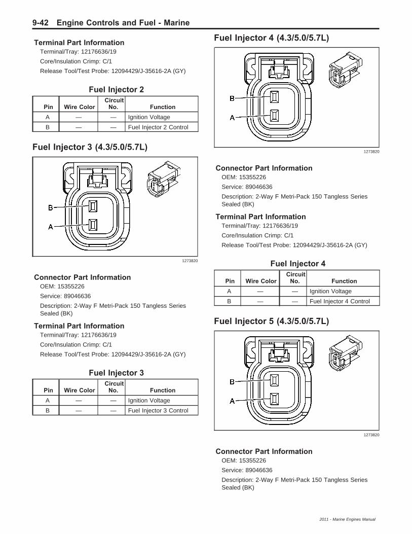
Terminal Part InformationTerminal/Tray: 12176636/19
Core/Insulation Crimp: C/1
Release Tool/Test Probe: 12094429/J-35616-2A (GY)
Fuel Injector 2
Pin Wire ColorCircuit
No. FunctionA — — Ignition Voltage
B — — Fuel Injector 2 Control
Fuel Injector 3 (4.3/5.0/5.7L)
Connector Part InformationOEM: 15355226
Service: 89046636
Description: 2-Way F Metri-Pack 150 Tangless SeriesSealed (BK)
Terminal Part InformationTerminal/Tray: 12176636/19
Core/Insulation Crimp: C/1
Release Tool/Test Probe: 12094429/J-35616-2A (GY)
Fuel Injector 3
Pin Wire ColorCircuit
No. FunctionA — — Ignition Voltage
B — — Fuel Injector 3 Control
Fuel Injector 4 (4.3/5.0/5.7L)
Connector Part InformationOEM: 15355226
Service: 89046636
Description: 2-Way F Metri-Pack 150 Tangless SeriesSealed (BK)
Terminal Part InformationTerminal/Tray: 12176636/19
Core/Insulation Crimp: C/1
Release Tool/Test Probe: 12094429/J-35616-2A (GY)
Fuel Injector 4
Pin Wire ColorCircuit
No. FunctionA — — Ignition Voltage
B — — Fuel Injector 4 Control
Fuel Injector 5 (4.3/5.0/5.7L)
Connector Part InformationOEM: 15355226
Service: 89046636
Description: 2-Way F Metri-Pack 150 Tangless SeriesSealed (BK)
1273820
1273820
1273820
9-42 Engine Controls and Fuel - Marine
2011 - Marine Engines Manual

Terminal Part InformationTerminal/Tray: 12176636/19
Core/Insulation Crimp: C/1
Release Tool/Test Probe: 12094429/J-35616-2A (GY)
Fuel Injector 5
Pin Wire ColorCircuit
No. FunctionA — — Ignition Voltage
B — — Fuel Injector 5 Control
Fuel Injector 6 (4.3/5.0/5.7L)
Connector Part InformationOEM: 15355226
Service: 89046636
Description: 2-Way F Metri-Pack 150 Tangless SeriesSealed (BK)
Terminal Part InformationTerminal/Tray: 12176636/19
Core/Insulation Crimp: C/1
Release Tool/Test Probe: 12094429/J-35616-2A (GY)
Fuel Injector 6
Pin Wire ColorCircuit
No. FunctionA — — Ignition Voltage
B — — Fuel Injector 6 Control
Fuel Injector 7 (4.3/5.0/5.7L)
Connector Part InformationOEM: 15355226
Service: 89046636
Description: 2-Way F Metri-Pack 150 Tangless SeriesSealed (BK)
Terminal Part InformationTerminal/Tray: 12176636/19
Core/Insulation Crimp: C/1
Release Tool/Test Probe: 12094429/J-35616-2A (GY)
Fuel Injector 7
Pin Wire ColorCircuit
No. FunctionA — — Ignition Voltage
B — — Fuel Injector 7 Control
Fuel Injector 8 (4.3/5.0/5.7L)
Connector Part InformationOEM: 15355226
Service: 89046636
Description: 2-Way F Metri-Pack 150 Tangless SeriesSealed (BK)
1273820
1273820
1273820
Engine Controls and Fuel - Marine 9-43
2011 - Marine Engines Manual

Terminal Part InformationTerminal/Tray: 12176636/19
Core/Insulation Crimp: C/1
Release Tool/Test Probe: 12094429/J-35616-2A (GY)
Fuel Injector 8
Pin Wire ColorCircuit
No. FunctionA — — Ignition Voltage
B — — Fuel Injector 8 Control
Heated Oxygen Sensor (HO2S) Bank ASensor 1
Connector Part InformationOEM: 12160825
Service: 15305801
Description: 4-Way M Metri-Pack 150 Series Sealed (BK)
Terminal Part InformationTerminal/Tray: 12045773/2
Core/Insulation Crimp: E/1
Release Tool/Test Probe: 12094429/J-35616-3 (GY)
Heated Oxygen Sensor (HO2S) Bank ASensor 1
Pin Wire ColorCircuit
No. Function
A — — HO2S Low Signal –Bank A Sensor 1
B — — HO2S High Signal –Bank A Sensor 1
C — —HO2S Heater LowControl – Bank ASensor 1
D — — Ignition 1 Voltage
Heated Oxygen Sensor (HO2S) Bank ASensor 2
Connector Part InformationOEM: 12160482
Service: 88988598
Description: 4-Way F Metri-Pack 150 Series Sealed (BK)
Terminal Part InformationTerminal/Tray: 12048074/2
Core/Insulation Crimp: E/1
Release Tool/Test Probe: 12094429/J-35616-2A (GY)
Heated Oxygen Sensor (HO2S) Bank ASensor 2
Pin Wire ColorCircuit
No. Function
A — — HO2S Low Signal –Bank A Sensor 2
B — — HO2S High Signal –Bank A Sensor 2
C — —HO2S Heater LowControl – Bank ASensor 2
D — — Ignition 1 Voltage
280761
456551
9-44 Engine Controls and Fuel - Marine
2011 - Marine Engines Manual

Heated Oxygen Sensor (HO2S) Bank BSensor 1
Connector Part InformationOEM: 12160825
Service: 15305801
Description: 4-Way M Metri-Pack 150 Series (BK)
Terminal Part InformationTerminal/Tray: 12045773/2
Core/Insulation Crimp: E/1
Release Tool/Test Probe: 12094429/J-35616-3 (GY)
Heated Oxygen Sensor (HO2S) Bank BSensor 1
Pin Wire ColorCircuit
No. Function
A — — HO2S Low Signal –Bank B Sensor 1
B — — HO2S High Signal –Bank B Sensor 1
C — —HO2S Heater LowControl – Bank BSensor 1
D — — Ignition 1 Voltage
Heated Oxygen Sensor (HO2S) Bank BSensor 2
Connector Part InformationOEM: 12160825
Service: 15305801
Description: 4-Way M Metri-Pack 150 Series (BK)
Terminal Part InformationTerminal/Tray: 12045773/2
Core/Insulation Crimp: E/1
Release Tool/Test Probe: 12094429/J-35616-3 (GY)
Heated Oxygen Sensor (HO2S) Bank BSensor 2
Pin Wire ColorCircuit
No. Function
A — — HO2S Low Signal –Bank B Sensor 2
B — — HO2S High Signal –Bank B Sensor 2
C — —HO2S Heater LowControl – Bank BSensor 2
D — — Ignition 1 Voltage
280761 456551
Engine Controls and Fuel - Marine 9-45
2011 - Marine Engines Manual

Ignition Coil (Distributor Ignition)
Connector Part InformationOEM: 12146121
Service: 88987992
Description: 3-Way F Metri-Pack 150 Series (BN)
Terminal Part InformationTerminal/Tray: See Terminal Repair Kit
Core/Insulation Crimp: See Terminal Repair Kit
Core/Insulation Crimp: See Terminal Repair Kit
Release Tool/Test Probe: See Terminal Repair Kit
Ignition Coil (Distributor Ignition)
Pin Wire ColorCircuit
No. FunctionA — — Ignition 1 Voltage
B — — Not Used
C — — Ignition Coil Control
Ignition Coil 1 (2.4L)
Connector Part InformationOEM: 7283-3392-30
Service: 88988338
Description: 4-Way F GT 150 Series Sealed (BK)
Terminal Part InformationTerminal/Tray: 15326267/19
Core/Insulation Crimp: E/1
Release Tool/Test Probe: 12094430/J-35616-2A (GY)
Ignition Coil 1 (2.4L)
Pin Wire ColorCircuit
No. Function1 — — Ground
2 — — Low Reference
3 — — IC 1 Control
4 — — Ignition Voltage
Ignition Coil 2 (2.4L)
Connector Part InformationOEM: 7283-3392-30
Service: 88988338
Description: 4-Way F GT 150 Series Sealed (BK)
Terminal Part InformationTerminal/Tray: 15326267/19
Core/Insulation Crimp: E/1
Release Tool/Test Probe: 12094430/J-35616-2A (GY)
Ignition Coil 21 (2.4L)
Pin Wire ColorCircuit
No. Function1 — — Ground
2 — — Low Reference
3 — — IC 2 Control
4 — — Ignition Voltage
68743
1590069
1590069
9-46 Engine Controls and Fuel - Marine
2011 - Marine Engines Manual

Ignition Coil 3 (2.4L)
Connector Part InformationOEM: 7283-3392-30
Service: 88988338
Description: 4-Way F GT 150 Series Sealed (BK)
Terminal Part InformationTerminal/Tray: 15326267/19
Core/Insulation Crimp: E/1
Release Tool/Test Probe: 12094430/J-35616-2A (GY)
Ignition Coil 3 (2.4L)
Pin Wire ColorCircuit
No. Function1 — — Ground
2 — — Low Reference
3 — — IC 3 Control
4 — — Ignition Voltage
Ignition Coil 4 (2.4L)
Connector Part InformationOEM: 7283-3392-30
Service: 88988338
Description: 4-Way F GT 150 Series Sealed (BK)
Terminal Part InformationTerminal/Tray: 15326267/19
Core/Insulation Crimp: E/1
Release Tool/Test Probe: 12094430/J-35616-2A (GY)
Ignition Coil 4 (2.4L)
Pin Wire ColorCircuit
No. Function1 — — Ground
2 — — Low Reference
3 — — IC 4 Control
4 — — Ignition Voltage
Ignition Coil 1 (6.0/6.2L)
Connector Part InformationOEM: 15439568
Service: 88987184
Description: 4-Way F GT 150 Series Sealed (BK)
Terminal Part InformationTerminal/Tray: 15326267/19
Core/Insulation Crimp: Pins A, D: E/1
Core/Insulation Crimp: Pins B, C: E/4
Release Tool/Test Probe: 15315247/J-35616-2A (GY)
Ignition Coil 1 (6.0/6.2L)
Pin Wire ColorCircuit
No. FunctionA — — Ground
B — — Low Reference
C — — IC 1 Control
D — — Ignition Voltage
1590069
1590069
1581641
Engine Controls and Fuel - Marine 9-47
2011 - Marine Engines Manual

Ignition Coil 2 (6.0/6.2L)
Connector Part InformationOEM: 15439568
Service: 88987184
Description: 4-Way F GT 150 Series Sealed (BK)
Terminal Part InformationTerminal/Tray: 15326267/19
Core/Insulation Crimp: Pins A, D: E/1
Core/Insulation Crimp: Pins B, C: E/4
Release Tool/Test Probe: 15315247/J-35616-2A (GY)
Ignition Coil 2 (6.0/6.2L)
Pin Wire ColorCircuit
No. FunctionA — — Ground
B — — Low Reference
C — — IC 2 Control
D — — Ignition Voltage
Ignition Coil 3 (6.0/6.2L)
Connector Part InformationOEM: 15439568
Service: 88987184
Description: 4-Way F GT 150 Series Sealed (BK)
Terminal Part InformationTerminal/Tray: 15326267/19
Core/Insulation Crimp: Pins A, D: E/1
Core/Insulation Crimp: Pins B, C: E/4
Release Tool/Test Probe: 15315247/J-35616-2A (GY)
Ignition Coil 3 (6.0/6.2L)
Pin Wire ColorCircuit
No. FunctionA — — Ground
B — — Low Reference
C — — IC 3 Control
D — — Ignition Voltage
Ignition Coil 4 (6.0/6.2L)
Connector Part InformationOEM: 15439568
Service: 88987184
Description: 4-Way F GT 150 Series Sealed (BK)
Terminal Part InformationTerminal/Tray: 15326267/19
Core/Insulation Crimp: Pins A, D: E/1
Core/Insulation Crimp: Pins B, C: E/4
Release Tool/Test Probe: 15315247/J-35616-2A (GY)
Ignition Coil 4 (6.0/6.2L)
Pin Wire ColorCircuit
No. FunctionA — — Ground
B — — Low Reference
C — — IC 4 Control
D — — Ignition Voltage
1581641
1581641
1581641
9-48 Engine Controls and Fuel - Marine
2011 - Marine Engines Manual

Ignition Coil 5 (6.0/6.2L)
Connector Part InformationOEM: 15439568
Service: 88987184
Description: 4-Way F GT 150 Series Sealed (BK)
Terminal Part InformationTerminal/Tray: 15326267/19
Core/Insulation Crimp: Pins A, D: E/1
Core/Insulation Crimp: Pins B, C: E/4
Release Tool/Test Probe: 15315247/J-35616-2A (GY)
Ignition Coil 5 (6.0/6.2L)
Pin Wire ColorCircuit
No. FunctionA — — Ground
B — — Low Reference
C — — IC 5 Control
D — — Ignition Voltage
Ignition Coil 6 (6.0/6.2L)
Connector Part InformationOEM: 15439568
Service: 88987184
Description: 4-Way F GT 150 Series Sealed (BK)
Terminal Part InformationTerminal/Tray: 15326267/19
Core/Insulation Crimp: Pins A, D: E/1
Core/Insulation Crimp: Pins B, C: E/4
Release Tool/Test Probe: 15315247/J-35616-2A (GY)
Ignition Coil 6 (6.0/6.2L)
Pin Wire ColorCircuit
No. FunctionA — — Ground
B — — Low Reference
C — — IC 6 Control
D — — Ignition Voltage
Ignition Coil 7 (6.0/6.2L)
Connector Part InformationOEM: 15439568
Service: 88987184
Description: 4-Way F GT 150 Series Sealed (BK)
Terminal Part InformationTerminal/Tray: 15326267/19
Core/Insulation Crimp: Pins A, D: E/1
Core/Insulation Crimp: Pins B, C: E/4
Release Tool/Test Probe: 15315247/J-35616-2A (GY)
Ignition Coil 7 (6.0/6.2L)
Pin Wire ColorCircuit
No. FunctionA — — Ground
B — — Low Reference
C — — IC 7 Control
D — — Ignition Voltage
1581641
1581641
1581641
Engine Controls and Fuel - Marine 9-49
2011 - Marine Engines Manual
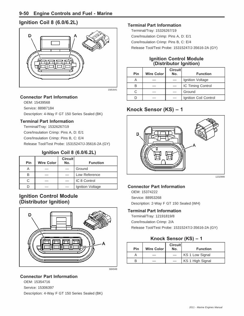
Ignition Coil 8 (6.0/6.2L)
Connector Part InformationOEM: 15439568
Service: 88987184
Description: 4-Way F GT 150 Series Sealed (BK)
Terminal Part InformationTerminal/Tray: 15326267/19
Core/Insulation Crimp: Pins A, D: E/1
Core/Insulation Crimp: Pins B, C: E/4
Release Tool/Test Probe: 15315247/J-35616-2A (GY)
Ignition Coil 8 (6.0/6.2L)
Pin Wire ColorCircuit
No. FunctionA — — Ground
B — — Low Reference
C — — IC 8 Control
D — — Ignition Voltage
Ignition Control Module(Distributor Ignition)
Connector Part InformationOEM: 15354716
Service: 15306397
Description: 4-Way F GT 150 Series Sealed (BK)
Terminal Part InformationTerminal/Tray: 15326267/19
Core/Insulation Crimp: Pins A, D: E/1
Core/Insulation Crimp: Pins B, C: E/4
Release Tool/Test Probe: 15315247/J-35616-2A (GY)
Ignition Control Module(Distributor Ignition)
Pin Wire ColorCircuit
No. FunctionA — — Ignition Voltage
B — — IC Timing Control
C — — Ground
D — — Ignition Coil Control
Knock Sensor (KS) – 1
Connector Part InformationOEM: 15374222
Service: 88953268
Description: 2-Way F GT 150 Sealed (WH)
Terminal Part InformationTerminal/Tray: 12191819/8
Core/Insulation Crimp: 2/A
Release Tool/Test Probe: 15315247/J-35616-2A (GY)
Knock Sensor (KS) – 1
Pin Wire ColorCircuit
No. FunctionA — — KS 1 Low Signal
B — — KS 1 High Signal
1581641
684948
1232999
9-50 Engine Controls and Fuel - Marine
2011 - Marine Engines Manual

Knock Sensor (KS) – 2
Connector Part InformationOEM: 15374222
Service: 88953268
Description: 2-Way F GT 150 Sealed (WH)
Terminal Part InformationTerminal/Tray: 12191819/8
Core/Insulation Crimp: E/A
Release Tool/Test Probe: 15315247/J-35616-2A (GY)
Knock Sensor (KS) – 2
Pin Wire ColorCircuit
No. FunctionA — — KS 2 Low Signal
B — — KS 2 High Signal
Manifold Air Temperature (MAT)Sensor (6.0/6.2L)
Connector Part InformationOEM: 15449028
Service: 88987993
Description: 2-Way F 150 GT Series Sealed (BK)
Terminal Part InformationTerminal/Tray: 15326267/19
Core/Insulation Crimp: E/4
Release Tool/Test Probe: 15315247/J-35616-2A (GY)
Manifold Air Temperature (MAT)Sensor (6.0/6.2L)
Pin Wire ColorCircuit
No. FunctionA — — MAT Sensor Signal
B — — Low Reference
Manifold Absolute Pressure (MAP)Sensor (2.4/6.0/6.2L)
Connector Part InformationHarness Type: Engine
OEM Connector: 15365614
Service Connector: 88988583
Description: 3-Way F Kompakt 2.8 Series, Sealed (BK)
Terminal Part InformationTerminated Lead: Pending
Release Tool: J-38125-561
Diagnostic Test Probe: J-35616-35 (VT)
Terminal/Tray: 1928498056/8
Core/Insulation Crimp: E/1
Manifold Absolute Pressure (MAP)Sensor (2.4/6.0/6.2L)
Pin Wire ColorCircuit
No. Function1 — — 5-Volt Reference
2 — — Low Reference
3 — — MAP Sensor Signal
1232999
1538760
1331443
Engine Controls and Fuel - Marine 9-51
2011 - Marine Engines Manual

Manifold Absolute PressureSensor/Manifold Air Temperature(MAP/MAT) Sensor (3.0/4.3/5.0/5.7L)
Connector Part InformationHarness Type: Engine
OEM Connector: 10763258
Service Connector: 88988320
Description: 4-Way F Kompakt 280 Series Sealed (BK)
Terminal Part InformationTerminated Lead: Pending
Release Tool: J-38125-561
Diagnostic Test Probe: J-35616-35 (VT)
Terminal/Tray: 1928498056/8
Core/Insulation Crimp: E/1
Manifold Absolute PressureSensor/Manifold Air Temperature
(MAP/MAT) Sensor (3.0/4.3/5.0/5.7L)
Pin Wire ColorCircuit
No. Function1 — — Low Reference
2 — — MAT Sensor Signal
3 — — 5-Volt Reference
4 — — MAP Sensor Signal
Pedal Position Sensor
Connector Part InformationOEM: 15326830
Service: 88953153
Description: 6-Way F GT 150 Series Sealed (BK)
Terminal Part InformationTerminal/Tray: 12191819/8
Core/Insulation Crimp: E/A
Release Tool/Test Probe: 15315247/J-35616-2A (GY)
Pedal Position Sensor
Pin Wire ColorCircuit
No. FunctionA — — 5-Volt Reference
B — — Pedal Position Sensor 1Signal
C — — Low Reference
D — —Low ReferencePedal Position Sensor 2Signal
E — — Pedal Position Sensor 2Signal
F — — 5-Volt Reference
1381341
886053
9-52 Engine Controls and Fuel - Marine
2011 - Marine Engines Manual
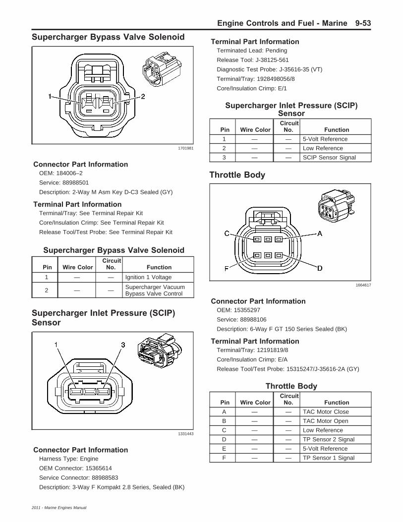
Supercharger Bypass Valve Solenoid
Connector Part InformationOEM: 184006–2
Service: 88988501
Description: 2-Way M Asm Key D-C3 Sealed (GY)
Terminal Part InformationTerminal/Tray: See Terminal Repair Kit
Core/Insulation Crimp: See Terminal Repair Kit
Release Tool/Test Probe: See Terminal Repair Kit
Supercharger Bypass Valve Solenoid
Pin Wire ColorCircuit
No. Function1 — — Ignition 1 Voltage
2 — — Supercharger VacuumBypass Valve Control
Supercharger Inlet Pressure (SCIP)Sensor
Connector Part InformationHarness Type: Engine
OEM Connector: 15365614
Service Connector: 88988583
Description: 3-Way F Kompakt 2.8 Series, Sealed (BK)
Terminal Part InformationTerminated Lead: Pending
Release Tool: J-38125-561
Diagnostic Test Probe: J-35616-35 (VT)
Terminal/Tray: 1928498056/8
Core/Insulation Crimp: E/1
Supercharger Inlet Pressure (SCIP)Sensor
Pin Wire ColorCircuit
No. Function1 — — 5-Volt Reference
2 — — Low Reference
3 — — SCIP Sensor Signal
Throttle Body
Connector Part InformationOEM: 15355297
Service: 88988106
Description: 6-Way F GT 150 Series Sealed (BK)
Terminal Part InformationTerminal/Tray: 12191819/8
Core/Insulation Crimp: E/A
Release Tool/Test Probe: 15315247/J-35616-2A (GY)
Throttle Body
Pin Wire ColorCircuit
No. FunctionA — — TAC Motor Close
B — — TAC Motor Open
C — — Low Reference
D — — TP Sensor 2 Signal
E — — 5-Volt Reference
F — — TP Sensor 1 Signal
1701981
1331443
1664617
Engine Controls and Fuel - Marine 9-53
2011 - Marine Engines Manual
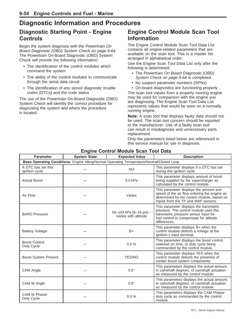
Diagnostic Information and ProceduresDiagnostic Starting Point - EngineControlsBegin the system diagnosis with the Powertrain OnBoard Diagnostic (OBD) System Check on page 9-64.The Powertrain On-Board Diagnostic (OBD) SystemCheck will provide the following information:
• The identification of the control modules whichcommand the system
• The ability of the control modules to communicatethrough the serial data circuit
• The identification of any stored diagnostic troublecodes (DTCs) and the code status
The use of the Powertrain On-Board Diagnostic (OBD)System Check will identify the correct procedure fordiagnosing the system and where the procedureis located.
Engine Control Module Scan ToolInformationThe Engine Control Module Scan Tool Data Listcontains all engine-related parameters that areavailable on the scan tool. This is a master listarranged in alphabetical order.Use the Engine Scan Tool Data List only after thefollowing is determined:
• The Powertrain On Board Diagnostic (OBD)System Check on page 9-64 is completed.
• No suspect parameter numbers (SPNs)• On-board diagnostics are functioning properly
The scan tool values from a properly running enginemay be used for comparison with the engine youare diagnosing. The Engine Scan Tool Data Listrepresents values that would be seen on a normallyrunning engine.Note: A scan tool that displays faulty data should notbe used. The scan tool concern should be reportedto the manufacturer. Use of a faulty scan toolcan result in misdiagnosis and unnecessary partsreplacement.Only the parameters listed below are referenced inthis service manual for use in diagnosis.
Engine Control Module Scan Tool DataParameter System State Expected Value Description
Base Operating Conditions: Engine Idling/Normal Operating Temperature/Neutral/Closed Loop
A DTC has set thisignition cycle — NO This parameter displays if a DTC has set
during this ignition cycle.
Actual Boost — 0.0 kPaThis parameter displays amount of boostbeing supplied by the supercharger ascalculated by the control module.
Air Flow — Varies
This parameter displays the amount andspeed of the air flow entering the engine asdetermined by the control module, based oninputs from the TP and MAP sensors.
BARO Pressure — 65–104 kPa (8–16 psi) -Varies with altitude
This parameter displays the barometricpressure. The control module uses thebarometric pressure sensor input forfuel control to compensate for altitudedifferences.
Battery Voltage — B+This parameter displays B+ when thecontrol module detects a voltage at theignition 1 input terminal.
Boost ControlDuty Cycle — 0.0 %
This parameter displays the boost controlsolenoid on time, or duty cycle beingcommanded by the control module.
Boost System Present — YES/NOThis parameter displays YES when thecontrol module detects the presence ofcertain boost system components.
CAM Angle — 0.0°This parameters displays the actual amount,in camshaft degrees, of camshaft actuationas measured by the control module.
CAM W Angle — 0.0°This parameters displays the actual amount,in camshaft degrees, of camshaft actuationas measured by the control module.
CAM W PhaserDuty Cycle — 0.0 %
This parameters displays the CAM Phaserduty cycle as commanded by the controlmodule.
9-54 Engine Controls and Fuel - Marine
2011 - Marine Engines Manual

Engine Control Module Scan Tool Data (cont’d)Parameter System State Expected Value Description
CAM W PhaserRef Angle — Varies
This parameters displays the CAM Phaserreference angle as determined by the controlmodule, based on inputs from the CMP andCKP sensors.
CAM X Angle — 0.0°This parameters displays the actual amount,in camshaft degrees, of camshaft actuationas measured by the control module.
CAM X PhaserDuty Cycle — 0.0 %
This parameters displays the CAM Phaserduty cycle as commanded by the controlmodule.
CAM X PhaserRef Angle — Varies
This parameters displays the CAM Phaserreference angle as determined by the controlmodule, based on inputs from the CMP andCKP sensors.
Cause For PowerReduction — NO
This parameter displays YES when thecontrol module is operating in reducedpower mode.
Check Engine LampOutput — OFF This parameter displays the control module
commanded state of the MIL control circuit.
Check Gauges LampOutput — OFF
This parameter displays the control modulecommanded state of the check gaugescontrol circuit.
Closed Throttle IdleControl Mode — YES
This parameter displays YES when thethrottle actuator control (TAC) motor is beingused to control the idle speed.
Coolant SensorResistance — Varies
This parameter displays the resistance of theengine coolant sensor based on input to thecontrol module from the engine coolanttemperature (ECT) sensor.
CoolantTemperature–Filtered — −39 to +140°C
( −38 to +284°F)
This parameter displays a defaulted coolanttemperature value being used by the controlmodule when the ECM has detected acondition with the engine coolanttemperature (ECT) sensor.
CoolantTemperature–Raw — −39 to +140°C
( −38 to +284°F)
This parameter displays the temperature ofthe engine coolant based on the input to thecontrol module from the ECT sensor.
Crank Request Input — NOThis parameter displays YES when thecontrol module detects a voltage at the crankrequest input terminal.
Cruise Cruise Control ON ONThis parameter displays the state of thecruise control ON/OFF switch input to thecontrol module.
CruiseResume/Accelerate
— OFFThis parameter displays the state of thecruise control decrease/increase switch inputto the control module.
CruiseDecrease/Increase
switch set to IncreaseON
Cruise Set/Coast
— OFFThis parameter displays the state of thecruise control decrease/increase switch inputto the control module.
CruiseDecrease/Increase
switch set to DecreaseON
Current RPM RatedTorque — Varies
This parameter displays the torque beingdelivered by the engine, based onengine speed.
Desired EGR Position — 0%This parameter displays the desired EGRposition as commanded by the controlmodule.
Desired Idle Speed — 500–700 RPMThis parameter displays the desired engineidle speed as commanded by the controlmodule.
Desired Throttle Position — 7.0–11.0 %This parameter displays the desired throttleposition as commanded by the controlmodule.
Engine Controls and Fuel - Marine 9-55
2011 - Marine Engines Manual

Engine Control Module Scan Tool Data (cont’d)Parameter System State Expected Value Description
Discrete Low OilPressure Input Active — YES/NO
This parameter displays YES if the controlmodule detects the presence of a low oilpressure switch.
Dual Fuel Mode — Fuel 1 or Fuel 2
This parameter displays the position of thefuel select switch as determined by theoperator, on vehicles equipped with dual fuelcapability.
ECM Hardware I.D.Version — Varies This parameter displays the ECM hardware
version installed in the vehicle.
ECM EmbeddedSoftware ReleaseNumber
— VariesThis parameter displays the ECM softwarerelease that is programmed in the controlmodule.
ECM EmbeddedSoftware RevisionNumber
— VariesThis parameter displays the ECM softwarerevision that is programmed in the controlmodule.
Emergency Stop Input — OFFThis parameter displays the status of theemergency stop input terminal to the controlmodule.
Engine Displacement — 5.7/6.0LThis parameter displays the enginedisplacement programmed in the controlmodule.
Engine Hours — Varies This parameter displays the total hours theengine has been operating.
Engine SpeedEngine Cranking Greater than 60 RPM This parameter displays the speed of the
engine crankshaft rotation from informationreceived from the crankshaft position (CKP)sensor.Engine Idling Approximately 600 RPM
Estimated Torque — Varies This parameter displays the available torquethe engine is delivering to the out-drive.
ETC Idle Stop/Idle ValveDuty Cycle — Varies
This parameter displays the duty cycle (ontime) of the ETC motor while the engine isoperating in idle mode.
ETC or GovernorMotor PWM — 8.0–30.0 %
This parameter displays the over-all dutycycle (on time) of the ETC motor regardlessof pedal position.
ETC System Present — YESThis parameter displays whether or not thevehicle is equipped with Electronic ThrottleControl.
Fuel Flow Rate — VariesThis parameter displays in liters or gallonsper hour, the fuel consumption as calculatedby the control module.
Fuel Level — 0–100%This parameter displays the amount of fuelremaining in percent of range, as calculatedby the control module.
Fuel Level 1 Percent — 0–100%This parameter displays the amount of fuelin the fuel tank 1 in percent of range, ascalculated by the control module.
Fuel Level 2 Percent — 0–100%This parameter displays the amount of fuelin the fuel tank 2 in percent of range, ascalculated by the control module.
Fuel Level 1 Volts — 0–5 VoltsThis parameter displays the voltage signalreceived by the control module from the fuellevel sensor 1.
Fuel Level 2 Volts — 0–5 VoltsThis parameter displays the voltage signalreceived by the control module from the fuellevel sensor 2.
Fuel Pressure — 380-427 kPa (55-62 psi)This parameter displays the pressure of thefuel system based on input to the controlmodule from the Fuel Pressure sensor.
Fuel Pressure SensorPresent — YES/NO
This parameter displays YES if the controlmodule detects the presence of a fuelpressure sensor.
9-56 Engine Controls and Fuel - Marine
2011 - Marine Engines Manual

Engine Control Module Scan Tool Data (cont’d)Parameter System State Expected Value Description
Fuel Pressure SensorVoltage — 0–5 Volts
This parameter displays the voltage signalreceived by the control module from the fuelpressure sensor.
Fuel Pump Relay OutputActive — YES
This parameter displays the commandedstate of the control module fuel pump relaycontrol circuit.
Fuel Pump 2 RelayOutput Active — NO
This parameter displays the commandedstate of the control module fuel pump relaycontrol circuit.
Fuel Select Output 1Active — NO
This parameter displays YES when theengine is being operated by an alternate fuelsource, if equipped.
Fuel Select Output 2Active — NO
This parameter displays YES when theengine is being operated by an alternate fuelsource, if equipped.
Fuel TemperatureSensor Present — NO
This parameter displays YES if the controlmodule detects the presence of a fueltemperature sensor.
Fuel TemperatureSensor Resolution — Coarse/Fine This parameter displays the type of scale the
fuel temperature is being displayed on.
Fuel Temp Sensor Volts — 0–5 VoltsThis parameter displays the voltage signalreceived by the control module from the fueltemperature sensor.
General WarningLamp 1 Output — OFF
This parameter displays the commandedstate of the control module general warninglamp 1 control circuit
General WarningLamp 2 Output — OFF
This parameter displays the commandedstate of the control module general warninglamp 2 control circuit
Gov Mode Input Cruise ON/OFFswitch ON ON
This parameter displays the status of thecruise control system as determined by thecontrol module.
GovernedVehicle Speed
Cruise MPH/RPM switchset to MPH Varies
This parameter displays the governed vehiclespeed limit in miles per hour that is set bythe throttle control.
Governor Present — YES This parameter displays whether or not thevehicle is equipped with governor control.
Governor RPM Speed Cruise MPH/RPM switchset to RPM Varies
This parameter displays the governed vehiclespeed limit in engine RPM that is set by thethrottle control.
Governor Status Lamp — OFFThis parameter displays the commandedstate of the control module governor statuslamp control circuit.
History Data Has BeenCorrupted — NO This parameter displays YES if the control
module detects an ECM reset.
IAC in Control of RPM — YESThis parameter displays YES when thecontrol module is regulating the enginespeed with the ETC motor.
IAC Position — 40–50 %
This parameter displays a percentage in arange of 0–100 percent relative to theposition of throttle plate when the engine isconsidered to be at idle, pedal position (PP)is 0 percent. The percentage indicates onlythe throttle opening necessary to maintainthe desired idle speed and is not a functionof the throttle plates total travel from closedto wide open.
Intercooler Output Active — YESThis parameter displays YES if the vehicle isequipped with an intercooler and the engineis operating.
In Fuel DetonationControl Mode — NO
This parameter displays YES when thecontrol module is compensating for anengine detonation spark knock.
Engine Controls and Fuel - Marine 9-57
2011 - Marine Engines Manual

Engine Control Module Scan Tool Data (cont’d)Parameter System State Expected Value Description
Injector Bank APulse Width — 2.5–3.5 ms
This parameter displays the average pulsewidth modulation in milliseconds of the fuelinjectors on cylinder bank A.
Injector Bank BPulse Width — 2.5–3.5 ms
This parameter displays the average pulsewidth modulation in milliseconds of the fuelinjectors on cylinder bank B.
Knock Present in LastSecond — NO
This parameter displays YES when thecontrol module detects a spark knockcondition.
Knock Retard — 0°
This parameter displays in degrees theamount of timing compensation the controlmodule is commanding to compensate forspark knock.
Load Anticipate 1 or 2Enable — NO
This parameter displays YES if an OEMsystem or component has been installed thatplaces an additional load on the engine whenactivated.
Load Anticipate 1or 2 Input — NO
This parameter displays YES if an OEMinstalled system or component has beenactivated.
Load Anticipate 1 or 2 — 0.0 %
This parameter displays the percentage ofload compensation needed to offset theengine drag caused by the activation of anOEM installed system or component.
Low Oil Level Input — ON This parameter displays the status of the lowoil switch circuit to the control module.
Low Oil Level LampOutput — OFF
This parameter displays the control modulecommanded state of the low oil level lampcontrol circuit.
Manifold AbsolutePressure — 32–50 kPa (9–15 in Hg) This parameter displays the pressure from
the MAP sensor to the control module.
MAP Sensor Voltage — 0–5 Volts This parameter displays the signal voltagefrom the MAP sensor to the control module.
Manifold AirTemperature —
−39° to +140°C(−38° to +284°F)
This parameter displays the temperature ofthe air entering the air induction systembased on input to the control module fromthe MAT sensor.
MAT Sensor Present — YESThis parameter displays whether or not thevehicle is equipped with a manifold airtemperature (MAT) sensor.
MAT Sensor Resistance — Varies
This parameter displays the resistance of themanifold air temperature (MAT) sensor basedon input to the control module from the MATsensor.
MAT Sensor Voltage — 0–5 Volts
This parameter displays the voltage of themanifold air temperature (MAT) sensor basedon input to the control module from the MATsensor.
Max Knock RetardCylinder — 0 #
This parameter displays the number of acylinder if a knock condition has beendetected related to that cylinders combustionevent. The scan tool will display 0 if there isno knock condition detected related to aspecific cylinder combustion event.
Min Position LearnPending — NO
This parameter will display YES if the controlmodule has not learned the minimum throttleposition.
Misc Status Flags — 0.0 #This parameter displays the number of thecurrent failure mode indicator (FMI) if an SPNis set.
Monitoring For Knock — YES This parameter displays if the control moduleis monitoring for knock.
9-58 Engine Controls and Fuel - Marine
2011 - Marine Engines Manual

Engine Control Module Scan Tool Data (cont’d)Parameter System State Expected Value Description
O2 A1 or B1 BLMCell I.D. — 0 #
This parameter displays the block learnmemory (BLM) or fuel trim cell number ascalculated by the control module based onengine speed and load inputs. The scan toolwill display a lower number as conditionsare nearer to idle, and a higher value asconditions approach maximum engine speedand maximum load.
O2 A1 or B1 BLMCell Value Closed Loop ON 0.90–1.10 #, Varies
This parameter displays the short termcorrection to fuel delivery for bank 1 orbank 2 in response to the amount of time theoxygen sensor voltage spends above orbelow the 450 mV threshold. The scan toolwill display a value of 1.00 which is equal tostoich 14.7–1, if no adjustments are required.The scan tool will display a value greaterthan 1.00 if fuel has to be added, and avalue less than 1.00 if fuel has to besubtracted.
O2 A1 Cross CountsPer Second — Varies
This parameter displays the oxygen sensorrich/lean and lean/rich switches. A switch iswhen the oxygen sensor voltage goes above450 mV and below 450 mV.
O2 B1 Cross CountsPer Second — Varies
This parameter displays the oxygen sensorrich/lean and lean/rich switches. A switch iswhen the oxygen sensor voltage goes above450 mV and below 450 mV.
O2 A1 or B1 FuelMultiplier Closed Loop ON 0.90–1.10 #
A change made to the fuel delivery will beindicated by the Fuel Multiplier and the BLMCell Value. The BLM Cell Values changerapidly in response to the HO2S signalvoltages. These changes fine tune theengine fueling. The Fuel Multiplier valueschange in response to the trends in theBLM Cell Values. The Fuel Multiplier makescoarse adjustments to the fueling in order tore-center and restore control to the BLMCell Value.The scan tool will display a value less than1.00 when the engine is running too rich andfuel is being subtracted from the combustionevent. The scan tool will display a valuegreater than 1.00 if the engine is runningtoo lean and fuel is being added to thecombustion event.
O2 A1 or B1 HeaterCurrent — 0.5–5 Amps
This parameter displays the amperage of theHO2S heater commanded by the controlmodule.
O2 A2 or B2 HeaterCurrent
Catalyst MonitoringEnabled 0–5 Amps
This parameter displays the amperage of theHO2S heater commanded by the controlmodule. The control module will notcommand any current until the conditionsfor running the catalyst monitoring havebeen met.
O2 A1, A2, B1, or B2Percent — −22 to +22 Percent
This parameter displays the oxygen contentof the exhaust stream at the respective O2sensor. A negative value indicates richexhaust, and a positive value indicates leanexhaust.
Engine Controls and Fuel - Marine 9-59
2011 - Marine Engines Manual

Engine Control Module Scan Tool Data (cont’d)Parameter System State Expected Value Description
O2 Sensor A1 or B1Closed Loop — ON
This parameter displays the state of the fuelcontrol system as commanded by the controlmodule. ON indicates that the control moduleis controlling the fuel delivery based on theoxygen sensors input signal. OFF indicatesOpen Loop operation. The control moduleignores the oxygen sensor input signal inOpen Loop and bases the amount of fuel tobe delivered on other sensor inputs.
O2 Sensor A1, A2, B1or B2 Present — YES This parameter displays whether or not the
vehicle is equipped with an oxygen sensor.O2 Sensor A1 orB1 Ready — YES This parameter displays that the HO2S 1 is
at operating temperature.
O2 Sensor A1 or B1Rich/Lean Closed Loop ON Varies
This parameter displays the oxygen sensorrich/lean and lean/rich status. A switch iswhen the oxygen sensor voltage goes above450 mV and below 450 mV.
O2 A1, A2, B1, orB2 Volts — 100–900 mV
This parameter displays the voltage outputfrom the HO2S to the control module. A lowervoltage indicates a lean exhaust, while ahigher voltage indicates a rich exhaust.
Octane Adapt Enable — OFF
This parameter displays ON when the controlmodule is calibrated to allow the ECM learnthe octane rating of the fuel being consumed.This feature, when enabled increases theignition timing advance curve to raise theperformance of an engine operating on higheroctane fuels. Used primarily in racingapplications.
Octane Rating Adapt — 0.0 %
This parameter displays a range of0–100 percent, and indicates amount ofan increase in the ignition timing advancecurve based on the learned octane rating.
Octane Update inProgress — NO
This parameter displays YES when the controlmodule is in the process of learning the octanerating.
OEM Input 1–4 Active — YES/NOThese parameters display YES if an input issupplied to the control module on therespective OEM circuit.
OEM Output 1–4 Active — YES/NO
These parameters display YES if the controlmodule is using the respective output controlcircuit to operate an OEM component orsystem.
Oil Pressure — 41–414 kPa (6–60 psi)This parameter displays the oil pressurebased on input to the control module from theengine oil pressure sensor.
Oil Pressure SensorVoltage — 0–5 Volts
This parameter displays the oil pressuresensor voltage based on input to the controlmodule from the engine oil pressure sensor.
Oil Sensor Resistance — VariesThis parameter displays the resistance of theoil pressure sensor based on input to thecontrol module from the sensor.
Oil Temperature — VariesThis parameter displays the temperature ofthe engine oil as determined by the controlmodule.
Oil Temperature Flag — NO
This parameter displays YES if the controldetects that the oil temperature was greaterthan a calibrated value during theignition cycle.
Paired Firing Mode — OFFThis parameter displays YES when the engineRPM is synchronized by the control module ona twin engine vehicle.
Pedal Position — 0%This parameter displays the pedal Positionangle as calculated by the control moduleusing the signals from the PP sensors.
9-60 Engine Controls and Fuel - Marine
2011 - Marine Engines Manual

Engine Control Module Scan Tool Data (cont’d)Parameter System State Expected Value Description
Pedal Position Sensor 1Voltage — PP 1 0.7–1.2 Volts
This parameter displays the actual voltage ofthe PP 1 sensor signal circuit as measuredby the control module.
Pedal Position Sensor 2Voltage — PP 2 0.3–0.6 Volts
This parameter displays the actual voltage ofthe PP 2 sensor signal circuit as measuredby the control module.
Powertrain Relay Output — ONThis parameter displays the control modulescommanded state of the powertrain relaycontrol circuit.
Reflects ETC H-BridgeDirection — Varies
This parameter will display OPEN or CLOSEdepending which direction the control moduleis commanding the throttle plate.
Required FuelFlow Rate — Varies
This parameter displays the desired fuelpressure as determined by the controlmodule, if applicable.
Rev Limit Threshold — Varies with engineapplication
This parameter display the engine revolutionlimit calibration in RPM.
Rev Limit Within LastSecond — NO
This parameter displays YES if the enginespeed was limited by the rev limit thresholdwithin the last second.
RPM Based OutputActive — NO
This parameter displays YES if the controlmodule detects OEM installed cruise controlsystem has been switched ON.
Shift Interrupt Input — OFF This parameter displays the shift interruptswitch circuit status to the control module.
Spark Advance — −20 to +40 Degrees
This parameter displays the amount of sparkadvance the control module is commandingon the ignition control circuits. The controlmodule determines the desired advance.
Starter Relay Output — OFFThis parameter displays the control modulescommanded state of the starter relay controlcircuit.
Supercharger InletPressure SensorPresent
— YES/NO This parameter displays YES if the controlmodule detects a SCIP sensor signal.
Supercharger InletPressure Sensor — Varies
This parameter indicates the pressure at thesupercharger inlet as calculated by thecontrol module based on the signal from thesupercharger inlet pressure (SCIP) sensor.The scan tool will display a higher value wideopen throttle, and a lower value at idle.
Supercharger InletPressure Sensor Volts — 0–5 Volts
This parameter indicates the voltage signalreceived by the control module from theSCIP sensor. The scan tool displays a lowvoltage at idle, and a high voltage at wideopen throttle. Barometric pressure andaltitude can effect these values.
Throttle Position — 7–11 %
This parameter displays the percent ofthrottle opening as calculated by the controlmodule using information from the two TPsensors.
Throttle PositionSensor 1 Voltage — 0.95–1.25 Volts
This parameter displays the actual voltage onthe TP sensor 1 signal circuit as measuredby the control module.
Throttle PositionSensor 2 Voltage — 3.75–4.25 Volts
This parameter displays the actual voltage onthe TP sensor 2 signal circuit as measuredby the control module.
Total Fuel Used — Varies Gal/Ltr This parameter displays the total amount offuel consumed over the life of the engine.
Total Hours — Varies This parameter displays the total number ofhours that the engine has been operating.
Engine Controls and Fuel - Marine 9-61
2011 - Marine Engines Manual

Engine Control Module Scan Tool Data (cont’d)Parameter System State Expected Value Description
Total Operating Time — VariesThis parameter displays the total number ofcrankshaft revolutions since the veryfirst engine start-up.
Trans Shift Output — OFF This parameter displays if the control moduleis limiting trans shift operation.
Troll Mode — OFF This parameter displays if the control moduleis commanding troll mode operation.
Troll Mode Enabled — OFF This parameter displays if troll modeoperation is enabled.
Troll Mode Input — OFF This parameter displays the state of the trollmode switch input to the control module.
Variable Governor InputVoltage — 0–5 Volts This parameter displays signal voltage of an
OEM installed speed or RPM control system.
Vehicle Speed — 0 mph/kph This parameter displays the vehicle speedsignal to the control module.
Warm Up Cycles SinceLast DTC — Varies
This parameter indicates the number of warmup cycles that have occurred without a faultpresent. The scan tool will display a 0 if afault has occurred. The scan tool will displaya higher count if a number of warm up cycleshave occurred without a fault.
Warning Buzzer Output — OFFThis parameter displays the commandedstate of the warning buzzer control circuit bythe control module.
Engine Control Module (ECM) Scan Tool Output ControlsOutput Control Description
Boost Override This function controls the boost solenoid from the none to ON or OFF.
Buzzer Override This function controls the buzzer. The normal commanded state is None. Whencommanded ON, the ECM will command the buzzer ON and OFF.
Cam Phaser Cleaning
This function controls the camshaft actuator solenoid. The normal commanded state isNONE. The system will command the camshaft solenoid valve ON to 90 percent forapproximately 2 seconds. This causes the camshaft actuator to travel to the maximumadvance or retard position, approximately 40 degrees camshaft, depending on the actualengine speed. The scan tool initiates the test when the following conditions are met:
• The vehicle speed is 0 km/h (0 mph).• The engine speed is between 2,000-2,500 RPM.• The transmission is in neutral.
Check Gauges Lamp Override This function controls the check gauges lamp. The normal commanded state is None.When commanded ON, the ECM will blink the check gauges lamp ON and OFF.
Fuel Pump 1 Relay Override
This function controls the fuel pump relay. When commanded ON/OFF, the ECMturns the fuel pump relay ON/OFF. If the engine is running and the fuel pump relay iscommanded OFF, the engine will stall. This output can also be monitored on the scan tooldata parameter Fuel Pump Relay Command. The system remains in the commandedstate until cancelled by the scan tool or the ECM.
9-62 Engine Controls and Fuel - Marine
2011 - Marine Engines Manual

Engine Control Module (ECM) Scan Tool Output Controls (cont’d)Output Control Description
Fuel Pump 2 Relay Override
This function controls the fuel pump 2 relay. When commanded ON/OFF, the ECMturns the fuel pump relay ON/OFF. If the engine is running and the fuel pump relay iscommanded OFF, the engine will stall. This output can also be monitored on the scan tooldata parameter Fuel Pump Relay Command. The system remains in the commandedstate until cancelled by the scan tool or the ECM.
Fuel Select Output 1 or 2This function controls the respective fuel control circuit, if used. The normal commandedstate is None. When commanded ON, the ECM will command the control circuit ONand OFF.
DTC Lamp 1–3 Override This function controls the respective DTC lamp. The normal commanded state is None.When commanded ON, the ECM will blink the DTC lamp ON and OFF.
Governor Status Lamp Override This function controls the governor status lamp. The normal commanded state is None.When commanded ON, the ECM will blink the governed status lamp ON and OFF.
Idle Speed Override
This function controls the idle speed override from the base idle speed. The scan toolinitiates the test when the following conditions are met:
• The transmission is in neutral.• The engine speed is less than 1,000 RPM.
The engine speed will remain in the commanded state until cancelled by the scan tool.
Intercooler Cooler OverrideThis function activates the intercooler coolant pump relay. The normal commanded stateis NONE. When commanded ON, the ECM turns the relay ON for approximately2 seconds.
MIL Lamp OverrideThis function controls the malfunction indicator lamp (MIL). The normal commanded stateis None. When commanded ON, the ECM will blink the malfunction indicator lamp (MIL)ON and OFF.
O2 Heater Test This function commands the selected O2 heater control circuit ON and OFF.
Oil Life Monitor Reset
This output control contains the engine oil remaining life determined from an algorithmbased upon the effective engine revolutions and the hours of operation since the last oilchange. This output control may be used to reset the engine oil remaining life to 100%after an oil change or to any other value when replacing a control module.
Power Balance Test This function will disable a fuel injector for a cylinder one at a time. The engine speed canbe monitored and used for comparing each cylinders RPM decrease.
Reset Block Learn Values Activates the reset of Fuel Multiplier data in all BLM Cell I.Ds.
Slow Mode Lamp Override This function controls the troll lamp lamp. The normal commanded state is None.When commanded ON, the ECM will blink the troll lamp ON and OFF.
Speed Based Output Override This function allows the scan tool to override the speed based system for testing.
SVS Lamp Override This function controls the service vehicle soon (SVS) lamp. The normal commanded stateis None. When commanded ON, the ECM will blink the oil level lamp ON and OFF.
Trans Shift OverrideThis function activates the shift interlock solenoid, if equipped. The normal commandedstate is NONE. When commanded ON, the control module turns the solenoid ON forapproximately 2 seconds.
Engine Controls and Fuel - Marine 9-63
2011 - Marine Engines Manual

Powertrain On BoardDiagnostic (OBD) System Check1. Verify that none of the following preliminary
inspections/tests reveal the cause of thevehicle concern before beginning diagnosis:• Ensure that the battery is fully charged.• Ensure that the battery cables are clean
and tight.• Inspect for any open fuses. Refer to Engine
Controls Schematics on page 9-6.• Ensure that the grounds are clean, tight, and
in the correct location.• Inspect the easily accessible systems or the
visible system components for obvious damageor conditions that could cause the concern.This would include checking to ensure that allconnections/connectors are fully seated andsecured.
• Inspect for aftermarket devices that could affectthe operation of the system. Refer to CheckingAftermarket Accessories on page 11-6.
• Search for applicable service bulletins.⇒ If the preceding inspections/tests resolve the
concern, go to Diagnostic Repair Verification onpage 6-22.
2. Install a scan tool. Verify that the scan toolpowers up.⇒ If the scan tool does not power up, refer to
Scan Tool Does Not Power Up on page 11-3.3. Ignition ON, Engine OFF, verify communication
with all of the control modules on the vehicle.⇒ If the scan tool does not communicate
with one or more of the expected controlmodules, refer to Scan Tool Does NotCommunicate with CAN Device on page 11-4.
4. Verify that SPN 65558 or 65559 is not set.⇒ If either SPN is set, refer to SPN 65558
or 65559 on page 9-118.5. Attempt to start the engine. Verify that the engine
cranks.⇒ If the engine does not crank, refer to
SPN 66002 on page 9-162 (if equipped).If the vehicle is not equipped with an ECMcontrolled starter relay, repair the startingsystem.
6. Attempt to start the engine. Verify the enginestarts and idles.⇒ If the engine does not start and idle, refer
to Engine Cranks But Does Not Run onpage 9-201.
Note: Do not clear any SPNs unless instructed to doso by a diagnostic procedure.7. Use the appropriate scan tool selections to obtain
any SPNs from each of the vehicle controlmodules. Verify there are no SPNs reportedfrom any module.⇒ If any SPNs are present, refer to Diagnostic
Trouble Code (DTC) List on page 6-11and diagnose any current SPNs in thefollowing order:
7.1. Any of the following: 630, 65580, 65581,or 65582.
7.2. SPN 627.
7.3. Component level SPNs.
7.4. System level SPNs.
7.5. Any remaining SPNs.
⇒ If none of the previous tests or inspectionsaddresses the concern, refer to Symptoms -Engine Controls on page 9-199.
9-64 Engine Controls and Fuel - Marine
2011 - Marine Engines Manual

SPN 38 or 96Diagnostic Instructions
• Perform the Powertrain On BoardDiagnostic (OBD) System Check on page 9-64prior to using this diagnostic procedure.
• Review Strategy Based Diagnosis on page 6-4 foran overview of the diagnostic approach.
• Diagnostic Procedure Instructions on page 6-5provide an overview of each diagnostic category.
SPN DescriptorSPN 38 FMI 3: Fuel Level Sensor 2 Circuit Voltage Above Normal or Shorted High
SPN 38 FMI 4: Fuel Level Sensor 2 Circuit Voltage Below Normal or Shorted Low
SPN 96 FMI 3: Fuel Level Sensor 1 Circuit Voltage Above Normal or Shorted High
SPN 96 FMI 4: Fuel Level Sensor 1 Circuit Voltage Below Normal or Shorted Low
Diagnostic Fault Information
CircuitShort toGround
Open/HighResistance
Short toVoltage
SignalPerformance
Fuel Level Sensor 1 Low Reference Circuit — 96–3 96–3 —Fuel Level Sensor 1 Signal Circuit 96–4 96–3 96–3 —Fuel Level Sensor 2 Low Reference Circuit — 38–3 38–3 —Fuel Level Sensor 2 Signal Circuit 38–4 38–3 38–3 —
Circuit/System DescriptionThe fuel level sensor changes resistance in responseto the fuel level. The engine control module (ECM)monitors the signal circuit of the fuel level sensor inorder to determine the fuel level. When the fuel tank isfull, the sensor resistance is low and the ECM detectsa low signal voltage. When the fuel tank is empty, thesensor resistance is high and the ECM detects a highsignal voltage. The ECM uses the signal circuit of thefuel level sensor in order to calculate the percentage ofremaining fuel in the tank.
Conditions for Running the SPN• SPN 630, 65580, 65620, or 65621 is not set.• The ignition is ON for a predetermined time.• SPNs 38 and 96 run continuously when the
conditions above exist.
Conditions for Setting the SPN38–3 and 96–3
• The ECM detects the fuel sensor voltage isgreater than 2.9 volts.
• The above condition is present for greater than30 seconds.
38–4 and 96–4• The ECM detects the fuel sensor voltage is less
than 0.39 volts.• The above condition is present for greater than
30 seconds.
Action Taken When the SPN Sets• SPNs 38 and 96 are type C SPNs.• The fuel gauge defaults to empty (if equipped).• The low fuel indicator illuminates (if equipped).
Conditions for Clearing the SPNSPNs 38 and 96 are type C SPNs.
Reference InformationSchematic ReferenceEngine Controls Schematics on page 9-6
Connector End View Reference• Engine Control Module Connector End Views on
page 9-30• Engine Controls Connector End Views on
page 9-33
Description and OperationFuel System Description on page 9-284
Electrical Information Reference• Circuit Testing on page 11-6• Connector Repairs on page 11-22• Testing for Intermittent Conditions and Poor
Connections on page 11-13
• Wiring Repairs on page 11-16
SPN Type ReferenceSuspect Parameter Number (SPN) Type Definitions onpage 6-9
Engine Controls and Fuel - Marine 9-65
2011 - Marine Engines Manual

Scan Tool ReferenceEngine Control Module Scan Tool Information onpage 9-54
Circuit/System Verificatio1. Ignition ON, observe the SPN information with a
scan tool. SPN 38 or 96 should not be set.
2. Observe the scan tool Fuel Level 1 or 2 Percentparameter. The parameter should be between4 percent and 98 percent.
3. Operate the vehicle within the Conditions forRunning the SPN to verify the SPN does notreset. You may also operate the vehicle within theconditions that you observed from the FreezeFrame/Failure Records data.
Circuit/System Testing1. Ignition OFF, disconnect the harness connector at
the appropriate fuel level sensor.
2. Ignition OFF, test for less than 5 Ω between thelow reference circuit terminal and ground.
⇒ If greater than the specified range, test the lowreference circuit for a short to voltage or anopen/high resistance. If the circuit tests normal,replace the ECM.
3. Ignition ON, verify that the appropriate scan toolFuel Level Volts parameter is greater than 4.97 V.
⇒ If less than the specified range, test thesignal circuit for a short to ground. If thecircuit tests normal, replace the ECM.
Note: If the fuse in the jumper wire opens the signalcircuit is shorted to a voltage, and the fuel level sensormay be damaged.4. Install a 3 A fused jumper between the signal
circuit terminal and the low reference circuitterminal. Verify the appropriate scan tool FuelLevel Volts parameter is less than 0.10 V.⇒ If greater than the specified range, test the
signal circuit for a short to voltage or anopen/high resistance. If the circuit testsnormal, replace the ECM.
5. If all circuits test normal, test or replace the fuellevel sensor.
Component Testing1. Ignition OFF, disconnect the harness connector at
the appropriate fuel level sensor.2. Remove the fuel level sensor.3. Connect a DMM between the terminals of the fuel
level sensor.4. While sweeping the fuel level sensor through its
full range of motion, test for a minimum valueless than 41 Ω and a maximum value greaterthan 119 Ω.⇒ If not within the specified range, replace the
fuel level sensor.
Repair InstructionsPerform the Diagnostic Repair Verification onpage 6-22 after completing the diagnostic procedure.Engine Control Module Replacement on page 9-217for engine control module replacement, setup,and programming
9-66 Engine Controls and Fuel - Marine
2011 - Marine Engines Manual

SPN 51Diagnostic Instructions
• Perform the Powertrain On BoardDiagnostic (OBD) System Check on page 9-64prior to using this diagnostic procedure.
• Review Strategy Based Diagnosis on page 6-4 foran overview of the diagnostic approach.
• Diagnostic Procedure Instructions on page 6-5provides an overview of each diagnostic category.
DTC DescriptorsSPN 51 FMI 0: Throttle Position (TP) Sensor Circuit Voltage Data Valid but Above Normal
SPN 51 FMI 3: Throttle Position (TP) Sensor Circuit Voltage Above Normal or Shorted High
SPN 51 FMI 4: Throttle Position (TP) Sensor Circuit Voltage Below Normal or Shorted Low
Diagnostic Fault Information
CircuitShort toGround
Open/HighResistance
Short toVoltage
SignalPerformance
5-Volt Reference 65623–4 51–4 51–3, 65605–2 —TP Sensor Signal 51–4 51–4 51–3 51–0Low Reference — 51–3 — 51–0
Typical Scan Tool DataTP Sensor 1 and 2
Circuit Short to Ground Open Short to VoltageOperating Conditions: The ignition is ON and the engine is OFF.Parameter Normal Range: TP Sensor 0.5 volts
5-Volt Reference 0.00 V 0.00 V 3.75 V
TP Sensor Signal 0.00 V 0.00 V 5.02 V
Low Reference 0.00 V 4.96 V —
Circuit/System DescriptionThe throttle body assembly contains a throttleposition (TP) sensor. The TP sensor is mountedexternally on the throttle body assembly. The TPsensor is a potentiometer which provides a signalvoltage that changes relative to the throttle bladeangle. The engine control module (ECM) suppliesthe TP sensor with a 5-volt reference circuit, alow reference circuit, and a signal circuit. The TPsensor signal voltage increases from less than1 volt at idle to greater than 4 volts at wide openthrottle (WOT).
Conditions for Running the SPN• Before the ECM can report that SPN 51–0 failed,
SPN 106–0 and 106–1 must run and pass.
• SPN 106, 630, 65580, 65620, 65621, 65622, or65623 is not set.
• The engine speed is less than apredetermined value.
• The MAP signal is less than apredetermined value.
51–3 and 51–4• SPN 630, 65580, 65620, 65621, 65622, or 65623
is not set.• The ignition is ON, or the engine is operating.• The SPN runs continuously when the conditions
above are met.
Conditions for Setting the SPN51–0The ECM detects that the TP sensor voltage isgreater than a calibrated value for greater than1 second.
51–3The ECM detects that the TP sensor voltage isgreater than 4.49 volts.
51–4The ECM detects that the TP sensor voltage is lessthan 0.29 volt.
Action Taken When the SPN SetsSPN 51 is a Type B SPN.
Engine Controls and Fuel - Marine 9-67
2011 - Marine Engines Manual

Conditions for Clearing the SPNSPN 51 is a Type B SPN.
Diagnostic AidsIf a shared 5-volt reference circuit is shorted to groundor shorted to a voltage, other 5-volt referencecircuits may be affected.
Reference InformationSchematic ReferenceEngine Controls Schematics on page 9-6
Connector End View Reference• Engine Control Module Connector End Views on
page 9-30• Engine Controls Connector End Views on
page 9-33
Electrical Information Reference• Circuit Testing on page 11-6• Connector Repairs on page 11-22• Testing for Intermittent Conditions and Poor
Connections on page 11-13
• Wiring Repairs on page 11-16
SPN Type ReferenceSuspect Parameter Number (SPN) Type Definitions onpage 6-9
Scan Tool ReferenceEngine Control Module Scan Tool Information onpage 9-54
Circuit/System Verificatio1. Ignition ON, observe the SPN information with
a scan tool. SPN 65623–4 should not be set.Refer to SPN 65620-65623 on page 9-149 if theSPN is set.
2. Engine operating, observe the SPN informationwith a scan tool. SPN 51 should not set.
3. Ignition ON, engine OFF, slowly depress theaccelerator pedal from the rest position to wideopen throttle and observe the scan tool TP Sensorvoltage parameter. The voltage should increasefrom less than 1 volt with the throttle closed togreater than 4 volts at WOT with no drop-outs orjumps in voltage.
4. Operate the vehicle within the Conditions forRunning the DTC to verify the DTC does notreset. You may also operate the vehicle withinthe conditions that you observed from the FreezeFrame/Failure Records data.
Circuit/System Testing1. Ignition OFF, disconnect the harness connector at
the TP sensor.2. Ignition OFF for 30 S, test for less than 5 Ω
between the low reference circuit terminal 3and ground.⇒ If greater than the specified range, test the low
reference circuit for an open/high resistance.If the circuit tests normal, replace the ECM.
3. Ignition ON, test for 4.8–5.2 volts between the5-volt reference circuit terminal 2 and ground.⇒ If less than the specified range, test the 5-volt
reference circuit for a short to ground oropen/high resistance. If the circuit tests normal,replace the ECM.
⇒ If greater than the specified range, test the5-volt reference circuit for a short to voltage.If the circuit tests normal, replace the ECM.
4. Verify the scan tool TP Sensor voltage parameteris less than 0.10 volt.⇒ If greater than the specified range, test the
signal circuit for a short to voltage. If thecircuit tests normal, replace the ECM.
5. Install a 3 A fused jumper wire between the signalcircuit terminal 3 and the 5-volt reference circuitterminal 2. Verify the scan tool TP sensor voltageparameter is greater than 4.80 volts.⇒ If less than the specified range, test the signal
circuit for a short to ground or an open/highresistance. If the circuit tests normal, replacethe ECM.
6. If all circuits test normal, test or replace the TPsensor.
Repair InstructionsPerform the Diagnostic Repair Verification onpage 6-22 after completing the diagnostic procedure.
• Throttle Position Sensor Replacement(Non ETC) on page 9-227
• Engine Control Module Replacement onpage 9-217 for ECM replacement, setup, andprogramming
9-68 Engine Controls and Fuel - Marine
2011 - Marine Engines Manual

SPN 84Diagnostic Instructions
• Perform the Powertrain On BoardDiagnostic (OBD) System Check on page 9-64prior to using this diagnostic procedure.
• Review Strategy Based Diagnosis on page 6-4 foran overview of the diagnostic approach.
• Diagnostic Procedure Instructions on page 6-5provide an overview of each diagnostic category.
SPN DescriptorSPN 84 FMI 1: Vehicle Speed Sensor (VSS) Data Valid but Below Normal
SPN 84 FMI 2: Vehicle Speed Sensor (VSS) Data Erratic, Intermittent or Incorrect
SPN 84 FMI 3: Vehicle Speed Sensor (VSS) Voltage Above Normal or Shorted High
SPN 84 FMI 4: Vehicle Speed Sensor (VSS) Voltage Below Normal or Shorted Low
Circuit/System DescriptionThe vessel speed is provided to the engine controlmodule (ECM) by the vehicle speed sensor (VSS).The sensor is a paddle wheel permanent magnetgenerator that is usually located through hull, orattached to the transom of the vessel. The VSSproduces a signal whenever the vessel is moving.The number of pulses increases with the speed of thevessel. The ECM converts this signal into miles perhour (MPH), which can be monitored with a scan tool.The vehicle speed information is used by the ECM forgoverning the vessels speed during cruise controloperation.
Conditions for Running the SPN84–1
• Before the ECM can report that SPN-84–1 failed,SPN 84–3 and 84–4 must run and pass.
• SPN 106, 630, 65580, 65620, 65621, 65622, or65623 is not set.
• The engine is operating for greater than acalibrated time.
• The engine speed is greater than acalibrated value.
• The MAP signal is less than a calibrated value.
• The pedal position is less than a calibrated value.
• The SPN runs continuously when the conditionsabove exist.
84–2• SPN 630, 65580, 65620, 65621, 65622, or 65623
is not set.• The engine is operating for greater than a
calibrated time.• The SPN runs continuously when the conditions
above exist.
84–3 and 84–4• SPN 630, 65580, 65620, 65621, 65622, or 65623
is not set.• The engine is operating for greater than a
predetermined time.• The pedal position is less than a
predetermined value.• The SPNs run continuously when the conditions
above are met.
Conditions for Setting the SPN84–1The ECM detects that the VSS signal is greater than acalculated value.
84–2The ECM detects the VSS signal is erratic for greaterthan pre-determined time.
84–3 and 84–4The ECM detects a short to ground, an open, or ashort to voltage in the VSS circuits or sensor.
Action Taken When the SPN Sets• SPN 84 is a Type C SPN.• The cruise control system will be disabled.
Conditions for Clearing the SPNSPN 84 is a Type C SPN.
Engine Controls and Fuel - Marine 9-69
2011 - Marine Engines Manual

Reference InformationSchematic ReferenceEngine Controls Schematics on page 9-6
Connector End View Reference• Engine Control Module Connector End Views on
page 9-30
• Engine Controls Connector End Views onpage 9-33
Electrical Information Reference• Circuit Testing on page 11-6
• Connector Repairs on page 11-22
• Testing for Intermittent Conditions and PoorConnections on page 11-13
• Wiring Repairs on page 11-16
Scan Tool ReferenceEngine Control Module Scan Tool Information onpage 9-54
Circuit/System Verificatio1. Ignition ON, observe the SPN information with a
scan tool. Verify SPN 65620, 65621 65622, or65623 is not set.
⇒ If an SPN is set, refer to SPN 65620-65623 onpage 9-149 for further diagnosis.
2. Operate the vehicle within the Conditions forRunning the SPN to verify the SPN does notreset. You may also operate the vehicle withinthe conditions that you observed from the FreezeFrame/Failure Records data.
Circuit/System Testing1. Ignition OFF, disconnect the harness connector at
the VSS.2. Test for less than 5 Ω between the low reference
circuit terminal and ground.⇒ If greater than the specified range, test the low
reference circuit for an open/high resistance.If the circuit tests normal, replace the ECM.
3. Ignition ON, test for 4.8–5.2 V between the 5-voltreference circuit terminal and ground.⇒ If less than the specified range, test the 5-volt
reference circuit for a short to ground or anopen/high resistance. If the circuit tests normal,replace the ECM.
⇒ If greater than the specified range, test the5-volt reference circuit for a short to voltage.If the circuit tests normal, replace the ECM.
4. Ignition ON, test for 4.8–5.2 V between the signalcircuit terminal and ground.⇒ If less than the specified range, test the signal
circuit for a short to ground or an open/highresistance. If the circuit tests normal, replacethe ECM.
⇒ If greater than the specified range, test thesignal circuit for a short to voltage. If thecircuit tests normal, replace the ECM.
5. If all circuits test normal, replace the VSS.
Repair InstructionsPerform the Diagnostic Repair Verification onpage 6-22 after completing the diagnostic procedure.
• Vehicle Speed Sensor Replacement• Engine Control Module Replacement on
page 9-217 for ECM replacement, setup, andprogramming
9-70 Engine Controls and Fuel - Marine
2011 - Marine Engines Manual

SPN 94Diagnostic Instructions
• Perform the Powertrain On BoardDiagnostic (OBD) System Check on page 9-64prior to using this diagnostic procedure.
• Review Strategy Based Diagnosis on page 6-4 foran overview of the diagnostic approach.
• Diagnostic Procedure Instructions on page 6-5provides an overview of each diagnostic category.
SPN DescriptorsSPN 94 FMI 3: Fuel Pressure Sensor Voltage Above Normal or Shorted High
SPN 94 FMI 4: Fuel Pressure Sensor Voltage Below Normal or Shorted Low
SPN 94 FMI 15: Fuel Pressure Data Valid But Above Normal Range-Least Severe Level
SPN 94 FMI 17: Fuel Pressure Data Valid But Below Normal Range-Least Severe Level
Diagnostic Fault Information
CircuitShort toGround
Open/HighResistance
Short toVoltage
SignalPerformance
5-Volt Reference 94–3 94–4 94–3 94–17FP Sensor Signal 94–4 94–4 94–3 94–15, 94–17Low Reference — 94–3 — 94–15
Typical Scan Tool DataFuel Pressure Sensor
Circuit Short to Ground Open Short to VoltageOperating Conditions: Engine idling at Normal Operating TemperatureParameter Normal Range: 379–427 kPa (55–62 psi)
5-Volt Reference 0 kPa (0 psi) 0 kPa (0 psi) 689 kPa (100 psi)
FP Sensor Signal 0 kPa (0 psi) 689 kPa (100 psi) 689 kPa (100 psi)
Low Reference — 689 kPa (100 psi) *
* Internal ECM damage may occur if the circuit is shorted to B+.
Circuit/System DescriptionThe fuel pressure (FP) sensor changes resistancebased on fuel system pressure. The engine controlmodule (ECM) monitors the signal circuit from the FPsensor. The ECM supplies 5-volts to the FP sensor onthe 5-volt reference circuit. The ECM also provides aground on the low reference circuit. The FP sensorprovides a signal to the ECM on the FP sensor signalcircuit which is relative to the pressure changes in thefuel system pressure. When the fuel pressure is high,the sensor resistance is high, and the ECM senses ahigh voltage. When the fuel pressure is low, the sensorvoltage is low, and the ECM senses a low signalvoltage. A FP sensor fault code may cause an enginespeed reduction to occur on vessels with certain engineapplications.
Conditions for Running the SPN94–3 and 94–4
• SPN 630, 65580, 65620, 65621, 65622, or 65623is not set.
• The engine is operating for greater than10 seconds.
• SPN 94 runs continuously when the aboveconditions are met.
94–15 and 94–17• SPN 630, 65580, 65620, 65621, 65622, or 65623
is not set.
• The ignition is ON, or engine is operating.
• The fuel pump is commanded ON.
• The desired fuel pressure is stable within+/−5 kPa (0.7 PSI).
• SPN 94 runs continuously when the aboveconditions are met for greater than 10 seconds.
Engine Controls and Fuel - Marine 9-71
2011 - Marine Engines Manual

Conditions for Setting the SPN94–3The ECM detects that the FP sensor voltage isgreater than 4.8 volts for greater than 1.3 seconds.
94–4The ECM detects that the FP sensor voltage is lessthan 0.25 volt for greater than 1.3 seconds.
94–15, 17The ECM detects that the actual fuel pressure is+/−40 kPa (6 PSI) of the desired fuel pressurefor greater than 10 seconds.
Action Taken When the SPN SetsSPN 94 is a Type B SPN.
Conditions for Clearing the SPNSPN 94 is a Type B SPN.
Diagnostic AidsIf a shared 5-volt reference circuit is shorted to groundor shorted to a voltage, other 5-volt referencecircuits may be affected.
Reference InformationSchematic ReferenceEngine Controls Schematics on page 9-6
Connector End View Reference• Engine Control Module Connector End Views on
page 9-30
• Engine Controls Connector End Views onpage 9-33
Electrical Information Reference• Circuit Testing on page 11-6
• Connector Repairs on page 11-22
• Testing for Intermittent Conditions and PoorConnections on page 11-13
• Wiring Repairs on page 11-16
SPN Type ReferenceSuspect Parameter Number (SPN) Type Definitions onpage 6-9
Scan Tool ReferenceEngine Control Module Scan Tool Information onpage 9-54
Special ToolsJ 34730-1A Fuel Pressure Gauge
Circuit/System Verificatio1. Ignition ON, observe the SPN information with a
scan tool. Verify that SPN 65620, 65621, 65622,or 65623 is not set.⇒ If either SPN is set, refer to SPN 65620-65623
on page 9-149.2. Engine idling, observe the scan tool FP Sensor
parameter. The reading should be between379–427 kPa (55–62 psi).
3. Operate the vehicle within the Conditions forRunning the SPN to verify the SPN does notreset. You may also operate the vehicle within theconditions that you observed from the FreezeFrame/Failure Records data.
Circuit/System Testing1. Ignition OFF, disconnect the harness connector at
the FP sensor.2. Ignition OFF, test for less than 5 Ω between the
low reference circuit terminal and ground.⇒ If greater than the specified range, test the low
reference circuit for an open/high resistance.If the circuit tests normal, replace the ECM.
3. Ignition ON, test for 4.8–5.2 V between the 5-voltreference circuit terminal and ground.⇒ If less than the specified range, test the 5-volt
reference circuit for a short to ground oropen/high resistance. If the circuit tests normal,replace the ECM.
⇒ If greater than the specified range, test the5-volt reference circuit for a short to voltage.If the circuit tests normal, replace the ECM.
4. Verify the scan tool FP sensor pressure parameteris 0 kPa (0 psi).⇒ If greater than the specified range, test the
signal circuit for a short to voltage. If thecircuit tests normal, replace the ECM.
5. Install a 3 A fused jumper wire between the signalcircuit terminal and the 5-volt reference circuitterminal. Verify the scan tool FP sensor parameteris greater than 655 kPa (95 psi).⇒ If less than the specified range, test the signal
circuit for a short to ground or an open/highresistance. If the circuit tests normal, replacethe ECM.
6. If all circuits test normal, refer to Fuel SystemDiagnosis (with Returnless Fuel System ) onpage 9-208 or Fuel System Diagnosis (withoutReturnless Fuel System) on page 9-210. If the fuelsystem tests normal, replace the FP sensor.
Repair InstructionsPerform the Diagnostic Repair Verification onpage 6-22 after completing the diagnostic procedure.Engine Control Module Replacement on page 9-217for engine control module replacement, setup,and programming
9-72 Engine Controls and Fuel - Marine
2011 - Marine Engines Manual

SPN 98Diagnostic Instructions
• Perform the Powertrain On BoardDiagnostic (OBD) System Check on page 9-64prior to using this diagnostic procedure.
• Review Strategy Based Diagnosis on page 6-4 foran overview of the diagnostic approach.
• Diagnostic Procedure Instructions on page 6-5provide an overview of each diagnostic category.
SPN DescriptorSPN 98 FMI 17: Oil Level Switch Signal Data Valid But Below Normal Range-Least Severe Level
Circuit/System DescriptionThe oil level switch is a normally open switch that isclosed when the oil is at the proper level. The enginecontrol module (ECM) monitors the signal circuit of theoil level switch in order to determine the if there is alow oil level condition. When the oil is full, the switchcontacts are closed, and the ECM detects a low signalvoltage. When the oil level is low, the switch contactsopen and the ECM detects a high signal voltage.
Conditions for Running the SPN• SPN 630 or 65580 is not set.• The ignition is ON.• The ECM determines that the oil has had time to
drain back into the oil pan.• The SPN runs at ignition ON depending on
coolant temperature.
Conditions for Setting the SPNThe ECM detects a low oil level condition for greaterthan 30 seconds.
Action Taken When the SPN SetsSPN 98 is a type C SPN.
Conditions for Clearing the SPNSPN 98 is a type C SPN.
Reference InformationSchematic ReferenceEngine Controls Schematics on page 9-6
Connector End View Reference• Engine Control Module Connector End Views on
page 9-30
• Engine Controls Connector End Views onpage 9-33
Description and OperationData Link Communications Description and Operationon page 11-5
Electrical Information Reference• Circuit Testing on page 11-6
• Connector Repairs on page 11-22
• Testing for Intermittent Conditions and PoorConnections on page 11-13
• Wiring Repairs on page 11-16
SPN Type ReferenceSuspect Parameter Number (SPN) Type Definitions onpage 6-9
Scan Tool ReferenceEngine Control Module Scan Tool Information onpage 9-54
Engine Controls and Fuel - Marine 9-73
2011 - Marine Engines Manual
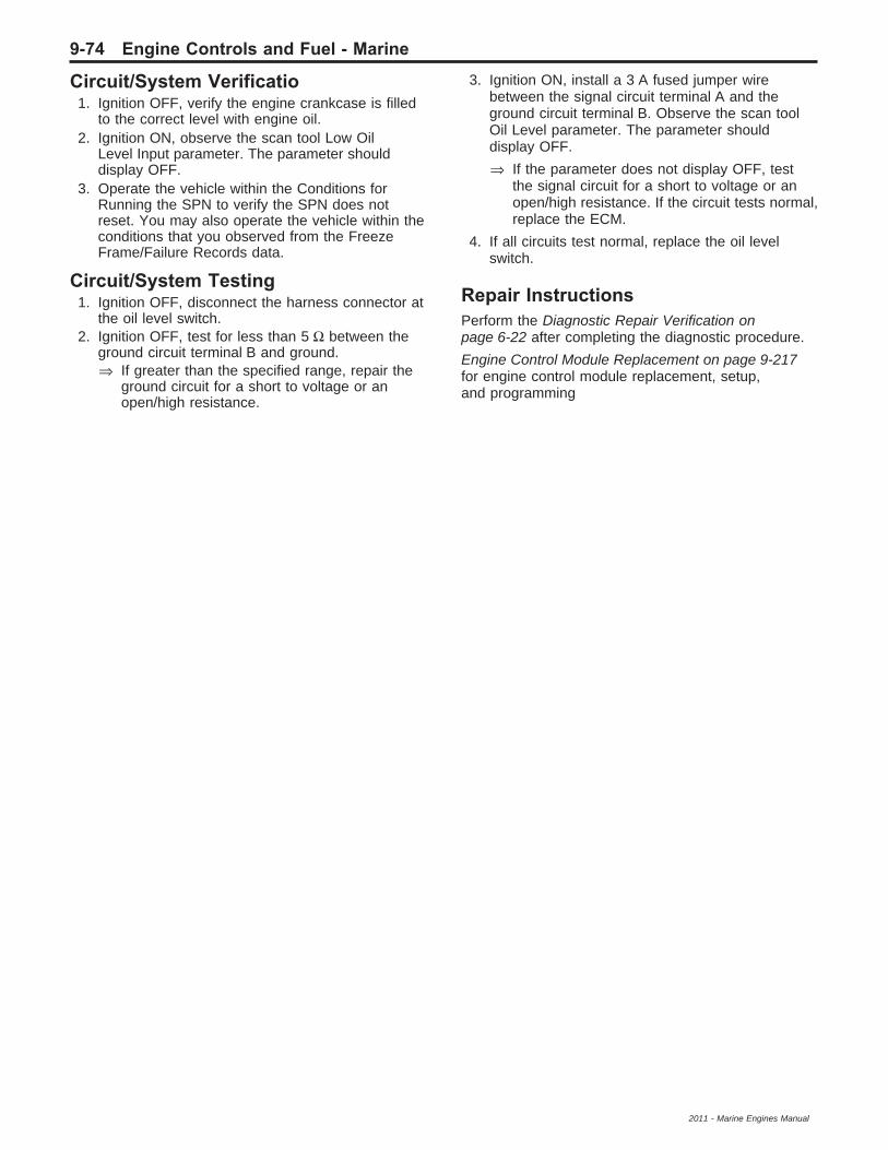
Circuit/System Verificatio1. Ignition OFF, verify the engine crankcase is filled
to the correct level with engine oil.2. Ignition ON, observe the scan tool Low Oil
Level Input parameter. The parameter shoulddisplay OFF.
3. Operate the vehicle within the Conditions forRunning the SPN to verify the SPN does notreset. You may also operate the vehicle within theconditions that you observed from the FreezeFrame/Failure Records data.
Circuit/System Testing1. Ignition OFF, disconnect the harness connector at
the oil level switch.2. Ignition OFF, test for less than 5 Ω between the
ground circuit terminal B and ground.⇒ If greater than the specified range, repair the
ground circuit for a short to voltage or anopen/high resistance.
3. Ignition ON, install a 3 A fused jumper wirebetween the signal circuit terminal A and theground circuit terminal B. Observe the scan toolOil Level parameter. The parameter shoulddisplay OFF.
⇒ If the parameter does not display OFF, testthe signal circuit for a short to voltage or anopen/high resistance. If the circuit tests normal,replace the ECM.
4. If all circuits test normal, replace the oil levelswitch.
Repair InstructionsPerform the Diagnostic Repair Verification onpage 6-22 after completing the diagnostic procedure.
Engine Control Module Replacement on page 9-217for engine control module replacement, setup,and programming
9-74 Engine Controls and Fuel - Marine
2011 - Marine Engines Manual

SPN 100 (3.0L, 4.3L, 5.0L, 5.7L)Diagnostic Instructions
• Perform the Powertrain On BoardDiagnostic (OBD) System Check on page 9-64prior to using this diagnostic procedure.
• Review Strategy Based Diagnosis on page 6-4 foran overview of the diagnostic approach.
• Diagnostic Procedure Instructions on page 6-5provides an overview of each diagnostic category.
SPN DescriptorsSPN 100 FMI 3: Engine Oil Pressure (EOP) Sensor Circuit Voltage Above Normal or Shorted High
SPN 100 FMI 4: Engine Oil Pressure (EOP) Sensor Circuit Voltage Below Normal or Shorted Low
SPN 100 FMI 17: Engine Oil Pressure (EOP) Sensor Data Valid But Below Normal Range-Least Severe Level
Diagnostic Fault Information
CircuitShort toGround
Open/HighResistance
Short toVoltage
SignalPerformance
5-Volt Reference 65620–4 100–4 100–4 —EOP Sensor Signal 100–4 100–4 100–3 100–17Low Reference — — — —
Typical Scan Tool DataEOP Sensor
Circuit Short to Ground Open Short to VoltageOperating Conditions: Engine idling at Normal Operating TemperatureParameter Normal Range: 41–414 kPa (6–60 psi)
5-Volt Reference 0 kPa (0 psi) 0 kPa (0 psi) 0 kPa (0 psi)
EOP Sensor Signal 0 kPa (0 psi) 0 kPa (0 psi) 910 kPa (132 psi)
Low Reference — 118 psi (813 kPa) *
* Internal ECM damage may occur if the circuit is shorted to B+.
Circuit/System DescriptionThe engine oil pressure (EOP) sensor changes voltagebased on the engine oil pressure. The EOP sensoris a 3-wire sensor comprising of the signal circuit, thelow reference circuit and the 5-volt reference circuit.The engine control module (ECM) supplies 5 volts tothe EOP sensor via the 5-volt reference circuit andprovides ground via the EOP low reference circuit.The ECM monitors the signal circuit of the EOP sensorto determine the EOP sensor voltage is within thenormal operating range of approximately 1-4 volts.When the engine oil pressure is high, the EOP sensorvoltage is high and the ECM senses a high signalvoltage. When the engine oil pressure is low, the EOPsensor voltage is low and the ECM senses a low signalvoltage. An EOP fault code will cause RPM reduction tooccur on some engine applications.
Conditions for Running the SPN100–3 and 100–4
• SPNs 630, 65580, 65620, 65621, 65622, or65623 is not set.
• The ignition is ON, or engine is operating.• The SPNs run continuously when the above
conditions are met for greater than 10 seconds.
100–17• SPNs 100–3, 100–4, 630, 65580, 65620, or
65621, 65622, or 65623 is not set.• The engine speed is equal to or greater than
500 RPM.• The SPN runs continuously when the above
conditions are met for greater than 10 seconds.
Engine Controls and Fuel - Marine 9-75
2011 - Marine Engines Manual

Conditions for Setting the SPN100–3The ECM detects that the EOP sensor voltage isgreater than 4.49 volts for greater than 3 seconds.
100–4The ECM detects that the EOP sensor voltage is lessthan 0.39 volts for greater than 3 seconds.
100–17The ECM detects that the engine oil pressure is lessthan a calibrated range, based on engine speed,for greater than 5 seconds.
Action Taken When the SPN Sets• SPN 100–3 and 100–4 are Type B SPNs.• SPN 100–17 is a Type C SPN.• Cam phaser not enabled.
Conditions for Clearing the SPN• SPN 100–3 and 100–4 are Type B SPNs.• SPN 100–17 is a Type C SPN.
Diagnostic AidsIf a shared 5-volt reference circuit is shorted to groundor shorted to a voltage, other 5-volt referencecircuits may be affected.
Reference InformationSchematic ReferenceEngine Controls Schematics on page 9-6
Connector End View Reference• Engine Control Module Connector End Views on
page 9-30• Engine Controls Connector End Views on
page 9-33
Electrical Information Reference• Circuit Testing on page 11-6• Connector Repairs on page 11-22• Testing for Intermittent Conditions and Poor
Connections on page 11-13• Wiring Repairs on page 11-16
SPN Type ReferenceSuspect Parameter Number (SPN) Type Definitions onpage 6-9
Scan Tool ReferenceEngine Control Module Scan Tool Information onpage 9-54
Circuit/System Verificatio1. Ignition ON, observe the SPN information with a
scan tool. Verify that SPN 65620, 65621, 65622,or 65623 is not set.⇒ If either SPN is set, refer to SPN 65620-65623
on page 9-149.
2. Engine operating, observe the SPN informationwith a scan tool. Verify SPN 100–3, 100–4 or100–17 is not set.
3. Engine idling, observe the scan tool EOP Sensorparameter. The reading should be between41–414 kPa (6–60 psi).
4. Operate the vehicle within the Conditions forRunning the SPN to verify the SPN does notreset. You may also operate the vehicle withinthe conditions that you observed from the FreezeFrame/Failure Records data.
Circuit/System Testing1. Ignition OFF, disconnect the harness connector at
the EOP sensor.2. Ignition OFF, test for less than 5 Ω between the
low reference circuit terminal A and ground.⇒ If greater than the specified range, test the low
reference circuit for an open/high resistance.If the circuit tests normal, replace the ECM.
3. Ignition ON, test for 4.8–5.2 V between the 5-voltreference circuit terminal B and ground.⇒ If less than the specified range, test the 5-volt
reference circuit for a short to ground oropen/high resistance. If the circuit tests normal,replace the ECM.
⇒ If greater than the specified range, test the5-volt reference circuit for a short to voltage.If the circuit tests normal, replace the ECM.
4. Verify the scan tool Oil Pressure Sensor Voltageparameter is less than 0.10 V.⇒ If greater than the specified range, test the
signal circuit for a short to voltage. If thecircuit tests normal, replace the ECM.
5. Connect a 3 A fused jumper wire between thesignal circuit terminal C and the 5-volt referencecircuit terminal B. Verify the scan tool Oil PressureSensor Voltage parameter is greater than 4.9 V.⇒ If less than the specified range, test the
signal circuit for a short to ground or foran open/high resistance. If the circuit testsnormal, replace the ECM.
6. Ignition OFF, install a mechanical engine oilpressure gauge.
7. Engine idling, verify the oil pressure is within41–414 kPa (6–60 psi).
⇒ If not within the specified range, repair theengine mechanical condition.
8. If all circuits test normal, replace the EOP sensor.
Repair InstructionsPerform the Diagnostic Repair Verification onpage 6-22 after completing the diagnostic procedure.
• Engine Oil Pressure Sensor Replacement onpage 9-225
• Engine Control Module Replacement onpage 9-217 for engine control modulereplacement, setup, and programming.
9-76 Engine Controls and Fuel - Marine
2011 - Marine Engines Manual

SPN 100 (6.0L, 6.2L)Diagnostic Instructions
• Perform the Powertrain On BoardDiagnostic (OBD) System Check on page 9-64prior to using this diagnostic procedure.
• Review Strategy Based Diagnosis on page 6-4 foran overview of the diagnostic approach.
• Diagnostic Procedure Instructions on page 6-5provides an overview of each diagnostic category.
SPN DescriptorsSPN 100 FMI 3: Engine Oil Pressure (EOP) Sensor Circuit Voltage Above Normal or Shorted High
SPN 100 FMI 4: Engine Oil Pressure (EOP) Sensor Circuit Voltage Below Normal or Shorted Low
SPN 100 FMI 17: Engine Oil Pressure (EOP) Sensor Data Valid But Below Normal Range-Least Severe Level
Diagnostic Fault Information
CircuitShort toGround
Open/HighResistance
Short toVoltage
SignalPerformance
5-Volt Reference 65620–4 100–4 100–4 —EOP Sensor Signal 100–4 100–4 100–3 100–17Low Reference — — — —
Typical Scan Tool DataEOP Sensor
Circuit Short to Ground Open Short to VoltageOperating Conditions: Engine idling at Normal Operating TemperatureParameter Normal Range: 41–414 kPa (6–60 psi)
5-Volt Reference 0 kPa (0 psi) 0 kPa (0 psi) 0 kPa (0 psi)
EOP Sensor Signal 0 kPa (0 psi) 0 kPa (0 psi) 910 kPa (132 psi)
Low Reference — 118 psi (813 kPa) *
* Internal ECM damage may occur if the circuit is shorted to B+.
Circuit/System DescriptionThe engine oil pressure (EOP) sensor changesresistance based on engine oil pressure. The enginecontrol module (ECM) monitors the signal circuit fromthe EOP sensor. The ECM supplies 5-volts to theEOP sensor on the 5-volt reference circuit. The ECMalso provides a ground on the low reference circuit.The EOP sensor provides a signal to the ECM on theEOP sensor signal circuit which is relative to thepressure changes in the engine oil pressure. When theoil pressure is high, the sensor resistance is high, andthe ECM senses a high voltage. When the oil pressureis low, the sensor voltage is low, and the ECM senses alow signal voltage. An EOP fault code may cause anengine speed reduction to occur on vessels with certainengine applications.
Conditions for Running the SPN100–3 and 100–4
• SPNs 630, 65580, 65620, or 65621, 65622, or65623 is not set.
• The ignition is ON, or engine is operating.• The SPNs run continuously when the above
conditions are met for greater than 10 seconds.
100–17• SPNs 100–3, 100–4, 630, 65580, 65620, or
65621, 65622, or 65623 is not set.• The engine speed is equal to or greater than
500 RPM.• The SPN runs continuously when the above
conditions are met for greater than 10 seconds.
Engine Controls and Fuel - Marine 9-77
2011 - Marine Engines Manual

Conditions for Setting the SPN100–3The ECM detects that the EOP sensor voltage isgreater than 4.49 volts for greater than 3 seconds.
100–4The ECM detects that the EOP sensor voltage is lessthan 0.39 volts for greater than 3 seconds.
100–17The ECM detects that the engine oil pressure is lessthan a calibrated range, based on engine speed,for greater than 5 seconds.
Action Taken When the SPN Sets• SPN 100–3 and 100–4 are Type B SPNs.• SPN 100–17 is a Type C SPN.• Cam phaser not enabled.
Conditions for Clearing the SPN• SPN 100–3 and 100–4 are Type B SPNs.• SPN 100–17 is a Type C SPN.
Diagnostic AidsIf a shared 5-volt reference circuit is shorted to groundor shorted to a voltage, other 5-volt referencecircuits may be affected.
Reference InformationSchematic ReferenceEngine Controls Schematics on page 9-6
Connector End View Reference• Engine Control Module Connector End Views on
page 9-30• Engine Controls Connector End Views on
page 9-33
Electrical Information Reference• Circuit Testing on page 11-6• Connector Repairs on page 11-22• Testing for Intermittent Conditions and Poor
Connections on page 11-13• Wiring Repairs on page 11-16
SPN Type ReferenceSuspect Parameter Number (SPN) Type Definitions onpage 6-9
Scan Tool ReferenceEngine Control Module Scan Tool Information onpage 9-54
Circuit/System Verificatio1. Ignition ON, observe the SPN information with a
scan tool. Verify that SPN 65620, 65621, 65622,or 65623 is not set.⇒ If an SPN is set, refer to SPN 65620-65623 on
page 9-149.
2. Engine operating, observe the SPN informationwith a scan tool. Verify SPN 100–3, 100–4 or100–17 is not set.
3. Engine idling, observe the scan tool EOP Sensorparameter. The reading should be between41–414 kPa (6–60 psi).
4. Operate the vehicle within the Conditions forRunning the SPN to verify the SPN does notreset. You may also operate the vehicle within theconditions that you observed from the FreezeFrame/Failure Records data.
Circuit/System Testing1. Ignition OFF, disconnect the harness connector at
the EOP sensor.2. Ignition OFF, test for less than 5 Ω between the
low reference circuit terminal 3 and ground.⇒ If greater than the specified range, test the low
reference circuit for an open/high resistance.If the circuit tests normal, replace the ECM.
3. Ignition ON, test for 4.8–5.2 V between the 5-voltreference circuit terminal 2 and ground.⇒ If less than the specified range, test the 5-volt
reference circuit for a short to ground oropen/high resistance. If the circuit tests normal,replace the ECM.
⇒ If greater than the specified range, test the5-volt reference circuit for a short to voltage.If the circuit tests normal, replace the ECM.
4. Verify the scan tool Oil Pressure Sensor Voltageparameter is less than 0.10 V.⇒ If greater than the specified range, test the
signal circuit for a short to voltage. If thecircuit tests normal, replace the ECM.
5. Connect a 3 A fused jumper wire between thesignal circuit terminal 1 and the 5-volt referencecircuit terminal 2. Verify the scan tool Oil PressureSensor Voltage parameter is greater than 4.9 V.⇒ If less than the specified range, test the signal
circuit for a short to ground or for an open/highresistance. If the circuit tests normal, replacethe ECM.
6. Ignition OFF, install a mechanical engine oilpressure gauge.
7. Engine idling, verify the oil pressure is within41–414 kPa (6–60 psi).⇒ If not within the specified range, repair the
engine mechanical condition.8. If all circuits test normal, replace the EOP sensor.
Repair InstructionsPerform the Diagnostic Repair Verification onpage 6-22 after completing the diagnostic procedure.
• Engine Oil Pressure Sensor Replacement onpage 9-225
• Engine Control Module Replacement onpage 9-217 for engine control modulereplacement, setup, and programming
9-78 Engine Controls and Fuel - Marine
2011 - Marine Engines Manual

SPN 105 (3.0L, 4.3L, 5.0L, 5.7L)Diagnostic Instructions
• Perform the Powertrain On BoardDiagnostic (OBD) System Check on page 9-64prior to using this diagnostic procedure.
• Review Strategy Based Diagnosis on page 6-4 foran overview of the diagnostic approach.
• Diagnostic Procedure Instructions on page 6-5provides an overview of each diagnostic category.
SPN DescriptorsSPN 105 FMI 3: Manifold Air Temperature (MAT) Sensor Circuit Voltage Above Normal or Shorted High
SPN 105 FMI 4: Manifold Air Temperature (MAT) Sensor Circuit Voltage Below Normal or Shorted Low
SPN 105 FMI 15: Manifold Air Temperature (MAT) Sensor Circuit Voltage Data Valid But Above NormalRange-Least Severe Level
Diagnostic Fault Information
CircuitShort toGround
Open/HighResistance
Short toVoltage
SignalPerformance
MAT Sensor Signal 105–4 105–3 105–3* 105–15MAP/MAT Low Reference — 105–3, 106–3 — 105–15* Internal ECM or sensor damage may occur if the circuit is shorted to B+.
Typical Scan Tool DataMAT Sensor
Circuit Short to Ground Open Short to VoltageOperating Conditions: Engine operating in Closed LoopParameter Normal Range: Varies with ambient temperature
MAT Sensor Signal 130°C (266°F) −40°C (−40°F) −40°C (−40°F)*
MAP/MAT Low Reference — −40°C (−40°F) −40°C (−40°F)*
* Internal ECM or sensor damage may occur if the circuit is shorted to B+.
Circuit DescriptionThe manifold air temperature (MAT) sensor is a part ofthe manifold absolute pressure (MAP) sensor. The MATis a variable resistor that measures the temperature ofthe air entering the engine. The MAT sensor has asignal circuit and shares a low reference circuit withthe MAP sensor. The engine control module (ECM)supplies 5 volts to the MAT signal circuit and a groundfor the MAP/MAT low reference circuit.The following table illustrates the difference betweentemperature, resistance, and voltage:
MAT MAT ResistanceMAT Signal
VoltageCold High High
Warm Low Low
Conditions for Running the SPN• SPN 110, 630, 65580, 65620, 65621, 65622, or
65623 is not set.• The engine is operating for greater than
10 seconds.• The SPN 105 runs continuously once the above
conditions are met.
Conditions for Setting the SPN105–3The ECM detects that the MAT sensor parameter iscolder than −38°C (−36°F).
105–4The ECM detects that the MAT sensor is warmer than129°C (264°F).
105–15The ECM detects that the manifold air temperature iswithin the range of the MAT sensor, but warmerthan a predicted value.
Engine Controls and Fuel - Marine 9-79
2011 - Marine Engines Manual

Action Taken When the SPN SetsSPN 105 is a Type B SPN.
Conditions for Clearing the SPNSPN 105 is a Type B SPN.
Diagnostic AidsIf the vehicle has set overnight, the MAT sensor andthe ECT sensor values should display within 3°C (5°F).
Reference InformationSchematic ReferenceEngine Controls Schematics on page 9-6
Connector End View Reference• Engine Control Module Connector End Views on
page 9-30
• Engine Controls Connector End Views onpage 9-33
Electrical Information Reference• Circuit Testing on page 11-6
• Connector Repairs on page 11-22
• Testing for Intermittent Conditions and PoorConnections on page 11-13
• Wiring Repairs on page 11-16
SPN Type ReferenceSuspect Parameter Number (SPN) Type Definitions onpage 6-9
Scan Tool ReferenceEngine Control Module Scan Tool Information onpage 9-54
Circuit/System Verificatio1. Engine running for 1 minute, observe the SPN
information with a scan tool. SPNs 105–3,105–4, or 105–15 should not set.
2. Operate the vehicle within the Conditions forRunning the SPN to verify the SPN does notreset. You may also operate the vehicle within theconditions that you observed from the FreezeFrame/Failure Records data.
Circuit/System Testing1. Ignition OFF, disconnect the harness connector at
the MAP/MAT sensor.2. Test for less than 5 Ω between the low reference
circuit terminal 1 and ground.⇒ If greater than the specified range, test the low
reference circuit for an open/high resistance.If the circuit tests normal, replace the ECM.
3. Ignition ON, verify the scan tool MAT sensorparameter is at −40°C (−40°F).⇒ If warmer than the specified range, test the
signal circuit terminal 2 for a short to ground.If the circuit tests normal, replace the ECM.
Note: If the fuse in the jumper wire opens, the signalcircuit is shorted to a voltage and the sensor maybe damaged.4. Connect a 3 A fused jumper wire between the
signal circuit terminal A and ground. Verify thescan tool MAT sensor parameter is warmer than129C (264°F).⇒ If colder than the specified range, test the
signal circuit for a short to voltage or anopen/high resistance. If the circuit testsnormal, replace the ECM.
5. If all circuits test normal, test or replace theMAP/MAT sensor.
Component Testing1. Ignition OFF, disconnect the harness connector at
the MAP/MAT sensor.Note: A thermometer can be used to test the sensoroff the vehicle.2. Test the MAT sensor by varying the sensor
temperature while monitoring the sensorresistance. Compare the readings with theTemperature Versus Resistance on page 9-3table and verify that the resistance is within5 percent of the specification.⇒ If not within the specified range, replace the
MAP/MAT sensor.
Repair InstructionsPerform the Diagnostic Repair Verification onpage 6-22 after completing the diagnostic procedure.
• Manifold Absolute Pressure Sensor Replacement(without Supercharger) on page 9-220
• Engine Control Module Replacement onpage 9-217 for engine control modulereplacement, setup, and programming
9-80 Engine Controls and Fuel - Marine
2011 - Marine Engines Manual

SPN 105 (2.4L, 6.0L, 6.2L)Diagnostic Instructions
• Perform the Powertrain On BoardDiagnostic (OBD) System Check on page 9-64prior to using this diagnostic procedure.
• Review Strategy Based Diagnosis on page 6-4 foran overview of the diagnostic approach.
• Diagnostic Procedure Instructions on page 6-5provides an overview of each diagnostic category.
SPN DescriptorsSPN 105 FMI 3: Manifold Air Temperature (MAT) Sensor Circuit Voltage Above Normal or Shorted High
SPN 105 FMI 4: Manifold Air Temperature (MAT) Sensor Circuit Voltage Below Normal or Shorted Low
SPN 105 FMI 15: Manifold Air Temperature (MAT) Sensor Circuit Voltage Data Valid But Above NormalRange-Least Severe Level
Diagnostic Fault Information
CircuitShort toGround
Open/HighResistance
Short toVoltage
SignalPerformance
MAT Sensor Signal 105–4 105–3 105–3* 105–15MAP/MAT Low Reference — 105–3 — 105–15* Internal ECM or sensor damage may occur if the circuit is shorted to B+.
Typical Scan Tool DataMAT Sensor
Circuit Short to Ground Open Short to VoltageOperating Conditions: Engine operating in Closed LoopParameter Normal Range: Varies with ambient temperature
MAT Sensor Signal 130°C (266°F) −40°C (−40°F) −40°C (−40°F)*
Low Reference — −40°C (−40°F) −40°C (−40°F)*
* Internal ECM or sensor damage may occur if the circuit is shorted to B+.
Circuit DescriptionThe manifold air temperature (MAT) sensor is a variableresistor that measures the temperature of the airentering the engine. The MAT sensor has a signalcircuit and a low reference circuit. The engine controlmodule (ECM) supplies 5 volts to the MAT signal circuitand a ground for the MAT low reference circuit.The following table illustrates the difference betweentemperature, resistance, and voltage:
MAT MAT ResistanceMAT Signal
VoltageCold High High
Warm Low Low
Conditions for Running the SPN• SPN 110, 630, 65580, 65620, 65621, 65622, or
65623 is not set.• The engine is operating for greater than
10 seconds.• The SPN 105 runs continuously once the above
conditions are met.
Conditions for Setting the SPN105–3The ECM detects that the MAT is colder than−38°C (−36°F).
105–4The ECM detects that the MAT sensor is warmer than129°C (264°F).
105–15The ECM detects that the manifold air temperature iswithin the range of the MAT sensor, but warmerthan a predicted value.
Action Taken When the SPN SetsSPN 105 is a Type B SPN.
Conditions for Clearing the SPNSPN 105 is a Type B SPN.
Diagnostic AidsIf the vehicle has set overnight, the MAT sensor andthe ECT sensor values should display within 3°C (5°F).
Engine Controls and Fuel - Marine 9-81
2011 - Marine Engines Manual

Reference InformationSchematic ReferenceEngine Controls Schematics on page 9-6
Connector End View Reference• Engine Control Module Connector End Views on
page 9-30• Engine Controls Connector End Views on
page 9-33
Electrical Information Reference• Circuit Testing on page 11-6• Connector Repairs on page 11-22• Testing for Intermittent Conditions and Poor
Connections on page 11-13• Wiring Repairs on page 11-16
SPN Type ReferenceSuspect Parameter Number (SPN) Type Definitions onpage 6-9
Scan Tool ReferenceEngine Control Module Scan Tool Information onpage 9-54
Circuit/System Verificatio1. Engine running for 1 minute, observe the SPN
information with a scan tool. SPNs 105–3,105–4, or 105–15 should not set.
2. Operate the vehicle within the Conditions forRunning the SPN to verify the SPN does notreset. You may also operate the vehicle within theconditions that you observed from the FreezeFrame/Failure Records data.
Circuit/System Testing1. Ignition OFF, disconnect the harness connector at
the MAT sensor.2. Test for less than 5 Ω between the low reference
circuit terminal B and ground.⇒ If greater than the specified range, test the low
reference circuit for an open/high resistance.If the circuit tests normal, replace the ECM.
3. Ignition ON, verify the scan tool MAT sensorparameter is at −40°C (−40°F).⇒ If warmer than the specified range, test the
signal circuit terminal A for a short to ground.If the circuit tests normal, replace the ECM.
Note: If the fuse in the jumper wire opens, the signalcircuit is shorted to a voltage and the sensor maybe damaged.4. Connect a 3 A fused jumper wire between the
signal circuit terminal A and ground. Verify thescan tool MAT sensor parameter is warmer than129C (264°F).
⇒ If colder than the specified range, test thesignal circuit for a short to voltage or anopen/high resistance. If the circuit tests normal,replace the ECM.
5. If all circuits test normal, test or replace theMAT sensor.
Component Testing1. Ignition OFF, disconnect the harness connector at
the MAT sensor.
Note: A thermometer can be used to test the sensoroff the vehicle.
2. Test the MAT sensor by varying the sensortemperature while monitoring the sensorresistance. Compare the readings with theTemperature Versus Resistance on page 9-3table and verify that the resistance is within5 percent of the specification.
⇒ If not within the specified range, replace theMAT sensor.
Repair InstructionsPerform the Diagnostic Repair Verification onpage 6-22 after completing the diagnostic procedure.
• Manifold Air Temperature Sensor Replacementon page 9-218
• Engine Control Module Replacement onpage 9-217 for engine control modulereplacement, setup, and programming
9-82 Engine Controls and Fuel - Marine
2011 - Marine Engines Manual
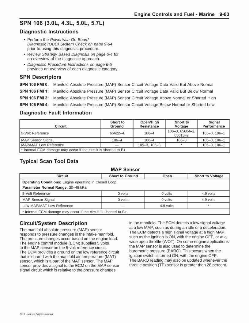
SPN 106 (3.0L, 4.3L, 5.0L, 5.7L)Diagnostic Instructions
• Perform the Powertrain On BoardDiagnostic (OBD) System Check on page 9-64prior to using this diagnostic procedure.
• Review Strategy Based Diagnosis on page 6-4 foran overview of the diagnostic approach.
• Diagnostic Procedure Instructions on page 6-5provides an overview of each diagnostic category.
SPN DescriptorsSPN 106 FMI 0: Manifold Absolute Pressure (MAP) Sensor Circuit Voltage Data Valid But Above Normal
SPN 106 FMI 1: Manifold Absolute Pressure (MAP) Sensor Circuit Voltage Data Valid But Below Normal
SPN 106 FMI 3: Manifold Absolute Pressure (MAP) Sensor Circuit Voltage Above Normal or Shorted High
SPN 106 FMI 4: Manifold Absolute Pressure (MAP) Sensor Circuit Voltage Below Normal or Shorted Low
Diagnostic Fault Information
CircuitShort toGround
Open/HighResistance
Short toVoltage
SignalPerformance
5-Volt Reference 65622–4 106–4 106–3, 65604–2,65613–2 106–0, 106–1
MAP Sensor Signal 106–4 106–4 106–3 106–0, 106–1MAP/MAT Low Reference — 105–3, 106–3 * 106–0, 106–1* Internal ECM damage may occur if the circuit is shorted to B+.
Typical Scan Tool DataMAP Sensor
Circuit Short to Ground Open Short to VoltageOperating Conditions: Engine operating in Closed LoopParameter Normal Range: 30–48 kPa
5-Volt Reference 0 volts 0 volts 4.9 volts
MAP Sensor Signal 0 volts 0 volts 4.9 volts
Low MAP/MAT Low Reference — 4.9 volts *
* Internal ECM damage may occur if the circuit is shorted to B+.
Circuit/System DescriptionThe manifold absolute pressure (MAP) sensorresponds to pressure changes in the intake manifold.The pressure changes occur based on the engine load.The engine control module (ECM) supplies 5 voltsto the MAP sensor on the 5-volt reference circuit.The ECM provides a ground on the low reference circuitthat is shared with the manifold air temperature (MAT)sensor, which is a part of the MAP sensor. The MAPsensor provides a signal to the ECM on the MAP sensorsignal circuit which is relative to the pressure changes
in the manifold. The ECM detects a low signal voltageat a low MAP, such as during an idle or a deceleration.The ECM detects a high signal voltage at a high MAP,such as the ignition is ON, with the engine OFF, or at awide open throttle (WOT). On some engine applicationsthe MAP sensor is also used to determine thebarometric pressure (BARO). This occurs when theignition switch is turned ON, with the engine OFF.The BARO reading may also be updated whenever thethrottle position (TP) sensor is greater than 28 percent.
Engine Controls and Fuel - Marine 9-83
2011 - Marine Engines Manual

Conditions for Running the SPN106–0
• Before the ECM can report that SPN 106–0, or106–1 failed, SPNs 100–3, 100–4, 65604,65605, 65610, 65613, 65615, 65616, and 65618must run and pass.
• SPN 105, 110, 630, 65580, 65621, or 65622 isnot set.
• The engine speed is greater than 800 RPM.• The throttle angle is less than 30 percent.• The ECM is not commanding reduced power, or
fuel cut-off.• The SPN runs continuously once the above
conditions are met.
106–1• Before the ECM can report that SPN 106–0, or
106–1 failed, SPNs 100–3, 100–4, 65604,65605, 65610, 65613, 65615, 65616, and 65618must run and pass.
• SPN 105, 110, 630, 65580, 65621, or 65622 isnot set.
• The engine speed is less than 150 RPM.OR
• The throttle angle is greater than 75 percent.• The ECM is not commanding reduced power, or
fuel cut-off.• The SPN runs continuously once the above
conditions are met.
106–3 and 106–4• SPN 105, 110, 630, 65580, 65621, or 65622 is
not set.• The ignition is ON.• The SPN runs continuously when the above
conditions are met.
Conditions for Setting the SPN106–0The ECM detects that the MAP sensor signal isgreater than 90 kPa for greater than 2 seconds.
106–1The ECM detects that the MAP sensor signal is lessthan 20 kPa for greater than 2 seconds.
106–3The ECM detects that the MAP sensor voltage isgreater than 4.8 V.
106–4The ECM detects that the MAP sensor voltage is lessthan 0.25 V.
Action Taken When the SPN Sets• SPN 106 is a Type B SPN.• The BARO will not be updated.• The ECM operates with a default MAP reading,
which varies based on throttle angle.
Conditions for Clearing the SPNSPN 106 is a Type B SPN.
Diagnostic AidsIf a shared 5-volt reference circuit is shorted to groundor shorted to a voltage, other 5-volt referencecircuits may be affected.
Reference InformationSchematic ReferenceEngine Controls Schematics on page 9-6
Connector End View Reference• Engine Control Module Connector End Views on
page 9-30• Engine Controls Connector End Views on
page 9-33
Electrical Information Reference• Circuit Testing on page 11-6• Connector Repairs on page 11-22• Testing for Intermittent Conditions and Poor
Connections on page 11-13• Wiring Repairs on page 11-16
SPN Type ReferenceSuspect Parameter Number (SPN) Type Definitions onpage 6-9
Scan Tool ReferenceEngine Control Module Scan Tool Information onpage 9-54
Special Tool RequiredJ-23738-A Vacuum Pump
Circuit/System Verificatio1. Ignition ON, observe the SPN information with a
scan tool. Verify that SPN 65622 is not set.⇒ If SPN 65622 is set, refer to SPN 65620-65623
on page 9-149 for further diagnosis.2. Turn all accessories OFF.
Note: In extreme cold weather conditions ice mayform in the vacuum source to the MAP sensorand may set a SPN. Inspect the MAP sensor and thevacuum source for ice, moisture, or other restrictions.3. Engine operating, observe the scan tool MAP
Sensor parameter. The reading should bebetween 31–68 kPa (9–20 in Hg).
4. Operate the vehicle within the Conditions forRunning the SPN to verify the SPN does notreset. You may also operate the vehicle within theconditions that you observed from the FreezeFrame/Failure Records data.
9-84 Engine Controls and Fuel - Marine
2011 - Marine Engines Manual

Circuit/System Testing1. Ignition OFF, disconnect the vacuum hose at the
MAP/MAT sensor, or remove the MAP/MATsensor from the intake manifold. Connect theJ-23738-A to the vacuum source.
2. Engine operating, verify that 31–68 kPa(9–20 in Hg) of vacuum is available to theMAP/MAT sensor.⇒ If not within the specified range, repair the
restriction in the vacuum supply to theMAP/MAT sensor.
3. Ignition OFF, connect the vacuum hose to theMAP/MAT sensor, or install the MAP/MATsensor to the intake manifold. Disconnect theharness connector at the MAP sensor.
4. Ignition OFF, test for less than 5 Ω between thelow reference circuit terminal 1 and ground.⇒ If greater than the specified range, test the low
reference circuit for an open/high resistance.If the circuit tests normal, replace the ECM.
5. Ignition ON, test for 4.8–5.2 V between the 5-voltreference circuit terminal 3 and ground.⇒ If less than the specified range, test the 5-volt
reference circuit for a short to ground oropen/high resistance. If the circuit tests normal,replace the ECM.
⇒ If greater than the specified range, test the5-volt reference circuit for a short to voltage.If the circuit tests normal, replace the ECM.
6. Verify the scan tool MAP sensor voltageparameter is less than 0.25 V.
⇒ If greater than the specified range, test thesignal circuit terminal 4 for a short to voltage.If the circuit tests normal, replace the ECM.
7. Install a 3 A fused jumper wire between the signalcircuit terminal 4 and the 5-volt reference circuitterminal 3. Verify the scan tool MAP sensorparameter is greater than 4.8 V.
⇒ If less than the specified range, test the signalcircuit for a short to ground or an open/highresistance. If the circuit tests normal, replacethe ECM.
8. If all circuits test normal, test or replace theMAP/MAT sensor.
Component TestingThe ignition ON, engine OFF MAP sensor scan toolvalue should decrease within +/- 4 kPa by the amountof vacuum applied with the J-23738-A. For example,at 92 kPa, the MAP sensor scan tool reading should bebetween 71–79 kPa with 5 in Hg (17 kPa) of vacuumapplied to the sensor.
SPN 106 (3.0L, 4.3L, 5.0L, 5.7L)Ignition ON, engine OFF, MAP
Sensor parameterMAP Sensor parameter with 5 inches
of vacuum appliedMAP Sensor parameter with
10 inches of vacuum applied100 kPa 79–87 kPa 62–70 kPa
95 kPa 74–82 kPa 57–65 kPa
90 kPa 69–77 kPa 52–60 kPa
80 kPa 59–67 kPa 42–50 kPa
70 kPa 49–57 kPa 32–40 kPa
60 kPa 39–47 kPa 22–30 kPa
Repair InstructionsPerform the Diagnostic Repair Verification onpage 6-22 after completing the diagnostic procedure.
• Manifold Absolute Pressure Sensor Replacement(without Supercharger) on page 9-220
• Engine Control Module Replacement onpage 9-217 for ECM replacement, setup, andprogramming
Engine Controls and Fuel - Marine 9-85
2011 - Marine Engines Manual

SPN 106 (2.4L, 6.0L, 6.2L)Diagnostic Instructions
• Perform the Powertrain On BoardDiagnostic (OBD) System Check on page 9-64prior to using this diagnostic procedure.
• Review Strategy Based Diagnosis on page 6-4 foran overview of the diagnostic approach.
• Diagnostic Procedure Instructions on page 6-5provides an overview of each diagnostic category.
SPN DescriptorsSPN 106 FMI 0: Manifold Absolute Pressure (MAP) Sensor Circuit Voltage Data Valid But Above Normal
SPN 106 FMI 1: Manifold Absolute Pressure (MAP) Sensor Circuit Voltage Data Valid But Below Normal
SPN 106 FMI 2: Manifold Absolute Pressure (MAP) Sensor Circuit Voltage Data Erratic, Intermittent or Incorrect
SPN 106 FMI 3: Manifold Absolute Pressure (MAP) Sensor Circuit Voltage Above Normal or Shorted High
SPN 106 FMI 4: Manifold Absolute Pressure (MAP) Sensor Circuit Voltage Below Normal or Shorted Low
Diagnostic Fault Information
CircuitShort toGround
Open/HighResistance
Short toVoltage
SignalPerformance
5-Volt Reference 65622–4 106–4 106–3, 65604–2,65613–2 106–0, 106–1
MAP Sensor Signal 106–4 106–4 106–3 106–0, 106–1Low Reference — 105–3 * 106–0, 106–1* Internal ECM damage may occur if the circuit is shorted to B+.
Typical Scan Tool DataMAP Sensor
Circuit Short to Ground Open Short to VoltageOperating Conditions: Engine operating in Closed LoopParameter Normal Range: 30–48 kPa
5-Volt Reference 0 volts 0 volts 4.9 volts
MAP Sensor Signal 0 volts 0 volts 4.9 volts
Low Reference — 4.9 volts *
* Internal ECM damage may occur if the circuit is shorted to B+.
Circuit/System DescriptionThe manifold absolute pressure (MAP) sensorresponds to pressure changes in the intake manifold.The pressure changes occur based on the engine load.The engine control module (ECM) supplies 5 voltsto the MAP sensor on the 5-volt reference circuit.The ECM provides a ground on the low referencecircuit. The MAP sensor provides a signal to the ECMon the MAP sensor signal circuit which is relative to thepressure changes in the manifold. The ECM detectsa low signal voltage at a low MAP, such as during anidle or a deceleration. The ECM detects a high signalvoltage at a high MAP, such as the ignition is ON, withthe engine OFF, or at a wide open throttle (WOT). TheMAP sensor is also used to determine the barometricpressure (BARO). This occurs when the ignition switchis turned ON, with the engine OFF. The BARO readingmay also be updated whenever the throttleposition (TP) sensor is greater than 28 percent.
Conditions for Running the SPN106–0
• Before the ECM can report that SPN 106–0, or106–1 failed, SPNs 100–3, 100–4, 65604,65605, 65610, 65613, 65615, 65616, and 65618must run and pass.
• SPN 105, 110, 630, 65580, 65621, or 65622 isnot set.
• The engine speed is greater than 800 RPM.
• The ECM is not commanding reduced power, orfuel cut-off.
• The throttle angle is less than 30 percent.
• The SPN runs continuously once the aboveconditions are met.
9-86 Engine Controls and Fuel - Marine
2011 - Marine Engines Manual

106–1• Before the ECM can report that SPN 106–0, or
106–1 failed, SPNs 100–3, 100–4, 65604,65605, 65610, 65613, 65615, 65616, and 65618must run and pass.
• SPN 105, 110, 630, 65580, 65621, or 65622 isnot set.
• The engine speed is less than 150 RPM.OR
• The throttle angle is greater than 75 percent.• The ECM is not commanding reduced power, or
fuel cut-off.• The SPN runs continuously once the above
conditions are met.
106–2• Before the ECM can report that SPN 106–2 failed,
SPNs 106–0, 106–1, 106–3, 106–4, and 3563must run and pass,
• SPN 105, 110, 630, 65580, 65621, or 65622 isnot set.
• The ignition is ON.• The engine speed is 0 RPM.• The ECM detects the BARO sensor, and SCIP
sensor.• The SPN runs at ignition ON once the above
conditions are met.
106–3 and 106–4• SPN 105, 110, 630, 65580, 65621, or 65622 is
not set.• The ignition is ON.• The SPNs run continuously when the above
conditions are met.
Conditions for Setting the SPN106–0The ECM detects that the MAP sensor signal isgreater than 90 kPa for greater than 2 seconds.
106–1The ECM detects that the MAP sensor signal is lessthan 20 kPa for greater than 2 seconds.
106–2The ECM detects that the MAP sensor does notcorrelate with the BARO sensor and the SCIP sensor,at ignition ON for greater than 2 seconds.
106–3The ECM detects that the MAP sensor voltage isgreater than 4.8 V for greater than 4 seconds.
106–4The ECM detects that the MAP sensor voltage is lessthan 0.25 V for greater than 4 seconds.
Action Taken When the SPN Sets• SPN 106 is a Type B SPN.• The ECM operates with a default MAP reading,
which varies based on throttle angle.• Super charger boost is disabled.• Camshaft actuator not enabled.
Conditions for Clearing the SPNSPN 106 is a Type B SPN.
Diagnostic AidsIf a shared 5-volt reference circuit is shorted to groundor shorted to a voltage, other 5-volt referencecircuits may be affected.
Reference InformationSchematic ReferenceEngine Controls Schematics on page 9-6
Connector End View Reference• Engine Control Module Connector End Views on
page 9-30• Engine Controls Connector End Views on
page 9-33
Electrical Information Reference• Circuit Testing on page 11-6• Connector Repairs on page 11-22• Testing for Intermittent Conditions and Poor
Connections on page 11-13• Wiring Repairs on page 11-16
SPN Type ReferenceSuspect Parameter Number (SPN) Type Definitions onpage 6-9
Scan Tool ReferenceEngine Control Module Scan Tool Information onpage 9-54
Special Tool RequiredJ-23738-A Vacuum Pump
Circuit/System Verificatio1. Ignition ON, observe the SPN information with a
scan tool. Verify that SPN 65621 or 65622 isnot set.⇒ If SPN 65621 or 65622 is set, refer to
SPN 65620-65623 on page 9-149 for furtherdiagnosis.
2. Turn all accessories OFF.3. Engine operating, observe the scan tool MAP
Sensor parameter. The reading should bebetween 31–68 kPa (9–20 in Hg).
4. Operate the vehicle within the Conditions forRunning the SPN to verify the SPN does notreset. You may also operate the vehicle withinthe conditions that you observed from the FreezeFrame/Failure Records data.
Engine Controls and Fuel - Marine 9-87
2011 - Marine Engines Manual

Circuit/System Testing1. Ignition OFF, disconnect the vacuum hose at the
MAP sensor, or remove the MAP sensor from theintake manifold. Connect the J-23738-A to thevacuum source.
2. Engine operating, verify that 31–68 kPa(9–20 in Hg) of vacuum is available to the MAPsensor.⇒ If not within the specified range, repair the
restriction in the vacuum supply to theMAP sensor.
3. Ignition OFF, connect the vacuum hose to theMAP sensor, or install the MAP sensor to theintake manifold. Disconnect the harness connectorat the MAP sensor.
4. Ignition OFF, test for less than 5 Ω between thelow reference circuit terminal 2 and ground.⇒ If greater than the specified range, test the low
reference circuit for an open/high resistance.If the circuit tests normal, replace the ECM.
5. Ignition ON, test for 4.8–5.2 V between the 5-voltreference circuit terminal 1 and ground.⇒ If less than the specified range, test the 5-volt
reference circuit for a short to ground oropen/high resistance. If the circuit tests normal,replace the ECM.
⇒ If greater than the specified range, test the5-volt reference circuit for a short to voltage.If the circuit tests normal, replace the ECM.
6. Verify the scan tool MAP sensor pressureparameter is less than 0.25 V.
⇒ If greater than the specified range, test thesignal circuit terminal 3 for a short to voltage.If the circuit tests normal, replace the ECM.
7. Install a 3A fused jumper wire between the signalcircuit terminal 3 and the 5-volt reference circuitterminal 1. Verify the scan tool MAP sensorparameter is greater than 4.8 V.
⇒ If less than the specified range, test the signalcircuit for a short to ground or an open/highresistance. If the circuit tests normal, replacethe ECM.
8. If all circuits test normal, test or replace the MAPsensor.
Component TestingThe ignition ON, engine OFF MAP sensor scan toolvalue should decrease within +/- 4 kPa by the amountof vacuum applied with the J-23738-A. For example,at 92 kPa, the MAP sensor scan tool reading should bebetween 71–79 kPa with 5 in Hg (17 kPa) of vacuumapplied to the sensor.
SPN 106 (2.4L, 6.0L, 6.2L)Ignition ON, engine OFF, MAP
Sensor parameterMAP Sensor parameter with 5 inches
of vacuum appliedMAP Sensor parameter with
10 inches of vacuum applied100 kPa 79–87 kPa 62–70 kPa
95 kPa 74–82 kPa 57–65 kPa
90 kPa 69–77 kPa 52–60 kPa
80 kPa 59–67 kPa 42–50 kPa
70 kPa 49–57 kPa 32–40 kPa
60 kPa 39–47 kPa 22–30 kPa
Repair InstructionsPerform the Diagnostic Repair Verification onpage 6-22 after completing the diagnostic procedure.
• Manifold Absolute Pressure Sensor Replacement(without Supercharger) on page 9-220
• Engine Control Module Replacement onpage 9-217 for ECM replacement, setup, andprogramming
9-88 Engine Controls and Fuel - Marine
2011 - Marine Engines Manual

SPN 108Diagnostic Instructions
• Perform the Powertrain On BoardDiagnostic (OBD) System Check on page 9-64prior to using this diagnostic procedure.
• Review Strategy Based Diagnosis on page 6-4 foran overview of the diagnostic approach.
• Diagnostic Procedure Instructions on page 6-5provides an overview of each diagnostic category.
SPN DescriptorsSPN 108 FMI 2: Barometric Pressure (BARO) Sensor Voltage Data Erratic, Intermittent or Incorrect
SPN 108 FMI 3: Barometric Pressure (BARO) Sensor Voltage Above Normal or Shorted High
SPN 108 FMI 4: Barometric Pressure (BARO) Sensor Voltage Below Normal or Shorted Low
SPN 108 FMI 10: Barometric Pressure (BARO) Sensor Abnormal Rate of Change
Diagnostic Fault Information
CircuitShort toGround
HighResistance Open
Short toVoltage
SignalPerformance
5-Volt Reference 65620–4 108–4 108–4 108–3 108–10BARO Sensor Signal 108–4 108–4 108–4 108–3 108–10Low Reference — 108–3 108–3 — 108–10
Circuit/System DescriptionThe engine control module (ECM) supplies 5 volts tothe BARO sensor on a 5-volt reference circuit, andprovides a ground on a low reference circuit. The BAROsensor provides a voltage signal to the ECM on a signalcircuit relative to the changes in atmospheric pressure.
Conditions for Running the SPN108–2
• Before the ECM can report that SPN 108–2 failed,SPNs 106, 108–3, 108–4, 108–10, and 3563must run and pass.
• SPN 630, 65580 65620, 65621, 65622, or 65623is not set.
• The engine speed is less than 150 RPM.• The ignition is ON.• The MAP and SCIP sensor correlation is within
5 kPa.• SPN 108–2 runs continuously when the conditions
above exist.
108–3 and 108–4• SPN 630, 65580 65620, 65621, 65622, or 65623
is not set.• The ignition is ON, or the engine is operating.• SPNs 108–3 and 108–4 run continuously when the
above conditions are met.
108–10• Before the ECM can report that SPN 108–10 failed,
SPNs 108–3, and 108–4 must run and pass.• SPN 630, 65580 65620, 65621, 65622, or 65623 is
not set.
• The ignition is ON, or the engine is operating.• SPN 108–10 runs continuously when the above
conditions are met.
Conditions for Setting the SPN108–2The ECM detects a differance of greater than 15 kPabetween the BARO signal and the MAP or SCIPsignals.
108–3The ECM detects the BARO sensor voltage is greaterthan 4.9 volts for greater than 5 seconds.
108–4The ECM detects the BARO sensor voltage is lessthan 0.20 volt for greater than 5 seconds.
108–10The ECM detects the BARO signal +/−10 kPa of theexpected value for greater than 5 seconds.
Action Taken When the SPN SetsSPN 108 is Type B SPN.
Conditions for Clearing the MIL/SPNSPN 108 is Type B SPN.
Reference InformationSchematic ReferenceEngine Controls Schematics on page 9-6
Engine Controls and Fuel - Marine 9-89
2011 - Marine Engines Manual
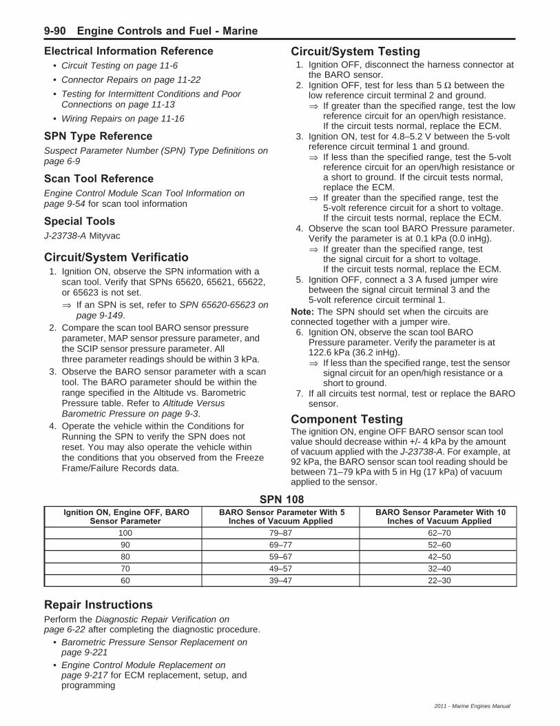
Electrical Information Reference• Circuit Testing on page 11-6
• Connector Repairs on page 11-22
• Testing for Intermittent Conditions and PoorConnections on page 11-13
• Wiring Repairs on page 11-16
SPN Type ReferenceSuspect Parameter Number (SPN) Type Definitions onpage 6-9
Scan Tool ReferenceEngine Control Module Scan Tool Information onpage 9-54 for scan tool information
Special ToolsJ-23738-A Mityvac
Circuit/System Verificatio1. Ignition ON, observe the SPN information with a
scan tool. Verify that SPNs 65620, 65621, 65622,or 65623 is not set.⇒ If an SPN is set, refer to SPN 65620-65623 on
page 9-149.2. Compare the scan tool BARO sensor pressure
parameter, MAP sensor pressure parameter, andthe SCIP sensor pressure parameter. Allthree parameter readings should be within 3 kPa.
3. Observe the BARO sensor parameter with a scantool. The BARO parameter should be within therange specified in the Altitude vs. BarometricPressure table. Refer to Altitude VersusBarometric Pressure on page 9-3.
4. Operate the vehicle within the Conditions forRunning the SPN to verify the SPN does notreset. You may also operate the vehicle withinthe conditions that you observed from the FreezeFrame/Failure Records data.
Circuit/System Testing1. Ignition OFF, disconnect the harness connector at
the BARO sensor.2. Ignition OFF, test for less than 5 Ω between the
low reference circuit terminal 2 and ground.⇒ If greater than the specified range, test the low
reference circuit for an open/high resistance.If the circuit tests normal, replace the ECM.
3. Ignition ON, test for 4.8–5.2 V between the 5-voltreference circuit terminal 1 and ground.⇒ If less than the specified range, test the 5-volt
reference circuit for an open/high resistance ora short to ground. If the circuit tests normal,replace the ECM.
⇒ If greater than the specified range, test the5-volt reference circuit for a short to voltage.If the circuit tests normal, replace the ECM.
4. Observe the scan tool BARO Pressure parameter.Verify the parameter is at 0.1 kPa (0.0 inHg).⇒ If greater than the specified range, test
the signal circuit for a short to voltage.If the circuit tests normal, replace the ECM.
5. Ignition OFF, connect a 3 A fused jumper wirebetween the signal circuit terminal 3 and the5-volt reference circuit terminal 1.
Note: The SPN should set when the circuits areconnected together with a jumper wire.6. Ignition ON, observe the scan tool BARO
Pressure parameter. Verify the parameter is at122.6 kPa (36.2 inHg).⇒ If less than the specified range, test the sensor
signal circuit for an open/high resistance or ashort to ground.
7. If all circuits test normal, test or replace the BAROsensor.
Component TestingThe ignition ON, engine OFF BARO sensor scan toolvalue should decrease within +/- 4 kPa by the amountof vacuum applied with the J-23738-A. For example, at92 kPa, the BARO sensor scan tool reading should bebetween 71–79 kPa with 5 in Hg (17 kPa) of vacuumapplied to the sensor.
SPN 108Ignition ON, Engine OFF, BARO
Sensor ParameterBARO Sensor Parameter With 5
Inches of Vacuum AppliedBARO Sensor Parameter With 10
Inches of Vacuum Applied100 79–87 62–7090 69–77 52–6080 59–67 42–5070 49–57 32–4060 39–47 22–30
Repair InstructionsPerform the Diagnostic Repair Verification onpage 6-22 after completing the diagnostic procedure.
• Barometric Pressure Sensor Replacement onpage 9-221
• Engine Control Module Replacement onpage 9-217 for ECM replacement, setup, andprogramming
9-90 Engine Controls and Fuel - Marine
2011 - Marine Engines Manual
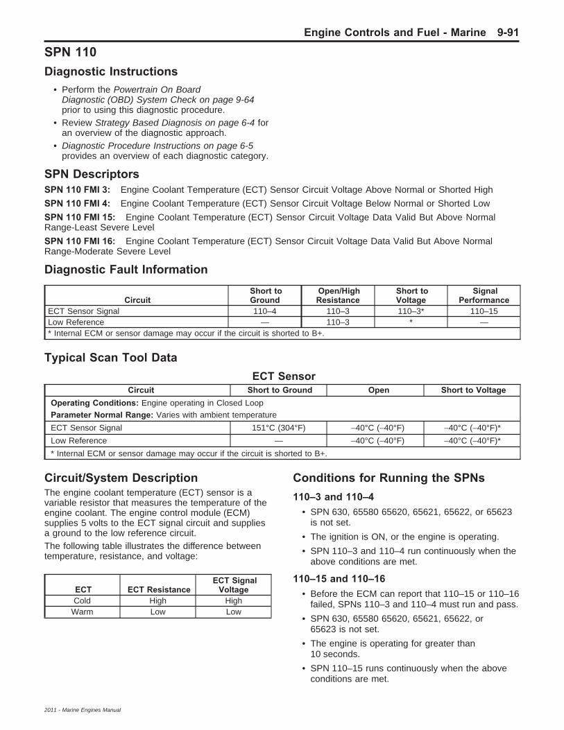
SPN 110Diagnostic Instructions
• Perform the Powertrain On BoardDiagnostic (OBD) System Check on page 9-64prior to using this diagnostic procedure.
• Review Strategy Based Diagnosis on page 6-4 foran overview of the diagnostic approach.
• Diagnostic Procedure Instructions on page 6-5provides an overview of each diagnostic category.
SPN DescriptorsSPN 110 FMI 3: Engine Coolant Temperature (ECT) Sensor Circuit Voltage Above Normal or Shorted High
SPN 110 FMI 4: Engine Coolant Temperature (ECT) Sensor Circuit Voltage Below Normal or Shorted Low
SPN 110 FMI 15: Engine Coolant Temperature (ECT) Sensor Circuit Voltage Data Valid But Above NormalRange-Least Severe Level
SPN 110 FMI 16: Engine Coolant Temperature (ECT) Sensor Circuit Voltage Data Valid But Above NormalRange-Moderate Severe Level
Diagnostic Fault Information
CircuitShort toGround
Open/HighResistance
Short toVoltage
SignalPerformance
ECT Sensor Signal 110–4 110–3 110–3* 110–15Low Reference — 110–3 * —* Internal ECM or sensor damage may occur if the circuit is shorted to B+.
Typical Scan Tool DataECT Sensor
Circuit Short to Ground Open Short to VoltageOperating Conditions: Engine operating in Closed LoopParameter Normal Range: Varies with ambient temperature
ECT Sensor Signal 151°C (304°F) −40°C (−40°F) −40°C (−40°F)*
Low Reference — −40°C (−40°F) −40°C (−40°F)*
* Internal ECM or sensor damage may occur if the circuit is shorted to B+.
Circuit/System DescriptionThe engine coolant temperature (ECT) sensor is avariable resistor that measures the temperature of theengine coolant. The engine control module (ECM)supplies 5 volts to the ECT signal circuit and suppliesa ground to the low reference circuit.The following table illustrates the difference betweentemperature, resistance, and voltage:
ECT ECT ResistanceECT Signal
VoltageCold High High
Warm Low Low
Conditions for Running the SPNs110–3 and 110–4
• SPN 630, 65580 65620, 65621, 65622, or 65623is not set.
• The ignition is ON, or the engine is operating.
• SPN 110–3 and 110–4 run continuously when theabove conditions are met.
110–15 and 110–16• Before the ECM can report that 110–15 or 110–16
failed, SPNs 110–3 and 110–4 must run and pass.
• SPN 630, 65580 65620, 65621, 65622, or65623 is not set.
• The engine is operating for greater than10 seconds.
• SPN 110–15 runs continuously when the aboveconditions are met.
Engine Controls and Fuel - Marine 9-91
2011 - Marine Engines Manual

Conditions for Setting the SPNs110–3The ECM detects that the ECT is warmer than302°F (150°C) for greater than 1 second.
110–4The ECM detects that the ECT is colder than−23°F (−31°C) for greater than 1 second.
110–15The ECM detects the ECT is warmer than220°F (104°C ) for greater than 1 second.
110–16The ECM detects the ECT is warmer than239°F (115°C) for greater than 1 second.
Action Taken When the SPN Sets• SPN 11–3 and 110–4 are Type B SPNs.• Cam phaser not enabled.• Boost not enabled.• The engine operates based on a default (filtered)
coolant temp.• SPN 110–15 is a type C SPN
Conditions for Clearing the MIL/SPN• SPN 11–3 and 110–4 are Type B SPNs.• SPN 110–15 is a type C SPN
Diagnostic Aids• After starting the engine, the ECT sensor
temperature should rise steadily, then stabilizeafter the thermostat opens.
• Test the ECT sensor at various temperature levelsin order to evaluate the possibility of a skewedsensor. A skewed sensor can result in adriveability condition.
• If the vehicle has set overnight, the ECT sensorand the MAT/IAT sensor values should displaywithin 3°C (5°F).
Reference InformationSchematic ReferenceEngine Controls Schematics on page 9-6
Connector End View Reference• Engine Control Module Connector End Views on
page 9-30
• Engine Controls Connector End Views onpage 9-33
Electrical Information Reference• Circuit Testing on page 11-6
• Connector Repairs on page 11-22
• Testing for Intermittent Conditions and PoorConnections on page 11-13
• Wiring Repairs on page 11-16
SPN Type ReferenceSuspect Parameter Number (SPN) Type Definitions onpage 6-9
Scan Tool ReferenceEngine Control Module Scan Tool Information onpage 9-54
Circuit/System Verificatio1. Ignition ON, observe the SPN information with a
scan tool. SPNs 110–3, 110–4 should not set.
2. Engine operating, observe the scan tool SPNinformation. Verify that SPN 110–15 or 110–16is not set.
⇒ If SPN 110–15 or 110–16 is set, inspect for anengine overheating condition. If a condition isfound, repair the cooling system asnecessary.
3. Operate the vehicle within the Conditions forRunning the SPN to verify the SPN does notreset. You may also operate the vehicle within theconditions that you observed from the FreezeFrame/Failure Records data.
9-92 Engine Controls and Fuel - Marine
2011 - Marine Engines Manual

Circuit/System Testing1. Ignition OFF, disconnect the harness connector at
the ECT sensor.2. Test for less than 5 Ω between the low reference
circuit terminal A and ground.⇒ If greater than the specified range, test the low
reference circuit for an open/high resistance.If the circuit tests normal, replace the ECM.
3. Ignition ON, verify the scan tool ECT sensorparameter is at −40°C (−40°F).⇒ If warmer than the specified range, test the
signal circuit for a short to ground. If thecircuit tests normal, replace the ECM.
Note: If the fuse in the jumper wire opens, the signalcircuit is shorted to a voltage and the sensor maybe damaged.4. Install a 3 A fused jumper wire between the signal
circuit terminal B and the low reference circuitterminal A. Verify the ECT sensor parameteris warmer than 150°C (303°F).⇒ If less than the specified range, test the signal
circuit for a short to voltage or an open/highresistance. If the circuit tests normal, replacethe ECM.
5. If all circuits test normal, test or replace the ECTsensor.
Component Testing1. Ignition OFF, disconnect the harness connector at
the ECT sensor.
Note: A thermometer can be used to test the sensoroff the vehicle.
2. Test the ECT sensor by varying the sensortemperature while monitoring the sensorresistance. Compare the readings with theTemperature Versus Resistance on page 9-3table and verify that the resistance is within5 percent of the specification.
⇒ If not within the specified range, replace theECT sensor.
Repair InstructionsPerform the Diagnostic Repair Verification onpage 6-22 after completing the diagnostic procedure.
• Engine Coolant Temperature Sensor Replacementon page 9-218
• Engine Control Module Replacement onpage 9-217 for ECM replacement, setup, andprogramming
Engine Controls and Fuel - Marine 9-93
2011 - Marine Engines Manual

SPN 174Diagnostic Instructions
• Perform the Powertrain On BoardDiagnostic (OBD) System Check on page 9-64prior to using this diagnostic procedure.
• Review Strategy Based Diagnosis on page 6-4 foran overview of the diagnostic approach.
• Diagnostic Procedure Instructions on page 6-5provides an overview of each diagnostic category.
SPN DescriptorsSPN 174 FMI 0: Fuel Temperature (FT) Sensor Data Valid but Above Normal
SPN 174 FMI 1: Fuel Temperature (FT) Sensor Data Valid but Below Normal
SPN 174 FMI 3: Fuel Temperature (FT) Sensor Circuit Voltage Above Normal or Shorted High
SPN 174 FMI 4: Fuel Temperature (FT) Sensor Circuit Voltage Below Normal or Shorted Low
Diagnostic Fault Information
CircuitShort toGround
Open/HighResistance
Short toVoltage
SignalPerformance
FT Sensor Signal 174–4 174–3 174–3* 174–1Low Reference — 174–3 * 174–0* Internal ECM or sensor damage may occur if the circuit is shorted to B+.
Circuit/System DescriptionThe fuel temperature (FT) sensor is a variable resistorthat measures the temperature of the fuel. The enginecontrol module (ECM) supplies 5 volts to the FT signalcircuit and supplies a ground to the low referencecircuit.The following table illustrates the difference betweentemperature, resistance, and voltage:
FT FT ResistanceFT SignalVoltage
Cold High HighWarm Low Low
Conditions for Running the SPN174 FMI 0 or 1
• SPN 630, 65580, 65620, 65621, 65622, or 65623is not set.
• Before the ECM can report that SPN 174–0 or174–1 failed, SPN 110, 174–3, and 174–4must run and pass.
• The engine is operating for greater than10 seconds.
• The SPNs run continuously when the abovecondition is met.
174 FMI 3 or 4• SPN 630, 65580, 65620, 65621, 65622, or 65623
is not set.• The ignition is ON, or the engine is operating. for
greater than 10 seconds.• The SPNs run continuously when the above
condition is met.
Conditions for Setting the SPN174–0 or 174–1The ECM detects that the FT is greater or less than acalibrated value of the expected value determinedby the control module.
174–3The ECM detects that the FT sensor voltage is greaterthan a calibrated value.
174–4The ECM detects that the FT sensor voltage is lessthan a calibrated value.
Action Taken When the SPN SetsSPN 174 is a Type B SPN.
Conditions for Clearing the SPNSPN 174 is a Type B SPN.
Diagnostic Aids• Test the FT sensor at various temperature levels
in order to evaluate the possibility of a skewedsensor. A skewed sensor can result in adriveability condition.
• If the vehicle has set overnight, the FT sensor,ECT sensor, and the MAT sensor valuesshould display within 3°C (5°F).
9-94 Engine Controls and Fuel - Marine
2011 - Marine Engines Manual

Reference InformationSchematic ReferenceEngine Controls Schematics on page 9-6
Connector End View Reference• Engine Control Module Connector End Views on
page 9-30• Engine Controls Connector End Views on
page 9-33
Electrical Information Reference• Circuit Testing on page 11-6• Connector Repairs on page 11-22• Testing for Intermittent Conditions and Poor
Connections on page 11-13• Wiring Repairs on page 11-16
SPN Type ReferenceSuspect Parameter Number (SPN) Type Definitions onpage 6-9
Scan Tool ReferenceEngine Control Module Scan Tool Information onpage 9-54
Circuit/System Verificatio1. Engine running, observe the SPN information with
a scan tool. SPN 174–3 or 174–4 should not set.2. Operate the vehicle within the Conditions
for Running the SPN to verify the SPN does notreset. You may also operate the vehicle within theconditions that you observed from the FreezeFrame/Failure Records data.
Circuit/System Testing1. Ignition OFF, disconnect the harness connector at
the FT sensor.2. Test for less than 5 Ω between the low reference
circuit terminal A and ground.⇒ If greater than the specified range, test the low
reference circuit for an open/high resistance.If the circuit tests normal, replace the ECM.
3. Ignition ON, verify the scan tool FT sensor voltageparameter is greater than 4.5 V.
⇒ If less than the specified range, test the signalcircuit for a short to ground. If the circuit testsnormal, replace the ECM.
Note: If the fuse in the jumper wire opens, the signalcircuit is shorted to a voltage and the sensor maybe damaged.
4. Install a 3 A fused jumper wire between the signalcircuit terminal B and the low reference circuitterminal A. Verify the FT sensor voltage parameteris less than 0.5 V.
⇒ If greater than the specified range, test thesignal circuit for a short to voltage or anopen/high resistance. If the circuit testsnormal, replace the ECM.
5. If all circuits test normal, test or replace the FTsensor.
Component Testing1. Ignition OFF, disconnect the harness connector at
the FT sensor.
Note: A thermometer can be used to test the sensoroff the vehicle.
2. Test the FT sensor by varying the sensortemperature while monitoring the sensorresistance. Compare the readings with theTemperature Versus Resistance on page 9-3table and verify that the resistance is within5 percent of the specification.
⇒ If not within the specified range, replace theFT sensor.
Repair InstructionsPerform the Diagnostic Repair Verification onpage 6-22 after completing the diagnostic procedure.
Engine Control Module Replacement on page 9-217for ECM replacement, setup, and programming
Engine Controls and Fuel - Marine 9-95
2011 - Marine Engines Manual

SPN 175Diagnostic Instructions
• Perform the Powertrain On BoardDiagnostic (OBD) System Check on page 9-64prior to using this diagnostic procedure.
• Review Strategy Based Diagnosis on page 6-4 foran overview of the diagnostic approach.
• Diagnostic Procedure Instructions on page 6-5provides an overview of each diagnostic category.
SPN DescriptorsSPN 175 FMI 3: Engine Oil Temperature (EOT) Sensor Circuit Voltage Above Normal or Shorted High
SPN 175 FMI 4: Engine Oil Temperature (EOT) Sensor Circuit Voltage Below Normal or Shorted Low
SPN 175 FMI 15: Engine Oil Temperature (EOT) Sensor Circuit Voltage Data Valid But Above NormalRange-Least Severe Level
Diagnostic Fault Information
CircuitShort toGround
Open/HighResistance
Short toVoltage
SignalPerformance
EOT Sensor Signal 175–4 175–3 175–3 175–15EOT Low Reference — 175–3 * —* Internal ECM or sensor damage may occur if the circuit is shorted to B+.
Typical Scan Tool DataEOT Sensor
Circuit Short to Ground Open Short to VoltageOperating Conditions: Engine operating in Closed LoopParameter Normal Range: Varies with ambient temperature
EOT Sensor Signal 152°C (305°F) −40°C (−40°F) −40°C (−40°F)*
Low Reference — −40°C (−40°F) −40°C (−40°F)*
* Internal ECM or sensor damage may occur if the circuit is shorted to B+.
Circuit/System DescriptionThe engine oil temperature (EOT) sensor is a variableresistor that measures the temperature of the engineoil. The engine control module (ECM) supplies 5 V onthe EOT signal circuit, and a ground to the lowreference circuit.
Monitoring the engine oil temperature is necessaryfor optimal control of the cam actuators. The oiltemperature is monitored from the dual function oil levelswitch and temperature sensor located in the oil pan.
Conditions for Running the SPNs175–3 and 175–4
• The ignition is ON, or the engine is operating.
• The SPNs run continuously when the aboveenable condition is met for greater than 2 s.
175–15• Before the ECM can report that 175–15 failed,
SPNs 175–3 and 175–4 must run and pass.• SPN 630, 65580, 65620, or 65621 is not set.• The engine run time is greater than a
calibrated value.• SPN 175–15 runs continuously when the above
conditions are met.
Conditions for Setting the SPNs175–3The ECM detects the EOT is colder than−35°C (−31°F).
175–4The ECM detects the EOT is warmer than170°C (331°F).
175–15The ECM detects the EOT is warmer than a calibratedtemperature for greater than 3 seconds.
9-96 Engine Controls and Fuel - Marine
2011 - Marine Engines Manual

Action Taken When the SPN Sets• SPN 175–3 and 175–4 are Type B SPNs.• SPN 175–15 is a type C SPN
Conditions for Clearing the MIL/SPN• SPN 175–3 and 175–4 are Type B SPNs.• SPN 175–15 is a type C SPN
Reference InformationSchematic ReferenceEngine Controls Schematics on page 9-6
Connector End View Reference• Engine Control Module Connector End Views on
page 9-30• Engine Controls Connector End Views on
page 9-33
Electrical Information Reference• Circuit Testing on page 11-6• Connector Repairs on page 11-22• Testing for Intermittent Conditions and Poor
Connections on page 11-13• Wiring Repairs on page 11-16
SPN Type ReferenceSuspect Parameter Number (SPN) Type Definitions onpage 6-9
Scan Tool ReferenceEngine Control Module Scan Tool Information onpage 9-54
Circuit/System Verificatio1. Engine operating, observe the SPN information
with a scan tool. SPN 175–3, 175–4, or 175–15should not set.
2. Operate the vehicle within the Conditions forRunning the SPN to verify the SPN does notreset. You may also operate the vehicle within theconditions that you observed from the FreezeFrame/Failure Records data.
Circuit/System Testing1. Ignition OFF, disconnect the harness connector at
the EOT sensor.
2. Test for less than 5 Ω between the low referencecircuit terminal and ground.
⇒ If greater than the specified range, test the lowreference circuit for an open/high resistance.If the circuit tests normal, replace the ECM.
3. Ignition ON, test for 4.8–5.2 V between the 5 Vreference circuit terminal and ground.
⇒ If less than the specified range, test thecircuit for a short to ground or an open/highresistance. If the circuit tests normal, replacethe ECM.
⇒ If greater than the specified range, test thecircuit for a short to voltage. If the circuittests normal, replace the ECM.
4. If all circuits test normal, replace the engine oillevel and temperature sensor.
Component Testing1. Connect a DMM between the signal and low
reference circuit terminals.
2. Verify the engine oil level and temperature sensorresistance is between 400–500 Ω at 21°C (70° F).
⇒ If the resistance is outside the specifiedrange, replace the engine oil level andtemperature sensor.
Repair InstructionsPerform the Diagnostic Repair Verification onpage 6-22 after completing the diagnostic procedure.
Engine Control Module Replacement on page 9-217for ECM replacement, setup, and programming.
Engine Controls and Fuel - Marine 9-97
2011 - Marine Engines Manual

SPN 627Diagnostic Instructions
• Perform the Powertrain On BoardDiagnostic (OBD) System Check on page 9-64prior to using this diagnostic procedure.
• Review Strategy Based Diagnosis on page 6-4 foran overview of the diagnostic approach.
• Diagnostic Procedure Instructions on page 6-5provides an overview of each diagnostic category.
SPN DescriptorSPN 627 FMI 15: System Voltage Data Valid But Above Normal Range-Least Severe Level
SPN 627 FMI 17: System Voltage Data Valid But Below Normal Range-Least Severe Level
Circuit/System DescriptionThe engine control module (ECM) monitors the ignitionvoltage to ensure that the voltage stays within theproper range. Damage to components, and incorrectdata may occur when the voltage is out of range.
Conditions for Running the SPN• SPNs 630 or 65580 are not set.• The ignition is ON, or the engine is operating.• The ignition voltage is between 10–16 volts.
Conditions for Setting the SPN627–15The ECM detects the ignition voltage is greater than16 volts.
627–17The ECM detects the ignition voltage is less than10 volts.
Action Taken When the SPN SetsSPN 627 is a Type C SPN.
Conditions for Clearing the SPNSPN 627 is a Type C SPN.
Reference InformationSchematic ReferenceEngine Controls Schematics on page 9-6
Connector End View Reference• Engine Control Module Connector End Views on
page 9-30• Engine Controls Connector End Views on
page 9-33
Electrical Information Reference• Circuit Testing on page 11-6• Connector Repairs on page 11-22• Testing for Intermittent Conditions and Poor
Connections on page 11-13• Wiring Repairs on page 11-16
SPN Type ReferenceSuspect Parameter Number (SPN) Type Definitions onpage 6-9
Scan Tool ReferenceEngine Control Module Scan Tool Information onpage 9-54
Circuit/System Verificatio1. Ignition ON, test for 11–15 V between the
terminals of each battery.⇒ If not within the specified range, charge and
test the battery, replace if necessary.2. Engine idling, the battery voltage tested in step 1
should increase.⇒ If the battery voltage does not increase, repair
the charging system condition.3. Observe the scan tool Battery Voltage parameter.
Compare the scan tool voltage parameter to thebattery voltage displayed on the DMM. The scantool parameter and the DMM should display within1 volt of each other.
4. Operate the vehicle within the Conditions forRunning the SPN to verify the SPN does notreset. You may also operate the vehicle within theconditions that you observed from the FreezeFrame/Failure Records data.
Circuit/System Testing1. Ignition OFF. Disconnect the ECM harness
connectors X1 and X2. Test for less than 1 Ωbetween the ground circuit terminal X2–73and ground.⇒ If greater than the specified range, test the
ground circuit for an open/high resistance.2. Load test for battery voltage between the battery
positive voltage circuit terminal X1–20 and ground.⇒ If not within the specified range, test the battery
positive voltage circuit for a short to ground oran open/high resistance.
3. If all circuits test normal, replace the ECM.
Repair InstructionsPerform the Diagnostic Repair Verification onpage 6-22 after completing the diagnostic procedure.Engine Control Module Replacement on page 9-217for ECM replacement, setup, and programming.
9-98 Engine Controls and Fuel - Marine
2011 - Marine Engines Manual

SPN 630, 65580, 65581, or 65582Diagnostic Instructions
• Perform the Powertrain On BoardDiagnostic (OBD) System Check on page 9-64prior to using this diagnostic procedure.
• Review Strategy Based Diagnosis on page 6-4 foran overview of the diagnostic approach.
• Diagnostic Procedure Instructions on page 6-5provides an overview of each diagnostic category.
SPN DescriptorsSPN 630 FMI 13: Cal Memory Out of Calibration
SPN 65580 FMI 12: CPU Bad Intelligent Device or Component
SPN 65581 FMI 12: MHC Failure Bad Intelligent Device or Component
SPN 65582 FMI 2: NV RAM Failure Data Erratic, Intermittent or Incorrect
Circuit/System DescriptionThis diagnostic applies to the integrity of the enginecontrol module’s (ECM) internal microprocessorand the throttle actuator control (TAC) system.This diagnostic also addresses “ECM is NotProgrammed” conditions.
Conditions for Running the SPNs• The ignition is ON, or the engine is operating.• The ignition voltage is greater than 10 volts.• SPNs 630, 65580–65582 run continuously once
the above conditions are met.
Conditions for Setting the SPNsThe ECM detects an internal failure, or incompleteprogramming for greater than 14 seconds.
Action Taken When the SPN Sets• SPN 630, 65580, and 65581 are type A SPNs.• SPN 65582 is a type B SPN• The ECM will disable engine operation or
command the TAC system to operate in aReduced Engine Power mode.
Conditions for Clearing the SPNs• SPN 630, 65580, and 65581 are type A SPNs.• SPN 65582 is a type B SPN
Reference InformationSchematic ReferenceEngine Controls Schematics on page 9-6
Connector End View Reference• Engine Control Module Connector End Views on
page 9-30• Engine Controls Connector End Views on
page 9-33
Description and OperationEngine Control Module Description on page 9-279
Electrical Information Reference• Circuit Testing on page 11-6• Connector Repairs on page 11-22• Testing for Intermittent Conditions and Poor
Connections on page 11-13• Wiring Repairs on page 11-16
SPN Type ReferenceSuspect Parameter Number (SPN) Type Definitions onpage 6-9
Scan Tool ReferenceEngine Control Module Scan Tool Information onpage 9-54
Circuit/System Testing1. Ignition ON, clear the SPN information with a
scan tool. Observe the scan tool SPN information.Verify that SPN 630–13 does not fail thisignition cycle.⇒ If the SPN fails this ignition cycle, reprogram
the ECM. Refer to Engine Control ModuleProgramming and Setup on page 6-3.If SPN 630–13 resets, replace the ECM.
2. Observe the SPN information with a scan tool.Verify that SPNs 65580–12, 65581–12, or65582–2 do not fail this ignition cycle.
⇒ If any of the SPNs set this ignition cycle,replace the ECM.
Repair InstructionsPerform the Diagnostic Repair Verification onpage 6-22 after completing the diagnostic procedure.
Engine Control Module Replacement on page 9-217for ECM replacement, setup, and programming
Engine Controls and Fuel - Marine 9-99
2011 - Marine Engines Manual
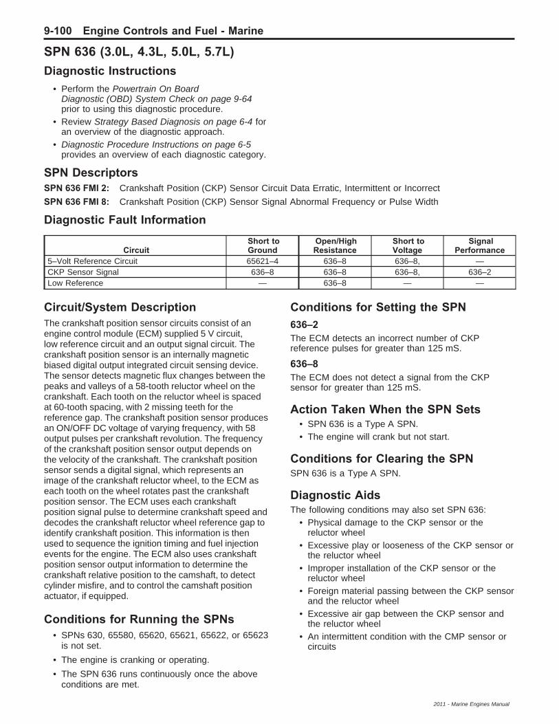
SPN 636 (3.0L, 4.3L, 5.0L, 5.7L)Diagnostic Instructions
• Perform the Powertrain On BoardDiagnostic (OBD) System Check on page 9-64prior to using this diagnostic procedure.
• Review Strategy Based Diagnosis on page 6-4 foran overview of the diagnostic approach.
• Diagnostic Procedure Instructions on page 6-5provides an overview of each diagnostic category.
SPN DescriptorsSPN 636 FMI 2: Crankshaft Position (CKP) Sensor Circuit Data Erratic, Intermittent or Incorrect
SPN 636 FMI 8: Crankshaft Position (CKP) Sensor Signal Abnormal Frequency or Pulse Width
Diagnostic Fault Information
CircuitShort toGround
Open/HighResistance
Short toVoltage
SignalPerformance
5–Volt Reference Circuit 65621–4 636–8 636–8, —CKP Sensor Signal 636–8 636–8 636–8, 636–2Low Reference — 636–8 — —
Circuit/System DescriptionThe crankshaft position sensor circuits consist of anengine control module (ECM) supplied 5 V circuit,low reference circuit and an output signal circuit. Thecrankshaft position sensor is an internally magneticbiased digital output integrated circuit sensing device.The sensor detects magnetic flux changes between thepeaks and valleys of a 58-tooth reluctor wheel on thecrankshaft. Each tooth on the reluctor wheel is spacedat 60-tooth spacing, with 2 missing teeth for thereference gap. The crankshaft position sensor producesan ON/OFF DC voltage of varying frequency, with 58output pulses per crankshaft revolution. The frequencyof the crankshaft position sensor output depends onthe velocity of the crankshaft. The crankshaft positionsensor sends a digital signal, which represents animage of the crankshaft reluctor wheel, to the ECM aseach tooth on the wheel rotates past the crankshaftposition sensor. The ECM uses each crankshaftposition signal pulse to determine crankshaft speed anddecodes the crankshaft reluctor wheel reference gap toidentify crankshaft position. This information is thenused to sequence the ignition timing and fuel injectionevents for the engine. The ECM also uses crankshaftposition sensor output information to determine thecrankshaft relative position to the camshaft, to detectcylinder misfire, and to control the camshaft positionactuator, if equipped.
Conditions for Running the SPNs• SPNs 630, 65580, 65620, 65621, 65622, or 65623
is not set.
• The engine is cranking or operating.
• The SPN 636 runs continuously once the aboveconditions are met.
Conditions for Setting the SPN636–2The ECM detects an incorrect number of CKPreference pulses for greater than 125 mS.
636–8The ECM does not detect a signal from the CKPsensor for greater than 125 mS.
Action Taken When the SPN Sets• SPN 636 is a Type A SPN.• The engine will crank but not start.
Conditions for Clearing the SPNSPN 636 is a Type A SPN.
Diagnostic AidsThe following conditions may also set SPN 636:
• Physical damage to the CKP sensor or thereluctor wheel
• Excessive play or looseness of the CKP sensor orthe reluctor wheel
• Improper installation of the CKP sensor or thereluctor wheel
• Foreign material passing between the CKP sensorand the reluctor wheel
• Excessive air gap between the CKP sensor andthe reluctor wheel
• An intermittent condition with the CMP sensor orcircuits
9-100 Engine Controls and Fuel - Marine
2011 - Marine Engines Manual

Reference InformationSchematic ReferenceEngine Controls Schematics on page 9-6
Connector End View Reference• Engine Control Module Connector End Views on
page 9-30• Engine Controls Connector End Views on
page 9-33
Electrical Information Reference• Circuit Testing on page 11-6• Connector Repairs on page 11-22• Testing for Intermittent Conditions and Poor
Connections on page 11-13• Wiring Repairs on page 11-16
SPN Type ReferenceSuspect Parameter Number (SPN) Type Definitions onpage 6-9
Scan Tool ReferenceEngine Control Module Scan Tool Information onpage 9-54
Circuit/System VerificatioNote: If you were sent here from Engine Cranks butDoes Not Run, proceed to Circuit/System Testing.1. Attempt to start the engine, observe the SPN
information with a scan tool. SPN 636–2 or636–8 should not set.
2. Engine cranking, observe the scan tool EngineSpeed parameter. The scan tool should indicatean engine speed greater than 0 RPM.
3. Move related harnesses/connectors of the CKPsensor and verify the engine does not stumble,stall, or change engine speed.
4. Operate the vehicle within the Conditions forRunning the SPN to verify the SPN does notreset. You may also operate the vehicle within theconditions that you observed from the FreezeFrame/Failure Records data.
Circuit/System Testing1. Ignition OFF, disconnect the harness connector at
the CKP sensor.2. Test for less than 5 Ω between the low reference
circuit terminal B/2 and ground.⇒ If greater than the specified range, test the low
reference circuit for an open/high resistance.If the circuit tests normal, replace the ECM.
3. Ignition ON, test for 4.8–5.2 V between the 5-voltreference circuit terminal A/1 and ground.⇒ If less than the specified range, test the 5-volt
reference circuit for a short to ground or anopen/high resistance. If the circuit tests normal,replace the ECM.
⇒ If greater than the specified range, test the5-volt reference circuit for a short to voltage.If the circuit tests normal, replace the ECM.
4. Test for 4.8–5.2 V between the signal circuitterminal C/3 and ground.⇒ If less than the specified range, test the signal
circuit for a short to ground or an open/highresistance. If the circuit tests normal, replacethe ECM.
⇒ If greater than the specified range, test thesignal circuit for a short to voltage. If thecircuit tests normal, replace the ECM.
5. If all circuits test normal, test or replace the CKPsensor.
Repair InstructionsPerform the Diagnostic Repair Verification onpage 6-22 after completing the diagnostic procedure.
• Crankshaft Position Sensor Replacement (3.0L)on page 9-256 or Crankshaft Position SensorReplacement (4.3/5.0/5.7L) on page 9-257or Crankshaft Position Sensor Replacement(6.0/6.2L) on page 9-258 or Crankshaft PositionSensor Replacement (2.4L) on page 9-261
• Engine Control Module Replacement onpage 9-217 for ECM replacement, setup,and programming
Engine Controls and Fuel - Marine 9-101
2011 - Marine Engines Manual

SPN 636 (6.0L, 6.2L)Diagnostic Instructions
• Perform the Powertrain On BoardDiagnostic (OBD) System Check on page 9-64prior to using this diagnostic procedure.
• Review Strategy Based Diagnosis on page 6-4 foran overview of the diagnostic approach.
• Diagnostic Procedure Instructions on page 6-5provides an overview of each diagnostic category.
SPN DescriptorsSPN 636 FMI 2: Crankshaft Position (CKP) Sensor Circuit Data Erratic, Intermittent or Incorrect
SPN 636 FMI 8: Crankshaft Position (CKP) Sensor Signal Abnormal Frequency or Pulse Width
Diagnostic Fault Information
CircuitShort toGround
Open/HighResistance
Short toVoltage
SignalPerformance
5–Volt Reference Circuit 65621–4 636–8 636–8, 3563–2,3563–4 —
CKP Sensor Signal 636–8 636–8 636–8 636–2Low Reference — 636–8 — —
Circuit/System DescriptionThe crankshaft position sensor circuits consist of anengine control module (ECM) supplied 5 V circuit,low reference circuit and an output signal circuit. Thecrankshaft position sensor is an internally magneticbiased digital output integrated circuit sensing device.The sensor detects magnetic flux changes between thepeaks and valleys of a 58-tooth reluctor wheel on thecrankshaft. Each tooth on the reluctor wheel is spacedat 60-tooth spacing, with 2 missing teeth for thereference gap. The crankshaft position sensor producesan ON/OFF DC voltage of varying frequency, with 58output pulses per crankshaft revolution. The frequencyof the crankshaft position sensor output depends onthe velocity of the crankshaft. The crankshaft positionsensor sends a digital signal, which represents animage of the crankshaft reluctor wheel, to the ECM aseach tooth on the wheel rotates past the crankshaftposition sensor. The ECM uses each crankshaftposition signal pulse to determine crankshaft speed anddecodes the crankshaft reluctor wheel reference gap toidentify crankshaft position. This information is thenused to sequence the ignition timing and fuel injectionevents for the engine. The ECM also uses crankshaftposition sensor output information to determine thecrankshaft relative position to the camshaft, to detectcylinder misfire, and to control the camshaft positionactuator, if equipped.
Conditions for Running the SPNs• SPNs 630, 65580, 65620, 65621, 65622, or 65623
is not set.
• The engine is cranking or operating.
• SPN 636 runs continuously once the aboveconditions are met.
Conditions for Setting the SPN636 2The ECM detects an incorrect number of CKPreference pulses for greater than 125 mS.
636 8The ECM does not detect a signal from the CKPsensor for greater than 125 mS.
Action Taken When the SPN Sets• SPN 636 is a Type A SPN.• The engine will crank but not start.
Conditions for Clearing the SPNSPN 636 is a Type A SPN.
Diagnostic AidsThe following conditions could also set the SPNs:
• Physical damage to the CKP sensor or thereluctor wheel
• Excessive play or looseness of the CKP sensor orthe reluctor wheel
• Improper installation of the CKP sensor or thereluctor wheel
• Foreign material passing between the CKP sensorand the reluctor wheel
• Excessive air gap between the CKP sensor andthe reluctor wheel
• An intermittent condition with the CMP sensor orcircuits
9-102 Engine Controls and Fuel - Marine
2011 - Marine Engines Manual

Reference InformationSchematic ReferenceEngine Controls Schematics on page 9-6
Connector End View Reference• Engine Control Module Connector End Views on
page 9-30• Engine Controls Connector End Views on
page 9-33
Electrical Information Reference• Circuit Testing on page 11-6• Connector Repairs on page 11-22• Testing for Intermittent Conditions and Poor
Connections on page 11-13• Wiring Repairs on page 11-16
SPN Type ReferenceSuspect Parameter Number (SPN) Type Definitions onpage 6-9
Scan Tool ReferenceEngine Control Module Scan Tool Information onpage 9-54
Circuit/System VerificatioNote: If you were sent here from Engine Cranks butDoes Not Run, proceed to Circuit/System Testing.1. Attempt to start the engine, observe the SPN
information with a scan tool. SPNs 636–2 or636–8 should not set.
2. Engine cranking, observe the scan tool EngineSpeed parameter. The scan tool should indicatean engine speed greater than 0 RPM.
3. Move related harnesses/connectors of the CKPsensor and verify the engine does not stumble,stall, or change engine speed.
4. Operate the vehicle within the Conditions forRunning the SPN to verify the SPN does notreset. You may also operate the vehicle withinthe conditions that you observed from the FreezeFrame/Failure Records data.
Circuit/System Testing1. Ignition OFF, disconnect the harness connector at
the CKP sensor.2. Test for less than 5 Ω between the low reference
circuit terminal B and ground.⇒ If greater than the specified range, test the low
reference circuit for an open/high resistance.If the circuit tests normal, replace the ECM.
3. Ignition ON, test for 4.8–5.2 V between the 5-voltreference circuit terminal C and ground.⇒ If less than the specified range, test the 5-volt
reference circuit for a short to ground or anopen/high resistance. If the circuit tests normal,replace the ECM.
⇒ If greater than the specified range, test the5-volt reference circuit for a short to voltage.If the circuit tests normal, replace the ECM.
4. Test for 4.8–5.2 V between the signal circuitterminal A and ground.⇒ If less than the specified range, test the signal
circuit for a short to ground or an open/highresistance. If the circuit tests normal, replacethe ECM.
⇒ If greater than the specified range, test thesignal circuit for a short to voltage. If thecircuit tests normal, replace the ECM.
5. If all circuits test normal, test or replace the CKPsensor.
Repair InstructionsPerform the Diagnostic Repair Verification onpage 6-22 after completing the diagnostic procedure.
• Crankshaft Position Sensor Replacement (3.0L)on page 9-256 or Crankshaft Position SensorReplacement (4.3/5.0/5.7L) on page 9-257or Crankshaft Position Sensor Replacement(6.0/6.2L) on page 9-258 or Crankshaft PositionSensor Replacement (2.4L) on page 9-261
• Engine Control Module Replacement onpage 9-217 for ECM replacement, setup,and programming
Engine Controls and Fuel - Marine 9-103
2011 - Marine Engines Manual

SPN 651, 652, 653, 654, 655, 656, 657, or 658
Diagnostic Instructions• Perform the Powertrain On Board
Diagnostic (OBD) System Check on page 9-64prior to using this diagnostic procedure.
• Review Strategy Based Diagnosis on page 6-4 foran overview of the diagnostic approach.
• Diagnostic Procedure Instructions on page 6-5provides an overview of each diagnostic category.
SPN DescriptorsSPN 651 FMI 3: Fuel Injector 1 Voltage Above Normal or Shorted High
SPN 651 FMI 5: Fuel Injector 1 Current Below Normal or Open Circuit
SPN 652 FMI 3: Fuel Injector 2 Voltage Above Normal or Shorted High
SPN 652 FMI 5: Fuel Injector 2 Current Below Normal or Open Circuit
SPN 653 FMI 3: Fuel Injector 3 Voltage Above Normal or Shorted High
SPN 653 FMI 5: Fuel Injector 3 Current Below Normal or Open Circuit
SPN 654 FMI 3: Fuel Injector 4 Voltage Above Normal or Shorted High
SPN 654 FMI 5: Fuel Injector 4 Current Below Normal or Open Circuit
SPN 655 FMI 3: Fuel Injector 5 Voltage Above Normal or Shorted High
SPN 655 FMI 5: Fuel Injector 5 Current Below Normal or Open Circuit
SPN 656 FMI 3: Fuel Injector 6 Voltage Above Normal or Shorted High
SPN 656 FMI 5: Fuel Injector 6 Current Below Normal or Open Circuit
SPN 657 FMI 3: Fuel Injector 7 Voltage Above Normal or Shorted High
SPN 657 FMI 5: Fuel Injector 7 Current Below Normal or Open Circuit
SPN 658 FMI 3: Fuel Injector 8 Voltage Above Normal or Shorted High
SPN 658 FMI 5: Fuel Injector 8 Current Below Normal or Open Circuit
Circuit/System DescriptionThe engine control module (ECM) enables theappropriate fuel injector pulse for each cylinder.Ignition voltage is supplied to the fuel injectors.The ECM controls each fuel injector by groundingthe control circuit via a solid state device calleda driver. The ECM monitors the status of each driver.
Conditions for Running the SPN• SPN 630 or 65580 is not set.• The ignition voltage is equal to or greater than
9 volts.• The SPNs 651–658 runs continuously once
the above conditions are met for greaterthan 6 seconds.
Conditions for Setting the SPNThe ECM detects that the commanded state of thedriver and the actual state of the control circuit do notmatch for greater than 5 seconds.
Action Taken When the SPN Sets• SPN 651, 652, 653, 654, 655, 656, 657, and 658
are Type B SPNs.
• Closed loop not enabled.
SPN 651, 652, 653, 654, 655, 656, 657, and 658 areType B SPNs.
Conditions for Clearing the SPNSPN 651, 652, 653, 654, 655, 656, 657, and 658 areType B SPNs.
Diagnostic AidsIf the ECM detects a short to ground the ECM entershydro-lock protection mode. The engine will stop,and engine cranking will be disabled if the vessel isequipped with smart start.
9-104 Engine Controls and Fuel - Marine
2011 - Marine Engines Manual

Reference InformationSchematic ReferenceEngine Controls Schematics on page 9-6
Connector End View Reference• Engine Control Module Connector End Views on
page 9-30• Engine Controls Connector End Views on
page 9-33• Diagnostic Starting Point - Engine Controls on
page 9-54
Electrical Information Reference• Circuit Testing on page 11-6• Connector Repairs on page 11-22• Testing for Intermittent Conditions and Poor
Connections on page 11-13• Wiring Repairs on page 11-16
SPN Type ReferenceSuspect Parameter Number (SPN) Type Definitions onpage 6-9
Scan Tool ReferenceEngine Control Module Scan Tool Information onpage 9-54
Special Tools RequiredJ 34730-405 Injector Test Lamp
Circuit/System Verificatio1. Engine operating, observe the SPN information
with a scan tool. SPNs 651, 652, 653, 654, 655,656, 657, or 658 should not set.
2. Operate the vehicle within the Conditions forRunning the SPN to verify the SPN does notreset. You may also operate the vehicle within theconditions that you observed from the FreezeFrame/Failure Records data.
Circuit/System Testing1. Ignition OFF, disconnect the harness connector at
the appropriate fuel injector.2. Ignition ON, verify that a test lamp illuminates
between the ignition voltage circuit terminal A/1and ground.⇒ If the test lamp does not illuminate, repair the
ignition voltage circuit for a short to ground oran open/high resistance. Replace the fuseif necessary.
3. Ignition OFF, connect the J 34730-405 betweenthe control circuit terminal B/2 and the ignitionvoltage circuit terminal A/1 of the appropriate fuelinjector.
4. Engine idling, the test lamp should flash.⇒ If the test lamp is always ON, test the control
circuit for a short to ground. If the circuittests normal, replace the engine controlmodule (ECM).
⇒ If the test lamp is always OFF, test the controlcircuit for a short to voltage or an open/highresistance. If the circuit tests normal, replacethe ECM.
5. If all circuits test normal, test or replace the fuelinjector.
Component TestingRefer to Fuel Injector Diagnosis on page 9-211 forcomponent testing.
Repair InstructionsPerform the Diagnostic Repair Verification onpage 6-22 after completing the diagnostic procedure.
• Fuel Injector Replacement (Except 2.4L) onpage 9-238 or Fuel Injector Replacement (2.4L) onpage 9-240
• Engine Control Module Replacement onpage 9-217 for engine control modulereplacement, setup, and programming
Engine Controls and Fuel - Marine 9-105
2011 - Marine Engines Manual

SPN 1765 (High-Side Driver)Diagnostic Instructions
• Perform the Powertrain On BoardDiagnostic (OBD) System Check on page 9-64prior to using this diagnostic procedure.
• Review Strategy Based Diagnosis on page 6-4 foran overview of the diagnostic approach.
• Diagnostic Procedure Instructions on page 6-5provides an overview of each diagnostic category.
SPN DescriptorSPN 1765 FMI 4: Fuel Valve High Side Driver Voltage below normal or shorted low
SPN 1765 FMI 5: Fuel Valve High Side Driver Current Below Normal or Open Circuit
Diagnostic Fault Information
CircuitShort toGround
Open/HighResistance
Short toVoltage
SignalPerformance
Fuel Solenoid Valve Control 1765–4 1765–5 1765–5 —Fuel Solenoid Valve Low Reference — 1765–5 * —* Internal ECM or sensor damage may occur if the circuit is shorted to B+.
Circuit/System DescriptionThe fuel solenoid valve allows the engine controlmodule (ECM) to control the amount of gaseous fuelentering the throttle body while the engine is cranking oroperating. The fuel solenoid valve signal from the ECMis pulse width modulated (PWM). The ECM controls thefuel solenoid valve duty cycle by controlling the amountof solenoid valve ON time. The fuel solenoid valveincreases or decreases the amount of gaseous fuelentering the engine based on inputs to the ECM fromthe HO2S, TPS, and MAP sensors. The ECM controlsthe fuel solenoid valve by suppling a 12 V pulse widthmodulated (PWM) signal. The ECM supplies a groundto the low reference circuit.
Conditions for Running the SPN1765–4
• SPN 630 65580, 65620, 65621, 65622 or 65623 isnot set.
• The ignition is ON, or the engine is operating.
• The ignition voltage is between 10–16 volts.
• The fuel valve is commanded ON.
• SPN 1765 runs continuously once the aboveconditions are met.
1765–5• SPN 630 65580, 65620, 65621, 65622 or 65623 is
not set.
• The ignition is ON, or the engine is operating.
• The ignition voltage is between 10–16 volts.
• The fuel valve is commanded OFF.
• SPN 1765 runs continuously once the aboveconditions are met.
Conditions for Setting the SPNThe ECM detects that the commanded state of thedriver and the actual state of the control circuit do notmatch for greater than 5 seconds.
Action Taken When the SPN SetsSPN 1765 is a Type B SPN.
Conditions for Clearing the SPNSPN 1765 is a Type B SPN.
Reference InformationSchematic ReferenceEngine Controls Schematics on page 9-6
Connector End View Reference• Engine Control Module Connector End Views on
page 9-30• Engine Controls Connector End Views on
page 9-33
Electrical Information Reference• Circuit Testing on page 11-6• Connector Repairs on page 11-22• Testing for Intermittent Conditions and Poor
Connections on page 11-13• Wiring Repairs on page 11-16
SPN Type ReferenceSuspect Parameter Number (SPN) Type Definitions onpage 6-9
Scan Tool ReferenceEngine Control Module Scan Tool Information onpage 9-54
9-106 Engine Controls and Fuel - Marine
2011 - Marine Engines Manual
Circuit/System Verificatio1. Ignition ON, command the fuel solenoid valve ON
and OFF with a scan tool. An audible click shouldbe heard when changing between the commandedstates.
2. Observe the SPN information with a scan tool.SPN 1765–4 or 1765–5 should not set.
3. Operate the vehicle within the Conditions forRunning the SPN to verify the SPN does notreset. You may also operate the vehicle within theconditions that you observed from the FreezeFrame/Failure Records data.
Circuit/System Testing1. Ignition OFF, disconnect the harness connector at
the fuel solenoid valve.
2. Test for less than 5 Ω between the low referencecircuit terminal and ground.
⇒ If greater than the specified range, test the lowreference circuit for an open/high resistance.If the circuit tests normal, replace the ECM.
3. Ignition ON, connect a test lamp between thecontrol circuit terminal and ground. The testlamp should not illuminate.⇒ If the test lamp is always ON, test the
control circuit for a short to voltage.If the circuit/connections test normal,replace the ECM.
4. Command the fuel solenoid valve ON and OFFwith a scan tool. The test lamp should illuminateand turn OFF as commanded.⇒ If the test lamp is always OFF, test the control
circuit for an open/high resistance or a short toground. If the circuit/connections test normal,replace the ECM.
5. If all the circuit/connections test normal, test orreplace the fuel solenoid valve.
Repair InstructionsPerform the Diagnostic Repair Verification onpage 6-22 after completing the diagnostic procedure.Engine Control Module Replacement on page 9-217for ECM replacement, setup, and programming
Engine Controls and Fuel - Marine 9-107
2011 - Marine Engines Manual

SPN 1765 (Low-Side Driver)Diagnostic Instructions
• Perform the Powertrain On BoardDiagnostic (OBD) System Check on page 9-64prior to using this diagnostic procedure.
• Review Strategy Based Diagnosis on page 6-4 foran overview of the diagnostic approach.
• Diagnostic Procedure Instructions on page 6-5provides an overview of each diagnostic category.
SPN DescriptorSPN 1765 FMI 3: Fuel Valve Low Side Driver Voltage Above Normal or Shorted High
SPN 1765 FMI 5: Fuel Valve Low Side Driver Current Below Normal or Open Circuit
Diagnostic Fault Information
CircuitShort toGround
Open/HighResistance
Short toVoltage
SignalPerformance
Fuel Solenoid Valve Voltage Supply * 1765–5 — —Fuel Solenoid Valve Voltage Control 1765–5 1765–5 1765–3 —* The fuse that supplies voltage to the device opens.
Circuit/System DescriptionThe fuel solenoid valve allows the engine controlmodule (ECM) to control the amount of gaseous fuelentering the throttle body while the engine is crankingor operating. The fuel solenoid valve is pulse widthmodulated (PWM). The ECM controls the fuel solenoidvalve duty cycle by controlling the amount of solenoidvalve ON time. The fuel solenoid valve increases ordecreases the amount of gaseous fuel entering theengine based on inputs to the ECM from the HO2S,TPS, and MAP sensors. Ignition voltage is supplieddirectly to the fuel solenoid valve through a fuse.The ECM controls the solenoid by grounding thecontrol circuit with a solid state device called a driver.The driver is equipped with a feedback circuit that ispulled-up to a voltage. The ECM can determine if thecontrol circuit is open, shorted to ground, or shortedto a voltage by monitoring the feedback voltage.
Conditions for Running the SPN1765–3
• SPN 630 65580, 65620, 65621, 65622 or 65623 isnot set.
• The ignition is ON, or the engine is operating.• The ignition voltage is between 10–16 volts.• The fuel valve is commanded ON.• SPN 1765 runs continuously once the above
conditions are met.
1765–5• SPN 630 65580, 65620, 65621, 65622 or 65623 is
not set.
• The ignition is ON, or the engine is operating.
• The ignition voltage is between 10–16 volts.
• The fuel valve is commanded OFF.
• SPN 1765 runs continuously once the aboveconditions are met.
Conditions for Setting the SPNThe ECM detects that the commanded state of thedriver and the actual state of the control circuit do notmatch for greater than 5 seconds.
Action Taken When the SPN SetsSPN 1765 is a Type B SPN.
Conditions for Clearing the SPNSPN 1765 is a Type B SPN.
9-108 Engine Controls and Fuel - Marine
2011 - Marine Engines Manual

Reference InformationSchematic ReferenceEngine Controls Schematics on page 9-6
Connector End View Reference• Engine Control Module Connector End Views on
page 9-30
• Engine Controls Connector End Views onpage 9-33
Electrical Information Reference• Circuit Testing on page 11-6
• Connector Repairs on page 11-22
• Testing for Intermittent Conditions and PoorConnections on page 11-13
• Wiring Repairs on page 11-16
SPN Type ReferenceSuspect Parameter Number (SPN) Type Definitions onpage 6-9
Scan Tool ReferenceEngine Control Module Scan Tool Information onpage 9-54
Circuit/System Verificatio1. Ignition ON, command the fuel solenoid valve ON
and OFF with a scan tool. An audible click shouldbe heard when changing between the commandedstates.
2. Observe the SPN information with a scan tool.SPN 1765–3 or 1765–5 should not set.
3. Operate the vehicle within the Conditions forRunning the SPN to verify the SPN does notreset. You may also operate the vehicle withinthe conditions that you observed from the FreezeFrame/Failure Records data.
Circuit/System Testing1. Ignition OFF, disconnect the harness connector at
the fuel solenoid valve.2. Ignition ON, verify a test lamp illuminates between
the ignition voltage supply circuit terminal andground.⇒ If the test lamp does not illuminate, test the
ignition circuit for a short to ground or anopen/high resistance. If the circuit tests normaland the ignition circuit fuse is open, test allthe components connected to the ignitioncircuit and replace as necessary.
3. Connect a test lamp between the control circuitterminal and B+. The test lamp should notilluminate.⇒ If the test lamp is always ON, test the
control circuit for a short to ground. Ifthe circuit/connections test normal, replacethe ECM.
4. Command the fuel solenoid valve ON and OFFwith a scan tool. The test lamp should illuminateand turn OFF as commanded.⇒ If the test lamp is always OFF, test the control
circuit for an open/high resistance. If thecircuit/connections test normal, replacethe ECM.
5. Test for 3.0-4.0 V between the control circuitterminal and ground.⇒ If not within the specified range, test the
control circuit for a short to voltage. If thecircuit/connections test normal, replacethe ECM.
6. If all the circuit/connections test normal, test orreplace the fuel solenoid valve.
Repair InstructionsPerform the Diagnostic Repair Verification onpage 6-22 after completing the diagnostic procedure.Engine Control Module Replacement on page 9-217for ECM replacement, setup, and programming
Engine Controls and Fuel - Marine 9-109
2011 - Marine Engines Manual

SPN 3563Diagnostic Instructions
• Perform the Powertrain On BoardDiagnostic (OBD) System Check on page 9-64prior to using this diagnostic procedure.
• Review Strategy Based Diagnosis on page 6-4 foran overview of the diagnostic approach.
• Diagnostic Procedure Instructions on page 6-5provides an overview of each diagnostic category.
SPN DescriptorsSPN 3563 FMI 0: Supercharger Inlet Pressure (SCIP) Sensor Circuit Data Valid but Above Normal
SPN 3563 FMI 1: Supercharger Inlet Pressure (SCIP) Sensor Circuit Data Valid but Below Normal
SPN 3563 FMI 2: Supercharger Inlet Pressure (SCIP) Sensor Circuit Data Erratic, Intermittent, or Incorrect
SPN 3563 FMI 3: Supercharger Inlet Pressure (SCIP) Sensor Circuit Voltage Above Normal or Shorted High
SPN 3563 FMI 4: Supercharger Inlet Pressure (SCIP) Sensor Circuit Voltage Below Normal or Shorted Low
Diagnostic Fault InformationSC Inlet Pressure Sensor
CircuitShort toGround
HighResistance Open
Short toVoltage
SignalPerformance
5-Volt Reference 65621–4* 3563–4 3563–4636–8,3563–2,3563–3*
—
SC Inlet Pressure Sensor Signal 3563–4 3563–4 3563–4 3563–3 3563–0,3563–2
Low Reference — 3563–3 3563–3 3563–3 3563–2
* Engine cranks but does not run.
Circuit DescriptionThe supercharger inlet pressure (SCIP) sensormeasures the pressure after the throttle body, butbefore the supercharger. Pressure in this area isaffected by engine speed, throttle opening, airtemperature, and barometric pressure (BARO).A diaphragm within the SCIP sensor is displacedby the pressure changes that occur from the varyingload and operating conditions of the engine. The enginecontrol module (ECM) supplies a regulated 5 volts tothe sensor on a 5-volt reference circuit, and a ground ona low reference circuit. The SCIP sensor provides asignal to the ECM on the SCIP sensor signal circuit,relative to pressure changes. The ECM converts thesignal voltage input to a pressure value.
Under normal operation the highest pressure that canexist in the supercharge intake manifold is equal toBARO. This occurs when the vehicle is operated atwide-open throttle (WOT) or when the ignition is ONwhile the engine is OFF. The lowest manifold pressuresoccur when the vehicle is idling or decelerating.The SCIP can range from 20–30 kPa, when pressuresare low, to as much as BARO when pressures are high.The ECM monitors the SCIP sensor signal for pressureoutside of the normal range.
Conditions for Running the SPN3563–0
• Before the ECM can report that SPN 3563–0failed, SPNs 3563–3, 3563–4, 65601, 65602, and65610 must run and pass.
• SPN 630, 65580, 65620, 65621, 65622, or 65623is not set.
• The throttle angle is less than 25 percent.• The engine speed is greater than 800 RPM.• The engine is not operating in reduced power
mode or fuel cut-off mode.• SPN 3563–0 runs continuously when the above
conditions are met.
3563–1• Before the ECM can report that SPN 3563–1
failed, SPNs 3563–3, 3563–4, 65601, 65602, and65610 must run and pass.
• SPN 630, 65580, 65620, 65621, 65622, or 65623is not set.
• The throttle angle is greater than 75 percent.OR
• The engine speed less than 150 RPM.• SPN 3563–1 runs continuously when the above
conditions are met.
9-110 Engine Controls and Fuel - Marine
2011 - Marine Engines Manual

3563–2• Before the ECM can report that SPN 3563–2
failed, SPNs 106, 108, 3563–0, 3563–1, 3563–3,and 3563–4 must run and pass.
• SPN 630, 65580, 65620, 65621, 65622, or 65623is not set.
• The ignition is ON.
• The engine speed is less than 150 RPM.
• The MAP and BARO sensor correlation is within5 kPa.
• SPN 3563–2 runs continuously when the aboveconditions are met.
3563–3 and 3563–4• SPN 630, 65580, 65620, 65621, 65622, or 65623
is not set.
• The ignition is ON.
• This SPNs 3563–3 and 3563–4 run continuouslywhen the above conditions are met.
Conditions for Setting the SPN3563–0The ECM detects that the SCIP sensor signal isgreater than 95 kPa for greater than 2 seconds.
3563–1The ECM detects that the SCIP sensor signal is lessthan 30 kPa for greater than 250 mS.
3563–2The ECM detects the SCIP sensor signal is not within15 kPa of the MAP and BARO sensors for greaterthan 156 mS.
3563–3The ECM detects that the SCIP sensor voltage isgreater than 4.8 volts for greater than 625 mS.
3563–4The ECM detects that the SCIP sensor voltage is lessthan 0.2 volt for greater than 625 mS.
Action Taken When the SPN SetsSPN 3563 is Type B SPN.
Conditions for Clearing the MIL/SPNSPN 3563 is Type B SPN.
Reference InformationSchematic ReferenceEngine Controls Schematics on page 9-6
Electrical Information Reference• Circuit Testing on page 11-6• Connector Repairs on page 11-22• Testing for Intermittent Conditions and Poor
Connections on page 11-13• Wiring Repairs on page 11-16
SPN Type ReferenceSuspect Parameter Number (SPN) Type Definitions onpage 6-9
Scan Tool ReferenceEngine Control Module Scan Tool Information onpage 9-54 for scan tool information
Special ToolsJ-23738-A Mityvac
Circuit/System Verificatio1. Ignition ON, observe SPN information with a scan
tool. Verify that SPN 65620, 65621 or 65622 isnot set.⇒ If any SPN is set, refer to SPN 65620-65623
on page 9-149.2. Observe the scan tool SCIP Sensor parameter.
The reading should be within 5 kPa of the BAROparameter. Refer to Altitude Versus BarometricPressure on page 9-3.
3. Engine idling, observe the scan tool SCIP sensorparameter. The reading should closely match theMAP sensor parameter value.
4. Observe the scan tool SPN information. SPN 3563should not be set.
5. Operate the vehicle within the Conditions forRunning the SPN to verify the SPN does notreset. You may also operate the vehicle within theconditions that you observed from the FreezeFrame/Failure Records data.
Engine Controls and Fuel - Marine 9-111
2011 - Marine Engines Manual

Circuit/System Testing1. Inspect the SCIP sensor system for the following
conditions:
• Any damage to the SCIP sensor housing.
• A loose or improperly installed SCIP sensor.
⇒ If a condition is found, repair as necessary.
2. Ignition OFF, disconnect the harness connector atthe SCIP sensor.
3. Test for less than 5 Ω between the low referencecircuit terminal 2 and ground.
⇒ If greater than the specified range, test the lowreference circuit for an open/high resistance.If the circuit tests normal, replace the ECM.
4. Ignition ON, test for 4.8–5.2 V between the 5-voltreference circuit terminal 1 and ground.
⇒ If less than the specified range, test the 5-voltreference circuit for a short to ground or anopen/high resistance. If the circuit tests normal,replace the ECM.
5. Verify the scan tool SC Inlet Pressure Sensorparameter is less than 20 kPa.⇒ If the greater than the specified parameter,
test the signal circuit terminal 3 for a shortto voltage. If the circuit tests normal, replacethe ECM.
6. Install a 3 A fused jumper wire between the 5-voltreference circuit terminal 1 and the signal circuitterminal 3. Verify the scan tool SC Inlet PressureSensor parameter is greater than 100 kPa.⇒ If less than the specified parameter, test the
signal circuit for a short to ground, open/highresistance. If the circuit tests normal,replace the ECM.
7. If all circuits test normal, test or replace the SCIPsensor.
Component TestingThe ignition ON, engine OFF SCIP sensor scan toolvalue should decrease within +/- 4 kPa by the amountof vacuum applied with the J-23738-A. For example, at92 kPa, the SCIP sensor scan tool reading should bebetween 71–79 kPa with 5 in Hg (17 kPa) of vacuumapplied to the sensor.
SPN 3563Ignition ON, Engine OFF, SCIP
Sensor ParameterSCIP Sensor Parameter With 5
Inches of Vacuum AppliedSCIP Sensor Parameter With 10
Inches of Vacuum Applied100 79–87 62–70
90 69–77 52–60
80 59–67 42–50
70 49–57 32–40
60 39–47 22–30
Repair InstructionsPerform the Diagnostic Repair Verification onpage 6-22 after completing the diagnostic procedure.
• Supercharger Air Inlet Pressure SensorReplacement on page 9-222
• Engine Control Module Replacement onpage 9-217 for ECM replacement, setup, andprogramming
9-112 Engine Controls and Fuel - Marine
2011 - Marine Engines Manual

SPN 65541, 65542, 65543, 65544, 65545, 65546, 65547, or 65548
Diagnostic Instructions• Perform the Powertrain On Board
Diagnostic (OBD) System Check on page 9-64prior to using this diagnostic procedure.
• Review Strategy Based Diagnosis on page 6-4 foran overview of the diagnostic approach.
• Diagnostic Procedure Instructions on page 6-5provides an overview of each diagnostic category.
SPN DescriptorsSPN 65541 FMI 4: Ignition Coil 1 Voltage Below Normal or Shorted Low
SPN 65541 FMI 5: Ignition Coil 1 Current Below Normal or Open Circuit
SPN 65542 FMI 4: Ignition Coil 2 Voltage Below Normal or Shorted Low
SPN 65542 FMI 5: Ignition Coil 2 Current Below Normal or Open Circuit
SPN 65543 FMI 4: Ignition Coil 3 Voltage Below Normal or Shorted Low
SPN 65543 FMI 5: Ignition Coil 3 Current Below Normal or Open Circuit
SPN 65544 FMI 4: Ignition Coil 4 Voltage Below Normal or Shorted Low
SPN 65544 FMI 5: Ignition Coil 4 Current Below Normal or Open Circuit
SPN 65545 FMI 4: Ignition Coil 5 Voltage Below Normal or Shorted Low
SPN 65545 FMI 5: Ignition Coil 5 Current Below Normal or Open Circuit
SPN 65546 FMI 4: Ignition Coil 6 Voltage Below Normal or Shorted Low
SPN 65546 FMI 5: Ignition Coil 6 Current Below Normal or Open Circuit
SPN 65547 FMI 4: Ignition Coil 7 Voltage Below Normal or Shorted Low
SPN 65547 FMI 5: Ignition Coil 7 Current Below Normal or Open Circuit
SPN 65548 FMI 4: Ignition Coil 8 Voltage Below Normal or Shorted Low
SPN 65548 FMI 5: Ignition Coil 8 Current Below Normal or Open Circuit
Diagnostic Fault Information
CircuitShort toGround
Open/HighResistance
Short toVoltage
SignalPerformance
Ignition Voltage 1 2 — —Ignition Coil 1 Control Circuit 65541–4 65541–5 65541–5 —Ignition Coil 2 Control Circuit 65542–4 65542–5 65542–5 —Ignition Coil 3 Control Circuit 65543–4 65543–5 65543–5 —Ignition Coil 4 Control Circuit 65544–4 65544–5 65544–5 —Ignition Coil 5 Control Circuit 65545–4 65545–5 65545–5 —Ignition Coil 6 Control Circuit 65546–4 65546–5 65546–5 —Ignition Coil 7 Control Circuit 65547–4 65547–5 65547–5 —Ignition Coil 8 Control Circuit 65548–4 65548–5 65548–5 —
1. The Engine Cranks but Does Not Run and/or the fuse opens that supplies voltage to the bank specific ignition coils.2. The Engine Cranks but Does Not Run.
Circuit/System DescriptionIgnition voltage is supplied to the ignition coil (module).The engine control module (ECM) provides a ground forthe ignition coil (IC) control circuits. When the ECMremoves the ground path of the ignition primary coil, themagnetic field produced by the coil collapses. Thecollapsing magnetic field produces a voltage in thesecondary coil which ignites the spark plugs. Thesequencing and timing are controlled by the ECM.
Conditions for Running the SPN• SPN 630 or 65580 is not set.
• The ignition voltage is equal to or greater than9 volts.
• The engine is cranking, or operating.
• The SPNs 65541–65548 run continuously oncethe above condition is met.
Engine Controls and Fuel - Marine 9-113
2011 - Marine Engines Manual
Conditions for Setting the SPNThe ECM detects that the commanded state of thedriver and the actual state of the control circuit do notmatch for greater than 500 mS.
Action Taken When the SPN Sets• SPN 65541, 65542, 65543, 65544, 65545, 65546,
65547, and 65548 are Type B SPNs.• Closed loop not enabled.• The injector to the corresponding EST fault is
disabled.
Conditions for Clearing the SPNSPN 65541, 65542, 65543, 65544, 65545, 65546,65547, and 65548 are Type B SPNs.
Diagnostic AidsThe SPN must be cleared after the condition isrepaired to enable the injector(s).
Reference InformationSchematic ReferenceEngine Controls Schematics on page 9-6
Connector End View Reference• Engine Control Module Connector End Views on
page 9-30• Engine Controls Connector End Views on
page 9-33
Electrical Information Reference• Circuit Testing on page 11-6• Connector Repairs on page 11-22• Testing for Intermittent Conditions and Poor
Connections on page 11-13• Wiring Repairs on page 11-16
Description and Operation• Electronic Ignition System Description on
page 9-286• Distributor Ignition (DI) System Description on
page 9-287
SPN Type ReferenceSuspect Parameter Number (SPN) Type Definitions onpage 6-9
Scan Tool ReferenceEngine Control Module Scan Tool Information onpage 9-54
Circuit/System Verificatio1. Engine running or cranking, observe the scan tool
SPN information. SPN 65541, 65542, 65543,65544, 65545, 65546, 65547, or 65548 shouldnot set.
2. Operate the vehicle within the Conditions forRunning the SPN to verify the SPN does notreset. You may also operate the vehicle withinthe conditions that you observed from the FreezeFrame/Failure Records data.
Circuit/System Testing1. Ignition OFF, disconnect the harness connector
at the ignition control module (ICM), or theappropriate ignition coil.
2. Test for less than 5 Ω between the ground circuitterminal listed below and ground.
• ICM Terminal C (3.0/4.3/5.0/5.7L)
• Coil Terminals A/1 and B/2 (2.4/6.0/6.2L)
⇒ If greater than the specified range, repair theground circuit for an open/high resistance.
⇒ (2.4/6.0/6.2L), If the EST return circuitterminal B/2 is greater than the specifiedrange, test for an open/high resistance,if the circuit tests normal, replace the ECM.
3. Ignition ON, verify that a test lamp illuminatesbetween the ignition voltage circuit terminal listedbelow and ground.
• ICM Terminal A (3.0/4.3/5.0/5.7L)
• Coil Terminal D/4 (2.4/6.0/6.2L)
⇒ If the test lamp does not illuminate, test theignition voltage circuit for a short to groundor an open/high resistance. If the circuit testsnormal and the ignition voltage circuit fuseis open, test all components connected tothe ignition voltage circuit and replaceas necessary.
Note: Set the DMM to the DC 4 volt scale for this test.
4. Connect a DMM between the appropriateignition control circuit terminal listed belowand ground.
• ICM Terminal B (3.0/4.3/5.0/5.7L)
• Coil Terminal C/3 (2.4/6.0/6.2L)
5. Ignition ON, verify the voltage is less than0.050 V.
⇒ If greater than the specified range, test thecircuit for a short to voltage.
6. Engine cranking or operating, verify the voltage isgreater than 100 mV.
⇒ If less than the specified range, test theignition control circuit for a short to ground oran open/high resistance. If the circuit testsnormal, replace the ECM.
7. If all circuits test normal, replace the ignition coilor IC module.
Repair InstructionsPerform the Diagnostic Repair Verification onpage 6-22 after completing the diagnostic procedure.
• Ignition Coil Replacement (3.0L) on page 9-241or Ignition Coil Replacement (6.0L and 6.2L)on page 9-242 or Ignition Coil Replacement (4.3L,5.0L, and 5.7L) on page 9-243 or Ignition CoilReplacement (2.4L) on page 9-244
• Engine Control Module Replacement onpage 9-217 for ECM replacement, setup, andprogramming
9-114 Engine Controls and Fuel - Marine
2011 - Marine Engines Manual

SPN 65550, 65551, or 65552
Diagnostic Instructions• Perform the Powertrain On Board
Diagnostic (OBD) System Check on page 9-64prior to using this diagnostic procedure.
• Review Strategy Based Diagnosis on page 6-4 foran overview of the diagnostic approach.
• Diagnostic Procedure Instructions on page 6-5provides an overview of each diagnostic category.
SPN DescriptorSPN 65551 FMI 1: Knock Sensor (KS) Bank 1 Data Valid, but Below Normal
SPN 65551 FMI 3: Knock Sensor (KS) Bank 1 Voltage Above Normal or Shorted High
SPN 65551 FMI 4: Knock Sensor (KS) Bank 1 Voltage Below Normal or Shorted Low
SPN 65551 FMI 5: Knock Sensor (KS) Bank 1 Current Below Normal or Open Circuit
SPN 65552 FMI 1: Knock Sensor (KS) Bank 2 Data Valid, but Below Normal
SPN 65552 FMI 3: Knock Sensor (KS) Bank 2 Voltage Above Normal or Shorted High
SPN 65552 FMI 4: Knock Sensor (KS) Bank 2 Voltage Below Normal or Shorted Low
SPN 65552 FMI 5: Knock Sensor (KS) Bank 2 Current Below Normal or Open Circuit
Circuit/System DescriptionThe knock sensor (KS) enables the engine controlmodule (ECM) to control the ignition timing for the bestpossible performance while protecting the engine frompotentially damaging levels of detonation. The KSproduces an AC voltage signal that varies depending onthe vibration level during engine operation. The ECMadjusts the spark timing based on the amplitude and thefrequency of the KS signal. The ECM receives the KSsignal through a signal circuit. The ECM supples aground circuit to the KS through a low reference circuit.The ECM also supplies a shielded ground circuit to theKS. The ECM learns the normal KS noise level at idleand uses the normal noise level as a base to predict thenormal values for the rest of the engine speed range.The ECM monitors the KS signal for detonation levelsthat exceed the predicted value of the normal noisechannel.
Conditions for Running the SPN65551 or 65552 FMI 1
• Before the ECM can report that SPN 65551–1or 65552–1 failed, SPN 65551–3, 65551–4,65552–3, and 65552–4 must run and pass.
• SPN 630 or 65580 is not set.
• The engine coolant temperature is warmer than50°C (122°F).
• The Fuel Detonation Control Mode is enabled.
• The ECM is not performing the KS intrusiveopen test.
• The engine speed is less than 2,000 RPM forgreater than 5 seconds to establish base-lineknock activity.
• The engine speed is greater than 3,500 RPM forgreater than 5 seconds to obtain a test sample.
• The SPN runs once every 250 cylinder eventswhen the conditions above are met.
65551 and 65552 FMI 3 and 4• SPN 630 or 65580 is not set.• The ignition is ON or the engine is operating.• The SPNs run continuously once the conditions
above are met.
65551 and 65552 FMI 5• Before the ECM can report that SPN 65551–5
or 65552–5 failed, SPN 65551–3, 65551–4,65552–3, and 65552–4 must run and pass.
• SPN 630 or 65580 is not set.• The engine coolant temperature is warmer than
50°C (122°F).• The Fuel Detonation Control Mode is enabled.• The engine speed is greater than 1,500 RPM.• The engine speed is steady within 500 RPM for
greater than 10 seconds.• The MAP signal is steady within 20 kPa for
greater than 10 seconds.• Knock retard activity is less than 0.5 degrees
since the last test.• The SPN runs once every 300 seconds when the
conditions above are met.
Engine Controls and Fuel - Marine 9-115
2011 - Marine Engines Manual

Conditions for Setting the SPN65551 or 65552 FMI 1The ECM detects that the knock sensor activitydid not increase with the engine speed for greaterthan 2 seconds.
65551 or 65552 FMI 3The ECM detects that the KS voltage is greater than2.5 volts for greater than 2 seconds.
65551 or 65552 FMI 4The ECM detects that the KS voltage is less than0.29 volt for greater than 2 seconds.
65551 or 65552 FMI 5The ECM detects that an open KS circuit for greaterthan 2 seconds.
Action Taken When the SPN SetsSPN 65551 and 65552 are Type B SPNs.
Conditions for Clearing the SPNSPN 65551 and 65552 are Type B SPNs.
Diagnostic AidsThe following conditions may also set the SPNs:
• Inspect the KS for physical damage. A KS that isdropped or damaged may cause an SPN to set.
• Inspect the KS for proper installation. A KS thatis loose or over torqued may cause an SPN toset. The KS should be free of thread sealant.The KS mounting surface should be free of burrs,casting flash, and foreign material.
• The KS must be clear of hoses, brackets, andengine electrical wiring.
Reference InformationSchematic ReferenceEngine Controls Schematics on page 9-6
Connector End View Reference• Engine Control Module Connector End Views on
page 9-30• Engine Controls Connector End Views on
page 9-33
Electrical Information Reference• Circuit Testing on page 11-6• Connector Repairs on page 11-22• Testing for Intermittent Conditions and Poor
Connections on page 11-13• Wiring Repairs on page 11-16
SPN Type ReferenceSuspect Parameter Number (SPN) Type Definitions onpage 6-9
Scan Tool ReferenceEngine Control Module Scan Tool Information onpage 9-54
Circuit/System Verificatio1. Engine operating, observe the SPN information
with a scan tool. SPN 65551 or 65552 shouldnot set.
2. Operate the vehicle within the Conditions forRunning the SPN to verify the SPN does notreset. You may also operate the vehicle withinthe conditions that you observed from the FreezeFrame/Failure Records data.
Circuit/System Testing1. Ignition OFF, disconnect the harness connector at
the appropriate KS.
2. Ignition ON, test for 1–2 V between the low signalcircuit terminal A and ground.
⇒ If less than the specified range, test the lowsignal circuit for a short to ground or anopen/high resistance. If the circuit testsnormal, replace the ECM.
⇒ If greater than the specified range, test the lowsignal circuit for a short to voltage, or for a wireto wire short between the KS circuits. If thecircuit tests normal, replace the ECM.
3. Test for 3–4 V between the high signal circuitterminal B and ground.
⇒ If less than the specified range, test the highsignal circuit for a short to ground or anopen/high resistance. If the circuit testsnormal, replace the ECM.
⇒ If greater than the specified range, test thesignal circuit for a short to voltage. If thecircuit tests normal, replace the ECM.
4. If all circuits test normal, replace the KS sensor.
Repair InstructionsPerform the Diagnostic Repair Verification onpage 6-22 after completing the diagnostic procedure.
• Knock Sensor Replacement (Except 2.4L) onpage 9-277 or Knock Sensor Replacement (2.4L)on page 9-278
• Engine Control Module Replacement onpage 9-217 for ECM replacement, setup, andprogramming
9-116 Engine Controls and Fuel - Marine
2011 - Marine Engines Manual

SPN 65555Diagnostic Instructions
• Perform the Powertrain On BoardDiagnostic (OBD) System Check on page 9-64Powertrain On Board Diagnostic (OBD) SystemCheck prior to using this diagnostic procedure.
• Review Strategy Based Diagnosis on page 6-4 foran overview of the diagnostic approach.
• Diagnostic Procedure Instructions on page 6-5provides an overview of each diagnostic category.
DTC DescriptorSPN 65555 FMI 1: Oil Life Monitor Data Valid But Below Normal
SPN 65555 FMI 18: Oil Life Monitor Data Valid But Below Normal Range - Moderate Severe Level
Circuit/System DescriptionThe engine control module (ECM) monitors thecondition or life of the engine oil and indicates whento change the engine oil and filter. This is based onengine revolutions and engine temperature, and not onmileage. The mileage at which the ECM indicates an oilchange is necessary can vary considerably dependingon operating conditions. The oil life monitor must bereset every time the oil is changed for the oil life systemto work properly. When the ECM determines the oil lifehas diminished the ECM will illuminate and/or flash anoriginal equipment manufacturer (OEM) specified lampto indicate an oil change is necessary. The ECM maysend oil life data via a CAN message to a monitoredsub-system that may display an oil life value and/or amessage to indicate an oil change is necessary.
Conditions for Running the DTCThe engine is operating.
Conditions for Setting the DTC65555–1The ECM detects that the remaining oil life is lessthan 6 percent.
65555–18The ECM detects that the remaining oil life is lessthan 20 percent.
Action Taken When the DTC Sets• SPN 65555 is a Type A SPN.• An OEM specified lamp illuminates or flashes.
OR• A OEM specified sub-system displays a Change
Oil Soon, or a Change Oil Now message.
Conditions for Clearing the DTCSPN 65555 is a Type A SPN.
Reference InformationSPN Type ReferenceSuspect Parameter Number (SPN) Type Definitions onpage 6-9
Scan Tool ReferenceEngine Control Module Scan Tool Information onpage 9-54
Circuit/System Verificatio1. Ignition ON, observe the SPN information with a
scan tool. SPN 65555–1 or 65555–18 should notbe set.⇒ If the SPN is set, change the engine oil and oil
filter per the OEM specific instructions.
Note: Some applications may not be equipped with apedal position sensor (PPS). Follow the OEM specificinstructions to reset the oil life monitor when a PPS isnot present.2. Reset the Oil Life monitor as follows:
2.1. Ignition ON, engine OFF.2.2. Press the accelerator pedal or actuate
the throttle lever from the closed throttleposition to the wide open throttle (WOT)position 3 times within 15 S.
3. The Oil Life monitor is reset when the OEMspecified lamp is OFF.
Repair InstructionsPerform the Diagnostic Repair Verification onpage 6-22 after completing the diagnostic procedure.
Engine Controls and Fuel - Marine 9-117
2011 - Marine Engines Manual

SPN 65558 or 65559Diagnostic Instructions
• Perform the Powertrain On BoardDiagnostic (OBD) System Check on page 9-64prior to using this diagnostic procedure.
• Review Strategy Based Diagnosis on page 6-4 foran overview of the diagnostic approach.
• Diagnostic Procedure Instructions on page 6-5provides an overview of each diagnostic category.
SPN DescriptorsSPN 65558 FMI 11: CAN 2 Bus Hardware Fault Root Cause Unknown
SPN 65559 FMI 11: CAN 1 Bus Hardware Fault Root Cause Unknown
Diagnostic Fault Information
CircuitShort toGround
Open/HighResistance
Short toVoltage
SignalPerformance
CAN HI Circuit 1 1 — —CAN LO Circuit 1 1 — —1. Scan Tool Does Communicate
Circuit/System DescriptionThe controller area network (CAN) HI and CAN LOcircuits transmit information between the engine controlmodule (ECM) and the scan tool. Some vehicles areequipped with multiple engines that require a controlmodule for each engine. Information is transmittedbetween the ECMs via the CAN communication circuits.The data link connector (DLC) is a 6 cavity connector.The connector provides the following:
• Scan tool power battery positive voltage atterminal A
• Scan tool ground circuit at terminal B• Controller area network (CAN) HI communication
circuit at terminal C• CAN LO communication circuit at terminal D
Conditions for Running the SPN• SPN 630 or 65580 is not set.• The ignition is ON, or the engine is operating.• The ignition voltage is between 9–16 volts• SPNs 65558 and 65559 run continuously when
the above conditions are met.
Conditions for Setting the SPN• The ECM does not receive a valid message
from 1 or more of the controllers on the CANcommunication circuit.
• The ECM detects the CAN communication circuitis shorted to a voltage or ground.
Action Taken When the SPN SetsSPNs 65558 and 65559 are Type B SPNs.
Conditions for Clearing the SPNSPNs 65558 and 65559 are Type B SPNs.
Diagnostic Aids• The scan tool will power up with the ignition OFF.• The ECM will not communicate unless the
ignition is ON.• It may be necessary to disconnect each module
connected to the CAN communication circuitsin order to isolate the condition.
• On vehicles equipped with multiple engine/controllers, the scan tool can only communicatewith one ECM at a time. Attempt to establishcommunication with each ECM. Communicationwith only one ECM can be caused by the following:
− An open CAN communication circuit betweenthe splice and the ECM
− An ECM that is not powered up. Test the B+,ignition feed, and ground circuits for anopen/high resistance or short to ground
9-118 Engine Controls and Fuel - Marine
2011 - Marine Engines Manual

Reference InformationSchematic ReferenceEngine Controls Schematics on page 9-6
Connector End View Reference• Engine Control Module Connector End Views on
page 9-30• Engine Controls Connector End Views on
page 9-33
Description and OperationData Link Communications Description and Operationon page 11-5
Electrical Information Reference• Circuit Testing on page 11-6• Connector Repairs on page 11-22• Testing for Intermittent Conditions and Poor
Connections on page 11-13• Wiring Repairs on page 11-16
SPN Type ReferenceSuspect Parameter Number (SPN) Type Definitions onpage 6-9
Scan Tool ReferenceEngine Control Module Scan Tool Information onpage 9-54
Circuit/System VerificatioNote: If the vehicle is equipped with multiple engines,the scan tool can only communicate with one ECMat a time. Attempt to establish communicationwith each ECM. The scan tool should display ECMinformation for each engine.1. Ignition ON, attempt to establish communication
with the ECM. The scan tool should display ECMinformation.
2. Operate the vehicle within the Conditions forRunning the SPN to verify the SPN does notreset. You may also operate the vehicle withinthe conditions that you observed from theFreeze Frame/Failure Records data.
Circuit/System Testing1. Ignition OFF, verify a test lamp does not illuminate
between the following CAN circuitterminals and B+.
• CAN HI Terminal C
• CAN LO Terminal D
⇒ If the test lamp illuminates, disconnect eachmodule connected to the CAN circuit one ata time while observing the test lamp. If thetest lamp does not illuminate when a moduleis disconnected replace the module. If thetest lamp remains illuminated, repair theappropriate circuit for a short to ground.
2. Ignition ON, test for 2–3 V between the followingCAN circuit terminals and ground.
• CAN HI Terminal C
• CAN LO Terminal D
⇒ If less than the specified range, repair theappropriate circuit for an open. If the circuittests normal replace the ECM.
⇒ If greater than the specified range, test theappropriate circuit for a short to voltage.If the circuit tests normal replace the ECM.
Repair InstructionsPerform the Diagnostic Repair Verification onpage 6-22 after completing the repair.
Engine Control Module Replacement on page 9-217for engine control module replacement, setup,and programming
Engine Controls and Fuel - Marine 9-119
2011 - Marine Engines Manual

SPN 65560Diagnostic Instructions
• Perform the Powertrain On BoardDiagnostic (OBD) System Check on page 9-64prior to using this diagnostic procedure.
• Review Strategy Based Diagnosis on page 6-4 foran overview of the diagnostic approach.
• Diagnostic Procedure Instructions on page 6-5provides an overview of each diagnostic category.
SPN DescriptorsSPN 65560 FMI 9: CAN Bus Governor Command Abnormal Update Rate
Circuit/System DescriptionThe controller area network (CAN) HI and CAN LOcircuits transmit information between the engine controlmodule (ECM), vessel specific control modules suchas a helm control module, and the scan tool. Somevehicles are equipped with multiple engines thatrequire a control module for each engine. Informationis transmitted between the ECMs via the CANcommunication circuits. The ECM monitors the CANcommunication circuits for messages from controlmodules that are connected to the CAN Communicationcircuits.
Conditions for Running the SPN• SPN 630 or 65580 is not set.• The ignition is ON, or the engine is operating for
greater than 6 seconds.• The ECM is not operating in CAN bus
override mode.• SPN 65560 runs continuously when the above
conditions are met.
Conditions for Setting the SPNThe ECM does not receive a valid message from aOEM specific controller on the CAN communicationcircuit for greater than 10 seconds.
Action Taken When the SPN Sets• SPN 65560 is a Type C SPN.• The ECM may command the throttle actuator
control (TAC) system to operate in reduced power.
Conditions for Clearing the SPNSPN 65560 is a Type C SPN.
Diagnostic Aids• The scan tool will power up with the ignition OFF.
• The ECM will not communicate unless theignition is ON.
Reference InformationSchematic ReferenceEngine Controls Schematics on page 9-6
Connector End View Reference• Engine Control Module Connector End Views on
page 9-30
• Engine Controls Connector End Views onpage 9-33
Description and OperationData Link Communications Description and Operationon page 11-5
Electrical Information Reference• Circuit Testing on page 11-6
• Connector Repairs on page 11-22
• Testing for Intermittent Conditions and PoorConnections on page 11-13
• Wiring Repairs on page 11-16
9-120 Engine Controls and Fuel - Marine
2011 - Marine Engines Manual

SPN Type ReferenceSuspect Parameter Number (SPN) Type Definitions onpage 6-9
Scan Tool ReferenceEngine Control Module Scan Tool Information onpage 9-54
Circuit/System Verificatio1. Ignition ON, observe the SPN information with a
scan tool. Verify that SPN 65658–11 or 65559–11is not set.
⇒ If an is set, refer to SPN 65558 or 65559 onpage 9-118 for further diagnosis.
2. Ignition ON, observe the SPN information with ascan tool. SPN 65560–9 should not set.
3. Operate the vehicle within the Conditions forRunning the SPN to verify the SPN does notreset. You may also operate the vehicle withinthe conditions that you observed from the FreezeFrame/Failure Records data.
Circuit/System Testing1. Ignition OFF, disconnect the harness connector at
the OEM specific control module.2. Ignition ON, test for 2–3 V between the following
CAN circuit terminals and ground.• CAN HI Terminal• CAN LO Terminal
⇒ If less than the specified range, test theappropriate circuit for an open. If thecircuit tests normal replace the ECM.
⇒ If greater than the specified range, test theappropriate circuit for a short to voltage.If the circuit tests normal replace the ECM.
3. If all circuits test normal, replace the vehiclespecific control module.
Repair InstructionsPerform the Diagnostic Repair Verification onpage 6-22 after completing the repair.Engine Control Module Programming and Setup onpage 6-3 for engine control module replacement,setup, and programming
Engine Controls and Fuel - Marine 9-121
2011 - Marine Engines Manual

SPN 65561, 65562, 65563, or 65564Diagnostic Instructions
• Perform the Powertrain On BoardDiagnostic (OBD) System Check on page 9-64prior to using this diagnostic procedure.
• Review Strategy Based Diagnosis on page 6-4 foran overview of the diagnostic approach.
• Diagnostic Procedure Instructions on page 6-5provides an overview of each diagnostic category.
SPN DescriptorsSPN 65561 FMI 0: Oxygen Sensor Bank A Sensor 1 Data Valid But Above Normal
SPN 65561 FMI 1: Oxygen Sensor Bank A Sensor 1 Data Valid But Below Normal
SPN 65561 FMI 3: Oxygen Sensor Bank A Sensor 1 Voltage Above Normal or Shorted High
SPN 65561 FMI 4: Oxygen Sensor Bank A Sensor 1 Voltage Below Normal or Shorted Low
SPN 65561 FMI 5: Oxygen Sensor Bank A Sensor 1 Current Below Normal or Open Circuit
SPN 65562 FMI 0: Oxygen Sensor Bank A Sensor 2 Data Valid But Above Normal
SPN 65562 FMI 1: Oxygen Sensor Bank A Sensor 2 Data Valid But Below Normal
SPN 65562 FMI 3: Oxygen Sensor Bank A Sensor 2 Voltage Above Normal or Shorted High
SPN 65562 FMI 4: Oxygen Sensor Bank A Sensor 2 Voltage Below Normal or Shorted Low
SPN 65562 FMI 5: Oxygen Sensor Bank A Sensor 2 Current Below Normal or Open Circuit
SPN 65563 FMI 0: Oxygen Sensor Bank B Sensor 1 Data Valid But Above Normal
SPN 65563 FMI 1: Oxygen Sensor Bank B Sensor 1 Data Valid But Below Normal
SPN 65563 FMI 3: Oxygen Sensor Bank B Sensor 1 Voltage Above Normal or Shorted High
SPN 65563 FMI 4: Oxygen Sensor Bank B Sensor 1 Voltage Below Normal or Shorted Low
SPN 65563 FMI 5: Oxygen Sensor Bank B Sensor 1 Current Below Normal or Open Circuit
SPN 65564 FMI 0: Oxygen Sensor Bank B Sensor 2 Data Valid But Above Normal
SPN 65564 FMI 1: Oxygen Sensor Bank B Sensor 2 Data Valid But Below Normal
SPN 65564 FMI 3: Oxygen Sensor Bank 2 Sensor 2 Voltage Above Normal or Shorted High
SPN 65564 FMI 4: Oxygen Sensor Bank B Sensor 2 Voltage Below Normal or Shorted Low
SPN 65564 FMI 5: Oxygen Sensor Bank B Sensor 2 Current Below Normal or Open Circuit
Typical Scan Tool DataHO2S 1 and 2
Circuit Short to Ground Open Short to VoltageOperating Conditions: Engine operating in Closed LoopParameter Normal Range: Fluctuates above and below 200–800 mV
HO2S 1 and 2 Signal 0 mV 947 mV 1,245 mV
Low Reference — 947 mV —
9-122 Engine Controls and Fuel - Marine
2011 - Marine Engines Manual

Circuit DescriptionThe heated oxygen sensor (HO2S) is used for fuelcontrol and catalyst monitoring. The HO2S comparesthe oxygen content of the surrounding air with theoxygen content of the exhaust stream. The HO2Ssamples the oxygen content of the exhaust streamas it passes the sensor. When the engine is started,the control module operates in an Open Loop mode,ignoring the HO2S signal voltage while calculating theair-to-fuel ratio. The control module supplies the HO2Swith a reference, or bias voltage of about 1,900 mV.When the engine is operating, the exhaust streamwarms the HO2S which affects the resistance of thesensing element. During normal operation, thetemperature of the exhaust stream fluctuates accordingto oxygen content of the stream, which causes thebias voltage to increase or decrease in a range of0-1,000 mV. Once sufficient HO2S voltage fluctuationis observed by the control module, Closed Loop isentered. The control module uses the HO2S signalvoltage to determine and vary the delivered air-to-fuelratio based in part, on the oxygen content of theexhaust. An HO2S voltage that increases toward1,000 mV indicates a rich fuel mixture. An HO2Svoltage that decreases toward 0 mV indicates a leanfuel mixture.The heating elements inside each HO2S heats thesensor to bring the sensor up to operating conditionsfaster. This allows the system to enter ClosedLoop earlier and the control module to calculatethe air-to-fuel ratio sooner, which reduces fuelconsumption and improves the vessels exhaustemissions performance.
Conditions for Running the SPN65561, 65563
• SPN 94, 106, 630 or 65580 is not set.• The ignition voltage is greater than 10 volts.• The engine is operating for greater than
60 seconds.• The engine coolant temperature is warmer than
60°C (140°F).• The engine is operating in Closed Loop for
greater than 50 seconds.• SPNs 65561 and 65563 run continuously when
the above conditions are met.
65562, 65564• SPN 94, 106, 630 or 65580 is not set.• The ignition voltage is greater than 10 volts.
• The engine is operating for greater than60 seconds.
• The engine coolant temperature is warmer than60°C (140°F).
• The engine is operating in Closed Loop forgreater than 50 seconds.
• The enable conditions for catalyst monitoring havebeen met.
• The ECM is not performing an intrusivecatalyst test.
• SPNs 65562 and 65564 run continuously whenthe above conditions are met.
Conditions for Setting the SPN65561–0, 65562–0, 65563–0, and 65564–0The engine control module (ECM) detects that theHO2S voltage is greater than 800 mV during DecelFuel Cut-Off.
65561–1, 65562–1, 65563–1, and 65564–1The ECM detects that the HO2S voltage is less than302 mV during Power Enrichment.
65561–3, 65562–3, 65563–3, and 65564–3The engine control module (ECM) detects that theHO2S voltage is greater than 1,240 mV.
65561–4, 65562–4, 65563–4, and 65564–4The engine control module (ECM) detects that theHO2S voltage is less than 48 mV for greaterthan 30 seconds.
65561–5, 65562–5, 65563–5, and 65564–5The ECM detects that the HO2S signal circuit is openfor greater than 30 seconds.
Action Taken when the SPN Sets• SPN 65561, 65562, 65563, and 65564 are
Type B SPNs• The ECM commands open loop fuel control
Conditions for Clearing the SPNSPN 65561, 65562, 65563, and 65564 areType B SPNs
Diagnostic AidsThis ECM uses a bias voltage on the high signal circuitof the HO2S. The voltage measured between the highand low signal HO2S terminals is approximately1,900 mV.
Engine Controls and Fuel - Marine 9-123
2011 - Marine Engines Manual
Reference InformationSchematic ReferenceEngine Controls Schematics on page 9-6
Connector End View Reference• Engine Control Module Connector End Views on
page 9-30• Engine Controls Connector End Views on
page 9-33
Electrical Information Reference• Circuit Testing on page 11-6• Connector Repairs on page 11-22• Testing for Intermittent Conditions and Poor
Connections on page 11-13• Wiring Repairs on page 11-16
SPN Type ReferenceSuspect Parameter Number (SPN) Type Definitions onpage 6-9
Scan Tool ReferenceEngine Control Module Scan Tool Information onpage 9-54
Circuit/System VerificatioNote: The rear heated oxygen sensor (HO2S) mustbe in closed loop for the rear HO2S diagnostics to run.A load condition is necessary to obtain closed loop.1. Engine operating, observe the scan tool
heated oxygen sensor voltage parameters.The parameter should fluctuate above and belowthe range of 200–800 mV.
2. Operate the vehicle within the Conditions forRunning the SPN to verify the SPN does notreset. You may also operate the vehicle withinthe conditions that you observed from theFreeze Frame/Failure Records data.
Circuit/System Testing1. Ignition OFF, disconnect the harness connector at
the appropriate HO2S.2. Ignition OFF, test for less than 5 Ω of between the
low reference circuit terminal A and ground.⇒ If greater than the specified range, test the low
reference circuit for a short to voltage or anopen/high resistance. If the circuit tests normal,replace the ECM.
3. Ignition ON, verify the HO2S scan tool voltageparameter is between 900–1,000 mV.
⇒ If less than the specified range, test the signalcircuit for a short to ground. If the circuit testsnormal, replace the ECM.
⇒ If greater than the specified range, test thesignal circuit for a short to voltage. If thecircuit tests normal, replace the ECM.
4. Install a 3 A fused jumper wire between the signalcircuit terminal B and the low reference circuitterminal A. Ignition ON, verify the scan tool HO2Svoltage parameter is less than 48 mV.
⇒ If greater than the specified range, test thesignal circuit for an open/high resistance.If the circuit tests normal, replace the ECM.
5. Verify none of the following conditions exist:
• Lean or rich fuel injectors—Refer to FuelInjector Diagnosis on page 9-211.
• Water intrusion in the HO2S harness connector
• Low or high fuel system pressure—Refer toFuel System Diagnosis (with ReturnlessFuel System ) on page 9-208 or Fuel SystemDiagnosis (without Returnless Fuel System)on page 9-210.
• Fuel that is contaminated—Refer toAlcohol/Contaminants-in-Fuel Diagnosis onpage 9-213.
• Exhaust leaks near the HO2S.
• Engine vacuum leaks.
⇒ If you find any of the above conditions, repairas necessary.
6. If all circuits test normal, test or replace theappropriate HO2S.
Repair InstructionsPerform the Diagnostic Repair Verification onpage 6-22 after completing the diagnostic procedure.
• Heated Oxygen Sensor Replacement onpage 9-226
• Engine Control Module Replacement onpage 9-217 for ECM replacement, setup, andprogramming
9-124 Engine Controls and Fuel - Marine
2011 - Marine Engines Manual
SPN 65565 or 65566Diagnostic Instructions
• Perform the Powertrain On BoardDiagnostic (OBD) System Check on page 9-64prior to using this diagnostic procedure.
• Review Strategy Based Diagnosis on page 6-4 foran overview of the diagnostic approach.
• Diagnostic Procedure Instructions on page 6-5provides an overview of each diagnostic category.
SPN DescriptorsSPN 65565 FMI 0: Fuel Trim Bank 1 Data Valid But Above Normal
SPN 65565 FMI 1: Fuel Trim Bank 1 Data Valid But Below Normal
SPN 65566 FMI 0: Fuel Trim Bank 2 Data Valid But Above Normal
SPN 65566 FMI 1: Fuel Trim Bank 2 Data Valid But Below Normal
Circuit DescriptionThe engine control module (ECM) controls a ClosedLoop air/fuel metering system in order to provide thebest possible combination of driveability, fuel economy,and emission control. The ECM monitors the heatedoxygen sensor (HO2S) signal voltage and adjusts thefuel delivery based on the signal voltage while in ClosedLoop. A change made to the fuel delivery changes thelong and short term fuel trim values. The short term fueltrim or O2-Fuel Multiplier values change rapidly inresponse to the HO2S signal voltages. These changesfine tune the engine fueling. The long term fuel trim orO2-BLM Cell Values change in response to trends inthe O2-Fuel Multiplier. The O2-BLM Cell Value makescoarse adjustments to fueling in order to re-center andrestore control to the O2-Fuel Multiplier. The idealO2-BLM Cell Values are around 1.00. A value greaterthan 1.00 indicates that the ECM is adding fuel in orderto compensate for a lean condition. A value less than1.00 indicates that the ECM is reducing the amount offuel in order to compensate for a rich condition. TheBLM Cell ID numbers are based on the engine speedand load.
Conditions for Running the SPN• SPN 94, 105, 106, 630, 651–658, 65541–65548,
65580, or 65591–65599 is not set.• The engine is operating in Closed Loop.• The ECT is warmer than 140°F (60°C).• The engine speed in less than 4,100 RPM.• SPNs 65565 and 65566 run continuously when
the above conditions are met.
Conditions for Setting the SPN65565–0 and 65566–0The O2-BLM Cell value is greater than 1.24 forgreater than 1 second.
65565–1 and 65566–1The O2-BLM Cell value is less than 0.74 for greaterthan 1 second.
Action Taken When the SPN SetsSPNs 65565 and 65566 are Type B SPNs.
Conditions for Clearing the SPNSPNs 65565 and 65566 are Type B SPNs.
Diagnostic Aids• The system will become lean if a fuel injector is
not supplying enough fuel.• A lean condition could be present during high fuel
demand due to a fuel pump that does not deliverenough fuel, a plugged fuel filter, or a restrictedfuel pipe.
• The system will become rich if a fuel injector issupplying too much fuel.
• Review the Freeze Frame/Failure Records with ascan tool.
Reference InformationSchematic ReferenceEngine Controls Schematics on page 9-6
Connector End View Reference• Engine Control Module Connector End Views on
page 9-30• Engine Controls Connector End Views on
page 9-33
Electrical Information Reference• Circuit Testing on page 11-6• Connector Repairs on page 11-22• Testing for Intermittent Conditions and Poor
Connections on page 11-13• Wiring Repairs on page 11-16
SPN Type ReferenceSuspect Parameter Number (SPN) Type Definitions onpage 6-9
Scan Tool ReferenceEngine Control Module Scan Tool Information onpage 9-54
Engine Controls and Fuel - Marine 9-125
2011 - Marine Engines Manual

Circuit/System Verificatio1. Ignition ON, observe the SPN information with a
scan tool. SPN 106, 65601, 65602, 65561–65564,65567, or 65568 should not be set.⇒ If any of the above SPNs are set, refer to
Diagnostic Trouble Code (DTC) List onpage 6-11
2. Engine operating, observe the SPN informationwith a scan tool. SPN 65565 or 65566 shouldnot set.
3. Observe the scan tool O2A1-BLM Cell Value andO2B1-BLM Cell Value. Verify both parameters arebetween 0.75 and 1.25.
4. Operate the vehicle within the Conditions forRunning the SPN to verify the SPN does notreset. You may also operate the vehicle withinthe conditions that you observed from the FreezeFrame/Failure Records data.
Circuit/System Testing1. Verify none of the following conditions exist:
65565–0 or 65566–0• Splits, kinks, or improper connections at the
vacuum hoses• Vacuum leaks at the intake manifold, throttle
body, and injector O-rings• Leaking crankcase ventilation system• Fuel contamination—Refer to
Alcohol/Contaminants-in-Fuel Diagnosis onpage 9-213.
• The fuel system is operating lean. Refer toFuel System Diagnosis (with ReturnlessFuel System ) on page 9-208 or Fuel SystemDiagnosis (without Returnless Fuel System)on page 9-210.
• The fuel injectors are operating lean. Refer toFuel Injector Diagnosis on page 9-211.
65565–1 or 65566–1• Fuel contamination—Refer to Alcohol/
Contaminants-in-Fuel Diagnosis on page 9-213.
• The fuel system is operating rich. Refer to FuelSystem Diagnosis (with Returnless Fuel System) on page 9-208 or Fuel System Diagnosis(without Returnless Fuel System) onpage 9-210.
• The fuel injectors are operating rich. Refer toFuel Injector Diagnosis on page 9-211.
• The air intake duct for being collapsed orrestricted, or a restricted air filter
• Leaking fuel pressure regulator—Inspect forevidence of fuel in the vacuum line. Refer toFuel System Diagnosis (with Returnless FuelSystem ) on page 9-208 or Fuel SystemDiagnosis (without Returnless Fuel System) onpage 9-210.
• Excessive fuel in the crankcase.
2. If all conditions test normal, test the engine for amechanical condition.
Repair InstructionsPerform the Diagnostic Repair Verification onpage 6-22 after completing the diagnostic procedure.
Fuel Injector Replacement (Except 2.4L) onpage 9-238 or Fuel Injector Replacement (2.4L) onpage 9-240
9-126 Engine Controls and Fuel - Marine
2011 - Marine Engines Manual

SPN 65567 or 65568Diagnostic Instructions
• Perform the Powertrain On BoardDiagnostic (OBD) System Check on page 9-64prior to using this diagnostic procedure.
• Review Strategy Based Diagnosis on page 6-4 foran overview of the diagnostic approach.
• Diagnostic Procedure Instructions on page 6-5provides an overview of each diagnostic category.
SPN DescriptorsSPN 65567 FMI 8: Oxygen Sensor Bank 1 Sensor 1 Abnormal Frequency or Pulse Width
SPN 65567 FMI 10: Oxygen Sensor Bank 1 Sensor 1 Abnormal Rate of Change
SPN 65568 FMI 8: Oxygen Sensor Bank 2 Sensor 1 Abnormal Frequency or Pulse Width
SPN 65568 FMI 10: Oxygen Sensor Bank 2 Sensor 1 Abnormal Rate of Change
Typical Scan Tool DataHO2S 1 and 2
Circuit Short to Ground Open Short to VoltageOperating Conditions: Engine operating in Closed Loop.Parameter Normal Range: Fluctuates above and below 350–500 mV.
Sensor Signal 0 mV 947 mV 1,245 mV
Low Reference — 947 mV —
Circuit DescriptionThe heated oxygen sensor (HO2S) is used for fuelcontrol and catalyst monitoring. The HO2S comparesthe oxygen content of the surrounding air with theoxygen content of the exhaust stream. The HO2Ssamples the oxygen content of the exhaust streamas it passes the sensor. When the engine is started,the control module operates in an Open Loop mode,ignoring the HO2S signal voltage while calculating theair-to-fuel ratio. The control module supplies the HO2Swith a reference, or bias voltage of about 450 mV.When the engine is operating, the exhaust streamwarms the HO2S which affects the resistance of thesensing element. During normal operation, thetemperature of the exhaust stream fluctuates accordingto oxygen content of the stream, which causes thebias voltage to increase or decrease in a range of0–1,000 mV. Once sufficient HO2S voltage fluctuationis observed by the control module, Closed Loop isentered. The control module uses the HO2S signalvoltage to determine and vary the delivered air-to-fuelratio based in part, on the oxygen content of theexhaust. An HO2S voltage that increases above biasvoltage toward 1,000 mV indicates a rich fuel mixture.An HO2S voltage that decreases below the bias voltagetoward 0 mV indicates a lean fuel mixture.
The heating elements inside each HO2S heats thesensor to bring the sensor up to operating conditionsfaster. This allows the system to enter ClosedLoop earlier and the control module to calculatethe air-to-fuel ratio sooner, which reduces fuelconsumption and improves the vessels exhaustemissions performance.
Conditions for Running the SPN• Before the ECM can report that SPN 65567 or
65568 failed, SPNs 106, 110, and 65561,65562, 65563, and 65564 must run and pass.
• SPN 94, 105, 630, 651–658, 65541–65548,65580, or 65590–65599, is not set.
• The engine is operating for greater than60 seconds.
• The coolant temperature is warmer than a60°C (140°F).
• The engine speed is between 2,000–4,500 RPM.• The MAP is between 35–80 kPa.• The engine is operating in Closed Loop.• The ECM is not performing an intrusive
catalyst test.• SPNs 65567 and 65568 run continuously once
the above conditions are met for greater than20 seconds.
Conditions for Setting the SPN• The engine control module (ECM) detects that
the HO2S rich-to-lean average response timeis greater than 309 mS.
• The engine control module (ECM) detects thatthe HO2S lean-to-rich average response timeis greater than a 281 mS.
• Either condition exists for greater than 20 seconds.
Action Taken when the SPN SetsSPNs 65567 and 65568 are Type B SPNs.
Engine Controls and Fuel - Marine 9-127
2011 - Marine Engines Manual
Conditions for Clearing the SPNSPNs 65567 and 65568 are Type B SPNs.
Reference InformationSchematic ReferenceEngine Controls Schematics on page 9-6
Connector End View Reference• Engine Control Module Connector End Views on
page 9-30• Engine Controls Connector End Views on
page 9-33
Electrical Information Reference• Circuit Testing on page 11-6• Connector Repairs on page 11-22• Testing for Intermittent Conditions and Poor
Connections on page 11-13• Wiring Repairs on page 11-16
SPN Type ReferenceSuspect Parameter Number (SPN) Type Definitions onpage 6-9
Scan Tool ReferenceEngine Control Module Scan Tool Information onpage 9-54
Circuit/System Verificatio1. Engine operating, observe the appropriate scan
tool HO2S voltage parameter. The readingshould fluctuate above and below 351–654 mV.
2. Observe the SPN information with a scan tool.Verify SPN 65567 or 65568 is not set.
3. Operate the vehicle within the Conditions forRunning the SPN to verify the SPN does notreset. You may also operate the vehicle withinthe conditions that you observed from the FreezeFrame/Failure Records data.
Circuit/System Testing1. Ignition OFF, disconnect the harness connector at
the appropriate HO2S.2. Test for less than 5 Ω between the low reference
circuit terminal A and ground.⇒ If greater than the specified range, test the low
reference circuit for a short to voltage or anopen/high resistance. If the circuit tests normal,replace the ECM.
3. Ignition ON, verify the HO2S scan tool voltageparameter is between 900–1,000 mV.
⇒ If less than the specified range, test the signalcircuit for a short to ground. If the circuit testsnormal, replace the ECM.
⇒ If greater than the specified range, test thesignal circuit for a short to voltage. If thecircuit tests normal, replace the ECM.
4. Install a 3 A fused jumper wire between the signalcircuit terminal B and the low reference circuitterminal A. Ignition ON, verify the scan tool HO2Svoltage parameter is less than 48 mV.
⇒ If greater than the specified range, test thesignal circuit for an open/high resistance.If the circuit tests normal, replace the ECM.
5. Verify none of the following conditions exist:
• The HO2S is loose.
• Lean or rich fuel injectors—Refer to FuelInjector Diagnosis on page 9-211.
• Water intrusion in the HO2S harness connector
• Low or high fuel system pressure—Refer toFuel System Diagnosis (with ReturnlessFuel System ) on page 9-208 or Fuel SystemDiagnosis (without Returnless Fuel System)on page 9-210.
• Fuel that is contaminated—Refer toAlcohol/Contaminants-in-Fuel Diagnosis onpage 9-213.
• Exhaust leaks near the HO2S
• Engine vacuum leaks
⇒ If you find any of the above conditions, repairas necessary.
6. If all circuits test normal, test or replace theapplicable HO2S.
Repair InstructionsPerform the Diagnostic Repair Verification onpage 6-22 after completing the diagnostic procedure.
• Heated Oxygen Sensor Replacement onpage 9-226
• Engine Control Module Replacement onpage 9-217 for engine control modulereplacement, setup, and programming
9-128 Engine Controls and Fuel - Marine
2011 - Marine Engines Manual

SPN 65570 (6.0/6.2L)Diagnostic Instructions
• Perform the Powertrain On BoardDiagnostic (OBD) System Check on page 9-64prior to using this diagnostic procedure.
• Review Strategy Based Diagnosis on page 6-4 foran overview of the diagnostic approach.
• Diagnostic Procedure Instructions on page 6-5provides an overview of each diagnostic category.
SPN DescriptorsSPN 65570 FMI 2: Cam Phaser W Data Erratic, Intermittent, or Incorrect
SPN 65570 FMI 4: Cam Phaser W Voltage Below Normal or Shorted Low
SPN 65570 FMI 5: Cam Phaser W Short High or Open
SPN 65570 FMI 7: Cam Phaser W Accuracy Mechanical System Not Responding or Out of Adjustment
Diagnostic Fault Information
CircuitShort toGround
Open/HighResistance
Short toVoltage
SignalPerformance
Cam Phaser Control 65570–4 65570–5 65570–5 —Low Reference — 65570–5 * —* Internal ECM or sensor damage may occur if the circuit is shorted to B+.
Circuit/System DescriptionThe camshaft position (CMP) actuator system enablesthe engine control module (ECM) to change the timingof the camshaft while the engine is operating. The ECMcontrols the Camshaft Position Actuator Magnet dutycycle by controlling the amount of ON time. The magnetcontrols the amount of engine oil flow to the CMPactuator by extending a pintle within the solenoid.The pintle acts against a spool valve in the CMPactuator mechanism which is attached to the frontof the camshaft. As the spool valve is moved, oil isdirected to the CMP actuator, which rotates thecamshaft. The ECM can only command the camshaftposition actuator to retard the valve timing from thecamshaft park position, or advance the valve timingback to the park position. The total range of valve timingcommand is 26 degree as measured at the camshaft or52 degree as measured at the crankshaft.The ECM controls the Camshaft PositionActuator Magnet by suppling a 12 V pulse widthmodulated (PWM) signal. The ECM supplies aground to the low reference circuit.
Conditions for Running the SPN65570–2
• Before the ECM can report that SPN 65570–2failed, SPNs 65570–3, 65570–4, and 65723must run and pass.
• SPN 630 or 65580 is not set.• The ignition is ON.• The cam reference angle is learned.• SPN 65570–2 runs continuously once the above
conditions are met.
65570–4 and 65570–5• The ignition is ON, or the engine is operating.• The ignition voltage is between 10–16 volts.• SPNs 65570–4 and 65570–5 run continuously
once the above conditions are met.
65570–7• Before the ECM can report that SPN 65570–7
failed, SPNs 65570–2, 65570–3, 65570–4,and 65723 must run and pass.
• SPN 630 or 65580 is not set.• The ignition is ON.• The cam reference angle is learned.• The cam phaser cleaning pulse is not enabled.• The SPN 65570–7 runs continuously once
the above conditions are met.
Conditions for Setting the SPN65570–2The ECM detects a deviation in the relationshipbetween a camshaft and the crankshaft.
65570–4 and 65570–5The ECM detects that the commanded state of thedriver and the actual state of the control circuit do notmatch for greater than 5 seconds.
65570–7The ECM detects the difference between the desiredcamshaft position angle and the actual camshaftposition angle.
Engine Controls and Fuel - Marine 9-129
2011 - Marine Engines Manual

Action Taken When the SPN Sets• SPN 65570 is a Type B SPN.• Cam phaser not enabled.
Conditions for Clearing the SPNSPN 65570 is a Type B SPN.
Diagnostic Aids• The engine oil condition has a major impact on
the camshaft actuator system.• A low oil level condition may set this SPN.
The engine may require an oil change. Inquirewith the customer when the last oil changewas performed.
• Inspect the engine for any recent enginemechanical repairs. An incorrectly installedcamshaft, camshaft actuator, or timing chainmay cause SPN 65570–2, or 65570–7 to set.
Reference InformationSchematic ReferenceEngine Controls Schematics on page 9-6
Connector End View Reference• Engine Control Module Connector End Views on
page 9-30• Engine Controls Connector End Views on
page 9-33
Electrical Information Reference• Circuit Testing on page 11-6• Connector Repairs on page 11-22• Testing for Intermittent Conditions and Poor
Connections on page 11-13• Wiring Repairs on page 11-16
SPN Type ReferenceSuspect Parameter Number (SPN) Type Definitions onpage 6-9
Scan Tool ReferenceEngine Control Module Scan Tool Information onpage 9-54
Circuit/System VerificatioNote: The engine oil level and the oil pressure arecritical to the correct operation of the camshaftposition (CMP) actuator system. Verify that the enginehas the correct oil level and the correct oil pressurebefore continuing with this diagnostic.1. Ignition ON, observe the scan tool SPN
information. Verify that none of the followingSPNs are set. SPN 98, 100, 636, 65615, 65616,65618, or 65723.⇒ If any of the SPNs are set, refer to Diagnostic
Trouble Code (DTC) List on page 6-112. Engine idling, observe the scan tool SPN
information. SPN 65570-2, or 65570-7 shouldnot set.
Note: It may be necessary to perform the procedure afew times in order to clean the cam phaser actuator.
⇒ If either SPN is set, perform the cam phaseractuator cleaning procedure with a scan tool.Verify SPNs 65570-2, or 65570-7 do not reset.
3. Engine idling, observe the scan tool SPNinformation. SPN 65570-4, or 65570-5 shouldnot be set.
4. Operate the vehicle within the Conditions forRunning the SPN to verify the SPN does notreset. You may also operate the vehicle withinthe conditions that you observed from the FreezeFrame/Failure Records data.
Circuit/System Testing1. Ignition OFF, disconnect the Camshaft Position
Sensor and Actuator Magnet jumper harnessconnector. Refer to Engine Controls ConnectorEnd Views on page 9-33 for connectoridentification.
Note: Testing for steps 2–4 is performed on the ECMside of the jumper harness connector.2. Ignition OFF for 1 minute, test for less than 5 Ω
between the low reference circuit terminal E andground.⇒ If greater than the specified value, test the low
reference circuit for an open/high resistance.If the circuit tests normal, replace the ECM.
3. Ignition ON, engine OFF, verify that a test lampdoes not illuminate between the control circuitterminal D and ground.⇒ If the test lamp illuminates, test the control
circuit for a short to voltage. If the circuittests normal, replace the ECM.
4. Connect the DMM black lead to the control circuitterminal D. Connect the DMM red lead to B+.Set the DMM on the diode setting.
5. Engine operating 2,000–2,500 RPM, pulse theCMP actuator solenoid ON with a scan tool.The DMM should transition from OL whencommanded OFF to less than 1 V whencommanded ON.⇒ If the circuit voltage does not correspond to
the specified values, test the control circuitfor an open/high resistance or a short toground. If the circuit tests normal, replacethe ECM.
Note: Testing for steps 5 and 6 is performed on theengine side of the jumper harness connector.6. Ignition OFF, test for infinite resistance between
the control circuit terminal D and ground.⇒ If not the specified value, repair the control
circuit for a short to ground.
9-130 Engine Controls and Fuel - Marine
2011 - Marine Engines Manual

7. Test for 5.0–9.0 Ω between the control circuitterminal D and the low reference circuitterminal E.⇒ If less than the specified range, test for a
short between the control circuit and thelow reference circuit. If the circuits/connectionstest normal, test or replace the CamshaftPosition Actuator Magnet.
⇒ If greater than the specified range, test thecontrol circuit and the low reference for anopen/high resistance. If the circuits/connectionstest normal, test or replace the CamshaftPosition Actuator Magnet.
8. Remove the Camshaft Position Actuator Magnet.Perform the Camshaft Position Actuator MagnetCleaning and Inspection on page 9-275.The Camshaft Position Actuator Magnetshould pass the inspection.⇒ If the inspection fails, replace the Camshaft
Position Actuator Magnet.9. Perform the Camshaft Position Actuator Solenoid
Valve Inspection on page 9-276. The CamshaftPosition Actuator Solenoid Valve should pass theinspection.⇒ If the inspection fails, replace the Camshaft
Position Actuator Solenoid Valve.10. If all circuits and components test normal, replace
the mechanical Camshaft Position Actuator.
Component TestingStatic Test1. Ignition OFF, remove the Camshaft Position
Actuator Magnet.2. Test for 5.0–9.0 Ω between the solenoid control
terminal 2 and the low reference terminal 1 at theCamshaft Position Actuator Magnet.⇒ If not within the specified range, replace the
Camshaft Position Actuator Magnet.3. Test for infinite resistance between each
terminal of the magnet and the magnet housing.⇒ If not the specified value, replace the Camshaft
Position Actuator Magnet.
Dynamic Test1. Remove the Camshaft Position Actuator Magnet.
Note:• The Camshaft Position Actuator Magnet pintle
should be facing downward for this test.
• Do not allow electrical current to flow through theCamshaft Position Actuator Magnet for greaterthan 1–2 s.
2. Install a 20 A fused jumper wire between thecontrol circuit terminal 2 and 12 V. Momentarilyinstall a jumper wire between the low referenceterminal 1 and ground. The pintle should extent.
⇒ If the function does not perform as specified,replace the Camshaft Position ActuatorMagnet.
Repair InstructionsPerform the Diagnostic Repair Verification onpage 6-22 after completing the diagnostic procedure.
• Camshaft Position Actuator Magnet Replacementon page 9-271
• Camshaft Position Actuator Solenoid ValveReplacement (6.0/6.2L) on page 9-272 orCamshaft Position Actuator Solenoid ValveReplacement (2.4L) on page 9-274
• Engine Control Module Replacement onpage 9-217 for ECM replacement, setup, andprogramming
Engine Controls and Fuel - Marine 9-131
2011 - Marine Engines Manual

SPN 65570, 65571, 65572, or 65573 (2.4L)
Diagnostic Instructions• Perform the Powertrain On Board
Diagnostic (OBD) System Check on page 9-64prior to using this diagnostic procedure.
• Review Strategy Based Diagnosis on page 6-4 foran overview of the diagnostic approach.
• Diagnostic Procedure Instructions on page 6-5provides an overview of each diagnostic category.
SPN DescriptorsSPN 65570 FMI 2: Cam Phaser W Data Erratic, Intermittent, or Incorrect
SPN 65570 FMI 4: Cam Phaser W Voltage Below Normal or Shorted Low
SPN 65570 FMI 5: Cam Phaser W Short High or Open
SPN 65570 FMI 7: Cam Phaser W Accuracy Mechanical System Not Responding or Out of Adjustment
SPN 65571 FMI 2: Cam Phaser X Data Erratic, Intermittent, or Incorrect
SPN 65571 FMI 4: Cam Phaser X Voltage Below Normal or Shorted Low
SPN 65571 FMI 5: Cam Phaser X Short High or Open
SPN 65571 FMI 7: Cam Phaser X Accuracy Mechanical System Not Responding or Out of Adjustment
SPN 65572 FMI 2: Cam Phaser Y Data Erratic, Intermittent, or Incorrect
SPN 65572 FMI 4: Cam Phaser Y Voltage Below Normal or Shorted Low
SPN 65572 FMI 5: Cam Phaser Y Short High or Open
SPN 65572 FMI 7: Cam Phaser Y Accuracy Mechanical System Not Responding or Out of Adjustment
SPN 65573 FMI 2: Cam Phaser Z Data Erratic, Intermittent, or Incorrect
SPN 65573 FMI 4: Cam Phaser Z Voltage Below Normal or Shorted Low
SPN 65573 FMI 5: Cam Phaser Z Short High or Open
SPN 65573 FMI 7: Cam Phaser Z Accuracy Mechanical System Not Responding or Out of Adjustment
Diagnostic Fault Information
CircuitShort toGround
Open/HighResistance
Short toVoltage
SignalPerformance
Cam Phaser Control 65570–4,65571–4
65570–5,65571–5
65570–5,65571–5 —
Low Reference — 65570–5,65571–5 * —
* Internal ECM or sensor damage may occur if the circuit is shorted to B+.
Circuit/System DescriptionThe camshaft position actuator system enables theEngine Control Module (ECM) to change the timingof the camshafts while the engine is operating. TheCamshaft Position Actuator Solenoid Valve signal fromthe ECM is pulse width modulated (PWM). The ECMcontrols the Camshaft Position Actuator Solenoid Valveduty cycle by controlling the amount of solenoid valveON time. The Camshaft Position Actuator Solenoid
Valve controls the advance or the retard of eachcamshaft. The Camshaft Position Actuator SolenoidValve controls the oil flow that applies the pressure toadvance or retard the camshafts.
The ECM controls the Camshaft Position ActuatorSolenoid Valve by suppling a 12 V pulse widthmodulated (PWM) signal. The ECM supplies aground to the low reference circuit.
9-132 Engine Controls and Fuel - Marine
2011 - Marine Engines Manual

Conditions for Running the SPN65570, 65571, 65572, 65573 FMI 2
• Before the ECM can report that SPN 65570–2,65571–2, 65572–2, or 65573–2 failed,SPNs 65570–4, 65570–5, 65571–4, 65571–5,65572–4, 65572–5, 65573–4, 65573–5, 65723,65724, 65725, or 65726 must run and pass.
• SPN 630 or 65580 is not set.• The ignition is ON.• The cam reference angle is learned.• The SPN runs continuously once the above
conditions are met.
65570, 65571, 65572, 65573 FMI 4 and 5• SPN 630 or 65580 is not set.• The ignition is ON, or the engine is operating.• The ignition voltage is between 10–16 volts.• The SPNs run continuously once the above
conditions are met.
65570, 65571, 65572, 65573 FMI 7• Before the ECM can report that SPN 65570–2,
65571–2, 65572–2, or 65573–2 failed,SPNs 65570–4, 65570–5, 65571–4, 65571–5,65572–4, 65572–5, 65573–4, 65573–5, 65723,65724, 65725, or 65726 must run and pass.
• SPN 630 or 65580 is not set.
• The ignition is ON.
• The cam reference angle is learned.
• The cam phaser cleaning pulse is not enabled.
• The SPN 65570–7 runs continuously oncethe above conditions are met.
Conditions for Setting the SPN65570, 65571, 65572, and 65573 FMI 2The ECM detects a deviation in the relationshipbetween a camshaft and the crankshaft.
65570, 65571, 65572, and 65573 FMI 4 and 5The ECM detects that the commanded state ofthe driver and the actual state of the control circuit donot match for greater than 5 seconds.
65570, 65571, 65572, and 65573 FMI 7The ECM detects that the actual cam angle is +/−40°of the desired cam angle as measured in degreesof crank rotation.
Action Taken When the DTC Sets• SPNs 65570, 65571, 65572, and 65573 are
type B DTCs.• Cam phasers not enabled.
Conditions for Clearing the DTCSPNs 65570, 65571, 65572, and 65573 aretype B DTCs.
Diagnostic Aids• The engine oil condition has a major impact on
the camshaft actuator system.• A low oil level condition may set this SPN.
The engine may require an oil change. Inquirewith the customer when the last oil changewas performed. You may also monitor the scantool Engine Oil Life parameter. Advise thecustomer an oil change may be required.
• Inspect the engine for any recent enginemechanical repairs. An incorrectly installedcamshaft, camshaft actuator, or timing chainmay cause SPN 65570-2, 65570–7, 65571-2,65571–7, 65572–2, 65572–7, 65573–2, or65573–7 to set.
Reference InformationSchematic ReferenceEngine Controls Schematics on page 9-6
Connector End View Reference• Engine Control Module Connector End Views on
page 9-30• Engine Controls Connector End Views on
page 9-33
Electrical Information Reference• Circuit Testing on page 11-6• Connector Repairs on page 11-22• Testing for Intermittent Conditions and Poor
Connections on page 11-13• Wiring Repairs on page 11-16
SPN Type ReferenceSuspect Parameter Number (SPN) Type Definitions onpage 6-9
Scan Tool ReferenceEngine Control Module Scan Tool Information onpage 9-54
Engine Controls and Fuel - Marine 9-133
2011 - Marine Engines Manual

Circuit/System VerificatioNote: If a crankshaft or camshaft position sensorSPN is set, the Cam Phaser Cleaning test may notfunction.1. Ignition ON, observe the scan tool SPN
information. Verify that none of the followingSPNs are set. SPN 98, 100, 636, 65615, 65616,65618, 65723, or 65724, 65725, or 65726.⇒ If any of the SPNs are set, refer to Diagnostic
Trouble Code (DTC) List on page 6-11 forfurther diagnosis.
2. Engine idling, observe the scan tool SPNinformation. SPN 65570-2, 65570–7, 65571-2,65571–7, 65572–2, 65572–7, 65573–2, or65573–7 should not set.
Note: It may be necessary to perform the procedure afew times in order to clean the cam phaser actuator.
⇒ If any of the SPNs are set, perform the CamPhaser Cleaning procedure with a scan tool.Verify SPN 65570-2, 65570–7, 65571-2,65571–7, 65572–2, 65572–7, 65573–2, or65573–7 does not reset.
3. Engine idling, observe the scan tool SPNinformation. SPN 65570-4, 65570-5, 65571–4,65571–5 65572–4, 65572–5, 65573–4, or65573–5 should not be set.
4. Operate the vehicle within the Conditions forRunning the DTC to verify the DTC does notreset. You may also operate the vehicle withinthe conditions that you observed from the FreezeFrame/Failure Records data.
Circuit/System Testing1. Ignition OFF, disconnect the harness connector
at the appropriate Camshaft Position ActuatorSolenoid Valve.
2. Test for less than 5 Ω between the low referencecircuit terminal B and ground.⇒ If greater than the specified value, test the low
reference circuit for an open/high resistance.If the circuit tests normal, replace the ECM.
3. Ignition ON, Engine OFF, verify that a test lampdoes not illuminate between the control circuitterminal A and ground.⇒ If the test lamp illuminates, test the control
circuit for a short to voltage. If the circuittests normal, replace the ECM.
4. Test for B+ between the control circuit terminal Aand ground with a DMM.⇒ If less than the specified range, test the
control circuit for a short to ground or foran open/high resistance.
5. Connect the DMM black lead to the control circuitterminal A. Connect the DMM red lead to B+.Set the DMM on the diode setting.
6. Engine operating 2,000–2,500 RPM, pulse theCMP actuator solenoid ON with a scan tool.The DMM should transition from OL whencommanded OFF to less than 1 V whencommanded ON.⇒ If the circuit voltage does not correspond to
the specified values, replace the ECM.
7. Ignition OFF, remove the Camshaft PositionActuator Solenoid Valve. Verify the followingconditions do not exist with the Camshaft PositionActuator Solenoid Valve:• Torn, restricted, mis-positioned, or missing
screens at the CMP actuator solenoid.• Engine oil leak between the oil sealing lands of
the CMP actuator solenoid. Inspect the landsof the CMP actuator solenoid for nicks.
• Oil seepage at the CMP actuator solenoidconnector.
⇒ If a condition is found, replace CamshaftPosition Actuator Solenoid Valve.
8. Ignition OFF, swap the appropriate CamshaftPosition Actuator Solenoid Valve with a CamshaftPosition Actuator Solenoid Valve that is operatingcorrectly.
9. Engine operating, perform the Cam PhaserCleaning procedure with a scan tool. VerifySPN 65570-2, 65570–7, 65571-2, 65571–7,65572–2, 65572–7, 65573–2, or 65573–7 doesnot reset.⇒ If an SPN resets, replace the mechanical
camshaft position actuator.10. If all circuits/connections test normal, test or
replace the appropriate Camshaft PositionActuator Solenoid Valve.
Component Testing1. Ignition OFF, disconnect the harness connector at
the appropriate Camshaft Position ActuatorSolenoid Valve.
2. Test for 8–15 Ω between the control terminal Aand the low reference circuit terminal B of theCamshaft Position Actuator Solenoid Valve.⇒ If not within the specified range, replace the
Camshaft Position Actuator Solenoid Valve.3. Test for infinite resistance between each
terminal and the Camshaft Position ActuatorSolenoid Valve housing.⇒ If not the specified value, replace the Camshaft
Position Actuator Solenoid Valve.
Repair InstructionsPerform the Diagnostic Repair Verification onpage 6-22 after completing the diagnostic procedure.
• Camshaft Position Actuator Solenoid ValveReplacement (6.0/6.2L) on page 9-272 orCamshaft Position Actuator Solenoid ValveReplacement (2.4L) on page 9-274
• Engine Control Module Replacement onpage 9-217 for ECM replacement, setup, andprogramming
9-134 Engine Controls and Fuel - Marine
2011 - Marine Engines Manual

SPN 65585Diagnostic Instructions
• Perform the Powertrain On BoardDiagnostic (OBD) System Check on page 9-64prior to using this diagnostic procedure.
• Review Strategy Based Diagnosis on page 6-4 foran overview of the diagnostic approach.
• Diagnostic Procedure Instructions on page 6-5provides an overview of each diagnostic category.
SPN DescriptorSPN 65685 FMI 2: Fuel Select Input Data Erratic, Intermittent or Incorrect
Diagnostic Fault Information
CircuitShort toGround
Open/HighResistance
Short toVoltage
SignalPerformance
5-Volt Reference 65621–4 65685–2 65685–2 —Fuel Select Input Signal 65621–4 65685–2 65685–2 65685–2Low Reference — 65685–2 — —
Circuit/System DescriptionThe fuel select input (FSI) sensor changes voltagebased on the position of the sensor switch. The fuelselect input sensor is a three wire sensor comprising ofthe signal circuit, the low reference circuit and the 5-voltreference circuit. The engine control module (ECM)supplies 5 volts to the sensor via the 5-volt referencecircuit and provides ground via the FSI low referencecircuit. The ECM monitors the voltage signal of the FSIsensor to determine which fuel type to use for engineoperation. The FSI sensor voltage is within the normaloperating range at approximately 1 or 4 volts.
Conditions for Running the SPN• SPNs 630, 65580, 65620, 65621, 65622, or 65623
is not set.• The ignition is ON, or engine is operating.• The SPNs run continuously when the above
conditions are met.
Conditions for Setting the SPN• The ECM detects that the FSI signal is greater or
less than 0.25–1.5 volts.OR
• The ECM detects that the FSI signal is greater orless than 3.5–4.5 volts.
Action Taken When the DTC SetsSPN 65585–2 is a Type B SPN.
Conditions for Clearing the DTCSPN 65585–2 is a Type B SPN.
Diagnostic AidsIf a shared 5-volt reference circuit is shorted to groundor shorted to a voltage, other 5-volt referencecircuits may be affected.
Reference InformationSchematic ReferenceEngine Controls Schematics on page 9-6
Connector End View Reference• Engine Control Module Connector End Views on
page 9-30• Engine Controls Connector End Views on
page 9-33
Electrical Information Reference• Circuit Testing on page 11-6• Connector Repairs on page 11-22• Testing for Intermittent Conditions and Poor
Connections on page 11-13• Wiring Repairs on page 11-16
SPN Type ReferenceSuspect Parameter Number (SPN) Type Definitions onpage 6-9
Scan Tool ReferenceEngine Control Module Scan Tool Information onpage 9-54 for scan tool information
Circuit/System Verificatio1. Ignition ON, observe the SPN information with a
scan tool. Verify that SPN 65620, 65621, 65622,or 65623 is not set.⇒ If either SPN is set, refer to SPN 65620-65623
on page 9-149.2. Move the fuel select input switch between the fuel
select 1 and 2 positions. Verify SPN 65585–2does not set.
3. Operate the vehicle within the Conditions forRunning the SPN to verify the SPN does notreset. You may also operate the vehicle within theconditions that you observed from the FreezeFrame/Failure Records data.
Engine Controls and Fuel - Marine 9-135
2011 - Marine Engines Manual

Circuit/System Testing1. Ignition OFF, disconnect the harness connector at
the fuel select input sensor.2. Ignition OFF, test for less than 5 Ω between the
low reference circuit terminal and ground.⇒ If greater than the specified range, test the low
reference circuit for an open/high resistance.If the circuit tests normal, replace the ECM.
3. Ignition ON, test for 4.8–5.2 V between the 5-voltreference circuit terminal and ground.⇒ If less than the specified range, test the 5-volt
reference circuit for a short to ground oropen/high resistance. If the circuit tests normal,replace the ECM.
⇒ If greater than the specified range, test the5-volt reference circuit for a short to voltage.If the circuit tests normal, replace the ECM.
4. Test for 0.050–1 volt between the signal circuitterminal and ground.
⇒ If greater than the specified range, test thesignal circuit for a short to voltage. If thecircuit tests normal, replace the ECM.
⇒ If less than the specified range, test the signalcircuit for an open/high resistance or a short toground.
5. If all circuits test normal, replace the FSI sensor.
Repair InstructionsPerform the Diagnostic Repair Verification onpage 6-22 after completing the diagnostic procedure.
Engine Control Module Replacement on page 9-217for engine control module replacement, setup,and programming.
9-136 Engine Controls and Fuel - Marine
2011 - Marine Engines Manual

SPN 65586 or 65587Diagnostic Instructions
• Perform the Powertrain On BoardDiagnostic (OBD) System Check on page 9-64prior to using this diagnostic procedure.
• Review Strategy Based Diagnosis on page 6-4 foran overview of the diagnostic approach.
• Diagnostic Procedure Instructions on page 6-5provides an overview of each diagnostic category.
SPN DescriptorSPN 65586 FMI 3: Fuel Select Output 1 Voltage Above Normal or Shorted High
SPN 65586 FMI 5: Fuel Select Output 1 Current Below Normal or Open Circuit
SPN 65587 FMI 3: Fuel Select Output 2 Voltage Above Normal or Shorted High
SPN 65587 FMI 5: Fuel Select Output 2 Current Below Normal or Open Circuit
Diagnostic Fault Information
CircuitShort toGround
Open/HighResistance
Short toVoltage
SignalPerformance
Fuel Select Output Voltage Supply * 65586–5,65587–5 — —
Fuel Select Output Control 65586–5,65587–5
65586–5,65587–5
65586–3,65587–3 —
* The fuse that supplies voltage to the device opens.
Circuit/System DescriptionThe fuel select output 1 or 2 circuit is used to enable arelay, or series of relays which are wired in parallel.The duel fuel relay(s) allow the engine to be operatedwith an alternate fuel system. Ignition voltage issupplied to the relay(s) through a fuse. The enginecontrol module (ECM) turns the relay(s) ON bygrounding the control circuit when the ECM receivesthe appropriate fuel select input. The ECM controls thesolenoid by grounding the control circuit with a solidstate device known as a low-side driver. The driver isequipped with a feedback circuit that is pulled-up tovoltage. The ECM can determine if the control circuitis open, shorted to ground, or shorted to a voltage bymonitoring the feedback voltage.
Conditions for Running the SPN65586 and 65587 FMI 3
• SPN 630 or 65580 is not set.• The ignition is ON, or the engine is operating.• The ignition voltage is between 10–16 volts.• The fuel select output is commanded ON.• The SPNs run continuously once the above
conditions are met.
65586 and 65587 FMI 5• SPN 630 or 65580 is not set.
• The ignition is ON, or the engine is operating.
• The ignition voltage is between 10–16 volts.
• The fuel select output is commanded OFF.
• The SPNs run continuously once the aboveconditions are met.
Conditions for Setting the SPNThe ECM detects that the commanded state of thedriver and the actual state of the control circuit do notmatch for greater than 5 seconds.
Action Taken When the SPN SetsSPNs 65586 and 65587 are Type B SPNs.
Conditions for Clearing the SPNSPNs 65586 and 65587 are Type B SPNs.
Engine Controls and Fuel - Marine 9-137
2011 - Marine Engines Manual

Reference InformationSchematic ReferenceEngine Controls Schematics on page 9-6
Connector End View Reference• Engine Control Module Connector End Views on
page 9-30• Engine Controls Connector End Views on
page 9-33
Electrical Information Reference• Circuit Testing on page 11-6• Connector Repairs on page 11-22• Testing for Intermittent Conditions and Poor
Connections on page 11-13• Wiring Repairs on page 11-16
SPN Type ReferenceSuspect Parameter Number (SPN) Type Definitions onpage 6-9
Scan Tool ReferenceEngine Control Module Scan Tool Information onpage 9-54
Circuit/System Verificatio1. Ignition ON, command the appropriate fuel select
output ON and OFF with a scan tool. An audibleclick should be heard when changing betweenthe commanded states.
2. Observe the SPN information with a scan tool.SPN 65586–3, 65586–5, 65587–3, or 65587–5should not set.
3. Operate the vehicle within the Conditions forRunning the SPN to verify the SPN does notreset. You may also operate the vehicle withinthe conditions that you observed from the FreezeFrame/Failure Records data.
Circuit/System TestingNote:1. Ignition OFF, disconnect all of the fuel control
relays.2. Ignition ON, verify a test lamp illuminates between
the ignition voltage supply circuit terminal 86 andground, at each relay connector.⇒ If the test lamp does not illuminate, test the
ignition circuit for a short to ground or anopen/high resistance. If the circuit tests normaland the ignition circuit fuse is open, test allthe components connected to the ignitioncircuit and replace as necessary.
3. Connect a test lamp between a fuel control relaycontrol circuit terminal 85 and B+. The test lampshould not illuminate.⇒ If the test lamp is always ON, test the control
circuit for a short to ground. If the circuit/connections test normal, replace the ECM.
Note: Perform this test at terminal 85 of each relay, ifapplicable.4. Command the appropriate fuel select output ON
and OFF with a scan tool. The test lamp shouldilluminate and turn OFF as commanded.⇒ If the test lamp is always OFF, test the control
circuit for an open/high resistance. If thecircuit/connections test normal, replacethe ECM.
5. Test for 3.0-4.0 V between the control circuitterminal and ground.⇒ If not within the specified range, test the
control circuit for a short to voltage. If thecircuit/connections test normal, replacethe ECM.
6. If all the circuit/connections test normal, test orreplace the fuel solenoid valve.
Component Testing1. Ignition OFF, disconnect the dual fuel control
relay with the J 43244.2. Test for 70–110 Ω between terminals 85 and 86.
⇒ If not within the specified range, replace thefuel pump relay 1.
3. Test for infinite resistance between the followingterminals:• 30 and 86• 30 and 87• 30 and 85• 85 and 87
⇒ If not within the specified range, replace thefuel pump relay 1.
4. Install a 20 A fused jumper wire between relayterminal 85 and 12 volts. Install a jumper wirebetween relay terminal 86 and ground. Testfor less than 2 Ω between terminals 30 and 87.⇒ If greater than the specified range, replace
the relay.
Repair InstructionsPerform the Diagnostic Repair Verification onpage 6-22 after completing the diagnostic procedure.Engine Control Module Replacement on page 9-217for ECM replacement, setup, and programming
9-138 Engine Controls and Fuel - Marine
2011 - Marine Engines Manual

SPN 65590, 65591, 65592, 65593, 65594, 65595, 65596, 65597, 65598, or 65599
Diagnostic Instructions• Perform the Powertrain On Board
Diagnostic (OBD) System Check on page 9-64prior to using this diagnostic procedure.
• Review Strategy Based Diagnosis on page 6-4 foran overview of the diagnostic approach.
• Diagnostic Procedure Instructions on page 6-5provides an overview of each diagnostic category.
SPN DescriptorsSPN 65590 FMI 7: Misfire Mechanical System Not Responding or Out of Adjustment
SPN 65591 FMI 7: Misfire Cylinder 1 Mechanical System Not Responding or Out of Adjustment
SPN 65592 FMI 7: Misfire Cylinder 2 Mechanical System Not Responding or Out of Adjustment
SPN 65593 FMI 7: Misfire Cylinder 3 Mechanical System Not Responding or Out of Adjustment
SPN 65594 FMI 7: Misfire Cylinder 4 Mechanical System Not Responding or Out of Adjustment
SPN 65595 FMI 7: Misfire Cylinder 5 Mechanical System Not Responding or Out of Adjustment
SPN 65596 FMI 7: Misfire Cylinder 6 Mechanical System Not Responding or Out of Adjustment
SPN 65597 FMI 7: Misfire Cylinder 7 Mechanical System Not Responding or Out of Adjustment
SPN 65598 FMI 7: Misfire Cylinder 8 Mechanical System Not Responding or Out of Adjustment
SPN 65599 FMI 7: Misfire Random Mechanical System Not Responding or Out of Adjustment
Circuit/System DescriptionThe engine control module (ECM) uses informationfrom the crankshaft position (CKP) sensor and thecamshaft position (CMP) sensor in order to determinewhen an engine misfire is occurring. By monitoringvariations in the crankshaft rotation speed for eachcylinder, the ECM is able to detect individual misfireevents. A misfire rate that is high enough can cause3-way catalytic converter damage. The malfunctionindicator lamp (MIL) will flash ON and OFF when theconditions for catalytic converter damage are present.
Conditions for Running the SPN• SPN 94, 105, 106, 110, 630, 636, 65570, 65571,
or 65580 is not set
• The engine is operating for greater than10 seconds.
• Engine speed is between 1,500–6,000 RPM.
• The ignition voltage is between 8-18 volts.
• The engine coolant temperature (ECT) is between108–221°F (42–105°C).
• The ECM is not in fuel cut-off or decel fuelcut-off (DFCO) mode.
• The throttle angle is greater than 10 percent andsteady within +/−5 percent.
• The manifold absolute pressure is greater than35 kPa.
• SPNs 65590–65599 run continuously when theabove conditions are met.
Conditions for Setting the SPN• The ECM detects a crankshaft rotation speed
variation indicating a misfire rate sufficientto cause emissions levels to exceed apredetermined value.
• The ECM detects a crankshaft rotation speedvariation indicating a misfire rate sufficient tocause catalyst damage (MIL flashing).
Action Taken When the SPN SetsSPN 65590, 65591, 65592, 65593, 65594, 65595,65956, 65597, 65598, and 65599 are Type A (MILflashing) or Type B SPNs.
Conditions for Clearing the SPNSPN 65590, 65591, 65592, 65593, 65594, 65595,65956, 65597, 65598, and 65599 are Type A(MIL flashing) or Type B SPNs.
Diagnostic Aids• On an engine equipped with a distributor ignition
system a misfire SPN may be caused by a camsensor, or distributor, that is out of adjustment.
• A misfire SPN may be caused by an excessivevibration from sources other than the engine.
Reference InformationSchematic ReferenceEngine Controls Schematics on page 9-6
Connector End View Reference• Engine Control Module Connector End Views on
page 9-30• Engine Controls Connector End Views on
page 9-33
Engine Controls and Fuel - Marine 9-139
2011 - Marine Engines Manual
Electrical Information Reference• Circuit Testing on page 11-6• Connector Repairs on page 11-22• Testing for Intermittent Conditions and Poor
Connections on page 11-13• Wiring Repairs on page 11-16
SPN Type ReferenceSuspect Parameter Number (SPN) Type Definitions onpage 6-9
Scan Tool ReferenceEngine Control Module Scan Tool Information onpage 9-54
Special Tools RequiredJ 26792 Spark Tester
Circuit/System Verificatio1. Engine idling, verify there is no abnormal
engine noise.⇒ If there is an abnormal engine noise, refer to
Engine Mechanical for further diagnosis.2. Observe the scan tool SPN information. Verify
that SPN 636, 651–658, 65541–65548, or65723–7 65724–7 is not set.⇒ If any of the SPNs are set, refer to Diagnostic
Trouble Code (DTC) List on page 6-11 forfurther diagnosis.
Note: A misfire may occur only when the engine isunder a load. An engine load may be necessaryto verify the condition.3. Operate the vehicle within the Conditions for
Running the SPN to verify the SPN does notreset. You may also operate the vehicle withinthe conditions that you observed from the FreezeFrame/Failure Records data.
Circuit/System Testing1. Verify the following conditions do not exist:
• Vacuum hose splits, kinks, and incorrectconnections
• Engine vacuum leaks• Crankcase ventilation system for vacuum leaks• Fuel pressure that is too low or too high—Refer
to Fuel System Diagnosis (with ReturnlessFuel System ) on page 9-208 or Fuel SystemDiagnosis (without Returnless Fuel System) onpage 9-210.
• Contaminated fuel—Refer to Alcohol/Contaminants-in-Fuel Diagnosis on page 9-213.
⇒ If you find any of the above conditions, repair asnecessary.
2. Ignition OFF, disconnect the spark plug wire fromthe misfiring cylinder.
3. Install the J 26792 to the boot of a spark plug wireand ground.
Note: An erratic or weak spark is considered a nospark condition.4. Attempt to start the engine and observe the
J 26792. The spark tester should spark.⇒ If there is no spark, test the spark plug wire for
the correct resistance. Refer to Spark PlugWire Inspection on page 9-245. Replacethe spark plug wire if necessary. If the sparkplug wire tests normal, refer to DistributorIgnition (DI) System Diagnosis on page 9-214or Electronic Ignition System Diagnosis onpage 9-215 for diagnosis of the ignition coil.
5. Ignition OFF, remove the spark plug from themisfiring cylinder. Verify the following conditionsdo not exist:• A spark plug that is Gas, coolant, or oil
fouled—Refer to Spark Plug Inspectionon page 9-245.
• Cracked, worn, incorrectly gapped spark plug.⇒ If there is a condition with the spark plug,
replace the spark plug.6. Exchange the suspected spark plug with another
cylinder that is operating correctly.7. Clear the SPN information with a scan tool.
Operate the vehicle within the Conditions forRunning the SPN. Observe the scan toolSPN information. The misfire should notfollow the spark plug exchange.⇒ If the misfire follows the spark plug, replace
the spark plug.8. If all conditions test normal, test or inspect for the
following:• A lean or rich fuel injector—Refer to Fuel
Injector Diagnosis on page 9-211• An engine mechanical condition—Refer to
Engine Mechanical.
Repair Instructions• Spark Plug Wire Replacement on page 9-245• Spark Plug Replacement on page 9-247
Repair Verificatio1. If the customer concern was a flashing MIL,
operate the vehicle within the Conditions forRunning SPN 65675 or 65676. Refer toSPN 65675 or 65676 on page 9-151.
2. Clear the SPNs with a scan tool.3. Turn OFF the ignition for 30 seconds.4. Start the engine.5. Operate the vehicle within the Conditions for
Running the SPN. You may also operate thevehicle within the conditions that you observedfrom the Freeze Frame/Failure Records.
6. If the SPN fails this ignition, a misfire still exists.
9-140 Engine Controls and Fuel - Marine
2011 - Marine Engines Manual

SPN 65601, 65602, or 65610Diagnostic Instructions
• Perform the Powertrain On BoardDiagnostic (OBD) System Check on page 9-64prior to using this diagnostic procedure.
• Review Strategy Based Diagnosis on page 6-4 foran overview of the diagnostic approach.
• Diagnostic Procedure Instructions on page 6-5provides an overview of each diagnostic category.
SPN DescriptorsSPN 65601 FMI 2: Throttle Position (TP) Sensor 2 Data Erratic, Intermittent or Incorrect
SPN 65602 FMI 2: Throttle Position (TP) Sensor 1 Data Erratic, Intermittent or Incorrect
SPN 65610 FMI 2: Throttle Position (TP) Sensor 1 and 2 Data Erratic, Intermittent or Incorrect
Diagnostic Fault Information
CircuitShort toGround
HighResistance Open
Short toVoltage
SignalPerformance
5-Volt Reference 65623–4 65610–265601–2,65602–2,65610–2
65601–2,65602–2,65605–2,65610–2,65613–2
65610–2
TP Sensor 1 Signal 65623–4 65610–2 65602–2,65610–2
65602–2,65610–2 65610–2
TP Sensor 2 Signal 65623–4 65610–2 65601–2,65610–2
65601–2,65610–2 65610–2
Low Reference — 65610–265601–2,65602–2,65610–2
— 65610–2
Typical Scan Tool DataTP Sensor 1 and 2
Circuit Short to Ground Open Short to VoltageOperating Conditions: The ignition is ON and the engine is OFF.Parameter Normal Range: TP Sensor 1 1.5 volts, TP sensor 2 3.5 volts
5-Volt Reference TP 1 0 volts, TP 20.06 volts
TP 1 0 volts, TP 20 volts —
TP Sensor 1 Signal 0 volts 0 volts 4.9 volts
TP Sensor 2 Signal 0 volts 4.9 volts 4.9 volts
Low Reference 0 volts 4.9 volts 4.9 volts
Circuit/System DescriptionThe throttle body assembly contains 2 throttleposition (TP) sensors. The TP sensors are mounted tothe throttle body assembly and are not serviceable.The TP sensors provide a signal voltage that changesrelative to throttle blade angle. The engine controlmodule (ECM) supplies the TP sensors with a common5-volt reference circuit, a common low referencecircuit, and 2 independent signal circuits.
The TP sensors have opposite functionality.TP sensor 1 signal voltage increases fromapproximately 1.5 volts at idle to above 4 voltsat wide open throttle (WOT). TP sensor 2 signalvoltage decreases from approximately 3.5 voltsat idle to below 1 volt at WOT.
Engine Controls and Fuel - Marine 9-141
2011 - Marine Engines Manual

Conditions for Running the SPN• SPN 630, 65580, 65620, 65621, 65622, or 65623
is not set.• The ignition is ON, or the engine is running.• SPNs 65601, 65602, and 65610 run continuously
when the conditions above are met.
Conditions for Setting the SPN65601–2The ECM detects that the TP sensor 2 voltage is lessthan 0.25 V or greater than 4.75 V for greater than247 mS.
65602–2The ECM detects that the TP sensor 1 voltage is lessthan 0.25 V or greater than 4.75 V for greater than247 mS.
65610–2The ECM detects that the actual TP sensor 1 and TPsensor 2 values disagree by greater than 5 % forgreater than 247 mS.
Action Taken When the SPN Sets• SPN 65601, 65602, and 65610 are type A SPNs.• The ECM will operate the engine in reduced
power mode.• An indicator may display Reduced Engine Power.
Conditions for Clearing the SPNSPN 65601, 65602, and 65610 are type A SPNs
Diagnostic AidsIf a shared 5-volt reference circuit is shorted to groundor shorted to a voltage, other 5-volt referencecircuits may be affected.
Reference InformationSchematic ReferenceEngine Controls Schematics on page 9-6
Connector End View Reference• Engine Control Module Connector End Views on
page 9-30• Engine Controls Connector End Views on
page 9-33
Electrical Information Reference• Circuit Testing on page 11-6
• Connector Repairs on page 11-22
• Testing for Intermittent Conditions and PoorConnections on page 11-13
• Wiring Repairs on page 11-16
SPN Type ReferenceSuspect Parameter Number (SPN) Type Definitions onpage 6-9
Scan Tool ReferenceEngine Control Module Scan Tool Information onpage 9-54
Circuit/System Verificatio1. Ignition ON, observe the SPN information with a
scan tool. Verify SPNs 65615, 65620, 65621,65622, or 65623 is not set.
⇒ If any of the listed SPNs are set, refer toSPN 65615, 65616, or 65618 on page 9-147or SPN 65620-65623 on page 9-149.
2. Observe both TP Sensor percentage parameterswhile pressing the accelerator pedal from a closedthrottle to WOT. Both TP Sensor percentageparameters should change.
3. Rapidly depress the accelerator pedal from therest position to the WOT position and releasepedal. Repeat the procedure several times.SPNs 65601, 65602, or 65610 should not set.
4. Slowly depress the accelerator pedal to WOT andthen slowly return the pedal to closed throttle.Repeat the procedure several times. SPNs 65601,65602, or 65610 should not set.
5. Operate the vehicle within the Conditions forRunning the SPN to verify the SPN does notreset. You may also operate the vehicle withinthe conditions that you observed from the FreezeFrame/Failure Records data.
9-142 Engine Controls and Fuel - Marine
2011 - Marine Engines Manual

Circuit/System Testing1. Ignition OFF, disconnect the harness connector at
the throttle body assembly.2. Ignition OFF, test for less than 5 Ω between the
low reference circuit terminal C and ground.⇒ If greater than the specified range, test the low
reference circuit for a short to voltage, or anopen/high resistance. If the circuit tests normal,replace the ECM.
3. Ignition ON, test for 4.8–5.2 V between the 5-voltreference circuit terminal E and ground.⇒ If less than the specified range, test the 5-volt
reference circuit for an open/high resistance.If the circuit tests normal, replace the ECM.
⇒ If greater than the specified range, test the5-volt reference circuit for a short to voltage.If the circuit tests normal, replace the ECM.
4. Verify the following scan tool parameters:• TP sensor 1; 0.0 V• TP sensor 2; 4.9 V
⇒ If less than the specified range, test theappropriate signal circuit for a short to ground.If the circuit tests normal, replace the ECM.
⇒ If greater than the specified range, test theappropriate signal circuit for a short tovoltage. If the circuit tests normal, replacethe ECM.
5. Connect a 3 A fused jumper wire between TPsensor 1 signal circuit terminal F and the 5-voltreference circuit terminal E. Verify the scan toolTP sensor 1 voltage parameter is greaterthan 4.5 V.
⇒ If less than the specified range, test the signalcircuit for a short to ground or an open/highresistance. If the circuit tests normal, replacethe ECM.
6. Connect a 3 A fused jumper wire between TPsensor 2 signal circuit terminal D and ground.Verify the scan tool TP sensor 2 voltage parameteris less than 0.5 V.
⇒ If greater than the specified range, test thesignal circuit for an open/high resistance.If the circuit tests normal, replace the ECM.
7. If all circuits test normal, test or replace thethrottle body assembly.
Repair InstructionsPerform the Diagnostic Repair Verification onpage 6-22 after completing the diagnostic procedure.
• Throttle Body Assembly Replacement onpage 9-228
• Engine Control Module Replacement onpage 9-217 for ECM replacement, setup, andprogramming
Engine Controls and Fuel - Marine 9-143
2011 - Marine Engines Manual

SPN 65604, 65605, or 65613Diagnostic Instructions
• Perform the Powertrain On BoardDiagnostic (OBD) System Check on page 9-64prior to using this diagnostic procedure.
• Review Strategy Based Diagnosis on page 6-4 foran overview of the diagnostic approach.
• Diagnostic Procedure Instructions on page 6-5provides an overview of each diagnostic category.
SPN DescriptorsSPN 65604 FMI 2: Pedal Position (PP) Sensor 2 Data Erratic, Intermittent or Incorrect
SPN 65605 FMI 2: Pedal Position (PP) Sensor 1 Data Erratic, Intermittent or Incorrect
SPN 65613 FMI 2: Pedal Position (PP) Sensor 1 and 2 Data Erratic, Intermittent or Incorrect
Diagnostic Fault Information
CircuitShort toGround
HighResistance Open
Short toVoltage
SignalPerformance
PP Sensor 1 5-Volt Reference 65623–4 65613–2 65605–2
65601–2,65602–2,65605–2,65610–2,65613–2
65613–2
PP Sensor 1 Signal 65623–4 65613–2 65605–2,65613–2
65605–2,65613–2 65613–2
PP Sensor 1 Low Reference — 65613–2 65605–2,65613–2 — 65613–2
CircuitShort toGround
HighResistance Open
Short toVoltage
SignalPerformance
PP Sensor 2 5-Volt Reference 65622–4 65613–2 65604–2,65613–2
106–2,106–3,
65604–2,65613–2
65613–2
PP Sensor 2 Signal 65622–4 65613–2 65604–2,65613–2
65604–2,65613–2 65613–2
PP Sensor 2 Low Reference — 65613–2 65604–2 — 65613–2
Typical Scan Tool DataPP Sensor 1 and 2
Circuit Short to Ground Open Short to VoltageOperating Conditions: The ignition is ON and the engine is OFF.Parameter Normal Range: PP Sensor 1; 1.0 volts, PP sensor 2; 0.49 volts
PP 1 5-Volt Reference 0.00 volts 0.00 volts 1.92 volts
PP Sensor 1 Signal 0.00 volts 0.00 volts 4.98 volts
PP 1 Low Reference — 4.96 volts *
PP 2 5-Volt Reference 0.00 volts 0.00 volts 1.22 volts
PP Sensor 2 Signal 0.00 volts 0.00 volts 4.98 volts
PP 2 Low Reference — 4.92 volts *
* Internal ECM or sensor damage may occur if the circuit is shorted to B+.
9-144 Engine Controls and Fuel - Marine
2011 - Marine Engines Manual

Circuit/System DescriptionThe pedal position sensor assembly contains 2 pedalposition (PP) sensors. The PP sensors provide asignal voltage that changes relative to the pedal angle.The engine control module (ECM) supplies each PPsensor with a 5-volt reference circuit, a low referencecircuit, and signal circuits.Both of the PP sensors have positive functionality.The PP sensor 1 signal voltage increases fromapproximately 1.0 volt at idle to greater than 4 voltsat wide open throttle (WOT). While the PP sensor 2signal voltage increases from approximately 0.5 voltsat idle to greater than 2 volts at WOT.
Conditions for Running the SPN• SPN 630, 65580, 65620, 65621, 65622, or 65623
is not set.• The ignition is ON, or the engine is operating.• The ignition voltage is greater than 10 volts.• SPNs 65604, 65605, and 65613 run continuously
when the conditions above are met.
Conditions for Setting the SPN65604–2The ECM detects that the PP sensor 2 voltage is lessthan 0.5 V or greater than 4.5 V for greater than247 mS.
65605–2The ECM detects that the PP sensor 1 voltage is lessthan 0.5 V or greater than 4.5 V for greater than247 mS.
65613–2The ECM detects that the PP sensor 1 and PPsensor 2 values disagree by greater than 8 % forgreater than 247 mS.
Action Taken When the SPN Sets• SPN 65604, 65605, and 65613 are type A SPNs• The ECM will operate the engine in reduced
power mode.• An indicator may display Reduced Engine Power.
Conditions for Clearing the SPNSPN 65604, 65605, and 65613 are type A SPNs
Diagnostic AidsIf a shared 5-volt reference circuit is shorted to groundor shorted to a voltage, other 5-volt referencecircuits may be affected.
Reference InformationSchematic ReferenceEngine Controls Schematics on page 9-6
Connector End View Reference• Engine Control Module Connector End Views on
page 9-30
• Engine Controls Connector End Views onpage 9-33
Electrical Information Reference• Circuit Testing on page 11-6
• Connector Repairs on page 11-22
• Testing for Intermittent Conditions and PoorConnections on page 11-13
• Wiring Repairs on page 11-16
SPN Type ReferenceSuspect Parameter Number (SPN) Type Definitions onpage 6-9
Scan Tool ReferenceEngine Control Module Scan Tool Information onpage 9-54
Circuit/System Verificatio1. Ignition ON, observe the SPN information with a
scan tool. Verify SPN 65620 or 65621 is not set.
⇒ If either SPN is set, refer to SPN 65620-65623on page 9-149.
2. Observe the PP Sensor percentage parameterswith a scan tool. Verify the scan tool PP sensorsparameters are at 0 percent.
3. Observe both PP Sensor percentage parameterswhile pressing the accelerator pedal from a closedpedal to WOT. Both PP Sensor percentageparameters should change.
4. Rapidly depress the accelerator pedal from therest position to the WOT position and releasepedal. Repeat the procedure several times.SPNs 65604, 65605, or 65613 should not set.
5. Slowly depress the accelerator pedal to WOT andthen slowly return the pedal to closed pedal.Repeat the procedure several times. SPN 65604,65605, or 65613 should not set.
6. Operate the vehicle within the Conditions forRunning the SPN to verify the SPN does notreset. You may also operate the vehicle withinthe conditions that you observed from the FreezeFrame/Failure Records data.
Engine Controls and Fuel - Marine 9-145
2011 - Marine Engines Manual

Circuit/System Testing1. Ignition OFF, disconnect the harness connector at
the pedal position sensor assembly.2. Test for less than 5 Ω between the following low
reference circuit terminals and ground.• PP sensor 1 terminal C• PP sensor 2 terminal D
⇒ If greater than the specified range, test theappropriate low reference circuit for a shortto voltage, or an open/high resistance. Ifthe circuit tests normal, replace the ECM.
3. Ignition ON, test for 4.8–5.2 V between theappropriate 5-volt reference circuit terminal andground.• PP sensor 1 terminal A• PP sensor 2 terminal F
⇒ If less than the specified range, test theappropriate 5-volt reference circuit for a shortto ground or open/high resistance. If thecircuit tests normal, replace the ECM.
⇒ If greater than the specified range, test theappropriate 5-volt reference circuit for ashort to voltage. If the circuit tests normal,replace the ECM.
4. Observe the scan tool PP sensor 1 and PPsensor 2 voltage parameters. Both parametersshould display less than 1 volt.⇒ If greater than the specified range, test the
appropriate signal circuit listed below, for ashort to voltage. If the circuit tests normal,replace the ECM.
• PP sensor 1, signal circuit terminal B• PP sensor 2, signal circuit terminal E
5. Connect a 3 A fused jumper wire between PPsensor 1 signal circuit terminal B and the 5-voltreference circuit terminal A. Verify the scantool PP sensor 1 voltage parameter is greaterthan 4.89 V.
⇒ If less than the specified range, test the signalcircuit for a short to ground or an open/highresistance. If the circuit tests normal, replacethe ECM.
6. Connect a 3 A fused jumper wire between PPsensor 2 signal circuit terminal E and the 5-voltreference circuit terminal F. Verify the scantool PP sensor 2 voltage parameter is greaterthan 4.89 V.
⇒ If less than the specified range, test the signalcircuit for an open/high resistance or for ashort to ground. If the circuit tests normal,replace the ECM.
7. If all circuits test normal, test or replace the pedalposition sensor.
Repair InstructionsPerform the Diagnostic Repair Verification onpage 6-22 after completing the diagnostic procedure.
Engine Control Module Replacement on page 9-217for ECM replacement, setup, and programming
9-146 Engine Controls and Fuel - Marine
2011 - Marine Engines Manual

SPN 65615, 65616, or 65618Diagnostic Instructions
• Perform the Powertrain On BoardDiagnostic (OBD) System Check on page 9-64prior to using this diagnostic procedure.
• Review Strategy Based Diagnosis on page 6-4 foran overview of the diagnostic approach.
• Diagnostic Procedure Instructions on page 6-5provides an overview of each diagnostic category.
SPN DescriptorsSPN 65615 FMI 7: Electronic Throttle Control (ETC) Actuation Fault Mechanical System Not Responding or Outof Adjustment
SPN 65616 FMI 12: Electronic Throttle Control (ETC) Process Fault Bad Intelligent Device or Component
SPN 65618 FMI 7: Electronic Throttle Control (ETC) Return Fault Mechanical System Not Responding or Out ofAdjustment
Circuit/System DescriptionThe engine control module (ECM) controls the throttlevalve by applying a varying voltage to the controlcircuits of the throttle actuator control (TAC) motor.The ECM monitors the duty cycle that is required toactuate the throttle valve. The ECM monitors the throttleposition (TP) sensors 1 and 2 to determine the actualthrottle valve position.
Conditions for Running the SPN65615–7
• Before the ECM can report that SPN 65615–7failed, SPNs 65601, 65602, 65610, and 65618–7must run and pass.
• SPN 630, 65580, 65620, 65621, 65622, or 65623is not set.
• The ignition is ON, or the engine is operating.
• The minimum throttle position is learned.
• The ignition voltage is greater than 9 volts.
• SPN 65615 runs continuously when the aboveconditions are met.
65616–12• SPN 630, 65580, 65620, 65621, 65622, or 65623
is not set.
• The ignition is ON, or the engine is operating.
• SPN 65616 runs continuously when the aboveconditions are met.
65618–7• Before the ECM can report that SPN 65618–7
failed, SPNs 65601, 65602, and 65610 mustrun and pass.
• SPN 630, 65580, 65620, 65621, 65622, or 65623is not set.
• The ignition is ON, or the engine is operating.
• SPN 65618 runs continuously when the aboveconditions are met.
Conditions for Setting the SPN65615–7The difference between the commanded and theactual throttle position is greater than 10 percent forgreater than 276 mS.
65616–12The predicted throttle position calculations in the mainprocessor differ from the motor control processor.
65618–7The ECM detects that the throttle blade did not returnto the default position, during power up.
Action Taken When the SPN Sets• SPN 65615, 65616, and 65618 are Type A SPNs.• The ECM commands the TAC system to
operate in a Reduced Engine Power mode.
Conditions for Clearing the SPNSPN 65615, 65616, and 65618 are Type A SPNs.
Diagnostic Aids• Inspect for a condition in which the throttle valve
may have been held open. For example, icemay have formed in the throttle bore causing thethrottle valve not to close.
• A high resistance condition on the throttle positionand throttle actuator control circuits could causea DTC to set.
• A low battery condition may cause a DTC to set.
Engine Controls and Fuel - Marine 9-147
2011 - Marine Engines Manual
Reference InformationSchematic ReferenceEngine Controls Schematics on page 9-6
Connector End View Reference• Engine Control Module Connector End Views on
page 9-30
• Engine Controls Connector End Views onpage 9-33
Electrical Information Reference• Circuit Testing on page 11-6
• Connector Repairs on page 11-22
• Testing for Intermittent Conditions and PoorConnections on page 11-13
• Wiring Repairs on page 11-16
SPN Type ReferenceSuspect Parameter Number (SPN) Type Definitions onpage 6-9
Scan Tool ReferenceEngine Control Module Scan Tool Information onpage 9-54
Circuit/System Verificatio1. Ignition ON, observe the SPN information with a
scan tool. Verify SPN 65601, 65602, 65604,65605, 65610, or 65613 is not set.
⇒ If any of the SPNs are set refer to SPN 65601,65602, or 65610 on page 9-141 or SPN 65604,65605, or 65613 on page 9-144 for furtherdiagnosis.
2. Clear the DTCs with a scan tool. Ignition OFF andall vehicle systems OFF.
Note: If there is a condition with the throttle body, theETC or Governor Motor PWM parameter will display0.0 % when an SPN sets.
3. Ignition ON, rapidly move the accelerator fromthe closed throttle position to the wide openthrottle (WOT) position and return to the closedthrottle. Repeat the procedure several times.
4. Slowly move the accelerator to WOT and thenslowly return to closed throttle. Repeat theprocedure several times.
5. Observe the DTC information with a scan tool.Verify SPN 65615, 65616, or 65618 is not set.
6. Operate the vehicle within the Conditions forRunning the SPN to verify the SPN does notreset. You may also operate the vehicle withinthe conditions that you observed from the FreezeFrame/Failure Records data.
Circuit/System TestingWarning: Turn OFF the ignition before insertingfingers into the throttle bore. Unexpectedmovement of the throttle blade could causepersonal injury.1. Ignition OFF, inspect the throttle body for the
following conditions:• A throttle blade that is not in the rest position• A throttle valve that is binding open or
closed• A throttle valve that opens or closes without
spring pressure⇒ If any condition is found, replace the throttle
body assembly.
Note: Disconnecting the throttle body harnessconnector may cause additional SPNs to set.2. Ignition OFF, disconnect the harness connector at
the throttle body assembly.3. Connect a test lamp between the ETC Motor
Control Closed circuit terminal A and ground.4. Ignition ON, verify that the test lamp flashes once
then remains illuminated.⇒ If the test lamp is always OFF, test the
circuit for a short to ground or an open/highresistance. If the circuit tests normal, replacethe ECM.
⇒ If the test lamp illuminates without flashing testthe circuit for a short to voltage.
5. Ignition ON, verify that a test lamp illuminatesbetween the ETC Motor Control Open circuitterminal B and ground.⇒ If the test lamp is always OFF, test the
circuit for a short to ground or an open/highresistance. If the circuit tests normal, replacethe ECM.
6. Ignition OFF, disconnect the ECM harnessconnector X2.
7. Ignition ON, test the ETC Motor Control Opencircuit terminal B for a short to voltage or ashort to the ETC Motor Control Closed circuitterminal A.⇒ If a condition exists, repair the circuit as
necessary.8. If all the circuits and connections test normal,
replace the throttle body assembly.
Repair InstructionsPerform the Diagnostic Repair Verification onpage 6-22 after completing the diagnostic procedure.
• Throttle Body Assembly Replacement onpage 9-228
• Engine Control Module Replacement onpage 9-217 for ECM replacement, setup, andprogramming
9-148 Engine Controls and Fuel - Marine
2011 - Marine Engines Manual

SPN 65620-65623Diagnostic Instructions
• Perform the Powertrain On BoardDiagnostic (OBD) System Check on page 9-64prior to using this diagnostic procedure.
• Review Strategy Based Diagnosis on page 6-4 foran overview of the diagnostic approach.
• Diagnostic Procedure Instructions on page 6-5provides an overview of each diagnostic category.
SPN DescriptorsSPN 65620 FMI 4: 5 Volt Reference A Circuit Voltage Below Normal or Shorted Low
SPN 65621 FMI 4: 5 Volt Reference B Circuit Voltage Below Normal or Shorted Low
SPN 65622 FMI 4: 5 Volt Reference C Circuit Voltage Below Normal or Shorted Low
SPN 65523 FMI 4: 5 Volt Reference D Circuit Voltage Below Normal or Shorted Low
Circuit/System DescriptionThe engine control module (ECM) uses two internal5–volt reference circuits. Each internal reference circuitprovides a bussed 5-volts via the external circuits thatsupply several sensors on each 5 V buss. A short toground or short to voltage on one of the external 5 Vreference circuits may affect the other componentsconnected to the same internal 5 V reference buss.The ECM monitors the 5–volt reference circuits forconditions that pull the 5 V buss above or below apredetermined voltage.
Conditions for Running the SPN• SPNs 630 or 65580 are not set.• The ignition is ON, or the engine is running.• SPNs 65620, 65621, 65622, and 65623 run
continuously when the above condition is met.
Conditions for Setting the SPNThe control module detects less than 4.5 volts, on a5-volt reference circuit for greater than 5 mS.
Action Taken When the SPN Sets• SPN 65620, 65621, 65622, and 65623 are Type
A SPNs.• The ECM commands the TAC system to operate
in a reduced engine power mode.
Conditions for Clearing the SPNSPN 65620, 65621, 65622, and 65623 are TypeA SPNs.
Diagnostic AidsIf a shared 5-volt reference circuit is shorted to groundor shorted to a voltage, other 5-volt referencecircuits may be affected.
65620–4The 5-volt reference A circuit provides 5 volts to thefollowing sensors:
• The barometric pressure (BARO) sensor• The camshaft position (CMP) sensor(s)• The engine oil pressure (EOP) sensor• The variable governor control sensor
65621–4The 5-volt reference B circuit provides 5 volts to thefollowing sensors:
• The crankshaft position (CKP) sensor• The supercharger inlet pressure (SCIP) sensor• The vehicle speed (VSS) sensor• The general warning sensor 1• The general warning sensor 2
65622–4The 5-volt reference C circuit provides 5 volts to thefollowing sensors:
• The manifold absolute pressure (MAP) sensor• The accelerator pedal position (APP) sensor 2
65623–4The 5-volt reference D circuit provides 5 volts to thefollowing sensors:
• The throttle position (TP) sensor 1• The throttle position (TP) sensor 2• The accelerator pedal position (APP) sensor 1
Engine Controls and Fuel - Marine 9-149
2011 - Marine Engines Manual

Reference InformationSchematic ReferenceEngine Controls Schematics on page 9-6
Connector End View Reference• Engine Control Module Connector End Views on
page 9-30• Engine Controls Connector End Views on
page 9-33
Electrical Information Reference• Circuit Testing on page 11-6• Connector Repairs on page 11-22• Testing for Intermittent Conditions and Poor
Connections on page 11-13• Wiring Repairs on page 11-16
SPN Type ReferenceSuspect Parameter Number (SPN) Type Definitions onpage 6-9
Scan Tool ReferenceEngine Control Module Scan Tool Information onpage 9-54
Circuit/System Verificatio1. Ignition ON, observe the SPN information with a
scan tool. SPNs 65620, 65621, 65622, or 65623should not set.
2. Operate the vehicle within the Conditions forRunning the SPN to verify the SPN does notreset. You may also operate the vehicle withinthe conditions that you observed from the FreezeFrame/Failure Records data.
Circuit/System TestingNote: Additional SPNs will set when disconnecting thecomponents.1. Ignition OFF, disconnect the harness connector at
all appropriate sensors for the applicable SPN.Refer to Diagnostic Aids.
2. Ignition ON, test for greater than 4.4 V betweenone of the 5–volt reference circuits and ground.⇒ If less than the specified range, test for a short
to ground on all the 5-volt reference circuitsfor each component associated with theappropriate 5-volt reference circuit. If allcircuits test normal, replace the controlmodule.
3. Connect each component associated with the5-volt reference circuit one at a time whilemonitoring the appropriate scan tool 5 voltreference parameter. The voltage should notchange greater than 0.5 volt.
⇒ If less than the specified range when acomponent is connected, replace thecomponent.
4. If all circuits test normal, replace the ECM.
Repair InstructionsPerform the Diagnostic Repair Verification onpage 6-22 after completing the diagnostic procedure.
• Throttle Body Assembly Replacement onpage 9-228
• Manifold Absolute Pressure Sensor Replacement(without Supercharger) on page 9-220
• Barometric Pressure Sensor Replacement onpage 9-221
• Crankshaft Position Sensor Replacement (3.0L)on page 9-256 or Crankshaft Position SensorReplacement (4.3/5.0/5.7L) on page 9-257or Crankshaft Position Sensor Replacement(6.0/6.2L) on page 9-258 or Crankshaft PositionSensor Replacement (2.4L) on page 9-261
• Camshaft Position Sensor Replacement(4.3/5.0/5.7L) on page 9-262 or Camshaft PositionSensor Replacement (with CMP Actuator) onpage 9-268 or Camshaft Position SensorReplacement (without CMP Actuator) onpage 9-269 or Camshaft Position SensorReplacement (2.4L Intake) on page 9-270 orCamshaft Position Sensor Replacement(2.4L Exhaust) on page 9-270
• Engine Oil Pressure Sensor Replacement onpage 9-225
• Supercharger Air Inlet Pressure SensorReplacement on page 9-222
• Engine Control Module Replacement onpage 9-217 for ECM replacement, setup,and programming
9-150 Engine Controls and Fuel - Marine
2011 - Marine Engines Manual

SPN 65675 or 65676Diagnostic Instructions
• Perform the Powertrain On BoardDiagnostic (OBD) System Check on page 9-64prior to using this diagnostic procedure.
• Review Strategy Based Diagnosis on page 6-4 foran overview of the diagnostic approach.
• Diagnostic Procedure Instructions on page 6-5provides an overview of each diagnostic category.
SPN DescriptorSPN 65675 FMI 11: Catalytic Converter A Efficiency Root Cause Unknown
SPN 65676 FMI 11: Catalytic Converter B Efficiency Root Cause Unknown
Circuit/System DescriptionA 3-way catalytic converter (TWC) controls emissionsof hydrocarbons (HC), carbon monoxide (CO), andoxides of nitrogen (NOx). The catalyst within theconverter promotes a chemical reaction, which oxidizesthe HC and the CO that are present in the exhaust gas.This process converts the HC and the CO into watervapor and carbon dioxide (CO2), and reduces theNOx, converting the NOx into nitrogen. The catalyticconverter also stores oxygen. The engine controlmodule (ECM) monitors this process by using a heatedoxygen sensor (HO2S) that is in the exhaust streamafter the TWC. The HO2S 2 produces an output signalthat the ECM uses to calculate the oxygen storagecapacity of the catalyst. This indicates the ability of thecatalyst to convert the exhaust emissions efficiently.The ECM monitors the efficiency of the catalyst byallowing the catalyst to heat, then wait for a stabilizationperiod while the engine is idling. The ECM then addsand removes fuel while monitoring the HO2S 2. Whenthe catalyst is functioning properly, the HO2S 2response to the extra fuel is slow compared to theresponse of the HO2S 1, which is located before theTWC. When the HO2S 2 response is near that of theHO2S 1, the oxygen storage capability and efficiency ofthe catalyst may be degraded below an acceptablethreshold.
Conditions for Running the SPN• Before the ECM can report that SPN 65675 or
65676 has failed, SPN 65561, 65562, 65563,65564, 65567, 65568 and 66019–66022 must runand pass.
• SPN 51, 94, 105, 106, 110, 630, 636, 651–658,65541–65548, 65561–65568, 65565, 65566,65580, 65590–65599, 65601, 65602, 65610,65620, 65621, 65622, 65623, or 65723–65726,is not set.
• The engine has been operating for greater than acalibrated time.
• The long term fuel trim is learned.• The engine coolant temperature (ECT) is between
a calibrated value.• The manifold air temperature (MAT) is between a
calibrated value• The engine is operating in Closed Loop.• The engine MAP and RPM is steady within a
calibrated value.• The vessel is operating under a load.• SPNs 65675 and 65676 attempts one test per
ignition cycle when the conditions above havebeen met.
Conditions for Setting the SPNThe ECM determines that the efficiency of the catalysthas degraded below a calibrated threshold.
Action Taken When the SPN SetsSPN 65675 and 65676 are Type B SPNs.
Conditions for Clearing the SPNSPN 65675 and 65676 are Type B SPNs.
Diagnostic AidsInspect for the following conditions, which may causea catalytic converter to degrade:
• An engine misfire• High engine oil or high coolant consumption• Retarded spark timing• A weak or poor spark• A lean fuel mixture• A damaged oxygen sensor or wiring harness
Engine Controls and Fuel - Marine 9-151
2011 - Marine Engines Manual
Reference InformationSchematic ReferenceEngine Controls Schematics on page 9-6
Connector End View Reference• Engine Control Module Connector End Views on
page 9-30• Engine Controls Connector End Views on
page 9-33
Electrical Information Reference• Circuit Testing on page 11-6• Connector Repairs on page 11-22• Testing for Intermittent Conditions and Poor
Connections on page 11-13• Wiring Repairs on page 11-16
SPN Type ReferenceSuspect Parameter Number (SPN) Type Definitions onpage 6-9
Scan Tool ReferenceEngine Control Module Scan Tool Information onpage 9-54
Circuit/System Testing1. Engine operating, observe the scan tool SPN
information. Verify there are no HO2S or misfireSPNs set.⇒ If any of the SPNs are set, refer to Diagnostic
Trouble Code (DTC) List on page 6-11 todiagnosis the applicable SPN, beforeproceeding with this diagnostic procedure.
2. Verify the following conditions do not exist withthe catalytic converter:• Dents• A severe discoloration caused by excessive
temperatures• An internal rattle caused by damaged catalyst
substrate• Restrictions
⇒ If a condition is found, replace the catalyticconverter.
3. Verify the following conditions do not exist withthe exhaust system:
• Leaks
• Physical damage
• Loose or missing hardware
• Water intrusion or terminal corrosion within theHO2S harness connectors
• Properly torqued HO2S
⇒ If a condition is found, repair the exhaustsystem.
4. Verify the following conditions do not exist withthe HO2S 2:
• A grounded wiring harness
• Damage
⇒ If a condition is found, replace the HO2S 2.
5. If no physical condition is detected perform thefollowing:
5.1. Operate the engine at 2,000 RPM for5 minutes under a load
5.2. Allow the engine to return to astabilized idle.
5.3. Verify that the HO2S 2 is not as active asthe HO2S 1.
⇒ If the HO2S 2 is as active as the HO2S 1,then replace the catalytic converter.
Repair InstructionsPerform the Diagnostic Repair Verification onpage 6-22 after completing the diagnostic procedure.
9-152 Engine Controls and Fuel - Marine
2011 - Marine Engines Manual

SPN 65690Diagnostic Instructions
• Perform the Powertrain On BoardDiagnostic (OBD) System Check on page 9-64prior to using this diagnostic procedure.
• Review Strategy Based Diagnosis on page 6-4 foran overview of the diagnostic approach.
• Diagnostic Procedure Instructions on page 6-5provides an overview of each diagnostic category.
SPN DescriptorsSPN 65690 FMI 3: Variable Governor Control Voltage Above Normal or Shorted High
SPN 65690 FMI 4: Variable Governor Control Voltage Below Normal or Shorted Low
Circuit/System DescriptionThe variable governor control switch is used onvessels equipped with cruise control to adjust thecruise speed. The ECM supplies the variable governorcontrol switch with a 5-volt reference circuit and alow reference circuit. The variable governor controlswitch supplies a signal voltage to the ECM that variesdependent upon switch rotation. As The variablegoverned control switch is rotated, the signal voltageincreases, or decreases depending on the cruisecontrol speed that is desired. The ECM controls thecruise speed with the throttle actuator control (TAC)system.
Conditions for Running the SPN• SPN 630, 65580, 65620, 65621, 65622, or 65623
is not set.• The ignition is ON, or the engine is operating.• SPN 65690 runs continuously when the conditions
above are met for greater than 5 seconds.
Conditions for Setting the SPN65690–3The ECM detects the variable governor control signalvoltage is greater than a calibrated value for greaterthan 5 seconds.
65690–4The ECM detects the variable governor control signalvoltage is less than a calibrated value for greaterthan 5 seconds.
Action Taken When the SPN SetsSPN 65690 is a Type C SPN.
Conditions for Clearing the SPNSPN 65690 is a Type C SPN.
Diagnostic AidsIf a shared 5-volt reference circuit is shorted toground or shorted to a voltage, other 5-volt referencecircuits may be affected.
Reference InformationSchematic ReferenceEngine Controls Schematics on page 9-6
Connector End View Reference• Engine Control Module Connector End Views on
page 9-30
• Engine Controls Connector End Views onpage 9-33
Electrical Information Reference• Circuit Testing on page 11-6
• Connector Repairs on page 11-22
• Testing for Intermittent Conditions and PoorConnections on page 11-13
• Wiring Repairs on page 11-16
SPN Type ReferenceSuspect Parameter Number (SPN) Type Definitions onpage 6-9
Scan Tool ReferenceEngine Control Module Scan Tool Information onpage 9-54
Engine Controls and Fuel - Marine 9-153
2011 - Marine Engines Manual

Circuit/System Verificatio1. Ignition ON, observe the SPN information with a
scan tool. Verify that SPN 65620, 65621, 65622,or 65623 is not set.⇒ If either SPN is set, refer to SPN 65620-65623
on page 9-149.2. Operate the vehicle within the Conditions for
Running the SPN to verify the SPN does notreset. You may also operate the vehicle within theconditions that you observed from the FreezeFrame/Failure Records data.
Circuit/System Testing1. Ignition OFF, disconnect the harness connector at
the variable governor control sensor.2. Ignition OFF, test for less than 5 Ω between the
low reference circuit terminal C and ground.⇒ If greater than the specified range, test the low
reference circuit for an open/high resistance.If the circuit tests normal, replace the ECM.
3. Ignition ON, test for 4.8–5.2 V between the 5-voltreference circuit terminal A and ground.⇒ If less than the specified range, test the 5-volt
reference circuit for a short to ground oropen/high resistance. If the circuit tests normal,replace the ECM.
⇒ If greater than the specified range, test the5-volt reference circuit for a short to voltage.If the circuit tests normal, replace the ECM.
4. Verify the scan tool variable governor controlsensor voltage parameter is less than 0.5 V.
⇒ If greater than the specified range, test thesignal circuit terminal B for a short to voltage.If the circuit tests normal, replace the ECM.
5. Install a 3 A fused jumper wire between the signalcircuit terminal B and the 5-volt reference circuitterminal A. Verify the scan tool variable governorcontrol sensor voltage parameter is greaterthan 4.8 V.
⇒ If less than the specified range, test the signalcircuit for a short to ground or an open/highresistance. If the circuit tests normal, replacethe ECM.
6. If all circuits test normal, replace the variablegovernor control sensor.
Repair InstructionsPerform the Diagnostic Repair Verification onpage 6-22 after completing the diagnostic procedure.
Engine Control Module Replacement on page 9-217for engine control module replacement, setup,and programming
9-154 Engine Controls and Fuel - Marine
2011 - Marine Engines Manual
SPN 65701 or 65702Diagnostic Instructions
• Perform the Powertrain On BoardDiagnostic (OBD) System Check on page 9-64prior to using this diagnostic procedure.
• Review Strategy Based Diagnosis on page 6-4 foran overview of the diagnostic approach.
• Diagnostic Procedure Instructions on page 6-5provides an overview of each diagnostic category.
SPN DescriptorsSPN 65701 FMI 31: General Warning Sensor 1 Not Available
SPN 65702 FMI 31: General Warning Sensor 2 Not Available
Circuit/System DescriptionThe general warning sensor changes resistance basedon position. The engine control module (ECM) monitorsthe signal circuit from the general warning sensor.The ECM supplies 5-volts to the general warningsensor on the 5-volt reference circuit. The ECMalso provides a ground on the low reference circuit.The general warning sensor provides a signal to theECM on the signal circuit which is relative to changesin position. The component that the general warningsensor monitors may vary between manufacturers.
Conditions for Running the SPN• SPN 630, 65580, 65620, 65621, 65622, or 65623
is not set.• The ignition is ON, or the engine is operating.• The SPNs 65701 and 65702 run continuously
when the above conditions are met for greaterthan 5 seconds.
Conditions for Setting the SPNThe ECM detects the general warning sensor voltageis less than, or greater than, a calibrated value forgreater than 5 seconds.
Action Taken When the SPN SetsSPN 65701 and 65702 are Type C SPNs.
Conditions for Clearing the SPNSPN 65701 and 65702 are Type C SPNs.
Diagnostic AidsIf a shared 5-volt reference circuit is shorted to groundor shorted to a voltage, other 5-volt referencecircuits may be affected.
Reference InformationSchematic ReferenceEngine Controls Schematics on page 9-6
Connector End View Reference• Engine Control Module Connector End Views on
page 9-30
• Engine Controls Connector End Views onpage 9-33
Electrical Information Reference• Circuit Testing on page 11-6
• Connector Repairs on page 11-22
• Testing for Intermittent Conditions and PoorConnections on page 11-13
• Wiring Repairs on page 11-16
SPN Type ReferenceSuspect Parameter Number (SPN) Type Definitions onpage 6-9
Scan Tool ReferenceEngine Control Module Scan Tool Information onpage 9-54
Engine Controls and Fuel - Marine 9-155
2011 - Marine Engines Manual

Circuit/System Verificatio1. Ignition ON, observe the SPN information with a
scan tool. Verify that SPN 65620, 65621, 65622,or 65623 is not set.⇒ If either SPN is set, refer to SPN 65620-65623
on page 9-149.2. Operate the vehicle within the Conditions for
Running the SPN to verify the SPN does notreset. You may also operate the vehicle withinthe conditions that you observed from the FreezeFrame/Failure Records data.
Circuit/System Testing1. Ignition OFF, disconnect the harness connector at
the general warning sensor.2. Ignition OFF, test for less than 5 Ω between the
low reference circuit terminal and ground.⇒ If greater than the specified range, test the low
reference circuit for an open/high resistance.If the circuit tests normal, replace the ECM.
3. Ignition ON, test for 4.8–5.2 V between the 5-voltreference circuit terminal and ground.⇒ If less than the specified range, test the 5-volt
reference circuit for a short to ground oropen/high resistance. If the circuit tests normal,replace the ECM.
⇒ If greater than the specified range, test the5-volt reference circuit for a short to voltage.If the circuit tests normal, replace the ECM.
4. Test for less than 0.5 V between the signal circuitterminal and ground.
⇒ If greater than the specified range, test thesignal circuit for a short to voltage. If thecircuit tests normal, replace the ECM.
5. Install a 3 A fused jumper wire between the signalcircuit terminal and the 5-volt reference circuitterminal. Verify the scan tool general warningsensor voltage parameter is greater than 4.8 V.
⇒ If less than the specified range, test the signalcircuit for a short to ground or an open/highresistance. If the circuit tests normal, replacethe ECM.
6. If all circuits test normal, replace the generalwarning sensor.
Repair InstructionsPerform the Diagnostic Repair Verification onpage 6-22 after completing the diagnostic procedure.
Engine Control Module Replacement on page 9-217for engine control module replacement, setup,and programming
9-156 Engine Controls and Fuel - Marine
2011 - Marine Engines Manual

SPN 65710Diagnostic Instructions
• Perform the Powertrain On BoardDiagnostic (OBD) System Check on page 9-64prior to using this diagnostic procedure.
• Review Strategy Based Diagnosis on page 6-4 foran overview of the diagnostic approach.
• Diagnostic Procedure Instructions on page 6-5provides an overview of each diagnostic category.
SPN DescriptorsSPN 65710 FMI 31: Emergency Stop Warning Not Available
Circuit/System DescriptionThe engine control module (ECM) applies a voltage tothe emergency stop switch circuit. The ECM monitorsthe status of the emergency stop switch circuit. Whenthe emergency stop switch is removed, the ECMdetects a high signal voltage and will limit the enginespeed output or stop the engine.
Conditions for Running the SPN• SPN 630 or 65580 is not set.• The engine is operating.• SPN 65710 runs continuously when the above
condition is met for greater than 5 seconds.
Conditions for Setting the SPNThe ECM detects the emergency stop voltage isgreater than a calibrated value for greater than5 seconds.
Action Taken When the SPN SetsSPN 65710 is a Type C SPN.
Conditions for Clearing the SPNSPN 65710 is a Type C SPN.
Reference InformationSchematic ReferenceEngine Controls Schematics on page 9-6
Connector End View Reference• Engine Control Module Connector End Views on
page 9-30• Engine Controls Connector End Views on
page 9-33
Electrical Information Reference• Circuit Testing on page 11-6• Connector Repairs on page 11-22• Testing for Intermittent Conditions and Poor
Connections on page 11-13• Wiring Repairs on page 11-16
SPN Type ReferenceSuspect Parameter Number (SPN) Type Definitions onpage 6-9
Scan Tool ReferenceEngine Control Module Scan Tool Information onpage 9-54
Circuit/System Verificatio1. Ignition ON, observe the scan tool emergency
stop parameter. The parameter should display ON.2. Observe the scan tool SPN information.
SPN 65710 should not be set.3. Operate the vehicle within the Conditions for
Running the SPN to verify the SPN does notreset. You may also operate the vehicle within theconditions that you observed from the FreezeFrame/Failure Records data.
Circuit/System Testing1. Ignition OFF, disconnect the emergency stop
switch harness connector.2. Test for less than 5 Ω between the emergency
stop switch ground circuit terminal B and ground.⇒ If greater than the specified range, test the
emergency stop switch ground circuit for anopen/high resistance.
3. Ignition ON, test for greater than 4 V between theemergency stop switch signal circuit terminal Aand ground.⇒ If less than the specified range, test the
emergency stop switch signal circuit for a shortto ground, or an open/high resistance. If thecircuit tests normal, replace the ECM.
4. If all circuits test normal, replace the emergencystop switch.
Repair InstructionsPerform the Diagnostic Repair Verification onpage 6-22 after completing the diagnostic procedure.Engine Control Module Replacement on page 9-217for ECM replacement, setup, and programming
Engine Controls and Fuel - Marine 9-157
2011 - Marine Engines Manual

SPN 65723, 65724, 65725, or 65726 (3.0/4.3/5.0/5.7L)
Diagnostic Instructions• Perform the Powertrain On Board
Diagnostic (OBD) System Check on page 9-64prior to using this diagnostic procedure.
• Review Strategy Based Diagnosis on page 6-4 foran overview of the diagnostic approach.
• Diagnostic Procedure Instructions on page 6-5provides an overview of each diagnostic category.
SPN DescriptorsSPN 65723 FMI 2: Camshaft Position (CMP) Sensor Circuit Data Erratic, Intermittent or Incorrect
SPN 65723 FMI 7: Camshaft Position (CMP) Sensor Mechanical System Not Responding or Out of Adjustment
SPN 65723 FMI 8: Camshaft Position (CMP) Sensor Signal Abnormal Frequency or Pulse Width
Diagnostic Fault Information
CircuitShort toGround
Open/HighResistance
Short toVoltage
SignalPerformance
5–Volt Reference Circuit 65620–4 636–8 100–17 —
CMP Sensor Signal 65723–8 65723–8 65723–8 636–2, 65723–2,65723–7
Low Reference — 65723–8 — —
Circuit/System DescriptionThe 4X camshaft position sensor circuits consist of anengine control module (ECM) supplied 5 V referencecircuit, low reference circuit, and an output signal circuit.The camshaft position sensor is an internally magneticbiased digital output integrated circuit sensing device.The sensor detects magnetic flux changes between thepeaks and valleys of a 4-tooth reluctor wheel attachedto the camshaft. As each reluctor wheel tooth rotatespast the camshaft position sensor, the resulting changein the magnetic field is used by the sensor electronics toproduce a digital output pulse. The sensor returns adigital ON/OFF DC voltage pulse of varying frequency,with 2 narrow, and 2 wide output pulses per camshaftrevolution that represent an image of the camshaftreluctor wheel. The frequency of the camshaft positionsensor output depends on the velocity of the camshaft.The ECM decodes the narrow and wide tooth pattern toidentify camshaft position. This information is then usedto sequence the ignition timing and fuel injection eventsfor the engine. The ECM also uses camshaft positionsensor output information to determine the camshaftrelative position to the crankshaft, to control thecamshaft position actuator if equipped, and forlimp-home operation.
Conditions for Running the SPN65723–2 and 65723–8
• SPN 630, 65580, 65620, or 65621, 65622, or65623 is not set.
• The engine is cranking or running.
• SPN 65723 runs continuously once the aboveconditions are met.
65723–7• SPN 630, 65580, 65620, or 65621, 65622, or
65623 is not set.• The engine speed is greater than 1,000 RPM.• SPN 65723–7 runs continuously once the above
conditions are met.
Conditions for Setting the SPN65723–2The ECM detects an incorrect number of CMPreference pulses for greater than 49 enginerevolutions.
65723–7The ECM detects the CMP sensor signal is out ofrange compared to the CKP sensor signal for greaterthan 49 engine revolutions.
65723–8The ECM does not detect a signal from the CMPsensor for greater than 49 engine revolutions.
Action Taken When the SPN SetsSPN 65723 is a Type B SPN.Closed Loop not enabled
Conditions for Clearing the SPNSPN 65723 is a Type B SPN.
9-158 Engine Controls and Fuel - Marine
2011 - Marine Engines Manual

Diagnostic AidsThe following conditions may also set the SPNs:
• Physical damage to the CMP sensor or thereluctor wheel
• Excessive play or looseness of the CMP sensoror the reluctor wheel
• A distributor that is installed improperly• Improper installation of the CMP sensor or the
reluctor wheel• Foreign material passing between the CMP
sensor and the reluctor wheel• Excessive air gap between the CMP sensor and
the reluctor wheel
Reference InformationSchematic ReferenceEngine Controls Schematics on page 9-6
Connector End View Reference• Engine Control Module Connector End Views on
page 9-30• Engine Controls Connector End Views on
page 9-33
Electrical Information Reference• Circuit Testing on page 11-6• Connector Repairs on page 11-22• Testing for Intermittent Conditions and Poor
Connections on page 11-13• Wiring Repairs on page 11-16
SPN Type ReferenceSuspect Parameter Number (SPN) Type Definitions onpage 6-9
Scan Tool ReferenceEngine Control Module Scan Tool Information onpage 9-54
Circuit/System VerificatioNote: If you were sent here from Engine Cranks butDoes Not Run, proceed to Circuit/System Testing.1. Attempt to start the engine, observe the SPN
information with a scan tool. SPN 65723–2and 65723–8 should not set.
2. Engine speed greater 1,000 RPM, observe theSPN information with a scan tool. SPN 65723–7should not set.⇒ If SPN 65723–7 is set, perform the camshaft
retard offset procedure—Refer to CamshaftRetard Offset Adjustment (3.0L and 4.3L)on page 9-255 or Camshaft Retard OffsetAdjustment (5.0L and 5.7L) on page 9-255.
3. Move related harnesses/connectors of the CMPsensor and verify the engine does not stumble,stall, or change engine speed.
4. Operate the vehicle within the Conditions forRunning the SPN to verify the SPN does notreset. You may also operate the vehicle within theconditions that you observed from the FreezeFrame/Failure Records data.
Circuit/System Testing1. Ignition OFF, disconnect the harness connector at
the CMP sensor.2. Test for less than 5 Ω between the low reference
circuit terminal A and ground.⇒ If greater than the specified range, test the low
reference circuit for an open/high resistance.If the circuit tests normal, replace the ECM.
3. Ignition ON, test for 4.8–5.2 V between the 5-voltreference circuit terminal C and ground.⇒ If less than the specified range, test the 5-volt
reference circuit for a short to ground or anopen/high resistance. If the circuit tests normal,replace the ECM.
⇒ If greater than the specified range, test the5-volt reference circuit for a short to voltage.If the circuit tests normal, replace the ECM.
4. Ignition ON, test for 4.8–5.2 V between the signalcircuit terminal B and ground.⇒ If less than the specified range, test the signal
circuit for a short to ground or an open/highresistance. If the circuit tests normal, replacethe ECM.
⇒ If greater than the specified range, test thesignal circuit for a short to voltage. If thecircuit tests normal, replace the ECM.
5. If all circuits test normal, replace the CMP sensor.
Repair InstructionsPerform the Diagnostic Repair Verification onpage 6-22 after completing the diagnostic procedure.
• Camshaft Position Sensor Replacement(4.3/5.0/5.7L) on page 9-262 or Camshaft PositionSensor Replacement (with CMP Actuator) onpage 9-268 or Camshaft Position SensorReplacement (without CMP Actuator) onpage 9-269 or Camshaft Position SensorReplacement (2.4L Intake) on page 9-270or Camshaft Position Sensor Replacement(2.4L Exhaust) on page 9-270
• Engine Control Module Replacement onpage 9-217 for ECM replacement, setup, andprogramming
Engine Controls and Fuel - Marine 9-159
2011 - Marine Engines Manual

SPN 65723, 65724, 65725, or 65726 (2.4/6.0/6.2L)
Diagnostic Instructions• Perform the Powertrain On Board
Diagnostic (OBD) System Check on page 9-64prior to using this diagnostic procedure.
• Review Strategy Based Diagnosis on page 6-4 foran overview of the diagnostic approach.
• Diagnostic Procedure Instructions on page 6-5provides an overview of each diagnostic category.
SPN DescriptorsSPN 65723 FMI 2: Camshaft Position (CMP) Sensor Circuit Data Erratic, Intermittent or Incorrect
SPN 65723 FMI 7: Camshaft Position (CMP) Sensor Mechanical System Not Responding or Out of Adjustment
SPN 65723 FMI 8: Camshaft Position (CMP) Sensor Signal Abnormal Frequency or Pulse Width
SPN 65724 FMI 2: Camshaft Position (CMP) Sensor Circuit Data Erratic, Intermittent or Incorrect
SPN 65724 FMI 7: Camshaft Position (CMP) Sensor Mechanical System Not Responding or Out of Adjustment
SPN 65724 FMI 8: Camshaft Position (CMP) Sensor Signal Abnormal Frequency or Pulse Width
Diagnostic Fault Information
CircuitShort toGround
Open/HighResistance
Short toVoltage
SignalPerformance
5–Volt Reference Circuit 65620–4 65723–8,65724–8 100–17, 108–3 —
CMP Sensor Signal 65723–8,65724–8
65723–8,65724–8
65723–8,65724–8
636–2, 65723–2,65723–7,65724–2,65724–7
Low Reference — 65723–8,65724–8 — —
Circuit/System DescriptionThe 4X camshaft position sensor circuits consist of anengine control module (ECM) supplied 5 V referencecircuit, low reference circuit, and an output signal circuit.The camshaft position sensor is an internally magneticbiased digital output integrated circuit sensing device.The sensor detects magnetic flux changes between thepeaks and valleys of a 4-tooth reluctor wheel attachedto the camshaft. As each reluctor wheel tooth rotatespast the camshaft position sensor, the resulting changein the magnetic field is used by the sensor electronics toproduce a digital output pulse. The sensor returns adigital ON/OFF DC voltage pulse of varying frequency,with 2 narrow, and 2 wide output pulses per camshaftrevolution that represent an image of the camshaftreluctor wheel. The frequency of the camshaft positionsensor output depends on the velocity of the camshaft.The ECM decodes the narrow and wide tooth pattern toidentify camshaft position. This information is then usedto sequence the ignition timing and fuel injection eventsfor the engine. The ECM also uses camshaft positionsensor output information to determine the camshaftrelative position to the crankshaft, to control thecamshaft position actuator if equipped, and forlimp-home operation.
Conditions for Running the SPN65723–2, 65723–8 65724–2, and 65724–8
• SPN 630, 65580, 65620, or 65621, 65622,or 65623 is not set.
• The engine is cranking or running.• SPN 65723 runs continuously once the above
conditions are met.
65723–7 and 65724–7• SPN 630, 65580, 65620, or 65621, 65622, or
65623 is not set.• The engine speed is greater than 1,000 RPM.• SPN 65723–7 runs continuously once the above
conditions are met.
Conditions for Setting the SPN65723–2 and 65714–2The ECM detects an incorrect number of CMPreference pulses for greater than 49 enginerevolutions.
65723–7 and 65724–7The ECM detects the CMP sensor signal is out ofrange compared to the CKP sensor signal for greaterthan 49 engine revolutions.
9-160 Engine Controls and Fuel - Marine
2011 - Marine Engines Manual

65723–8 and 65724–8The ECM does not detect a signal from the CMPsensor for greater than 49 engine revolutions.
Action Taken When the SPN SetsSPN 65723 and 65724 are Type B SPNs.
• Closed Loop not enabled• Cam phaser not enabled
Conditions for Clearing the SPNSPN 65723 and 65724 are Type B SPNs.
Diagnostic AidsThe following conditions may also set the SPNs:
• Physical damage to the CMP sensor or thereluctor wheel
• Excessive play or looseness of the CMP sensoror the reluctor wheel
• A distributor that is installed improperly• Improper installation of the CMP sensor or the
reluctor wheel• Foreign material passing between the CMP
sensor and the reluctor wheel• Excessive air gap between the CMP sensor and
the reluctor wheel
Reference InformationSchematic ReferenceEngine Controls Schematics on page 9-6
Connector End View Reference• Engine Control Module Connector End Views on
page 9-30• Engine Controls Connector End Views on
page 9-33
Electrical Information Reference• Circuit Testing on page 11-6• Connector Repairs on page 11-22• Testing for Intermittent Conditions and Poor
Connections on page 11-13• Wiring Repairs on page 11-16
SPN Type ReferenceSuspect Parameter Number (SPN) Type Definitions onpage 6-9
Scan Tool ReferenceEngine Control Module Scan Tool Information onpage 9-54
Circuit/System VerificatioNote: If you were sent here from Engine Cranks butDoes Not Run, proceed to Circuit/System Testing.1. Attempt to start the engine, observe the SPN
information with a scan tool. SPN 65723–265723–8, 65724–2, or 65724–8 should not set.
2. Engine speed greater 1,000 RPM, observe theSPN information with a scan tool. SPN 65723–7or 65724–7 should not set.
3. Move related harnesses/connectors of the CMPsensor and verify the engine does not stumble,stall, or change engine speed.
4. Operate the vehicle within the Conditions forRunning the SPN to verify the SPN does notreset. You may also operate the vehicle withinthe conditions that you observed from the FreezeFrame/Failure Records data.
Circuit/System Testing1. Ignition OFF, disconnect the harness connector at
the CMP sensor.2. Test for less than 5 Ω between the low reference
circuit terminal B and ground.⇒ If greater than the specified range, test the low
reference circuit for an open/high resistance.If the circuit tests normal, replace the ECM.
3. Ignition ON, test for 4.8–5.2 V between the 5-voltreference circuit terminal A and ground.⇒ If less than the specified range, test the 5-volt
reference circuit for a short to ground or anopen/high resistance. If the circuit tests normal,replace the ECM.
⇒ If greater than the specified range, test the5-volt reference circuit for a short to voltage.If the circuit tests normal, replace the ECM.
4. Ignition ON, test for 4.8–5.2 V between the signalcircuit terminal C and ground.⇒ If less than the specified range, test the signal
circuit for a short to ground or an open/highresistance. If the circuit tests normal, replacethe ECM.
⇒ If greater than the specified range, test thesignal circuit for a short to voltage. If thecircuit tests normal, replace the ECM.
5. If all circuits test normal, replace the CMP sensor.
Repair InstructionsPerform the Diagnostic Repair Verification onpage 6-22 after completing the diagnostic procedure.
• Camshaft Position Sensor Replacement(4.3/5.0/5.7L) on page 9-262 or Camshaft PositionSensor Replacement (with CMP Actuator) onpage 9-268 or Camshaft Position SensorReplacement (without CMP Actuator) onpage 9-269 or Camshaft Position SensorReplacement (2.4L Intake) on page 9-270or Camshaft Position Sensor Replacement(2.4L Exhaust) on page 9-270
• Engine Control Module Replacement onpage 9-217 for ECM replacement, setup, andprogramming
Engine Controls and Fuel - Marine 9-161
2011 - Marine Engines Manual

SPN 66002Diagnostic Instructions
• Perform the Powertrain On BoardDiagnostic (OBD) System Check on page 9-64prior to using this diagnostic procedure.
• Review Strategy Based Diagnosis on page 6-4 foran overview of the diagnostic approach.
• Diagnostic Procedure Instructions on page 6-5provides an overview of each diagnostic category.
SPN DescriptorSPN 66002 FMI 4: Starter Relay High Side Driver Voltage Below Normal or Shorted Low
SPN 66002 FMI 5: Starter Relay High Side Driver Current Below Normal or Open Circuit
Circuit/System DescriptionThe Starter Relay, is controlled by the engine controlmodule (ECM) depending upon input from the ignitionswitch. When the ignition switch is rotated to the crankposition, a voltage is applied to the neutral start switch.With the neutral switch in the closed position the ECMwill receive a crank signal. The ECM will then supply avoltage to the control circuit of the crank relay. Whenthis occurs, battery voltage is supplied through theswitch side of the crank relay to the S terminal of thestarter solenoid. The starter relay control circuit isequipped with a feedback circuit that is pulled up to2.5 volts within the ECM. The ECM can determine if thecontrol circuit is open, shorted to ground, or shorted to avoltage by monitoring the feedback voltage.
Conditions for Running the SPN• SPN 630 or 65580 is not set.• The ignition is ON, or the engine is operating.• The ignition voltage is greater 9 volts.• The relay has been commanded ON and OFF at
least once during the ignition cycle.• SPN 66002 runs continuously once the above
conditions are met.
Conditions for Setting the SPNThe ECM detects that the commanded state of thedriver and the actual state of the control circuit do notmatch for greater than 2 seconds.
Action Taken When the SPN SetsSPN 66002 is a Type C SPN.
Conditions for Clearing the SPNSPN 66002 is a Type C SPN.
Reference InformationSchematic ReferenceEngine Controls Schematics on page 9-6
Connector End View Reference• Engine Control Module Connector End Views on
page 9-30
• Engine Controls Connector End Views onpage 9-33
Electrical Information Reference• Circuit Testing on page 11-6
• Connector Repairs on page 11-22
• Testing for Intermittent Conditions and PoorConnections on page 11-13
• Wiring Repairs on page 11-16
SPN Type ReferenceSuspect Parameter Number (SPN) Type Definitions onpage 6-9
Scan Tool ReferenceEngine Control Module Scan Tool Information onpage 9-54
Special ToolsJ 43244 Relay Puller Pliers
Circuit/System Verificatio1. Ignition ON, observe the SPN information with a
scan tool. SPN 66002–4, or 66002–5 shouldnot set.
2. Cycle the ignition from RUN to CRANK.The engine should crank, or you should hearand feel an audible click from the starter relay.Repeat as necessary in order to verify starter relayoperation.
3. Operate the vehicle within the Conditions forRunning the SPN to verify the SPN does notreset. You may also operate the vehicle withinthe conditions that you observed from the FreezeFrame/Failure Records data.
9-162 Engine Controls and Fuel - Marine
2011 - Marine Engines Manual

Circuit/System Testing1. Ignition OFF, disconnect the starter relay with the
J 43244.2. Test for less than 5 Ω between the ground circuit
terminal 86 and ground.⇒ If greater than the specified range, repair the
ground circuit for an open/high resistance.3. Connect a test lamp between the starter relay
control circuit terminal 85 and ground.4. Ignition ON, cycle the ignition from RUN to
CRANK. verify a test lamp illuminates whenthe ignition is cycled to CRANK.⇒ If the test lamp does not illuminate, test the
relay control circuit for a short to ground oran open/high resistance. If the circuittests normal, replace the ECM.
⇒ If the test lamp is always ON, test the relaycoil control circuit for a short to voltage.If the circuit tests normal, replace the ECM.
5. If all circuits test normal, test or replace thestarter relay.
Component Testing1. Ignition OFF, disconnect the starter relay with the
J 43244.2. Test for 70–110 Ω between terminals 85 and 86.
⇒ If not within the specified range, replace thestarter relay.
3. Test for infinite resistance between the followingterminals:
• 30 and 86
• 30 and 87
• 30 and 85
• 85 and 87
⇒ If not the specified value, replace thestarter relay.
4. Install a 20 A fused jumper wire between relayterminal 85 and 12 volts. Install a jumper wirebetween relay terminal 86 and ground.
5. Test for less than 2 Ω between terminals 30and 87.
⇒ If greater than the specified range, replace thestarter relay.
Repair InstructionsPerform the Diagnostic Repair Verification onpage 6-22 after completing the diagnostic procedure.
Engine Control Module Replacement on page 9-217for ECM replacement, setup, and programming
Engine Controls and Fuel - Marine 9-163
2011 - Marine Engines Manual

SPN 66003Diagnostic Instructions
• Perform the Powertrain On BoardDiagnostic (OBD) System Check on page 9-64prior to using this diagnostic procedure.
• Review Strategy Based Diagnosis on page 6-4 foran overview of the diagnostic approach.
• Diagnostic Procedure Instructions on page 6-5provides an overview of each diagnostic category.
SPN DescriptorSPN 66003 FMI 3: Malfunction Indicator Lamp (MIL) Driver Voltage Above Normal or Shorted High
SPN 66003 FMI 5: Malfunction Indicator Lamp (MIL) Driver Current Below Normal or Open Circuit
Diagnostic Fault Information
CircuitShort toGround
Open/HighResistance
Short toVoltage
SignalPerformance
MIL Voltage Supply * 66003–5 — —MIL Control 66003–5 66003–5 66003–3 —* The fuse that supplies voltage to the IPC/Bulb opens.
Circuit/System DescriptionThe malfunction indicator lamp (MIL) is located onthe instrument panel cluster (IPC). Ignition voltage issupplied to the MIL through a fuse. The engine controlmodule (ECM) turns the MIL ON by grounding the MILcontrol circuit. There should be a steady MIL with theignition ON and the engine OFF.
Conditions for Running the SPN• SPN 630 or 65580 is not set.• The ignition is ON, or the engine is operating.• The ignition voltage is greater than 9 volts.• The MIL has been commanded ON and OFF at
least once during the ignition cycle.• SPN 66003 runs continuously once the above
conditions are met.
Conditions for Setting the SPNThe ECM detects that the commanded state of thedriver and the actual state of the control circuit do notmatch for greater than 5 seconds.
Action Taken When the SPN SetsSPN 66003 is a Type B SPN.
Conditions for Clearing the SPNSPN 66003 is a Type B SPN.
Reference InformationSchematic ReferenceEngine Controls Schematics on page 9-6
Connector End View Reference• Engine Control Module Connector End Views on
page 9-30• Engine Controls Connector End Views on
page 9-33
Electrical Information Reference• Circuit Testing on page 11-6• Connector Repairs on page 11-22• Testing for Intermittent Conditions and Poor
Connections on page 11-13• Wiring Repairs on page 11-16
SPN Type ReferenceSuspect Parameter Number (SPN) Type Definitions onpage 6-9
Scan Tool ReferenceEngine Control Module Scan Tool Information onpage 9-54
9-164 Engine Controls and Fuel - Marine
2011 - Marine Engines Manual

Circuit/System Verificatio1. Ignition ON, command the MIL ON and OFF with
a scan tool. The MIL should turn ON and OFF.2. Observe the SPN information with a scan tool.
SPN 66003 should not set.3. Operate the vehicle within the Conditions for
Running the SPN to verify the SPN does notreset. You may also operate the vehicle within theconditions that you observed from the FreezeFrame/Failure Records data.
Circuit/System Testing1. Ignition ON, verify that no other indicators are
inoperative.⇒ If any other indicators are inoperative, repair
the ignition supply voltage circuit.2. Ignition OFF, disconnect the ECM harness
connector X1.
3. Ignition ON, the MIL should not illuminate.⇒ If the MIL illuminates, repair the MIL control
circuit for a short to ground.
4. Ignition ON, connect a 3 A fused jumper wirebetween the MIL control circuit terminal X1–52and ground. The MIL should illuminate.
⇒ If the MIL does not illuminate, test the MILcontrol circuit for a short to voltage or anopen/high resistance. If the circuit test normal,replace the IPC/Bulb.
5. If all of the circuits/connections test normal,replace the ECM.
Repair InstructionsPerform the Diagnostic Repair Verification onpage 6-22 after completing the diagnostic procedure.
Engine Control Module Replacement on page 9-217for ECM replacement, setup, and programming
Engine Controls and Fuel - Marine 9-165
2011 - Marine Engines Manual

SPN 66004Diagnostic Instructions
• Perform the Powertrain On BoardDiagnostic (OBD) System Check on page 9-64prior to using this diagnostic procedure.
• Review Strategy Based Diagnosis on page 6-4 foran overview of the diagnostic approach.
• Diagnostic Procedure Instructions on page 6-5provides an overview of each diagnostic category.
SPN DescriptorSPN 66004 FMI 3: Service Vehicle Soon Lamp (SVS) Voltage Above Normal or Shorted High
SPN 66004 FMI 5: Service Vehicle Soon Lamp (SVS) Current Below Normal or Open Circuit
Diagnostic Fault Information
CircuitShort toGround
Open/HighResistance
Short toVoltage
SignalPerformance
SVS Voltage Supply * 66004–5 — —SVS Control 66004–5 66004–5 66004–3 —* The fuse that supplies voltage to the IPC/Bulb opens.
Circuit/System DescriptionThe Service Vehicle Soon (SVS) Lamp is located onthe instrument panel cluster (IPC). Ignition voltage issupplied to the SVS lamp through a fuse. The enginecontrol module (ECM) turns the SVS lamp ON bygrounding the control circuit. There should be a steadySVS lamp with the ignition ON and the engine OFF.
Conditions for Running the SPN• SPN 630 or 65580 is not set.• The ignition is ON, or the engine is operating.• The ignition voltage is greater than 9 volts.• The SVS lamp has been commanded ON and
OFF at least once during the ignition cycle.• SPN 66004 runs continuously once the above
conditions are met.
Conditions for Setting the SPNThe ECM detects that the commanded state of thedriver and the actual state of the control circuit do notmatch for greater than 5 seconds.
Action Taken When the SPN SetsSPN 66004 is a Type C SPN.
Conditions for Clearing the SPNSPN 66004 is a Type C SPN.
Reference InformationSchematic ReferenceEngine Controls Schematics on page 9-6
Connector End View Reference• Engine Control Module Connector End Views on
page 9-30• Engine Controls Connector End Views on
page 9-33
Electrical Information Reference• Circuit Testing on page 11-6• Connector Repairs on page 11-22• Testing for Intermittent Conditions and Poor
Connections on page 11-13• Wiring Repairs on page 11-16
SPN Type ReferenceSuspect Parameter Number (SPN) Type Definitions onpage 6-9
Scan Tool ReferenceEngine Control Module Scan Tool Information onpage 9-54
9-166 Engine Controls and Fuel - Marine
2011 - Marine Engines Manual

Circuit/System Verificatio1. Ignition ON, command the SVS lamp ON and
OFF with a scan tool. The SVS lamp shouldturn ON and OFF.
2. Observe the SPN information with a scan tool.SPN 66004 should not set.
3. Operate the vehicle within the Conditions forRunning the SPN to verify the SPN does notreset. You may also operate the vehicle within theconditions that you observed from the FreezeFrame/Failure Records data.
Circuit/System Testing1. Ignition ON, verify that no other indicators are
inoperative.⇒ If any other indicators are inoperative, repair
the ignition supply voltage circuit.2. Ignition OFF, disconnect the ECM harness
connector X3.
3. Ignition ON, the SVS lamp should not illuminate.⇒ If the SVS illuminates, test the SVS control
circuit for a short to ground.
4. Ignition ON, connect a 3 A fused jumperwire between the SVS lamp control circuitterminal X3–8 and ground. The SVS shouldilluminate.
⇒ If the SVS lamp does not illuminate, test theSVS control circuit for a short to voltage oran open/high resistance. If the circuit testnormal, replace the IPC/Bulb.
5. If all the circuit/connections test normal, replacethe ECM.
Repair InstructionsPerform the Diagnostic Repair Verification onpage 6-22 after completing the diagnostic procedure.
Engine Control Module Replacement on page 9-217for ECM replacement, setup, and programming
Engine Controls and Fuel - Marine 9-167
2011 - Marine Engines Manual

SPN 66005Diagnostic Instructions
• Perform the Powertrain On BoardDiagnostic (OBD) System Check on page 9-64prior to using this diagnostic procedure.
• Review Strategy Based Diagnosis on page 6-4 foran overview of the diagnostic approach.
• Diagnostic Procedure Instructions on page 6-5provides an overview of each diagnostic category.
SPN DescriptorSPN 66005 FMI 3: Governor Status Lamp (GSL) Voltage Above Normal or Shorted High
SPN 66005 FMI 5: Governor Status Lamp (GSL) Current Below Normal or Open Circuit
Diagnostic Fault Information
CircuitShort toGround
Open/HighResistance
Short toVoltage
SignalPerformance
GSL Voltage Supply * 66005–5 — —GSL Control 66005–5 66005–5 66005–3 —* The fuse that supplies voltage to the IPC/Bulb opens.
Circuit/System DescriptionThe Governor Status Lamp (GSL) is located on theinstrument panel cluster (IPC). Ignition voltage issupplied to the GSL through a fuse. The engine controlmodule (ECM) turns the GSL ON by grounding thecontrol circuit. There should be a steady GSL with theignition ON and the engine OFF.
Conditions for Running the SPN• SPN 630 or 65580 is not set.• The ignition is ON, or the engine is operating.• The ignition voltage is greater than 9 volts.• The GSL has been commanded ON and OFF at
least once during the ignition cycle.• SPN 66005 runs continuously once the above
conditions are met.
Conditions for Setting the SPNThe ECM detects that the commanded state of thedriver and the actual state of the control circuit do notmatch for greater than 5 seconds.
Action Taken When the SPN SetsSPN 66005 is a Type C SPN.
Conditions for Clearing the SPNSPN 66005 is a Type C SPN.
Reference InformationSchematic ReferenceEngine Controls Schematics on page 9-6
Connector End View Reference• Engine Control Module Connector End Views on
page 9-30• Engine Controls Connector End Views on
page 9-33
Electrical Information Reference• Circuit Testing on page 11-6• Connector Repairs on page 11-22• Testing for Intermittent Conditions and Poor
Connections on page 11-13• Wiring Repairs on page 11-16
SPN Type ReferenceSuspect Parameter Number (SPN) Type Definitions onpage 6-9
Scan Tool ReferenceEngine Control Module Scan Tool Information onpage 9-54
9-168 Engine Controls and Fuel - Marine
2011 - Marine Engines Manual

Circuit/System Verificatio1. Ignition ON, command the GSL ON and OFF with
a scan tool. The GSL should turn ON and OFF.2. Observe the SPN information with a scan tool.
SPN 66005 should not set.3. Operate the vehicle within the Conditions for
Running the SPN to verify the SPN does notreset. You may also operate the vehicle withinthe conditions that you observed from the FreezeFrame/Failure Records data.
Circuit/System Testing1. Ignition ON, verify that no other indicators are
inoperative.⇒ If any other indicators are inoperative, repair
the ignition supply voltage circuit.2. Ignition OFF, disconnect the ECM harness
connector X1.
3. Ignition ON, the GSL should not illuminate.⇒ If the GSL illuminates, repair the GSL
control circuit for a short to ground.
4. Ignition ON, connect a 3 A fused jumper wirebetween the GSL control circuit terminal X1–56and ground. The GSL should illuminate.
⇒ If the GSL does not illuminate, test the GSLcontrol circuit for a short to voltage or anopen/high resistance. If the circuit test normal,replace the IPC/Bulb.
5. If all the circuit/connections test normal, replacethe ECM.
Repair InstructionsPerform the Diagnostic Repair Verification onpage 6-22 after completing the diagnostic procedure.
Engine Control Module Replacement on page 9-217for ECM replacement, setup, and programming
Engine Controls and Fuel - Marine 9-169
2011 - Marine Engines Manual

SPN 66007Diagnostic Instructions
• Perform the Powertrain On BoardDiagnostic (OBD) System Check on page 9-64prior to using this diagnostic procedure.
• Review Strategy Based Diagnosis on page 6-4 foran overview of the diagnostic approach.
• Diagnostic Procedure Instructions on page 6-5provides an overview of each diagnostic category.
SPN DescriptorSPN 66007 FMI 3: Buzzer Driver Short Voltage Above Normal or Shorted High
SPN 66007 FMI 5: Buzzer Driver Current Below Normal or Open Circuit
Diagnostic Fault Information
CircuitShort toGround
Open/HighResistance
Short toVoltage
SignalPerformance
Buzzer Voltage Supply * 66007–5 — —Buzzer Control 66007–5 66007–5 66007–3 —* The fuse that supplies voltage to the IPC/Bulb opens.
Circuit/System DescriptionThe Buzzer is located on the driver informationcenter (DIC). Ignition voltage is supplied directly to theBuzzer. The engine control module (ECM) turns theBuzzer ON by grounding the control circuit.
Conditions for Running the SPN• SPN 630 or 65580 is not set.• The ignition is ON, or the engine is operating.• The ignition voltage is greater than 9 volts.• The Buzzer has been commanded ON and OFF
at least once during the ignition cycle.• The SPNs run continuously once the above
conditions are met.
Conditions for Setting the SPNThe ECM detects that the commanded state of thedriver and the actual state of the control circuit do notmatch for greater than 5 seconds.
Action Taken When the SPN SetsSPN 66007 is a Type C SPN.
Conditions for Clearing the SPNSPN 66007 is a Type C SPN.
Reference InformationSchematic ReferenceEngine Controls Schematics on page 9-6
Connector End View Reference• Engine Control Module Connector End Views on
page 9-30
• Engine Controls Connector End Views onpage 9-33
Electrical Information Reference• Circuit Testing on page 11-6
• Connector Repairs on page 11-22
• Testing for Intermittent Conditions and PoorConnections on page 11-13
• Wiring Repairs on page 11-16
SPN Type ReferenceSuspect Parameter Number (SPN) Type Definitions onpage 6-9
Scan Tool ReferenceEngine Control Module Scan Tool Information onpage 9-54
9-170 Engine Controls and Fuel - Marine
2011 - Marine Engines Manual

Circuit/System Verificatio1. Ignition ON, command the buzzer ON and OFF
with a scan tool. The buzzer should turn ONand OFF.
2. Observe the SPN information with a scan tool.SPN 66007 should not set.
3. Operate the vehicle within the Conditions forRunning the SPN to verify the SPN does notreset. You may also operate the vehicle withinthe conditions that you observed from the FreezeFrame/Failure Records data.
Circuit/System Testing1. Ignition ON, verify that no other indicators are
inoperative.⇒ If any other indicators are inoperative, repair
the ignition supply voltage circuit.2. Ignition OFF, disconnect the ECM harness
connector X1.
3. Ignition ON, the buzzer should not sound.
⇒ If the buzzer sounds, test the buzzer controlcircuit for a short to ground.
4. Ignition ON, connect a 3 A fused jumper wirebetween the buzzer control circuit terminalX1–54 and ground. The buzzer should sound.
⇒ If the buzzer does not sound, test the buzzercontrol circuit for a short to voltage or anopen/high resistance. If the circuit test normal,replace the buzzer.
5. If all the circuit/connections test normal, replacethe ECM.
Repair InstructionsPerform the Diagnostic Repair Verification onpage 6-22 after completing the diagnostic procedure.
Engine Control Module Replacement on page 9-217for ECM replacement, setup, and programming
Engine Controls and Fuel - Marine 9-171
2011 - Marine Engines Manual

SPN 66006, 66008, or 6609Diagnostic Instructions
• Perform the Powertrain On BoardDiagnostic (OBD) System Check on page 9-64prior to using this diagnostic procedure.
• Review Strategy Based Diagnosis on page 6-4 foran overview of the diagnostic approach.
• Diagnostic Procedure Instructions on page 6-5provides an overview of each diagnostic category.
SPN DescriptorSPN 66006 FMI 3: DTC Lamp 3 Voltage Above Normal or Shorted High
SPN 66006 FMI 5: DTC Lamp 3 Current Below Normal or Open Circuit
SPN 66008 FMI 3: DTC Lamp 1 Voltage Above Normal or Shorted High
SPN 66008 FMI 5: DTC Lamp 1 Current Below Normal or Open Circuit
SPN 66009 FMI 3: DTC Lamp 2 Voltage Above Normal or Shorted High
SPN 66009 FMI 5: DTC Lamp 2 Current Below Normal or Open Circuit
Diagnostic Fault Information
CircuitShort toGround
Open/HighResistance
Short toVoltage
SignalPerformance
DTC 1 Lamp Voltage Supply * 66008–5 — —DTC 2 Lamp Voltage Supply * 66009–5 — —DTC 3 Lamp Voltage Supply * 66006–5 — —DTC 1 Lamp Control 66008–5 66008–5 66008–3 —DTC 2 Lamp Control 66009–5 66009–5 66009–3 —DTC 3 Lamp Control 66006–5 66006–5 66006–3 —* The fuse that supplies voltage to the IPC/Bulb opens.
Circuit/System DescriptionThe DTC 1, 2, and 3 lamps are located in theinstrument panel cluster (IPC). Ignition voltage issupplied to the DTC lamps through a fuse. The enginecontrol module (ECM) turns the DTC lamps ON bygrounding a dedicated control circuit for each lamp.
Conditions for Running the SPN• SPN 630 or 65580 is not set.• The ignition is ON, or the engine is operating.• The ignition voltage is greater ha 9 volts.• The DTC lamp has been commanded ON and
OFF at least once during the ignition cycle.• SPNs 66006, 66008, and 66009 run continuously
once the above conditions are met.
Conditions for Setting the SPNThe ECM detects that the commanded state of thedriver and the actual state of the control circuit do notmatch for greater than 5 seconds.
Action Taken When the SPN SetsSPNs 66006, 66008, and 66009 are Type C SPNs.
Conditions for Clearing the SPNSPNs 66006, 66008, and 66009 are Type C SPNs.
Reference InformationSchematic ReferenceEngine Controls Schematics on page 9-6
Connector End View Reference• Engine Control Module Connector End Views on
page 9-30• Engine Controls Connector End Views on
page 9-33
Electrical Information Reference• Circuit Testing on page 11-6• Connector Repairs on page 11-22• Testing for Intermittent Conditions and Poor
Connections on page 11-13• Wiring Repairs on page 11-16
SPN Type ReferenceSuspect Parameter Number (SPN) Type Definitions onpage 6-9
Scan Tool ReferenceEngine Control Module Scan Tool Information onpage 9-54
9-172 Engine Controls and Fuel - Marine
2011 - Marine Engines Manual

Circuit/System Verificatio1. Ignition ON, command the appropriate DTC lamp
ON and OFF with a scan tool. The DTC lampshould turn ON and OFF as commanded.
2. Observe the SPN information with a scan tool.SPN 66006, 66008, or 66009 should not set.
3. Operate the vehicle within the Conditions forRunning the SPN to verify the SPN does notreset. You may also operate the vehicle within theconditions that you observed from the FreezeFrame/Failure Records data.
Circuit/System Testing1. Ignition ON, verify that no other indicators are
inoperative.⇒ If any other indicators are inoperative, repair
the ignition supply voltage circuit.2. Ignition OFF, disconnect the ECM harness
connectors.3. Ignition ON, the DTC lamps should not illuminate.
⇒ If a DTC lamp illuminates, test the appropriateDTC lamp control circuit for a short to ground.
4. Ignition ON, connect a 3 A fused jumper wirebetween ground and a DTC lamp control circuitterminal listed below:
• DTC 1 lamp control circuit terminal X1–51
• DTC 2 lamp control circuit terminal X3–9
• DTC 3 lamp control circuit terminal X3–14
The DTC lamp should illuminate.
⇒ If the DTC lamp does not illuminate, test theappropriate DTC lamp control circuit for ashort to voltage or an open/high resistance.If the circuit test normal, replace the IPC/Bulb.
5. If all the circuit/connections test normal, replacethe ECM.
Repair InstructionsPerform the Diagnostic Repair Verification onpage 6-22 after completing the diagnostic procedure.
Engine Control Module Replacement on page 9-217for ECM replacement, setup, and programming
Engine Controls and Fuel - Marine 9-173
2011 - Marine Engines Manual

SPN 66010Diagnostic Instructions
• Perform the Powertrain On BoardDiagnostic (OBD) System Check on page 9-64prior to using this diagnostic procedure.
• Review Strategy Based Diagnosis on page 6-4 foran overview of the diagnostic approach.
• Diagnostic Procedure Instructions on page 6-5provides an overview of each diagnostic category.
SPN DescriptorSPN 66010 FMI 3: Slow Mode Lamp Voltage Above Normal or Shorted High
SPN 66010 FMI 5: Slow Mode Lamp Current Below Normal or Open Circuit
Diagnostic Fault Information
CircuitShort toGround
Open/HighResistance
Short toVoltage
SignalPerformance
Slow Mode Lamp Voltage Supply * 66010–5 — —Slow Mode Lamp Control 66010–5 66010–5 66010–3 —* The fuse that supplies voltage to the IPC/Bulb opens.
Circuit/System DescriptionThe slow mode lamp is located on the instrumentpanel cluster (IPC). Ignition voltage is supplied to theslow mode lamp through a fuse. The engine controlmodule (ECM) turns the slow mode lamp ON bygrounding the control circuit.
Conditions for Running the SPN• SPN 630 or 65580 is not set.• The ignition is ON, or the engine is operating.• The ignition voltage is greater than 9 volts.
• The Slow Mode lamp has been commanded ONand OFF at least once during the ignition cycle.
• SPN 66010 runs continuously once the aboveconditions are met.
Conditions for Setting the SPNThe ECM detects that the commanded state of thedriver and the actual state of the control circuit do notmatch for greater than 5 seconds.
Action Taken When the SPN SetsSPN 66010 is a Type C SPN.
Conditions for Clearing the SPNSPN 66010 is a Type C SPN.
Reference InformationSchematic ReferenceEngine Controls Schematics on page 9-6
Connector End View Reference• Engine Control Module Connector End Views on
page 9-30• Engine Controls Connector End Views on
page 9-33
Electrical Information Reference• Circuit Testing on page 11-6• Connector Repairs on page 11-22• Testing for Intermittent Conditions and Poor
Connections on page 11-13• Wiring Repairs on page 11-16
SPN Type ReferenceSuspect Parameter Number (SPN) Type Definitions onpage 6-9
Scan Tool ReferenceEngine Control Module Scan Tool Information onpage 9-54
9-174 Engine Controls and Fuel - Marine
2011 - Marine Engines Manual

Circuit/System Verificatio1. Ignition ON, command the Slow Mode lamp ON
and OFF with a scan tool. The Slow Mode lampshould turn ON and OFF.
2. Observe the SPN information with a scan tool.SPN 66010 should not set.
3. Operate the vehicle within the Conditions forRunning the SPN to verify the SPN does notreset. You may also operate the vehicle withinthe conditions that you observed from the FreezeFrame/Failure Records data.
Circuit/System Testing1. Ignition ON, verify that no other indicators are
inoperative.⇒ If any other indicators are inoperative, repair
the ignition supply voltage circuit.2. Ignition OFF, disconnect the ECM harness
connector X3.3. Ignition ON, the slow mode lamp should not
illuminate.⇒ If the slow mode lamp illuminates, repair the
slow mode lamp control circuit for a short toground.
4. Ignition ON, connect a 3 A fused jumper wirebetween the slow mode lamp control circuitterminal X3–12 and ground. The slow mode lampshould illuminate.
⇒ If the slow mode lamp does not illuminate, testthe slow mode lamp control circuit for a short tovoltage or an open/high resistance. If the circuittest normal, replace the IPC/Bulb.
5. If all the circuit/connections test normal, replacethe ECM.
Repair InstructionsPerform the Diagnostic Repair Verification onpage 6-22 after completing the diagnostic procedure.
Engine Control Module Replacement on page 9-217for ECM replacement, setup, and programming
Engine Controls and Fuel - Marine 9-175
2011 - Marine Engines Manual

SPN 66011Diagnostic Instructions
• Perform the Powertrain On BoardDiagnostic (OBD) System Check on page 9-64prior to using this diagnostic procedure.
• Review Strategy Based Diagnosis on page 6-4 foran overview of the diagnostic approach.
• Diagnostic Procedure Instructions on page 6-5provides an overview of each diagnostic category.
SPN DescriptorSPN 66011 FMI 3: Speed Based Output Voltage Above Normal or Shorted High
SPN 66011 FMI 5: Speed Based Output Current Below Normal or Open Circuit
Diagnostic Fault Information
CircuitShort toGround
Open/HighResistance
Short toVoltage
SignalPerformance
Voltage Supply * 66011–5 — —Control 66011–5 66011–5 66011–3 —* The fuse that supplies voltage to the device opens.
Circuit/System DescriptionThis SPN diagnosis the control circuit of an OEMspecified speed based component. Ignition voltage issupplied to the component through a fuse. The enginecontrol module (ECM) turns the component ON or OFFby grounding and ungrounding the control circuit basedon engine or vehicle speed. The ECM controls thecomponent by grounding the control circuit with a solidstate device called a driver. The driver is equipped witha feedback circuit that is pulled-up to voltage. The ECMcan determine if the control circuit is open, shorted toground, or shorted to a voltage by monitoring thefeedback voltage.
Conditions for Running the SPN• SPN 630 or 65580 is not set.• The ignition is ON, or the engine is operating.• The ignition voltage is between 10–16 volts.• The component has been commanded ON and
OFF during the ignition cycle.• SPN 66011 runs continuously once the above
conditions are met.
Conditions for Setting the SPNThe ECM detects that the commanded state of thedriver and the actual state of the control circuit do notmatch for greater than 5 seconds.
Action Taken When the SPN SetsSPN 66011 is a Type C SPN.
Conditions for Clearing the SPNSPN 66011 is a Type C SPN.
Reference InformationSchematic ReferenceEngine Controls Schematics on page 9-6
Connector End View Reference• Engine Control Module Connector End Views on
page 9-30• Engine Controls Connector End Views on
page 9-33
Electrical Information Reference• Circuit Testing on page 11-6• Connector Repairs on page 11-22• Testing for Intermittent Conditions and Poor
Connections on page 11-13• Wiring Repairs on page 11-16
SPN Type ReferenceSuspect Parameter Number (SPN) Type Definitions onpage 6-9
Scan Tool ReferenceEngine Control Module Scan Tool Information onpage 9-54
9-176 Engine Controls and Fuel - Marine
2011 - Marine Engines Manual

Circuit/System Verificatio1. Ignition ON, command the speed based
component ON and OFF with a scan tool.The component should turn ON and OFF.
2. Observe the SPN information with a scan tool.SPN 66011–3 or 66011–5 should not set.
3. Operate the vehicle within the Conditions forRunning the SPN to verify the SPN does notreset. You may also operate the vehicle withinthe conditions that you observed from the FreezeFrame/Failure Records data.
Circuit/System Testing1. Ignition OFF, disconnect the harness connector to
the speed based component.2. Ignition ON, verify a test lamp illuminates between
the ignition voltage supply circuit terminal andground.⇒ If the test lamp does not illuminate, test the
ignition circuit for a short to ground or anopen/high resistance. If the circuit tests normaland the ignition circuit fuse is open, test allthe components connected to the ignitioncircuit and replace as necessary.
3. Connect a test lamp between the control circuitterminal and B+. The test lamp should notilluminate.⇒ If the test lamp is always ON, test the control
circuit for a short to ground. If the circuit/connections test normal, replace the ECM.
4. Command the speed based component ON andOFF with a scan tool. The test lamp shouldilluminate and turn OFF as commanded.
⇒ If the test lamp is always OFF, test the controlcircuit for an open/high resistance. If thecircuit/connections test normal, replacethe ECM.
5. Test for 3.0-4.0 V between the control circuitterminal and ground.
⇒ If not within the specified range, test thecontrol circuit for a short to voltage. If thecircuit/connections test normal, replacethe ECM.
6. If all the circuit/connections test normal, test orreplace the speed based component.
Repair InstructionsPerform the Diagnostic Repair Verification onpage 6-22 after completing the diagnostic procedure.
Engine Control Module Replacement on page 9-217for ECM replacement, setup, and programming
Engine Controls and Fuel - Marine 9-177
2011 - Marine Engines Manual

SPN 66012Diagnostic Instructions
• Perform the Powertrain On BoardDiagnostic (OBD) System Check on page 9-64prior to using this diagnostic procedure.
• Review Strategy Based Diagnosis on page 6-4 foran overview of the diagnostic approach.
• Diagnostic Procedure Instructions on page 6-5provides an overview of each diagnostic category.
SPN DescriptorSPN 66012 FMI 3: Trans UpShift Output Voltage Above Normal or Shorted High
SPN 66012 FMI 5: Trans UpShift Output Current Below Normal or Open Circuit
Diagnostic Fault Information
CircuitShort toGround
Open/HighResistance
Short toVoltage
SignalPerformance
Trans Upshift Output Voltage Supply * 66012–5 — —Trans Upshift Output Control 66012–5 66012–5 66012–3 —* The fuse that supplies voltage to the device opens.
Circuit/System DescriptionIgnition voltage is supplied to the transmission shiftlock-out solenoid through a fuse. The engine controlmodule (ECM) turns the solenoid ON or OFF bygrounding and ungrounding the control circuit based onengine speed and load. The ECM controls the solenoidby grounding the control circuit with a solid state devicecalled a driver. The driver is equipped with a feedbackcircuit that is pulled-up to voltage. The ECM candetermine if the control circuit is open, shorted toground, or shorted to a voltage by monitoring thefeedback voltage.
Conditions for Running the SPN• SPN 630 or 65580 is not set.• The ignition is ON, or the engine is operating.• The ignition voltage is between 10–16 volts.• The component has been commanded ON and
OFF during the ignition cycle.• SPN 66012 runs continuously once the above
conditions are met.
Conditions for Setting the SPNThe ECM detects that the commanded state of thedriver and the actual state of the control circuit do notmatch for greater than 5 seconds.
Action Taken When the SPN SetsSPN 66012 is a Type C SPN.
Conditions for Clearing the SPNSPN 66012 is a Type C SPN.
Reference InformationSchematic ReferenceEngine Controls Schematics on page 9-6
Connector End View Reference• Engine Control Module Connector End Views on
page 9-30• Engine Controls Connector End Views on
page 9-33
Electrical Information Reference• Circuit Testing on page 11-6
• Connector Repairs on page 11-22
• Testing for Intermittent Conditions and PoorConnections on page 11-13
• Wiring Repairs on page 11-16
SPN Type ReferenceSuspect Parameter Number (SPN) Type Definitions onpage 6-9
Scan Tool ReferenceEngine Control Module Scan Tool Information onpage 9-54
9-178 Engine Controls and Fuel - Marine
2011 - Marine Engines Manual

Circuit/System Verificatio1. Ignition ON, command the transmission shift
lock-out solenoid ON and OFF with a scantool. The solenoid should turn ON and OFFas commanded.
2. Observe the SPN information with a scan tool.SPN 66012–3 or 66012–5 should not set.
3. Operate the vehicle within the Conditions forRunning the SPN to verify the SPN does notreset. You may also operate the vehicle withinthe conditions that you observed from the FreezeFrame/Failure Records data.
Circuit/System Testing1. Ignition OFF, disconnect the harness connector at
the trans shift solenoid.2. Ignition ON, verify a test lamp illuminates between
the ignition voltage supply circuit terminal andground.⇒ If the test lamp does not illuminate, test the
ignition circuit for a short to ground or anopen/high resistance. If the circuit tests normaland the ignition circuit fuse is open, test allthe components connected to the ignitioncircuit and replace as necessary.
3. Connect a test lamp between the control circuitterminal and B+. The test lamp should notilluminate.⇒ If the test lamp is always ON, test the
control circuit for a short to ground.If the circuit/connections test normal,replace the ECM.
4. Command the trans shift solenoid ON and OFFwith a scan tool. The test lamp should illuminateand turn OFF as commanded.
⇒ If the test lamp is always OFF, test the controlcircuit for an open/high resistance. If thecircuit/connections test normal, replacethe ECM.
5. Test for 3.0-4.0 V between the control circuitterminal and ground.
⇒ If not within the specified range, test thecontrol circuit for a short to voltage. If thecircuit/connections test normal, replacethe ECM.
6. If all the circuit/connections test normal, test orreplace the trans shift solenoid.
Repair InstructionsPerform the Diagnostic Repair Verification onpage 6-22 after completing the diagnostic procedure.
Engine Control Module Replacement on page 9-217for ECM replacement, setup, and programming
Engine Controls and Fuel - Marine 9-179
2011 - Marine Engines Manual

SPN 66013 or 66014Diagnostic Instructions
• Perform the Powertrain On BoardDiagnostic (OBD) System Check on page 9-64prior to using this diagnostic procedure.
• Review Strategy Based Diagnosis on page 6-4 foran overview of the diagnostic approach.
• Diagnostic Procedure Instructions on page 6-5provides an overview of each diagnostic category.
SPN DescriptorSPN 66013 FMI 3: Powertrain Relay Voltage Above Normal or Shorted High
SPN 66013 FMI 5: Powertrain Relay Current Below Normal or Open Circuit
SPN 66014 FMI 4: Powertrain Relay Contact Voltage Below Normal or Shorted Low
Circuit/System DescriptionThe Powertrain (PT) Relay, or MEFI relay, is controlledby the engine control module (ECM) depending uponinput from the ignition switch. Battery positive voltage issupplied to the relay coil and switch. When the ignitionswitch is turned to the ON position, the ECM will provideground on the control circuit of the relay with a low sidedriver. This will allow voltage through the relay switchcontacts to the MEFI components. The ECM monitorsthe voltage level on the control circuit of the relay.
Conditions for Running the SPN66013–3 and 66013–5
• SPN 630 and 65580 are not set.• The relay has been commanded ON and OFF at
least once during the ignition cycle.• The ignition voltage is greater than 9 volts.• SPN 66013 runs continuously once the above
conditions are met.
66014–4• SPN 630 and 65580 are not set.• The ignition is ON, or the engine is operating.• SPN 66014 runs continuously once the above
conditions are met for greater than 1 second.
Conditions for Setting the SPN66013–3 and 66013–5The ECM detects that the commanded state of thedriver and the actual state of the control circuit do notmatch for greater than 5 seconds.
66014–4• The ECM detects greater than 3 volts on the PT
relay output circuit when the relay has beencommanded OFF.OR
• The ECM detects 5 volts or less on the PT relayoutput circuit when the relay has beencommanded ON.
Action Taken When the SPN SetsSPNs 66013 and 66014 are Type B SPNs.
Conditions for Clearing the SPNSPNs 66013 and 66014 are Type B SPNs.
Reference InformationSchematic ReferenceEngine Controls Schematics on page 9-6
Connector End View Reference• Engine Control Module Connector End Views on
page 9-30• Engine Controls Connector End Views on
page 9-33
Electrical Information Reference• Circuit Testing on page 11-6• Connector Repairs on page 11-22• Testing for Intermittent Conditions and Poor
Connections on page 11-13• Wiring Repairs on page 11-16
SPN Type ReferenceSuspect Parameter Number (SPN) Type Definitions onpage 6-9
Scan Tool ReferenceEngine Control Module Scan Tool Information onpage 9-54
Special ToolsJ 43244 Relay Puller Pliers
Circuit/System VerificatioNote: If you were sent here from Engine CranksBut Does Not Run proceed to Circuit/System Testing.1. Ignition ON, observe the SPN information with
a scan tool. SPN 66013, or 66014 shouldnot set.
2. Cycle the ignition from OFF to ON.You should hear and feel an audible click fromthe powertrain (MEFI) relay. Repeat as necessaryin order to verify powertrain relay operation.
3. Operate the vehicle within the Conditions forRunning the SPN to verify the SPN does notreset. You may also operate the vehicle withinthe conditions that you observed from the FreezeFrame/Failure Records data.
9-180 Engine Controls and Fuel - Marine
2011 - Marine Engines Manual

Circuit/System Testing1. Ignition OFF, disconnect the powertrain (MEFI)
relay with the J 43244.2. Ignition ON, verify a test lamp illuminates between
the relay coil ignition circuit terminal 86 andground.⇒ If the test lamp does not illuminate, test the
relay coil ignition circuit for a short to groundor an open/high resistance.
3. Ignition OFF, connect a test lamp between therelay coil control circuit terminal 85 and the relaycoil ignition circuit terminal 86.⇒ If the test lamp is always ON, test the relay
coil control circuit for a short to ground.If the circuit tests normal, replace the ECM.
4. Ignition ON, the test lamp should illuminate.⇒ If the test lamp is always OFF, test the
relay coil control circuit for a short to voltageor an open/high resistance. If the circuittests normal, replace the ECM.
5. Connect a 20 A fused jumper wire between therelay switch B+ circuit terminal 30 and the relayswitch ignition voltage circuit terminal 87.
6. Attempt to start the engine. The engineshould start.⇒ If the engine does not start, test the relay
switched ignition voltage circuit betweenthe MEFI relay and the ECM for a shortto ground or for an open/high resistance.If the circuit tests normal, replace the ECM.
7. If all circuits test normal, test or replace thepowertrain (MEFI) relay.
Component Testing1. Ignition OFF, disconnect the powertrain (MEFI)
relay with the J 43244.
2. Test for 70–110 Ω between terminals 85 and 86.
⇒ If not within the specified range, replace thepowertrain relay.
3. Test for infinite resistance between the followingterminals:
• 30 and 86
• 30 and 87
• 30 and 85
• 85 and 87
⇒ If not the specified value, replace the relay.
4. Install a 20 A fused jumper wire between relayterminal 85 and B+. Install a jumper wire betweenrelay terminal 86 and ground. Test for lessthan 2 Ω between terminals 30 and 87.
⇒ If greater than the specified range, replace thepowertrain relay.
Repair InstructionsPerform the Diagnostic Repair Verification onpage 6-22 after completing the diagnostic procedure.
• Relay Replacement (Fuse Block ) on page 11-28or Relay Replacement (Harness) on page 11-29
• Engine Control Module Replacement onpage 9-217 for ECM replacement, setup,and programming
Engine Controls and Fuel - Marine 9-181
2011 - Marine Engines Manual

SPN 66017Diagnostic Instructions
• Perform the Powertrain On BoardDiagnostic (OBD) System Check on page 9-64prior to using this diagnostic procedure.
• Review Strategy Based Diagnosis on page 6-4 foran overview of the diagnostic approach.
• Diagnostic Procedure Instructions on page 6-5provides an overview of each diagnostic category.
SPN DescriptorsSPN 66017 FMI 4: Fuel Pump Relay 1 Voltage Below Normal or Shorted Low
SPN 66017 FMI 5: Fuel Pump Relay 1 Current Below Normal or Open Circuit
Diagnostic Fault Information
CircuitShort toGround
Open/HighResistance
Short toVoltage
SignalPerformance
Battery Voltage – Relay Switch 1 2 — —Fuel Pump Supply Voltage 1 2 3 —Fuel Pump Relay 1 Control 66017–4 66017–5 3 —Fuel Pump Ground — 2 — —
1. The fuel pump fuse opens and the engine cranks but does not run.2. The engine cranks but does not run.3. The fuel pump operates continuously and the battery will discharge.
Circuit/System DescriptionThe engine control module (ECM) provides ignitionvoltage to the coil side of the fuel pump relay wheneverthe engine is cranking or running. The control moduleenables the fuel pump relay as long as the engine iscranking or running, and ignition system referencepulses are received. If no ignition system referencepulses are received, the control module turns OFFthe fuel pump. The fuel pump relay control circuit isequipped with a feedback circuit that is pulled up to avoltage within the ECM. The ECM can determine if thecontrol circuit is open, shorted to ground, or shorted toa voltage by monitoring the feedback voltage.
Conditions for Running the SPN• SPN 630 or 65580 is not set.• The ignition is ON, or the engine is operating.• The ignition voltage is greater than 9 volts.• The ECM has commanded the fuel pump
relay ON and OFF at least once during theignition cycle.
• SPN 66017 runs continuously once the aboveconditions are met.
Conditions for Setting the SPNThe ECM detects that the commanded state of thedriver and the actual state of the control circuit do notmatch for greater than 2 seconds.
Action Taken When the SPN SetsSPN 66017 is a Type B SPN.
Conditions for Clearing the SPNSPN 66017 is a Type B SPN.
Reference InformationSchematic ReferenceEngine Controls Schematics on page 9-6
Connector End View Reference• Engine Control Module Connector End Views on
page 9-30
• Engine Controls Connector End Views onpage 9-33
Electrical Information Reference• Circuit Testing on page 11-6
• Connector Repairs on page 11-22
• Testing for Intermittent Conditions and PoorConnections on page 11-13
• Wiring Repairs on page 11-16
SPN Type ReferenceSuspect Parameter Number (SPN) Type Definitions onpage 6-9
Scan Tool ReferenceEngine Control Module Scan Tool Information onpage 9-54
Special ToolsJ 43244 Relay Puller Pliers
9-182 Engine Controls and Fuel - Marine
2011 - Marine Engines Manual

Circuit/System Verificatio1. Cycle the ignition from OFF to ON. You should
hear and feel an audible click from the fuelpump relay. Repeat as necessary in orderto verify fuel pump relay operation.
2. Ignition ON, command the fuel pump relay ONand OFF with a scan tool. Verify SPN 66017 isnot set.
3. Operate the vehicle within the Conditions forRunning the SPN to verify the SPN does notreset. You may also operate the vehicle withinthe conditions that you observed from the FreezeFrame/Failure Records data.
Circuit/System Testing1. Ignition OFF, disconnect the fuel pump relay 1
with the J 43244.2. Test for less than 5 Ω between the ground circuit
terminal 86 and ground.⇒ If greater than the specified range, test the
ground circuit for an open/high resistance.3. Connect a test lamp between the relay coil control
circuit terminal 85 and ground.4. Ignition ON, command the fuel pump ON and
OFF with a scan tool. The test lamp shouldturn ON and OFF when changing between thecommanded states.⇒ If the test lamp is always ON, test the control
circuit for a short to voltage. If the circuit testsnormal, replace the ECM.
⇒ If the test lamp is always OFF, test the controlcircuit for a short to ground or an open/highresistance. If the circuit tests normal, replacethe ECM.
5. If all circuits test normal, test or replace the fuelpump relay 1.
Component Testing1. Ignition OFF, disconnect the fuel pump relay 1
with the J 43244.
2. Test for 70–110 Ω between terminals 85 and 86.
⇒ If not within the specified range, replace thefuel pump relay 1.
3. Test for infinite resistance between the followingterminals:
• 30 and 86
• 30 and 87
• 30 and 85
• 85 and 87
⇒ If not within the specified range, replace thefuel pump relay 1.
4. Install a 20 A fused jumper wire between relayterminal 85 and 12 volts. Install a jumper wirebetween relay terminal 86 and ground. Testfor less than 2 Ω between terminals 30 and 87.
⇒ If greater than the specified range, replacethe relay.
Repair InstructionsPerform the Diagnostic Repair Verification onpage 6-22 after completing the diagnostic procedure.
• Relay Replacement (Fuse Block ) on page 11-28or Relay Replacement (Harness) on page 11-29
• Engine Control Module Replacement onpage 9-217 for engine control modulereplacement, setup, and programming
Engine Controls and Fuel - Marine 9-183
2011 - Marine Engines Manual

SPN 66018Diagnostic Instructions
• Perform the Powertrain On BoardDiagnostic (OBD) System Check on page 9-64prior to using this diagnostic procedure.
• Review Strategy Based Diagnosis on page 6-4 foran overview of the diagnostic approach.
• Diagnostic Procedure Instructions on page 6-5provides an overview of each diagnostic category.
SPN DescriptorSPN 66018 FMI 3: Tachometer Voltage Above Normal or Shorted High
SPN 66018 FMI 5: Tachometer Current Below Normal or Open Circuit
Diagnostic Fault Information
CircuitShort toGround
Open/HighResistance
Short toVoltage
SignalPerformance
Tachometer Driver Circuit 66018–5 66018–5 66018–4 —Tachometer Pull-up Circuit 66018–5 66018–5 66018–4 —
Circuit/System DescriptionThe engine control module (ECM) creates thetachometer signal by pulsing the engine speed signalcircuit to ground at a rate of 2 pulses per enginerevolution. The instrument panel cluster (IPC)converts the 2 pulses per engine revolution signalto a tachometer position indicating the engine speed.The engine speed is sent to the IPC over a discreetwire from the ECM.
Conditions for Running the SPN• SPN 630 or 65580 is not set.
• The ignition voltage is greater than 9 volts.
• The component has been commanded ON andOFF at least once during the ignition cycle.
• SPN 66018 runs continuously once the aboveconditions are met.
Conditions for Setting the SPNThe ECM detects that the commanded state of thedriver and the actual state of the control circuit do notmatch for greater than 5 seconds.
Action Taken When the SPN SetsSPN 66018 is Type C SPN.
Conditions for Clearing the SPNSPN 66018 is Type C SPN.
Reference InformationSchematic ReferenceEngine Controls Schematics on page 9-6
Connector End View Reference• Engine Control Module Connector End Views on
page 9-30• Engine Controls Connector End Views on
page 9-33
Electrical Information Reference• Circuit Testing on page 11-6• Connector Repairs on page 11-22• Testing for Intermittent Conditions and Poor
Connections on page 11-13• Wiring Repairs on page 11-16
SPN Type ReferenceSuspect Parameter Number (SPN) Type Definitions onpage 6-9
Scan Tool ReferenceEngine Control Module Scan Tool Information onpage 9-54
9-184 Engine Controls and Fuel - Marine
2011 - Marine Engines Manual

Circuit/System Verificatio1. Engine idling, the tachometer should display
engine speed.2. Engine operating, observe the scan tool SPN
information. SPN 66018 should not be set.3. Operate the vehicle within the Conditions for
Running the SPN to verify the SPN does notreset. You may also operate the vehicle withinthe conditions that you observed from the FreezeFrame/Failure Records data.
Circuit/System Testing1. Ignition OFF, disconnect the harness connector at
the tachometer.2. Ignition ON, test for greater than 11 V from the
tachometer circuit.⇒ If less than the specified range, test the
tachometer driver circuit, and tachometerpull-up circuit for an open, or a short to ground.If the circuits test normal, replace the ECM.
3. Engine idling, test for 4–7 V from the tachometercircuit.
⇒ If greater than the specified range, test thetachometer driver circuit, and tachometerpull-up circuit for a short to voltage. Ifthe circuit tests normal, replace the ECM.
4. If all circuits test normal, replace the tachometer.
Repair InstructionsPerform the Diagnostic Repair Verification onpage 6-22 after completing the diagnostic procedure.
Engine Control Module Replacement on page 9-217for ECM replacement, setup, and programming.
Engine Controls and Fuel - Marine 9-185
2011 - Marine Engines Manual
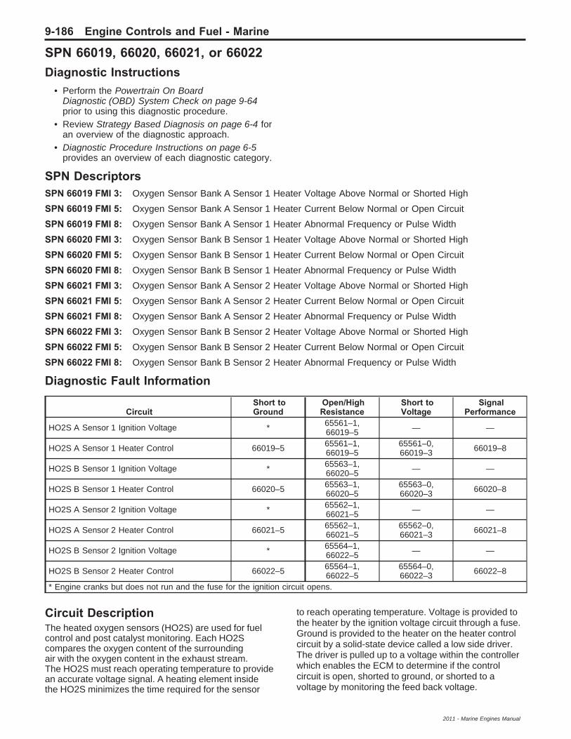
SPN 66019, 66020, 66021, or 66022Diagnostic Instructions
• Perform the Powertrain On BoardDiagnostic (OBD) System Check on page 9-64prior to using this diagnostic procedure.
• Review Strategy Based Diagnosis on page 6-4 foran overview of the diagnostic approach.
• Diagnostic Procedure Instructions on page 6-5provides an overview of each diagnostic category.
SPN DescriptorsSPN 66019 FMI 3: Oxygen Sensor Bank A Sensor 1 Heater Voltage Above Normal or Shorted High
SPN 66019 FMI 5: Oxygen Sensor Bank A Sensor 1 Heater Current Below Normal or Open Circuit
SPN 66019 FMI 8: Oxygen Sensor Bank A Sensor 1 Heater Abnormal Frequency or Pulse Width
SPN 66020 FMI 3: Oxygen Sensor Bank B Sensor 1 Heater Voltage Above Normal or Shorted High
SPN 66020 FMI 5: Oxygen Sensor Bank B Sensor 1 Heater Current Below Normal or Open Circuit
SPN 66020 FMI 8: Oxygen Sensor Bank B Sensor 1 Heater Abnormal Frequency or Pulse Width
SPN 66021 FMI 3: Oxygen Sensor Bank A Sensor 2 Heater Voltage Above Normal or Shorted High
SPN 66021 FMI 5: Oxygen Sensor Bank A Sensor 2 Heater Current Below Normal or Open Circuit
SPN 66021 FMI 8: Oxygen Sensor Bank A Sensor 2 Heater Abnormal Frequency or Pulse Width
SPN 66022 FMI 3: Oxygen Sensor Bank B Sensor 2 Heater Voltage Above Normal or Shorted High
SPN 66022 FMI 5: Oxygen Sensor Bank B Sensor 2 Heater Current Below Normal or Open Circuit
SPN 66022 FMI 8: Oxygen Sensor Bank B Sensor 2 Heater Abnormal Frequency or Pulse Width
Diagnostic Fault Information
CircuitShort toGround
Open/HighResistance
Short toVoltage
SignalPerformance
HO2S A Sensor 1 Ignition Voltage * 65561–1,66019–5 — —
HO2S A Sensor 1 Heater Control 66019–5 65561–1,66019–5
65561–0,66019–3 66019–8
HO2S B Sensor 1 Ignition Voltage * 65563–1,66020–5 — —
HO2S B Sensor 1 Heater Control 66020–5 65563–1,66020–5
65563–0,66020–3 66020–8
HO2S A Sensor 2 Ignition Voltage * 65562–1,66021–5 — —
HO2S A Sensor 2 Heater Control 66021–5 65562–1,66021–5
65562–0,66021–3 66021–8
HO2S B Sensor 2 Ignition Voltage * 65564–1,66022–5 — —
HO2S B Sensor 2 Heater Control 66022–5 65564–1,66022–5
65564–0,66022–3 66022–8
* Engine cranks but does not run and the fuse for the ignition circuit opens.
Circuit DescriptionThe heated oxygen sensors (HO2S) are used for fuelcontrol and post catalyst monitoring. Each HO2Scompares the oxygen content of the surroundingair with the oxygen content in the exhaust stream.The HO2S must reach operating temperature to providean accurate voltage signal. A heating element insidethe HO2S minimizes the time required for the sensor
to reach operating temperature. Voltage is provided tothe heater by the ignition voltage circuit through a fuse.Ground is provided to the heater on the heater controlcircuit by a solid-state device called a low side driver.The driver is pulled up to a voltage within the controllerwhich enables the ECM to determine if the controlcircuit is open, shorted to ground, or shorted to avoltage by monitoring the feed back voltage.
9-186 Engine Controls and Fuel - Marine
2011 - Marine Engines Manual

Conditions for Running the SPN66019, 66020, 66021, 66022 FMI 3 and 5
• SPN 110, 630, or 65580 is not set.• The ignition is ON or the engine is operating.• The ignition voltage is greater than 9 volts.• The heater control circuit has been commanded
ON and OFF at least once during theignition cycle.
• The SPNs run continuously when the aboveconditions are met.
66019, 66020, 66021, 66022 FMI 8• SPN 110, 630, or 65580 is not set.• The ignition voltage is greater than 10 volts.• The engine is operating.• The ECM is not commanding decel fuel
cut-off (DFCO).• The calculated airflow is greater than
10 grams/second (36 kg/hour).• The SPN runs continuously when the above
conditions are met.
Conditions for Setting the SPN66019, 66020, 66021, 66022 FMI 3 and 5The ECM detects that the commanded state of thedriver and the actual state of the control circuit do notmatch for greater than 5 seconds.
66019 and 66020 FMI 8The ECM detects that the heater control duty cycle isgreater than 90 percent for greater than 160 seconds.
66021 and 66022 FMI 8The ECM detects that the heater control duty cycle isgreater than 0 percent.
Action Taken When the SPN SetsSPN 66019, 66020, 66021, and 66022 areType B SPNs.
Conditions for Clearing the SPNSPN 66019, 66020, 66021, and 66022 areType B SPNs.
Reference InformationSchematic ReferenceEngine Controls Schematics on page 9-6
Connector End View Reference• Engine Control Module Connector End Views on
page 9-30
• Engine Controls Connector End Views onpage 9-33
Electrical Information Reference• Circuit Testing on page 11-6
• Connector Repairs on page 11-22
• Testing for Intermittent Conditions and PoorConnections on page 11-13
• Wiring Repairs on page 11-16
SPN Type ReferenceSuspect Parameter Number (SPN) Type Definitions onpage 6-9
Scan Tool ReferenceEngine Control Module Scan Tool Information onpage 9-54
Circuit/System Verificatio1. Engine idling at normal operating temperature,
observe the SPN information with a scan tool.SPN 66019, 66020, 66021, or 66022 shouldnot set.
2. Operate the vehicle within the Conditions forRunning the SPN to verify the SPN does notreset. You may also operate the vehicle withinthe conditions that you observed from the FreezeFrame/Failure Records data.
Engine Controls and Fuel - Marine 9-187
2011 - Marine Engines Manual

Circuit/System Testing1. Ignition OFF, disconnect the harness connector at
the appropriate HO2S.2. Ignition ON, verify that a test lamp illuminates
between the ignition voltage circuit terminal Dand ground.⇒ If the test lamp does not illuminate, test the
ignition voltage circuit for a short to groundor an open/high resistance. If the circuit testsnormal and the ignition voltage circuit fuseis open, test all components connected tothe ignition voltage circuit and replaceas necessary.
3. Ignition ON, connect a test lamp between theheater control circuit terminal C and B+. Verifythe test lamp does not illuminate.⇒ If the test lamp illuminates, test the control
circuit for a short to ground. If the circuittests normal, replace the ECM.
Note: The heater control circuit is pulled-up to avoltage within the controller. 3–4 volts measured onthis circuit is normal.4. Command the heater control circuit ON for the
appropriate HO2S with a scan tool. Verify thetest lamp illuminates, and turns OFF, ascommanded.⇒ If the test lamp is always OFF, test the control
circuit for a short to voltage or an open/highresistance. If the circuit tests normal, replacethe ECM.
5. If all circuits test normal, test or replace the HO2S.
Component Testing1. Ignition OFF, disconnect the harness connector at
the HO2S.
2. Test for 4–8 Ω between the ignition voltage circuitterminal D and the control circuit terminal C.
⇒ If not within the specified range, replacethe HO2S.
Repair InstructionsPerform the Diagnostic Repair Verification onpage 6-22 after completing the diagnostic procedure.
• Heated Oxygen Sensor Replacement onpage 9-226
• Engine Control Module Replacement onpage 9-217 for ECM replacement, setup, andprogramming
9-188 Engine Controls and Fuel - Marine
2011 - Marine Engines Manual

SPN 66025Diagnostic Instructions
• Perform the Powertrain On BoardDiagnostic (OBD) System Check on page 9-64prior to using this diagnostic procedure.
• Review Strategy Based Diagnosis on page 6-4 foran overview of the diagnostic approach.
• Diagnostic Procedure Instructions on page 6-5provides an overview of each diagnostic category.
SPN DescriptorsSPN 66025 FMI 4: Fuel Pump Relay 2 Voltage Below Normal or Shorted Low
SPN 66025 FMI 5: Fuel Pump Relay 2 Current Below Normal or Open Circuit
Diagnostic Fault Information
CircuitShort toGround
Open/HighResistance
Short toVoltage
SignalPerformance
Battery Voltage – Relay Switch 1 2 — —Fuel Pump Supply Voltage 1 2 3 —Fuel Pump Relay Control 66025–4 66025–5 3 —Fuel Pump Ground — 2 — —
1. The fuel pump fuse opens and the engine cranks but does not run.2. The engine cranks but does not run.3. The fuel pump operates continuously and the battery will discharge.
Circuit/System DescriptionThe engine control module (ECM) provides ignitionvoltage to the coil side of the fuel pump relay 2whenever the engine is cranking or running. The controlmodule enables the fuel pump relay as long as theengine is cranking or running, and ignition systemreference pulses are received. If no ignition systemreference pulses are received, the control module turnsOFF the fuel pump. The fuel pump relay control circuitis equipped with a feedback circuit that is pulled up to avoltage within the ECM. The ECM can determine if thecontrol circuit is open, shorted to ground, or shorted to avoltage by monitoring the feedback voltage.
Conditions for Running the SPN• SPN 630 or 65580 is not set.• The ignition is ON, or the engine is operating.• The ignition voltage is greater than 9 volts.• The ECM has commanded the fuel pump relay
ON and OFF at least once during theignition cycle.
• SPN 66025 runs continuously once the aboveconditions are met.
Conditions for Setting the SPNThe ECM detects that the commanded state of thedriver and the actual state of the control circuit do notmatch for greater than 2 seconds.
Action Taken When the SPN SetsSPN 66025 is a Type B SPN.
Conditions for Clearing the SPNSPN 66025 is a Type B SPN.
Reference InformationSchematic ReferenceEngine Controls Schematics on page 9-6
Connector End View Reference• Engine Control Module Connector End Views on
page 9-30
• Engine Controls Connector End Views onpage 9-33
Electrical Information Reference• Circuit Testing on page 11-6
• Connector Repairs on page 11-22
• Testing for Intermittent Conditions and PoorConnections on page 11-13
• Wiring Repairs on page 11-16
SPN Type ReferenceSuspect Parameter Number (SPN) Type Definitions onpage 6-9
Scan Tool ReferenceEngine Control Module Scan Tool Information onpage 9-54
Special ToolsJ 43244 Relay Puller Pliers
Engine Controls and Fuel - Marine 9-189
2011 - Marine Engines Manual

Circuit/System Verificatio1. Ignition ON, command the fuel pump relay 2 ON
and OFF with a scan tool. You should hear andfeel an audible click.
2. Observe the scan tool SPN information.SPN 66025 should not be set.
3. Operate the vehicle within the Conditions forRunning the SPN to verify the SPN does notreset. You may also operate the vehicle withinthe conditions that you observed from the FreezeFrame/Failure Records data.
Circuit/System Testing1. Ignition OFF, disconnect the fuel pump relay 2
with the J 43244.2. Test for less than 5 Ω between the ground circuit
terminal 86 and ground.⇒ If greater than the specified range, repair the
ground circuit for an open/high resistance.3. Connect a test lamp between the relay coil control
circuit terminal 85 and ground.4. Ignition ON, command the fuel pump relay 2 ON
and OFF with a scan tool. The test lamp shouldturn ON and OFF when changing betweenthe commanded states.⇒ If the test lamp is always ON, test the control
circuit for a short to voltage. If the circuit testsnormal, replace the ECM.
⇒ If the test lamp is always OFF, test the controlcircuit for a short to ground or an open/highresistance. If the circuit tests normal, replacethe ECM.
5. If all circuits test normal, test or replace the fuelpump relay 2.
Component Testing1. Ignition OFF, disconnect the fuel pump relay 2
with the J 43244.
2. Test for 70–110 Ω between terminals 85 and 86.
⇒ If not within the specified range, replacethe relay.
3. Test for infinite resistance between the followingterminals:
• 30 and 86
• 30 and 87
• 30 and 85
• 85 and 87
⇒ If not within the specified range, replacethe relay.
4. Install a 20 A fused jumper wire between relayterminal 85 and B+. Install a jumper wire betweenrelay terminal 86 and ground. Test for lessthan 2 Ω between terminals 30 and 87.
⇒ If greater than the specified range, replacethe relay.
Repair InstructionsPerform the Diagnostic Repair Verification onpage 6-22 after completing the diagnostic procedure.
• Relay Replacement (Fuse Block ) on page 11-28or Relay Replacement (Harness) on page 11-29
• Engine Control Module Replacement onpage 9-217 for engine control modulereplacement, setup, and programming
9-190 Engine Controls and Fuel - Marine
2011 - Marine Engines Manual

SPN 66026Diagnostic Instructions
• Perform the Powertrain On BoardDiagnostic (OBD) System Check on page 9-64prior to using this diagnostic procedure.
• Review Strategy Based Diagnosis on page 6-4 foran overview of the diagnostic approach.
• Diagnostic Procedure Instructions on page 6-5provides an overview of each diagnostic category.
SPN DescriptorsSPN 66026 FMI 7: Shift Interrupt Switch Mechanical System Not Responding or Out of Adjustment
Circuit/System DescriptionThe shift interrupt switch is used to reduce the torqueapplied to the lower unit while shifting in and out of gear.This makes it easier to shift, and reduces gear noise.The engine control module (ECM) supplies B+ to theshift interrupt switch signal circuit. When the throttlecontrol is in the neutral position, the ECM detects a highsignal voltage. When the throttle control is shifted outof neutral, the contacts on the shift interrupt switchclose and the ECM detects a low shift interrupt signal.The ECM will momentarily reduced the engine RPMwhen the signal circuit is grounded.
Conditions for Running the SPN• SPN 630 or 65580 is not set.• The ignition is ON, or the engine is operating.• The pedal position is less than 5 percent.• SPN 66026 runs continuously when the above
conditions are met.
Conditions for Setting the SPNThe ECM detects the shift interrupt switch signalcircuit is open, shorted to ground, or shorted toa voltage for greater than a calibrated amount of time.
Action Taken When the SPN SetsSPN 66026 is Type C SPN.
Conditions for Clearing the MIL/SPNSPN 66026 is Type C SPN.
Reference InformationSchematic ReferenceEngine Controls Schematics on page 9-6
Electrical Information Reference• Circuit Testing on page 11-6• Connector Repairs on page 11-22• Testing for Intermittent Conditions and Poor
Connections on page 11-13• Wiring Repairs on page 11-16
SPN Type ReferenceSuspect Parameter Number (SPN) Type Definitions onpage 6-9
Scan Tool ReferenceEngine Control Module Scan Tool Information onpage 9-54 for scan tool information
Circuit/System Verificatio1. Ignition ON, observe the shift interrupt switch
parameter with a scan tool while shifting in andout of gear. The parameter should display OFF inneutral and ON in gear.
2. Observe the SPN information with a scan tool.SPN 66026 should not set.
3. Operate the vehicle within the Conditions forRunning the SPN to verify the SPN does notreset. You may also operate the vehicle withinthe conditions that you observed from the FreezeFrame/Failure Records data.
Engine Controls and Fuel - Marine 9-191
2011 - Marine Engines Manual

Circuit/System TestingNote: Verify the shift interrupt switch is properlyadjusted before proceeding with this diagnosticprocedure.1. Ignition OFF, disconnect the harness connector at
the shift interrupt switch.2. Test for less than 5 Ω between the ground circuit
terminal 2 and ground.⇒ If greater than the specified range, test the
ground circuit for an open/high resistance.3. Ignition ON, test for greater than 10 V between
the shift interrupt switch signal circuit terminal 1and ground.⇒ If less than the specified range, test the signal
circuit for an open/high resistance or a shortto ground. If the circuit tests normal,replace the ECM.
4. Ignition OFF, install a 3 A fused jumper wirebetween the between the shift interrupt switchsignal circuit terminal 1 and ground.
5. Ignition ON, observe the scan tool shift interruptswitch parameter. The parameter shoulddisplay ON.⇒ If the parameter does not display ON, test the
signal circuit for a short to voltage. If the circuittests normal, replace the ECM.
6. If all circuits test normal, test or replace the shiftinterrupt switch.
Component Testing1. Ignition OFF, disconnect the harness connector at
the shift interrupt switch.
2. Measure the resistance between the shift interruptswitch signal circuit terminal 1 and the shiftinterrupt switch ground circuit terminal 2.The DMM should display OL.
⇒ If less than the specified value, replace theshift interrupt switch.
3. Test for less than 5 Ω while depressing the shiftinterrupt switch.
⇒ If greater than the specified range, replace theshift interrupt switch.
Repair InstructionsPerform the Diagnostic Repair Verification onpage 6-22 after completing the diagnostic procedure.
Engine Control Module Replacement on page 9-217for ECM replacement, setup, and programming
9-192 Engine Controls and Fuel - Marine
2011 - Marine Engines Manual

SPN 66030Diagnostic Instructions
• Perform the Powertrain On BoardDiagnostic (OBD) System Check on page 9-64prior to using this diagnostic procedure.
• Review Strategy Based Diagnosis on page 6-4 foran overview of the diagnostic approach.
• Diagnostic Procedure Instructions on page 6-5provides an overview of each diagnostic category.
SPN DescriptorSPN 66030 FMI 3: Intercooler Relay Voltage Above Normal or Shorted High
SPN 66030 FMI 5: Intercooler Relay Voltage Below Normal or Shorted Low
Circuit DescriptionThe supercharger intercooler relay is a normally openrelay. The relay switch is held in the open position byspring tension. Ignition voltage is supplied directly to therelay coil. Battery voltage is supplied to the switch sideof the relay. The engine control module (ECM) providesground to the control circuit of the relay with a low sidedriver. When the ECM commands the relay ON, therelay contacts will close allowing current to flow from thebattery to the supercharger intercooler pump. The fuelpump relay control circuit is equipped with a feedbackcircuit that is pulled up to 2.5 volts within the ECM. TheECM can determine if the control circuit is open, shortedto ground, or shorted to a voltage by monitoring thefeedback voltage.
Conditions for Running the SPN• SPN 630 or 65580 is not set.• The ignition is ON, or the engine is operating.• The ignition voltage is greater than 9 volts.• The ECM has commanded the intercooler
relay ON and OFF at least once during theignition cycle.
• SPN 66030 run continuously when the abovecondition is met.
Conditions for Setting the SPNThe ECM detects that the commanded state of thedriver and the actual state of the control circuit do notmatch for greater than 5 seconds.
Action Taken When the SPN SetsSPN 66030 is a Type B SPN.
Conditions for Clearing the MIL/SPNSPN 66030 is a Type B SPN.
Diagnostic Aids• A resistance on the intercooler pump control
circuit or the relay coil ignition voltage circuit maycause this SPN to set.
• When disconnecting electrical connectors orremoving fuses and relays from a fuse block,always inspect the component electricalterminals for corrosion and the matingelectrical terminals for correct tension.
Reference InformationSchematic ReferenceEngine Controls Schematics on page 9-6
Connector End View Reference• Engine Control Module Connector End Views on
page 9-30• Engine Controls Connector End Views on
page 9-33
Electrical Information Reference• Circuit Testing on page 11-6• Connector Repairs on page 11-22• Testing for Intermittent Conditions and Poor
Connections on page 11-13• Wiring Repairs on page 11-16
SPN Type ReferenceSuspect Parameter Number (SPN) Type Definitions onpage 6-9
Scan Tool ReferenceEngine Control Module Scan Tool Information onpage 9-54 for scan tool information
Special ToolsJ 43244 Relay Puller Pliers
Circuit/System Verificatio1. Ignition ON, command the intercooler coolant
pump relay ON and OFF several times with ascan tool. Listen and feel for the intercoolercoolant pump relay to click with each command.
2. Observe the SPN information with a scan tool.SPN 66030 should not set.
3. Operate the vehicle within the Conditions forRunning the SPN. You may also operate thevehicle within the conditions that you observedfrom the Freeze Frame/Failure Records data.
Engine Controls and Fuel - Marine 9-193
2011 - Marine Engines Manual

Circuit/System Testing1. Ignition OFF, disconnect the intercooler coolant
pump relay with the J 43244.
2. Ignition ON, verify a test lamp illuminates betweenthe relay coil ignition voltage circuit terminal 85and ground.
⇒ If the test lamp does not illuminate, test therelay coil ignition voltage circuit for a shortto ground or an open/high resistance.
3. Ignition ON, command the intercooler pump relayON and OFF with a scan tool. The test lamp turnON and OFF as commanded.
⇒ If the test lamp is always ON, test the relaycoil control circuit for a short to ground.If the circuit tests normal, replace the ECM.
⇒ If the test lamp is always OFF, test the relaycoil control circuit for a short to voltage oran open/high resistance. If the circuittests normal, replace the ECM.
4. Connect a 20 A fused jumper wire betweenthe relay switch B+ circuit terminal 30 andthe relay switch ignition voltage circuit terminal 87.The intercooler pump should operate.
⇒ If the intercooler pump does not operate, referto Supercharger Intercooler Relay Diagnosison page 9-204.
5. If all circuits test normal, test or replace theintercooler pump relay.
Component Testing1. Ignition OFF, disconnect the intercooler pump
relay with the J 43244.2. Test for 70–110 Ω between terminals 85 and 86.
⇒ If not within the specified range, replacethe relay.
3. Test for infinite resistance between the followingterminals:• 30 and 86• 30 and 87• 30 and 85• 85 and 87
⇒ If not the specified value, replace the relay.4. Install a 10 A fused jumper wire between relay
terminal 85 and B+.5. Install a jumper wire between relay terminal 86
and ground.6. Test for less than 2 Ω between terminals 30
and 87.⇒ If greater than the specified range, replace
the relay.
Repair InstructionsPerform the Diagnostic Repair Verification onpage 6-22 after completing the repair.
• Relay Replacement (Fuse Block ) on page 11-28or Relay Replacement (Harness) on page 11-29
• Engine Control Module Replacement onpage 9-217 for ECM replacement, setup, andprogramming
9-194 Engine Controls and Fuel - Marine
2011 - Marine Engines Manual

SPN 66035Diagnostic Instructions
• Perform the Powertrain On BoardDiagnostic (OBD) System Check on page 9-64prior to using this diagnostic procedure.
• Review Strategy Based Diagnosis on page 6-4 foran overview of the diagnostic approach.
• Diagnostic Procedure Instructions on page 6-5provides an overview of each diagnostic category.
SPN DescriptorSPN 66035 FMI 0: Supercharger Boost Control Solenoid Data Valid but Above Normal
SPN 66035 FMI 3: Supercharger Boost Control Solenoid Data Valid but Below Normal
SPN 66035 FMI 5: Supercharger Boost Control Solenoid Current Below Normal or Open Circuit
SPN 66035 FMI 7: Supercharger Boost Control Solenoid Mechanical System Not Responding or Out ofAdjustment
Circuit DescriptionSupercharger (SC) boost pressure is regulated toprevent engine damage. When the engine is operatingunder high boost conditions, the engine controlmodule (ECM) limits boost pressure to a calibratedvalue. The ECM disables boost under the followingconditions:
• When an electronic throttle control (ETC) fault isdetected.
• When an intercooler pump failure is detected
• When the ECM detects an over-temperaturecondition.
The ECM controls boost pressure by pulse widthmodulation (PWM) of the boost control solenoid.The boost control solenoid is a normally open valve.Under most conditions, the ECM commands the boostcontrol solenoid to operate at a 99–100 percent dutycycle. This keeps the boost control solenoid valveclosed and allows only inlet vacuum from thesupercharger plenum to the bypass valve actuator tocontrol the position of the bypass valve. At idle, enginevacuum is applied to the upper side of the bypass valveactuator, counteracting spring tension to hold thebypass valve open. When the engine load is increased,the engine vacuum is decreased, causing the spring inthe bypass valve actuator to overcome the diminishingapplied vacuum, closing the bypass valve and allowingthe boost pressure to increase. When reduced boostpressure is desired, the ECM commands the boostcontrol solenoid to operate at a 0–98 percent dutycycle. This opens the solenoid valve and allows boostpressure to enter the bypass valve actuator at the lowerside to counteract the spring tension, opening thebypass valve and recirculating excess boost pressureback into the supercharger inlet. The ECM controls thevalve by grounding the control circuit with a solid statedevice called a driver. The driver is equipped with afeedback circuit that is pulled-up to a voltage. The ECMcan determine if the control circuit is open, shorted toground, or shorted to a voltage by monitoring thefeedback voltage.
Conditions for Running the SPN66035–0
• Before the ECM can report that SPN 66035–0failed, SPNs 66035–3, and 66035–5 must runand pass.
• SPN 106, 108, 630, 3563, or 65580 is not set.
• The ignition is ON, or the engine is operating.
• The ignition voltage is greater than 9 volts.
• SPN 66035–0 runs continuously when the aboveconditions are met.
66035–3• SPN 630 or 65580 is not set.
• The ignition is ON, or the engine is operating.
• The ignition voltage is greater than 9 volts.
• The boost control solenoid is commanded ON.
• SPN 66035–3 runs continuously when the aboveconditions are met.
66035–5• SPN 630 or 65580 is not set.
• The ignition is ON, or the engine is operating.
• The ignition voltage is greater than 9 volts.
• The boost control solenoid is commanded OFF.
• SPN 66035–5 runs continuously when theabove conditions are met.
66035–7• Before the ECM can report that SPN 66035–7
failed, SPNs 66035–3, and 66035–5 must runand pass.
• SPN 106, 108, 630, 3563, or 65580 is not set.
• The ignition is ON, or the engine is operating.
• The ignition voltage is greater than 9 volts.
• The desired boost is stable within 5 percent.
• SPN 66035–7 runs continuously when the aboveconditions are met.
Engine Controls and Fuel - Marine 9-195
2011 - Marine Engines Manual

Conditions for Setting the SPN66035–0The ECM detects the SC boost exceeds 75 kPa forgreater than 2 seconds.
66035–3 and 66035–5The ECM detects that the commanded state of thedriver and the actual state of the control circuit do notmatch for greater than 5 seconds.
66035–7• The Actual SC boost is 99.6 percent less than the
desired boost for greater than 2 seconds.
OR
• The SC boost is 30 percent greater than thedesired boost for greater than 2 seconds.
Action Taken When the SPN SetsSPN 66035 is a Type B SPN.
Conditions for Clearing the MIL/SPNSPN 66035 is a Type B SPN.
Reference InformationSchematic ReferenceEngine Controls Schematics on page 9-6
Connector End View Reference• Engine Control Module Connector End Views on
page 9-30
• Engine Controls Connector End Views onpage 9-33
Description and OperationSupercharger Description and Operation onpage 9-282
Electrical Information Reference• Circuit Testing on page 11-6• Connector Repairs on page 11-22• Testing for Intermittent Conditions and Poor
Connections on page 11-13• Wiring Repairs on page 11-16
SPN Type ReferenceSuspect Parameter Number (SPN) Type Definitions onpage 6-9
Scan Tool ReferenceEngine Control Module Scan Tool Information onpage 9-54 for scan tool information
Circuit/System Verificatio1. Ignition ON, compare the scan tool BARO sensor
pressure parameter, MAP sensor pressureparameter, and the SCIP sensor pressureparameter. All three parameter readingsshould be within 5 kPa of each other.⇒ If greater than the specified range, refer to
Altitude Versus Barometric Pressure onpage 9-3 and Diagnostic Trouble Code (DTC)List on page 6-11 for diagnosis of an out ofrange sensor.
2. Engine operating, verify the intercooler pump isoperating.⇒ If the intercooler pump is not operating, refer
to Supercharger Intercooler Relay Diagnosison page 9-204.
3. Verify proper operation of the boost controlsystem. Refer to Boost Control System Diagnosison page 9-205
4. Observe the SPN information with a scan tool.SPN 66035 should not set.
5. Operate the vehicle within the Conditions forRunning the SPN to verify the SPN does notreset. You may also operate the vehicle within theconditions that you observed from the FreezeFrame/Failure Records data.
9-196 Engine Controls and Fuel - Marine
2011 - Marine Engines Manual

Circuit/System Testing1. Ignition OFF, disconnect the harness connector at
the SCB solenoid.2. Ignition ON, verify that a test lamp illuminates
between the ignition voltage supply circuitterminal 1 and ground.⇒ If the test lamp does not illuminate, test the
ignition circuit for a short to ground or anopen/high resistance. If the circuit tests normaland the ignition voltage circuit fuse is open,test all components connected to the ignitionvoltage circuit and replace as necessary.
3. Test for 2.6-4.6 V between the control circuitterminal 2 and ground.⇒ If less than the specified range, test the
control circuit for a short to ground or anopen/high resistance. If the circuit tests normal,replace the ECM.
⇒ If greater than the specified range, test thecontrol circuit for a short to voltage. If thecircuit tests normal, replace the ECM.
4. Connect a test lamp between the ignition voltagesupply circuit terminal 1 and the control circuitterminal 2.
5. Command the SCB solenoid on with a scan tool.Verify the test lamp should illuminates.
⇒ If the test lamp does not illuminate, replacethe ECM.
6. If all circuits test normal, test or replace theSCB solenoid.
Component Testing1. Ignition OFF, disconnect the harness connector at
the SCB solenoid.
2. Test for 30–55 Ω between the control terminal andthe voltage supply terminal of the SCB solenoid.
⇒ If the resistance is not within the specifiedrange, replace the SCB solenoid.
Repair InstructionsPerform the Diagnostic Repair Verification onpage 6-22 after completing the diagnostic procedure.
Engine Control Module Replacement on page 9-217for ECM replacement, setup, and programming
Engine Controls and Fuel - Marine 9-197
2011 - Marine Engines Manual

SPN 66040-66043Diagnostic Instructions
• Perform the Powertrain On BoardDiagnostic (OBD) System Check on page 9-64prior to using this diagnostic procedure.
• Review Strategy Based Diagnosis on page 6-4 foran overview of the diagnostic approach.
• Diagnostic Procedure Instructions on page 6-5provides an overview of each diagnostic category.
SPN DescriptorSPN 66040 FMI 3: OEM Output Driver 1 Voltage Above Normal or Shorted High
SPN 66040 FMI 5: OEM Output Driver 1 Current Below Normal or Open Circuit
SPN 66041 FMI 3: OEM Output Driver 2 Voltage Above Normal or Shorted High
SPN 66041 FMI 5: OEM Output Driver 2 Current Below Normal or Open Circuit
SPN 66042 FMI 3: OEM Output Driver 3 Voltage Above Normal or Shorted High
SPN 66042 FMI 5: OEM Output Driver 3 Current Below Normal or Open Circuit
SPN 66043 FMI 3: OEM Output Driver 4 Voltage Above Normal or Shorted High
SPN 66043 FMI 5: OEM Output Driver 4 Current Below Normal or Open Circuit
Circuit/System DescriptionIgnition voltage is supplied to the OEM device througha fuse. The engine control module (ECM) turns theOEM device ON by grounding the OEM output controlcircuit.
Conditions for Running the SPN• SPN 630 or 65580 are not set.• The ignition is ON, or the engine is operating.• The ignition voltage is greater than 9 volts.• The ECM has commanded the OEM output ON
and OFF at least once during the ignition cycle.• The SPNs 66040–66043 run continuously
once the above conditions are met.
Conditions for Setting the SPNThe ECM detects that the commanded state of thedriver and the actual state of the control circuit do notmatch for greater than 5 seconds.
Action Taken When the SPN SetsSPN 66040, 66041, 66042, and 66043 areType C SPNs.
Conditions for Clearing the SPNSPN 66040, 66041, 66042, and 66043 areType C SPNs.
Reference InformationSchematic ReferenceEngine Controls Schematics on page 9-6
Connector End View Reference• Engine Control Module Connector End Views on
page 9-30
• Engine Controls Connector End Views onpage 9-33
Electrical Information Reference• Circuit Testing on page 11-6
• Connector Repairs on page 11-22
• Testing for Intermittent Conditions and PoorConnections on page 11-13
• Wiring Repairs on page 11-16
SPN Type ReferenceSuspect Parameter Number (SPN) Type Definitions onpage 6-9
Scan Tool ReferenceEngine Control Module Scan Tool Information onpage 9-54
Circuit/System Verificatio1. Ignition ON, command the OEM device ON and
OFF with a scan tool. The OEM device shouldturn ON and OFF.
2. Observe the SPN information with a scan tool.SPN 66040, 66041, 66042, or 66043 shouldnot set.
3. Operate the vehicle within the Conditions forRunning the SPN to verify the SPN does notreset. You may also operate the vehicle withinthe conditions that you observed from the FreezeFrame/Failure Records data.
9-198 Engine Controls and Fuel - Marine
2011 - Marine Engines Manual

Circuit/System Testing1. Ignition OFF, disconnect the harness connector at
the OEM device.2. Ignition ON, verify a test lamp illuminates between
the ignition voltage circuit terminal and ground.⇒ If the test lamp does not illuminate, test
the ignition voltage circuit for a short to ground,or an open/high resistance. If the circuittests normal and the ignition voltage circuitfuse is open, test all components connectedto the ignition voltage circuit and replaceas necessary.
3. Ignition OFF, connect a test lamp between thecontrol circuit terminal and B+.
4. Ignition ON, command the OEM device ON andOFF with a scan tool. The test lamp should turnON and OFF with each command.⇒ If the test lamp is ON all of the time, test the
control circuit for a short to ground. If thecircuit test normal, replace the ECM.
⇒ If the test lamp is OFF all of the time, test thecontrol circuit for a short to voltage, or anopen/high resistance. If the circuit test normal,replace the ECM.
5. If all circuits test normal, test or replace the OEMdevice.
Repair InstructionsPerform the Diagnostic Repair Verification onpage 6-22 after completing the diagnostic procedure.Engine Control Module Replacement on page 9-217for ECM replacement, setup, and programming
Symptoms - Engine Controls
Diagnostic Instructions• Perform the Powertrain On Board
Diagnostic (OBD) System Check on page 9-64prior to using this diagnostic procedure.
• Review Strategy Based Diagnosis on page 6-4 foran overview of the diagnostic approach.
• Diagnostic Procedure Instructions on page 6-5provides an overview of each diagnostic category.
Symptoms DescriptionSymptoms covers conditions that are not coveredby DTCs. Certain conditions can cause multiplesymptoms. These conditions are listed together underSymptoms Testing. Conditions that may only causespecific symptoms are listed separately underAdditional Symptoms Testing. Perform the SymptomsTesting before using the Additional Symptoms Testing.
Symptoms DefinitioBackfire Fuel ignites in the intake manifold or in theexhaust system, making a loud popping noise.
Cuts Out, Misses: A steady pulsation or jerkingthat follows engine speed, which is usually morepronounced as the engine load increases. Thiscondition is not normally felt above 1,500 RPM or48 km/h (30 mph). The exhaust has a steady spittingsound at idle or at low speed.
Detonation/Spark Knock: A mild to severe pingwhich usually occurs worse while under acceleration.The engine makes sharp metallic knocks thatchange with throttle opening.
Dieseling, Run-On: Fuel ignites in the intakemanifold or in the exhaust system, making a loudpopping noise.
Hard Start: Engine cranks OK, but does not startfor a long time. The vehicle does eventually run,or may start but immediately stalls.
Hesitation, Sag, Stumble: Momentary lackof response as the accelerator is pushed down.This condition can occur at any vehicle speed.This condition is usually more pronounced whenfirst trying to make the vehicle move, as from a stop.This condition may cause the engine to stall insevere conditions.
Lack of Power, Sluggishness, orSponginess: The engine delivers less than expectedpower. Little or no increase in speed when theaccelerator pedal is pushed down part way.
Poor Fuel Economy: Fuel economy is noticeablylower than expected. Also, the fuel economy isnoticeably lower than it was on this vehicle at one time.
Poor Fuel Fill Quality: Difficulty when refuelingthe vehicle.
Rough, Unstable, or Incorrect Idle andStalling: The engine runs unevenly at idle. If severe,the engine or the vehicle may shake. Engine idlemay vary in speed. Either condition may be severeenough to stall the engine.
Surges/Chuggles: Engine power variation understeady throttle or cruise. Feels like the vehicle speedsup and slows down with no change in the acceleratorpedal position.
Symptoms VerificatioVerify all of the following conditions are true:
• The engine control module (ECM) and themalfunction indicator lamp (MIL) are operatingcorrectly
• There are no suspect parameter numbers (SPNs)stored
• The scan tool data is within the normaloperating range
• Bulletins are not available for the current symptom• The ECM grounds are clean, tight, and in the
correct locations• The air filter element is not restricted
Engine Controls and Fuel - Marine 9-199
2011 - Marine Engines Manual

Symptoms TestingBackfire Cuts Out/Misses, Detonation/SparkKnock, Dieseling/Run-On, Hard Start,Hesitation/Sag/Stumble, Lack ofPower/Sluggishness/Sponginess, Poor FuelEconomy, Rough, Unstable, or IncorrectIdle and Stalling, or Surges/Chuggles1. Test for the following conditions:
• The fuel system for the following:− Correct fuel pressure—Refer to Fuel
System Diagnosis (with ReturnlessFuel System ) on page 9-208 or FuelSystem Diagnosis (without Returnless FuelSystem) on page 9-210
− Fuel injectors that are leaking or improperoperation—Refer to Fuel Injector Diagnosison page 9-211
− Contaminated or a poor fuel qualitycondition—Refer to Alcohol/Contaminants-in-Fuel Diagnosis onpage 9-213
• The ignition system for the following:− Spark plugs for incorrect heat range or an
abnormal condition—Refer to Spark PlugInspection on page 9-245
− Wet down the secondary ignition system withwater from a spray bottle—Wetting down thesecondary ignition system may help locatedamaged or deteriorated components.Look/listen for arcing or misfiring as thewater is applied
− Weak spark using the J 26792 SparkTester—Refer to Distributor Ignition (DI)System Diagnosis on page 9-214 orElectronic Ignition System Diagnosis onpage 9-215
• Items that can cause an engine to run lean orrich—Refer to SPN 65565 or 65566 onpage 9-125
• The crankshaft position (CKP) sensor for thecorrect resistance—The CKP sensor resistancemay be out of range after a hot soak. Theresistance should be between 460–620 Ω
• The engine for the following mechanicalfailures:− Excessive oil in the combustion chamber or
leaking valve seals− Incorrect cylinder compression− Sticking or leaking valves− Worn camshaft lobes− Incorrect valve timing− Worn rocker arms− Broken valve springs− Excessive carbon buildup in the combustion
chambers—Clean the chambers with topengine cleaner. Follow the instructions onthe can
− Incorrect engine parts
• Vacuum hoses for splits or kinks—Verify thatthe routing and connections are correct
• Knock sensor (KS) system for excessive sparkretard activity—Refer to SPN 65550, 65551, or65552 on page 9-115
• The exhaust system components for thefollowing:
− Physical damage or possible internal failure
− The three-way catalytic converters for arestriction
• Electromagnetic interference (EMI) on thereference circuit can cause a misfire condition.You can usually detect EMI with a scan toolby monitoring the engine speed parameter.A sudden increase in the engine speedparameter with little change in actual enginespeed indicates that EMI is present. Inspect thehigh voltage components near the ignitioncontrol circuit if a condition exists
• Inspect the positive crankcase ventilation (PCV)system and all connections for leaks orrestrictions
• The engine cooling system for the followingconditions:
− The thermostat is the correct heat range
− Proper engine coolant level
• The supercharger intercooler pump operation—Refer to Supercharger Intercooler RelayDiagnosis on page 9-204
• The supercharger boost control system forproper operation—Refer to Boost ControlSystem Diagnosis on page 9-205
2. If the above conditions do not address thesymptom, refer to the additional symptoms tests.
Additional Symptoms TestsDetonation/Spark KnockTest the engine for an overheating condition.
Lack of Power, Hesitation, or Cut OutTest for the correct operation of the ignition system.Refer to Distributor Ignition (DI) System Diagnosison page 9-214 or Electronic Ignition System Diagnosison page 9-215.
Rough, Unstable, or Incorrect Idle and StallingInspect the engine mounts.
Surges/ChugglesTest the heated oxygen sensors (HO2S). The HO2Sshould respond quickly to a change in throttle position.If the HO2S do not respond to different throttlepositions, inspect for contamination from fuel, silicon,or the incorrect use of RTV sealant. The sensorsmay have a white powdery coating and result in a high,but false, signal voltage, which gives a rich exhaustindication. The ECM reduces the amount of fueldelivered to the engine, causing a driveabilitycondition.
9-200 Engine Controls and Fuel - Marine
2011 - Marine Engines Manual

Hard Start• Test the engine coolant temperature (ECT)
sensor. Compare the ECT sensor value tothe manifold air temperature (MAT) sensor valueon a cold engine. The ECT and MAT sensorvalues should be within ± 3°C (5°F). If the ECTsensor is out of range with the MAT sensor,test the resistance of the ECT sensor. Refer toTemperature Versus Resistance on page 9-3for resistance specifications. Replace the ECTsensor if the resistance is not within specification.Refer to Engine Coolant Temperature SensorReplacement on page 9-218. If the sensor is withinthe specification, test the ECT circuits for a highresistance.
• Test the fuel pump relay operation. The fuel pumpshould turn ON for 2 seconds when the ignitionis turned ON. Refer to Fuel Pump Electrical CircuitDiagnosis on page 9-207.
Hesitation, Sag, Stumble• Test the manifold absolute pressure (MAP)
sensor. Refer to SPN 106 (3.0L, 4.3L, 5.0L, 5.7L)on page 9-83 or SPN 106 (2.4L, 6.0L, 6.2L) onpage 9-86.
• Test the generator. Repair the charging system ifthe generator output voltage is less than 10 V orgreater than 16 V.
Poor Fuel Economy• Heavy loads being carried or towed.• Acceleration rate too much or too often.• Inspect for foreign material accumulation in the
throttle bore, and for carbon deposits on thethrottle plate and shaft. Also inspect for throttlebody tampering.
Poor Fuel Fill QualityTest for the following conditions that are applicable tothe current symptom:
Difficult to fil• Restricted fill lines.• Restricted vent lines.• High fuel temperature.• A condition with the internal components of the
fuel tank assembly.
Fuel Odor• A leak in the fuel supply or return lines—Refer to
Fuel System Diagnosis (with Returnless FuelSystem ) on page 9-208 or Fuel System Diagnosis(without Returnless Fuel System) on page 9-210.
• A condition with the internal components ofthe fuel tank assembly.
Engine Cranks But Does Not Run
Diagnostic Instructions• Perform the Powertrain On Board
Diagnostic (OBD) System Check on page 9-64prior to using this diagnostic procedure.
• Review Strategy Based Diagnosis on page 6-4 foran overview of the diagnostic approach.
• Diagnostic Procedure Instructions on page 6-5provides an overview of each diagnostic category.
Circuit/System DescriptionThis Engine Cranks but Does Not Run diagnosticis an organized approach to identify a conditionwhich causes the engine to crank but not start.This diagnostic directs the technician to the appropriatesystem diagnosis.
Diagnostic AidsInspect for any of the following conditions:
• Insufficient fuel can cause a no start condition.Thoroughly inspect the fuel delivery systemfor sufficient fuel volume to the fuel injectors.Inspect the fuel supply components for partialblockage or restrictions.
• Fuel injectors with partially blocked and restrictednozzles, or a malfunctioning solenoid, can causea no start condition. Refer to Fuel InjectorDiagnosis on page 9-211.
• There may be fuel spray at the fuel injectors andthe indicated fuel pressure may be correct, yetthere may not be enough fuel to start the engine.If the fuel injectors and the injector circuit areOK, and fuel spray is detected, the fuel injectorON time may be inadequate. If the engine controlmodule (ECM) receives incorrect inputs fromthe various information sensors, the fuel deliveredby the fuel injectors may be inadequate to startthe engine. Check all the engine data parameterswith a scan tool and compare the valuesindicated with the expected values.
• Check the crankshaft position (CKP) sensorengine reference signal with a scan tool. Observethe Engine Speed parameter while crankingthe engine. The scan tool should indicate a steady200–300 RPM while cranking. If erratic values,such as sudden spikes in the engine speedare displayed, the engine reference signal is notstable enough for the engine to start and runproperly.
• Inspect the engine for good secure electricalgrounds.
• If the engine almost starts and then stalls, checkfor an open in the ground circuits of the CKPsensor and the camshaft position (CMP) sensor.
Engine Controls and Fuel - Marine 9-201
2011 - Marine Engines Manual
• Water or foreign material in the fuel can cause ano start or engine will not stay running condition.During freezing weather water can freezeinside the fuel system. Extreme weather conditionscan cause contaminated fuel to prevent thevehicle from starting.
• A vehicle that starts and runs after being broughtto the repair shop for a no start condition, mayhave an ignition system that is susceptibleto moisture. Spray water on the ignition systemcomponents and the wiring in order to check for anengine starting or will not stay running concern.
Reference InformationSchematic ReferenceEngine Controls Schematics on page 9-6
Connector End View Reference• Engine Control Module Connector End Views on
page 9-30
• Engine Controls Connector End Views onpage 9-33
Electrical Information Reference• Circuit Testing on page 11-6
• Connector Repairs on page 11-22
• Testing for Intermittent Conditions and PoorConnections on page 11-13
• Wiring Repairs on page 11-16
Scan Tool ReferenceEngine Control Module Scan Tool Information onpage 9-54
Special Tools• J 34730-1A Fuel Pressure Gauge
• J 26792 Spark Tester
• J 34730-405 Injector Test Lamp
Circuit/System VerificatioNote: This diagnostic assumes the following:
• The battery is completely charged.
• The engine cranking speed is acceptable.
• There is adequate fuel in the fuel tank.
1. Engine cranking for 15 seconds, observe the scantool SPN information. Verify that SPN 110, 627,630, 636, 651–658, 65541–65548, 65580, 65581,65615, 65616, 65620, 65621, 65622, 65623,66013, 66014, or 66017 is not set.
⇒ If any DTCs are set, refer to DiagnosticTrouble Code (DTC) List on page 6-11.
2. Engine cranking, observe the scan tool EngineSpeed parameter. The scan tool should indicatean engine speed greater than 0 RPM.⇒ If the engine speed is 0 RPM, refer to
SPN 636 (3.0L, 4.3L, 5.0L, 5.7L) onpage 9-100 or SPN 636 (6.0L, 6.2L) onpage 9-102 for further diagnosis.
3. Cycle the ignition from OFF to ON. You shouldhear and feel an audible click from the powertrainrelay. Repeat as necessary in order to verifypowertrain relay operation.⇒ If the powertrain relay does not click, refer to
SPN 66013 or 66014 on page 9-180 forfurther diagnosis.
4. Connect a J 26792 to the boot of a spark plugwire of a cylinder and ground.
Note: An erratic or weak spark is considered a nospark condition.5. Engine cranking, verify the spark tester sparks.
⇒ If there is no spark, refer to DistributorIgnition (DI) System Diagnosis on page 9-214or Electronic Ignition System Diagnosis onpage 9-215.
6. Ignition ON, command the fuel pump ON with ascan tool. You should hear the fuel pumpturn ON.⇒ If the fuel pump does not turn ON, refer to
Fuel Pump Electrical Circuit Diagnosis onpage 9-207.
7. Ignition OFF, disconnect the harness connector ata fuel injector.
8. Connect a J 34730-405 between the control circuitand the ignition 1 voltage circuit. Engine cranking,the injector test lamp should flash.⇒ If the injector test lamp does not flash, refer to
SPN 651, 652, 653, 654, 655, 656, 657, or658 on page 9-104.
9. Ignition OFF, install the J 34730-1A. Refer to FuelPressure Gauge Installation and Removal onpage 9-229.
Note:• The fuel pump may need to be commanded ON a
few times, in order to obtain the highest possiblefuel pressure.
• Do NOT start the engine for this test.10. Ignition ON, command the fuel pump ON with a
scan tool. The fuel pressure should be between380–427 kPa (55–62 psi).⇒ If not within the specified range, refer to Fuel
System Diagnosis (with Returnless FuelSystem ) on page 9-208 or Fuel SystemDiagnosis (without Returnless Fuel System)on page 9-210.
9-202 Engine Controls and Fuel - Marine
2011 - Marine Engines Manual

11. Verify the following conditions do not exist:• Collapsed air intake duct to the throttle body• Restricted air filter element• Spark plugs for being gas or coolant fouled• A skewed manifold absolute pressure (MAP)
sensor—Refer to SPN 106 (3.0L, 4.3L,5.0L, 5.7L) on page 9-83 or SPN 106(2.4L, 6.0L, 6.2L) on page 9-86
• A skewed engine coolant temperature (ECT)sensor—Refer to SPN 110 on page 9-91
• Exhaust system restricted
• Fuel contamination—Refer to Alcohol/Contaminants-in-Fuel Diagnosis on page 9-213
• Engine mechanical condition, for example, wornvalve-train components, or low compression
⇒ If you find any of the above conditions, repair asnecessary.
Repair InstructionsPerform the Diagnostic Repair Verification onpage 6-22 after completing the diagnostic procedure.
Run/Crank Relay Diagnosis
Diagnostic Instructions• Perform the Powertrain On Board
Diagnostic (OBD) System Check on page 9-64prior to using this diagnostic procedure.
• Review Strategy Based Diagnosis on page 6-4 foran overview of the diagnostic approach.
• Diagnostic Procedure Instructions on page 6-5provides an overview of each diagnostic category.
Diagnostic Fault Information
CircuitShort toGround
Open/HighResistance
Short toVoltage
SignalPerformance
Battery Voltage – Relay Switch 1 2 — —Battery Voltage – Relay Coil 1 2 — —Run/Crank Relay Signal 1 2 — —Run/Crank Ground — 2 — —
1. The fuse opens and the scan tool does communicate with the ECM.2. The scan tool does communicate with the ECM.
Circuit/System DescriptionThe Run/Crank Relay is controlled by the ignitionswitch. When the ignition switch in the run, or crankposition, ignition voltage is supplied to the relay coilwhich allows voltage through the relay switch contactsto the engine control module (ECM). When the ignitionswitch is rotated to the crank position, a voltage isapplied to the neutral start switch. With the neutralswitch in the closed position the ECM will receive acrank signal. If the vessel is equipped with ECM startercontrol, the ECM will then supply 12 volts, or a ground,to the control circuit of the starter control relaydependent upon option. When this occurs, batteryvoltage is supplied through the switch of the crankrelay to S terminal of the starter solenoid.
Reference InformationSchematic ReferenceEngine Controls Schematics on page 9-6
Connector End View Reference• Engine Control Module Connector End Views on
page 9-30
• Engine Controls Connector End Views onpage 9-33
Electrical Information Reference• Circuit Testing on page 11-6
• Connector Repairs on page 11-22
• Testing for Intermittent Conditions and PoorConnections on page 11-13
• Wiring Repairs on page 11-16
Scan Tool ReferenceEngine Control Module Scan Tool Information onpage 9-54
Special Tools RequiredJ 43244 Relay Puller Pliers
Engine Controls and Fuel - Marine 9-203
2011 - Marine Engines Manual

Circuit/System VerificatioCycle the ignition from OFF to ON. You should hearand feel an audible click from the run/crank relay.Repeat as necessary in order to verify run/crank relayoperation.
Circuit/System Testing1. Ignition OFF, disconnect the run/crank relay with
the J 43244.2. Test for less than 5 Ω between the ground circuit
terminal 86 and ground.⇒ If greater than the specified range, repair the
ground circuit for an open/high resistance.3. Connect a test lamp between the relay coil control
circuit terminal 85 and ground.4. Cycle the ignition ON and OFF. The test lamp
should turn ON and OFF when changingbetween the commanded states.⇒ If the test lamp is always ON, test the control
circuit for a short to voltage. If the circuit testsnormal, replace the ignition switch.
⇒ If the test lamp is always OFF, test the controlcircuit for a short to ground or an open/highresistance. If the circuit tests normal, replacethe ignition switch.
5. Test for B+ between the relay switch voltagecircuit terminal 30 and ground.⇒ If less than the specified range, repair the
relay switch voltage circuit for an open/highresistance.
6. Install a 20 A fused jumper wire between the relayswitch voltage circuit terminal 30, and the relayswitch supply circuit terminal 87. Attempt tostart the engine. The engine should start and idle.⇒ If the engine does not start and idle, test
the run/crank relay signal circuit for a short toground or an open/high resistance. If thecircuit tests normal, replace the ECM.
7. If all circuits test normal, test or replace therun/crank relay.
Component Testing1. Ignition OFF, disconnect the run/crank relay with
the J 43244.2. Test for 70–110 Ω between terminals 85 and 86.
⇒ If not within the specified range, replacethe relay.
3. Test for infinite resistance between the followingterminals:• 30 and 86• 30 and 87• 30 and 85• 85 and 87
⇒ If not within the specified range, replacethe relay.
4. Install a 20 A fused jumper wire between relayterminal 85 and 12 volts. Install a jumper wirebetween relay terminal 86 and ground. Testfor less than 2 Ω between terminals 30 and 87.⇒ If greater than the specified range, replace
the relay.
Repair InstructionsPerform the Diagnostic Repair Verification onpage 6-22 after completing the diagnostic procedure.
• Relay Replacement (Fuse Block ) on page 11-28or Relay Replacement (Harness) on page 11-29
• Engine Control Module Programming and Setupon page 6-3 for engine control modulereplacement, setup, and programming
Supercharger Intercooler RelayDiagnosis
Diagnostic Instructions• Perform the Powertrain On Board
Diagnostic (OBD) System Check on page 9-64prior to using this diagnostic procedure.
• Review Strategy Based Diagnosis on page 6-4 foran overview of the diagnostic approach.
• Diagnostic Procedure Instructions on page 6-5provides an overview of each diagnostic category.
Circuit/System DescriptionThe supercharger intercooler relay is a normally openrelay. Ignition voltage is supplied to the relay coilwhen the ignition is ON or the engine is operating,and B+ is supplied directly to the switch side contactthrough a fuse. The engine control module (ECM)supplies the ground path to the relay coil control circuitwith a low side driver. When the engine is operating,the ECM commands the relay ON, which allowsB+ through the relay switch contacts to thesupercharger intercooler pump.
Reference InformationSchematic ReferenceEngine Controls Schematics on page 9-6
Connector End View Reference• Engine Control Module Connector End Views on
page 9-30• Engine Controls Connector End Views on
page 9-33
Electrical Information Reference• Circuit Testing on page 11-6• Connector Repairs on page 11-22• Testing for Intermittent Conditions and Poor
Connections on page 11-13• Wiring Repairs on page 11-16
Scan Tool ReferenceEngine Control Module Scan Tool Information onpage 9-54
9-204 Engine Controls and Fuel - Marine
2011 - Marine Engines Manual

Special Tools RequiredJ 43244 Relay Puller Pliers
Circuit/System Verificatio1. Cycle the ignition from OFF to ON. You should hear
and feel an audible click from the superchargerintercooler coolant pump relay. Repeat asnecessary in order to verify superchargerintercooler relay operation.
2. Cycle the ignition from OFF to ON. You shouldhear and feel the supercharger intercoolercoolant pump operate.
Circuit/System Testing1. Ignition OFF, disconnect the supercharger
intercooler coolant pump relay with the J 43244.2. Ignition ON, verify a test lamp illuminates between
the voltage supply circuit terminals 30 and 85.⇒ If the test lamp is not illuminated, test
the appropriate voltage circuit for a short toground or an open/high resistance.
3. Connect a test lamp between the relay coil controlcircuit terminal 86 and ground.
4. Cycle the ignition ON and OFF. The test lampshould turn ON and OFF when changingbetween the commanded states.⇒ If the test lamp is always ON, test the control
circuit for a short to voltage. If the circuit testsnormal, replace the ECM.
⇒ If the test lamp is always OFF, test the controlcircuit for a short to ground or an open/highresistance. If the circuit tests normal, replacethe ECM.
5. Install a 20 A fused jumper wire between the relayswitch voltage circuit terminal 30, and the relaycontrolled output circuit terminal 87. IgnitionON, the supercharger intercooler coolant pumpshould operate.⇒ If the supercharger intercooler coolant pump
does not operate, test for the following:• The relay controlled output circuit for a short to
ground or an open/high resistance• The supercharger intercooler coolant pump
ground circuit for an open/high resistance⇒ If the circuits test normal, replace the
supercharger intercooler coolant pump.6. If all circuits test normal, test or replace the
supercharger intercooler coolant pump relay.
Component Testing1. Ignition OFF, disconnect the supercharger
intercooler coolant pump relay with the J 43244.2. Test for 70–110 Ω between terminals 85 and 86.
⇒ If not within the specified range, replacethe relay.
3. Test for infinite resistance between the followingterminals:• 30 and 86• 30 and 87• 30 and 85• 85 and 87
⇒ If not within the specified range, replacethe relay.
4. Install a 20 A fused jumper wire between relayterminal 85 and B+. Install a jumper wire betweenrelay terminal 86 and ground. Test for lessthan 2 Ω; between terminals 30 and 87.⇒ If greater than the specified range, replace
the relay.
Repair InstructionsPerform the Diagnostic Repair Verification onpage 6-22 after completing the diagnostic procedure.
• Relay Replacement (Fuse Block ) on page 11-28or Relay Replacement (Harness) on page 11-29
• Engine Control Module Programming and Setupon page 6-3 for engine control modulereplacement, setup, and programming
Boost Control System Diagnosis
Diagnostic Instructions• Perform the Powertrain On Board
Diagnostic (OBD) System Check on page 9-64prior to using this diagnostic procedure.
• Review Strategy Based Diagnosis on page 6-4 foran overview of the diagnostic approach.
• Diagnostic Procedure Instructions on page 6-5provides an overview of each diagnostic category.
Circuit DescriptionSupercharger boost pressure is regulated under certainconditions to prevent engine and drive train damage.The ECM controls boost pressure by a pulse-widthmodulated ground signal to the boost control solenoid.The boost control solenoid is a normally open valve.Under most conditions, the ECM commands the boostcontrol solenoid to 99–100 percent. This keeps theboost control solenoid valve closed and allows only inletvacuum from the supercharger plenum to the bypassvalve actuator to control the position of the bypassvalve. At idle, engine vacuum is applied to the upperside of the bypass valve actuator, counteracting springtension to hold the bypass valve open. When the engineload increases, the engine vacuum decreases, allowingthe spring in the bypass valve actuator to overcome theapplied vacuum. This closes the bypass valve andallows the boost pressure to increase. When reducedboost pressure is desired, the ECM decreases theboost control solenoid duty cycle. This opens the boostcontrol solenoid and allows boost pressure to enter thebypass valve actuator at the lower side to counteractthe spring tension. When the bypass valve opens,excess boost pressure is re-circulated back into thesupercharger inlet.
Engine Controls and Fuel - Marine 9-205
2011 - Marine Engines Manual

Reference InformationSchematic ReferenceEngine Controls Schematics on page 9-6
Connector End View Reference• Engine Control Module Connector End Views on
page 9-30• Engine Controls Connector End Views on
page 9-33
Description and OperationSupercharger Description and Operation onpage 9-282
Electrical Information Reference• Circuit Testing on page 11-6• Connector Repairs on page 11-22• Testing for Intermittent Conditions and Poor
Connections on page 11-13• Wiring Repairs on page 11-16
Scan Tool ReferenceEngine Control Module Scan Tool Information onpage 9-54 for scan tool information
Special ToolsJ-23738-A Mityvac
Circuit/System Verificatio1. Ignition OFF, inspect the supercharger vacuum
lines for any of the following conditions:• Cracking• Loose fit• Improper connections• Improper routing• Restrictions
2. Inspect the following components for damage,and for improper connections, improperadjustments, and improper installation:• The bypass valve actuator• The boost control solenoid• The bypass valve lever• The bypass valve cable
3. Verify that the supercharger coolant pump coolantlevel is full.
4. Ignition ON, command the supercharger coolantpump ON with a scan tool. Listen for thesupercharger coolant pump to turn ON for2 seconds and then OFF.⇒ If the supercharger coolant pump does not
turn ON and OFF refer to SuperchargerIntercooler Relay Diagnosis on page 9-204.
5. Verify there are no vacuum leaks at thesupercharger manifold gaskets and superchargerintake plenum.
Circuit/System Testing1. Ignition OFF, disconnect the boost source hose
from the boost control solenoid. Connect theJ-23738-A to the boost source hose.
2. Engine idling, verify that greater than 15 inch Hgis displayed on the gauge.⇒ If less than the specified range, repair the
boost source hose or the intake manifoldport for a restriction or blockage.
3. Ignition OFF, connect the boost source hose tothe boost solenoid.
4. Disconnect the boost signal hose from the bottomport of the bypass valve actuator.
5. Connect the J-23738-A to the boost signal hose.6. Engine idling, verify that less than 1 inch Hg is
displayed on the gauge.⇒ If greater than the specified range, replace the
boost control solenoid.
Note: SPNs will set when disconnecting components.7. Ignition OFF, disconnect the harness connector
at the boost control solenoid.
8. Engine idling, verify greater than 15 inch Hg isdisplayed on the gauge.
⇒ If less than the specified range, test the boostsignal hose for a restriction or blockage. If theboost signal hose tests normal, replace theboost control solenoid.
9. Disconnect the inlet vacuum signal hose from thetop of the bypass valve actuator, and connect theJ-23738-A to the inlet vacuum signal hose.
10. Engine running, observe the gauge on theJ-23738-A. The gauge should display greater than15 inch Hg.
⇒ If less than the specified range, repair the inletvacuum signal hose or the intake manifold portfor a restriction or blockage.
Component Testing1. Ignition OFF, disconnect the inlet vacuum signal
hose from the top of the bypass valve actuator.
2. Connect the J-23738-A to the inlet vacuum signalport at the bypass valve actuator. Slowly apply15 inch Hg of vacuum while observing the bypassvalve actuator. The bypass valve actuator andcable should retract.
⇒ If the bypass valve actuator and cable do notretract, inspect the bypass valve and bypassvalve actuator linkage for binding, sticking,or damage. If the bypass valve, cable,and linkage operate normally, replace thebypass valve actuator.
3. Connect the inlet vacuum signal hose to the topof the bypass valve actuator.
4. Disconnect the boost signal hose from the bottomof the bypass valve actuator.
5. Connect the J-23738-A to the boost signal port onthe bypass valve actuator.
9-206 Engine Controls and Fuel - Marine
2011 - Marine Engines Manual

6. Engine idling, slowly apply 20 inch Hg of vacuum,while observing the bypass valve actuator. Thebypass valve actuator should extend.⇒ If the bypass valve actuator does not extend,
inspect the bypass valve and linkage forbinding, sticking, or damage. If the bypassvalve and linkage operate normally, replacethe bypass valve actuator.
Repair InstructionsPerform the Diagnostic Repair Verification onpage 6-22 after completing the repair.
• Charge Air Bypass Regulator Solenoid ValveReplacement on page 9-223
• Supercharger Bypass Valve Actuator Replacementon page 9-224
Fuel Pump Electrical Circuit Diagnosis
Diagnostic Instructions• Perform the Powertrain On Board
Diagnostic (OBD) System Check on page 9-64prior to using this diagnostic procedure.
• Review Strategy Based Diagnosis on page 6-4 foran overview of the diagnostic approach.
• Diagnostic Procedure Instructions on page 6-5provides an overview of each diagnostic category.
Diagnostic Fault Information
CircuitShort toGround
Open/HighResistance
Short toVoltage
SignalPerformance
Fuel Pump Relay Ignition 1 Voltage 1 2 — —Fuel Pump Motor Supply Voltage 1 2 3 —Fuel Pump Relay Control 66017–4 66017–5 3 —Fuel Pump Relay Ground — 2 — —Fuel Pump Ground — 2 — —
1. The fuel pump fuse opens and the engine cranks but does not run.2. The engine cranks but does not run.3. The fuel pump operates continuously and the battery will discharge.
Circuit/System DescriptionWhen the ignition switch is turned ON, the enginecontrol module (ECM) energizes the fuel pump relaywhich powers the fuel pump ON. The fuel pumpremains ON as long as the engine is cranking orrunning and the ECM receives ignition referencepulses. If there are no ignition reference pulses, theECM shuts the fuel pump OFF within 2 seconds afterthe ignition was switched to the ON position or if theengine stops.
Diagnostic AidsThe following conditions may cause the fuel pumpfuse to open:
• The fuse is faulty.• There is an intermittent short to ground in the
supply voltage circuit of the fuel pump.• The fuel pump has an intermittent internal
condition.
Reference InformationSchematic ReferenceEngine Controls Schematics on page 9-6
Connector End View Reference• Engine Control Module Connector End Views on
page 9-30
• Engine Controls Connector End Views onpage 9-33
Electrical Information Reference• Circuit Testing on page 11-6
• Connector Repairs on page 11-22
• Testing for Intermittent Conditions and PoorConnections on page 11-13
• Wiring Repairs on page 11-16
Scan Tool ReferenceEngine Control Module Scan Tool Information onpage 9-54
Special Tools RequiredJ 43244 Relay Puller Pliers
Engine Controls and Fuel - Marine 9-207
2011 - Marine Engines Manual

Circuit/System Verificatio1. Cycle the ignition ON, you should hear and feel a
click from the fuel pump relay when you turn theignition ON.
2. Ignition ON, command the fuel pump relay ONand OFF with a scan tool. You should hear andfeel a click when you command the fuel pumprelay ON and OFF.
Circuit/System Testing1. Ignition OFF, the fuel pump should not be
running.⇒ If the fuel pump runs continuously, test the
relay switch supply circuit terminal 87 for ashort to voltage. If the circuit tests normal,replace the fuel pump relay.
2. Ignition OFF, remove the fuel pump relay with theJ 43244.
3. Test for less than 5 Ω; between the relay coilground circuit terminal 86 and ground.⇒ If greater than the specified range, repair the
relay coil ground circuit for an open/highresistance.
4. Ignition ON, verify a test lamp illuminates betweenthe relay switch B+ voltage circuit terminal 30 andground.⇒ If the test lamp does not illuminate, repair the
relay switch B+ voltage circuit for a short toground or an open/high resistance.
5. Install a 15A fused jumper wire between the relayswitch B+ voltage circuit terminal 30 and the relayswitch supply circuit terminal 87. The fuel pumpshould turn ON.⇒ If the fuel pump does not turn ON, test for the
following conditions:• An open/high resistance in the relay switch
supply circuit• An open/high resistance in the fuel pump
ground circuit⇒ If the above circuits test normal, replace the
fuel pump.6. Ignition OFF, connect a test lamp between the
relay coil control circuit terminal 85 and ground.7. Ignition ON. The test lamp should turn ON for
approximately 3 seconds and then OFF.⇒ If the test lamp is always ON, test the relay
coil control circuit for a short to voltage.If the circuit tests normal, replace the ECM.
⇒ If the test lamp is always OFF, test the relaycoil control circuit for a short to ground or anopen/high resistance. If circuit tests normal,replace the ECM.
8. If all circuits test normal, test or replace the fuelpump relay.
Component Testing1. Ignition OFF, remove the fuel pump relay from the
electrical center with the J 43244.2. Test for 70–110 Ω; between terminals 85 and 86.
⇒ If not within the specified range, replacethe relay.
3. Test for infinite resistance between the followingterminals:• 30 and 86• 30 and 87• 30 and 85• 85 and 87
⇒ If not the specified value, replace the relay.4. Install a 20A fused jumper wire between relay
terminal 85 and 12 volts. Install a jumper wirebetween relay terminal 86 and ground. Testfor less than 2 Ω; between terminals 30 and 87.⇒ If greater than the specified range, replace
the relay.
Repair InstructionsPerform the Diagnostic Repair Verification onpage 6-22 after completing the diagnostic procedure.
• Relay Replacement (Fuse Block ) on page 11-28or Relay Replacement (Harness) on page 11-29
• Engine Control Module Programming and Setupon page 6-3 for engine control modulereplacement, setup, and programming
Fuel System Diagnosis(with Returnless Fuel System)
Diagnostic Instructions• Perform the Powertrain On Board
Diagnostic (OBD) System Check on page 9-64prior to using this diagnostic procedure.
• Review Strategy Based Diagnosis on page 6-4 foran overview of the diagnostic approach.
• Diagnostic Procedure Instructions on page 6-5provides an overview of each diagnostic category.
Circuit/System DescriptionWhen the ignition switch is turned ON, the enginecontrol module (ECM) supplies power to the fuelpump(s), by energizing the fuel pump relay. The fuelpump remains ON as long as the engine is cranking orrunning and the ECM receives crankshaft referencepulses. If there are no reference pulses, the ECM turnsthe fuel pump OFF, 2 seconds after the ignition switchis turned ON or 2 seconds after the engine stopsrunning. The fuel pump supplies fuel through a fuelfilter, through the fuel feed pipes, to the fuel railassembly. The fuel pump provides fuel at a pressureabove the pressure needed by the fuel injectors.The fuel pressure regulator, located in the modularfuel pump and sender assembly, keeps the fuelavailable to the fuel injectors at a regulated pressure.
9-208 Engine Controls and Fuel - Marine
2011 - Marine Engines Manual

When the fuel pressure rises above the pressureregulator calibration, the pressure is relieved, withexcess fuel returned to the fuel tank.
Reference InformationDescription and OperationFuel System Description on page 9-284
Electrical Information Reference• Circuit Testing on page 11-6• Connector Repairs on page 11-22• Testing for Intermittent Conditions and Poor
Connections on page 11-13• Wiring Repairs on page 11-16
Scan Tool ReferenceEngine Control Module Scan Tool Information onpage 9-54
Special Tools• J 34730-1A Fuel Pressure Gauge• J 37287 Fuel Line Shut-Off Adapters
Circuit/System VerificatioNote:
• Inspect the fuel system for damage or externalleaks before proceeding.
• Verify that adequate fuel is in the fuel tank beforeproceeding.
• Verify that the low pressure fuel pump is operating(if equipped). A low pressure pump that is notfunctioning will cause low fuel pressure.
• The fuel pump relay may need to be commandedON a few times in order to obtain the highestpossible fuel pressure.
1. Ignition ON, command the fuel pump relay ONwith a scan tool. You should hear the fuel pumpturn ON and OFF.⇒ If the fuel pump does not turn ON, refer to
Fuel Pump Electrical Circuit Diagnosis onpage 9-207.
2. Ignition OFF, install the J 34730-1A. Refer to FuelPressure Gauge Installation and Removal onpage 9-229.
3. Ignition ON, command the fuel pump relay ONwith a scan tool. Verify the fuel pressure isbetween 380–427 kPa (55–62 psi) and remainssteady for 5 minutes.
Circuit/System TestingNote:
• The fuel pump relay may need to be commandedON a few times in order to obtain the highestpossible fuel pressure.
• DO NOT start the engine.1. Ignition ON, command the fuel pump relay ON with
a scan tool and observe the fuel pressure gaugewhile the fuel pump is operating. Verify the fuelpressure is between 380–427 kPa (55–62 psi).
Note: It may be necessary to remove the fuel tank.⇒ If less than the specified range, test, inspect,
and repair the items listed below. If all itemstest normal, replace the fuel pump.
• Restricted fuel feed pipe• Restricted or plugged fuel filter• Restricted or plugged strainer• Stuck or binding fuel level float• Inspect the harness connectors and the
ground circuits of the fuel pump for poorconnections.
⇒ If greater than the specified range, replace thefuel pump.
Note: The fuel pressure may vary slightly when thefuel pump stops operating. After the fuel pumpstops operating, the fuel pressure should stabilize andremain constant.2. Verify the fuel pressure does not decrease greater
than 34 kPa (5 psi) in 1 minute.⇒ If greater than the specified range, perform the
following procedure:2.1. Ignition OFF, relieve the fuel pressure.
Refer to Fuel Pressure Relief onpage 9-230.
2.2. Install the J 37287 between the fuel feedpipe and the fuel rail.
2.3. Open the valve on the J 37287.2.4. Ignition ON, command the fuel pump relay
ON with a scan tool and bleed the air fromthe fuel pressure gauge.
2.5. Close the valve on the J 37287.2.6. Verify the fuel pressure does not decrease
greater than 34 kPa (5 psi) in 1 minute.
⇒ If the fuel pressure drops, locate and replacethe leaking fuel injector.
2.7. If the fuel system test normal, replace thefuel pump.
3. Relieve the fuel pressure to 69 kPa (10 psi).Verify the fuel pressure does not decrease greaterthan 14 kPa (2 psi) in 5 minutes.
⇒ If greater than the specified range, replace thefuel pump.
4. Remove the J 37287 and J 34730-1A. Refer toFuel Pressure Gauge Installation and Removalon page 9-229.
5. Operate the vehicle within the conditions of thecustomers concern while monitoring fuel relatedparameters with a scan tool. The scan toolparameters should not indicate a lean condition.
⇒ If the scan tool parameters indicate a leancondition, test for a restricted fuel feedpipe, restricted fuel filter, or poor connectionsat the harness connectors and groundcircuits of the fuel pump. If all test normal,replace the fuel pump.
6. If the fuel system components test normal, referto Symptoms - Engine Controls on page 9-199.
Engine Controls and Fuel - Marine 9-209
2011 - Marine Engines Manual

Repair InstructionsPerform the Diagnostic Repair Verification onpage 6-22 after completing the diagnostic procedure.
• Fuel Injection Fuel Rail Assembly Replacement(3.0L) on page 9-230 or Fuel Injection FuelRail Assembly Replacement (4.3L 5.0L and 5.7L)on page 9-231 or Fuel Injection Fuel RailAssembly Replacement (6.0L and 6.2L) onpage 9-234 or Fuel Injection Fuel Rail AssemblyReplacement (2.4L) on page 9-235
• Fuel Injector Replacement (Except 2.4L) onpage 9-238 or Fuel Injector Replacement (2.4L) onpage 9-240
Fuel System Diagnosis (withoutReturnless Fuel System)
Diagnostic Instructions• Perform the Powertrain On Board
Diagnostic (OBD) System Check on page 9-64prior to using this diagnostic procedure.
• Review Strategy Based Diagnosis on page 6-4 foran overview of the diagnostic approach.
• Diagnostic Procedure Instructions on page 6-5provides an overview of each diagnostic category.
Circuit/System DescriptionWhen the ignition switch is turned ON, the enginecontrol module (ECM) supplies power to the fuelpump(s), by energizing the fuel pump relay. The fuelpump remains ON as long as the engine is cranking orrunning and the ECM receives crankshaft referencepulses. If there are no reference pulses, the ECM turnsthe fuel pump OFF, 2 seconds after the ignition switchis turned ON or 2 seconds after the engine stopsrunning. The fuel pump supplies fuel through a fuelfilter, through the fuel feed pipes, to the fuel railassembly. The fuel pump provides fuel at a pressureabove the pressure needed by the fuel injectors.The fuel pressure regulator, located in the modular fuelpump and sender assembly, keeps the fuel available tothe fuel injectors at a regulated pressure. When the fuelpressure rises above the pressure regulator calibration,the pressure is relieved, with excess fuel returned to thefuel tank.
Reference InformationDescription and OperationFuel System Description on page 9-284
Electrical Information Reference• Circuit Testing on page 11-6• Connector Repairs on page 11-22• Testing for Intermittent Conditions and Poor
Connections on page 11-13• Wiring Repairs on page 11-16
Scan Tool ReferenceEngine Control Module Scan Tool Information onpage 9-54
Special Tools• J 34730-1A Fuel Pressure Gauge
• J 37287 Fuel Line Shut-Off Adapters
Circuit/System VerificatioNote:
• Inspect the fuel system for damage or externalleaks before proceeding.
• Verify that adequate fuel is in the fuel tank beforeproceeding.
• Verify that the low pressure fuel pump is operating(if equipped). A low pressure pump that is notfunctioning will cause low fuel pressure.
• The fuel pump relay may need to be commandedON a few times in order to obtain the highestpossible fuel pressure.
1. Ignition ON, command the fuel pump relay ONwith a scan tool. You should hear the fuel pumpturn ON and OFF.
⇒ If the fuel pump does not turn ON, refer toFuel Pump Electrical Circuit Diagnosis onpage 9-207.
2. Ignition OFF, install the J 34730-1A. Refer to FuelPressure Gauge Installation and Removal onpage 9-229.
3. Ignition ON, command the fuel pump relay ONwith a scan tool. Verify the fuel pressure isbetween 380–427 kPa (55–62 psi) and remainssteady for 5 minutes.
Circuit/System TestingNote:
• The fuel pump relay may need to be commandedON a few times in order to obtain the highestpossible fuel pressure.
• DO NOT start the engine.
1. Ignition ON, command the fuel pump relay ON witha scan tool and observe the fuel pressure gaugewhile the fuel pump is operating. Verify the fuelpressure is between 380–427 kPa (55–62 psi).
Note: It may be necessary to remove the fuel tank.
⇒ If less than the specified range, test, inspect,and repair the items listed below. If all itemstest normal, replace the fuel pump.
• Restricted fuel feed pipe
• Restricted or plugged fuel filter
• Restricted or plugged strainer
• Stuck or binding fuel level float
• Inspect the harness connectors and theground circuits of the fuel pump for poorconnections.
⇒ If greater than the specified range, replace thefuel pump.
9-210 Engine Controls and Fuel - Marine
2011 - Marine Engines Manual

Note: The fuel pressure may vary slightly when thefuel pump stops operating. After the fuel pumpstops operating, the fuel pressure should stabilize andremain constant.2. Verify the fuel pressure does not decrease greater
than 34 kPa (5 psi) in 1 minute.⇒ If greater than the specified range, perform the
following procedure:2.1. Ignition OFF, relieve the fuel pressure.
Refer to Fuel Pressure Relief onpage 9-230.
2.2. Install the J 37287 between the fuel feedpipe and the fuel rail.
2.3. Open the valve on the J 37287.2.4. Ignition ON, command the fuel pump relay
ON with a scan tool and bleed the air fromthe fuel pressure gauge.
2.5. Close the valve on the J 37287.
2.6. Verify the fuel pressure does not decreasegreater than 34 kPa (5 psi) in 1 minute.
⇒ If the fuel pressure drops, locate and replacethe leaking fuel injector.
2.7. If the fuel system test normal, replace thefuel pump.
3. Relieve the fuel pressure to 69 kPa (10 psi). Verifythe fuel pressure does not decrease greaterthan 14 kPa (2 psi) in 5 minutes.
⇒ If greater than the specified range, replace thefuel pump.
4. Remove the J 37287 and J 34730-1A. Refer toFuel Pressure Gauge Installation and Removalon page 9-229.
5. Operate the vehicle within the conditions of thecustomers concern while monitoring fuel relatedparameters with a scan tool. The scan toolparameters should not indicate a lean condition.
⇒ If the scan tool parameters indicate a leancondition, test for a restricted fuel feedpipe, restricted fuel filter, or poor connectionsat the harness connectors and groundcircuits of the fuel pump. If all test normal,replace the fuel pump.
6. If the fuel system components test normal, referto Symptoms - Engine Controls on page 9-199.
Repair InstructionsPerform the Diagnostic Repair Verification onpage 6-22 after completing the diagnostic procedure.
• Fuel Injection Fuel Rail Assembly Replacement(3.0L) on page 9-230 or Fuel Injection FuelRail Assembly Replacement (4.3L 5.0L and 5.7L)on page 9-231 or Fuel Injection Fuel RailAssembly Replacement (6.0L and 6.2L) onpage 9-234 or Fuel Injection Fuel Rail AssemblyReplacement (2.4L) on page 9-235
• Fuel Injector Replacement (Except 2.4L) onpage 9-238 or Fuel Injector Replacement (2.4L)on page 9-240
Fuel Injector Diagnosis
Diagnostic Instructions• Perform the Powertrain On Board
Diagnostic (OBD) System Check on page 9-64prior to using this diagnostic procedure.
• Review Strategy Based Diagnosis on page 6-4 foran overview of the diagnostic approach.
• Diagnostic Procedure Instructions on page 6-5provides an overview of each diagnostic category.
Circuit/System DescriptionThe control module enables the appropriate fuel injectorpulse for each cylinder. The ignition voltage is supplieddirectly to the fuel injectors. The control module controlseach fuel injector by grounding the control circuit via asolid state device called a driver. A fuel injector coilwinding resistance that is too high or too low will affectthe engine driveability. A fuel injector control circuit DTCmay not set, but a misfire may be apparent. The fuelinjector coil windings are affected by temperature. Theresistance of the fuel injector coil windings will increaseas the temperature of the fuel injector increases.When performing the fuel injector balance test, thescan tool is first used to energize the fuel pump relay.The fuel injector tester or the scan tool is then used topulse each injector for a precise amount of time,allowing a measured amount of the fuel to be injected.This causes a drop in the system fuel pressure that canbe recorded and used to compare each injector.
Reference InformationSchematic ReferenceEngine Controls Schematics on page 9-6
Connector End View Reference• Engine Control Module Connector End Views on
page 9-30• Engine Controls Connector End Views on
page 9-33
Description and OperationData Link Communications Description and Operationon page 11-5
Electrical Information Reference• Circuit Testing on page 11-6• Connector Repairs on page 11-22• Testing for Intermittent Conditions and Poor
Connections on page 11-13• Wiring Repairs on page 11-16
Scan Tool ReferenceEngine Control Module Scan Tool Information onpage 9-54
Special Tools• CH-48027 Digital Fuel Pressure Gauge• J 34730-1A Fuel Pressure Gauge• J 39021 Fuel Injector Coil and Balance Tester• J 44602 Injector Test Adapter
Engine Controls and Fuel - Marine 9-211
2011 - Marine Engines Manual

Component TestingFuel Injector Coil TestVerify the resistance of each fuel injector with one ofthe following methods:
• If the engine coolant temperature (ECT) sensor isbetween 10–32°C (50–90°F), the resistance ofeach fuel injector should be 11–14 Ω.⇒ If the injectors test OK, perform the Fuel
Injector Balance Test – Fuel Pressure Test.⇒ If not within the specified range, replace the
fuel injector.• If the ECT sensor is not between 10–32°C
(50–90°F), measure and record the resistance ofeach fuel injector with a DMM. Subtract the lowestresistance value from the highest resistance value.The difference between the lowest value and thehighest value should be equal to or less than 3 Ω.⇒ If the difference is equal to or less than 3 Ω,
refer to Fuel Injector Balance Test – FuelPressure Test for further diagnosis of the fuelinjectors.
⇒ If the difference is greater than 3 Ω, add all ofthe fuel injector resistance values to obtain atotal resistance value. Divide the totalresistance value by the number of fuel injectorsto obtain an average resistance value. Subtractthe lowest individual fuel injector resistancevalue from the average resistance value.Compute the difference between the highestindividual fuel injector resistance value and theaverage resistance value. Replace the fuelinjector that displays the greatest differenceabove or below the average.
Fuel Injector Balance Test-Fuel Pressure TestNote:
• DO NOT perform this test if the engine coolanttemperature (ECT) is above 94°C (201°F).Irregular fuel pressure readings may resultdue to hot soak fuel boiling.
• Verify that adequate fuel is in the fuel tank beforeproceeding with this diagnostic.
1. Install a J 34730-1A, refer to Fuel PressureGauge Installation and Removal on page 9-229.
2. Ignition ON, engine OFF.
Note:• The fuel pump relay may need to be commanded
ON a few times in order to obtain the highestpossible fuel pressure.
• DO NOT start the engine.3. Command the fuel pump relay ON with a
scan tool.4. Observe the fuel pressure gauge with the fuel
pump commanded ON. The fuel pressureshould be 380–427 kPa (55–62 psi).⇒ If less than the specified range, refer to Fuel
System Diagnosis (with Returnless FuelSystem ) on page 9-208 or Fuel SystemDiagnosis (without Returnless Fuel System)on page 9-210.
5. Monitor the J 34730-1A for one minute. The fuelpressure should not decrease more than34 kPa (5 psi).⇒ If the fuel pressure decreases greater than
34 kPa (5 psi), refer to Fuel System Diagnosis(with Returnless Fuel System ) on page 9-208or Fuel System Diagnosis (without ReturnlessFuel System) on page 9-210
⇓ If the fuel system tests OK, perform the FuelInjector Balance Test with Special Tool orthe Fuel Injector Balance Test with Scan Tool.
Fuel Injector Balance Test with Special Tool1. Install a J 34730-1A, refer to Fuel System
Diagnosis (with Returnless Fuel System )on page 9-208 or Fuel System Diagnosis(without Returnless Fuel System) on page 9-210.
2. Set the amperage supply selector switch on thefuel injector tester to the Balance Test 0.5–2.5 ampposition.
3. Connect the J 39021 to a fuel injector witha J 44602.
4. Command the fuel pump relay ON and then OFFthree times with a scan tool. On the last command,as the fuel pressure begins to slowly degradeand stabilize, select a fuel pressure within34 kPa (5 psi) of the maximum pump pressure.Record this fuel pressure. This is the startingpressure at which you will pulse each injector.
Caution: Refer to Fuel Injector Balance Test Cautionon page 0-5.5. Command the fuel pump relay ON and energize
the fuel injector by depressing the Push to StartTest button on the J 39021 at the previouslyselected pressure.
Note: The fuel pressure may rise after the fuel injectorstops pulsing. Record the fuel pressure valueimmediately after the fuel injector stops pulsing.DO NOT record the higher fuel pressure value.6. After the injector stops pulsing, record the
minimum pressure displayed on the J 34730-1A.7. Repeat steps 5 and 6 for each fuel injector.
⇓ Perform the Pressure Drop Calculation.
Fuel Injector Balance Test with Scan Tool andCH 48027-5Note: Before proceeding with this test review theUser Manual CH 48027-5 for Safety Information andInstructions.1. Command the fuel pump relay ON and then OFF
three times with a scan tool. On the last command,as the fuel pressure begins to slowly degradeand stabilize, select a fuel pressure within34 kPa (5 psi) of the maximum pump pressure.Record this fuel pressure. This is the startingpressure at which you will pulse each injector.
2. Select the Fuel Injector Balance Test functionwithin the Control Functions menu of a scan tool.
3. Select an injector to be tested.4. Press Enter to prime the fuel system.
9-212 Engine Controls and Fuel - Marine
2011 - Marine Engines Manual

5. Energize the fuel injector by depressing the PulseInjector button on the scan tool at the previouslyselected pressure.
6. After the injector stops pulsing, select Min fromthe Display Mode on the CH-48027 and recordthe minimum pressure.
Note: New test results will not be recorded if theMin/Max results are not cleared after each injector istested.7. Clear the Min/Max results on the CH-48027.8. Select Normal from the Display Mode on
the CH-48027.9. Press Enter on the scan tool to bring you back to
the Select Injector screen.10. Repeat steps 3 through 9 for each fuel injector.
⇓ Perform the Pressure Drop Calculation.
Pressure Drop Calculation1. Subtract the minimum pressure from the starting
pressure for one fuel injector. The result is thepressure drop value.
2. Obtain a pressure drop value for each fuelinjector.
3. Add all of the individual pressure drop valuesexcept for the injector suspected of beingfaulty. This is the total pressure drop.
4. Divide the total pressure drop by the number offuel injectors that were added together. This isthe average pressure drop. The differencebetween any individual pressure drop and theaverage pressure drop should not be more than20 kPa (3 psi).⇒ If the difference between any individual
pressure drop and the average pressure dropis more than 20 kPa (3 psi), replace thefuel injector.
Repair InstructionsPerform the Diagnostic Repair Verification onpage 6-22 after completing the diagnostic procedure.Fuel Injector Replacement (Except 2.4L) onpage 9-238 or Fuel Injector Replacement (2.4L)on page 9-240
Alcohol/Contaminants-in-FuelDiagnosis
Diagnostic Instructions• Perform the Powertrain On Board
Diagnostic (OBD) System Check on page 9-64prior to using this diagnostic procedure.
• Review Strategy Based Diagnosis on page 6-4 foran overview of the diagnostic approach.
• Diagnostic Procedure Instructions on page 6-5provide an overview of each diagnostic category.
Test DescriptionWater contamination in the fuel system may causedriveability conditions such as hesitation, stalling, nostart, or misfires in one or more cylinders. Water maycollect near a single fuel injector at the lowest point inthe fuel injection system and cause a misfire in thatcylinder. If the fuel system is contaminated with water,inspect the fuel system components for rust ordeterioration.
Alcohol concentrations of 10 percent or greater infuel can be detrimental to fuel system components.Alcohol contamination may cause fuel systemcorrosion, deterioration of rubber components, andsubsequent fuel filter restriction. Some types of alcoholare more detrimental to fuel system components thanothers. Ethanol is commonly used in gasoline, but inconcentrations of no more than 10 percent. Some fuels,such as E85, contain a very high percentage of ethanol.Fuel with more than 10 percent ethanol may causedriveability conditions such as hesitation, lack of power,stalling, or no start.
System VerificatioThe fuel sample should be drawn from the bottom ofthe tank so that any water present in the tank willbe detected. The sample should be bright and clear.
System Testing1. Using a 100 ml (3.38 oz) specified cylinder with
1 ml (0.034 oz) graduation marks, fill the cylinderwith fuel to the 90 ml (3.04 oz) mark.
2. Add 10 ml (0.34 oz) of water in order to bring thetotal fluid volume to 100 ml (3.38 oz) and install astopper.
3. Shake the cylinder vigorously for 10–15 seconds.
4. Carefully loosen the stopper in order to releasethe pressure.
5. Install the stopper and shake the cylindervigorously again for 10–15 seconds.
6. Place the cylinder on a level surface forapproximately 5 minutes in order to allow adequateliquid separation. If alcohol is present in the fuel,the volume of the lower layer, which would nowcontain both alcohol and water, will be greater than10 ml (0.34 oz). For example, if the volume of thelower layer is increased to 15 ml (0.51 oz), thisindicates at least 5 percent alcohol in the fuel.The actual amount of alcohol may be somewhatgreater because this procedure does not extract allof the alcohol from the fuel.
Engine Controls and Fuel - Marine 9-213
2011 - Marine Engines Manual

Particulate Contaminants in FuelTesting Procedure1. Using an approved fuel container, draw
approximately 0.5 liter (0.53 qt) of fuel.2. Place the container on a level surface for
approximately 5 minutes in order to allow settlingof the particulate contamination. Particulatecontamination will show up in various shapes andcolors. Sand will typically be identified by a white orlight brown crystals. Rubber will appear as blackand irregular particles.
3. Observe the fuel sample. If any physicalcontaminants or water are present, clean thefuel system.
Distributor Ignition (DI) SystemDiagnosis
Diagnostic Instructions• Perform the Powertrain On Board
Diagnostic (OBD) System Check on page 9-64prior to using this diagnostic procedure.
• Review Strategy Based Diagnosis on page 6-4 foran overview of the diagnostic approach.
• Diagnostic Procedure Instructions on page 6-5provides an overview of each diagnostic category.
Circuit/System DescriptionThe distributor ignition (DI) system uses the crankshaftposition (CKP) sensor in order to provide a timinginput to the engine control module (ECM). Ignitioncontrol (IC) spark timing for each cylinder is based onthis input. The ECM provides the ignition timing signalto the ignition control module (ICM) to control theignition coil. Each timing pulse detected by the ICMallows it to energize the ignition coil. A large secondaryignition voltage is induced in the secondary coil by theprimary coil. This high voltage is switched to the correctspark plug by the distributor.
Reference InformationSchematic ReferenceEngine Controls Schematics on page 9-6
Connector End View Reference• Engine Control Module Connector End Views on
page 9-30• Engine Controls Connector End Views on
page 9-33
Electrical Information Reference• Circuit Testing on page 11-6• Connector Repairs on page 11-22• Testing for Intermittent Conditions and Poor
Connections on page 11-13• Wiring Repairs on page 11-16
Scan Tool ReferenceEngine Control Module Scan Tool Information onpage 9-54
Special ToolsJ 26792 Spark Tester
Circuit/System VerificatioNote:
• Do not perform this diagnostic procedure if youwere not sent here from a misfire DTC or theEngine Cranks but Does Not Run diagnostic.
• It may be necessary to perform step 1 on a few ofthe spark plug wires.
1. Ignition OFF, connect the J 26792 to the boot of aspark plug wire of a cylinder and ground.
Note: An erratic or weak spark is considered a nospark condition.
2. Engine cranking, the spark tester should spark.
Circuit/System Testing1. Ignition OFF, inspect the spark plug wires, and
coil wire for the following:
• Mis-routed wires
• Cracks in the insulation
• Improper connection at the spark plugs anddistributor cap
⇒ If a condition is found, repair as necessary.
2. Disconnect the harness connector at the ICM.
3. Test for less than 5 Ω between the ground circuitterminal C and ground.
⇒ If greater than the specified range, repair theground circuit for an open/high resistance.
4. Ignition ON, verify that a test lamp illuminatesbetween the ignition voltage circuit terminal Aand ground.
⇒ If the test lamp does not illuminate, test theignition voltage circuit for a short to groundor an open/high resistance. If the circuit testsnormal and the ignition voltage circuit fuseis open, test all components connected tothe ignition voltage circuit and replaceas necessary.
Note: Set the DMM to the DC 4 volt scale for this test.
5. Connect a DMM between the ignition controlcircuit terminal B and ground.
6. Ignition ON, verify the voltage is less than0.050 V.
⇒ If greater than the specified range, test thecircuit for a short to voltage.
7. Engine cranking, verify the voltage is greater than100 mV.
⇒ If less than the specified range, test theignition control circuit for a short to ground oran open/high resistance. If the circuit testsnormal, replace the ECM.
8. Ignition OFF, connect the ICM harness connector.Disconnect the harness connector at theignition coil.
9-214 Engine Controls and Fuel - Marine
2011 - Marine Engines Manual

9. Ignition ON, verify that a test lamp illuminatesbetween the ignition voltage circuit terminal Aand ground.⇒ If less than the specified range, repair the
ignition voltage circuit for an open/highresistance.
10. Connect a test lamp between the coil driver circuitterminal C and B+.
11. Engine cranking, the test lamp should blink.⇒ If the test lamp remains ON all the time,
test the ignition control circuit for a shortto ground. If the circuit tests normal, replacethe ICM.
⇒ If the test lamp remains OFF all the time,test the ignition control circuit for a shortto voltage, or an open/high resistance. If thecircuit tests normal, replace the ICM.
12. Ignition OFF, connect the ignition coil harnessconnector. Disconnect the ignition coil wire fromthe distributor cap. Connect the J 26792 betweenthe boot of the coil wire and ground.
13. Engine cranking, the spark tester should spark.⇒ If the spark tester does not spark, test the
coil wire for an open/high resistance. If thecoil wire tests normal, replace the ignition coil.
14. Ignition OFF, remove the distributor cap.15. Engine cranking, verify the distributor rotor is
rotating.⇒ If the distributor rotor does not rotate, repair
the engine mechanical condition.16. If all circuits test normal, inspect and replace the
distributor cap and rotor.
Repair InstructionsPerform the Diagnostic Repair Verification onpage 6-22 after completing the diagnostic procedure.
• Ignition Coil Replacement (3.0L) on page 9-241 orIgnition Coil Replacement (6.0L and 6.2L) onpage 9-242 or Ignition Coil Replacement (4.3L,5.0L, and 5.7L) on page 9-243 or Ignition CoilReplacement (2.4L) on page 9-244
• Spark Plug Wire Inspection on page 9-245
• Engine Control Module Programming and Setupon page 6-3 for ECM replacement, setup, andprogramming
Electronic Ignition SystemDiagnosis
Diagnostic Instructions• Perform the Powertrain On Board
Diagnostic (OBD) System Check on page 9-64prior to using this diagnostic procedure.
• Review Strategy Based Diagnosis on page 6-4 foran overview of the diagnostic approach.
• Diagnostic Procedure Instructions on page 6-5provides an overview of each diagnostic category.
Circuit/System DescriptionIgnition 1 voltage is supplied to the ignition coil.The engine control module (ECM) provides a groundfor the ignition coil (IC) control circuits. When the ECMremoves the ground path of the ignition primary coil,the magnetic field produced by the coil collapses.The collapsing magnetic field produces a voltagein the secondary coil which ignites the spark plugs.The sequencing and timing are controlled by the ECM.
Reference InformationSchematic ReferenceEngine Controls Schematics on page 9-6
Connector End View Reference• Engine Control Module Connector End Views on
page 9-30• Engine Controls Connector End Views on
page 9-33
Electrical Information Reference• Circuit Testing on page 11-6• Connector Repairs on page 11-22• Testing for Intermittent Conditions and Poor
Connections on page 11-13• Wiring Repairs on page 11-16
Scan Tool ReferenceEngine Control Module Scan Tool Information onpage 9-54
Circuit/System TestingNote: Do not perform this diagnostic procedure ifyou were not sent here from a misfire DTC orthe Engine Cranks but Does Not Run diagnostic.1. Ignition OFF, disconnect the harness connector at
the ignition coil.2. Test for less than 2 Ω between the ground circuit
terminal A/1 and ground.⇒ If greater than the specified range, repair the
ground circuit for an open/high resistance.3. Test for less than 2 Ω between the EST return
circuit terminal B/2 and ground.⇒ If greater than the specified range, test the
EST return circuit for an open/high resistance.If the circuit tests normal, replace the ECM.
4. Ignition ON, load test for B+ between the ignitionvoltage circuit terminal D/4 and ground.⇒ If less than the specified range, test the ignition
voltage circuit for a short to ground or anopen/high resistance. If the circuit tests normaland the ignition voltage circuit fuse is open,test all components connected to the ignitionvoltage circuit and replace as necessary.
5. If all circuits test normal, replace the ignition coil.
Engine Controls and Fuel - Marine 9-215
2011 - Marine Engines Manual

Repair InstructionsPerform the Diagnostic Repair Verification onpage 6-22 after completing the diagnostic procedure.
• Ignition Coil Replacement (3.0L) on page 9-241or Ignition Coil Replacement (6.0L and 6.2L)on page 9-242 or Ignition Coil Replacement (4.3L,5.0L, and 5.7L) on page 9-243 or Ignition CoilReplacement (2.4L) on page 9-244
• Engine Control Module Programming and Setupon page 6-3 for ECM replacement, setup, andprogramming
Slow Mode Switch Diagnosis
Diagnostic Instructions• Perform the Powertrain On Board
Diagnostic (OBD) System Check on page 9-64prior to using this diagnostic procedure.
• Review Strategy Based Diagnosis on page 6-4 foran overview of the diagnostic approach.
• Diagnostic Procedure Instructions on page 6-5provides an overview of each diagnostic category.
Circuit/System DescriptionThe slow mode switch allows the operator to changethe throttle control percentage in order to maintain amore accurate control of the engine speed at lowvehicle speeds. The engine control module (ECM)applies a voltage to the slow mode circuit. The ECMmonitors the status of the slow mode circuit. When theslow mode switch is depressed, the ECM detects a lowsignal voltage and will limit the engine speed output.Normal throttle control will return when the slow modeswitch is OFF, and the throttle has been placed inneutral.
Reference InformationSchematic ReferenceEngine Controls Schematics on page 9-6
Connector End View Reference• Engine Control Module Connector End Views on
page 9-30• Engine Controls Connector End Views on
page 9-33
Electrical Information Reference• Circuit Testing on page 11-6
• Connector Repairs on page 11-22
• Testing for Intermittent Conditions and PoorConnections on page 11-13
• Wiring Repairs on page 11-16
Scan Tool ReferenceEngine Control Module Scan Tool Information onpage 9-54
Circuit/System VerificatioNote: Verify the throttle is in neutral for this procedure.
Engine idling, depress the slow mode switch. Withthe throttle control in neutral, raise the engine speed.The engine should operate at a reduced RPM.
Circuit/System Testing1. Ignition OFF, disconnect the slow mode switch
harness connector.
2. Test for less than 5 Ω between the slow modeswitch ground circuit and ground
⇒ If greater than the specified range, repair theslow mode switch ground circuit for anopen/high resistance.
3. Ignition ON, test for greater than 4 V between theslow mode switch signal circuit and ground.
⇒ If less than the specified range, test the slowmode switch signal circuit for a short toground, or an open/high resistance. If thecircuit tests normal, replace the ECM.
4. If all circuits test normal, replace the slow modeswitch.
Repair InstructionsPerform the Diagnostic Repair Verification onpage 6-22 after completing the diagnostic procedure.
Engine Control Module Programming and Setupon page 6-3 for ECM replacement, setup, andprogramming
9-216 Engine Controls and Fuel - Marine
2011 - Marine Engines Manual

Repair Instructions
Engine Control Module Replacement
Removal ProcedureNote:
• Turn the ignition OFF when installing or removingthe control module connectors and disconnectingor reconnecting the power to the control modulein order to prevent internal control moduledamage.
• Control module damage may result when themetal case contacts battery voltage. DO NOTcontact the control module metal case with batteryvoltage when servicing a control module, usingbattery booster cables, or when charging thevehicle battery.
• In order to prevent any possible electrostaticdischarge damage to the control module, dono touch the connector pins or the solderedcomponents on the circuit board.
• Remove any debris from around the controlmodule connector surfaces before servicingthe control module. Inspect the control moduleconnector gaskets when diagnosing or replacingthe control module. Ensure that the gasketsare installed correctly. The gaskets preventcontaminant intrusion into the control module.
1. Ignition OFF.2. Disconnect the negative battery cable.3. Disconnect the engine wiring harness electrical
connectors (1) and (2) from the ECM.
Installation Procedure1. Connect the engine wiring harness electrical
connectors (1) and (2) to the ECM.2. Connect the negative battery cable.3. If a NEW ECM was installed, the ECM may need
to be programmed. Refer to Engine ControlModule Programming and Setup on page 6-3.
1838648
1838648
Engine Controls and Fuel - Marine 9-217
2011 - Marine Engines Manual

Engine Coolant Temperature SensorReplacement
Removal Procedure1. Drain the cooling system to a level below the
engine cooling temperature (ECT) sensor.
Note: Use care when handling the coolant sensor.Damage to the coolant sensor will affect the operationof the fuel control system.2. Disconnect the engine wiring harness electrical
connector from the ECT sensor.3. Remove the ECT sensor.
Installation ProcedureCaution: Refer to Component Fastener TighteningCaution on page 0-5.1. If installing the old sensor, coat the
threads with sealant GM P/N 12346004(Canadian P/N 10953480) or equivalent.
Caution: Refer to Fastener Caution on page 0-5.2. Install the ECT sensor.
TightenTighten the sensor to 20 N·m (15 lb ft).
3. Connect the engine wiring harness electricalconnector to the ECT sensor.
4. Refill the cooling.
Manifold Air Temperature SensorReplacement
Removal Procedure1. Disconnect the negative battery cable.2. Disconnect the manifold air temperature (MAT)
sensor harness connector.
855737
855737
2004809
9-218 Engine Controls and Fuel - Marine
2011 - Marine Engines Manual

3. Remove the MAT sensor from the air cleaneroutlet duct by pulling the sensor upward.
Installation Procedure1. Install the MAT sensor in the air cleaner
outlet duct.
2. Connect the MAT sensor harness connector.3. Connect the negative battery cable.
2004821
2004821
2004809
Engine Controls and Fuel - Marine 9-219
2011 - Marine Engines Manual
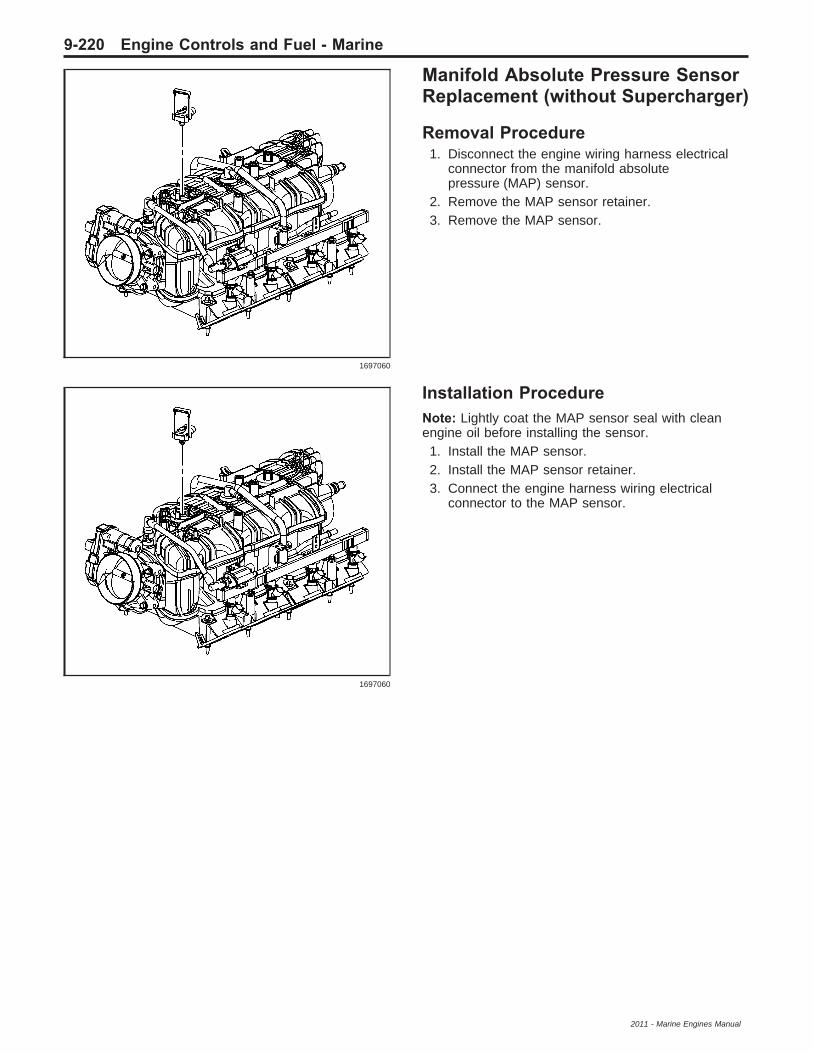
Manifold Absolute Pressure SensorReplacement (without Supercharger)
Removal Procedure1. Disconnect the engine wiring harness electrical
connector from the manifold absolutepressure (MAP) sensor.
2. Remove the MAP sensor retainer.3. Remove the MAP sensor.
Installation ProcedureNote: Lightly coat the MAP sensor seal with cleanengine oil before installing the sensor.1. Install the MAP sensor.2. Install the MAP sensor retainer.3. Connect the engine harness wiring electrical
connector to the MAP sensor.
1697060
1697060
9-220 Engine Controls and Fuel - Marine
2011 - Marine Engines Manual
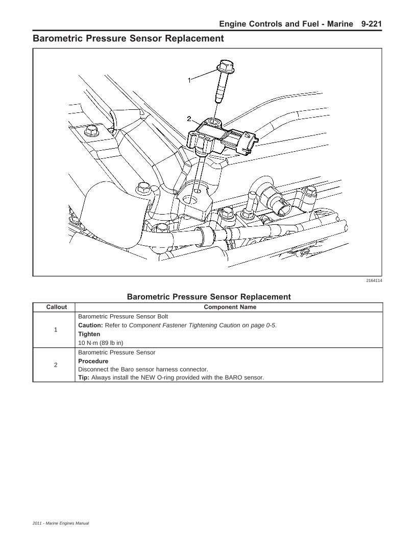
Barometric Pressure Sensor Replacement
Barometric Pressure Sensor ReplacementCallout Component Name
1
Barometric Pressure Sensor BoltCaution: Refer to Component Fastener Tightening Caution on page 0-5.Tighten10 N·m (89 lb in)
2
Barometric Pressure SensorProcedureDisconnect the Baro sensor harness connector.Tip: Always install the NEW O-ring provided with the BARO sensor.
2164114
Engine Controls and Fuel - Marine 9-221
2011 - Marine Engines Manual

Supercharger Air Inlet Pressure Sensor Replacement
Supercharger Air Inlet Pressure Sensor ReplacementCallout Component Name
1
Super Charger Inlet Pressure Sensor BoltCaution: Refer to Component Fastener Tightening Caution on page 0-5.Tighten10 N·m (89 lb in)
2
Super Charger Inlet Pressure SensorProcedureDisconnect the super charger pressure sensor harness connector.Tip: Always install the NEW O-ring provided with the super charger pressure sensor.
2157401
9-222 Engine Controls and Fuel - Marine
2011 - Marine Engines Manual

Charge Air Bypass Regulator Solenoid Valve Replacement
Charge Air Bypass Regulator Solenoid Valve ReplacementCallout Component Name
1
Charge Air Bypass Regulator Solenoid FastenerCaution: Refer to Component Fastener Tightening Caution on page 0-5.Tighten10 N·m (89 lb in)
2
Charge Air Bypass Regulator Solenoid
Procedure• Disconnect the harness connector.• Disconnect the vacuum tubes from the charge air bypass regulator solenoid.
2164115
Engine Controls and Fuel - Marine 9-223
2011 - Marine Engines Manual

Supercharger Bypass Valve Actuator Replacement
Supercharger Bypass Valve Actuator ReplacementCallout Component Name
1
Supercharger Air Bypass Regulator Actuator FastenerCaution: Refer to Component Fastener Tightening Caution on page 0-5.Tighten10 N·m (89 lb in)
2
Supercharger Air Bypass Regulator Actuator
Procedure1. Disconnect the Vacuum Tube from the supercharger.2. Disconnect the vacuum tubes from the supercharger air bypass regulator actuator.
2159710
9-224 Engine Controls and Fuel - Marine
2011 - Marine Engines Manual

Engine Oil Pressure SensorReplacementSpecial ToolsJ 41712 Oil Pressure Sensor Socket
Removal Procedure1. Clean area around the oil sensor/switch before
removing it.
2. Disconnect the electrical connector for the oilpressure sensor/switch (2).
3. Remove the oil pressure sensor/switch with theJ 41712 (1).
Installation Procedure
1. If installing the old sensor, coat thethreads with sealant GM P/N 12346004(Canadian P/N 10953480) or equivalent.
Caution: Refer to Fastener Caution on page 0-5.2. Install the oil pressure sensor/switch with
the J 41712 (1).
TightenTighten the engine oil pressure sensor to35 N·m (26 lb ft).
3. Reconnect the oil pressure sensor/switch electricalconnector (2).
1656451
1658870
1658870
1656451
Engine Controls and Fuel - Marine 9-225
2011 - Marine Engines Manual

Heated Oxygen Sensor Replacement
Removal ProcedureCaution: Refer to Heated Oxygen and OxygenSensor Caution on page 0-6.1. Remove the connector position assurance (CPA)
retainer.
2. Disconnect the HO2S harness connector from theengine wiring harness connector.
Caution: Refer to Excessive Force and OxygenSensor Caution on page 0-5.3. Remove the HO2S.
Installation ProcedureNote: A special anti-seize compound is used on theHO2S threads. The compound consists of liquidgraphite and glass beads. The graphite tends to burnaway, but the glass beads remain, making the sensoreasier to remove. New, or service replacement sensorsalready have the compound applied to the threads.If the sensor is removed from an exhaust componentand if for any reason the sensor is to be reinstalled, thethreads must have anti-seize compound applied beforethe reinstallation.
Caution: Replacement components must be thecorrect part number for the application. Componentsrequiring the use of the thread locking compound,lubricants, corrosion inhibitors, or sealants areidentified in the service procedure. Some replacementcomponents may come with these coatings alreadyapplied. Do not use these coatings on componentsunless specified. These coatings can affect thefinal torque, which may affect the operation of thecomponent. Use the correct torque specification wheninstalling components in order to avoid damage.1. If reinstalling the old sensor, coat the threads with
anti-seize compound GM P/N 12377953, orequivalent.
2. Install the HO2S.
TightenTighten the sensor to 42 N·m (31 lb ft).
3. Connect the HO2S harness connector to theengine wiring harness connector.
4. Install the CPA retainer.
313264
313264
9-226 Engine Controls and Fuel - Marine
2011 - Marine Engines Manual

Throttle Position SensorReplacement (Non ETC)
Removal Procedure
1. Disconnect the throttle position (TP) sensorelectric connection.
2. Remove the TP sensor attaching screws (1).3. Remove the TP sensor (2) and seal (3).
Installation Procedure
1. With the throttle valve in the normal closed (idle)position, install the TP sensor (2) and the seal (3)on the throttle body assembly.
Caution: Refer to Fastener Caution on page 0-5.
Note: Install the new TP sensor attaching screwswhen replacing the TP sensor.2. Install 2 TP sensor screws (1).
TightenTighten the screws to 3 N·m (27 lb in).
3. Connect the TP sensor electric connection.
13315
13315
Engine Controls and Fuel - Marine 9-227
2011 - Marine Engines Manual

Throttle Body AssemblyReplacement
Removal ProcedureCaution: Handle the electronic throttle controlcomponents carefully. Use cleanliness in order toprevent damage. Do not drop the electronic throttlecontrol components. Do not roughly handle theelectronic throttle control components. Do not immersethe electronic throttle control components in cleaningsolvents of any type.
Caution: DO NOT for any reason, insert a screwdriveror other small hand tools into the throttle body tohold open the throttle plate, as the wedge inside thethrottle body could be damaged.1. Remove the air cleaner outlet duct.2. Disconnect the engine wiring harness electrical
connector from the electronic throttle control.3. Remove the throttle body nuts (507) and
bolts (538).4. Remove the throttle body (508).5. Remove and discard the throttle body
gasket (509).
Installation Procedure1. Install a NEW throttle body gasket to the intake
manifold. Align the tab of the gasket with thenotch in the manifold.
Caution: Refer to Fastener Caution on page 0-5.2. Install the throttle body (508), bolts (538),
and nuts (507).
TightenTighten the bolts/nuts to 10 N·m (89 lb in).
Note: Verify that the engine wiring harness electricalconnector seal for the electronic throttle control isproperly installed and not damaged.3. Connect the engine wiring harness electrical
connector to the electronic throttle control.4. Install the air cleaner outlet duct.5. Connect a scan tool in order to test for proper
throttle-opening and throttle-closing range.6. Operate the accelerator pedal and monitor the
throttle angles. The accelerator pedal shouldoperate freely, without binding, between a closedthrottle, and a wide open throttle (WOT).
7. Verify that the vehicle meets the followingconditions:• The vehicle is not in a reduced engine
power mode.• The ignition is ON.• The engine is OFF.
8. Start the engine.9. Inspect for coolant leaks.
1401966
1401966
9-228 Engine Controls and Fuel - Marine
2011 - Marine Engines Manual

Fuel Pressure Gauge Installationand Removal
Installation ProcedureTools Required
• J 34730-1A Fuel Pressure Gauge• J-34730-FF Fuel Pressure Gauge
Warning: Wrap a shop towel around the fuelpressure connection in order to reduce the riskof fire and personal injury. The towel will absorbany fuel leakage that occurs during the connectionof the fuel pressure gauge. Place the towel in anapproved container when the connection ofthe fuel pressure gauge is complete.
Warning: Fuel Vapors can collect while servicingfuel system components in enclosed areas suchas the vessels cabin or engine compartment.To reduce the risk of fire and increased exposureto vapors:
• Use forced air ventilation such as a fan setoutside of the vessels engine compartment.
• Plug or cap any fuel system openings in orderto reduce fuel vapor formation.
• Clean up any spilled fuel immediately.• Avoid sparks and any source of ignition.• Use signs to alert others in the work area that
fuel system work is in process.1. Remove the fuel rail pressure fitting cap.2. Connect the J 34730-1A or the J-34730-FF to the
fuel pressure valve. Wrap a shop towel aroundthe fitting while connecting the gauge in order toavoid spillage.
3. Install the bleed hose on the J 34730-1A or theJ-34730-FF into an approved container.
Removal Procedure1. Remove the bleed hose on the J 34730-1A or the
J-34730-FF from the approved container.2. Remove the shop towel from around the fitting
and discard into an approved container.3. Disconnect the J 34730-1A or the J-34730-FF
from the fuel pressure valve.4. Install the fuel rail pressure fitting cap.
180378
180378
Engine Controls and Fuel - Marine 9-229
2011 - Marine Engines Manual

Fuel Pressure ReliefSpecial ToolsJ 34730-1A Fuel Pressure Gauge
Warning: Refer to Actions to Take When Workingwith Fuel Warning on page 0-3.
Warning: Remove the fuel tank cap and relieve thefuel system pressure before servicing the fuelsystem in order to reduce the risk of personalinjury. After you relieve the fuel system pressure,a small amount of fuel may be released whenservicing the fuel lines, the fuel injection pump,or the connections. In order to reduce the risk ofpersonal injury, cover the fuel system componentswith a shop towel before disconnection. This willcatch any fuel that may leak out. Place the towel inan approved container when the disconnection iscomplete.
1. Disconnect the negative battery cable.2. Install the J 34730-1A. Refer to Fuel Pressure
Gauge Installation and Removal on page 9-229.3. Open the valve on the J 34730-1A in order to
bleed the system pressure. The fuel connectionsare now safe for servicing.
4. Drain any fuel remaining in the gauge into anapproved container.
5. Once the system pressure is completely relieved,remove the J 34730-1A.
Fuel Injection Fuel Rail AssemblyReplacement (3.0L)
Removal Procedure1. Relieve the fuel system pressure. Refer to the
Fuel Pressure Relief on page 9-230.2. Before removal, clean the fuel rail assembly
with a spray type engine cleaner, GM X-30Aor equivalent, if necessary. Follow the packageinstructions. Do not soak fuel rails in liquidcleaning solvent.
Caution:• Use care when servicing the fuel system
components, especially the fuel injector electricalconnectors, the fuel injector tips, and theinjector O-rings. Plug the inlet and the outlet portsof the fuel rail in order to prevent contamination.
• Do not use compressed air to clean the fuel railassembly as this may damage the fuel railcomponents.
• Do not immerse the fuel rail assembly in a solventbath in order to prevent damage to the fuel railassembly.
3. Disconnect the fuel feed hose from the fuel rail.
4. Disconnect the electrical connectors from thefuel injectors. Identify the connectors to theircorresponding injectors to ensure correctsequential injector firing order after reassembly.
5. Remove the fuel rail attaching bolts (1).6. Lift evenly on both sides of the fuel rail, and
remove the fuel rail assembly.7. Remove the injector lower O-ring seal (3) from the
spray tip end of each injector.8. Discard the O-ring seals.
180378
2211680
9-230 Engine Controls and Fuel - Marine
2011 - Marine Engines Manual

Installation Procedure
1. Lubricate the new lower injector O-ring seals withclean engine oil.
2. Install the new O-ring seals on the spray tip endof each injector.
3. Install the fuel rail assembly to the cylinder head.4. Apply a 0.5 mm (0.020 in) band of GM
P/N 12345382 (Canadian P/N 10953489)threadlock or equivalent to the threads ofthe fuel rail bolts.
Caution: Refer to Fastener Caution on page 0-5.5. Install the fuel rail attaching bolts.
TightenTighten the fuel rail attaching bolts to10 N·m (89 lb in).
6. Connect the injector electrical connectors.• Install each connector on the proper injector
in order to ensure correct sequential injectorfiring order.
• Rotate the injectors as required in order toavoid stretching the wire harness.
7. Connect the fuel feed hose to the fuel railfuel pipe.
8. Connect the negative battery cable.9. Inspect for leaks:
9.1. Turn ON the ignition for 2 seconds.9.2. Turn OFF the ignition for 10 seconds.9.3. Turn ON the ignition.9.4. Inspect for fuel leaks.
Fuel Injection Fuel Rail AssemblyReplacement (4.3L 5.0L and 5.7L)
Removal ProcedureCaution: Refer to Fuel Rail Caution on page 0-5.1. Relieve the fuel system pressure. Refer to Fuel
Pressure Relief on page 9-230.2. Remove the air cleaner outlet resonator.3. Remove the accelerator controls cable.4. Remove the radiator inlet hose.
5. Disconnect the electrical connector from thethrottle body assembly.
6. Disconnect the electrical connectors (2) from thefuel injectors using the following procedure:
6.1. Pull upwards on the CPA retainer.6.2. Pinch the connector to unlock.6.3. Disconnect the connector from the fuel
injector.
2211680
12885
735711
Engine Controls and Fuel - Marine 9-231
2011 - Marine Engines Manual

7. Remove the secondary retainers (4) from the fuelfeed and fuel return pipes (2, 3).
8. Disconnect the fuel feed pipe (2) and the fuelreturn pipe (3) from the fuel rail assembly (1).
9. Remove the fasteners (1) from the fuel railassembly.
Notice: Mask off the intake ports. Accidental entry offoreign objects can cause severe engine damage.10. Remove the fuel rail assembly (2) from the intake
manifold (3).
Installation Procedure1. Inspect the fuel injector O-ring seals for damage
and replace if necessary.2. Lubricate the fuel injector O-rings with clean
engine oil before installation.
785740
740874
738694
9-232 Engine Controls and Fuel - Marine
2011 - Marine Engines Manual

3. Install the fuel rail assembly (2) to the intakemanifold (3).
Caution: Refer to Fastener Caution on page 0-5.4. Install the fasteners (1) to the fuel rail assembly.
TightenTighten the fasteners to 10 N·m (88 lb in).
5. Connect the fuel feed pipe (2) and the fuel returnpipe (3) to the fuel rail assembly (1).
6. Install the secondary retainers (4) to the fuel feedand fuel return pipes (2, 3).
7. Connect the electrical connectors (2) to the fuelinjectors.
738694
740874
785740
735711
Engine Controls and Fuel - Marine 9-233
2011 - Marine Engines Manual

8. Connect the electrical connector to the throttlebody assembly.
9. Connect the vacuum hose to the fuel pressureregulator.
10. Install the radiator inlet hose.11. Install the air cleaner outlet resonator.12. Connect the negative battery cable.13. Inspect for fuel leaks using the following
procedure:13.1. Ignition ON for 2 seconds.13.2. Ignition OFF for 10 seconds.13.3. Ignition ON.13.4. Inspect for fuel leaks.
Fuel Injection Fuel Rail AssemblyReplacement (6.0L and 6.2L)
Removal Procedure
Note: Observe the location of the fuel rail groundstrap (557).1. Relieve the fuel system pressure. Refer to the
Fuel Pressure Relief on page 9-230.2. Before removal, clean the fuel rail assembly with
a spray type engine cleaner, GM X-30A orequivalent, if necessary. Follow the packageinstructions. Do not soak fuel rails in liquidcleaning solvent.
Caution: Refer to Fuel Rail Caution on page 0-5.
Caution: Cap the fittings and plug the holes whenservicing the fuel system in order to prevent dirt andother contaminants from entering the open pipesand passages.3. Disconnect the fuel feed hose from the fuel rail.
12885
1408855
9-234 Engine Controls and Fuel - Marine
2011 - Marine Engines Manual

4. Disconnect the electrical connectors from thefuel injectors. Identify the connectors to theircorresponding injectors to ensure correctsequential injector firing order after reassembly.
5. Disconnect the electrical harness from the fuel railbrackets.
6. Remove the fuel rail attaching bolts (511, 512),ground strap (557).
7. Lift evenly on both sides of the fuel rail, andremove the fuel rail assembly.
8. Remove the injector lower O-ring seal from thespray tip end of each injector.
9. Discard the O-ring seals.
Installation Procedure
1. Lubricate the new lower injector O-ring seals withclean engine oil.
2. Install the new O-ring seals on the spray tip endof each injector.
3. Install the fuel rail assembly to the intake manifold.4. Apply a 0.5 mm (0.020 in) band of GM
P/N 12345382 (Canadian P/N 10953489)threadlock or equivalent to the threads ofthe fuel rail bolts.
Caution: Refer to Fastener Caution on page 0-5.5. Install the fuel rail attaching bolts (511, 512),
ground strap (557).
TightenTighten the fuel rail attaching bolts to10 N·m (89 lb in).
6. Connect the injector electrical connectors.• Install each connector on the proper injector in
order to ensure correct sequential injectorfiring order.
• Rotate the injectors as required in order toavoid stretching the wire harness.
7. Connect the electrical harness to the fuel railbrackets.
8. Connect the fuel feed hose to the fuel railfuel pipe.
9. Connect the negative battery cable.10. Inspect for leaks.
10.1. Ignition ON for 2 seconds.10.2. Ignition OFF for 10 seconds.10.3. Ignition ON.10.4. Inspect for fuel leaks.
Fuel Injection Fuel Rail AssemblyReplacement (2.4L)
Removal Procedure
1. Relieve the fuel system pressure. Refer to FuelPressure Relief on page 9-230.
2. Disconnect the fuel feed line quick connect fittingfrom the fuel rail.
1408856
1408856 1625417
Engine Controls and Fuel - Marine 9-235
2011 - Marine Engines Manual

3. Disconnect the fuel injector harness electricalconnector (2).
4. Disconnect the manifold absolute pressure (MAP)sensor electrical connector.
5. Remove the fuel injector harness electricalconnector clips (4 and 5) from the intake manifold.
6. Remove the fuel rail studs.
Note: Use care when removing the fuel rail assemblyin order to prevent damage to the fuel injectorselectrical connector terminals and spray tips.7. Pull the fuel rail back and upward in order to
release the fuel injectors from the cylinderhead ports.
8. Remove the fuel rail.9. Remove the fuel injectors, if necessary. Refer to
Fuel Injector Replacement (Except 2.4L) onpage 9-238 or Fuel Injector Replacement (2.4L)on page 9-240.
1623764
1623549
1578472
9-236 Engine Controls and Fuel - Marine
2011 - Marine Engines Manual

Installation ProcedureNote: Install new lower O-rings when reusing fuelinjectors. Lubricate the injector tip O-rings priorto installing the injectors into the intake manifold.
1. Install the fuel injectors, if necessary. Refer toFuel Injector Replacement (Except 2.4L) onpage 9-238 or Fuel Injector Replacement (2.4L)on page 9-240.
2. With the fuel injectors positioned downward, lowerthe fuel injectors into the cylinder head ports.
3. Carefully push the fuel injectors into the cylinderhead ports.
Caution: Refer to Fastener Caution on page 0-5.4. Install the fuel rail bolts.
TightenTighten the bolts to 10 N·m (89 lb in).
5. Connect the fuel injector harness electricalconnector (2).
6. Connect the MAP sensor electrical connector.
7. Install the fuel injector harness electrical connectorclips (4 and 5) to the intake manifold.
8. Connect the fuel feed line quick connect fitting tothe fuel rail.
9. Connect the negative battery cable10. Inspect for fuel leaks using the following
procedure:10.1. Turn ON the ignition, with the engine OFF
for 2 seconds.10.2. Turn OFF the ignition for 10 seconds.10.3. Turn ON the ignition.10.4. Inspect for fuel leaks.
1578472
1623764
1623549
1625417
Engine Controls and Fuel - Marine 9-237
2011 - Marine Engines Manual

Fuel Pressure RegulatorReplacementSpecial ToolsJ 34730-1A Fuel Pressure Gauge
Warning: Refer to Actions to Take When Workingwith Fuel Warning on page 0-3.
Warning: Remove the fuel tank cap and relieve thefuel system pressure before servicing the fuelsystem in order to reduce the risk of personalinjury. After you relieve the fuel system pressure,a small amount of fuel may be released whenservicing the fuel lines, the fuel injection pump,or the connections. In order to reduce the risk ofpersonal injury, cover the fuel system componentswith a shop towel before disconnection. This willcatch any fuel that may leak out. Place the towel inan approved container when the disconnection iscomplete.
1. Disconnect the negative battery cable.2. Install the J 34730-1A. Refer to Fuel Pressure
Gauge Installation and Removal on page 9-229.3. Open the valve on the J 34730-1A in order to
bleed the system pressure. The fuel connectionsare now safe for servicing.
4. Drain any fuel remaining in the gauge into anapproved container.
5. Once the system pressure is completely relieved,remove the J 34730-1A.
Fuel Injector Replacement(Except 2.4L)
Removal Procedure1. Relieve the fuel system pressure. Refer to Fuel
Pressure Relief on page 9-230.2. Disconnect the negative battery cable.
Note: Mask off the intake ports. Accidental entry offoreign objects can cause severe engine damage.3. Remove the fuel rail assembly. Refer to Fuel
Injection Fuel Rail Assembly Replacement(3.0L) on page 9-230 or Fuel Injection Fuel RailAssembly Replacement (4.3L 5.0L and 5.7L)on page 9-231 or Fuel Injection Fuel RailAssembly Replacement (6.0L and 6.2L) onpage 9-234 or Fuel Injection Fuel Rail AssemblyReplacement (2.4L) on page 9-235.
4. Remove the retaining clip from the fuel injector.180378
738617
9-238 Engine Controls and Fuel - Marine
2011 - Marine Engines Manual

5. Remove the fuel injector and the injector O-ringfrom the fuel rail assembly.
Installation Procedure1. Inspect the fuel injector O-ring seals for damage
and replace if necessary.2. Lubricate the fuel injector O-rings with clean
engine oil.
3. Install the fuel injector to the fuel rail assembly.
4. Install the retaining clip onto the fuel injector.5. Install the fuel rail assembly. Refer to Fuel
Injection Fuel Rail Assembly Replacement (3.0L)on page 9-230 or Fuel Injection Fuel RailAssembly Replacement (4.3L 5.0L and 5.7L) onpage 9-231 or Fuel Injection Fuel Rail AssemblyReplacement (6.0L and 6.2L) on page 9-234or Fuel Injection Fuel Rail Assembly Replacement(2.4L) on page 9-235.
6. Connect the negative battery cable.7. Inspect for fuel leaks using the following
procedure:7.1. Ignition ON for 2 seconds.7.2. Ignition OFF for 10 seconds.7.3. Ignition ON.7.4. Inspect for fuel leaks.
738607
738607
738617
Engine Controls and Fuel - Marine 9-239
2011 - Marine Engines Manual

Fuel Injector Replacement (2.4L)
Removal ProcedureCaution: Use care in removing the fuel injectors inorder to prevent damage to the fuel injector electricalconnector pins or the fuel injector nozzles. Do notimmerse the fuel injector in any type of cleaner.The fuel injector is an electrical component andmay be damaged by this cleaning method.
Note: If the fuel injectors are found the be leaking,the engine oil may be contaminated with fuel.
1. Remove the fuel rail. Refer to Fuel Injection FuelRail Assembly Replacement (3.0L) on page 9-230or Fuel Injection Fuel Rail Assembly Replacement(4.3L 5.0L and 5.7L) on page 9-231 or FuelInjection Fuel Rail Assembly Replacement (6.0Land 6.2L) on page 9-234 or Fuel Injection Fuel RailAssembly Replacement (2.4L) on page 9-235.
2. Remove the fuel injector retaining clip (1).3. Remove the fuel injector (3) from the fuel rail.4. Remove and discard the fuel injector lower
O-ring (4).5. Remove and discard the fuel injector upper
O-ring (2).
Installation Procedure
Note: Be sure to use the correct part number whenordering replacement fuel injectors.1. The fuel injector assembly (1) is stamped with a
par number identification (2).
2. Lubricate the NEW injector O-rings with cleanengine oil.
3. Install the fuel injector upper O-ring (2).4. Install the fuel injector lower O-ring (4).5. Install the fuel injector (3) to the fuel rail.6. Install the fuel injector retaining clip (1).7. Install the fuel rail. Refer to Fuel Injection Fuel Rail
Assembly Replacement (3.0L) on page 9-230 orFuel Injection Fuel Rail Assembly Replacement(4.3L 5.0L and 5.7L) on page 9-231 or FuelInjection Fuel Rail Assembly Replacement (6.0Land 6.2L) on page 9-234 or Fuel Injection Fuel RailAssembly Replacement (2.4L) on page 9-235.
537311
537308
537311
9-240 Engine Controls and Fuel - Marine
2011 - Marine Engines Manual
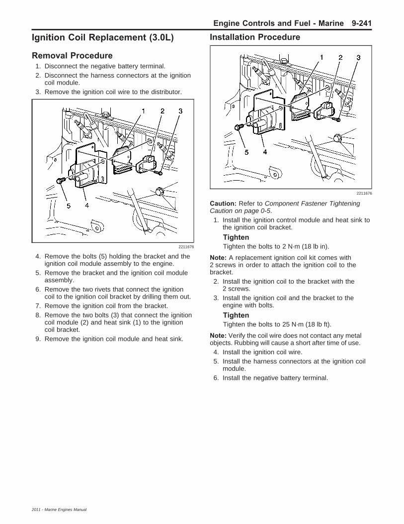
Ignition Coil Replacement (3.0L)
Removal Procedure1. Disconnect the negative battery terminal.2. Disconnect the harness connectors at the ignition
coil module.3. Remove the ignition coil wire to the distributor.
4. Remove the bolts (5) holding the bracket and theignition coil module assembly to the engine.
5. Remove the bracket and the ignition coil moduleassembly.
6. Remove the two rivets that connect the ignitioncoil to the ignition coil bracket by drilling them out.
7. Remove the ignition coil from the bracket.8. Remove the two bolts (3) that connect the ignition
coil module (2) and heat sink (1) to the ignitioncoil bracket.
9. Remove the ignition coil module and heat sink.
Installation Procedure
Caution: Refer to Component Fastener TighteningCaution on page 0-5.1. Install the ignition control module and heat sink to
the ignition coil bracket.
TightenTighten the bolts to 2 N·m (18 lb in).
Note: A replacement ignition coil kit comes with2 screws in order to attach the ignition coil to thebracket.2. Install the ignition coil to the bracket with the
2 screws.3. Install the ignition coil and the bracket to the
engine with bolts.
TightenTighten the bolts to 25 N·m (18 lb ft).
Note: Verify the coil wire does not contact any metalobjects. Rubbing will cause a short after time of use.4. Install the ignition coil wire.5. Install the harness connectors at the ignition coil
module.6. Install the negative battery terminal.
2211676
2211676
Engine Controls and Fuel - Marine 9-241
2011 - Marine Engines Manual

Ignition Coil Replacement(6.0L and 6.2L)
Removal Procedure
1. Remove the intake manifold sight shield, ifequipped.
2. Disconnect the ignition coil wiring harnesselectrical connector (1) from the ignition coil.
3. Remove the spark plug wire from the ignition coil.• Twist the spark plug wire boot a 1/2 turn.• Pull only on the boot in order to remove the
wire from the ignition coil.4. Remove the ignition coil bolts.5. Remove the ignition coil from the bracket.
(left side shown, right side similar).
6. There are 2 different manufacturers for the ignitioncoils and coil brackets. They are as follows:
7. The Melco® (1) ignition coil is a square design.8. The Delphi® (2) ignition coil is a round design.
9. The Melco® ignition coil bracket (1) is a squaredesign.
10. The Delphi® ignition coil bracket (2) is a rounddesign.
1707122
1707124
260177
260077
9-242 Engine Controls and Fuel - Marine
2011 - Marine Engines Manual

Installation Procedure
1. Position the ignition coil to the ignition coilbracket. (left side shown, right side similar).
Caution: Refer to Fastener Caution on page 0-5.2. Install the ignition coil bolts.
TightenTighten the bolts to 10 N·m (89 lb in).
3. Install the spark plug wire to the ignition coil.4. Inspect the spark plug wire for proper installation:
• Push sideways on each boot in order theinspect the seating.
• Reinstall any loose boot.
5. Connect the ignition coil wiring harness electricalconnector (1) to the ignition coil.
6. Install the intake manifold sight shield.
Ignition Coil Replacement(4.3L, 5.0L, and 5.7L)
Removal Procedure1. Disconnect the negative battery terminal.2. Disconnect the electrical connectors.3. Remove the ignition coil wire to the distributor.
4. Remove the studs holding the bracket and theignition coil to the intake manifold.
5. Remove the bracket and the ignition coil.6. Remove the two rivets that connect the ignition
coil to the ignition coil bracket by drilling andthem out.
7. Remove the ignition coil from the bracket.
1707124
1707122
31466
Engine Controls and Fuel - Marine 9-243
2011 - Marine Engines Manual

Installation ProcedureNote: A replacement ignition coil kit comes with2 screws in order to attach the ignition coil to thebracket.1. Install the ignition coil to the bracket with the
2 screws.
Caution: Refer to Component Fastener TighteningCaution on page 0-5.
2. Install the ignition coil and the bracket to theintake manifold with studs.
TightenTighten the studs to 11 N·m (97 lb in).
Note: Verify the coil wire does not contact any metalobjects. Rubbing will make a ground or short aftertime of use.
3. Install the ignition coil wire.4. Install the electrical connectors.5. Install the negative battery terminal.
Ignition Coil Replacement (2.4L)
Removal Procedure1. Disconnect the ignition coil electrical
connector(s) (3).
2. Remove the ignition coil bolt(s).3. Remove the ignition coil(s).
Installation Procedure
1. Install the ignition coil(s).
Caution: Refer to Fastener Caution on page 0-5.2. Install the ignition coil bolt(s).
TightenTighten the bolt(s) to 10 N·m (89 lb in).
31466
387772
1578474
1578474
9-244 Engine Controls and Fuel - Marine
2011 - Marine Engines Manual

3. Connect the ignition coil electrical connector(s) (3).
Spark Plug Wire InspectionSpark plug wire integrity is vital for proper engineoperation. A thorough inspection is necessaryto accurately identify conditions that may affect engineoperation. Inspect for the following conditions:1. Correct routing of the spark plug wires, Incorrect
routing may cause cross firing.2. Any signs of cracks or splits in the wires.3. Inspect each boot for any of the following
conditions:• Tearing• Piercing• Arcing• Carbon tracking• Corroded terminal
If corrosion, carbon tracking or arcing are indicated ona spark plug wire boot or terminal, replace the wireand the component connected to the wire.
Spark Plug Wire Replacement
Removal Procedure1. Disconnect the spark plug wire at each spark plug.
• Twist each spark plug 1/2 turn.• Pull only on the boot in order to remove the
wire from each spark plug.2. Disconnect the spark plug wire from the
ignition coil.• Twist each spark plug boot 1/2 turn.• Pull only on the boot in order to remove the
wires from the ignition coil.
Installation Procedure1. Install the spark plug wires at the ignition coil.2. Install the spark plug wire to each spark plug.3. Inspect the wires for proper installation:
• Push sideways on each boot in order to inspectthe seating.
• Reinstall any loose boot.
Spark Plug InspectionSpark Plug Usage
• Ensure that the correct spark plug is installed.An incorrect spark plug causes driveabilityconditions.
• Ensure that the spark plug has the correct heatrange. An incorrect heat range causes thefollowing conditions:
− Spark plug fouling—Colder plug− Pre-ignition causing spark plug and/or engine
damage—Hotter plug
Spark Plug Inspection
1. Inspect the terminal post (1) for damage.• Inspect for a bent or broken terminal post (1).• Test for a loose terminal post (1) by twisting
and pulling the post. The terminal post (1)should NOT move.
1628020
622530
Engine Controls and Fuel - Marine 9-245
2011 - Marine Engines Manual

2. Inspect the insulator (2) for flashover or carbontracking, soot. This is caused by the electricalcharge traveling across the insulator (2) betweenthe terminal post (1) and ground. Inspect forthe following conditions:• Inspect the spark plug boot for damage.• Inspect the spark plug recess area of the
cylinder head for moisture, such as oil, coolant,or water. A spark plug boot that is saturatedcauses arcing to ground.
3. Inspect the insulator (2) for cracks. All or part ofthe electrical charge may arc through the crackinstead of the electrodes (3, 4).
4. Inspect (3) for evidence of improper arcing.• Measure the gap between the center
electrode (4) and the side electrode (3)terminals. An excessively wide electrode gapcan prevent correct spark plug operation.
• Inspect for the correct spark plug torque.Insufficient torque can prevent correctspark plug operation. An over torqued sparkplug, causes the insulator (2) to crack.
• Inspect for signs of tracking that occurred nearthe insulator tip instead of the centerelectrode (4).
• Inspect for a broken or worn side electrode (3).• Inspect for a broken, worn, or loose center
electrode (4) by shaking the spark plug.− A rattling sound indicates internal damage.− A loose center electrode (4) reduces the
spark intensity.• Inspect for bridged electrodes (3, 4). Deposits
on the electrodes (3, 4) reduce or eliminatesthe gap.
• Inspect for worn or missing platinum pads onthe electrodes (3, 4), if equipped.
• Inspect for excessive fouling.5. Inspect the spark plug recess area of the cylinder
head for debris. Dirty or damaged threads cancause the spark plug not to seat correctly duringinstallation.
622529
622528
622527
9-246 Engine Controls and Fuel - Marine
2011 - Marine Engines Manual

Spark Plug Visual Inspection• Normal operation—Brown to grayish-tan with small
amounts of white powdery deposits are normalcombustion by-products from fuels with additives.
• Carbon fouled—Dry, fluffy black carbon, or sootcaused by the following conditions:
− Rich fuel mixtures• Leaking fuel injectors• Excessive fuel pressure• Restricted air filter element• Incorrect combustion
− Reduced ignition system voltage output• Weak coils• Worn ignition wires• Incorrect spark plug gap
− Excessive idling or slow speeds under lightloads can keep spark plug temperatures solow that normal combustion deposits may notburn off.
• Deposit fouling—Oil, coolant, or additives thatinclude substances such as silicone, very whitecoating, reduces the spark intensity. Most powderydeposits will not effect spark intensity unless theyform into a glazing over the electrode.
Spark Plug ReplacementRemoval Procedure1. Remove the spark plug wire from the spark plug.
1.1. Twist the spark plug wire boot a 1/2 turn.1.2. Pull only on the boot in order to remove the
wire from the spark plug.
2. Brush or using compressed air, blow away anydirt from around the spark plug.
3. Remove the spark plug.If removing more than one plug, place each plugin a tray marked with the corresponding cylindernumber.
Installation Procedure
1. Inspect the spark plug gap. Adjust the gap asneeded. Refer to Ignition System Specifications(2.4L) on page 9-4 or Ignition SystemSpecifications (3.0L) on page 9-4 or IgnitionSystem Specifications (4.3L, 5.0L, or 5.7L) onpage 9-4 or Ignition System Specifications (6.0L or6.2L) on page 9-4.
2. Hand start the spark plug in the correspondingcylinder.
Caution: Refer to Fastener Caution on page 0-5.3. Tighten the spark plug to 15 N·m (11 lb ft).4. Install the spark plug wire to the spark plug.5. Inspect the spark plug wire for proper installation:
5.1. Push sideways on each boot in order toinspect the seating.
5.2. Reinstall any loose boot.
14824
14824
Engine Controls and Fuel - Marine 9-247
2011 - Marine Engines Manual

Distributor Replacement (3.0L)
Removal ProcedureNote: There are two procedures available to install thedistributor. Use Installation Procedure 1 when thecrankshaft has not been rotated from the originalposition. Use Installation Procedure 2 when anyof the following components are removed:
• The camshaft• The complete engine
1. Ignition OFF.
2. Disconnect the spark plug wires (1) from thedistributor cap.
3. Disconnect the harness connector from thedistributor.
4. Remove the distributor cap from the distributorhousing.
5. Mark the position of the rotor in relation to thedistributor housing (1) with a grease pencil.
6. Mark the distributor housing to engine blockposition with a grease pencil.
7. Remove the distributor hold down bolt (5) andhold down (4).
8. Remove the distributor and gasket (3).
9. As the distributor is being removed from theengine, the rotor will move in a counter-clockwisedirection.
10. Place a second mark (2) on the base of thedistributor housing in order to ensure properrotor alignment during the distributor installation.
2211673
4373
2211673
4376
9-248 Engine Controls and Fuel - Marine
2011 - Marine Engines Manual

Installation Procedure 1Note: If installing a new distributor assembly, transferthe two marks from the original housing to the newdistributor housing in the same location.1. Install a new gasket on the distributor.
2. Align the distributor rotor with mark made atlocation 2.
3. Guide the distributor into the engine.
4. While the distributor is being installed, observethe rotor moving in a clockwise direction.
5. With the distributor fully seated, verify the rotorsegment is aligned with the mark on thedistributor base in location 1.⇒ If the rotor segment is not aligned with the
number 1 mark, the driven gear teeth and thecamshaft have meshed one or more teeth outof alignment. In order to correct this condition,remove the distributor and reinstall it.
Caution: Refer to Component Fastener TighteningCaution on page 0-5.6. Install the distributor hold down bolt.
TightenTighten the distributor clamp bolt to27 N·m (20 lb ft).
Install the distributor cap.
4376
2211673
4373
2211673
Engine Controls and Fuel - Marine 9-249
2011 - Marine Engines Manual
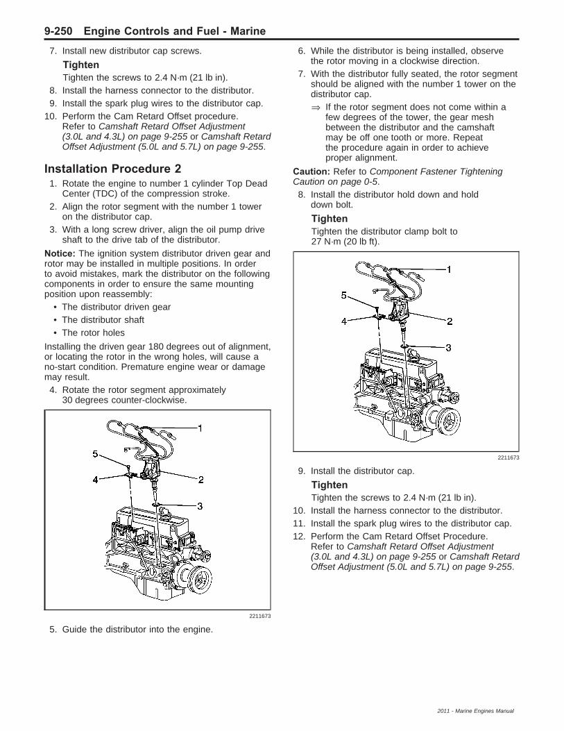
7. Install new distributor cap screws.
TightenTighten the screws to 2.4 N·m (21 lb in).
8. Install the harness connector to the distributor.9. Install the spark plug wires to the distributor cap.
10. Perform the Cam Retard Offset procedure.Refer to Camshaft Retard Offset Adjustment(3.0L and 4.3L) on page 9-255 or Camshaft RetardOffset Adjustment (5.0L and 5.7L) on page 9-255.
Installation Procedure 21. Rotate the engine to number 1 cylinder Top Dead
Center (TDC) of the compression stroke.2. Align the rotor segment with the number 1 tower
on the distributor cap.3. With a long screw driver, align the oil pump drive
shaft to the drive tab of the distributor.
Notice: The ignition system distributor driven gear androtor may be installed in multiple positions. In orderto avoid mistakes, mark the distributor on the followingcomponents in order to ensure the same mountingposition upon reassembly:
• The distributor driven gear• The distributor shaft• The rotor holes
Installing the driven gear 180 degrees out of alignment,or locating the rotor in the wrong holes, will cause ano-start condition. Premature engine wear or damagemay result.4. Rotate the rotor segment approximately
30 degrees counter-clockwise.
5. Guide the distributor into the engine.
6. While the distributor is being installed, observethe rotor moving in a clockwise direction.
7. With the distributor fully seated, the rotor segmentshould be aligned with the number 1 tower on thedistributor cap.⇒ If the rotor segment does not come within a
few degrees of the tower, the gear meshbetween the distributor and the camshaftmay be off one tooth or more. Repeatthe procedure again in order to achieveproper alignment.
Caution: Refer to Component Fastener TighteningCaution on page 0-5.8. Install the distributor hold down and hold
down bolt.
TightenTighten the distributor clamp bolt to27 N·m (20 lb ft).
9. Install the distributor cap.
TightenTighten the screws to 2.4 N·m (21 lb in).
10. Install the harness connector to the distributor.11. Install the spark plug wires to the distributor cap.12. Perform the Cam Retard Offset Procedure.
Refer to Camshaft Retard Offset Adjustment(3.0L and 4.3L) on page 9-255 or Camshaft RetardOffset Adjustment (5.0L and 5.7L) on page 9-255.
2211673
2211673
9-250 Engine Controls and Fuel - Marine
2011 - Marine Engines Manual

Distributor Replacement(4.3L, 5.0L, 5.8L)
Removal ProcedureNote: There are two procedures available to install thedistributor. Use Installation Procedure 1 when thecrankshaft has not been rotated from the originalposition. Use Installation Procedure 2 when anyof the following components are removed:
• The intake manifold• The cylinder head• The camshaft• The timing chain or sprockets• The complete engine
1. Ignition OFF.2. Disconnect the spark plug wires from the
distributor cap.3. Disconnect the harness connector from the
distributor.
4. Remove the distributor cap screws and discard.5. Remove the distributor cap from the distributor
housing.
6. Mark the position of the rotor in relation to thedistributor housing (1) with a grease pencil.
7. Mark the distributor housing to intake manifoldposition with a grease pencil.
8. Remove the distributor hold down bolt.9. Remove the distributor.
301393
4373
34397
Engine Controls and Fuel - Marine 9-251
2011 - Marine Engines Manual

10. As the distributor is being removed from theengine, the rotor will move in a counter-clockwisedirection about 42 degrees.
11. Place a second mark (2) on the base of thedistributor housing in order to ensure properrotor alignment during the distributor installation.
Installation Procedure 1Note: If installing a new distributor assembly, transferthe two marks from the original housing to the newdistributor housing in the same location.
1. Align the distributor rotor with mark made atlocation 2.
2. While the distributor is being installed, observethe rotor moving in a clockwise direction about42 degrees.
3. With the distributor completely seated, verify therotor segment is aligned with the mark on thedistributor base in location 1.⇒ If the rotor segment is not aligned with the
number 1 mark, the driven gear teeth andthe camshaft have meshed one or more teethout of alignment. In order to correct thiscondition, remove the distributor andreinstall it.
Caution: Refer to Component Fastener TighteningCaution on page 0-5.4. Install the distributor hold down bolt.
TightenTighten the distributor clamp bolt to27 N·m (20 lb ft).
Install the distributor cap.
4376
4376
4373
301393
9-252 Engine Controls and Fuel - Marine
2011 - Marine Engines Manual

5. Install new distributor cap screws.
TightenTighten the screws to 2.4 N·m (21 lb in).
6. Install the harness connector to the distributor.7. Install the spark plug wires to the distributor cap.8. Perform the Cam Retard Offset Procedure.
Refer to Camshaft Retard Offset Adjustment(3.0L and 4.3L) on page 9-255 or Camshaft RetardOffset Adjustment (5.0L and 5.7L) on page 9-255.
Installation Procedure 21. Rotate the number 1 cylinder to Top Dead
Center (TDC) of the compression stroke.
2. Align white paint mark on the bottom stem of thedistributor, and the pre-drilled indent hole in thebottom of the gear (3).
Caution: The ignition system distributor driven gearand rotor may be installed in multiple positions.In order to avoid mistakes, mark the distributor on thefollowing components in order to ensure the samemounting position upon reassembly:
• The distributor driven gear• The distributor shaft• The rotor holes
Installing the driven gear 180 degrees out of alignment,or locating the rotor in the wrong holes, will cause ano-start condition. Premature engine wear or damagemay result.
Caution: Installing the driven gear 180 degrees outof alignment, or locating the distributor rotor inthe wrong holes, may cause a no-start condition.Premature engine wear and damage may result.3. With the gear in this position, the rotor segment
should be positioned as shown for a V6 engine(1) or V8 engine (2).• The alignment will not be exact.• If the driven gear is installed incorrectly, the
dimple will be approximately 180 degreesopposite of the rotor segment when it isinstalled in the distributor.
4. With a long screw driver, align the oil pump driveshaft to the drive tab of the distributor.
5. Guide the distributor into the engine.Ensure that the spark plug towers areperpendicular to the centerline of the engine.
301395
34397
Engine Controls and Fuel - Marine 9-253
2011 - Marine Engines Manual

6. Once the distributor is fully seated, the rotorsegment should be aligned with the pointercast into the distributor base.• This pointer may have a 6 cast into it,
indicating that the distributor is to be used on a6 cylinder engine or a 8 cast into it, indicatingthat the distributor is to be used on a 8 cylinderengine.
• If the rotor segment does not come within afew degrees of the pointer, the gear meshbetween the distributor and the camshaftmay be off one tooth or more. Repeatthe procedure again in order to achieve properalignment.
Caution: Refer to Component Fastener TighteningCaution on page 0-5.7. Install the distributor hold down bolt.
TightenTighten the distributor clamp bolt to27 N·m (20 lb ft).
8. Install the distributor cap.9. Install new distributor cap screws.
TightenTighten the screws to 2.4 N·m (21 lb in).
10. Install the harness connector to the distributor.11. Install the spark plug wires to the distributor cap.12. Perform the Cam Retard Offset Procedure.
Refer to Camshaft Retard Offset Adjustment (3.0Land 4.3L) on page 9-255 or Camshaft RetardOffset Adjustment (5.0L and 5.7L) on page 9-255.
4350 301393
9-254 Engine Controls and Fuel - Marine
2011 - Marine Engines Manual

Camshaft Retard Offset Adjustment(3.0L and 4.3L)The distributor and ignition timing are not adjustable.The distributor will need to be removed in order toreposition the rotor in order to prevent ignition crossfire.To verify proper alignment of the distributor, perform thefollowing:
Note: The scan tool Cam Angle reading will not beaccurate below 1,200 RPM.1. Engine idling at operating temperature. Observe
the scan tool Cam Angle parameter.2. Increase the engine speed to 1,200 RPM.
Verify the scan tool Cam Angle parameter iswithin 700–740 degrees.⇒ If within the specified range, the distributor is
properly adjusted.⇒ If not within the specified range, remove the
distributor in order to adjust the rotor. Refer toInstallation Procedure 2 in DistributorReplacement (3.0L) on page 9-248 orDistributor Replacement (4.3L, 5.0L, 5.8L) onpage 9-251.
Camshaft Retard Offset Adjustment(5.0L and 5.7L)
Test ProcedureThe ignition timing is not adjustable. The distributormay need to adjusted in order to prevent ignitioncrossfire. To insure proper alignment of the distributor,perform the following:
Note: The scan tool Cam Angle reading will not beaccurate below 1,200 RPM.1. Engine idling at operating temperature. Observe
the scan tool Cam Angle parameter.2. Increase the engine speed to 1,200 RPM. Verify
the scan tool Cam Angle parameter is within685–725 degrees.⇒ If within the specified value, the distributor is
properly adjusted.⇒ If not within the specified value, adjust the
distributor.
Adjustment Procedure
1. Ignition OFF, slightly loosen the distributor holddown bolt.
Note: The Cam Angle reading will not be accuratebelow 1,200 RPM.2. Engine operating, raise the engine speed to
1,200 RPM. Observe the scan tool Cam Angleparameter.⇒ If the Cam Angle parameter is less than
685 degrees, rotate the distributor in acounterclockwise direction to adjust.
⇒ If the Cam Angle parameter is greater than725 degrees, rotate the distributor in aclockwise direction to adjust.
3. Repeat step 2 until 705 degrees is obtained.4. Ignition OFF.
Caution: Use the correct fastener in the correctlocation. Replacement fasteners must be the correctpart number for that application. Do not use paints,lubricants, or corrosion inhibitors on fasteners, orfastener joint surfaces, unless specified. Thesecoatings affect fastener torque and joint clampingforce and may damage the fastener. Use the correcttightening sequence and specifications when installingfasteners in order to avoid damage to parts andsystems. When using fasteners that are threadeddirectly into plastic, use extreme care not to strip themating plastic part(s). Use hand tools only, and do notuse any kind of impact or power tools. Fastener shouldbe hand tightened, fully seated, and not stripped.5. Tighten the distributor hold-down bolt.
TightenTighten the bolt to 27 N·m (20 lb ft).
18446
Engine Controls and Fuel - Marine 9-255
2011 - Marine Engines Manual

Crankshaft Position SensorReplacement (3.0L)
Removal ProcedureWarning: Refer to Battery Disconnect Warning onpage 0-4.1. Disconnect the negative battery cable.2. Remove the crankshaft position sensor (CKP)
sensor harness connector.3. Remove the CKP sensor hold down bolt (3).4. Remove the CKP sensor (2) from the
engine block.5. Inspect the sensor O-ring (1) for wear, cracks, or
leakage.6. Replace if necessary. Lubricate the new O-ring
with clean engine oil before installing.
Installation Procedure1. Lubricate the CKP sensor O-ring with clean
engine oil.
Note:• Verify the crankshaft position (CKP) sensor
mounting surfaces are clean and free of burrsbefore installing the CKP sensor.
• When installing the CKP sensor, ensure thesensor is fully seated and held stationary inthe engine block before torquing the hold downbolt. A sensor which is not seated may causeerratic operation and false codes to set.
2. Install the CKP sensor into the engine block.
Caution: Refer to Fastener Caution on page 0-5.3. Install the sensor hold down bolt.
TightenTighten the hold down bolt to 10 N·m (88 lb in).
4. Install the CKP sensor harness connector.5. Connect the negative battery cable.
2211668
2211668
9-256 Engine Controls and Fuel - Marine
2011 - Marine Engines Manual

Crankshaft Position SensorReplacement (4.3/5.0/5.7L)
Removal ProcedureWarning: Refer to Battery Disconnect Warning onpage 0-4.1. Disconnect the negative battery cable.2. Remove the CKP sensor harness connector.
3. Remove the sensor hold down bolt.4. Remove the sensor from the timing cover.5. Inspect the sensor O-ring for wear, cracks, or
leakage.6. Replace if necessary. Lube the new O-ring with
clean engine oil before installing.
Installation Procedure1. Lube the CKP sensor O-ring with clean engine oil.
Note:• Verify the crankshaft position (CKP) sensor
mounting surfaces are clean and free of burrsbefore installing the CKP sensor.
• When installing the CKP sensor, ensure thesensor is fully seated and held stationary inthe front cover before torquing the hold down bolt.A sensor which is not seated may cause erraticoperation and false codes to set.
2. Install the CKP sensor into the timing cover.
Caution: Refer to Fastener Caution on page 0-5.3. Install the sensor hold down bolt.
TightenTighten the hold down bolt to 8 N·m (71 lb in.).
10937
11485
11485
Engine Controls and Fuel - Marine 9-257
2011 - Marine Engines Manual

4. Install the CKP sensor harness connector.5. Connect the negative battery cable.
Crankshaft Position SensorReplacement (6.0/6.2L)
Removal ProcedureWarning: Refer to Battery Disconnect Warning onpage 0-4.1. Disconnect the negative battery cable.2. Remove the starter.
3. Disconnect the crankshaft position (CKP) sensorelectrical connector.
10937
211621
56592
9-258 Engine Controls and Fuel - Marine
2011 - Marine Engines Manual

4. Remove the CKP sensor retaining bolt.5. Remove the CKP sensor.
Installation Procedure1. Install the CKP sensor.
Caution: Refer to Fastener Caution on page 0-5.2. Install the CKP sensor retaining bolt.
TightenTighten the CKP sensor to 25 N·m (18 lb ft).
55322
55322
Engine Controls and Fuel - Marine 9-259
2011 - Marine Engines Manual

3. Connect the CKP sensor electrical connector.
4. Install the starter.
56592
211621
9-260 Engine Controls and Fuel - Marine
2011 - Marine Engines Manual

Crankshaft Position SensorReplacement (2.4L)
Removal Procedure
1. Remove the starter motor assembly.2. Disconnect the crankshaft position (CKP) sensor
electrical connector (4).
3. Remove the CKP sensor bolt.4. Remove the CKP sensor.
Installation Procedure
1. Lubricate the CKP sensor O-ring seal with cleanengine oil.
2. Install the CKP sensor.
Caution: Refer to Fastener Caution on page 0-5.3. Install the CKP sensor bolt.
TightenTighten the sensor bolt to 10 N·m (89 lb in).
4. Connect the CKP sensor electrical connector (4).5. Install the starter motor assembly.
1622787
1578475
1578475
1622787
Engine Controls and Fuel - Marine 9-261
2011 - Marine Engines Manual

Camshaft Position SensorReplacement (4.3/5.0/5.7L)
Removal Procedure1. Disconnect the spark plug wires and ignition coil
wire from the distributor. Refer to Spark Plug WireReplacement on page 9-245.
2. Disconnect the camshaft position (CMP) sensorharness connector from the distributor.
3. Remove the distributor cap screws.
302854
302829
157984
9-262 Engine Controls and Fuel - Marine
2011 - Marine Engines Manual

4. Remove the distributor cap.
5. Remove the rotor screws.
6. Remove the rotor.
157986
4354
156748
Engine Controls and Fuel - Marine 9-263
2011 - Marine Engines Manual

7. Align the square slot in the reluctor wheel with theCMP sensor.
8. Remove the CMP screws.
9. Remove the CMP sensor.
156754
4341
301398
9-264 Engine Controls and Fuel - Marine
2011 - Marine Engines Manual
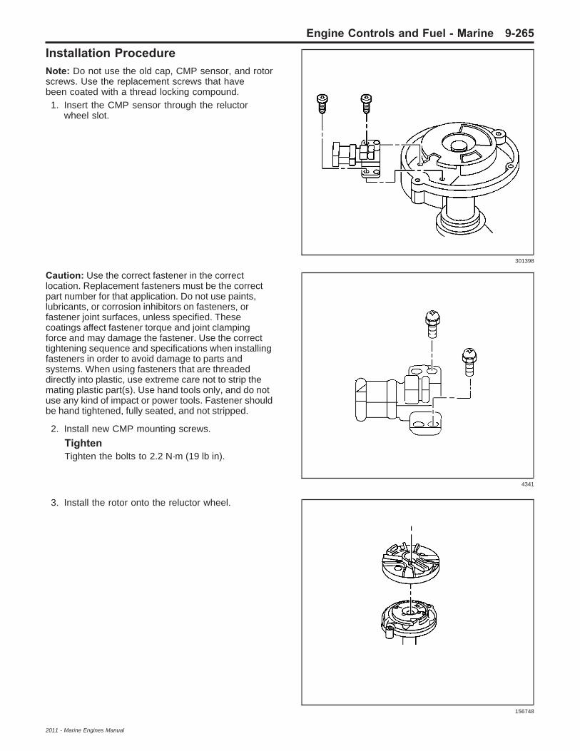
Installation ProcedureNote: Do not use the old cap, CMP sensor, and rotorscrews. Use the replacement screws that havebeen coated with a thread locking compound.1. Insert the CMP sensor through the reluctor
wheel slot.
Caution: Use the correct fastener in the correctlocation. Replacement fasteners must be the correctpart number for that application. Do not use paints,lubricants, or corrosion inhibitors on fasteners, orfastener joint surfaces, unless specified. Thesecoatings affect fastener torque and joint clampingforce and may damage the fastener. Use the correcttightening sequence and specifications when installingfasteners in order to avoid damage to parts andsystems. When using fasteners that are threadeddirectly into plastic, use extreme care not to strip themating plastic part(s). Use hand tools only, and do notuse any kind of impact or power tools. Fastener shouldbe hand tightened, fully seated, and not stripped.
2. Install new CMP mounting screws.
TightenTighten the bolts to 2.2 N·m (19 lb in).
3. Install the rotor onto the reluctor wheel.
301398
4341
156748
Engine Controls and Fuel - Marine 9-265
2011 - Marine Engines Manual

4. Install new rotor screws.
TightenTighten the screws to 1.9 N·m (17 lb in).
5. Install the distributor cap.
6. Install new distributor cap screws.
TightenTighten the screws to 2.4 N·m (21 lb in).
4354
157986
157984
9-266 Engine Controls and Fuel - Marine
2011 - Marine Engines Manual

7. Connect the CMP sensor harness connector.
8. Connect the spark plug wires and ignition coilwire. Refer to Spark Plug Wire Replacement onpage 9-245.
302829
302854
Engine Controls and Fuel - Marine 9-267
2011 - Marine Engines Manual

Camshaft Position Sensor Replacement (with CMP Actuator)
Camshaft Position Sensor Replacement (with CMP Actuator)Callout Component Name
1
Camshaft Position Sensor Fastener (Qty: 3)Caution: Refer to Fastener Caution on page 0-5.Tighten12 N·m (106 lb in)
2Camshaft Position SensorProcedureDisconnect the electrical connectors.
2491396
9-268 Engine Controls and Fuel - Marine
2011 - Marine Engines Manual

Camshaft Position Sensor Replacement (without CMP Actuator)
Camshaft Position Sensor Replacement (without CMP Actuator)Callout Component Name
1
Camshaft Position Sensor Fastener (Qty: 2)Caution: Refer to Fastener Caution on page 0-5.Tighten12 N·m (106 lb in)
2Camshaft Position SensorProcedureDisconnect the electrical connectors.
2491402
Engine Controls and Fuel - Marine 9-269
2011 - Marine Engines Manual

Camshaft Position SensorReplacement (2.4L Intake)
Removal Procedure1. Disconnect the intake camshaft position (CMP)
sensor electrical connector (2).
2. Remove the CMP sensor bolt.3. Remove the CMP sensor.
Installation Procedure
Note: Inspect the CMP sensor for damage. Replaceas necessary.1. Lubricate the CMP sensor O-ring seal with clean
engine oil.2. Install the CMP sensor.
Caution: Refer to Fastener Caution on page 0-5.3. Install the CMP sensor bolt.
TightenTighten the bolt to 10 N·m (89 lb in).
4. Connect the intake CMP sensor electricalconnector (2).
Camshaft Position SensorReplacement (2.4L Exhaust)
Removal Procedure1. Disconnect the exhaust camshaft position (CMP)
sensor electrical connector (1).
2. Remove the CMP sensor bolt. Intake CMPshown, exhaust CMP similar.
3. Remove the CMP sensor.
1578483
1578483
1639712
1578483
9-270 Engine Controls and Fuel - Marine
2011 - Marine Engines Manual

Installation Procedure
Note: Inspect the CMP sensor for damage, replace asnecessary.1. Lubricate the CMP sensor O-ring seal with clean
engine oil.2. Install the CMP sensor. Intake CMP shown,
exhaust CMP similar.
Caution: Refer to Fastener Caution on page 0-5.3. Install the CMP sensor bolt.
TightenTighten the bolt to 10 N·m (89 lb in).
4. Connect the exhaust CMP sensor electricalconnector (1).
Camshaft Position Actuator MagnetReplacement
Removal Procedure
1. Remove the water pump.2. Disconnect the engine harness electrical
connector from the camshaft position (CMP)actuator magnet.
3. Remove the CMP actuator magnet bolts (751)and magnet (752).
4. Remove and discard the CMP actuator magnetgasket (753).
1578483
1639712
1658168
Engine Controls and Fuel - Marine 9-271
2011 - Marine Engines Manual

Installation Procedure
Note: The gasket surface should be free of oil orother foreign material during assembly.1. Install a NEW CMP actuator magnet gasket (753)
onto the CMP actuator magnet.2. Install the CMP actuator magnet (752) to the
front cover.
Caution: Refer to Fastener Caution on page 0-5.3. Install the CMP actuator magnet bolts (751) and
tighten to 12 N·m (106 lb in).4. Connect the engine harness electrical connector
to the CMP actuator magnet.5. Install the water pump.
Camshaft Position ActuatorSolenoid Valve Replacement(6.0/6.2L)Special Tools
• J 42386-A Flywheel Holding Tool• J 45059 Angle Meter
Removal Procedure
Caution: Refer to Fastener Caution on page 0-5.1. Install the J 42386-A (1) and bolts. Use 1 M10 –
1.5 x 120 mm and 1 M10 – 1.5 x 45 mm bolt forproper tool operation. Tighten the J 42386-A boltsto 50 N·m (37 lb ft).
2. Remove the camshaft position (CMP) actuatormagnet. Refer to Camshaft Position ActuatorMagnet Replacement on page 9-271.
1658168
1658136
9-272 Engine Controls and Fuel - Marine
2011 - Marine Engines Manual

Warning: Refer to Camshaft Position ActuatorRemoval and Installation Warning on page 0-4.3. Remove the CMP actuator solenoid valve (234).4. Discard the solenoid valve.
Installation Procedure
1. Install a NEW CMP actuator solenoid valve (234).With the CMP actuator properly positioned ontothe camshaft, the CMP actuator solenoidvalve can be threaded completely into thecamshaft using light hand pressure. Tighten byhand until snug.
2. Tighten the CMP actuator solenoid valve.2.1. Tighten the CMP actuator solenoid valve a
first pass to 65 N·m (48 lb ft).2.2. Tighten the CMP actuator solenoid valve a
final pass an additional 90 degrees usingthe J 45059.
3. Remove the J 42386-A (1).4. Install the CMP actuator magnet. Refer to
Camshaft Position Actuator Magnet Replacementon page 9-271.
1670622
1670622
1658245
1658136
Engine Controls and Fuel - Marine 9-273
2011 - Marine Engines Manual

Camshaft Position ActuatorSolenoid Valve Replacement (2.4L)
Removal Procedure1. Disconnect the intake (3) or exhaust (2) camshaft
position actuator solenoid valve electricalconnector, as required.
2. Remove the exhaust (1) camshaft position (CMP)actuator solenoid valve bolt and valve, as required.
3. Remove the intake (2) CMP actuator solenoidvalve bolt and valve, as required.
4. Inspect the solenoid valve O-ring seals fromdamage, replace as necessary.
Installation Procedure
1. Lubricate the solenoid valve O-ring seals withclean engine oil.
Caution: Refer to Fastener Caution on page 0-5.2. Install the intake (2) CMP actuator solenoid valve
and bolt, as required.
TightenTighten the bolt to 10 N·m (89 lb in).
3. Install the exhaust (1) CMP actuator solenoidvalve and bolt, as required.
TightenTighten the bolt to 10 N·m (89 lb in).
4. Connect the intake (3) or exhaust (2) camshaftposition actuator solenoid valve electricalconnector, as required.
1578482
1578482
1647538
9-274 Engine Controls and Fuel - Marine
2011 - Marine Engines Manual

Camshaft Position Actuator MagnetCleaning and Inspection
Note: Do not energize the camshaft position (CMP)magnet using a 12-volt power supply.1. Inspect the CMP magnet for the following
conditions:• A damaged electrical connector• An accumulation of dirt or debris in the
recessed area around the pintle• A build-up of burnt engine oil on the shaft
of the pintle which may cause the pintle to stickand not move freely within the proper rangeof travel
2. Holding the CMP magnet with the pintle facingupward, measure the pintle retracted position (a).Record the dimension.
3. Holding the CMP magnet with the pintle facingdownward, measure the pintle extendedposition (a). Record the dimension.
4. Subtract the retracted dimension from theextended dimension to determine pintle travel.A properly moving pintle will travel3.0–5.5 mm (0.12–0.22 in).
5. If the pintle of the CMP magnet is binding or doesnot move within the proper range of travel,replace the CMP magnet as an assembly.
1721004
1721006
Engine Controls and Fuel - Marine 9-275
2011 - Marine Engines Manual

Camshaft Position ActuatorSolenoid Valve InspectionNote: Do not use the camshaft position (CMP)actuator solenoid valve again. Install a NEW valveduring assembly. The inspection procedure below isprovided for on-vehicle diagnostic purposes only.1. With the CMP magnet removed, inspect for
a sticking valve spool or broken valve spoolspring.
2. Depress the valve spool into the housing.The valve should move freely with no bindingor sticking and minimal resistance inward.When released, the valve spring should returnthe spool to the proper extended position (1) of6.08–6.12 mm (0.239–0.241 in).
1714950
9-276 Engine Controls and Fuel - Marine
2011 - Marine Engines Manual

Knock Sensor Replacement(Except 2.4L)
Removal Procedure1. Disconnect the negative battery cable.
2. Disconnect the harness connector (4) at theknock sensor (KS).
3. Remove the mounting bolt (739) from theKS (718).
4. Remove the KS (718) from the engine block.
Installation Procedure
1. Position the KS (718) on the engine block.2. Install the mounting bolt (739) for the KS.
Caution: Refer to Fastener Caution on page 0-5.3. Tighten the KS mounting bolt.
TightenTighten the KS mounting bolt to 25 N·m (18 lb ft).
4. Reconnect the harness connector (4) at the KS.5. Connect the negative battery cable.
1699536
1402136
1402136
1699536
Engine Controls and Fuel - Marine 9-277
2011 - Marine Engines Manual

Knock Sensor Replacement (2.4L)
Removal Procedure
1. Disconnect the knock sensor (KS) electricalconnector (6).
2. Remove the KS bolt.3. Remove the KS.
Installation ProcedureNote: Rotate the pigtail 90 degrees from verticalbefore securing the fastener.
1. Install the KS.
Caution: Refer to Fastener Caution on page 0-5.2. Install the KS bolt.
TightenTighten the bolt to 25 N·m (18 lb ft).
3. Connect the KS electrical connector (6).
1622787
1578476
1578476
1622787
9-278 Engine Controls and Fuel - Marine
2011 - Marine Engines Manual

Description and OperationEngine Control Module DescriptionThe engine control module (ECM) interacts withmany emission related components and systems.The ECM also monitors emission related components,and systems, for deterioration. The on-boarddiagnostics monitor the system performance and asuspect parameter number (SPN) sets if the systemperformance degrades.The malfunction indicator lamp (MIL) operation andSPN storage are dictated by the SPN type. SPNs areranked as a Type A, B, C, or E. Types A, B and ESPNs are emissions related. Type C SPNs arenon-emissions related.The ECM is the control center of the engine controlssystem. The ECM controls the following components:
• The fuel injection system• The ignition system• The emission control systems• The on-board diagnostics• The throttle control (TAC) system
The ECM constantly monitors the information fromvarious sensors and other inputs, and controls thesystems that affect the vehicle performance andemissions. The ECM also performs diagnostic tests onvarious parts of the system. The ECM can recognizeoperational problems and alert the driver via the MIL.When the ECM detects a malfunction, the ECM stores aSPN. The condition area is identified by the particularSPN that is set. This aids the technician in makingrepairs.
ECM FunctionThe engine control module (ECM) can supply 5 volts,12 volts, or ground to various sensors or switches.Voltage is supplied through pull-up resistors to theregulated power supplies within the ECM. In somecases an ordinary shop voltmeter will not give anaccurate reading due to low input resistance. A DMMwith at least 10 megaohms input impedance is requiredin order to ensure accurate voltage readings.The ECM controls the output circuits by controlling theground or the power feed circuit through the transistorsor a device called an output driver module.
EEPROMThe electronically erasable programmable read onlymemory (EEPROM) is a permanent memory thatis physically part of the engine control module (ECM).The EEPROM contains program and calibrationinformation that the ECM needs in order to controlthe powertrain operation.Special equipment, as well as the correct program andcalibration for the vehicle, are required in order toreprogram the ECM.
ECM Default ActionsWhen a malfunction occurs within the engine controlsystem, the engine control module (ECM) maintainscontrol of the system with Default Actions. DefaultActions are calculated values, and/or calibrated defaultvalues, that are stored within the ECM. A certainlevel of engine performance is possible when amalfunction occurs dependant on the Default Actionstaken. The ECM Default Actions prevent a completeloss of engine performance.
ECM Output ControlsThe scan tool can control certain solenoids, valves,motors, and relays. The Output Controls can be foundunder the Special Functions selection of the scantool. Some Output Controls may be disabled by theengine control module (ECM) during certain typesof vehicle operation.
Data Link Connector (DLC)The data link connector (DLC) provides the techniciana means of accessing serial data for aid in diagnosis.This connector allows the technician to use a scantool in order to monitor the various serial dataparameters, and to display SPN information.
Malfunction Indicator Lamp (MIL)The malfunction indicator lamp (MIL) is located on theinstrument panel cluster (IPC). The MIL is controlledby the engine control module (ECM) and illuminateswhen the ECM detects a condition that affectsthe vehicle emissions.
ECM Service PrecautionsThe engine control module (ECM) is designed towithstand the normal current draws that are associatedwith vehicle operation. Care must be used in orderto avoid overloading any circuits during testing. Do notground, or apply voltage, to any ECM circuits unlessa diagnostic procedure instructs you to do so.Circuits should only be tested with a DMM.
Throttle Actuator Control (TAC)System Description
PurposeThe throttle actuator control (TAC) system deliversimproved throttle response and greater reliability andeliminates the need for mechanical cable. TheTAC system performs the following functions:
• Pedal position sensing• Throttle positioning to meet driver and engine
demands• Throttle position sensing• Internal diagnostics• Cruise control functions• Manage TAC electrical power consumption
Engine Controls and Fuel - Marine 9-279
2011 - Marine Engines Manual

The TAC system includes the following components:
• The pedal position sensors
• The throttle body assembly
• The engine control module (ECM)
Pedal Position SensorThe pedal position sensor contains 2 individualsensors within the assembly. The Pedal Positionsensors 1 and 2 are potentiometer type sensors eachwith 3 circuits:
• A 5-volt reference circuit
• A low reference circuit
• A signal circuit
The pedal position sensors are used to determine thethrottle angle. The engine control module (ECM)provides each pedal position sensor a 5-volt referencecircuit and a low reference circuit. The pedal positionsensors provide the ECM with signal voltageproportional to the throttle movement. The pedalposition sensor 1 signal voltage at rest position is lessthan 1 volt and increases to above 4 volts as the pedalis actuated. The APP sensor 2 signal voltage at restposition is greater than 4 volts and decreases to lessthan 1 volt as the throttle is actuated.
Throttle Body AssemblyThe throttle assembly contains the followingcomponents:
• The throttle blade
• The throttle actuator motor
• The throttle position (TP) sensor 1 and 2
The throttle body functions similar to a conventionalthrottle body with the following exceptions:
• An electric motor opens and closes thethrottle valve.
• The throttle blade is spring loaded in bothdirections and the default position is slightly open.
• There are 2 individual TP sensors within thethrottle body assembly.
The TP sensors are used to determine the throttleplate angle. The TP sensors provide the engine controlmodule (ECM) with a signal voltage proportional tothrottle plate movement. The TP sensor 1 signalvoltage at closed throttle is approximately 1.5 voltsand increases to greater than 4 volts as the throttleplate is opened. The TP sensor 2 signal voltageat closed throttle is approximately 3.5 volts anddecreases to less than 1 volt as the throttle plateis opened.
Engine Control ModuleThe engine control module (ECM) is the control centerfor the throttle actuator control (TAC) system. TheECM determines the drivers intent and then calculatesthe appropriate throttle response. The ECM achievesthrottle positioning by providing a pulse widthmodulated voltage to the TAC motor.
Modes of OperationNormal ModeDuring the operation of the throttle actuatorcontrol (TAC) system, several modes or functions areconsidered normal. The following modes may beentered during normal operation:
• Minimum pedal value—At key-up the enginecontrol module (ECM) updates the learnedminimum pedal value.
• Minimum throttle position (TP) values—At key-upthe ECM updates the learned minimum TPvalue. In order to learn the minimum TP value,the throttle blade is moved to the closed position.
• Ice break mode—If the throttle is not able to reacha predetermined minimum throttle position, the icebreak mode is entered. During the ice breakmode, the ECM commands the maximum pulsewidth several times to the throttle actuator motor inthe closing direction.
• Battery saver mode—After a predetermined timewithout engine RPM, the ECM commands thebattery saver mode. During the battery savermode, the TAC module removes the voltage fromthe motor control circuits, which removes thecurrent draw used to maintain the idle position andallows the throttle to return to the spring loadeddefault position.
Reduced Engine Power ModeWhen the ECM detects a condition with the TACsystem, the ECM may enter a reduced engine powermode. Reduced engine power may cause one ormore of the following conditions:
• Acceleration limiting—The ECM will continue touse the accelerator pedal for throttle control;however, the vehicle acceleration is limited.
• Limited throttle mode—The ECM will continue touse the accelerator pedal for throttle control;however, the maximum throttle opening is limited.
• Throttle default mode—The ECM will turn offthe throttle actuator motor and the throttlewill return to the spring loaded default position.
• Forced idle mode—The ECM will performthe following actions:
− Limit engine speed to idle by positioning thethrottle position, or by controlling the fueland spark if the throttle is turned off.
− Ignore the accelerator pedal input.• Engine shutdown mode—The ECM will disable
fuel and de-energize the throttle actuator.
9-280 Engine Controls and Fuel - Marine
2011 - Marine Engines Manual

Camshaft Actuator System Description
Camshaft Position (CMP) Actuator System
The camshaft position (CMP) actuator system is usedfor a variety of engine performance enhancements.These enhancements include lower emission output, awider engine torque range, improved gas mileage, andimproved engine idle stability. The park position for theCMP actuator and camshaft is 7 crankshaft degreesBTDC. The engine control module (ECM) can onlycommand the CMP actuator to retard the valve timingfrom the park position or return the valve timing backto the park position. The total range of valve timingauthority is 52 degrees of crankshaft rotation. Thecontrol range is from the park position of 7 degreescrankshaft BTDC, to 45 degrees crankshaft after topdead center (ATDC).
CMP Actuator System OperationThe camshaft position (CMP) actuator system iscontrolled by the engine control module (ECM).The ECM sends a pulse width modulated 12-volt signalto a CMP actuator solenoid in order to control theamount of engine oil flow to a camshaft actuatorpassage. There are 2 different passages for oil to flowthrough, a passage for cam advance and a passage forcam retard. The camshaft actuator is attached to the
front of the camshaft and is hydraulically operated inorder to change the angle of the camshaft relative tocrankshaft position (CKP). Incorrect engine oilpressure (EOP), viscosity, temperature, engine oil level,or aftermarket engine oil additives can have an adverseaffect on camshaft phaser performance.
CMP Actuator Solenoid CircuitDiagnosticsThe engine control module (ECM) monitors the controlcircuit of the camshaft position (CMP) actuatorsolenoid for electrical faults. The control module hasthe ability to determine if a control circuit is open,shorted high, or shorted low.
CMP Actuator System PerformanceDiagnosticThe engine control module (ECM) monitors theperformance of the camshaft position (CMP) actuatorsystem by monitoring the calibrated desired positionand the actual position of the camshaft throughthe 4X signal of the CMP sensor.
1916848
Engine Controls and Fuel - Marine 9-281
2011 - Marine Engines Manual
Supercharger Description andOperationSupercharger DescriptionThe marine supercharger is a positive displacementpump that consists of 2 counter-rotating rotors, an inletport and an outlet port, and an air bypass valve that isbuilt into a housing. The rotors are designed with3 lobes and a helical twist. An air bypass valve is builtinto the housing. The rotors in the supercharger aredesigned to run at a minimal clearance, not in contactwith each other or the housing and are timed to eachother by a pair of precision spur gears which arepressed onto the rotor shafts. The front ends of therotors are held in position by deep-groove ball bearings,while the rear ends of the rotors are supported bysealed roller bearings.The gears and ball bearings are lubricated by asynthetic oil. The oil reservoir is self-contained in thesupercharger, isolated from the engine oil, sealedfor the life of the unit and is not serviceable.The cover on the supercharger contains the inputshaft which is supported by 2 deep-groove ballbearings, and is coupled to the rotor drive gears.The pulley is pressed onto the input shaft and isnot serviceable. The bearings are lubricated by thesynthetic oil contained in the same reservoir.
OperationThe supercharger is designed to increase the airpressure and density in the intake manifold. When thisair is mixed with the correct amount of fuel the result ismore power from the engine. This excess air creates aboost pressure in the intake manifold. Because thesupercharger is a positive displacement pump and isdirectly driven from the engine drive belt system, boostpressure is available at all driving conditions.
When boost is not required, such as during idle or lightthrottle cruising, the excess air is routed through thebypass passage between the intake manifold and thesupercharger inlet. This bypass circuit is regulatedby a bypass valve which is similar to a throttle plate.The bypass valve is controlled by a vacuum actuatorwhich is connected to the vacuum signal between thethrottle and the supercharger inlet. Spring force fromthe actuator holds the valve in a normally closedposition to create boost, and vacuum pulls the valveopen when the throttle closes to decrease boost.A solenoid valve is attached to the superchargerhousing. This three-way valve, controlled by the enginecontrol module (ECM), determines whether pressurefrom the manifold is routed to the bypass actuator orclosed off. This valve allows pressure from the manifoldto open the bypass valve and lower boost pressureduring specific driving conditions. The open bypassvalve reduces the pumping effort of the supercharger,thereby increasing the fuel efficiency in light loadoperations.
IntercoolerThe supercharger has an intercooler. Cooling thesupercharger boost air enhances the effectiveness ofthe supercharger. The intercooler uses conventionalcoolant in a separate sealed system from the enginecooling system. The intercooler system has a radiator, aback fill port at the rear of the supercharger, attachinghoses, and a coolant pump. The coolant pump issupplied power through the coolant pump relay.The coolant pump relay operation is controlled by theECM. Ignition voltage is supplied to the coolant pumprelay coil, and the coolant pump relay switch. The ECMcontrols the coolant pump relay with a low side driver.When the ECM commands the coolant pump relay ON,the relay contacts close, supplying power to thesupercharger intercooler coolant pump.
9-282 Engine Controls and Fuel - Marine
2011 - Marine Engines Manual

Boost Control System Operation
Legend
(1) By-pass Valve Actuator(2) Boost Signal(3) Boost Control Solenoid(4) Boost Vacuum Source(5) Supercharger(6) Intake Plenum
(7) By–pass Valve (normally closed)(8) Throttle Body(9) Air Cleaner
(10) MAF Sensor(11) Inlet Vacuum Signal
Bypass Valve Closed
1671645
Engine Controls and Fuel - Marine 9-283
2011 - Marine Engines Manual

OperationThe ECM controls boost pressure by using the boostcontrol solenoid. The boost control solenoid is normallyan open valve. Under most conditions, the ECMcommands the boost control solenoid to operate at a99–100 percent duty cycle. This keeps the solenoidvalve closed and allows only inlet vacuum to control theposition of the bypass valve. At idle, engine vacuum isapplied to the upper side of the bypass valve actuator,counteracting spring tension to hold the bypass valveopen. As engine load is increased, engine vacuum isdecreased, causing the spring in the bypass valveactuator to overcome the applied vacuum, closingthe bypass valve and allowing the boost pressure toincrease. When reduced boost pressure is desired, theECM decreases the boost control solenoid duty cycle.This opens the solenoid valve and allows boostpressure to enter the bypass valve actuator at the lowerside to counteract the spring tension, opening thebypass valve and re-circulating excess boost pressureback into the supercharger inlet.
Results of Incorrect OperationThe following conditions will result in reduced enginepower, especially during a wide open throttle (WOT)operation:
• An open boost control solenoid control circuit.• An open control solenoid ignition 1 voltage circuit.• An open control solenoid control circuit.• A boost control solenoid valve that is stuck open.
The following conditions will result in full boost tobe commanded at all times. These conditions can alsoresult in over-boost conditions during high engineload situations.
• A boost control solenoid control circuit shorted toground.
• A boost control solenoid valve is stuck closed.• A restriction in the boost source or signal
vacuum hoses.• A restriction in the exhaust system may cause an
over-boost condition and reduced fuel economy.A restriction in the vacuum signal hose to the bypassvalve actuator or stuck closed bypass valve willcause a noisy idle and reduced fuel economy.
Fuel System Description
Fuel System OverviewLow Pressure Fuel PumpThe low pressure fuel pump supplies low pressure,high volume fuel flow to the high pressure fuel pump.The low pressure fuel pressure pump maintains aconstant flow of fuel to the high pressure fuel pump inorder to prevent long cranking times.
High Pressure Fuel PumpThe fuel pump supplies high pressure fuel through thefuel filter and the fuel feed pipe to the fuel injectionsystem. The fuel pump provides fuel at a higher rate offlow than is needed by the fuel injection system.The fuel pressure regulator maintains the correctfuel pressure to the fuel injection system. Thefuel pump and sender assembly contains a reverseflow check valve. The check valve and the fuelpressure regulator maintain fuel pressure in the fuelfeed pipe and the fuel rail in order to prevent longcranking times.
Fuel Level SensorThe fuel level sensor consists of a float, a wire floatarm, and a ceramic resistor cord. The position ofthe float arm indicates the fuel level. The fuel levelsensor contains a variable resistor, which changesresistance in correspondence to the amount of fuelin the fuel tank. The engine control module (ECM)sends the fuel level information via the class 2 circuitto the instrument panel (I/P) cluster. This informationis used for the I/P fuel gauge and the low fuel warningindicator, if applicable. The ECM also monitors thefuel level input for various diagnostics.
Fuel PumpThe fuel pump is an electric high pressure pump.Fuel is pumped to the fuel rail at a specified flow andpressure. The fuel pump delivers a constant flowof fuel to the engine during low fuel conditions andaggressive vehicle maneuvers. The engine controlmodule (ECM) controls the electric fuel pump operationthrough a fuel pump relay.
Fuel FilterThe fuel filter is contained in the fuel sender assemblyinside the fuel tank. The paper filter element of the fuelfilter traps particles in the fuel that may damage the fuelinjection system. The fuel filter housing is made towithstand maximum fuel system pressure, exposure tofuel additives, and changes in temperature.
Nylon Fuel PipesWarning: Refer to Fuel Pipe Fitting Warning onpage 0-4.Nylon pipes are constructed to withstand maximumfuel system pressure, exposure to fuel additives, andchanges in temperature. There are 3 sizes of nylonpipes used: 9.5 mm (3/8 in) ID for the fuel supply,7.6 mm (5/16 in) ID for the fuel return, and 12.7 mm(1/2 in) ID for the vent. Heat resistant rubber hoseor corrugated plastic conduit protects the sectionsof the pipes that are exposed to chafing, to hightemperatures, or to vibration.Nylon fuel pipes are somewhat flexible and can beformed around gradual turns under the vehicle.However, if nylon fuel pipes are forced into sharpbends, the pipes kink and restrict the fuel flow. Also,once exposed to fuel, nylon pipes may become stifferand are more likely to kink if bent too far. Take specialcare when working on a vehicle with nylon fuel pipes.
9-284 Engine Controls and Fuel - Marine
2011 - Marine Engines Manual

Quick-Connect FittingsQuick-connect fittings provide a simplified means ofinstalling and connecting fuel system components.The fittings consist of a unique female connector anda compatible male pipe end. O-rings, located insidethe female connector, provide the fuel seal. Integrallocking tabs inside the female connector hold thefittings together.
Fuel Pipe O-RingsO-rings seal the threaded connections in the fuelsystem. Fuel system O-ring seals are made of specialmaterial. Service the O-ring seals with the correctservice part.
Fuel Rail Assembly
The fuel rail assembly attaches to the engine intakemanifold. The fuel rail assembly performs the followingfunctions:
• Positions the injectors (3) in the intake manifold• Distributes fuel evenly to the injectors (2)• Fuel rail feed pipe (1)
Fuel InjectorsThe fuel injector assembly is a solenoid devicecontrolled by the engine control module (ECM) thatmeters pressurized fuel to a single engine cylinder.The ECM energizes the injector solenoid to open anormally closed ball valve. This allows the fuel toflow into the top of the injector, past the ball valve,and through a director plate at the injector outlet.The director plate has machined holes that control thefuel flow, generating a spray of finely atomized fuel at
the injector tip. Fuel from the injector tip is directed atthe intake valve, causing the fuel to become furtheratomized and vaporized before entering the combustionchamber. This fine atomization improves fuel economyand emissions.
Fuel Pressure RegulatorThe type of fuel system, return or returnless, will varydepending on year, and engine. Returnless fuelsystems are not regulated at the fuel rail. Fuel pressureregulation is controlled at the module outlet filter,therefore the type of fuel system can be determined bythe number of fuel lines to the fuel rail.The fuel pressure regulator controls the fuel pressurethat is delivered to the fuel injectors.
Fuel Metering Modes of OperationThe engine control module (ECM) monitors voltagesfrom several sensors in order to determine howmuch fuel to give the engine. The ECM controls theamount of fuel delivered to the engine by changing thefuel injector pulse width. The fuel is delivered underone of several modes.
Starting ModeWhen the ignition is first turned ON, the ECMenergizes the fuel pump relay for 2 seconds.This allows the fuel pump to build pressure in the fuelsystem. The ECM calculates the air/fuel ratio basedon inputs from the engine coolant temperature (ECT),manifold absolute pressure (MAP), and throttleposition (TP) sensors. The system stays in startingmode until the engine speed reaches apredetermined RPM.
Clear Flood ModeIf the engine floods, clear the engine by pressing theaccelerator pedal down to the floor and then crankthe engine. When the TP sensor is at wide openthrottle (WOT), the ECM reduces the fuel injector pulsewidth in order to increase the air to fuel ratio. The ECMholds this injector rate as long as the throttle stays wideopen and the engine speed is below a predeterminedRPM. If the throttle is not held wide open, the ECMreturns to the starting mode.
Run Mode without Heated OxygenSensors (HO2S)On vehicles that are not equipped with heated oxygensensors (HO2S) the run mode is called Open Loop.When the engine is first started and the engine speedis above a predetermined RPM, the system beginsOpen Loop operation. The ECM calculates the air/fuelratio based on inputs from the ECT, MAP, and TPsensors.
1542826
Engine Controls and Fuel - Marine 9-285
2011 - Marine Engines Manual

Run Mode with Heated OxygenSensors (HO2S)On vehicles that are equipped with heated oxygensensors (HO2S) the run mode has 2 conditions calledOpen Loop and Closed Loop. When the engine isfirst started and the engine speed is above apredetermined RPM, the system begins Open Loopoperation. The ECM ignores the signal from the heatedoxygen sensors HO2S. The ECM calculates the air/fuelratio based on inputs from the ECT, MAP, and TPsensors. The system stays in Open Loop until meetingthe following conditions:
• Both front HO2S have varying voltage output,showing that both HO2S are hot enough to operateproperly.
• The ECT sensor is above a specified temperature.
• A specific amount of time has elapsed after startingthe engine.
Specific values for the above conditions exist for eachdifferent engine, and are stored in the electricallyerasable programmable read-only memory (EEPROM).The system begins Closed Loop operation afterreaching these values. In Closed Loop, the ECMcalculates the air/fuel ratio, injector ON time, basedupon the signal from various sensors, but mainly fromthe HO2S. This allows the air/fuel ratio to stay veryclose to 14.7:1.
Acceleration ModeWhen the driver pushes on the accelerator pedal, airflow into the cylinders increases rapidly. To preventpossible hesitation, the ECM increases the pulsewidth to the injectors to provide extra fuel duringacceleration. This is also known as power enrichment.The ECM determines the amount of fuel requiredbased upon the TP, the ECT, the MAP, and theengine speed.
Deceleration ModeWhen the driver releases the throttle, air flowinto the engine is reduced. The ECM monitors thecorresponding changes in the TP, and the MAP.The ECM shuts OFF fuel completely if the decelerationis very rapid. The fuel shuts OFF in order to preventdamage to the catalytic converters.
Battery Voltage Correction ModeWhen the battery voltage is low, the ECMcompensates for the weak spark delivered by theignition system in the following ways:
• Increasing the amount of fuel delivered
• Increasing the idle RPM
• Increasing the ignition dwell time
Fuel Cutoff ModeThe ECM cuts OFF fuel from the fuel injectors whenthe following conditions are met in order to protect thepowertrain from damage and improve driveability:
• The ignition is OFF. This prevents engine run-on.• The ignition is ON but there is no ignition
reference signal. This prevents flooding orbackfiring.
• The engine speed is too high, above red line.• During rapid deceleration, in order to prevent
damage to the catalytic converters
Fuel TrimThe engine control module (ECM) controls the air/fuelmetering system in order to provide the best possiblecombination of driveability, fuel economy, and emissioncontrol. The ECM monitors the heated oxygen sensor(HO2S) signal voltage while in Closed Loop andregulates the fuel delivery by adjusting the pulse widthof the fuel injectors based on this signal. The ideal fueltrim values are around 0 percent for both short term andlong term fuel trim. A positive fuel trim value indicatesthe ECM is adding fuel in order to compensate for alean condition by increasing the pulse width. A negativefuel trim value indicates that the ECM is reducing theamount of fuel in order to compensate for a richcondition by decreasing the pulse width. A changemade to the fuel delivery changes the short term andlong term fuel trim values. The short term fuel trimvalues change rapidly in response to the HO2S signalvoltage. These changes fine tune the engine fueling.The long term fuel trim makes coarse adjustments tothe fueling in order to re-center and restore control toshort term fuel trim. A scan tool can be used to monitorthe short term and long term fuel trim values. The longterm fuel trim diagnostic is based on an average ofseveral of the long term speed load learn cells. TheECM selects the cells based on the engine speed andengine load. If the ECM detects an excessive lean orrich condition, the ECM will set a fuel trim diagnostictrouble code (DTC).
Electronic Ignition SystemDescriptionElectronic Ignition (EI) SystemOperationThe electronic ignition (EI) system produces andcontrols the high energy secondary spark. This sparkignites the compressed air/fuel mixture at preciselythe correct time, providing optimal performance, fueleconomy, and control of exhaust emissions. The enginecontrol module (ECM) primarily collects informationfrom the crankshaft position (CKP) and camshaftposition (CMP) sensors to control the sequence, dwell,and timing of the spark.
9-286 Engine Controls and Fuel - Marine
2011 - Marine Engines Manual

Crankshaft Position (CKP) SensorThe crankshaft position (CKP) sensor is an internallymagnetic biased digital output integrated circuit sensingdevice. The sensor detects magnetic flux changesof the teeth and slots of the reluctor wheel on thecrankshaft. The CKP sensor produces an ON/OFF DCvoltage of varying frequency. The CKP sensor sends adigital signal to the ECM as each tooth on the reluctorwheel rotates past the CKP sensor. The ECM useseach CKP signal pulse to determine crankshaft speedand position. This information is then used to determinethe optimum ignition and injection points of the engine.The ECM also uses CKP sensor output informationto determine the camshaft relative position to thecrankshaft, to control camshaft phasing, and to detectcylinder misfire.
Camshaft Position (CMP) SensorThe sensor detects magnetic flux changes between thefour narrow and wide tooth slots on the reluctor wheel.The CMP sensor provides a digital ON/OFF DC voltageof varying frequency per each camshaft revolution.The ECM will recognize the narrow and wide toothpatterns to identify camshaft position, or which cylinderis in compression and which is in exhaust. Theinformation is then used to determine the correct timeand sequence for fuel injection and ignition sparkevents. The CMP sensor information is used by theECM to determine the position of the valve train relativeto the crankshaft.
Knock Sensor (KS)The knock sensor (KS) system enables the controlmodule to control the ignition timing for the bestpossible performance while protecting the enginefrom potentially damaging levels of detonation, alsoknown as spark knock. The KS system uses oneor 2 flat response 2-wire sensors. The sensor usespiezo-electric crystal technology that produces an ACvoltage signal of varying amplitude and frequencybased on the engine vibration or noise level.The amplitude and frequency are dependant uponthe level of knock that the KS detects. The controlmodule receives the KS signal through the signalcircuit. The KS ground is supplied by the controlmodule through the low reference circuit.The control module learns a minimum noise level,or background noise, at idle from the KS and usescalibrated values for the rest of the RPM range.The control module uses the minimum noise level tocalculate a noise channel. A normal KS signal will ridewithin the noise channel. As engine speed and loadchange, the noise channel upper and lower parameterswill change to accommodate the normal KS signal,keeping the signal within the channel. In order todetermine which cylinders are knocking, the controlmodule only uses KS signal information when eachcylinder is near top dead center (TDC) of the firingstroke. If knock is present, the signal will range outsideof the noise channel.
If the control module has determined that knock ispresent, it will retard the ignition timing to attempt toeliminate the knock. The control module will always tryto work back to a zero compensation level, or nospark retard. An abnormal KS signal will stay outsideof the noise channel or will not be present. KSdiagnostics are calibrated to detect faults with the KScircuitry inside the control module, the KS wiring,or the KS voltage output. Some diagnostics are alsocalibrated to detect constant noise from an outsideinfluence such as a loose/damaged componentor excessive engine mechanical noise.
Ignition CoilsEach ignition coil has an ignition 1 voltage feed and aground circuit. The engine control module (ECM)supplies a low reference and an ignition control (IC)circuit. Each ignition coil contains a solid statedriver module. The ECM will command the IC circuitON, which allows the current to flow through theprimary coil windings. When the ECM commands theIC circuit OFF, this will interrupt current flow throughthe primary coil windings. The magnetic field createdby the primary coil windings will collapse acrossthe secondary coil windings, which induces a highvoltage across the spark plug electrodes.
Distributor Ignition (DI) SystemDescriptionThe distributor ignition (DI) system is responsible forproducing and controlling a high energy secondaryspark. This spark is used to ignite the compressedair/fuel mixture at precisely the correct time. Thisprovides optimal performance, fuel economy, andcontrol of exhaust emissions. This ignition systemconsists of a single ignition coil and ignition controlmodule (ICM). Spark energy is delivered via adistributor cap, rotor, and secondary spark plug wires.The driver module within the ICM is commanded tooperate the coil by the engine control module (ECM),that has complete control over spark timing. The DIsystem consists of the following components:
Crankshaft Position (CKP) SensorThe crankshaft position (CKP) sensor is an internallymagnetic biased digital output integrated circuit sensingdevice. The sensor detects magnetic flux changesof the teeth and slots of the reluctor wheel on thecrankshaft. The CKP sensor produces an ON/OFF DCvoltage of varying frequency. The CKP sensor sends adigital signal to the ECM as each tooth on the reluctorwheel rotates past the CKP sensor. The ECM useseach CKP signal pulse to determine crankshaft speedand position. This information is then used to determinethe optimum ignition and injection points of the engine.The ECM also uses CKP sensor output informationto determine the camshaft relative position to thecrankshaft, to control camshaft phasing, and to detectcylinder misfire.
Engine Controls and Fuel - Marine 9-287
2011 - Marine Engines Manual

Camshaft Position (CMP) SensorThe sensor detects magnetic flux changes between thefour narrow and wide tooth slots on the reluctor wheel.The CMP sensor provides a digital ON/OFF DC voltageof varying frequency per each camshaft revolution. TheECM will recognize the narrow and wide tooth patternsto identify camshaft position, or which cylinder is incompression and which is in exhaust. The information isthen used to determine the correct time and sequencefor fuel injection and ignition spark events. The CMPsensor information is used by the ECM to determine theposition of the valve train relative to the crankshaft.
Ignition Coil and ICMThe ICM is connected to the ECM by an ignitioncontrol (IC) circuit. The ICM also has a ground circuitand shares an ignition 1 voltage supply with the ignitioncoil. The coil driver in the ICM controls current throughthe ignition coil based on signal pulses from the ECM.There is no back-up or by-pass function in the ICM.
Secondary Ignition ComponentsHigh Voltage Switch/DistributorThe high voltage switch (HVS) or distributor containsthe Camshaft Position (CMP Sensor), cap, rotor andshaft. The HVS is splined by a helical gear to thecamshaft and rotates providing a spark to each sparkplug wire. When servicing the HVS, it is critical toensure proper cap sealing to the Distributor body andcorrect installation to the camshaft. If the HVS isinstalled a tooth off in relation to the camshaft, a DTCmay set, or a misfire will occur.
Ignition WiresThe spark plug wires are a carbon-impregnatedcord conductor encased in a silicone rubber jacket.Silicone wiring will withstand very high temperatureand is an excellent insulator for the higher voltages.The silicone spark plug boots provide a tight sealon the spark plug.
Engine Control Module (ECM)The ECM controls all ignition system functions, andconstantly corrects the basic spark timing. The ECMmonitors information from various sensor inputs thatinclude the following:
• The throttle position (TP) sensor
• The engine coolant temperature (ECT) sensor
• The manifold air temperature (MAT) sensor
• The vehicle speed sensor (VSS)
• The transmission gear position or range informationsensors
• The engine knock sensors (KS)
Modes of OperationThere is one normal mode of operation, with the sparkunder ECM control. If the CKP pulses are lost theengine will not run. The loss of a CMP signal may resultin a longer crank time since the ECM cannot determinewhich stroke the pistons are on. Diagnostic troublecodes are available to accurately diagnose the ignitionsystem with a scan tool.
9-288 Engine Controls and Fuel - Marine
2011 - Marine Engines Manual

Special Tools and EquipmentIllustration Tool Number/Description
5381
J 26792HEI Spark Tester
5389
J 34730-1AFuel Pressure Gauge
1738990
CH 48027-5Digital Pressure Gauge
8917
J 35616GM-Approved
Terminal Test Kit
1338380
J 35616-200Test Light – Probe Kit
Illustration Tool Number/Description
13542
J 37088-AFuel Line Disconnect
Tool Set
13541
J 37287Fuel Line Shut Off Adapters
5380
J 39021Fuel Injector Coil/Balance
Tester
696431
J 43244Relay Puller Pliers
649345
J 44602Injector Test Adapter
Engine Controls and Fuel - Marine 9-289
2011 - Marine Engines Manual

Illustration Tool Number/Description
1161158
J 44603Injector Test Lamp
67136
J 41712Oil Pressure Switch Socket
5386
J 23738-AMityvac Vacuum Pump
Illustration Tool Number/Description
1651410
EN-47814Supercharger Bypass valve
Actuator Setting Tool
1651407
EN-47748Supercharger Lifting Fixture
9-290 Engine Controls and Fuel - Marine
2011 - Marine Engines Manual

Section 11
Power and Signal Distribution
Data Communications ...................................11-3Diagnostic Information and Procedures .......11-3
Scan Tool Does Not Power Up ....................11-3Scan Tool Does Not Communicate with
CAN Device .............................................11-4Description and Operation ............................11-5
Data Link Communications Descriptionand Operation ..........................................11-5
Wiring Systems ..............................................11-6Diagnostic Information and Procedures .......11-6
General Electrical Diagnosis .........................11-6Checking Aftermarket Accessories ...............11-6Circuit Testing ..............................................11-6Using Connector Test Adapters ...................11-6Probing Electrical Connectors .......................11-6Troubleshooting with a Digital
Multimeter ................................................11-8Troubleshooting with a Test Lamp .............11-10Using Fused Jumper Wires ........................11-10Measuring Voltage .....................................11-10Measuring Voltage Drop .............................11-11Measuring Frequency .................................11-11Testing for Continuity .................................11-12Testing for Short to Ground .......................11-12Testing for a Short to Voltage ....................11-13
Testing for Intermittent Conditions andPoor Connections ...................................11-13
Inducing Intermittent Fault Conditions .........11-14Testing for Electrical Intermittents ...............11-15Circuit Protection - Fuses ............................11-15Circuit Protection - Circuit Breakers ............11-16Circuit Protection - Fusible Links ................11-16Wiring Repairs ...........................................11-16
Flat Wire Repairs .......................................11-17Heated Oxygen Sensor Wiring Repairs ......11-17Splicing Copper Wire Using Splice
Clips .......................................................11-17Splicing Copper Wire Using Splice
Sleeves ..................................................11-21Splicing Twisted or Shielded Cable ............11-22Connector Repairs .....................................11-22Connector Position Assurance Locks ..........11-24Terminal Position Assurance Locks .............11-24Push to Seat Connectors ...........................11-25Pull to Seat Connectors .............................11-26Weather Pack Connectors ..........................11-26Repairing Connector Terminals ..................11-27
Repair Instructions ......................................11-28Relay Replacement (Fuse Block ) ..............11-28Relay Replacement (Harness) ....................11-29
Special Tools and Equipment .....................11-30
Table of Contents 11-1
2011 - Marine Engines Manual

BLANK
11-2 Table of Contents
2011 - Marine Engines Manual

Data CommunicationsDiagnostic Information and Procedures
Scan Tool Does Not Power Up
Diagnostic Instructions• Perform the Powertrain On Board
Diagnostic (OBD) System Check on page 9-64prior to using this diagnostic procedure.
• Review Strategy Based Diagnosis on page 6-4 foran overview of the diagnostic approach.
• Diagnostic Procedure Instructions on page 6-5provide an overview of each diagnostic category.
Diagnostic Fault Information
CircuitShort toGround
Open/HighResistance
Short toVoltage
SignalPerformance
Battery Positive Voltage (DLC) 1 1 — —Ground (DLC) — 1 — —1. Scan Tool Does Not Power Up
Circuit/System DescriptionThe data link connector (DLC) is a 6 cavity connector.The connector provides the following:
• Scan tool power battery positive voltage atterminal A
• Scan tool power ground at terminal B• Controller area network (CAN) HI communication
circuit at terminal C• CAN LO communication circuit at terminal D
Diagnostic Aids• The scan tool will power up with the ignition OFF.
The ECM will not communicate unless theignition is ON.
• If the battery positive voltage, ground circuits andconnections of the DLC are functioning properly,the malfunction must be due to the scan tool.
Reference InformationSchematic ReferenceEngine Controls Schematics on page 9-6
Connector End View Reference• Engine Control Module Connector End Views on
page 9-30
• Engine Controls Connector End Views onpage 9-33
Description and OperationData Link Communications Description and Operationon page 11-5
Electrical Information Reference• Circuit Testing on page 11-6• Connector Repairs on page 11-22• Testing for Intermittent Conditions and Poor
Connections on page 11-13• Wiring Repairs on page 11-16
Scan Tool ReferenceEngine Control Module Scan Tool Information onpage 9-54
Circuit/System VerificatioIgnition ON, connect a scan tool to the diagnosticconnector. The scan tool should power up.
Circuit/System Testing1. Test for less than 2 ohms between the DLC
ground circuit terminal B and ground.⇒ If greater than the specified range, repair the
ground circuit for an open/high resistance.2. Ignition ON, verify a test lamp illuminates between
the DLC battery voltage circuit terminal A andground.⇒ If the test lamp does not illuminate, repair the
voltage supply circuit for a short to ground oran open/high resistance.
3. If all circuits test normal, refer to the scan tooluser guide.
Repair InstructionsPerform the Diagnostic Repair Verification onpage 6-22 after completing the repair.
Data Communications 11-3
2011 - Marine Engines Manual

Scan Tool Does Not Communicate with CAN Device
Diagnostic Instructions• Perform the Powertrain On Board
Diagnostic (OBD) System Check on page 9-64prior to using this diagnostic procedure.
• Review Strategy Based Diagnosis on page 6-4 foran overview of the diagnostic approach.
• Diagnostic Procedure Instructions on page 6-5provides an overview of each diagnostic category.
Diagnostic Fault Information
CircuitShort toGround
Open/HighResistance
Short toVoltage
SignalPerformance
CAN HI Circuit 1 1 — —CAN LO Circuit 1 1 — —1. Scan Tool Does Communicate
Circuit/System DescriptionThe controller area network (CAN) HI and CAN LOcircuits transmit information between the engine controlmodule (ECM) and the scan tool. Some vehicles areequipped with multiple engines that require acontrol module for each engine. Information istransmitted between each ECM via the CANcommunication circuits.
The data link connector (DLC) is a 6 cavity connector.The connector provides the following:
• Scan tool power battery positive voltage atterminal A
• Scan tool power ground at terminal B
• Controller area network (CAN) HI communicationcircuit at terminal C
• CAN LO communication circuit at terminal D
Diagnostic Aids• The scan tool will power up with the ignition OFF.
• The ECM will not communicate unless theignition is ON.
• It may be necessary to disconnect each moduleconnected to the CAN communication circuitsin order to isolate the condition.
• On vehicles equipped with multipleengine/controllers, the scan tool can onlycommunicate with one ECM at a time. Attempt toestablish communication with each ECM.Communication with only one ECM can be causedby the following:
− An open CAN communication circuit betweenthe splice and the ECM
− An ECM that is not powered up. Test the B+,ignition feed, and ground circuits for an openor short to ground
Reference InformationSchematic ReferenceEngine Controls Schematics on page 9-6
Connector End View Reference• Engine Control Module Connector End Views on
page 9-30
• Engine Controls Connector End Views onpage 9-33
Description and OperationData Link Communications Description and Operationon page 11-5
Electrical Information Reference• Circuit Testing on page 11-6
• Connector Repairs on page 11-22
• Testing for Intermittent Conditions and PoorConnections on page 11-13
• Wiring Repairs on page 11-16
Scan Tool ReferenceEngine Control Module Scan Tool Information onpage 9-54
Circuit/System VerificatioNote: If the vehicle is equipped with multiple engines,the scan tool can only communicate with one ECMat a time. Attempt to establish communicationwith each ECM. The scan tool should display ECMinformation for each engine.
Ignition ON, attempt to establish communicationwith the ECM. The scan tool should display ECMinformation.
11-4 Data Communications
2011 - Marine Engines Manual

Circuit/System Testing1. Ignition OFF, test for less than 2 ohms between
the DLC ground circuit terminal B and ground.
⇒ If greater than the specified range, repair theground circuit for an open/high resistance.
2. Ignition ON, verify a test lamp illuminates betweenthe DLC battery voltage circuit terminal A andground.
⇒ If the test lamp does not illuminate, repair thevoltage supply circuit for a short to ground oran open/high resistance.
3. Attempt to start the engine. The engine shouldstart and idle.
⇒ If the engine does not start and idle performthe following:
3.1. Ignition OFF, disconnect the ECM harnessconnectors.
3.2. Ignition ON, verify that B+ is availableat the ECM ignition voltage circuitterminal X1–19.
⇒ If less than the specified range, refer toRun/Crank Relay Diagnosis on page 9-203 forfurther diagnosis.
3.3. Test for B+ at the ECM Battery voltagecircuit terminal X1–20.
⇒ If less than the specified range, repair thecircuit for a short to ground, or an open/highresistance.
3.4. Test for less than 5 ohms between theground circuit terminal X2–73 and ground.
⇒ If greater than the specified range, repair thecircuit for an open/high resistance.
3.5. If all circuits test normal, replace the ECM.
4. Ignition OFF, verify a test lamp does not illuminatebetween the following data link connector CANcircuit terminals and B+.
• CAN HI Terminal C
• CAN LO Terminal D
⇒ If the test lamp illuminates, disconnect eachmodule connected to the CAN circuit one ata time while observing the test lamp. If the testlamp does not illuminate when a module isdisconnected replace the module. If thetest lamp remains illuminated, repair theappropriate circuit for a short to ground.
5. Ignition ON, test for 2–7 volts between thefollowing data link connector CAN circuitterminals and ground.• CAN HI Terminal C• CAN LO Terminal D
⇒ If less than the specified range, repair theappropriate circuit for an open. If the circuittests normal replace the ECM.
⇒ If greater than the specified range, test theappropriate circuit for a short to voltage.If the circuit tests normal replace the ECM.
6. If all circuits test normal, refer to the scan tooluser guide.
Repair InstructionsPerform the Diagnostic Repair Verification onpage 6-22 after completing the repair.Engine Control Module Programming and Setup onpage 6-3 for engine control module replacement,setup, and programming
Description and Operation
Data Link CommunicationsDescription and OperationThe communication among control modules andscan tool is performed through the Controller areanetwork (CAN) high speed serial data circuit.The data link connector (DLC) is a 6 cavity connector.The connector provides the following:
• Scan tool power battery positive voltage atterminal A
• Scan tool power ground at terminal B• CAN HI communication circuit at terminal C• CAN LO communication circuit at terminal D
The serial data is transmitted on two twisted wires.The twisted pair is terminated with a 120 ohmsresistor. The resistor is located in the engine controlmodule (ECM). The resistor is used to reduce noise onthe High Speed CAN bus during normal vehicleoperation. The high speed CAN is a differential bus.The high speed CAN serial data bus (+) and highspeed CAN serial data (-) are driven to oppositeextremes from a rest or idle level. The idle level, whichis approximately 2.5 volts, is considered recessivetransmitted data and is interpreted as a logic 1. Drivingthe lines to their extremes, adds one volt to the highspeed CAN serial data bus (+) and subtracts one voltfrom the high speed CAN serial data bus (-) wire.This state is interpreted as a logic 0.
Data Communications 11-5
2011 - Marine Engines Manual

Wiring SystemsDiagnostic Information and ProceduresGeneral Electrical Diagnosis
Basic Knowledge RequiredWithout a basic knowledge of electricity, it will bedifficult to use the diagnostic procedures contained inthe service manual. You should understand thebasic theory of electricity, and know the meaning ofpotential (voltage), current (amperes), and resistance(ohms). You should also be able to read andunderstand a wiring diagram, as well as understandwhat happens in a circuit with an open or ashorted wire.
Checking Aftermarket AccessoriesInspect for aftermarket accessories (non-OEM)as the first step in diagnosing electrical concerns.Inquire with the customer if the condition occurs whenan accessory is in use.Possible causes of vehicle conditions related toaftermarket accessories include:
• Power and ground circuits connected toterminals other than the battery
• Accessory wiring spliced into the ECM wiringharness
• Antenna location• Transceiver wiring located too close to control
modules or wiring• Poor shielding or poor connectors on
antenna cable
Circuit TestingThe Circuit Testing section contains the followingdiagnostic testing information. Using this informationalong with the diagnostic procedures will identifythe cause of the electrical malfunction.
• Using Connector Test Adapters on page 11-6• Probing Electrical Connectors on page 11-6• Troubleshooting with a Digital Multimeter on
page 11-8• Troubleshooting with a Test Lamp on page 11-10• Using Fused Jumper Wires on page 11-10• Measuring Voltage on page 11-10• Measuring Voltage Drop on page 11-11• Measuring Frequency on page 11-11• Testing for Continuity on page 11-12• Testing for Short to Ground on page 11-12• Testing for a Short to Voltage on page 11-13• Testing for Intermittent Conditions and Poor
Connections on page 11-13• Inducing Intermittent Fault Conditions on
page 11-14• Testing for Electrical Intermittents on page 11-15
Using Connector Test AdaptersCaution: Do not insert test equipment probes (DVOMetc.) into any connector or fuse block terminal. Thediameter of the test probes will deform most terminals.A deformed terminal will cause a poor connection,which will result in a system failure. Always usethe J-35616 GM-Approved Terminal Test Kit in orderto front probe terminals. Do not use paper clips orother substitutes to probe terminals.
When using the J-35616 GM-Approved Terminal TestKit, ensure the terminal test adapter choice is thecorrect size for the connector terminal. Do not visuallychoose the terminal test adapter because someconnector terminal cavities may appear larger thanthe actual terminal in the cavity. Using a largerterminal test adapter will damage the terminal.Refer to the J-35616 GM-Approved Terminal Test Kitlabel on the inside of the J-35616 GM-ApprovedTerminal Test Kit for the correct adapter along with theconnector end view for terminal size.
Probing Electrical ConnectorsSpecial ToolsEL-35616 Terminal Test Probe KitFor equivalent regional tools, refer to Special Tools onpage 11-30.
Danger: This procedure should not be performedon high voltage circuits. Performing this procedureon high voltage circuits may result in serious injuryor death.
Note: Always be sure to reinstall the connectorposition assurance (CPA) and terminal positionassurance (TPA) when reconnecting connectors orreplacing terminals.
Front ProbeDisconnect the connector and probe the terminals fromthe mating side (front) of the connector.
Caution: Refer to Test Probe Caution on page 0-6.
Note: When probing female 0.64 terminals, it isimportant to use the correct adapter. There have beensome revisions to the test adapter for 0.64 terminals.The proper adapter for 0.64 terminals is theJ-35616-64B which has a gold terminal and a blackwire between the base and tip. Failure to use theproper test adapter may result in damage to theterminal being tested and improper diagnosis.
Note: The proper adapter for probing the terminals forfuses, relays, or diodes in an electrical center isJ-35616-35. Using any other tool or adapter maydamage the terminal being tested.
11-6 Wiring Systems
2011 - Marine Engines Manual

Refer to the following table as a guide in selecting thecorrect test adapter for front probing connectors:
Test Adapter DescriptionJ-35616-2A 150 Male Probe Adapter (gray)
J-35616-3 150 Female Probe Adapter (gray)
J-35616-4A 280 Male Probe Adapter (purple)
J-35616-5 280 Female Probe Adapter (purple)
J-35616-6 100W Male (round) Probe Adapter (brown)
J-35616-7 100W Female (round) Probe Adapter (brown)
J-35616-8 Weather Pack Male Probe Adapter (orange)
J-35616-9 Weather Pack Female Probe Adapter (orange)
J-35616-10 100W Male (round) Probe Adapter (green)
J-35616-11 100W Female (round) Probe Adapter (green)
J-35616-12 130 Male Probe Adapter (blue)
J-35616-13 130 Female Probe Adapter (blue)
J-35616-14 150 Male Probe Adapter (green)
J-35616-16 100 Male Probe Adapter (lt green)
J-35616-17 100 Female Probe Adapter (lt green)
J-35616-18 220 Male Probe Adapter (black)
J-35616-19 220 Female Probe Adapter (black)
J-35616-21 950 Female Probe Adapter (red)
J-35616-22 950 Male Probe Adapter (red)
J-35616-31 500 Male Probe Adapter (orange)
J-35616-32 500 Female Probe Adapter (orange)
J-35616-33 160/180 Male Probe Adapter (yellow)
J-35616-34 160/180 Female Probe Adapter (yellow)
J-35616-35 280 Male Probe Adapter (violet)
J-35616-40 480 Male Probe Adapter (dk blue)
J-35616-41 480 Female Probe Adapter (dk blue)
J-35616-42 630 Male Probe Adapter (red)
J-35616-43 630 Female Probe Adapter (red)
J-35616-44 800 Male Probe Adapter (yellow)
J-35616-45 800 Female Probe Adapter (yellow)
J-35616-54 280 Male (round) Probe Adapter (tan)
J-35616-55 280 Female (round) Probe Adapter (tan)
J-35616-64B 0.64 Male Probe Adapter (lt blue)
J-35616-65B 0.64 Female Probe Adapter (lt blue)
J-35616-66 150 Male (round) Probe Adapter (yellow)
J-35616-67 150 Female (round) Probe Adapter (yellow)
BackprobeNote:
• Backprobe connector terminals only whenspecifically required in diagnostic procedures.
• Do not backprobe a sealed (Weather Pack®)connector, less than a 280 series Metri-Packconnector, a Micro-Pack connector, or a flat wireconnector.
• Backprobing can be a source of damage toconnector terminals. Use care in order to avoiddeforming the terminal, either by forcing thetest probe too far into the cavity or by using toolarge of a test probe.
• After backprobing any connector, inspect forterminal damage. If terminal damage is suspected,test for proper terminal contact.
Do not disconnect the connector and probe theterminals from the harness side (back) of theconnector.
Wiring Systems 11-7
2011 - Marine Engines Manual

Troubleshooting with a DigitalMultimeterOne of the most useful diagnostic tools is the digitalmultimeter. These basic operating procedures fora multimeter may vary with the make of meter and themanufacturer’s operating instructions should beread and understood before using the multimeter.
Use Of A Multimeter1. Always turn meter OFF when not in use.2. Ensure the meter face reads zero.3. If applicable, touch the leads together then adjust
the resistance reading to zero each time aresistance range is selected or changed.
4. If you are not sure of the reading you expect toget, always select the highest scale, then reduceto allow an effective reading.
5. When measuring current, ensure the meter canhandle the load and that the test leads are in thecorrect jacks.
6. Treat the instrument with the respect it deserves.Note:
• Voltage readings are taken in parallel (i.e. overthe load).
• Current readings are taken in series (i.e. breakthe circuit and use meter leads to completethe open circuit).
Resistance: Disconnect all external power, whichincludes the discharging of capacitors in electroniccomponents.
Selection Of MultimetersThe best type of multimeter is one which has:Internal protection so that it cannot be damaged if,for example, voltage is put through when the meter isset on ohms. The fuse protects the meter and isthe only thing that has to be replaced.One that you can use to carry out a diode checkfacility which also provides an audible signal.An audible signal when carrying out continuity checks.A data hold facility so when a reading is taken thatreading will remain on the display after the leads areremoved.A multimeter today also has to have a high impedancefactor. The common analogue type multimeter maybe inadequate and may actually damage sensitiveelectronic circuitry. Analogue meters, due to their lowinternal resistance (input impedance), draw toomuch power from the device they are testing for useon computers. Many analogue meters use 9 voltsto power the resistance test which is enough to destroysensitive digital components. Digital multimetershave an input impedance of about 10 Megohms whichis much higher than analogue multimeters. Thehigh impedance means that the meter will draw verylittle power from the device under test. This means themeter will provide a more accurate measurementand will not damage delicate electronic components.The multimeter used should also be able to testtemperature and high amperages. This allows theone tool to do a vast amount of work in the areaof diagnosis.
Auto diagnosis is the art of the mechanical trade.To be able to fault find, rectify the fault and have thevehicle back to the owner/operator with minimumdelay is what leads to repeat business for theworkshop. To do this you must be able to refer toavailable literature, apply basic theories and use thecorrect test equipment.
Voltage MeasurementWith the Volts DC mode selected, the digitalmultimeter will operate as a voltmeter.
When using a voltmeter, the circuit power must beON and the voltmeter must be connected withthe correct polarity. This means the red lead shouldbe on the positive (+) side of the load or circuit and theblack lead should be on the negative (–) side of theload or circuit.The voltmeter must be connected in parallel with theload or circuit. It has a high internal resistance andtakes only a small amount of current. The meter willdisplay the voltage difference between the pointswhere the meter leads are attached. If the voltmeteris connected in series, the meter’s high internalresistance will reduce the circuit current, resulting inan incorrect reading.Testing for correct supply voltage is usually thefirst thing measured in a circuit. If there is no voltagepresent, or if the supply voltage is too high or toolow, the voltage problem should be corrected beforefurther testing.
1683680
11-8 Wiring Systems
2011 - Marine Engines Manual

Note: Voltage readings should always be taken inparallel, i.e. across the load.To make the reading:
1. Select VOLTS DC.2. Plug the black test probe into the COM input jack
and the red test probe into the V input jack.3. Touch the probe tips to the circuit across the load
or power source.4. View the reading, being sure to note the unit of
measurement.
Resistance MeasurementWith the resistance mode selected, the digitalmultimeter will operate as an ohmmeter.
The ohmmeter can be connected without regard topolarity, unless there is a diode in the circuit.Always remember, however, that an ohmmeter mustNEVER be connected to a live circuit, which couldblow a fuse in the meter or damage the meter.The ohmmeter has its own battery, which provides thenecessary voltage for testing. If an ohmmeter isconnected into a “live” circuit the ohmmeter will bedamaged. Components or circuits MUST bedisconnected from the power source when beingtested.
Resistance TestingResistance measurements must be made with thecircuit power OFF, otherwise damage to the meter orthe circuit may result.To make the resistance test:
1. Remove the power from the circuit and selectohm Ω on the DMM.
2. Plug the black test probe into the COM input jackand the red test probe into the Ω input jack.
3. Touch the probe tips across the component or thepart of the circuit to be tested.
4. Observe the reading, being sure to note the unitof measurement.
Note:• 1,000 Ω = 1 k Ω.• 1,000,000 Ω = 1 M Ω.
Continuity TestingA continuity test is a quick test that distinguishesbetween an open and a closed circuit.A digital multimeter with a continuity beeper allowsyou to complete many continuity tests easily andquickly as the meter beeps when it detects a closedcircuit. The level of resistance required to triggerthe beeper varies from model to model of meter.Continuity tests determine:
• Good or blown fuses.• Open or shorted conductors.• Operation of switches.• Circuit paths.
Note: Circuits which include any solid state controlmodules, such as the Engine Control Module (ECM),should be tested only with a 10 Megohm or higherimpedance digital multimeter.Diodes and solid state components in a circuit cancause an ohmmeter to give a false reading. To find outif a component is affecting a measurement, take areading once, reverse the leads and take asecond reading. If the readings differ, the solid statecomponent is affecting the measurement.
Diode TestingA diode is like an electronic switch. It can be turnedON if the voltage is above a certain level, generallyabout 0.6 V for a silicon diode, and allows current toflow in one direction.Some meters have a special mode called diode test.In this mode the readings across the diode shouldbe 0.6 V to 0.7 V in one direction and indicate an opencircuit in the other. This indicates a good diode.If both readings are open circuit, the diode is open.If both readings indicate continuity, the diode isshorted.
1683682
Wiring Systems 11-9
2011 - Marine Engines Manual

Current MeasurementWith the AMPS DC mode selected, the digitalmultimeter will operate as an ammeter.
An ammeter is an instrument that measures currentflow in a circuit. For this reason ammeters MUSTbe connected in series. The ammeter must also beconnected into the circuit according to polarity.Current measurements are different from othermeasurements made with a digital multimeter.Current measurements are made in series, unlikevoltage or resistance measurements, which are madein parallel. The entire current being measured flowsthrough the meter. Also, the tests probes mustbe plugged into a different set of input jacks onthe meter.
Danger: Do not leave the test leads plugged intothe current input jacks and then attempt a voltagemeasurement. This causes a direct short acrossthe source voltage through the low-value resistorinside the digital multimeter and if the meter isnot adequately protected, can cause injury to theoperator.
Caution: Do not leave the test leads plugged intothe current input jacks and then attempt a voltagemeasurement. This causes a direct short across thesource voltage through the low-value resistor inside thedigital multimeter and if the meter is not adequatelyprotected, can cause extreme damage to themeter and/or the circuit.
To take a current reading:1. Remove the power from the circuit, cut or open
the circuit and select A.2. Plug the black test probe into the COM input jack
and the red test probe into the 10 A input jack.3. Touch the probe tips across the cut or open circuit
as shown in the following illustration.4. View the reading, being sure to note the unit of
measurement.
Note: If the test leads are reversed, a − sign showson the meter display.
Troubleshooting with a Test LampTools RequiredJ 35616-200 12 Volt Un-powered Test Lamp
Caution: Refer to Test Probe Caution on page 0-6.A test lamp can simply and quickly test a lowimpedance circuit for voltage.The J 35616-200 is Micro-Pack compatible andcomprised of a 12 volt light bulb with an attached pairof leads.To properly operate this tool use the followingprocedure:
1. Attach one lead to ground.2. Touch the other lead to various points along the
circuit where voltage should be present.3. When the bulb illuminates, there is voltage at the
point being tested.
Using Fused Jumper WiresTools RequiredJ 36169-A Fused Jumper Wire
Note:• A fused jumper may not protect solid state
components from being damaged.• Do not use a fuse with a higher rating than the
fuse that protects the circuit being tested.The J 36169-A includes small clamp connectors thatprovide adaptation to most connectors withoutdamage. This fused jumper wire is supplied with a20 A fuse which may not be suitable for some circuits.
Measuring VoltageTo perform a voltage test:
1. Connect one lead of a test light to a good ground.If using a voltmeter, ensure the voltmeter’snegative (COM) lead is connected to ground(battery negative).
2. Switch the meter to V and connect the other leadof the test light or voltmeter to a selected testpoint on a connector or terminal.
3. If the test light illuminates, there is voltagepresent. If using a voltmeter, note the voltagereading. It should be within one volt of themeasured battery voltage, unless otherwisespecified in the system diagnosis.
1683685
11-10 Wiring Systems
2011 - Marine Engines Manual

Legend(1) Power From Battery(2) Fuse(3) Switch(4) Relay Coil(5) Meter(6) Voltage Test Point(7) Voltage Test Point
Measuring Voltage DropThis test checks for voltage being lost along a wire orthrough a connection or switch.
1. Switch the voltmeter to V and connect the positivelead to the end of the wire (or to one side of theconnection or switch) which is closest to thebattery.
2. Connect the negative lead to the other end of thewire (or other side of the connection or switch).
3. Operate the circuit.4. The voltmeter will show the difference in voltage
between the two points. A difference (or drop) ofmore than 1 volt indicates a problem.
Legend(1) Power From Battery(2) Fuse(3) Switch(4) Relay Coil(5) Meter
Measuring FrequencyCaution: Refer to Test Probe Caution on page 0-6.The following procedure determines the frequency of asignal.
Note: Connecting the DMM to the circuit beforepressing the Hz button will allow the DMM toautorange to an appropriate range.
1. Apply power to the circuit.2. Set the rotary dial of the DMM to the V (AC)
position.3. Connect the positive lead of the DMM to the
circuit to be tested.4. Connect the negative lead of the DMM to a good
ground.5. Press the Hz button on the DMM.6. The DMM will display the frequency measured.
1683686 1683689
Wiring Systems 11-11
2011 - Marine Engines Manual
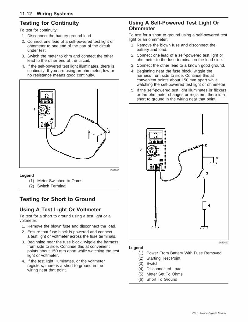
Testing for ContinuityTo test for continuity:
1. Disconnect the battery ground lead.2. Connect one lead of a self-powered test light or
ohmmeter to one end of the part of the circuitunder test.
3. Switch the meter to ohm and connect the otherlead to the other end of the circuit.
4. If the self-powered test light illuminates, there iscontinuity. If you are using an ohmmeter, low orno resistance means good continuity.
Legend(1) Meter Switched to Ohms(2) Switch Terminal
Testing for Short to Ground
Using A Test Light Or VoltmeterTo test for a short to ground using a test light or avoltmeter:
1. Remove the blown fuse and disconnect the load.2. Ensure that fuse block is powered and connect
a test light or voltmeter across the fuse terminals.3. Beginning near the fuse block, wiggle the harness
from side to side. Continue this at convenientpoints about 150 mm apart while watching the testlight or voltmeter.
4. If the test light illuminates, or the voltmeterregisters, there is a short to ground in thewiring near that point.
Using A Self-Powered Test Light OrOhmmeterTo test for a short to ground using a self-powered testlight or an ohmmeter:
1. Remove the blown fuse and disconnect thebattery and load.
2. Connect one lead of a self-powered test light orohmmeter to the fuse terminal on the load side.
3. Connect the other lead to a known good ground.4. Beginning near the fuse block, wiggle the
harness from side to side. Continue this atconvenient points about 150 mm apart whilewatching the self-powered test light or ohmmeter.
5. If the self-powered test light illuminates or flickers,or the ohmmeter changes or registers, there is ashort to ground in the wiring near that point.
Legend(1) Power From Battery With Fuse Removed(2) Starting Test Point(3) Switch(4) Disconnected Load(5) Meter Set To Ohms(6) Short To Ground
1683688
1683692
11-12 Wiring Systems
2011 - Marine Engines Manual

Using A Short FinderA short finder is a device used for locating hiddenshorts. These create a magnetic field in the shortedcircuit and allow you to read its location throughbody trim or sheet metal.
Using A CompassAn ordinary magnetic compass may be used to locategrounded circuits. It makes use of the fact that awire carrying current creates a magnetic field.In circuits that are protected by a circuit breaker, ashort or ground can be quickly located by use ofan ordinary magnetic compass. Turn the circuit breakeron and off and start following the wiring with thecompass, the compass will ’kick’ each time the circuitbreaker closes. As the compass passes the pointof the short or ground, the compass will stop ’kicking’.Thus, the compass can pinpoint the problem withoutremoving trim, cover plates or tape. If the circuitis fused, the problem can be found in the samemanner by substituting a circuit breaker for the fuse.
Using A Circuit BreakerBy using a circuit breaker as a substitute for a fuse,other tools can be more effectively used to findtroubles. A turn signal flasher makes a convenientcircuit breaker. Solder a lead to each terminal of theturn signal flasher, and each lead with a terminal froman old fuse. If this unit is inserted in the junctionblock in place of a fuse, it may operate too fast toproduce good compass needle deflection. To slow itdown, insert a rheostat in series with the flasher.By cutting in additional resistance, the flashing rate ofthe unit may be slowed down to produce goodcompass needle deflection.
Testing for a Short to VoltageCaution: Refer to Test Probe Caution on page 0-6.The following procedure tests for a short to voltage ina circuit.
1. Set the rotary dial of the DMM to the V (DC)position.
2. Connect the positive lead of the DMM to one endof the circuit to be tested.
3. Connect the negative lead of the DMM to a goodground.
4. Turn ON the ignition and operate all accessories.5. If the voltage measured is greater than 1 V,
there is a short to voltage in the circuit.
Testing for Intermittent Conditionsand Poor ConnectionsIntermittent and Poor ConnectionsMost intermittents are caused by faulty electricalconnections or wiring. Occasionally a sticking relay orsolenoid can also cause an intermittent failure.
Some items to check are:• Poor mating of connector halves, or terminals not
fully seated in the connector body (backed out).• Dirt or corrosion on the terminals.• The terminals must be clean and free of any
foreign material which could impede properterminal contact.
• Damaged connector body.• Exposure of terminals to moisture and dirt causing
improper terminal orientation with the componentor mating connector.
• Improperly formed or damaged terminals.• Check all connector terminals in problem circuits
in order to ensure good contact tension. Use acorresponding mating terminal to check for propertension. Refer to Checking Terminal Contact inthis section for the specific procedure.
• Poor terminal to wire connection.• Some conditions which fall under this description
are poor crimps, poor solder joints, crimpingover wire insulation rather than the wire itself,corrosion in the wire to terminal contact area, etc.
• Wire insulation which is rubbed through.• This causes an intermittent short as the bare area
touches other wiring or parts of the vehicle.• Wiring broken inside the insulation.• This condition could cause a continuity check to
show a good circuit, but if only one or two strandsof a multi-strand type wire are intact, resistancecould be far too high.
To avoid any of the above problems when makingwiring or terminal repairs, always follow the instructionsfor wiring and terminal repair detailed in WiringRepairs and Connector Repairs.
Checking Terminal ContactWhen diagnosing an electrical system that utilizesMetri-Pack 150/280/480/630 series terminals (refer tothe J 38125-A Terminal Repair Kit or the J 38125-4Instruction Manual for terminal identification), itis important to check terminal contact between aconnector and component, or between in-lineconnectors, before replacing a suspect component.When diagnosing an electrical system that utilizesMetri-Pak.Frequently, a diagnostic chart leads to a step thatreads: Check for poor connection. Mating terminalsmust be inspected to assure good terminal contact.A poor connection between the male and femaleterminal at a connector may be the result ofcontamination or deformation.Contamination is caused by the connector halvesbeing improperly connected, a missing or damagedconnector seal, or damage to the connector itself,exposing the terminals to moisture and dirt.Contamination, usually in underhood or underbodyconnectors, leads to terminal corrosion, causingan open circuit or intermittently open circuit.
Wiring Systems 11-13
2011 - Marine Engines Manual

Deformation is caused by probing the mating side ofa connector terminal without the proper adapter,improperly joining the connector halves or repeatedlyseparating and joining the connector halves.Deformation, usually to the female terminal contacttang, can result in poor terminal contact, causingan open or intermittently open circuit.Follow the procedure below to check terminal contact.
1. Separate the connector halves. Refer tothe J 38125-A Terminal Repair Kit or theJ 38125-4 instruction manual.
2. Inspect the connector halves for contamination.Contamination will result in a white or greenbuild- up within the connector body or betweenterminals, causing high terminal resistance,intermittent contact, or an open circuit. Anunderhood or underbody connector that showssigns of contamination should be replaced in itsentirety: terminals, seals, and connector body.
3. Using an equivalent male terminal from theJ 38125-A Terminal Repair Kit, check the retentionforce is significantly different between the twofemale terminals, replace the female terminalin question (refer to the J 38125-A TerminalRepair Kit.
If a visual (physical) check does not reveal the causeof the problem, you may have the vehicle with aDMM connected to the suspected circuit. An abnormalvoltage reading when the problem occurs indicatesthe problem may be in that circuit.
Inducing Intermittent FaultConditionsIn order to duplicate the customer’s concern, it may benecessary to manipulate the wiring harness if themalfunction appears to be vibration related.Manipulation of a circuit can consist of a wide varietyof actions, including:
• Wiggling the harness• Disconnecting a connector and reconnecting• Stressing the mechanical connection of a
connector• Pulling on the harness or wire in order to identify
a separation/break inside the insulation• Relocating a harness or wires
All these actions should be performed with some goal inmind. For instance, with a scan tool connected, wigglingthe wires may uncover a faulty input to the controlmodule. The snapshot option would be appropriatehere. You may need to load the vehicle in order toduplicate the concern. This may require the use ofweights, floorjacks, jackstands, frame machines, etc.In these cases you are attempting to duplicate theconcern by manipulating the suspension or frame.This method is useful in finding harnesses that are tooshort and their connectors pull apart enough to cause apoor connection. A DMM set to Peak Min/Max modeand connected to the suspect circuit while testing canyield desirable results. Refer to Testing for ElectricalIntermittents on page 11-15.
Certainly, using the senses of sight, smell, andhearing while manipulating the circuit can providegood results as well.There may be instances where circuit manipulationalone will not meet the required criteria for thefault condition to appear. In such cases it may benecessary to expose the suspect circuit to otherconditions while manipulating the harness. Suchconditions would include high moisture conditions,along with exceptionally high or low temperatures.The following discusses how to expose the circuit tothese kinds of conditions.
Salt Water SpraySome compounds possess the ability to conductelectricity when dissolved in water such as ordinarysalt. By mixing table salt with water in sufficientquantities, you can enhance the conductive propertiesof water so that any circuit which may be sensitiveto moisture will more readily fail when liberally sprayedwith this mixture.Mixing 0.35L (12 oz) of water with approximately1 tablespoon of salt will yield a salt solution of5 percent. Fill a normal spray bottle with this mixture.This mixture is sufficient to enhance the water’sown conductivity. This may cause the circuit to failmore easily when sprayed. Once the mixture iscompleted, spray the suspect area liberally with thesolution. Then, while monitoring either a scan toolor DMM, manipulate the harness as discussedpreviously.
High Temperature ConditionsTools RequiredJ 25070 Heat GunIf the complaint tends to be heat related, you cansimulate the condition using the J 25070.Using the heat gun, you can heat up the suspectedarea or component. Manipulate the harnessesunder high temperature conditions while monitoringthe scan tool or DMM to locate the fault condition.The high temperature condition may be achievedsimply by test driving the vehicle at normal operatingtemperature. If a heat gun is unavailable, considerthis option to enhance your diagnosis. This option doesnot allow for the same control, however.
Low Temperature ConditionsDepending on the nature of the fault condition, placinga fan in front of the vehicle while the vehicle is inthe shade can have the desired effect.If this is unsuccessful, use local cooling treatmentssuch as ice or a venturi type nozzle (one that provideshot or cold air). This type of tool is capable ofproducing air stream temperatures down to –18°C(0°F) from one end and 71°C (160°F) from the other.This is ideally suited for localized cooling needs.Once the vehicle, component, or harness has beensufficiently cooled, manipulate the harness orcomponents in an effort to duplicate the concern.
11-14 Wiring Systems
2011 - Marine Engines Manual

Testing for Electrical IntermittentsSpecial ToolsJ-39200 Digital MultimeterPerform the following procedures while wiggling theharness from side to side. Continue this at convenientpoints (about 6 inches apart) while watching thetest equipment.
• Testing for Short to Ground on page 11-12• Testing for Continuity on page 11-12• Testing for a Short to Voltage on page 11-13
If the fault is not identified, perform the procedure belowusing the MIN MAX feature on the J-39200 DMM. Thisfeature allows you to manipulate the circuit withouthaving to watch the J-39200. The J-39200 will generatean audible tone when a change is detected.
Note: The J-39200 should be used in order to performthe following procedure since the J-39200 canmonitor current, resistance or voltage while recordingthe minimum (MIN), and maximum (MAX) valuesmeasured.
1. Connect the J-39200 to both sides of a suspectedconnector (still connected), or from one end of asuspected circuit to the other. Refer toTroubleshooting with a Digital Multimeter onpage 11-8 for information on connectingthe J-39200 to the circuit.
2. Set the rotary dial of the J-39200 to the V (AC) orV (DC) position.
3. Press the range button of the J-39200 in order toselect the desired voltage range.
4. Press the MIN MAX button of the J-39200.The J-39200 displays 100 ms RECORD and emitsan audible tone (beep).
Note: The 100 ms RECORD mode is the length oftime an input must stay at a new value in orderto record the full change.
5. Simulate the condition that is potentially causingthe intermittent connection, either by wiggling theconnections or the wiring, test driving, orperforming other operations. Refer to InducingIntermittent Fault Conditions on page 11-14.
6. Listen for the audible Min Max Alert whichindicates that a new minimum or maximum valuehas been recorded.
7. Press the MIN MAX button once in order todisplay the MAX value and note the value.
8. Press the MIN MAX button again in order todisplay the MIN value and note the value.
9. Determine the difference between the MIN andMAX values.• If the variation between the recorded MIN and
MAX voltage values is 1 V or greater anintermittent open or high resistance conditionexists. Repair the condition as necessary.
• If the variation between the recorded MIN andMAX voltage values is less than 1 V, anintermittent open or high resistance conditiondoes not exist.
Circuit Protection - Fuses
The fuse is the most common method of an automotivewiring circuit protection. Whenever there is anexcessive amount of current flowing through a circuitthe fusible element will melt and create an openor incomplete circuit. Fuses are an one time protectiondevice and must be replaced each time the circuit isoverloaded. To determine if a fuse is open, remove thesuspected fuse and examine the element in the fusefor an open (break). If not broken, also check forcontinuity using a DMM or a continuity tester. If theelement is open or continuity is suspect, replacethe fuse with one of equal current rating.
Fuse TypesCurrent Rating Amperes Color
Auto Fuses, Mini Fuses
2 Gray
3 Violet
5 Tan
7.5 Brown
10 Red
15 Blue
20 Yellow
25 White or Natural
30 Green
Maxi Fuses
20 Yellow
30 Light Green
40 Orange or Amber
60 Blue
50 Red
8786
Wiring Systems 11-15
2011 - Marine Engines Manual
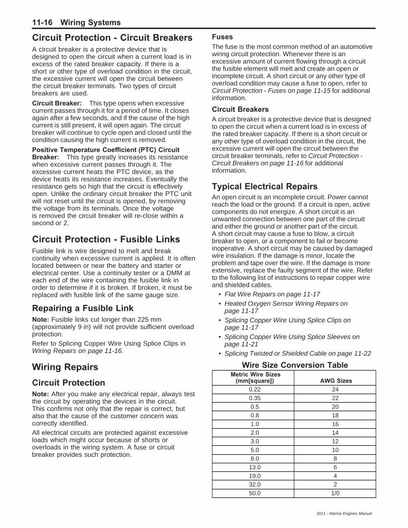
Circuit Protection - Circuit BreakersA circuit breaker is a protective device that isdesigned to open the circuit when a current load is inexcess of the rated breaker capacity. If there is ashort or other type of overload condition in the circuit,the excessive current will open the circuit betweenthe circuit breaker terminals. Two types of circuitbreakers are used.
Circuit Breaker: This type opens when excessivecurrent passes through it for a period of time. It closesagain after a few seconds, and if the cause of the highcurrent is still present, it will open again. The circuitbreaker will continue to cycle open and closed until thecondition causing the high current is removed.
Positive Temperature Coefficient (PTC) CircuitBreaker: This type greatly increases its resistancewhen excessive current passes through it. Theexcessive current heats the PTC device, as thedevice heats its resistance increases. Eventually theresistance gets so high that the circuit is effectivelyopen. Unlike the ordinary circuit breaker the PTC unitwill not reset until the circuit is opened, by removingthe voltage from its terminals. Once the voltageis removed the circuit breaker will re-close within asecond or 2.
Circuit Protection - Fusible LinksFusible link is wire designed to melt and breakcontinuity when excessive current is applied. It is oftenlocated between or near the battery and starter orelectrical center. Use a continuity tester or a DMM ateach end of the wire containing the fusible link inorder to determine if it is broken. If broken, it must bereplaced with fusible link of the same gauge size.
Repairing a Fusible LinkNote: Fusible links cut longer than 225 mm(approximately 9 in) will not provide sufficient overloadprotection.Refer to Splicing Copper Wire Using Splice Clips inWiring Repairs on page 11-16.
Wiring RepairsCircuit ProtectionNote: After you make any electrical repair, always testthe circuit by operating the devices in the circuit.This confirms not only that the repair is correct, butalso that the cause of the customer concern wascorrectly identified.All electrical circuits are protected against excessiveloads which might occur because of shorts oroverloads in the wiring system. A fuse or circuitbreaker provides such protection.
FusesThe fuse is the most common method of an automotivewiring circuit protection. Whenever there is anexcessive amount of current flowing through a circuitthe fusible element will melt and create an open orincomplete circuit. A short circuit or any other type ofoverload condition may cause a fuse to open, refer toCircuit Protection - Fuses on page 11-15 for additionalinformation.
Circuit BreakersA circuit breaker is a protective device that is designedto open the circuit when a current load is in excess ofthe rated breaker capacity. If there is a short circuit orany other type of overload condition in the circuit, theexcessive current will open the circuit between thecircuit breaker terminals, refer to Circuit Protection -Circuit Breakers on page 11-16 for additionalinformation.
Typical Electrical RepairsAn open circuit is an incomplete circuit. Power cannotreach the load or the ground. If a circuit is open, activecomponents do not energize. A short circuit is anunwanted connection between one part of the circuitand either the ground or another part of the circuit.A short circuit may cause a fuse to blow, a circuitbreaker to open, or a component to fail or becomeinoperative. A short circuit may be caused by damagedwire insulation. If the damage is minor, locate theproblem and tape over the wire. If the damage is moreextensive, replace the faulty segment of the wire. Referto the following list of instructions to repair copper wireand shielded cables.
• Flat Wire Repairs on page 11-17• Heated Oxygen Sensor Wiring Repairs on
page 11-17• Splicing Copper Wire Using Splice Clips on
page 11-17• Splicing Copper Wire Using Splice Sleeves on
page 11-21• Splicing Twisted or Shielded Cable on page 11-22
Wire Size Conversion TableMetric Wire Sizes
(mm[square]) AWG Sizes0.22 240.35 220.5 200.8 181.0 162.0 143.0 125.0 108.0 8
13.0 619.0 432.0 250.0 1/0
11-16 Wiring Systems
2011 - Marine Engines Manual
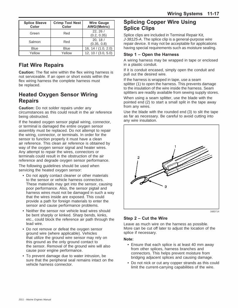
Splice SleeveColor
Crimp Tool NestColor
Wire GaugeAWG/(Metric)
Green Red 22, 26 /(0.2, 0.35)
Salmon Red 20, 18 /(0.35, 0.8)
Blue Blue 16, 14 / (1.0, 2.0)Yellow Yellow 12, 10 / (3.0, 5.0)
Flat Wire RepairsCaution: The flat wire within the flex wiring harness isnot serviceable. If an open or short exists within theflex wiring harness the complete harness mustbe replaced.
Heated Oxygen Sensor WiringRepairsCaution: Do not solder repairs under anycircumstances as this could result in the air referencebeing obstructed.If the heated oxygen sensor pigtail wiring, connector,or terminal is damaged the entire oxygen sensorassembly must be replaced. Do not attempt to repairthe wiring, connector, or terminals. In order for thesensor to function properly it must have a cleanair reference. This clean air reference is obtained byway of the oxygen sensor signal and heater wires.Any attempt to repair the wires, connectors orterminals could result in the obstruction of the airreference and degrade oxygen sensor performance.The following guidelines should be used whenservicing the heated oxygen sensor:
• Do not apply contact cleaner or other materialsto the sensor or vehicle harness connectors.These materials may get into the sensor, causingpoor performance. Also, the sensor pigtail andharness wires must not be damaged in such a waythat the wires inside are exposed. This couldprovide a path for foreign materials to enter thesensor and cause performance problems.
• Neither the sensor nor vehicle lead wires shouldbe bent sharply or kinked. Sharp bends, kinks,etc., could block the reference air path through thelead wire.
• Do not remove or defeat the oxygen sensorground wire (where applicable). Vehiclesthat utilize the ground wire sensor may rely onthis ground as the only ground contact tothe sensor. Removal of the ground wire will alsocause poor engine performance.
• To prevent damage due to water intrusion, besure that the peripheral seal remains intact on thevehicle harness connector.
Splicing Copper Wire UsingSplice ClipsSplice clips are included in Terminal Repair Kit,J-38125-A. The splice clip is a general-purpose wirerepair device. It may not be acceptable for applicationshaving special requirements such as moisture sealing.
Step 1 – Open the HarnessA wiring harness may be wrapped in tape or enclosedin a plastic conduit.If it is conduit encased, simply open the conduit andpull out the desired wire.If the harness is wrapped in tape, use a seamsplitter (1) to open the harness. This prevents damageto the insulation of the wire inside the harness. Seamsplitters are readily available from sewing supply stores.When using a seam splitter, use the blade with thepointed end (2) to start a small split in the tape awayfrom any wires.Use the blade with the rounded end (3) to slit the tapeas far as necessary. Be careful to avoid cutting intoany wire insulation.
Step 2 – Cut the WireLeave as much wire on the harness as possible.More can be cut off later to adjust the location of thesplice if necessary.
Note:• Ensure that each splice is at least 40 mm away
from other splices, harness branches andconnectors. This helps prevent moisture frombridging adjacent splices and causing damage.
• Do not nick or cut any copper strands as this couldlimit the current-carrying capabilities of the wire.
1683714
Wiring Systems 11-17
2011 - Marine Engines Manual
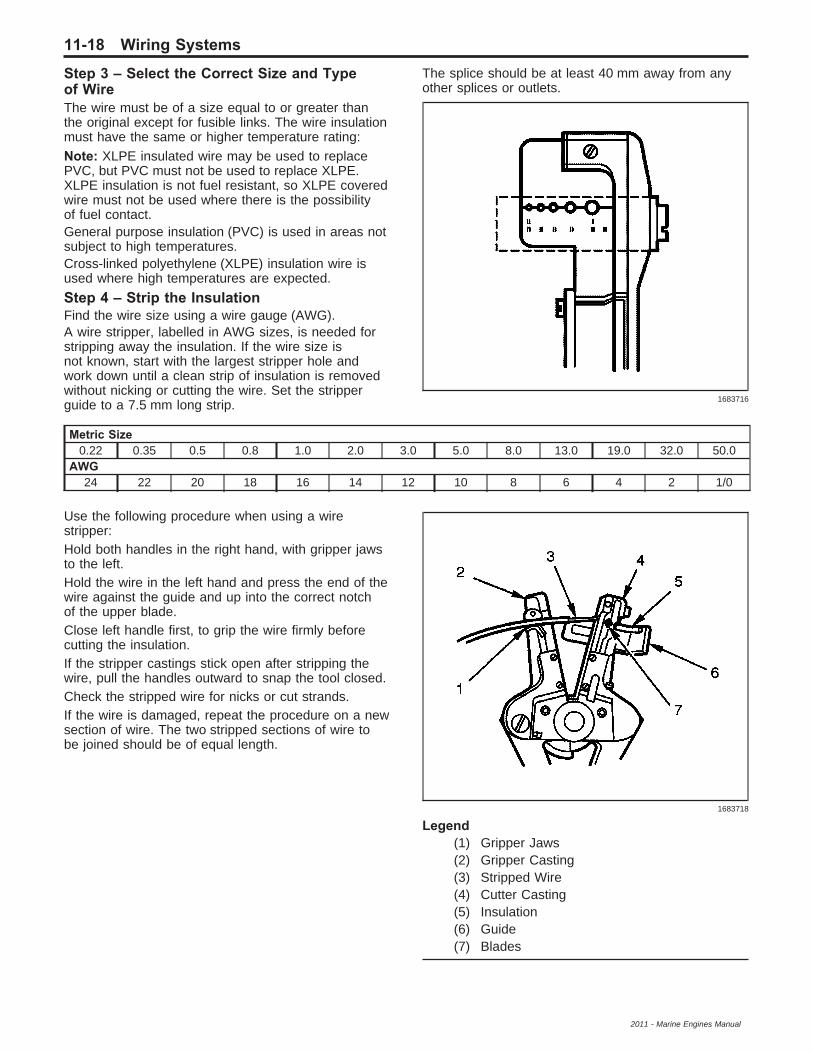
Step 3 – Select the Correct Size and Typeof WireThe wire must be of a size equal to or greater thanthe original except for fusible links. The wire insulationmust have the same or higher temperature rating:
Note: XLPE insulated wire may be used to replacePVC, but PVC must not be used to replace XLPE.XLPE insulation is not fuel resistant, so XLPE coveredwire must not be used where there is the possibilityof fuel contact.General purpose insulation (PVC) is used in areas notsubject to high temperatures.Cross-linked polyethylene (XLPE) insulation wire isused where high temperatures are expected.
Step 4 – Strip the InsulationFind the wire size using a wire gauge (AWG).A wire stripper, labelled in AWG sizes, is needed forstripping away the insulation. If the wire size isnot known, start with the largest stripper hole andwork down until a clean strip of insulation is removedwithout nicking or cutting the wire. Set the stripperguide to a 7.5 mm long strip.
The splice should be at least 40 mm away from anyother splices or outlets.
Metric Size0.22 0.35 0.5 0.8 1.0 2.0 3.0 5.0 8.0 13.0 19.0 32.0 50.0
AWG24 22 20 18 16 14 12 10 8 6 4 2 1/0
Use the following procedure when using a wirestripper:Hold both handles in the right hand, with gripper jawsto the left.Hold the wire in the left hand and press the end of thewire against the guide and up into the correct notchof the upper blade.Close left handle first, to grip the wire firmly beforecutting the insulation.If the stripper castings stick open after stripping thewire, pull the handles outward to snap the tool closed.Check the stripped wire for nicks or cut strands.If the wire is damaged, repeat the procedure on a newsection of wire. The two stripped sections of wire tobe joined should be of equal length.
Legend(1) Gripper Jaws(2) Gripper Casting(3) Stripped Wire(4) Cutter Casting(5) Insulation(6) Guide(7) Blades
1683716
1683718
11-18 Wiring Systems
2011 - Marine Engines Manual

Step 5 – Crimping the Joint1. Select the correct sized clip.2. Unlock the crimping tool.3. Slightly close the clip using the nose of the
crimping tool as shown in the following illustration.
Legend(1) Nose(2) Former(3) Small Anvil(4) Lock(5) Former(6) Large Anvil(7) Clip
4. Select the correct crimper anvil.5. Overlap the two stripped wire ends (1) and hold
them between the thumb and forefinger asshown in the following illustration.
6. Centre the splice clip (2) under the stripped wiresand hold in place as shown.• Ensure that the wires extend beyond the clip in
each direction.• Ensure no insulation is caught under the clip.• Strands of wire are not cut or loose.
7. Fully open the crimping tool and rest one handleon a firm, flat surface.
8. Centre the back of the splice clip on the properanvil (2) and close the crimping tool to the pointwhere the former touches the wings of the clip (1).
9. Verify the clip and wires are still in the correctposition before closing the crimping tool withsteady pressure.
1683721
1683723
1683724
Wiring Systems 11-19
2011 - Marine Engines Manual

10. Crimp the splice clip a second and third time,once at each end (1). Do not let the crimpingtool extend beyond the edge of the clip whendoing so.
Step 6 – SolderApply 50/50 resin core solder to the hole in the backof the clip as shown in the following illustration.
Ensure there are none of the faults shown in thefollowing illustration.
Legend(1) Poor Solder Application With Bad Solder
Fillets(2) Excessive Burning Which Cannot Be
Covered With 50 mm Splice Tape(3) Insulation Clamped Under The Clip(4) Sharp Solder Spikes(5) Wires Not Fully Inserted Into The Clip(6) Tape Width Less Than 50 mm
Step 7 – Tape the SpliceCentre and roll a 50 mm x 50 mm piece of tapearound the splice joint.If the wire is not in conduit or another harnesscovering, tape it again using a winding motion, entirelyoverlapping the first piece.
Legend1. Example Of Properly Rolled Tape2. Tape Again If Needed3. Example Of Bad (Flagged) Taping
1683725
1683727
1683729
11-20 Wiring Systems
2011 - Marine Engines Manual

Splicing Copper Wire Using SpliceSleevesTools RequiredJ-38125 Terminal Repair Kit
Note: Use only GM splice sleeves, other splicesleeves may not protect the splice from moisture orprovide a good electrical connection.Use crimp and seal splice sleeves to form a one-to-onesplice on all types of insulation except tefzel and coaxialto form a one-to-one splice. Use tefzel and coaxialwhere there is special requirements such as moisturesealing. Follow the instructions below in order to splicecopper wire using crimp and seal splice sleeves.
1. Open the harness.• If the harness is taped, remove the tape.• To avoid wiring insulation damage, use
a sewing ripper in order to cut open theharness.
• If the harness has a black plastic conduit, pullout the desired wire.
2. Cut the wire.• Cut as little wire off the harness as possible.• Ensure that each splice is at least 40 mm
(1.5 in) away from other splices, harnessbranches and connectors. This helps preventmoisture from bridging adjacent splicesand causing damage.
3. Select the proper size and type of wire.• The wire must be of equal or greater size than
the original.• The wire’s insulation must have the same or
higher temperature rating (4).− Use general purpose insulation for areas
that are not subject to high temperatures.
Note:• Use cross-linked polyethylene wire to replace
PVC, but do not replace cross-linked polyethylenewith PVC.
• Cross-linked polyethylene wire is not fuel resistant.Do not use to replace wire where there is thepossibility of fuel contact.
− Use a cross-linked polyethylene insulatedwire for areas where high temperaturesare expected.
4. Strip the insulation.• Select the correct size opening in the wire
stripper or work down from the largest size.• Strip approximately 7.5 mm (5/16 in) of
insulation from each wire to be spliced (1).5. Select the proper splice sleeve (2) and the
required crimp nest tool, refer to the Crimpand Seal Splice Table.
6. Place the nest tool in the J-38125 crimp tool.7. Place the splice sleeve in the crimp tool nest so
that the crimp falls at point 1 on the splice.8. Close the hand crimper handles slightly in order
to hold the splice sleeve firmly in the proper crimptool nest.
9. Insert the wires into the splice sleeve until thewire hits the barrel stop. The splice sleeve hasa stop in the middle of the barrel in order toprevent the wire from passing through thesplice (3).
10. Close the handles of the J-38125 until the crimperhandles open when released. The crimperhandles will not open until the proper amount ofpressure is applied to the splice sleeve.
11. Shrink the insulation around the splice.• Using the heat torch apply heat to the crimped
area of the barrel.• Gradually move the heat barrel to the open
end of the tubing.− The tubing will shrink completely as the
heat is moved along the insulation.− A small amount of sealant will come out of
the end of the tubing when sufficientshrinkage is achieved.
8796
Wiring Systems 11-21
2011 - Marine Engines Manual

Splicing Twisted or Shielded CableTwisted or shielded cable is used to protect wiring fromelectrical noise. Two-conductor cable is usedbetween the radio and the Delco-Bose® speakeramplifier units and other applications where low level,sensitive signals must be carried.
Step 1 – Strip the Cable1. Remove the outer jacket (1). Use care not to cut
into the drain wire (2) of the mylar tape (3).
2. Unwrap the mylar tape. Do not remove the tapebecause it will be used to re-wrap the conductorsafter the splice has been made.
Step 2 – Prepare the Splice1. Straighten the conductors and stagger the splices
by 65 mm.
2. Follow the instructions for splicing copper wire.
Step 3 – Reassemble the Cable1. Re-wrap the conductors with the mylar tape,
taking care not to wrap the drain wire (1) inthe tape.
Note: Apply the mylar tape with the aluminum sideinward to ensure good electrical connection.
2. Follow the instructions for splicing copper wireand splice the drain wire.
3. Wrap the drain wire around the conductors andtape with mylar tape.
Step 4 – Tape the JointTape over the entire cable using a winding motionwhile applying the tape.
Connector RepairsThe following general terminal removal procedurescan be used on most types of connectors. The removalprocedures are divided into three general groups;Push to-Seat, Pull-to-Seat and Weather Pack®.
1683739
1683740
1683742
1683745
11-22 Wiring Systems
2011 - Marine Engines Manual

Push to Seat ConnectorsPush-to-Seat connectors are those which have theterminal inserted in the rear of the connector bodywhen assembled.
Legend(1) Connector Body(2) Terminal(3) Locking Tang(4) Insertion Direction
Pull-to-Seat ConnectorsPull-to-Seat connectors, refer to the followingillustration, have the terminal inserted in the front ofthe connector body when assembled.Use the proper pick(s) or tool(s) that apply to theappropriate terminal and connector.
Legend(1) Connector Body(2) Terminal
(3) Locking Tang(4) Insertion Direction
Repairing Push-To-Seat And Pull-To-SeatConnectorsThe following steps will enable repair of Push to Seator Pull to Seat type connectors. The steps areillustrated with typical connectors. A specific connectormay differ, but the repair steps are similar. Someconnectors do not require all the steps shown.To repair a connector:
1. Lift up the connector body retaining tangs (1) andpull mating connector bodies (2) apart, ordisconnect the connector from the component.
Note: The anti-backout combs must be removed priorto terminal removal and must be replaced when theterminal is repaired and re-seated.
2. Remove any anti-backout combs that may befitted to the connector.Anti-backout combs are designed to keep theterminal from backing out of the connector.
1683755
1683756
1683757
Wiring Systems 11-23
2011 - Marine Engines Manual

Note: A secondary lock aids in terminal retention andis usually moulded as part of the connector body.
3. If fitted, open any connector secondary locks (1).4. Grasp the lead and push the terminal (1) to
the forward most position in the connectorbody (2). Hold the lead at this position.
5. Locate the terminal lock tang (3) in theconnector canal.
6. Insert the proper size pick (4) (refer toTerminal Repair Kit J-38125-A ) straight into theconnector canal at the mating end of theconnector.
7. Depress the locking tang to unseat the terminal.8. For push-to-seat connectors, gently pull on
the leas to remove the terminal through theback of the connector.
Note: Never use force to remove a terminal from aconnector.
9. For pull-to-seat connectors, gently push on thelead to remove the terminal through the front ofthe connector.
10. Inspect terminal and connector for damage.11. Repair or replace parts as necessary.
Refer to Parts Information for availability ofterminal/pigtail or connector body assemblies thatare serviced separately.
12. Reform lock tang (1) using a wide pick (2) andre-seat terminal in connector body.
13. Reinstall any anti-backout combs and join theconnector bodies.
Connector Position AssuranceLocksThe Connector Position Assurance (CPA) is a smallplastic insert that fits through the locking tabs ofelectrical harness connectors. The CPA ensures thatthe connector halves cannot vibrate apart. You musthave the CPA in place in order to ensure good contactbetween the mating terminals.
Terminal Position Assurance LocksThe terminal position assurance (TPA) insertresembles the plastic combs used in the controlmodule connectors. The TPA keeps the terminalsecurely seated in the connector body. Do not removethe TPA from the connector body unless you removea terminal for replacement.
1683758
1683760
11-24 Wiring Systems
2011 - Marine Engines Manual

Push to Seat Connectors
Terminal RemovalFollow the steps below in order to repair push to seatconnectors.
1. Remove the terminal position assurance (TPA)device, the connector position assurance (CPA)device, and/or the secondary lock.
2. Separate the connector halves (1).
3. Use the proper pick or removal tool (1) in order torelease the terminal.
4. Gently pull the cable and the terminal (2) out ofthe back of the connector.
5. Re-form the locking device if you are going toreuse the terminal (1).
6. To repair the terminal, refer to Terminal Repair.
Terminal Repair1. Slip the cable seal away from the terminal.2. Cut the wire as close to the terminal as possible.3. Slip a new cable seal onto the wire.4. Strip 5 mm (3/16 in) of insulation from the wire.5. Crimp a new terminal to the wire.6. Solder the crimp with rosin core solder.7. Slide the cable seal toward the terminal.8. Crimp the cable seal and the insulation.9. If the connector is outside of the passenger
compartment, apply grease to the connector.
Reinstalling Terminal1. In order to reuse a terminal or lead assembly,
refer to Wiring Repairs on page 11-16.2. Ensure that the cable seal is kept on the
terminal side of the splice.3. Insert the lead from the back until it catches.4. Install the TPA, CPA, and/or the secondary locks.
8802
8803
8804
Wiring Systems 11-25
2011 - Marine Engines Manual

Pull to Seat Connectors
Terminal RemovalIf the terminal is visibly damaged or is suspected ofhaving a faulty connection, the terminal shouldbe replaced.Follow the steps below in order to repair pull-to-seatconnectors:
1. Remove the connector position assurance (CPA)device and/or the secondary lock.
2. Disconnect the connector from the component orseparate the connectors for in-line connectors.
3. Remove the terminal position assurance (TPA)device.
4. Insert the proper pick or removal tool into the frontof the connector body.
Note: On connectors with more than one terminal theservice loop may not be large enough to removethe terminal and crimp on a new one. If theterminal wire does not have a large enough serviceloop for removal, cut the wire 5 cm (2 in) behindthe connector before removal.
5. Grasp the wire at the back of the connector bodyand gently push the terminal (1) out the front ofthe connector body (3).
Terminal Repair1. If the wire needed to be cut in order to remove
the terminal, gently push a small length of thesame size wire through the back of the connectorcavity until there is enough wire exposed inorder to crimp on a new terminal. If the wire wasnot cut, cut the existing wire as close to theold terminal as possible.
2. Strip 5 mm (3/16 in) of insulation from the wire.3. Crimp a new terminal to the wire.4. Solder the crimp with rosin core solder.
Terminal Installation1. Align the terminal and pull the wire from the back
of the connector in order to seat the terminal.2. If necessary, cut the new wire to proper length
and splice with existing circuit. Refer to SplicingCopper Wire Using Splice Sleeves, in WiringRepairs on page 11-16.
3. If the connector is outside of the passengercompartment, apply dielectric grease to theconnector.
4. Install the TPA, CPA and/or the secondary locks.
Weather Pack ConnectorsWeather Pack® ConnectorsTo remove Weather Pack® terminals:
1. Lift up the connector body retaining tangs and pullthe mating connector bodies apart, or disconnectthe connector from the component.
Note:• Anti-backout combs are designed to keep the
terminal from backing out of the connector.• The anti-backout combs must be removed before
terminal removal and must be replaced when theterminal is repaired and re-seated.
2. If fitted, open secondary lock (1) or remove theanti-backout comb.
3. Grasp the lead and push the terminal to theforward most position. Hold the lead at thisposition.
4. Insert the Weather Pack® terminal removal tool (1)into the front (mating end) of the connector cavityuntil it rests on the cavity shoulder.
904718
1683758
11-26 Wiring Systems
2011 - Marine Engines Manual

Note: Never use force to remove a terminal from aconnector.
5. Gently pull on the lead (2) to remove theterminal through the back of the connector.
6. Inspect the terminal and connector for damage.7. Repair or replace parts as necessary. Refer
to Parts Information for availability ofterminal/pigtail or connector body assemblies thatare serviced separately.
8. Use the Weather Pack® pick (1) to reform themale lock tang (2) or the female lock tang (3).
9. Re-seat the terminal in the connector body.
10. Close the secondary lock and reinstall theconnector to the component or mating connector.
Repairing Connector TerminalsTools RequiredJ-38125 Terminal Repair KitUse the following repair procedures in order to repairthe following:
• Push to Seat terminals• Pull to Seat terminals• Weather Pack® terminals
Some terminals do not require all of the steps shown.Skip the steps that do not apply for your immediateterminal repair. The J-38125 contains furtherinformation.
1. Cut off the terminal between the core and theinsulation crimp. Minimize any wire loss.For Weather Pack® terminals, remove the seal.
2. Apply the correct seal per gauge size of the wire.For Weather Pack® terminals, slide the seal backalong the wire in order to enable insulationremoval.
3. Remove the insulation.4. For Weather Pack® terminals only, align the seal
with the end of the cable insulation.5. Position the strip in the terminal.
For Weather Pack® terminals, position the stripand seal in the terminal.
6. Hand crimp the core wings.7. Hand crimp the insulation wings.
For Weather Pack® terminals, hand crimp theinsulation wings around the seal and the cable.
8. Solder all of the hand crimp terminals exceptingMicro-Pack 100 World terminals. SolderingMicro-Pack 100 World terminals may damage theterminal.
1683762
1683763
Wiring Systems 11-27
2011 - Marine Engines Manual

Repair InstructionsRelay Replacement (Fuse Block )Tools RequiredJ 43244 Relay Puller Pliers
Removal Procedure1. Remove the electrical center cover.2. Locate the relay.
Note:• Always note the orientation of the relay.• Ensure that the electrical center is secure, as not
to put added stress on the wires or terminals.
3. Using the J 43244 (1) position the tool onopposing corners of the relay (2).
Notice: Use J43244 to pull the relay straight out fromthe electrical center terminals. The use of pliers ora flat bladed tool could damage the electrical center.
4. Remove the relay (2) from the electrical center.
Installation Procedure
1. Install the relay (2) in the same position asremoved.
2. Install the electrical center cover.
786629
786629
11-28 Wiring Systems
2011 - Marine Engines Manual

Relay Replacement (Harness)
Removal Procedure
1. Locate the relay.2. Remove any fasteners which hold the relay
in place.3. Remove any connector position assurance (CPA)
devices or secondary locks.
Note: Use care when removing a relay in a wiringharness when the relay is secured by fastenersor tape.
4. Separate the relay (1) from the wire harnessconnector (2).
Installation Procedure
1. Connect the relay (1) to the wire harnessconnector (2).
2. Install any connector position assurance (CPA)devices or secondary locks.
3. Install the relay using any fasteners or tape thatoriginally held the relay in place.
791846
791846
Wiring Systems 11-29
2011 - Marine Engines Manual
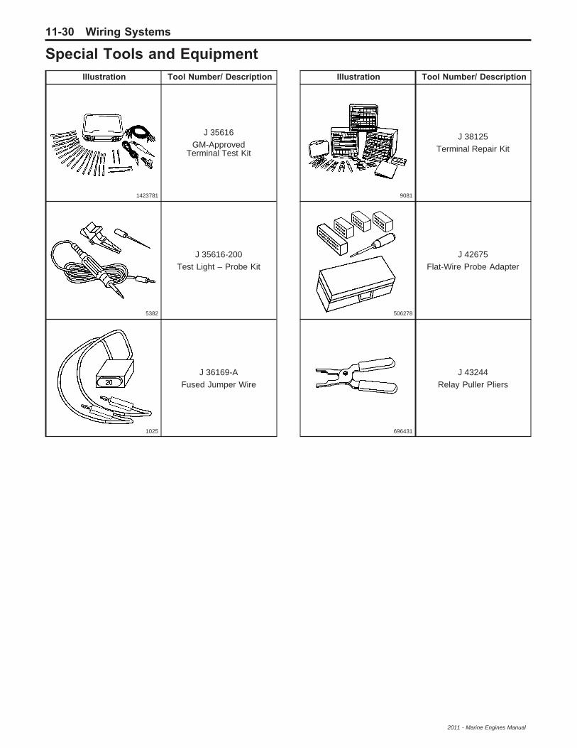
Special Tools and EquipmentIllustration Tool Number/ Description
1423781
J 35616GM-Approved
Terminal Test Kit
5382
J 35616-200Test Light – Probe Kit
1025
J 36169-AFused Jumper Wire
Illustration Tool Number/ Description
9081
J 38125Terminal Repair Kit
506278
J 42675Flat-Wire Probe Adapter
696431
J 43244Relay Puller Pliers
11-30 Wiring Systems
2011 - Marine Engines Manual