MEDINA 9.0.5.0 - Interface - T-Systems
277
MEDINA 9.0.5.0 - Interface
-
Upload
khangminh22 -
Category
Documents
-
view
5 -
download
0
Transcript of MEDINA 9.0.5.0 - Interface - T-Systems

MEDINA 9.0.5.0 - Interface

MEDINA 9.0.5.0 - Interface:
Version 1.0
Publication date Last revised 26.02.2020Copyright © 2020 T-Systems International GmbH

Table of Contents1. Introduction ............................................................................................................ 1
1.1. Calling interfaces with MEDINA Monitor ..................................................... 11.2. Calling interfaces without MEDINA Monitor ................................................ 21.3. Optional program parameters ..................................................................... 4
2. CAD Interfaces ...................................................................................................... 72.1. Overview of CAD Interfaces in MEDINA ..................................................... 72.2. CATIA V5 -> Interface CATIA V5 ................................................................ 8
2.2.1. CATIA V5 - Introduction .................................................................... 82.2.2. BIF Conversion using CATIA Runtime ............................................ 10
2.2.2.1. Integrate CATBIF for CATIA V5 into a CATIA V5Installation ........................................................................................... 112.2.2.2. Specific Parameters for the Conversion using CATIARuntime .............................................................................................. 142.2.2.3. Conversion of Metadata ........................................................ 152.2.2.4. Metadata - conversion of unities ........................................... 152.2.2.5. Which versions are available on which operationsystems? ............................................................................................. 16
2.2.3. BIF Conversion not using CATIA Runtime ...................................... 172.2.3.1. Which versions are available on which operationsystems? ............................................................................................. 18
2.2.4. General parameters for the Conversion .......................................... 192.2.5. Calling CATBIF V5 without MEDINA Monitor .................................. 242.2.6. Conversion of CATIA Product structure to BIF ............................... 262.2.7. Conversion of CATIA Solids and Shells to BIF ............................... 272.2.8. Glossary .......................................................................................... 27
2.3. STEP, VDAFS, IGES, JT and SAT ........................................................... 282.3.1. Introduction ...................................................................................... 282.3.2. STEP-BIF -> Interface STEP to BIF ............................................... 34
2.3.2.1. Mapping table STEP - BIF .................................................... 352.3.2.2. Working with large STEP Models ......................................... 412.3.2.3. Logfile contents and messages ............................................ 412.3.2.4. Control parameters ............................................................... 43
2.3.3. VDAFS-BIF -> Interface VDAFS to BIF .......................................... 452.3.4. IGES-BIF -> Interface IGES to BIF ................................................. 482.3.5. JT-BIF -> Interface JT to BIF .......................................................... 502.3.6. SAT-BIF -> Interface SAT to BIF .................................................... 51
iii

MEDINA 9.0.5.0 - Interface
2.3.7. Glossary .......................................................................................... 532.4. STL -> STL Interface ................................................................................ 57
2.4.1. BIFSTL -> Interface BIF to STL ...................................................... 592.4.2. STLBIF -> Interface STL to BIF ...................................................... 60
2.5. Universal File Interface ............................................................................. 612.5.1. UNI-BIF-BOF -> Interface Universal File to BIF and BOF ............... 612.5.2. BIF-BOF-UNI -> Interface BIF and BOF to Universal File ............... 66
3. Modeling Interfaces ............................................................................................. 683.1. AutoSEA -> Interface to AUTOSEA .......................................................... 68
3.1.1. BIFSEA -> Interface BIF to AUTOSEA ........................................... 683.2. PATRAN -> PATRAN Neutral File Interface .............................................. 70
3.2.1. BIFPAT -> Interface BIF to PATRAN ............................................... 703.2.2. PATBIF -> Interface PATRAN to BIF ............................................... 77
3.3. SYSTUS -> Interface to SYSTUS ............................................................. 864. Solver Interfaces .................................................................................................. 88
4.1. ABAQUS -> Interface to ABAQUS ............................................................ 884.1.1. ABAQUS - Control file .................................................................... 884.1.2. BIFABA-> Interface BIF to ABAQUS .............................................. 89
4.1.2.1. BIFABA - Parameters ........................................................... 894.1.2.2. BIFABA - Additional program parameters ............................. 914.1.2.3. BIFABA - Initial conditions .................................................... 934.1.2.4. BIFABA - Automatic node set detection ................................ 954.1.2.5. BIFABA - Beam Sections ...................................................... 95
4.1.3. ABABIF -> Interface ABAQUS to BIF ............................................. 974.1.3.1. ABABIF - Parameters ........................................................... 974.1.3.2. ABABIF - Search for include files ......................................... 99
4.1.4. BIFABA/ABABIF .............................................................................. 994.1.4.1. ABAQUS - Using properties to define element sets ............. 994.1.4.2. ABAQUS - Using Connection elements (CONN3D) ........... 110
4.1.5. ABABOF -> Interface ABAQUS to BOF ........................................ 1114.1.5.1. ABABOF - FIL Interface ...................................................... 1114.1.5.2. ABABOF - ODB Interface ................................................... 1144.1.5.3. ABABOF - Supported result data for ABABOF/ODB .......... 117
4.2. ANSYS -> Interface to ANSYS ............................................................... 1234.2.1. BIFANS -> Interface BIF to ANSYS .............................................. 1234.2.2. ANSBIF -> Interface ANSYS to BIF .............................................. 1244.2.3. BIFANS/ANSBIF ............................................................................ 1264.2.4. ANSBOF -> Interface ANSYS to BOF .......................................... 129
iv
MEDINA 9.0.5.0 - Interface
4.3. AUTOFORM -> Interface to AUTOFORM ............................................... 1314.3.1. AUTOBOF-> Interface AUTOFORM to BOF ................................. 131
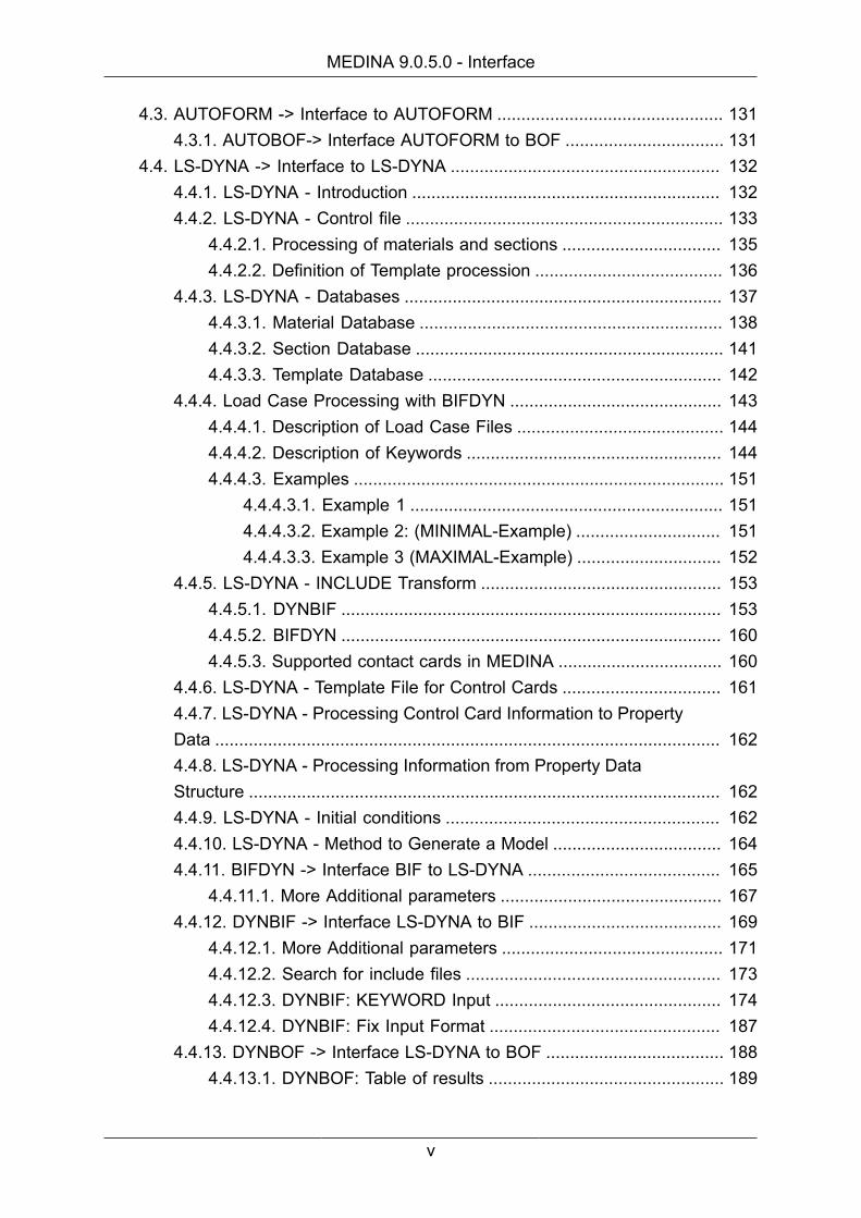
4.4. LS-DYNA -> Interface to LS-DYNA ........................................................ 1324.4.1. LS-DYNA - Introduction ................................................................ 1324.4.2. LS-DYNA - Control file .................................................................. 133
4.4.2.1. Processing of materials and sections ................................. 1354.4.2.2. Definition of Template procession ....................................... 136
4.4.3. LS-DYNA - Databases .................................................................. 1374.4.3.1. Material Database ............................................................... 1384.4.3.2. Section Database ................................................................ 1414.4.3.3. Template Database ............................................................. 142
4.4.4. Load Case Processing with BIFDYN ............................................ 1434.4.4.1. Description of Load Case Files ........................................... 1444.4.4.2. Description of Keywords ..................................................... 1444.4.4.3. Examples ............................................................................. 151
4.4.4.3.1. Example 1 ................................................................. 1514.4.4.3.2. Example 2: (MINIMAL-Example) .............................. 1514.4.4.3.3. Example 3 (MAXIMAL-Example) .............................. 152
4.4.5. LS-DYNA - INCLUDE Transform .................................................. 1534.4.5.1. DYNBIF ............................................................................... 1534.4.5.2. BIFDYN ............................................................................... 1604.4.5.3. Supported contact cards in MEDINA .................................. 160
4.4.6. LS-DYNA - Template File for Control Cards ................................. 1614.4.7. LS-DYNA - Processing Control Card Information to PropertyData ......................................................................................................... 1624.4.8. LS-DYNA - Processing Information from Property DataStructure .................................................................................................. 1624.4.9. LS-DYNA - Initial conditions ......................................................... 1624.4.10. LS-DYNA - Method to Generate a Model ................................... 1644.4.11. BIFDYN -> Interface BIF to LS-DYNA ........................................ 165
4.4.11.1. More Additional parameters .............................................. 1674.4.12. DYNBIF -> Interface LS-DYNA to BIF ........................................ 169
4.4.12.1. More Additional parameters .............................................. 1714.4.12.2. Search for include files ..................................................... 1734.4.12.3. DYNBIF: KEYWORD Input ............................................... 1744.4.12.4. DYNBIF: Fix Input Format ................................................ 187
4.4.13. DYNBOF -> Interface LS-DYNA to BOF ..................................... 1884.4.13.1. DYNBOF: Table of results ................................................. 189
v

MEDINA 9.0.5.0 - Interface
4.5. MARC -> Interface to MARC .................................................................. 1904.5.1. BIFMARC -> Interface BIF to MARC ............................................ 1904.5.2. MARCBIF -> Interface MARC to BIF ............................................ 192
4.6. MSC-NASTRAN -> Interface MSC NASTRAN ....................................... 1954.6.1. BIFNAS -> Interface BIF to NASTRAN ......................................... 1954.6.2. NASBIF -> Interface NASTRAN to BIF ......................................... 2034.6.3. NASBOF -> Interface NASTRAN to BOF ..................................... 215
4.7. PAMCRASH -> Interface to PAMCRASH ................................................ 2204.7.1. PAMCRASH - Material Databases ................................................ 2214.7.2. PAMCRASH - Control file ............................................................. 2224.7.3. PAMCRASH - Configuration file .................................................... 2234.7.4. PAMCRASH - INCLUDE files ....................................................... 2234.7.5. PAMCRASH - INCLUDE Transform .............................................. 2234.7.6. PAMCRASH - Starting the Interface ............................................. 224
4.7.6.1. Interface with MedPre ......................................................... 2244.7.6.2. Interface with MEDINA Monitor .......................................... 2254.7.6.3. Interface with shell prompt .................................................. 226
4.7.7. PAMCRASH - PLINK cards / spotweld connectors ....................... 2284.7.8. PAMBIF -> Interface PAMCRASH to BIF ...................................... 2284.7.9. BIFPAM -> Interface BIF to PAM .................................................. 2454.7.10. PAMBOF -> Interface PAMCRASH to BOF ................................ 261
4.8. STARCD -> Interface to STARCD ........................................................... 2664.8.1. BIFSTAR -> Interface BIF to STARCD ......................................... 2664.8.2. STARBIF -> Interface STARCD to BIF ......................................... 268
vi

List of Figures1.1. Starting a window for an interface ..................................................................... 11.2. MEDINA Monitor with interface menu ................................................................ 22.1. "Use predefined CATIA environment" option ................................................... 132.2. SAT-BIF Interface ............................................................................................. 533.1. Visual result ...................................................................................................... 694.1. BIFABA Interface .............................................................................................. 904.2. ABABIF Interface .............................................................................................. 974.3. LS-Dyna data types ........................................................................................ 1334.4. BIFNAS Interface ............................................................................................ 1954.5. NASBIF Interface ............................................................................................ 2044.6. The panel of the MatDBParam command ...................................................... 2224.7. The MedPre Import command panels for PamBif start .................................. 2244.8. The MedPre Export command panels for PamBif start .................................. 2254.9. BIFPAM Interface ............................................................................................ 2264.10. PAMBIF Interface .......................................................................................... 226
vii
Chapter 1. Introduction
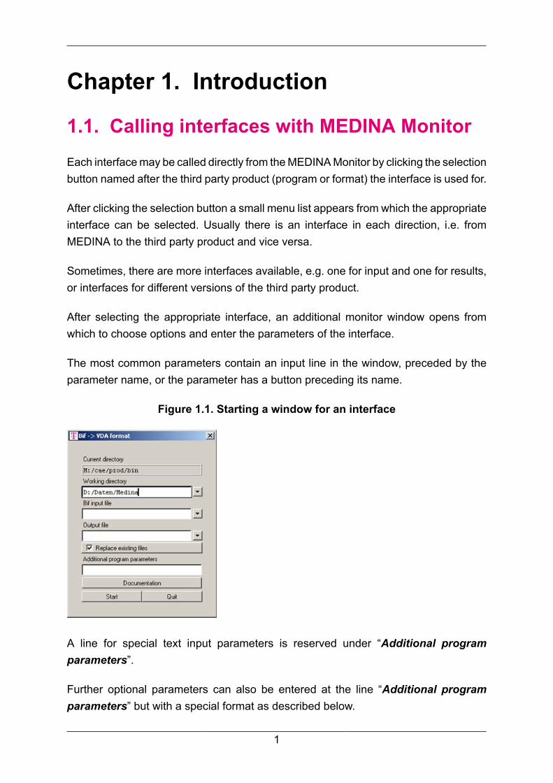
1.1. Calling interfaces with MEDINA MonitorEach interface may be called directly from the MEDINA Monitor by clicking the selectionbutton named after the third party product (program or format) the interface is used for.
After clicking the selection button a small menu list appears from which the appropriateinterface can be selected. Usually there is an interface in each direction, i.e. fromMEDINA to the third party product and vice versa.
Sometimes, there are more interfaces available, e.g. one for input and one for results,or interfaces for different versions of the third party product.
After selecting the appropriate interface, an additional monitor window opens fromwhich to choose options and enter the parameters of the interface.
The most common parameters contain an input line in the window, preceded by theparameter name, or the parameter has a button preceding its name.
Figure 1.1. Starting a window for an interface
A line for special text input parameters is reserved under “Additional programparameters”.
Further optional parameters can also be entered at the line “Additional programparameters” but with a special format as described below.
1
Introduction
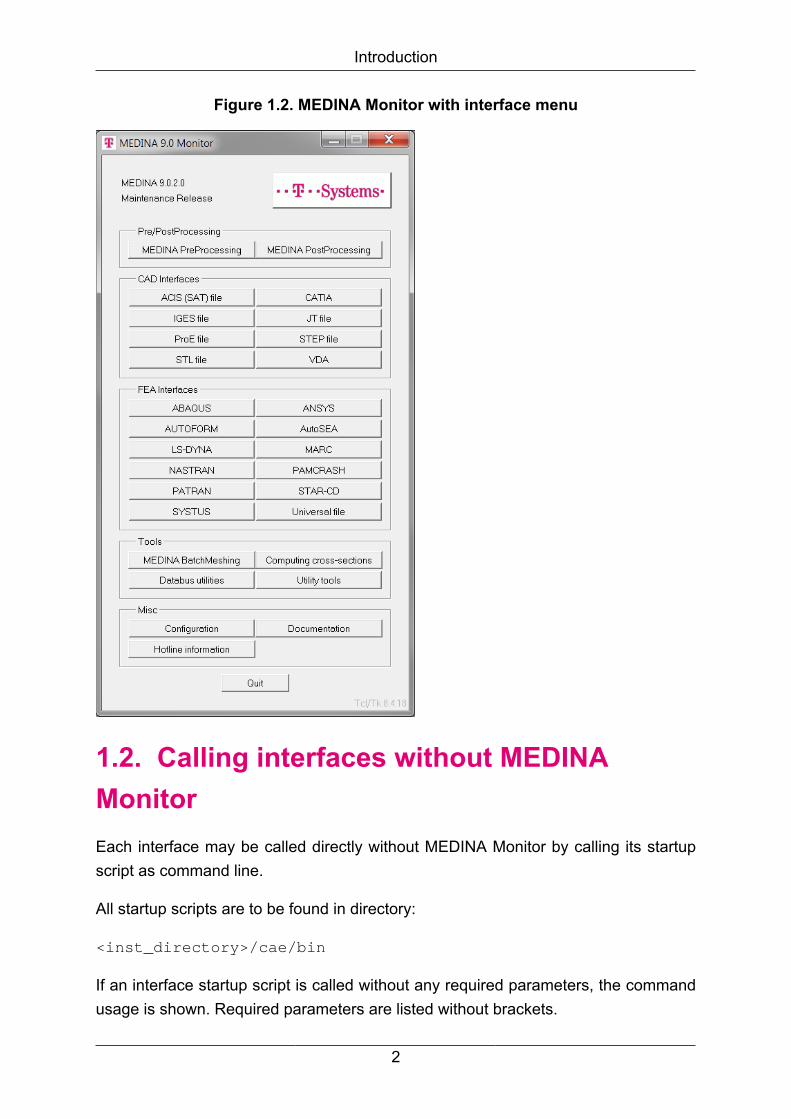
Figure 1.2. MEDINA Monitor with interface menu
1.2. Calling interfaces without MEDINAMonitorEach interface may be called directly without MEDINA Monitor by calling its startupscript as command line.
All startup scripts are to be found in directory:
<inst_directory>/cae/bin
If an interface startup script is called without any required parameters, the commandusage is shown. Required parameters are listed without brackets.
2
Introduction
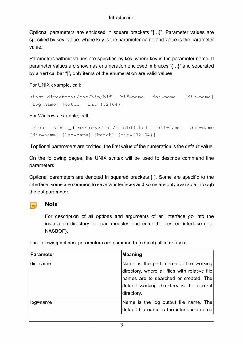
Optional parameters are enclosed in square brackets “[…]”. Parameter values arespecified by key=value, where key is the parameter name and value is the parametervalue.
Parameters without values are specified by key, where key is the parameter name. Ifparameter values are shown as enumeration enclosed in braces “{…}” and separatedby a vertical bar “|”, only items of the enumeration are valid values.
For UNIX example, call:
<inst_directory>/cae/bin/bif bif=name dat=name [dir=name]
[log=name] [batch] [bit={32|64}]
For Windows example, call:
tclsh <inst_directory>/cae/bin/bif.tcl bif=name dat=name
[dir=name] [log=name] [batch] [bit={32|64}]
If optional parameters are omitted, the first value of the numeration is the default value.
On the following pages, the UNIX syntax will be used to describe command lineparameters.
Optional parameters are denoted in squared brackets [ ]. Some are specific to theinterface, some are common to several interfaces and some are only available throughthe opt parameter.
Note
For description of all options and arguments of an interface go into theinstallation directory for load modules and enter the desired interface (e.g.NASBOF).
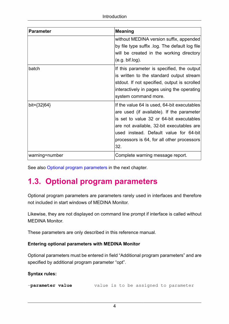
The following optional parameters are common to (almost) all interfaces:
Parameter Meaning
dir=name Name is the path name of the workingdirectory, where all files with relative filenames are to searched or created. Thedefault working directory is the currentdirectory.
log=name Name is the log output file name. Thedefault file name is the interface’s name
3
Introduction
Parameter Meaningwithout MEDINA version suffix, appendedby file type suffix .log. The default log filewill be created in the working directory(e.g. bif.log).
batch If this parameter is specified, the outputis written to the standard output streamstdout. If not specified, output is scrolledinteractively in pages using the operatingsystem command more.
bit={32|64} If the value 64 is used, 64-bit executablesare used (if available). If the parameteris set to value 32 or 64-bit executablesare not available, 32-bit executables areused instead. Default value for 64-bitprocessors is 64, for all other processors32.
warning=number Complete warning message report.
See also Optional program parameters in the next chapter.
1.3. Optional program parametersOptional program parameters are parameters rarely used in interfaces and thereforenot included in start windows of MEDINA Monitor.
Likewise, they are not displayed on command line prompt if interface is called withoutMEDINA Monitor.
These parameters are only described in this reference manual.
Entering optional parameters with MEDINA Monitor
Optional parameters must be entered in field “Additional program parameters” and arespecified by additional program parameter “opt”.
Syntax rules:
-parameter value value is to be assigned to parameter
4

Introduction
If value contains no spaces, type:
"opt=-parameter value"
If value contains spaces, type:
{opt=-parameter "value"}
Example 1:
To assign file name myfile to
parameter clayer, type:
"opt=-clayer myfile"
Example 2:
To assign file name my file to
paramater clayer, type:
{opt=-parameter "my file"}
Entering optional parameters without MEDINA Monitor
If interface is called from command line, optional parameters must be entered after allother parameters and are specified additional command line parameter “opt”.
Syntax rules:
-parameter value value is to be assigned to parameter
If value contains no spaces, type:
'opt=-parameter value'
If value contains spaces, type:
'opt=-parameter "value"'
Example 1:
To assign file name myfile to
parameter clayer, type:
'opt=-clayer myfile'
Example 2:
To assign file name my file to
paramater clayer, type:
'opt=-parameter "my file"'
5

Introduction
Note that single quotation marks are used instead of double quotation marks andbraces.
6
Chapter 2. CAD Interfaces
2.1. Overview of CAD Interfaces in MEDINA
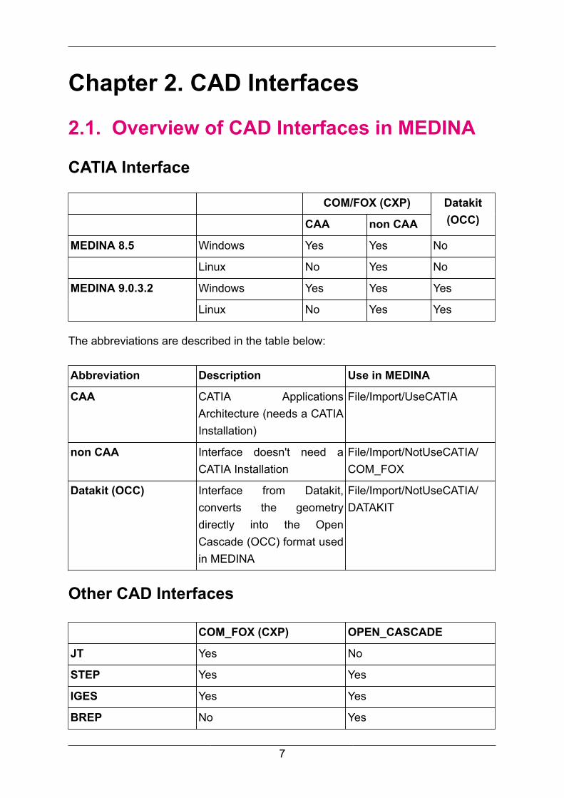
CATIA Interface
COM/FOX (CXP)
CAA non CAA
Datakit(OCC)
MEDINA 8.5 Windows Yes Yes No
Linux No Yes No
Windows Yes Yes YesMEDINA 9.0.3.2
Linux No Yes Yes
The abbreviations are described in the table below:
Abbreviation Description Use in MEDINA
CAA CATIA ApplicationsArchitecture (needs a CATIAInstallation)
File/Import/UseCATIA
non CAA Interface doesn't need aCATIA Installation
File/Import/NotUseCATIA/COM_FOX
Datakit (OCC) Interface from Datakit,converts the geometrydirectly into the OpenCascade (OCC) format usedin MEDINA
File/Import/NotUseCATIA/DATAKIT
Other CAD Interfaces
COM_FOX (CXP) OPEN_CASCADE
JT Yes No
STEP Yes Yes
IGES Yes Yes
BREP No Yes
7
CAD Interfaces
2.2. CATIA V5 -> Interface CATIA V5This chapter is intended to support the work with the CATBIF V5 conversion program.
CATBIF V5 enables the unidirectional data conversion CATIA V5 –> BIF.
The CATBIF V5 interface will export CAD data and assembly parts defined in CATIAV5 format to MEDINA, creating a BIF file.
2.2.1. CATIA V5 - Introduction
BIF
MEDINA's data structure is based on the BIF format and additionally supportsassembly parts.
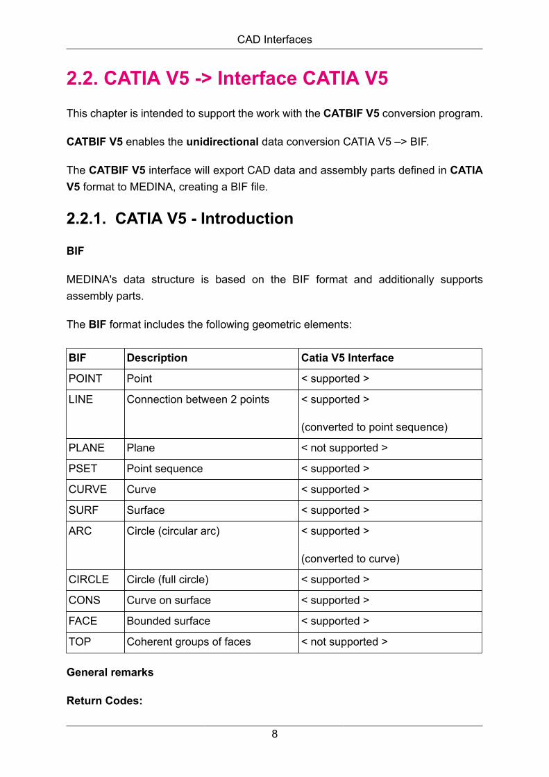
The BIF format includes the following geometric elements:
BIF Description Catia V5 Interface
POINT Point < supported >
LINE Connection between 2 points < supported >
(converted to point sequence)
PLANE Plane < not supported >
PSET Point sequence < supported >
CURVE Curve < supported >
SURF Surface < supported >
ARC Circle (circular arc) < supported >
(converted to curve)
CIRCLE Circle (full circle) < supported >
CONS Curve on surface < supported >
FACE Bounded surface < supported >
TOP Coherent groups of faces < not supported >
General remarks
Return Codes:
8

CAD Interfaces
COM/FOX reports error conditions and certain conversion results via the programreturn code.
Note that it is recommended to check the logfile either manually or automatically to getmore information about the conversion result. The return code is only a hint to indicatethat something has failed, it does not provide any detailed information.
Different COM/FOX releases may report different return codes for the sameconversion.
The main reason for different return codes for the same input file with different COM/FOX releases is usually a change in underlying technology like the JT toolkit.
In case the JT toolkit reports more or less errors to COM/FOX, the return code mightchange from 6 to 12 or from 12 to 6.
Note that the default value for RtcGeoLimit and RtcPmiLimit is five, therefore assoon as five geometry or PMI errors are encountered or reported by the JT toolkit thereturn code is changed from 6 to 12 or from 5 to 11.
Note that return codes have a certain priority and a return code with a higher prioritywill override a return code with a lower priority.
Since COM/FOX V4.3.7, the non CAA CATIA V5 Reader maps the CATIA assemblystructure to the corresponding product structure into BIF in the same way as the CATIACAA interface does.
Order of priority from low to high:
0 Success
1 LICMAN license is missing
2 Unspecific error during processing
3 Failed to process all assembly elements
4 No geometry processed
5 Failed to process some PMI elements
6 Failed to process some geometry elements
7 V4 to V5 migration error
8 Fatal error during processing
10 CATIA session creation failed
11 Failed to process more than RtcPmiLimit PMI elements
12 Failed to process more than RtcGeoLimit geometry elements
9

CAD Interfaces
Note
A return code of 6 indicates that there are some errors during geometryconversion, but this does not mean that there are no PMI errors at all becausereturn code 6 has a higher priority than return code 5.
COM/FOX and the JT toolkit are used by MEDINA interfaces.
2.2.2. BIF Conversion using CATIA Runtime
The CATBIF V5 converter can be invoked interactively from MEDINA Monitor or inbatch mode.
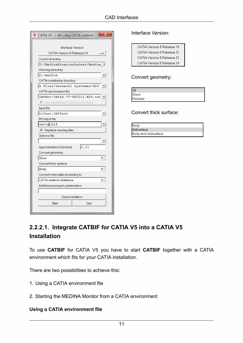
MEDINA supports the CATIA V5 Releases 19, 21, 22 and 24 (see section SpecificParameters for the Conversion using CATIA Runtime for specific parameters).
MEDINA Monitor:
10
CAD Interfaces
Interface Version:
Convert geometry:
Convert thick surface:
2.2.2.1. Integrate CATBIF for CATIA V5 into a CATIA V5Installation
To use CATBIF for CATIA V5 you have to start CATBIF together with a CATIAenvironment which fits for your CATIA installation.
There are two possibilities to achieve this:
1. Using a CATIA environment file
2. Starting the MEDINA Monitor from a CATIA environment
Using a CATIA environment file
11

CAD Interfaces
If you have a default CATIA installation you need a CATIA environment file which fitsfor your installation.
You can find an environment file in the folder /CATEnv on Windows in the folder:
C:\Documents and Settings\All Users\Anwendungsdaten
\DassaultSystemes\CATEnv (German Windows installation).
If you are using a customized CATIA installation, please ask your local CATIAadministrator how to obtain a valid environment file.
Note
Currently, the CATBIF for CATIA V5 interface supports 64 bit.
Enter the full path to the CATIA environment file into the CATBIF start window.Additionally, it is required to specify the CATIA installation path.
Note
On Windows platforms the CATBIF dialog window enters the path to the CATIAinstallation automatically; please verify that the entered path is correct.
Starting the MEDINA Monitor from a CATIA environment
Start a command shell with a CATIA environment and, from this shell, start the MEDINAMonitor.
Then, the CATIBIF dialog panel allows to select the check box labeled "Use predefinedCATIA environment".
12

CAD Interfaces
Figure 2.1. "Use predefined CATIA environment" option
There is no need to specify the CATIA installation directory or an environment filebecause all required information is gathered from the CATIA environment.
Please ask your local CATIA installation administrator how to start a command shellwith a CATIA environment.
This second possibility is the recommended way to use CATBIF as it is often difficultfor the end-user to get a correct environment file, especially in the case where acustomized CATIA installation is used.
F.A.Q.:
• What is a CATIA environment?
13

CAD Interfaces
A CATIA environment is a set of environment variables which have to bedefined when the main CATIA program executable "cnext" is started. Usually,the environment is either setup by the Dassault Systèmes CATIA V5 start script"catstart" or through your local CATIA startup procedure.
• When I start CATBIF I get an error message like:
Possible reason: No CATIA configuration license selected
Error: 21
-------------------------------------------------------
Internal error: execution stopped
Use one of the above described methods to select a valid CATIA environment. TheCATIA license to use is defined via the CATIA environment.
Note
If you use a newly installed default CATIA installation (no customization) it isrequired to start CATIA once to select the license to use. The same settingwill be used by CATBIF as long as the same environment file is used.
2.2.2.2. Specific Parameters for the Conversion using CATIARuntime
This CATBIF V5 processor can be controlled by several options.
The option for Thick Surfaces conversion is only available in the converter using theCATIA runtime.
Convert thick surface
Mid-surfaces may be created out of thick surfaces. Optionally only the mid-surfaces,the surface or both of them will be transferred to BIF.
This is determined by the following parameters:
• Body (Default):
Only the surface of the thick-surfaces will be transferred (as it was before).
• MidSurface:
14
CAD Interfaces
Only the mid-surfaces of the thick-surfaces will be transferred
• Body and MidSurface:
Both mid-surfaces and surfaces of the thick-surfaces will be transferred.
2.2.2.3. Conversion of Metadata
You now can convert CATIA metadata (part material data, color, transparency, sheetthickness, ...) to BIF.
There are two approaches for the evaluation of CATIA metadata:
• using standard CATIA functions based on CATIA material database
• using Daimler metadata standard process based on Daimler CATIA start model
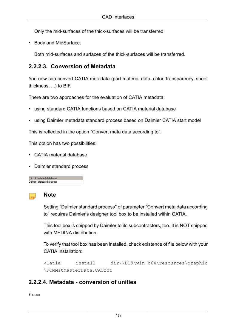
This is reflected in the option "Convert meta data according to".
This option has two possibilities:
• CATIA material database
• Daimler standard process
Note
Setting "Daimler standard process" of parameter "Convert meta data accordingto" requires Daimler's designer tool box to be installed within CATIA.
This tool box is shipped by Daimler to its subcontractors, too. It is NOT shippedwith MEDINA distribution.
To verify that tool box has been installed, check existence of file below with yourCATIA installation:
<Catia install dir>\B19\win_b64\resources\graphic
\DCMMstMasterData.CATfct
2.2.2.4. Metadata - conversion of unities
From
15

CAD Interfaces
CatiaMaterialPar Young Modulus = " 7e+010N_m2"
or
CatiaMaterialPar Young-Modul = " 7e+010N_m2"
create
.CAD Material Density_SI = 70000
From
CatiaMaterialPar Poisson Ratio = " 0,346"
or
CatiaMaterialPar Poisson-Faktor = " 0,346"
create
.CAD Material Poisson Ratio_SI = 0.346
From
CatiaMaterialPar Density = "2710kg_m3"
or
CatiaMaterialPar Dichte = "2710kg_m3"
create
.CAD Material Density_SI = 2.71e-9
From
CatiaMaterialPar Thermal Expansion = " 2,36e-005_Kdeg"
or
CatiaMaterialPar Wärmeausdehnung = " 2,36e-005_Kdeg"
create
.CAD Material Thermal Expansion_SI = 2.36e-005
From
CatiaMaterialPar Yield Strength = " 9,5e+007N_m2"
or
CatiaMaterialPar Elastizitätslimit = " 9,5e+007N_m2"
create
.CAD Material Yield Strength_SI = 95
2.2.2.5. Which versions are available on which operationsystems?
The CATIA version V5 Releases 19, 21, 22 and 24 are available and supported byWindows 64-bit (wnt_ix86_64) operating system.
16
CAD Interfaces
2.2.3. BIF Conversion not using CATIA RuntimeYou can convert CATIA V5 data without using a CATIA runtime library or license. Forthat, choose one of the two available interfaces: COM_FOX or DATAKIT.
Note
DATAKIT converts geometry directly into the Open Cascade (OCC) formatused in MEDINA. This interface uses a library of Datakit (http://www.datakit.com[http://www.datakit.com/]).
The currently provided version for MEDINA CATIA V5 -> BIF interface is a Pre-Release,which can indeed convert geometry but no assembly structures or midsurfaces.
This CATBIF V5 converter can be invoked interactively from MEDINA Monitor or inbatch mode.
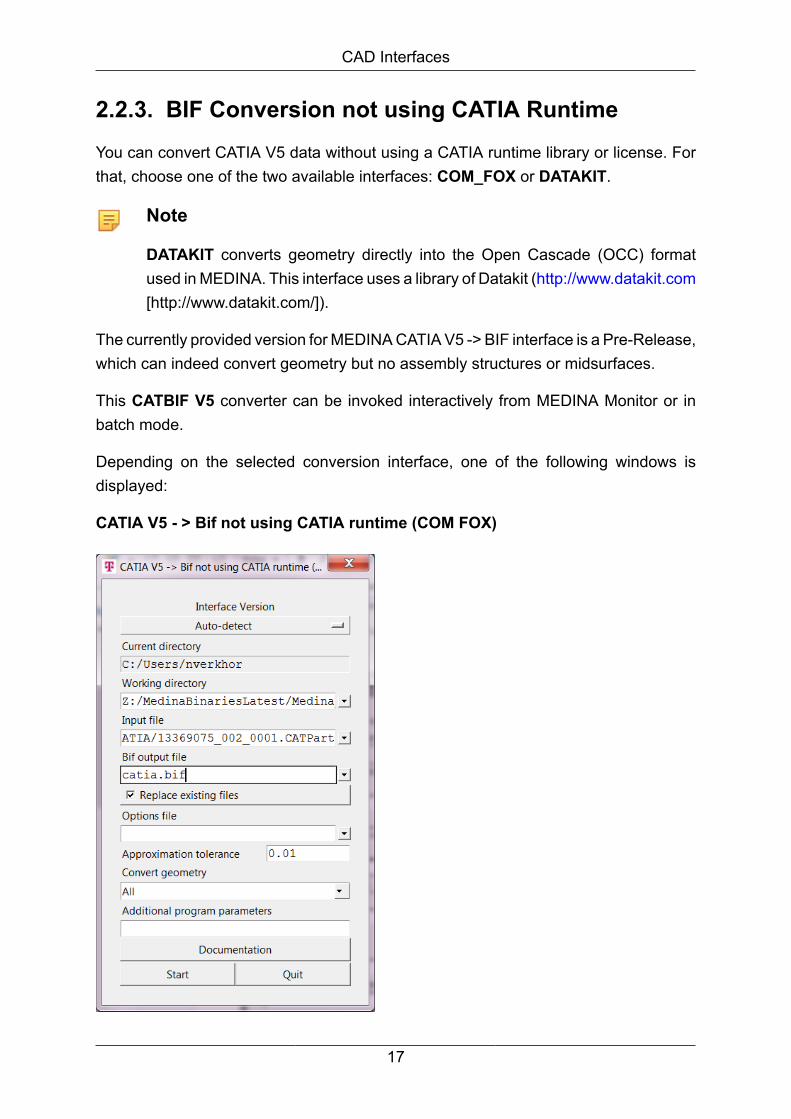
Depending on the selected conversion interface, one of the following windows isdisplayed:
CATIA V5 - > Bif not using CATIA runtime (COM FOX)
17

CAD Interfaces
For the description of the window parameters, see the General parameters for theConversion chapter.
CATIA V5 - > Brep not using CATIA runtime (DATAKIT)
Two additional conversion parameters are available in this window:
• Convert invisible entities
Check this parameter to convert both visible and invisible entities to BIF. If it isunchecked, only entities in SHOW are converted.
• Write reference planes as hidden
Check this parameter if you don't want to convert reference planes. If it is unchecked,reference planes are converted to BIF.
2.2.3.1. Which versions are available on which operationsystems?
CATBIF V5 is supported by the following operation systems: wnt_ix86_64 andlnx_86_64.
18

CAD Interfaces
2.2.4. General parameters for the Conversion
Both CATBIF V5 processors (with and without using CATIA runtime) can be controlledby several options.
The MEDINA Monitor allows these options to be set in a straight forward way.
Interface version
Use this button to select the desired Catia V5 Release (for using CATIA runtime). Fornot using CATIA runtime the interface version is detected automatically (Auto-detect).
Approximation tolerance
This parameter specifies the tolerance to be used during conversion in cases whereapproximation is required (e.g., for degree reduction of B-spline surfaces).
A positive real value has to be provided, it is interpreted as a millimeter value regardlessof the length unit used in the input file. The default value is 0.01.
Convert geometry
Use this button to select which Catia geometry shall be converted to BIF. Choose oneof the following options from the drop-down list:
All The complete Catia geometry (Show+Noshow) will be converted toBIF.
Show Only the Catia show geometry will be converted to BIF.
Noshow Only the Catia noshow geometry will be converted to BIF.
Options file
Use this field to select an options file. Press the question button "?" to open the fileselection window.
If the field is empty, the default file from the installation will be used.
Example of options file:
19

CAD Interfaces
Use # as first character if the parameter shall be ignored (comment character) .
The parameter will be used, if it begins with - .
If the options file vdabif.opt exists, it will be searched first in the current directory andthen in HOME directory. Otherwise, the cxpbif.opt file will be searched in the installationdirectory.
You will find further descriptions for available parameters in this section.
After definition you have to close the editor to start the Catia interface with the desiredparameter definitions.
Note
Some options are not directly available in the MEDINA Monitor. To specifythese options use the additional input field. This input field is located on the'Parameter' page.
The available options (and shortcuts) for CATBIF V5 are together with this syntax inthe batch mode option file:
Common options:
• Input file: -InFile, -if
The only mandatory option, i.e. all other options are optional. Specifies the name(including path) of the CATIA document to convert.
Example: -InFile=C:/abc/xyz.model or if=C:/abc/xyz.model
• Output file: -OutFile, -of
20

CAD Interfaces
Name (including path) of the BIF output file to create.
Default: If this option is omitted, CATBIF V5 will use the name of the input file, withoutits extension and with the extension '.bif added.
Example: -OutFile=C:/Data/File.bif
• Log file: -Logfile, -log
Name (including path) of the conversion protocol to create.
Default: If this option is omitted, CATBIF V5 will use the name of the input file, withoutits extension and with the extension '.log' added. When running, the convertercreates a log file with time stamp, statistics of processed entities and informationmessages, warnings and errors.
Example: -LogFile=C:/logData/aLogFile.log
• Output format: -OutFormat, -fmt
This parameter determines the type of the output format and can’t be omitted.
The possible value is:
"BIF": BIF for MEDINA.
Example:-OutFormat=BIF
• Verbosity: -Verbosity, -vb
Verbosity of the log file, possible values are:
"Error": (default): print only errors, no information messages and warnings
"Info": print information messages, warnings, and errors
"Warning": print warnings and errors, suppress information messages
"Trace": trace the elements processed.
Example: -Verbosity=Trace
• Output mode: -OutMode, -om
Controls the creation of the output file, possible values are:
21

CAD Interfaces
"Replace":(default): replace an existing file without question
"New": stop processing if the output file already exists.
Example: -OutMode=New
• Approximation tolerance: - ApproximationTol, -ac
Specifies the tolerance to use during the conversion in cases where approximationis required (e.g., for degree reduction of B-spline surfaces).
A positive real value has to be provided, it is interpreted as a millimeter valueregardless of the length unit used in the input file. The default value is 0.01.
Example: -ApproximationTol=0.01
• Brep tolerance: -BrepTol, -brt
Tolerance for Brep conversion in millimeters.
Default: 0.004.
Example: -BrepTol=0.004
This option is not directly available in the MEDINA Monitor.
• Edge tolerance: -EdgeTol, -edt
Tolerance for edges in millimeters.
Default: 0.004.
Example: -EdgeTol=0.004
This option is not directly available in the MEDINA Monitor.
Further Options valid for CATIA to BIF conversion
The following parameters only work if they are entered in the options file:
• Line mapping: -LineMap, -lnm
Controls how lines are converted from CATIA to BIF, possible values are:
Curve: converts a CATIA line into a BIF CURVE element (default).
22

CAD Interfaces
PSET: converts a CATIA line into a BIF PSET element.
Example: -LineMap=PSET
• Body mapping: -BodyMap –bom
Controls how CATIA part or open bodies are mapped to BIF, possible values:
Set: converts each part/open body into a SET (default).
Group: converts each part/open body into a GROUP.
Example: -BodyMap=Set
• Hollow body: -VoidMap
The hollow body had to be translated by the interface and affects how voids in solidsare mapped, possible values:
Map: convert voids.
Suppress: voids are not converted, this skips interior shells of the solids (e.g. inorder to reduce the file size).
This option is available only in case of STEP input data.
Example: -VoidMap=Map
• Select geometry from Show/NoShow:
• -ConvertVisibleGeometry -cvg
• -ConvertInvisibleGeometry -civg
Possible combinations:
cvg civg Effect
Yes No Only visible geometry will be converted (default)
No Yes Only geometry from NoShow will be converted
No No No geometry will be converted
Yes Yes All geometry will be converted
Example: -cvg=yes -civg=no (only visible geometry)
23

CAD Interfaces
• Select invisible CATProducts/CATParts
• -ConvertInvisibleProducts (=yes/=no)
ConvertVisibleGeometry affects several geometric elements in the CATPart whileConvertInvisibleProducts affects CATProducts/CATParts.
A CATPart may contain as many geometric elements as desired.
ConvertInvisibleProducts takes effect at a higher level in the whole structure.
Only in converter using CATIA runtime
Convert thick surface
-ConvertThickSurface (=Body/=Surface/=BodyandSurface)
One of the following options can be selected:
• Body: only the surface of the thick-surfaces will be transferred. This option is setby default.
• Midsurface: only mid-surfaces of the thick-surfaces will be transferred.
• Body and Midsurface: both midsurfaces and surfaces of the thick-surfaces will betransferred.
2.2.5. Calling CATBIF V5 without MEDINA Monitor
Call:
<inst_directory>/cae/bin/cat5bif dat=name bif=name [rel={19|
20|21|22|24}] [runtime={catia|datakit}] [useenv] [catdir=name]
[catenv=name] [options=name] [apptol=num] [geom={all|
show|noshow}] [thicksurface={body|surface|bodyandsurface}]
[metadata={catia|daimler}] [msg={0|1}] [dir=name] [log=name]
[batch] [bit={32|64}]
If optional parameters are omitted, the first value of the numeration is the default value.
Note
For description of all options and arguments above go into the installationdirectory for load modules and enter the desired interface (e.g. catbif).
24

CAD Interfaces
Option Meaning
dat Specifies the name (including path) of the CATIA document toconvert.
bif Name (including path) of the BIF output file to create.
default If this option is omitted, CATBIF V5 will use the name of the inputfile, without its extension and with the extension '.bif added.
rel Use rel={19|20|21|22|24} for CATIA V5 release.
runtime Use catia or datakit to start CATBIF with or without runtimelibrary.
useenv Use a predefined CATIA environment (see also sectionIntegrate CATBIF for CATIA V5 into a CATIA V5 Installation).
catdir Directory of the CATIA installation.
catenv Name and directory of the CATIA environment file (see alsosection Integrate CATBIF for CATIA V5 into a CATIA V5Installation).
options Name and directory of the options file.
apptol Specifies the tolerance to use during the conversion in caseswhere approximation is required (e.g., for degree reduction ofB-spline surfaces).
A positive real value has to be provided, it is interpreted as amillimeter value regardless of the length unit used in the inputfile.
The default value is 0.01.
geom Defines which geometry will be processed (also see sectionSpecific Parameters for the Conversion using CATIA Runtime.
msg Additional log-file of the STEP toolkits, not relevant for CATBIF.
Default is 0 for no logfile.
The following parameters are valid for all interfaces and are explained in section 1.2:dir, log, batch, bit, warning.
Note
Currently, the CATBIF interface without runtime library only supports 32 bit.
25

CAD Interfaces
The following table describes the mapping of CATIA entities of the geometry levelsto BIF:
CATIA BIF Mapping Rem.
Geometry
3D wireframe
CATPoint POINT 1-1
CATCurve CURVE 1-1
CATCircle CURVE 1-1
CATLine CURVE, PSET 1-1
CATNurbsCurve CURVE 1-1
CATEllipse CURVE 1-1
CATSplineCurve CURVE 1-1
Surfaces
CATSurface SURFACE 1-1
CATFace FACE 1-1
CATEdge CONS 1-1
Additional elements
CATShell GEOMETRY SET
CATBody GEOMETRY SET
CATWire GEOMETRY SET
Mapping cardinality
The CATIA entity is mapped to exactly one corresponding equivalent BIF element.
2.2.6. Conversion of CATIA Product structure to BIF
Since BIF does not support ditto parts, the CATIA product structure will be completelyexploded on export to BIF. The entire assembly will result in one single BIF file.
The created MEDINA parts will get an unique, non-empty label corresponding to theCATIA product name. The MEDINA part codes will be set according to the CATIAproduct identifiers.
26

CAD Interfaces
Note
All CATIA documents other than CATProducts and CATParts that might appearwithin the product structure (e.g. a CATIA V4 model or CGR) will not beconverted.
2.2.7. Conversion of CATIA Solids and Shells to BIFFor CATIA PartBodies (i.e. Solids) the BRep (Boundary Representation) is extracted,for CATIA Shells the bounding faces are retrieved.
For both cases, the resulting set of trimmed surfaces is then exported to BIF.
Curves and surfaces in BIF are described in a power basis form. Hence, on export toBIF the CATIA geometry has to be converted in several steps including approximationfrom rational B-spline with a non-rational curve, basis conversion from B-spline topower basis and recreation of trim curves in the parameter space of surfaces.
The accuracy for these conversions, which is the maximum distance allowed betweenthe approximation and the original geometry, can be specified with certain controlparameters (ApproximationTol, BRepTol, EdgeTol).
Since MEDINA 8.1 and CATIA V5 R17 it can be defined an additionally option for midsurface generation:
2.2.8. GlossaryCATIA
CATIA is one of the world's leading CAD/CAM/CAE software systems.
CATIA provides integrated solutions tailored to the needs of small and medium sizedenterprises as well as large industrial corporations in all industries.
BIF
BIF is the native file format of MEDINA. Its geometric data structures are inspiredby VDAFS format. Besides VDAFS’ geometrical entities, BIF additionally supportsassembly parts, called parts.
27

CAD Interfaces
Boundary representation (BRep)
BRep models represent a solid directly by a representation of its bounding surface.A BRep solid is represented as a volume contained in a set of faces together withtopological information, which defines the relationships between the faces.
Because BReps include such topological information, a solid is represented as a closedspace in 3D space. The boundary of a solid separates points inside from points outsideof the solid.
Continuity of curves and surfaces
In computer aided design it is important to understand the principals of G2 or C2curvature continuity and how to use these principles when creating a design.
The attractive free flowing shapes we see on the market today are almost alwayscreated in a high end surface modeler that can create and check for curvaturecontinuous conditions.
If a model is created with the major visible surfaces being curvature continuous thehuman eye can detect no instant changes in curvature and therefore perceives thesurface to be continuous and "correct".
Mathematically speaking, a curve is called G1 continuous (G for geometric) ifthe tangent directions coincide at neighboring segment endpoints. However, theirmagnitudes may be different.
If the magnitudes are equal and the first derivative is continuous we have C1 continuity.G1 continuity implies that the curve is visually continuous (smooth) but may have adiscontinuity in the parameterization.
Considering the second derivative representing the curvature of the curve, analogicallywe can determine the C2 continuity or curvature continuity.
2.3. STEP, VDAFS, IGES, JT and SAT
2.3.1. Introduction
This User Manual is intended to support the work with the product STEPBIF, VDABIF,JTBIF, IGESBIF and SATBIF conversion programs.
28

CAD Interfaces
The STEPBIF and JTBIF interfaces will import CAD data and assembly structuresdefined in JT format into MEDINA, creating a so called BIF file (binary input CAEdatabus format).
The other interfaces will import CAD data only, defined in VDAFS, IGES and SATformats into MEDINA, creating a BIF file.
Assembly structures will be exploded on import of IGES and SAT.
STEP - The standard for product data
With the International Standard ISO 10303 (STEP: Standard for the Exchange ofProduct Model Data) it is possible to describe product model data for exchange,storage and archiving.
The product data which can be described by STEP include the data of all productsthroughout the entire life cycle of the product.
Description of product data
A product data model includes not only geometry data but also the structure data of theproduct, e. g. product identifying data or assembly structures and more technologicaldata, like tolerances or material properties.
On the basis of STEP you can realize an integration of geometry data and productstructure data, for example between CAD/CAM and parts list application systems.
This is a clear delimitation from the standards applied today (IGES, VDAFS, and SET)with which in essence only geometry data can be exchanged.
Therefore STEP is:
• more than just a new standard for data exchange, it is
• the entry into a new technology: the product data technology.
An essential aspect of the description of product data is the so-called productidentifying data, which are mandatory with each data exchange.
This includes the identifiers and the descriptions of the product (e. g. the productidentifier), the version of the product and the type of the product describing data. Ifthese are not available in the CAD system, they have to be extracted from an attachedEDM system or specified by the user through data entry panels.
29

CAD Interfaces
The program STEPBIF offers flexible configuration possibilities for the data entrypanels and for the default values.
STEP standardizes product model data which are independent from their form ofimplementation, e. g. sequential exchange file or data base.
Therefore, the data models are defined in the formal data definition languageEXPRESS so that contrary to the present standards not only the syntax but alsothe semantics are formally described. These formal descriptions can be processedautomatically by different tools.
General remarks
Return Codes:
COM/FOX reports error conditions and certain conversion results via the programreturn code.
Note that it is recommended to check the logfile either manually or automatically to getmore information about the conversion result. The return code is only a hint to indicatethat something has failed, it does not provide any detailed information.
Different COM/FOX releases may report different return codes for the sameconversion.
The main reason for different return codes for the same input file with different COM/FOX releases is usually a change in underlying technology like the JT toolkit.
In case the JT toolkit reports more or less errors to COM/FOX, the return code mightchange from 6 to 12 or from 12 to 6.
Note that the default value for RtcGeoLimit and RtcPmiLimit is five, therefore as soonas five geometry or PMI errors are encountered or reported by the JT toolkit the returncode is changed from 6 to 12 or from 5 to 11.
Moreover, return codes have a certain priority and a return code with a higher prioritywill override a return code with a lower priority.
Order of priority from low to high:
0 Success
1 LICMAN license is missing
30

CAD Interfaces
2 Unspecific error during processing
3 Failed to process all assembly elements
4 No geometry processed
5 Failed to process some PMI elements
6 Failed to process some geometry elements
7 V4 to V5 migration error
8 Fatal error during processing
10 CATIA session creation failed
11 Failed to process more than RtcPmiLimit PMI elements
12 Failed to process more than RtcGeoLimit geometry elements
Note
A return code of 6 indicates that there are some errors during geometryconversion but this does not mean that there are no PMI errors at all becausereturn code 6 has a higher priority than return code 5.
COM/FOX and the JT toolkit are used by the MEDINA interfaces.
STEP Application Protocols
ISO 10303 (STEP) is a very complex standard. Therefore it is published in variousparts which are based on a specific document structure.
The parts of STEP which can be implemented are called Application Protocols(APs).These are the application relevant and implementable parts of the entire STEPstandard.
Since 1994 STEP is available as an International Standard in several parts with a totalvolume of much more than 3000 pages.
The following STEP Application Protocols are available as International Standard:
• AP 201 ‘Explicit draughting’:
Technical drawings with 2D geometry and explicit dimensions.
• AP 202 ‘Associative draughting’:
Technical drawings with 3D geometry and associative dimensions.
• AP 203 ‘Configuration controlled design’:
31

CAD Interfaces
Product structure and configuration data with 3D geometry in variousrepresentations.
One more important Application Protocol that becomes international standard in 2001according to ISO 10303 is:
• AP 214 ‘Core data for automotive mechanical design processes’:
The data of the development processes in the automotive industry.
Since the data models in the Application Protocols become sometimes very large andcomplex, they cannot always be implemented entirely.
Therefore, and because in specific cases of data exchange partial scopes are moreefficient, an AP’s data model is subdivided into so-called "Conformance Classes".
These are partial scopes of an Application Protocol that can be implemented.
Supported EXPRESS schemas
The STEP-BIF conversion program supports the following schemas:
• AP 214 ‘Conformance Class 20’:
Complete schema automotive_design for AP214 IS and DIS version
• AP 203 ‘3D geometry (possibly with assembly structures)’:
Config_control_design for AP 203 IS version (1994) AP 203 corresponds to theInternational Standard (IS) from 1994 for AP 203 [3].
VDAFS (VDA-Flächen-Schnittstelle, VDA surface interface)
The VDAFS (VDA-Flächen-Schnittstelle, VDA surface interface) is a system neutralCAD format. It has been created by the department ”CAD/CAM” of the GermanAutomobile Industry Association to simplify the exchange of 3D geometry andparticularly of free form surfaces between various CAD systems.
VDAFS currently exists in the versions 1.0 and 2.0. Version 1.0, which has been a DINStandard (DIN 66301) since 1986, includes the following geometrical elements:
POINT Point
32
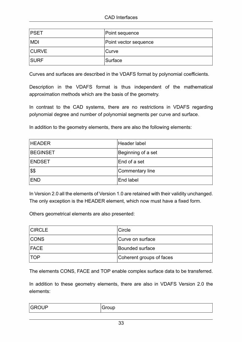
CAD Interfaces
PSET Point sequence
MDI Point vector sequence
CURVE Curve
SURF Surface
Curves and surfaces are described in the VDAFS format by polynomial coefficients.
Description in the VDAFS format is thus independent of the mathematicalapproximation methods which are the basis of the geometry.
In contrast to the CAD systems, there are no restrictions in VDAFS regardingpolynomial degree and number of polynomial segments per curve and surface.
In addition to the geometry elements, there are also the following elements:
HEADER Header label
BEGINSET Beginning of a set
ENDSET End of a set
$$ Commentary line
END End label
In Version 2.0 all the elements of Version 1.0 are retained with their validity unchanged.The only exception is the HEADER element, which now must have a fixed form.
Others geometrical elements are also presented:
CIRCLE Circle
CONS Curve on surface
FACE Bounded surface
TOP Coherent groups of faces
The elements CONS, FACE and TOP enable complex surface data to be transferred.
In addition to these geometry elements, there are also in VDAFS Version 2.0 theelements:
GROUP Group
33

CAD Interfaces
TMAT Transformation matrix
TLIST Transformation list
Further elements were deliberately foregone in VDAFS. It is not possible therefore totransfer, for example, dimensions and representation attributes via VDAFS.
A file with data in the VDAFS format is a simple sequential file. There is a fundamentaldifference, however, between the two versions in the structural configuration of aVDAFS file.
The geometrical elements of Version 1.0 are all defined singularly and are completelyindependent in their description from all other geometrical elements in the same file.
Ignoring the set assignment, the sequence of elements in the file is, therefore, of nosignificance. Manipulating an element in the editor, for example, also does not affectthe description of any other element of the file.
In Version 2.0, by contrast, there are element types which in their description relateto other elements and do not obtain their geometrical significance without thosesupporting elements.
Elements which are related to other elements, must be listed before these in thesequential sequence in the file.
As a result of these possible back-references, the structure of a file with data ofVDAFS Version 2.0 may become so complex that manual manipulation destroys thefile structure. Consequently, it is also no longer possible as a general rule to split upa file into several parts.
The VDABIF conversion program operates on the basis of VDAFS Version 2.0, theelement TOP is not being supported, though.
2.3.2. STEP-BIF -> Interface STEP to BIF
The STEPBIF interface will import CAD data and assembly structures defined in STEPformat into MEDINA , creating a so called BIF file (binary input CAE databus format).
The table Mapping table STEP - BIF describes the mapping of STEP entities of productstructure and of the geometry levels to BIF.
The remarks in the right-hand column of the table are only related to the conversionof the STEP entities in the corresponding line.
34

CAD Interfaces
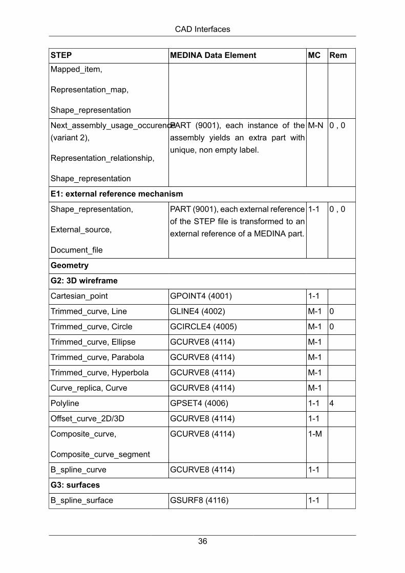
2.3.2.1. Mapping table STEP - BIF
STEP MEDINA Data Element MC Rem
Product structure
S1: product management data
Product,
Product_definition_formation,
Product_definition,
Shape_representation
PART (9001), each information yieldsan extended string attributes of rootpart
1-M
S2: element structure
Mapped_item,
Representation_map,
Shape_representation
PART (9001), each instance of themapped item yields an extra part withunique, non empty label.
M-N 0 , 0
Mapped_item,
Representation_map,
Draughting_model
not supported -- 0
Presentation_layer_assignment GGROUP (4025), layer names arepreserved
1-1 3
Applied_group_assignment GGROUP (4025), group names arepreserved
1-1 0
Representation_context,
Geometric_representation_context,
Global_unit_assigned_context,
Global_uncertainty_assigned_context
Geomeric_representation_context isignored.
Units are transformed to mm.
Closure tolerance of STEP istransformed to MEDINA geometrytolerance RESTART (10001).
M-1 0
S3: item definition structure
Next_assembly_usage_occurrence(variant 1),
PART (9001), each instance of theassembly yields an extra part withunique, non empty label.
M-N 0 , 0
35
CAD Interfaces
STEP MEDINA Data Element MC RemMapped_item,
Representation_map,
Shape_representation
Next_assembly_usage_occurence(variant 2),
Representation_relationship,
Shape_representation
PART (9001), each instance of theassembly yields an extra part withunique, non empty label.
M-N 0 , 0
E1: external reference mechanism
Shape_representation,
External_source,
Document_file
PART (9001), each external referenceof the STEP file is transformed to anexternal reference of a MEDINA part.
1-1 0 , 0
Geometry
G2: 3D wireframe
Cartesian_point GPOINT4 (4001) 1-1
Trimmed_curve, Line GLINE4 (4002) M-1 0
Trimmed_curve, Circle GCIRCLE4 (4005) M-1 0
Trimmed_curve, Ellipse GCURVE8 (4114) M-1
Trimmed_curve, Parabola GCURVE8 (4114) M-1
Trimmed_curve, Hyperbola GCURVE8 (4114) M-1
Curve_replica, Curve GCURVE8 (4114) M-1
Polyline GPSET4 (4006) 1-1 4
Offset_curve_2D/3D GCURVE8 (4114) 1-1
Composite_curve,
Composite_curve_segment
GCURVE8 (4114) 1-M
B_spline_curve GCURVE8 (4114) 1-1
G3: surfaces
B_spline_surface GSURF8 (4116) 1-1
36

CAD Interfaces
STEP MEDINA Data Element MC Rem
Plane GPLANE4 (4003) 1-1
Conical_surface GSURF8 (4116) 1-1
Cylindrical_surface GSURF8 (4116) 1-1
Spherical_surface GSURF8 (4116) 1-1
Toroidal_surface,
Degenerate_toroidal_surface
GSURF8 (4116) 1-1
Offset_surface GSURF8 (4116) 1-1
Surface_of_linear_extrusion GSURF8 (4116) 1-1
Surface_of_revolution GSURF8 (4116) 1-1
Surface_replica, Surface GSURF8 (4116) 1-1
Surface_curve, Pcurve GCURVE8 (4114) plus 2x GCONS8(4122)
1-3 0
Advanced_face,
Face_outer_bound,Face_bound
Edge_loop, Oriented_edge,
Edge_curve,
Surface_curve, Surface
GFACE (4023) 1-M 0
Shell_based_surface_model,
Open_shell /Closed_shell,
Advanced_face
STRUKTUR (106) M-1 0 , 0
G4: faceted brep
Faceted_brep,
Face_surface,
Poly_loop
not supported -- 0
G5: brep
37

CAD Interfaces
STEP MEDINA Data Element MC Rem
Manifold_solid_brep,Brep_with_voids,
Closed_shell,
Oriented_closed_shell,
Advanced_face
STRUKTUR (106) M-1 0 , 0
G8: geometrically bounded surface
Rectangular_trimmed_surface
Surface
GFACE (4023), with accordingGSURF8 (4116) and 4x GCURVE8(4114)
1-M 0
Rectangular_composite_surface
Surface_patch, Surface
several GFACE (4023), withaccording GSURF8 (4116) andGCURVE8 (4114)
1-M 0
Curve_bounded_surface
Boundary_curve,
Outer_boundary_curve,
Composite_curve_segment
GFACE (4023), with accordingGSURF8 (4116) and GCURVE8(4114)
1-M 0
Geometric_set STRUKTUR (106) 1-1 0
Presentation/draughting
P1: geometric presentation
Styled_item,
Presentation_style_assignment,
Point_style, Curve_style,
Surface_style_fill_area,
Colour_rgb
RESTART (10001), but colors only.Other styles cannot be converted.
M-1 0
Styled_item, Point_style
Presentation_style_assignment
not supported -- 8
Styled_item, Curve_style not supported -- 8
38
CAD Interfaces
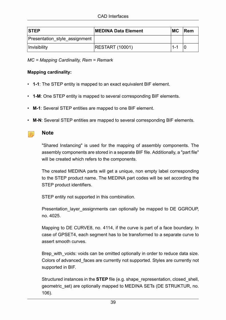
STEP MEDINA Data Element MC RemPresentation_style_assignment
Invisibility RESTART (10001) 1-1 0
MC = Mapping Cardinality, Rem = Remark
Mapping cardinality:
• 1-1: The STEP entity is mapped to an exact equivalent BIF element.
• 1-M: One STEP entity is mapped to several corresponding BIF elements.
• M-1: Several STEP entities are mapped to one BIF element.
• M-N: Several STEP entities are mapped to several corresponding BIF elements.
Note
"Shared Instancing" is used for the mapping of assembly components. Theassembly components are stored in a separate BIF file. Additionally, a "part file"will be created which refers to the components.
The created MEDINA parts will get a unique, non empty label correspondingto the STEP product name. The MEDINA part codes will be set according theSTEP product identifiers.
STEP entity not supported in this combination.
Presentation_layer_assignments can optionally be mapped to DE GGROUP,no. 4025.
Mapping to DE CURVE8, no. 4114, if the curve is part of a face boundary. Incase of GPSET4, each segment has to be transformed to a separate curve toassert smooth curves.
Brep_with_voids: voids can be omitted optionally in order to reduce data size.Colors of advanced_faces are currently not supported. Styles are currently notsupported in BIF.
Structured instances in the STEP file (e.g. shape_representation, closed_shell,geometric_set) are optionally mapped to MEDINA SETs (DE STRUKTUR, no.106).
39

CAD Interfaces
Invisibility can optionally be mapped to MEDINA geometric objects in NoShow.Since this requires to generate a MEDINA RESTART DE, no. 10001, this optionis deferred to future releases.
Applied_group_assignment can optionally be mapped to DE GGROUP, no.4025.
Currently, only referenced STEP files can be transformed.
Colors of geometric objects are mapped to MEDINA color indices.
Since MEDINA's geometric tolerance is contained in RESTART DE, no. 10001,its transfer to BIF is deferred. The original closure tolerance is just mentionedin log file. MEDINA RESTART DE, no. 10001, this option is deferred to futurereleases.
Topological connected faces are represented by one or several commoncurves, having separate CONSes. Surface_curves are thus automaticallytranslated with the translated faces.
If appropriate, faces are split at seams of closed surfaces. Cylindrical faces aresplit into two half cylindrical faces. A complete toroidal surface is split into fourfaces. In general, faces using a single curve twice are avoided.
Hierarchical Assembly Structures
MEDINA currently supports only hierarchical assemblies of tree shape. Thus, repeatedor symmetric parts will be exploded during translation to BIF format.
Calling STEPBIF without MEDINA Monitor
Call:
<inst_directory>/cae/bin/stepbif stp=name bif=name
[options=name] [apptol=num] [msg={0|1}] [dir=name] [log=name]
[batch] [bit={32|64}]
If optional parameters are omitted, the first value of the numeration is the default value.
Note
For description of all options and arguments above go into the installationdirectory for load modules and enter the desired interface (e.g. stepbif).
40

CAD Interfaces
2.3.2.2. Working with large STEP Models
Recommendations:
1. Define the COM/STEP parameters LINDEX and LDATA with adequate values.
2. Check if the /tmp directory has enough free working space. The "/tmp/<userid>/cdalib/" directory, which is created during the convertion, can be used twice as muchworking space as the created or read in STEP file. During CATIA > STEP export, theSTEP file can be increased to the double or triple size like the original CATIA model.In the opposite way during import to CATIA, the CATIA model can be increased tothe 5-6 times size of the original STEP file, because of the different mathematicaldescriptions.
2.3.2.3. Logfile contents and messages
The STEPBIF and VDABIF converters can be invoked interactively by a user interfacewithin the MEDINA Monitor.
When running, the converter creates a logfile with time stamp, statistics of processedentities and information messages, warnings and errors.
The logfile of the converter has the following contents:
• Time stamp indicating the start of the conversion
• Table of options used for the conversion
• Information messages, warnings, and errors (see below)
• Statistics for the read input file.
• Statistics for the created output file.
• Time stamp indicating the end of the conversion
Here is a list of the information/warning/error messages of the converters and a shortdescription. The amount of messages can be controlled via the option "Verbosity".
If nothing is specified, the default value error will only display error messages, andsuppress all warning and information messages.
Warning messages
Warning: Conversion not implemented for instance #<name>.
41
CAD Interfaces
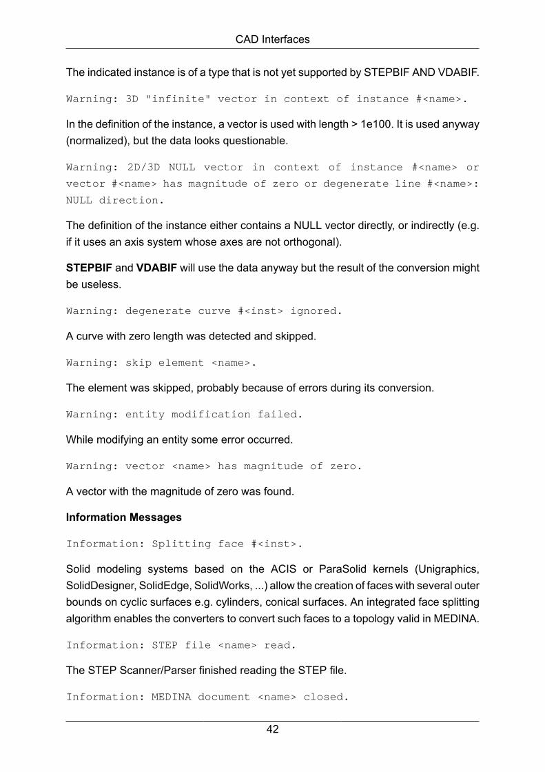
The indicated instance is of a type that is not yet supported by STEPBIF AND VDABIF.
Warning: 3D "infinite" vector in context of instance #<name>.
In the definition of the instance, a vector is used with length > 1e100. It is used anyway(normalized), but the data looks questionable.
Warning: 2D/3D NULL vector in context of instance #<name> or
vector #<name> has magnitude of zero or degenerate line #<name>:
NULL direction.
The definition of the instance either contains a NULL vector directly, or indirectly (e.g.if it uses an axis system whose axes are not orthogonal).
STEPBIF and VDABIF will use the data anyway but the result of the conversion mightbe useless.
Warning: degenerate curve #<inst> ignored.
A curve with zero length was detected and skipped.
Warning: skip element <name>.
The element was skipped, probably because of errors during its conversion.
Warning: entity modification failed.
While modifying an entity some error occurred.
Warning: vector <name> has magnitude of zero.
A vector with the magnitude of zero was found.
Information Messages
Information: Splitting face #<inst>.
Solid modeling systems based on the ACIS or ParaSolid kernels (Unigraphics,SolidDesigner, SolidEdge, SolidWorks, ...) allow the creation of faces with several outerbounds on cyclic surfaces e.g. cylinders, conical surfaces. An integrated face splittingalgorithm enables the converters to convert such faces to a topology valid in MEDINA.
Information: STEP file <name> read.
The STEP Scanner/Parser finished reading the STEP file.
Information: MEDINA document <name> closed.
42
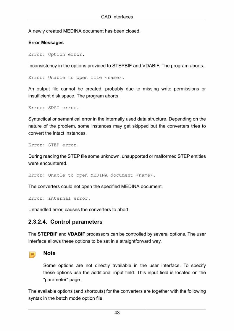
CAD Interfaces
A newly created MEDINA document has been closed.
Error Messages
Error: Option error.
Inconsistency in the options provided to STEPBIF and VDABIF. The program aborts.
Error: Unable to open file <name>.
An output file cannot be created, probably due to missing write permissions orinsufficient disk space. The program aborts.
Error: SDAI error.
Syntactical or semantical error in the internally used data structure. Depending on thenature of the problem, some instances may get skipped but the converters tries toconvert the intact instances.
Error: STEP error.
During reading the STEP file some unknown, unsupported or malformed STEP entitieswere encountered.
Error: Unable to open MEDINA document <name>.
The converters could not open the specified MEDINA document.
Error: internal error.
Unhandled error, causes the converters to abort.
2.3.2.4. Control parameters
The STEPBIF and VDABIF processors can be controlled by several options. The userinterface allows these options to be set in a straightforward way.
Note
Some options are not directly available in the user interface. To specifythese options use the additional input field. This input field is located on the"parameter" page.
The available options (and shortcuts) for the converters are together with the followingsyntax in the batch mode option file:
43
CAD Interfaces
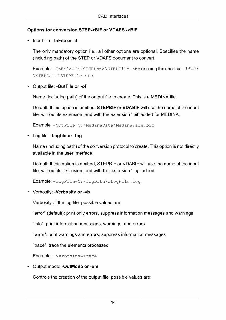
Options for conversion STEP->BIF or VDAFS ->BIF
• Input file: -InFile or -if
The only mandatory option i.e., all other options are optional. Specifies the name(including path) of the STEP or VDAFS document to convert.
Example: -InFile=C:\STEPData\STEPFile.stp or using the shortcut -if=C:\STEPData\STEPFile.stp
• Output file: -OutFile or -of
Name (including path) of the output file to create. This is a MEDINA file.
Default: If this option is omitted, STEPBIF or VDABIF will use the name of the inputfile, without its extension, and with the extension '.bif' added for MEDINA.
Example: -OutFile=C:\MedinaData\MedinaFile.bif
• Log file: -Logfile or -log
Name (including path) of the conversion protocol to create. This option is not directlyavailable in the user interface.
Default: If this option is omitted, STEPBIF or VDABIF will use the name of the inputfile, without its extension, and with the extension '.log' added.
Example: -LogFile=C:\logData\aLogFile.log
• Verbosity: -Verbosity or -vb
Verbosity of the log file, possible values are:
"error" (default): print only errors, suppress information messages and warnings
"info": print information messages, warnings, and errors
"warn": print warnings and errors, suppress information messages
"trace": trace the elements processed
Example: -Verbosity=Trace
• Output mode: -OutMode or -om
Controls the creation of the output file, possible values are:
44
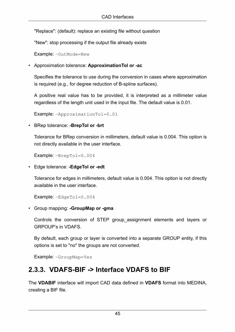
CAD Interfaces
"Replace": (default): replace an existing file without question
"New": stop processing if the output file already exists
Example: -OutMode=New
• Approximation tolerance: ApproximationTol or -ac
Specifies the tolerance to use during the conversion in cases where approximationis required (e.g., for degree reduction of B-spline surfaces).
A positive real value has to be provided, it is interpreted as a millimeter valueregardless of the length unit used in the input file. The default value is 0.01.
Example: -ApproximationTol=0.01
• BRep tolerance: -BrepTol or -brt
Tolerance for BRep conversion in millimeters, default value is 0.004. This option isnot directly available in the user interface.
Example: -BrepTol=0.004
• Edge tolerance: -EdgeTol or -edt
Tolerance for edges in millimeters, default value is 0.004. This option is not directlyavailable in the user interface.
Example: -EdgeTol=0.004
• Group mapping: -GroupMap or -gma
Controls the conversion of STEP group_assignment elements and layers orGRPOUP’s in VDAFS.
By default, each group or layer is converted into a separate GROUP entity, if thisoptions is set to "no" the groups are not converted.
Example: -GroupMap=Yes
2.3.3. VDAFS-BIF -> Interface VDAFS to BIF
The VDABIF interface will import CAD data defined in VDAFS format into MEDINA,creating a BIF file.
45

CAD Interfaces
Please see the Control parameters for converting VDAFS to BIF.
Beside the control parameters described before, the VDA -> BIF Interface has onespecific option which is the geometry processing.
• "Without geometry processing" will call the old interface: It will translate allASCII numbers direct to binary numbers without checking or even processing them.This leads to a very fast converting of the VDA. But if the VDA file is faulty, a faulty BIFwill be created. Furthermore, the interface will crash with especial complex faces.
• "With geometry processing" enabled, the new interface will be called: Thisnew interface is based on the same technique as the ACISBIF, CATBIFV5, IGESBIF,JTBIF and STEPBIF. It does not only check the VDA file for errors, it also breaksclosed faces (cylinder) in several faces which may be handled much better inMEDINA.
In batch mode, use geom=1 to activate or geom=0 to deactivate the geometryprocessing.
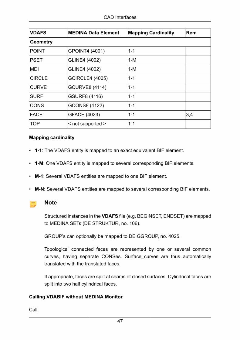
The next table describes the mapping of VDAFS entities to BIF.
The remarks in the right-hand column of the table are only related to the conversionof the VDAFS entities in the corresponding line.
Mapping table VDAFS - BIF
VDAFS MEDINA Data Element Mapping Cardinality Rem
Non geometric entities
HEADER GHEADER 1-M
BEGINSET,ENDSET
STRUKTUR (106) M-1 1
GROUP GGROUP (4025), groupnames are preserved
1-1 2
TMAT < not supported > 1-1
TLIST Create transformed copiesof elements referenced bythe TLIST
1-M
46
CAD Interfaces
VDAFS MEDINA Data Element Mapping Cardinality Rem
Geometry
POINT GPOINT4 (4001) 1-1
PSET GLINE4 (4002) 1-M
MDI GLINE4 (4002) 1-M
CIRCLE GCIRCLE4 (4005) 1-1
CURVE GCURVE8 (4114) 1-1
SURF GSURF8 (4116) 1-1
CONS GCONS8 (4122) 1-1
FACE GFACE (4023) 1-1 3,4
TOP < not supported > 1-1
Mapping cardinality
• 1-1: The VDAFS entity is mapped to an exact equivalent BIF element.
• 1-M: One VDAFS entity is mapped to several corresponding BIF elements.
• M-1: Several VDAFS entities are mapped to one BIF element.
• M-N: Several VDAFS entities are mapped to several corresponding BIF elements.
Note
Structured instances in the VDAFS file (e.g. BEGINSET, ENDSET) are mappedto MEDINA SETs (DE STRUKTUR, no. 106).
GROUP’s can optionally be mapped to DE GGROUP, no. 4025.
Topological connected faces are represented by one or several commoncurves, having separate CONSes. Surface_curves are thus automaticallytranslated with the translated faces.
If appropriate, faces are split at seams of closed surfaces. Cylindrical faces aresplit into two half cylindrical faces.
Calling VDABIF without MEDINA Monitor
Call:
47

CAD Interfaces
<inst_directory>/cae/bin/vdabif dat=name bif=name [geom={1|0}]
[options=name] [apptol=num] [msg={0|1}] (used for geom=1 only)
[dir=name] [log=name] [batch] [bit={32|64}]
If optional parameters are omitted, the first value of the numeration is the default value.
Note
For description of all options and arguments above go into the installationdirectory for load modules and enter the desired interface (e.g. vdabif).
2.3.4. IGES-BIF -> Interface IGES to BIF
SupportedEntities
Description
Type 100 Circular Arc Entity
Type 102 Composite Curve Entity
Type 104 Conic Arc Entity
Type 106 Copious Data Entity (etc). Forms 1, 2, and 3 created as collectionsof points. Forms 11, 12, and 13 created as two- or three-dimensional piecewise linear NURBS.
Type 108 Plane Entity. We support form 0 and form 1.
Type 110 Line Entity
Type 112 Parametric Spline Curve Entity
Type 114 Parametric Spline Surface Entity
Type 116 Point Entity
Type 118 Ruled Surface Entity
Type 120 Surface of Revolution Entity
Type 122 Tabulated Cylinder Entity. Here the parameterization might bemessed up, depending on the curves used to create the surface.If so, the above type 120 comments apply.
Type 124 Transformation Matrix Entity
Type 126 Rational B-Spline Curve Entity
Type 128 Rational B-Spline Surface Entity
Type 130 Offset Curve Entity
48

CAD Interfaces
SupportedEntities
Description
Type 140 Offset Surface Entity
Type 141 Boundary Entity
Type 142 Curve on a Parametric Surface Entity
Type 143 Bounded Surface Entity
Type 144 Trimmed (Parametric) Surface Entity
Type 158 Sphere Entity
Type 186 Manifold Solid B-Rep Object Entity
Type 190 Plane Surface Entity
Type 192 Right Circular Cylindrical Surface Entity
Type 194 Right Circular Conical Surface Entity
Type 196 Spherical Surface Entity
Type 198 Toroidal Surface Entity
Type 308 Subfigure Definition Entity
Type 408 Singular Subfigure Instance Entity
Type 504 Edge Entity
Type 508 Loop Entity
Type 510 Face Entity
Type 514 Shell Entity
This list contains all standard geometry entities in IGES. There are also a numberof entities designed for creating CSG solids which MEDINA does not have plans tosupport at the moment.
Calling IGESBIF without MEDINA Monitor
Call:
<inst_directory>/cae/bin/igesbif igs=name bif=name
[options=name] [apptol=num] [msg={0|1}] [dir=name] [log=name]
[batch] [bit={32|64}]
If optional parameters are omitted, the first value of the numeration is the default value.
49
CAD Interfaces
Note
For description of all options and arguments above go into the installationdirectory for load modules and enter the desired interface (e.g. igesbif).
2.3.5. JT-BIF -> Interface JT to BIF
JT is a mature lightweight data format that already enjoys widespread use in theautomobile and aerospace industries and is equally suitable for all manufacturingindustry applications.
JT has become the preferred common data format for many large end-users.
The JT data representation is CAD-neutral supporting all major MCAD applications.
JT data can be very lightweight, holding little more than facet data or it can be richerand hold associations to the original CAD information, assemblies, product structure,geometry, attributes, meta data and PMI.
It supports multiple tessellations and level-of-detail generation.
Mapping table JT - BIF
JTBIF converts data from the JT format file to the binary CAE-Databus format (BIF).
JTBIF does not create layers in BIF. But it is possible to activate or deactivate the layerfilter that deals with reading layers from a JT file. Add the following line into the optionsfile to deactivate the filter:
-JtReadActiveLayerFilter=IgnoreALF
The following table compares and describes the parameters in the MEDINA Monitorand the command line parameters for the tcl batch script:
Start MonitorParameter
Batch ScriptParameter
Description
Working directory dir=dirname Set the working directory for file access.
Input file jt=filename Formatted JT input file.
BIF output file bif=filename Binary file for MEDINA PreProcessing.
Replace existingfiles
(alwaysreplace)
The monitor toggle has two states: ON and OFF. Ifthe toggle is ON, existing files, e.g. the BIF output
50

CAD Interfaces
Start MonitorParameter
Batch ScriptParameter
Description
file, are overwritten. If called from a script, files arealways replaced.
Options file options Use this field to select an options file. Pressthe question button "?" to open the file selectionwindow.
Approximationtolerance
apptol=value An approximation tolerance value for the geometrymay be given here.
Additionalprogramparameters
batch
bit=32|64
warning
log=filename
Parameters shared by all interfaces (see chapter 1for a description).
Calling JTBIF without MEDINA Monitor
Call:
<inst_directory>/cae/bin/jtbif jt=name bif=name [options=name]
[apptol=num] [TesselationToFE={0|1}] [msg={0|1}] [dir=name]
[log=name] [batch] [bit={32|64}]
If optional parameters are omitted, the first value of the numeration is the default value.
Note
For description of all options and arguments above go into the installationdirectory for load modules and enter the desired interface (e.g. jtbif).
2.3.6. SAT-BIF -> Interface SAT to BIF
The 3D ACIS® Modeler (ACIS) is a 3D modeling kernel (or engine) owned by SpatialCorporation (formerly Spatial Technology).
SATBIF allows to convert SAT files (Standard ACIS Text Files) to MEDINA. CurrentlySAB files (Standard ACIS Binary) are not supported.
File Types
51
CAD Interfaces
The two formats store identical information, so the term SAT file is generally used torefer to either (when no distinction is needed).
SAT files are ASCII text files that may be viewed with a simple text editor. A SAT filecontains carriage returns, white space and other formatting that makes it readable tothe human eye. A SAT file has a .sat file extension.
SAB files cannot be viewed with a simple text editor and are meant for compactnessand not for human readability. A SAB file has a .sab file extension. A SAB file usesdelimiters between elements and binary tags, without additional formatting.
MEDINA requires a file in SAT format. You can check the format regardless of the fileextension if you open the file with a normal text editor.
If the file is readable, MEDINA will be able to convert it.
Structure of the file
A save file contains:
• a three-line header
• entity records, representing the bulk of the data
• optionally, a begin history data marker
• optionally, old entity records needed for history and rollback
• optionally, an end history data marker
• an end marker
For the SAT -> BIF interface only the standard settings are available.
52
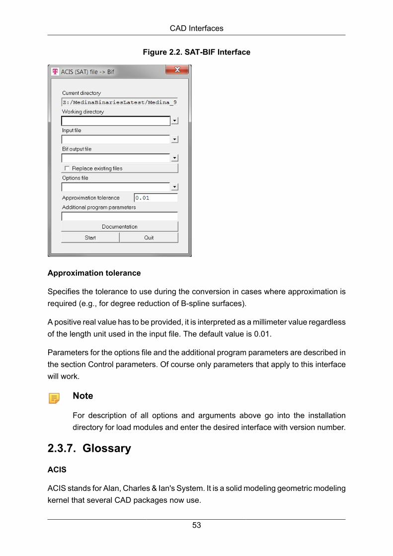
CAD Interfaces
Figure 2.2. SAT-BIF Interface
Approximation tolerance
Specifies the tolerance to use during the conversion in cases where approximation isrequired (e.g., for degree reduction of B-spline surfaces).
A positive real value has to be provided, it is interpreted as a millimeter value regardlessof the length unit used in the input file. The default value is 0.01.
Parameters for the options file and the additional program parameters are described inthe section Control parameters. Of course only parameters that apply to this interfacewill work.
Note
For description of all options and arguments above go into the installationdirectory for load modules and enter the desired interface with version number.
2.3.7. GlossaryACIS
ACIS stands for Alan, Charles & Ian's System. It is a solid modeling geometric modelingkernel that several CAD packages now use.
53
CAD Interfaces
ACIS uses a sophisticated object-oriented approach for modeling, the data is storedin boundary representation.
ACIS is owned by Spatial Technology. This was the author's second generation system,the first generation being Romulus. In 1999 around the time when Spatial was boughtout by Dassault Systemes, the file format changed slightly and was no longer openlypublished.
Application Protocol
The parts of STEP which can be implemented are called Application Protocols (APs).
This is a list of the most popular AP’s:
ISO 10303-203: Industrial automation systems and integration
• Product data representation and exchange
• Application protocol: Configuration controlled design
ISO 10303-201: Industrial automation systems and integration
• Product data representation and exchange
• Application protocol: Explicit draughting
ISO 10303-202: Industrial automation systems and integration
• Product data representation and exchange
• Application protocol: Associative draughting
ISO 10303-214: Industrial automation systems and integration
• Product data representation and exchange
Application protocol: Core data for automotive mechanical design processes
Conformance Class
STEP AP's are subdivided into so-called 'Conformance Classes'. These are partialscopes of an Application Protocol that can be implemented.
IGES
IGES (Initial Graphics Exchange Specification) was the first specification for CAD dataexchange published in 1980 as a NBS (National Bureau of Standards) report in USA.
54
CAD Interfaces
IGES version 1.0 was accepted and released in 1981 as an ANSI standard.
IGES is supported by all important CAD vendors and it is currently by far the mostwidespread standard for CADdata exchange.
IGES was originally developed for the exchange of drafting data like 2D/3D wireframemodels, text, dimensioning data, and a limited class of surfaces.
Due to criticism and bad experience with the data transfer using IGES, the standardhas been gradually extended and developed concerning supported entities, syntax,clarity, and consistency.
SAT
SAT stands for "Standard ACIS Text" and is one of two types of ACIS files (SAB,Standard ACIS Binary, being the other).
SAT files are ASCII text files that may be viewed with a text editor.
STEP
STEP (STandard for the Exchange of Product model data) is a new InternationalStandard (ISO 10303) for representing and exchanging product model information. Itincludes an object-flavored data specification language, EXPRESS, to describe therepresentation of the data.
STEP defines also implementation methods, for instance, a physical transfer file, andoffers different resources, e.g. geometric and topological representation.
The development of STEP started in 1984 as a worldwide collaboration. The goalwas to define a standard to cover all aspects of a product (i.e. geometry, topology,tolerances, materials, etc.), during its life time. This kind of attempt has not been madebefore.
STEP is a collection of standards to represent and exchange product information. Themain parts of STEP are already international standards, while many parts are still underdevelopment.
The development is performed under the control of the International Standardsorganization (ISO), Technical Committee 184 (TC184, Industrial Automation Systems),Subcommittee 4 (SC4, Industrial Data and Global Manufacturing ProgrammingLanguages).
VDAFS
55

CAD Interfaces
VDAFS (Vereinung Deutsche Automobilindustrie Flächen Schnittstelle)] is a Germanneutral file format for the exchange of surface geometry. It was developed to exchangefree form surfaces and it became a DIN standard in 1986.
VDAFS supports elementary curve and surface geometry entities and some topologyto define more complex models.
VDAFS is used by German automotive industry to define surface models, e.g. carbodies.
Bibliography
[1] VDA-Flächenschnittstelle Version 2.0
Verband der Automobilindustrie e.V. (VDA)
[2] PSstep_Caselib, ProSTEP Software Tool Kit, User Manual, Darmstadt 1994
[3] ISO 10303-203:1994, Industrial automation systems and integration
- Product data representation and exchange:
- Application protocol: Configuration controlled design
[4] ISO 10303-201:1994, Industrial automation systems and integration
- Product data representation and exchange:
- Application protocol: Explicit draughting
[5] ISO 10303-202:1996, Industrial automation systems and integration
- Product data representation and exchange:
- Application protocol: Associative draughting
[6] ISO 10303-214:---, Industrial automation systems and integration
- Product data representation and exchange:
- Application protocol: Core data for automotive mechanical design processes
- ISO TC 184/SC4 N335, CD1 from August 8, 1995
[7] ISO 10303-214:---, Industrial automation systems and integration
- Product data representation and exchange:
56

CAD Interfaces
- Application protocol: Core data for automotive mechanical design processes
- ISO TC 184/SC4 N582, CD2 from March 14, 1997
[8] ISO 10303-214:---, Industrial automation systems and integration
- Product data representation and exchange:
- Application protocol: Core data for automotive mechanical design processes
ISO TC 184/SC4 N335, DIS from February 20, 1999
2.4. STL -> STL InterfaceThe STL or stereo lithography file format is an ASCII or binary file used inmanufacturing.
It is a list of triangular surfaces and describes a solid model.
STL file format:
http://www.vr.clemson.edu/rp/rp_stlfile.htm
STL file is composed of a set of many unordered triangular facets. Its BNF format isdefined as followed:
<STL file>::=<facet 1><facet 2>...<facet n>
<facet>::=<normal>< vertex 1>< vertex 2><vertex 3>
<normal>::=<lx><ly><lz>
<vertex>::=<x><y><z>
STL file has two formats, ASCII format and BINARY format.
The ASCII format is described as followed: The first line in the file is the descriptionline, which contains the STL filename.
Facets begin from the second line: first is the normal of the facet, then the vertices.
The coordinates of the three vertices are given in the order that comply with the right-hand rule.
When the information of this triangle ends, then begins the next one. In this way, thewhole model is recorded.
Example: ASCII format STL file
57
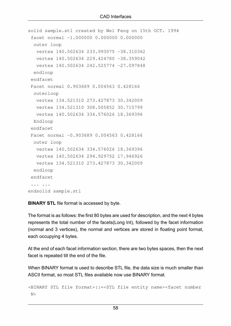
CAD Interfaces
solid sample.stl created by Wei Feng on 15th OCT. 1994
facet normal -1.000000 0.000000 0.000000
outer loop
vertex 140.502634 233.993075 -38.310362
vertex 140.502634 229.424780 -38.359042
vertex 140.502634 242.525774 -27.097848
endloop
endfacet
Facet normal 0.903689 0.004563 0.428166
outerloop
vertex 134.521310 273.427873 30.342009
vertex 134.521310 308.505852 30.715799
vertex 140.502634 334.576026 18.369396
Endloop
endfacet
Facet normal -0.903689 0.004563 0.428166
outer loop
vertex 140.502634 334.576026 18.369396
vertex 140.502634 294.929752 17.946926
vertex 134.521310 273.427873 30.342009
endloop
endfacet
... ...
endsolid sample.stl
BINARY STL file format is accessed by byte.
The format is as follows: the first 80 bytes are used for description, and the next 4 bytesrepresents the total number of the facets(Long Int), followed by the facet information(normal and 3 vertices), the normal and vertices are stored in floating point format,each occupying 4 bytes.
At the end of each facet information section, there are two bytes spaces, then the nextfacet is repeated till the end of the file.
When BINARY format is used to describe STL file, the data size is much smaller thanASCII format, so most STL files available now use BINARY format.
<BINARY STL file format>::=<STL file entity name><facet number
N>
58

CAD Interfaces
<facet info>
<STL file entity name >::=<80 bytes entity name, spaces are
used to fill the blank>
<facet number N>::=<4 bytes long integer>
<facet info>::=<facet normal><facet vertices><2 bytes spaces>
<facet normal><facet vertices><2 bytes spaces>
... ...
<facet normal>::=<lx,ly,lz, float, 12 bytes>
<facet vertex coordinates>::=<x1,y1,z1,x2,y2,z2,x3,y3,z3,
float, 36 bytes>
2.4.1. BIFSTL -> Interface BIF to STL
The BIFSTL interface converts MEDINA data (BIF) to a binary or ASCII STL file.
Option Meaning
bif=name Input: MEDINA data file name (e.g. test.bif)
dat=name Output: STL file name (e.g. test.stl)
type={binary|ascii} Output file type (default: binary)
endian={big|little} Byte ordering for binary STL files (default: big).
UNIX Risc processors usually use big-endian byte orderingwhile X86 processors use little-endian.
eol={unix|windows} End-of-line termination for ASCII STL files (default: unix).
UNIX workstations usually use CarriageReturn whileWindows PCs use CarriageReturn/LineFeed.
format=string Output format descriptor for floating point values in ASCIISTL files, C syntax (default: "%f")
Features
The BIFSTL interface reads nodes and Tria3 (CAE key 31) elements from input BIF file.Facet vertex coordinates are formed of the coordinates of Tria3 node points P1,P2,P3.
Facet normal vectors are computed as cross-product of vectors: x
Calling BIFSTL without MEDINA Monitor
Call:
59
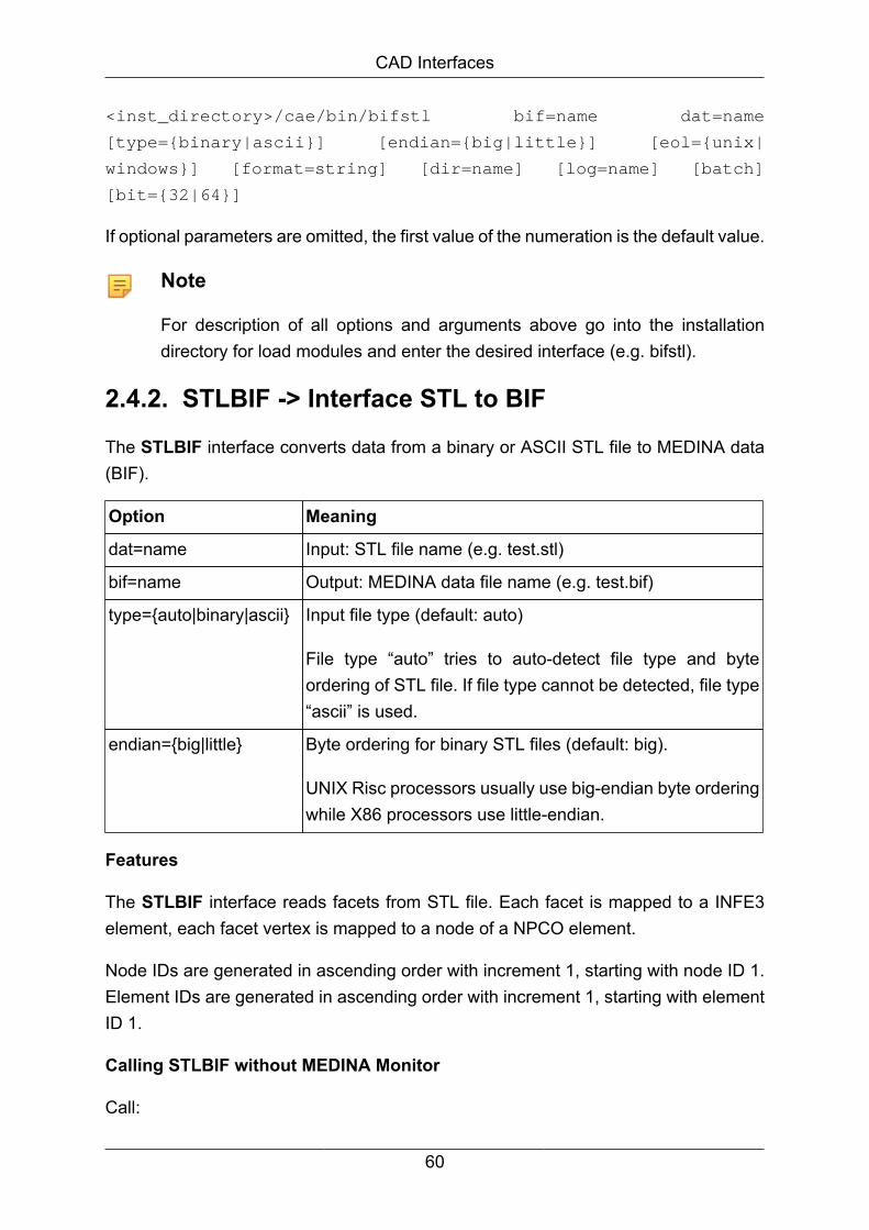
CAD Interfaces
<inst_directory>/cae/bin/bifstl bif=name dat=name
[type={binary|ascii}] [endian={big|little}] [eol={unix|
windows}] [format=string] [dir=name] [log=name] [batch]
[bit={32|64}]
If optional parameters are omitted, the first value of the numeration is the default value.
Note
For description of all options and arguments above go into the installationdirectory for load modules and enter the desired interface (e.g. bifstl).
2.4.2. STLBIF -> Interface STL to BIF
The STLBIF interface converts data from a binary or ASCII STL file to MEDINA data(BIF).
Option Meaning
dat=name Input: STL file name (e.g. test.stl)
bif=name Output: MEDINA data file name (e.g. test.bif)
type={auto|binary|ascii} Input file type (default: auto)
File type “auto” tries to auto-detect file type and byteordering of STL file. If file type cannot be detected, file type“ascii” is used.
endian={big|little} Byte ordering for binary STL files (default: big).
UNIX Risc processors usually use big-endian byte orderingwhile X86 processors use little-endian.
Features
The STLBIF interface reads facets from STL file. Each facet is mapped to a INFE3element, each facet vertex is mapped to a node of a NPCO element.
Node IDs are generated in ascending order with increment 1, starting with node ID 1.Element IDs are generated in ascending order with increment 1, starting with elementID 1.
Calling STLBIF without MEDINA Monitor
Call:
60

CAD Interfaces
<inst_directory>/cae/bin/stlbif dat=name bif=name [type={auto|
binary|ascii}] [endian={big|little}] [dir=name] [log=name]
[batch] [bit={32|64}]
If optional parameters are omitted, the first value of the numeration is the default value.
Note
For description of all options and arguments above go into the installationdirectory for load modules and enter the desired interface (e.g. stlbif).
2.5. Universal File Interface
2.5.1. UNI-BIF-BOF -> Interface Universal File to BIFand BOFUNIB*F converts data from the formatted Universal File to the binary CAE-Databusformat (BIF/BOF).
The following table compares and describes the parameters in the MEDINA Monitorand the command line parameters for the tcl batch script:
Start MonitorParameter
Batch ScriptParameter
Description
Workingdirectory
dir=dirname Set the working directory for file access.
Input file unv=filename Formatted UNIVERSAL input file.
BIF output file bif=filename Binary file for MEDINA PreProcessing.
BOF output file bof=filename Binary file for MEDINA PostProcessing.
Replaceexisting files
(alwaysreplace)
The monitor toggle has two states, ON and OFF. Ifthe toggle is ON, existing files, e.g. the BIF outputfile, are overwritten. If called from a script, files arealways replaced.
Additionalprogramparameters
batch
bit=32|64
log=filename
Parameters shared by all interfaces (see chapter 1for a description).
Supported data
61

CAD Interfaces
The following table lists the data translated from the UNIVERSAL to the MEDINA dataformat:
Universal File Data Sets CAE Data Element(MEDINA Element)
Remarks
Nodes (15, 781, 2411) NPCO Number of nodes limited to:
3 000 000
Coordinates Systems (18) CORSIS TRAFO
Element (71, 780, 2412) INFE (Continuouselements)
Number of elements is limitedto:
3 000 000
Trace line (82) PLOTEL, INFE2
Restraint Set (89, 755) SUPDOF, PREDOF
Load Set (90, 756, 782) SKNPCO, SKINFE
Universal File Data Sets CAE Data Element(MEDINA Element)
Remarks
Element Properties
Material Table (91, 731/747,772/773)
ESOLID, ESHELL,MAT1
Constrain Set (88, 754) MPC
Nodal Forces (90, 756, 782) FORCE
Data at Nodes (55, 2414) DEFO,DEFOK,NPST,SKNPCO,
VKNPCO
Without transformation fromlocal to global system
Data at Nodes on Elements(57, 2414)
SINFE, SINFEK Without transformation fromlocal to global system
Function at nodal DOF (58) DEFO (t) Without transformation fromlocal to global system (seeNote below)
Scalar results at elements(2414)
SKINFES Complex results are notsupported
62

CAD Interfaces
Note
All data sets 58 of an Universal File must fulfill the following restrictions:
- same order
- same frequencies (max 200)
- same nodes (max 400)
- three components (x,y,z) per node, x, y, and z are complex
A Data Set 58 must contain the following records and fields:
Recordnumber
Recorddefinition
Field number Field definition Remarks
6 DOFIdentification
6 Response node interpreted asnode
6 DOFIdentification
7 Responsedirection
interpreted ascomponent
only valuesbetween -3 and3 are supported(Rotation is notsupported).
7 Data Form 6 Z-axis value interpreted asorder = (Z-axisvalue)/60
12 Data Values interpreted asrevolutions perminute D(i)and a pairof measuredvalues with Re/Im:
D(i) Re(i) Im(i)D(i+1) Re(i+1)Im(i+1)
63

CAD Interfaces
Recordnumber
Recorddefinition
Field number Field definition Remarks
i= 1 to (numberof data pairs)/2
The following records and fields of data set 58 are supported:
Recordnumber
Recorddefinition
Field number Field definition Remarks
6 DOFIdentification
1 Function Type only value 12(Spectrum) issupported
7 Data Form 1 Ordinate Datatype
only value5 (complex,singleprecision) issupported
7 Data Form 3 AbscissaSpacing
only value 0(uneven) issupported
8 Abscissa DataChar
1 Specific Datatype
only value 1(general) andvalue 19 (rpm)are supported.
value 19 (rpm)will beconverted tofrequency(value 18)
9 Ordinate DataChar
1 Specific Datatype
only value 1(general) andvalue 19 (rpm)are supported.
If Field 7 ofRecord 6 is 0
64

CAD Interfaces
Recordnumber
Recorddefinition
Field number Field definition Remarks
the value 1(general) istreated as value15 (pressure)
value 19 (rpm)will beconverted tofrequency(value 18)
11 Z-axis
Data Char
1 Specific Datatype
only value 1(general) andvalue 19 (rpm)are supported.
value 19 (rpm)will beconverted tofrequency(value 18)
If the order or number of data pairs has been changed, all previously processed DataSets 58 will be converted to one CAE Data Element.
If a node with component occurs more than once within one frequency series, the lastvalue becomes valid.
For every frequency one CAE Data Element will be created for all nodes.
The element types LINE and PLANE are extensions. If necessary, LINEs can bechanged to PSETs with a text editor replacing the character strings ’LINE /’ by ’PSET /2, ’.
Calling UNIBIF without the MEDINA Monitor
Call:
<inst_directory>/cae/pgm/unibif unv=name bif=name bof=name
[dir=name] [log=name] [batch] [bit={32|64}]
65
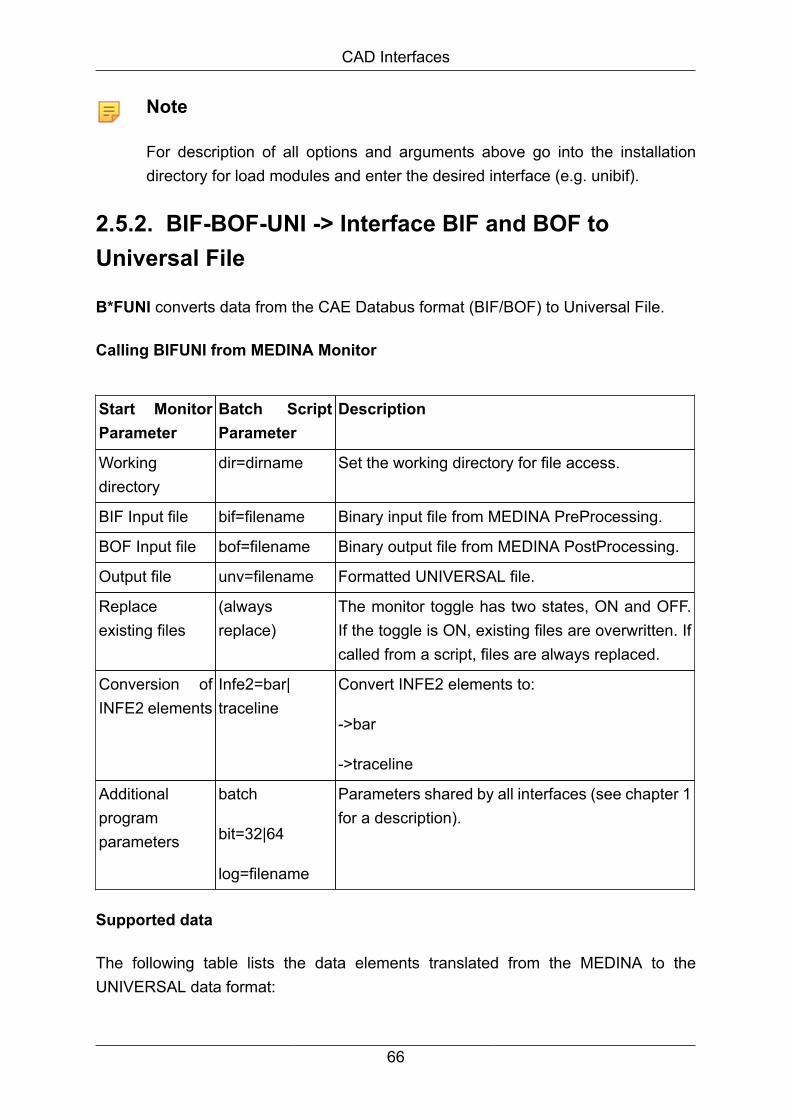
CAD Interfaces
Note
For description of all options and arguments above go into the installationdirectory for load modules and enter the desired interface (e.g. unibif).
2.5.2. BIF-BOF-UNI -> Interface BIF and BOF toUniversal File
B*FUNI converts data from the CAE Databus format (BIF/BOF) to Universal File.
Calling BIFUNI from MEDINA Monitor
Start MonitorParameter
Batch ScriptParameter
Description
Workingdirectory
dir=dirname Set the working directory for file access.
BIF Input file bif=filename Binary input file from MEDINA PreProcessing.
BOF Input file bof=filename Binary output file from MEDINA PostProcessing.
Output file unv=filename Formatted UNIVERSAL file.
Replaceexisting files
(alwaysreplace)
The monitor toggle has two states, ON and OFF.If the toggle is ON, existing files are overwritten. Ifcalled from a script, files are always replaced.
Conversion ofINFE2 elements
Infe2=bar|traceline
Convert INFE2 elements to:
->bar
->traceline
Additionalprogramparameters
batch
bit=32|64
log=filename
Parameters shared by all interfaces (see chapter 1for a description).
Supported data
The following table lists the data elements translated from the MEDINA to theUNIVERSAL data format:
66
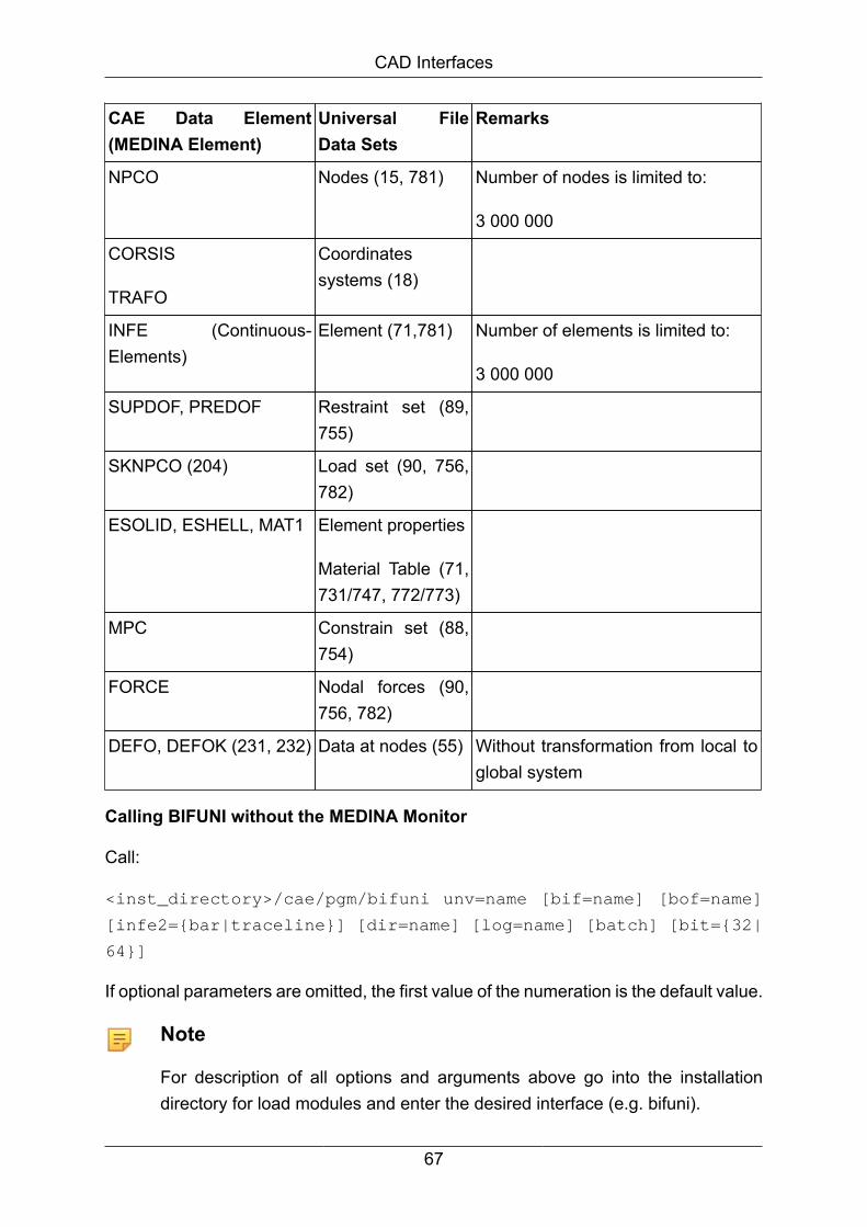
CAD Interfaces
CAE Data Element(MEDINA Element)
Universal FileData Sets
Remarks
NPCO Nodes (15, 781) Number of nodes is limited to:
3 000 000
CORSIS
TRAFO
Coordinatessystems (18)
INFE (Continuous-Elements)
Element (71,781) Number of elements is limited to:
3 000 000
SUPDOF, PREDOF Restraint set (89,755)
SKNPCO (204) Load set (90, 756,782)
ESOLID, ESHELL, MAT1 Element properties
Material Table (71,731/747, 772/773)
MPC Constrain set (88,754)
FORCE Nodal forces (90,756, 782)
DEFO, DEFOK (231, 232) Data at nodes (55) Without transformation from local toglobal system
Calling BIFUNI without the MEDINA Monitor
Call:
<inst_directory>/cae/pgm/bifuni unv=name [bif=name] [bof=name]
[infe2={bar|traceline}] [dir=name] [log=name] [batch] [bit={32|
64}]
If optional parameters are omitted, the first value of the numeration is the default value.
Note
For description of all options and arguments above go into the installationdirectory for load modules and enter the desired interface (e.g. bifuni).
67

Chapter 3. Modeling Interfaces3.1. AutoSEA -> Interface to AUTOSEAThe AutoSEA interface converts BIF data to the AutoSEA data.
3.1.1. BIFSEA -> Interface BIF to AUTOSEAThe interface program BIFSEA converts MEDINA BIF files into AutoSEA input files(NEUTRAL-ASCII-File format).
Option Meaning
bif=name Input: MEDINA bif file name
dat=name Output: AutoSEA data file name
template=name Input: Name of the template file [optional]
The interface converts subsystems into a doubly-curved plate of the type "FACE /SPHEROIDAL_CAP".
A subsystem is defined in MEDINA as a connected TRIA3 mesh with any boundarynodes and one center node.
All TRIA3 elements in a subsystem must have the same property ID.
Example of a plate definition:
# property label
FACE 1 {
SPHEROIDAL_CAP {
NODES_LIST {
4000010
4000016
4000017
4000018
4000011
4000681
}
}
}
68

Modeling Interfaces
The comment line "#" before the plate definition contains the property label.
The last node in the node list is the center node of the subsystem.
Example of a subsystem in MEDINA with shrink factor = 0.1:
Definition of the node coordinates:
# Nodes
NODES {
NODE {
NODE_ID 4000001
NODE_NAME "4000001"
POSITION (1.69854,-0.769085,0.623066)
}
}
The node coordinates are in the global coordinate system. The NODE_NAMEcorresponds to the node ID.
Figure 3.1. Visual result
Calling BIFSEA without MEDINA Monitor
Call:
<inst_directory>/cae/bin/bifsea bif=name dat=name
[template=name] [size=number] [dir=name] [log=name]
[warning=number] [batch] [bit={32|64}]
If optional parameters are omitted, the first value of the numeration is the default value.
69

Modeling Interfaces
Note
For description of all options and arguments above go into the installationdirectory for load modules and enter the desired interface (e.g. bifsea).
3.2. PATRAN -> PATRAN Neutral FileInterfaceBIFPAT/PATBIF converts MEDINA data (BIF) into PATRAN data (Neutral File Format)and vice versa according to PATRAN Plus User Manual, September 1989.
3.2.1. BIFPAT -> Interface BIF to PATRANBIFPAT converts MEDINA data (BIF Format) into PATRAN input data.
Calling BIFPAT from the MEDINA Monitor
The following table compares and describes the parameters in the Start Monitor andthe command line parameters for the tcl batch script:
Start MonitorParameter
Batch ScriptParameter
Description
Workingdirectory
dir=dirname Set the working directory for file access.
BIF Input file bif=filename Binary input file from MEDINA PreProcessing.
Output file pat=filename Formatted output file used as PATRAN input deck.
Replaceexisting files
(alwaysreplace)
The monitor toggle has two states, ON and OFF. Ifthe toggle is ON, existing files, e.g. the PATRAN inputfile, are overwritten. If called from a script, files arealways replaced.
Additionalprogramparameters
bit=32|64
log=filename
Parameters shared by all interfaces (see chapter 1 fora description).
Calling BIFPAT without MEDINA Monitor
Call:
<inst_directory>/cae/bin/bifpat bif=name pat=name [dir=name]
[log=name] [bit={32|64}]
70

Modeling Interfaces
Option Meaning
bif=name Input: MEDINA data file name (e.g. test.bif)
pat=name Output: PATRAN data file name (e.g. test.pat)
Note
For description of all options and arguments above go into the installationdirectory for load modules and enter the desired interface (e.g. bifpat).
Supported data
The following table lists the data translated from the MEDINA to the PATRAN dataformat:
CAE Data Element(MEDINA Element)
PATRAN DataPacket Type(TypeID)
Remarks
TEXT Title Card (25) Extracted out of text line following a linecontaining /TITLE/ (max. length of text line is256 characters)
Headers of severaldata elements
Summary Data(26)
NPCO Node Data (1) Coordinates transformed into globalcartesian system:
Number of DOF = 6
Node type = G
Condensation flag set to 1
Node CONFIG set to 0
INFE2, GEINFE2
INFE3
INFE4
INFE4S
INFE6
Element Data (2)
additionalElementProperties (4)
Associated data not considered (exceptionbars)
CONFIG of element not considered
Material orientation angles not considered
Congruent element ID set to 0
71
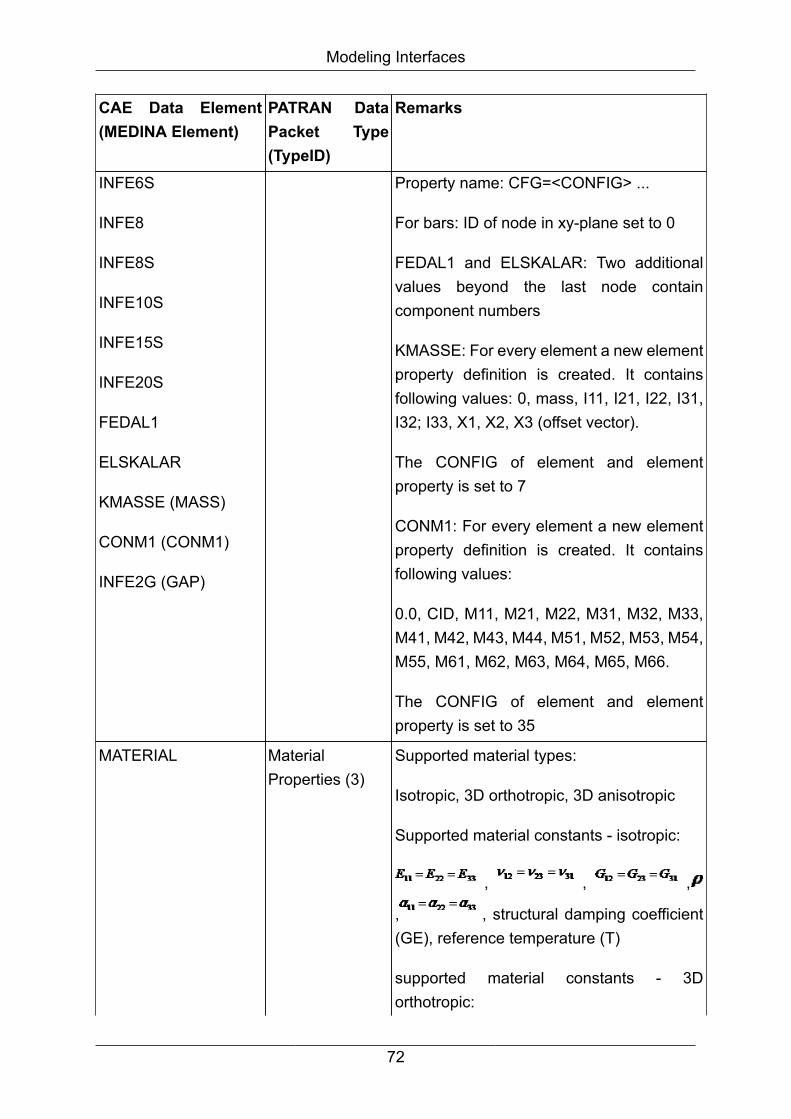
Modeling Interfaces
CAE Data Element(MEDINA Element)
PATRAN DataPacket Type(TypeID)
Remarks
INFE6S
INFE8
INFE8S
INFE10S
INFE15S
INFE20S
FEDAL1
ELSKALAR
KMASSE (MASS)
CONM1 (CONM1)
INFE2G (GAP)
Property name: CFG=<CONFIG> ...
For bars: ID of node in xy-plane set to 0
FEDAL1 and ELSKALAR: Two additionalvalues beyond the last node containcomponent numbers
KMASSE: For every element a new elementproperty definition is created. It containsfollowing values: 0, mass, I11, I21, I22, I31,I32; I33, X1, X2, X3 (offset vector).
The CONFIG of element and elementproperty is set to 7
CONM1: For every element a new elementproperty definition is created. It containsfollowing values:
0.0, CID, M11, M21, M22, M31, M32, M33,M41, M42, M43, M44, M51, M52, M53, M54,M55, M61, M62, M63, M64, M65, M66.
The CONFIG of element and elementproperty is set to 35
MATERIAL MaterialProperties (3)
Supported material types:
Isotropic, 3D orthotropic, 3D anisotropic
Supported material constants - isotropic:
, , ,
, , structural damping coefficient(GE), reference temperature (T)
supported material constants - 3Dorthotropic:
72

Modeling Interfaces
CAE Data Element(MEDINA Element)
PATRAN DataPacket Type(TypeID)
Remarks
, , , , , , , , , ,
, , , , words 83-85
supported material constants - 3Danisotropic:
, , , (6 thermal expansion
coefficients), (21 material stiffness matrixterms)
PROPERTY of typeROD, BAR, BEAM,SHELL, SOLID,SPRING, DAEMPFERor MASSE
TEXT
ElementProperties (4)
Property name: CFG=<CONFIG> ...
Negative PIDs not considered
Material ID is extracted out of PROPERTYelement (for BAR, ROD, BEAM, SHELL,SOLID)
CONFIG of elements specified in filepatran.cfg in the directory .medina in user'shome directory
Shape and number of nodes are taken fromcorresponding element with the smallestelement ID (if not found: SHELL 4/4, SOLID8/8)
Property values:
1. extracted out of text lines following a linewith:
´/PROPERTY/ ID=<PID>´ (for eachproperty)
2. each line except the last one has tocontain exactly five property values
73
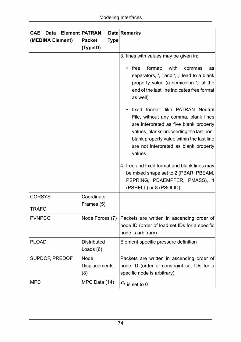
Modeling Interfaces
CAE Data Element(MEDINA Element)
PATRAN DataPacket Type(TypeID)
Remarks
3. lines with values may be given in:
• free format: with commas asseparators, ‘,,’ and ‘, ,’ lead to a blankproperty value (a semicolon ‘;’ at theend of the last line indicates free formatas well)
• fixed format: like PATRAN NeutralFile, without any comma, blank linesare interpreted as five blank propertyvalues, blanks proceeding the last non-blank property value within the last lineare not interpreted as blank propertyvalues
4. free and fixed format and blank lines maybe mixed shape set to 2 (PBAR, PBEAM,PSPRING, PDAEMPFER, PMASS), 4(PSHELL) or 8 (PSOLID)
CORSYS
TRAFO
CoordinateFrames (5)
PVNPCO Node Forces (7) Packets are written in ascending order ofnode ID (order of load set IDs for a specificnode is arbitrary)
PLOAD DistributedLoads (6)
Element specific pressure definition
SUPDOF, PREDOF NodeDisplacements(8)
Packets are written in ascending order ofnode ID (order of constraint set IDs for aspecific node is arbitrary)
MPC MPC Data (14) is set to 0
74

Modeling Interfaces
CAE Data Element(MEDINA Element)
PATRAN DataPacket Type(TypeID)
Remarks
MPC-IDs are generated by BIFPAT (startingat 1), rigid elements are followed by generalMPCs
MPC-ID from BIF becomes MPC-SETID inneutral file
RINFE2 (RROD) MPC Data (14) Element ID from BIF becomes MPC-ID inneutral file
MPC-SETID set to 50
NDT set to 0
is set to 0
in data cards 2 and 3:
1. dependent DOF
2. 6 independent DOFs
RINFE2 (RBAR) MPC Data (14) Element ID from BIF becomes MPC-ID inneutral file
MPC-SETID set to 10
NDT set to 0
is set to 0
Coefficients C(I) set to 1
in data cards 2, 3, ...:
1. all dependent DOFs
2. 6 independent DOFs
RBE2 (RBE2) MPC Data (14) Element ID from BIF becomes MPC-ID inneutral file
75

Modeling Interfaces
CAE Data Element(MEDINA Element)
PATRAN DataPacket Type(TypeID)
Remarks
MPC-SETID set to 30
NDT set to 0
is set to 0
Coefficients C(I) set to 1
in data cards 2, 3, ...:
1. all dependent DOFs
2. 6 independent DOFs
SET NAMEdComponentDefinition (21)
Set text: ID=<Set-ID> NAME=<Name> (linemay be up to 40 characters long)
Supported types: node, bar, triangle,quadrilateral, tetrahedron, wedge,hexahedron, coordinate frame, multi-pointconstraints (the latter two cannot be handledwithin MEDINA)
TEXT NAMEdComponentDefinition (21)
Coordinate frames and multi pointconstraints are extracted out of text linesfollowing a lines with:
/NAME/ ID=<NameID> NAME=<Name> infirst line, CID=CID1,CID2, ... in second lineand MPCID=MPCID1, MPCID2, ... in thirdline
TEXT LIST Card (40) LIST cards are extracted out of text linesfollowing a line with /LIST/ ID=<ListID>
TEXT DATA Card (41) DATA cards are extracted out of text linesfollowing a line with /DATA/ ID=<DataID>
Note
<varName> means content of variable varName
76
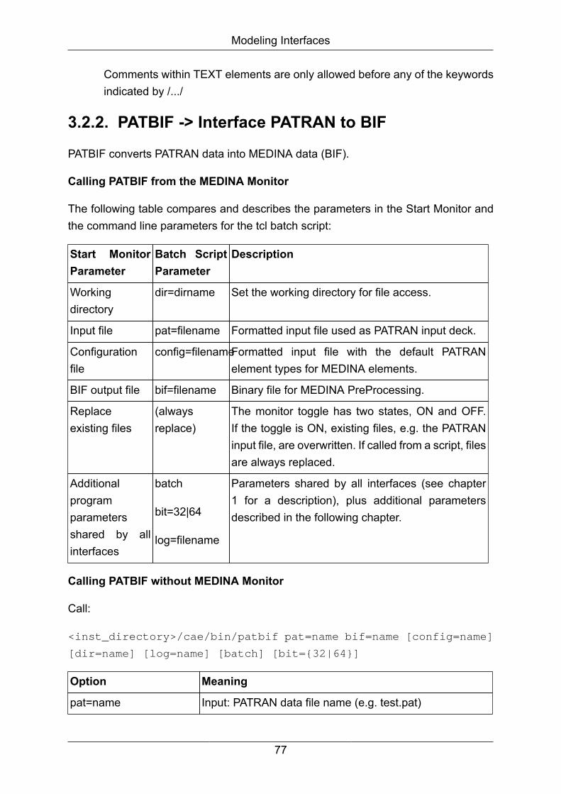
Modeling Interfaces
Comments within TEXT elements are only allowed before any of the keywordsindicated by /.../
3.2.2. PATBIF -> Interface PATRAN to BIF
PATBIF converts PATRAN data into MEDINA data (BIF).
Calling PATBIF from the MEDINA Monitor
The following table compares and describes the parameters in the Start Monitor andthe command line parameters for the tcl batch script:
Start MonitorParameter
Batch ScriptParameter
Description
Workingdirectory
dir=dirname Set the working directory for file access.
Input file pat=filename Formatted input file used as PATRAN input deck.
Configurationfile
config=filenameFormatted input file with the default PATRANelement types for MEDINA elements.
BIF output file bif=filename Binary file for MEDINA PreProcessing.
Replaceexisting files
(alwaysreplace)
The monitor toggle has two states, ON and OFF.If the toggle is ON, existing files, e.g. the PATRANinput file, are overwritten. If called from a script, filesare always replaced.
Additionalprogramparametersshared by allinterfaces
batch
bit=32|64
log=filename
Parameters shared by all interfaces (see chapter1 for a description), plus additional parametersdescribed in the following chapter.
Calling PATBIF without MEDINA Monitor
Call:
<inst_directory>/cae/bin/patbif pat=name bif=name [config=name]
[dir=name] [log=name] [batch] [bit={32|64}]
Option Meaning
pat=name Input: PATRAN data file name (e.g. test.pat)
77
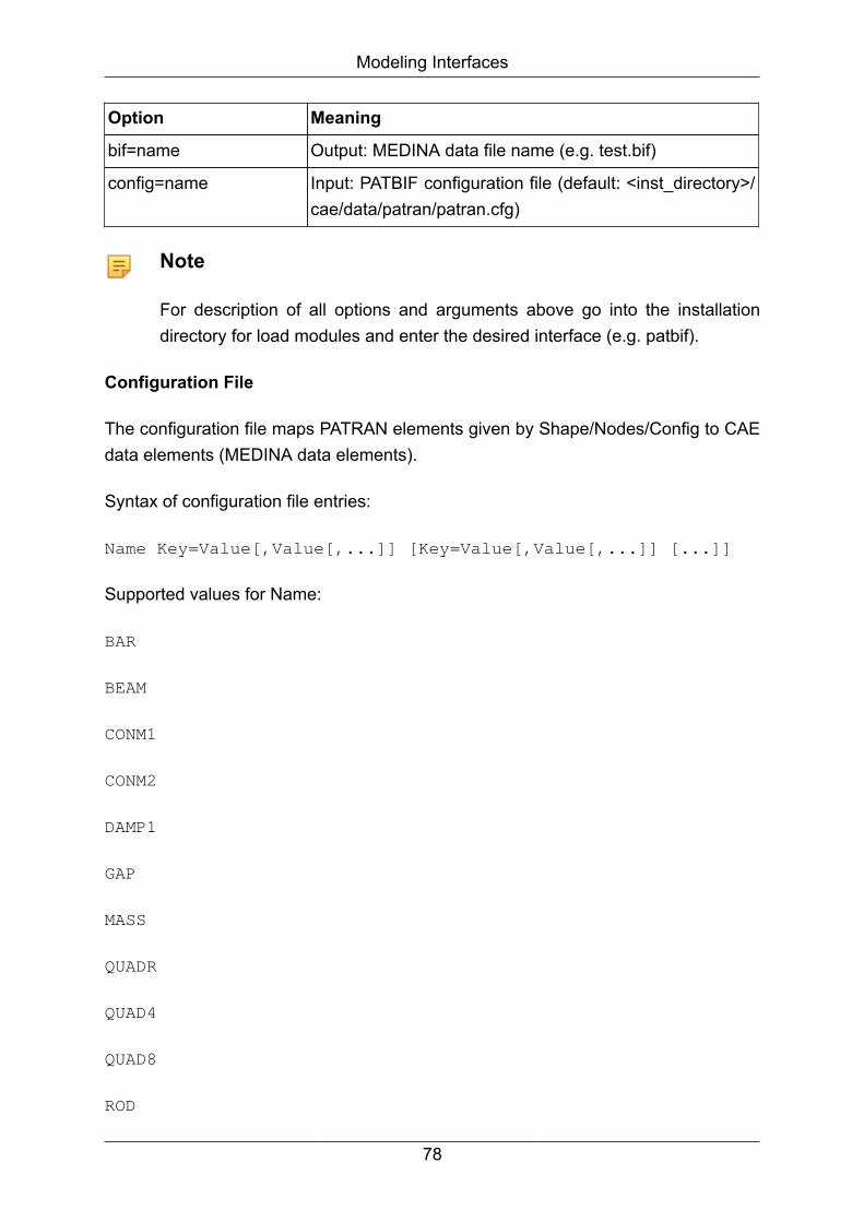
Modeling Interfaces
Option Meaning
bif=name Output: MEDINA data file name (e.g. test.bif)
config=name Input: PATBIF configuration file (default: <inst_directory>/cae/data/patran/patran.cfg)
Note
For description of all options and arguments above go into the installationdirectory for load modules and enter the desired interface (e.g. patbif).
Configuration File
The configuration file maps PATRAN elements given by Shape/Nodes/Config to CAEdata elements (MEDINA data elements).
Syntax of configuration file entries:
Name Key=Value[,Value[,...]] [Key=Value[,Value[,...]] [...]]
Supported values for Name:
BAR
BEAM
CONM1
CONM2
DAMP1
GAP
MASS
QUADR
QUAD4
QUAD8
ROD
78
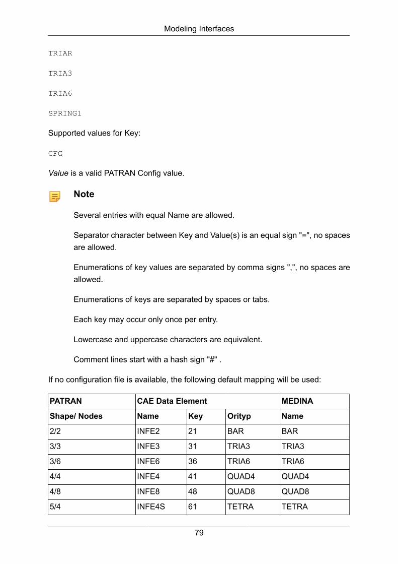
Modeling Interfaces
TRIAR
TRIA3
TRIA6
SPRING1
Supported values for Key:
CFG
Value is a valid PATRAN Config value.
Note
Several entries with equal Name are allowed.
Separator character between Key and Value(s) is an equal sign "=", no spacesare allowed.
Enumerations of key values are separated by comma signs ",", no spaces areallowed.
Enumerations of keys are separated by spaces or tabs.
Each key may occur only once per entry.
Lowercase and uppercase characters are equivalent.
Comment lines start with a hash sign "#" .
If no configuration file is available, the following default mapping will be used:
PATRAN CAE Data Element MEDINA
Shape/ Nodes Name Key Orityp Name
2/2 INFE2 21 BAR BAR
3/3 INFE3 31 TRIA3 TRIA3
3/6 INFE6 36 TRIA6 TRIA6
4/4 INFE4 41 QUAD4 QUAD4
4/8 INFE8 48 QUAD8 QUAD8
5/4 INFE4S 61 TETRA TETRA
79
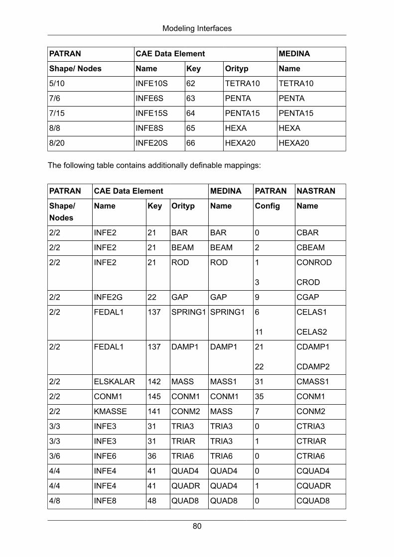
Modeling Interfaces
PATRAN CAE Data Element MEDINA
Shape/ Nodes Name Key Orityp Name
5/10 INFE10S 62 TETRA10 TETRA10
7/6 INFE6S 63 PENTA PENTA
7/15 INFE15S 64 PENTA15 PENTA15
8/8 INFE8S 65 HEXA HEXA
8/20 INFE20S 66 HEXA20 HEXA20
The following table contains additionally definable mappings:
PATRAN CAE Data Element MEDINA PATRAN NASTRAN
Shape/Nodes
Name Key Orityp Name Config Name
2/2 INFE2 21 BAR BAR 0 CBAR
2/2 INFE2 21 BEAM BEAM 2 CBEAM
2/2 INFE2 21 ROD ROD 1
3
CONROD
CROD
2/2 INFE2G 22 GAP GAP 9 CGAP
2/2 FEDAL1 137 SPRING1 SPRING1 6
11
CELAS1
CELAS2
2/2 FEDAL1 137 DAMP1 DAMP1 21
22
CDAMP1
CDAMP2
2/2 ELSKALAR 142 MASS MASS1 31 CMASS1
2/2 CONM1 145 CONM1 CONM1 35 CONM1
2/2 KMASSE 141 CONM2 MASS 7 CONM2
3/3 INFE3 31 TRIA3 TRIA3 0 CTRIA3
3/3 INFE3 31 TRIAR TRIA3 1 CTRIAR
3/6 INFE6 36 TRIA6 TRIA6 0 CTRIA6
4/4 INFE4 41 QUAD4 QUAD4 0 CQUAD4
4/4 INFE4 41 QUADR QUAD4 1 CQUADR
4/8 INFE8 48 QUAD8 QUAD8 0 CQUAD8
80

Modeling Interfaces
Features
PATRAN DataPacket Type(TypeID)
CAE Data Element(MEDINA Element)
Remarks
Title Card (25) TEXT Inserted into text lines following a linecontaining /TITLE/
Summary Data(26)
Don't need correction
Node Data (1) NPCO Node type not considered
CONFIG not supported
Element Data (2) INFE2 (BAR/BEAM/ROD)
INFE2G (GAP)
INFE3 (TRIA3)
INFE3V (TRIA3)
INFE6 (TRIA6)
INFE6V (TRIA6V)
INFE4 (QUAD4)
INFE4V (QUAD4V)
INFE8 (QUAD8)
INFE8V (QUAD8V)
INFE4S (TETRA)
INFE10S (TETRA10)
INFE6S (PENTA)
INFE15S (PENTA15)
INFE8S (HEXA)
Associated data not considered(exception bars)
Bars: ID of node in xy-plane notconsidered
CONFIG of element must match propertyCONFIG (to keep consistency)
Material orientation angles notconsidered
Property name: CFG=<CONFIG> ...
CONFIG of elements specified in filepatran.cfg in the directory .medina inuser's home directory. If it is not availablefollowing default values apply:
Shape/Nodes CAE Data Elements
2/2 INFE2
3/3 INFE3
3/6 INFE6
4/4 INFE4
4/8 INFE8
81

Modeling Interfaces
PATRAN DataPacket Type(TypeID)
CAE Data Element(MEDINA Element)
Remarks
INFE20S (HEXA20)
FEDAL1 (SPRING1/DAMP1)
CONM1 (CONM1)
KMASSE (MASS)
ELSKALAR (MASS1)
GEINFE2 (BAR/BEAM)
5/4 INFE4S
5/10 INFE10S
7/6 INFE6S
7/15 INFE15S
8/8 INFE8S
8/20 INFE20S
Negative PIDs:
mapped to 1000000-PID
KMASSE: values of correspondingelement property are extracted andwritten into element by followingconvention:
*, mass, I11, I21, I22, I31, I32; I33, X1, X2,X3 (offset vector)
CONM1: values of correspondingelement property are extracted andwritten into element by followingconvention:
0.0, CID, M11, M21, M22, M31, M32,M33, M41, M42, M43, M44, M51, M52,M53, M54, M55, M61, M62, M63, M64,M65, M66
INFE3V, INFE4V, INFE6V, INFE8V: istaken as material orientation angle
MaterialProperties (3)
MATERIAL Supported material types:
isotropic, 3D orthotropic, 3D anisotropic
82
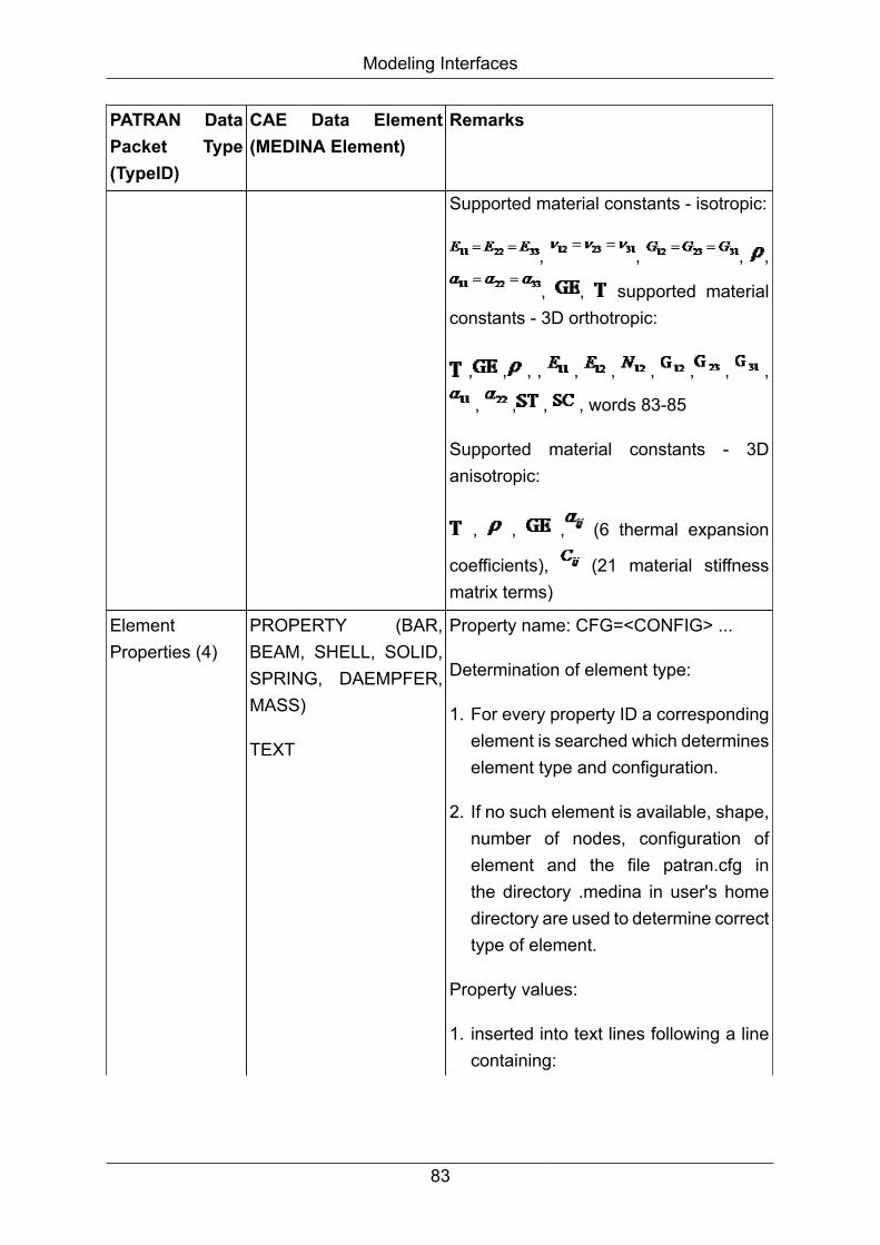
Modeling Interfaces
PATRAN DataPacket Type(TypeID)
CAE Data Element(MEDINA Element)
Remarks
Supported material constants - isotropic:
, , , ,
, , supported materialconstants - 3D orthotropic:
, , , , , , , , , ,
, , , , words 83-85
Supported material constants - 3Danisotropic:
, , , (6 thermal expansion
coefficients), (21 material stiffnessmatrix terms)
ElementProperties (4)
PROPERTY (BAR,BEAM, SHELL, SOLID,SPRING, DAEMPFER,MASS)
TEXT
Property name: CFG=<CONFIG> ...
Determination of element type:
1. For every property ID a correspondingelement is searched which determineselement type and configuration.
2. If no such element is available, shape,number of nodes, configuration ofelement and the file patran.cfg inthe directory .medina in user's homedirectory are used to determine correcttype of element.
Property values:
1. inserted into text lines following a linecontaining:
83

Modeling Interfaces
PATRAN DataPacket Type(TypeID)
CAE Data Element(MEDINA Element)
Remarks
´/PROPERTY/ ID=<PID>´ (for eachnew property)
2. inserted into PROPERTY elementsfollowing NASTRAN conventions:
PBAR: MID, A, I1, I2, J, NSM, C1, C2,D1, D2, E1, E2, F1, F2, K1, K2, I12
PBEAM: MID, A(A), I1(A), I2(A),I12(A), J(A), NSM(A)
PSHELL: MID1, T, MID2, 12I/T3,MID3, TS/T, NSM
PSOLID: MID, CORDM, IN, STRESS,ISOP
CAE data element KMASSE:
Values are extracted out of thecorresponding element property andwritten into element data by following
convention:
*, mass, I11, I21, I22, I31, I32; I33, X1, X2,X3 (offset vector).
The corresponding element property isdropped and does not appear in TEXTelements.
If SHELL element and its’ propertycontain additional layer values, INFExVelements are created .
84

Modeling Interfaces
PATRAN DataPacket Type(TypeID)
CAE Data Element(MEDINA Element)
Remarks
Several different element configurationsfor one element property:
A new element property with the samevalues is created for each elementconfiguration.
CoordinateFrames (5)
CORSYS
TRAFO
DistributedLoads (6)
PLOAD Element specific pressure definition
Restrictions:
only surface loads
only forces in z-direction
Forces have to act on all nodes of asurface (also for volume surfaces)
PLOAD ID is set to load set ID
Node Forces (7) PVNPCO
NodeDisplacements(8)
PREDOF/SUPDOF CID is not considered
MPC Data (14) MPC
RINFE2 (RROD)
RINFE2 (RBAR)
RBE2 (RBE2)
is set to 0
MPC-SETID becomes MPC-ID on BIF
packet with TYPE = ‘RIGID’ areinterpreted by NASPAT convention andtranslated to rigid elements
NAMEdComponentDefinition (21)
SET
TEXT
Set text: ID=<NameID> NAME=<Name>(name is truncated to 12 characters)
85

Modeling Interfaces
PATRAN DataPacket Type(TypeID)
CAE Data Element(MEDINA Element)
Remarks
Supported types: node, bar, triangle,quadrilateral, tetrahedron, wedge,hexahedron)
Coordinate frames and multi pointconstraints are inserted into textlines with /NAME/ ID=<NameID>NAME=<Name> in first line,CID=CID1,CID2, ... in second line andMPCID=MPCID1, MPCID2, ... in third line
LIST Card (40) TEXT LIST cards are inserted into text lineswhich start with /LIST/ ID=<ListID>
DATA Card (41) TEXT DATA cards are inserted into text lineswhich start with /DATA/ ID=<DataID>
Note
<varName means content of variable varName Syntax of file patran.cfg:
Name Key=Value[,Value[, ...] [Key=Value[,Value[, ...]]
[...]]
Name in { BAR, BEAM, ROD, GAP, TRIA3, TRIAR, TRIA6, QUAD4, QUADR,QUAD8, SPRING1, DAMP1, MASS, CONM1 CONM2}, Key in {CFG}
3.3. SYSTUS -> Interface to SYSTUSThe interface program systbof converts SYSTUS data to MEDINA BIFs and BOFs.
Call:
<inst_directory>/cae/bin/systbof bif=name bof=name dat=datfile
result=resultfile [warning=number]
Option Meaning
bif=name Output: MEDINA data file name (e.g. medina.bif). If nameis blank no BIF file will generated.
86
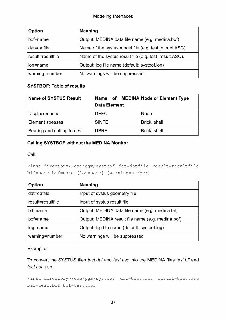
Modeling Interfaces
Option Meaning
bof=name Output: MEDINA data file name (e.g. medina.bof)
dat=datfile Name of the systus model file (e.g. test_model.ASC).
result=resultfile Name of the systus result file (e.g. test_result.ASC).
log=name Output: log file name (default: systbof.log)
warning=number No warnings will be suppressed.
SYSTBOF: Table of results
Name of SYSTUS Result Name of MEDINAData Element
Node or Element Type
Displacements DEFO Node
Element stresses SINFE Brick, shell
Bearing and cutting forces UBRR Brick, shell
Calling SYSTBOF without the MEDINA Monitor
Call:
<inst_directory>/cae/pgm/systbof dat=datfile result=resultfile
bif=name bof=name [log=name] [warning=number]
Option Meaning
dat=datfile Input of systus geometry file
result=resultfile Input of systus result file
bif=name Output: MEDINA data file name (e.g. medina.bif)
bof=name Output: MEDINA result file name (e.g. medina.bof)
log=name Output: log file name (default: systbof.log)
warning=number No warnings will be suppressed
Example:
To convert the SYSTUS files test.dat and test.asc into the MEDINA files test.bif andtest.bof, use:
<inst_directory>/cae/pgm/systbof dat=test.dat result=test.asc
bif=test.bif bof=test.bof
87

Chapter 4. Solver Interfaces
4.1. ABAQUS -> Interface to ABAQUSBIFABA/ABABIF converts MEDINA data (BIF) to ABAQUS data and vice-versaaccording to ABAQUS/Standard.
ABABOF/fil converts a binary or ASCII ABAQUS result file (.fil file) to MEDINA format(BIF and BOF).
ABABOF/odb converts a binary ABAQUS result file (.odb file) to MEDINA format (BIFand BOF).
4.1.1. ABAQUS - Control file
Using ABAQUS element names in MEDINA, it is necessary to read in a Config fileduring the start of MEDINA.
Solver-specific element names are defined unique by a Default Config file in MEDINAinstallation directory and additional by an User-defined Config file in $HOME/.medinadirectory.
First the Default Config file and after that a User-defined Config file are read in duringthe start of the MEDINA PreProcessing, whereas the definitions in the User-definedConfig file obtain higher priority.
At this time the default ABAQUS element names are defined and can be controlled byEList command in the column Name.
When saving a BIF, the element names are unique and can be converted to ABAQUS(with correct SURFACE identification).
Note
The User-defined Config file which could be defined in the BIFABA monitoris removed because the user shall use only one Config file.
User-Config-File
The User-defined Config file is defined in $HOME/.medina<version>.abq directory.
88

Solver Interfaces
In this file the input data can be written in 3 columns:
• In the 1st column the related MEDINA elements are defined
• In the 2nd column the related MEDINA properties are defined
• In the 3rd column the ABAQUS elements are defined (user default ABAQUSelements) and can be changed by the user
Note
The user shall change only the third column (see below).
# Med_Eletyp Med_Proptyp Abaqus_Eletyp
BAR BAR B31
QUAD4 SHELL S4R
TETRA10 SOLID C3D10
The other input data (e.g. the related property ID, the surface name, etc.) are managedby MEDINA.
4.1.2. BIFABA-> Interface BIF to ABAQUS
4.1.2.1. BIFABA - Parameters
BIF -> ABAQUS input
89

Solver Interfaces
Figure 4.1. BIFABA Interface
The following table compares and describes the parameters in the Start Monitor andthe command line parameters for the tcl batch script:
Start Monitor Batch Script Description
Working directory dir=dirname Set the working directory for file access.
BIF Input file bif=filename Binary input file from MEDINA PreProcessing.
Configuration file config=filename Formatted input file with the default ABAQUSelement types for MEDINA elements.
Output file inp=filename Formatted output file used as ABAQUS inputdeck.
Replace existingfiles
(always replace) The monitor toggle has two states, ON andOFF. If the toggle is ON, existing files, e.g. theBIF output file, are overwritten. If called from ascript, files are always replaced.
Discretizeconnectors
discrconn If this toggle is ON, or the parameter"discrconn" is entered at the script command
90
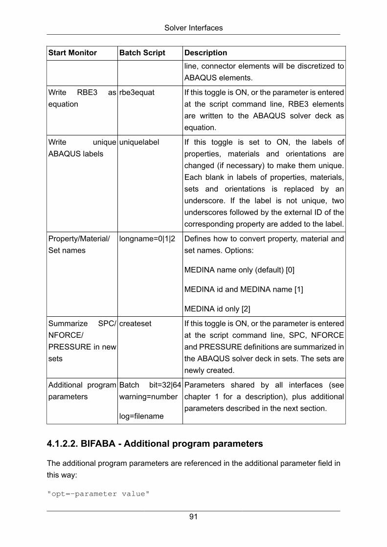
Solver Interfaces
Start Monitor Batch Script Descriptionline, connector elements will be discretized toABAQUS elements.
Write RBE3 asequation
rbe3equat If this toggle is ON, or the parameter is enteredat the script command line, RBE3 elementsare written to the ABAQUS solver deck asequation.
Write uniqueABAQUS labels
uniquelabel If this toggle is set to ON, the labels ofproperties, materials and orientations arechanged (if necessary) to make them unique.Each blank in labels of properties, materials,sets and orientations is replaced by anunderscore. If the label is not unique, twounderscores followed by the external ID of thecorresponding property are added to the label.
Property/Material/Set names
longname=0|1|2 Defines how to convert property, material andset names. Options:
MEDINA name only (default) [0]
MEDINA id and MEDINA name [1]
MEDINA id only [2]
Summarize SPC/NFORCE/PRESSURE in newsets
createset If this toggle is ON, or the parameter is enteredat the script command line, SPC, NFORCEand PRESSURE definitions are summarized inthe ABAQUS solver deck in sets. The sets arenewly created.
Additional programparameters
Batch bit=32|64warning=number
log=filename
Parameters shared by all interfaces (seechapter 1 for a description), plus additionalparameters described in the next section.
4.1.2.2. BIFABA - Additional program parameters
The additional program parameters are referenced in the additional parameter field inthis way:
"opt=-parameter value"
91
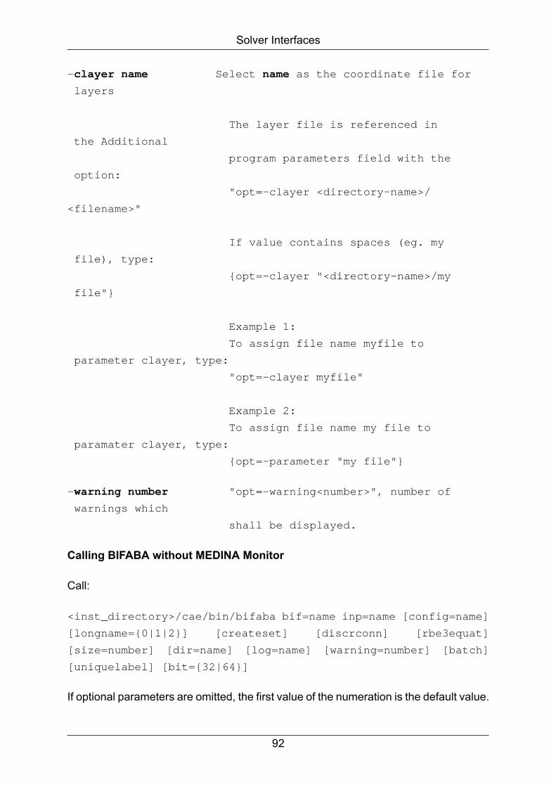
Solver Interfaces
-clayer name Select name as the coordinate file for
layers
The layer file is referenced in
the Additional
program parameters field with the
option:
"opt=-clayer <directory-name>/
<filename>"
If value contains spaces (eg. my
file), type:
{opt=-clayer "<directory-name>/my
file"}
Example 1:
To assign file name myfile to
parameter clayer, type:
"opt=-clayer myfile"
Example 2:
To assign file name my file to
paramater clayer, type:
{opt=-parameter "my file"}
-warning number "opt=-warning<number>", number of
warnings which
shall be displayed.
Calling BIFABA without MEDINA Monitor
Call:
<inst_directory>/cae/bin/bifaba bif=name inp=name [config=name]
[longname={0|1|2}] [createset] [discrconn] [rbe3equat]
[size=number] [dir=name] [log=name] [warning=number] [batch]
[uniquelabel] [bit={32|64}]
If optional parameters are omitted, the first value of the numeration is the default value.
92
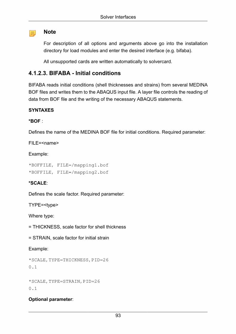
Solver Interfaces
Note
For description of all options and arguments above go into the installationdirectory for load modules and enter the desired interface (e.g. bifaba).
All unsupported cards are written automatically to solvercard.
4.1.2.3. BIFABA - Initial conditions
BIFABA reads initial conditions (shell thicknesses and strains) from several MEDINABOF files and writes them to the ABAQUS input file. A layer file controls the reading ofdata from BOF file and the writing of the necessary ABAQUS statements.
SYNTAXES
*BOF :
Defines the name of the MEDINA BOF file for initial conditions. Required parameter:
FILE=<name>
Example:
*BOFFILE, FILE=/mapping1.bof
*BOFFILE, FILE=/mapping2.bof
*SCALE:
Defines the scale factor. Required parameter:
TYPE=<type>
Where type:
= THICKNESS, scale factor for shell thickness
= STRAIN, scale factor for initial strain
Example:
*SCALE,TYPE=THICKNESS,PID=26
0.1
*SCALE,TYPE=STRAIN,PID=26
0.1
Optional parameter:
93
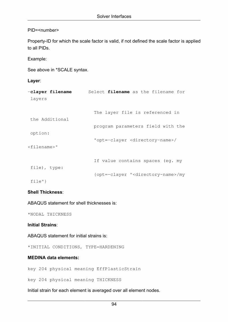
Solver Interfaces
PID=<number>
Property-ID for which the scale factor is valid, if not defined the scale factor is appliedto all PIDs.
Example:
See above in *SCALE syntax.
Layer:
-clayer filename Select filename as the filename for
layers
The layer file is referenced in
the Additional
program parameters field with the
option:
"opt=-clayer <directory-name>/
<filename>"
If value contains spaces (eg. my
file), type:
{opt=-clayer "<directory-name>/my
file"}
Shell Thickness:
ABAQUS statement for shell thicknesses is:
*NODAL THICKNESS
Initial Strains:
ABAQUS statement for initial strains is:
*INITIAL CONDITIONS, TYPE=HARDENING
MEDINA data elements:
key 204 physical meaning EffPlasticStrain
key 204 physical meaning THICKNESS
Initial strain for each element is averaged over all element nodes.
94

Solver Interfaces
4.1.2.4. BIFABA - Automatic node set detection
When writing the data elements NFORCE, SPC and PRESSURE, the BIFABAinterface automatically detects and writes node set IDs instead of numerous node IDswhen the above data elements have been created using node sets.
4.1.2.5. BIFABA - Beam Sections
The ABAQUS interface supports ABAQUS cross sections for beams (*BEAMSECTION).
If for a standard cross section in MEDINA there is an equivalent standard cross sectionin ABAQUS, BIFABA automatically detects and converts it.
If there is no equivalent cross section in ABAQUS (e.g. for a Z-Section in MEDINA),it is translated as a general cross section.
For a detailed list of cross sections in MEDINA and ABAQUS, see the list below.
See also: MEDINA PreProcessing Reference Manual, BeamSection command.
Cross Section MEDINA ABAQUS
Circle Circular
Tube Pipe
Rectangle Rectangular
Box Box
Triangle -
95
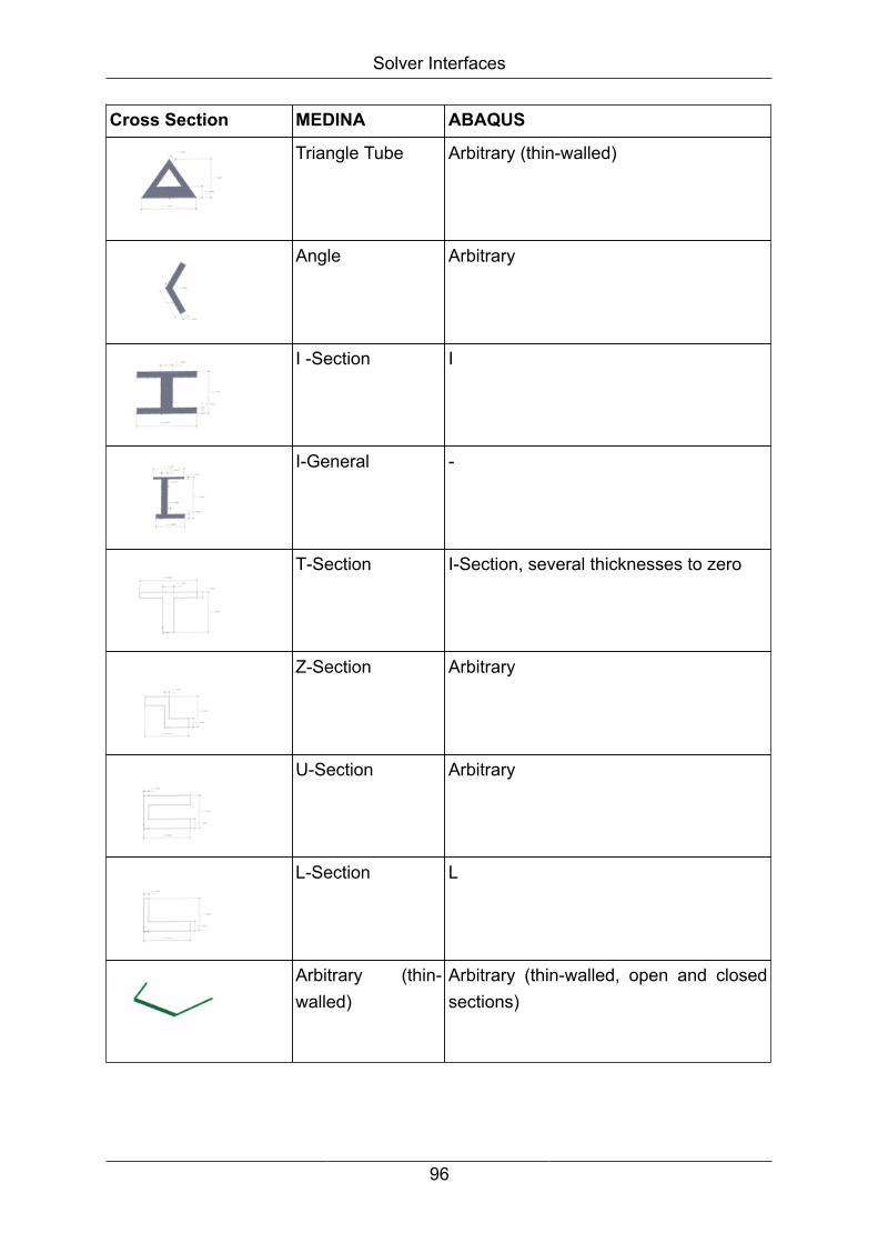
Solver Interfaces
Cross Section MEDINA ABAQUS
Triangle Tube Arbitrary (thin-walled)
Angle Arbitrary
I -Section I
I-General -
T-Section I-Section, several thicknesses to zero
Z-Section Arbitrary
U-Section Arbitrary
L-Section L
Arbitrary (thin-walled)
Arbitrary (thin-walled, open and closedsections)
96

Solver Interfaces
Cross Section MEDINA ABAQUS
--- (Arbitrary) Hexagonal
--- (Arbitrary) Trapezoidal
4.1.3. ABABIF -> Interface ABAQUS to BIF
4.1.3.1. ABABIF - Parameters
ABAQUS input -> BIF
Figure 4.2. ABABIF Interface
The following table compares and describes the parameters in the Start Monitor andthe command line parameters for the tcl batch script:
97
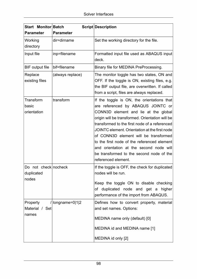
Solver Interfaces
Start MonitorParameter
Batch ScriptParameter
Description
Workingdirectory
dir=dirname Set the working directory for the file.
Input file inp=filename Formatted input file used as ABAQUS inputdeck.
BIF output file bif=filename Binary file for MEDINA PreProcessing.
Replaceexisting files
(always replace) The monitor toggle has two states, ON andOFF. If the toggle is ON, existing files, e.g.the BIF output file, are overwritten. If calledfrom a script, files are always replaced.
Transformbasicorientation
transform If the toggle is ON, the orientations thatare referenced by ABAQUS JOINTC orCONN3D element and lie at the globalorigin will be transformed. Orientation will betransformed to the first node of a referencedJOINTC element. Orientation at the first nodeof CONN3D element will be transformedto the first node of the referenced elementand orientation at the second node willbe transformed to the second node of thereferenced element.
Do not checkduplicatednodes
nocheck If the toggle is OFF, the check for duplicatednodes will be run.
Keep the toggle ON to disable checkingof duplicated node and get a higherperformance of the import from ABAQUS.
Property /Material / Setnames
longname=0|1|2 Defines how to convert property, materialand set names. Options:
MEDINA name only (default) [0]
MEDINA id and MEDINA name [1]
MEDINA id only [2]
98

Solver Interfaces
Start MonitorParameter
Batch ScriptParameter
Description
Additionalprogramparameters
batch
bit=32|64
warning=number
log=filename
Parameters shared by all interfaces (seechapter 1 for a description).
"opt=-warning <number>", number ofwarnings, which shall be displayed.
"opt=-abaqus_keyword <name>" ,readxml file to check ABAQUS input file.
Calling ABABIF without MEDINA Monitor
Call:
<inst_directory>/cae/bin/ababif bif=name inp=name [longname={0|
1|2}] [abaqus_keyword=name] [size=number] [transform] [dir=name]
[log=name] [warning=number] [batch] [nocheck] [bit={32|64}]
If optional parameters are omitted, the first value of the numeration is the default value.
Note
For the description of all options and arguments above go to the installationdirectory for load modules and enter the desired interface (e.g. ababif).
All unsupported cards are read automatically from the solvercard.
4.1.3.2. ABABIF - Search for include files
ABABIF searches for include files in the following manner:
1. If an absolute path is provided exactly this path will be used.
2. If a relative path is provided ABABIF will first search the directory in which the maindeck is situated in and after that in the working directory.
4.1.4. BIFABA/ABABIF
4.1.4.1. ABAQUS - Using properties to define element sets
Elements with the same property are defined as an element set. The name of theelement set is the name of the MEDINA property.
99
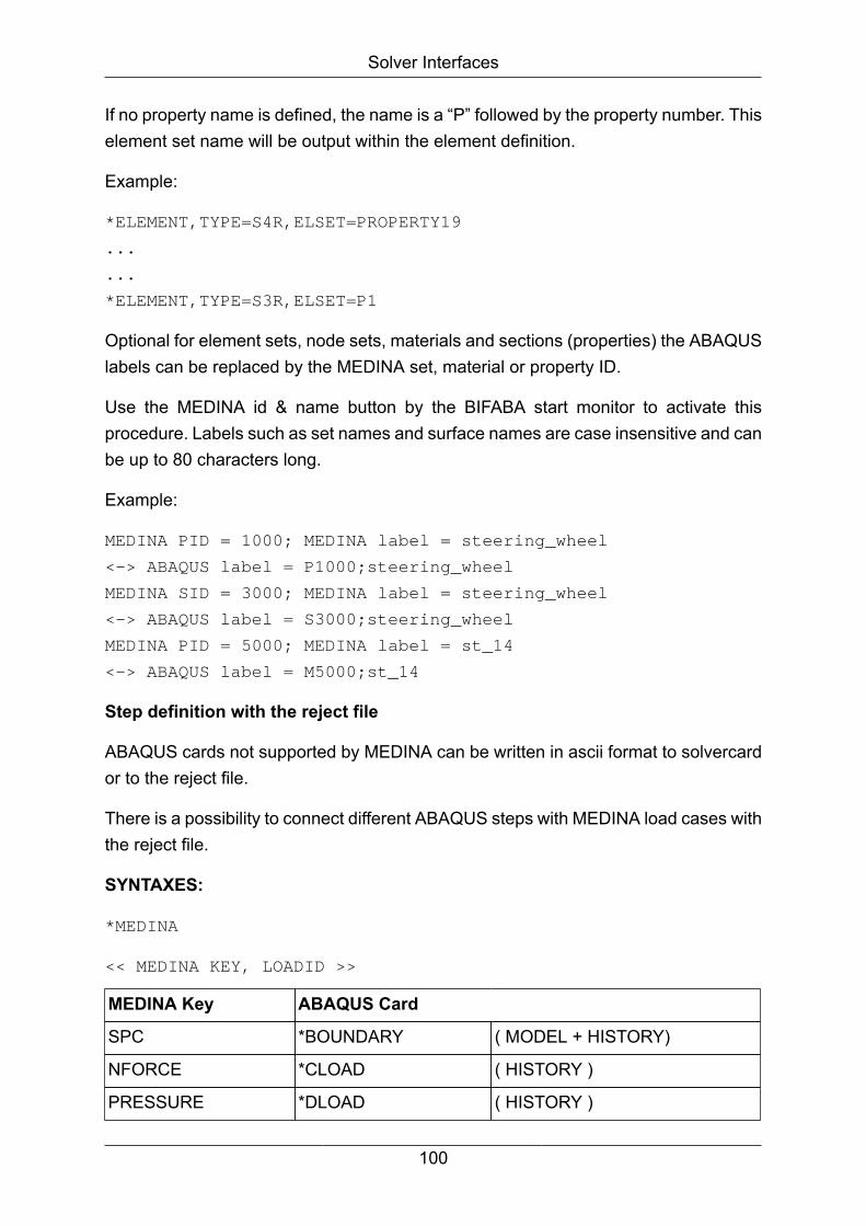
Solver Interfaces
If no property name is defined, the name is a “P” followed by the property number. Thiselement set name will be output within the element definition.
Example:
*ELEMENT,TYPE=S4R,ELSET=PROPERTY19
...
...
*ELEMENT,TYPE=S3R,ELSET=P1
Optional for element sets, node sets, materials and sections (properties) the ABAQUSlabels can be replaced by the MEDINA set, material or property ID.
Use the MEDINA id & name button by the BIFABA start monitor to activate thisprocedure. Labels such as set names and surface names are case insensitive and canbe up to 80 characters long.
Example:
MEDINA PID = 1000; MEDINA label = steering_wheel
<-> ABAQUS label = P1000;steering_wheel
MEDINA SID = 3000; MEDINA label = steering_wheel
<-> ABAQUS label = S3000;steering_wheel
MEDINA PID = 5000; MEDINA label = st_14
<-> ABAQUS label = M5000;st_14
Step definition with the reject file
ABAQUS cards not supported by MEDINA can be written in ascii format to solvercardor to the reject file.
There is a possibility to connect different ABAQUS steps with MEDINA load cases withthe reject file.
SYNTAXES:
*MEDINA
<< MEDINA KEY, LOADID >>
MEDINA Key ABAQUS Card
SPC *BOUNDARY ( MODEL + HISTORY)
NFORCE *CLOAD ( HISTORY )
PRESSURE *DLOAD ( HISTORY )
100
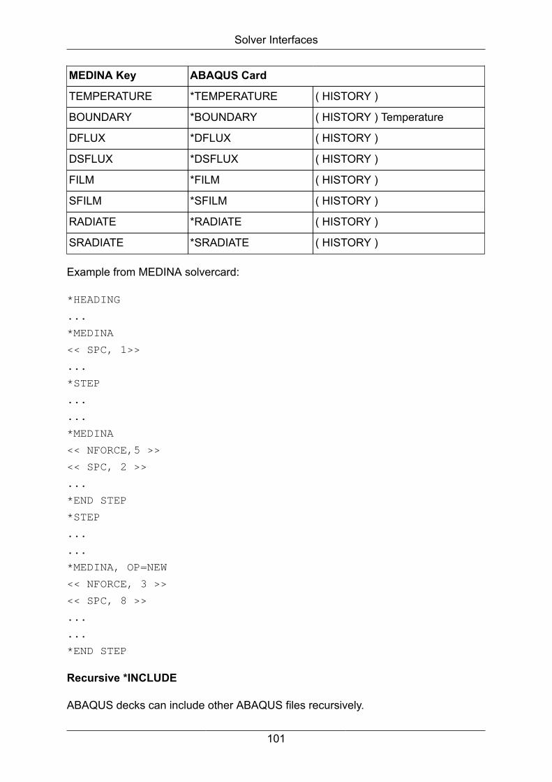
Solver Interfaces
MEDINA Key ABAQUS Card
TEMPERATURE *TEMPERATURE ( HISTORY )
BOUNDARY *BOUNDARY ( HISTORY ) Temperature
DFLUX *DFLUX ( HISTORY )
DSFLUX *DSFLUX ( HISTORY )
FILM *FILM ( HISTORY )
SFILM *SFILM ( HISTORY )
RADIATE *RADIATE ( HISTORY )
SRADIATE *SRADIATE ( HISTORY )
Example from MEDINA solvercard:
*HEADING
...
*MEDINA
<< SPC, 1>>
...
*STEP
...
...
*MEDINA
<< NFORCE,5 >>
<< SPC, 2 >>
...
*END STEP
*STEP
...
...
*MEDINA, OP=NEW
<< NFORCE, 3 >>
<< SPC, 8 >>
...
...
*END STEP
Recursive *INCLUDE
ABAQUS decks can include other ABAQUS files recursively.
101
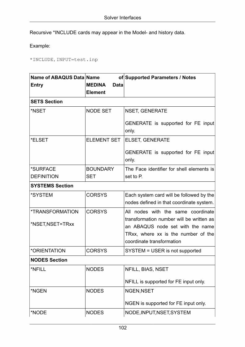
Solver Interfaces
Recursive *INCLUDE cards may appear in the Model- and history data.
Example:
*INCLUDE,INPUT=test.inp
Name of ABAQUS DataEntry
Name ofMEDINA DataElement
Supported Parameters / Notes
SETS Section
*NSET NODE SET NSET, GENERATE
GENERATE is supported for FE inputonly.
*ELSET ELEMENT SET ELSET, GENERATE
GENERATE is supported for FE inputonly.
*SURFACEDEFINITION
BOUNDARYSET
The Face identifier for shell elements isset to P.
SYSTEMS Section
*SYSTEM CORSYS Each system card will be followed by thenodes defined in that coordinate system.
*TRANSFORMATION
*NSET,NSET=TRxx
CORSYS All nodes with the same coordinatetransformation number will be written asan ABAQUS node set with the nameTRxx, where xx is the number of thecoordinate transformation
*ORIENTATION CORSYS SYSTEM = USER is not supported
NODES Section
*NFILL NODES NFILL, BIAS, NSET
NFILL is supported for FE input only.
*NGEN NODES NGEN,NSET
NGEN is supported for FE input only.
*NODE NODES NODE,INPUT,NSET,SYSTEM
102
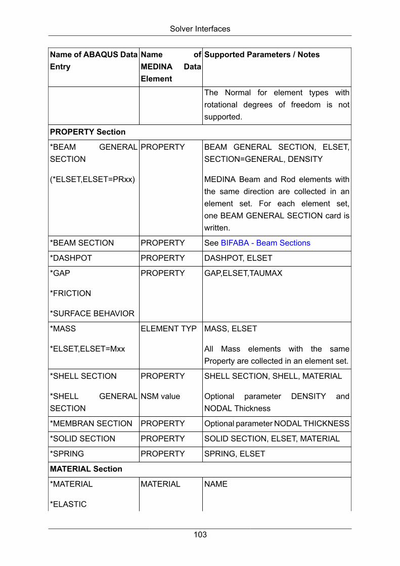
Solver Interfaces
Name of ABAQUS DataEntry
Name ofMEDINA DataElement
Supported Parameters / Notes
The Normal for element types withrotational degrees of freedom is notsupported.
PROPERTY Section
*BEAM GENERALSECTION
(*ELSET,ELSET=PRxx)
PROPERTY BEAM GENERAL SECTION, ELSET,SECTION=GENERAL, DENSITY
MEDINA Beam and Rod elements withthe same direction are collected in anelement set. For each element set,one BEAM GENERAL SECTION card iswritten.
*BEAM SECTION PROPERTY See BIFABA - Beam Sections
*DASHPOT PROPERTY DASHPOT, ELSET
*GAP
*FRICTION
*SURFACE BEHAVIOR
PROPERTY GAP,ELSET,TAUMAX
*MASS
*ELSET,ELSET=Mxx
ELEMENT TYP MASS, ELSET
All Mass elements with the sameProperty are collected in an element set.
*SHELL SECTION
*SHELL GENERALSECTION
PROPERTY
NSM value
SHELL SECTION, SHELL, MATERIAL
Optional parameter DENSITY andNODAL Thickness
*MEMBRAN SECTION PROPERTY Optional parameter NODAL THICKNESS
*SOLID SECTION PROPERTY SOLID SECTION, ELSET, MATERIAL
*SPRING PROPERTY SPRING, ELSET
MATERIAL Section
*MATERIAL
*ELASTIC
MATERIAL NAME
103
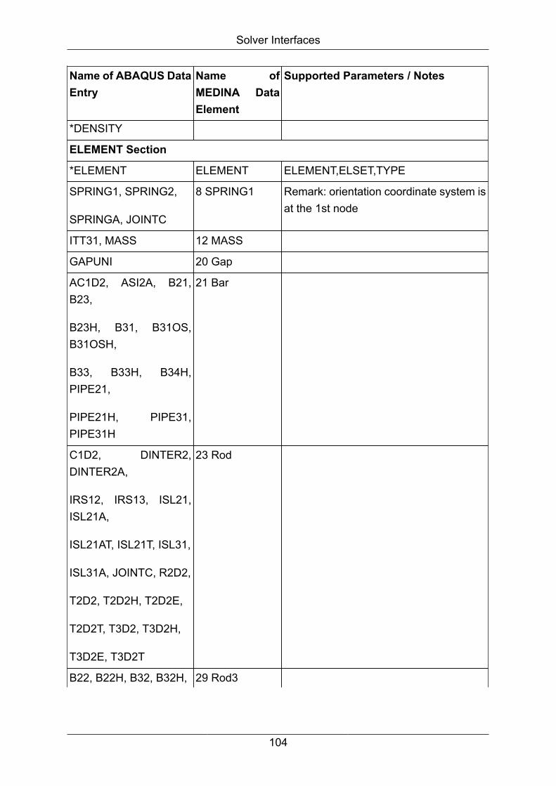
Solver Interfaces
Name of ABAQUS DataEntry
Name ofMEDINA DataElement
Supported Parameters / Notes
*DENSITY
ELEMENT Section
*ELEMENT ELEMENT ELEMENT,ELSET,TYPE
SPRING1, SPRING2,
SPRINGA, JOINTC
8 SPRING1 Remark: orientation coordinate system isat the 1st node
ITT31, MASS 12 MASS
GAPUNI 20 Gap
AC1D2, ASI2A, B21,B23,
B23H, B31, B31OS,B31OSH,
B33, B33H, B34H,PIPE21,
PIPE21H, PIPE31,PIPE31H
21 Bar
C1D2, DINTER2,DINTER2A,
IRS12, IRS13, ISL21,ISL21A,
ISL21AT, ISL21T, ISL31,
ISL31A, JOINTC, R2D2,
T2D2, T2D2H, T2D2E,
T2D2T, T3D2, T3D2H,
T3D2E, T3D2T
23 Rod
B22, B22H, B32, B32H, 29 Rod3
104

Solver Interfaces
Name of ABAQUS DataEntry
Name ofMEDINA DataElement
Supported Parameters / Notes
B32OS, B32OSH,PIPE22,
PIPE22H, PIPE32,PIPE32H,
T2D3, T2D3H, T2D3E,
T2D3T, T3D3, T3D3H,
T3D3E, T3D3T
AC1D3, CPE3, CPE3H,
CPS3, DC2D3, R3D3,S3R,
STRI3, STRI35
31 Tria3
CAX6H, CPE6, CPE6H,
CPE6M, CPE6MH,CPS6,
CPS6M, DC2D6,STRI65
36 Tria6
ACAX4, AC2D4, CAX4,
CPE4, CPE4H, CPE4I,
CPE4IH, CPE4R,CPE4RH,
CPS4, CPS4I, CPS4R,
DC2D4, DCC2D4,DCC2D4D,
DS4, R3D4, S4R, S4R5
41 Quad4
105
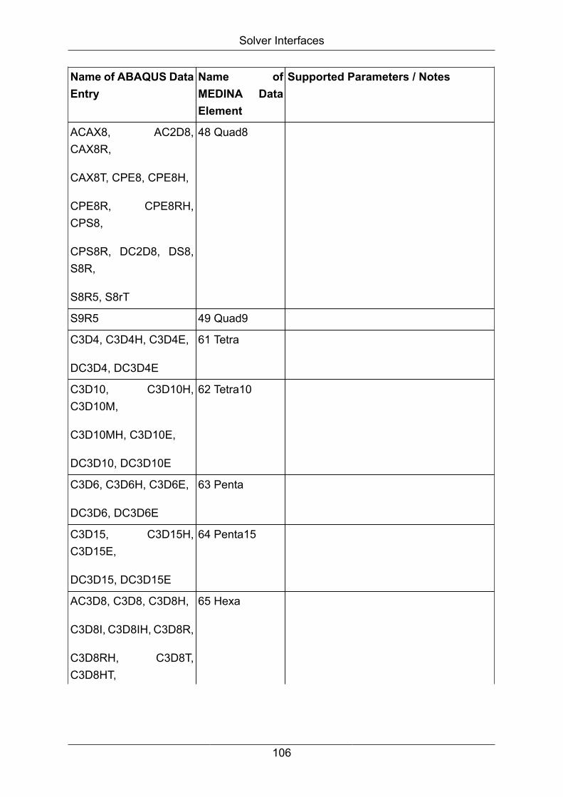
Solver Interfaces
Name of ABAQUS DataEntry
Name ofMEDINA DataElement
Supported Parameters / Notes
ACAX8, AC2D8,CAX8R,
CAX8T, CPE8, CPE8H,
CPE8R, CPE8RH,CPS8,
CPS8R, DC2D8, DS8,S8R,
S8R5, S8rT
48 Quad8
S9R5 49 Quad9
C3D4, C3D4H, C3D4E,
DC3D4, DC3D4E
61 Tetra
C3D10, C3D10H,C3D10M,
C3D10MH, C3D10E,
DC3D10, DC3D10E
62 Tetra10
C3D6, C3D6H, C3D6E,
DC3D6, DC3D6E
63 Penta
C3D15, C3D15H,C3D15E,
DC3D15, DC3D15E
64 Penta15
AC3D8, C3D8, C3D8H,
C3D8I, C3D8IH, C3D8R,
C3D8RH, C3D8T,C3D8HT,
65 Hexa
106
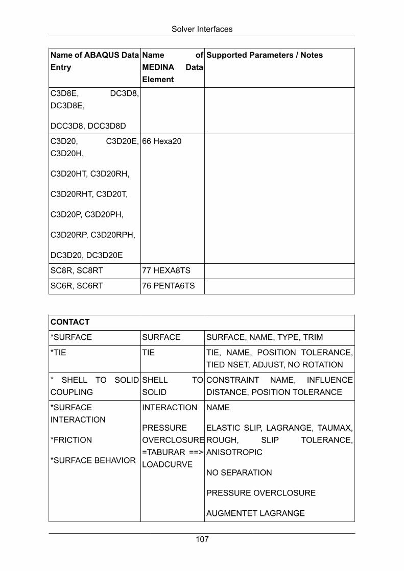
Solver Interfaces
Name of ABAQUS DataEntry
Name ofMEDINA DataElement
Supported Parameters / Notes
C3D8E, DC3D8,DC3D8E,
DCC3D8, DCC3D8D
C3D20, C3D20E,C3D20H,
C3D20HT, C3D20RH,
C3D20RHT, C3D20T,
C3D20P, C3D20PH,
C3D20RP, C3D20RPH,
DC3D20, DC3D20E
66 Hexa20
SC8R, SC8RT 77 HEXA8TS
SC6R, SC6RT 76 PENTA6TS
CONTACT
*SURFACE SURFACE SURFACE, NAME, TYPE, TRIM
*TIE TIE TIE, NAME, POSITION TOLERANCE,TIED NSET, ADJUST, NO ROTATION
* SHELL TO SOLIDCOUPLING
SHELL TOSOLID
CONSTRAINT NAME, INFLUENCEDISTANCE, POSITION TOLERANCE
*SURFACEINTERACTION
*FRICTION
*SURFACE BEHAVIOR
INTERACTION
PRESSUREOVERCLOSURE=TABURAR ==>LOADCURVE
NAME
ELASTIC SLIP, LAGRANGE, TAUMAX,ROUGH, SLIP TOLERANCE,ANISOTROPIC
NO SEPARATION
PRESSURE OVERCLOSURE
AUGMENTET LAGRANGE
107

Solver Interfaces
CONTACT
* CONTACT PAIR CONTACT INTERACTION, ADJUST, EXTENSIONZONE, HCRIT, SMALL SLIDING,SMOOTH, TIED
*RIGID SURFACE RIGIDSURFACE
RIGID SURFACE ,TYPE, NAME, REFNODE
Type user is not supported.
*SLIDE LINE SLIDE LINE SLIDE LINE, ELSET, GENERATE,SMOOTH
GENERATE is supported for fe input only.
CONSTRAINTS
*BOUNDARY SPC
*EQUATION MPC
*COUPLING
*KINEMATIC
RBE2ELEMENTS
CONSTRAINT NAME, REF NODE,SURFACE
*COUPLING
*DISTRIBUTING
RBE3ELEMENTS
CONSTRAINT NAME, REF NODE,SURFACE
*MPC RBAR Only for *MPC type BEAM
LOADS
*AMPLITUDE LOADCURVE NAME, TIME, VALUE
*BOUNDARY (1-6) SPC BOUNDARY,TYPE= DISPLACEMENT
*BOUNDARY (11-18) NTEMPERATUREAMPLITUDE
*CLOAD NFORCE MEDINA forces with local coordinatesystems are transformed to thedisplacement system of the node.
Abaqus forces are transformed fromthe local coordinate system of thecorresponding node in the global system.
108

Solver Interfaces
LOADSSolvercard must be used to translate*CLOAD with “OP=..” .
*DLOAD PRESSURE
*FILM CONVECTIONPROPERTY
*FILM
*SFILM
*DFLUX
*DSFLUX
*RADIATE
*SRADIATE
ETEMPERATUREAMPLITUDE, FILM AMPLITUDE
*PRE-TENSIONSECTION
Pretension Node, element, surface, normal
*TEMPERATURE NTEMPERATUREAMPLITUDE
MISCELLANEOUS
*NODAL THICKNESS MEDINA V-elements
The thickness is written into MEDINA V-elements
*DISTRIBUTION CORSYS andMEDINA V-elements
1. Only type angle and coordinateare supported. The angle is writteninto MEDINA V-elements and thecoordinate is written to MEDINAcoordinate.
2. It is supported only if referenced by*ORIENTATION and the orientation isreferenced by an ABAQUS sectioncard.
3. It is supported only for LOCATION=ELEMENT
*DISTRIBUTION TABLE CORSYS
109

Solver Interfaces
4.1.4.2. ABAQUS - Using Connection elements (CONN3D)
Both interfaces convert the elements BUSH, CONN3D and DISCBEAM with itsproperty.
The following table shows the differences between the elements:
MEDINA-CONN3D, BUSH, DISCRETE BEAM ABAQUS
Element node 1 and node 2 *ELEMENT, TYPE=CONN3D2
Element label Comment line before *ELEMENT,TYPE=CONN3D2
Element - Coordinate system 1 and 3rd ElementCoordinate system
*CONNECTOR SECTION
Connection type *CONNECTOR SECTION
Property – Label *CONNECTOR BEHAVIOUR
During the conversion of BUSH and DISCRETE BEAM elements from MEDINA toABAQUS, for each element the following warning is displayed:
"BUSH element <id> converted into CONN3D element"
"DISCRETE BEAM element <id> converted into CONN3D element"
"<id> converted into CONN3D element"
ABABIF
The CONNECTOR BEHAVIOUR is defined on Solvercard and the property of theCONN3D element contains the name of the CONNECTOR BEHAVIOUR as label.
BIFABA
The property label of the CONN3D element identifies the CONNECTOR BEHAVIOURon Solvercard and will be converted to the CONNECTOR SECTION of the CONN3Delement on ABAQUS deck.
Node_System cards
When a global coordinate system is defined by a *NODE, SYSTEM=C, *NODE,SYSTEM=S or *NODE, SYSTEM=R card, they will created in MEDINA as localcoordinate systems with the labels NODE_SYSTEMS_C, NODE_SYSTEMS_R orNODE_SYSTEMS_S.
110
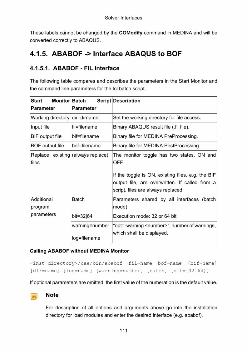
Solver Interfaces
These labels cannot be changed by the COModify command in MEDINA and will beconverted correctly to ABAQUS.
4.1.5. ABABOF -> Interface ABAQUS to BOF
4.1.5.1. ABABOF - FIL Interface
The following table compares and describes the parameters in the Start Monitor andthe command line parameters for the tcl batch script.
Start MonitorParameter
Batch ScriptParameter
Description
Working directory dir=dirname Set the working directory for file access.
Input file fil=filename Binary ABAQUS result file (.fil file).
BIF output file bif=filename Binary file for MEDINA PreProcessing.
BOF output file bof=filename Binary file for MEDINA PostProcessing.
Replace existingfiles
(always replace) The monitor toggle has two states, ON andOFF.
If the toggle is ON, existing files, e.g. the BIFoutput file, are overwritten. If called from ascript, files are always replaced.
Batch Parameters shared by all interfaces (batchmode)
bit=32|64 Execution mode: 32 or 64 bit
Additionalprogramparameters
warning=number
log=filename
"opt=-warning <number>", number of warnings,which shall be displayed.
Calling ABABOF without MEDINA Monitor
<inst_directory>/cae/bin/ababof fil=name bof=name [bif=name]
[dir=name] [log=name] [warning=number] [batch] [bit={32|64}]
If optional parameters are omitted, the first value of the numeration is the default value.
Note
For description of all options and arguments above go into the installationdirectory for load modules and enter the desired interface (e.g. ababof).
111

Solver Interfaces
Supported result data for ABABOF/FIL
The following table lists the result data translated from the ABAQUS to the MEDINAdata format:
Name of ABAQUS DataBlock
Name ofMEDINA DataElement
Description
*NODE FILE
U
V
A
RF
CF
NT
DEFO
VKNPCO
VKNPCO
VKNPCO
VKNPCO
SKNPCO
Displacements
Velocities
Accelerations
Reaction Forces
Concentrated Forces
Nodal Temperatures
*ELFILE,POSITION=NODES
S,SINV
E
PE
SF
SINFE
DINFE
DINFE
FINFE2
Stresses and MISES Stress
Total Strains
Plastic Strains
Section Forces
*EL FILE
FILM
RAD
LOADS
FLUXS
SKINFE
SKINFE
SKINFE
SKINFE
Film
Radiation
Distributed Loads
Distributed Flux
*ELFILE,POSITION=NODES
SINFE Nodal forces caused by stress for beamelements
112

Solver Interfaces
Name of ABAQUS DataBlock
Name ofMEDINA DataElement
Description
NFORC
(only for beam elements)
*ELFILE,POSITION=NODES
S
E
(for ITT21 and ITT31elements)
SKINFE,contains S11
SKINFE,contains E11
For ITT21 and ITT31 elements S11 is thenormal component of the force and E11is the separation of the surfaces
*ELFILE,POSITION=NODES
S
E
(for JOINTC elements)
UBRR, containsS11
UBRR, containsS12
For JOINTC elements S11 is the totaldirect force in the first local direction andS12 is the total moment about the firstlocal direction.
*ELFILE,POSITION=NODES
S
E
(For GAPUNI elements)
SKINFE,contains S11
SKINFE,contains E11
For GAPUNI elements S11 is the force inthe gap and E11 is the current opening ofthe gap.
*ELFILE,POSITION=NODES
S
E
(for SPRING2 andSPRINGA elements)
SKINFE,contains S11
SKINFE,contains E11
For SPRING2 and SPRINGA elementsS11 is the force in the spring and E11is the relative displacement across thespring.
113

Solver Interfaces
Name of ABAQUS DataBlock
Name ofMEDINA DataElement
Description
*CONTACT FILE
CSTRESS,CDISP
SKNPCO,containsCPRESS
SKNPCO,contains CDISP
Contact results: CPRESS is the pressurebetween the node on the slave surfaceand the master surface and CDISP is theseparation of the surfaces in the directionof the normal.
*ELFILE,POSITION=NODES
NE
DINFE Nominal strains
As a default, BOF output for shell elements is in the local coordinate system.
If the global coordinate system is desired, the command *EL FILE,POSITION=NODES, DIRECTIONS=YES must be used.
4.1.5.2. ABABOF - ODB Interface
ABAQUS versions 6.7, 6.8, 6.9, 6.10, 6.11, 6.12, 6.13, 6.14, 2016, 2017, 2018 and2019 are supported.
When executing ABAQUS ODB interface, ABAQUS runtime libraries are required.ABAQUS runtime libraries are not part of MEDINA distribution and not installed duringMEDINA installation.
ABAQUS and ABAQUS runtime libraries and therefore ODB interface are not availablefor all platforms supported by MEDINA. Detailed information about MEDINA platformsand supported ABAQUS versions may be found at:
https://plm.t-systems-service.com/en/plm-products/simulation-cae/fem-pre-and-post-processing/medina-714910 [https://plm.t-systems-service.com/en/plm-products/simulation-cae/fem-pre-and-post-processing/medina-714910]
The ABABOF/odb interface can also be called by the MEDINA PostProcessingthrough Import command.
The following table compares and describes the parameters in the Start Monitor andthe command line parameters for the tcl batch script:
114
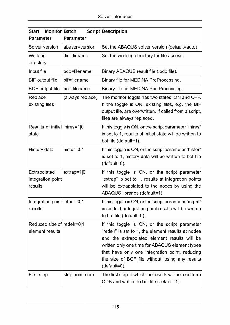
Solver Interfaces
Start MonitorParameter
Batch ScriptParameter
Description
Solver version abaver=version Set the ABAQUS solver version (default=auto)
Workingdirectory
dir=dirname Set the working directory for file access.
Input file odb=filename Binary ABAQUS result file (.odb file).
BIF output file bif=filename Binary file for MEDINA PreProcessing.
BOF output file bof=filename Binary file for MEDINA PostProcessing.
Replaceexisting files
(always replace) The monitor toggle has two states, ON and OFF.If the toggle is ON, existing files, e.g. the BIFoutput file, are overwritten. If called from a script,files are always replaced.
Results of initialstate
inires=1|0 If this toggle is ON, or the script parameter “inires”is set to 1, results of initial state will be written tobof file (default=1).
History data histor=0|1 If this toggle is ON, or the script parameter “histor”is set to 1, history data will be written to bof file(default=0).
Extrapolatedintegration pointresults
extrap=1|0 If this toggle is ON, or the script parameter“extrap” is set to 1, results at integration pointswill be extrapolated to the nodes by using theABAQUS libraries (default=1).
Integration pointresults
intpnt=0|1 If this toggle is ON, or the script parameter “intpnt”is set to 1, integration point results will be writtento bof file (default=0).
Reduced size ofelement results
redelr=0|1 If this toggle is ON, or the script parameter“redelr” is set to 1, the element results at nodesand the extrapolated element results will bewritten only one time for ABAQUS element typesthat have only one integration point, reducingthe size of BOF file without losing any results(default=0).
First step step_min=num The first step at which the results will be read formODB and written to bof file (default=1).
115

Solver Interfaces
Start MonitorParameter
Batch ScriptParameter
Description
Last step step_max=num The last step at which the results will be read formODB and written to bof file (default is the last stepfound on ODB file).
Increment step_inc=num Step increment between first step and last step(default=1)
First increment incr_min=num The first increment at which the results will beread form ODB and written to bof file (default=1).
Last increment incr_max=num The last increment at which the results will beread form ODB and written to bof file (default isthe last increment found on ODB file).
Increment incr_inc=num Increment between the first increment and lastincrement (default=1)
batch Parameters shared by all interfaces (batch mode)
bit=32|64 Execution mode: 32 or 64 bit
Additionalprogramparameters
log=filename The name of log file (default abaodb.log)
When ABABOF/odb is called from MEDINA PostProcessing, a PostProcessinglicense is used additionally to the interface license.
Note
If temporary directory or hard disk is full, an error message with rc=2 will beproduced.
The default Abaqus version is auto. In this case the interfaces look for theAbaqus version on ODB file.
Calling ABAODB without MEDINA Monitor
<inst_directory>/cae/bin/abaodb odb=name [bif=name]
[bof=name] [abaver={auto|6.7-2|6.8-1|6.8-EF1|6.9-1|6.9-EF2|
6.10-1|6.11-1|6.12-1|6.13-1|6.14-1|2016|2017|2018|2019}]
[inires={1|0} [histor={0|1} [redelr={0|1} [extrap={1|0}]
[intpnt={0|1}] [step_min=num] [step_max=num] [step_inc=num]
[incr_min=num] [incr_max=num] [incr_inc=num] [dir=name]
[log=name] [batch] [bit={32|64}]
116

Solver Interfaces
If optional parameters are omitted, the first value of the numeration is the default value.
4.1.5.3. ABABOF - Supported result data for ABABOF/ODB
The following tables list the model and result data converted from ABAQUS to MEDINAdata format.
Supported ABAQUS model data
Enum Name Type ID Description
Element Types
MD_UNKNOWN_ELEMENT 0 Unknown Element
MD_SPRING 9 Spring Element
MD_MASS 12 Mass Element
MD_BEAM 22 Beam Element
MD_BAR 21 Bar Element
MD_TRIA3 31 Tria Element (3 Nodes)
MD_TRIA6 36 Tria Elements (6 Nodes)
MD_QUAD4 41 Quad Elements (4 Nodes)
MD_QUAD8 48 Quad Elements (8 Nodes)
MD_TETRA 61 Tetra Elements
MD_TETRA10 62 Tetra Elements (10 Nodes)
MD_PENTA 63 Penta Elements.
MD_PENTA15 64 Penta Elements (15 Nodes)
MD_HEXA 65 Hexa Elements.
MD_HEXA20 66 Hexa Elements (20 Nodes)
MD_PLOTEL 7 Plot Elements.
MD_CONNSPOT 84 Connspot Elements
MD_ROD 23 Rod Elements
Coordinate system types
MD_CARTESIAN 1 Cartesian Coordinate System.
MD_CYLINDRICAL 2 Cylindrical Coordinate System.
MD_SPHERICAL 3 Spherical Coordinate System.
Nodes
117

Solver Interfaces
Enum Name Type ID Description
Element Sets
Node Sets
Supported ABAQUS result data
AC YIELD
AR
A
CDISP
CF
CM
CNAREA
CNORMF
COPEN
CPRESS
CSHEAR1
CSHEAR2
CSHEARF
CSLIP1
CSLIP2
CSTRESS
E11
E
FLUXS
FTEMP
FV
HFL
LE
LOADS
NE
NFORC
118

Solver Interfaces
NT
PEEQ
PEMAG
PE
PPRESS
RADFLA
RADFL
RADTLA
RADTL
RAD
RBANG
RBFOR
RBROT
RFL
RF
RM
S11
SF
SM
S
TEMP
TF
TM
UR
U
VFTOT
VR
V
History results
119

Solver Interfaces
Note
ABAQUS output variables CSLIP1 and CSLIP2 for the same load case, sameload increment and same surface will be written to MEDINA vector data elementVKNPCO (CAE key 208). The first component of this vector is CSLIP1 andthe second component is CLSIP2. The description of this result in the RSelectcommand contains the text "CSLIP12".
History result data
Use the following two ways to write ABAQUS history results from odb file to MEDINAPostProcessing:
1. MEDINA: Import command
In addition to the model and result data, the history results are imported and savedin the curve memory as result curves.
2. ABAB*F: ABAQUS ODB output -> B*f
Use the odb interface to write ABAQUS history results to the new data elementCRVTABLE on Bof.
MEDINA loadcase number
In general, the MEDINA loadcase number and the step number in ABAQUS are equal.
The step subheading in ABAQUS input file can be used to define user loadcase numberin MEDINA and must be used with the following syntax rules (case insensitive):
*STEP:
BOF_LC=<nr>; an arbitrary text where:
• nr is loadcase number in MEDINA. It must be integer positive.
• all text after semicolon is comment
• MEDINA writes the following message in log file:
"New Loadcase number <nr> extracted from step title <subheading
of step>"
For example, to define a loadcase 27005 for MEDINA, one of the following stepsubheadings in ABAQUS input file can be used:
120
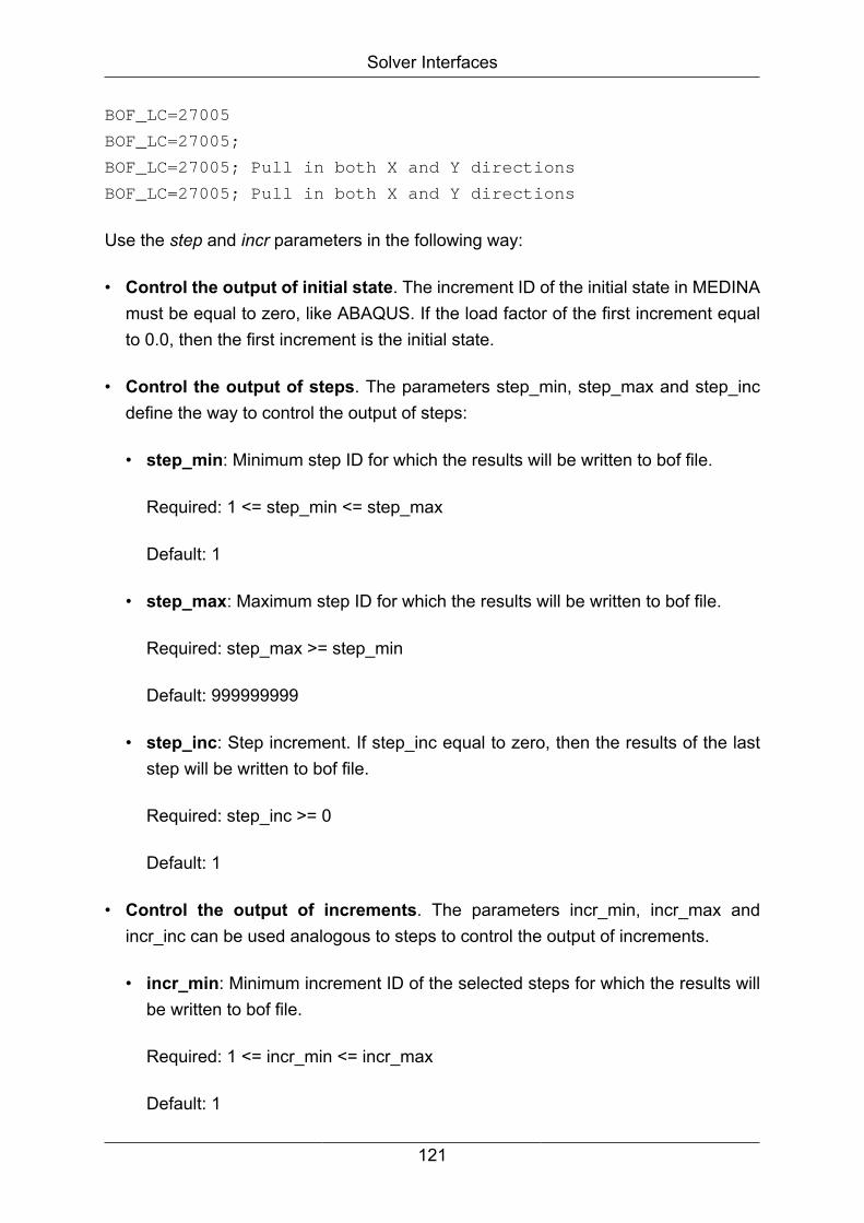
Solver Interfaces
BOF_LC=27005
BOF_LC=27005;
BOF_LC=27005; Pull in both X and Y directions
BOF_LC=27005; Pull in both X and Y directions
Use the step and incr parameters in the following way:
• Control the output of initial state. The increment ID of the initial state in MEDINAmust be equal to zero, like ABAQUS. If the load factor of the first increment equalto 0.0, then the first increment is the initial state.
• Control the output of steps. The parameters step_min, step_max and step_incdefine the way to control the output of steps:
• step_min: Minimum step ID for which the results will be written to bof file.
Required: 1 <= step_min <= step_max
Default: 1
• step_max: Maximum step ID for which the results will be written to bof file.
Required: step_max >= step_min
Default: 999999999
• step_inc: Step increment. If step_inc equal to zero, then the results of the laststep will be written to bof file.
Required: step_inc >= 0
Default: 1
• Control the output of increments. The parameters incr_min, incr_max andincr_inc can be used analogous to steps to control the output of increments.
• incr_min: Minimum increment ID of the selected steps for which the results willbe written to bof file.
Required: 1 <= incr_min <= incr_max
Default: 1
121

Solver Interfaces
• incr_max: Maximum increment ID of the selected steps for which the results willbe written to bof file.
Required: incr_max >= incr_min
Default: 999999999
• incr_inc: Increment of increment. If incr_inc equal to zero, then the results of thelast increment of the selected steps will be written to bof file.
Required: incr_inc >= 0
Default: 1
Examples:
step_min=2 step_max=8 step_inc=3 (the results of the steps 2,
5 and 8
will be written to bof file)
incr_min=2 incr_max=6 incr_inc=2 (the results for the
increments 2, 4
and 6 of the selected steps
will be
written to bof file)
Analysis title
Similar to the load case title, the analysis title is read from ABAQUS ODB file andwritten to MEDINA BOF file. The analysis title is defined in ABAQUS input file after thekeyword line *HEADING.
The length of the analysis and load case titles can be up to 80 characters. The bothtitles are optional in ABAQUS and used in plot layout elements.
Note
For description of all options and arguments above go into the installationdirectory for load modules and enter the desired interface (e.g. abaodb).
History data: The history data are written as usual for all steps and increments.All changes must have no effect on the handling of the history data.
122
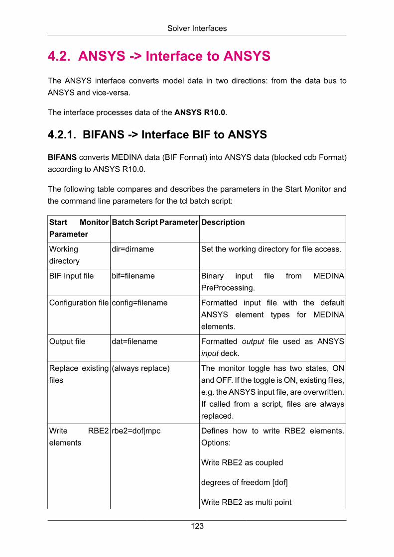
Solver Interfaces
4.2. ANSYS -> Interface to ANSYSThe ANSYS interface converts model data in two directions: from the data bus toANSYS and vice-versa.
The interface processes data of the ANSYS R10.0.
4.2.1. BIFANS -> Interface BIF to ANSYS
BIFANS converts MEDINA data (BIF Format) into ANSYS data (blocked cdb Format)according to ANSYS R10.0.
The following table compares and describes the parameters in the Start Monitor andthe command line parameters for the tcl batch script:
Start MonitorParameter
Batch Script Parameter Description
Workingdirectory
dir=dirname Set the working directory for file access.
BIF Input file bif=filename Binary input file from MEDINAPreProcessing.
Configuration file config=filename Formatted input file with the defaultANSYS element types for MEDINAelements.
Output file dat=filename Formatted output file used as ANSYSinput deck.
Replace existingfiles
(always replace) The monitor toggle has two states, ONand OFF. If the toggle is ON, existing files,e.g. the ANSYS input file, are overwritten.If called from a script, files are alwaysreplaced.
Write RBE2elements
rbe2=dof|mpc Defines how to write RBE2 elements.Options:
Write RBE2 as coupled
degrees of freedom [dof]
Write RBE2 as multi point
123

Solver Interfaces
Start MonitorParameter
Batch Script Parameter Description
constraint rigid link [mpc]
ANSYS datanot supplied byMEDINA
full=1|2 Defines how to include unsupplied cards.File options:
Add only cards completely not supported
Merge cards supplying unsupportedfields (default)
Additionalprogramparameters
batch
bit=32|64
warning=number
log=filename
Parameters shared by all interfaces (seechapter 1 for a description).
Calling BIFANS without MEDINA Monitor
Call:
<inst_directory>/cae/bin/bifans bif=name dat=name [full={1|
2}] [rbe2={dof|mpc}] [config=name] [size=number] [dir=name]
[log=name] [warning=number] [batch] [bit={32|64}]
If optional parameters are omitted, the first value of the numeration is the default value.
Note
For description of all options and arguments above go into the installationdirectory for load modules and enter the desired interface (e.g. bifans).
4.2.2. ANSBIF -> Interface ANSYS to BIF
ANSBIF converts ANSYS data (blocked cdb Format) according to ANSYS R10.0 intoMEDINA data (BIF Format).
The following table compares and describes the parameters in the Start Monitor andthe command line parameters for the tcl batch script:
124
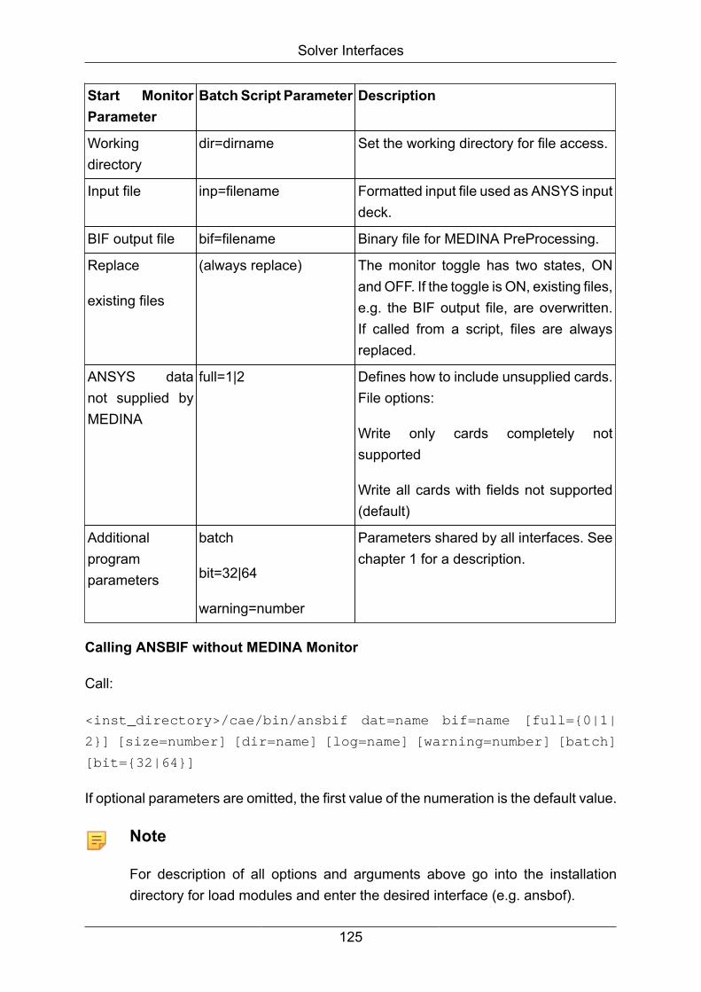
Solver Interfaces
Start MonitorParameter
Batch Script Parameter Description
Workingdirectory
dir=dirname Set the working directory for file access.
Input file inp=filename Formatted input file used as ANSYS inputdeck.
BIF output file bif=filename Binary file for MEDINA PreProcessing.
Replace
existing files
(always replace) The monitor toggle has two states, ONand OFF. If the toggle is ON, existing files,e.g. the BIF output file, are overwritten.If called from a script, files are alwaysreplaced.
ANSYS datanot supplied byMEDINA
full=1|2 Defines how to include unsupplied cards.File options:
Write only cards completely notsupported
Write all cards with fields not supported(default)
Additionalprogramparameters
batch
bit=32|64
warning=number
Parameters shared by all interfaces. Seechapter 1 for a description.
Calling ANSBIF without MEDINA Monitor
Call:
<inst_directory>/cae/bin/ansbif dat=name bif=name [full={0|1|
2}] [size=number] [dir=name] [log=name] [warning=number] [batch]
[bit={32|64}]
If optional parameters are omitted, the first value of the numeration is the default value.
Note
For description of all options and arguments above go into the installationdirectory for load modules and enter the desired interface (e.g. ansbof).
125

Solver Interfaces
Option Meaning
bif=name Output: MEDINA data file name (e.g. medina.bif). If nameis blank no BIF file will be generated.
dat=name Name of the ansys file (e.g. ansys.dat).
warning=number No warnings will be suppressed.
Switching additional ANSYS cards not supported by MEDINA
• ignore: BIF generation without additional ANSYS cards
• write to BIF file: additional ANSYS statements are stored in the BIF file
• write to ASCII reject file: additional ANSYS statements are stored in an ASCII rejectfile
Additional program parameters
The additional program parameters are referenced in the additional parameter field inthis way:
"opt=-parameter value".
-warning number Complete warning message report
-size number Start memory size data structures
(usually automatically determined)
-vers Show the version and stop the
interface
4.2.3. BIFANS/ANSBIF
Name of ANSYS DataEntry
Name ofMEDINA DataElement
Supported Parameters / Notes
SETS Section
CMBLOCK NODE SET ENTITY=NODES
CMBLOCK ELEMENT SET ENTITY=ELEMENTS
SYSTEMS Section
CS CORSYS Extra nodes will be created
126
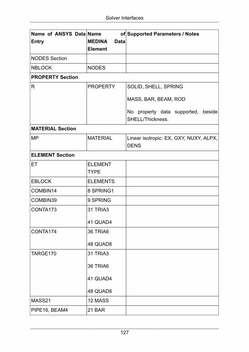
Solver Interfaces
Name of ANSYS DataEntry
Name ofMEDINA DataElement
Supported Parameters / Notes
NODES Section
NBLOCK NODES
PROPERTY Section
R PROPERTY SOLID, SHELL, SPRING
MASS, BAR, BEAM, ROD
No property data supported, besideSHELL/Thickness.
MATERIAL Section
MP MATERIAL Linear isotropic: EX, GXY, NUXY, ALPX,DENS
ELEMENT Section
ET ELEMENTTYPE
EBLOCK ELEMENTS
COMBIN14 8 SPRING1
COMBIN39 9 SPRING
CONTA173 31 TRIA3
41 QUAD4
CONTA174 36 TRIA6
48 QUAD8
TARGE170 31 TRIA3
36 TRIA6
41 QUAD4
48 QUAD8
MASS21 12 MASS
PIPE16, BEAM4 21 BAR
127

Solver Interfaces
Name of ANSYS DataEntry
Name ofMEDINA DataElement
Supported Parameters / Notes
BEAM44 22 BEAM
LINK8 23 ROD
SHELL28, SHELL41,SHELL43, SHELL57,SHELL63, SHELL143,SHEL157, SELL163,SHELL181, PLANE42
31 TRIA3
SHELL93, PLANE82 36 TRIA6
SHELL28, SHELL41,SHELL43, SHELL57,SHELL63, SHELL143,SHEL157, SHELL163,
SHELL181, PLANE42
41 QUAD4
SHELL93, PLANE82 48 QUAD8
SOLID45, SOLID65,
SOLID73, SOLID5,SOLID185
61 TETRA
SOLID92 62 TETRA10
SOLID45, SOLID65,
SOLID73, SOLID5,SOLID185
63 PENTA 6
SOLID45, SOLID65,
SOLID73, SOLID5,SOLID185
65 HEXA
71 PYRAM 5
SOLID186, SOLID95 66 HEXA20
64 PENTA15
62TETRA10
70 PYRAM13
128
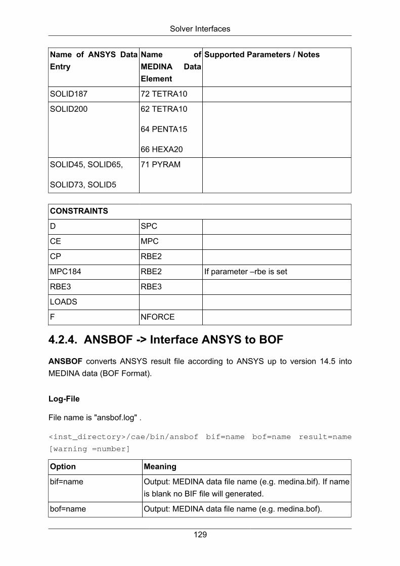
Solver Interfaces
Name of ANSYS DataEntry
Name ofMEDINA DataElement
Supported Parameters / Notes
SOLID187 72 TETRA10
SOLID200 62 TETRA10
64 PENTA15
66 HEXA20
SOLID45, SOLID65,
SOLID73, SOLID5
71 PYRAM
CONSTRAINTS
D SPC
CE MPC
CP RBE2
MPC184 RBE2 If parameter –rbe is set
RBE3 RBE3
LOADS
F NFORCE
4.2.4. ANSBOF -> Interface ANSYS to BOFANSBOF converts ANSYS result file according to ANSYS up to version 14.5 intoMEDINA data (BOF Format).
Log-File
File name is "ansbof.log" .
<inst_directory>/cae/bin/ansbof bif=name bof=name result=name
[warning =number]
Option Meaning
bif=name Output: MEDINA data file name (e.g. medina.bif). If nameis blank no BIF file will generated.
bof=name Output: MEDINA data file name (e.g. medina.bof).
129
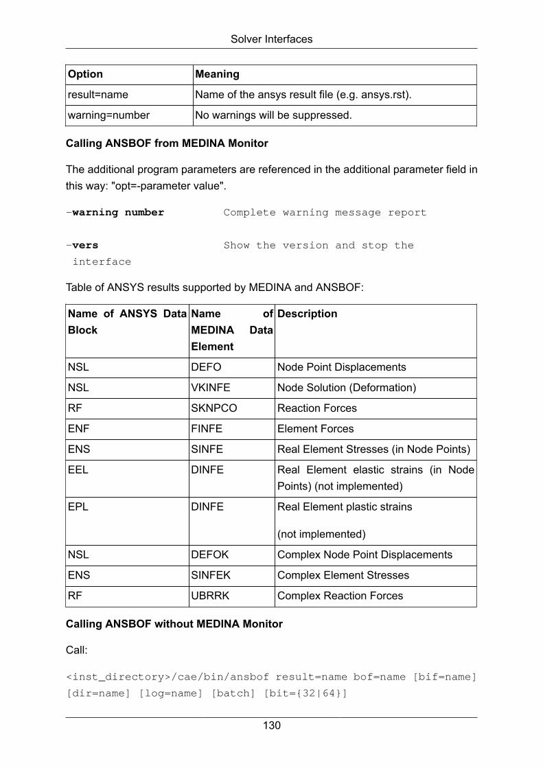
Solver Interfaces
Option Meaning
result=name Name of the ansys result file (e.g. ansys.rst).
warning=number No warnings will be suppressed.
Calling ANSBOF from MEDINA Monitor
The additional program parameters are referenced in the additional parameter field inthis way: "opt=-parameter value".
-warning number Complete warning message report
-vers Show the version and stop the
interface
Table of ANSYS results supported by MEDINA and ANSBOF:
Name of ANSYS DataBlock
Name ofMEDINA DataElement
Description
NSL DEFO Node Point Displacements
NSL VKINFE Node Solution (Deformation)
RF SKNPCO Reaction Forces
ENF FINFE Element Forces
ENS SINFE Real Element Stresses (in Node Points)
EEL DINFE Real Element elastic strains (in NodePoints) (not implemented)
EPL DINFE Real Element plastic strains
(not implemented)
NSL DEFOK Complex Node Point Displacements
ENS SINFEK Complex Element Stresses
RF UBRRK Complex Reaction Forces
Calling ANSBOF without MEDINA Monitor
Call:
<inst_directory>/cae/bin/ansbof result=name bof=name [bif=name]
[dir=name] [log=name] [batch] [bit={32|64}]
130

Solver Interfaces
If optional parameters are omitted, the first value of the numeration is the default value.
Note
For description of all options and arguments above go into the installationdirectory for load modules and enter the desired interface (e.g. ansbof).
4.3. AUTOFORM -> Interface to AUTOFORMThe AUTOFORM interface converts AUTOFORM result data to the databus.
4.3.1. AUTOBOF-> Interface AUTOFORM to BOF
The interface program autobof converts AUTOFORM (ascii) result files to MEDINABIFs and BOFs.
Call:
<inst_directory>/cae/bin/autobof bof=name result=name
[warning=number]
Option Meaning
bof=name Output: MEDINA data file name (e.g. medina.bof).
bif=name Output: MEDINA data file name (e.g. medina.bif).
result=name Name of the autoform result file.
warning=number No warnings will be suppressed.
AUTOBOF: Table of results
Name of AUTOFORMResult
Name of MEDINA Data Element Node or element type
Thickness SKNPCO Node
Plastic Strain SKINFE Element
AUTOBOF: Table of geometry data
Name of AUTOFORM Data Name of MEDINA Data Element
Nodes NPCO
Points NPCO
Facet INFE3
131
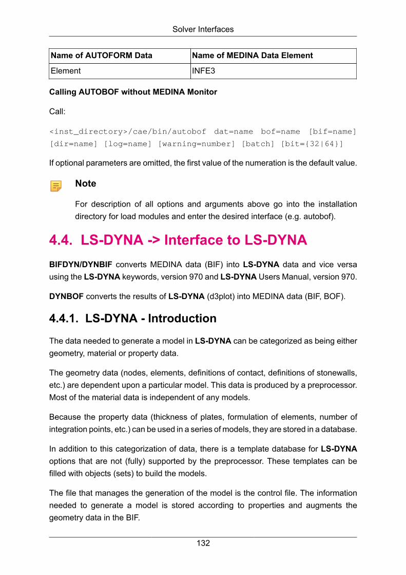
Solver Interfaces
Name of AUTOFORM Data Name of MEDINA Data Element
Element INFE3
Calling AUTOBOF without MEDINA Monitor
Call:
<inst_directory>/cae/bin/autobof dat=name bof=name [bif=name]
[dir=name] [log=name] [warning=number] [batch] [bit={32|64}]
If optional parameters are omitted, the first value of the numeration is the default value.
Note
For description of all options and arguments above go into the installationdirectory for load modules and enter the desired interface (e.g. autobof).
4.4. LS-DYNA -> Interface to LS-DYNABIFDYN/DYNBIF converts MEDINA data (BIF) into LS-DYNA data and vice versausing the LS-DYNA keywords, version 970 and LS-DYNA Users Manual, version 970.
DYNBOF converts the results of LS-DYNA (d3plot) into MEDINA data (BIF, BOF).
4.4.1. LS-DYNA - Introduction
The data needed to generate a model in LS-DYNA can be categorized as being eithergeometry, material or property data.
The geometry data (nodes, elements, definitions of contact, definitions of stonewalls,etc.) are dependent upon a particular model. This data is produced by a preprocessor.Most of the material data is independent of any models.
Because the property data (thickness of plates, formulation of elements, number ofintegration points, etc.) can be used in a series of models, they are stored in a database.
In addition to this categorization of data, there is a template database for LS-DYNAoptions that are not (fully) supported by the preprocessor. These templates can befilled with objects (sets) to build the models.
The file that manages the generation of the model is the control file. The informationneeded to generate a model is stored according to properties and augments thegeometry data in the BIF.
132

Solver Interfaces
This concept of data types is portrayed schematically in the following diagram:
Figure 4.3. LS-Dyna data types
4.4.2. LS-DYNA - Control fileThe control file is created together with the material and section user database whenimporting an LS-DYNA input deck into a MEDINA BIF using the DYNBIF program, ifthe “Create databases” option or the “Merge with user databases” option is chosen.
It holds information about all properties in the model, which is used when exporting aMEDINA BIF into an LS-DYNA input deck using the BIFDYN program. As a plain textfile, it can be viewed and modified by means of an editor.
Lines starting with asterisk (*) are comment lines. Comment lines are ignored byDYNBIF, except the one holding the control file version.
Each non-comment line of the control file represents the data of one property. The dataare arranged in columns with the following meaning:
Column Meaning
PID The ID of the PART card
TEXT The name of the PART card
ELE-TYP The corresponding element type, from the referenced sectioncard
ELE-FORM The ID of the HOURGLASS card referenced by the PART card
133

Solver Interfaces
Column Meaning
SECT-NAME The directory name in the section database which holds thesection card referenced by the PART card. In the control file,the directory name is preceded by a “>” sign.
DATA Some section data, depending on the element type. See tablebelow.
MATERIAL The directory name in the material database which holds thematerial card referenced by the PART card. In the control file,the directory name is preceded by a “>” sign.
CONTACT The data of a contact optional card, see table below.
INERTIA The data of a inertia optional card, see table below
Comments Room for comments. This column is ignored by the interface.
The following table shows the data stored into the control file DATA column for eachsection type:
Type DATA column values
BEAM A, ISS, ITT, IRR, SA
DISCRETE,SPRING-DAMPER
CDL, TDL
SHELL T1, T2, T3, T4. If they are all equal, only T1 is stored. All equalmeans, that for each section mapped to the same database fileT1, T2, T3 and T4 are equal, but may differ between sections.
Other For other section types no data is stored in the control file DATAcolumn.
The following table shows the data stored in the CONTACT column for each option:
Option CONTACT column values
CONTACT fs, fd, dc, vc, optt, sft, ssf
The following table shows the data stored in the INERTIA column for each option:
Option INERTIA column values
INERTIA xc,yc, zc, tm, ircs, node, ixx, ixy, ixz, iyy, iyz, izz, vtx, vty, vtz,vrx, vry, vrz, xl, yl, zl, xlip, ylip, zlip, cid
The values of the DATA and CONTACT, INERTIA columns are provided in the format:
134

Solver Interfaces
<variable name>=<variable value>,…,<variable name>=<variable
value>
For example:
*Control file version 2.0
*Created by MEDINA X.X.X.X (64 Bit)
*PID ;TEXT ;TYPE ;ELE-FORM;SECT-NAME ;DATA ;MATERIAL ;CONTACT,
INERTIA ;Comments
2000000 ; F-CH-A-PILL-TOP-ROOF-RAIL ; SHELL ; 0 ;
>SECTION_SHELL_1; T1=1.9,T2=2.9,T3=3.9,
T4=5.9; >MAT_PIECEWISE_LINEAR_PLASTICITY_1;123test
2000001 ; F-CH-A-PILLAR-BKT1-R ; SHELL ; 0 ; >SECTION_SHELL_1;
T1=1.26,T2=1.26,T3=1.26,
T4=1.26; >MAT_PIECEWISE_LINEAR_PLASTICITY_2
2000038 ; F-CH-BUMPER-FRONT-SUPPORT-BKT- ; SHELL ; 0 ;
>SECTION_SHELL_2; T1=1.3;
>MAT_PIECEWISE_LINEAR_PLASTICITY_39
2000324 ; F-MC-ENGINE-CRANK-PULLEY ; SOLID ; 2001717 ;
>SECTION_SOLID_3; ;
>MAT_PIECEWISE_LINEAR_PLASTICITY_325
4.4.2.1. Processing of materials and sections
*PID DescriptionType ofElement
Elform
Section SectionDataMaterial InertiaComment
1000 Right, frontdoors
SHELL 2 >shell_1 s=1.00 >mat_1 Introducedon June26, 1998
2000 Dummy SOLID 1 >mat_2
3000 Pipe BEAM 3 >beam_1di=1.0,da=2.0>mat_4 xc=-223.Variation 1
Key to terms
PID Property ID of the component
135

Solver Interfaces
Description Description of the component
Type of Element The type of element out of which the component consists (SOLID,BEAM, SHELL, THICK SHELL)
El form The formulation of the element
Section Reference to the database that contains the section data. If nothingis specified, then this component does not have any section data(e.g. solids)
Section data Section parameter, which will be replaced from the database
Material Reference to the material database
Inertia Additional information due to *PART_*_INERTIA cards (Only forvalues which do not correlates to the default values)
Comment Field for comments (comments are not processed.)
Comment lines are indicated by an "*" in the first column.
The delimiter between separated data items is a ";".
The separated parameters in the Section data column use a "," as a delimiter.
4.4.2.2. Definition of Template procession
To process templates, the control file was extended with the following definitions:
*PID Description Type ofElement
Elform
Section SectionData
MaterialComment
1000 Right, frontdoors
SHELL 2 >shell_1 s=1.00 >mat_1 Introducedon June26, 1998
2000 Dummy SOLID 1 >mat_2
3000 Pipe BEAM 3 >beam_1 di=1.0,da=2.0>mat_4 Variation1
*KEY Description Template ObjectCriteria Parameter
CombineAirbag >air_1 SetText
*Airbag_1
CombineRigid body >card_36 SetText
*Rigid_1
CombineAcceleration >card_41 Acc=1e5
136

Solver Interfaces
Key to terms
KEY Keyword “combine” needed to call this function
Description Comments
Template Name of file with the templates from the template Database
Object Object from MEDINA, e.g. SET Text, Box ID, Prop. ID
Criteria Text or ID to determine the MEDINA partner to be used with thetemplate
Parameter Parameters entered here using the syntax name=value will beprocessed
Template processing is available for the following LS-DYNA options with structuredformat:
LS-DYNA Option MEDINA Element MEDINA Object
CARD 35 SET SET Text
CARD 36 SET SET Text
CARD 41
CARD 51 SET SET Text
CARD 52 SET SET Text
CARD 57 SET SET Text
For the keyword format in LS-DYNA, template processing is supported for all LS-DYNAoptions that are defined by sets.
4.4.3. LS-DYNA - Databases
The databases which are used store the necessary information in LS-DYNA format,i.e. in either KEYWORD format or STRUCTURED format.
Neither a syntax check nor a consistency check is performed. The variables such as#MID which are described below, are replaced with the current values when generatinga model.
The concepts used here allow the formation of a central database which can be usedby all engineers in a team. In addition, each user can temporarily overwrite this centraldefinition by using his personal database.
137
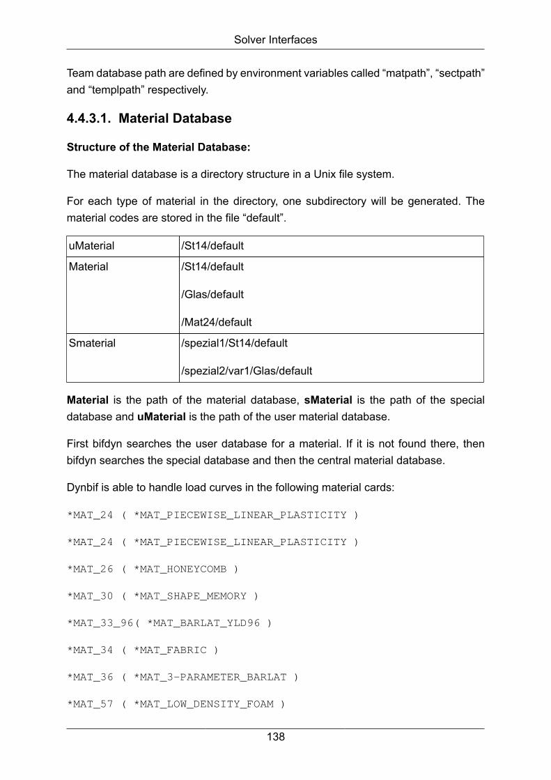
Solver Interfaces
Team database path are defined by environment variables called “matpath”, “sectpath”and “templpath” respectively.
4.4.3.1. Material Database
Structure of the Material Database:
The material database is a directory structure in a Unix file system.
For each type of material in the directory, one subdirectory will be generated. Thematerial codes are stored in the file “default”.
uMaterial /St14/default
Material /St14/default
/Glas/default
/Mat24/default
Smaterial /spezial1/St14/default
/spezial2/var1/Glas/default
Material is the path of the material database, sMaterial is the path of the specialdatabase and uMaterial is the path of the user material database.
First bifdyn searches the user database for a material. If it is not found there, thenbifdyn searches the special database and then the central material database.
Dynbif is able to handle load curves in the following material cards:
*MAT_24 ( *MAT_PIECEWISE_LINEAR_PLASTICITY )
*MAT_24 ( *MAT_PIECEWISE_LINEAR_PLASTICITY )
*MAT_26 ( *MAT_HONEYCOMB )
*MAT_30 ( *MAT_SHAPE_MEMORY )
*MAT_33_96( *MAT_BARLAT_YLD96 )
*MAT_34 ( *MAT_FABRIC )
*MAT_36 ( *MAT_3-PARAMETER_BARLAT )
*MAT_57 ( *MAT_LOW_DENSITY_FOAM )
138

Solver Interfaces
*MAT_63 ( *MAT_CRUSHABLE_FOAM )
*MAT_71 ( *MAT_CABLE_DISCRETE_BEAM )
*MAT_73 ( *MAT_LOW_DENSITY_VISCOUS_FOAM )
*MAT_76 ( *MAT_GENERAL_VISCOELASTIC )
*MAT_81 ( *MAT_PLASTICITY_WITH_DAMAGE )
*MAT_81 ( *MAT_PLASTICITY_WITH_DAMAGE )
*MAT_83 ( *MAT_FU_CHANG_FOAM )
*MAT_113 ( *MAT_TRIP )
*MAT_120 ( *MAT_GURSON )
*MAT_123 ( *MAT_MODIFIED_PIECEWISE_LINEAR_PLASTICITY )
*MAT_123 ( *MAT_MODIFIED_PIECEWISE_LINEAR_PLASTICITY )
*MAT_126 ( *MAT_MODIFIED_HONEYCOMB )
*MAT_133 ( *MAT_BARLAT_YLD2000 )
*MAT_156 ( *MAT_MUSCLE )
*MAT_179 ( *MAT_LOW_DENSITY_SYNTHETIC_FOAM )
*MAT_187 ( *MAT_SAMP-1 )
*MAT_1001 ( *MAT_DAMPER_NONLINEAR_VISCOUS )
*MAT_1003 ( *MAT_SPRING_GENERAL_NONLINEAR )
*MAT_S15 ( *MAT_SPRING_MUSCLE )
*MAT_T01 ( *MAT_THERMAL_ISOTROPIC )
*MAT_T02 ( *MAT_THERMAL_ORTHOTROPIC )
*MAT_T03 ( *MAT_THERMAL_ISOTROPIC_TD )
*MAT_T04 ( *MAT_THERMAL_ORTHOTROPIC_TD )
*MAT_T05 ( *MAT_THERMAL_ISOTROPIC_PHASE_CHANGE )
*MAT_T06 ( *MAT_THERMAL_ISOTROPIC_TD_LC )
139

Solver Interfaces
Contents of the Material Database
The materials in the database are stored in the LS-DYNA format. The loadcurves aredefined in the same file. The internal loadcurve id is denoted with “# x #”. Such labeledloadcurve ids and “#MID” are replaced in bifdyn.
Example:
*
#MID 24 .7850E-05 0 1 0.100E+00 1
0.150E+01 0.600E-01
PSHELL ZE 260
0.2100E+03
0.3400E+00
0.2810E+00 #1#
#1# 5 0 1
0.0 #2#
0.001 #3#
0.01 #4#
0.1 #5#
0.225 #6#
#2# 3 0
0.0 0.281
0.02 0.304
0.04 0.329
#3# 2 0
0.0 0.338
0.02 0.361
#4# 2 0
0.0 0.385
0.02 0.403
#5# 1 0
0.0 0.437
140

Solver Interfaces
#6# 2 0
0.0 0.488
0.02 0.505
4.4.3.2. Section Database
Structure of the Section Database
The section database is a directory structure in a Unix file system. For each type ofsection in the directory, one subdirectory will be generated.
The actual sections are stored in the corresponding subdirectory in the file “default”.
Section is the path of the section database and uSection is the path of the user sectiondatabase.
First BIFDYN searches the user database for a section. If it is not found there, thenbifdyn searches the central section database.
Example:
USection /shell_1 / default /shell_1 / default etc.
Section /shell / default
/beam / default
/membrane / default
Contents of the Section Database
The sections are stored in the LS-DYNA formats. Parameters with "#x" are searchedfor in the parameter list of the control file and are replaced. Each #SID is replaced withthe corresponding section ID.
Example:
* shell_template: shell_1
* can be used for all shell and membrane elements *
* Parameter: #SID Section ID
* #s shell thickness
*
*
================================================================
141

Solver Interfaces
* nr|etyp|
#SID 2
shell
*shfact| z-integr| printout| quadrule|
0.83333 2.0 3.0 0.0
*thickn1| thickn2 thickn3 thickn4
ref.surf|
#s #s #s #s 0.0
*
================================================================
4.4.3.3. Template Database
The template database is for the LS-DYNA options, which are not (fully) supported bythe preprocessor.
These templates can augment the data in the BIF, which MEDINA generates.
This means that one could, for example, use an element set with one airbag and atemplate for a complete LS-DYNA definition for an airbag.
Structure of the Template Database
The template database is a directory structure in a Unix file system.
For each type of template in the directory, one subdirectory will be generated. Theactual templates are stored in the corresponding subdirectory in the file “default”.
Template is the path of the template database and uTemplate is the path of the usertemplate database.
First BIFDYN searches the user database for a template. If it is not found there, thenbifdyn searches the central template database.
Example:
UTemplat /card_36 / default /card_29 / default /card_57 / default etc.
Template /card_36 / default
etc.
Contents of the Template Database
The templates are written using the LS-DYNA formats.
142

Solver Interfaces
The parameters designated with "# x" in the parameter list in the control file will bereplaced.
Example: Airbag Definition
*card57
* V O R L A G E
* Karte 57 Lumped Parameter Control Volumes: simple airbag
model
* - param1 : heat capacity at constant volume cv
* - param2 : heat capacity at constant volume cp
*--------------------- CONTROL VOLUME DEFINITIONS
----------------*
-1 3 0 0 0.000E+00 0.000E+00 0.000E+00 0.000E+00
0.000
#SID
#param1 #param2 1.200E+03 2 7.000E-01 0.000E+00 1.470E+01
3.821E-06
4.4.4. Load Case Processing with BIFDYN
In addition to the databases material, section and template, 2 new databases will besupported:
• subassemblies like barriers
• load cases
They are structured analogous to the known databases, e.g.:
Barrier/ODB/default (INPUT of the ODB-barrier)
Barrier/ODB/control (control-file related to INPUT)
LoadCase/SideImpact/default (informations about added
barriers
and also additional data about
the
load case to create.
See description below)
The part processing will be invoked by additional BIFDYN command-line parameters:
• partpath: path to the part database (e.g. “Barrier”).
143

Solver Interfaces
• loadcasepath: path to the load case database (e.g. “Loadcase”).
• loadcase: selection of a load case in the load case database (e.g. “SideImpact”).
Note
Only those LS-DYNA cards will be supported in the part processing that aresupported by MEDINA too.
4.4.4.1. Description of Load Case Files
Supported Keywords:
*BARRIER
*BOX_CONTACT
*COOR
*ENDTIME
*INITIAL_VELOCITY
*INITIAL_IDS
*MEDINA_COOR
*TOTAL_CONTACT
Comment lines start with a "$" -sign in the first column.
In the following, the term BIF always refers to the MEDINA-BIF to be read, usually thevehicle model.
The term INPUT refers to the barriers that need to be added from the data base, whichhas to be available as executable LS-Dyna-Input file.
Furthermore, every barrier needs to be accompanied by a control file containingassignments of materials to the barrier.
4.4.4.2. Description of Keywords
=====================================================================================
$ Definition of a selection of barriers from the database
=====================================================================================
144

Solver Interfaces
*BARRIER
=====================================================================================
1.line
Column Description
FORMAT
____________________________________________________________________________________
1 - 10 ID of the barrier
I10
(ID-Barr, arbitrary but unique)
11 - 20 ID-Mirr of coordinate system for symmetry reflection
I10
of the barrier (ID-Coor, default 0)
21 - 30 ID-Trans of coordinate system for transversal
I10
positioning of the barrier (ID-Coor, default 0)
31 - 40 ID of initial velocity set of the barrier
I10
(ID-IniV, default 0)
41 - 50 ID of initial ID set of the barrier
I10
(ID-IniS, default 0)
2.line
Column Description
FORMAT
____________________________________________________________________________________
1 - 80 Name of the barrier (from barrier database)
A80
=====================================================================================
$ Definition of an additional contact as box over BIF and
barriers with all materials
=====================================================================================
*BOX_CONTACT
=====================================================================================
1. line
Column Description
FORMAT
145
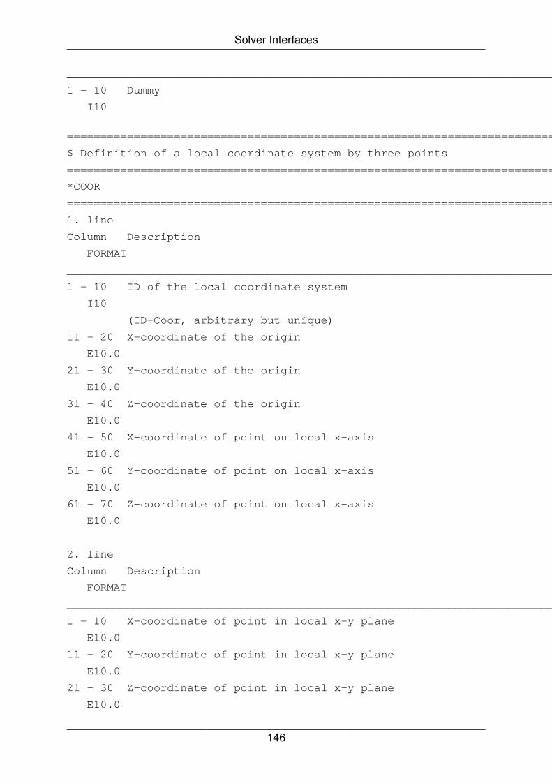
Solver Interfaces
____________________________________________________________________________________
1 - 10 Dummy
I10
=====================================================================================
$ Definition of a local coordinate system by three points
=====================================================================================
*COOR
=====================================================================================
1. line
Column Description
FORMAT
____________________________________________________________________________________
1 - 10 ID of the local coordinate system
I10
(ID-Coor, arbitrary but unique)
11 - 20 X-coordinate of the origin
E10.0
21 - 30 Y-coordinate of the origin
E10.0
31 - 40 Z-coordinate of the origin
E10.0
41 - 50 X-coordinate of point on local x-axis
E10.0
51 - 60 Y-coordinate of point on local x-axis
E10.0
61 - 70 Z-coordinate of point on local x-axis
E10.0
2. line
Column Description
FORMAT
____________________________________________________________________________________
1 - 10 X-coordinate of point in local x-y plane
E10.0
11 - 20 Y-coordinate of point in local x-y plane
E10.0
21 - 30 Z-coordinate of point in local x-y plane
E10.0
146
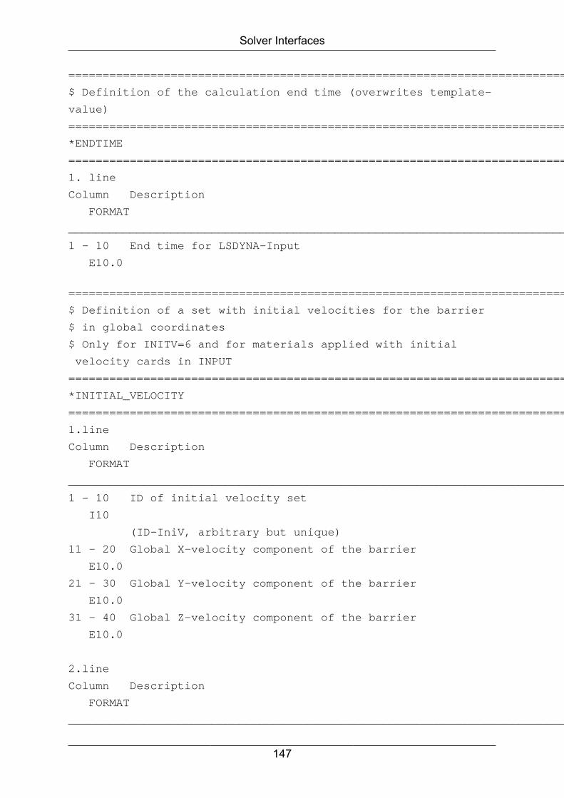
Solver Interfaces
=====================================================================================
$ Definition of the calculation end time (overwrites template-
value)
=====================================================================================
*ENDTIME
=====================================================================================
1. line
Column Description
FORMAT
____________________________________________________________________________________
1 - 10 End time for LSDYNA-Input
E10.0
=====================================================================================
$ Definition of a set with initial velocities for the barrier
$ in global coordinates
$ Only for INITV=6 and for materials applied with initial
velocity cards in INPUT
=====================================================================================
*INITIAL_VELOCITY
=====================================================================================
1.line
Column Description
FORMAT
____________________________________________________________________________________
1 - 10 ID of initial velocity set
I10
(ID-IniV, arbitrary but unique)
11 - 20 Global X-velocity component of the barrier
E10.0
21 - 30 Global Y-velocity component of the barrier
E10.0
31 - 40 Global Z-velocity component of the barrier
E10.0
2.line
Column Description
FORMAT
____________________________________________________________________________________
147
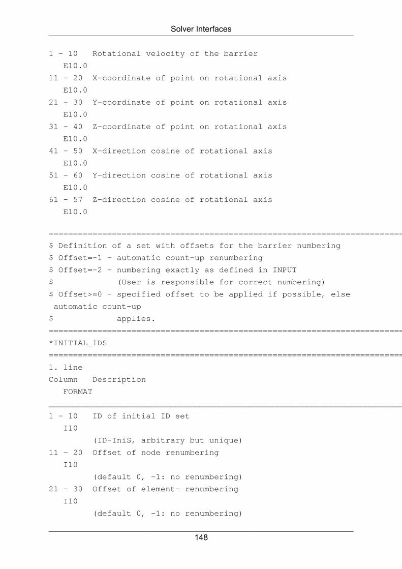
Solver Interfaces
1 - 10 Rotational velocity of the barrier
E10.0
11 - 20 X-coordinate of point on rotational axis
E10.0
21 - 30 Y-coordinate of point on rotational axis
E10.0
31 - 40 Z-coordinate of point on rotational axis
E10.0
41 - 50 X-direction cosine of rotational axis
E10.0
51 - 60 Y-direction cosine of rotational axis
E10.0
61 - 57 Z-direction cosine of rotational axis
E10.0
=====================================================================================
$ Definition of a set with offsets for the barrier numbering
$ Offset=-1 – automatic count-up renumbering
$ Offset=-2 – numbering exactly as defined in INPUT
$ (User is responsible for correct numbering)
$ Offset>=0 – specified offset to be applied if possible, else
automatic count-up
$ applies.
=====================================================================================
*INITIAL_IDS
=====================================================================================
1. line
Column Description
FORMAT
____________________________________________________________________________________
1 - 10 ID of initial ID set
I10
(ID-IniS, arbitrary but unique)
11 - 20 Offset of node renumbering
I10
(default 0, -1: no renumbering)
21 - 30 Offset of element- renumbering
I10
(default 0, -1: no renumbering)
148
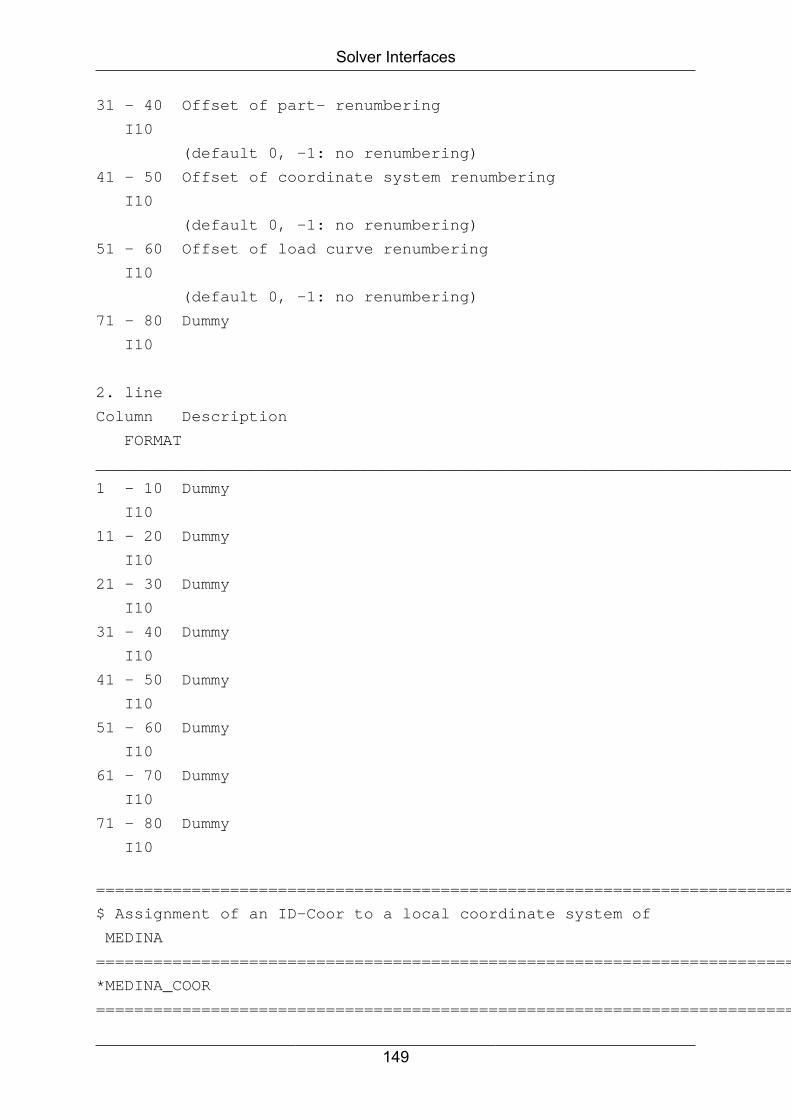
Solver Interfaces
31 - 40 Offset of part- renumbering
I10
(default 0, -1: no renumbering)
41 - 50 Offset of coordinate system renumbering
I10
(default 0, -1: no renumbering)
51 - 60 Offset of load curve renumbering
I10
(default 0, -1: no renumbering)
71 - 80 Dummy
I10
2. line
Column Description
FORMAT
____________________________________________________________________________________
1 - 10 Dummy
I10
11 - 20 Dummy
I10
21 - 30 Dummy
I10
31 - 40 Dummy
I10
41 - 50 Dummy
I10
51 - 60 Dummy
I10
61 - 70 Dummy
I10
71 - 80 Dummy
I10
=====================================================================================
$ Assignment of an ID-Coor to a local coordinate system of
MEDINA
=====================================================================================
*MEDINA_COOR
=====================================================================================
149

Solver Interfaces
1.line
Column Description
FORMAT
____________________________________________________________________________________
1 - 10 ID of the local coordinate system
I10
(ID-Coor, arbitrary but unique)
2.line
Column Description
FORMAT
____________________________________________________________________________________
1 - 80 Name of the local coordinate system in MEDINA
A80
(must be available on BIF)
=====================================================================================
$ Definition of an additional contact as complement of a
contact on BIF
$ (Name: TOTAL_CONTACT) by the contact at the assigned
position in INPUT.
$ The box will be enhanced and also the list of materials,
that either will be added
$ or excluded.
=====================================================================================
*TOTAL_CONTACT
=====================================================================================
Column Description
FORMAT
____________________________________________________________________________________
1 - 10 Position at which the contact from the barrier
I10
will be found in INPUT, so that a total contact
may be created by this contact and the contact
from BIF with name “TOTAL_CONTACT”.
150
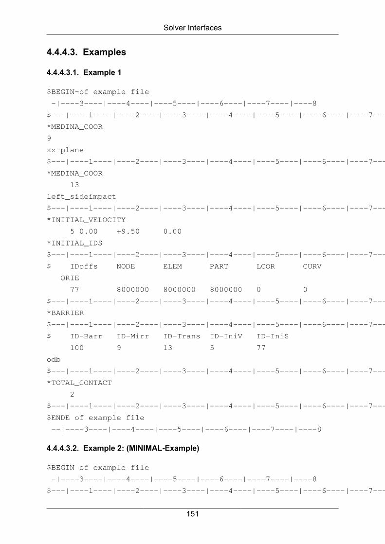
Solver Interfaces
4.4.4.3. Examples
4.4.4.3.1. Example 1
$BEGIN-of example file
-|----3----|----4----|----5----|----6----|----7----|----8
$---|----1----|----2----|----3----|----4----|----5----|----6----|----7----|----8
*MEDINA_COOR
9
xz-plane
$---|----1----|----2----|----3----|----4----|----5----|----6----|----7----|----8
*MEDINA_COOR
13
left_sideimpact
$---|----1----|----2----|----3----|----4----|----5----|----6----|----7----|----8
*INITIAL_VELOCITY
5 0.00 +9.50 0.00
*INITIAL_IDS
$---|----1----|----2----|----3----|----4----|----5----|----6----|----7----|----8
$ IDoffs NODE ELEM PART LCOR CURV
ORIE
77 8000000 8000000 8000000 0 0
$---|----1----|----2----|----3----|----4----|----5----|----6----|----7----|----8
*BARRIER
$---|----1----|----2----|----3----|----4----|----5----|----6----|----7----|----8
$ ID-Barr ID-Mirr ID-Trans ID-IniV ID-IniS
100 9 13 5 77
odb
$---|----1----|----2----|----3----|----4----|----5----|----6----|----7----|----8
*TOTAL_CONTACT
2
$---|----1----|----2----|----3----|----4----|----5----|----6----|----7----|----8
$ENDE of example file
--|----3----|----4----|----5----|----6----|----7----|----8
4.4.4.3.2. Example 2: (MINIMAL-Example)
$BEGIN of example file
-|----3----|----4----|----5----|----6----|----7----|----8
$---|----1----|----2----|----3----|----4----|----5----|----6----|----7----|----8
151

Solver Interfaces
*MEDINA_COOR
1
left_sideimpact
$---|----1----|----2----|----3----|----4----|----5----|----6----|----7----|----8
*BARRIER
$---|----1----|----2----|----3----|----4----|----5----|----6----|----7----|----8
$ ID-Barr ID-Mirr ID-Trans ID-IniV ID-IniS
100 0 1
odb
$---|----1----|----2----|----3----|----4----|----5----|----6----|----7----|----8
*TOTAL_CONTACT
1
$---|----1----|----2----|----3----|----4----|----5----|----6----|----7----|----8
$ENDE of example file
--|----3----|----4----|----5----|----6----|----7----|----8
4.4.4.3.3. Example 3 (MAXIMAL-Example)
$BEGIN of example file
-|----3----|----4----|----5----|----6----|----7----|----8
$---|----1----|----2----|----3----|----4----|----5----|----6----|----7----|----8
*COOR
9 0.0 0.0 0.0 1.0 0.0
0.0
0.0 0.0 1.0
$---|----1----|----2----|----3----|----4----|----5----|----6----|----7----|----8
*MEDINA_COOR
13
left_sideimpact
$---|----1----|----2----|----3----|----4----|----5----|----6----|----7----|----8
*INITIAL_VELOCITY
5 0.00 +9.50 0.00
*INITIAL_IDS
$---|----1----|----2----|----3----|----4----|----5----|----6----|----7----|----8
$ IDoffs NODE ELEM PART LCOR CURV
ORIE
77 8000000 8000000 8000000 0 0
$---|----1----|----2----|----3----|----4----|----5----|----6----|----7----|----8
*BARRIER
152
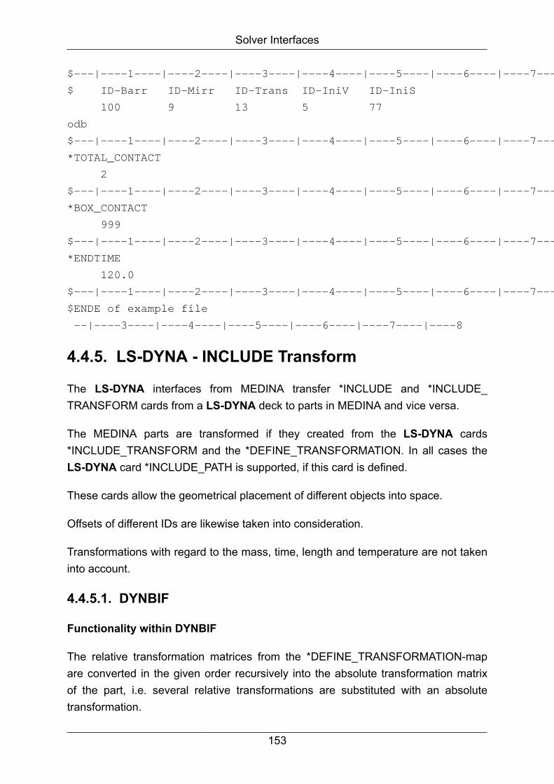
Solver Interfaces
$---|----1----|----2----|----3----|----4----|----5----|----6----|----7----|----8
$ ID-Barr ID-Mirr ID-Trans ID-IniV ID-IniS
100 9 13 5 77
odb
$---|----1----|----2----|----3----|----4----|----5----|----6----|----7----|----8
*TOTAL_CONTACT
2
$---|----1----|----2----|----3----|----4----|----5----|----6----|----7----|----8
*BOX_CONTACT
999
$---|----1----|----2----|----3----|----4----|----5----|----6----|----7----|----8
*ENDTIME
120.0
$---|----1----|----2----|----3----|----4----|----5----|----6----|----7----|----8
$ENDE of example file
--|----3----|----4----|----5----|----6----|----7----|----8
4.4.5. LS-DYNA - INCLUDE Transform
The LS-DYNA interfaces from MEDINA transfer *INCLUDE and *INCLUDE_TRANSFORM cards from a LS-DYNA deck to parts in MEDINA and vice versa.
The MEDINA parts are transformed if they created from the LS-DYNA cards*INCLUDE_TRANSFORM and the *DEFINE_TRANSFORMATION. In all cases theLS-DYNA card *INCLUDE_PATH is supported, if this card is defined.
These cards allow the geometrical placement of different objects into space.
Offsets of different IDs are likewise taken into consideration.
Transformations with regard to the mass, time, length and temperature are not takeninto account.
4.4.5.1. DYNBIF
Functionality within DYNBIF
The relative transformation matrices from the *DEFINE_TRANSFORMATION-mapare converted in the given order recursively into the absolute transformation matrixof the part, i.e. several relative transformations are substituted with an absolutetransformation.
153
Solver Interfaces
Transformations of nodes, elements and other cards with local coordinates will betranslated to the global coordinate system of MEDINA.
Nodes, elements, Properties and all relations on them (see the following list) will berecursively renumbered with the given offset.
Data from the *INCLUDE transform map will be found in the MEDINA part.
*AIRBAG_SIMPLE_PRESSURE_VOLUME
*BOUNDARY_PRESCRIBED_MOTION_NODE
*BOUNDARY_PRESCRIBED_MOTION_RIGID
*BOUNDARY_PRESCRIBED_MOTION_RIGID_LOCAL
*BOUNDARY_PRESCRIBED_MOTION_SET
*BOUNDARY_SPC_NODE*BOUNDARY_SPC_SET
*CONSTRAINED_EXTRA_NODES_NODE
*CONSTRAINED_EXTRA_NODES_SET
*CONSTRAINED_GENERALIZED_WELD_BUTT
*CONSTRAINED_GENERALIZED_WELD_FILLET
*CONSTRAINED_GENERALIZED_WELD_SPOT
*CONSTRAINED_INTERPOLATION
*CONSTRAINED_JOINT_CYLINDRICAL
*CONSTRAINED_JOINT_LOCKING
*CONSTRAINED_JOINT_PLANAR
*CONSTRAINED_JOINT_REVOLUTE
*CONSTRAINED_JOINT_SPHERICAL
*CONSTRAINED_JOINT_TRANSLATIONAL
*CONSTRAINED_JOINT_UNIVERSAL
*CONSTRAINED_NODAL_RIGID_BODY
154

Solver Interfaces
*CONSTRAINED_NODAL_RIGID_BODY_INERTIA
*CONSTRAINED_NODE_SET
*CONSTRAINED_RIGID_BODIES
*CONSTRAINED_RIVET
*CONSTRAINED_SPOTWELD
*CONTACT_AUTOMATIC_SINGLE_SURFACE
*CONTACT_ERODING_SINGLE_SURFACE
*CONTACT_ERODING_SURFACE_TO_SURFACE
*CONTACT_FORCE_TRANSDUCER_PENALTY
*CONTACT_NODES_TO_SURFACE
*CONTACT_ONE_WAY_SURFACE_TO_SURFACE
*CONTACT_SINGLE_EDGE
*CONTACT_SURFACE_TO_SURFACE
*CONTACT_TIED_NODES_TO_SURFACE
*CONTROL_
*CONTROL_HOURGLASS
*DATABASE_CROSS_SECTION_PLANE
*DATABASE_CROSS_SECTION_PLANE_ID
*DATABASE_CROSS_SECTION_SET
*DATABASE_CROSS_SECTION_SET_ID
*DATABASE_HISTORY_BEAM
*DATABASE_HISTORY_BEAM_SET
*DATABASE_HISTORY_BEAM_ID
*DATABASE_HISTORY_NODE
155

Solver Interfaces
*DATABASE_HISTORY_NODE_SET
*DATABASE_HISTORY_NODE_ID
*DATABASE_HISTORY_SHELL
*DATABASE_HISTORY_SHELL_SET
*DATABASE_HISTORY_SHELL_ID
*DATABASE_HISTORY_SOLID
*DATABASE_HISTORY_SOLID_SET
*DATABASE_HISTORY_SOLID_ID
*DATABASE_HISTORY_TSHELL
*DATABASE_HISTORY_TSHELL_SET
*DATABASE_HISTORY_TSHELL_ID+B28
*DATABASE_NODAL_FORCE_GROUP
*DEFINE_BOX
*DEFINE_COORDINATE_NODES
*DEFINE_COORDINATE_SYSTEM
*DEFINE_COORDINATE_VECTOR
*DEFINE_CURVE
*DEFINE_SD_ORIENTATION
*DEFINE_TABLE
*DEFINE_VECTOR
*DEFINE_VECTOR_NODES
*ELEMENT_BEAM
*ELEMENT_BEAM_ORIENTATION
*ELEMENT_BEAM_PID
156

Solver Interfaces
*ELEMENT_BEAM_THICKNESS
*ELEMENT_DISCRETE
*ELEMENT_MASS
*ELEMENT_SEATBELT
*ELEMENT_SEATBELT_ACCELEROMETER
*ELEMENT_SHELL
*ELEMENT_SHELL_BETA
*ELEMENT_SHELL_BETA_OFFSET
*ELEMENT_SHELL_MCID
*ELEMENT_SHELL_MCID_OFFSET
*ELEMENT_SHELL_OFFSET
*ELEMENT_SHELL_THICKNESS
*ELEMENT_SOLID
*ELEMENT_SOLID_ORTHO
*ELEMENT_TSHELL
*END
*HOURGLASS
*INCLUDE
*INCLUDE_PATH
*INITIAL_VELOCITY
*INITIAL_VELOCITY_GENERATION
*INITIAL_VELOCITY_NODE
*INTERFACE_COMPONENT_NODE
*INTERFACE_COMPONENT_SEGMENT
*KEYWORD
157

Solver Interfaces
*LOAD_BODY_X
*LOAD_BODY_Y
*LOAD_BODY_Z
*LOAD_NODE_POINT
*LOAD_NODE_SET
*LOAD_RIGID_BODY
*LOAD_SHELL_ELEMENT
*LOAD_THERMAL_CONSTANT
*MAT
*NODE
*PART
*PART_COMPOSITE
*PART_COMPOSITE_CONTACT
*PART_COMPOSITE_TSHELL
*RIGIDWALL_GEOMETRIC_CYLINDER
*RIGIDWALL_GEOMETRIC_CYLINDER_MOTION
*RIGIDWALL_GEOMETRIC_FLAT
*RIGIDWALL_GEOMETRIC_FLAT_MOTION
*RIGIDWALL_GEOMETRIC_PRISM
*RIGIDWALL_GEOMETRIC_PRISM_MOTION
*RIGIDWALL_GEOMETRIC_SPHERE
*RIGIDWALL_GEOMETRIC_SPHERE_MOTION
*RIGIDWALL_PLANAR
*RIGIDWALL_PLANAR_FINITE
158
Solver Interfaces
*RIGIDWALL_PLANAR_FINITE_MOVING
*RIGIDWALL_PLANAR_MOVING
*SECTION_BEAM
*SECTION_DISCRETE
*SECTION_SHELL
*SECTION_SOLID
*SET_BEAM
*SET_DISCRETE
*SET_NODE
*SET_NODE_COLUMN
*SET_NODE_LIST
*SET_NODE_LIST_TITLE
*SET_PART
*SET_PART_COLUMN
*SET_PART_LIST
*SET_SEGMENT
*SET_SHELL
*SET_SHELL_COLUMN
*SET_SHELL_LIST
*SET_SOLID
*SET_TSHELL
*TITLE
Note
DYNBIF supports only LS-DYNA3D keyword format.
159

Solver Interfaces
4.4.5.2. BIFDYN
If the option "Write extra include file for each part" is set, then the interface for everypart (except root) generates an include file.
Additionally, either a *INCLUDE or if the transformation of the part does not correspondto the identity matrix, a card pair consisting of a *INCLUDE_TRANSFORM with itsaccompanying *DEFINE_TRANSFORMATION will be generated.
Note
During the use of BIFDYN in automated processes, BIFDYN gives backreturncode 10 if a warning occurs.
4.4.5.3. Supported contact cards in MEDINA
Contacttype
*CONTACT_[Description]
1 AIRBAG_SINGLE_SURFACE
2 AUTOMATIC_GENERAL
3 AUTOMATIC_NODES_TO_SURFACE
4 AUTOMATIC_ONE_WAY_SURFACE_TO_SURFACE
5 AUTOMATIC_SINGLE_SURFACE
6 AUTOMATIC_SURFACE_TO_SURFACE
7 CONSTRAINT_NODES_TO_SURFACE
8 CONSTRAINT_SURFACE_TO_SURFACE
9 DRAWBEAD
10 ERODING_NODES_TO_SURFACE
11 ERODING_SINGLE_SURFACE
12 ERODING_SURFACE_TO_SURFACE
13 FORCE_TRANSDUCER_CONSTRAINT
14 FORCE_TRANSDUCER_PENALTY
15 FORMING_NODES_TO_SURFACE
16 FORMING_ONE_WAY_SURFACE_TO_SURFACE
17 FORMING_SURFACE_TO_SURFACE
18 NODES_TO_SURFACE
160

Solver Interfaces
Contacttype
*CONTACT_[Description]
19 ONE_WAY_SURFACE_TO_SURFACE
20 RIGID_NODES_TO_RIGID_BODY
21 RIGID_BODY_ONE_WAY_TO_RIGID_BODY
22 RIGID_BODY_TWO_WAY_TO_RIGID_BODY
23 SINGLE_EDGE
24 SINGLE_SURFACE
25 SLIDING_ONLY
26 SLIDING_ONLY_PENALTY
27 SURFACE_TO_SURFACE
28 TIEBREAK_NODES_TO_SURFACE
29 TIEBREAK_SURFACE_TO_SURFACE
30 TIED_NODES_TO_SURFACE
31 TIED_SHELL_EDGE_TO_SURFACE
32 TIED_SURFACE_TO_SURFACE
33 TIED_NODES_TO_SURFACE_OFFSET
34 TIED_SHELL_EDGE_TO_SURFACE_OFFSET
35 TIED_SURFACE_TO_SURFACE_OFFSET
36 TIED_SHELL_EDGE_TO_SURFACE_BEAM_OFFSET
37 TIED_NODES_TO_SURFACE_CONSTRAINED_OFFSET
38 TIED_SHELL_EDGE_TO_SURFACE_CONSTRAINED_OFFSET
39 TIED_SURFACE_TO_SURFACE_CONSTRAINED_OFFSET
4.4.6. LS-DYNA - Template File for Control Cards
The information for the LS-DYNA control cards in the template file is stored in LS-DYNA Structured Input Format.
Data that is in the MEDINA data file will be replaced. All other data is taken from thetemplate file and passed on to the LS-DYNA input file.
If there is no template file specified, then the default values will be written onto thecontrol cards.
161

Solver Interfaces
The data in the template file must be written in the LS-DYNA format.
4.4.7. LS-DYNA - Processing Control Card Informationto Property Data
Using the program DYNBIF with the parameter “material” (or using the option “createdatabase”), the control file information is written to the control file and additionally aMEDINA property is generated in the following manner:
Example:
Control file 1000; right front door; SHELL; 2; >shell_1; s=1.00; >mat_1;
Property ID=1000
thickness=1.00
label="right front door; 2; >shell_1; s=1.00;"
mid=1
Material ID=1
label=">mat_1"
4.4.8. LS-DYNA - Processing Information fromProperty Data Structure
The interface program bifdyn search for control file information in the property labels,this information is processed to the LS-DYNA input file.
4.4.9. LS-DYNA - Initial conditions
BIFDYN reads initial conditions (shell thicknesses and strains) from several MEDINABOF files and writes them to the LS-DYNA input file.
A layer file controls the reading of data from BOF file and the writing of the necessaryLS-DYNA statements.
SYNTAX:
*BOF :
Defines the name of the MEDINA BOF file for initial conditions. Required parameter:
162

Solver Interfaces
FILE=<name>
*LAYER:
First line:
Layer ID, Layer coordinates
*SCALE:
Defines the scale factor. Required parameter:
TYPE=<type>
Where type:
= THICKNESS, scale factor for shell thickness
= STRAIN, scale factor for initial strain
Optional parameter
PID=<number>
Property-ID for which the scale factor is valid, if not defined the scale factor is appliedto all PIDs.
First line: Scale factor
Example:
*BOFFILE, FILE=/mapping1.bof
*BOFFILE, FILE=/mapping2.bof
*LAYER
1, 0.0
2, -0.906179846
3, -0.538469310
4, 0.538469310
5, 0.906179846
*SCALE,TYPE=THICKNESS,PID=26
0.1
*SCALE,TYPE=STRAIN,PID=26
0.1
163
Solver Interfaces
The layer file is referenced in the Additional program parameters field in the interfacestart window with the option:
"opt=-clayer <directory-name>/<filename>"
If the file name contains blanks (e.g. my file), the correct input is:
{opt=-clayer "<directory-name>/my file”}
Shell elements are written to the LS-DYNA input file as shells with variable thicknesses.
LS-DYNA statement for initial strains is (keyword input only):
*INITIAL_STRESS_SHELL with the corresponding layer coordinates
MEDINA data elements
key 204 physical meaning EffPlasticStrain
key 204 physical meaning THICKNESS
Initial strain for each element is averaged over all element nodes.
4.4.10. LS-DYNA - Method to Generate a Model
Generating the databases
Use a LS-DYNA input deck to generate the databases needed for DYNBIF.
Call DYNBIF:
dynbif –dat input –bif test.bif –material
It generates the databases dbsection and dbmaterial in the current workingdirectory.
The control file which is produced is stored under dbcontrol. These files cannot existin the working directory before the call.
Example named “plate”:
The following input files are available for the example named “plate”:
plate.bif file name with the MEDINA data
plate.control list of components
164

Solver Interfaces
plate.template control card template
Material directory with the material data
Section directory with the section data
Call BIFDYN:
bifdyn bif plate.bif –dat plate.inp –large –matpath Material –
sectpath Section –control plate.control
BIFDYN generates a LS-DYNA input deck with the name plate.inp.
This example is in:
<inst_directory>/cae/data/bifdyn/example
4.4.11. BIFDYN -> Interface BIF to LS-DYNA
The interface BIFDYN converts MEDINA data (BIF) into LS-DYNA data.
The following table compares and describes the parameters in the MEDINA Monitorand the command line parameters for the tcl batch script:
Start MonitorParameter
Batch ScriptParameter
Description
Workingdirectory
dir=dirname Set the working directory for file access.
BIF Input file bif=filename Binary input file from MEDINA PreProcessing.
BIFDYN controlfile
control=filename Specify a BIFDYN component control file.
DYNA3D controlcard template file
template=filenameSpecify a template file for DYNA3D control cards.
User materialdatabase
umatpath=dirnameSet the directory of the user material database.
User sectiondatabase
usectpath=dirnameSet the directory of the user section database.
User templatedatabase
utemplpath=dirnameSet the directory of the user template database.
Output file inp=filename Formatted output file used as DYNA3D inputdeck.
165
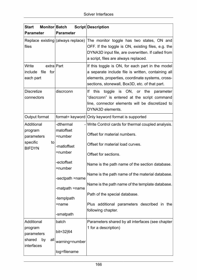
Solver Interfaces
Start MonitorParameter
Batch ScriptParameter
Description
Replace existingfiles
(always replace) The monitor toggle has two states, ON andOFF. If the toggle is ON, existing files, e.g. theDYNA3D input file, are overwritten. If called froma script, files are always replaced.
Write extrainclude file foreach part
Part If this toggle is ON, for each part in the modela separate include file is written, containing allelements, properties, coordinate systems, cross-sections, stonewall, Box3D, etc. of that part.
Discretizeconnectors
discrconn If this toggle is ON, or the parameter“discrconn” is entered at the script commandline, connector elements will be discretized toDYNA3D elements.
Output format format= keyword Only keyword format is supported
Additionalprogramparametersspecific toBIFDYN
-dthermal -matoffset=number
-matloffset=number
-ectoffset=number
-sectpath =name
-matpath =name
-templpath=name
-smatpath
Write Control cards for thermal coupled analysis.
Offset for material numbers.
Offset for material load curves.
Offset for sections.
Name is the path name of the section database.
Name is the path name of the material database.
Name is the path name of the template database.
Path of the special database.
Plus additional parameters described in thefollowing chapter.
Additionalprogramparametersshared by allinterfaces
batch
bit=32|64
warning=number
log=filename
Parameters shared by all interfaces (see chapter1 for a description)
166

Solver Interfaces
Calling BIFDYN without MEDINA Monitor
Call:
<inst_directory>/cae/bin/bifdyn bif=name inp=name
[format={keyword}] [replace] [control=name] [template=name]
[matpath=name] [sectpath=name] [templpath=name] [umatpath=name]
[usectpath=name] [utemplpath=name] [matoffset=number]
[matloffset=number] [sectoffset=number] [flansch=number]
[dthermal] [discrconn] [parts] [size=number] [dir=name]
[log=name] [warning=number] [batch] [bit={32|64}]
if optional parameters are omitted, the first value of the numeration is the default value.
Note
For description of all options and arguments above go into the installationdirectory for load modules and enter the desired interface (e.g. bifdyn).
BIFDYN supports only LS-DYNA3D keyword format.
Example:
To convert the MEDINA file test.bif into the LS-DYNA file test.inp in the keyword format,use:
<inst_directory>/cae/bin/bifdyn bif=test.bif inp=test.inp
Calling BIFDYN from MEDINA Monitor
To define the names of the material database, the section database and the templatedatabase for MEDINA Monitor set environment variables matpath, sectpath andtemplpath to the appropriate directory names.
If these variables are set, the names of the corresponding directories are shown in theBIFDYN start window.
4.4.11.1. More Additional parameters
The additional program parameters are referenced in the additional parameter field inthis way:
"opt=-parameter <name/number>"
167
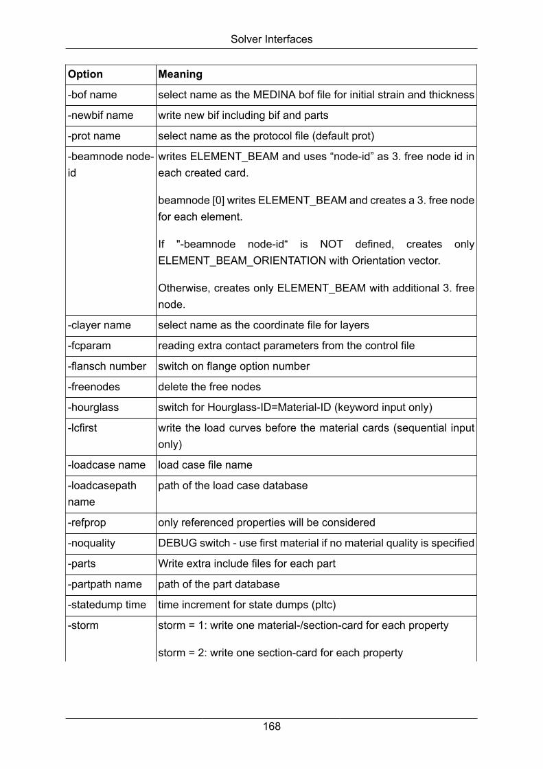
Solver Interfaces
Option Meaning
-bof name select name as the MEDINA bof file for initial strain and thickness
-newbif name write new bif including bif and parts
-prot name select name as the protocol file (default prot)
-beamnode node-id
writes ELEMENT_BEAM and uses “node-id” as 3. free node id ineach created card.
beamnode [0] writes ELEMENT_BEAM and creates a 3. free nodefor each element.
If "-beamnode node-id“ is NOT defined, creates onlyELEMENT_BEAM_ORIENTATION with Orientation vector.
Otherwise, creates only ELEMENT_BEAM with additional 3. freenode.
-clayer name select name as the coordinate file for layers
-fcparam reading extra contact parameters from the control file
-flansch number switch on flange option number
-freenodes delete the free nodes
-hourglass switch for Hourglass-ID=Material-ID (keyword input only)
-lcfirst write the load curves before the material cards (sequential inputonly)
-loadcase name load case file name
-loadcasepathname
path of the load case database
-refprop only referenced properties will be considered
-noquality DEBUG switch - use first material if no material quality is specified
-parts Write extra include files for each part
-partpath name path of the part database
-statedump time time increment for state dumps (pltc)
-storm storm = 1: write one material-/section-card for each property
storm = 2: write one section-card for each property
168
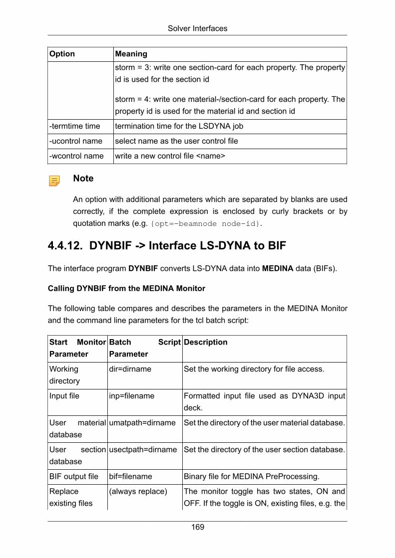
Solver Interfaces
Option Meaningstorm = 3: write one section-card for each property. The propertyid is used for the section id
storm = 4: write one material-/section-card for each property. Theproperty id is used for the material id and section id
-termtime time termination time for the LSDYNA job
-ucontrol name select name as the user control file
-wcontrol name write a new control file <name>
Note
An option with additional parameters which are separated by blanks are usedcorrectly, if the complete expression is enclosed by curly brackets or byquotation marks (e.g. {opt=-beamnode node-id}.
4.4.12. DYNBIF -> Interface LS-DYNA to BIF
The interface program DYNBIF converts LS-DYNA data into MEDINA data (BIFs).
Calling DYNBIF from the MEDINA Monitor
The following table compares and describes the parameters in the MEDINA Monitorand the command line parameters for the tcl batch script:
Start MonitorParameter
Batch ScriptParameter
Description
Workingdirectory
dir=dirname Set the working directory for file access.
Input file inp=filename Formatted input file used as DYNA3D inputdeck.
User materialdatabase
umatpath=dirname Set the directory of the user material database.
User sectiondatabase
usectpath=dirname Set the directory of the user section database.
BIF output file bif=filename Binary file for MEDINA PreProcessing.
Replaceexisting files
(always replace) The monitor toggle has two states, ON andOFF. If the toggle is ON, existing files, e.g. the
169
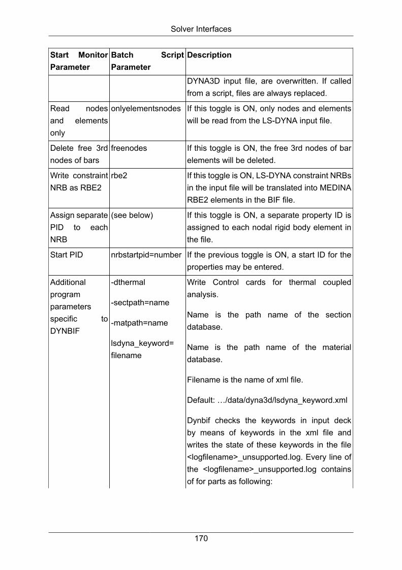
Solver Interfaces
Start MonitorParameter
Batch ScriptParameter
Description
DYNA3D input file, are overwritten. If calledfrom a script, files are always replaced.
Read nodesand elementsonly
onlyelementsnodes If this toggle is ON, only nodes and elementswill be read from the LS-DYNA input file.
Delete free 3rdnodes of bars
freenodes If this toggle is ON, the free 3rd nodes of barelements will be deleted.
Write constraintNRB as RBE2
rbe2 If this toggle is ON, LS-DYNA constraint NRBsin the input file will be translated into MEDINARBE2 elements in the BIF file.
Assign separatePID to eachNRB
(see below) If this toggle is ON, a separate property ID isassigned to each nodal rigid body element inthe file.
Start PID nrbstartpid=number If the previous toggle is ON, a start ID for theproperties may be entered.
Additionalprogramparametersspecific toDYNBIF
-dthermal
-sectpath=name
-matpath=name
lsdyna_keyword=filename
Write Control cards for thermal coupledanalysis.
Name is the path name of the sectiondatabase.
Name is the path name of the materialdatabase.
Filename is the name of xml file.
Default: …/data/dyna3d/lsdyna_keyword.xml
Dynbif checks the keywords in input deckby means of keywords in the xml file andwrites the state of these keywords in the file<logfilename>_unsupported.log. Every line ofthe <logfilename>_unsupported.log containsof for parts as following:
170
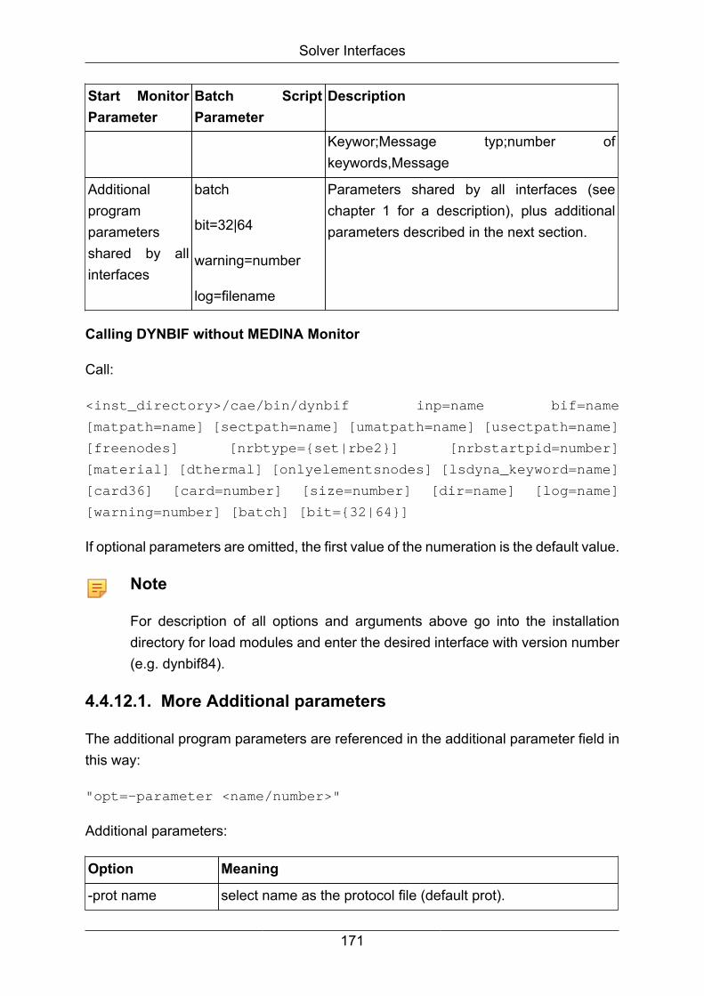
Solver Interfaces
Start MonitorParameter
Batch ScriptParameter
Description
Keywor;Message typ;number ofkeywords,Message
Additionalprogramparametersshared by allinterfaces
batch
bit=32|64
warning=number
log=filename
Parameters shared by all interfaces (seechapter 1 for a description), plus additionalparameters described in the next section.
Calling DYNBIF without MEDINA Monitor
Call:
<inst_directory>/cae/bin/dynbif inp=name bif=name
[matpath=name] [sectpath=name] [umatpath=name] [usectpath=name]
[freenodes] [nrbtype={set|rbe2}] [nrbstartpid=number]
[material] [dthermal] [onlyelementsnodes] [lsdyna_keyword=name]
[card36] [card=number] [size=number] [dir=name] [log=name]
[warning=number] [batch] [bit={32|64}]
If optional parameters are omitted, the first value of the numeration is the default value.
Note
For description of all options and arguments above go into the installationdirectory for load modules and enter the desired interface with version number(e.g. dynbif84).
4.4.12.1. More Additional parameters
The additional program parameters are referenced in the additional parameter field inthis way:
"opt=-parameter <name/number>"
Additional parameters:
Option Meaning
-prot name select name as the protocol file (default prot).
171

Solver Interfaces
Option Meaning
-warning number complete warning message report.
-card number Read until that card number.
-card36 read a nodal rigid body constraint set as a set (structured inputonly)
-dthermal dyna3d thermal or coupled structural/thermal analysis.
-discretefromcontrol write material and section of springs and dampers in database
-fcparam reading extra contact parameters from the control file
-freenodes delete the free nodes.
-keepnumber keeps the original material-, section- and loadcurve-id whencreating the databases
-material read the material card 3. and creates the databases
-onlyelementsnodes read only elements and nodes.
-nrbstartpid a separate property ID is assigned to each nodal rigid bodyelement, starting with the ID given here.
-rbe2 read a *CONSTRAINED_NODAL_RIGID_BODY as RBE2element (keyword input only)
-umatpath name checks each materials, not found in <matpath>, if it exists inthe database - if not adding it to the database. If <name> is notexisting it will be created. (default: dbMaterial).
-sectpath name checks each section in the input if it exists in the database (ifexisting) - if not checks the <usectpath>.
-smatpath path of the special database
-usectpath name checks each section, not found in <sectpath>, if it exists in thedatabase - if not adding it to the database. If <name> is notexisting it will be created. (default: dbSection).
-secform writes a comment for the element formulation to the database.(for structured solver file only).
-control name writes a control file <name>. (default: dbpropin).
-vers show the version and stop the interface
Calling DYNBIF without MEDINA Monitor
Call:
172

Solver Interfaces
<inst_directory>/cae/bin/dynbif84 inp=name bif=name [log=name]
[dir=name] [freenodes] [material] [dthermal] [card36]
[card=number] [warning=number]
If optional parameters are omitted, the first value of the numeration is the default value.
Note
For description of all options and arguments above go into the installationdirectory for load modules and enter the desired interface (e.g. dynbif).
Option Meaning
inp=name Input: LS-DYNA data file name (e.g.: test.inp)
bif=name Output: MEDINA data files name (e.g. medina.bif)
log=name Output: log file name (default: dynbif.log)
dir=name Name is the path name of the working directory
freenodes Delete free third beam nodes.
material Generate the databases and the control file
dthermal Control cards for the thermal coupled analysis will beread.
card36 Use the spot welds only in beams
weldspot={set|rbe2} Translate a constrained node set or a constrained nodalrigid body to a MEDINA set or RBE2 element. (keywordformat only)
nrbstartpid=number Start pid for NRB elements from LS-Dyna without adefined property ID. Each element gets its own property.
card=number Process all options up to the card number
warning=number No warnings will be suppressed.
Example:
To convert the MEDINA file test.bif into the LS-DYNA file test.inp in the large format,use:
<inst_directory>/cae/bin/dynbif bif=test.bif inp=test.inp
4.4.12.2. Search for include files
DYNBIF searches for include files in the following manner:
173

Solver Interfaces
• If an absolute path is provided exactly this path will be used.
• If a relative path is provided, DYNBIF will first search the directory in which the maindeck is situated. If the include file is not found and *INCLUDE_PATH is defined, thenDYNBIF looks for the file in the directories specified by *INCLUDE_PATH.
4.4.12.3. DYNBIF: KEYWORD Input
Name of LS-DYNA DATA Entry Support Name ofMEDINAEntry
Remarks
*AIRBAG_SIMPLE_PRESSURE_VOLUME Full General Setwith Solverkey
None
*BOUNDARY_PRESCRIBED_MOTION_NODE Full PVAD None
*BOUNDARY_PRESCRIBED_MOTION_RIGID Full PVAD None
*BOUNDARY_PRESCRIBED_MOTION_RIGID_LOCAL Full PVAD None
*BOUNDARY_PRESCRIBED_MOTION_SET Full PVAD None
*BOUNDARY_PRESCRIBED_MOTION_SET_BOX Full PVAD None
*BOUNDARY_SPC_NODE None
*BOUNDARY_SPC_SET None
*CONSTRAINED_EXTRA_NODES_NODE Full General Setwith Solverkey
None
*CONSTRAINED_EXTRA_NODES_SET Full General Setwith Solverkey
None
*CONSTRAINED_GENERALIZED_WELD_BUTT Full General Setwith Solverkey
None
*CONSTRAINED_GENERALIZED_WELD_FILLET Full General Setwith Solverkey
None
*CONSTRAINED_GENERALIZED_WELD_SPOT Full General Setwith Solverkey
None
*CONSTRAINED_INTERPOLATION None
*CONSTRAINED_JOINT_CYLINDRICAL Full JCYLINelement
None
*CONSTRAINED_JOINT_LOCKING Full JLOCKINGelement
None
174

Solver Interfaces
Name of LS-DYNA DATA Entry Support Name ofMEDINAEntry
Remarks
*CONSTRAINED_JOINT_PLANAR Full JPLANARelement
None
*CONSTRAINED_JOINT_REVOLUTE Full JREVOLVEelement
None
*CONSTRAINED_JOINT_SPHERICAL Full JSPHEREelement
None
*CONSTRAINED_JOINT_TRANSLATIONAL Full JTRANSLelement
None
*CONSTRAINED_JOINT_UNIVERSAL Full JUNIVERSelement
None
*CONSTRAINED_NODAL_RIGID_BODY Full NRIGBODYelement
None
*CONSTRAINED_NODAL_RIGID_BODY_INERTIA Full NRIGBODYelement withinertiaparameter
None
*CONSTRAINED_NODE_SET Full General Setwith Solverkey
None
*CONSTRAINED_RIGID_BODIES Full General Setwith Solverkey
None
*CONSTRAINED_RIVET Full General Setwith Solverkey
None
*CONSTRAINED_SPOTWELD Full General Setwith Solverkey
None
*CONTACT_* Limited Contact None
*CONTACT_INTERIOR Full General Setwith Solverkey
None
*CONTROL_ Solvercard None
*CONTROL_HOURGLASS None
*DATABASE_CROSS_SECTION_PLANE Full CrossSection SetAnalysis
175

Solver Interfaces
Name of LS-DYNA DATA Entry Support Name ofMEDINAEntry
Remarks
System toLS-DYNAin Paramcommand
*DATABASE_CROSS_SECTION_PLANE_ID Full CrossSection SetAnalysisSystem toLS-DYNAin Paramcommand
*DATABASE_CROSS_SECTION_SET Full CrossSection SetAnalysisSystem toLS-DYNAin Paramcommand
*DATABASE_CROSS_SECTION_SET_ID Full CrossSection SetAnalysisSystem toLS-DYNAin Paramcommand
*DATABASE_HISTORY_BEAM Full General Setwith Solverkey
None
*DATABASE_HISTORY_BEAM_SET Full General Setwith Solverkey
None
*DATABASE_HISTORY_BEAM_ID Full General Setwith Solverkey
None
*DATABASE_HISTORY_NODE Full General Setwith Solverkey
None
*DATABASE_HISTORY_NODE_SET Full General Setwith Solverkey
None
176

Solver Interfaces
Name of LS-DYNA DATA Entry Support Name ofMEDINAEntry
Remarks
*DATABASE_HISTORY_NODE_ID Full General Setwith Solverkey
None
*DATABASE_HISTORY_SHELL Full General Setwith Solverkey
None
*DATABASE_HISTORY_SHELL_SET Full General Setwith Solverkey
None
*DATABASE_HISTORY_SHELL_ID Full General Setwith Solverkey
None
*DATABASE_HISTORY_SOLID Full General Setwith Solverkey
None
*DATABASE_HISTORY_SOLID_SET Full General Setwith Solverkey
None
*DATABASE_HISTORY_SOLID_ID Full General Setwith Solverkey
None
*DATABASE_HISTORY_TSHELL Full General Setwith Solverkey
None
*DATABASE_HISTORY_TSHELL_SET Full General Setwith Solverkey
None
*DATABASE_HISTORY_TSHELL_ID Full General Setwith Solverkey
None
*DATABASE_NODAL_FORCE_GROUP Full General Setwith Solverkey
None
*DEFINE_BOX Full Box3D None
*DEFINE_COORDINATE_NODES Full CoordinateSystem of typeNode
None
*DEFINE_COORDINATE_SYSTEM Full CoordinateSystem of typeCoordinates
None
177

Solver Interfaces
Name of LS-DYNA DATA Entry Support Name ofMEDINAEntry
Remarks
*DEFINE_COORDINATE_VECTOR Full CoordinateSystem of typeCoordinates
None
*DEFINE_CURVE Limited Loadcurve SIDR andDATTYPare notsupported.
*DEFINE_SD_ORIENTATION Full OrientationVector
None
*DEFINE_TRANSFORMATION None
*DEFINE_TABLE Limited Loadcurve None
*DEFINE_VECTOR Full Vector None
*DEFINE_VECTOR_NODES Full Vector None
*ELEMENT_BEAM Full BEAMelement
None
*ELEMENT_BEAM_ORIENTATION Full BEAMelement
None
*ELEMENT_BEAM_PID Limited BEAMelement
None
*ELEMENT_BEAM_THICKNESS Limited BEAMelement
Thicknessnotsupported
*ELEMENT_BEAM_SCALAR Limited BEAMelement
Thicknessnotsupported
*ELEMENT_DISCRETE Full NLSPRING,NLDAMPelements
None
*ELEMENT_MASS Full MASSelement
None
*ELEMENT_MASS_NODE_SET Full NSM None
178

Solver Interfaces
Name of LS-DYNA DATA Entry Support Name ofMEDINAEntry
Remarks
*ELEMENT_MASS_PART Full NSM None
*ELEMENT_MASS_PART_SET Full NSM None
*ELEMENT_SEATBELT Full General Setwith Solverkey
None
*ELEMENT_SEATBELT_ACCELEROMETER Full General Setwith Solverkey
None
*ELEMENT_SEATBELT_SLIPRING Full General Setwith Solverkey
None
*ELEMENT_SHELL Full TRIA3,QUAD4element
None
*ELEMENT_SHELL_BETA Full TRIA3V,QUAD4Velement
None
*ELEMENT_SHELL_BETA_OFFSET Full TRIA3V,QUAD4Velement
None
*ELEMENT_SHELL_MCID Full TRIA3V,QUAD4Velement
None
*ELEMENT_SHELL_MCID_OFFSET Full TRIA3V,QUAD4Velement
None
*ELEMENT_SHELL_OFFSET Full TRIA3V,QUAD4Velement
None
*ELEMENT_SHELL_THICKNESS Full TRIA3V,QUAD4Velement
None
*ELEMENT_SOLID Full TETRA,TETRA10,PENTA,
None
179

Solver Interfaces
Name of LS-DYNA DATA Entry Support Name ofMEDINAEntry
Remarks
HEXA,PYRAMelement
*ELEMENT_SOLID_ORTHO Limited TETRA,PENTA,HEXAelement
A1, A2,A3, BETHAand D1, D2,D3 ignored
*ELEMENT_TSHELL Full PENTA6TS,HEXA8TSelements
None
*HOURGLASS None
*INCLUDE Full Part structure Includestructure issupportedas Partstructure
*INCLUDE_PATH Full Part structure None
*INITIAL_STRESS_SECTION Full General Setwith Solverkey
None
*INITIAL_VELOCITY Full IniVel None
*INITIAL_VELOCITY_GENERATION Full IniVel None
*INITIAL_VELOCITY_NODE Full IniVel None
*INITIAL_VELOCITY_RIGID_BODY Full IniVel None
*INTERFACE_COMPONENT_NODE Full General Setwith Solverkey
None
*INTERFACE_COMPONENT_SEGMENT Full General Setwith Solverkey
None
*LOAD_BODY_X, Y, Z Full Accel None
*LOAD_BODY_RX, RY, RZ Full Accel None
*LOAD_BODY_PART Full Accel None
*LOAD_BODY_VECTOR Full Accel None
180
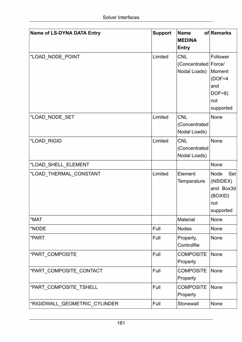
Solver Interfaces
Name of LS-DYNA DATA Entry Support Name ofMEDINAEntry
Remarks
*LOAD_NODE_POINT Limited CNL(ConcentratedNodal Loads)
FollowerForce/Moment(DOF=4andDOF=8)notsupported
*LOAD_NODE_SET Limited CNL(ConcentratedNodal Loads)
None
*LOAD_RIGID Limited CNL(ConcentratedNodal Loads)
None
*LOAD_SHELL_ELEMENT None
*LOAD_THERMAL_CONSTANT Limited ElementTemperature
Node Set(NSIDEX)and Box3d(BOXID)notsupported
*MAT Material None
*NODE Full Nodes None
*PART Full Property,Controlfile
None
*PART_COMPOSITE Full COMPOSITEProperty
None
*PART_COMPOSITE_CONTACT Full COMPOSITEProperty
None
*PART_COMPOSITE_TSHELL Full COMPOSITEProperty
None
*RIGIDWALL_GEOMETRIC_CYLINDER Full Stonewall None
181
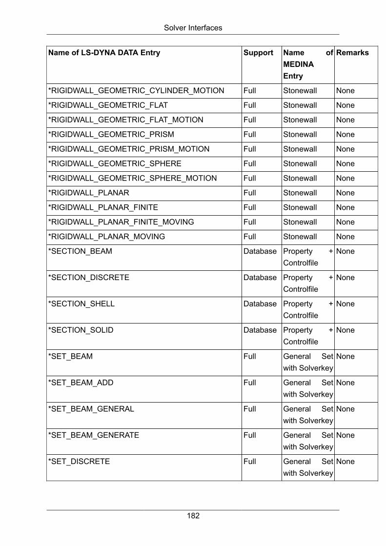
Solver Interfaces
Name of LS-DYNA DATA Entry Support Name ofMEDINAEntry
Remarks
*RIGIDWALL_GEOMETRIC_CYLINDER_MOTION Full Stonewall None
*RIGIDWALL_GEOMETRIC_FLAT Full Stonewall None
*RIGIDWALL_GEOMETRIC_FLAT_MOTION Full Stonewall None
*RIGIDWALL_GEOMETRIC_PRISM Full Stonewall None
*RIGIDWALL_GEOMETRIC_PRISM_MOTION Full Stonewall None
*RIGIDWALL_GEOMETRIC_SPHERE Full Stonewall None
*RIGIDWALL_GEOMETRIC_SPHERE_MOTION Full Stonewall None
*RIGIDWALL_PLANAR Full Stonewall None
*RIGIDWALL_PLANAR_FINITE Full Stonewall None
*RIGIDWALL_PLANAR_FINITE_MOVING Full Stonewall None
*RIGIDWALL_PLANAR_MOVING Full Stonewall None
*SECTION_BEAM Database Property +Controlfile
None
*SECTION_DISCRETE Database Property +Controlfile
None
*SECTION_SHELL Database Property +Controlfile
None
*SECTION_SOLID Database Property +Controlfile
None
*SET_BEAM Full General Setwith Solverkey
None
*SET_BEAM_ADD Full General Setwith Solverkey
None
*SET_BEAM_GENERAL Full General Setwith Solverkey
None
*SET_BEAM_GENERATE Full General Setwith Solverkey
None
*SET_DISCRETE Full General Setwith Solverkey
None
182
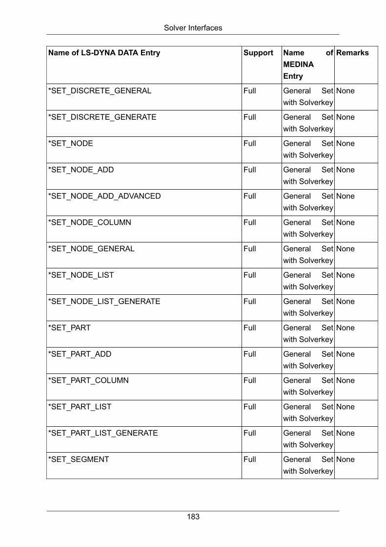
Solver Interfaces
Name of LS-DYNA DATA Entry Support Name ofMEDINAEntry
Remarks
*SET_DISCRETE_GENERAL Full General Setwith Solverkey
None
*SET_DISCRETE_GENERATE Full General Setwith Solverkey
None
*SET_NODE Full General Setwith Solverkey
None
*SET_NODE_ADD Full General Setwith Solverkey
None
*SET_NODE_ADD_ADVANCED Full General Setwith Solverkey
None
*SET_NODE_COLUMN Full General Setwith Solverkey
None
*SET_NODE_GENERAL Full General Setwith Solverkey
None
*SET_NODE_LIST Full General Setwith Solverkey
None
*SET_NODE_LIST_GENERATE Full General Setwith Solverkey
None
*SET_PART Full General Setwith Solverkey
None
*SET_PART_ADD Full General Setwith Solverkey
None
*SET_PART_COLUMN Full General Setwith Solverkey
None
*SET_PART_LIST Full General Setwith Solverkey
None
*SET_PART_LIST_GENERATE Full General Setwith Solverkey
None
*SET_SEGMENT Full General Setwith Solverkey
None
183
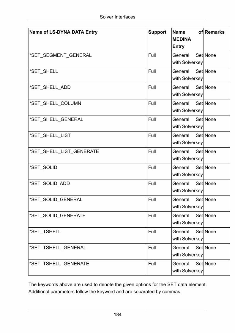
Solver Interfaces
Name of LS-DYNA DATA Entry Support Name ofMEDINAEntry
Remarks
*SET_SEGMENT_GENERAL Full General Setwith Solverkey
None
*SET_SHELL Full General Setwith Solverkey
None
*SET_SHELL_ADD Full General Setwith Solverkey
None
*SET_SHELL_COLUMN Full General Setwith Solverkey
None
*SET_SHELL_GENERAL Full General Setwith Solverkey
None
*SET_SHELL_LIST Full General Setwith Solverkey
None
*SET_SHELL_LIST_GENERATE Full General Setwith Solverkey
None
*SET_SOLID Full General Setwith Solverkey
None
*SET_SOLID_ADD Full General Setwith Solverkey
None
*SET_SOLID_GENERAL Full General Setwith Solverkey
None
*SET_SOLID_GENERATE Full General Setwith Solverkey
None
*SET_TSHELL Full General Setwith Solverkey
None
*SET_TSHELL_GENERAL Full General Setwith Solverkey
None
*SET_TSHELL_GENERATE Full General Setwith Solverkey
None
The keywords above are used to denote the given options for the SET data element.Additional parameters follow the keyword and are separated by commas.
184

Solver Interfaces
Use keywords exactly as shown (e.g. upper case, no further blanks are allowed).
Additional user comments are possible. Append a semicolon and the comment textafter the keyword. User comments are written as a comment line to the output file.
Note
The DYNBIF interface only converts a Discrete Beam as Bush element to theMEDINA Bif file if a material data base is created.
With it creates NO data base, Discrete Beams are converted to normal Beamelements.
Examples:
*CONSTRAINED_NODE_SET,1 means x-translation
*CONSTRAINED_EXTRA_NODES_SET,1 means RIGID BODY
material ID = 1
*CONSTRAINED_RIGID_BODIES means PROPERTY_SET
contains master
and slave IDs. 1st entry
is master
followed by one or more
slaves.
*BOUNDARY_PRESCRIBED_MOTION_SET,1,0 means x-translation
velocity definition
*BOUNDARY_PRESCRIBED_MOTION_SET,2,1 means y-translation
acceleration definition
*BOUNDARY_PRESCRIBED_MOTION_SET,3,2 means z-translation
displacement definition
*DATABASE_CROSS_SECTION_SET,1,NODE means Cross section, ID
1, nodes
*DATABASE_CROSS_SECTION_SET,1,SHEL means Cross section, ID
1, shells
*DATABASE_HISTORY_NODE; RADNABEN means keyword and
comment
The following keywords with ID and title are supported:
*CONSTRAINED_JOINT_OPTION
*DATABASE_CROSSECTION_SET
185
Solver Interfaces
*DATABASE_HISTORY_NODE
*DATABASE_HISTORY_SHELL
*DATABASE_HISTORY_SOLID
*DATABASE_HISTORY_TSHELL
*DEFINE_BOX
*DEFINE_COORDINATE_NODES
*DEFINE_COORDINATE_SYSTEM
*DEFINE_TABLE
*DEFINE_CURVE
*BOUNDARY_PRESCRIBED_MOTION_OPTION
*SET_{Option}_{Option} (described above)
Additional Information:
• Output file header: Contains information about files used, a timestamp andinterface version information.
• Filtering and Sorting: Node IDs which are referenced by*DATABASE_HISTORY_NODE are written in ascending order to the output file.Each node ID entry is unique.
Generation of 3rd beam node:
One orientation node for each element rod, bar, beam is generated.
Exception:
No node generation for rod with property 1111 or 1110 (e.g. weldspot or rivet).
Orientation node is defined by orientation vector:
• Rod: Uses automatic generation of orientation vector.
• Beams: Orientation vector is directly used.
Generation method:
+90° rotation of the beam in a suitable plane in the local coordinate system.
186

Solver Interfaces
Origin of local coordinate system is node 2. (until bifdyn V.6.0.5.20)
Origin of local coordinate system is node 1. (bifdyn V.6.0.5.21)
The generation algorithm was changed in bifdyn version 6.0.5.17.
MEDINA Orientation Vector
Element Internal Key Available Length Generation Comment
Bar 21 yes = 0
> 0
yes
-
Warning message inlogfile
-
Beam 22 yes = 0
> 0
yes
-
Warning message inlogfile
-
Rod 23 no - yes Exception seeabove
4.4.12.4. DYNBIF: Fix Input Format
If the program is called in FIX format, the data must be defined within the context ofthe following keywords:
LS-DYNA Keyword FormatUsed forReading
Remarks
*NODE (I8,3e16.9,2i8)
*ELEMENT_BEAM (5I8) Nodal point 3 for orientationwill be used to calculate theorientation vector at the firstnode. After that, the nodalpoint 3 will be ignored.
*ELEMENT_SHELL (6I8) Only elements with 4 nodes
*ELEMENT_DISCRETE (5i8,e16.0,i8,e16.0)
*ELEMENT_MASS (2i8,e16.9)
*DEFINE_COORDINATE_SYSTEM (i10,6e10.0)
*DEFINE_COORDINATE_VECTOR (i10,6e10.0)
187

Solver Interfaces
LS-DYNA Keyword FormatUsed forReading
Remarks
*DEFINE_COORDINATE_NODES (i10,6e10.0)
*LOAD_BODY_X (i10,e10.0,i10)
*LOAD_BODY_Y (i10,e10.0,i10)
*LOAD_BODY_Z (i10,e10.0,i10)
*INITIAL_VELOCITY_NODE (i10,6e10.0)
In FIX format, a comma produces an input error.
In LS-DYNA format, a comma forces the record to be read in FREE format.
In FIX format, you can still use two asterisks in the first two columns, or use a singleasterisk followed by a keyword to denote keywords.
The data for all keywords that are not mentioned above are read using FREE format.
4.4.13. DYNBOF -> Interface LS-DYNA to BOFThe interface program DYNBOF converts LS-DYNA d3plot files to MEDINA BIFs andBOFs.
Call:
<inst_directory>/cae/bin/dynbof bif=name bof=name result=name
[minmax='string'] [warning=number]
If optional parameters are omitted, the first value of the numeration is the default value.
Option Meaning
bif=name Output: MEDINA data file name (e.g. medina.bif).
If name is blank no BIF file will generated.
bof=name Output: MEDINA data file name (e.g. medina.bof)
result=name Select name as the dyna3d d3plot file
Nodalres Generate nodal results
minmax='string' Select the states to process name='first,last,increment'
warning=number Warning message report
Log=name Name of the log file
188
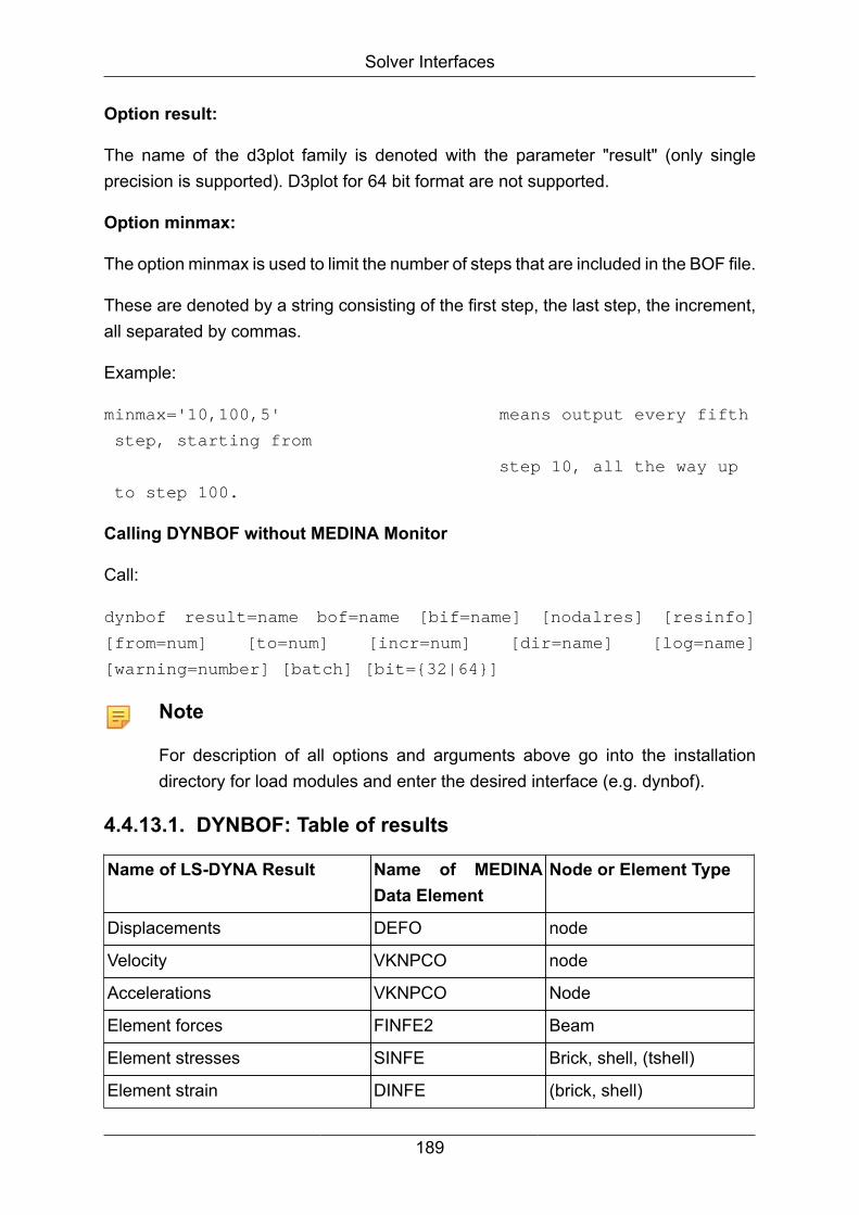
Solver Interfaces
Option result:
The name of the d3plot family is denoted with the parameter "result" (only singleprecision is supported). D3plot for 64 bit format are not supported.
Option minmax:
The option minmax is used to limit the number of steps that are included in the BOF file.
These are denoted by a string consisting of the first step, the last step, the increment,all separated by commas.
Example:
minmax='10,100,5' means output every fifth
step, starting from
step 10, all the way up
to step 100.
Calling DYNBOF without MEDINA Monitor
Call:
dynbof result=name bof=name [bif=name] [nodalres] [resinfo]
[from=num] [to=num] [incr=num] [dir=name] [log=name]
[warning=number] [batch] [bit={32|64}]
Note
For description of all options and arguments above go into the installationdirectory for load modules and enter the desired interface (e.g. dynbof).
4.4.13.1. DYNBOF: Table of results
Name of LS-DYNA Result Name of MEDINAData Element
Node or Element Type
Displacements DEFO node
Velocity VKNPCO node
Accelerations VKNPCO Node
Element forces FINFE2 Beam
Element stresses SINFE Brick, shell, (tshell)
Element strain DINFE (brick, shell)
189

Solver Interfaces
Name of LS-DYNA Result Name of MEDINAData Element
Node or Element Type
Effective plastic strain SKINFE Brick, shell, (tshell)
Thickness SKINFE (shell)
User defines variables SKINFE (brick)
The output of the element types in parentheses in column 3 may be specified by theuser.
4.5. MARC -> Interface to MARCFeatures
The BIFMARC and MARCBIF interfaces converts a model data file (BIF) into a MARCinput file and vice versa according to MARC Version K7, Solver Reference Manual.
The MARCBIF interface converts a binary or formatted MARC result file into a modeldata file (BIF) and a result data file (BOF) in the CAE data bus format.
4.5.1. BIFMARC -> Interface BIF to MARC
BIFMARC converts MEDINA data (BIF Format) into MARC input data.
The following table compares and describes the parameters in the MEDINA Monitorand the command line parameters for the tcl batch script:
Start MonitorParameter
Batch ScriptParameter
Description
Workingdirectory
dir=dirname Set the working directory for file access.
BIF Input file bif=filename Binary input file from MEDINA PreProcessing.
Configurationfile
config=filename Formatted input file with the default MARCelement types for MEDINA elements.
Output file dat=filename Formatted output file used as MARC input deck.
Replaceexisting files
(always replace) The monitor toggle has two states, ON and OFF.If the toggle is ON, existing files, e.g. the MARCinput file, are overwritten. If called from a script,files are always replaced.
190

Solver Interfaces
Start MonitorParameter
Batch ScriptParameter
Description
Additionalprogramparameters
batch
bit=32|64
warning=number
log=filename
Parameters shared by all interfaces (see chapter1 for a description).
Supported data
The following data elements of the CAE data bus are supported:
CAE Data Elementnumber / name
Meaning MARC output
1 / NPCO Node points COORDINATES
20 / GAP Elements with 2 nodes CONNECTIVITY, Elementtype 12,
with GEOMETRY
21 / BAR Elements with 2 nodes CONNECTIVITY, Elementtype 98,
with GEOMETRY
23 / ROD Elements with 2 nodes CONNECTIVITY, Elementtype 9,
with GEOMETRY
31 / INFE3 Elements with 3 nodes CONNECTIVITY, Elementtype 75,
with GEOMETRY
41 / INFE4 Elements with 4 nodes CONNECTIVITY, Elementtype 75,
with GEOMETRY
34 / INFE3V Elements with 3 nodeswith
variable thickness
CONNECTIVITY, Elementtype 75,
with GEOMETRY
44 / INFE4V Elements with 4 nodeswith
variable thickness
CONNECTIVITY, Elementtype 75,
with GEOMETRY
191

Solver Interfaces
CAE Data Elementnumber / name
Meaning MARC output
65 / HEXA8 Elements with 8 nodes CONNECTIVITY, Elementtyp 7,
with GEOMETRY
13 / TETRA4 Elements with 6 nodes CONNECTIVITY, Elementtype 7,
with GEOMETRY
63 / PENTA6 Elements with 6 nodes CONNECTIVITY, Elementtyp 7,
with GEOMETRY
62 / TETRA10 Elements with 10 nodes CONNECTIVITY, Elementtyp 127,
with GEOMETRY
8,9 / SPRINGS SPRINGS
CONTACT CONTACT
115 / MPC TYING, type: 1,2,3,4,5,6,100
113 / SPC FIXED DISPLACEMENT
100 / NODE SET DEFINE NODE SET
100 / ELEMENT SET DEFINE ELEMENT SET
3 / CORSYS TRANSFORMATION
Calling BIFMARC without MEDINA Monitor
Call:
<inst_directory>/cae/bin/bifmarc bif=name dat=name
[config=name] [size=number] [dir=name] [log=name]
[warning=number] [batch] [bit={32|64}]
If optional parameters are omitted, the first value of the numeration is the default value.
Note
For description of all options and arguments above go into the installationdirectory for load modules and enter the desired interface (e.g. bifmarc).
4.5.2. MARCBIF -> Interface MARC to BIFMARCBIF programs converts a MARC input file into a model data file (BIF).
192
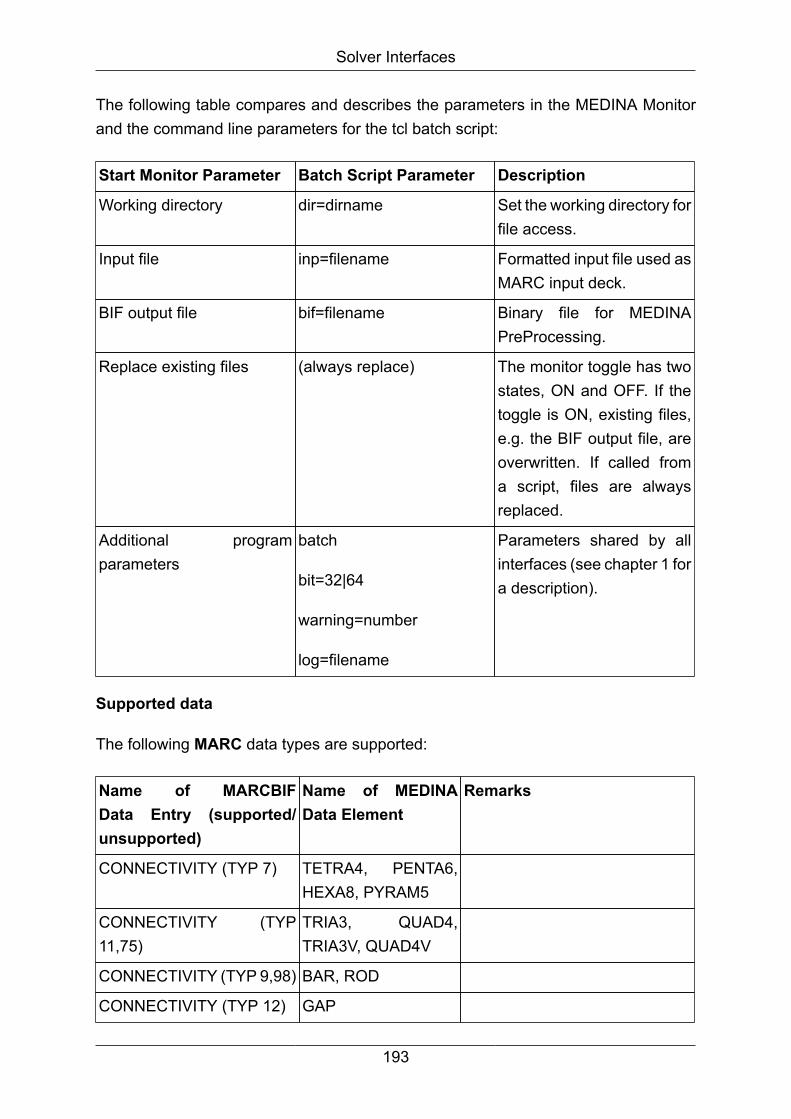
Solver Interfaces
The following table compares and describes the parameters in the MEDINA Monitorand the command line parameters for the tcl batch script:
Start Monitor Parameter Batch Script Parameter Description
Working directory dir=dirname Set the working directory forfile access.
Input file inp=filename Formatted input file used asMARC input deck.
BIF output file bif=filename Binary file for MEDINAPreProcessing.
Replace existing files (always replace) The monitor toggle has twostates, ON and OFF. If thetoggle is ON, existing files,e.g. the BIF output file, areoverwritten. If called froma script, files are alwaysreplaced.
Additional programparameters
batch
bit=32|64
warning=number
log=filename
Parameters shared by allinterfaces (see chapter 1 fora description).
Supported data
The following MARC data types are supported:
Name of MARCBIFData Entry (supported/unsupported)
Name of MEDINAData Element
Remarks
CONNECTIVITY (TYP 7) TETRA4, PENTA6,HEXA8, PYRAM5
CONNECTIVITY (TYP11,75)
TRIA3, QUAD4,TRIA3V, QUAD4V
CONNECTIVITY (TYP 9,98) BAR, ROD
CONNECTIVITY (TYP 12) GAP
193
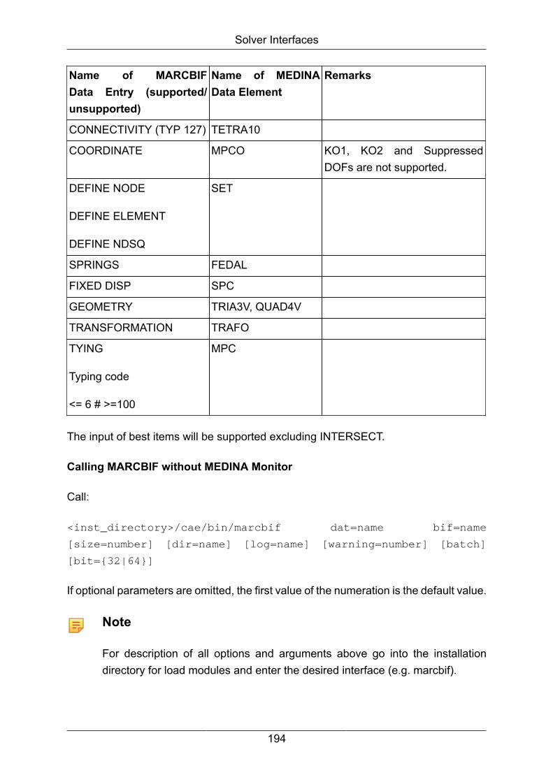
Solver Interfaces
Name of MARCBIFData Entry (supported/unsupported)
Name of MEDINAData Element
Remarks
CONNECTIVITY (TYP 127) TETRA10
COORDINATE MPCO KO1, KO2 and SuppressedDOFs are not supported.
DEFINE NODE
DEFINE ELEMENT
DEFINE NDSQ
SET
SPRINGS FEDAL
FIXED DISP SPC
GEOMETRY TRIA3V, QUAD4V
TRANSFORMATION TRAFO
TYING
Typing code
<= 6 # >=100
MPC
The input of best items will be supported excluding INTERSECT.
Calling MARCBIF without MEDINA Monitor
Call:
<inst_directory>/cae/bin/marcbif dat=name bif=name
[size=number] [dir=name] [log=name] [warning=number] [batch]
[bit={32|64}]
If optional parameters are omitted, the first value of the numeration is the default value.
Note
For description of all options and arguments above go into the installationdirectory for load modules and enter the desired interface (e.g. marcbif).
194
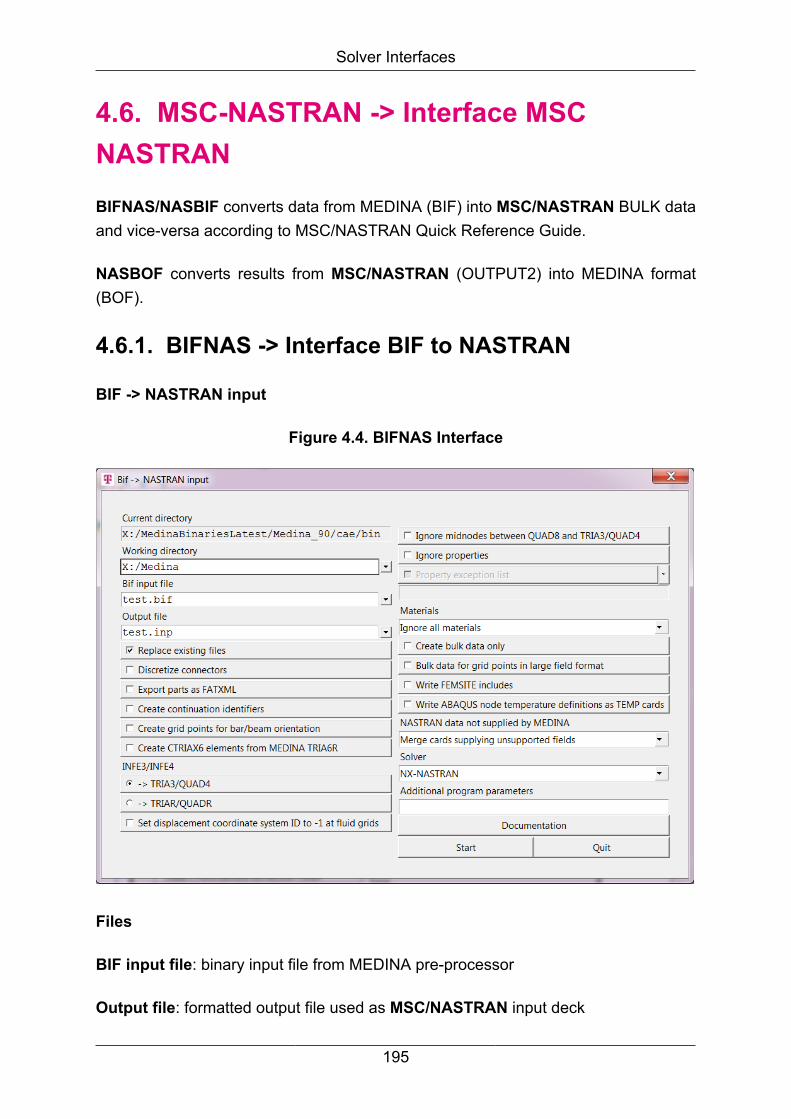
Solver Interfaces
4.6. MSC-NASTRAN -> Interface MSCNASTRANBIFNAS/NASBIF converts data from MEDINA (BIF) into MSC/NASTRAN BULK dataand vice-versa according to MSC/NASTRAN Quick Reference Guide.
NASBOF converts results from MSC/NASTRAN (OUTPUT2) into MEDINA format(BOF).
4.6.1. BIFNAS -> Interface BIF to NASTRAN
BIF -> NASTRAN input
Figure 4.4. BIFNAS Interface
Files
BIF input file: binary input file from MEDINA pre-processor
Output file: formatted output file used as MSC/NASTRAN input deck
195
Solver Interfaces
ASCII input file: formatted input (reject) file for additional NASTRAN cards not(completely) supported by MEDINA. Used only if option 6 are selected (for a descriptionof options available, see below).
Protocol file: formatted output file with a short summary of NASTRAN entriesprocessed and error messages. The default file name is bifnas.log. To select anothername, use the last line in the BIFNAS panel: Where is says "additional programparameters", enter log=new file name where file name is the desired name of theprotocol file.
Option parameters:
• Switch for part output
• Switch for discretized connectors
• Switch for bulk data file
a) create bulk data only, all NASTRAN entries generated due to BIF-file. As the bulkdata entries on the solvercard are placed directly after the BEGIN BULK statement,no data will be written.
b) file as described in a) with the addition of entries like BEGIN BULK / ENDDATA
• Format of resulting FIF-file Small: all NASTRAN entries generated are printed inNASTRAN small field format
• Switch for generation of continuation entries (field one and ten in a NASTRAN line)
• Switch for generation of grid points for bar/beam orientation (instead of orientationvector)
• Switch for generation of CTRIAX6 elements from MEDINA TRIA6R element
• Switch for NASTRAN elements generated from MEDINA QUAD4, TRIA3 elements:a) CQUAD4 and CTRIA3 elements are generated b) CQUADR and CTRIARelements are generated
• Check the Set displacement coordinate system ID to -1 at fluid grids box toset the displacement coordinate system ID to -1 at solid properties that have thePFLUID or FFLUID fluid element flag.
• Switch for processing additional NASTRAN cards not supported by MEDINA
196
Solver Interfaces
a) ignore: generation of NASTRAN entries without additional NASTRAN statements
b) read from BIF file: additional NASTRAN statements are read from a BIF file
c) read from ASCII input file: additional NASTRAN statements are read from anASCII reject file (inactive in case of “bulk data only”)
• Switch for processing additional NASTRAN statements The complete executivecontrol section, file management section, and case control section are written backinto the input deck. For processing the bulk data deck, two options are possible:
a) add only cards completely not supplied: at the end of the bulk data deck, allNASTRAN entries not supported by MEDINA are printed. The partially supportedNASTRAN bulk data entries will not be read from solvercard.
b) merge cards supplying unsupported fields: bulk data entries with fields that arenot supported by MEDINA will be processed completely (see table below). In thiscase, only the unsupported fields will be read from solvercard and other fields will beread from bif. Additionally, the completely not supported cards will be written afterthe NASTRAN keyword BEGIN BULK.
• Switch for ignoring midnodes (edge nodes) of QUAD8 elements connected to linear2D-elements. These nodes were set to "0" in the NASTRAN input deck and thecorresponding grid entries are deleted
• Switch for “Write FEMSITE includes” to generate the FEMSITE include files<filename>.bar and <filename>.gri_set, if the toggle “Discretize connectors” isactivated and the FEMSITE idealization is available In the ECNGenerat commandthe directory for the FEMSITE include files has to be defined and will be written to Bif(use the parameters “Directory for FEMSITE output files” and “Name of femsite files”in the “Create FEMSITE Spotweld Idealization window). Additionally the include file<file_name>.mpc is written from ECNGenerat to the defined directory (contains onlythe MPCs for spotweld idealization) The remaining idealized elements (Bar andHexa with properties and materials) are generated and will be written to the Bif
• Save the model to Bif and enter the NASTRAN interface BIFNAS in the MEDINAstart monitor
• Switch for ignoring properties
• Switch for ignoring property exception list. This toggle is active if the ignoreproperties is on. A list of properties can be chosen
197
Solver Interfaces
• Material select box Write as defined: All materials will be written as defined. Ignoreall materials: The material cards will not be written. Ignore MID4 in PSHELL: If MID4is not defined, MID4 will not be written into PSHELL card Check MID3 and MID4in PSHELL:
The following checks will be executed for each shell property:
a) If MID1 > 0 and MID2 > 0 and MID4 > 0, warning will be written and MID4 willbe ignored.
b) If CQUADR or CTRIAR elements are used by a shell property, warning will bewritten and MID4 will be ignored.
c) If MID2 <= 0 and MID3>0, warning will be written and MID3 will be ignored.
• Activate the toggle “Write FEMSITE includes” to generate the include files<file_name>.bar and <file_name>.gri_set The include file <file_name>.bar containsthe idealized spotweld elements (Bar and Hexa with properties and materials)and the <file_name>.gri_set contains a node set, which is generated during theidealization process
• Switch for writing ABAQUS node temperature definitions as NASTRAN TEMP cardsAn ABAQUS *TEMPERATURE card defined for shell elements and temperature attemperature nodes will be converted by considering the first temperature nodeonly.
Spotweld idealization for FEMSITE
Enter the ECNGenerat command in MEDINA PreProcessor and define the directoryand file name for the FEMSITE include files.
After running ECNGenerat in MEDINA, the FEMSITE include files below are writtento the defined directory:
<file_name>.swm_v2 (FEMSITE spotweld matrix file)
<file_name>.mpc (contains only the MPCs for the
spotweld idealization)
<file_name>.log (FEMSITE log file)
If <file_name> is blank, the files are named swm_v2, mpc and log. The remainingidealized elements (Bar and Hexa) are added to the model.
Solver
198

Solver Interfaces
This parameter allows you to choose between NX-NASTRAN and MSC-NASTRAN.NX-NASTRAN is used by default.
Note
BIFNAS exports NX-NASTRAN specific cards (e.g. contact and surface cards)only if NX-NASTRAN is defined in the Solver parameter.
Additional program parameters
The additional program parameters are referenced in the additional parameter field inthis way:
"opt=-parameter <name/number>"
-clayer name Select name as the coordinate file for
layers
The layer file is referenced in
the Additional
program parameters field with the
option:
"opt=-clayer <directory-name>/
<filename>"
If value contains spaces (eg. my
file), type:
{opt=-clayer "<directory-name>/my
file"}
Example 1:
To assign file name myfile to
parameter clayer, type:
"opt=-clayer myfile"
Example 2:
To assign file name my file to
paramater clayer, type:
{opt=-parameter "my file"}
199

Solver Interfaces
-holdeletype TRIAxV/QUADxV elements are generated and
the following
are defined:
- Material property orientation angle
in degrees/material
coordinate system identification
number
- Offset from the surface
- Membran tickness
-include Only bulk data deck generated (sets
are commented out)
-no_conn_err_msg Implementation of the switch
“no_conn_err_msg” to control if
an error message or only a comment
will be written out. If the
Additional program parameter
“no_conn_err_msg” is supplied
for BIFNAS, than instead of the error
message
"-E- CONNSPOT 8001922 is not
connected", only a comment line
"$ -E- CONNSPOT 8001922 is not
connected" will be written into
the Nastran file
-vers Show the version and stop the
interface
Calling BIFNAS without MEDINA Monitor
Call:
<inst_directory>/cae/bin/bifnas bif=name dat=name [full={1|2|
3}] [large][bulkonly] [contid] [relem] [gporient] [ctriax6]
[nomidnodes][ignoreProperties] [propertyExceptionList=list]
[ignoreMaterials={0-3}][fatxml] [discrconn] [FEMSITEincludes]
[ABAQUSnodetemps] [fluid][size=number][dir=name] [log=name]
[warning=number] [batch][bit={32|64}] [solver={0|1}]
200

Solver Interfaces
solver=0 calls for NX-NASTRAN, solver=1 - MSC-NASTRAN.
If optional parameters are omitted, the first value of the numeration is the default value.
Note
For the description of all options and arguments above, go into the installationdirectory for load modules and enter the desired interface (e.g. bifnas).
Unsupported cards are read automatically from solvercard.
Miscellaneous
A NASTRAN Comment line marks the set as MEDINA element or node set ($NSET /$ESET).
If include files are present, the sets are commented out and a warning is printed inthe protocol file.
Superelement sets are supported using the GRID entries.
Element labels are supported for CONM2, CELAS1, CELAS2, CDAMP1 andCDAMP2 elements (description of element labels see section NASBIF).
If "generation of grid points for bar/beam orientation" is selected, the new grid pointsgenerated are reported in the protocol file.
Supported data
PLOTEL3 and PLOTEL4 elements are supported only by NX-Nastran.
When the solver is set to NX-NASTRAN in the BIFNAS monitor or Export toNASTRAN panel, PLOTEL3 and PLOTEL4 are written to the Nastran input file.
When the solver is set to MSC-NASTRAN, a corresponding warning message isdisplayed.
Table of MSC/NX-NASTRAN entries supported by MEDINA and BIFNAS
Example:
$part begin root,n_pid=1,n_type=4
CQUAD4 1 1 1 2 3 4
201
Solver Interfaces
PSHELL 1
$part end
Parts
MEDINA parts are translated into a XML-attachment and written to NASTRANinterface as comments.
Elements and properties are written after the corresponding part comment.
BIFNAS writes the XML attachment in this way:
$Begin part description
$<?xml version="1.0" encoding="iso-8859-1" standalone="no"?>
$<!DOCTYPE Part SYSTEM "part_tree.dtd">
$<Part label="root" ........
.........
$</Part>
$<!-- end of /root --><!-- .....
....
$End part description
Initial conditions
BIFNAS reads initial conditions (shell thicknesses and strains) from several MEDINABOF files and writes them to the NASTRAN input file.
A layer file controls the reading of data from BOF file and the writing of the necessaryNASTRAN statements.
SYNTAX:
*BOF :
Defines the name of the MEDINA BOF file for initial conditions. Required parameter:
FILE=<name>
*SCALE:
202

Solver Interfaces
Defines the scale factor. Required parameter:
TYPE=<type>
Where type= THICKNESS (scale factor for shell thickness)
Optional parameter:
PID=<number>
Property-ID for which the scale factor is valid, if not defined the scale factor is appliedto all PIDs.
First line : Scale factor
Example:
*BOFFILE, FILE=/mapping1.bof
*BOFFILE, FILE=/mapping2.bof
*SCALE,TYPE=THICKNESS,PID=26
0.1
The layer file is referenced in the Additional program parameters field in the interfacestart window with the option:
"opt=-clayer <directory-name>/<filename>"
If the file name contains blanks (e.g. my file), the correct input is:
{opt=-clayer "<directory-name>/my file”}
Shell elements are written to the NASTRAN input file as shells with variablethicknesses.
MEDINA data elements
Key 204 Physical meaning THICKNESS
VMA Entries are translated to NSM cards
4.6.2. NASBIF -> Interface NASTRAN to BIF
NASTRAN input -> BIF
203
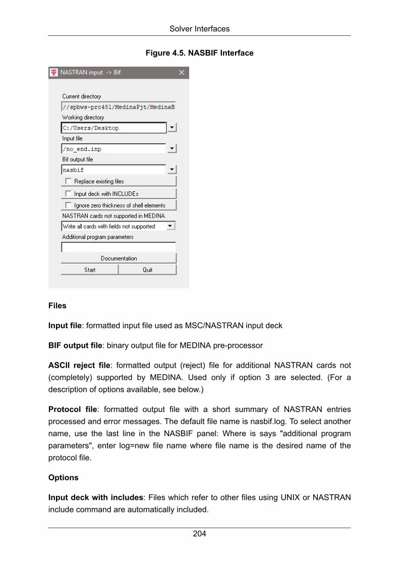
Solver Interfaces
Figure 4.5. NASBIF Interface
Files
Input file: formatted input file used as MSC/NASTRAN input deck
BIF output file: binary output file for MEDINA pre-processor
ASCII reject file: formatted output (reject) file for additional NASTRAN cards not(completely) supported by MEDINA. Used only if option 3 are selected. (For adescription of options available, see below.)
Protocol file: formatted output file with a short summary of NASTRAN entriesprocessed and error messages. The default file name is nasbif.log. To select anothername, use the last line in the NASBIF panel: Where is says "additional programparameters", enter log=new file name where file name is the desired name of theprotocol file.
Options
Input deck with includes: Files which refer to other files using UNIX or NASTRANinclude command are automatically included.
204

Solver Interfaces
Search for include files
NASBIF searches for include files in the following manner:
• If an absolute path is provided exactly this path will be used.
• If a relative path is provided NASBIF will first search the directory in which the maindeck is situated in and after that in the working directory.
Ignore zero thickness of shell elements:
• Toggle is ON:Shell element that has zero value for ZOFFS, THETA, MCID andthickness on all nodes will not be written as MEDINA V-element to bif.
• Toggle is OFF: Shell element that has zero value for ZOFFS, THETA, MCID orthickness at least on one node will be written as MEDINA V-element to bif.
Switch additional NASTRAN cards not supported by MEDINA
Ignore: generation of NASTRAN entries without additional NASTRAN statements
Write to BIF file: additional NASTRAN statements are stored in a BIF file
Write to ASCII reject file: additional NASTRAN statements are stored in an ASCIIreject file
Switch processing of additional NASTRAN statements
The complete executive control section, file management section, and case controlsection are written to a BIF or an ASCII file.
For processing the bulk data deck, two options are possible
• Only cards completely not supported: all NASTRAN entries not supported byMEDINA are written to a BIF or an ASCII file.
• All cards with fields not supported: bulk data entries which contain fields that are notsupported by MEDINA (see table below) are written to a BIF or an ASCII file.
Additional program parameters
The additional program parameters are referenced in the additional parameter field:
resolve=name NASTRAN includes are resolved into new
file named
filename (complete NASTRAN deck).
205

Solver Interfaces
The following additional program parameters are referenced in the additionalparameter field in this way:
"opt=-parameter <name/number>"
-holdeletype TRIAxV/QUADxV elements are generated and
the following
are defined:
- Material property orientation angle
in degrees/material
coordinate system identification
number
- Offset from the surface
- Membran tickness
-size number Start memory size for data structures
(usually, it is automatically
determined).
-warning number Complete warning message report
-vers Show the version and stop the
interface
Calling BIFNAS without MEDINA Monitor
Call:
<inst_directory>/cae/bin/nasbif dat=name bif=name [full={1|2|
3}] [include] [resolve=name] [size=number] [dir=name] [log=name]
[warning=number] [batch] [holdeletype] [bit={32|64}]
If optional parameters are omitted, the first value of the numeration is the default value.
Note
For description of all options and arguments above go into the installationdirectory for load modules and enter the desired interface (e.g. bifnas).
Unsupported cards are written automatically to solvercard.
Miscellaneous
206

Solver Interfaces
All NASTRAN entries may be in uppercase or lowercase, with tabulators allowed. AllNASTRAN entries must begin in the first column.
MSC/NASTRAN small, free, and large format are supported: Replication syntax is notallowed.
In case of large format, at least one continuation card must follow (i.e. PDAMP* needsone empty continuation card following: "*....."). In case of large format, the syntax for,i.e. the GRID entry, must be: "GRID*", "GRID *" is not allowed.
Continuation lines must immediately follow the line that they continue.
No comment lines in the middle of a NASTRAN entry are allowed.
Blanks are allowed for continuation keywords.
Comments are not allowed at the end of a NASTRAN statement.
Sets are supported. If the set is marked with the comment $NSET or $ESET, NASBIFcreates the corresponded set for MEDINA.
If the sets are referred to the case control section (i.e. DISPL=5), NASBIF creates thecorresponding set for MEDINA (node or element set).
If this reference is missing, NASBIF creates a node set with the set ID used in the inputdeck and additionally an element set with a new set ID (this action is documented inthe protocol file).
Comments at the end of set entries are allowed.
Sets which are defined in the MSC/NASTRAN plot section must have an unique set ID.
Elements with unknown grids are not converted to the BIF file.
Element labels are supported for CONM2, CELAS1, CELAS2, CDAMP1 and CDAMP2elements. Element labels are defined as the text of the preceding comment line.
Coordinate systems, which are referred to, must be defined in the current inputfile. Otherwise, the corresponding entry fields (i.e. CD field on GRID entry) are ignored.
While processing CQUAD8 elements, if edge grid points with identification numbers of"0" or "blank" are found, new edge grid points are automatically generated using linearinterpolation. These new grid points were additionally sampled in an new node set.
Supported data
207
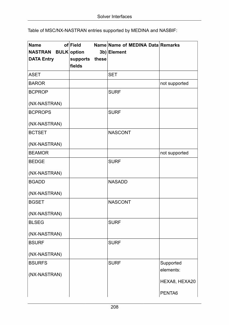
Solver Interfaces
Table of MSC/NX-NASTRAN entries supported by MEDINA and NASBIF:
Name ofNASTRAN BULKDATA Entry
Field Nameoption 3b)supports thesefields
Name of MEDINA DataElement
Remarks
ASET SET
BAROR not supported
BCPROP
(NX-NASTRAN)
SURF
BCPROPS
(NX-NASTRAN)
SURF
BCTSET
(NX-NASTRAN)
NASCONT
BEAMOR not supported
BEDGE
(NX-NASTRAN)
SURF
BGADD
(NX-NASTRAN)
NASADD
BGSET
(NX-NASTRAN)
NASCONT
BLSEG
(NX-NASTRAN)
SURF
BSURF
(NX-NASTRAN)
SURF
BSURFS
(NX-NASTRAN)
SURF Supportedelements:
HEXA8, HEXA20
PENTA6
208

Solver Interfaces
Name ofNASTRAN BULKDATA Entry
Field Nameoption 3b)supports thesefields
Name of MEDINA DataElement
Remarks
PENTA15
TETRA4
TETRA10
CAABSF GENSOLE
CBAR INFE2
CBEAM SA,SB,BIT INFE2
CBUSH CBUSH
CDAMP1 FEDAL1
CDAMP2 FEDAL
CELAS1 FEDAL1
CELAS2 FEDAL
CFAST SPOTWELD
CGAP INFE2G
CHBDYE IVIEWF/B,RADMIDF/B
not supported
CHEXA INFE8S/INFE20S
CMASS1 ELSCALAR
CMASS2 ELSCALAR
CONM1 CONM1
CONM2 KMASSE
CONROD A, J INFE2 C, NSM notsupported, seeCROD
CONV BOUNDARY not supported
COORD1C CORSYS
COORD2C CORSYS
COORD1R CORSYS
209
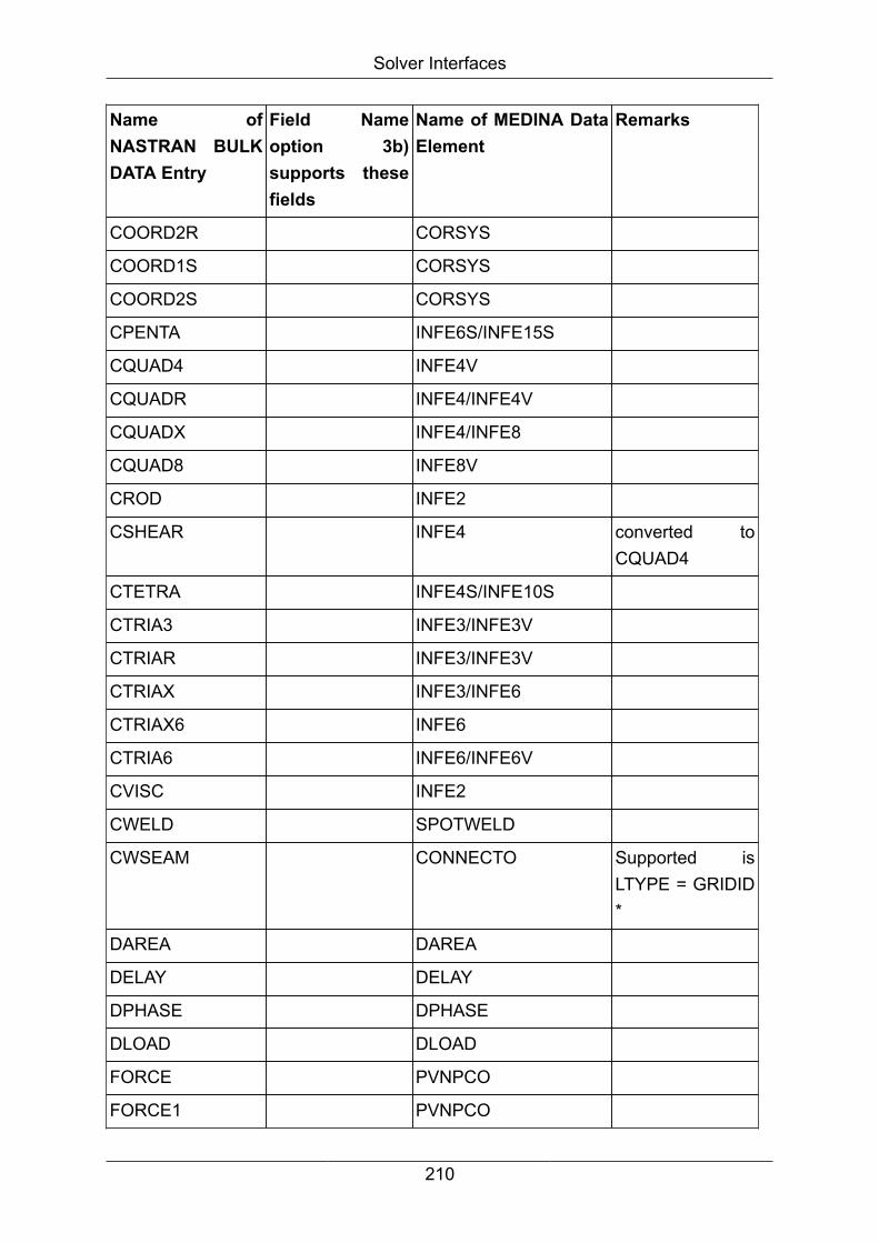
Solver Interfaces
Name ofNASTRAN BULKDATA Entry
Field Nameoption 3b)supports thesefields
Name of MEDINA DataElement
Remarks
COORD2R CORSYS
COORD1S CORSYS
COORD2S CORSYS
CPENTA INFE6S/INFE15S
CQUAD4 INFE4V
CQUADR INFE4/INFE4V
CQUADX INFE4/INFE8
CQUAD8 INFE8V
CROD INFE2
CSHEAR INFE4 converted toCQUAD4
CTETRA INFE4S/INFE10S
CTRIA3 INFE3/INFE3V
CTRIAR INFE3/INFE3V
CTRIAX INFE3/INFE6
CTRIAX6 INFE6
CTRIA6 INFE6/INFE6V
CVISC INFE2
CWELD SPOTWELD
CWSEAM CONNECTO Supported isLTYPE = GRIDID*
DAREA DAREA
DELAY DELAY
DPHASE DPHASE
DLOAD DLOAD
FORCE PVNPCO
FORCE1 PVNPCO
210

Solver Interfaces
Name ofNASTRAN BULKDATA Entry
Field Nameoption 3b)supports thesefields
Name of MEDINA DataElement
Remarks
GDRSET not supported
GRID NPCO
MAT1 2nd line MATERIAL
MAT4 MATERIAL
MAT8 MATERIAL
MAT9 MATERIAL
MAT10 MATERIAL
MAT11 MATERIAL Orthotropic solidmaterial,supported only byNX-NASTRAN
MOMENT PVNPCO
MOMENT1 PVNPCO
MPC MPC
PAABSF PROPERTY
PBAR 2nd line PROPERTY
PBARL BOX1, CROSS,HAT, HEXA
PROPERTY
PBEAM 2nd, 4th + 6th line PROPERTY
PBEAML BOX1, CROSS,HAT, HEXA
PROPERTY
PBUSH PROPERTY
PBUSHT PROPERTY
PCOMP PROPERTY
PCOMPG PROPERTY
PCONV PROPERTY/PSSET not supported
PDAMP PROPERTY
PELAS PROPERTY
211

Solver Interfaces
Name ofNASTRAN BULKDATA Entry
Field Nameoption 3b)supports thesefields
Name of MEDINA DataElement
Remarks
PFAST PROPERTY MCID = -1 issupported
PGAP PROPERTY
PLOAD not supported
PLOAD1 not supported
PLOAD2 PLOAD
PLOAD4 P2/3/4, 2nd line PLOAD No alternateformat allowedwhen using option3
PLOTEL
PLOTEL3
(NX-NASTRAN)
GENSOLE
PLOTEL4
(NX-NASTRAN)
GENSOLE
PMASS PROPERTY
PROD PROPERTY
PSHEAR
PSHELL PROPERTY
PSOLID IN,STRESS,ISOP,FCTN,COROT
PROPERTY COROT issupported only byMSC Nastran
PVISC PROPERTY
PWSEAM PROPCONN
QVECT TIDi, CNTRLND PSSET
RBAR RINFE2
RBE2 RBE2
212

Solver Interfaces
Name ofNASTRAN BULKDATA Entry
Field Nameoption 3b)supports thesefields
Name of MEDINA DataElement
Remarks
RBE3 ELRBE Completelysupported
RLOAD1 RLOAD
RLOAD2 RLOAD
RROD RINFE2
RSPLINE RSPLINE
RTRPLT RBE2
SESET GRID
SET1 Option SKIN Nodeset
Elementset
Solvercard
Solverkey SET1,Set type = Node
Solverkey SET1,Set type =Element
SET3 Option GRID
Option ELEM
Option PROP
Option POINT
Nodeset
Elementset
Propertyset
Solvercard
Solverkey SET3,Set type = Node
Solverkey SET3,Set Type =Element
Solverkey SET3,Set Type =Property
SPC SUPDOF
SPC BOUNDARY elementtemperatures
SPC1 SUPDOF
SPCD PREDOF
SPOINT NPCO
213

Solver Interfaces
Name ofNASTRAN BULKDATA Entry
Field Nameoption 3b)supports thesefields
Name of MEDINA DataElement
Remarks
SPOINT BOUNDARY scalar point forelementtemperatures notsupported
TABLED1 LOADCURVES
TABLED2 "SKIP" LOADCURVES
TABLED3 LOADCURVES
TEMP PSNPCO
TLOAD1 RLOAD
TLOAD2 RLOAD
Note
CWSEAM cards with LTYPE = "POINTID" or "XYZ" are written on the solvercard(use parameter –full number). Only two nodes of every card are translated.
Cards with more than 2 nodes are written in the solvercard when using –fullnumber.
PCID is not supported. CWSEAM cards are always placed in the global system.
CWSEAM cards reference PWSEAM cards.
Depending on the PWSEAM thickness, CWSEAM cards result in Weldline orBondline elements:
• PWSEAM-Thickness == Blank result in Weldline elements
• PWSEAM-Thickness ! = Blank result in Bondline elements
NASBIF can read the XML-attachments.
If Parts information are translated, NASBIF does not write the NSM cards to the solvercard.
SET1:
214

Solver Interfaces
SET1 with SKIN option is put to solvercard and a warning is created by Nasbif:
"SET1 <id> with option SKIN is stored onto solvercard"
For SET1, an additional coded comment line will be written by Bifnas to support theset type and label. If a coded comment line is not defined, NASBIF tries to create twosets, a node set and an element set, from the defined IDs in each SET1 card.
• For Node example, type:
$MEDINA_Key NSET Label="label of the node set"
SET1 ...
SET3:
For SET3, an additional coded comment line will be written by Bifnas to support theset label:
$MEDINA_Key Label="label of the set"
SET3 ...
4.6.3. NASBOF -> Interface NASTRAN to BOF
Files
Input file: MSC/NASTRAN binary output2 file
BOF output file: Binary BOF file for MEDINA postprocessor
BIF output file: Binary BIF file for MEDINA. If BIF file name is blank no BIF file willgenerated.
Protocol file: formatted output file with a short summary of the MEDINA data elementsprocessed and error messages. The default file name is nasbof.log.
To select another name, use the last line in the NASBOF panel: Where it says"Additional program parameters", enter log=file name where file name is the desiredname of the protocol file.
Options
Combine loadcases at same frequency: with this toggle deactivated the NASBOFinterface reads the text of TITLE, SUBTITLE and LABEL (if these objects are defined)and writes it to a BOF file.
215

Solver Interfaces
Write deformations in global coordinates.
Reduce geometry and results to surface. The volume model will be reduced to thesurface model.
Only the surface elements and the surface nodes will be written on the Bif file. Theresults (Displacements and stresses) of the elements and nodes of the surface will bewritten on the Bof file.
It is also possible to eliminate the midnodes and the results at the midnodes.
Retrieve geometry from bif file: NASBOF reads the geometry data from an extra bifFile. NASTRAN results with no geometry on the op2 file can be processed.
Additional program parameters
The additional program parameters are referenced in the additional parameter field inthis way:
"opt=-parameter <name/number>"
-statistics Replace results by calculated min,
max, absmax and rms values
-no_conn_err_msg Implementation of the switch
“no_conn_err_msg” to control if
an error message or only a comment
will be written out. If the
Additional program parameter
“no_conn_err_msg” is supplied
for BIFNAS, than instead of the error
message
"-E- CONNSPOT 8001922 is not
connected", only a comment line
"$ -E- CONNSPOT 8001922 is not
connected" will be written into
the Nastran file
-warning number Complete warning message report
-vers Show the version and stop the
interface
Miscellaneous
216
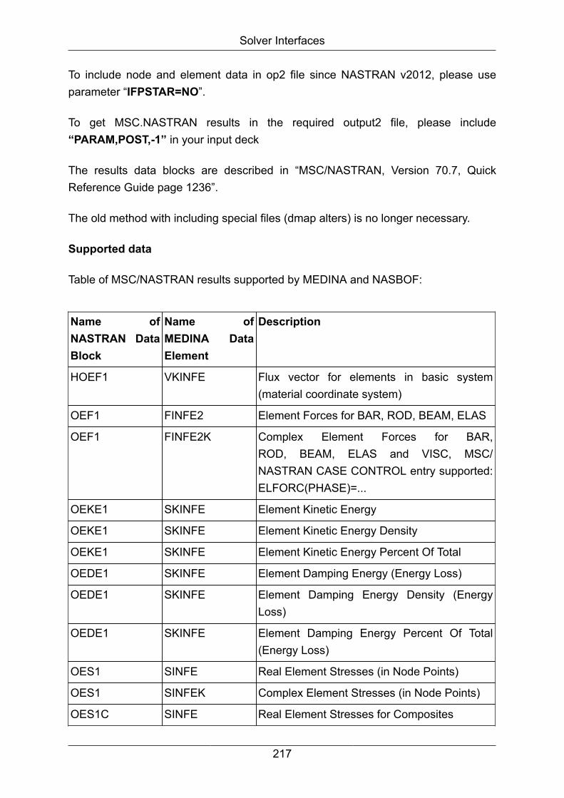
Solver Interfaces
To include node and element data in op2 file since NASTRAN v2012, please useparameter “IFPSTAR=NO”.
To get MSC.NASTRAN results in the required output2 file, please include“PARAM,POST,-1” in your input deck
The results data blocks are described in “MSC/NASTRAN, Version 70.7, QuickReference Guide page 1236”.
The old method with including special files (dmap alters) is no longer necessary.
Supported data
Table of MSC/NASTRAN results supported by MEDINA and NASBOF:
Name ofNASTRAN DataBlock
Name ofMEDINA DataElement
Description
HOEF1 VKINFE Flux vector for elements in basic system(material coordinate system)
OEF1 FINFE2 Element Forces for BAR, ROD, BEAM, ELAS
OEF1 FINFE2K Complex Element Forces for BAR,ROD, BEAM, ELAS and VISC, MSC/NASTRAN CASE CONTROL entry supported:ELFORC(PHASE)=...
OEKE1 SKINFE Element Kinetic Energy
OEKE1 SKINFE Element Kinetic Energy Density
OEKE1 SKINFE Element Kinetic Energy Percent Of Total
OEDE1 SKINFE Element Damping Energy (Energy Loss)
OEDE1 SKINFE Element Damping Energy Density (EnergyLoss)
OEDE1 SKINFE Element Damping Energy Percent Of Total(Energy Loss)
OES1 SINFE Real Element Stresses (in Node Points)
OES1 SINFEK Complex Element Stresses (in Node Points)
OES1C SINFE Real Element Stresses for Composites
217
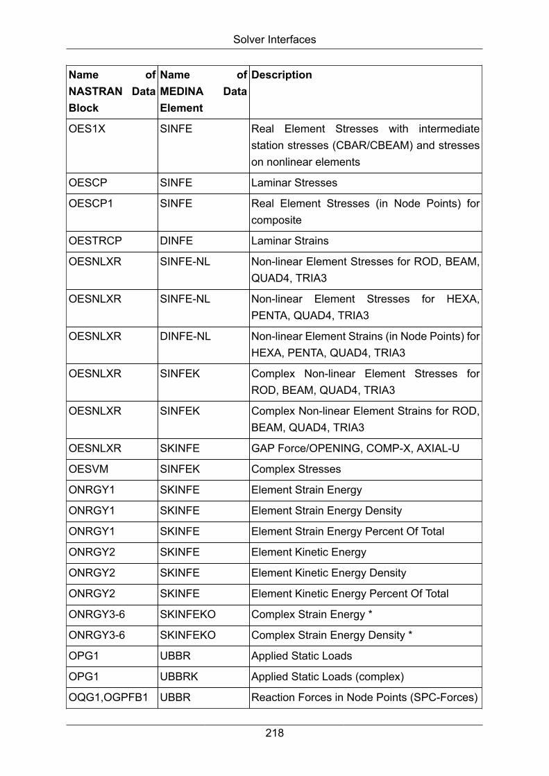
Solver Interfaces
Name ofNASTRAN DataBlock
Name ofMEDINA DataElement
Description
OES1X SINFE Real Element Stresses with intermediatestation stresses (CBAR/CBEAM) and stresseson nonlinear elements
OESCP SINFE Laminar Stresses
OESCP1 SINFE Real Element Stresses (in Node Points) forcomposite
OESTRCP DINFE Laminar Strains
OESNLXR SINFE-NL Non-linear Element Stresses for ROD, BEAM,QUAD4, TRIA3
OESNLXR SINFE-NL Non-linear Element Stresses for HEXA,PENTA, QUAD4, TRIA3
OESNLXR DINFE-NL Non-linear Element Strains (in Node Points) forHEXA, PENTA, QUAD4, TRIA3
OESNLXR SINFEK Complex Non-linear Element Stresses forROD, BEAM, QUAD4, TRIA3
OESNLXR SINFEK Complex Non-linear Element Strains for ROD,BEAM, QUAD4, TRIA3
OESNLXR SKINFE GAP Force/OPENING, COMP-X, AXIAL-U
OESVM SINFEK Complex Stresses
ONRGY1 SKINFE Element Strain Energy
ONRGY1 SKINFE Element Strain Energy Density
ONRGY1 SKINFE Element Strain Energy Percent Of Total
ONRGY2 SKINFE Element Kinetic Energy
ONRGY2 SKINFE Element Kinetic Energy Density
ONRGY2 SKINFE Element Kinetic Energy Percent Of Total
ONRGY3-6 SKINFEKO Complex Strain Energy *
ONRGY3-6 SKINFEKO Complex Strain Energy Density *
OPG1 UBBR Applied Static Loads
OPG1 UBBRK Applied Static Loads (complex)
OQG1,OGPFB1 UBBR Reaction Forces in Node Points (SPC-Forces)
218

Solver Interfaces
Name ofNASTRAN DataBlock
Name ofMEDINA DataElement
Description
OQMG1 UBRR MPC Forces
OSTR1 DINFE Real Element Strains (in Node Points)for HEXA, PENTA, TETRA, QUAD8, ROD,TRAPRG, SHEAR, TRIARG, QUAD4, QUAD8,TRIA3, TRIA6, SHEAR, TRIARG
OSTRVM DINFEK Complex Strains
OUGV1 DEFO Real Node Point Displacements, Eigenvectors,Velocities, Accelerations
OUGV1 DEFOK Complex Node Point Displacements,Eigenvectors, Velocities, Accelerations
SET Set of superelements
TOUGV TEMP Temperatures in Node Points
OVG1 DEFO Real velocities at nodes
OVG1 DEFOK Complex velocities at nodes
OMM DEFO Find min. and max. value of each requestedresult type for each element over all time stepsfor grid point output.
Displacement, Acceleration, Velocity
OMM SINFE Find min. and max. value of each requestedresult type for each element over all time stepsfor element output.
OGF GPFORCE Element node forces and moments (grid pointforces). This datablock is not supported byMEDINA post
* these datablocks (ONGRY3–6) could be generated only with a special dmap alter
Calling NASBOF without MEDINA Monitor
Call:
219
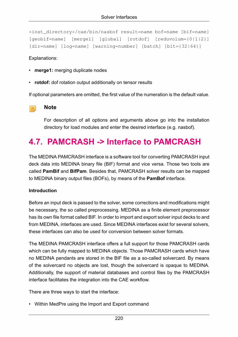
Solver Interfaces
<inst_directory>/cae/bin/nasbof result=name bof=name [bif=name]
[geobif=name] [merge1] [global] [rotdof] [reduvolum={0|1|2}]
[dir=name] [log=name] [warning=number] [batch] [bit={32|64}]
Explanations:
• merge1: merging duplicate nodes
• rotdof: dof rotation output additionally on tensor results
If optional parameters are omitted, the first value of the numeration is the default value.
Note
For description of all options and arguments above go into the installationdirectory for load modules and enter the desired interface (e.g. nasbof).
4.7. PAMCRASH -> Interface to PAMCRASHThe MEDINA PAMCRASH interface is a software tool for converting PAMCRASH inputdeck data into MEDINA binary file (BIF) format and vice versa. Those two tools arecalled PamBif and BifPam. Besides that, PAMCRASH solver results can be mappedto MEDINA binary output files (BOFs), by means of the PamBof interface.
Introduction
Before an input deck is passed to the solver, some corrections and modifications mightbe necessary, the so called preprocessing. MEDINA as a finite element preprocessorhas its own file format called BIF. In order to import and export solver input decks to andfrom MEDINA, interfaces are used. Since MEDINA interfaces exist for several solvers,these interfaces can also be used for conversion between solver formats.
The MEDINA PAMCRASH interface offers a full support for those PAMCRASH cardswhich can be fully mapped to MEDINA objects. Those PAMCRASH cards which haveno MEDINA pendants are stored in the BIF file as a so-called solvercard. By meansof the solvercard no objects are lost, though the solvercard is opaque to MEDINA.Additionally, the support of material databases and control files by the PAMCRASHinterface facilitates the integration into the CAE workflow.
There are three ways to start the interface:
• Within MedPre using the Import and Export command
220

Solver Interfaces
• Using the MEDINA Monitor
• As a shell command, e.g. pambif, bifpam or pambof, depending on the MEDINAversion.
PAMCRASH cards or parameters which have no correspondence in MEDINA cannotbe supported by the interface. Workarounds exist however, in order to prevent dataloss.
PamBof uses the ESI DSY library, which requires a Pamcrash license and is justavailable for certain platforms. The PamBof interface will be just briefly mentioned here.
4.7.1. PAMCRASH - Material Databases
The use of material databases is optional in the context of the MEDINA PAMCRASHinterface. Material databases are directories with text files. Each file holds exactly onematerial in solver format, together with the function cards (load curves) referenced bythis material. It is assumed that no function is referenced by more than one material.
Two types of material databases are supported:
• Databases where each material file is named “default” and placed in its ownsubdirectory with a name characteristic for this material.
• Databases where the file name itself is characteristic for the material. The files maybe placed in the same directory or in an arbitrary directory tree below.
For MedPre and the MEDINA Monitor, the database type can be configured bysetting the environment variable matdbtypepam to either the value subdir_with_default_files or dir_with_mat_files. The last is assumed when no value isprovided.
The MEDINA PAMCRASH interface can handle up to three databases. These arecalled user, team and global database. The team and global database are read only,they will never be modified by the interface. For MedPre and the MEDINA Monitor, theteam and global databases are specified by the environment variables “tmatpathpam”and “gmat-pathpam”.
In MedPre, the user database is specified by means of the MatDBParam command.In the MEDINA Monitor, a user database panel field is found.
221

Solver Interfaces
Figure 4.6. The panel of the MatDBParam command
PamBif can create a new user material database containing all materials in the givenPAMCRASH input deck. Alternatively, PamBif can merge given material databaseswith the materials of the solver deck, so that just the material files missing in all threedatabases are created in the existing user database.
PamBif identifies the materials by their unique ID number. For MedPre andthe MEDINA Monitor, the search order can be specified by the environmentvariable matdbpriopam. The default value is global_db_first. Alternatively,user_db_first may be specified. The team database is always the second.
The values corresponding to the environment variables above are then passed tothe interface call as command line parameters. The interface itself does not read theenvironment variables.
For each material in the solver input deck, PamBif also creates an isotropic materialwith the corresponding ID. The label of this MEDINA material will be the file or directoryname specific to the material preceded by an “>” sign, rather than the actual materialname. Accordingly, BifPam considers material names starting with “>” to be databasereferences. A corresponding material file is searched in the database conform to thesearch priority and the contents of this file is copied to the PAMCRASH input deckgoing to be written. This way, single materials or whole material databases can beeasily replaced when they become obsolete.
When PamBif is configured to create no databases, all MATER cards of thePAMCRASH input deck will be found on the solvercard of the appropriate MEDINApart. This way, they will be exported in their original format into the appropriate includefile. FUNC cards referenced by materials on the solvercard will be mapped to MEDINAload curves in this case, no matter whether they are referenced by a material.
4.7.2. PAMCRASH - Control file
The optional control file is a text file which holds information about the PAMCRASHPART cards, i.e. the MEDINA properties. This facilitates the overview and the handling
222

Solver Interfaces
of those data, including the material references. The control file is written by PamBifwhen a file name is specified.
During the BifPam run, the control file data, when provided, have priority over the BIFdata. Control files can also be written and read during the MedPre session by meansof the ControlFil command.
4.7.3. PAMCRASH - Configuration file
The configuration file is an optional, plain text file provided to PamBif only. The usercan place in it PAMCRASH keywords, one keyword per line. The correspondingPAMCRASH cards will then be unconditionally put onto the solvercard. This way, theuser can make sure that those cards will not be modified and that they will stay in theright include file.
4.7.4. PAMCRASH - INCLUDE files
A PAMCRASH input deck may consist of several files referenced in a tree hierarchyby means of the “INCLU” keyword. In order to keep the file hierarchy, PamBif createsa MEDINA part for each included file and places the include file contents into thatMEDINA part. Nodes of elements referenced by two MEDINA parts will be found in thelowest common parent part.
MEDINA objects that support no part membership for the time being will be found in theroot part. For those objects, the include file membership cannot be preserved, unlessthey are put onto the solvercard by means of the configuration file.
BifPam either writes the whole model into a single PAMCRASH file or alternativelyinto a hierarchy of include files corresponding to the MEDINA part hierarchy. It isalso possible to import and export single include files while choosing the appropriateMEDINA part.
4.7.5. PAMCRASH - INCLUDE Transform
The information of the PAMCRASH TRSFM cards becomes the transformation matrixof the MEDINA part’s external reference. This implies that the PAMCRASH TRSFMcard references the contents of exactly one include file. Otherwise, the PAMCRASHTRSFM card cannot be mapped to MEDINA and will be put onto the solvercard.
In PamBif, the transformation will also be applied to the coordinates of the referrednodes, in order to visualize their actual position. Then, BifPam restores the original
223

Solver Interfaces
node coordinates by means of the MEDINA part’s transformation matrix. Nodesreferred by the unsupported TRSFM cards found on the solvercard will be at theiruntransformed position in MedPre.
4.7.6. PAMCRASH - Starting the Interface
Starting the PamBif / BifPam interface requires at least a PAMCRASH input deck filename as well as a MEDINA BIF name to be provided. When starting the interfacesfrom MedPre, a temporary BIF will be created automatically.
Further interface parameters are optional. For a full list of interface parameters, typee.g. pambif or bifpam at the system shell prompt. Most of these parameters havetheir corresponding fields in the MedPre Import / Export panels, as well as in theMEDINA Monitor panels. The other optional interface parameters may be provided inthe “Additional program parameters” panel field.
4.7.6.1. Interface with MedPre
Within the MedPre session, start the Import or Export command. Make sure thatPAMCRASH is selected in the solver list of the Import / Export panel. In this panelselect also the “Complete” toggle, unless you want to handle single include files asdescribed in chapter “Work with include files”. When this is done, a panel named“Import from PAM-CRASH” respectively “Export to PAMCRASH” appears. Enter atleast the PAMCRASH file name to be read or written. Tooltips give additional help whenthe mouse is moved above the panel fields. For material database settings, pleasealso refer to the Material Databases section.
Figure 4.7. The MedPre Import command panels for PamBif start
224

Solver Interfaces
Figure 4.8. The MedPre Export command panels for PamBif start
4.7.6.2. Interface with MEDINA Monitor
Within the “FEA Interfaces” Monitor area, press the PAMCRASH button. Then choosebetween “PAMCRASH input -> BIF” for PamBif and “BIF -> PAMCRASH input” forBifPam. If available on your platform, you will also see a “PAMCRASH output -> B*F”item for staring the PamBof interface. A panel will show up, which is similar to thoseseen in MedPre. Additionally, a working directory can be given, which will be the currentdirectory for the interface run.
225
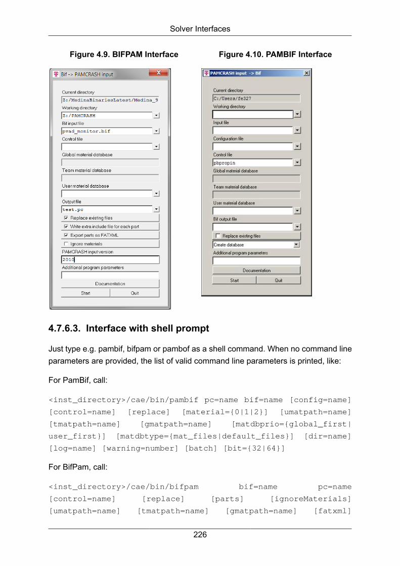
Solver Interfaces
Figure 4.9. BIFPAM Interface Figure 4.10. PAMBIF Interface
4.7.6.3. Interface with shell prompt
Just type e.g. pambif, bifpam or pambof as a shell command. When no command lineparameters are provided, the list of valid command line parameters is printed, like:
For PamBif, call:
<inst_directory>/cae/bin/pambif pc=name bif=name [config=name]
[control=name] [replace] [material={0|1|2}] [umatpath=name]
[tmatpath=name] [gmatpath=name] [matdbprio={global_first|
user_first}] [matdbtype={mat_files|default_files}] [dir=name]
[log=name] [warning=number] [batch] [bit={32|64}]
For BifPam, call:
<inst_directory>/cae/bin/bifpam bif=name pc=name
[control=name] [replace] [parts] [ignoreMaterials]
[umatpath=name] [tmatpath=name] [gmatpath=name] [fatxml]
226
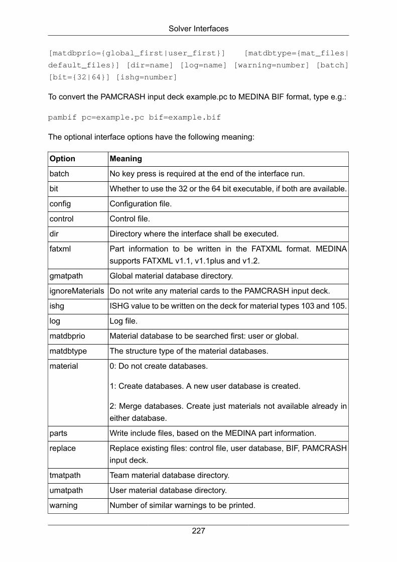
Solver Interfaces
[matdbprio={global_first|user_first}] [matdbtype={mat_files|
default_files}] [dir=name] [log=name] [warning=number] [batch]
[bit={32|64}] [ishg=number]
To convert the PAMCRASH input deck example.pc to MEDINA BIF format, type e.g.:
pambif pc=example.pc bif=example.bif
The optional interface options have the following meaning:
Option Meaning
batch No key press is required at the end of the interface run.
bit Whether to use the 32 or the 64 bit executable, if both are available.
config Configuration file.
control Control file.
dir Directory where the interface shall be executed.
fatxml Part information to be written in the FATXML format. MEDINAsupports FATXML v1.1, v1.1plus and v1.2.
gmatpath Global material database directory.
ignoreMaterials Do not write any material cards to the PAMCRASH input deck.
ishg ISHG value to be written on the deck for material types 103 and 105.
log Log file.
matdbprio Material database to be searched first: user or global.
matdbtype The structure type of the material databases.
material 0: Do not create databases.
1: Create databases. A new user database is created.
2: Merge databases. Create just materials not available already ineither database.
parts Write include files, based on the MEDINA part information.
replace Replace existing files: control file, user database, BIF, PAMCRASHinput deck.
tmatpath Team material database directory.
umatpath User material database directory.
warning Number of similar warnings to be printed.
227
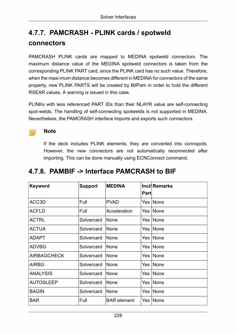
Solver Interfaces
4.7.7. PAMCRASH - PLINK cards / spotweldconnectors
PAMCRASH PLINK cards are mapped to MEDINA spotweld connectors. Themaximum distance value of the MEDINA spotweld connectors is taken from thecorresponding PLINK PART card, since the PLINK card has no such value. Therefore,when the maxi-mum distance becomes different in MEDINA for connectors of the sameproperty, new PLINK PARTS will be created by BifPam in order to hold the differentRSEAR values. A warning is issued in this case.
PLINKs with less referenced PART IDs than their NLAYR value are self-connectingspot-welds. The handling of self-connecting spotwelds is not supported in MEDINA.Nevertheless, the PAMCRASH interface imports and exports such connectors.
Note
If the deck includes PLINK elements, they are converted into connspots.However, the new connectors are not automatically reconnected afterimporting. This can be done manually using ECNConnect command.
4.7.8. PAMBIF -> Interface PAMCRASH to BIF
Keyword Support MEDINA Incl/Part
Remarks
ACC3D Full PVAD Yes None
ACFLD Full Acceleration Yes None
ACTRL Solvercard None Yes None
ACTUA Solvercard None Yes None
ADAPT Solvercard None Yes None
ADVBG Solvercard None Yes None
AIRBAGCHECK Solvercard None Yes None
AIRBG Solvercard None Yes None
ANALYSIS Solvercard None Yes None
AUTOSLEEP Solvercard None Yes None
BAGIN Solvercard None Yes None
BAR Full BAR element Yes None
228
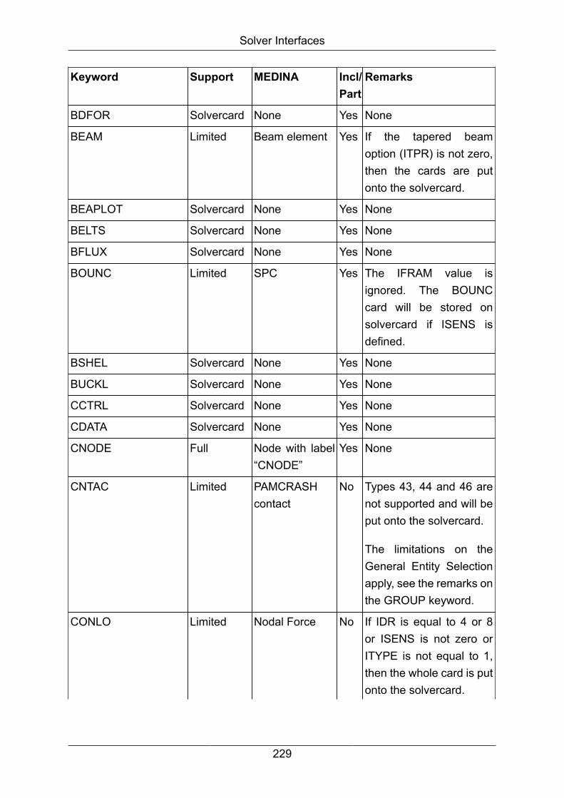
Solver Interfaces
Keyword Support MEDINA Incl/Part
Remarks
BDFOR Solvercard None Yes None
BEAM Limited Beam element Yes If the tapered beamoption (ITPR) is not zero,then the cards are putonto the solvercard.
BEAPLOT Solvercard None Yes None
BELTS Solvercard None Yes None
BFLUX Solvercard None Yes None
BOUNC Limited SPC Yes The IFRAM value isignored. The BOUNCcard will be stored onsolvercard if ISENS isdefined.
BSHEL Solvercard None Yes None
BUCKL Solvercard None Yes None
CCTRL Solvercard None Yes None
CDATA Solvercard None Yes None
CNODE Full Node with label“CNODE”
Yes None
CNTAC Limited PAMCRASHcontact
No Types 43, 44 and 46 arenot supported and will beput onto the solvercard.
The limitations on theGeneral Entity Selectionapply, see the remarks onthe GROUP keyword.
CONLO Limited Nodal Force No If IDR is equal to 4 or 8or ISENS is not zero orITYPE is not equal to 1,then the whole card is putonto the solvercard.
229

Solver Interfaces
Keyword Support MEDINA Incl/Part
Remarks
Option CLOAD (constantload definition) is ignored.
COUPLING Solvercard None Yes None
CPCTRL Solvercard None Yes None
CPULIMIT Solvercard None Yes None
DAMP Solvercard None Yes None
DATACHECK Solvercard None Yes None
DCNTA Solvercard None Yes None
DCOMP Solvercard None Yes None
DEBUG Solvercard None Yes None
DETOP Solvercard None Yes None
DFLUX Solvercard None Yes None
DIS3D Full PVAD Yes None
DIS3DM Full PVAD Yes None
DIS3DX Full PVAD Yes None
DISLIM Solvercard None Yes None
DMPEW Solvercard None Yes None
DOMAIN Solvercard None Yes None
DPEEN Solvercard None Yes None
DPEMA Solvercard None Yes None
DPEQM Solvercard None Yes None
DPNQM Solvercard None Yes None
DRAPF Solvercard None Yes None
ECTRL Solvercard None Yes None
ELINK Solvercard None Yes None
ENDDATA Solvercard None Yes None
ENERGY_MONITORING
Solvercard None Yes None
ERFFIL Solvercard None Yes None
230
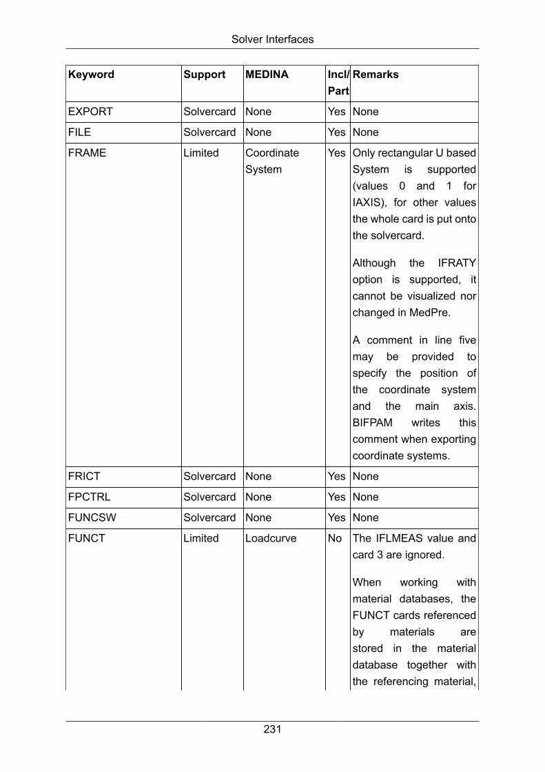
Solver Interfaces
Keyword Support MEDINA Incl/Part
Remarks
EXPORT Solvercard None Yes None
FILE Solvercard None Yes None
FRAME Limited CoordinateSystem
Yes Only rectangular U basedSystem is supported(values 0 and 1 forIAXIS), for other valuesthe whole card is put ontothe solvercard.
Although the IFRATYoption is supported, itcannot be visualized norchanged in MedPre.
A comment in line fivemay be provided tospecify the position ofthe coordinate systemand the main axis.BIFPAM writes thiscomment when exportingcoordinate systems.
FRICT Solvercard None Yes None
FPCTRL Solvercard None Yes None
FUNCSW Solvercard None Yes None
FUNCT Limited Loadcurve No The IFLMEAS value andcard 3 are ignored.
When working withmaterial databases, theFUNCT cards referencedby materials arestored in the materialdatabase together withthe referencing material,
231

Solver Interfaces
Keyword Support MEDINA Incl/Part
Remarks
rather than in theMEDINA data structures.
GAP Solvercard None Yes None
GASPEC Solvercard None Yes None
GFRP Solvercard None Yes None
GLOBAL Solvercard None Yes None
GRPEGM Solvercard None Yes None
GROUP Limited Set Yes The keywords GRP, SEGand EDG of the GeneralEntity Selection (GES)are not supported.
When one of thosekeywords is used, thewhole card is put onto thesolvercard.
Same applies when somereferenced ID is missing,except for ranges.
HEAT Solvercard None Yes None
HTSURF Solvercard None Yes None
IDEXP Solvercard None Yes None
IMPFIL Solvercard None Yes None
IMPORT Solvercard None Yes None
INCLU Full Part Yes A MEDINA part is createdwhich holds the contentsof the include file, exceptfor those objects whichhave no MEDINA partmembershipimplemented yet.
INPRES Solvercard None Yes None
232

Solver Interfaces
Keyword Support MEDINA Incl/Part
Remarks
INPUTVERSION Solvercard None Yes None
INVEL Full Initial velocity Yes None
INVSYS Solvercard None Yes None
IVCTRL Solvercard None Yes None
JOINT Solvercard None Yes None
KINDA Solvercard None Yes None
KINJ Solvercard None Yes None
KJOIN Full KJOINTelement
Yes None
LAYER Solvercard None Yes None
LCPSD Solvercard None Yes None
LCTRL Solvercard None Yes None
LINCO Solvercard None Yes None
LLINK Solvercard None Yes None
LOOKU Solvercard None Yes None
MACTRL Solvercard None Yes None
MASS Limited Mass element Yes Values of IDFRA (localframe), Dr, Ds andDt (distance components)are ignored.
If Mx, My, and Mz havedifferent values, then thewhole card is put onto thesolvercard.
If a node is provided incard 1, no General EntitySelection is considered.In this case, a masselement ID may bedefined in Card 5 incolumns 9 up to 16.
233

Solver Interfaces
Keyword Support MEDINA Incl/Part
Remarks
Card 5 should not beused to provide DiagonalMoment of inertia Ixy, Iyzand Ixz (Pamcrash 2010feature) because PAMBIFwill confuse it with thenode selection cards orwith the element ID.
The limitations on theGeneral Entity Selectionapply; see the remarks onGROUP keyword.
MATER Limited Material No Depending on thesettings, there are threeways how material cardsare treated by PAMBIF:
• "Create no databases"just stores thematerial cards on thesolvercard
• "Create databases"writes each materialtogether with thereferenced FUNCTcards into one file intothe user database.
• "Merge databases"does the same, butonly if the materialdoes not already existin either of the givenmaterial databases.
234

Solver Interfaces
Keyword Support MEDINA Incl/Part
Remarks
Additionally, all materialcards are mappedto MEDINA isotropicmaterials forconvenience. Thematerial data, e.g.the density values,are mapped to theappropriate parametersof the isotropic materialas much as possible.
When working withmaterial databases, thematerial label holdsthe database referencerather than the materialname. The materialreference is the nameof the material file orsubdirectory, preceded bya greater sign (">").
MBSYS Solvercard None Yes None
MCTRL Solvercard None Yes None
MDBODY Solvercard None Yes None
MEMBR Limited TRIA3V orQUAD4Velement
Yes Fields Beta1 and Beta2(fiber angles) are ignored.
MERGEGAP Solvercard None Yes None
METRIC Solvercard None Yes None
METRICCHECK Solvercard None Yes None
MMCASS Solvercard None Yes None
MODEL Solvercard None Yes None
MODULAR_DATA Solvercard None Yes None
235

Solver Interfaces
Keyword Support MEDINA Incl/Part
Remarks
MODULE Solvercard None Yes None
MSTRM Solvercard None Yes None
MTOCO Limited RBE2 element Yes ITMTO (MTOCO type)and Card 2 are ignored.ITMTO is assumed to bezero.
MTOJNT Solvercard None Yes None
MUSC1 Solvercard None Yes None
NLAVE Solvercard None Yes None
NODCO Full General nodeset withsolverkeyNODCO
Yes None
NODE Full Node Yes None
NODPLOT Solvercard None Yes None
NSMAS Full NSM Yes None
NSMAS2 Solvercard None Yes None
OCTRL Solvercard None Yes None
ORTHF Solvercard None Yes None
OTMCO Limited RBE3 element Yes ITYP and ALPHA are notsupported.
PART Limited Property Yes Card 1a is not supported.Therefore IDMAT>0 mustbe provided.
PART type PLINK ismapped to connectorproperty.
CARDs 3 and 4 areignored.
236

Solver Interfaces
Keyword Support MEDINA Incl/Part
Remarks
Field IRADBEN of theCARD 5 is ignored.
Values of RSEAR andNLAYR are not stored inthe property but in theelements.
PART type SHELL ismapped to shell property.
Fields TSCALF andEPSINI are ignored.
CARD 6 (materialorthotropic orientation) isignored.
For PART types MEMBR,BAR, BEAM, SPRING,MBSBR, BSHEL, TSHEL,JOINT, KJOIN, MBKJN,LLINK, ELINK, SLINK,SPHEL, SPRGBM, TIED,SOLID and TETRA, thecontent of cards 3 up tothe last card is mappedto a text field, whichis editable in the PEditcommand.
As an exception, if Parttype is MEMBR, then field"h" of card 5 (thickness) issupported as a distinctiveattribute of the property.Its corresponding fieldin the text field is
237

Solver Interfaces
Keyword Support MEDINA Incl/Part
Remarks
replaced by the string"< T >" (which will bereplaced by the thicknessof the property during theBIFPAM run). Part typeMEMBR is mapped tomembrane property.
Analogously, if PART typeis BAR or BEAM, then thecross section area (field"A" of card 5) is supportedas a distinctive attributeof the Property. Itscorresponding field in thetext field is replaced bythe string "< A >". PARTtype BAR and BEAMare mapped to BARand BEAM properties,respectively.
PART types SPRING andMBSBR are mapped toDynaSP1 property.
PART type SOLID andTETRA are mapped tosolid property, which hasa "sub-type" attribute thatindicates whether thePAMCRASH PART typeis SOLID or TETRA.
PART types BSHEL,TSHEL, JOINT, KJOIN,MBKJN, LLINK, ELINK,
238

Solver Interfaces
Keyword Support MEDINA Incl/Part
Remarks
SLINK, SPHEL,SPRGBM, TIED aremapped to generalproperty, which hasa "sub-type" attributethat indicates thePAMCRASH PART type.
It is possible to createa special file whenimporting a PAMCRASHfile.
This file, called the controlfile, has values that canbe edited by the user toreplace values of specialfields.
Please refer to thecontrol file section ofthe MEDINA PAMCRASHinterface documentationfor details.
PENTA6 Full PENTA element Yes None
PFLOW Solvercard None Yes None
PFMAT Solvercard None Yes None
PICK Solvercard None Yes None
PIPE Solvercard None Yes None
PLINK Limited CONNSPOTelement
No The General EntitySelection of the PLINKcard is limited to thePART keyword, i.e. onlyPART IDs may beprovided. Otherwise, the
239

Solver Interfaces
Keyword Support MEDINA Incl/Part
Remarks
whole PLINK card is putonto the solvercard.
PLY Solvercard None Yes None
PREBM Solvercard None Yes None
PREFA Solvercard None Yes None
PREFILTER Solvercard None Yes None
PRESBC Solvercard None Yes None
PRINT Solvercard None Yes None
PROFILE_DMP Solvercard None Yes None
PYFUNC Solvercard None Yes None
RAC3D Full PVAD Yes None
RAN3D Full PVAD Yes None
RAN3DM Full PVAD Yes None
RAN3DX Full PVAD Yes None
RBODY Full NRIGBODY Yes None
RESTARTFILES Solvercard None Yes None
RESUMERUN Solvercard None Yes None
RETRA Solvercard None Yes None
RMLOAD Solvercard None Yes None
RMSSOL Solvercard None Yes None
RUNEND Solvercard None Yes None
RUPMO Solvercard None Yes None
RVE3D Full PVAD Yes None
RWALL Limited Stonewall Yes If ISENS is not zero thewhole card is put onto thesolvercard.
ILEAK (airbag flag) valueis ignored.
240

Solver Interfaces
Keyword Support MEDINA Incl/Part
Remarks
Only Rigid Walls oftype 4 (infinite wall),5 (cylinder wall) and7 (spherical wall) aresupported. Otherwise thewhole card is put onto thesolvercard.
RWALL_KIN_CHECK Solvercard None Yes None
SECFO Limited CrossSection Yes Only PLANE, SECTION,SUPPORT andCONTACT types aresupported. Otherwise thewhole card is put onto thesolvercard.
SECURE Limited Material No PLY, FUNCT, GASPEC,MUSC1, PART andNODE encrypted optionsare put onto solvercard.
In case of the MATERoption, the SECURE cardis treated like a MATERcard.
SELOUT Solvercard None Yes None
SENPT Full General nodeset withsolverkeySENPT
Yes The limitations on theGeneral Entity Selectionapply; see the remarks onGROUP keyword.
SENPTG Full General nodeset withsolverkeySENPTG
Yes The limitations on theGeneral Entity Selectionapply; see the remarks onGROUP keyword.
SENSOR Solvercard None Yes None
SEWING Solvercard None Yes None
241
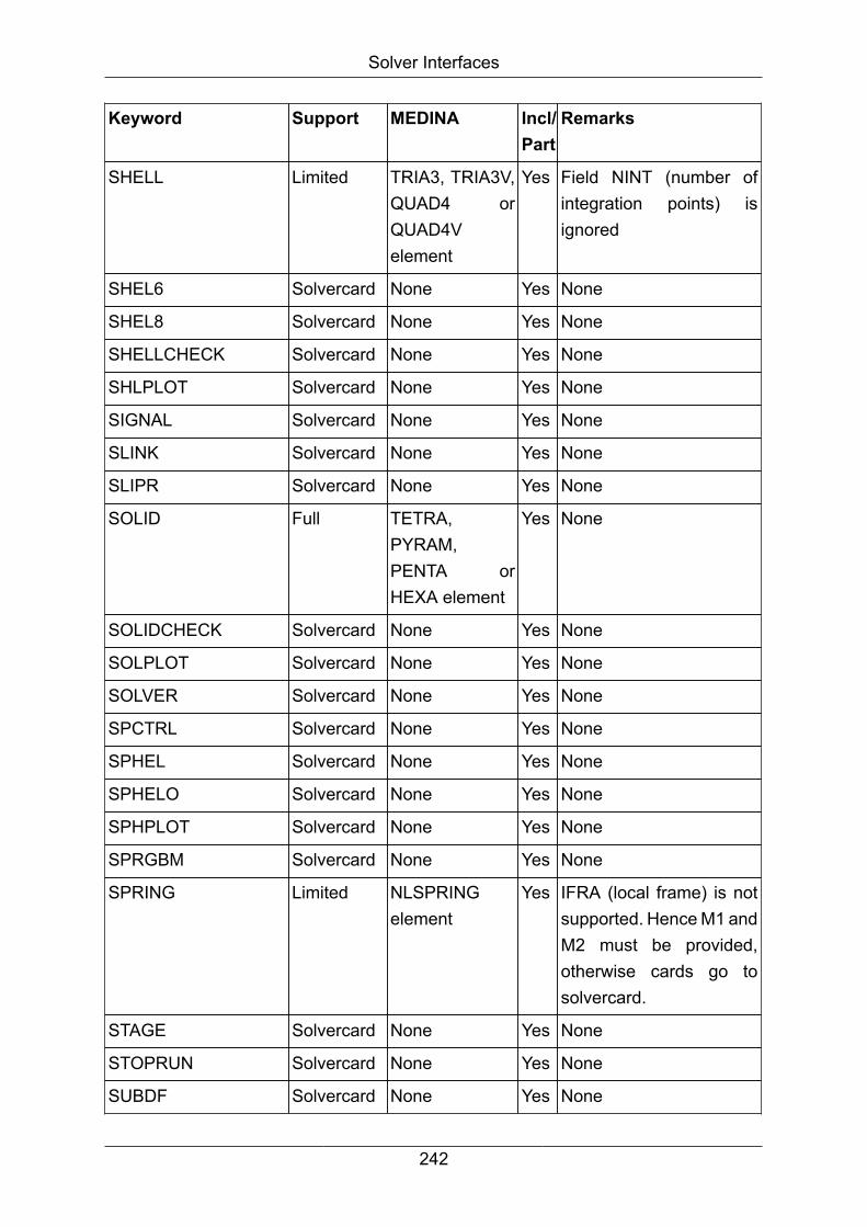
Solver Interfaces
Keyword Support MEDINA Incl/Part
Remarks
SHELL Limited TRIA3, TRIA3V,QUAD4 orQUAD4Velement
Yes Field NINT (number ofintegration points) isignored
SHEL6 Solvercard None Yes None
SHEL8 Solvercard None Yes None
SHELLCHECK Solvercard None Yes None
SHLPLOT Solvercard None Yes None
SIGNAL Solvercard None Yes None
SLINK Solvercard None Yes None
SLIPR Solvercard None Yes None
SOLID Full TETRA,PYRAM,PENTA orHEXA element
Yes None
SOLIDCHECK Solvercard None Yes None
SOLPLOT Solvercard None Yes None
SOLVER Solvercard None Yes None
SPCTRL Solvercard None Yes None
SPHEL Solvercard None Yes None
SPHELO Solvercard None Yes None
SPHPLOT Solvercard None Yes None
SPRGBM Solvercard None Yes None
SPRING Limited NLSPRINGelement
Yes IFRA (local frame) is notsupported. Hence M1 andM2 must be provided,otherwise cards go tosolvercard.
STAGE Solvercard None Yes None
STOPRUN Solvercard None Yes None
SUBDF Solvercard None Yes None
242

Solver Interfaces
Keyword Support MEDINA Incl/Part
Remarks
SUBRUN Solvercard None Yes None
TETR10 Solvercard None Yes None
TETR4 Full TETRA element Yes None
TETRA Full TETRA10element
Yes None
TETRA4 Solvercard None Yes None
THCRS Solvercard None Yes None
THELE Full Generalelement setwith solverkeyTHELE
Yes The limitations on theGeneral Entity Selectionapply; see the remarks onGROUP keyword.
THICKNESS_INTEGRATIONSolvercard None Yes None
THLOC Full General NodeSet withSolverkey=THLOC
Yes The limitations on theGeneral Entity Selectionapply; see the remarks onGROUP keyword.
THMAT Solvercard None Yes None
THNAC Solvercard None Yes None
THNOD Full General NodeSet withSolverkey=THNOD
Yes The limitations on theGeneral Entity Selectionapply; see the remarks onGROUP keyword.
THNPO Solvercard None Yes None
TIED Full TIED Yes None
TIMESTEP Solvercard None Yes None
TITLE Solvercard None Yes None
TRAFO Solvercard None Yes None
TRANS Solvercard None Yes None
TRSFM Limited Part attributeplus generalnode set with
Yes If there is one or moreMEDINA part(s) whosenodes are all present
243

Solver Interfaces
Keyword Support MEDINA Incl/Part
Remarks
label "GES ofTRSFM ..."
in the node selectionof the TRSFM card,then this transformationis assigned to thispart(s) and thetransformation is appliedto the referenced nodecoordinates. Otherwise,the whole TRSFM cardis put onto the solvercardand no node coordinatesare transformed.
The transformed nodecoordinates will berestored to theiruntransformed positionduring the BIFPAM run.
A general node setis created in order topreserve the original GESformat.
The limitations on theGeneral Entity Selectionapply; see the remarks onGROUP keyword.
TSHEL Solvercard None Yes None
UDATA Solvercard None Yes None
UNIT Solvercard None Yes None
VACPL Solvercard None Yes None
VAMAT Solvercard None Yes None
VAMPSO Solvercard None Yes None
VAPANL Solvercard None Yes None
244

Solver Interfaces
Keyword Support MEDINA Incl/Part
Remarks
VARDEF Solvercard None Yes None
VEL3D Full PVAD Yes None
Note
Contents of CDATA block is not interpreted by PAMBIF, even if it is a GESreferencing to certain object IDs. Be aware that renumbering those referencedobjects damages such GES.
With Pamcrash 2011, the following feature in the syntax of the GES is available:
• The notation " :n" (space-colon-n) denotes all IDs from 1 to n
• The notation "m: " (m-colon-space) denotes all IDs from m to infinity
PAMCRASH contacts keeps their location in Include files in Import and Exportcommands.
4.7.9. BIFPAM -> Interface BIF to PAM
LOADS Exportedas
Remarks
Nodal Force CONLO / CNL of type rigid is not exported.
If CNL is of NodeSet type, thenfor each node in which the load isapplied, one "CONLO / " card iswritten.
Alternative Coordinate System shouldnot be used because BIFPAM willignore it.
ISENS field is not supported (will bezero).
ITYPE field will be equal to 1.
CLOAD field will be empty.
245

Solver Interfaces
LOADS Exportedas
Remarks
Pressure PRESH / none
PVAD ACC3D / full support
PVAD DIS3D / full support
PVAD DIS3DM / full support
PVAD DIS3DX / full support
PVAD RAC3D / full support
PVAD RAN3D / full support
PVAD RAN3DM /full support
PVAD RAN3DX / full support
PVAD RVE3D / full support
PVAD VEL3D / full support
Initital velocity INVEL / full support
Acceleration ACFLD / full support
Thermal loads and thermalboundary conditions
notexported
none
CONSTRAINTS Exportedas
Remarks
SPC BOUNC / IFRAM (frame ID) and ISENS (sensorID) fields will be zero.
MPC notexported
none
Pre-stress notexported
none
Stone wall RWALL / StoneWalls of type FLAT LIMITED arenot exported
SETS Exportedas
Remarks
Boundary and geometry sets notexported
none
246
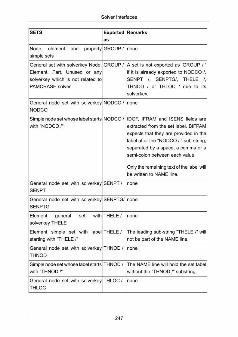
Solver Interfaces
SETS Exportedas
Remarks
Node, element and propertysimple sets
GROUP / none
General set with solverkey Node,Element, Part, Unused or anysolverkey which is not related toPAMCRASH solver
GROUP / A set is not exported as 'GROUP / 'if it is already exported to NODCO /,SENPT /, SENPTG/, THELE /,THNOD / or THLOC / due to itssolverkey.
General node set with solverkeyNODCO
NODCO / none
Simple node set whose label startswith "NODCO /"
NODCO / IDOF, IFRAM and ISENS fields areextracted from the set label. BIFPAMexpects that they are provided in thelabel after the "NODCO / " sub-string,separated by a space, a comma or asemi-colon between each value.
Only the remaining text of the label willbe written to NAME line.
General node set with solverkeySENPT
SENPT / none
General node set with solverkeySENPTG
SENPTG/ none
Element general set withsolverkey THELE
THELE / none
Element simple set with labelstarting with "THELE /"
THELE / The leading sub-string "THELE /" willnot be part of the NAME line.
General node set with solverkeyTHNOD
THNOD / none
Simple node set whose label startswith "THNOD /"
THNOD / The NAME line will hold the set labelwithout the "THNOD /" substring.
General node set with solverkeyTHLOC
THLOC / none
247

Solver Interfaces
SETS Exportedas
Remarks
Simple node set whose label startswith "THLOC /"
THLOC / The fields IFRAM, N1, N2, Correctionflag for acceleration and IDAFLD areextracted from the set label. BIFPAMexpects that they are provided inthe set label after the "NODCO /"substring, separated by a space, acomma or a semi-colon between eachvalue. Only the remaining text of thelabel will be written to the NAME line.
ELEMENTS Exportedas
Remarks
BAR BAR / Orientation of cross section is notwritten.
ROD BAR / Orientation of cross section is notwritten.
BEAM BEAM / Tapered beam is not supported.
The offset vector is ignored
BEAM4 notexported
none
BUSH notexported
none
CONM1 notexported
none
DAMP notexported
none
DAMP1 notexported
none
GAP notexported
none
HEXA SOLID / full support
248
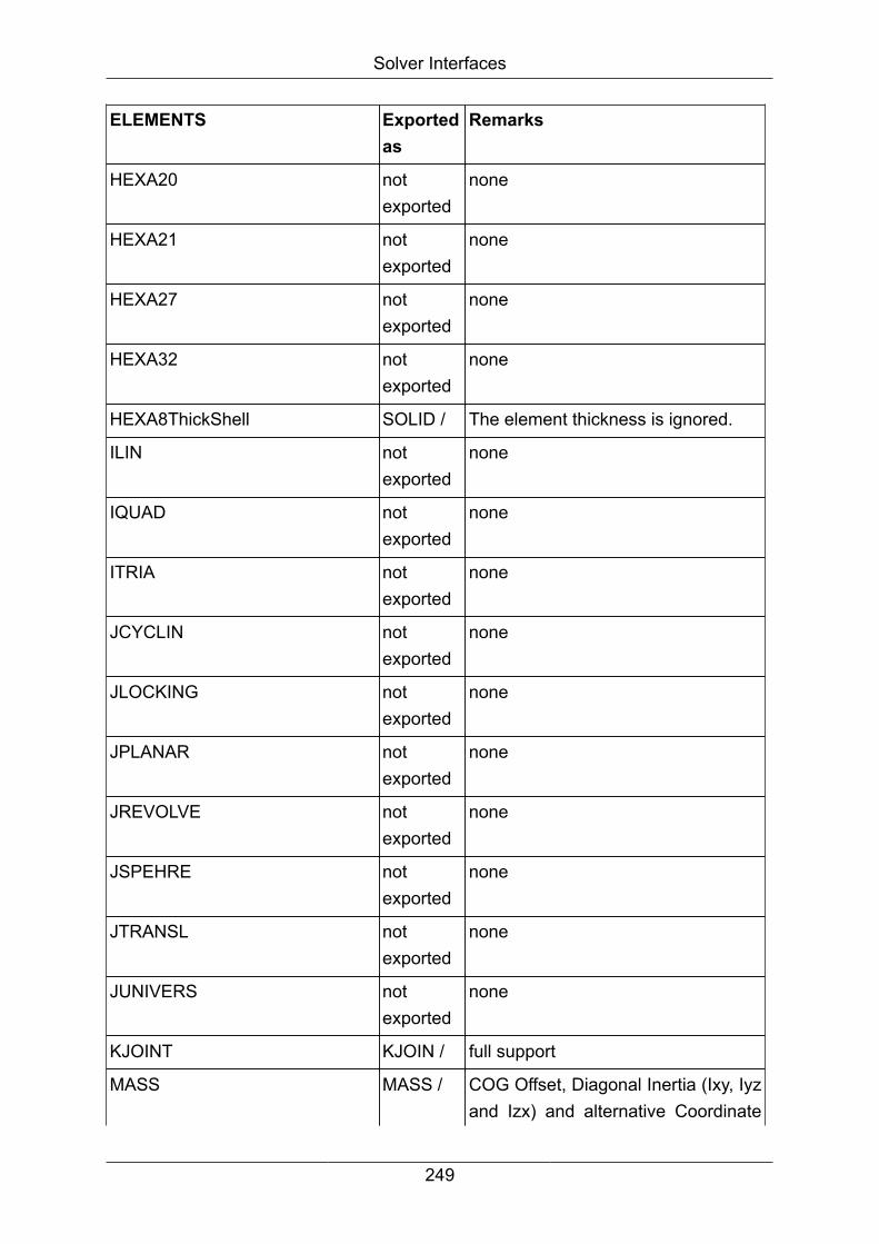
Solver Interfaces
ELEMENTS Exportedas
Remarks
HEXA20 notexported
none
HEXA21 notexported
none
HEXA27 notexported
none
HEXA32 notexported
none
HEXA8ThickShell SOLID / The element thickness is ignored.
ILIN notexported
none
IQUAD notexported
none
ITRIA notexported
none
JCYCLIN notexported
none
JLOCKING notexported
none
JPLANAR notexported
none
JREVOLVE notexported
none
JSPEHRE notexported
none
JTRANSL notexported
none
JUNIVERS notexported
none
KJOINT KJOIN / full support
MASS MASS / COG Offset, Diagonal Inertia (Ixy, Iyzand Izx) and alternative Coordinate
249

Solver Interfaces
ELEMENTS Exportedas
Remarks
System should not be used becauseBIFPAM ignores these features.
Fields Dr, Ds, Dt and IDFRA (distanceto COG and frame number) will beblank.
Card 5 (Diagonal Inertia - Ixy, Iyz andIzx) will not be written.
MASS1 notexported
none
MASS2 notexported
none
NLSPRING and NLDAMP SPRING/ Only the nodes and orientationis exported. Other attributes (initialoffset, scale factor, print flag) are lostduring export.
If "GROUND" is used as second node,then the second node will be equal tothe first node on the SPRING / card.
NRIGBODY RBODY / Full Support. But in MedPre, elementmust be created with analysisparameter set to PAMCRASH in thePARAM command.
PENTA PENTA6 / Full support
PENTA15 notexported
none
PENTA18 notexported
none
PENTA24 notexported
none
PENTA6ThickShell SOLID / The element thickness is ignored.
250
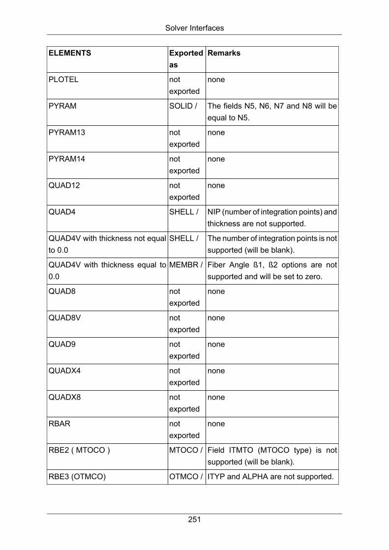
Solver Interfaces
ELEMENTS Exportedas
Remarks
PLOTEL notexported
none
PYRAM SOLID / The fields N5, N6, N7 and N8 will beequal to N5.
PYRAM13 notexported
none
PYRAM14 notexported
none
QUAD12 notexported
none
QUAD4 SHELL / NIP (number of integration points) andthickness are not supported.
QUAD4V with thickness not equalto 0.0
SHELL / The number of integration points is notsupported (will be blank).
QUAD4V with thickness equal to0.0
MEMBR / Fiber Angle ß1, ß2 options are notsupported and will be set to zero.
QUAD8 notexported
none
QUAD8V notexported
none
QUAD9 notexported
none
QUADX4 notexported
none
QUADX8 notexported
none
RBAR notexported
none
RBE2 ( MTOCO ) MTOCO / Field ITMTO (MTOCO type) is notsupported (will be blank).
RBE3 (OTMCO) OTMCO / ITYP and ALPHA are not supported.
251

Solver Interfaces
ELEMENTS Exportedas
Remarks
ROD3 notexported
none
RROD notexported
none
RSPLINE notexported
none
SPRING notexported
none
SPRING1 notexported
none
TETRA TETR4 / full support
TETRA10 TETRA10 /full support
TETRA16 notexported
none
TRIA3 SHELL /
MEMBR /
NIP (number of integration points )and thickness are not supported.
TRIA3 are exported as "SHELL /",unless a control file is used andtheir property on the control file is ofmembrane type.
N4 will be 0.
TRIA3V with thickness not equalto 0.0
SHELL / The field N4 will be equal to N3.
TRIA3V and QUAD4V withthickness equal to 0.0
MEMBR / Fiber Angle ß1, ß2 options are notsupported and will be set to zero.
TRIA6 notexported
none
TRIA6V notexported
none
TRIA7 notexported
none
252

Solver Interfaces
ELEMENTS Exportedas
Remarks
TRIA9 notexported
none
TRIAX3 notexported
none
TRIAX6 notexported
none
VISC notexported
none
CONNSPOT PLINK / Maximum distance will be dividedby 2 and stored as RSEAR in thePART card. If some spotwelds ofthe same property have differentmaximum distance values, additionalPART cards will be written in orderto map all those values. A warning isissued in such cases.
PROPERTIES Part/Type Remarks
ConnSpot PLINK CARDs 3 and 4 (fields DTELIM,TSCALF, TCONT and EPSINI) are notsupported.
In CARD 5:
• IRADBEN is not supported
• Field SPWLG (maximal length) issupported though it is not possibleto edit its value in MedPre. It isdefined by PAMBIF when PART /...PLINK is imported. Its default valueis 0.0
• The value of RSEAR (link searchradius) is not stored in the property,but by means of the spotweld
253
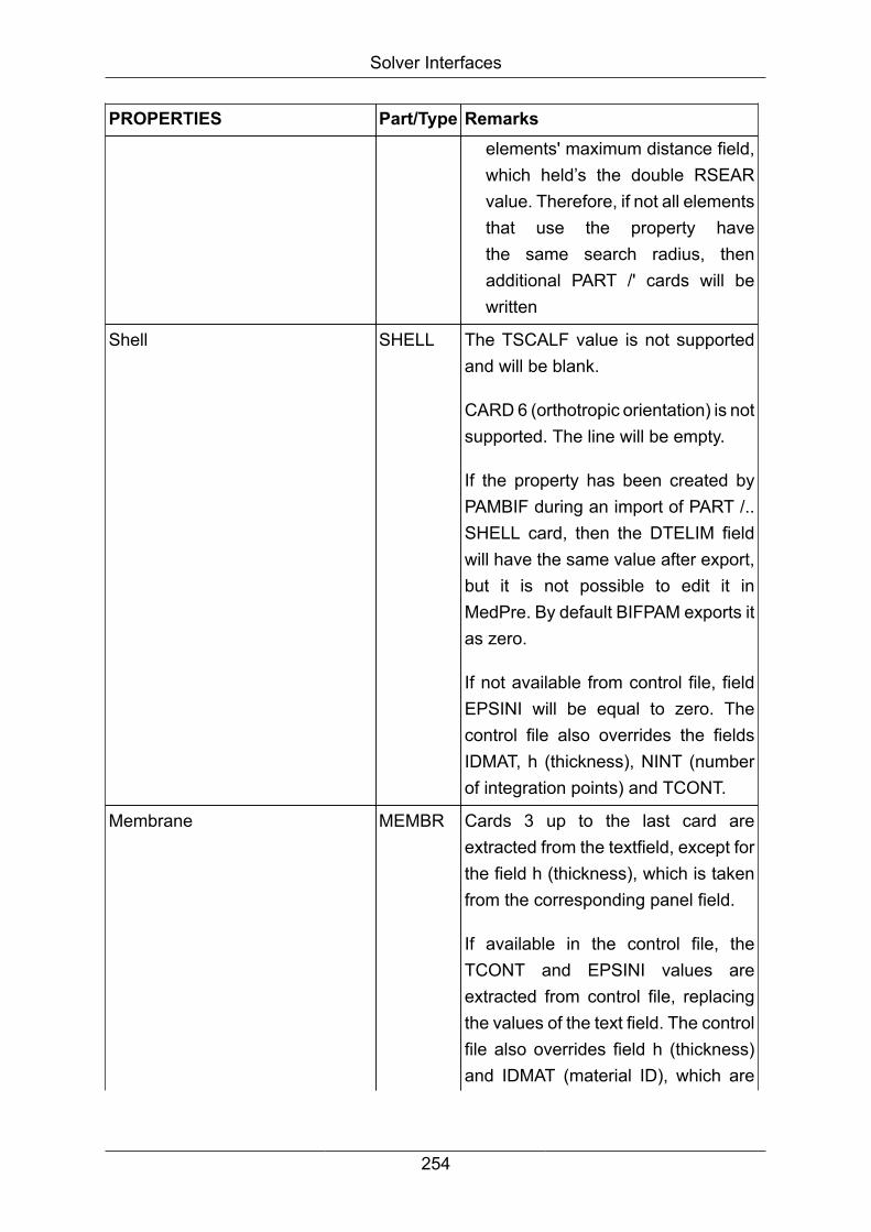
Solver Interfaces
PROPERTIES Part/Type Remarkselements' maximum distance field,which held’s the double RSEARvalue. Therefore, if not all elementsthat use the property havethe same search radius, thenadditional PART /' cards will bewritten
Shell SHELL The TSCALF value is not supportedand will be blank.
CARD 6 (orthotropic orientation) is notsupported. The line will be empty.
If the property has been created byPAMBIF during an import of PART /..SHELL card, then the DTELIM fieldwill have the same value after export,but it is not possible to edit it inMedPre. By default BIFPAM exports itas zero.
If not available from control file, fieldEPSINI will be equal to zero. Thecontrol file also overrides the fieldsIDMAT, h (thickness), NINT (numberof integration points) and TCONT.
Membrane MEMBR Cards 3 up to the last card areextracted from the textfield, except forthe field h (thickness), which is takenfrom the corresponding panel field.
If available in the control file, theTCONT and EPSINI values areextracted from control file, replacingthe values of the text field. The controlfile also overrides field h (thickness)and IDMAT (material ID), which are
254
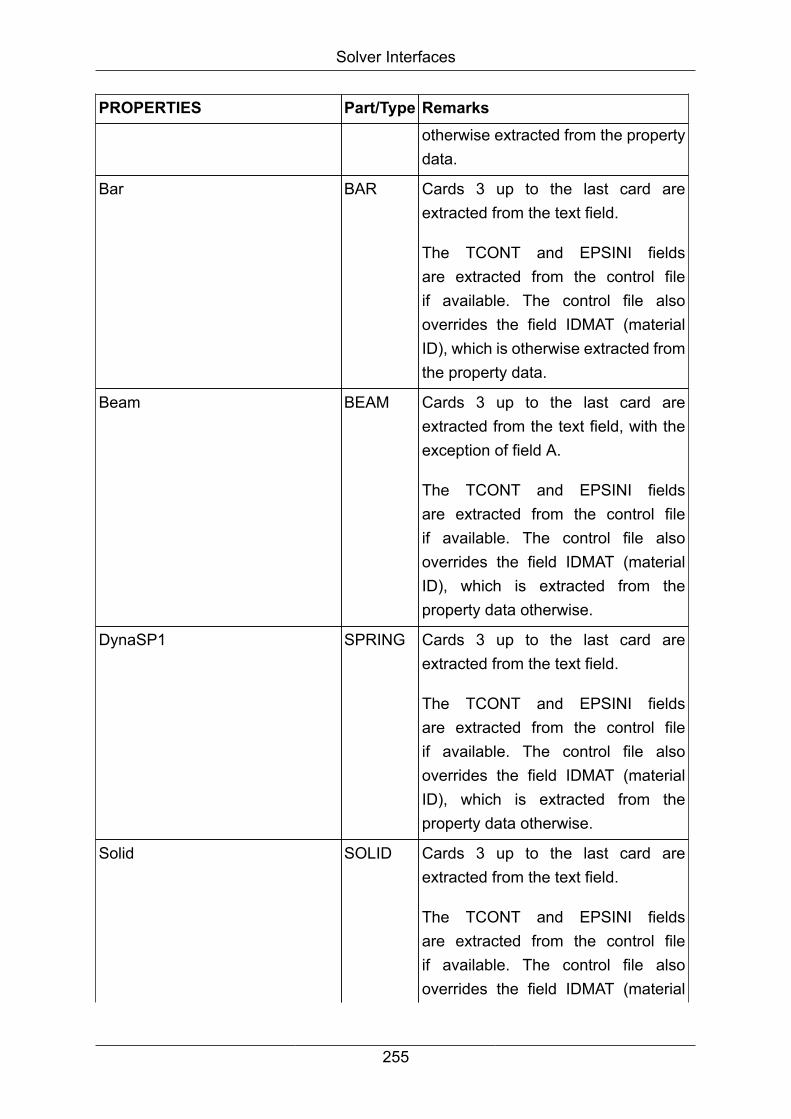
Solver Interfaces
PROPERTIES Part/Type Remarksotherwise extracted from the propertydata.
Bar BAR Cards 3 up to the last card areextracted from the text field.
The TCONT and EPSINI fieldsare extracted from the control fileif available. The control file alsooverrides the field IDMAT (materialID), which is otherwise extracted fromthe property data.
Beam BEAM Cards 3 up to the last card areextracted from the text field, with theexception of field A.
The TCONT and EPSINI fieldsare extracted from the control fileif available. The control file alsooverrides the field IDMAT (materialID), which is extracted from theproperty data otherwise.
DynaSP1 SPRING Cards 3 up to the last card areextracted from the text field.
The TCONT and EPSINI fieldsare extracted from the control fileif available. The control file alsooverrides the field IDMAT (materialID), which is extracted from theproperty data otherwise.
Solid SOLID Cards 3 up to the last card areextracted from the text field.
The TCONT and EPSINI fieldsare extracted from the control fileif available. The control file alsooverrides the field IDMAT (material
255

Solver Interfaces
PROPERTIES Part/Type RemarksID), which is extracted from theproperty data otherwise.
General BSHEL,ELINK,JOINT,LLINK,MBKJN,SLINK,SPHEL,SPRGBM,TIED orTSHEL
Field ATYPE (PART type) isdeterminate by the property sub-typeflag, which is editable in the PCreateand PEdit command.
Cards 3 up to the last card areextracted from the text field, withexception of field h (thickness) forsub-type TShell and of fields TCONTand EPSINI for the case that they areprovided on control file.
Note
Properties are exported to PAMCRASH PART cards which have rather nothingto do with MEDINA parts.
Properties that are not used by any element are not exported.
Properties of BAR, BEAM, DYNASP1, GENERAL, MEMBR and SOLID typesprovide a solver-specific text field, in order to store the cards 3 up to the lastcard. The text field is opaque to MEDINA and is editable by means of thePCreate and PEdit commands, except for a few values mapped to dialoguefields. Those values are represented by placeholder strings in the text fieldsand should be edited by means of the corresponding dialogue panel fields only.
When a control file is used, the property data contained therein have priority.
Others
MEDINA OBJECTS Exportedas
Remarks
Node NODE / Node should not have suppressedDOF because BIFPAM will ignorethem. Use SPC instead.
256

Solver Interfaces
MEDINA OBJECTS Exportedas
Remarks
Node Coordinate System ID isignored. The global coordinates of thenodes are used.
Node with label starting with"CNODE"
CNODE / (Same as Node)
BeamSection notexported
none
CossSection SECFO / These MEDINA commands must beexecuted with analysis parameterset to PAMCRASH in the PARAMcommand
PAMCRASH contact TIED TIED / full support
PAMCRASH contact CNTAC / full support
NSM NSMAS / full support
Loadcurve FUNCT / Not exported if not referenced in anyMEDINA object.
BIFPAM always sets to zero theSHIFTX and SHIFTY fields (shiftvalue for abscissa and ordinate)
BIFPAM never writes the fieldIFLMEAS.
The abscissa and ordinate labelsdefined in MedPre are ignored.
Coordinate Systems FRAME / Cylindrical and spherical coordinatessystems are not exported.
Local 1 direction should always be X.If it is set to Y or Z, BIFPAM will treatit as if it were X.
The position of the coordinate systemand the main axis information is
257

Solver Interfaces
MEDINA OBJECTS Exportedas
Remarks
written as a comment in what wouldbe the fifth card.
If the coordinate system has beencreated by PAMBIF during an importof a FRAME card, then the IFRATYfield value will have the same valueon the exported FRAME / card.Otherwise it will be zero. It is notpossible to edit this value in MedPre.
If the coordinate system referencesanother one as parent, BIFPAM willrecalculate its coordinate vectors intothe global system, since PAMCRASHdoes not support such a feature.
Component notexported
none
Layer notexported
none
Box3D notexported
none
Material MATER / If material databases are provided,the material cards and theirreferenced FUNCT cards will beextracted from the material database.In order to be exported, the materialdatabase files must be referencedby a MEDINA material by meansof its label of the form ">" followedby the name of the material file ordirectory. If a control file is used,the material references therein havepriority. Additionally, MATER / cardsfrom the solvercard, e.g. resulting
258
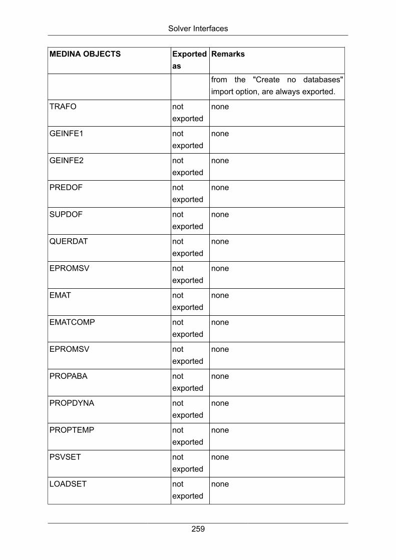
Solver Interfaces
MEDINA OBJECTS Exportedas
Remarks
from the "Create no databases"import option, are always exported.
TRAFO notexported
none
GEINFE1 notexported
none
GEINFE2 notexported
none
PREDOF notexported
none
SUPDOF notexported
none
QUERDAT notexported
none
EPROMSV notexported
none
EMAT notexported
none
EMATCOMP notexported
none
EPROMSV notexported
none
PROPABA notexported
none
PROPDYNA notexported
none
PROPTEMP notexported
none
PSVSET notexported
none
LOADSET notexported
none
259
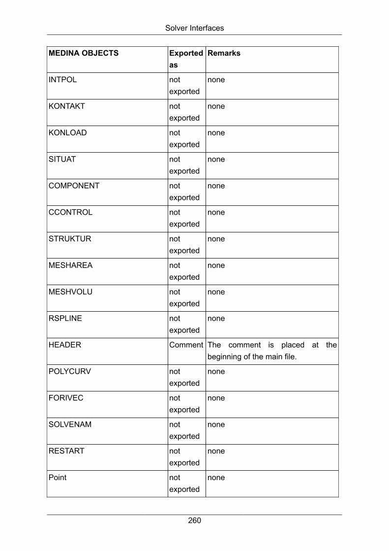
Solver Interfaces
MEDINA OBJECTS Exportedas
Remarks
INTPOL notexported
none
KONTAKT notexported
none
KONLOAD notexported
none
SITUAT notexported
none
COMPONENT notexported
none
CCONTROL notexported
none
STRUKTUR notexported
none
MESHAREA notexported
none
MESHVOLU notexported
none
RSPLINE notexported
none
HEADER Comment The comment is placed at thebeginning of the main file.
POLYCURV notexported
none
FORIVEC notexported
none
SOLVENAM notexported
none
RESTART notexported
none
Point notexported
none
260
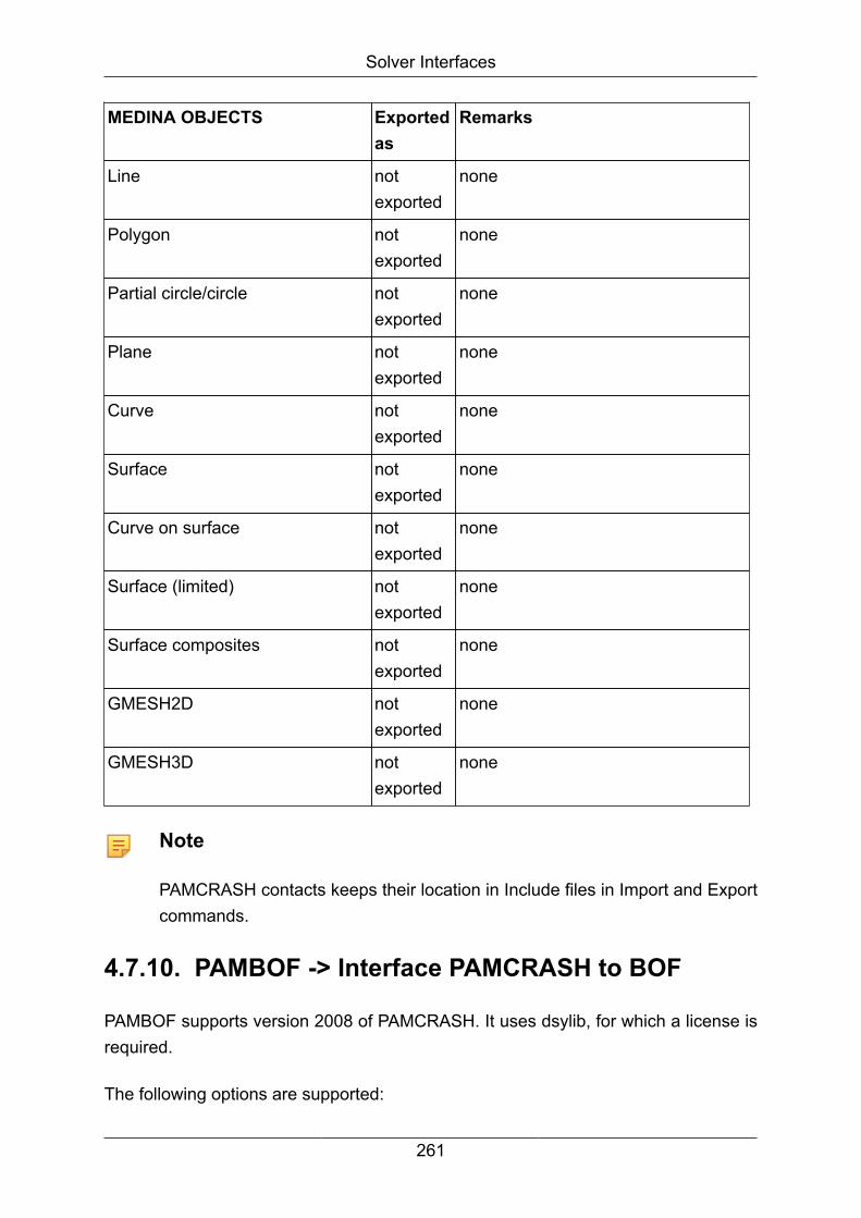
Solver Interfaces
MEDINA OBJECTS Exportedas
Remarks
Line notexported
none
Polygon notexported
none
Partial circle/circle notexported
none
Plane notexported
none
Curve notexported
none
Surface notexported
none
Curve on surface notexported
none
Surface (limited) notexported
none
Surface composites notexported
none
GMESH2D notexported
none
GMESH3D notexported
none
Note
PAMCRASH contacts keeps their location in Include files in Import and Exportcommands.
4.7.10. PAMBOF -> Interface PAMCRASH to BOF
PAMBOF supports version 2008 of PAMCRASH. It uses dsylib, for which a license isrequired.
The following options are supported:
261

Solver Interfaces
Option - interactive
With this button an interactive selection of the results from a list is available.
The list has the general form:
Option info selected, results on File for beam:
1 AXIALFORCE Scalar
2 T-SHEAR FORCE AT NODE 2 Scalar
3 TORSION MOMENT Scalar
4 S-BENDIND MOMENT NODE 1 Scalar
5 T-BENDING MOMENT NODE 1 Scalar
6 S-BENDIND MOMENT NODE 2 Scalar
7 T-BENDING MOMENT NODE 2 Scalar
8 AXIAL ELONGATION Scalar
9 TORSION ANGLE Scalar
10 S-BENDING ANGLE NODE 1 Scalar
11 T-BENDING ANGLE NODE 1 Scalar
12 S-BENDING ANGLE NODE 2 Scalar
13 T-BENDING ANGLE NODE 2 Scalar
Option info selected, results on File for shell:
0 RES-MXX Scalar
1 RES-MYY Scalar
2 RES-MXY Scalar
3 MX PLAST e Scalar
4 MN PLAST e Scalar
5 RES-NXX Scalar
6 RES-NYY Scalar
7 RES-NXY Scalar
8 Thickness Scalar
9 MAX VM Value Scalar
262

Solver Interfaces
Option info selected, results on File for shell:
10 MIN VM Value Scalar
11 Int Energy Density Scalar
Option info selected, results on File for solid:
0 X STRESS Scalar
1 Y STRESS Scalar
2 Z STRESS Scalar
3 XY STRESS Scalar
4 YZ STRESS Scalar
5 ZX STRESS Scalar
6 Effect. Plastic Strain Scalar
7 Solid Aux 1 Scalar
8 Solid Aux 2 Scalar
9 Solid Aux 3 Scalar
10 Solid Aux 4 Scalar
11 Solid Aux 5 Scalar
12 Solid Aux 6 Scalar
13 Int Energy Density Scalar
14 HG Energy Density Scalar
The selection takes place according to the number given in the first column.
For a tensor one must select all the components of the tensor.
To finish the selection, uses only "end".
Selecting the option interactive will override the option rtype.
Option info: With this button the list will be written to the prot file.
The list has the general form:
Option info selected, results on File for shell:
0 RES-MXX M Scalar
263

Solver Interfaces
Option info selected, results on File for shell:
1 RES-MYY M Scalar
2 RES-MXY M Scalar
3 MX PLAST e EPMA Scalar
4 MN PLAST e EPMI Scalar
5 RES-NXX N Scalar
6 RES-NYY N Scalar
7 RES-NXY N Scalar
8 Thickness THIC Scalar
9 MAX VM Value ESMA Scalar
10 MIN VM Value ESMI Scalar
No selection is possible.
The keywords for the input of option rtype are found in column 25-30.
For the vector MXYZ, with the components RES-MXX, RES-MYY and RES-MXY, thekeyword mxyz must be used.
For the vector NXYZ, with the components RES-NXX, RES-NYY and RES-NXY, thekeyword nxyz must be used.
Selecting the option info will overwrite the option interactive.
Option rtype: The string which is included in ' " ' represents the results which arewritten to the BOF for all states.
The options, included by ' " ', are the connection of the element type (beam, shell, solidor tool) and the output qualifier (first column in the SOLVER NOTES MANUAL, plotoutput).
Different options may be separated by commas.
The meanings of the options are summarized in the lists below.
For element type BEAM:
String in rtype Title Variable type
beam_faxi AXIAL FORCE Scalar
264

Solver Interfaces
String in rtype Title Variable type
beam_fssh SHEAR FORCE AT NODE 2 Scalar
beam_ftsh T-SHEAR FORCE AT NODE 2 Scalar
beam_mtor TORSION MOMENT Scalar
beam_msn1 S-BENDIND MOMENT NODE 1 Scalar
beam_mtn1 T-BENDIND MOMENT NODE 1 Scalar
beam_msn2 S-BENDIND MOMENT NODE 2 Scalar
beam_mtn2 T-BENDIND MOMENT NODE 2 Scalar
beam_daxi AXIAL ELONGATION Scalar
beam_rtor TORSION ANGLE Scalar
beam_rsn1 S-BENDING ANGLE NODE 1 Scalar
beam_rtn1 T-BENDING ANGLE NODE 1 Scalar
beam_rsn2 S-BENDING ANGLE NODE 2 Scalar
beam_rtn2 T-BENDING ANGLE NODE 2 Scalar
For element type SHELL:
String in rtype Title Variable type
shell_mxyz RES-MXX 2D Tensor
RES-MYY
RES-MXY
shell_epma MX PLAST e scalar
shell_epmi MN PLAST e scalar
shell_nxyz RES-NXX 2D Tensor
RES-NYY
RES NXY
shell_thic Thickness scalar
shell_esma MAX VM Value scalar
shell_esmi MIN VM Value scalar
shell_mntr1 Int Energy Density scalar
shell_mntr2 HG Energy Density scalar
For element type SOLID:
265

Solver Interfaces
String in rtype Title Variable type
solid_sxyz X STRESS 3D Tensor
Y STRESS
Z STRESS
XY STRESS
YZ STRESS
ZX STRESS
solid_eple Effect. Plastic Strain scalar
solid_aux1 Solid Aux 1 scalar
solid_aux1 Solid Aux 1 scalar
solid_aux1 Solid Aux 1 scalar
solid_aux1 Solid Aux 1 scalar
solid_aux1 Solid Aux 1 scalar
solid_aux1 Solid Aux 1 scalar
solid_mntr1 Int Energy Density scalar
solid_mntr2 HG Energy Density scalar
4.8. STARCD -> Interface to STARCDBIFSTAR/STARBIF converts MEDINA data (BIF) into STARCD data and vice versausing the standards described in STARCD Version 3.05.
Introduction
The basic data needed to generate a model are nodes and elements. This data isproduced by a preprocessor.
4.8.1. BIFSTAR -> Interface BIF to STARCD
The interface program bifstar converts MEDINA data (BIF) into binary STARCD datafiles.
Calling BIFSTAR from the MEDINA Monitor
The following table compares and describes the parameters in the MEDINA Monitorand the command line parameters for the tcl batch script:
266
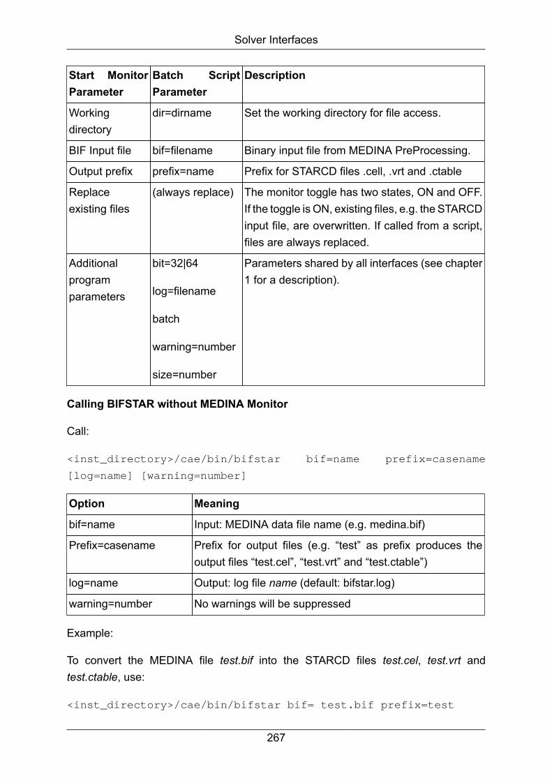
Solver Interfaces
Start MonitorParameter
Batch ScriptParameter
Description
Workingdirectory
dir=dirname Set the working directory for file access.
BIF Input file bif=filename Binary input file from MEDINA PreProcessing.
Output prefix prefix=name Prefix for STARCD files .cell, .vrt and .ctable
Replaceexisting files
(always replace) The monitor toggle has two states, ON and OFF.If the toggle is ON, existing files, e.g. the STARCDinput file, are overwritten. If called from a script,files are always replaced.
Additionalprogramparameters
bit=32|64
log=filename
batch
warning=number
size=number
Parameters shared by all interfaces (see chapter1 for a description).
Calling BIFSTAR without MEDINA Monitor
Call:
<inst_directory>/cae/bin/bifstar bif=name prefix=casename
[log=name] [warning=number]
Option Meaning
bif=name Input: MEDINA data file name (e.g. medina.bif)
Prefix=casename Prefix for output files (e.g. “test” as prefix produces theoutput files “test.cel”, “test.vrt” and “test.ctable”)
log=name Output: log file name (default: bifstar.log)
warning=number No warnings will be suppressed
Example:
To convert the MEDINA file test.bif into the STARCD files test.cel, test.vrt andtest.ctable, use:
<inst_directory>/cae/bin/bifstar bif= test.bif prefix=test
267

Solver Interfaces
4.8.2. STARBIF -> Interface STARCD to BIFThe interface program starbif converts STARCD data files into MEDINA data (BIF).
The binary files of STARCD version 3 and older versions are supported. The ASCIIfiles of STARCD version 4 is supported.
Calling STARBIF from the MEDINA Monitor
The following table compares and describes the parameters in the MEDINA Monitorand the command line parameters for the tcl batch script:
StartMonitorParameter
Batch ScriptParameter
Description
Workingdirectory
dir=dirname Set the working directory for file access.
Input prefix prefix=name Input file prefix for STARCD data files.
STAR-CD fileformat
format=0|1 Set the format of STARCD file
EQ. 0: Binary (default)
EQ. 1: ASCII Version 4.
BIF output file bif=filename Binary file for MEDINA PreProcessing.
Replaceexisting files
(always replace) The monitor toggle has two states, ON and OFF. If thetoggle is ON, existing files, e.g. the STARCD input file,are overwritten. If called from a script, files are alwaysreplaced.
Additionalprogramparametersshared by allinterfaces
batch
bit=32|64
log=filename
warning=number
Parameters shared by all interfaces (see chapter 1 fora description), plus additional parameters described inthe following chapter.
Calling STARBIF without the MEDINA Monitor
Call:
<inst_directory>/cae/bin/starbif dat=casename bif=name
[log=name] [warning=number][format=number]
268

Solver Interfaces
Option Meaning
Prefix=casename Input: STARCD data file name prefix (e.g. test)
bif=name Output: MEDINA data file name (e.g. medina.bif)
log=name Output: log file name (default: starbif.log)
warning=number No warnings will be suppressed
format=number Input: Format of STARCD file
EQ. 0: Binary
EQ. 1: ASCII Version 4
Example:
To convert the binary STARCD files test.cel, test.vrt into the MEDINA file test.bif, use:
<inst_directory>/cae/bin/starbif prefix=test bif=test.bif
format=0
STARCD Topology Definition
Topology Dimension Number ofvertices
Name MEDINAelement
1 0-D 1 Point Not supported
2 1-D 2 Line BAR
3 2-D Varies Shell/baffle 1. Number ofvertices=3TRIA3
2. Number ofvertices=4QUAD4
3. Other casesnotsupported
4 2-D Varies Shell/baffle withmidside vertices
Not supported
11 3-D 8 Hexahedron HEXA
12 3-D 6 Prism PENTA
269

Solver Interfaces
Topology Dimension Number ofvertices
Name MEDINAelement
13 3-D 4 Tetrahedron TETRA
14 3-D 5 Pyramid PYRAM
21 3-D 20 Hexahedronwith midsidevertices
Not supported
22 3-D 15 Prism withmidside vertices
Not supported
23 3-D 10 Tetrahedronwith midsidevertices
Not supported
24 3-D 13 Pyramid withmidside vertices
Not supported
28 1-D 3 Line with oneextra vertex
Not supported
29 1-D 4 Line with twoextra vertices
Not supported
30 2-D Varies Shell/baffle withextra centervertex
Not supported
31 2-D Varies Shell/baffle withmidside verticesand extra centervertex
Not supported
33 1-D 3 Line with onemidside vertex
Not supported
34 1-D 4 Line with onemidside vertexand one extravertex
Not supported
255 3-D Varies Polyhedron Not supported
270