Mechanics; a textbook for engineers
442
-
Upload
khangminh22 -
Category
Documents
-
view
0 -
download
0
Transcript of Mechanics; a textbook for engineers


MECHANICSA TEXT-BOOK FOR ENGINEERS
BY
JAMES E. BOYD, M.S.PROFESSOK OF MECHANICS, THE OHIO STATE UNIVERSITY
AUTHOR OF "STRENGTH OF MATERIALS," "DIFFERENTIAL EQUATIONS FORENGINEERING STUDENTS," ETC.
FIRST EDITION
McGRAW-HILL BOOK COMPANY, INC.
NEW YORK: 370 SEVENTH AVENUELONDON: 6*8 BOUVERIE ST., E. C. 4
1921

COPYRIGHT, 1921, BY THE
McGRAW-HiLL BOOK COMPANY, INC.
THE MAFL E FXK 8 S T O H K PA.

PREFACE
This book is intended to give a working knowledge of the
principles of Mechanics and to supply a foundation upon which
intelligent study of Strength of Materials, Stresses in Structures,
Machine Design, and other courses of more technical nature mayrest.
In the development of this subject, emphasis is put upon the
physical character of the ideas involved, while mathematics is
employed as a convenient tool for the determination and expres-
sion of quantitative relations. Analytical and graphical methods
are given together and each is interpreted in terms of the other.
While the principal stress is placed upon Mechanics as a science,
considerable attention is given to Mechanics as an art. In the
text, in some of the problems, and in many of the illustrative
examples, methods of calculation are suggested by means of
which accurate results may be most readily obtained.
The definitions of work and potential energy, together with the
solution of problems of statics by the method of virtual work
are given early. In the treatment of dynamics, the definitions
of kinetic energy and its application to the conditions of variable
motion are introduced as soon as possible.
In equations involving acceleration or energy, the commoncommercial units are employed the pound mass as the unit of
mass and the weight of the pound mass as the unit of force. In
order to clear up the confusion which results from the fact that
physicists use one set of units while some engineering writers
use another, Chapter XVIII is devoted to a discussion of the
various systems.
The author acknowledges his obligations to many of his col-
leagues who have assisted in the preparation of this book. P.
W. Ott of the Department of Mechanics checked the problemsof several chapters. S. A. Harbarger of the Department of
English read all the manuscript and assisted in the final revision.
Professor O. E. Williams of the Department of Engineering

vi PREFACE
Drawing supervised the preparation of the drawings, and
Professor Robert Meiklejohn of the same department made
many valuable suggestions.
J. E. BOYD.
COLUMBUS, OHIO,
May 13, 1921.

CONTENTSPAGE
PREFACE v
NOTATION xiii
CHAPTER I
FUNDAMENTAL IDEAS 1
Mechanics Illustrations Fundamental Quantities Standards
and Units Length Time Matter and Mass Force WeightyX Relation of Mass to Weight Variation of Weight with Latitude
and Altitude.
CHAPTER II
QUANTITY AND CALCULATIONS 9
Representation of Quantity by Numbers Representation of
Quantity by Lines-^Vectors ^Addition of Vectors-vComponentsof a Vector Computation of the Vector Sum Vector Difference
Vectors in Space Vectors by Direction Cosines Addition of
Vectors in Space Graphical Resolution of Vectors in Space
Graphical Determination of the Vector Sum Product of TwoVectors Summary.
CHAPTER III
APPLICATION OF FORCE . . . . 29
y Tension, Compression, and Shear States of Matter 4 Rigid
Body A Flexible Cord Eguilibrium A smooth Surface ASmooth Hinge Resultant and Equilibrant The Force Circuit
The Free Body Application of Forces Resultant of Concurrent
Forces Resolution of Forces Work Classes of Equilibrium.
CHAPTER IV
CONCURRENT CO-PLANAR FORCES 43
/>( Resultant Calculation of Resultants and Components Equi-librium Equilibrium by Resolutions Trigonometric Solution
Number of Unknowns Moment of a Force Moment of Resultant
Equilibrium by Moments Conditions for Independent Equa-tions Connected Bodies Bow's Method Summary Miscellane-
ous Problems.
CHAPTER V
NON-CONCURRENT CO-PLANAR FORCES 72
Resultant of Parallel Forces in the Same Direction Resultant of
Parallel Forces in Opposite Directions Equilibrium of Parallel
Co-planar Forces Condition of Stable Equilibrium Resultant of
vii

viii CONTENTS
PAGE
Non-parallel Forces Graphically Calculation of the Resultant of
Non-parallel Forces Equilibrium of Non-concurrent Forces
Condition for Independent Equations Direction Condition of
Equilibrium Trusses Method of Sections Jointed Frame with
Non-concurrent Forces Summary Miscellaneous Problems.
CHAPTER VI
.. COUPLES Ill
Moment of a Couple Equivalent Couples Algebraic Addition
of Couples Equilibrium of Couples Reduction of a Force and a
Couple to a Single Force Resolution of a Force into a Force and a
Couple Summary.
CHAPTER VII
GRAPHICS OF NON-CURRENT FORCES 120
Resultant of Parallel Forces Resultant of Non-parallel Forces
Parallel Reactions Non-parallel Reactions.
CHAPTER VIII
FLEXIBLE CORDS 129
The Catenary Deflection in Terms of the Length Deflection in
Terms of the Span Solution by Infinite Series Cable Uni-
formly Loaded per Unit of Horizontal Distance SummaryMiscellaneous Problems.
CHAPTER IX
yCONCURRENT NON-COPLANAR FORCES 141
Resultant and Components Resolution of Non-coplanar Forces
Calculation of Resultant Equilibrium of Concurrent, Non-
coplanar Forces Moment About an Axis Equilibrium byMoments Summary.
CHAPTER X
.. PARALLEL FORCES AND CENTER OF GRAVITY 149
Resultant of Parallel Forces Equilibrium of Parallel Forces
Center of Gravity Center of Gravity Geometrically Center of
Gravity of a Triangular Plate Center of Gravity of a PyramidCenter of Gravity of Integration Combination Methods of Calcu-
lation Center of Gravity of Some Plane Areas Liquid Pressure
Center of Pressure Summary.
CHAPTER XI
y FORCES IN ANY POSITION AND DIRECTION 173
Couples in Parallel Planes A Couple as a Vector Resultant
Couple Forces reduced to a Force and Couple Equilibrium of
Non-concurrent, Non-coplanar Forces Summary.
CONTENTS ix
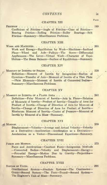
PAGECHAPTER XII
FRICTION 189
Coefficient of Friction Angle of Friction Cone of Friction
Bearing Friction Rolling Friction Roller Bearings Belt
Friction Summary Miscellaneous Problems.
CHAPTER XIII
WORK AND .MACHINES 205
Work and Energy Equilibrium by Work Machines Inclined
Plane Wheel and Axle Pulleys The Screw Differential
Applicances The Lever Virtual Work Character of Equi-librium The Beam Balance Surface of Equilibrium Summary.
CHAPTER XIV
MOMENT OF INERTIA OF SOLIDS 228
Definition Moment of Inertia by Integration Radius of
Gyration Transfer of Axis Moment of Inertia of a Thin Plate
Plate Elements Moment of Inertia of Connected Bodies
Summary Miscellaneous Problems.
CHAPTER XV
y MOMENT OF INERTIA OF A PLANE AREA 241
Definition Polar Moment of Inertia Axis in Plane Relation
of Moments of Inertia Product of Inertia Transfer of Axes for
Product of Inertia Change of Direction of Axis for Moment of
Inertia Change of Direction of Axes for Product of Inertia
Maximum Moment of Inertia Center of Pressure Moment of
Inertia by Moment of a Mass Summary.
CHAPTER XVIMOTION 259
Displacement Velocity Average and Actual Velocity Velocity
as a Derivative Acceleration Acceleration as a Derivative
Acceleration as a Vector Dimensional Equations Summary.
CHAPTER XVIIFORCE AND MOTION 273
Force and Acceleration Constant Force Integration Methods
Connected Bodies Velocity and Displacement EnergyPotential Energy Motion Due to Gravity Projectiles
Summary Miscellaneous Problems.
CHAPTER XVIIISYSTEM OF UNITS 294
Gravitational System Absolute Systems The Centimeter
Gram Second System The Foot Pound Second SystemThe Engineer's Unit of Mass Summary.

x CONTENTS
PAGECHAPTER XIX
FORCE WHICH VARIES AS THE DISPLACEMENT 301
Force of a Spring Potential Energy of a Spring Velocity Pro-
duced by Elastic Force Vibration from Elastic Force Sudden
Loads Composition of Simple Harmonic Motions Correction for
the Mass of the Spring Determination of g Determination of an
Absolute Unit of Force Positive Force which Varies as the
Displacement Summary.
CHAPTER XXCENTRAL FORCES 327
Definition Work of a Central Force Force Inversely as the
Square of the Distance Equipotential Surfaces Summary.
CHAPTER XXI
ANGULAR DISPLACEMENT AND VELOCITY 334
Angular Displacement Angular Velocity Kinetic Energy of
Rotation Rotation and Translation Translation and Rotation
Reduced to Rotation Summary.
CHAPTER XXII
ACCELERATION TOWARD THE CENTER 342
Components of Acceleration Acceleration toward the Center
Centrifugal Force Static Balance Running Balance Ball
Governor Loaded Governor Fly-wheel Stresses Summary.
CHAPTER XXIII
ANGULAR ACCELERATION 354
Angular Acceleration Displacement with Constant Acceleration
Acceleration and Torque Equivalent Mass Reactions of
Supports Reaction by Experiment Reactions of a System
Summary.
CHAPTER XXIV
ANGULAR VIBRATION 368
Work of Torque Angular Velocity with Variable TorqueTime of Vibration The Gravity Pendulum Simple Pendulum
Axis of Oscillation Exchange of Axes Summary.
CHAPTER XXVMOMENTUM AND IMPULSE 379
Momentum Impulse Action and Reaction Collision of
Inelastic Bodies Collision of Elastic Bodies Moment of
Momentum Center of Percussion Summary.
CONTENTS xi
PAGECHAPTER XXVI
ENERGY TRANSFER 395Units of Energy Power Mechanical Equivalent of HeatPower of a Jet of Water Work of an Engine Friction BrakeCradle Dynamometer Transmission Dynamometer PowerTransmission by Impact Summary.
INDEX. ..... . 413


NOTATION
Symbols frequently used in this book are:
a = linear acceleration; apparent moment arm; length of
balance beam; radius of circle; distance on figure,
a = a vector of length a.
A = Area; a force (in few cases).
b = breadth; base of triangle; a distance.
b = a vector of length b.
B = a force (in few cases).
c = a distance; a constant of the catenary; distance of center
of gravity of balance beam below central knife-edge,
c = a vector of length c.
C = integration constant; a force (in few cases).
d = diameter; a distance; pitch of screw; distance of central
knife-edge above end knife-edges; distance between
parallel axes,
d = a vector of length d.
e = base of natural logarithms; a distance.
E = electromotive force; modulus of elasticity.
/ = coefficient of friction.
F = force; total force of friction.
Fw = weight.
g = acceleration of gravity; a constant, 32.174.
h = height; height of triangle.
hp = horsepower.H = product of inertia.
HQ = product of inertia for axes through center of gravity.
H, H, HX) H2= horizontal force; horizontal vector.
/ = moment of inertia; electric current.
/o = moment of inertia for axis through the center of gravity.
Ix = moment of inertia with respect to the X axis.
/j,= moment of inertia with respect to the Y axis.
I max, Imin = maximum and minimum moments of inertia.
J = product of inertia.
k = radius of gyration; a constant.
fco = radius of gyration for axis through the center of gravity.
K = force which deforms a spring 1 foot; a constant; integration
constant; coefficient of discharge.
I = length; length of simple pendulum.m = mass in pounds, grams, or kilograms.
m.e.p. = mean effective pressure.M = moment.
xiii

xiv NOTATION
N = force normal to surface.
p = a small weight.
P, P = a force; force which causes an acceleration.
Q = quantity of liquid.
Q, Q = a force.
r = radius; amplitude of vibration.
r = radius to center of gravity.
R = resistance in ohms.
R, R = resultant force; reaction of support.
s = length; length of catenary from lowest point.
S, S = equilibrant; a force; unit stress.
t = time; time of vibration; thickness.
tc= time of a complete period.
T = torque.
T, T = tension; tension in a cord.
U = kinetic energy; work.
v = linear velocity.
V = volume.
V, V = a vertical force.
w = weight per unit length.
w' = weight per unit of horizontal distance.
W = weight.
x, y, z = distances.
x,y,z = coordinates of center of gravity.
X, Y, Z = coordinate axes.
yc= distance to center of pressure.
a = angular acceleration; any angle; angle with X axis; angle
of contact with belt.
= angle with Y axis; any angle.
7 = angle with z axis; any angle.
dx, dy, dz = small increments of x, y, and z.
p = density.
</>= an angle; angle of friction.
6 = an angle; angular displacement.
S = a summation,
w = angular velocity.

MECHANICSCHAPTER I
FUNDAMENTAL IDEAS
1. Mechanics. Mechanics is the science which treats of
the effect of forces upon the form or motion of bodies. Thescience of mechanics is divided into statics and dynamics.When the forces which act on a body are so balanced as to cause
no change in its motion, the problem of finding the relations of
these forces falls under the division of statics. When the forces
which act on a body cause some change in its motion, the problemof finding the relation of the forces to the mass of the bodyand to the change of its motion falls under the division of dy-
namics. The division of dynamics is frequently called kinetics.
2. Illustrations. Fig. 1 is an example of a problem of statics.
The figure shows a 10-pound mass which is supported by two
spring balances. In Fig. 1, I, the balances are nearly vertical.
One balance reads a little less than 5 pounds and the other
balance reads over 6 pounds. In Fig. 1, II, each balance makesa large angle with the vertical. The right balance, which is
nearly horizontal, reads 13 pounds and the left balance reads
15 pounds. In this position, the reading of each balance is
greater than the entire weight which is supported by the twobalances. In each position, the balance which is the more nearly
1

2 MECHANICS [ART. 3
vertical'' giv^s -the 'larger reading. The problem of finding the
relation between the pulls which these balances exert and the
angles which they make with the vertical is a problem of statics.
In Fig. 2, the mass of 10 pounds is supported by one spring
balance and by a cord which runs over a pulley and carries a
mass of 8 pounds on its free end. This system will come to rest
in a definite position. If moved from this position, the system
will return to it after a few vibrations. The problem of finding
this position and the tension in the spring balance is a problem
of statics.
If the cord which runs over the pulley of Fig. 2 is cut or broken,
the 10-pound mass will swing back and forth as a pendulum and
will finally come to rest with the balance in a vertical position.
FIG. 2. FIG. 3.
This final position is shown in Fig. 3. The 8-pound mass will
fall vertically downward with increasing speed. As the 10-
pound mass swings back and forth, the pull on the balance will
change. The problem of finding the position of either body at
any time after the cord has been severed, and the problem of
finding the pull of the spring balance are problems of dynamics.
3. Fundamental Quantities. The problem of Fig. 2 involves
position and direction. These are properties of space. The
problem also involves the pull of the cord and of the spring
balance. These are forces. Every problem of statics involves
the two fundamental ideas of space and force. If a body of
different mass were used in place of the 10 pounds, the force
and space relations would be changed. In this problem, the
forces depend upon the masses. All problems of statics involve
force and space. Most problems of statics involve also mass.
A problem of dynamics differs from one of statics in the fact
that it involves the element of time.

CHAP. I] FUNDAMENTAL IDEAS
The four fundamental quantities of mechanics are space,
mass, force, and time. A problem of dynamics includes all four
of these quantities. A problem of statics may include all except
time.
Space, mass (or matter), force, and time are elementary.
None of them may be reduced to anything more simple. Con-
sequently, it is useless to attempt to define them. On the
other hand, everyone has a clear knowledge of these quantities.
This knowledge has been gained through one or more of his
senses as a part of the experience of his lifetime.
4. Standards and Units. While space, mass, time, and force
can not be defined, they may all be measured. To measure
any quantity, it is necessary to have a unit of measure. If
measurements are to be taken at diverse times and places, it is
necessary to have some standard unit to which all other units are
referred. These units of measure were originally arbitrarily
chosen. Other units might have been selected just as well.
When a particular unit has once been adopted, however, it is
important that its value be preserved without change, in order
that physical measurements separated by wide intervals of time
may be accurately compared.5. Length. Space in one direction is length. There are two
official standards of length preserved by the Bureau of Standards
at Washington. These are the Standard Yard, which is practi-
cally equal to the British Imperial Standard Yard, and the Stand-
ard Meter, which is a copy of the International Standard.
The length of the International Meter in terms of the wave
length of cadmium vapor light has been carefully determined byMichelson. If this standard bar and the copies preserved byvarious nations should undergo any change, the magnitude of the
variation may be found by a new comparison with the wave
length of this light.
The foot is the unit of length which is commonly used byAmerican engineers. A foot is one-third the length of the
Standard Yard. Physicists use the centimeter as the unit. In
countries where the metric system has been adopted, engineers
employ the meter as the unit of length.
Length measurements are generally made by means of the
sense of sight. Sometimes the sense of touch, the sense of hear-
ing, or the muscular sense is used in comparing two lengths.
The vision, however, is employed to get the actual reading.

4 MECHANICS [ART. 6
Space in one dimension is length; space in two dimensions
is area; space in three dimensions is volume.
The idea of space, including length and direction, is gained
by the child through the sense of touch, the muscular sense, and
the sense of sight. The sense of hearing also assists in deter-
mining direction.
The relation between the metric system and the inch is given
with sufficient accuracy for most purposes by
39.370 inches = 1 meter.
2.540 centimeters = 1 inch.
Problems
1. Calculate the length of a foot in centimeters and memorize the result.
2. Calculate the length of a meter in feet and memorize the result.
3. Find the length of a kilometer in feet and in miles and compare the
results with some reference book.
4. Express 100 meters in yards and 440 yards in meters.
5. By logarithms find the number of square inches and square feet in
one square meter.
6. A hectare is 100 meters square. Find the value of a hectare in acres.
7. Using five-place logarithms, find the number of cubic centimeters in
one cubic inch. Compare with some handbook.
8. A liter is a cubic decimeter. Find the relation between the liter andthe U. S. liquid quart.
6. Time. The standard of time measurement is the mean solar
day. The unit commonly employed in problems of mechanics is
the mean solar second. The subdivision of the solar day into
hours, minutes, and seconds is made by means of the vibration
of pendulums or other mechanical devices. In making time meas-
urements, the senses of sight and hearing are used in connection
with these mechanical timepieces.
The child gains his ideas of time from the succession of events
as revealed through any or all of his senses.
7. Matter and Mass. From the mechanical standpoint, at
least, time and space are simple and easily measured. Time
possesses a single property, that of extent; space has extension
or length in three dimensions. Matter, on the other hand, pos-sesses many properties, some one of which must be selected anddefined as measuring the amount of material in a given body.Volume might be chosen as the measure of the quantity of mate-
rial. It is found, however, that the amount of a given material
in a given volume may be greatly changed by pressure. It is

CHAP. I] FUNDAMENTAL IDEAS 5
also found that equal volumes of different materials differ greatly
in their mechanical effects. It is evident, then, that some other
property must be selected to designate the amount of matter.
In Fig. 4, A represents a block of soft rubber resting on some
convenient support. In Fig. 4, II, a body B has been placed on
this block of rubber. The length of the block is found to have
been shortened. If B is removed, the block A returns to its
original length. If a body C is now placed on A, there is again
a change in length. If the change in length of A due to the bodyC is the same as that due to the bodyB, the bodies B and C are said to con-
tain equal amounts of material. Theamount of material (or matter) in a
body, as thus defined is called the mass
of the body. Two bodies have equalmasses if they produce equal deforma-
tions in a third body when they are applied to it in exactly the
same way. The ordinary spring balance is a common form of
a third body for the comparison of masses.
Instead of being supported on an elastic body, the bodies
B and C may be carried on the hand or shoulder of the observer.
The deformation of his muscles is accompanied by a sensation,
called the muscular sense, which enables him to judge roughlywhich body has the -greater mass.
A second method of measurement of mass is by means of
inertia. This involves the conditions of change of motion and
will be considered in Chapter XVII.The child gains an idea of mass in the mechanical way by means
of the muscular sense and the sense of touch as experienced whenhe supports bodies free from the earth, stops them when moving,or otherwise changes their motion. The concept of matter in
general is gained through all the senses.
The pound is the common unit of mass. In the metric systemthe unit is the kilogram. Physicists and chemists use chiefly
the gram. Units of mass are generally called"weights." A
so-called 10-pound weight as used on a beam balance is a 10-
pound mass.
To convert from the metric system to the avoirdupois system,the relations are,
15432 grains = 1 gram,453.6 grams = 1 pound.

6 MECHANICS [ART. 8
The official Standard Pound and Kilogram are preserved bythe Bureau of Standards:
Problems
1. Find the number of pounds in 1 kg. correct to four significant figures.
2. The mass of one cubic centimeter of water at 4C. is practically one
gram. Find the mass of one cubic foot of water in pounds.
8. Force. In Fig. 4, the rubber block A is shortened when the
body B is placed on it. The body B is said to exert a force on
A at their surface of contact. The block A is also said to
exert a force on B in the opposite direction. Force is some-
thing which may exist between two bodies or between two
parts of the same body. Forces occur in pairs. There is a
force from the first body to the second body, and an equal and
opposite force from the second body to the first body. Newtonstated this fact in what is called the Third Law of Motion:" Action and reaction are equal and opposed to each other."
A force always causes some change in the dimensions of a
body. A force always tends to produce some change in the motion
of the body upon which it acts, and does cause some changeunless it is balanced by an equal and opposite force acting on the
body, or by a number of forces equivalent to an equal and oppo-site force.
Force is recognized and measured by means of the change in
the dimensions and form of elastic bodies, by the muscular sense,
and by the change in the motion of bodies of known mass.
9. Weight. When the masses of two bodies are compared bymeans of the muscular sensation experienced in lifting them, the
observer really gets a comparison of two forces. The comparisonof mass is indirect. If the observer were at the center of the
Earth, there would be no muscular sensation so long as there were
no change in the motion of the body. The Earth exerts a force
on all bodies. This force is in the form of a pull directed toward
the center of the Earth. This pull or attraction is called the
weight of the body. When a body is supported and thus pre-
vented from moving toward the earth, the support exerts a
force upward which is equal to the weight of the body.When a physicist speaks of the weight of a body, he always means
the force with which the Earth attracts the body. In the com-
mon use of the word, weight generally means mass. When one
says that the weight of a bar of iron is 16 pounds, he is usually
CHAP. I] FUNDAMENTAL IDEAS 7
thinking of the amount of iron and not of the force required to
lift it. Much confusion has resulted from the failure to designate
clearly which of these two meanings is intended.
10. .Relation of Mass to Weight. The definition of mass in
Art. 7 may now be extended. Two bodies have equal masses if,
at a given point, they are attracted toward the Earth with equal force.
The determination of mass by means of a spring balance or a
beam balance is accomplished indirectly by a comparison of
forces, with the tacit assumption that equal forces produce equal
effects. The first definition of mass is : The mass of a body is pro-
portional to its weight. If Fw is the weight of the body in some
convenient unit, and m is its mass, the definition may be ex-
pressed algebraically by the equation,
Fw = km, (1)
in which k is a constant. The numerical value of k depends uponthe units used in expressing Fw and m. These units may be
so chosen that k is unity. If m is expressed in pounds of mass
and Fw is in pounds of force, then k =1, and
Fw = m. (2)
Equation (2) states that the mass of a body in pounds is equal to
its weight in pounds.1 The word pound has two meanings in
mechanics. It may be used to designate the amount of material
(mass) or to express the force of attraction toward the Earth
(weight as meant by the physicist). In a similar way, the
weight of one kilogram of matter is one kilogram, and the weightof one gram of matter is one gram. With the systems of units
in everyday use, k is unity. In some systems, k is not unity.
In the absolute system of units k =g, and Fw = mg. The Weight
of a mass of m grams in that system is mg dynes.
The absolute systems of units are not used by engineers in
the solution of problems of statics. In all such problems,
Equation (2) applies. The weight of a body is numerically
equal to its mass. The absolute systems of units and a second
1 A formula is merely a brief statement of the relation of quantities.The letters of a formula represent the number of units which express the
magnitude of the quantity. In the above equations, m represents the num-ber of pounds, the number of kilograms, the number of tons, or the numberof grams of material in the body under consideration. Similarly Fw repre-sents the number of units of force in pounds, kilograms, tons, grams, poundals,or dynes.

8 MECHANICS [ART. 11
definition of mass will be considered in this book in ChaptersXVII and XVIII.
11. Variation of Weight with Latitude and Altitude. The
weight of a body at any given position varies as its mass. It
has been shown by experiment that the weight of a body varies
inversely as the square of its distance from the center of the
Earth. If the Earth .were a sphere and did not rotate on its
axis, the weight of a body would be the same at all points at the
same level on its surface. Since the Earth is a sphoroid with its
polar radius about 13 miles shorter than its equatorial radius,
the weight of a body increases with latitude. While a poundmass is an invariable quantity, the weight of a pound mass, as
measured by a spring balance, varies with the latitude. If two
masses have equal weights at one locality, their weights will be
equal at any other locality. Masses may be compared by weigh-
ing at any point. A spring balance, however, which has been
calibrated by means of a standard weight at one locality, can
not be used for the accurate determination of mass at another
locality. (No one would do so on account of the variation of the
spring, even if the force of gravity were constant.)
Since the practical units of force are determined from the
weights of the standard units of mass, it is necessary to choose
some standard location for the definition of these units of force.
The sea level at 45 latitude is taken as this standard location.
A pound force is defined as the weight of a pound mass at the
standard location. A pound mass will weigh 0.997 Ib. at the
Equator and 1.003 Ib. at the Poles on a spring balance which is
correct at the standard latitude. This difference, while impor-tant in the determination of physical constants, is usually neg-lected in engineering calculations.
Problems
1. Taking the equatorial diameter of the Earth as 8000 miles and the
polar diameter as 26 miles less, and neglecting the effect of the rotation of
the earth, what is the weight at the Pole of a body which weighs 1 poundat the Equator, if both weighings are made on the same spring balance?
2. What is the relative change in the weight of a body when it is takenfrom a point at the sea level to a point one mile higher?

CHAPTER II
QUANTITY AND CALCULATIONS
12. Representation of Quantity by Numbers. There are
several ways of representing the magnitude of a quantity. The
most common method is by means of numbers, as 6 feet, 8 pounds,
10 seconds. A number expresses the magnitude of the quantity
in terms of the unit and means little to one who does not possess
a definite idea of the magnitude of the unit. Two such numbers
give a clear notion of the relative size of quantities without
conveying any information as to the actual size of either. Any-one will know that 20 dekameters is twice 10 dekameters,
without having any idea as to the size or nature of a dekameter.
If he has learned that a 'dekameter is 10 meters and that a meter
is 3.28 feet, he will calculate that one dekameter is approximately2 rods and that 20 dekameters is nearly 40 rods, or he may reduce
to yards and think of 10 dekameters as a little over 100 yards.
A Frenchman, on the other hand, who thinks in the metric sys-
tem, must translate rods and yards into meters before he can
have a real idea of their meaning.13. Representation of Quantity by Lines. The relative
magnitudes of several quantities are frequently represented to
the eye by means of straight lines as in Fig. 5.
Economic data, such as the population and area
of countries and cities, the production and con-
sumption of commodities, etc., are commonlyshown in this way. These lines may be hori-
zontal, as in Fig. 5, or vertical with their lower
ends on the same horizontal line.
For most purposes such lines are merely used
to express magnitude to the eye. The necessary
calculations are made by means of numbers. The operation of
addition, however, may be performed conveniently with lines.
In Fig. 6, it is desired to find the sum of the quantities rep-
resented by the lines ab and cd. The lines are placed together
so as to form one continuous line without overlapping. The total
9

10 MECHANICS [ART. 14
line thus formed is the sum of the lines. As may be seen from
Fig. 6, it is immaterial in what order the lines are placed together.
For subtraction, especially when the remainder is negative,
it is desirable to adopt some convention as to positive and nega-
tive direction. Horizontal lines extending toward the right
and vertical lines extending upward are regarded as positive.
In Fig. 6, the line ab runs from a to 6. The left end, a, is called
the origin, and the right end, b, is called the terminus. To find
ab + cd, the origin of the second line is placed at the terminus of
FIG. 7.
321001 234-567 09 IO
7-3FIG. 8.
a bI ab+cdI a
Ic dcd + ab
FIG. 6.
the first line. The sum of the two lines extends from the origin
of the first line to the terminus of the second line. This cor-
responds with ordinary addition of numbers. To get the sum of
7 + 3 begin at 7, which is the terminus of the first number, andcount forward 3 steps. This is shown graphically by Fig. 7.
Subtraction is the addition of a negative quantity. To get
7-3, begin at 7 and count backward 3 steps. This is shown byFig. 8. To get ab cd, begin at the terminus of ab and measure
the length of cd toward the left. This is shown in Fig. 9. Thearrows in Fig. 9 give the direction of the motion.
14. Vectors. A quantity which has both magnitude and
direction is called a vector quantity. Force is an example of
this kind of quantity. In Fig. 10, ab, cd, and e/are vectors in the
plane of the paper. The vectors ab and ef are equal, since they
have the same direction and equal length.

CHAP. 1IJ QUANTITY AND CALCULATIONS 11
In the vector ab, the point a is the origin and the point b is
the terminus. The vector is considered as extending from the
origin to the terminus, as is indicated by the arrow. The arrow
points from the origin and toward the terminus. The direction
of the arrow is the positive direction of the vector.
When a vector is represented by a
single letter, that letter is usually 2 > b
printed in black face type. In Fig.
11, a and b represent two such vectors.
The arrow shows the origin, terminus, e f
and direction.FIG /
A vector is described in words bygiving its direction and its length. When the plane of the
vector is known, a single angle is sufficient to designate its
direction. For instance, a given vector is 8 feet in length and
makes an angle of 35 degrees with the horizontal. When the
vectors under consideration are not all in the same plane, two
angles are required to express the direction of each vector. For
instance, a vector is 8 feet in length and makes an 1
angle of 40
degrees with the vertical in a vertical plane which is north 25
degrees east.
When it is desirable to distinguish a quantity which has
magnitude but not direction from a vector, such a quantity is
called a scalar quantity. The mass of a body or the number of
individuals in a group is a scalar quantity. In an algebraic
formula in which only the magnitude of a vector is represented
by a letter while its direction is expressed in terms of angles, the
letter is printed in Italics in-
stead of in black face type.
In this book, a letter (such as
P or Q) is used to represent
a force, which is a vector.D When emphasis is put on
both the direction and mag-nitude of the force, the letter is printed in black face type. Whenonly the magnitude is stressed, it is printed in Italics.
15. Addition of Vectors. The addition of vectors is dennedin the same way as the addition of lines (Art 13). The origin of
the second vector is placed at the terminus of the first vector.
The line which extends from the origin of the first vector to
the terminus of the second vector is the sum of the two vectors.

12 MECHANICS [ART. 16
Fig. 11, II, shows the addition of the vectors a and b to get their
sum a + b. Fig, 11, III, shows b + a. The vector a is first
in Fig. 11, II, and the vector b is first in Fig. 11, III. Fig. 11,
IV, shows both additions in one diagram. The additions begin
at a common origin O. Since the two lines a are equal and parallel
and the two lines b are also equal and parallel, the four lines
form a parallelogram. The diagonal of this parallelogram is
the vector sum and it is immaterial in what order the two vectors
are added. The sum of three vectors is
found in the same way. Fig. 12, II, repre-
sents the sum of three vectors. Fig. 12,
I, may be regarded as a graphical statement
^ ^e vec^ors wmcn are to be added. In
^is figure all the vectors start from a com-
mon origin. In Fig. 11, I, on the other
FIG. 12. hand, the vectors a and b start from differ-
ent origins.
There are two methods of finding the vector sum. Theseare the graphical method in which the lengths and angles are
measured, and the trigonometric (or algebraic) method in whichthe lengths and angles are computed.
Problems
1. Given two vectors, a = 15 ft. at degrees, b = 12 ft. at 40 degrees.
Solve graphically for the vector sum, a + b. Use the scale of 1 inch = 5
feet. Measure the vector sum and express the result in feet. Measurethe angle of the vector sum with the first vector and express the result in
degrees.
First construct the statement to scale as shown in Fig. 13, I. Then drawa in Fig. 13, II, equal and parallel to a of the statement. From the terminus
of a draw b equal and parallel to b of the statement.
2. Solve problem 1 for the vector sum b -f- a.
3. Find the sum of three vectors: 20 ft. at degrees, 15 ft. at 45 degrees,and 10 ft. at 110 degrees. Use the same scale as in Problem 1.
4. Find the vector sum of 16 ft. at 10 degrees and 20 ft. at 70 degrees.
Construct the 10-degree angle by means of its tangent. Construct the
60-degree angle by means of its chord. Measure the angle of the vector
sum by means of its chord and check by means of the sine of the angle whichthe vector sum makes with a line at 90 degrees.
16. Components of a Vector. The sum of two or more vectors
is frequently called the resultant vector and the vectors which

CHAP. II] QUANTITY AND CALCULATIONS 13
are added are called components of the resultant. The process
of finding the resultant is called composition of vectors. The
process of finding the components is
called resolution. In Fig. 13, the vector
a + b is the resultant of vectors a and
b, and the vectors a and b are com-
ponents of a + b.
Problems
FIG. 13.
1. A vector of 25 ft. at 30 degrees is made up of two components. Oneof these components makes an angle of 5 degrees with the reference line
and the other makes an angle of 45 degrees with the reference line. Find
these components graphically.
2. A vector of 20 ft. at 45 degrees is made up of a vector a at 20 degreesand a vector b which is 12 ft. in length. Find the magnitude of a and the
direction of b.
The most important kind of resolution
of vectors is that in which each com-
ponent is formed by the orthographic
projection of the resultant upon a line
along the desired direction. In Fig. 14,
c is a vector which makes an angle 6
with the horizontal. Its horizontal
component is a and its vertical com-FlG.
ponent is b. Thethe equations
lengths of these components are given by
a = 'c cos 0.
b = c sin 0.
(In these equations, the letters a, 6, and c represent magnitudes
only. For that reason they are printed in Italics instead of in
black face type.)
Figure 15 shows two such orthographic components, which
with their resultant form a right triangle.
When the term component is used without
qualification, the orthographic component is
generally meant. The process of finding the
orthographic component of a vector in a givendirection is called resolution in that direction.
Problems
Solve the following problems graphically and trigonometrically.3. A vector of 60 ft. is north 27 degrees east. Find its component north
and its component east. Ans. 53.46 ft. north; 27.24 ft. east.
14 MECHANICS [ART. 17
4. A vector of 45.67 ft. is directed north 27 07' west. Find its componentnorth and its component west by means of logarithmic functions.
5. Find the component of the vector of Problem 3 along a line which is
north 45 degrees east. Check by means of the sum of the components
along this direction of the east and north components as given in the answer
to Problem 3.
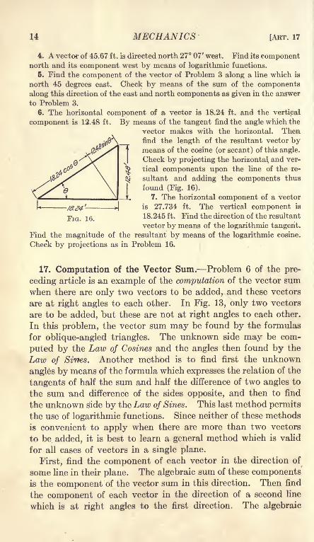
6. The horizontal component of a vector is 18.24 ft. and the vertical
component is 12.48 ft. By means of the tangent find the angle which the
vector makes with the horizontal. Thenfind the length of the resultant vector bymeans of the cosine (or secant) of this angle.
Check by projecting the horizontal, and ver-
tical components upon the line of the re-
sultant and adding the components thus
found (Fig. 16).
7. The horizontal component of a vector
is 27.734 ft. The vertical component is
16 18.245ft. Find the direction of the resultant
vector by means of the logarithmic tangent.
Find the magnitude of the resultant by means of the logarithmic cosine.
Check by projections as in Problem 16.
17. Computation of the Vector Sum. Problem 6 of the pre-
ceding article is an example of the computation of the vector sumwhen there are only two vectors to be added, and these vectors
are at right angles to each other. In Fig. 13, only two vectors
are to be added, but these are not at right angles to each other.
In this problem, the vector sum may be found by the formulas
for oblique-angled triangles. The unknown side may be com-
puted by the Law of Cosines and the angles then found by the
Law of Sines. Another method is to find first the unknown
angles by means of the formula which expresses the relation of the
tangents of half the sum and half the difference of two angles to
the sum -and difference of the sides opposite, and then to find
the unknown side by the Law of Sines. This last method permits
the use of logarithmic functions. Since neither of these methods
is convenient to apply when there are more than two vectors
to be added, it is best to learn a general method which is valid
for all cases of vectors in a single plane.
First, find the component of each vector in the direction of
some line in their plane. The algebraic sum of these componentsis the component of the vector sum in this direction. Then find
the component of each vector in the direction of a second line
which is at right angles to the first direction. The algebraic

CHAP. II] QUANTITY AND CALCULATIONS 15
sum of these components is the component of the vector sumin this direction. These two algebraic sums represent the legs
of a right-angled triangle. The hypotenuse of this triangle
is the vector sum required.
Figure 17 shows the addition of three vectors a, b, and c in the
same plane. These vectors make angles of a, fi, and 7, respec-
tively with the horizontal line. If H is the algebraic sum of the
components of these vectors parallel to the horizontal line,
H = a cos a. + b cos ff -f c cos 7.
If V is the algebraic sum of all the vertical components,
V = a sin a + b sin + c sin 7.
FIG. 17.
The resultant vector is the vector sum of a horizontal vector of
length H and a vertical vector of length V. (Fig. 17, III.)
If B is the angle which the resultant vector, makes with the
horizontal,
tan B =^; (1)
*~(2)R = H seed =
cosO
R =sin B'
(3)
If H is greater than F, use Equation (2) to find R; if V is greaterthan H, use Equation (3). The most accurate result is obtained
by this method.
It is not necessary that the direction of H should be horizontal.
The resolution may be taken along any direction, and the resolu-
tion for V at right angles to the direction of H.

16 MECHANICS [ABT. 17
Example
Find the direction and magnitude of the vector sum of 12 units at 18
degrees and 15 units at 50 degrees.
The equation for the components at degrees is,
H = 12 cos 18 + 15 cos 50,12 X 0.9511 = 11.4132
15 X 0.6428 = 9.6420
H = 21.0552
The equation for the components at 90 degrees is,
V = 12 sin 18 + 15 sin 50,12 X 0.3090 = 3.7080
15 X 0.7660 = 11.4900
Tan, =
R
21.0552
35 49'.
21.0552
cos e
V = 15.1980
= 0.7218,
21,05520.810S
FIG. 18.
Instead of taking resolutions along the lines at degrees and 90 degrees,
resolve along the direction of the first vector and perpendicular to that
direction (Fig. 18). If the component of the vector sum along the first
direction is H' and the component at right angles to this direction is V,
H' = 12 + 15 cos 32,H' = 12 + 15 X 0.8480 = 12 + 12.7200 = 24.7200,
V = 15 sin 32 = 15 X 0.5299 = 7.9485.
Tan 624.7200
= 17 49'.
R = 24.7200
cos e
= 0.3215,
24.720025.96 units.
0.9520
This will be recognized as the method of computing oblique-angled triangles
by means of right triangles.
The computation of the components in the foregoing ex-
ample has been carried to four decimal places, which gives
five or six significant figures in the resultant products. As

CHAP. II] QUANTITY AND CALCULATIONS 17
only four-place trigonometric functions have been used, the
last figure or the last two figures may be incorrect. The last
figure of each product may well be dropped and the results
written # = 11.413 + 9.642 = 21.055. Many computers would
drop the last two figures and give H = 21.06. This, however,
should not be done. An error of unity in the last figure of 21.06
is greater relatively than an error of unity in the fourth place
of the cosines which are used in the computation. For accurate
work it is a good rule to carry the calculations one figure farther
than the data, and finally drop the last figure from the result.
This method prevents errors in the calculations, which maygreatly exceed the errors of the data.
In the foregoing example, it has been assumed that the length
of each vector is correct to four significant figures. In manycases the degree of accuracy is expressed by the addition of
zeros. A length of 12 feet, which is correct to hundredths of a
foot, is written 12.00 ft. This, however, is not always done.
In these .examples, it is also assumed that the angles are
correct /to minutes. An angle which is given as 32 will be
understood to be 32 00'.
Problems
1. Find the magnitude and direction of the resultant of 24.8 ft. at
degrees and 22.8 ft. at 65 degrees. Ans. 40.16 ft. at 30 58'.
30.8
^
1
FIG. 19.
2. Find the magnitude and direction of the resultant of 24 units at 10
degrees, 32 units at 28 degrees, and 16 units at 70 degrees. Resolve along
degrees and 90 degrees.
3. Check Problem 2 by resolving along the line at 10 degrees and alongthe line at 100 degrees.
2

18 MECHANICS [ART. 18
4. Find the direction and magnitude of the vector sum of 25.6 units at
12 degrees, 18.3 units at 56 degrees, 30.8 units at 98 degrees, and 21.4 units
at 123 degrees.
Where there are several vectors, it is convenient to arrange the solution
in tabular form.
Length

CHAP. II] QUANTITY AND CALCULATIONS 19
Fig. 20, 1. The vector c from the origin of a to the terminus of
b is the required difference.
a b =c,
a = c + b.
Figure 20, III, shows another method of getting the same result.
If c = a b, a = b + c. The vector c is the vector which
must be added to vector b to get vector a. Vectors a and b
are drawn from the same origin and the terminus of b is joined to
the terminus of a. This vector c, with its origin at the terminus
of b and its terminus at the terminus of a, is the required differ-
ence. Fig. 20, IV, shows the two methods combined. The
is:
vectors a and b form the sides of a parallelogram. The diagonal
which starts at the origin of the first two vectors is the vector
sum. The other diagonal is the vector difference.
Problems
1. Given a vector a = 22 units at degrees and a vector b = 22 units
at 30 degrees. Find b a. Ans. b a = 11.39 units at 105.
2. A vector a = 17.28 ft. at 56 and a vector b = 27.34 ft. at 24 degrees.
Find a b. Solve graphically, then solve trigonometrically.
3. A vector a = 12.4 ft. at 20, a vector b = 17.2 ft. at 45, and a vector
c = 19.2 ft. at 64. Find a + b - c. First solve graphically. Then
solve by resolutions as in Art. 17. Ans. 15.42 ft. at 356 49'.
4. Check Problem 3 by resolutions along 20 and 110.
5. In Problem 3, find a b c.
19. Vectors in Space. A vector in a plane may be specified
numerically by two quantities. These may be its length and
its angle with some axis, which correspond with polar coor-
dinates, or its components along two axes, which correspond
with Cartesian coordinates.

20 MECHANICS [AET. 19
To specify fully a vector in space requires three quantities.
These may be its length and two angles or its components alongthree axes which are not all in one plane.
Figure 21 shows one way cf expressing the angles of a vector in
space. The vector of length / makes an angle with the Yaxis, while the plane which passes through the vector and the
Y axis makes an angle < with the XY plane. This is equivalent
to co-latitude and longitude on a sphere. The Y axis may be
regarded as the polar axis of the sphere. The angle Q is equivalent
to the co-latitude and the angle $ is equiva'ent to the longitude.
These coordinates are called spherical coordinates.
FIG. 21. FIG. 22.
If H is the component in the XZ plane and V is the componentparallel to the Y axis, Fig. 22,
B = I sin 0, (1)
V = I cos 0. (2)
If H x is the component along the X axis and Hz is the component
along the Z axis,
H x = H cos < = / sin cos <f>,
Hz= H sin 3> = / sin sin <i>.
(3)
(4)
Problems
1. A vector, 25 feet in length, makes an angle of 35 degrees with the
horizontal in a vertical plane which is south 25 degrees east. Find its
vertical component and its horizontal components east and south.
Ans. V - 14.34 ft.; He= 8.65 ft.; tf, = 18.56 ft.

CHAP. II] QUANTITY AND CALCULATIONS 21
2. A vector, 64.24 feet in length, is in a vertical plane which is north
37 degrees east. The elevation of the vector is 47 degrees. Find its com-
ponent north, its component east, and its component vertical.
3. The vertical component of a given vector is 25.6 feet. The horizontal
component east is 16.8 feet. The horizontal component south is 14.4 feet.
Find the direction and magnitude of the vector.
20. Vectors by Direction Cosines. A second method of
expressing the direction of a vector is by means of the angles
which it makes with two of the
coordinate axes. In Fig. 23, the
vector OP of length I is drawn as
the diagonal of a rectangular
parallelepiped. Three edges of
this parallelepiped lie in the axes
of coordinates. The angle be-
tween the vector and the X axis
is a. The angle between the vector
and the Y axis is /?; and the angle
between the vector and the Z axis
is 7. These angles are the direction
angles of the vector, and their cosines
are called the direction cosines.FIG. 23.
H x= I cos a; (1)
V = I cos 0; (2)
Hz = I cos 7. (3)
Since Z2 = Hi + T 2 + H\ = Z
2(cos
2a + cos 2 + cos 27),
cos 2a + cos 2j3 + cos 2
7 = 1 (4)
Equation (4) is a fundamental formula of solid analytic geometry.In the statement of a problem, two of the direction angles
are given and the third is found by means of Equation (4).
It will be noted that Equation (2) is the same as Equation (2)
of Art. 19. One angle is measured in the same way in bothmethods.
(In works of mathematical physics, the components which are
here written Hx, V, and Hz are written X, Y, and Z.)It is not necessary, of course, that these axes be horizontal
and vertical. They may be taken in any convenient direction.
In most cases of practice, however, it is easiest to measure the
angles from a vertical line and from lines in the horizontal
plane.

22 MECHANICS [ART. 21
Example
A vector, 30 feet in length, makes an angle of 70 degrees with the hori-
zontal axis east, and an angle of 65 degrees with the vertical axis. Find
its components along each of the coordinate axis.
cos27 = 1 - cos270 - cos* 65 = 1 - 0.1170 - 0.1786 = 0.7044;
cosV- 0.7044 - 1+%*
2*;
cos 2y = 0.4088;
2-y= 6552', 7 = 3256'.
The squares of the cosines of 70 and of 65 are most easily found bymeans of the cosines of the double angles.
Problems
1. A vector 24 feet in length makes an angle of 65 degrees with the south
horizontal line and an angle of 60 degrees with the east horizontal line. Thedirection of the vector is above the horizontal. Find its angle with the
vertical and find its components.Ans. ft
= 60 00'; Hs= 16.97 ft.; He
= 12 ft.; V = 12 ft.
2. A vector 40 feet in length makes an angle of 67 degrees with the vertical
and an angle of 23 degrees with the east horizontal axis. Find its anglewith the south horizontal axis and find its components.
3. A vector 50 feet in length makes an angle of 25 degrees with the east
horizontal axis and an angle of 80 degrees with the vertical. Its direction
is east of south. Find its angle with the south horizontal axis and find its
components. Ans. 7= 67 20'; H e= 45.32ft.; Ha
= 19.27ft.; V = 8.68ft.
4. The east component of a vector is 18 feet. The vertical componentis 20 feet. The length of the vector is 32 feet. Find the south componentand the direction angles.
21. Addition of Vectors in Space. To compute the vector
sum of vectors in one plane, each vector is revolved along two axes
at right angles to each other. The sum of the components along
one axis forms one leg of a right-angled triangle, and the sum of
the components along the other axis forms the other leg of this
triangle. The hypotenuse of this triangle is the vector sum or
resultant of the separate vectors. (Art. 17.) Likewise, to find
the vector sum of a number of vectors in space, each vector is
resolved into three components along axes which are mutually at
right angles. The sum of the components along each axis forms
one edge of a rectangular parallelepiped . The diagonal of this
parallelepiped is the vector sum required.
Example
Find the vector sum of a vector 20 feet in length, which is elevated 40
degrees above the horizontal in a vertical plane north 25 degrees east, and

CHAP. II] QUANTITY AND CALCULATIONS 23
a vector 30 feet in length, which is elevated 65 degrees in a vertical plane
north 55 degrees east.
Vector. V Hn
20 12.856 13.883
30 27.189 7.272
40.045 21.155 16.861
In horizontal plane
_ He _ 16.861tan0 - ^ -
21155 ;
log tan <f>= 9.90147; <f>
= 38 33'.
= 2JL155 ff = t 43215 H = 27 05 ftcos <t>
Tan =|^^; log tan ft
= 9.82960; = 34 02'.
R =^^j.iog
R = 1.68415; 72 = 48.32 ft.
Problems
1. Find the vector sum of a vector 30 feet in length, which is elevated
60 degrees in a vertical plane north 35 degrees east; a vector 20 feet in length,
north 65 degrees east in a horizontal plane; and a vector 25 feet in length in
a north and south vertical plane at an angle of 36 degrees north of the
vertical.
Ans. V = 46.21 ft.; Hn = 35.43 ft.; H e= 26.73 ft.;
= 37 02'; H =
44.38 ft.;= 43 51; R = 64.08 ft.
2. In Problem 1, find the angle which the resultant makes with each of
the three coordinate axes.
3. Find the vector sum of the following vectors: a vector20.66^ feet in
length, which is elevated 32 degrees in a vertical plane north 16 degrees
east; a vector 12.84 feet in length, which is elevated 64 degrees in a vertical
plane north 30 degrees east; and a vector 18.62 feet in length, which is
elevated 40 degrees in a vertical plane north 45 degrees west.
Ans. V = 34.46 ft.; Hn= 31.80 feet.; He
= - 2.44 ft.; R = 46.95 ft.
at an angle of 42 47' with the vertical in a plane north 4 23' west.
4. Find the vector sum of a vector 25 feet in length in the north east
quadrant at an angle of 64 degrees with the vertical and at an angle of 60
degrees with the north horizontal axis; and a vector 20 feet in length at an
angle of 40 degrees with the vertical in a vertical plane, which is north 36
degrees east.
22. Graphical Resolution of Vectors in Space. Fig. 24 shows
the graphical method of finding the components of a vector
when the directions are given in spherical coordinates. The
vector of length I makes an angle ft with the vertical in a vertical

24 MECHANICS [ART. 22
VP/ane
HP/ane
plane at an angle with the XY vertical plane. The lineOP,of
length I, is first drawn in the 7 plane at an angle with the verti-
cal. Its projection on the Y axis gives
the V component, and its projection on
the X axis gives the length of the hori-
zontal component H. The line OQ of
length H is revolved through an angle <f> in
the horizontal plane to the position OQ' .
This line OQ' gives the location and mag-nitude of the horizontal component. The
component of OQ' along the X axis is H x
and the component along the Z axis is
Hz .
Problems
1. Solve Problem 1 of Art. 19 graphically to the scale of 1 inch = 5 feet.
Also find the component in each of the three planes.
2. A vector 20 feet in length makes an angle of 35 degrees with the hori-
zontal axis east. The vector is in a plane which makes an angle of 40 degrees
with the horizontal in the octant above the horizontal plane and north of
the east axis. Find the components of this vector along the east horizontal,
the north horizontal, and the vertical axis.
Figure 25 shows the graphical method of finding the compo-nents of a vector when two of its direction angles are given. The
FIG. 24.
FIG. 25.
vector of length I makes an angle a. with the X axis and an angle
|3 with the Y axis. In the V plane the line OP of length / is first
constructed at an angle a. with the X axis. Its projection on the

CHAP. II] QUANTITY AND CALCULATIONS 25
X axis is the component H x . The line OP' of length I is next
drawn at an angle |8 with the Y axis. Its projection on the Y axis
is the component V. The intersection of the horizontal line
through P' with the vertical line through P gives the point Q.
This point is the projection on the V plane of the terminus of the
vector in space. With OQ as a radius and as a center, an arc
is described intersecting the X axis at Q''. With I as a radius and
O as a center, a second arc is described in the H plane. From Q'
a line is drawn in the H plane perpendicular to the X axis. This
line intersects the arc of radius I at the point P". Since OP"is the length of the vector, and OQ' is the length of its componentin the V plane, the line Q' P", which completes the right triangle
OQ'P", is equal to the component Hz . The line OR of length His the component in the H plane and the line OS is the componentin the profile plane. It is nob necessary to find these last two
components, but it is sometimes desirable to have them.
Problems
3. Solve Problem 2 of. Art. 20 graphically to the scale of 1 inch = 10 feet.
4. Solve Problem 3 of Art. 20 graphically to the scale of 1 inch = 10 feet.
23. Graphical Determination of the Vector Sum. To find
the sum of several vectors in space by graphical methods, each
vector is first resolved into components along the three axes as
in Figs. 24 and 25. To avoid confusion it is often advisable
to make a separate drawing for the resolution of each vector.
The components along each axis are added graphically and laid
off along the corresponding axis of the final diagram. If the direc-
tion of the vector sum is desired in spherical coordinates, the
construction is that of Fig. 24 in the inverse order. If the direc-
tion angles of the vector sum are required, they may be obtained
by reversing the construction of Fig. 25.
Problems
1. Solve Problem 1 of Art. 21 graphically to the scale of 1 inch = 5 feet.
2. Solve Problem 2 of Art. 21 graphically to the scale of 1 inch = 5 feet.
3. Solve Problem 4 of Art. 21 graphically to the scale of 1 inch = 5 feet.
24. Product of Two Vectors. There are two ways of multi-
plying two vectors. The result of one method is a vector and is
called the vector product of the two vectors. The result of the

26 MECHANICS [ART. 24
other method is a mere number without direction, and is called
scalar product of the two vectors.
If the length of vector a is a units and the length of vector bis 6 units, and if the angle between the two vectors is 0,
scalar product a. b = ab cos 6. Formula I.
Since b cos 6 is the length of the orthographic projection of vec-
tor b upon the line of vector a, the scalar product of Wo vectors
may be defined as numerically equal to the product of the magni-tude of one vector multiplied by the magnitude of the projectionof the other vector upon its direction. Since
ab cos = ba cos 0,
either vector may be regarded as projected upon the other.
When the angle between the two vectors is zero, their scalar
product is simply the product of their magnitudes. Scalar mul-
tiplication of vectors, when they are in the same direction, is
equivalent to multiplication of ordinary arithmetic, just as
addition of vectors in the same direction is equivalent to
addition of ordinary arithmetic.
The work done by a force, which is the product of the magni-tude of the force multiplied by the component of the displace-
ment in the direction of the force, is an example of a scalar
product.
The vector product of two vectors a and b is defined by the
equationvector product a X b = ab sin B. Formula II,
The vector product of two vectors is numerically equal to the
^ product of the length of one vector
multiplied by the component of the
other vector perpendicular to its
direction.
The vector product of two vectors
/ i A> n is defined as a vector perpendicular^ to the plane of the two vectors which
are multiplied together. In the right-
handed system of coordinates, the direction of the angle between
the vectors and the direction of the vector product bear the
same relation to each other as the direction of rotation and motionof a right-handed screw. If the rotation from b to a in the XYplane of Fig. 26, I, is clockwise, the vector product bXa is along

CHAP. II] QUANTITY AND CALCULATIONS 27
the Z axis away from the observer. If the rotation from a to b
is counter-clockwise, the vector product a X b is directed along
the Z axis toward the observer.
The moment of a force, which is the product of the force
multiplied by the length of the component of the moment arm
perpendicular to the direction of the force, is an example of a
vector product.There are several ways of indicating the multiplication of two
vectors. The most convenient one is that used by Gibbs:
Scalar product of ab = a.b,
which is read a dot b and is called the dot product.
Vector product of ab = a X b,
which is read a cross b and is called the cross product.
This method of writing the vector products has not come into
general use and is not employed in elementary texts on
mechanics.
Problems
1. Given vector a = 6 feet at 20, vector b = 4 feet at 45, find a.b,
a X b, and b X a.
Ans. a.b = 21.75; a X b = 10.14 ft. toward the front ;b X a = a X b.
2. A vector a = 16.4 feet at 0, a vector b = 20.4 feet at 25, and a vector
c = 18.2 feet at 65. All these vectors are in one plane. Find a.b, a.c,
aXb, aXc, aXb + cXb, aXb+aXc.Ans. aXb+cXb = - 97.27 ft.; aXb+aXc= 411.9 ft.
25. Summary. The magnitude of a quantity may be repre-
sented by a number or by the length of a line.
A quantity which has magnitude and direction is called a
vector. A vector is represented by a line.
A vector in a plane may be expressed by two numbers. Onenumber gives its length and the other gives its angle with a knownline. A vector in a plane may also be expressed by means of
its projections on two lines.
A vector in space may be expressed by three numbers. Its
length may be given and its angle with two lines at right angleswith each other. These angles are called direction angles andtheir cosines are direction cosines of the vector. The direction
angle with the third axis at right angles to the plane of these twolines may be found by the relation of analytic geometry that the
sum of the squares of the three direction cosines is equal to unity.

28 MECHANICS [Asa. 25
The direction of a vector in space may also be found by means of
its angle with one axis and the angle which the plane through the
vector and this axis makes with another reference plane throughthe axis. This method is equivalent to co-latitude and longitude
and is sometimes called representation by spherical coordinates.
A vector in space may also be expressed by means of its projec-
tions on three axis, only two of which are in any one plane.
The sum of two vectors is obtained by placing the origin of the
second vector at the terminus of the first vector. The required
sum is the vector which joins the origin of the first vector with
the terminus of the second. The vector sum is called the re-
sultant vector.
Vectors which added together form a given vector are called
components of the given vector. The most important compo-nents are those which are obtained by orthographic projection.
To calculate the vector sum of several vectors in space, each
vector is first resolved into its components along the three co-
ordinate axes The sum of the components along any axis forms
one edge of a rectangular parallelepiped. The resultant vector
is the diagonal of this parallelepiped. If the vectors are in a
single plane, the parallelepiped is reduced to a rectangle, and
the resultant vector is the hypotenuse of the right-angled
triangle which forms one half of this rectangle.
To subtract a vector add an equal vector in the opposite
direction.
There are two kinds of products of vectors. The vector productis the product of the length of the vectors multiplied by the sine of
the angle between them. This product is a vector and is normal
to the plane of the given vectors. The scalar product is the
product of the length of the vectors multiplied by the cosine of
the angle between them. This p oduct is a scalar quantity.
It has magnitude but not direction.

CHAPTER III
APPLICATION OF FORCE
26. Tension, Compression, and Shear. Figure 27 shows a 10-
pound mass (a so-called 10-pound weight) supported by a cord,
which is fastened to a short horizontal beam at the top. Thebeam pulls upward on the cord at the top, and the 10-
pound mass pulls downward at the bottom. The cord
is said to be in tension. A body is in tension whenit is subjected to a pair of equal forces which are
along the same line, opposite in direction, and awayfrom each other. A body in tension is said to be
under tensile stress.
Figure" 28~shows a 50-pound mass resting on a short FlG< 27>
block. The block is subjected to a downward push of 50 poundsat the top, and an upward push of 50 pounds (in addition to
its own weight) from the support at the bottom. The block is
in compression and is subjected to compressive stress.
A body is in compression when it is subjected to a
pair of equal forces which are along the same line,
opposite in direction, and toward each other.
In Fig. 29, the weight tends to slide the rightFIG. 28.
portion of the block downward relatively to the left
portion. The block AB is said to be in shear and subjected to
shearing stress. A body is in shear when it is subjected to a
pair of equal forces which are opposite in direction, and which
act along parallel planes.
A body in tension is lengthened along the direction
of the forces; a body in compression is shortened.
27. States of Matter. Materials exist in one of
three forms, solid, liquid, or gaseous.
A block of steel or a block of ice is an example of
matter in the solid state. A solid may be supportedFlG - 29 -
against the force of gravity by a single force in one direction.
A block of ice resting on a table is supported by the reaction of
the table, which is a single force acting upward. A flexible cord,
on the other hand, can not be made to stand on the lower end,29

30 MECHANICS [ART. 28
but may be supported on the side, or suspended from the upper
end, and, in these ways, fulfill the condition of support by a single
force in one direction.
If a block of ice is heated and changed into the liquid state,
it can no longer be supported by a single force upward, but must
be confined on all sides by walls which exert lateral pressure.
If the water is heated still further, so as to turn it into steam,
it comes into the gaseous state. It must now be confined at
the top, as well as at the sides and bottom, to prevent it from
expanding.A solid has a definite form and a definite volume; a liquid has a
definite volume but not a definite form; a gas has neither a
definite form nor a definite volume.
A solid can resist tension, compression, or shear. A liquid
offers no resistance to shear and will support practically no ten-
sion. If confined so as to prevent lateral shear, a liquid or gas
will resist compression. The volume of a gas is greatly changed
by a small change of the compression; the volume of a liquid is
changed very little. A viscous liquid offers some resistance to
shear, especially when the force is applied for a short time. Tar
at ordinary temperatures, and steel at red heat are viscous. *
Every liquid has some viscosity. It is, however, very small in
the case of water or alcohol, and relatively large in heavy oils.
A liquid with absolutely no viscosity is called an ideal perfect
fluid.
28. A Rigid Body. A solid body, which suffers little changeof form when subjected to considerable force, is called a rigid
^ ..... ^ body. All bodies are elastic, so that'
there is some change in form or dimen-
sions when force is applied; but these.. ,.
^ changes are frequently so small as to be
negligible, except for measurements re-
, quiring the greatest accuracy. Such
bodies are regarded as rigid. Fig. 30, I,
shows a beam supported at the middle with a load on each end.
The beam is somewhat bent, but the amount of bending may be
so small that the distance of the loads from the vertical line
through the support is not materially changed. Fig. 30, II, shows
a lighter beam, in which the amount of bending is sufficiently
great to change materially its form and dimensions. If, how-
ever, the beam be considered as it is now loaded, it may be

CHAP. Ill] APPLICATION OF FORCE 31
regarded as a rigid body, but one of different form and dimensions
from that which it would have with a different loading.
In elementary calculations of Mechanics no allowance is madefor slight elastic deformations. In that branch of Mechanics
which is called Strength of Materials or Mechanics of Materials,
however, these deformations are taken into account.
29. A Flexible Cord. Fig. 31,1, shows a stiff rope supported at
the middle. This rope has some rigidity. It is similar to a very
flexible beam. Fig. 31, II, shows a perfectly flexible cord. The
10 Ib.
FIG. 32.
cord takes the form of the support at the top and hangs vertically
downward at the ends. An ideal flexible cord offers no resistance
to bending. A flexible* cord or rope can exert force only in the
form of tension in the direction of its length. When a flexible
cord forms a part of a structure or piece of apparatus the position
and direction of the force which it exerts is definitely known.
In Fig. 32, two flexible cords are attached to the beam AB.The direction of the tension exerted by each cord on the beam is
shown by the arrow; the position of the force in each is knownto be along its axis. On the other hand, the direction of the
force exerted by the beam at B can not be determined by in-
spection of the diagram, but must be calculated from the direction
and magnitude of the forces in the cords.
30. Equilibrium. Fig. 33 shows a 10-poundmass (an ordinary 10-pound weight) supported
by a flexible cord. If the mass is stationarywith respect to the earth, that is, if it is not swing-
ing as a pendulum or vibrating up and down onan elastic support, it is said to be in equilibrium.
In order that a body may be in equilibrium, the
forces which act on it from other bodies must balance. Instead
of stating that the body is in equilibrium, it is frequently said
that the forces which act on the body are in equilibrium. A
FIG. 33.

32 MECHANICS [ABT. 31
body in equilibrium is not necessarily stationary. It may be
moving with constant speed in a straight line.
Two forces act on the 10-pound mass of Fig. 33. These are
the pull of the cord directed upward, and the pull of gravity,
acting from the earth through the ether, directed downward.These two forces are equal in magnitude; that is, each is a force
of 10 pounds. They are opposite in direction and are exerted
along the same vertical line.
A body is in equilibrium when the forces in any direction are
balanced by the forces along the same line in the opposite
direction.
The attraction of the earth and the pull on the cord in Fig.
33 do not constitute action and reaction, as is
often erroneously assumed. There are two sets
of action and reaction involved in this equi-
librium. The pull of the earth on the body and
the pull of the body on the earth form one action
and reaction. The pull of the cord on the bodyand the pull of the body on the cord form the
other.
In Fig. 34, the knot at which the three cords
meet may be regarded as the bocjy in equilibrium. The down-ward pull of the cord from the 10-pound mass is balanced by the
combined upward pulls of the cords from the spring balances.
31. A Smooth Surface. A smooth surface is one which offers
no resistance to the motion of a body along it. The only force
which a smooth body can exert is normal to its surface. A bodyin motion on a smooth, horizontal surface will continue to movefor an indefinite time with no diminution of speed.
No surface is perfectly smooth; there is always some friction.
Friction is a force at the surface of contact of two bodies which
resists the motion of one body along the surface of the other.
The friction between smooth ice and a polished steel runner, or
the friction between a metal shaft and a well lubricated bearing,
is small.
Figure 35 represents a horizontal surface upon which a body Bis placed. A flexible cord, which runs over a smooth pulley and
supports a weight P is attached to B. If there were no friction
at the pulley, the tension in the cord at B would be equal to the
weight of P. With some friction, the tension P' is slightly less
than the weight of P. If the force P' parallel to the surface is

CHAP. Ill] APPLICATION OF FORCE 33
just sufficient to start the body in motion, this force is said to
be equal to the starting friction between the body and the surface
upon which it rests. If the force P f
is just sufficient to keep the
body moving with uniform speed after it has been started bysome additional force, then the force P' is said to be equal to the
moving friction. The force of
friction is represented in Fig. 35
by the single-barbed arrow. This
arrow indicates that the fric-
tion from the lower surface to
the body B is directed toward
the left. This is opposite to the
direction of the force P'. The FlG - 35 -
friction of the body B upon the surface below it is directed toward
the right.
For the purpose of demonstrating the mechanics of ideal
frictionless surfaces, the moving body may be provided with
wheels or rollers, as in Fig. 36. This figure approximates
closely to the ideal condition of a smooth bar which rests on a
smooth horizontal floor and leans against a smooth vertical wall.
The subject of friction is continued in Chapter XII. For the
present, bodies will be assumed to be frictionless. The condition
of equilibrium for perfectly smooth bodies is approximately
midway between the limiting conditions of equilibrium for
rough bodies. A 10-pound mass on a smooth plane, which makes
an angle of 30 degrees with the horizontal, may be held in equi-
librium by a force of 5 pounds parallel to the plane. If the planewere not smooth, the body would still be held in equilibrium bythe 5-pound force, or by a force somewhat greater or somewhat
less than 5 pounds. If the coefficient of friction
were 0.1, as in Problem 10 of Art. 112, the bodywould be held by any force parallel to the planebetween the limits of 4.134 pounds and 5.866 pounds.The same mass may be held on a smooth plane bya horizontal force of 5.77 pounds; and may be held
on a plane for which the coefficient of friction is
0.1 by any horizontal force between the limits of 4.74 poundsand 7.19 pounds (Problem 11 Art. 112). In the first case, the
force which holds the body on the smooth plane is exactly mid-
way between the limiting forces for the rough plane; in the
second case, it deviates a little from the median value.
FIG. 36.

34 MECHANICS (ART. 32
32. A Smooth Hinge. Two bodies are frequently connected
as in Fig. 37. A cylindrical pin passes through cylindrical holes
in each of the bodies B and C. The pin may be fixed in one of the
bodies but must be free to turn in the other. This form of connec-
tion is called a hinge. One body can rotate relatively to the other
in a plane which is perpendicular to the axis of the pin. In a smooth
hinge or pin-connection the force between the pin and the hollow
cylinder is normal to the curved surfaces at the line of contact.
The force is, therefore, along a line through the axes of the pin
and -the hollow cylinder, and in a plane normal to these axes.
In Fig. 37, the hollow cylinder in body C is drawn much larger
than the pin A. In practice the pin is made to fit the cylinder
with little clearance.
FIG. 37. FIG. 38.
A body with a smooth hinge at each end, as in Fig. 38, is
called a link. A link transmits force in the direction of the line
joining the two hinges.
33. Resultant and Equilibrant. In Fig. 34, the upward pull
of the vertical cord is replaced at the knot A by the combined
pull of the cords which lead to the spring balances. The upward
pull in the vertical cord is equal to the resultant of the forces in
the other two cords. The downward pull of the vertical cord
at the knot, which balances the combined upward pull of the
other two cords, is called the equilibrant. The resultant of a com-
bination of forces is the single force whose effect on the equilib-
rium of a body is equivalent to that of the combination of forces.
The equilibrant of a combination of forces is the single force
which will balance these forces and produce equilibrium. The
resultant of a set of forces is equal and opposite to their equi-
librant. Though the word equilibrant is not in general use, the
distinction between equilibrant and resultant must be kept
clearly in mind to avoid confusion.
In Art. 29, it was stated that the force in each flexible cord of
Fig. 32 is transmitted along the axis of the cord. In reality, the
force is transmitted in all parts of the cord. The resultant of all

CHAP. Ill] APPLICATION OF FORCE 35
these forces is transmitted along the geometrical axis. In Art.
30, it was stated that the pull of gravity on the 10-pound mass is
vertically downward. In reality, every particle of the 10
pound mass is attracted by every particle of the earth, so that
some of the force is nearly horizontal. The resultant of all these
forces is vertically downward.
The resultant pull of gravity on a body passes through a point
which is called the center of gravity or center of mass of the body.
Any system of forces in equilibrium may be divided into two
groups. The resultant of the forces of one group forms the
equilibrant for the resultant of the forces of the other group.
In Fig. 34, the pull from the left spring balance may be regarded
as combined with the downward force of 10 pounds. The resul-
tant of these two forces is equal and opposite to the pull from the
right spring balance. In like manner, the pull from the right
spring balance may be combined with the downward force of 10
pounds. The resultant of these two forces is balanced by the
pull from the left spring balance. The force in any one of the
cords of Fig. 34 serves as the equilibrant which balances the
resultant of the forces in the other two cords.
The forces which make up a resultant force are called com-
ponents of the resultant.
In the calculation of problems of equilibrium, it is often possible
to use the resultant of a number of forces, instead of the separate
forces, and, in this way, to make the computations more simple,
without introducing any error in the result.
34. The Force Circuit. In Fig. 27, the earth pulls downward on
the 10-pound mass. The force is transmitted from the earth
through the ether. The 10-pound mass pulls down on the hori-
zontal beam. The force is transmitted from the mass to the
beam in the form of tension in the cord. The beam pushes downon the top of the post B C. The force is transmitted from the
top of the cord to the top of the post in the form of shear in the
horizontal beam. The force is transmitted as compression from
the top to the bottom of the post. It is next transmitted, toward
the left, in the base as shear. Finally it passes to the earth as
compression, and the resultant compression is vertical and
directly underneath the center of gravity of the 10-poundmass.
35. The Free Body. In a problem of equilibrium the forces
are considered which act on some definite body or portion of a

36 MECHANICS [ART. 36
body. This body or portion of a body is called the free body in
equilibrium. In Fig. 27, the 10-pound mass may be taken as the
free body. It is in equilibrium under the pull of the earth
downward and the pull of the cord upward. The cord maylikewise be taken as the free body in equilibrium under the pull
of the 10-pound mass and the pull of gravity on its own mass,both of which are balanced by the upward pull of the beam A B.
The entire system of Fig. 27 may be taken as a free body. In
this case the weights of the parts of the system form one set of
external forces. These are balanced by the upward reaction at
the support.
In Fig. 35, the mass B may be regarded as the free body.
The forces which act on it are, (1) the force of gravity downward,
(2) the vertical reaction of the plane upward, (3) the horizontal
friction of the supporting plane toward the left, and (4) the
horizontal pull of the rope toward the right. The force of gravity,
or weight, is represented by the arrow marked W. The upwardreaction of the plane is represented by the arrow marked N.
Generally the arrow which represents the weight is drawn down-
ward from the body; in this case it is placed above the body and
drawn downward to it. This is done in order to avoid confusion
with the upward reaction N, which would fall on the same line
if both were drawn below the body. The friction from the
supporting plane to the body is represented by the single-barbed
arrow F; and the pull from the cord by the arrow P'. Thearrows must show the direction of the force exerted by the other
bodies or parts of a body upon the free body. If B is the free
body, F is toward the left and N is upward. If the supporting
plane were under consideration as the free body, then the friction
F from B to the plane would be toward the right, and the normal
N from B to the plane would be downward.
In considering a problem of equilibrium, it is absolutely
necessary to decide what body or portion of a body is to be
taken as the free body, and then to designate all the forces which
act on that free body.
36. Application of Forces. In Fig. 34, the three cords meet
at a point at the knot A. Forces which meet at a point are
concurrent. All these cords lie in one vertical plane. Forces
in the same plane are coplanar. Fig. 34 is an illustration of
concurrent, coplanar forces.
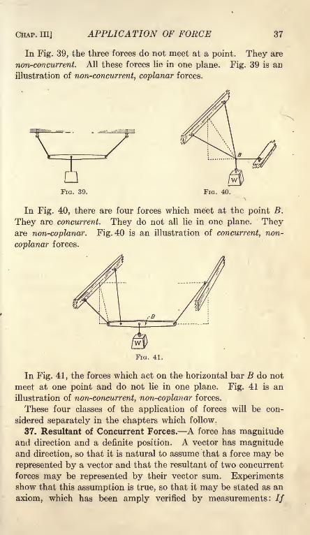
CHAP. Ill] APPLICATION OF FORCE 37
In Fig. 39, the three forces do not meet at a point. They are
non-concurrent. All these forces lie in one plane. Fig. 39 is an
illustration of non-concurrent, coplanar forces.
FIG. 39. FIG. 40.
In Fig. 40, there are four forces which meet at the point B.
They are concurrent. They do not all lie in one plane. Theyare non-coplanar. Fig. 40 is an illustration of concurrent, non-
coplanar forces.
In Fig. 41, the forces which act on the horizontal bar B do not
meet at one point and do not lie in one plane. Fig. 41 is an
illustration of non-concurrent, non-coplanar forces.
These four classes of the application of forces will be con-
sidered separately in the chapters which follow.
37. Resultant of Concurrent Forces. A force has magnitudeand direction and a definite position. A vector has magnitudeand direction, so that it is natural to assume that a force may be
represented by a vector and that the resultant of two concurrent
forces may be represented by their vector sum. Experimentsshow that this assumption is true, so that it may be stated as an
axiom, which has been amply verified by measurements: //

38 MECHANICS [ART. 38
two concurrent forces are represented by vectors, the resultant of the
forces is represented, in direction and magnitude, by the vector sumof these two vectors. The two vectors and their resultant form a
triangle, Fig. 42, II, which is called the force triangle. Theresultant force passes through the point at which the two forces
are concurrent, the point of Fig. 42, I.
Since the resultant of two concurrent
forces may be represented by their
vector sum, the resultant of three con-
^, -r -.j^ r current forces may be represented by\^ u the vector sum obtained by com-
FIG 42 bining the resultant of the first twoforces with the third force. The third
force may not be in the plane of the first two forces. When the
three forces are all in one plane, it is not necessary to draw the
resultant of the first two forces and then to draw the third
force. All three forces may be added at one time, as in Fig. 43.
The figure thus obtained is called the force polygon.
The vector sum of two vectors a and b may be drawn by addingvector b to vector a, or by adding vector a to vector b, as shownin Fig. 11. If the addition is made in both orders, each starting
from the same origin, the figure obtained is a parallelogram. For
this reason, the method of finding the resultant of two forces bymeans of their vector sum is often called the parallelogram law.
It is, however, entirely unnecessary to draw the parallelogram.The* single triangle, which is one-half of the parallelogram, is
sufficient. Moreover, the use of par-
allelograms causes confusion whenthree or more forces are involved in
the problem. It is best, therefore, to
consider the force triangle and the
force polygon, and to forget the
parallelogram.
The process of finding the resultant of two or more forces is
called the composition of forces, and the forces which make upthe resultant are called its components.
38. Resolution of Forces. The process of finding the compo-nents of a force is resolution of the force. The force is said to be
resolved into its components. The most important case of resolu-
tion is that in which the components are at right angles to each
other. There may be two components at right angles to each
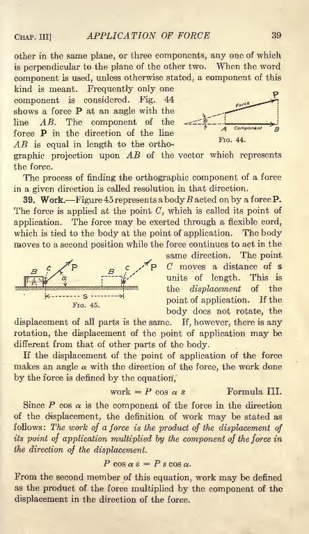
CHAP. Ill] APPLICATION OF FORCE 39
other in the same plane, or three components, any one of which
is perpendicular to the plane of the other two. When the word
component is used, unless otherwise stated, a component of this
kind is meant. Frequently only one
component is considered. Fig. 44
shows a force P at an angle with the
line AB. The component of the
force P in the direction of the line
AB is equal in length to the ortho-
graphic projection upon AB of the vector which represents
the force.
The process of finding the orthographic component of a force
in a given direction is called resolution in that direction.
39. Work. Figure 45 represents a bodyB acted on by a force P.
The force is applied at the point C, which is called its point of
application. The force may be exerted through a flexible cord,
which is tied to the body at the point of application. The bodymoves to a second position while the force continues to act in the
same direction. The point
C moves a distance of s
units of length. This is
the displacement of the
point of application. If the
body does not rotate, the
displacement of all parts is the same. If, however, there is any
rotation, the displacement of the point of application may be
different from that of other parts of the body.If the displacement of the point of application of the force
makes an angle a with the direction of the force, the work done
by the force is defined by the equation',
work = P cos a s Formula III.
Since P cos a is the component of the force in the direction
of the displacement, the definition of work may be stated as
follows : The work of a force is the product of the displacement of
its point of application multiplied by the component of the force in
the direction of the displacement.
P cos a s = P s cos a.
From the second member of this equation, work may be defined
as the product of the force multiplied by the component of the
displacement in the direction of the force.

40 MECHANICS [ART. 40
,
If the force is expressed in pounds and the displacement in
feet, the work is in foot-pounds. Other units of work are inch-
pounds, gram-centimeters, kilogram-meters, and ergs.
Both force and displacement are vectors. The product of twovectors may be a third vector, or may be a scalar quantity,which has magnitude but not direction. Work is a scalar prod-
uct, and is not a vector.
40. Classes of Equilibrium. There are three kinds of equilib-
rium. These are called stable, unstable, and neutral or indifferent.
Figure 46 shows three cases of stable equilibrium. When a bodyin stable equilibrium is displaced slightly from its position of
III
equilibrium by an additional force, it will return to that position
of equilibrium when the additional force ceases to act. In Fig.
46, I, the body is hung on a flexible cord. The body is in stable
equilibrium in position A. The cord is vertical and the center
of mass is directly under the point of support. If an additional
force is applied, which deflects the body to position B, it will
return to position A when the additional force is removed. In
the position of equilibrium the forces which act on the body are
its weight and the tension in the cord. When the body is
moved from position A to position B, no work is done by the
tension in the cord, since the displacement is perpendicular to
the direction of the force; negative work is done by the weight,
since the upward component of the displacement is opposite the
direction of the force of gravity. When a body in stable equi-

CHAP. Ill] APPLICATION OF FORCE 41
librium is displaced slightly, the original forces which produce
equilibrium do negative work, and positive work must be done bythe additional forces to cause the displacement.
Figure 46, II, shows a body on a smooth, curved surface which is
concave upward. The forces which produce equilibrium are the
weight of the body and the normal reaction of the surface. If
the surface is that of a sphere or circular cylinder, the conditions
are the same as those of a body suspended by a flexible cord.
Figure 46, III, shows a body suspended from a smooth hinge
and attached to a cord which runs over a smooth pulley andcarries a second body Q. If the body is displaced toward the
right, the weight W does negative work and the pull in the cord
does positive work. It may be shown that the negative work is
the greater, and that the equilibrium is stable.
Figure 47 shows three cases of unstable equilibrium. Figure
47, I, shows a body on a smooth curved surface which is concave
W
FIG. 47.
downward. If the body is moved slightly in either direction
from the position of equilibrium, it will not return, but will
continue to move in that direction. The vertical component of
the displacement is in the same direction as the force of gravity;hence its weight does positive work when it is moved from the
position of equilibrium.
Figure 47, II, shows a body supported on a smooth hinge which
directly under its center of mass. The motion is the same as

42 MECHANICS [AKT. 40
that of Fig. 47, I, when the surface is cylindrical. The body of
Fig. 47, II, will rotate about the hinge until its center of mass is
directly under the point of support. It will then be in stable
equilibrium in the position of Fig. 46, I. In like manner, the
body of Fig. 47, I, will move to the position of Fig. 46, II, pro-vided the surface is continuous, and there is some arrangement to
keep it from falling off when below the center.
Figure 47, III, is similar to Fig. 46, III, but the equilibrium is
unstable. If displaced, it will rotate to the position of stable
equilibrium of Fig. 46, III.
FIG. 48.
Figure 48 shows two cases of neutral equilibrium. The body re-
mains in equilibrium in any position. Figure 48, I, represents a
body on a smooth, horizontal plane surface. No work is done whenit is displaced, as the weight and the normal reaction of the sur-
face are both perpendicular to the direction of the displacement.
Figure 48, II, shows a body on a smooth inclined plane. The
body is supported by a cord which runs parallel to the plane and
exerts a constant pull Q. If the body is displaced on the plane,
the positive work of the force Q is, equal to the negative work of
the weight. If the body is displaced down the plane, the positive
work of the weight is equal to the negative work of the force Q.

A^r
CHAPTER IV
CONCURRENT CO-PLANAR FORCES
41. Resultant. If the direction and magnitude of each of
several forces is represented by a vector, the direction and mag-
nitude of the resultant of these forces will be represented by the
vector sum of these vectors. As stated in Art. 37, this statement
may be regarded as an axiom which has been amply verified by
experiment. If these forces are concurrent at a given point,
their resultant will pass through this point.
In Fig. 49, I, two flexible cords in a vertical plane are attached
to a beam at a point A. Each cord runs over a smooth pulley.
II III
FIG. 49.
The left cord makes an angle of 35 degrees to the left of the
vertical, and supports a mass of 8 pounds; the right cord makesan angle of 50 degrees to the right of the vertical, and supportsa mass of 12 pounds. If the pulleys are frictionless, the tension
of each cord at A will be equal to the mass which it supports.
Fig. 49, II, is the space diagram representing the direction andlocation of these forces, which are concurrent atA . Figure 49, III,
is the force polygon, which, in this case, is a triangle. To con-
struct the force triangle, point is selected as the origin and a
line is drawn through this point parallel to the direction of the
force of 12 pounds in the space diagram. A length of 12 units,
from to C, is measured in this line. The point C is the terminusof the vector which represents the 12-pound force. From Cas the origin, a second vector, 8 units in length, is drawn parallel
to the direction of the force of 8 pounds in the space diagram.43
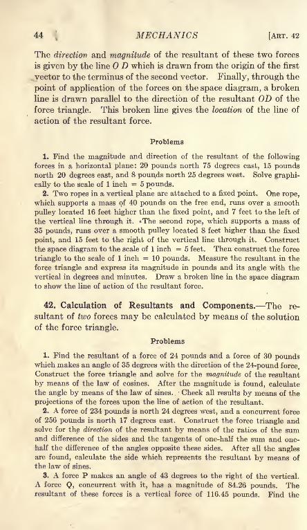
44 MECHANICS [ART. 42
The direction and magnitude of the resultant of these two forces
is given by the line D which is drawn from the origin of the first
vector to the terminus of the second vector. Finally, through the
point of application of the forces on the space diagram, a broken
line is drawn parallel to the direction of the resultant OD of the
force triangle. This broken line gives the location of the line of
action of the resultant force.
Problems
1. Find the magnitude and direction of the resultant of the following
forces in a horizontal plane: 20 pounds north 75 degrees east, 15 poundsnorth 20 degrees east, and 8 poun,ds north 25 degrees west. Solve graphi-
cally to the scale of 1 inch = 5 pounds.2. Two ropes in a vertical plane are attached to a fixed point. One rope,
which supports a mass of 40 pounds on the free end, runs over a smooth
pulley located 16 feet higher than the fixed point, and 7 feet to the left of
the vertical line through it. The second rope, which supports a mass of
35 pounds, runs over a smooth pulley located 8 feet higher than the fixed
point, and 15 feet to the right of the vertical line through it. Construct
the space diagram to the scale of 1 inch = 5 feet. Then construct the force
triangle to the scale of 1 inch = 10 pounds. Measure the resultant in the
force triangle and express its magnitude in pounds and its angle with the
vertical in degrees and minutes. Draw a broken line in the space diagramto show the line of action of the resultant force.
42. Calculation of Resultants and Components. The re-
sultant of two forces may be calculated by means of the solution
of the force triangle.
Problems
1. Find the resultant of a force of 24 pounds and a force of 30 poundswhich makes an angle of 35 degrees with the direction of the 24-pound force.
Construct the force triangle and solve for the magnitude of the resultant
by means of the law of cosines. After the magnitude is found, calculate
the angle by means of the law of sines. Check all results by means of the
projections of the forces upon the line of action of the resultant.
2. A force of 234 pounds is north 24 degrees west, and a concurrent force
of 256 pounds is north 17 degrees east. Construct the force triangle andsolve for the direction of the resultant by means of the ratios of the sumand difference of the sides and the tangents of one-half the sum and one-
half the difference of the angles opposite these sides. After all the anglesare found, calculate the side which represents the resultant by means of
the law of sines.
3. A force P makes an angle of 43 degrees to the right of the vertical.
A force Q, concurrent with it, has a magnitude of 84.26 pounds. Theresultant of these forces is a vertical force of 116.45 pounds. Find the

CHAP. IV] CONCURRENT CO-PLANAR FORCES 45
direction of the force Q and the magnitude of the force P, using logarithms.
Construct the force triangle to the scale of 1 inch = 20 pounds and comparewith the calculated results.
4. The resultant of two forces of 16 pounds and 24 pounds in a horizontal
plane is a force of 34 pounds north 10 degrees east. Find the direction of
the forces by means of the formula for the tangent of the half angle.
When it is desired to find the resultant of more than two forces,
the method of calculation by means of triangles is laborious.
To solve such problems each force is resolved along the direction
of two axes which are at right angles to each other. The sumof the components of all these forces along one axis is the compo-nent of the resultant along that axis, and the sum of the compo-nents of all these forces along the other axis is the component of the
resultant along that axis. These two components of the resul-
tant form two sides of a right-angled triangle of which the resul-
tant is the hypotenuse. When the resultant of several forces is
to be found, the work may be arranged in tabular form, as wasshown in Problem 4 of Art. 17.
Problems
5. A horizontal force of 25 pounds is north 37 degrees east, Find theeast and north components.
Ans. East component = 15.05 Ib.;north component = 19.97 Ib.
6. A horizontal force of 46 pounds is north 22 degrees west. Find the
component north and the component east.
Ans. East component = 17.23 Ib.; north component = 42.65 Ib.
7. A force of 24 pounds makes an angle of 20 degrees with the horizontal.
A concurrent force of 30 pounds in the same vertical plane makes an angleof 64 degrees with the horizontal on the same side of the vertical. Find thesum of the horizontal and the sum of the vertical components.
Ans. H = 35.70 Ib.; V = 35.17 Ib.
8. Find the direction and magnitude of the resultant of the two forces of
Problem 7.
9. Solve Problem 8 by resolving along the line of the force of 24 poundsand along a line perpendicular to the force of 24 pounds in the same vertical
plane.
10. Find the direction and magnitude of the resultant of 14 pounds north27 degrees east, 15 pounds north 35 degrees west, and 18 pounds south56 degrees west. Resolve east and north then check by resolutions alongsome other pair of axes.
11. Solve Problem 1 of Art. 41 by means of resolutions, and comparethe results with the graphical solution.
12. Solve Problem 2 of Art. 41 and compare the results with the graphicalsolution.
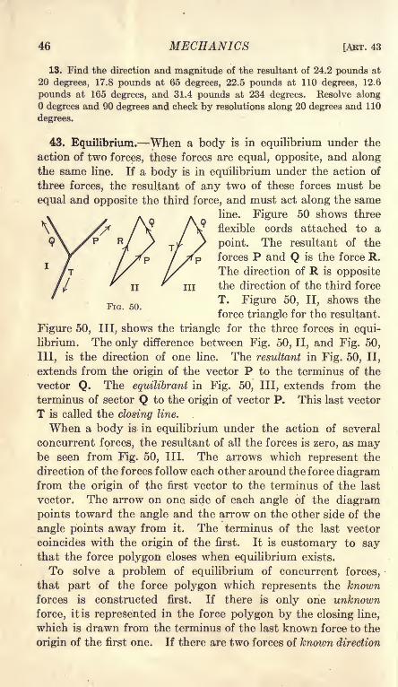
46 MECHANICS [ART. 43
13. Find the direction and magnitude of the resultant of 24.2 pounds at
20 degrees, 17.8 pounds at 65 degrees, 22.5 pounds at 110 degrees, 12.6
pounds at 165 degrees, and 31.4 pounds at 234 degrees. Resolve along
degrees and 90 degrees and check by resolutions along 20 degrees and 110
degrees.
43. Equilibrium. When a body is in equilibrium under the
action of two forces, these forces are equal, opposite, and alongthe same line. If a body is in equilibrium under the action of
three forces, the resultant of any two of these forces must be
equal and opposite the third force, and must act along the same
line. Figure 50 shows three
flexible cords attached to a
point. The resultant of the
forces P and Q is the force R.
The direction of R is opposite
II^
ill the direction of the third force
5QT. Figure 50, II, shows the
force triangle for the resultant.
Figure 50, III, shows the triangle for the three forces in equi-
librium. The only difference between Fig. 50, II, and Fig. 50,
111, is the direction of one line. The resultant in Fig. 50, II,
extends from the origin of the vector P to the terminus of the
vector Q. The equilibrant in Fig. 50, III, extends from the
terminus of sector Q to the origin of vector P. This last vector
T is called the closing line.
When a body is in equilibrium under the action of several
concurrent forces, the resultant of all the forces is zero, as maybe seen from Fig. 50, III. The arrows which represent the
direction of the forces follow each other around the force diagramfrom the origin of the first vector to the terminus of the last
vector. The arrow on one side of each angle of the diagram
points toward the angle and the arrow on the other side of the
angle points away from it. The terminus of the last vector
coincides with the origin of the first. It is customary to saythat the force polygon closes when equilibrium exists.
To solve a problem of equilibrium of concurrent forces,
that part of the force polygon which represents the knownforces is constructed first. If there is only one unknown
force, it is represented in the force polygon by the closing line,
which is drawn from the terminus of the last known force to the
origin of the first one. If there are two forces of known direction

CHAP. IV] CONCURRENT CO-PLANAR FORCES 47
but of unknown magnitude, a line is drawn through the terminus of
the last known vector in the direction of one of these unknown
forces, and a line is drawn through the origin of the first known
vector in the direction of the other unknown force. The length
of each of these lines to their point or intersection represents the
required force.
Example
A 40-pound mass rests on a smooth inclined plane, which makes an angle
of 35 degrees with the horizontal. It is supported by a horizontal push of
12 pounds, and a pull P parallel to the plane. Find the force P and the
normal reaction.
Figure 51, I, is the space diagram showing the direction of all the forces.
The mass of 40 pounds is the free body in equilibrium. The arrows show
the direction of the forces
which act from other bodies
on the free body. The reac-
tion of the plane is upward at
an angle of 35 degrees with
the vertical. The pull of the
earth on the free body is a
downward force of 40 pounds.The length of the lines in this
diagram is not necessarily pro-
portional to the magnitude of FlG 51the forces.
Figure 51, II, is the force polygon. The known forces are 40 pounds down-
ward and 12 pounds horizontal toward the right. As the first step in the
construction of the force polygon lay off AB 40 units in length. From Bdraw the horizontal line BC 12 units in length. The arrow in AB is down-ward toward B, and the arrow in BC is to the right, directed away from B.
Through C draw a line parallel to the force P of the space diagram, and
through A draw a line parallel to the direction of the normal reaction. Ex-
tend these two lines till they intersect at D. The length of CD measures
the tension parallel to the inclined plane, and the length of DA represents
the normal reaction of the plane against the 40-pound mass. The arrow
in BC is toward C. The arrow in CD must by away from C toward D; the
corresponding direction in the space diagram is up the plane. The arrow
in DA is from D toward A.
Problems
1. Solve the example above graphically to the scale of 1 inch = 10 pounds,with the horizontal force 20 pounds instead of 12 pounds.
2. A 20-pound mass on a 35 degree inclined plane is held in equilibrium
by a horizontal push of 5 pounds, and by a pull at an angle of 40 degreeswith the horizontal and an angle of 5 degrees with the plane. Solve for
this pull and the normal reaction to the scale of 1 inch = 5 pounds.
isib.

48 MECHANICS [AET. 44
3. A 50-pound mass is supported by 3 cords in the same vertical plane.
One cord makes an angle of 45 degrees to the left of the vertical. Thesecond cord makes an angle of 30 degrees to the right of the vertical. Thethird cord runs horizontally toward the right and exerts a pull of 10 pounds.Find the tension in the first two cords, graphically, to the scale of 1 inch =10 pounds.
4. A 40-pound mass is supported by two cords, one of which makes an
angle of 35 degrees to the right of the vertical, and the other exerts a pull of
25 pounds. Find the direction of the second cord and the tension in the
first one, graphically, to the scale of 1 inch = 10 pounds. There are two
solutions. Are both solutions possible with cords?
6. A 40-pound mass is supported by a cord and a rod hinged at the ends.
One of these makes an angle of 24 degrees to the right of the vertical, and
the other makes an angle of 85 degrees to the right of the vertical. Find
the tension in the cord and the compression in the rod.
I*44. Equilibrium by Resolutions. The force diagram for con-
current, coplanar forces in equilibrium is a closed polygon.
If a closed polygon is projected upon any line in its plane, the
sum of the positive projections is equal to the sum of the nega-
tive projections, and the total projection is zero. It follows,
therefore, that when a set of forces are in equilibrium, the sum of
FIG. 52.
the components of these forces along any direction is zero.
Fig. 52, I, is the space diagram for Problem 3 of Art. 43 and
OA SCO, in Fig. 52, II, is the force polygon. Figure 52, III, shows
the projections of the sides of the force pfcftygon upon a line at an
angle of 10 degrees with the horizontal. The projections O'A',
A'B', and B'C', extend from left to right. The projection C'O',
extends from right to left to the point of beginning.
To solve a problem of equilibrium of concurrent forces by resolu-
tions, it is not necessary to draw the force polygon, as the com-
ponents may be calculated from the space diagram. However,

CHAP. IV] CONCURRENT CO-PLANAR FORCES 49
always draw the space diagram and mark all the forces which act
on the free body.
Figure 53 shows the space diagram for four forces PI, P2 , PS,
and P 4 ,which make angles i, a 2 , <*3, and 4 , respectively, with the
FIG. 53.
horizontal line toward the right. The point at which the forces
meet is the free body. The components along the horizontal are
PI cos a i} P2 cos 2 ,etc. If the forces are in equilibrium,
Pi COS i -f P 2 COS Q! 2 + P 3 COS 0:3 + P COS 4 a 4= 0. (1)
If the forces of Fig. 53 make angles 0i, 02, #3 ,and 4 with a
second axis, the second condition of equilibrium is
Pi cos 0i -f P 2 cos /3 2 + P 3 cos 03*+ P4 cos 4= 0. (2)
Any number of equations may be written by changing the
direction of the axis of resolution. Since it will be shown later
that only two such equations can be independent, nothing is
gained by writing more than that number.
Example
A 40-pound mass is supported by three flexible cords in the same vertical
plane. One cord makes an angle of 35 degrees to the left of the vertical
and exerts an unknown pull of P pounds. A second cord makes an angleof 25 degrees to the right
of the vertical and exerts
an unknown pull of Qpounds. The third cord
makes an angle of 80 de-.
grees to the right of the
vertical and exerts a pull
of 10 pounds. Find the
unknown forces by reso-
lutions.
The point 0, Fig. 54, I,
at which all these cords
meet, is the free body in equilibrium. Resolving horizontally and consider-
ing components toward the right positive components,
10 cos 10 + Q sin 25 - P sin 35 = 0, (3)
FIG

50 MECHANICS [AKT. 44
Resolving vertically and considering upward components positive,
10 sin 10 + Q cos 25 + P cos 35 = 40. (4)
Substituting the values of the trigonometric functions and transposing,
0.4226Q - 0.5736P = - 9.848 (5)
0.9063Q + 0.8192P = 40 - 1.736 = 38.264 (6)
To eliminate Q multiply Equation (5) by 0.9063 and Equation (6) by 0.4226,and subtract.
0.4226 X 0.9063Q - 0.5199P = -8.925,. 4226 X . 9063Q + . 3462P = 16 . 170,
0.8661P = 25.095,P = 28.97 Ib.
Substituting the value of P in Equation (5),
0.4226 Q = 28.97 X 0.5736 - 9.848 = 16.617 - 9.848 = 6.769.
Q = 16.02 Ib.
This method of horizontal and vertical resolution involves two unknownsin each equation. Since the coefficients of these unknowns are sines andcosines taken to four significant figures, considerable labor is required in
order to eliminate one unknown and solve the equations. It is better to
make the resolutions in such a way that one equation will contain only one
unknown. This may be done by resolving perpendicular to the direction
of the other unknown force, since the component of a force along a line
perpendicular to its direction is zero. In the above example resolve alongthe broken line of Fig. 54, II, which is perpendicular to the direction of Q.Since the force Q makes an angle of 25 degrees with the vertical, this line
perpendicular to Q makes an angle of 25 degrees with the horizontal. Onthe right, this line makes an angle of 35 degrees with the direction of the
10-pound force and an angle of 65 degrees with the vertical line of the weight.On the left it makes an angle of 30 degrees with the direction of the force P.
Giving the positive sign to the component toward the left, and putting the
negative terms on the right of the equality sign,
P cos 30 = 10 cos 35 + 40 sin 25, (7)
0.866 P = 10 X 0.8192 + 40 X 0.4226, (8)
0.866 P = 8.192 + 16.904 = 25.096,
P = 28.98.
The force Q may now be calculated by a resolution perpendicular to the
force P, or by substitution in Equation (5). After both P and Q are found,
both may be checked by substitution in Equation (6),
LO X 0.1.736 = 1.736
16.03 X 0.9063 = 14.528
28.98 X 0.8192 = 23.740
40.004 - 40 = 0.004.

CHAP. IV] CONCURRENT CO-PLANAR FORCES 51
Problems
(Draw the space diagram for each problem. Mark each force which acts on
the free body.)
1. A 60-pound mass is suspended by two cords, one of which makes an
angle of 32 degrees to the left of the vertical, and the other makes an angle
of 27 degrees to the right of the vertical. Find the tension in each cord
by a resolution perpendicular to the other cord, and check by a vertical
resolution. Ans. 31.78 Ib. at 32; 37.09 Ib. at 27.
2. A 40-pound mass is held on a smooth inclined plane, which makes an
angle of 27 degrees with the horizontal, by means of a cord parallel to the
plane. Find the tension in the cord by a resolution parallel to the plane,
and find the normal reaction of the plane. Check both by a vertical resolu-
tion. Ans. 18.16 Ib. tension; 35.64 Ib. normal pressure.
3. A 40-pound mass is held on a smooth inclined plane, which makes an
angle of 27 degrees with the horizontal, by means of a cord, which makes
an angle of 40 degrees with the horizontal. Find the tension in the cord
and the normal reaction and check.
Ans. 18.64 Ib. tension; 31.45 Ib. normal pressure.
4. A mass of m pounds is held on a smooth inclined plane, which makes
an angle 6 with the horizontal, by means of a cord parallel to the plane.
Find the tension in the cord and the normal reaction of the plane by resolu-
tions parallel and perpendicular to the plane, and check by a resolution
vertical. Ans. Tension = m sin 6; normal = m cos 0.
6. A mass of m pounds is held on a smooth inclined plane, which makes
an angle 6 with the horizontal, by means of a horizontal cord. Find the
tension in the cord and the normal reaction, and check.
Ans. Tension = m tan 6; normal"
6. Figure 55 shows a rod AB, 8 feet
in length, which is hinged at B and sup-
ported in a horizontal position by a cord at
A. The cord is fastened to a point C,
which is 6 feet above the hinge B. A 60-
pound mass is suspended from A. Neg-
lecting the weight of the rod, and regard-
ing all forces as concurrent at A, find the
tension in the cord and the horizontal
reaction in the rod. Solve by vertical
and horizontal resolutions, and check by a
resolution parallel to the cord.
When a force is unknown, both as to direction and magnitude,it is best to consider this force as made up of two componentsat right angles to each other, and find the magnitude of eachof these components separately. Next find the direction and
magnitude of their resultant, which is the force required. Thismethod is the same as the one for finding the resultant of a set
of concurrent forces.

52 MECHANICS [ART. 44
Example
A 50-pound mass is supported by two cords, one of which makes an angle
of 75 degrees to the right of the vertical and exerts
a pull of 30 pounds. Find the direction of the second
cord and the tension which it exerts.
In Fig. 56, the unknown force Q at an unknown
angle 6 with the vertical may be regarded as made
up of a horizontal component H and a vertical
component V. Resolving horizontally,
H = 30 cos 15 = 30 X 0.9659 = 28.977.
FIG. 56. Resolving vertically,
V = 50 - 30 sin 15 = 50 - 30 X 0.2588 = 50 - 7.764 =42.236,
6 = 34 27',
_ 42.236 _ 42.236 _y "~^oiY 08246
Check by resolving parallel to Q,
50 cos 34 27' + 30 sin 19 27' = Q,
50 X 0.8246 = 41.23
30 X 0.3330 = 9.99
51.22 = Q
Problems
7. A mass of 80 pounds is supported by three cords in the same vertical
plane. One cord exerts a pull of 20 pounds in a horizontal direction toward
the right. The second cord makes an angle of 35 degrees to the right of the
vertical and exerts a pull of 50 pounds. Find the direction of the third
cord and the tension which it exerts. Check.
8. A 50-pound mass is supported by two cords, one of which makes an
angle of 38 degrees to the right of the vertical, and the other exerts a pull
of 35 pounds. Find the tension in the first cord, and the direction of the
second. Check the results.
Ans. 23 35' or 80b 25' with the vertical; 22.74 Ib. or 56.06 Ib.
9. A mass of 100 pounds is supported by two cords, each of which makesan angle of 55 degrees with the vertical. Find the tension in each by tworesolutions. Check.
10. Solve Problem 9 when each cord makes an angle of 80 degrees with
the vertical. Check by means of the force triangle drawn to the scale of
1 inch = 40 pounds.11. A mass of 80 pounds is supported by two cords, one of which exerts
a pull of 60 pounds; the other exerts a pull of 50 pounds. Find the direction
of each cord by horizontal and vertical resolutions.
Ans. The cord which pulls 60 pounds makes an angle of 38 38' with the
vertical. The other cord makes an angle of 48 31' with the vertical.

CHAP. IV] CONCURRENT CO-PLANAR FORCES 53
45. Trigonometric Solution. When three concurrent forces
are in equilibrium, the force polygon is a triangle. It is some-
times convenient to draw this triangle and calculate the un-
known forces or directions trigonometrically. This method is
especially desirable when two of the forces are perpendicular
to each other so that the force polygon is a right-angled triangle.
It is the best method when the forces are expressed literally in-
stead of numerically. When the forces form an oblique-angled
triangle, and the known forces are given in numbers, the methodof resolutions is better.
Example
A 40-pound mass is supported by two cords, one of which is horizontal
and exerts a pull of 16 pounds. Find the direction of the second cord andthe tension which it exerts.
The force triangle, Fig. 57, is a right-
angled triangle of base 16 and altitude
40. Tan =0.4, P = 40 sec 6.
Problems
(In these problems draw the space
diagram and the force diagram. Unless
it is desired to check by means of the
graphical solution, it is not necessary
that these diagrams be drawn to scale.
The force diagram must be drawn sepa-
rate from the space diagram. )
1. Selve Problem 2 of Art. 44 by the trigonometric solution of the force
triangle.
2. Solve Problem 6 of Art. 44 by means of the force triangle.
3. Solve Problem 1 of Art. 44 by means of the oblique-angled force
triangle. Use the law of sines. Is the method shorter than that of tworesolutions?
/ 4. A mass of m pounds is held on a smooth inclined plane, which makesan angle a with the horizontal, by a rope which makes an angle ft with the
horizontal. Find the tension in the rope and the normal reaction by meansof the solution of the force triangle.
40 I b. 16 Ib.
FIG. 57.
Ans. Tension = _-==r-
cos (a /3)
;normal
m cos
cos (a j8)
It sometimes happens that the force triangle is similar to a
triangle of the space diagram. In that case the magnitudes of the
forces are proportional to the corresponding lengths in the space
diagram.
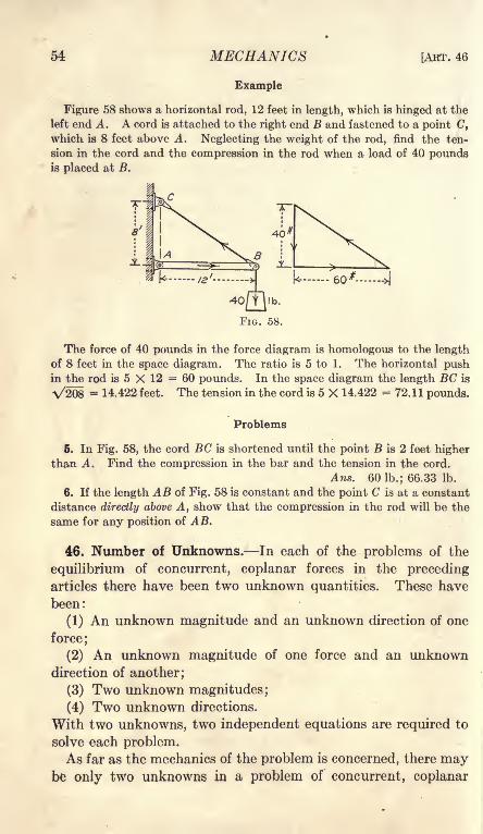
54 MECHANICS
Example
[ART. 46
Figure 58 shows a horizontal rod, 12 feet in length, which is hinged at the
left end A. A cord is attached to the right end B and fastened to a point C,
which is 8 feet above A. Neglecting the weight of the rod, find the ten-
sion in the cord and the compression in the rod when a load of 40 poundsis placed at B.
The force of 40 pounds in the force diagram is homologous to the lengthof 8 feet in the space diagram. The ratio is 5 to 1. The horizontal pushin the rod is 5 X 12 = 60 pounds. In the space diagram the length BC is
A/208 = 14.422 feet. The tension in the cord is 5 X 14.422 =72.11 pounds.
Problems
6. In Fig. 58, the cord BC is shortened until the point B is 2 feet higherthan A. Find the compression in the bar and the tension in the cord.
Ans. 60 lb.; 66.33 Ib.
6. If the length AB of Fig. 58 is constant and the point C is at a constant
distance directly above A, show that the compression in the rod will be the
same for any position of AB.
46. Number of Unknowns. In each of the problems of the
equilibrium of concurrent, coplanar forces in the preceding
articles there have been two unknown quantities. These have
been:
(1) An unknown magnitude and an unknown direction of one
force;
(2) An unknown magnitude of one force and an unknowndirection of another;
(3) Two unknown magnitudes;
(4) Two unknown directions.
With two unknowns, two independent equations are required to
solve each problem.As far as the mechanics of the problem is concerned, there may
be only two unknowns in a problem of concurrent, coplanar

CHAP. IV] CONCURRENT CO-PLANAR FORCES 55
forces in equilibrium. This may be shown in several ways. If
the problem is solved by resolutions, only two equations can be
written which are independent of each other. Fig. 59 shows a
force AB. Its orthographic component along a direction OC is
the length A\Bi. Its orthographic component along another
direction OD is the length A 2B 2 . If a third orthographic com-
ponent were drawn, its length could be expressed in terms of
AiBi, A 2B 2 ,and the angles. Consequently,
if three equations were written for a problemof concurrent, coplanar forces, any one of
these equations could be derived algebraically
from the other two, and would not be inde-
pendent. Since there can be only two inde-
pendent equations for a problem of concurrent,* B,
coplanar forces, it is evident that there maybe only two unknowns, unless conditions are given which are
not based upon mechanics.
The number of possible unknowns may be determined in a
different way from the geometry of the force polygon. All the
known forces may be represented in the force diagram by the
single vector of their resultant. The problem of equilibrium
involves the solution of a polygon of which this resultant vector
is one side. This polygon is a triangle for all problems which
may be solved from mechanical considerations. A triangle maybe solved in the following cases:
1. One side and two angles given, with the length of two sides
unknown.
2. Two sides and the included angle given, with the magnitudeand direction of the third side unknown.
3. One side given together with the length of a second side
and the direction of the third side. The length of one side and
the direction of another are unknown.
4. The length of all sides given, with two directions unknown.
Some of these cases apparently have three unknowns. Whentwo angles of a triangle are given, the third angle is regarded
as known.
It is evident from the foregoing statements that a problem of
the equilibrium of concurrent, coplanar forces may have onlytwo unknown quantities. Sometimes it happens that there is a
greater number of unknowns. Such a problem can not be solved
completely unless additional conditions are given.

56 MECHANICS [ART. 47
Example
A body is in equilibrium under the action of three forces. These are:
a force of 40 pounds horizontally toward the right, a force P at ^n angle of
25 degrees to the left of the vertical, and a force Q of unknown direction
and magnitude.There are three unknowns, and an attempt at a graphical solution, Fig.
60, shows that it may be solved in an infinite number of ways. Another
condition must be added to make the problem definite. Let the force Qof unknown direction be twice as great as the force P at 25 degrees to the left
of the vertical. This is an additional algebraic condition which does not
depend upon mechanics.
Q = 2P (1)
Resolving horizontally and vertically,
P sip 25 + 2P sin = 40, (2)
P cos 25 = 2P cos 8, (3)
cos 25 0.9063cos e 0.4531.
Problems
1. In Fig. 60, let the force Q be three times the force P. Find the mag-nitude of each force and the direction of Q.
Ans. P = 12.19 lb.; Q = 36.57 Ib.
2. Solve Problem 1 graphically.
3. A body is in equilibrium under
the action of four forces. These are:
a force of 40 pounds at degrees, a
force Q at 110 degrees, a force P at 245
degrees, and a force equal to Q at 180
degrees. Solve graphically.
47. Moment of a Force. Figure 61 shows a bar OB, which is
hinged at and has a load P applied at B. The load tends to
turn the bar about the hinge,
and does turn it unless it is
balanced by a second force
tending to turn in the oppo-
site direction. In Fig. 61,
I, the turning effect of the
force is greater than in the
position of Fig. 61, II. In
the position of Fig. 61, III,
the force has no tendency to
turn the bar about the hinge.
In the other positions, the force P is said to exert a moment
on the bar about the hinge. The point about which moment
III
>
FIG. 61.

CHAP. IV] CONCURRENT CO-PLANAR FORCES
is taken is called the origin of moments or the center of
moments. r
Definition^-The moment of a force about a point in its plane is
the product of the magnitude of the force multiplied by the perpendicu-
lar distance from the point to the line along which the force acts.
In Fig. 61, the moment of the force P is the product of the
force multiplied by the length OC. If the force is measured in
pounds and the distance in feet, the moment is expressed in
foot-pounds. To distinguish moment from work, some writers ^use pound-feet for moment and foot-pounds IO^W-I^Hfor work. Though this distinction is desirable, Pi ee\f
*tfa&*
it has not come into general use. *&''' ^~- *The perpendicular distance from the origin tfs&
B-e.- >o^J*
of moments to the line of action of the force is
the effectiyejrioment arm. The length OB, from o^.crs-
n. & ..>( fi^^-Py
the origin of moments to the point of appli-
cation of the force, may be called the apparentmoment arm. If the length of the apparent mo-
ment arm is a, Fig. 62, and the angle between
its direction and the direction of the force is a,
effective arm = a sin a (1) FlG 62moment = P X a sin a. Formula IV
Counter-clockwise moment is generally regarded as positive,
especially in works of mathematical nature; and clockwise
moment is regarded as negative. In algebraic equations, mo-ment will be represented in this book, by M.
Problems
1. A force of 60 pounds, at an angle of 25 degrees to the right of the ver-
tical, is applied to the right end of a bar, which is 3 feet in length. The bar
makes an angle of 80 degrees to the right of the vertical. Find the momentof this force about the left end of the bar.
Ans. M = 147.45 foot-pounds.2. A force of 12 pounds, at an angle of 20 degrees to the left of the vertical,
is applied to a point whose coordinates are (4, 3). Find the moment of
this force about the origin of cobrdinates.
Ans. M = 57.42 foot-pounds.3. Solve Problem 2 if the force is at an angle of 20 degrees to the right of
the vertical.
By changing the order of the letters of Formula IV, it may be
written,
M = P sin a X a. (2)

58 'MECHANICS [ART. 48
The term P sin a is the component of the force perpendicular to
the direction of the apparent moment arm. Equation (2) gives
this second definition of moment : The moment of a force is the
product of the apparent arm multiplied by the component of the
force which is perpendicular to it.
The first definition states that moment is the entire force
multiplied by the component of the arm; the second definition
states that moment is the product of the entire arm multiplied
by the component of the force.
Since force and apparent arm are vectors, moment is the prod-
uct of two vectors. It will be shown in Art. 108 that this product
is a vector.
48. Moment of Resultant. If PI, P2 , PS, etc. are forces which
make angles ai, a 2 , s, etc. with the apparent arm of length a,
the sum of the moments of all these forces about the origin is
M = PI sin aia + P2 sin a za + P 3 sin a3a = (Pi sin i +P2 sin a 2 + PS sin a 3)a. The term PI sin i + P2 sin 2 +
'
P3 sin as + etc. in the above equation is the component of the
resultant force perpendicular to the apparent arm; conse-
quently, the moment of the resultant of several concurrent forces is
equal to the sum of the moments of separate forces.
When the moment of a force is calculated by means of the com-
ponent perpendicular to the apparent arm, it is really calculated
by means of the moment of two components at right angles to
each other. From Fig. 62, II, the second component is P cos a
in the direction of the apparent arm. Since the line of action of
this component passes through the origin of moments, its mom-ent is zero. The total moment is, then, the moment of the com-
ponent normal to the apparent arm.
It is often advisable to resolve both the force and the apparent
arm into components. This method is especially convenient
when the coordinates of the ends of the apparent arm are given
instead of its length and direction.
Example
A force of 40 pounds at an angle of 25 degrees to the left of the vertical
is applied at the point whose coordinates are (6, 2). Find the moment of
this force about the origin of coordinates.

CHAP. IV] CONCURRENT CO-PLANAR FORCES 59
First method.
The apparent moment arm is OB, Fig. 63.
OB = 6.325 ft.
Tan 6 = *;6 =18 26'.
OC = OB cos (25-
9) = OB cos 6 34' = 6,325 X 0.9934 = 6.283 ft.
M = 40 X 6.283 = 251.32 foot-pounds.
40
Second method.
Resolving horizontally, Fig. 63, II,
H = 40 X 0.4226 = 16.904.
Resolving vertically,
V = 40 X 0.9063 = 36.252. > \
The effective arm of the horizontal component is the vertical length of 2
feet. The effective arm of the vertical component is the horizontal distance
of 6 feet. Both components turn counter-clockwise.
16.904 X 2 = 33.80836. 252 X 6 = 217.512
251.320 foot-pounds.
Problems
1. Solve the example above if the force makes an angle of 25 degrees to
the right of the vertical.
2. A force of 50 pounds at an angle of 15 degrees to the right of the vertical
is applied at the point (5, 4). Find the moment of this force about the
origin of coordinates, and also about the point (2, 2).
A force may be regarded as applied at any point along its
line of action. The effective moment arm in Fig. 63, III, is the
same, whether the force is applied at B or D, or at any other
point along its line. If the force of 40 pounds be regarded as
applied at D, on the axis of X, the moment about is the productof the length OD multiplied by the vertical component of the
force.
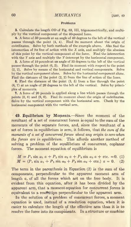
60 MECHANICS [ART. 49
Problems
3. Calculate the length OD of Fig. 63, III, trigonometrically, and multi-
ply by the vertical component of the 40-pound force.
4. A force of 50 pounds at an angle of 40 degrees to the left of the vertical
passes through the point (4, 4). Find its moment about the origin of
coordinates. Solve by both methods of the example above. Also find the
intersection of its line of action with the X axis, and multiply the abscissa
of this point by the vertical component of the force. Find the intersection
with the y axis and multiply the F-intercept by the horizontal component.5. A force of 10 pounds at an angle of 35 degrees to the left of the vertical
passes through the point (6, 5). Find its moment with respect to the point
(2, 2). Solve by means of the horizontal and vertical components. Solve
by the vertical component alone. Solve by the horizontal component alone.
Find the distance of the point (2, 2) from the line of action of the force.
6. Find the distance of the point (3, 5) from a line through the point
(6, 7) at an angle of 20 degrees to the left of the vertical. Solve by princi-
ples of moments.
7. A force of 20 pounds is applied along a line which passes through the
points (0, 6) and (8, 0). Find its moment about the origin of coordinates.
Solve by the vertical component with the horizontal arm. Check by the
horizontal component with the vertical arm.
49. Equilibrium by Moments. Since the moment of the
resultant of a set of concurrent forces is equal to the sum of the
moments of the separate forces, and, since the resultant of a
set of forces in equilibrium is zero, it follows, that the sum of the
moments of a set of concurrent forces about any origin is zero when
the forces are in equilibrium. This affords another method of
solving a problem of the equilibrium of concurrent, coplanarforces. The moment equation of equilibrium is
M = PI sin ai a + P2 sin a 2 a- + PS sin a 3 a + etc. =0'. (1)
M (Pi sin ai + P% sin a 2 + PS sin a 3 + etc.) a = 0. (2)
The term in the parenthesis in Equation (2) is the sum of the
components, perpendicular to the apparent moment arm of
length a, of all the forces which act on the free body. It is
evident from this equation, after it has been divided by the
apparent arm, that a moment equation for concurrent forces is
equivalent to a resdhitipn perpendicular to the apparent arm.
In the solution of a problem of concurrent forces, a moment
equation is used, instead of a resolution equation, when it is
easier to calculate the length of the effective arm than it is to
resolve the force into its components. In a structure or machine

CHAP. IV] CONCURRENT CO-PLANAR FORCES 61
FIG. 64.
the effective force may often be measured directly. Figure 64
represents a bar hinged at and supporting a load P at B. The
bar is supported by a cord at B. It is desired to find the tension
in this cord. The three forces at B are the load P, the tension in
the cord T, and the compression along the bar. If moments are
taken about the hinge 0, the line of action of the compression in
the bar passes through this point so that its moment is zero.
The moment of T in a counter-clock-
wise direction must be equal to the
moment of P in a clockwise direc-
tion. The effective moment arm of
T is the length OD, measured from
perpendicular to the direction of the
cord. The moment arm of P is the
perpendicular distance from the hinge
to its line of action the length OC of
Fig. 64. To find the perpendicular
distance from a point to a straight
line, it is only necessary to measure
the shortest distance. This may be
done with a tape-line or rule. In the actual machine or struc-
ture, it is much easier to measure these lengths than it is to
determine the angles necessary for resolution equations.
The moment equation for Fig. 64 is
T X OD = P X OC (3)
To find the compression in the bar of Fig. 64, moments may be
taken about some point in the line of the cord. The point Gmay well be used as the center of moments.
Problems
1. A mass of 200 pounds is suspended by two cords, which are fastened
to the mass at a point A. One cord is attached to a fixed point, which is
5 feet higher than A and 8 feet to the left of the vertical line through it.
The second cord is attached to another point, which is 7 feet higher thanA and 4 feet to the right of the vertical line through it. Draw the space
diagram to scale. Find the tension in the left cord by moments about some
point in the line of the right cord, measuring the moment arms from the
drawing. Then find the tension in the right cord by moments about some
point in the line of the left cord. Check by moments about a point directly
over the load.
2. A 40-pound mass is supported by two cords, one of which is horizontal
and the other makes an angle of 23 degrees with the vertical. Find the

62 MECHANICS [ART. 50
tension in the horizontal cord by moments about some point in the line of
the other cord, computing the effective arm trigonometrically. Find the
tension in the other cord by resolutions.
3. In an arrangement similar to Fig. 64 the bar is weightless, is 6 feet
long, and makes an angle of 25 degrees with the horizontal. The cord is
attached to a fixed point E which is 5 feet above the hinge O. Draw the
space diagram to the scale of 1 inch = 1 foot. With the hinge as the origin
of moments, measure the effective arms on the space diagram and calculate
T when the load P is 60 pounds. Find the compression in the bar with
the origin of moments at G, at a distance of 1 foot from E. Also solve for
the compression with the origin of moments at E.
4. Solve Problem 3 by moments, calculating the arms instead of measuringthem.
5. Solve Problem 6 of Art. 44 by moments.
50. Conditions for Independent Equations. In a problem of
concurrent, coplanar forces there are two independent equations.
These may be :
(1) Two resolution equations;
(2) Two moment equations;
(3) One resolution equation and one moment equation.
A moment equation is equivalent to a resolution perpendicularto the line joining the origin of moments to the point of applica-
tion of the forces. If two moment equations are written, and
the line joining the point of application of the forces with one
origin of moments passes through the other origin of moments,the equations will not be independent. Each moment equationwill be equivalent to a resolution perpendicular to this line.
After the equations have been divided by the lengths of the
apparent moment arms, they are identical. When two
moment equations are written for a problem of concurrent, coplanar
forces, the two origins of moment and the point of application of the
forces must not lie in the same straight line. When one resolution
and one moment equation are written, the resolution must not be
perpendicular to the line joining the origin of moments with the
point of application of the forces.
A resolution perpendicular to the direction of an unknown force
eliminates that force. A moment about a point in the line of
action of an unknown force eliminates that force.
61. Connected Bodies. It frequently happens that two points,
each of which is subjected to a set of concurrent forces, are con-
nected together by a single member, such as a cord or hinged rod.

CHAP. IV] CONCURRENT CO-PLANAR FORCES 63
40'
FIG. 65.
Each point is in equilibrium under the action of the external
forces and of the force in the connecting member.
In Fig. 65, the forces are concurrent at A and B. The memberwhich joins A to B exerts a downward pull T on B and an equal
upward pull on A. Including the
direction and magnitude of the un-
known tension T, there are four
unknowns at B. It is not possible
to solve for these unknowns by equi-
librium equations at B, unless the
number of unknowns is reduced to
two. At A, on the other hand, there
are only two unknowns, and the
problem may be solved. In prob-
lems of this kind, begin at a point
where there are only two unknowns.
The equilibrium at A may be
solved by one moment and one
resolution equation. If the lengthAB is a and the angle with the vertical is 6, moments about Bgive,
10 a cos 6 = 40 a sin 0, (1)
tan0 = 0.25; = 14 02'.
A vertical resolution gives,
T7cos = 40; T = 40 sec = 40 X 1.0307 = 41. 23. Ib.
The force T may be checked from the force triangle by means of
the square root of the sum of the squares of 10 and 40. This
method is convenient when the numbers are small. The trigo-
nometric method is better for large numbers.
A closed curve has been drawn about the point A of Fig. 65.
This curve encloses the joint, which is the free body. Thearrows inside the curve represent the direction of the forces
which act on the free body. The arrow in the member AB points
upward, which shows that AB pulls upward on the joint. Since
AB pulls upward on the joint at A, the joint pulls downward on
AB. The stress in AB is tensile.
At joint B the tension in AB pulls downward. The direction
and magnitude of this tension are known. Its components are
10 pounds horizontally toward the left and 40 pounds vertically
downward, The force T at A is the equilibrant of the forces of

64 MECHANICS (ART. 51
10 pounds and 40 pounds. The force T at B is the resultant of
these two forces. The unknowns at B are now the forces P and
Q of known direction. The free body is now the joint B. Re-
solving perpendicular to Q and using the components of Tinstead of the resultant force,
P sin 70 + 10 cos 40 = 40 sin 40 (2)
40 X 0.6428 = 25.712- 10 X 0.7660 = -7.660
0.9397 P = 18.052
P = 19.20 Ib.
Resolving vertically,
Q cos 40 + P cos 30 = 40 (3)
0.7660Q = 40 - 19.20 X 0.8661 = 40 - 16.64 = 23.36
Q = 30.49 Ib.
These results may be checked by horizontal resolution.
Problems
1. In Fig. 66, find the unknown forces at the right end by one momentand one resolution equation or by two resolution equations. Put the arrows
showing the direction of the forces R and Q inside the closed curve.
Ans. R = 160 Ib. compression; Q = 200 Ib. tension.
2. "Using the value of Q found in Problem 1 (or its components) find the
magnitude of the forces P and T at the top. Draw the arrows inside the
closed curve at this point to show the forces acting on the joint.
Ans. T = 241.7 Ib. tension; P = 166.9 Ib. tension; horizontal com-
ponent of P = 1 18.02 Ib.

CHAP. IV] CONCURRENT CO-PLANAR FORCES 65
3. At the left end, put arrows in the closed curve to give the direction of
the forces P and R. Find the horizontal and vertical components of the
hinge reaction S, and find the direction and magnitude of S.
Ans. H = 41.98 Ib. toward the right; V = 118.02 Ib. downward.S = 125.3 Ib. at 19 35' with the vertical.
4. Solve Problems 1, 2, and 3 if the force T is vertical.
5. Solve Problems 1, 2, and 3 if the force T makes an angle of 10 degrees
to the right of the vertical.
52. Bow's Method. The forces in a connected system are
often determined graphically. It is possible to begin at some
point at which there are only two unknowns and draw the force
polygon. The force in the member which joins this point with
a second point may then be used in the force polygon for that
point. Instead of drawing two lines for the force in the connect-
ing member, and making two separate force polygons, it is
better to draw this common line but once, and to connect the
two polygons into a single diagram. To avoid confusion in
complicated diagrams, a system of lettering the space diagramand force diagram has been adopted by many workers in graphi-
cal statics. This is called, from the name of the inventor, Bow's
method. Each letter in the space diagram represents an area
bounded by members which transmit force in the direction of
their length. The force in a
given member is represented
by the two letters which the
member separates in the space
diagram. In the force dia-
gram, one of these letters is putat each end of the line repre-
senting the force. In this
book, Italic capitals will be
used on the space diagram andlower case Italics on the force
diagram.In Fig. 67, the letter A, on
the space diagram, represents the area to the left of the vertical
cord and below the horizontal cord. The letter B represents the
area above the horizontal cord and to the left of the cord at
30 degrees with the vertical. The horizontal cord in the spacediagram separates the area A from the area B. The line from a to
b in the force diagram represents the force in the horizontal cord.5
40 Ib.Force Diagram
Space Diagram
FIG. 67.

66 MECHANICS [ART. 52
To solve the problem graphically, the space diagram is first
drawn to scale and the spaces are lettered. The direction and
magnitude of the force in the vertical cord are known. To
represent the direction, an arrow pointing downward is placedon this member in the space diagram. The force diagram is
begun by drawing a vertical line 40 units in length. Since the
vertical cord separates area A from area Z), one end of this line
in the force diagram is marked a and the other end is marked d.
In Fig. 67, the letter a is put at the top. It would be just as
correct to put d at the top. An arrow is put in the force diagramto show the direction of the force in ad. Since the horizontal
cord separates area A from area B, the force in this member is ab.
A line of indefinite length is drawn horizontally through a in the
force diagram. The third force at this joint is bd. Through the
point d of the force diagram, a line is now drawn parallel to the
cord which separates B from D in the space diagram. The inter-
section of this line through d with the horizontal line through a
gives the point b. The arrows are now placed in the force dia-
gram. Since the arrow in ad points toward d the arrow in db
must point from d toward b and the arrow in ba from b toward a.
Corresponding arrows are now drawn at the lower joint in the
These fe" shown in Fig. 68.
Figure 68 shows the final
diagrams for both joints,while Fig. 67 gives the first
steps in the construction of
these diagrams. To avoid
confusion, the joints are
numbered 1 and 2. Thearrows which show the direc-
tions are marked with similar
numerals in the force diagram.The arrows marked 1 in Fig. 68 are the same as those in the force
diagram of Fig. 67.
Since the force bd at the lower joint is upward, it must be
downward at the upper joint. An arrow pointing downward is
now placed on this member at the upper joint, as shown in Fig.
68. In the line bd of the force diagram a similar arrow is placedand marked with the numeral 2. A line is then drawn through b
parallel to the member BC of the space diagram, and a line is
drawn through d parallel to DC of the space diagram. The inter-
40 I b.
Space Diagram Force Diagram
FIG. 68.
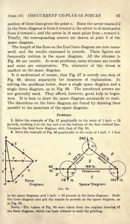
CHAP. IV] CONCURRENT CO-PLANAR FORCES 67
section of these lines gives the point c. Since the arrow marked 2
in the force diagram is from b toward d, the arrow in dcmust point
from d toward c, and the arrow in cb must point from c toward 6.
Finally, the corresponding arrows are drawn at joint 2 of the
space diagram.The length of the lines on the final force diagram are now meas-
ured, and the results expressed in pounds. These figures are
frequently written in the space diagram. All the stresses in
Fig. 68 are tensile. In most problems, some stresses are tensile
and some are compressive. The character of the stress is
marked on the space diagram.It is understood of course, that Fig. 67 is merely one step of
Fig. 68, drawn separately for clearness of explanation. In
solving the problems below, draw a single space diagram and a
single force diagram, as in Fig. 68. The numbered arrows are
not generally used. They afford, however, great help to begin-
ners. It is best to draw the space diagram accurately to scale.
The directions on the force diagram are found by drawing lines
parallel to the members of the space diagram.
Problems
1. Solve the example of Fig. 67 graphically to the scale of 1 inch = 10
pounds, marking d at the top and a at the bottom of the first vertical line.
Compare the final force diagram with that of Fig. 68.
2. Solve the example of Fig. 66 graphically to the scale of 1 inch = 1 foot
340
Force
Diagram
I b.
Space D'ragramFIG. 69.
in the space diagram, and 1 inch = 40 pounds in the force diagram. Scale
the force diagram and put the results in pounds on the space diagram, as
in Fig. 69.
NOTE. The values of Fig. 69 were taken from the original drawing of
the force diagram, which has been reduced in scale for printing.

68 MECHANICS [AKT. 53
3. The mast of a derrick is 15 feet long and the boom is 20 feet long.
One guy rope, in the same vertical plane as the boom, makes an angle of
30 degrees with the horizontal. The boom makes an angle of 15 degrees
with the horizontal and carries a load of 300 pounds. Find all internal
forces, the tension in the guy rope, and the horizontal and vertical compo-nents of the reaction at the bottom ofthe mast. Use the scale of 1 inch = 5
feet on the space diagram, and 1 inch = 100 pounds on the force
diagram.
FIG. 70.
NOTE. In an actual derrick, the boom is attached to the mast at some
distance above the bottom. The cable which supports the load runs parallel
to the boom, and increases the compression in that member. The boom is
lifted by several cables, which run over pulleys. The part of the cable
which comes down the mast increases the compression in that member.
4. Solve Problem 3 by moments and resolutions, beginning with the
right end of the boom as the first free body. Show that the compression
in the boom is the same, no matter what angle it makes with the horizontal.
(In the solution by moments and resolutions, it is convenient to represent
each force by a single letter, as H, V, P, etc., instead of by two letters as in
Bow's method.)5. Solve Problem 3 graphically when the boom is elevated to make an
angle of 45 degrees with the horizontal.
53. Summary. The resultant of concurrent, coplanar forces
is their vector sum.
The graphical condition of equilibrium for a set of concurrent,
coplanar forces, is that the force diagram is a closed polygon.
A problem of the equilibrium of concurrent, coplanar forces
may be solved by any one of the following methods :
1 . Construct the force polygon and determine the magnitude and
direction of each of the unknown forces by measurement.
2. Construct the force polygon and solve trigonometrically. This
method is convenient when the force polygon is a triangle, espe-
cially if it is a right-angled or an isosceles triangle.
3. Write two resolution equations. The sum of the components
along any direction is zero.

CHAP. IV] CONCURRENT CO-PLANAR FORCES 69
4. Write two moment equations. The sum of the moments about
any point is zero. The two origins of moment and the point
of application of the forces must not lie in the same straight line.
5. Write one moment equation and one resolution equation. Theresolution must not be perpendicular to the straight line which
joins the origin of moments and the point of application of the
forces.
Jointed frames, in which the forces are parallel to the members
connecting the joints, may be solved as a series of problems of
concurrent forces. Begin with a joint at which there are only
two unknowns, and solve by any of the methods above. Bythe use of Bow's method of lettering, a problem of this kind maybe solved graphically, with all the forces on a single diagram.A resolution perpendicular to the direction of an unknown
force eliminates that force. Moment about a point in .the
line of action of an unknown force eliminates that force.
The moment of a force is the product of the magnitude of the
force multiplied by the component of the apparent arm perpendicu-lar to it; or the product of the entire apparent arm multiplied
by the component of the force perpendicular to it. When the
coordinates of the ends of the apparent arm are given, instead of
its length and direction, it is advisable to resolve both the force
and the apparent arm into their components.
M = Vx - Hy, Formula V.
in which V and H are the components of the force and x and yare the components of the arm. The component V is parallel to
y and the component H is parallel to x.
54. Miscellaneous Problems
1. Find the direction and magnitude of the resultant of 24 pounds at 20
degrees, 30 pounds at 50 degrees, 20 pounds at 110 degrees, and 16 poundsat 210 degrees. Solve by resolutions along one pair of axes at right angles
to each other. Check by resolutions along a second pair of axes.
2. A mass of 50 pounds on a smooth inclined plane, which makes an
unknown angle with the horizontal, is held by a force of 18 pounds parallel
to the plane. Find the inclination of the plane and the normal reaction.
y 3. An unknown mass is placed on a smooth inclined plane which makesan unknown angle with the horizontal. It is held in equilibrium by a force
of 18 pounds parallel to the plane, or by a force of 20 pounds at an angleof 10 degrees above the horizontal. Find the mass of the body and the
inclination of the plane. Also find the normal reaction of the plane in each
case,

70 MECHANICS [ART. 54
4. Solve Problem 3 graphically.5. A 40-pound mass slides on a smooth straight rod which makes an
angle of 25 degrees with the horizontal. It is attached by means of a
weightless cord to a mass of 20 pounds which slides on a second smoothrod. This rod makes an angle of 35 degrees with the horizontal. The tworods are in the same vertical plane and on opposite sides of the vertical.
Find the direction of the cord, the tension which it exerts, and the normalreaction of each rod.
Figure 71, II, shows the masses supported by two cords. The problem is
the same as that of Fig. 71, I, and the diagram is more convenient for a
graphical solution.
Considering the 40-pound mass as the free body in equilibrium, and
resolving horizontally,
P sin 25 = Q cos 6. (1)
Considering the 20-pound mass as the
free-body in equilibrium, and resolving
horizontally,
Q sin 35 = T cos 0. (2)
FIG. 72.
Combining Equations (1) and (2)
P sin 25 = Q sin 35. (3)
Equation (3) is the same as if the forces P and Q were concurrent.
Resolving vertically,
P cos 25 = 40 - T sin 6, (4)
Q cos 35 = 20 + T sin 6, (5)
from whichP cos 25 + Q cos 35 = 60. (6)
Equation (6) is the same as if all the external forces were concurrent.
Combining Equations (3) and (6), P = 39.74 lb.; Q = 29.28 lb. Com-
bining Equations (1) and (4), 6 = 13 23', T = 17.23 lb.
6. Letter Fig. 71, II, by Bow's method and solve graphically.
7. A mass of 5 pounds is supported by a cord AB, which is 2 feet long and
is fixed at A, and by a second cord which runs over a smooth pulley and
supports a mass of 3 pounds. The point (C of Fig. 72) at which the second
cord is tangent to the pulley is 4 feet from A. in a horizontal direction.
Find the angle which AB makes with the horizontal when the system is
in equilibrium.

CHAP. IV] CONCURRENT CO-PLANAR FORCES 71
Taking moments about A and eliminating trigonometrically, the equationis found to be
cos3 - 1.61 cos 2 6 + 0.36 =
This equation may be solved by the trigonometric method for the solution
of a cubic, or by the method of trial and error (see Art. 252). One root is
cos 6 = 0.5958. To get the remaining two roots of the cubic, divide the
equation by cos 6 0.5988, and solve the quadratic thus obtained.
Two of these roots are solutions of the problem of mechanics. (Construct
the space diagram for one of these.) The third root is a solution of the
mathematical equation but is impossible mechanically.8. A 20-pound mass is supported by a cord AB which is 3 feet long, and
a second cord which runs over a smooth pulley 2 feet in diameter and sup-
ports a mass of 15 pounds. The axis of the pulley is 6 feet to the right and
FIG. 73.
1.5 feet above the point A, the upper end of the first cord. Find the posi-
tion of equilibrium.The algebraic solution of this equation is difficult and involves the solu-
tion of an equation of higher degree by the method of trial and error. It is
most easily solved by a combination of moments and graphics. With Aas the center and with a radius of 3 feet, draw the arc FG, Fig. 73. Select
some point B on this arc and draw AB. From B draw a line tangent to
the pulley. The length AE drawn perpendicular to this tangent is the
moment arm of the 15-pound force. The moment arm of the 20-poundforce is AD. For equilibrium.
20AD = 15AE.
If the moment of the 20-pound force is too great, the angle 6 is too small.
Choose another point on the arc and repeat the process. Interpolate for
the final result.

^ CHAPTER V
NON-CONCURRENT CO-PLANAR FORCES
55. Resultant of Parallel Forces in the Same Direction.
Figure 74 shows a common case of parallel forces in the same direc-
tion. The rigid beam ABC carries two loads, P and Q, which
are parallel forces. The equilibrant of these two forces is the
force S at B. The resultant of P and Q is a force at B, which is
equal and opposite to the equilibrant. The direction, magnitude,
FIG. 75.
and position of the resultant may be found by first finding the
equilibrant.
To find the equilibrant, replace the rigid beam ABC of Fig.
74 by the jointed frame of Fig. 75. Neglecting the weight of the
frame, the forces at each joint may be found by the methods for
concurrent forces. Figure 76, 1, is the space diagram for Fig. 75.
For simplicity, each member is represented by a single line. Figure72

CHAP. V] NON-CONCURRENT CO-PLANAR FORCES 73
76, II, shows the force diagram constructed by Bow's method.
The angle a is assumed to be known and the angle 6 is assumed to
be unknown. Beginning at joint No. 1, construct the force tri-
angle acd. At joint No. 2, the direction of dc is from left toward
right, and the magnitude of cb is known. The force triangle is
cbd. The direction of bd gives the unknown angle 0. At
joint No. 3, the direction and magnitude of the forces ad and
db are known. The line ba represents the equilibrant desired.
The force ba of triangle No. 3 is along the same line as the
forces P and Q, and is equal to their sum. The equilibrant of
two parallel forces is equal to the sum of the two forces, and is in
the opposite direction.
P + Q + S = 0;P + Q= - S. (1)
The resultant, which is equal and opposite the equilibrant, is
the algebraic sum of P and Q and has the same sign.
P + Q = R (2)
The force polygon of Fig. 76, II, gives the direction and magni-tude of the equilibrant, and, consequently, of the resultant.
There remains the problem of finding algebraically the position
of the equilibrant or resultant. This position is given graphi-
cally by the space diagram of Fig. 76, I. It is now desirable to
express this position in algebraic language. Extend the line Sof Fig. 76, I, till it intersects the line 1-2 at the point 4. Let
the distance from point 1 to point 4 be represented by x, the dis-
tance from point 2 to point 4 be represented by y, and the dis-
tance from point 3 to point 4 be represented by z. The triangle
1-3-4 of the space diagram is similar to the triangle dac of the
force diagram; and the triangle 2-4-3 of the space diagram is
similar to the triangle deb of the force diagram. From the
homologous sides of 1-3-4 and dac,
x - 2- mdc~P
From the homologous sides of 2-4-3 and deb,
From Equations (3) and (4),X - Q - (toy~P'
Px = Qy. Formula VI.
The angles a and 6 do not appear in any of the equations above.

74 MECHANICS [ART. 55
A- cos<J> >t*--y cos 6
FIG. 77.
It is evident, therefore, that the magnitude, direction, and posi-
tion of the equilibrant (and resultant) are independent of the
form of the jointed frame. These are the same whether the
rigid body is a jointed frame, as in Fig. 75, or a single beam, as
in Fig. 74. The triangular frame is merely a convenient meansof finding the equilibrant.
This same result may be obtained by resolving the forces Pand Q, with one component of P equal and opposite to one com-
ponent of Q, and with these two components along the same line.
These two components balance
each other. The remaining
components intersect. Their
resultant at -the point of inter-
section may 'be found by the
methods for concurrent forces.
In Fig. 77, a line is drawn
through the point 4 at right
angles to the direction of P and
Q. This line makes an angle with the direction of the line 1-2.
Multiplying both sides of Formula VI by cos </>,
Px cos = Qy cos 0. (6)
Since x cos is the perpendicular distance from the point 4
to the line of the force P, the term P x cos is the moment of the
force P about the point 4 (or about any point in the line of the
equilibrant). Qy cos is, likewise, the moment of the force Qabout point 4. Equation (6) may be interpreted as follows:
The moment of one of the parallel forces about any point in the line
of the resultant is equal and opposite to the moment of the other forceabout that point.
The moment of the result-
ant of two parallel forces
about any point in their
plane is equal to the sum of""
the moments of the two forces
about that point. This maybe proved from Fig. 78.
Take moments about the point at a distance e from the line
of the force P measured in the direction of x and y. Themoment of the resultant about this point is
Mr= R(e + x) cos = (Pe + Px + Qe + Qx) cos 0. (7)
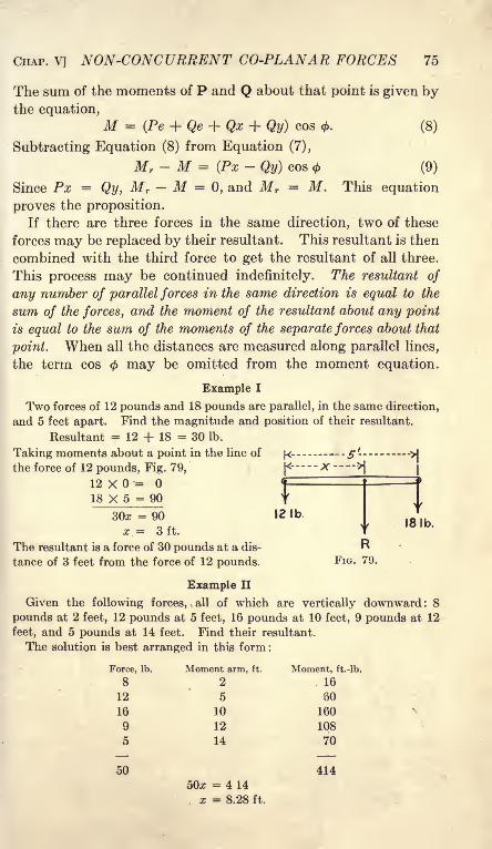
CHAP. V] NON-CONCURRENT CO-PLANAR FORCES 75
The sum of the moments of P and Q about that point is given bythe equation,
M = (Pe + Qe -f Qx + Qy) cos 0. (8)
Subtracting Equation (8) from Equation (7),
Mr- M = (Px - Qy) cos (9)
Since Px = Qy, Mr M =0, and Mr
= M. This equation
proves the proposition.
If there are three forces in the same direction, two of these
forces may be replaced by their resultant. This resultant is then
combined with the third force to get the resultant of all three.
This process may be continued indefinitely. The resultant of
any number of parallel forces in the same direction is equal to the
sum of the forces, and the moment of the resultant about any point
is equal to the sum of the moments of the separate forces about that
point. When all the distances are measured along parallel lines,
the term cos may be omitted from the moment equation.
Example I
Two forces of 12 pounds and 18 pounds are parallel, in the same direction,
and 5 feet apart. Find the magnitude and position of their resultant.
Resultant = 12 + 18 = 30 Ib.
Taking moments about a point in the line of|<- -5'-
->|
the force of 12 pounds, Fig. 79, [<-X
|(
12 X =18 X 5 = 90
30z = 90 12 I b
x.= 3ft.
The resultant is a force of 30 pounds at a dis- Rtance of 3 feet from the force of 12 pounds. FIG. 79.
18 Ib.
Example II
Given the following forces, all of which are vertically downward: 8
pounds at 2 feet, 12 pounds at 5 feet, 16 pounds at 10 feet, 9 pounds at 12
feet, and 5 pounds at 14 feet. Find their resultant.
The solution is best arranged in this form :
Force, Ib.

76 MECHANICS [AKT. 56
The resultant is 50 pounds at a distance of 8.28 feet from the line of the
8-pound force.
Problems
1. Check Example II by moments about a point 2 feet from the 8-poundforce.
2. A weightless, horizontal bar is 12 feet long and carries 40 pounds at
the left end, 55 pounds 3 feet from the left end, 80 pounds 6 feet fromthe left end, and 25 pounds at the right end. Find the magnitude of the
resultant and find its position by moments about the left end. Check bymoments about some other point.
3. A beam 20 feet long weighs 40 pounds. Its center of mass is 9 feet
from the left end. The beam is placed in a horizontal position and loaded
with 60 pounds on the left end, 50 pounds 6 feet from the left end, 80 pounds4 feet from the right end, and 30 pounds on the right end. The beam rests
on a single support. Where must this support be placed?4. A weightless bar 5 feet long forms a part of a jointed frame as in Fig.
76. The bar is horizontal and carries a load of 60 pounds on the left end
and a load of 40 pounds on the right end. Solve graphically for the magni-tude and position of the equilibrant. Make the angle a = 30 and use
the scale of 1 inch = 1 foot on the space diagram, and 1 inch = 20 poundson the force diagram.
6. Solve Problem 4 with a = 45.
6. Check Problem 4 by moments.
7. The ends of a bar 5 feet in length are connected to the ends of a chain
which is 7 feet in length. A load of 50 pounds is hung on one end of the
bar and a load of 30 pounds is hung on the other end. The chain is suspendedfrom a hook. What is the length of chain between the hook and the 30
pound load if the bar hangs horizontal?
/ ;*V56. Resultant of Parallel Forces in Opposite Directions.
In Fig. 76 or Fig. 77, the force Q may be regarded as the equilib-
rant of the forces P and S. Numerically
The resultant of the forces P and S in opposite directions is
the force RI of Fig. 80. This resultant is equal and opposite the
5 force Q. From the equations of the
preceding article, it is evident that the__ I_jf sum of the moments of P, Q, and S
t about any point is zero. Since RI is
equal and opposite to Q, the momentFlG. 80. f -n -
i . xi e ,1of RI is equal to the sum of the mo-
ments of S and P taken with their proper signs. The moment
of the resultant of two parallel forces is equal to the sum of the
moments of the forces, whether the forces are in the same direction
or in opposite directions.

CHAP. V] NON-CONCURRENT CO-PLANAR FORCES 77
Example I
Find the magnitude and position of the resultant of a downward force of
8 pounds and an upward force of 18 pounds, the horizontal distance between
the lines of the two forces being 5 feet.
Taking moments about a point in the line of the 8-pound force, and giving
the negative sign to the downward force,
-8X0=18 X 5 = 90
Wx = 90
x = 9 ft.
The resultant is a force of 10 pounds at a distance of 9 feet from the force
of 8 pounds and 4 feet from the force of 18 pounds. The resultant is up-ward. A downward force of 10 pounds along the same line would balance
the upward force of 18 pounds and the downward force of 8 pounds.
The resultant of any number of parallel forces is the algebraic
sum of the forces; the moment of the resultant about any point is
the algebraic sum of the moments of the several forces about that
point.
Example II
Find the resultant of 10 pounds down at 2 feet, 17 pounds down at 5
feet, 21 pounds up at 10 feet, 16 pounds down at 12 feet, and 12 poundsdown at 15 feet. Solve by moments about the 5-foot position. Call down-ward direction positive, since most of the forces are downward. Withdistances toward the right from the origin regarded as positive, clockwise
moment is now positive.
Force, Ib. Arm, ft. Moment, ft.-lb.
10
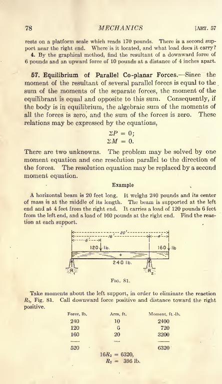
78 MECHANICS [ART. 57
rests on a platform scale which reads 170 pounds. There is a second sup-
port near the right end. Where is it located, and what load does it carry?
4. By the graphical method, find the resultant of a downward force of
6 pounds and an upward force of 10 pounds at a distance of 4 inches apart.
57. Equilibrium of Parallel Co-planar Forces. Since the
moment of the resultant of several parallel forces is equal to the
sum of the moments of the separate forces, the moment of the
equilibrant is equal and opposite to this sum. Consequently, if
the body is in equilibrium, the algebraic sum of the moments of
all the forces is zero, and the sum of the forces is zero. These
relations may be expressed by the equations,
ZP = 0;
ZM = 0.
There are two unknowns. The problem may be solved by one
moment equation and one resolution parallel to the direction of
the forces. The resolution equation may be replaced by a second
moment equation.
Example
A horizontal beam is 20 feet long. It weighs 240 pounds and its center
of mass is at the middle of its length. The beam is supported at the left
end and at 4 feet from the right end. It carries a load of 120 pounds 6 feet
from the left end, and a load of 160 pounds at the right end. Find the reac-
tion at each support.
Ib
FIG. 81.
Take moments about the left support, in order to eliminate the reaction
Ri, Fig. 81. Call downward force positive and distance toward the right
positive.
Force, Ib. Arm, ft. Moment, ft.-lb.
240 10 2400
120 720
160 20 3200
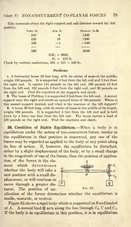
CHAP. V] NON-CONCURRENT CO-PLANAR FORCES 79
Take moments about the right support and call distance toward the left
positive.
Force, Ib. Arm, ft. Moment, ft.-lb.
240 6 1440
120 10 1200
160 -4 -640
520 2000
16fli = 2000,
R! = 125 Ib.
Check by vertical resolutions; 395 + 125 = 520 Ib.
Problems
1. A horizontal beam 24 feet long, with its center of mass at the middle,
weighs 180 pounds. It is supported 4 feet from the left end and 2 feet from
the right end. It carries 144 pounds on the left end, 160 pounds 13 feet
from the left end, 162 pounds 6 feet from the right end, and 90 pounds on
the right end. Find the reactions at the supports and check.
2. The beam of Problem 1 is supported 2 feet from the left end. A second
support near the right end exerts an upward force of 400 pounds. Where is
this second support located, and what is the reaction of the left support?3. A beam 20 feet long, with its center of mass at the middle of its length,
weighs 160 pounds. It is supported 5 feet from the left end and is held
down by a force one foot from the left end. The beam carries a load of
120 pounds on the right end. Find the reactions and check.
58. Condition of Stable Equilibrium. When a body is in
equilibrium under the action of non-concurrent forces, insofar as
the equilibrium in that position is concerned, any one of the
forces may be regarded as applied to the body at any point alongits line of action. If, however, the equilibrium be disturbed,
either by a slight displacement of the body, or by a small changein the magnitude of one of the forces, then the position of applica-
tion of the forces is the ele-
ment which determineswhether the body will take a
new position with a small dis-
placement, or will continue to
move through a greater dis-
tance. The position of ap-
plication of the forces determines whether the equilibrium is
stable, unstable, or neutral.
Figure 82 shows a rigid body which is supported atB and loaded
at A. A second load.Q acts along the line through C%, C and C\.
If the body is in equilibrium in this position, it is in equilibrium
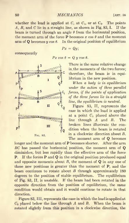
80 MECHANICS [ART. 58
whether the load is applied at C, at Ci, or at C2 . The points
A, B, and C lie in a straight line, as shown in Fig. 83, 1. If the
beam is turned through an angle from the horizontal position,
the moment arm of the force P becomes x cos B and the momentarm of Q becomes y cos B. In the original position of equilibrium
consequently
Px = Qy;
Px cos B = Q y cos B.
There is the same relative change
in. the moments of the two forces;
therefore, the beam is in equi-
librium in the new position.
When a body is in equilibrium
under the action of three parallel
forces, if the points of application
of the three forces lie in a straight
line, the equilibrium is neutral.
Figure 83, II, represents the
case in which the load is applied
at a point Ci placed above the
line through A and B. Thebroken lines illustrate the con-
dition when the beam is rotated
in a clockwise direction about B.
The moment arm of Q becomes
longer and the moment arm of P becomes shorter. After the armBC has passed the horizontal position, the moment arm of Qdiminishes, but less rapidly than the effective arm of the force
P. If the forces P and Q in the original position produced equaland opposite moments about B, the moment of Q in any one of
these new positions is greater than the moment of P, and the
beam continues to rotate about B through approximately 180
degrees to the position of stable equilibrium. The equilibriumof Fig. 83, II, is unstable. If the beam had been rotated in the
opposite direction from the position of equilibrium, the same
condition would obtain and it would continue to rotate in that
direction.
Figure 83, III, represents the case in which the load is applied at
C2 placed below the line through A and B. When the beam is
rotated slightly from this position in a clockwise direction, the
FIG. 83.
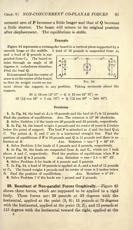
"
r\c
CHAP. V] NON-CONCURRENT CO-PLANAR FORCES 81
moment arm of P becomes a little longer and that of Q becomes
a little shorter. The beam will return to its original position
after displacement. The equilibrium is stable.
Example
Figure 84 represents a rectangular board in a vertical plane supported by a
smooth hinge at the middle. A load of 10 pounds is suspended from A 2
and a load of Q pounds is sus-
pended from C 2 . The board ro-
tates through an angle of 10
degrees in a clockwise direction.
Find the load Q.It is assumed that the center of
mass is at the center of the board,so that its weight exerts no mo- ^IG - &*
ment about the support in any position. Taking moments about the
support,10 X 13 cos 12 37' = Q X 13 cos 32 37'; or
10 (12 cos 10 + 5 sin 10) = Q (12 cos 10 - 5sin 10)
%
Problems
1. In Fig. 84, the load at A 2 is 10 pounds and the load at C2 is 12 pounds.Find the position of equilibrium. Ans. The rotation is 12 36' clockwise.
2. Solve Problem 1 if the loads are 20 pounds and 22 pounds, respectively.
3. In Fig. 84, the board weighs 4 pounds and its center of mass is 2 inches
below the point of support. The load P is attached at A and the load Q at
C. The points A, B, and C are in a horizontal straight line. Find the
position of equilibrium if P is 10 pounds and Q is 11 pounds and there is no
friction at B. Ans. Rotation = tan- 1
-f= 56 19'.
4. Solve Problem 3 for loads of 5 pounds and 6 pounds, respectively.
6. In Fig. 84, the loads are suspended from AI and Ci, which are 1 inch
above A and C, respectively. Find the position of equilibrium when P is
1 pound and Q is 2 pounds. Ans. Rotation = tan- 1 2.4 = 67 23'.
6. Solve Problem 5 for loads of 4 pounds and 5 pounds.7. In Fig. 84, a load of 10 pounds is applied at A 2 and a load of 11 pounds
at C2 . The board weighs 4 pounds and its center of mass is 2 inches below
B. Find the position of equilibrium. Ans. Rotation = 6 04'.
8. Solve Problem 7 if the loads are 1 pound and 2 pounds.
59. Resultant of Non-parallel Forces Graphically. Figure 85
shows three forces, which are supposed to be applied to a rigid
body. These forces are: 20 pounds at 30 degrees with the
horizontal, applied at the point (5, 0) ;15 pounds at 75 degrees
with the horizontal, applied at the point (3, 2) ;and 12 pounds at
115 degrees with the horizontal toward the right, applied at the
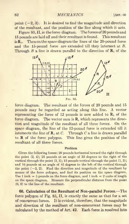
82 MECHANICS [ART. GO
point ( 2,3). It is desired to find the magnitude and direction
of the resultant, and the position of the line along which it acts.
Figure 85, II, is the force diagram. The forces of 20 pounds and
15 pounds are laid off and their resultant is found. This resultant
isRi. Then on the space diagram the lines of the 20-pound force
and the 15-pound force are extended till they intersect at B.
Through B a line is drawn parallel to the direction of Ri of the

CHAP. V] NON-CONCURRENT CO-PLANAR FORCES 83
two components along a pair of axes at right angles to each other.
The sum of the components along one axis is taken as one side of
right-angled triangle. The sum of the components along the other
axis is taken as the other side of the same right-angled triangle.
The resultant is represented by the hypotenuse of his triangle.
The position of the line of action of this resultant is calculated
by moments. In Fig. 85, the force of 20 pounds and the force of
15 pounds may be regarded as concurrent at B. According to
Art. 48, the moment of RI about any point is equal to the sum of
the moments of the 20-pound force and the 15-pound force about
that point. The resultant RI may be regarded as concurrent
with the force of 12 pounds at C. The sum of the moments of
RI and the 12-pound force about any point is equal to the mo-ment of the final resultant about that point. The moment about
any point of the resultant of a set of non-concurrent, coplanar
forces is equal to the sum of the moments of the several forces about
that point.
Example
A rectangular board, Fig. 86, is 4 feet wide and 3 feet high. A force of
20 pounds, at an angle of 15 degrees with the horizontal toward the right,
ni
FIG. 86.
is applied at the lower right corner. A force of 24 pounds, at an angle of
30 degrees to the right of the vertical, is applied at the upper right corner.
A force of 16 pounds at an angle of 45 degrees to the left of the vertical is

84 MECHANICS [ART. 60
applied at the upper left corner. Find the magnitude and direction of the
resultant, and its distance from the lower left corner.
Resolving horizontally and vertically,
Force H component V component
20 19.318 5.176
24 12.000 20.784
16 -11.314 11.314
20.004 37.274
The resultant is the hypotenuse of the right-angled triangle of which the
base is 20.004 units and the altitude is 37.274 units. The resultant makesan angle of 61 47' with the horizontal toward the right. Its magnitude is
42.30 pounds.To find the location of the line of the resultant force on the space diagram,
moments are taken about the lower left corner of the board. Since the
horizontal and vertical components of the several forces have already been
computed, it is convenient to use these components in calculating the
moments.
The horizontal component of -the 20-pound force and the vertical com-
ponent of the 16-pound force pass through the origin of moments so that
the moment of each of these components is zero.
V component of 20 Ib. 5 . 176 X 4 = 20 . 704
V component of 24 Ib. 20 . 784 X 4 = 83 . 136
# component of 24 Ib. 12.000 X 3 = - 36.000
H component of 16 Ib. 11 . 314 X 3 = 33. 942
M = 101 . 782 ft.-lb.
Figure 86, III, shows the location of the resultant. Since the resultant
makes an angle of 61 47' with the horizontal, a line perpendicular to it makesan angle of 28 13' with the horizontal. To locate the resultant on the space
diagram, a line is first drawn through the lower left corner at an angle of
28 13' below the horizontal toward the right. A length of 2.406 feet is
measured off on this line from the origin of moments to the point B. Themoment is counter-clockwise and the resultant force is upward; hence the
moment arm must be measured toward the right from the corner of the
board. Through the point B, a line is drawn perpendicular to OB. Theresultant force is applied along this perpendicular line. If a smooth pin
were passed through the board at any point along this line, this pin would
hold the board in equilibrium, and the reaction at the point of contact
would be 42.30 pounds. The equilibrium would be stable, unstable or
neutral, depending upon the position of the pin in the line of action of the
resultant force.

CHAP. V] NON-CONCURRENT CO-PLANAR FORCES 85
It is best to determine the sign of the moments by observing on the space
diagram whether the rotation is clockwise or counter-clockwise, rather than
by using the signs of the forces and effective arms. A horizontal force
toward the right applied to a vertical arm upward gives a clockwise moment.A vertical force upward applied to a horizontal arm toward the right gives
a counter-clockwise moment. If counter-clockwise moment be taken as
positive,
M = Vx - Hy,
in which V is the component of the force parallel to the Y axis, H is the
component of the force parallel to the X axis, x is the abscissa, and y is the
ordinate of some point in the line of action of the force. It is not necessarythat the X axis be horizontal and the Y axis vertical. The X axis may have
any direction and the F axis be perpendicular to the X axis.
The student who prefers to make use of the signs of the forces and dis-
tances may employ the equation above, but he should also check his results
and visualize his problem by observing the direction of rotation on the space
diagram.Instead of finding the perpendicular distance from the origin of moments
to the line of the resultant, the points of intersection of the resultant force
with the axes of coordinates might have been calculated. Since the origin
of moments lies in the X axis, the moment of the horizontal component is
zero at the point where the line of the resultant cuts that axis.
101.782 = Vx,
in which x is the abscissa of the point of intersection with the X axis.
_ 101.782 _~37^74~
Regarding the force as applied at the Y intercept,
101.782
The moment is counter-clockwise. A vertical force upward gives a counter-
clockwise moment when the point of application is to the right of the origin
of moments. A horizontal force toward the right gives a counter-clockwise
moment when the point of application is below the origin.
Problems
1. Solve the Example of Fig. 85 by resolutions and moments.2. Solve the Problem of Art. 59 and compare with your graphical
solution.
3. Find the direction, magnitude, and the line of application of the resul-
tant of the following forces : 20 pounds, at 65 degrees to the right of the ver-
tical, through the point (2, 3); 16 pounds, at 20 degrees to the right of the
vertical, through the point (2, 2); 12 pounds, at 40 degrees to the left of
the vertical, through the point (1, 5); and 18 pounds, at 110 degrees to the
left of the vertical, through the point (3, 2).

86 MECHANICS [ART. 61
The solution may be arranged in tabular form as was done with Problem
4 of Art. 17.
Force,
Ib.

CHAP. V[ NON-CONCURRENT CO-PLANAR FORCES 87
In the case of coplanar forces, two independent equations of this
kind may be written.
The resultant of one group of forces may be equal and opposite
to the resultant of all the other forces, but may not lie in the
same line. In the latter case, the moment of one group of forces
will not balance the moment of the other forces, and the forces
will rotate the body. The second condition is satisfied whenthe sum of the moments of all the forces which act on the rigid
body is zero. This condition is expressed algebraically by the
equation= 0. (3)
A problem of the equilibrium of non-concurrent, coplanar
forces may be solved by writing two resolution equations and one
moment equation. Since a moment equation may replace a resolu-
tion equation, any one of the following combinations may be
used :
1. One moment equation and two resolution equations.
2. Two moment equations and one resolution equation.
3. Three moment equations.
As in the case of concurrent forces, resolution perpendicular to
the line of action of a force eliminates that force; moment about
a point in the line of action of a force eliminates that force.
Moment about the point of intersection of two forces eliminates
both of them. When two forces of unknown magnitude inter-
sect, it is advisable to begin the solution by writing the moment
equation about their point of intersection as the origin. Fre-
quently, both the direction and magnitude of one force are un-
known. If, however, some point on the line of action of this
force is known, it is advisable to take moments about this point.
Example
A bar AB, Fig. 87, is 20 feet long, weighs 60 pounds, and has its center
of mass 8 feet from A. The bar is hinged at A and supported by a cord at
B. The bar makes an angle of 15 degrees above the horizontal toward the
right, and the cord makes an angle of 35 degrees to the left of the vertical.
Find the tension in the cord and the direction and magnitude of the hingereaction at.il.
The free body is the entire bar AB. The forces which act on the free
body are its weight, the unknown tension in the cord at B, and the reaction
of the hinge at A. The hinge reaction is unknown, as to both direction
and magnitude.

88 MECHANICS [ART. 61
Begin by writing a moment equation about the hinge A, since this elimi-
nates two unknowns.
60 X 8 X cos 15 = P X 20 cos 20
24 X 0.9659 = 0. 9397PP = 24.671b.
(4)
To find the direction and magnitude of the reaction at the hinge, it is
convenient to regard it as made up of a horizontal component H and a
vertical component V. Resolving horizontally,
H = P sin 35 = 14.15 Ib.
Resolving vertically,
V = 60 - P cos 35 = 60 - 20.21 = 39.79 Ib.
(5)
(6)
From the force triangle, Fig. 87, II, the resultant reaction of the hinge is
found to be 42.23 pounds at an angle of 19 35' to the right of the vertical.
Check all results by moments about B,
60 X 12 cos 15 = 42.23 X 20 cos 34 35' (7)
Problems
1. Complete the check of the Example above by substituting in Equa-tion (7).
2. Solve the Example of Fig. 87 if the cord makes an angle of 35 degreesto the right of the vertical. Check the result.
3. Consider the hinge reaction in Fig. 87 as made up of a componentparallel to AB and a component perpendicular to AB. Find the componentperpendicular to AB by moments about B. Find the component parallel
to AB by a resolution parallel to the bar. Calculate the resultant reaction
and check.
4. A vertical door, Fig. 88, is 12 feet wide, 10 feet high, and weighs 360
pounds. The hinges are one foot from the top and bottom, respectively,
and are so placed that all the vertical load comes on the lower hinge. Find
the direction and magnitude of each hinge reaction.
6. A derrick mast is 30 feet long. The boom is &0 feet long, is elevated

.. ,-. r
CHAP. V] NON-CONCURRENT CO-PLANAR FORCES 89
20 degrees above the horizontal, and carries a load of 1200 pounds. A guy
rope attached to the top of the mast makes an angle of 35 degrees with the
horizontal. Considering the mast, boom, and the ropes which connect them
as a single rigid body, find the tension in the guy rope, and the direction
and magnitude of the reaction at the base due to the load of 1200 pounds.
6. A derrick mast is 15 feet long.
The boom is 20 feet long and is ele-
vated to a position in which the free
end is 16 feet from the top of the
mast. A guy rope in the same planeas the boom and mast is attached to
a point at the same level as the bot-
tom of the mast, at a distance of 18
feet from the bottom. Find the ten-
sion in the guy rope and the hori-
zontal and vertical components of the
reaction at the bottom of the mastdue to a load of 1600 pounds on the
end of the boom. Construct the space diagram to the scale of 1 inch = 5
feet, and solve by measuring moment arms on the diagram.7. In Problem 6, calculate the angles and the moment arms trigonomet-
rically, and solve by one moment and two resolution equations.8. Solve Problem 6 for all forces by Bow's method, drawing the lines in
the force diagram parallel to the corresponding members of the space
diagram.9. Solve Problem 5 for all forces joint at a time by resolutions.
10. A bar A B, Fig. 89,l is 7 feet long, weighs 28 pounds, and has its center
of mass 3 feet from A. The end A is provided with a cylindrical roller,
/.
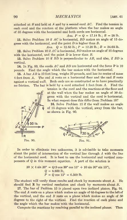
90 MECHANICS [AKT. 61
attached at B and held at A and by a second cord AC. Find the tension in
each cord and the reaction of the platform when the bar makes an angle
of 35 degrees with the horizontal and both cords are horizontal.
Ans. P = Q = 17.14 lb.; R = 28 Ib.
11. Solve Problem 10 if AC is horizontal, BD makes an angle of 15 de-
grees with the horizontal, and the point D is higher than B.
Ans. Q = 12.83 lb.; P = 12.39 lb.; R = 24.68 lb.
12. Solve Problem 10 if AC is horizontal, BD makes an angle of 15 degrees
with the horizontal, and the point D is lower than B.
13. Solve Problem 10 if BD is perpendicular to AB, and also, if BD is
vertical.
14. In Fig. 89, the cords AC and BD are horizontal and the force P is 10
pounds. Find the angle which the bar makes with the horizontal.
15. A bar AB is 10 feet long, weighs 30 pounds, and has its center of mass
4 feet from A. The end A rests on a horizontal floor and the end B rests
against a vertical wall. Both ends are so constructed as to have practically
no friction. The bar is held by a cord attached 1 foot from A. Find the
tension in the cord and the reactions at the floor and
at the wall when the bar makes an angle of 30 de-
grees with the vertical and the cord is horizontal.
In what respect does this differ from Problem 10?
16. Solve Problem 15 if the wall makes an angle
of 15 degrees with the vertical, away from the bar,
as shown in Fig. 90.
FIG. 91.
In order to eliminate two unknowns, it is advisable to take momentsabout the point of intersection of the vertical line through A with the line
of the horizontal cord. It is best to use the horizontal and vertical com-
ponents of Q in this moment equation. A part of the solution is
30 X 4 sin 30 = Q(9 cos 30 cos 15 -f 10 sin 30 sin 15),
Q = 6.800 lb,
P = Q cos 15 = 6.569 lb.
The student will verify these results and check by moments about A. Heshould find R by vertical resolution and check by moments about B.
17. The bar of Problem 15 is placed upon two inclined planes, Fig. 91.
The end A rests on a plane which makes an angle of 65 degrees to the left of
the vertical, and the end B rests on a plane which makes an angle of 50
degrees to the right of the vertical. Find the reaction of each plane and
the angle which the bar makes with the horizontal.
Compute the reactions by resolving parallel to the inclined planes. Then

CHAP. V] NON-CONCURRENT CO-PLANAR FORCES 91
find the angle by moments about A. It is best to use the components of
the force P in the moment equation.
30 X 4 cos 6 = P sin 40 X 10 sin + P cos 40 X 10 cos 6,
12 = P (sin 40 tan + cos 40).
Check by moments about B. Ans. 9 = 8 07'.
62. Condition for Independent Equations. // two moment
equations of equilibrium are written for a problem of non-concur-
rent, coplanar forces, and these equations are combined into a sin-
gle equation, the resulting equation is equivalent to a resolution
perpendicular to the line joining the two origins of moment.
In Fig. 92, A and B are taken as the two origins of moment.The point B is the origin of coordinates and the^X" axis is passed
through the point A . The distance between A and B is equal to
c. A force PI at an angle ai with the X axis passes through the
X
/ B
FIG. 92.
point (xi, yi) and a force P2 at an angle a2 with the -X" axis passes
through the point (x2} yz), etc. Taking moments about B,
XiPi sin ai 2/i-Pi cos i + XzPz sin a 2 2/2^*2 cos az + etc.
= 0. (1)
Taking moments about A}
(xi + c)Pi sin ai yfi cos i + (xz + c)P2 sin a2 yzPz cos
a 2 + etc = 0. (2)
Subtracting Equation (1) from Equation (2),
c(Pi sin i + P2 sin a 2 + etc.)= 0. (3)
The term in the parenthesis of Equation (3) is the sum of the
components parallel to the Y axis; therefore, Equation (3) provesthe proposition.
If two moment equations are written and one resolution equa-
tion, and if the resolution is taken along a direction which is

92 MECHANICS [ABT. 62
perpendicular to the line joining the two origins of moment, the
three equations will not be independent. If three moment equa-tions are written, and if the three origins of moment lie on the
same straight line, the three equations will not be independent.For concurrent, coplanar forces in equilibrium there are
two unknowns, and two independent equations may be written.
These may be:
(1) Two resolutions,
(2) One moment and one resolution.
(3) Two moments.
For non-concurrent, coplanar forces there are three unknowns,and three independent equations may be written. These are
the same as the equations for concurrent forces with the addition
of one moment equation. If the forces are all parallel, there can
be only one independent resolution equation, and only two un-
known quantities.
When one resolution and one moment equation are written
for concurrent forces, the resolution must not be taken perpen-dicular to the line which joins the origin of moments and the
point of application of the forces. When one resolution and two
moment equations are written for non-concurrent forces, the
resolution must not be taken perpendicular to the line which
joins the two origins of moment.When two moment equations are written for concurrent forces,
the two origins of moment and the point of application of the
forces must not lie on the same straight line. When three
moment equations are written for non-concurrent forces, the
three origins of moment must not lie on the same straight line.
63. Direction Condition of Equilibrium. When a body is in
equilibrium under the action of three non-concurrent forces,
in order that any one of these forces
may lie in the line of the resultant
of the other two forces, it is necessary
that all three forces intersect at a
single point. In Fig. 93, the bar
AB is hinged at A and supported
by a cord at B. The vertical line
through the center of mass at the point C intersects the line of
the cord at D. In order that the bar may be in equilibrium, the
direction of the hinge reaction must be such that its line of action
shall pass through D. This relation is sometimes called the

CHAP. V] NON-CONCURRENT CO-PLANAR FORCES 93
geometrical condition of equilibrium. In this book it will be
called the direction condition of equilibrium.
Example I
A horizontal bar 5 feet long, weighing 30 pounds, with its center of mass2 feet from the left end, is supported by cords at the ends. The cord at
the left end makes an angle of 30 to the left of the vertical. Find the
direction of the cord at the right end.
From the right-angled triangles of Fig. 94,
CD = 2 tan 60 = 3 tan 6,
tan. = 2X13
7321 =1.1547,
6 = 49 06'.
The cord at the right end makes an angleof 40 54' to the right of the vertical. The
magnitude of the forces may be found by t pIG 94moments or resolutions.
The direction condition may take the place of one moment equation in
the solution of a problem of non-concurrent forces. The other necessary
equations may be resolutions.
This method of solution is especially valuable when only the direction
is required. In practical work it is often desirable to know the direction
of a force, in order to put in a support in the best position. The engineershould cultivate the habit of observing the direction of forces in actual
structures.
Problems
1. A horizontal beam, 12 feet long, with its center of mass 5 feet from the
left end, is supported by two posts. One post at the left end makes an
angle of 25 degrees to the right of the vertical. What should be the direc-
tion of the post at the right end in order that the compression in each postshall be parallel to its length? Solve also if the second post is 2 feet from
the right end.
2. Solve Problem 1 if one post is at the left end and the other is 3 feet
from the left end.
3. A derrick boom is 20 feet long, makes an angle of 40 degrees with the
horizontal, and carries a load of 400 pounds. The mast is 12 feet long.
One guy rope, which is in the plane of the mast and boom, makes an angleof 30 degrees with the horizontal. Find the direction of the reaction at
the bottom of the mast by means of the direction condition of equilibrium.With this direction known, draw the force triangle for the three external
forces, which are the weight on the boom, the tension of the guy rope, andthe reaction at the bottom of the mast. Also solve completely by Bow'smethod for all external and internal forces. Compare the two diagrams.
4. A bar 7 feet long, with its center of mass 3 feet from the left end, is
supported by a rope at the left end which makes an angle of 30 degrees to
the left of the vertical, and a rope at the right end which makes an angle of
35 degrees to the right of the vertical. What angle does the bar make with

94 MECHANICS [ART. 63
the horizontal? If the bar weighs 60 pounds, what is the tension in each
rope?From Fig. 95,
DF = DE + EF.
4 cos 6 tan 55 = 3 cos 6 tan 60 + 7 sin 6; .
tan0
f5V

CHAP. V] NON-CONCURRENT CO-PLANAR FORCES 95
smooth vertical wall. It is held from slipping by a horizontal force of 12
pounds at the bottom. Find the position of equilibrium.
The resultant of the horizontal force and the vertical reaction at the
bottom must pass through the point D,
(Fig. 96), at which the vertical line
through the center of mass intersects
the horizontal line through the top of
the ladder. By vertical resolution, the
vertical reaction at the bottom is found
to be 40 pounds. The resultant of 40
pounds and 12 pounds makes an angle
with the vertical whose tangent is 0.3.
From the figure,
DE = 20 sin 6 = 8 cos 9 cot a;
tan =0.3 X 20
6 = 53 08'.
1.3333;
FIG. 96.
Problems
7. A bar 10 feet long, weighing 40 pounds, with its center of mass at the
middle, rests on a smooth horizontal floor and leans against a smooth vertical
wall. It is held by a horizontal pull of 10 pounds applied 2 feet from the
lower end. Find the reactions at the floor and at the wall by resolutions,
and find the angle which the bar makes with the vertical by means of the
direction condition of equilibrium. Ans. 21 48' with the vertical.
' 8. A bar *j? feet long, with its center of mass 5 feet from the lower end,
rests on a smooth horizontal floor and leans against a wall which makes an
angle of 15 degrees with the vertical, away from the bar. The bar makesan angle of 35 degrees with the vertical. It is held by a horizontal force
applied 2 feet from the bottom. Determine the three unknown forces
graphically, using the direction condition of equilibrium to find the angles.
64. Trusses. A truss is a jointed frame. Since a triangle is
the only jointed frame which retains its form when loaded, a
truss is made up of a connected series of triangular elements.
FIG. 97.
Figure 97 shows a truss which is entirely supported from one end.
A truss supported at one end is called a cantilever truss. The dis-
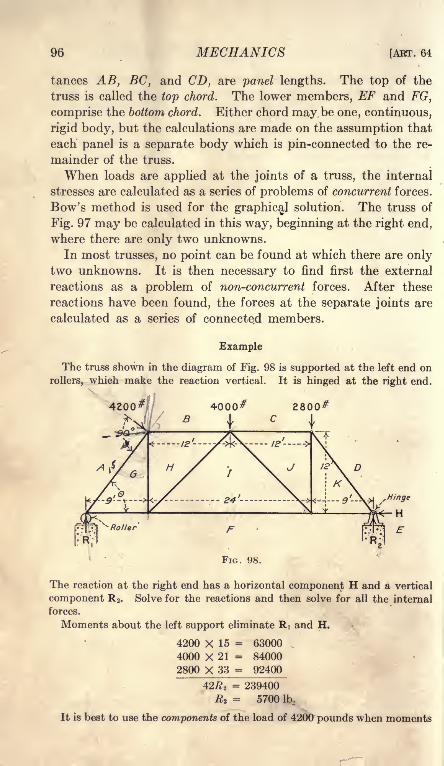
96 MECHANICS [ABT. 64
tances AB, BC, and CD, are panel lengths. The top of the
truss is called the top chord. The lower members, EF and FG,
comprise the bottom chord. Either chord may be one, continuous,
rigid body, but the calculations are made on the assumption that
each panel is a separate body which is pin-connected to the re-
mainder of the truss.
When loads are applied at the joints of a truss, the internal
stresses are calculated as a series of problems of concurrent forces.
Bow's method is used for the graphical solution. The truss of
Fig. 97 may be calculated in this way, beginning at the right end,
where there are only two unknowns.
In most trusses, no point can be found at which there are onlytwo unknowns. It is then necessary to find first the external
reactions as a problem of non-concurrent forces. After these
reactions have been found, the forces at the separate joints are
calculated as a series of connected members.
Example
The truss shown in the diagram of Fig. 98 is supported at the left end on
rollers, which make the reaction vertical. It is hinged at the right end.
, Hinge
H
The reaction at the right end has a horizontal component H and a vertical
component R 2 . Solve for the reactions and then solve for all the internal
forces.
Moments about the left support eliminate Ri and H.
4200 X 15 = 63000
4000 X 21 = 84000
2800 X 33 = 92400
42# 2= 239400
R 2= 5700 lb.
It is best to use the components of the load of 4200 pounds when moments

CHAP. V] NON-CONCURRENT CO-PLANAR FORCES 97
are taken about the hinge. The end posts are 15 feet in length. Sin =
ye= 0.8000; cos = 0.6000. The force of 4200 pounds at right angles to
the end post makes an angle 6 with the horizontal. The horizontal com-
ponent of 4200 pounds is 4200 X 0.8 = 3360 pounds. The vertical com-
ponent is 4200 X 0.6 = 2520 pounds. Using these components instead of
the 4200-pounds force, and taking moments about the right end of the truss,
2800 X 9 = 25200
4000 X 21 = 84000
2520 X 33 = 83160
192360 counter-clockwise,3360 X 12 = 40320 clockwise,
42tfi =152040R! = 3620 Ib.
Resolve vertically for a check,
5700
3620
2520
4000
2800
9320 = 9320
The horizontal component of the hinge reaction is obtained by a horizontal
resolution,
H = 3360 Ib.
This problem of non-concurrent, coplanar forces has now been solved bytwo moments and one resolution and partly checked by a second resolution,
It might well be checked again by moments about the point of applicationof the 4200-pound load, or about the middle of the top chord.
2520# 4000# 3800^'
3360#
It is not best to use the components of the inclined force in both momentequations, for, if an error is made in the computation, the reactions will
check and still be incorrect.
Figure 99 shows the reactions for the truss of Fig. 98. The force of 4200
pounds is replaced by its components. If a force and its components are
written on the same diagram, one or the other should be enclosed in a7

98 MECHANICS [ART. 64
parenthesis, or otherwise marked, on account of the danger of using both
the force and its components in the same equation.
With the external forces known, the internal forces may now be computed.The algebraic method of solution, joint at a time, will be given first. This
will be followed by the graphical solution. Figure 99 has been lettered byBow's method. Each force will be represented by two letters. (It is most
convenient in the algebraic method to use a single letter for each force.
The two letters, will be used here, however, in order to compare the results
more readily with the graphical solution.)
Beginning with joint No. 1 as the free body and resolving vertically,
ag sin = 3620,
comPress*on -
Resolving horizontally,
fff= ag cos e = 4525 X 0.6, gf = 2715 Ib. tension.
The tension in GF might have been calculated by moments about joint No. 2,
gf X 12 = 3620 X 9.
At joint No. 2, AG pushes upward. Its horizontal component at the topis the same as at the bottom, or 2715 pounds. Its vertical component is
3620 pounds. Resolving horizontally,
bh = 3360 + 2715, bh = 6075 Ib. compression.
Resolving vertically, and assuming that gh pulls downward,
ag sin 6 = 2520 + gh,
gh = 3620 -2520, gh = 1100 Ib. tension.
Resolving vertically at joint No. 3,
Ai sin 45 = gh = 1100,
hi = 1100 X 1.4142, hi = 1556 Ib. compression.
Resolving horizontally, HI pushes toward the left and GF pulls toward the
left, consequently IF must pull toward the right. The horizontal compo-nent of the force in HI is the same as the vertical component;
if= 2715 + 1100, if = 3815 Ib. tension.
Resolving vertically at joint No. 4,
ij sin 45 = 4000 - 1100 = 2900,
ij= 2900 X 1.4142, ij
= 3701 Ib. compression.
Resolving horizontally, assuming that cj is compression,
cj= bh + hi cos 45 ij cos 45,
cj= 6075 + 1100 -
2900, cj''= 4275 Ib, compression.
At joint No. 5,
kd cos 6 =cj
= 4275,4275^ ="Oil"'
^ = ^^ ***' compression.
jk + 2800 = Kd sin 6 = 7125 X 0.8,
jk = 5700 -2800, jk = 2900 Ib. tension.

CHAP. V] NON-CONCURRENT CO-PLANAR FORCES 99
At joint No. 6,
jk =ij sin 45 = 2900 Ib.
kf = if- ij cos 45 = 3815 -2900, kf = 916 Ib. tension.
At joint No. 7,
kd sin = fe = RzR2
= 7125 X0.8 = 5700 Ib.
kd cos 6 kf = de = H,H = 4275 - 915 = 3360 Ib.
These last two results check the hinge reaction. The values of jk from joints
5 and 6 also check.
Figure 100 is the graphical solution for Fig. 98. The diagram
begins with a/, the vertical reaction at the left end. The last
FIG. 100.
point is k. This point should fall on the horizontal line igf,
in order that the line kf may be horizontal. On account of errors
in the drawing, the point k is slightly above igf. The distance
from k to the horizontal line is the closing error.
The external forces fa, ab, be, cd, de, and ef form a polygon.A line representing an external force is recognized by the fact
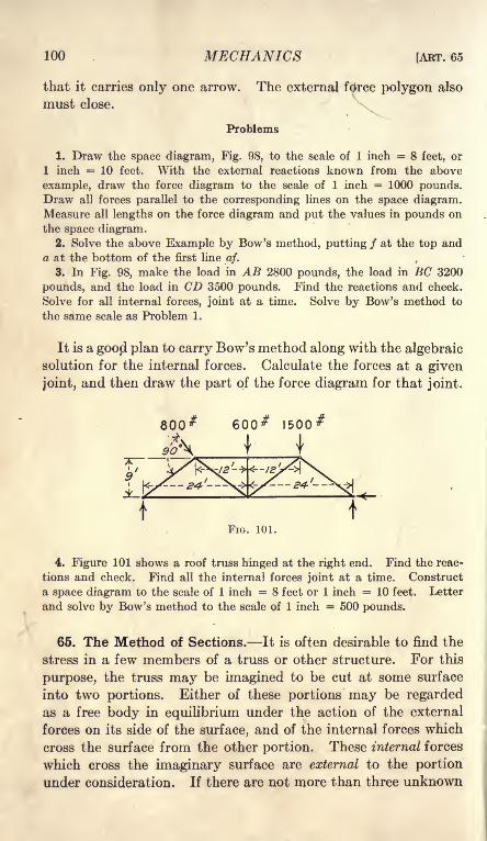
100 MECHANICS [ART. 65
that it carries only one arrow. The external fdrce polygon also
must close.
Problems
1. Draw the space diagram, Fig. 98, to the scale of 1 inch = 8 feet, or
1 inch = 10 feet. With the external reactions known from the above
example, draw the force diagram to the scale of 1 inch = 1000 pounds.Draw all forces parallel to the corresponding lines on the space diagram.Measure all lengths on the force diagram and put the values in pounds on
the space diagram.2. Solve the above Example by Bow's method, putting / at the top and
a at the bottom of the first line a/. c
3. In Fig. 98, make the load in AB 2800 pounds, the load in BC 3200
pounds, and the load in CD 3500 pounds. Find the reactions and check.
Solve for all internal forces, joint at a time. Solve by Bow's method to
the same scale as Problem 1.
It is a goopl plan to carry Bow's method along with the algebraic
solution for the internal forces. Calculate the forces at a given
joint, and then draw the part of the force diagram for that joint.
800# 600# I500#&
90'3\ I I
FIG. 101.
4. Figure 101 shows a roof truss hinged at the right end. Find the reac-
tions and check. Find all the internal forces joint at a time. Construct
a space diagram to the scale of 1 inch = 8 feet or 1 inch = 10 feet. Letter
and solve by Bow's method to the scale of 1 inch = 500 pounds.
65. The Method of Sections. It is often desirable to find the
stress in a few members of a truss or other structure. For this
purpose, the truss may be imagined to be cut at some surface
into two portions. Either of these portions may be regarded
as a free body in equilibrium under the action of the external
forces on its side of the surface, and of the internal forces which
cross the surface from the other portion. These internal forces
which cross the imaginary surface are external to the portion
under consideration. If there are not more than three unknown

CHAP. V] NON-CONCURRENT CO-PLANAR FORCES 101
forces acting on the portion in question, these may be deter-
mined as a problem of non-concurrent forces.
Example
Figure 102 represents the truss of Fig. 99. The external reactions are known.The truss may be regarded as divided at the surface SR, which cuts the
members CJ, JI, and IF. The portion to the right of SR will be taken as
the free body This portion is shown separately in Fig. 102, II. Theforces which act on the free body are the known forces of 2800 pounds,3360 pounds, and 5700 pounds, together with the unknown forces in the
members C/, ,77, and IF. The direction of each of these members is known;
hence, the unknowns are the magnitudes of the three forces.
E5ZO
36ZO
FIG. 102.
The members // and IF intersect at joint No. 6. If moments are taken
about this joint, the only unknown is the force in CJ.
12 X cj= 9 X 5700, cj
= 4275 Ib.
The reaction of 5700 pounds tends to turn the portion of the truss in a
counter-clockwise direction about joint No. 6. The force in CJ must turn
in the opposite direction. Consequently CJ must push toward the right.
cj= 4275 Ib. compression.
The members JI and CJ intersect at joint No. 4, Fig. 102, I. If momentsare taken about this joint, the only unknown is the force in IF. (This
origin of moments is outside the portion under consideration. If a body ia

102 MECHANICS [AKT. 65
in equilibrium, the sum of the moments is zero for any origin whatever,
whether inside the body or entirely away from it.)
2800 X 12
3360 X 12
= 33600= 40320
73920 clockwise,5700 X 21 = 119700 counter-clockwise
if X 12 = 45780,if = 3817 Ib. tension.
Two of the unknowns have now been found by two moment equations.
The third unknown is best found by a vertical resolution,
ij sin 45 = 5700 - 2800 = 2900,
ij= 2900 cosec 45 = 2900 X 1.4142,
ij= 3701 Ib. compression.
It is not at all necessary to make a separate drawing of the portion of the
truss which is taken as the free body. This has been done in Fig. 102, II,
in order to simplify the explanation. Generally the original space diagram,
Fig. 102, I, is employed and a section line is drawn across to indicate the
boundary of the portion in equilibrium.
The solution of a problem, joint at a time, may be regarded
as a special case of the method of sections. A single joint is cut
off as the free body and the forces are concurrent. The term,
"method of sections" is applied to cases like that of Fig. 102, II,
in which the forces on the free body are non-concurrent.
600 #
800*
1000'
Problems
1. In Fig. 102, use the portion of the truss to the left of the section RSas the free body and solve for the forces in CJ, JI, and IF. Take moments
about the same points as in the example above.
2. In Fig. 102, make a section VU, which cuts the members BH, HI,
and IF, and find the force in the members cut without using any other
internal forces. Solve first with the
portion to the left of the section as
the free body and check with the
portion to the right of the section as
the free body.3. Make a section WX in Fig. 102,
separating the end post AG as a free
body. Find the force in HG by a
vertical resolution.
4. In Problem 3 of Art. 64, cal-
culate the external reactions, and
then find bh and hi by sections without using any other internal forces.
6. In Fig. 103, find the reactions and check. Make a section through
BH, HG, and OF and find the forces in these members, without using any
other internal forces.
10
FFIG. 103.

CHAP. V] NON-CONCURRENT CO-PLANAR FORCES 103
Could you solve Problem 5 by means of a section through BH, HI, IJ,and JF1 Why?
6. Solve Problem 5 for all internal forces, joint at a time.
7. Solve Problem 5 for all internal forces by Bow's method to the scale
of 1 inch = 400 pounds.8. In Fig. 104, the loads in AB \ B \
and BC are each 1200 pounds.Find the reactions. Find bf and
fd by sections. Find all internal
forces, joint at a time.
9. In Fig. 104, the load in AB is
800 pounds, and the load in BC is i
1200 pounds. Find the reactions. '
Find bf and fd by sections. Check
by a horizontal resolution.
10. In Fig. 105, find the reactions in BA, AF, and FE. Check. Find
ci, ij, and je by sections. Begin at the right end and solve for all forces,
joint at a time. Begin at the right end and solve graphically.
*5K.1600*
ia
FIG. 105.
66. Jointed Frame with Non-concurrent Forces. In the
jointed frames considered, the loads have been applied at the
joints; consequently the intervening members transmitted force
only in the direction of their length. A member to which onlytwo forces are applied, is called a two-force member. If the forces
are in equilibrium, they must lie along the same straight line, andif they are applied at opposite ends of the member, the direction
of each force must be in the line of the member. A member to
which three forces are applied is called a three-force member.
It is not necessary that any of these forces be in the direction of
its length.
Example
Figure 106 shows two links which are connected to each other and to the
supports by smooth hinges. The left link carries a load of 30 pounds 1 foot
from the left end; the right link carries a load of 50 pounds at the middle.
The problem is to find the reactions of the supporting hinges and the in-
ternal reaction at the hinge which connects the links.
Equilibrium equations may be written for the two links separately, or
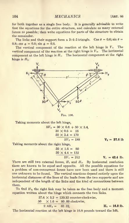
104 MECHANICS [ART. 66
for both together as a single free body. It is generally advisable to write
first the equations for the entire structure, and calculate as many external
forces as possible; then write equations for parts of the structure to obtain
the remainder.
The links and their support form a 3 : 4 : 5 triangle. Cos 6 = 0.6; sin =
0.8; cos <=
0.8; sin<f>= 0.6.
The vertical component of the reaction at the left hinge is Vi. The
vertical component of the reaction at the right hinge is F 2 . The horizontal
component at the left hinge is H i. The horizontal component at the right
hinge is H 2 .
FIG. 106.
Taking moments about the left hinge,
5F2= 30 X 0.6 + 50 X 3.4,
30 X 0.6 = 18
50 X 3.4 = 170
5F2= 188
Taking moments about the right hinge,
50 X 1.6 = 80
30 X 4.4 = 132
V, = 37.6 Ib
5Vi = 212 Vi = 42.4 Ib.
There are still two external forces, HI and H 2 . By horizontal resolution
these are known to be equal and opposite. All the possible equations for
a problem of non-concurrent forces have now been used and there is still
one unknown to be found. The vertical reactions depend entirely upon the
horizontal distances of the lines of the loads from the two supports and are
independent of the length of the links and the kind of connections between
them.
To find H 2 ,the right link may be taken as the free body and a moment
equation written about the hinge which connects the two links.
37.6 X 3.2 = 120.32 counter-clockwise,
50 X 1.6 = 80 . 00 clockwise,
2.4#2= 40.32, H 2
= 16.8 Ib.
The horizontal reaction at the left hinge is 16.8 pounds toward the left.

CHAP. V] NON-CONCURRENT CO-PLANAR FORCES 105
In Fig. 106, Hz is the horizontal component of the force from the right
link to the left link, and F 3 is the vertical component. Equal and opposite
forces act from the left link to the right link.
Using the left link as the free body and taking vertical resolutions,
y l + Vz = 30 Ib.
F 3= 30 -
42.4, V 3= 12.4 Ib. downward.
If F 4 is the vertical component of the reaction of the left link on the right
link, a vertical resolution with the right link as the free body gives an equal
force in the opposite direction.
By horizontal resolutions, with either link as the free body, H 3= 16.8 Ib.
Both Hz and F 3 may be checked by moments about the left hinge with the
left link as the free body.
Problems
1. In Fig. 107, find the direction and magnitude of the reactions at the
supporting hinges, and the direction and magnitude of the force from the
inclined member to the horizontal member at the hinge which connects
them.
Ans. H l= #2
= #3 = 163.92 Ib.;
Fi = 25.36 Ib.; F2= 134.65 Ib.; F 3
= 34.64 Ib.;
fa = 165.9 Ib. left 8 48' up;
, JK2 = 212.1 Ib. right 39 24' up;
#3 = 167.5 Ib. right 11 32' up.
60
Lr- *'-

106 MECHANICS [ABT. 66
problem of the ordinary type by considering the forces between
the joints as replaced by forces at the joints. In Fig. 109, which
is the same as Fig. 106, the load of 50 pounds at the middle of the
200 Ib.
FIG. 108.
right link has been replaced by a load of 25 pounds at each end of
the member; and the load of 30 pounds at the third point of the
left link has been replaced by 20 pounds at the left end and 10
f-I M
II
pounds at the right end. The load of 10 pounds at the right
end of the left link and the load of 25 pounds at the left end of the
right link together are equivalent to 35 pounds. As far as the
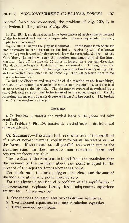
CHAP. V] NON-CONCURRENT CO-PLANAR FORCES 107
external forces are concerned, the problem of Fig. 109, I, is
equivalent to the problem of Fig. 106.
In Fig. 109, I, single reactions have been drawn at each support, instead
of the horizontal and vertical components. These components, however,
might have been used. .
Figure 1 09, II, shows the graphical solution. At the lower joint, there are
two unknowns in the direction of the links. Beginning with the knownload of 35 pounds vertically downward, draw the force triangle dca. At the
right hinge, the unknowns are the direction and magnitude of the hinge
reaction. Lay off the line cb, 25 units in length, in a vertical direction.
The closing line ba gives the direction and magnitude of the hinge reaction.
The horizontal component of the hinge reaction is the force H 2 of Fig. 106,
and the vertical component is the force Vz> The left reaction de is found
in a similar manner.
To find the direction and magnitude of the reaction at the lower hinge,
the load of 25 pounds is regarded as acting on the right link, and the load
of 10 as acting on the left link. The pin may be regarded as replaced by a
short link and an additional letter inserted in the space diagram. On the
force diagram measure 10 units downward from d to the point/. The broken
line af is the reaction at the pin.
Problems
4. In Problem 1, transfer the vertical loads to the joints and solve
graphically.
5. In Problem 3, Fig. 108, transfer the vertical loads to the joints andsolve graphically.
67. Summary. The magnitude and direction of the resultant
of a set of non-concurrent, coplanar forces is the vector sum of
the forces. If the forces are all parallel, the vector sum is the
algebraic sum. In these respects, non-concurrent forces andconcurrent forces are alike.
The location of the resultant is found from the condition that
the moment of the resultant about any point is equal to the
moment of the separate forces about that point.
For equilibrium, the force polygon must close, and the sum of
the moments about any point must be zero.
For the algebraic solution of a problem of the equilibrium of
non-concurrent, coplanar forces, three independent equationsare written. These may be:
1. One moment equation and two resolution equations.2. Two moment equations and one resolution equation.3. Three moment equations.

108 MECHANICS [ART. 68
When two moment and one resolution equation are written,
the resolution must be not taken perendicular to the line which
joins the two origins of moment. When three moment equations
are written, the three origins of moment must not lie in the same
straight line.
When the forces are all parallel, there can be only two unknowns
and two independent equations. One of these equations must
be a moment equation.
The direction condition of equilibrium for three forces requires
that the lines of action of the forces must meet at a point. Thedirection condition for four forces is that the resultant of two
of the forces must pass through the intersection of the other two.
A direction condition may replace a moment equation in the
solution of a problem of equilibrium. The direction conditions of
equilibrium are especially useful in problems in which angles are
to be found.
A resolution perpendicular to the direction of an unknown force
eliminates that force. A moment equation with respect to
a point in the line of action of an unknown force eliminates that
force. It is often desirable to take moments about the point of
intersection of two unknown forces, or about a point in the line of
action of a force whose direction and magnitude are both
unknown.
In a connected system, the entire system is first treated as the
free body and as many of the reactions as possible are calculated.
The parts of the system are then treated as free bodies. Whenthe free body is a single joint, the forces are concurrent. Themethod of sections divides the system into two portions. Either
portion may be treated as the free body in equilibrium. Theforces which act on the portion are the external forces on its side
of the section, and the internal forces in the members which are
cut by the section.
68. Miscellaneous Problems
1. Two bodies, one of which weighs 20 pounds and the other 50 pounds,are attached to the ends of a rope which runs over a smooth pulley. The
50-pound mass is in contact with a smooth plane which makes an angle of
15 degrees with the horizontal. Find the position of equilibrium, the reac-
tion of the plane, and the direction and magnitude of the resultant force on
the pulley.
2. In Problem 1, what is the maximum angle of the plane with the hori-
zontal in order that equilibrium may be possible?

CHAP. V] NON-CONCURRENT CO-PLANAR FORCES 109
3. In Problem 1, both bodies are ki contact with the plane. The per-
pendicular distance from the pulley to the plane is 5 feet. Neglecting the
dimensions of the pulley, find the minimum length of rope for possible
equilibrium.
4. A 20-pound mass is supported by two cords. One cord is 5 feet long
and has the upper end attached to a point A. The second cord runs over
a smooth pulley at the same level as the point A tand 5 feet therefrom, and
carries a load of 12 pounds. Find the position of equilibrium, the tension
in the first cord, and the resultant force on the pulley. There are two possi-
ble solutions of the equations. What change must be made in the construc-
tion of the apparatus in order that both solutions may be mechanically
possible?
5. Solve Problem 4 if the pulley is 5 feet from A along a line which makes
an angle of 10 degrees with the horizontal. Write moments about A and
solve by trial and error.
Ans. The cord from A makes an angle of 29 18' with the vertical.
6. A bar 10 feet long, weighing 60 pounds, with its center of mass 6 feet
from the left end, is hinged at the left end and supported by means of a
rope at the right end. The right end is elevated 20 degrees above the
horizontal. The rope at the right end makes an angle of 35 degrees to the
left of the vertical. Find the tension in the rope and the direction and mag-nitude of the hinge reaction by means of one moment equation and two
resolution equations. Check by a second moment equation.
7. Solve Problem 6 by means of the direction condition >of equilibrium.
Compare with the results of Problem 6.
8. A box is 5 feet long horizontally and 3 feet high. It weighs 240 poundsand its center of mass is at the center. A force applied at the upper right
edge tips the box about the lower left edge. The force makes an angle of
25 degrees to the left of the vertical. If the friction is sufficient to prevent
sliding, what force will be required to start the box?
Ans. 103.4 Ib.
9. Solve Problem 8 graphically by means of the direction condition of
equilibrium.
10. In Problem 8, what is the direction and magnitude of the minimumforce at the upper right edge which will start to tip the box?
11. The box of Problem 8 is turned through an angle of 20 degrees. Find
the direction and magnitude of the smallest force at the upper right corner
which will hold it in this position?
12. A ladder 20 feet long, weighing 50 pounds, with its center of mass8 feet from the lower end, stands on a smooth horizontal floor and leans
against a smooth, vertical wall. It is held from slipping by a horizontal
force at the floor. Find this force and the reaction at the floor and at the
wall when the ladder makes an angle of 25 degrees with the vertical.
13. The ladder of Problem 12 stands on a smooth horizontal floor andleans against the edge of a wall 15 feet in height. It is held from slipping bya horizontal force at the bottom. Solve for the unknowns when the ladder
makes an angle of 30 degrees with the horizontal.
14. Solve Problem 12 if the horizontal force at the bottom of the ladder
is 16 pounds and the position is unknown.

110 MECHANICS [ART. 68
16. Solve Problem 12 if the horizontal force is 15 pounds and is applied
2 feet from the bottom of the ladder. Check your results by means of
the direction .condition of equilibrium.* 16. A beam 20 feet long, weighing 80 pounds, with its center of mass at
the middle, has its left end on a smooth plane which makes an angle of 60
degrees to the left of the vertical, and its right end on a smooth plane which
makes an angle of 70 degrees to the right of the vertical. The beam carries
a load of 60 pounds 5 feet from the left end, and a load of 100 pounds 4 feet
from the right end. Find the reactions of the planes and the angle which
the beam makes with the horizontal.
1000'
*17. A bar 4 feet in length, weighing 50 pounds, with its center of mass at
the middle, has one end against a smooth vertical wall. The other end is
attached to a rope 5 feet in length which is fastened to a point in the wall.
Find the position of equilibrium, the reaction of the wall, and the tension
in the rope.
18. The bar AB t Fig. 110, has its center of mass at the middle of its length.
The end B is against a smooth wall which makes an angle of 10 degrees
with the vertical. The end A is supported by a rope. Find the direction
of the rope, the tension in it, and the reaction of the plane.
19. In Fig. Ill, find all reactions and check. Find bh, hg, and gf bysections. Find all forces joint at a time. With the reactions known, solve
by Bow's method.

CHAPTER VI
COUPLES
69. Moment of a Couple. In Fig. 112, P and Q are twoforces in opposite directions at a distance a apart. Their
equilibrant is the force Q P at a distance x from Q. Thedistance x is given by the equation,
(Q -P)x = Pa . (1)
IfQ = P,Q - P = Q,x =infinity.
Two equal and opposite forces acting on a body form a couple.
The forces of a couple have a moment about any point and tend
to produce rotation about any point. Since the forces are equal,
their resultant is zero. The forces of a couple do not producetranslation.
If the magnitude of each force is P and the distance between
the forces is a, the moment is Pa. The moment is the same with
f'
i--4- --1 o f=*
TP Q-P
T P
FIG. 112 FIG. 113.
respect to any point in the plane of the forces. This statement
may be proved by Fig. 113. The point 0, at a distance x from
the downward force of the couple, may be taken as the origin
of moments. The sum of the moments of the two forces about
this origin is
M = - Px + P(x + a)= Pa (2)
The moment of the couple is the same, no matter what point is
taken as the origin. The moment of a couple is the product of
either force multiplied by the distance between the lines of action of
the two forces.
70. Equivalent Couples. Two forces are equivalent if either
force may be balanced by a third force so that no translation is
produced in the body upon which the forces act. Two couples
111

112 MECHANICS IABT. 70
are equivalent if either couple may be balanced by a third coupleso that no rotation is produced in the body upon which the couples
act. These definitions may be stated briefly: Forces which are
balanced by the same force are equivalent. Couples which are
balanced by the same couple are equivalent^
In order that two forces may produce equilibrium, the forces
must be equal, opposite, and along the same line. In order that
two couples may be in equilibrium, the magnitude of their mo-
ments must be equal, the direction of rotation must be opposite,
and the couples must lie in the same plane or in parallel planes.
It will now be proved that a given couple may be balanced bya second couple in the same plane, provided the moments are
equal and opposite. If the moments are equal and opposite,
the forces may have any magnitude and may be placed at any
position in the plane. A couple may be made of an upward
<?\ >R^f \P, V-V^ P-
1 *-" &\% \ Vector Diagram
FIG. 114.
force of 6 pounds and a downward force of 6 pounds at a distance
of 4 feet to the right of the first force. The moment of this
couple is 24 foot-pounds clockwise. Any counter-clockwise
couple of 24 foot-pounds in the same plane will produce equilib-
rium. This second couple may be made of two horizontal
forces of 24 pounds at a distance of 1 foot apart, with the upperforce toward the left, or it may be made of two forces of 12
pounds at a distance of 2 feet apart, or of two forces of 8 poundsat a distance of 3 feet, or of any other combination whose momentis 24 foot-pounds counter-clockwise.
In Fig. 114, PI and P2 are equal forces of magnitude P at a
distance a apart. These forces form a clockwise couple of magni-tude Pa. A second pair of forces, Qi and Q 2 ,
each of magnitude
Q, at a distance b apart, form a counter-clockwise couple of
moment Qb. It will be proved that these couples produce
equilibrium if the magnitude of the moment Pa is equal to the
magnitude of the moment Qb,

CHAP. VI] COUPLES 113
Extend the lines of the forces until the line of the force PI
intersects the line of the force Qi, and the line of the force P2
intersects the line of the force Q 2 . The resultant of the forces
Pi and Qi at A is a force RI. The direction and magnitude of the
force RI are given by the vector diagram, E, F, G, of Fig. 114, II.
The resultant of P 2 and Q 2 at C is a force R2 . The magnitudeand direction of R2 are given by the lower force triangle of Fig.
114, II. Since PI is equal and opposite to P2 ,and Qi is equal and
opposite to Q 2 ,it is evident from Fig. 114, II, that RI is equal and
opposite to R2 . If the resultant RI through A of the space dia-
gram falls on the same line as the resultant R2 through C, the
forces will balance and the couples will be in equilibrium. This
condition is satisfied if the line of RI passes through the point C.
In the space triangle ABC, and the force triangle EFG, the
angle at B is equal to the angle at F. If this angle is represented
by 0;
AB sin 6 =b, (1)
BC sin =o, (2)
AB - b m"a
The triangles ABC and EFG are similar if
AB EFBC
=FG'
and the resultant RI on the space diagram falls on the line AC.
Substituting from Equation (3)
6 EF P(5)a FG Q
Pa = Qt (6)
Equation (6) states that the moments of the two couples are
equal, when ABC and EFG are similar.
Since the couple Pa may be balanced by any other couple of
equal moment and opposite direction in the same plane, it
follows that any. two couples in the same plane are equivalent if
moments are equal in magnitude and sign.
If the moment Pa of Fig. 114 does not equal the moment Qb,
the resultant RI will still be equal and opposite to the resultant
R2 . The two resultants will not, however, lie on the same line
but will form a new couple of moment Pa Qb.8

114 MECHANICS'
[ART. 71
Problems
1. A couple is made up of a horizontal force of 12 pounds toward the
right and an equal force toward the left at a distance of 3 inches below the
first force. A second couple is made up of a force of 8 pounds upward at
an angle of 30 degrees to the right of the vertical and an equal force in the
opposite direction at a distance of 5 inches, so placed that the moment is
counter-clockwise. Draw a space diagram similar to Fig. 114 to the scale
of 1 inch = 1 inch. Construct the force diagram similar to EFG of Fig. 114
to the scale of 1 inch = 4 pounds, and find RI. Through A and C draw lines
parallel to RI. Measure the distance between these lines and multiply byRI. Compare the product with the difference of the two moments.
2. Solve Problem 1 if the forces, of the second couple are so placed that
its moment is clockwise.
3. A clockwise couple is made up of two horizontal forces of 10 poundseach at a distance of 6 inches from each other. A counter-clockwise couplein the same plane is made up of two forces of 15 pounds each at a distance of
4 inches apart. Find their resultant graphically.
It will be shown in Art. 106 that couples in parallel planeswhich are equal in magnitude and have the same signs are equiva-
lent.
71. Algebraic Addition of Couples. Couples in the same plane
may be added graphically by methods of Art. 70. It will
II
FIG. 115.
now be proved that the combined moment of two couples in
the same plane is the algebraic sum of the moments of the couples.If Pa is one couple and Qb is another couple in the same plane,the resultant moment is Pa + Qb when the moments are in the
same direction, and the resultant moment is Pa Qb when the
moments are in opposite directions.
There are two couples in Fig. 115. If = R, the couple
Qb may be replaced by a second couple Ra. The forces of the
second couple are RI and R2 ,each of magnitude R. According
to Art. 70, this couple Ra may be placed anywhere in the plane of
the original couples. In Fig. 115, II, the force RI is placed in theline of the force PI, and the force R2 is placed in the line of the

CHAP. VI] COUPLES 115
force P2 . The resultant force in each of these lines is now P + Rand
M = (P + R)a = Pa + Ra = Pa + Qb
This equation proves the proposition. Any number of couples
may be added in the same way.Since the moment of a couple is the same about any point in
its plane, it might be regarded as self-evident that the combined
moment of several couples is the algebraic sum of the separatemoments. The proof here given is, however, more satisfactory
to most readers, than this brief statement.
72. Equilibrium by Couples. In many problems of equilib-
rium, the forces may be grouped to form two equal and opposite
FIG. 116.
couples in the same plane. Figure 116 represents an arrangementfor demonstrating the equilibrium of couples. A rigid bodyis made up of a bar and a wheel fastened together. The bar
is supported by a small cylinder which rolls on a plane surface.
The reaction of the small cylinder is vertical. This reaction
together with the weight of the system forms one couple. Twocords are passed partly around the wheel and fastened to it.
One cord runs horizontally toward the left and is attached to a
post. The second cord runs horizontally toward the right,
passes over a smooth pulley, and supports a mass of P pounds.P = T and R = W For equilibrium
Pa = WbThe plane supporting the cylinder may be a platform scale.

116 MECHANICS [ART. 73
If the scale poise is set to equal the load W and the weight of
the small cylinder, the beam will be in balance when the cords
are. parallel.
Figure 117 shows a beam with loads P and Q near the ends.
k-
\
9><------ b ----->\
LFIG. 117.
Neglecting the weight of the beam, the . reaction S = P + Q.
The load P at the left end together with an equal amount of the
reaction at the middle forms a couple of moment Pa. The load
Q at the right end, together with the remainder of the reaction,
forms an opposite couple of moment Qb. For equilibrium these
couples are equal.
In Fig. 118, the two forces P and Q are not parallel. The
equilibrant S may be resolved into two components, which
are equal and opposite to P and Q, respectively. The beamis then subjected to two couples of moments Pa and Qb.
Problems
1. What are the two equal couples in Fig. 96 of Art. 63?
2. What are the two equal couples of Fig. 88?
3. In Fig. 89, when AC and BD are parallel, what are the two equivalent
couples?
73. Reduction of a Force and a Couple to a Single Force. In
Fig. 119, I, there is a single force P, and a counter-clockwise
couple in the same plane made up of two equal forces Qi and

CHAP. VI] COUPLES 117
Q 2 at a distance b apart. The moment of this couple is Qb.
If Pa = Qb, this couple may be replaced by a couple made up of
two equal forces PI and P 2 at a distance a apart. By Art. 70
these forces may be placed anywhere in the plane of the couple.
The force PI may be placed in the line of action of the single force
P, and the force P 2 at a distance a from that
line on the side which makes the moment ^2A
counter-clockwise. The force PI, Fig. 119,
II, balances the force P. The remaining forcep/
j ^Q,P2 ,
at a distance a from the position of the force /P, replaces the force and the couple. p r
A force and a couple in the same plane are / ypzequivalent to a single force. The direction and 4 /
magnitude of the single force are the same as / /
those of the line of action of the original force.
Its distance from the line of action of the original
force is such that its moment about any point in that line is equal in
magnitude and sign to the moment of the original couple.
Example ^
A vertical force of 20 pounds upward is applied at the point x = 4 ft.
A horizontal force of 5 pounds toward the right is applied at y = 2 ft. and
an equal horizontal force toward the left is applied at y = 12 ft. Find the
location of the single force which is equivalent to this force and couple.
The moment of the couple is 50 foot-pounds.
|'
>
|!= 2.5ft.
The single force is 20 pounds upward at a distance of 2.5 feet from the
vertical line through the point x = 4 ft. Since the couple is counter-
clockwise, the distance of 2.5 feet must be measured toward the right from
the line x = 4 ft. The resultant force lies in the line x = 6.5 ft.
Problems
1. A force of 12 pounds, along the line x = 2 ft., is combined with a
couple made up of a horizontal force of 8 pounds toward the right, alongthe line y = 1 ft., and an equal and opposite force, along the line y = 13 ft.
Find the location of the single force which is equivalent to the force andthe couple.
2. Solve Problem 1 graphically to the scale of 1 inch = 4 feet, and 1
inch = 8 pounds. Through the intersection of the line of action of the
vertical force with the line of action of one of the horizontal forces draw a
line parallel to the direction of their resultant. Through the intersection
of this line with the line of the third force on the space diagram, draw a
line parallel to the direction of the resultant of all three forces.

118 MECHANICS [ART. 74
3. Find the single force which can be substituted for a horizontal force of
16 pounds directed toward the right and a clockwise couple of 48 foot-pounds.
Ans. 16 pounds towards the right through a point 3 ft. above the original
force.
4. An upward vertical force of 8 pounds acts along the F-axis, and a
second upward vertical force of 4 pounds acts along^ the line x = 6 ft. A
couple of 60 foot-pounds clockwise and a couple of & foot-pounds counter-
clockwise act on the body in the same plane with these forces. Find the
single force which will replace all of these.
HA
74. Resolution of a Force into a Force and a Couple. Figure
120 shows a single force P. It is desired to replace this force bythe force and a couple of moment Pa. In Fig. 120,
C is a point at a distance a from the line of action
of the force P. At C are applied two opposite forces,
Pi and P2 ,each of which is equal in magnitude to
the force P, and along a parallel line. Since these
forces balance each other, they have no effect uponthe equilibrium of the body upon which they act.
The force P| and the force P form a couple of moment Pa.
The force Pj^ which is equal and parallel to the original force
P, stands alone as the single force required.
A single force may be replaced by an equal force in the same direc-
tion through any point in its plane, and a couple, the moment of
which is the same in magnitude and direction as the moment of
the original force about that point.
Problems
1. A force of 12 pounds upward acts at the point x 3. Replace this
force by an equal force through the origin and a couple.Ans. 12 pounds upward through the origin and a counter-clockwise
couple of 36 units.
2. A force of 16 pounds at an angle of 45 degrees to the right of the
vertical upward acts at the point x= 3 ft., y = 5 ft. Replace by a force
through the origin and a couple.
Ans. 16 pounds through the origin at an angle of 45 degrees to the rightof the vertical, and a counter-clockwise couple of 22.62 foot-pounds.
3. A force of &Q pounds at an angle of 25 degrees to the right of the
vertical is applied at the point x = 2 ft., y = 3 ft. and a force of 15 poundsat an angle of 60 degrees to the right of the vertical is applied at the pointx = 2 ft., y = 8 ft. Replace these by a single force at the origin and a
single couple.
Replace each force by a single force at the origin and a single couple.Add the two couples and find the resultant of the two forces.

CHAP. VI] COUPLES 119
The principles of this article afford a method of finding the
resultant of a set of non-concurrent, coplanar forces. Let
Pi, P2 , PS, etc be a set of forces in the same plane. Each force
may be replaced by an equal force in the same direction appliedat some convenient point and a couple. Since all the forces are
now applied at the same point, they may be treated as concurrent
and their resultant found by means of the force polygon or cal-
culated by the methods of Art. 42. The couples may be added
algebraically. Their sum is a single couple.
The resultant of a set of non-concurrent forces in the same
plane is equivalent to a single force and a single couple. Since
a force and a couple in the same plane may be reduced to a single
force by the methods of Art. 73, it follows that, in general, the
resultant of a set of non-concurrent, coplanar forces is a single
force. It sometimes happens that the resultant force is zero,
while the resultant couple is not zero. This resultant couplecan hot be reduced to a single force.
A set of non-concurrent, coplanar forces may always be
reduced to a single force or to a single couple.'
While the steps of the proof are different, the results of this
article are practically the same as the method of finding the
resultant, which is given in Art. 60.
75. Summary. Two equal, opposite forces form a couple.
The moment of a couple is the product of either force multiplied
by the distance between them. The moment of a couple is the
same with respect to any origin.
Two couples in the same plane are equivalent if their momentsare equal in magnitude and sign.
The combined moment of several couples in the same plane is
the algebraic sum of the separate moments.
A force and a couple in the same plane may be replaced by a
single force which is equal in magnitude and direction to the
original force, and is so located that its moment about any pointin the line of the original force is equal to the moment of the couple.
A single force may be replaced by an equal force in the samedirection through any point in its plane, and a couple whose
moment is equivalent to the moment of the force about that point.
A set of non-concurrent, coplanar forces may be replaced by a
single force and a single couple. These may be reduced to a
single force, except when the resultant force is zero. In this
case, the final resultant is a couple.

CHAPTER VII
GRAPHICS OF NON-CONCURRENT FORCES
76. Resultant of Parallel Forces. In Art. 55, a method was
given for finding the resultant of parallel forces in the same direc-
tion. In Fig. 76, the rigid bar was assumed to be connected to
two ropes or hinged rods, and the equilibrant was found as a
problem of connected bodies with concurrent forces. This proof
was given because it is concrete and because it fits the methods
of the preceding chapter. A more abstract proof is generally
used. This will now be given.
Figure 121, I, shows two parallel forces P and Q which are
applied to the ends of a rigid bar. The force P at the left end is
Force Polygon
Fio. 121.
resolved into two components RI and S, which are not at right
angles to each other. These are shown in the triangle at the
left of the bar.' The component S is parallel to the bar. Theforce Q at the right end is resolved into two components S and
R2. The component S is equal and opposite to thec omponentS at the left end. On the space diagram, it is seen that the force
S balances the force S and the components RI and R2 remain to
act on the bar. The resultant of RI and R 2 must pass throughthe intersection of the broken lines of the space diagram, which
are drawn parallel to the corresponding forces of the force tri-
120

CHAP. VII] NON-CONCURRENT-FORCE 121
angles. Figure 121, II shows the two force triangles combined,as they are generally drawn. The components S and S fall on
the same line. The resultant of RI and R2 is the force P + Q,in the direction of the original forces.
Figure 121, III, shows the usual method of construction for the
position of the resultant. The parallel forces are P and Q. It
is, not necessary to draw the body upon which they act, or to
consider the direction of the line which joins their point of appli-
cation. The force diagram is first drawn. The distances ab =P and be = Q are laid off on a vertical line. Then a point is
selected to one side of this line, and connected to the points a, b,
and c by lines ao, bo, and co. The figure thus obtained is the
same as the force diagram of Fig. 121, II. A point No. 1 is
chosen on the line of the force P and a line is drawn through it
parallel to ao and a second line parallel to bo. The line parallel
to bo is extended till it intersects the line of the force Q at the
point No. 2. Through point No. 2, a line is drawn parallel to
the line co of the force diagram. The intersection -of the line
parallel to ao with the line parallel to co gives a point on the line
of the resultant. The resultant is equal and parallel to ac of
the force diagram.The space diagram of Fig. 121, III is called a string polygon, or
funicular polygon. The solid lines of the drawing give the
directions which three connected strings could take when sup-
porting the loads P and Q at a definite distance apart. The
diagram is lettered by Bow's method to correspond with the force
diagram of the figure. (The line P + Q does not represent a
force, but only the position of the resultant.) The arrows showthe directions required for equilibrium.
The point of the force polygon of Fig. 121, III, is called the
pole. The lines ao, bo, and co are rays. The position of the pole
may be chosen at any point. It should be so selected that lines
parallel to the rays will intersect at convenient positions on the
string polygon.Problems
1. Two vertical loads of 15 pounds and 20 pounds are 6 inches apart.Draw a force polygon to the scale of 1 inch = 5 pounds and put the pole 5
inches to the right of the load line. Draw the string polygon to the scale of
1 inch = 1 inch and find the distance of the resultant from the loads.
Check by moments. Change the position of the pole and solve again.2. Solve Problem 1 with the pole to the left of the load line. Explain
the result.

122 MECHANICS [ART. 77
3. Draw the force polygon and the funicular polygon for three vertical
forces: 13 pounds downward at feet, 10 pounds downward at 4 feet, and18 pounds downward at 12 feet. Use scale of 1 inch = 5 pounds and 1
inch = 2 feet. Compare with Fig. 122 which is drawn for a different load-
ing. Locate the resultant force and check by moments.4. Three weights of 10 pounds at feet, 15 pounds at 4 feet, and 10
pounds at 8 feet, are connected by cords and supported by two cords. Thecords supporting the first and last weights make angles of 45 degrees with
the horizontal. Find the direction and length of the cords connecting the
weights.
5. Given three vertical loads: 12 pounds at feet, 16 pounds at 5 feet,
and 20 pounds at 8 feet. Find the location of the resultant graphically andcheck by moments. If the cord supporting the 12 pounds makes an angleof 60 degrees to the left of the vertical, and the cord supporting the 20
pounds maks an angle 50 degrees to the right of the vertical, what is the
direction and length of the connecting cords?
Line of \
Resultant-^ \
A 7^ "I I
String PolygonForce
Polygon
FIG. 122.
77. Resultant of Non-parallel Forces. Art. 59 gives a methodof finding the resultant of non-parallel forces graphically. It
frequently happens that some of the forces are so nearly parallelthat this method requires an extremely large space diagram to
get the intersections. In such a case the results are likely to beinaccurate. In most cases of non-parallel forces, especiallywhen there are more than three forces, it is advisable to use themethod of Art. 76. This differs from the method of Art. 59
only in the fact that the first and last forces are resolved into
components, with one component of the first force equal andopposite to one component of the last force, and acting alongthe same line. By properly choosing the location of the polein the force diagram, the rays may be given such directions thatthe forces which they represent will make large angles with thedirections of the applied loads on the space diagram. Theintersections will then be found accurately.
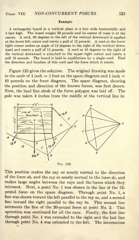
CHAP. VII] NON-CONCURRENT FORCES 123
Example
A rectangular board in a vertical plane is 4 feet wide horizontally and3 feet high. The board weighs 20 pounds and its center of mass is at the
center. A cord, 30 degrees to the left of the vertical downward is appliedat the lower left corner and exerts a pull of 12 pounds. A cord at the lower
right corner makes an angle of 15 degrees to the right of the vertical down-ward and exerts a pull of 15 pounds. A cord at 45 degrees to the right of
the vertical downward is attached to the upper right corner and exerts a
pull 16 pounds. The board is held in equilibrium by a single cord. Find
the direction and location of this cord and the force which it exerts.
Figure 123 gives the solution. The original drawing was madeto the scale of 1 inch = 1 foot on the space diagram and 1 inch =10 pounds on the force diagram. The space diagram, showingthe position and direction of the known forces, was first drawn.
Next, the load line abode of the force polygon was laid off. The
pole was taken 4 inches from the middle of the vertical line be.
20
FIG. 123.
This position makes the ray ao nearly normal to the direction
of the force ab, and the ray eo nearly normal to the force de, andmakes large angles between the rays and the forces which theyintersect. Next, a point No. 1 was chosen in the line of the 12-
pound force on the space diagram. Through point No. 1, aline was drawn toward the left parallel to the ray ao, and a secondline toward the right parallel to the ray bo. This second line
intersects the line of the 20-pound force at point No. 2. This
operation was continued for all the rays. Finally, the first line
through point No. 1 was extended to the right and the last line
through point No. 4 was extended to the left. The intersection

124 MECHANICS [ART. 78
of these lines is point No. 5, which lies on the line of the resultant
(or the equilibrant) of all these forces. The resultant of all
these forces is the line ae of the force polygon. The broken line
through point No. 5, drawn parallel to ae, gives the line of action
of the resultant. A single cord attached to the board at any
point on this line may hold it in equilibrium.
Problems
1. Solve the Example above graphically, choosing the pole 3 inches from
c on the horizontal line through c.
2. The following forces act on a rigid body: 20 pounds 18 degrees to the
left of the vertical downward, applied at the point (4, 2); 16 pounds
vertically downward, applied at the point ( 1, 0); 18 pounds 25 degrees
to the right of the vertical downward, applied at the point (2, 1); and 24
pounds 40 degrees to the right of the vertical downward, applied at the
point (4, 0). Find the magnitude, direction, and location of the resultant
graphically.
3. Solve the Example of Art. 60 by the graphical method.
78. Parallel Reactions. When a body is subjected to a set of
forces in the same plane, it may be held in equilibrium by a
single force in that plane, except when the resultant is a couple.
This equilibrant is equal and opposite to the resultant of all the
forces and lies in the same line. The line of the resultant in
the space diagrams of the problems of Art. 77 gives the location
of a series of points at which the body may be supported bya single smooth hinge.
Usually such bodies are supported at two points. When the
loads are all parallel, the reactions at these points are generally
parallel. In most cases the positions of the supports are givenand the problem is that of finding the magnitude of the reactions.
The resultant of all the parallel loads may be found by the
methods of Art. 76. This resultant. is equal and opposite to
the equilibrant, which, in turn, is the resultant of the reactions.
The problem of finding these reactions resolves itself into the
problem of finding two parallel forces which have a given resul-
tant and which pass through known points. It is the converse
of the problem of finding the resultant of two known forces.
Figure 124 gives the method of finding the resultant of two
reactions, RI and R2 . Suppose that the magnitude and positionof the resultant S are known; that the positions of the reactions
RI and R2 are also known; and that it is desired to find the
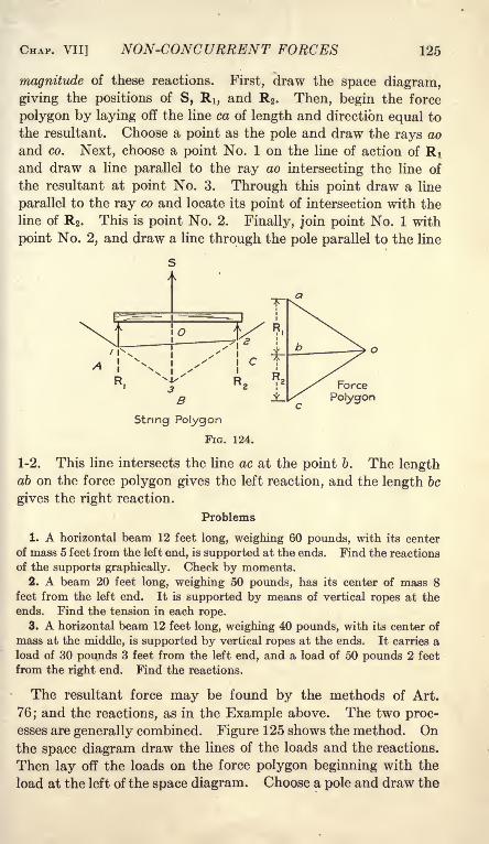
CHAP. VII] NON-CONCURRENT FORCES 125
magnitude of these reactions. First, draw the space diagram,
giving the positions of S, RI, and R2 . Then, begin the force
polygon by laying off the line ca of length and direction equal to
the resultant. Choose a point as the pole and draw the rays ao
and co. Next, choose a point No. 1 on the line of action of RIand draw a line parallel to the ray ao intersecting the line of
the resultant at point No. 3. Through this point draw a line
parallel to the ray co and locate its point of intersection with the
line of R. This is point No. 2. Finally, join point No. 1 with
point No. 2, and draw a line through the pole parallel to the line
Force
Polygon
String Polygon
FIG. 124.
1-2. This line intersects the line ac at the point b. The lengthab on the force polygon gives the left reaction, and the length be
gives the right reaction.
Problems
1. A horizontal beam 12 feet long, weighing 60 pounds, with its center
of mass 5 feet from the left end, is supported at the ends. Find the reactions
of the supports graphically. Check by moments.2. A beam 20 feet long, weighing 50 pounds, has its center of mass 8
feet from the left end. It is supported by means of vertical ropes at the
ends. Find the tension in each rope.
3. A horizontal beam 12 feet long, weighing 40 pounds, with its center of
mass at the middle, is supported by vertical ropes at the ends. It carries a
load of 30 pounds 3 feet from the left end, and a load of 50 pounds 2 feet
from the right end. Find the reactions.
The resultant force may be found by the methods of Art.
76; and the reactions, as in the Example above. The two proc-esses are generally combined. Figure 125 shows the method. Onthe space diagram draw the lines of the loads and the reactions.
Then lay off the loads on the force polygon beginning with the
load at the left of the space diagram. Choose a pole and draw the

126 MECHANICS [ART. 78
rays. Beginning with the left load of 30 pounds select point No. 1 .
Draw a line through point No. 1 parallel to bo. This line inter-
sects the line of the 40-pound load at point No. 2. Through
point No. 2 draw the next line parallel to the ray co, intersecting
the line of the 50 pound load at point No. 3. Through point
No. 1 draw a line parallel to ao and through point No. 3 draw a
line parallel to do. If these lines were carried downward, their
intersection would give a point on the line of the resultant.
All this is exactly the same as the method of Art. 76.
Space Diagram Funicular Polygon
FIG. 125.
Force
Polygon
It is not necessary, however, to find the location of the resul-
tant. The line ad of the force polygon gives its magnitude and
direction. The rays ao and do are components of the resultant.
Draw a line through point No. 1 parallel to the ray ao and extend
it till it intersects the line of the left reaction at point No. 4.
Similarly, draw a line through point No. 3 parallel to the ray do
and extend it till it intersects the line of the right reaction at
point No. 5. Since these lines would intersect on the resultant
if they were extended in the opposite directions, and since their
directions are those of the first and -last rays, ao and do, they
correspond to the lines of Fig. 124. Connect point No. 4 to
point No. 5 by a straight line and draw a ray parallel to this
line. The intersection of this ray with the load line divides ad
into two parts ae and ed. The lengths of these parts give the
reactions.
Problems
4. A beam 20 feet long, with its center of mass at the middle, weighs 60
pounds. It is supported in a horizontal position by a vertical rope at each
end, and carries a load of 40 pounds 4 feet from the left end, and a load of
50 pounds 4 feet from the right end. Find the reactions graphically andcheck by moments.

CHAP. VII] NON-CONCURRENT FORCES 127
6. Solve Problem 1 if the second rope is 6 feet from the right end.
6. Solve Problem 3 if the beam is supported at the left end and 4 feet
from the left end.
7. The beam of Problem 4 has one support at the left end, where the
vertical reaction is 80 pounds. Locate the second support graphically.
Check by moments.
79. Non-parallel Reactions. When the loads applied to a rigid
body are not parallel, the reactions usually are not parallel.
Sometimes when the loads are parallel the reactions are not
parallel. Generally, the line of action of one reaction, and the
location of a single point in the line of the other are known. Themethod of solution is the same as for parallel reactions, exceptthat the point of beginning of the funicular polygon is fixed by the
conditions of the problem.
Example
A beam 10 feet long, weighing 15 pounds, with its center of mass at the
middle, is hinged at the left end and supported at the right end by a cord
which makes an angle of 30 degrees to the left of the vertical. The right
end of the beam is elevated 10 degrees above the horizontal. The beam
10
Space Diagram Funicular Polygon
FIG. 126.
Force
Polygon
carries a vertical load of 10 pounds 2 feet from the left end, and a load of
20 pounds at an angle of 1*5 degrees to the right of the vertical downwardat a point 2 feet from the right end. Solve for the reactions graphically,
using the scale of 1 inch = 2 feet on the space diagram, and 1 inch = 10
pounds on the force diagram.
First, construct the load line and the rays as in the preceding
problems. In Fig. 125, the line of action of the left reaction was
known and the point No. 4 could fall anywhere on that line.
In Fig. 126, the left reaction passes through the hinge, but its
direction is not known. It is necessary, therefore, to put point

128 MECHANICS [ART. 79
No. 4 at the hinge. Draw the lines 4-1, 1-2, 2-3, and 3-5 parallel
to the rays ao, bo, co and do as in Fig. 125. Through d, on the
force diagram, draw a line parallel to the direction ,of the right
reaction. Draw the closing line 4-5 and draw a ray parallel to
it. This ray intersects the line from d at the point e. The
length de gives the magnitude of the right reaction. Draw the
closing line ea of the force polygon. This line gives the direction
and magnitude of the hinge reaction. The broken line throughthe hinge may now be drawn parallel to ea.
Problems
1. A horizontal beam 12 feet long, weighing 20 pounds, with its center of
mass at the middle, is hinged at the right end and supported by a cord at
the left end. The cord makes an angle of 20 degrees to the left of the
vertical. The beam carries a load of 16 pounds downward 2 feet from the
left end, and a load of 18 pounds 20 degrees to the left of the vertical down-ward 3 feet from the right end. Find the pull on the cord and the direction
and magnitude of the hinge reaction. Check by moments and resolutions.
2. Find the reactions at the supports of the truss of Fig. 98.
3. A rectangular frame in a vertical- plane is 10 feet wide horizontallyand 4 feet high. It is hinged at the upper left corner and supported by a
rope at the upper right corner. The rope makes an angle of 20 degrees to
the left of the vertical. The frame weighs 160 pounds and its center of
mass is at the middle. A force of 100 pounds at an angle of 10 degrees to
the left of the vertical downward is applied at the lower left corner. Aforce of 120 pounds at an angle of 15 degrees to the left of the vertical upwardis applied at the upper edge at a distance of 4"fe'et from the upper rightcorner. A force of 150 pounds downward is applied at the lower edge at a
distance of 2 feet from the lower right corner. Find the tension in the ropeand the direction and magnitude of the hinge reaction. Check by momentsand resolutions.

CHAPTER VIII
FLEXIBLE CORDS
80. The Catenary. A flexible cord or chain suspended from
two points takes a definite form, depending upon its length and
the relative positions of the points of support. If the chain or
cord is of uniform weight per unit of length, the curve in a vertical
plane is a catenary. The problem of finding the equation of the
catenary is an important application of statics.
Figure 127 shows a flexible cord suspended from two points
A and B. In this figure the points are at the same level. This,
however, is not necessary. The cord weighs w pounds per unit
FIG. 127.
of length. The force in the cord at every point is a tension
parallel to its length. At the lowest point this tension is hori-
zontal. The horizontal component of the tension is the same at
all points. In the formulas which follow, this horizontal compo-
nent is represented by H .
single letter c.
Hc; H = we
Ti-
lt is customary to represent 'by a
w129

130 MECHANICS [ART. 81
The constant c is the length of cord whose weight is equal to the
horizontal tension (Fig. 128).
In Fig. 127, a portion of cord of length s is taken as the free
body. The left end of the portion is at the lowest point of the
curve, where the tension is horizontal. Figure 127, II, showsthis portion of the cord detached from the remainder. Three
forces act on the portion. The horizontal tension H is toward
the left at the lower end. The tension T in the direction of the
tangent acts at the upper right end. The weight of the portionof cord is ws and acts vertically downward. Figure 127, III,
gives the force triangle for these forces. In Figure 127, I, ah
element of length ds is shown at the right end of the length s.
The components of the element are dx and dy. Figure 127, IV,
shows the same element enlarged.
Since the tension at the end of the cord is along the tangent at
that position, T is parallel to ds and the force triangle of Fig.
127, III, is similar to Fig. 127, IV. These triangles furnish
relations necessary for finding the equations of the catenary.
81. Deflections in Terms of the Length. From the triangles
of Fig. 127,
dy ws
ds=
~T'
This equation involves three variables, T, s, and y. The tension
may be eliminated by substituting
T = Vs 2 + # 2, (2)
Equation (1) becomes
ws
ds==
Vw 2s 2-h w 2c 2 Vs 2 + c2
'
Separating the variables in Equation (3),
sdsdy =
vWT^' (4)
Integrating,
y = V* 2 + c 2 + Ki, (5)
in which KI is an arbitrary constant of integration. If the origin
is taken at the lowest point of the curve, so that?/ = when s =0,the value of KI is found to be equal to c. It is customary to
take the origin at a distance c below the lowest point of the curve,
so that y = c when s 0. When these values are substituted

CHAP. VIII] FLEXIBLE CORDS 131
in Equation (5), then KI is found to be equal to 0, and Equation
(5) reduces to
y = Vs* + c 2, (6)
2/2 = s
2 + c2 Formula VII
A point on the curve at a distance s from the lowest point,
measured along the curve, is at a vertical distance y c above the
lowest point of the curve.
A right triangle may be drawn for which y is the hypotenuse-aftd s and c are the sides. In Fig. 127, III, the altitude is ws and
the base is H, which is equal to we.
T* = wzs* + w 2
c2 = wz
(s2 + c
2)= w2
y2
, (7)
T = wy. (8)
These relations are shown in Fig. 127, V. From this figure, it
may be shown that
y = c sec 6, (9)
s = ysmB. (10)
Example
A rope 100 feet long is .stretched between points at the same level. The
rope weighs 0.2 pound per foot and the horizontal component of the tension
is 50 pounds. Find the sag at the middle.
Since the supports are at the same level, the lowest point is at the middle.
To find the elevation of the ends above the middle, the value of s is taken as
one-half the length. \
s = 50 ft.,
c = ~ = 250ft.,
y* = 5Q2 + 250 2,
y = 50\/26 = 254,95 ft.
sag = y - c = 254.95 - 250 = 4.95 ft.
Problems
1. A chain weighing 240 pounds is 120 feet long, and is stretched between
points at the same level. The horizontal tension is 400 pounds. Find the
sag and the resultant tension at the ends.
Ans. Sag = 8.806 ft., T = 417.6 Ib.
2. In Problem 1, find the sag below the support of a point on the chain
which is 20 feet from one support. Ans, 4.845 ft.
3. A chain 100 feet in length, weighing 400 pounds, is stretched between
points at the same level. The resultant tension is 520 pounds at either end.
Find the horizontal tension and the sag. Ans. Sag = 10 ft.

132 MECHANICS [ART. 82
4. A rope 100 feet in length is stretched between points at the samelevel and sags 10 feet at the middle. Find the length of rope whose weightis equal to the horizontal tension, and find the slope of the rope at the ends.
From Formula VII,
100'
y + c = 250,
2c = 240, c = 120 ft.
frrj
slope= = 0.4167.
6. A flexible rope has one end attached to a fixed
point. The rope runs over a smooth pulley. At
F 128*ne uPPer Pomt f contact wth the pulley, the ropeis horizontal and is 10 feet below the fixed point.
The free end of the rope hangs vertically downward a distance of 100 feet
(Fig. 128). Find total length. Ans. Total length = 145.8 ft.
T y6. Show that
jr= -'
82. Deflection in Terms of the Span. From the triangles of
Fig. 127,dy ws s
dx- :
~H:=
c'
Substituting s = \/y 2 c2 to reduce the variables to two,
dx c
dy _ d?. ,QX
=^=:
c(6)
Integrating Equation (3),
log (y + Vy 2 - c2)=
^ + K2 . (4)C .
It has already been assumed that y = c at the lowest point. If
the Y axis is taken through the lowest point, then x = when
y = c. Substituting in Equation (4),
log c = K2 ,
and the equation becomes,
log^c c c
II -4- -\A/2 _ /.2
(6)

CHAP. VIII] FLEXIBLE CORDS 133
2x x
2/2_ C2
_C2ec _
2cyec + y
2; (8)
X X
c c c
y =|
(e + e ). Formula VIII
Formula VIII is the principal equation of the catenary.
Differentiating Formula VIII,
From Equations (1) and (9),
c * -** =
o (gc~~ e c
)* Formula IX
Zi
The student who is familiar with hyperbolic functions will
X _X X _XpC \ p C r* pC __ p C
recognize - --- as the hyperbolic cosine of - and --~-- asZ c Z
the hyperbolic sine of Formula VIII may be written,
y ' or
y = c cosh -; Formula IX may be written s = c sinh -. Wherec c
tables of these functions are available, the labor of solving some
of the following problems is materially reduced.
Example
A rope weighing 0.4 pounds per foot is stretched between points 100 feet
apart at the same level. The horizontal tension is 120 pounds. Find the
sag and the length of the rope.
This is a case where x and c are given. For the entire rope, x = 50 and
c = 300.
y = I50(e* + e'1);
loglo /= 0,4342945 =0()723824;D
e*= 1.1813.
loglo e" = 1.9276176;
e~* = 0.8465
y = 150 X 2.0278 = 304.17ft.
y - c = 4.17ft.
If a table of hyperbolic functions were available, the solution would be
y = 150 cosh 0.16667.

134 MECHANICS [ART. 82
To find the length of half the rope, Formula VII might now be used.
Since the values of e* and e~* have already been found, Formula IX is more
convenient.
s = 150(1.1813 - 0.8465) = 50.02 ft.
Problems
1. A cable weighing 1 pound per foot is stretched between points 400
feet apart at the same level. The horizontal tension is 800 pounds. Find
the sag at the middle, the length of the cable, and the direction and magni-tude of the resultant tension at each end.
2. A chain 100 feet in length is stretched between points at the same
level and sags 5 feet. Find the horizontal distance between the points.
Solve first for c and y, as in Problem 4 of the preceding article, c =
247.5 ft., y = 252.5 ft.
_ c I*
-^\S~2\ec ~e c
)>
y -f s = c
which is the same as equation (7).
g _ 302.5 302.5 _ x
ec~247^ ' ge
247.5~
c'
= 0.08715, loge=
-200669 -
2x = 0.200669 X 2 X 247.5 = 99.33 ft.
The second form of Equation (5) gives the same method.
3. A steel tape 100 feet long is stretched between points at the same level
and sags 2 feet. What is the horizontal distance between the points? If
the tape weighs 1 pound, what is the horizontal tension?
Ans. 2x = 99.89 ft.; H = 6.24 Ib.
4. Solve Problem 3 if the sag is only 1 foot.
6. A steel tape 100 feet long, weighing 1 pound, is stretched between
points at the same level. The horizontal tension is 12 pounds. Find the
distance between the points.
In this problem, s is given and x is to be found. Formula VII mightbe used to find y, and this value of y might be substituted in Equation (6).
Another method is by Formula IX.
X _X1 = 12(e< - e
c).
X
Multiplying by e c
x 2x
e = 12e c -12,
2x x
I2e c - ec - 12 = 0.

CHAP. VIII] FLEXIBLE CORDS 135
Solving this quadratic,X
e~c = 1.042534,from which
2x = 99.96 ft.
6. A chain 120 feet long, weighing 100 pounds, is stretched between
points at the same level. The resultant tension at either end is 130 pounds.Find the horizontal distance between the points and the sag at the middle.
83. Solution by Infinite Series. In the problems of the pre-
ceding articles, the values of c were easily calculated from the
tension and weight per foot or from the length and the sag.
Problems for which c can not be so calculated are more difficult
to solve.
Example
A rope is stretched between points at the same level 100 feet apart and
sags 4 feet. Find the tension in terms of the weight of 1 foot of rope.
50 _50
+e50 _50c + e
]~c, (2)
50 _50
8 = c (e + ec - 2\. (3)
Equation (3) may be solved by the method of trial and error. The labor
is much reduced if a suitable table of hyperbolic cosines is available. An
approximate value of c may easily be obtained. Where the sag is small, s
is very nearly equal to x. Taking s = 50, and y c = 4 the value of c is
found to be 310.5 ft. Substituting in Equation (3),
8 = 310.5(1.17472 + 0.85126 -2) = 8.067.
A closer approximation may be obtained by assuming that s2 = 2500 + 16.
This assumption gives c = 312.5 ft. When this value of c is substituted in
Equation (3), the result is
8 = 8.015.
Exterpolating, c = 313.1 ft.
To get an algebraic expression for s in terms of x and c, expand
into a series by means of Maclaurin's Theorem. This theorem is
/(*) = /(O) + f(0)x +/"(0)|
+/'"(0)|
+ ,
in which / (x) is the quantity required, /(O) of is the value f(x)

136 MECHANICS [ART. 83
when x becomes 0, /'(0)is the value of the first derivative of
f(x) when x becomes 0, etc.
Expand ex e~x by Maclaurin's Theorem.
f(x) =e*-e~* ,/(0) =0;/'(*) =e*+e-*, f(0) =
2;
/"(*) = e*- e-*,/"(0) =0;/'"(*) = e*+e-*,f'"(Q) =2.
^r+0+-M- + etc.
3 51
- e-x-- = smh
Equation (4) is the same as the series for sin x, except that
all the terms are positive. In the series for sin x, the terms are
alternately positive and negative.
or
Substituting- for x and multiplying by c,c
X _Xe c _ e c
In a similar manner,X _X"c -L e ~~c I X 2 X* \
^~- =c(l+ 272+4574+ etc.
j;(7)
When x is small compared with c, as is the condition in cables
with small sag, these series converge rapidly and two terms are
generally sufficient to obtain a fairly accurate result.
Problems
1. A rope weighing 0.2 pounds per foot is stretched between points at
the same level which are 160 feet apart. The horizontal tension is 80
pounds. Find the sag at the middle by one term of Equation (8). Solvealso by means of two terms of Equation (8). Compare the results withthose obtained by Formula VIII. Ans. 8 ft.; 8.026 ft.; 8.026 ft.

CHAP. VIII] FLEXIBLE CORDS 137
2. Find the length of the rope of Problem 1 by the series and by Formula
IX. Ans. 161.07ft.; 161.11 ft.
3. A chain 102 feet long is stretched between points 100 feet apart at
the same level. Find the horizontal tension in terms of the weight of unit
length of chain.
In this problem s and x are given and c is unknown. A problem of this
kind can not be solved directly by the exponential equations of the catenary.
If two terms of the series of Equation (6) are used,
i.<B-i+
from which c = 144.3 ft. If three terms of the series are used,
from which c = 144.7 ft.
4. Solve the example at the beginning of this article by means of one
term of Equation (9).
5. A chain weighing 1 pound per foot is stretched between points 120
feet apart at the same level. Find the sag at the middle when the horizontal
tension is 180 pounds. Solve by one term of the series and by Formula
VIII.
6. Solve Problem 5 if the horizontal tension is 60 pounds.
84. Cable Uniformly Loaded per Unit of Horizontal Distance.
A suspension bridge consists of trusses supported by cables.
\wxIII
HFIG. 129.
The weight of each truss and the part of the floor which it carries
is much greater than that of the supporting cable. The load
on the cable is nearly constant for the unit of horizontal distance.
If w' is the weight per unit length of the combined truss and
cable, the total weight in length x is w'x. Figure 129, II, shows a
part of such a cable. The distance x is measured from the lowest

138 MECHANICS [ART. 84
point. The forces acting on the portion of cable are the hori-
zontal tension H, the tension T in the direction of the tangent at
the other end of the portion, and the vertical load w'x. Figure
129, III, is the force triangle.
Tfln fi_dy _w'x _xT e -dx~^r -?'
., Hlf
w'= c
, xdx /n .
dy =-j- ; (2)
T*2
... -!?+* .. .
If the origin of coordinates is taken at the lowest point, y =when x =
0, and K = 0.
This is the equation of a parabola with the axis vertical.
To find the length of this parabola,
Expanding Equation (4) by the binomial theorem,
/- X * X * X* 5#8\ J /r\
ds ==
I1 +2^
-M* + 167
~IW) **
Integrating Equation (5)
x s x 5 x7 5x9
f /2~
/4 + /6"
1
A comparison of Equation (6) for the parabola with Equa-tion (6) for the catenary shows that the first two terms of the
series are identical if c = c1
'. Comparison of Equation (3) for
the parabola with Equation (9) for the catenary shows that the
parabola is equivalent to the first term of the series for the
catenary. There are few problems to which the parabola formula
strictly applies. Engineers use it frequently as an approxima-tion for the catenary. When so used, it is better to consider it
as the first term of the series of Equation (9) of Art. 83, rather
than to assume that the load is uniformly distributed per unit of
horizontal distance.

CHAP. VIII] FLEXIBLE CORDS 139
Do not make the common mistake of using an approximateformula for a problem, when it is easy to solve by the correct
catenary equations.Problems
1. A steel cable weighing 1 pound per foot carries a lead-sheathed tele-
phone cable weighing 3 pounds per foot. The lead cable is suspended from
the steel cable in such a way that it is practically horizontal. (This is not
generally done with telephone cables.) Assuming that the combined weight
per horizontal foot is constant, find the tension in the steel cable if the spanis 400 feet and the sag is 20 feet.
Ans. cf = 1000 ft.; T = 4080 Ib.
2. What must be the height of the towers to carry cables such as those of
Problem 1 across a river 800 feet wide if the maximum tension is 5000
pounds and if the cable must ber at least 40 feet above the water?
85. Summary. In the case of a flexible cord or chain with
uniform load per unit of length, the following cases are important :
(1) Span and Horizontal Tension Given. Substitute in
Formula VIII for the sag and in Formula IX for the length.
Check by Formula VII.
For an approximate value of the sag use Equation (9) of Art.
83. The first term of the series is equivalent to the equation for
a cord with uniform load per unit of horizontal distance, and
gives a fair approximation when the sag is small compared with
the length. For more accurate results use two or three terms.
For an approximate value of the length, use Equation (6) of
Art. 83.
(2) Length and Sag Given. Solve for c by Formula VII, and
then for x by Equation (5) of Art. 82, or by Formula VIII.
(3) Length and Horizontal Tension Given. Substitute theX
values of s and c in Formula IX. Multiply by e c to form aX
quadratic in which the unknown is e c. Solve for y by Formula
VII.X
The term e~ c may be eliminated by adding Formulas VIII andX
IX instead of by multiplying by e c.
(4) Length and Total Tension Given. Solve for the horizontal
tension by means of the force triangle; then use the methods of
Case (3) above.
(5) Length and Span Given. In this case c is unknown and
Formula VII does not apply. Use the series of Art. 83 as in
Problem 3 of that article.

140 MECHANICS [ART. 86
(6) Sag and Span Given. Use Equation (9) of Art. 83 to get
the value of c. The first term of the series is the same as the
equation of a cord with uniform load per unit horizontal length.
The use of the next term involves the solution of a cubic.
After c has been found, the length may be computed by For-
mula VII or by the series for s.
86. Miscellaneous Problems
1. A flexible cable, weighing 1 pound per foot, is stretched across a river
1200 feet wide. The allowable tension is 6000 pounds. What must be
the height of the supports if the cable is not permitted to come within 60
feet of the water? Solve as a catenary.
2. A flexible cord 200 feet long, is stretched between two points of support.
The lowest point of the cord is 8 feet below one of the points and 12 feet
below the other. Find the horizontal distance between the supports.
Ans. Lowest point is 89.8 ft. from the lower support, measured alongthe cord. The total horizontal distance between supports = 198.66 ft.
3. A cable across a river 800 feet in width is used to supply concrete for
a dam. The cable weighs 2 pounds per foot. The allowable tension is
10,000 pounds. The maximum load is 1200 pounds. Find the sag at the
middle when this load is at the middle. Solve by approximate formula.
Consider the additional load as replaced by additional cable in the middle.
Ans. Sag at middle = 40.4 ft. with no allowance for stretch of the cable.

CHAPTER IX
CONCURRENT NON-COPLANAR FORCES
87. Resultant and Components. It is an experimental fact
that the resultant of two concurrent, coplanar forces is repre-sented by their vector sum. Starting from this fact, it has been
shown that the resultant of any number of concurrent, coplanarforces may be represented by their vector sum. Finally, it has
been proved that the direction and magnitude of the resultant
of any number of non-concurrent, coplanar forces may be deter-
mined from the vector sum of these forces.
The next problem for consideration is that of concurrent, non-
coplanar forces. Figure 130 shows two forces, P and Q in a verti-
cal plane, and a single force H in the horizontal plane. Theresultant of P and Q, or of any number of forces in the same
plane, is the single force R in that plane. This resultant R andthe force H intersect at the point of application. They lie in
the inclined plane OAB of
Fig. 130, II. Since R and Hare in a plane, their resultant
is their vector sum in that
plane. The force H as well
as the force R may be the
resultant of several forces in
its plane. In Fig. 130 the
original planes are normal to
each other. There is nothingin the proof which is limited to this position of the planes. Theymay have any angle with each other.
The resultant of concurrent forces in space may be represented by
their vector sum. The forces which make up the resultant are its
components.
88. Resolution of Non-coplanar Forces. The most important
components are those obtained by orthographic projection upon a
line or upon a plane. If the force is projected upon three lines
at right angles to each other, the three components form the
edges of a rectangular parallelepiped. The resultant of these
three components is the diagonal of the parallelepiped.141

142 MECHANICS [ART. 89
Example
A cord is attached to a fixed point A, passes over a pulley B, and carries
a load of 24 pounds on the free end. The pulley is 4 feet south and 3 feet
east of a point C. The point C is 6 feet above the point A. Find the
components of the pull in the cord vertically upward, horizontally toward
the south, and horizontally toward the east,
The length of the diagonal from A to B is A/61 ft. East component =3 4
X 24 = 9.22 Ib. South component = 7= X 24 = 12.29 Ib. Ver-V61tical component = 18.44 Ib.
South component =/= X 24 = 12.29 Ib.
Horizontal Com,
I-I I----
It will be observed that the componentsare proportional to the edges of a rec-
tangular parallelepiped of which the
dimensions are 3 ft., 4 ft., and 6 ft.
Figure 131 gives the graphical solution
for these components.The student should make a sketch of
the cord and pulley.
Problems
Force
1. A horizontal trap-door, 6 feet by 10
feet is lifted by a rope attached to one
FIG. 131. corner. The rope passes over a pulley,
which is 7 feet above the middle of the
door, and carries a load of 40 pounds on the free end. Find the vertical
component of the pull on the door and find the horizontal components
parallel to the edges. Ans. Vertical component = 30.73 Ib.
2. Solve Problem 1 graphically, using the scale of 1 inch = 2 feet in the
space diagram, and 1 inch = 10 pounds in the force diagram.3. A pull of 50 pounds is applied by a rope which makes an angle of 35
degrees with the vertical in a vertical plane wh'ch is north 20 degrees east.
Find the vertical component of the force and the horizontal componentseast and north. Ans. Horizontal component north = 26.95 Ib.
4. Solve Problem 3 graphically to the scale of 1 inch = 10 pounds.6. A force of 20 pounds makes an angle of 42 degrees with the vertical,
and an angle of 55 degrees with the horizontal line toward the north. Find
its vertical component and its horizontal components east and north.
Ans. Horizontal component east = 6.89 Ib.
6. Solve Problem 5 graphically to the scale of 1 inch = 5 pounds.
89. Calculation of Resultant. To find the resultant of a
number of non-coplanar forces, it is best to resolve each force
along each of three axes at right angles to each other, to add the
components along each axis to get the component of the resultant
along that axis, and finally to combine these components to form
a single force. The components of the resultant are the edges
of a rectangular parallelepiped of which the resultant is the

CHAP. IX] CONCURRENT NON-COPLANAR FORCES 143
diagonal. The resolutions and compositions may be made
algebraically or graphically. In the graphical method it is best
to resolve each force on a separate diagram.
Example
Find the resultant of the following three forces: 10 pounds at 38 degrees
with the vertical in a vertical plane which is north 25 degrees east; 12 poundseast of north at an angle of 45 degrees with the vertical and an angle of 60
degrees with the north horizontal; and 13 pounds applied by means of a
rope which passes over a pulley 4 feet east, 3 feet south, and 12 feet above
the point of application of the forces.
Force

144 MECHANICS [ART. 90
and also solve with one horizontal axis north 70 degrees east and the other
north 20 degrees west.
2. Solve Problem 1 graphically to the scale of 1 inch = 10 pounds.Make a separate diagram for each resolution, and a third diagram for the
composition.3. Find the resultant of the following forces: 40 pounds east of north
at an angle of 50 degrees with the vertical and 60 degrees with the hori-
zontal north; 50 pounds east of south, at an angle of 70 degrees with the
vertical and 65 degrees with the horizontal south; 40 pounds above the
horizontal at an angle of 62 degrees with the horizontal north and 40 degrees
with the horizontal east.
Ans. 115.4 Ib. at an angle of 57 37' with the vertical, in a vertical plane
north 79 34' east.
90. Equilibrium of Concurrent, Non-coplanar Forces. The
condition for equilibrium of concurrent, non-coplanar forces is
the same as for coplanar forces. The force polygon must close,
or the resultant of all the forces must equal zero. Since the
force polygon is not all in one plane, three components are
required to specify fully some of the forces. There are three
unknowns and three independent equations. The sum of the
components along any axis is zero. In order that the equations
may be independent, one of these axes must have a component
perpendicular to the plane of the other two.
The principal difficulty in the solution of a problem of con-
current, non-coplanar forces is that of finding the required angles
from the conditions of the problem.
Example
A mass of 40 pounds is supported by three
ropes. The ropes are fastened to a horizontal
ceiling 8 feet above the body at points A, B,
and C, respectively. If E is a point in the
ceiling directly over the body, the point A is 3
feet north and 4 feet east of E; the point B is 3
feet north and 4 feet west of E', the point Cis
6 feet directly south of E. Find the tension in
each rope.
A horizontal resolution perpendicular to the
vertical plane ECO of Fig. 132 eliminates the
force in OC. The ropes OA and OB make equal
angles with the axis of resolution. If the forces in the ropes are represented
by A, B, and C, respectively,
A = B.
By a vertical resolution,
2A X 7^ + 0.8C = 40.
40 Ib.
FIG. 132.
'

CHAP. IX] CONCURRENT NON-COPLANAR FORCES 145
By a horizontal resolution parallel to EC
32A X
A/89
5A/89
- 0.6C = 0;
= 15.72 Ib.
C = 16.67 Ib.
Problems
1. In the example above, let B be 3 feet west of the plane ECO', let the
other data remain unchanged. Find the tension in each rope.Ans. C = 16.67 Ib.; A = 13.48 Ib.; B = 17.34 Ib.
2. A 40-pound mass is supported by three ropes Each rope is 10 feet
long. The ends of the ropes are attached to a horizontal ceiling at the
vertices of an equilateral triangle each side of which is 8 feet. Find the
tension in each rope.
91. Moment about an Axis. The moment of a force about anaxis is the product of the component of the force in a plane per-
pendicular to the axis multiplied by the shortest distance fromthe line of the force to the axis. In Fig. 133, the force is Pand the axis is OZ. The XY plane is perpendicular to the axis.
The force P may be resolved into two components at right
angles to each other. One
component, which is not shownin Fig. 133, is parallel to the
axis OZ. The other compo-nent is P' in the plane perpen-dicular to the axis. The,
distance d from the axis to the
line of the component P' is the
effective moment arm.
M = P'd. FIG. 133.
In Art. 47, the moment of a force was said to be about a
point in its plane. It is better to consider the moment to be
about an axis which passes through the point and which is
perpendicular to the plane.
In the case of the moment of a force about a point in its plane,
the apparent arm was drawn from the origin of moments to
the line of the force; then this arm was multiplied by the compo-nent of the force perpendicular to it. Likewise, in the case of the
moment of a force with respect to any axis, a plane may be passed10

146 MECHANICS [ART. 92
through the axis of moments intersecting the line of force at anyconvenient point. The component of the force normal to this
plane multiplied by the perpendicular distance from the point of
intersection to the axis gives the required moment.In Fig. 133, the plane OXZ passes through the axis OZ. The
line of force may be extended until it intersects this plane at
C. The moment of the force about OZ is the product of the
vertical component Pv multiplied by the distance from C to the
axis. The other components of the force P at this point lie in
the plane OXZ and either intersect the axis or are parallel to it.
Consequently only the vertical component Pv has moment about
the axis.
The line of the force P might be extended in the oppositedirection till it intersects the vertical plane OYZ. The horizon-
tal component of the force at this point of intersection multiplied
by the vertical distance from the point to the axis gives the
moment. Any plane through the axis may be used in this way.The choice of a plane depends upon the difficulty of finding the
component of the force perpendicular to it, and of finding the
distance from the point of intersection to the axis.
Example
In Fig. 132, find the moment of the force in OC about the axis AB.Use first the horizontal plane ABC. The moment arm is 9 feet in length.
If C is the magnitude of the force in OC, its vertical component is 0.8(7.
M = 0.8C X 9 = 7.2C.
Use next the vertical plane through the axis. Extend the line of CObeyond till it intersects this plane. The point of intersection is 12 feet
from BA and the horizontal component of the force is 0.6C.
M = 0.6C X 12 = 7.2C.
92. Equilibrium by Moments. If a body is in equilibriumunder the action of a number of concurrent, non-coplanar forces,
the sum of the moments of these forces about any axis is zero.
If a plane is passed through the axis of moments and the point of
application of the forces, the moment of each force will be the
product of its component perpendicular to the plane multiplied
by the distance of the point of application from the axis. Since
the moment arm is the same for all the concurrent forces, the
sum of the moments is equivalent to a resolution perpendicularto the plane. It is not necessary to use this plane in calculating
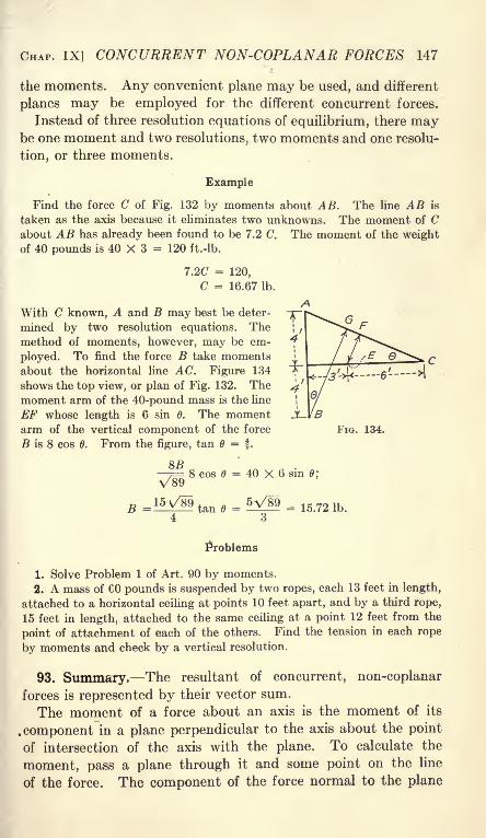
CHAP. IX] CONCURRENT NON-COPLANAR FORCES 147
the moments. Any convenient plane may be used, and different
planes may be employed for the different concurrent forces.
Instead of three resolution equations of equilibrium, there maybe one moment and two resolutions, two moments and one resolu-
tion, or three moments.
Example
Find the force C of Fig. 132 by moments about AB. The line AB is
taken as the axis because it eliminates two unknowns. The moment of Cabout AB has already been found to be 7.2 C. The moment of the weightof 40 pounds is 40 X 3 = 120 ft.-lb.
7.2C = 120,
C = 16.67 Ib.
With C known, A and B may best be deter-
mined by two resolution equations. Themethod of moments, however, may be em-
ployed. To find the force B take momentsabout the horizontal line AC. Figure 134
shows the top view, or plan of Fig. 132. Themoment arm of the 40-pound mass is the line
EF whose length is 6 sin 6. The momentarm of the vertical component of the force
B is 8 cos 6. From the figure, tan B = f .
FIG. 134.
8B
V898 cos 6 = 40 X 6 sin 0;
B = 15V/89 tan 6 = = 15.72 Ib.
Problems
1. Solve Problem 1 of Art. 90 by moments.
2. A mass of 60 pounds is suspended by two ropes, each 13 feet in length,
attached to a horizontal ceiling at points 10 feet apart, and by a third rope,
15 feet in length, attached to the same ceiling at a point 12 feet from the
point of attachment of each of the others. Find the tension in each rope
by moments and check by a vertical resolution.
93. Summary. The resultant of concurrent, non-coplanar
forces is represented by their vector sum.
The moment of a force about an axis is the moment of its
.component in a plane perpendicular to the axis about the point
of intersection of the axis with the plane. To calculate the
moment, pass a plane through it and some point on the line
of the force. The component of the force normal to the plane

148 MECHANICS [ART. 93
multiplied by the distance of the point from the axis gives the
required moment.For equilibrium the force polygon closes. There are three
unknowns and three independent equations may be written.
These equations may be:
(1) Three resolutions.
(2) One moment and two resolutions.
(3) Two moments and one resolution.
(4) Three moments.
A moment equation for non-coplanar concurrent forces is
equivalent to a resolution perpendicular to the plane which passes
through the axis of moments and the point of application of the
forces.
In writing resolution equations, each direction of resolution
must have a component perpendicular to the plane of the others.
It is not necessary that these directions be at right angles to each
other. A resolution perpendicular to the direction of a force
eliminates that force.
When moment and resolution equations are written together,a resolution must not be taken perpendicular to the plane throughthe axis of moments and the point of application of the forces.
When two resolutions and one moment equation are written, the
plane of the directions of the two resolutions must not be perpen-dicular to the moment plane.
Two axes of moments and the point of application of the forces
must not lie in the same plane. Three axes of moment must not
be parallel.

CHAPTER X
PARALLEL FORCES AND CENTER OF GRAVITY
94. Resultant of Parallel Forces. Articles 55 and 56 show that
the resultant of two or more parallel forces in the same planeis equal to their algebraic sum, and that the sum of the momentsof all the forces about any point in their plane, is equal to the
moment of their resultant about that point. It will now be
shown that the resultant of parallel forces which are not all in the
same plane is the algebraic sum of the forces, and that the sum of the
moments of all the forces about any axis is equal to the moment of
their resultant about that axis.
Figure 135 shows two forces, P and Q together with their
resultant R. The moment of R about any point in their plane
II
FIG. 135.
is equal to the sum of the moments of P and Q about that point.
The origin of moments at the point may be regarded as the
point at which an axis perpendicular to the plane of the forces
intersects that plane. In Fig. 135, II, the axis is OZ. If the
moment of the resultant is equal to the sum of the moments of
the two forces about an axis perpendicular to their plane, the
moments of these forces about any other axis through are
likewise equal. To change from the moment about the perpen-dicular axis to the moment about an inclined axis, it is necessaryto multiply each term by the cosine of the same angle; hence, if
the moments are equal in the one case, they are equal in the other.
Let S be a third force which is parallel to P and Q but is not
in the same plane. A plane may be passed through R and S. To149

150 MECHANICS [ART. 95
find their resultant the forces, R and S, may now be treated in the
same way as P and Q. The resultant of three parallel forces which
are not all in the same plane is equal to the algebraic sum of the
forces and the moment of the resultant about any axis is equal to the
sum of the moments of the three forces about that axis. This method
may be extended to include any number of forces. The axis of
moments is generally in a plane perpendicular to the direction
of the forces. This, however, is not necessary.
Example
Find the magnitude and position of the resultant of the following vertical
forces: 24 pounds down through the point (3, 5), 16 pounds down throughthe point (2, 7), 9 pounds up through the point (5, 4), 12 pounds down
through the point ( 6, 3), and 23 pounds up through the point (8, 5).
In the tabulated solution below, since most of the forces are downward,that direction is taken as positive. The moments are calculated about the
X and the Z axes.
FORCE x Px z Pz
24 3 72 5 120
16 2 32 7 112- 9 5 - 45 4 - 36
12 -6 - 72 3 36
-23 8 -184 -5 115
R = 20 Rx = -197 Rz = 347
x = -9.85, z = 17.35,
in which x and z are the coordinates of the resultant force.
Problems
1. Find the magnitude and position of the resultant of the followinghorizontal forces: 184 pounds toward the east through a point 5 feet abovea floor and 3 feet north of a vertical wall, 160 pounds east through a point8 feet above the floor and 2 feet south of the wall, 124 pounds west througha point 3 feet above the floor and 6 feet north of the vertical wall.
2. A rectangular door in a horizontal position is 7 feet long from left to
right and 4 feet wide. It weighs 40 pounds and its center of mass is at the
center. The door carries 50 pounds at the right corner near the observer,
35 pounds at the left corner diagonally across from the 50 pounds, 24 poundsat the other right corner, and 16 pounds at the middle of the left edge.Find the location of a single support which will hold the door in the hori-
zontal position.
95. Equilibrium of Parallel Forces. To find the resultant of
parallel forces, three quantities are calculated. These are the

CHAP. X] PARALLEL FORCES 151
magnitude of the resultant and two coordinates of its position.
A problem of the equilibrium of parallel forces involves three
unknowns and requires three independent equations for its
solution. Since the forces are all in one direction, each force is
fully determined by a single resolution. Only one of the three
possible equations may be a resolution equation. When there
are two moment equations, one of the axes must not be parallel
to the other. When three moment equations, are written, not
more than two of the axes may be parallel. It will be noticed
that two moment equations and one resolution equation were
used in the example of Art. 94. It is not necessary that the axes
of moments be at right angles to each other.
Problems
1. A horizontal trap door is 8 feet long and 4 feet wide. Its center of
mass is at the center. The door has 2 hinges, each one foot from a corner
on an 8-foot side. The door is lifted by a vertical rope attached 3 feet from
one corner on the other long side. Find the tension in the rope and the
hinge reactions. Solve by three moment equations and check by a vertical
resolution.
2. Solve Problem 1 if the rope is attached to one corner.
3. In the trap door of Problem 1, find the position at which the rope maybe attached at the edge of the door in order that one hinge reaction may be
zero. Solve algebraically and graphically.
4. A horizontal table is 5 feet long from left to right and 3 feet wide.
It is supported on three legs, one at each of the left corners and one at the
middle of the right side. A load of 60 pounds is placed 1 foot from the
front edge and 1 foot from the left edge. Find the reaction of each leg if
the weight of the table is neglected.
5. The load on the table of Problem 4 is placed 6 inches from the front
edge. How far may it be moved from the left edge without upsetting the
table.
6. Solve Problem 5 if the table weighs 20 pounds and its center of mass is
at the center.
7. A wheelbarrow is 5 feet long from axis of axle to points at which
the handles are gripped, and is 2 feet wide between centers of handles. It
carries a load of 160 pounds, which is placed 1 foot from the axis of the axle
and 4 inches to the right of the middle. Find the reaction of the wheel and
of each handle.
96. Center of Gravity. When parallel forces are applied to
each particle of a body, and each force is proportional to the
mass of the particle upon which it acts, the line of action of
the resultant of these forces passes through a point which is
called the center of mass of the body. The force of gravity on

152 MECHANICS [ART. 96
each particle of a body is directed toward the* center of the Earth,which is so distant that the forces on the various particles of an
ordinary body are practically parallel. The force of gravityvaries as the mass of the particle and inversely as the square of
its distance from the center of the Earth. This distance is so
great that for bodies of ordinary dimensions, the error in the
assumption that the attraction on each particle is proportionalits mass is negligible. For these reasons center of mass is usually
regarded as synonymous with center of gravity. Center of gravity
may be defined as the point of application of the resultant of the
gravity forces which act on the body. The term center of gravity
is used more commonly than center of mass.
The position of a line through the center of gravity may be
found by taking moments about two axes which are not parallel.
The position of the center of gravity on this line is found byregarding the direction of all the forces as changed and then
taking moments about a third axis.
The coordinates of the center of gravity are represented byx, y, and z. These may be read "bar x,
" "bar y}
" and "bar z."
Example
The base ABC of Fig. 136 is a plane surface and the faces ADDE andDEC are also plane and are perpendicular to each other and to the base.
The body weighs 24 pounds. The body rests on three supports, which are
not shown in the drawing. Two supports are 1 inch from the edge AB.The third support, 17 inches from the
edge AB, rests on a platform scale.
The scale reading is 4.52 poundswhen the base is horizontal. Howfar is the center of gravity from the
plane ABDE?Taking moments about the two
supports,
FIG. 136. 24x = 4.52 X 16,
x = 3.01 in.
The center of gravity lies in a vertical plane which is parallel to the face
ABDE and is 4.01 inches from it.
When the body is supported on two points, each 1 inch from the edge BC,and a third point rests on a platform scale 13 inches from BC, the scale
reading is found to be 7.24 pounds. From this experiment, the center of
gravity is found to lie in a plane parallel to the face BCD at a distance of
4.61 inches from that plane. The intersection of these two planes through
the center of gravity gives the location of a line through the center of gravity.
To find the location of the center of gravity on the line of intersection

CHAP. X] PARALLEL FORCES 153
of the two planes, its position must be changed so that the forces of gravitywill act in a relatively different direction. For the experiment the body is
placed with the face BCD horizontal. When it is supported at two points,
each 1 inch from BC, and on a third point at a distance of 11 inches from
BC, the scale supporting the third point reads 7.20 pounds. From this
reading the center of gravity is found to be 4.00 inches from the planeABC.
It will be observed that each of these experiments locates a vertical planewhich is parallel to the axis of moments and passes through the center of
gravity. Three such planes, if no two of them are parallel, fully locate the
center of gravity.
Problems
1. A triangular board of uniform thickness is 12 inches wide at the base.
The perpendicular distance from the vertex to the base is 18 inches. Theboard is supported on two knife-edges, each 0.5 inch from the base, and on a
third knife edge, parallel to the base, at 1 inch from the vertex. The board
weighs 15.00 pounds. When the third knife-edge, which weighs 0.45 pound,rests on a platform scale, the reading is 5.45 pounds. How far is the center
of gravity of the board from the base? Ans. 6.00 inches.
2. A rectangular plate of uniform thickness is 24 inches long and 18
inches wide. A circular hole, 10 inches in diameter, is cut from the plate.
The center of the hole is 6 inches from the front 24-inch edge and 8 inches
from the left 18-inch edge. The plate is supported on a knife-edge 0.1
inch from the left edge and on a second knife edge at the same distance
from the right edge. The knife edge at the right rests on a platform scale.
The increase of the load on the scale when the plate is put on the knife-edge,
amounts to 22.72 pounds. The plate weighs 42.40 pounds. How far is
its center of gravity from the left edge?As a second experiment, the plate is supported on a knife-edge 0.1 inch
from the front and on a second knife-edge 17 inches from this one. Theload on the second knife-edge reads 23.87 pounds. How far is the center
of gravity from the front edge of the plate?3. A heavy rectangular door is placed in a horizontal position and sup-
ported by three spherical steel balls. Each ball rests on a separate platformscale. The door is 6 feet long from left to right and 4 feet wide. One ball
is 1 inch from the front edge and 1 inch from the left edge. The scale which
supports it reads 32 pounds. The second ball is 1 inch from the left edgeand 3 inches from the rear edge. The scale which supports it reads 104
pounds. The third ball is 1 inch from the right edge and 1 foot from the
front edge. The scale which supports it reads 144 pounds. Locate the
center of gravity.
Ans. One inch to the right and 1 inch to the front of the middle.
When the dimensions of a body and its density at all points
are known, the center of gravity may be calculated. Momentsare taken in the same way as in the experimental determination.
For the last determination, the position of the body is not changed.

154 MECHANICS [ART. 97
The direction of the parallel forces is assumed to be different.
This assumption makes it possible to take moments about an
axis which is perpendicular to the first two axes of moments.
In Fig. 136, the forces may be regarded as parallel to the line
AB.When all the forces are parallel to a given plane, the moment
about any one of a set of parallel lines in that plane is the same.
In this case the moment is often called the moment with respect
to the plane. In Fig. 136, the moment about AB is equal to
the moment about any line in the plane of ABDE parallel to
the line AB. The moment with respect to AB is the momentwith respect to the plane ABDE.
97. Center of Gravity Geometrically. When the density of a
body is uniform, the center of gravity may sometimes be deter-
mined geometrically. If the body has a plane of symmetry, the
plane divides it into equal halves. If the plane of symmetrybe placed vertical, or if the forces be regarded as acting parallel
to it, the moment of one-half of the body about any axis in the
plane is equal and opposite the moment of the other half. // a
body of uniform density has a plane of symmetry, the center of
gravity lies in that plane. If there are two or more planes of
symmetry, the center of gravity lies at their intersection.
All planes through the center of a sphere are planes of sym-
metry. The center of gravity of a sphere is at its center.
All planes through the axis of a right circular cylinder are
planes of symmetry. The plane perpendicular to the axis at
the middle is also a plane of symmetry. The center of gravity
of a right circular cylinder of uniform density is located at the
middle of the axis.
The center of gravity of a rectangular parallelopiped is located at a
point which is midway between all the faces.
A The center of gravity of a right prism, the sec-
tions of which are equilateral triangles is located
at the middle of its length at the intersection of
the lines which bisect the angles of the section.
Figure 137 shows an oblique-angled parallelo-
gram. The sections perpendicular to the planeof the paper are assumed to be rectangular. The
plane of which the line AB is the trace is not
a plane of symmetry. It is a plane of symmetry for elements,such as EFG, perpendicular to it, but these elements do not

CHAP. X] PARALLEL FORCES 155
include the entire figure. They leave out a triangular area at
the top and another at the bottom. If, however, the parallelo-
gram is divided into elements such as COD, by lines parallel to
the ends, a series of such elements will include the entire figure.
It will be shown that the center of gravity of the element CODis midway between the ends. If the part OC is rotated about the
line AB as an axis, it will not coincide with the part OD. If,
however, OC is rotated through 180 degrees about an axis at
perpendicular to the plane of the paper, it will coincide exactlywith OD. The center of gravity of OC is as far from the line ABon one side as the center of gravity of OD from the line on the
other side. The moment of OC about the line AB is equal and
opposite to the moment of OD. The center of gravity of the
element lies in the plane of AB. The center of gravity of an
oblique prism or cylinder lies in a plane parallel to the bases and
midway between them.
Problems
1. A plate of uniform thickness and density is of the form of a 5'
by 1" angle section as shown in Fig. 138. Find
the distance of the center of gravity from the
back of each leg. Solve by dividing the section
into two equal rectangles. Check x by dividing
the section into a 5" by 1" rectangle and a
1" by 3" rectangle. Since the thickness and
density are constant, the terms which representthem may be omitted.
Taking moments about the back of the 4-inch
leg,
AREA ARM MOMENT
4 0.5 2.0
4 3.0 12.0
by 4"
8 14.0
Total mass = 8. Total moment8z = 14,
* = 1.75 in.
14
2. A homogeneous solid cylinder, 6 inches in diameter and 10 inches long,
weighs 15 pounds. The cylinder stands on a rectangular parallelepiped, 10
inches square and 6 inches high, which weighs 35 pounds. Find the distance
of the center of gravity of the two from the base of the parallelepiped.
Ans. 5Qy = 270; y = 5.4 in. from the base.
3. A homogeneous solid cylinder 8 inches in diameter is 6 inches long. Asecond homogeneous solid cylinder is 4 inches in diameter and 10 inches
long. The 8-inch cylinder stands vertical and the 4-inch cylinder is placed

156 MECHANICS [ART. 98
on it with its axis 2 inches to the right of the axis of the first cylinder. If
both cylinders have the same density, find the center of gravity.
Ans. x = 0.59 in. from axis of 8-in. cylinder;
y = 5.35 in. from base of 8-in. cylinder.
4. Solve Problem 2 if the cylinder and block have the same density.
6. Solve Problem 3 if the density of the 8-inch cylinder is twice that of the
4-inch cylinder.
6. The plate of Problem 2 of Art. 96 is of uniform thickness and density.
Determine the position of the center of gravity. Subtract the moment and
mass of the circular hole from the moment and mass of the entire plate.
7. A homogeneous cylinder 8 inches in diameter and 10 inches long has a
circular hole drilled in one end. The hole is 4 inches in diameter, 8 inches
deep, and its axis is 1 inch from the axis of the cylinder. Find the center of
gravity of the remainder.
98. Center of Gravity of a Triangular Plate. Figure 139 repre-
sents a triangular plate of uniform thickness perpendicular to the
HFIG. 139. FIG. 140.
plane of the paper. OH is the median line. The triangle is
divided into elements such as ADFB, by lines parallel to the
base. The moment of the oblique parallelogram ACED with
respect to the line H (or any line in the plane through OHperpendicular to the plane of the paper) is zero. The small
trianglesABC and DEF are left over. These triangles have equal
areas, and their bases are equally distant from the line OH', con-
sequently their moments about OH must be approximately equal.
The lines A D and B F may be brought infinitely close together,
so that the areas of these triangles become infinitesimals of the
second order, and the difference of their moments become infini-
tesimals of the third order. The center of gravity of the ele-
ment ADFB must then lie in the median line. The entire
triangle is made up of similar elements, each of which has its
center of gravity on the median line. It follows that the center
of gravity of the entire triangular plate of uniform thickness and
density must lie on the plane of the median line.

CHAP. X] PARALLEL FORCES 157
A second median may be drawn as in Fig. 140. The center
of gravity lies in this median, and, consequently, at the intersec-
tion of the medians.
It was learned in Geometry that the intersection of the mediansof a triangle is located at one-third the length from the base. In
Fig. 140, HK is one-third of OH, and KL is one-third of ML. If
h is the perpendicular distance from a vertex to the opposite base,and y is the perpendicular distance from the center of gravityto that base, then y is one-third of h.
Example
A plate of uniform thickness and density is in the form of a trapezoidThe lower base is 18 inches, the
upper base is 10 inches, and the
height is 12 inches. Find the
distance of the center of gravityfrom the lower base.
The trapezoid may be divided,
as shown in Fig. 141, I, into a
parallelogram and a triangle.
Since the thickness and densityare constant, their values in the mass and moment will cancel. Only the
area, then, need be considered.
AREA ARM MOMENT
Parallelogram 120 6 720
Triangle 48 4 192
IQSy 912
y = 5f in.
Problems
1. Solve the example above by dividing the trapezoid into two triangles
as in Fig. 141, II.
2. Solve the example above by means of a parallelogram of 18-inch base
from which an inverted triangle is subtracted to form the trapezoid.
3. A trapezoidal plate of uniform
thickness has the lower base 24 inches,
the upper base 18 inches, and the
height 15 inches. Find the distance of
the center of gravity from the lower
FIG. 142. base. Check by moments about the
upper base.
4. Figure 142 shows a standard 15" channel section. Find the distance
of the center of gravity from the back of the web, and compare the result
with Cambria Steel or Carnegie Handbook.
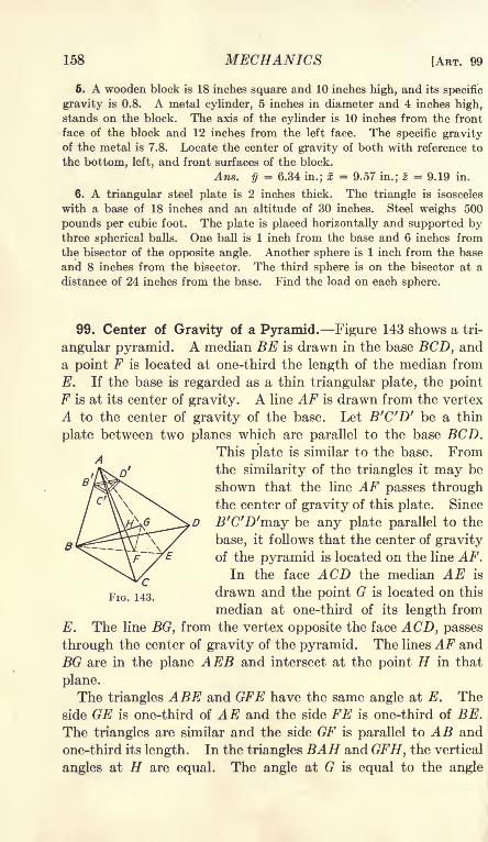
158 MECHANICS [ART. 99
6. A wooden block is 18 inches square and 10 inches high, and its specific
gravity is 0.8. A metal cylinder, 5 inches in diameter and 4 inches high,stands on the block. The axis of the cylinder is 10 inches from the front
face of the block and 12 inches from the left face. The specific gravityof the metal is 7.8. Locate the center of gravity of both with reference to
the bottom, left, and front surfaces of the block.
Ans. y = 6.34 in.; x = 9.57 in.; z = 9.19 in.
6. A triangular steel plate is 2 inches thick. The triangle is isosceles
with a base of 18 inches and an altitude of 30 inches. Steel weighs 500
pounds per cubic foot. The plate is placed horizontally and supported bythree spherical balls. One ball is 1 inch from the base and 6 inches from
the bisector of the opposite angle. Another sphere is 1 inch from the base
and 8 inches from the bisector. The third sphere is on the bisector at a
distance of 24 inches from the base. Find the load on each sphere.
99. Center of Gravity of a Pyramid. Figure 143 shows a tri-
angular pyramid. A median BE is drawn in the base BCD, and
a point F is located at one-third the length of the median from
E. If the base is regarded as a thin triangular plate, the point
F is at its center of gravity. A line AF is drawn from the vertex
A to the center of gravity of the base. Let B'C'D' be a thin
plate between two planes which are parallel to the base BCD.This plate is similar to the base. Fromthe similarity of the triangles it may be
shown that the line AF passes throughthe center of gravity of this plate. Since
B'C'D'may be any plate parallel to the
base, it follows that the center of gravityof the pyramid is located on the line AF.
In the face ACD the median AE is
drawn and the point G is located on this
median at one-third of its length from
E. The line BG, from the vertex opposite the face ACD, passes
through the center of gravity of the pyramid. The lines AF and
BG are in the plane AEB and intersect at the point H in that
plane.
The triangles ABE and GFE have the same angle at E. The
side GE is one-third of AE and the side FE is one-third of BE.
The triangles are similar and the side GF is parallel to AB and
one-third its length. In the triangles BAH and GFH, the vertical
angles at H are equal. The angle at G is equal to the angle
CHAP. X] PARALLEL FORCES 159
at B and the angle at E is equal to the angle at A. These
triangles are similar and
HF = GF i
AH AB 3;
4 HF = AF; AF = ~The center of gravity of a triangular pyramid is on a line joining
the vertex with the intersection of the medians of the base, at a distance
from the base equal to one-fourth the length of this line. If h is the
vertical distance of the vertex from the base, the center of gravity
lines in a plane parallel to the base at a distance of j therefrom.
A pyramid with quadrilateral base may be divided into two
triangular pyramids. Since the center of gravity of each of these
triangular pyramids is at a distance of one-fourth the vertical
height from the base, the center of gravity of the entire pyramidlies in the same plane. This may be extended to pyramids of
any form.
A cone may be regarded as made up of an infinite number of
small pyramids of the same altitude. Its center of gravity is,
therefore, at one-fourth the height from the base.
Problems
1. A homogeneous solid right cylinder, 5 inches in diameter and 6 inches
long, stands with its axis vertical. On the top of the cylinder is placed a
homogeneous solid right cone, which is 6 inches in diameter and 8 inches
high. The axis of the cone is 1 inch from the axis of the cylinder. The
density of cone and cylinder is the same. Find the center of gravity of
the combination. AnSi x = 0.39 in. from the axis of cylinder;
y = 4.95 in. from the base of cylinder.
2. A homogeneous solid right cylinder is 10 inches in diameter and 8
inches high. A cone 6 inches in diameter and 6 inches deep is cut out of the
top of the cylinder. The axis of the cone is 1 inch from the axis of the
cylinder. Find the center of gravity of the remainder.
3. Solve Problem 1 if the density of the cylinder is twice the density of
the cone.
4. A frustrum of a cone is 6 inches in diameter at the lower base, 4 inches
in diameter at the upper base, and 6 inches high. Find its center of gravity.
100. Center of Gravity by Integration. The calculation of
the center of gravity is equivalent to the location of the line

160 MECHANICS [ART. 100
of application of the resultant of parallel forces. The moment of
each mass is found with respect to some plane; then this momentis divided by the sum of the masses. If m\ is the mass of one
element of the body, and x\ is its abscissa, its moment about anyline in the YZ plane is m\x\. If mi, m2 , Ws, etc. are masses, and
Xit #2, 3, etc., are the coordinates of their centers of gravity with
respect to some plane of reference, the total moment with respect
to that plane is'
M = m\x\ -f- m^Xz + mzx3 + etc. = Smx. (1)
Total mass = Wi+ m% + ^3 + etc. = 2m. (2)
Similarly, the other coordinates of the center of gravity are
2m?/y = --
2mz
In order to use these equations, the center of gravity of each
of the parts which compose the system must be known. Whenthe center of gravity of each part is not known, it is necessaryto divide the body into infinitesimal elements, write the expres-
sion for the moment of each element, and find the sum of the
moments by integration. If dm is the mass of an element and x'
is the coordinate of the center of gravity, Equation (1) becomes
M= fx'dm. (6)
If p is the density and dV is the element of volume,
dm pdV,M = fpx'dV. (7)
If p is the mass of a plate per unit area, and dA is an element of
area,
dm = pdA,M = fpx'dA.
If the density is uniform throughout all parts of the body, it
may be omitted in finding the center of gravity.
With the integral expressions for the moment,
fx'dm_ fpx'dVfdm fpdV
' W

CHAP. X] PARALLEL FORCES
When the density is constant, Equation (8) becomes
_ fx'dV fx'dV~7W ~F~
For a plate of uniform thickness and density,
161
Similar expressions give y and z.
It must be remembered that xris the distance of the center of
gravity of the element from the plane of reference.
Example I
Find the center of gravity of a triangular plate of uniform thickness and
density, by moments about an axis through the
vertex parallel to the base. (Fig. 144.)
The element of area is y high and dx wide.
This form of element is chosen because the entire
triangle may be built up of strips of this kind andbecause its moment arm is easy to find. Neglect-
ing the small triangle at the top of the element,its area is ydx. The moment arm of the ele-
ment about the line AB through the vertex of the
triangle is FIG. 144.
When -~- is multiplied by the element of area, the product is a differential
of the second order and may be neglected.
M = fx'dA = fxydx. (11)
This expression for the moment contains two variables, x and y. One of
these variables must be eliminated. From the geometry of the similar
triangles of Fig. 144,
bx
Substituting in Equation (11) and integrating,
_ Cbx2
db C , b
The limits for x are x = and x =h,
o~ 3
Dividing the moment by the area,
bh* bh 2h
11

162 MECHANICS [ART. 100
Problem
1. Instead of eliminating y from Equation (11) of Example I, eliminate x
and dx and integrate between the proper limits for the moment. Also
integrate ydx for the area of the triangle.
Example II
Find the center of gravity of a triangle bymeans of elements perpendicular to the base.
In Fig. .145; the vertical line CD is taken
as the base of the triangle. With the origin
at the vertex, x is the abscissa of a point on
the line OC. The length of an element of area
is h x and the width is dy
FIG. 145. .
* dA = (h-
x)dy.
The center of gravity of the element is at the middle of its length, which is
at a distance of ~ from either end.
h - x h + x
M dy.
(13)
(14)
Since y =-j-> dy = T dx. Substituting in Equation (14)
M - x')dx - - h'x- -~3
This result applies to the right triangle OCE. Dividing by the area, the
center of gravity of this right triangle is found to be at two-thirds the altitude
from the vertex. In a similar way the center of gravity of the other right
triangle OED is found to be at the same distance from the vertex. Since
the center of gravity of the entire triangle is on the line which joins these two
centers, it is located at two-thirds the altitude from the vertex.
Problems
2. Substitute for x2 in Equation (14) and integrate in terms of x as the
independent variable.
3. Find the center of gravity of a quadrant of a uniform circular plate
of radius a.
Using the vertical element of Fig. 146 to find the moment with respect
to the plane of A ,
3
a* ~~
O3
4a0~"'3ir
Solve for y by means of the same element.

CHAP. X] PARALLEL FORCES 163
4. Find the center of gravity of a 60-degree sector of a circle of radius a
by polar coordinates with double integration.The element of area is rdedr, and the moment arm for finding x is x' =
r cos
FIG. 146. FIG. 147.
M
M oV36
~6~
cos e de dr = /cos 6 de =o o
^-?ra2 = 0/3
6 TT
'
The Y coordinate-of the center of gravity may be found by a similar
method, and may oe checked by the condition
that the center of gravity lies on the bisector of
the angle.
6. Find the center of gravity of a 60-degree
sector of a circle of radius a, using the bisector of
the angle as the axis of X. Check trigonom-
etrically with the results of Problem 4.
6. Find the center of gravity of a wire of
uniform section which is bent into the form of
a semicircle of radius a. Use polar coordinates
with a single integraion.
Ans. x : y = 0.FIG 148.
7. Find the center of gravity of a homogeneous solid hemisphere,the hemisphere of circular disks as in Fig. 148.
Ans. M = 7r/(a2 -
Build
7T0 4
3a
8. A homogeneous solid cylinder, 8 inches in diameter and 6 inches longhas a hemispherical depression, 6 inches in diameter, in one end. Find
the center of gravity of the remainder.
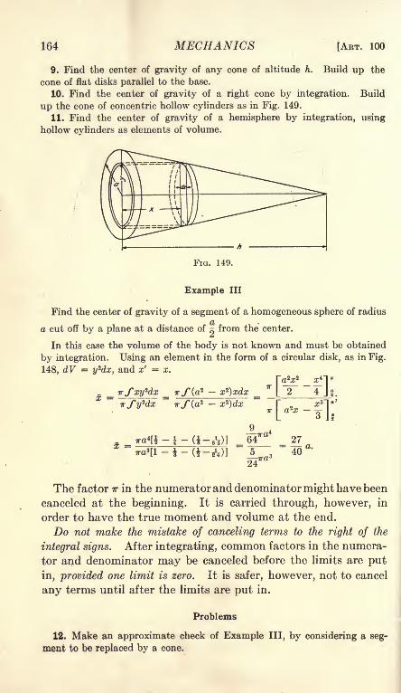
164 MECHANICS [ART. 100
9. Find the center of gravity of any cone of altitude h. Build up the
cone of flat disks parallel to the base.
10. Find the center of gravity of a right cone by integration. Build
up the cone of concentric hollow cylinders as in Fig. 149.
11. Find the center of gravity of a hemisphere by integration, using
hollow cylinders as elements of volume.
FIG. 149.
Example III
Find the center of gravity of a segment of a homogeneous sphere of radius
a cut off by a plane at a distance of ~ from the center.
In this case the volume of the body is not known and must be obtained
by integration. Using an element in the form of a circular disk, as in Fig.
148, dV = y*dx, and x' = x.I~ 2 2 4T o
rSxyUx Tr/Ca' - x*)xdx*I 2
~4 Jf.
64 27
24
The factor TT in the numerator and denominator might have been
canceled at the beginning. It is carried through, however, in
order to have the true moment and volume at the end.
Do not make the mistake of canceling terms to the right of the
integral signs. After integrating, common factors in the numera-
tor and denominator may be canceled before the limits are put
in, provided one limit is zero. It is safer, however, not to cancel
any terms until after the limits are put in.
Problems
12. Make an approximate check of Example III, by considering a seg-
ment to be replaced by a cone.

CHAP. X] PARALLEL FORCES 165
13. Find the center of gravity of a uniform plate in the form of a segment
of a circle of radius a which is cut off by a plane at a distance of from theo
center. Use a vertical element as in Fig. 150. When integrating for the
area, substitute x = a cos 6, y = a sin 6.
Ans. x = O.GlOa: y = 0.
FIG. 150. FIG. 151.
14. Find y for half the segment of Problem 13. Use the area alreadyobtained for the entire segment and integrate for the moment only.
15. A uniform plate is bounded by the X axis, the curve y2 = 4x and
the lines x = 4 and x = 9. Find its center of gravity, Fig. 151.
Ans. x = 6.66; y = 2.57.
16. Check Problem 15 approximately by replacing the area by the enclosed
trapezoid.
17. Find x for the area bounded by the X axis, the line x =a, and the
curve y2 = bx. Ans. x = 0.6a.
18. Find x for the area bounded by the X axis, the line x =a, and the
line y = bx.
19. Find x for the area bounded by the X axis, the
line x =a, and the curve y = bx2
.
3aAns. x = -r-
20. Find x for the area bounded by the X axis, the
line x =a, and the curve y = bx 3
.
4aAns. x = -=-
o
21. A solid cylinder is cut by two planes which
intersect on a diameter. One of these planes is per-
pendicular to the cylinder and the other makes an
angle a with this plane, Fig. 152. Find the center of
gravity of the part of the cylinder between the planes.
Ans.
Ans. =16
FIG. 152.
22. A solid cylinder of radius a is cut by two planes which intersect on a
tangent and make an angle a with each other. One plane is normal to the
axis of the cylinder. Find the center of gravity of the portion of the
cylinder between the planes. Solve by polar coordinates.
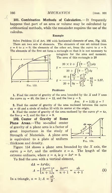
166 MECHANICS [ART. 101
101. Combination Methods of Calculation. It frequently
happens that part of an area or volume may be calculated byarithmetical methods, while the remainder requires the use of the
calculus.
Example
Solve Problem 15 of Art. 100 with horizontal elements of area, Fig. 153.
There are two sets of elements. The elements of one set extend from
x = 4 to x = 9; the elements of the other set, from the curve to x = 9.
The elements of the first set form a rectangle so that it is not necessary to
integrate for the area and moment.The area of this rectangle is 20
20X2+'/(
9 -j~
20 +
FIG. 153.
s = 2.57.
Problems
1. Find the center of gravity of the area bounded by the X and Y axes
the curve xy = 48, the line x =12, and the line y = 8.
Ans. x = 5.32; y = ?
2. Find the center of gravity of the area enclosed between the curve
xy 48 and a circle of radius 10 with its center at the origin.
3. Find the center of gravity of the area enclosed by the curve y2 = 4x,
the line y =2, and the line x = 9.
102. Center of Gravity of SomePlane Areas. The so-called center
of gravity of a plane area is a factor of
great importance in the study of
Strength of Materials. A plane area
is equivalent to a plate of uniform
thickness and density.
Figure 154 shows a plane area bounded by the X axis, the
curve y = kxn,and the ordinate x = a. The length of the
extreme ordinate, where x =a, is y = kan = b.
To find the area with a vertical element,
dA = kxndx',
*.-y-xtfIn H- Uo
In a triangle, n =1; A =
-^-
FIG. 154.
kan+1 ab
n + l(1)

CHAP. X] PARALLEL FORCES 167
In a parabola with the axis horizontal, n ~; A = -3^ o
In a parabola with axis vertical, n = 2; A = -~-
To find the moment with respect to the YZ plane,
M = Ix'dA = k ix+ ldx =
M = kan+z
=
n +2
1
In a triangle, where n =1, x = -~-
In a parabola with axis horizontal, where n = s' ^ =~H~*
In a parabola with axis vertical, where n =2, x =
-j-
(2)
(3)
(4)

168 MECHANICS [ART. 102
To find the moment with respect to the XZ plane,
M =
M =
Cy
ab*
2(2nMA 2(2n + 1)
1) 2(2n + 1)
afr2
; ab (n
n + 1 2(2n
In a triangle, where n =I, y =
^
In a parabola with axis horizontal, where n = ~
1)
(5)
(6)
(7)
36
Figure 155 shows four of the most
important cases of areas bounded by the
X axis, the ordinate x = a, and the curve
y = kxn . It shows also the center of
gravity of a 90-degree sector and a 60-
degree sector.
Figure 156 shows any sector of a circle
of radius a bounded on one side by the Xaxis, and on the other by a radius at an
angle with the X axis. The area is ira? multiplied by the ratio of
the arc to the circumference of the circle. If a be the angle in2
degrees, A =
FIG. 156.
To find the moment with respect to the YZ plane with polar
coordinates,
M = I r2 cos 6 d6 dr = ^ I cos 6 dO = ^ [sin B]Q. (8)J 6 J
(9)= M 120 a sin a;c
A 3"
360
For a 60-degree sector, sin a =
120a
and
X =607T 7T
Since these sectors are symmetrical with respect to the radius
at angle |with the X axis, y may be calculated by multiplying x
by the tangent of the half-angle.

CHAP. X] PARALLEL FORCES 169
Problems
1. By means of Equation (9), find the center of gravity of a 45-degreesector.
2. By means of the answer of Problem 1 find the center of gravity of a
sector of which the angle is 22 30'.
3. Find the center of gravity of the area bounded by the X axis, the
curve y =x^, and the line x = 8 by means of the equations of this article.
4. Find the center of gravity of a segment cut off by a line at a distance
from the center equal to one-half the radius. Calculate the area and
moment of the half sector and subtract the moment and area of the triangle.
5. Find the center of gravity of the area bounded by the X axis, the
curve y* = 4z, and the lines x = 4 and x = 9. Find the moment and area
of the entire area to the line x = 9 and then subtract for the area to the
Jeft of x = 4.
103. Liquid Pressure. The pressure of a liquid is the same in
all directions, and is proportional to the depth below the surface.
If w is the weight of unit volume of the liquid, and y the depth of the
surface below the surface of the liquid, the pressure per unit area
is wy. The density of water is
nearly 62.5 pounds per cubic
foot; the constant w for water
is 62.5 when foot and poundunits are used. With gramand centimeter units, w = 1.
Figure 157 represents a tank
of liquid in which there is a
submerged surface MN. Anelement of the surface, dA, is
located at a vertical distance
y below the surface of t;he
liquid. The total pressure on
one side of the surface on the element dA is wydA. The total
pressure on the entire surface is
total pressure= fwy dA = wfydA. & (1)
Since JydA is the moment of the area dA with respect to the
surface of the liquid
fydA = yA, (2)
total pressure = wyA. (3)
The total pressure of a liquid on a surface is the weight of a
column of liquid whose area is the area of the surface and whose
height is the depth of the center of gravity of the surface below
the surface of the liquid.
FIG. 157.

170 MECHANICS [ART. 104
Problems
1. One end of the tank of Fig. 157 is 6 feet wide and 8 feet high to the
surface of the water. Find the total horizontal pressure on this vertical
surface. Arts. 12,000 Ib.
2. A vertical gate, 5 feet wide and 4 feet high, is subjected to pressure of
water which rises 6 feet above the top of the gate. Find the total horizontal
pressure on the gate. Ans. 10,000 Ib.
3. A cylindrical tank with axis horizontal is 6 feet in diameter. It is filled
with water and connected to a 4-inch pipe in which water stands 8 feet
above the axis of the cylinder. Find the total pressure on the end.
Ans. 14,137 Ib.
4. Solve Problem 3 if the cylinder is half full of water. Ans. 1125 Ib.
6. A tank with triangular ends is 6 feet wide at the top and 4 feet high.
Find the pressure at one end when the tank is filled with water. If the
tank is 6 feet long, find the pressure on one side.
104. Center of Pressure. In the case of a vertical or inclined
surface, the pressure varies with the depth. The average pressure
is that at the center of gravity of the area. The resultant pres-
sure is below the center of gravity. Fig. 158 shows the variation
of pressure against a vertical surface. The same relation holds
for an inclined surface. Since the pressure varies as the depthbelow the surface, it may be represented by the weight of a
volume of liquid between two planes which intersect at the sur-
face of the liquid. In the case of a rectangular plane surface,
Fig. 158, II, the pressure is equivalent to the weight of a wedgeof constant width equal to the width of the surface. The pressure
at the bottom is wy. The average pressure is -77, which is the
pressure at the center of gravity of the area. The resultant pres-
sure is located at the center of gravity of the wedge. The center
of gravity of the wedge is the same as that of a triangular plate,
which is two-thirds the height from the vertex. The position

CHAP. X] PARALLEL FORCES 171
of the resultant pressure is called the center of pressure. Thecenter of pressure on a rectangular surface which reaches the topof the liquid is two-thirds the height of the surface below the
surface of the liquid. This distance is measured parallel to the
rectangular surface.
Problems
1. A vertical rectangular gate is 5 feet wide and 6 feet high. It is sub-
jected to pressure of water which just reaches the top. Find the total
pressure and the center of pressure. If the gate is held by bolts at the topand bottom, find the tension in each.
Ans. Tension in top bolts = 1875 lb.; tension in bottom bolts = 3750 Ib.
2. A vertical rectangular gate is 5 feet wide and 12 feet high. It is sub-
jected to the pressure of 12 feet of water on one side and the pressure of 6
feet of water on the other. Find the force at the top and bottom requiredto hold the gate against this pressure. Ans. 6562 lb. at the top.
3. A vertical triangular gate is 8 feet wide
at^ the bottom and 12 feet high. It is sub-
jected to water pressure on one side. Find
the center of pressure, Fig. 158, III.
4. A vertical rectangular gate, 8 feet wide
and 12 feet high, is subjected to the pressure
of water which rises 4 feet above the top.
Find the horizontal force at the top required
to hold the gate. Where is the center of ^OOl^/tt^ 75O
pressure? Fig. 159.
T 6. Find the center of pressure of the semicircular area of Problem 4 of the
preceding article.
Generally, the location of the center of gravity of the wedge-
shaped solid which represents the pressure is not known. In
Art. 153, a general method of solution is given, which involves
the radius of gyration of the area of the surface. The determina-
tion of the center of pressure by means of the wedge of pressure
is convenient for rectangular surfaces.
105. Summary. The resultant of parallel forces in space is
equal to the algebraic sum of the forces. The moment of the
resultant about any axis is equal to the sum of the moments of
the separate forces about that axis.
For a problem of equilibrium of parallel forces in space there
are three unknowns and three independent equations. These
equations may be two moments and one resolution or three
moments.
The center of mass is the point of application of the resultant
of parallel forces which are proportional to the masses of the

172 MECHANICS [ART. 105
particles upon which they act. Center of mass is practically
the same as center of gravity.
Center of gravity is calculated by dividing the sum of the
moments by the sum of the masses. This calculation locates
one plane through the center of gravity. Two other planes are
found in the same way. The center of gravity lies at the inter-
section of the three planes.
_ = /Vdmfdmfy'dm
_ = fz'dmfdm
'
in which x, y and z are coordinates of the center of gravity of
the body and x', y', and z' are the coordinates of the elements or
particles which compose the body.When the density is constant, the elements of volume may
replace the elements of mass. When the body is a plate of uni-
form thickness and density, the elements of area may be used
in place of elements of mass.
If a body of uniform density has a plane of symmetry, the
center of gravity lies in that plane.
The center of gravity of a triangular plate of uniform densityand thickness is located at the intersection of the medians,which is at a distance from the base equal to one-third of the
altitude of the triangle.
The center of a pyramid or cone of uniform density is located
at a, distance from the base equal to one-fourth the altitude.
The pressure of a liquid on a plane surface consists of parallel
forces perpendicular to the surface. This pressure is directly
proportional to the vertical depth below the surface of the liquid.
The average pressure on any surface is the pressure at the center
of gravity of the surface. The point of application of the resul-
tant pressure is called the center of pressure. The center of
pressure may be found by means of the center of gravity of a
wedge-shaped solid. The center of pressure on a rectangular
plane surface which extends to the surface of the liquid is at
two-thirds the altitude of the surface below the surface of the
liquid.

CHAPTER XI
FORCES IN ANY POSITION AND DIRECTION
106. Couples in Parallel Planes. In Art. 70, it was shownthat a couple may be balanced by another couple of equal magni-tude and opposite sign acting in the same plane, and that the
forces of this second couple might have any magnitude, direction,and position in the plane. It
will now be shown that it is
not necessary for the couples
to be in the same plane. Acouple may be balanced by a
couple in any parallel plane,
provided the moments are
equal and opposite. Figure160 shows a wheel to which
two ropes are attached. The
ropes run horizontally in oppo-site directions. If a force P is FlG 160
applied to the lower rope, and
if the upper rope is attached to a fixed point, the tensions in the
two ropes will be equal and opposite, and form a counter-clock-
wise couple. The center of gravity of the system is supposed to
be located at W. The plane of the weight and of the upwardreaction R is parallel to the plane of the wheel. It is possible to
make the force P of such magnitude that the system is in equilib-
rium. The weight W and the reaction R form a clockwise
couple, which is equal and opposite to that of the forces in the
ropes.
Figure 161 shows two forces, PI and ?2, each of magnitude P.
These forces are at a distance a apart in the same vertical plane.
Suppose that an opposite couple made up of two forces Qi and
Q 2 at a distance b apart acts in a parallel plane. If the moments
are equal so that
Pa = Qb
it may be shown that these couples balance and produce
equilibrium.173

174 MECHANICS [ART. 106
FlG 161
According to Art. 70, the couple Qb may be replaced by an
equal couple Pa in its plane. In Fig. 161, these forces are
P3 and P4 and are parallel to PI and P2 . In Fig. 161, ABCDis a quadrilateral perpendicular to the forces. Since AB = a =
CD, and since AB is parallel to CD, the quadrilateral is a paral-
lelogram. The upward force PI of the first couple and the up-
ward force P3 of the second couple may be replaced by a force
of magnitude 2P at a point midway between them. The down-
ward force P2 and the downwardforce ?4 may be replaced by their
resultant of magnitude 2P at a point
midway between C and B. Theline of the upward resultant passes
through the middle of one diagonal
of the parallelogram, and the line of
the downward force passes throughthe middle of the other diagonal. These two forces must lie in
the same line. They are equal and opposite; consequently, theybalance and produce equilibrium.
Since two couples which balance the same couple are equiva-
lent, two couples in parallel planes which are numerically equaland have the same sign are equivalent. The combined moment of
two couples in the same plane is the algebraic sum of the momentsof the separate couples. The combined moment of couples in
parallel planes is the algebraic sum of the moments of the several
couples.
The addition of couples in parallel planes may be provedin a slightly different way. In Fig. 161, suppose that both
couples are clockwise so that the
force P4 is up and the force P3 is
down. The resultant of PI and P4
is a force 2P midway between them.
The resultant of P2 and P3 is an
equal downward force. These two
resultants are at a distance a apart,
and form a couple of magnitude2Pa. This couple is in a plane
parallel to the planes of the original couples and midwaybetween them.
Figure 162 applies to unequal couples. It will be shown that
the resultant couple may be in any plane parallel to the plane of
P
./[<___
,
-->|1-9

CHAP. XI] FORCES IN POSITION AND DIRECTION 175
the couples to be added. This figure represents a plane perpen-dicular to the planes of the two couples. One of these couplesis made up of a force P upward perpendicular to the plane of
the paper and an equal force downward at a distance a from
this upward force. In the second couple the forces are Q down-ward at the right and an equal force upward at a distance 6.
The distance between the planes of the two couples is d. Theresultant of the upward parallel forces P and Q is a force P + Qat a distance x from the plane of the first couple. By moments
-
The resultant of the two downward forces is a downwardforce P + Q at the same distance from the plane of the first
couple. The moment arm of the resultant couple is c.
Resultant moment = (P + Q)c = Pa + Qb. (4)
The couple Qb may be replaced by any other couple in its
plane, provided the moment is the same in magnitude and sign.
If Q were made larger and b smaller, the plane of the resultant
couple would be closer to the couple Qb. By changing the rela-
tive values of Q and 6, it may be shown that the resultant couple
may come in any plane parallel to the planes of the original
couples.
An ordinary windlass affords an example of the equilibrium
of parallel couples. The force on the crank and part of the
reactions of the bearings form one couple. The load on the ropeand the remainder of the reactions of the bearings form the other
couple. This arrangement, and the similar one of pulleys on
shafting are complicated by the fact that the reactions at the
bearings are not usually in the same plane as the turning forces,
and must be resolved into components to get a pair of couples.
107. A Couple as a Vector. It has been shown that a couple
may be replaced by another couple of the same magnitude and
sign. The forces of the couple may have any magnitude and
position, and may be located anywhere in the plane of the original
couple or in any plane parallel to the plane of the original couple.
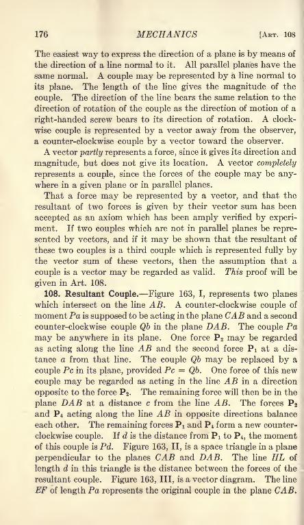
176 MECHANICS [ART. 108
The easiest way to express the direction of a plane is by means of
the direction of a line normal to it. All parallel planes have the
same normal. A couple may be represented by a line normal to
its plane. The length of the line gives the magnitude of the
couple. The direction of the line bears the same relation to the
direction of rotation of the couple as the direction of motion of a
right-handed screw bears to its direction of rotation. A clock-
wise couple is represented by a vector away from the observer,
a counter-clockwise couple by a vector toward the observer.
A vector partly represents a force, since it gives its direction and
magnitude, but does not give its location. A vector completely
represents a couple, since the forces of the couple may be any-where in a given plane or in parallel planes.
That a force may be represented by a vector, and that the
resultant of two forces is given by their vector sum has been
accepted as an axiom which has been amply verified by experi-
ment. If two couples which are not in parallel planes be repre-
sented by vectors, and if it may be shown that the resultant of
these two couples is a third couple which is represented fully bythe vector sum of these vectors, then the assumption that a
couple is a vector may be regarded as valid. This proof will be
given in Art. 108.
108. Resultant Couple. Figure 163, I, represents two planes
which intersect on the line AB. A counter-clockwise couple of
moment Pa is supposed to be acting in the plane CAB and a second
counter-clockwise couple Qb in the plane DAB. The couple Pa
may be anywhere in its plane. One force P2 may be regardedas acting along the line AB and the second force PI at a dis-
tance a from that line. The couple Qb may be replaced by a
couple PC in its plane, provided PC = Qb. One force of this new
couple may be regarded as acting in the line AB in a direction
opposite to the force ?2. The remaining force will then be in the
plane DAB at a distance c from the line AB. The forces ?2and ?4 acting along the line AB in opposite directions balance
each other. The remaining forces PI and ?4 form a new counter-
clockwise couple. If d is the distance from PI to ?4, the momentof this couple is Pd. Figure 163, II, is a space triangle in a plane
perpendicular to the planes CAB and DAB. The line HL of
length d in this triangle is the distance between the forces of the
resultant couple. Figure 163, III, is a vector diagram. The line
EF of length Pa represents the original couple in the plane CAB,

CHAP. XI] FORCES IN POSITION AND DIRECTION 177
The line EF is normal to this plane, and therefore, lies in the plane
of the triangle HLK, and is perpendicular to the line HK. The
line FG is normal to the plane DAB and is normal to the line KLof the space triangle. Since
Pa _ a
PC~
~c'
and since the angle at F is equal to the angle at K, the space
diagram and the vector diagram are similar triangles. As the
FIG. 163.
angle at E is equal to the angle at H, EG is normal to HL. Since
the sides are proportionalEG = d
Pa''
a'
If two couples are represented by vectors normal to their
respective planes, the resultant of these couples is represented
by the vector sum of the two vectors.
Example
A force of 12 pounds is vertically downward. Another force of 12 pounds
vertically upward is located 2 feet east of this first force. A second couple
is made up of a horizontal force of 8 pounds directed north and an equal
force directed south at a distance of 4 feet above this force. Find the
resultant couple,12

178 MECHANICS [ART. 109
The first force has a moment of 24 foot-pounds. It is represented by a
horizontal vector 24 units in length directed south. The second coupleis represented by a horizontal vector 32 units in length directed east. Theresultant couple is represented by their vector sum. This is a horizontal
vector 40 units in length directed south 53 08' east. The resultant couple
is in a vertical plane normal to this resultant vector.
Problem
1. A box is 6 feet long from east to west, 4 feet wide, and 3 feet high. It
weighs 160 pounds and its center of mass is at its center. At the northwest
corner at the bottom, the box rests upon a support which permits it to turn
but not to move laterally. A horizontal force of 60 pounds directed south
is applied at the south east corner at the bottom. A horizontal force of 80
pounds directed east is applied at the northwest corner at the top. In
what plane will these three forces and the reactions at the support turn the
box, and what is the resultant moment?
When the planes of the couples which are to be combined are
not at right angles to each other, it is advisable to resolve each
vector along three coordinate axes; then combine the componentsin exactly the same way as was used in the calculation of the
resultant of non-ooplanar forces.
Problem
2. In Fig. 164, find the sum of the com-
ponents of the moment vectors along each of
the three axes.
Ans. 170 ft.-lb. about a vertical axis;
120 ft.-lb. about a horizontal axis toward
the left; 150 ft.-lb. about a horizontal axis
FIG. 164. toward the front.
109. Forces Reduced to a Force and a Couple. In ChapterVI it was shown that a set of non-concurrent, coplanar forces
may be reduced to a single force and a single couple in the same
plane. It will now be shown that a set of non-concurrent forces,
which are not coplanar, may likewise be reduced to a single force
and a single couple. The force and the couple will not, in general,
be in the same plane.
In Fig. 165, the line AB represents the line of a single force of
magnitude P. This force may be replaced by an equivalent
force P at some point and a couple in the plane AOB. The
moment of this couple is the product of the force P multiplied
by the distance from to its line of action. A second force Q

CHAP. XI] FORCES IN POSITION AND DIRECTION 179
(not shown in the drawing may likewise be replaced by a force
Q at and a couple in the plane through and its line of action.
The resolution of any number of forces in this way, gives a set
of concurrent forces at and a set of couples. The concurrent,
non-coplanar forces at may be combined into a single resultant
Y
FIG. 165.
by the methods of Art. 89. The couples may be combined into
a single couple by a similar addition of vectors.
In the case of non-concurrent, coplanar forces, the single force
and the single couple may be further reduced to a single force,
except when the resultant force is zero. When the resultant
force is zero, the final result is a couple. In the case of non-con-
current, non-coplanar forces, the force and the couple can not,
in general, be combined into a single force. In Fig. 166, P repre-
sents a force through the point 0,
and Qb represents a couple in
a different plane. One of the
forces of the couple may be madeto intersect the force P at 0.
By changing the value of 6, the
force Qi may be given any de-
sired magnitude. If, however, the
couple does not lie in a plane parallel to the direction of the
force P, the two intersecting forces can not be made to balance.
In general, the resultant of the forces P and Qi will be a force R.
This force R is not in the same plane with the force Q 2 . The set
of forces reduces to a force and a couple, and the force and the
R--^

180 MECHANICS [ART. 110
couple reduce to two forces, which are not in the same plane anddo not intersect.
By changing the distance b, the value of Q is changed, hence
the magnitude and position of the force Q 2 and the magnitude and
direction of the force R may be changed.110. Equilibrium of Non-concurrent, Non-coplanar Forces.
It has been shown that a set of non-concurrent, non-coplanarforces may be reduced to a single force through some arbitrarily
chosen point and a single couple. The magnitude and direction
of the force are determined by the conditions of the problem.The magnitude and direction of the couple depend upon the
conditions of the problem and the location of the arbitrarily
chosen point through which the single force acts. To specify
fully the single force through a known point, three factors are
required. These may be the magnitude of the force and two
angles, or the components along each of three axes. To specify
fully the couple as a vector, three factors are required. These
may be one magnitude and two directions, or three components.A problem of non-concurrent, non-coplanar forces in equilibrium
may, therefore, involve six unknowns and require six equationsfor its solution.
For equilibrium, the resultant force must be zero. The force
diagram for all the forces at the arbitrarily chosen point forms a
closed polygon in space. Each force at this arbitrary point is
identical in magnitude and direction with the force which it
replaces. If all the non-concurrent forces of the problem are
regarded as concurrent and combined into a single force polygon,this polygon is closed. The sum of the components along each
of three axes is zero.
The resultant couple must also be equal to zero. The forces
and reactions on the rigid body combine to make up this resul-
tant couple. In order that the couple may be zero, it is necessarythat the sum of the moments about any axis be equal to zero.
To solve a problem of equilibrium in which there are six
unknowns, it is necessary to write six independent equations.Three of these must be moment equations. The remainingthree may be either resolution equations or moment equations.It is advisable to begin with a moment equation about some axis
which will eliminate most of the unknowns.
In the special instance in which all the forces are parallel,
the number of unknowns is reduced to three. Since the forces

CHAP. XI] FORCES IN POSITION AND DIRECTION 181
are all in the same direction, only one resolution equation maybe written. The other two equations must be moment equations.
If all the forces are in parallel planes, the resolution perpen-dicular to these planes will give zero for each force. In this case
there may be only two resolutions. The total number of un-
knowns is reduced to five.
Example
A horizontal trap door, Fig. 167, is 8 feet long and 6 feet wide. It is
supported by two hinges, each 1 foot from a corner, on an 8-foot edge.
It is lifted by a rope attached to the other 8-foot edge at a distance of 2 feet
Space Diagram
^ H '--re '
11
Force Diagram
FIG. 167.
from one corner. This rope passes over a smooth pulley which is 4 feet above
the center of the door. The door weighs 60 pounds and its center of mass
is at the center. Find the tension in the rope and the horizontal and vertical
components of the hinge reaction, assuming that the hinges are so con-
structed that the horizontal force parallel to their line is all taken by the
left hinge.
The unknown quantities are the tension in the rope, the horizontal and
vertical components of the reaction at the right hinge, two horizontal
components and one vertical component at the left hinge. The tension
of the rope is made up of three components. Since the direction of the
rope is known, the problem is fully solved when one of these componentsis determined.
A moment equation about the line of the hinges eliminates five of the
unknowns, together with the horizontal components of the tension of the

182 MECHANICS [ART. 110
rope. The forces which have moment about this line are the weight of
the door and the vertical component of the tension in the rope.
60 X 3 = Vi X 6,
Vi = 30 Ib.
The tension in the rope and its horizontal components may now be com-
puted by resolutions. (These resolutions form no part of the six equations,since the door is not under consideration as the free body.) The space
diagram, Fig. 167, II, is similar to the force diagram, Fig. 167, III. All
the dimensions of the space diagram are known. The vertical force Viof the force diagram is also known. The other forces may be found from
the geometry of the similar solids. If P is the tension in the rope,
P_ = /29.
30 4'
P = 40.39 Ib.
Similarly, HI = 15 Ib., H 2= 22.5 Ib. These components are convenient
in finding the components at the hinges.
Taking moments about an axis which passes through the left hinge and is
parallel to the 6-foot edges,
F3 X 6 = 60 X 3 - 30 X 5;
F 3= 5 Ib.
Taking moments about an axis through the right hinge parallel to the
6-foot edges,F2 X 6 = 60 X 3 - 30 X 1;
F 2= 25 Ib.
Check by a vertical resolution,
Fi + F 2 + F3= 30 + 25 + 5 = 60.
To find H4 ,take moments about a vertical axis through the right hinge.
This eliminates H3 and H 8 .
H4 X 6 = tf ! X 6 + H* X 1
15 X 6 = 90
22.5 X 1 = 22.5
6#4= 112.5,
Hi = 18.751b.
To find H3 ,take moments about a vertical axis through the left hinge,
15 X 6 = 90 counter-clockwise,
22.5 X 5 = 112. 5 clockwise,
6# 3= 22.5 clockwise,
ffa = 3.75lb.
The moment of H3 about the vertical axis through the left hinge must
balance a clockwise moment. The direction of H 3 must be opposite the

CHAP. XI] FORCES IN POSITION AND DIRECTION 183
direction of the arrow in Fig. 167. H3 might have been computed by a
horizontal resolution. Resolving as a check,
3.75 + 18.75 = 22.5.
By resolutions parallel to the line of the hinges,
#5 = H l= 15 Ib.
The problem has been solved by five moment equations and one resolution
equation, and partly checked by two resolution equations. Three of the
moments were taken about horizontal axes and two were taken about vertical
axes.
Problems
1. A horizontal trap door, similar to Fig. 167, is 10 feet long, 7 feet wide,
weighs 80 pounds, and has its center of mass at the center. It is hinged1 foot from the corners on one long side and lifted by a rope at one corner of
the opposite side. The rope passes over a smooth pulley which is 8 feet
above the center of the door. Find all the reactions.
Diagram Vector Diagram of Coup/es
FIG. 168.
2. A horizontal plank, 24 inches long, 18 inches wide, weighs 18 poundsand has its center of gravity at the center. It is supported at the middle
of one 24-inch side, and 2 inches from one corner and 4 inches from the other
corner of the other 24-inch side. Find the reactions of these supports.
Ans. 9 Ib., 4 Ib., 5 Ib.
.3. In problem 2 consider the downward force of 18 pounds as made up
of 9 pounds, 4 pounds, and 5 pounds, and consider that these forces form
couples with the three reactions. The vectors which represent these coupleslie in the plane of the board. Draw the vector diagram for the couples,
Fig. 168.
4. In Fig. 168, the reaction of 9 pounds is moved 4 inches to the right of
the middle. Find the other reactions and draw the vector diagram for the
three couples in equilibrium.
6. The mast of a stiff-leg derrick, Fig. 169, is 30 feet high. The stiff legs
are in vertical planes at right angles to each other. One of these planesextends south and the other extends west of the mast. The stiff legs make
angles of 45 degrees with the vertical. The boom is 40 feet long and carries
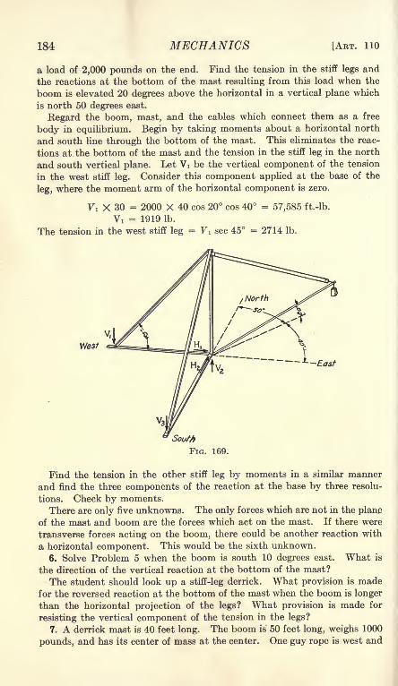
184 MECHANICS [ART. 110
a load of 2,000 pounds on the end. Find the tension in the stiff legs and
the reactions at the bottom of the mast resulting from this load when the
boom is elevated 20 degrees above the horizontal in a vertical plane which
is north 50 degrees east.
Regard the boom, mast, and the cables which connect them as a free
body in equilibrium. Begin by taking moments about a horizontal north
and south line through the bottom of the mast. This eliminates the reac-
tions at the bottom of the mast and the tension in the stiff leg in the north
and south vertical plane. Let Vi be the vertical component of the tension
in the west stiff leg. Consider this component applied at the base of the
leg, where the moment arm of the horizontal component is zero.
Vi X 30 = 2000 X 40 cos 20 cos 40 = 57,585 ft.-lb.
Vi = 1919 Ib.
The tension in the west stiff leg = Vi sec 45 = 2714 Ib.
Find the tension in the other stiff leg by moments in a similar manner
and find the three components of the reaction at the base by three resolu-
tions. Check by moments.
There are only five unknowns. The only forces which are not in the plane
of the mast and boom are the forces which act on the mast. If there were
transverse forces acting on the boom, there could be another reaction with
a horizontal component. This would be the sixth unknown.
6. Solve Problem 5 when the boom is south 10 degrees east. What is
the direction of the vertical reaction at the bottom of the mast?
The student should look up a stiff-leg derrick. What provision is madefor the reversed reaction at the bottom of the mast when the boom is longer
than the horizontal projection of the legs? What provision is made for
resisting the vertical component of the tension in the legs?
7. A derrick mast is 40 feet long. The boom is 50 feet long, weighs 1000
pounds, and has its center of mass at the center. One guy rope is west and

CHAP. XI] FORCES IN POSITION AND DIRECTION 185
another is north 10 degrees east. These ropes make angles of 30 degreeswith the horizontal. The boom is horizontal in a position south 60 degreeseast and carries a load of 2000 pounds. Find the tension in the west guyrope by moments about a horizontal line through the bottom of the mastand the bottom of the other guy rope. Ans. 3443 Ib.
8. At what position of the boom in Problem 7 will the tension in the west
guy rope be the greatest, and what will be its value?
Ans. 3664 Ib. when the boom is south 80 degrees east.
9. Find the four remaining unknowns in Problem 7.
10. A windlass, Fig. 170, is 1 foot in diameter and 4 feet long between
bearings. The crank is 2 feet long from the center of the crank pin to the
axis of the axle. The force is applied to the crank pin at a distance of 1 foot
from the plane through the right bearing perpendicular to the axis. A ropewound round the windlass 20 inches from the left bearing carries a load of
480 pounds. The crank makes an angle of 30 degrees to the right of the
FIG. 170.
vertical upward viewed from the right. The force on the crank is normal
.to the plane through the axis of the windlass and the crank pin. Find this
force and the horizontal and vertical reactions at the bearings. The forces
are all in planes perpendicular to the axis so that there are only five un-
knowns.
Ans. P = 120 Ib.; Vi = 265 Ib.; 7 2= 275 Ib.; Hi = 25.98 Ib.; H2
=129.90 Ib.
11. Solve Problem 10 when the crank is 45 degrees to the right of the
vertical.
12. A shaft is 6 feet long from center to center of bearings and weighs200 pounds. At one foot from the left bearing it carries a pulley 4 feet in
diameter which weighs 240 pounds. At 2 feet from the right bearing it
carries a pulley 3 feet in diameter which weighs 180 pounds. The belt from
the left pulley runs forward horizontally and exerts a pull of 600 poundsat the top and 150 pounds at the bottom. The belt from the right pulley
passes around a pulley 6 feet in diameter on a second shaft. The axis of
this second shaft is 10 feet below the axis of the first shaft. The tension
in the front of this belt is 200 pounds. Find the tension in the other part of
the belt and the components of the reactions of the bearings.

186 MECHANICS [ART. 110
13. A door is 10 feet high, 12 feet wide, weighs 180 pounds, and has its
center of gravity at the center. It is hinged 1 foot from the top and 1 foot
from the bottom. The top hinge is 6 inches north of a vertical line throughthe bottom hinge. The hinges are so placed that the lower hinge takes all
the force parallel to the edge of the door. Find the force on each hingewhen the door is directly south of the hinges. The door is turned until the
top and bottom are east and west and is held by a horizontal force appliedto the edge 4 feet from the bottom. Find this force and the componentsof the forces of the hinges.
14. A rod 12 feet long, weighing 270 pounds, with its center of mass at
the center, is hung horizontally north and south and supported by three
cords. One cord is attached 2 feet from the north end. The others are
attached 2 feet from the south end. One of the latter makes an angle of
34 degrees within the vertical in a vertical plane which is north 75 degreeseast. The other makes an angle of 45 degrees with the vertical in a vertical
plane which is south 60 degrees west. Find the direction of the cord near
the north end and the tension in each of the three.
Ans. 6 34' north of the vertical, tension 136.9 lb.; 92.9 lb.; 81.9 Ib.
15. A bar, weighing 114 pounds, with its center of mass at the middle,is supported in a north and south horizontal position by means of three ropes.
One rope is attached 5 feet north of the middle. The second rope is attached
2 feet south of the middle. The upper end of this rope is fastened to a
point which is 5 feet above, 2 feet south and 3 feet east of the point of attach-
ment to the bar. The third rope is attached 7 feet south of the middle of
the bar. The upper end of this rope is fastened to a point which is 6 feet
above, 4 feet west and 1 foot north of the point of attachment to the bar.
Find the tension in each rope and the direction of the first one.
Ans. First rope is 19 02' with the vertical in a vertical plane which is
north 38 40' west. The tensions are 51.44 lb., 52.84 lb., and 27.30 lb.
16. A wheelbarrovTis 5 feet long from axle to handles, and 2 feet wide
between handles. A *oad of 180 pounds is placed 3 inches to the right of
the center and 12 inches from the axis of the axle. The wheelbarrow is
held horizontal and pushed up an inclined plane which makes an angle of 5
degrees with the horizontal. Find the reaction at the wheel and the direc-
tion and magnitude of the force at each handle.
17. A cylinder 6 inches in diameter and weighing 60 pounds is suspended in
a horizontal position by means of two ropes. One rope supports the
cylinder 2 feet from the middle. This rope passes under the cylinder, and
both ends leave the cylinder in the samevertical plane perpendicular to its axis.
One end makes an angle of 45 degrees with the vertical and the other makes
an angle of 30 degrees with the vertical. The friction is sufficient to preventthe cylinder from slipping. The second rope is wound round the cylinder
and fastened to it. How far must this second rope be placed from the middle
of the cylinder? Solve graphically, neglecting the diameter of the ropes.
18. A right cone, 2 feet in diameter at the base and 8 feet high, is supportedwith its axis horizontal by means of a vertical rope which is wound round it
several times but is not fastened to it. The friction is sufficient to prevent
slipping. One end of the rope leaves the cone 4 inches from the base.
Where must the other end leave? Solve graphically.

CHAP. XI] FORCES IN POSITION AND DIRECTION 187
111. Summary. Couples in parallel planes which have the
same magnitude and sign are equivalent. If their signs are
opposite, they balance each other. Couples in parallel planesare added algebraically.
A couple may be represented by a vector perpendicular to its
plane. The magnitude of the vector is proportional to the
moment of the couple. The direction of the vector bears the
same relation to the direction of rotation of the couple as the direc-
tion of motion of a right-handed screw bears to its direction of
rotation. (This is merely a convention. The opposite direction
might have been chosen just as well.)
A set of non-concurrent, non-coplanar forces acting on a rigid
body may be reduced to a single force at any arbitrarily chosen
point and a single couple. This single force is equivalent to the
resultant of all the forces which act on the body. The force andthe couple may be reduced to two forces. These two forces do
not, in general, intersect.
Any rigid body may be held in equilibrium by a single force
which is equal and opposite to the resultant of the applied forces
and a couple. Any rigid body may be held in equilibrium bytwo forces of proper magnitude, direction, and location.
The conditions of equilibrium are:
(1) The force polygon must close.
(2) The sum of the moments about any axis must be zero.
The condition that the force polygon must close is expressed
algebraically by the statement that the sum of the components
along any axis is equal to zero. By taking resolutions along three
axes, not more than two of which are in the same plane, three
independent equations are obtained. By taking momentsabout three axes, three more independent equations are obtained.
A problem of the equilibrium of non-concurrent, non-coplanarforces may involve six unknowns and six independent equationsof mechanics. There may be other equations depending uponthe geometric, algebraic, or other conditions of the problem.These six equations may be three resolutions and three moments.
Any or all of the resolutions may be replaced by moment
equations.
Many problems involve fewer than six unknowns. In Problem
2 of Art. 110, all the forces are parallel. One resolution com-
pletely specifies these forces, hence two resolution equations mustbe omitted. The forces exert no moment about a vertical axis.

188 MECHANICS [ART. ill
This eliminates one possible moment equation. When non-
coplanar forces are parallel, the number of unknowns is reduced
to three. In Problem 5 of Art. 110, there is no moment about
a vertical axis. This eliminates one couple and reduces the
possible unknowns to five. In problem 10 of Art. 110, the forces
have no components parallel to the axis of the cylinder. This
eliminates a resolution equation and reduces the unknowns to
five. In Problem 13, the forces are coplanar in the first position and
there are three unknowns. In the second position, the problem
involves six unknowns In Problem 14, one couple is left out and
the unknowns are reduced to five.

CHAPTER XII
FRICTION
112. Coefficient of Friction. Figure 171 represents a body of Wpounds mass on a horizontal plane. A rope runs horizontallyfrom the body, passes over a smooth pulley, and supports a massof P pounds. When the load P is relatively small, the systemremains stationary. Regarding the mass W as the free bodyand resolving horizontally, the tension P' in the horizontal cord
(which is nearly equal to the load P) is balanced by the horizontal
force from the supporting plane at
the surface of contact. This hori-
zontal force is the friction between
the two bodies at their surface of
contact. Friction is a force exerted
between two bodies at their surface of
contact. The force of friction resists
motion of one body parallel to the
surface of the other. In Fig. 171, the tension P' tends to pull
the mass W toward the right. The friction from the plane to the
body acts toward the left as is indicated by the arrow.
If the load P is gradually increased, the tension P' will
finally reach a value greater than the friction. The mass W will
begin to move toward the right and continue to move with in-
creasing speed. If an additional load be applied to the mass W,the force required to start it in motion will also be increased. The
body W may be a wooden block weighing 10 pounds and the force
required to start it may be 4 pounds. If an additional 10-pound
weight be put on the block, the force required to start it will be
about 8 pounds.The force which must be overcome in order to start a body in
motion is called the static or starting friction.
If a force is sufficient to start a body in motion, that force
will cause the body to move with increasing speed after it has
been started. A considerably smaller force will keep it in motion
with uniform speed, after it has been started. If the force P'
is gradually increased, a value will be found at which the body189

190 MECHANICS [ART. 112
will continue to move with constant speed after it has been set
in motion by an additional force. This force which will keep the
body in motion with constant speed after it has been started is
somewhat less than the force required to start it. The resistance
when the body is moving at constant speed is called the moving
friction, the sliding friction, or the kinetic friction.
The ratio of the friction to the pressure normal to the surface
is called the coefficient of friction.
f-jpf-flfj Formula X
in which / is the coefficient of friction, F is frictional resistance,
and N is the normal pressure.
Example
In Fig. 171, the mass W weighs 12 pounds and the load P required to
start it in motion is 5.4 pounds. The ^ad P required to keep the body in
motion after it has been started is 4.2 pounds. Find the coefficient of mov-
ing friction and the coefficient of starting friction.
If the friction of the pulley is negligible, it may be assumed that the
horizontal tension in the cord is equal to the weight P. For the coefficient
of starting friction,
/.-MFor the coefficient of moving friction,
" '"
The coefficient of starting friction is very irregular. For moderate loads,
the coefficient of moving friction between surfaces which are not lubricated
is fairly constant. For very low pressures, and for very high pressures
which exceed the elastic limit of the material, the coefficient of movingfriction is greater than it is for moderate pressures. Friction depends uponthe material and upon the polish of the surfaces of contact.
Friction is greatly reduced by lubrication with suitable oils. If the speedis sufficient to keep a good oil film between the surfaces, the friction is that
of solids on viscous liquids, and the coefficient of friction decreases with
increase of pressure.
In the problems below it will be assumed that the coefficient
of friction is constant.
Problems
1. A 60-pound mass is pulled along a horizontal plane by a horizontal
force of 21 pounds. Find the coefficient of friction. Ans. f = 0.35.
m

CHAP. XII] FRICTION 191
2. A 60-pound mass is pulled along a horizontal plane by a force of 20
pounds at an angle of 20 degrees above the horizontal. Find the coefficient
of friction.
Ans. f = 18.79
53.160.353.
FIG. 172.
3. The coefficient of friction between a
wooden block weighing 40 pounds and a hori-
zontal wooden floor is 0.32. What horizontal
force will keep the block moving with con-
stant speed?4. Solve Problem 3 if the force makes an
angle of 20 degrees above the horizontal.
Resolving horizontally, Fig. 172,
P cos 20 = F = 0.32 N.
Resolving vertically,
N = 40 - P sin 20.
Ans. P = 12.20 tb.
6. A 60-pound mass on a plane inclined 25 degrees to the horizontal is
just. pulled up the plane by a force of 40 pounds acting upward parallel to
14.64the plane. Find the coefficient of friction. Ans. f = '- - = 0.27.
54.38
6. In Problem 5, what force upward, parallel to the plane, will allow the
60-pound mass to slide down the plane with uniform speed after it has once
started? Ans. 10.72 Ib.
7. In Problem 5, what horizontal force is required to keep the 60-poundmass moving up the plane with uniform speed? Ans. 50.5 Ib.
8. A ladder 24 feet long rests on a horizontal floor and leans against a
smooth vertical wall. The ladder makes an angle of 20 degrees with the
vertical. The center of gravity of the ladder and its load is 16 feet from
the bottom. What must be the minimumvalue of the coefficient" of friction in order
that the ladder may not slide down after it
has been started by a slight jar?
Solve by one moment and two resolution
equations, together with Formula X. (Fig.
173.) Ans. f = 0.24.
9. Solve Problem 8 if the wall is not smooth
but has a coefficient of friction equal to that
of the horizontal floor.
10. A ladder weighing 40 pounds, with its
center of gravity 12 feet from the lower end,
rests on a horizontal floor and leans over the
upper edge of a smooth vertical wall at a
distance of 20 feet from the floor. Theladder makes an angle of 25 degrees with the vertical. The coefficient of
friction at the floor is 0.35. How far up the ladder may a man weighing 160
pounds climb? Ans. 18.7 ft.
11. A 10-pound mass is placed on a 30-degree inclined plane. If the
coefficient of moving friction is 0.1, what force parallel to the plane will
H
FIG. 173.
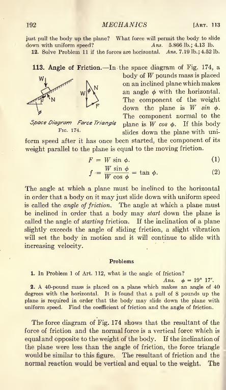
192 MECHANICS [ART. 113
just pull the body up the plane? What force will permit the body to slide
down with uniform speed? Ans. 5.866 lb.; 4.13 Ib.
12. Solve Problem 11 if the forces are horizontal. Ans. 7.19 lb.; 4.52 lb.
113. Angle of Friction. In the space diagram of Fig. 174, a
body of W pounds mass is placed
on an inclined plane which makes
an angle with the horizontal.
The component of the weight
down the plane is W sin <j>.
The component normal to the
Space Diagram Force Triangle plane is W cos 0. If this bodyFlG - 174>
slides down the plane with uni-
form speed after it has once been started, the component of its
weight parallel to the plane is equal to the moving friction.
F = W sin <. (1)
= tan . (2)W cos
The angle at which a plane must be inclined to the horizontal
in order that a body on it may just slide down with uniform speed
is called the angle of friction. The angle at which a plane must
be inclined in order that a body may start down the plane is
called the angle of starting friction. If the inclination of a plane
slightly exceeds the angle of sliding friction, a slight vibration
will set the body in motion and it will continue to slide with
increasing velocity.
Problems
1. In Problem 1 of Art. 112, what is the angle of friction?
Ans. = 19 17'.
2. A 40-pound mass is placed on a plane which makes an angle of 40
degrees with the horizontal. It is found that a pull of 8 pounds up the
plane is required in order that the body may slide down the plane with
uniform speed. Find the coefficient of friction and the angle of friction.
The force diagram of Fig. 174 shows that the resultant of the
force of friction and the normal force is a vertical force which is
equal and opposite to the weight of the body. If the inclination of
the plane were less than the angle of friction, the force triangle
would be similar to this figure. The resultant of friction and the
normal reaction would be vertical and equal to the weight. The

CHAP. XII] FRICTION 193
friction, however, would be less than its limiting value and the
body would remain stationary.
In Fig. 175, four forces are in equilibrium. The resultant of Fand N makes an angle </> with the normal to the surface. In all
cases where a body is sliding with uniform speed there is a force
from the surface of con- pA I
tact to the moving body,
which is the resultant of
the normal reaction andj-j-^ J N ^\ W
the moving friction.
W
N B
FIG. 175.
The angle which this
resultant force makes with
the direction of the normal
to the surface is the angle of friction. If the body is at rest at
the condition of incipient sliding, the tangent of the angle which
the resultant of the friction and the normal forces makes with
the normal is the coefficient of starting friction.
Example
A body is moved along a horizontal plane by a force which makes an
angle 6 with the horizontal. What is the value of in order that the force
may be a minimum?In Fig. 176, the weight W is laid off as a vertical line of known length.
The resultant of the normal and the friction makes an angle < with the ver-
tical. The tangent of < is the coefficient of friction. Through one end of
the vector W of the force diagram, a line of indefinite length is drawn at
an angle </> with the vertical. This line gives the direction of the resultant
of the friction and the normal. A line from the other end of W to the line
of this resultant represents the force P.
The length of this line is the least
when it is perpendicular to the line
of the resultant. Since the resultant
makes an angle with the vertical, the
line P perpendicular to the resultant
makes the same angle with the hori-
zontal. The pull is a minimum whenits angle with the horizontal plane is
the angle of friction.
W WTan<t>f
Force Diagram
FIG. 1761
Problems
3. A body is pulled up an inclined plane by a force which makes an angle
6 with the plane. Show graphically that the pull is the least when its angle
with the plane is equal to the angle of friction.
4. Solve Problem 8 of the preceding article by means of the direction
condition of equilibrium.13
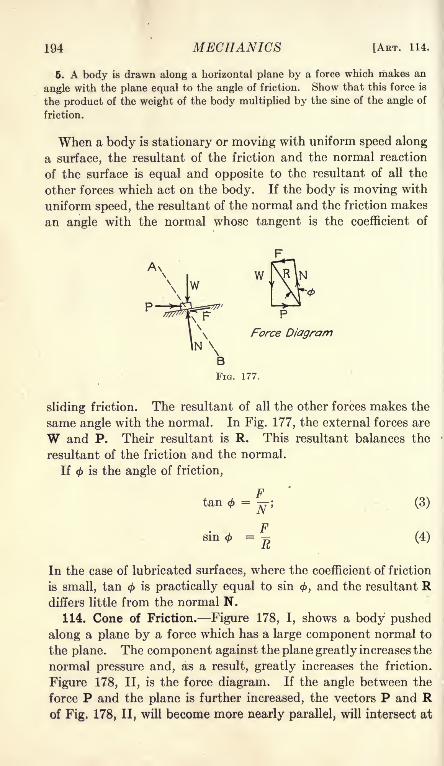
194 MECHANICS [ART. 114.
6. A body is drawn along a horizontal plane by a force which makes an
angle with the plane equal to the angle of friction. Show that this force is
the product of the weight of the body multiplied by the sine of the angle of
friction.
When a body is stationary or moving with uniform speed along
a surface, the resultant of the friction and the normal reaction
of the surface is equal and opposite to the resultant of all the
other forces which act on the body. If the body is moving with
uniform speed, the resultant of the normal and the friction makes
an angle with the normal whose tangent is the coefficient of
A\
\\\
P
NBFIG. 177.
sliding friction. The resultant of all the other forces makes the
same angle with the normal. In Fig. 177, the external forces are
W and P. Their resultant is R. This resultant balances the
resultant of the friction and the normal.
If < is the angle of friction,
tan </>= TF; (3)
sin0 =J (4)
In the case of lubricated surfaces, where the coefficient of friction
is small, tan < is practically equal to sin 0, and the resultant Rdiffers little from the normal N.
114. Cone of Friction. Figure 178, I, shows a body pushed
along a plane by a force which has a large component normal to
the plane. The component against the plane greatly increases the
normal pressure and, as a result, greatly increases the friction.
Figure 178, II, is the force diagram. If the angle between the
force P and the plane is further increased, the vectors P and Rof Fig. 178, II, will become more nearly parallel, will intersect at

CHAP. XII] FRICTION 195
greater distances, and will represent correspondingly greater
forces.
In Fig. 178, III, the force P makes an angle with the vertical
which is equal to the angle of friction. The force polygon will
not close. It is impossible to move the body by a force in this
direction. If the force makes a still smaller angle with the
FIG. 178.
vertical, as shown in Fig. 178, IV, the force polygon will not close
when the force is downward toward the surface. When a force
which pushes a body against a surface makes an angle with the
normal which is less than the angle of friction, this force will
not move the body along the surface, no matter how great it maybe. The lines which make the same angle with the normal to
a surface form a cone, as shown in Fig. 179. When this angleis the angle of friction, the cone is called the cone of friction. Aforce which is applied along a direction inside
the cone of friction for a body and surface has
no tendency to move the body along the sur-
face. The component of such a force normal
to the surface increases the friction more than
the tangential component increases the com-
ponent parallel to the surface.
When a body is moved along a surface, the
applied force must be outside the cone of fric-
tion for the body and the surface. A force, applied inside the
direction of the cone of friction, tends to hold the body stationary.
115. Bearing Friction. Figure 180 shows a shaft of radius a
turning in a very loose bearing in a clockwise direction. Nosuch bearing would be used in practice. It is drawn in this way
FIG. 179.

196 MECHANICS [ART. 115
in Fig. 180 in order to show details more clearly. When the
shaft is turned, it climbs up on the bearing until it reaches a
point at which it slides down as fast as it rolls up. At this
point, the resultant pressure makes an angle with the normalwhich is equal to the angle of friction for the surfaces of the shaft
and the bearing.
If there is a wheel rigidly attached to the shaft, and if forces Pand Q are applied to this wheel by means of a belt, the resultant
moment of these forces about the axis of the shaft must be equalto the moment of the friction about that axis. In Fig. 180, the
FIG. 180.
moment of the friction is counter-clockwise. The moment of
the force P must then be greater than the moment of the force
Q. The line of the normal at the point of contact B passes
through the axis of the shaft. The resultant of the friction and
the normal reaction of the bearing makes an angle with the
direction of this normal. The resultant of the external forces Pand Q passes through their intersection at C. If the weight of
the wheel and of the shaft are neglected, the resultant of the
forces P and Q will pass through B. The resultant of P and Qwill be equal and opposite to the resultant of the normal reaction
and the friction at B, and will lie along the same line.
If a circle of radius a sin is drawn concentric with the axis
of the shaft, the line of the resultant reaction at B will be tangentto this circle. This circle, called the friction circle, is convenient
for some graphical solutions.

CHAP. XII] FRICTION
Example
197
In Fig. 181 the shaft is 6 inches in diameter. The wheel is 2 feet in diam-
eter and weighs 200 pounds. The force P is 240 pounds. The force Q is
200 pounds. Both forces are vertically downward. Find the coefficient
of friction.
Taking moments about the axis of the shaft,
3F = 240 X 12 - 200 X 12 = (240 - 200) X 12 = 480 ft.-lb.
F = 160 Ib.
Since all the applied forces are parallel, their resultant is equal to their sum.
The resultant is 640 pounds vertically downward.
14 29'.
tan <f>= 0.258.
FIG. 181.
The student will understand that this bearing is not lubricated. The
coefficient of friction for a well lubricated bearing should be many times
smaller than 0.258.
Since all the applied forces are vertical, this problem may be conveniently
solved by moments about the point of contact of the shaft and bearing.
The equation of moments about this point B of Fig. 181 is
200(12 + 3 sin 0) + 200 X 3 sin <= 240(12 - 3 sin 0)
Problems
1. In the Example above, the force Q is vertical and the force P is hori-
zontal toward the right. Find the coefficient of friction, and the position
of the point of contact of the shaft and bearing.

198 MECHANICS [ART. 116
Ans. R = 467 lb.; / = 0.365. The normal at the point of contact
makes an angle of 20 04' + 30 58' = 51 02' with the vertical.
2. An axle 4 inches in diameter is connected to a wheel 2 feet in diameter.
The wheel and axle together weigh 160 pounds. A rope passes over the
wheel and hangs vertically downward on each side. A load of 240 poundsis placed on one end of the rope. The coefficient of friction is 0.16. Whatis the load on the other end of the rope which will lift the 240-pound load?
Ans. 257.3 lb.
3. Solve Problem 2 if the axle is only 2 inches in diameter at the bearings.
4. Solve Problem 3 if the bearings are so well lubricated that the coeffi-
cient of friction is 0.03.
Approximate solutions of problems of bearing friction are
often sufficiently accurate. One approximation is the assump-tion that the resultant is equal to the normal pressure. This
is equivalent to R = N, and sin = tan 0. When the coefficient
of friction is small this method involves little relative error.
Another approximation is the calculation of the resultant (but
not the moment) on the assumption that P = Q. In Problem
2, if it is assumed that P = Q in the calculation of the resultant,
R = 240 + 240 + 160 = 640 lb.
If it is assumed that R = N,
F = 0.16 X 640 = 102.40 lb.
Taking moments about the axis of the shaft,
(Q -240) X 12 = 102.40 X 2;
(Q-
240) = 17.07 lb;
Q = 257.07 lb.
It is not probable that the coefficient of friction is known with
anything like the relative accuracy of this result.
Problems
6. Solve Problem 3 by the approximate methods.
6. An axle 4 inches in diameter is attached to a wheel 4 feet in diameter.
The wheel and axle together weigh 200 pounds. A rope hangs vertically
downward on one side of the wheel and supports a load of 300 pounds.On the other side of the wheel the rope makes an angle of 30 degrees below
the horizontal. What is the tension in this part of the rope required to
lift the load of 300 pounds if the coefficient of friction is 0.12? Solve bythe approximate method.
116. Rolling Friction. When a cylinder rolls on a surface, the
surface is depressed somewhat by the pressure which the cylinderexerts on it. This is shown on an exaggerated scale in Fig. 182.

CHAP. Xll] FRICTION 199
If the material of the surface is resilient, it will spring back so as
to push against the cylinder on both sides of the lowest point.
If its resilience is small, it will come back slowly so that practi-
cally all the pressure will be in front of the lowest point of the
cylinder. In any case, the reaction of that part of the surface in
front of the cylinder will be greater than the reaction on the
other side, and the resultant of all the reactions will be somewhatas shown in the figures. The cylinder may be regarded as con-
tinuously climbing a small hill. Experiments have shown that
the distance of the resultant reaction from the line of the load Wis practically constant for a given material and is independentof the diameter of the cylinder. This distance, fr of Fig. 182,
is the coefficient of rolling friction. For steel on steel the coeffi-
cient of rolling friction is from 0.02 inch to 0.03 inch.
FIG. 182.
In Fig. 182, I, the cylinder is rolled along a horizontal surface
by a horizontal force applied at the center. If moments are
taken about the point of contact B, the moment arm of the force
P is practically equal to the radius of the cylinder. The momentarm of the weight W is the coefficient of rolling friction fr . The
moment equation is then,
Wfr= Pa. (1)
In Fig. 182, II, the cylinder is rolled along by means of a force
parallel to the surface applied at the top. The moment arm of
this force is the diameter of the cylinder.
Wfr = 2Pa. (2)
Problems
1. If the coefficient of rolling friction of iron on iron is 0.03 inch, what
horizontal force applied at the center of an iron wheel, 18 inches in diameter,
weighing 200 pounds, will just roll it along a smooth, horizontal iron surface.
Ans. 0.67 Ib.

200 MECHANICS [ART. 117
2. An iron wheel, 30 inches in diameter, weighing 160 pounds, rolls on a
steel rail. The coefficient of rolling friction is 0.03 inch. The wheel is
attached to an axle 4 inches in diameter. A load of 800 pounds is applied
to the axle by means of a bearing. The coefficient of sliding friction between
the axle and the bearing is 0.04. What horizontal pull is required to movethe load? Ans. 6.32 Ib.
3. Figure 183 represents a mass of W pounds
]\ ' W ^y /'\ > P on cylindrical rollers. The coefficient of roll-
?Hr'
/< \ ing friction is 0.04 inch at the bottom and 0.05
wyiw^JfLw*-^^ i 110*1 at *he toP- ^e cylinders are 10 inches
FIG. 183. *n diameter and weigh 100 pounds each. Theload W is 2000 pounds. If the track is hori-
zontal, what is the force required to keep the load moving?Ans. 18.8 Ib.
4. In Problem 3, what is the pull required to keep the load moving up a
1-degree inclined plane?
117. Roller Bearings. Since the coefficient of rolling friction
of hard steel on hard steel is very small, it is desirable to design
bearings in which the friction is rolling rather than sliding. This
is accomplished by means of roller bearings, or ball bearings.
Fig. 184 shows a roller bearing. The axle rotates on hardened
steel rollers which in turn roll on the inside surface of a hollow
steel cylinder. In order to keep the rollers properly spaced so
that they will not come together and introduce sliding friction,
each roller is connected at the ends to a light metal frame called
the cage.
For relatively light loads, ball bear- ^^ }
ings are employed instead of roller
bearings. Spherical balls roll in
grooves or races, which may be Vshaped or circular.
For rolling, the coefficient of start-
ing friction is nearly the same as the
coefficient of moving friction. This
property is one of the elements of the
superiority of roller or ball bearings FIG. 184.
over the ordinary bearings.
118. Belt Friction. Figure 185, I, represents a pulley and a
belt. The belt is in contact with the pulley through an angle of
a radians. The tension of the belt at the left point of tangencywith the pulley is PI. The tension at the right point of tangency

CHAP. XII] FRICTION 201
is P2 . The tension P 2 is greater than PI so that the belt tends
to turn the pulley in a clockwise direction.
P2 P\ = friction between belt and pulley.
Figure 185, II, shows a small element of the length of the belt.
This element is enclosed between radii which make an angle dB
with each other. The tension on the left end of the element is P;on the right end is P -f dP. The difference between these twotensions is dP. This difference is equal to the friction between
the belt and the pulley. Since the two tensions, P and P + dP,
FIG. 185.
are each tangent to the pulley, they make an angle d0 with each
other, and each tension makes an angle -~ with the tangent at
the middle of the element. The normal reaction of the pulley on
the element of the belt is obtained by a resolution along the
radius BO. The component of P is P sin-^>
which, for a small
d6angle, is equal to P -^- When the differentials of the second
z
order are omitted, the component of P + dP is also P -*- The
total normal force on the element is
N = Pdd. (1)
If the coefficient of friction between the belt and the pulley is /,
then
F = fN = fPdS = dP. (2)

202 MECHANICS [ART. 118
Separating the variables in this last equation,
^ = fdO; (3)
lo&P = fB + C. (4)
When = 0, P = PI; C = log (Pi
/0 = log,P-
logePi. (5)
When = a,P = P2 ;
... (6)
Example
A belt is in contact with a pulley through an angle of 180 degrees. The
tension at one point of tangency is 100 pounds and the coefficient of friction
is 0.4. What is the maximum tension at the other point of tangency?
loge ^ = 3.1416 X 0.4 = 1.2566./i
If a suitable table of Naperian logarithms were available, the ratio of P 2
to PI could be found by looking up the number whose logarithm is 1.2566.
Without such a table, the Naperian logarithms must be reduced to common
logarithms.
logic= 0.5457,
P 2= 100 X 3.51 = 351 Ib.
The tension of 351 pounds is the greatest value possible without slipping.
The actual tension may be very much less than 351 pounds.
Problems
1. A rope is wound twice around a cylindrical post. The coefficient of
friction is 0.3. What must be the minimum tension in one end of the rope
in order to have a tension of 1,000 pounds in the other end?
Ans. 23.05 Ib.
2. A rope is hung over a cylinder whose axis is horizontal. When a
load of 20 pounds is hung on one end of the rope, it is found that a load of
60 pounds may be hung on the other end. If the rope were given an addi-
tional turn around the cylinder, how many pounds could be hung on one
end when there is a load of 20 pounds on the other end? Solve without
writing.
3. A cylindrical drum 10 inches in diameter is used to lift a load of 2,000
pounds by means of a 1-inch rope. The drum is turned by means of a
pulley 4 feet in diameter which is attached at one end. The pulley is driven

CHAP. XII] FRICTION 203
by a belt from a second pulley of the same diameter. If the coefficient of
friction between the belt and the pulley is 0.4, what must be the tension in
the two parts of the belt? Ans. 641 lb.; 183 Ib.
4. Solve Problem 3 if the second pulley is 1 foot in diameter and its axis
is 5 feet from the axis of the drum.
119. Summary. Friction is a force at the surface of contact of
two bodies, which resists the motion of one body along the surface
of the other. The force of friction is tangent to the commonsurface of the two bodies and is opposite the direction which one
body is moving or tending to move relative to the other body.The ratio of the friction to the normal pressure is called the
coefficient of friction. The coefficient of moving friction is
the value of this ratio when the bodies actually move relative to
each other. The coefficient of starting friction is the maximumvalue of this ratio when there is no motion. The coefficient of
starting friction is greater than the coefficient of moving friction.
For solids which are not lubricated, the coefficient of friction
is fairly constant with varying pressure and velocity. Thecoefficient varies greatly with the smoothness of the surface and
the kind of material.
MATERIAL COEFFICIENT OF MOVING FRICTION
Wood on wood, dry . 25 to . 50
Metal on metal, dry . 15 to . 20
Leather on metal, dry . 35 to . 55
When the surfaces are well lubricated, the coefficient of friction
decreases with increase of pressure and is much smaller than for
dry surfaces.
The ratio of the friction to the normal pressure (the coefficient
of friction) is the tangent of the angle of friction. The ratio of the
friction to the resultant pressure is the sine of the angle of friction.
If <f> is the angle of friction, the resultant of all the applied
forces, except the normal reaction and the friction, makes an
angle <f> with the direction of the normal.
The coefficient of rolling friction is the distance of the point of
application of the resultant reaction at the surface of the rolling
body from a line through the center of the rolling body parallel
to the resultant of all loads except the force required to roll
the body.The coefficient of rolling friction is practically independent
of the radius of the rolling body. The force required to roll
a body varies inversely as its diameter.

204 MECHANICS [ART. 120
In the case of a belt running over a pulley,
loglo ^-2 = 0.4343 fa,
r\
in which P2 is the tension in the belt at one point of tangency,
PI is the tension at the other point of tangency, / is the coefficient
of friction, and a is the angle of contact in radians.
120. Miscellaneous Problems
1. A cylinder, 8 inches in diameter, weighing 6 pounds, is placed on two
parallel rods, which make an angle of 15 degrees with the horizontal. Astring is wound around the cylinder and supports a weight on the free end.
What must be the weight in order to hold the cylinder in equilibrium, andwhat must be the minimum value of the coefficient of friction? What is the
direction of the resultant of the friction and the normal at the points of
contact with the rods?
2. A cylinder, 8 inches in diameter, and 24 inches in length, weighs 18
pounds and has its center of gravity at the middle. The cylinder is sup-
ported by a rod perpendicular to its length at a distance of 9 inches from
one end, and by a cord which is wound around it and supported above. If
the coefficient of friction is sufficient to prevent sliding, how far must the
cord be placed from the other end of the cylinder? Solve by moments.
Also solve graphically.
3. A car is 56 inches wide, center to center of wheels, and 108 inches
long, center to center of axles. The center of gravity is 30 inches above
the ground and 60 inches in front of the rear axle. If the coefficient of
starting friction is 0.30 and the brakes are set so that the wheels will turn,
what is the steepest grade which the car can descend without accelerating?
Ans. 7 01'.
4. What is the steepest grade which it is possible for the car of Problem 3
to ascend? Ans. 8 16'.

CHAPTER XIII
WORK AND MACHINES
121. Work and Energy. In Art. 39, the work done by a force
was defined as the product of the displacement of its point of
application multiplied by the component of the force in the direc-
tion of the displacement. Expressed algebraically,
U = P cos a s, Formula III
in which P is the force; s is the displacement or amount of motionof its point of application; a is the angle between the direction
of the force and the direction of the displacement; and U is the
work. Since
P cos a X s = P X s cos a, (1)
work may be defined as the product of the entire force multiplied
by the component of the displacement in the direction of the
force.
Work is the scalar product of two vectors, and is not a vector.
Quantities of work may be added as mere numbers with no regardto the directions of the forces and displacements.
Example I
A 10-pound mass is lifted 4 feet vertically upward. Find the work donein lifting it.
The average force is 10 pounds vertically upward. If the body was
initially at rest, a force a little greater than 10 pounds was required to set
it in motion. As it was brought to rest at the end of the displacement,the force was a little less than 10 pounds. The point of application of
the force moves in the direction of the force so that cos a = 1.
U = 10 X 4 = 40 foot-pounds.
Example II
A 10-pound mass is pulled 12 feet up a 30-degree smooth inclined plane
by a force which makes an angle of 15 degrees with the plane. Find the
work done.
A resolution parallel to the plane gives,
P cos 15 = 10 sin 30 = 5 lb.;
U = 5 X 12 = 60 foot-pounds.
Instead of taking the body up the inclined plane of Fig. 186, it mighthave been taken horizontally from A to B, and then lifted vertically from
205

206 MECHANICS [ART. 121
B to C. If there is no friction, no work is done in taking the body from
A to B (since the force is normal to the displacement). A force of 10
pounds is required to lift the body vertically upward from B to C. The
displacement from B to C is 6 feet and the work is 60 foot-pounds.
When the force varies in mag-nitude or direction, or when the
'*\ /fe^^n displacement varies in direction,
the total work is calculated from
the work of a large number of
small displacements. If ds is an
element of the displacement so
small that the magnitude and
direction of the force and the direction of the displacement maybe taken as constant throughout that interval, the increment of
work is given by the equation,
dU = Pcosads. (2)
The total work is the integral of Equation (2),
U = fP cos a ds. (3)
Problems
1. A 90-pound mass on a horizontal plane is moved 60 feet north by a
force of 50 pounds which is directed north 20 degrees east. Find the work
done by this force. Ans. 2819 ft.-lb.
2. It requires a force of 12 pounds to stretch a given spring a distance of
1 foot. If the force is proportional to the elongation, what is the work done
in stretching the spring 1 foot? Solve by means of the average force and
check by integrating Equation 3. Ans. 6 ft.-lb.
3. After the spring of Problem 2 has been stretched 1 foot, find the work
required to stretch it an additional foot. Ans. 18 ft.-lb.
When a body is lifted vertically upward, work is done on it.
When the body comes down to its original position, it may do an
equal amount of work on another body. When a spring is
stretched, work is stored up in it and this work may later be
given to another body. Work which is stored up in a body is
called energy. The energy of a deformed elastic body, or the
energy of a body which has been lifted against the force of gravity,
is called potential energy. Potential energy is sometimes defined
as the energy of position. The energy of a moving body is called
kinetic energy ,or the energy ofmotion. In Example 1, the potential
energy of the 10-pound mass, after it has been lifted 4 feet, is
40 foot-pounds more than the energy before it was lifted. This
gravitational potential energy may be regarded as the energy

CHAP. XIII] WORK AND MACHINES 207
of deformed ether. In Problem 2, the potential energy of the
spring is 6 foot-pounds when it is stretched 1 foot, and is 24 foot-
pounds when it is stretched 2 feet.
Kinetic energy will be discussed in Chapter XVI.122. Equilibrium by Work. When a body which is in equi-
librium under the action of several forces is displaced, the total
work done by all the forces is equal to zero. This is true because,when a body is in equilibrium, the resultant force is zero and the
component of the resultant along any direction of displacementis zero. This principle affords a convenient method of solvingsome problems of equilibrium. The method is especially valu-
able when the body is constrained to move along some smoothsurface. In the application of the method, the body is assumedto suffer a displacement along the surface, and the total work of
all the forces is equated to zero. If the direction and magnitudeof the forces remain constant through a large displacement, the
assumed displacement may be taken as equally large. If either
the direction or the magnitude of any force changes with a small
displacement, the assumed displacement is taken as an infinitesi-
mal length.
123. Machines. A body or combination of bodies for the
transfer or transformation of work is called a machine. The
input is the work done on a machine. The output is the useful
work done by the machine. The ratio of the useful work done
by the machine to the input is the efficiency of the machine.
Suppose that a rope over a single pulley is employed to lift a
load of 40 pounds vertically upward, and suppose that the pull
on the rope on the other side of the pulley is 50 pounds. Whenthe load is lifted 1 foot, the useful work is 40 foot-pounds. If
the rope does not stretch, the input is 50 foot-pounds. The
efficiency is 80 per cent. The 10 foot-pounds of work are lost
in friction of the pulley, and are transformed into heat. If there
were no friction or similar losses, the efficiency would be one
hundred per cent.
The force which acts on a machine with a component in the
direction of the displacement, and which does positive work on
the machine, is called the effort. The force which does negative
work on the machine, or with which the machine does work, is
called the resistance. The ratio of the resistance to the effort is
called the mechanical advantage of the machine. When a force
of 20 pounds on one arm of a lever lifts a mass of 60 pounds

208 MECHANICS [ART. 124
w
vertically upward, the mechanical advantage of that lever as a
machine is ^ = 3. Since the work done by the effort is equal to
the negative work of the resistance, (assuming no friction), the
mechanical advantage is equal to the ratio of the displacementof the effort to the displacement of the resistance.
124. Inclined Plane. In Fig. 187, a body on an inclined plane
is supported by a force parallel to the plane.
The supporting force P and the mechanical
advantage will be found by the method of
work. If the length of the plane is I, the
work done by the force P in pulling the bodythat distance is PL If the height of the plane
is h, the negative work of gravity on the body of W pounds mass
is Wh. The normal reaction of the plane does no work, since
its direction is perpendicular to the displacement. If there is
no friction, the input is equal to the output, and
PI = Wh, (1)
Wh
FIG. 187.
P = = W sin
Equation (2) is the same as is obtained by a resolution parallel
to the inclined plane.
Equation (3) states that the mechanical advantage of an inclined
plane, when the force is applied parallel to the plane, is equal to
the ratio of the length of the plane to its
height, or is equal to the cosecant of the wl ^^^angle of slope of the plane. JpwX\ l<:
In Fig. 188, the force P, which acts on ^^ p
the body, is horizontal. When the bodymoves a distance / along the plane, the com-
ponent of its displacement in the direction
of the force is the horizontal projection of that distance. The
work done by the force P is Pb, in which b is the horizontal
projection of I.
Pb = Wh, (4)
p = I = W tan 0. (5)
FIG. 188.
W b-^ = 7 = cotan 6.
r n(6)
CHAP. XIII] WORK AND MACHINES 209
Equation (5) states that the mechanical advantage of an inclined
plane, when the force is horizontal, is equal to the ratio of the
base of the plane to its height.
When a body is lifted up an inclined plane, the output is in
the form of the increased potential energy at the new position.
In any machine, the input is always greater than the output.No work is gained. What is gained is the ability to exert a largeforce through a small distance by means of a convenient small
force acting through a larger distance, or a large displacementwith a small force by means of a smaller displacement with a
larger force. One may not be able to lift 400 pounds vertically
upward a distance of 2 feet, but he may easily accomplish the
same result by means of an inclined plane 10 feet in length.
Problems
1. A barrel weighing 240 pounds is lifted a vertical distance of 3 feet byrolling up a plank 12 feet in length as an inclined plane. The force is
applied parallel to the plank by means of a frictionless bearing at the axis.
If the rolling friction is negligible, what is the work done? What is the
force, and what is the mechanical advantage?2. The barrel of Problem 1 is rolled up the plane by means of a rope which
is wound around it several times and then fastened. How far will the endof the rope move while the barrel rolls 12 feet, if the pull is applied parallel
to the plane? What is the pull? What is the mechanical advantage?What is the minimum value of the coefficient of friction between the barrel
and the plank in order that it may be rolled in this way? (The diameter
of the rope is negligible.)
3. A body is pulled up a 30-degree inclined plane by means of a force
parallel to the plane. The body is on rollers which have a combined fric-
tion equal to a coefficient of sliding friction of 0.02. Find the efficiency.
The useful work is W s. sin 30 The normal pressure is W cos 30. Thelost work of friction is 0.02 W s cos 30
Useful work = 0.500 Ws;lost work = 0.0173 Ws;
0.500efficiency =
r~rr^= 96.7 per cent.
0.517
Frequently, the body is lifted in a carriage which takes up part
of the energy. If the energy of the carriage is not returned in the
form of useful work, it represents a loss which must be taken into
account in calculating the commercial efficiency of the machine.
Problems
4. A mass of 100 pounds is lifted up a 30-degree plane on a carriage
which weighs 20 pounds. The pull is by means of a rope parallel to the
14

210 MECHANICS [ART. 125
plane. The coefficient of friction is 0.03. Find the commercial efficiency
of the inclined plane and carriage if the carriage, when running back, helps
lift another one.
Ans. 93.2 per cent, neglecting the loss in transmission to the second
carriage.
6. Solve Problem 4 if the carriage is let down by a brake.
Ans. 79.2 per cent.
6. If the efficiency is 95 per cent, what load can be lifted up a 16-degree
inclined plane by a pull of 100 pounds parallel to the plane/The mechanical advantage is the cosecant of 16 degrees. If the efficiency
were 100 per cent,
W = 100 X 3.628 = 362.8 Ib.
Allowing for the losses,
W = 362.8 X 0.95 = 344.7 Ib.
'
7. If the efficiency is 94 per cent, what force parallel to a 20-degree in-
clined plane will lift 600 pounds up the plane?
125. Wheel and Axle. When a wheel of radius r (Fig. 189)
rotates through an angle of 6 radians, the linear displacement is
rd. If the wheel of radius r is attached to
an axle of radius a, the equation of work is
WaS = PrB;
W_ r
~P~ a
(1)
(2)
Fia/189.
The mechanical advantage of the wheel and
axle is the ratio of the radius (diameter) of
the wheel to the radius (diameter) of the
axle.
Equation (2) might be derived by mo-
ments about the axis. A wheel and axle maybe regarded as a continuous lever.
Problems
1. The diameter of a wheel is 2 feet, and the diameter of the axle is 6
inches. The rope on the wheel is % inch in diameter and the rope on the
axle is 1 inch in diameter. Find the mechanical advantage.Ans. 3.5.
2. A wheel 40 inches in diameter is attached to an axle 8 inches in diam-
eter. The bearings are 3 inches in diameter and the coefficient of friction
is 0.03. The wheel and axle together weigh 120 pounds. Both ropes run
vertically downward. Neglecting the diameter of the ropes, find the force
required to lift 200 pounds, and find the efficiency.
Ans. 40.8 Ib.; 98 per cent.

CHAP. X1I1] WORK AND MACHINES 211
3. Solve Problem 2 for a load of 100 pounds and for a load of 600 pounds.4. What force is required with a wheel 4 feet in diameter and an axle
10 inches in diameter to lift a load of 1200 pounds, if the rope on the wheel
is 0.5 inch in diameter; the rope on the axle is 1 inch in diameter; and the
efficiency is 94 per cent?
6. A body is pulled up a 20-degree inclined plane by means of a rope
parallel to the plane. The rope runs from an axle 12 inches in diameter
which is turned by a wheel 40 inches in diameter. Neglecting the diameter
of the ropes, find the mechanical advantage of the combination. If the
combined efficiency is 92 per centj what force on the wheel will lift 1200
pounds up the plane?
126. Pulleys. Figure 190 shows a single pulley with a flexible
cord. When the effort P moves downward a distance s, the
load W moves upward an equal distance. The mechanical
advantage is unity.
w
FIG. 190. FIG. 191.
In Fig. 191, there is a fixed pulley at the top and a single
movable pulley below. If the movable pulley is lifted a distance
s, the rope supporting it is shortened that distance on each side
and the part of the rope which passes over the fixed pulley musttravel a distance of 2s.
P2s = Ws;
The mechanical advantage of a single movable pulley supported
by two parts- of a continuous rope is 2. This is evident from the
fact that the tension in a continuous rope which runs over smooth
pulleys is the same in all parts of its length, and two parts of

212 MECHANICS [ART. 126
the rope support the load W, while only one part supports the
force P.
Since the block and pulley of weight TFi, which form the mov-
able system, must be lifted along with the load Wz, the com-
mercial efficiency is W if there are no losses due to friction
w,
w,
of the pulleys or bending of the ropes.
In Fig. 192, the movable
block carries one pulley and?
. I & I the fixed block carries two
pulleys. The rope is attached
to the movable block. For
clearness, the pulleys in the
upper block are made of un-
equal size and placed one
above the other. This, how-
ever, is not a customary
arrangement. It is evident
that the mechanical advan-
tage is 3 when the blocks are
so far apart that the three
ropes which support the
movable block are practically
parallel. In the positionshown in Fig. 192, the me-
chanical advantage is less
than 3.
Figure 193 shows a systemwith two pulleys in the movable block. The mechanical
advantage is 4 when the blocks are so far apart that the ropes
are practically parallel. The pulleys on each block run on the
same axis but with different speeds.
In a system of pulleys with one continuous rope, the mechanical
advantage is equal to the number of ropes which directly support
the weight.
Problems
1. Sketch a system of pulleys arranged as in Fig. 192 with a mechanical
advantage of 5.
2. In a system similar to Fig. 193, the mechanical efficiency is 95%.The movable block and pulleys weigh 20 pounds. The weight TF 2 is 400
FIG. 192. FIG. 193.

CHAP, X11I] WORK AND MACHINES 213
pounds. Find the force required to lift the system, and find the commercialefficiency.
3. A safe weighing 2,400 pounds is pulled up an inclined plane by a blockand tackle. The plane is 24 feet long and 5 feet high. The block andtackle has a mechanical advantage of 4 and an efficiency of 95 per cent.
The efficiency of the plane is 90 per cent. Find the force and find the re-
quired length of rope4. Sketch a system of pulleys combined with a wheel and axle for a
combined mechanical advantage of 12.
127. The Screw. In lifting a body by means of a screw, theeffort travels a distance 2irr in one revolution, where r is the
distance of the effort from the axis. At the same time, the load
moves a distance equal to the pitch of the screw. If d is the
pitch (distance between threads),
Wd =2-irPr;
mechanical advantage = -=-
The efficiency of a screw is small. It must be less than 50
per cent or the screw will run down when the turning moment is
released. The screw is a continuous inclined plane with the
force applied parallel to the base. If the friction on an inclined
plane is less than the component of the load parallel to the plane,
the load will slide down. In order to pull a body up a plane where
the friction is sufficient to prevent it from sliding down, the force
parallel to the plane must be twice as great as the component of
the weight. The force parallel to the base must be still greater.
Problem
A screw with 4 threads to the inch is turned by a lever 15 inches longfrom the axis of the screw to the point of application of the effort. What is
the mechanical advantage? If the efficiency is 30 per cent, what is the
force required to lift 2,000 pounds? .Ans. 377,17.7 Ib.
128. Differential Appliances. Figure 194 shows a differentia
screw. The part which passes through the nut A is made with
one pitch, while the part which passes through the nut B is madewith a smaller pitch. If the screw is rotated in a clockwise direc-
tion, (as seen by an observer looking toward the head from the
right), it will move toward the left through the nut A. If the
nut B is held so that it does not rotate with the screw, it will

214 MECHANICS [ART. 128
move toward the right relative to the screw, but will movetoward the left relative to the nut A. The actual motion of Brelative to A during one revolution is equal to the difference of
pitch of the two parts of the screw.
> -^
FIG. 194.
Problems
1. The pitch of the right end of the screw of Fig. 194 is three threads
to the inch and the pitch of the left end is four threads to the inch. Thescrew is turned by means of a rod which is 20 inches long from the axis of
the screw to the point of application of the force. Find the mechanical
advantage. Ans. 1508.
2. What would be the mechanical advantage in Problem 1 if the pitches
were 8 threads and 9 threads to the inch, respectively?
Figure 195 shows a differential axle. As
part of the rope around the axle of radius
a2 is wound up, the part around the axle
of radius 0,1 is unwound. In turning
through an angle of 6 radians, the total
vertical rope is decreased in length by an
amount (a2 a\)Q and the load is lifted
-^-s-
0. The effort moves through az
distance r6, and mechanical advantage =
The combination is equivalentCf 2 fli
to an axle of radius a2 ai lifting a single
movable pulley with two ropes to support
the weight. With this arrangement, the
mechanical advantage of a small axle is
secured and the axle is sufficiently large to
FIG. 195. carry the required load.
Problems
3. In Fig. 195, the wheel is 20 inches in diameter. The larger part of
the axle is 6 inches in diameter and the smaller part is 5 inches in diameter.
Find the mechanical advantage.

CHAP. XIII] WORK AND MACHINES 215
4. Find the mechanical advantage of Problem 3 by moments about theaxis of the axle.
In many machines it is not easy to determine the mechanicaladvantage from inspection. The mechanical advantage mayalways be found by moving the machine and measuring therelative motion of the effort and the resistance. In a differential
pulley, for instance, it was found that the chain by which theeffort was applied moved 50 inches, while the hook which carriedthe load moved 1 inch. Evidently the mechanical advantageis 50.
129. The Lever. The mechanical advantage of the lever, is
most easily calculated by moments. If the forces are perpendicu-lar to the moment arms, as in Fig. 196, I; or if the lever is
straight so that the points of application of all the forces are onthe same straight line, and the forces are parallel, the momentequation is
Pa = Wb, (1)
.?-5' .
&Equation (2) states that the
mechanical advantage is the
ratio of the effort arm to the
resistance arm.
If the lever of Fig. 196, I,
is turned through a small
angle d0, the work done bythe force P is PadQ, and the
negative work of the resis-
tance W is WbdB. Equation FlG - 196.
(1) is obtained by equating these two expressions for work.
In Fig. 196, II, the work of the force P is Pad6 cos 0, and the
work of the force W is Wbd9 cos 6, in which 6 is the angle between
the lever and a line perpendicular to the forces.
The efficiency of a lever as a machine may be nearly 100
per cent, when the fulcrum is a carefully made knife edge as in
a chemical balance.
130. Virtual Work. The preceding articles of Chapter XIII
have dealt with bodies moving with uniform speed. The same
conditions apply to a body at rest. If a body in equilibrium
be considered as suffering a small displacement, the total work of

216 MECHANICS [ART. 130
all the forces will be zero. In Fig. 197, the body of mass Wwhich is held on a smooth inclined plane by a force P parallel to
the plane may be regarded as moved up the plane a distance ds.
The body is raised a vertical distance dy, so that
- Wdy + Pds =
P = Wdyds
W sin 6.
(1)
(2)
Figure 198 shows a bar of length I, mass W, with its center of
mass at a distance a from the lower end. The bar rests on a
smooth horizontal floor and leans .
against a smooth vertical wall.
The bar is held from slipping by a
horizontal force at the bottom.
This horizontal force will be com-
puted by the method of work.
FIG. 197. FIG. 198.
When the lower end of the bar is moved a distance dx toward
the right, the center of mass is moved upward a distance dy. Asthe reactions at the wall and the floor are normal to the displace-
ment, their work is zero. This work equation is
Pdx = Wdy (3)
The relation between dx and dy is found by differentiating an
equation between x and y. This relation is conveniently found
by means of a third variable. If 6 is the angle between the bar
and the horizontal, and y is the distance of the center of massabove the floor,
y = a sin 6,
dy = a cos dB.
(4)
(5)

CHAP. XIII] WORK AND MACHINES 217
If x is the distance of the lower end of the bar from the vertical
wall and is positive toward the right,
x = I cos 8, (6)
dx = I sin B dO. (7)
Substitution in Equation (3) gives
PI sin d6 = Wa cos 6 dO, (8)
W _ a cotan 6
P=
1 (9)
This method of determining the conditions of equilibrium
by assuming that the body suffers a small displacement and
equating the work of all the forces is called the method of virtual
work.
Problems
1. A ladder 20 feet long, weighing 36 pounds, with its center of gravity
8 feet from the lower end, rests on a smooth horizontal floor and leans
against a smooth vertical wall. It is held from slipping by a horizontal
force of 16 pounds applied 2 feet from the bottom. Find the position of
equilibrium by the method of virtual work. Check
by moments and resolutions.
Ans. 45 degrees with the horizontal.
2. The ladder of Problem 1 rests on a smooth
horizontal floor and leans against a smooth wall
which makes an angle of 15 degrees with the vertical,
away from the ladder. It is held from slipping by a
horizontal push of 8 pounds at the bottom. Find
the position of equilibrium.
Ans. Tan 6 = 1.5321; 6 = 56 52' with the
horizontal.
3. Find the mechanical advantage of the toggle
joint, Fig. 199, in terms of x and the lengths a and b.
y =
dy =
W

218 MECHANICS [ART. 130
force perpendicular to the crank. Give the result in terms of the
lengths of the crank and the connecting rod and the position of the crank.
x = a cos + 6 cos <f>= a cos + \/6 2 a2 sin 2
0;
-P dx = R a de\
p= sin
a sin cossn cos e tan
Problems
6. In Fig. 200, find the normal reaction N at the cross-head by resolutions,
Then find the moment about the axis of the axle at by a moment equation.
FIG. 200.
regarding the connecting rod and crank as a single body. Compare the
result with that obtained by means of the answer of the Example.6. A bar AB, Fig. 201, of length c is hinged at A and supported by a rope
at B. The rope runs over a smooth pulley C at the same level as A, at a
distance 6 therefrom, and carries a load of P pounds on the free end. Thebar weighs W pounds and its center of mass is at a distance a from the
hinge. Find the ratio of W to P at any position.
FIG. 201.
Let BC =s, and let the vertical distance of the center of mass below the
hinge be represented by y, which is taken as positive downward.
Wdy = P ds;
T7=
be sin
p a cos 0V& 2 + c2 - 26c cos 0'
7. In Problem 6, let W = 12 pounds, P = 10 pounds, a = 4 feet, 6 =
8 feet, and c = 6 feet. Find the equation for the angle 0.
Ans. 0.96 cos 3 0-2 cos2 + 1=0.

CHAP. XIII] WORK AND MACHINES 219
8. Solve Problem 7 for cos 6 by the method of trial and error.
cos 6 0.96 cos 3 6 2 cos2 6 f(6)
1 0.96 -2 -0.0400. +1
The function of 6 changes sign between cos = and cos 6 = 1. There
must be one real root or three real roots between these values. One root
is evidently much closer to unity than to zero. Beginning with cos =0.9,
0.9 0.69984
0.95 0.82308
0.96 0.84936
0.97 0.87616
0.965 0.862687
. 966 . 865372
.62 - +0.07984
.805 +0.01808
.84320 +0.00616
.88180 -0.00564
.862450 +0.000237
.866312 -0.000940
An interpolation of the last two results gives cos 6 = 0.9652, 6 = 15 10'.
The remaining roots may be found by a similar process. It is better,
however, to divide the cubic equation by cos 0.9652. The quotientis an equation of the second degree, which may be solved by the ordinarymethods for quadratics. One of the roots of this quadratic is a solution of
the problem of mechanics. The other root is a solution of the mathematical
equation, but is geometrically impossible. Draw the space diagram for the
possible result.
9. A straight bar of length I and mass W, with its center of mass at a
distance a from the lower end, rests on a smooth horizontal floor and leans
over the edge of a smooth wall. The vertical height from the floor to the
point of contact with the wall is h. A rope attached to the bottom of the
bar runs horizontally over a smooth pulley and supports a mass of P pounds.Find the equation for the position of equilibrium by the method of virtual
work. Ans. Wa(cos 6 cos 36)
= Ph.
10. Solve Problem 9 by trial and error for the following cases:
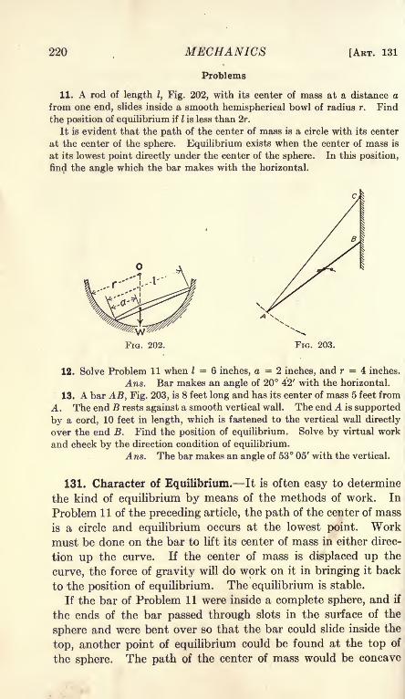
220 MECHANICS
Problems
[ART. 131
11. A rod of length I, Fig. 202, with its center of mass at a distance a
from one end, slides inside a smooth hemispherical bowl of radius r. Find
the position of equilibrium if I is less than 2r.
It is evident that the path of the center of mass is a circle with its center
at the center of the sphere. Equilibrium exists when the center of mass is
at its lowest point directly under the center of the sphere. In this position,
find the angle which the bar makes with the horizontal.
FIG. 203.
12. Solve Problem 11 when I = 6 inches, a = 2 inches, and r = 4 inches.
Ans. Bar makes an angle of 20 42' with the horizontal.
13. A bar AB, Fig. 203, is 8 feet long and has its center of mass 5 feet from
A. The end B rests against a smooth vertical wall. The end A is supported
by a cord, 10 feet in length, which is fastened to the vertical wall directly
over the end B. Find the position of equilibrium. Solve by virtual work
and check by the direction condition of equilibrium.
Ans. The bar makes an angle of 53 05' with the vertical.
131. Character of Equilibrium. It is often easy to determine
the kind of equilibrium by means of the methods of work. In
Problem 1 1 of the preceding article, the path of the center of mass
is a circle and equilibrium occurs at the lowest point. Workmust be done on the bar to lift its center of mass in either direc-
tion up the curve. If the center of mass is displaced up the
curve, the force of gravity will do work on it in bringing it back
to the position of equilibrium. The equilibrium is stable.
If the bar of Problem 11 were inside a complete sphere, and if
the ends of the bar passed through slots in the surface of the
sphere and were bent over so that the bar could slide inside the
top, another point of equilibrium could be found at the top of
the sphere. The path of the center of mass would be concave

CHAP. XIII] WORK AND MACHINES 221
downward at this position. If the bar were displaced slightly
from this position, the force of gravity would tend to displace
it still farther, and it would not return. In this case, the equi-
librium is unstable. In many cases, when a body is displaced
from its position of unstable equilibrium, it will move to the
position of stable equilibrium.
A position at which the total work of a small displacement is
zero, is a position at which the potential energy of the system is a
maximum or a minimum. If gravity is the only force which
does work on a body, the potential energy is a maximum whenthe path is concave downwards, and a minimum when the pathis concave upwards.
In Fig. 203, the location of the center of mass for one position
on each side of the position of equilibrium is represented by a
small circle. It is evident that the locus of the center of mass
is concave downward, and that the equilibrium is unstable.
Figure 201 applies to Problem 6 of Art. 130 for one position of
equilibrium. At the other position of equilibrium, the bar is
above the hinge and toward the left. In this second position,
the center of mass of the bar is higher than that of Fig. 201.
The length BC is also greater; hence the load P. is higher. Conse-
quently the potential energy in the second position is greater
than in Fig. 201. Figure 201 shows the position of stable
equilibrium. At the other position, the equilibrium is unstable.
132. The Beam Balance. Figure 204 shows the fundamental
parts of a beam balance with equal arms. In an accurately
constructed balance, the three knife edges are in the same plane
and the center of gravity of the beam is located a little below the
central knife edge. When equal loads are applied to the end
knife edges, the resultant of these loads falls on the central
knife edge and does no work when the beam is deflected. When

222 MECHANICS [ART. 132
a small additional load p is placed on the right knife edge, the
beam is turned through an angle in a clockwise direction. If
W is the weight of the beam, c is the distance of its center of
gravity below the central knife edge, and a is the distance be-
tween knife edges, a moment equation gives
We sin 6 = pa cos 0; (1)
*-& (2)
For small angles, the tangent is equal to the arc in radians and
equation (2) becomes,pa
~~
We' (3)
Equations (2) and (3) give the sensibility of the balance. The
sensibility of a balance is the angle through which the beam is
turned by unit additional load on one knife edge. Delicate
balances are provided with a pointer which projects downwardand moves in front of a graduated scale. The sensibility of the
balance is usually expressed in terms of the scale reading.
Problems
1. A balance beam weighs 50 grams and its center of gravity is 0.008
inch below the central knife edge. The knife edges are 4 inches apart andare in the same plane. The pointer is 10 inches long. How much will
the end of the pointer move when 1 milligram is placed on one pan?Ans. 0.10 inch.
2. The center of gravity of a balance beam is frequently adjusted bymeans of a nut, which may be turned up or down on a screw at the top of the
beam. (This screw is not shown in Fig. 204.) In Problem 1, the beamweighs 48 grams and the nut weighs 2 grams. How much must the nutbe moved to double the sensibility?
If the central knife edge is above the plane of the end knife
edges, the resultant of equal loads on the pans is a load of 2Punits directly below the central knife edge. In order to deflect
the beam, work must be done on this load. The sensibility of
such a balance is diminished as the load is increased. If d is the
distance of the central knife edge above the plane of the endknife edges, the moment equation becomes
pa cos = We sin 6 + 2Pd sin 0', (4)
tan

CHAP. XIII] WORK AND MACHINES 223
When the central knife edge is above the plane of the end knife
edges, the equilibrium is stable for all loads.
Problem
3. In the beam of Problem 1, the central knife edge is 0.0004 inch abovethe plane of the end knife edges. When the load on each pan is 50 grams,find the deflection of the pointer for 1 milligram additional load on one pan.
Ans. 0.091 inch.
When the central knife edge is below the plane of the end knife
edges a distance d, the moment of the resultant force 2P changes
sign and Equation (5) becomes
The sensibility is increased with increased load. If the load
is too great, the second term of the denominator becomes larger
than the first term and the equilibrium is unstable.
When a balance is loaded, the beam is slightly bent. Thecentral knife edge may be a little . below the plane of the end
knife edges when the total load is small and may come above their
plane when the total load is larger. In a beam of this kind, the
sensibility may increase with a small increase of total load and
decrease with a larger load.
The theory above applies to balances with equal arms. Thesame principles obtain when the arms are not equal. The only
difference is that the sum of the loads on the two pans replaces
the load 2P of the formulas.
The arms of a balance, which are supposed to be equal, maynot be equal. Let a be the length of one arm and b the length of
the other. Let P be the load on the arm of length a which bal-
ances an unknown load W on the other arm.
Pa = Wb. (7)
Now put the load W on the arm of length a and suppose that it is
balanced by a load Q on the other arm.
Qb = Wa, (8)
W = VPQ. (9)
The true weight is the geometric mean of the apparent weights.
The arithmetic mean of the apparent weights is sufficiently exact
for all ordinary purposes.

224 MECHANICS [ART. 133
If W is eliminated from Equations (7) and (8),
Problems
4. An unknown load on the left pan of a balance is balanced by 100.012
grams on the right pan. When the unknown load is placed on the right
pan, it is balanced by 99.976 grams on the left pan. Find the true weightof the body. What is the difference between the geometric mean of Equa-tion (9) and the arithmetic mean?
5. Find the ratio of the arms in Problem 4.
133. Surface of Equilibrium. It is sometimes desirable to find
a surface of such form that a body under a given set of forces
will be in equilibrium at any point on it. The reaction of the
surface at every point must be opposite the direction of the
resultant of the applied forces. This means that the resultant
of the applied forces must everywhere be normal to the surface.
Such a surface is called an equipotential surface for the forces
involved. The surface of a still lake is an equipotential surface
for the force of gravity.
Since the resultant force is normal to an equipotential surface,
no work is done in moving a body from one part of the surface to
another. If Hx is the component in the direction of the X axis
of the resultant of all the forces at the surface (except the reaction
of the surface), the work done in displacing a body a distance
dx is Hxdx. If V is the component in the direction of the Y axis,
and Hz is the component in the direction of the Z axis, the total
work of a displacement in the surface is
U = Hxdx + Vdy + Hzdz = 0. (1)
Example
The centrifugal force of a rotating body varies as the distance from the
axis of rotation. A body of liquid rotates at constant speed about a vertical
axis. Find the equation of the intersection of the surface of the liquid with
the XY plane.
The horizontal force on a unit of mass is kx and the vertical force is 1.
Equation (1) becomes,kxdx Idy =
0,
dy = kxdx.
kx*, n
y =~T + c -
The curve is a parabola with the axis vertical.

CHAP. XIII] WORK AND MACHINES 225
Problems
1. A mass of 10 pounds slides on a smooth wire in a vertical plane. Themass is attached to a cord which passes over a pulley in the same vertical
plane. The other end of the cord is attached to a spring. A force of 1
pound stretches this spring 1 inch. When there is no elongation of the
spring, the end of the cord just reaches the pulley. If the wire passes
through a point 12 inches above the pulley, find its equation in order that the
mass may be in equilibrium at any point on it.
The tension in the cord is equal to r where r is the distance of the end of
the cord from the pulley. The horizontal component of this tension is the
total tension multiplied by the cosine of the angle which the cord makes
with the horizontal. This cosine is-
Hx = -x; V = -y - 10;
xdx + (y + W)dy =0;
z2 + ?/2 + 20y = C.
When x =0, y = 12; C = 384;
x z + (y + 10)2 = 22 2
.
The wire is in the form of a circle of 22 inches radius with its center 10 inches
below the pulley.
2. Solve Problem 1 if the end of the cord is 4 inches from the pulleywhen the tension in it is zero. (The pull =
(r 4).)
Ans. x* + y* + 2Qy - 4\x* + y* = 336.
3. A body slides on a curved wire in a horizontal plane. It is fastened
to two cords. One cord passes over a pulley at A and is attached to a
spring which requires a pull of k\ pounds to stretch it unit distance. Thesecond cord passes over a pulley at B and is attached to a spring which
requires a pull of fc 2 pounds to stretch it unit distance. The points A and Bare at a distance c apart in the direction of the X axis. Find the equationof the wire if the body is in equilibrium at any point on it.
Ans. (fcj + /c 2)(z2 + i/
2)- 2k,cx = C
in which the origin of coordinates is located at A, and the point B lies onthe X axis to the right of A.
134. Summary. The amount of work done by a force is the
product of the magnitude of the force multiplied by the compo-nent of the displacement of its point of application in the direc-
tion of the force
U = P X s cos a. = P cosa X s. Formula III
The second form of the formula states that work is the productof the displacement multiplied by the component of the force
in the direction of the displacement.When the direction or magnitude of the force varies, or when
15

226 MECHANICS [ART. 134
the direction of the displacement varies, the increment of work is
given bydU = P cos a ds.
A machine transmits energy. The ratio of the work done bya machine to the work done on it is called the efficiency of the
machine. The ratio of the force exerted by a machine to the
force applied to it is called the mechanical advantage of the machine.
The efficiency of a machine is never quite equal to unity. Themechanical advantage may have any value.
Problems of equilibrium may be solved by means of work equa-
tions. In the method of virtual work, the body or system is
assumed to suffer a small displacement and the work of this
displacement is equated to zero.
Equilibrium may be stable, unstable, or neutral. The poten-
tial energy of a body in stable equilibrium is a minimum. Workmust be done on the body to move it from the position of equilib-
rium. The potential energy of a body in unstable equilibrium
is a maximum. If the body is slightly displaced from the position
of equilibrium, work must be done on it to move it back to
that position. When a body is in neutral equilibrium, no work
is required to move it in either direction.
When the force is applied parallel to an inclined plane, the
mechanical advantage is the ratio of the length of the planeto its height. When the force is applied parallel to the base of
an inclined plane, the mechanical advantage is the ratio of the
base to the height.
The mechanical advantage of a wheel and axle is the ratio of
the diameter of the wheel to the diameter of the axle.
When a continuous rope is used, the mechanical advantageof a system of pulleys is equal to the number of parts of the
rope which support the weight.
The mechanical advantage of a screw is the ratio of the cir-
cumference of the circle in which the effort moves to the pitch
of the screw. The efficiency of a screw is less than 50 per cent.
The mechanical advantage of a lever is the ratio of the lengthof the effort arm to the length of the resistance arm. The
efficiency of a lever may be very high.
The sensibility of a balance is proportional to the length of the
arms and inversely proportional to the mass of the beam and the
distance of its center of gravity below the central knife edge.
CHAP. X1I1] WORK AND MACHINES 227
If the central knife edge is above the plane of the end knife edges,
the sensibility is decreased with increased load. If the central
knife edge is below the plane of the end knife edges, the sensi-
bility is increased with increased load. If there is much differ-
ence in this direction, the equilibrium may be unstable with a
large load.
If the arms of a balance are unequal, the load must be weighedfirst on one pan and then on the other. The true weight is the
geometric mean of the two weighings. The arithmetric meanis sufficiently exact in a fairly good balance.
On an equipotential surface
H xdx + Vdy + Hxdz = 0.

CHAPTER XIV
MOMENT OF INERTIA OF SOLIDS
135. Definition. The moment of inertia of a solid with respect
to an axis may be defined mathematically as the sum of the prod-
ucts obtained by multiplying each element of mass by the square
of its distance from the axis. Expressed algebraically,
/ = 2wr2, (1)
in which 7 is the moment of inertia, m is an element of mass, and
r is the distance of the element from the axis. The element
must be of such form that all parts are at the same distance from
the axis. If the elements are infinitesimal, Equation (1) is
written
7 =fr*dm,
Formula XI
in which dm is the element of mass.
Figure 205 shows the form of the element required to find the
moment of inertia with respect to
the Z axis OZ. The element BB'is parallel to the axis OZ. If its
transverse dimensions are infini-
tesimal, all parts of the element
are at the same distance from OZ,within infinitesimal limits. Theelement may also be infinitesimal
parallel to the axis or it may ex-
X tend entirely through the body in
this direction as shown in Fig.
205. The cross-section of the ele-
ment in the plane perpendicular to the axis may be rectangularas shown, or may have the form necessary for integration with
polar coordinates. The element may be a hollow cylinder of
radius r and thickness dr, which extends through the bodyparallel to the axis.
136. Moment of Inertia by Integration. Figure 206 shows one
end of a cylinder of radius a. It is desired to find the moment of
228
FIG. 205.

CHAP. XIV] MOMENT OF INERTIA OF SOLIDS 229
inertia of this cylinder with respect to its axis, which is perpen-dicular to the plane of the paper.
Polar coordinates are best suited for this problem. Theelement of volume parallel to the axis of the cylinder has the
cross-section dA = rdddr. If I is the length of the cylinder,the element of volume is
dV = Irdedr.
If p is the density, or mass per unit volume,
dm = plrdddr.
I =fr
zdm =plffr*dddr.
(1)
(2)
(3)
role
FIG. 206. FIG. 207.
Integrating first with respect to r and putting in the limits r =and r = a,
I = P
-\~dO. (4)
Integrating next with respect to B and putting in the limits
6 = and 6 = 27r,
7 -*? Mo* T' .
(5)
The mass of the cylinder is
m = plird2
,
which substituted in Equation (5) gives
I =^f-
Formula XII
Figure 207 represents a rectangular parallelepiped of length I,
breadth 6, and depth d. It is desired to find its moment of
inertia with respect to the axis of symmetry parallel to its length.
The line 00' is the axis. The element of volume is dV = Idxdy.

230 MECHANICS [ART. 136
The element of mass is dm = pldxdy. With 0-0' as the axis
of coordinates,
/ =Jr
2dm =plff(x
2 + y^dxdy (6)
The limits for x are -^ and +2
- The limits for y are^and
/ =
Problems
1. Find the moment of inertia of the rectangular parallelepiped of Fig.
207 with respect to the axis CC".2 2
Ans. I =3
2. Figure 208 shows a triangular prism of length I. The cross-section
is a right-angled triangle. Find the moment of inertia with respect to the
edge 00'.
AnS. 1 =fn/u/ -
fyiiv ~
3. Find the moment of inertia of a right circular
cone of height h and diameter 2a with respect to its
axis.
Build up the cone of a series of flat disks parallel to
the base as shown in Fig. 209. The radius of each disk
is r and its thickness is dy. The distance y may be
L_____J measured from the base, as in Fig. 209 or from the
F 208vertex. The expression for the moment of inertia of
the disk is written by means of Formula XII. Theradius r is expressed in terms of y and the constants; the moment of inertia
is found by a single integration.
T pirha1 3wa 2
"To- "To"4. Solve Problem 3 by building up the cone of hollow cylinders of radius
r and thickness dr, coaxial with the cone. (Fig. 210.)
The solutions of Problems 3 and 4 are instances of the integration of an
element of volume rdddrdy. Integrating 6 first gives a hollow ring. Inte-
grating y next builds the rings into a hollow cylinder. Integrating r last
expands these cylinders to form the cone. For Fig. 209, r may be integratedfirst and 6 next, or 6 may be integrated first and r next. In either case, the
result is the thin disk. The final integration with respect to y builds upthe cone of a series of such disks.
6. Find the moment of inertia of a sphere with respect to a diameter,
using disks as elements. Ans. / = -^~10

CHAP. XIV] MOMENT OF INERTIA OF SOLIDS 231
6. Solve Problem 5 by a single integration, using hollow cylinders as
elements of volume.
7. By means of Equation (5) Problem 5, find the moment of inertia of a
hollow cylinder of inside radius b and outside radius a.
FIG. 209. FIG. 210.
8. A right circular cone, 10 inches in diameter, and 12 inches high, has
a coaxial cylindrical hole, 4 inches in diameter, cut through it. By meansof the results of the preceding examples and problems, find the moment of
inertia of the remainder. Ans. I = 615.6 trp= 1934p.
FIG. 211. FIG. 212.
9. Find the moment of inertia of a homogeneous solid cylinder of lengthI and radius a with respect to a line in its surface parallel to its axis. Theend of this cylinder is shown in Fig. 211.
10. Find the moment of inertia of a homogeneous solid cylinder with
respect to an axis parallel to the axis of the cylinder at a distance d therefrom.
Figure 212 shows the end of the cylinder. The axis of inertia is perpen-

232 MECHANICS [ART. 137
dicular to the plane of the paper. For simplicity, the origin of coordinates
is taken at the center of the circle. The distance r of Formula XI is r' of
the figure. This distance must be expressed in terms of r, 0, and d.
Ans. I = ml +y 11. In Problem 10, find the moment of inertia of the first quadrant alone.
12. Find the moment of inertia with respect to the Z axis of the tetra-X 77 2,
hedron bounded by the three coordinate planes, and the plane- + r + - =1.
Ans. I
137. Radius of Gyration. The radius of gyration of a body is
the distance from the axis at which all the mass of the bodymust be placed in order that the moment of inertia may be the
same as that of the actual body. It is defined mathematically
by the equation
k 2 = -, Formula XIIIra
in which k is the radius of gyration.
The moment of inertia of a homogeneous solid cylinder with77? Cl CL^
respect to its axis is ~Q~; anc* ^ ="9"'
^ a h m geneous solid
cylinder of given mass is replaced by a thin hollow cylindrical
shell of the same mass, the moment of inertia of the shell will
equal that of the cylinder, provided the radius of the shell is
0.7071 of the radius of the cylinder.
Problems
1. Find the radius of gyration of a homogeneous solid sphere 20 inches in
diameter. Ans. k = \/40 = 6.32 in.
2. Find the radius of gyration of a homogeneous hollow cylinder, of whichthe outside diameter is 16 inches and the inside diameter is 10 inches.
Ans. k = 6.67 in.
3. Find the radius of gyration of a homogeneous hollow cylinder, of
which the outside diameter is 16 inches and the inside diameter is 15 inches.
Ans. k = 7.75 in.
4. Derive the expression for the square of the radius of gyration of a
hollow cylinder, of which the outside radius is a and the inside radius is b.
Am . *..*+6. Derive the expression for the square of the radius of gyration of a
homogeneous solid cone of radius a with respect to the axis of the cone.
7, 3a 2
Ans. fc2 =--

CHAP. XIV] MOMENT OF INERTIA OF SOLIDS 233
138. Transfer of Axis. The calculation of the moment of
inertia about any axis is frequently a laborious process. Thework may often be simplified by means of a transfer of the axis.
If the moment of inertia of a body is known with respect to some
axis, its moment of inertia with respect to any other axis parallel
to that axis may be found by simple algebraic methods.
In Fig. 213, the moment of inertia with respect to the line
00' is desired. Let BB' represent any element of the body
parallel to 00'. The distance from 00' to BB' is r.
I = fr2dm. (1)
Suppose that the moment of inertia of the body is known with
respect to the axis CC', and suppose that CC fis parallel to 00'
FIG. 213.
at a distance d. The horizontal component of d is a and the
vertical component is 6.
& = a2 + b2. (2)
The coordinates of the element BB' with respect to CC' as the
Z axis are x and y.
r* = (a + x)2 + (b + y)
2. (3)
/ = /( 2 + 2ax + x2 + &2 + 2by + y2)dm', (4)
/ = /(a2 + b*)dm + f(x2 + y2)dm + 2afxdm +
2bfydm. (5)
The first term of the second member of Equation (5) is
(a2 + b2)fdm = md2
.

234 MECHANICS [ART. 138
The second term is the moment of inertia with respect to CC'.
This moment of inertia may be represented by 7 .
f(xi + y2)dm = 7 .
The third term is lafxdm. The expression xdm is the moment
of the element with respect to the vertical plane through CC'.
The expression fxdm is the moment of the entire volume with
respect to this plane. If the vertical plane through CC' passes
through the center of gravity of the body, the moment is zero.
Similarly, the last term is zero if the horizontal plane through
CC' passes through the center of gravity of the body. If the
line CC' passes through the center of gravity of the body, the last
two terms of Equation (5) vanish and
/ = / + md\ Formula XIV
in which 7 is the moment of inertia with respect to an axis
through the center of gravity, / is the moment of inertia with
respect to a parallel axis at a distance d from the center of gravity,
and m is the mass of the body.
Formula XIV affords a convenient method of finding the
moment of inertia of a body with respect to any axis, if the
moment of inertia is known with respect to a parallel axis through
the center of gravity. If the moment of inertia is known for some
axis which does not pass through the center of gravity, and if it
is desired for some other axis which does not pass through the
center of gravity, Formula XIV may be used to transfer from the
first axis to the center of gravity and then to transfer fromthe center of gravity to the second axis.
If k is the radius of gyration with respect to an axis through
the center of gravity,
7 = mkl.
If k is the radius of gyration with respect to the axis 00',
md 27 , , 9 ^ , VT ,
kz = = - - = kl + d 2. Formula XVm m
Problems
1. Solve Problem 9 of Art. 136 by means of Formula XIV.2. Solve Problem 10 of Art. 136 by means of Formula XIV.
3. A solid sphere is 12 inches in diameter. Find its radius of gyration
with respect to an axis 10 inches from its center. Ans. k = 10.70 in.
4. Find the radius of gyration of a hollow cylinder, 8 inches outside
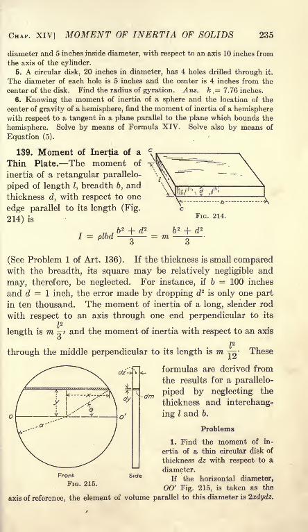
CHAP. XIV] MOMENT OF INERTIA OF SOLIDS 235
diameter and 5 inches inside diameter, with respect to an axis 10 inches from
the axis of the cylinder.
6. A circular disk, 20 inches in diameter, has 4 holes drilled through it.
The diameter of each hole is 5 inches and the center is 4 inches from the
center of the disk. Find the radius of gyration. Ans. k .= 7.76 inches.
6. Knowing the moment of inertia of a sphere and the location of the
center of gravity of a hemisphere, find the moment of inertia of a hemispherewith respect to a tangent in a plane parallel to the plane which bounds the
hemisphere. Solve by means of Formula XIV. Solve also by means of
Equation (5).
139. Moment of Inertia of a
Thin Plate. The moment of
inertia of a retangular parallelo-
piped of length I, breadth 6, and
thickness d, with respect to one
edge parallel to its length (Fig.
214) is
+ dT i^1 = plod m
\\IHlii,
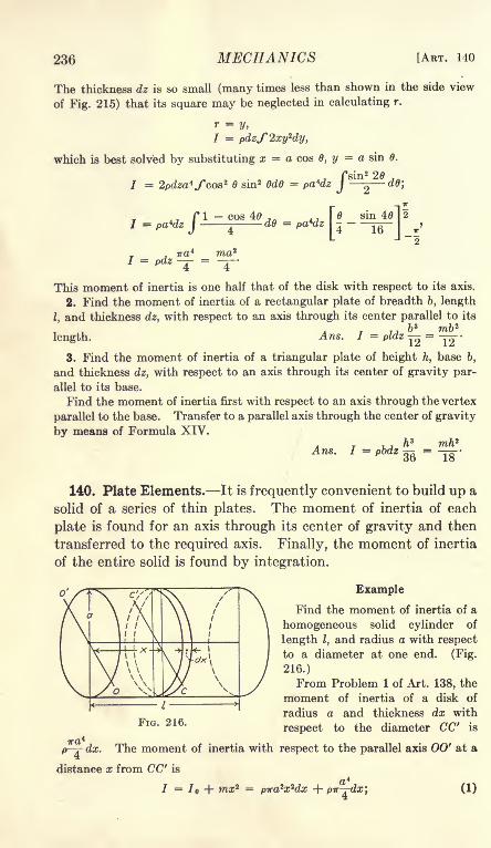
236 MECHANICS [ART. 140
The thickness dz is so small (many times less than shown in the side view
of Fig. 215) that its square may be neglected in calculating r.
r =y,
I = pdzS2xy2dy,
which is best solved by substituting x = a cos 0, y = a sin 0.
/sin
2 20
2d0
'
pa*dzf-
, Tr
pdz =
cos 40d6 = pa*dz
[0
sin 401 2
J--H-J v
This moment of inertia is one half that of the disk with respect to its axis.
2. Find the moment of inertia of a rectangular plate of breadth 6, length
I, and thickness dz, with respect to an axis through its center parallel to its
, , 7 b 3 mb 2
length. Ans. I = pldz =-^
3. Find the moment of inertia of a triangular plate of height h, base 6,
and thickness dz, with respect to an axis through its center of gravity par-
allel to its base.
Find the moment of inertia first with respect to an axis through the vertex
parallel to the base. Transfer to a parallel axis through the center of gravity
by means of Formula XIV.
Ans. I36
mfe2
18'
140. Plate Elements. It is frequently convenient to build up a
solid of a series of thin plates. The moment of inertia of each
plate is found for an axis through its center of gravity and then
transferred to the required axis. Finally, the moment of inertia
of the entire solid is found by integration.
Example
Find the moment of inertia of a
homogeneous solid cylinder of
length I, and radius a with respect
to a diameter at one end. (Fig.
216.)
From Problem 1 of Art. 138, the
moment of inertia of a disk of
radius a and thickness dx with
respect to the diameter CC" is
ir-r- dx. The moment of inertia with respect to the parallel axis 00' at a
distance x from CC' is
7 = 7 + ma;2 = pira*x*dx + pir-j-dx; (1)

;
CHAP. XIV] MOMENT OF INERTIA OF SOLIDS 237
(3)
Problems
1. Find the moment of inertia of a homogeneous solid cylinder with respect
to a diameter at the middle. Ans. I = m l^~ + ]
*
2. Find the moment of inertia of a circular rod with respect to an axis
through one end perpendicular to its length, if the diameter is so small that
its square is negligible compared with the square of the length., ml z
Ans. I---3. Find the moment of inertia of a homogeneous right cone of altitude h
and diameter 2a with respect to an axis through the vertex parallel to the
base. Ans. I =*
+
4. Solve Problem 12 of Art. 136 by means of plate elements.
6. Find the square of the radius of gyration of a square right pyramidwith respect to an axis through the vertex parallel to one edge of the base.
Ans. jfc* =|
For any right pyramid or cone, the square of the radius of gyration with
respect to an axis through the vertex parallel to the base is given by the
equation,
fc2 =
jj(fc{+ V), (4)
in which kb is the radius of gyration of the base (considered as a thin plate)
with respect to an axis through its center of gravity parallel to the axis
through the vertex.
4 6. For any right cylinder or prism, show that the radius of gyration with
respect to an axis perpendicular to the length through the center of one endis given by the equation,
7. For any axis perpendicular to the length of any right cylinder or prism,show that the radius of gyration is given by the equation,
k 2 = k\ + kl,
in which fci is the radius of gyration of a thin rod of length equal to that of
the cylinder or prism with respect to a perpendicular axis, and kb is the
radius of gyration of a thin plate equivalent to a section of the cylinder or
prism parallel to the base.
8. By means of Problem 7, find the moment of inertia of a homogeneous
cylinder 10 inches long, 4 inches in diameter, and weighing 24 pounds,with respect to an axis perpendicular to its length and tangent to one end.
Ans. 7 = 920.

238 MECHANICS [ART. 142
9. A solid cylinder, 10 inches in diameter and 12 inches long, has a cylin-
drical hole, 6 inches in diameter arid 8 inches long, drilled in the upper end.
The axis of the hole is parallel to the axis of the cylinder and 1 inch from it.
Find the square of the radius of gyration of the remainder with respect to
an axis in the upper end through the axis of the hole and perpendicular to
the plane of the two axes.
141. Moment of Inertia of Connected Bodies. To find the
moment of inertia of two or more connected bodies with respect
to a single axis, it is necessary to find the moment of inertia
of each body with respect to a parallel axis through its center
of gravity and then transfer to the common axis. The momentof inertia of all the bodies with respect to this axis is found by
adding the moment of inertia of each of the separate parts.
Since moment of inertia involves the square of a distance, it is
always positive.
Problems
1. A solid sphere is 4 inches in diameter and weighs 10 pounds. It is
hung on the end of a rod 1 inch in diameter and 40 inches long, which weighs9 pounds. The end of the rod is tangent to the surface of the sphere. Find
the radius of gyration with respect to a diameter of the rod at the end oppo-site the sphere. Ans. k = 34.37 in.
2. What change will be made in the result of Problem 1 if the diameter
of the rod is neglected?3. A right cone, 4 inches in diameter and 12 inches high, stands on the
end of a cylinder, 2 inches in diameter and 20 inches long. The axis of the
cone coincides with the axis of the cylinder. The cone and cylinder havethe same density. Find the radius of gyration with respect to a diameter
of the cylinder at the end opposite the cone. Ans. 17.77 in.
142. Summary. Moment of inertia is defined mathematically
by the equations,
/ = fr*dm; I =Zmrjj
Formula XI
in which / is the moment of inertia/W is a finite element of mass,dm is an infinitesimal element of maJl, and r is the distance of the
element from the axis wifrT resJbt to which the moment of
inertia is taken.
The radius of gyration iscpfined mathematically by the
equation
k 2 = -, Formula XIIIm
in which k is the radius of gyration and m is the entire massof the body. The radius of gyration is the distance from the

CHAP. XIV] MOMENT OF INERTIA OF SOLIDS 239
axis at which all the material of the body must be placed in order
to have a moment of inertia equal to that of the actual body.When the moment of inertia of a sphere of radius a is taken with
respect to a diameter,
]fc-^!.5
When the moment of inertia of a solid cylinder of radius a
is taken with respect to the axis of the cylinder,
a 2
l/m 2 ."
2
When the moment of inertia of a right cone is taken with
respect to the axis of the cone,
* - 3 2
wWhen the moment of inertia of a rectangular parallelepiped
is taken with respect to an axis through the center perpendicular
to the edges of length b and d,
fc2 + d 2
k 2 =12
When the moment of inertia of a right cylinder is taken for an
axis through the center perpendicular to its length,
For any right cylinder or prism, for which the moment of
inertia is taken with respect to an axis perpendicular to its length,
the square of the radius of gyration is equal to the square of
the radius of gyration regarded as a thin rod plus the square of
the radius of gyration regarded as a thin plate.
To transfer from an axis through the center of gravity to a
parallel axis,
jfcz = kl + d\ Formula XVin which & is the radius of gyration with respect to the axis
through the center of gravity and d is the distance between the
axes.
143. Miscellaneous Problems
1. A homogeneous hollow cylinder has an inside diameter of 6 inches and
and outside diameter of 10 inches. Find its radius of gyration with respect
to an axis 12 inches from its axis and parallel to it.
Ans, k = 13.34 in.

240 MECHANICS [ART. 143
2. A solid of revolution is formed by revolving the area enclosed by the
X axis, the curve y2 = 2x, and the line x = 8 about the X axis. Find the
radius of gyration of this solid with respect to the X axis.
Ans. k = 2.309 in.
3. Find the radius of gyration of the solid of Problem 2 with respect to
the Y axis.
4. A homogeneous solid cylinder, 2 inches in diameter and 20 inches long,
is attached to a homogeneous solid hemisphere 8 inches in diameter. Thecenter of the hemisphere coincides with the center of one end of the cylinder.
If the density of the hemisphere is the same as the density of the cylinder,
find the radius of gyration with respect to a diameter of the cylinder at the
end opposite the hemisphere.6. Solve Problem 4 if the density of the hemisphere is twice that of the
cylinder.

CHAPTER XV
MOMENT OF INERTIA OF A PLANE AREA
144. Definition. In calculating the strength and stiffness of
members of structures and machines, much use is made of the
expression Jr2dA, in which dA is an element of the area of a
plane cross-section of the member, and r is the distance of the
element from an axis in the plane or from an axis normal to the
plane.
When the axis is normal to the plane, the integral is equivalentto the moment of inertia of a prism of cross-section equal to
that of the member and of such length and density that its mass
per unit area is unity. When the axis is in the plane of the sec-
tion, the integral is equivalent to the moment of inertia of a
plate so thin that the square of its thickness is negligible and of
such density that its mass per unit area is unity. On account of
the mathematical similarity with
/ =fr
2dm,
the expression Jr2dA is called the moment of inertia of the area.
Considered physically, the so-called moment of inertia of an
area is entirely different from the moment of inertia of a solid.
Considered mathematically, they are so much alike that it is
worth while to treat them together. A formula which applies
to a solid of uniform thickness may also be applied to the momentof inertia of a plane area by the substitution of area for mass.
The radius of gyration of a plane area is defined by the equation
79 moment of inertia , .
k 2 = (1)area
The formula for the transfer of axis for the moment of inertia
of a plane area is
/ = /o + Ad\ (2)
145. Polar Moment of Inertia. When the axis is normal to the
plane of the area, JVcL4.is called the polar moment of inertia
of the area. The polar moment of inertia of a plane area is
16 241

242 MECHANICS [ART. 146
equivalent to the moment of inertia of a right prism or cylinder
for an axis parallel to its length, provided the density and lengthare such that the mass per unit area is unity.
It is customary to represent the polar moment of inertia by J.
J =fr'-dA.
Formula XVIn Fig. 217, represents an axis perpendicular to the plane of the
paper. The element of area is rdOdr and
J =ffr*dOdr. (1)
In Fig. 218, the element of area is dxdy and
J =fr*dA
=//(z
2 + y^dxdy. (2)
dx
FIG. 217. FIG. 218.
Problems
1. Find the polar moment of inertia of a circle of radius a with respect
to an axis through its center and compare the moment of inertia and radius
of gyration with those of a cylinder., Tra* Aa* 79 a 2
v Ans. J = =;
fc2 == -.
2. Find the polar moment of inertia of a rectangle of breadth b and depthd with respect to an axis through its center.
Ans. J = ^- 5fc2
\2~'
3. Find the polar moment of inertia of an isosceles triangle of base b
and altitude h with respect to an axis through the vertex.
, bh z. Vh
Ans. J = r- + 27T*
146. Axis in Plane. When Jr*dA is taken with respect to
an axis in the plane of the area, it is called simply the momentof inertia of the area. This moment of inertia is a factor in the
strength and stiffness of beams and columns, and has much
greater application than the polar moment of inertia. Thevalues of this moment of inertia for the common geometrical
figures and for sections of the ordinary structural shapes are given
in the handbooks of the steel companies.

CHAP. XV] INERTIA OF A PLANE AREA 243
If the moment of inertia is taken with respect to the X axis,
r = y, and
/ = fy*dA = Ix . (1)
If the moment of inertia is taken with respect to the Y axis,
r = x, and
/ = fx*dA = I y . (2)
For convenience, the moment of inertia with respect to the
X axis may be designated by I 3 and the
moment of inertia with respect to the
Y axis by I y . (This convention is con-
venient. It is not, however, in general
use.)
Example
Find the moment of inertia of a circular
area of radius a with respect to a diameter.
Figure 219 applies to this example. Themoment of inertia is taken with respect to
the -X" axis and the element of area is givenin polar coordinates.
FIG. 219.
7 =fy*dA
=JJr
3 sin 2 edddr =|~^1 Jsin
2BdO',
a4 T02w
Problems
1. Find the radius of gyration of a circular area with respect to a diameter.
Ans. k =
r 2. Find the moment of inertia of a rectangle of base b and altitude d
with respect to a line through the center parallel to the base.
Ans. I = .
12
3. Find the moment of inertia of the rectangle of Problem 2 with respect
to the base. Solve by integration and also by transfer of axis.
, bd*Ans. I =
o
4. The base of a rectangle is 6 inches and its altitude is 10 inches. Find
its moment of inertia with respect to an axis 4 inches below the base and
parallel to it. Solve two ways.
Ans. 7 = 6 X^ 00+ 60 X 81 = 5360 in.<;
12
6 X 2744 6 X_643
= 5360 in. 4

244 MECHANICS [ART. 146
6. By integration find the moment of inertia of a triangle of base 6 and
altitude h with respect to an axis through the vertex parallel to the base.
T bh 3
Ans. I = r-4
6. Using the answer of Problem 5, find the moment of inertia of a triangle
with respect to an axis through the center of gravity parallel to the base,
and find the moment of inertia with respect to the base.
bh 3T bh 3
Ans. /=_;/ =_7. Find the moment of inertia of a triangle with respect to the base by
subtracting the moment of inertia of an inverted triangle from the momentof inertia of a parallelogram.
8. A trapezoid has a lower base of 12
-/ inches, an upper base of 6 inches, and an
|
altitude of 9 inches. Find its moment of
Jinertia with respect to the lower base.
I Solve by means of two triangles and check
by means of a triangle and a rectangle.
Ans. I = 1822.5 in. 4
9. Find the moment of inertia of a
,, 6-inch by 5-inch by 1-inch angle section
Ij__|_ with respect to an axis through the center
of gravity parallel to the 5-inch leg. (Fig.
220.)
The center of gravity is found to be 2
inches from the back of the 5-inch leg.
To find the moment of inertia with respect to the axis 00', the sec-
tion is divided into a 6-inch by 1-inch rectangle and a 1-inch by 4-inch
rectangle. The moment of inertia of each rectangle is found with respect
to a vertical line through its center of gravity, and then transferred to the
axis 00'.
The moment of inertia of the 6-inch by 1-inch rectangle with respect to
the vertical line through its center of gravity is 18 in. 4 This axis is 1 inch
from the axis 00'. The moment of inertia of the 6-inch by 1-inch rectanglewith respect to 00' is 18 + 6 X I 2 = 24 in. 4 The moment of inertia of
the 1-inch by 4-inch rectangle with respect to OO' is 0.33 + 4 X 1.5 2 =9.33. The moment of inertia of the entire section with respect to 00' is
24 + 9.33 = 33.33 in. 4
The problem may also be solved by finding first the moment of inertia
of the entire section with respect to some vertical axis and then by transfer-
ring to the parallel axis through the center of gravity. The moment of inertia
with respect to the back of the 5-inch leg is
_ 1 X6* 4X1* _ .
This axis is 2 inches from the axis 00'.
7 = 731 - 10 X 2 2 = 331.
10. Solve Problem 9 by dividing the section into two equal rectangles

CHAP. XV] INERTIA OF A PLANE AREA 245
as shown in Fig. 221. For the second method, find I with respect to theaxis CC' and then transfer to 00' through the center of gravity.
11. Find the moment of inertia of the 6-inch by 5-inch by 1-inch anglesection of Fig. 220 with respect to the axis through the center of gravityparallel to the 6-inch leg. Calculate the radius of gyration and comparethe results with those of Cambria Steel or Carnegie Pocket Companionfor a similar smaller section.
12. Figure 222 shows a standard channel
section without fillets or curves. The slope
of the flange of standard section is Find
the moment of inertia of this section with
respect to an axis through the center of
gravity perpendicular to the web.
M3 h* -l*
12"
16Ans. I =
C' 0'
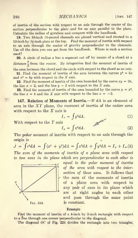
246 MECHANICS [ART. 147
of inertia of the section with respect to an axis through the center of the
section perpendicular to the plate and for an axis parallel to the plate.
Calculate the radius of gyration and compare with the handbook.
19. Two 10-inch 15-pound channels are placed vertical and riveted to a
12-inch by ^-inch plate at the top. Find the moment of inertia with respect
to an axis through the center of gravity perpendicular to the channels.
Use all the data you can get from the handbook. Where is such a section
used?
20. A circle of radius a has a segment cut off by means of a chord at a
distance ^ from the center. By integration find the moment of inertia of
the area between the chord and the circle with respect to the chord as an axis.
21. Find the moment of inertia of the area between the curves yz = Qx
and z* = Qy with respect to the X axis.
22. Find the moment of inertia of the area bounded by the curve xy = 24,
the line x =2, and the line y 3 with respect to the X axis.
23. Find the moment of inertia of the area bounded by the curve y = x z,
the line x = 4 and the X axis with respect to the line x = 2.
147. Relation of Moments of Inertia. If dA is an element of
area in the XY plane, the moment of inertia of the entire area
with respect to the X axis is
J, =J>dA. (1)
With respect to the Y axis +^*I = (2)
The polar moment of inertia with respect to an axis through the
origin is
c c c c
The sum of the moments of inertia of a plane area with respect
to two axes in its plane which are perpendicular to each other is
^,, equal to the polar moment of inertia
of the area with respect to the inter-
section of these axes. It follows that
the sum of the moments of inertia
of a plane area with respect to
any pair of axes in its plane which
are at right angles to each other
\N
and pass through the same point
FIG. 224. is constant.
Example
Find the moment of inertia of a 4-inch by 3-inch rectangle with respect
to a fine through one corner perpendicular to the diagonal.
The diagonal OC of Fig. 224 divides the rectangle into two triangles,

/
CHAP. XV] INERTIA OF A PLANE AREA 247
each of which has a base of 5 inches and an altitude of 2.4 inches. Themoment of inertia of each triangle with respect to OC is 5.76 in. 4 and the
moment of inertia of the rectangle is 11.52 in. 4 If moments of inertia are
taken with respect to horizontal and vertical axes through 0,
I x = 36; / = 64;
I* + Iy = J = 11.52 + 7;
/ = 88.48 in. 4
Problems
1. The moment of inertia of a circle with respect to a diameter isj-
By the principle of Equation (3) show that the polar moment of inertia
with respect to the center is ~--
2. The polar moment of inertia of a circle with respect to a point at its
37T0 4
2circumference is Find the moment of inertia of a circle with respect
to a tangent in its plane. Check by the transfer of axis.
3. Find the moment of inertia of a 6-inch by 6-inch by 1-inch anglesection with respect to the axis which bisects the angle between the legs of
the section. Use Equation (3) and get all the data from the handbook.
Check by completing the square and subtracting the moment of inertia of
the additional area from the moment of inertia of the square.
148. Product of Inertia. To find the moment of inertia of a
plane figure with respect to some inclined axis in its plane often
involves difficult integrations or limits.
These difficulties may be avoided by
finding the moment of inertia with
respect to a pair of axes for which the
calculations are easiest and then trans-
ferring to a new axis at the required
angle with these axes. In making this
transformation (Art. 150) one of the
terms is found to be \ xydA . This in-
tegral is called the product of inertia of
the area. The product of inertia is rep-
resented by H in algebraic equations.
H =fxydA
FIG. 225.
(1)
The product of inertia has no physical significance. It is, how-
ever, so useful in the calculation of the moment of inertia of
plane areas that it is desirable to master some of its properties.

248 MECHANICS [ART. 149
// an area has an axis of symmetry, the product of inertia with
respect to that axis and the axis perpendicular to it is zero. In
Fig. 225, the Y axis is an axis of symmetry. Any horizontal
line extends equal distances on each side of the Y axis. If
Equation (1) is integrated first with respect to x
H =fxydA
=ffxydydx
=-[z
2
]ydy =
/|*i r ^i] ydy.-
When the area is symmetrical with respect to the Y axis, x\ is
numerically equal 'to xz but has the opposite sign. Since the
square of a negative quantity is positive, x\ has the same sign
as x\ and x\ x\ = 0. Consequently
H = 0. (2)
Problems
1. By integration find the product of inertia of a rectangle of width b
and height d with respect to the lower edge and the left edge as axes.
Ans. H = r-'4
2. Solve Problem 1 with respect to the lower edge and the right edge as
axes. Ans. H =j-*
3. Find the product of inertia of the first quadrant of a circle of radius
a with respect to the X and Y axes. Ans. H =-^>o
4. Find the product of inertia with respect to the coordinate axes of the
area bounded by these axes and the line whose intercepts are x = 6 and
y = 4. A?is. H = 24 in. 4
6. Find the product of inertia with respect to the coordinate axes of the
area bounded by these axes and the line whose intercepts are (0, d) and
(b, 0).
149. Transfer of Axes for Product of Inertia. In Fig. 226,
OX and OF are a pair of axes at right angles to each other, andO'X' and O'Y' are a second pair of axes parallel to these. Thecoordinates of the point with respect to the axes O'X' and 0' Y'
are a and b. It is required to find the product of inertia of the
area with respect to O'X' and O'Y'.
The coordinates of an element dA with respect to OX and Yare x and y. With respect to O'X' and O'Y', the coordinates

CHAP. XV] INERTIA OF A PLANE AREA 249
are a -f- x and b + y.
equation,
H
The product of inertia is given by the
f(a + x)(b + y)dA = abfdA + afydA +bfxdA + fxydA. (1)
The first term, dbfdA, is equivalentto abA. The last term fxydA. is
HQ, which is the product of inertia
with respect to the axes OX and OF.The term fydA. is the moment of
the area with respect to the X axis andthe term fxdA is the moment of the
area with respect to the Y axis. If o1
the point is at the center of grav-
ity of the area, these
andFIG. 226.
Formula XVI
If either OX or F*1s--aft~ftxi&_of symnigfer^ the last term also
vanishes. While the moment of inertia is always positive, the
product of inertia may be either positive or negative.
Problems
1. Find the product of inertia of a rectangle 6 inches wide and 4 inches
high with respect to the lower edge and the left edge as axes.
Ans. H = 3 X 2 X 24 = 144 in. 4
2. Find the product of inertia of the rectangle of Problem 1 with respectto the lower edge and the right edge as axes.
Ans. H = (-3)2 X 24 = -144 in. 4
3. Find the product of inertia of a semi-
circle in the first and fourth quadrants with
respect to the diameter which bounds it andthe tangent at the lower end of this diameter.
Ans. H =^.
4. Find the product of inertia of a 6-inch
by 5-inch by 1-inch angle section in the
position of Fig. 227 with respect to the backof the legs as axes.
5. Find the product of inertia of the anglesection of Problem 4 with respect to axes through the center of gravity
parallel to the legs.
The section may be divided into two rectangles. The product of inertia
may be transferred from lines through the center of gravity of each of these
rectangles to the parallel lines through the center of gravity of the figure.
Y

250 MECHANICS [ART. 151
Another way is to take the product of inertia with respect to the axes O'X'
and O'Y' which bisect the legs. The product of inertia for these axes is
zero, since O'X' is an axis of symmetry for the horizontal leg and O'Y' is
an axis of symmetry for the vertical leg. Transferring to the center of
gravity,= Ho + abA = H + 1.5 X 1 X 10
#o = -15 in. 4
150. Change of Direction of Axis for Moment of Inertia. In
Fig. 228, OX and OY are
a pair of axes for which
the moment of inertia is
known. These are Ix=
fyfdA and I y= fx^dA .
It is desired to find the
moment of inertia with
respect to the axis OX'which makes an angle 6
with OX.Let OY' be an axis
.perpendicular to OX'.
The coordinates of the element dA with respect to OX' and
OY' as axes are (x', y'). The moment of inertia with respect
to OX' is
/' = Sy'*dA. (1)
From the geometry of the figure,
y'= y cos 0' x sin 0;
/' = f(y * cos 2 6 - 2xy cos B sin + x 2 sin 2
/' = Ix cos 2 e + Iy sin 2 6 - 2 cos sin BfxydA ;
/' = Ix cos 2 + Iy sin 2 - H sin 20;
/' = ^4^ + IjL^ cos 20 - H sin 20.
(2)
(3)
(4)
(5)
(6)
Problems
1. Find the moment of inertia of a 6-inch by 4-inch rectangle with respect
to an axis through the center at an angle of 25 degrees with the 6-inch edges.
Ix = 32, / = 72, H = 0;
/' = 52 - 20 cos 50 = 52 - 20 X 0.6428 = 39.144 in."
2. Find the moment of inertia of the rectangle of Problem 1 with respect
to the diagonal by means of Equation (6). Check by dividing the rectangle
into two triangles and finding the moment of inertia of each with respect
to the diagonal as the base.
3. Find the moment of inertia of the rectangle of Problem 1 with respect

CHAP. XV] INERTIA OF A PLANE AREA 251
to an axis through one corner. The axis makes an angle of 20 degrees with
the 6-inch edge, and cuts one 4-inch edge.
Ans. I' = 208 - 61.28 - 92.56 = 54.16 in. 4
151. Change of Direction of Axes for Product of Inertia.
From Fig. 228, the product of inertia with respect to the axes
OX' and OY' is
H' = fx'y'dA-, (1)
H f = f(x cos 6 + y sin 0)(y cos - x sin 0) dA; (2)
H' = (cos2 6 - sin 2 6)fxydA +
cos B sin 0f(y 2 - x 2)dA; (3)
H' = H cos 26 + Ix Iysin 29. (4)
If H' is zero the second member of Equation (4) is zero, and
H cos 6 = v~
xsin 20; (5)
tan 20 = T2H
T- (6)/,-
Since the tangent of an angle may have any value from minus
infinity to plus infinity, there is always some direction for which
the product of inertia for a pair of axes through any point is
zero. If there is a line of symmetry through the point, this line
is one of the axes for which the product of inertia is zero.
Problems
1. Find the direction of the axes through the lower left corner of a rect-
angle 6 inches wide and 4 inches high for
which the product of inertia is zero. (Fig.
229.)
Ans. 30 28' and 120 28' with
the 6-inch edge.2. Find the direction of the axes through
the center of gravity of a 6-inch by 4-inch
by 1-inch angle section for which the pro-duct of inertia is zero.
Ans. Tan 26 = -1; 6 = -22 30' and 67 30'.

252 MECHANICS [ART. 153
matical conditions for maximum and minimum are applied to
Equation (6) of Art. 150.
7, = I* + Iy + I*_^JjL COs20 - Hsiu20. (1)'
Differentiating with respect to 0,
~ = (/-/*) sin 2(9 - 2H cos 20. (2)a0
Equating the derivative to zero and solving for 0,
2/7 Stan 20 =
^r- -y- K (3)1 y 1 x
Equation (3) is identical with Equation (6) of Art. 151. It is
evident, therefore, that the directions for which the momentof inertia is a maximum or a minimum coincide with the two
directions for which the product of inertia is zero.
Two angles which are 180 degrees apart have the same tangent.
Equation (3), therefore, gives two values of 0, which differ by 90
degrees. For one of these directions, the moment of inertia is
a maximum; for the other, the moment of inertia is a minimum.If an axis of symmetry passes through a given point, the
moment of inertia for that axis is either a maximum or a
minimum.
Problems
1. Find the maximum and minimum moment of inertia of a 6- inch by4- inch rectangle for axes through the lower left corner. (Fig. "229.)
From Problem 1 of Art. 151, tan 20 = 1.800; 20 = 60 57' and 240 57'.
/m = 208 - 80 cos 60 57' - 144 sin 60 57' = 43.27 in. 4
Ima* = 208 - 80 cos 240 57' - 144 sin 240 57' = 372.73 in."
Imi* is the moment of inertia with respect to OM of Fig. 229.
2. Find the least moment of inertia and the least radius of gyration of
a 6-inch by 6-inch by 1-inch angle section. Take Ix and Iv from the
handbook.
3. Find the maximum and minimum moments of inertia for axes throughthe center of gravity of a 6-inch by 4-inch by 1-inch angle section. TakeIx and 7y from handbook. Calculate the least radius of gyration and
compare the result with the handbook.
153. Center of Pressure. In Art. 104, the center of pressure
of a liquid on a plane surface was defined as the point of applica-
tion of the resultant of all the pressure on one side of the sur-
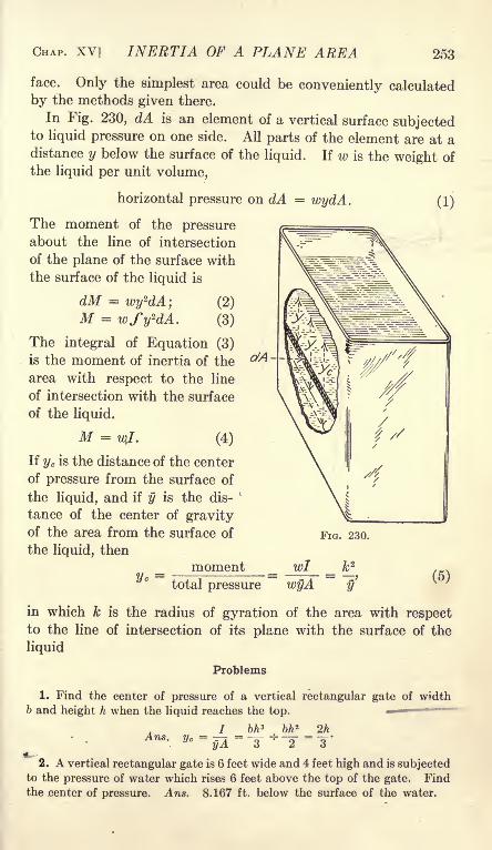
CHAP. XV] INERTIA OF A PLANE AREA 253
face. Only the simplest area could be conveniently calculated
by the methods given there.
In Fig. 230, dA is an element of a vertical surface subjectedto liquid pressure on one side. All parts of the element are at adistance y below the surface of the liquid. If w is the weight of
the liquid per unit volume,
ctA
horizontal pressure on dA = wydA.
The moment of the pressureabout the line of intersection
of the plane of the surface with
the surface of the liquid is
dM = wy*dA; (2)
M = wfyzdA. (3)
The integral of Equation (3)
is the moment of inertia of the
area with respect to the line
of intersection with the surface
of the liquid.
M =vjf. (4)
If yc is the distance of the center
of pressure from the surface of
the liquid, and if y is the dis-
tance of the center of gravityof the area from the surface of FIG. 230.
the liquid, then
moment wl _ k 2
total pressure wyA y'
(1)
(5)
in which k is the radius of gyration of the area with respectto the line of intersection of its plane with the surface of the
liquid
Problems
1. Find the center of pressure of a vertical rectangular gate of widthb and height h when the liquid reaches the top.
7 bh* bh 2 2hVc =
$A=~y
*~2
=T'
2. A vertical rectangular gate is 6 feet wide and 4 feet high and is subjectedto the pressure of water which rises 6 feet above the top of the gate. Find
the center of pressure. Ans. 8.167 ft. below the surface of the water.

254 MECHANICS [ART. 153
If fco is the radius of gyration of the surface with respect
to the horizontal axis in its plane through the center of gravity,
fc2 =
fcj + y\ (6)
and Equation (5) becomes
y*=
y v
The distance of the center of pressure below the center of gravity
of the area is equal to the square of the radius of gyration of
the area divided by the distance of its center of gravity below the
surface of the liquid.
Problems
'
3. A vertical circular gate of radius r is subjected to the pressure of
liquid which just reaches the top. Find the center of pressure.
Ans. - below the center of the circle.
4
pressure
4. A vertical circular gate, 4 feet in diameter, is subjected to the pressure
of a liquid which reaches 10 feet above the center. Locate the center of
Ans. 0.1 ft. below the center.
5. A vertical circular gate, 6
feet in diameter, is subjected to
the pressure of water which rises
to the center. The gate is held
by two bolts at opposite ends of
the horizontal diameter and a
single bolt at the bottom. Find
the tension in each bolt.
Ans. 662.7 Ib. in the
lower bolt.
6. A solid cylinder, 1 foot in
diameter, is cut by two planes.
One plane is perpendicular to the
axis and the other plane cuts the
cylinder so that the longest ele-
ment is 2 feet long and the
shortest element is 1 foot long.
Use the equations above to find
the center of gravity of the volume between the planes.
Ans. 0.5 inch from the axis.
Figure 231 shows liquid pressure on an inclined surface. Theline BD is the intersection of the plane of the inclined surface
with the surface of the liquid. The element dA is at a distance
y' from the line BD. If 6 is the angle which the plane makes with
the vertical, the vertical distance of the element of area below
FIG. 231.

CHAP. XV] INERTIA OF A PLANE AREA 255
the surface of the liquid is y' cos 0, and the pressure on the element
is wy' cos 6dA. The moment equation about BD is
M = w cos 6fy'2dA = WF cos 0. (8)
in which /' is the moment of inertia of the area with respectto the axis BD.
wi fcos e r
wy'A cos y'A(9)
Equation (9) is the same as Equation (5) except that the dis-
tances are not vertical. An equation may be written which
is similar to Equation (7).
154. Moment of Inertia by Moment of a Mass. In the pre-
ceding articles it was shown that the moment of a pressure which
varies as the distance from the axis of moments may be calculated
by means of the moment of inertia of the plane area. From
Equation (5) of Art. 153
wl = wyAyc ;
I = yAyc .
(1)
(2)
From Equation (2), the moment of inertia of a plane area with
respect to a given axis is the product of the area A, multiplied
by the distance of its center of gravity from the axis, and by the
distance of the center of a pressure which varies as the distance
from the axis. The center of pressure is located at the center of
gravity of a solid, the base of which is the given area and the heightis proportional to the distance from the axis.
The center of gravity of a solid may be found experimentally
by moments. Figure 232 shows a convenient method. The
body whose center of gravity is desired is placed on a balance
beam and carefully balanced with the beam in a horizontal posi-
tion. It is then turned 180 degrees about a vertical axis to the
position shown by the broken lines of the figure, and moved along

256 MECHANICS [ART. 154
the beam until exact balance is obtained with no change of the
weights. The center of gravity is then at the same location as it
was in the first position. If C is a point in the body, and C" is the
same point after the body is turned, the center of gravity_is
located in a vertical line midway between C and C'.
Figure 233 represents a section of a beam whose moment of
inertia is desired for a line through the center of gravity parallel
to a given line 00'. If the section is large, the outlines may be
traced on paper and the area determined by a planimeter. If
the section is small, a portion of the beam of convenient length
may be cut off between two sections. The volume of this por-
tion may be determined by weighing in air and in water and its
area may then be calculated by dividing the volume by the
length.
FIG. 233.
The center of gravity of the section may be found by balancing
this portion of uniform thickness upon the beam of a balance, as
in Fig. 232. The line CC", Fig. 233, passes through the center of
gravity.
To get the moment of inertia, a force is required which varies
directly as the distance from the center of gravity. Wedge-
shaped pieces are cut from the beam by planes which intersect
at AB. The plane ABD of Fig. 233, II, is normal to the length
of the beam, and the plane ABE makes a convenient angle with
the length. This wedge-shaped piece is balanced as in Fig. 232
and its center of gravity determined. The distance of the center
of gravity from the line AB gives Yc for this part of the section.
The location of the center of gravity of the part to the right of
AB is found by balancing a piece of uniform length. This
experiment gives y.
The product y (Ay for the part to the right of AB gives the
moment of inertia of that part of the section. A similar set of
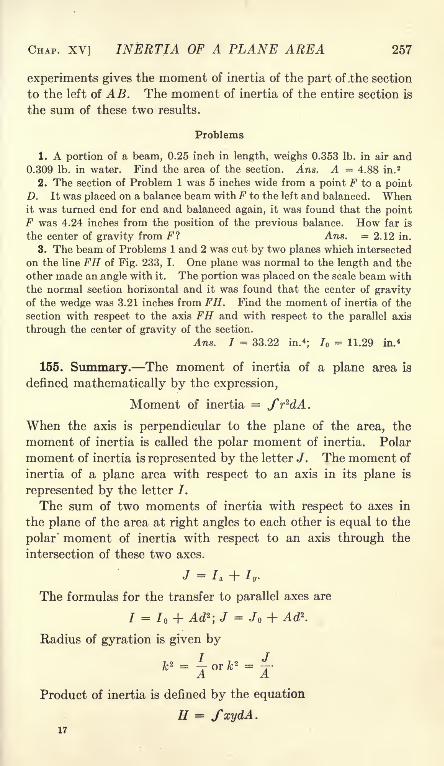
CHAP. XV] INERTIA OF A PLANE AREA 257
experiments gives the moment of inertia of the part of .the section
to the left of A B. The moment of inertia of the entire section is
the sum of these two results.
Problems
1. A portion of a beam, 0.25 inch in length, weighs 0.353 Ib. in air and0.309 Ib. in water. Find the area of the section. Ans. A = 4.88 in. 2
2. The section of Problem 1 was 5 inches wide from a point F to a pointD. It was placed on a balance beam with F to the left and balanced. Whenit was turned end for end and balanced again, it was found that the pointF was 4.24 inches from the position of the previous balance. How far is
the center of gravity from F? Ans. = 2.12 in.
3. The beam of Problems 1 and 2 was cut by two planes which intersected
on the line FH of Fig. 233, I. One plane was normal to the length and the
other made an .angle with it. The portion was placed on the scale beam with
the normal section horizontal and it was found that the center of gravityof the wedge was 3.21 inches from FH. Find the moment of inertia of the
section with respect to the axis FH and with respect to the parallel axis
through the center of gravity of the section.
Ans. I = 33.22 in.*; / = 11.29 in. 4
155. Summary. The moment of inertia of a plane area is
defined mathematically by the expression,
Moment of inertia =
When the axis is perpendicular to the plane of the area, the
moment of inertia is called the polar moment of inertia. Polar
moment of inertia is represented by the letter J. The moment of
inertia of a plane area with respect to an axis in its plane is
represented by the letter /.
The sum of two moments of inertia with respect to axes in
the plane of the area at right angles to each other is equal to the
polar moment of inertia with respect to an axis through the
intersection of these two axes.
J = h + /,.
The formulas for the transfer to parallel axes are
7 = 7 + Ad2 ;J = Jo + Ad2.
Radius of gyration is given by
/c2 =
4- r fc2 = T-A A
Product of inertia is defined by the equation
H = fxydA.17

258 MECHANICS [ART. 155
Product of inertia is useful in changing the direction of the axis
for moment of inertia, and in finding the direction of the axes
for which the moment of inertia is a maximum or a minimum.
Moment of inertia is a maximum for one of the pair of axes
for which the product of inertia is zero and a minimum for the
other. Product of inertia is zero if either axis is an axis of sym-
metry. Moment of inertia is a maximum or minimum and prod-
uct of inertia is zero for the directions which satisfy the equation
2Htan 26
I, - L
The location of the center of pressure of a liquid on a plane
surface is given by the equations,
in which yc is the distance of the center of pressure from line of
intersection of the plane of the area with the surface of the liquid,
y is the distance of the center of gravity of the area from this
line, k is the radius of gyration of the area with respect to the
same line, and k is the radius of gyration with respect to a paral-
lel line through the center of gravity. These equations apply to
inclined and to vertical surfaces.

CHAPTER XVI
MOTION
156. Displacement. When a body changes its position relative
to another body, it is said to be displaced relatively to the other
body. The distance from the initial position to the final posi-
tion is the displacement of the body. Displacement is generallymeasured relative to the earth. Displacement has direction as
well as magnitude, and is, therefore, a vector quantity.
Problems
1. A man steps from a car and walks east a distance of 40 feet. Duringthe same time, the car moves west 60 feet. What is the displacement of
the man relative to the earth and relative to the car?
Ans. 40 feet east; 100 feet east.
2. A body moves from one position to another position which is 40 feet
east and 30 feet north of the starting point. What is its displacement?Ans. 50 feet north 53 08' east.
3. A base ball is struck by a bat. Two seconds later it is80^|^ajt
above and150 feet south of the starting point. What is the displacement?
157. Velocity. Rate of displacement is called velocity. In
problems of mechanics, velocity is generally expressed in feet
per second. Since displacement is a vector, and velocity is
displacement divided by time (which is not a vector) it follows
that velocity is a vector. A velocity of ten feet per second north
is not equivalent to a velocity of ten feet per second east. Whenonly the magnitude of the motion is considered without reference
to its direction, the rate of displacement is called speed. A body
moving east at the rate of ten feet per second has the same speedas a body moving north at the rate of ten feet per second.
Example
A man is 40 feet south of a given point when his watch reads 1 min. 20 sec.
When he is 100 feet south of the' point, his watch reads 1 min. 35 sec.
What is his average velocity during that interval?
The displacement is 100 40 = 60 feet south. The time interval is 15
f*f\
seconds. Average velocity south =y^
= 4 feet per second.
259

260 MECHANICS [ART. 157
Velocity is calculated by dividing the difference in position
by the corresponding difference in time. If Xi is a coordinate
of the position at the time ti and Xz is a coordinate of the
position at the time 2, and if vx is the component of the velocity
parallell to the X axis,
Vx = *L--L_?i. Formula XVII'2 t\
Similar expressions give the components of the velocity parallel
to the other axes of coordinates. The actual velocity is the
vector sum of these components.Formula XVII and the similar expressions
give the average velocity during the interval of
time. The actual velocity at any instant maybe quite different. In Fig. 234, a body maystart at A and move along the curved path
ABCDE, passing over each interval in one
second. If an interval of one second is con-
sidered, the velocity during the first second is
equal to the length AB and is in the direction
from A to B. If the entire 4 seconds are con-
sidered as the interval, the velocity is, apparently, one-fourth of
the length AE and is in the direction from A to E. Again, the
speed or magnitude of the velocity may change. A body maymove 2 feet in one second, 5 feet in the next second, and 11 feet
in the third second. For the first second, the average velocity is
2 feet per second; for the first two seconds, the average velocity
is 3.5 feet per second; for the three seconds, the average velocity
is 6 feet per second. When the velocity varies in direction and
magnitude and it is desired to find the true velocity at any
instant, a small displacement and a correspondingly small inter-
val of time must be employed. Formula XVII becomes
To determine experimentally the actual velocity at any given
instant, means must be devised for measuring small intervals
of time and corresponding increments of displacement. Supposeit is desired to find the velocity of a steel ball attached to a small
parachute after falling two seconds from rest. The ball mayfall beside a vertical scale as in Fig. 235. The time and dis-
placement may be measured by means of a photographic camera

CHAP. XVI] MOTION 261
provided with an " instantaneous shutter " of known time. Anelectromagnetic arrangement may be provided which will release
the shutter two seconds after the ball starts to fall. If the ball
is properly illuminated, its displacement is given by a vertical
streak, AB of Fig. 235. Suppose that the "time" of the shutter
is 0.02 second, and that the length of the streak on the plate is
equivalent to 0.36 foot of the scale. The average
velocity for the 0.02 second is .0
.1
.2- .3
.4
.5
.6
.7
.8
.93.0
0.36 10 ,
v = ^-^r= 18 feet per second.
0-02
This experiment gives the average velocity for
the interval of 0.02 second. If the change of
velocity is all in one direction, that is, if the
velocity is either increasing or decreasing through-out the entire interval, the average velocity is the
velocity at about the middle of the interval. The pIG . 235.
result of this experiment is, then, the velocity at
about 2.01 seconds after the beginning of the fall. If the
velocity is desired at 2 seconds from the beginning of the fall,
the apparatus must be arranged to release the shutter 1.99
seconds after the body starts to move.
Problems
1. The position of a body is given by the equation x = 8 2,in which x
is the position in feet and t is the time in seconds. Find the approximate
velocity at the end of 4 seconds by means of the displacement during a 2-
, . , 8 X 52 - 8 X 3 2RAt .
second interval. Ans. Average v =^
= 64 ft. per sec.
2. Solve Problem 1 for the velocity at the end of 4 seconds by means of
the average velocity during an interval of 0.2 second.
Ans. Average v = 8 X ^'^^ X 3 '9*
= 64 ft. per sec.
3. The position of a body is given by x = 2t*. Using an interval of 2
seconds, find the approximate velocity at the end of 4 seconds.o V ^3 9 V ^3
Ans. Average v = =-^- ~ - = 98 ft. per sec.
4. Solve Problem 3 for an interval of 0.2 second.0(4. 1 3 Q Q3
1
)
Ans. Average v =02
= 96 '02 ft * Per sec "
In Problems 1 and 2, the average velocity for the 2-second interval is
the same as the average velocity for the 0.2-second interval. It is fair to
assume that the average velocity is the actual velocity at the middle of the
interval and that 64 feet per second is the true velocity at the end of 4
seconds.

262 MECHANICS [ART. 158
In Problems 3 and 4, the average velocity for the 2-second interval is
greater than the average velocity for the 0.2-second interval. It is evident,
therefore, that the average velocity is not exactly the velocity at the middle
of the interval and that a very short interval must be used to get an exact
result.
Problem
6. In Problem 3, let the interval be 0.02 second and find the approximate
velocity at the end of 4 seconds.
Ans. v = 2(4 '01
Q Q2
3'" '* = ^6.0002 ft. per sec.
It is evident that an interval of 0.2 second is sufficiently short to give a
result as accurate as can be measured.
168. Average and Actual Velocity. Formula XVII gives the
average velocity for the interval. From the problems of the
preceding article, it is evident that the average velocity is some-
times equal to the velocity at the middle of the time interval,
and at other times is not equal to that velocity. A few cases will
now be considered in order to determine under what conditions
it is necessary to make the time interval very short.
Let x = kt2 be the expression for the displacement, and let the
average velocity be found for an interval of 2AZ seconds.
Average v- k(t +^ ~
k(t~ ^ - - 2kt2M 2&t
The result is independent of the length of the interval 2A.
Consequently, when the displacement varies as the square of the
time, the velocity at the middle of the interval of time is equalto the average velocity during that interval. This is true also
when the displacement varies as the time.
When the displacement varies as the cube of the time, x = kt3 .
For an interval 2At,
average t . _
It is evident that the average velocity is slightly different
from the velocity at the middle of the interval. The error,
however, decreases rapidly with decrease of the interval of time.
In an experimental problem, it may be known that the dis-
placement varies as the square of the time, as the first power of
the time, or as a combination of the two. In these cases, the
time interval may be taken of any convenient length. The
average velocity during the interval is the velocity at the middle

CHAP. XVI] MOTION 263
of the interval. If the experimental values of the velocity are
the same, whether the intervals are long or short, it may be
taken for granted that the displacement varies as the time or as
the square of the time.
For any form of mathematical expression for the displacementin terms of the time, it is easy to calculate the effect of the
length of the interval upon the accuracy of the result.
159. Velocity as a Derivative. When the interval of time
becomes infinitesimal, Formula XVII reduces to
dxv * =
dt'
In Problem 1 of Art. 157,
When t = 4 seconds, v x= 16 X 4 = 64 ft. per sec.
In Problem 3 of Art. 157,
x = 2t
When t = 4 seconds, vx = 6 X 16 = 96 ft. per sec.
Since these derivatives give the correct result so easily, it
may be asked why the methods of Article 157 are employed.The derivative is sufficient when the equation of the displace-
ment in terms of the time is accurately known. In most cases,
however, the displacement is not known in terms of the time
and an experimental determination is required to get the velocity.
The work of the two preceding articles is intended to show with
what accuracy the average velocity during an interval gives the
true velocity at the middle of that interval.
Problems
1. The position of a body is given by the equations x = 3t 2, y = t
3,in
which the distances are expressed in feet and the time is given in seconds.
Find the magnitude and direction of the resultant velocity when t = 4
seconds. Ans. v = 53.66 ft. per sec. at 63 26' with the X axis, v
2. The position of a body is given by x = sin t,in which x is given in
feet and t is given in seconds. Find the velocity when t = 1 second and
when t = 2 seconds.
Ans, vi = 0.540 ft. per sec.; t> 2= - 0.416 ft. per sec.

264 MECHANICS [ART. 159
3. The position of a body is given by x r cos ut, y = r sin ut, in which
r is a constant length expressed in feet and w is a constant number. Find the
magnitude and direction of the resultant velocity for any given value of the
time / /Ans. vx = rw sin w; vy = rco cos co; v = rw, at an angle with the X
axis whose tangent is equal to -cotan at.
Problem 3 gives the motion of a body moving in a circle of
radius r with uniform speed rco. In Fig. 236, I, the body is at
B and is moving in a counter-clockwise direction. The radius
from the center to B makes an angle cot with the horizontal line
OA . Fig. 236, II, is the vector velocity triangle. The horizontal
component vx is toward the left, while the vertical component is
y= r sin cot\
xHII
FIG. 236.
upward. The resultant velocity v makes an angle B with the
horizontal toward the right.
Tan B = cotan coZ,
which shows that the resultant velocity is normal to the line OB.
The line which is tangent at B in Fig. 236, I, gives the direction
of the resultant velocity.
160. Acceleration. The rate of change of velocity is called
the acceleration. If a body is moving east with a velocity of 10
feet per second, and 2 seconds later is moving east with a velocity
of 40 feet per second, the change in velocity is 30 feet per second
east. This change takes place in 2 seconds. The rate of changeis 30 -r- 2 = 15 feet per second per second.
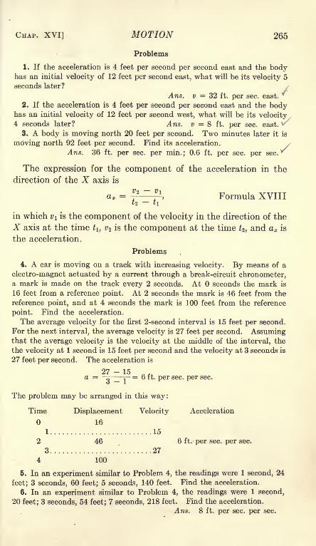
CHAP. XVI] MOTION 265
Problems
1. If the acceleration is 4 feet per second per second east and the bodyhas an initial velocity of 12 feet per second east, what will be its velocity 5
seconds later?
Ans. v = 32 ft. per sec. east.*
2. If the acceleration is 4 feet per second per second east and the bodyhas an initial velocity of 12 feet per second west, what will be its velocity4 seconds later? Ans. v = 8 ft. per sec. east. ^
3. A body is moving north 20 feet per second. Two minutes later it is
moving north 92 feet per second. Find its acceleration. >
Ans. 36 ft. per sec. per min.; 0.6 ft. per sec. per sec.*
The expression for the component of the acceleration in the
direction of the X axis is
a x =v *~ v
\ Formula XVIIItz t\
in which v\ is the component of the velocity in the direction of the
X axis at the time t\, vz is the component at the time Z2 ,and ax is
the acceleration.
Problems
4. A car is moving on a track with increasing velocity. By means of a
electro-magnet actuated by a current through a break-circuit chronometer,a mark is made on the track every 2 seconds. At seconds the mark is
16 feet from a reference point. At 2 seconds the mark is 46 feet from the
reference point, and at 4 seconds the mark is 100 feet from the reference
point. Find the acceleration.
The average velocity for the first 2-second interval is 15 feet per second.
For the next interval, the average velocity is 27 feet per second. Assumingthat the average velocity is the velocity at the middle of the interval, the
the velocity at 1 second is 15 feet per second and the velocity at 3 seconds is
27 feet per second. The acceleration is
a = - -= = 6 ft. per sec. per sec.o 1
The problem may be arranged in this way:
Time Displacement Velocity Acceleration
16
1 15
2 46 6 ft. per sec. per sec.
3 27
4 100
6. In an experiment similar to Problem 4, the readings were 1 second, 24
feet; 3 seconds, 60 feet; 5 seconds, 140 feet. Find the acceleration.
6. In an experiment similar to Problem 4, the readings were 1 second,
20 feet; 3 seconds, 54 feet; 7 seconds, 218 feet. Find the acceleration.
Ans. 8 ft. per sec. per sec.

266 MECHANICS [ART. 161
7. In Problem 4, suppose that the acceleration is constant. Find the
position at the 6th second.
8. In Problem 1 of Art. 157, find the velocity at 4 seconds and at
5 seconds by means of intervals of 0.2 second; then find the average accel-
eration for the one-second interval.
Ans. Average a = 16 ft. per sec. per sec.
9. In problem 3 of Art. 157, find the approximate velocity at 4 seconds
and at 6 seconds by means of 2-second intervals, and then find the average
acceleration for the 2-second interval.
Ans. a = 60 ft. per sec. per sec.
10. A cannon ball acquires a velocity of 1800 feet per second in 0.004 second.
Find its acceleration. Ans. a = 450,000 ft. per sec. per sec.
11. A baseball with a speed of 100 feet per second is stopped in 0.001
second. Find its acceleration.
12. The velocity of a body is changed from 80 feet per second east to 40
feet per second west in 3 seconds. Find its acceleration.
Ans. a = 40 ft. per sec per sec. west.
161. Acceleration as a Derivative. When the increment of
time and the corresponding increment of velocity are very small,
Formula XVIII becomes
t- wSince v x
=-jr*
Equation (1) reduces to
The acceleration along the other coordinate axes is given bysimilar derivatives.
dv x _ d 2x"
~dt "". ~dt2 '
a v= -~~ =
-^;Formulas XIX
_ dv, _ d2z"
dt"" dt 2
In some works of mathematical physics the components of velocity and
acceleration are written thus: The component of the velocity parallel to
the X axis is x and the component of the acceleration is x. A derivative
with respect to time is written with a single dot over the variable.' Thesecond derivative with respect to time is written two dots over the variable.
Problems
1. The position of a body is given by x = ktz. When the displacement
varies as the square of the time, show that the acceleration is constant.
Ans. a = 2k.
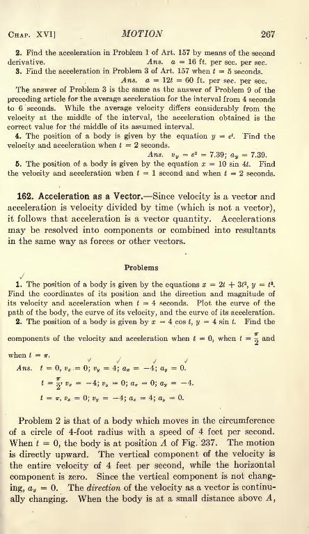
CHAP. XVI] MOTION 267
2. Find the acceleration in Problem 1 of Art. 157 by means of the second
derivative. Ans. a = 16 ft. per sec. per sec.
3. Find the acceleration in Problem 3 of Art. 157 when t = 5 seconds.
Ans. a = 12t = 60 ft. per sec. per sec.
The answer of Problem 3 is the same as the answer of Problem 9 of the
preceding article for the average acceleration for the interval from 4 seconds
to 6 seconds. While the average velocity differs considerably from the
velocity at the middle of the interval, the acceleration obtained is the
correct value for the middle of its assumed interval.
4. The position of a body is given by the equation y = e*. Find the
velocity and acceleration when t 2 seconds.
Ans. v y= e z =
7.39; a y= 7.39.
6. The position of a body is given by the equation x = 10 sin 4t. Find
the velocity and acceleration when t = 1 second and when t = 2 seconds.
162. Acceleration as a Vector. Since velocity is a vector and
acceleration is velocity divided by time (which is not a vector),
it follows that acceleration is a vector quantity. Accelerations
may be resolved into components or combined into resultants
in the same way as forces or other vectors.
Problems\/
1. The position of a body is given by the equations x = 2t + 3t 2, y = t
3.
Find the coordinates of its position and the direction and magnitude of
its velocity and acceleration when t = 4 seconds. Plot the curve of the
path of the body, the curve of its velocity, and the curve of its acceleration.
2. The position of a body is given by x = 4 cos t, y = 4 sin t. Find the
components of the velocity and acceleration when t = 0, when t = ~ and
when t = IT.
tf .
\ V y J
Ans. t = 0, vx =0; vy
=4; ax = 4; av
= 0.
t =7j
vx =4; vu
=0; ax = 0; ay
= 4.
t = TT, vx =0; % =
4; ax =4; au
= 0.
Problem 2 is that of a body which moves in the circumference
of a circle of 4-foot radius with a speed of 4 feet per second.
When t = 0, the body is at position A of Fig. 237. The motion
is directly upward. The vertical component of the velocity is
the entire velocity of 4 feet per second, while the horizontal
component is zero. Since the vertical component is not chang-
ing, ay= 0. The direction of the velocity as a vector is continu-
ally changing. When the body is at a small distance above A,

268 MECHANICS [ART. 162
its velocity has a component toward the left. There is an ac-
celeration toward the left to give it this change of velocity. This
acceleration is 4 ft. per sec. per sec. At B, where t = ^ the
entire velocity is horizontal
toward the left. It is rep-
resented by vx = 4, v y= 0.
The acceleration is 4 ft. per
sec. per sec. downward.
The results of Problem 2
show that the acceleration is
constant in magnitude and is
directed toward -the center,
while the velocity is constant
in magnitude and is directed
along the tangent.FIG. 237.
Problem
3. The position of a body is given by the equations, x = r cos cof , y = r sin co t,
in which r and co are constants. Find the magnitude and direction of the
acceleration for any given time.
FIG. 238.
Ans. ax = rco2 cos o)t; a y= rco 2 sin (at; resultant acceleration = rco 2
.
Problem 3 gives the motion of a body which moves in a circle of radius
r with a linear velocity of r co. (Problem 3, Art. 159). If the linear velocity
rco =v,
r 2co
2v z
acceleration = rco 2 = = Formula XX
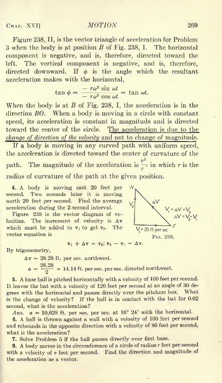
CHAP. XVI] MOTION 269
Figure 238, II, is the vector triangle of acceleration for Problem
3 when the body is at position B of Fig. 238, I. The horizontal
component is negative, and is, therefore, directed toward the
left. The vertical component is negative, and is, therefore,
directed downward. If is the angle which the resultant
acceleration makes with the horizontal,
rco2 sin ut
tan 4>= ~
.= tan ut.
rw2 cos ut
When the body is at B of Fig. 238, I, the acceleration is in the
direction BO. When a body is moving in a circle with constant
speed, its acceleration is constant in magnitude and is directed
toward the center of the circle. The acceleration is due to the
change of direction of the velocity and not to change of magnitude.If a body is moving in any curved path with uniform speed,
the acceleration is directed toward the center of curvature of the
v2
path. The magnitude of the acceleration is ; in which r is the
radius of curvature of the path at the given position.
4. A body is moving east 20 feet per
second. Two seconds later it is movingnorth 20 feet per second. Find the averageacceleration during the 2-second interval.
Figure 239 is the vector diagram of ve-
locities. The increment of velocity is Avwhich must be added to Vi to get v2 . Thevector equation is
Vi 4- Av = vj; v2-
By trigonometry,
Av = 28.28 ft. per sec. northwest.
28 28a = ^ = 14.14 ft. per sec. per sec. directed northwest.
5. A base ball is pitched horizontally with a velocity of 100 feet per second.
It leaves the bat with a velocity of 120 feet per second at an angle of 30 de-
grees with the horizontal and passes directly over the pitchers box. Whatis the change of velocity? If the ball is in contact with the bat for 0.02
second, what is the acceleration?
Ans. a = 10,628 ft. per sec. per sec. at 16 24' with the horizontal.
6. A ball is thrown against a wall with a velocity of 100 feet per second
and rebounds in the opposite direction with a velocity of 80 feet per second,
what is the acceleration?
7. Solve Problem 5 if the ball passes directly over first base.
8. A body moves in the circumference of a circle of radius r feet per second
with a velocity of v feet per second. Find the direction and magnitude of
the acceleration as a vector.

270 MECHANICS [ART. 163
Figure 240, I, shows the circle of Problem 8. When the body
is at A, the velocity is Vij when the body is at B, the velocity is
v2 . The velocities Vi and v2 have equal magnitudes. Their
directions, on the other hand, are different. Since Vi is normal to
the radius OA and v2 is normal to the radius OB, the angle
between Vi and V2 is equal to
the angle AOB. Figure 240,
II, is the vector diagram of the
velocities. The change in ve-
locity is the vector Aw. If
this change takes place in time
A, the acceleration is ^jThe
direction of the acceleration is
the direction of Aw. From Fig.
240, II, Aw = wA0, in which v is
the magnitude of the velocities
Vi and v2 . The distance from A to B of Fig. 240, I, measured
along the arc of the circle, is rA0. The body moving with a
speed v passes over this distance in time A.
FIG. 240.
/*A0 = vAtj At =
Awa = - = wA0
At w
rA0
v'
rA0 = w 2
rFormula XX
The direction of Aw is perpendicular to the bisector of the angle
between YI and v2 and is, therefore, parallel to the bisector of the
angle AOB. As A0 is made smaller and smaller, the direction
of the acceleration is always parallel to this bisector. When the
angle becomes infinitesimal, it is evident that the acceleration is
directed toward the center of curvature. The methods of Prob-
lem 3 differ from those of Problem 8. The results, however, are
identical.
163. Dimensional Equations. A dimensional equation is an
equation which shows with what powers the fundamental quanti-
ties of mass, length, and time appear in the expression for a physi-
cal quantity. In these equations, mass is represented by M,time is represented by T, and length is represented by L. Somedimensional equations are:
Area = L 2;
Volume = L 3;

CHAP. XVI] MOTION 271
Density = ^ = ML~*-,
Velocity =^= LT~ l
;
Acceleration = -=-2= LT~2
.
Negative exponents are generally used instead of fractional forms.
Dimensional equations have two important uses. These are:
1. A dimensional equation may be used to determine whether
a literal expression for a quantity is possibly correct.
2. In transferring from one system of units to another, a
dimensional equation indicates the required power of the ratio
of the units of the two systems.
The dimensions of an area are A = L2. If an area in square
yards is transferred to square feet, the ratio of the number of
units of length in feet to the number of units in yards is 3.
Since L in the dimensional equation is squared, it follows that the
number of square feet in a given area is 3 2 times as great as the
number of square yards. This is an example of the second use
of a dimensional equation.
If a, 6, and c are lengths, an area may be expressed by a2,62
,
c2, ab, ac, be, c\/a
2 + fr2
,etc. If an expression which is known to
be an area has any of these forms, or any other form which is
equivalent to the square of a length, the expression represents
a 2_j_ 52
a area. Such expressions as abc,-
, v abc, etc, can notC
represent areas. If such an expression appears in a quantitywhich is known to be an area, it will be recognized as incorrect.
These are examples of the first use of a dimensional equation.
Only quantities having the same dimensions may be added or
subtracted. Volume can not be added to area nor velocity to
density. If a, b, and c are lengths, and m is a mass, ab + b2 +a\/bc and me + m-\/a 2 + c 2 are possible additions.
Problems
1. The dimension of the trigonometric functions is zero, since each func-
tion is the ratio of two lengths. If a, b, c, and s are lengths, is it possible
6 ab, 1(8 -&)(- c) s2 + 6c
to represent a sine by . . by , by \/ : ,or by (
-y/a 2_|_ C2
7
C2 \ far a
What is the nature of the quantity expressed by \/s(s a)(s b)(s c)?
What is the quantity expressed by *y?

272 MECHANICS [ART. 164
2. If w represents mass, q represents time, and a, 6, and c represent lengths,
state whether the following are possible physical quantities, and give the
meaning of those which are possible:
v,_ Vab a 2 + fr2 a 2 + b 2 + c2
abc q' w q
2
3. What is the coefficient required to reduce area in square feet to area
in square inches and to area in square yards? Ans. 12 2; () 2
.
4. What is the factor required to reduce pounds per square inch to grams
per square centimeter?
5. How is velocity in feet per second reduced to velocity in miles per hour?
6. How is acceleration in feet per minute per minute reduced to accelera-
tion in feet per second per second?
164. Summary. Displacement is the amount of change of
position. Displacement is a vector.
The displacement per unit of time is the velocity. Velocity
is a vector. The component of the velocity parallel to the Xaxis is
#2 #1 _ dx''
t 2-
<i
==
dt'
The dimensional equation of velocity is LT~ l.
Change of velocity per unit of time is acceleration. Since
velocity is a vector, the change of velocity may involve changein direction, change in magnitude, or change in both direction
and magnitude. Acceleration is a vector. The component of
acceleration parallel to the X axis is
When a body is moving in a circle of radius r with a velocity
of v units per unit of time, the acceleration toward the center due
to the change of direction is
The dimensional equation of acceleration is LT~2.
A dimensional equation is useful in transferring from one
system of units to another and in checking literal equations.

CHAPTER XVII
FORCE AND MOTION
165. Force and Acceleration. If the forces which act on a
body are in equilibrium, the body either remains at rest or movesin a straight line with constant speed. There is no change of
motion. Newton's First Law states: A body at rest remains at
rest and a body in motion continues to move uniformly in a
straight line unless constrained by some external force to changethat condition. If a horizontal sheet of ice were perfectly fric-
tionless, a body sliding on it would continue to move in one
direction with constant speed for an indefinite distance. Theattraction of the earth downward on the body and the reaction
of the ice upward are in equilibrium and do not affect the motion.
If there is some friction between the body and the ice, the velocity
gradually decreases until the body finally comes to rest. Theforce of friction opposite the direction of the motion produces a
negative acceleration in the body. The ice sheet may be so
inclined to the horizontal that the component of the weight downthe incline exactly equals the friction. If, then, the body is
given an initial velocity down the plane, it will continue to movein that direction with constant speed. In that case, the forces
are in equilibrium and cause no change in motion. If the slope
of the plane is increased so that the component of the weightdown the plane exceeds the force of friction in the opposite direc-
tion, the velocity of the body down the plane will continually
increase. The effective force is down the plane in the direction
of the initial velocity and the acceleration is positive.
The acceleration of a body is proportional to the resultant
effective force which acts on it from other bodies and is inversely
proportional to its mass. If an unbalanced force of 1 poundaccelerates a given mass 5 feet per second per second, a force of 2
pounds will accelerate the mass 10 feet per second per second
and a force of 3 pounds will accelerate it 15 feet per second per
second. If a given force accelerates a mass of 1 pound 16 feet
per second per second, that force will accelerate a mass of 2
is 273

274 MECHANICS [ART. 165
pounds 8 feet per second per second and will accelerate a mass 8
pounds 2 feet per second per second. These statements are
based on experiments and on deductions from observed facts.
The acceleration is in the direction of the resultant force. New-
ton's Second Law states: Change of motion is proportional to the
force applied and takes place in the direction in which the force
acts. Expressed algebraically,
a constant X effective forceacceleration =
mass of the body
kP
P = ~-> Formula XXI/C
in which P is the unbalanced force, a is the acceleration in the
direction of the force, m is the mass, and k is a constant. The
value of the constant k depends upon the units of force, mass,
length, and time which are employed. These units may be so
chosen that k is equal to unity.
The most common case of uniformly accelerated motion is that
of a freely falling body. If the density of the body is sufficiently
great so that the resistance of the air may be neglected without
appreciable error (or if the body falls in a vacuum), the only
force acting on the body is the attraction of the earth. The
effective force is the weight of the body. Experiments show that
the acceleration of a freely falling body is a little over 32 feet
per second per second. This figure is called the acceleration of
gravity and is represented in algebraic equations by the letter g.
If a freely falling body has a mass of one pound, the effective
force (which is equal to its weight) is one pound. A force of one
pound gives to a mass of one pound an acceleration of g feet per
second per second. If the mass of a freely falling body is m, its
weight is m pounds. Substituting in Equation (1)
kma =
g= = k. (2)
When the effective force is expressed in pounds, the mass
is expressed in pounds, and the acceleration is given in. feet per
second per second, the constant k of Equation (1) and Formula
XXI is equal to g. In general, when the unit of force is taken
as the weight of the unit of mass, as is done in practically all

CHAP. XVII] FORCE OF MOTION 275
engineering and commercial work, the constant k is equal to gand Formula XXI becomes
P = Formula XXIIy
If the acceleration is given in feet per second per second, the" standard" value of g is 32.174. Formula XXII becomeseffective force in pounds =
mass in pounds X accel. in ft. per sec. per sec.
32.174
The standard value of g is the acceleration of a freely falling
body at the sea level at 45 degrees latitude. It is sometimes
written gQ . The average g for the British Isles is about 32.2.
This value is largely used in English books. The average g for
The United States is less than 32.174. The value of 32.16 is in
common use.
Formula XXII may be written
P = a
g(3)
This form of the equation states that the effective force is equalto the product of the mass multiplied by the ratio of its accelera-
tion to the acceleration of gravity. If a 10-pound shot is accel-
erated 16 feet per second per second, the effective force is 10
X f| = 5 pounds.
Examples
Solve these examples without writing, using 32 feet per second per second
as the value of g.
1. A mass of 24 pounds has an acceleration of 8 feet per second persecond. What is the effective force?
2. A mass of 48 pounds moving with a velocity of 80 feet per second is
brought to rest in 5 seconds. What is the acceleration and what is the
effective force?
3. A force of 20 pounds acts on a 10-pound mass for 2 seconds. Whatis the acceleration and what velocity will the body acquire if initially at rest?
4. A force of 12 pounds acting for 3 seconds gives a body a velocity of
24 feet per second. The body was at rest at the beginning of the interval.
What is its mass in pounds?Problems
Useg = 32.174
1. A mass of 40 pounds moving at the rate of 60 feet per second on a
horizontal plane is brought to rest in 6 seconds by the friction of the plane.Find the retarding force in pounds and the coefficient of friction.
Ans. P = 12.43 Ib.

276 MECHANICS [ART. 166
2. A body is moving on a horizontal plane with a velocity of 50 feet per
second. If the coefficient of friction is 0.3, what is the negative accelera-
tion and in what time will the body come to rest?
a = 9.65 ft. per sec. per sec.
3. A body is placed on a smooth inclined plane, which makes an angle
of 20 degrees with the horizontal. What is the effective force in pounds,
and what is the acceleration down the plane?
Ans. P = 0.342 m.; a = 11.00 ft. per sec. per sec.
4. A body weighing 30 pounds is placed on an inclined plane, which makes
an angle of 25 degrees with the horizontal. The coefficient of friction is 0.12.
Find the effective force down the plane and find the acceleration.
Ans. P = 9.42 lb.; a = 10.10 ft. per sec. per sec.
6. The projectile from a 12-inch naval gun weighs 1000 pounds and ac-
quires a velocity of 2800 feet per second in 0.035 second. If the pressure is
constant throughout this interval, find the total pressure and the pressure
per square inch. Ans. Total pressure = 2,486,000 lb.
166. Constant Force. When the resultant force is constant,
the acceleration is constant and the velocity and displacement
are easily calculated. If a is the acceleration, the change of
velocity in t seconds is at feet per second. If v is the velocity
at the beginning of the time t, the velocity at the end of the
interval is
v = v + at. (1)
Unless the initial velocity and the acceleration are in the same
direction, Equation (1) must be treated as a vector equation.
R In Fig. 241, time is plotted as ab-
scissas and velocity as ordinates. The
velocity curve is the straight line ABwith slope equal to the acceleration.
Displacement is the product of ve-
locity multiplied by time. When the
velocity varies, the displacement is the
product of the average velocity mul--i-l
:l-i-i tiplied by the time interval. When
10*241^e accelerati n ig constant, as in Fig.
241, the average velocity is the ve-
locity at the middle of the time interval, or one-half the sumof the initial and final velocities.
, ., v + v 2v -{-at ,at
Average velocity = - = - - = v -f- (2)Z 2 2
The last form of Equation (2) states that the average velocity,
at
4

CHAP. XVII] FORCE OF MOTION 277
when the acceleration is constant, is the initial velocity plus one-
half of the increase during the interval t.
Examples
Solre wiihoijA writing
1. The velocity of a body changes from 20 feet per second east to 40 feet
per second east in 5 seconds. What is the average velocity and what is
the distance traversed in 5 seconds?
Ans. Average velocity = 30 ft. per sec. ; displacement = 30 X 5 = 150
ft,
2. A body moving with a velocity of 40 feet per second is brought to
rest in 4 seconds. How far does it go? Ans. 20 X 4 = 80 ft.
3. A body moving 40 feet per second is brought to rest in 100 feet. Whatis the time interval, and what is the acceleration?
The average velocity is 20 feet per second. The time is 100 -5- 20 = 5
seconds. The change in velocity is 40 feet per second and takes place in
5 seconds. The acceleration is 40 -5- 5 = 8 ft. per sec. per sec.
4. In Problem 3, the mass is 60 pounds. What is the retarding force in
pounds?5. A body has its velocity changed from 20 feet per second east to 50
feet per second east while moving 140 feet. Find its acceleration.
6. A body has its velocity changed from 40 feet per second east to 20
feet per second west in 6 seconds. What is its average velocity for the
6 seconds? How far is it from the starting point at the end of the 6 seconds?
How far does it actually travel in the 6 seconds?
The displacement is the product of the average velocity multi-
plied by the time. If s represents the displacement in any
direction,
,
2/0 \
V + '
( ^
The first term of the second member of Equation (3) gives the
displacement which results from the initial velocity. The
second term gives the additional displacement which results from
the acceleration, or the displacement which would exist if the
body had no initial velocity.
Equation (3) may be represented by the area of the diagram of
Fig. 241. The rectangle DAFC represents v t; the triangle
at 2
ABF represents -^-
If the initial velocity and the acceleration are not in the same
direction, Equation (3) must be regarded as the sum of two
vectors.
In solving problems, it is recommended that the student make

278 MECHANICS [ART. 166
use of the average velocity as in the preceding examples and
employ Equation (3) as little as possible.
Problems
1. A mass of 40 pounds is moving east with a velocity of 50 feet per
second. After an interval of 4 seconds, the body is 120 feet farther east.
Find the final velocity, the acceleration, and the effective force. Solve bymeans of average velocity and the definition of acceleration. Check by
Equations (1) and (3).
2. A 40-pound mass has a velocity of 60 feet per second east. It is sub-
jected to a force of 10 pounds north. What will be its position and velocity
at the end of 3 seconds?
Ans. Displacement = 183.6 ft. north 78 37' east of the initial point;
v = 64.68 ft. per sec. north 68 05' east.
3. A body is moving east with a velocity of 50 feet per second. After 6
seconds, it is moving west with a velocity of 10 feet per second. How far
does it move during the 6 seconds, and how far is it from the initial point
at the end of 6 seconds? Draw a diagram similar to Fig. 241 to give its
velocity and position.
4. A body starts up a 20-degree inclined plane with a velocity of 60 feet
per second. The coefficient of friction is 0.2. What is the negative accelera-
tion when the body is going up the plane? In what time will it come to
rest and what will be its distance from the initial point? What is the
acceleration when the body is coming down the plane? How long will it
take to come down and what will be the final velocity at the bottom?
Ans. Distance = 105.57 ft.
5. Solve Problem 4 if the coefficient of friction is 0.4.
6. A 20-pound mass moving with a velocity of 100 feet per second is
stopped in 2 feet. Find the acceleration and the effective force.
Ans. a = 2500 ft. per sec. per sec.;P = 777 Ib.
7. A base ball weighing 5. 5 oz. and moving with a speed of 100 feet per
second is stopped in 1 foot. Find the average force.
Ans. P = 53.4 Ib.
8. Solve Problem 7 if the ball is stopped in 1 inch.
9. A cannon ball weighing 1000 pounds acquires a velocity of 2800 feet
per second while moving 50 feet. Find the acceleration and the effective
force on the projectile. Ans. P = 2,436,000 Ib.
10. The projectile of Problem 9 strikes a steel plate and is stopped in
2 feet. Find the force.
11. An automobile is traveling on a level street with a velocity of 30 feet
per second. The coefficient of starting friction is 0.35. Half the weight
comes on the rear wheels. In what time can the car be brought to rest and
how far does it go, if the brakes are set so that the wheels do not skid?
Ans. t = 5.33 sec.; s = 80ft.
12. Solve Problem 11 if the coefficient of sliding friction is 0.25 and the
brakes are set too tight so that the wheels skid.
13. Solve Problem 11 if the speed is only 15 feet per second.
14. Solve Problem 11 for a speed of 30 miles per hour, 15 miles per hour,
and 10 miles per hour.

CHAP. XVII] FORCE OF MOTION 279
16. An elevator starts from rest and is accelerated upward 6 feet persecond per second for 3 seconds. It then moves upward with constant
speed for 5 seconds. For the last 26 feet the acceleration is downward.What is the total distance? What is the effective force on a man weighing160 pounds during each stage of the ascent? What is the pressure between
his shoes and the floor? If the man stands on a platform scale, what is
his apparent weight during each stage?
16. What is the direction of the acceleration of an elevator at the bottom
when it is starting up, and when it is coming to a stop at the bottom? Whatis the direction of acceleration at the top when it is starting down, and whenit is coming to a stop at the top?
167. Integration Methods. Equations (1) and (3) of the
preceding article were derived by algebraic methods. These are
the better methods for constant acceleration, as they give
greater prominence to the physical ideas than do the methods of
calculus. With variable acceleration, calculus is necessary. In
order to become familiar with the application of calculus, it is
advisable to apply it to constant acceleration and check the
results by means of the equations of the preceding article.
= a (1)
Multiplying by dt and integrating
v = at + Ci, (2)
in which Ci is an integration constant. If v is the velocity
when t = 0, C\ = VQ and Equation (1) becomes
v = v + at, (3)
which is Equation (1) of the preceding article.
dxSubstituting v =
-77 in Equation (3)
dx / A ^
dt= + <*> <4>
x = v Qt + -=- H- Cz- (5)
If space is measured from the position where t = 0, then Cz =0,
and,
a^ fa\x = v t + --
(Q)2
If space is measured from some other point such that x = x
when t = 0, then Cz XQ and
x = x, + tut + ~- (7)

280 MECHANICS [ART. 168
Problem
The acceleration of a body is proportional to the time and is 8 feet per
second per second when t = 2 seconds. The velocity is 10 feet per second in
the direction of the acceleration when t = 1 second. By integration, find the
equations of velocity and displacement in terms of the time and calculate
the velocity and displacement when t = 5 seconds.
Ans. v 58.0 ft. per second; s = 123.3 ft. from the position whent = 0.
168. Connected Bodies. When the equilibrium of connected
bodies is considered, the entire system is first taken as a free
body for the determination of the external reactions. The
system is then divided into parts, and each portion is treated as
a free body in equilibrium under the action of the external
forces and of the internal forces from the adjacent portions
of the system. This method is used in the calculation of the
forces in trusses and other structures. In a similar manner,Formula XXII may be applied to an entire system or to any partof the system.
Example
Figure 242 shows a 20-pound mass on a smooth horizontal plane. Acord attached to the mass runs horizontally over a smooth pulley and
supports a 12-pound201 lib. mass. Assuming that
the cord and the pulley
are weightless and that
the plane and pulley are
frictionless, find the ac-
celeration and the tension
in the cord.
The two masses and
the connecting cord form
a system. The weight of
the 20-pound mass and
the reaction of the planeare in equilibrium. Theunbalanced effectiveforce is the pull of the
earth on the 12-poundmass. The pulley merely
changes the direction of
the cord. Mechanicallythe system is equivalent to Fig. 242, II, in which both masses are on the
same horizontal plane and a horizontal force of 12 pounds is applied to
the 12-pound mass
Considering the system as a whole, the effective force is 12 pounds and
III
Fid. 242.

CHAP. XVII] FORCE OF MOTION 281
the mass which must be accelerated is 32 pounds. Substituting in Formula
XXII,
12 = 3
f;12 X 32.174
a = = 12.065 it. per sec. per sec.oZ
To determine the tension in the cord, which is an internal force between
portions of the system, the 12-pound mass may now be treated as a free
body. The forces which act on this free body are the pull of the earth
downward and the tension of the cord upward. The effective force is 12 Tpounds, Fig. 242, III. The mass which is accelerated by this force is
12 pounds. The acceleration is now known to be 12.045 or -^~ feet peroZsecond per second.
12 X^10 12 X 12.065 ^32 , ,12 - T =
32.174Or^^" = 4 '51b '
;
T = 12 - 4.5 = 7.5 Ib.'
As a check, the 20-pound mass may be considered as the free body. Theeffective force is T pounds toward the right and the mass is 20 pounds.
20 X^2 X
Problems
1. Solve the example above if the coefficient of friction between the 20-
pound mass and the plane is 0.1.
Ans. a = --
3
~ 2\ = 10.054 ft. per sec. per sec.; T = 8.25 Ib.
2. A 40-pound mass is placed on a plane which makes an angle of 20
degrees with the horizontal. The mass is attached to a cord which runs
up parallel to the plane, passes over a smooth pulley, and supports a 30-
pound mass on the free end. Find the acceleration and the tension on the
cord if the plane is smooth. Check.
Ans. P = 16.32 Ib.; a = = 7.501 ft. per sec. per sec.; T = 23.02 Ib.
3. Solve Problem 2 if the coefficient of friction between the plane and
the 40-pound mass is 0.1.
Ans. a = 5.776 ft. per sec. per sec.; T = 24.62 Ib.
4. What velocity will the bodies of Problem 2 acquire in 3 seconds and
what distance will they travel in 3 seconds if they start from rest?
5. A mass of 20 pounds is on a horizontal plane. It is attached to a
cord which runs horizontally over a smooth weightless pulley and sup-
ports a mass of 16 pounds. The system starts from rest and travels 24
feet in the first 2 seconds. Find the coefficient of friction between the 20-
pound mass and the horizontal plane. Ans. f = 0.129.

282 MECHANICS [ART. 169
6. Figure 243 shows a cord which runs over a pulley and supports a
mass of 6 pounds on one end and a mass of 4 pounds on the other. If
the pulley is weightless and frictionless and if the cord is weightless, what
velocity will the system acquire in 4 seconds after starting from rest? Whatdistance will it travel in the 4 seconds? What is the tension in the cord?
What is the total load on the pulley. If this load is
less than 10 pounds explain the discrepancy?
Figure 243 represents the Atwood machine,
which is considerably used to demonstrate the
laws of acceleration and to determine g approxi-
mately. The machine is subject to errors which
result from the friction and from the mass of
the pulley. These errors may be determined
experimentally and corrections made. Error
caused by the varying length ofcord on the two
sides may be avoided by having the cord con-
tinuous as is shown in the figure. The total
mass of the cord must be added to that of the
two suspended bodies togefcmof Formula XXII.
4lb.
2lb.
4lkx'
FIG. 243.
Problems
7. A 20-pound mass is placed on a plane which makes an angle of 20
degrees with the horizontal. The mass is attached to a cord which runs
up the plane, passes over a smooth weightless pulley, and supports a mass
of 12 pounds on the free end. Starting from rest, the system moves 18
feet during the first 3 seconds. Find the coefficient of fric-
tion between the plane and the 20-pound mass.
Ans. F = 1.1721b.;/ = 0.063.
8. In Fig. 244, the movable pulley and the mass Wtogether weigh 160 pounds. The mass P is 100 pounds.Find the acceleration of each body and the tension in the
rope if the mass of the fixed pulley and the rope is negligible
and there is no friction. Ans. T = 85.71 Ib.
Suggestion: In this problem it is best to write a sep-arate equation for each of the two bodies and combine these
equations to solve for T and a.
169. Velocity and Displacement. The equationsof Art. 167 give the displacement in terms of the
initial velocity, the acceleration, and the time. It FlG 344is sometimes desirable to express the displacementin terms of the initial and final velocities and the acceleration,
and to eliminate the time.
+ v
~2~s =
(1)

CHAP. XVII] FORCE OF MOTION 283
From the definition of acceleration,
V Vt
a
v 2 -s =
t;2 - v 2 = 2 as. (4)
When the initial velocity is zero, Equation (4) becomes
v2 = 2as, Formula XXIIIIf the final velocity is zero,
vl=
2as, (5)
in which a is negative.Problems
1. The acceleration of a given body is 8 feet per second per second.
What is its velocity after moving 36 feet from the position of rest? Solve
by Formula XXIII. Check by means of the time.
2. The velocity of a body changes from 4 feet per second to 12 feet persecond while it travels 32 feet. Find the acceleration. Solve by one of
the equations above and check by means of the average velocity and the
time.
3. The acceleration of a body is 12 feet per second per second. Howfar must it travel in order that the velocity may change from 4 feet per
second to 16 feet per second in the same direction?
4. The answer to Problem 3 is the same whether the initial velocities are
in opposite directions or in the same direction. What is the meaning of s
when the velocities are in opposite directions?
170. Energy. A force of P pounds acts on a mass of m poundswhich is moving with a Velocity v feet per second in the direction
of the force. During a time interval dt, the displacement is
ds = vdt and the work done by the force of P pounds is
dU = Pds = Pvdt. (1)
The force P accelerates the body of mass m. The value of the
force in terms of the mass and the acceleration is
ma _mdv , .
g
"
gdt'
Substituting in Equation (1) and integrating,
JTT n J* /Q\dU = P vdt =-; (3)
t ...**
U = ^- Formula XXIV
If the body starts from rest, the limits of Formula XXIV are

284 MECHANICS [ART. 170
and v. The formula, therefore, gives the entire work done
in increasing the velocity from zero to v. It is not necessarythat the force and acceleration should be constant in order that
these equations may be valid.
Formula XXIV is the expression for the kinetic energy of
the body. This energy depends upon the mass and the velocity.
It is immaterial how the velocity is obtained. Since vzis
positive whether v is positive or negative, the kinetic energy is
independent of the direction of the motion. Kinetic energy is,
therefore, a scalar quantity.
In Formula XXIV, if the mass is given in pounds and the
velocity in feet per second, g is 32.174 and the energy is given in
foot pounds.Kinetic energy in
mass in pounds (v in feet per sec.)2
footpounds 2 X 32.174
Problems
1. A car weighing 2400 pounds is moving with a velocity of 20 feet persecond. Find its kinetic energy in foot-pounds. If the car is brought to
rest while moving 80 feet, what is the average retarding force?
Ans. Kinetic energy = 14,919 foot-pounds; force = 186.5 Ib.
2. Solve Problem 1 if the velocity is 40 feet per second.
3. The car of Problem 1 has its velocity changed from 40 feet per secondto 20 feet per second while it runs 100 feet. Find the force required.
4. What is the kinetic energy of a cannon ball weighing 1000 pounds and
moving with a velocity of 2800 feet per second. If this projectile is fired
from a gun which is 50 feet in length, what is the average force?
5. The projectile of Problem 4 strikes a wall and is stopped in 10 feet.
Find the average pressure.
Problems of accelerated motion (whether positive or negative
acceleration) in which the distance and change in velocity are
given are best solved by equating the change of kinetic energywith the work done on the body when the acceleration is positiveor with the work done by the body when the acceleration is
negative. Problems in which the time and the change in velocityare given are best solved by means of the acceleration andFormula XXII.
Example
A mass of 40 pounds has its velocity changed from 60 feet per second to
20 feet per second while it goes 200 feet. Find the force required.
Change in kinetic energy = 40%~* = 1989 = 200 P; P = 9.95 Ib.

CHAP. XVII] FORCE OF MOTION 285
To solve this example by means of the acceleration,
80 + 20average v = --- = 40 ft. per sec.;
200* = =osec.;
20 - 60a = = - 8 ft. per sec. per sec.;
p -
It is evident that the method of kinetic energy is the shorter
for a problem in which the distance is given.
171. Potential Energy. In Art. 121, potential energy was de-
nned as the energy of position. If a 12-pound mass is lifted a
vertical distance of 10 feet, work done on the mass is 120 foot-
pounds and the mass can do 120 foot-pounds of work as it returns
to its original position. The change of potential energy is
120 foot-pounds.
If no energy is lost by change into heat or by work on other
bodies, the sum of the potential and kinetic energy of a body or
system of bodies remains constant. This statement, which is
based on experiments, is called theLaw of Conservation of Energy.
Energy may be transformed from one kind to another but can
not be destroyed. Many problems of mechanics may be solved
by means of this principle.
Example
Solve Problem 8 of Art. 168 by means of the energy relations. Assumethat the mass of 100 pounds moves downward a distance of s feet. Thework is 100 s foot-pounds and the potential energy of the system is reduced
that amount. At the same time the mass of 160 pounds is raised a distanceo
of -Q feet and t-he potential of the system is increased 80 foot-pounds. The
total change of potential energy is 20 s foot-pounds. Equating the changeof potential energy with the change of kinetic energy,
From Formula XXIII,
v 2 = 2as;
a = = 4.595 ft. per sec. per sec.

286 MECHANICS [ART. 172
Problems
1. A body slides 50 feet down a smooth inclined plane which makes an
angle of 25 degrees with the horizontal. What is its velocity at the end of
its descent? Ans. 21.13 m =^-;
v = 36.8 ft. per sec.
2. The body of Problem 1 weighs 20 pounds and the friction is equivalent
to a force of 2 pounds. Find the final velocity.
Ans. 322.60 ft.-lb. =^*; v = 32.2 ft. per sec.
3. Solve Problem 1 if the coefficient of friction is 0.2.
4. A block and tackle has three ropes which support the weight (Fig. 192).
The movable pulley and its load weigh 240 pounds. A mass of 120 poundsis hung on the free end of the rope. Find the velocity of the free end of the
rope when the load is lifted 20 feet. Find the acceleration and the tension
on the rope.
6. A mass of 3 pounds is placed on one end of the cord of an Atwoodmachine and a mass of 2 pounds is placed on the other end. The efficiency
of the pulley is 95 per cent. What is the velocity after moving 10 feet?
What is the tension in the cord?
172. Motion Due to Gravity. When a body is not supported,
its weight is the effective force, and its acceleration downward is
equal to g. If displacement and velocity downward are taken as
positive, then the force of gravity and the acceleration are posi-
tive. In the equations of the preceding articles the acceleration
a becomes g andv ='v + gt, (1)
h = v t + ^ (2)
v* - vl=
2gh, (3)
in which h is the vertical distance and is positive downward.
When the initial velocity is zero, Equation (3) becomes
v* = 2gh Formula XXIII
This form of Formula XXIII is important. It gives the velocity
which a body will acquire in falling from a given height, the
height to which a body will rise with a given initial velocity
upward, and the velocity of flow of a liquid from an orifice under
a given head.
When the initial velocity is upward, it is often desirable to
regard velocity and displacement upward as positive. Theacceleration of gravity is then taken as a negative quantity.

CHAP. XVII] FORCE OF MOTION 287
Example
A body is thrown upward with a velocity of 80 feet per second. Whatwill be its velocity when it is 20 feet above the starting point?
Using Equation (3) with h positive and g negative,
v 2 = 6400 -1286.96;
v = 71.5 feet per second.
Problems
1. In the example above there are two solutions for the velocity. Explain.2. A body is thrown vertically upward with a velocity of 100 feet per
second. How high will it rise? In what time will it return to the starting
point? Ans. h = 155.4 ft.; time of ascent and return = 6.216 sec.
Solve Problems 3, 4, and 5 without writing. Use g = 32 and employ the
average value of the velocity when convenient.
3. A body is thrown upward with a velocity of 80 feet per second. Howlong will it rise? What is the average velocity upward? How high will
it go?4. A body is thrown upward with a velocity of 80 feet per second. What
is the average velocity during the first second? How far does it go duringthe first second?
6. A body is thrown upward with a velocity of 40 feet per second. Whatis its average velocity during the first second? Where will it be at the end
of the first second? What is its average velocity during the first 2 seconds?
Where will it be at the end of 2 seconds? How far will it travel during the
first 2 seconds?
6. Derive Formula XXIII by equating the potential and kinetic energy.7. A body is thrown upward with a velocity of 120 feet per second. At
what point will the velocity be 60 feet per second? At what point will
the velocity be 150 feet per second?
8. In what time will a body fall 100 feet if it has an initial velocity of 60
feet per second downward?8. Derive Equation (3) by means of kinetic and potential energy.
173. Projectiles. A body which is thrown into the air and
continues its motion under the action of no external force exceptits weight and the resistance of the air is called a projectile. For
the present, consideration will be given to comparatively heavy
projectiles moving at relatively low velocities. The resistance
of the air may be neglected for such projectiles and the only force
is that due to gravity. The problems of the preceding article are
examples of projectiles with initial velocity vertical.
The only effect of gravity is to change the vertical componentof the velocity. The horizontal component remains constant.
The velocity at any instant is the resultant of the horizontal and
vertical components.

288 MECHANICS [ART. 173
Figure 245 shows positions of a body A which has been thrown
horizontally. At the same time, a second body B has been
allowed to fall. Body A moves over equal horizontal distances
during each interval of time, and falls vertically through the same
distances as a body which drops directly downward. The first
body A may be thrown from a spring gun. The second body Bmay be supported by an electromagnet the circuit of which is
broken when the projectile leaves the gun. If their paths do
not intersect, both bodies will strike the horizontal floor at exactly
the same instant. If their paths intersect, the bodies will collide.
~C/T
rb
X
\ C\\\\\\
\4
-<j>
B
B
g B
-Q B
FIG. 245.
In Fig. ,246, the first body is thrown at an angle with the
horizontal and the second body is dropped at the same time from
a point which is in the line of the initial velocity of the first body.The distance which the projectile falls from the line of its initial
velocity is exactly the same as in the case when the initial velocity
is horizontal or zero. The projectile may be regarded as movingwith constant speed along the line of its initial velocity and falling
from that line with constant acceleration. If the path of the
projectile and the falling body intersect, they will collide. If the
paths do not intersect, they will strike a horizontal floor
simultaneously.1
1PThis interesting experiment was suggested by Professor F. E. Kester
of the University of Kansas.

CHAP. XVII] FORCE OF MOTION 289
Problems
1. A body is projected horizontally with a speed of 40 feet per second.Where will it be at the end of one second, and what will be the direction andmagnitude of its resultant velocity?
Ans. x = 40 ft.; y = -16.09 ft.; v = 51.4 ft. per sec. at an angle of 3849' with the horizontal.
2. A train is running over a trestle with a velocity of 40 feet per second.A lump of coal falls from the tender and strikes the ground 30 feet below.Find its resultant velocity by means of the energy equations.
Ans. v = 59.4 ft. per sec.
b
c
\\\
FIG. 246.
3. A train is running over a trestle with a velocity of 40 feet per second.
A lump of coal is thrown horizontally at right angles to the direction of the
track with a velocity of 30 feet per second. Find the direction and magni-tude of the velocity after 2 seconds.
Ans. v = 81.5 ft. per sec. at 52 09' with the horizontal.
4. A body is thrown upward at an angle of 30 degrees with the horizontal
with a velocity of 140 feet per second. Find the horizontal component and
the vertical component of its velocity after 2 seconds.
Ans. t'z = 121; 24 ft. per sec. vv= 5.65 ft. per sec. upward.
19

290 MECHANICS [ART. 173
5. In Problem 4, how long will the body continue to rise? How high will
it go? Solve for the height by means of the average velocity.
Ans. 2.176 sec.; 76.16 ft.
6. In what time will the body of Problem 4 return to the ground? Howfar from the starting point will it strike? Ans. x = 527.6.
If a projectile is thrown upward at an angle a with the hori-
zontal with a velocity of v feet per second, the components of
its velocity after t seconds are
V x= VQ COS a, (1)
v y= VQ sin a gt. (2)
The time required to reach the highest point in the path is found
by equating the vertical component to zero. This method is
equivalent to treating the vertical component as the velocity of a
body moving vertically upward.To find the position at any time t,
x =(v cos or) t, (3)
at 2
y =(V Q sin a)t
- ~(4)
The first term of Equation (4) gives the distance the body would
rise with a constant velocity VQ sin a. The last term gives the
distance it would fall. The difference of the terms gives the dis-
tance above the horizontal line through the starting point.
Problems
7. Eliminate t from Equations (3) and (4) and derive the equation of the
path of the projectile in terms of x and y.
8. Derive the expression for the horizontal range of the projectile.
v o sin 2aAns. x =
9
9. What is the range of a projectile if the initial velocity is 160 feet per
second at an angle of 35 degrees with the horizontal?
Ans. x = 747.7. ft.
10. Show that the range is a maximum if the initial velocity makes an
angle of 45 degrees with the horizontal.
11. If the resistance of the air may be neglected, what is the maximumdistance which a basball may be thrown with an initial velocity of 100 feet
per second? Ans. 310.8 ft,
12. A 16-pound shot leaves an athlete's hand at a distance of 7 feet
above the ground with a velocity of 36 feet per second. How far will it
go, if thrown at 45 degrees with the horizontal? Ans. 46.36 ft.
13. The shot of Problem 12 moves a distance of 7 feet before leaving the
athlete's hand. What is the average resultant force. Solve by work and
energy, Ans. 57.3 Ib.

CHAP. XVII] FORCE OF MOTION 291
174. Summary. Newton's Laws of Motion are:
1. Every body continues in a state of rest or of uniform motion
in a straight line, unless impelled by some external force to
change that condition.
2. Change of momentum [Momentum is the product of the
mass and velocity] is proportional to the applied force and takes
place in the direction in which the force acts.
3. For every action there is an equal and opposite reaction.
A force which changes the motion of a body must be exerted
by some outside body. The attraction of the Earth for a projec-
tile changes the motion of the projectile. The attraction of the
projectile for the Earth changes the motion of the Earth. Re-
garded as a single system the motion of the center of mass of
the projectile and the Earth is not changed.The term "
applied force" means the resultant, unbalanced,effective force.
Newton's Second Law is expressed algebraically by the formula,
P .= , Formula XVIIg
in which the force P is expressed in terms of the weight of unit
mass. When the time is expressed in seconds and the distance
in feet so that the acceleration is in feet per second per second,
then g= 32.174. If the distance is given in centimeters, the
value of g is 981.
Acceleration is the rate of change of velocity.
t t fit /7/ 2&2 & 1 ^vv \MV
X2 x\ _ dxVx ~~, j
==~T7*
c 2 ti dt
The displacement is the product of the average velocity multi-
plied by the time. When the acceleration is constant, the dis-
placement may be represented by the area of a trapezoid whose
base is the time and whose terminal ordinates are the initial and
final velocities. The average velocity, when the acceleration is
constant, is the velocity at the middle of the time interval.
Kinetic energy is the energy of motion. Its equation is
U = Formula XXIV20

292 MECHANICS [ART. 175
Potential energy is the energy of position. The sum of the
potential and kinetic energies of a system remains constant unless
work is done by outside bodies.
Displacement, velocity, and acceleration are vectors. Workand energy are not vectors.
When a body is moving in a circle with uniform speed v, the
acceleration toward the center due to the change in direction is
v 2
ar
If a projectile has a low velocity and considerable density, so
that the influence of the air resistance is negligible, the horizontal
component of the velocity will remain unchanged throughout
the flight and the vertical component will be the initial vertical
component minus the change due to gravity.
Formula XXII applies to an entire connected system or to
any part of such system.
175. Miscellaneous Problems
1. A mass of 20 pounds slides down a plane, which is 60 feet long and
makes an angle of 20 degrees with the horizontal. After leaving the
inclined plane, it slides on a horizontal plane. The coefficient of friction of
the inclined plane is 0.2 and the coefficient of friction of the horizontal
plane is 0.25. How far will the body go on the horizontal plane? Solve bywork and energy. What is the acceleration on each plane?
Ans. 36.97 ft.; 4.96 ft./sec2
; -8.04 ft./sec.2
2. A man standing on the ground throws a ball weighing 1 pound with
a horizontal velocity of 60 feet per second. What energy does he give to the
ball?Ans. V- = 55.95 ft,lb.
g
3. The man of Problem 2 stands on a car which is moving at the rate of
40 feet per second and throws the 1-pound ball with a velocity of 60 feet
per second relative to the car in the direction the car is moving. How much
energy does he give to the ball? He exerts the same force as when he was
standing on the ground. Explain the difference.
Ans. Energy change = 130.53 ft.-lb.
4. The man of Problem 2 stands on a car which is moving with a speedof 40 feet per second and throws a ball weighing 1 pound with a velocity of
60 feet per second in a horizontal direction at right angles to the direction
of the car's motion. How much energy does he impart to the ball? Whatis the total energy after the ball has fallen 20 feet? What is the direction
of the motion after the ball has fallen 20 feet?
Ans. 55.95 ft.-lb.; 100.76 ft.-lb. 26 27' with the horizontal in a vertical
plane which makes an angle 56 19' with the direction of motion of the car.
5. A rope is thrown over a cylinder whose axis is horizontal. A 4-poundmass is hung on one end of the rope and a 1-pound mass is hung on the other

CHAP. XVII] FORCE OF MOTION 293
end. The coefficient of friction is 0.2. Find the tension on each end of
the rope and the acceleration.
6. A 40-pound mass has its velocity changed during 4 seconds from 120
feet per second east to 40 feet per second east. Find the force required.
7. A 40-pound mass has its velocity changed from 120 feet per second
east to 40 feet per second east while it goes 240 feet. Find the acceleration
by means of the average velocity and find the force required to change the
motion. Solve also for the force by means of work and energy.8. A 40-pound mass has its velocity changed from 120 feet per second
east to 40 feet per second west during an interval of 5 seconds. How far
does it travel during the 5 seconds and how far is the final position from the
initial position? Draw the diagram of velocity and time, and check the
distances by means of the areas.
9. A mass of 60 pounds has its velocity changed from 80 feet per second
east to 60 feet per second north in an interval of 3 seconds. Find the
direction and magnitude of the resultant force.
10. A body slides down an inclined plane and out upon a horizontal
plane as in Problem 1. If the coefficient of friction is the same for both
planes, and if no additional energy is lost when the direction of the motion
is changed, show that the final position will be the same no matter what is
the angle of the inclined plane. Show also that the horizontal distance of
the final position from the initial position is equal to the initial height
multiplied by the cotangent of the angle of friction.

CHAPTER XVIII
SYSTEMS OF UNITS
176. Gravitational System. The system of units used in the
preceding chapter may be called the gravitational system. The
unit force in this system is the weight of unit mass. With
English units the unit of mass is the pound and the unit of force
is the weight of one pound mass, the pound mass is the unit of
mass and the pound weight is the unit of force. With metric
units the unit of mass is the gram or the kilogram and the unit
of force is the weight of a gram mass or of a kilogram mass.
These are the ordinary units in every day use. They have the
apparent disadvantage that the weight of unit mass varies
slightly with latitude and altitude. The standard unit of force
is the weight of the unit of mass at 45 degrees latitude at the sea
level.
In the gravitational system, the constant in the equation which
expresses the relation of force, mass and acceleration is g.
P =;
Formula XXII9
TYIV^kinetic energy = -
. Formula XXIV^9
177. Absolute Systems. In the absolute systems, the constant
in the equation of force, mass, and acceleration is unity. The
equation reads
P = ma Formula XXVIf m = 1 and a = 1 in Formula XXV, then the formula defines
P as the force which gives unit acceleration to unit mass. The
equation gives a definition of the unit of force which is everywhereconstant.
Since force is the product of mass multiplied by acceleration,
and since the dimensional equation of acceleration is L77"2,
it
follows that the dimensional equation of force is MLT~2.
The expression for kinetic energy in an absolute system is
TT - H!T294

CHAP. -XVIII] SYSTEMS OF UNITS 295
The dimensional equation of kinetic energy is ML2T~2. The
dimensional equation of work is the same as that of kinetic
energy.
178. The Centimeter-Gram-Second System. An absolute
system in which the unit of mass is the gram and the unit of
acceleration is the centimeter per second per second is called the
centimeter-gram-second system. The name is abbreviated to
the C.G.S. system.
In this system, the unit of force is the dyne. The dyne is that
force which gives to a gram mass an acceleration of 1 centimeter
per second per second. The weight of a gram mass gives to a graman acceleration of g centimeters per second per second. Thevalue of g varies slightly. For most places it is between 980 and
981. The weight of a gram is about 981 dynes. In the C.G.S.
system, weight = mg; in the gravitational system, weight = m.
The unit of energy in the C.G.S system is called the erg. Anerg is the work done by a force of one dyne when the displace-
ment is 1 centimeter. Ergs are reduced to gram-centimeters of
work by dividing by 981.
The C.G.S system is used by physicists. It has the advantageof apparent simplicity and it gives a unit of force which does not
change with locality. The commercial electrical units were
originally based on the C.G.S system. The official definitions
now used do not, however, depend directly upon this system.
Problems
1. A mass of 20 grams has its velocity changed from 60 centimeters
per second to 20 centimeters per second in 4 seconds. Find the effective
force in dynes and the change in kinetic energy.
Ans. P = 200 dynes; change in energy = 32,000 ergs.
2. Calculate the displacement in Problem 1 by means of the average
velocity and compute the work done by the force.
3. A mass of 50 grams is placed on one side of an Atwood machine and a
mass of 30 grams on the other Find the acceleration and the tension in
the cord, if g is 980.6 at that locality.
4. What is the kinetic energy in ergs of a mass of 2 kilograms which is
moving with a velocity of 4 meters per second. .4ns. U = 16 X 107ergs.
5. A mass of 20 kilograms is moving on a horizontal plane with a velocity
of 5 meters per second. It is brought to rest in 10 meters by the friction
of the plane. Find the coefficient of friction. Ans. f = 0.127.
6. How many dynes are equal to a standard pound force?
Ans. 444,820 dynes = 1 standard pound.

296 MECHANICS [Awr. 179
7. Reduce a standard foot-pound to ergs.
Ans. 13,558 X 10 3ergs = 1 standard foot-pound.
8. How many dynes are equal to the weight of one gram at 45 degrees
latitude at the sea level? Ans. 980.66 dynes.
179. The Foot-Pound-Second System. The Foot-Pound-
Second System is an absolute system in which the pound is the
unit of mass and the foot per second per second is the unit of
acceleration. The unit of force is called the poundal. A poundalis that force which gives to a pound mass an acceleration of 1 foot
per second per second. Since the weight of a pound mass gives
to a pound mass an acceleration of g feet per second per second,
it is evident that a pound force is equal to g poundals force.
A standard pound force is 32.174 poundals. A poundal is a
little less than the weight of one-half ounce. The unit of work
and energy in this system is the foot-poundal.
Problems
1. A mass of 60 pounds is moving with a velocity of 20 feet per second.
Find the force in poundals which will stop it in a space of 20 feet.
Ans. P = 600 poundals.
2. A car weighing 2400 pounds is moving with a velocity of 30 feet per
second. Find its kinetic energy in foot-poundals.
Ans. 108 X 104foot-poundals.
3. A 40-pound mass on a 20-degree inclined plane is attached to a rope
which runs up the plane, passes over a smooth pulley, and supports a mass
of 24 pounds. Find the acceleration and the tension on the rope in poundals.
In problem 3, and in all problems in which a force depends uponthe weight of some body, it is necessary to know the local value
of g in order to get the true results in poundals. If an assumed
value of g is used, the results will be in error in the ratio of the
assumed value of g to the true local value. When the Formulas
of Art 165 are employed with the standard value of g, the accel-
eration of Problem 3 will be in error in the ratio of the standard
g to the local g. The tension, on the other hand, will be correct
in local pounds. As far as the absolute accuracy of the results
are concerned, one system has no advantage over the other.
Forces are usually measured by means of the local weight of a
copy of a standard mass. When it is desired to calibrate a spring
balance, standard "weights" are hung on it. (Methods for
calibrating a spring directly in absolute units are given in Chapter
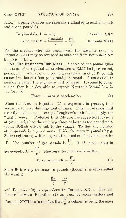
CHAP. XVIII] SYSTEMS OF UNITS 297
XIX.) Spring balances are generally graduated to read in poundsand not in poundals.
In poundals, P = ma; Formula XXV, poundals ma ^ , VVTT
in pounds, P = - = Formula XXIIQ Q
For the student who has begun with the absolute systems,Formula XXII may be regarded as obtained from Formula XXVby division by g.
180. The Engineer's Unit Mass. A force of one pound gives
to a mass of one pound an acceleration of 32.17 feet per second,
per second. A force of one pound gives to a mass of 32.17 poundsan acceleration of 1 foot per second per second. A mass of 32.17
pounds is called the engineer's unit of mass. It seems to be as-
sumed that it is desirable to express Newton's Second Law in
the form of
Force = mass X acceleration (1)
When the force in Equation (1) is expressed in pounds, it is
necessary to have this large unit of mass. This unit of mass until
recently had no name except"engineer's unit," or simply the
''unit of mass." Professor E. R. Maurer has suggested the nameof gee-pound, since the unit is g times as large as the pound unit.
(Some British writers call it the slugg.) To find the numberof gee-pounds in a given mass, divide the mass in pounds by g.
Some engineering writers express the number of pounds mass byW
W. The number of gee-pounds is . If M is the mass iny
Wgee-pounds, M =
. Newton's Second Law is written,y
WForce in pounds = a. (2)
ij
Since W is really the mass in pounds (though it is often called
the weight)Wa ma
and Equation (2) is equivalent to Formula XXII. The dif-
ference between Equation (2) as used by some writers and
WFormula XXII lies in the fact that is defined as being the mass

298 MECHANICS [ART. 181
of the body in a new unit, while in Formula XXII, W or m repre-
sents the mass in pounds, and -is the ratio of the acceleration
y
of the body to the acceleration of gravity, or g is regarded as a
constant occurring in the formula.
It is sometimes stated that W in this equation is the weight
of the mass on a standard spring balance. A body may weigh332 pounds at one locality and 321.5 pounds at another. If
g at the first locality is 32.2 and at the second locality is 32.15,
the mass is found to be 10 units in each case. The formula
P = Ma gives the correct accelerating force in standard pounds,Mv 2
and the formula U = ~ gives the correct energy in standard
foot-pounds. Unfortunately, the use of such a standard springbalance assumes that the true value of g is known. The same
errors, therefore, come in as with the use of other methods.
Moreover, such standard spring balances do not exist, and wouldnot be sufficiently accurate for refined experiments if they were
made. When it is necessary to measure forces with an accuracy
greater than the variation of gravity, beam balances are employedand the value of g is determined by vibration experiments.
WaThe formula P = - - may be written,
In this equation W is regarded as a force. The effective force is to
the weight of the body as the acceleration produced by the force
is to the acceleration produced by the weight of the body. Equa-tion (3) may be regarded as the simplest form of the equation of
acceleration. It does not involve any unusual unit, such as the
poundal force or the gee-pound mass. If only linear accelera-
tion were to be considered, Equation (3) would be the best
form to use. On account of the necessity of applying the
formulas to angular acceleration and to problems of kinetic
energy, it is advisable to emphasize the idea of the mass.
Formula XXII is, therefore, best adapted for general use.
181. Summary. Systems of units depend upon the value of
the constant k in the equation P = -r~. The constant is unity

CHAP. XVIII] SYSTEMS OF UNITS 299
in the absolute systems and the equations for acceleration andkinetic energy are written
P = ma; Formula XXV
In these systems, the units of mass, length, and time are arbi-
trarily defined and the unit of force is derived from Formula XXV.The results are changed into gravitational units by dividing by g.
In the C.G.S. system, the dyne is the unit of force. A dyne is
the force which gives to a gram mass an acceleration of 1 centi-
meter per second per second. In the foot-pound-second system,the poundal is the unit of force. A poundal is the force which
gives to a pound mass an acceleration of 1 foot per second. One
pound force is equal to 32.174 poundals. One gram force is
equal to 981 dynes.
In the so-called Engineer's System, the units of time and
length are the same as in the other systems. The unit offeree is
taken arbitrarily and the unit of mass is defined by Formula XXV.Standard units of force and mass, as required by this system,
do not exist. Physicists use the pound as the unit of mass and
define the unit of force by Formula XXV. Engineers, also,
use the pound as the unit of mass and define the unit of force as
the weight of a pound mass at the standard position. Since
nothing is gained by the use of the so-called Engineer's Unit
of mass, it might well be dropped from technical literature.
Many books have the formulas,
WaForce in pounds = -
;
Wv 2
Kinetic energy in foot-pounds = =
These are identical with the formulas of the preceding chapter
except that W is used instead of m for the mass in pounds. The
student is advised to think of g as a mere coefficient occurring
in the formula on account of the units employed, and not to
Wconsider as representing the mass.
\y
The absolute systems have their uses in some scientific work.
In problems where forces depend upon the weight of some bodies,
it is necessary to know the local value of g. In these systems,

300 MECHANICS [ART. 181
weight = mg. While these systems eliminate g from the formula
for acceleration, they insert g into many problems of statics.
Engineers are advised to learn Formulas XXII and XXIV as
given in the preceding chapter. These formulas are apparently
more complex than those of the other systems. It is easier,
however, for the engineer who is not working daily with such ideas
to remember (or look up) an equation with an additional letter
in it than to remember to divide by g to transform to practical
units.
The systems of units are given in Table 1 below.
TABLE I. SYSTEMS OF UNITS
System

CHAPTER XIX
FORCE WHICH VARIES AS THE DISPLACEMENT
182. The Force of a Spring. The deformation of a spring or
other elastic body is proportional to the force. Figure 247, I,
shows a helical spring which is not loaded. A load of 1 poundstretches the spring a definite amount d as shown in Fig. 247, II.
A load of 2 pounds would produce an elongation of 2d. Theforces on the spring are downward and the elongation is down-ward. The force with which the spring acts on the loads is
upward opposite to the deformation.
O
FIG. 247.
When a body is attached to a spring, there is some position
at which it remains at rest. In this position, either the force of
the spring is zero, or the resultant of the force of the spring and
the other forces is zero. Figure 248 represents a body on a flat
strap spring. The plane of the paper is supposed to be horizontal
in Fig. 248, I. The weight of the body tends to bend the spring
in a vertical direction but not in a horizontal direction. Equi-librium exists, therefore, when the spring viewed from above,
appears straight. If the body is displaced toward the right, as
301

302 MECHANICS [ART. 182
shown in Fig. 248, III, the spring tends to move it backward
toward the left. If it is displaced toward the left from the
position of equilibrium, the spring tends to move it toward the
right.
If the spring in Fig. 248 exerts a force of K pounds when it is
deformed a distance of 1 foot, it will exert a force of 2K poundswhen it is deformed a distance of 2
feet and a force of Kx pounds whenit is deformed a distance of x feet.
The force acts in a dipeclion oppositeto the displacement. The direction
and magnitude of the force exerted bythe spring on the body is given mathe-
matically by the equation.
P = -Kx. (1)
In Equation (1) K is the force of the
spring when the displacement is
unity, x is the displacement from the
position of equilibrium, and P is the
force of the spring when the displace-
ment is x. The negative sign indi-
cates that the direction of the force
which the spring exerts on the
body is opposite the direction of the
displacement.
Equation (1) applies also when a
body is subjected to the force of a
spring and a constant force. The dis-
placement is measured from the posi-
tion of equilibrium at which the force
of the spring is equal and opposite to the constant force. Figure
249 shows a vertical helical spring. It is assumed that a load of 24
pounds stretches this spring a distance of 3 feet, as shown in Fig.
249, II. The constant K is 8 pounds. In Fig. 249, II, the massof 24 pounds is subjected to a downward pull of 24 pounds which
is due to gravity, and to an upward pull of 24 pounds which is due
to the reaction of the spring. If the 24-pound mass is now
displaced an additional foot downward, the elongation of the
spring becomes 4 feet and the force in it becomes 32 pounds.The force of gravity remains 24 pounds. The resultant force
in
FIG. 249.

CHAP. XIX] FORCE VARIES AS DISPLACEMENT 303
on the 24-pound mass is an upward force of 8 pounds. If the
24-pound mass is displaced a distance y from the position of
equilibrium, the total elongation of the spring is 3 + y feet, andthe upward pull of the spring becomes 24 + Sy pounds. Thedownward pull of gravity is still 24 pounds.. The resultant
force on the body, when the displacement is y feet, is equal to
Sy pounds. If the 24-pound mass is displaced a distance y
upward from the position of equilibrium, the total elongation of
the spring is 3 y feet and the pull of the spring is 24 Sy,
provided y is not more than 3 feet. The downward pull of the
earth is still 24 pounds so that the resultant force on the body is
Sy pounds when the displacement is -\-y feet from the position
of equilibrium.
If the origin of coordinates is taken at the position of equi-
librium under the action of the constant force and the reaction
of the spring, the expression for the resultant force on the body is
P = -KxorP = -Ky.If the displacement in Fig. 249 is greater than 3 feet, the spring
will come into compression. If the force required to compressthe spring unit distance is the same as the force required to
stretch it unit distance, Equation (1) will remain valid. A longhelical spring such as is shown in Fig. 249 will buckle in compres-sion so that the force required to compress it unit distance is
not the same as the force which stretches it unit distance. Withsuch a spring Equation (1) will not hold when it is shortened
below its natural length.
Problems
1. A spring board is deflected 5 inches downward by a load of 100 poundson the free end. What is the value of K? Ans. K = 240 Ib.
2. What is the deflection of the spring board of Problem 1 when a boyweighing 120 pounds stands on the end? Ans. 0.5 ft.
3. In Problem 2, what is the resultant force on the boy when the spring
board is deflected 8 inches below the position at which it stands when not
loaded. Ans. 40 Ib. upward.4. In Problem 2, what is the resultant force on the boy when the spring
is deflected 3 inches downward from the position of equilibrium under no
load? Ans. 60 Ib. downward.
5. Solve Problem 4 if the deflection is 1 inch upward from the position
of equilibrium under no load and the boy is not fastened to the spring
board. Ans. P = - 120 Ib.
6. A body is placed on a horizontal plane and attached to one end of a
spring. The natural length of the spring is 3 feet and a pull of 12 pounds

304 MECHANICS [ART. 183
stretches it 6 inches. A cord attached to the body runs horizontally over
a smooth pulley and supports a mass of 60 pounds, as shown in Fig. 250, II.
What is the zero position of the right end of the spring when the system is
in equilibrium? When the spring is stretched to a length of 7 feet, what is
the resultant force on the body?
FIG. 250.
7. Figure 251 shows two springs attached to fixed points A and C, which
are at the same level and are 10 feet apart. The natural length of each
spring is 3 feet and a force of 20 pounds stretches each spring 1 foot. Abody B is fastened to the free ends of these springs. What is the resultant
force on the body when it is displaced 1 foot from the position of equilibrium,
and when it is displaced x feet from that position? Ans. K = 40x.
8. The two springs of Problem 7 are replaced by a single spring of natural
length of 6 feet. It takes a force of 10 pounds to stretch this spring 1 foot.
A body is attached 4 feet from the left end of the stretched spring. Whatforce will displace this body 1 foot in the direction of the length of the
spring?
183. Potential Energy of a Spring. The work done by a force
is the average force multiplied by the displacement. Whenthe force varies as the displacement, the average force is the
mean of the initial and final forces. If K is the force which
produces unit deformation in a spring and si is the initial defor-
mation, the initial force is Ksi. If 2 is the final deformation,

CHAP. XIX] FORCE VARIES AS DISPLACEMENT 305
the final force is Ks2 . The average force for the displacement
s2 si is
K(sl-
Area =
Equation (1) gives the increase of potential energy.
Work is often represented bythe area of a diagram in which
force is the ordinate, and defor-
mation or displacement is the
abscissa. Figure 252 is the work
diagram for a spring. The dia-
gram is a trapezoid. The par-
allel sides are Ksi and Ksz,
and the distance between the sides is s% s\. If the initial
displacement is zero, the diagram is a triangle and the total
h 5/ ^
. .
work is
Problems
1. In Problem 1 of Art. 182, what is the work done in deflecting the board
6 inches? Solve without the formula.
2. In Problem 1 of Art. 182, what is the work done in deflecting the
board 1 foot? What is the work of the last 6 inches of the foot? Con-struct the work diagram to the scale of 1 inch = 50 pounds and 1 inch =0.25 ft.
184. Velocity Produced by Elastic Force. When the force is
proportional to the displacement, as in the case of a spring, the
expression for the force is
P = -(1)
in which P is the force exerted by the spring, x is the displace-
ment, and K is the force when the displacement is unity. The
sign is negative for a spring because the direction of the force
exerted by the spring is opposite the direction of the displacement.If a body of mass m is attached to the spring, as in Fig. 253,
the acceleration of this body is given by Formula XXII.
20
- Kx =Q
(2)

306 MECHANICS [ART. 184
Since acceleration along the X axis is ^p Equation (2) may be
written/XM /72<y
(3)m cr:
7^d 2z
A differential equation of the form^ = a function of x is solved
by first multiplying each side by dx.
m dx d 2x-Jfe&,-___=-m dx d 2x
~gdt~dt'dx d 2x
Since ^7 =v, -n- =
dt;, and Equation (2) becomesdt
m
(4)
(5)
(6)
In Fig. 253, I, the mass m is at its position of equilibrium
with equal tension on the two springs. In Fig. 253, II, the body
Kxdx = v dv.
g
Integrating Equation (5),
has been displaced a distance r toward the right and is assumed
to be stationary. If let free at this point, the body will move
to the position of Fig. 253, I, and will continue to move to a
distance r on the left of the position of equilibrium. Whenx =
r, v = 0. Substituting in Equation (6),
-1~
2
A substitution for Ci in Equation (6) gives
mv* Kr* Kx*Formula XXVI
At the position of maximum deflection, at which x = r and
the velocity is zero, the body is at positive elongation. The
distance r is called the amplitude.

CHAP. XIX] FORCE VARIES AS DISPLACEMENT 307
The first member of Formula XXVI is the expression for
kinetic energy, consequently the second member must also
Kr2
represent energy. The term^- gives the potential energy
Kx 2
when the displacement is r. The term ~- gives the potential
, Kr2 Kx2
energy when the displacement is x. The expression = ^Z Zi
represents the work done on the spring when the displacements
changed from x to r or the work done by the spring when the
displacement is changed from r to x.
When the displacement is r feet, the mass m is stationaryand all the energy is in the form of potential energy of the spring.
When the displacement is reduced to x the potential energy of
Kx 2 Kr2 Kx 2
the spring is FT~. The difference between ^r- and ^ repre-z z z
sents the energy which is given up by the spring to the bodyand is transformed into kinetic energy of the mass. Whenx =
r, all the energy is potential. When x =0, all the
energy is kinetic. When x =r, all the energy is again poten-
tial and the body comes to rest with negative elongation equalto the positive elongation. This is the well known case of
vibratory motion. The total motion is twice the amplitude.If there were no loss of energy, the vibration would continue
indefinitely. Since there is always some loss of energy, the
amplitude of the vibration will slowly diminish and the body will
come to rest at the position of equilibrium after a long interval.
Formula XXVI might have been derived directly from the
relation of the potential to the kinetic energy, without the use
of integration. The integration method here given is general,
however, and may be applied to any problem in which the
effective force is a function of the displacement. It is advisable,
therefore, to use the method in this case where it may be checked
in order that it may be employed with confidence in other cases
where it is not possible to verify the results.
Problems
1. A spring suspended from a fixed support is elongated 3 feet when a
24-pound mass is hung on it. The spring is stretched an additional 2 feet
downward and then released. What will be the velocity when the spring
is stretched 1 foot below the position of equilibrium? What will be the
velocity when the body is 1 foot above the position of equilibrium? What
308 MECHANICS [ART. 185
will be the maximum velocity upward? What will be the maximum velocity
downward? Ans. 5.67 ft. per sec.; 5.67 ft. per sec.; 6.54 ft. per sec.
2. A 24-pound mass rests on a horizontal table between the ends of two
horizontal springs similar to those of Fig. 251. It requires a force of 20
pounds to move the body 1 foot in the direction of the length of the springs.
The body is displaced a distance of 3 feet and then released. If there is no
friction, find the maximum velocity of the body, the velocity when the
displacement is 1 foot, and when the displacement is 2 feet.
Ans. 15.53 ft. per sec.; 14.65 ft. per sec.; 11.58 ft. per sec.
3. Solve Problem 2 if the coefficient of friction between the body and the
table is 0.1.
When the displacement is 2 feet, the energy given up by the spring is
20(9 _ 4\*-=-' = 50 ft.-lb. The work done in moving the body 1 foot against
the friction is 2.4 ft.-lb. The kinetic energy is 50 2.4 = 47.6 ft.-lb.
The velocity of the 24-pound mass is 11.29 ft. per sec.
The maximum velocity is at the point at which the force of the spring
is equal to the friction. At this point, the resultant force is zero and the
2.4acceleration is reduced to zero. This position is sir = 0-12 feet from the
point of zero tension in the spring.
= ??(9- 0,0144) - 2.4 X 2.88;
max v = 14.91 ft. per sec.
4. In Problem 3, find the maximum negative elongation from the position
of zero force in the spring. Ans. x = 2.76 ft.
6. A mass of 40 pounds is placed on a small platform supported by a
spring. The weight of the 40-pound mass elongates the spring a distance
of 2 feet. The platform and mass are pulled down an additional 3 feet and
then released. If no energy is lost and if the mass is not fastened to the
platform, how high will the 40 pounds rise above the position of equilibrium?Ans. 3.25 ft.
185. Vibration from Elastic Force. From Formula XXVI,which applies to the force of a spring, or to any force which is
proportional to the displacement and is opposite the direction
of the displacement, the velocity is
v * = ^(r
* - z2). (1)
In this equation, v is the velocity when the displacement is x, r
is the amplitude or maximum displacement, and K is the force
in pounds exerted on the mass m when the displacement is 1 foot.

CHAP. XIX] FORCE VARIES AS DISPLACEMENT 309
If the time of positive elongation at which x = r is taken as the
zero time,7T
C 2= sin" 1
1; sin C 2=
1; C 2=
J
\Kg .. . "x TT x t
t = sin- 1 = cos- 1 -,m r 2 r
cos
x = r cos ^Am I
(4)
(5)
(6)
(V)
Equation (6) gives the displacement of the mass in terms of the
interval which has elapsed since it was at positive elongation.
When x =r, t = 0. When x =
0, cos and
'
t = ~. The time from positive elongation to zero elongationtn -
is one-half the time of single vibration and one-fourth the time of a
complete period. From the expression above, the time from
positive elongation to zero elongation is
i-imKg
(8)
The time of a single vibration from positive elongation to negative
elongation, or from zero elonga-
tion to positive elongation andback to zero elongation, is given
by the equation
mKg:- (9)
The time of a complete periodfrom positive elongation to posi-
tive elongation, or from anyposition to the same position with
motion in the same direction, is
given by the equationFIG. 254.
(10)
Figure 2f54 represents a circle of radius r. The angle between

310 MECHANICS [ART. 185
the horizontal diameter and the radiusOB\s\\t radians. The
projection of OB on the horizontal diameter is
r cos'Kg\
(11)
If the point B moves around the circle with uniform speed,
-is the angle which the line OB passes through in one second,
and if t is the time which has elapsed since the point B was at the
right end of the horizontal diameter, then \ t gives the angle\ Tfl
which the line OB makes with the horizontal diameter at the
end of time t. If tc is the time of a complete revolution,
tc=
27r;
27TmKg'
(12)
Equation (12) shows that the time of a complete revolution of
the point B is the sameH F
as the time of a com-
plete period of a vibrat-
ing mass.
When a body is vi-
brating under the action
of an attractive force
which is proportional to
the displacement, its
motion along its path is
the projection on that
path of the motion of a
body which moves with
uniform speed around
a circular path. In Fig.
255, A, B, C, D, E, etc. are equidistant points on the circum-
ference of a circle. If a body moves in this circle with uniform
speed, it passes from one of these points to the next one in the
same interval of time. The points B', C', D', etc. are the pro-
jections of the points B, C, D, etc., on the horizontal diameter of
the circle, The body which is vibrating along the straight line
FIG. 255.

CHAP. XIX] FORCE VARIES AS DISPLACEMENT 311
AM passes from A to B>',from B' to C", from C" to Z)', etc., in
equal intervals of time.
A motion of this kind is called a simple harmonic motion. Asimple harmonic motion is equivalent to the motion in the diam-
eter of a circle of the projections of the positions of a body which
moves with uniform speed in the circumference of that circle.
The circle of Fig. 255 may be called the reference circle of the
simple harmonic motion. The actual motion is along the straight
line A G' M. The reference circle is used as a convenient device
for finding the position and velocity at any given time.
If Equation (7) is differentiated with respect to time, the
results are
dt
md*x_ma_1 W~ 7"
Equation (15) is identical with Equation (2) of Art. 183. The
differentiation, therefore, checks the integration.
The velocity of the simple harmonic motion is a maximum
when the sine of */
- t is equal to unity. From Equation (13),m
the maximum velocity is r A / This is equal to the velocity\ m
of a body which is moving in the circumference of a circle of
radius r and passing through the angle of A /- radians per\ m
second.
From Fig. 255, when the body which is moving in the reference
circle AG'M is passing the point G', its motion is parallel to the
diameter AM. The projection of its velocity on the diameter is,
therefore, equal to the velocity of the body which is moving in
the circle of reference.
To find the position of a body which is moving with a simple
harmonic motion, the maximum velocity is first calculated bymeans of the energy equation, Formula XXVI: A body is
assumed to be moving with this velocity in the circumference
of a reference circle. The radius of this reference circle is equal

312 MECHANICS [ART. 185
to the amplitude of the vibration. The time of one revolution
of the body in the reference circle gives the time of a complete
period of the vibration. The position at any time is found bythe projection on the diameter of the reference circle.
Example
Find the time of a complete vibration of the body of Problem 2 of Art. 184.
Find the position and velocity 0.2 second after the body is released.
The amplitude is 3 ft. and the circumference of the circle of reference is
18.8946 ft. The maximum velocity was found to be 15.53 ft. per sec.
If te is the time of a complete period,
18.8496
At 0.2 second, the angle traversed in the reference circle is
O 9
Y~^ X 360 = 59.31 = 59 19'.
re = 3 cos 59 19' = 1.531 ft.
v = 15.53 sin 59 19' = 13.35 ft. per sec.
The time of a complete period may be checked by Equation (10)
and the velocity by Equation (13). The velocity may also be
checked by Formula XXVI after the displacement has been found.
It is recommended that the student make use of the reference
circle and Formula XXVI instead of the equations of this article.
The potential energy of a stretched spring is proportional to
the square of the displacement from the position of equilibrium.
The kinetic energy is proportional to the square of the velocity.
The maximum velocity is, therefore, directly proportional to the
amplitude. The circumference of the reference circle is propor-
tional to amplitude, consequently the time of vibration is inde-
pendent of the amplitude. If a mass on a given spring has a
maximum velocity of 1 foot per second when the amplitude of
the vibration is 1 foot, it will have a maximum velocity of 2 feet
per second when the amplitude of the vibration is 2 feet. In
each case the time of a complete period is 2?r seconds. Equation
(12), which gives the time of a complete period, does not contain
the amplitude. This fact is a mathematical proof of the state-
ment that the time of vibration is independent of the length of
the swing. A vibration which is independent of the amplitude
is called an isochronous vibration.

CHAP. XIX] FORCE VARIES A S DISPLACEMENT 31 3
Problems
1. The mass m of Fig. 253 is 40 pounds. It requires a pull of 16 poundsto displace the mass a distance of 1 foot in the direction of the length of
the spring. The mass is displaced 2 feet from the position of equilibriumand then released. Find the maximum velocity. Find the time of a
complete period. Find the velocity when the body is 1 foot from the
position of equilibrium.
Ans. Max v = 7.175 ft. per sec.; te = 1.75 sec.
2. In Problem 1, find the maximum velocity and the time of a completeperiod if the mass is displaced 1 foot from the position of equilibrium andthen released.
3. In Problem 1, the mass is displaced 2 feet and then released. Find
the time required to come back 1 foot toward the position of equilibrium.
'*
Displacement
FIG. 256.
If a body vibrating with a simple harmonic motion is arranged
to draw a line on a plate which moves with uniform speed at
right angles to the direction of the vibration, the line so drawn
will have the form of Fig. 256, I.
The equation for the velocity of a simple harmonic motion is
v = r sm Kg\ir t
im/ (13)

314 MECHANICS [ART. 186
The velocity curve is a sine curve which has the same period as
the displacement curve of Fig. 256, I. The velocity is when
the displacement is a maximum. The velocity curve is shifted
90 degrees with reference to the displacement curve, as is shown
in Fig. 256, II.
To an observer standing in front of an engine, the circular
motion of the crank pin appears as a linear vertical motion,
which is rapid at the middle and slower at the top and the bottom.
This is a simple harmonic motion, if the engine is running at
uniform speed. To an observer standing at one side of the
engine, the piston rod and cross-head appear to move horizontally
in a similar way. If the connecting rod were infinitely long,
Connecting Rod
FIG. 257.
this would be a simple harmonic motion. With a connectingrod of finite length, as shown in Fig. 257, I, the motion of the
cross-head differs slightly from a true simple harmonic motion.
Figure 257, II, shows a method of changing uniform circular
motion into horizontal simple harmonic motion. The crank Bcarries a pin C which passes through a vertical slot in the head H.
The horizontal component of the circular motion is transmitted
to the horizontal rod. The motion of the rod is, therefore, a
true simple harmonic motion, when the angular speed of the
wheel is uniform.
186. Sudden Loads. When a load is applied to an elastic
body, the force exerted on the elastic body may be much greater
than the weight of the load. Figure 258 represents a helical
spring on which is placed a mass of m pounds. Figure 258, I,
shows the natural length of the spring. In Fig. 258, II, the mass

CHAP. XIX] FORCE VARIES AS DISPLACEMENT 315
m is attached to the spring but is held up by the support B so
that none of its weight comes on the spring. If the support Bis lowered slowly until all the weight comes on the spring, the
condition of Fig. 258, III, is reached. The mass comes to rest
FIG. 258.
when the spring is stretched a distance d. If K pounds is suffi-
cient to stretch the spring 1 foot,
I
"
d = f (1)
The work done by gravity on the mass m while it moves a dis-
tance of d feet ismiU~md"~ (2)

316 MECHANICS [ART. 186
The work done by the mass on the spring, or the potential energy
acquired by the spring, is
TT - + m * _ rad _2
/ON
2 2: "2K
Equation (3) represents only half the work of Equation (2). It
is necessary to account for the remainder. At the beginning of
the descent, the entire weight of the body rested on the supportB. As the body was lowered, the spring took an increasingly
greater proportion until it finally carried the entire load and the
reaction of the support became zero. The work done on the
support B was
Equation (4) accounts for the remaining half of the energy.If the support B is suddenly removed when there is no tension
in the spring, the motion is that shown in Fig. 258, IV. Nowork is done on the support and all the energy is stored in the
spring. If di is the total elongation of the spring, the average
tension is ~- and the potential energy of the spring is -~^-Zi 2
The work of gravity on the mass is mdi. Equating the work and
energy,, Kdl .
mdi =-3^; (5)
* -5' .
v
(6)
A comparison with Equation (1) shows that the elongation whenthe load is
"suddenly applied" is twice as great as when the
load is gradually applied. When a load is suddenly applied to a
spring or other elastic body in which the stress is proportionalto the deformation, the deformation is twice as great as that dueto the weight of the load. Since the force is proportional to the
deformation, it follows that the force is likewise twice as greatas the weight of the load. This fact is expressed by the state-
ment "Live load is twice the dead load."
Since the tension in the spring at the bottom of its path in
Fig. 258 is twice the weight of the body, the resultant force
upward in that 'position is m pounds. The body will move up-ward to the position of Fig. 258, II, and will continue to vibrate

CHAP. XIX] FORCE VARIES AS DISPLACEMENT 317
for a long time. It will finally come to rest in the position of Fig.
258, III.
In Fig. 258, V, the body is suspended from the spring by an
inelastic cord which permits it to fall a distance h before it brings
any tension on the spring. If dz is the distance which the springis stretched, the work of gravity on the mass is m(h + d2), and
Kd*the work done on the spring is -
m(h + d.)- -
(7)
When a load falls upon an elastic body, the deformation is greater
than twice the deformation caused by the weight of the load.
The body will vibrate according to the laws of a simple harmonic
motion from the position of no deformation of the elastic bodydown to the lowest point and back again. After it reaches the
position at which there is no deformation of the elastic body, the
load will continue to move as a projectile which is thrown straight
upward. After reaching the starting point, it will fall and repeat
the cycle.
Problems
1. A force of 10 pounds stretches a given spring 6 inches. How much is
this spring stretched when a mass of 40 pounds is hung on it so that the load
is gradually applied?2. How much is the spring of Problem 1
stretched if the mass of 40 pounds is put on sud-
denly? What is the tension at the lowest point?
What is the time required to reach the lowest
point?3. The 40-pound mass of Problem 1 falls on
the spring from a height of 1 foot. How muchis the spring elongated? Ans. 4.828 ft.
4. In Problem 3, what is the entire time
required for the mass to fall, compress thej, 259
spring, and return to its original position?
At the position of equilibrium, the spring is stretched 2 feet. The
amplitude of the vibration below this point is 2.828 feet. Consequently,
the radius of the circle of reference is 2.828 feet. The angle 6 of Fig. 259
is given by the equation
COS
If the entire vibration were a simple harmonic motion, the time of the com-
plete period would be tc= 1.566 seconds. The time required to traverse

318 MECHANICS [ART. 187
270 degrees of the reference circle is 1.174 seconds. The time required to
fall 1 foot is 0.249 second. The entire time is 1.174 + 0.498 = 1.672 sec.
187. Composition of Simple Harmonic Motions. Figure 260
shows a body supported by a single vertical spring and held bytwo horizontal springs. [One horizontal spring is sufficient if it
does not buckle in compression.] The springs are supposed to
be so long that the vertical component of the tension in the hori-
zontal springs when the body is displaced vertically may be
neglected, and the horizontal component in the vertical spring
when the body is displaced horizontally may be also neglected.
If the body is displaced horizontally, it will vibrate in that direc-
tion with a simple harmonic motion. If it is displaced vertically,
FIG. 260.
it will vibrate vertically with a simple harmonic motion. If it is
displaced to the right a distance a and given a vertical component
upward sufficient to carry it to a vertical distance 6, it will then
have a motion which is the resultant of the two simple harmonic
motions at right angles to each other. If Kh is the constant of
the horizontal springs, and Kv is the constant of the vertical
spring, the equations of displacement are
a cos . ^ t, CD
2,= 6 sin , f-^ . (2)
If Kh = KV) the periods of the two components are equal and
the path of the body is an ellipse. If the amplitudes are equal,
the ellipse becomes a circle.

CHAP. XIX] FORCE VARIES AS DISPLACEMENT 319
Figure 261 shows the motion when the time of vibration in the
horizontal direction is twice as great as in the vertical direction.
The equations may be written briefly,
x = a sin ct; y = b sin 2ct.
FIG. 261.
Problems
1. If the force required to stretch the horizontal spring 1 foot is 20
pounds, what must be the force required to stretch the vertical spring 1
foot in order that the time of vibration vertically may be one-half the time
of vibration horizontally?2. Plot the curve of the resultant of two simple harmonic motions of
equal amplitude if the time of vibration horizontally is two-thirds the time
of vibration vertically.
Instead of the springs as shown in Fig. 260, a single bar maybe used as the elastic body. The bar is fixed rigidly at one end
and carries a heavy mass at the other end. The section of the

320 MECHANICS [ART. 188
bar is a rectangle. In Fig. 262, the vertical sides of the rectangle
are greater than the horizontal width. The vertical stiffness is
greater than the horizontal stiffness and the time of vibration in
the vertical plane is greater than in the horizontal plane. These
dimensions may be such as to give any desired ratio to the time of
vibration.
Front View
FIG. 262.
Problem
(A knowledge of Strength of Materials is required for this problem.)3. A steel cantilever 30 inches long is Y inch wide and % inch deep. It
carries a mass of 2 pounds on the free end. If E = 30,000,000, find the
force required to deflect this cantilever 1 inch in a vertical direction and the
force required to deflect it 1 inch in the horizontal direction. Calculate
Kv and Kh . Neglecting the mass of the bar, find the time of a complete
period in each direction.
188. Correction for the Mass of the Spring. In the case of a
vibrating spring or other elastic body, a part of the kinetic energyis located in the spring. For accurate work, correction must be
made for this energy.
The effective mass of the spring may be calculated from twosets of vibration experiments. Let m be the effective mass of
the spring, mi be a known additional mass, and ra2 be a second
known mass. The time of vibration is found with the mass mion the spring, and again with mz on the spring. If ti and t2 are
these times of vibration,
CDKg
,, =fc^SJjSSj (2)
i=2r+-S ;
;
(3)
/wi -1 -f 2
ra2- mi
=t\-
t\ (*\
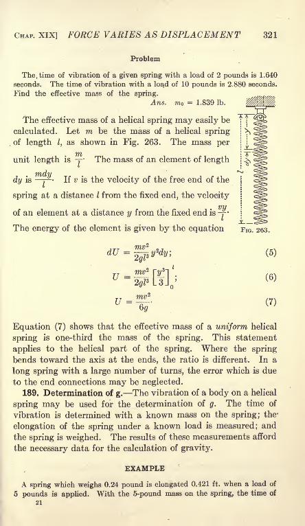
CHAP. XIX] FORCE VARIES AS DISPLACEMENT 321
Problem
The. time of vibration of a given spring with a load of 2 pounds is 1.640
seconds. The time of vibration with a load of 10 pounds is 2.880 seconds.
Find the effective mass of the spring.
Ans. m = 1.839 Ib.
The effective mass of a helical spring may easily be
calculated. Let m be the mass of a helical spring
of length I, as shown in Fig. 263. The mass per
tnunit length is y The mass of an element of length
7?? f7 77
dy isj
If v is the velocity of the free end of the
spring at a distance I from the fixed end, the velocity
of an element at a distance y from the fixed end isyThe energy of the element is given by the equation
dU =
7=^1^
Umv
Equation (7) shows that the effective mass of a uniform helical
spring is one-third the mass of the spring. This statement
applies to the helical part of the spring. Where the spring
bends toward the axis at the ends, the ratio is different. In a
long spring with a large number of turns, the error which is due
to the end connections may be neglected.
189. Determination of g. The vibration of a body on a helical
spring may be used for the determination of g. The time of
vibration is determined with a known mass on the spring; the-
elongation of the spring under a known load is measured; and
the spring is weighed. The results of these measurements afford
the necessary data for the calculation of gravity.
;" EXAMPLE
A spring which weighs 0.24 pound is elongated 0.421 ft. when a load of
5 pounds is applied. With the 5-pound mass on the spring, the time of
21

322 MECHANICS [ART. 190
100 complete periods is 72.4 seconds. Find the value of g for that
locality.
-; m = 5 + 0.08; tc= 0.724 sec.
0.4:
47r2 X 5.08 X 0.421
5 X 0.7242= 32.20 ft.
This experiment does not require that the masses be accurately
known in terms of the standard units. If the effective mass of
the spring were negligible, it would only be necessary to find the
elongation due to any given mass and the time of vibration with
that mass. Since the effective mass of the spring is not negli-
gible, the ratio of its mass to that of the additional load must be
determined. It is not necessary, however, to determine the
actual mass of either the spring or the load.
Problem
A helical spring weighing 0.42 pound is stretched 0.362 foot by a load of
6 pounds. With a mass of 10 pounds on the spring, the time of 100 com-
plete periods is 86.6 seconds. Find g.
190. Determination of an Absolute Unit of Force. If an
absolute unit of force is used, Equations (2) and (3) of Art. 184
become-K'x = ma; (1)
-X'* =mg- .
^
(2)
In these equations, K' is the force in absolute units which causes
unit displacement.
Formula XXVI is
mv 2 _ K'r2
_ K'x 2
~2~ ~2~~ ~T~
Equation (12) of Art. 185 is
t e= 2^~ (4)
Equation (4) affords an easy method of finding the constant of
the spring and getting a unit of force which is entirely inde-
pendent of gravity.

CHAP. XIX] FORCE VARIES AS DISPLACEMENT 323
Problems
1. A helical spring weighs 0.6312 pound. A 10-pound "weight" is hungon this spring and the time of 1000 complete periods is found to be 1243.6
seconds. Find the constant of the spring in poundals if the actual mass of
the 10-pound weight is 9.9842 pounds.Ans. K' = 260.2 poundals; 100 poundals elongates the spring 0.3844 ft.
2. A given spring makes 1000 complete vibrations in 528.3 seconds whena 500 gram mass is attached to it, and makes 1000 complete vibrations in
1014.2 seconds when the mass is increased to 2000 grams. How manydynes force are required to deform this spring 1 centimeter?
Ans. K' = 7900.9 dynes.
191. Positive Force which Varies as the Displacement. Thereaction of a spring is proportional to the displacement. Thedirection of the reaction is opposite the direction of the displace-
ment. The expression for the reaction of the spring is P = Kx.
When the force varies as the displacement and is in the same
direction, the expression is
P = Kx. (1)
If a body subjected to a force of this kind is in equilibrium,
the equilibrium is unstable. If the body is displaced ever so
little from its position of equilibrium, the increased force in
the direction of the displacement will cause it to continue to
move in the same direction, and it will not return to the position
of equilibrium. If the body is displaced a distance r from the
Kr2
position of equilibrium, the work done by the force is -5-.
The work done in displacing the body from a distance r to a
distance x from the position of equilibrium is
U =(*>
-r). (2)
If the body is at rest when the displacement is r, its kinetic
energy when its displacement is x is given by the equation
mv 2 K,2, ,Q N
-w" :
~2(x
' r} -
Problems
1. A rope, 100 feet long, weighing 1 pound per foot, runs over a smooth
pulley as shown in Fig. 264. When the center of the rope is 1 foot below
the pulley, so that there is 49 feet of rope on one side of the pulley and 51
feet on the other side, what is the resultant force? Ans: P = 2 Ib.

324 MECHANICS [ART. 192
2. In Problem 1, what is the expression for the resultant force in terms of
the displacement of the center of the rope? Ans. P = 2x.
3. Find the work done when the rope of Fig. 264 moves from the position
of equilibrium to the position at which there is 40 feet of rope on one side
and 60 feet on the other. Ans. U = 100 ft.-lb.
4. What is the final velocity in Problem 3 if the initial velocity is so small
that its kinetic energy is negligible? Ans. v = 8.02 ft. per sec.
The relation of displacement to time is found by
integration. From Equation (3)
(4)
(5)
(6)
If time is measured from the time when x
=r, then t = when x = r. Substituting in
FIG. 264. Equation (6),
(7)
(8)
(9)
Problem
6. In Fig. 264, the rope is placed with 49 feet on one side and 51 feet on
the other and then released. Find the time required for the rope to entirely
leave the pulley. Find the final velocity.
Ans. t = 5.63 sec.; v = 40.10 ft. per sec.
192. Summary. There are two classes of forces which varyas the displacement. In one class, the direction of the force is
opposite the direction of the displacement. In the other class,
the direction of the force is the same as the direction of the
displacement.A spring or other elastic body exerts a force which is opposite
the displacement. The expression for the force is
P = -Kx.
CHAP. XIX] FORCE VARIES AS DISPLACEMENT 325
The change of kinetic energy when the body moves from displace-
Kr 2 Kx 2
ment r to displacement x is^- ^ If the velocity is
zero at displacement r, the velocity at displacement x is given bythe energy equation,
mv 2 Kr2 Kx 2 _ . _____- =
-g 2~ Formula XXVI
When the force is proportional to the displacement and in the
opposite direction, the motion is periodic. The position at anytime is given by the equation
x = r cos
in which r is the maximum displacement, or the amplitude of the
vibration, t is the time which has elapsed since the displace-ment was equal to r, and x is the displacement at time t. The
velocity at time t is given by the equation
dx~
dt
The time of a complete period is
The time of vibration is independent of the amplitude.
Simple harmonic motion may be studied by means of a refer-
ence circle, the radius of which is equal to the amplitude of
the motion. The maximum velocity is found by FormulaXXVI. A body is assumed to move with this velocity in the
circumference of the reference circle. The projection of the
motion on the diameter of the reference circle gives the required
motion.
When a load is applied suddenly to an elastic body, the
deformation is twice as great as that when the load is applied
gradually, and the stress is twice as great as that resulting from
a quiescent load.
An absolute unit of force may be determined by means of the
time of vibration of a known mass on a spring. The value of
g may be found by means of the time of vibration of a mass on
a spring and the elongation of the spring caused by the weight
of the mass.

326 MECHANICS [ART. 192
The second class of force which is proportional to the displace-
ment is expressed by the equation
P = Kx.
If the velocity is zero at displacement r, the velocity at dis-
placement x is given by the energy equation
mv* Kx2 Kr2
2g"
2 2'
The motion is not periodic. The equilibrium when x = is
unstable. Equations (8) and (9) of Art. 191 give the position
in terms of the time.

CHAPTER XX
CENTRAL FORCES
193. Definition. A central force is one whose direction is alonga line which joins its point of application wtih some fixed point;
whose magnitude depends upon the length of that line and does
not depend upon its direction. In Fig. 265, is a central point
FIG. 265. FIQ. 266.
and Q is the point of application of a force directed toward 0.
If the force satisfies the definition of a central force, its magnitudeis constant for any position of Q on the surface of a sphere of
radius OQ with its center at 0.
FIG. 267.
In Fig. 266, a rope which supports a load W runs over a small
pulley. The force at B is constant and is directed toward the
pulley as a center.
In Fig. 267, the rope which runs over the pulley is attached to a
spring. If the end of the rope is at a distance b from the pulley
327

328 MECHANICS [ART. 194
when there is no tension in the spring, the force at B is given bythe equation,
P - K(r -V). (1)
The force of gravity is a central force directed toward the
center of the Earth. Above the surface of the Earth, the magni-tude of the force of gravity varies inversely as the square of the
distance from the center. The force is given by the expression,
An expression similar to Equation (2) gives the attraction or
repulsion of a single magnetic pole or of an electrically charged
sphere.
194. Work of a Central Force. The work done by a central
force depends upon the distances of the initial and final points of
application from the center, and is independent of the form of
the path.
Fio. 268. FIG. 269.
In Fig. 268, the point of application moves a distance ds from
point A to point B. The angle between the radius vector OAand the line AB is <J>. The work of the displacement is
dU = P cos <f> ds = Pds cos <}>. (1)
Since ds cos <t>=
dr,
dU = Pdr; (2)
U = fPdr. (3)
If a body under the action of a force which is central at 0, Fig.
269, moves from a point E at a distance r\ from to a point Fat a distance r2 from 0, the total work depends only upon the
distance r2 r\. The body might move from E to G on the cir-
cumference of a circle of radius r\. Since the force is normal to
the displacement, no work is done during this displacement. The

CHAP. XX] CENTRAL FORCES 329
body may then move along the line OGF directly away from the
center. The total work is equal to that given by Equation (3).
Problems
-
1. A body rests on a horizontal plane. It is subjected to a constant forceof 20 pounds directed towarda point which is 12 feet
above the plane, and directly
over a point B on the plane.The body moves from a pointwhich is 16 feet from B to a
point which is 5 feet from B.
Find the work done by the
force of 20 pounds. Solve byarithmetic.
2. Solve Problem 1 by integra-
tion, assuming that the body %w . %xw . WN%WWWWmoves along a straight line on
'_"_"^'"""^
x Jthe surface of the plane. f .* /$'From Fig. 270,
*s{/////jtyf
lf\
13'
JL_L:.
\
>?
.:_
FIG. 270.
dU = 20 cos 6 dx - - 2
X&^.U = 140 ft.-lb.
3. The body of Problem 1 weighs 60 pounds. If its velocity is zero whenit is 16 feet from B, what is its velocity when it is 5 feet from B? If its
velocity is 20 feet per second
when it is 16 feet from B,what is its velocity when it
is5feetfrom?Ans. v = 12.26 ft. per sec.;
v = 23.45 ft. per sec.
4. The body of Problem 1
weighs 60 pounds and the
coefficient of friction be-
tween the body and the
plane is 0.1. Find the in-
crease of kinetic energy whenthe body moves from the
point at 16 feet from B to
the point at 5 feet from B.
Find the friction by integ-
ration.
Ans. 94.63 ft.-lb.
6. Figure 271 shows a drum which is rotated by a spiral spring. A ropeattached to the drum runs over a smooth pulley at a distance of 20 feet
above a point B on a smooth horizontal floor. There is no tension in the
rope when the end is at C at a distance of 5 feet from 0. A force of 3 pounds

330 MECHANICS [ART. 195
is required to rotate the drum 1 foot. The drum is rotated and the end of
the rope is fastened to a mass of 80 pounds which rests on the floor. The
80-pound mass moves from a point which is 21 feet from B to a point which
is 15 feet from B. Find the work done by the spring. If the mass of the
drum and spring is negligible and the 80-pound mass starts from rest, find
its final velocity.Ara. U = 264 ft.-lb.
6. Solve Problem 5 if the coefficient of fric-
tion between the mass and the floor is 0.12.
Ans, Change of kinetic energy = 2 64
57.6 + 43.2 - 8.03 = 241.57 ft.-lb.
7. Figure 272 is similar to Fig. 270. The force,
however, is that resulting from a suspended mass
of 20 pounds. The body starts from a point 16
feet from B. If there is no friction, find its
velocity when it reaches B.
Ans. v = 13.1 ft. per sec.
8. In Fig. 272, find the velocity of the 60-
FIG 272. pound mass at 5 feet from B if its velocity was
zero at 16 feet from B. Find also the velocity
of the 20-pound mass.
Ans. Velocity of the 60-pound mass = 11.91 ft. per sec.
195. Force Inversely as the Square of the Distance. Whenthe magnitude of the force varies inversely as the square of the
distance from the central point and is directed toward that point,
its equation is
When the point of application is displaced a distance dr, the
increment of work done by the force is
--
(2)
If the total displacement is r2 ri, the total work is
-ir
Problems
1. The attraction between two charged spheres is 200 dynes when their
centers are 5 centimeters apart. Find K of the equations above. Howmuch work is done in moving one sphere from a position 10 centimeters from
the other to a position 20 centimeters from the*other?
Ans. K = 5000 dynes; U = 500 ergs.
2. For bodies above the Earth's surface, the attraction of gravitation
varies inversely as the square of the distance from the center of the Earth.
If the radius of the Earth is taken as 4000 miles, and is expressed in feet,
what is the value of K in pounds? Ans. K = 21,120,0002
.

CHAP. XX] CENTRAL FORCES 331
3. A mass of 1 pound is lifted from the surface of the Earth a vertical
distance of 4000 miles. Find the work in foot-pounds.Ans. U = 10,560,000 ft.-lb.
4. If only the attraction of the Earth is considered, show that the workdone in moving a body from the surface of the Earth to an infinite distance
is 21,120,000 foot-pounds multiplied by the mass of the body.5. A body falls to the Earth from an infinite distance. If the resistance
of the air were negligible, with what velocity would it strike the Earth?
Ans. 37,000 ft. per sec.
If a body were thrown out of the Earth's atmosphere with
a velocity of 37,000 feet per second, it would not return. It
would not, however, leave the solar system on account of the
greater energy required to overcome the attraction of the Sun.
The results of Problems 2, 3, and 4 are slightly in error owingto the fact that 4000 miles has been used as the radius of the
Earth. The actual radius is less than 21,000,000 feet. (See
Hussey's Mathematical Tables, p. 147.)
196. Equipotential Surfaces. In Art. 135, an equipotential
surface was denned as a surface normal to the resultant of all
the applied forces except the reaction of the surface. No workis done when a body moves from one part of an equipotential
surface to another. When the forces have a single center, the
equipotential surfaces are concentric spheres.
If U is the potential energy of a body, and if the body receives
a displacement dx while y and z remain constant, the changein the energy is the partial derivative of U with respect to x
multiplied by dx. When x alone varies,
increment of U '= dx. (1)oX
Since the work done in moving a distance dx is the product of
dx multiplied by the component of the force in that direction,
the partial derivative of U with respect to X is the X componentof the applied forces.
dU dU dU __ (2.
^x =Hx '^= V
'~dz
The equation of the equipotential surface is
dU , . dU , ,dU, f^~dx + dy + dz==0.
The potential energy U is called the potential function. The
potential function may be denned as the expression whose

332 MECHANICS [ART. 196
derivative with respect to any direction gives the force in that
direction.
Problems
1. Solve Problem 1 of Art. 133 by Equation 3. Assume that the diameter
of the pulley is negligible.
If the origin of coordinates is taken at the pulley, Fig. 273, the energyp2 /J.2
I y2due to gravity is Wy. The energy of the spring is =- = =
U = Wy
dU dU2
10dx
~''
dyxdx + (10 + y)dy = 0;
FIG. 273. FIG. 274.
2. A body is subjected to the action of two forces directed toward two
fixed points, A and B of Fig. 274, at a distance a apart. The magnitude of
each force is Kr in which r is the distance from A for one force and the
distance from B for the other. Find the equation of the equipotential
curves in a plane through A and B.
If B is taken as the origin of coordinates,
2U = K((a + xY + y*) + K(x* + y);
[2(a + z) + 2x]dx + [2y + 2y]dy =0;
adx + 2xdx + 2ydy =0;ax + x 2 + y
2 = C.
The curves are circles with their centers midway between A and B.
3. In Fig. 274, let the distance from A to B be 10 feet. Let the force
which is central at A be 3r, where r is the distance from A;and let the force
which is central at B be 2r, where r is the distance from B. With the
origin of coordinates at B and with the X axis passing through A, find the
equation of the equipotential curve through the point (0,8).
Ans. (x + 6)2 + y
2 = 100.

CHAP. XX] CENTRAL FORCES 333
The curve is a circle with its center on the line AB at a distance of 6 feet
from B.
4. In Problem 3, find the potential energy at the point (0,8) and at the
point on the X axis at the same distance from the center of the circle
Compare the two values.
197. Summary. The direction of a central force is along the
line which joins its points of application with some center; its
magnitude is some function of the length of this line.
The work done by a central force depends only upon the dif-
ference of the distances of the initial and final positions from the
center.
U = Pfdr
When the magnitude of a force varies inversely as the squareof distance of its point of application from the center, the poten-tial difference between two points is
r2
If r2 is infinity,
which is the potential of the point. If the force is attraction, the
potential is the work done by the force in bringing the body from
infinity to the point at a distance r from the center. If the
force is repulsion, the potential is the work done against the
force in bringing the body from infinity.
The potential due to several forces is found by adding the
potential due to the separate forces. Since potential is not a
vector, this addition is the addition of ordinary arithmetic. The
derivative of the potential with respect to any direction gives the
force in that direction,
dU dUT7
dUto-*- ; aT
V>lte"
The equation of an equipotential surface is
dU, dU, dU,dz =

CHAPTER XXI
ANGULAR DISPLACEMENT AND VELOCITY
198. Angular Displacement. When a rigid body rotates
about an axis, all parts of the body turn through the same angle.
In Fig. 275, the axis passes through and is
perpendicular to the plane of the paper. If
a point on the body moves from position Bto position B', its path is the arc BB f
. The
angular displacement of this point is the
angle between the radii OB and OB'. If r
is the length of the radius from to B, the
FIG. 275. angular displacement in radians is
_ arc BB'\J
*
r
Angular displacement is linear displacement divided by the
radius.
Problems
1. A point moves a distance of 6 feet in the circumference of a circle of
3-foot radius. Find the angular displacement in radians.
Ans. = 2 radians.
2. A body revolves once on its axis. What is the angular displacement?Ans. 6 = 2ir = 6.2832 radians.
3. What is the angular displacement when a body turns through an angleof 60 degrees?
4. A cylinder 4 feet in diameter turns through an angle of 50 degrees.Find the linear displacement of any point on the surface of this cylinder.
5. The hour hand of a clock moves from 2 to 10. What is the angular
displacement?
199. Angular Velocity. Angular velocity is the rate of changeof angular displacement. Angular velocity is usually represented
by the Greek letter co (omega).
-
Equation (1) is analogous to the corresponding formula for linear
velocity. For small intervals of time,
334

CHAP. XXI] ANGULAR DISPLACEMENT 335
If v is the linear velocity of a point on a rotating body, vt
is the length of the arc which the point describes in time t. The
angular displacement of the point is The angular velocity of
the point is
?**;.-5 .
. (3)
v = rco Formula XXVII. . (4)
The angular velocity of a point is its linear velocity divided by the
radius; the linear velocity is the angular velocity multiplied bythe radius.
Problems
1. The circumference of a flywheel 6 feet in diameter is moving 3000 feet
per minute. What is the angular velocity of the wheel?
Ans. to = 16.67 radians per sec.
2. What is the angular velocity of a pulley which is making 300 revolutions
per minute? Ans. = WTT = 31.416 radians per sec.
3. A steel ball is whirled in a vertical plane on the end of a rod 4 feet in
length at the rate of 8 revolutions in 4 seconds. If the ball is released fromthe rod when the rod is horizontal and is moving upward, how high will the
ball rise? How many times will the ball rotate on its axis before it returns
to the starting point?
The formula for displacement in simple harmonic motion is
x = r cos JZg t
\ m
The expression */ ^t is the angular displacement in the circle
of reference, and .*/ - is' the angular velocity in that circle.\ fit
The time of a complete period, which corresponds with the
time of one revolution in the circle of reference, is
t.= 2, + , - 2rj.
200. Kinetic Energy of Rotation. Fig. 276 shows an element
of mass dm at a distance r from an axis through 0. If this
element rotates about the axis with an angular velocity co, its
linear velocity is rco, and its kinetic energy is
(3)

336 MECHANICS [ART. 200
The kinetic energy of the entire mass rotating with angular
velocity about the axis through is the integral of Equation (1).
dm; (2)
U = kinetic energy .= - Formula XXVIII
If the mass is expressed in pounds and if
g= 32.174, Formula XXVIII gives the
kinetic energy in foot pounds. If the mass
is given in kilograms and g= 9.81, the for-
mula gives the kinetic energy in kilogram-
FIG. 276. meters.
Problems
1. A homogeneous solid cylinder 4 feet in diameter and weighing 600
pounds revolves on its axis at the rate of 2 revolutions per second. Find
its kinetic energy in foot pounds.
TT 600 X 2 X 16 X 9.8696 on ._,,AnS ' U
2 X 32.174
2. A hollow cylinder 6 feet outside diameter and 4 feet inside diameter
weighs 800 pounds and revolves on its axis at the rate of 5 revolutions per
second. Find its kinetic energy. Ans. U = 79,756 ft. Ib.
3. A flywheel has a radius of gyration of 1.8 feet and weighs 600 pounds.
Find its kinetic energy when it is making 300 revolutions per minute.
Ans. U = 29,818 ft. Ib.
4. The flywheel of Problem 3 is brought to rest by means of a brake which
rubs on the outer surface. The diameter of the wheel is 4 feet. The brake
exerts a normal pressure of 100 pounds and the coefficient of friction is
0.24. How many revolutions will the wheel make before it comes to rest?
Ans. 96.3 revolutions.
6. A homogeneous solid cylinder which is 4 feet in diameter and weighs
400 pounds rotates on a frictionless axis. A rope is wound several times
around the cylinder and is fastened to it. A constant pull of 120 poundsis applied to the rope while the cylinder makes 5 revolutions. What is the
work done by the rope on the cylinder? What is the final velocity of the
cylinder at the end of 5 revolutions?
Ans. U = 120s = 120 X 47r X 5 = 7540 ft. Ib.;
^^ = 7540, co = 24.64 radians per sec.
6. In Problem 5, what is the final velocity of the surface of the cylinder
in feet per second. v = 49.28 ft. per sec.

CHAP. XXI] ANGULAR DISPLACEMENT 337
7. A mass of 120 pounds is hung on the rope of Problem 5, Fig. 277.
Find the angular velocity of the cylinder and the linear velocity of the
rope after the mass has moved 60 feet.
201280co2
= 7200;
w = 19.0 radians per sec; v = 38.0 ft. per sec.
8. A homogeneous solid cylinder weighing 200 pounds is 2 feet in diameter.
This cylinder is coaxial with a second cylinder which is 6 inches in diameter
and weighs 40 pounds. A rope wound on the smaller cylinder supports a
mass of 60 pounds. If there is no friction and if the mass starts from rest,
what velocity will it acquire while it moves 100 feet?
Ans. v = 15.16 ft. per sec.
FIG. 277. FIG. 27S.
9. A uniform rod AB is 6 feet in length and is hinged at A. The rod
is placed in the position of unstable equilibrium and then released. Find
its velocity when it reaches the horizontal position of Fig. 278.
Ans. Velocity of B is 24.06 ft. per sec.
10. Solve Problem 9 for the velocity when rod is 30 degrees below the
horizontal and when the rod is vertical downward.
Ans. 4.91 radians per sec.; 5.67 radians per sec.
201. Rotation and Translation. In the preceding article, the
axis of rotation is stationary and the kinetic energy is the energyof rotation. When a body is rotating about an axis and the axis
has a linear motion, the total kinetic energy is the sum of the
energy of rotation and the energy of translation.
22
?-! + .
&Q &Q(1)

.338 MECHANICS [ART. 202
Since energy is not a vector quantity, the total energy is
arithmetric sum of the two terms.
Figure 279 shows a wheel of radius r which rolls without
slipping on a horizontal surface. If the axis were stationary,
the velocity of the circumference of the wheel relative to the
point B would be rw. When the wheel does
not slip, the velocity of its axis relative to the
surface is v = r<o.
V Problems
1. A homogeneous solid cylinder is 4 feet in
diameter and weighs 240 pounds. It is rolling at a
speed of 60 feet per second. Find the kinetic energy
279^ *rans^ati n
>tne kinetic energy of rotation, and the
total kinetic energy.
Ans. 13,426 ft.-lb.; 6713 ft.-lb.; 20,739 ft.-lb.
2. When a homogeneous cylinder is rolling without slipping on a surface,
show that the kinetic energy of rotation is one-half the kinetic energy of
translation.
3. A homogeneous solid cylinder rolls down an inclined plane which
makes an angle of 20 degrees with the horizontal. What velocity will it
acquire while moving 100 feet from rest? What velocity would it acquire
if it were to slide down the plane with no friction?
Ans. 38.3 ft. per sec.; 46.9 ft. per sec.
4. In Problem 3, what is the average velocity when the cylinder rolls
down the plane? What is the time of descent? Ans. t = 5.22 sec.
5. The outside diameter of a hollow cylinder is 4 feet and the inside diameter
is 3.9 feet. The cylinder rolls 100 feet down a plane which makes an angle
of 10 degrees with the horizontal. Find the final velocity of the hollow
cylinder. What velocity would a solid cylinder acquire in rolling the same
distance down this plane?Ans. Velocity of hollow cylinder = 23.78 ft. per sec.; velocity of solid
cylinder = 27.29 ft. per sec.
6. A sphere which is 8 feet in diameter rolls on two parallel rods which
are 1 foot in diameter. The axes of the rods are 5 feet apart. Find the
ratio of the angular velocity of the sphere to the linear of velocity of its
center.
7. A homogeneous solid sphere rolls on a surface. What is the ratio of
its energy of rotation to its energy of translation?
202. Translation and Rotation Reduced to Rotation. Trans-
lation and rotation in the same plane may be regarded as rotation
about some axis. Figure 280 shows a cylinder of radius r, which
is rolling with velocity v on a plane surface. The angular velocity
of the cylinder about its axis is co = The velocity at any
point may be found from the resultant of the velocity of the axis

CHAP. XXI] ANGULAR DISPLACEMENT 339
of the cylinder and the angular rotation about the axis. The
velocity at any point may also be found from the angular motion
about the line of contact with the plane. In Fig. 280, the
cylinder may be regarded as rotating about an axis through Operpendicular to the plane of the paper. The axis of the cylindermoves a distance vdt during a time in-
terval dt. The angular velocity with
respect to the instantaneous axis through
B is w = Since the cylinder is a
rigid body, the angular velocity of all
parts is the same. All parts of the cylin-
der may, therefore, be regarded as rotat-
ing with angular velocity about the
instantaneous axis through B.
The kinetic energy of a body which rolls on a plane surface is
If r is the radius from the axis of the body to the line of contact
with the surface, v = ro; and Equation (1) may be written
(3)
in which &o is the radius of gyration with respect to the axis
through the center of gravity, and k is the radius of gyrationwith respect to the line of contact with the surface. These
equations show that the energy computed from the linear
velocity of the center of mass and the angular velocity about
that center is the same as the energy computed from the angular
velocity about the line of contact.
Problems
1. A homogeneous solid cylinder which is 4 feet in diameter and weighs600 pounds rolls on a plane surface with a velocity of 20 feet per second.
Find the kinetic energy in foot-pounds, regarding the axis as moving 20
feet per second, and the cylinder as rotating on its axis at the rate of 10
radians per second. Also find the kinetic energy, regarding the cylinder
as rotating about the axis of contact with the surface with an angular velocity
of 10 radians per second. Ans. U = 5594.4 ft.-lb.
2. A bar of length I is rotating with angular velocity w about an axis
through one end perpendicular to its length. Find its kinetic energy,

340 MECHANICS [ART. 203
3. Solve Problem (2) from the condition that the center of gravity of the
bar has a linear velocity of - and the bar rotates about the center with an
angular velocity of <o radians per sec. TT _ mZ2o?
2
Ans. u 7;
60
4. In Fig. 281, find the direction and magnitude of the velocity of each
of the points A, B, C, D, and E. Solve by regarding the axis as movingin a straight line while the points revolve about it.
5. Solve Problem 5 by considering the cylinder as rotating about the line
of contact with the plane.
6. A car weighing 200 pounds has a radius of gyration of 2 feet with
respect to the vertical a:is through its center of gravity. The car moves
with a velocity of 40 feet per second on a straight track. If no energy is
lost in friction, what is its velocity when it runs on to a curve of 10-foot
radius? Ans. 39.2 ft. per sec.
A
f /\
\
s. A\
FIG. 281.
cJ@B
FIG. 282.
Rotation of a body about any axis with an angular velocity
of co radians per second is equivalent to a linear velocity of
rco feet per second combined with an angular velocity of co radians
per second about a parallel axis through the center of gravity.
Figure 282 shows four positions of a body AB which rotates
about an axis normal to the plane of the paper. The axis
through the center of gravity of AB passes through C. At
position 1 at the right of the figure, the point B is to the right of
C. At the second position, B is above C. At the third position,
B is to the left of C. At the last position, B is below C. It is
evident, therefore, that when the body makes one revolution
about 0, it makes one revolution about C.
203. Summary. Angular displacement is measured in radians.
Angular velocity is measured in radians per second. When the
velocity is constant, the displacement is the product of the velocity
multiplied by the time. When the velocity varies, the displace
ment is the product of the average velocity multiplied by the time.

CHAP. XXI] ANGULAR DISPLACEMENT 341
If r is the distance from a point to the axis of rotation, the
linear velocity of the point due to an angular velocity of co radians
about the axis is given by
v = rco. Formula XXVII
This linear velocity is normal to the direction of r.
If the axis of rotation is moving with a linear velocity, the
resultant linear velocity of any point is obtained by combiningthe linear velocity of rotation with the linear velocity of the
axis. These velocities are added as vectors.
The kinetic energy of a rotating body is
U =^ Formula XXVIII20
This expression for kinetic energy corresponds with the expression
for the kinetic energy of a body which has a linear velocity.
Angular velocity replaces linear velocity, and moment of inertia
replaces mass or inertia.
If the axis of rotation is moving with a linear velocity, the
total energy is the sum of the energy of rotation and the energyof translation. Energy is a scalar quantity; kinetic energy is
always positive.

CHAPTER XXII
ACCELERATION TOWARD THE CENTER
204. Components of Acceleration. In Fig. 283, a point at
A i in the circumference of a circle of radius r is moving with a
linear velocity v\. When the point reaches the position A 2 ,its
velocity is v^. The direction and magnitude of the velocity at A i
is given by the tangent AI C; the direction and magnitude of the
velocity at A z is given by the tangent A 2D. Figure 283, II,
is the vector diagram of the velocities with a common initial
point A. The vector CD of Fig. 283, II, represents the change of
velocity while the body moves from A\ to A 2 . This increment
Vector
Diagram
II
FIG. 283.
of velocity may be resolved into two components CE and ED.The length AE is made equal to AC. The component ED repre-
sents the increment which is due to change in the magnitude of
the velocity; the component CE represents the increment which is
due to change in the direction. Since AEC is an isosceles triangle,
the direction of CE is normal to the line which bisects the angle
CAE, and is- parallel to the line which bisects the line AiOA z of
Fig. 283, I
205. Acceleration Toward the Center. If v is the magnitudeof the velocity at A\ and if the distance from A \ to A 2 is infinitesi-
mal, the increment CE is
dv =vdO, (1)
342

CHAP. XXII] ACCELERATION TOWARD CENTER 343
in which d6 is the change in the direction of the velocity and dv
is the increment which is due to the change in direction. Since
the direction of the increment is perpendicular to the line which
dBmakes an angle with the direction of vi, the change of velocitym
is toward the center of the circle of Fig. 283, I.
The linear acceleration toward the center is
- dv v'
Since AiA 2= r dO =
vdt,
- -'
Jt~
dt
d0 _ v
di~'~
r'
Formula XXSince v = rco;
a = rco2
. (3)
Formula XX has already been derived in Art. 162 for motion
in a circular path with uniform speed.
Problems
1. A body is whirled in a circular path 6 feet in diameter with a speed of
15 feet per second. Find its acceleration toward the center due to change of
direction. Ans. a = 75 ft. per sec. per sec.
2. A wheel 4 feet in diameter is making 5 revolutions per second. What is
the acceleration toward the center of a point on the rim of the wheel?
Ans. a = 2 X 102 X 7T2 = 1974 ft. per sec. per sec.
3. A wire is bent into the form of an ellipse the equation of which is
A body moves on this wire with a constant speed v. Find the acceleration
of the body when it is at the end of the major axis. v zaJ Ans. a = T-Z-.6 2
Problem 3 may be solved by substituting the radius of curvature of the
ellipse in Formula XX. Another solution, which does not depend uponFormula XX, is given below. Differentiating the equation of the ellipse
with respect to t,
x_dx + y_dy = Q (4)a2 dt
+6 2 dt
When x =a, y =
0, Substitution in E uation (4) shows that^r
=
when x = a. Since the X component of the velocity is zero at this position,

344 MECHANICS [ART. 206
the Y component must equal v;- = v when x = a. The motion at the
point A of Fig. 284 is vertically upward.
Differentiating Equation (4) with respect to t,
x_ d^x _1/dx\ 2
y_ d^y 1^ fdy\2
= ,-v
a2 d<2 a 2Vft / 6 2
<ft2
fe2- \d /
From the vector triangle of velocities,
V
Differentiating Equation (6) with v constant,
l^+t^- ft (7 >
When x = a,-rr
FIG. 284.
0. Substitution in Equa-
d 2!/
tion (7) show that -^ is zero: hence the2
acceleration has no vertical component whenx = a. Substituting the conditions that the horizontal component of the
velocity and the vertical component of the acceleration are each zero whenx =
a, Equation (5) becomes
_'
d*x a(dy\
* av*
dt* b* \dt / Z>2
If a = b, the ellipse is a circle and Equation (9) reduces to Formula XX.
206. Centrifugal Force. When a particle is rotating about
an axis, the acceleration toward the axis which results from the
change of direction is
Since the force which produces
the force, ,. .ma
acceleration is,
y
which produces this accelera-
tion in a particle of mass dm is
dmv* dmrw2
- or This is called
the centrifugal force. The force ^ x ^on the particle is toward the
Fio 2g5
axis; it is, therefore, centripetal
force. The force which the rotating particle exerts on the
body or surface which holds it to a curved path is directed
away from the axis; it is, therefore, centrifugal.
All parts of a small particle are at the same distance from

CHAP. XXII] ACCELERATION TOWARD CENTER 345
the axis. When a body* of considerable dimensions is rotatingabout an axis, it is necessary to find an expression for the resultant
centrifugal force exerted by the entire body. Figure 285 repre-
sents a body which is rotating about an axis at normal to the
plane of the paper. The element of mass dm at a distance
r from the axis is subjected to a pull toward the axis. The
magnitude of this pull is
dp = r-^ CD
To find the resultant pull on all the elements of mass, this force
is resolved into components parallel to the coordinate axes.
The resolution parallel to the X axis is
dPx = r cos 6 dm = xdm\ (2)
n co2 r , w*mx /ONPx = I xdm =
(3)9 J Q
In a similar way, the component parallel to the Y axis is found to
P.-*&. (4)I/
The resultant force is
~ wfco 2 mV* _, ,
P = = i Formula XXIXQ ffr
in which f is the distance of the center of gravity of the mass
from the axis, and v is the linear velocity of the center of gravity.
Problems
1. A mass of 4 pounds is whirled in a horizontal plane at the end of a rod
4 feet in length. The velocity of the center of gravity of the body is 20
feet per second. What tension does the body exert on the rod?
Ans. P = 12.43 Ib.
2. The body of Problem 1 makes 2 revolutions per second about a vertical
axis. Find the tension in the rod. Use the formula in terms of the angular
velocity. , Ans. P = 78.53 Ib.
3. A mass of 5 pounds is whirled in a vertical plane at the end of a cord
5 feet in length. Find the tension at the top and bottom of its path if the
velocity at each position is 24 feet per second.
Ans. 12.90 Ib. at the top; 22.90 Ib. at the bottom.
4. In Problem 3, the velocity at the top is 24 feet per second. If no force
acts except gravity, find the velocity at the bottom and the tension in the
cord.
5. A pail of water is whirled in a vertical plane about a horizontal axis.

346 MECHANICS [ART. 207
The distance from the axis to the surface of the water is 3 feet. Find the
minimum velocity.
6. In a "Loop the Loop," the radius of curvature at the top is 20 feet.
How much must the starting point be elevated above the top of the loopif no allowance is made for loss of energy which is due to friction, or for the
kinetic energy of rotation?
7. In a "Loop the Loop," the starting point is 40 feet above the lowest
point. The radius of curvature at the lowest point is 40 feet. What will
be the weight on a spring balance of a 200-pound body when passing the
lowest point? Ans. P = 600 Ib.
8. A boy on a bicycle makes a turn of 40 feet radius at a speed of 20 feet
per second. How much must he lean from the vertical? Ans. 17 16'.
9. If the boy of Problem 8 makes the turn on a level street, what must be
be the minimum value of the coefficient of friction? Ans. f = 0.311.
10. If the distance between rails of a track is 56.5 inches, how muchmust the outer rail be elevated for a curve of 800 feet radius in order that
the resultant force may be normal at a speed of 30 miles per hour?
Ans. 4.25 inches.
11. A dynamo armature weighing 400 pounds runs at 1200 revolutions
per minute. If its center of gravity is 0.03 inch from its axis, what is the
maximum vertical pull upward on the bearings, and what is the maximumhorizontal force on the bearings? Ans. 90.8 Ib. 490.8 Ib.
207. Static Balance. The armature of Problem 11 of the
preceding article is "out of balance." The resultant pressure
downwards when the center of gravity is below the axis is 890
pounds. The resultant pressure upward, when the center of
gravity is above the axis, is 90 pounds. The increased pressure
which is due to centrifugal force bends the shaft. This deflection
of the shaft increases the distance of the center of gravity from
the axis of rotation and still further increases the centrifugal
force. If the time of vibration of the shaft should coincide with
the time of one revolution, the deflection and stress would be
increased still more. Even if the condition of resonance does not
exist, the additional stresses which are due to the centrifugal
force are dangerous and destructive. It is evident, therefore
that rapidy running machinery must be accurately balanced so
that the center of gravity of the rotating part may coincide with
its axis of rotation.
In Problem 11, the moment of the mass about the axis is
400 X 0.03 = 12 inch pounds. This moment may be balanced
by a mass of 6 pounds at 2 inches from the axis or a mass
4 pounds at 3 inches from the axis.
The static balance of an armature or other body designed
to rotate at high speed is frequently determined by placing the
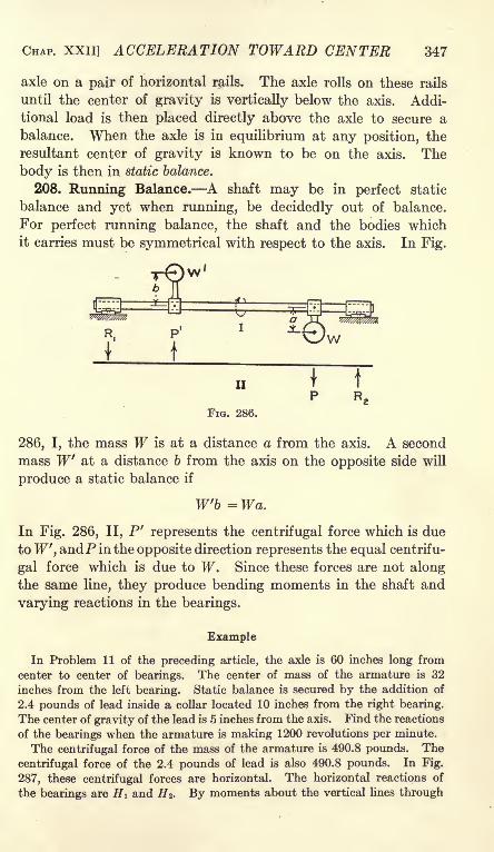
CHAP. XXII] ACCELERATION TOWARD CENTER 347
axle on a pair of horizontal rails. The axle rolls on these rails
until the center of gravity is vertically below the axis. Addi-
tional load is then placed directly above the axle to secure a
balance. When the axle is in equilibrium at any position, the
resultant center of gravity is known to be on the axis. The
body is then in static balance.
208. Running Balance. A shaft may be in perfect static
balance and yet when running, be decidedly out of balance.
For perfect running balance, the shaft and the bodies whichit carries must be symmetrical with respect to the axis. In Fig.
w/////$w//,
R.
i

348 MECHANICS [ART. 209
the bearings, HI is found to be 147.2 pounds in one direction and H 2 is
found to be an equal force in the opposite direction. When the center of
gravity is below the axis, the centrifugal force adds 147.2 pounds to the
60" "-
1490.8*-- 32-- >
490.8'C.
FIG. 287.
load on the left bearing and subtracts the same amount from the load on the
right bearing.
Problems
1. Find the reactions of the bearings of the above example when the
center of gravity of the armature is directly below the axis.
Ans. 334.3 lb.; 65.8 Ib.
2. Solve Problem 1 when the center of gravity of the armature is directly
above the axis of the shaft.
209. Ball Governor. In Fig. 288, AB is shaft which rotates
about a vertical axis, and C is a heavy ball connected to the
shaft by a rod. The rod is attached to the shaft at B by means
of a hinge which permits the rod and the ball C to rotate in a
vertical plane. As the vertical shaft rotates, the centrifugal
force in C develops a moment which
tends to lift BC toward a horizontal
position.
If 6 is the angle which BC makeswith the vertical, if I is the length of BCfrom the hinge to the center of gravity,
and if m is the combined mass of the ball
and the rod, the centrifugal force is
u ml sin 0co2
ti = (1)FIG. 288. Q
The moment arm of this horizontal centrifugal force about the
hinge at B is I cos 8 while the moment arm of the weight is I
sin 6. Equating the moment of the centrifugal force to the
moment of the weight,
cos e = ^ (3)

*u*'
-
^ ,
CHAP. XXII] ACCELERATION TOWARD CENTER 349
Problems
1. The length of a governor arm is 12 inches. At what speed will the
arm stand at 60 degrees with the vertical?
Ans. 8.02 radians per sec.; 76.6 rev. per min.
2. In Problem 1, what is the value of 6 when the speed is 50 revolutions
per minute? Ans. 6 = 0.
FIG. 289. FIG. 290.
3. Figure 289 shows several arms of different lengths which are attached
to the same hinge. Show that the center of gravity of each will fall on the
same horizontal line, provided the angular velocity is sufficient to make all
of them leave the vertical position.
4. In Problem 1, find the angle for angular velocities of 6, 7, 8, 9, and 10
radians per second. Ans. 26 40', 48 58', 59 49', 66 36', and 71 14'.
5. In Problem 1, find the angular velocity for
angles of 30, 40, 50, 60, and 70.'
Ans. 6.10, 6.48, 7.07, 8.02, and 9.70
radians per sec.
6. In Fig. 290, find the angular velocity for
angles of 30, 40, 50, 60, and 70.
Ans. 4.72, 5.26, 5.90, 6.82, and 8.33
radians per sec.
7. Figure 291 shows a crossed-arm governorsuch as is used on some chronographs. Find
the expression for the angular velocity in terms
of the angle 6, the length a, and the length I.
, g tanAns. or = -j^ ^
I sin a
If I in Fig. 291 is 12 inches and a is 4 inches,
find the value of the angular velocity for angles
of 45, 50, 60, and 70.Ans. 9.28, 9.41, 10.23, and
FIG. 291.
12.07 radians per sec.
The form of governor shown in Fig. 291 is extremely sensitive
when 6 is about 45 degrees. A change of angular velocity of

350 MECHANICS [ART. 210
less than 2 per cent causes a change in the angle from 45 to
50.210. Loaded Governor. Figure 292 shows a loaded governor.
In this figure, the length of the links which connect the load with
the arms is equal to the distance from the top of the arm to
the connection with the link. The link and the arm, therefore,
make equal angles with the vertical. The centrifugal force is
ml sin 0co2
H (1)
FIG. 292.
If Q is the tension in one link and W is the weight lifted by both
links,
WQ cos 6 = --
The horizontal component of Q is
WN = Q sin = tan 6.
(2)
(3)
Consider the right arm and the right link as a system in equi-
librium, and take moments about the top of the arm. The force
from the weight to the link may be resolved into a vertical
component downward and a horizontal component N directed
toward the left. The moment arm of the vertical component is
zero. The moment arm of the horizontal component is 2a cos 6.
Wml sin + 2 a tan 6 cos 6 =
m 2co
2
ml + TFa = -
ml sin 0co2
g
cos e.
I cos 6; (4)
(5)

CHAP. XXII] ACCELERATION TOWARD CENTER 351
Problems
1. In Fig. 292, the length Z is 20 inches and the length a is 12 inches.
The load W is 12 pounds and the weight of each arm is 10 pounds. Find
the speed when the arms make an angle of 45 degrees with the vertical.
Ans. 6.85 radians per sec.
2. What is the angular velocity required to lift the weight of Problem 1
a distance of 2 inches from the position at which the arms make an angle of
45 degrees with the horizontal? Ans. 7.30 radians per sec.
211. Flywheel Stresses. When a wheel is rotating, every partof its mass exerts a pull due to the centrifugal force. In calculat-
ing the stresses, the rim is often
considered separately and the
mass of the spokes is neglected.
The force on a rim is similar
to the force exerted on a cylin-
drical drum from the pressure of
confined liquid or gas. The cen-
trifugal force on an element of
rco2
mass of the rim is . The rimg
of Fig. 293 may be considered as
made up of circular hoops each
of which is 1 inch wide and t
inches thick. If w is the weightof a rod of the material 1 inch
square and 1 foot long, the cen- FlG 293
trifugal force per foot of the hoop
is . To find the total force on one half of the hoop which
tends to rupture it at the sections A and B, the forces on this
half are resolved normal to the diameter through A and B.
The sum of all the components is equal to a force of per
foot of length of the diameter.
AVTotal pull = n
2r =Q
(1)
This pull is resisted by the tensile strength of the material atA and
B. The total cross section is 2t. If St is the unit tensile stress,
2tSt = (2)
(3)
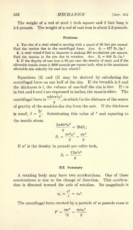
352 MECHANICS [ART. 212
The weight of a rod of steel 1 inch square and 1 foot long is
3.4 pounds. The weight of a rod of cast iron is about 3.2 pounds.
Problems
1. The rim of a steel wheel is moving with a speed of 80 feet per second.
Find the tension due to the centrifugal force. Ans. S t= 677 Ib. /in.
2
2. A steel wheel 6 feet in diameter is making 300 revolutions per minute.
Find the tension in the rim due to rotation. Ans. St= 939 lb./in.
2
3. If the density of cast iron is 90 per cent the density of steel, and if the
allowable tensile stress is 2000 pounds per square inch, what is the maximumallowable rim velocity for cast iron wheels?
Equations (2) and (3) may be derived by calculating the
centrifugal force on one half of the rim. If the breadth is b and
the thickness is t, the volume of one-half the rim is btirr. If r is
in feet and b and t are expressed in inches, the mass is wbtirr. The
centrifugal force is,in which r is the distance of the center
y
of gravity of the semicircular rim from the axis. If the thickness
rs small, r = . Substituting this value of r and equating to
the tensile stress.
= 2btS t',
o
g = wrV = wv 2
Q 9
'
If w' is the density in pounds per cubic inch,
212. Summary
A rotating body may have two accelerations. One of these
accelerations is due to the change of direction. This accelera-
tion is directed toward the axis of rotation. Its magnitude is
- = r,.,2
The centrifugal force exerted by a particle of m pounds mass is
ru
9
_ mv 2

CHAP. XXII] ACCELERATION TOWARD CENTER 353
The centrifugal force exerted by a body of some magnitude is
mv 2rarco
2
P = -=r- = Formula XXIXr 9 9
in whichr
is the distance of the center of gravity of the mass from
the axis of rotation and v is the linear velocity of the center of
gravity.
A rotating body is in static balance when the center of gravitycoincides with the axis of revolution. A body is in runningbalance when the center of gravity of every small portion between
two planes normal to the axis falls on the axis.
In a Watt or ball governor, the arms take positions of equilib-
rium under the action of the horizontal centrifugal force which
varies as the square of the angular velocity and as the distance
from the axis, and the constant vertical weights of the arms and
the additional loads.
Allowance must be made for stresses which are due to cen-
trifugal force in high speed machinery. Since centrifugal force
varies as the square of the angular velocity, a relatively small
increase of speed may become a source of danger.
23

CHAPTER XXIII
ANGULAR ACCELERATION
213. Angular Acceleration. The rate of change of angular
velocity is the angular acceleration.
a =
in which a is the angular acceleration. Angular acceleration is
expressed in radians per second per second. For small intervals
of time, the angular acceleration is
c&o d*6
Problems
1. A fly wheel is making 2 revolutions per second, after an interval of
4 seconds, it is making 5 revolutions per second. Find the angular accelera-
tion. By means of the average velocity, find the number of revolutions
during the 4-second interval.
Ans. a = 4.712 radians per sec. per sec.; 14 revolutions.
2. A point on the rim of a wheel 6 feet in diameter is moving with a
velocity of 60 feet per second. After 2 seconds, it is moving with a velocity
of 90 feet per second. Find the angular acceleration of the wheel.
Ans. 5 radians per sec. per sec.
3. A pencil held for O.-l second against the rim of a wheel which is 8 feet
in diameter makes a mark 18 inches long. Two seconds later the pencil is
held against the wheel for the same time and makes a mark 30 inches long.
Find the angular acceleration of the wheel.
Ans. a = 1.25 radians per sec. per sec.
214. Displacement with Constant Acceleration. The expres-
sions for angular velocity and displacement when the acceleration
is constant are similar, to those for linear displacement and
velocity when the linear acceleration is constant.
a) = co + at (1)
e = 0,0* +^ (2)
Equation (1) may be derived from the definition of acceleration.
354

CHAP. XXIII] ANGULAR ACCELERATION 355
Equation (2) may be derived by multiplying the average an-
gular velocity by the time. Both equations may be derived by
integration.
Problems
1. A wheel has an angular acceleration of 2 revolutions per second per
second. Its initial velocity is 3 revolutions per second. What will be its
velocity after 4 seconds? Ans. 11 revolutions per second.
2. How many revolutions will the wheel of Problem 1 make during the
interval of 4 seconds. Solve by means of the average velocity.
Ans. 26 revolutions.
3. A wheel is making 1600 revolutions per minute. After an interval of
20 seconds, it is making 600 revolutions per minute. Find its acceleration
in radians per second per second.
Ans. a = 5.24 radians per sec. per sec.
4. How many revolutions does the wheel of Problem 3 make during the
interval of 20 seconds? Ans. 367 rev.
215. Acceleration and Torque. In Fig. 294, a mass dmrotates about an axis at 0. The angular acceleration is a and
the distance of the element from the axis is r. The linear accelera-
tion of the element of mass is a = ra. Theforce which must be applied to produce this
linear acceleration is
dP = m-
(1)Q
The moment of this force with respect to the
axis through is
,m r 2adm a , /oxdT = - - = -r*dm. (2) FIG. 294.g g
The moment required to produce an angular acceleration in
a mass made up of elements dm is
T = -I r*dm = Formula XXX
g
The moment with respect to an axis of a rotating body is called
torque. Torque is represented algebraically by the letter T.
Formula XXX for angular acceleration is similar to Formula
XXII for linear acceleration. Force in Formula XXII is
replaced by moment of force, and mass (or inertia) is replaced bymoment of inertia.
If force is expressed in absolute units, Formula XXX becomes
T = la (3)
Equation (3) is sometimes given as the physical definition of
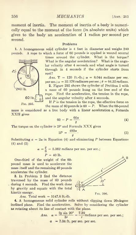
356 MECHANICS [ART. 215
moment of inertia. The moment of inertia of a body is numeri-
cally equal to the moment of the force (in absolute units) which
gives to the body an acceleration of 1 radian per second per
second.
Problems
1. A homogeneous solid cyUnder is 4 feet in diameter and weighs 240
pounds. A rope to which a force of 60 pounds is applied is wound several
times around the cylinder. What is the torque?What is the angular acceleration? What is the angu-lar velocity after 4 seconds and what angle is turned
through in 4 seconds if the cylinder starts from
rest?
Ans. T = 120 ft.-lb.; a = 8.044 radians per sec.
per sec. :o> = 32. 176 radiance per sec. ;0 = 64.35 radians.
2. Figure 295 shows the cylinder of Problem 1 with
a mass of 60 pounds hung on the free end of the
rope. Find the acceleration, the tension in the rope,
and the angular velocity after 4 seconds.
If P is the tension in the rope, the effective force on
the mass of 60 pounds is 60 P. When the 60-poundmass is considered as a free body with a linear acceleration a, Formula
XXII gives
60-P = a.(4)
340 I b,
60 Ib.I
FIG. 295.
The torque on the cylinder is 2P and Formula XXX gives
2p = 480(5)
.A B
Substituting a = 2a in Equation (4) and eliminating P between Equations
(4) and (5)
a =|= 5.362 radians per sec. per sec.;
P = 40 Ib.
One-third of the weight of the 60-
pound mass is used to accelerate the
mass itself and the remaining 40 poundsaccelerates the cylinder.
3. In Problem 2 find the distance
traversed by the mass of 60 pounds
during 4 seconds. Find the work done
by gravity and equate with the total
kinetic energy.
Ans. Total work = 5147.8 ft.-lb.
4. A homogeneous solid cylinder rolls without slipping down 20-degreeinclined plane. Find the acceleration. Solve by considering the cylinder
as rotating about its line of contact with the plane.
20 sin 20 7.39 ,.Ans. a =
^= radians per sec. per sec.;
tjT T
a = 7.34 ft. per sec. per sec.
30
FIG. 296.

CHAP. XXIII] ANGULAR ACCELERATION 357
6. A uniform bar AB, Fig. 296, 6 feet long and weighing 12 pounds, is
hinged at A. What is the angular acceleration when the bar is in the posi-
tion at which it makes an angle of 30 degrees with the horizontal?
Ans. a. = 3.483 radians per sec. per sec.
6. Solve Problem 5 for the horizontal position of the bar.
Ans. a = 8.044 radians per sec. per sec.
216. Equivalent Mass. Problem 2 of the preceding article
may be solved by first finding the mass which would have the
same velocity as the rope and the same moment of inertia as
the cylinder. If all the mass of the 'cylinder were concentrated
at the surface, it would move with the linear velocity of the rope.
The moment of inertia of a solid cylinder is
/ = ^-,
W/" /// // ,. ;
W| 120 ib/{/I
II
60 Ib,
FIG. 297.
ma mass
-^-, concentrated at the surface in the form of a veryA
thin hollow cylinder of radius r, has the same moment of inertia
as the actual solid cylinder of mass m. The problem of accelerat-
ing a solid cylinder of mass m by means of a rope to which a mass
m' is attached is equivalent to that of accelerating a thin hollow
cylinder of mass -^- The problem of accelerating a thin hollow&
cylinder is equivalent to the problem of Fig. 297, II. Themass of 240 pounds of Problem 2 of Art. 215 may be replaced
by a mass of 120 pounds on a horizontal plane as in Fig. 297, II
and the problem may be solved as a problem of linear accelera-
tion. Since the effective force on the system is 60 pounds and
the total equivalent mass is 180 pounds, it is evident that the
linear acceleration is gr/3 and that one-third of the force of 60
pounds is required to accelerate its own mass.
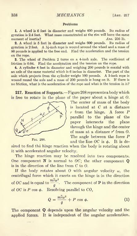
358 MECHANICS ~, [ART. 217
Problems
1. A wheel is 6 feet in diameter and weighs 400 pounds. Its radius of
gyration is 2.4 feet. What mass concentrated at the rim will have the same
moment of inertia? Ans. 256 1-b.
2. A wheel is 5 feet hi diameter and weighs 600 pounds. Its radius of
gyration is 2 feet. A J^-inch rope is wound around the wheel and a mass of
80 pounds is applied to the free end. Find the acceleration and the tension
on the rope.
3. The wheel of Problem 2 turns on a 4-inch axle. The coefficient of
friction is 0.04. Find the acceleration and the tension on the rope.
4. A cylinder 4 feet in diameter and weighing 200 pounds is coaxial with
an axle of the same material which is 6 inches in diameter. The part of the
axle which projects from the cylinder weighs 100 pounds. A 1-inch rope is
wound round the axle and a mass of 200 pounds is hung on it. If there is
no friction, what is the acceleration of the rope and what is the tension in it?
217. Reaction of Supports. Figure 298 represents a body which
is free to rotate in the plane of the paper about a hinge at 0.
The center of mass of the bodyis located at C at a distance
r from the hinge. A force Pparallel to the plane of the
paper intersects the plane
through the hinge and the center
of mass at a distance r' from 0.
The angle between the force Pand the line OC is 0. It is de-
sired to find the hinge reaction when the body is rotating about
it with accelerated angular velocity.
The hinge reaction may be resolved into two components.One component N is normal to OC; the other component Qis in the direction of the line from C to 0.
If the body rotates about with angular velocity ,the
centrifugal force which it exerts on the hinge is in the direction
of OC and is equal to- . The component of P in the direction
of OC is P cos (f>. Resolving parallel to CO,
The component Q depends upon the angular velocity and the
applied forces. It is independent of the angular acceleration,

CHAP. XXIII] ANGULAR ACCELERATION 359
If the center of mass at C has a linear acceleration a, the total
effective force on the body in the direction of this acceleration
(which is normal to the direction of OC) is . Since the lineary
acceleration is ra, in which a is the angular acceleration about the
hinge, this force is-
. Resolving along an axis in the plane of
the paper normal to OC.
Psin*-JV = ^; (2)y
N = P sin 4>- -^-
(3)y
In Equation (3) the positive direction of N is opposite the direc-
tion of the linear acceleration of the center of mass.
The torque about the hinge is Pr f
sin </>. From Formula XXX,the angular acceleration is
Tg Pr'g sin <
* a T ~T-
The force P may be resultant of several forces. If any of
the forces have components parallel to the axis of the hinge, these
components produce no torque about the hinge. The force Pis the resultant of all the components in planes which are normal
to the axis of the hinge.
Example
A uniform bar of length I and mass ra is hinged at one end. Find the
hinge reaction when the bar is horizontal.
The force which produces angular acceleration is the weight of m pounds
vertically downward at the center of mass which is at a distance of ^ from
the hinge. (In this example r = r' )
T - T -'2' 3
'
a=lf ;
I v 30 30a = ra =
2X
21= T
AT _ ma - _m 3g _ ma Q 4 4

360 MECHANICS [ART. 218
When the bar is horizontal, the vertical reaction is one-fourth the weight.
To find the horizontal component of the hinge reaction, it is necessary
to know the angular velocity. As an additional condition of the example,
it will be assumed that the bar was stationary in the vertical position and
fell to the horizontal position
of Fig. 299 with no loss of
~"*\ energy. Equating the worki of gravity to the kinetic
'
energy of rotation,
1::, ...1 u2 1
mml2
T~ II
FIG. 299.
The centrifugal force is
mlml?
3
ml 3m"2
"
The force on the hinge is to-
ward the center of mass of the
bar. The hinge reaction is hori-
zontal toward the left. Thedirection and magnitude of the
resultant hinge reaction are
shown in Fig. 299, II.
Problems
1. Solve the Example above
when the bar is 30 degrees
above the horizontal as shownin Fig. 300.
mA X"\ " **
Ans. Q =j-
m
FIG. 300.
? cos 30 = 0.2163m.
2. Find the reactions in Problem 1 of Art. 215 if the force of 60 pounds is
vertically downward. Ans. 300 Ib. vertically upward.3. Find the reactions of the supports for Problem 2 of Art. 215.
218. Reactions by Experiment. Figure 301 shows a method of
measuring the reaction of the bearings which support a cylinder.
The frame AB which supports the bearings is mounted on
knife-edges at O. The distance from the line of the knife-edges
to the axis of the cylinder is equal to the sum of the radius
of the cylinder and the radius of the cord which drives it. Theline of the resultant force in the cord intersects the line of the
knife-edges. If the cylinder is held so that it can not revolve on
its axis, a weight hung on the cord has no effect on the equilibriumof the frame. If the cylinder is free to rotate, there is an addi-

CHAP. XXIII] ANGULAR ACCELERATION 361
tional force at the axis equal to that part of the tension in the
cord which goes to produce acceleration. If there is friction
at the bearings, that part of the tension in the cord which is
required to overcome the friction has no effect on the balance.
A force P applied to the cylinder by the cord is transmitted to
the frame at the bearing. The moment of this force about the
knife-edge at a distance r from the axis is Pr in a counter-clock-
wise direction. If the cylinder is fixed to the frame, the force in
the cord exerts a torque Pr upon the frame at the bearing.
FIG. 301.
This torque is clockwise and exactly balances the moment of the
downward force. Expressed in another way, the moment armof the cord about the line of the knife-edge is zero. If the frame
and cylinder are not rigidly connected, that part of the force
which is required to overcome the friction may be regarded as
acting on a rigid body. The friction at the bearing exerts
a torque on the frame which is equal and opposite the momentof the corresponding downward force on the bearing.
To use the apparatus, the beam is balanced on the knife-
edges. The cylinder is fastened to the frame so that it can not
rotate and a load W is hung on the cord. If the knife-edges
are in the correct position, the balance is unchanged when this
load is applied. The cylinder is now released and is accelerated
by the load. The part of the weight W which accelerates the
cylinder is transmitted to the axis of the bearing. This addi-
tional force downward on the left arm of the frame lifts the right
arm. The poise p must now be moved toward the right to

362 MECHANICS [ART. 219
secure a running balance. If the acceleration of the cylinder is
measured and if the moment of inertia of the cylinder is known,the balance reading makes it possible to determine the value
of g. If g is known, the reading may be used to determine the
moment of inertia of the cylinder. The results obtained by this
apparatus require no correction for friction.
Example
A cylindrical drum with its axle weighs 8 pounds. Its diameter is a
little less than 6 inches. A cord is wound several times round the drum andfastened to it. The radius of the drum plus the radius of the cord is ex-
actly 3 inches. The drum is mounted on a frame similar to that of Fig. 301.
The frame is supported on knife-edges which are on a line 3 inches from the
axis of the axle. The poise p weighs 0.2 pound. When a mass of 1 poundis hung on the cord and the drum is released, the poise must be moved 0.96
foot toward the right to secure equilibrium. The pound mass moves 28.89
feet in 3 seconds after starting from rest. The value of g is known to be
32.16 feet per sec. per sec. at that locality. Find the moment of inertia of
the drum.
The acceleration of the cord is
2 X 28.89a = --;:
- = 6.42 ft. per sec. per sec.y
a = 25.68 radians per sec. per sec.
T = 0.2 X 0.96 = 0.192ft. Ib.
7 = ^ = 0.2404a
The force required to give an acceleration of 6.42 feet per second per second
to the 1-pound mass is
The force required to produce a torque of 0.192 foot-pound on an arm 3
inches in length is 0.192 -=- I = 0.768 Ib.
0.1996 + 0.768 = 0.9678 Ib.
The residue of 0.0322 Ib. is taken up by the friction.
219. The Reactions of a System. Figure 302 shows a frame
which carries two pulleys. The frame is supported by two
knife-edges. The line of these knife-edges passes through the
center line of the cord which drives the pulleys. The cord is
passed over pulley A and is wound round pulley B and fastened
to it. If the frame is in equilibrium with no load on the cord, it
is in equilibrium when the cord is loaded and pulley B is held bya brake or stop attached to the frame. The frame and the two
pulleys may be regarded as a single body in equilibrium. The

CHAP. XXIII] ANGULAR ACCELERATION 363
moment arm of a force applied by the cord is zero. The load
on the cord, therefore, makes no change in the balance.
The frame and pulley B may be regarded as a rigid body,and pulley A may be treated separately. The simplest form
of this apparatus is the one where the pulleys are of equal radii r.
FIG. 302.
If pulley A is frictionless, the pull in the horizontal cord is equalto the weight W. The moment of this pull on pulley B about
the knife-edges is equal to Wr. This moment is counter-clock-
wise. The resultant of the vertical pull W and the horizontal
pull W acting on pulley A is a force of 2W sin 45 through the
axis of the pulley. . The vertical component of this force is a
force of 2W sin 45 cos 45 or W pounds. The moment of this
vertical component about the line of the knife-edges is Wr foot-
pounds clockwise. The horizontal component has zero momentarm. The total moment is Wr Wr = 0.
The pulley B may now be released and allowed to accelerate.
The friction on either pulley has no effect on the equilibrium of
the frame, for, in so far as friction is concerned, trhe pulleys and
the frame may be regarded as a single rigid system.

364 MECHANICS [ART. 219
If P is the force required to accelerate pulley A, there is a
vertical force of P pounds downward from the pulley to the
bearing. This force produces a clockwise moment Pr about the
knife-edges, Fig. 303. If Q is the force which accelerates pulley
B}a horizontal force equal to Q may be regarded as transferred
from the top of pulley B to its axis, and the counter-clockwise
FIG. 304.
moment of the system is reduced by an amount Qr. The total
counter-clockwise moment is' reduced by an amount (P + Q)r
when the pulleys are released and allowed to accelerate. If the
two pulleys have equal moments of inertia, the force P is equal to
the force Q and the total change in moment is 2Pr. To secure
equilibrium, the poise p must be moved toward the left.
In Fig. 304, the cord passes around pulley B in the counter-
clockwise direction. When this pulley is accelerated, the force
Q which produces the acceleration
may be regarded as shifted from
the tangent to the axis. The
change of moment is Qr. Theclockwise moment on the systemis reduced by the amount Qr.
When the moment of inertia is
the same for both pulleys, the
counter-clockwise change in mo-ment which is due to the ac-
celeration of pulley B exactlybalances the clockwise change which is due to the acceleration
of pulley A. There is, therefore, no change of the balance of
the frame, when the pulleys are of equal radius and equalmoment of inertia, and rotate in opposite directions.
The discussion of the preceding paragraph may be stated in
FIG. 305.

CHAP. XXIII] ANGULAR ACCELERATION 365
another way. In Fig. 305, the pulley A may be considered
separately. The distance between the axes of the pulleys is
d and the angle between the cord which joins the pulleys and
the line which joins the axes is 6. When pulley B is accelerated
by an effective force Q, the counter-clockwise moment about the
knife-edge is Q sin 0(d + T). Since sin 6 =-p
(1)
The resultant of two forces Q acting tangent to pulley A at an
angle with each other is
R = 2Q cos |. (2)z
This resultant passes through the axis of pulley A. Its vertical
component is
V = 2Qcos2
1= Q(l + cos 4>)
= Q(l + sin 0)=Q(I +
) (3)
The moment of this vertical force with respect to the knife-edgeis
M = Qr + ^. (4)
The total moment is the sum of the counter-clockwise momentof Equation (1) and the clockwise moment of Equation (4).
M. = Qr (5)
in the counter-clockwise direction. Equation (5) states that
the change of moment on the frame when pulley B is accelerated
is equal to the moment of the force which causes the acceleration.
Figure 306 shows the author's modification of the Atwoodmachine. A frame supported by knife-edges carries two equal
pulleys. A cord which carries a mass m runs over pulley Band under pulley A. From pulley A the cord runs upward to
a third pulley C which is carried on a separate support. Thecenter line of this vertical cord intersects the line of the knife-
edges which carry the frame. A mass W, which is larger than
m is hung on the part of the cord which is suspended from C.
(In Fig. 306 a fourth pulley D is shown, for clearness. A single
pulley C is sufficient if placed with its axis parallel to the frame.

366 MECHANICS [ART. 220
A brake (not shown in the drawing) holds pulley C stationary
while the poise is adjusted to balance. When the brake is
released, the mass m is accelerated upward. The additional
force on the cord which supports the mass m is
p =Q
(6)
This additional force is balanced by moving the poise p toward
the left. A few trials are required to find the position of running
equilibrium.
FIG. 306.
If I is the moment arm of the mass m, p is the mass of the
poise, and b is the distance the poise is moved to secure equi-
librium of the frame,
ma
Q(7)
This apparatus is free from any correction for friction or the
mass of the pulleys. To avoid any correction for the weightof the cord, it should be continuous from W to m. The mass
m includes the mass of cord above and below it.
220. Summary. Angular acceleration bears the same rela-
tion to linear acceleration that angular velocity bears to linear
velocity.
_ do> _ (P81~
dt'"
dt2'Angular acceleration

CHAP. XXIII] ANGULAR ACCELERATION 367
Angular acceleration is proportional to the torque and
inversely proportional to the moment of inertia of the body.
Moment of inertia X angular accelerationTorque
9
T = Formula XXX9
When the foot is the unit of length in the computation of torqueand moment of inertia, the value of g is 32.174.
The component of the reaction at the axis in the direction
normal to the plane through the axis and the center of mass is
maN = P cos 6 ,
9
in which P cos 6 is the component of the applied force normal
to the plane through the axis and the center of mass, m is the
mass, and a is the linear acceleration of the center of mass.
The component N is positive in the direction opposite the direc-
tion of the linear acceleration of the center of mass. The linear
acceleration a is given by the equation
a =ra,
in which r is the distance of the center of mass from the axis of
rotation.
The component of the reaction along the line, perpendicularto the axis, which joins the center of mass with the axis of rotation
is equal to the component of the applied forces in this direction
combined with the centrifugal force. If the axis of rotation
passes through the center of mass, the centrifugal force is zero
and the linear acceleration of the center of mass is zero; the
reaction of the axis is equal and opposite to the applied force.
In the calculation of the acceleration of a rotating body,the actual mass may be replaced by an equivalent mass in the
line of action of the applied force. If r' is the perpendiculardistance from the axis to the line of action of the applied force,
7 is the moment of inertia of the body, and m' is the equivalent
mass,
7 = m'r' 2;
7'2
By means of the equivalent mass, a problem of angular accelera-
tion may be reduced to a problem of linear acceleration. The
angular velocity and acceleration may finally be computedfrom the linear acceleration and velocity by dividing by r'.

CHAPTER XXIV
ANGULAR VIBRATION
221. Work of Torque. When a force is applied to an arm of
length r, the work done by the force when the arm turns throughan angle 6 is
U =Pr6, (1)
in which P is the component of the force normal to the plane
through its point of application and the
axis of rotation. Since the product P X r
is the torque, Equation (1) is equivalent to
u = Te. (2)
Equation (2) states that the work of a
constant force is equal to the product of
the torque multiplied by the angular dis-
placement. The work per revolution is
U = 2vT. (3)
When the torque varies,
U =fTde (4)
When an elastic rod, or a spiral or helical spring is twisted,
the torque is proportional to the angular displacement. If Kis the torque when the angular twist is one radian, the expression
for the torque when the angle is 6 radians is
T = KB. (5)
u =Kfede
=![*']
- fM -of). (6)
When the initial angular displacement is zero
(7)
Problems
1. A force of 20 pounds at the end of an arm 4 feet in length ft fists a
steel rod through an angle of 90 degrees. If there is no initial torque, find
the work, Solve by means of the average torque.
Ans. U - ?2+_? x 5- 62.832 ft, lb.
_ &

CHAP. XXIV] ANGULAR VIBRATION 369
2. A wheel is driven by a constant torque. Find the work per revolution.
Ans. U = 2irT.
3. A drum 16 inches in diameter is driven by a rope which is woundround it. The rope is inch in diameter and exerts a pull of 300 pounds.Find the work per revolution.
Ans. U = 1295.9 ft. Ib.
222. Angular Velocity from Variable Torque. When the
torque is constant, the angular velocity is easily obtained first
by finding the angular acceleration and then by multiplying bythe time. When the torque is variable, the angular velocity at
any given position is easiest found by means of the kinetic energyof rotation.
The most important problem is that in which the torquevaries as the angular displacement. If a body on an elastic
rod or spring is twisted through an angle |8 from the position ofJff)2
equilibrium, the work done is ~ This work is stored up asm
elastic energy. If the body is released and permitted to rotate
back to the position at which its displacement from the position
of equilibrium is 6, the change in elastic energy is the first memberof the equation
KP K6 2 7o> 2
-~ - = Formula XXXI
The second member of Formula XXXI is the kinetic energy of
rotation. The formula states that the change of potential en-
ergy is equal to the kinetic energy, or that the sum of the potential
energy and the kinetic energy is constant. The angle is
the amplitude of the vibration in angular measure.
Formula XXXI reduces to
"=-?2.
(i)
The maximum angular velocity is
(2)
Problems
1. A homogeneous solid cylinder 1 foot in diameter and weighing 20
pounds is suspended with its axis vertical by means of a |-inch steel rod 10
24

370 MECHANICS [ART. 223
feet in length, Fig. 308. A force of 3 pounds at the end of an arm 1 foot
long is capable of twisting this rod through one radian. The cylinder is
FIG. 308.
rotated through an angle of 180 degrees and then released. Find its maxi-
mum angular velocity.
Ans. w 2 = ^-', w = 19.52 radians per sec.A.O
2. In problem 1, what is the maximum angular velocity if the initial
displacement is 90 degrees from the position of equilibrium?
223. Time of Vibration. FormulaXXXIfor the angular velocity is similar to For-
mula XXVI for the linear velocity caused bya force which varies as the displacement.
In Formula XXXI, angular velocity and
angular displacement take the place of
linear velocity and displacement, and
_ ^ moment of inertia replaces mass.a t> c ct if ne circular motion of a point on a
body which moves with the angular velocity
of Formula XXXI is developed into linear motion, as shown
in Fig. 309, this developed motion is simple harmonic. If a
sheet of paper is placed on a cylinder which has this motion,

CHAP. XXIV] ANGULAR VIBRATION 371
and a pencil is moved with uniform speed parallel to its length,the pencil mark is the sine curve shown in Fig. 310.
Since the angular motion of a body subjected to torque whichvaries as the angular displacement is a simple harmonic motion,it may be studied by means of a circle of reference. The radius
of this circle of reference is the angular amplitude /3 expressedin radians, Fig. 311. A point may be con-
sidered as moving in the circumference of
this circle with a linear velocity which is
equal to the maximum angular velocity of the
vibrating mass. The time of a complete period
FIG. 311.
is the time required for this point to make one complete revolu-
tion around the circle of reference. The angular velocity at anyinstant is the component along the diameter of the circle of
this maximum velocity in its circumference.
Problems
1. Find the time of a complete oscillation of the cylinder of Problem 1
of Art. 222.
Ans. tc= = 2ir\~ = 1.01 sec.
CO \ 30
2. Find the time of a complete oscillation for Problem 2 of Art. 222.
3. Express in terms of 7 and K the time of a complete oscillation caused
by a torque which varies as the displacement. Compare the result with
Equation (10) of Art. 185.
Formula XXXIIAns. tc= 2ir\
4. A cylindrical disk 6 inches in diameter is suspended with its axis vertical
by means of a vertical wire. The disk makes 100 complete oscillations in
96 seconds. Two wires, each 0.04 inch in diameter, are fastened to the
cylinder and extend horizontally to smooth pulleys, as shown in Fig. 308.

372 MECHANICS [ART. 223
When a mass of 1 pound is hung on each wire, the cylinder is found to
rotate 12 degrees. Find the moment of inertia of the cylinder.
2 X 3.02 K = 3.02 7T
15
tc=
4?r
15.10,
27T
pound
B, 12 of/am
FIG. 312.
Log / = 0.25649, 7 = 1.805
and foot units.
6. The small cylinder .4 of Fig. 312 sus-
pended by a wire is found to make 1000
complete torsional vibrations in 240
seconds. A bronze disk B, 12 inches
outside diameter, 1 inch inside diameter,and weighing 32.04 pounds is hung on the
small cylinder. The time of 1000 completevibrations is now 2500 seconds. Find the
moment of inertia of the small cylinder.
Ans. I of disk = 16.02 X
0.0576
1454.0329;
0.24 2
2.5 2
6.25 - 0.0576
576 '
/o + .
; Log /o = 2.57417; / = 0.0375.
6. Two wires, each 0.06 inch in diameter are attached to the disk of
Problem 5 and passed over smooth pulleys. When a 1-pound mass is hungon each wire, the disk is twisted through an angle of 45 50'. Find g.
I*"
TFront View
FIG. 313.
End View
7. The frame of Fig. 313 is supported by a vertical wire at the center of
the vertical cylinder A. Each of the cylinders B and C weighs 3 poundsand has its center of gravity 2 inches from the end nearest to cylinder A.
When the inner ends of B and C are 0.250 inch from the vertical axis, the
time of vibration of the system is 0.428 second. When cylinders B and C

CHAP. XXIV] ANGULAR VIBRATION 373
are moved out till their ends are 10 inches from the vertical axis, the time
of vibration is 1.126 second. Find the effective moment of inertia of the
system with the cylinders in the first position.
Ans. 1 2- 1 1
= 5.7891; 7 2= 6.7667; A = 0.9776,
in which 7 2 is the moment of inertia at the second position and I\ is the
moment of inertia at the first position.
8. A torque of 3.436 foot pounds twists the system of Problem 7 throughan angle of 30 degrees. Find g.
The method of Problems 5 and 6 may be used to determine the value
of g at any locality. The mass of the cylinder may be determined byaccurate weighing. It is not necessary that standard weights be used in
this weighing. It is necessary, however, that the weights used in weighingthe disk and those used in determining the torque be expressed in terms of
the same unit. This method assumes that the material of the disk is
homogeneous throughout.The method of Problems 7 and 8 does not require that the cylinders B
and C should be homogeneous. The method, however, does require that
the location of their centers of gravity be experimentally determined.
224. The Gravity Pendulum. A body which is free to rotate
through a small angle about a horizontal axis under the action
of its weight is called a pendulum. The axis
of Fig. 314 about which it rotates is called the
axis of suspension. If m is the mass of the
pendulum and f is the distance of its center of
mass below the axis of suspension, the torquewhich is due to its weight.when the pendulumis displaced through an angle 6 from the position
of equilibrium is given by the equation
T = mr sin0 (1)
If is small, its sine is practically equal to its
arc in radian measure. For a small angle,
Equation (1) becomes
T = mrB. (2)
FIG. 314.
When the angular displacement is small, the torque is propor-
tional to the displacement and Formula XXXII applies to the
motion of the pendulum. The value of K for a pendulum
vibrating through a small arc is K = mr, and Formula XXXII
becomes,
(3)mrg

374 MECHANICS [ART. 225
Problems
1. A uniform bar of length I vibrates as a pendulum about an axis per-
pendicular to its length through one end. Find the time of a complete
period.
2. Solve Problem 1 for a length of 4 feet.
AnS. t c= 27T\ TT-
Ans. tc= 1.809 sec.
3. A flywheel is 4 feet in diameter,
weighs 200 pounds, and has its center
of mass at its axis. The flywheel vi-
brates as a pendulum about a knife
edge under the rim at a distance of 23
inches from the axis (Fig. 315). Thewheel makes 100 complete vibrations in
196 seconds. Find its moment of inertia
with respect to the knife edge and its
moment of inertia with respect to its axis.
Ans. I = 1200.2; 7 = 465.5.
225. Simple Pendulum. Theideal simple pendulum consists of
a small body suspended by a
weightless cord. The dimensions
of the body must be so small that all parts are at the same dis-
tance from the axis of suspension. If m is the mass of the bodyand I is its distance from the axis of suspension,
r = l;I = ml2,
and Equation (3) of the preceding article becomes
FIG. 315.
Problems
1. Find the length of the simple pendulum which makes a single oscilla-
tion in one second at a place where g = 32.174 ft.
Ans. I = 39.12 in.
2. Find the value of g at a place where the "second pendulum" is 39.00
inches in length.
In the ordinary physical pendulum,
= m(r2
-f- kl), (2)
in which k is the radius of gyration with respect to the axis
parallel to the axis of suspension which passes through the center

CHAP. XXIV] ANGULAR VIBRATION 375
of mass. The expression for the time of a complete period is
*"*Ir+ T . (3)VT
/CoThe term r.+ -=^ in Equation (3) is a length and corresponds
with I of Equation (1). This term is called the length of the
equivalent simple pendulum. It will be represented by /'.
rf + y- (4)
If k is small compared with r}then Z' approaches r, and the
pendulum is approximately a simple pendulum.
Problem
3. A sphere 0.4 inch in diameter is suspended by a cord of negligible
weight. The center of the sphere is 40 inches from the point of suspensionof the cord. What is the length of the equivalent simple pendulum? Whatis the relative error in the time of vibration if the radius of gyration of the
sphere is neglected?Ana. I' = 40.004 in.; error 1 part in 20,000.
226. Axis of Oscillation. The axis of oscillation of a physical
pendulum is a line parallel to the axis of suspension at a distance
from the axis of suspension equal to the length of the equivalent
simple pendulum. The axis of oscillation lies in the plane which
passes through the axis of suspension and the center of mass of
the pendulum. A particle at the axis of oscillation is neither
accelerated nor retarded by the motion of the pendulum as a
whole. A particle below the axis of oscillation is forced to vibrate
faster than it would if it were suspended by a weightless cord and
moved as a simple pendulum. A particle above the axis of oscil-
lation moves slower than it would if it were moving alone.
If V is the distance between the axis of suspension and the
axis of oscillation,
r r
Problems
1. A bar of uniform section and density vibrates about an axis which is
perpendicular to its length and passes through one end. Find the distance
between the axis of suspension and the axis of oscillation.
Ans. I' =

376 MECHANICS [ART. 227
2. A uniform bar of length I vibrates as a pendulum about an axis per-
pendicular to its length at a distance of one-third its length from one end.
Find the length of the equivalent simple pendulum.2Z
Ans. I
o
3. Find the length of the simple pendulum equivalent to a uniform bar
of length I which vibrates about an axis of suspension at one-fourth the
length from one end. Solve also when the axis of suspension is three-
eighths the length from one end.
Ans ? - 7l. v -19J
12 J ' '24
'
4. What is the position of the axis of suspension of a uniform bar which
gives the minimum time of vibration? What is the length of the equivalent
simple pendulum?
Ans. r = -4=-; V =-7=-
=-577 L
Vl2 V3
227. Exchange of Axes. If the axis of oscillation of a pendu-lum is made the axis of suspension, the former axis of suspen-
sion becomes the axis of oscillation. When the original axis
of suspension is at a distance r from the center of gravity of the
pendulum, the length of the equivalent simple pendulum is
^2I' - r + =?- (1)
The distance from the center of gravity to the axis of oscilla-
fc2
tion is -^- When the axis of oscillation becomes the axis ofr
k 2
suspension, -= is the distance from the new axis of suspension tor
the center of gravity. If I" is the length of the equivalent simple
pendulum when the axis of oscillation is made the axis of sus-
pension,
fr2 ^2 JL2
I" -=? + * 3 + r, (2)r 2 r
r
I" = V. (3)
The principle of Equation (3) is employed in the determination
of g. A pendulum is provided with a pair of knife-edges parallel
to each other at approximately the correct distance for one

CHAP. XXIV] ANGULAR VIBRATION 377
knife-edge to be the axis of suspension and the other the axis of
oscillation. A small body, b of Fig. 316, is arranged to slide
along the pendulum. This body is adjusted till the time of
vibration is the same when either axis is used as the axis of
suspension. The time of vibration and the distance
between the knife-edges afford the necessary data for
the determination of g by substitution in the equa-tion of vibration of the simple pendulum.
Instead of one adjustment weight, two equal
weights may be employed. These may be moved
equal distances in opposite directions at each adjust-ment. When the adjustment is made in this way, r
is not changed, the variation of time of vibration
follows a simpler law, and correct position is easier to
find.
The determination of g by this method involves only measure-
ments of time and length, and is independent of mass and density.
228. Summary. When the torque varies as the angular
displacement, the work is given by
V -f (S\
-9J),
in which K is the torque when the displacement from the posi-
tion of zero torque is one radian, and 6\ and 62 are angular dis-
placements from the position of equilibrium. When the initial
displacement is zero and the final displacement is radians,
TJ - K6*
~2~
The equation which connects the work of torque and the kinetic
energy is
7co2
_,,= -} Formula
Z Z Zg
in which /? is the angular displacement when the velocity is zero,
and co is the angular velocity when the displacement is 6. When6 is zero
If angular displacement is plotted on a straight line, the
motion of a body subjected to torque which varies as the dis-

378 MECHANICS [ART. 228
placement is a simple harmonic motion. The time of a single
oscillation is
The time of a complete period is
Formula XXXII
In a gravity pendulum the torque is
T = mr sin 0.
When the angle is small, sin 6 reduces to 6 and
T = mr0.
With a small amplitude of vibration the torque on a gravity
pendulum varies as the displacement and Formula XXXIapplies. The constant K is equal to mr, and the time of a
complete period is
t c= 2ir
The term r + ~= is the length of the equivalent simple pen-
dulum. The length of the equivalent simple pendulum is the
distance between the axis- of suspension and the axis of oscillation.
The axis of suspension and the axis of oscillation are inter-
changeable. If the time of vibration is found for a given axis
of suspension and the pendulum is then reversed and suspendedfrom the axis of oscillation, the time of vibration for the two
positions is found to be identical.

CHAPTER XXV
MOMENTUM AND IMPULSE
229. Momentum. The product of the mass of a body multi-
plied by its velocity is called its momentum.
Momentum = mv. (1)
Since velocity is a vector quantity and mass is a scalar quan-
tity, their product is a vector. Momentum has direction as well
as magnitude.
Problems
1. What is the total momentum of 40 pounds moving east 50 feet persecond and 20 pounds moving west 60 feet per second?
Ans. Momentum = 800 in foot and pound units.
2. What is the total momentum of 20 pounds moving north 30 feet persecond and 40 pounds moving east 20 feet per second?
An s . Momentum = 1000 units north 53 08' east.
230. Impulse. The rate of change of momentum when the
velocity changes isra-^
which is equal to ma.
dvm-r-
-^ ma dt ,.,,.Force = =-> (1)9 9
Pdt =; (2)
; (3)
fJPdt = -(v2
-Vl). (4)
The termJ.Pdt is called the impulse of the force. When the
force is constant during an interval of time t, the impulse is
Pt. Equation (4) shows that the change of momentum is
proportional to the impulse. When the pound force is used as
the unit of force and the pound mass is used as the unit of mass,
the impulse is the change in momentum divided by 32.174.
In terms of the absolute units, the change of momentum is
numerically equal to the impulse.379

380 MECHANICS [ART. 231
When an impulse is given by a blow, as when an object is
struck by a hammer, the force is large and the time is very short.
Such an impulse is frequently called an instantaneous impulse.
Sudden impulse is a better name. Suppose that a ball movingwith a velocity of 100 feet per second strikes a wall and bounds
back with a velocity of nearly 100 feet per second. Suppose that
the compression of the ball amounts to 0.5 inch. If the force
were uniform during the time of contact, the average velocity
would be 50 feet per second while the ball is coming to rest.
The time required to bring the ball to rest would be
- = second.
The entire time of contact would be about -$$-$ second. If
the pressure varies as the displacement, instead of being uniform,
the motion during contact is simple harmonic. The time re-
quired to complete a semicircle of \ inch radius at a speed of
100 feet per second is?>TQQ
= 0.0013 second. When a hammer
strikes an anvil, the deformation is much smaller and the time of
contact is less. In general, the duration of a so-called instanta-
neous impulse is a few ten-thousandths of a second.
It is sometimes stated that an instantaneous impulse is com-
pleted before the body which is struck starts to move. This
statement is incorrect. The full velocity is attained at the
end of the impulse. The time, however, is so short that the
actual displacement is small. In the case of a galvanometer
needle, which is actuated by the discharge of a condenser, the
needle has attained its maximum velocity at the time when the
current becomes negligible. The deflection, on the other hand,
is so small that the moment arm of the impulse is practically
constant throughout the entire impulse.
231. Action and Reaction. When force acts on a body, the
force must come from some other body. Since, as stated byNewton's Third Law, action and reaction are equal, the force
exerted by the second body on the first body is equal and opposite
the force exerted by the first body on the second body. Since
the forces are equal, the impulses are equal, and, conse-
quently, the change of momentum of one body is equal and oppo-
site the change of momentum of the other.
In Fig. 317, A and B are two bodies. Suppose that A exerts
a force on B by means of a spring which forms a part of A . The

CHAP. XXV] MOMENTUM AND IMPULSE 381
change of momentum of A toward the left is equal and opposite
the change of momentum of B toward the right. Suppose that
A with the attached spring weighs 5 pounds and B weighs 4
pounds, and suppose that both are stationary. When the
spring is released, suppose that B receives a velocity of 10 feet
per second toward the right. Its change of momentum is 40.
At the same time, A receives a velocity of 8 feet per second
toward the left. Its change of momentumis ~40. The total change of momentumof the two bodies considered as a single
system is zero. It is impossible to changethe total momentum of two bodies by FIG. 317.
means of any force exerted between them.
Any change in the momentum of a body is at the expense of
an equal and opposite change in the momentum of some other
body or bodies. When a man jumps upward into the air, he
kicks the earth in the opposite direction with equal momentum.While he is in the air, the attraction of gravity draws him towardthe earth and, likewise, draws the earth toward him. Con-sidered as one body, the center of gravity of the earth and the
man moves on unchanged.If mi is the mass of one body and v\ is its velocity, ra2 is the
mass of a second body and v% is its velocity, and if a force acts
between the bodies which changes the velocity of mi from v\
to v( and changes the velocity of ra2 from vz to v'z ,
+ m2v 2=
miv'i + m^. (1)
Example
A mass of 20 pounds moving east 30 feet per second overtakes a mass of
12 pounds moving east 12 feet per second. After collision, the bodies move
together with the same velocity. Find that velocity.
The total momentum east is
20 X 30 = 600
12 X 10 = 120
720
tf*The total Hf&ss is 32 pounds. If v is the final velocity,
32v = 720
v = 22.5 ft. per sec. east.

382 MECHANICS [ART. 232
Problems
1. A man weighing 150 pounds jumps horizontally with a speed of 10 feet
per second from a boat weighing 200 pounds. If the boat was initially at
rest and if the friction of the water is neglected, with what velocity does the
boat move in the opposite direction?
Ans. 7.5 ft. per sec.
2. A man weighing 150 pounds can jump with a horizontal velocity of 15
feet per second with reference to a fixed point. With what speed relative
to the earth can he jump from a boat which weighs 100 pounds and what is
the velocity of the boat?
Ans. 6 ft. per sec.; 9 ft. per sec.
3. A shot weighing 10 pounds is fired from a gun weighing 800 pounds.The velocity of the shot relative to the earth is 1200 feet per second. Find
the velocity of the gun's recoil. Find the kinetic energy of the shot and of
the gun.Ans. v = 15 ft. per sec.; kinetic energy of shot = 223,780 ft. lb., kinetic
energy of gun = 2797 ft. lb.
4. When a shot is fired from a gun, show that the kinetic energy of the
shot is to the kinetic energy of the gun as the weight of the gun is to the
weight of the shot.
5. A 4-pound mass moving east 60 feet per second meets a 5-pound mass
moving west 20 feet per second. After collision, the 5-pound mass moveseast 20 feet per second. By means of the total momentum find the velocity
of the 4-pound mass.
Ans. v = 10 ft. per sec. east.
6. If the 5-pound mass of Problem 5 moves east 40 feet per second after
collision, what is the velocity of the 4-pound mass? .
Ans. v = 15 ft. per sec. west.
7. The bodies of Problem 5 collide obliquely. After collision the 5-poundmass moves northeast with a velocity of 30 feet per second. What is the
velocity of the 4-pound mass?Ans. The 4-pound mass has a velocity component east of 10.97 ft. per
sec. and a component south of 26.51 ft. per sec.
232. Collision of Inelastic Bodies. When inelastic bodies
collide, -they remain together after collision and move with
the same velocity. If mi and m% are the masses, v\ and v^ are
their respective velocities before collision, and v is their common
velocity after collision, the momentum equation is
miVi + m 2vz = (mi + m^v. (1)
When inelastic bodies collide, there is a loss of kinetic energy.
[6 of the kinetic energy is transformed into heat energy.
Problems
1. A mass of 20 pounds moving east with a velocity of 40 feet per second
overtakes a mass of 30 pounds moving east with a velocity of 10 feet persecond. After collision the bodies move together. Find their commonvelocity. Ans. v = 22 ft. per sec.

CHAP. XXV] MOMENTUM AND IMPULSE 383
2. In Problem 1, what part of the kinetic energy is lost?
Ans. 41 per cent.
3. A mass of 20 pounds moving east with a velocity of 40 feet per second
meets a mass of 30 pounds moving west with a velocity of 10 feet per second.
Find the velocity after collision and the kinetic energy lost.
Ans. 10 ft. per sec.; 87.8 per cent.
4. A gun is hung in a horizontal position
on a vertical support which is hinged at the
top as shown in Fig 318. The gun and
support weigh 800 pounds and their center
of gravity is 12 feet below the hinge. Whena 10-pound shot is fired from the gun, the
reaction swings the support through an arc
of 45 degrees. Find the velocity of the shot.
Ans. v = 1203 ft. per sec.
5. A soft wood block weighing 5 poundsis suspended by vertical cords 5 feet in
length. A bullet weighing 0.02 pound isjpIG 318
fired horizontally into the block and re-
mains imbedded in it. The block swings through a vertical angle of 35
Find the velocity of the bullet.
II
233. Collision of Elastic Bodies. When two elastic bodies
collide, both bodies suffer a change of form. Their centers of
mass continue to approach each other
for a little time and both bodies are
compressed at the surface of contact.
If one of the bodies is fixed so as to be
practically stationary, the other bodywill come to rest and then rebound.
If both bodies are free to move, there
comes a time when each is stationary
relative to the other, and both are
moving with the same velocity relative
to the earth. Fig. 319 represents three
stages of the collision of two bodies.
In Fig. 319, I, the bodies are movingtoward each other at the beginning of
contact. In Fig. 319, II, the centers
Oi and 0% are nearest to each other.
The bodies are stationary relative to
each other and are moving with a velocity v relative to the
earth. It is assumed that the momentum of m\ is the greater;the common velocity is, therefore, toward the right. The interval
from the beginning of collision to the condition of Fig. 319,
FIG. 319.

384 MECHANICS [ART. 234
II, is called the compression stage of the collision. The common
velocity v at the end of the compression stage is found in the
same way as if the bodies were inelastic.
After the bodies have reached the end of the compression
stage, their elasticity causes them to separate. The interval
from the end of the compression stage to the time when the
bodies cease to be in contact with each other is called the restitu-
tion stage. Fig. 319, III, shows the bodies at the end of the
restitution stage.
If the bodies are perfectly elastic, the impulse during resti-
tution is equal to the impulse during compression and the changeof momentum of each body during restitution is equal to the
change during compression. With imperfectly elastic bodies
the change of momentum during restitution is less than the
change during compression. The ratio of the impulse duringrestitution to the impulse during compression is called the
coefficient of restitution. When the bodies are perfectly elastic,
the coefficient of restitution is unity. The coefficient of restitu-
tion is expressed by the letter e.
Problems
1. A body is thrown against a fixed
wall with a speed of 60 feet per second
and rebounds with a speed of 45 feet
per second. Find the coefficient of
restitution. Ans. e = 0.75.
2. A ball is dropped 4 feet upona horizontal surface and rebounds 3
feet. Find the coefficient of restitution.
Ans. e = 0.866.
3. A body is dropped 10 feet to a
horizontal surface. If the coefficient
of restitution is 0.8, how high will it
rebound?
II
III
The behavior of a pair of""
elastic bodies during collision is
best studied by a numerical
example rather than by the use
of literal formulas. Fig. 320, I,
represents a mass of 25 pounds
moving east with a velocity of 40
feet per second, which is overtaking a mass of 15 pounds movingeast with a velocity of 20 feet per second. Fig. 320, II, shows
the two bodies at the end of the compression stage. It may
FIG. 320.

CHAP. XXV] MOMENTUM AND IMPULSE 385
be assumed that the bodies are photographed and that the
plate is shifted vertically between exposures. The initial
momentum is
25 X 40 + 15 X 20 = 1300.
v = 32.5 feet per second.
As a condition of the problem, it will be assumed that the
coefficient of restitution is 0.8. The change of velocity of the
25-pound mass during compression is 32.5 40 = 7.5 feet
per second. The change of velocity of this mass during restitu-
tion is 0.8 ( 7.5)= 6 feet per second. The final velocity
of the 25-pound mass is
v = 32.5 6 = 26.5 feet per second east.
The change of velocity of the 15-pound mass during compressionis 12-.5 feet per second. Its change during restitution is 10 feet
per second. The final velocity of the 15-pound mass is
v = 32.5 H- 10 = 42.5 feet per second east.
The results may be checked by means of the final momentum;
25 X 26.5 = 662.5
15 X 42.5 = 637.5
Total momentum = 1300.
Problems
1. A mass of 40 pounds moving east with a velocity of 30 feet per second
meets a mass of 20 pounds moving west with a velocity of 45 feet per second.
The coefficient of restitution is 0.6. What is the velocity of each body after
collision? Ans. 10 ft. per sec. west; 35 ft. per sec. east.
2. A mass of 20 pounds moving east 40 feet per second meets a mass of
5 pounds moving west 50 feet per second. After collision, the 20-pound massmoves east 8.5 feet per second. By equating the momenta, find the velocity
of the 5-pound mass after collision. Ans. v = 76 ft. per sec. east.
3. In Problem 2, what is the common velocity at the end of the compres-sion stage and what is the coefficient of restitution?
Ans. v = 22 ft. per sec. east; e = 0.75.
4. A mass of 15 pounds moving east 60 feet per second overtakes a
mass of 10 pounds moving east 20 feet per second. After collision, the
mass of 10 pounds moves east 65.6 feet per second. Find the final velocity
of the mass of 15 pounds and find the coefficient of restitution.
6. A baseball moving 100 feet per second is struck by a bat moving 60
feet per second in the opposite direction. If the bat weighs 6 times as muchas the ball, and the coefficient of restitution is 0.9, with what velocity will
the ball leave the bat? Ans. 133.6 ft. per sec.
25

386 MECHANICS [ART. 234
6. In Problem 1, what is the energy of each mass before and after collision;
what is the total loss of energy; and what is the ratio of the loss to the original
energy? Ans. Loss = 621.6ft. Ib. = 62.7% of initial energy.
7. Solve Problem 1 if the bodies are perfectly elastic, and find the energyloss. Ans. 20 ft. per sec. west; 55 ft. per sec. east. No energy lost.
234. Moment of Momentum. If a body of mass m is movingwith linear velocity v, its momentum is mv. If 0, Fig. 321,
is an axis perpendicular to the plane of the paper, and if r is
the length of the line perpendicular to
o *V this axis and to the line of motion of the
X T^ mass m, the product of the momentum
^/\ / of m multiplied by the length r is the
x:y
'moment of momentum of m with respect
to the axis. When a body is rotating
about an axis, the linear velocity of an
element dm at a distance r from the axis is given by the-
equationv = rco (1)
The momentum of this element is rudm and the moment of
momentum with respect to the axis of rotation is r2udm. The
total moment of momentum is
a)frzdm = co/. (2)
The moment of momentum with respect to an axis of a bodywhich is rotating about that axis is the product of the momentof inertia of the body multiplied by its angular velocity. Acomparison of moment of momentum with momentum shows
that moment of inertia replaces mass, and angular velocity
replaces linear velocity.
To change the momentum of a body, force must be applied
from an outside body. Likewise, to change the moment of
momentum of a body, torque must be applied from some out-
side body or system of bodies. From Formula XXXla _ I dw
t(
.
7 ~g Tt'
; (4)
Tt-+C, (5)
in which C is an integration constant. The product Tt may be
called the impulse of the torque.

CHAP. XXV] MOMENTUM AND IMPULSE 387
The moment of momentum of a rotating body may be changedby changing the angular velocity or by changing the configurationof the body in such a way as to alter its moment of inertia. Fig.322 shows a frame arranged to rotate about a vertical axis. Theframe carries two equal bodies A and B. These bodies are
connected to cords which run over pulleys and are attached to the
sleeve F on the vertical shaft. Suppose that the frame is rotatingwith an angular velocity co when A and B are in the positions
shown in the figure. If the sleeve F is now pulled down by someoutside force, or by its own weight, and draws A and B in towardthe axis, the moment of inertia of the system is reduced. Since
FIG. 322.
the moment of momentum remains constant, the angular velocity
of the frame must increase. If the sleeve is lifted and the
bodies A and B are allowed to move out to the original positions,
the moment of inertia is again increased and the angular velocity
is correspondingly diminished.
In Fig. 323, a mass m is supposed to be revolving in a horizontal
plane about a vertical axis perpendicular to the plane of the
paper at 0. The mass is at a distance r from the axis and maybe regarded as supported by a frictionless horizontal plane and
held by a cord attached to the axis. If the cord is released at
the axis, the mass will move along the line of the tangent to its
path at the moment of release. If the angular velocity is coi, the
linear velocity in the tangent line will be rcoi. Suppose that the
cord is stopped at the axis when the mass is in the position of
Fig. 323, II, at a distance R from the axis. The linear velocity of

388 MECHANICS [ART. 234
the mass is still rcoi. The component of this linear velocity per-
pendicular to the radius R is ran cos 6. Its angular velocity
about the axis is this component of the linear velocity divided
by R7*00 1 COS
co =R (6)
Since cos 6 = H>
r2coi,
(7)
(8)
in which co is the angular velocity at the new position. Themoment of inertia at the first position is rar2 and at the second
FIG. 323.
position is mR 2. Multiplying both sides of Equation (8) by
m,/CO = 7 1W1 , (9)
in which /i is the moment of inertia at the first position at a
distance r from the axis, and / is the moment of inertia at the
second position at a distance R from the axis. It may be assumed
that the dimensions are relatively so small that the moment of
inertia of the body with respect to an axis through the center of
mass is negligible. This assumption, however, is not necessary,
since the body may be considered as composed of a great number
of small elements, each of which has its own r and R.
Equation (9) gives an independent illustration of the fact
that the moment of momentum is not altered when the configura-
tion is changed by forces which exert no torque about the axis.
On the other hand, the kinetic energy of the system is changed.

CHAP. XXV] MOMENTUM AND IMPULSE 389
The kinetic energy varies as the square of the angular velocity
while the moment of momentum varies as the first power of the
angular velocity. When the moment of inertia is doubled, the
angular velocity becomes one-half as great and the kinetic energybecomes one-half as great. In the system of Fig. 323, the kinetic
energy is expended when the radial motion is stopped by the
inelastic cord. If the body is brought back toward the axis,
considerable force must be exerted on the cord. The work done
on the system through the cord represents the increase of kinetic
energy.
Example
A frame similar to Fig. 322 carries two masses, each of which weighs3 pounds. The moment of inertia of the frame about its axis, together with
the moment of inertia of each mass about an axis through its center of mass
parallel to the axis of the frame is 2 units (expressed in pounds and feet).
When the masses are each 1 foot from the vertical axis, the system is rotating
with an angular velocity of 10 radians per second. The sleeve attached to
the cords is then raised and the masses move to positions 2 feet from the axis.
Find the angular velocity and the change of kinetic energy.In the first position
/i = 2 + 6 = 8;
Moment of momentum = 8 X 10 = 80.
In the second position
/2 = 2 + 6 X 4 = 26;
26o> 2= 80;
co 2= 3.08 radians per sec.
In the first position, the kinetic energy is 12.43 foot-pounds. In the second
position, the kinetic energy is 4.86 foot pounds.
Problems
1. In the above example the two masses are drawn in till their centers
of gravity are each 6 inches from the axis. Find the angular velocity.
Ans. w = 22.86 radians per second.
2. A circular disk 2 feet in diameter and weighing 4 pounds rotates about
a vertical axis with an angular velocity of 6 radians per second. A second
disk 1 foot in diameter and weighing 16 pounds is coaxial with the first disk.
This second disk is dropped a short distance upon the first disk and adheres
to it. If the second disk is initially stationary, what is the common velocity
of the two when they rotate together? Ans. co = 3 radians per second.
3. Solve Problem 2 if the axis of the second disk is 6 inches from the axis
of rotation.
4. Solve Problem 2 if the second disk has an initial velocity of 10 radians
per second in the same direction as the first disk.

390 MECHANICS [ART. 234
FIG. 324.
5. Figure 324 represents a frame arranged to rotate about a vertical axis
with little friction. A mass m rolls on a curved arm. The moment of
inertia of the frame about its axis together with the moment of inertia of mabout a vertical axis through its center
of gravity is /. When the mass m is at
a distance r\ from the axis of rotation,
the angular velocity of the frame is coi
radians per second. Find the form of the
arm in order that the mass m may be in
equilibrium in any position.
. mru 2.
I he centrifugal iorce is > ina
which w is the angular velocity
when the center of mass is at a
distance r from the axis.
When the center of mass is at a
distance r\ from the axis, the
moment of inertia is 7 + mr\ ;and when m is at a distance r from
the axis, the moment of inertia is I + mr2- If w is the angular
velocity when the center of mass of m is at a distance r from the
axis, the equation of moment of momentum is
(7 + mrj)coi= (/ + mr2
)co.
2 (7+ mrg)X(7 + rar2
)2
By the method of virtual work, the equation of the surface of
equilibrium is given by the expression
Hdx + Vdy = 0.
The centrifugal force is H and the weight of m is V. Since the
weight is downward, V = m. Substituting the value of
co2 in the expression for the centrifugal force and replacing dx
by dr, the equation of the surface becomes,
-(1 +
If y = when r
2gm(I
_ (I + mrfX .
2gm(7+mr 2
)o)2 / 7 + mrf
2gm \
~
I + 2mr

CHAP. XXV] MOMENTUM AND IMPULSE 391
When the angular velocity exceeds on by ever so little, the
mass m moves out to the extremity of the arm and the angular
velocity falls. The kinetic energy of rotation is diminished,while the potential energy is increased. When the velocity
is slightly diminished, the mass m moves inward toward the
axis, and the angular velocity increases.
235. Center of Percussion. The center of percussion of a
body with respect to an axis is the point at which a sudden
impulse normal to the plane through the axis and the center of
mass may be given to the bodywithout causing an additional re-
action at the axis in the direction
of the impulse. Fig. 325 representsa bar hinged at the top. If a blow
perpendicular to its length is de-
livered to the bar at the middle,the bar tends to move toward the
left parallel to itself. In order
that it may rotate around the
hinge, the hinge must exert a force
toward the right. If the blow is
delivered near the bottom, as shownin Fig. 325, II, the bar tends to
rotate in a clockwise direction about
some axis below the hinge. The
hinge must then exert a reaction
toward the left in the direction of
the impulse. Between the middle
of the bar and the bottom there
is some point at which a blow may be struck without developing
any horizontal reaction in the hinge. This point is the center
of percussion. Students who play baseball are familiar with
the effects of failure to strike a ball at the center of percussion
of the bat.
If P is the force on a body such as the bar of Fig. 325, a is the
linear acceleration of the center of mass, and N is the normal
component of the hinge reaction opposite the direction of P.
Formula XXII gives the equation
FIG. 325.
P -N = ma
T'(i)
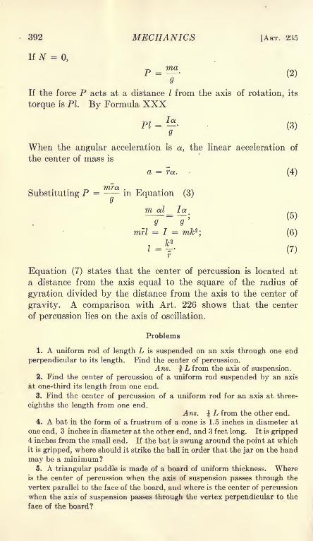
392 MECHANICS [ART. 23.5
If N =0,
P = ^ (2)
If the force P acts at a distance / from the axis of rotation, its
torque is PL By Formula XXX
Pl=j- (3)
When the angular acceleration is a, the linear acceleration of
the center of mass is
a = ra. (4)
Substituting P = - - in Equation (3)
m al la .N
(5)Q 9
mrl = I = m/b 2; (6)
JU2
* = r (7)
Equation (7) states that the center of percussion is located at
a distance from the axis equal to the square of the radius of
gyration divided by the distance from the axis to the center of
gravity. A comparison with Art. 226 shows that the center
of percussion lies on the axis of oscillation.
Problems
1. A uniform rod of length L is suspended on an axis through one end
perpendicular to its length. Find the center of percussion.Ans. f L from the axis of suspension.
2. Find the center of percussion of a uniform rod suspended by an axis
at one-third its length from one end.
3. Find the center of percussion of a uniform rod for an axis at three-
eighths the length from one end.Ans. L from the other end.
4. A bat in the form of a frustrum of a cone is 1.5 inches in diameter at
one end, 3 inches in diameter at the other end, and 3 feet long. It is gripped4 inches from the small end. If the bat is swung around the point at which
it is gripped, where should it strike the ball in order that the jar on the hand
may be a minimum?6. A triangular paddle is made of a board of uniform thickness. Where
is the center of percussion when the axis of suspension passes through the
vertex parallel to the face of the board, and where is the center of percussion
when the axis of suspension passes through the vertex perpendicular to the
face of the hoard?
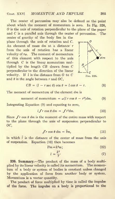
CHAP. XXV] MOMENTUM AND IMPULSE 393
The center of percussion may also be defined as the pointabout which the moment of momentum is zero. In Fig. 326,
is the axis of rotation perpendicular to the plane of the paperand C is a parallel axis through the center of percussion. Thecenter of gravity of the body lies in the
plane through the axis of rotation and C.
An element of mass dm at a distance r
from the axis of rotation has a linear
velocity of ro>. The moment of momentumof this element with respect to the axis
through C is the linear momentum mul-
tiplied by the length CB drawn from C
perpendicular to the direction of the linear
velocity. If I is the distance from to Cand is the angle between r and OC,
CB =(I- r sec 6) cos = I cos 6 - r. (8)
The moment of momentum of the element dm is
moment of momentum =co(Z r cos 6 r2
)dm. (9)
Integrating Equation (9) and equating to zero,
Ifr cos B dm = fr zdm. (10)
Since fr cos 6 dm is the moment of the entire mass with respect
to the plane through the axis of suspension perpendicular to
OC,
fr cos 6 dm = rm, (11)
in which r is the distance of the center of mass from the axis
of suspension. Equation (10) then becomes
lrm=k zm', (12)
236. Summary. The product of the mass of a body multi-
plied by its linear velocity is called its momentum. The momen-tum of a body or system of bodies is constant unless changed
by the application of force from another body or system.
Momentum is a vector quantity.
The product of force multiplied by time is called the impulse
of the force. The impulse on a body is proportional to the

394 MECHANICS [ART. 326
change of momentum. With absolute units, the impulse is
numerically equal to the change of momentum. With gravita-
tional units, the impulse is numerically equal to the change of
momentum divided by g.
Since action and reaction are equal, when two bodies exert
force on each other, their impulses are equal. As a result the
bodies suffer equal and opposite changes of momentum. The
total change of momentum of two bodies due to forces which act
between the bodies is zero.
When inelastic bodies collide, their velocity after impactis calculated from the fact that the total momentum is not
changed. When elastic bodies collide, they approach for a
short time. At the end of this interval, which is called the
stage of compression, the bodies are moving with equal velocities
in the same direction. The common velocity at the end of the
compression stage is the same as it would be if the bodies were
inelastic. After they reach the end of the compression stage,
the elasticity of the bodies causes them to separate. The interval
from the end of the compression stage until the bodies cease to
touch is the stage of restitution. The ratio of the impulse
during restitution to the impulse during compression is the
coefficient of restitution. When the coefficient of restitution is
unity, the bodies are perfectly elastic and no energy is lost in
the collision.
The product of the momentum of a body multiplied by the
perpendicular distance of its line of action from a given axis
is the moment of momentum of the body with respect to that
axis. The moment of momentum can be changed only by torque
from an outside body.The center of percussion with respect to an axis is the point
at which an impulse may be given to the body in a direction
normal to the plane through the axis and the center of gravity
without causing any change in the reaction of the axis in the
direction of the impulse. The center of percussion falls on the
axis of oscillation. The moment of momentum of a rotating
body about an axis through the center of percussion parallel
to the axis of rotation is zero.

CHAPTER XXVI
ENERGY TRANSFER
237. Units of Energy. In English-speaking countries, energy
is measured by engineers in foot-pounds. Where the metric
system is used, the engineering unit of energy is the kilogram-
meter. Since 1 kilogram is equal to 2.20462 pounds, and 1
meter is equal to 3.28083 feet,
1 kilogram-meter = 7.2330 foot-pounds;
1 foot-pound = 0.13826 kilogram-meters.
For some purposes, energy is expressed in gram-centimeters.
1 foot-pound =13,826 gram-centimeters.
For scientific purposes, work and energy are measured in
ergs. An erg is the work done by the force of one dyne whenthe point of application moves one centimeter in the direction
of the force. At the standard location, the acceleration of grav-
ity is 32.174 X 30.4801 = 980.67 cm. per sec. per sec.
1 gram-centimeter = 980.67 ergs.
1 foot-pound = 13,558,700 ergs.
Physicists use the joule as a unit of work or energy.
1 joule = 10,000,000 ergs.= 107
ergs.
1 foot-pound = 1.35587 joules.
Problems
1. A 40-pound mass is pulled up a 30-degree inclined plane by a force
parallel to the plane. The coefficient of friction is 0.1. How much work is
done and how much is the potential energy increased when the body is
moved 50 feet? Ana. 1173.2 ft.-lb.; 1000 ft.-lb.
2. Express the answers to Problem 1 in kilogram-meters.3. A 4-pound mass is lifted vertically a distance of 25 feet at a place where
g = 32.2. Find the work in joules. Ans. 135.69 joules.
395

396 MECHANICS [ART. 238
238. Power. Rate of working is called power. The unit of
power in English-speaking countries is the horsepower.
1 horsepower = 550 foot-pounds per second.
1 horsepower = 33,000 foot-pounds per minute.
For electrical measurement, the watt is the unit of power.
1 watt = 1 joule per second = 10 7ergs per second.
1 horsepower = 550 X 1.35587 = 745.7 watts.
It is customary to use
1 horsepower = 746 watts.
For direct currents and for alternating currents in non-induc-
tive circuits, the power in watts is equal to the product of the
potential difference of the terminals of the circuit in volts multi-
plied by the current in amperes.
Watts = El = volts X amperes.
Since E = RI in a non-inductive circuit,
watts = PR,
in which R is the resistance in ohms.
Problems
1. A tank, 20 feet square and 30 feet deep, is filled with water from a
source which is 40 feet below the bottom of the tank. If the intake pipeenters the bottom of the tank, what is the horsepower required to fill it in
50 minutes. Ans. 25 hp.2. The pump in Problem 1 has an efficiency of 80 per cent and is driven
by a motor which has an efficiency of 90 per cent. How many kilowatts are
required to drive the motor? Ans. 25.9 kilowatts.
3. A conical tank is 20 feet in diameter at the top and 30 feet deep. It is
filled with water from a source 40 feet below the bottom by means of a pumpof 75 per cent efficiency which is driven by a 220-volt motor of 90 per cent
efficiency. If the tank is filled in 30 minutes through a pipe which enters at
the bottom, what is the average current supplied to the motor?4. How many horsepower equal one kilowatt?
6. A flywheel 6 feet in diameter is making 300 revolutions per minute.
The tension on one side of the belt is 1800 pounds and the tension on the
other side is 300 pounds. Find the horsepower transmitted. Ans. 25.7 hp.6. If T is the torque in foot-pounds in a shaft, show that the work per
revolution is 2wT,
239. Mechanical Equivalent of Heat. Energy can neither be
created nor destroyed. When it apparently disappears, it merely
changes its form. The statement that the total energy of a

CHAP. XXVI] ENERGY TRANSFER 397
closed system remains unchanged is called the Law of Conserva-tion of Energy.The most common change of energy is the change to the form of
heat energy. When friction takes place between two bodies,heat is generated. The temperature of the bodies may be so
raised by the heat of friction that the bodies are melted or ignited.Heat energy is measured in British thermal units or in calories.
A British thermal unit is the heat required to raise the tempera-ture of one pound of water one degree Fahrenheit. Since the
specific heat of water varies slightly with the temperature, a
British thermal unit is defined more accurately as the amount of
heat required to raise the temperature of one pound of water from
32 degrees to 33 degrees Fahrenheit.
A calorie is the amount of heat required to raise the tem-
perature of one kilogram of water one degree Centigrade. Acalorie is defined accurately as the amount of heat required to
raise the temperature of one kilogram of water from degrees to
1 degree Centigrade.
A small calorie is the amount of heat required to raise the
temperature of 1 gram of water from degrees to 1 degree Centi-
grade. The small calorie is called a calorie by physicists.
The experiments of Joule and Rowland have shown that
427 kilogram-meters of work will raise -the temperature of 1
kilogram of water 1 degree Centigrade. This figure is called
the mechanical equivalent of heat.
1 large calorie = 427 kilogram meters = J.
1 British thermal unit = 778 foot-pounds.
Problems
1. If the work done in lifting 1 kilogram a distance of 427 meters is
sufficient to raise the temperature of 1 kilogram of water 1 degree Centigrade,
how high will a mass of 1 pound be lifted by the energy which is required to
raise the temperature of 1 pound of water 1 degree Centigrade?Ans. h = 1400 ft.
2. If the energy required to raise the temperature of 1 pound of water
1 degree Centigrade is sufficient to lift 1 pound a vertical distance of 1400
feet, how high will the energy required to raise the temperature of 1 pound of
water 1 degree Fahrenheit lift 1 pound?3. A friction brake which is absorbing 30 horsepower is cooled by water
at 20 degrees Centigrade. The water is evaporated from and at 100 degrees
Centigrade. How many pounds of water are required per hour?
Ans. 68.7 Ib,

398 MECHANICS [ART. 239
4. A sled weighing 1200 pounds is drawn along a horizontal ice surface bya horizontal pull of 70 pounds. If the temperature of the ice is 32 degrees
Fahrenheit, how much ice is melted when the sled moves 100 feet?
6. An iron shot moving at a speed of 1200 feet per second is stopped bystriking an object. If the specific heat of iron is 0.11 and if one-half of the
energy goes to heat the shot, how high is its temperature raised?
6. A meteorite strikes the air with a velocity of 6 miles per second rela-
tive to the earth. If the specific heat is 0.11 and if one-half of the energy
goes to heat the meteorite, how high is its temperature raised?
7. The drum of Fig. 327 is mounted on a smooth pivot. The vertical
shaft at the top drives a set of paddles inside the drum. The drum is rilled
with water which is heated by the mechanical energy of the rotating paddles.
FIG. 327.
The torque is measured by means of two cords which are wound round
the drum and run over smooth pulleys. The water equivalent of heat of the
apparatus was found to be 2.42 pounds. With 17.58 pounds of water in the
drum, the temperature was raised from 50 Fahr. to 74 Fahr. while the shaft
made 4000 revolutions. The average torque during the experiment was10.8 foot-pounds. Find the mechanical equivalent of heat.
8. How many kilowatts are required to raise the temperature of 20
pounds of water from 62 degrees to boiling in 30 minutes?
9. How many kilowatt-hours are required to raise 10 kilograms of water
from 20 degrees C. to 100 degrees C.?
10. Coal with a calorific value of 13000 B.t.u per pound is used with a
boiler of 70 per cent efficiency and an engine of 15 per cent efficiency. Howmany pounds of coal are required per horsepower-hour? Ans. 1.87 Ib.

CHAP. XXVI] ENERGY TRANSFER 399
240. Power of a Jet of Water. When a liquid flows from an
orifice, the velocity is the same as that which a body would
acquire in falling freely from a height equal to the vertical dis-
tance of of the orifice below the surface the liquid. In Fig. 328,
v = V2jh> (1)
in which h is measured from the center of the orifice and v is the
velocity at the center. If h is measured from any other pointin the orifice, the velocity v is the velocity at that point. For an
I*
ContractedVein
FIG. 328.
orifice of small dimensions compared with the height of the
water, the velocity at the middle agrees with the average velocity
within narrow limits.
The velocity of Equation (1) is called the theoretical velocity.
Fig. 328, I, shows an orifice in a thin plate (sometimes called a
frictionless orifice). Practically no energy is lost in an orifice of
this kind, and Equation (1) gives the true velocity. When an
orifice of this kind is placed in a plane surface of dimensions
considerably greater than the diameter of the orifice, the momen-tum of the liquid flowing in from all sides tends to carry it in
past the edge. As a result of this transverse component, the
motion at the surface is not normal to the plane of the orifice and
the jet is contracted on all sides. At a distance from the orifice
about equal to its radius, all the liquid is moving in one direction
and the diameter of the jet is considerably smaller than that

400 MECHANICS [ART. 240
of the orifice. This section of the jet is called the contracted vein.
The ratio of the area of the contracted vein to the area of the
orifice is called the coefficient of contraction. With full contrac-
tion, the coefficient of contraction for circular orifices is about
0.62.
The quantity of liquid which flows from an orifice in one unit
of time is equal to the area of the contracted vein multiplied
by the average velocity. The quantity is given by the equation,
Q = KAV2Jh, (2)
in which A is the area of the orifice, and K is a coefficient called
the coefficient of discharge. The coefficient of discharge is the
ratio of the quantity actually discharged to the quantity which
would flow through the orifice if there were no contraction andthe actual velocity were the full theoretical velocity. In an
orifice in a thin plate, the velocity is the full theoretical velocity
and the coefficient of discharge is equal to the coefficient of con-
traction. The coefficient of contraction for an orifice of this
kind is 0.62. The equation
Q = Q.62A\/2gh
gives the discharge from an orifice in a thin plate.
Figure 328, II, shows a gradually converging short nozzle.
Since the area of the jet is equal to the area of the nozzle, the
coefficient of contraction is unity. The friction slightly reduces
the velocity at the surface; the coefficient of discharge is, there-
fore, a little less than unity. With the proper curvature, K is
greater than 0.99. With ordinary nozzles, K is about 0.95.
The power of a jet may be found by means of the kinetic
energy per pound of liquid. Since the energy is equivalent to
the work done in lifting a pound a vertical distance of h feet, the
power is easiest calculated by multiplying the number of pounds
per second by the height h.
ExampleWater flows from a 6-inch orifice in a thin plate under a head of 60 feet.
The coefficient of contraction is 0.62. Find the horsepower of the jet.
v = V2 X 32.174 X 60 = 62.14 ft. per sec.
Q = 0.62 X~Q
X 62.14 = 7.582 cu. ft. per sec.
Since one cubic foot of water weighs nearly 62.5 pounds, the energy of
each cubic foot is 62.5 X 60 = 3750 ft.-lb. The total energy is 7.582 X3750 = 28,432 ft.-lb. per second. This is 51.7 horsepower.

CHAP. XXVI] ENERGY TRANSFER 401
Pressure of a liquid or gas is often given in pounds per square inch. A* o r
column of water 1 inch square and 1 foot high weighs -~r = 0.434 pound.
A column 1 inch square and 2.30 feet high weighs 1 pound. To change water
pressure in pounds per square inch to head in feet of water, multiply by2.30.
Problems
1. Water flows from a 4-inch circular orifice in a thin plate under a pres-
sure of 40 pounds per square inch. Find the horsepower of the jet.
Ans. 43.52 hp.2. The jet from the orifice of Problem 1 drives a water wheel of 80 per
cent efficiency which drives a generator of 90 per cent efficiency. Howmany kilowatts are generated? Ans. 23.38 kw.
3. If the jet from a given orifice delivers 60 hp. when the head is 40 feet
of water, what will it deliver when the pressure is 50 pounds per square inch?
241. Work of an Engine. The work done by the steam in an
engine during one stroke is the product of the total pressure on
one side of the piston multiplied by the length of the stroke.
,- Pisfan
Connecting Rod
- Guides
Piston Rod
FIG. 329.
The total pressure is the pressure per square inch multiplied bythe area of the piston. If the diameter of the cylinder is 20 inches,the length of the stroke is 48 inches, and the average pressure on
one side of the piston during the stroke is 50 pounds per square
inch, the total work of the steam on that side is
314.16 X 50 X 4 = 62,832 foot-pounds.
If the pressure of 50 pounds per square inch is measured fromthe atmospheric pressure as the zero (as is customary) and if the
opposite end of the cylinder is entirely open during the entire
stroke, then 62,832 foot-pounds represents the actual work doneon the piston. Usually, there is some back pressure in the oppo-site end of the cylinder; the effective work on the piston is,
therefore, somewhat less than the work of the steam on one26

402 MECHANICS [ART. 241
side. The actual work is the difference between the positive
work in the steam end of the cylinder and the negative work in
the other end.
The average pressure in an engine cylinder is determined bymeans of an indicator, Fig. 330, I. An indicator is a pressure
gage which is connected to the cylinder by means of a short
steam pipe. An indicator consists essentially of a small cylinder
in which moves a light piston. The steam pressure in the cylin-
der of the gage is balanced by a calibrated spring on the
opposite side of the piston. The piston actuates a light lever,
which carries a pencil at the end. When a sheet of paper is
-Pipe to
Engine Cylinder
FIG. 330.
moved perpendicular to the motion of the pencil, a curve whoseordinates give the pressure at every instant is drawn. The paperis placed on a drum which is attached to the engine in such waythat its motion is proportional to the motion of the piston.
Figure 330, II, shows an indicator card. The arrows give the
direction of the motion of the pencil relative to the paper. Thedistance of any point, such as G, above the atmospheric line
measures the pressure in the cylinder of the engine at the cor-
responding point of its stroke. The effective force on the pistonis the difference between this pressure and the back pressure onthe opposite side of the piston. This back pressure may be
obtained by a second indicator attached to the opposite end of
the cylinder. It is not necessary to consider together the pres-
sure on one side of the piston and the back pressure on the other
side in order to calculate the power. The effective work duringone cycle may be calculated from the difference of pressure on the

CHAP. XXVI] ENERGY TRANSFER 403
same side of the cylinder. In Fig. 330, II, the height FG of the
indicator card gives the difference in pressure during the forward
and backward strokes. The average net height of the indicator
card, as obtained by dividing its area by its length, gives the
mean effective pressure for the one end of the cylinder.
Problems
1. The indicator card from the head end of an engine cylinder has an area
of 8.40 square inches, and the card from the crank end has an area of 8.64
square inches. Each card is 8 inches long. The indicator spring used in
this test is compressed 1 inch by a pressure of 40 pounds per square inch in
the cylinder of the indicator. Find the mean effective pressure.
Ans. m.e.p. = 42 pounds per square inch in the head end, and43.2 pounds per square inch in the crank end.
2. The cylinder of the engine in Problem 1 is 20 inches in diameter and the
piston rod is 4 inches in diameter. The stroke is 48 inches and the speed is
80 revolutions per minute. Find the indicated horse power.Ans. 284.5 hp.
*
Friction Block
FIG. 331.
242. Friction Brake. Fig. 331 shows one type of friction
brake, such as is used to absorb and measure the power developed
by an engine or motor. The form shown consists of a numberof wooden friction blocks placed around the rim of the pulley.
The blocks are fastened to a flexible metal band. The ends of the
band are connected together by bolts. By turning the nuts on
these bolts the tension may be varied and the pressure of the
blocks on the pulley may be adjusted to give any desired value to
the friction. The arm B ends with a knife-edge C at a distance
R from the axis of the pulley. The knife-edge rests on a vertical

404 MECHANICS [ART. 242
support, which stands on a platform scale. When the pulley is
turning in the direction of the arrow, the friction of the blocks
transmits a torque to the brake. This torque is balanced by the
upward force P from the support to the knife-edge.
Suppose that the pulley is held stationary and that a force Pis applied to the knife-edge at right angles to the radius R. If
the torque of this force is sufficient to balance the torque of
friction, the knife-edge will describe a circle of radius R about the
axis of the pulley. The circumference of this circle is 2irR, and
the work done by the force P during one
revolution is
-26
U = ZirRP =2irT, (I)
in which T is the torque.
If the brake is held stationary by the
reaction of the support and the pulley
is rotated, the work per revolution is the
same as it would be if the pulley were
stationary and the brake were rotated.
In all cases, the work per revolution =2irT.
Problems
1. The flywheel of an engine makes 300
revolutions per minute. A friction brake on the
wheel has a moment arm of 90 inches. Find
the horsepower when the reaction at the end
of the brake arm is 420 pounds.Ans. 178 hp.
2. The arm of a brake which is attached to
the pulley of a motor is 30 inches long. Themotor makes 1200 revolutions per minute. Find
the horsepower when the reaction at the sup-
port is 60 pounds. If the current used to
drive the motor is 130 amperes at 220 volts,
what is the efficiency?
Ans. 34.27 hp.; 89.3 per-cent.
3. The pulley of Fig. 332 is 10 inches in
diameter and the rope is % inch in diameter. The total weight is 112
pounds and the spring balance reads 26 pounds. Find the horsepowerwhen the pulley is making 800 revolutions per minute. Ans. 5.86 hp.
4. What must be the coefficient of friction between the rope and the pulleyof Problem 3?
6. The flywheel of Problem 1 is cooled by water which is held against the
rim of the wheel by centrifugal force. The water is supplied to the wheel
at 60 degrees Fahrenheit and is evaporated at 210 degrees Fahrenheit.
How many pounds of water are required per hour?
/2/b.
FIG. 332.

CHAP. XXVI] ENERGY TRANSFER 405
243. Cradle Dynamometer. The output of a small motor
may be measured by means of a cradle dynamometer. Themotor is mounted on a frame which is supported by a pair of
knife-edges. These knife-edges are in line with the axis of the
shaft of the motor. The torque of the belt on the motor tends to
rotate the frame about the knife-edges. Since the knife-edges are
in line with the axis of the pulley, the direct pull of the belt has no
effect on the equilibrium. The torque of the belt is balanced bythe weights P and the poise Q on a horizontal arm attached to the
frame. When the motor is revolving clockwise with the belts
extending toward the left, as shown in Fig. 333, the tension is
SuspensionBar-
'- Cradle
FIG. 333
greater in the upper belt and the torque from the belt to the
armature is counter-clockwise. This torque is transmitted
electromagnetically from the armature to the field, and then
transmitted mechanically from the field to the dynamometer.When a dynamo which is driven by a belt is to be tested,
either the rotation must be opposite that shown in Fig. 333, or
the arm which carries the balancing weights must extend toward
the left.
The calculation of power of a cradle dynamometer is the sameas the calculation for a friction brake. The work per revolution
244. Transmission Dynamometer. A transmission dynamom-eter transmits and measures power without dissipating it bytransfer into heat. Fig. 334 shows one type of a dynamometerdriven by a belt. The pulley B is driven from pulley A throughthe dynamometer pulleys C and D. The dynamometer is
arranged to measure the pull Q in the part of the belt running

406 MECHANICS [ART. 244
from C to B and the pull P in the part of the belt running from Bto D. The difference P Q multiplied by the radius of the
pulley B (measured to the center of the belt) gives the torque.
Each dynamometer pulley is mounted on a frame which is sup-
ported by knife-edges. The knife-edges which support pulley C are
in the plane of the center of the belt running from AtoC and the
knife-edges which support pulleyD are in the plane of the center of
FIG. 334.
the belt running from D to A . The tension in these parts of the
belt, therefore, exert no torque on the frames which support the
dynamometer pulleys. The moment on the left frame is the
product of the pull Q multiplied by the diameter of pulley C(from center to center of belt): and the moment on the right
frame is the product of P multiplied by the diameter of pulley D.
Figure 335 shows both frames attached to a single lever, at
equal distances on opposite sides of the fulcrum G. The momenton this lever measures the difference Q P.
It is not absolutely necessary that the belt should run vertical
from A to C and from D to A. The belt may run at any angle,
provided the plane of the center passes through the line of the
knife-edges on each side.
Figure 336 shows the essentials of the Robinson dynamometer.

CHAP. XXVI] ENERGY TRANSFER 407
The spur gear A drives the spur gear C through the gear B. The
gearwheel B is mounted on a frame which is pivoted at in the
FIG. 335.
rz^Bf-ri l::::iSp::::
lX7"
LJl: ""X
FIG. 336.
plane tangent to the pitch circle of B. The reaction between
B and C does not, therefore, exert any moment on the frame.

408 MECHANICS [ART. 245
The reaction of A on B has a moment arm equal to the diameter
of the pitch circle of B. This moment is balanced by the weightsat the end of the lever arm. The gearwheels A and C are
mounted on a frame. Each is generally connected to a pulley
by which the power is transferred to a belt.
The torque in a shaft may be measured by means of the angle
of twist of a portion of its length. The angle of twist in a shaft of
large diameter is very small. Delicate devices have been made,
however, by means of which these small angles may be measured
in a rotating shaft.
Problem
Devise a transmission dynamometer made with three bevel-gearwheels.
245. Power Transmission by Impact. When a perfectly
elastic body collides with another perfectly elastic body, there is
no loss of energy. If the final velocity of one of the bodies is
zero, all of its kinetic energy is transferred to the other body.
A vrj
FIG. 337.
In Figure 337, A is a relatively large body which is movingwith a velocity vz , when it is struck by a relatively small bodyof mass m moving in the same direction with a velocity v\. The
change of velocity of m during compression is v\ v-*. If the
bodies are perfectly elastic, the change during compression and
restitution is 2(vi v^). If t is the time of contact, the averageforce is
The distance which the mass A moves during the time t is
the work done by m on A is, therefore,
2m (PI-
Q
The kinetic energy of the mass m before collision was

CHAP. XXVI] ENERGY TRANSFER 409
If all this energy is transferred to A,
0;
(4)
(5)
(6)
When the mass of A is so large relatively that its velocity is
not appreciably changed by collision with m, the velocity of Amust be one-half as great as the initial velocity of m in order that
all the energy of m may be transferred. The change of velocity
I
Fio. 338. Fio. 339.
of m during compression is ^ and the change during restitution
is the same; the final velocity of m is zero and its kinetic energyis zero. VWhen a water jet strikes a plane surface, as in Fig. 338, it
behaves almost as an inelastic body. If it strikes a curved sur-
face tangentially, it is deflected with little
loss of energy. If the surface is such as
to deflect the jet through 180 degrees, as in
Fig. 339, it behaves as a stream of perfectly
elastic particles.
Figure 340 shows a section of one bucket
of a Pelton impulse wheel, which makes use
of this principle. The water jet strikes
the middle of the bucket and divides. Each portion of the
stream has its direction changed nearly 180 degrees. A series of
such buckets is arranged around the rim of the wheel in such a
way that the jet is always striking one or two buckets. The
FIG. 340.
410 MECHANICS [ART. 246
maximum efficiency is secured when the velocity of the buckets is
one-half the velocity of the water in the jet.
Problems
1. A Pelton wheel is 5 feet in diameter from center to center of buckets.
It is driven by a jet which has a velocity of 120 feet per second. Whatshould be the speed of the wheel for maximum efficiency? Ans. 229 r.p.m.
2. What should be the linear velocity of the buckets of an impulse wheel
which is driven by water under a pressure of 150 pounds per square inch?
246. Summary. Energy is measured in foot-pounds, kilogram-
meters, gramcentimeters, ergs, and joules.
Power is rate of working. A horsepower is 550 foot-pounds
per second. A watt is the electrical measure of power.
746 watts = 1 horsepower.
The relation between heat energy and mechanical energy is
called the mechanical equivalent of heat.
778 foot-pounds = 1 British thermal unit.
427 kilogram-meters = 1 large calorie.
The velocity of a liquid flowing from an orifice is that of a bodywhich falls freely from a height equal to the depth of liquid above
the orifice.
v = V2gh.
The quantity is the velocity multiplied by the area of the jet.
For an orifice in a thin plate,
Q = 0.62A\/2^.
The work of a water jet per unit of time is the product of the
mass per unit of time multiplied by the height of the water
above the orifice.
The work of steam in a cylinder is the product of the pressure
multiplied by the length of stroke. The pressure is the area of
the piston multiplied by the mean effective pressure. Themean effective pressure is determined from the average height
of an indicator card.
The power of a motor may be measured by means of a friction
brake. The work per revolution is
U =27I-T,

CHAP. XXVI] ENERGY TRANSFER 411
in which T is the torque about the axis of rotation. The torque
of small motors may be measured by means of a cradle
dynamometer.Transmission dynamometers measure the power of a machine
without absorbing it.
When perfectly elastic bodies collide, there is no loss of energy.
In order that a body may give up all of its energy, its
final velocity must be zero. When a continuous stream of
particles strikes a moving body, the condition of maximum effi-
ciency requires that the body shall be moving with one-half the
velocity of the particles. A jet of water which strikes a curved
surface tangentially and is deflected 180 degrees behaves like a
body which is highly elastic.


INDEX
Absohite units, 294, 322
Acceleration, linear, 264, 265, 266,
267, 280, 342, 343
angular, 354, Chapter XXIIIAction and reaction, 32, 380
Addition, of couples, 114
of numbers, 10
of vectors, 11, 12, 14, 15, 16, 17,
18, 22, 23, 25
Amplitude of vibration, 306
Angle of friction, 192
Angle section, moment of inertia of,
244, 245, 249
Angular motion, 354, Chapter XXI,368, Chapter XXIV.
Atwood machine, 282, 365
Axis, instantaneous, 339
of oscillation, 375
of suspension, 373
transfer of, 233, 248, 250, 258
B
Balance, running, 347
static, 346
Ball governor, 348
Beam balance, 221, 222, 223
Bearing friction, 195
Belt friction, 200
Body, rigid, 30
free, 35, 36
Bow's method, 65, 99, 121
Brake, 463
British thermal unit, 397
Bureau of Standards, 3
Calculation of resultants and com-
ponents, 44
Calorie, 397
Catenary, 129, Chapter VIII
Center of gravity, 35, 151, 154 156,166
by integration, 159
Center of mass, 35, 152
Center of percussion, 391
Center of pressure, 170, 252, 253,254
Centimeter-gram-second system, 295
Central forces, 327, Chapter XXCentrifugal force, 344
Channel sections, moment of inertia
of, 245
Chord, 96
Circle, moment of inertia of, 242,
243
Circuit of force, 35
Coefficient of discharge, 400
of friction, 190
Collision of elastic bodies, 383
of inelastic bodies, 382
Components of acceleration, 267
of force, 44
of a vector, 12
of velocity, 264
Compression, 29
t Concurrent, coplanar forces, 36, 43,
Chapter IVcalculation of resultants and
components, 44
equilibrium, 46, 48
resultant, 37, 43
trigonometric solution, 53
unknowns, 54
(. Concurrent non-coplanar forces, 141,
Chapter IX
Cone, moment of inertia of, 231
Cone of friction, 194
Connecting rod, 218, 401
X Couples, 111, Chapter VIaddition of, 114, 116
combination with forces, 116
equivalent, 111
413

414 INDEX
Couples, in parallel planes, 173
as vectors, 175
Cradle dynamometer, 405
Cross-head, 218, 401
Cubic equation, 219
Cylinder, moment of inertia of,
229, 231
Deflection of catenary, 130, 132
Derrick, 68, 184
Differential appliances, 213, 214
Dimensional equations, 270, 294
Direction condition of equilibrium,92
Direction cosines, 21, 22
Displacement, angular, 334, 355
linear, 259
in terms of velocity, 282
Dynamometer, 405, 406
Dyne, 7, 295
E
Effective moment arm, 56
Efficiency, 207
Elongation, 306
Energy, kinetic, 283
potential, 207, 285
transfer of, 395, Chapter XXVIEquations, concurrent, coplanar
forces, 49, 54, 55, 62, 68, 69
concurrent, non-coplanar forces,
148
dimensional, 270
non-concurrent, coplanar forces,
87, 91, 92, 107
non-concurrent, non-coplanar
forces, 180
Equilibrant, 34, 46, 72
Equilibrium, 31, 32, 40, 46, 53, 78
calculation by moments, 60, 146
calculation by resolutions, 48
classes, 40, 220
concurrent, coplanar forces, 46,
47, 48
concurrent, non-coplanar forces,
144, 146, 147
Equilibrium, conditions of stable,
79, 221
of couples, 115
direction condition of, 92
moment condition of, 60, 146
non-concurrent, coplanar forces,
86, 87, 115
non-concurrent, non-coplanar
forces, 180
of parallel forces, 78, 150
surface of, 224
trigonometric solution for, 53
by work, 207
Equipotential surface, 224, 331
Equivalent mass, 357
Erg, 295, 395
Flexible cord, 31, 129
Fly-wheel stresses, 351
Force, 2, 3, 6, 29, 43, 273
application of, 29, 36
centrifugal, 206
moment of, 56
polygon of, 46
triangle of, 38
Force circuit, 35
Force and couple, 116, 118, 178
and motion, 273, et seq.
Forces, concurrent, coplanar, 36,
Chapter IV
concurrent, non-coplanar, 141,
Chapter IX
non-concurrent, coplanar, 72,
Chapter V, 111, 120, 121
non-concurrent, non-coplanar,180
resultant of, 37, 42, 120, 122
Formulas, meaning of, 7
(Foot, standard, 3, 7
'Free body, 35, 36
Friction, 32, 33, 189, Chapter XIIFriction brake, 403
Funicular polygon, 121, 126, 127
G
Gaseous state, 30
Gee-pound, 297

INDEX 415
Governor, 348, 349, 350
Graphics of non-concurrent forces,
Chapter VII
of vectors in space, 24
Gravity, acceleration of, 275
center of, 35
determination of, 377
motion from, 286
Gyration, radius of, 232
H
Harmonic motion, 311, 318
Heat equivalent, 396
Hinge, 34
Horsepower, 396
Impulse, 379
Inclined plane, 208, 216
Independent equations, 54, 55, 62,
68, 69, 89, 91, 92, 107, 148,
180
Indicator, 402
Inertia, moment of, Chapters XIV,XV
product of, 247
Infinite series, 135
Input, 207
Instantaneous axis, 339
Isochronous vibration, 312
Jointed frame, 95, 103
Joule, 395
K
Kilogram, 5, 6
Kilogram-meter, 395
Kinetic energy, 283, 294, 307
Kinetic energy of rotation, 335, 336
Kinetics, 1
Length, 3, 4
Lever, 215
Link, 34
Liquid pressure, 169, 252
Liquid state, 30
M
Machines, 205, Chapter XIIIMaclaurin's Theorem, 135, 136
Mass, 2, 3, 4, 5
relation to weight, 7
engineer's unit of, 297
Matter, 4
Maximum moment of inertia, 251
Mechanical advantage, 207, 226
Mechanical equivalent of heat, 396
Mechanics, 1
Meter, standard, 3
Moment, 56
of couple, 111
of non-coplanar forces, 145
X resultant, 58
Moment of inertia, 228, Chapters
XIV, XVof connected bodies, 238
maximum, 251
of plane area, 241, ChapterXVof plate, 235
polar, 241
transfer of, 233
Moment of momentum, 386
Momentum, 379, Chapter XXVMotion, 259, Chapter XVIMotion and force, 273, Chapters
XVII, XVIII
N
X Neutral equilibrium, 42
Newton's Laws of Motion, 6
)( Non-concurrent forces, 37, 72, 111
Non-coplanar forces, 37
Numbers, 9
Origin of moments, 57
of a vector, 11
Oscillation, axis of, 375
Output, 207

416 INDEX
Panel, 96
Parabola, center of gravity of, 165'
Parabola of flexible cord, 137
Parallel forces, 72, 74, 75, 78, 124,
149
Parallelepiped, moment of inertia
of, 230
Pelton wheel, 409
Pendulum, gravity, 373
simple, 374
torsion, 369
Percussion, axis of, 391
Plane, smooth, 33..
Plate and angle sections, 245
Plate elements, 236
Polar moments of inertia, 241
Pole, 121
Polygon, of forces, 46, 55
funicular, 121, 126, 127
Potential energy, 207, 304
Pound force, 7, 8, 294, 296
Pound mass, 5, 6, 8
Poundal, 7, 296, 299
Power, 396, 399
Power transmission by impact, 408
Pressure, center of, 170, 252, 253,
254
of liquid, 169
Product of inertia, 247, 248, 249
Product of vectors, 25, 26
Projectiles, 287
Pulleys, 211
QQuantity, 9
represented by lines, 9, 10
represented by numbers, 9
fundamental, 2
Radius of gyration, 232
Range, 290
Ray, 121
Reactions, parallel, 124
non-parallel, 127
of supports, 358, 360, 362
Reference circle, 311
Resolution, of vectors, 13, 16
of forces, 38, 141
Resultant, 34
of concurrent forces, 37, 44, 141,
142
of couples, 176
of non-concurrent forces, 81, 82
of non-parallel forces graphic-
ally, 81, 122
of parallel forces, 72, 76
Robinson dynanometer, 407
Roller bearings, 200
Rolling friction, 198
Rotation, 335
Rotation and translation, 337, 338
Rowland's experiments, 397
Scalar product, 26, 27
Screw, 213
differential, 214
Second, 4
Sections, method of, 100
Sensibility of balance, 222
Shear, 29
Simple harmonic motion, 311
Slugg, 297
Smooth hinge, 34
Smooth surface, 32, 33
Solid, 29
Space, 2, 3
Sphere, moment of inertia of, 230
Spring, energy of, 304, 307
time of vibration, 309
Stable equilibrium, 41, 79, 221
Standard pound force, 8, 294, 296
Standards of mass, etc., 35
Starting friction, 33, 189
Statics, 1, 2
Strength of materials, 71
String polygon, 121
Subtraction, of numbers, 10
of vectors, 18, 19
Suspension, axis of 373
Tension, 29
Terminus of vector, 11
INDEX 417
Three force member, 103
Time, 234
Time of vibration, 309, 370
Toggle joint, 217
Transfer of axes, 233, 248, 250, 251
Vectors, components, 12, 13, 22, 24,
25
definition, 10
resolution, 13
subtraction, 18, 19
Translation and rotation, 337, 338 Vectors in space, 19, 20, 21, 22, 23,Transmission dynamometer, 405
Triangle of forces, 45
Trigonometric solution, 53
Trusses, 95, 96, 97, 98
by method of sections, 100
Two force member, 103
U
24, 25
graphical resolution of, 24, 25
Velocity, angular, 334
Velocity, linear, 260, 261, 262, 305
average, 262
as a derivative, 263
Vibration, 307, 368
Virtual work, 215, 217
Units, systems of, 299, ChapterXVIII
Unknowns, 54
concurrent, coplanar forces, 54Water J et >
W
concurrent, non-coplanar forces,Watt
>
148 Weight, 6
non-concurrent, coplanar forces,relation to mass, 7
g7 variation with latitude, 8
non-concurrent, non-coplanarWheel and axle
>21
forces, 180 differential, 214
X Unstable equilibrium, 40, 41, 221Wmdlass 185
Work, 39, 205, 328
v virtual, 215, 217
Vector products, 25, 26
Vectors, addition of, 11, 14, 15, 16,
17, 18, 22, 23, 25 Yard, standard, 3
'27


TH:
UNIVERSITY OF CALIFORNIA LIBRARY
This book is DUE on the last date stamped below.
Fine schedule: 25 cents on first day overdue
50 cents on fourth day overdue
One dollar <>n seventh day overdue.
LD 21-100m-12,'46(A2012sl6)4120

9967
THE UNIVERSITY OF CALIFORNIA LIBRARY