Mechanical Unit Operations Professor Nanda Kishore Department of ...
30
Mechanical Unit Operations Professor Nanda Kishore Department of Chemical Engineering Indian Institute of Technology, Guwahati Lecture 34 Centrifugal Separations Welcome to the MOOCs Mechanical Unit Operations. The title of this lecture is Centrifugal Separations. Previously in one of the lectures, we have already seen the centrifugal force, particles settling under centrifugal field, those kind of things we have seen and then compared with the particles settling in a gravity field. There we have found that the magnitude of a centrifugal force is several hundred or sometimes several thousand times higher than the gravitation force. So some particles if you wanted to separate from a solid fluid system, if some particles taking very long time to settle or being separated from under gravity field then that is not going to be practically possible. Or you may not wish to wait for so long for those particles to be settle under gravity and then you separate and then you go for the subsequent operations. So that is not possible always. So under such conditions, if you apply kind of centrifugal field for separation of those particles then the separation is going to be taken place in very less time because the magnitude of centrifugal force is in general much higher than the gravitational force – several times like hundred times or thousand times depending on the rotational speed of the centrifugal ball that we are using. That is one advantage. Another advantage is like that in general gravitation sedimentation equipment or very very big sized tanks or containers or kind of things are used for gravity separations. But centrifugal separation can be done in small bowls having diameter 700 to 1200 mm diameter only, so such is the advantage. Because of these two major advantages of centrifugal field in general, you know suppression based on centrifugal field is going to be advantageous as well as economical over a gravity separation especially if the separation or the settling velocity of the particle is very very small in general. So now we see why centrifugal separations are required as I mentioned.
-
Upload
khangminh22 -
Category
Documents
-
view
1 -
download
0
Transcript of Mechanical Unit Operations Professor Nanda Kishore Department of ...

Mechanical Unit Operations
Professor Nanda Kishore
Department of Chemical Engineering
Indian Institute of Technology, Guwahati
Lecture 34
Centrifugal Separations
Welcome to the MOOCs Mechanical Unit Operations. The title of this lecture is Centrifugal
Separations. Previously in one of the lectures, we have already seen the centrifugal force,
particles settling under centrifugal field, those kind of things we have seen and then compared
with the particles settling in a gravity field.
There we have found that the magnitude of a centrifugal force is several hundred or sometimes
several thousand times higher than the gravitation force. So some particles if you wanted to
separate from a solid fluid system, if some particles taking very long time to settle or being
separated from under gravity field then that is not going to be practically possible. Or you may
not wish to wait for so long for those particles to be settle under gravity and then you separate
and then you go for the subsequent operations. So that is not possible always.
So under such conditions, if you apply kind of centrifugal field for separation of those particles
then the separation is going to be taken place in very less time because the magnitude of
centrifugal force is in general much higher than the gravitational force – several times like
hundred times or thousand times depending on the rotational speed of the centrifugal ball that
we are using. That is one advantage. Another advantage is like that in general gravitation
sedimentation equipment or very very big sized tanks or containers or kind of things are used
for gravity separations.
But centrifugal separation can be done in small bowls having diameter 700 to 1200 mm
diameter only, so such is the advantage. Because of these two major advantages of centrifugal
field in general, you know suppression based on centrifugal field is going to be advantageous
as well as economical over a gravity separation especially if the separation or the settling
velocity of the particle is very very small in general. So now we see why centrifugal separations
are required as I mentioned.

(Refer Slide Time 2:42)
Wide range of industrial applications are existing where centrifugal force is used in place of
gravitation force to accelerate separations. The acceleration of separation can be done by using
these centrifugal forces. Acceleration of separation can be several thousand times compared to
gravity.
Some benefits include far greater rates of separation i.e. possibility of achieving separations
which are either not practically feasible or actually impossible in the gravitational field. Some
particles let us say if you have very fine micron size or sub-micron size particles are suspended
in the air then if you wanted to pure that air then gravity separation if you are doing, try to do,
that is going to take long time, very very long time or sometimes it is not even possible. But if
you apply centrifugal field for such cases it is easy that acceleration of separation would be
taking place and then under centrifugal field the separation of those particles can be easily done
as done sometimes in cyclone separators et cetera.
And then substantial reduction of size of the equipment is possible by using centrifugal field in
place of gravity separation as I already mentioned.

(Refer Slide Time 3:54)
Then how to generate centrifugal field? Having seen that advantage of centrifugal force, now
next point is that how to generate centrifugal field. There are two different ways are possible
in general:
First way is that by introducing a fluid with a high tangential velocity into a cylindrical or
conical vessel, as we do in general in hydrocyclones or cyclone separators. So let us say, what
we have? We have in general cyclone separators or hydrocyclone separators or something like
conical shape something like this. The fluid that comes in that are the fluid that is containing
the particles, fine particles, they come at high velocity and then hit the wall. So then they are
kind of spiral of this, rotation of this fluid element will take place and when they are hitting at
high velocity to the surface of the cone and then cone radius is, size of the cone, I mean the
cross-section of the cone decreases gradually downwards.
So then because of that one kind of rotation, increased rotation of the fluid element will take
place and then that will generate a kind of centrifugation and then particles will be settled at
the bottom and collected there. Whereas thick layer air can be collected from the top. This is
what we do. This is one way of doing the, or generating the centrifugal field. So here at any
point what you see, you have a kind of two forces. One is the gravitational force that is acting
downward in the Y direction and then another one is the centrifugal force that is acting in the
radial direction.
So if fluid is rotating then in vertical direction gravity is predominant, so 𝑑𝑝
𝑑𝑟 should be nothing
but – 𝜌𝑔 or −𝑔 𝑉⁄ . We can write V is a kind of volume per unit mass kind of units and in

horizantal axis what we have? We have centrifugal force predenominating with pressure drop
𝑑𝑝
𝑑𝑟 is nothing but 𝜌𝑟𝜔2 that can be written
𝜌𝑢2
𝑟as well. So
𝑑𝑝
𝑑𝑟= 𝜌𝑟𝜔2, that again anyway we
are going to derive in subsequent slides.
Then larger and heavier particles will be collected near walls and then smaller and lighter
particles will be taken off through the outlet near the axis of vessel.
The second approach is by use of centrifuge – in this case what happens, fluid is introduced in
some type of rotating bowl and is being rapidly accelerated. You take a bowl and in that bowl
you take these fluid containing particles and then rotate that bowl at very high rotational speed.
So then what happens, you know heavier phase will be thrown towards the wall of the container
bowl and then will be taken away separated from the other phase, lighter phase. So that is what
the other way of indcing the centrifuge.
So because of frictional drag within the fluid ensures that there is a very little rational slip or
relative motion between fluid layers within the bowl and all the fluid tends to rotate at a
constant angular velocity. These are the two ways that we can apply to generate centrifugal
field in general. Now the areas of applications: there are large number of applications are
available for this centrifugal separations. The separation by using centrifugal field.
(Refer Slide Time 07:31)
Separation of particles on the basis of their size and density and then separation of immiscible
liquids of different densities. Sometimes there may be immiscible liquids, let us say from oil
industry, from vestibule seeds, edible oils when you produce, there are kind of two phases
aqueous phase and oil phase in general. So these two phases are immiscible and their densities

are very close to each other. So separating those two phases is a kind of very difficult task by
gravity or it will take a long long time.
So if you apply centrifugal field so then those immiscible liquids of different densities but close
to each other, the densities are different but close to each other, so those separation, those
immiscible liquids can be separated easily.
Then filtration of suspensions, already we have seen in one of the previous lecture you know
centrifugal filtrations, that are quite famously used.
And then drying of soilds and crystals, in those centrifugal filtration we have also seen like you
know sometimes if you want to partially dry the solids that have been separated from the slurry
then you know, you rotate those solids in the same centrifugal separation unit for a very large,
for some more time but very high rotational speed compared to the rotational speed of a
filtration separation. Now the separation of the slurry will take whatever the rotaional speed
you have given.
Compared to that one, you have to rotate it at a very high velocity. Then whatever the liquid
that is there between the particles of the cake are trapped between the particles of cake, that is
interstitial spaces of the particles in the cake are being occupied by the liquid. Those liquid also
be drained off and then solids would be partially dried. So drying of solids and crystals is one
application.
And then in one of the previous lecture also we have seen emulsions and colloidal suspensions,
so they in general aglomerate. You wanted to make kind of uniform solution, then breaking
down of emulsions and colloidal suspensions can be done by the centrifugal field. And then
some time for separation of gases espeicially in nuclear industries where isotopes are of this
closed density to each other. Then some of the other areas are centrifugal packed beds where
you can find this application centrifugal separations.

(Refer Slide Time 09:53)
Now shape of free surface of liquid under centrifugal force: we all know that when in a bowl
if you take a fluid and then rotate it, the interface will have a kind of paraboloid kind of shape.
If you rotate at much higher speeds, then it will be the liquid would be kind of attached layer
to the walls of the container and then almost bottom of the surface is bowl is kind of vacant
kind of thing. That is let us say if you have a kind of centrifugal bowl here, initially you take a
liquid and then you rotate. You rotate at certain velocity. So when you are rotating at moderate
rotational speeds, then the interface will have kind of a paraboloid shape like this.
So when you rotate at very high speeds, then what happens you know, these liquids may form
kind of almost two different layers. So there on the liquids the whichever liquid is being rotated
is under centrifugal field and then centrifugal field if it is strong by large rotational speeds,
these liquids are you know attached to the wall as a kind of cyclindrical layer like this where
leaving this bottom without any liquid, almost kind of dry bottom, you can see here.
These kind of things in general we see, we know but can we generate or develop a kind of
equation for this, that we are going to see now.
(Refer Slide Time 11:27)
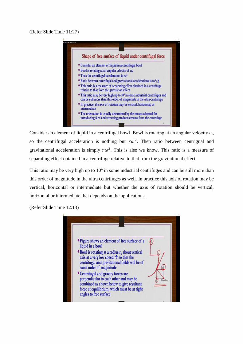
Consider an element of liquid in a centrifugal bowl. Bowl is rotating at an angular velocity ω,
so the centrifugal acceleration is nothing but 𝑟𝜔2. Then ratio between centrigual and
gravitational acceleration is simply 𝑟𝜔2. This is also we know. This ratio is a measure of
separating effect obtained in a centrifuge relative to that from the gravitational effect.
This ratio may be very high up to 104 in some industrial centrifuges and can be still more than
this order of magnitude in the ultra centrifuges as well. In practice this axis of rotation may be
vertical, horizontal or intermediate but whether the axis of rotation should be vertical,
horizontal or intermediate that depends on the applications.
(Refer Slide Time 12:13)

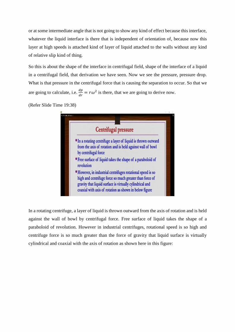
Now let us say you have taken a centrifugal bowl and then you rotate at kind of a moderate
speed, not very high speed so that you know both gravitational and centrifugal forces are of
comparable magnitudes. So this radius of this paraboloid is 𝑟0 and then it is rotating along this
axis, vertical axis 𝑧0 at this location. Let us say, at any point on this paraboloid if you wanted
to find the relative magnitude of these centrifugal and gravity forces, what you can do, you can
draw a kind of tangent like this so that there what you do, for that tangent you try to get the
normal components like this.
One is in the downward direction where the gravity is predominating, another one is kind of
the horizontal direction where the centrifugal field is dominating. If you take the resultant of
these two vectors, summation of these two, then the resultant whatever is there that is going to
be the total force that is acting at that particular point where you have drawn the tangent.
Figure shows an element of free surface of a liquid in a bowl. Bowl is rotating at radius r naught
about vertical axis at a very low speed so that the centrifugal and gravity fields will be of same
order of magnitude. Centrifugal and gravity forces are perpendicular to each other and may be
combined as shown below, here to give a resultant force at equilibrium, which must be at right
angles to free surface. So this resultant whatever is there that is at the right angle. So if this is
a kind of tangent, at this point of tangent if you have this right angle at right angle if you draw
a line, so that is going to give you the resultant of these two, which is nothing but summation
of these two; r and 𝑟𝜔2 and g.
(Refer Slide Time 14:21)

Thus the slope at this point is given by 𝑑𝑧0
𝑑𝑟0, obviously the slope, the slope at that point whatever
the tangent that you have drawn, that slope, this tangent.
(Refer Slide Time 14:34)
At this point if you draw the slope then what you have? 𝑑𝑧0
𝑑𝑟0. So that is
𝑑𝑧0
𝑑𝑟0 is equals to radial
component of force divied by the axial component of force, that is nothing but 𝑟𝜔2
𝑔 where 𝑧0 is
the axial coordinate of free surface of the liquid.
Integration of the above equation will give us 𝑧0 =𝜔2𝑟0
2
2𝑔+ 𝑐𝑜𝑛𝑠𝑡𝑎𝑛𝑡. Then let 𝑧0 is equals to
𝑧𝑎 at 𝑟0 is equals to 0, that is 𝑧𝑎 is value of 𝑧0 which corresponds to the postion where the free
surface is at axis of rotation i.e. at 𝑟0 is equals to 0. Then in this equation, if you substitute 𝑟0
is equals to 0 then constant is going to be 𝑧0 is equal to 𝑧𝑎.
At 𝑟0, the boundary condition is what? At 𝑟0 is equals to 0, we have 𝑧0 is equals to 𝑧𝑎. So this
when you substitute here in this equation, you will get constant is equals to z a and then we
substitute here and then simplify and you can write this equation as 𝑧0 − 𝑧𝑎 =𝜔2𝑟0
2
2𝑔. This is the
equation that represent the free surface of fluid layer which is under a centrifugal action.

(Refer Slide Time 16:20)
So let us take base of bowl as the origin for the measurement of 𝑧0 and if positive values of 𝑧𝑎
corresponds to conditions where the whole of the bottom of the bowl is covered by liquid, so
as I mentioned like different speeds if you do this rotations kind of thing, if you do kind of a
rotation at smaller flow rates, if you rotate this bowl at lower angular velocity so then you can
have a kind of interface something like this. So this is all kind of liquid. So the whole of the
bottom of this bowl is covered by the liquid. Under such conditions, in general, whatever the
𝑧𝑎 that you get is going to be kind of a positive one.
If you have kind of negative values of 𝑧𝑎, then what will happen? This bowl again you know,
that is corresponds to – this is the rotational axis along which it is rotating. If 𝑧𝑎 is negative,
then we will have kind of a fluid attached to the bowl as a kind of layer and then rotating
without any relative slip. And then this bottom of the bowl is completely dry and exposed. So
under such conditions, 𝑧𝑎 is nothing but negative one.
So negative 𝑧𝑎 you can have if the rotational speed is very high, positive 𝑧𝑎 you can have if the
rotational speed is low to moderate. But in general, we know that r omega square is much larger
than the g, i.e. centrifugal force is much larger than the gravity force. The surface is nearly
vertical and 𝑧0 has a very large negative value.
Thus in practice, the free surface of the liquid will be effectively concentric with the walls of
the bowl and therefore the operation of high-speed centrifuge is independent of the orientation
of the axis of rotation, whether are you rotating along the vertical axis or along horizontal axis
or at some intermediate angle that is not going to show any kind of effect because this interface,
whatever the liquid interface is there that is independent of orientation of, because now this
layer at high speeds is attached kind of layer of liquid attached to the walls without any kind
of relative slip kind of thing.
So this is about the shape of the interface in centrifugal field, shape of the interface of a liquid
in a centrifugal field, that derivation we have seen. Now we see the pressure, pressure drop.
What is that pressure in the centrifugal force that is causing the separation to occur. So that we
are going to calculate, i.e. 𝑑𝑝
𝑑𝑟= 𝑟𝜔2 is there, that we are going to derive now.
(Refer Slide Time 19:38)
In a rotating centrifuge, a layer of liquid is thrown outward from the axis of rotation and is held
against the wall of bowl by centrifugal force. Free surface of liquid takes the shape of a
paraboloid of revolution. However in industrial centrifuges, rotational speed is so high and
centrifuge force is so much greater than the force of gravity that liquid surface is virtually
cylindrical and coaxial with the axis of rotation as shown here in this figure:

(Refer Slide Time 20:05)
If you have kind of a very high rotational speed, this is the wall, actually this is the wall of the
bowl, so which is having a kind height b and then radius 𝑟2, this is the central axis of the bowl.
The radius of this bowl is 𝑟2. If you rotate this one at very high speed having the liquid already
present in the bowl when you rotate at very high speeds, the liquid is usually thrown outward
toward the wall and almost concentric cylindrical interface you can see here as shown in the
picture. And then this is going to be very true, very often occurs in many of the industrial
centrifuges that often applied for a given separation, solid separations.
Radial distance from axis of rotation to the free liquid surface is 𝑟1. So let us say initially liquid
is there, so that liquid is kind of having this thrown towards the kind of wall, so like this. So
towards the center of this bowl, we have a kind of empty column kind of thing without any
liquid and then liquid is thrown towards the wall which is forming a kind of concentric interface
like this. So this part whatever this filled part that I am showing is empty. There is no liquid
kind of thing. So that is the radius of the interface. Free liquid surface, whatever this is the
liquid that is thrown here and then liquid is now occupied from 𝑟1 to 𝑟2.
That is this is (𝑟2 − 𝑟1) , −𝑟1 is nothing but the thickness of the liquid that is forming as a kind
of layer along the surface and then this interface, whatever is the liquid interface is there, that
radial distance from the axis of rotation to the free liquid surface is nothing but 𝑟1. Radius of
the centrifugal bowl is 𝑟2. Entire mass of liquid is rotating as a rigid body with no sliding of
one layer of liquid over another. Under these conditions, pressure distribution can be found
from static principles.

Now consider a ring of liquid, now within this liquid layer it is actually both side is there. So
within this liquid layer what you do, you take a layer of liquid or a ring of liquid. We cannot
say layer because now it is now the centrifugal bowl. Entire bowl surface is attached with the
liquid layer forming a kind of a static liquid without any sliding of liquid layer, one liquid layer
over another liquid. Those kind of things are not there. So it is a centrifugal bowl rotating very
high speed. So within that liquid which is being attached to the bowl surface on that bowl
surface, that liquid layer, what you do, you take a ring of having thickness dr at distance r from
the axis of rotation.
From the axis of rotation at distance r, you take a ring of liquid of thickness dr and then consider
mass of that liquid in that ring of liquid is dm. So then volume of element at thickness dr at
radius of r, you can calculate. So the centrifugal force for that ring of liquid would be nothing
but 𝑑𝐹 = 𝑟𝜔2𝑑𝑚. So 𝑟𝜔2 is nothing but the centrifugal acceleration like gravitational
acceleration or acceleration due to gravity g is there. Acceleration due to centrifugal force,
whatever is there that is r omega square. If that is multiplied by the mass then you will get the
centrifugal force. You get centrifugal force but that we are doing now for a layer of the liquid
or the ring of a liquid having the thickness dr.
So within this layer of ring of liquid having thickness dr, so the centrifugal force dF. That
should be 𝑟𝜔2𝑑𝑚 where dm is nothing but the mass of the liquid present in that ring of
thickness dr. So centrifugal force 𝑑𝐹 = 𝑟𝜔2𝑑𝑚. but if the density of the liquid is constant and
then breadth or height of the ring is given as same as the height of the bowl b, then mass of the
liquid dm is nothing but volume of that particular ring of liquid multiplied by the density of the
liquid.
Then volume of that particular ring of thickness dr is nothing but (2𝜋𝑟𝑏 × 𝑑𝑟) × 𝜌 then you
will get the mass of the liquid in that ring of the liquid. So that is 𝑑𝑚 = (2𝜋𝑟𝑏 × 𝑑𝑟) × 𝜌 . So
now this dm you can substitute here in this equation. When you substitute, you will get 𝑑𝐹 =
(2𝜋𝜌𝑏𝜔2𝑟2) × 𝑑𝑟. Now the force is there, if you divide by the area, then you will get the
pressure. So the pressure due to the centrifugal force, that you can obtain now.

(Refer Slide Time 25:51)
So change in pressure over the element in the force exerted by the element of liquid divided by
the area of the ring, then we will get dp. So, dp is equal to dF by area of the ring. Area of the
ring is what? 2𝜋𝑟𝑏. 2𝜋𝑟𝑏, so that is nothing but now, dF we already got it. If you divide 𝑑𝐹
2𝜋𝑟𝑏,
then you will get 𝑑𝑝 = 𝜔2𝜌𝑟𝑑𝑟 or from here we can write 𝑑𝑝
𝑑𝑟= 𝜌𝑟𝜔2. So let us say pressure
drop over the entire ring is (𝑝2 − 𝑝1). Then you integrate this right hand side and then substitute
ring size 𝑟1 to 𝑟2. Then we will get (𝑝2 − 𝑝1) =𝜔2𝜌(𝑟2
2−𝑟12)
2. 𝑟2 is nothing but bowl radius and
𝑟1 is nothing but the radius of the interface.
So (𝑝2 − 𝑝1), 𝑝2 is nothing but pressure at the bowl wall and then 𝑝1 is nothing but pressure at
the liquid free surface which is at 𝑟1 distance from the axis of rotation. Ok. So that is
(𝑝2 − 𝑝1) =𝜔2𝜌(𝑟2
2−𝑟12)
2. Remember, this equation applies only when 𝑟1 and 𝑟2 are not greatly
different from each other, that is liquid layer thickness whatever that is attaching to the
centrifugal bowl because of the centrifugal field is not very thick, it is thin so that 𝑟2 and 𝑟1 are
now different from each other because (𝑟2 − 𝑟1) is nothing but the thickness of that liquid.
But for practical system, the error is so small that you do not need to worry about this 𝑟2 and
𝑟1 differences, how much they are different from each other because practically when you apply
high centrifugal field, this difference in 𝑟2 and 𝑟1 is going to play a kind of very less influence.
So, now using this centrifugal field how to do separation of immiscible liquids of different
densities?

(Refer Slide Time 28:06)
Let us say, you have a immiscible liquids – light liquid and then heavy liquid. And then there
may be let us say some small solids also. Forget about the solids, we do not need to worry as
of now. So when you do separation of these immiscible liquids by the gravity, it will take very
very long time and then after very very long time, this heavier liquid will be forming as a kind
of bottom layer and then on the top one, light liquid will be forming as a kind of light liquid
layer so that they can be separated out. But here it is going to take long time because in general
immiscible liquids, though the densities are different but the difference in densities of heavier
and then lighter liquids is not very high. In general that is the case.
Let us say, the example of obtaining edible oil from vegetable seeds then whatever aqeous oil
phases that we get, the densities are in general, oil phase may be having 0.95 gram per cc and
then aqeous phase may be having 0.98 or 1.00 gram per cc, something like that. They are very
close to each other. Under such conditions, if the densities are close and then forming
immiscible phases, settling of those immiscible liquids into two separate layers by gravity is
going to take very long, is going to take very long time.
But if you take kind of a centrifugal bowl and then in that one you take this immiscible liquids
and then rotate that centrifugal bowl at high speeds, then what happens is like whatever the
heavier phase is there, heavier liquid is there, that will be attached, that will be thrown towards
the wall and then form a kind of layer A like shown here and then next to that one, the lighter
liquid shown as zone B that will be attached very next to this heavier liquid and then from the
top, heavier liquid can be taken from this outlet 1 and then lighter liquid can be taken from this
outlet 2.

So, here the notations are again same: 𝑟2 is kind of radius of the wall, then height of the wall is
B let us say. Now this 𝑟𝐴 and 𝑟𝐵 are the corresponding radius of this outlet for heavy liquid
collection and then light liquid collection respectively. Because the feed is continously coming
in and continously you can take out these things, so that you do this process continuously. The
interface between this heavy liquid and then light liquid whatever is there, that is 𝑟𝑖, that is 𝑟𝑖
and this 𝑟𝑖 is kind of very important calculation, this 𝑟𝑖 calculation based on that one this 𝑟𝐴 and
𝑟𝐵 locations are set so that the collection of this heavy and light liquids can be taken
continuously.
So what is the 𝑟𝑖? 𝑟𝑖 is known as the neutral zone. A is a kind of heavy liquid zone, B is kind
of light liquid zone and then in between that interface whatever is there, that is 𝑟𝑖 having the
radius 𝑟𝑖 which is known as the neutral zone. So that 𝑟𝑖, we are going to calculate now.
So in this process if at all some solids are there, they will be kind of settled at the bottom and
then few solids may be climbing towards the corner of the wall like this, that is also possible.
So if at all solids are there, you know, one has to be careful while rotating this bowl, so that is
at what speed one has to rotate this bowl, that one has to be careful because if it is rotating too
high, very very high speeds, then these particles will also be coming towards the wall. We do
not want that high velocity, we want those particles to be at the bottom only.
So because this particle’s density is going to be much higher than the density of heavier liquid,
so that one we have to be careful. Anyway this particular thing, when there are particles are
also there, that we are going to take in the kind of next lecture. So as of now, forget about
particle, solid particles in this case. If difference between densities of two liquids is small,
gravitational force may be too weak to separate liquids in reasonable time.
Thus separation may be improved in a liquid liquid centrifuge or centrifugal decanter as shown
above in this picture.

(Refer Slide Time 32:46)
So liquid-liquid centrifuge consists of a cylindrical metal bowl, ususally mounted vertically,
that rotates about its axis at high speed. When bowl is at rest and contains a quantity of two
immiscible liquids of differing densities, then heavy liquid forms a layer on the floor of the
bowl beneath a layer of light liquid. On rotating the bowl, heavy liquid forms a layer, denoted
as zone A, next to the inside wall of the bowl. And then layer of light liquid denoted as zone B
forms inside layer of the heavy liquid.
(Refer Slide Time 33:23)
How to obtain the radius of neutral zone? The cylindrical interface of radius 𝑟𝑖 which separates
these two layers which are forming zone A and zone B, that known as a kind of neutral zone.
So that 𝑟𝑖 we have to calculate. Since force of gravity can be neglected in comparison with

greater centrifugal force, this interface is vertical and is called as neutral zone. So if the density
of a heavy liquid is 𝜌𝐴 and then overflows at radius 𝑟𝐴, so there is an overflow opening at the
top for this heavy liquid to go out and then radius of the overflow distance, that 𝑟𝐴 distance is
there from the central axis.
(Refer Slide Time 34:15)
That is this 𝑟𝐴 is location of overflow ducts from where, you know from the top heavy liquid is
taken. 𝑟𝐵 is the location of the distance from central axis to the location of overflow for a lighter
liquid. Ok.
(Refer Slide Time 34:32)
Simialrly, density of light liquid is 𝜌𝐵 and leaves the centrifuge at 𝑟𝐵. If both liquids rotate with
the bowl and friction is negligible, pressure difference in light liquid between 𝑟𝐵 and 𝑟𝐴 must
be equal that in heavy liquid between 𝑟𝐴 and then 𝑟𝑖. This is the reason because we need to
know the pressure distribution in centrifugal field in order to get these calculations. What we
have done, we have previosuly derived 𝑑𝑝
𝑑𝑟= 𝜌𝑟𝜔2. So therefore, in order to have this neutral
zone to be stable this 𝑝𝑖 − 𝑝𝐵 = 𝑝𝑖 − 𝑝𝐴 where 𝑝𝐴 is nothing but pressure at the interface there
at neutral zone. 𝑝𝐴 and 𝑝𝐵 are nothing but pressure in the zone A and zone B respectively.

(Refer Slide Time 35:23)
So from centrifugal pressure distribution principles, we have already seen that 𝑑𝑝
𝑑𝑟= 𝜌𝑟𝜔2.
When you integrate them, then we have (𝑝2 − 𝑝1) =𝜔2𝜌(𝑟2
2−𝑟12)
2. That is what we have. So that
principle if you apply here, (𝑝𝑖 − 𝑝𝐵) =𝜔2𝜌𝐵(𝑟𝑖
2−𝑟𝐵2)
2 and then (𝑝𝑖 − 𝑝𝐴) =
𝜔2𝜌𝐴(𝑟𝑖2−𝑟𝐴
2)
2. But
these two things are equal at the neutral zone, these two quantities. So then when we equate
these equations, you will get 𝜌𝐵(𝑟𝑖2 − 𝑟𝐵
2) = 𝜌𝐴(𝑟𝑖2 − 𝑟𝐴
2).
So when you solve this equation for 𝑟𝑖, we will get 𝑟𝑖 = √𝑟𝐴2−(
𝜌𝐵𝜌𝐴⁄ )𝑟𝐵
2
1−(𝜌𝐵
𝜌𝐴⁄ ). So now we can see
(𝜌𝐵
𝜌𝐴⁄ ). The density ratio of light to heavy liquid is going to play a kind of very vital role in
positioning this 𝑟𝑖. So above equation shows th`at the radius of neutral zone is sensitive to
density ratio, especially when this ratio is nearly unit. If it is like almost close to 1, so then this
value is going to be, denominator one is going to be close to 0. Then it is going to be a kind of
very large value and then under such conditions this 𝑟𝑖 is going to be unstable.

(Refer Slide Time 36:59)
If densities of fluids are too alike then neutral zone may be unstable even if speed of rotation
is sufficient to separate liquids quickly. Difference between densities should not be less than
approximately 3 percent of, so that to have a kind of stable operation. So equation of 𝑟𝑖 from
there, what we can understand: if 𝑟𝐵 is held constant and 𝑟𝐴 is increased, then neutral zone is
shifted towards wall of the bowl and if 𝑟𝐴 is decreased by keeping 𝑟𝐵 as constant then neutral
zone has to be shifted towards the axis. So this is the importance of calculation of 𝑟𝐴 based on
the 𝑟𝑖 value.
One can change the locations of 𝑟𝐴 and 𝑟𝐵 locations so that we can have the effective and then
clear separations of these two phases. Simialarly, if 𝑟𝐴 is held constant then 𝑟𝐵 is increased so
that neutral zone shifts towards the axis, and then decrease in rB by keeping 𝑟𝐴 constant causes
a shift of neutral zone towards the wall. So according to this value of 𝑟𝑖, one can place this 𝑟𝐵
and then 𝑟𝐴 locations so that the separation of these two phases can be taken effectively and
continuously.
Therefore, practically position of neutral zone is very very important. That is the reason we
have calculated what is this 𝑟𝑖.

(Refer Slide Time 38:34)
In zone A, the lighter liquid is being removed from a mass of heavier liquid and in zone B,
heavy liquid is being removed from a mass of light liquid. If one of the process is more difficult
than the other, more time should be provided for more difficult step. Let us say, if separation
in zone B is more difficult than that in zone A, then zone B should be large so that more time
is there for the liquid to separate and then zone A has to be small. That is the advantage of
knowing this 𝑟𝑖 information.
This is accomplished by moving the neutral zone toward wall by increasing 𝑟𝐴 or decreasing
𝑟𝐵 accordingly as per the requirement. To obtain a large time factor in zone A, opposite
adjustments should be made that is moving the neutral zone towards the axis of rotation and
then decreasing 𝑟𝐴 and then increasing 𝑟𝐵. So the opposite one has to be followed. Many
centrifugal separators are so constructed that either 𝑟𝐴 or 𝑟𝐵 can be varied to control position of
the neutral zone as well.

(Refer Slide Time 39:47)
So now we see a few centrifugal decanters – equipments that are used for the separation of
immiscible liquids or separation of immiscible liquids and solids from a mixture of solids and
immiscible liquids. There are several types of decanters or centrifugal decanters are available.
What are they? Some of the industrially famous one we are going to discuss now.
In industries, immiscible liquids can be effectively separated in centrifugal decanters.
Separating centrifugal force is much larger than that of gravity, that is the reason centrifugal
force are in general applied so that they do separation of immiscible liquids. This force acts in
direction away from axis of rotation instead of downward toward the bottom of the equipment
as the gravity does. There are two main types of centrifugal decanters: tubular centrifuges and
then disk centrifuges. So let us start with the tubular centrifuge.

(Refer Slide Time 40:48)
In the tubular centrifuge, actually a kind of a tall and narrow bowl we have. The bowl is having
diameter 100 to 150 mm. This bowl is rotating by vertical axis like this. The feed is coming
here, continuously like this and then given in this one. So then when this feed is having
immiscible liquids, then whatever the heavier liquid is there, that will be thrown towards the
wall and then collected from this heavier liquid duct or weir. So lighter liquid is towards this
interface of heavier liquid, not towards the wall of the liquid. So from there you know, there is
a weir that is connecting to collect the lighter liquid. That is the basic principle and this bowl
whatever that we are having, that is rotating at high speed.
Actually, this is the bowl and this is present in a kind of casing like this. So this heavy liquid
side wear whatever is there, that can be removable and that can be adjusted as per the
requirement. So whether it is tubular centrifuge or disk centrifuge, whatever it is there, the
working principle is same. Design, how the centrifugation is done, how the collection of this
heavier and then lighter phases has been done, that is the only difference from one design to
the other design.
So, here in tubular centrifuge, bowl is tall and narrow having the diameter in general 100 to
150 mm only and turns in a stationery casing at about 15,000 rpm. It rotates at very high speeds.
Feed enters from a stationery nozzle inserted through an opening in the bottom of the bowl. It
separates into two concentric layers of liquid inside the bowl. Lighter layer spills over a weir
at top of the bowl, it is thrown outward into a stationery discharge cover and from there to a
spout.

Heavy liquid flows over another weir into a separate cover and discharge spout. Weir over
which heavy liquid flows is removable and may be replaced with another having an opening
of different size. Position of liquid liquid interface that is neutral zone is maintained by the
hydraulic balance. This is about the tubular centrifuge.
(Refer Slide Time 43:22)
Now disk centrifuges. Here the working principle is the same. Again we have a bowl in which
we take the feed and then rotate it so that the feed separates into the two phases – heavy and
then lighter liquid phases, like that. But within the bowl what we are having, we are having
some kind of conical sheets kind of disks are there. So towards the centre or towards the wall
of this or towards the edge as well as towards the centre of these sheets there are kind of holes
through which you know, these holes forms a kind of channel so that liquid pass from one sheet
to the other sheet kind of thing.
So, it is highly effective for liquid-liquid separations. It is a short and wide bowl of 200 to
500mm in diameter which turns on a vertical axis. The bowl has a flat bottom and conical top
as shown here in the picture. Feed enters from above through a stationery pipe set into neck of
the bowl. Two liquid layers formed as in tubular centrifuge and flow over adjustable dams into
separate discharge spouts. So there is a light liquid discharge spout and then heavy liquid
discharge spout is there.

(Refer Slide Time 44:43)
There are closely spaced disks inside the bowl and rotating with it which are actually cones of
sheet metal set one above the other. There are n number of conical metal sheets kind of thing
are there which are used as a kind of a disk and they are spaced very close to each other. And
this set is there inside the bowl.
Matching holes in disks about halfway between the axis and wall of the bowl form channels
through which the liquids passes from one disk to the other disk or from the space between two
disks to the next space between another subsequent two disks, like that. Feed enters the bowl
at bottom and flows into channels and upward past the disk. Heavier liquid is thrown outward
displacing lighter liquid toward the centre of the bowl. While being through outward, this heavy
liquid very soon strikes the underside of a disk and flows beneath it to periphery of a bowl
without encountering any light liquid.

(Refer Slide Time 45:45)
Similarly, light liquid flows inward and then upward over upper surface of the disk. Because
of the having this disk what happens, these liquids they are moving into different directions.
The heavier liquid is moving towards the wall and then lighter liquid is moving towards the
axis of the bowl. So then because of that movement, there is a kind of friction also. Since disks
are closely spaced, distance a drop of either liquid must travel to escape from other phase is
short, must shorter than in comparatively thick liquid layers in a tubular centrifuge.
In addition, in disk machine, there is considerable shearing at liquid-liquid interface as one
phase flows in one direction and other phase in opposite direction. Because of this one, you
know it helps shearing, whatever the shearing is there, it helps break certain type of emulsions
if at all they are existing in the feed system.
Disk centrifuges are particularly valuable where purpose of centrifuge is not complete
separation only but concentration of one fluid phase as in the separation of cream from milk
and concentration of rubber latex et cetera.

(Refer Slide Time 47:00)
Let us say, sometimes if you have solid impurities in the feed, whatever the feed that immiscible
liquids that you are separating, in the feed if you have solid impurities then how to clean up in
centrifuges. So whatever the disk centrifuges that can be modified so that the solids can also
be removed. However before that what we need to know? If liquid fed to disk or tubular
centrifuge contains dirt or other heavy solid particle, solids accumulate inside the bowl and
periodically must be discharged. This is accomplished by stopping the machine, removing and
opening bowl and scraping out its load of solids. That is one way.
But this becomes uneconomical if the solids are more than a few percent of the solids. You
cannot afford to have kind of interrupting the process especially in the industry level and then
if the solids percent is very high then you are forced to stop the process and then do the
separation, so that is not going to be economical. Tubular and disk centrifuges are used to
advantage for removing traces of solids from lubricating oil, process liquids, ink and beverages
that must be perfectly clean. They can take out gelatinous slimy solids that would quickly plug
a filter.
Usually they clarify a single liquid in a bowl provided with but a single liquid overflow.
However they also may throw down solids while simultaneously separating two liquid phases.
How it is being done, that we see now.

(Refer Slide Time 48:30)
Nozzle discharge centrifuge – it is nothing but modification of a disk centrifuge. That we are
going to see, how it looks like. It is like you know, pictorially if you see, it is almost like similar
kind of a disk centrifuge but at the bottom there is a kind of provision to collect the solids. If
feed liquid contains more than a few percent of solids, some means must be provided for
discharging solids automatically as shown in picture. This is a modified disk type centrifuge
with a double conical bowl.
In periphery of bowl at its maximum diameter is a set of small holes or nozzles around 3mm
in diameter. So at this periphery, what we have is nozzles. We have a kind of nozzles of a very
small size like 3mm in diameter, something like that. Central part of bowl operates in same
way as usual disk centrifuge, overflowing either one or two streams of clarified liquid.

(Refer Slide Time 49:32)
Solids are thrown to the periphery of bowl and escape continuously through the nozzles
together with considerable liquid also. In some deisgns, part of the slurry discharge from the
nozzles is recycled through the bowl to increase its concentration of solids. Wash liquids may
also be introduced into the bowl for displacement of washing as well. So through the nozzle,
not only the solids are being discharged but some amount of liquid is also being collected or
being taken out. So what happens, this liquid if you want like a dry solids kind of thing, this
liquid has to be drained off.
So further what you can do? You can take this concentrated solid sludge again and throw inside
the the disk vessel, further separation of the liquid can be taken place. A kind of recycling can
be done. In other designs, nozzles are closed most of the time by plugs or valves that open
periodically to discharge a moderately concentrated slurry. So this is about the several types of
centrifugal decanters.
(Refer Slide Time 50:41)
The references, we have several refernces for this lecture. But primarily the lecture, the notes
that has been prepared for this lecture can be taken, can be found in this first book, Unit
Operations of Chemical Engineering by McCabe, Smith and Harriot. So this reference is a kind
of very important reference. Thank you.