Mechanical and Thermal Transport Properties of Suspension Thermal-Sprayed Alumina-Zirconia Composite...
15
NRC Publications Archive (NPArC) Archives des publications du CNRC (NPArC) Publisher’s version / la version de l'éditeur: Journal of Thermal Spray Technology, 17, 1, pp. 91-104, 2007-05-14 Mechanical and thermal transport properties of suspension thermal sprayed Alumina-Zirconia composite coatings Oberste Berghaus, Jörg; Legoux, Jean-Gabriel; Moreau, Christian; Terasi, Fariba; Chraska, Tomas Contact us / Contactez nous: [email protected]. http://nparc.cisti-icist.nrc-cnrc.gc.ca/npsi/jsp/nparc_cp.jsp?lang=fr L’accès à ce site Web et l’utilisation de son contenu sont assujettis aux conditions présentées dans le site Web page / page Web http://dx.doi.org/10.1007/s11666-007-9146-0 http://nparc.cisti-icist.nrc-cnrc.gc.ca/npsi/ctrl?action=rtdoc&an=15774998&lang=en http://nparc.cisti-icist.nrc-cnrc.gc.ca/npsi/ctrl?action=rtdoc&an=15774998&lang=fr LISEZ CES CONDITIONS ATTENTIVEMENT AVANT D’UTILISER CE SITE WEB. READ THESE TERMS AND CONDITIONS CAREFULLY BEFORE USING THIS WEBSITE. Access and use of this website and the material on it are subject to the Terms and Conditions set forth at http://nparc.cisti-icist.nrc-cnrc.gc.ca/npsi/jsp/nparc_cp.jsp?lang=en
-
Upload
independent -
Category
Documents
-
view
1 -
download
0
Transcript of Mechanical and Thermal Transport Properties of Suspension Thermal-Sprayed Alumina-Zirconia Composite...

NRC Publications Archive (NPArC)Archives des publications du CNRC (NPArC)
Publisher’s version / la version de l'éditeur: Journal of Thermal Spray Technology, 17, 1, pp. 91-104, 2007-05-14
Mechanical and thermal transport properties of suspension thermal sprayed Alumina-Zirconia composite coatingsOberste Berghaus, Jörg; Legoux, Jean-Gabriel; Moreau, Christian; Terasi, Fariba; Chraska, Tomas
Contact us / Contactez nous: [email protected].
http://nparc.cisti-icist.nrc-cnrc.gc.ca/npsi/jsp/nparc_cp.jsp?lang=frL’accès à ce site Web et l’utilisation de son contenu sont assujettis aux conditions présentées dans le site
Web page / page Webhttp://dx.doi.org/10.1007/s11666-007-9146-0http://nparc.cisti-icist.nrc-cnrc.gc.ca/npsi/ctrl?action=rtdoc&an=15774998&lang=enhttp://nparc.cisti-icist.nrc-cnrc.gc.ca/npsi/ctrl?action=rtdoc&an=15774998&lang=fr
LISEZ CES CONDITIONS ATTENTIVEMENT AVANT D’UTILISER CE SITE WEB.
READ THESE TERMS AND CONDITIONS CAREFULLY BEFORE USING THIS WEBSITE.
Access and use of this website and the material on it are subject to the Terms and Conditions set forth athttp://nparc.cisti-icist.nrc-cnrc.gc.ca/npsi/jsp/nparc_cp.jsp?lang=en

Mechanical and Thermal TransportProperties of Suspension Thermal-Sprayed
Alumina-Zirconia Composite CoatingsJorg Oberste Berghaus, Jean-Gabriel Legoux, Christian Moreau, Fariba Tarasi, and Tomas Chraska
(Submitted February 27, 2007; in revised form June 29, 2007)
Micro-laminates and nanocomposites of Al2O3 and ZrO2 can potentially exhibit higher hardnessand fracture toughness and lower thermal conductivity than alumina or zirconia alone. The potential ofthese improvements for abrasion protection and thermal barrier coatings is generating considerableinterest in developing techniques for producing these functional coatings with optimized microstructures.Al2O3-ZrO2 composite coatings were deposited by suspension thermal spraying (APS and HVOF) ofsubmicron feedstock powders. The liquid carrier employed in this approach allows for controlledinjection of much finer particles than in conventional thermal spraying, leading to unique and novel fine-scaled microstructures. The suspensions were injected internally using a Mettech Axial III plasma torchand a Sulzer-Metco DJ-2700 HVOF gun. The different spray processes induced a variety of structuresranging from finely segregated ceramic laminates to highly alloyed amorphous composites. Mechanismsleading to these structures are related to the feedstock size and in-flight particle states upon their impact.Mechanical and thermal transport properties of the coatings were compared. Compositionally segregatedcrystalline coatings, obtained by plasma spraying, showed the highest hardness of up to 1125 VHN3 N, aswell as the highest abrasion wear resistance (following ASTM G65). The HVOF coating exhibited thehighest erosion wear resistance (following ASTM G75), which was related to the toughening effect ofsmall dispersed zirconia particles in the alumina-zirconia-alloyed matrix. This microstructure alsoexhibited the lowest thermal diffusivity, which is explained by the amorphous phase content and limitedparticle bonding, generating local thermal resistances within the structure.
Keywords abrasive and erosive wear, nanocrystalline com-posites, solution-precursor TS
1. Introduction
Laminated composites, in which ceramic layers ofdifferent compositions and microstructures are combinedto obtain properties superior to those of the constituentlayer materials, have emerged as an area of extensive re-search in recent years. Drastic increase in strength andfracture toughness has been achieved in alumina/zirconialaminar composites. The improvements in mechanicalbehavior are primarily linked to the crack-diverting char-acteristics of the interlaminate interfaces and the presenceof second phases acting as crack arrestors (Ref 1). Otherstrengthening mechanisms are attributed to the surfaceresidual compressive stresses, which arise from the differ-ent thermal expansion coefficients (Ref 2) and elastic
moduli of the layers. In alumina/zirconia-layered com-posites, the strength and toughness have been reported toincrease with progressive layer refinement and the intro-duction of corrugated interfaces (Ref 3, 4). Laminar com-posites are presently synthesized by different processingroutes including tape casting, sequential slip casting, elec-trophoretic deposition, and colloidal techniques (Ref 5).More recently, physical vapor deposition techniques(PVD) (Ref 6) and thermal spraying have also been used.Thermal spray processing, a technique by which moltenceramic droplet impinge on a substrate and solidify as largedisks, i.e., ‘‘splats,’’ imparts an inherent lamellar structure,which has been exploited to form alumina-zirconia multi-layers (Ref 7) and micro-composites (Ref 8-10). Theprincipal driving force for the development of thermal-sprayed Al2O3/ZrO2 composites is to enhance the resis-tance against abrasion, wear, and oxygen diffusion, as wellas the thermal resistance of thermal barrier coatings(TBCs) over conventional stabilized zirconia in the high-temperature environment of turbine engines. The combi-nation of high hardness of alumina with the low thermalconductivity of zirconia may lead to next generation TBCswith improved properties and service life. Besides creatingthin alternating layers, the rapid solidification of the mol-ten ceramics in the thermal spray process can, in somecases, extend the solid solution of zirconia in alumina toform metastable amorphous phases. This is most easilyaccomplished at a composition of 57% Al2O3-43% ZrO2,
Jorg Oberste Berghaus, Jean-Gabriel Legoux, and ChristianMoreau, Industrial Materials Institute, NRC, Boucherville,QC, Canada; Fariba Tarasi, Concordia University, Mon-treal, QC, Canada; and Tomas Chraska, Institute of PlasmaPhysics, ASCR, Praque, Czech Republic. Contact e-mail:[email protected].
JTTEE5 17:91–104
DOI: 10.1007/s11666-007-9146-0
1059-9630/$19.00 � ASM International
Journal of Thermal Spray Technology Volume 17(1) March 2008—91
PeerReviewed

since the binary phase diagram features a eutectic pointwith lowering of the liquid curve to 1900 �C (Ref 11, 12). Ananocomposite structure can arise from this metastableamorphous phase by the nucleation of ZrO2 crystals in theAl2O3 matrix during postannealing (Ref 13-15). Similar tothe laminates, the nanocomposites can show improve-ments in thermal resistance and mechanical propertiescompared to both alumina and zirconia, i.e., higher frac-ture toughness (Ref 13, 16). In fact, the ZrO2/Al2O3 bulkcomposite is a classical model of a transformation-tough-ening ceramic system (Ref 6). The toughening effect ismost often explained in terms of an alumina matrix, whichexerts local compressive stresses around small zirconiacrystals, hindering the martensitic phase transformationfrom tetragonal to monoclinic ZrO2 (Ref 16).
Thermal spraying of liquid feedstock, using eitherprecursor salts in solution (Ref 17-19) or particle suspen-sions (Ref 20-22), are emerging technologies for the pro-duction of finely structured functional layers and can yieldunique microstructures (Ref 23, 24) and phase composi-tions (Ref 25) in Al2O3-ZrO2 composites.
In this work, microlaminate composites of alumina/zirconia are produced by suspension thermal sprayingof submicron feedstock powders. The liquid carrieremployed in this approach allows for controlled injectionof much finer particles than in conventional thermalspraying, leading to a high degree of structural refinementin the coatings. The effects of spray conditions and feed-stock nature are explored to either foster a structure offinely alternating ceramic layers or the creation of amor-phous/nanostructured constituents. Two different thermalspray systems were employed, an axial injection plasmatorch and a high-velocity oxyfuel (HVOF) gun. A widediversity in coating microstructure is expected from thetwo very different spray systems. Mechanical propertiesand thermal conductivities of the coatings are evaluated.The ultimate goal is to delineate how to tailor the uniquemicrostructures obtained by suspension thermal sprayingfor meeting desired mechanical and thermal transportproperty requirements.
2. Experimental Procedure
2.1 Suspension Spray Equipment and Operation
Suspension spraying was implemented for an axialinjection plasma torch Mettech Axial III (NorthwestMettech Corp., North-Vancouver, BC, Canada) and aHVOF DJ-2700 Hybrid gun (Sulzer-Metco, Westbury,NY, USA). The systems were equipped with internalinjection and twin-fluid atomization modules. Theco-axially fed suspension droplets are fully entrained byencircling three plasma streams, as in the case of theMettech Axial III torch, or are intimately contacted withthe fuel inside the HVOF combustion chamber, as in thecase of the DJ-2700 gun. Such arrangements can reducethe process sensitivity to the injection conditions and areexpected to yield a high degree of heat and momentumtransfer from the jets. The suspensions were delivered by a
specialized feeding system, using a positive-displacementdosing pump and precision flow meters. Start-up, shut-down, and rinsing sequences were fully automated and PCcontrolled. The plasma torch was operated at threeselected conditions of gas flow rate, gas composition, andexit nozzle sizes, which were previously used to producecontinuous, dense, and well-adhering coatings and whichare summarized in Table 1. Nitrogen at a flow rate of10 slpm was employed as the atomizing gas. A spraydistance of 51 mm between the torch exit nozzle and thesubstrate was maintained throughout during coatingfabrication.
The spray parameters for the DJ 2700 HVOF gun arelisted in Table 2. These conditions, with over stoichiom-etric oxygen flow, were selected to yield a high flametemperature and heat output of this equipment, whilelimiting the backpressure in the combustion chamberduring spraying to approximately 620 kPa (90 psi).
In-flight particle states were measured with a com-mercial diagnostic system (AccuraSpray� G2 and G3,Tecnar Automation, St-Bruno, PQ, Canada). Since thesmall size of the particles prevents individual in-flightparticle detection, an ensemble particle diagnostic system,which senses the fluctuations of the total emitted radiationin the field of view, is deemed necessary (Ref 26). Thetemperature measurement is based on two-color pyrom-etry, and the velocity is determined by a time-of-flighttechnique. The measurement volume was centered in thespray plume at the location of the substrate during depo-sition.
2.2 Coating Characterization
Microstructures of the coatings were observed by SEM(JEOL JSM-610) and FE-SEM (Hitachi S4700). Thesamples were sectioned using a precision saw, mountedunder vacuum in epoxy resin, and prepared by standard
Table 1 Plasma operating conditions
Spraycondition
Exitnozzle,mm
Torchcurrent,
·3
Gasflow,slpm
Power,kW
Ar,%
N2,%
H2,%
1 11 (7/16 in.) 180 A 180 84 45 45 102 9.5 (3/8 in.) 180 A 180 86 45 45 103 9.5 (3/8 in.) 200 A 245 82 75 10 15
Torch traverse speed: 600 mm/s (24 in./s); Atomizing gas N2 at10 slpm
Table 2 HVOF spray parameters for ceramic A40Zfeedstock suspension, DJ 2700
Parameter Value
Propylene flow 85 slpmOxygen flow 279 slpmAir flow 202 slpmCarrier gas (N2) flow 17 slpmSuspension feed rate 55 mL/min (3.1 kg/h)Spray distance 12.7-15.2 cmGun traverse speed 30 in/s
92—Volume 17(1) March 2008 Journal of Thermal Spray Technology
PeerReviewed

metallographic methods to produce a polished cross sec-tion. Porosity was assessed on the cross section by SEM(500 and 5000 magnification) using image analysis. Theintensity range and thresholds were standardized on ref-erence materials, and 10 measurements were averaged persample. This method at 500 times magnification is wellsuited to rank porosities of conventional thermal spraycoatings and well describes the occurrence of large defectsin the present coatings. Evaluation at 5000 magnificationwas attempted to capture some of the finer porosity andnanopores encountered in this study.
Vickers microhardness measurements were performedunder a 3 N load for 20 s on the polished cross section ofthe coatings. A total of 10 measurements were taken persample. The relative toughness of the material was esti-mated from the crack propagation resistance, as deter-mined from the average crack length (2c) originating fromthe corners of the Vickers indentation impression at a load(P) of 3 N. The relationship P/c3/2, where P is in Newtonsand c in meters, was employed in this comparison (Ref27). An average of 10 indents were used per sample.
Abrasion resistance of the coatings under dry condi-tions was tested based on the ASTM standard methodG65-00 (procedure D-modified), also known as the drysand/rubber wheel test (Ref 28). A coated sample ispressed against a rotating rubber wheel (200 rpm) with aforce of 45 N. Silica sand (212-300 lm) is fed between thecoating and the wheel, until the wheel has traveled anequivalent linear distance of 1436 m (2000 rev.). Thelighter load variation of the standard procedure allowedranking of the relatively thin coating material. Prior to thetest, the coatings were faced to a level surface. The volumeloss was measured by optical profilometry.
Erosion resistance by solid particle impingement wasevaluated based on the ASTM standard method G76-83,exposing a coated sample to 100 grit alumina particles(standard 122 lm average and 203 lm maximum), whichimpact with a speed of 64 m/s at an angle of 30� (Ref 29).The test duration was 30 s with a particle feed rate of3.86 g/min. The volume loss at the erosion scar was mea-sured by optical profilometry.
Thermal diffusivity a was evaluated for selected sam-ples using a laser flash method (Ref 30). For each spraycondition, three replicate samples were analyzed with atleast five heating cycles. To ensure absorption of the laser
radiation at the coating surface, the samples were coatedwith palladium. The thermal conductivity k of thesecoatings was determined using the relationship k=aCpq.Specific-heat (Cp) measurements for Al2O3-ZrO2 coatingsare made using a standard differential scanning calorim-eter (DSC-2, Perkin-Elmer, Fremont, CA, USA), withsapphire as a reference material. Material density wasapproximated by a linear law of mixing, neglectingporosity.
Phase analysis was carried out by XRD using a BruckerD8-Discovery diffractometer (Brucker AXS Inc., Madi-son, WI, USA) with Cu-Ka radiation at an acquisition of0.01�/s. The crystallite size was approximated from theSherrer equation at the principal diffraction lines (Ref 31).An attempt was made to quantify the degree of crystal-linity by measuring the area of crystalline peaks between25� and 40� vs. the total integrated area in this region,including the diffuse amorphous hump. This index reflectsthe alloying of the ceramic constituents into an amorphousphase due to rapid solidification and allows here a quali-tative comparison between the coatings obtained at dif-ferent spray conditions.
Particle sizes and distribution were measured with aCoulter LS Laser Particle size analyzer (Beckman-Coul-ter, Mississauga, ON, Canada) using the Universal LiquidModule, characterizing the powders and powder agglom-erates as they are present in the suspension.
2.3 Materials and Suspensions
Two different feedstock particle sizes were used in thisstudy, namely nanosized (<80 nm), NA, and slightly largersuperfine powders (SF). NA denotes feedstocks of nano-sized alumina mixed with nanosized zirconia. SF denotesmixtures of the larger superfine alumina and zirconiapowders. The distinction between nanosized and superfineparticles is somewhat arbitrary, but allows here to differ-entiate between the powders. The constituents Al2O3-ZrO2-Y2O3 were mixed with weight ratios of 57-42-1(NA), 60-40-0 (NA-HVOF), and 60-40-0 (SF), which areclose to the eutectic composition. YSZ powder (3 mole%yttria-doped ZrO2) without the addition of alumina wasalso used for reference purposes. The four differentpowder mixtures and the corresponding constituents aresummarized in Table 3. The morphologies and phase
Table 3 Summary of feedstock powders
Feedstocks Wt.% Powders Nominal particle size, nm Specific surface area, m2/g
NA 57 (60) a-Al2O3 27-43 35 (a)21.5 (40) m-ZrO2 29-68 35 (a)21.5 (0) 3 mol% YSZ 58-76 17.5 (a)
NA-HVOF 60 a-Al2O3 27-43 35 (a)40 m-ZrO2 29-68 35 (a)
YSZ 100 3 mol% YSZ 58-76 17.5 (a)SF 60 a-Al2O3 390 8.0 (b)
40 m-ZrO2 300-700 15 (c)
(a) Nanostructured & Amorphous Materials, Houston TX, USA(b) Malakoff Industries, Malakoff TX, USA(c) Inframat Advanced Materials, Farmington CT, USA
Journal of Thermal Spray Technology Volume 17(1) March 2008—93
PeerReviewed
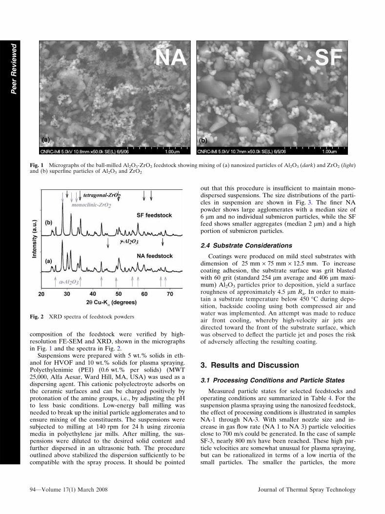
composition of the feedstock were verified by high-resolution FE-SEM and XRD, shown in the micrographsin Fig. 1 and the spectra in Fig. 2.
Suspensions were prepared with 5 wt.% solids in eth-anol for HVOF and 10 wt.% solids for plasma spraying.Polyethylenimie (PEI) (0.6 wt.% per solids) (MWT25,000, Alfa Aesar, Ward Hill, MA, USA) was used as adispersing agent. This cationic polyelectroyte adsorbs onthe ceramic surfaces and can be charged positively byprotonation of the amine groups, i.e., by adjusting the pHto less basic conditions. Low-energy ball milling wasneeded to break up the initial particle agglomerates and toensure mixing of the constituents. The suspensions weresubjected to milling at 140 rpm for 24 h using zirconiamedia in polyethylene jar mills. After milling, the sus-pensions were diluted to the desired solid content andfurther dispersed in an ultrasonic bath. The procedureoutlined above stabilized the dispersion sufficiently to becompatible with the spray process. It should be pointed
out that this procedure is insufficient to maintain mono-dispersed suspensions. The size distributions of the parti-cles in suspension are shown in Fig. 3. The finer NApowder shows large agglomerates with a median size of6 lm and no individual submicron particles, while the SFfeed shows smaller aggregates (median 2 lm) and a highportion of submicron particles.
2.4 Substrate Considerations
Coatings were produced on mild steel substrates withdimension of 25 mm · 75 mm · 12.5 mm. To increasecoating adhesion, the substrate surface was grit blastedwith 60 grit (standard 254 lm average and 406 lm maxi-mum) Al2O3 particles prior to deposition, yield a surfaceroughness of approximately 4.5 lm Ra. In order to main-tain a substrate temperature below 450 �C during depo-sition, backside cooling using both compressed air andwater was implemented. An attempt was made to reduceair front cooling, whereby high-velocity air jets aredirected toward the front of the substrate surface, whichwas observed to deflect the particle jet and poses the riskof adversely affecting the resulting coating.
3. Results and Discussion
3.1 Processing Conditions and Particle States
Measured particle states for selected feedstocks andoperating conditions are summarized in Table 4. For thesuspension plasma spraying using the nanosized feedstock,the effect of processing conditions is illustrated in samplesNA-1 through NA-3. With smaller nozzle size and in-crease in gas flow rate (NA 1 to NA 3) particle velocitiesclose to 700 m/s could be generated. In the case of sampleSF-3, nearly 800 m/s have been reached. These high par-ticle velocities are somewhat unusual for plasma spraying,but can be rationalized in terms of a low inertia of thesmall particles. The smaller the particles, the more
Fig. 1 Micrographs of the ball-milled Al2O3-ZrO2 feedstock showing mixing of (a) nanosized particles of Al2O3 (dark) and ZrO2 (light)and (b) superfine particles of Al2O3 and ZrO2
Fig. 2 XRD spectra of feedstock powders
94—Volume 17(1) March 2008 Journal of Thermal Spray Technology
PeerReviewed

intimately they follow the gas flow velocity as they areentrained in the plasma stream (Ref 26). Previous workhas, however, shown that these high velocities do notnecessarily translate into high impact velocities on thesubstrate (Ref 26). The same low inertia, readily acceler-ating the particles in the jet, slows the particles in thestagnation point above the substrate. For the same particlesize, however, faster free stream conditions lead to higherimpact velocities.
It was also generally observed that the high velocitiescome at the expense of a reduced particle temperature,possibly due to a shorter residence time of the particles inthe heating plasma jet. The suspension feed rate, affectingthe thermal load on the plasma, was reduced in those casesto maintain the particle temperatures above the meltingpoint of the refractory ceramic, i.e., at least above 2700 �Cfor zirconia (see Table 4).
The high particle temperatures measured for theHVOF system, i.e., above the melting point of zirconia,are somewhat surprising, considering the much lowerflame temperatures, as compared to plasma. The largersurface area and the smaller thermal mass of the submi-cron particles may lead to improved heat absorption andfacilitate heating and melting. The long residence time ofthe particles in the flame may also play a role. It should bementioned that only the particle surface temperature iscaptured by the optical diagnostics, while the particlecores may actually be colder.
3.2 Coating Structure and Phase Composition
Typical microstructures of the coatings are shown inFig. 4, 5, and 6. Depending on the operating conditionsand feeding rates, deposition rates varied from 3 to 5 lm/pass. Coatings up to 600 lm in thickness were produced.Table 5 shows porosities of approximately 2% as evalu-ated from image analysis at a magnification of 500. Thebulk regions of the coatings are significantly denser withporosities below 1%, as evaluated at a magnification of5000. However, for some conditions the coatings featurelarge cone-shaped defects delimited by porous regions,which grow as the films gain thickness. The cones termi-nate as surface bumps. These defects may arise by virtueof the low inertia of the small particles and were alsoobserved by other authors for small particles plasma-sprayed alumina coatings (Ref 32). The root cause forthese structures may lie in the turning trajectory of somesmall particles, which carry little momentum to properlyimpact and spread on the substrate. Earlier work hasshown that these particles, contained within the particlejet, intimately follow the radially deflecting gas flow in thestagnation point above the substrate (Ref 26). Instead ofimpacting with a high normal velocity, those particlestravel laterally along the substrate surface and possiblyattach on asperities comprised in the surface roughness,creating a region of porosity and build-up. The growingcones then further shadow the underlying pores from thenormal impacting particles (Ref 33). On the other hand,high particle velocities can decrease the portion ofdeflecting particles to smaller sizes and lower numbers.During the course of the experiments, many other processparameters were observed to promote these structures.Some of these are: a high surface roughness leading toearly defect formation by providing asperities for particleattachment; a large substrate size and a diverting plasmajet, exposing the coating to the periphery of the particlejet, which preferentially contains the smallest particles, toname a few. An attempt has been made here to minimizethe extent of these defects for each feedstock and process,
Fig. 3 Aggregate size distribution in feed suspensions as measured with a Coulter LS Particle size analyzer for (a) nanosized powdermixture NA and (b) superfine powder mixture SF
Table 4 Operating conditions and particle states
SamplePlasma/HVOF
conditionFeed rate,
kg/hSD,mm
Vpart,m/s
Tpart,�C
NA-1 1 1.8 50 500 2860NA-2 2 1.4 50 620 2937NA-3 3 1.1 50 690 2750SF- 3 3 1.1 50 774 2760NA-HVOF HVOF 3.1 127 740 2814YSZ 2 1.4 50 640 2980
Journal of Thermal Spray Technology Volume 17(1) March 2008—95
PeerReviewed

and to compare only optimized coatings of porositiesaround or below 2%.
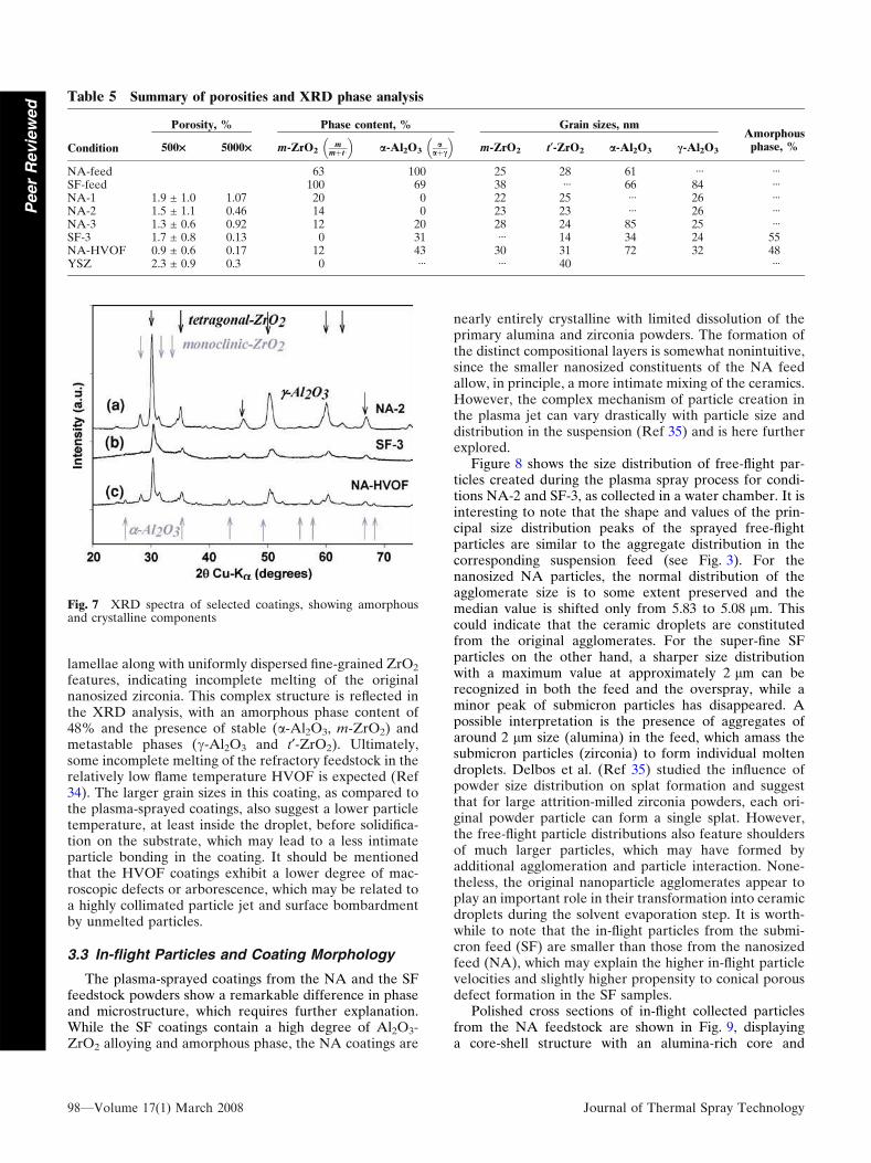
XRD spectra of the selected coatings are shown inFig. 7. Phase composition and grain sizes are summarizedin Table 5. The plasma-sprayed coatings from the nano-sized feedstock (NA-1 to NA-3) feature a high degreeof crystallinity dominated by the metastable t¢-ZrO2 andc-Al2O3 phases. The grain sizes in these phases areapproximately 20-30 nm. The small volume of the liquidceramic droplets likely restricts the grain growth duringthe rapid solidification, which leads to nanostructuredcoatings and retention of the metastable phases (Ref 24).
The micrographs of the NA coatings in Fig. 5(a) and 6show a fine lamellar structure of alternating alumina andzirconia layers. A small amount of intimate mixing of thecomponents can be identified in the gray halo regions inthe vicinity of the zirconia splats, which may indicate thepresence of some amorphous phase. This phase remains,however, undetectable within the resolution of the XRDspectra. A possible mechanism, leading to this phasesegregation will be suggested later. The microstructures of
the NA coatings are all very similar. However, at higherparticle velocity (NA-1 to NA-3), more of the smallestparticles are incorporated into the coating, leading to arefinement in the layer structure, as can be seen by com-paring Fig. 6(a), 5(a), and 6(b). The high velocity andlower particle temperature in NA-3 may also foster thedeposition of small in-flight solidified particles, leading tosome retention of the a-Al2O3 phase (Table 5).
Contrary, the coatings from the submicron feedstock(SF-3) are dominated by gray lamellar of intermediatecontrast, i.e., alloyed Al2O3-ZrO2 composite. Indeed, anamorphous phase content of 55% was estimated by XRD,see Table 5. In spite of the lack of yttria for chemicalstabilization, only the metastable tetragonal phase can beidentified. Furthermore, the t¢-ZrO2 grain size of 14 nm isconsiderably lower than in the NA coatings. This maysuggest the formation of a nanocomposite whereby the t¢-ZrO2 crystallites are stabilized by the constraining Al2O3
matrix, as explained earlier.The microstructure of the HVOF coating is most
complex and shows Al2O3 and Al2O3-ZrO2-alloyed
Fig. 4 Cross section micrograph of coating (a) plasma-sprayed coating from nanosized feedstock NA-2, (b) plasma-sprayed coatingusing superfine feedstock SF-3, and (c) HVOF-sprayed coating using nanosized feedstock NA-HVOF, all showing a dense structure withcone-shaped regions of porosity and cracks
96—Volume 17(1) March 2008 Journal of Thermal Spray Technology
PeerReviewed

Fig. 5 Cross section micrograph of (a) plasma-sprayed coating from nanometric feedstock NA-2, showing distinct lamellar structure (b)plasma-sprayed coating using superfine feedstock SF-3, showing amorphous Al2O3-ZrO2 pseudo-alloyed lamellar structure, and (c)HVOF-sprayed coating using nanometric feedstock NA-HVOF, showing a complex lamellar structure containing amorphous Al2O3-ZrO2 pseudo-alloyed and embedded unmelted clusters of submicron zirconia particles
Fig. 6 Microstructures of (a) NA-1 and (b) NA-3, showing distinct compositional layers of Al2O3 (dark) and ZrO2 (light), andincreasing layer refinement with particle velocity
Journal of Thermal Spray Technology Volume 17(1) March 2008—97
PeerReviewed
lamellae along with uniformly dispersed fine-grained ZrO2
features, indicating incomplete melting of the originalnanosized zirconia. This complex structure is reflected inthe XRD analysis, with an amorphous phase content of48% and the presence of stable (a-Al2O3, m-ZrO2) andmetastable phases (c-Al2O3 and t¢-ZrO2). Ultimately,some incomplete melting of the refractory feedstock in therelatively low flame temperature HVOF is expected (Ref34). The larger grain sizes in this coating, as compared tothe plasma-sprayed coatings, also suggest a lower particletemperature, at least inside the droplet, before solidifica-tion on the substrate, which may lead to a less intimateparticle bonding in the coating. It should be mentionedthat the HVOF coatings exhibit a lower degree of mac-roscopic defects or arborescence, which may be related toa highly collimated particle jet and surface bombardmentby unmelted particles.
3.3 In-flight Particles and Coating Morphology
The plasma-sprayed coatings from the NA and the SFfeedstock powders show a remarkable difference in phaseand microstructure, which requires further explanation.While the SF coatings contain a high degree of Al2O3-ZrO2 alloying and amorphous phase, the NA coatings are
nearly entirely crystalline with limited dissolution of theprimary alumina and zirconia powders. The formation ofthe distinct compositional layers is somewhat nonintuitive,since the smaller nanosized constituents of the NA feedallow, in principle, a more intimate mixing of the ceramics.However, the complex mechanism of particle creation inthe plasma jet can vary drastically with particle size anddistribution in the suspension (Ref 35) and is here furtherexplored.
Figure 8 shows the size distribution of free-flight par-ticles created during the plasma spray process for condi-tions NA-2 and SF-3, as collected in a water chamber. It isinteresting to note that the shape and values of the prin-cipal size distribution peaks of the sprayed free-flightparticles are similar to the aggregate distribution in thecorresponding suspension feed (see Fig. 3). For thenanosized NA particles, the normal distribution of theagglomerate size is to some extent preserved and themedian value is shifted only from 5.83 to 5.08 lm. Thiscould indicate that the ceramic droplets are constitutedfrom the original agglomerates. For the super-fine SFparticles on the other hand, a sharper size distributionwith a maximum value at approximately 2 lm can berecognized in both the feed and the overspray, while aminor peak of submicron particles has disappeared. Apossible interpretation is the presence of aggregates ofaround 2 lm size (alumina) in the feed, which amass thesubmicron particles (zirconia) to form individual moltendroplets. Delbos et al. (Ref 35) studied the influence ofpowder size distribution on splat formation and suggestthat for large attrition-milled zirconia powders, each ori-ginal powder particle can form a single splat. However,the free-flight particle distributions also feature shouldersof much larger particles, which may have formed byadditional agglomeration and particle interaction. None-theless, the original nanoparticle agglomerates appear toplay an important role in their transformation into ceramicdroplets during the solvent evaporation step. It is worth-while to note that the in-flight particles from the submi-cron feed (SF) are smaller than those from the nanosizedfeed (NA), which may explain the higher in-flight particlevelocities and slightly higher propensity to conical porousdefect formation in the SF samples.
Polished cross sections of in-flight collected particlesfrom the NA feedstock are shown in Fig. 9, displayinga core-shell structure with an alumina-rich core and
Table 5 Summary of porosities and XRD phase analysis
Condition
Porosity, % Phase content, % Grain sizes, nmAmorphousphase, %500· 5000· m-ZrO2
m
mþt;
� �
a-Al2O3a
aþc
� �
m-ZrO2 t¢-ZrO2 a-Al2O3 c-Al2O3
NA-feed 63 100 25 28 61 ÆÆÆ ÆÆÆ
SF-feed 100 69 38 ÆÆÆ 66 84 ÆÆÆ
NA-1 1.9 ± 1.0 1.07 20 0 22 25 ÆÆÆ 26 ÆÆÆ
NA-2 1.5 ± 1.1 0.46 14 0 23 23 ÆÆÆ 26 ÆÆÆ
NA-3 1.3 ± 0.6 0.92 12 20 28 24 85 25 ÆÆÆ
SF-3 1.7 ± 0.8 0.13 0 31 ÆÆÆ 14 34 24 55NA-HVOF 0.9 ± 0.6 0.17 12 43 30 31 72 32 48YSZ 2.3 ± 0.9 0.3 0 ÆÆÆ ÆÆÆ 40 ÆÆÆ
Fig. 7 XRD spectra of selected coatings, showing amorphousand crystalline components
98—Volume 17(1) March 2008 Journal of Thermal Spray Technology
PeerReviewed

zirconia-rich shell. Only particles larger than 2 lm weresuccessfully cleaved due to limitations in the polishingmedia. The core of the particles appears porous or evenhollow in some cases. During evaporation of the solvent,the ceramic concentration builds up near the dropletsurface to form a concentrated ceramic shell as the dropletshrinks. This layer may inhibit further diffusion of thesolute (ethanol) and delay complete melting. Ozturk et al.describe a similar mechanism in liquid precursor thermalspraying and delineate the conditions leading to hollowsphere particles (Ref 36). A unique feature here is thesegregation of the ceramic within a droplet into thezirconia-rich shell and alumina-rich core. It can be spec-ulated that the segregation is caused by a higher affinity ofzirconia to the solvent (over alumina), allowing thesolvent to entrain the zirconia particles as it flows from thecenter to the outside of the droplet during evaporation.The melting and mixing of the molten ceramics is limited
by this driving force for segregation, the reduced heatingof the particle core, and the short residence time of thedroplet in the plasma jet.
The free-flight particles from the SF feedstock, on theother hand, have a homogenous composition and no shell-like particles were found. Typical particles are shown inFig. 9(b). For the SF feed, the larger primary particles inthe center of the suspension droplet likely reduceentrapment of the solvent in the core and are less easilyentrained ensuring more homogenous melting and mixingof the ceramic. Rapid quenching of those homogenousparticles on a substrate is expected to promote an amor-phous phase in the resulting coating (Fig. 5b).
For the core-shell particles, the segregated micro-structure is likely retained until impact. Top-view SEMimages of impacted particles, as depicted in the examplein Fig. 10, show zirconia (white-contrast) only at thevery edges of some splats. A bilayer structure with the
Fig. 8 Free-flight particle size distribution for typical plasma spray conditions using (a) nanosized feedstock powder NA and (b)superfine feedstock powder SF
Fig. 9 Cross section of in-flight particles from (a) nanosized suspension feed NA-2 showing core-shell morphologies with a zirconia-richshell and alumina-rich core and (b) submicron suspension feed SF-3, showing homogenous phase distribution in the particles
Journal of Thermal Spray Technology Volume 17(1) March 2008—99
PeerReviewed

zirconia-rich material on the underside of the splat ispossibly created, which is consistent with the observedmicrostructure.
3.4 Mechanical Behavior and Properties
Selected mechanical properties, such as hardness,abrasion and erosion volume loss of the suspension-sprayed alumina-zirconia composite coatings were evaluated.The hardness values in Fig. 11 show that the composi-tionally segregated coatings from the nanosized NAfeedstock are generally harder than the coatings with theamorphous phase content, as created from the submicronSF powder. The coating NA-2 with 1125 VHN3 N is thehardest in this study. Besides a low porosity in the bulk ofthe coating, the nanosized crystal grains (smaller than30 nm) can contribute to this high hardness in accordancewith the Hall-Pecht relationship (Ref 15). The superiorhardness of NA-2 over the NA-1 coating may be the resultof the layer refinement and improved splat contact, in-duced by the higher particle temperature and velocity, asseen in Fig. 5 and 6. With further increase in velocity, thehardness somewhat decreases in coating NA-3, possiblybecause of the incorporated in-flight solidified particles,leading to a less-defined lamellar structure and compro-mised splat contact. It should be pointed out that themeasured hardness exceeds the values reported for con-ventional plasma (APS)-sprayed Al2O3-40% ZrO2 coat-ings (Ref 37, 38) and approaches those of APS-sprayedalumina, at similar macroscopic porosity. The SF-3 coatingshows a lower hardness value, which is likely due to thepresence of the weak amorphous phase. Even thoughexceptionally high hardness values are reported for pseu-do-binary Al2O3-ZrO2 alloys produced by plasma spray-ing (Ref 13, 15), these values are generally obtained onlyafter heat-treatment and crystallization into a nanocom-posite of the as-sprayed coatings. The HVOF-sprayedcomposite has the lowest hardness, containing both a
softer amorphous phase and dispersed unmolten zirconiaparticles with possibly weak particle bonding.
Figure 12 shows the abrasion volume loss of thecoatings as measured with a modified ASTM-65 method.The hard NA-2 coating shows the best abrasion resistancein this study. The slightly softer coatings NA-1 and NA-3show lower wear performance. This is followed by theamorphous SF-3 coating. The lowest resistance is foundfor the HVOF-sprayed coating and the YSZ referencecoating, which also showed the lowest hardness values.The direct relation between hardness and abrasion volumeloss is in accordance with abrasive wear behavior ofceramic bulk materials (Ref 38, 39).
Figure 13 summarizes the volume loss under dry par-ticle erosion at an angle of 30� according to ASTM G-75.Contrary to the superior abrasion performance of thecompositionally segregated coatings (NA-1 to NA-3), theyshow only an intermediate resistance against dry particleerosion. The lowest erosion resistance was measured for
Fig. 10 Top-view SEM image of splats form nanosized feedsuspension NA, showing white zirconia contrast only at the splatedges and suggesting a bilayer splat structure
Fig. 11 Hardness VHN3 N for selected coatings, showing hard-est plasma-sprayed coatings from nanosized NA feedstock andsoftest coating by HVOF spraying. Error bars represent standarddeviations resulting from 10 non-adjusted measurements
Fig. 12 Abrasion wear volume loss (ASTM G-65). Error barsrepresent standard deviations resulting from three non-adjustedmeasurements
100—Volume 17(1) March 2008 Journal of Thermal Spray Technology
PeerReviewed

the amorphous SF-3 coating, while the highest resis-tance is shown by the rather soft NA-HVOF and YSZcoatings. Contrary to the expected behavior of bulk
ceramics (Ref 39), the erosion resistance does not rankwith the hardness values in our case. The high hardnessmay come at the expense of increased brittleness in somecoatings, which may adversely affect their erosion wearbehavior. Figure 14 shows crack formation on the cornersof the Vickers indent impressions in the segregated NA-2and amorphous SF-3 coating, while the NA-HVOF coat-ing is virtually crack free (Ref 3). The crack propagationresistance, which can serve as an indication of the tough-ness of the material, was determined from the averagecrack length originating from the corners of the Vickersindentation impression and is summarized in Fig. 15. Itcan be noted that the erosion wear volume loss ranksclosely with the crack propagation resistance. The lowtoughness of the amorphous SF-3 coating leads to the lowerosion resistance, followed by the compositionally seg-regated NA-2 coating. The highest toughness values aremeasured in the HVOF (NA-HVOF) coating and thezirconia (YSZ), translating into superior erosion wearresistance. The high toughness of partially stabilized zir-conia is well documented and is related to the transfor-mation of metastable t-ZrO2 into m-ZrO2 in the stress
Fig. 13 Erosion wear volume loss as measured at 30� particleimpingement (ASTM G-75). Error bars represent standarddeviations resulting from three non-adjusted measurements
Fig. 14 Optical images of Vickers indent impression at 300 g load in coating (a) NA-2 and (b) SF-3, showing extensive crack formationemanating from the indent corners parallel and perpendicular to substrate surface, and (c) NA-HVOF, showing virtual absence of cracks
Journal of Thermal Spray Technology Volume 17(1) March 2008—101
PeerReviewed
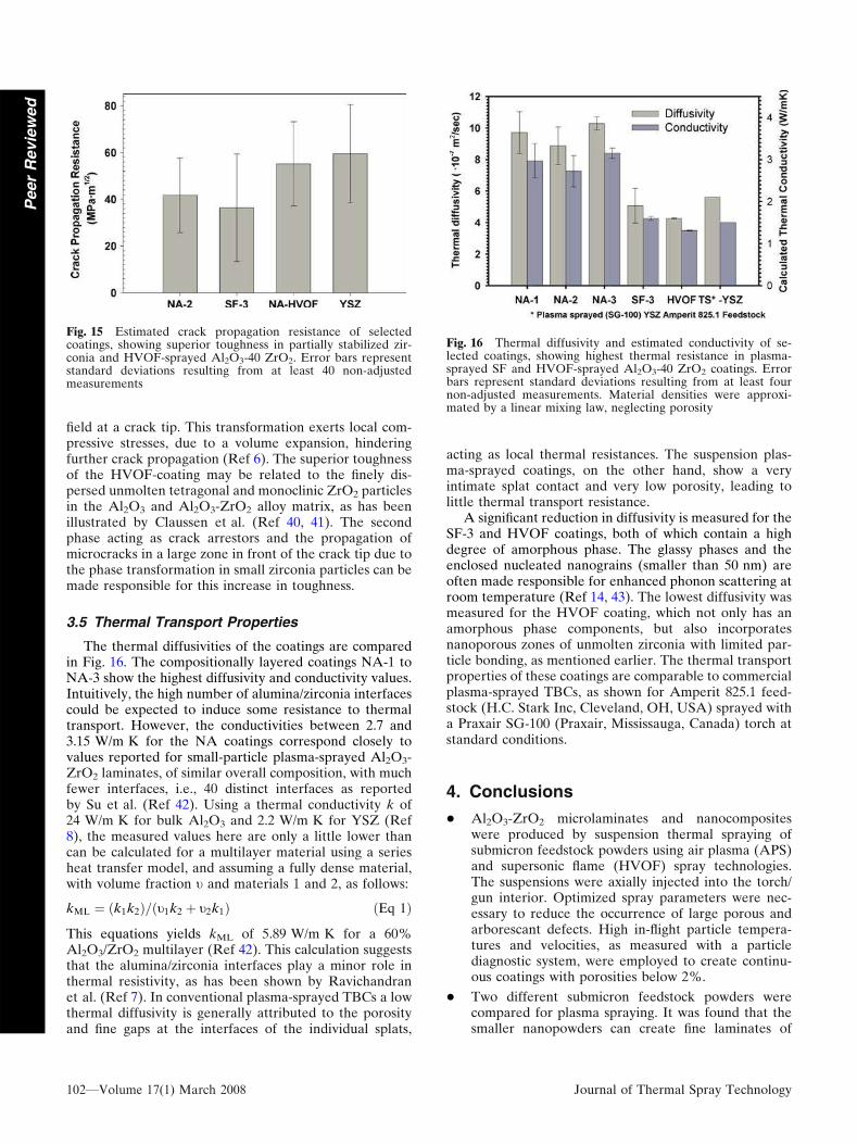
field at a crack tip. This transformation exerts local com-pressive stresses, due to a volume expansion, hinderingfurther crack propagation (Ref 6). The superior toughnessof the HVOF-coating may be related to the finely dis-persed unmolten tetragonal and monoclinic ZrO2 particlesin the Al2O3 and Al2O3-ZrO2 alloy matrix, as has beenillustrated by Claussen et al. (Ref 40, 41). The secondphase acting as crack arrestors and the propagation ofmicrocracks in a large zone in front of the crack tip due tothe phase transformation in small zirconia particles can bemade responsible for this increase in toughness.
3.5 Thermal Transport Properties
The thermal diffusivities of the coatings are comparedin Fig. 16. The compositionally layered coatings NA-1 toNA-3 show the highest diffusivity and conductivity values.Intuitively, the high number of alumina/zirconia interfacescould be expected to induce some resistance to thermaltransport. However, the conductivities between 2.7 and3.15 W/m K for the NA coatings correspond closely tovalues reported for small-particle plasma-sprayed Al2O3-ZrO2 laminates, of similar overall composition, with muchfewer interfaces, i.e., 40 distinct interfaces as reportedby Su et al. (Ref 42). Using a thermal conductivity k of24 W/m K for bulk Al2O3 and 2.2 W/m K for YSZ (Ref8), the measured values here are only a little lower thancan be calculated for a multilayer material using a seriesheat transfer model, and assuming a fully dense material,with volume fraction t and materials 1 and 2, as follows:
kML ¼ ðk1k2Þ=ðt1k2 þ t2k1Þ ðEq 1Þ
This equations yields kML of 5.89 W/m K for a 60%Al2O3/ZrO2 multilayer (Ref 42). This calculation suggeststhat the alumina/zirconia interfaces play a minor role inthermal resistivity, as has been shown by Ravichandranet al. (Ref 7). In conventional plasma-sprayed TBCs a lowthermal diffusivity is generally attributed to the porosityand fine gaps at the interfaces of the individual splats,
acting as local thermal resistances. The suspension plas-ma-sprayed coatings, on the other hand, show a veryintimate splat contact and very low porosity, leading tolittle thermal transport resistance.
A significant reduction in diffusivity is measured for theSF-3 and HVOF coatings, both of which contain a highdegree of amorphous phase. The glassy phases and theenclosed nucleated nanograins (smaller than 50 nm) areoften made responsible for enhanced phonon scattering atroom temperature (Ref 14, 43). The lowest diffusivity wasmeasured for the HVOF coating, which not only has anamorphous phase components, but also incorporatesnanoporous zones of unmolten zirconia with limited par-ticle bonding, as mentioned earlier. The thermal transportproperties of these coatings are comparable to commercialplasma-sprayed TBCs, as shown for Amperit 825.1 feed-stock (H.C. Stark Inc, Cleveland, OH, USA) sprayed witha Praxair SG-100 (Praxair, Mississauga, Canada) torch atstandard conditions.
4. Conclusions
� Al2O3-ZrO2 microlaminates and nanocompositeswere produced by suspension thermal spraying ofsubmicron feedstock powders using air plasma (APS)and supersonic flame (HVOF) spray technologies.The suspensions were axially injected into the torch/gun interior. Optimized spray parameters were nec-essary to reduce the occurrence of large porous andarborescant defects. High in-flight particle tempera-tures and velocities, as measured with a particlediagnostic system, were employed to create continu-ous coatings with porosities below 2%.
� Two different submicron feedstock powders werecompared for plasma spraying. It was found that thesmaller nanopowders can create fine laminates of
Fig. 15 Estimated crack propagation resistance of selectedcoatings, showing superior toughness in partially stabilized zir-conia and HVOF-sprayed Al2O3-40 ZrO2. Error bars representstandard deviations resulting from at least 40 non-adjustedmeasurements
Fig. 16 Thermal diffusivity and estimated conductivity of se-lected coatings, showing highest thermal resistance in plasma-sprayed SF and HVOF-sprayed Al2O3-40 ZrO2 coatings. Errorbars represent standard deviations resulting from at least fournon-adjusted measurements. Material densities were approxi-mated by a linear mixing law, neglecting porosity
102—Volume 17(1) March 2008 Journal of Thermal Spray Technology
PeerReviewed

alumina and zirconia layers, while slightly largerpowders promote pseudo-alloyed Al2O3-ZrO2 amor-phous phase components. The unique microstructuresof the finely segregated layers are a consequence of acomplex mechanism of particle formation in theatomization and solvent evaporation step. Theaggregates of the nanopowder produce droplets ofcore-shell structure with an alumina-rich core and azirconia-rich shell. The incomplete mixing within thedroplets is retained until impact on the substrate. Itwas further observed that the in-flight particle size,which is a critical parameter in the coating formation,is closely linked to the aggregate size in the suspensionand was different for the two powders.
� HVOF spraying of ceramic nanopowder suspensionswas successfully implemented. The lower flame tem-perature allows retention of some of the size featuresand phases of the feedstock, leading to complexmicrostructures containing amorphous as well as un-molten feedstock components.
� Mechanical properties of the coatings were compared.Compositionally segregated crystalline coatings, ob-tained by plasma spraying, showed the highest hard-ness of up to 1125 VHN3 N, as well as the highestabrasion wear resistance (ASTM G65). Their erosionwear performance was, however, compromised bytheir brittleness. The more amorphous plasma spraycoatings were both softer and more brittle, leading torather poor wear performance. The HVOF coatingswere neither very hard nor particularly abrasionresistant, but they exhibited the highest erosion wearresistance (ASTM G75), which was related to thetoughening effect of small dispersed zirconia particlesin the alumina-zirconia-alloyed matrix.
� The HVOF composites exhibited the lowest thermaldiffusivity due to a high amorphous phase content,limited particle bonding, and incorporation of par-tially molten feedstock at the low flame temperature.The alumina/zirconia interfaces in the segregatedplasma-sprayed coatings pose only a small resistanceto thermal transport, leading to high diffusivity values.It was observed that an amorphous/nanocompositestructure from a pseudo-alloyed phase constitutes theprincipal resistance to thermal transport in thesecoatings.
� A large variety in microstructures and properties ofsuspension-sprayed Al2O3-ZrO2 composites was in-duced by the different feedstocks, spray systems, andoperating conditions. This flexibility is expected toallow tailoring and optimization of these coatings tomeet desired property requirements in the future,which is the focus of our ongoing work.
Acknowledgments
This work was supported through the collaborativeprogram on Amorphous and Nanocrystalline Ceramic
Coatings (ANCEC) between the National ResearchCouncil of Canada and the Academy of Science of theCzech Republic.
References
1. S. Deb and B.V. Radhakrishna Bhat, Optimization of ProcessingParameters for making Alumina-Partially Stabilized ZirconiaLaminated Composites, Bull. Mater. Sci., 2000, 23(2), p 109-117
2. D.J. Green, P.Z. Cai, and F.L. Messing, Residual Stresses inAlumina-Zirconia Laminates, J. Euro. Ceram. Soc., 1999, 19(13/14), p 2511-2517
3. A. Dakskobler and T. Kosmac, The Preparation and Propertiesof Al2O3-ZrO2 Composites with Corrugated Microstructures,J. Euro. Ceram. Soc., 2004, 24(12), p 3351-3357
4. M. Jimenez-Melendo, F. Gutierrez-Mora, and A. Dominguez-Rodriguez, Effect of Layer Interfaces on the High-TemperatureMechanical Properties of Alumina/Zirconia Laminate Compos-ites, Acta Mater., 2000, 48(18-19), p 4715-4720
5. H.M. Chan, Layered Ceramics: Processing and MechanicalBehavior, Annu. Rev. Mater. Sci., 1997, 27, p 249-282
6. V. Teixeira, A. Monteiro, J. Duarte, and A. Portinha, Depositionof Composite and Nanolaminate Ceramic Coatings by Sputtering,Vacuum, 2002, 67, p 477-483
7. K.S. Ravichadran and K. An, Thermal Conductivity of Plasma-sprayed Monolithic and Multilayer Coatings of Alumina and Yt-tria-Stabilized Zirconia, J. Am. Ceram. Soc., 1999, 82(3), p 673-682
8. S. Sharafat, A. Kobayashi, Y. Chen, and N.M. Ghoniem, PlasmaSpraying of Microcomposite Thermal Barrier Coatings, Vacuum,2002, 65, p 415-425
9. T. Kuroda and A. Kobayashi, Adhesion Characteristics of Zir-conia-Alumina Composite Coatings by Gas Tunnel Type PlasmaSpraying, Vacuum, 2004, 73, p 635-641
10. A.Kobayashi, Formation ofTiN-Al2O2-ZrO2CompositeCoatingsby Gas Tunnel Type Plasma Spraying, Thermal Spray Connects:Explore its Surface Potential, C. Berndt and E. Lugscheider, Eds.,May 2-4, 2005 (Basel, Switzerland), ASM International, 2005
11. X. Zhou, V. Shukla, W.R. Cannon, and B.H. Kear, MetastablePhase Formation in Plasma-Sprayed ZrO2 (Y2O3)-Al2O3, J. Am.Ceram. Soc., 2003, 86(8), p 1415-1420
12. H.-J. Kim and Y.J. Kim, Amorphous Phase Formation of thePseudo-Binary Al2O3-ZrO2 Alloy during Plasma Spray Process-ing, J. Mater. Sci., 1999, 34, p 29-33
13. S. Sodeoka, M. Suzuki, and T. Inoue, Mechanical Properties ofPlasma Sprayed Alumina-Zirconia Nano-Composite Films,Thermal Spray: Building on 100 Years of Success, B. Marple, M.Hyland, Y.-C. Lau, R. Lim, and J. Voyer, Eds., May 15-18, 2006(Seattle, USA), ASM International, 2006
14. S. Sodeoka, M. Suzuki, and T. Inoe, Thermal and MechanicalProperties of Alumina-Zirconia Nano-Composite Coatings,Thermal Spray Solutions: Advances in Technology and Appli-cation, ASM International, May 10-12, 2004 (Osaka, Japan),ASM International, 2004
15. T. Chraska, K. Neufuss, J. Dubsky, J. Nohava, and J. ObersteBerghaus, Plasma Spraying of a Novel Material with Amorphousand Nanocrystalline Microstructure, Thermal Spray Connects:Explore its Surface Potential, C. Berndt and E. Lugsheider, Eds.,May 2-4, 2005 (Basel, Switzerland), ASM International, 2005
16. S. Deville, J. Chevalier, G. Fantozzi, J.-F. Bartolome, J. Rquena,J.S. Moya, R. Torrecillas, and L.A. Dıaz, Low-TemperatureAgeing of Zirconia-Toughened Alumina Ceramics and itsImplication in Biomedical Implants, J. Euro. Ceramic Soc., 2003,23, p 2975-2982
17. J. Karthikeyan, C.C. Berndt, S. Reddy, J.-Y. Wnag, A.H. King,and H. Hermann, Nanomaterial Deposits Formed by DC Plas-ma Spraying of Liquid Feedstocks, J. Am. Ceram. Soc., 1998,81(1), p 121-128
18. E.H. Jordan, L. Xie, X. Ma, M. Gell, N.P. Padture, B. Cetegen,A. Ozturk, J. Roth, T.D. Xiao, and P.E.C Bryant, SuperiorThermal Barrier Coatings Using Solution Precursor PlasmaSpray, J. Therm. Spray Technol., 2004, 13(1), p 57-65
Journal of Thermal Spray Technology Volume 17(1) March 2008—103
PeerReviewed

19. B.G. Ravi, S. Sampath, R. Gambino, P.S. Devi, and J.B. Parise,Plasma Spray Synthesis from Precursors: Progress, Issues andConsiderations, Thermal Spray: Building on 100 Years of Success,B. Marple, M. Hyland, Y.-C. Lau, R. Lim, and J. Voyer, Eds.,May 15-18, 2006 (Seattle, USA), ASM International, 2006
20. P. Bazdell and S. Kuroda, Plasma Spraying of Submicron Cera-mic Suspensions Using a Continuous Ink Jet Printer, Surf. Coat.Technol., 2000, 123, p 239-246
21. P. Fauchais, Understanding Plasma Spraying, J. Phys. D: Appl.Phys., 2004, 27, p R86-R108
22. R. Siegert, J.-E. Doring, J.-L. Marques, R. Vaßen, D. Sebold, andD. Stover, Influence of the Injection Parameters on the SuspensionPlasma Spraying Coating Properties, Thermal Spray Connects:Explore Its Surface Potential, C. Berndt and E. Lugsheider, Eds.,May 2-4, 2005, (Basel, Switzerland), ASM International, 2005
23. C. Delbos, J. Fazilleau, V. Rat, J.-F. Coudert, P. Fauchais, and L.Bianchi, Finely Structured Ceramic Coatings Elaborated by Li-quid Suspension Injection in a DC Plasma Jet, Thermal SpraySolutions: Advances in Technology and Application, ASMInternational, May 10-12, 2004 (Osaka, Japan), ASM Interna-tional, 2004
24. J. Oberste Berghaus, S. Bouaricha, J.-G. Legoux, and C. Moreau,Suspension Plasma Spraying of Nanoceramics Using an AxialInjection Torch, Thermal Spray Connects: Explore its SurfacePotential, C. Berndt and E. Lugsheider, Eds., May 2-4, 2005,(Basel, Switzerland), ASM International, 2005
25. A.L. Vasiliev, N.P. Padture, and X. Ma, Coatings of MetastableCeramics Deposited by Solution-Precursor Plasma Spray: I.Binary ZrO2-Al2O3 System, Acta Mater., 2006, 54, p 4913-4920
26. J. Oberste Berghaus, S. Bouaricha, J.-G. Legoux, and C. Moreau,Injection Conditions and In-Flight Particle States in SuspensionPlasma Spraying of Alumina and Zirconia Nano-Ceramics,Thermal Spray Connects: Explore its Surface Potential, C. Berndtand E. Lugsheider, Eds., May 2-4, 2005 (Basel, Switzerland),ASM International, 2005
27. G.R. Anstis, P. Chantikul, B.R. Lawn, and D.B. Marshall, ACritical Evaluation of Indentation Techniques for MeasuringFracture Toughness. I. Direct Crack Measurements, J. Am.Ceram. Soc., 1981, 64(9), p 533-538
28. ‘‘Standard Test Method for Measuring Abrasion Using the DrySand/Rubber Wheel Apparatus,’’ G 65-91, Annual Book ofASTM Standards, ASTM, 1993, p 363-368
29. ‘‘Standard Practice for Conducting Erosion Tests by Solid Par-ticle Impingement Using Gas Jets,’’ G 75-89, Annual Book ofASTM Standards, ASTM, 1989, p 305-309
30. A.S. Houlbert, P. Cielo, C. Moreau, and M. Lamontagne, Mea-surement of Thermal Diffusivity and anisotropy of Plasma-Sprayed Coatings, Int. J. Thermophys., 1994, 15(3), p 525-546
31. B.D. Cullity, Elements of X-Ray Diffraction, (2nd ed.). Addison-Wesley Publ. Co, Massachusetts, 1978
32. R.W. Trice and K.T. Faber, Role of Lamellae Morphology on theMicrostructural Development and Mechanical Properties ofSmall-Particle Plasma-Sprayed Alumina, J. Am. Ceram. Soc.,2000, 83(4), p 889-896
33. J. Oberste Berghaus, S. Bouaricha, J.-G. Legoux, C. Moreau, R.Hui, and D. Gosh, Suspension Plasma Spraying of IntermediateTemperature SOFC Components using an Axial Injection DCTorch, Materials Science Forum, Vols. 539-543, Trans TechPublications, March 2007
34. A. Killinger, M. Hyhn, and R. Gadow, High-Velocity SuspensionFlame Spraying, A New Approach for Spraying Nanoparticleswith Hypersonic Speed, Surf. Coat. Technol., 2006, 201, p 1922-1929
35. C. Delbos, J. Fazilleau, V. Rat, J.-F. Coudert, P. Fauchais, and L.Bianchi, Influence of Powder Size Distribution and Heat Flux onYttria Stabilized Coatings Elaborated by Liquid SuspensionInjection in DC Plasma Jet, Thermal Spray Connects: Explore itsSurface Potential, C. Berndt and E. Lugsheider, Eds., May 2-4,2005, (Basel, Switzerland), ASM International, 2005
36. A. Ozturk and B.M. Cetegen, Modeling of Plasma AssistedFormation of Precipitates in Zirconium Containing Liquid Pre-cursor Droplets, Mater. Sci. Eng. A, 2004, 384, p 331-351
37. G. Barbezat, A.R. Nicoll, and A. Sickinger, Abrasion, Erosionand Scuffing Resistance of Carbide and Oxide Ceramic ThermalSprayed Coatings for Different Applications, Wear, 1993, 162-164(pt. A), p 529-537
38. A.A. Abdel-Samad, A.M.M. El-Bahloul, S.A. Rassoul, and E.Lugscheider, A Comparative Study on Thermally Sprayed Alu-mina Based Ceramic Coatings, J. Mater. Sci., 2000, 35(12), p3127-3130
39. H.X. Zhao, H. Goto, M. Matsumura, T. Takahashi, andM. Yamamoto, Slurry Erosion of Plasma-sprayed CeramicCoatings, Surf. Coat. Technol., 1999, 115(2-3), p 123-131
40. N. Claussen, Fracture Toughness of Al2O3 with an UnstabilizedZrO2 Dispersed Phase, J. Am. Ceram. Soc., 1976, 59(9), p 49
41. W.H. Tuan, R.Z. Chen, T.C. Wang, C.H. Cheng, and P.S. Kuo,Mechanical Properties of Al2O3/ZrO2 Composites, J. Euro.Ceram. Soc., 2002, 22(16), p 2827-2833
42. Y.J. Su, H. Wang, W.D. Porter, A.R.A. Lopez, and K.T. Fa-ber, Thermal Conductivity and Phase Evolution of Plasma-sprayed Multilayer Coatings, J. Mater. Sci., 2001, 36(14), p3511-3518
43. S. Raghavan, H. Wang, R.B. Dinwiddie, W.D. Porter, and M.J.Mayo, The Effect of Grain Size, Porosity and Yttria Content onthe Thermal Conductivity of Nanocrystalline Zirconia, ScriptaMater., 1998, 39(8), p 1119-1125
104—Volume 17(1) March 2008 Journal of Thermal Spray Technology
PeerReviewed