ROCK1-directed basement membrane positioning coordinates epithelial tissue polarity
Upload
khangminh22Category
view
1download
0

2 | May 2010
http://www.southinstrument.com
http://www.southprecision.in
http://www.southinstrument.com
http://www.southprecision.in
Main board BD970 inside
Combine the high productive
capacity of SOUTH with world's
top-class technology. S82T helps
you maximize the power of your
employees
SOUTH PRECISION INSTRUMENT PVT.LTDAdress :FA-229B , Mansa rove r Ga rden , New De lh i -110015Te l : +91-11 -64563666Fax : +91-11 -45530854Ema i l : i nd i a@sou thsu rvey . com

May 2010 | 3
4 | May 2010
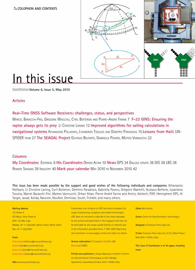
Volume 6, Issue 5, May 2010
colophon and contents
Mailing address
11C Pocket A
SFS Mayur Vihar Phase III
Delhi 110 096, India.
Phones +91 11 22632607, 98102 33422, 98107 24567
Fax +91 11 22632607
[information][email protected]
[editorial][email protected]
[advertising][email protected]
[subscriptions][email protected]
Web www.mycoordinates.org
Coordinates is an initiative of cGIT that aims to broaden the
scope of positioning, navigation and related technologies.
cGIT does not neccesarily subscribe to the views expressed
by the authors and advertisers in this magazine and may not
be held liable for any losses caused directly or indirectly due
to the information provided herein. © cGIT, 2009. Reprinting
with permission is encouraged; contact the editor for details.
annual subscription (12 issues) [India] Rs.1,200
[Overseas] US$80
printed and published by Sanjay Malaviya on behalf of Centre
for Geoinformation Technologies at A221 Mangal
Apartments, Vasundhara Enclave, Delhi 110096, India.
editor Bal Krishna
owner Centre for Geoinformation Technologies
designed at Thomson Press India Ltd.
printer Thomson Press India Ltd., B 315, Okhla Phase I,
New Delhi-110020, India
this issue of coordinates is of 44 pages, including
cover
articles
Real-time Gnss software Receivers: challenges, status, and perspectivesMarcel Baracchi-Frei, GréGoire Waelchli, cyril Botteron and Pierre-andré Farine 7 F-22 GIns: ensuring the raptor always gets its prey lt christine laninG 12 Improved algorithms for sailing calculations in navigational systems athanasios Pallikaris, lysandros tsoulos and deMitris Paradissis 15 lessons from haiti un-
sPider teaM 27 the seaGal project Gustavo BelForte, GaBriella Povero, Matteo vannucchi 32
columnsMy coordinates editorial 6 his coordinates orhan altan 10 news GPs 34 Galileo uPdate 36 Gis 38 lBs 38
reMote sensinG 39 industry 40 Mark your calendar May 2010 to noveMBer 2010 42
this issue has been made possible by the support and good wishes of the following individuals and companies Athanasios Pallikaris, Lt Christine Laning, Cyril Botteron, Demitris Paradissis, Gabriella Povero, Grégoire Waelchli, Gustavo Belforte, Lysandros Tsoulos, Marcel Baracchi-Frei, Matteo Vannucchi, Orhan Altan, Pierre-André Farine and Antrix, Ashtech, FOIF, Hemisphere GPS, Hi Target, Javad, Kolida, Navcom, NovAtel, Omnistar, South, Trimble; and many others.
In this issue
May 2010 | 5
6 | May 2010
Bal Krishna, [email protected]
adVIsoRs Naser El-Sheimy PEng, CRC Professor, Department of Geomatics Engineering, The University of Calgary Canada, George Cho
Professor in GIS and the Law, University of Canberra, Australia, Associate Professor Abbas Rajabifard Director, Centre for SDI and Land
Administration, University of Melbourne, Australia, Luiz Paulo Souto Fortes PhD Associate Director of Geosciences, Brazilian Institute of
Geography and Statistics -IBGE, Brazil, John Hannah Professor, School of Surveying, University of Otago, New Zealand
MycooRdInates
Lessons from HaitiNature strikes at will.
Some areas and people are better prepared.
Some are not.
Haiti is a case in point.
Poor infrastructure.
Inadequately trained personnel.
Weak cooperation among institutions.
And the situation worsened
When the earthquake struck.
Tremendous efforts have been made.
And are being made.
Still.
Any lesson learnt?
May 2010 | 7
using software techniques. The software implementation of all baseband functions offers a great flexibility that allows rapid changes and modifications. This property is an advantage in the fast changing environment of GNSS receivers as new radio frequency (RF) bands, modulation types, bandwidths, and spreading/dispreading and baseband algorithms are regularly introduced.
software reveiver: definition and types
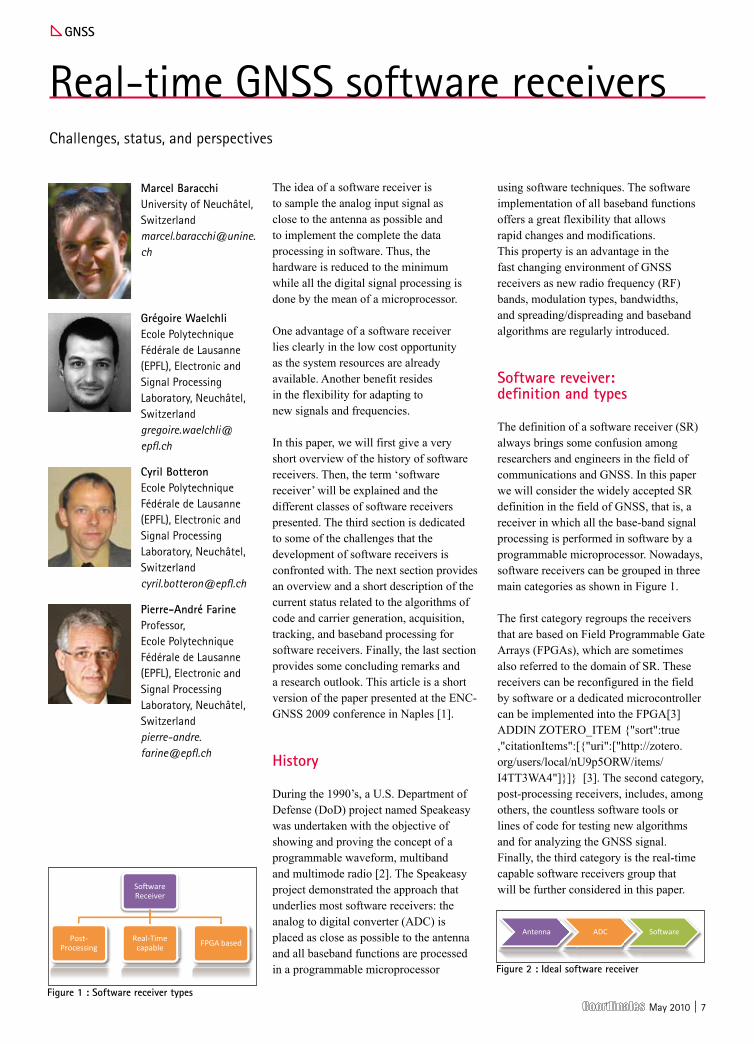
The definition of a software receiver (SR) always brings some confusion among researchers and engineers in the field of communications and GNSS. In this paper we will consider the widely accepted SR definition in the field of GNSS, that is, a receiver in which all the base-band signal processing is performed in software by a programmable microprocessor. Nowadays, software receivers can be grouped in three main categories as shown in Figure 1.
The first category regroups the receivers that are based on Field Programmable Gate Arrays (FPGAs), which are sometimes also referred to the domain of SR. These receivers can be reconfigured in the field by software or a dedicated microcontroller can be implemented into the FPGA[3] ADDIN ZOTERO_ITEM {"sort":true,"citationItems":[{"uri":["http://zotero.org/users/local/nU9p5ORW/items/I4TT3WA4"]}]} [3]. The second category, post-processing receivers, includes, among others, the countless software tools or lines of code for testing new algorithms and for analyzing the GNSS signal. Finally, the third category is the real-time capable software receivers group that will be further considered in this paper.
The idea of a software receiver is to sample the analog input signal as close to the antenna as possible and to implement the complete the data processing in software. Thus, the hardware is reduced to the minimum while all the digital signal processing is done by the mean of a microprocessor.
One advantage of a software receiver lies clearly in the low cost opportunity as the system resources are already available. Another benefit resides in the flexibility for adapting to new signals and frequencies.
In this paper, we will first give a very short overview of the history of software receivers. Then, the term ‘software receiver’ will be explained and the different classes of software receivers presented. The third section is dedicated to some of the challenges that the development of software receivers is confronted with. The next section provides an overview and a short description of the current status related to the algorithms of code and carrier generation, acquisition, tracking, and baseband processing for software receivers. Finally, the last section provides some concluding remarks and a research outlook. This article is a short version of the paper presented at the ENC-GNSS 2009 conference in Naples [1].
history
During the 1990’s, a U.S. Department of Defense (DoD) project named Speakeasy was undertaken with the objective of showing and proving the concept of a programmable waveform, multiband and multimode radio [2]. The Speakeasy project demonstrated the approach that underlies most software receivers: the analog to digital converter (ADC) is placed as close as possible to the antenna and all baseband functions are processed in a programmable microprocessor
Gnss
Real-time GNSS software receivers Challenges, status, and perspectives
Marcel BaracchiUniversity of Neuchâtel, [email protected]
Grégoire Waelchli Ecole Polytechnique Fédérale de Lausanne (EPFL), Electronic and Signal Processing Laboratory, Neuchâtel, [email protected]
cyril BotteronEcole Polytechnique Fédérale de Lausanne (EPFL), Electronic and Signal Processing Laboratory, Neuchâtel, [email protected]
pierre-andré FarineProfessor, Ecole Polytechnique Fédérale de Lausanne (EPFL), Electronic and Signal Processing Laboratory, Neuchâtel, [email protected]
Figure 1 : software receiver types
Figure 2 : Ideal software receiver

8 | May 2010
challenges
The following chapter highlights some of the main challenges related to software receivers. This includes the problem of the high data rate when working with a nearly ideal implementation and also talks about the high processing power requirements for the base-band processing algorithms.
data rate
The ideal software receiver places the ADC as close as possible to the antenna in order to reduce the hardware parts to the minimum (see Figure 2). In that sense, the most straightforward approach consists in digitizing the data directly at the antenna. But as the Nyquist theorem must be fulfilled, this translates into a data rate that is, for the time being, too high to be processed by a microcontroller.
Considering the GPS L1 signal and assuming 2 quantization bit per sample, this leads to the following values:
FGPSL1 = 1.575 GHz FSampling ≥ 2 * FGPSL1 = 3.15 GHz Data rate ≥ 6.3 GBit/s = 806.4 MByte/s
In order to reduce the data throughput, a solution such as a low intermediate frequency (low-IF) or a sub-sampling analog front-end can be chosen. In a low-IF front-end, the incoming signal is down-converted to an intermediate frequency of several megahertz. This allows obtaining a data rate that can be more easily handled by a microcontroller.
The sub-sampling technique exploits the fact that the effective signal bandwidth in a GNSS signal is much lower than the carrier frequency. Therefore, not the carrier frequency but the signal bandwidth must be respected by the Nyquist theorem. In this case, the modulated signal is under-sampled to achieve frequency translation via intentional aliasing. But this solution is difficult to implement due to current hardware and resources limitations. Again, if the GPS L1 signal is taken as an example with 2 quantization bit per sample, this leads to the following values:
Bandwidth GPS L1 = 2 MHz
FSampling ≥ 2 * Bandwidth = 4 MHz Data rate ≥ 8 MBit/s = 1 MByte/s
complexity of base-band operations
Considering a low-IF based architecture, the ADC provides a data stream that is first down-converted to base-band to remove the remaining Doppler frequency offset. The signal is then multiplied with several code replicas (generally Early, Prompt, and Late) and finally accumulated. An example of a real data IF architecture is shown in Figure 3.
Former studies [4] demonstrated that, assuming that an integer operation and a multiplication take respectively 1 and 14 CPU cyclesfor an Intel Pentium 4 processor, the base-band operations (without carrier and code generation) would require at least a 3 GHz Intel Pentium 4 processor at 100% CPU load. Therefore, such an architecture is not suitable as a real-time software solution.
current implementations
A major problem of the software architecture is the important amount of CPU cycles needed for executing the base-band operations. In order to reduce this number, two alternate strategies can be found: the first one applies Single Instruction Multiple Data (SIMD) operations while the second one utilizes the bitwise representation of the signal.
single Instruction Multiple data (sIMd)
In 1995, Intel introduced Single Instruction Multiple Data (SIMD) operations under the name of Multi Media Extension (MMX). The SIMD are mathematical instructions that operate on vectors of data and perform integer arithmetic on eight 8-bit, four 16-bit, or two 32-bit integers packed into a MMX register (see Figure 4). Later SIMD extensions, SSE, SSE2, and SSE3 include SIMD floating point operations
and expand the type of integer operations.
SIMD operations are well fitted to execute the same mathematical operation on several sets of data. In particular, they can be used to perform the PRN code mixing and the accumulation concurrently for all code replicas. With the help of further optimizations, such as instruction pipelining, more than 600% performance improvement with the SIMD operations compared to the standard integer operations can be observed [5]. For this reason, most of the implementations of software receivers with real-time processing capabilities are using SIMD operations.
Bitwise operations
Bitwise operation (or vector processing) exploits the bit representation of the incoming signal. Figure 55 shows a typical data storage scheme for vector processing.
Figure 3 : Real IF architecture
Figure 4 : single Instruction single data vs. single Instruction Multiple data
Figure 5 : Bitwise representation
1 Sign word0 0 1 0 1 0 1
1 Magn_high word1 1 0 1 0 1 1
1 Magn_low word0 1 1 0 1 1 1
Time
1 Code1 1 1 1 1 0 0
Input sample #5Value -3d

May 2010 | 9
The sign information is stored in the sign word while the remaining bit(s) representing the magnitude is (are) stored in the magn word(s). The objective is to take advantage of the high parallelism and speed of the bitwise operations for which a single integer addition or multiplication is translated into simple parallel logical operations. The carrier mixing stage is reduced to one or a few simple logical operations that can be performed concurrently on several bits. In the same way, the PRN code removal only affects the sign word.
The inherent drawback of this approach is the lack of flexibility: the complexity of the process becomes bit-depth dependent and the signal quantification cannot be easily changed without important modification of the software code. To overcome this limitation, a combination of bitwise processing and distributed arithmetic was proposed, as described in [6].
code generation
The real-time generation of the pseudorandom noise (PRN) code is too power consuming to be implemented in a software receiver. The most efficient way (in terms of processing load) is to pre-generate the codes, assuming a zero Doppler shift,. and store them in memory.
As the incoming signal code phase is random, the beginning of the first code chip is in general not aligned with the beginning of stored code and may occur at any position. To overcome this issue, either all the possible phases can be stored in memory or the code can be shifted appropriately during the tracking phase. While the first approach increases the memory requirements, the second requires further data processing. This approach is very popular in the domain of software receiver and can be found in several solutions: [4], [7], [8], [9], [10].
carrier generation
The generation of a local carrier frequency is necessary to perform the Doppler removal for every channel. Several techniques exist to reduce the computational load for the carrier
generation: the values for the carrier can be pre-generated and then stored in lookup tables. As it would require several gigabytes of memory to store all the possible frequencies, the values are recorded on a coarse frequency grid with no phase offset. This method is very popular in the domain of software receivers and many solutions take advantage of it to avoid the power hungry real-time carrier generation [8], [11], [12].
outlook
Software receivers have found their place in the field of algorithm prototyping and testing for a long time. Nowadays they also play a key role for certain special applications. What remains unclear today is if they will enter and change drastically the embedded market or succeed as generic high-end receivers.
A software GNSS receiver offers different advantages including design flexibility, faster adaptability, faster time-to-market, higher portability and easy optimization at any algorithm stage. However, a major drawback persists in the high CPU load.
Many different companies and universities have projects running that aim at optimizing and developing new algorithms and methods for a software implementation. The development not only includes the software level, but also enlarges in the direction of using additional hardware that is already available on a standard PC (for example, using the high performance graphic processing unit (GPU) for calculating the local carrier [13]).
References
M. Baracchi-Frei, G. Waelchli, C. Botteron, and P. Farine, “Real-Time GNSS Software Receiver: Challenges, Status, and Perspectives,” ENC-GNSS 2009, Naples: 2009.
R. Lackey and D. Upmal, “Speakeasy: The Military Software Radio,” IEEE Communications Magazine, May. 1995, pp. 56-61.
“Altera NIOS II Processor” Available: http://www.altera.com/products/ip/processors/nios2/ni2-index.html.
G.W. Heckler and J.L. Garrison, “Architecture of a Reconfigurable Software Receiver,” ION GNSS ITM, 2004.
G.W. Heckler and J.L. Garrison, “SIMD correlator library for GNSS software receiver,” GPS Solutions, Oct. 2006, pp. 269-276.
G. Waelchli, M. Baracchi-Frei, C. Botteron, and P. Farine, “Distributed Arithmetic for Efficient Base-Band Processing in Real-Time GNSS Software Receivers,” Journal of Electrical and Computer Engineering, vol. 2010.
Y. Chen and J. Juang, “A GNSS Software Receiver Approach for the Processing of Intermittent Data,” 2007.
A. Fridmann and S. Semenov, “Architectures of Software GPS Receivers,” GPS Solutions, vol. 3, 2000, pp. 58-64.
M.L. Psiaki, “Real-Time Generation of Bit-Wise Parallel Representation of Over-Sampled PRN Code,” IEEE Trans. on Wireless Communication, vol. 5, Mar. 2006.
J. Tian, Q. HongLei, Z. JunJie, and L. Yang, “Real-time GPS Software Receiver Correlator Design,” 2007.
T. Pany, S.W. Moon, M. Irsigler, B. Eissfeller, and K. Fürlinger, “Performance assessment of an under sampling SWC receiver for simulated high bandwidth GPS/Galileo signals and real signals,” ION GPS/GNSS: 2003.
S. Charkhandeh, M. Petovello, R. Watson, and G. Lachapelle, “Implemenation and Testing of a Real-Time Software-Based GPS Receiver for x86 Processors,” ION NTM: 2006.
M. Petovello, C. O'Driscoll, G. Lachapelle, D. Borio, and H. Murtaza, “Architecture and Benefits of an Advanced GNSS Software Receiver,” International Symposium on GPS/GNSS: 2008.
10 | May 2010
hIs cooRdInates
In the historical background section on the ISPRS site it says, “There
is no clear-cut distinction between photogrammetry and remote sensing, and it is for this reason that the Society changed its name in 1980.” What then is the individual significance of ‘photogrammetry’ and ‘remote sensing’ for ISPRS?
Traditionally the term ‘photogrammetry’ has been used to describe the extraction of metric information from images, while ‘remote sensing’ has dealt more with the extraction of semantic information. However, the use of digital image processing to extract information from images has blurred the distinction between the two topics. Metric as well as semantic attributes are often equally important for information extraction from images, and therefore there is no longer a clear distinction between ‘photogrammetry’ and ‘remote sensing’. The ISPRS Council in 1980 in changing the name of the Society to include Remote Sensing decided to maintain the term photogrammetry in the title to respect the contributions of our forefathers in establishing and maintain such a strong Society originally based on photogrammetry over the past 100 years.
ISPRS will be celebrating its centenary this year, how has the role of the Society evolved over the years to keep in tune with the changing world scenario?
Technologies in photogrammetry and remote sensing have changed enormously over the past 100 years. They were originally based on hardcopy images and outputs, and processing methods, prior
to the development of computers, were aimed at avoiding computations because of their complexity. Today’s images are digital and the processing is likewise digital. As well, multi-spectral digital imaging from aircraft and satellites are far more readily available than in the past. Management of spatial data has become inherently part of the processing of information derived by image processing. Hence ISPRS now has two Technical Commissions dealing with spatial information acquisition, processing and management. ISPRS today is also governed by Statutes and Bylaws that ensure that the Society is well managed and is very active in attracting many high quality scientists to work on the ISPRS Council and to manage its scientific activities. Therefore ISPRS today has developed from the strong foundation introduced by the early leaders based on photogrammetry, into a leading broadly based Society dealing with all aspects of ‘information from imagery’.
One of the objectives of the ISPRS is ‘development of international cooperation for the advancement of phogrammetry and remote sensing and their applications’.
Could you highlight some of the efforts of ISPRS to fulfil this objective in the last one year?
ISPRS is a ‘Society of Societies’ with a mandate to include members from all regions around the world. The Society adheres to the Statutes and Bylaws of ISPRS which specify that the ‘Society pursues its aims without any discrimination on grounds of race, religion, nationality, or political philosophy’. Through the ISPRS Technical Commissions we aim to attract
people from as many countries as possible to participate in their activities. The newly appointed Regional Representatives from Africa, Latin America and Asia are a further demonstration of the Society’s commitment to include participants from parts of the world. Recent meetings with these representatives have proved to be very fruitful and have led to new collaborative initiatives for the regions. As well, the ISPRS Council has been very active in visiting as many national members, regional members and international organisations to encourage participation in ISPRS activities.
Spatial content from ‘remote’ sensors is not an end, but the start for many applications. Which applications do you think have had the most impact on our lives in the last five years?
Major applications of remote sensing have especially included managing and monitoring natural and man-made disasters. The ‘JBGIS Best Practises Booklet on Geo-information for Risk and Disaster Management’ to be launched at the UN Office of Outer Space Affairs (UN-OOSA) on 2 July 2010 during the ISPRS Centenary Celebrations will document a number of examples. There has been excellent cooperation between ISPRS and UN-SPIDER in applying remote sensing technologies for disaster monitoring, management of relief for victims and documenting the impacts of the disasters. In addition, ISPRS is a member organisation of the Group on Earth Observation (GEO), which is making significant advances in the development of the Global Earth Observation System
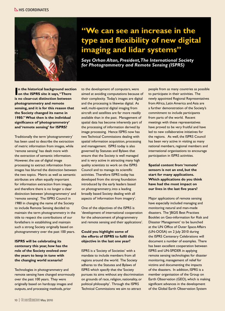
“We can see an increase in the type and flexibility of new digital imaging and lidar systems”Says Orhan Altan, President, The International Society for Photogrammetry and Remote Sensing (ISPRS)
10 | May 2010
May 2010 | 11
of Systems (GEOSS). Achievements of GEOSS are many, but they include: the GEOSS data sharing principles; and the Geo Web portal and GEOSS clearinghouse for searching data, information and services registries containing information about GEOSS components.
With remotely sensed images and data becoming freely available on many portals on the internet, it is felt that this technology is no more the prerogative of only the professionals. Would you like to comment?
Images of the earth are becoming more available thanks to Google Earth, Bing Maps and similar companies, as well as the many images appearing in the media. However, the images should be used for more than just the so-called ‘jee whizz’ factor, ie for looking at the images. The use of the data for extraction information still requires understanding the technologies, the local conditions for ground truthing, as well as processes that can be undertaken by software. There are still many new processes that need to be developed to
fully extract information contained in the images. This is where the professions are required to ensure that the data is used correctly and the full information that can be extracted from them is understood.
In the past few years, legal and privacy issues have increasingly been raised with reference to high resolution imagery. What are your views on this?
UN Charter approved by the Committee for the Peaceful Uses of Outer Space defined conditions under which one country can image another. However, Governments have made decisions to license the development of satellites for increasingly higher resolution image acquisition. This has caused concern by some countries about the data revealing confidential information, but I take the view that the more information available about the environment, the better we are able to understand it and seek methods towards sustainability. This will be an important issue for the future of the environment.
How do you see this whole gamut of ‘remote’ sensing technology and applications developing in the coming years? What do you think the scenario will be in 2020?
Looking into crystal balls is fraught with difficulties, not the least because one can be accountable for one’s predictions. However, in a general fashion, I think we can see an increase in the type and flexibility of new digital imaging and lidar systems; we are likely to see increasingly higher resolution space systems; there will be a continued introduction of automation for processing images, so that maps can be kept up-to-date more rapidly on a regular basis; there will be a greater availability and use of images and spatial information.
However, we are not likely to see a major leap forward in these developments. Looking back over the past 10 years, the improvements have been gradual and I think this will continue to occur over the next 10 years.
May 2010 | 11
12 | May 2010
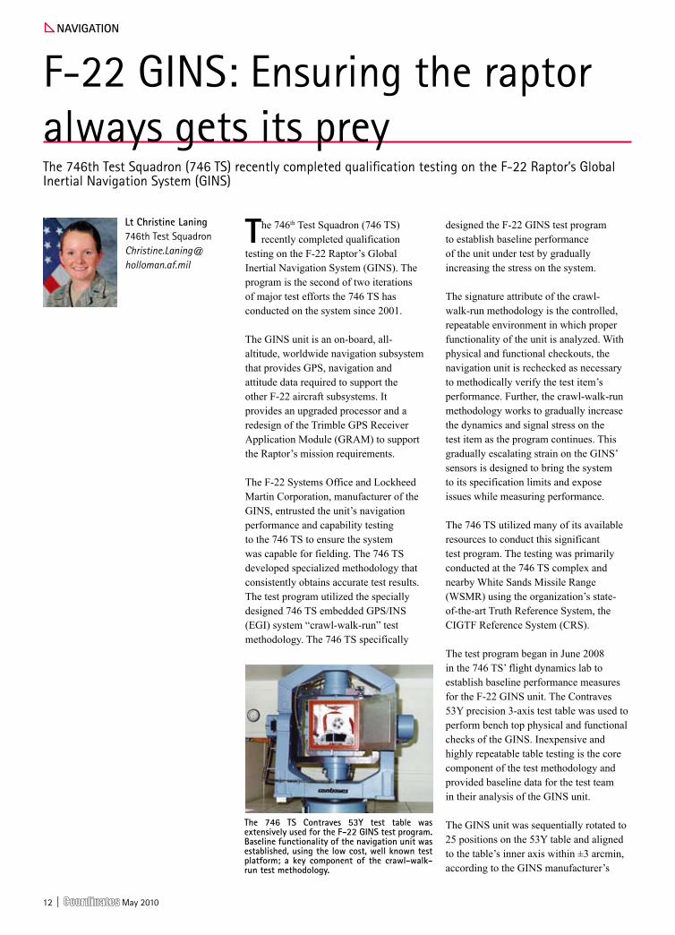
The 746th Test Squadron (746 TS) recently completed qualification
testing on the F-22 Raptor’s Global Inertial Navigation System (GINS). The program is the second of two iterations of major test efforts the 746 TS has conducted on the system since 2001.
The GINS unit is an on-board, all-altitude, worldwide navigation subsystem that provides GPS, navigation and attitude data required to support the other F-22 aircraft subsystems. It provides an upgraded processor and a redesign of the Trimble GPS Receiver Application Module (GRAM) to support the Raptor’s mission requirements.
The F-22 Systems Office and Lockheed Martin Corporation, manufacturer of the GINS, entrusted the unit’s navigation performance and capability testing to the 746 TS to ensure the system was capable for fielding. The 746 TS developed specialized methodology that consistently obtains accurate test results. The test program utilized the specially designed 746 TS embedded GPS/INS (EGI) system “crawl-walk-run” test methodology. The 746 TS specifically
designed the F-22 GINS test program to establish baseline performance of the unit under test by gradually increasing the stress on the system.
The signature attribute of the crawl-walk-run methodology is the controlled, repeatable environment in which proper functionality of the unit is analyzed. With physical and functional checkouts, the navigation unit is rechecked as necessary to methodically verify the test item’s performance. Further, the crawl-walk-run methodology works to gradually increase the dynamics and signal stress on the test item as the program continues. This gradually escalating strain on the GINS’ sensors is designed to bring the system to its specification limits and expose issues while measuring performance.
The 746 TS utilized many of its available resources to conduct this significant test program. The testing was primarily conducted at the 746 TS complex and nearby White Sands Missile Range (WSMR) using the organization’s state-of-the-art Truth Reference System, the CIGTF Reference System (CRS).
The test program began in June 2008 in the 746 TS’ flight dynamics lab to establish baseline performance measures for the F-22 GINS unit. The Contraves 53Y precision 3-axis test table was used to perform bench top physical and functional checks of the GINS. Inexpensive and highly repeatable table testing is the core component of the test methodology and provided baseline data for the test team in their analysis of the GINS unit.
The GINS unit was sequentially rotated to 25 positions on the 53Y table and aligned to the table’s inner axis within ±3 arcmin, according to the GINS manufacturer’s
naVIGatIon
F-22 GINS: Ensuring the raptor always gets its prey The 746th Test Squadron (746 TS) recently completed qualification testing on the F-22 Raptor’s Global Inertial Navigation System (GINS)
lt christine laning 746th Test Squadron [email protected]
the 746 ts contraves 53y test table was extensively used for the F-22 GIns test program. Baseline functionality of the navigation unit was established, using the low cost, well known test platform; a key component of the crawl-walk-run test methodology.
May 2010 | 13
specifications. The INS system was tested to 18 deg/sec rotation rates. The GINS completed several Gyrocompass (GC) Alignment, Stored Heading (SH) and Calibration Evaluation tests. The 53Y test table was utilized several other times in the test program to easily and economically identify and troubleshoot performance issues with the unit.
During this baseline lab testing, a GINS performance issue was uncovered. A standard calibration evaluation test revealed the inertial heading and roll errors were out of spec when the GINS was pitched at 90 degrees up or down. Upon further research, the 746 TS discovered that the blended attitude demonstrated similar behavior. The problem was reported to the 746 TS customer, who was able to respond to the problem by implementing corrections before further testing was conducted, thus saving the program considerable time, effort, and flight costs. If the test item had been put directly into the higher dynamic flight testing phase, this issue would have been uncovered at a substantially higher cost and with great delay to the program schedule. By catching the issue early in lab testing, $15,000 of flight testing costs, $9,000 of analysis troubleshooting costs and weeks of delays were avoided.
The next step in the crawl methodology for the GINS test program was to move into the Navigation Test & Evaluation Laboratory (NavTEL). NavTEL is the 746 TS modeling and simulation lab capability offering hardware in the loop testing designed to effectively and efficiently stress EGI systems under test. This laboratory provides a Radio Frequency (RF) sterile laboratory environment with the capability to replicate real world operations in a controlled, scientific manner. The Satellite Tool Kit was used to predict and analyze GPS denied operational effects on the GINS. After it passed the tests, the team confidently moved into the walk phase of the test program.
The program progressed to low dynamic ground testing with the controlled environment and medium cost that is characteristic of the walk methodology. Dynamic ground test and low dynamic
flight test beds were used for several months of operationally realistic test missions with the GINS and CRS on board. The CRS provides sub-meter accuracy in low-to-high dynamic environments, is capable in clean air and GPS denied environments and is extremely mobile and versatile because it can be palletized and utilized for van and flight testing.
Dynamic ground testing on the GINS program schedule started on the Small Test Vehicle (STV). The STV is a very versatile asset for navigation testing. It can be modified for a vast array of antenna configurations including up to three Controlled Reception Pattern Antennas (CRPA) and Fixed Reception Pattern Antennas (FRPA). It has onboard power for the test item and can carry up to three pallets and three operators.
The test team leveraged the capabilities of the STV in three, 2-hour clean air test profiles conducted on WSMR. The
60-mile roundtrip route conducted at 40-50 mph began and ended at CIGTF with a turnabout at the Small Missile Range on WSMR. Next, a GPS-denied environment was created using the 746 TS portable box jammer. A static ground jamming test was conducted at the Static Antenna Test Range, part of the CIGTF complex. The GINS and CRS endured a 2 dB/min jammer ramping scenario inside the parked STV.
The 746 TS conducted several one-hour GPS denied dynamic ground profiles on WSMR where the GINS was again subjected to ramping jamming scenarios. The 41 mile route went from the WSMR Stallion site to Gap site and back to Stallion at a speed of approximately 40-50mph.
Low dynamic flight testing was next on the GINS test schedule. East to west profiles were flown in an C-12D cargo aircraft in a profile designed to expose INS performance errors. The C-12D is operated
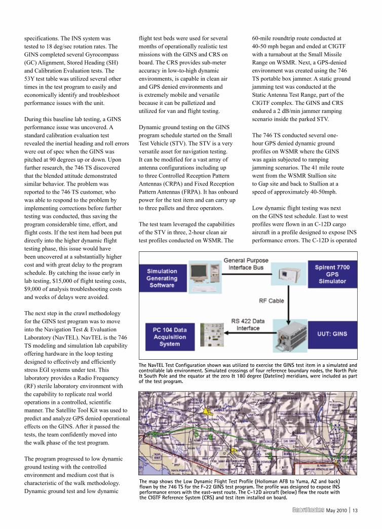
the navtel test configuration shown was utilized to exercise the GIns test item in a simulated and controllable lab environment. simulated crossings of four reference boundary nodes, the north pole & south pole and the equator at the zero & 180 degree (dateline) meridians, were included as part of the test program.
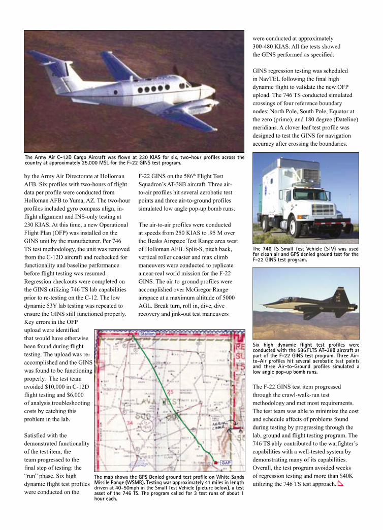
the map shows the low dynamic Flight test profile (holloman aFB to yuma, aZ and back) flown by the 746 ts for the F-22 GIns test program. the profile was designed to expose Ins performance errors with the east-west route. the c-12d aircraft (below) flew the route with the cIGtF Reference system (cRs) and test item installed on board.
14 | May 2010
by the Army Air Directorate at Holloman AFB. Six profiles with two-hours of flight data per profile were conducted from Holloman AFB to Yuma, AZ. The two-hour profiles included gyro compass align, in-flight alignment and INS-only testing at 230 KIAS. At this time, a new Operational Flight Plan (OFP) was installed on the GINS unit by the manufacturer. Per 746 TS test methodology, the unit was removed from the C-12D aircraft and rechecked for functionality and baseline performance before flight testing was resumed. Regression checkouts were completed on the GINS utilizing 746 TS lab capabilities prior to re-testing on the C-12. The low dynamic 53Y lab testing was repeated to ensure the GINS still functioned properly. Key errors in the OFP upload were identified that would have otherwise been found during flight testing. The upload was re-accomplished and the GINS was found to be functioning properly. The test team avoided $10,000 in C-12D flight testing and $6,000 of analysis troubleshooting costs by catching this problem in the lab.
Satisfied with the demonstrated functionality of the test item, the team progressed to the final step of testing: the “run” phase. Six high dynamic flight test profiles were conducted on the
F-22 GINS on the 586th Flight Test Squadron’s AT-38B aircraft. Three air-to-air profiles hit several aerobatic test points and three air-to-ground profiles simulated low angle pop-up bomb runs.
The air-to-air profiles were conducted at speeds from 250 KIAS to .95 M over the Beaks Airspace Test Range area west of Holloman AFB. Split-S, pitch back, vertical roller coaster and max climb maneuvers were conducted to replicate a near-real world mission for the F-22 GINS. The air-to-ground profiles were accomplished over McGregor Range airspace at a maximum altitude of 5000 AGL. Break turn, roll in, dive, dive recovery and jink-out test maneuvers
were conducted at approximately 300-480 KIAS. All the tests showed the GINS performed as specified.
GINS regression testing was scheduled in NavTEL following the final high dynamic flight to validate the new OFP upload. The 746 TS conducted simulated crossings of four reference boundary nodes: North Pole, South Pole, Equator at the zero (prime), and 180 degree (Dateline) meridians. A clover leaf test profile was designed to test the GINS for navigation accuracy after crossing the boundaries.
The F-22 GINS test item progressed through the crawl-walk-run test methodology and met most requirements. The test team was able to minimize the cost and schedule affects of problems found during testing by progressing through the lab, ground and flight testing program. The 746 TS ably contributed to the warfighter’s capabilities with a well-tested system by demonstrating many of its capabilities. Overall, the test program avoided weeks of regression testing and more than $40K utilizing the 746 TS test approach.
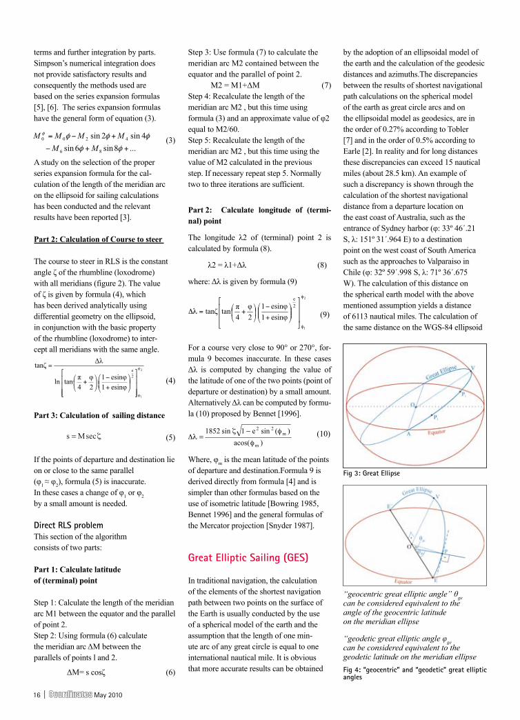
the army air c-12d cargo aircraft was flown at 230 KIas for six, two-hour profiles across the country at approximately 25,000 Msl for the F-22 GIns test program.
the map shows the Gps denied ground test profile on White sands Missile Range (WsMR). testing was approximately 41 miles in length driven at 40-50mph in the small test Vehicle (picture below), a test asset of the 746 ts. the program called for 3 test runs of about 1 hour each.
the 746 ts small test Vehicle (stV) was used for clean air and Gps denied ground test for the F-22 GIns test program.
six high dynamic flight test profiles were conducted with the 586 Flts at-38B aircraft as part of the F-22 GIns test program. three air-to-air profiles hit several aerobatic test points and three air-to-Ground profiles simulated a low angle pop-up bomb runs.

May 2010 | 15
tion the navigator is inter ested only in the inverse RLS problem that solves for the “course to steer” and the “sailing distance” from one location to another.
In contemporary navi gational systems (ECDIS, ECS) the accu rate solu-tion of the direct RLS is required for the portrayal of the RLS paths on the displayed electronic chart. The RLS paths (loxodromes) are depicted on the electronic chart through the calculation of the coordi nates of intermediate points between the points of departure and destination for specific dis tance inter-vals and for a given steering course.
Inverse Rls problem
This section of the algorithm consists of three parts:
Part 1: Calculation of Meridian distance
The calculation of the length of the arc of the meridian is a prerequisite not only for RLS calculations, but also for “geodesic sailing” and “great elliptic sailing”. The funda mental equation for the calculation of the length of the meridian arc on the ellipsoid (figure 1), is:
(1)
Where RM is the radius of curvature of the meridian.
Replacing the well known value of RM in (1) we obtain (2):
(2)
Formula 2 can be transformed into an elliptic inte gral of the second type, which cannot be evaluated in a “closed” form. The calculation can be per formed either by numerical integration methods, such as Simpson’s rule, or by the binomial expan sion of the denominator to rapidly converging se ries, retention of a few
From the early days of the de velop-ment of ba sic naviga tional software
built into sat ellite navigational receivers, it has been noted that for the sake of sim-plicity and a number of other reasons, this navi gational software is often based on methods of lim ited accuracy [1]. It is surprising that even nowadays the use of navigational soft ware is still used in a loose manner, sometimes ignoring ba sic princi ples and adopting over simpli fied as-sumptions and errors such as the wrong mixture of spherical and ellipsoidal calcula-tions in different steps of the solution of a particular sailing problem [2]. The lack of official standardi zation on both the “ac curacy required” and the equi va lent “methods em ployed”, in con junc tion to the “black box so lutions” provided by GNSS naviga tio nal recei vers and navigational systems (ECDIS and ECS) suggest the necessity of a thorough examina tion of the issue of sailing calcu lations for navigational systems and GNSS receiv ers [3].
New formulas have been derived for both Rhumb Line Sailing (RLS) on the ellipsoid and Great Elliptic Sail ing (GES). The RLS formulas result from the analysis of the geometry of the loxodrome on the ellip soid and are simpler and faster than those tradi tionally used for RLS on the ellip soid, which are normally based on the Mercator projec tion formulas. The proposed new algorithm for Great Elliptic Sail ing (GES), provides extremely high accuracies comparable to those obtained by the computa tions of geodesics. Numerical tests show that dis cre p an-cies in the compu ted distances between “geodesic” and “great elliptic arc” are prac ti cally negligible for navigation [4].
Rhumbline sailing (Rls)
The proposed formulas for rhumbline sailing calculations on the ellipsoid solve both the direct and the inverse RLS problem. In traditional naviga-
naVIGatIon
Improved algorithms for sailing calculationsThis paper presents new algorithms for rhumbline sailing (RLS) and great elliptic sailing (GES) calculations for route planning and portrayal of navigational paths on Electronic Chart Systems
Figure 1: the meridian arc
Fig-2: the geometry of the loxodrome (rhumbline) on the ellipsoid
athanasios pallikaris Associate Professor Hellenic Naval [email protected]
lysandros tsoulos Professor, Nati o nal Technical University of [email protected]
demitris paradissisProfessor, National Technical University of [email protected]
p1Kp2: infintesimal right triangle with hypotenuse ds on the rhumbline
16 | May 2010
terms and further integration by parts. Simpson’s numerical in tegration does not provide satisfactory results and consequently the methods used are based on the series expansion formulas [5], [6]. The series expansion formulas have the general form of equation (3).
(3)
A study on the selection of the proper series expansion formula for the cal-culation of the length of the meridian arc on the ellip soid for sailing calculations has been conducted and the relevant results have been reported [3].
Part 2: Calculation of Course to steer
The course to steer in RLS is the constant angle ζ of the rhumbline (loxodrome) with all meridians (figure 2). The value of ζ is given by formula (4), which has been deri ved analytically using differential geome try on the ellipsoid, in conjunction with the basic property of the rhumbline (loxo drome) to inter-cept all meridians with the same angle.
(4)
Part 3: Calculation of sailing distance
(5)
If the points of departure and destination lie on or close to the same parallel (φ1 ≈ φ2), formula (5) is inaccurate. In these cases a change of φ1 or φ2 by a small amount is needed.
direct Rls problem This section of the algorithm consists of two parts:
Part 1: Calculate latitude of (terminal) point
Step 1: Calculate the length of the meridian arc Μ1 between the equator and the parallel of point 2. Step 2: Using formula (6) calculate the meridian arc ΔΜ between the parallels of points l and 2.
ΔΜ= s cosζ (6)
Step 3: Use formula (7) to calculate the meridian arc Μ2 contained between the equator and the parallel of point 2.
Μ2 = Μ1+ΔΜ (7)
Step 4: Recalculate the length of the meridian arc Μ2 , but this time using formula (3) and an approxi mate value of φ2 equal to M2/60. Step 5: Recalculate the length of the meridian arc Μ2 , but this time using the value of M2 calculated in the previous step. If necessary repeat step 5. Normally two to three iterations are sufficient.
Part 2: Calculate longitude of (termi-nal) point
The longitude λ2 of (terminal) point 2 is calcula ted by formula (8).
λ2 = λ1+Δλ (8)
where: Δλ is given by formula (9)
(9)
For a course very close to 90° or 270°, for-mula 9 becomes inaccurate. In these cases Δλ is compu ted by changing the value of the latitude of one of the two points (point of departure or destination) by a small amount. Alternatively Δλ can be computed by formu-la (10) proposed by Bennet [1996].
(10)
Where, φm is the mean latitude of the points of departure and destination.Formula 9 is derived directly from formula [4] and is simpler than other formulas based on the use of isometric latitude [Bowring 1985, Bennet 1996] and the general formulas of the Mercator projection [Snyder 1987].
Great elliptic sailing (Ges)
In traditional navigation, the calculation of the elements of the shortest navigation path between two points on the surface of the Earth is usually conducted by the use of a spherical model of the earth and the assumption that the length of one min-ute arc of any great circle is equal to one interna tional nautical mile. It is obvious that more ac curate results can be obtained
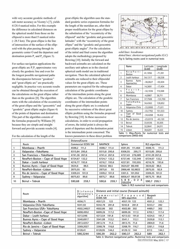
by the adoption of an ellipsoidal model of the earth and the calculation of the geodesic distances and azimuths.The discrepancies between the results of shortest navigational path calculations on the spherical model of the earth as great circle arcs and on the el lipsoidal model as geodesics, are in the order of 0.27% according to Tobler [7] and in the order of 0.5% according to Earle [2]. In reality and for long distances these discrepancies can exceed 15 nautical miles (about 28.5 km). An example of such a discrepancy is shown through the calculation of the shortest navigational distance from a departure location on the east coast of Australia, such as the entrance of Sydney harbor (φ: 33º 46´.21 S, λ: 151º 31´.964 E) to a destination point on the west coast of South America such as the approaches to Valpa raiso in Chile (φ: 32º 59´.998 S, λ: 71º 36´.675 W). The calculation of this distance on the spherical earth model with the above mentioned assumption yields a distance of 6113 nautical miles. The calcula tion of the same distance on the WGS-84 el lipsoid
Fig 3: Great ellipse
Fig 4: “geocentric” and “geodetic” great elliptic angles
“geocentric great elliptic angle” θge can be considered equivalent to the angle of the geocentric latitude on the meridian ellipse
“geodetic great elliptic angle φge can be considered equivalent to the geodetic latitude on the meridian ellipse
May 2010 | 17
with very accurate geodetic methods of sub meter accuracy as Vicenty’s [7], yields 6128.4 nautical miles. For this example the differ ence in calculated distances on the spherical model from those on the ellipsoid is more than15 nautical miles (~28.5 km). The great ellipse is the line of intersection of the surface of the ellip-soid with the plan passing through its geomet ric center O and the departure and destination points P1 and P2 (figure 3).
For surface navigation appli ca tions the great elliptic arc P1P2 approximates very closely the geodesic line and even for the longest possible navigational paths the discrepancies be tween “geodesic” and “great elliptic arc” are practi cally negligible. In practice very accurate results can be obtained through the execution of the calculations on the great ellipse rather than on the geodesic [8]. The algorithm starts with the calculation of the eccentricity of the great ellipse and the “geocentric” and “geodetic” great elliptic angles (figure 4) of the points of departure and destination. This part of the algorithm consists of the formulas proposed by Williams [9] because they are simple and straight forward and provide accurate results [4].
For the calcu la tion of the length of the
great elliptic the algorithm uses the stan-dard geodetic series expansion formulas for the length of the meridian arc, after their proper mo di fi ca tion for the great ellipse by the substitution of the “eccen tricity of the ellipsoid” and the “geodetic and geocentric latitudes” with the “ec centricity of the great ellipse” and the “geo detic and geocentric great elliptic an gles”. For the calcu la tion of the initial and final course the algorithm adopts the methodol ogy proposed by Bowring [10]. Initially the forward and back ward azimuths are calculated on the auxiliary unit sphere as in the classical sphe ri cal earth model use in traditional navigation. Then the cal culated spherical azi muths are reduced to their ellipsoidal values for the great ellip tic arc. These parameters are required for the subsequent calculation of the geodetic coordinates of the intermediate points along the great elliptic arc. The calculation of the geodetic coordinates of the intermediate points along the great elliptic arc is conducted by successive solutions of the direct great elliptic problem using the formulas proposed by Bowring [10]. In these successive calculations, in order to avoid propagation of errors, the initial point is always the point of departure and the destination point is the intermediate point concerned. The known parameters in these direct problem
table 1: Way-points for numerical tests and comparisons (WGs-84)
name latitude (d.dd)
longitude (d.dd)
1 N e w P o r t -Boston 41,1056 -71,391
2 Leath harbour 54,1317 -36,538
3 Buenos Ayres Approaches -36,0627 -55,504
4 Dakar 14,3691 -17,454
5 P e a r t h , Australia -32,1036 115,568
6 Mombassa -4,0987 39,7117 San Francisco 37,7508 -122,700
8 Y o k o H a m a , Japan 34,4363 139,852
9 Valparaiso Chile -33,0000 -71,61110 Sydney -33,7702 151,533
11 Cape of Good Hope -34,4268 18,432
12 Rio de Janeiro -23,0319 -43,12013 Beirut 33,9336 35,50514 Tobruk 32,0641 24,01115 Lisbon 38,6201 -9,223
Routed i s t a n c e [ V i c e n t r y ’ s algorithm]
distance and initial course (forward azimuth)c o m m e r c i a l ecdIs sW
p r o p o s e d Ges algorithm
navpack (G.c)
Mombassa - pearth 4556,71 4557,23 122 4557.19 122 4551,2 122,1Valparaiso chile yokohama 9241,92 9242,78 281,8 9242.8 281,9 9233,7 282san Francisco Usa- yokohama 4502,34927 4502,86 302 4502.89 302 4489,7 302newport-Boston -cape of Good hope 6698,4952 6699,26 117,2 6699.26 117,3 6702,1 117,4dakar - leath harbour 4213,046 4213,54 191,8 4213.53 191,8 4224,5 191,7Buenos ayres - cape of Good hope 3540,6917 3541,08 112,2 3541.1 112,1 3530,8 112,1newport-Boston -lisbon 2813,4257 2813,74 71,5 2813.75 71,6 2804,9 71,6Rio de Janeiro - cape of Good hope 3269,2027 3268,78 116,8 3268.79 116,7 3261,1 116,8sydney - Valparaiso 6128,41 6128,95 144,2 6129.12 144 6113 144,1Beirut - tobruk 590,3244 590,39 262,2 590.37 262,2 589 262,1
table 2: Rls numerical tests and comparisons
table 3: shortest navigational paths- numerical tests and comparisons
distance/course Route commercial ecdIs sW naVpacK sphere Rls algorithm
1 Mombassa - pearth 4598,2 111,3 4598,7 111,4 4591,95 111,464 4598.15 111.32 Valparaiso -yokohama 9315,84 295,6 9315,8 295,6 9306,55 295,77 9315,85 295,63 san Francisco - yokohama 4741,36 267,6 4741,4 267,6 4727,43 276,589 4741,39 267,64 newport-Boston - cape of Good hope 6724,67 132,2 6724,7 132,2 6727,46 132,349 6724,67 132,25 dakar - leath harbour 4216,77 193,6 4216,7 193,6 4227,81 193,555 4216,76 193,66 Buenos ayres - cape of Good hope 3634,6 88,5 3634,6 88,5 3624,07 88,448 3634,62 88,57 newport-Boston -lisbon 2875,55 93 2875,6 93 2866,48 92,9822 2875,55 92,98 Rio de Janeiro - cape of Good hope 3309,24 101,9 3309,2 101,9 3301,5 101,952 3309,25 101,99 sydney - Valparaiso 6875,63 89,6 6875,7 89,6 6856,47 89,6138 6875,75 89,6
10 Beirut - tobruk 590,68 259,1 590,6 259,1 5 8 9 , 0 2 4 259,024 590,7 259,1
Fig 5: sailing routes used in numerical tests
solid lines: loxodromes dotted lines: shortest navigational paths (G.C)

18 | May 2010
solutions are: “the geodetic coordinates of the point of departure”, “the calculated initial course at this point” and “the distance of the intermediate point from the point of departure”. The full set of the formulas used in the algorithm can be found in [4].
numerical tests and comparisons
For the numerical evaluation of the proposed new algorithms for RLS and GES calculations, a data set of ten (10) routes between selected ports and harbors has been used (table 1). These routes cover distances from 500 up to about 9000 nautical miles distributed all over the globe (figure 5). The proposed new algorithm for RLS has been tested against:
The simplified formulas for • RLS on the sphere.
The rhumbline sailing module of the • Navpack navigational software, which is provided jointly by the UK Almanac office and the US Naval Observatoty [12].
Typical commercial ECDIS kernel • navigational SW for RLS calculations.
The proposed new algorithm for GES [8] has been tested against:
Other methods and formulas for GES • that were proposed in the past as those of Willi ams [9] and Earle [13].
Vicenty’s algorithm for the • precise calcula tion of geodesic distances and azimuths [8]
Typical commercial ECDIS • kernel navigational SW.
Traditional G.C (Great Circle) • sailing formulas on the sphere.
The conducted numerical tests (tables 2 and 3) show that:
The average error of the proposed new • algorithm for GES in the cal culation of the great elliptic arc distances is 4,38 meters. This error is smaller than the 6,54 meters average errors of the
methods of Williams and Earle. Seeking higher accuracy for sailing calcula-tions does not have any practical value for marine navigation and simply adds more complexity to the calculations.
Dis crepancies in the compu ted • distances between the “geodesic” and the “great elliptic arc” are practically negligible for marine navigation.
Discrepancies between the results of • shortest navigational path calcula-tions on the spherical model of the earth as great circle arcs and on the ellip-soidal model as great elliptic arcs, or ge o de sics, may in some ca ses exceed 15 nauti cal miles (~28.5 km).
The discrepancies between RLS • calculations on the sphe re and the ellip-soid for very long sailing distances may exceed 19 nautical miles (~35 km).
For short sailing distances (smaller • than 600 nauti cal miles) the discrepancies between the cal cula-tions on the spherical and the ellipsoidal model of the earth practi cally can be considered negli gible for navi gation.
conclusions The new improved algorithms for RLS and GES calculations:
are straightforward and can be easily • implemented in navigational software,
provide the same and in some • cases, higher accuracy than other methods and formulas for sailing calculations on the ellipsoid,
can be used in program mable pocket • calculators for the solution of the in-verse RLS and GES problems,
are used for the calculation of the geodetic • co ordinates of an unlimited num ber of intermediate points along the rhumbline and the great elliptic arc and thus they can be easily imple mented in naviga tional systems (ECDIS and ECS) for the display of navigational paths on the Electronic Chart Systems (ECDIS and ECS).
Detailed presentations of the improved algorithms for sailing calculations in GIS navigati o nal systems can be found in references [3], [4] and [11].
abbreviations ECDIS: Electronic Chart Display and Information System ECS: Electronic Chart System ENC: Electronic Navigational Chart G.C: Great Circle GES: Great Elliptic Sail ing RLS: RhumbLine Sailing
References Bennet G.G. 1996. Practical Rhumb Line Calculations on the Spheroid. Journal of Navigation, Vol. 49 No 1. 112-119.
Earle M. A. 2006. Sphere to Spheroid Comparisons, Journal of Navigation, Vol.59, 491-496.
Pallikaris A. Tsoulos L. Paradisis D. New meridian arc formulas for sailing calculations in GIS, International Hydrographic Review May 2009.
Pallikaris, Α. Latsas, G. New algorithm for Great Elliptic Sailing (GES), Journal of Navigation, Vol. 62, No 3. 493-507.
Snyder, J. P. 1987. Map Projections: A Working Manual. U. S. Geological Survey Professional Paper 1395
Torge, W. 2001. Geodesy 3rd edition. Walter de Gruyter, Berlin, New York.
Tobler. W.R. 1964. A comparison of spherical and ellipsoidal measures. The Professional Geographer, Vol XVI, no 4, pg 9-12.
Vincenty, T. 1975. Direct and Inverse Solutions of Geodesics on the Ellipsoid with Application of Nested Equations. Survey Review, vol. XXII no 176. 88-93.
Williams, R. 1996. The Great Ellipse on the surface of the spheroid. Journal of Navigation, Vol. 49, No 2. pp. 229-234.
Bowring, B.R. 1984. The Direct and Inverse Solutions for the Great Elliptic Line on the Reference Ellipsoid. Bull. Geodesique, 58 pp. 101-108.
Pallikaris A. Tsoulos L. Paradisis D. New calculation algorithms for for GIS navigational systems and receivers, Proccedings of the Eu-ro pean Navigational Conference ENC-GNSS 2009. Naples Italy May 2009.
Hohenkerk C.Y. and Yallop B.D. 2004 NavPac and Compact Data 2006 – 2010 AstroNaviga tion Methods and Software for the PC. TSO, London
Earle, M. A. 2000. A Vector Solution for Navigation on a Great Ellipse. Journal of Navigation, Vol. 53, no 03

May 2010 | 19
20 | May 2010

May 2010 | 21

22 | May 2010

May 2010 | 23
24 | May 2010

May 2010 | 25

26 | May 2010
May 2010 | 27
During a disaster, situational awareness can mean the difference between
life and death. Satellites provide reliable and rapid communication, observation and positioning tools, especially when crucial on-the-ground infrastructure is damaged. Risk management activities also benefit greatly from space-based data.
In general terms, applying space-based technology to support disaster management in its various aspects means using suitable spectral ranges of electromagnetic radiation for observation and imaging, atmospheric sounding, radio communication, navigation and positioning, while taking advantage of the orbital position of satellites.
Images from Earth observing satellites are used to produce maps of disaster areas for overview information and damage assessment, and to provide specific data layers for applications of Geographic Information Systems (GIS), e.g. for early warning and risk and vulnerability mapping. Satellite communication serves to warn people at risk in remote areas, and to connect a disaster area to the outside world, providing medical information (telemedicine) or geographic information and data to support mapping activities. Global Navigation Satellite Systems (GNSS) provide positional information on disaster related events and objects and support relief teams in the field.
Un-spIdeR’s involvement in haiti
First response
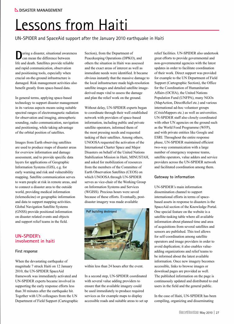
When the devastating earthquake of magnitude 7 struck Haiti on 12 January 2010, the UN-SPIDER SpaceAid framework was immediately activated and UN-SPIDER experts became involved in supporting the early response efforts less than 30 minutes after the earthquake hit. Together with UN colleagues from the UN Department of Field Support (Cartographic
Section), from the Department of Peacekeeping Operations (DPKO), and others the situation in Haiti was assessed and the exact areas of interest as well as immediate needs were identified. It became obvious instantly that the massive damage to the local infrastructure made high-resolution satellite images and detailed satellite image-derived maps vital to assess the damage and plan the relief work on the ground.
Without delay, UN-SPIDER experts began to coordinate through their well established network with providers of space-based information, including public and private satellite operators, informed them of the most pressing needs and requested tasking of their satellites. Among others, UNOOSA requested the activation of the International Charter Space and Major Disasters on behalf of the United Nations Stabilization Mission in Haiti, MINUSTAH, and asked for mobilization of resources from the members of the Committee of Earth Observation Satellites (CEOS) on which UNOOSA through UN-SPIDER serves as vice-chair of the Working Group on Information Systems and Services (WGISS). Precious hours were saved because of these efforts. Eventually, post-disaster imagery was made available
within less than 24 hours after the event.
In a second step, UN-SPIDER coordinated with several value adding providers to ensure that the available imagery could be used immediately to produce required services as for example maps to display accessible roads and suitable areas to set up
relief facilities. UN-SPIDER also undertook great efforts to provide governmental and non-governmental agencies with the latest updates in order to facilitate coordination of their work. Direct support was provided for example to the UN Department of Field Support (Cartographic Section), the Office for the Coordination of Humanitarian Affairs (OCHA), the United Nations Population Fund (UNFPA), many NGOs (MapAction, DirectRelief etc.) and various international ad-hoc volunteer groups (CrisisMappers etc.) as well as universities. UN-SPIDER staff also closely coordinated with other UN agencies on the ground such as the World Food Programme (WFP), and with private entities like Google and ESRI. Throughout the entire response phase, UN-SPIDER maintained efficient two-way communication with a large number of emergency response teams, satellite operators, value adders and service providers across the UN-SPIDER network and facilitated coordination among them.
Gateway to information
UN-SPIDER’s main information dissemination channel to support international efforts in terms of space-based assets in response to disasters is the SpaceAid section of the Knowledge Portal. One special feature on the website is a satellite-tasking table where all available information about planned time and area of acquisitions from several satellites and sensors are published. This tool allows for self-coordination among satellite operators and image providers in order to avoid duplication; it also enables value-adding organizations and relief teams to be informed about the latest available information. Once new imagery becomes accessible, links to browse images or download pages are provided as well. The published information on the page is continuously updated and distributed to end users in the field and the general public.
In the case of Haiti, UN-SPIDER has been compiling, organizing and disseminating
dIsasteR ManaGeMent
Lessons from HaitiUN-SPIDER and SpaceAid support after the January 2010 earthquake in Haiti
pop building destroyed

28 | May 2010
the latest available space-based information, including web links to satellite-derived images, maps and related geospatial data of the affected areas on a dedicated SpaceAid website (link: www.un-spider.org/haiti). For the Haiti earthquake, the respective SpaceAid Updates webpage was consulted more than 4000 times by partner agencies, relief experts, scientists, the media as well as the public.Another major achievement in response to the Haiti earthquake is the establishment of a time critical Web Map Service (WMS) by UN-SPIDER. This service allows for serving geospatial data over the web and also for viewing data even over low-bandwidth connections, without the need to download and process the raw data. Within only two days of operation, about 1.5 million jpeg files were delivered through this service to intermediaries, value adders and other users. As an additional service to support relief operations, UN-SPIDER set up an ftp site on its servers in order to disseminate otherwise
restricted raw data to eligible partners such as emergency relief organizations.
Unfortunately, due to the disrupted infrastructure in Haiti, the huge amount of compiled data could not be downloaded by the partners on the ground via internet. Interrupted networks and low bandwidth pose a serious bottle neck, and this was also the case in Haiti. Feedback from users on the ground suggests that it was from difficult to impossible for them to download large files via internet for the first couple of weeks after the earthquake. Therefore, UN-SPIDER staff hand-delivered approximately 50 GB of digital elevation data as well as satellite and aerial imagery on a hard drive to cartographers from OCHA/ReliefWeb while conducting a Technical Advisory Mission in Santo Domingo, Dominican Republic.
ensuring continuous support for recovery and reconstruction
After the conclusion of the first response phase, UN-SPIDER has not ceased its involvement but rather seeks to play a decisive role in supporting the ongoing recovery and reconstruction efforts. UN-SPIDER submitted a project proposal for the UN Haiti Flash Appeal covering the topic of “Satellite derived geo-information to support relief efforts and early recovery”. With this project, UN-SPIDER envisages ensuring accessibility of all available geospatial data and derived products for Haiti by compiling and disseminating these to all beneficiaries, in particular to international organizations and the Civil Protection Agency of Haiti, through the UN-SPIDER Web Map Server as well as dedicated ftp sites. Also, UN-SPIDER will support the use of space-based information by local partner institutions to enable them to assess priority areas for
further interventions. In particular, UN-SPIDER seeks to strengthen the capacity of the Civil Protection Agency of Haiti to access and use the compiled geospatial data according to the country’s needs.
As another major follow-up to the early response phase, in its capacity as UNGIWG co-chair, UNOOSA through UN-SPIDER is coordinating an Ad hoc Haiti Geospatial Cooperation Task Group comprising UN Agencies, governmental and non-governmental organizations as well as other partners in order to ensure better communication among the various agencies that provide geospatial support to Haiti and also to coordinate the work ahead. Among others, the establishment of a Spatial Data Infrastructure (SDI) for Haiti involving all partners will be one of the major tasks ahead to be coordinated. The group convenes by teleconference on a bi-weekly basis and uses various electronic communication tools, including a workspace on the UN-SPIDER Knowledge Portal, to facilitate its work.
On request of the government of Haiti, UN-SPIDER conducted a Technical Advisory Mission to Port-au-Prince from 14 to 20 March 2010. The purpose of the mission was to support the Civil Protection Agency of Haiti and the National Center for Geo-Spatial Information to rebuild their capacities to access and use space-based technology and information for disaster-risk management and emergency response. In view of the coming hurricane season, the mission team also tried to identify institutional partners who may be able to provide technical assistance, while capacities are re-established within government agencies dealing with geo-spatial information and disaster response. During the mission, UN-SPIDER managed to facilitate links between the relevant national agencies and GIS units of several
What is Un-spIdeR?
The world of disaster management and space-based technologies is complex. Knowledge and expertise are widely dispersed. Institutions and practitioners need support, orientation and advice to access and use available data, information, knowledge and services. In recognition of these needs the United Nations General Assembly, in its resolution A/RES/61/110 of 14 December 2006, established UN-SPIDER as a programme implemented by the United Nations Office for Outer Space Affairs (UNOOSA), with the following mission statement:
“Ensure that all countries and international and regional organizations have access to and develop the capacity to use all types of space-based information to support the full disaster management cycle.”
UN-SPIDER is achieving this by being a gateway to space-based information for disaster management support; serving as a bridge to interlink the disaster management and space communities; and being a facilitator of capacity-building and institutional strengthening.
pop harbour destroyed

May 2010 | 29

30 | May 2010
UN agencies present in Haiti with respect to disaster management, and to facilitate technical assistance to these national agencies. UN-SPIDER was able to identify through this mission current strengths, impacts provoked by the earthquake as well as needs to rebuild local capacities. Based on the mission insights, UN-SPIDER will develop an action plan on how to best ensure continuous support to those agencies in the short and in the long term. UN-SPIDER is committed to further providing long-term support to the Government of Haiti, especially in cooperation with the Civil Protection Agency and the National Center for Geo-Spatial Information and its partners from the international community.
lessons from haiti: challenges and a look ahead
In disaster management in general and during the response phase in particular there are numerous challenges to face, especially in developing countries. Poor infrastructure and communication channels, lack of adequately trained personnel, and weak cooperation among institutions are some of the main hurdles to overcome. The destruction caused by disasters creates additional difficulties.
communications
When a disaster strikes, land-based communications infrastructures are highly vulnerable and often fail due to destruction or saturation of the channels available for such communications. Satellite communications offer an alternative in these situations. They can be delivered to the users immediately after a disaster to facilitate communication and relief efforts. In the case of the earthquake in Haiti, the
disrupted communication channels during the first hours after the incident did pose an obstacle in assessing the situation and the needs and in coordinating with the local partners. Satellite communications seem to be the only secure way to support specific emergency telecommunication needs. Ideally, they would facilitate the deployment and operation of on-the-scene teams and their sharing information internally as well as externally with other organizations; they could operate with wired and wireless media, and could be affordable and accessible to the entire spectrum of potential users. For emergency responders, satellite phones and derivatives are the most robust, reliable emergency communications means during the first response, search and rescue, and the recovery phase of a disaster. For communicating and relaying data, voice and video to the rest of the world and from the rest of the world to the area of the disaster VSAT (Very Small Aperture Terminals) is the technology of choice. VSAT and/or portable base towers for cell phones offer the best viable solutions for providing temporary means of communication to the affected population until the telecommunications infrastructure is restored.
UN-SPIDER is in the process of developing partnerships and networking with the space communications providers, namely telecom satellite operators, satellite phone companies, and satellite broadband providers, to help coordinate the provision of robust emergency communications means to the countries at the face of disasters. In this process, UN-SPIDER consults and takes into account similar work done by other organizations, such as the International Telecommunication Union (ITU) in order to avoid the duplication of efforts. To achieve this in the most effective
and complimentary fashion UN-SPIDER will: determine the current emergency telecommunications capacity and capability of UN and UN-affiliated organizations, telecom satellite operators, and international and national aid agencies; make this information available to the community and to the general public through the UN-SPIDER Knowledge Portal; and increase the awareness of these capacities by means of UN-SPIDER Technical Advisory Missions and relevant gatherings.
Infrastructure and institutional framework
But not only communication difficulties are to be overcome. As was the case in Port au Prince, the facilities of the national Civil Protection Agency collapsed, the MINUSTAH mission was temporarily not able to respond due to severe losses in its own personnel, buildings, and materials, and other international relief organizations
What is spaceaid?
SpaceAid is UN-SPIDER’s framework to facilitate fast and efficient access to space-based information in case of disasters for countries, international and regional organizations. This includes all types of information provided by earth observation satellites, communication satellites and global navigation satellite systems. SpaceAid support can be accessed by the UN-SPIDER National Focal Points (NFP), UN-SPIDER Regional Support Offices (RSO) and UN organizations. Government agencies, major international and regional organizations will also have access to SpaceAid as procedures develop.
Users can request the support through a hotline via telephone, e-mail or fax. A central coordination unit coordinates and follows-up on all requests. This framework is operational on a 24 hours a day/7 days a week basis in order to respond timely to a disaster.
Through its SpaceAid Framework, UNOOSA continues to be the main contributor to ensuring access and use of space-based information to support emergency response, especially in developing countries.
pop map cseRtItpop map cdlR
May 2010 | 31
Expert Speakers From:
Monetise connected services, re-evaluate your business models and identify new revenue streams
Navigate the market in 2010: • Discover how to boost sales in a dramatically changing and commoditised navigation marketNext-generation strategies for in-car navigation: • Analyse the profi t potential of embedded & low-cost navigation and re-examine your target marketsHarness the surge in smartphones: • Examine pricing, routes to market and the app store model as navigation goes mobileCompete with free services: • Redefi ne your business models, defend your business against the onslaught of “free” and demonstrate the value of enhanced services Enhance your product with traffi c and connected services: • Discover how to deploy cost-effective live traffi c information and evaluate the profi t potential of connected servicesProfi table innovation: • Augmented reality, speech technology,3D navigation – which are the genuine money makers?
For more information call Helen on +44 (0) 207 375 7582 or go to www.thewherebusiness.com
Monetise connected services, re-evaluate your
Navigation & Location Summit June 15th – 16th, The Marriott, Berlin
The 50 SPEAKERS3 TRACKS200 ATTENDEESEUROPE 2010
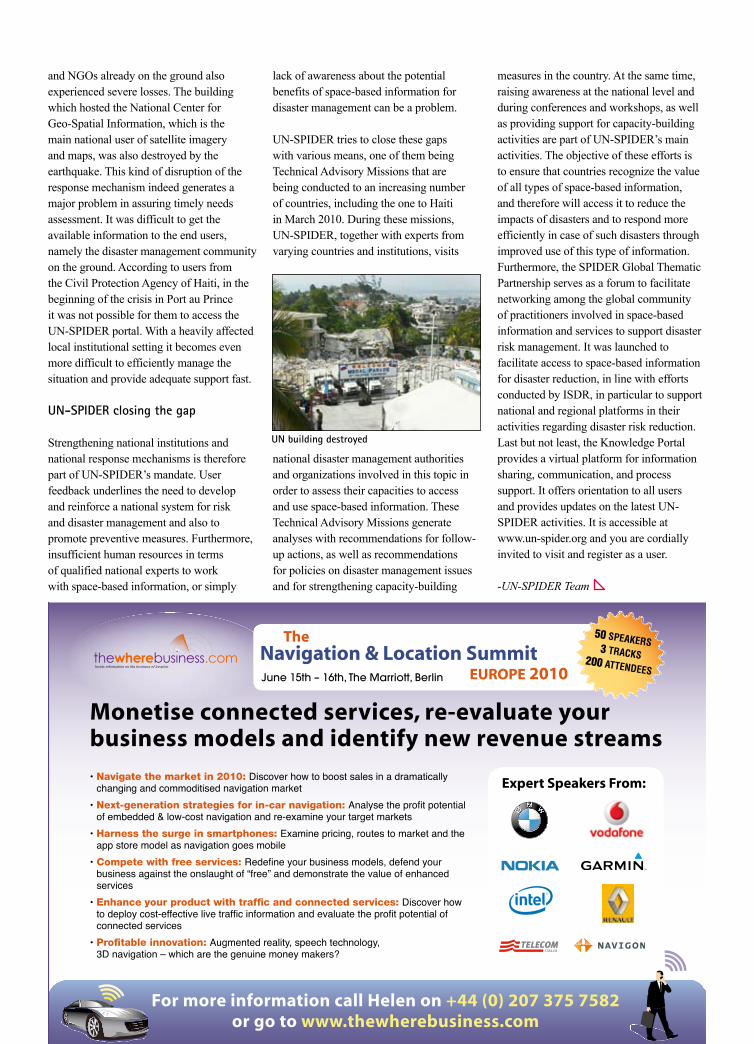
and NGOs already on the ground also experienced severe losses. The building which hosted the National Center for Geo-Spatial Information, which is the main national user of satellite imagery and maps, was also destroyed by the earthquake. This kind of disruption of the response mechanism indeed generates a major problem in assuring timely needs assessment. It was difficult to get the available information to the end users, namely the disaster management community on the ground. According to users from the Civil Protection Agency of Haiti, in the beginning of the crisis in Port au Prince it was not possible for them to access the UN-SPIDER portal. With a heavily affected local institutional setting it becomes even more difficult to efficiently manage the situation and provide adequate support fast.
Un-spIdeR closing the gap
Strengthening national institutions and national response mechanisms is therefore part of UN-SPIDER’s mandate. User feedback underlines the need to develop and reinforce a national system for risk and disaster management and also to promote preventive measures. Furthermore, insufficient human resources in terms of qualified national experts to work with space-based information, or simply
lack of awareness about the potential benefits of space-based information for disaster management can be a problem.
UN-SPIDER tries to close these gaps with various means, one of them being Technical Advisory Missions that are being conducted to an increasing number of countries, including the one to Haiti in March 2010. During these missions, UN-SPIDER, together with experts from varying countries and institutions, visits
national disaster management authorities and organizations involved in this topic in order to assess their capacities to access and use space-based information. These Technical Advisory Missions generate analyses with recommendations for follow-up actions, as well as recommendations for policies on disaster management issues and for strengthening capacity-building
measures in the country. At the same time, raising awareness at the national level and during conferences and workshops, as well as providing support for capacity-building activities are part of UN-SPIDER’s main activities. The objective of these efforts is to ensure that countries recognize the value of all types of space-based information, and therefore will access it to reduce the impacts of disasters and to respond more efficiently in case of such disasters through improved use of this type of information. Furthermore, the SPIDER Global Thematic Partnership serves as a forum to facilitate networking among the global community of practitioners involved in space-based information and services to support disaster risk management. It was launched to facilitate access to space-based information for disaster reduction, in line with efforts conducted by ISDR, in particular to support national and regional platforms in their activities regarding disaster risk reduction. Last but not least, the Knowledge Portal provides a virtual platform for information sharing, communication, and process support. It offers orientation to all users and provides updates on the latest UN-SPIDER activities. It is accessible at www.un-spider.org and you are cordially invited to visit and register as a user.
-UNSPIDER Team
Un building destroyed

32 | May 2010
The development and deployment of the European Satellite Based
Augmentation System EGNOS followed by the development of the Global Navigation Satellite System (GNSS) Galileo, that is currently under deployment, definitely represent the largest technological initiative promoted by the European Union so far. While designing and setting up its own GNSS, Europe has devoted funding and energies not only for the core activities needed to make the new system operational, but also to support research projects and actions targeting at large the GNSS sector, in order to promote its growth and its strengthening. GNSS application have therefore deserved keen attention, awareness and education actions have been funded and cooperation and synergies with different countries and regions have been sought. It is in this framework that a project entitled “South-East Asia centre on European GNSS for international cooperation And Local development” (SEAGAL) has been conceived and funded (Seventh Research Framework Programme – Galileo I Call – Grant Agreement no. 228061).
SEAGAL aims to establish a new link between Europe and South East Asia in the framework of satellite navigation and related applications, from education to technology transfer, from research activities to life-long learning. The main objective of the project is to set up a Collaboration Centre in South East Asia and with South East Asia, on European GNSS technologies. The Centre will be located in the premises of Hanoi University of Technology (HUT) in Vietnam and it will be opened at the end of the project on 1st October 2010. The project foresees also the preparation of a “Plan of activities” for three years after the opening of the Collaboration Centre so that it can start its activities right after the opening. Within the project some ancillary awareness and dissemination activities are foreseen as
well, which are mainly constituted by two workshops held in October 2009 in Hanoi and in March 2010 in Bangkok.
Although based in Vietnam and strongly connected to the Vietnamese society, the Collaboration Centre is being designed to develop its activities with a clear South East Asian perspective and for the benefit of all the Countries in the Region thus promoting a strong partnership with Europe on GNSS advanced scientific and technological topics. These can highly contribute to a sustainable improvement of the quality of life providing better, safer, and faster services in almost any field, from the mitigation of disasters to the use of natural resources, from infrastructures in support of mobility and transportation to tourism, power generation and transport, insurances, etc.
The collaboration Centre is expected to promote awareness and technology transfer, research, training, higher education, and support to public bodies in the field of GNSS and related applications. Activities of the Centre should have a strong orientation in support of the productive sector and should promote cooperation with European institutions and industries while acting also as a focal point at research and university level. In this sense the Centre is going to establish a real link in the South East Asia Region with European actors, promoting European GNSS technology. The Centre should become the place where students, companies and policy makers find information, resources and support on GNSS related activities. The Centre will also offer support to European companies and universities operating in the GNSS field to find links and partnerships in South East Asia.
The consortium created to implement the SEAGAL project was obtained putting together selected European and Asian Institutions with long lasting cooperation records among them so as to facilitate the
Gnss
The SEAGAL ProjectAn opportunity for GNSS collaboration between South East Asia and Europe
Gustavo Belforte Dipartimento di Automatica e Informatica, Politecnico di Torino, [email protected]
Gabriella povero Laboratorio Navigazione Istituto Superiore Mario Boella, [email protected]
Matteo Vannucchi Dipartimento di Automatica e Informatica, Politecnico di Torino, [email protected]
May 2010 | 33
project execution. Since, with a total budget of less than 500K Euros, the size of the project is moderate, the partnership is not large and is composed of: Istituto Superiore Mario Boella (ISMB) (Italy), Politecnico di Torino (Polito) (Italy), Universidad Politecnica de Catalunya (UPC) (Spain), Université De Franche-Comté (UFC) (France), Hanoi University of Technology (HUT) (Vietnam), Asian Institute of Technology (AIT) (Thailand). ISMB acts as coordinator of the project.
The European Partners have solid records in GNSS related activities and have complementary expertise in important sectors of GNSS such as receivers and signal processing, Satellite Based Augmentation Systems (EGNOS etc.), Precise Positioning, combined GNSS-WiFi positioning, Location Based Services, Geo-casting in vehicle to vehicle communication, rapid prototyping and development of applications, etc. European partners have also consistent teaching experience at graduate and PhD level as well as in the organization of specific curricula as the Master on Navigation offered at Politecnico di Torino, which is supported by the UN Office for Outer Space Affairs. Finally, some of the European Partners’ key persons involved in SEAGAL are members of GNSS international committees such as the International Committee on GNSS of UN and the Galileo Signal Task Force. With these qualifications European partners can support the design of the Collaboration Center and of its activities to which they can contribute with their expertise. However cooperation on the European side should not be restricted to the project partners. Links, contacts, and joint activities with other European institutions is welcome and will be sought.
Indeed also the Asian partners are very important. For the success of its activities the SEAGAL project deeply relays on the commitment of the two Asian Universities: HUT and AIT. HUT is the leading Vietnamese higher education technical institution with important ties with Ministries and Governmental Bodies as well with specific technical expertise and technical staff trained in GNSS. Therefore, HUT is the ideal recipient for the Cooperation Centre to which it can offer important local and regional links both technical and political. AIT is a well known international higher education institution based in Thailand, but addressing a truly international group of users. Its long lasting cooperation with HUT makes it an ideal partner to direct the actions of the Cooperation Centre also in the whole South-East Asia region. Also from the Asian side the Collaboration Centre is open to cooperation with any interested public or private institution. Those who are interested to know more on the project can visit the project website at www.navsas.ismb.it/seagal and get in touch with the SEAGAL consortium.
ARE YOU HEADING IN
THE RIGHT DIRECTION?
Trimble GNSS OEM Systems: Performance You Can Rely On
www.trimble.com/GNSS-Inertial
34 | May 2010
neWs Gps
lockheed on scheduled with Gps III
Lockheed Martin has nearly finished with critical design review for the next-generation of the GPS satellite. Its team working on the GPS III satellite constellation was on schedule for the critical design review phase of the program. The team has finished 26 of the 65 CDRs for the program. Overall space vehicle CDR is scheduled for an August completion, two months ahead of schedule. GPS III scheduled for a 2014 launch, improves the network security, accuracy and reliability of the current constellation. www.lockheedmartin.com
Boeing to provide next-Generation Gps Ground systems support
Boeing will develop portions of the U.S. Air Force’s new ground control segment. It will provide infrastructure, development of the ground systems, and continued 24/7 operational and sustainment support for the current and future GPS satellite systems. It will install hardware and software at GPS control stations at Schriever Air Force Base in Colorado and Vandenberg Air Force Base in California. www.boeing.com
taoglas antennas for Miniature devices
Taoglas has launched the AP.35a, a 35 x 35-millimeter square GPS antenna for compromised environments where next-generation miniature tracking devices are placed, deep inside vehicles and assets. The AP.35a antenna is embedded securely in any GPS device, eliminating the need for an external antenna. www.taoglas.com
Indian GslV-d3 Mission not successful
The flight-testing of the indigenous Cryogenic Engine and the Stage conducted in the Geosynchronous Satellite Launch Vehicle GSLV-D3 was not successful. GSLV-D3 vehicle performance was normal up to the end of the second stage (GS2) till 293 seconds. Afterwards, the Cryogenic Stage was to ignite and burn for about
720 seconds to provide the necessary velocity to inject GSAT-4 Satellite into the intended Geosynchronous Transfer Orbit. The vehicle was seen tumbling, lost altitude and finally splashed down in the sea. Detailed analysis of the flight data is being carried out to find out the exact reasons for the failure and take corrective measures to realise the next flight test of the indigenous Cryogenic Engine and Stage within the next one year. www.isro.org
Use Gps to control prices, suggests Indian pM’s core group
A meeting on rising prices in India, chaired by Prime Minister, Manmohan Singh, recommended the use of technology and GPS to track vehicles carrying essential commodities for better management of the public distribution system (PDS). http://sify.com
Russia to orbit 7 new Glonass satellites in 2010
“We are actively continuing to increase our space grouping. There are presently 23 satellites functioning in orbit, 21 of them operating perfectly, though the work the two remaining ones are under question,” according to Russian Prime Minister Vladimir Putin. He added that the additional seven satellites to be launched this year would bring the total to 27-28 fully functional satellites for the navigation system. He added that 2.5 billion rubles ($85.24 mln) was spent on the satellite system in 2009, and another 3.7 billion rubles was allocated for 2010-2011. RIA Novosti
portable Gps Jammers
Shoghi GPS Jammers transmit adequate power radio signals to cut-off communications between GPS Receiver and Satellite stations, by jamming the signals in the operating frequencies of GPS bands. It does not interfere with any communications other than GPS within the defined regulated zone. Upon activating the Jammer, all idle GPS receivers will indicate “NO SERVICE”. When the Jammer,
is turned off, all GPS receivers will automatically re-establish communications and provide full service. www.shoghi.co.in
India to have Gps based navigation system by next year
India would have a GPS-based aviation navigation system by next year, Civil Aviation Minister Praful Patel has said. “In the meantime we would be doing trial run on borrowed satellite. This is for the entire Indian network. Our entire air mapping would be done by GPS,” he said, adding that India is moving into GPS satellite based navigation system from the present ground based navigation system.http://economictimes.indiatimes.com
Bill promotes Gps in air traffic system
The transformation of the US’s air traffic system by replacing World War II-era radars with 21st century GPS technology would be accelerated under a bill approved by the Senate. The USD 34.5 billion bill funds the Federal Aviation Administration (FAA) through Sept. 30, 2011. The centrepiece of the bill calls for key elements of the FAA’s NextGen programme to be in place at the busiest American airports by 2014. The system is crucial to handling the expected growth in air traffic from about 700 million passengers in 2009 to the more than 1 billion annually by 2023. http://news.yahoo.com
oGc: aviation domain Working Group
The Open Geospatial Consortium (OGC) announced the formation of an Aviation Domain Working Group (DWG). It will support the evaluation, advancement, operational use and validation of OGC standards within the aviation domain. It will contribute towards increasing global adoption of OGC standards and complementary standards and coordinate the technical input, when required, to support profiling or extending those standards to meet the requirements of the aviation community. www.opengeospatial.org
May 2010 | 35
ProMark 500the Winning Combination
ProMark™ 500Multi-constellation RTK Surveying by Ashtech
The new ProMark™ 500 offers GPS+GLONASS+25 years of field-provenAshtech technologies. Designed by our GNSS experts, this powerful surveysolution delivers state-of-the art RTK features in a light, cable-free rover thatgives you maximum mobility and flexibility in the field. Its unique GNSS engineinsures fast initialization, long-range accuracy, robust signal tracking, andsecures future constellation evolutions.
Offering a wide range of built-in communications and extensive equipmentinteroperability via the new FAST Survey™ field software, ProMark 500 is alsothe only survey equipment featuring a handheld GPS as field terminal readyfor navigation and GIS data collection.
ProMark 500 encompasses all the RTK features that land surveyors expect for productive and reliable positioning and concentrates the best Ashtech technologies for the survey market.
Competitive Advantage:
• BLADE™ GNSS technology• Enhanced RTK accuracy• Wide range of communications• Cable-free lightweight design• Rugged base & rover solution• Multi-application field terminal
©2010 Ashtech LLC. All rights reserved. The Ashtech logo, ProMark, BLADE and FAST Survey are trademarks of Ashtech LLC.
For more information:France(HQ) +33 2 28 09 38 00China +86 10 5802 5174APAC +65 983 842 29
Visit www.ashtech.com today
NEW VERSIONAVAILABLEMore features,enhanced performanceand a new price offer

36 | May 2010
eurocopter and Funkwerk avionics
Eurocopter and Funkwerk Avionics have successfully completed a helicopter test flight with an EC145 in the Galileo test bed GATE in Berchtesgaden, Southern Germany. The test flight was observed by IFEN GmbH, the operator of the GATE test bed. The test marked the first time that signals from Galileo were used for navigation in a helicopter. In the “Galileo Test and Development Environment” (GATE), transmission antennas on six mountain peaks simulate the Galileo signals. In recent months, these so-called “pseudolites” had been upgraded to the current Galileo signal definition. The test flight was one of three demonstration campaigns as part of the European research project Mature Applications of Galileo for Emergency Services (MAGES). www.eurocopter.com
eGnos and aviation ready for take off in 2010
The aviation industry is preparing to use EGNOS once it becomes certified for the sector later this year, said speakers at Galileo Application Days. The aviation sector is one of the primary reasons EGNOS was launched by the European Community. The EGNOS Open Signal became operational in October 2009. The safety-of-life signal is expected to be certified for use in civil aviation later this year, said Hans de With, Market Development Officer with GSA. Studies have shown that the full adoption of EGNOS-enabled flight procedures, such as localised performance with vertical guidance (LPV), could produce savings of up to €4 billion in Europe. Using EGNOS to guide landing can help airports reduce noise, delayed flights, and timeslots for aircraft arrival could be more accurately
predicted compared to the current relative block system. www.gsa.europa.eu
saving lives
The Mature Applications of Galileo for Emergency Scenarios (MAGES) project received funding from the EU’s Sixth Framework Programme for Research (FP6) and recently showcased its results in this area at a workshop in Brussels. The project showed how accurate location-based services and products can add value to field operations in emergencies, and highlighted the benefits through five real-life demonstrations. www.gsa.europa.eu
Gnss science
ESA has opened an Announcement of Opportunity for scientific studies in areas of advanced GNSS research under the European GNSS Evolution Programme. With this call, the Agency intends to foster the scientific utilisation of EGNOS and Galileo and to gather feedback from the scientists for the designers and integrators of the next generation of navigation satellites, with a view to maximising the scientific value of the exploitation of European GNSS signals and data. www.esa.int
spectratime to supply atomic clocks
SpectraTime shall supply advanced atomic space clocks, including Crystal oscillators, Rubidium Atomic Frequency Standards, and Passive Hydrogen Masers, for the first 14 Full Operational Capability satellites and the ground mission segment (GMS) of the Galileo global navigation satellite system. www.spectratime.com
Galileo updatesnIppets
AT A GlAnce
►Honeywell to supply IMUs for GPS III program
►PCI to partner with Vexcel Imaging GmbH.
►Geosemble Technologies and BAE integrate their technologies to offer better geospatial decision making.
►Rolta acquires OneGIS, Inc.
►SimpleGeo and deCarta enters into partnership
►Imaginet appointed as authorised reseller for MapInfo Professional, Discover, Discover 3D and Discover Mobile product lines in the Philippines.
►According to market research firm IMS, annual smartphone shipments to Asia are expected to be more than quadruple between now and 2015.
►iiTc Solution become SuperGeo’s reseller in Korea.
►GeoEye, Inc. has signed a modification to a contract with the NGA to provide Web mapping services.
►DigitalGlobe content library contains more than one billion sqkm of earth imagery, 33% of which is less than a year old.
►According to IMS Research, the GPS chipset market capped 300 million units in 2009.
►Geographic information industry value in China is expected to reach about 14.6 billion USD this year, according to CAGIS.
►Philippines’s first fully-automated web GIS parcellary mapping service at www.mapsys.ph, has been launched.
►Nepal and China have agreed to disagree on the height of Mount Everest
►According to a new research report by Berg Insight, global shipments of GPS-enabled GSM/WCDMA handsets increased 92 percent in 2009 to 150 million units.

May 2010 | 37K O L I D A I N S T R U M E N T
Indian Engineering Agencies
6, State Bank Street, Near LIC Building,Annasalai,Chennai -600002,India
Phone: 0091-44-42027450 0091-44-42027460
Mobile: 0091-9940015170 / 15176

38 | May 2010
neWs GIs neWs lBs
Maps for visually challenged
In a pioneering effort, an Atlas of Madhya Pradesh (MP), India has been prepared for the visually challenged in Hindi Braille. It contains eight theme maps on 1) Districts of MP, 2) National Highways passing through State, 3) Important district roads, 4) Railway Lines passing through state and their Junctions, 5) Rivers, 6) Hills, 7) Principle crops, and 8) Minerals. The Atlas has been distributed free to all the blind schools in the State. A Guide Map of Indore City has also been prepared on similar lines. [email protected]
Google releases satellite images of china quake damage
Google released satellite imagery on Google Earth of the recent 6.9-magnitude quake in Qinghai province of China. It had worked with satellite company GeoEye to obtain the high resolution post-earthquake pictures. www.google.com.hk
Bentley’s i-model solves dynamic collaboration problem
With Bentley’s i-model format when users aggregate project information into a single immutable file, there is a transformation process to create the file that removes redundant information and compresses the source file at roughly a 10:1 ratio. Unlike other formats, the geometry is retained rather than faceted, so that true measurements are maintained. It also has the ability to see who changed what when, and to capture and record comments and workflows. www.bentley.com
aaM launches pictometry online
AAM introduced hosted imagery and spatial tools for major urban areas of Australia and New Zealand. Pictometry® Online is ‘software and data’ as a service, which can be used to view a project site from any angle, providing new capabilities for confirmation of property value and site assessment that includes accurate measurements, all from the desktop. www.aamgroup.com
azerbaijan creating e-map base
The State Committee for Property Affairs (SCPA) of Azerbaijan is using GIS to improve the quality of services to its people regarding real estate registration and cadastre management. Electronic base of maps within administrative borders of the country’s regions is being prepared with help of WGS-84 in projection UTM. The maps also take into account cadastre information gathered in executive power organs. www.today.az
Map for FIFa World cup
MapIT, South Africa and Tele Atlas is starting to supply a special map dataset for the 2010 FIFA World Cup in South Africa. The dataset will contain the logistical detail needed to navigate the event, such as road closures around major matches, stadium entrance gates, ‘Fan Park’ points, drop-off areas. www.mapit.co.za
Bahrain to open maps for public
Bahrain’s Survey and Land Registration Bureau (SLRB) and Bahrain-based International Consortium (ICON) in an MOU have agreed to make official Bahrain maps available to the public. Any interested public or private sector party and individuals may also commission ICON to develop specialised maps based on the official SLRB data. www.tradearabia.com
nigeria's land management
In 2009, Ogun State in Nigeria generated more than NGN 4 billion in revenue to revolutionise land management and administration in Ogun State, according to Director General of the Ogun State Bureau of Lands & Survey. He said that we have noticed influx of companies into Ogun state. It could be possible because we have liberalised land allocation and land acquisition procedures and processes. He added that GIS-based Certificate of Occupancy (C-of-O) in the state is still on. The usual bureaucracy and all the problems associated with procurement/processing of C-of-O in the past have been eliminated with the help of GIS. http://allafrica.com
simpleGeo location services launched
SimpleGeo location services infrastructure provides the foundation for new level of intelligent, location-aware applications. It makes it easy and cost-effective to add geo-aware features to applications. Built with developers in mind, it eliminates the excessive time and money spent to build and scale location infrastructure. SimpleGeo provides client libraries and SDKs that enable app developers to get up and running quickly on the platform. www.simplegeo.com
ctIa: Best practices for lBs
CTIA-The Wireless Association® has released industry’s updated voluntary “Best Practices and Guidelines for Location-Based Services” which promote and protect the privacy of wireless customers’ location information. Initially released in June 2008, the Guidelines were revised due to the dynamic and constantly innovative nature of the wireless ecosystem and the latest developments in LBS. In particular, the Guidelines have been revised to recognize that multiple entities can play a role in the delivery of a single LBS application. LBS providers that have adopted these Guidelines provide consumers with the confidence and assurance that their private location information is protected. www.ctia.org
averna testing with telogis technology
Averna has integrated GPS routing technology from Telogis into its Universal Receiver Tester solution. Telogis GeoBase is now an integral part of the URT’s NAVigation Advanced SIMulator (NAVASIM) for GPS receiver validation of essential LBS. NAVASIM enables GPS-device OEMs to create complex driving scenarios using a point-and-click interface and a dynamic vehicle model with built-in Tele Atlas digital maps. www.averna.com
dhl Global Forwarding service in sri lanka
DHL has launched a GPS Tracking System for its LCL ocean freight shipments out of

May 2010 | 39
neWs ReMote sensInG
nasa-JaXa partnership
In a unique collaboration between national space agencies, the US and Japan began combining elements of their satellite resources to increase a critical type of Earth observation data. The partnership will more than double the quantity of this data that is used to explore earthquake hazards, forest declines, and changing water resources in the Americas. This new partnership between NASA and JAXA uses NASA’s Tracking and Data Relay Satellite System to download observations over North and South America taken by instruments on JAXA’s Advanced Land Observing Satellite, or ALOS. www.spacecomm.nasa.gov
IsRo to launch cartosat-2B
India will launch an advanced remote-sensing satellite Cartosat-2B - the high-resolution spacecraft, designed for an operational life of five years giving pictures of 0.8 metre resolution. In simple terms, the single panchromatic camera on board this cartographic satellite would be able to identify and take pictures of a moving car. The camera provides scene specific spot imageries for cartographic and a host of other civilian applications. Press Trust of India
JaXa provides images of volcano
The Greenhouse Gases Observing Satellite “IBUKI” shoots all-globe images every three days using its onboard supplement sensor “Cloud and Aerosol Imager, TANSO-CAI.” It took images of the fumes billowing over Iceland and other European countries, and of the major eruption.
The British Government asked JAXA to provide observation data for verifying a prediction model, and, accordingly, JAXA started offering processed images taken by the IBUKI. www.jaxa.jp
constellation Management system
DigitalGlobe has contracted with Raytheon to provide a constellation collection management system. Using a strategic analysis of collection orders and other company priorities, the system will further optimise the use of DigitalGlobe’s constellation.
archaeological discoveries in china
A team of Chinese archaeologists revealed findings dating back thousands of years after a successful expedition to one of China’s most intriguing and dangerous areas - Lop Nur, or Lop Lake also known as the Sea of Death . Remote sensing archaeology was used for the first time in the region to help with the investigation. http://life.globaltimes.cn
singapore to have satellite in space
Singapore will have its first self-made satellite sent to the space in the middle of this year. The X-Sat, a 120 kg micro-satellite about the size of a refrigerator, will be launched from India. Singapore is believed to be the first Southeast Asian country that will have its own locally built satellite in space with the launch of the satellite. The X-Sat, expected to spend three years in orbit at a height of 800 km. The Straits Time
hazard mapping of coastline
India will initiate hazard mapping across its 7,500 km long coastline to study the impact of global warming and assist in protecting coastal communities and infrastructure. The study will be done in a span of two years using an aerial mapping system by the Survey of India through a World Bank-funded project Integrated Coastal Zone Management (ICZM). http://economictimes.indiatimes.com
Colombo. The real-time data provided now helps customers in Sri Lanka to improve their supply chain processes, better evaluate delivery times, monitor container routes, and most importantly, reduce costs of risk management. www.dhldgf.com
navmii in Mauritius
Island Communications Ltd. and Navmii launched Navmii turn-by-turn navigation application for PND and smartphones in Mauritius. Now visitors can search for an address by city, street or junction, or simply select a point on the map. It calculates the best route to the destination. www.icl.mu
MiX telematics' business intelligence tool
MiX Telematics has developed a business intelligence tool, MiX Insight Reports. It forms part of FM-Web, the Internet-based fleet management service of the company. The reports suite helps to provide insight into customers’ data that is stored in a powerful data warehouse and presented in an intuitive reporting structure. The new features enable FM-Web customers to leverage both real-time and historical fleet information. www.mixtelematics.com
tomtom debuts start² pnd in europe
TomTom unveiled their latest entry-level device, Start². It embeds software improvements such as lane assistance and text-to-speech previously not available on this product in Europe. At the hardware level the device is compatible with RDS-TMC to add real-time traffic information. The RDS-TMC receiver is sold as an option. www.tomtom.com
Garmin ships new Gps Watch
Garmin Forerunner 110 is a slim and water-resistant watch and has a high-sensitivity SiRFstarIV GPS receiver that boosts the satellite reception even under obstructed sky visibility. The battery lasts up to 8 hours in GPS/training mode and up to three weeks in power-save mode. www.garmin.com
40 | May 2010
IndUstRy
leica Xpro 4.3 and powerdigger 3d
Leica XPro, Leica Geosystems’ line sensor workflow has been updated with several new features. It includes fast high-resolution orthophoto processing of RGB imagery by combining the HiRes data acquisition mode implemented in the Leica ADS product line with post-processing algorithms. With the new Leica HiRes capability orthophotos and orthomaps can be produced from imagery captured at up to two times higher flying altitude. The new drawing tool allows the operator during the quality control process to highlight particular image areas that require a reflight, for instance due to cloud coverage.
The Leica PowerDigger 3D expands Leica Geosystems’ PowerSnap concept, which provides total flexibility and interchangeability of machine control products and of machines such as excavators, dozers, and graders. It allows users to swap panels between laser, slope, and 3D machine control completely seamlessly as the job demands. It also provides a cable-free system: data communication via infrared and induction for power supply. www.leicageosystems.com
tW2400 antenna tallysman
Tallysman Wireless released TW2400 Magnet Mount GPS/GLONASS Antenna. It covers the GPS L1, GLONASS L1 and SBAS (WAAS, EGNOS & MSAS) frequency band (1574 to 1606 MHz). It is especially designed for precision industrial, agricultural and military applications and offers excellent circular polarized signal reception, multipath rejection and out of band signal rejection. www.tallysman.com
trimble unveils portfolio of Gnss Receivers
Trimble announced a new portfolio of GNSS receivers for construction site positioning and machine control applications. New GNSS receivers include the Trimble SPS852 GNSS Modular Receiver and SPS882 GNSS Smart Receiver for site positioning and the
Trimble MS992 GNSS Smart Antenna for machine control applications. The new construction receivers support a wide range of satellite signals, including GPS L2C and L5 and GLONASS L1/L2 signals. The SPS882, SPS852, and MS992 are capable of tracking the experimental Galileo GIOVE-A and GIOVE-B test satellites
The Trimble NetR9 GNSS reference receiver is a Continuously Operating Reference Station (CORS) receiver that can support the demanding applications for the earth science community and for the surveying, construction, mapping, and agricultural industries. www.trimble.com
pBBI debuts Risk data suite
Pitney Bowes Business Insight (PBBI) launched its Risk Data Suite™, a new product for the insurance industry specifically designed to assist underwriting decisions, improve risk awareness and monitor exposure. It combines geospatial datasets and historical information on a variety of perils – including flooding, subsidence, crime and arson – with the ability to analyse this data via PBBI’s MapInfo Professional™. www.pbbi.com
septentrio announces aiRx2 receiver
Septentrio announced AiRx2™, a compact TSO-certifiable GPS+SBAS Beta-3 OEM receiver. It is specially designed for integration in precision aviation applications such as ADS-B, LPV approach or RNP-NAV applications. AiRx2 is ready for in the field upgrade to GPS L5 and Galileo, and provides the preparation for reaping the benefits of GNSS modernization in aviation applications. www.septentrio.com
sokkia: series 50X total stations
Sokkia released new Series 50X total stations with increased measurement range and speed as well as an array of new features. It extends measurement range to 13,120ft. with a single prism, and up to 16,400ft. with three prisms. www.sokkia.com
northrop Grumman awarded taseR Base contracts
Northrop Grumman Corporation has been named one of four recipients to receive contracts in all areas of the National Geospatial-Intelligence Agency’s (NGA) Total Application Services for Enterprise Requirements (TASER) program, providing timely and innovation solutions to critical geospatial intelligence requirements. The TASER program has an indefinite delivery/indefinite quantity (ID/IQ) contract structure with a ceiling of $1 billion over five years. www.northropgrumman.com
esRI: new highway solution
ESRI is developing a comprehensive highway data maintenance and linear referencing solution. Aimed at road and highway departments, it will provide an integrated set of tools and functionality that allows agencies to easily maintain highway geometry, their associated multiple linear referencing systems, and complex roadway features. www.esri.com
optech lidar Rectification software
Optech released OLMS V1.0 (Optech Lidar Mapping Suite V1.0), a new software package for its ALTM Airborne Laser Terrain Mapper clients. Incorporating batch-mode processing capability, it automates production processing of multi-mission data collections, and includes multi-threaded and distributed processing capabilities to increase processing efficiency. www.optech.ca
smart Grid partnership
Intergraph has entered into a partnership with meter data management (MDM) provider eMeter to integrate smart meter data into its Smart Grid Operations Command-and-Control Centre. The integration will provide grid operators with consolidated end-to-end network visibility and management capabilities to provide utilities with the full operational benefits of their advanced metering infrastructure (AMI) and smart meter

May 2010 | 41
deployments for use in outage detection and response. www.emeter.com
hemisphere Gps launches earthworks Business Unit
Hemisphere GPS launched its new Earthworks Business Unit that designs and manufactures products for the construction market. The product line is focused on machine guidance and control of earth-moving machinery. www.hemispheregps.com
UsGs certification for UltracamXp and UltracamXp Wa
Vexcel Imaging has received notice from the United States Geological Survey (USGS) that the UltraCamXp and UltraCamXp Wide Angle (WA) successfully completed the USGS Sensor Type Certification Process. They are “capable of providing quality, consistent image data to support civil government
programs at the performance level specified in the USGS sensor type certification report.” These cameras are following in the UltraCam tradition of quality.
BI network in India
MapmyIndia announced a partnership with Alteryx to spatially enable India’s business intelligence data infrastructure. In support of MapmyIndia’s navigational networks and databases, the Alteryx technology platform will integrate strategic BI analytics into the company’s national system. The partnership will launch. www.businesswire.com
Magellan® eXplorist® Gc
Magellan launched eXplorist GC, the first dedicated GPS device for geocaching. It includes paperless geocaching, pre-loaded with the most popular geocaches in the world, color screen, rich graphics and an easy to use interface and waterproof device. http://www.geocaching.com.
at&t certifies u-blox GsM module
u-blox announced the official AT&T certification of LEON, u-blox’ 2G GSM/GPRS small-outline module. LEON is targeted for use in machine-to-machine (M2M) communication devices for a wide variety of applications. www.ublox.com
symmetricom timing system
Intended for international metrology, aerospace, and defense customers, Symmetricom's commercial Time-Scale System offers a fully integrated, redundant nanosecond-level timing solution. The system combines multiple atomic clocks in a time scale that drives a local real-time clock. The system provides clock redundancy through the use of multiple cesium and/or hydrogen maser clocks, as well as a method to periodically compare clocks and steer the system output using time-transfer techniques for high reliability. www.symmetricom.com

42 | May 2010
May 2010 | 43

44 | May 2010
1817 10th Avenue SW Calgary, AB T3C 0K2 Telephone (403) 266-4094 Fax (403) 269-1140
Docket: 32557 Due Date: Feb.26.10 Client: NovAtel Description: Chief Engineer AdSize: Full page bleed (7.83" x 11" trim) Insertion date: XX.00.10 Publication: Coordinates Magazine Colour: cmykAccount Ex: B.Edwards Designer: S.Shymko Production: Storm Design Inc
“Using NovAtel’s AEGIS ots GNSS receiver in our sive sedonnnnely gave us a real competitive edge.”
Stan Johnson CHIEF ENGINEER, BOMBARDIER AVIATION
Success has a secret ingredient.
Our precise positioning technology helps some of the world’s leading companies stay in the lead. To join them, visit novatel.com or call you know who. Integrate success into your .
Copyright © 2022 FDOKUMEN