Mathematical Model for Sizing Combined Nitrification and Pre-denitrification Activated Sludge...
10
391 Environmental Technology, Vol. 28. pp 391-399 © Selper Ltd., 2007 MATHEMATICAL MODEL FOR SIZING COMBINED NITRIFICATION AND PRE-DENITRIFICATION ACTIVATED SLUDGE SYSTEMS G. ESPOSITO 1 *, M. FABBRICINO 2 , P. LENS 3 AND F. PIROZZI 2 1 Department of Mechanics, Structures and Environmental Engineering, University of Cassino, via Di Biasio 43, 03043 Cassino (FR), Italy 2 Department of Hydraulic and Environmental Engineering ‘Girolamo Ippolito’, University of Naples Federico II, via Claudio 21, 80125 Naples, Italy 3 Sub-department of Environmental Technology, Agricultural University of Wageningen, “Biotechnion” – Bomenweg, 2 P.O.Box 8129, 6700 EV Wageningen, The Netherlands (Received 2 February 2006; Accepted 27 November 2006) ABSTRACT Two mathematical steady-state models for sizing single activated sludge systems aimed at nitrogen and organics removal from wastewater are proposed. The attention is focused on the combined nitrification system and the pre-denitrification system, considering three (soluble and particulate biodegradable organic matter and ammonia nitrogen) and four (the above cited and nitrate nitrogen) substrates, respectively. Growth and decay of two groups of bacteria (heterotrophic and autotrophic) are taken into account. If the influent flow composition and the kinetic parameters are known and the effluent nitrogen concentration is fixed, both models give explicit expressions of the volumes of the biological reactors. Moreover, the pre-denitrification model makes it possible to define a priori the applicability of the system for a particular wastewater. Model applications show that the nitrification reactor volume increases in the case of a higher influent organic load or to achieve a higher nitrogen ammonia removal efficiency. A smaller denitrification volume is required to face a higher influent organic load. A sensitivity analysis on the kinetic parameters shows an important influence of the maximum ammonia nitrogen removal rate and the ratio between the decay rates of heterotrophic and autotrophic biomass on the nitrification reactor volume. Keywords: Activated sludge, design, kinetics, nitrogen removal, sensitivity. INTRODUCTION Activated single sludge systems are the most widely applied systems in large wastewater treatment plants (WWTP) aimed at the removal of biodegradable organic matter and nitrogen compounds from wastewater. The combined nitrification system (Figure 1A) is a single stage system, where the combined oxidation of biodegradable organic matter and ammonia-nitrogen contained in the influent wastewater is performed by, respectively, heterotrophic and autotrophic micro-organisms. This system is not able to remove the nitrification products, i.e. nitrite and nitrate. This can be done in a pre-denitrification system (Figure 1B), which essentially consists of two biological reactors: nitrification and denitrification. The nitrification reactor achieves the simultaneous oxidation of most of the influent organic and nitrogen compounds. The nitrites and nitrates produced are then reduced in the anoxic denitrification reactor, mainly by heterotrophic biomass, in a process involving the oxidation of the influent biodegradable organic matter. Several studies have been carried out to model the activated sludge process and to propose design tools for nitrification and denitrification reactors. The most advanced models, e.g. the IWA Task Group models [1-5], are based on the kinetics and stoichiometry of the biochemical processes prevailing in the system. They take several substrates into account, simulating their removal both in steady-state and dynamic conditions. However, although these models are very appropriate to assess the operational performance of WWTP, they are less suitable to design, because these models use the biological reactor volumes as an input parameter. In design practice, the volumes of the biological reactors are typically calculated by means of empirical parameters, such as the sludge retention time (SRT) or the organic load factor (F/M) [6]. Mathematical models are sometimes applied as well [7-15]. Almost all these models are based on the SRT, following the approach firstly proposed by Lawrence and McCarty [16]. Although these models offer an easy and fast application procedure, they are not directly related to the required performance of the system [17].
Transcript of Mathematical Model for Sizing Combined Nitrification and Pre-denitrification Activated Sludge...

391
Environmental Technology, Vol. 28. pp 391-399© Selper Ltd., 2007
MATHEMATICAL MODEL FOR SIZING COMBINEDNITRIFICATION AND PRE-DENITRIFICATION
ACTIVATED SLUDGE SYSTEMS
G. ESPOSITO1*, M. FABBRICINO2, P. LENS3 AND F. PIROZZI2
1Department of Mechanics, Structures and Environmental Engineering, University of Cassino,via Di Biasio 43, 03043 Cassino (FR), Italy
2Department of Hydraulic and Environmental Engineering ‘Girolamo Ippolito’, University of Naples Federico II,via Claudio 21, 80125 Naples, Italy
3Sub-department of Environmental Technology, Agricultural University of Wageningen, “Biotechnion” – Bomenweg, 2P.O.Box 8129, 6700 EV Wageningen, The Netherlands
(Received 2 February 2006; Accepted 27 November 2006)
ABSTRACT
Two mathematical steady-state models for sizing single activated sludge systems aimed at nitrogen and organics removalfrom wastewater are proposed. The attention is focused on the combined nitrification system and the pre-denitrificationsystem, considering three (soluble and particulate biodegradable organic matter and ammonia nitrogen) and four (the abovecited and nitrate nitrogen) substrates, respectively. Growth and decay of two groups of bacteria (heterotrophic andautotrophic) are taken into account. If the influent flow composition and the kinetic parameters are known and the effluentnitrogen concentration is fixed, both models give explicit expressions of the volumes of the biological reactors. Moreover, thepre-denitrification model makes it possible to define a priori the applicability of the system for a particular wastewater.Model applications show that the nitrification reactor volume increases in the case of a higher influent organic load or toachieve a higher nitrogen ammonia removal efficiency. A smaller denitrification volume is required to face a higher influentorganic load. A sensitivity analysis on the kinetic parameters shows an important influence of the maximum ammonianitrogen removal rate and the ratio between the decay rates of heterotrophic and autotrophic biomass on the nitrificationreactor volume.
Keywords: Activated sludge, design, kinetics, nitrogen removal, sensitivity.
INTRODUCTION
Activated single sludge systems are the most widelyapplied systems in large wastewater treatment plants(WWTP) aimed at the removal of biodegradable organicmatter and nitrogen compounds from wastewater. Thecombined nitrification system (Figure 1A) is a single stagesystem, where the combined oxidation of biodegradableorganic matter and ammonia-nitrogen contained in theinfluent wastewater is performed by, respectively,heterotrophic and autotrophic micro-organisms. This systemis not able to remove the nitrification products, i.e. nitrite andnitrate. This can be done in a pre-denitrification system(Figure 1B), which essentially consists of two biologicalreactors: nitrification and denitrification. The nitrificationreactor achieves the simultaneous oxidation of most of theinfluent organic and nitrogen compounds. The nitrites andnitrates produced are then reduced in the anoxicdenitrification reactor, mainly by heterotrophic biomass, in aprocess involving the oxidation of the influent biodegradable
organic matter.Several studies have been carried out to model the
activated sludge process and to propose design tools fornitrification and denitrification reactors. The most advancedmodels, e.g. the IWA Task Group models [1-5], are based onthe kinetics and stoichiometry of the biochemical processesprevailing in the system. They take several substrates intoaccount, simulating their removal both in steady-state anddynamic conditions. However, although these models arevery appropriate to assess the operational performance ofWWTP, they are less suitable to design, because these modelsuse the biological reactor volumes as an input parameter. Indesign practice, the volumes of the biological reactors aretypically calculated by means of empirical parameters, suchas the sludge retention time (SRT) or the organic load factor(F/M) [6]. Mathematical models are sometimes applied aswell [7-15]. Almost all these models are based on the SRT,following the approach firstly proposed by Lawrence andMcCarty [16]. Although these models offer an easy and fastapplication procedure, they are not directly related to therequired performance of the system [17].
392
A design model supported by the current knowledge onthe kinetics and stoichiometry of the bioconversion processesand, at the same time, easy to apply and with a fastcalculation procedure was recently proposed [17, 18] for thepre-denitrification system (Figure 1B). In this paper the abovecited model has been extended, taking the biomass decay intoaccount, neglected in the previous version of the model. Asimilar model has been developed for the combinednitrification system (Figure 1A). These models have beenapplied in order to evaluate the sensitivity of the biologicalreactor volumes to the influent organic load, the desired
nitrogen substrate concentrations in the final effluent and thevalues of the kinetic parameters.
MATHEMATICAL MODELS
Combined Nitrification
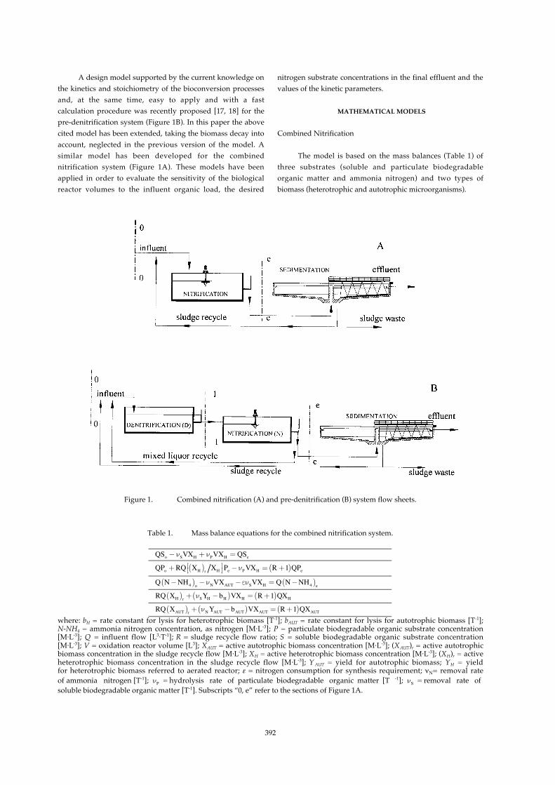
The model is based on the mass balances (Table 1) ofthree substrates (soluble and particulate biodegradableorganic matter and ammonia nitrogen) and two types ofbiomass (heterotrophic and autotrophic microorganisms).
Figure 1. Combined nitrification (A) and pre-denitrification (B) system flow sheets.
Table 1. Mass balance equations for the combined nitrification system.
QSo −νSVXH + νPVXH = QSe
QPo +RQ XH( )r XH
⎡⎣ ⎤⎦ Pe −νPVXH = R+1( )QPe
Q N−NH4( )o −νNVXAUT −ενSVXH = Q N−NH4( )e
RQ XH( )r + νSYH −bH( )VXH = R+1( )QXH
RQ XAUT( )r + νNYAUT −bAUT( )VXAUT = R+1( )QXAUT
where: bH = rate constant for lysis for heterotrophic biomass [T-1]; bAUT = rate constant for lysis for autotrophic biomass [T-1];N-NH4 = ammonia nitrogen concentration, as nitrogen [M⋅L-3]; P = particulate biodegradable organic substrate concentration[M⋅L-3]; Q = influent flow [L3⋅T-1]; R = sludge recycle flow ratio; S = soluble biodegradable organic substrate concentration[M⋅L-3]; V = oxidation reactor volume [L3]; XAUT = active autotrophic biomass concentration [M⋅L-3]; (XAUT)r = active autotrophicbiomass concentration in the sludge recycle flow [M⋅L-3]; XH = active heterotrophic biomass concentration [M⋅L-3]; (XH)r = activeheterotrophic biomass concentration in the sludge recycle flow [M⋅L-3]; Y AUT = yield for autotrophic biomass; YH = yieldfor heterotrophic biomass referred to aerated reactor; ε = nitrogen consumption for synthesis requirement; νN= removal rateof ammonia nitrogen [T-1]; νP = hydrolysis rate of particulate biodegradable organic matter [T -1]; νS = removal rate ofsoluble biodegradable organic matter [T-1]. Subscripts “0, e” refer to the sections of Figure 1A.

393
The following assumptions are adopted: i) completely stirredbiological reactor; ii) ammonia nitrogen is the only nitrogencompound in the influent flow; iii) ratio between biomass inthe influent of the final settling and in the sludge recycle flowequal to the ratio between the suspended organic substrateconcentrations in the same streams and iv) inert compoundsare not considered.
The relationships of the removal rate adopted for thebiological processes are:
νS = ν̂S
SKS +S
(i)
νP = ν̂P
P / XH
KP +P / XH
(ii)
νN = ν̂N
N−NH4
KN +N−NH4
⋅O2
KO2 +O2
(iii)
where: KN = ammonia nitrogen half-saturation coefficient[M⋅L-3]; KO2 = dissolved oxygen half-saturation coefficient
[M⋅L-3]; K P = suspended biodegradable organic matter half-saturation coefficient; KS = dissolved biodegradable organicmatter half-saturation coefficient [M⋅L-3]; ν̂N = maximumremoval rate of ammonia nitrogen [T-1]; ν̂P = maximumhydrolysis rate of suspended biodegradable organic matter[T-1]; ν̂S = maximum removal rate of dissolved biodegradableorganic matter [T-1] ; O2 = oxygen concentration in theoxidation reactor [M⋅L-3].
Elaborating the above-mentioned equations, it ispossible to obtain all model unknowns in explicit terms. Infact, when the desired value of the ammonia effluentconcentration, (N-NH4)e, is fixed and the total biomassconcentration (sum of autotrophic and heterotrophicbiomasses) both in the oxidation reactor, (XTOT), and in thesludge recycle flow, (XTOT)r, is assigned, equations reported inTable 1 and the following equation (iv) are a 6 algebraicequations system with 6 unknowns: Se; XH; XAUT; Pe; V and R.
XTOT = XH + XAUT (iv)
XTOT and (XTOT)r are assigned according to, respectively,the needs of the final settling process and the aeration systemfunctioning and the thickening capacity of the settling tank.The resolutive expressions of the unknowns are reported inTable 2, where ΔS and Δ(N-NH4) represent, respectively, thedifference between influent and effluent solublebiodegradable organic substrate (So-Se) and ammonia nitrogen[(N-NH4)o-(N-NH4)e] concentration.
Pre-denitrification System
Four substrates (three as used for the combinednitrification system and nitrate nitrogen) and two biomassgroups (heterotrophic and autotrophic microorganisms) aretaken into account, considering their mass balances betweenthe influent and effluent sections of the biological reactors(Table 3).
Table 2. Design expressions for the combined nitrification system.
Se =
KS νNYAUT + bH −bAUT( )ν̂SYH − νNYAUT + bH −bAUT( )
XH =
ΔS ⋅νN KP + δ( )ΔS⋅ νN −ενS( ) KP + δ( )+Δ N−NH4( )⋅ νS KP + δ( )−Δ N−NH4( )⋅ ν̂Pδ
XTOT
where:
δ =− ζ+ ν̂P ΔS+ Po( )−νSPo⎡⎣⎢
⎤⎦⎥+ ζ+ ν̂P ΔS+ Po( )−νSPo
⎡⎣⎢
⎤⎦⎥2
+ 4ζνSPo
2 νSYH−bH( )ΔS; and
ζ= νS YH − bH( )KpΔS
Pe =δXH
V=
QΔSνS −νP( )XH
R =
11− XH( )r XH
νSYH −bH( )ΔSνS −νP( )XH
−1⎡
⎣⎢⎢⎢
⎤
⎦⎥⎥⎥

394
Table 3. Mass balance equations for the pre-denitrification system.
QSo + (R1 +R2 )QSe −ωνDVD XH( )D + νP VD XH( )D = (R1 +R2 +1)QS1
QPo +R1Q XH( )r XH( )N⎡⎣ ⎤⎦ Pe +R2QPe −νPVD XH( )D = (R1 +R2 +1)QP1
Q N−NH4( )o + (R1 +R2 )Q N−NH4( )e −εωνDVD XH( )D = (R1 +R2 +1)Q N−NH4( )1
(R1 +R2 )Q N−NO3( )e −νDVD XH( )D = (R1 +R2 +1)Q N−NO3( )1
(R1 +R2 +1)QS1 −νSVN XH( )N + νPVN XH( )N = (R1 +R2 +1)QSe
(R1 +R2 +1)QP1 −νPVN XH( )N = (R1 +R2 +1)QPe
(R1 +R2 +1)Q N−NH4( )1−νNVN XAUT( )N −ενSVN XH( )N = (R1 +R2 +1)Q N−NH4( )e
(R1 +R2 +1)Q N−NO3( )1 + νNVN XAUT( )N = (R1 +R2 +1)Q N−NO3( )e
R1Q XH( )r +R2Q XH( )N + νDYD −bHD( )VD XH( )D = (R1 +R2 +1)Q XH( )D
(R1 +R2 +1)Q XH( )D + νSYH −bHN( )VN XH( )N = (R1 +R2 +1)Q XH( )N
R1Q XH( )r XH( )N⎡⎣ ⎤⎦ XAUT( )N +R2Q XAUT( )N = (R1 +R2 +1)Q XAUT( )D
(R1 +R2 +1)Q XAUT( )D + νNYAUT −bAUT( )VN XAUT( )N = (R1 +R2 +1)Q XAUT( )N
where: N-NO3 = nitrate nitrogen concentration, as nitrogen [M⋅L-3]; R1 = sludge recycle flow ratio; R2 = aerated mixed liquorrecycle flow ratio; VD = denitrification reactor volume [L3]; VN = nitrification reactor volume [L3]; YD = yield for heterotrophicbiomass referred to denitrification process; νD = removal rate of nitrate nitrogen [T -1]; ω = unit mass of biodegradable organicmatter removed for unit mass of nitrate nitrogen reduced in the denitrification process. Subscripts “0, 1, e, N, D” refer to thesections of figure 1B.
The assumption that the dissolved oxygen in the recycleflow does not affect the denitrification rate is adopted inaddition to the above-cited assumptions considered for thecombined nitrification system. The adopted kinetics are thesame as used for the combined nitrification model (equationsi-iii) and a zero order kinetic relationship is used for thedenitrification process.
Fixing the values of (N-NH4)e and (N-NO3)e andassigning the total biomass concentrations (sum ofautotrophic and heterotrophic biomasses) both in thenitrification reactor, (XTOT)N, and in the sludge recycle flow,(XTOT)r, and the value of (R1+R2), Table 3 gives a twelvealgebraic equations system with twelve unknowns: Se, (XH)N,Pe, VD, VN, R1, (XAUT)D, (XH)D, S1, P1, (N-NH4)1 and (N-NO3)1. Itshould be noted that ( XAUT)N and R 2 are not unknowns if(XTOT)N =(XH)N + (XAUT)N and (R1+R2) are assigned. (XTOT)N canbe assigned according to the needs of the final settling processand the aeration system functioning. The total recycle flow(R1+R2) has to be higher than a minimum value (equation v) toassure that the nitrate nitrogen concentration in thedenitrification reactor effluent is positive.
R1 +R2( )min =
N−NH4( )o − N−NH4( )e − N−NO3( )e⎡⎣ ⎤⎦
νNYAUT− bAUT( )− νSYH −bHN( )YD − bHD νD
⎡
⎣
⎢⎢⎢
⎤
⎦
⎥⎥⎥
ενS + εω+1( )νNYAUT−bAUT( )− νSYH −bHN( )
YD − bHD νD
⎡
⎣
⎢⎢⎢
⎤
⎦
⎥⎥⎥
N−NO3( )e(v)
All the unknowns in the equations system of Table 3
can be expressed as a function of Se, obtaining the elevenexplicit relationships reported in Table 4. The value of Se isobtained by solving equation (vi), which is a non linearequation in the unknown Se, having several mathematicalsolutions. However, only one solution guarantees a positivevalue of Pe and thus can be considered admissible. The latter
is the only solution in the range 0, Semax⎡⎣⎢
⎤⎦⎥ where Semax is given
by equation (vii).
Q So −Se( )−ωνDVD XH( )D + νP VD XH( )D −νSVN XH( )N +
νP VN XH( )N = 0
(vi)
Semax =
−b− b2 − 4ac2a
(vii)
where:
a = εν̂S YD −
bHDνD
⎛
⎝⎜⎜⎜⎜
⎞
⎠⎟⎟⎟⎟⎟+ εω+1( ) YAUTνN − bAUT( )− YH ν̂S − bHN( )⎡
⎣⎢⎤⎦⎥ (viii)
b=− So + Po( ) εν̂S YD −bHDνD
⎛
⎝⎜⎜⎜⎜
⎞
⎠⎟⎟⎟⎟⎟
+ εω+1( ) YAUTνN −bAUT( )− YH ν̂S −bHN( )⎡⎣⎢
⎤⎦⎥
⎡
⎣⎢⎢⎢
⎤
⎦⎥⎥⎥
+KS εω+1( ) YAUTνN −bAUT + bHN( )+ N−NH4( )o − N−NH4( )e − N−NO3( )e⎡⎣ ⎤⎦
ν̂S YD −bHDνD
⎛
⎝⎜⎜⎜⎜
⎞
⎠⎟⎟⎟⎟⎟+ ω YAUTνN −bAUT( )− YH ν̂S − bHN( )⎡⎣⎢
⎤⎦⎥
⎡
⎣⎢⎢⎢
⎤
⎦⎥⎥⎥
(ix)

395
Table 4. Design expressions for the pre-denitrification system.
XH( )N =XTOT( )N νN
νN +N−NO3( )e
Δ N−NH4( )− N−NO3( )eενS + εω+1( )
νNYAUT −bAUT( )− νSYH − bHN( )YD −bHD νD
⎡
⎣
⎢⎢⎢
⎤
⎦
⎥⎥⎥+νNYAUT −bAUT( )− νSYH − bHN( )
YD −bHD νD
Pe =XH( )N
νNYAUT− bAUT
ΔS+ Po( ) ενS + εω+1( )νNYAUT− bAUT( )− νSYH − bHN( )
YD −bHD νD
⎡
⎣
⎢⎢⎢
⎤
⎦
⎥⎥⎥
Δ N−NH4( )− N−NO3( )e+
− νS +ωνNYAUT−bAUT( )− νSYH −bHN( )
YD − bHD νD
⎛
⎝
⎜⎜⎜⎜⎜
⎞
⎠
⎟⎟⎟⎟⎟⎟
⎧
⎨
⎪⎪⎪⎪⎪⎪⎪⎪⎪
⎩
⎪⎪⎪⎪⎪⎪⎪⎪⎪
⎫
⎬
⎪⎪⎪⎪⎪⎪⎪⎪⎪
⎭
⎪⎪⎪⎪⎪⎪⎪⎪⎪
VD =
QνNYAUT −bAUT( )− νSYH − bHN( )
νDYD −bHD1+R1 +R2( ) Δ N−NH4( )− N−NO3( )e⎡
⎣⎤⎦
XH( )N 1+R1 +R2( ) ενS + εω+1( )νNYAUT −bAUT( )− νSYH − bHN( )
YD −bHD νD
⎡
⎣
⎢⎢⎢
⎤
⎦
⎥⎥⎥− νSYH −bHN( ) Δ N−NH4( )− N−NO3( )e⎡⎣ ⎤⎦
VN =Q Δ N−NH4( )− N−NO3( )e⎡⎣
⎤⎦
XH( )N ενS + εω+1( )νNYAUT −bAUT( )− νSYH − bHN( )
YD −bHD νD
⎡
⎣
⎢⎢⎢
⎤
⎦
⎥⎥⎥
R1 =
(XTOT )N(XTOT )r −(XTOT )N
1−νNYAUT −bAUT( )VN
Q⎛
⎝⎜⎜⎜⎜
⎞
⎠⎟⎟⎟⎟
XAUT( )D =
XTOT( )rXTOT( )N
R1 +R2
⎡
⎣⎢⎢⎢
⎤
⎦⎥⎥⎥XAUT( )N ⋅
11+R1 +R2( )
XH( )D = XH( )N −νSYH −bHN( ) Δ N−NH4( )− N−NO3( )e⎡
⎣⎤⎦
1+R1 +R2( ) ενS + εω+1( )νNYAUT−bAUT( )− νSYH −bHN( )
YD − bHD νD
⎡
⎣
⎢⎢⎢
⎤
⎦
⎥⎥⎥
S1 = Se +
Sν −νP( )VN XH( )N
Q 1+R1 +R2( )
P1 = Pe +νPΔ N−NH4( )− N−NO3( )e⎡⎣ ⎤⎦
1+R1 +R2( ) ενS + εω+1( )νNYAUT− bAUT( )− νSYH −bHN( )
YD − bHD νD
⎡
⎣
⎢⎢⎢
⎤
⎦
⎥⎥⎥
N−NH4( )1 = N−NH4( )e + Nν VN XAUT( )N + ενSVN XH( )N
Q 1+R1 +R2( )
N−NO3( )1 = N−NO3( )e −
Nν VN XAUT( )NQ 1+R1 +R2( )
c=−KS So + Po( ) εω+1( ) YAUTνN −bAUT + bHN( )+ωKS N−NH4( )o − N−NH4( )e − N−NO3( )e⎡⎣ ⎤⎦ YAUTνN −bAUT + bHN( )
(x)
The equations system of Table 3 only has an acceptablesolution (i.e. positive values for all unknowns) if the followingconstraint is met:
So +Po( ) >
ω N−NH4( )o − N−NH4( )e − N−NO3( )e⎡⎣
⎤⎦
1+ εω (xi)
This condition can be verified a priori. It is related to theinfluent wastewater characteristics and stems from the need
for a sufficient biodegradable organic influent load to supportthe denitrification process for assigned treatment efficiencies.The calculation procedure of the model can be easily appliedwithout any iteration [17].
RESULTS AND DISCUSSION
Effect of Influent Organic Load and the DesiredNitrogen Removal Efficiency on the Required Volumes of theBiological Reactors
The mathematical model has been applied for sizing thebiological reactors of a typical municipal WWTP with the

396
following characteristics of the influent wastewater: Q = 10000m3 d-1; (N-NH4)o = 50 g m-3; (N-NO3)o = 0 g m-3; Po/So = 3.Values of the kinetic and stoichiometric parameters andoperational conditions according to Esposito et al. [17] and abiomass decay of 0.01 d-1 for both autotrophic andheterotrophic biomasses are adopted, unless specifiedotherwise.
Figure 2 shows the sensitivity of the biological reactorvolumes to the organic load both for the combinednitrification system and the pre-denitrification system. Thesimulations have been performed assigning the values 5 and
10 g m-3 to (N-NH4)e and (N-NO3)e respectively, keeping thePo/So ratio constant and varying (So+Po) from 200 to 400gBOD5 m-3. The results show an increase of V and VN and adecrease of VD with increasing (So+Po). The outcome related toVD is not due to a higher denitrification efficiency, but to theincrease of nitrogen assimilation for cell synthesis [17, 19, 20].
Further simulations have been carried out (Figure 3) inorder to evaluate the influence of the (N-NO3)e/(N-NH4)e ratioon the biological reactor volumes. The total nitrogenconcentration in the final effluent (N-NO3)e + (N-NH4)e hasbeen kept constant and equal to 15 g m-3. The influent organic
Figure 2. Effect of the influent organic substrate on the volumes of the biological nitrification () and denitrification ()reactors. (A) Combined nitrification, (B) Pre-denitrification.

397
Figure 3. Effect of the assigned concentrations of the effluent nitrogen compounds on the volumes of the biologicalnitrification () and denitrification () reactors. (A) Combined nitrification, (B) Pre-denitrification.
concentration is 300 gBOD5 m-3 (So = 75 gBOD5 m-3; Po = 225gBOD5 m-3). The results show a negligible influence on VD. Onthe contrary, a sharp increase of V and VN is necessary to facelower (N-NH4)e values. The (N-NO3)e/(N-NH4)e ratio does notaffect VD as no changes in the nitrate nitrogen load that has tobe reduced in the anoxic reactor occur.
Sensitivity Analysis on the Kinetic Parameters
The influence of the maximum removal rate ofammonia nitrogen on the biological reactor volumes has been
assessed by performing simulations with ν̂N ranging from0.40 to 0.70 d-1 and (N-NH4)e, (N-NO3)e, So and Po values of 5 gm-3, 10 g m-3, 75 gBOD5 m-3 and 225 gBOD5 m-3, respectively.Figure 4 shows that increasing ν̂N results in a clear decreasein VN whereas VD is hardly affected.
Changing the decay rates of heterotrophic andautotrophic biomass is barely effective when their ratio is keptconstant (data not shown). Figure 5 shows the results ofsimulations carried out under the same conditions as Figure 4,with a ν̂N value of 0.55 d -1 and bAUT ranging from 0.02 to0.0033 d-1.

398
Figure 4. Effect of the maximum removal rate of ammonia nitrogen on the volumes of the biological nitrification () anddenitrification () reactors. (A) Combined nitrification, (B) Pre-denitrification.
Figure 5. Effect of the ratio between the decay rates of heterotrophic and autotrophic biomass on the volumes of the biologicalnitrification () and denitrification () reactors. (A) Combined nitrification, (B) Pre-denitrification.

399
An increase in the bH/bAUT ratio from 0.5 to 3.0 (i.e. a decreasein bAUT from 0.02 to 0.0033 d-1) results in a 31% decrease in therequired volume of the nitrification reactor for both thecombined nitrification and pre-denitrification systems (Fig. 5).
CONCLUSIONS
Two mathematical models aimed at the design ofactivated single sludge systems, i.e. the combined nitrificationsystem and the pre-denitrification system, are proposed. Themain characteristics of these models are: i) the biologicalprocesses taking place in the WWTP are described at a high
level of detail; ii) the calculation procedure is fast and easy toapply; iii) the results of the models’ application are consistent.Moreover, the pre-denitrification model enables an a priorievaluation of the system's applicability, once the influentwastewater characteristics are known and the concentrationsof the nitrogen compounds in the final effluent are fixed.
A sensitivity analysis on the kinetic parametersindicates a relevant effect of the maximum removal rate ofammonia nitrogen and the ratio between the decay rates ofheterotrophic and autotrophic biomass on the volume of thenitrification reactor. The bacterial decay rates are shown to benot effective in simulations carried out keeping the ratiobH/bAUT constant.
REFERENCES
1. Henze M., Grady C.P.L. Jr., Gujer W., Marais G.v.R. and Matsuo T., Activated sludge model No.1. Rep. No. 1, IWAPublishing, London (1987).
2. Henze M., Gujer W., Mino T., Matsuo T., Wentzel M.C. and Marais G.v.R., Activated sludge model No.2. Rep. No. 3, IWAPublishing, London (1995).
3. Gujer W., Henze M., Mino T. and van Loosdrecht M.C.M., Activated sludge model No.3. Rep. No. 9, IWA Publishing,London (1998).
4. Henze M., Gujer W., Mino T. and van Loosdrecht M.C.M., Activated sludge models ASM1, ASM2, ASM2d and ASM 3.Rep. No. 9, IWA Publishing, London (2000).
5. Gernaey K. V., van Loosdrecht M.C.M., Henze M., Lind M. and Jørgensen S.B., Activated sludge wastewater treatmentplant modelling and simulation: state of the art. Environ. Modell. Softw., 19, 763-783 (2004).
6. Metcalf and Eddy Inc., Wastewater Engineering Treatment and Reuse. 4th ed. Mc Graw-Hill, New York (2003).7. Beccari M., Di Pinto A.C., Passino R. and Ramadori R., Biological nitrogen removal from wastewater. Rep. No. 53 (in
italian), IRSA - Italian Institute for Water Research, Rome (1980).8. Argaman Y., Design and performance charts for single sludge nitrogen removal systems. Water Res., 15, 841-847 (1981).9. Argaman Y., A steady-state model for single sludge activated sludge system – I. Model Description. Water Res., 29, 137-145
(1995).10. Argaman Y., Papkov G., Ostfeld A. and Rubin D., Single sludge nitrogen removal model: calibration and verification. J.
Environ. Eng., 125, 608-617 (1999).11. Ekama G.A. and Marais G.v.R., Nitrification. In: Theory, Design and Operation of Nutrient Removal Activated Sludge Processes,
University of Cape Town, City Council of Johannesburg, and the National Institute for Water Research of the CSIR.Pretoria, South Africa, Chapter 5, pp1-12 (1984).
12. Di Pinto A.C., Passino R., Ramadori R. and Tomei M.C., Modelling of two stage single sludge system for nitrogenremoval. Environ. Technol., 11, 509-520 (1990).
13. Di Pinto A.C., Passino R., Ramadori R. and Tomei M.C., Activated sludge biological process modelling for nutrientremoval. Rep. No. 91 (in italian), IRSA - Italian Institute for Water Research, Rome (1990).
14. Akca L., Kinaci C. and Karpuzcu M., A model for optimum design of activated sludge plants. Water Res., 27, 1461-1468(1993).
15. Orhon D., Hanhan O., Görgün E. and Sözen S., A unified basis for the design of nitrogen removal activated sludge process- the Braunschweig exercise. Water Sci. Technol., 38, 227-236 (1998).
16. Lawrence A.W. and McCarty P.L., Unified basis for biological treatment design and operation. J. Sanit. Eng. Div., 96, 757-778 (1970).
17. Esposito G., Fabbricino M. and Pirozzi F., Four substrates design model for single stage predenitrification system. J.Environ. Eng., 129, 394-401 (2003).
18. Fabbricino M. and Pirozzi F., Coupled design model of predenitrification systems. Environ. Technol., 26, 783-791 (2005).19. van Loosdrecht M.C.M., Kuba T., van Veldhuizen H.M., Brandse F.A. and Heijnen J.J., Environmental impacts of nutrient
removal processes: case study. J. Environ. Eng., 123, 33-40 (1997).20. Esposito G., Bastianutti C., Bortone G., Pirozzi F. and Sgroi S. Influence of primary sedimentation on pre-
denitrification system performances. Water Sci. Technol., 44, 113–120 (2001).

400