
Matching Model-Snippets
16
Modeling Time(s) Charles Andr´ e, Fr´ ed´ eric Mallet, and Robert de Simone I3S, Universit´ e de Nice-Sophia Antipolis, CNRS, F-06903 Sophia Antipolis INRIA, F-06902 Sophia Antipolis {candre,fmallet,rs}@sophia.inria.fr Abstract. Time and timing features are an important aspect of mod- ern electronic systems, often of embedded nature. We argue here that in early design phases, time is often of logical (rather than physical) nature, even possibly multiform. The compilation/synthesis of heterogeneous ap- plications onto architecture platforms then largely amounts to adjusting the former logical time(s) demands onto the latter physical time abili- ties. Many distributed scheduling techniques pertain to this approach of “time refinement”. We provide extensive Time and Allocation metamodels that open the possibility to cast this approach in a Model-Driven Engineering light. We give a UML representation of these concepts through two subpro- files, parts of the foundations of the forthcoming OMG UML Profile for Modeling and Analysis of Real-Time and Embedded systems (MARTE). Time modeling also allows for a precise description of time-related enti- ties and their associated timed properties. Key words: UML profile, real-time embedded. The original publication is available at www.springerlink.com 1 . 1 Introduction Modeling of Time should be a central concern in Model-Driven Engineering for Real-Time Embedded systems. Nevertheless, (too?) many modeling frameworks consider Time annotations as to be considered in timing/schedulability/perfor- mance, and accordingly build uninterpreted stereotypes and label locations with insightful names only for the future analysis tool (and no meaning at all for the time augmented profile). Given that the default operational semantics of the UML is inherently untimed, and rightfully so since there is no Time information in the ground metamodel, one can reach the situation where the same model can be understood differently depending on whether it is considered from the UML causality model or the intended timed analysis viewpoint. Our primary goal here is to lay the foundation for a Time model which could be deeply embedded in UML as a profile allowing the subsequent clean and precise definition of a timed causality model enforcing timed operational semantics of events and actions. 1 http://dx.doi.org/10.1007/978-3-540-75209-7_38 inria-00204489, version 1 - 27 Mar 2009 Author manuscript, published in "ACM/IEEE Int. Conf. on Model Driven Engineering Languages and Systems (MoDELS/UML) LNCS 4735 (2007) pp. 559-573" DOI : 10.1007/978-3-540-75209-7_38
-
Upload
independent -
Category
Documents
-
view
0 -
download
0
Transcript of Matching Model-Snippets

Modeling Time(s)
Charles Andre, Frederic Mallet, and Robert de Simone
I3S, Universite de Nice-Sophia Antipolis, CNRS, F-06903 Sophia AntipolisINRIA, F-06902 Sophia Antipolis
{candre,fmallet,rs}@sophia.inria.fr
Abstract. Time and timing features are an important aspect of mod-ern electronic systems, often of embedded nature. We argue here that inearly design phases, time is often of logical (rather than physical) nature,even possibly multiform. The compilation/synthesis of heterogeneous ap-plications onto architecture platforms then largely amounts to adjustingthe former logical time(s) demands onto the latter physical time abili-ties. Many distributed scheduling techniques pertain to this approach of“time refinement”.We provide extensive Time and Allocation metamodels that open thepossibility to cast this approach in a Model-Driven Engineering light.We give a UML representation of these concepts through two subpro-files, parts of the foundations of the forthcoming OMG UML Profile forModeling and Analysis of Real-Time and Embedded systems (MARTE).Time modeling also allows for a precise description of time-related enti-ties and their associated timed properties.
Key words: UML profile, real-time embedded.
The original publication is available at www.springerlink.com1.
1 Introduction
Modeling of Time should be a central concern in Model-Driven Engineering forReal-Time Embedded systems. Nevertheless, (too?) many modeling frameworksconsider Time annotations as to be considered in timing/schedulability/perfor-mance, and accordingly build uninterpreted stereotypes and label locations withinsightful names only for the future analysis tool (and no meaning at all for thetime augmented profile). Given that the default operational semantics of theUML is inherently untimed, and rightfully so since there is no Time informationin the ground metamodel, one can reach the situation where the same model canbe understood differently depending on whether it is considered from the UMLcausality model or the intended timed analysis viewpoint. Our primary goal hereis to lay the foundation for a Time model which could be deeply embedded inUML as a profile allowing the subsequent clean and precise definition of a timedcausality model enforcing timed operational semantics of events and actions.1 http://dx.doi.org/10.1007/978-3-540-75209-7_38
inria
-002
0448
9, v
ersi
on 1
- 27
Mar
200
9Author manuscript, published in "ACM/IEEE Int. Conf. on Model Driven Engineering Languages and Systems (MoDELS/UML)
LNCS 4735 (2007) pp. 559-573" DOI : 10.1007/978-3-540-75209-7_38

2
Following some works on dedicated Models of Computation and Communi-cation (MoCCs) for real-time embedded systems [1–3], we view Time in a verybroad sense. It can be physical, and considered as continuous or discretized, butit can also be logical, and related to user-defined clocks. For instance, durationscould be counted in terms of numbers of execution steps, or clock cycles on aprocessor or even more abstract time bases, without a strong relation to theactual physical duration (which may not be known at design time, or fluctuate,or be a parameter that allows the same model to be instantiated under differ-ent contexts and speeds). With modern embedded designs where, for low-powerreasons, the actual processor clock can be shut down and altered at times, suchusage of logical time in the application design will certainly become customary.In our approach, time can even be multiform, allowing different time threads toprogress in a non-uniform fashion.
This approach looks certainly non-standard, but is getting increasing inter-est from a number of directions. A mostly untimed concurrent application canbe considered as comprising several unrelated (or loosely coupled) time threads(thereafter called “clocks”, not to be confused with the physical measurementdevice which we will never consider). The process of allocating the various opera-tions/functions/actions of such a concurrent model onto an embedded executionplatform comprises aspects of spatial distribution and temporal scheduling. Thisis accomplished by resolving the mutual sets of timing constraints imposed bythe designer of the time scales of the application, the target architecture, and thereal-time requirements to be met. We call the approach one of Time refinement.
A number of existing transformation techniques can be cast in this frame-work. Nested loop scheduling and parallelization [4, 5] in high-performance com-puting, software pipe-lining, SoC synthesis phases from so-called transactionallevel (TLM) down to cycle-accurate RTL level, to mention a few. In all cases,the purpose is to progressively refine the temporal structure, which starts witha number of degrees of freedom, to attain a fully scheduled and precisely cycle-allocated version, with predictable timing. In that sense our model allows, andit is in fact its primary aim, to describe formal clock relations in a simple math-ematical way.
We provide a UML model for Time in its different guises, physical/logical,dense/discrete, single/multiple, and some useful basic operators and relations tocombine timed events or clocks. From this set of primitives, we hope to buildexplicit representation of MoCCs, and to provide a Timed causality model toendow the timed models with a timed semantics, according to the one that wouldbe considered by analysis tools. When the relation are simple enough (periodicor regular), the system of contraints imposed by these relations can be solved,and the schedule itself becomes an explicit modeling element, traceable to thedesigner. In other, more complex cases, the constraints embody a given schedul-ing policy, which can be analyzed with corresponding schedulability analysistechniques when applicable.
inria
-002
0448
9, v
ersi
on 1
- 27
Mar
200
9

3
After describing some existing time and allocation models (Section ??), Sec-tion ?? introduces our contribution, the MARTE2 subprofiles for time and allo-cation. Section ?? briefly illustrates their use.
2 Existing time and allocation models
2.1 Time modeling
This subsection focuses on time models and time-related concepts in use in theUML and some of its profiles.
UML In UML [6] Time is seldom part of the behavioral modeling, whichis essentially untimed (by default, events are handled in the same order asthey arrive in event handlers). UML describes two kinds of behaviors [7]: theintra-object behavior—the behavior occurring within structural entities—andthe inter-object behavior, which deals with how structural entities communicatewith each other. The CommonBehaviors package defines the relationship betweenstructure and behavior and the general properties of the behavior concept. Asubpackage called SimpleTime adds metaclasses to represent time and duration,as well as actions to observe the passing of time. This is a very simple time model,not taking account of problems induced by distribution or by clock imperfections.In particular the UML causality model, which prescribes the dynamic evaluationmechanisms, does never refer to time (stamps). Instead, the UML specificationdocument explicitly states that “It is assumed that applications for which suchcharacteristics are relevant will use a more sophisticated model of time providedby an appropriate profile”. Our contribution can be seen as providing the meansfor building such sophisticated time models.
SPT The UML Profile for Schedulability, Performance, and Time (SPT) [8]aimed at filling the lacks of UML 1.4 in some key areas that are of particularconcern to real-time system designers and developers. SPT introduces a quantifi-able notion of time and resources. It annotates model elements with quantitativeinformation related to time, information used for timeliness, performance, andschedulability analyses.
SPT only considers (chrono)metric time, which makes implicit reference tophysical time. It provides time-related concepts: concepts of instant and dura-tion, concepts for modeling events in time and time-related stimuli. SPT alsoaddresses modeling of timing mechanisms (clocks, timers), and timing services.SPT, which relies on UML 1.4, had to be aligned with UML 2.1. This is one ofthe objectives of the MARTE profile, presented in Section ??.
2 a preliminary version is available at www.promarte.org
inria
-002
0448
9, v
ersi
on 1
- 27
Mar
200
9

4
Non OMG profiles Several “unofficial” UML profiles are also considering timemodeling. We mention a few, developed for different purposes, as work relatedto ours.
EAST-EEA is an ITEA project on Embedded Electronic Architecture [9]. Itprovides a development process and automotive-specific constructs for the designof embedded electronic applications. Temporal aspects in EAST are handledby requirement entities. The concepts of Triggers, Period, Events, End to EndDelay, physical Unit, Timing restriction, can be applied to any behavioral EASTelements. It is compliant with UML2.0, the intent is to deliver a UML2 profile.
The UML profile Omega-RT [10] focuses on analysis and verification of timeand scheduling related properties. It is a refinement of the SPT profile. Theprofile is based on a specific concept of event making it easy to express durationconstraints between occurrences of events. The concept of observer, which is astereotype of state machine, is a convenient way for expressing complex timeconstraints. It would have to be aligned with UML2.0.
Summary The abovementioned profiles introduce relationships between Timeand Events or Actions. They annotate the UML model with quantitative infor-mation about time. None consider logical and multiform time.
2.2 Allocation models
These are concerned with the mapping of application elements onto architecturalplatform resources and services. The following frameworks are currently untimed.It is in fact our main goal that a Time Model can be used to select and optimizesuch mapping according to the timing demands of both sides (and possiblyadditional real-time requirements).
UML deployments UML deployments consist in assigning concrete softwareelements of the physical world (artifacts) to nodes. Nodes can represent eitherhardware devices or software execution environments. Artifacts are physical pieceof information—a file or a database entry—and model elements are stored inresources specified by artifacts. The MARTE allocation mechanism is comple-mentary to the UML deployment mechanism, the differences are described insection ??.
SysML allocation SysML[11] provides a mechanism to represent, at an ab-stract level, cross-associations among model elements with the broadest meaning.A SysML allocation is expected to be the precursor of more concrete relation-ships. It differentiates three of the many possible and not exclusive categories:behavior, flow and structure allocations. Behavior allocations separate the func-tions from the structure; they provide a way to allocate a behavior to a behavioralfeature. Flow allocations have many usages; they include allocations of activitytransitions (SysML flows) to connectors of structured activities (SysML blocks).
inria
-002
0448
9, v
ersi
on 1
- 27
Mar
200
9

5
Structure allocations acknowledge the needs for a mapping relation of logicalparts to more physical ones. The MARTE allocation is inspired from the SysMLallocation and the differences are described in section ??. One reason for thischoice is that we want to be able to define, in the most convenient way, howvarious durations and clock streams are connected in the course of the alloca-tion. This can easily fit some of SysML constraints/parametrics and requirementsmodeling features, which were originally used to model physical constraints oruninterpreted requirement engineering information respectively.
2.3 Timed allocation models
We believe that suitable models for real-time and embedded systems design andanalysis should support both time and allocation. We give here a brief insightof the Society of Automotive Engineer(SAE)’s Architecture Analysis & DesignLanguage(AADL) standard [12].
The temporal semantics of AADL concepts is defined using ”hybrid au-tomata”. These automata are hierarchical finite state machines with real-valuedvariables that denote the time. Temporal constraints, expressed as state invari-ants and guards over transitions, define when the discrete transitions occur.Concurrent executions are modeled using threads managed by a scheduler. Thedispatch protocol (periodic, aperiodic, sporadic and background) determineswhen an active thread executes its computation. AADL supports multiformtime models. However, it lacks model elements to describe the application it-self, independently of the resources. UML activities allow for a description ofthe application, actions executed sequentially or concurrently, without knowing,at first, whether actions are executed by a periodic thread or a subprogram. Thisimportant information is brought by an orthogonal process, the allocation. Afterseveral iterations, analysis, the threads are eventually deployed (or bound) tothe execution platform.
AADL offers a binding mechanism to assign software components (data,thread, process, etc.) to execution platform components (memory, processor,buses, etc.). Each software component can define several possible bindings andproperties may have different values depending on the actual binding. This bind-ing mechanism encompasses both the UML deployment and the MARTE allo-cation, while sometimes it is useful to separate the two concepts.
3 MARTE
MARTE is a response to the OMG RFP to provide a UML profile for real-timeand embedded systems [13]. MARTE is a successor of SPT, aligned with UML 2,and with a wider scope. MARTE introduces a number of new concepts, includingtime and allocation concepts, which are central to this paper.
inria
-002
0448
9, v
ersi
on 1
- 27
Mar
200
9

6
3.1 MARTE time model
Time in SPT is a metric time with implicit reference to physical time. As asuccessor of SPT, MARTE supports this model of time. However, MARTE goesbeyond this quantitative model of time and adopts more general time modelssuitable for system design. In MARTE, Time can be physical, and consideredas dense or discretized, but it can also be logical, and related to user-definedclocks. Time may even be multiform, allowing different times to progress in anon-uniform fashion, and possibly independently to any (direct) reference tophysical time.
MultipleTimeBase
TimeBase
date: Real
Instant
{ ordered }instants
base1
1..*
memberTB0..*
TimeStructureRelation
tsRelations
0..*
currentInstant1
TimeBaseRelation
TimeInstantRelation
2..*
/relatedInstants{ union, ordered }
0..*
0..1 parentMTB
subMTB
0..*
1
ownedTB{ subsets memberTB }
2..*
{ union, ordered }/relatedTB
Fig. 1. Time structure (Domain view).
Concept of time structure Figure ?? shows the main concepts introducedin MARTE to model time. This is a conceptual view, or in the UML profileterminology, a domain view. The corresponding UML representations will bepresented later. The building element in a time structure is the TimeBase. Atime base is a totally ordered set of instants. A set of instants can be discrete ordense. The linear vision of time represented by a single time base is not sufficientfor most of the applications, especially in the case of multithreaded or distributedapplications. Multiple time bases are then used. A MultipleTimeBase consists ofone or many time bases. A time structure contains a tree of multiple time bases.
Time bases are a priori independent. They become dependent when instantsfrom different time bases are linked by relationships (coincidence or precedence).The abstract class TimeInstantRelation in Figure ?? has CoincidenceRelation and
inria
-002
0448
9, v
ersi
on 1
- 27
Mar
200
9

7
PrecedenceRelation as concrete subclasses. Instead of imposing local dependenciesbetween instants, dependencies can be directly imposed between time bases. ATimeBaseRelation (or more precisely one of its concrete subclasses) specifies many(possibly an infinity of) individual time instant relations. This will be illustratedlater on some time base relations. TimeBaseRelation and TimeInstantRelation havea common generalization: the abstract class TimeStructureRelation. As a resultof adding time structure relations to multiple time bases, time bases are nolonger independent and the instants are partially ordered. This partial orderingof instants characterizes the time structure of the application.
This model of time is sufficient to check the logical correctness of the appli-cation. Quantitative information, attached to the instants, can be added to thisstructure when quantitative analyses become necessary.
Clock In real world technical systems, special devices, called clocks, are usedto measure the progress of physical time. In MARTE, we adopt a more generalpoint of view: a clock is a model giving access to the time structure. Time may belogical or physical or both. MARTE qualifies a clock refering to physical time as achronometric clock, emphasizing on the quantitative information attached to thismodel. A Clock makes reference to a TimeBase. Clocks and time structures havemathematical definitions introduced below. This formal modeling is transparentto the user of the profile.
The mathematical model for a clock is a 5-tuple (I,4,D, λ, u) where I is aset of instants, 4 is an order relation on I, D is a set of labels, λ : I → D is alabeling function, u is a symbol, standing for a unit. For a chronometric clock,the unit can be the SI time unit s (second) or one of its derived units (ms, us. . . ).The usual unit for logical clocks is tick, but user-defined units like clockCycle,executionStep . . . may be chosen as well. To address multiform time, it is evenpossible to consider other physical units like angle degrees (this is illustratedin an application of our time model to an automotive application [14]). Since aclock refers to a TimeBase, (I,≺) is an ordered set.
A Time Structure is a 4-tuple (C,R,D, λ) where C is a set of clocks, R is arelation on
⋃a,b∈C,a 6=b (Ia × Ib), D is a set of labels, λ : IC → D is a labeling
function. IC is the set of the instants of a time structure. IC is not simply theunion of the sets of instants of all the clocks; it is the quotient of this set by thecoincidence relation induced by the time structure relations represented by R.
Time-related concepts Events and behaviors can be directly bound to time.The occurrences of a (timed) event refer to points of time (instants). The exe-cutions of a (timed) behavior refer to points of time (start and finish instants)or to segments of time (duration of the execution). In MARTE, Instant and Du-
ration are two distinct concepts, specializations of the abstract concept of Time.TimedEvent (TimedBehavior, resp.) is a concept representing an event (a behavior,resp.) explicitly bound to time through a clock. In this way, time is not a mereannotation: it changes the semantics of the timed model elements.
inria
-002
0448
9, v
ersi
on 1
- 27
Mar
200
9

8
MARTE Time profile The time structure presented above constitutes thesemantic domain of our time model. The UML view is defined in the “MARTETime profile”. This profile introduces a limited number of powerful stereotypes.We have striven to avoid the multiplication of too specialized stereotypes. Thanksto the sound semantic grounds of our styereotypes, modeling environments maypropose patterns for more specific uses.
«stereotype»TimedElement
«metaclass»UML::Classes::Kernel::Class
nature: TimeNatureKind [1]unitType: Enumeration [0..1]isLogical: Boolean [1] = falseresolAttr: Property [0..1]maxValAttr: Property [0..1]offsetAttr: Property[ 0..1]getTime: Operation [0..1]setTime: Operation [0..1]indexToValue: Operation [0..1]
«stereotype»ClockType
«metaclass»UML::Classes::Kernel::InstanceSpecification
«stereotype»Clock
«stereotype»NFPs::Unit
«stereotype»TimedDomain
«metaclass»UML::Classes::Kernel::
Package
on 1..*
unit
0..1
type
1
«metaclass»UML::Classes::Kernel::
EnumerationLiteral
Fig. 2. MARTE TimeModeling profile: Clock.
The main sterotypes are presented in figures ?? to ??. ClockType is a stereo-type of the UML Class. Its properties specifies the kind (chronometric or logical)of clock, the nature (dense or discrete) of the represented time, a set of clockproperties (e.g., resolution, maximal value. . . ), and a set of accepted time units.Clock is a sterotype of InstanceSpecification. An OCL rule imposes to apply theClock stereotype only to instance specifications of a class stereotyped by Clock-
Type. The unit of the clock is given when the stereotype is applied. Unit is definedin the Non Fonctional Property modeling (NFPs) subprofile of MARTE, it ex-tends EnumerationLiteral. It is very convenient since a unit can be used like anyuser-defined enumeration literal, and conversion factors between units can bespecified (e.g., 1ms = 10−3s). TimedElement is an abstract stereotype with nodefined metaclass. It stands for model elements which reference clocks. All othertimed stereotypes specialize TimedElement.
Clock constraints ClockConstraint is a stereotype of the UML Constraint. Theclock constraints are used to specify the time structure relations of a time do-main. In turn, these relations characterize theR relation of the underlying math-ematical model of the time structure.
The context of the constraint must be a TimedDomain. The constrained ele-ments are clocks of this timed domain and possibly other objects. The specifi-cation of a clock constraint is a set of declarative statements. This raises the
inria
-002
0448
9, v
ersi
on 1
- 27
Mar
200
9

9
question of choosing a language for expressing the clock constraints. A natu-ral language is not sufficiently precise to be a good candidate. UML encour-ages the use of OCL. However, our clocks usually deal with infinite sets ofinstants, the relations may use many mathematical quantifiers, which are notsupported by OCL. Additionnally, OCL [15] is made to be evaluatable, whileour constraints often have to be processed altogether to get a set of possiblesolutions. So, we have chosen to define a simple constraint expression languageendowed with a mathematical semantics. The specification of a clock constraintis a UML::OpaqueExpression that makes use of pre-defined (clock) relations, themeaning of which is given in mathematical terms, outside the UML. Our Con-straint Specification Language is not normative. Other languages can be used,so long as the semantics of clocks and clock constraints is respected.
repetition: Integer[0..1]
«stereotype»TimedEvent
«metaclass»UML::CommonBehavior::
SimpleTime::TimeEvent
«metaclass»UML::Classes::Kernel::
ValueSpecification 0..1 0..1
every «stereotype»TimedElement
Fig. 3. MARTE TimeModeling profile: TimedEvent.
TimedEvent and TimedProcessing In UML, an Event describes a set ofpossible occurrences; an occurrence may trigger effects in the system. A UML2TimeEvent is an Event that defines a point in time (instant) when the eventoccurs. The MARTE stereotype TimedEvent extends TimeEvent (Figure ??). Itsinstant specification explicitly refers to a clock. If the event is recurrent, a rep-etition period—duration between two successive occurrences of the event—andthe number of repetitions may be specified.
«stereotype»TimedProcessing
start
0..1
finish
0..1
duration
0..1 0..1
«metaclass»UML::CommonBehavior::
Communication::Event
«metaclass»UML::Actions::
Action
«metaclass»UML::CommonBehaviors::
Behavior
«metaclass»UML::Interactions::BasicInteractions::
Message
«stereotype»TimedElement
«metaclass»UML::Classes::Kernel::
ValueSpecification
Fig. 4. MARTE TimeModeling profile: TimedProcessing.
inria
-002
0448
9, v
ersi
on 1
- 27
Mar
200
9

10
In UML, a Behavior describes a set of possible executions; an execution isthe performance of an algorithm according to a set of rules. MARTE associatesa duration, an instant of start, an instant of termination with an execution,these times being read on a clock. The stereotype TimedProcessing (Figure ??)extends the metaclasses Behavior, Action, and also Message. The latter extensionassimilates a message tranfer to a communication action.
Note that, StateMachine, Activity, Interaction being Behavior, they can be stereo-typed by TimedProcessing, and thus, can be bound to clocks.
3.2 MARTE allocation model
Allocation of functional application elements onto the available resources (theexecution platform) is main concern of real-time embedded system design. Thiscomprises both spatial distribution and temporal scheduling aspects, in order tomap various algorithmic operations onto available computing and communica-tion resources and services.
The MARTE profile defines application and execution platform models. AMARTE allocation is an association between a MARTE application and a MARTEexecution platform. Application elements may be any UML element suitable formodeling an application, with structural and behavioral aspects. An executionplatform is represented as a set of connected resources, where each resource pro-vides services to support the execution of the application. So, resources are basi-cally structural elements, while services are rather behavioral elements. Applica-tion and Execution platform models are built separately, before they are pairedthrough the Allocation process. Often this requires prior adjustment (inside eachmodel) to abstract/refine its components so as to allow a direct match. Allocationcan be viewed as a “horizontal” association, and abstraction/refinement layeringas a “vertical” one, with the abstract version relying on constructs introduced inthe more refined model. While different in role, allocation and refinement sharea lot of formal aspects, and so both are described here.
Application and Execution platform elements can be annotated with timeinformation based on logical or chronometric clocks (Section ??). Allocation andrefinement provide relations between these timings under the form of constraintsbetween the clocks and their instants. Other similar non-functional propertiessuch as space requirement, cost, or power consumption are also considered.
In MARTE, we use the word allocation rather than deployment (as in UML)since allocation does not necessarily imply a physical distribution and couldsimply represent a logical distribution or scheduling. Execution platform mod-els can be abstract at some points and not necessarily seen as concretizationmodels. For instance, two pieces of an algorithm could be allocated to two dif-ferent processor cores, while the executable file containing both pieces would bedeployed on the memory of the processor and the source file containing the spec-ification of the algorithm would be deployed on a hard disk. This dual functionwas recognized in SPT, where allocation was called realization, while refinementwas used as such. MARTE allocation and refinement are complementary to theUML deployment; we prefer to keep the three concepts separated. This is not
inria
-002
0448
9, v
ersi
on 1
- 27
Mar
200
9

11
the case of AADL that provides a single mechanism—the binding—for all threeconcepts. The allocation mechanism proposed by MARTE is actually very closeto the structure allocations of SysML because it allocates logical parts to morephysical ones. However, MARTE makes it explicit that both the logical andphysical parts could be either of a behavioral or structural nature. Contrary toSysML, MARTE makes a difference between allocation—from application modelelements to execution platform model elements—and refinement of an abstractmodel elements (logical or physical) into more specific elements.
The stereotype Allocate A MARTE allocation is materialized by the stereo-type Allocate (Figure ??), which extends the UML metaclass Abstraction, and canbe associated with NFP constraints. Allocation can be structural, behavioral,or hybrid. Structural allocation associates a group of structural elements and agroup of resources. Behavioral allocation associates a set of behavioral elementsand a service provided by the execution platform. When clear from context, hy-brid allocations are allowed (e.g., when an implicit service is uniquely definedfor a resource). At the finer level of detail, behavioral allocation deals with themapping of UML actions to resources and services.
«metaclass»UML::Abstraction
«stereotype»NFPs::
NfpConstraint
impliedConstraint
*
«enumeration»AllocationKind
structuralbehavioralhybrid
«enumeration»AllocationNature
spatialDistributiontimeScheduling
«stereotype» Allocate
kind : AllocationKindnature : AllocationNature
Alloc
Fig. 5. The stereotype «allocate».
The stereotype Allocated MARTE advocates the need to differentiate thepotential sources of an allocation from the targets. Each model element involvedin an allocation is annotated with the stereotype Allocated (as in SysML), whichextends the metaclass NamedElement or rather one of its specializations (Fig-ure ??). The stereotype ApplicationAllocationEnd, noted by the keyword «ap allocated»,denotes a source of an allocation. The stereotype ExecutionPlatformAllocationEnd,noted by the keyword «ep allocated», represents the target of an allocation. Thestereotype Allocated is not abstract to ensure compatibility with SysML, but oneof its specializations should be preferred. The property allocatedTo, respectively
inria
-002
0448
9, v
ersi
on 1
- 27
Mar
200
9

12
allocatedFrom, is a derived property resulting from the process of creating theabstraction (allocation); they facilitate the identification of the targets, respec-tively the sources, of the allocation when all model elements cannot be drawnon the same diagram.
«stereotype»Allocated
«metaclass»NamedElement
«stereotype»ApplicationAllocationEnd
«stereotype»ExecutionPlatformAllocationEnd
/allocatedTo
*/allocatedFrom
*
Fig. 6. The stereotype «allocated».
4 Illustrative Examples
4.1 Chronometric clocks
The MARTE TimeLibrary provides a model for the ideal time used in physicallaws: idealClk, which is an instance of the class IdealClock, stereotyped by ClockType
(Fig. ??). idealClk is a dense time clock, its unit is the SI time unit s.
currentTime( ): Real
«clockType»{ nature = dense, unitType = TimeUnitKind,
getTime = currentTime }IdealClock
«clock»{ unit = s }
idealClk:IdealClock currentTime( ): Real
resolution: Real {readOnly}
«clockType»{ nature = discrete,
unitType = TimeUnitKind,resolAttr=resolution,
getTime = currentTime }Chronometric
Fig. 7. Ideal and Chronometric clocks.
Starting with idealClk, the user can define new discrete chronometric clocks(Fig. ??). First, the user specifies Chronometric—a class stereotyped by Clock-
Type—which is discrete, not logical (therefore chronometric), and with a readonly attribute (resolution). Clocks belong to timed domains. In Fig. ??, a singletime domain is considered. It owns 3 clocks: idealClk, cc1 and cc2, two instancesof Chronometric that both use s (second) as a time unit; and whose resolution is0.01 s. The three clocks are a priori independent. A clock constraint specifiesrelationships among them.
inria
-002
0448
9, v
ersi
on 1
- 27
Mar
200
9

13
The first statement of the constraint defines a clock c local to the constraint.c is a discrete time clock derived from idealClk by a discretization relation. Theresolution of this clock is 1 ms. The next two statements specify that cc1 and cc2
are subclocks of c with a rate 10 times slower than c. The fourth and fifth state-ments indicate that cc1 and cc2 are not perfect clocks. Flaws are characterizedby non functional properties like stability and offset. Their rate may have smallvariations (a stability of 10−5 implicitly measured on idealClk). The last state-ment claims that the two clocks are out of phase, with an offset value between0 and 5 ms measured on idealClk. Note that even if cc1 and cc2 look alike, theyare not identical because relations are not necessarily functional.
resolution = 0.01
«clock»{ unit = s }
cc1:Chronometric
resolution = 0.01
«clock»{ unit = s }
cc2:Chronometric
«clockConstraint»{ Clock c is idealClk discretizedBy0.001; cc1 isPeriodicOn c period10; cc2 isPeriodicOn c period10; cc1 hasStability1E-5; cc2 hasStability 1E-5; cc1,cc2 haveOffset [0..5] ms on idealClk;}
«clock»{ unit = s }
idealClk:IdealClock
«timeDomain»ApplicationTimeDomain
Fig. 8. Clock constraints.
4.2 AADL communication
To explain its port-based communication semantics, the AADL specificationtakes the example of a thread Read that captures a sample and sends it to a sec-ond thread Control. The two threads are assumed to be dispatched at the sametime. Several cases are studied, the case where the two threads are dispatchedwith the same period, the case where Read is dispatched twice faster than Control
(undersampling), and the case where Read is dispatched twice slower than Control
(oversampling). These cases are studied first with an immediate communication(the output value is available as soon as the thread Read completes) and thenwith a delayed communication (the output value is available only at the nextdispatch of the thread Read).
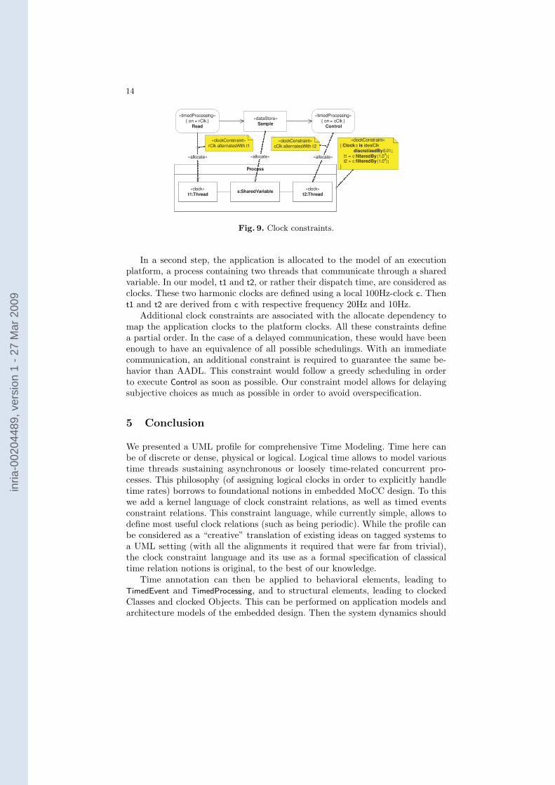
To compare our approach to AADL, we take the case of an immediate com-munication, which is the more challenging, with undersampling. As said before,the main difference of our approach is that we separate the application mod-els from the execution platform models. The application is described with aUML activity diagram (Fig. ??) using purely logical clocks and stereotyped by«TimedProcessing». The behavior of Read and Control are executed repetitively,they communicate through a datastore object node that allows for multiple read-ings of the same sample.
inria
-002
0448
9, v
ersi
on 1
- 27
Mar
200
9
14
«timedProcessing»{ on = rClk }
Read
«timedProcessing»{ on = cClk }
Control
«dataStore»Sample
Process
«clock»t1:Thread
«clock»t2:Thread
s:SharedVariable
«allocate» «allocate»«allocate»
«clockConstraint»rClk alternatesWith t1
«clockConstraint»cClk alternatesWith t2
«clockConstraint»{ Clock c is idealClk discretizedBy0.01; t1 = c filteredBy(1.0
4);
t2 = c filteredBy(1.09);}
Fig. 9. Clock constraints.
In a second step, the application is allocated to the model of an executionplatform, a process containing two threads that communicate through a sharedvariable. In our model, t1 and t2, or rather their dispatch time, are considered asclocks. These two harmonic clocks are defined using a local 100Hz-clock c. Thent1 and t2 are derived from c with respective frequency 20Hz and 10Hz.
Additional clock constraints are associated with the allocate dependency tomap the application clocks to the platform clocks. All these constraints definea partial order. In the case of a delayed communication, these would have beenenough to have an equivalence of all possible schedulings. With an immediatecommunication, an additional constraint is required to guarantee the same be-havior than AADL. This constraint would follow a greedy scheduling in orderto execute Control as soon as possible. Our constraint model allows for delayingsubjective choices as much as possible in order to avoid overspecification.
5 Conclusion
We presented a UML profile for comprehensive Time Modeling. Time here canbe of discrete or dense, physical or logical. Logical time allows to model varioustime threads sustaining asynchronous or loosely time-related concurrent pro-cesses. This philosophy (of assigning logical clocks in order to explicitly handletime rates) borrows to foundational notions in embedded MoCC design. To thiswe add a kernel language of clock constraint relations, as well as timed eventsconstraint relations. This constraint language, while currently simple, allows todefine most useful clock relations (such as being periodic). While the profile canbe considered as a “creative” translation of existing ideas on tagged systems toa UML setting (with all the alignments it required that were far from trivial),the clock constraint language and its use as a formal specification of classicaltime relation notions is original, to the best of our knowledge.
Time annotation can then be applied to behavioral elements, leading toTimedEvent and TimedProcessing, and to structural elements, leading to clockedClasses and clocked Objects. This can be performed on application models andarchitecture models of the embedded design. Then the system dynamics should
inria
-002
0448
9, v
ersi
on 1
- 27
Mar
200
9

15
run according to (partial) timing constraints, if possible, according to a timedoperational semantics. Providing timed constructs in UML behavioral models(state diagrams and activity diagrams mostly) would be the next step here. Nu-merous examples exist (outside the UML) of timed languages and calculi underthe form of MoCC constructors inside the proper time domain. Model transfor-mation tools could extract the time properties, feed them into timing analysistools and bring the result back into UML within a UML simulator. In that sense,our profile would give the time semantics of UML models.
Clock constraints provide partial scheduling information, and an actual sched-ule can be obtained by solving such a set of constraints, some of which originatefrom the application model, some from the execution platform model, and somefrom the system’s real-time requirements. The same formalisms of clock relationscan also be used in some case to represent the result of the scheduling decisions,and display them to the designer.
We provided modeling instances and case studies to illustrate and motivatethe modeling framework. We showed how it allows to introduce a number ofuseful time predicates on events. We also showed the intent behind logical timeby considering examples with various clocks running at unrelated speeds.
References
1. Lee, E.A., Sangiovanni-Vincentelli, A.L.: A framework for comparing models ofcomputation. IEEE Transactions on Computer-Aided Design of Integrated Circuitsand Systems 17(12) (1998) 1217–1229
2. Buck, J., Ha, S., Lee, E., Messerschmitt, D.: Ptolemy: A framework for simulat-ing and prototyping heterogeneous systems. International Journal of ComputerSimulation, special issue on “Simulation Software Development” 4 (1994) 155–182
3. Jantsch, A.: Modeling Embedded Systems and SoCs - Concurrency and Time inModels of Computation. Morgan Kaufman (2003)
4. Darte, A., Robert, Y., Vivien, F.: Scheduling and Automatic Parallelization.Birkhauser (2000)
5. Feautrier, P.: Compiling for massively parallel architectures: a perspective. Micro-programming and Microprocessors (41) (1995) 425–439
6. OMG: UML 2.1 Superstructure Specification, Object Management Group, Inc.,492 Old Connecticut Path, Framing-ham, MA 01701. (2006) OMG document num-ber: ptc/2006-04-02.
7. Selic, B.: On the semantic foundations of standard uml 2.0. In: SFM-RT 2004.Volume 3185 of LNCS., Springer-Verlag (2004) 181–199
8. OMG: UML Profile for Schedulability, Performance, and Time Specification,Object Management Group, Inc., 492 Old Connecticut Path, Framing-ham, MA01701. (2005) OMG document number: formal/05-01-02 (v1.1).
9. ITEA: EAST-ADL — The EAST-EEA Architecture Description Language. (2004)ITEA Project Version 1.02.
10. Graf, S., Ober, I., Ober, I.: A real-time profile for UML. STTT, Software Toolsfor Technology Transfer 8(2) (2006) 113–127
11. OMG: Systems Modeling Language (SysML) Specification. (2006) OMG documentnumber: ad/2006-03-01.
inria
-002
0448
9, v
ersi
on 1
- 27
Mar
200
9

16
12. SAE: Architecture Analysis and Design Language (AADL). (2006) document num-ber: AS5506/1.
13. OMG: UML profile for Modeling and Analysis of Real-Time and Embeddedsystems (MARTE), Request for proposals, Object Management Group, Inc., 492Old Connecticut Path, Framing-ham, MA 01701. (2005) OMG document number:realtime/2005-02-06.
14. Andre, C., Mallet, F., Peraldi-Frati, M.A.: A multiform time approach to real-timesystem modeling: Application to an automotive system. Technical Report ISRNI3S/RR–2007–14–FR, I3S laboratory, Sophia-Antipolis, France (2007)
15. OMG: Object Constraint Language, version 2.0, Object Management Group, Inc.,492 Old Connecticut Path, Framing-ham, MA 01701. (2006) OMG document num-ber: formal/06-05-01.
inria
-002
0448
9, v
ersi
on 1
- 27
Mar
200
9