
leadreachconnect - Automotive Parts Manufacturers' Association
Upload
khangminh22Category
view
3download
0

Actiflo OMKRUGER I Kru er Incg
TABLE OF CONTENTS
CiICDSECTION DESCRIPTION ico
QIIUUlO1 Contact List
2 Process O M
3 Mixers
CoagulationInjection Mixer
Maturation Mixer
4 Sand RecirculationSlurry Pumps
5 Settling Tank Scraper
6 Hydrocyclones
7 Pressure Instruments
Pressure GaugePressure Switch
8 Valves
9 Lamella Tubes
1 Microsand
11 Bill of Materials Drawings
12 Warranty
P
IivFfFtFitJn14CCUetlr1cip4t
nxL6lit9
i
1 a
Project42470003 PortAngeles WAVEOIIA
Actiflo OM
January 2009Ss Thg

Actiflo OMKRlCER I Kruger Inc
SECTION 1
Contacts
Project 42470003 Port Angeles WA Q VEOIIAActiflo OM wArER
January 2009Salutions Technologies

Actiflo OMU I Kruge Inc
KRUGER PARTS AND SERVICE
UNDER WARRANTY CONTACT
Timothy Platt Project ManagerPh 9196778310
Fax 9196770082
Direct 9196534510
Emailtimplatt@veoliawatercomAFTER
WARRANTY CONTACT Bryan
Hewitt AftermarketSales Manager Ph919 6778310Direct
919 6534521Cell
919 3491616Email
bryan hewitt@veoliawatercomProject42470003
Port Angeles wAo VEOl1A ActifloOM WATERJanuary2009
Solutions Technologies

KR GER Actiflo OMU L Kruger Inc
1
SECTION 2
Process OM
Project 42470003 Port Angeles WA OVELAActiflo OM
January 2009WLITER
Solutions iehnologies
ACTIFLO PROCESS
O 8 M MANUAL
Port Angeles WA
Olympic National Park
ElwhaIiver Restoration
January 30 2009
I KRUGER Inc
401 Harrison Oaks BlvdSuite 100
Cary NC 27513
Phone 919 6778310
Fax 919 6770082
Kruger Project Number 42470003
RI Kruger Incorporated ACTIFLO OM Manual
Port Angeles WA
Date January 30 2009
Revision 0
TABLE OF CONTENTS
1 INTROUCTION4
AIBACKGROUND J
B OBJECTIVES OF TIIG MANUAL
C GENGRAL PROCESS DESCRPTION 51 Coagulation lnjection and Maturation Tanks 6
2 Settling Tank 7
3 Sand Recirculation System 7
2 DESCRIPTION OF EQUPMENT8
A ACTILO CLARIFICATION SYS7EM 91 Functional Characteristics 9
2 General Description 93 Coagzrlation Tnnks 94 Injection Tanks l0S Maturation Tanks 106 Settling Tanks l I
7 MicrosandRecirculation Circuits 12
8 Microsand 3
9 Coagulant l4
10 Coagzlant Metering Pumps BY OTHGRS 14ll Polymer Preparation Sysem BY OTHERS 4
2 Polymer Metering Pumps BYOTHERS lSB CONTROL PANEL 15
1 General lS
2 PC Control Panel Descripion l5
3 STARTUP OPERATION AIVD MOIYITORING1G
A START 17
1 Preliminary nerifications l7
2 Debris removalfrom process tanks l7
3 Loading ofmiaosand l813 NORMAL OPERAIION I 3
Sand loss estimation l82 Sand concentratron nzonitoring 193 Sand addition
214 Hydrocyclones 21S Polyme dosing 246 Coagulant Dosrng 24
7 Calibiation ofCoagzdant nnd Polymer posing Pumps 25
4 PERFORn4ANCE MONITORIIYCOPTIMIZAfION AND TROUBLE SHOOTINC GUIDELINES28
A PROCESS PERPORMANCG MONIIORING 291 Recommendednon moniloring schedrde 29
B OPTIMIZATION3
Bnckground and initial informatron 302 Peocess parameter considerations 33 Oplimiaionprocedure 35
C TROUBLE SHOOTING GUIDG 39
5 JAR TEST PROCEDURE41
2

I Kruger Incorporated ACTIFLO 08M Manual
Port Angeles WA
Date January 30 2009
Revision 0
A ACTIFLO JAR T6ST PROCEDURE VITH MICROSAND FOR DRY NOLYMGR 42
1 PreJar Testing Chemical Preparation Calculations and Recommendations 42
2 JarIesting Procedure 43
B ACTIFLO JAR TESf PROCEDURL WTFIMCROSAND FOR GMULSfON POLYMER 45
I PreJar Testing Chemical Preparation Calculations and Recommendations 4
2 Jar Testing Procedure 6
6 MAINTENANCE48
A GGNERAI MAINTENANCE 49
IIamellar tubes 49
2 Mixers SO
3 Scrapers 5
4 Sand Pumps Sl
i Hydrocyclones SI
B INTERMITTENIUSE PROCLDURIS 52
I Shor Term StandByAtode Wet Slorage 52
2 LongIerm Shutclown and Freee Yrotection 3
3 lnstrumentation Nlaintenance 53
4 Chenica Feed Maintenance 59
7 APPENDICES5
A ACTIFLOPROCGSS CONIROLS DESCRIPTION J6

I Kruger IncorporatedR
ACTIFLO OM Manual
Port Angeles WA
Date January 30 2009
Revision 0
1 INTRODUCTION
4

I Kruger Incorporated ACTIFLO OM Manual
Port Angeles WA
Date January 30 2009
Revision 0
A Historical Background
The US National Parks Service has mandated I Kruger Incorporated for the supply of
an ACTIFLO System for the Elwha River Restoration Project in Port Angeles WA
The ACTlFLO clarification system has been designed far a total treatment capacity of
11 MGD consisting of 2 x 55 MGD process trains
Kruger lnc supplied components of the ACTIFLO System for the Elwha River
Restoration Project This equipnent is of superior quality and its proven design will
ensure years of low maintenance operation However in order to obtain a continuous
and efficient performance from the system it is important that the operators follow
the preventative measures and operating procedures described in this manual
To obtain any additional information concerning the characteristics andor the
functioning of this equipment or if a problem persists please contact
I Kruger Incorporated401 Harrison Oaks Boulevard
Suite 100
Cary NC 27513
Phone 919 6778310
Fax 919 6770082
Each request will need to be accompanied by the following information
Project Name Port Angeles WA
Kruger Project1iumber 42470003
B Objectives of the Manual
The goal of this manual is to
Describe and explain the functioninb of the various components of the
ACTIFLO SystemDescribe the procedures for startup standard operation and shut down of the
systenDocnnent preventative maintenance measures and describe procedures for
maintaining the equipment properly
C General Process Description
The ACTIFLO Process is a compact high perfonnance water clarification systemthat combines the advantages of microsand enhanced flocculation wit11 lamellar plate
settlin 1he addition of microsand serves as a flocculation aid and ballasting agent
allowing for an overflow rate of 20 gpmft2 for the Port Angeles WA ACTIFLO
project These high overflow rates result in system footprints that are between 5 and
5
I Kruger IncorporatedACTIFLO OM Manual
Port Angeles WA
Date January 30 2009
Revision 0
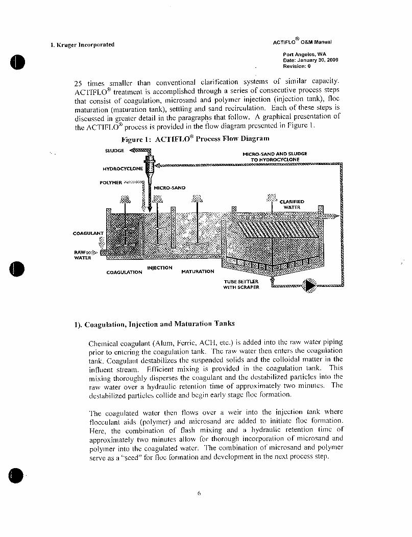
25 times smaller than conventional clarification systems of similar capacityACTIFLO treatment is accomplished through a series of consecutive process steps
that consist of coagulation microsand and polymer injection injection tank floc
maturation maturation tank settling and sand recirculation Each of these steps is
discussed in greater detail in the paragraphs that follow A graphical presentation of
the ACTIFLO process is provided in the flow diagram presented in Figure 1
Figure 1 ACTIFLO Process Flow Diagram
SW DGEMICROSAND AND SLUDGE
TO HYDROCYCLONE
HYDROCYCLONE
POLYMER ti
MICROSAND
g
CLARIFIED
WATER
ec i ie Eme T ag h s o
COAGULANT t
Y z s rx y
RAWsP d M3
i xWATER c a wr
wa k
INJEC770Ns
COAGULATION MATURATION s
TUBE SETTLER
WITH SCRAPER
1 Coagulation Injection and Maturation Tanks
Chemical coagulant Alum Ferric ACI1 etc is added into the raw water piping
prior to entering the coagulation tank The raw water then enters the coagulationtank Coagulant destabilizes the suspended solids and the colloidal matter in the
influent stream Efficient mixing is provided in the coagulation tank This
mixing thoroughly disperses the coagulant and the destabilized particles into the
raw water over a hydraulic retention time of approximately two minutes The
destabilized particles collide and begin early stage loc formation
The coagulated water then flows over a weir into the injection tank where
flocculant aids polymer and microsand are added to initiate floc fonnation
Here the combination of flash mixing and a hydraulic retention time of
approximately two minutes allow for thorough incorporation of microsand and
polymer into the coagulated water The combination of microsand and polymerserve asaseed for floc formation and development in the next process step
6

I Kruger Incorporated ACTIFLO OM Manual
Port Angeles WA
Date January 30 2009
Revision 0
ACTIFLO treatment continues as water passes through the underflow passage
from the injection tank into the maturation tank Although chemical floc
formation actually begins with the addition of polymer and microsand in the
injection tank the majority of ballasted floc formation occurs during the
maturation process step Gentle mixing and an increased hydraulic retention time
of approximately six minutes provides ideal conditions for the formation of
polymer bridges between the microsand and the destabilized suspended solids
The large specific surface area of the microsand provides enhanced opportunityfor polymer bridging and enmeshment of microsand and floc already in
suspension further augment this process
2 Settling Tank
The fiilly formed ballasted flocs leave the maturation tank and enter the settlingtank Fere the ballasted flocs rapidly settle and are removed from the treated
water via lamellar settling Laminar up flov through the lamellar settling zone
provides rapid and effective removal of the microsandsludge floc Clarified
water exits the ACTIFLO system via a series of collection troughs oc weirs for
subsequent filtration disinfecting and delivery to the distribution network
3 Sand Recirculation System
The ballasted floc sandsludge miture is collected at the bottom of the settlingtank and withdrawn using a rubberlined centrifugal surry pump The sand
sludge mixture is then pumped to the hydrocyclone for separation Lnergy from
pumping is effectively converted to centrifuga forces within the body of the
hydrocyclone causing chemical sludge to be separated from the higher densitymicrosand Once separated the microsand is concentrated and discharged from
the bottom of the hydrocyclone and reinjected into the ACTIFLO process for
reuse The lighter density sludge is discharaed out of the top of the hydrocycloneand sent for thickening or final disposaL
y
7

L Kruger Incorporated ACTIFLO OM Manual
Port Angeles WA
Date January 30 2009
Revision 0
2 DESCRIPTION OF EQUIPMENT

1 Kruger Incorporated ACTIFLO OM Manual
Port Mgeles WA
Date January 30 2009
Revision0
A ACTIFLO Clarification System
The purpose of this section is to provide a functional description of each majorcomponent in the ACTIFLO Process
1 Functional Characteristics
The ACTIFLO system for Port Angeles WA has been designed to treat a raw
water flow rate of I 1 million gallons per day
2 General Description
The ACTIFLO clarifier consists of a coagulation tanlc with nixer an injectiontank with mixer a maturation tank vith mixer a settling tank with a sludgescraper lamellar tube modules effluent collection troughs chemical feed
equipment dry polymer preparation system and microsand recirculation circuits
with pumps piping valves hydrocyclones etc The system is monitored and
controlled via a PLC controf panel
3 Coagulation Tanks
Length 9 10
Width 7 8
Sidewater Depth 16 10
Detention Time 2 ininutes at nominal flow
This rapidmixing tank is used for the coagulation of raw water The coagulant is
injected directly into the raw water supply prior to entering the coagulation tank
The raw water enters side of the tank via pipe opening with flow directed to the
bottom of the tank
The coagulation tank is equipped with a mixer assembly consisting of a shaft with
an axial flow impeller a 5 HP TEFC motor a helical gear reducer and a constant
speed drive The shaft and impeller are made of 304 stainless steeL The motor
requires an electric power suppfy of 460 V 3 ph 60 hz The shaft is designedwith a key way to allow for adjustment of the impeller position
9
I Kruger Incorporated ACTIFLO 08M Manual
Port Angeles WA
Date January 30 2009
Revision 0
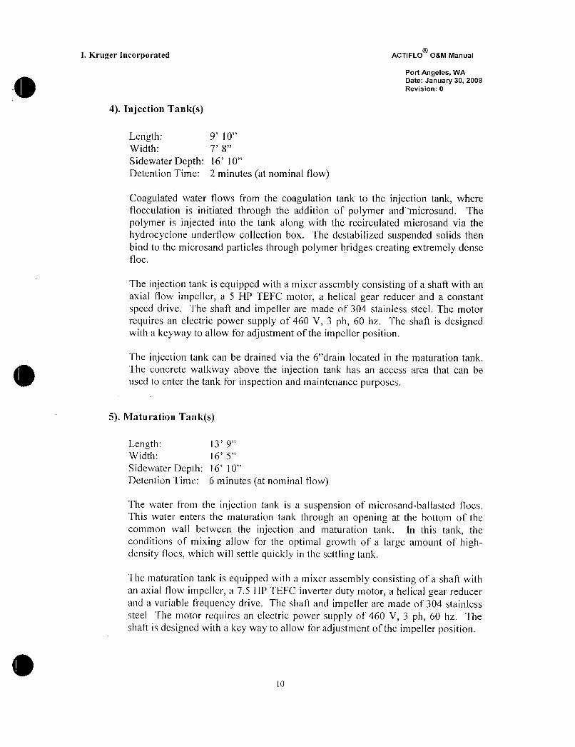
4 Injection Tanks
Length 9 10
Width 7 8
Sidewater Depth 16 10
Detention Time 2 minutes at nominal f7ow
Coagulated water flows from the coagulation tank to the injection tank where
flocculation is initiated through the addition of polymer and microsand The
polymer is injected into the tank along with the recirculated microsand via the
hydrocyclone underflow collection box The destabilized suspended solids then
bind to the microsand particles through polymer bridges creating extremely dense
floc
The injection tank is equipped with a miYer assembly consisting of a shaft with an
axial flow impeller a 5 HP TEFC motor a helical gear reducer and a constant
speed drive The shaft and impeller are made of 304 stainless steeL The motor
requires an electric power supply of 460 V 3 ph 60 hz The shaft is designedwitll a keyway to allow for adjustment of the impeller position
The injection tank can be drained via the 6drain located in the maturation tank
The concrete walkway above the injection tank has an access area that can be
used to enter the tank for inspection and maintenance purposes
5 Maturation Tanks
Length 13 9
Width 16 S
Sidewater Depth 16 0
Detention Time 6 minutes at nominal flow
The water from the injection tank is a suspension of microsandbailasted flocs
This water enters the maturation tank through an opening at the bottom of the
common wall between the injection and maturation tank In this tank the
conditions of mixing allow for the optimal growth of a large amount of highdensity flocs which will settleqiickly in the settling tank
The maturation tanlc is equipped with a mixer assembly consisting of a shaft with
an axial flow impeller a 75 HP TEFC inverter duty motor a helical gear reducer
and a variable frequency drive The shaft and impeller are made of 304 stainless
steel The motor requires an electric power supply of 460 V 3 ph 60 hz The
shaft is designed with a key way to allow for adjustment of the impeller position
0

I Kruger Incorporated ACTIFLO OM Manual
Port Angeles WA
Date January 30 2009
Revision 0
The mixer is vertically mounted and its rotating speed can vary between 45 and
60I1z adjusted with a variable frequency drive for optimum floc formation
The maturation tank has a 6 drain with a mud valve controllable from the
concrete walkway above the maturation tank
The maturation tank is covered with concrete walkways and open areas for
process observation The open areas are also used to gain access into the
maturation tank for inspection and maintenance purposes
6 Settling Tanks
Length 16 S
Width 16 S
Sidewater Depth 16 10
Rise Rate 20 gpmft Ntaximum at desibn flow
The settling tank is composed of a circular sandsludge scraper a sandsludgecollection pit lamellar tube modules and effluent collection troughs
The water from the maturation tank is a suspension of highdensity microsand
ballasted flocs This water flows Crom the maturation tank into the settling tank
where the ballasted flocs settle to the bottom fhe scraper continuously rakes the
sandsludge slurry towards the sandsludge collection pit located at t11e center of
the settling tank A center pit scraper is provided to keep the sandsludge slurryfiom compacting in the pit prior to bing removed by lhe sandsludge pumps
a Sludge collection pit
Located at the center of the bottom of the settling tank is a sludge collection
pit The bottom of the pit is covered with a stainless steel wear plate designedto prevent deterioration of the concrete due to abrasion The sandsludge slurryis continuously pumped from the bottom of the sludge collection pit
b Lamellar tubes
The settling tank is provided vith lamellar tube modules made of polystyreneThe lamellar tubes are inclined at an angle of 60 degrees with respect to the
horizontal axis They have a vertical heighc of 4 The modules are supportedfrom the bottom with a series of 304 stainless steel beams
I Kruger Incorporated ACTIFLO OM Manual
Port Angeles WA
Date January 30 2009
Revision 0
c Effluent Collection Troughs
Clarified water is collected in a series of stainless steel rectangular effluentcollection troughs located above the lamellar tube modules The collection
troughs are provided with adjustable rectangularnotch weirs which can beleveed to ensure equal distribution of the flow
7 Microsand Recirculation Circuits
The microsand is recirculated from the bottom of the settling tank back to the
injection tank This is accomplished through the microsand recirculation circuitEach ACTIFLO train is provided with one microsand recirculation circuit Thereis a common standby unit shared by the two trains Each microsand recirculationcircuit consists of 304 stainless steel piping 1 100 rubber lined sandslurrypump 1 suction side flush connections 1 isolation plug valve 1 dischargeside plug valve and l 1ow pressure switch There are two 2 hydrocyclones pertrain one duty and one standby
a Sand pumps
The sand pumps are centrifugal rubber lined slurry pumps with Vbelt drivesEach pump is provided with a 10 HP TEFC motor and a pumping capacity oCl 15 gpm at a discharge pressure of 3040 psi The impeller and the inside ofthe housing shell are rubberlined which is resistant to the microsand abrasionThe motor requires an electric power supply of 460V 3 ph 60 hz The sand
pumps are supplied with a hydrostatic seal but a minimum amount of sealwater must be fed to each pump at a sufficient rate to keep the packinglubricated
The sand pump must operate at a constant discharge pressure A suddendecrease in pressure may be caused by a blockage in the discharge or suction
piping To monitor this condition there is a lowpressure switch located at the
pump discharge If the measured pressure becomes too low the PLC will stopthe lead pump alarm the operator to the problem and the lag pump will startIf both the lead and lag pump pressure become too low the train will shutdown
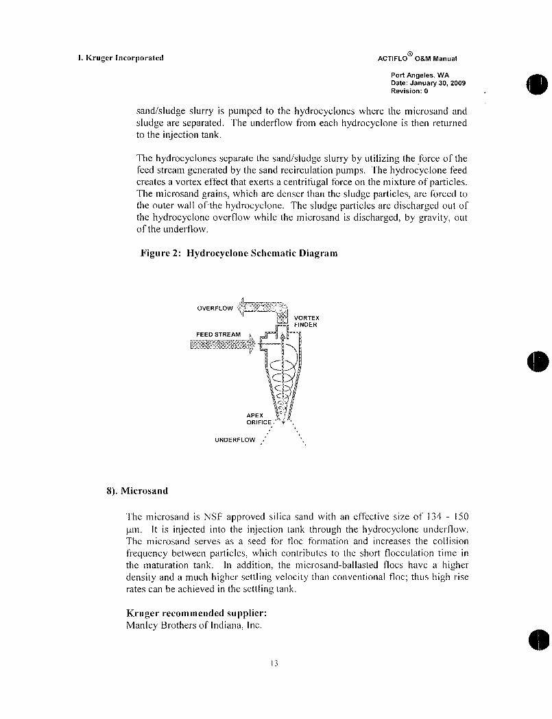
b Hydrocyclones
The Krebs U6 hydrocyclones with an inlet orifice of22 sq in a vortex finderof 175 and an apex of 10 are completely molded in food grade urethane
Refer to Figure 2 Each train is designed with two 2 hydrocyclones The
12
I Kruger Incorporated ACTIPLO OM Manual
Port Angeles WA
Date January 30 2009
Revision 0
sandsludge slurry is pumped to the hydrocycones where the microsand and
sludge are separated The underflow from each hydrocyclone is then returned
to the injection tank
The hydrocyclones separate the sandsludge slurry by utiizing the force of the
feed stream generated by the sand recirculation pumps The hydrocyclone feed
creates a vortex effect that exerts a centrifugal force on the mixture of particlesThe microsand grains which are denser than the sludge particles are forced to
the outer wall of te hydrocyclone The sludge particles are discharged out of
the hydrocyclone overflow while the microsand is discharged by gravity out
of the underflow
Figure 2 Hydrocyclone Schematic Diagram
OVERFLOW
VORTEX
FINDER
FEED STREAM
I adiry t
cr f
APEX
ORIFICE
UNDERFLOW
8 Microsand
The microsand is NSF approved silica sand with an effective size of 134 150
m It is injected into the injection tank through the hydrocyclone underflow
The microsand serves as a seed for floc fonnation and increases the collision
frequency between particles which contributes to the short flocculation time in
the maturation tank In addition the microsandballasted flocs have a higherdensity and a much higher settling velocity than conventional floc thus hibh rise
rates can be achieved in the settling tank
Kruger recommended supplierManley Brothers of Indiana Inc
13
R
I Kruger Incorporated ACTIFLO OM Manual
Port Angeles WA
Date January 30 2009
Revision 0
PO BOX 8O
300 South Vermillion St
Troy Grove Illinois 613727741
Telephone1800237SAND or18155397486
Fax18155397741
The microsand for Port Angeles WA is Manley Brothers Grade 80
9 Coagulant
The coagulant is injected directly into raw water influent pipe The coagulantcauses particle destabilization by neutralizing the particles present in the raw
water Also by reacting with alkaline components in the raw water the coagulantwill form the precipitation of inetal hydroxides Both charge neutralization and
precipitation contribute to coagulation
10 Coagutant Metering Pumps BY OTHERS
Kruger lnc is not supplying the chemical feed systems for this project
11 Polymer Preparation System I3Y OTHERS
Kruger Inc is not supplying the chemical feed systems for this project
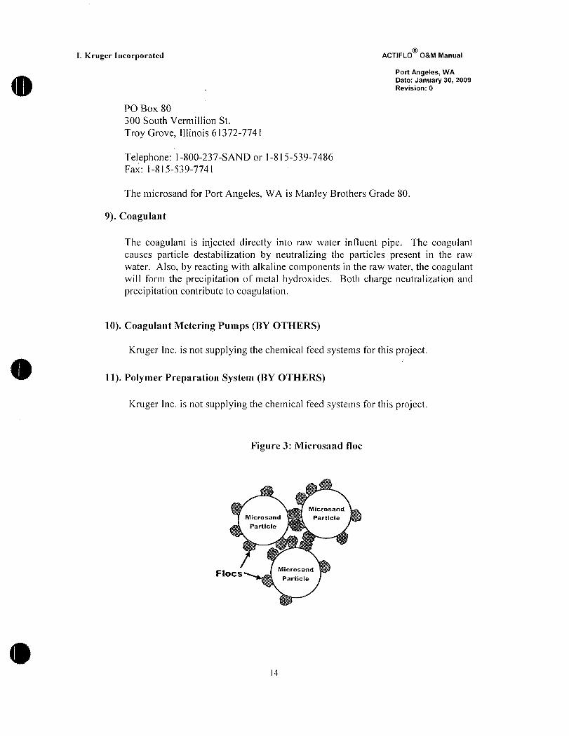
Figurc 3 Microsand floc
Microsand
Microsand Particle
Particle
FOCSMicrosand
Particle
14

I Kruger Incorporated ACTIFLO 08M Manual
Port Angeles WA
Date January 30 2009
Revision 0
12 Polymer Metering Pumps BY OTHERS
Kruger Inc is not supplying the chemical feed systems for this project
B Control Panel
1 General
The electrical circuit of the control panel integrates the necessary functions for
fully automatic operation and equipment protection of the ACTIFLO process
The control panel gives the operator access to every mechanical component of the
system Moreover the control panel gathers the alarms of the system and warns
the operator of an equipment failure or problem
2 PLC Control Panel Description
Panel Type NEMA 12 Steel Panel with back panel
On the Face of the PaneL
Reset pushbuttonAcknowledge alarm pushbuttonOperator Interface
Inside panel120 VAC Surge arrestor
DC power suppliesAnalog isoation
Analog surge suppressionControl relaysPLC equipmentPLC Power supply24 VDC Discrete nput Cards
24 VDC Discrete Output Cards
Analog Output Cards
Analog Input Cards
Circuit breakers
Terminals
Ground Fault Circuit InterrupterEthernet Switch
15

I Kruger Incorporated ACTIFLO o8M Manual
Port Angeles WA
Date January 30 2009
Revision 0
3 STARTUP OPERATION AND
MONITORING
16
I Kruger Incorporated ACTIFLO 08M Manual
Port Angeles WA
Date January 30 2009
Revision 0
A StartUp
1 Preliminary verifications
Prior to system startup the operators must ensure that
all tanks in the ACTIFLO clarifier are completely cleanall tanks in the ACTIFLO clarifier are compfetely filled with water
the manual valves at the suction and discharge of the sandsluny recirculation
pumps must be fully openthe seal water for the sandslurry punps is functionalthe coagulant and polymer dosing equipment ie pumps valves etc is
operationalthe coagulant storage tank is full to sufficient capacitythe polymer solution is wellmixed and aged properlythe coagulant and polymer metering pumps are calibrated and adjusted to
provide the f7owrates required to obtain the right dosage in the system These
can however be adjusted once the system is operational
2 Debris removal from process tanks
If there is any debris left in the process tanks after the startup of the ACTIFLOsysten the debris may enter the hydrocyclones and clog the hydrocyclone apexIf the apex becomes clogged microsand will be forced out of the systemTherefore it is extremely important to ensure a debrisfree condition in the
process tanks before the system startup This includes nails screvs bolts
cigarettes concrete chunks and general construction debris The contractor
should drain the settling tank if necessary and inspect the tank bottom for debris
by physically climbing inside the tank and perforining a walkthrough As a tinal
check the following procedure should be followed to remove any smallsized
debris that may have been overlooked during the tank inspection and cleaning
1 Remove the apex of the hydrocyclone in order to allow the debris to flow
through the hydrocyclone
2 Place a fine screen in the hydrocyclone underflow collection box to remove
the debris
3 Run the system for at least 20 minutes
17
I
L Kruger Incorporated ACTIFLO 08M Manual
Port Angeles WA
Date January 30 2009
Revision 0
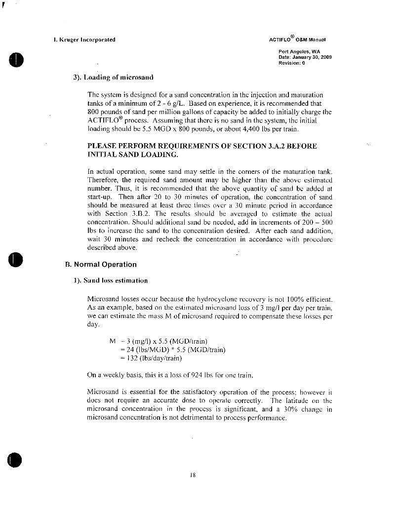
3 Loading of microsand
The system is designed for a sand concentration in the injection and maturation
tanks of a minimum of2 6 gL Based on experience it is recommended that
800 pounds of sand per million gallons of capacity be added to initially charge the
ACTIFLO process Assuming that there is no sand in the system the initial
loading should be 55 MGD x 800 pounds or about4400 Ibs per train
PLEASE PERFORM REQUII2EMENTS OF SECTION3A2 BEFORE
INITIAL SAND LOADING
In actual operation some sand may settle in the corners of the maturation tank
Therefore the required sand amount may be higher than the above estimated
number Thus it is recommended that the above quantity of sand be added at
startup Then after 20 to 30 minutes of operation the concentration of sand
should be measured at east three times over a 30 minute period in accordance
with Section 3B2 The results should be averaged to estimate the actual
concentration Should additional sand be needed add in increments of 200 500
Ibs to increase the sand to the concentration desired After each sand additionwait 30 minutes and recheck the concentration in accordance with proceduredescribed above
B Normal Operation
1 Sand loss estimation
Microsand losses occur because tlle hydrocyclone recovery is not 00 efficient
As an eYample based on the estmated microsand loss of 3 mg1 per day per trainwe can estimate the mass M of microsand required to compensate these losses per
day
M 3 mg1 x 55 MGDtrain24 IbsMGD 55 MGDtrain132 Ibsdaytrain
On a weekly basis this is a loss of 924 Ibs for one train
Microsand is essential for the satisfactory operation of the process however it
does not require an accurate dose to operate correctly The latitude on the
microsand concentration in the process is significant and a 30o change in
microsand concentration is not detrimental to process performance
l8
l Kruger Incorporated ACTIFLO OM Manual
Port Angeles WA
Date January 30 2009
Revision 0
Sand concentration monitorin
Although a minor amount of microsand is constantly discharged out of the
process and a sand concentration as low as 2 gI is sufficient for satisfactoryoperation of the ACTIFLO process the microsand concentration should alwaysbe maintained at recommended levels 2 6 gL Therefore the operators shouldmonitor the microsand concentration 23 times per day The concentration can
easily be estimated using the following method
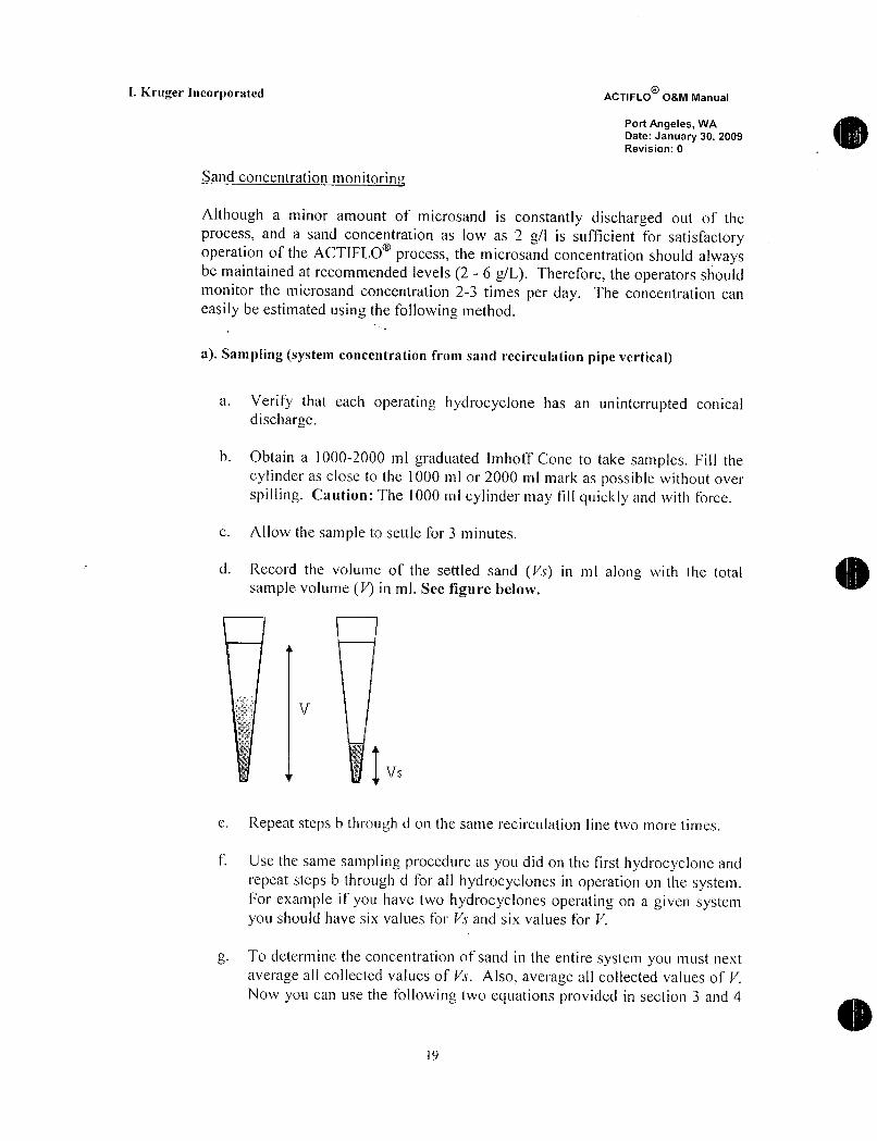
a Sampling system concentration from sand recirculation pipe vertical
a VeriFy that each operatinb hydrocyclone has an uninterrupted conicald ischarge
b Obtain a 10002000 ml graduated mhoff Cone to take samples Fill the
cylinder as close to the 1000 ml or 2000 ml mark as possible ithout over
spilling Caution The 1000 ml cylinder may ill quickly and with force
c Allow the sample to settle for 3 minutes
d Record the volume of the settled sand V in ml along vith the total
sample volume T in ml See figure below
r
m T r
i
e Repeat steps b through d on the same recirculation line two more times
f Use the same sampling procedure as you did on the first hydrocyclone and
repeat steps b through d for all hydrocyclones in operation on the systemFor example if you have two hydrocyclones operating on a given systemyou should have six values for Is and six values for V
g To determine the concentration of sand in the entire system you must next
average all collected values of Us Also average all collected values of V
Now you can use the following two equations provided in section 3 and 4
19
I Kruger Incorporated ACTIFLO 08M Manual
Port Angeles WA
Date January 30 2009
Revision 0
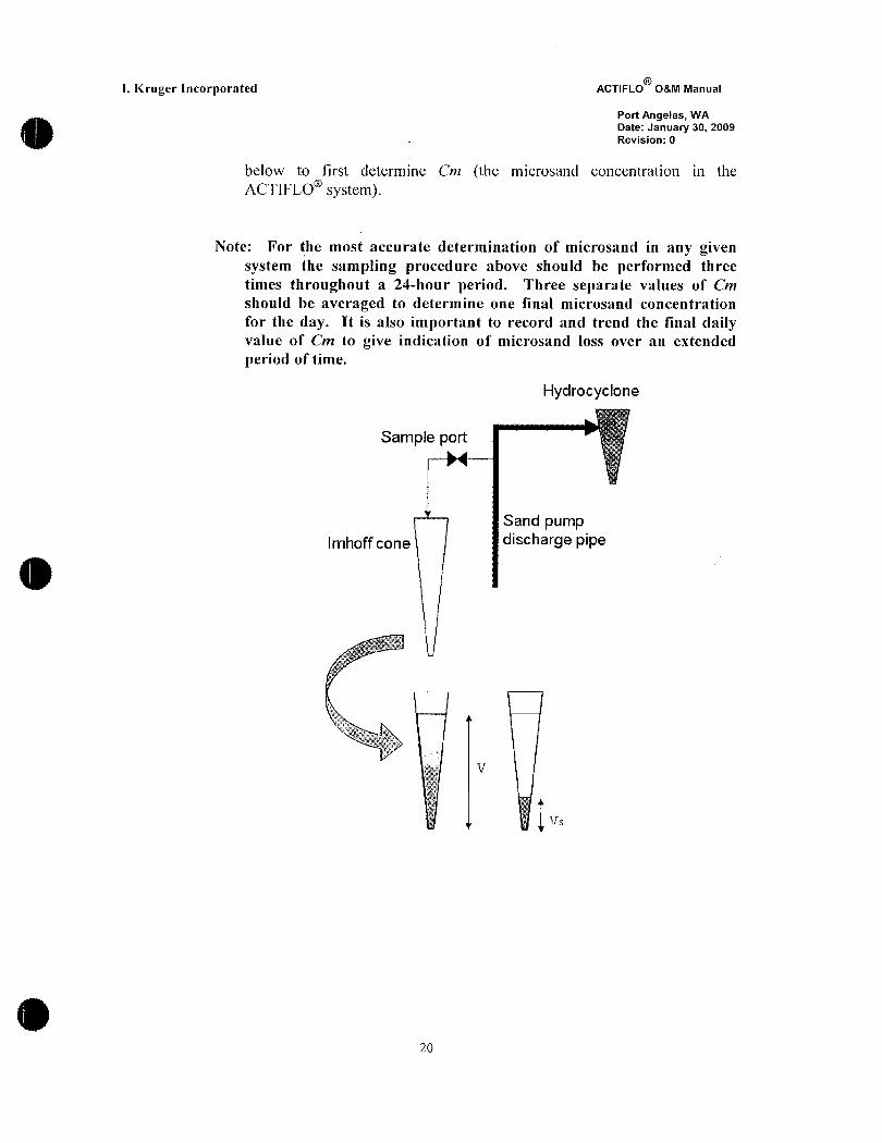
below to first determine Cm the microsand concentration in the
ACTIFLO system
Note For the most accurate determination of microsand in any givensystem the sampling procedure above should be performed three
times throughout a 24hour period Three separate values of Cm
should be averaged to determine one final microsand concentration
for the day It is also important to record and trend the Cnal dailyvalue of Cm to give indication of microsand loss over an extended
period of time
Hydrocyclone
Sample port
Sand pump
Imhoff cone discharge pipe
j J
s y
i jrj
Zo
L Kruger Incorporated ACTIFLO OM Manual
Port Angeles WA
Date January 30 2009
Revision 0
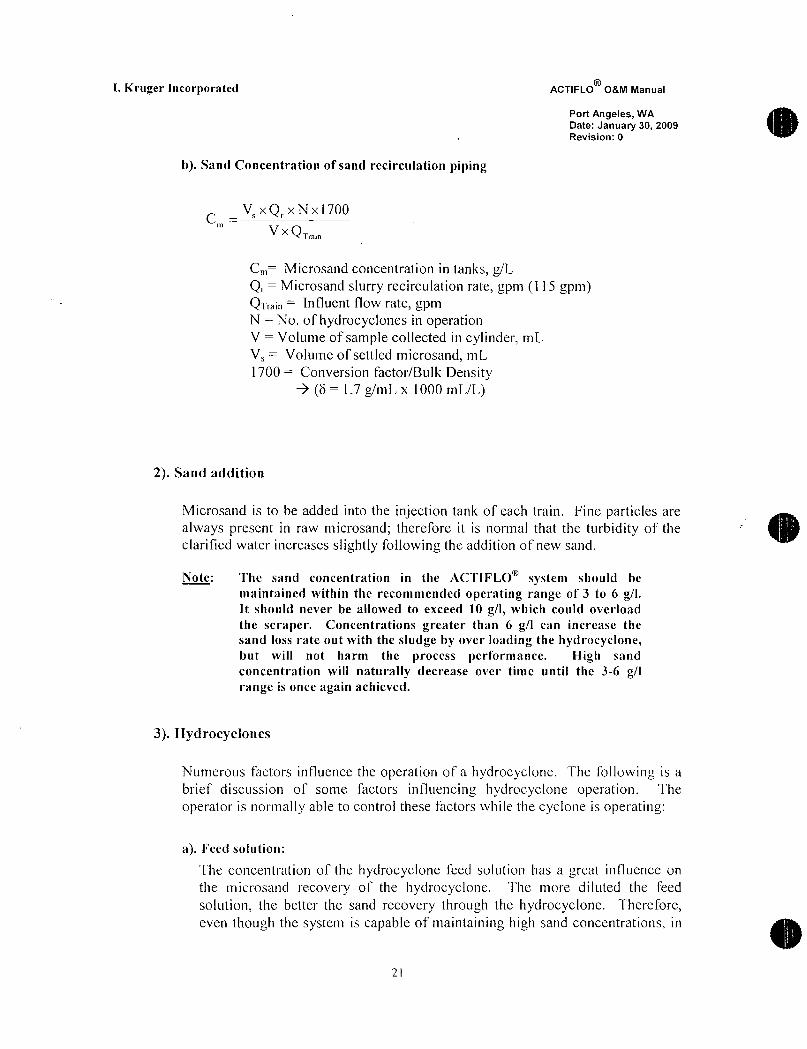
b Sand Concentration of sand recirculation piping
C Vm
xTrain
C Microsand concentration in tanks gLQ Microsandsurry recirculation rate gpm 1 15 gpmQTa Influent flow rate gpmN No of hydrocyclones in operationV Volume of sample collected in cylinder mL
V Volume of settled microsand mL
1700 Conversion factorBulk Densityb 17gmL x 1000 mLL
2 Sand addition
Microsand is to be added into the injection tank of each train Fine particles are
always present in raw microsand therefore it is normal that the turbidity of the
clarified water increases slightly following the addition of new sand
Note The sand concentration in the ACTIFLO system should bc
maintained within the recommended operating range of 3 to 6 gIIt should never be allowed to exceed 10 gI which could overload
the scraper Concentrations greater than 6 gI can increase the
sand loss rate out with the sludge by over loading the hydrocyclonebut will not harm the nrocess performance High sand
concentration vill naturally decrease over time until the 36 gIrnge is once again achieved
3 Hydrocyclones
Numerous factors influence the operation of a hydrocyclone The followinb is a
brief discussion of some factors influencing hydrocyclone operation The
operator is normally able to control these facors vhile the cyclone is operatin
a Feed solution
Ihe concentration of the hydrocyclone feed solution has a breat influence on
the microsand recovery of the hydrocyclone The more diluted the feed
solution the better the sand recovery through the hydrocyclone Thereforeeven though the system is capable of maintaining high sand concentrations in
2t

I Kruger Incorporated ACTIFLO 08M Manual
Port Angeles WA
Date January 30 2009
Revision 0
order to minimize the sand losses of the hydrocyclone it is not recommended
to overload the system with microsand
b Underflow
Normally the apex produces a 2030 degree cone discharge Under the
condition of extremely high underflow solid concentration the apex will create
aroping discharge Arope is an indication that the apex is not allowing all
of the coarse solids out and consequently some are being forced out the
cyclone overfiow In addition the operator must make sure at all times there is
no obstruction at the apex of the hydrocycones If the apex becomes cloggedmicrosand will be forced out of the system
c nlet Pressurc
The pressure at the inlet of the hydrocyclone should be approximately 20 to 30
psi to ensure an efficient microsandsludge separation
d Overflow
It is important to verify on a daily basis that there is no detectable presence of
microsand in the overflow of the hydrocyclone To do this the operator inust
take a sample of the overflow with a gradaated cylinder and measure the
microsand concentration following a settling time of one minute Normallythe presence of any significant microsand in the overflow should not be
detectable
e Clogging
There are four areas of a hydrocyclone that can hold debris and need to be
inspected if higher than expected sand usage rates are experienced They are
listed as follows
Note All four inspection arcas should be inspected regardless of findingdebris in other areas Multiple obstructions are possible
Apex Tin The apex tip is the most obvious area to notice if debris is presentAs described in our operator training presentation the underflow from the
hydrocyclone should be a uniform shape throughout the entire spray area
When a portion or the entire underflow spray pattern is irregular this is a goodindication of debris lodged in the apex tip Removal of this debris is done bytaking the hydrocyclone out of service and disassembling the lowest section o1
the hydrocyclone body and inspecting the interior portion for debris
Hydrocyclone Body Depending on the size of the obstruction it could be
lodged in any portion of the hydrocyclone body without showing any irregular
22

I Kruger Incorporated ACTIFLO o8M Manual
Port Angeles WA
Date January 30 2009
Revision 0
underflow spray patterns The best way to inspect the body is to take the
hydrocyclone out of service by performing proper locktag out procedures ofthe sand pump that supplies slurry to the hydrocyclone to be inspected andremove the lower portion of the hydrocyclone body Inspect the removedsection along with the upper portion of the hydrocyclone body still attached
Any debris in these areas should be easy to remove Any debris found shouldbe identified and noted in case similar material is found in subsequentinspections If the same type of debris is responsible for reoccurringobstructions steps should be taken to nininize or eliminate the source andorthe entrance ofthis debris to the ACTIFLO process trains Once the
hydrocyclone has been inspected and all obstructions been removedreassemble the flange connection
Hydrocvclone overflowvortex finder Obstructions in the area will not
create irregular underflow spray patterns so higher than normal sand usage is a
good guide To inspect this area the hydrocyclone should be taken out ofservice by performing proper locktag out procedures of the sand pump that
supplies slurry to the hydrocyclone to be inspected and the overflov pipeshould be removed The overflow pipe is connected in two locations One is a
coupling on top of the vortex finder on the hydrocyclone The other is a clampconnected to the overflow piping which is connected to the overflow pipeheader This clamp does not need to be completely removed just loosened
enough to allow the overflow pipe itself to rotate Once there is a clear viewinto the vortex finder inspect for obstructions
Iydrocyelone Inlet Obstructions in the area will notceate irregularmderflow spray patterns so higher than normal sand usage is a good guide To
inspect this area the hydrocyclone should be taken out of service byperfonning proper locktag out procedures of the sand pump that suppliesslurry to the hydrocyclone to be inspected and the inFluent piping to the
hydrocyclone should be disconnected fi the inlet to the hydrocycloneDependinb on the method the hydrocyclone influent piping is assembled andthe entire inlet head of the hydrocyclone may need to be removed in order to
inspect the inlet area To remove the inlet head the overflow pipe should be
removed as described above in the vortex finder inspection process Once this
is done remove each of the bolts used to connect the upper portion of the
hydrocyclone to the hydrocyclone support stand Once these bolts are removed
and the influent and overf7ov piping are disconnected the inlet head assemblyshould be easily removed Once removed inspect the inlet chamber of the
hydrocycfone for debris
23
I Kruger Incorporated ACTIFLO 08M Manual
Port Angeles WA
Date January 30 2009
Revision 0
4 Polymer dosing
The polymer is dosed into the ACTIFLO process at three different points the
injection tank the inlet ta the maturation tank and at the maturation tank baffles
Under certain conditions such as low raw water temperatures in the winter the
system may prefer a longer coagulation detention time The operators can control
the polymer split to deliver more polymer directly to the injectionmaturationtanks so that the coagulant would have more reaction time before reacting with
the polymer
The polymer stock solution and feed solution should not be prepared over the
recommend maximum concentrations which is 05 o 5 gI for the Ciba LT
series The in line dilution is a very important factor for the efficiency of the
polymer since it increases its dispersion into the ACTIFLO process
The optimum dose of polymer for the ACTIFLO process is adjusted in
accordance with three different parameters
Raw water turbiditySettled water turbidityFilter run time
The raw water turbidity is the factor with the most influence on the polymerrequirement After accumulating enough operation experience with different raw
water characteristics operators should be able to generateaturbidity matria
guide for polymer dosage control
5 Coagulant Dosing
The coagulant causes particle destabilization by neutralizing the particles presentin the raw water Also by reacting with alkaline components in the raw waterthe coagulant will form the precipitation of inetal hydroxides Both chargeneutralization and precipitation contribute to coagulation
The optimum dose of coagulant for the ACTIFLO process is adjusted in
accordance with the raw water turbidity and color After accumulating enoughoperation experience with different raw water characteristics operators should be
able to produceaturbidity matrix guide for coagulant dosabe control
24
I Kruger Incorporated ACTIFLO OM Manual
Port Angeles WA
Date January 30 2009
Revision 0
6 Calibration of Coagulant and Polymer posing Pums
Kruger did not provide the chemical feed systems for this project The
following section is included as a general guide for chemical feed pump
calibration however the equipment manafacturers recommended
guidelines should be followed
Calibration of the coagulant and polymer dosing systems is required to ensure that
the system will provide the required amount of chemicals The system must be
calibrated prior to startup and possibly abain if there is a significant increase or
decrease in average flow rate such that the current settings of the dosing systemwill not meet the expected peak or minimum dosage requirements
During system calibration the objective for diaphragm pumps is to first set the
pump stroke length manually This should allow change in the pump speedcontrol to cover the expected range of ra water Flow to be treated These
settings are usually determined at startup and may not need to be determined
again until a significant increase or decrease in the longtenn average dailyinfluent flow occurs For automatic dosing control via the PLC the pump
capacity must be determined at a predetermined stroke length setting at the 100
percent speed setting Capacities are determined manually using the manual
stroke length control knob and the manual pump speed control on the local
control panel and the calibration cylinder located at the metering pumps For each
combination of settings the time required to pump out a known volue of liquidfrom the calibration cylinder is recorded
The stroke length wili typically be set betveen 20 and 80 of its maimum
setting As a general rule of thumb select a stroke length that will allow the
metering piunp to run at 50 speed for the required dosage at the average dailyflow rate This should allow the PLC to automatically provide the requireddosage over the expected range of flows encountered on a daily basis The onlyinputs to the PLC that may need to be updated are the desired dosage and the
solution strength If the daily average flow changes significantly the proceduremay need to be repeated for a new stroke length settinb
The procedure is outlined stepwise below
1 Have a stopwatch and notepad available
2 Determine the metering capacity in milliliters per minute or gallons per hour
required to provide the expected dosage at the average daily Flow rate
3 Turn the selector switch for the pump on the local control panel to the HAND
position
2
R
I Kruger ncorporated ACTIFLO OM Manual
Port Angeles WA
Date January 30 2009
Revision 0
4 Manually select a stroke length via the knob on the metering pump
Depending upon the required metering capacity this will typically be between
20 and 80 of its maximum setting
NOTE Only adjust the stroke ength when the pump running
5 Adjust the speed control at the locai controi panel to its 100 setting6 Fill the calibration cylinder with chemical such as coagulant or polymer7 Ensure that all valves on the metering pump system are in the proper position
to allow the metering pump to draw chemical from the calibration cylinderand pump it to the ACTIFLO
8 The liquid level in the calibration cylinder should be dropping as it is pumpedout
9 Record the time required to pump a known volume of iquid from the
cylinder10 Shut off the metering pump by turning the selector switch to the OrF position1 l Calculate the metering capacity of the pwnp for the selected stroke length
using the following formula
QVTx60
Where
Q is the metering rate in milliliters per minute or gallons per minuteV is the volume in milliliters or gallons pumped from the cylinderT is the time required to pump the volume in seconds
NOTE At this point you may want to repeat Steps 5 through 1 1 at least once
to verify that you have estimated the pumping rate correctly
12 If the required metering capacity determined in Step 2 is between 40 and 60o
of the metering capacity calculated in Step 1 1 Go to Step I5
13 f the required metering capacity determined in Step 2 is less than 40 of the
metering capacity determined in Step I1 then increase the stroke lengthsetting If the required metering capacity is greater than 60 of the meteringcapacity determined in Step 1 l then decrease the stroke length setting How
much you increase or decrease the settinb depends upon how much that you
need to increase or decrease the metering capacity14 Go back to Step 6 and repeat through Step 12
15 Ensure all valves are returned to the proper position to allow the meteringpump to pump chemical from the storage tank to the ACI
16 Input into the PLC the calculated value for pump capacity Q at the current
stroke length setting and the 100 speed settingl7 Check and correct if required the input values in the PLC for required
dosage and solution strength
26

L Kruger Incorporated ACTIFLO OM Manual
Port Angeles WA
Date January 30 2009
Revision 0
18 Return control of the ACTIFLO system to the PLC and return the Selectorswitch at the local pump control panel to the AUTO position
27

I Kruger Incorporated ACTIFLO OM Manual
4Port Angeles WA
Date January 30 2009
Revision 0
4 PERFORMANCE MONITORING
OPTIMIZATION AND TROUBLE
SHOOTING GUIDELINES
28

I Kruger Incorporated ACTIFLO OM Manual
Port Angeles WA
Date January 30 2009
Revision 0
A Process Performance Monitoring
1 Recommended noninclusive monitoring schedule
The process performance monitoring and analysis to be carried out at
minimum is as follows
Hourly Every Daily Weekly4 hours
Influent
Flowrate
Color
TurbidityAlkalinitypHTemperature
Effluent
Daily Total Flowrate
Color
TurbidityAlkalinitypH
E uipment VFD Fre uency
Maturation Mixer
Sludge Scraper
Scra er
Torque
Sand PumpsSeal Water Pressu Rate
Discharge Pressure
No Sand Spraying Out
HydrocycloncInlet Pressure 27 to 30 psiUnderflow Flowrate
Underflow Spray Pattern
Chemical Dosin
Alum Feed Rate and DosagePolymer Feed Rate and DosageAcid Feed Rate and DosageBase Feed Rate and Dosage
System Sand Concentration
2 to 6 g1 I
29

R
I Kruger Incorporated ACTIFLO OM Manual
Port Angeles WA
Date January 30 2009
Revision 0
B Optimization
The following outline describes the ACTIFLO system optimization procedure and treatment
considerations
1 Background and initial information
a Treatment Objectives
Removal ofturbidity color suspended solids and other parameters from
the influent raw water
Efficient usage of chemicals
Proper maintenance of ACTIFLO equipment
b ACTlFLO Optimization
The process used to identify and select the process variables and operatingparameters which give the best ACTIFLO perfonnanceTypical Process Parameters Variables
o Flow Rate
o pHo Coagulant type and dose
o Polymer type and dose
o Alkalinityo Temperatureo Time of day week month
o Etc
c Performance Criteria For Optimization
Parameters monitored could include
o Turbidityo Total Organic Carbon TOCo Color
o Algaeo Total Suspended SolidsIo Oil and Grease OGo Metals
o Trihalomethanes THMo Haloacetic acids HAA
cl Optimization Sequence
1 Determine the pH of Coagulation2 Optimize coagulant dose at the optimum pfI3 Optimize polymer dose at the optimum coagulant dose and pH
30

I Kruger Incorporated ACTIFLO OM Manual
Port Angeles WA
Date January 30 2009
Revision 0
e Other Considerations
Prior to optimization verify proper operation of all ACTIFLO related
equipment instruments chem feed etc
Change only one variable at a time
Wait a minimum of two hydraulic retention times before recording data or
making another changeRecord influent water data and perfornance for future reference when
similar conditions exist
2 Process parameter considerations
a Fully Formed Ballasted Floc Iilustration
j4o
i4
e 1C 1 i rtiz r
K 1t f 4j xt
1 it
fi zr
a S rx 3 i
s a 4 t a F
1 4rF r are Aa h 4 s
rJ s a
tr sa a i
b r Ei
V lb IIIla
py
ti
rT
31

I Kruger Incorporated ACTIFLO OM Manual
Port Angeles WA
Date January 30 2009
Revision 0
b Insufficient Polymer pose
Coagulated particles in the raw water will not fully attach to the microsand
to enhance settling and may result in carryover in the settling tank
Generally you will not see a well defned floc in the maturation tank
Pin floc carryover in the settling tank
c Insfficient Polymer pose Illustration
O i
i
jt
S3
S 0 l y12
33
Ya
3vI
43 m
is
e 9
w r sa ey d 3 p
h
Si wt r v f
w i Y
xi
32

I Krugcr Incorporated ACTIFLO 08M Manual
Port Angeles WA
Date January 30 2009
Revision0
d Insufficient Influent Water Coagulation
Raw water particles not fully destabilized resulting in decreased settled
water qualityCloudy appearance in the settling tank
Clear ribbons or marbling not seen in maturation tank
e Insufficient Influent Water Coagulation Illustration
fI
e r 4m P Lc
Zt y
tE mS
xr
z
a u z a r s zA b r g z sv u
yt
ea R
3 k f v v 3ir s
n tirr uaru r
n 441
r a ull i
4 x fxR f Y j l
x L
u F Y
kwc
Y 1Y
sF 2r i
1llk E w y
t q q4fr A
gT f
y
c s
1t
iJx
e o ot
g T3
33

I Kruger Incorporated ACTIFLO OM Manual
Port Angeles WA
Date January 30 2009
Revision 0
f Low Microsand Concentration
High Effluent turbidityClear ribbons or marbling not seen in maturation tank
Potential floc carryover
Lower floc density in thematuration tank
g Low Microsand Concentration Illustration
A
A r
n sz
3
fr I as
4
S yt1 a 2
t
p T
F
g 4 g1 x
f a n Y 4 a 5 tr zZ t
s r ql sf x 7F Jii r 4
y
o YIF ti
r
rr
34
I Kruger Incorporated ACTIFLO OM Manual
Port Angeles WA
Date January 30 2009
Revision 0
3 Optimization procedure
a Step One
With a predetermined starting point based on prior treatment experienceset the initial parameters and let system operate for at least 2 hydraulicretention times
o Ex flow rate coagulant type and dose polymer type and dose pHRecord ACTIFLO process variables and performance criteria for bothinfluent and effluento Ex Time Flow Alkalinity plI urbidity color afgae TOC THM
etc
b Step Two
Select the process variable to be investigated Hold all other variablesconstant except this one
o Ex select coagulant dose for optimizationHold the flow rate polymer pH etc constant
Vary the coagulant dose increasing the dosage l0 or in 5 I 0 mgLincrements around the start pointIf increasing the coagulant dose improves the settled water qualitycontinue to increase the coagulant until treatment no longer improvesKee in mind that you will reach a point in which adding additional
coagulant may only slightly increase settled water quality and it may not
be beneficial to overdose chemicals the operator must determine whatthe best coagulant dosage will be
If increasing the coagulant dose does not increase treatment try loweringthe dosage until the optimal coagulant dose has been determined
Record the effect of the variations in coagulant dose on ACTIFLOPerformance
o Ex turbidity color albae TOC etc
c Step Three
Plot the effect of the process variable on ACTIFLO performanceIdentify and select the Optimum setting for the variable beinginvestigatedThis will be the point on the curve where the slope of the curve changes or
where the curve begins to plateau
35
I Kruger Incorporated ACTIFLO OM Manual
Port Angeles WA
Date January 30 2009
Revision 0
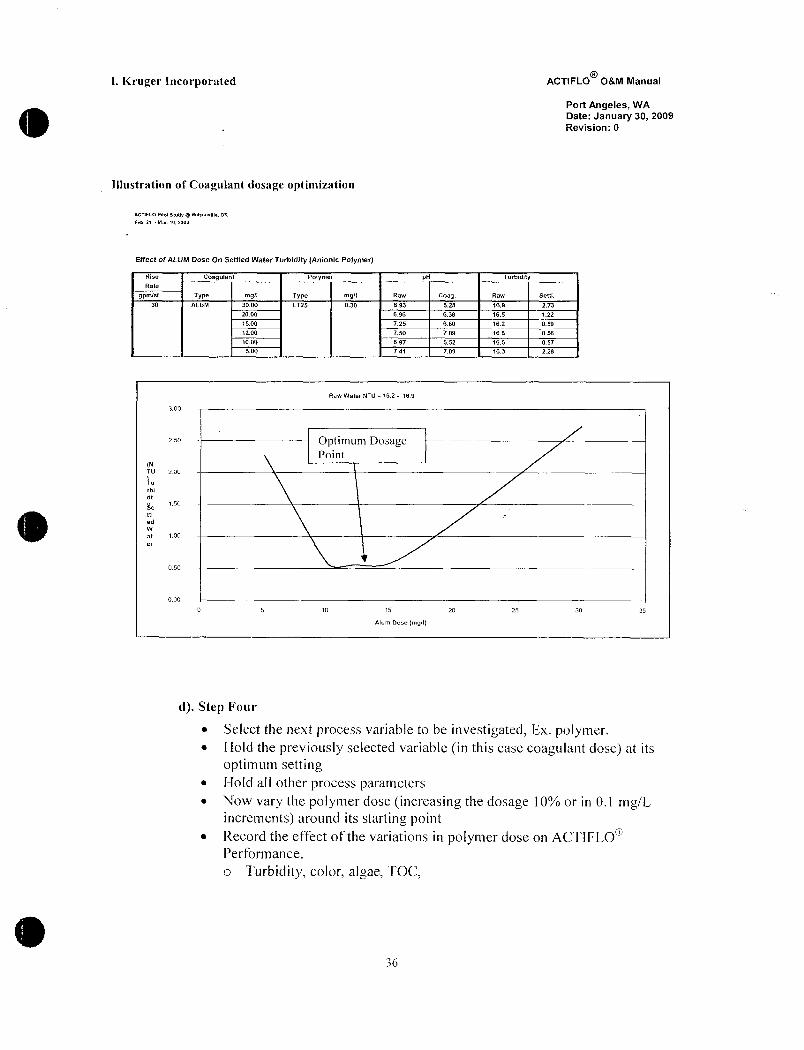
Illustration of Coagulant dosage optimization
PGTiFLO Pilol SWtly Wilzonville OR
Feb11 Mar10I00
Efect ofAUM Dose On Settled Water Turbidity Anionic Polymer
Rise Coagulant Polymer pH TurbidityRate
gpmsf Type mgl Type mgI Raw Coag Raw Settl
30 ALUM 3000 LT25 030 693 628 169 277
2000 696 638 165 122
1500 725 660 162 059
1200 750 709 166 056
1000 697 652 166 057
500 741 709 163 228
Raw Water NTU 162 169
300
zso Oplimum DosagePint
NTU 200
urbl
d
t50
n
w
a i o0
aso
o00
0 5 10 15 20 25 30 35
11um Oose mg71
d Step Four
Select the next process variable to be investigated Ex polymerHold the previously selected variable in this case coagulant dose at its
optimum settingHold all other process parametersNow vary the polymer dose increasing the dosage 10 or in 01 mgLincrements around its starting pointRecord the effect of the variations in polymer dose on ACTIFLO
Perfonnance
o Turbidity color algae TOC
36
I Kruger Incorporated ACTIFLO OM Manual
Port Angeles WA
Date January 30 2009
Revision 0
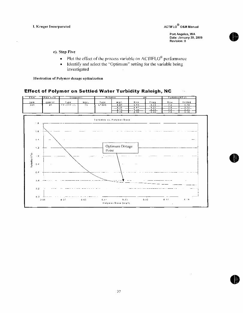
e Step Five
Plot the effect of the process variable on ACTIFLO performanceIdentify and select the Optimum setting for the variable beinginvestigated
Illustration of Polymer dosage optimization
Effect of Pofymer on Settled Water Turbidity Raleigh NC
Plow Rise Rate Coa ulant Pol mer H Turbidi NTU
m msf T e mL T e ml Raw Coa Raw Settled
22 20 Fe SO 75 LT22S 0OS 663 454 76 170
010 661 453 76 052
015 659 457 76 033
020 650 450 76 028
Turbitlity vs Polymer pose
1 8
Li6
I
1 4
z Optimum DosagePnini
Z o i
iv i
08
Fi
06 I
i04 I i
02i
i
00I
005 007 009 011 013 015 017 079
Polymer Oose mgl1
7
I Kruger Incorporated ACTIFLO OM Manual
Port Angeles WA
Date January 30 2009
Revision 0
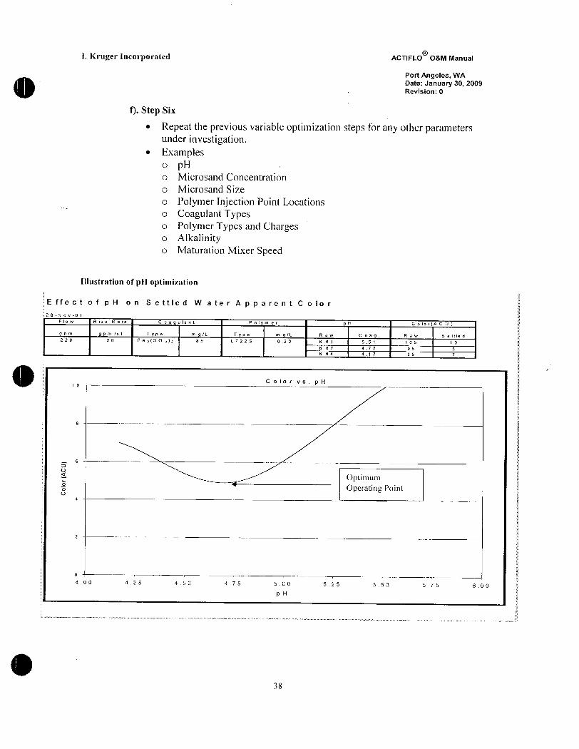
Step Six
Repeat the previous variable optimization steps for any other parametersunder investigationExampleso pHo Microsand Concentration
o Microsand Size
o Polymer Injection Point Locationso Coagulant Typeso Polymer Types and Chargeso Alkalinityo Maturation Mixer Speed
Illustration of pH optimiztion
E ffe c t o f p H o n S e ttle d W a te r A p p a re n t C o lo r
2 8N o v0 1
Flow Rise Rate Coagulant Polyme pH ColorACU
gpm gpmsf lype mgL Type mgL Ra Co a g R a w 5 e t I e d220 20 f e iS O a 85 LT22 S 020 661 551 1 O S 1 0
6 6 7 4 7 7 9 5 56 6 4 4 1 7 9 5 7
a
C o 1 o r v s p Hio
g
6
Y
iUa
OplimumOperating Point
4 K
59
2a
0 E
4 0 0 4 2 5 4 5 0 4 7 5 5 0 0 5 2 5 5 5 0 5 7 5 6 0 0
pH
g
I Kruger Incorporated ACTIFLO 08M Manual
Port Angeles WA
Date January 30 2009
Revision 0
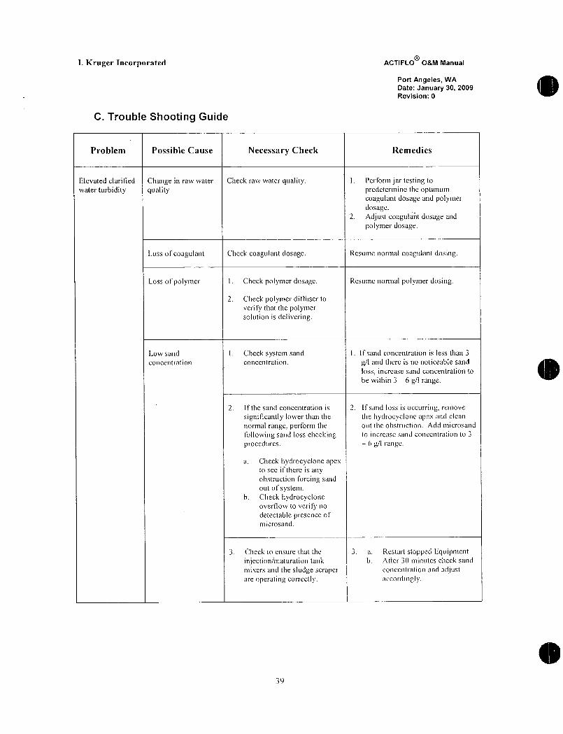
C Trouble Shooting Guide
Problem Possible Cause Necessary Check Remedies
Elevated clarilied Change in raw water Check raw water quality I Perforni jar testing to
water turbidity quality predetermine the optimumcoagulant dosage and polymerdosage
2 Adjust coagulant dosage and
polmier dosage
Loss of coagulant Check coagulant dosage Resume normal coagulant dosing
Loss ofpolymer I Check polymer dosage Rcsumc normal polymer dosing
2 Check polymer diffuser to
verify thal thc polymersolution is delivering
Low sand I Check system sand l If sand concentration is less than 3
concentration concentration gI and there is no noticeable sand
loss increase sand concentration to
be within 3 6 gI range
2 If de sand concentration is 2 Ifsand loss is occurring remove
significantly lower than thc thc hydrocyclone ape and clean
normal range perform the out the obstruction Add microsand
following sand loss checkinb to increase sand concentration to 3
procedures 6 dIrnge
a Checkhdrocyclonc apex
to see if there is any
obstruction Corcing sand
ou of systemb Check hydrocyclone
overFlow to verify no
detectable presence of
microsand
3 Check to ensure tlat the 3 a Restart stopped Iiquipmentinjectionmaluration tank b After 30 minutes check sand
mixers and the sludge scraper concentration and adjustare operating correctl accordingly
39

I Kruger Incorporated ACTIFLO OM Manual
Port Angeles WA
Date January 30 2009
Revision 0
Problem Possible Cause Necessary Check Remedies
Scraper High 1 Check general mechanical 1 Refer to scraper suppliersTorque Alarm condition of scSaper and the Operation and Maintenance Manual
lubricating oil level of for remedy information
scra er
2 Check if a foreign object has 2 t will be necessary to drain the
fallen into the tank tank if the item cannot be fished
out
3 Check if the system is 3 If the system is overload with
overloaded with microsand microsand contact Kruger lnc
4 If the cause cannot be
determined do ot attempt to
restart it until the tank is
drained and cleaned
Low Pressure Pump inlet pipe Check pump inlet pipe to make Perform suctiot pipe flusltingAlarm for Sand clogging sure there are no obstructions proceduresPump Pressure a Close the disdiarge side plugSwitch valve
b Connect the flush line
c furn on water for continuous
five minutes
d Put the equipment back into
normal operatione Restart thc pump
Sand Leakage Mechanical Seal Check general mechanical Refer co pump supplicrsOperationfrom Sand Pump Failure condition of sand pump and Maintenance Manual for remedy
information
Sand Loss from Coss of Treatment Check tha chemical dosages are Resurne normal polyner and coagulantthe system correct and that chemicals are dosing
actually being iqjected into system
Clog in hydrocycione Check for underFlow blockage Ifobstruction is present remove apexunderflow tip clean replace and restart system
Loss of Make sure tnjectionMaturation Correct if failure exists and resume
lnjectionMaturation Mixers and Settling tank scraper is normal operationMixer and or Settting operating check ifshafts are
tank Scraper rotating clockwise
40

I Kruger Incorporated ACTIFLO OM Manual
Port Angeles WA
Date January 30 2009
Revision 0
J JAR TEST PROCEDURE
41
I Kruger Incorporated ACTIFLO OSM Manual
Port Angeles WA
Date January 30 2009
Revision 0
A ACTIFLO Jar Test Procedure with Microsand for Dry Polymer
1 PreJar Testing Chemical Preparation Calculations and
Recommendations
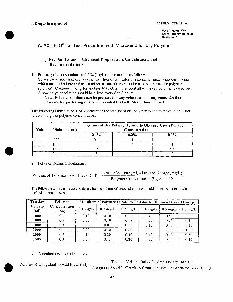
l Prepare polymer solutions at 01 1 gL concentration as follows
Very slowly add 1 g of dry polymer to l liter of tap water in a container under vigorous mixingwith a mechanical mixer jar test mixer at 100200 rpm can be used to prepare the polymersolution Continue mixing for another 30 to 60 minutes until all of the dry polymer is dissolved
A new polymer solution should be mixed every 6 to 8 hours
Note Polymer solutions can be prepared in any volume and at any concentrationhowever for jar testing it is recommended that a 01 solution be used
The following table can be used to determine the amount of dry polymer to add to the dilution water
to obtain a given polymer concentration
Grams of Dry Polymer to Add to Obtain a Given PolymerVolume of Solution ml Cocentration
01 02 03
500 05 1 15
1000 1 2 3
2000 1 4 452 Polymer posing Calculations
Volume of Polymer to Add to Jar mTest Jar Volume ml x Desired Dosage mgL
Polymer Concentration x 10000
The following table can be used to determine the volume of prepared polymer to add to the test jar to obtain a
desired polymer dosage
Test Jar Polymer Milliliters of Pol mer to Add to Test Jar to Obtain a Desired Dosa e
Volume Concentration
m01 mL 02 mL 03 mL 04 mL 05 mL 06 mL
1000 01 010 020 030 040 050 060
1000 02 005 010 015 020 025 030
1000 03 003 007 010 013 017 020
2000 01 020 040 060 080 I00 120
2000 02 010 020 030 040 050 060
2000 03 007 013 020 027 033 040
3 Coagulant Dosing Calculations
Volume of Coagulant to Add to Jar mlTest Jar Volume ml x Desired Dosage mgL
Coagulant Specific Gravity x Coagulant Percent Activity x 10000
42

I Kruger Incorporated ACTIFLO OM Manual
Port Angeles WA
Date January 30 2009
Revision 0
4 Since jar testing with microsand is very rapid approx 5 minutestest it is recommended to run
only one jar at a time Therefore in order to ensure consistent raw water quality a largecontainer should be filled with raw water This container should be stirred each time before a
sample is taken for jar testing In this way testing can be performed while avoiding anyinconsistencies that can be caused by varying raw water characteristics
5 For best results test parameters in the following sequencea At optimum coagulant dose and pH from previous experience check the different polymers
at 020 mgI polymer to find which polymer works bestb With best polymer at 020 mgI and optimum coagulant dose try different pH of coagulationc With best polymer at 020 mg1 and optimum pH of coagulation try different coagulant
dosages to fine tune coagulant dose
d With best polymer at 020 mg1 and optimum coagulant dose try different pH of coagulatione At optimum coagulant dose pH and polymer type try various polymer dosagesie005010030 etc
2 Jar Testing Procedure
1 Fill a square beaker with raw water Typically 2000 or 1000 ml of raw water is used for jartesting
Note square beakers are recommended for jar testing round jars can be usedbut the results may not properly reflect actual ACTIFLO operation
2 Add 5 grams of microsand per liter raw water in the test beaker
a Add 5 grams for a 1000 ml 1 L sampleb Add 10 grams for a 2000 ml 2 L sample
3 At time 0 add the coagulant into the vortex around the shaft of the mixer in order to ensure
better and instantaneous mixing and mix at maximum speed 300 rpm for 20 minutes If plfadjuscment is needed add alkali before coagulant addition
Note
To ensure the desired pH of coagulation is achieved following coagulant addition it is
recommended to use a titration method to figure out the required amount of pHadjustment In a separate jar add the desired amount of coagulant into a raw water
sample and mix for 15 minutes Record the pH of the sample and record In the same
coagulated water samplejar add a specific amoint of p1 adjustment and mix After
about 30 seconds measure the pH of the solution once aain and record Continue to do
this until a correlation can be drawn between the amount of pH adjustment added and its
effect on the coagulated water pH This may require 5 10 attempts before a goodcorrelation can be drawn The following table shows the recommended pH ranges to tryfor the corresponding type of coagulant
43

I Kruger Incorporated ACTIFLO OM Manual
Port Angeles WA
Date January 30 2009
Revision 0
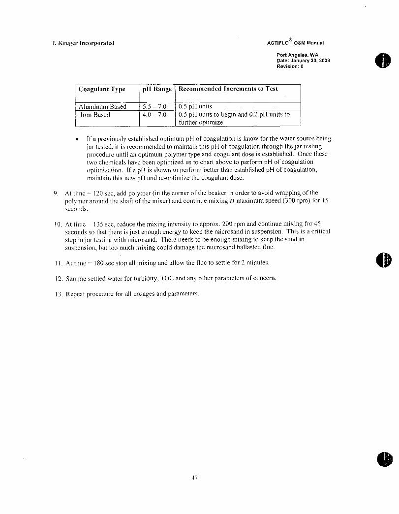
Coagulant Type pH Range Recommended Increments to Test
Aluminum Based 55 70 05 H units
Iron Based 40 70 05 pH units to begin and 02 pH units to
further o timize
If a previously established optimum pH of coagulation is know for the water source being
jar tested it is recommended to maintain this pH of coagulation through the jar tetirtgprocedure until an optimum polymer type and coagulant dose is established Once these
two chemicals have been optimized us to chart above to perform pH of coagulationoptimization If a pH is shown to perform better than established pH of coagulationmaintain this new pH andreoptimize the coagulant dose
4 At time 120 sec add polymer in the corner of the beaker in order to avoid wrapping of the
polymer around the shaft of the mixer and continue mixing at maximum speed 300 rpm for 15
seconds
5 At time 135 sec reduce the mixing intensity to approx 200 rpm and continue mixing for 45
seconds so that there is just enough energy to keep the microsand in suspension This is a critical
step in jar testing with microsand There needs to be enough mixing to keep the sand in
suspension but too much mixing could damage the microsand balasted floc
6 At time 180 sec stop all mixing and allow the floc to settle for 2 minutes
7 Sample settled water for turbidity TOC and any other parameters of concern
8 Repeat procedure for all dosages and parameters
44
I Kruger Incorporated ACTIFLO OM Manual
Port Angeles WA
Date January 30 2009
Revision 0
B ACTIFLO Jar Test Procedure with Microsand for Emulsion Polymer
1 PreJar Testing Chemical Preparation Calculations and
Recommendations
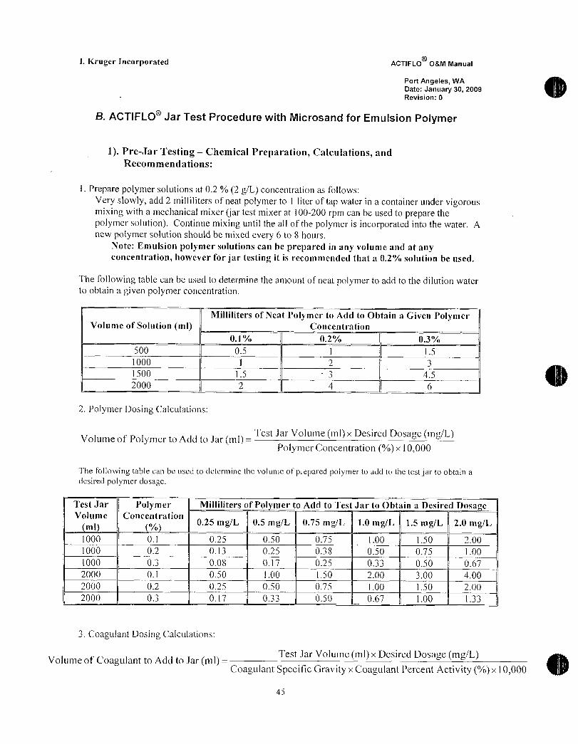
1 Prepare polymer solutions at 02 2gL concentration as follows
Very stowly add 2 milliliters of neat polymer to l liter of tap water in a container inder vigorousmixing with a mechanical mixer jar test mixer at 00200 rpm can be used to prepare the
polymer solution Continue mixing until the al of the polymer is incorporated into the water A
new potymer solution should be mixed every 6 to 8 hours
Note Emulsion polymer solutions can be prepared in any volume and at anyconcentration however for jar testing it is recommended that 02 solution be used
The following table can be used to determine the amount of neat polymer to add to the dilution water
to obtain a given polymer concentration
Milliliters of Neat Polymer to Add to Obtain a Given PolymerVolume of Solution ml Concentration
01 02 03
500 05 1 l 5
1000 1 2 3
1500 15 3 45
2000 2 4 6
2 Polymer posing Calculations
Volume of Polymer to Add to Jar mlTest Jar Volume ml x Desired Dosage mgL
Polymer Concentration x 10000
The following table can be used to determine the volume of prepared polymer to add to the testjar to obtain a
desired polymer dosage
Test Jar Polymer Milliliters of Pol mer to Add to Test Jar to Obtain a Desired Dosa e
Volume Concentration
m025 mgL 05 mgL 075 mgL 10 mgL 15 mgL 20 mg1L
1000 01 025 050 07 100 150 200
000 02 013 025 038 050 075 100
1000 03 008 017 025 033 050 067
2000 01 050 100 150 200 300 400
2000 02 025 050 075 100 150 200
2000 Q3 017 033 050 067 100 133
3 Coagulant Dosing Calculations
Volume of Coagulant to Add to Jar nlTest Jar Volume ml x Desired Dosage mgL
Coagulant Specific Gravity x Coagulant Percent Activity x 10004
45
I Kruger Incorporated ACTIFLO OM Manual
Port Angeles WA
Date January 30 2009
Revision 0
4 Since jar testing with microsand is very rapid approx 5 minutestest it is recommended to run
only one jar at a time Therefore in order to ensure consistent raw water qualityaarge container
should be filled with raw water This cantainer should be stirred each time before a sample is taken
for jar testing ln this way testing can be performed while avoiding any inconsistencies that can be
caused by varying raw water characteristics
5 For best results test parameters in the following sequencef At optimum coagulant dose and pH from previous experience check the different polymers
at 020 mg1 polymer to find which polymer works best
g With best polymer at 020 mg1 and optimum coagulant dose try different pH of coagulationh W ith best polymer at 020 mgI and optimum pH of coagulation try different coaguant
dosages to finetme coagulant dose
i With best polymer at 020 mg1 and optimum coagulant dose try different pH of coagulationj At optimum coagilant dose pH and polymer type try various polymer dosages ie005010 030 etc
2 Jar Testing Procedure
6 Fill a square beaker with raw water Typically 2000 or 1000 ml of raw water is used for jar testing
Note square beakers are recommended for jar testing round jars can be usedbut the results may not properly reflect actual ACTIFLO operation
7 Add 5 grams of microsand per liter raw water in Yhe test beakera Add 5 grams for a 1000 ml 1 L sampLeb Add 10 grams for a 2000 ml 2 L sample
8 At time 0 add the coagulant into the vortex aroind the shaf of the mixer in order to ensure
better and instantaneous mixing and mix at maximum speed 300 rpm for 20 minutes If pHadjustment is needed add alkafi before coagulant addition
Note o ensure the desired pH of coagulation is achieved followingcoagulant addition it is recommended to use a titration merhod to figure out
the required amount of pH adjustment In a separate jar add the desired
amount of coagulant into a raw water sample and mix for 15 ininutes Record
the pH of the sample and record In the same coagulated water sample jaradd a specific amount of pH adjustment and mix After about 30 secondsmeasure the pH of the solution once again and record Continue to do this
until a correlation can be drawn between the amount of pH adjustment added
and its effect on the coagulated water pH This may require 5 10 attemptsbefore a good correlation can be drawn The following table shows the
recommended pH ranges to try for the corresponding type of coagulant
t6
R
I Kruger Incorporated ACTIFLO OM Manual
Port Angeles WA
Date January 30 2009
Revision 0
Coagulant Type H Range Recommended lncrements to Test
Aluminum Based 55 70 05 H units
Iron Based 40 70 05 pH units to begin and 02 pH units to
further optimize
If a previously established optimum pH of coagulation is know for the water source beingjar tested it is recommended to maintain this pH of coagulation through the jar testing
procedure until an optimum polymer type and coagulant dose is established Once these
two chemicals have been optimized us to chart above to perfarm pH of coagulationoptimization If a pH is shown to perform better than established pH of coagulationmaintain this new pH andreoptimize the coagulant dose
9 At time 120 sec add polymer in the corner of the beaker in order to avoid wrapping of the
polymer arolind the shaft of the mixer and continue mixing at maximum speed 300 tpm for I S
seconds
10 At time 135 sec reduce tlie mixing intensity to approx 200 rpm and continue mixing for 45
seconds so that there is just enough energy to keep the microsand in suspension This is a critical
step in jar testing with microsand There needs to be enough mixing to keep the sand in
suspension but too much mixing could damage the microsand ballasted floc
1 l At time 180 sec stop all mixing and allow the floc to settle for 2 minutes
12 Sample settled water for turbidity TOC and any other parameters of concern
13 Repeat procedure for all dosages and parameters
47

I Kruger Incorporated ACTIFLO 08M Manual
Port Angeles WA
Date January 30 2009
Revision 0
6 MAINTENANCE
48
I Kruger Incorporated ACTIFLO OM Manual
Port Angeles WA
Date January 30 2009
Revision 0
A General Maintenance
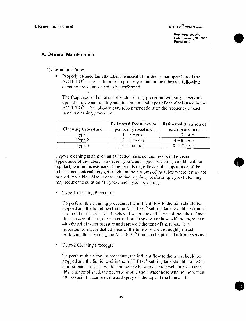
1 Lamellar Tubes
Properly cleaned lamella tubes are essential for the proper operation of the
ACTIFLO process In order to properly maintain the tubes the followingcleaning procedures need to be performed
The frequency and duration of each cleaning procedure will vary dependingupon the raw water quality and the amowlt and types of chemicals used in the
ACTIFLO The following are recommendations on the frequency of each
lamella cleaning procedure
Estimated frequency to Estimated duration of
Cleanin Procedure erform rocedurc each rocedure
Type1 1 3 veeks 1 3 hours
Type2 2 6 weeks 4 8 hours
Type3 3 6 rnonths 8 12 hours
Type1 cleaning is done on an as needed basis depending upon the visual
appearance of the tubes However Type2 and Type3 cleaning should be done
regularly within the estimated time periods regardless of the appearance of the
tubes since material tnay get caughl on the bottoms of the tubes where it may not
be readily visible Also please note that rebularly performing Type l cleaningmay reduce the duration of Type2 and Type3 cleaning
Type1 Cleanin Procedure
To perform this cleaning procedure the influent flow to the train should be
stopped and the liquid level in the ACTIFLO settling tank should be drained
to a point that there is 2 3 inches of water above the tops of the tubes Once
this is accomplished the operator should use a water hose with no more than
40 60 psi of water pressure and spray off the tops of the tubes It is
important to ensure that all areas of tle tube tops are thoroughly rinsed
Following this cleaning the ACTIFLO hain can be placed back into service
Iype2Cleanin Procedure
To perform this cleaning procedw the influent flow to the train should be
stopped and the liquid level in the ACTIFLO settling tank should drained to
a point that is at least two feet below the bottom of the lamella tubes Once
this is accomplished the operator should use a water hose with no more than
40 60 psi of water pressure and spray off the tops of the tubes It is
49
R
I Kruger Incorporated ACTIFLO OM Manual
Port Angeles WA
Date January 30 2009
Revision 0
important to ensure that all areas of the tube tops are thoroughly rinsed
Following this the operators should clean out the tube sections that have
noticeable amount of flocculated material still contained in them following the
initial tube top cleaning Cleaning the lower portion of the tubes can be
accomplished by attaching a long piece of PVC pipe 12 to 34 in diameterto the head ofa water hose with a valve and use this apparatus to force the
flocculated material out For areas under the collection troughs andor scraper
support bridge a short section of pipe can be used to prod the individual
tubes Following this cleaning the ACTIFLO train can be placed back into
service
Type3 Cleanin Procedure
To perform this cleaning procedure the operator should perfortn the Bi
weekly procedures first and then clean the entire underside of the lamella
tubes This can be accomplished by shutting off the influent flow to the train
draining the ACTIFLO settling tank to the level that would allow a person to
waik around the bottom of the settlng tank and then hose off the material
collected on the bottom of the tubes by using a water hose with no more than
40 60 psi of water pressure
After iinishing this cleaning procedure it is recommendelthat the operatorinspect the underside of the lamella tubes to ensure all tube packs are still in
the proper placement are supported correctly and are not dainaged
2 Mixers
ensure that the drive remains cleancheck the oil Ieve1 in the drive on a regular basis
change gear oil every six months or2500 hours wllichever occurs first refer
to Mixer OM for exact instructions
grease bearings when changing oil
keep motors clean and drytighten terminal connections assembly screws bolts and nuts as requiredcheck insulation resistance of motors periodicallykeep external airway on aircooled motors clear as obstructions will restrict air
passagerefer to the Mixer Section of the Mechanical Operation and Maintenance
Manual for further information
50
L Kruger Incorporated ACTIFLO OM Manual
Port Angeles WA
Date January 30 2009
Revision 0
3 Scrapers
ensure that the drive remains clean
inspect oil level in the variable speed reducer every weekinspect all reducers every ten years or as indicated by gearbox manufactureroverhaul as requiredkeep motors clean and drytighten terninal connections assembly screws bolts and nuts as requiredcheck insulation resistance of motors periodicallykeep external airway on aircooled motors clear as obstructions will restrict air
passage refer to the scraper suppliers Operation and Maintenance Manual for
further information
4 Sand Pumps
refer to the Pump Section of the Mechanicaf Operation Maintenance Manual
for further information
ensure that the drive remains cleangland leakage should be checked periodically to ensure that adequatelubrication water is being provided to the sealtake oil sample every month and change when necessary
grease bearings monthly at a minimum
keep motors clean and drytighten tenninal connections assembly screws bolts and nuts as requiredcheck insulation resistance of motors periodicallykeep external airway on aircooed motors clear as obstructions will restrict air
passage
refer to the pump suppliers Parts List and Operating Instructions for further
information
5 Hydrocyciones
inspect cyclone on a monthly basismaintain smooth surfaces on the interior of the cyclonereplace parts when interior surfaces become worn or uneven
reptace apex tip when wear exceeds 18check cone for wear while replacing apex tip to make sure that internal
surfaces are smooth and a lip does not occtr
refer to the hydrocyclone section of the Mechanical Operation Maintenance
Mamal for further information
Sl

L Kruger Incorporated ACTIFLO 08M Manual
Port Angeles WA
Date January 30 2009
Revision 0
B Intermittent Use Procedures
The purpose of this section is to provide information on the proper proceduresrequired when the ACTIFLO process is operated intermittently The ACTIFLOprocess has the unique ability to operate under repeated start and stop operationswithout effecting process performance or the equipment supplied with it This type of
operation is typical for the ACTIFLO process and provides the ability to
successfully treat events within 10 15 minutes of system startup The ACTIFLOsystem intermittent use procedures is described in the following pages as pertaining to
a single ACTIFLO train
1 Short Term StandBy Mode Wet Storage
StandBy Mode is defined as a shutdown where sand and water are retained in the
ACTIFLO system for purposes of keeping the system active and ready for an
event Nearly all ACTIFLO instalations use the wet storage standby mode
during offline conditions This method is recommended by Kruger in lieu of drysystem storage since it allows for fast system startup allows for all mechanical
equipment to be exercised under full loadbiweekly and does not require sand
removal from the system
The StandBy Mode consists of two parts
Flushing the system with clean chlorinated water
Kruger recommends maintaining a small 12 mgL CI residual in the processtanls fo prevent biological growth and provide added odor control Several
options exist for system maintenance following a shut down The system can
be flushed continuously with either a small flow of potable water or
chlorinated secondary effluentreuse water An intermittent flush may be on
option as well as long as a CI residual is maintained in between flushes
Iffieezing conditions are not expected the system can be drained down to a
level just above the lamella tubes A flush with potable water or chlorinated
secondary effluent may not be required if septic conditions or odor is not an
issue Minimal sand wiI be lost when the system is drained mainly in the
area directly around the drains
Biweekly exercisinb of the mechanical equipment
It is recommended that the equipment be exercised every 14 days for 30
minutes This keeps the gears and bearings freshly lubricated with oil and
grease and provides for onger equipment life The microsand that is
inventoried in the system will be unaCfected and will remain inventoried in the
52
I Kruger Incorporated ACTIFLO 08M Manual
Port Angeles WA
Date January 30 2009
Revision 0
bottom of the process tanks During equipment exercising and system startupthe microsand will be readilyresuspended
2 Long Term Shutdown and Freeze Protection
If the ACTIFLO system will be out of service for periods longer than two
months Kruger recommends either of the following methods
1 Continuous cycle of a small flow of potable water treated secondary effluent
or nonpotable vater through the system This will allow for periodicexercising of the equipment and will control any odor or growth issues that
may arise
2 Complete drain of the tanks f desired all sand can be removed from the
system by bypassing the hydrocyclones and sending the sand pump dischargeto drain or a hopper Please keep in mind that the cost of sand is minimal on a
per ton basis
Freeze protection requirements vary by location Various methods are employedat existing installations Local site conditions operation frequency and
economics need to be analyzed in order to determine the best method of freeze
protection
A method of freeze protection which is common for ACTIFLO systems located
at existing wastewater plants is to continuously flow a portion of treated
secondary eFfluent troubh the system For remote site not located at the W WTPtreated reuse or potable water can be used as the flush
Another method of freeze protection that may be more benefcially in extreme
cold climates especially durinb the time period when the system is not eYpectedto run is to completely drain the system and store the equipment during the
winter months according to long tenn equipment storage instructions Prior to
draining the system the microsand can be easily removed from the system bysimply bypassing the hydrocyclones and sending it to the existing sewer system or
trash hoppec
3 Instrumentation Maintenancc
pH Meters Steps need to be taken to ensure that the pH probes are not
allowed to dry out Ihe plI meters supplied are the immersion or insertion
type so as lonb as the water surface elevation remains above the pH probesthis will not be an issue If the pII probes are to remain dry for any period of
time they should be placed in a container with distilled water For
53

I Kruger Incorporated ACTIFLO OM Manual
Port Angeles WA
Date January 30 2009
Revision 0
recommendations on proper long term and shortterm storage of the pHprobes please reference the manufacturersinstrument manual
Turbidity Meters The turbidity meters supplied are also the immersion or
insertion type It is recommended that each turbidity meter both influent and
effluent be cleaned and wiped down at the beginning of each shutdown
period This will help to prevent any type of biological growth or buildup on
the sensor Longterm storage of these instruments shall be in accordance
with the manufacturersrecommendations as stated in the instrument manual
4 Chemical Feed Maintenance
All chemical feed equipment should be flushed with water if it is not anticipatedthe system will be used again in the next few days This is easily accomplished on
all Kruger supplied chemical feed pump skids since they are supplied with a flush
water connection and each piup has a dedicated calibration column
It is a good procedure to operate all chemical feed equipment during the bi
weekly exercise If a dry polymer systen is used it is suggested that water is run
through the system and punps as opposed to polyner This will prevent the need
flushing and cleaning the polymer
54

R
I Kruger Incorporated ACTIFLO OM Manual
Port Angeles WA
Date January 30 2009
Revision 0
7 APPENDICES
5

I Kruger Incorporated ACTIFLO OM Manual
Port Angeles WA
Date January 30 2009
Revision 0
A ACTIFLO Process Controls Description
s

o
I Kruger InC TELEPHONE 9196778310
401 Harrison Oaks Blvd FACSIMILE 9196770082
Ste 100
Cary NC 27513
ACTIFLO Process Controls DescriptionPort Angeles WA
The following descriptions will describe a Standard ACTIFLO train operation consisting of standard
instrumentation coagulation injection and maturation mixers a sandsludge scraper and microsand
recirculation pumps This document describes the operation instruinentation and equipment required fora single Standard ACTIFLO Train Additional trains may be added requiring additional
instrumentation and equipment but operation would be consistent to this description
Coagulant is added to the influent water through static induction or inechanical mixing prior to enteringthe coagulation tank The coagulated water then enters the coagulation tank Coagulant destabilizes the
suspended solids and colloidal matter in the influent stream Efficient inixing is provided in the
coagulation tank to thoroughly disperse the coagulant over a hydraulic retention time of approximatelytwo minutes The destabilized particles collide and begin early stage floc fonnation
The coagulated water then flows over a weir into the injection tank where flocculent aid polyiner and
microsand are added to initiate floc formation Here the combination of flash mixing and a hydraulicretention time of approximately two minutes allow for thorough incorporation of microsand and
polymer into the coagulated water The combination of microsand and polymer serve asaseed for
floc formation and development in the next process step
ACTIFLO treatment continues as water passes through the underflow passage from the injection tank
into the maturation tank Although chemical floc formation actually begins with the addition of polymerand microsand in the injection tank the majority of ballasted floc formation occurs during the
maturation process step Gentle mixing and increased hydraulic retention time of appreximately six
minutes provide ideal conditions for the formation of polymer bridges between the nlicrosand and the
destabilized suspended solids The large effective surface area of the microsand provides enhanced
opportunity for polymer bridging and enmeshment of microsand and floc already in suspension
The fully formed ballasted floc leave the maturation tank and enter the settling tank Here the ballasted
flocs rapidly settle and are further removed from the treated water via lamella settling Here laminar
upflow through the lamellasettling zone provides rapid and effective removal of the microsandsludgefloc Clarified water exits the ACTIFLO system via a series of collection troughs or weirs for
subsequent filtration disinfecting and delivery to the distribution network
The ballasted floc sandsludge inixture is collected at the bottom of the settling tank moved to the center
collection pit via a scraper mechanism and withdrawn using a rubberlined centrifugal slurry pump The
sandsludge inixture is then pumped to the hydrocyclone for separation Energy from pumping is
effectively converted to centrifugal forces within the body of the hydrocyclone causing the sludge to be
separated from the higher density microsand Once separated the microsand is concentrated and
January 2009 jVELAWATER
Solutions S Txcnnologes
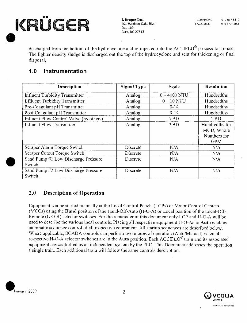
I Kruger Inc TELEPHONE 9196778310
401 Harrison Oaks Blvd FACSIMILE 9196770082
Ste 100
Cary NC 27513
discharged from the bottom of the hydrocyclone andreinjected into the ACTIFLO process for reuse
The lighter density sludge is discharged out the top of the hydrocyclone and sent for thickening or final
disposal
10 Instrumentation
Description Signal Type Scale Resolution
Influent Turbidity Transmitter Analog 0 4000 NTU Hundredths
Effluent Turbidity Transmitter Analog 0 10 NTU Hundredths
PreCoagulant pH Transmitter Analog 014 Hundredths
PostCoagulant pH Transmitter Analog 014 Hundredths
Influent Flow Control Valve by others Analog TBD TBD
Influent Flow Transmitter Analog TBD Hundredths for
MGD Whole
Numbers for
GPM
Scraper Alarm Tor ue Switch Discrete NA NA
Scraper Cutout Torque Switch Discrete NA NA
Sand Pump 1 Low Discharge Pressure Discrete NA NA
Switch
Sand Pump 2 Low Discharge Pressure Discrete NA NA
Switch
20 Description of Opea
Equipment can be started manually at the Local Control Panels LCPs or Motor Control Centers
MCCs using the Hand position of the HandOffAutoHOA or Local position of the LocalOff
RemoteLOR selector switches For the remainder of this document only LCP and HOA will be
used to describe the various local controls Placing all respective equipmentHOAs in Auto enables
automatic sequence control of all respective equipment All startup sequences are described below
Where applicable SCADA controls can perform two modes of operation AutoManual when all
respective HOAselector switches are in the Auto position Each ACTIFLO train and its associated
equipment are controlled as an independent system by the PLC This Docuinent addresses the operationa single train Each additional train will follow the same controls description
January 2009 2
VEOIiAWATER
Soluions Tehnalopies

I Kruger Inc TELEPHONE 9196778310
401 Harrison OakS Blvd FACSIMILE 9196770082
Ste 100
Cary NC 27513
Should a maturation or injection tank mixer fail at any time during operation or startup the PLC willissue an alarm and will initiate the Shutdown Sequence No system shutdown is associated with a
coagulation mixer failure but the PLC will issue an alarm
Should the scraper fail at any time during operation or startup the PLC will issue an alarm and willinitiate the Shutdown Sequence Since the scraper will not be operational the Shutdown Sequence willconsist of the sand recirculation pumps running for the durations as described in section 40 Shutdown
Should a lead sand pump fail the PLC will issue an alarm and sequentially initiate operation of a lagpump if available If all sand pumps fail the PLC will initiate an immediate shutdown of all
equipment
If the maturation tank inixer injection tank mixer or scraper is reinoved from Auto at the LCP while thePLC is in automatic control of the ACTIFLO system the PLC will initiate the Shutdown Sequence As
long as one sand pump is in Auto at the LCP and has not failed the PLC will not initiate the shutdown
sequence though failure alarms may exist on other sand pumps
Manual control of the ACTIFLO process can be assumed by switching the HOA selector switches at
the LCPs to the Hand position for each piece of equipment
30 StartUp
Permissives to initiate the automatic start sequence are
HOA selector switches for all mixers scraper and at least one sand pump are in Auto
Mixers scraper ad at least one sand pump do not have existing fail alanns
If all permissives are present and no equipment alarms exist the OIT will display Train Ready Tlle
Startup Sequence can be initiated via the OIT
Note To prevent damage to the equipment the Train should have water in the tanks above the
mixer impeller elevations prior to Startup In addition the water level in the settling tank should
be greater than the NPSHR for the microsand recirculation pump
To start the train when Train Ready is displayed on the OIT the operator selects Train Start
The system displays Train Starting at the OIT The system then automatically cycles through the stepslisted below
January 2009 3t lEOli
WATER
sotna a rzaowe

e
I Kruger Inc TELEPHONE 9196778310
401 Harrison Oaks Blvd FACSIMILE 9196770082
Ste 100
Cary NC 27513
1 Lead Sand Pump Recirculation System Startup Initiated
a Start Lead Sand Pumpb If the Duty Pump Running signal not seen within 5 seconds issue alarm Sand Pump
Fail To Start
c If the Duty Pump Motor Overload has tripped issue alarm Sand Pump Fault
d If the Duty Pump Discharge Pressure is not within acceptable limits within 30 seconds
issue alarm Sand Pump Low Pressure
If a failure oceurs the lead pump will be locked out in the PLC and the system will shut down This is
due to the fact that there is one common backup pump but no automated valves to allow for the backuppump to serve either train
2 Lead Sand Recirculation Pump successfully started
a Delay 30 seconds
b Start the Settling Tank Scraperc If the Scraper Running signal is not seen within 5 seconds issue alarm Scraper Fail To
Start
d If the Scraper Variable Frequency Drive VFD has tripped issue alann Scraper Fault
If a Scraper failure occurs initiate a Shutdown Sequence
3 Scraper successfully started
a Delay 5 seconds
b Start the Maturation Injection and Coagulation tank mixers These mixer starts are
respectively staggered by 5 seconds
c If the Maturation Tank Mixer Running signal is not seen within 5 seconds issue alarm
Maturation Tank Mixer Fail To Start
d If the Maturation Tank Mixer VFD has tripped issue alann Maturation Tank Mixer
Fault
e If the Injection Tank Mixer Running signal is not seen within 5 seconds issue alarm
Injection Tank Mixer Fail To Start
f If the Injection Tank Mixer Motor Overload has tripped issue alarm Injection Tank
Mixer Fault
g If the Coagulation Tank Mixer Running signal is not seen within 5 seconds issue alann
Coagulation Tank Mixer Fail To Start
h If the Coagulation Tank Mixer Motor Overload has tripped issue alarm CoagulationTank Mixer Fault
Januar 2009Y 4VE7llAWATER
sinos s redoiogez

B
I KIU921 InC TELEPHONE 9196778310
401 Harrison Oaks Blvd FACSIMILE 9196770082
Ste 100
Cary NC Z7513
If a Maturation or Injection Tank Mixer failure occurs initiate a Shutdown Sequence No systemshutdown is associated with a Coagulation Mixer failure
4 All Tank Mixers successfully started
a Delay 5 seconds
b Start the Chemical Feed Pumpsb If the Duty Polymer Feed Pump Running signal is not seen within 5 seconds issue alarm
Polymer Pump Fail To Start
c If the Duty Coagulant Feed Pump Running signal is not seen within 5 seconds issue
alarm Coagulant Pump Fail To Start
d If the Duty Caustic Feed Pump Running signal is not seen within 5 seconds issue alann
Caustic Pump Fail To Start
e If the Duty Sulfuric Acid Feed Puinp Running signal is not seen within 5 seconds issue
alann Acid Pump Fail To Start
If any Duty Chemical Feed Pump is taken out of the AUTO position at the LCP while in operation the
standby pump shall be initiated The duty pump will not be locked out so when the pump is placed back
into the AUTO position it will resume operation Duty chemical feed pump alternation is manual onlyat the Operator interface panel
5 Chemical Feed Pumps successfully started
a Open the Influent Water Valve
The Operator will have the option to terminate startup at the OIT at any point in the sequence byselecting Train Stop If the startup fails at any point the sequence will initiate a train shutdown The
operator can correct the failure and then resuine the startup sequence from the current step
40 Shutdown
When in automatic the operator inay iinplement the Shutdown Sequence at any time at the OIT Duringshutdown the OIT will display Train Stopping
Train Started the operator selects Train Stop and the system displays Train Stopping at the OIT
The system then automatically cycles through the steps listed below
l Influent Valve closes
2 Shut down the Chemical Feed Pumps
January 2009 5o E l711
WATER
Solutiois ltcnolgies

I KIU9Ci I11C TELEPHONE 9196778310
401 Harrison Oaks Blvd FACSIMILE 9196770082
Ste 100
Cary NC 27513
3 Shut down the Coagulation Injection and Maturation Tank Mixers
4 AfteraOperator Adjustable delay 1030 minutes shut down the Settling Tank Scraper5 After 5 minutes shut down the LeadDuty Sand Pump
NOTE This delay allows purging of sand and sludge contained in the settling tank and
piping andredeposits it back into the injection tank
The Operator can initiate the Train Auto startup sequence at the OIT at any point during the shutdown
sequence by selecting Train Start This initiates the immediate Startup Sequence of equipinent from
the current sequence step
50 Individual Equipment Operation
Coagulation Tank Mixer
Each coagulation tank is equipped with a constant speed mixer assembly consisting of a constant speedmotor gearbox output sllaft and hydrofoil impeller
Mixer operation is controlled through an HOA selector switch In Auto the mixer operation is
controlled by the PLC and will come on after the start sequence is initiated at the OIT and the duty sand
pump and scraper are verified to be running Operating statuses displayed at the OIT for the mixer are
Ready Running and Failure AReady status indicates that theHOA is in Auto no failures
exist and the mixer is available for operation from the OIT should a start sequence be initiated A
Running status indicates that the PLC has verified that a Run Signal is being received from the motor
starter AFailure status or condition occurs when the ACTIFLO system is in operation and the PLC
is unable to confirm a Run Signal or an overload condition exists IfaFailure condition occurs the
PLC will issue an alarm No shufdowns are associated with this mixer
Injection Tank Mixer
Each injection tank is equipped with a constant speed inixer assembly consisting of a constant speedmotor gearbox output shaft and hydrofoil impeller
Mixer operation is controlled through an HOA selector switch In Auto the mixer operation is
controlled by the PLC and will come on after the start sequence is initiated at the OIT and the duty sand
pump and scraper are verified to be running Operating statuses displayed at the OIT for the inixer are
Ready Running and Failure AReady status indicates that the HOA is in Auto no failuresexist and the mixer is available for operation from the OIT should a start sequence be initiated A
Running status indicates that the PLC has verified that a Run Signal is being received from the motor
starter AFailure status or condition occurs when the ACTIFLO system is in operation and the PLC
anua 2009y 6e VEOIIA
WATER
soico s rzdoRe

I KIU9e I11C TELEPHONE 9196778310
401 Harrison Oaks Blvd FACSIMILE 9196770082
Ste 100
Cary NC 27513
is unable to confirm a Run Signal or an overload condition exists IfaFailure condition occurs the
PLC will issue an alarni and initiate the shutdown sequence Conditions that would cause the PLC to
initiate the shutdown sequence are
Loss of Motor Power which can result froin
o Loss of Electrical Service
o Motor Overload Device Trippedo Motor Disconnect Switch Off
HOA Selector Switch Reinoved From Auto Position
Maturation Tank Mixer
Each inaturation tank is equipped with a variable speed mixer assembly consisting of an inverter dutyrated motor gearbox output shaft and hydrofoil impeller
The operator can chane mixer speed at the OIT This only affects the speed when theHOAis in the
Auto position Generally the optiinum mixer speed is determined during start up and commissioningand generally it does not require to be changed during normal process operations When under Hand
control the mixer speed can be controlled by the operator at the LCP
Mixer operation is controlled through anHOA selector switch In Auto the mixer operation is
controlled by the PLC and will come on after the start sequence is initiated at the OIT and the duty sand
pump and scraper are verified to be running Operating statuses displayed at the OIT for the mixer are
Ready Running and Failure AReady status indicates that theHOAis in Auto no failures
exist and the mixer is available for operation from the OIT should a start sequence be initiated A
Running status indicates that the PLC has verified that a Run Signal is being received from the VFD
AFailure status or condition occurs when the ACTIFLO system is in operation and the PLC is
unable to confirm a Run Signal or a VFD fault condition exists IfaFailure condition occurs the
PLC will issue an alarm and initiate the shutdown sequence
Note The operator adjustable setpoint for the maturation tanlc mixer speed is 70 to 100 speed42 to 60 Hz
Conditions that would cause the PLC to initiate the shutdown sequence are
Loss of Motor Power which can result from
o Loss of Electrical Service
o VFD Fault
o Motor Disconnect Switch Off
HOA Selector Switch Removed From Auto Position
January 2009 7EOLwaTCR
ss TzoREF

e
I Kruger Inc TELEPHONE 9196778310
401 Harrison Oaks Blvd FACSIMILE 9196770082
Ste 100
Cary NC 27513
Settling Tank Scraper
The scraper drive mechanism consists of a an inverter duty motor a gearbox a vertical rotating shafttwo truss rake arms with ralce blades and a center pit scraper During automatic startup via the PLC the
scraper will come on after the start sequence is initiated and 5 seconds after the duty sand pump isverified to be running With the HOAin Auto the scraper speed can be adjusted manually at the OITThis only affects the speei when theHOAis in the Auto position Generally the optimum scraperspeed is determined during start up and commissioning and generally it does not require to be changedduring normal process operations When under Hand control the scraper speed can be controlled by the
operator at the LCP
Note The operator adjustable setpoint for the scraper speed is 75 to 100 speed 45 to 60 Hz
The scraper drive is equipped with torque overload protection When the torque exceeds the continuous
operating torque the PLC will issue a warning alarm The torque monitoring device is also interlockedwith the scraper at the LCP and when the torque exceeds the maximuin operating cutout torque the
scraper will shutdown the PLC will issue a second alarm scraper fail and initiate the ACTIFLOshutdown sequence These alarm settings are field adjustable at the device however modification ofthese settings without consulting Kruger is not recommended and may void any warranty associatedwith the equipment
Scraper operation is controlled through an HOA selector switch In Auto the scraper operation iscontrolled by the PLC and will come on after the start sequence is initiated at the OIT and the duty sand
pump is verified to be running Operating statuses displayed at the OIT for the scraper are ReadyRunning and Failure AReady status indicates that the H0A is in Auto no failures zxist andthe scraper is available for operation from the OIT should a start sequence be initiated A Runningstatus indicates that the PLC has verified that a Run Signal is being received from the VFD AFailurestatus or condition occurs when the ACTIFLO system is in operation and the PLC is unable to confirma Run Signal or a VFD fault condition exists IfaFailure condition occurs the PLC will issue an
alarm and initiate the shutdown sequence
Conditions that would cause the PLC to initiate the shutdown sequence are
Loss of Motor Power which can result from
o Loss of Electrical Service
o VFD Fault
o Motor Disconnect Switch Off
Torque load equal or exceeding the Cutout Torque Limit settingHOA Selector Switch Removed From Auto Position
anuary 2009 g
VE7lIAWATER
Solutiohs Tefinoogfes

I Kruger Inc TELEPHONE 9196778310
401 Harrison Oaks Blvd FACSIMILE 9196770082
Ste 100
Cary NC 27513
Sand Recirculation Circuits
There are a total of 3 sand pumps provided Each train has one duty pump and they will share a
common standby pump The sand recirculation pumps are centrifugal rubber lined slurry pumps with V
belt drives The impeller and the inside of the housing shell are rubberlined or hard metal both of
which are resistant to the microsand abrasion The control scheme for microsand recirculation pump
operation is described below
One Duty One StandbyIn this configuration a duty pump plus a standby pump are supplied for each ACTIFLO process
train Only the duty pump runs during train operation The standby pump is changed to the dutyposition either if a duty pump failure occurs or the operator manually alternates the pumps at the
OIT Duty and standby pumps are alternated as described below
The lead sand pump will be altenlated by the PLC according to one of the three methods below
1 End of cycle The lead pump will be automatically alternated at the end of cycleShutdown Sequence to the next sequentially available pump Note This is the method
of pump alternation preferred by Kruger2 Manual alternation The operator selects the duty pump manually at the OIT
Note This method provides the ability for the Operator to switch sand pumps
without shutting down the system but does not purge the pump discharge lines as
recommended by Kruger
In the event of a dutylead pump failure the PLC will issue an alarm and the standby pump will be
alternated to dutylead status However the train will shut down upon failure of the lead pump The
pump circuits are supplied with manual valves so it will be the operators responsibility to detennine
the correct valve positions If both the duty and standby pump have failed the ACTIFLO PLC will
initiate an immediate system shutdown
Sand pump operation is controlled through an HOA selector switch In Auto the sand pump operationis controlled by the PLC and will come on after the start sequence is initiated at the OIT Operatingstatuses displayed at the OIT for the sand pump are Reaciy Running and FailureAReadystatus indicates that theHOA is in Auto no failures exist and the sand pump is available for operationfrom the OIT should a start sequence be initiatedARunning status indicates that the PLC has verified
that a Run Signal is being received from the motor starter AFailure status or condition occurs when
the ACTIFLO system is in operation and the PLC is unable to confirm a Run Signal or an overload
condition exists IfaFailure condition occurs the PLC will issue an alarm and initiate the shutdown
sequence
January 2009 9fEOIAWATER
Solutions lcnnooges

sI Kruger Inc TELEPHONE 9196778310
401 Harrison Oaks Blvd FACSIMILE 99677oos2
Ste 100
Cary NC 27513
Conditions that would cause the PLC to initiate the shutdown sequence are
Loss of Motor Power which can result from
o Loss of Electrical Service
o Motor Overload Device Trippedo Motor Disconnect Switch Off
Low Discharge Pressure At The PumpHOA Selector Switch Removed From Auto Position
The PLC will not attempt to bring any pump into service that is in a fail condition until the operatorresets the alarm If all pumps in a train enter into a fail condition the PLC will initiate an immediate
ACTIFLO shutdown
Each sand pump has a pressure switch installed on the discharge line This switch is input to the PLCwhich will stop the pump after a 30 second delay if the pressure is not greater than the preset ininimum
pressure field adjustable at the device If the pump is shut down by low pressure the control systemwill automatically shut down the ACTIFLO train If the pump is manually started in Hand at the LCP a
lowpressure condition will not shut down the pump and will not annunciate the alarm
Most alarms have associated time delays to allow the PLC todebounce the signal from the respectivealarm signal thus eliminating inadvertent shutdowns Only motor overloads or VFD fault indications do
not have associated time delays
60 Chemical Metering Pump Calculations and Control Descriptions
The ACTIFLO PLC calculates the chemical feed rates and controls the chemical metering purnps usingthe following procedure The chemical feed rate is based on
1 The influent raw water flow rate
2 The chemical dose
3 The physical properties of the chemicals
4 The capacity and settings of the metering pump5 The raw water turbidity
The influent raw water flow rate is obtained through tlle raw water flow meter which sends a signal to
the PLC
The influent raw water turbidity rate is obtained through the raw water turbidimeter and the coagulatedwater pH is obtained through the coagulated water pH meter
January 2009 10o VEOl6A
WAjER
SolYios ftcimuloges
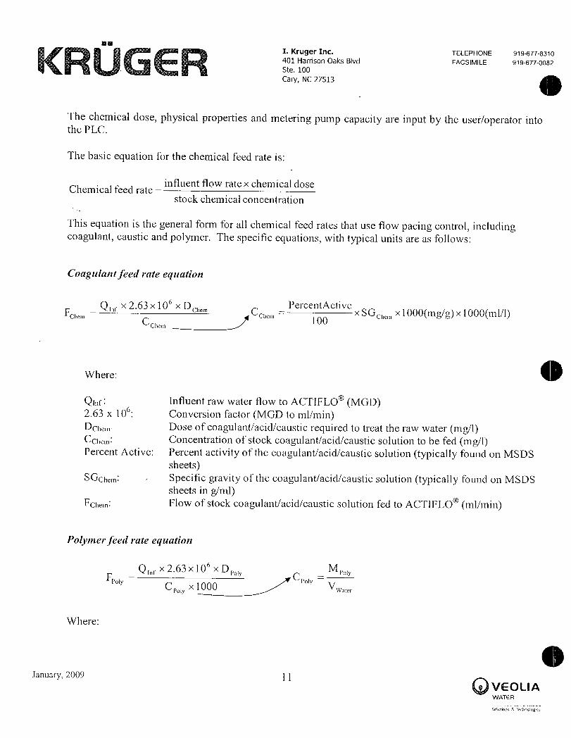
I Kruger Inc TELEPHONE 9196778310
401 Harrison Oaks Blvd FACSIMILE 9196770082Ste 100
Cary NC 27513
The chemical dose physical properties and metering pump capacity are input by the useroperator intothe PLC
The basic equation for the chemical feed rate is
Chemical feed rateinfluent flow rate x chemical dose
stock chemical concentration
This equation is the general form for all chemical feed rates that use flow pacing control includingcoagulant caustic and polymer The specific equations with typical units are as follows
Coagulant feed rate equation
Q x 263 x 10 x Dci1e11 PercentActiveFeie1n Cci1e11 x SGeite1n x 1000ing x 1000nl1
CChem
1 O
Where
Qif Influent raw water flow to ACTIFLO MGD263 x 10 Conversion factor MGD to tnlminDcie Dose ofcoagulantacidcaustic required to treat The raw water mg1Ccie Concentration of stock coagulantacidcaustic solution to be fed mgIPercent Active Percent activity of the coagulantacidcaustic solution typically found on MSDS
sheetsSGcte Specific gravity of the coagulantacidcaustic solution typically found on MSDS
sheets ingmlFcien Flow of stock coagulantacidcaustic solution fed to ACTIFLO inlmin
Polynerfeed rate eyuation
Q 1iex 263 x 1 O x D M
FYC x 1000
CyV
i oi wae
Where
January 2009 1 1
QLIAvaTE
olutions Terinoiopes

I Kruger Inc TELEPHONE 9196778310
401 Harrison Oaks Bivd FACSIMILE 9196770082
Ste 100
Cary NC 27513
Q Influent raw water flow to ACTIFLO MGD263 x 10 Conversion factor MGD to mlmin
Dp Dose of polymer required to treat raw water mg1
CP Concentration of stock polymer solution to be fed g1
M Mass of dry polymer used to prepare solution guwac Volume of water used to prepare polnner solution I
F Flow of stock polymer solution fed to ACTIFLO mlmin
Flow Pacing Control
The way the PLC uses these calculations to determine the chemical inetering pump output is
1 The chemical feed rate equations are programmed into the PLC by a Kruger instruinentation and
controls engineer2 The useroperator inputs the chemical dose physical properties and maximum chemical
metering puinp capacity at the OIT on the ACTIFLO control panel The PLC calculates the
specific chemical feed rate based on the useroperator inputs and the influent raw water flow to
the train
3 The calculated feed rate is then converted by the PLC into a percent speed based on the
maximuin capacity of the metering puinps This signal is then sent to the metering pump
Turbidity Pacing Control
Turbidity pacing control is in addition to the flow pacing control described above The turbidity pacingcontrol screen has a matrix that covers 5 different turbidity levels Each level has operator adjustabiesetpoints for coagulant polymer and the corresponding turbidity threshold For example level one may
have a coagulant dosage of 20 mgL and a polyiner dosage of 01 mgL with a threshold value of 20
NTU If the raw water NTU signal is greater than or equal to 20 NTU and less than level two the
coagulant and polymer dosages will be 20 and 01 mgL respectively If the raw water NTU is greaterthan the level two threshold value the con dosages shall be set by the operator setpoints for
level two
Flow Pacing Control Example
Assume
a You have a 0 to 40 MGD raw water flow meter
January 2009 j 2VEOIfAWATER
soia sraoFEs

e
I Kruger Inc TELEPHONE 9196778310
401 Harrison Oaks Blvd FACSIMIE si960082
Ste 100
Cary NC 27513
b You have an ACTIFLO train running at 20 MGD
c The specific gravity of ferric chloride is 14
d The percent activity of the ferric chloride is 43
e The dose required is 15 mg1The maximum capacity ofthe metering pump is 5000 mlmin
The PLC calculation process is
a A 50 signal is sent to the PLC from the raw water flow meter
b The PLC converts this value to 20 MGD based on the predefined scaling of the raw water
flow meter 0 to 40 MGD 0 MGD 0 and 40 MGD 100c This 20 MGD value is input into the programmed chemical dosing equation in the PLC
d The programmed equation then calculates the ferric chloride feed rate required
PercentActive
Ca100
X SG x 1000mg g x 1000ml 1
CCa100
X 14ginl x 1000mgg x 1000ml1
C 602 000 m 1Coag
Q 1iex 263 x l O x D
co
FcoCco
20 MGD x 263 x 10 x 15 mg1F
602000 mg1
Fcoab 13106mlmin
e With the ferric chloride flow rate calculated by the PLC the PLC then calculates the pump
speed percentage based on the maximum pump capacity input by the useroperator
January 2009 13o VEOIIA
YtdAE R
seino 1zdomgEs

I Kruger Inc TELEPHONE 9196778310
401 Harrison Oaks Blvd FACSIMILE 9196770082
Ste 100
Cary NC 27513
Coagulant Pump SpeedFca
x 100PumpMax
Coagulant Pump Speed 13106mlminX 100
5000 mlmin
Coagulant Pump Speed 262
Once the pump speed is calculated the PLC sends a signal to the metering pump motor to
operate at that speed
January 2009 14ELAWATER
sisraoogts

KFUGER Actiflo OML Kruger Inc
SECTION 3
Mixers
CoagulationInjection Mixer
Maturation Mixer
Project 42470003 Port Angeles wA OVEOIAActiflo OM
warER
January 2009Solutions Technalogies
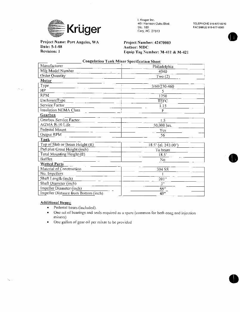
I Kruger Inc
401 Harrison Oaks Blvd TELEPHONE 9196778310
sw Ste 100 FACSIMILE 919
p Cary NC 27513
Project Name Port Angeles WA Project Number 42470003Date5108 Author MDCRevision 1 Equip Tag Number M411 M421
Coa ulation Tank Mixer S ecification Sheet
Manufacturer Philadel hia
Mig Model Number 4040Order Quantity Two 2Motor
T e 360230460HP 5
RPM 1750
EnclosureTy e IEFC
Service Factor 115
nsulation NEMA Class p
Gearbox
Gearbox Service actor I5
AGMA B10 Life 50000 hrs
Pedestal Mount Yes
Out ut RPM 56
Tank
To of Slab or Beam Height ft 185 el 24300Pad lus Grout Hei ht inch To beam
Total Mountin Height ft gs
Baffles No
Wetted Parts
Material of Construction 304 SS
No Im ellers i
Shaft Length inch 201
Shaft Diameter inchm eller Diameter inch 55
Im eller Distance from Bottoir inch 43
Additional Items
Pedestal bases includedOne set of bearings and seals required as a spare common for both coag and injectionmixersOne gallon of gear oil per mixer to be provided
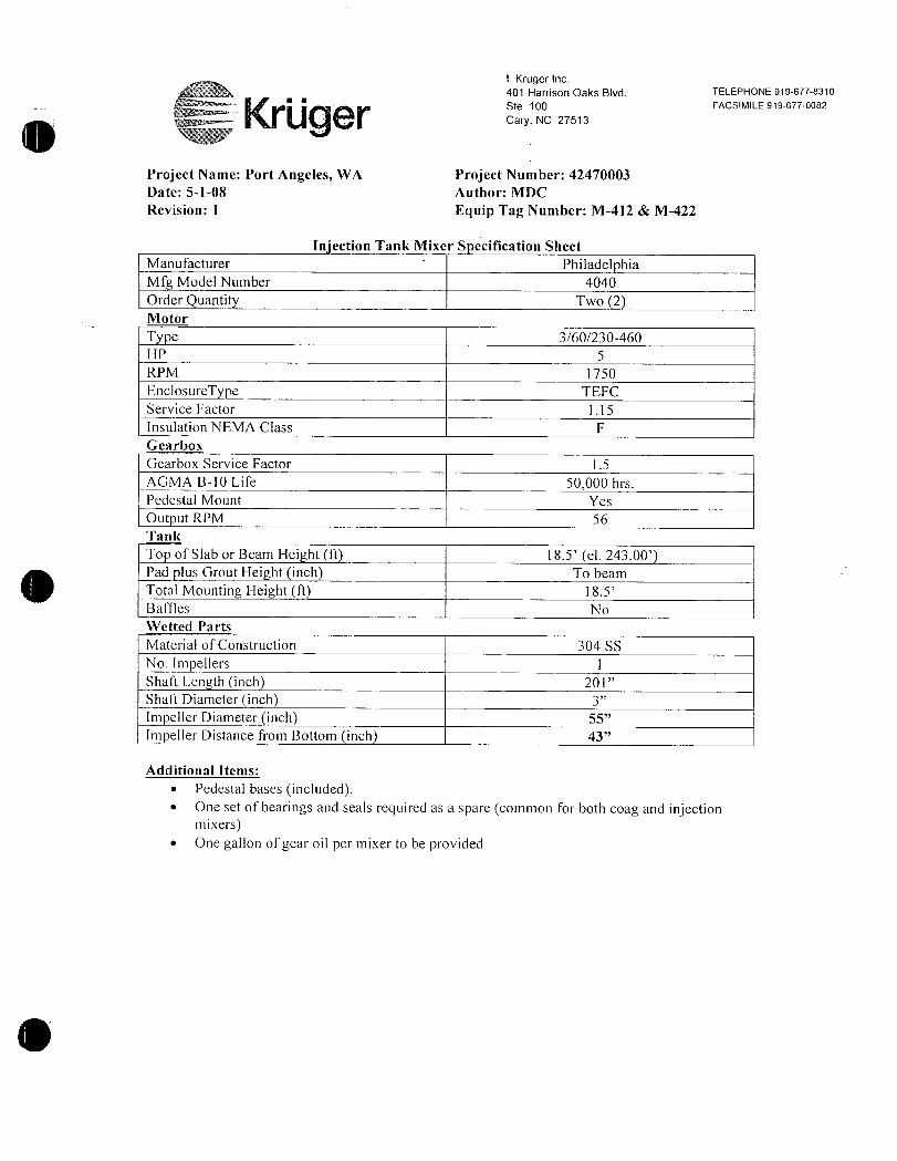
I Kruger Inc
401 Harrison Oaks Blvd TELEPHONE 9196778310
Ste 100 FACSIMILE 9196770082az r Cary NC 27513
Project Name Port Angeles WA Project Number 42470003
Date5108 Author MDC
Revision 1 Equip Tag Numbcr M412 M422
Inection Tank Mixer S ecification Sheet
Manufacturer Philadel hia
Mfg Model Number 4040
Order Quantity Two 2Motor
T e 360230460
HP 5
RPM 1750
EnclosureType TEFC
Service Factor 11 S
Insulation NEMA Class F
Gearbox
Gearbox Service Factor 15
AGMA B10 Life 50000 hrs
Pedestal Mount Yes
Output RPM 56
Tank
To of Slab or 3eam Hei ht ft 185 el 24300Pad plus Grout Height inch To beam
Total Mounting Height ft 185
Baffles No
Wetted Parts
Material of Construction 304 SS
No Impellers 1
Shaft Length inch 20l
Shaft Diameter inchIm eiler Diameter inch 55
Impeller Distance from Bottom inch 43
Additional Items
Pedestal bases includedOne set of bearings and seals required as a spare common for both coag and injectionmixersOne gallon of gear oil per mixer to be provided
INSTALLATION OPERATING AND
MAINTENANCE MANUAL
Project Name
Port Angeles WTP
Customer
i Kruger Inc
Customer PO No
27540
Equipment Tag No
Coagulation
PMSL Order No 42114
Serial No 08UDK01162
1221 East Main Street Palmyra PA 170789518
i j Phone 7178322800 Fax 7178321740
Q Philly OnCall Services18007331341
EMail phillyoncallaphilamixerscomwwwphilamixerscom
LtlT11VS
INSTALLATION OPERATING AND
MAINIENANCE MANUAL
Project Name
Port Angeles WTP
Customer
I Kruger Inc
Customer PO No
27540
Equipment Tag No
Injection
PMSL Order No 42114
Serial No 08UDK01182
1221 East Main Street Palmyra PA 170789518
0jjPhone 7178322800 Fax 7178321740
y rr Philly OnCall Services18007331341EMail phillyoncallaphilamixerscom
wwwphilamixerscomP
iS
s F
e

TABLE OF CONTENTS
Service
Parts
Maintenance
Rigid Coupling
Impeller
Motor
Flexible Coupling
Drawings

m
3 P1fiI111X
Service
PHILADELPHIAMIXINGSOLUTIONS TAB UniFirst 4040SM 2 SECTION Introduction
Current INTRODUCTION PAGE 00
Volume 1 ISSUED 30 SEP 98
REVISION 30 APR 00
This Service Manual covers Philadelphia UniFirst 4000 Series Mixer Drives a high qualitymixer drive designed in accordance with the Standards of the American Gear Manufactur
ers Association Certain precautions and procedures however must be observed in
handling installing and servicing the mixer drive and accessories
This manual contains general installation operating maintenance and troubleshootinginstructions for your mixing equipment Also special instructions applicable to specificmixer drives may be included Should questions arise that are not covered additional
information can be obtained by contacting your local representative or Customer Service
at Philadelphia Mixing Solutions Palmyra PA Telephone 717 8381341 FAX 717 832
1740email philamixers@philadelphiamixerscomNOTE
All inquiries must be accompanied by the following information which can be
obtained from the nameplate on the mixer drive Mixer
Drive Size and Type or Model PhiladelphiaMixing Solutions Order Number Serial
Number Orders
for renewal parts must include description and part number shown on
parts list in addition to the above information See Parts Section of this
manual for specific parts ordering procedure and order form Copyright0
Philadelphia Mixing Solutions Specifications subject to change without notice

ISM ZOOOPHILADELPHIAMIXINGSOLUTIONS TAB UniFirst 4040
SECTION SafetyCurrent SAFETY WARNING PAGE 200
Volume I mportant Safety Instructions ISSUED 15 SEP 98
REVISION 15 MAR 02
WARNING
In the installation operatiort and maintenance of gear drives SAFETY comes firstUse proper clothing tools and methods of handling to prevent serious accidentsThe safety precautions listed in this manual MUST be followed by all personnelworking on equipment otherwise serious injury may result
This manual lists a number of safety precautions Follow them and insist that those
working on this equipment do the same An accident is usually caused by neglect or
oversight
Adequate installation maintenance and safety instructions must be given by the user to
personnel directly responsible for the operation of the mixer drive and accessory equipment In addition the procedures set forth in the operating instructions must be carefullyfollowed
Guards alarms heaters and safety devices which may be furnished by Philadelphia MixingSolutions must be installed by the user
The user is also responsible for furnishing and installing any guards or other safety equipment needed to protect operating personnel as required by the Occupational Safety andHealth Administration OSHA Standards or other applicable safety regulations Thisequipment normally is not furnished by Philadelphia Mixing Solutions except when specifiedas part of the order In all cases however the user has the responsibility of complying with allapplicable safety regulations when installing the equipment
SAFETY PRECAUTIONS
TO AVOID SERIOUS BODILY INJURY OR POSSIBLE DEATHTHE FOLLOWING PRECAUTIONS MUST BE FOLLOWED
ONLY AUTHORIZED PERSONS MAY OPERATE THIS
Ii EQUIPMENTAdequate installation maintenance and safety
instructions must be given by the user to personnel directlyresponsible for the safe operation of the mixer or aerator and
accessory equipment In addition the procedures set forth in theService Instructions must be carefully followed Use qualified andskilled tradespersons to perform each work discipline when
installing inspecting or servicing this equipment All personnel mustbe required to remain a safe distance from rotating shafts couplingsimpellers clutches etc
Copyright0 Philadelphia Mixing Solutions Specificalions subject to change without notice
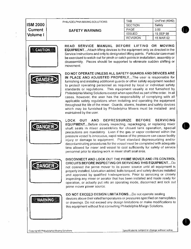
PHILADELPHIAMIXINGSOLUTIONS TAB UniFirst 4040ISM 2000 SECTION Safety
Current SAFETY WARNING PAGE 300
Volume I ISSUED 15 SEP 98
REVISION 15 MAR 02
READ SERVICE MANUAL BEFORE LIFTING OR MOVING
EQUIPMENTAttach lifting devices to the equipment only as directed in the
Service Instructions and only to designated lifting points Particular care must
be exercised to watch out for pinch or catch points in installation assembly or
disassembly Pieces should be supported to eliminate sudden shifting or
movement
DO NOT OPERATE UNLESS ALL SAFETY GUARDS AND DEVICES ARE
IN PLACE AND ADJUSTED PROPERLYThe user is responsible forr
furnishing and installing additional guards or other safety equipment neededv
to protect operating personnel as required by local or individual safetystandards or regulations This equipment usually is not furnished byPhiladelphia Mixing Solutions except when specified as part of the order In all
cases however the user has the responsibility of complying with all
applicable safety regulations when installing and operating the equipment
throughout the life of the mixer Guards alarms heaters and safety devices
which may be furnished by Philadelphia Mixers must be installed and
maintained by the user
LOCK OUT AND DEPRESSURIZE BEFORE SERVICING
EQUIPMEN7Before closely inspecting repackaging or replacing mixer
shaft seals in mixer assemblies for closed tank operation specialprecautions are mandatory Even if the gas or vapor contained within the
pressure vessel is innocuous rapid release of the pressure can cause bodily
injury or damage to equipment Plant standard depressurizing andor
decontaminating procedures for the vessel must be completed with adequatetime allowed for mixer and vessel to cool sufficiently for safety of service
personnei prior to starting work in mixer shaft seal area
DISCONNECT AND LOCK OUT THE PRIME MOVER AND ITS CONTROL
u CIRCUITS BEFORE INSPECTING OR SERVICING THIS EQUIPMENTDo
not connect the prime mover to its power source until all equipment isN
properly installed lubrication added bolts torqued and safety devices installed
and approved by qualified tradespersons Prior to servicing or closely
inspecting any mixer or aerator that has been installed and made ready for
operation or actually put into an operating mode disconnect and lock out
prime mover power source
DO NOT EXCEED DESIGN LIMITATIONSDo not operate sealingdevices above their rated temperatures or pressures specified on nameplatesor drawings Do not exceed any design limitations or make modifications to
this equipment without first consulting Philadelphia Mixign Solutions
Copyright0 Philadelphia Mixing Solutions Specifications subject to change without notice

PHILADELPHIAMIXINGSOLUTIONS TAB UniFirst 4040M 20 SECTION Service
Current SERVICE INSTRUCTIONS PAGE a00
Volume I GeneralissuE 15 SEP 98
REVISION 15 MAR 02
1 Any apparent or suspected damage sustained by equipment manufactured or fur
nished by Philadelphia Mixers during transport from the factory to the user should be
reported in writing immediately to both Philadelphia Mixing Solutions and the Carrier
2 Upon delivery all equipment furnished must be carefully inventoried against shippingpapers to determine whether any shortages exist in delivered materials Any such
shortages must be immediately reported in writing to both Philadelphia Mixing Solutions
Customer Service Department and the Carrier if a timely claim is to be made
3 The mixer has been protected for limited term storage Inspect mixer drive and anyother equipment furnished by Philadelphia Mixers for corrosion If corrosion is presentnotify in writing Philadelphia Mixing Solutions Customer Service Department
4 The installation of most mixers does not usually require the services of a factory engineer These services are not included in the selling price of the equipment unless
specifically agreed upon in writing between the seller and the purchaser In applications requiring a more complex arrangement of components consideration should be
given to the use of a factory engineer for construction supervision or inspection of the
installation These services are available from Philadelphia Mixing Solutions bycontacting our Customer Service Department
5 The Sellers Warranty applies insofar as the unit is operated within the rating and
service conditions for which it was specificaliy sold The purchaser must prevent the
existence of any destructive external conditions which might typically include vibratoryloads due to critical speeds severe shock loading mechanical or thermal overloads or
other conditions which may adversely affect the operation The mixer mst be installed
and maintained in accordance with instructions provided in this manual
6 In the event of malfunction within the warranty period Philadelphia Mixing Solutions must
be notified promptly in writing within thirty 30 days if it is intended that the warranty is to
cover the incident
7 Adequate installation maintenance and safety instructions must be given by the user
to personnel directly responsible for the operation of the mixer and accessory equipment In addition the procedures set forth in the operating instructions must be care
fully followed
8 Guards alarms heaters and safety devices which may be furnished by PhiladelphiaMixing Solutions must be installed by the user
9 The user is also responsible for furnishing and installing any guards or other safetyequipment needed to protect operating personnel as required by Occupationai Safetyand Health Administration OSHA standards or other applicable safety regulations In
Copyright0 Philadelphia Mixing Solutions Specifications subject to change without notice
ISM ZOOOPHILADELPHIAMIXINGSOLUTIONS TAB UniFirst4040
SECTION ServiceCurrent
SERVICE INSTRUCTIONSPAGE 500
Volume I GeneralISSUED 15 SEP 98
REVISION 15 MAR 02
all cases however the user has the responsibility of compiying with all safety regulationswhen installing the equipment
10Mixers equipped with electrical controi devices must be wired and checked for
proper operation
11Before startup all Philadelphia mixer drives must be filled with the type and gradeof oil specified
12A11 unauthorized personnel must be required to remain a safe distance from rotatingshafts couplings agitators etc
INSTALLATION
The basic mixer drive is shipped completely assembled Mating gears and pinions are
carefully assembled at the factory to provide proper tooth contact Nothing must be done todisturb this setting Single mechanical seals may be shipped with seal face apart Consultsection Shaft Seal Information for instruction on proper setting
HANDLING See Gearbox Handling Procedure Tab
When handling a UniFirst 4000 Philadelphia Mixer care must be taken to avoid supportingor lifting in a manner that would place excessive stress on parts that are not designed to
support the weight
The UniFirst mixer drive must be lifted with the three shoulder eyebolts provided at the topof the mixer drive The mixer must not be lifted by the motor eyebolt Lifting slings shouldbe used to distribute load evenly When using lifting slings exercise caution to avoid dam
aging any external piping or gauges
Never drag the mixer drive This will mar the machined mounting surfaces and may dam
age the housing
RUST PREVENTION
When the mixer drive is shipped the internal parts are protected with a film of rust preventive which protects the gear drive during shipment This film is soluble in the recommendedlubricant and does not have to be flushed before filling Inspect mixer drive and any other
equipment furnished by Philadelphia Mixing Solutions If corrosion is present notifyPhiladelphia Mixing Solutions Customer Service Department in writing immediately
CopyrightOO Philadelphia Mixing Solutions Specifications subject to change without notice
PHILADELPHIAMIXINGSOLUTIONS TAB UniFirst 4040M 200 SECTION Service
CurrentGeneral
PAGE s00
Volume I ISSUED 15 SEP 98
REVISION 15 MAR 02
PROLONGED STORAGE
If installation of the mixer drive and operation is to be delayed for more than one 1month after shipment see Section Long Term Storage Instructions The manufacturers
warranty on mixer drives held in prolonged storage must be covered by a special agreement reflecting the storage conditions In order to validate warranty storage must be as
per Long Term Storage Instructions
If prolonged storage is necessary it should be indoors and preferably in a dry area hav
ing a relatively constant temperature When outdoor storage is unavoidable mixer drivesshould be stored on their shipping skids and covered by a tarpaulin or an equivalentcovering Seal all openings with plugs vapor inhibitor paper or caps Also mixer drivesshould be filled to the proper level with a mixture of oil and vapor phase rust preventativeSee Long Term Storage Instructions Exterior exposed metal parts should be coatedwith a heavy duty rust preventive such as Houghton Cosmoline 1102 or equivalent
The mixer drives and any associated equipment must be inspected periodically to ensure
there is still an effective coating of rust preventative on the internal parts The coatingshould be replaced as required
Remove motor fan cover and rotate motor fan weekly to prevent the forming of flat spotson bearings and to refresh coating of gears and bearings with oil mixture Motor fans mustbe rotated until the output shaft completes one revolution Reinstall motor fan cover
SHIPPIIVG COVERS
All protective shipping covers must be removed from the mixer drive The shaft extensions and outside machined surfaces are protected during shipment by a rust inhibitingcompound This compound should be removed by using a solvent if the mixer is
equipped with a mounting flange gently scrape do not scratch clean the surface Use a
solvent or approved plant cleaner to remove any remaining residue
ACCESSORIES
Any field installed straight bore interference fit couplings must be installed carefully to
provide good contact on the driving keys as well as to prevent cocking on the shaft extensions Since an endwise blow on the shaft may damage gears and bearings theseattachments must not be hammered into position but heated to approximately 375F and
sfipped onto shafts
All electric control or monitoring devices must be wired and checked for proper operation
When prolonged storage is anticipated consult Philadelphia Mixing Solutions Long Term Storage Instructions for more detailed information
Copyright0 Philadelphia Mixing Solutions Specifications subject to change without notice

ISM ZOOOPHILADELPHIAMIXINGSOLUTIONS TAB UniFirst4040
SECTION Service
Current PAGE 700
Volume I General ISSUED 15 SEP 98
REVISION 15 MAR 02
HIGH SPEED MOTOR COUPLING
The mixer has been shipped with a factory installed flexible high speed motor coupling Nolubrication or adjustment is required
RIGID COUPLING
In many mixer applications the fower agitator shaft as weil as the mixer drive output shaftare shipped with rigid coupling halves and impeller hubs fixed in their proper positionsBefore assembly in tank make certain that the rabbet faces of the rigid couplings are freeof all foreign matter nicks or burrs
FOUNDATIONS
The foundation must be rigid enough to maintain proper alignment with connected machin
ery The foundation must have a flat mounting surface to ensure uniform support for themixer drive If the mixer drive is installed on a surface which is other than horizontalconsult Philadelphia Mixing Solutions to ensure that design provides for proper tooth contact
and adequate lubrication
Customer designed fabricated pedestals or baseplates must be carefully analyzed to deter
mine that they are sufficiently rigid to withstand operating vibrations The mixer
support structure is to be designed so that dynamic angular deflection of the mixer islimited to 025 degree in any direction using the mixer support loads provided on theOutline Installation Drawing supplied with this manual
When installing the mixer drive on structural steel the use of a rigid baseplate is stronglyrecommended Bolt mixer drive and baseplate securely to steel supports with proper
shimming technique to ensure a level surface
If the mixer drive is to be installed on a concrete foundation allow the concrete to cure
properly before bolting down the mixer drive For best installation grout structural steel
mounting pads into the concrete base rather than grouting the mixer drive directly into the
concrete
LEVELING
When shims are used to level or align the mixer drive they must be distributed around the
base under all mounting pads to equalize the support load and avoid distortion of the
housing and high localized stresses
Use a feeler gauge to determine thickness of required shims All pads must be squarelysupported to prevent distortion of the housing when the gear drive is bolted down
Copyright0 Philadelphia Mixing Solutions Specifications subject to change without notice
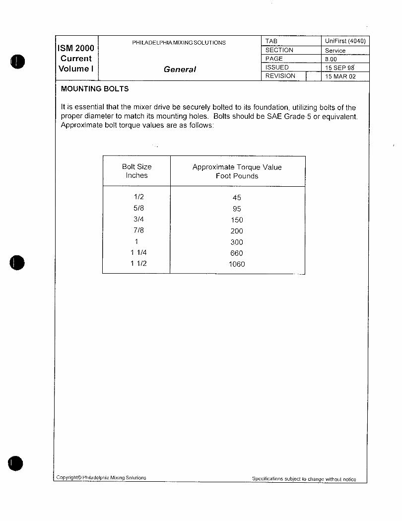
PHILADELPHIAMIXINGSOLUTIONS TAB UniFirst 4040M 200 SECTION Service
Current PAGE 800
Volume I General ISSUED 15 SEP 98
REVISION 15 MAR 02
MOUNTING BOLTS
It is essential that the mixer drive be securely bolted to its foundation utilizing bolts of the
proper diameter to match its mounting holes Bolts should be SAE Grade5 or equivalentApproximate boit torque values are as foliows
Bolt Size Approximate Torque Value
Inches Foot Pounds
1 2 45
58 95
34 150
7 200
300
1 1 4 660
1 1 2 1060
Copyright0 Philadelphia Mixing Solutions Specifications subject to change withoul notice

PHILADELPHIAMIXINGSOLUTIONS TAB UniFirst 4040M 20 SECTION Service
Current PAGE 900
Volume I Lubrication ISSUED 15 SEP 98
REVISION 15 MAR 02
The UniFirst 4000 Series bearings are all oil bath lubricated The motor bearings are
grease lubricated
The mixer drives are shipped without oil They must be filled with the proper
lubrication before startup
The recommended type of oil for use in the UniFirst mixer drive is an extreme pressure
EP oil
Oil volume is approximately 5 gallonsAGMA Lube No Tem erature Ran e Lubricant
4 EP 15F to 50F Mobilgear0 629 or
9C to 16C Mobilgear SHCO 150
6 EP 50F to 125F Mobilgear 6320 or
10C to 52C Mobilgear SHCO 220
Grease for bearings and Mobilith0 AW 2 or
seals when required Mobilith SHCO 220
v
FILLING MIXER DRIVE WITH OIL
1 The mixer drive can be filled with oil in 2 places the fill plug or the dipstickbreather2 Remove dipstickbreather from top of mixer drive housing and wipe clean
3 Fill mixer drive with recommended lubricant through breather hole Fill mixer until oil
level falls between the two lines scribed on dipstick Make sure dipstick is fully seated in
determining oil measurement Do not under fill or overfill The scribed lines representminimum and maximum levels
4 Install dipstickbreather
LOW TEMPERATURE OPERATION
Philadelphia Mixers must be advised if the mixer will be started up in temperatures less
than 10F above the pour point of oil used in the mixer Refer to oil manufactures data
sheet for pour point temperatures
OIL CHANGES
After the initial two weeks of operation of the mixer the original oil should be changed while
the equipment is at operating temperature CAUTION take necessary precautions when
handling hot oil This oil may be strained and used again Consult your oil supplier for
proper filter size Often due to the wearingin process small metal particles will appear in
the oil this is not abnormal
Flush the mixer drive housing thoroughly after the original oil has been drained Fill the
housing to the required level with SAE 10 straight mineral flushing oil Start mixer drive
Copyright0 Philadelphia Mixing Solutions Specifications subject to change without notice
PHILADELPHIAMIXINGSOLUTIONS TAB UniFirst 4040M2 SECTION Service
Current PAGE 1000
Volume I Lubrication ISSUED 15 SEP 98
REVISION 15 MAR 02
and bring up to operating speed preferably without load and immediately shut down
Drain flushing oil and fill with recommended operating lubricant to the proper leve Oil
should be changed after each subsequent2500 hours of operation or six months of
normal operation whichever occurs first
Unusual environmental or load conditions may require replacement of oil as frequently as 1
to 2 month intervals as determined by field inspection of the oil Special attention must be
given to the inspection of lubricants when the conditions exist
1 High operating temperatures resulting from heavy intermittent loads causing the
temperature of the mixer drive housing to rise rapidly and then cool
2 Ambient temperature conditions which could cause sweating on the inside walls of themixer drive housing
3 Operating oil temperatures that exceed 200 F
4 When the mixer drive is exposed to an unusually moist or dusty atmosphere or corro
sive or reactive vapors
SYNTHETIC LUBRICANTS
Synthetic lubricants have been used very successfully in mixer applications offering the
advantages of longer usable life better stability and operation over a wide temperaturerange In some cases installed in outdoor service summerwinter changeout of oil can beeliminated Do not misinterpret longer service fife for lack of attention Unless field experience with a specific synthetic lubricant is availble use must be closely monitoreu forbehavior in the presence of moisture and chemicals Use should be coordinated betweenthe user the lubricart supplier and Philadelphia Mixers
Only synthesized hydrocarbon fluids should be selected It should be high grade and
specifically formulated for industrial gear use It should be a nonreactive oxidation resis
tant formulation noncorrosive to gears and bearings It should have good defoamingproperties Viscosity should be equal to recommended oils shown in Synthetic Oil table
Synthetic Oil Oil volume is approximately 5 gallonsSummer Ambient 50 to 125F 10 to 50C AGMA 6S or ISO 320 Mobilgear SMC 2200Winter Ambient 15 to 50F 10 to 10C AGMA 4S or ISO 150 Mobilgear SHC 1500
After initial startup using synthetic lubricants sample lubricant after the first three 100 hour
periods of operation thereafter take samples every 2500 hours of operation or six monthswhichever occurs first Draw a onequart sample when mixeraerator is shut down and
analyze Change lubricant whenever sample reveais incipient deterioration
If changing from mineral oil to synthetic lubricant for best results flush mixer drive
Copyright0 Philadelphia Mixing Sofutions Specifications subject to change without notice
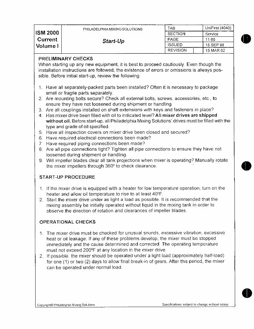
PHILADELPHIAMIXINGSOLUTIONS TAB UniFirst 4040M 200 SECTION Service
Current fPAGE 1100
Volume I ISSUED 15 SEP 98
REVISION 15 MAR 02
PRELIMINARY CHECKS
When starting up any new equipment it is best to proceed cautiously Even though the
installation instructions are followed the existence of errors or omissions is always possible Before initial startup review the following
1 Have all separatelypacked parts been installed Often it is necessary to packagesmall or fragile parts separately
2 Are mounting bolts secure Check all external bolts screws accessories etc to
ensure they have not loosened during shipment or handling3 Are all couplings installed on shaft extensions with keys and fasteners in place4 Has mixer drive been filled with oil to indicated level All mixer drives are shipped
without oil Before startup all Philadelphia Mixing Solutions drives must be filled with the
type and grade of oil specified5 Have all inspection covers on mixer drive been closed and secured
6 Have required electrical connections been made
7 Have required piping connections been made
8 Are all pipe connections tight Tighten all pipe connections to ensure they have not
loosened during shipment or handling9 Will impelter blades clear all tank projections when mixer is operating Manually rotate
the mixer impellers through 360 to check clearance
STARTUP PROCEDURE
1 If the mixer drive is equipped with a heater for low temperature operation turn on the
heater and allow oil temperature to rise to at least 40F
2 Start the mixer drive under as light a load as possible It is recommended that the
mixing assembly be initially operated without liquid in the mixing tank in order to
observe the direction of rotation and clearances of impeller blades
OPERATIONAL CHECKS
1 The mixer drive must be checked for unusual sounds excessive vibration excessive
heat or oil leakage If any of these problems develop the mixer must be stopped
immediately and the cause determined and corrected The operating temperaturemust not exceed 200F at any location in the mixer drive
2 If possible the mixer should be operated under a light load approximately halfloadfor one 1 or two 2 days to allow final breakin of gears After this period the mixer
can be operated under normal load
Copyright0 Philadelphia Mixing Solutions Specifications subject to change without notice

ISM ZOOOPHILADELPHIAMIXINGSOLUTIONS TAB UniFirst 4040
SECTION Service
Current Maintenance Instructions PAGE 1200
Volume I for a Ratio Change ISSUED 30 APR 00
REVISION 15 MAR 02
1 LockOutTagOut Procedure
a Open the disconnect on the motor control panelb Hang a lock and warning tag on the control panel handlec Try to start the motor If it starts there is a remote starter somewhere locate
it and lock it
2 Remove the bolts 224 and lockwashers 225 securing motor 220 to the highspeed cartridge Remove the motor 220 and high speed coupling 221 from the
input shaft Proceed to remove the hardware 142 and 143 securing the clamp ring141 to housing and set aside
3 Carefully remove the high speed cartridge 140 so as not to break the fange when
removing it off the dowel pin 146 Removel dowel pin 146
4 When replacing new high speed cartridge 140 refer to the drawing for proper location of the dowel pin 146 for that ratio
5 Carefully install high speed cartridge 140 so as not to damage the gearing Rotatethe high speed cartridge 140 to correctly mesh the tooth contact Reinstall the dowel
pin 146 into the correct hole Apply Hylomar Superflex or equal on the split to prevent oil leakage
6 Reinstall the clamp ring 141 and secure with the proper hardware 142 143 and
torque to specifications
7 Carefuliy turn the input shaft 152 by hand to be sure the mixer turns freely
8 Reinstall the high speed coupling 221 on the input shaft 152 and proceed to installthe motor 220 with correct hardware 224 225 and torque
9 Remove the lock and warning tag and proceed to just bump the mixer first Mixer isnow ready to go back into service
aCopyright0 Philadelphia Mixing Solutions Specifications subject to change without notice
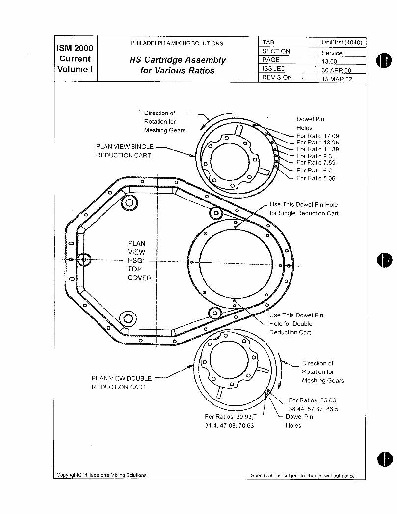
ISM ZOOOPHILADELPHIAMIXINGSOLUTIONS TAB UniFirst 4040
SECTION Service
Current HS Cartridge Assembly PAGE o
Volume I for Varous Ratios ISSUED 30 APR 00
REVISION 15 MAR 02
Direction of
Rotation for Dowei Pin
Meshing Gears Holes
o For Ratio 1709
PLAN VIEW SINGLE pFor Ratio 1395
For Ratio 1139REDUCTION CART a For Ratio 93
p For Ratio 759
For Ratio 62R
0 For Ratio 506
t3t
I4
Use This Dowel Pin Hole
f O afor Single Reduction Cart
Q
0
i a
c PLAEJ
VIItV
HSG
TQI
c CGVEFa
o o
Q Use This Dowel Pin0
Hole for poublefl Q
Reduction Cartf
t3 qp
p
Direction of
Rotation for
PLAN VIEW DOUBLE O Meshing Gears
REDUCTION CART
For Ratios 2563
3844 5767 865
For Ratios 2093 Dowel Pin
3144708 7063 Holes
Copyright0 Philadelphia Mixing Solutions Specifications subject to change without notice
SM ZOOOPHILADELPHIAMIXINGSOLUTIONS TAB UniFirst 4040
SECTION WarrantCurrent WARRANTY PAGE 1400
Volume I ISSUED 15 SEP 98
REVISION 15 MAR 02
For a period of one year after date start up or eighteen months after delivery to Customer whichever comes first Seller warrants that the products sold to Customer will be free from defects inmaterials and workmanship and will perform the paticular function for which they are intendedMixers and aerators are warranted to be fit to perform the function for which they are intendedwhen operated under the specified mixing or design conditions provided accurate and necessarydata have been furnished to Seller in writing by Customer Seller assumes no responsibility for theaccuracy or reliability of specifications design conditions or other furnished by or on behalf ofCustomer or the ultimate user Customer selected materials are warranted only to conform withCustomer specifications Materials not specified by Customer shall be Sellers standard materialsof construction for out of tank components Material exposed to process are not warranted againstcorrosion or other deterioration due to exposure to vessel contents
These warranties shall not be effective if the product or part is not used strictly in accordance withall instructions as to storage handling maintenance lubrication installation startup operation andsafety set forth in the manuals and instruction sheets furnished by Seller
The standards of the American Gear Manufacturers Association will be used and shall governwhere applicable in the manufacture of gears and gear drive assemblies unless Seller expresslyagrees otherwise in writing
The foregoing limited warranties are exclusive and are in lieu of all other warranties express andimplied including but not limited to implied warranties of inerchantability or fitness for a particularpurpose
LIMITATION OF REMEDIES
Customers remedy for breach of any of the forgoing warranties shall be limited to replacement or
repair by Seler oi any defective equipment or parts discovered during the 1 year warranty periodSuch products or parts shall be shipped to Seller FOB Sellers plant orFOB at such otherlocation as may be designated by Seller Seller shall have the right at its sole discretion to refundthe purchase price paid by Customer in lieu of repair or replacement Without limiting the foregoing under no circumstances shall Seller be liable for any expenses for removal of allegedly defective equipment or parts or for installation costs of repaired or replaced equipment or parts
All claims for breach of any Sellers warranties shall be barred unless Customer notices Seller ofsuch breach in writing within 30 days of discovery of the breach
LIMITATION OF LIABILITIESSeller shall not be liable for any liquidated consequential or incidental damages due to defects inmalfunctions or failure of its products to perform late delivery of loss of use nor shall Sellers totalliability under any circumstances exceed the purchase price of the products sold Seller shall notbe liable for any damage resulting from improper storage or handling following shipment Sellershall not be responsible for repairs performed by others outside Sellers plant unless such repairsare authorized by Seller in writing in advance Seller shall not be responsible for any defects in anycomponents such as gears shafts bearings or motors furnished by others
CopyrightO Philadelphia Mixing SolutionsSpecifications subject to change without notice

PHILADELPHIAMIXINGSOLUTIONS TAB UniFirst 4040ISM 2000 SECTION Shaft Handling
Current PAGE 1500
Volume I A9itator Shaft Lifting Procedure issuE 15 SEP 98
REVISION 15 MAR 02
Caution Only trained professionals experienced in the handling rigging and
lifting of heavy machinery should be employed to install or remove
mixer components
Warning Never lift the agitator shaft from the horizontal position with one end of
the shaft on the ground Lifting in this manner may bend the shaft asin Figure 1A
NOTE In certain applications the impeller hubs may have to be removed
from the agitator shaff prior to insfalling the agitator shaft into the
vessel
Handling and Lifting
Handling and lifting of mixer components like all heavy machinery can be dangerous and
proper methods may depend upon the particular instailation Philadelphia Mixers recom
mends that only trained professionals perform these tasks during installation or removal of
the mixers and assumes no responsibility for injury to persons or property that may occur
during these activities
1 Attach one lifting sling at or near the coupling at the top of the agitator shaft Use onlyproperly rated new nonmetallic slings See Outline Installation drawing for weights
2 Attach a second lifting sling approximately onethird of the length of the shaft from the
bottom See Figure 1 B
3 Lift the agitator shaft horizontally to a sufficient height so that the impeller end of the
shaft will not contact the ground when the shaft is moved into a vertical position
4 Continue to lift the agitator shaft from the coupling end sling only until the shaft is
vertical
5 When the agitator shaft is vertical remove the impeller end sling and use the couplingend sling to lower the shaft into the mixing vessel
Copyright0 Philadelphia Mixing Solutions Specifications subject to change without notice
ISM ZOOOPHILADELPHIAMIXINGSOLUTIONS TAB UniFirst 4040
SECTION Shaft HandlingCurrent Agitator Shaft Lifting Procedure PAGE 1600
Volume I ISSUED 15 SEP 98
REVISION 15 MAR 02
Figure 1A
ru i
F
1
li i
is
i I t
I i
IgUi @
1Copyright0 Philadelphia Mixing Solutions Specifications subject to change without
notice

ISM ZOOOPHILADELPHIAMIXINGSOLUTIONS TAB UniFirst 4040
SECTION Gear Box Handlin
Current PAGE
Volume IRECEIPT AND HANDLING ISSUED 15 SEP 98
REVISION 15 MAR 02
Receipt and Inspection
1 UniFirst Series mixers are generally shipped bolted to a hardwood pallet Remove any
packaging material from around the mixer and carefully examine it for evidence of
damage during shipping If damage is found retain the damaged material and contact
Philadelphia Mixing Solutions ProTech Services at18007331341 for guidance
2 Inventory the equipment against the shipping papers to verify that the correct components have been received If any components appear to be missing contact Philadel
phia Mixing Solutions or your sales representative for guidance
3 Inspect the mixer drive and other components for evidence of rust or corrosion particularly if there are areas of chipped paint due to handling damage If corrosion is presentcontact Philadelphia Mixing Solutions ProTech Services at18007331341 for further
instructions
Copyright0 Philadelphia Mixing Solutions Specifications subject to change without notice

ISM ZOOOPHILADELPHIAMIXINGSOLUTIONS TAB UniFirst 4040
SECTION Gear Box Handlin
Current PAGE 1800
Volume I RECEIPT AND HANDLING ISSUED 15 SEP 98
REVISION 15 MAR 02
Caution Only trained professionals experienced in the handling rigging and liftingof heavy machinery should be employed to install or remove mixer components
Handling and Lifting
Handling and lifting of mixer componentslike all heavy machinerycan be dangerousand proper methods may depend upon the particular installation Philadelphia Mixing Solutions recommends that only trained professionals perform these tasks during installation or
removal of the mixers and assumes no responsibility for injury to persons or property that
may occur during these activities
In addition the following general guidelines should be observed when moving or lifting themixer
1 Keep the mixer drive in the upright position
2 Never support the mixer by the output shaft
3 When the mixer is to be placed on the ground put blocks under the mounting surfaces
4 Never drag the mixer This will damage the machined mounting surfaces and could
damage the housing
5 There are eyebolts on both the mixer drive housing and the motor housing Do not liftthe mixer drive by the eyebolts on the motor housing Lift the mixer gear drive by the
eyebolts attached to the top of the drive housing Use lifting slings to distribute the load
evenly Make sure the slings are positioned so they do not place a load on external
components pipes gauges etc when the mixer is lifted
6 Never shock the mixer by snapping loose lifting rigging
7 Never lift a fully assembled mixer weighing over 1200 Ibs including the gear drivemotor agitator shaft and impellers Refer to Outline Installation Drawing for each
components weight
8 The 4040 mixer is shipped on two or more skids One skid will contain the mixer drivewhich is positioned horizontally or vertically and the other skids will contain the agitator shaft andor additional components Remove all shipping restraints Two hoists or
cranes are necessary to lift the mixer and agitator parts LIFT THE MIXER DRIVE BYITSELF DO NOT ATTACH THE AGITATOR SHAFT
Copyright0 Philadelphia Mixing Solutions Specifications subject to change without notice
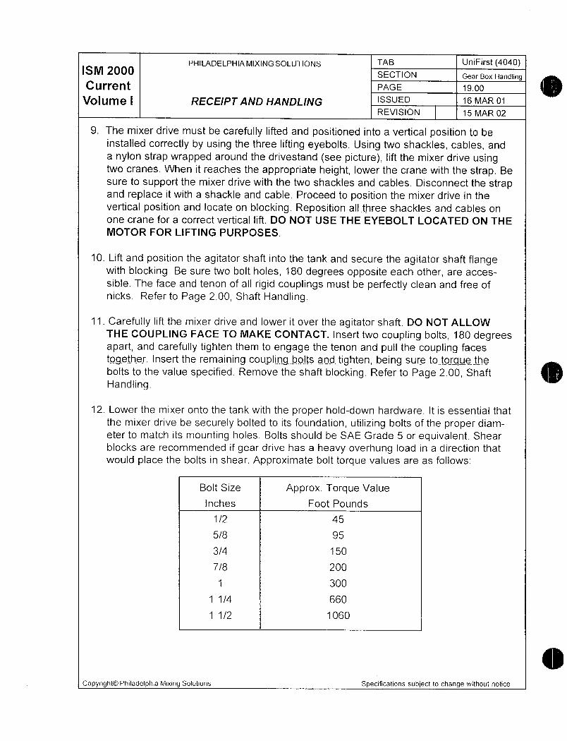
ISM ZOOOPHILADELPHIAMIXINGSOLUTIONS TAB UniFirst 4040
SECTION Gear Box Handling
Current PAGE 1900
Volume I RECEIPT AND HANDLING ISSUED 16 MAR 01
REVISION 15 MAR 02
9 The mixer drive must be carefully lifted and positioned into a vertical position to be
installed correctly by using the three lifting eyebolts Using two shackles cables and
a nylon strap wrapped around the drivestand see picture lift the mixer drive usingtwo cranes When it reaches the appropriate height lower the crane with the strap Be
sure to support the mixer drive with the two shackles and cables Disconnect the strapand replace it with a shackle and cable Proceed to position the mixer drive in the
vertical position and locate on blocking Reposition allthree shackles and cables on
one crane for a correct vertical lift DO NOT USE THE EYEBOLT LOCATED ON THE
MOTOR FOR LIFTING PURPOSES
10 Lift and position the agitator shaft into the tank and secure the agitator shaft flangewith biocking Be sure two bolt holes 180 degrees opposite each other are acces
sible The face and tenon of all rigid couplings must be perfectly clean and free of
nicks Refer to Page 200 Shaft Handling
11 Carefully lift the mixer drive and lower it over the agitator shaft DO NOT ALLOW
THE COUPLING FACE TO MAKE CONTACT Insert two coupling bolts 180 degreesapart and carefully tighten them to engage the tenon and pull the coupling faces
together Insert the remaining coupling bolts and tighten being suretotorque thebolts to the value specified Remove the shaft blocking Refer to Page 200 Shaft
Handling
12 Lower the mixer onto the tank with the proper holddown hardware It is essential that
the mixer drive be securely bolted to its foundation utilizing bolts of the proper diam
eter to match its mounting holes Bolts should be SAE Grade 5 or equivalent Shear
blocks are recommended if gear drive has a heavy overhung load in a direction that
would place the bolts in shear Approximate bolt torque values are as follows
Bolt Size Approx Torque Value
inches Foot Pounds
1 2 45
58 95
34 150
78 200
1 300
1 1 4 660
1 1 2 1060
Copyright0 Philadelphia Mixing Solutions Specifications subject to change without notice
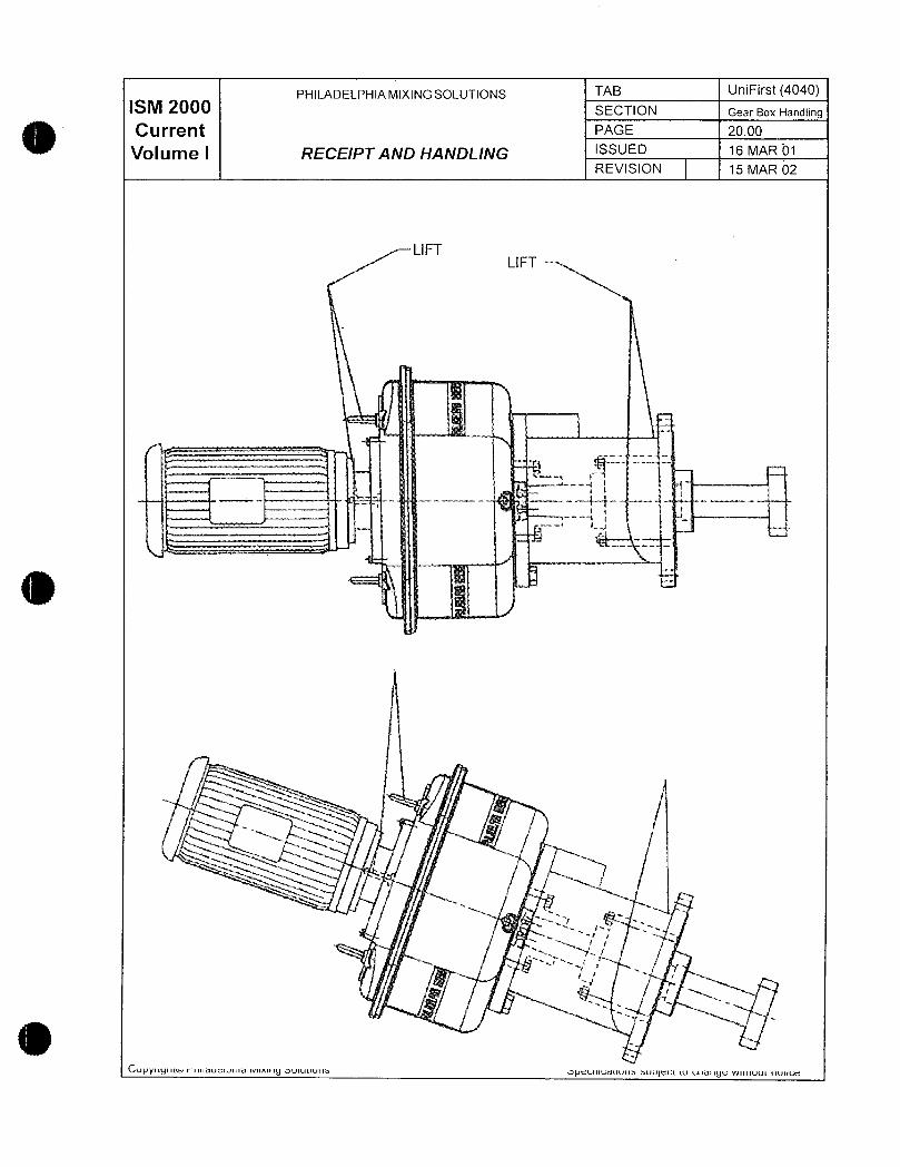
PHILADELPHIAMIXINGSOLUTIONS TAB UniFirst 4040SM 20 SECTION Gear Box Handling
Current PAGE 2000
Volume I RECEIPT AND HANDLING ISSUED 16 MAR 01
REVISION 15 MAR 02
LIFTLI FT
R
f
I
4
47 7
yft
a
r r t
f f
CvNyiiynnvnmaueiNiva rvuxuiy oviuuia oNccmcauvna auuCCt wtnanyC wunui iiuca
PHILADELPHIA MIXING SOLUTIONS TAB UniFirst 4040SM 20 SECTION Lon Term Stora e
Current PAE Z00
Volume 1 GENERALISSUED 15 SEP 98
REVISION 15 MAR 02
These procedures are designed to protect your mixers or aerators from atmospheric corro
sion or other harmful effects during storage or periods of inactivity The critical periods are
before the new mixer is ever run and prolonged idle periods thereafter
The storage instructions for gear drive protection can be valid for periods as long as two yearsfor equipment stored under best conditions Longer term storage is acceptable provided
necessary procedures are followed contact the Service Department of Philadelphia MixingSolutions for additional information Any costs for storage materials or labor required after shipment will be paid by the customer unless specifically contracted for by Philadelphia Mixers at
the time of purchase
Specific storage procedures to be followed are meant to maintain the Mixers or Aerators as
nearly as possible to their as shipped condition Failure to properly store and protect the
equipment as outlined may void any warranty either expressed or implied It is advisable
for the user to keep a detailed log to record the results of inspections and maintenance
performed on each Aerator or Mixer
We recommend that the gear reducers and motors be kept in a dry temperaturecontrolledindoor area We do not recommend outdoor storage There may be some instances where
indoor storage is impossible Storage of special equipment supplied by Philadelphia MixingSolutions such as motors control panels etc is to be in accordance with the manufacturers
recommendations included with this manual
Copyright0 Philadelphia Mixing Solutions Specifications subject lo change wiihout notice
PHILADELPHIAMIXINGSOLUTIONS TAB UniFirst 4040SM 2000 SECTION Long Term Storage
Current PAE z200
Volume I RECEIVING THE EQUIPMENT ISSUED 15 SEP 98
REVISION 15 MAR 02
1 Check impellers and impeller shafts for obvious shipping damage Should such
damage be found immediately report the details to the carrier that delivered the
equipment and the Philadelphia Mixing Solutions Service Department
Carefully move these components to a storage area where they will be least likelyto be damaged by contact with fork trucks etc Carbon steel components whether
painted or not should be protected Protective coatings against atmosphericcorrosion as applied for shipping should be checked for damage and renewed or
patched as necessary Periodic checks preferably at no more than 30day inter
vals should be made to assure that no rusting or other damage has occurred
Should such be noted corrective action should be quickly initiated Contact Phila
delphia Mixers Service Department for guidance2 Carefully check before putting drives into storage to assure that the plugs are
installed in place of breathers and all other openings to the atmosphere are
sealed
3 If the duration of storage in any of 3 environments to be defined in the followingwill not exceed six months for a newlymanufactured drive the gear reducer if
properly prepared will not require additional protective procedures Inspect the
drive to assure that longterm preservation procedures were applied at the factoryThis is indicated by a tag attached to the drive which will say This mixeraerator
has internal rust protection which is considered adequate under normal INDOOR
storage conditions FOR SIX 6 TO TWELVE 12 MONTHS from date of preservation application The date of the preservation application appears on the tag
PHONE 7178322800
FAX 7178328802
Philly OnCall Services18007331341
Copyright0 Philadelphia Mixing Solutions Specifications subject to change without notice
PHILADELPHIA MIXING SOLUTIONS TAB UniFirst 4040ISM ZOOO SECTION Long Term Storage
Current PAGE
Volume GENERAL ISSUED 15 SEP 98
REVISION 15 MAR 02
Field Application of Corrosion Protection
If field application of longterm internal corrosion protection to a miXer drive is necessaryfor any reason arrangements should be made with thePhladelphia Mixing SolutionsService Department for a factory representative to be on hand if possible while the
preservation procedure is carried out The first step is to inspect the drive to assure that a
damaging degree of corrosion does not exist If existing corrosion or other damage doesnot require attention proceed as follows
To coaf all internal surfaces with a protective compound such as HoughtonCosmoline 1902 fill the gear drive to its normal operafing level with the com
pound To insure complete coating the drive must be rotated using the electricmotor to splash all internal surfaces for one to three minutes Caution Onlvctualified electrical and mechanical personnel should perform this operationContact the factory if assistance is reguired Drain the excess rusfprevenfivecompound Sea all drive openings with plugs paper impregnated with vaporizing corrosion inhibitor caps etc
Further prepare the drive motor for storage as described by the storage location
according to the appropriate following procedures
Storing in 3 Types of Locations
Please note that there are 3 basic types of storage locations and environments forAerators and Mixers Storage procedures are different for each Use the procedurewhich applies to your drive
A Indoor Storage in a Dry TemperatureControlled Area
The preferred storage environment for Mixers or Aerators is a dry area with relativelyconstant temperature prevent condensation The use of a mechanical dehumidifyingsystem with controls to maintain the atmosphere at 40 relative humidity or lower is
recommended
If automatic humidity control is unavailable and conditions become extreme it may be
necessary to use trays of renewable desiccant such as silica gel or portable dehu
midifiers to remove moisture from the air in the enclosed storage area in order to
properly maintain necessary relative humidity levels
Each gear reducer should be stored in its normal operating position and then filled to
normal operating oil level with the recommended oil see Operating and MaintenanceInstructions for the specific Aerator or Mixer Add NoxRust VCI10 or equal volatile corrosion inhibitive oil at the rate of 2 of sump capacity added to the conven
tional oil used Replace oil fill plug when finished Assure that all other openings in
Copyright0 Philadelphia Mixing Solutions Specifications subject to change without notice

IS ZOOOPHILADELPHIAMIXINGSOLUTIONS TAB UniFirst 4040
SECTION Lon Term Stora e
Current PAGE 2400
Volume I GENERAL ISSUED 15 SEP 98
REVISION 15 MAR 02
the gear drive are closed to the atmosphere Rotate shaft several times by removingmotor fan cover and rotating fan by hand Reinstall fan cover At six month intervalsdrain 2 of sump capacity and replace with NoxRust
If the furnished motors have motor heaters connect these to a proper power source
immediately upon putting into storage
Motor shafts in storage should be rotated at regular intervals We recommend 5 com
plete rotations of the shafts Foilow motor manufacturer recommendations for storageMotors supplied with breathers and drains must be inspected for operability Motor
bearings must be greased per instructions from the manufacturer of the motor supplied These recommendations have been supplied with this manual
B Indoor Storage No Temperature Nor Humidity Control
Motors must be stored with all breathers and drains operable and motor heaters if
any connected If motor heaters are furnished they must be connected to a properpower source upon placement in storage regardless of the duration of storage Covereach motor but do not seal it off as this might trap moisture
If no motor heaters are supplied motors must be securely wrapped in plastic withdesiccant bags placed inside Replace the desiccant bags at 30day intervals
Motor shafts in storage should be rotated at regular intervals We recommend 5 com
plete rotations of the shafts Follow motor manufacturer recommendations for storageMotors supplied with breathers and drains must be inspected for operability Motor
bearings must be greased per instructions irom the manufacturer of the motor supplied These recommendations nave been supplied with this manuai
Each gear reducer should be stored in its normal operating position and then filled tonormal operating oil level with the recommended oil see Operating and MaintenanceInstructions for the specific Aerator or Mixer Add NoxRust VCI10 or equai volatile corrosion inhibitive oil at the rate of 2 of sump capacity added to the conven
tional oil used Replace oil fill plug when finished Assure that all other openings in the
gear drive are closed to the atmosphere Rotate Shaft several times by removingmotor fan cover and rotating fan by hand Reinstall fan cover At six month intervalsdrain 2 of sump capacity and replace with NoxRust
Product of Daubert Chemical Company Chicago IL
Copyright0 Philadelphia Mixing Solutions Specifications subject to change without notice
PHILADELPHIAMIXINGSOLUTIONS TAB UniFirst 4040
SM 200 SECTION Lon Term Stora e
CurrentGENERAL
PAGE 2500
Volume I ISSUED 15 SEP 98
REVISION 15 MAR 02
C Outdoor Storage Not Recommended
PROCEDURES TO FOLLOW WHEN OUTDOOR STORAGE IS UNAVOIDABLE
All Aerator or Mixer components must be kept off the ground Storage should be on
skids or platforms and protected with a tarpaulin or other waterproof covering If this
equipment is mounted for storage in its eventual operating location on top of tanks or
wastewater treatment basins the equipment should be protected by a tarpaulin or
other waterproof covering
If the furnished motors have motor heaters connect these to a proper power source
immediately upon putting into storage
If no motor heaters are supplied motors must be securely wrapped in plastic with
desiccant bags placed inside Replace the desiccant bags at 30day intervals
Motor shafts in storage should be rotated at regular intervals We recommend 5 com
plete rotations of the shafts Follow motor manufacturer recommendations for storageMotors supplied with breathers and drains must be inspected for operability Motor
bearings must be greased per instructions from the manufacturer of the motor sup
plied These recommendations have been supplied with this manual
Each gear reducer should be stored in its normal operating position and then filled to
normal operating oil level with the recommended oil see Operating and Maintenance
Instructions for the specific Aerator orIllixer Add NoxRust VCI10 or equal vola
tile corrosion inhiitive oil at the rate of 2 of sump capacity added to the conven
tional oil used Replace oil fill plug when finished Assure that all other openings in the
gear drive are closed to the atmosphere Rotate Shaft several times by removingmotor fan cover and rotating fan by hand Reinstall fan cover At six month intervals
drain 2 of sump capacity and replace with NoxRust
NOTE In the event that the Aerafors or Mixers are fully installed and secured
in their eventual operating location with full power available and a standard
startup procedure possible revert to Operating and Maintenance Instruc
tions manual for filling each drive with proper lubricant and conducting a
thorough startup check and initial startup fo prepare the equipmenf for later
normal operation Having done this it is absolutely mandatory that each
Aerator or Mixer must be run twice a week for a period of one hour
Note once operated the corrosionprotective coatrng on drive internals has
been removed by operating with normal lubricant the internals are
Product of Daubert Chemical Company Chicago IL
Copyright0 Philadelphia Mixing Solutions Specifications subject to change without notice
ISM ZOOOPHILADELPHIAMIXINGSOLUTIONS TAB UniFirst 4040
SECTION Long Term StorageCurrent
GENERALPAGE 2s00
VOIUfYI@ I ISSUED 15 SEP 98
REVISION 15 MAR 02
now subject to atmospheric corrosion more than ever Experience hasshown that failure to follow the operatetwiceaweek instruction betweendate of installing and testing a drive and the start of continuous operationcan be the most critical period for potential damage by atmospheric corro
sive attack
From Storage Into Service
All applicable portions ofthe Operating and Maintenance Instructions should be re
viewed for special instructions relative to handling of the assemblies and storage procedures to follow for motors coupiings or special auxiliary equipment supplied in each
assembly
Preparing StoredAeratorsMixers for Service
1 Wipe off any dust and other accumulated dirt or grime from the exterior of each drive
assembly Inspect both interior and exterior of the gear drive for any rusting If rust or
other damage is noted contact Philadelphia Mixing Solutions Service Department
2 Remove motor coverings or wrappings and any desiccant bags that may have beenplaced inside the wrappings Be sure that motor breathers and drains are operable
Remove plugs from breather holes on gear drives and install the breather shipped withthe drive
CopyrightOO Philadelphia Mixing Solutions Specifications subject to change without notice

a ww
Y re
y
N11I1wnmxer
ie F
Pa rts
0
ISM ZOOOPHILADELPHIAMIXINGSOLUTIONS TAB UniFirst4040
SECTION PartsCurrent PAGE
Volume I4040 Common Parts Drawing ISSUED 15 SEP 98
REVISION 15 MAR 02
ii
I I I II II I II f i I i I i l l I
I i I i I I
II IiI Ia I i
It
ii
I I iI i I
iI i Ii il I
ii I
nr ct tL
Iil r i
Ij IIx
I i II i 1 li
I
l
I tni
i
i
I i
i
i
CopyrightOO Philadelphia Mixing SolutionsSpecifications subject to change without notice
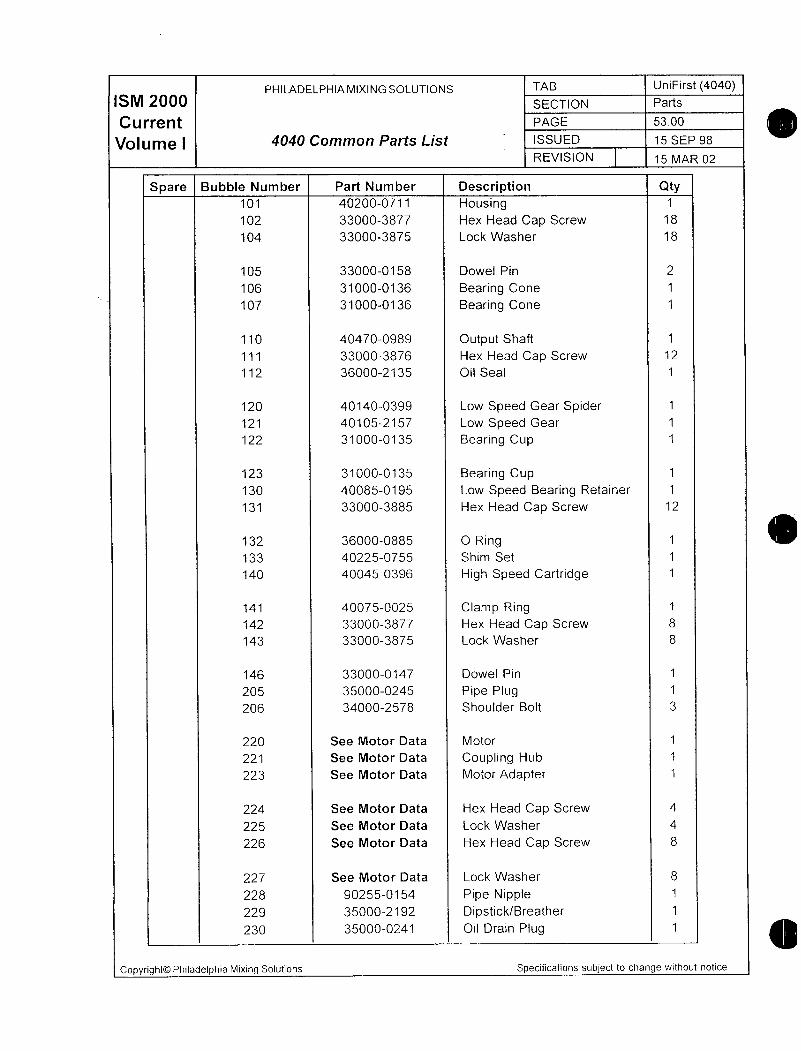
PHILADELPHIAMIXINGSOLUTIONS TAB UniFirst 4040ISM 2000 SECTION Parts
Current PAGE 5300
Votume 1 4040 Common Parts List ISSUED 15 SEP 98
REVISION 15 MAR 02
Spare Bubble Number Part Number Description Qty101 402000711 Housing 1
102 330003877 Hex Head Cap Screw 18
104 330003875 Lock Washer 18
105 330000158 Dowel Pin 2
106 310000136 Bearing Cone 1
107 310000136 Bearing Cone 1
110 404700989 Output Shaft 1
111 330003876 Hex Head Cap Screw 12
112 360002135 Oil Seal 1
120 401400399 Low Speed Gear Spider 1
121 401052157 ow Speed Gear 1
122 310000135 Bearing Cup 1
123 310000135 Bearing Cup 1
130 400850195 Low Speed Bearing Retainer 1
131 330003885 Hex Head Cap Screw 12
132 360000885 O Ring 1
133 402250755 Shim Set 1
140 400450396 High Speed Cartridge 1
141 400750025 Clamp Ring 1
142 330003877 Hex Head Cap Screw 8
143 330003875 Lock Washer 8
146 330000147 Dowel Pin 1
205 350000245 Pipe Plug 1
206 340002578 Shoulder Bolt 3
220 See Motor Data Motor 1
221 See Motor Data Coupling Hub 1
223 See Motor Data Motor Adapter 1
224 See Motor Data Hex Head Cap Screw 4
225 See Motor Data Lock Washer 4
226 See Motor Data Hex Head Cap Screw 8
227 See Motor Data Lock Washer 8
228 902550154 Pipe Nipple 1
229 350002192 DipstickBreather 1
230 350000241 Oil Drain Piug 1
Copyright0 Philadelphia Mixing Solutions Specifications subject to change without notice
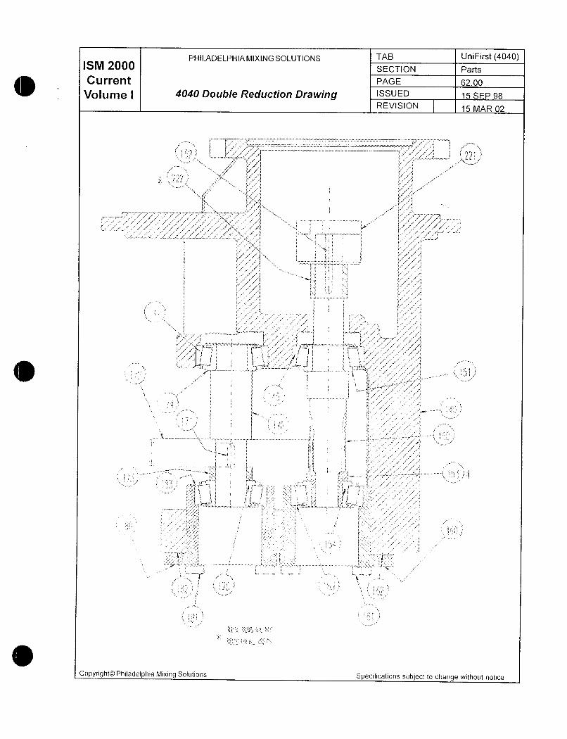
ISM ZOOOPHILADELPHIAMIXINGSOLUTIONS TAB UniFirst 4040
SECTION Parts
Current PAGE 6200
Volume I 4040 Double Reduction Drawing ISSUED 15 SEP 98
REVISION 15 MAR 02
3
f FN
F ry irt
j a a
j
C 3
X
i z
f F3 mf
f
ti
ey ti
s Ip t j y
rs
e5 Y
y N
fL i
rf Ji y
i i
fE
I
J rtff j F R F
d1t L t
ft
l w pa
Ze
3
w
Sj s
f 3 i t
1ar
Y
3 3
t 3
f 3d a
E
ri
s l 1i r f
y
t
i
im
fij
33 i t F
P
CopyrightOO Philadelphia Mixing Soiutions Specifications subject to change without notice
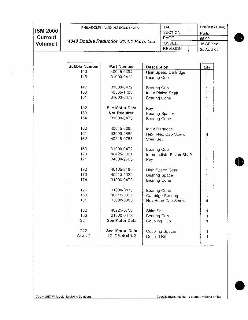
PHILADELPHIAMIXINGSOLUTIONS TAB UniFirst 4040ISM 2000 SECTION Parts
Current PAGE 6500
Volume I4040 Double Reduction 3141 Parts List ISSUED 15 SEP 98
REVISION 25 AUG 05
Bubble Number Part Number Descri tion Qt140 400450394 High Speed Cartridge 1
145 310000472 Bearing Cup 1
147 310000472 Bearing Cup 1
150 403651405 Input Pinion Shaft 1
151 310000473 Bearing Cone 1
152 See Motor Data Key 1
153 Not Required Bearing Spacer154 310000473 Bearing Cone 1
160 400450395 Input Cartridge 1
161 330003885 Hex Head Cap Screw 4
162 402250758 Shim Set 1
163 310000472 Bearing Cup 1
170 404251361 Intermediate Pinion Shaft 1
171 340002565 Key 1
172 401052160 High Speed Gear 1
173 403151338 Bearing Spacer 1
174 310000473 Bearing Cone 1
175 310000473 Bearing Cone 1
180 400450395 Cartridge Bearing 1
181 330003885 Hex Head Cap Screw 4
182 402250758 Shim Set 1
183 310000472 Bearing Cup 1
221 See Motor Data Coupling Hub 1
222 See Motor Data Coupling Spacer 1
SPARE 1212540402 Rebuild Kit 1
Copyright0 Philadelphia Mixing Solutions Specifications subject lo change without notice
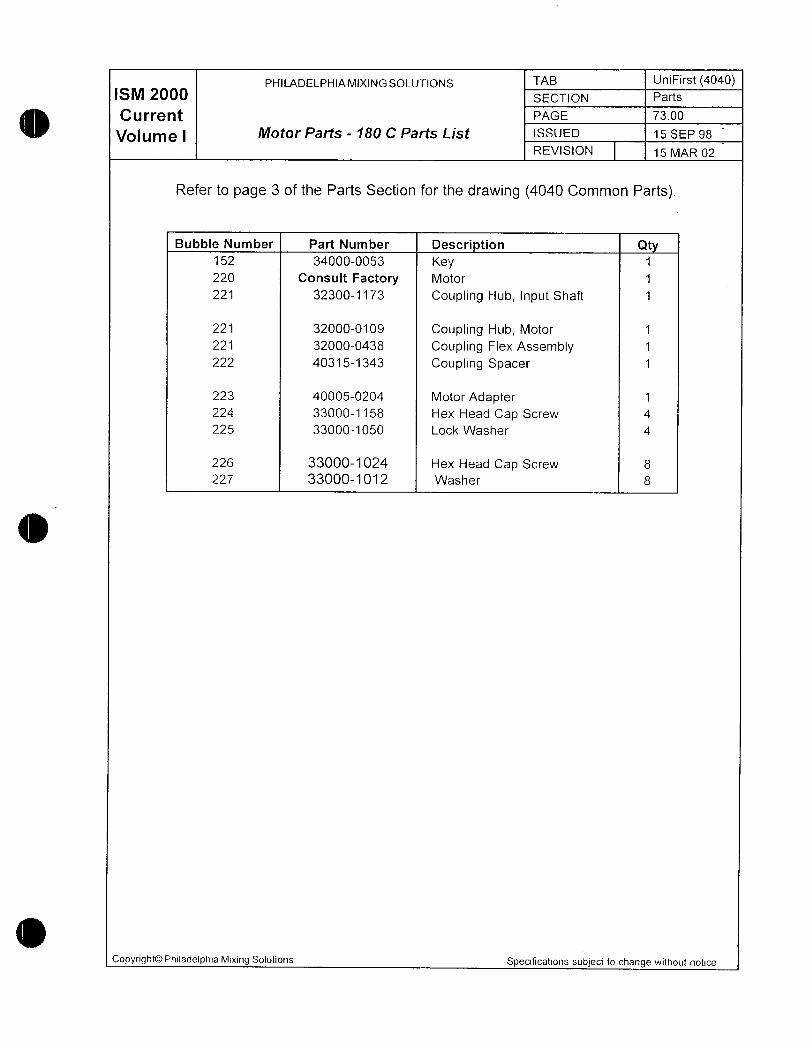
PHILADELPHIAMIXINGSOLUTIONS TAB UniFirst 4040ISM 2000 SECTION Parts
Current PAGE s00
VOIU111e I Mofor Parts 180 C Parts List ISSUED 15 SEP 98
REVISION 15 MAR 02
Refer to page 3 of the Parts Section for the drawing 4040 Common Parts
Bubble Number Part Number Description Qt
152 340000053 Key 1
220 Consult Factory Motor 1
221 323001173 Coupling Hub Input Shaft 1
221 320000109 Coupling Hub Motor 1
221 320000438 Coupiing Flex Assembly 1
222 403151343 Coupling Spacer 1
223 400050204 Motor Adapter 1
224 330001158 Hex Head Cap Screw 4
225 330001050 Lock Washer 4
226 330001024 Hex Head Cap Screw 8
227 330001012 Washer 8
CopyrightO Philadelphia Mixing Solutions Specifications subject to change without notice
PHILADELPHIA MIXING SOLUTIONS TAB UniFirst 4040ISM 2000 SECTION Parts
Current PAGE 13000
Volume 1 PTO DS 25 30 Drawing ISSUED 15 SEP 98
REVISION 15 MAR 02
I iiIII
II
t i
1L
I
1 iII l r I f j yi t
i iI I
I i
J
I
j
i
1
i i i
i
f
I I
Copyright0 Philadelphia Mixing Solutions Specifications subject to change without notice
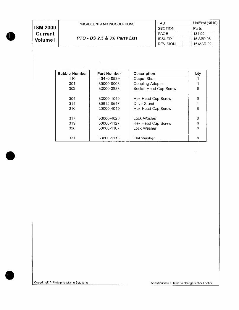
PHILADELPHIAMIXINGSOLUTIONS TAB UniFirst 4040M 2000 SECTION Parts
Current PAGE 13100
Volume IPTO DS 25 8 30 Parts List ISSUED 15 SEP 98
REVISION 15 MAR 02
Bubble Number Part Number Description Qty110 404700989 Output Shaft 1
301 800000008 Coupling Adapter 1
302 330003883 Socket Head Cap Screw 6
304 330001040 Hex Head Cap Screw 6
314 806150547 Drive Stand 1
316 330004019 Hex Head Cap Screw 8
317 330004020 Lock Washer 8
319 330001127 Hex Head Cap Screw 8
320 330001107 Lock Washer 8
321 330001113 Flat Washer 8
Copyright0 Philadelphia Mixing Solutions Specifications subject to change without notice

PHILADELPHIAMIXINGSOLUTIONS TAB UniFirst 4040ISM 2000 SECTION Parts
CurrentpARTS
PAGE 5000
Volume I ISSUED 15 SEP 98
REVISION 15 MAR 02
Parts Order Procedure
This manual includes the information necessary to assist you in ordering replacement parts for
your Philadelphia Mixing Solutions UniFirst Mixer Drive Please use the followirg procedure for ease
in meeting your mixer parts requirements
The parts order procedure will be simplified if you use the following 3 reference materials
included in this manual
1 Parts QuoteOrder Form
2 Parts List
3 Drawings bubble
Find a copy of the Parts QuoteOrder Form on page 2 of this section Please make a copv
of this form for your transmittal
Use the Parts QuoteOrder Form when requesting quote information from PhiladeiphiaMixers Upon completion of all information this form can be used as an order submittal
along with a copy of your authorized purchase order form
Please fill in the serial number order number model customer name requisitioner return
fax number and all information for parts required bubble item description and quan
tity requested Fill in this information completely for easy cross reference to the specificpiece of equipment
The identification information for the particular mixer drive referenced can be found on the
Outline installation Drawing cover page of this manual andor the nameplate attached to
the mixer drive
This manual has a complete parts list for your specific gear drives and related accesso
ries to assist you in ordering replacement parts
Bubble number drawings are enclosed for your reference Use these for easy identification
of the required replacement parts
s Please make any notes or comments on the bottom of the Parts QuoteOrder Form bottom
in the space provided
Upon completion of all information FAX the Parts QuoteOrder Form to your local sales
representative or the Parts Department at Philadelphia Mixing Solutions at7178321746 for
your quote and delivery schedule Your quote will be returned as soon as possible so you can
proceed with your order processing Remember this form can then be used as an order sub
mittal along with a copy of your authorized purchase order form
Copyright0 Philadelphia Mixing Solutions Specifications subject to change without notice

PHILADELPHIAMIXINGSOLUTIONS TAB UniFirst 4040ISM 2000 SECTION Parts
CurrentQuofeOrder Form
PAGE 5100
Volume I ISSUED 15 SEP 98
REVISION 15 MAR 02
QUOt@
Serial Number Customer
Order Number Requisitioner
Model Return Fax Number
Fax to Philadelphia Mixing Solutions Parts Sales 717 8321746
or Fax to your local sales representative
Bubble Part Number Description Qty Price Each Total Price Delivery
NotesCommentsCustomer
NotesCommentsPMSL
Copyright0 Philadelphia Mixing Solutions Specifications subject to change without notice

M
f i114DL1fr
Kav
L iY 5k
YW
1Y
n
Mintenance

ISM ZOOOPHILADELPHIAMIXINGSOLUTIONS TAB UniFirst4040
SECTON Maint Trouble
CurrentMAINTENANCE TROUBLESHOOTING
PAGE 200
Volume i ISSUED 15 SEP 98
REVISION 15 MAR 02
Preventive Maintenance Schedule for UniFirst Series Mixers
PM Interval Required Preventive Maintenance
Daily Inspect mixer drive for unusual sounds or oil leaks
Weekly Check oil level on dipstick Mixer must be off
Record level and add oil as necessary
Monthly Check oil for contamination
Check operation of guards alarm systems gaugescontrols and other safety devices in accordance withOwners Plant Safety Operating Procedures
Six Month or 2500 Hour Intervals Refer to Motor Service Instructions for GreasingInstructions
Change oil in mixer drive
Inspect impeller for evidence of erosion and
corrosion
Check hardware tightness Retorque to originalspecifications
Extended Shutdown Periods See appropriate Long Term Storage InstructionsGreater than 1 Week Run mixer for approx 1 hour twice a week to coat
gears and bearings with oil and to prevent rust due
to moisture condensation
Note These Philadelphia Mixing Solution Procedures are for mixers installed in theirnormal operating position See Philadelphia Mixing Solutions LONG TERM STORAGEINSTRUCTIONS for additional information on storage of mixers
Copyright0 Philadelphia Mixing Solutions Specifications subject to change without notice
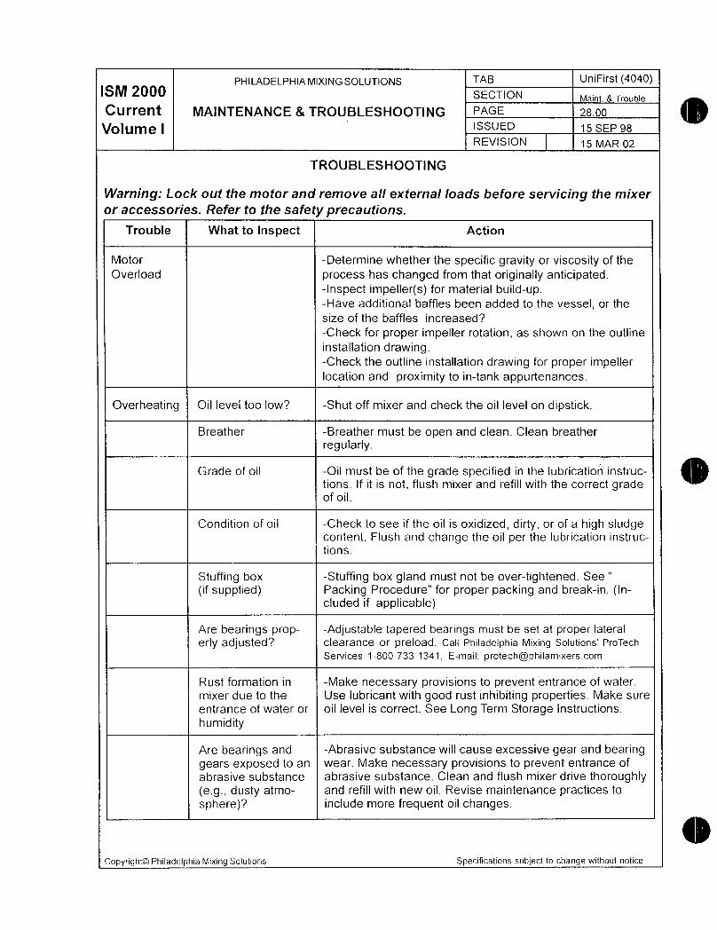
PHILADELPHIAMIXINGSOLUTIONS TAB UniFirst 4040SM ZOOO SECTION
Current MAINTENANCE 8 TROUBLESHOOTING 28100Trouble
PAGE
Volume I ISSUED 15 SEP 98
REVISION 15 MAR 02
TROUBLESHOOTING
Warning Lock out the mofor and remove all external oads before servicing the mixer
or accessories Refer fo the safety precautionsTrouble What to Inspect Action
Motor Determine whether the specific gravity or viscosity of the
Overload process has changed from that originally anticipatedInspect impellers for material buildupHave additional baffles been added to the vessel or the
size of the baffles increased
Check for proper impeller rotation as shown on the outline
installation drawingCheck the outline installation drawing for proper impellerlocation and proximity to intank appurtenances
Overheating Oil level too low Shut off mixer and check the oil level on dipstick
Breather Breather must be open and clean Clean breather
regularly
Grade of oil Oil must be of the grade specified in the lubrication instruc
tions If it is not flush mixer and refill with the correct gradeof oil
Condition of oil Check to see if the oil is oxidized dirty or of a high sludgecontent Flush and change the oil per the lubrication instruc
tions
Stuffing box Stuffing box gland must not be overtightened See
if supplied Packing Procedure for proper packing and breakin Included if applicable
Are bearings prop Adjustable tapered bearings must be set at proper lateral
erly adjusted ClearanCe or preload Call Philadelphia Mixing Solutions ProTech
Services18007331341 Emaii protech@philamixerscomRust
formation in Make necessary provisions to prevent entrance of water mixer
due to the Use lubricant with good rust inhibiting properties Make sure entrance
of water or oil level is correct See Long Term Storage Instructions humidity
Are
bearings and Abrasive substance will cause excessive gear and bearing gearsexposed to an wear Make necessary provisions to prevent entranceof abrasive
substance abrasive substance Clean and flush mixer drive thoroughlyegdusty atmo and refill with new oil Revise maintenance practices to sphere
include more frequent oil changes Copyright0
Philadelphia Mixing Solutions Specifications subject to change without notice

PHILADELPHIAMIXINGSOLUTIONS TAB UniFirst 4040SM 20 SECTION Maint Trouble
Current MAINTENANCE TROUBLESHOOTINGPAGE 2s00
Volume I ISSUED 15 SEP 98
REVISION 15 MAR 02
Trouble What to Inspect Action
Noise Coupling wear Check input coupling for wear Replace if worn
Are bearings prop Adjustable tapered bearings must be set at proper lateral
erly adjusted clearance or preload Call Philadelphia Mixing Solutions ProTech
Services18007331341 Email protech@philamixerscomAre
bearings and Shut off mixer and check the oil level on dipstick gearsproperly Oil must be of the grade specified in the lubrication instruc lubricatedtions If it is not flush mixer drive and refill with the correct grade
of oil Hardware
tight Be certain that all mounting and coupling hardware is enedtightened to the correct wrench torque Mixer
support Does the mounting arrangement for the mixer provide structuresufficient support to prevent wobblingor vibrationof the assembly
See Outline Installation Drawing for criteria Vibration
Agitator Shaft Agitator shaft should not be bent The rigid coupling halves mustbe connected according to the instructions Critical
SpeedIf the shaft and or impellers are supplied by others check fora critical speed condition Vibrations can occur througha particular
speed range Steady
bearing Has excessive wear occurred to the steady bearing Is the if
applicable bearing securely bolted to the vessel and is it properly alignedInspect
hardware Is all blade hardware and extension arm hardwareif applicable
properly torqued Including agit shaft couplings andmounting hardware Oil
Leakage Plug at drain and Apply pipe joint sealant or equal and tighten fittings standardpipe fittingsHousing
and caps Tighten capscrews or bolts to proper torqueIf not entirely effectiveremove housing cover and caps Clean mating surfacesand apply new sealing compound gasket Mixer
output shaft Has the recommendedoil level been exceeded Check oil levelon the dipstick Drain oil to the correct level Breather
open Breather must be open and clean PHONE
717 8381341FAX 717 8321740ProTech
Services1 8007331341E
mailprotech@philamixerscomCopyright0PhiladelphiaMixing Solutions Specifications subject to change without notice

v yTmwwM
ry
39 ks
m
dQ
a
w
Rigid Couplingo
a
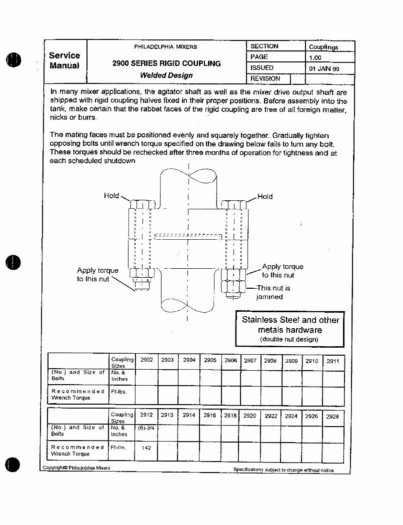
PHILAQELPHIA MIXERS SECTiON Cou lin s
erVICB PAGE i00
Manual 2900 SERIES RIGI COUPLINGissu 01 JAN 99
Welded Design REVISION
In many mixer applications the agitator shaf as well as the mixer drive output shaft are
shipped with rigid coupfing halves fixed in their proper positions Before assembly into the
tank make certain that the rabbet faces of the rigid coupling are free of at foreign matternicks or burrs
The mating faces must be positioned evenly and squarely together Gradually tightenopposing bolts until wrench torque speced on the drawing below fails to tum ay boitThese torques should be rechecked after three months of operation for tightness and at
each scheduled shutdawnI
I
Hold Hold
f
II II C 7II II
II I 11 11 1 II
li 11 1 II
I I 11 11 I II
p u
I ry n
4 II II I 11
A 1 tar usA tor ue f pp y qP y q
to this nutto this nut
I This nut is
jammed
Stainless Steel and other
metals hardware
double nut design
Coupling 2902 2903 2904 2905 2906 2907 2908 2909 2910 2911Sizes
No and Size of NoBBolts Inches
Recommended FtIbs
Wrench Torque
Coupling 2912 2913 2914 2916 2918 2920 2922 2924 2926 2928Sites
No and Size of NoB 634Bolts Inches
Recommended FtIbs 142
Wrench Torque
Copyfightm Philadelphia Mixers S eclficatlons subject to change wiUout noUce
E
aa e
aw LtTl1
P
Impeller
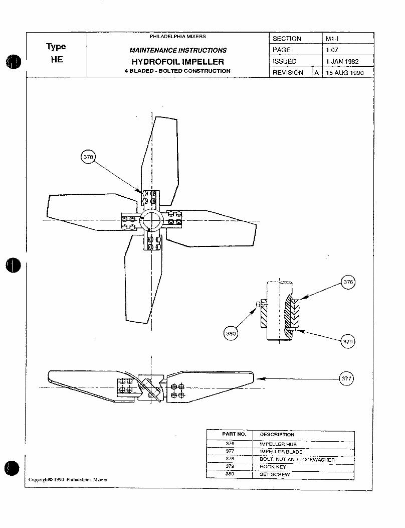
PHILADElPH1AMIXERSSCIOI M1I
Type MAlNTNANCE INSTRUCTlONS PAGE 107
E HYDROFOIL 9MPELLER ISSUED 1 JAN 1982
4 BLADED BOLTED GONSTRUCTION REVIStON A 15 AUG 1990
i
378
i
I 376
i
Ii
1380 I
379
377
PART NO DESCRIPTION
376 IMPELLER HUB
377 IMPEILER BIADE
378 BOLT NUT AND LOCKWASHER
379 HOOK KEY
380 SET SCREW
Copyright 1990 Philaddphia Mixcrs
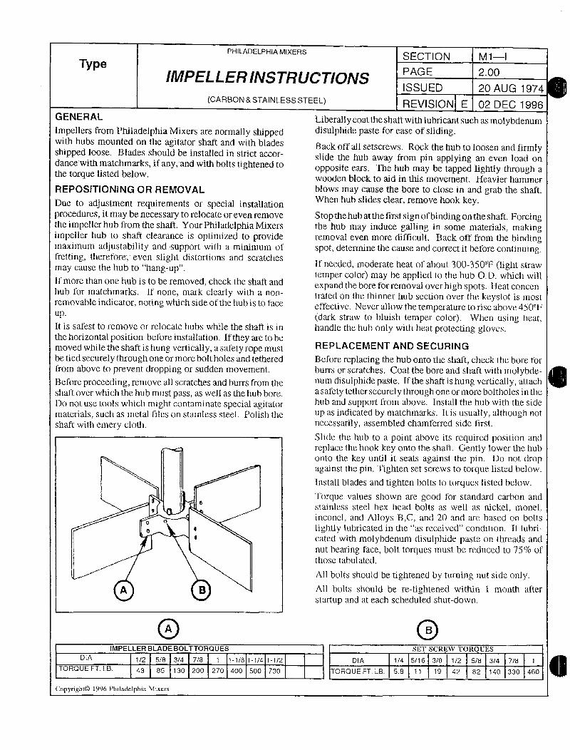
PHILADELPHIAMIXERSSECTION MI
TypIMPELLERINSTRUCTIONS
PAGE 200
ISSU ED 20 AUG 1974
CARBONSTAINLESSSTEEL REVISION E 02 DEC 1996
G ENE RAL Liberally coat the shait with lubricant such as molybdenumImpellers from Philadelphia Mixers are normally shipped disulphide paste for ease of slidingwith hubs mounted on the agitator shaft and with blades Back oft ail setscrews Rock the hub to loosen and firrnlyshipped loose Blades should be installed in strict accor slide the hub away from pin applying an even load ondance with matchmarks if any and with bolts tightened to
opposite ears The hub may be tapped lightly through athe torque listed below
wooden block to aid in this movement Heavier hammerREPOSITIONING OR REMOVAL blows may cause the bore to close in and grab the shaft
Due to adjustment requirements or special installationen hub slides clear remove hook key
procedures it may be necessary to relocate or even remove Stop the hub at the first signoibinding on the shaft Forcingthe impeller hub from the shaft Your Philadelphia Mixeis tie hub may induce galling in some materials makingimpeller hub to shaft clearance is optimized to provide emoval even more difficult Back off from the bindingmaximum adjustability and support with a minimum of spot determine the cause and correct it berore conlinuingfretting therefore even slight distortions and scratches
If needed moderate heat of about 300350l ligYit strawmay cause the hab to hangup
temper color may be applied to the hub OD which willIf more than one hub is to be removed check the shaft and
expand the bore for removal over high spots Heat concenhub for matchmarks lf none mark ciearly with a non trated on ttie thinner hub sec6on over the keyslot is mostremovable indicator noting wtuch side of the hub is to face effective Never allow the temperature to rise above 450F
dark straw to bluish temper color Wtien using heatIt is safest to remove or relocate hubs while the shaft is in handle the hub only with heat protecting glovesthe horizontal position belore installation If they are to be
movedwhiletheshaftishungverticallyasafetyropemust REPLACEMENTANDSECURWG
be tied securely through one or more boltholes and tethered Before replacing the hub onto the shatt check the bore forzrom above t prevent dropping or sudden movement burrs or scratches Coat the bore and shaft with molybdeBefore proceeding remove all scratches and burrs from the num disulphide paste Ifthe shaft is hung vertically attach
shaft over which the hub must pass as well as the hub bore asafety tether securely through one or more boltholes ii the
Do not use tools wluch might contaminate special agitator hub and support from above Install the hub wiLh lhe side
materials such as metal files on stainless steel Polish the up as indicated by matchmarks It is usually although not
shaft with emery cloth necessarily assembled chamferred side t7rst
Slide the hub to a point above its required position and
replace the hookkey onto the shaf Gently lower thc hub
onto the key until it seats against tlte pin Do noc dropagainst the pin Tighten set screws to torque listed below
Install blades and tighten bolts to torques IisCed below
Torque values shown are good for standard carbon and
stainless steel hex head bolts as well nickel monet
o inconel and Alloys T3C and 20 and are based on bolts
a e lightly lubricated in the as received condition If lubri
cated with molybdenum disulphide paste on threads and
nut bearing face bolt torques must be reduced to 750 of
those tabulated
A11 bolfs should be tightened byhrning nut side only
q g All boits should be retightened within 1 month after
statup and at each scheduled shutdown
O OIMPELLERBLADEBOLTTORQUES SLI SCREV TOIL UES
DIA 2 58 34 78 1 118 1141t2 DIA 1A 516 38 12 58 34 78 7
TORQUE FT LB 43 85 130 200 270 400 S00 730 TORQUE FT LB 58 11 19 42 82 140 330 460
Copyright0 1996 Fhiladclphia Mixers
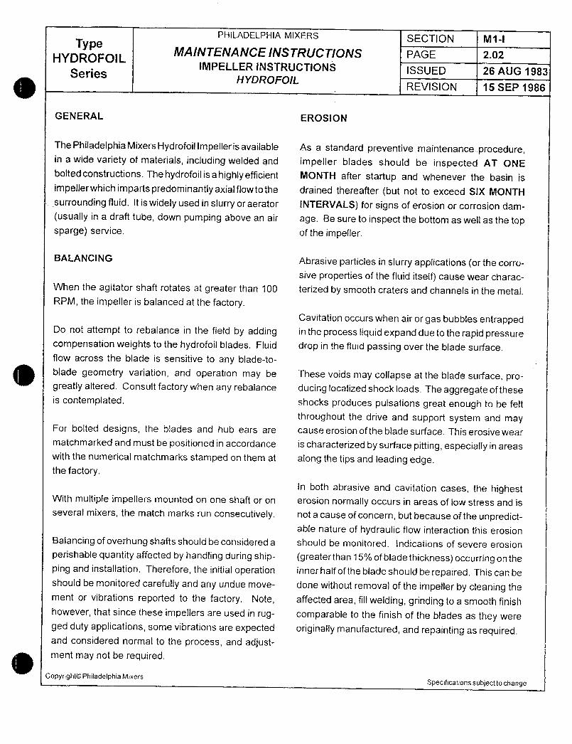
PHILADELPHIA MIXERS SECTION M1IType
MAINTENANCE INSTRUCTIONS PAGE 202HYDROFOILIMPELLER INSTRUCTIONS
Series ISSUED 26 AUG 1983HYDROFOIL
REVISION 15 SEP 1986
GENERAL EROSION
ThePhiladelphiaMixersHydrofoillmpeflerisavailable As a standard preventive maintenanceprocedurein a wide variety of materials including welded and impeller blades should be inspected AT ONE
bolted constructions The hydrofoil is a highly efficient MONTH after startup and whenever the basin is
impellerwhichimpartspredominantlyaxialflowtothe drained thereafter but not to exceed SIX MONTH
surrounding fluid It is widely used in slurry or aerator INTERVALS for signs of erosion or corrosion dam
usually in a draft tube down pumping above an air age Be sure to inspect the bottom as well as the topsparge service of the impeller
BALANCING Abrasive particles in slurry applications or the corro
sive properties of the fluid itselfl cause wear charac
When the agitator shaft rotates at greater than 100 terized by smooth craters and channels in the metal
RPM the impeller is balanced at the factoryCavitation occurs when air or gas bubbles entrapped
Do nof attempt to rebafance in the fietd by adding in the process liquid expand due to the rapid pressure
compensation weights to the hydrofoil blades Fluid drop in the fluid passing over the blade surface
flow across the blade is sensitive to any bladeto
blade geometry variation and operation may be These voids may collapse at the blade surface pro
greatly altered Consult factory when any rebalance ducing localized shock loads The aggregate of theseis contemplated shocks produces pulsations great enough to be felt
throughout the drive and support system and mayFor bolted designs the blades and hub ears are cause erosion of the blade surface This erosive wear
matchmarked and must be posifioned in accordance is characterized by surface pitting especially in areas
with the numerical matchmarks stamped on them at along the tips and leading edgethe factory
In both abrasive and cavitation cases the highestWith multiple impellers mounted on one shaft or on erosion normaHy occurs in areas of low stress and isseveral mixers the match marks run consecutively not a cause of concern but because of the unpredict
able nature of hydraulic flow interaction this erosion
Balancing of overhung shafts should be considered a should be monitored Indications of severe erosion
perishable quantity affected by handling during ship greaterthan15ofbladethicknessoccurringontheping and installation Therefore the initial operation inner half of the blade should be repaired This can beshould be monitored carefully and any undue move done without removal of the impeller by cleaning the
ment or vibrations reported to the factory Note affected area fill welding grinding to a smooth finish
however that since these impellers are used in rug comparable to the finish of the blades as they were
ged duty applications some vibrations are expected originally manufactured and repainting as requiredand considered norma to the process and adjustment may not be required
CopyrightOPhiladelphia MixersSpecifications subject to change

Motor
I 0
o
C
7 J
e U FEai
k Yh 1 tf
y ew nr
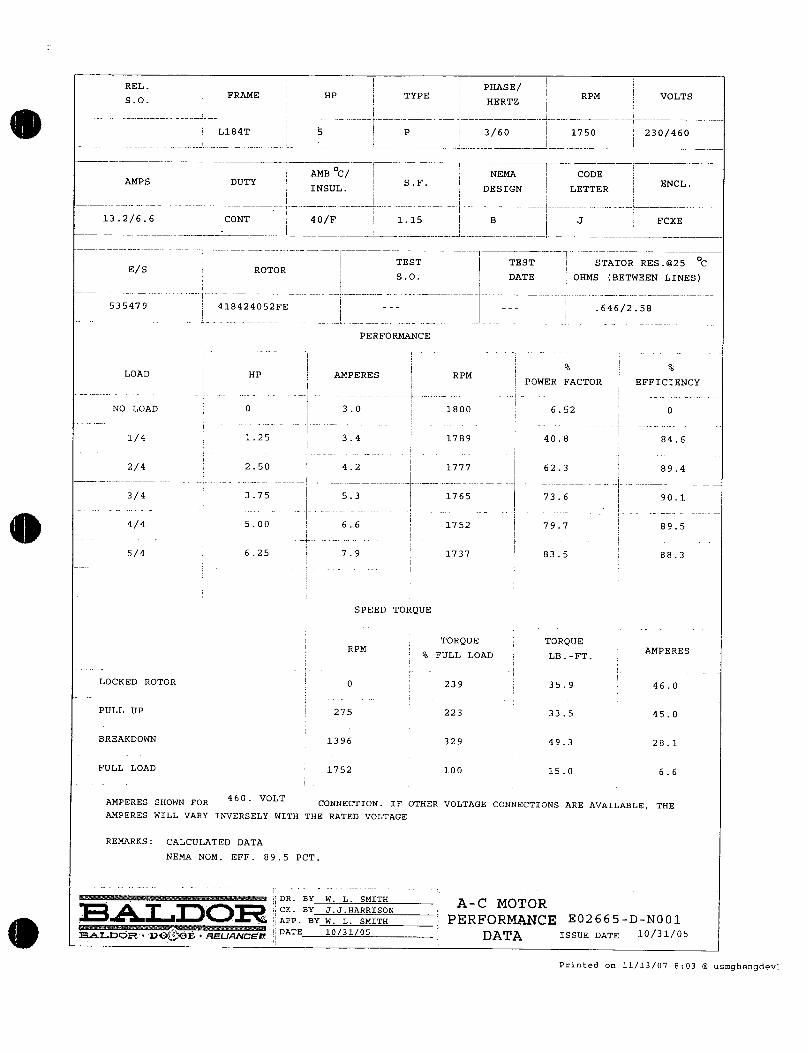
iRELi PHASE
SO j FRAME HP i TYPE RPM VOLTSHERTZ
Ii
I I
L184T 5 P 360 1750 i 230460I
i
AMB C I NEMA CODEAMPS DUTY i ENCL
j I INSULSF I
DESIGN LETTER
i I I i
13266 CONT 40F 115 B J FCXE
I I
Ei
TEST TEST i STATOR RES@25 CS ROTOR iI 50 DATE OHMS BETWEEN LINES
i
535479 418424052FE 646258I
PERFORMANCE
I e I
LOAD HP AMPERES j RPM i POWER FACTOR i EFFICIENCY
INO LOAD 0 i 30 1800 652 0
i
I i
14 125 34 i 1789 I 408 846i i I
i24 250 42 j 1777 I 623 894
l34 375 53 1765 I 736
I901
ii
44 500 66 i 1752 797 895
ii
54 625 79 1737 835 883
SPEED TORQUE
TORQUE TORQUERPM
FULL LOAD LBFTAMPERES
LOCKED ROTOR 0 239 359 460
PULL UP 275 223 335 450
BREAKDOWN 1396 329 493 281
FULL LOAD 1752 100 150 66
AMPERES SfiOWN FOR460 VOLT
CONNECTION IF OTHER VOLTAGE CONNECTIONS ARE AVAILABLE THE
AMPERES WILL VARY INVERSELY WITH THE RATED VOLTAGE
REMARKS CALCULATED DATA
NEMA NOM EFF 895 PCT
i DR BY W L SMITHA MOTOR
T iCK BY JJHARRISON
E02665DN001L APP BY w L sMZTx PERFORMANCESALDQR DOE RELlANGPI
DATE 1031OS DATA ISSUE DATE 1031OS
Printed on 111307 803 usmghengdev
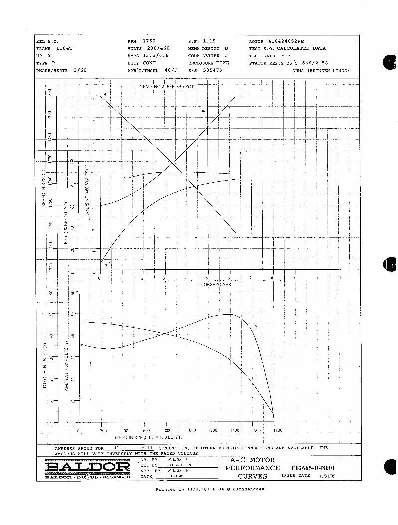
REL SO RPM 1750 SF 115 ROTOR 416424052FE
FxAME L184T vOLTS 230460 xartA DESZGN B TEST So CALCULATED DATA
HP S AMPS 13266 CODE LETTER J TEST DATE
TYPE P DUTY CONT ENCLOSURE FCXE STATOR RES @25C6462
58PHASE HERTZ3 60 AMB40 FE S 535479 OHMS BETWEEN
LINES
I
I ii I i
i
J
i
I NEMA
NOMEFF Sy S PCT i I i r
i a II J I I I
i o i I i i
i a 1 ii I I i i
i i j i
i i i I I
I if i i r i I 1 ii I o i iiI TI
i I i I i I III i
I 4 I I Ii I I
I 1 I I IiI iIo I I I I I I I I I I
I I n
i I I i i I i I I I I Ii
i T I I I II F i
T a 1 p j I iI
I i i
ii
q Y y il
i I I I I
I I I I II i
i o i Ii n i i I
II
I i I
i i I II
zI j I
i a Ii ii
I i i I i I i i Ii I
I o i1
r
I II I I
i I II
I I I
II I i I
L I i III I i I I L Ii
I
I
I II
I I o
f
I j I i i I I i I
I I I i I I I
i
J
I 6 I 8 9 I 0 II I I p 3 1
5 IiORS6POWER I
i oo i I II I
i
ii
lIIi
ii o i a
i i ii i
i i
i ii o
I iI II
i ii
F tiJI o
o J
i7
7 I
IWF
Q d o oI
KF
Q o
a
i
i o
o o oo aoo oo soo iuooi oo iaoai oo
isoo SPEED INRP 1I A LBFT
i AMPERES SHOWN FOR 4G0VOI 1 CONNECTION ZF OTHER VOLTAGE CONNECTIONS ARE AVAILABLE
THE AMPERES WILL VARYZN VERSELY WZTH THE RATED
VOLTAGE DR BYS TF A C
MOTORBAL O CK BY
JJJiARRISON L ppp Hy us T PERFORMANCEG02665D
N001SAS DGRDE RELIANGEt DATE10I 0 CURVES ISSUE DATEpJ
pS Printed on1113 078 04
usmghengdevl
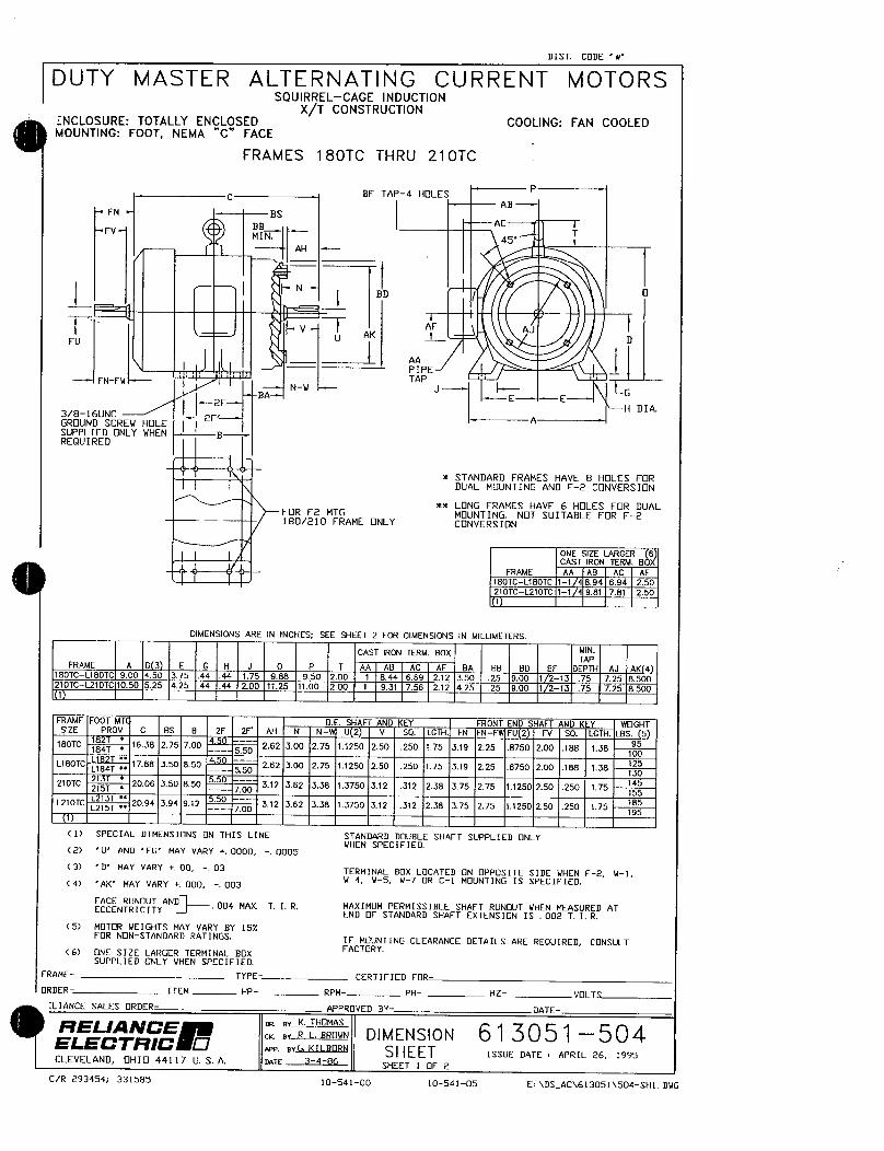
DIST LODE w
DUTY MASTER ALTERNATING CURRENT MOTORSSQUIRRELCAGE INDUCTION
XT CONSTRUCTIONNCLOSURE TOTALLY ENCLOSED COOLING FAN COOLEDMOUNTING FOOT NEMA C FACE
FRAMES 180TC THRU 210TC
BF TAP4 HOLESP
AB
BS
FVBB AC
MIN 45T
AH
I Np
F VAK A 1 AJ
D
AA 1PIPEFNFW
NWTAP
JBA E
I H DIA3816UNC
I IzF AGROUND SCREN HOLE
SUPPLIED ONLY IJHEN gREQUIRED
STANDARD FRAMES HAVE 8 HOLES FORDUAL MUNTING AND F2CNVERSION
LONG FRAMES HAVE 6 HOLES FR DUALFOR F2 MTG MOUNTING NT SUITABLE FOR F2180210 FRAME NLY CONVERSION
ONE SIZE LAF2GER 6CAST IRON TERM B
FRAME AA AB AC AF
180TCL180TC 11 894 694 250
210TCL2107C 11 981 781 2501
DIMENSIONS ARE IN INCHES SEE SHEET 2 FOR DIMENSIONS IN MILLIMETERS
CAST IRON TERM BOX MINTAP
FRAME A D 3 E G H J 0 P T AA AB AC AF BA BB BD 8f DEPTH AJ AK 4180TCL180TC 900 450 375 44 44 175 988 950 200 1 844 669 212 350 25 900 7 213 75 725 8500210TCL210TC 1050 525 425 44 44 200 1725 1100 200 1 931 756 272 425 25 900 1 213 75 725 8500
1
FRAME FOOT MT BE SHAFT AND KEY FRONT END SHAFT AND KEY WOGHTSIZE PROV C BS B 2F 2F AH N N U 2 V SQ LGiH F1J FNFW FU 2 FV SQ LGTH LBS 5
180TC 184T 1638 275 700 4 550262 300 275 11250 250 250 175 319 225 8750 200 188 138
95
100
L180TCL184T
g8 350 850450
550z62 300 275 11250 250 250 175 319 225 8750 200 188 138
25
130
210TC 25T 2006 350 850 312 362 338 13750 312 312 238 375 275 11250 250 250 17514
155785L210TC
15T2094 394 912 550 700
312 362 738 13750 312 312 238 375 275 17250 250 250 775195
1
1 SPECIAL DIMENSIONS ON THIS LINE STANDARD DOUBLE SHAFT SUPPLIED ONLYVHEN SPECFIED
2 U AND FU MAY VARY 0000 0005
3 D MAY VARY 00 03TERMINAL BX LOCATED ON OPPOSITE SIDE NHEN F2 N1
4 AK MAY VARY 000 003W N5 V7 R C1 MOUNTING IS SPECIFIED
FACE RUNOUT AND 004 MAX T I R MAXIMUM PERMISSIBLE SHAFT RUNOUT IIHEN MEASURED ATECCENTRICITYEND OF STANDARD SHAFT EXTENSION IS 002 T I R
S MTR NEIGHTS MAY VARY BY 15FR NONSTANDARD RATINGS IF MOUNTING CLEARANCE DETAILS ARE REQUIRED CNSULT
6 ONE SIZE LARGER TERMINAL BXFACTORY
SUPPLIED ONLY VHEN SPECIFIED
FRAME 7YPE CERTIFIED FOR
ORDER ITEN HP RPM PH HZ VLT
LIANCE SALES ORDER APPROVED HY DATE
f7ELA1VCE er K THOMAS
ELECTl9C BY R L BROWN D I M E N S I 0 N 61 3 0 51 5 0 4tap arG KILBORN SHEET ISSUE DATE APRIL 26 1995
CLEVELAND OHI 44117 U S A nnTE 3486SHEET I OF 2
CR 293454 331585 1054100 10541OS EDSAC613051504SH1DlIG
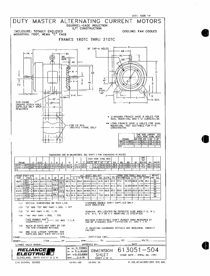
DIST CODE w
DUTY MASTER ALTERNATING CURRENT MOTORSSQUIRRELCAGE NDUCTION
XT CONSTRUCTIONNCLOSURE TOTALLY ENCLOSED COOLING FAN COOLEDMOUNTING F00T NEMA C FACE
FRAMES 180TC THRU 210TC
CHF TAP4 HOLES
P
ABFN BS
BBAC
FVMIN 45
T
AH
I t N
AF
F VU AK 1
AJD
AA 1PIPE
FNFW
IBA
NuTAP
J IE
G
H DIA
3816UNC 2F qGRUND SCREIJ HOLESUPPLIED NLY WHEN
I Ig
REQUIRED
STANDARD FRAMES HAVE 8 HOLES FOR
DUAL MOUNTING AND F2 CONVERSIN
LONG FRAMES HAVE 6 HOLES FOR DUAL
FOR F2 MTG MOUNTING NOT SUITABLE FOR F21802L0 FRAME ONLY CONVERSION
ONE SIZE LARGER 6CAST IRON TERM BdX
FRAME AA 7 AB AC AF
780TCL180TC 11 2271 1763 635
210TCL210TC 11 2492 1984 635
1
OIMENSIONS ARE IN MILLIMETERS SEE SHEET 2 FOR DIMENSIONS IN INCHES
CAST IRON TERM BOXMINTAP
FRAME A D 3 E G H J 0 P T AA 7 AB AC A BA BB BD BF DEPTH AJ AK 4
180TCL180TC 2286 1143 953 112 t12 445 2510 2413 508 1 2744 7699 538 889 635 2286 1 21 191 1842 21590
210TCL210TC 2667 1334 1080 112 112 508 2858 2794 508 7 2365 1920 538 1080 635 2286 1 21 191 1842 27590
1
FRAME F00T MT BE SHAFT AND KEY FRONT END SHAFT AND KEY WEIGHT
SIZE PROV C BS B 2F 2F AH N NW U 2 V SQ LGTH FN FNFW FU 2 FV SQ LG7H L85 5
180TC182T
4161 699 778 665 762 699 28575 635 635 445 810 572 22225 508 478 35143
184T 1397 45
L180TC 4542 889 159114
665 762 699 28575 635 635 445 870 572 22225 508 478 35157
L184T 1397 5
210TC21
095 889 1599
792 919 859 34925 792 792 605 953 699 28575 635 635 445 60215T 1778
1210TCL213T
5319 1001 2316139
792 919 859 34925 792 792 605 953 699 28575 635 635 44584
L215T 177B 8B
1
C1 SPECIAL DIMENSIONS ON THIS LINE STANDARD DDUBLE SHAFT SUPPLIED ONLYVHEN SPECIFED
2 U AND FU MAY VARY 000 127
C3 MAY VARY 00 76 TERMINAL BX LOCATED N OPPOSITE SIDE NHEN F2 u1
4 AK MAY VARY 000 076u N5 W7 OR C1 MDUNTING IS SPECIFIED
FACE RUNUT AND 101 MAX TIR MA7IMUM PERMISSIBLE SHAFT RUNUT WHEN MEASURED ATECCENTRICITY END F STANDARD SHAFT EXTENSION IS O50 T I R
CS MOTOR WEIGHTS MAY VARY BY 15
FORNNSTANDARD RATINGS IF MOUNTING CLEARANCE DETAILS ARE REOUIRED CONSUIT
6 NE SIZE LARGER TERMINAL BOXFACTORY
SUPPLIE NLY VHEN SPECIFIED
FRAME TYPE CERTIFIED FOR
RDER ITEM HP RPM PH HZ VLTS
LIANCE SALES ORDER APPROVED BY DATE
RELANCEBY K THMAS
ELECTRCBY R BRWN D I M E N S I 0 N 61 3 0 51 5 0 4
nPp arG KILBORN SHEET ISSUE DATE APRIL 26 1995
CLEVELAND HI 44117 U S A nnT 3486SHEET 2 OF 2
CR 293454 331585 1054100 10541OS EDSAC613051504SH2DUG
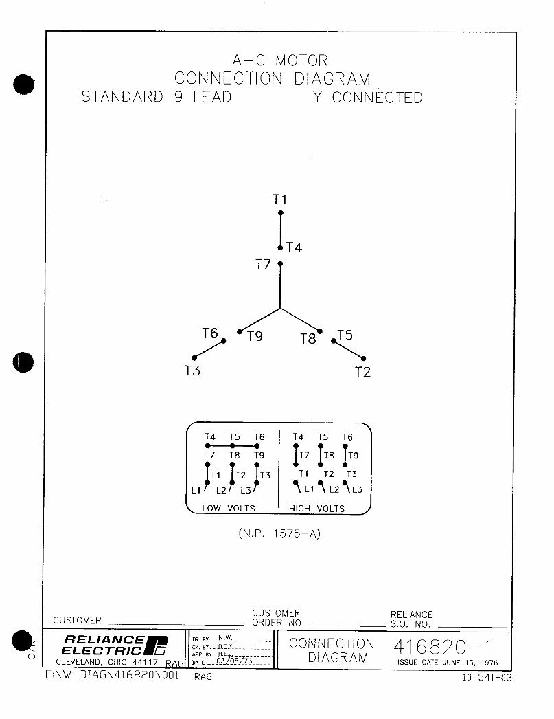
A C M OTOR
CONNECTION DIAGRAMSTANDARD 9 EAD Y CONNECTED
T1
T4
T7
T6 Tg T8 T5
T3 T2
T4 TS T6 T4 T5 T6
T7 T9 IT7 IT8 IT9
T1 T2 T3 Tt T2 T3
L1 L2 L3 L1 L2 L3
LOW VOLTS HIGH VOLTS
NP 1575
CUSTOMER RELIANCECUSTOMER ORDER N0 SO N0
RELANCE DRBNwCONNECTIONELECTRC K BYY 416 8 201
APP BY HE D I A G R A MCLEVELAND OHIO 441 17 RAG Dn7E 03OSf76 ISSUE DATE JUNE 15 1976
EW RAG 1054103
AL170IVIOTORS AND DRIVES
Integrae HorsepowerAC Induction Motors
ODP Enclosure
TFCErclosure
Explosion Proof
Installation Operating Manual
701 MN400

Table of Contents
Section 1
Generalinformation 11
Overview 11
LimitedWarranty 11
SafetyNotice 12
Receiving 14
Storage 14
Unpacking 14
Handling 14
Section 2
Installation Operation 21
Overview 21
Location 21
Mounting 21
Alignment 2t
Doweling Bolting 22
PowerConnection 22
ConduitBox 22
ACPower 22
FirstTime Start Up 24
CoupledStart U p 24
Jogging and Repeated Starts 24
Section 3
M aintenance Troubleshooting 31
Generallnspection 31
Lubrication Bearings 31
Typeof Grease 31
Lubricationlntervals 31
Lubrication Procedure 33
Accessories 34
Troubleshooting Chart 35
MN400 Table of Contents i

Section 1
Generai Information
Overview This manual contains general procedures that apply to Baldor Motor products Be sure to read and
understand the Safety Notice statements in this manual For your protection do not install operate or
attempt to perform maintenance procedures until you understand the Warning and Caution statements A
Warning statement indicates a possible unsafe condition that can cause harm to personnel A Cautionstatement indicates a condition that can cause damage to equipment
Important This instruction manual is not intended to include a comprehensive listing of all details for all
procedures required for installation operation and maintenance This manual describes generalguidelines that apply to most of the motor products shipped by Baldor If you have a questionabout a procedure or are uncertain about any detail Do Not Proceed Please contact your Baldordistributor for more information or clarification
Before you install operate or perform maintenance become familiar with the followingNEMA Publication MG2 Safety Standard for Construction and guide
for Selection Installation and Use of Electric Motors and Generators
The National Electrical Code
Local codes and Practices
Limited Warrantv
1 Baldor Electric motors are warranted for a period of one 1 year from date of shipment from the factory or factorywarehouse against defects in material and workmanship To allow for stocking andor fabrication period and to
provide one year of actual service the warranty period is extended for an additional period of six 6 months for a
total of eighteen 18 months from the original date of shipment from the factory or factory warehouse stock In no
case will the warranty period be extended for a longer period Baldor extends this limited warranty to each buyerof the electric motor for the purpose of resale and to the original purchaser for use
2 Baldor will at its option repair or replace a motor which fails due to defects in material or workmanship during the
warranty period if
a the purchaser presents the defective motor at or ships it prepaid to the Baldor plant in Fort Smith Arkansas
or one of the Baldor Authorized Service Centers and
b the purchaser gives written notification concerning the motor and the claimed defect including the date
purchased the task performed by the Baldor motor and the problem encountered
3 Baldor vill not pay the cost of removal of any electric motor from any equipment the cost of delivery to Fort SmithArkansas or a Baldor Authorized Service Center or the cost of any incidental or consequential damages resultingfrom the claimed defects Some states do not allow the exclusion or limitation of incidental or consequentialdamages so the above exclusion may not apply to you Any implied warranty given by laws shall be limited to
the duration of the warranty period hereunder Some states do not allow limitations on how long an impliedwarranty lasts so the above limitation may not apply to you
4 Baldor Authorized Service Centers when convinced to their satisfaction that a Baldor motor developed defects in
material or workmanship within the warranty period are authorized to proceed with the required repairs to fulfill
Baldors warranty when the cost of such repairs to be paid by Baldor does not exceed Baldors warranty repairallowance Baldor will not pay overtime premium repair charges without prior written authorization
5 The cost of warranty repairs made by centers other than Baldor Authorized Service Centers WILL NOT be paidunless first authorized in writing by Baldor
6 Claims by a purchaser that a motor is defective even when a failure results within one hour after being placed into
service are not always justified Therefore Baldor Authorized Service Centers must determine from the condition
of the motor as delivered to the center whether or not the motor is defective If in the opinion of a Baldor
Authorized Service Center a motor did not fail as a result of defects in material or workmanship the center is to
proceed with repairs only if the purchaser agrees to pay for such repairs If the decision is in dispute the
purchaser should still pay for the repairs and submit the paid invoice and the Authorized Service Centers signedservice report to Baldor for further consideration
7 This warranty gives you specific legal rights and you may also have other rights which vary from state to state
Note that Baldor SuperEO Premium Efficiency electric motors are warranted for a period of three 3 yearsAll other terms and conditions of the Limited Warranty statement apply
MN400 General Information 11
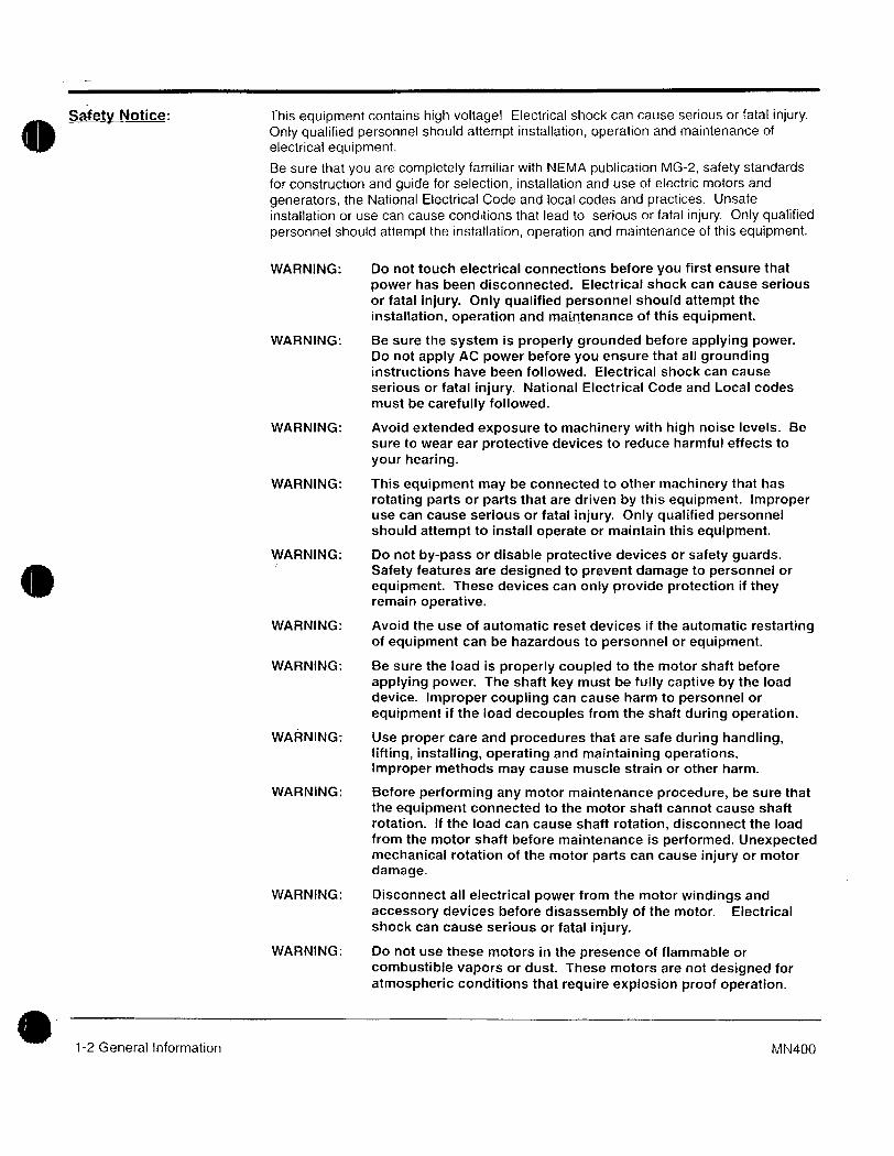
Saety Notice This equipment contains high voltage Electrical shock can cause serious or fatal injuryOnly qualified personnel shouid altempt instailation operation and maintenance of
electrical equipment
Be sure that you are completely familiar with NEMA publication MG2 safety standards
for construction and guide for selection installation and use of electric motors and
generators the National Electricai Code and locai codes and practices Unsafe
installation or use can cause conditions that lead to serious or fatal injury Only qualifiedpersonnel should attempt the installation operation and maintenance of this equipment
WARNING Do not touch electrical connections before you first ensure that
power has been disconnected Electrical shock can cause serious
or fatal injury Only qualified personnel should attempt the
instalation operation and maintenance of this equipment
WARNING Be sure the system is properly grounded before applying powerDo not apply AC power before you ensure that all groundinginstructions have been followed Electrical shock can cause
serious or fatal injury National Electrical Code and Local codes
must be carefully followed
WARNING Avoid extended exposure to machinery with high noise levels Be
sure to wear ear protective devices to reduce harmful effects to
your hearing
WARNING This equipment may be connected to other machinery that has
rotating parts or parts that are driven by this equipment Improperuse can cause serious or fatal injury Only qualified personnelshould attempt to install operate or maintain this equipment
WARNING Do not bypass or disable protective devices or safety guardsSafety features are designed to prevent damage to personnel or
equipment These devices can only provide protection if theyremain operative
WARNING Avoid the use of automatic reset devices if the automatic restartingof equipment can be hazardous to personnel or equipment
WARNING Be sure the load is properly coupled to the motor shaft before
applying power The shaft key must be fully captive by the load
device Improper coupling can cause harm to personnel or
equipment if the load decouples from the shaft during operation
WARNING Use proper care and procedures that are safe during handlinglifting installing operating and maintaining operationsImproper methods may cause muscle strain or other harm
WARNING Before performing any motor maintenance procedure be sure that
the equipment connected to the motor shaft cannot cause shaft
rotation If the load can cause shaft rotation disconnect the load
from the motor shaft before maintenance is performed Unexpectedmechanical rotation of the motor parts can cause injury or motor
damage
WARNING Disconnect all electrical power from the motor windings and
accessory devices before disassembly of the motor Electricalshock can cause serious or fatal injury
WARNING Do not use these motors in the presence of flammable or
combustible vapors or dust These motors are not designed for
atmospheric conditions that require explosion proof operation
12 General Information MN400
Safety Notice Continued
WARNING Motors that are to be used in flammabJe andor explosiveatmospheres must display the UL label on the nameplate
Specific service conditions for these motors are defined in
NEC 70599
WARNING UL rated motors must only be serviced by authorized Baldor
Service Centers if these motors are to be returned to a flammable
andor explosive atmosphere
Caution To prevent premature equipment failure or damage only qualifiedmaintenance personnel should perform maintenance
Caution Do not lift the motor and its driven load by the motor liftinghardware The motor lifting hardware is adequate for lifting only the
motor Disconnect the load from the motor shaft before moving the
motr
Caution If eye bolts are used for lifting a motor be sure they are securelytightened The lifting direction should not exceed a 20 angle from
the shank of the eye bolt or lifting lug Excessive lifting angles can
cause damage
Caution To prevent equipment damage be sure that the electrical service is
not capable of delivering more than the maximum motor rated ampslisted on the rating plate
Caution If a HI POT test High Potential Insulation test must be performedfollow the precautions and procedure in NEMA MG1 and MG2
standards to avoid equipment damage
If you have any questions or are uncertain about any statement or procedure or if you
require additional information please contact your Baldor distributor or an Authorized
Baldor Service Center
MN400 General Information 13

Reeivinq Each Baldor Electric Motor is thoroughly tested at the factory and carefully packaged for
shipment When you receive your motor there are several things you should do
immediately
1 Observe the condition of the shipping container and report any damageimmediately to the commercial carrier that delivered your motor
2 Verify that the part number of the motor you received is the same as the partnumber listed on your purchase order
Sta If the motor is not put into service immediately the motor must be stored in a clean dryand warm location Several precautionary steps must be performed taavoid motor
damage during storage
1 UseaMegger periodically to ensure that the integrity of the winding insulationhas been maintained Record the Megger readings Immediately investigateany significant drop in insulation resistance
2 Do not lubricate bearings during storage Motor bearings are packed with
grease at the factory Excessive grease can damage insulation quality3 Rotate motor shaft at least 10 turns every two months during storage more
frequently if possible This will prevent bearing damage due to storage4 If the storage location is damp or humid the motor windings must be protected
from moisture This can be done by appiying power to the motors spaceheater if available while the motor is in storage
Unpackinq Each Baldor motor is packaged for ease of handling and to prevent entry ofcontaminants
1 To avoid condensation inside the motor do not unpack until the motor hasreached room temperature Room temperature is the temperature of the room
in which it will be installed The packing provides insulation from temperaturechanges during transportation
2 When the motor has reached room temperature remove all protective wrappingmaterial from the motor
Handling The motor should be lifted using the lifting lugs or eye bolts provided1 Use the lugs or eye bolts provided to lift the motor Never attempt to lift the
motor and additional equipment connected to the motor by this method The
lugs or eye bolts provided are designed to lift only the motor Never lift themotor by the motor shaft
2 If the motor must be mounted to a plate with the driven equipment such as
pump compressor etc it may not be possible to lift the motor alone For thiscase the assembly should be lifted by a sling around the mounting base Theentire assembly can be lifted as an assembly for installation Do not lift usingthe motor lugs or eye bolts provided
If the load is unbalanced as with couplings or additional attachmentsadditional slings or other means must be used to prevent tipping In any eventthe load must be secure before lifting
14 General Information MN400
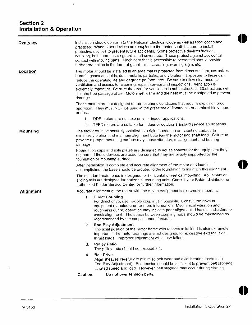
Section 2
Installation Operation
Overview Instaliation should conform to the National Electrical Code as well as locai codes and
practices When other devices are coupied to the motor shaft be sure to install
protective devices to prevent future accidents Some protective devices include
coupling belt guard chain guard shaft covers etc These protect against accidental
contact with moving parts Machinery that is accessibie to personnel should providefurther protection in the form of guard rails screening warning signs etc
Location The motor should be installed in an area that is protected from direct sunlight corrosives
harmful gases or liquids dust metallic particles and vibration Exposure to these can
reduce the operating life and degrade performance Be sure to allow clearance for
ventilation and access for cleaning repair service and inspections Ventilation is
extremely important Be sure the area for ventilation is not obstructed Obstructions will
limit the free passage of air Motors get warm and the heat must be dissipated to prevent
damage
These motors are not designed for atmospheric conditions that require explosion proof
operation They must NOT be used in the presence of flammable or combustible vapors
or dust
1 ODP motors are suitable only for indoor applications
2 TEFC motors are suitable for indoor or outdoor standard service applications
Mountinq The motor must be securely installed to a rigid foundation or mounting surface to
minimize vibration and maintain alignment between the motor and shaft load Failure to
provide a proper mounting surface may cause vibration misalignment and bearingdamage
Foundation caps and sole plates are designed to act as spacers for the equipment they
support If these devices are used be sure that they are evenly supported by the
foundation or mounting surface
After installation is compiete and accurate alignment of the motor and load is
accomplished the base should be grouted to the foundation to maintain this alignment
The standard motor base is designed for horizontal or vertical mounting Adjustable or
sliding rails are designed for horizontal mounting only Consult your Baidor distributor or
authorized Baldor Service Center for further information
Alignment Accurate alignment of the motor with the driven equipment is extremely important
1 Direct CouplingFor direct drive use flexible couplings if possible Consult the drive or
equipment manufacturer for more information Mechanical vibration and
roughness during operation may indicate poor alignment Use dial indicators to
check alignment The space between coupling hubs should be maintained as
recommended by the coupling manufacturer
2 EndPlay AdjustmentThe axial position of the motor frame with respect to its load is also extremely
important The motor bearings are not designed for excessive external axial
thrust loads Improper adjustment will cause failure
3 Pulley Ratio
The pulley ratio should not exceed 81
4 Belt Drive
Align sheaves carefully to minimize belt wear and axial bearing loads seeEndPlay Adjustment Beft tension should be sufficient to prevent belt slippageat rated speed and load However belt slippage may occur during starting
Caution Do not over tension belts
MN400 Installation Operation 21

Daweling Boiting After proper alignment is verified dowel pins should be inserted through the motor feet
into the foundation This will maintain the correct motor position should motor removal be
required Baldor motors are designed for doweling1 Drill dowel holes in diagonally opposite motor feet in the locations provided2 Drill corresponding holes in the foundation
3 Ream all holes
4 Install proper fitting dowels
5 Mounting bolts must be carefully tightened to prevent changes in alignmentUse a flat washer and lock washer under each nut or bolt head to hold the
motor feet secure Flanged nuts or bolts may be used as an alternative to
washers
Power ConneCtion Motor and control wiring overload protection disconnects accessbries and groundingshould conform to the National Electrical Code and local codes and practices
Conduit Box For ease of making connections an oversize conduit box is provided The box can be
rotated 360 in 90 increments Auxiliary conduit boxes are provided on some motors for
accessories such as space heaters RTDs etc
AC Power Connect the motor leads as shown on the connection diagram located on the name plateor inside the cover on the conduit box Be sure the following guidelines are met
1 AC power is within 10 of rated voltage with rated frequency See motor
name pfate for ratingsOR
2 AC power is within 5 of rated frequency with rated voltageOR
3 A combined variation in voltage and frequency of 10 sum of absolute
values of rated values provided the frequency variation does not exceed 5
of rated frequencyPerformance within these voltage and frequency variations are shown in Figure 21
22 Installation Operation MN400
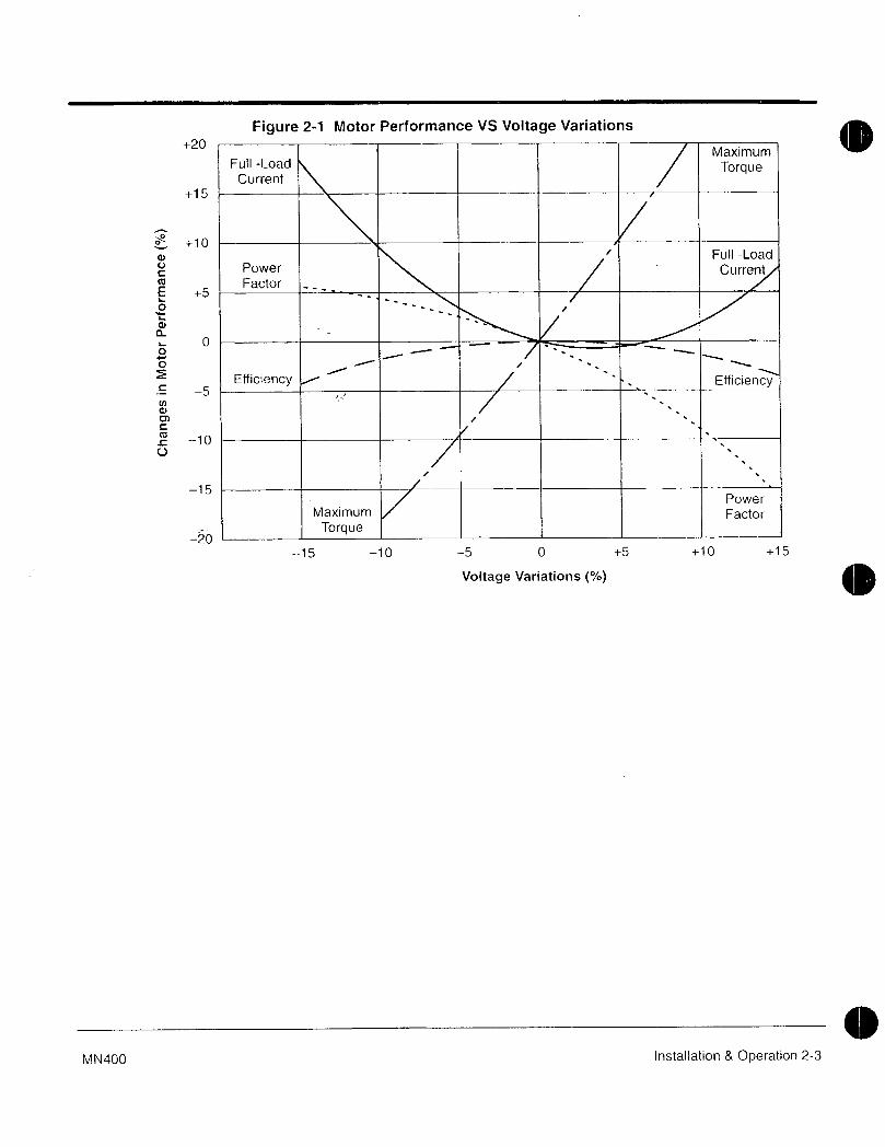
Figure 21 Motor Performance VS Voltage Variations
20Maximum
Full Load TorqueCurrent
15
10y FullLoad
Power CurrentFactor
E 5L
O
L
a
0O r
Efficiency Efficiency5
d
c10
U
15Power
Maximum Factor
Torque20
15 10 5 0 5 10 15
Voltage Variations
0MN400 Installation Operation 23
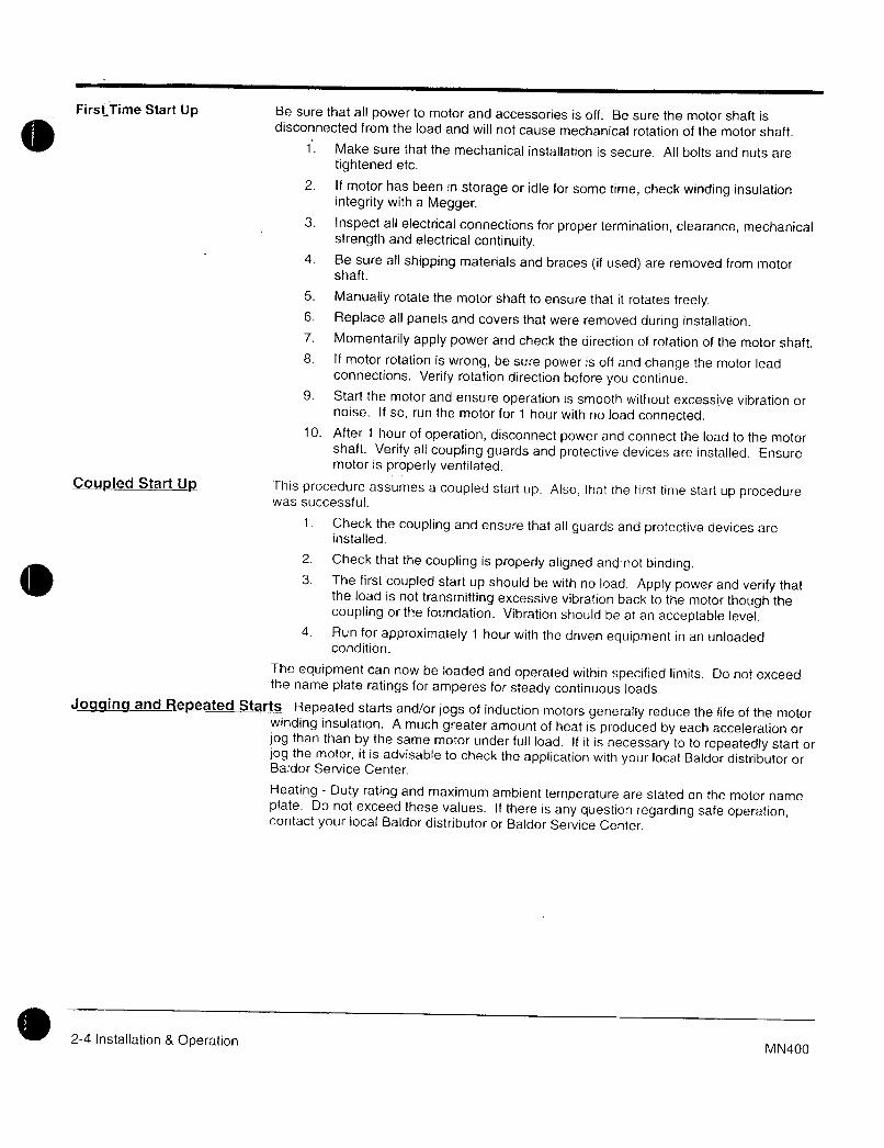
Firsf Time Start Up Be sure that all power to motor and accessories is off Be sure the motor shaft isdisconnected from the load and will not cause mechanical rotation of the motor shaft
1 Make sure that the mechanical installation is secure All bolts and nuts are
tightened etc
2 If motor has been in storage or idle for some time check winding insulation
integrity with a Megger3 Inspect all electrical connections for proper termination clearance mechanical
strength and electrical continuity4 Be sure all shipping materials and braces if used are removed from motor
shaft
5 Manualiy rotate the motor shaft to ensure that it rotates freely6 Replace all panels and covers that were removed during installation
7 Momentarily apply power and check the direction of rotation of the motor shaft
8 If motor rotation is wrong be sure power is off and change the motor leadconnections Verify rotation direction before you continue
9 Start the motor and ensure operation is smooth without excessive vibration or
noise If so run the motor for 1 hour with no load connected
10 After 1 hour of operation disconnect power and connect the load to the motorshaft Verify all coupling guards and protective devices are insialled Ensuremotor is properly ventilated
Coupled Start U This procedure assumes a coupied start up Also that the first time start up procedurewas successful
t Check the coupling and ensure that aii guards and protective devices are
installed
2 Check that the coupling is properly aligned and not binding3 The first coupled start up should be with no load Apply power and verify that
the load is not transmitting excessive vibration back to the motor though thecoupling or the foundation Vibration should be at an acceptable levei
4 Run for approximately 1 hour with the driven equipment in an unloadedcondition
The equipment can now be loaded and operated within specified limits Do not exceedthe name plate ratings for amperes for steady continuous loads
Joaqing and Repeated Starts Repeated starts andor jogs of induction motors generally reduce the life of the motor
winding insulation A much greater amount of heat is produced by each acceleration or
jog than than by the same motor under full load If it is necessary to to repeatedly start or
jog the motor it is advisable to check the application with your local Baldor distributor orBaldor Service Center
Heating Duty rating and maximum ambient temperature are stated on the motor name
plate Do not exceed these values If there is any question regarding safe operationcontact your locai Baldor distributor or Baldor Service Center
24 Installation OperationMN400
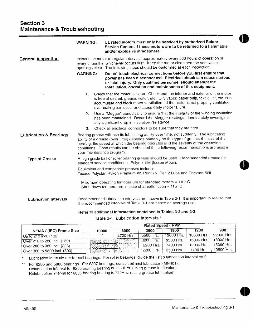
Section 3
Maintenance Troubleshooting
WARNING UL rated motors must only be serviced by authorized Baldor
Service Centers if these motors are to be returned to a flammable
andor explosive atmosphere
General InspeCtion Inspect the motor at regular intervals approximately every 500 hours of operation or
every 3 months whichever occurs first Keep the motor clean and the ventilation
openings clear The following steps should be performed at each inspection
WARNING Do not touch electrical connections before you first ensure that
power has been disconnected Electrical shock can cause serious
or fatal injury Only qualified personnel should attempt the
installation operation and maintenance of this equipment
1 Check that the motor is clean Check that the interior and exterior of the motor
is free of dirt oil grease water etc Oily vapor paper pulp textile lint etc can
accumulate and block motor ventilation If the motor is not properly ventilated
overheating can occur and cause early motor failure
2 UseaMegger periodically to ensure that the integrity of the winding insulation
has been maintained Record the Megger readings Immediately investigateany significant drop in insulation resistance
3 Check all electrical connectors to be sure that they are tight
Lubrication Bearinqs Bearing grease will tose its lubricating ability over time not suddenly The lubricating
ability of a grease over time depends primarily on the type of grease the size of the
bearing the speed at which the bearing operates and the severity of the operatingconditions Good results can be obtained if the following recommendations are used in
your maintenance program
Type of Grease A high grade ball or roller bearing grease should be used Recommended grease for
standard service conditions is Polyrex EM Exxon Mobil
Equivalent and compatible greases include
Texaco Polystar Rykon Premium 2 Pennzoil Pen 2 Lube and Chevron SRI
Maximum operating temperature for standard motors 110 C
Shutdown temperature in case of a malfunction 115 C
Lubrication Intervals Recommended lubrication intervals are shown in Table 31 It is important to realize that
the recommended intervals of Table 31 are based on average use
Refer to additional information contained in Tables 32 and 33
Table 31 Lubrication Intervals
Rated peed RPM
NEMA IEC Frame Size 10000 6000 3600 1800 1200 900
Up to 210 incl 132 2700 Hrs 5500 Hrs 12000 Hrs 18000 Hrs 22000 Hrs
Over 210 to 280 incl 180 v 3600 Hrs 9500 Hrs 15000 Hrs 18000 Hrs
Over 280 to 360i 225 xr e
2200 Hrs 7400 Hrs 12000 Hrs 15000 Hrs
Over 360 to 5800 incl 300 2200 Hrs 3500 Hrs 7400 Hrs 10500 Hrs
Lubrication intervals are for ball bearings For roller bearings divide the listed lubrication interval by 2
For 6205 and 6806 bearings For 6807 bearings consult oil mist lubrication MN401Relubrication interval for 6205 bearing bearing is 1550Hrs using grease lubricationRelubrication interval for 6806 bearing bearing is 720Hrs using grease lubrication
0
MN400 Maintenance Troubleshooting 31

Table 32 Service Conditions
everity of ervice Ambient emperature Atmospheric Type of BearingMaximum Contamination
Standard 40 C Clean Little Corrosion Deep Groove Ball BearingSevere 50 C Moderate dirt Corrosion Ball Thrust Roller
Extreme 50 C or Severe dirt Abrasive dust All BearingsClass H Insulation Corrosion
Low Temperature 30 C
Special high temperature grease is recommended Dow Corning DC44 Note that Dow Corning DC44 grease doesnot mix with other grease types Thoroughly clean bearing cavity before adding grease
Special low temperature grease is recommended Aeroshell 7
Table 33 Lubrication Interval Multiplier
everty of ervice MultiplierStandard 10
Severe pg
Extreme 01
Low Temperature 1p
Table 3 Bearings Sizes and TypesFrame Size Bearing pescriptionNEMA IEC These are the Large bearings Shaft End in eac frame size
Bearing OD Width Weight of Volume of greaseD mm B mm Grease to to be added
add tea
oz Grams j spoonUp to 210 incl 132 6307 80 21 030 84 i 06 20
Over 210 to 280 incl 180 6311 120 29 061 17 12 39Over 280 to 360 incl 225 6313 140 33 081 23 15 52Over 360 to449 incL 280 NU319 200 45 212 60 41 134
Over 5000 to 5800 incl 355 NU328 300 62 470 130 92 300Spindle Motors
76 Frame 6207 72 17 022 61 044 1477 Frame 6210 90 20 032 90 064 2180 Frame 6213 120 23 049 140 099 33
Weight in grams 005 DB
32 Maintenance Troubleshooting MN400

Lubrication Procedure Be sure that the grease you are adding to the motor is compatible with the grease alreadyin the motor Consult your Baldor distributor or an authorized service center if a greaseother than the recommended type is to be used
Caution To avoid damage to motor bearings grease must be kept free of dirt
For an extremely dirty environment contact your Baldor distributor or
an authorized Baldor Service Center for additional information
With Grease Outlet Plug
1 Clean all grease fittings2 Remove grease outlet plug
3 If motor is stopped add the recommended amount of grease
If motor is to be greased while running a slightly greater quantity oi grease will
have to be added Add grease slowly until new grease appears at shaft hole in
the endplate or purge outlet plug4 Reinstall grease outlet plug
Without Grease Outlet Plug1 Disassemble motor
2 Add recommended amount of grease to bearing and bearing cavity Bearingshould be about 13 full of grease and outboard bearing cavity should be about
12 full of grease
Note Bearing is 13 full when only one side of bearing is completely full of grease
3 Assemble motor
Sample Lubrication Determination
Assume NEMA 286T IEC 180 1750 RPM motor driving an exhaust fan in an ambient
temperature of 43 C and the atmosphere is moderately corrosive
1 Table 31 list 9500 hours for standard conditions
2 Table 32 classifies severity of service as Severe
3 Table 33 lists a multiplier value of 05 for Severe conditions
4 Table 34 shows that 12 in or 39 teaspoon of grease is to be added
Note Smaller bea ings in size category may require reduced amounts of grease
0MN400 Maintenance Troubleshooting 33
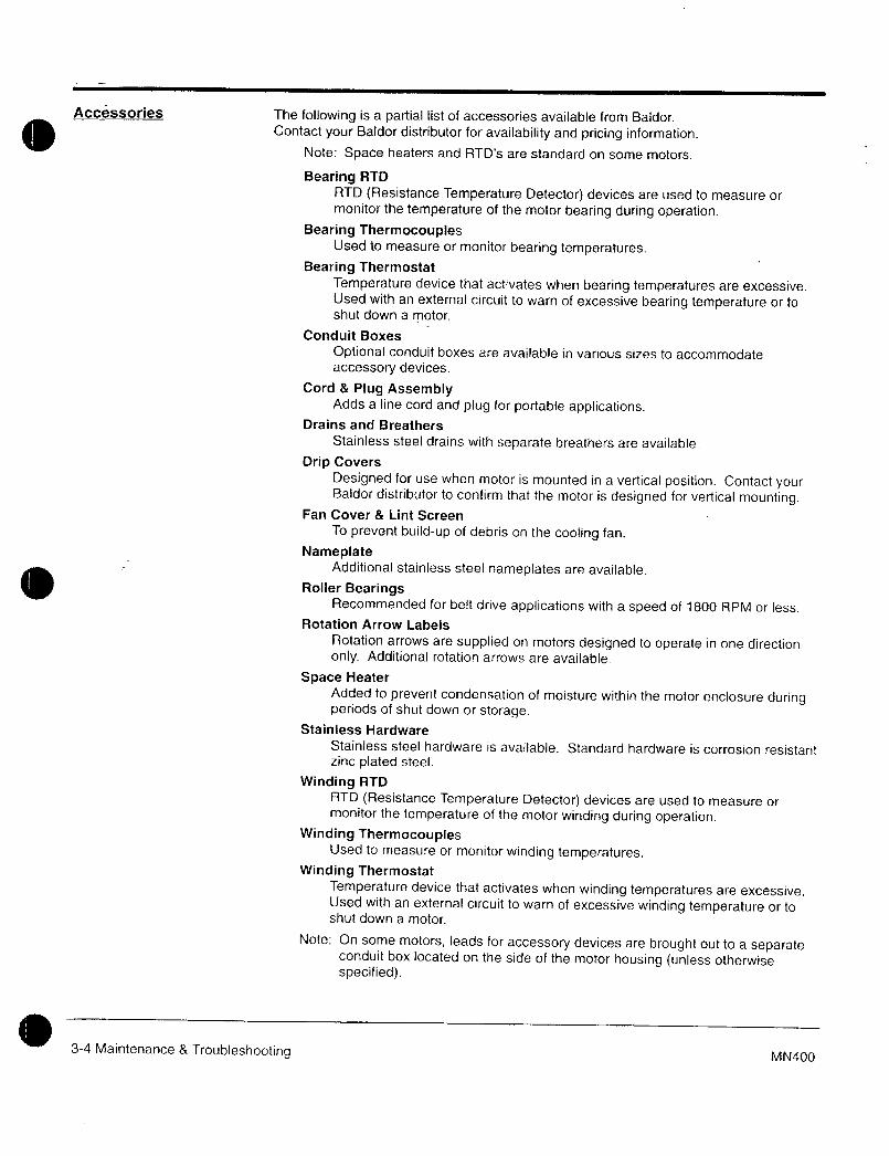
Accessories The following is a partial list of accessories available from Baldor
Contact your Baldor distributor for availability and pricing information
Note Space heaters and RTDs are standard on some motors
Bearing RTD
RTD Resistance Temperature Detector devices are used to measure or
monitor the temperature of the motor bearing during operation
Bearing ThermocouplesUsed to measure or monitor bearing temperatures
Bearing Thermostat
Temperature device that activates when bearing temperatures are excessiveUsed with an external circuit to warn of excessive bearing temperature or toshut down a motor
Conduit Boxes
Optional conduit boxes are available in various sizes to accommodate
accessory devices
Cord Plug AssemblyAdds a line cord and plug for portable applications
Drains and Breathers
Stainless steel drains with separate breathers are available
Drip Covers
Designed for use when motor is mounted in a vertical position Contact yourBaldor distributor to confirm that the motor is designed for vertical mounting
Fan Cover Lint Screen
To prevent buildup of debris on the cooling fan
NameplateAdditional stainless steel nameplates are available
Roller BearingsRecommended for belt drive applications with a speed of 1800 RPM or less
Rotation Arrow Labels
Rotation arrows are supplied on motors designed to operate in one direction
only Additional rotation arrows are available
Space Heater
Added to prevent condensation of moisture within the motor enclosure duringperiods of shut down or storage
Stainless Hardware
Stainless steel hardware is available Standard hardware is corrosion resistantzinc plated steef
Winding RTD
RTD Resistance Temperature Detector devices are used to measure or
monitor the temperature of the motor winding during operation
Winding ThermocouplesUsed to measure or monitor winding temperatures
Winding Thermostat
Temperature device that activates when winding temperatures are excessiveUsed with an external circuit to warn of excessive winding temperature or toshut down a motor
Note On some motors leads for accessory devices are brought out to a separateconduit box located on the side of the motor housing unless otherwisespecified
34 Maintenance 8 Troubleshootin g MN400
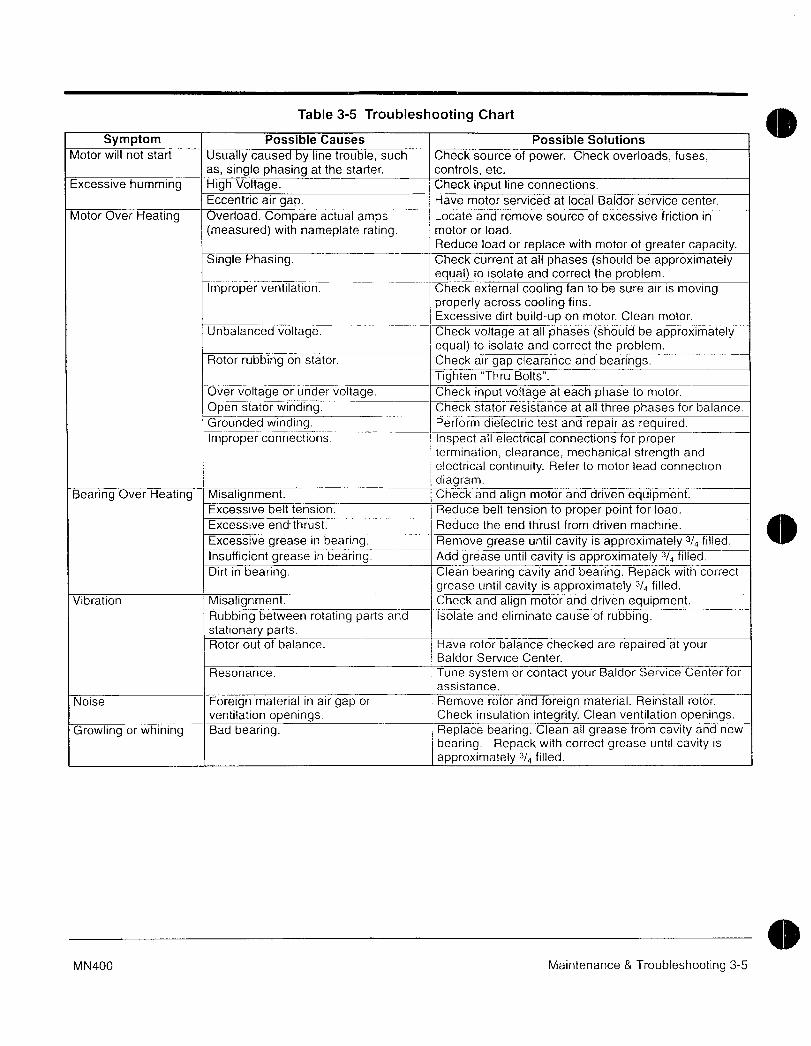
Table 35 Troubleshooting Chart
Symptom Possible Causes Possible Solutions
Motor will not start Usually caused by line troubie such Check source of power Check overloads fusesas single phasing at the starter controls etc
Excessive humming High Voltage Check input line connections
Eccentric air gap Have motor servic at local Baldor service center
Motor Over Heating Overload Compare actual amps Locate and remove source of excessive friction in
measuredj with nameplate rating motor or load
Reduce load or replace with motor of greater capacitySingle Phasing Check current at all phases should be approximately
equa to isolate and correct the problemImproper ventilation Check external cooling fan to be sure air is moving
properly across cooling fins
Excessive dirt build on motor Clean motor
Unbalanced voltage Check voltage at all phases should be approximatelyequal to isolate and correct the problem
Rotor rubbing on stator Check air gap clearance and bearingsTighten Thru Bolts
Over voltage or under volt Check input voitage at each phase to motor
Open stator winding Check stator resistance at all three phases for balance
Grounded winding Perform dielectric test and repair as requiredImproper connections Inspect all electrical connections for proper
termination ciearance mechanical strength and
I electrical continuity Refer to motor lead connection
diagramBearing Over Heating Misalignment Check and align motor and driven equipment
Excessive belt tension Reduce belt tension to proper point for load
Excessive end thrust Reduce the end thrust from driven machine
Excessive grease in bear Remove grease until cavity is approximately 3 fiiled
Insufficient grease in bearing Add grease un cavity is approximately 3J4 filled
Dirt in bearing Clean bearing cavity and bearing Repack with correct
grease until cavit is approximately 3 filled
Vibration Misalignment Check and align motoranddriven equipment
Rubbing between rotating parts and fsolate and eliminate cause of rubbingstationary partsRotor out of balance Have rotor balance checked are repaired at your
Baldor Service Center
Resonance Tune system or contact your Baldor Service Center for
assistance
Noise Foreign material in air gap or Remove rotor and foreign material Reinstall roior
ventilation openings Check insulatio integrity Cleanventilation openingsGrowling or whining Bad bearing Replace bearing Clean all grease from cavity and new
i bearing Repack with correct grease until cavity is
approximately 3l4 filled
MN400 Maintenance Troubleshooting 35

SALL70RMOTORS AND DRIVES
BALDOR ELECTRIC COMPANY
PO Box 2400
Ft Smith AR 729022400
501 6464711
Fax 501 6485792
O Baldor Electric Company Printed in USAMN400 701 CJ10000

m wwaaMT
M r
3
LtVfs
e
Flexible Coapling
ox
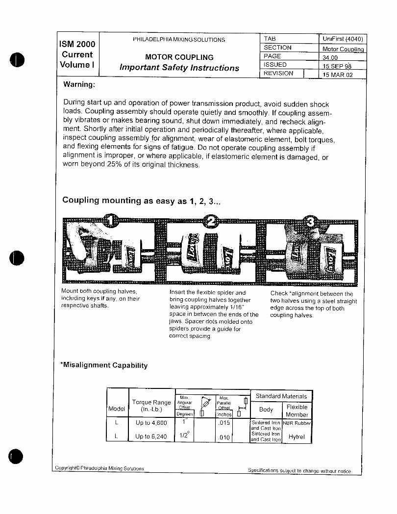
ISM ZOOOPHILADELPHIAMIXINGSOLUTIONS TAB UniFirst4040
SECTION Motor Cou linCurrent MOTOR COUPLING PAGE 3400
Volume I mportant Safety InstructionsSSUED 15 SEP 98
REVISION 15 MAR 02
Warning
During start up and operation of power transmission product avoid sudden shockloads Coupling assembfy shouid operate quietly and smoothly If coupling assem
bly vibrates or makes bearing sound shut down immediately and recheck alignment Shortly after initial operation and periodically thereafter where appiicableinspect coupling assemblyforalignment wear of elastomeric element bolt torquesand flexing elements for signs of fatigue Do not operate coupling assembly if
alignment is improper or where applicable if elastomeric element is damaged or
worn beyond 25o of its original thickness
Coupling mounting as easy as 1 2 3
f euzC
s
4 Fi r I
i
r
rs
tx x
Mount both coupling halves Insert the flexible spider and Ch2ckalignment between theincluding keys if any on their bring coupling halves together two halves using a steel straightrespective shafts leaving approximately 116 edge across the top of both
space in between the ends of the coupling halves
jaws Spacer dots molded onto
spiders provide a guide for
correct spacing
Misalignment Capability
max MaX Standard Materials
Torque Range Angular Parallel
Model InLbOffset rf5et Body
Flexible
Degrees inctes Member
L Up to 4600 015 Sintered Iron NBR Rubberand Cast Iron
2 Sintered IronL Up to 6240 010 and Cast ron Hytrel
Copyright0 Philadelphia Mixing Solutions Specifications subject to change without notice
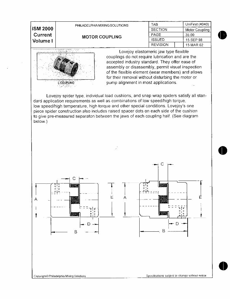
PHILADELPHIAMIXINGSOLUTIONS TAB UniFirst 4040M 200 SECTION Motor CouplingCurrent MOTOR COUPLING
PAGE 3500
Volume I ISSUED 15 SEP 98
REVISION 15 MAR 02
Lovejoy elastomeric jaw type flexible
couplings do not require lubrication and are the
accepted industry standard They offer ease of
assembly or disassembly permit visual inspection3r J3t of the flexible element wear members and allows
for their remova without disturbing the motor or
tcouit pump alignment in most applications
Lovejoy spider type individual load cushions and snap wrap spiders satisfy all stan
dard application requirements as well as combinations of low speedhigh torquelow speedhigh temperature high torque and other special conditions Lovejoys one
piece spider construction also includes raised spacer dots on each side of the cushion
to give premeasured separaton between the jaws of each coupling half See diagrambelow
C
CI
ii iiI i n
nIiiu
1tL y
AE A
I L
iti trniu un u
u nnl
D DB B
aCopyright0 Philadelphia Mixing Solutions Specifications subject to change without notice
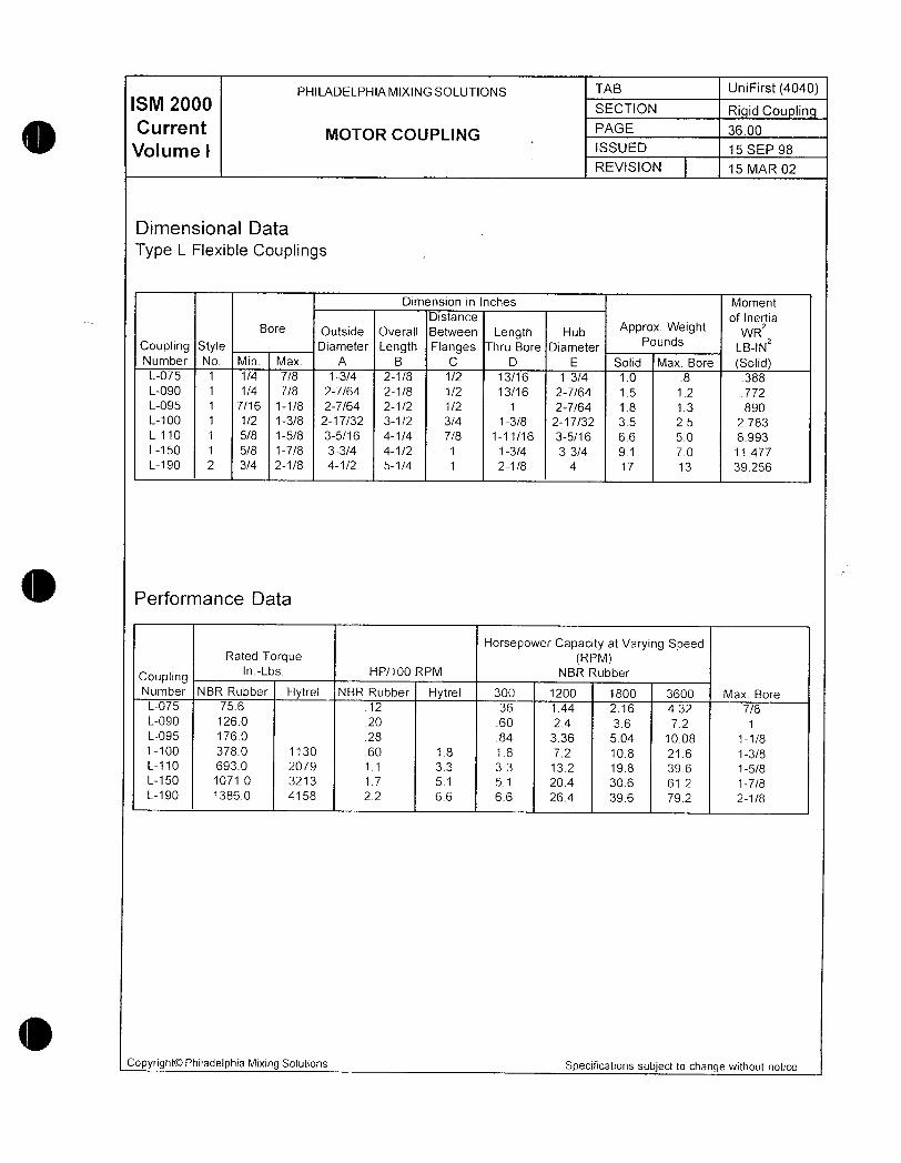
PHILADELPHIAMIXINGSOLUTIONS TAB UniFirst 4040ISM 2000 SECTION R d cou nn
Current MOTOR COUPLINGPAGE 3600
Volume 1 ISSUED 15 SEP 98
REVISION 15 MAR 02
Dimensional Data
Type L Flexibie Couplings
Dimension in Inches Moment
Distance of InertiaBore Outside Overall Between Length Hub Approx Weight wR2
Coupling Style Diameter Length Flanges Thru Bore DiameterPounds LBINZ
Number No Min Max A B C D E Solid Max Bore SolidL075 1 14 78 134 21 8 12 1316 134 10 8 388L090 1 14 78 2764 21 8 12 1316 2764 15 12 772
L095 1 716 118 2764 212 12 1 2764 18 13 890L100 1 12 138 21732 312 34 138 21732 35 25 2783
L110 1 58 158 3516 414 78 11116 3516 66 50 8993L150 1 58 178 334 412 1 134 334 91 70 11477
L190 2 34 218 412 514 1 218 4 17 13 39256
Performance Data
Horsepower Capacity at Varying SpeedRated Torque RPM
CouplingInLbs HP100 RPM NBR Rubber
Number NBR Rubber Hytrel NBR Rubber Hytrel 300 1200 1800 3600 Max BoreL075 756 12 36 144 216 432 78
L090 1260 20 60 24 36 72 1L095 1760 28 84 336 504 1008 118
L100 3780 1130 60 18 18 72 108 216 138L110 6930 2079 11 33 33 132 198 396 158
L150 10710 3213 17 51 51 204 306 612 178L190 13860 4158 22 66 66 264 396 792 21 8
Copyright0 Philadelphia Mixing Solutions Specifications subject to change without notice

A
fH2
k S LfTtta m
m vR 4
a
Dravvings
v
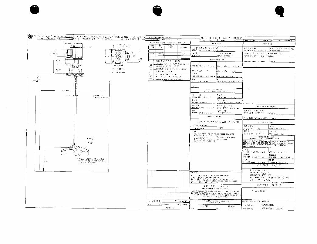
Phi laael hia Mii Soliosizzi e nnirsraECi cnnan aA ime usn aniie3rzeoo inne3znao u iD4L N0 8UK0 162 scRia vo 08UDK01160117 OFOEA x0 4 4 SQ FEV
F
OUaN111Y ON IHIS OFDEF 2 DfiN fi qPPqVO SEF FFVIEUE BY MIKE BISHaP OaIE 0125OBFEOnnFNDED uAENCH t9A0UE I16 Irl Irv265 SLOIS GOA
DPIVE OAtA MOIOfV OAtA
933 05 MiG BOLtS CPLG BOIt iHq115tOUPLIHGi0 SIZE 51ZE PLaiE 4040 20 3140 Pi05 PM Sid PM 3 60 230460 or 460
IAIVE IYPE GER Rq110 SEAI IYPE nOtOR FKE i SuPPLIEO BY PrvASEHValS
si3 nnx 2ei2 3iaio i2560 I5 e c50 h 500 1800 i IBOiC HEtCn dy
2000 1300nlEP AGy 5 RvICE LFCIOA MOtOA HP qPM LApME rvC 0 R
1625 OESIGx CONOIIIN126Z 4LSV95 2 B4 1450
300 60LiED KEYED 1200 yAx nIx uol I o II nIn nIx voL I ai iIW
17001625 J CrvSiRUCiION II1PElLERi MUB KErunv 0
JI213NC 92OD nRx IO LEV Ifil II nIN 110 LEV Iti Inl
rI2000 W
I00
I MI ENS ISGI IVI MI VISCOSIIY IPIF 400 34 13000
I O uun F r I i ioR E D00 NZzZ SOLIDS CONCENtARilpx OPENPiE FILL OR PAIN YN
OiNEA
VESSEL INiORnqiION91 IIB v55EL SUPPlIEO BY OiNEfi51
30o zo30091 I IB 0 0VESSFL DIq lil lel SArv IO tAH 11 II
0 0 00 072NOZZLES i0PBOItOn PRESStEnP IiborlilFCI
222 6 4 976 00nq1E01AL aEOUIaErEx15
OVEFALL nEIGN lil ITI BaGGL rv0LIIDin li i II
228 FLA1 fLAi 304 SS 316 55
BnGFE ENGIH lil i II NEFDS tOPBattOM MRiERIA oF CONSiRUCtION i HnRDUAPE
PAINI AE4UIflEMENtnLLOU SuB511iuilDrv 0 UPGRAE nAi6AlAl5
PMSL SiANDARD SLAiE BLIJE 4 6 MDfi conaoncN ueicNr
eouceanxo noroa 6a0 i 290 IOOO
AGIiAiOP PqRiS NA ftEDUCEH Ilbl Iel MOiOR Ilbl 14 I
n0iE5 5220 12620I ALC OInEN510N5 AFE IN fuCNES tINLE55 SPFCIIED SMAFI d IMP Ilbl 14 IO7Al 1161 lY I
2 nOUrvtHG uqADUqkE PY i4ER5MIMEF DESIGN LOnDS3 nLL qIVES IO BE PREPn4E0 GOA LONG iIME StOfiAGE
NLLIIING SI11iABLE OVERLOR fAC10Rr415ra5 q SHAFt AOiAtING CLOCN415E 100KING DOUNI 5 SuPPLIE ultH rcAU6EA iAG iHE MIxER SUPPORi SiRUCtURE M1151 BE LEVEL YIININ I
fN2B OEGFEE ANP IS 10 BE DESIGNEO 50 iHAt iHE OiHRMIC ANCdIARDEIECfON OG fxE DFIVE IS LIMIIED f0 12 OEGREE IN
J ANY OIRECION
IB930
SiPlIC VEIGHi I161 IN NGl llV1116iol IN1
ssa 28959 113050orrv non nei i iui orN roao iisi i ixi
inP6ea ianrior is nouvne157 27 JS
a300AEtuEErv UPy IN PN OOUrv 0 Iv
YNAMIC SNEAR Ilbl INI CENIEAID lil III 3 IxH IrvCpEYEN15
CUSTOMER SOLD TO
1 KRUGER INCnutloH AiiN ARAH SNEEi
i coNSUU ssavicc ranuni acroaE aaocEEOiec OPERALNG SERVICESvn IxSrAUnnaH nNO SiaAtuP 401 HARRISON OAKS BLVD SUILE 100
2 ALl DInEN51on5 nAE Irv NCMES UNLE55 SPEfIfIaD CARY NC 275133 nlEF SIIPPOPt DESIGrv OA05 INCLUDE SEAVIE LACiOR9 iN15 OAAVING IS NOi t0 SCALE
ixis oanuiuc is iE anoaEair orCUSTOMER SHIP TO
IPnitaoELPHin nIMuG soLUilaNs
AN IS SuBJECi 10 REiUFN uPON REOUESI I IS IO 9E USE WLL ADVISEOxLx i0P iHE PURPOSE GOF uHICN II uq5 ESPRESSx LORHE
Au li IS n0i t0 BE USEO Irv nxv vnr OElqInEHlq i0 iHEINiEAE51 01 iHS COFVOPAiIpN
I 4 AS 22B0vEa ocx
PHILaELPHIP hIMIrvG S4LUIIOnS CUS10nEP PQ NUnBEN z7S4OCEPIIfIED pafp
FEU DESCAIP110rv Dal pPVOSi OSIEF OBOBOB
IiEM AG N0 COAGULAIION
acuisioNS Hanc oar aca eounnc SEE NOiES COLLECT
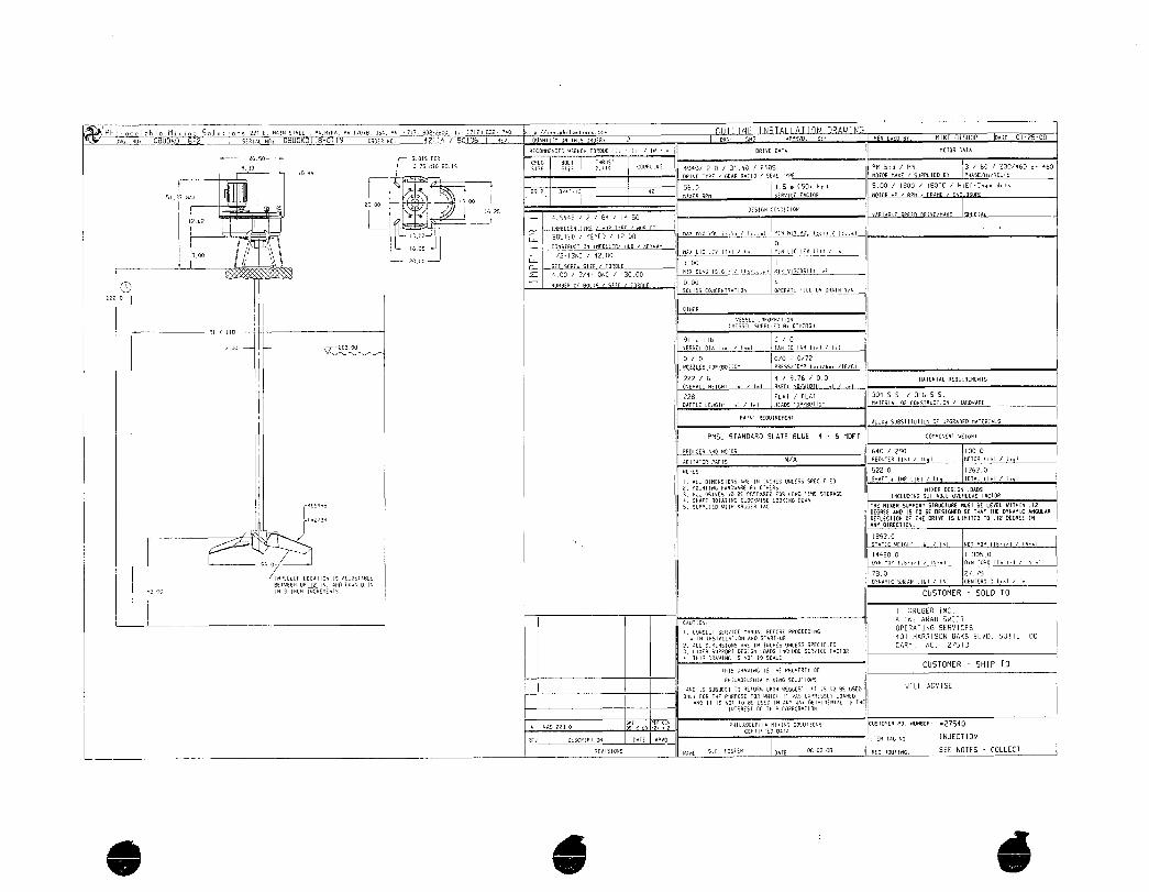
Ph i I ode I h o M a i Sa I u i i ons iz2i e naiH siaeci annrxn vnime usa Pti i earteoo i nii e7riw utiia
DuG NO BUDK I IB SEAIaL N0 O U KOI IBOI I9 OFOEA N0 4 I I4 0196 REV
F
OUaNtItY ON IHIS DAEP 2 PN APPRVO SEF P VIENED BY MIKE BISHOP OaIE 0125OB
AECnnErvEO uAENCH OAOVE Ile II IN I pqIVE niA h010A Ala
2650 SL015 L0CPLG 60L1 inFUSi
93310 A
015 n1G BO115SIZE Sl2E PIAIE
COUPIxG 4040 20 3V90 1 Pi05 PM Std PM 3 60 23096 ar 460
ORIVE tYPE GEnR pa110 SEAI IYPE MOiOA nnKE SuPPLIED BY PMASENVOLiS
z9i2 aiio ia256 I5 cSOt hl 500 1800 IBOiC i HiEfC6m dy
SI3 aX nIxER PPn SERVILE fqC10P M i0N HP HPM i FRFnE Erv L F
200o1300
1625 GESIGN COnItlGn
12624LSY45 i 2 Ba Ia50
i
i1oaq
nax n7x voi ioau imi nirv nix vo i an iii
wB011ED KEYED 1200
i625 J COnSiPUC110N IhPELLER HVP KEVUaY
1300 I J I213NC 4200MAx LIO LEV III II nIN LIO LEV Itl II
2C00 W I00 I
MIx OErvS ISLI I mi nlx VISCOSIIY IPiq00 34IONC 13000
O nR L a000 N
soios roncErrRnon aaEanc ri oa oaniN rin
zzz o
aicF
vESSri inraanaiiox
I x IIB
ESSEL SUPPLIEO BY OiNEfl51
91 II8 0 0
300 2000 VESSEL DIA II II tArv t0 iArv lil II
0 0 00 a72
oues ioPieamn eacssirna i ibviviu
222 6 4 976 00 q1EFlal0EWIREnEN15
OvERALL NEIGNi lil i Iml AAFL NOVIOiH lil II
228 FLAi FA1 304 55 316 SS
BNFFLE IENGin lil Iml HEApS IOPBOtiOn MRIEPIRL QI CONSiRUCiIOn NAHuRRE
PAINI AEOUIFEMENIAON SUBSIIlUtION OF uPGRnE nAtERAlS
PMSL SiANDARD SLFTE BWE 4 6 MDF1 conaHui wEicxr
aEDUCEa AuD n00A 640 290 1000
nGItA10R PfA15 NA 0EUGEA II61 I4 I MOlOA Ilbl 11 I
eorES 5220 12620
I PlL DIMENSIONS aAE IN INCNES UNlE55 SPECIIEDHA1I IMP Ilbl IV I IOIAL Ilbl 14 I
2 n0uN11NG nPAAFE 8Y OinEPS MIMEF DESIGN LOnS3 011 R14C5 0 BC PREPaAEO OP pNG tnE 51DAnGE INCLUDING SI11iRBlE OVEPLOAD LACOIi
q 5 e4 SXPiI HIAtING Cl0NUISE 100KING DOUN
IS SuPPlIEO uI1H rcliuGEN inG THE MIxER SUPPORt SiPUCiURE nU51 BE LEVEL VItMIN 12
Nzigq OELECIION 0iEBDRIVEII5E0 MO E7012 DEGREE HLIILIFANY DIftECiION
18930
S10tiC 4EIGHt Ilbl INI VGi hOn 116i1 I
I44B00 113050
So orn non uei i iri ovN roaa uei i iNmi
inaufa acaion is nousiee780 2775
BEtWEEU IIP In nrvD DOVnQ IrvDYNP111C SNEPR Ilbl INI ENfEF01 II Iml
300 I 3 Ixy ItCAErviS CUSTOMER SOLD TO
I 1 KRUGER iNCAiiN ARAH SWEEi
CnuiloN
i corsur sEavicE nnHUn aEroaE PaocccoincOPERATING SERVICES
unH irvsnuniioe nxo sinarua 401 HARRISON OAKS BLVD SUIiE 100
2 ALL DInErv510rv5 aPE In IrCnES UrlE55 SPECIIC ARY NC 275133 MISEri SIIPPORI pE516rv 1OP05 IHCLE SERUIC fhCt0li
9 iH15 DTAUING IS rv01 10 SULE
rnis oaAiec is in anaaEnr ovCUSiOMER SHIP i0
IPnIIROELPMIA nliNG SOLUilONS
Prvp 15 SIIBJECI 1p REfURN UPaN 0EOUCSI lt l5 id 8E I15C WL AVE
I IONLY 4OF IHE GIIPPOSE fOP VHICN II vA5 EP9ESSLY l0ANE0
qND I1 IS N 0 Bt USEO Irv quv 4AV DEPInEHAI rC iNE
IINtERES Of in15 COriPOAAiION
A AS 2280 PrF PNILAOIPiIP nIMIrvG SJLUtI0n5 CUS10nEF P0 xUnBEP ZS4OCEPIIIEO OAtP
REV DESCRIPIION DAiE APVO ItEn iAG NO INJECTION
avisions hp7E sE vosea pqrE 0808 aca Aouric SEE NOTES COLLECT


I Kruger Inc
401 Harrison Oaks Blvd TELEPHONE 9196778310
Ste 100 FACSIMILE 9196770082
Cary NC 27513
Project Name Port Angeles WA Project Number 42470003
Date5108 Author MDC
Revision 1 Equip Tag Number M13 M423
Maturation Tank Mixer S ecification Sheet
Manufacturer Philadel hia
Mfg Model Number 3855
Order Quantity Two 2
Motor
T e 360230460 nverter Dut
HP 75
RPM 1750
EnclosureType TEFC
Service Factor 115
Insulation NEMA Class F
Gearbox
Gearbox Service Factor 15
AGMA B10 Life 50000 hrs
Pedestal Mount Yes
Output RPM
Tank
To of Slab or Beam Height ft 185 el 24300
Pad lus Grout Height inch To beam
Total Mounting Height ft 85
Wetted Parts
Material of Construction 304 SS
No I mpel lers
Shaft Length inch gg
Shaft Diameter inch
Impeller Diameter inch 95
lmpeller Distance from Bottom inch 4
Additional Items
Pedestal bases includedOne set of bearings and seals required as a spare
One gallon of lubricant per mixer to be included
INSTALLATION OPERATING AND
MAINTENANCE MANUAL
Project Name
Port Angeles WTP
Customer
I Kruger I nc
Customer PO No
27540
Equipment Tag No
Maturation
PMSL Order No 42114
Serial No 08DEN01202
1221 East Main Street Palmyra PA 170789518
n Phone 7178322800 Fax 7178321740
Philly OnCall Services18007331341
JjEMail phillyoncallaphilamixerscom
E11 wwwphilamixerscom
r

TABLE OF CONTENTS
Service
Pa rts
Maintenance
Rigid Coupling
Impeller
Motor
Flexible Coupling
Drawings

m
ctu
3 wmwms uewr wov
HgAXeh
ia
R i
l
1Gvx n nm
SGVIC

PHILADELPHIAMIXERS INDEX 3850Series
ISM 2000 SECTION Introduction
Current INTRODUCTIQN PAGE 100
Volume I ISSUED o urv 2002
REVISION A 01 MAY 2003
This Service Manual covers Philadelphia 3850 Series Mixer Drives a high quality mixer drive
designed in accordance withthe Standards of the American Gear Manufacturers Associa
tion Certain precautions and procedures however must be observed in handiing installingand servicing the mixer drive and accessories
This manual contains general installation operating maintenance and troubieshooting in
structions for your mixing equipment Also special instructions applicable to specific mixer
drives may be included Should questions arise that are not covered additional information
can be obtained by contacting your local representative or Customer Service at PhiladeiphiaMixers Palmyra PA Telephone 717 8322800 FAX 717 8321746email
protech@philamixerscomNOTE
All inquiries must be accompaniedby the foilowing information which can be
obtained from the nameplate on the mixer drive Mixer
Drive Size and Type or Mode PhiladelphiaMixer Order NumberO
SerialNumberOrders
for renewal parts must include description and part number shown on
parts list in addition to the above information See Parts Section of this
manual for specific parts ordering procedure and order form Copyright0
Philadelphia Mixers Specifications subject to change without notice
PHILADELPHIA MIXERS INDEX 3850 Series
ISM 2000 SECTION Safety
Current SAFETY WARNING PAGE 200
Volume I ISSUED 01 JUN 2002
REVISION A 01 MAY 2003
WARNING
In the installation operation and maintenance of gear drives SAFETY comes first Use
proper clothing tools and methods of handling to prevent serious accidents The
safety precautions listed in this manual MUST be followed by all personnel working on
equipment otherwise serious injury may result
This manual lists a number of safety precautions Follow them and insist that those working on
this equipment do the same An accident is usually caused by neglect or oversight
Adequate installation maintenance and safety instructions must be given by the user to person
nel directly responsible for the operation of the mixer drive and accessory equipment In addi
tion the procedures set forth in the operating instructions must be carefully followed
Guards alarms heaters and safety devices which may be furnished by Philadelphia Mixers
must be installed by the user
The user is also responsible for furnishing and installing any guards or other safety equipmentneeded to protect operating personnel as required by the Occupational Safety and Health
Administration OSHA Standards or other applicable safety regulations This equipmentnormally is not furnished by Philadelphia Mixers except when specified as part of the order In
all cases however the user has the responsibility of complying with all applicable safety regulations when installing the equipment
SAFETY PRECAUTIONS
TO AVOID SERIOUS BODILY INJURY OR POSSIBLE DEATH
THE FOLLOWING PRECAUTIONS MUST BE FOLLOWED
ONLY AUTHORIZED PERSONS MAY OPERATE THIS
EQUIPMENTAdequate installation maintenance and safety instructions
must be given by the user to personnel directly responsible for the safe
operation of the mixer or aerator and accessory equipment In addition
the procedures set forth in the Service Instructions must be carefully fol
lowed Use qualified and skilled tradespersons to perform each work
discipline when installing inspecting or servicing this equipment All per
sonnel must be required to remain a safe distance from rotating shafts
couplings impellers clutches etc
OCopyright0 Philadelphia Mixers Specifications subject to change without notice
PHILADELPHIAMIXERS INDEX 3850 Series
2 SECTION SafetyCurrent
SAFETY WARNING PAGE s00
Volume I iSSUE 01 JUN 2002
REVISION A OA1 MAY200
READSERVICE MANUAL BEFORE LIFTING OR MOVING
EQUIPMENTAttach lifting devices to the equipment only as directed in the
Service Instructions and onlyto designated lifting points Particularcare must
be exercised to watch out for pinch or catch points in installation assembly or
disassembly Pieces should be supported to eliminate sudden shifting or
movement
DO NOT OPERATE UNLESS ALL SAFETY GUARDS AND DEVICES AREIN PLACE AND ADJUSTED PROPERLYThe user is responsible for fur
nishing and installing additional guards or other safety equipment needed to
protect operating personnel as required by local or individual safety standardsor regulations This equipment usually is not furnished by Philadelphia Mixers
except when specified as part of the order In all cases however the user
has the responsibility of complying with all appiicable safety regulations when
installing and operating the equipment throughout the life of the mixer Guardsalarms heaters and safety devices which may be furnished by PhiladelphiaMixers must be installed and maintained by the user
LOCK OUT AND DEPRESSURIZE BEFORE SERVICINGEQUIPMENTBefore closely inspecting repackaging or replacing mixershaft seals in mixer assemblies for cosed tank operation special precautions are mandatory Even if the gas or vapor contained within the pressurevessel is innocuous rapid release of the pressure can cause bodily injury or
damage to equipment Plant standard depressurizing andor decontaminat
ing procedures for the vessel must be completed with adequate time allowedfor mixer and vessel to cool sufficiently for safety of service personel prior to
starting work in mixer shaft seal area
DISCONNECT AND LOCK OIJT THE PRIME MOVER AND ITS CONTROLCIRCUITS BEFORE INSPECTING OR SERVICING THISEQUIPMENTDo not connect the prime mover to its power source until all
equipment is properly installed lubrication added bolts torqued and safetydevices installed and approved by qualified tradespersons Prior to servicingor closely inspecting any mixer or aerator that has been installed and made
ready for operation or actually put into an operating mode disconnect andlock out prime mover power source
DO NOT EXCEED DESIGN LIMITATIONSDo not operate sealingdevices above their rated temperatures or pressures specified on nameplatesor drawings Do not exceed any design limitations or make modifications tothis equipment without first consulting Philadelphia Mixers
CopyrightOO Philadelphia Mixers Specifications subject to change without notice

PHILADELPHIA MIXERS INDEX 3850 Series
M 20 SECTION Service
CurrentSERVICE PAGE 400
Volume iGENERAL ISSUED o uN 2002
REVISION A 01 MAY 2003
1 Any apparent or suspected damage sustained by equipment manufactured or furnished byPhiladelphia Mixers during transport from the factory to the user should be reported in
writing immediately to both Philadelphia Mixers and the Carrier
2 Upon delivery all equipment furnished must be carefully inventoried against shipping papersto determine whether any shortages exist in delivered materials Any such shortages must
be immediateVy reported in writing to both Philadelphia Mixers Customer Service Department and the Carrier if a timely claim is to be made
3 The mixer has been protected for limited term storage Inspect mixer drive and any other
equipment furnished by Philadelphia Mixers for corrosion If corrosion is present notify in
writing Phiadelphia Mixers Customer Service Department
4 The installation of most mixers does not usually require the services of a factory engineerThese services are not incfuded in the selling price of the equipment unless specificallyagreed upon in writing between the seiler and the purchaser in applications requiring a
more complex arrangement of components consideration should be given to the use of a
factory engineer for construction supervision or inspection of the installation These services
are available from Philadelphia Mixers by contacting our Customer Service Deartment
5 The Sellers Warrantv applies insofar as the unit is operated within the rating and service
conditions for which it was specifically sold The purchaser must prevent the existence of
any destructive external conditions which might typicaily include vibratory foads due to
critical speeds severe shock loading mechanica or thermal overloads or other conditions
which may adversely affect the operation The mixer must be installed and maintained in
accordance with instructions provided in this manual
6 In the event of malfunction within the warranty period Philadelphia Mixers must be notified
promptly in writing within thirty 30 days if it is intended that the warranty is to cover the
incident
7 Adequate installation maintenance and safety instructions must be given by the user to
personnel directly responsible for the operation of the mixer and accessory equipment In
addition the procedures set forth in the operating instructions must be carefully followed
8 Guards alarms heaters and safety devices which may be furnished by Philadelphia Mixers
must be installed by the user
9 The user is also responsible for furnishing and installing any guards or other safety equipment needed to protect operating personnel as required by Occupational Safety
Copyright0 Philadelphia Mixers Specifications subject to change without notice

PHILADELPHIAMIXERS INDEX 3850 Series
M 2 SECTION Service
CurrentSERVICE
PAGE 500Volume I issuE
GENERAL 01 JUN 2002
REVISION q 01 MAY 2003
and Health Administration OSHA standards or other applicabie safety regulations In all
cases however the user has the responsibility of complying with all safety regulations when
instaliing the equipment
10Mixers equipped with electrical control devices must be wired and checked for
proper operation
11Before startup all Philadelphia Mixers drives must be filled with the type and gradeof oil specified
12A11 unauthorized personnel must be required to remain a safe distance from rotatingshafts couplings agitators etc
INSTALLATION
The basic mixer drive is shipped completely assembled Mating gears and pinions are care
fully assembled at the factory to provide proper tooth contact Nothing must be done to disturbthis setting Single mechanical seals may be shipped with seai face apart Consult sectionShaft Seal information for instruction on proper setting
HANDLING See Gearbox Handling Procedure Tab
When handling a 3850 Series Philadelphia Mixer care must be taken to avoid supporting or
lifting in a manner that would place excessive stress on parts that are not designed ta supportthe weight
The 3850 Series mixer drive must be lifted with the three shoulder eyebolts provided at the topof the mixer drive The mixer must not be lifted by the motor eyebolt Lifting slings should beused to distribute load evenly When using lifting slings exercise caution to avoid damagingany external piping or gauges
Never drag the mixer drive This will mar the machined mounting surfaces and may damagethe housing
RUST PREVENTION
When the mixer drive is shipped the internal parts are protected with a film of rust preventivewhich protects the gear drive during shipment This film is soluble in the recommended lubricant and does not have to be flushed before filling Inspect mixer drive and any other equipmentfurnished by Philadephia Mixers If corrosion is present notify Philadelphia Mixers CustomerService Department in writing immediately
Copyright0Philadelphia Mixers Specifications subject to change without notice

PHILADELPHIAMIXERS INDEX 3850 Series
M 2 SECTION Service
CurrentSERVICE
PAGE 600
Volume I issuE 01 JUN 2002
REVISION A 01 MAY 2003
PROLONGED STORAGE
If installation of the mixer drive and operation is to be delayed for more than one 1 month
after shipment see Section Long Term Storaqe Instructions The manufacturers warranty on
mixer drives heid in prolonged storage must be covered by a special agreement reflecting the
storage conditions In order to validate warranty storage must be as per Long Term StorageInstructions
If prolonged storage is necessary it should be indoors and preferably in a dry area having a
relatively constant temperature When outdoor storage is unavoidable mixer drives should be
stored on their shipping skids and covered by a tarpaulin or an equivalent covering Seal all
openings with plugs vapor inhibitor paper or caps Also mixer drives should be filled to the
proper level with a mixture of oil and vapor phase rust preventative See Long Term Storaqeinstructions Exterior exposed metal parts should be coated with a heavy duty rust preventivesuch as Houghton Cosmoline 1102 or equivalent
The mixer drives and any associated equipment must be inspected periodically to ensure
there is still an effective coating of rust preventative on the internal parts The coating should
be replaced as required
Remove motor fan cover and rotate motor fan weekly to prevent the forming of flat spots on
bearings and to refresh coating of gears and bearings with oil mixture Motor fans must be
rotated until the output shaft completes one revolution Reinstall motor fan cover
SHIPPING COVERS
All protective shipping covers must be removed from the mixer drive The shaft extensions
and outside machined surfaces are protected during shipment by a rust inhibiting compoundThis compound should be removed by using a solvent If the mixer is equipped with a mount
ing flange gently scrape do not scratch clean the surface Use a solvent or approved plantcleaner to remove any remaining residue
ACCESSORIES
Any field installed straight bore interference fit couplings must be installed carefully to pro
vide good contact on the driving keys as well as to prevent cocking on the shaft extensions
Since an endwise blow on the shaft may damage gears and bearings these attachments
must not be hammered into position but heated to approximately 375F and slipped onto
shafts
When prolonged storage is anticipated consult Philadelphia Mixers Long Term Storage Instructions for
more detailed information
CopyrightOO Philadelphia Mixers Specifications subject to change without notice

PHILADELPHIA MIXERS INDEX 3850 Series
M 2Q0 SECTION Service
CurrentSERVICE
PAGE 700
Volume I issuE 01 JUN 2002
REVISION A 01 MAY 2003
HIGH SPEED MOTOR COUPLING
The mixer has been shipped with a factory installed flexible high speed motor coupling
RIGID COUPLING
In many mixer applications the lower agitaor shaft as weli as the mixer drive output shaft are
shipped with rigid coupling halves and impeller hubs fixed in their proper positions Before
assembly in tank make certain that the rabbet faces of the rigid couplings are free of all
foreign matter nicks or burrs
FOUNDATIONS
The foundation must be rigid enough to maintain proper alignment with connected machineryThe foundation must have a flat mounting surface to ensure uniform support for the mixer drive
If the mixer drive is installed on a surface which is other than horizontal consult PhiladelphiaMixers to ensure that design provides for proper tooth contact and adequate lubrication
Customer designed fabricated pedestals or baseplates must be carefully analyzed to deter
mine that they are sufficiently rigid to withstand operating vibrations The mixer support struc
ture is to be designed so that dynamic angular defiection of the mixer is limited to 25 degreein any direction using the mixer support loads provided on the Outline Installation Drawingsupplied with this manual
When installing the mixer drive on structural steei the use of a rigid basepiate is stronglyrecommended Bolt mixer drive and baseplate securely to steel supports with proper shim
ming technique to ensure a level surface
If the mixer drive is to be installed on a concrete foundation allow the concrete to cure properlybefore bolting down the mixer drive For best installation grout structural steel mounting padsinto the concrete base rather than grouting the mixer drive directly into the concrete
LEVELING
When shims are used to level or align the mixer drive they must be distributed around the
base under all mounting pads to equalize the support load and avoid distortion of the housingand high localized stresses
Use a feeler gauge to determine thickness of required shims All pads must be squarelysupported to prevent distortion of the housing when the gear drive is bolted down
Copyrighl0 Philadelphia Mixers Specifications subject to change without notice
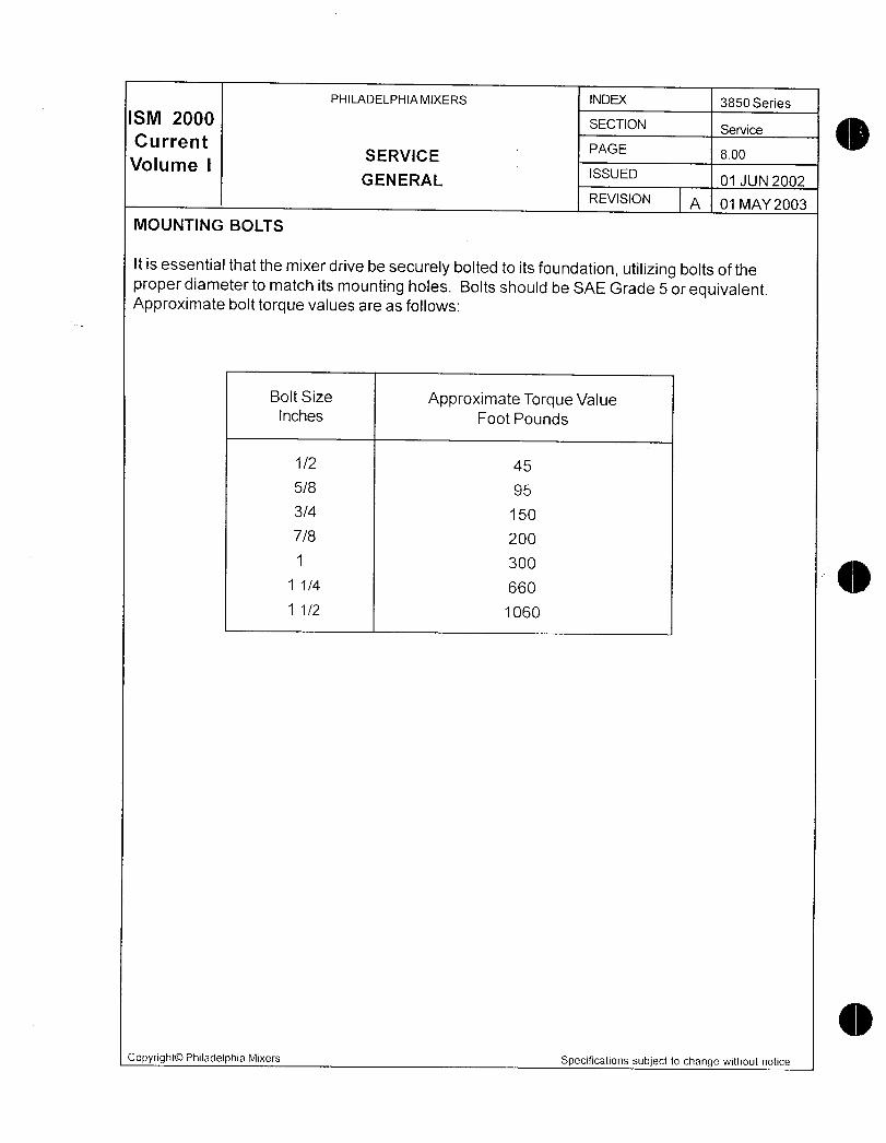
PHILADELPHIAMIXERS INDEX 3850 Series
M 20 SECTION Service
Current PAGE
VolumeSERVICE s00
GENERALISSUED
01 JUN 2002
REVISION A 01 MAY 2003
MOUNTING BOLTS
It is essential that the mixer drive be securely bolted to its foundation utilizing boits of the
proper diameter to match its mounting holes Botts should be SAE Grade 5 or equivalentApproximate bolt torque values are as follows
Bolt Size Approximate Torque Valueinches Foot Pounds
1 2 45
58 95
34 150
78 200
300
1 1 4 660
1 1 2 1060
Copyright0 Philadelphia Mixers Specifications subject to change without notice

PHILADELPHIA MIXERS INDEX 3850 Series
M 200 SECTION Service
Current SERVICE PAGE 900
Volume I LUBRICATION ISSUED 10 JAN 2003
REVISION A 01 MAY 2003
The mixer drives are shipped without oil They must be filled with the properlubrication before startup
The recommended type of oil for use in the 3850 series mixer drive is an extreme pressure
EP oif
AGMAlube No Tem erature Ran e Lubricant
3 EP 15F to 50F Mobilgear0 627 or
10C to 10C Mobilgear SHCO 150
5 EP 50F to 125F Mobilgear 6300 or
10C to 50C Mobilgear SHCO 220
Grease for bearings and MobilithOAW 2 or
seals when required Mobilith SHCO 220
Approximate Oil Capacity and Weight
3853MS2 3855MS2 3857MS2 3859MS2 3861 MS2
Oil Capacity 3 gallon 7 gallon 8 gallon 16 gallon 35 gallonWeight 450 bs 820 Ibs 1100 Ibs 1870 Ibs 37200 Ibs
3853MS3 3855MS3 3857MS3 3859MS3 3861 MS3
Oil Capacity 3 gallon 7 gallon 8 gallon 16 gallon 35 gallonWeight 4951bs 9051bs 11901bs 20051bs 39601bs
FILLING MIXER DRIVE WITH OiL
1 The mixer drive can be filled with oil in 2 places the breaher or the high speed gearinginspection cover
2 Remove dipstickbreather from top of mixer drive housing and wipe clean
3 ill mixer drive with recommended lubricant through breather hole Fill mixer until oil level
falls between the two lines scribed on sightgass Do not under fili or overfill The scribedlines represent minimum and maximum levels
4 After start up grease bearing at oil change intervals or every 6 months
LOW TEMPERATURE OPERATION
Philadelphia Mixers must be advised ifthe mixerwill be started up in temperatures less than10F above the pour point of oil used in the mixer Refer to oil manufactures data sheet for
pour point temperatures
OIL CHANGES
After the initial two weeks of operation of the mixer the original oil should be changed while the
eguipment is at operating temperature CAUTION take necessary precautions when handlinghot oil This oil may be strained and used again Consult your oil supplier for proper filtersize Often due to the wearingin process small metal particles will appear in the oil this is not
abnormal
Copyright0 Philadelphia Mixers Specifications subject to change without notice
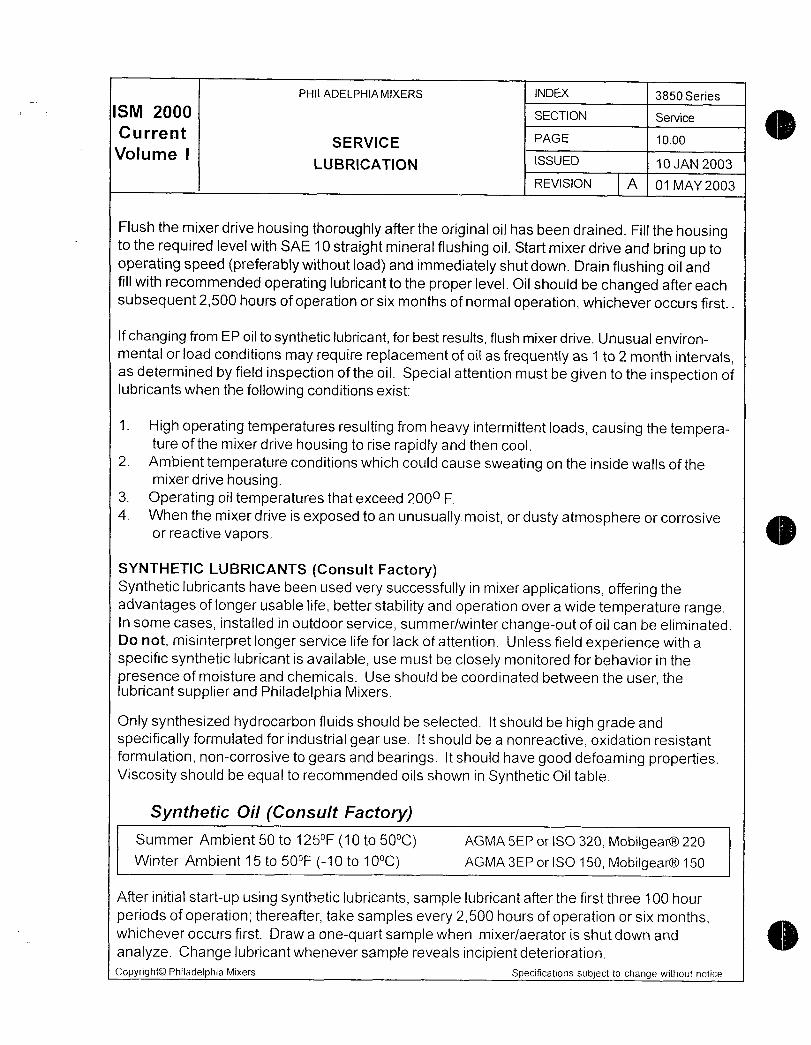
PHILADELPHIA MIXERS INDEX 3850 Series
M 2 SECTION Service
CurrentSERVICE PAGE 1000
Volume ILUBRICATION ISSUED 10 JAN 2003
REVISION A 01 MAY 2003
Flush the mixer drive housing thoroughly after the original oil has been drained Fili the housingto the required level with SAE 10 straight mineral flushing oil Start mixer drive and bring up to
operating speed preferably without load and immediately shut down Drain flushing oil andfill with recommended operating lubricant to the proper level Oil should be changed after each
subsequent2500 hours of operation or six months of normal operation whichever occurs first
If changing from EP oil to synthetic lubricant for best results flush mixer drive Unusual environmental or load conditions may require repacement of oil as frequently as 1 to 2 month intervalsas determined by field inspection of the oil Special attention must be given to the inspection oflubricants when the following conditions exist
1 High operating temperatures resulting from heavy intermittent loads causing the temperature of the mixer drive housing to rise rapidly and then cool
2 Ambient temperature conditions which could cause sweating on the inside walis of themixer drive housing
3 Operating oil temperatures that exceed 200 F
4 When the mixer drive is exposed to an unusually moist or dusty atmosphere or corrosiveor reactive vapors
SYNTHETIC LUBRICANTS Consult FactorySynthetic lubricants have been used very successfully in mixer applications offering the
advantages of longer usable life better stability and operation over a wide temperature rangeIn some cases installed in outdoor service summerwinter changeout of oil can be eliminatedDo not misinterpret longer service life for lack of attention Unless field experience with a
specific synthetic lubricant is available use must be closely monitored for behavior in the
presence of moisture and chemicals Use should be coordinated between the user thelubricant supplier and Philadelphia Mixers
Only synthesized hydrocarbon fluids should be selected It should be high grade and
specifically formulated for industriai gear use It should be a nonreactive oxidation resistant
formulation noncorrosive to gears and bearings It should have good defoaming propertiesViscosity should be equal to recommended oils shown in Synthetic Oil table
Synthetic Oil Consult FactorySummer Ambient 50 to 125 10 to 50 AGMA 5EP or SO 320 Mobifgear0 220
Winter Ambient 15 to 50 10 to 10 AGMA 3EP or ISO 150 Mobilgear0150
After initial startup using synthetic lubricants sampie lubricant after the first three 100 hour
periods of operation thereafter take samples every2500 hours of operation or six monthswhichever occurs first Draw a onequart sample when mixeraerator is shut down and
analyze Change lubricant whenever sample reveals incipient deterioration
Copyright0 Philadelphia Mixers Specifications subject to change without notice
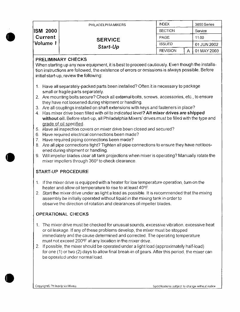
PHILADELPHIAMIXERS INDEX 3850 Series
M 2QQQ SECTION Service
CurrentSERVICE
PAGE 1100
Volume I issuEO o utv 2002StartUp
REVISION A 01 MAY 2003
PRELIMINARY CHECKS
When starting up any new equipment it is best to proceed cautiously Even though the installa
tion instructions are followed the existence of errors or omissions is always possible Before
initial startup review the following
1 Have ail separatelypacked parts been installed Often it is necessary to packagesmall or fragile parts separately
2 Are mounting bolts secure Check aI externa bolts screws accessories etc to ensure
they have not loosened during shipment or handling3 Are all couplings installed on shaft extensions with keys and fasteners in place4 Has mixer drive been filied with oil to indicated level All mixer drives are shipped
without oil Before startup all Philadelphia Mixers drives must be filled with the type and
arade of oil specified5 Have all inspection covers on mixer drive been closed and secured
6 Have required electrical connections been made
7 Have required piping connections been made
8 Are all pipe connections tight Tighten all pipe connections to ensure they have not loos
ened during shipment or handling9 Will impeller blades clear all tank projections when mixer is operating Manually rotate the
mixer impellers through 360 to check clearance
STARTUP PROCEDURE
1 If the mixer drive is equipped with a heater for low temperature operation turn on the
heater and allow oil temperature to rise to at least 40F
2 Start the mixer drive under as light a load as possible It is recommended that the mixingassembly be initially operated without liquid in the mixing tank in order to
observe the direction of rotation and clearances of impeller blades
OPERATIONAL CHECKS
1 The mixer drive must be checked for unusual sounds excessive vibration excessive heat
or oil leakage If any of these problems develop the mixer must be stoppedimmediately and the cause determined and corrected The operating temperaturemust not exceed 200F at any location in the mixer drive
2 If possible the mixer should be operated under a light load approximately halfloadfor one 1 or two 2 days to allow final breakin of gears After this period the mixer can
be operated under normal load
Copyright0 Philadelphia Mixers Specifications subject to change without nofice

PHILADELPHIAMIXERS INDEX 3850 Series
ISM 2000 SECTION WarrantyCurrent wqRRqNT PAGE 200
Volume I ssuE o uN 2002
REVISION q 01 MAY 2003
For a period of one year after date start up or eighteen months after delivery to Customer whichevercomes first Selier warrants that the products sold to Customer will be free fromdefects in materiais and workmanship and will perform the particularfunction for which theyare intended Mixers and aerators are warranted to be fit to perForm the function for which they are
intended when operated under the specified mixing or design conditions provided accurate and
necessary data have been furnished to Seller in writing by Customer Seller assumes no responsibility for the accuracy or reliability of specifications design conditions or other furnished by or on behaffof Customer or the ultimate user Customer selected materials are warranted only to conform withCustomer specifications Materials not specified by Customer shall be Sellers standard materials ofconstruction for out of tank components Material exposed to process are not warranted againstcorrosion or other deterioration due to exposure to vessel contents
These warranties shall not be effective if the product or part is not used strictly in accordance with allinstructions as to storage handling maintenance lubrication instaNation startupoperation and safety set forth in the manuals and instruction sheets furnished by Seller
The standards of theAmerican Gear ManufacturersAssociation will be used and shall govern where
appiicabfe in the manufacture of gears and gear drive assemblies unless Seller expressly agreesotherwise in writing
The foregoing limited warranties are exclusive and are in lieu of al other warranties express and
implied including but not limited to implied warranties of inerchantability or fitness for a particularpurpose
LIMTATION OF REMEDIES
Customers remedy for breach of any of the forgoing warranties shall be limited to replacement or
repair by Seller of any defective equipment or parts discovered during the 1 year warranty periodSuch products or parts shall be shipped to SellerFOBSelers plant orFOB at such other locationas may be designated by Seller Seller shall have the right at its sole discretion to refund the purchaseprice paid by Customer in lieu of repair or replacement Without limiting the foregoing under no
circumstances shall Seller be liable for any expenses for removal of allegedly defective equipment or
parts or for installation costs of repaired or replaced equipment or parts
All claims for breach of any Sellerswarranties shall be barred unless Customer notices Seller ofsuch breach in writing within 30 days of discovery of the breach
LIMITATION OF LIABILITIES
Seller shall not be liable for any liquidated consequential or incidental damages due to defects inmalfunctions or failure of its products to perform late delivery of loss of use nor shall Sellers totai
liabifity under any circumstances exceed the purchase price of the products sold Seiler shall not beliable for any damage resulting from improper storage or handling following shipment Seller shall not
be responsible for repairs performed by others outside Sellers plant unless such repairs are authorized by Seller in writing in advance Seller shall not be responsible for any defects in any componentssuch as gears shafts bearings or motors furnished by others
CopyrightOO Philadelphia Mixers Specifications subject to change without notice

PHILADELPHIAMIXERS INDEX 3850 Series
ISM 2000 SECTION ShaftHandlin
C u r re n tSHAFT HANDLING PAGE 1300
Volume ISSUED 01JUN2002
REVISION A 01 MAY 2003
Agitator Shaft Lifting Procedure
Caution Only trained professionals experienced in the handling rigging and
lifting ofheavy machinery should be employed to instal or remove
mixer components
Warning Never lift the agitator shaft from the horizonfal position with one end of
the shaft on the ground Lifting in this manner may bend the shaft asin Fiaure 1A
NOTE In certain applications the impellerhubs mayhave to be removed
from the agitatorshaft prior to installing the agitaforshaff into the
vesse
Handling and Lifting
Handling and lifting of mixer components like ail heavy machinery can be dangerous and
proper methods may depend upon the particular installation Philadelphia Mixers recom
mends that only trained professionals perform these tasks during installation or removal of the
mixers and assumes no responsibility for injury to persons or property that may occur duringthese activities
1 Attach one lifting sling at or near the coupling at the top of the agitator shaft Use oniyproperly rated newnonmetallic slings See Outline Installation drawing forweights
2 Attach a second lifting sling approximately onethird of the length of the shaft from the
bottom See Fiqure 1 B
3 Lift the agitator shaft horizontally to a sufFcient height so that the impeller end of the shaft
will not contact the ground when the shaft is moved into a verticai position
4 Continue to lift the agitator shaft from the coupling end sling only until the shaft is vertical
5 When the agitator shaft is vertical remove the impeller end sling and use the coupling end
sling to lower the shaft into the mixing vessel
Copyright0 Philadelphia Mixers Specifications subject to change without notice
PHILADELPHIAMIXERS INDEX 3850 Series
fSM 2000 SECTION ShaftHandlin
C u rren t SHAFT HANDLING PAGE 1400
Volume I issuE 01 JUN 2002
REVISION A 01 MAY 2003
Shaft Lifting Procedure Diagram
Figure 1A
fi
is
f
i
Ir
Figure
Copyright0 Philadelphia Mixers Specifications subject to change without notice

PHILADELPHIAMIXERS INDEX 3850 Series
SM 2Q SECTION Gear Box Handlin
CurrentRECEIPT AND HANDLING
PAGE 1500
Volume ISSUED 01 JUN2002
REVISION A 01 MAY 2003
Receipt and Inspection
1 3850 Series mixers are generally shipped bolted to a hardwood pallet Remove any
packaging material from around the mixer and carefully examine it for evidence of dam
age during shipping If damage is found retain the damaged material and contact Phiia
delphia Mixing Solutions Philly OnCall Services at18007331341 for guidance
2 Inventory the equipment against the shipping papers to verify that the correct componentshave been received If any components appear to be missing contact Philadelphia Mixers
or your sales representative for guidance
3 Inspect the mixer drive and other components for evidence of rust or corrosion particularlyif there are areas of chipped paint due to handling damage If corrosion is present contact
Philly OnCall Services at18007331341 for further instructions
Copyright0 Philadelphia Mixers Specifications subject to change without notice
PHILADELPHIA MIXERS INDEX 3850 Series
SM 20 SECTION Gear Box Handling
CurrentGEAR BOX HANDLING PROCEDURES
PAGE 1600
VolumeRECEIPT AND HANDLING
issuEO o uN2oo2
REVISION 01 MAY 2003
Caution Only frained professionals experienced in the handling rigging and lifting of
heavymachineryshould be employed to install orremove mixercomponents
Handling and Lifting
Handling and lifting of mixer componentslike ail heavy machinerycan be dangerous and
proper methods may depend upon the particular installation Philadelphia Mixers recommends
that only trained professionals perform these tasks during installation or removal of the mixersand assumes no responsibility for injury to persons or property that may occur during these
activities
In addition the foliowing genera guidelines should be observed when moving or lifting the
mixer
1 Keep the mixer drive in the same position as shipped from factory
2 Neversupport the mixer by the output shaft
3 When the mixer is to be placed on the ground put blocks under the mounting surfaces
4 Neverdrag the mixer This will damage the machined mounting surfaces and could dam
age the housing
5 There are eyebolts on both the mixer drive housing and the motor housing Do not lift the
mixer drive by the eyebolts on the motor housing Lift the mixer gear drive by the eyeboltsattached to the top of the drive housing Use lifting slings to distribute the load evenly Make
sure the slings are positioned so they do not place a load on external components pipesgauges etc when the mixer is lifted
6 Nevershock the mixer by snapping loose lifting rigging
7 The 3850 series mixer is shipped on two or more skids One skid wiil contain the mixer
drive which is positioned horizontally or vertically and the other skids will contain the
agitator shaft andor additional components Remove all shipping restraints Two hoists or
cranes are necessary to lift the mixer and agitator parts LIFT THE MIXER DRIVE BY
ITSELF DO NOT ATTACH THE AGITATOR SHAFT
Copyright0 Philadelphia Mixers Specifications subject to change without notice
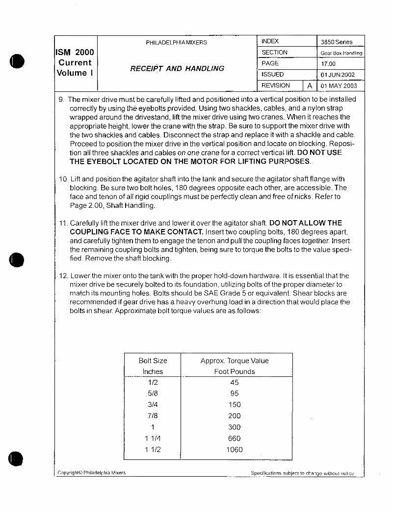
PHILADELPHIAMIXERS N 3850 Series
SM 2 SECTION Gear Box Handling
Current PAGE 1700
Volume I RECEIPT AND HANDUNGissuo ouN2oo2
REVISION A 01 MAY 2003
9 The mixer drive must be carefully lifted and positioned into a vertical position to be installed
correctly by using the eyebolts provided Using two shackles cables and a nylon strapwrapped around the drivestand lift the mixer drive using two cranes When it reaches the
appropriate height lower the crane with the strap Be sure to support the mixer drive with
the two shackles and cables Disconnect the strap and replace it with a shackle and cable
Proceed to position the mixer drive in the vertical position and locate on blocking Reposition all three shackles and cables on ore crane for a correct vertical lift DO NOT USE
THE EYEBOLT LOCATED ON THE MOTOR FOR LIFTING PURPOSES
10 Lift and position the agitator shaft into the tank and secure the agitator shaft flange with
blocking Be sure two bolt holes 180 degrees opposite each other are accessible The
face and tenon of all rigid coupings must be perfectly clean and free of nicks Refer to
Page 200 Shaft Handling
11 Carefully lift the mixer drive and lower it over the agitator shaft DO NOT ALLOW THE
COUPLING FACE TO MAKE CONTACT Insert two coupling bolts 180 degrees apartand carefully tighten them to engage fhe fenon and pull the coupling faces together Insert
the remaining coupling bolts and tighten being sure to torque the bolts to the value specified Remove the shaft blocking
12 Lower the mixer onto the tank with the proper holddown hardware It is essential that the
mixer drive be securely bolted to its foundation utilizing bolts of the proper diameter to
match its mounting holes Bolts should be SAE Grade 5 or equivalent Shear blocks are
recommended if gear drive has a heavy overhung load in a direction that would place the
bolts in shear Approximate bolt torque values are as follows
Bolt Size Approx Torque Value
Inches Foot Pounds
1 2 45
58 95
34 150
78 200
1 300
1 1 4 660
1 1 2 1060
Copyright0 Philadelphia Mixers Specifications subject to change without notice

PHILADELPHIA MIXERS INDEX 3850 Series
SM 20 SECTION Long Term Stosage
C u rren t PAGE 2400
Volume iLONG TERM STORAGE
ISSUED 01 JUN2002
REVISION q 01 MAY 2003
These procedures are designed to protect your mixers or aerators frorn atmospheric corrosionor other harmful effects during storage or periods of inactivity The critical periods are before thenew mixer is ever run and prolonged idle periods thereafter
The storage instructions for gear drive protection can be valid for periods as long as two yearsfor equipment stored under best conditions Longer term storage is acceptable provided
necessary procedures are followed contact the Service Department of Philadelphia Mixers foradditional information Any costs for storage materials or labor required after shipment will be
paid by the customer unless specifically contracted for by Philadelphia Mixers at the time of
purchase
Specific storage procedures to be foilowed are meant to maintain the Mixers or Aerators as
nearly as possible to their as shipped condition Failure to properly store and protect the equipment as outlined may void any warranty either expressed or implied It is advisable for theuser to keep a detailed log to record the results of inspections and maintenance performed on
each Aerator or Mixer
We recommend that the gear reducers and motors be kept in a dry temperaturecontrolledindoor area We do nt recommend outdoor storage There may be some instances whereindoor storage is impossible Storage of special equipment supplied by Philadelphia Mixers
such as motors control panels etc is to be in accordance with the manufacturers recommen
dations included with this manuai
Copyright0 Philadelphia Mixers Specifications subject to change without notice
PHILADELPHIA MIXERS INDEX 3850 Series
SM 2000 SECTION Long Term Storage
Current PAGE Zs00
Volume 1LONG TERM STORAGE
Receiving the EguipmentISSUED o uN2oo2
REVISION q Q1 MAY 2003
1 Check impellers and impeller shafts for obvious shipping damage Shouid such
damage be found immedtately report the details to the carrier that delivered the
equipment and the Philadelphia Mixers ServiceDartment
Carefully move these components to a storage area where they will be least likely to
be damaged by contact with fork trucks etc Carbon steel components whether
painted or not should be protected Protective coatings against atmospheric corro
sion as applied for shipping should be checked for damage and renewed or
patched as necessary Periodic checks preferably at no more than 30day intervalsshould be made to assure that no rusting or other damage has occurred Should such
be noted corrective action should be quickly initiated Contact Philadelphia Mixers
Service Department for guidance2 Carefully check before putting drives into storage to assure that the plugs are instailed
in place of breathers and ali other openings to the atmosphere are sealed
3 If the duration of storage in any of 3 environments to be defined in the following will
not exceed six months for a newlymanufactured drive the gear reducer if properlyprepared wili not require additional protective procedures Inspectthe drive to assure
that longterm preservation procedures were applied at the factory This is indicated
by a tag attached to the drive which will say This mixeraerator has internal rust
protection which is considered adequate under normal INDOOR storage conditionsFOR SIX 6 TO TWELVE 12 MONTHS from date of preservation application The
date of the preservation application appears on the tag
PHONE 7178322800
FAX 7178321746
Philly OnCall Services18007331341
Email protech@philamixerscomCopyright
0Philadelphia Mixers Specifications subject to change without notice

PHILADELPHIAMIXERS INDEX 3850 Series
SM 200 SECTION Long jerm Storage
Current PAGE 2s00
Volume ILONG TERM STORAGE
ISSUED 01 JUN202
REVISION q 01 MAY 2003
Field Application of Corrosion Protection
If field application of longterm internal corrosion protection to a mixer drive is necessaryfor any reason arrangements should be made with the Philadelphia Mixers Service
Department for a factory representative to be on hand if possible while the preservationprocedure is carried out The first step is to inspect the drive to assure that a damagingdegree of corrosion does not exist If existing corrosion or other damage does not re
quire attention proceed as follows
To coat all internal surfaces with a protective compound such as Cosmoline 1102 aproduct of Houghton International Inc Valley Forge PA spray or brush areas above oil
level thru the access windows and fill the gear drive to the proper oil level with the com
pound To insure complete coating rotate the motor coupling a sufficient number of timesfor two complete revolutions of the drive output shaft Drain therustpreventative com
pound Seal all drive openings with plugs paper impregnated with uapor phase corrosion
inhibitor caps etc Alternatively or if no access openings exist the procedure below maybe used
If the gear drive is supplied with an external pump lubrication system DO NOT PUMP
COSMOLINE THRU THE PIPING SYSTEM because Cosmoline contains solids which
may clog small orifices and spray nozzles Instead fill the gearbox to just below the
proper low oil level with about 1 part Rust Veto Concentrate a product of HoughtonInternational Inc Valley Forge PA to 9 parts of a standard gear or motor oil of the recom
mnded viscosity To this mixture add about 2 of NOX Rust VCI10 a product of
Daubert Chemical Co Chicago IL volatile corrosion inhibitive oil Run drive unloaded
including the lubrication pump for about one hour then seal afl openings as above Unit
does not need to be drained if it is not to be moved during the length of storage Every 6
months unseal the drive drain just enough oil to add 2 capacity of NOX Rust to main
tain the proper oif level run the drive and pump for one hour and reseal This procedurecan be repeated for up to 3 years of storage Drain oil completely and flush drive before
adding the recommended operating oil and placing into service
Further prepare the drive motor for storage as described by the storage location
according to the appropriate following procedures
Storing in 3 Types of Locations
Please note that there are 3 basic types of storage locations and environments for Aera
tors and Mixers Storage procedures are different for each Use th procedure which
applies to your drive
Copyright0 Philadelphia Mixers Specifications subject to change without notice

PHILADELPHIAMIXERS INDEX 3850 Series
SM ZQQQ SECTlON Long Term Storage
CurrentLONG TERM STORAGE
PAGE 2700
Volume ISSUED 01 JUN2002
REVISION q 01 MAY 2Q03
A Indoor Storage in a Dry TemperatureControlled Area
The preferred storage environment for Mixers orAerators is a dry area with relativelyconstant temperature prevent condensation The use of a mechanical dehumidifyingsystem with controls to maintain the atmosphere at 40o relative humidity or lower is
recommended
If automatic humidity control is unavailable and conditions become extreme it may be
necessary to use trays of renewable desiccant such as silica gel or portable dehumidifi
ers to remove moisture from the air in the enclosed storage area in order to properlymaintain necessary relative humidity levels
Each gear reducer should be stored in its normal operating position and then filled to
normai operating oil level with the recommended oi see Oqerating and Maintenance
Instructions for the specificAerator or Mixer Add NoxRust VCI10 or equal volatile
corrosion inhibitive oil at the rate of 2 of sump capacity added to the conventional oii
used Replace oil fill plug when finished Assure that all other openings in the gear drive
are closed to the atmosphere Rotate shaft several times by removing motor fan cover
and rotating fan by hand Reinstall fan cover At six month intervals drain 2 of sump
capacity and replace with NoxRust
If the furnished motors have motor heaters connect these to a proper power source
immediately upon putting into storage
Motor shafts in storage should be rotated at regular intervals We recommend 5 completerotations of the shafts Foow motor manufacturer recommerdatonsfor torage Motors
supplied with breathers and drains must be inspected for operability Motor bearingsmust be greased per instructions from the manufacturer of the motor supplied These
recommendations have been supplied with this manual
B Indoor Storage No Temperature Nor Humidity Control
Motors must be stored with all breathers and drains operable and motor heaters if anyconnected If motor heaters are furnished they musf be connected to a proper power
source upon placement in storage regardless of the duration of storage Cover each
motor but do not seal it off as this might trap moisture
If no motor heaters are supplied motors must be securely wrapped in plastic with desic
cant bags placed inside Replace the desiccant bags at 30day intervals
Product of Daubert Chemical Company Chicago IL
Copyright0 Philadelphia Mixers Specifications subject to change without notice

PHILADELPHfA MIXERS N 3850 Series
SM 20 SECTION Long Term Storage
CurrentLOiVG TERM STORAGE
PAGE Zs00
Volume 1SSUED 01 JUN2002
REVISION 01 MAY 2003
Motor shafts in storage should be rotated at regular intervals We recommend 5 compieterotations of the shafts Follow motor manufacturer recommendations for storage Motors
supplied with breathers and drains must be inspected for operability Motor bearings must
be greased per instructions from the manufacturer of the motor supplied These recommen
dations have been supplied with this manual
Each gear reducer should be stored in its normal operating position and then filled to nor
mal operating oil level with the recommended oil see Operatinq and Maintenance Instruc
tions for the specificAerator or Mixer Add NoxRust VCI10 or equal vofatile corrosion
inhibitive oil at the rate of 2 of sump capacity added to the conventional oil used Replaceoil fill plug when finished Assure that all other openings in the gear drive are closed to the
atmosphere Rotate Shaft several times by removing motor fan cover and rotating fan byhand Reinstail fan cover At six month intervals drain 2 of sump capacity and replace with
NoxRust
C Outdoor Storage Not Recommended
PROCEDURES TO FOLLOW WHEN OUTDOOR STORAGE IS UNAVOIDABLE
All Aerator or Mixer components must be kept off the ground Storage should be on skids or
piatforms and protected with a tarpaulin or other waterproof covering If this equipment is
mounted for storage in its eventual operating location on top of tanks or wastewater treat
ment basins the equipment should be protected by a tarpaulin or other waterproof cover
ing
If the furnished motors have motor heaters connect these to a proper power source immedi
ately upon putting into storage
If no motor heaters are supplied motors must be securely wrapped in plastic with desiccant
bags ptaced inside Replace the desiccant bags at 30day intervals
Motor shafts in storage should be rotated at regular intervals We recommend 5 completerotations of the shafts Follow motor manufacturer recommendations for storage Motors
supplied with breathers and drains must be inspected for operability Motor bearings must
be greased per instructions from the manufacturer of the motor supplied These recommen
dations have been supplied with this manual
Each gear reducer should be stared in its normal operating position and then filled to nor
mal operating oil levef with the recommended oil see Operating and Maintenance
Product of Daubert Chemical Company Chicago IL
Copyright0 Philadelphia Mixers Specifications subject to change without notice
PHILADELPHIAMIXERS NDEX 3850 Series
SM 200 SECTION Lon Term Stora e
C u rrent PAGE Zs00
Volume ILONG TERM STORAGE
ISSUED 01 JUN 2002
REVISION A 01 MAY 2003
Instructions for the specificAerator or Mixer Add NoxRust VCl10 or equal volatile corro
sion inhibitive oii at the rate of2 of sump capacity added to the conventional oil used Re
place oil fill plug when finished Assure that all other openings in the gear drive are closed to
the atmosphere Rotate Shaft several times by removing motor fan cover and rotating fan byhand Reinstall fan cover At six month intervals drain 2 of sump capacity and replace with
NoxRust
NOTE In the event that the Aerators or Mixers are fully installed and secured in
their eventual operating location with full power available and a standard startupprocedure possible revert to Operating and Maintenance lnsfructions manual for
filling each drive with proper lubricant and conducting a thorough startup check
and initial startup to prepare the equipment for later normal operation Havingdone this it is absolutely mandatory that each Aerator or Mixer must be run
twice a week for a period of one hour Note once operated the corrosionprotective coating on drive internals has been removed by operating with normal lubri
cant the internals are now subject to atmospheric corrosion more than everExperience has shown that failure to follow the operatetwiceaweek instruction
between date of installing and testing a drive and the start of continuous operationcan be the most critical period for potential damage by atmospheric corrosive
attack
From Storage Into Service
All applicable portions ofthe Operating and Maintenance Instructions should be reviewed for
special instructions relative to handling of the assemblies and storage procedures to followfor motors couplings or special auxifiary equipment supplied in each assembly
Preparing StoredAeratorsMixers for Service
1 Wipe off any dust and other accumulated dirt or grime from the exterior of each drive as
sembfy Inspect both interior and exterior of the gear drive fior any rusting f rust or other
damage is noted contact Philadelphia Mixers Service Department
2 Remove motor coverings or wrappings and any desiccant bags that may have been
placed inside the wrappings Be sure that motor breathers and drains are operable
Remove plugs from breather holes on gear drives and install the breather shipped with the
drive
CopyrightOO Philadelphia Mixers Specifications subject to change without notice
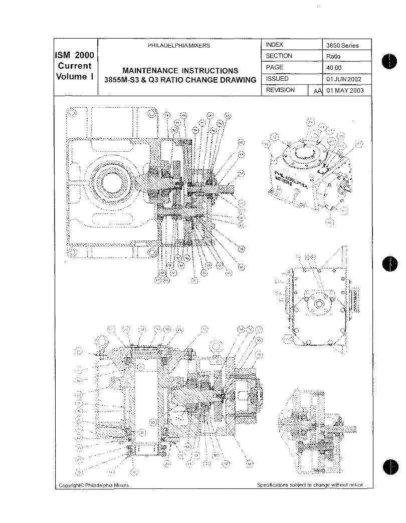
PHILADELPHIAMIXERS INDEX 3850 Series
ISM 2000 SECTION Ratio
CurrentqINTENANCE INSTRUCTIONS
PAGE ao00
Volume I3855MS3 Q3 RATIO CHANGE DRAWING ISSUED 01 JUN2002
REVISION 01 MAY 2003
11 u x gxa i
rr
ri gy
W i rs ra
k Y 4 j s w
j tr
f 4d
6 ss Z 3 t a
av 1 i F
St i slt a
M p3 ri 4
iy Z gy3 1x l y 3 y L
k f t4ry
f a43
3
3 Lf
E r 2
ti e 7 3 a d E
s
t 3 xa bN
9
x
c 4
e ti 3b pF
L lfd 7t afx
4 N
i R 5S FY M j s
fP
t k j a
xa w 7 4
i i5
FS3 s9 a1
f l 2 r t trtc e4a
F
Ft
ed W6
i i
ji itr
1i
p
1 b4 t
S P rN3
i 4 r t l 3s
tvFS Iq JF
L
1 td 3 rF
3s
f f ve
13 f tfi rr
F 4 3r
ki
r
iR
22t
E anrC t
5 n3 t a yxr C z 1
Ea y c Y
a
3 5 aif 1C
03 i
wwd6ri
a 61 k
7y 3 L y He3a7Y
T dT4f
r
Copyright0 Phifadelphia Mixers Specifications subject to change without nolice
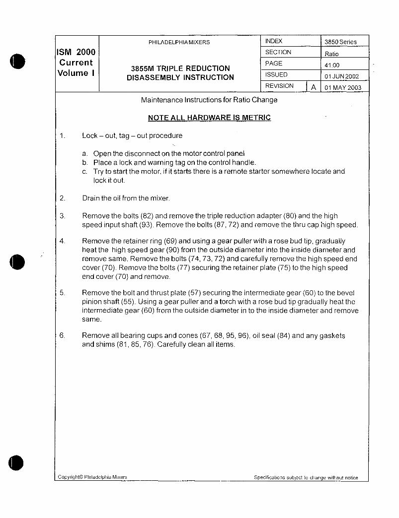
PHILADELPHIAMIXERS N 3850 Series
ISM 2000 SECTION Ratio
Current PAGE 4100
Volume I3855M TRIPLE REDUCTION
SSUEDDISASSEMBLY INSTRUCTION 01 JUN2002
REVISION A 01 MAY 2003
Maintenance Instructions for Ratio Change
NOTE ALL HARDWARE IS METRIC
1 Lock out tag out procedure
a Open the disconnect on the motor control panelb Place a lock and warning tag on the control handle
c Try to start the motor if it starts there is a remote starter somewhere locate and
lock it out
2 Drain the oil from the mixer
3 Remove the bolts 82 and remove the triple reduction adapter 80 and the highspeed input shaft 93 Remove the bolts 87 72 and remove the thru cap high speed
4 Remove the retainer ring 69 and using a gear puller with a rose bud tip graduallyheat the high speed gear 90 from the outside diameter into the inside diameter and
remove same Remove the bolts 74 73 72 and carefully remove the high speed end
cover 70 Remove the bolts 77 securing the retainer plate 75 to the high speedend cover 70 and remove
5 Remove the bolt and thrust plate 57 securing the intermediate gear 60 to the bevel
pinion shaft 55 Using a gear puller and a torch with a rose bud tip gradually heat the
intermediate gear 60 from the outside diameter in to the inside diameter and remove
same
6 Remove all bearing cups and cones 67 68 95 96 oil seal 84 and any gasketsand shims 81 85 76 Carefully ciean all items
Copyright0 Philadelphia Mixers Specifications subject to change without notice
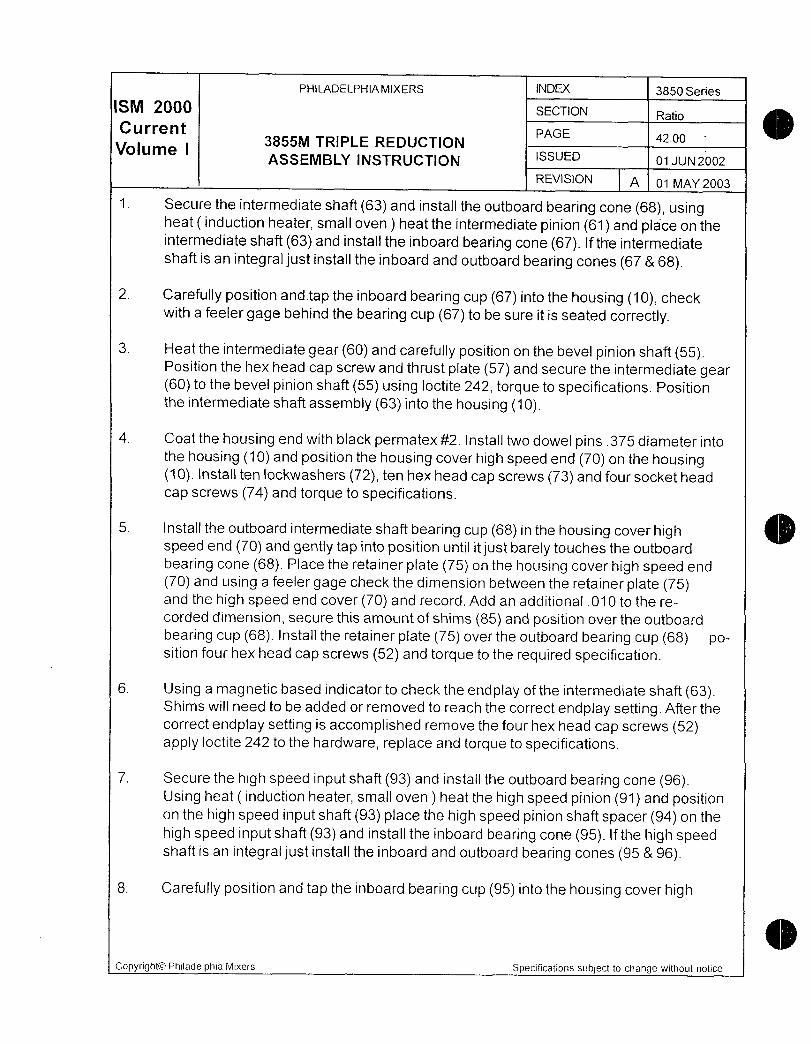
PHILADELPHIAMIXERS INDEX 3850 Series
ISM 2000 SECTION Ratio
Current PAGE 4200Volume I
3855M TRIPLE REDUCTIONASSEMBLY INSTRUCTION SSUED olUN2oo2
REVISION A 01 MAY 2003
1 Secure the intermediate shaft 63 and install the outboard bearing cone 68 usingheat induction heater small oven heat the intermediate pinion 61 and place on theintermediate shaft 63 and install the inboard bearing cone 67 If the intermediateshaft is an integral just instail the inboard and outboard bearing cones 67 68
2 Carefully position andtap the inboard bearing cup 67 into the housing 10 checkwith a feeler gage behind the bearing cup 67 to be sure it is seated correctly
3 Heat the intermediate gear 60 and carefully position on the bevel pinion shaft 55Position the hex head cap screw and thrust plate 57 and secure the intermediate gear60 to the bevel pinion shaft 55 using loctite 242 torque to specifications Positionthe intermediate shaft assembly 63 into the housing 10
4 Coat the housing end with black permatex 2 install two dowel pins 375 diameter intothe housing 10 and position the housing cover high speed end 70 on the housing10 Install ten lockwashers 72 ten hex head cap screws 73 and four socket head
cap screws 74 and torque to specifications
5 Install the outboard intermediate shaft bearing cup 68 in the housing cover highspeed end 70 and gently tap into position until it just barely touches the outboard
bearing cone 68 Place the retainer plate 75 on the housing cover high speed end
70 and using a feeler gage check the dimension between the retainer plate 75and the high speed end cover 70 and record Add an additional 010 to the re
corded dimension secure this amount of shims 85 and position over the outboard
bearing cup 68 Install the retainer plate 75 over the outboard bearing cup 68 position four hex head cap screws 52 and torque to the required specification
6 Using a magnetic based indicator to check the endplay of the intermediate shaft 63Shims will need to be added or removed to reach the correct endplay setting After the
correct endplay setting is accomplished remove the four hex head cap screws 52apply loctite 242 to the hardware replace and torque to specifications
7 Secure the high speed input shaft 93 and install the outboard bearing cone 96Using heat induction heater small oven heat the high speed pinion 91 and positionon the high speed input shaft 93 place the high speed pinion shaft spacer 94 on the
high speed input shaft 93 and install the inboard bearing cone 95 If the high speedshaft is an integral just install the inboard and outboard bearing cones 95 96
8 Carefully position and tap the inboard bearing cup 95 into the housing cover high
Copyright0 Philadelphia Mixers Specifications subject to change without notice

PHILADELPHIA MIXERS INDEX 3850 Series
ISM 2000 SECTION Ratio
Current PAGE 4300
Volume I3855M TRIPLE REDUCTION
ASSEMBLY INSTRUCTION continuedSSUED o utv2oo2
REVISION A 01 MAY 2003
speed end 70 check with a feeler gage behind the inboard bearing cup 95 to be sure
it is seated correctly
9 Heat the high speed gear 90 and carefully position on the intermediate shaft 63 and
install the retainer ring 69 Position the high speed shaft assembly 93 into the inboard
bearing cone 95 and mesh the teeth with the high speed gear 90 Position the gaskethigh speed adapter 81 on the housing cover high speed end 70 Position the tripiereduction adapter 80 on the housing cover high speed end 70 and secure usingseven socket head cap screws 82
10 Carefully position and tap the outboard bearing cup 96 into the triple reduction adapter80 until itjust barely touches the outboard bearing cone 96 Place the thru cap highspeed 83 and using a feeler gage check the dimension between the thru cap highspeed 83 and the triple reduction adapter 80 and record Add an additional 010 to
the recorded dimension secure this amount of shims 76 and position over the out
board bearing cup 96 Position the lockwashers 72 and hex head cap screws 87and torque to specifications Using a magnetic based indicator check the endplay of the
high speed input shaft 93 Shims will have to be added or removed to reach the correct
endplay setting Instalt the oil seai 84 after the correct endplay setting is accomplished
11 Reinstall the high speed couping 209 on the input shaft 63 and proceed to install the
motor mounting spooi 200 and motor 220 with the correct hardware and torque to
specifications
Copyright0 Philadelphia Mixers Specifications subject to change without notice

n
wy
P
r mF eW
Pa rts

PHILADELPHIAMIXERS N 3850 Series
ISM 2000 SECTION Parts
Current PAE 6600
Volume I QuofeOrderForm ISSUED 01 JUN2002
REVISION 01 MAY 2003
QUOt@
Serial Number Customer
Order Number Requisitioner
Model Return Fax Number
Fax to Philadelphia Mixers Parts Sales 717 8321746
or Fax to your local sales representative
Bubble Item Number Description Qty Price Each Total Price Delivery
NotesCommentsCustomer
NotesCommentsPM
Copyright0 Philadelphia Mixers Specifications subject to change without notice
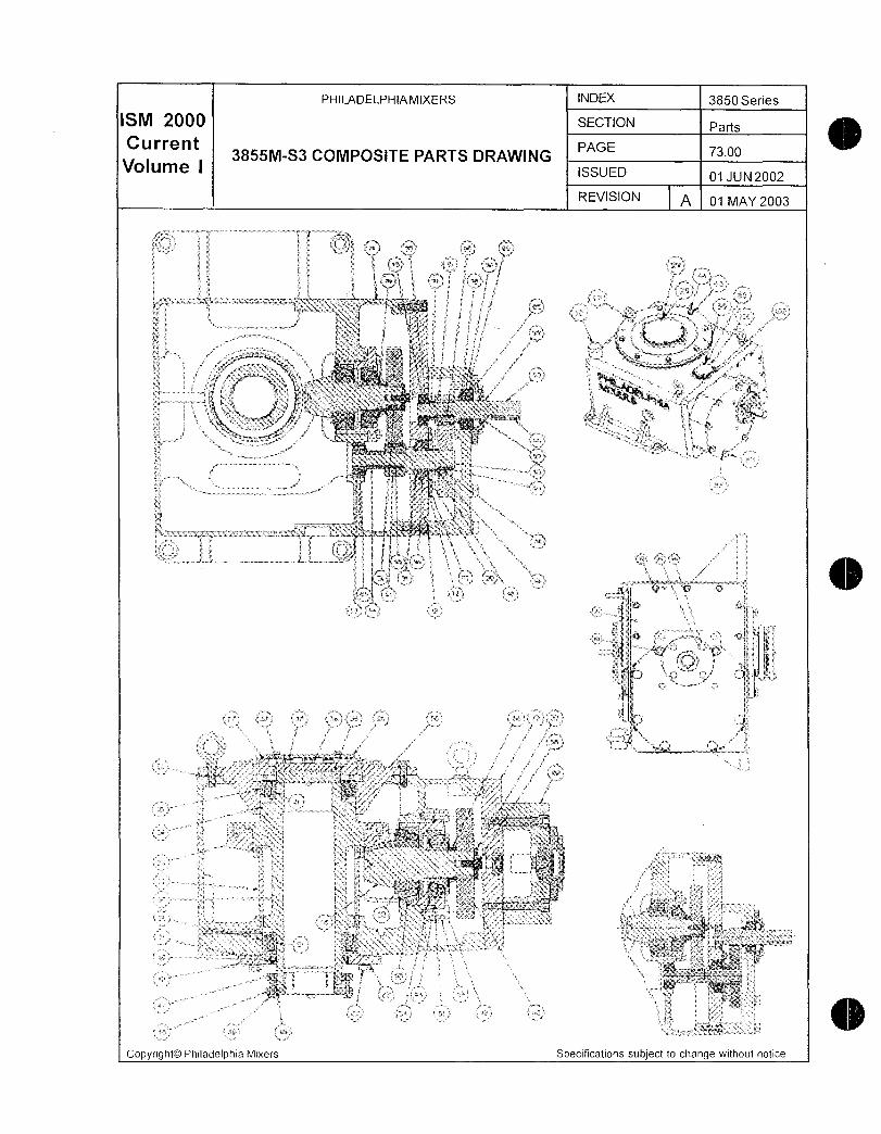
PHILADELPHIAMIXERS INDEX 3850 Series
ISM 2000 SECTION Parts
Current3855MS3 COMPOSITE PARTS DRAWING
PAGE 7300
Volume ISSUED 01JUN2002
REVISION A 01 MAY 2003
si dd iS3 n ax
j k r ik f ila tt ga
j dtaal axj E se
3 x y s er 5e 3
t 1 t i ti
tqE r i
s 4i fY v d s
f
t
i 6 tt t t
1sr zti i4 2 a i i a
s
v n3
P i
y f
9 Y
XC4 i
i P
s i a w
f4 J r
g j pta xt a d a
ii S 3 M ia F g
n S e 24p t r
e 4
7 t1
Fs La
f x3e y
z e
qXi i
4s
t P 4 v
E
zE h
t F
I 5 t
p ar
et
orn aW
i
tP
i F u94 L Ft F
33
W r z
3a
Sa tdgrE
s Pi 4
p7
tas
w
gk f
1r r
F y
S 3 R
v 5
f R Frr
p t t s3
t
dbl 1 fq r
i
s r
4 x g
rt rs ca r a
yr N
jn 5R
a
cg 1 A
s i 3 T a i e t
u l ea1j
rrry
6
yix m J C
c7
L fsr
r zTM
5 43
Q a 6
Copyrfght0 Philadelphia Mixers Specifications subject to change without notice
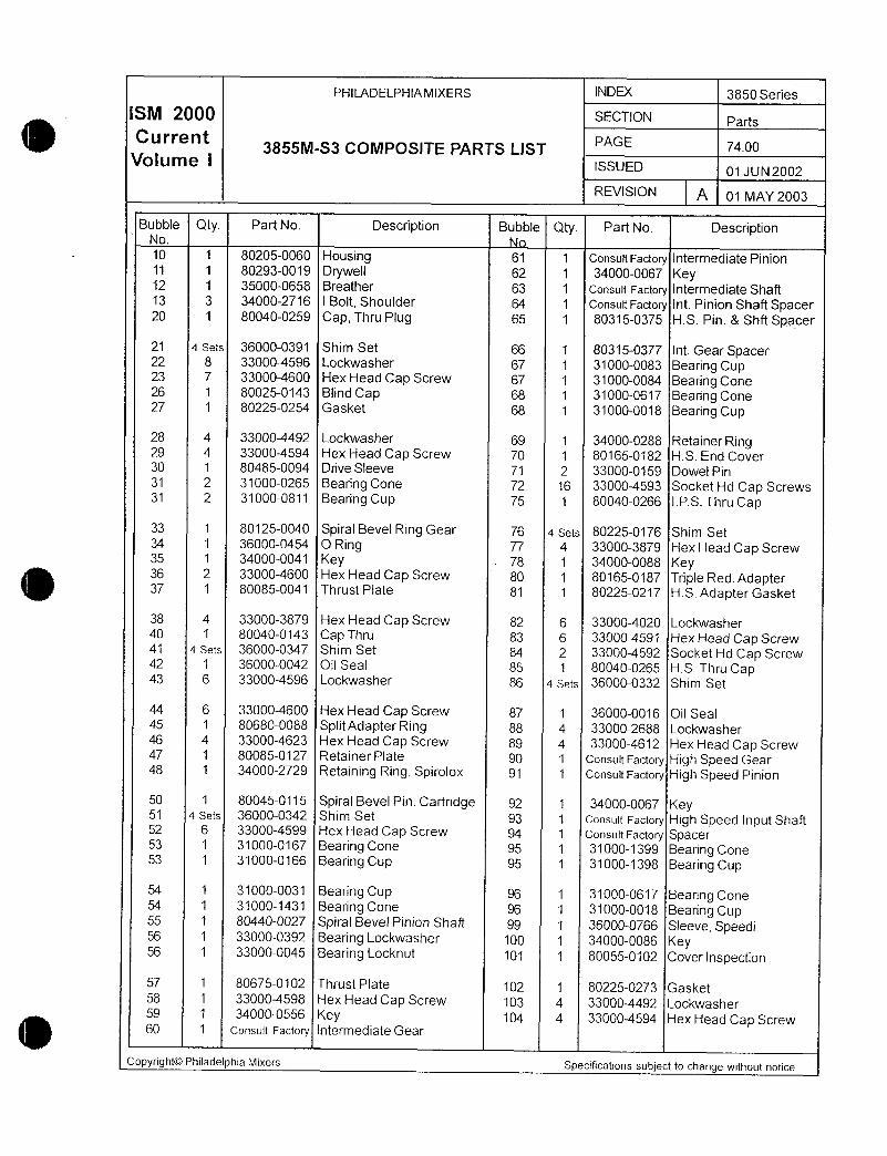
PHILADELPHIA MIXERS INDEX 3850 Series
ISM 2000 SECTION Parts
Current3855MS3 COMPOSITE PARTS L1ST
PAGE a00
Volume ISSUED 01JUN2002
REVISION A 01 MAY 2003
Bubble Qty Part No Description Bubble Qty Part No DescriptionNo
10 1 802050060 Housing 61 1 Consut Factory Intermediate Pinion11 1 802930019 Drywell 62 1 340000067 Key12 1 350000658 Breather 63 1 consuit Factory Intermediate Shaft13 3 340002716 I Bolt Shoulder 64 1 ConsultFactory Int Pinion Shaft Spacer20 1 800400259 Cap Thru Pug 65 1 803150375 HS Pin Shft Spacer
21 a sets 360000391 Shim Set 66 1 803150377 Int GearSpacer22 8 330004596 Lockwasher 67 1 310000083 Bearing Cup23 7 330004600 Hex Head Cap Screw 67 1 310000084 Bearing Cone26 1 800250143 Blind Cap 68 1 310000617 Bearing Cone27 1 802250254 Gasket 68 1 310000018 Bearing Cup
28 4 330004492 Lockwasher 69 1 340000288 Retainer Ring29 4 330004594 Hex Head Cap Screw 70 1 801650182 HS End Cover30 1 804850094 Drive Sleeve 71 2 330000159 Dowel Pin31 2 310000265 Bearing Cone 72 16 330004593 Socket Hd Cap Screws31 2 310000811 Bearing Cup 75 1 800400266 IPS Thru Cap
33 1 801250040 Spiral Bevel Ring Gear 76 a sets 802250176 Shim Set34 1 360000454 O Ring 77 4 330003879 Hex Head Cap Screw35 1 340000041 Key 78 1 340000088 Key36 2 330004600 Hex Head Cap Screw 80 1 801650187 Triple Red Adapter37 1 800850041 Thrust Plate 81 1 802250217 HS Adapter Gasket
38 4 330003879 Hex Head Cap Screw 82 6 330004020 Lockwasher40 1 800400143 Cap Thru 83 6 330004591 Hex Head Cap Screw41 a sets 360000347 Shim Set 84 2 330004592 Socket Hd Cap Screw42 1 360000042 Oil Seal 85 1 800400265 HS Thru Cap43 6 330004596 Lockwasher 86 a sets 360000332 Shim Set
44 6 330004600 Hex Head Cap Screw 87 1 360000016 Oil Seal45 1 806800088 SplitAdapterRing gg 4 330002688 Lockwasher46 4 330004623 Hex Head Cap Screw 8g 4 330004612 Hex Head Cap Screw47 1 800850127 Retainer Plate 90 1 Consuit Factory High Speed Gear48 1 340002729 Retaining Ring Spirolox 91 1 Consuit Factory High Speed Pinion
50 1 800450115 Spiral Bevel Pin Cartridge 92 1 340000067 Key51 a sets 360000342 Shim Set 93 1 consuit Factory High Speed Input Shaft52 6 330004599 Hex Head Cap Screw g4 1 Consult Factory Spacer53 1 310000167 Bearing Cone 95 1 310001399 Bearing Cone53 1 310000166 Bearing Cup g 1 310001398 Bearing Cup
54 1 310000031 Bearing Cup gg 1 310000617 Bearing Cone54 1 310001431 Bearing Cone 96 1 310000018 Bearing Cup55 1 8Q4400027 Spiral Bevel Pinion Shaft 9g 1 360000766 Sleeve Speedi56 1 330000392 Bearing Lockwasher 100 1 340000086 Key56 1 330000045 Bearing Locknut 101 1 800550102 Cover Inspection
57 1 806750102 Thrust Piate 102 1 802250273 Gasket58 1 330004598 Hex Head Cap Screw 103 4 330004492 Lockwasher59 1 340000556 Key 104 4 330004594 Hex Head Cap Screw60 1 Consult Factory Intermediate Gear
CopyrightOO Philadelphia Mixers Specifications subject to change without notice

PHILADELPHIAMIXERS N 3850 Series
M 20 SECTION Parts
Current PARTS PAGE 6500
Volume I ISSUED 01 JUN2002
REVISION 01 MAY 2003
Parts Order Procedure
This manual includes the information necessary to assist you in ordering replacement parts for
your Philadelphia Mixers 3850 Series Mixer Drive Please use the following procedure for ease in
meeting your mixer parts requirements
The parts order procedure will be simplified if you use the following 3 reference materials included
in this manual
1 Parts QuoteOrder Form
2 Parts List
3 Drawings bubble
Find a copy of the ParsQuoteOrder Form on page 2 of this section Please make a coav of
this form for your transmittal
Use the Parts QuoteOrder Form when requesting quote information from Philadelphia Mixers
Upon compfetion of a1f information this form can be used as an order submittal along with a
copy of your authorized purchase order form
Please fill in the serial number order number model customer name requisitioner return fax
number and all information for parts required bubble item description and quantity re
quested FiH in this information completely for easy cross reference to the specific piece of
equipment
The identification information for the particular mixer drive referenced can be found on the
Outline Installation Drawing cover page of this manual andorthe nameplate attached to the
mixer drive
This manual has a complete parts list for your specific gear drives and related accessories to
assist you in ordering replacement parts
Bubble number drawings are enclosed for your reference Use these for easy identification of
the required replacement parts
o Please make any notes or comments on the bottom of the Parts QuoteOrder Form bottom in
the space provided
Upon completion of all information FAX the Parts QuoteOrder Form to your local sales repre
sentative or the Parts Department at Philadelphia Mixers at7178321746 for your quote and
delivery schedule Your quote will be returned as soon as possible so you can proceed with
your order processing Remember this form can then be used as an order submittal along with
a copy of your authorized purchase order form
Copyright0 Philadelphia Mixers Specifications subject to change without notice

A
rT
F 4
r
k
m
v
m
Maintenance

PHILADELPHIA MIXERS INDEX 3850 Series
SM 200 SECTION MaintTrouble
CurrentMAINTENANCE AND TROUBLESHOOTING
PAGE 00
Volume ISSUED 01JUN2002
REVISION A 01 MAY 2003
Preventive Maintenance Schedule for 3850 Series Mixers
PM Intervai Required Preventive Maintenance
Daily Inspect mixer drive for unusual sounds or oil leaks
Weekly Check oil level on dipstick Mixer must be off Record
level and add oil as necessary
Monthly Check oil for contamination
Check operation of guards alarm systems gaugescontrols and other safety devices in accordance with
Owners Piant Safety Operating Procedures
Six Month or 2500 Hour Intervals Refer to Motor Service Instructions for Greasinginstructions
Change oil in mixer drive
Inspect impeller for evidence of erosion and
corrosion
Check hardware tightness Retorque to originalspecifications
Extended Shutdown Periods See appropriate Long Term Storage Instructions
Greater than 1 Week Run mixer for approx 1 hour twice a week to coat
gears and bearings with oii and to prevent rust due to
moisture condensation
Note These Philadelphia Mixers Procedures are for mixers installed in their normal
operating position See Philadelphia Mixers LONG TERM STORAGE INSTRUC
TIONS for additional information on storage of mixers
Copyright0 Philadelphia Mixers Specifications subject to change without notice

PHILADELPHIAMIXERS N 3850 Series
SM 2 SECTION MaintTrouble
CurrentMAINTENANCE AND TROUBLESHOOTING
PAGE 1900
Volume I ISSUED 01 JUN2002
REVISION A 01 MAY 2003
TROUBLESHOOTING
Warning Lock out the motorand remove all external loads before servicing the mixer
or accessories Refer to the safety precautionsTrouble What to Inspect Action
Motor Determine whether the specific gravity or viscosity of the
Overload process has changed from that originally anticipatedInspect impellers for material buildupHave additional baffles been added to the vessel or the
size of the baffles increased
Check for proper impeller rotation as shown on the outline
installation drawingCheck the outline installation drawing for proper impellerlocation and proximity to intank appurtenances
Overheating Oil level too low Shut off mixer and check the oil level in sightglass
Breather Breather must be open and cfean Clean breather
regularly
Grade of oil Oil must be of the grade specified in the lubrication instruc
tions If it is not flush mixer and refill with the correct gradeof oil
Condition of oil Check to see if the oil is oxidized dirty or of a high sludgecontent Flush and change the oil per the lubrication instruc
tions
Stuffing box Stuffing box gland must not be overtightened See Pack
if supplied ing Procedure for proper packing and breakin Included if
applicable
Are bearings prop Adjustabfe tapered bearings must be set at proper lateral
erly adjusted clearance or preload Call Philadelphia Mixers ProTech
Services18007331341 Email protech@philamixerscomRust
formation in Make necessary provisionsto prevent entrance of water mixer
due to the Use lubricant with good rust inhibiting properties Make sure entrance
of water or oil level is correct See Lona Term Storagef nstructions humidity
Are
bearings and Abrasive substance will cause excessive gear and bearing gearsexposed to an wear Make necessary provisionsto prevent entranceof abrasive
substance abrasive substance Clean and flush mixer drive thoroughlyegdusty atmo and refill with new oil Revise maintenance practices to sphere
include more frequent oil changes Copyright0
Philadelphia Mixers Specifications subject to change without notice

PHILADELPHIA MIXERS INDEX 3850 Series
SM 2 SECTION Maint Trouble
C u rrent PAGE 2000
Volume IMAINTENANCE AND TROUBLESHOOTING
ISSUED 01 JUN2002
REVISION A 01 MAY 2003
Trouble What to Inspect Action
Noise Coupiing wear Check input coupling for wear Replace if worn
Are bearings prop Adjustable tapered bearings must be set at proper lateral
erly adjusted clearance or preload Call Philadelphia Mixers ProTech
Services18007331341 Email protech@philamixerscomAre
bearings and Shut off mixer and check the oil level at sightglass gearsproperly Oil must be of the grade specified in the lubrication instruc lubricatedtions If it is not flush mixer drive and refill with the correct grade
of oil Hardware
tightenedBe certain that all mounting and coupling hardware is tightened
to the correct wrench torque Mixer
support Does the mounting arrangement for the mixer provide structuresufficient support to prevent wobblingor vibrationof the assembly
See Outline Installation Drawing for criteria Vibration
Agitator Shaft Agitator shaft should not be bent The rigid coupling halves mustbe connected accordingto the instructions Critical
Speed If the shaft and or impellers are supplied by others check for
a critical speed condition Vibrations can occur througha particular
speed range Steady
bearing Has excessive wear occurredto trie steady bearing Is the if
applicable bearing securely bolted to the vessel and is it properly alignedInspect
hardwareIs all blade hardware and extension arm hardwareif applicable
properly torqued Including agit shaft couplings andmounting hardware Oil
Leakage Plug at drain and Apply pipe joint sealant or equal and tighten fittings standardpipe fittings Housing
and caps Tighten capscrewsor bolts to proper torqueIf not entirely effectiveremove housing cover and caps Clean mating surfacesand apply new sealing compound gasket Mixer
output shaft Has the recommendedoil level been exceeded Check oil levelat sightglass Drain oil to the correct level Breather
open Breather must be open and clean PHONE
717 8381341FAX 717 8321746ProTech
Services1 8007331341E mailprotech@philamixers comCopyright0PhiladelphiaMixers Specifications subject to change without notice
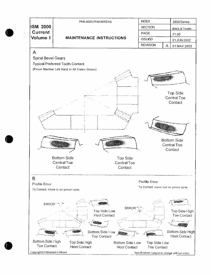
PHILADELPHIAMIXERS N 3850 Series
SM 2 SECTIONMaintTrouble
Current PAGE 2100
Votume i MAINTENANCE INSTRUCTIONS iSSUED 01 JUN 2002
REVISION A 01 MAY 2003
A
Spiral Bevel Gears
Typical Preferred Tooth Contact
Pinion Member Left Hand in All Cases Shown
e
F i tti t
a
Top Side
Central Toe
Contact
r
1kt r
ti
lr
S i
iQ
ri
ves msttw
Bottom Side
Central Toe
Contact
Bottom Side Top Side
Central Toe Central Toe
Contact Contact
BProfile Error
Profile Error
To Correct move out on pinion coneTo Correct move in on pinion cone
Mti
ERROR 4
ERRORs Top Side Low Top Side High
E Heel Contact Toe Contact
ri
T
Bottom Side Low Bottom Side HighToe Contact Heel Contact
Bottom Side High Top Side High Bottom Side Low Top Side LowToe Contact Heel Contact Heel Contact Toe Contact
Copyright0 Philadelphia Mixers Specifications subject to change without notice

PHILADELPHIAMIXERS INDEX 3850 Series
SM 200 SECTIONMaintTrouble
Current MAINTENANCE iNSTRUCTIONS PAGE 2200
VOIU111@ I Diagnosing Causes ofISSUED
Helical Gear Tooth Damage01 JAN 2001
REVISION A 01 MAY 2003
Shown here are typical illustrations of the five basic3causes of gear tooth failures although this is an y
a
oversimplification of gear tooth failures it might be
of some value in solving problems in the field The
five basic causes are
1 Original surface roughness 32 Foreign matter in the lubricant E3 Mechanical damage t r a4 Metal failure
5 Lubrication failure yPhiladelphia Mixers has a competent staff of
engineers to furtheranalyze yourgearproblems5
Foreign Material in the Lubricant
This failure shows upon the surface as wearr
f scratches or dents When contaminating mate
s rial is of a fine nature a lapping or polishingoccurs however tooth profiles also show wear
f s
Scratches of this nature are most prominent at
root and tip of teeth where sliding is greatestS M h
1 aa32
Thorough flushing of the mixer drive and replacement of the lubricant will eliminate this cause of
g failure
Original Surface Roughness 4F
No matter how smooth a surface may appear to
the eye it is comparatively rough when viewed 4under the microscope Usually lubricatonwill
provide a thin film for protection however under wn
borderline conditions these high spots will be
more highly stressed than adjacent areas Thus
pitch line pitting occurs
Improvement of finish such as shaving grindingor lapping will help this condition Mechanical Damage
This sort of damage includes bent broken or
scarred teeth In most cases when damage first
occurs only one or two teeth are affected ff teeth
are completely cracked off an examination of the
broken surface will usually indicate whether the
break is due to sudden impact overload or from
fatigue Impact overload condition will be dull in
color and crystallike structure
Copyright0 Philadelphia Mixers Specifications subject to change without notice
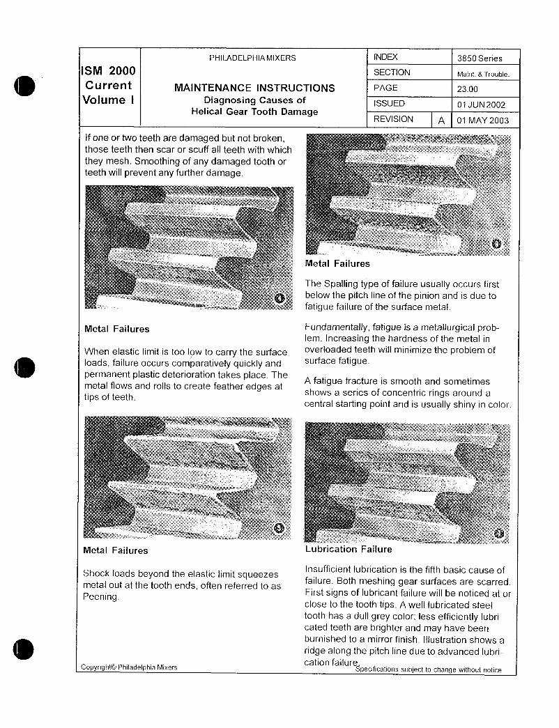
PHILADELPHIA MIXERS n1 3850 Series
SM 20 SECTION MaintTrouble
Current MAINTENANCE INSTRUCTIONS PAGE 2300
VOIUtII@ I Diagnosing Causes of ISSUED 01 JUN2002Helical Gear Tooth Damage
REVISION 01 MAY 2003
f one or two teeth are damaged but not brokenq
ethose teeth then scar or scuff all teeth with which z Y
z
they mesh Smoothing of any damaged tooth or
teeth will prevent any further damageA Z 3
asbsaWiwaa1Ya
V
fiw
y3M w YmXLlpa Pyi i m
t i al4 s1 l
sdeNcZ wr A
1ht h
g cWv wZc
3
r
nwEw n 4mm aiF r Y3
3
Metal Failures
The Spalling type of failure usually occurs first
e
y below the pitch line of the pinion and is due to
fatigue failure of the surface metal
Metal Failures Fundamentally fatigue is a metallurgical problem Increasing the hardness of the metal in
When elastic limit is too low to carry the surface overloaded teeth will minimize the problem of
loads failure occurs comparatively quickly and surface fatigue
permanent plastic deterioration takes place TheA fatigue fracture is smooth and sometimes
metal flows and rolls to create feather edges atshows a series of concentric rings around a
tips of teethcentral starting point and is usually shiny in color
k
Et3t 3
v Y t
1y F r
Fk
ah cr 2s y wc
i oAy j t
T i p r
r w x aahy aY
a s
r a am
ras vA s
Metal Failures Lubrication Failure
Shock loads beyond the elastic limit squeezesInsufficient lubrication is the fifth basic cause of
metal out at the tooth ends often referred to asfailure Both meshing gear surfaces are scarred
PeeningFirst signs of lubricant failure will be noticed at or
close to the tooth tips A well iubricated steel
tooth has a dull grey color less efficiently lubricated teeth are brighter and may have been
burnished to a mirror finish Illustration shows a
ridge along the pitch line due to advanced lubri
co ht0 Philadel hia Mixerscation failure
PY 9 p Specifications subject to change without notice

Ew
y j J
5d
a 4u
Rigid Coulingo
3ac
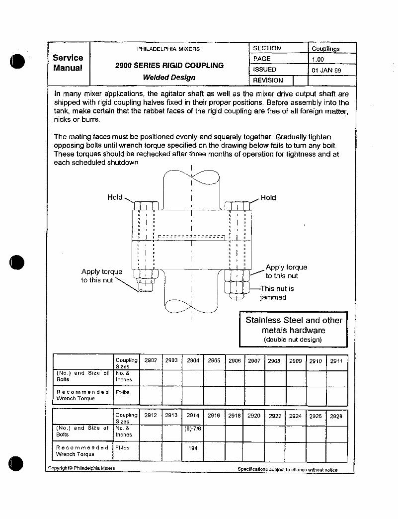
PHiL4DELPHlA MIXERS SECTON Cou Ilh s
Service PAGE i00
Manual 2g00 SERIES RiGlD COUPLlNGssUo 01 JAN 99
Welded Design REVlSION
In many mixer appfications the agitator shaft as well as the mixer drive output shaft are
shipped with rigid coupling halves fixed in their proper positions Befare assembly into the
tank make certain that the rabbet facss of the rigid coupling are free of a foreign matternicks or burrs
The mating faces must be positioned evenly and squareiy togethar Gradually tightenopposing bolts until wrench orque specifidon th drawing below fails to tum any boitThese torques should be rechecked after three rnonths of operatian for tightness and at
each schedufed shutdownI
I
Hold Hold
IpCY
i
i
ry u ry 1 II
11 II II II
II I II I I II
11 II I II
I 1 II I II 1 II
IAPply torque
Apply forque to this nuto this nut
I This nut is
jammed
Stainlss Steel and other
metals hardwaredouble nut design
Coupling 2902 29b3 2904 2905 2906 29Q7 2908 2909 2910 291iSizes
No and Size of NoBBolts Inches
Recommended FtIbs
Wrench 7orgue
Coupling 2912 2913 2914 2916 2918 2920 2922 2924 2926 2928Sizes
No and Size of tVo 878Bolts Inches
Recommended FtIbs 194
Wrench Torque
CopyrlghKD Philadeaphia Miuers Specifications subject to change without notice

p
wM W
s
cY
Ei
Impelle
Q
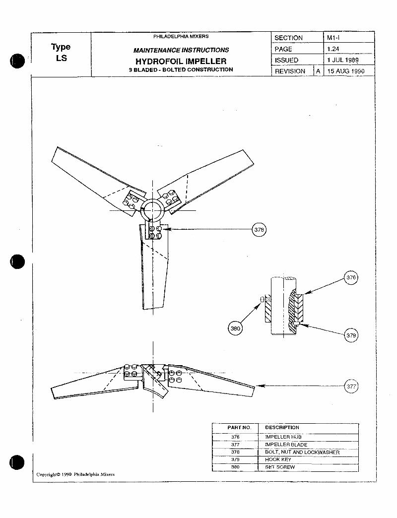
PHIIADELPHIA MIXERS SECTION M1I
Typ MAfNTENANCE dNSTRUCTIONS PAGE 124
ITYDROFOIL IMPELLER ISSUED 1 JUL 1989
3 BLADED BOLTED CONS7RUCTION REVISIOfV A 15 AUG 1990
if
t
i
378
376
1
380j
379
I
i oF gi
eJ
1ii
PAR7 NO DESCRIPTION
376 1MPELLER MiJB
377 IMPELLER 6lADE
378 BOLT NUT AND LOCKWASHER
379 HOOK KEY
380 SET SCREW
Copyright t990 Philadelphia Mixcrs
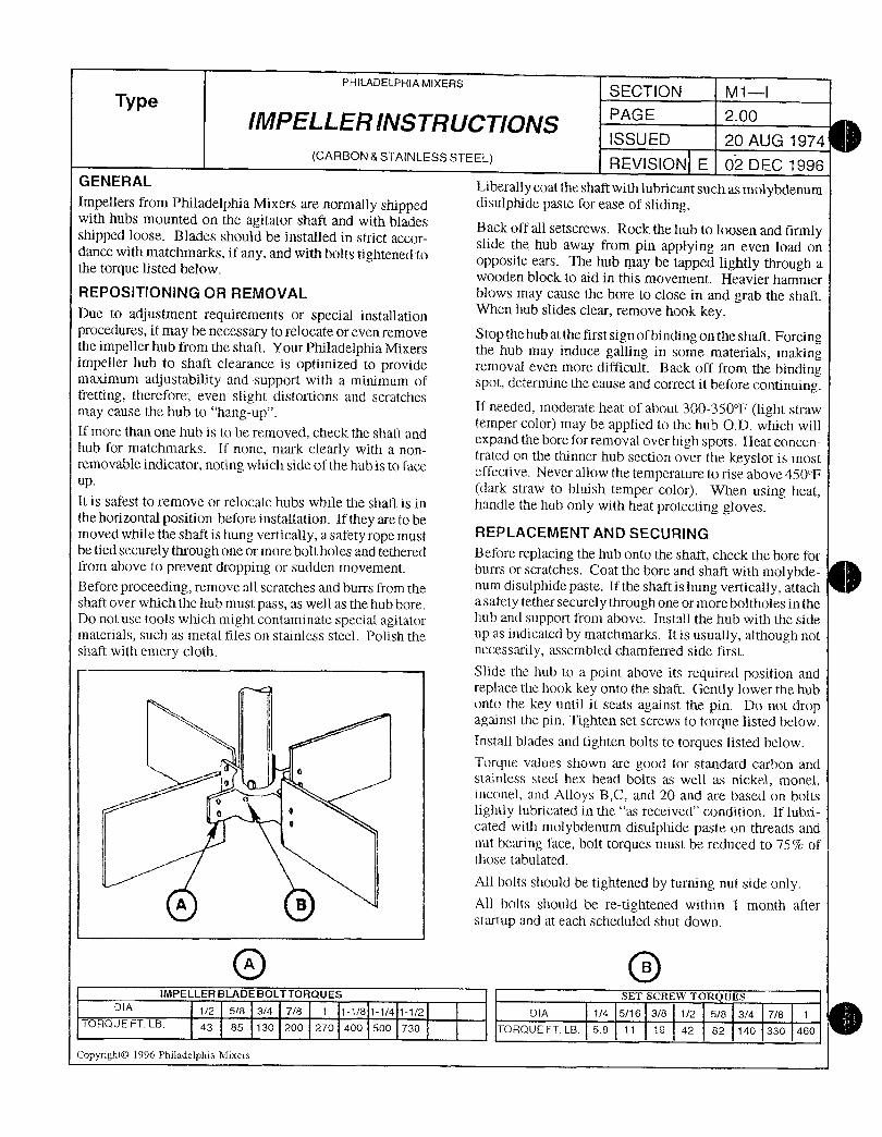
PHILADELPHIAMIXERSSECTION M1I
TypeIlV1PELLERIIVSTRUCTIQNS
PAGE 200
ISSUED 20 AUG 1974CARBONSTAINLESSSTEEL REVISION E 02 DEC 1996
G E N E R AL Liberall y coat the shaft with lubricant such as molybdenumImpellers from Philadelphia Mixers are normally shipped disulphide paste for ease of slidingwith hubs mounted on the agitator shaft and with blades Back off all setscrews Rock the hub to loosen and firmlyshipped loose Blades should be installed in strict accor slide the hub away from pin appying an even load ondance with matchmarks if any and with bolts tightened to
opposite ears The hub may be tapped lightly through athe torque listed belowwooden block to aid in this movement Heavier hammer
REPOSITIONING OR REMOVAL blows may cause the bore to close in and grab the shaft
Due to adjustment requirements or special installationen hub slides clear remove hook key
procedures it may be necessary to relocate or even remove StoQ the hub at the first sign of binding on the shaft Forcingthe impeller hub from the shaft YourPhiladelphia Mixers the hub may induce galling in some materials makingimpeller hub to shaft clearance is optimized to provide removal even more difficult Back off from the bindingmaximum adjustability and support with a minimum of spot determine the cause and correct it before continuingfretting theretiore even slight distortions and scratches
If needed moderate heat of about 300350F li ht strawmay cause the hub to hangup gtemper color may be applied to the hub OD which willIf more than one hub is to be removed check the shaft andexpand the bore for removal over high spots Heat concenhub for matchmarks If none mark clearly with a non trated on the thinner hub section over the keyslot is inost
removable indicator noting wiiich side of the hub is to face effective Never allow the temperature to rise above 450Fp dark straw to bluish temper color When using heatIt is safest to remove or relocate hubs while the shaft is in handle the hub only with heat protecting glovesthe horizontal position before insCallation If they are to be
movedwhiletheshaftishungverticallyasafetyropemust REQLACEMENTANDSECURINGbe fied securely through one or more bolt holes and tethered Before repiacing the hub onto the shaft check the bore forfrom above to prevent dropping or sudden movement buns or scratches Coat the bore and shaft with niolybdeBefore proceeding remove all scratches and burrs from the num disulphide paste If the shaft is hung vertically attach
shaft over which the hub must pass as well as the hub bore a safety tether securely through one or mare boltholes in the
Do not use tools which might contaminate special agitator hub and support from above Install the hub with the side
materials such as metal files on stainless steel Polish the up as indicated by matchmarks Itis usually aithough not
shaft with emery cloth necessarily assembied chamferred side tirst
Slide the hub to a point above its required position and
replace ttie liook key onto the staft Gently lower the hub
onto the key unti it seats against the pin Do not dropagainst the pin Tighten set screws to torque listed below
Install blades and fighten bolts to torques listed below
Torque values shown are good for standard carbon andstainless steel hex head bolts aS well as nickel monel
e inconel and Alloys BC and 20 and are based on bolts
a e lightly lubricated in the as received condition If lubri
cated with molybdenum disulphide paste on ttueads and
nut bering face bolt torques must be reduced to 75 ofthose tabulated
Ail bolts should be 6ghtened by turning nut side onlyq g All bolts should be reflghtened within 1 month after
startup and at each scheduled shutdown
0 0IMPELLERBLADEBOLTTORQUES SET SCREW TOR UE5
DIA z 58 34 78 i 118 114 1i2 DIA 14 516 38 12 58 34 78 1
TORQUE FT LB 43 85 130 200 270 400 500 730 TORQUE FT LB 58 1 1 19 42 82 140 330 460
Copyright0 1996 Philadelphia Mixers
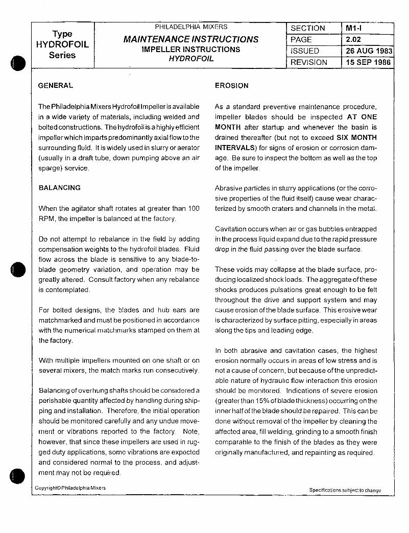
PHILADELPHIA MIXERS SECTION M1I
TypeMAINTENANCE INSTRUCTlONS PAGE 202
HYDROFOILIMPELLER fNSTRUCTiQNS ISSUED 26 AUG 1983
Series HYDROFOILREVISION 15 SEP 1986
GENERAL EROSION
The Philadelphia Mixers Hydrofoil lmpefleris available As a standard preventive maintenance procedurein a wide variety of materials including welded and impeller blades should be inspected AT ONE
bolted constructions The hydrofoil is a highlyecient MOIVTFf after startup and whenever the basin is
impellerwhichimpartspredominantlyaxialflowtothe drained thereafter but not to exceed SIX MONTH
surrounding fluid It is widey used in slurry or aerator INTERVALS for signs of erosion or corrosion dam
usually in a draft tube down pumping above an air age Be sure to inspect the bottom as well as the top
sparge service of the impeller
BALANCING Abrasive particles in slurry applications or the corro
sive properties of the fluid itselfl cause wear charac
When the agitator shaft rotates at greater than 100 terized by smooth craters and channels in the metal
RPM the impeller is baanced at the factory
Cavitation occurs when air or gas bubbles entrapped
Do nof attempt to rebalance in the field by adding in the process liquid expand due to the rapid pressure
compensation weights to the hydrofoil blades Fluid drop tn the fluid passing over the blade surface
flow across the blade is sensitive to any bladeto
blade geometry variation and operation may be These voids may collapse at the blade surface pro
greatly altered Consult factory when any rebalance ducing localized shock loads The aggregate ofthese
is contemplated shocks produces pulsations great enough to be felt
throughout the drive and support system and may
For bolted designs the blades and hub ears are cause erosion of the blade surface This erosive wear
matchmarked and must be positioned in accordance is characterized by surface pitting especially in areas
with the numerical matchmarks stamped on them at along the tips and leading edgethe factory
In both abrasive and cavitation cases the highestWith multiple impellers mounted on one shaft or on erosion normally occurs in areas of low stress and is
several mixers the match marks run consecutively not a cause of concern but because of the unpredictable nature of hydraulic flow interaction this erosion
Balancing of overhung shafts should be considered a should be monitored Indications of severe erosion
perishable quantity affected by handling during ship greaterthan 15ofbladethickness occurring on the
ping and installation Therefore the initial operation inner half of the blade should be repaired This can be
should be monitored carefully and any undue move done without removal of the impeller by cleaning the
ment or vibrations reported to the factory Note affected area fill welding grinding to a smooth finish
however that since these impellers are used in rug comparable to the finish of the blades as they were
ged duty appications some vibrations are expected originally manufactured and repainting as requiredand considered normal to the process and adjust
ment may not be required
CopyrightOO PhiladelphiaMixers Specifications subjectto change

w w
W
y
w
Moto r
0
0
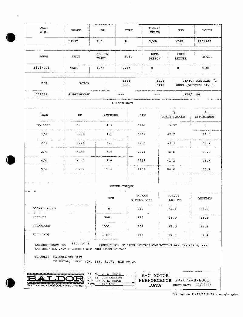
REL I I PHASEI
SO II FRAME HP TYPEHERTZ I RPM VOLTS
III I
L213T 75 P 360 I 1765 I 230460I j I i
iAMB C j NEMA CODE1
AMPS DUTY SF i ENCLj INSUL DESIGN LETTER i
i
f
II I18894 i CONT 40F 115 B H FCXE
I I I Ii
TEST i TEST i STATOR RES25 CES I ROTOR iI SO DATE i OHMS BETWEEN LINES
1 I
f t534693 i 418425053JE i I I 376150
L
PERFORMANCE
1
iiII POWER FACTOR I EFFICIENCY
LOAD
I HPAMPERES RPM
II ji i
NO LOAD 0 41 1800 I 532 0
14 i 188 47 1792 422 878
i
i24 375 60 i 1784 i 644 I 917
i34 562 76 1776 i 755 I 922
I i44 750 94 j 1767 I 812 917
i j
54 937 114 1757 846 907I
6
I i
JSPEED TORQUE
I TORQUE TORQUE
iRPM
FULL LOAD I LBFT iAMPERES
II
ILOCKED ROTOR I 0 215 480 635i
i
PULL UP j 360 175 390 613
i
BREAKDOWN 1551 309 690 385i
FULL LOAD 1767 100 223 94
AMPERES SHOWN FOR460 VOLT
CONNECTION IF OTHER VOLTAGE CONNECTIONS ARE AVAILABLE THE
AMPERES WILL VARY INVERSELY WITH THE RATED VOLTAGE
REMARKS CALCULATED DATA
XE MOTOR NEMA NOM EFF 917 MIN9020
i DR BY W L SMITAA MOTOR
IICR BY JJHARRISON i
iAPP BY w L sMZTH PERFORMANCE E02672BE001
BALDQRDfJ3ERLIANGE iiDATE 1213OS DATA ZSSUE DATE 1213OS
Printed on 111307 830 usmghengdev

REL SO RPM 1765 SF 115 ROTOR 418425053JE
FRAME L213T VOLTS 230460 NEMA DESIGN B TEST SO CALCULATED DATA
HP 75 AMpS 16894 CODE LETTER H TEST DATE
TYPE P DUTY CONT ENCLOSURE FCXE STATOR RES @25c376150PHASE AERTZ3 60 AMB40 FE S 534693 OHMS BETWEEN
LINES IFF9I MIN902rb IIII I a I I I I I I I iI
IXE MOTOR NEMA NOM
E i Ii i i i r
i I ijiIIi
i r j I i I r h L IL o I i I I I IiI i I II rn i
Ii v I I I I
II rr
rj I
I4 I
I I jI I I iII
I
i tI ir I I
i i o Ii
i i J iI II
I i r
L ToI i iI J i i Ii
II
I
a i I i
I
I
i S i i 3 i I i I ii
ii O I
i cC o ii
i iil I i i I i i i ii
o nl i Ii I
L
wI
I
I I I I iIo
iI
I
I II
I
oI i Z
i
i
II
jl
I i
I o i iI
iW o I i i
I a3 r
Y II
I I i I I1 o r
I I o a I
I
I o j I I II i
ii I i i
i
II
II I I I
II I II 1 i r
II
i
i oic
II i
I i i I I I II i
I i I i i i 1I
1HORSEPOWtR i
10 iI
N
i i
I i i 8
9 iI I
ii o
o O I O i I II
i
I
I I I I
iI
Ii
i i Ili
i I iI i I
I 4 t
ir
I
Ii iI
i
iI
rv
iI Ii
F l J I7 O 0
0 m I Ii
i Ii Z
ILlJ
r QI
p
c QI o
O
Ii
i
i
O i U I UU 4UU GUU 5UU i UUU UU VUUt
vUSPE ED INRPM PLT22 3 L6
PT AMPERES SHOWN FOR d60 VOLT CONNECTION IF OTHER VOLTAGE CONNECTIONSARE AVAZLABLETAE AMPERES WILL VARY INVERSELY WITH THE RATED
VOLTAGE I DR BY WL SMITH A C
MOTOR Lc K BYFaR
soN pERFORMANCEE02672BE001I APP BY W L
SYIITHHAL LIORD04CE RELfANCEI DATEI13 OS CURVES ISSUE DATE1213
OS Printed on1113 078 30
usmghengdevl
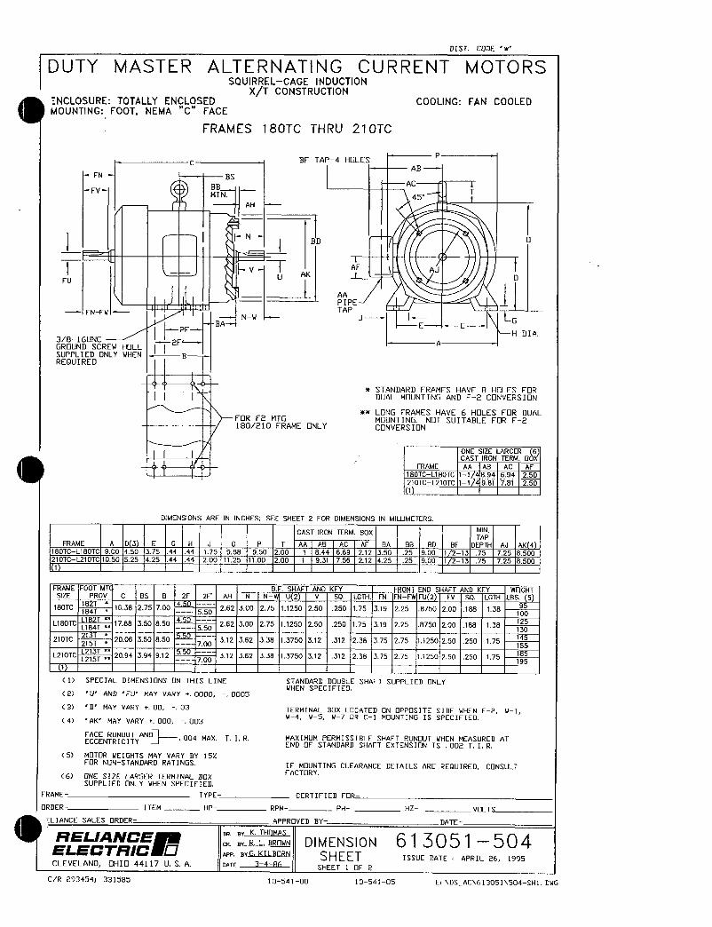
DIST CODE w
DUTY MASTER ALTERNATING CURRENT MOTORSSQUIRRELCAGE INDUCTION
XT CONSTRUCTIONNCLOSURE TOTALLY ENCLOSED COOLING FAN COOLEDMOUNTING FOOT NEMA C FACE
FRAMES 180TC THRU 210TC
BF TAP4 HOLESP
AB
BS
BBAC
FVMIN 45
T
AH
I r N
j
F VAK A1 AJ
D
L AA
PIPE 1FNFW
IBA
NWTAP
J 4E
G
3816UNCH DIA
GRUND SCREW HOLE Ii2F A
SUPPLIED ONLY WHEN gREQUIRED
STANDARD FRAMES HAVE 8 HLES FORDUAL MOUNTING AND F2CNVERSION
LONG FRAMES HAVE 6 HOLES FR DUALFR F2 MTG MUNTING NOT SUITABLE FR F2180210 FRAME ONLY CONVERSIN
ONE SIZE LARGER 6CAST IRON TERM BbX
fRAME AA AB AC AF
180TCL180TC 11 894 694 250
210TCL210TC 11 981 781 250
1
DIMENSIONS ARE IN INCHES SEE SHEET 2 FOR DIMENSIONS IN MILLIMEIERS
CAST IRON TERM BOX MINTAP
FRAME A D 3 E G H J 0 P T AA AB AC AF BA BB BD BF DEPTH AJ AK 4180TCL180TC 900 450 375 44 44 175 988 950 200 1 844 669 212 350 25 900 1 213 75 725 8500210TCL210TC 1050 525 425 44 44 200 1125 1100 200 1 931 756 212 425 25 900 1 213 75 725 8500
1
FRAME FOOT MT BE SHAFT AND KEY FRONT END SHAFT AND KEY WqGHTSIZE PROV C BS B 2F 2F AH N N U 2 V SQ tGTH FN FNFW FU 2 FV SQ IGTH LBS 5
95180TC 8 1638 275 700 450 55D262 300 275 11250 250 250 175 319 225 8750 200 188 138
L180TCL184T
88 350 850 4S0 550262 300 275 11250 250 250 175 319 225 8750 200 188 138
ZS
130
210TC Z 2006 350 850700
312 362 338 13750 312 312 238 375 275 11250 250 250 17545
155
L270TCL215T
2094 394 912550
700 312 362 338 13750 312 372 238 375 275 71250 250 250 17585
195t
ll SPECIAL DIMENSIONS N THIS LINE STANDARD DOUBLE SHAFT SUPPLIED NLYVHEN SPECIFIED
2 U AND FU MAY VARY 0000 0005
C3 D MAY VARY 00 03 TERMINAL BX IOCATED N PPOSITE SIDE uHEN F2 V114 AK MAY VARY 000 003
W 115 W7 OR C1 MOUNTING IS SPECIFIE
FACE RUNOUT AND 004 MAX TIR MAXIMUM PERMISSIBLE SHAFT RUNOUT YHEN MEASURED ATECCENTRICITY END F STANDARD SHAFT EXTENSIN IS 002 T I R
5 MTOR WEIGHTS MAY VARY BY 15FOR NONSTANDARD RATINGS IF MOUNTING CLEARANCE DETAILS ARE REQUIRED CNSUT
6 NE SIZE LARGER TERMINAL BaXFACTORY
SUPPLIED ONLY YHEN SPECFIED
FRAME TYPE CERTIFIED FOR
RDER ITEM HP RPM PH HZ VOLT
LIANCE SALES RDER APPRaVED HY DATE
RELANCEBY K THOMAS
ELECTRCB R L BROWN D I M E N S I 0 N 61 3 0 51 5 0 4
rwP arG KILBRN SHEET ISSUE ATE APRIL 26 1995CLEVELAND pHI 44117 U S A narE 34A6
SHEEr t F 2
CR 2934541 331585 1054100 10541OS EDSAC613051504SH1UG
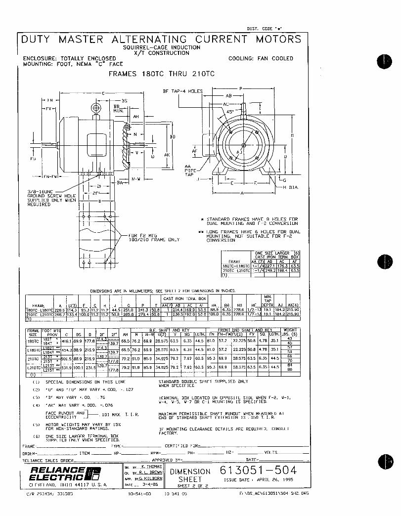
DIST CODE w
DUTY MASTER ALTERNATING CURRENT MOTORSSQUIRRELCAGE INDUCTION
XT CONSTRUCTIONENCLOSURE TOTALLY ENCLOSED COOLING FAN COOLEDMOUNTING FOOT NEMA C FACE
FRAMES 180TC THRU 210TC
BF TAP4 HLESP
AB
FN BSAC
HBFV
MIN 45T
AH
r N l1
AF
FU
vU
AKAJ
D
AA 1PIPE
FNFM
IBA
Nu
TAP
JE
G
H DIA3816UNC
IiZF A
GRUND SCREW HOLESUPPLIED ONLY WHEN gREQUIRED
STANDARD FRAMES HAVE 8 HLES FR
DUAL MUNTING AND F2 CONVERSION
LONG FRAMES HAVE 6 HOLES FOR DUALFR F2 MTG MDUNTING NOT SUITABLE FOR F2180210 FRAME NLY CONVERSION
ONE SIZE LARGER 6CAST IRON TERM BbX
FRAME AA 7 AB AC PF
180TCL180TC 11 2271 1763 635
210TCL210TC 11 2492 1984 635
1
DIMENSIONS ARE IN MILLIMEiERS SEE SHEET 2 FOR DMENStONS IN 1NCHES
CAST IRON TERM BOXMINTAP
FRAME A D 3 E G H J 0 P T AA 7 AB AC AF BA B8 BD BF DEPTH AJ AK 4
180TCL180TC 2285 143 953 112 112 445 2510 2413 508 1 2744 1699 538 889 635 2286 1 21 191 1842 21590
210TCL210TC 2667 1334 1080 112 112 508 2858 2794 508 1 2365 1920 538 1080 635 2286 1 21 191 1842 21590
1
FRAME F007 MT BE SHAFT AND KEY FRONT END SHAFT AND KEY WEIGHT
SIZE PROV C BS B 2F 2F AH N NW U 2 V SQ LGTH FN FNFW FU 2 FV SQ LGTH LBS 54
180TC182T
4161 699 778 665 762 699 28575 635 635 445 810 572 22225 508 478 3514
184T 1397 45
L180TCL784T
4542 889 159 114 1397665 762 699 28575 635 635 445 870 572 22225 508 478 351 59
210TC23T
095 869 159139
792 919 859 34925 792 792 605 953 699 28575 635 635 44566
215T 1776 70
L270TCL215T
5319 1001 2316t39
B792 919 859 34925 792 792 605 953 699 28575 635 635 445
84
88
1
ll SPECIAL DIMENSIONS N THIS LINE STANDARD BQUBLE SHAfT SUPPLIED NLY
NHEN SPECIFIED
2 U AND FU MAY VARY 000 127
C3 D MAY VARY 00 76 TERMINAL BOX LOCATED N OPPSITE SIDE WHEN F2 LI1N4 N5 W7 OR C1 MDUNTING IS SPECIFIED
C 4 AK MAY VARY 000 076
FACE RUNOUT AND 101 MAX TIR MAXIMUM PERMISSIBLE SHAFT RUNOUT NHEN MEASURED ATECCENTRICITY END F STANDARD SHAF7 EXTENSION IS O50 T I R
5 MOTR MEIGHTS MAY VARY BY 15FRNNSTANDARD RATINGS IF MOUNTING CLEARANCE DETAILS ARE REQUIRED CNSULT
6 NE SIZE LARGER TERMINAL BOXFACTORY
SUPPIED ONLV VHEN SPECIFIED
FRAME TYPE CERTIFIED FOR
RDER ITEM HP RPM PH HZ VOLT
ZELIANCE SALES ORDER APPROVED BY DATE
RELANCEBY K THOMAS
EcrRc gY RLBROWN DIMENSION 61 3051 504aaa BrGKILBORN SHEET ISSUE DATE APRIL 26 1995
CLEVELAND OHI 44117 U S A nnTE 3486SHEET 2F 2
CR 293454 331585 1054100 0541OS EDSAC613051504SH2DVG

AC MOTOR
CONNECTION DIAGRAM
STANDARD 9 LEAD DELTACONNECTED
T1
T9 T4
T6 T
T3 T8 T5 T2
T4 T5 T6 T4 T5 T6
T7 T8 T9 T7 T8 T9
T1 T2 T3 T1 T
LTLZ L3L1 L2 3
LOWER VOLTSLINEHIGHER VOLTS
NP 1575B
N
o CUSTOMER RELIANCE
CUSTOMER ORDER N0 SO N0
iRELANCE DRBYNF CON N ECTI ON 416 8 20 2ELECTRC
CKBYDGYAPP BY HEJ
UCLEVELAND OHIO 44117 DATE3151z6 DIAGRAM ISSUE DATE OCT 30 1986
EWDIAG416820002 RAG 1054106

lNIOTOfS Al1V RIVES
IntegratHrsepowerACIductioa Motors
ODP Ercosure
TEFCEclosure
Explosior Proof
Installation Operating Manual
701 MN400

Table of Contents
Section 1
Generalinformation 11
Overview 11
LimitedWarranty 11
SafetyNotice 12
Receiving 14
Storage 1
Unpacking 14
Handling 14
Section 2
Instatlation Operation 21
Overview 21
Location 21
Mounting 21
Alignent 21
Doweling Bolting 22
PowerConnection 22
Conduit 22
ACPower 22
FirstTime U p 24
Coupled U p 24
Jogging and Repeated Starts 24
Section 3
M aintenance Troubleshooting 31
G enerallnspection 31
Lubrication Bearings 31
Typeof Grease 31
Lubricationlntervals 31
Lubrication Procedure 33
Accessories 34
TroubleshootingChart 35
MN400Table of Contents i

Section 1
General information
Overview This manual contains general procedures that apply to Baldor Motor products Be sure to read and
understand the Safety Notice statements in this manual For your protection do not instail operate or
attempt to perform maintenance procedures until you understand the Warning and Caution statements A
Warning statement indicates a possible unsafe condition that can cause harm to personnel A Caution
statement indicates a condition that can cause damage to equipment
Important This instruction manual is not intended to include a comprehensive listing of all details for alt
procedures required for installation operation and maintenance This manual describes generalguidelines that apply to most of the motor products shipped by Baldor If you have a questionabout a procedure or are uncertain about any detail Do Not Proceed Please contact your Baldor
distributor for more information or clarification
Before you install operate or perform maintenance become familiar with the followingNEMA Publication MG2 Safety Standard for Construction and guide
for Selection Installation and Use of Electric Motors and Generators
The National Electrical Code
Local codes and Practices
Limited Warrantv
1 Baldor Electric motors are warranted for a period of one 1 year from date of shipment from the factory or factorywarehouse against defects in material and workmanship To allow for stocking andor fabrication period and to
provide one year of actual service the warranty period is extended for an additional period of six 6 months for a
total of eighteen 18 months from the original date of shipment from the factory or factory warehouse stock In no
case will the warranty period be extended for a longer period Baldor extends this limited warranty to each buyerof the electric motor for the purpose of resale and to the original purchaser for use
2 Baldor will at its option repair or replace a motor which fails due to defects in material or workmanship during the
warranty period if
a the purchaser presents the defective motor at or ships it prepaid to the Baldor plant in Fort Smith Arkansas
or one of the Baldor Authorized Service Centers and
b the purchaser gives written notification concerning the motor and the claimed defect including the date
purchased the task performed by the Saldor motor and the problem encountered
3 Baldor will not pay the cost of removal of any electric motor from any equipment the cost of delivery to Fort SmithArkansas or a Baldor Authorized Service Center or the cost of any incidental or consequential damages resultingfrom the claimed defects Some states do not allow the exclusion or limitation of incidental or consequential
damages so the above exclusion may not apply to you Any implied warranty given by laws shall be limited to
the duration of the warranty period hereunder Some states do not allow limitations on how long an impliedwarranty lasts so the above limitation may not apply to you
4 Baldor Authorized Service Centers when convinced to their satisfaction that a Baldor motor developed defects in
material or workmanship within the warranty period are authorized to proceed with the required repairs to fulfill
Baldors warranty when the cost of such repairs to be paid by Baldor does not exceed Baldors warranty repairallowance Baldor will not pay overtime premium repair charges without prior written authorization
5 The cost of warranty repairs made by centers other than Baldor Authorized Service Centers WILL NOT be paidunless first authorized in writing by Saldor
6 Claims by a purchaser that a motor is defective even when a failure results within one hour after being placed into
service are not always justified Therefore Baldor Authorized Service Centers must determine from the condition
of the motor as delivered to the center whether or not the motor is defective If in the opinion of a Baldor
Authorized Service Center a motor did not fail as a result of defects in material or workmanship the center is to
proceed with repairs only if the purchaser agrees to pay for such repairs If the decision is in dispute the
purchaser should still pay for the repairs and submit the paid invoice and the Authorized Service Centers signedservice report to Baldor for further consideration
7 This warranty gives you specific legal rights and you may also have other rights which vary from state to state
Note that Baldor SuperEO Premium Efficiency electric motors are warranted for a period of three 3 years
All other terms and conditions of the Limited Warranty statement apply
MN400 General Information 11

Safety Notice This equipment contains high voltage Electrical shock can cause serious or fatal injury
Oniy qualified personnel should attempt instaliation operation and maintenance of
electricai equipment
Be sure that you are completely familiar with NEMA publication MG2 safety standards
for construction and guide for selection installation and use of electric motors and
generators the Nationai Electricai Code and local codes and practices Unsafe
installation or use can cause conditions that lead to serious or fatal injury Only qualifiedpersonnel should attempt the instailation operation and maintenance of this equipment
WARNING Do not touch electrical connections before you first ensure that
power has been disconnected Electrical shock can cause serious
or fatal injury Only qualified personnel should attempt the
installation operation and maintenance of this equipment
WARNING Be sure the system is properly grounded before applying power
Do not apply AC power before you ensure that all groundinginstructions have been followed Electrical shock can cause
serious or fatal injury National Electrical Code and Local codes
must be carefully followed
WARNING Avoid extended exposure to machinery with high noise levels Be
sure to wear ear protective devices to reduce harmful effects to
your hearing
WARNING This equipment may be connected to other machinery that has
rotating parts or parts that are driven by this equipment Improperuse can cause serious or fatal injury Only qualified personnelshould attempt to install operate or maintain this equipment
WARNING Do not bypass or disable protective devices or safety guards
Safety features are designed to prevent damage to personnel or
equipment These devices can only provide protecteon if theyremain operative
WARNING Avoid the use of automatic reset devices if the automatic restartingof equipment can be hazardous to personnel or equipment
WARNING Be sure the load is properly coupled to the motor shaft before
applying power The shaft key must be fully captive by the load
device Improper coupling can cause harm Yo personnel or
equipment if the load decouples from the shaft during operation
WARNING Use proper care and procedures that are safe during handlinglifting installing operating and maintaining operationsImproper methods may cause muscle strain or other harm
WARNING Before performing any motor maintenance procedure be sure that
the equipment connected to the motor shaft cannot cause shaft
rotation If the load can cause shaft rotation disconnect the load
from the motor shaft before maintenance is performed Unexpectedmechanica rotation of the motor parts can cause injury or motor
damage
WARNING Disconnect all electrical power from the motor windings and
accessory devices before disassembly of the motor Electrical
shock can cause serious or fa1a1 injury
WARNING Do not use these motors in the presence of flammable or
combustible vapors ar dust These motors are not designed for
atmospheric conditions that require explosion proof operation
12 General Information MN400
Safety Notice Continued
WARNING Motors that are to be used in flammable andor explosiveatmospheres must display the UL label on the nameplate
Specific service conditions for these motors are defined in
NEC 70599
WARNING UL rated motors must only be serviced by authorized Baldor
Service Centers if these motors are to be returned to a flammable
andor explosive atmosphere
Caution To prevent premature equipment failure or damage only qualifiedmaintenance personnel should perform maintenance
Caution Do not lift the motor and itslriven load by the motor liftinghardware The motor lifting hardware is adequate for lifting onfy the
motor Disconnect the load from the motor shaft before moving the
motor
Caution If eye bolts are used for lifting a motor be sure they are securelytightened The lifting direction should not exceed a 20 angle from
the shank of the eye bolt or lifting lug Excessive lifting angtes can
cause damage
Caution 7o prevent equipment damage be sure that the electrical service is
not capable of delivering more than the maximum motor rated ampslisted on the rating plate
Caution If a HI POT test High Potential Insulation test must be performedfollow the precautions and procedure in NEMA MG1 ad MG2
standards to avoid equipment damage
If you have any questions or are uncertain about any statement or procedure or if you
require additional information please contact your Baldor distributor or an Authorized
Baldor Service Center
MN400 General Information 13

Reeivinq Each Baldor Electric Motor is thoroughly tested at the factory and carefully packaged for
shipment When you receive your motor there are several things you should do
immediately1 Observe the condition of the shipping container and report any damage
immediately to the commercial carrier that delivered your motor
2 Verify that the part number of the motor you received is the same as the partnumber listed on your purchase order
Storaqe If the motor is not pui into service immediately the motor must be stored in a clean dryand warm location Several precautionary steps must be performed to avoid motor
damage during storage
1 UseaMegger periodically to ensure that the integrity of the winding insulation
has been maintained Record the Megger readings Immediately investigateany significant drop in insulation resistance
2 Do not lubricate bearings during storage Motor bearings are packed with
grease at the factory Excessive grease can damage insulation quality
3 Rotate motor shaft at least 10 turns every two months during storage more
frequently if possibie This will prevent bearing damage due to storage
4 If the storage location is damp or humid the motor windings must be protectedfrom moisture This can be done by applying power to the motors space
heater if available while the motor is in storage
UnpBCkinq Each Baldor motor is packaged for ease of handling and to prevent entry of
contaminants
1 To avoid condensation inside the motor do not unpack until the motor has
reached room temperature Room temperature is the temperature of the room
in which it will be installed The packing provides insulation from temperature
changes during transportation
2 When the motor has reached room temperature remove all protective wrappingmaterial from the motor
Handling The motor should be lifted using the lifting lugs or eye bolts provided
1 Use the lugs or eye bolts provided to lift the motor Never attempt to lift the
motor and additional equipment connected to the motor by this method The
lugs or eye boits provided are designed to lift only the motor Never lift the
motor by the motor shaft
2 If the motor must be mounted 10 a plate with the driven equipment such as
pump compressor etc it may not be possible to lift the motor alone For this
case the assembly shoufd be lifted by a sling around the mounting base The
entire assembly can be lifted as an assembly for installation Do not lift usingthe motorIgs or eye bolts provided
If the load is unbalanced as with couplings or additional attachmentsadditional siings or other means must be used to prevent tipping In any eventthe load must be secure before lifting
14 General Information MN400
Section 2
Installation Operation
Overview Installation should conform to the National Eaectrical Code as well as local codes and
practices When other devices are coupled to the motor shaft be sure to install
protective devices to prevent future accidents Some protective devices includecoupling belt guard chain guard shaft covers etc These protect against accidentalcontact with moving parts Machinery that is accessible to personnel should providefurther protection in the form of guard rails screening warning signs etc
Location The motor should be installed in an area that is protected from direct sunlight corrosivesharmful gases or liquids dast metallic particles and vibration Exposure to these can
reduce the operating life and degrade performance Be sure to ailow clearance forventilation and access for cleaning repair service and inspections Ventilation is
extremely important Be sure the area for ventilation is not obstructed Obstructions wiVllimit the free passage of air Motors get warm and the heat must be dissipated to preventdamage
These motors are not designed for atmospheric conditions that require explosion proofoperation They must NOT be used in the presence of flammable or combustible vaporsor dust
1 ODP motors are suitable oniy for indoor applications2 TEFC motors are suitable for indoor or outdoor standard service applications
Mountinq The motor must be securely installed to a rigid foundation or mounting surface to
minlmize vibration and maintain alignment between the motor and shaft load Failure to
provide a proper mounting surface may cause vibration misalignment and bearingdamageFoundation caps and sole plates are designed to act as spacers for the equipment theysupport If these devices are used be sure that they are evenly supported by thefoundation or mounting surface
After installation is complete and accurate alignment of the motor and load is
accomplished the base should be grouted to the fioundation to maintain this alignmentThe standard motor base is designed for horizontal or vertical mounting Adjustable or
sliding rails are designed for horizontal mounting only Consult your Baldor distributor or
authorized Baldor Service Center for further information
Alignment Accurate alignment of the motor with the driven equipment is extremely important1 Direct Coupling
For direct drive use flexible couplings if possible Consult the drive or
equipment manufacturer for more information Mechanical vibration and
roughness during operation may indicate poor alignment Use dial indicators tocheck alignment The space between coupling hubs should be maintained as
recommended by the coupling manufacturer
2 EndPlay AdjustmentThe axial position of the motor frame with respect to its load is also extremelyimportant The motor bearings are not designed for excessive external axialthrust loads Improper adjustment will cause failure
3 Pulley Ratio
The pulley ratio should not exceed 81
4 Belt Drive
Align sheaves carefully to minimize belt wear and axial bearing loads seeEndPlay Adjustment Belt tension should be sufficient to prevent belt slippageat rated speed and load However belt slippage may occur during starting
Caution Do not over tension belts
MN400 Installation Operation 21

Daweling Bolting After proper alignment is verified dowel pins should be inserted through the moor feet
into the foundation This will maintain the correct motor position should motor removal be
required Baldor motors are designed for doweling1 Drill dowel holes in diagonally opposite motor feet in the locaiions provided2 Drill corresponding holes in the foundation
3 Ream all holes
4 Install proper fitting dowels
5 Mounting bolts must be carefully tightened to prevent changes in alignmentUse a flat washer and lock washer under each nut or bolt head to hold the
motor feet secure Flanged nuts or bolts may be used as an alternative to
washers
Power Connection Motor and control wiring overload protection disconnects aceessories and groundingshould conform ta the National Electrical Code and local codes and practices
Conduit Box For ease of making connections an oversize conduit box is provided The box can be
rotated 360 in 90 increments Auxiliary conduit boxes are provided on some motors for
accessories such as space heaters RTDs etc
AC Power Connect the motor leads as shown on the connection diagram located on the name plateor inside the cover on the conduit box Be sure the following guidelines are met
1 AC power is within 10 of rated voltage with rated frequency See motor
name plate for ratingsOR
2 AC power is within 5 of rated frequency with rated voltageOR
3 A combined variation in voltage and frequency of 1 p sum of absolute
values of rated values provided the frequency variation does not exceed 5
of rated frequencyPerformance within these voltage and frequency variations are shown in Figure 21
22 Instailation Operation MN400
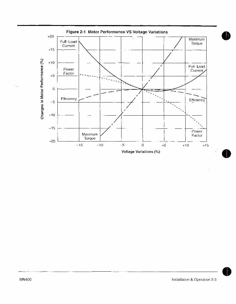
Figure 21 Motor Performance VS Voltage Variations20
Full LoadMaximum
CurrentTorque
15
10
Full LoadPower CurrentFactor
5
oL
aL O00
Efficiency Efficiency5Nd
C
L lOU
15Power
Maximum FactorTorque
20
15 10 5 0 5 10 15
Voltage Variations
MN400 Installation Operation 23

First Time Start Up Be sure that all power to motor and accessories is off Be sure the motor shaft is
disconnected from the load and will not cause mechanical rotation of the motor shaft
1 Make sure that the mechanical installation is secure All bolts and nuts are
tightened etc
2 If motor has been in storage or idle for some time check winding insulation
integrity with a Megger3 Inspect all electrical connections for proper termination clearance mechanical
strength and electrical continuity4 Be sure all shipping materials and braces if used are removed from motor
shaft
5 Manualiy rotate the motor shaft to ensure that it rotates freely6 Replace all panels and covers that were removed during instailation
7 Momentarily apply power and check the direction of rotation of the motor shaft
8 If motor rotation is wrong be sure power is off and change the motor lead
connections Verify rotation direction before you continue
9 Start the motor and ensure operation is smooth without excessive vibration or
noise If so run the motor for 1 hour with no load connected
10 After 1 hour of operation disconnect power and connect the load to the motor
shaft Verify all coupling guards and protective devices are installed Ensure
motor is properly ventilated
Coupled Start Up This procedure assumes a coupled start up Also that the first time start up procedurewas successful
1 Check the coupling and ensure that all guards and protective devices are
instailed
2 Check that the coupling is properly aligned and not binding
3 The first coupled start up should be with no load Apply power and verify that
the load is not transmitting excessive vibration back to the motor though the
coupling or the foundation Vibration should be at an acceptable level
4 Run for approximately 1 hour with the driven equipment in an unloaded
condition
The equipment can now be loaded and operated within specified limits Do not exceed
the name plate ratings for amperes for steady contiruous loads
Jogging and Repeated Starts Repeated starts andor jogs of induction motors generally reduce the life of the motor
winding insulation A much greater amount of heat is produced by each acceleration or
jog than than by the same motor under full load If it is necessary to to repeatedly start or
jog the motor it is advisable to check the application with your local Baldor distributor or
Baldor Service Center
Heating Duty rating and maximum ambient temperature are stated on the motor name
plate Do not exceed these values If there is any question regarding safe operationcontact your loca Saldor distributor or Baldor Service Center
24 Installation Operation MN400
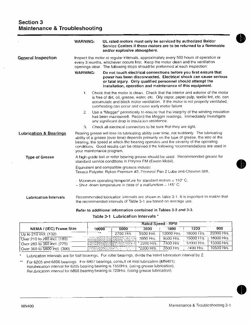
Section 3
Maintenance Troubleshooting
WARNING UL rated motors must only be serviced by authorized Baldor
Service Centers if these motors are to be returned to a flammable
andor explosive atmosphere
General InspeCtion Inspect the motor at regular intervals approximately every 500 hours of operation or
every 3 months whichever occurs first Keep the motor clean and the ventilation
openings cfear The following steps should be performed at each inspection
WARNING Do not touch electrical connections before you first ensure that
power has been disconnected Electrical shock can cause serious
or fatal injury Only qualified personnel should attempt the
installation operation and maintenance of this equipment
1 Check that the motor is cfean Check that the interior ard exterior of the motor
is free of dirt oil grease water etc Oily vapor paper pulp textile lint etc can
accumulate and block motor ventilation If the motor is not properly ventilated
overheating can occur and cause early motor failure
2 UseaMegger periodically to ensure that the integrity of the winding insulation
has been maintained Record the Megger readings Immediately investigateany significant drop in insulation resistance
3 Check all electrical connectors to be sure that they are tight
Lubrication Bearinqs Bearing grease will lose its lubricating ability over time not suddenly The lubricating
ability of a grease over time depends primarily on the type of grease the size of the
bearing the speed at which the bearing operates and the severity of the operatingconditions Good results can be obtained if the following recommendations are used in
your maintenance program
Type of Grease A high grade ball or roller bearing grease should be used Recommended grease for
standard service conditions is Polyrex EM Exxon Mobil
Equivalent and compatible greases include
Texaco Polystar Rykon Premium 2 Pennzoil Pen 2 Lube and Chevron SRI
Maximum operating temperature for standard motors 110 C
Shutdown temperature in case of a malfunction 115 C
Lubrication Intervals Fiecommended lubrication intervals are shown in Table 31 It is important to realize that
the recommended intervals of Table 31 are based on average use
Refer to additional information contained in Tables 32 and 33
Table 31 Lubrication Intervals
Rated peed RPM
NEMA IEC Frame Size 10000 6000 3600 1800 1200 900
Up to 210 incl 132 2700 Hrs 5500 Hrs 12000 Hrs 18000 Hrs 22000 Hrs
Over 210 to 280 incL 180 3600 Hrs 9500 Hrs 15000 Hrs 18000 Hrs
Over 280 to 360 incL 225 2200 Hrs 7400 Hrs 12000 Hrs 15000 Hrs
Over 360 to 5800 incL 300 2200 Hrs 3500 Hrs 7400 Hrs 10500 Hrs
Lubrication ntervals are for ball bearings or roller bearings divide the iisted lubrication interval by 2
For 6205 and 6806 bearings For 6807 bearings consult oil mist lubrication MN401Relubrication interval for 6205 bearing bearing is 1550Hrs using grease lubricationRelubrication interval for 6806 bearing bearing is 720Hrs using grease lubrication
MN400 Maintenance Troubleshooting 31

Table 32 Service Conditions
everity of ervice Ambient emperature Atmospheric Type of BearingMaximum Contamination
Standard 40 C Clean Little Corrosion Deep Groove Ball BearingSevere 50 C Moderate dirt Corrosion Ball Thrust Rolier
Extreme 50 C or Severe dirt Abrasive dust All BearingsClass H Insulation Corrosion
Low Temperature 30 C
Special high temperature grease is recommended Dow Corning DC44 Note that Dow Corning DC44 grease does
not mix with other grease types Thoroughly clean bearing cavity before adding grease
Special low temperature grease is recommended Aeroshell 7
Table 33 Lubrication Interval Multiplier
everity of ervice MultiplierStandard 10
Severe 05
Extreme 01
Low Temperature 10
Table 3 Bearings Sizes and Types
Frame Size Bearing DescriptionNEMA IEC These are the Large bearings Shaft End in each frame size
Bearing OD Width Weight of Volume of greaseD mm B mm Grease to to be added
add in tea
i oz Grams spoon
Up to 210 incl 132 6307 8Q 21 030 84 06 20
Over 210 to 280 incl 180 6311 120 29 061 17 12 39
Over 280 to 360 incl 225 6313 140 33 081 23 15 52
Over 360 to 449 incl 280 NU319 200 45 212 60 41 134
Over 5000 to 5800 incl 355 NU328 300 62 470 130 92 300
Spindle Motors
76 Frame 6207 72 17 022 6 i 044 14
77 Frame 6210 90 20 032 90 064 21
80 Frame 6213 120 23 049 140 099 33
Weight in grams 005 DB
32 Maintenance Troubleshootin MN4009

Lubrication Procedure Be sure that the grease you are adding to the motor is compatible with the grease alreadyin the motor Consult your Baldor distributor or an authorized service center if a greaseother than the recommended type is to be used
Caution To avoid damage to motor bearings grease must be kept free of dirt
For an extremely dirty environment contact your Baldor distributor or
an authorized Baldor Service Center for additional information
With Grease Outlet Plug1 Clean all grease fittings
2 Remove grease outlet plug3 If motor is stopped add the recommended amount of grease
If motor is to be greased while running a slightly greater quantity of grease will
have to be added Add grease slowly until new grease appears at shaft hole in
the endplate or purge outlet plug4 Reinstall grease outlet plug
Without Grease Outlet Plug1 Disassemble motor
2 Add recommended amount of grease to bearing and bearing cavity Bearingshoud be about 13 full of grease and outboard bearing cavity should be about12 full of grease
Note Bearing is 13 full when only one side of bearing is completely full of grease
3 Assemble motor
Sample Lubrication Determination
Assume NEMA 286T IEC 180 1750 RPM motor driving an exhaust fan in an ambient
temperature of 43 C and the atmosphere is moderately corrosive
1 Table 31 list 9500 hours for standard conditions
2 Table 32 classifies severity of service as Severe
3 Table 33 lists a multiplier value of 05 for Severe conditions
4 Table 34 shows that 12 in or 39 teaspoon of grease is to be added
Note Smaller bearings in size category may require reduced amounts of grease
MN400 Maintenance Troubleshooting 33
ACCesSOPies The following is a partial list of accessories available frpm Baldor
Contact your Baldor distributor for availability and pricing informationNote Space heaters and RTDs are standard on some motors
Bearing RTD
RTD Resistance Temperature Detector devices are used to measure or
monitor the temperature of the motor bearing during operation
Bearing ThermocouplesUsed to measure or monitor bearing temperatures
Bearing Thermostat
Temperature device that activates when bearing temperatures are excessiveUsed with an externai circuit to warn of excessive bearing temperature or toshut down a motor
Conduit Boxes
Optional conduit boxes are available in various sizes to accommodate
accessory devices
Cord Plug AssemblyAdds a line cord and plug for portable applications
Drains and Breathers
Stainless steel drains with separate breathers are available
Drip Covers
Designed for use when motor is mounted in a vertical position Contact yourBaldor distributor to confirm that the motor is designed for vertical mounting
Fan Cover int ScreenTo prevent buildup of debris on the cooling fan
NameptateAdditional stainless steel nameplates are available
Roller BearingsRecommended for belt drive applications with a speed of 1800 RPM or less
Rotation Arrow Labels
Rotation arrows are supplied on motors designed to operate in one direction
only Additional rotation arrows are available
Space Heater
Added to prevent condensation of moisture within the motor enciosure duringperiods of shut down or storage
Stainless Hardware
Stainless steel hardware is availabie Standard hardware is corrosion resistantzinc plated steei
Winding RTD
RTD Resistance Temperature Detector devices are used to measure or
monitor the temperature of the motor winding during operation
Winding ThermocouplesUsed to measure or monitor winding temperatures
Winding Thermostat
Temperature device that activates when winding temperatures are excessiveUsed with an external circuit to warn of excessive winding temperature or foshut down a motor
Note On some motors leads for accessory devices are brought out to a separaieconduit box located on the side of the motor housing unless otherwisespecified
34 Maintenance Troubleshooting MN400
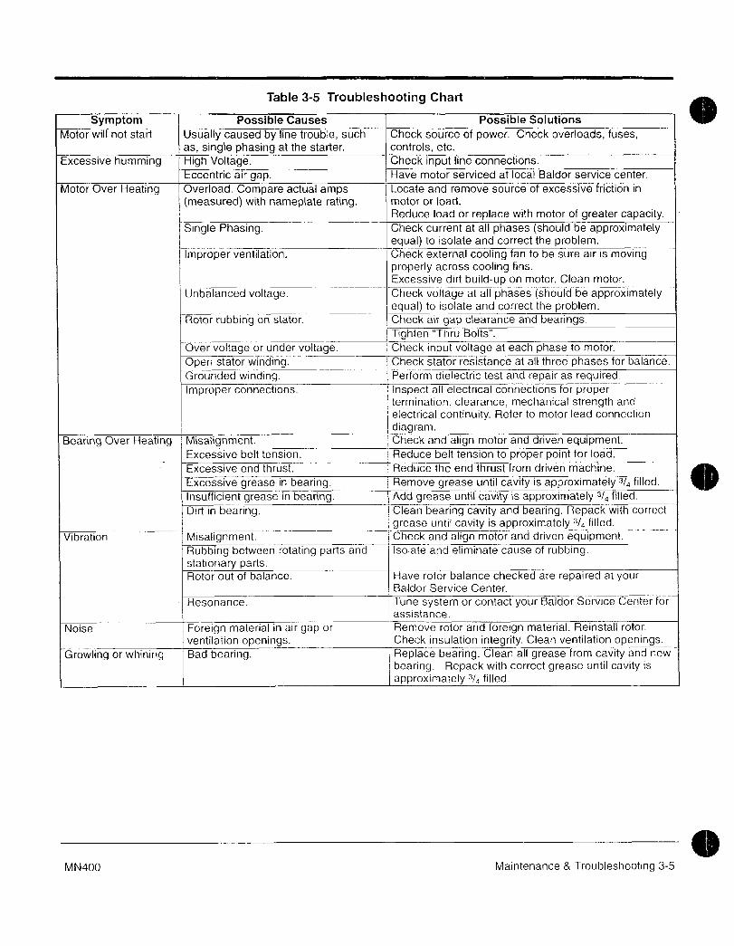
Table 35 Troubleshooting Chart
Symptom Possible Causes Possible Solutions
Motor will not start Usually caused by line trouble such Check source of power Check overloads fuses
as single phasing at the starter controls etc
Excessive humming High Voltage j Check input line connections
Eccentric air gap I Have motor serviced at loca Baldorservice center
Motor Over Heating Overload Compare actual amps I Locate and remove source of excessive friction in
fmeasured with nameplate rating motor or foad
i Reduce load or replace with motor of greater capacity
Single Phasing Check current at all phases should be approximatelyequal to isolate and correct the problem
Improper ventilation Check external cooling fan to be sure air is movingproperly across cooling fins
Excessive dirt build on motor Clean motor
Unbalanced voltage Check voltage at all phases should be approximatelyequai to isolate and correct the problem
Rotor rubbing on stator Check air gapcearance and bearings
Tighten Thru Bolts
Over voltage or under voltage Check input voitage at each phase to motor
Open stator winding Check stator resistance at all three phases for balance
Grounded winding Perform dielectric test and repair as required
Improper connections Inspect all electrical connections for proper
termination clearance mechanical strength and
electrical continuity Refer to motor lead connection
diagramBearing Over Neating Misalignment Check and align motor and driven equipment
Excessive belt tension Reduce belt tension to proper point for toad
Excessive end thrust Reduce the end thrust from driven machine
Excessive grease in bearing Remove grease until cavity is approximately 34 filled
Insufficient grease in beaing Add grease until caviry is approximateiy 34 filled
Dirt in bearing Clean bearing cavity and bearing Repack with correct
grease unti cavit is approximately 34 filled
Vibration M Check and align motor and driven equipment
Rubbing between rotating parts and Isolate and eliminate cause of rubbingstationary partsRotor out of balance Have rotor balance checked are repaired at your
Baldor Service Center
Resonance Tune system or contact your Baldor Service Center for
assistance
Noise Foreign material in air gap or Remove rotor and foreign material Reinstall rotor
ventilation openings Cherk insulatio integrity Clean ventilation openingsGrowling or whining Bad bearing Replace bearing Clean all grease from cavity and new
i bearing Repack with correct grease until cavity is
approximately 34 filled
MN400 Maintenance Troubleshooting 35

BALORMOTORS AND DRIiES
BALDOR ELECTRIC COMPANYPO Box 2400
Ft Smith AR 729022400
501 6464711
Fax 501 6485792
O Baldor Electric Company Printed in USA
MN400 701 CJ10000

Flexibfe
Coupling
3
f
V
aF
r r9
ti s L a6 s
E3l
3
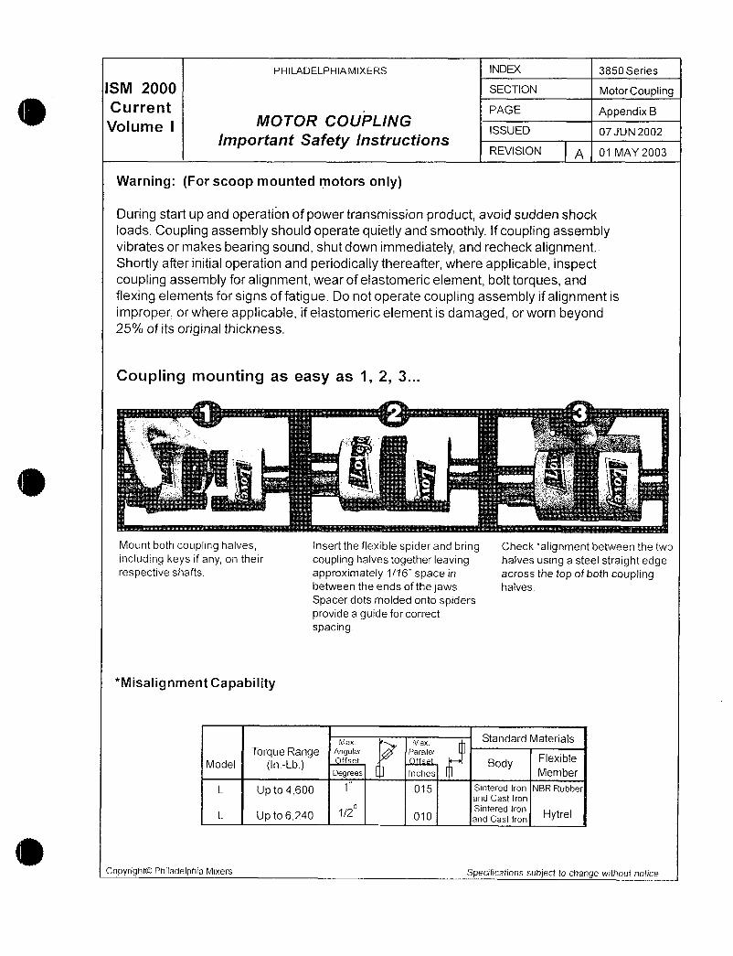
PHILADELPHIAMIXERS N 3850 Series
M 200 SECTION MotorCoupling
CUPi@tlt PAGE AppendixBVolume I MOTOR COUPLING
ISSUED 07 JUN 2002
Important Safety lnstructionsREVISION A 01 MAY 2003
Warning For scoop mounted motors only
During start up and operation of power transmission product avoid sudden shock
ioads Coupling assembiy should operate quietly and smoothly If coupling assemblyvibrates or makes bearing sound shut down immediately and recheck alignmentShortly after initial operation and periodicaliy thereafter where applicable inspectcoupling assembly for alignment wear of elastomeric element boit torques and
flexing elements for signs of fatigue Do not operate coupling assembly if alignment is
improper or where applicable if elastomeric element is damaged or worn beyond25o of its origina thickness
Coupling mounting as easy as 1 2 3
z
1 vrr
1
iz
C
Mount both coupling halves insert the flexible spider and bring Check alignment between the two
including keys if any on their coupling halves together leaving halves using a steel straight edgerespective shafts approximately 116 space in across the top of both coupling
between the ends of the jaws halves
Spacer dots molded onto spidersprovide a guide for correct
spacing
Misalignment Capability
MaX max Standard Materials
Torque Range Angular Parallel
Model Inorrset fset
godyFlexible
Degrees Inches Member
L Up to4600 015 Sintered Iron NBR Rubberand Cast Iron
Sintered IronL Up to6240 010 and Cast Iron HYtrel
CopyrightOO Philadelphia Mixers Specrfications subject to change without notice

PHILADELPHIAMIXERS INDEX 3850Series
M 20 SECTION MotorCou lin
Current MOTOR COUPLING PAGE
Volume I mportant Safety InstructionsAppendix B
ISSUED07 JUN 2002
REVISION A 01 MAY 2003
Lovejoy elastomeric jaw type flexible
couplings do nt require lubrication and are the
accepted industry standard They offer ease of
assembly or disassembly permit visual inspection ofh the flexible element wear members and allows for
their removal without disturbing the motor or pump
alignment in most applications
Lovejoy spider type individual load cushions and snap wrap spiders satisfy all standard
application requirements as well as combinations of low speedhigh torquelow speedhigh temperature high torque and other special conditions Lovejoys one
piece spider construction aso includes raised spacer dots on each side of the cushionto givepremeasured separaton between the jaws of each coupling half See diagrambelow
C
I IC
i
n n tiii Iii uu
A E A
L
II tlllnl uq
D DB B
Copyrfght0 Philadelphia Mixers Specifications subject to change without notice
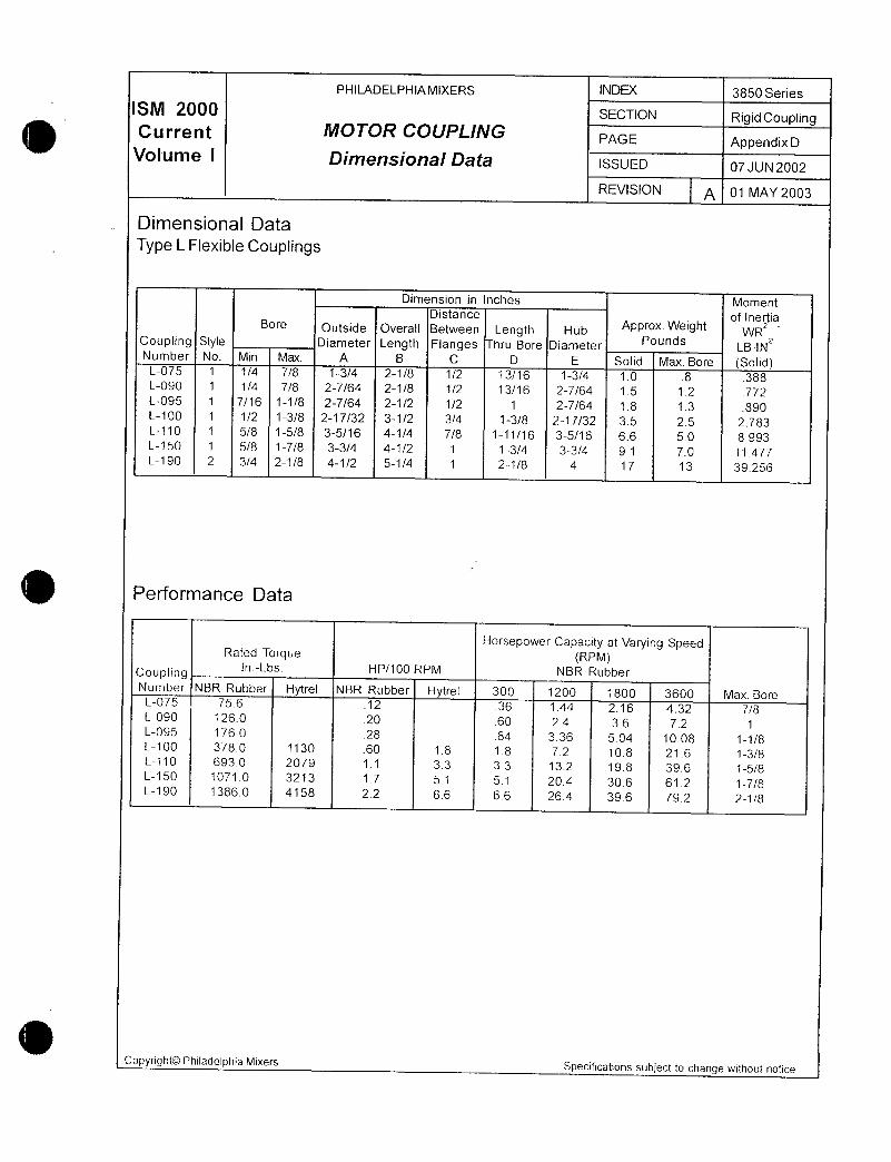
PHILADELPHIAMIXERS INDEX 3850 Series
S 20 SECTION RigidCouplingCurrent MOTOR COUPLING PAGE AppendixD
Volume I Dimensional Data ISSUED 07JUN2002
REVISION A 01 MAY 2003
Dimensional Data
Type L Flexible Couplings
Dimension in Inches MomentDistance of Ineria
Bore putside Overall Between Length Hub Approx Weight WRzCoupling Style Diameter Length Flanges hru Bore Diameter Pounds LBINzNumber No Min Max A B C D E Solid Max Bore SolidL075 1 14 78 134 218 12 1316 134 10 8 388L090 1 14 78 2764 218 12 1316 2764 15 12 772L095 1 716 118 2764 212 12 1 2764 18 13 890L100 1 12 138 21732 312 34 138 21732 35 25 2783L110 1 58 158 3516 414 78 11116 3516 66 50 8993L150 1 58 178 33l4 412 1 134 334 91 70 11477L190 2 34 218 412 514 1 218 4 17 13 39256
Performance Data
Horsepower Capacity at Varying SpeedRated Torque RPM
CouplingnLbs HP100 RPM NBR Rubber
Number NBR Rubber Hytrel NBR Rubber Hytrel 300 1200 1800 3600 Max BoreL075 756 12 36 144 216 432 78L090 1260 20 60 24 36 72 1L095 1760 28 84 336 504 1008 118L100 3780 1130 60 18 18 72 108 216 138L110 6930 2079 11 33 33 132 198 396 158L150 10710 3213 17 51 51 204 306 612 178L190 13860 4158 22 66 66 264 396 792 218
Copyright0 Philadelphia MixersSpecifications subject to change without notice

a w
4
r
aanmku n mx
Dravvings
0
3
N
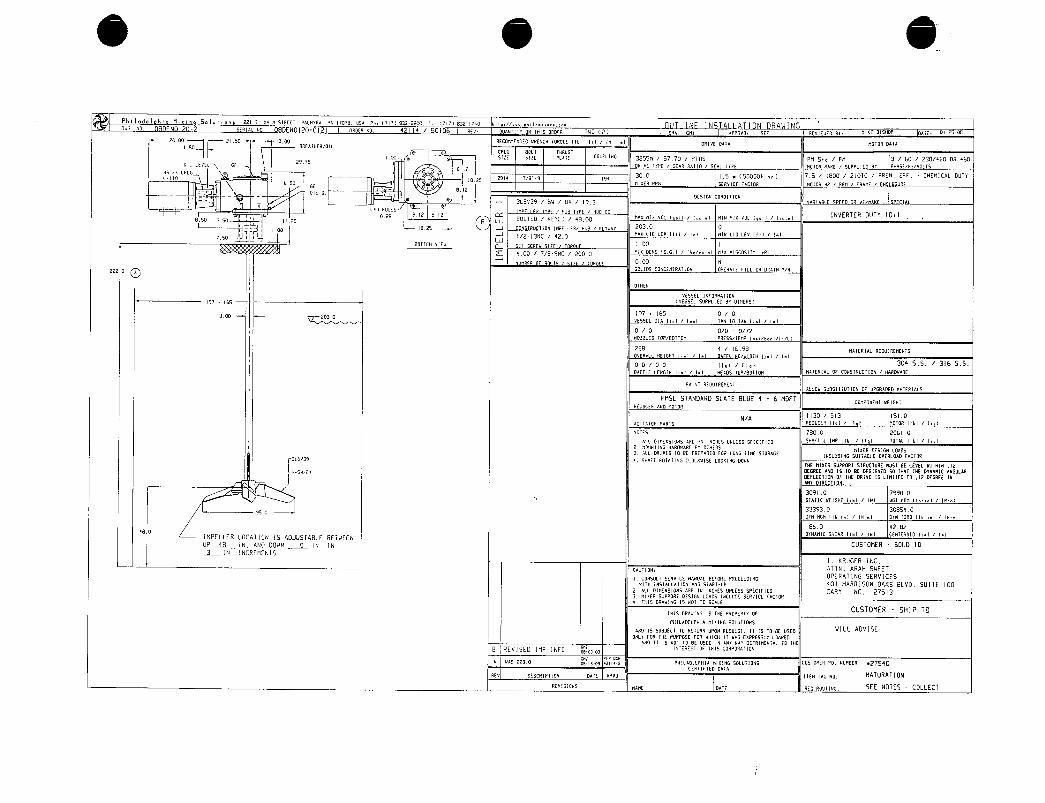
Phi ladelphia Mii Soluiae i22i nnlx StAEEt aninraa pn ime u5n vniieazteoo rcieznao nhi N Tv SEAIAL rv0 N OFpEA u0 42 114 5G106 aEU
F
OUAHtItr ON IHIS OPER iV 2 pPrv GM2 nPPqVD SEf AEVIEUEO Br hIKE BISNOP pqE OI25o8
Z000
i2150r 1000 AECOnI1NDED VRENCH i0R0UE 116 lil IN 1 I pPIVE OAIP MOiOA DAIn
150
i IBAEatNEaOIL
CPIG BLi In5U5i
2s5512E SIZE Put a 3855n 5770 P705 PM Std PM 3 60 230460 OR 460
OIL LEVEt Gfe Z
OPIVE tYPE GEnR FAII SEAI iYPE MOIOR MAKE SIIPPIE BY PHASEHVOLSHs rx cPc I
300 I5050000 h 75 i I800 210iC PREM EFF CHEnICAI DlliY1110 IB25
291a 189 195650 t11kER RPY SEAVIE ACON M t4P HP PPlf RhHE N UA
812t Oli
DESIGx COrv0lldx3LSV39 SV B9 193
c NoES F
oee eiz eizP
nax nix voi iii iii niu mx vo i on iiiINVERiEA DUiY 101
BSO 350 i 125 B w BOLTED KEYED 4800
iiB15 J coNSrau iiou naeuqi xu i rcxvar 2030 0
r I 1213NC 420Ax 4 LEV Ilii I1 nIN LIO LEV 1Ir 11
50
BOftoM rlEVp
I00 I
F 400 7B9NC 2000 nIX DENS ISGI ItI Mlx VISCSItr IPI
rt i i 1 R 000 N
ZZZ ppSOLIS CONCENiRRtIN OPEFAiE ILL OX ONAIN YN
OtXE4
VESSEL IxORnAlION
19l I65 VESSEI SVPPLIED BY O7MEP51
197 165 0 03 2030VESSEL IR lil 11 IAN 10 iAN lil II
0 0 00 072NpZZLES i0PBOliOn FqE55iEMP IiborlIfCI
228 4 1698 Ma1ENIAL FEOUIREnENiSOvEPnLL MEIGHI lil Inl AGF NQivIDiH il II
oo i 00 Ila Flo 304 55 316 55
BRFFIE LENGIN lil 11 HFROS IOPBIIOn hAEFIAL 0 CONSiFUCt10N naqDV1qE
PAlrvi AEOUINEMENiALLOU SuBSiIUiION OF UPGFRDED MAiEN1Al5
PMSL STANDAFD SLAiE BLUE 4 6 MDFTonaaxEnt vEicni
FEOJCEF nuD nOION
NA1130 S13 I510
aeiiaiaa vnnrs eeoucew nei i i I h0I0fl nei i i i
rvarES 7800 206Io
I ALL DInEx510N5 nFE irv INCHES UNLE55 SGECIIE SHFF1 IMP II61 IV I i01AL Ilbl 14a1
2 OJNiINL NnFOUnNE Ax OIMERSnlEP OESIGN LORDS
3 LL flIVES 10 BE PPEPhflE LOR LQAG illlE SIONRGEINCLVOING SIIIiFELE OYEFl04D LAC109
I r SNPFf flOtailnG CLOCRVISE LOOrclN4 DOVN
I iME MIYER SIIPPOFI SiRUC1URE MU51 BE LEVEL YIINx 12
H54i2s OEGREE ANO IS 10 BE DESIGNED 50 INAi IME xMIC NGUTARDEfLEC110N Oi IME ORIVE IS LIMIiE i0 17 DEGREE INNY DINECtION
30910 79900
inilC vEIGXf Ilbi INI vGi XOM Ilbinl IN1
950333930 30850Dr non nei i ini orH toaa iiei i ini
1860 428280
DYNRMIC SHE4R Ilbl lul CENiERpID lil I1IMPELLER IOCFiION 15 ADJUSiABLE BEivEN
IUP 48 IN AuD DOIN 0 IN IN LUSTOMER SOLD i0
3 IN INCREMENiSI KRUGER INC
cauriorv ATiN ARAH SwEET
I CONSIILI SERYICE nqNUAL BEf00E PNOGEEDIxG OPERAiNG SERVICESnx INSIALUIION Rxp 9AFi 401 HARRISON OAKS BLVD S1117E 100
2 AlL OIMENSIONS AFE IN INCHES VNLE55 SPFCIGIE CARY NC Z7S137 nIMER SIIPFOHi OESIGN 10A5 INCLUOE SENVICE ACiOa
iA15 FRVING IS Npl i0 SCALE
iN15 RRVING IS ME FFOPEFiY 0CUSTDMER SHIP TO
PHILRDELPHIA ttiMING SLII110N5
n9 IS SUBJECI i0 REiU0N UPON AEuESi li IS i0 BE USED WLL ADVISEONL FOF INE PVPPOSE faF uXlH Ii VAS EPRESSLY LOANEO
ANO It IS NOi tp BE I15E0 IN aNV wqY OEtNInENtnl ip iHE
B REVISED InP IvFO iieAer ov reis caeaoanrioNOB OB OB
un5 2280nt vEA ocx
IOSISOB 2iit I PHIlROFLPHIa t11AING SOLUIIONS CUSiOMER Pp NUhBEH zS4OCEF11lIEO OaA
REV pESCflIPIION OnIE APVD ItEn rnc xo MAiURATION
AeuisioNS eane one Ao eouiirc SEE NOtES COLLECT
Copyright © 2022 FDOKUMEN