MANUAL INGLES
271
User’s Manual of Laser Engraving / 1 Catalo g Catalog ············································ ············································ ············································ ····································1 Preface ············································ ············································ ············································ ····································1 I Manual of laser machine ············································ ············································ ············································ ·····2 Statement ···························· ···························· ···························· ················2 Safety Note ···························· ···························· ···························· ··············3 I Chapter 1 Machine Appearance and Accessories ···························· ··········4 I.1.1 Machine Appearance (Different model will have different appearance, according to the real object) 4 I.1.2 Accessories set (according to the real object) ·································· ·································· ···············5
-
Upload
independent -
Category
Documents
-
view
0 -
download
0
Transcript of MANUAL INGLES
User’s Manual of Laser Engraving /
1
Catalog
Catalog····································································································································
····································1Preface
····································································································································
····································1I Manual of laser machine
····································································································································
·····2
Statement ····································································································2
Safety Note ··································································································3
I Chapter 1 Machine Appearance and Accessories ······································4
I.1.1 Machine Appearance (Different model will have different appearance, according to the real object) 4I.1.2 Accessories set (according to the real object) ···················································································5
User’s Manual of Laser Engraving /
2
I Chapter 2 Installation and Commissioning of the Machine·························7
I. 2 Installation and Adjusting Steps ·····································································································7
I Chapter 3 the Operation of laser machine················································13
I.3.1 Introduction of Main Interface ······································································································13I.3.2 Introduction of key ·······················································································································15
I Chapter 4 Alignment Standards of Optical Path·····································24
I Chapter 5 Daily Maintenance and Common Faults ··································27
I.5.1 Daily maintenance ························································································································27
I Chapter 6 Warranty Regulations ······························································30
II RDCAM V6.0 User Manual···································································································································31
II Chapter 1 Overview ····························
User’s Manual of Laser Engraving /
3
····················································31
II.1.1 Laser engraving cutting system introduction ················································································31II.1.2 Environmental requirements ········································································································31II.1.3 Software running ·························································································································31
II Chapter 2 Software installation ·······························································33
II.2.1 Install steps··································································································································33II.2.2 Installation settings ······················································································································34II.2.3 Installation ··································································································································34II.2.4 Exit ·············································································································································34II.2.4 Other matters ·······························································································································35II.2.5 The plug-in of CorelDraw installed ··································

User’s Manual of Laser Engraving /
4
····························································35II.2.6 The plug-in of AutoCAD installed ·······························································································38II.2.7 The plug-in of Cadian installed ····································································································41
User’s Manual of Laser Engraving /
5
II.2.8 The plug-in of IIIustrator installed ·······························································································42
II Chapter 3 Introduction of CorelDraw_Laser ············································44
II.3.1 Main interface ·····························································································································44II.3.2 Language settings and machine information ·················································································44II.3.3 File parameters setting ·················································································································45II.3.4 Object Selection ··························································································································46II.3.5 Object Color ································································································································47II.3.6 Object Transformation ·················································································································47II.3.7 Place object ·································································································································48II.3.8 Object align ····································································
User’s Manual of Laser Engraving /
6
·····························································48II.3.9 Object View·································································································································48II.3.10 Group and unGroup ···················································································································49II.3.11 Basic graphics creation ··············································································································49II.3.12 Important Tool ···························································································································49II.3.12.7 Bitmap Handle························································································································56
II Chapter 4 System Settings ·····································································62
II.4.1 Output Setting ·····························································································································62II.4.2 General settings ···························································································································65II.4.3 Machine parameters·····················································································································66II.4.4 Document Management ····································································
User’s Manual of Laser Engraving /
7
···········································71II.4.5 Manual ········································································································································73II.4.6 Info ·············································································································································74
II Chapter 5 Processing Output ··································································75
II.5.1 Device port··································································································································75II.5.2 Go Scale, Cut Scale ·····················································································································75II.5.3 Start, Pause, Stop, SaveToUFile, UfileOutput, Download ·····························································76II.5.4 Layer Setting ·······························································································································76
II Chapter 6 FAQ ························································································83
II.6.1 After start processing, the machine does not move or disorder or loss part of graphics ··················83II.6.2 Software automatically shut down when import file ·····································································83
User’s Manual of Laser Engraving /
8
II.6.3 Machine panel prompt 【Less buffer distance】 ·········································································83II.6.4 Processing graphics sis mirror to the actual graphics ····································································83
III User’s Manual of Laser Engraving Cutting Software LASER_WORK RDCAM6.0····································84
III Chapter 1 Overview ···············································································84
III.1.1 Laser engraving cutting system introduction ···············································································84III. 1.2 Software supported file formats ·································································································84III. 1.3 Environmental requirements ······································································································84
User’s Manual of Laser Engraving /
9
III Chapter 2 Software Basic Operation ······················································85
III.2.1 The main interface operation ······································································································85III. 2.2 Language settings and manufactures information ·······································································86III.2.3 Page Setting ·······························································································································86III. 2.4 File Open and Save ···················································································································87III. 2.5 File Import and Export ··············································································································88III. 2.6 Basic graphics creation ··············································································································90III.2.8 Object Color·······························································································································94III. 2.9 Object Transformation ···············································································································94III. 2.10 Object Align ····································································
User’s Manual of Laser Engraving /
1
························································99III. 2.11 Object View···························································································································100III. 2.12 Group and UnGroup ··············································································································100III. 2.13 Important Tool·······················································································································101
III. Chpater 3 System Settings ·································································120
III. 3.1General settings························································································································120III. 3.2 System info ·····························································································································123III. 3.3 User parameters·······················································································································124III. 3.4 Document Management···········································································································129
III. Chapter 4 Processing Output ···························································130
III. 4.1 Search Device ··································
User’s Manual of Laser Engraving /
1
·······················································································130III. 4.2 Layer processing ·····················································································································131III. 4.3 Position ···································································································································131III. 4.4 Go Scale、Cut Scale ···············································································································131III. 4.5 Start、Pause、Stop、SaveToUFile、UFileOutput、Download ··············································131III. 4.6 Output select graphics ·············································································································132III. 4.7 Path optimize ··························································································································132III. 4.8 Test ·········································································································································132III. 4.9 Output Setting ·························································································································133III. 4.10 Layer Settings ·······················································································································134
IV Introduction of AutoCAD_Laser ······················································································································143
User’s Manual of Laser Engraving /
1
IV .2.1 Features of AutoCAD_Laser ···································································································143IV.2.2 Environmental requirements ·····································································································143IV.2.3 Installation and startup··············································································································143
V Attached ······························································································································································146VI User Parameters················································································································································151VII Instruction on the Machine Parts ···················································································································154
1
User’s Manual of Laser Engraving /
Preface
Thank you for buying our products. Our machine is professional and
high-technology equipment combined with the optical,
mechanical and electrical; here especially edit this manual for your good operating and maintenance.
We also take many real object photographs in the manual; it helpfully introduces installation &
adjustment, maintenance, safety attention etc. in details.
The user should read this manual in details before
using, because it will help you have a good grasp of
operating and maintenance.
Welcome to provide your valuable comments or suggestions, will highly appreciate it!
User’s Manual of Laser Engraving /
2
I Manual of lasermachine
Statement
1. Any differences are not specially notified in
advance for products update etc. reasons.
2. All products according to the real object, manual's
photograph maybe different with real object for products
update etc. reasons.
User’s Manual of Laser Engraving /
3
SafetyNote
★The users should read the related operating manual carefully before operating. Must obey the operating regulations strictly. Non-trained people are forbidden tooperate machine.★The machine uses IV LASER (strong laser radiate), thiskind laser radiation might make following accidents:①Easy to burn around combustible materials;② Different working materials might produce other radiations and toxic or harmful gases during laser processing;③ Laserradiation's direct sunlight will cause body harm;The machine location must equip fire-fighting equipment,so forbidden something combustible and explosive around the machine, keep drafty. Non-trained people are forbidden to operate the machine.★Processing material and emission should conform to local laws and regulations★The user should consider carefully whether processingmaterials are suitable for laser working for risk reason.★There are high-voltage and other potentially dangerous inthe machine,nonprofessionals are forbidden to disassemble machines.★The operator is forbidden to leave during operating and must cut off switch when finishing work.★Forbid open any cover during working.★Make sure the wire connects well with the ground before operating.★Forbid the things inconnected diffuse reflection around the machine for fear the laser light reflect theperson or incendive directly (advice use firehosereel box in location of working).★The operator must observe carefully during the working ofmachine, if something is
User’s Manual of Laser Engraving /
4
exceptional, should cut off all the switch.★Keep the machine in the dry place, non-pollution, non-concussing, non-strong electricity, strong magnetism etc.,environmental temperature should be5-40℃,environmental humidity should be 5-95%(no condensedsteam).★The laser machine needs far from sensitive EMI equipment, it will make EMI to this kind equipment.★The machine is forbidden to open machine when the power supply voltage is unsteady or mismatch.Manufacturer won't take any responsibility and liability because of improper use and user not obey above all regulations.
User’s Manual of Laser Engraving /
5
I Chapter 1 Machine Appearance andAccessories
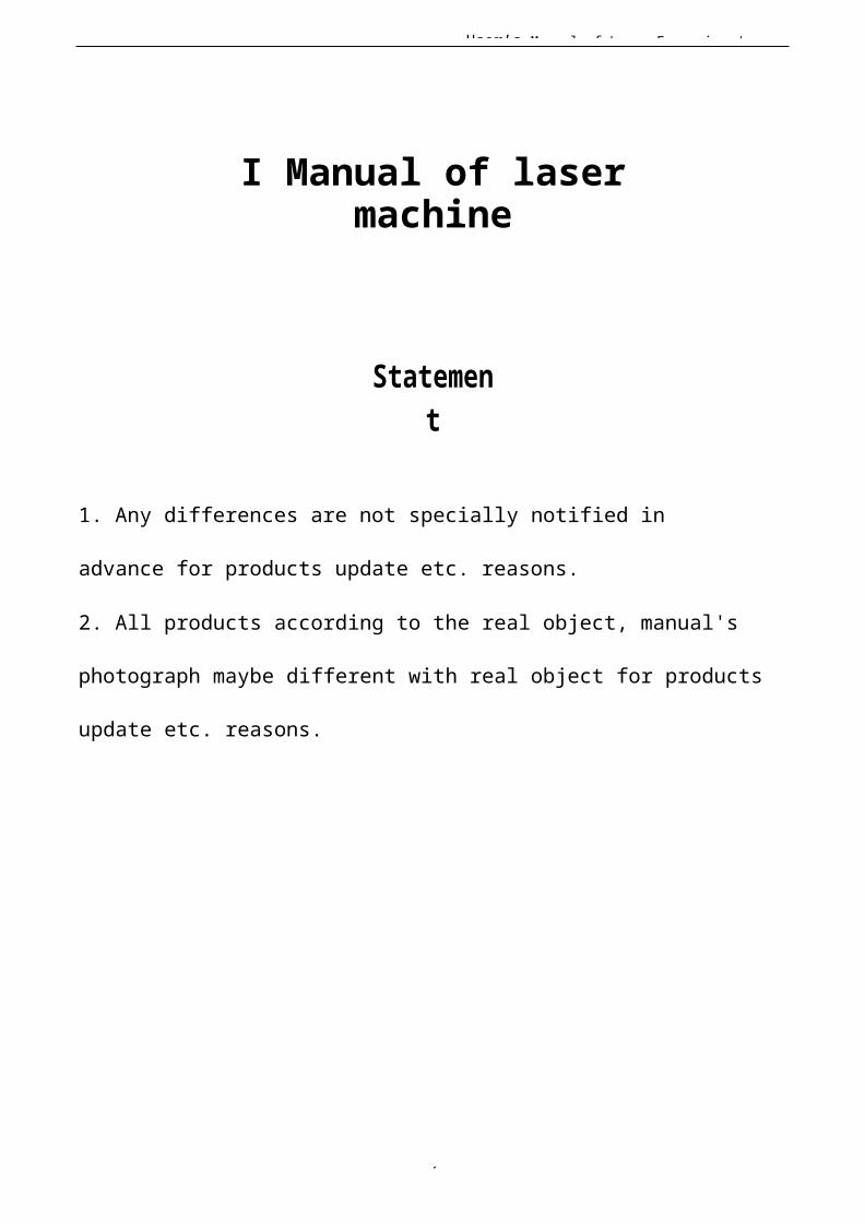
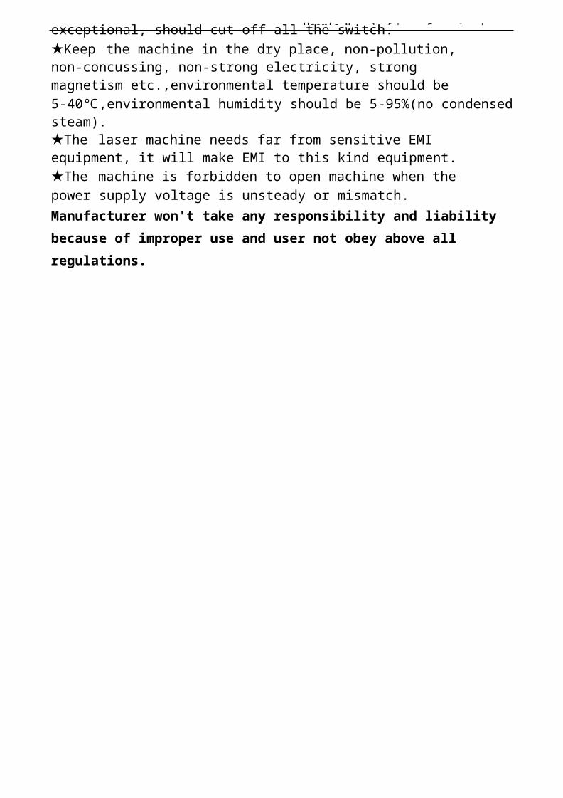
I.1.1 Machine Appearance (Different model will have different appearance, according to the real object)
1. Right side is shown in Fig.F1-1
F1-1
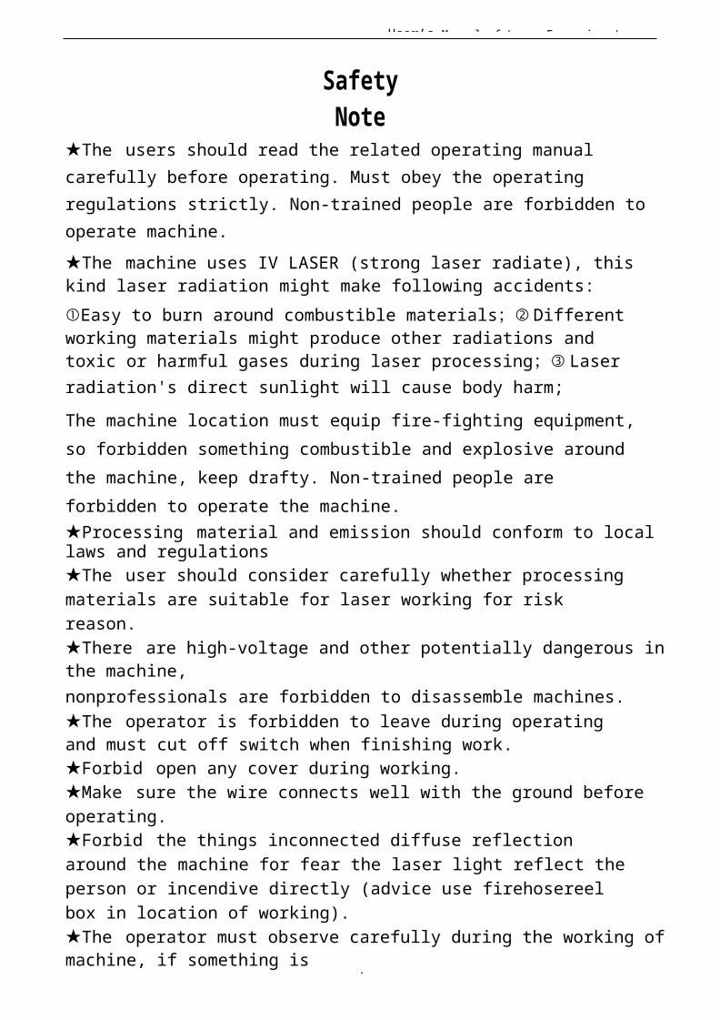
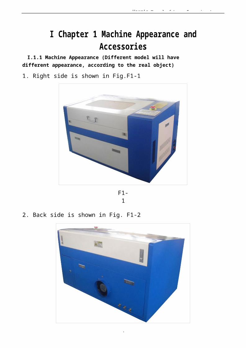
2. Back side is shown in Fig. F1-2
User’s Manual of Laser Engraving /
6
F1-2
User’s Manual of Laser Engraving /
7
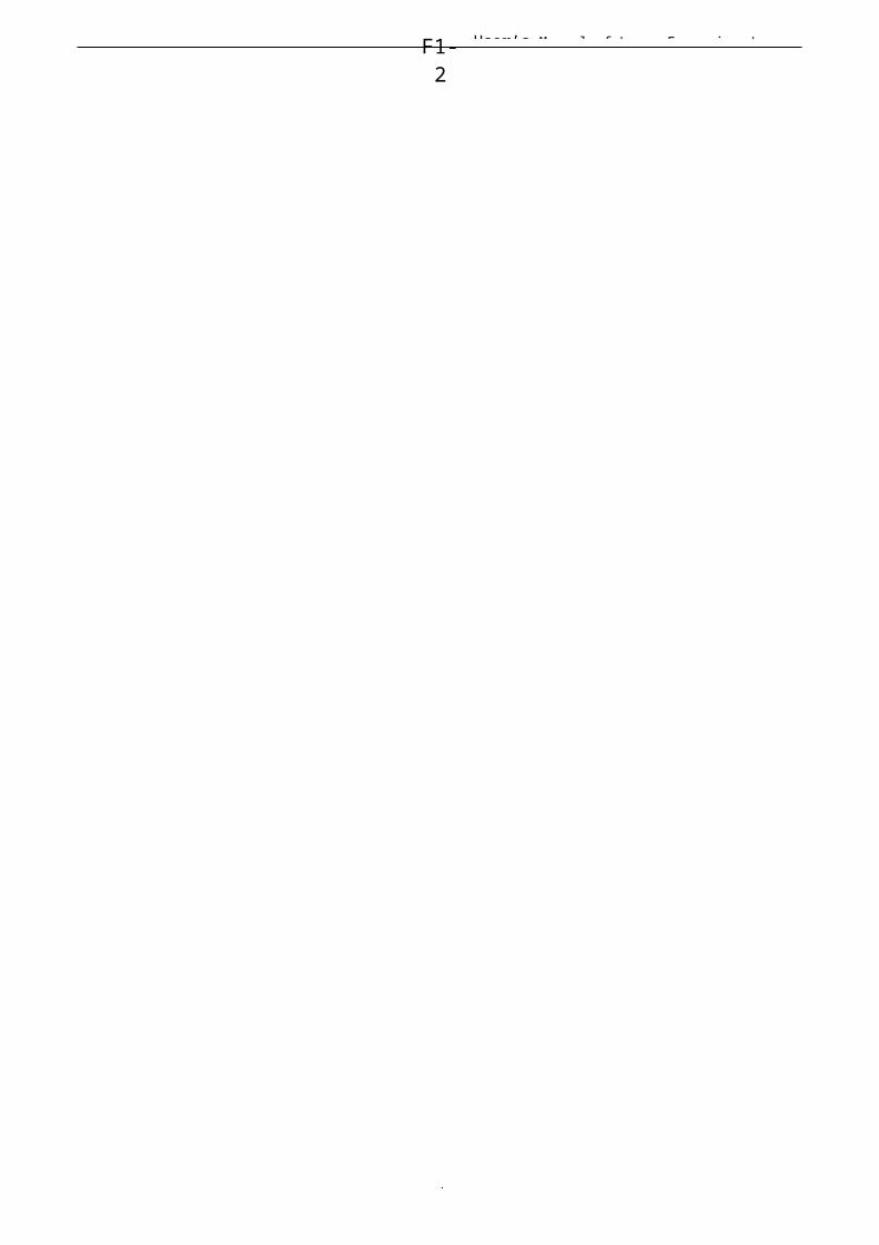
I.1.2 Accessories set (according to the real object)Your accessories set include following parts except
machine (except option spare parts)1. Water pipe (air pipe), Air pump, Water pump (some installed in water tank), is shown in Fig. F1-3:
F1-3
2. Exhaust fan, smoke pipe, is shown in Fig. F1-4:
3. Laser tube, is shown in Fig. F1-5:
F1-4
F1-5
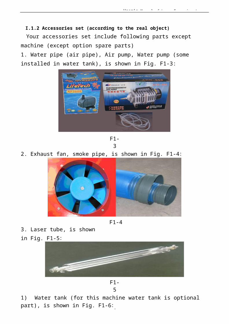
1) Water tank (for this machine water tank is optional part), is shown in Fig. F1-6:
User’s Manual of Laser Engraving /
8
F1-6
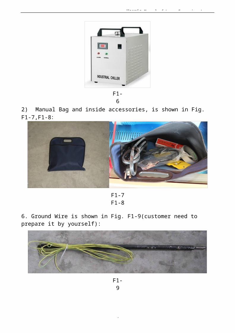
2) Manual Bag and inside accessories, is shown in Fig. F1-7,F1-8:
F1-7F1-8
6. Ground Wire is shown in Fig. F1-9(customer need to prepare it by yourself):
F1-9
User’s Manual of Laser Engraving /
9
I Chapter 2 Installation and Commissioning of the Machine A complete working system is composed by laser engraving machine, the exhaust fan, air pump, water pump, water tank, exhaust pipe, data transmission lines and so on. According to the needs, the users can configurethe computers, printers, scanners andso on by themselves.I. 2 Installation and Adjusting Steps
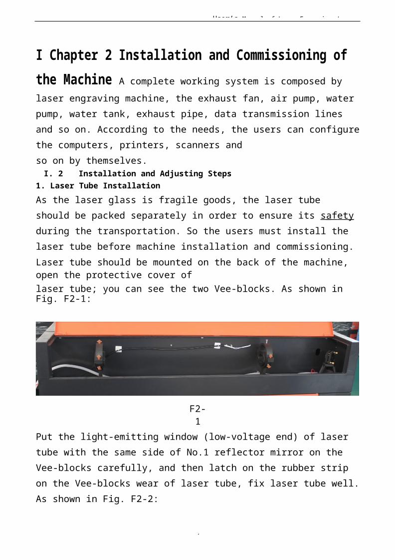
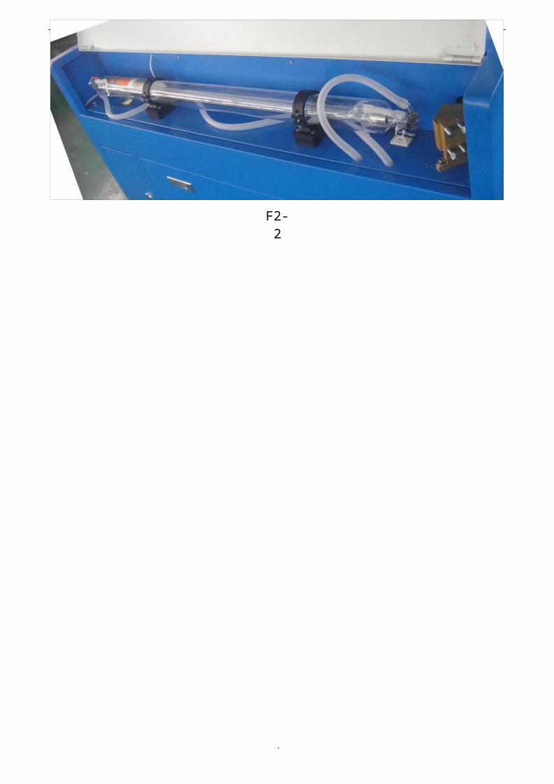
1. Laser Tube InstallationAs the laser glass is fragile goods, the laser tube should be packed separately in order to ensure its s af e t y during the transportation. So the users must install the laser tube before machine installation and commissioning.Laser tube should be mounted on the back of the machine, open the protective cover oflaser tube; you can see the two Vee-blocks. As shown in Fig. F2-1:
F2-1
Put the light-emitting window (low-voltage end) of laser tube with the same side of No.1 reflector mirror on the Vee-blocks carefully, and then latch on the rubber strip on the Vee-blocks wear of laser tube, fix laser tube well.As shown in Fig. F2-2:
User’s Manual of Laser Engraving /
1
F2-2
User’s Manual of Laser Engraving /
1
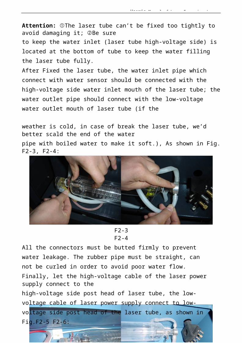
Attention: ①The laser tube can’t be fixed too tightly to avoid damaging it; ②Be sureto keep the water inlet (laser tube high-voltage side) islocated at the bottom of tube to keep the water filling the laser tube fully.After Fixed the laser tube, the water inlet pipe which connect with water sensor should be connected with the high-voltage side water inlet mouth of the laser tube; thewater outlet pipe should connect with the low-voltage water outlet mouth of laser tube (if the
weather is cold, in case of break the laser tube, we’d better scald the end of the waterpipe with boiled water to make it soft.), As shown in Fig.F2-3, F2-4:
F2-3F2-4
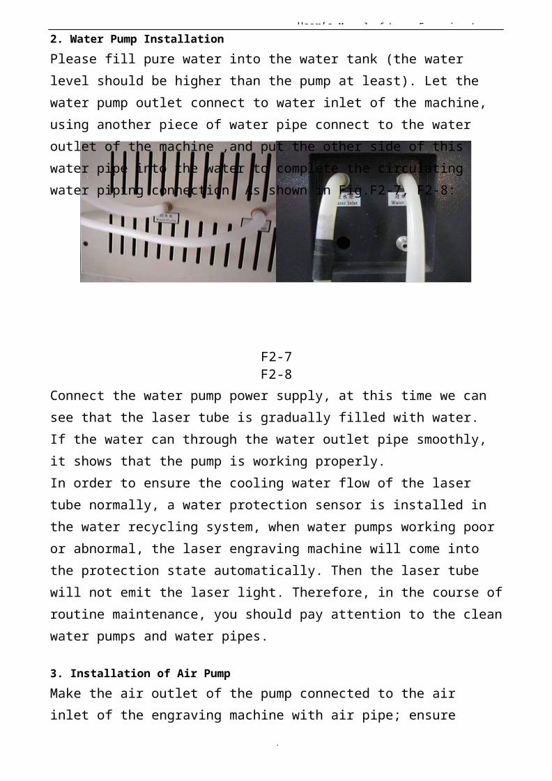
All the connectors must be butted firmly to prevent water leakage. The rubber pipe must be straight, can not be curled in order to avoid poor water flow.Finally, let the high-voltage cable of the laser power supply connect to thehigh-voltage side post head of laser tube, the low-voltage cable of laser power supply connect to low-voltage side post head of the laser tube, as shown in Fig.F2-5 F2-6:
User’s Manual of Laser Engraving /
1
F2-5F2-6
For security, please seal the post head of the high voltage side and low voltage with silicon gel.
User’s Manual of Laser Engraving /
1
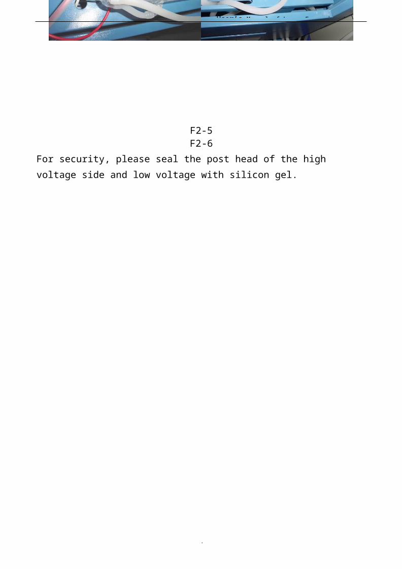
2. Water Pump InstallationPlease fill pure water into the water tank (the water level should be higher than the pump at least). Let the water pump outlet connect to water inlet of the machine, using another piece of water pipe connect to the water outlet of the machine ,and put the other side of this water pipe into the water to complete the circulating water piping connection. As shown in Fig.F2-7, F2-8:
F2-7F2-8
Connect the water pump power supply, at this time we can see that the laser tube is gradually filled with water. If the water can through the water outlet pipe smoothly, it shows that the pump is working properly.In order to ensure the cooling water flow of the laser tube normally, a water protection sensor is installed in the water recycling system, when water pumps working poor or abnormal, the laser engraving machine will come into the protection state automatically. Then the laser tube will not emit the laser light. Therefore, in the course ofroutine maintenance, you should pay attention to the cleanwater pumps and water pipes.
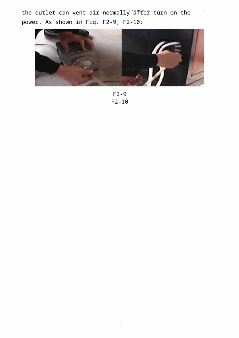
3. Installation of Air PumpMake the air outlet of the pump connected to the air inlet of the engraving machine with air pipe; ensure
User’s Manual of Laser Engraving /
1
the outlet can vent air normally after turn on the power. As shown in Fig. F2-9, F2-10:
F2-9F2-10
User’s Manual of Laser Engraving /
1
Air pump is very important in the system. High-pressure air r un s through the air pump and blew out from the laserlight-emitting window of the laser head. On the one hand,it can ensure the cleanliness of the focus lens, on the other hand, it can prevent the material inflame by the laser light. Therefore, in the routine maintenance, the user should pay attention to the air pipe, must ensure that it can not be twisty or damaged, otherwise abnormal air may lead to burning materials.
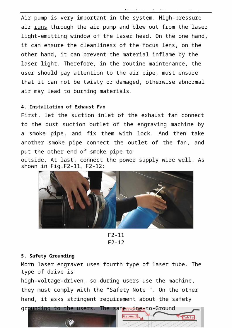
4. Installation of Exhaust FanFirst, let the suction inlet of the exhaust fan connectto the dust suction outlet of the engraving machine bya smoke pipe, and fix them with lock. And then takeanother smoke pipe connect the outlet of the fan, andput the other end of smoke pipe tooutside. At last, connect the power supply wire well. As shown in Fig.F2-11,F2-12:
F2-11F2-12
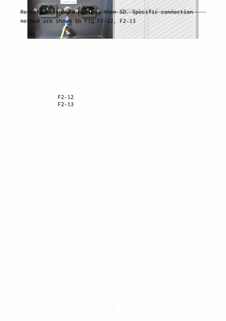
5. Safety GroundingMorn laser engraver uses fourth type of laser tube. The type of drive ishigh-voltage-driven, so during users use the machine, they must comply with the "Safety Note ". On the other hand, it asks stringent requirement about the safety grounding to the users. The safe Line-to-Ground
User’s Manual of Laser Engraving /
1
Resistance should be less than 5Ω. Specific connection method are shown in Fig.F2-12, F2-13
F2-12 F2-13
User’s Manual of Laser Engraving /
1
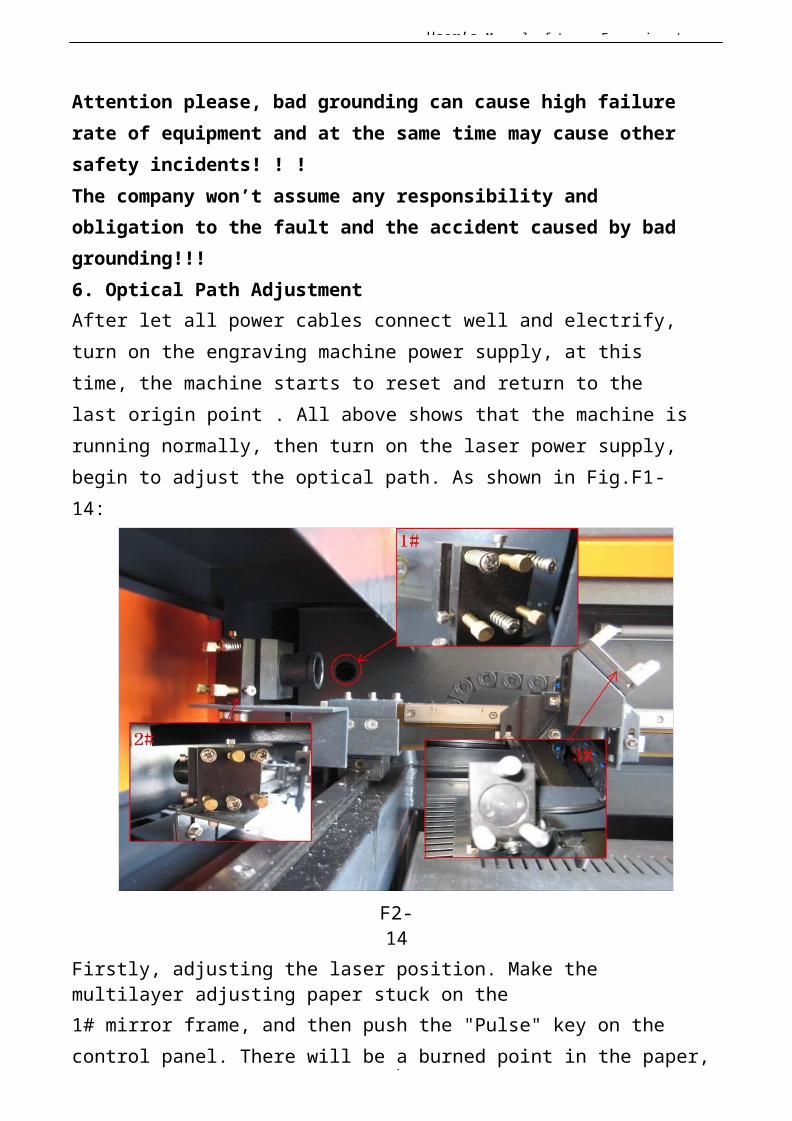
Attention please, bad grounding can cause high failure rate of equipment and at the same time may cause other safety incidents! ! !The company won’t assume any responsibility and obligation to the fault and the accident caused by bad grounding!!!6. Optical Path AdjustmentAfter let all power cables connect well and electrify, turn on the engraving machine power supply, at this time, the machine starts to reset and return to the last origin point . All above shows that the machine isrunning normally, then turn on the laser power supply, begin to adjust the optical path. As shown in Fig.F1-14:
F2-14
Firstly, adjusting the laser position. Make the multilayer adjusting paper stuck on the1# mirror frame, and then push the "Pulse" key on the control panel. There will be a burned point in the paper,
User’s Manual of Laser Engraving /
1
check whether the light spot is in the center of the mirror, if the light spot is not in the center o f the mirror center, we have to make the light spot in the center of the mirror by regulating the location of the laser tube.
Then adjust the 1# reflector mirrors. Move the beams to the nearest place to the
1# reflector; push “Pulse” to get a spot in the paper.And then move the beams to the farthest place from the1# reflector, get another spot in the paper. We adjustthe angle of the mirrors by adjusting the three screws onthe back of mirror (clockwise rotation the above screw,the spot will be down; clockwise rotation of the lowerleft corner of the screw, the spot will move to right;clockwise rotation of the lower right corner of
User’s Manual of Laser Engraving /
1
screw, the spot will move to left.), to insure that allthe spot are in the same place in the paper when and where the beam we move.
After adjust the 1# reflector mirror well, the next, adjust the mirror 2# as we do at the first step, move the laser head to the nearest side to 2# reflector , then makea spot in the paper , then move the laser head to the farthest place to 2# , make a spot.We have to adjust the further spot overlap with the first spot by adjust the screws on the 2# reflector frame.Note: As the best, the location of light spot should be inthe center of mirrors. The light spot can not hit the edges of the mirrors. If playing in the edges, please continue to adjust the mirrors until the light spot in thecentral of them.
At last we have to check whether the light spots are superposition wherever the laser head is. If the spots can not coincide, please re-adjust the optical path by the way we talked above until the spots coincide
After finished the adjustment, we will check whether this laser spot is playing in central of the laser head light hole. If not, turn off the laser power supply, adjust the laser tube position. If it is left and right excursion, which side is biased on, we move the laser tube to this side direction. Such as: if left, we adjust the laser tube to left ; if right , we adjust the laser tube to right .
If the migration is up and down, we have to adjustthe laser tube to the opposite direction, that is, ifup, we will make the laser tube down; if down, we willmake the laser tube up.
User’s Manual of Laser Engraving /
2
Note: The above adjustments is just for a low-voltage sideof laser tube (light side), if we want to adjust high-voltage side of the laser to achieve the same effect, thenthe adjusting direction is opposite.
The detailed description of how to adjust optical path, please see Chapter 4 "Alignment Standards of Optical Path".
After adjustment of optical path, please close the laser tube protective cover.
User’s Manual of Laser Engraving /
2
I Chapter 3 the Operation of lasermachine
Besides use the computer to control the function key,we can use the Control
Panel. The following is the brief instruction of control panel and main function.
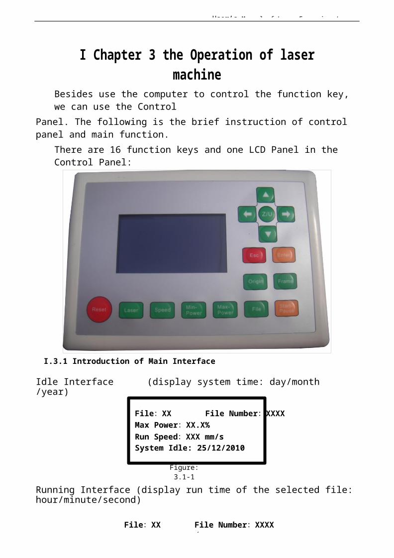
There are 16 function keys and one LCD Panel in the Control Panel:
I.3.1 Introduction of Main Interface
Idle Interface (display system time: day/month/year)
File:XX File Number:XXXXMax Power:XX.X%Run Speed:XXX mm/sSystem Idle: 25/12/2010
Figure:3.1-1
Running Interface (display run time of the selected file:hour/minute/second)
File:XX File Number:XXXX

User’s Manual of Laser Engraving /
2
Max Power:XX.X%Run Speed:XXX mm/sSystem Run: 00.12.40
Figure:3.1-2
User’s Manual of Laser Engraving /
2
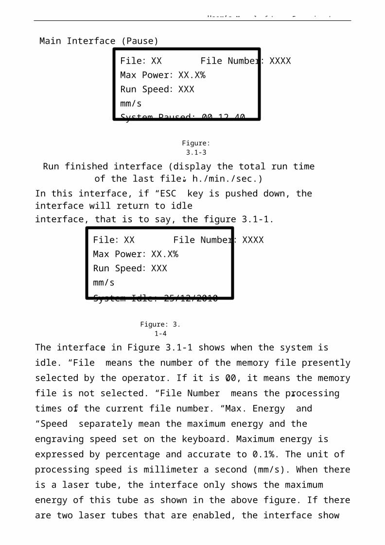
Main Interface (Pause)
File:XX File Number:XXXXMax Power:XX.X% Run Speed:XXX mm/sSystem Paused: 00.12.40
Figure:3.1-3
Run finished interface (display the total run timeof the last file: h./min./sec.)
In this interface, if “ESC” key is pushed down, the interface will return to idleinterface, that is to say, the figure 3.1-1.
File:XX File Number:XXXXMax Power:XX.X% Run Speed:XXX mm/sSystem Idle: 25/12/2010
Figure: 3.1-4
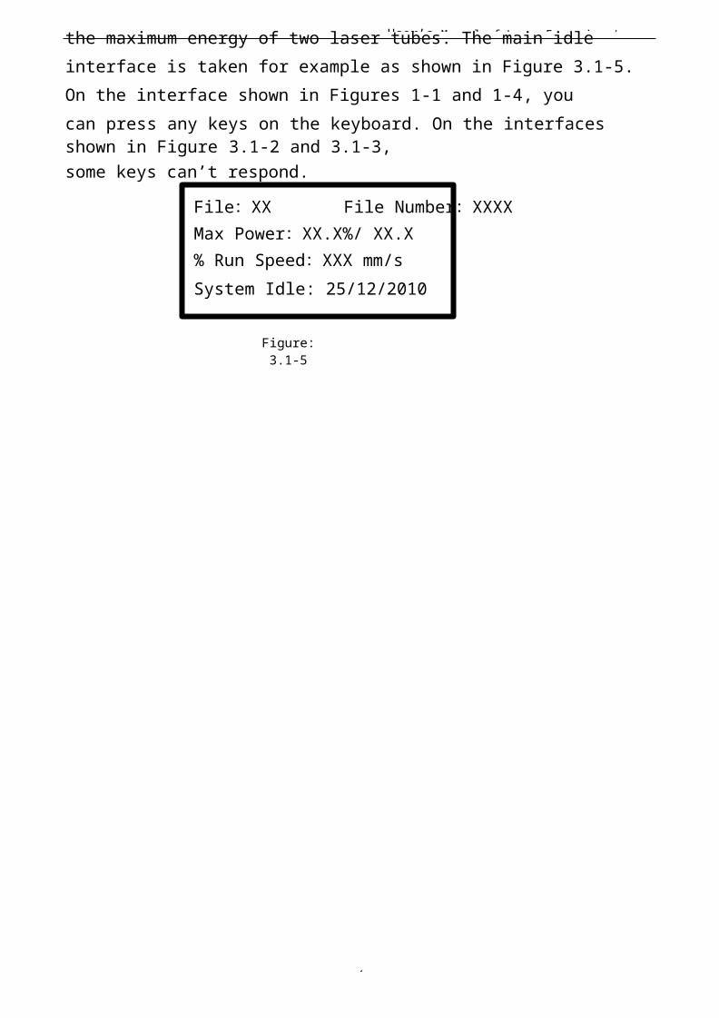
The interface in Figure 3.1-1 shows when the system is idle. “File” means the number of the memory file presentlyselected by the operator. If it is 00, it means the memoryfile is not selected. “File Number” means the processing times of the current file number. “Max. Energy” and “Speed” separately mean the maximum energy and the engraving speed set on the keyboard. Maximum energy is expressed by percentage and accurate to 0.1%. The unit of processing speed is millimeter a second (mm/s). When thereis a laser tube, the interface only shows the maximum energy of this tube as shown in the above figure. If thereare two laser tubes that are enabled, the interface show
User’s Manual of Laser Engraving /
2
the maximum energy of two laser tubes. The main idle interface is taken for example as shown in Figure 3.1-5. On the interface shown in Figures 1-1 and 1-4, youcan press any keys on the keyboard. On the interfaces shown in Figure 3.1-2 and 3.1-3,some keys can’t respond.
File:XX File Number:XXXXMax Power:XX.X%/ XX.X% Run Speed:XXX mm/sSystem Idle: 25/12/2010
Figure:3.1-5
User’s Manual of Laser Engraving /
2
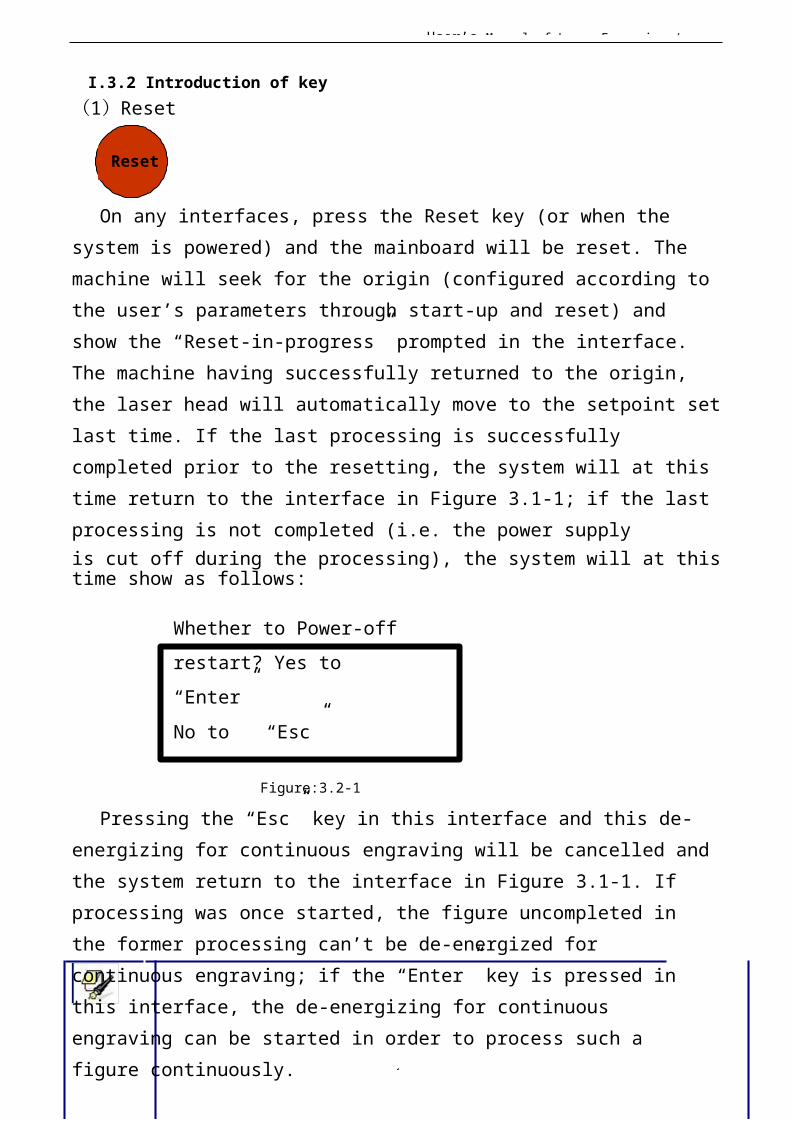
I.3.2 Introduction of key(1)Reset
Reset
On any interfaces, press the Reset key (or when the system is powered) and the mainboard will be reset. The machine will seek for the origin (configured according to the user’s parameters through start-up and reset) and show the “Reset-in-progress” prompted in the interface. The machine having successfully returned to the origin, the laser head will automatically move to the setpoint setlast time. If the last processing is successfully completed prior to the resetting, the system will at this time return to the interface in Figure 3.1-1; if the last processing is not completed (i.e. the power supplyis cut off during the processing), the system will at thistime show as follows:
Whether to Power-off restart? Yes to “Enter”No to “Esc”
Figure:3.2-1
Pressing the “Esc” key in this interface and this de-energizing for continuous engraving will be cancelled andthe system return to the interface in Figure 3.1-1. If processing was once started, the figure uncompleted in the former processing can’t be de-energized for continuous engraving; if the “Enter” key is pressed in this interface, the de-energizing for continuous engraving can be started in order to process such a figure continuously.
User’s Manual of Laser Engraving /
2
After the de-energizing for continuous engraving isstarted, the interface will show “Looking for cutoff point, please wait”. The
Prompt waiting time has something to do with the data size of last processing. The larger thedata size is, the longer the search for the cutoff point by the mainboard is. Generally speaking, if the power is cut off after the figure processing of one hour, the time that the mainboard looks for the cutoff point is approximately one minute when the de-energizing for continuous engraving is started after it ispowered next time.
(2)Laser Laser
User’s Manual of Laser Engraving /
2
On the system idle interface, the work finished interface, the system paused interface and the interface to prompt whether to de-energize for continuous engraving,press the “Laser” key and the laser outputs on the bursting. The time of open laser may be set. If the time is set to zero, then the outputting time is the time when the “Laser” key is pressed, that is to say, press this keyfor outputting and release it for blanking. If the time isnot zero, such as, 100ms, then the laser flash 100ms when you push down the laser key. You can press the “Down” key on pressing the “Laser” key to start manual cutting. The laser energy of burst is the maximum energy value set on the keyboard. It is no use to press the “Laser” key on other interfaces. If the waterprotector is started and something wrong happens to the protector, no laser will beoutputted after the laser and the interface prompts dislocation.(3)Max. Power key Max
Power
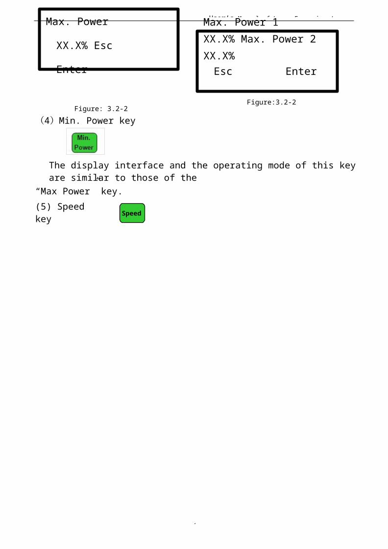
On four main interfaces (i.e. idle system, running system and suspended system, work finished interface) this key can be pressed. On pressing this key, if the manufacturer only provides a single laser tube or if there is a double-path laser tube, but the user only enables one path, it only shows the maximum energy of this-path laser tube and the interface shows the same asFigure 3.2-2. If two laser tubes areenabled together, it will show the maximum energy of two laser tubes and the interfaceshows the same as Figure 3.2-3.
User’s Manual of Laser Engraving /
2
Max. Power
XX.X% Esc
Enter
Figure: 3.2-2(4)Min. Power key
Max. Power 1 XX.X% Max. Power 2XX.X%Esc Enter
Figure:3.2-2
The display interface and the operating mode of this keyare similar to those of the
“Max Power” key.(5) Speedkey Speed
User’s Manual of Laser Engraving /
2
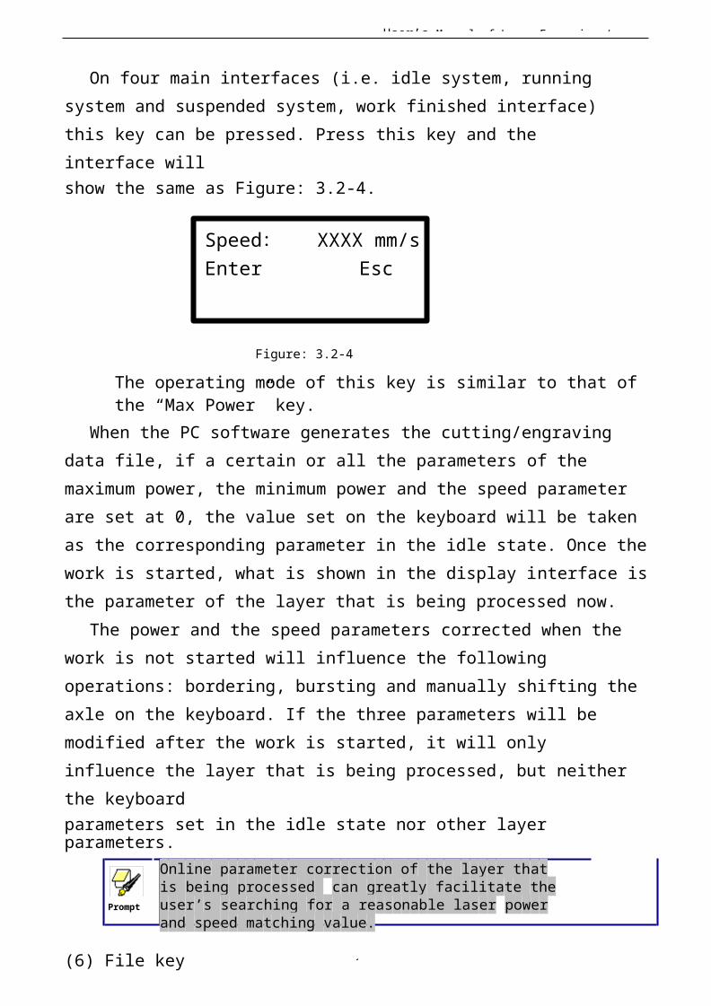
On four main interfaces (i.e. idle system, running system and suspended system, work finished interface) this key can be pressed. Press this key and the interface willshow the same as Figure: 3.2-4.
Speed : XXXX mm/sEnter Esc
Figure: 3.2-4
The operating mode of this key is similar to that of the “Max Power” key.
When the PC software generates the cutting/engraving data file, if a certain or all the parameters of the maximum power, the minimum power and the speed parameter are set at 0, the value set on the keyboard will be taken as the corresponding parameter in the idle state. Once thework is started, what is shown in the display interface isthe parameter of the layer that is being processed now.
The power and the speed parameters corrected when the work is not started will influence the following operations: bordering, bursting and manually shifting theaxle on the keyboard. If the three parameters will be modified after the work is started, it will only influence the layer that is being processed, but neither the keyboardparameters set in the idle state nor other layer parameters.
Prompt
Online parameter correction of the layer that is being processed can greatly facilitate the user’s searching for a reasonable laser power and speed matching value.
(6) File key
User’s Manual of Laser Engraving /
3
File
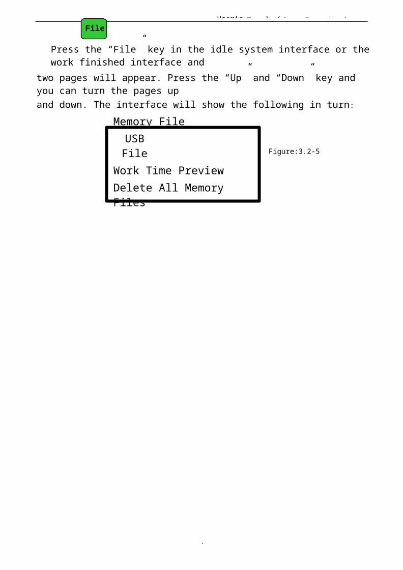
Press the “File” key in the idle system interface or thework finished interface and
two pages will appear. Press the “Up” and “Down” key and you can turn the pages upand down. The interface will show the following in turn:
Memory FileUSBFile
Work Time PreviewDelete All MemoryFiles
Figure:3.2-5
User’s Manual of Laser Engraving /
3
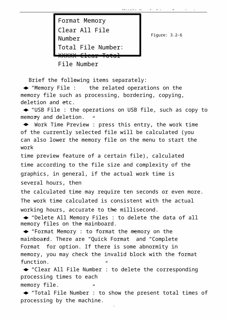
Format MemoryClear All File NumberTotal File Number:XXXXX Clear Total File Number
Figure: 3.2-6
Brief the following items separately:◆“Memory File”: the related operations on the memory file such as processing, bordering, copying, deletion and etc.◆“USB File”: the operations on USB file, such as copy tomemory and deletion.◆”Work Time Preview”: press this entry, the work time of the currently selected file will be calculated (you can also lower the memory file on the menu to start the worktime preview feature of a certain file), calculated time according to the file size and complexity of the graphics, in general, if the actual work time is several hours, thenthe calculated time may require ten seconds or even more.The work time calculated is consistent with the actual working hours, accurate to the millisecond.◆“Delete All Memory Files”: to delete the data of all memory files on the mainboard.◆“Format Memory”: to format the memory on the mainboard. There are “Quick Format” and “Complete Format” for option. If there is some abnormity in memory, you may check the invalid block with the formatfunction.◆“Clear All File Number”: to delete the corresponding processing times to eachmemory file.◆“Total File Number”: to show the present total times ofprocessing by the machine.
User’s Manual of Laser Engraving /
3
◆“Clear Total File Number”: to clear and recalculate thetotal file number.
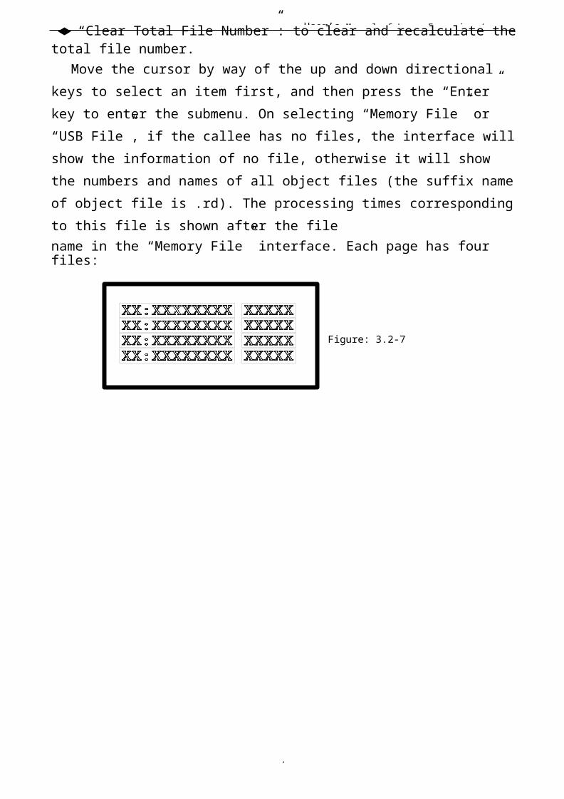
Move the cursor by way of the up and down directional keys to select an item first, and then press the “Enter” key to enter the submenu. On selecting “Memory File” or “USB File”, if the callee has no files, the interface willshow the information of no file, otherwise it will show the numbers and names of all object files (the suffix nameof object file is .rd). The processing times correspondingto this file is shown after the filename in the “Memory File” interface. Each page has four files:
Figure: 3.2-7
User’s Manual of Laser Engraving /
3
Select a certain file by pressing the directional keys(move the cursor with the up and down keys and turn pages with the left and right keys) first, and then press the “Enter” key to enter the submenu. For memory file, it supports such six items as“Copy to USB”, “Run”, “Deletion”, “Work Time Preview”, “Track Frame” and “ClearFile Number”.
On pressing the “Enter” key when you select the “Run” item, directly start the processing of this file and the interface shows the same as Figure 8.1-3 (Running Interface); selecting “To USB” and pressing the “Enter” key, this memory file will be copied to USB disk. If copying fails, the interface will show the error information; if copying succeeds, the system will return to the prior interface after the bell rings. On selectingthe “Deletion” and pressing the “Enter” key, this file inthe memory will be deleted. Selecting the “Work Time Preview” and pressing the “Enter” key, to start the work time preview feature of the certain file. If “Track Frame” is selected, the frame of the graph is previewed. Then if “Clear File Number” is selected, the work number of the certain file is set to zero.
For USB files, it supports such two options as “Copy toMemory” and “Deletion”, the operation of which is similarto that of memory file. In the operation of file copying,if the interface shows the error information, please press the “Enter” key or“Esc” key and the interface will return to the prior one.
Prompt
This system supports such file formats of USB as FAT32 and FAT16, but it can identify them when the files are put under the root directory of USB. The file name of more than 8 characters will automatically be cut out by
User’s Manual of Laser Engraving /
3
the system.
The file name that has only English letters and digits will not show when they are copied to the mainboard. Thefiles copied from the mainboard to USB will be placed under the root directory of USB.
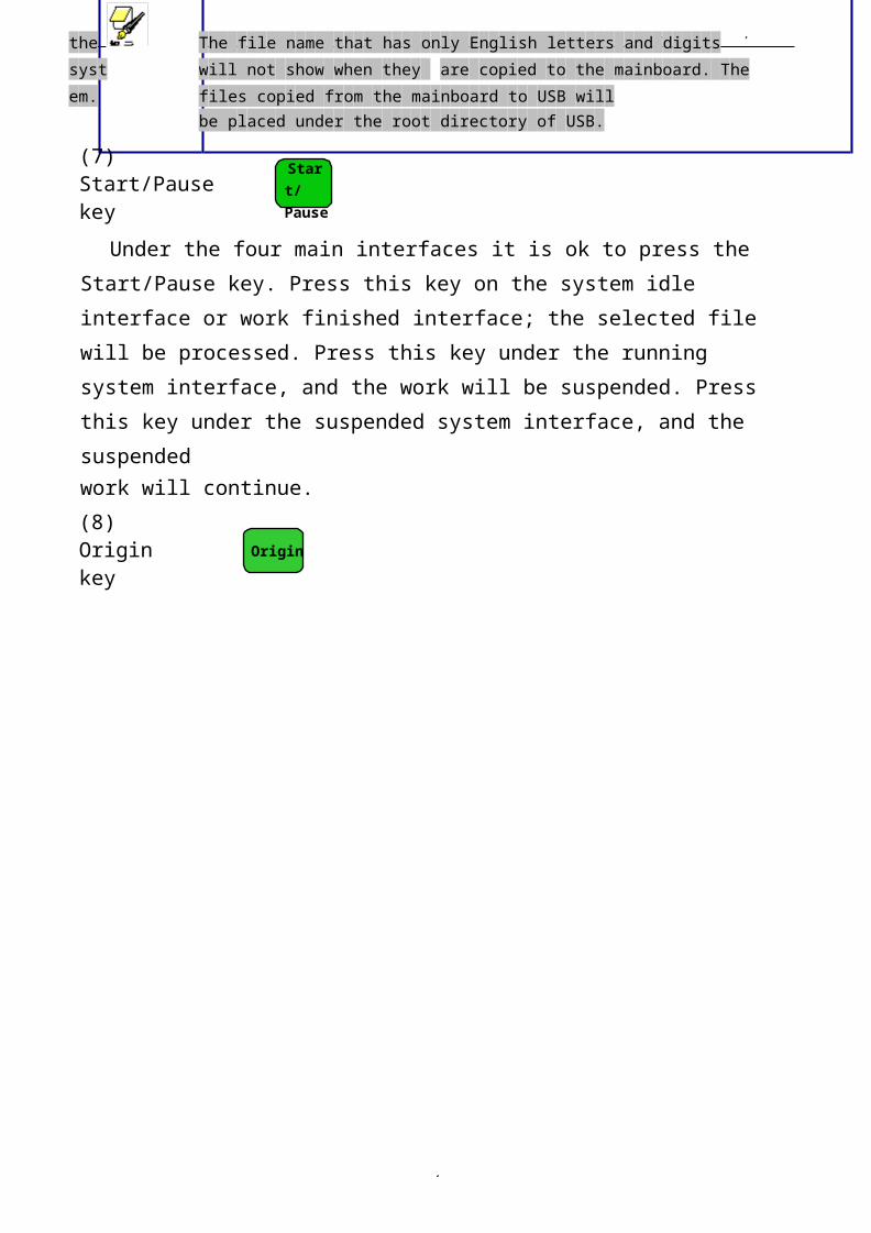
(7) Start/Pause key
Start/ Pause
Under the four main interfaces it is ok to press the Start/Pause key. Press this key on the system idle interface or work finished interface; the selected file will be processed. Press this key under the running system interface, and the work will be suspended. Press this key under the suspended system interface, and the suspendedwork will continue.(8) Origin key
Origin
User’s Manual of Laser Engraving /
3
It will respond when this key is pressed under the idlesystem interface or the work finished interface. If the single setpoint logic is selected by the system, press this key and the mainboard will take the current X/Y-axle position of the machine as therelative origin of the figure; if the multiple setpoint logic is selected by the system, it is invalid to press this key at any time.(9) Frame key
Frame
It is valid to press this key under the idle systeminterface and the work finished interface. Press thiskey and the bordering will be operated on the currentlyselected file.(10) Esc and Enter key
Esc Enter
Press the Esc or Enter key under different interfaces means to confirm or deny this operation.(11) Directional Keys (Up, Down, Left and Right keys)
In addition to being used for modifying parameters and moving the cursor as abovementioned, the directional keyscan be used to move the kinematic axis under such three interfaces as idle, suspended system or work finished interface. Under such three interfaces, press the Left and Right keys to move X axis and press the Up and down keys to move Y axis. If the inching distance is set at 0,the moving time means the time of pressing this key, which means that movement starts after the one of the keys is pressed and movement stops after the keys are
User’s Manual of Laser Engraving /
3
released. Where the inching distance is not 0, the corresponding axis will move for the corresponding inching distance after one of the directional keys is pressed once. In the movement processing the speed can beincreased or reduced automatically in order to reach the maximum/minimum coordinates. The maximum speed of key movement is the speedvalue set on the keyboard when the system lies idle.
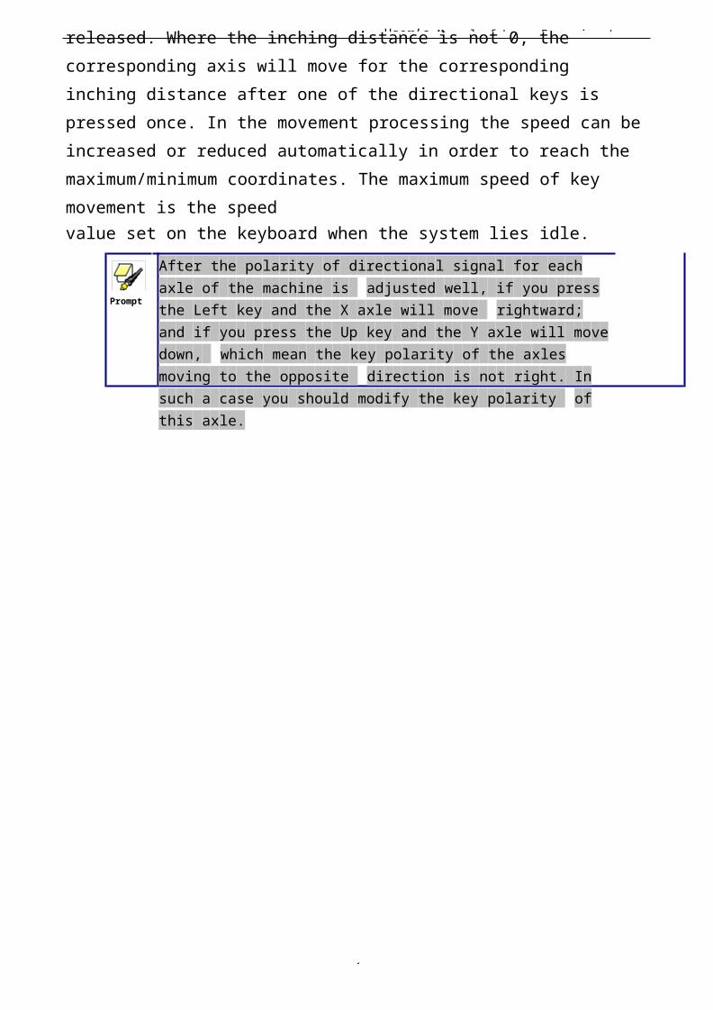
Prompt
After the polarity of directional signal for each axle of the machine is adjusted well, if you press the Left key and the X axle will move rightward; and if you press the Up key and the Y axle will movedown, which mean the key polarity of the axles moving to the opposite direction is not right. In such a case you should modify the key polarity of this axle.
User’s Manual of Laser Engraving /
3
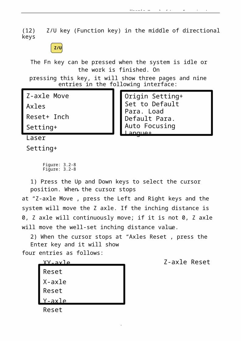
(12) Z/U key (Function key) in the middle of directionalkeys
Z/U
The Fn key can be pressed when the system is idle orthe work is finished. On
pressing this key, it will show three pages and nineentries in the following interface:
Z-axle MoveAxles Reset+ InchSetting+ Laser Setting+
Origin Setting+Set to DefaultPara. Load Default Para. Auto FocusingLangue+
Figure: 3.2-8 Figure: 3.2-8
1) Press the Up and Down keys to select the cursor position. When the cursor stops
at “Z-axle Move”, press the Left and Right keys and the system will move the Z axle. If the inching distance is 0, Z axle will continuously move; if it is not 0, Z axle will move the well-set inching distance value.
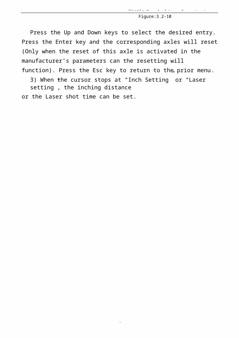
2) When the cursor stops at “Axles Reset”, press the Enter key and it will show
four entries as follows:XY-axle ResetX-axle ResetY-axle Reset
Z-axle Reset
User’s Manual of Laser Engraving /
3
Figure:3.2-10
Press the Up and Down keys to select the desired entry.Press the Enter key and the corresponding axles will reset(Only when the reset of this axle is activated in the manufacturer’s parameters can the resetting will function). Press the Esc key to return to the prior menu.
3) When the cursor stops at “Inch Setting” or “Laser setting”, the inching distance
or the Laser shot time can be set.
User’s Manual of Laser Engraving /
3
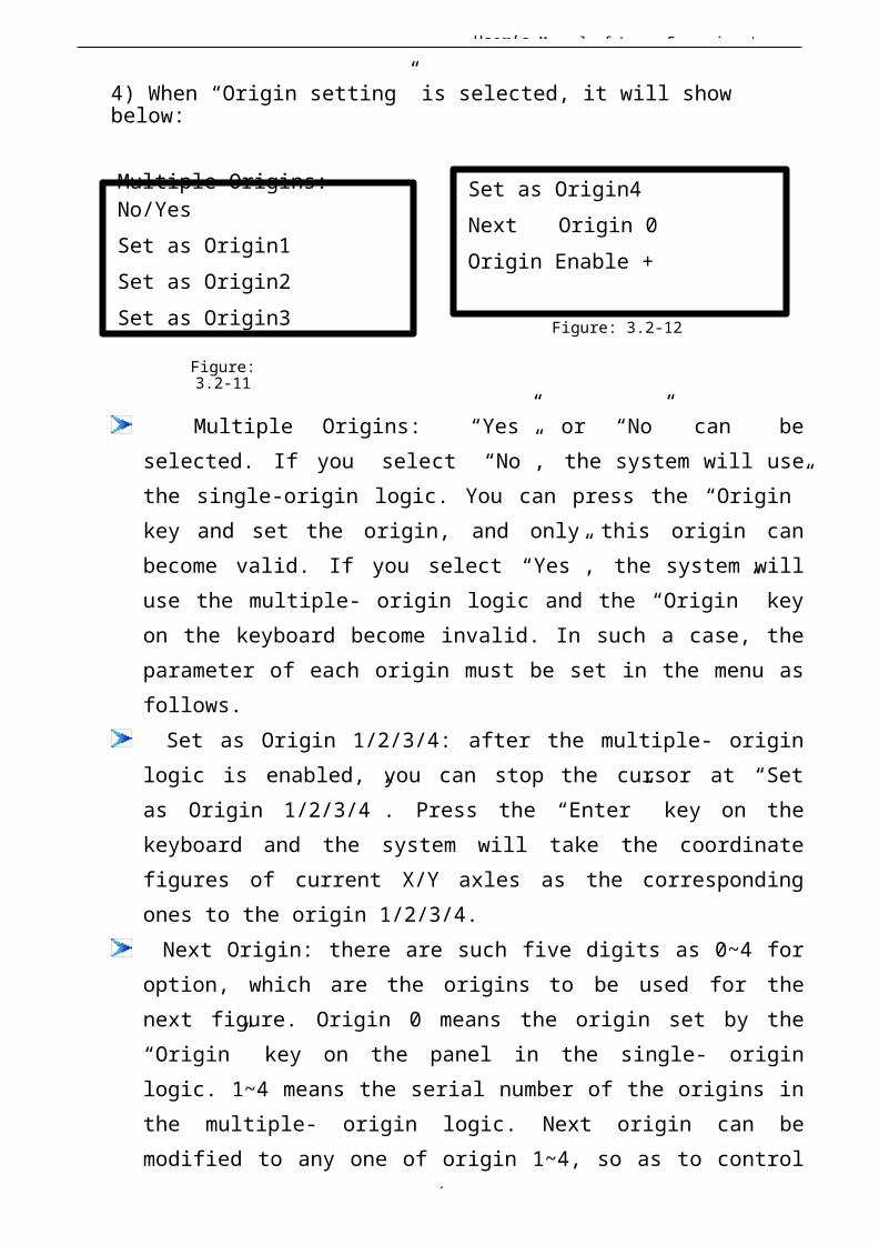
4) When “Origin setting” is selected, it will show below:
Multiple Origins: No/YesSet as Origin1Set as Origin2Set as Origin3
Figure:3.2-11
Set as Origin4Next Origin 0Origin Enable +
Figure: 3.2-12
Multiple Origins: “Yes” or “No” can beselected. If you select “No”, the system will usethe single-origin logic. You can press the “Origin”key and set the origin, and only this origin canbecome valid. If you select “Yes”, the system willuse the multiple- origin logic and the “Origin” keyon the keyboard become invalid. In such a case, theparameter of each origin must be set in the menu asfollows.
Set as Origin 1/2/3/4: after the multiple- originlogic is enabled, you can stop the cursor at “Setas Origin 1/2/3/4”. Press the “Enter” key on thekeyboard and the system will take the coordinatefigures of current X/Y axles as the correspondingones to the origin 1/2/3/4.
Next Origin: there are such five digits as 0~4 foroption, which are the origins to be used for thenext figure. Origin 0 means the origin set by the“Origin” key on the panel in the single- originlogic. 1~4 means the serial number of the origins inthe multiple- origin logic. Next origin can bemodified to any one of origin 1~4, so as to control
User’s Manual of Laser Engraving /
4
the start location of next work (the premise is thatthe origin is enabled), but it can’t be modified toorigin 0.
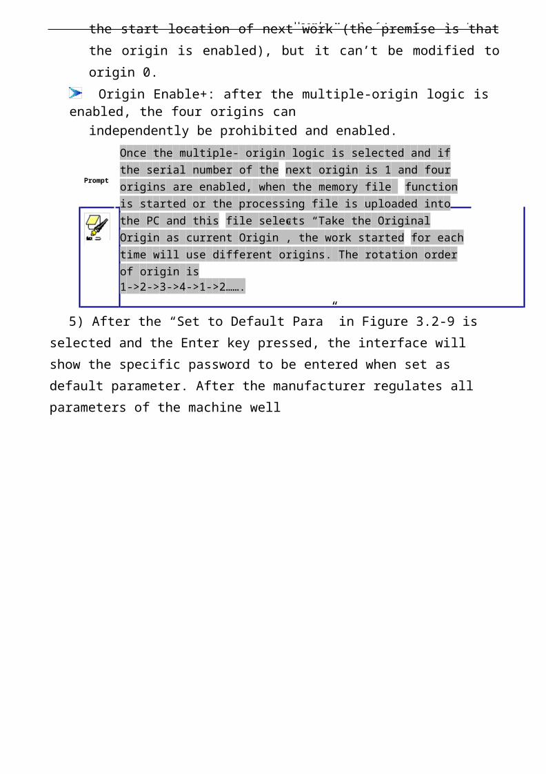
Origin Enable+: after the multiple-origin logic is enabled, the four origins can
independently be prohibited and enabled.
Prompt
Once the multiple- origin logic is selected and if the serial number of the next origin is 1 and four origins are enabled, when the memory file function is started or the processing file is uploaded into the PC and this file selects “Take the Original Origin as current Origin”, the work started for eachtime will use different origins. The rotation order of origin is1->2->3->4->1->2…….
5) After the “Set to Default Para” in Figure 3.2-9 is selected and the Enter key pressed, the interface will show the specific password to be entered when set as default parameter. After the manufacturer regulates all parameters of the machine well
User’s Manual of Laser Engraving /
4
(including all manufacturer parameters and user parameters), this function can be used to store the well-regulated parameters to help users to recover the original parameters (including all manufacturer parameters and user parameters) through selecting “Load Default Para” when they regulate parameters improperly.
6) After the “Load Default Para” in Figure 3.2-9 is selected and the Enter key pressed, the “Successful Recovery” dialog box will pop up to prompt that all manufacturer parameters and user parameters are recovered successfully. You can return to the previousmenu by press the Enter key.
7) When the cursor stops at “Auto Focusing”, press theEnter key to search for the focus(When there is z axes,and the z axes reset function is enabled, the autofocusing is valid); press the Esc key to return the priormenu.
8) The item “Langue” helps you to select a appropriate langue which is displayed
on the panel.
User’s Manual of Laser Engraving /
4
I Chapter 4 Alignment Standards of Optical Path
During common use, there may appear some deviation with the optical path, resulting in no laser or light path is abnormal, then please refer to the following method to adjust the optical path:
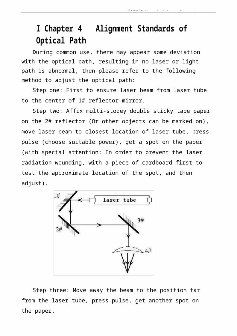
Step one: First to ensure laser beam from laser tube to the center of 1# reflector mirror.
Step two: Affix multi-storey double sticky tape paper on the 2# reflector (Or other objects can be marked on), move laser beam to closest location of laser tube, press pulse (choose suitable power), get a spot on the paper (with special attention: In order to prevent the laser radiation wounding, with a piece of cardboard first to test the approximate location of the spot, and then adjust).
Step three: Move away the beam to the position far from the laser tube, press pulse, get another spot on the paper.
User’s Manual of Laser Engraving /
4
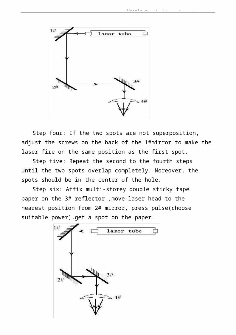
Step four: If the two spots are not superposition, adjust the screws on the back of the 1#mirror to make thelaser fire on the same position as the first spot.
Step five: Repeat the second to the fourth steps until the two spots overlap completely. Moreover, thespots should be in the center of the hole.
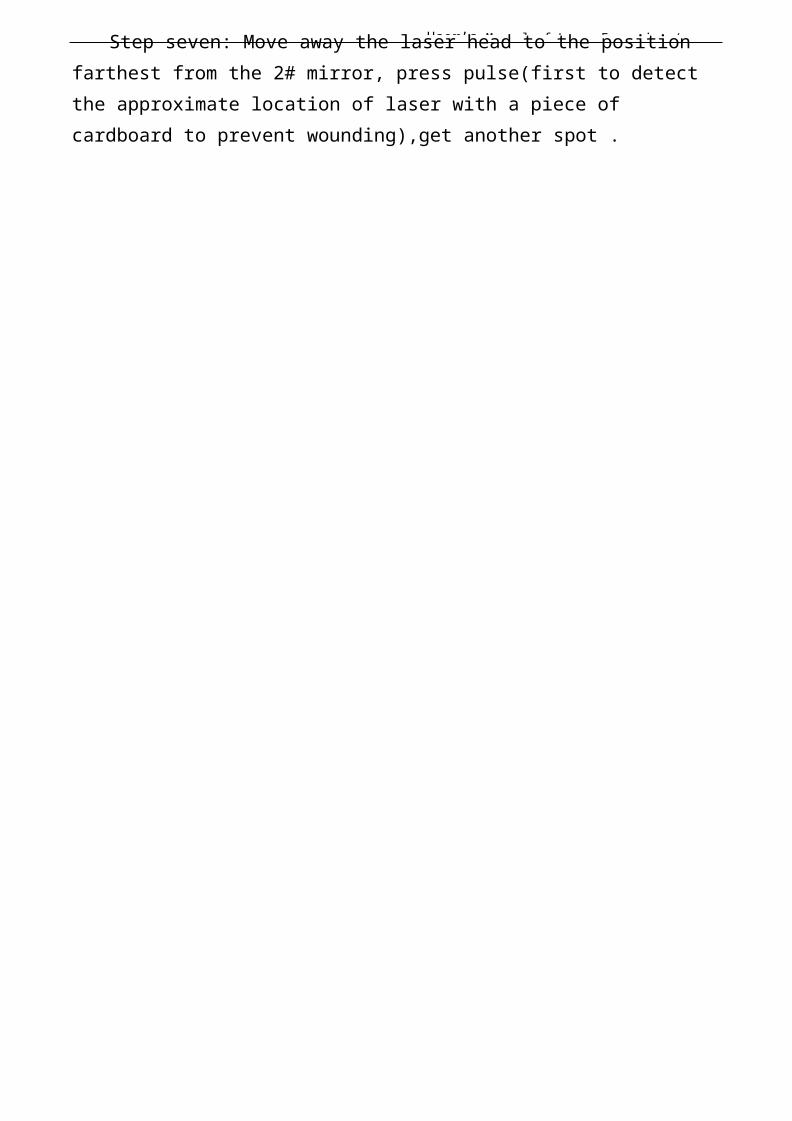
Step six: Affix multi-storey double sticky tape paper on the 3# reflector ,move laser head to the nearest position from 2# mirror, press pulse(choose suitable power),get a spot on the paper.
User’s Manual of Laser Engraving /
4
Step seven: Move away the laser head to the position farthest from the 2# mirror, press pulse(first to detect the approximate location of laser with a piece of cardboard to prevent wounding),get another spot .
User’s Manual of Laser Engraving /
4
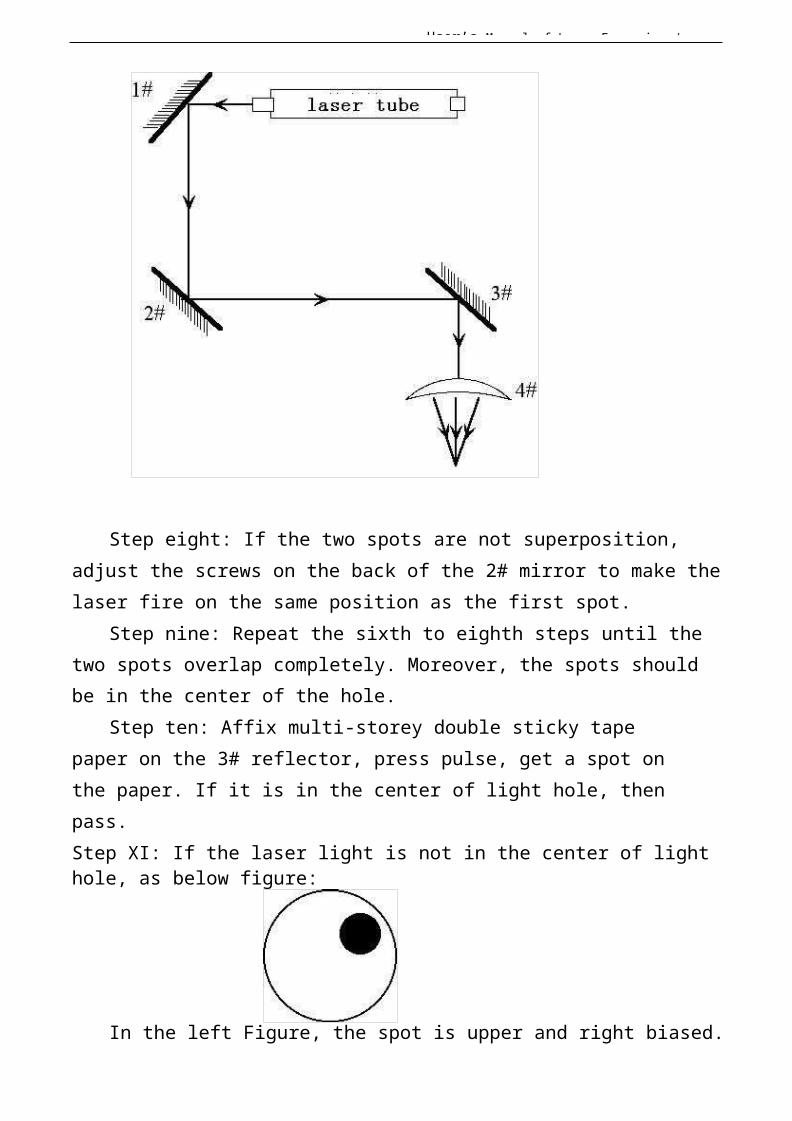
Step eight: If the two spots are not superposition, adjust the screws on the back of the 2# mirror to make thelaser fire on the same position as the first spot.
Step nine: Repeat the sixth to eighth steps until the two spots overlap completely. Moreover, the spots should be in the center of the hole.
Step ten: Affix multi-storey double sticky tape paper on the 3# reflector, press pulse, get a spot on the paper. If it is in the center of light hole, then pass.Step XI: If the laser light is not in the center of light hole, as below figure:
In the left Figure, the spot is upper and right biased.
User’s Manual of Laser Engraving /
4
Top to bottom bias: can only raise or lower the laser tube.Inside and outside bias: only move the laser tube in orout to adjust.In this case, it is essential to lower the laser tube
(here refers to low-voltage side of the laser tube), and then, from the beginning of all the re-adjustment of the first step.
User’s Manual of Laser Engraving /
4
Note: The operator can’t do the above working until after the professional training. Otherwise, the operator do this working must with the help of the professional .The operator must pay attention to security when adjusting, to prevent the laser radiation wounding.
I Chapter 5 Daily Maintenance and CommonFaults
The stable working of the machine is inseparable with normal daily operation and maintenance. Here are some common daily maintenance and common faults analysis:
I.5.1 Dailymaintenance
1. Replacement of the cooling water (clean water tank andreplace recycled water once a week are recommended):
Quality and temperature of the cooling water can affect the lifetime of laser tube directly, suggest use purified water or distilled water, and water temperature should bebelow than 35 ℃.When higher than 35 ℃,please replace cooling water, or add icecubes to lower the water temperature,(cooling device is recommended, or use two water tanks).Note: To ensure that the laser tube full filled with cooling water before machine working.2. Cleaning of Water Tank
First of all, turn off power, disconnect the water inlet pipe, let the inside water of the laser tube flow into the water tank automatically, open water tank, take out the water pump, clean water pump and water tank, put the pump back to water tank, insert the water pipe which
User’s Manual of Laser Engraving /
4
connect water pump to water inlet mouth of the machine, finish all joints, then replace cooling water. Turn on the water pump power supply isolately, let the pump run 2-3 minutes (make laser tube full filled with water).3. Cleaning of Exhaust Fan
After long time using, inside of fan will accumulate much solid dust, so the exhaust fan will make a great noise, and it is not conducive to the exhaust .When the exhaust effect become poor, we have to clean the fan and smoke pipe .Firstly, turn off the power supply, remove the two pipes from the fan, clean dust inside of the pipes, and then clean the dust inside of the fan.4. Cleaning of Lens (daily cleaning is recommended before work, equipment must be in shutdown state)
As we have talked before, engraving machine has three reflector mirrors and one focus lens (1# reflector mirroris near the light outlet mouth of laser tube, the upper
User’s Manual of Laser Engraving /
4
left corner of the machine, 2# reflector mirror is at leftside of the beam, 3# reflector mirror is on the top of laser head, the focus lens is located in the bottom part of the laser head), the laser is send out by the mirror reflecting and focus lens focalizing. Mirror is easy to bedirty, resulting in laser loss and mirror damage, you needn’t remove 1#,2# and 3# mirror when cleaning them, Just using a cotton bar to dip some cleaning solution (acetone or alcohol) , swab carefully by rotating from central to edge of the lens.
Take out the focus lens from the laser head, using thesame method clean it, after cleaning, put it back.Note: ① you should wipe the lens carefully, cannot damage the surface coating;② you should do that lightly, to prevent falling; ③keepconcave side downward when install the focus lens.5. Cleaning of Guideway (suggest cleaning every two weeks, equipment must be in shutdown state)
First of all, move the laser head to the far right (orleft),wipe with a dry cloth until shiny clean, together with a little oil (sewing machine oil is recommended),pushthe laser head several times slowly along the guide, so that lubricant can be evenly distributed. Clean and lubricate the Y axis two guideways is the same as X axis.Note: Please prepare for cleaning Guide - dry cotton cloth, lubricating oil.6. Optical path inspection
Optical path system of the laser engraving machine is completed by the mirror reflection and focus lens focusing, and there is optical path bias with the focus lens, but the three mirrors is fixed by the mechanical part, optical path bias is very possible for them, although there is no optical bias normally, we still suggest you check optical path before working.

User’s Manual of Laser Engraving /
5
Please get detailed explanation from Chapter 4 "Alignment Standards of Optical
Path "
User’s Manual of Laser Engraving /
5
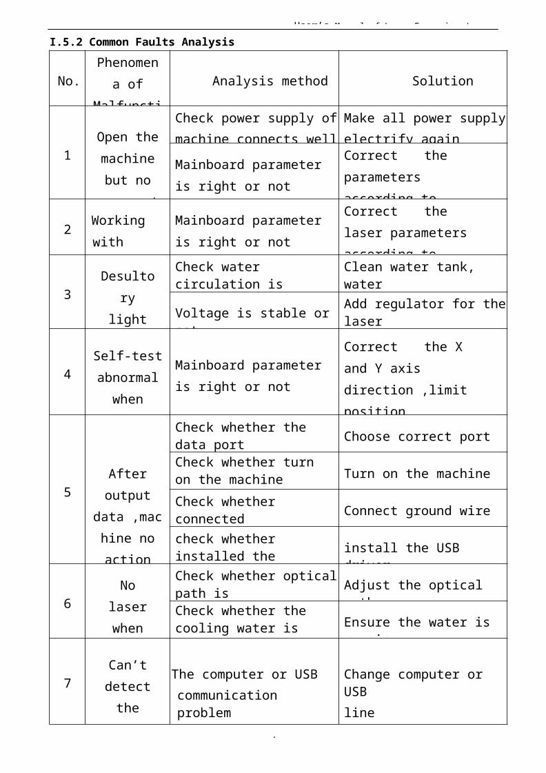
I.5.2 Common Faults Analysis
No.Phenomen
a ofMalfuncti
Analysis method Solution
1Open themachinebut no
movement
Check power supply ofmachine connects well
Make all power supplyelectrify again
Mainboard parameter is right or not
Correct the parameters according to
2 Working with nonstop
Mainboard parameter is right or not
Correct the laser parametersaccording to
3Desulto
rylightwhen
Check water circulation is
Clean water tank, water
Voltage is stable or not
Add regulator for thelaser
4Self-testabnormalwhen
starting
Mainboard parameter is right or not
Correct the X and Y axis direction ,limit position
5Afteroutput
data ,machine noaction
Check whether the data port Choose correct portCheck whether turnon the machine Turn on the machine
Check whether connected Connect ground wire
check whether installed the install the USB
driver
6No
laserwhen
workin
Check whether opticalpath is Adjust the optical
pathCheck whether the cooling water is running
Ensure the water is running
7Can’tdetectthelaser
The computer or USBcommunication problem
Change computer or USBline
User’s Manual of Laser Engraving /
5
I Chapter 6 Warranty RegulationsI 6.1 Warranty Periods
From the date of purchase, whole year warranty (except consumables). Optical lenses and the laser tube are consumables, three months warranty.
I 6.2 Warranty Clauses
This warranty is for products of our company.During the warranty period and under the correct use,
malfunction can be based on this warranty terms, show thewarranty card or invoice, enjoy our free maintenance service.
The following cases, can’t enjoy the free service, a fee will be charged according
to the concrete condition.1) Maintenance services not caused by the machine quality;2) Overstep the warranty period;3) Can’t show or alter warranty card;4) Didn’t fulfill the contractual obligation;5) Without the company agrees, privately to tear open outfit, modification, maintenance of product;6) Equipment failure due to human or force majeure factors.The company only assume the legal obligation for the
product itself, but don't assume other responsibilitieswhich caused by the using of the products.
User’s Manual of Laser Engraving /
5
II RDCAM V6.0 UserManual
II Chapter 1Overview
II.1.1 Laser engraving cutting system introductionLaser engraving cutting system through a computer
numerical control machine tools to achieve effective control, according to the user’s different requirements of the completion of processing tasks. This manual describes how to use the software to complete the task oflaser processing
II.1.2 Environmental requirements⑴ Windows XP operating system and above, XP recommended。⑵ Above CPU586,above PIII or PV recommended。⑶ Memory, above 1G recommended
II.1.3 Software runningEmbedded software can be embedded in CorelDraw、AutoCad、CaDian2010 and
Illustrator CS5 software, the software is similar to the operation, embedded software, installation methods, please refer to <<RDCAM software Setup Manual >>1.3.1 Run CorelDraw1>Run CorelDraw。2>Import graph to CorelDraw,or draw some graphics。
3>Click toolbar button , then RDCAM running。1.3.2 Run AutoCad

User’s Manual of Laser Engraving /
5
1> Run AutoCad2> Import grahic to AutoCad,or draw some。
3>Click toolbar
button then RDCAM running.
User’s Manual of Laser Engraving /
5
1.3.3 Run Cadian20101>Run Cadian20102>Import grahic to Cadian,or draw some.
3>Click toolbar
button then RDCAM
running
1.3.4 Run Illustrator CS51>Run Illustrator CS5。2> Import grahic to Illustrator,or draw some.
3> Click toolbar button , then RDCAM running。
User’s Manual of Laser Engraving /
5
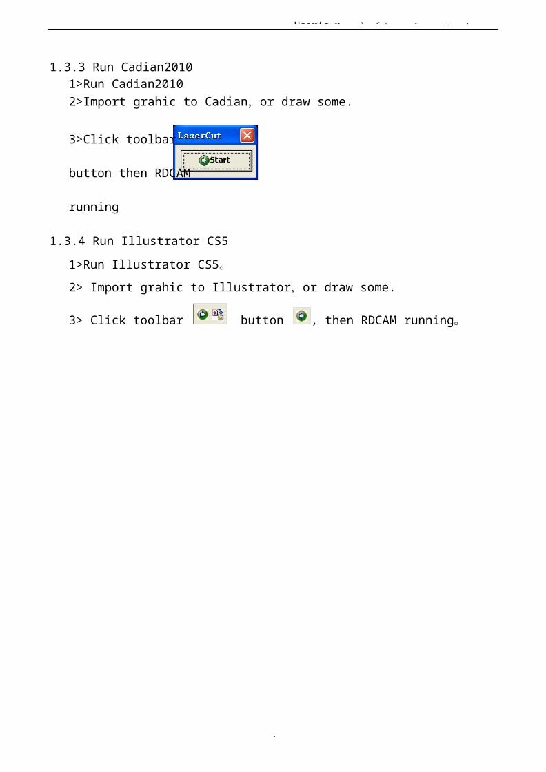
II Chapter 2 Software installationII.2.1 Install steps(1)Double-click the RDCAMSetup.exe under the installation directory, the following dialog
box appears:
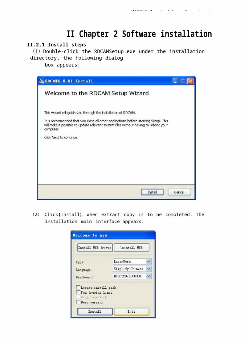
(2) Click【Install】,when extract copy is to be completed, the installation main interface appears:
User’s Manual of Laser Engraving /
5
II.2.2 Installation settingsThe installer can choose different installation content.1> Install/Uninstall USB driver , reference《Install USB driver》2> According to the different customer application needs andthe habit of using to select the type of software
a. Stand-alone software LaserWork.b. The software that plug-ins to CorelDraw. Support the version from Coreldraw11 to X5. c. The software that plug-ins to AutoCad. Support the version from 2004 to 2010.d. The software that plug-ins to Cadian.e. The software that plug-ins to Illustrator.
3> Choose a different installation languagesAt present, it support Simplified Chinese, Traditional Chinese,English and the custom language type.
4> Select the software matches the motherboardThe software can support three kind of motherboards:RDLC430、RDLC320、RDC633X. Both RDLC320 and RDC633X arecompatible, but RDLC430 is different. So, please choose the corresponding software with motherboard. Otherwise, it does not work.
5> Locate install pathWhen install the LaserWork, default install path is “C:\”, for changethe install path, check thisoption.When install the plug software RDPlug, under normal circumstances, the install program will locate to the target software automatically. If the installer does not locate to the target software automatically, you need to check this option, andlocate to the target software manually.
6> Pen drawing linesThis option is only applicable to a particular machine, which has the function of the chalk line, ordinary machines do not need to check this.
7> Plug laserworkThe installer default install a special plug-ins RDPlug, if the users are more accustomed to using LaserWork program ,can check this.
8> Demo version installationAccording to the type of software installation, the installation language, the choice of motherboard generate different versions of the DEMO Software.
II.2.3 Installation
User’s Manual of Laser Engraving /
5
Choose the type of software, installation language and the appropriate motherboard. Click【Install】to install the software. After installation is complete, the following dialog box appears to prompt the user that the software has been installed successfully.
II.2.4 ExitAfter installing the installation needed. Click【Exit】to end the installation process.
Because of the possible need to use several installation, so the installation dialog does not automatically exit, until users click button【Exit】.
User’s Manual of Laser Engraving /
5
II.2.4 Other matters1> Before installing the plug-in software, the software that has been articulated should be shut down. After installation, restart the software.
2> The regular version and the DEMO version of the plug-in software is covered by each other.3> In the default installation path, the normal version and the DEMO
version of the independent software and different types of independent software motherboard with each other.
For the same time to install two versions, select the【Locate install path】.The regular
version and the Demo version should be installed in the different location.In addition, need to the appropriate software installation
location, manually add a desktop shortcut for the software.4> Modify the information of manufacturers
In the package, in addition to RDCAMSetup, there are four text files. Info_Sche、Info_Tche、Info_En、Info_Other, the four files correspond to the software
information of manufacturers that be displayed in Simplified Chinese, Traditional Chinese, English and the custom language. If the four text ismodified, manufacturer information also will be installed when the program was installed.
Open the text that should be modify, an example in Simplified Chinese:0 = Company Name:1 = ... (Fill in company name here)And so on, the company information in other languages is the same set.
II.2.5 The plug-in of CorelDrawinstalled
Plug-in software support the version from CorelDraw11 to X5, but some simplified versions of CorelDraw is not supported. Here to the installation of CorelDraw12 as an example to introduce the installation process of plug-in software. If not specified, it is referring to CorelDraw12.
Before installing the plug-in software to run CorelDraw.
User’s Manual of Laser Engraving /
6
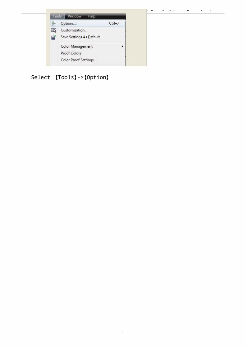
Select 【Tools】->【Option】
User’s Manual of Laser Engraving /
6
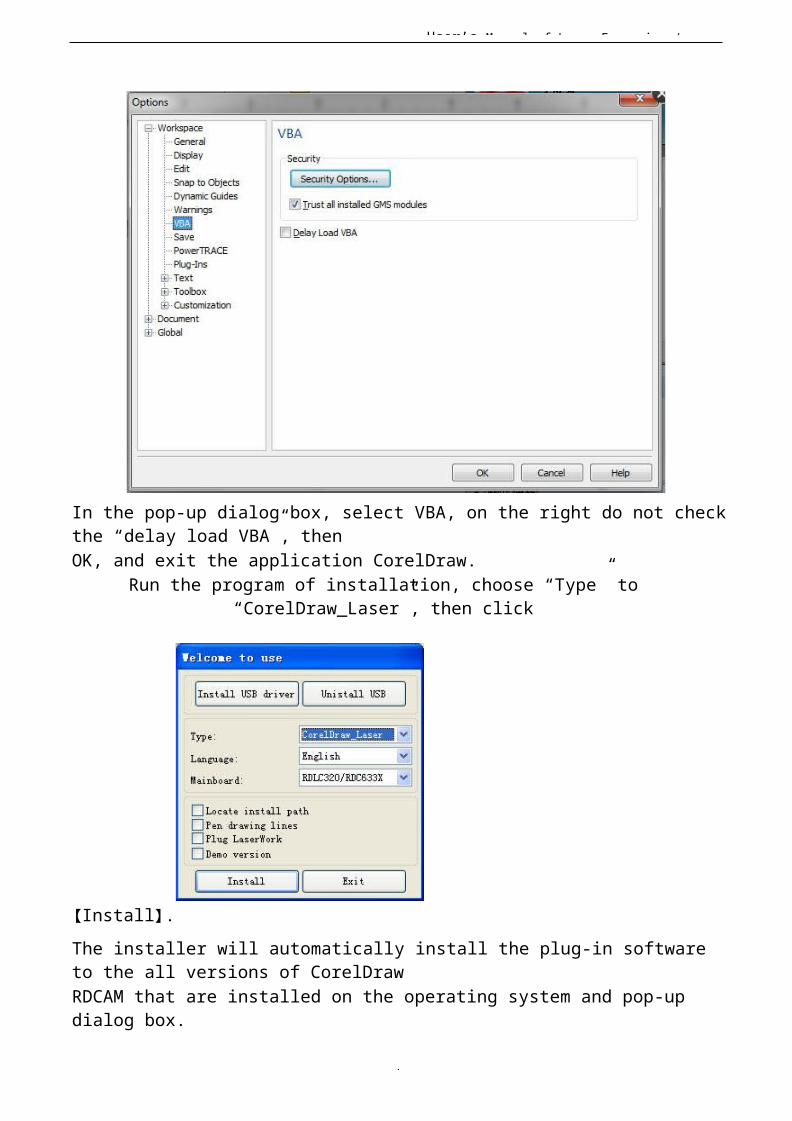
In the pop-up dialog box, select VBA, on the right do not checkthe “delay load VBA”, thenOK, and exit the application CorelDraw.
Run the program of installation, choose “Type” to“CorelDraw_Laser”, then click
【Install】.The installer will automatically install the plug-in software to the all versions of CorelDrawRDCAM that are installed on the operating system and pop-up dialog box.

User’s Manual of Laser Engraving /
6
User’s Manual of Laser Engraving /
6
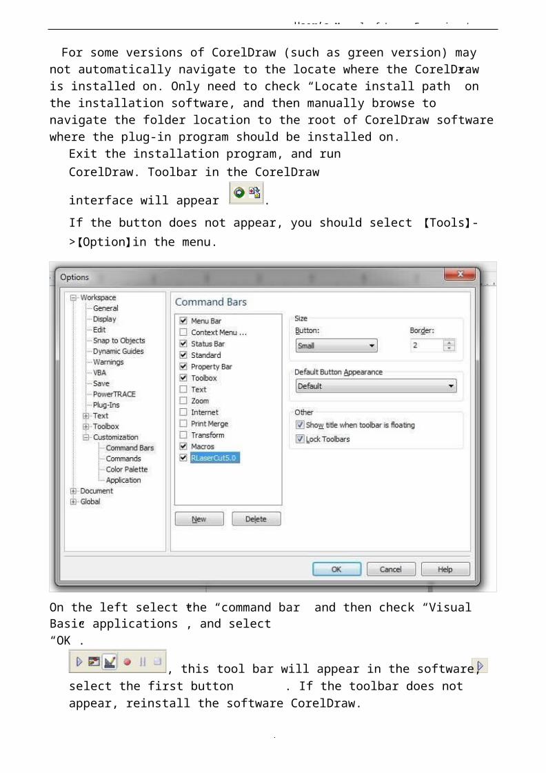
For some versions of CorelDraw (such as green version) may not automatically navigate to the locate where the CorelDraw is installed on. Only need to check “Locate install path” on the installation software, and then manually browse to navigate the folder location to the root of CorelDraw softwarewhere the plug-in program should be installed on.
Exit the installation program, and runCorelDraw. Toolbar in the CorelDraw
interface will appear .If the button does not appear, you should select 【Tools】->【Option】in the menu.
On the left select the “command bar” and then check “Visual Basic applications”, and select“OK”.
, this tool bar will appear in the software, select the first button . If the toolbar does not appear, reinstall the software CorelDraw.
User’s Manual of Laser Engraving /
6
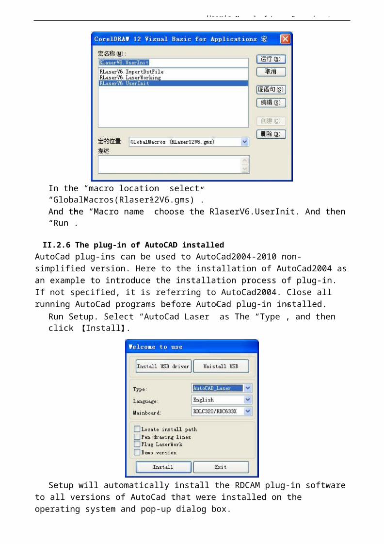
In the “macro location” select “GlobalMacros(Rlaser12V6.gms)”.And the “Macro name” choose the RlaserV6.UserInit. And then “Run”.
II.2.6 The plug-in of AutoCAD installedAutoCad plug-ins can be used to AutoCad2004-2010 non-simplified version. Here to the installation of AutoCad2004 asan example to introduce the installation process of plug-in. If not specified, it is referring to AutoCad2004. Close all running AutoCad programs before AutoCad plug-in installed.
Run Setup. Select “AutoCad Laser” as The “Type”, and then click 【Install】.
Setup will automatically install the RDCAM plug-in softwareto all versions of AutoCad that were installed on the operating system and pop-up dialog box.

User’s Manual of Laser Engraving /
6
User’s Manual of Laser Engraving /
6
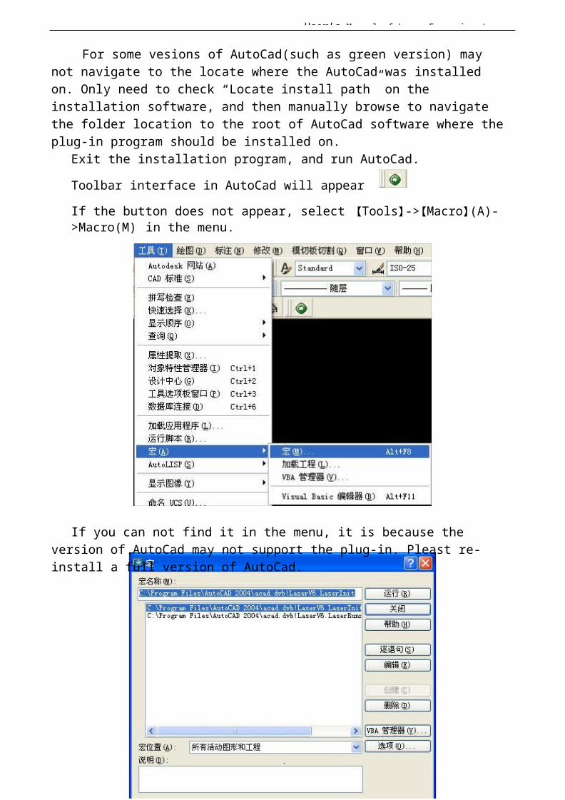
For some vesions of AutoCad(such as green version) may not navigate to the locate where the AutoCad was installed on. Only need to check “Locate install path” on the installation software, and then manually browse to navigate the folder location to the root of AutoCad software where theplug-in program should be installed on.
Exit the installation program, and run AutoCad.
Toolbar interface in AutoCad will appear
If the button does not appear, select 【Tools】->【Macro】(A)->Macro(M) in the menu.
If you can not find it in the menu, it is because the version of AutoCad may not support the plug-in. Pleast re-install a full version of AutoCad.
User’s Manual of Laser Engraving /
6
In the pop-up dialog box, select LaserInit, and run.The plug-in toolbar can occur if you select this option,
but when you close AutoCad and then open the AutoCad softwareagain. But also do not see the toolbar. Then it is possible that your computer is infected with a virus. You must manually to define the boot loader works of AutoCad, or you can re-check for viruses or reinstall the operating system and AutoCad software.
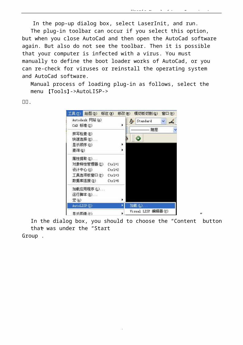
Manual process of loading plug-in as follows, select the menu 【Tools】->AutoLISP->
加加.
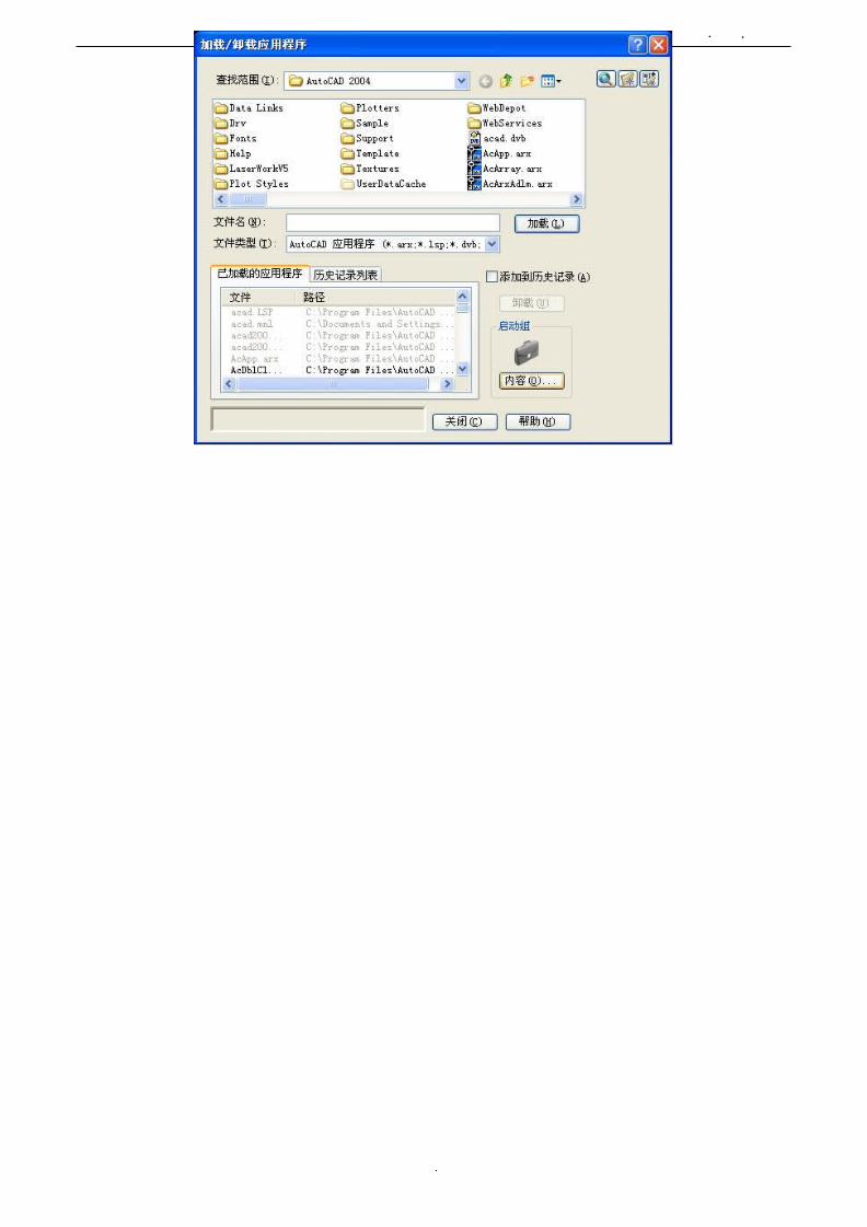
In the dialog box, you should to choose the “Content” buttonthat was under the “Start
Group”.
User’s Manual of Laser Engraving /
6
User’s Manual of Laser Engraving /
6
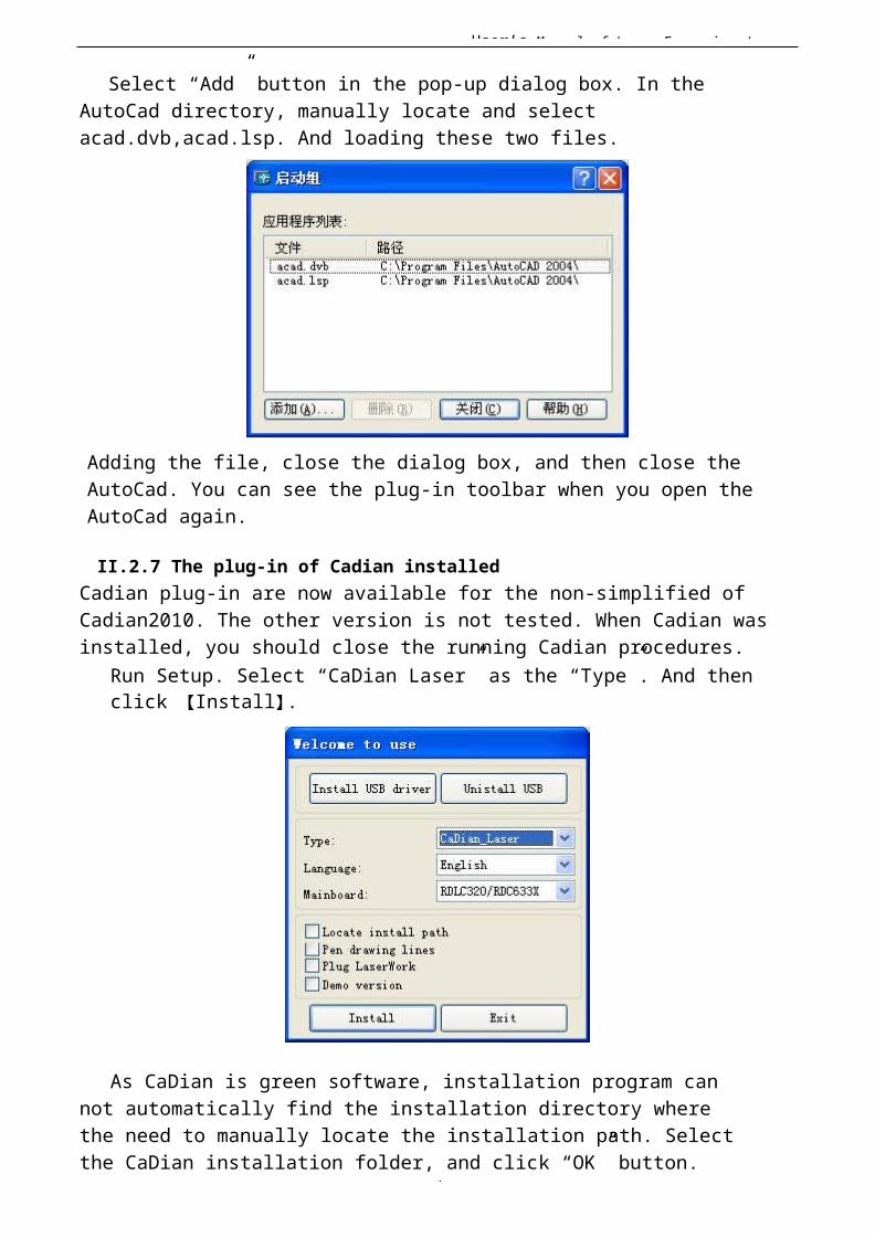
Select “Add” button in the pop-up dialog box. In the AutoCad directory, manually locate and select acad.dvb,acad.lsp. And loading these two files.
Adding the file, close the dialog box, and then close the AutoCad. You can see the plug-in toolbar when you open the AutoCad again.
II.2.7 The plug-in of Cadian installedCadian plug-in are now available for the non-simplified of Cadian2010. The other version is not tested. When Cadian was installed, you should close the running Cadian procedures.
Run Setup. Select “CaDian Laser” as the “Type”. And then click 【Install】.
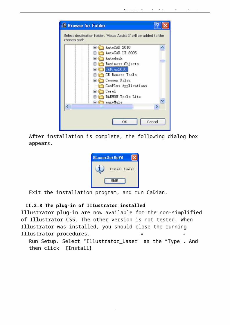
As CaDian is green software, installation program can not automatically find the installation directory where the need to manually locate the installation path. Select the CaDian installation folder, and click “OK” button.
User’s Manual of Laser Engraving /
7
After installation is complete, the following dialog box appears.
Exit the installation program, and run CaDian.
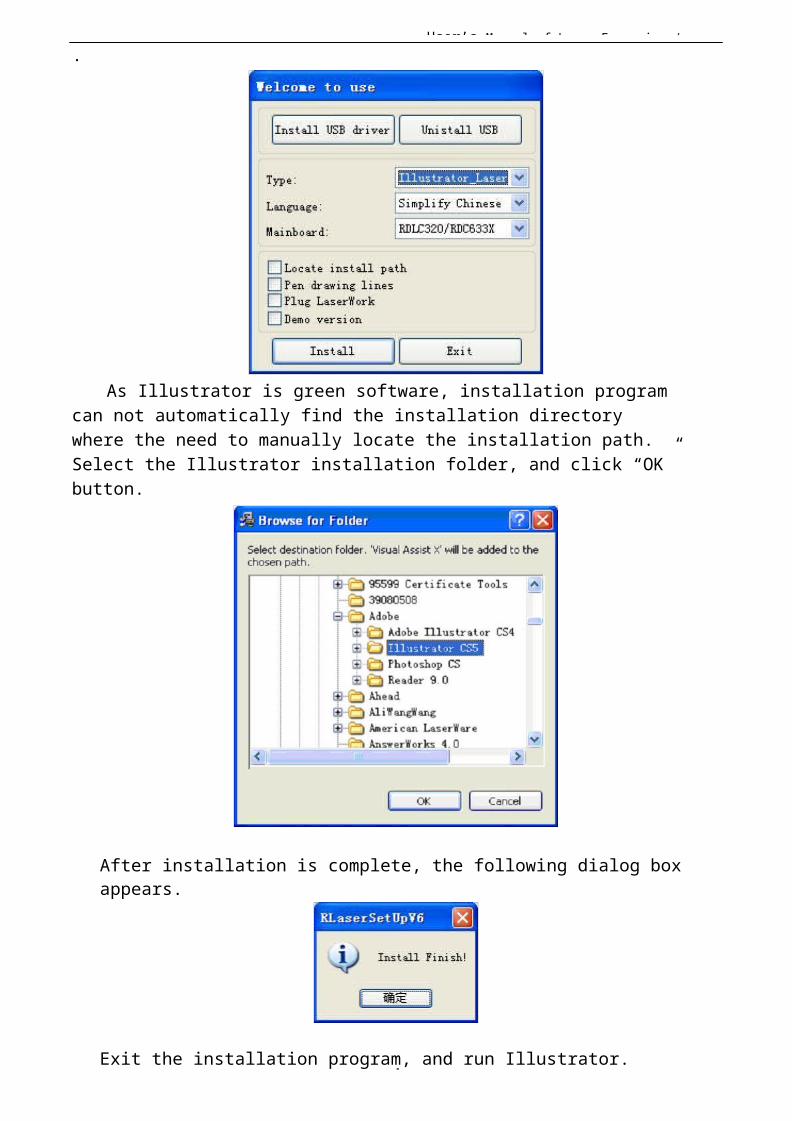
II.2.8 The plug-in of IIIustrator installedIllustrator plug-in are now available for the non-simplified of Illustrator CS5. The other version is not tested. When Illustrator was installed, you should close the running Illustrator procedures.
Run Setup. Select “Illustrator_Laser” as the “Type”. And then click 【Install】
User’s Manual of Laser Engraving /
7
.
As Illustrator is green software, installation program can not automatically find the installation directory where the need to manually locate the installation path. Select the Illustrator installation folder, and click “OK”button.
After installation is complete, the following dialog box appears.
Exit the installation program, and run Illustrator.
User’s Manual of Laser Engraving /
7
II Chapter 3 Introduction ofCorelDraw_Laser
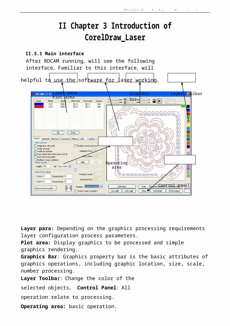
II.3.1 Main interfaceAfter RDCAM running,will see the following interface。Familiar to this interface,will
helpful to use the software for laser working。
Layer para Plot area
Graphicsbar
Layer toolbar
Operatingarea
Control panel
Layer para: Depending on the graphics processing requirements layer configuration process parameters.Plot area: Display graphics to be processed and simple graphics rendering.Graphics Bar: Graphics property bar is the basic attributes ofgraphics operations, including graphic location, size, scale, number processing.Layer Toolbar:Change the color of the selected objects 。 Control Panel:All operation relate to processing. Operating area: basic operation.

User’s Manual of Laser Engraving /
7
II.3.2 Language settings and machine information
In addition to installation process can set the softwarelanguage type, you can easily switch in different language.
User’s Manual of Laser Engraving /
7
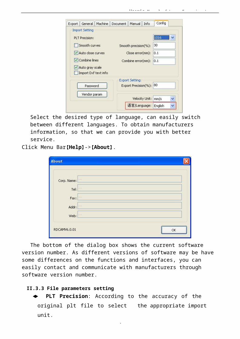
Select the desired type of language, can easily switch between different languages. To obtain manufacturers information, so that we can provide you with better service.
Click Menu Bar【Help】->【About】.
The bottom of the dialog box shows the current software version number. As different versions of software may be havesome differences on the functions and interfaces, you can easily contact and communicate with manufacturers through software version number.
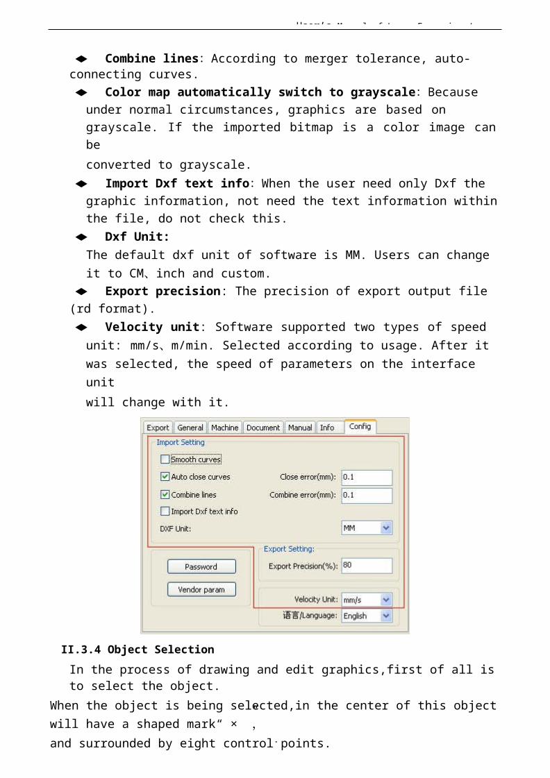
II.3.3 File parameters setting◆ PLT Precision: According to the accuracy of the
original plt file to select the appropriate import unit.
User’s Manual of Laser Engraving /
7
◆ Smooth curves: When import vector file,automatically smoothing the original
curves. For the original graphic is smooth or need torepeatedly adjust the beset smoothing effect, you canuncheck this button. Do not do smoothing curves mayreduce time of import processing.
◆ Auto close curves:According to close tolerance automatic check and closed curve
User’s Manual of Laser Engraving /
7
◆ Combine lines:According to merger tolerance, auto-connecting curves.◆ Color map automatically switch to grayscale:Because
under normal circumstances, graphics are based on grayscale. If the imported bitmap is a color image can beconverted to grayscale.
◆ Import Dxf text info:When the user need only Dxf the graphic information, not need the text information withinthe file, do not check this.
◆ Dxf Unit:The default dxf unit of software is MM. Users can change it to CM、inch and custom.
◆ Export precision: The precision of export output file (rd format).◆ Velocity unit: Software supported two types of speed
unit: mm/s、m/min. Selected according to usage. After it was selected, the speed of parameters on the interface unitwill change with it.
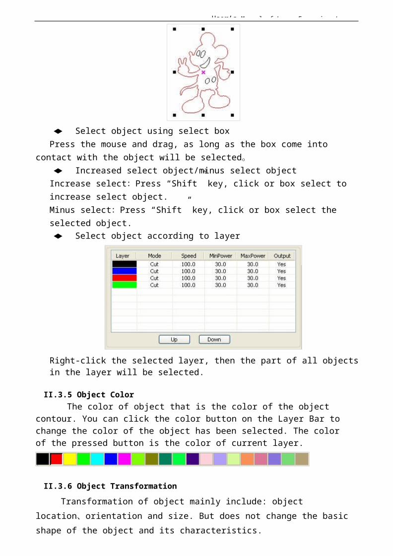
II.3.4 Object SelectionIn the process of drawing and edit graphics,first of all is to select the object.
When the object is being selected,in the center of this object will have a shaped mark“ × ”,and surrounded by eight control points.

User’s Manual of Laser Engraving /
7
Click menu【Select】, switch to status“Select”。Under this status, you can select object. The following are five kinds of method of selecting◆ Shortcuts Ctrl+A, select all objects。◆ Click mouse on the screen to select single object
User’s Manual of Laser Engraving /
7
◆ Select object using select boxPress the mouse and drag, as long as the box come into
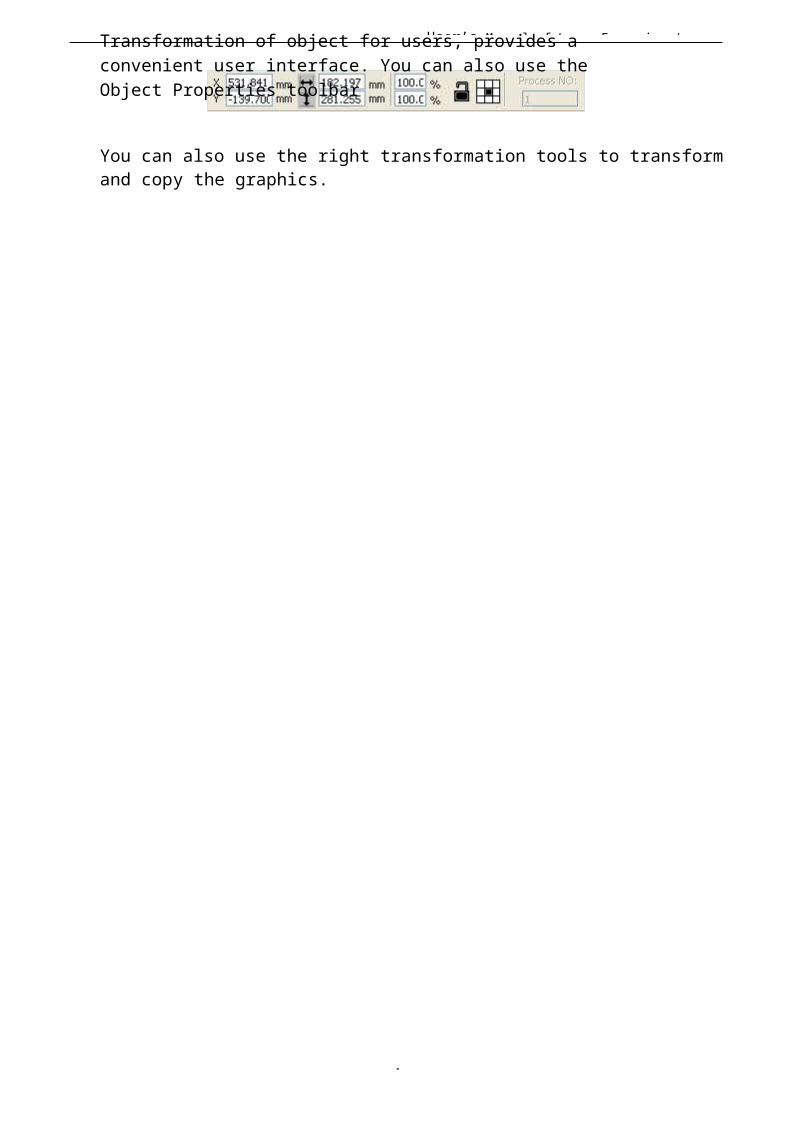
contact with the object will be selected。◆ Increased select object/minus select objectIncrease select:Press “Shift” key, click or box select to increase select object.Minus select:Press “Shift” key, click or box select the selected object.◆ Select object according to layer
Right-click the selected layer, then the part of all objectsin the layer will be selected.
II.3.5 Object ColorThe color of object that is the color of the object
contour. You can click the color button on the Layer Bar to change the color of the object has been selected. The color of the pressed button is the color of current layer.
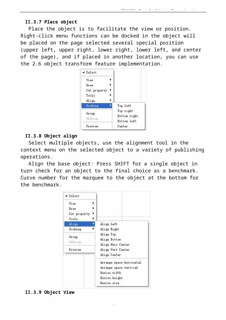
II.3.6 Object TransformationTransformation of object mainly include: object
location、orientation and size. But does not change the basicshape of the object and its characteristics.
User’s Manual of Laser Engraving /
7
Transformation of object for users, provides a convenient user interface. You can also use the Object Properties toolbar
You can also use the right transformation tools to transformand copy the graphics.
User’s Manual of Laser Engraving /
8
II.3.7 Place objectPlace the object is to facilitate the view or position.
Right-click menu functions can be docked in the object will be placed on the page selected several special position (upper left, upper right, lower right, lower left, and centerof the page), and if placed in another location, you can use the 2.6 object transform feature implementation.
II.3.8 Object alignSelect multiple objects, use the alignment tool in the
context menu on the selected object to a variety of publishingoperations.
Align the base object: Press SHIFT for a single object in turn check for an object to the final choice as a benchmark. Curve number for the marquee to the object at the bottom forthe benchmark.
II.3.9 Object View

User’s Manual of Laser Engraving /
8
The view of the object can be used in the viewer right-click menu.◆ Translation: Click 【View】/【Move】, Then hold down the
left mouse button in the drawing area, drag the pan.◆ Marquee view: Click 【View】/【View select】 .Mouse to the drawing area, hold
down the left mouse button and drag in the drawing area displays a marquee in the dashed
User’s Manual of Laser Engraving /
8
box, release the mouse, were framed in the region will be the largest share in the drawingarea to display.◆ View page: Click【View】【/◆ View data: Click【View】【/
II.3.10 Group and unGroup
View Page Frame】. You can view the full page display. View Data Frame】. You can view the full selected object.
Edit graphics, and sometimes need to be a part of the operation as a whole (such as multi-line text layout).
Method: Select the group of graphics, and then select the menu 【Edit】 / 【Group】
(【UnGroup】).
II.3.11 Basic graphics creation◆ LineClick menu【Line】,drag the mouse on the screen you can draw an arbitrary line。Press the“Ctrl” key while dragging the mouse to draw horizontal or vertical line.◆ PolylineClick menu【Polyline】。Drag the mouse on the screen you can draw an arbitrary polyline.◆ Rectangle
Click menu【Rectangle】。Drag the mouse on thescreen you can draw an arbitrary size rectangle.Press the “Ctrl” key while dragging the mouse to draw square.◆ EllipseClick menu【Ellipse】。Drag the mouse on the screen you can draw an arbitrary size ellipse. Press the “Ctrl” key while dragging the mouse to draw round.◆ PointClick menu【Ellipse】. Click the mouse on the screen, you can draw a point.
II.3.12 Important ToolHere are some frequently used tools. Using these
important tools, can make the current document in the
User’s Manual of Laser Engraving /
8
graphics more orderly, and make the processing of
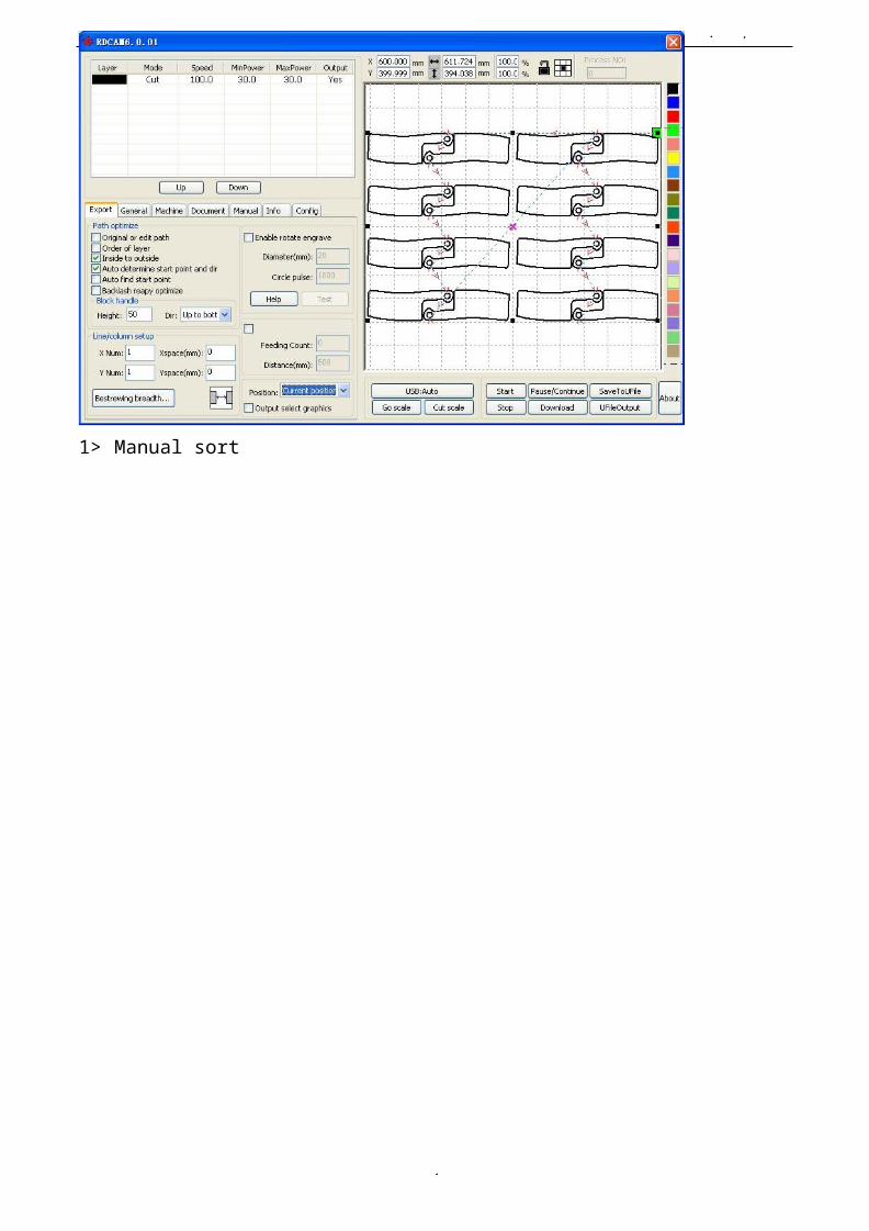
output more fast.II.3.12.1 Manual sorting and the set of cutting point and the cutting direction
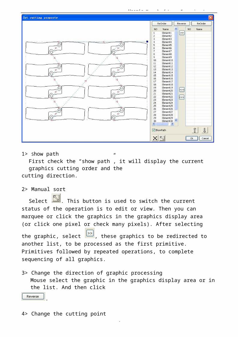
Software provides users a convenient tool for the manualsorting. Select 【 Edit 】 -> 【 Set cutting property 】 . Cuttingproperty dialog box will pop up. All with manual sorting, andcut points, cutting the direction of the settings in thisdialog box can be completed.
User’s Manual of Laser Engraving /
8
1> Show pathFirst check the “show path”, it will display the current graphics cutting order and the
cutting direction.
2> Manual sort
Select . This button is used to switch the current status of the operation is to edit or view. Then you can marquee or click the graphics in the graphics display area (or click one pixel or check many pixels). After selecting
the graphic, select , these graphics to be redirected to another list, to be processed as the first primitive. Primitives followed by repeated operations, to complete sequencing of all graphics.
3> Change the direction of graphic processingMouse select the graphic in the graphics display area or inthe list. And then click
.
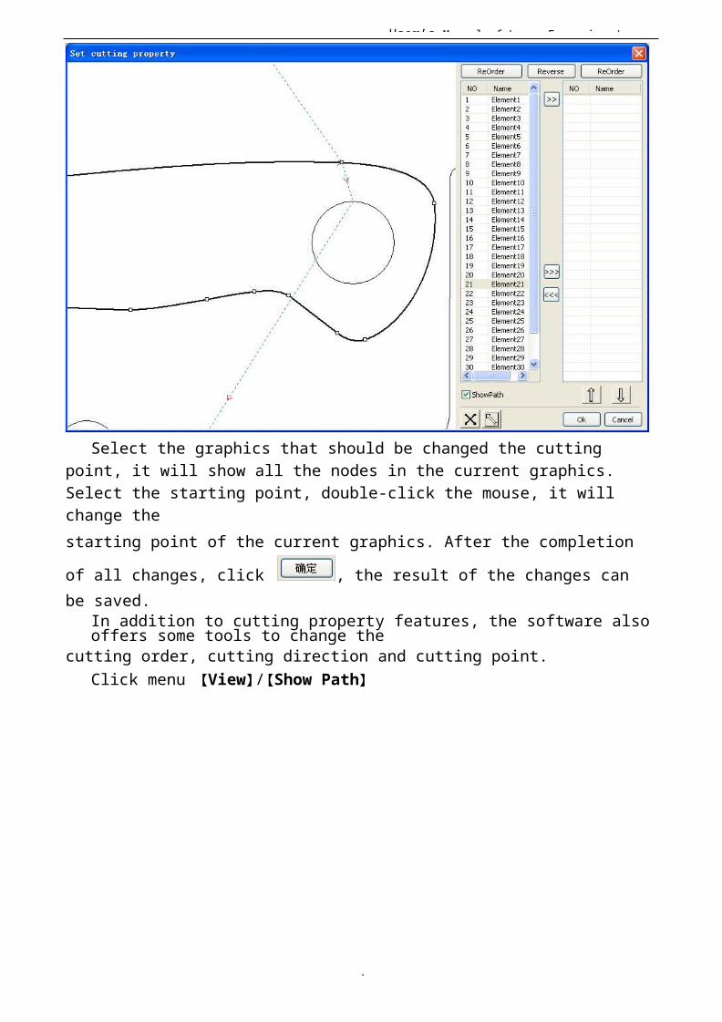
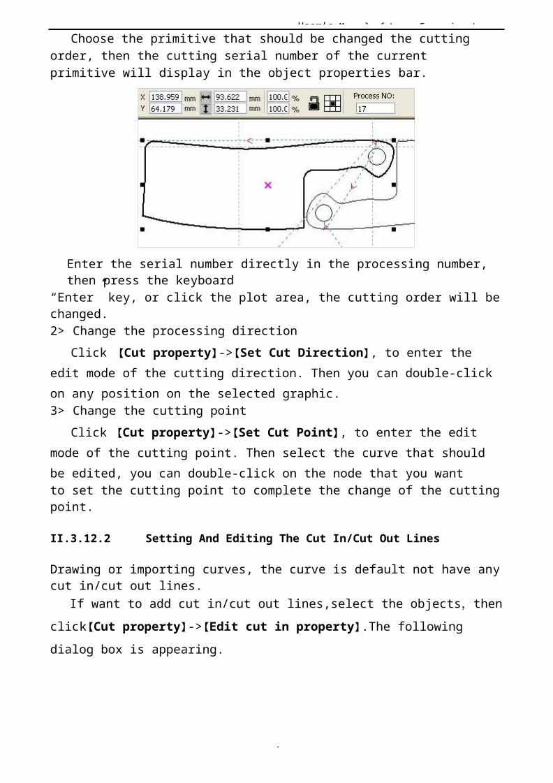
4> Change the cutting point
User’s Manual of Laser Engraving /
8
Select the graphics that should be changed the cutting point, it will show all the nodes in the current graphics. Select the starting point, double-click the mouse, it will change thestarting point of the current graphics. After the completion
of all changes, click , the result of the changes can be saved.
In addition to cutting property features, the software also offers some tools to change the
cutting order, cutting direction and cutting point.Click menu 【View】/【Show Path】
User’s Manual of Laser Engraving /
8
1> Manual sort
User’s Manual of Laser Engraving /
8
Choose the primitive that should be changed the cutting order, then the cutting serial number of the current primitive will display in the object properties bar.
Enter the serial number directly in the processing number, then press the keyboard
“Enter” key, or click the plot area, the cutting order will be changed.2> Change the processing direction
Click 【Cut property】->【Set Cut Direction】, to enter the edit mode of the cutting direction. Then you can double-click on any position on the selected graphic.3> Change the cutting point
Click 【Cut property】->【Set Cut Point】, to enter the edit mode of the cutting point. Then select the curve that should be edited, you can double-click on the node that you wantto set the cutting point to complete the change of the cutting point.
II.3.12.2 Setting And Editing The Cut In/Cut Out Lines
Drawing or importing curves, the curve is default not have any cut in/cut out lines.
If want to add cut in/cut out lines,select the objects,thenclick【Cut property】->【Edit cut in property】.The following dialog box is appearing.
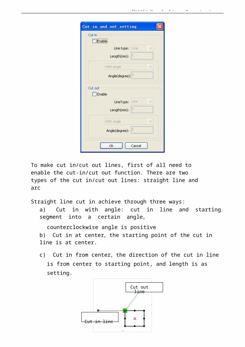
User’s Manual of Laser Engraving /
8
To make cut in/cut out lines, first of all need to enable the cut-in/cut out function. There are two types of the cut in/cut out lines: straight line and arc
Straight line cut in achieve through three ways:a) Cut in with angle: cut in line and starting segment into a certain angle,
counterclockwise angle is positiveb) Cut in at center,the starting point of the cut in line is at center.
c) Cut in from center,the direction of the cut in line is from center to starting point, and length is as setting.
Cut outline
Cut in line
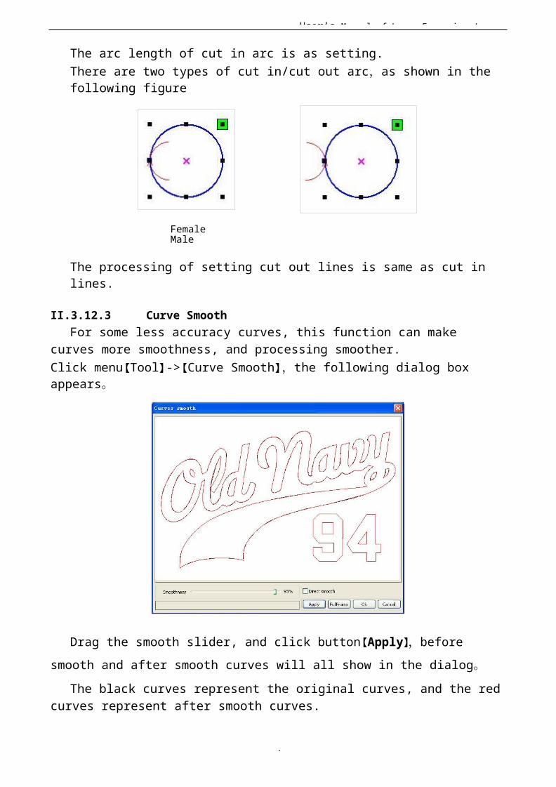
User’s Manual of Laser Engraving /
8
The arc length of cut in arc is as setting.There are two types of cut in/cut out arc,as shown in the following figure
Female Male
The processing of setting cut out lines is same as cut in lines.
II.3.12.3 Curve SmoothFor some less accuracy curves, this function can make
curves more smoothness, and processing smoother.Click menu【Tool】->【Curve Smooth】,the following dialog box appears。
Drag the smooth slider, and click button【Apply】,before smooth and after smooth curves will all show in the dialog。
The black curves represent the original curves, and the redcurves represent after smooth curves.
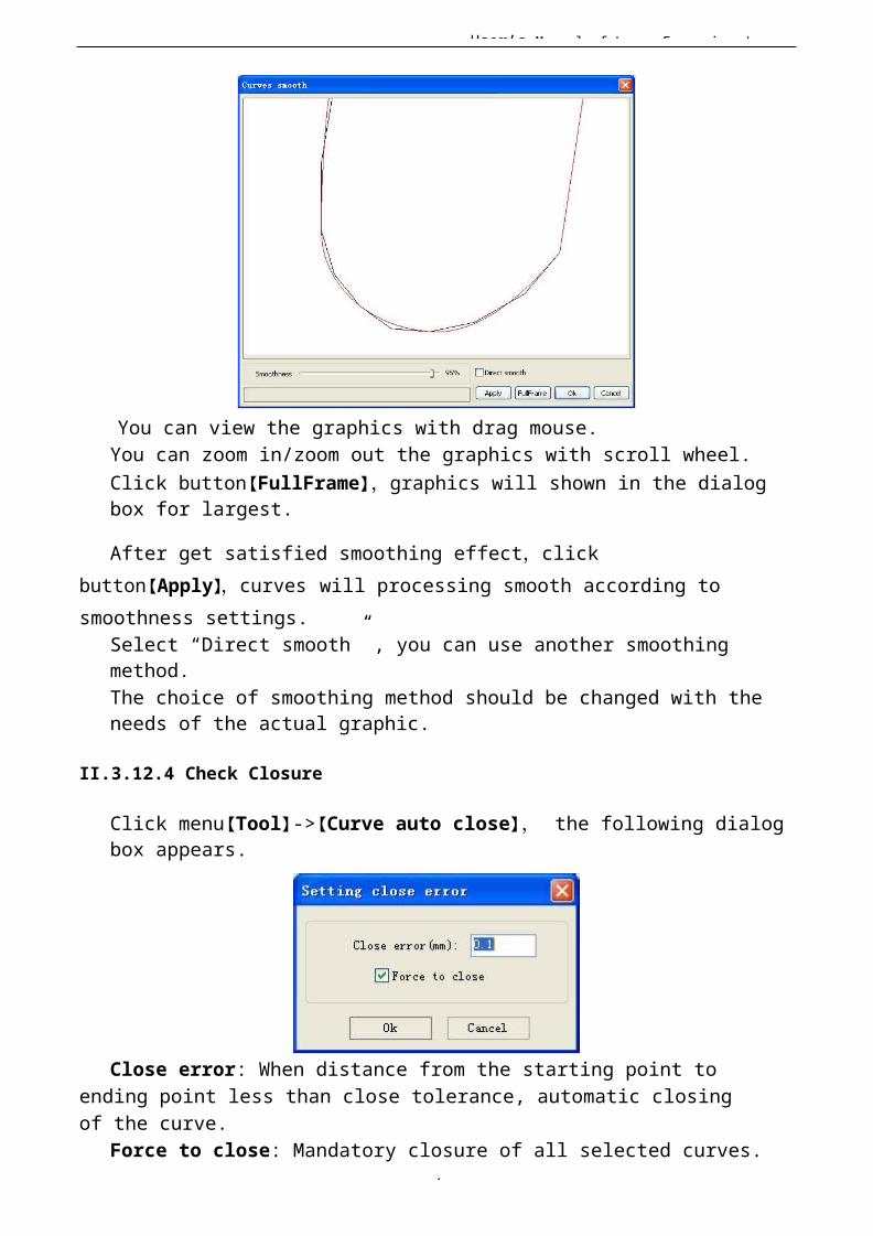
User’s Manual of Laser Engraving /
9
You can view the graphics with drag mouse.You can zoom in/zoom out the graphics with scroll wheel.Click button【FullFrame】,graphics will shown in the dialog box for largest.
After get satisfied smoothing effect,click button【Apply】,curves will processing smooth according to smoothness settings.
Select “Direct smooth” , you can use another smoothing method.The choice of smoothing method should be changed with the needs of the actual graphic.
II.3.12.4 Check Closure
Click menu【Tool】->【Curve auto close】, the following dialog box appears.
Close error: When distance from the starting point to ending point less than close tolerance, automatic closingof the curve.
Force to close: Mandatory closure of all selected curves.

User’s Manual of Laser Engraving /
9
II.3.12.5 Remove The Overlap
Click menu【Tool】->【Delete overlap】,the dialog box appear.
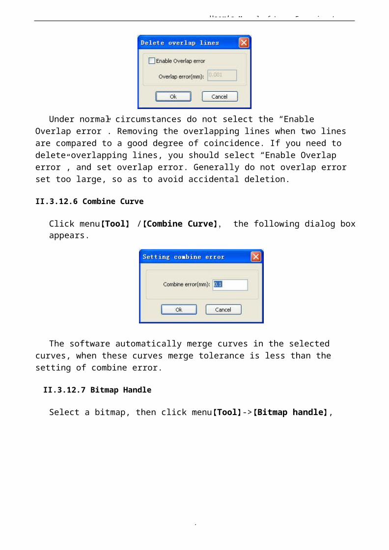
User’s Manual of Laser Engraving /
9
Under normal circumstances do not select the “Enable Overlap error”. Removing the overlapping lines when two linesare compared to a good degree of coincidence. If you need to delete overlapping lines, you should select “Enable Overlap error”, and set overlap error. Generally do not overlap errorset too large, so as to avoid accidental deletion.
II.3.12.6 Combine Curve
Click menu【Tool】 /【Combine Curve】, the following dialog boxappears.
The software automatically merge curves in the selectedcurves, when these curves merge tolerance is less than thesetting of combine error.
II.3.12.7 Bitmap Handle
Select a bitmap, then click menu【Tool】->【Bitmap handle】,
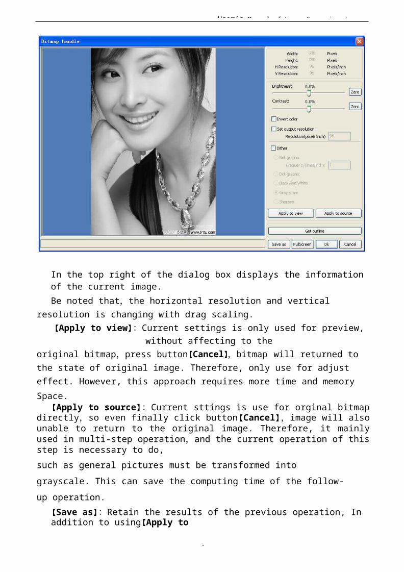
User’s Manual of Laser Engraving /
9
In the top right of the dialog box displays the information of the current image.Be noted that,the horizontal resolution and vertical
resolution is changing with drag scaling.【Apply to view】:Current settings is only used for preview,
without affecting to theoriginal bitmap,press button【Cancel】,bitmap will returned to the state of original image. Therefore, only use for adjust effect. However, this approach requires more time and memorySpace.
【Apply to source】:Current sttings is use for orginal bitmapdirectly,so even finally click button【Cancel】,image will alsounable to return to the original image. Therefore, it mainlyused in multi-step operation,and the current operation of thisstep is necessary to do,such as general pictures must be transformed into grayscale. This can save the computing time of the follow-up operation.
【Save as】:Retain the results of the previous operation, In addition to using【Apply to
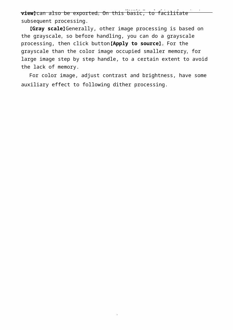
User’s Manual of Laser Engraving /
9
view】can also be exported。On this basic, to facilitate subsequent processing.
【Gray scale】Generally, other image processing is based on the grayscale,so before handling, you can do a grayscale processing, then click button【Apply to source】。For thegrayscale than the color image occupied smaller memory,for large image step by step handle, to a certain extent to avoid the lack of memory.
For color image, adjust contrast and brightness, have someauxiliary effect to following dither processing.
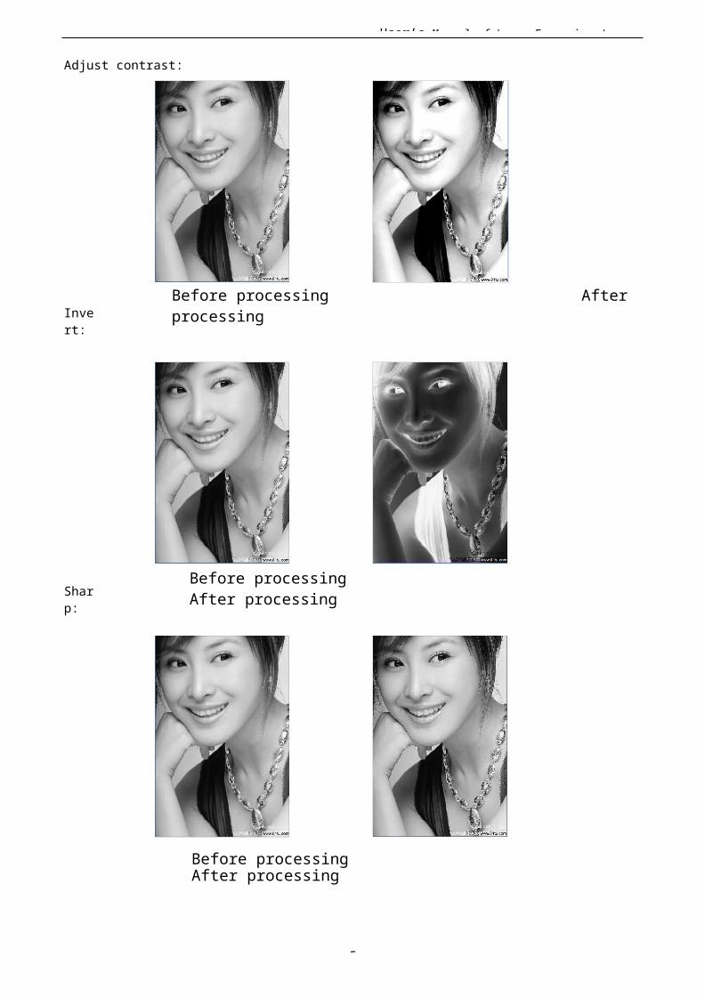
5
User’s Manual of Laser Engraving /
Adjust contrast:
Invert:
Sharp:
Before processing After processing
Before processing After processing
Before processing After processing

5
User’s Manual of Laser Engraving / There are three method for dither processing: Net graphic、Dot graphic、Black and white1> Net graphic
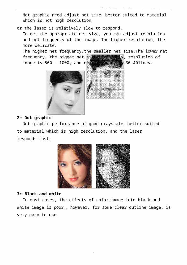
User’s Manual of Laser Engraving /
6
Net graphic need adjust net size,better suited to material which is not high resolution,
or the laser is relatively slow to respond.To get the appropriate net size, you can adjust resolution and net frequency of the image. The higher resolution, the more delicate.The higher net frequency,the smaller net size.The lower net frequency, the bigger net size. Generally, resolution of image is 500 - 1000, and net frequency is 30-40lines.
2> Dot graphicDot graphic performance of good grayscale,better suited
to material which is high resolution, and the laser responds fast.
3> Black and whiteIn most cases, the effects of color image into black and
white image is poor,,however, for some clear outline image, isvery easy to use.

User’s Manual of Laser Engraving /
6
Get outline:
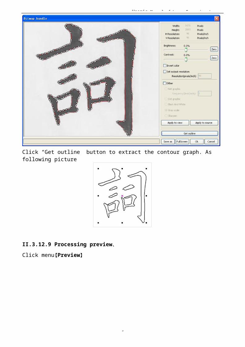
User’s Manual of Laser Engraving /
6
Click “Get outline” button to extract the contour graph. As following picture
II.3.12.9 Processing preview、Click menu【Preview】
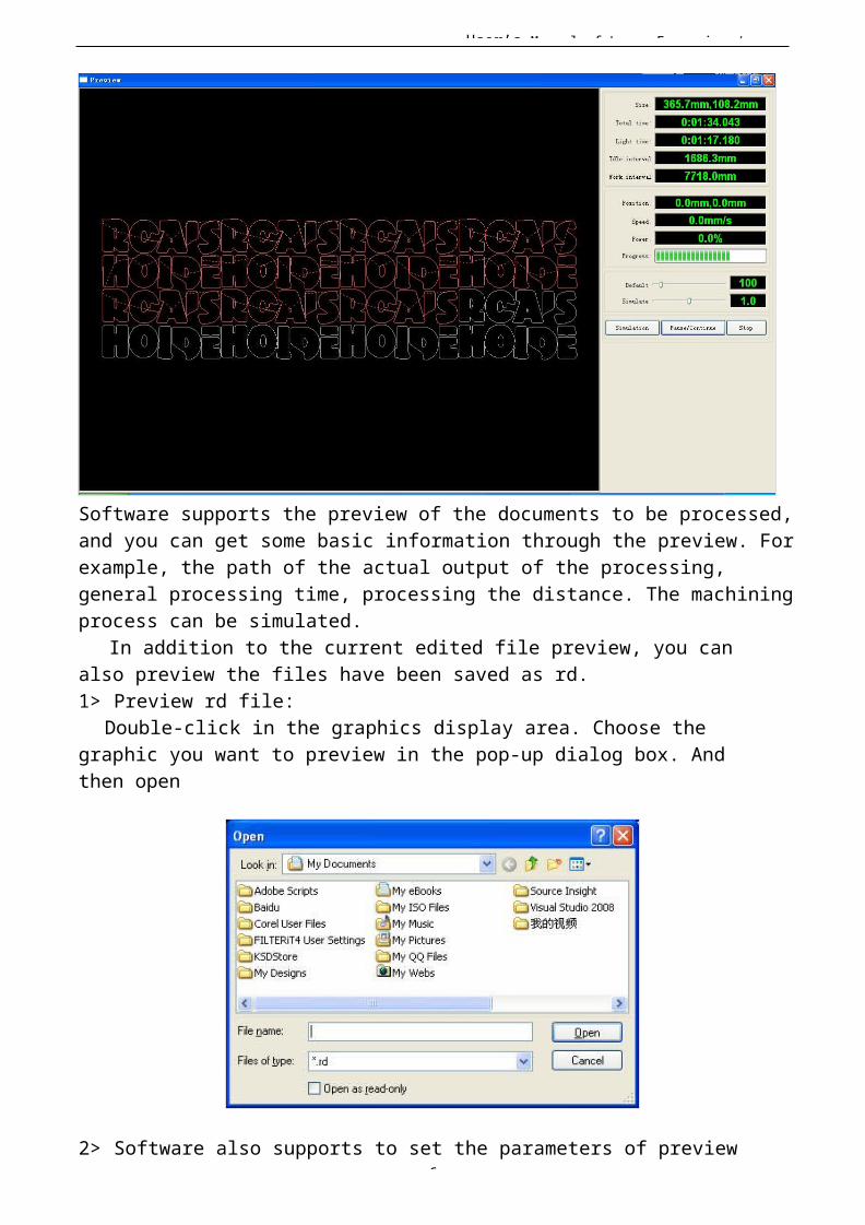
User’s Manual of Laser Engraving /
6
Software supports the preview of the documents to be processed,and you can get some basic information through the preview. Forexample, the path of the actual output of the processing, general processing time, processing the distance. The machiningprocess can be simulated.
In addition to the current edited file preview, you can also preview the files have been saved as rd.1> Preview rd file:
Double-click in the graphics display area. Choose the graphic you want to preview in the pop-up dialog box. And then open
2> Software also supports to set the parameters of preview

User’s Manual of Laser Engraving /
6
Right-click Anywhere in the graphics display area, the configuration menu will appears.Select “Config” , pop-up following dialog box
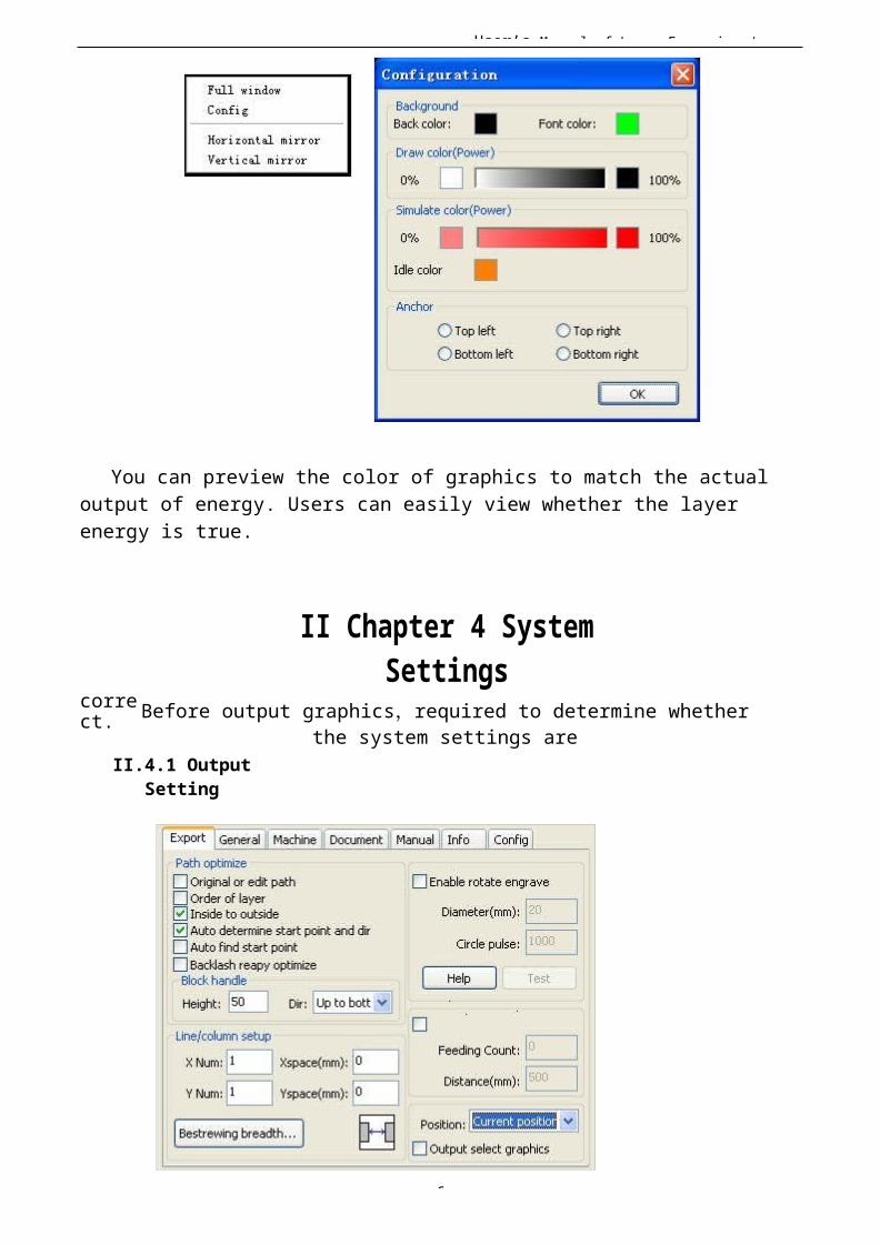
User’s Manual of Laser Engraving /
6
You can preview the color of graphics to match the actualoutput of energy. Users can easily view whether the layer energy is true.
correct.
II Chapter 4 SystemSettings
Before output graphics,required to determine whetherthe system settings are
II.4.1 OutputSetting

User’s Manual of Laser Engraving /
6
II.4.1.1 Pathoptimize
1> Original oredit path
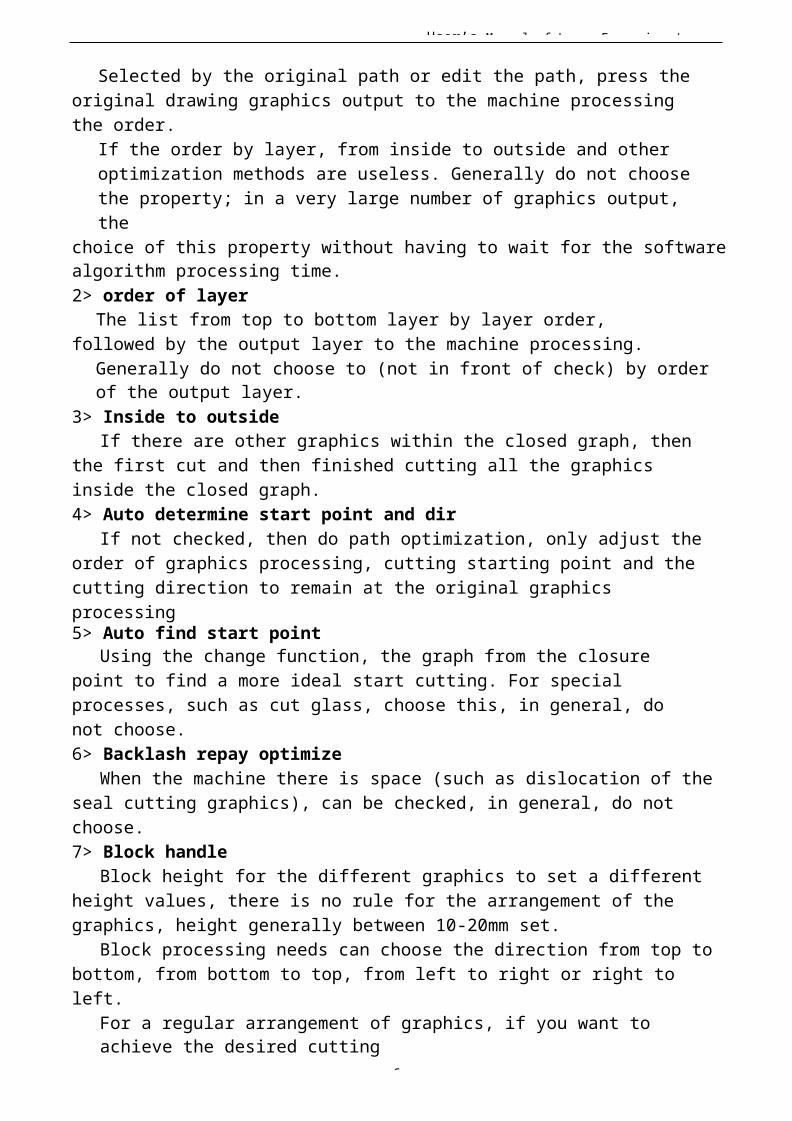
User’s Manual of Laser Engraving /
6
Selected by the original path or edit the path, press the original drawing graphics output to the machine processing the order.
If the order by layer, from inside to outside and other optimization methods are useless. Generally do not choose the property; in a very large number of graphics output, the
choice of this property without having to wait for the softwarealgorithm processing time.2> order of layer
The list from top to bottom layer by layer order, followed by the output layer to the machine processing.
Generally do not choose to (not in front of check) by order of the output layer.
3> Inside to outsideIf there are other graphics within the closed graph, then
the first cut and then finished cutting all the graphics inside the closed graph.4> Auto determine start point and dir
If not checked, then do path optimization, only adjust theorder of graphics processing, cutting starting point and thecutting direction to remain at the original graphics processing5> Auto find start point
Using the change function, the graph from the closure point to find a more ideal start cutting. For special processes, such as cut glass, choose this, in general, do not choose.6> Backlash repay optimize
When the machine there is space (such as dislocation of theseal cutting graphics), can be checked, in general, do not choose.7> Block handle
Block height for the different graphics to set a different height values, there is no rule for the arrangement of the graphics, height generally between 10-20mm set.
Block processing needs can choose the direction from top tobottom, from bottom to top, from left to right or right to left.
For a regular arrangement of graphics, if you want to achieve the desired cutting
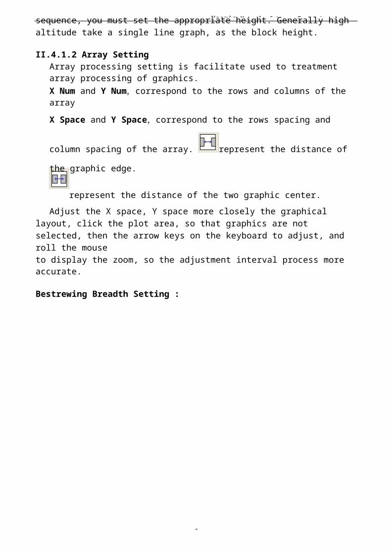
User’s Manual of Laser Engraving /
6
sequence, you must set the appropriate height. Generally high altitude take a single line graph, as the block height.
II.4.1.2 Array SettingArray processing setting is facilitate used to treatment array processing of graphics.X Num and Y Num,correspond to the rows and columns of the arrayX Space and Y Space,correspond to the rows spacing and
column spacing of the array. represent the distance of
the graphic edge.
represent the distance of the two graphic center.Adjust the X space, Y space more closely the graphical
layout, click the plot area, so that graphics are not selected, then the arrow keys on the keyboard to adjust, and roll the mouseto display the zoom, so the adjustment interval process more accurate.
Bestrewing Breadth Setting :
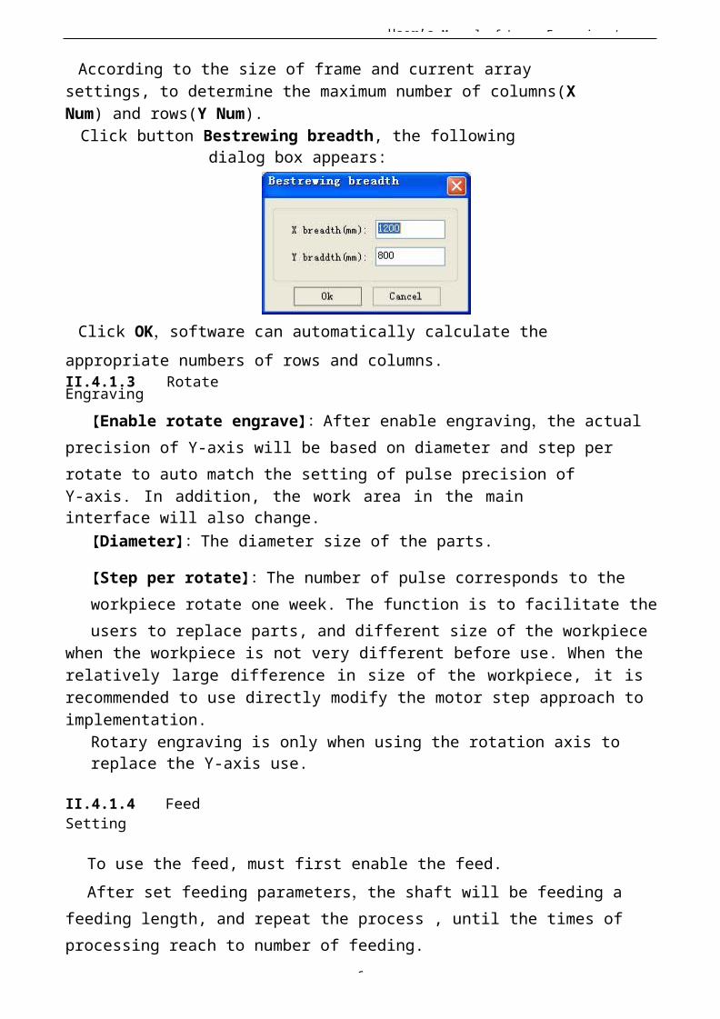
User’s Manual of Laser Engraving /
6
According to the size of frame and current array settings, to determine the maximum number of columns(X Num) and rows(Y Num).Click button Bestrewing breadth, the following
dialog box appears:
Click OK,software can automatically calculate the appropriate numbers of rows and columns.II.4.1.3 RotateEngraving
【Enable rotate engrave】:After enable engraving,the actual precision of Y-axis will be based on diameter and step per rotate to auto match the setting of pulse precision ofY-axis. In addition, the work area in the maininterface will also change.
【Diameter】:The diameter size of the parts.
【Step per rotate】:The number of pulse corresponds to the workpiece rotate one week. The function is to facilitate theusers to replace parts, and different size of the workpiece
when the workpiece is not very different before use. When therelatively large difference in size of the workpiece, it isrecommended to use directly modify the motor step approach toimplementation.
Rotary engraving is only when using the rotation axis to replace the Y-axis use.
II.4.1.4 FeedSetting
To use the feed, must first enable the feed.After set feeding parameters,the shaft will be feeding a
feeding length, and repeat the process , until the times of processing reach to number of feeding.
User’s Manual of Laser Engraving /
7
If the machine is not equipped with feeding devices, in general, enable the feed ban.
II.4.1.5Position
Setting the laser head back location after processing completed.(Current position、
Originalanchor、Machine Zero.
Current Position : Laser head back to theposition before processing.
Original anchor : Laser head back to the last anchor,the anchor may set at panel.Machine zero : Laser head back to the zero of the machine.
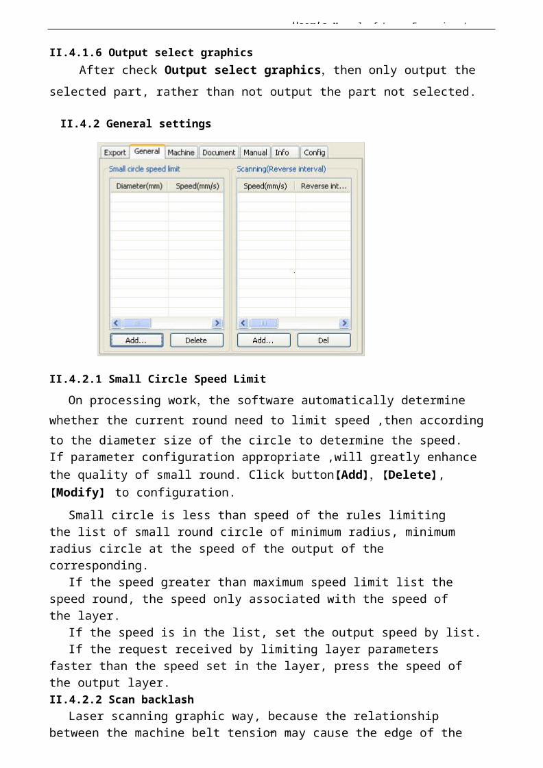
User’s Manual of Laser Engraving /
7
II.4.1.6 Output select graphicsAfter check Output select graphics,then only output the
selected part, rather than not output the part not selected.
II.4.2 General settings
II.4.2.1 Small Circle Speed LimitOn processing work,the software automatically determine
whether the current round need to limit speed ,then accordingto the diameter size of the circle to determine the speed.If parameter configuration appropriate ,will greatly enhance the quality of small round. Click button【Add】,【Delete】, 【Modify】 to configuration.
Small circle is less than speed of the rules limiting the list of small round circle of minimum radius, minimum radius circle at the speed of the output of the corresponding.
If the speed greater than maximum speed limit list the speed round, the speed only associated with the speed of the layer.
If the speed is in the list, set the output speed by list.If the request received by limiting layer parameters
faster than the speed set in the layer, press the speed of the output layer.II.4.2.2 Scan backlash
Laser scanning graphic way, because the relationship between the machine belt tension may cause the edge of the

User’s Manual of Laser Engraving /
7
scanned graphics uneven. Therefore, increasing backlash to fix. It has the specific backlash for the certain speed. General, the greater the speed, the greater the backlash.① Add backlash
Click the Add button, the screen will pop up as shown in Figure
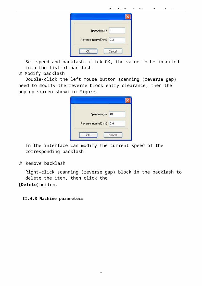
User’s Manual of Laser Engraving /
7
Set speed and backlash, click OK, the value to be inserted into the list of backlash.
② Modify backlashDouble-click the left mouse button scanning (reverse gap)
need to modify the reverse block entry clearance, then the pop-up screen shown in Figure.
In the interface can modify the current speed of the corresponding backlash.
③ Remove backlashRight-click scanning (reverse gap) block in the backlash to delete the item, then click the
【Delete】button.
II.4.3 Machine parameters
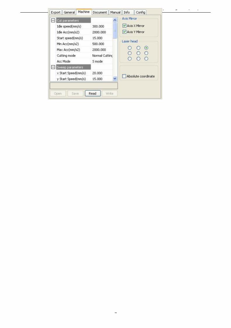
User’s Manual of Laser Engraving /
7
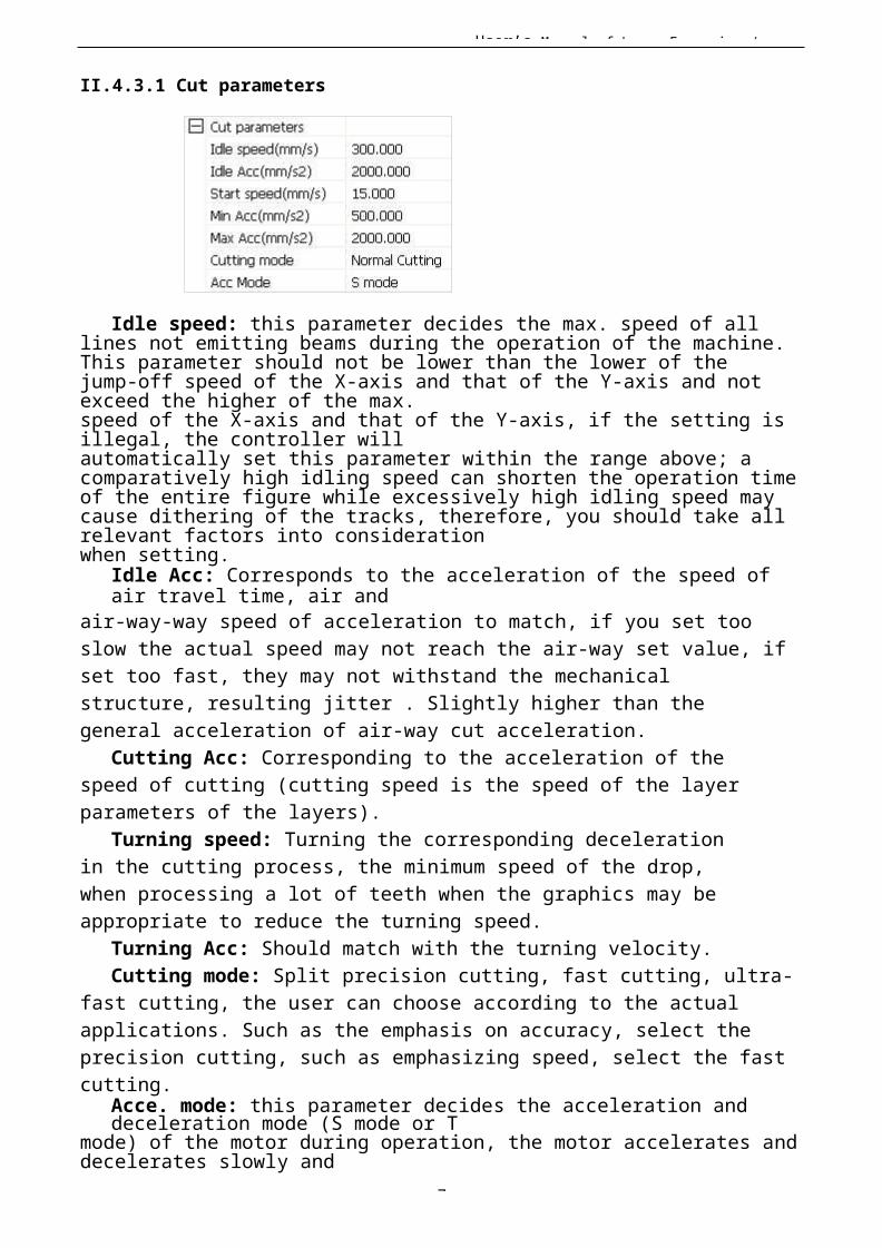
User’s Manual of Laser Engraving /
7
II.4.3.1 Cut parameters
Idle speed: this parameter decides the max. speed of all lines not emitting beams during the operation of the machine.This parameter should not be lower than the lower of thejump-off speed of the X-axis and that of the Y-axis and not exceed the higher of the max.speed of the X-axis and that of the Y-axis, if the setting is illegal, the controller willautomatically set this parameter within the range above; a comparatively high idling speed can shorten the operation timeof the entire figure while excessively high idling speed may cause dithering of the tracks, therefore, you should take all relevant factors into considerationwhen setting.
Idle Acc: Corresponds to the acceleration of the speed of air travel time, air and
air-way-way speed of acceleration to match, if you set too slow the actual speed may not reach the air-way set value, ifset too fast, they may not withstand the mechanical structure, resulting jitter . Slightly higher than the general acceleration of air-way cut acceleration.
Cutting Acc: Corresponding to the acceleration of the speed of cutting (cutting speed is the speed of the layer parameters of the layers).
Turning speed: Turning the corresponding deceleration in the cutting process, the minimum speed of the drop, when processing a lot of teeth when the graphics may be appropriate to reduce the turning speed.
Turning Acc: Should match with the turning velocity.Cutting mode: Split precision cutting, fast cutting, ultra-
fast cutting, the user can choose according to the actual applications. Such as the emphasis on accuracy, select the precision cutting, such as emphasizing speed, select the fast cutting.
Acce. mode: this parameter decides the acceleration and deceleration mode (S mode or T
mode) of the motor during operation, the motor accelerates and decelerates slowly and
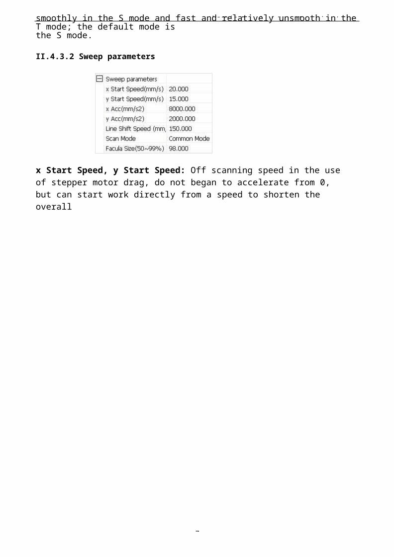
User’s Manual of Laser Engraving /
7
smoothly in the S mode and fast and relatively unsmooth in the T mode; the default mode isthe S mode.
II.4.3.2 Sweep parameters
x Start Speed, y Start Speed: Off scanning speed in the use of stepper motor drag, do not began to accelerate from 0, but can start work directly from a speed to shorten the overall
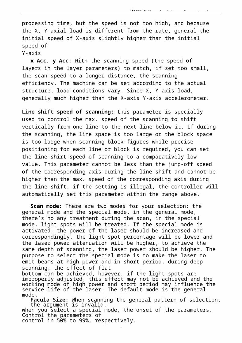
User’s Manual of Laser Engraving /
7
processing time, but the speed is not too high, and becausethe X, Y axial load is different from the rate, general theinitial speed of X-axis slightly higher than the initial speed ofY-axis
x Acc, y Acc: With the scanning speed (the speed of layers in the layer parameters) to match, if set too small, the scan speed to a longer distance, the scanning efficiency. The machine can be set according to the actual structure, load conditions vary. Since X, Y axis load, generally much higher than the X-axis Y-axis accelerometer.
Line shift speed of scanning: this parameter is specially used to control the max. speed of the scanning to shift vertically from one line to the next line below it. If duringthe scanning, the line space is too large or the block space is too large when scanning block figures while precise positioning for each line or block is required, you can set the line shirt speed of scanning to a comparatively low value. This parameter cannot be less than the jump-off speed of the corresponding axis during the line shift and cannot behigher than the max. speed of the corresponding axis during the line shift, if the setting is illegal, the controller willautomatically set this parameter within the range above.
Scan mode: There are two modes for your selection: the general mode and the special mode, in the general mode, there’s no any treatment during the scan, in the special mode, light spots will be treated. If the special mode is activated, the power of the laser should be increased and correspondingly, the light spot percentage will be lower and the laser power attenuation will be higher, to achieve the same depth of scanning, the laser power should be higher. Thepurpose to select the special mode is to make the laser to emit beams at high power and in short period, during deep scanning, the effect of flatbottom can be achieved, however, if the light spots are improperly adjusted, this effect may not be achieved and the working mode of high power and short period may influence theservice life of the laser. The default mode is the general mode.
Facula Size: When scanning the general pattern of selection,the argument is invalid,
when you select a special mode, the onset of the parameters. Control the parameters ofcontrol in 50% to 99%, respectively.
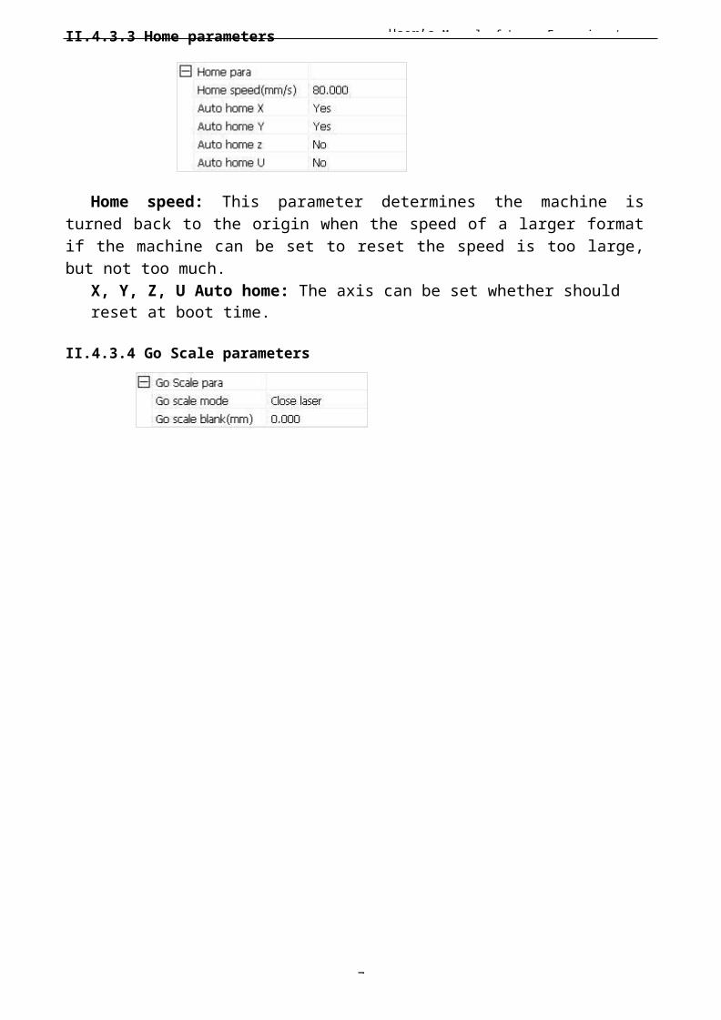
User’s Manual of Laser Engraving /
7
II.4.3.3 Home parameters
Home speed: This parameter determines the machine isturned back to the origin when the speed of a larger formatif the machine can be set to reset the speed is too large,but not too much.
X, Y, Z, U Auto home: The axis can be set whether should reset at boot time.
II.4.3.4 Go Scale parameters
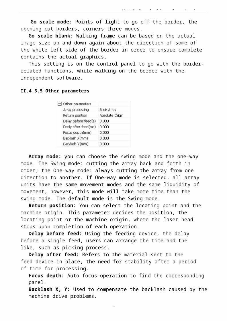
User’s Manual of Laser Engraving /
7
Go scale mode: Points of light to go off the border, theopening cut borders, corners three modes.
Go scale blank: Walking frame can be based on the actual image size up and down again about the direction of some of the white left side of the border in order to ensure complete contains the actual graphics.
This setting is on the control panel to go with the border-related functions, while walking on the border with the independent software.
II.4.3.5 Other parameters
Array mode: you can choose the swing mode and the one-way mode. The Swing mode: cutting the array back and forth in order; the One-way mode: always cutting the array from one direction to another. If One-way mode is selected, all array units have the same movement modes and the same liquidity of movement, however, this mode will take more time than the swing mode. The default mode is the Swing mode.
Return position: You can select the locating point and the machine origin. This parameter decides the position, the locating point or the machine origin, where the laser head stops upon completion of each operation.
Delay before feed: Using the feeding device, the delay before a single feed, users can arrange the time and the like, such as picking process.
Delay after feed: Refers to the material sent to the feed device in place, the need for stability after a periodof time for processing.
Focus depth: Auto focus operation to find the corresponding panel.Backlash X, Y: Used to compensate the backlash caused by themachine drive problems.
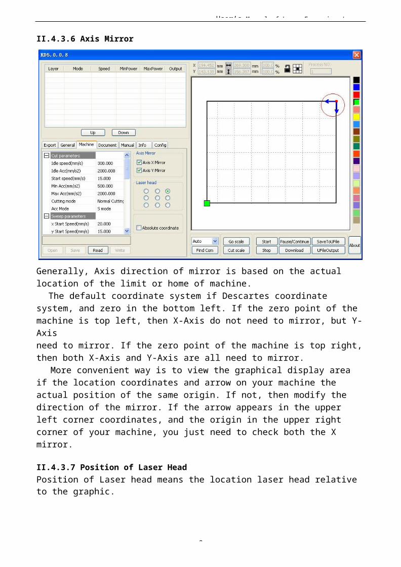
User’s Manual of Laser Engraving /
8
II.4.3.6 Axis Mirror
Generally, Axis direction of mirror is based on the actual location of the limit or home of machine.
The default coordinate system if Descartes coordinate system, and zero in the bottom left. If the zero point of the machine is top left, then X-Axis do not need to mirror, but Y-Axisneed to mirror. If the zero point of the machine is top right,then both X-Axis and Y-Axis are all need to mirror.
More convenient way is to view the graphical display area if the location coordinates and arrow on your machine the actual position of the same origin. If not, then modify thedirection of the mirror. If the arrow appears in the upper left corner coordinates, and the origin in the upper right corner of your machine, you just need to check both the X mirror.
II.4.3.7 Position of Laser HeadPosition of Laser head means the location laser head relative to the graphic.
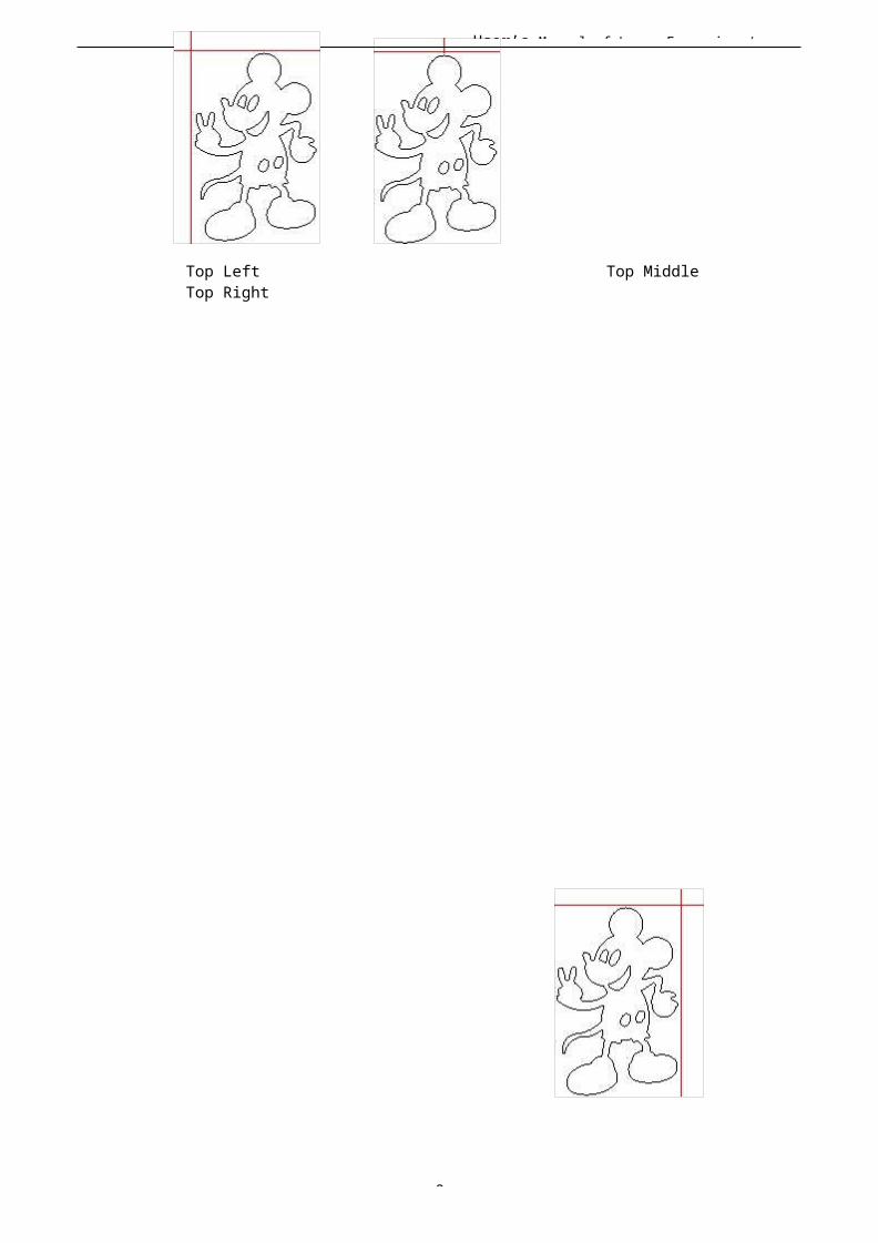
User’s Manual of Laser Engraving /
8
Top Left Top Middle Top Right
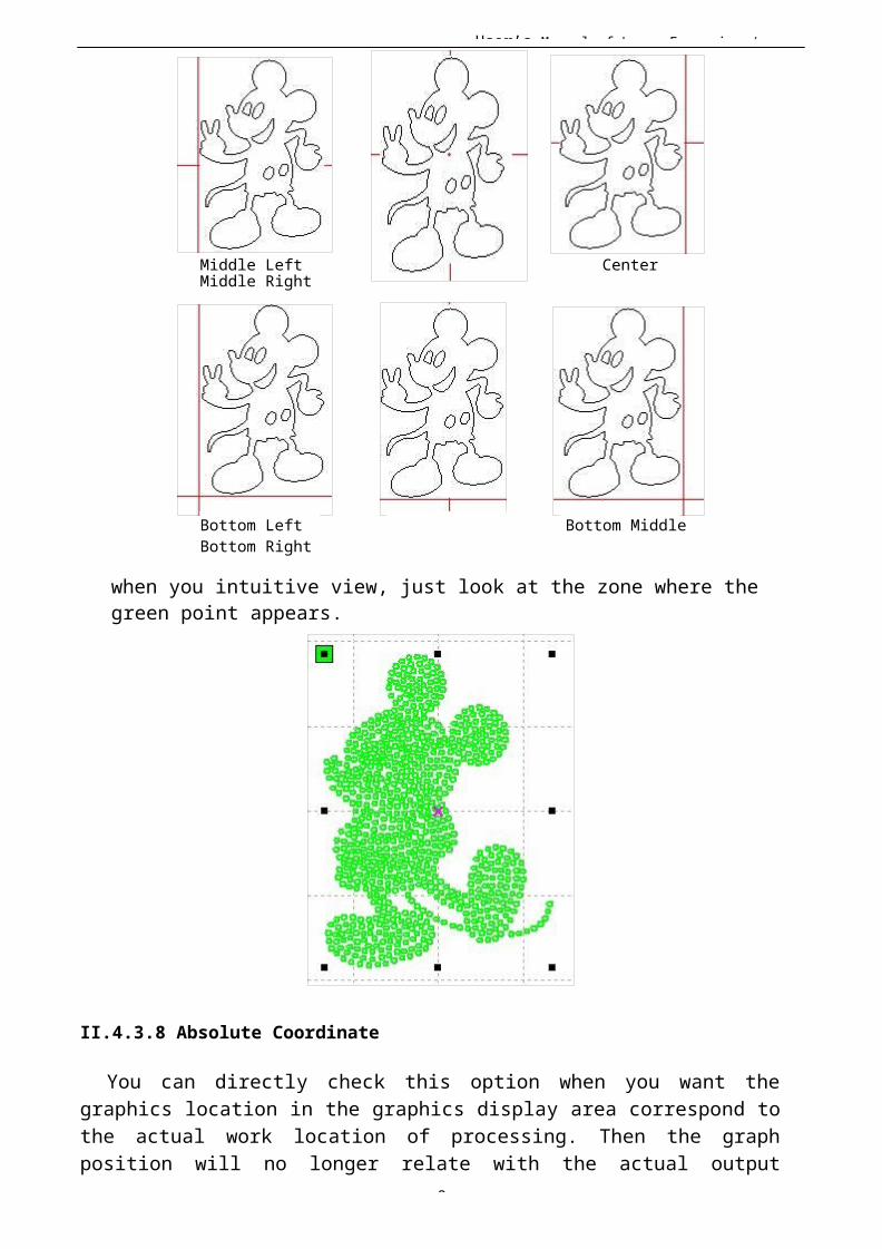
User’s Manual of Laser Engraving /
8
Middle Left Center Middle Right
Bottom Left Bottom Middle Bottom Right
when you intuitive view, just look at the zone where the green point appears.
II.4.3.8 Absolute Coordinate
You can directly check this option when you want thegraphics location in the graphics display area correspond tothe actual work location of processing. Then the graphposition will no longer relate with the actual output

User’s Manual of Laser Engraving /
8
position of the laser head and orientation point, but alwaysregard mechanical origin as the anchor point.
II.4.4 Document Management
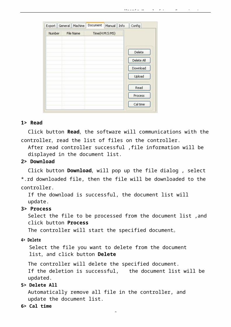
User’s Manual of Laser Engraving /
8
1> ReadClick button Read,the software will communications with the
controller,read the list of files on the controller.After read controller successful ,file information will be displayed in the document list.
2> DownloadClick button Download,will pop up the file dialog , select
*.rd downloaded file, then the file will be downloaded to the controller.
If the download is successful, the document list will update.
3> ProcessSelect the file to be processed from the document list ,and click button ProcessThe controller will start the specified document。
4> DeleteSelect the file you want to delete from the document list,and click button DeleteThe controller will delete the specified document.If the deletion is successful, the document list will be updated.
5> Delete AllAutomatically remove all file in the controller, and update the document list.
6> Cal time

User’s Manual of Laser Engraving /
8
Motherboard supports processing files towards hours worked.Select the file to calculate the work hours worked and click the button. Calculation to be completed, the control panel will be prompted to complete the calculation. And then point to read button shown in the list, calculated from the working hours.
In addition, when the document processing operation performed, the hours information will also be covered by theactual processing work.7> Upload
Upload the selected file which is on the motherboard to PC.
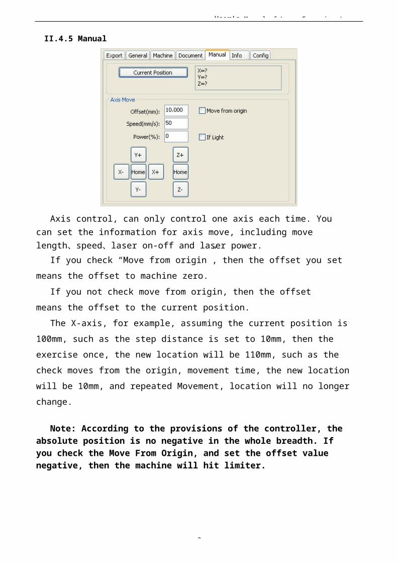
User’s Manual of Laser Engraving /
8
II.4.5 Manual
Axis control, can only control one axis each time. You can set the information for axis move, including move length、speed、laser on-off and laser power.
If you check “Move from origin”, then the offset you set means the offset to machine zero.
If you not check move from origin, then the offset means the offset to the current position.
The X-axis, for example, assuming the current position is 100mm, such as the step distance is set to 10mm, then the exercise once, the new location will be 110mm, such as the check moves from the origin, movement time, the new location will be 10mm, and repeated Movement, location will no longer change.
Note: According to the provisions of the controller, the absolute position is no negative in the whole breadth. If you check the Move From Origin, and set the offset value negative, then the machine will hit limiter.
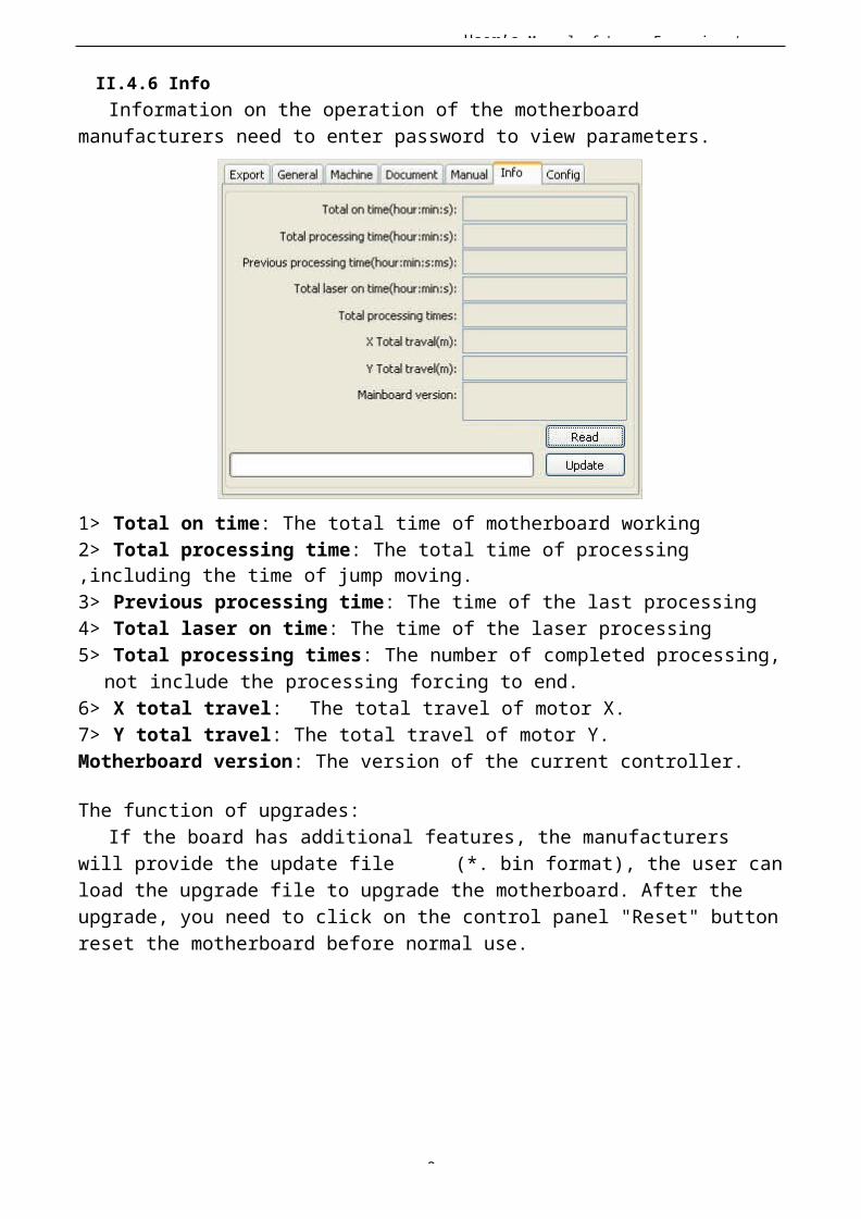
User’s Manual of Laser Engraving /
8
II.4.6 InfoInformation on the operation of the motherboard
manufacturers need to enter password to view parameters.
1> Total on time: The total time of motherboard working2> Total processing time: The total time of processing,including the time of jump moving.3> Previous processing time: The time of the last processing4> Total laser on time: The time of the laser processing5> Total processing times: The number of completed processing,
not include the processing forcing to end.6> X total travel: The total travel of motor X.7> Y total travel: The total travel of motor Y.Motherboard version: The version of the current controller.
The function of upgrades:If the board has additional features, the manufacturers
will provide the update file (*. bin format), the user canload the upgrade file to upgrade the motherboard. After the upgrade, you need to click on the control panel "Reset" buttonreset the motherboard before normal use.
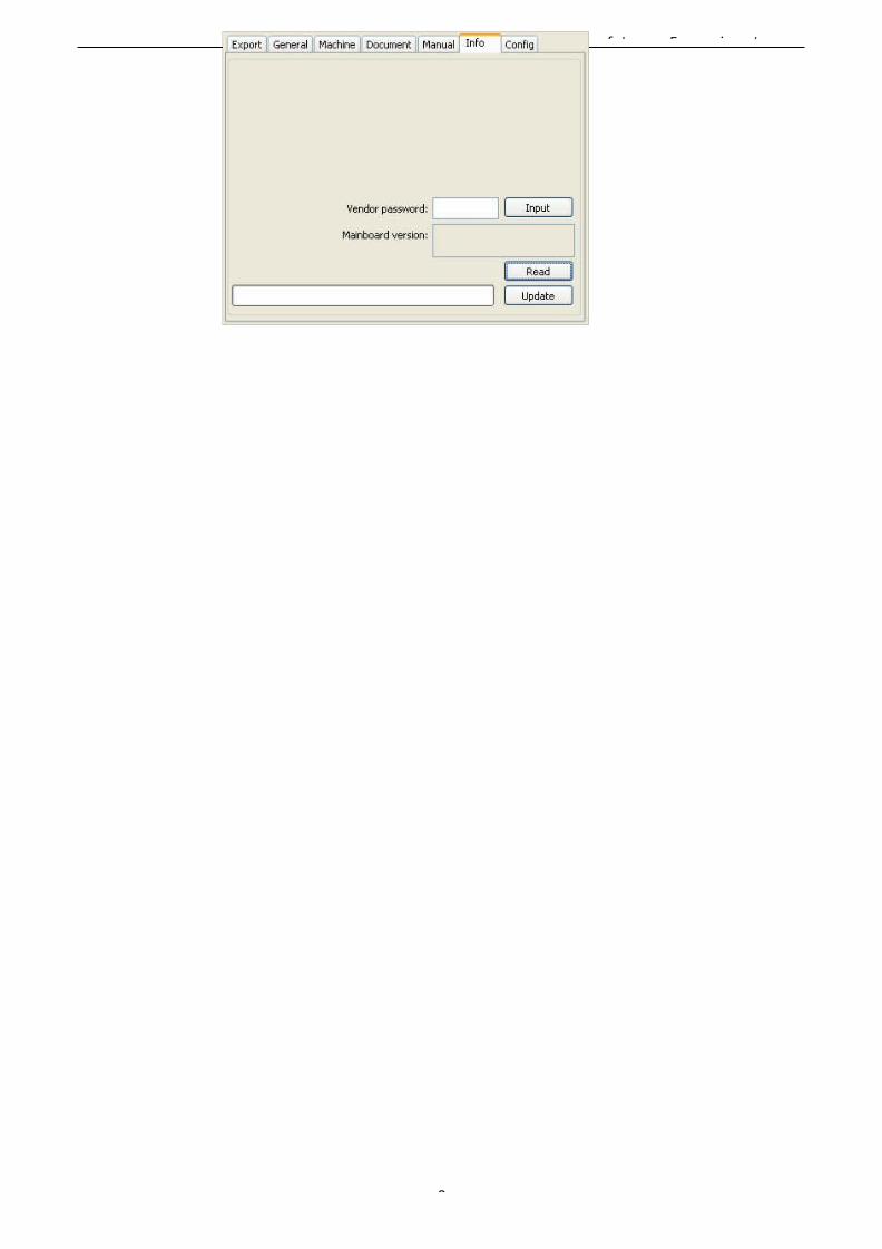
User’s Manual of Laser Engraving /
8
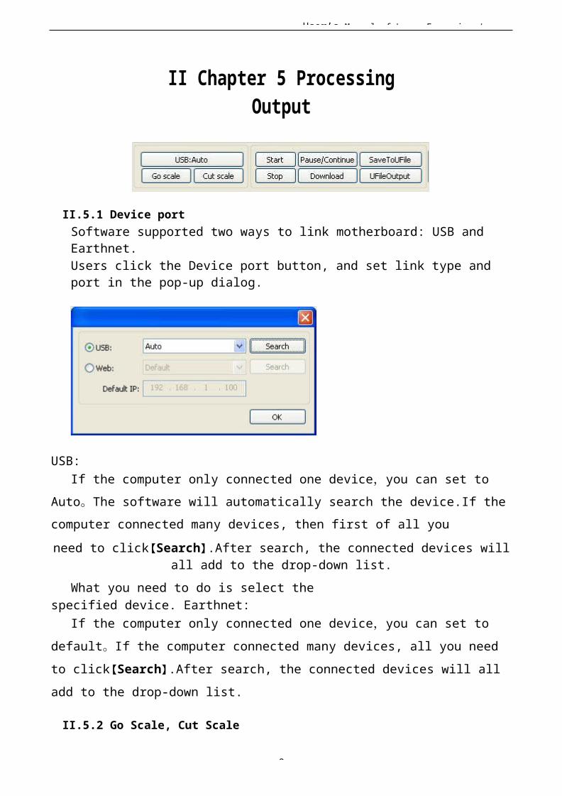
User’s Manual of Laser Engraving /
8
II Chapter 5 ProcessingOutput
II.5.1 Device portSoftware supported two ways to link motherboard: USB and Earthnet.Users click the Device port button, and set link type and port in the pop-up dialog.
USB:If the computer only connected one device,you can set to
Auto。The software will automatically search the device.If thecomputer connected many devices, then first of all youneed to click【Search】.After search, the connected devices will
all add to the drop-down list.What you need to do is select the
specified device. Earthnet:If the computer only connected one device,you can set to
default。If the computer connected many devices, all you need to click【Search】.After search, the connected devices will all add to the drop-down list.
II.5.2 Go Scale, Cut Scale

User’s Manual of Laser Engraving /
9
For Example Go Scale, As the following figure shown, the actual graphic is round, and the red rectangle outside the circle is the smallest rectangle, click button Go Scale, laserhead will run once along the rectangular path.
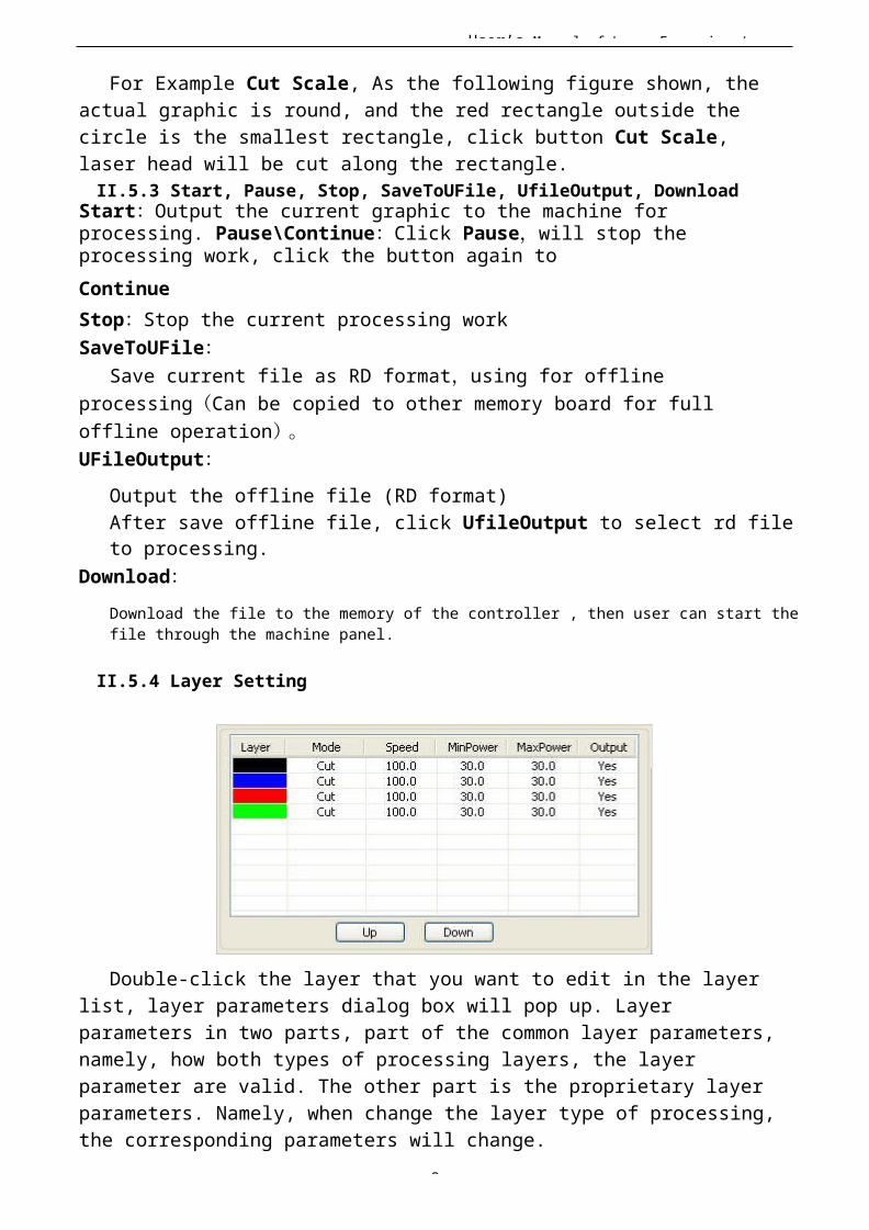
User’s Manual of Laser Engraving /
9
For Example Cut Scale, As the following figure shown, the actual graphic is round, and the red rectangle outside the circle is the smallest rectangle, click button Cut Scale, laser head will be cut along the rectangle.II.5.3 Start, Pause, Stop, SaveToUFile, UfileOutput, Download
Start:Output the current graphic to the machine for processing. Pause\Continue:Click Pause,will stop the processing work, click the button again toContinueStop:Stop the current processing workSaveToUFile:
Save current file as RD format,using for offline processing(Can be copied to other memory board for full offline operation)。UFileOutput:
Output the offline file (RD format)After save offline file, click UfileOutput to select rd fileto processing.
Download:Download the file to the memory of the controller , then user can start thefile through the machine panel.
II.5.4 Layer Setting
Double-click the layer that you want to edit in the layer list, layer parameters dialog box will pop up. Layer parameters in two parts, part of the common layer parameters,namely, how both types of processing layers, the layer parameter are valid. The other part is the proprietary layer parameters. Namely, when change the layer type of processing,the corresponding parameters will change.
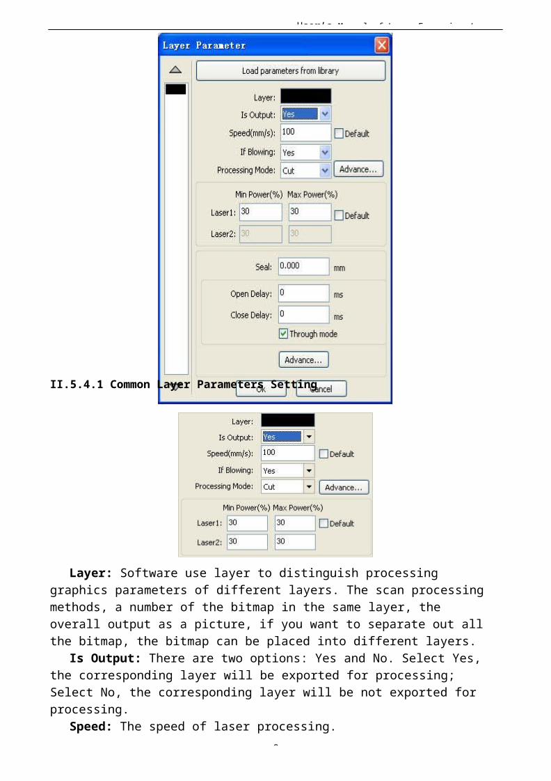
User’s Manual of Laser Engraving /
9
II.5.4.1 Common Layer Parameters Setting
Layer: Software use layer to distinguish processing graphics parameters of different layers. The scan processing methods, a number of the bitmap in the same layer, the overall output as a picture, if you want to separate out all the bitmap, the bitmap can be placed into different layers.
Is Output: There are two options: Yes and No. Select Yes, the corresponding layer will be exported for processing; Select No, the corresponding layer will be not exported for processing.
Speed: The speed of laser processing.
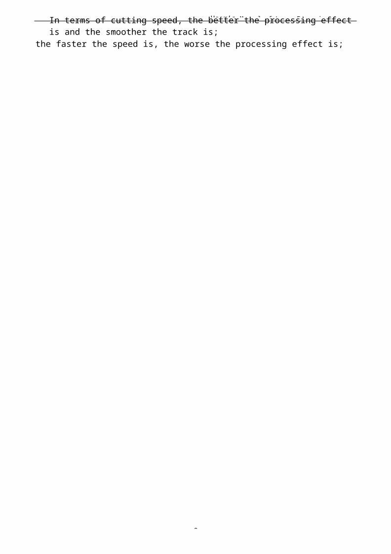
User’s Manual of Laser Engraving /
9
In terms of cutting speed, the better the processing effect is and the smoother the track is;
the faster the speed is, the worse the processing effect is;
User’s Manual of Laser Engraving /
9
On the scanning process, the more slowly, the same energy the deeper the next scan, scan traces thickening, scanning resolution accordingly reduced. Faster to scan the same energythe more shallow depth, detail distortion increases.
On the dot process, the main change is the speed of moving air.If you check the "default", the actual speed of the speed set by the panel to decide.Is blowing: If the machine add a fan, and fan has been
enabled, then if the selection is "Yes", then when processing the layer, it will open the fan, otherwise, will not open fan.If the fan is not enabled, you either select "yes" or "No", are meaningless.
Processing mode: Processing mode, meaning the mode to process corresponding layer. If you select vector layer (color layer) currently, there are three options: Laser scanning,
Laser cutting and Laser dotting;If you select bitmap layer (BMP layer) currently, there is only one option: Laser scanning.Laser1, Laser2: Laser signal corresponding to the board 1
channel and 2-way laser output. If a single head machine, the first 2-way laser meaningless.Min power, Max power: The range of power value is 0~100, it means the intensity of laser during the process; the higher the value is, the stronger the laser is, and the lower the value is, the weaker the laser is.
Processing for different types have different meaning.The cutting process, the actual power is compared with the
cutting speed to follow, the speed of low energy is also low,high-speed energy is high, so as to ensure the energy evenly throughout the cutting process. Therefore, the speed of minimum power corresponding to the lowest energy, the minimumspeed is usually 0, but if you set a minimum speed of take-off speed of the take-off speed; maximum power corresponds tothe layer speed.How to set proper Min power and Max power:
If the laser is too strong during the whole process, you should set the minimum and maximal power lower, otherwise, set them higher;
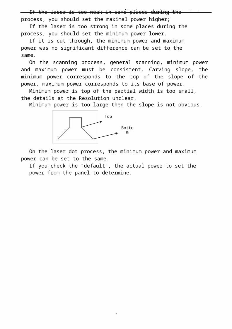
User’s Manual of Laser Engraving /
9
If the laser is too weak in some places during the process, you should set the maximal power higher;
If the laser is too strong in some places during the process, you should set the minimum power lower.
If it is cut through, the minimum power and maximum power was no significant difference can be set to the same.
On the scanning process, general scanning, minimum powerand maximum power must be consistent. Carving slope, theminimum power corresponds to the top of the slope of thepower, maximum power corresponds to its base of power.
Minimum power is top of the partial width is too small, the details at the Resolution unclear.
Minimum power is too large then the slope is not obvious.
Top
Bottom
On the laser dot process, the minimum power and maximum power can be set to the same.
If you check the "default", the actual power to set the power from the panel to determine.
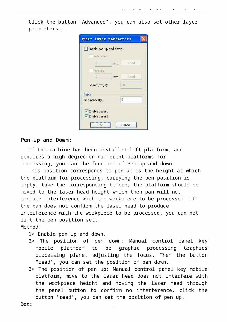
User’s Manual of Laser Engraving /
9
Click the button "Advanced", you can also set other layer parameters.
Pen Up and Down:If the machine has been installed lift platform, and
requires a high degree on different platforms for processing, you can the function of Pen up and down.
This position corresponds to pen up is the height at whichthe platform for processing, carrying the pen position is empty, take the corresponding before, the platform should be moved to the laser head height which then pan will not produce interference with the workpiece to be processed. If the pan does not confirm the laser head to produce interference with the workpiece to be processed, you can not lift the pen position set.Method:
1> Enable pen up and down.2> The position of pen down: Manual control panel key
mobile platform to be graphic processing Graphicsprocessing plane, adjusting the focus. Then the button"read", you can set the position of pen down.
3> The position of pen up: Manual control panel key mobileplatform, move to the laser head does not interfere withthe workpiece height and moving the laser head throughthe panel button to confirm no interference, click thebutton "read", you can set the position of pen up.
Dot:
User’s Manual of Laser Engraving /
9
Dot here is specifically for the point drawing tools to draw primitives, or imported from a dxf file, point primitives. And independent of the current way of processing layers, namely, whether the current layer is cut or a scan, pixel graphics of the dot to dot mode is always output.
The speed of dot is the speed of layer, and the energy of dot is the maximum energy of the layer.Enable laser:
When the machine is equipped with two lasers, under normal circumstances, is two simultaneous output
However, users can also be enabled by setting the laser to make them all the way is not output.
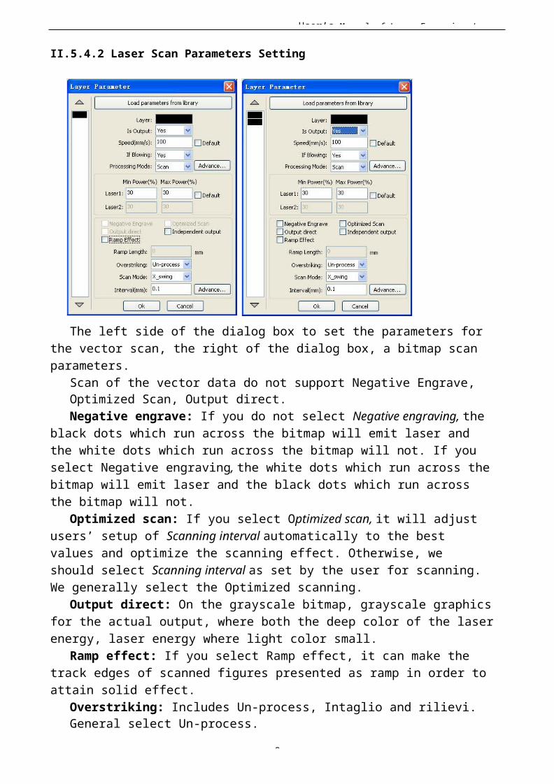
User’s Manual of Laser Engraving /
9
II.5.4.2 Laser Scan Parameters Setting
The left side of the dialog box to set the parameters forthe vector scan, the right of the dialog box, a bitmap scanparameters.
Scan of the vector data do not support Negative Engrave, Optimized Scan, Output direct.Negative engrave: If you do not select Negative engraving, the
black dots which run across the bitmap will emit laser and the white dots which run across the bitmap will not. If you select Negative engraving, the white dots which run across the bitmap will emit laser and the black dots which run across the bitmap will not.
Optimized scan: If you select Optimized scan, it will adjust users’ setup of Scanning interval automatically to the best values and optimize the scanning effect. Otherwise, we should select Scanning interval as set by the user for scanning.We generally select the Optimized scanning.
Output direct: On the grayscale bitmap, grayscale graphics for the actual output, where both the deep color of the laserenergy, laser energy where light color small.
Ramp effect: If you select Ramp effect, it can make the track edges of scanned figures presented as ramp in order toattain solid effect.
Overstriking: Includes Un-process, Intaglio and rilievi. General select Un-process.
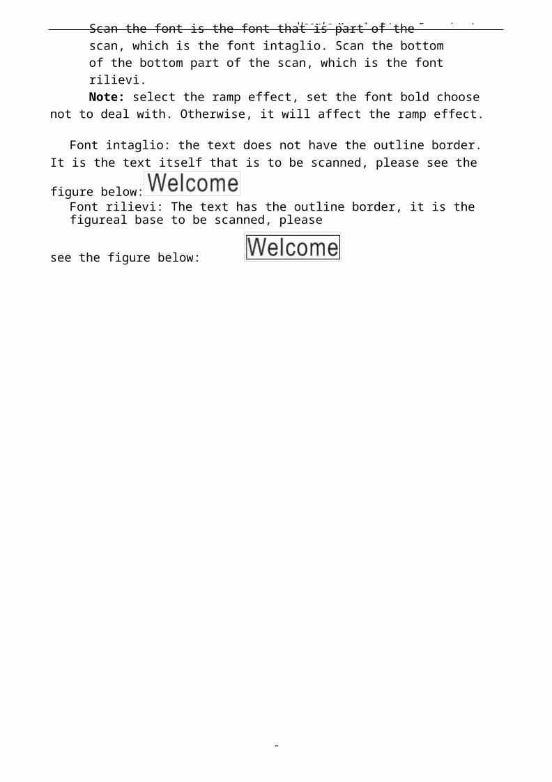
User’s Manual of Laser Engraving /
9
Scan the font is the font that is part of the scan, which is the font intaglio. Scan the bottomof the bottom part of the scan, which is the fontrilievi.Note: select the ramp effect, set the font bold choose
not to deal with. Otherwise, it will affect the ramp effect.
Font intaglio: the text does not have the outline border.It is the text itself that is to be scanned, please see the
figure below:Font rilievi: The text has the outline border, it is the figureal base to be scanned, please
see the figure below:
User’s Manual of Laser Engraving /
1
Scan modes: including X_unilateralism, X_swing, Y_unilateralism and Y_swing. X_unilateralism: The laser head scans figures back and forth at the level direction, but onlyemit laser toward one direction. For example, the laser head emits laser when scanning from right to left, but not emits laser when scanning from left to right.X_swing: The laser head emits laser and scans figures back andforth horizontally.
Y_unilateralism: The laser head scans figures back and forth vertically, but only emit laser toward one direction. For example, the laser head emits laser when scanning from the top down, but not emits laser when scanning from the bottom up.
Y_swing: The laser head emits laser and scans figures back andforth vertically.Note: We generally adopt the scanning mode of X_swing.
Interval: The interval between the current line and the next line to be scanned by the laser head. The smaller the interval is, the darker the scanned figures is; If reverse, the weaker. Recommendation: ① The scanning interval is set below 0.1mm for vector layer (colorlayer) in general. ② The scanning interval is set above 0.1mm for bitmap layer (BMPlayer) in general, and then the Minimum power and Maximum power should be changed to attain the perfect effect of the scanned figures.
II.5.4.3 Laser Cut Setting
Seal cutting has not closed the graphics appear the case is closed, you can compensate with
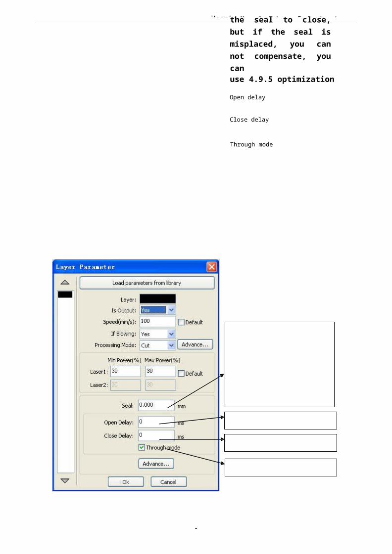
User’s Manual of Laser Engraving /
1
the seal to close,but if the seal ismisplaced, you cannot compensate, youcanuse 4.9.5 optimization
Open delay
Close delay
Through mode
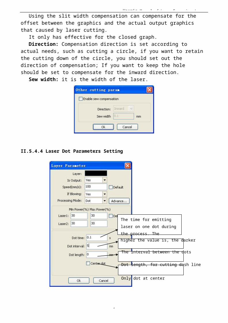
User’s Manual of Laser Engraving /
1
Using the slit width compensation can compensate for the offset between the graphics and the actual output graphics that caused by laser cutting.
It only has effective for the closed graph.Direction: Compensation direction is set according to
actual needs, such as cutting a circle, if you want to retainthe cutting down of the circle, you should set out the direction of compensation; If you want to keep the hole should be set to compensate for the inward direction.
Sew width: it is the width of the laser.
II.5.4.4 Laser Dot Parameters Setting
The time for emitting laser on one dot duringthe process. Thehigher the value is, the darker
The interval between the dots
Dot length, for cutting dash line
Only dot at center
User’s Manual of Laser Engraving /
1
II Chapter 6FAQ
II.6.1 After start processing, the machine does not move ordisorder or loss part of graphics◆ Check whether the graphic data is out if frame. The data beyond of the frame
will not be cut.◆ Check the setting of Laser head position.II.6.2 Software automatically shut down when import fileIf the operating system is XP, please check if the patch is installed.
II.6.3 Machine panel prompt 【Less buffer distance】◆ Check the engraving speed in the machine parameter,generally, the engrave speed no 8000◆ Ensure that graphics are not close to the border of the machine frame.
II.6.4 Processing graphics sis mirror to the actual graphicsCheck “Axis Mirror” in the General settings dialog(See:4.2 General settings )
User’s Manual of Laser Engraving /
1
III User’s Manual of LaserEngraving
Cutting Software LASER_WORK RDCAM6.0
III Chapter 1Overview
III.1.1 Laser engraving cutting system introductionLaser engraving cutting system through a computer numerical control machine tools to achieve effective control, according to the user’s different requirements of the completion of processing tasks。
The system including control board and control panel, and supporting software. This manual describes how to use the software to complete the task of laserprocessing.( Motherboard wiring and control panel operations, see the accompanying manual and control panel wiring board operating instructions)
III. 1.2 Software supported file formats
Vector format:dxf, ai, plt, dst, dsb…etc. Bitmap format:bmp,jpg,gif,png,mng,…etc.
III. 1.3 Environmental requirements
⑴ WindowsXP operating system and above, XP recommended。⑵ Above CPU586,above PIII or PV recommended。⑶ Memory, above 1G recommended
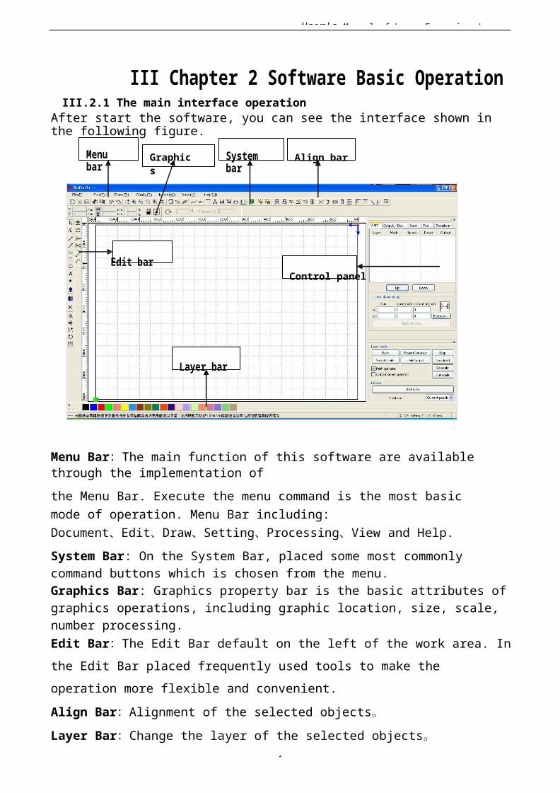
User’s Manual of Laser Engraving /
1
III Chapter 2 Software Basic OperationIII.2.1 The main interface operation
After start the software, you can see the interface shown in the following figure.
Menu bar
Graphics
System bar
Align bar
Edit barControl panel
Layer bar
Menu Bar:The main function of this software are available through the implementation ofthe Menu Bar. Execute the menu command is the most basic mode of operation. Menu Bar including: Document、Edit、Draw、Setting、Processing、View and Help.System Bar: On the System Bar, placed some most commonly command buttons which is chosen from the menu.Graphics Bar: Graphics property bar is the basic attributes ofgraphics operations, including graphic location, size, scale, number processing.Edit Bar:The Edit Bar default on the left of the work area. Inthe Edit Bar placed frequently used tools to make the operation more flexible and convenient.Align Bar:Alignment of the selected objects。Layer Bar:Change the layer of the selected objects。

User’s Manual of Laser Engraving /
1
Control Panel:Using the Control Panel to complete laser processing of multiple tasks, Layer parameter settings, axis control, processing …etc.
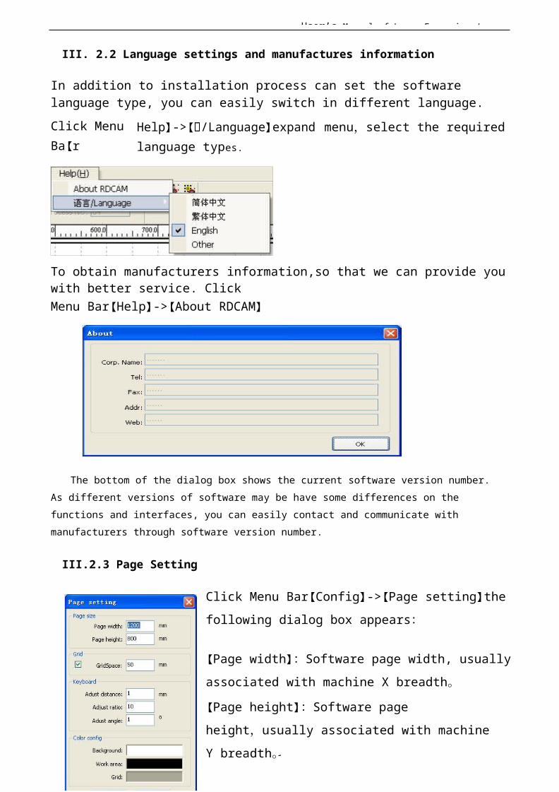
User’s Manual of Laser Engraving /
1
III. 2.2 Language settings and manufactures information
In addition to installation process can set the software language type, you can easily switch in different language.Click Menu Ba【r
Help】-> 加【加/Language】expand menu,select the required language types.
To obtain manufacturers information,so that we can provide you with better service. ClickMenu Bar【Help】->【About RDCAM】
The bottom of the dialog box shows the current software version number.As different versions of software may be have some differences on the functions and interfaces, you can easily contact and communicate with manufacturers through software version number.
III.2.3 Page Setting
Click Menu Bar【Config】->【Page setting】thefollowing dialog box appears:
【Page width】:Software page width, usuallyassociated with machine X breadth。
【Page height】:Software page height,usually associated with machine Y breadth。

User’s Manual of Laser Engraving /
1
Under normal circumstances, if you have connected to the motherboard, software will automatically format for the
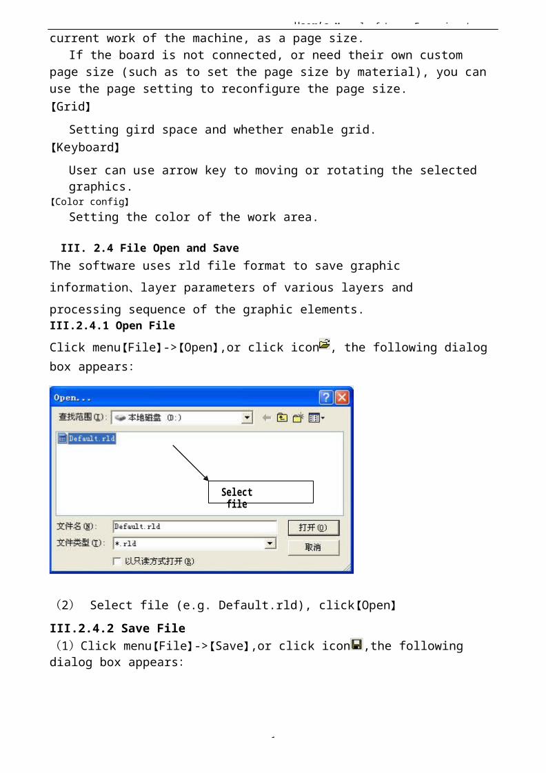
User’s Manual of Laser Engraving /
1
current work of the machine, as a page size.If the board is not connected, or need their own custom
page size (such as to set the page size by material), you can use the page setting to reconfigure the page size.【Grid】
Setting gird space and whether enable grid.【Keyboard】
User can use arrow key to moving or rotating the selected graphics.
【Color config】Setting the color of the work area.
III. 2.4 File Open and SaveThe software uses rld file format to save graphic information、layer parameters of various layers and processing sequence of the graphic elements.III.2.4.1 Open FileClick menu【File】->【Open】,or click icon , the following dialog box appears:
Selectfile
(2) Select file (e.g. Default.rld), click【Open】III.2.4.2 Save File(1)Click menu【File】->【Save】,or click icon ,the following dialog box appears:
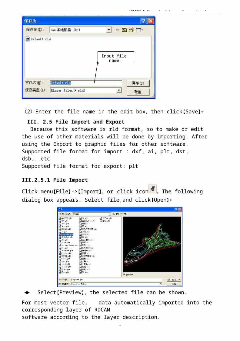
User’s Manual of Laser Engraving /
1
Input filename
(2)Enter the file name in the edit box,then click【Save】。III. 2.5 File Import and ExportBecause this software is rld format, so to make or edit
the use of other materials will be done by importing. After using the Export to graphic files for other software.Supported file format for import : dxf, ai, plt, dst, dsb...etcSupported file format for export: plt
III.2.5.1 File Import
Click menu【File】->【Import】,or click icon 。The following dialog box appears. Select file,and click【Open】。
◆ Select【Preview】,the selected file can be shown.For most vector file, data automatically imported into the corresponding layer of RDCAMsoftware according to the layer description.

User’s Manual of Laser Engraving /
1
For some special documents such as DST/DSB, data will be imported into the current layer.
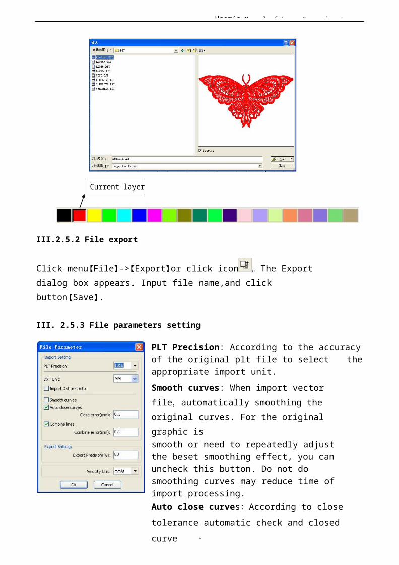
User’s Manual of Laser Engraving /
1
Current layer
III.2.5.2 File export
Click menu【File】->【Export】or click icon 。The Export dialog box appears. Input file name,and click button【Save】.
III. 2.5.3 File parameters setting
PLT Precision: According to the accuracyof the original plt file to select theappropriate import unit.Smooth curves: When import vector file,automatically smoothing the original curves. For the original graphic issmooth or need to repeatedly adjust the beset smoothing effect, you can uncheck this button. Do not do smoothing curves may reduce time of import processing.Auto close curves:According to close tolerance automatic check and closed curve

User’s Manual of Laser Engraving /
1
Combine lines:According to merger tolerance,auto-connecting
curves.
Color map automatically switch to grayscale:Because under normal circumstances, graphics are based on grayscale. If theimported bitmap is a color image can be converted tograyscale.
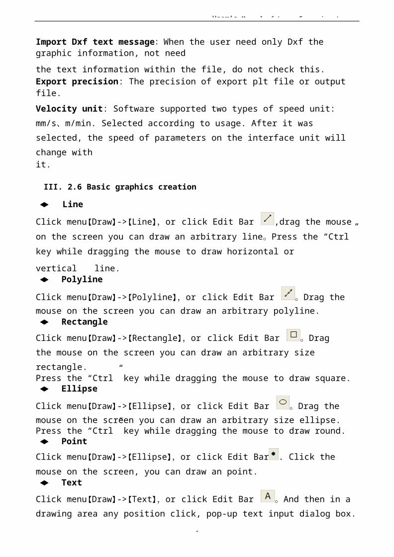
User’s Manual of Laser Engraving /
1
Import Dxf text message:When the user need only Dxf the graphic information, not needthe text information within the file, do not check this.Export precision: The precision of export plt file or output file.Velocity unit: Software supported two types of speed unit: mm/s、m/min. Selected according to usage. After it was selected, the speed of parameters on the interface unit will change withit.
III. 2.6 Basic graphics creation
◆ Line
Click menu【Draw】->【Line】,or click Edit Bar ,drag the mouse on the screen you can draw an arbitrary line。Press the “Ctrl” key while dragging the mouse to draw horizontal orvertical line.◆ Polyline
Click menu【Draw】->【Polyline】,or click Edit Bar 。Drag the mouse on the screen you can draw an arbitrary polyline.◆ RectangleClick menu【Draw】->【Rectangle】,or click Edit Bar 。Drag the mouse on the screen you can draw an arbitrary size rectangle.Press the “Ctrl” key while dragging the mouse to draw square.◆ Ellipse
Click menu【Draw】->【Ellipse】,or click Edit Bar 。Drag the mouse on the screen you can draw an arbitrary size ellipse.Press the “Ctrl” key while dragging the mouse to draw round.◆ PointClick menu【Draw】->【Ellipse】,or click Edit Bar . Click the mouse on the screen, you can draw an point.◆ TextClick menu【Draw】->【Text】,or click Edit Bar 。And then in a drawing area any position click, pop-up text input dialog box.
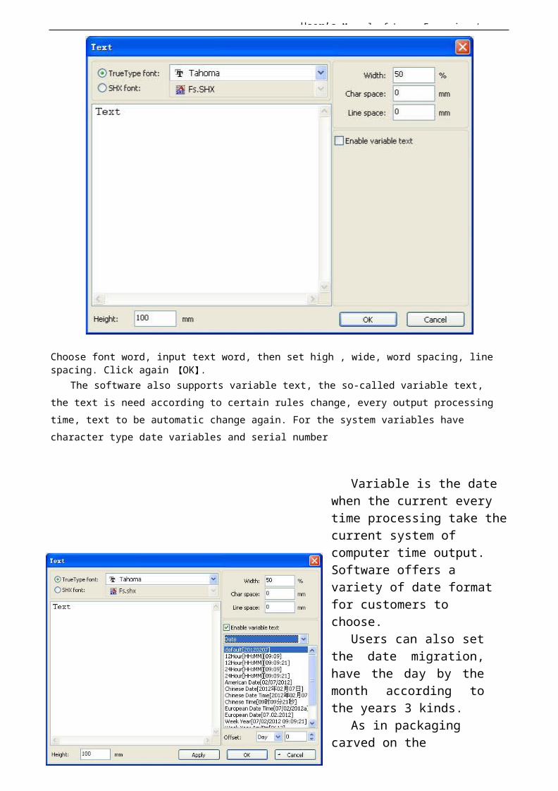
User’s Manual of Laser Engraving /
1
Choose font word, input text word, then set high , wide, word spacing, line spacing. Click again 【OK】.
The software also supports variable text, the so-called variable text, the text is need according to certain rules change, every output processing time, text to be automatic change again. For the system variables have character type date variables and serial number
Variable is the date when the current every time processing take thecurrent system of computer time output. Software offers a variety of date format for customers tochoose.
Users can also setthe date migration,have the day by themonth according tothe years 3 kinds.
As in packaging carved on the

User’s Manual of Laser Engraving /
1
expiration period can use the product.
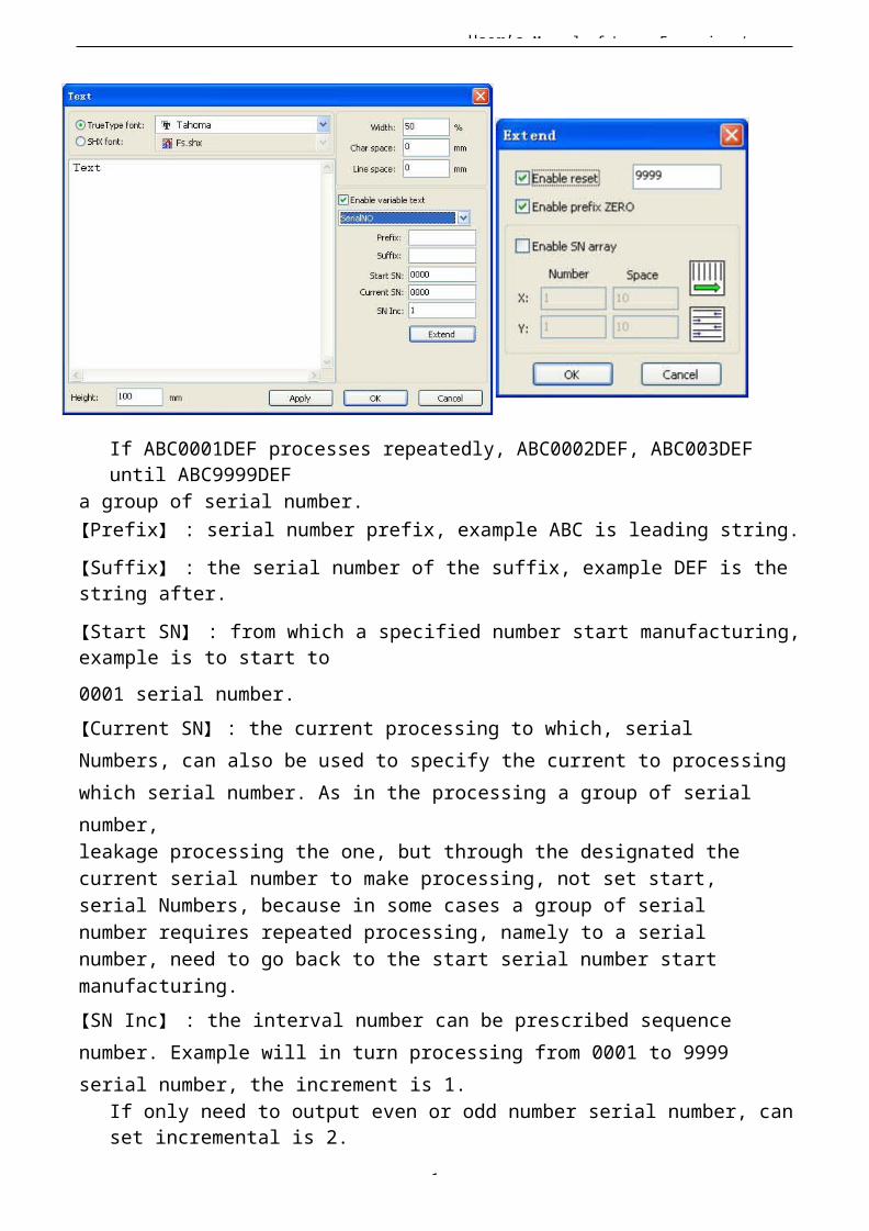
User’s Manual of Laser Engraving /
1
If ABC0001DEF processes repeatedly, ABC0002DEF, ABC003DEF until ABC9999DEF
a group of serial number.【Prefix】 : serial number prefix, example ABC is leading string.【Suffix】 : the serial number of the suffix, example DEF is the string after.【Start SN】 : from which a specified number start manufacturing,example is to start to0001 serial number.【Current SN】 : the current processing to which, serial Numbers, can also be used to specify the current to processingwhich serial number. As in the processing a group of serial number,leakage processing the one, but through the designated the current serial number to make processing, not set start, serial Numbers, because in some cases a group of serial number requires repeated processing, namely to a serial number, need to go back to the start serial number start manufacturing.【SN Inc】 : the interval number can be prescribed sequence number. Example will in turn processing from 0001 to 9999 serial number, the increment is 1.
If only need to output even or odd number serial number, can set incremental is 2.
User’s Manual of Laser Engraving /
1
【 Enable reset】 : when serial number processing to reset the serial number, 【current SN】will be automatically reset to 【start SN】.
Example requires repeated processing from 0001 to 9999, serial Numbers, so can be designated 9999 as reset, serial Numbers, when processing the 9999 serial number, text will automatically change to 0001.【 Enable prefix ZERO】 : if not lead to zero, the system will automatically remove the first in the serial number of zero digital before the zero. Such as the example, serial Numbers, ifnot the leader's zero can ABC0001DEF will become ABC1DEF. But it is worth noting that, if we want to output serial number isABC1DEF, ABC2DEF until ABC9999DEF, we can't
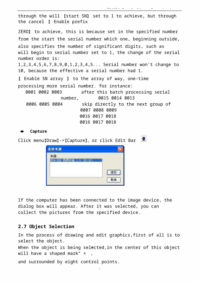
User’s Manual of Laser Engraving /
1
through the will 【start SN】 set to 1 to achieve, but through the cancel 【 Enable prefix
ZERO】 to achieve, this is because set in the specified numberfrom the start the serial number which one, beginning outside,also specifies the number of significant digits, such aswill begin to serial number set to 1, the change of the serial number order is:1,2,3,4,5,6,7,8,9,0,1,2,3,4,5... Serial number won't change to 10, because the effective a serial number had 1.【 Enable SN array 】 to the array of way, one-time processing more serial number. for instance:
0001 0002 0003 after this batch processing serialnumber, 0015 0014 0013
0006 0005 0004 skip directly to the next group of0007 0008 00090016 0017 00180016 0017 0018
◆ Capture
Click menu【Draw】->【Capture】,or click Edit Bar
If the computer has been connected to the image device, the dialog box will appear. After it was selected, you can collect the pictures from the specified device.
2.7 Object SelectionIn the process of drawing and edit graphics,first of all is to select the object.When the object is being selected,in the center of this object will have a shaped mark“ × ”,and surrounded by eight control points.

User’s Manual of Laser Engraving /
1
Click menu【Draw】->【Select】,or click Edit Bar ,switch to status“Select”。Under this status,you can select object.The following are five kinds of method of selecting:
◆ Click menu【Edit】->【Select All】(Shortcuts Ctrl+A), select all objects。
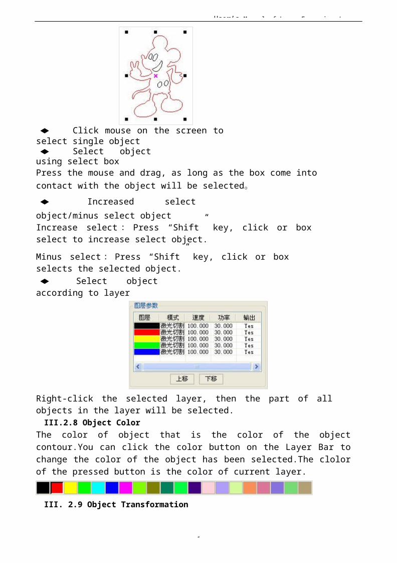
User’s Manual of Laser Engraving /
1
◆ Click mouse on the screen toselect single object◆ Select objectusing select boxPress the mouse and drag, as long as the box come into contact with the object will be selected。◆ Increased selectobject/minus select objectIncrease select : Press “Shift” key, click or boxselect to increase select object.Minus select: Press “Shift” key, click or boxselects the selected object.◆ Select objectaccording to layer
Right-click the selected layer, then the part of allobjects in the layer will be selected.III.2.8 Object Color
The color of object that is the color of the objectcontour.You can click the color button on the Layer Bar tochange the color of the object has been selected.The clolorof the pressed button is the color of current layer.
III. 2.9 Object Transformation
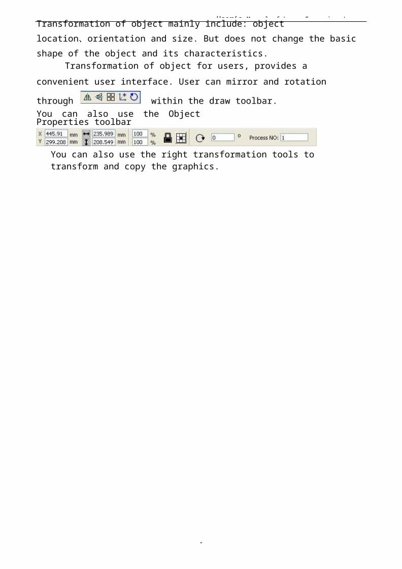
User’s Manual of Laser Engraving /
1
Transformation of object mainly include: object location、orientation and size. But does not change the basic shape of the object and its characteristics.
Transformation of object for users, provides a convenient user interface. User can mirror and rotation
through within the draw toolbar.You can also use the ObjectProperties toolbar
You can also use the right transformation tools to transform and copy the graphics.
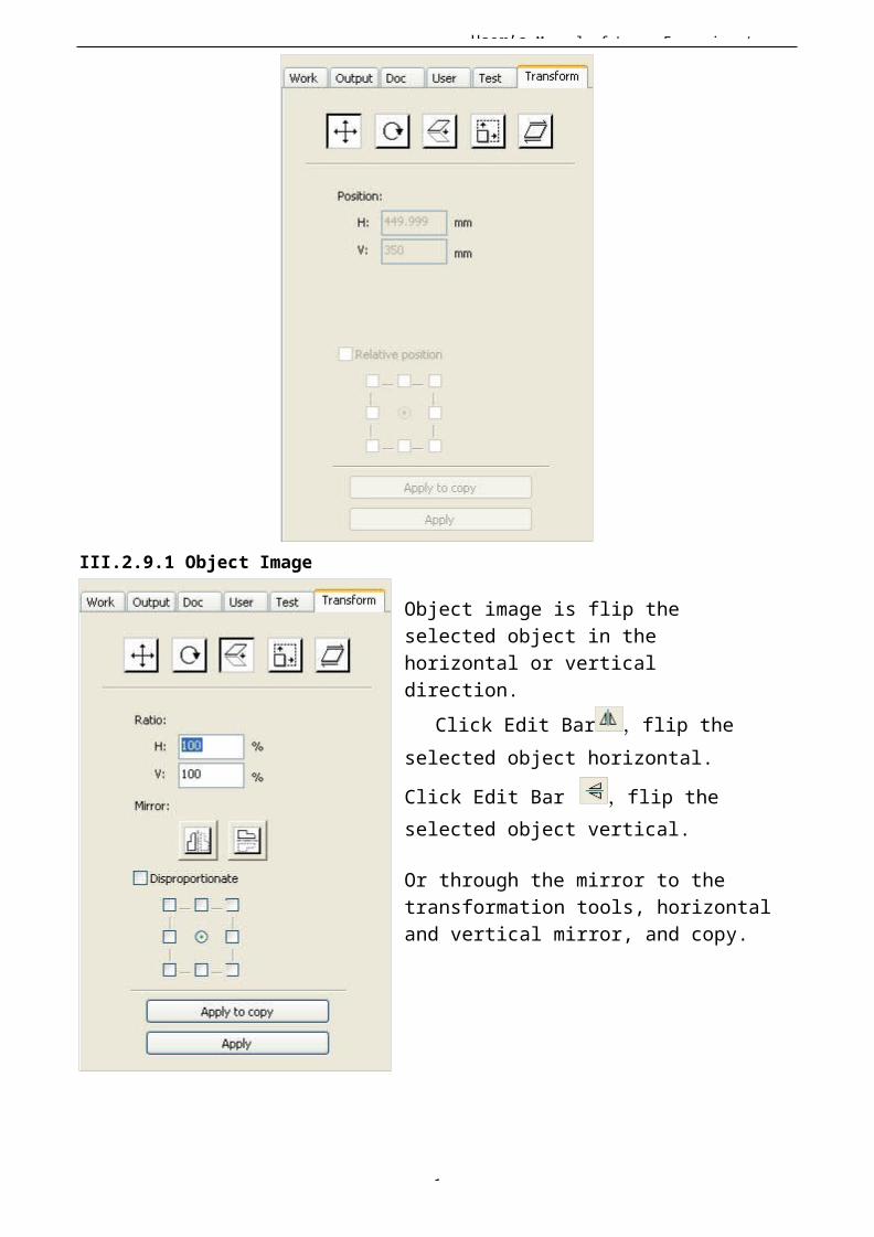
User’s Manual of Laser Engraving /
1
III.2.9.1 Object Image
Object image is flip the selected object in the horizontal or vertical direction.
Click Edit Bar ,flip the selected object horizontal.
Click Edit Bar ,flip the selected object vertical.
Or through the mirror to the transformation tools, horizontal and vertical mirror, and copy.
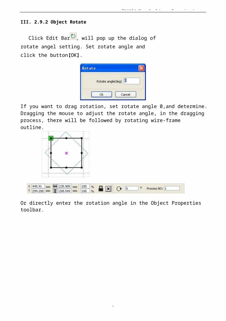
User’s Manual of Laser Engraving /
1
III. 2.9.2 Object Rotate
Click Edit Bar ,will pop up the dialog of rotate angel setting. Set rotate angle and click the button【OK】.
If you want to drag rotation, set rotate angle 0,and determine.Dragging the mouse to adjust the rotate angle, in the draggingprocess, there will be followed by rotating wire-frame outline.
Or directly enter the rotation angle in the Object Properties toolbar.
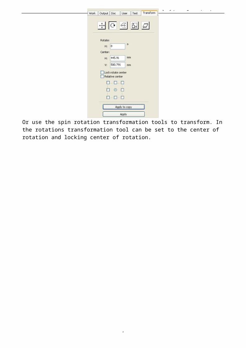
User’s Manual of Laser Engraving /
1
Or use the spin rotation transformation tools to transform. Inthe rotations transformation tool can be set to the center of rotation and locking center of rotation.
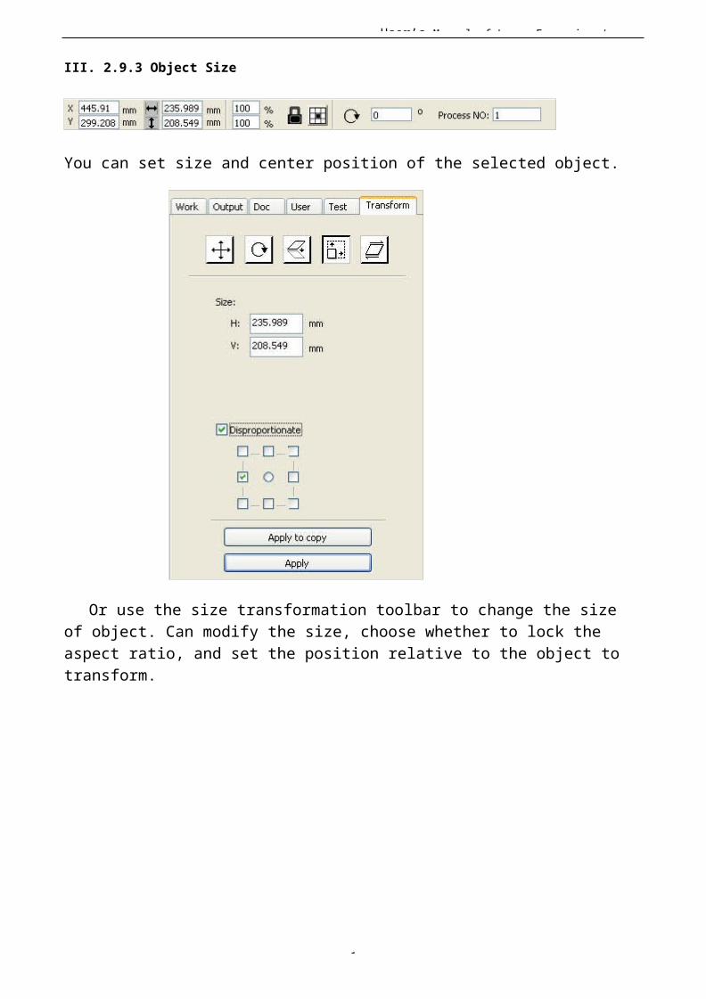
User’s Manual of Laser Engraving /
1
III. 2.9.3 Object Size
You can set size and center position of the selected object.
Or use the size transformation toolbar to change the size of object. Can modify the size, choose whether to lock the aspect ratio, and set the position relative to the object to transform.
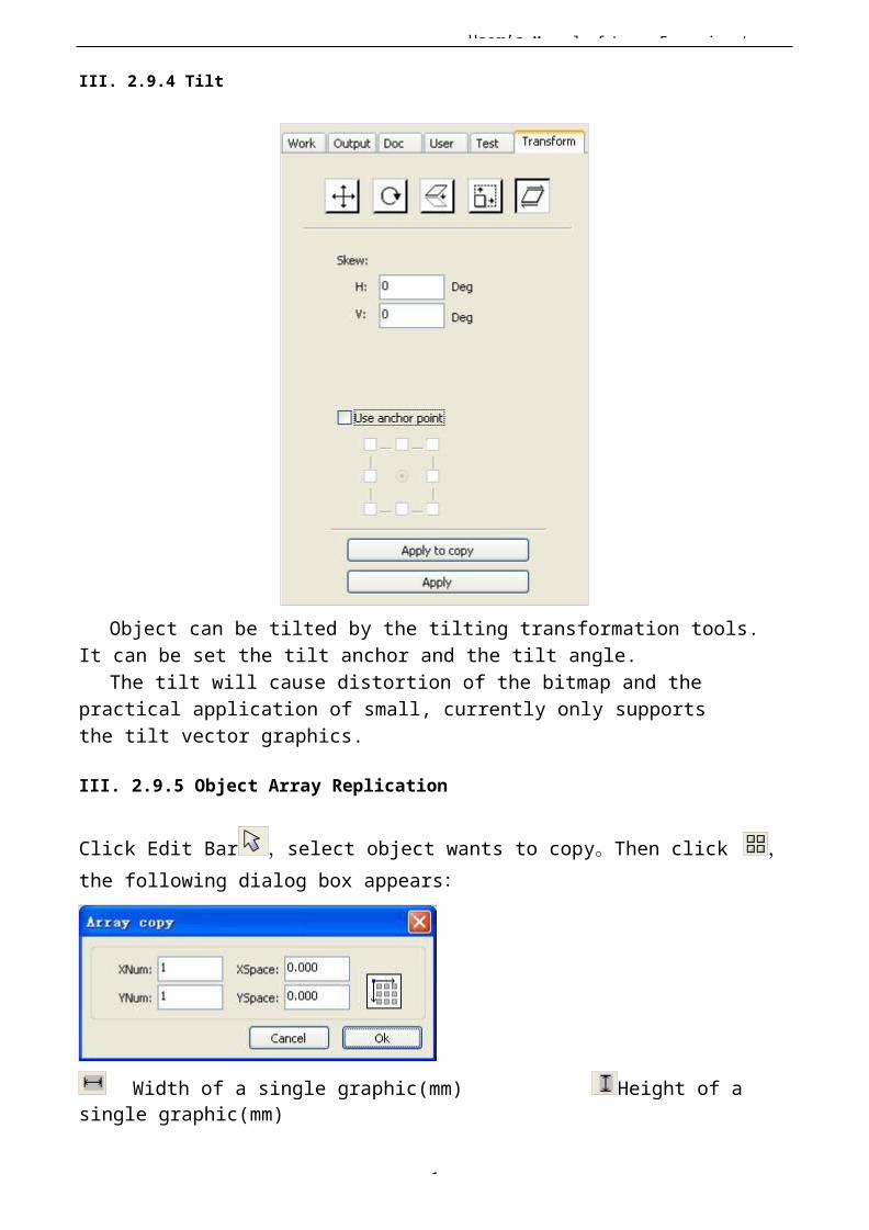
User’s Manual of Laser Engraving /
1
III. 2.9.4 Tilt
Object can be tilted by the tilting transformation tools. It can be set the tilt anchor and the tilt angle.
The tilt will cause distortion of the bitmap and the practical application of small, currently only supports the tilt vector graphics.
III. 2.9.5 Object Array Replication
Click Edit Bar ,select object wants to copy。Then click ,
the following dialog box appears:
Width of a single graphic(mm) Height of a single graphic(mm)

User’s Manual of Laser Engraving /
1
You can array replication object along different directions. The direction of copy is based on the original graphics. Such as choose the array direction lower right, then the original graphic
User’s Manual of Laser Engraving /
1
will appear on the upper left corner.wheras if it is to theupper left array, then the original graph appears in the lower right.After setting the array number and array spacing,click button【Apply】,you can see the actual graphicsarray.There are two forms of array spacing:center spacing and edge spacing.Choose center spacing,then【X Distance(mm)】、【Y Distance(mm)】representing the distance of the two graphic center.If not choose center spacing,then 【X Distance(mm)】、【Y Distance(mm)】representing thedistance of the graphic edge.Center distance X = Edge distance X + width of objectCenter distanceY = Edge distance Y + height of objectSwitch between the two kinds of calculate method, 【X Distance(mm)】、【Y Distance(mm)】will be calculated automatically.Click【Bestrewing breadth】,The software will automatically calculate the array number according to the workpiece sie、width、height、X distance and Y distance。
Adjust spacing can be directly input values,and click 【Apply】Can also press the dirction keys to adjust objects spacing。Check【Center】,then after object array replication,graphics will be centered on the work area. Scroll the mouse wheel to zoom view of the graphics.Drag the mouse to pan view of the graphics。
III. 2.9.6 Place Object To The Origin
Place the object is to facilitate the view or orientation.The following tools are provided by software:
, selected object will be placed in the center of thepage, that is the object center coincides with the center of the page.

User’s Manual of Laser Engraving /
1
, Selected object will be placed on the pageleft, upper right, lower right, lower left, upper leftcorner of the object, upper right, lower right, lower leftand upper left corner, top right, bottom right, bottom leftcorner of coincidence.
III. 2.10 Object Align
Select objects,click tools on the Align Bar.
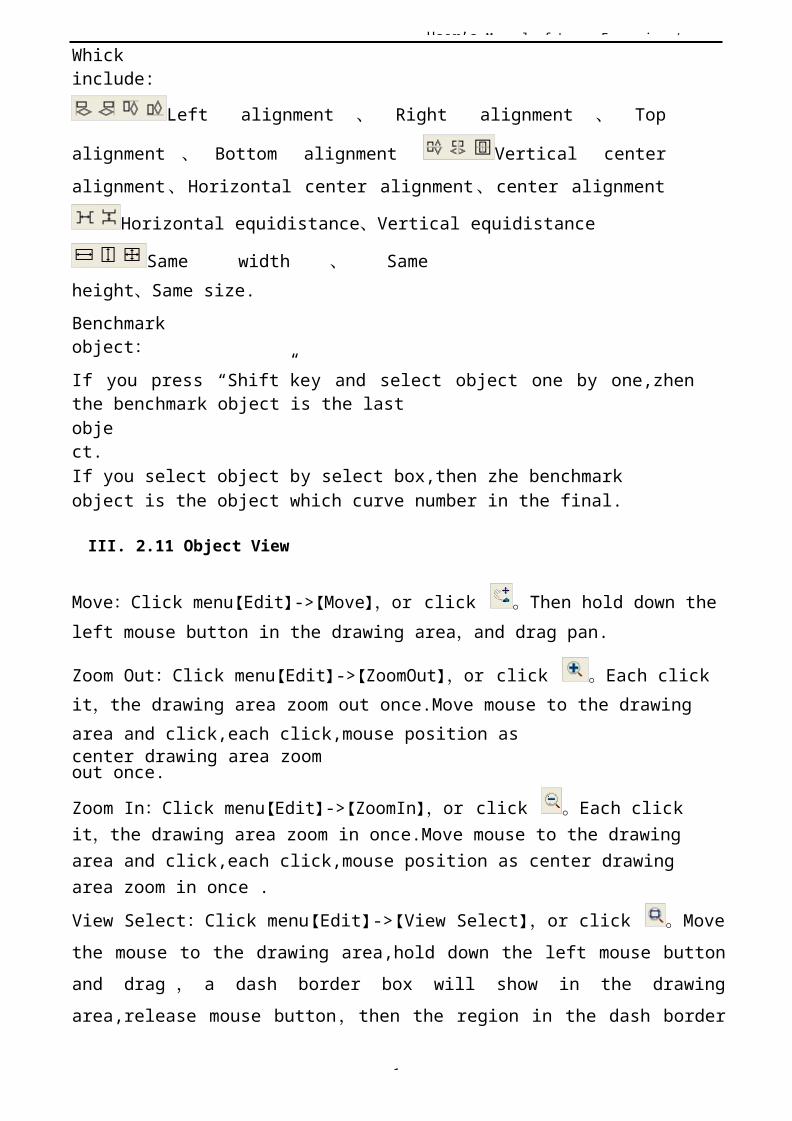
User’s Manual of Laser Engraving /
1
Whickinclude:
Left alignment 、 Right alignment 、 Top
alignment 、 Bottom alignment Vertical centeralignment、Horizontal center alignment、center alignment
Horizontal equidistance、Vertical equidistance
Same width 、 Sameheight、Same size.Benchmarkobject:If you press “Shift”key and select object one by one,zhenthe benchmark object is the lastobject.If you select object by select box,then zhe benchmark object is the object which curve number in the final.
III. 2.11 Object View
Move:Click menu【Edit】->【Move】,or click 。Then hold down theleft mouse button in the drawing area,and drag pan.
Zoom Out:Click menu【Edit】->【ZoomOut】,or click 。Each click it,the drawing area zoom out once.Move mouse to the drawing area and click,each click,mouse position ascenter drawing area zoomout once.
Zoom In:Click menu【Edit】->【ZoomIn】,or click 。Each click it,the drawing area zoom in once.Move mouse to the drawing area and click,each click,mouse position as center drawing area zoom in once .View Select:Click menu【Edit】->【View Select】,or click 。Movethe mouse to the drawing area,hold down the left mouse buttonand drag , a dash border box will show in the drawingarea,release mouse button,then the region in the dash border
User’s Manual of Laser Engraving /
1
box will display in the drawing area with the largestproportion.
View Page Frame:Click menu【Edit】->【View Page Frame】,or click。The page frame will full display.
View Data Frame:Click menu【Edit】->【View Data Frame】,or click。The selected objects will full display
III. 2.12 Group and UnGroup
Edit graphics, and sometimes need to be a part of the operation as a whole (such as multi-line text layout).
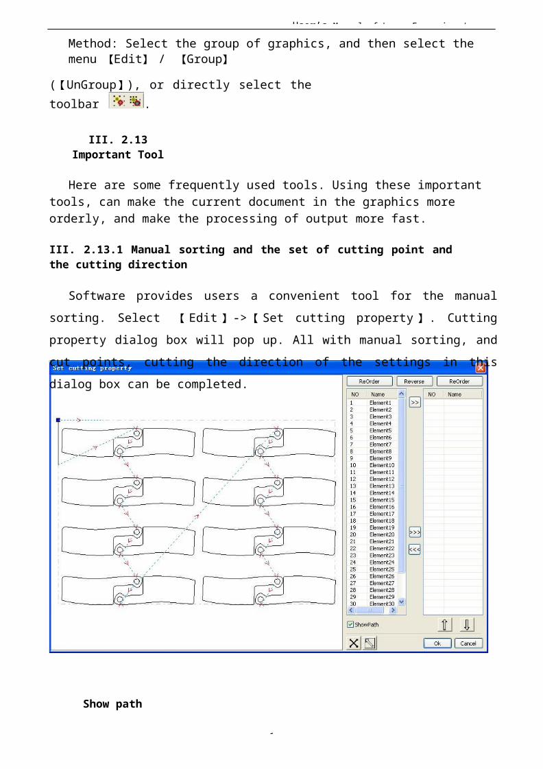
User’s Manual of Laser Engraving /
1
Method: Select the group of graphics, and then select the menu 【Edit】 / 【Group】
(【UnGroup】), or directly select thetoolbar .
III. 2.13Important Tool
Here are some frequently used tools. Using these importanttools, can make the current document in the graphics more orderly, and make the processing of output more fast.
III. 2.13.1 Manual sorting and the set of cutting point andthe cutting direction
Software provides users a convenient tool for the manualsorting. Select 【 Edit 】 -> 【 Set cutting property 】 . Cuttingproperty dialog box will pop up. All with manual sorting, andcut points, cutting the direction of the settings in thisdialog box can be completed.
Show path
User’s Manual of Laser Engraving /
1
First check the “show path”, it will display the current graphics cutting order and the cutting direction.
Manualsort
Select . This button is used to switch the current statusof the operation is to edit or view. Then you can marquee orclick the graphics in the graphics display area (or click onepixel or check many pixels). After selecting the graphic,
select , these graphics to be redirected
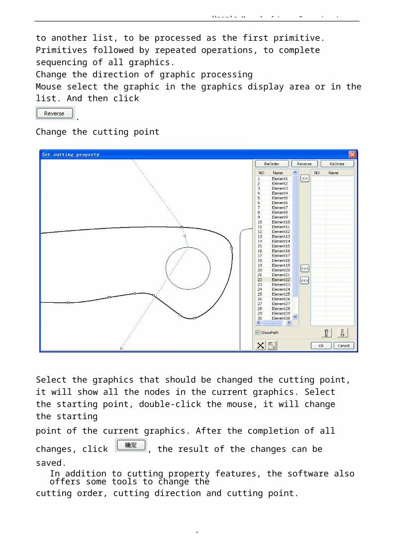
User’s Manual of Laser Engraving /
1
to another list, to be processed as the first primitive.Primitives followed by repeated operations, to complete sequencing of all graphics.Change the direction of graphic processingMouse select the graphic in the graphics display area or in thelist. And then click
.Change the cutting point
Select the graphics that should be changed the cutting point,it will show all the nodes in the current graphics. Select the starting point, double-click the mouse, it will change the startingpoint of the current graphics. After the completion of all
changes, click , the result of the changes can be saved.
In addition to cutting property features, the software also offers some tools to change the
cutting order, cutting direction and cutting point.
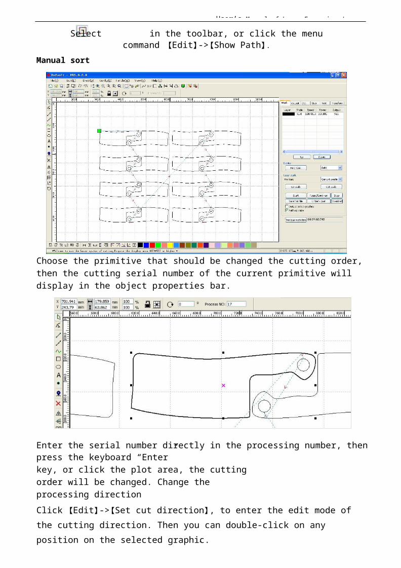
User’s Manual of Laser Engraving /
1
Select in the toolbar, or click the menucommand 【Edit】->【Show Path】.
Manual sort
Choose the primitive that should be changed the cutting order,then the cutting serial number of the current primitive will display in the object properties bar.
Enter the serial number directly in the processing number, thenpress the keyboard “Enter”key, or click the plot area, the cuttingorder will be changed. Change the processing directionClick 【Edit】->【Set cut direction】, to enter the edit mode of the cutting direction. Then you can double-click on any position on the selected graphic.
User’s Manual of Laser Engraving /
1
Change the cutting pointClick 【Edit】->【Set cut point】, to enter the edit mode of the cutting point. Then select the curve that should be edited, you can double-click on the node that you want to set the cuttingpoint to complete the change of the cutting point.
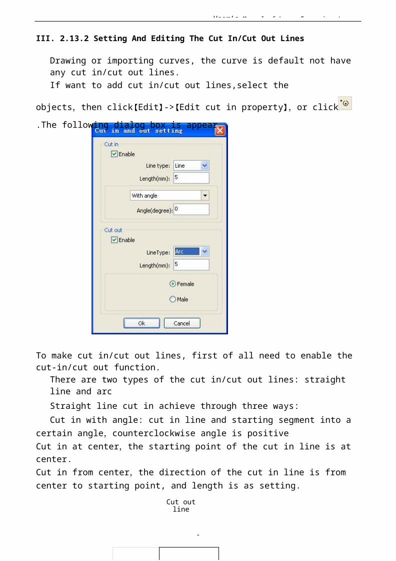
User’s Manual of Laser Engraving /
1
III. 2.13.2 Setting And Editing The Cut In/Cut Out Lines
Drawing or importing curves, the curve is default not have any cut in/cut out lines.If want to add cut in/cut out lines,select the
objects,then click【Edit】->【Edit cut in property】,or click
.The following dialog box is appear.
To make cut in/cut out lines, first of all need to enable the cut-in/cut out function.
There are two types of the cut in/cut out lines: straight line and arcStraight line cut in achieve through three ways:Cut in with angle: cut in line and starting segment into a
certain angle,counterclockwise angle is positiveCut in at center,the starting point of the cut in line is at center.Cut in from center,the direction of the cut in line is from center to starting point, and length is as setting.
Cut outline
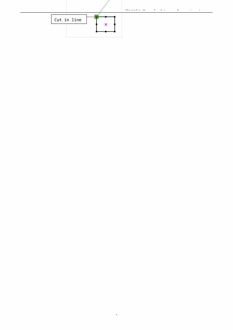
User’s Manual of Laser Engraving /
1
Cut in line
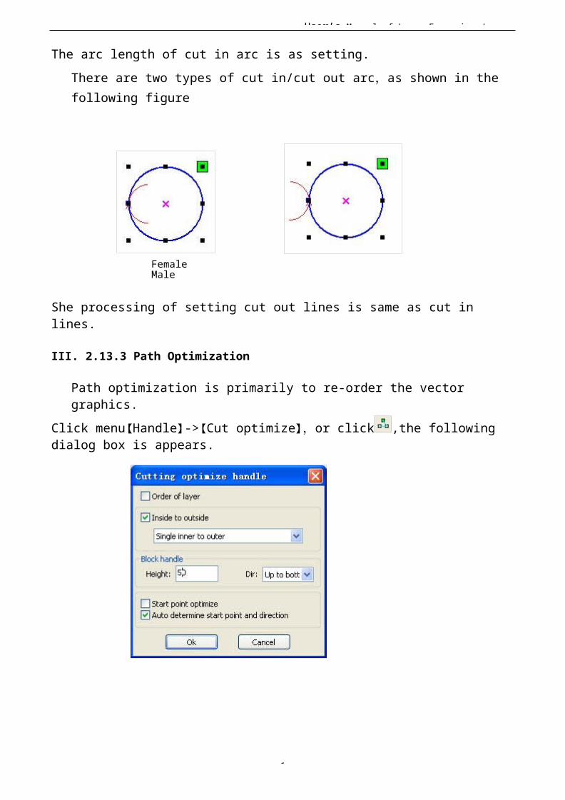
User’s Manual of Laser Engraving /
1
The arc length of cut in arc is as setting.There are two types of cut in/cut out arc,as shown in the following figure
Female Male
She processing of setting cut out lines is same as cut in lines.
III. 2.13.3 Path Optimization
Path optimization is primarily to re-order the vector graphics.
Click menu【Handle】->【Cut optimize】,or click ,the following dialog box is appears.
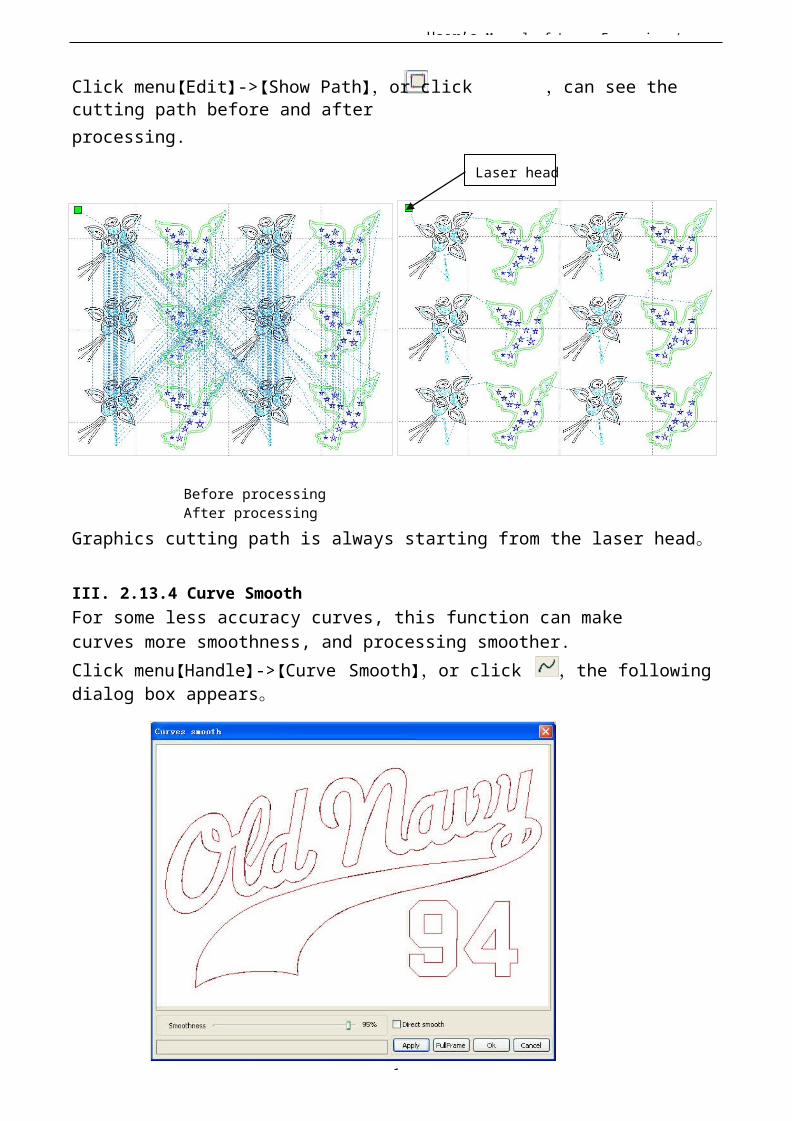
User’s Manual of Laser Engraving /
1
Click menu【Edit】->【Show Path】,or click ,can see the cutting path before and afterprocessing.
Laser head
Before processing After processing
Graphics cutting path is always starting from the laser head。
III. 2.13.4 Curve SmoothFor some less accuracy curves, this function can make curves more smoothness, and processing smoother.Click menu【Handle】->【Curve Smooth】,or click ,the following dialog box appears。
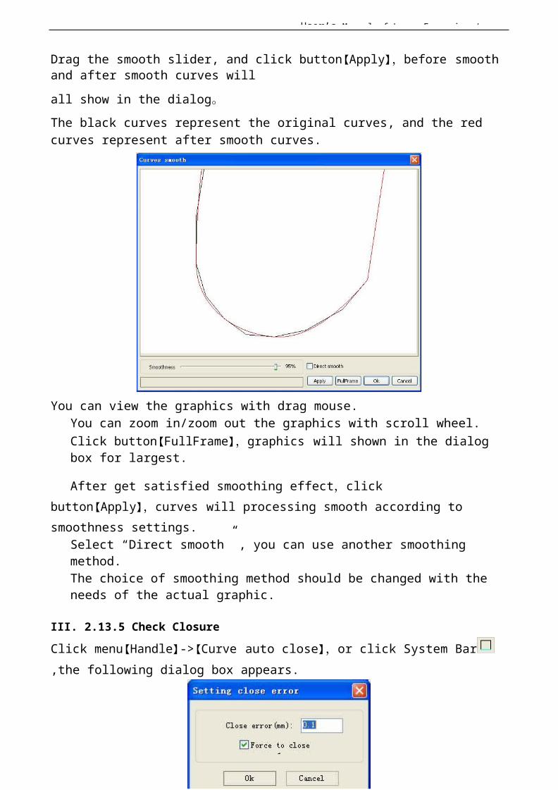
User’s Manual of Laser Engraving /
1
Drag the smooth slider, and click button【Apply】,before smooth and after smooth curves willall show in the dialog。The black curves represent the original curves, and the redcurves represent after smooth curves.
You can view the graphics with drag mouse.You can zoom in/zoom out the graphics with scroll wheel.Click button【FullFrame】,graphics will shown in the dialog box for largest.
After get satisfied smoothing effect,click button【Apply】,curves will processing smooth according to smoothness settings.
Select “Direct smooth” , you can use another smoothing method.The choice of smoothing method should be changed with the needs of the actual graphic.
III. 2.13.5 Check ClosureClick menu【Handle】->【Curve auto close】,or click System Bar,the following dialog box appears.
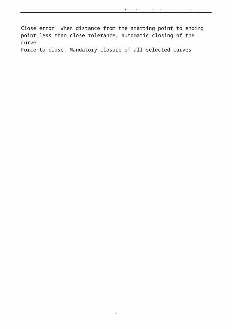
User’s Manual of Laser Engraving /
1
Close error: When distance from the starting point to ending point less than close tolerance, automatic closing of the curve.Force to close: Mandatory closure of all selected curves.
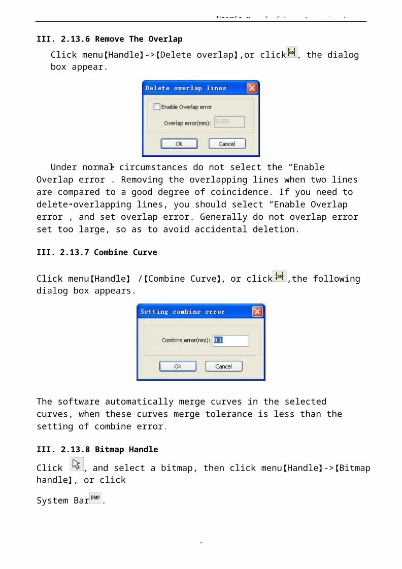
User’s Manual of Laser Engraving /
1
III. 2.13.6 Remove The OverlapClick menu【Handle】->【Delete overlap】,or click ,the dialog box appear.
Under normal circumstances do not select the “Enable Overlap error”. Removing the overlapping lines when two linesare compared to a good degree of coincidence. If you need to delete overlapping lines, you should select “Enable Overlap error”, and set overlap error. Generally do not overlap errorset too large, so as to avoid accidental deletion.
III. 2.13.7 Combine Curve
Click menu【Handle】 /【Combine Curve】,or click ,the following dialog box appears.
The software automatically merge curves in the selected curves, when these curves merge tolerance is less than the setting of combine error.
III. 2.13.8 Bitmap Handle
Click ,and select a bitmap, then click menu【Handle】->【Bitmaphandle】, or click
System Bar .

User’s Manual of Laser Engraving /
1
In the top right of the dialog box displays theinformation of the current image.Be noted that , the horizontal resolution and verticalresolution is changing with drag scaling.【Apply to view】:Current settings is only used for preview, without affecting to the original bitmap,press button【Cancel】,bitmap will returned to the state of original image. Therefore,only use for adjust effect. However, this approach requiresmore time and memory Space.【Apply to source 】:Current sttings is use for orginal bitmapdirectly,so even finally click button【Cancel】,image will alsounable to return to the original image. Therefore, it mainlyused in multi-step operation,and the current operation of thisstep is necessary to do, such asgeneral pictures must be transformed into grayscale. This can save the computing time of the follow-up operation.【 Save as 】: Retain the results of the previous operation, Inaddition to using【Apply to view】can also be exported 。 On this basic, tofacilitate subsequent processing.

User’s Manual of Laser Engraving /
1
【Gray scale】Generally, other image processing is based on thegrayscale,so before handling, you can do a grayscale processing, then click button【Apply to source】。For thegrayscale than the color image occupied smaller memory,for large image step by step handle, to a certain extent to avoid the lack of memory.For color image, adjust contrast and brightness, have someauxiliary effect to following dither processing.
Adjustcontrast:
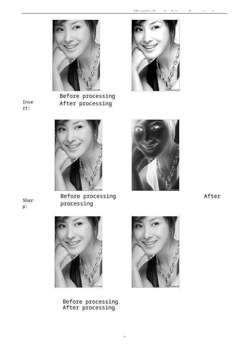
1
User’s Manual of Laser Engraving /
Invert:
Sharp:
Before processing After processing
Before processing After processing
Before processing After processing

1
User’s Manual of Laser Engraving / There are three method for dither processing: Net graphic、Dot graphic、Black and white
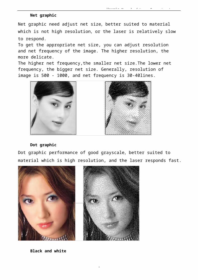
User’s Manual of Laser Engraving /
1
Net graphic
Net graphic need adjust net size,better suited to material which is not high resolution,or the laser is relatively slow to respond.To get the appropriate net size, you can adjust resolution and net frequency of the image. The higher resolution, the more delicate.The higher net frequency,the smaller net size.The lower net frequency, the bigger net size. Generally, resolution of image is 500 - 1000, and net frequency is 30-40lines.
Dot graphicDot graphic performance of good grayscale,better suited to material which is high resolution, and the laser responds fast.
Black and white

User’s Manual of Laser Engraving /
1
In most cases, the effects of color image into black and white image is poor,,however, for some clear outline image, is very easy to use.
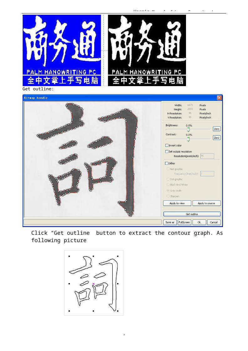
User’s Manual of Laser Engraving /
1
Get outline:
Click “Get outline” button to extract the contour graph. Asfollowing picture
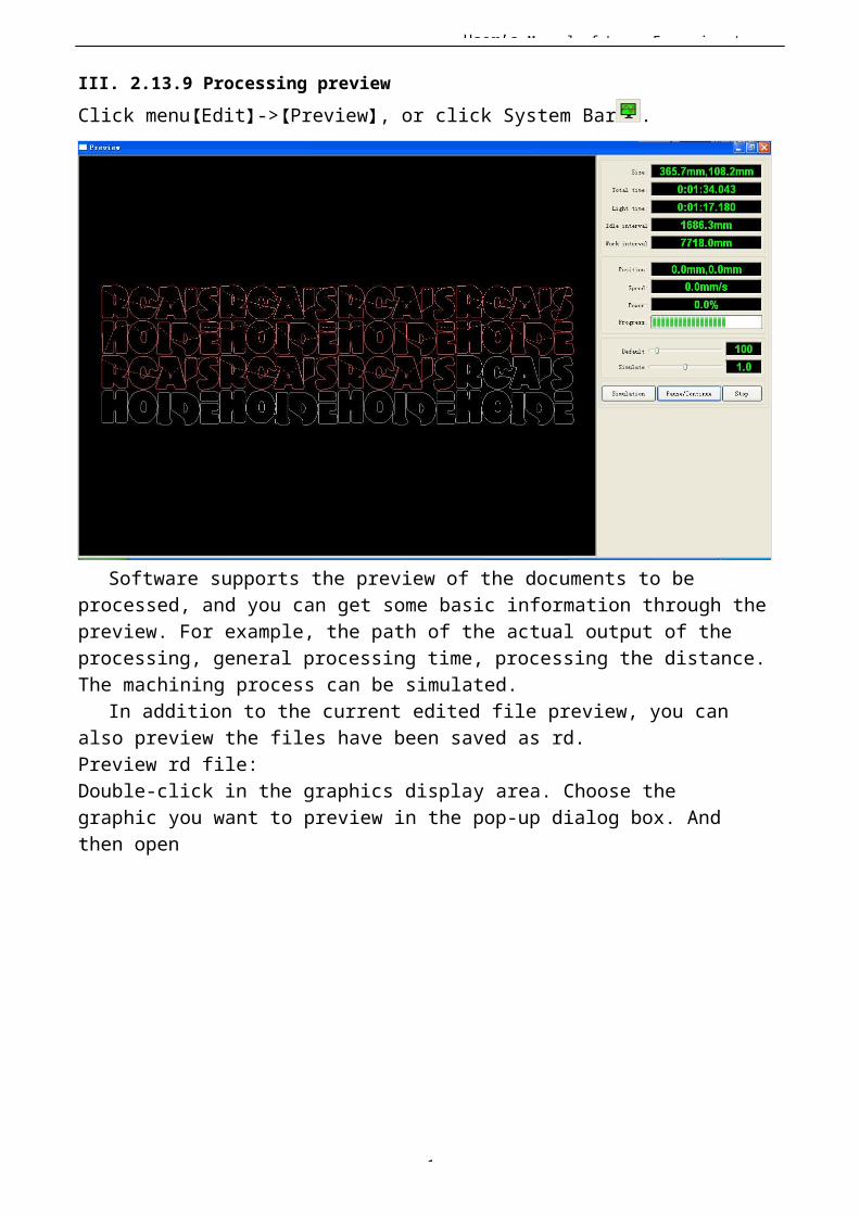
User’s Manual of Laser Engraving /
1
III. 2.13.9 Processing previewClick menu【Edit】->【Preview】, or click System Bar .
Software supports the preview of the documents to be processed, and you can get some basic information through thepreview. For example, the path of the actual output of the processing, general processing time, processing the distance.The machining process can be simulated.
In addition to the current edited file preview, you can also preview the files have been saved as rd.Preview rd file:Double-click in the graphics display area. Choose the graphic you want to preview in the pop-up dialog box. And then open
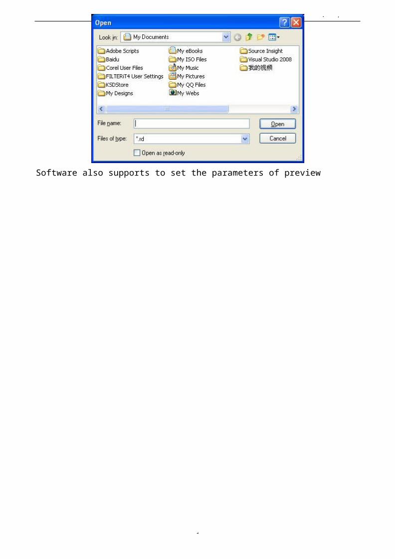
User’s Manual of Laser Engraving /
1
Software also supports to set the parameters of preview
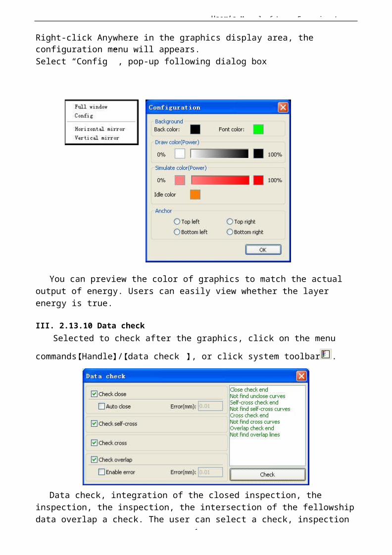
User’s Manual of Laser Engraving /
1
Right-click Anywhere in the graphics display area, the configuration menu will appears.Select “Config” , pop-up following dialog box
You can preview the color of graphics to match the actualoutput of energy. Users can easily view whether the layer energy is true.
III. 2.13.10 Data checkSelected to check after the graphics, click on the menu
commands【Handle】/【data check 】, or click system toolbar .
Data check, integration of the closed inspection, the inspection, the inspection, the intersection of the fellowshipdata overlap a check. The user can select a check, inspection

User’s Manual of Laser Engraving /
1
to the problem after data, will be in the dialog box right tiphave been found and, at the same time, the problem in selectedstate graphics. Check-> ruled out repeatedly error-> inspection process until all the data are conform to the requirements of the processing.
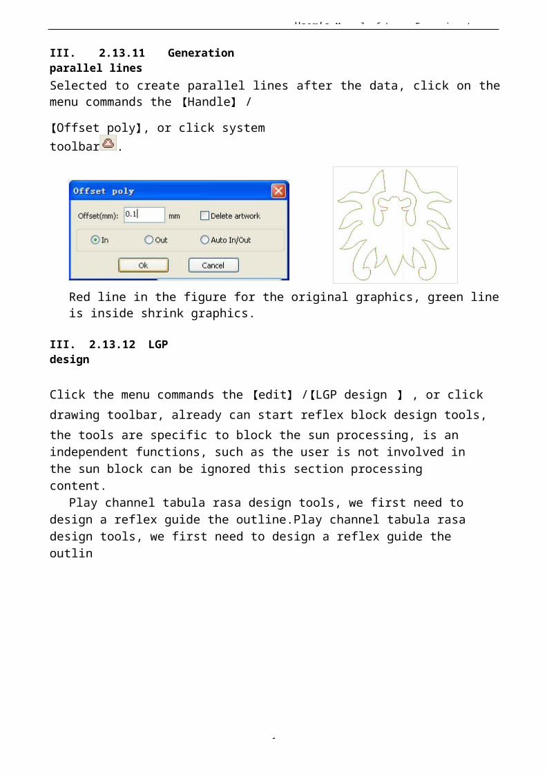
User’s Manual of Laser Engraving /
1
III. 2.13.11 Generationparallel linesSelected to create parallel lines after the data, click on themenu commands the 【Handle】 /
【Offset poly】, or click systemtoolbar .
Red line in the figure for the original graphics, green lineis inside shrink graphics.
III. 2.13.12 LGPdesign
Click the menu commands the 【edit】 /【LGP design 】 , or click drawing toolbar, already can start reflex block design tools, the tools are specific to block the sun processing, is anindependent functions, such as the user is not involved in the sun block can be ignored this section processing content.
Play channel tabula rasa design tools, we first need to design a reflex guide the outline.Play channel tabula rasa design tools, we first need to design a reflex guide the outlin
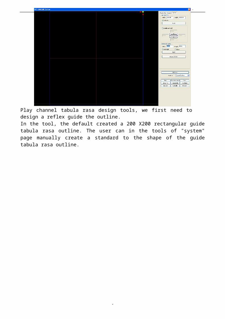
User’s Manual of Laser Engraving /
1
Play channel tabula rasa design tools, we first need todesign a reflex guide the outline.In the tool, the default created a 200 X200 rectangular guidetabula rasa outline. The user can in the tools of "system"page manually create a standard to the shape of the guidetabula rasa outline.
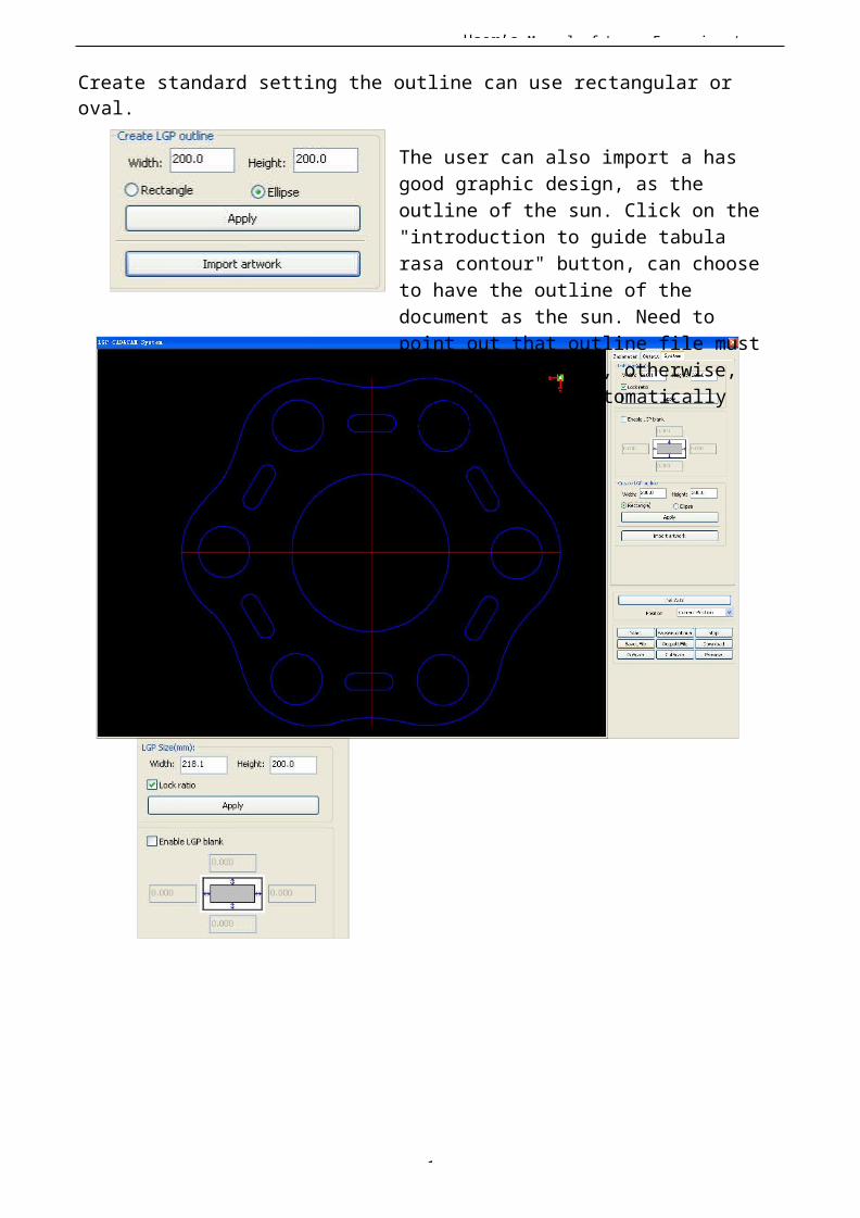
User’s Manual of Laser Engraving /
1
Create standard setting the outline can use rectangular or oval.
The user can also import a has good graphic design, as the outline of the sun. Click on the "introduction to guide tabula rasa contour" button, can choose to have the outline of the document as the sun. Need to point out that outline file must be closed graphics, otherwise, the system will automatically deleted.

User’s Manual of Laser Engraving /
1
If the outline of import size requirements, users can also change size outline, and can set up if stay white edge.Outline graphics ready, they can start on the tabula rasa increase network.
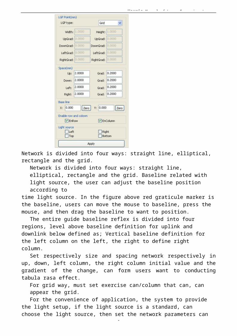
User’s Manual of Laser Engraving /
1
Network is divided into four ways: straight line, elliptical, rectangle and the grid.
Network is divided into four ways: straight line, elliptical, rectangle and the grid. Baseline related with light source, the user can adjust the baseline position according to
time light source. In the figure above red graticule marker isthe baseline, users can move the mouse to baseline, press the mouse, and then drag the baseline to want to position.
The entire guide baseline reflex is divided into four regions, level above baseline definition for uplink and downlink below defined as; Vertical baseline definition for the left column on the left, the right to define right column.
Set respectively size and spacing network respectively inup, down, left column, the right column initial value and thegradient of the change, can form users want to conductingtabula rasa effect.
For grid way, must set exercise can/column that can, can appear the grid.For the convenience of application, the system to provide
the light setup, if the light source is a standard, can choose the light source, then set the network parameters can

User’s Manual of Laser Engraving /
1
be, do not need to adjust the baseline. At this time, baseline shows hides also.
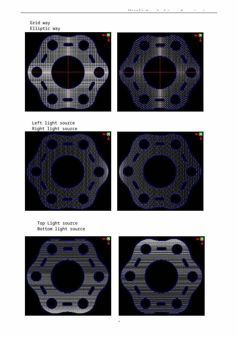
User’s Manual of Laser Engraving /
1
Grid way Elliptic way
Left light source Right light source
Top Light source Bottom light source
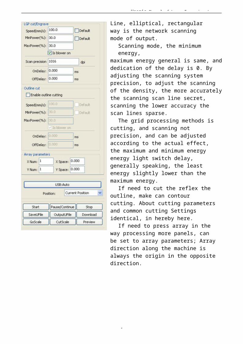
User’s Manual of Laser Engraving /
1
Line, elliptical, rectangular way is the network scanning mode of output.
Scanning mode, the minimum energy,
maximum energy general is same, anddedication of the delay is 0. By adjusting the scanning system precision, to adjust the scanning of the density, the more accuratelythe scanning scan line secret, scanning the lower accuracy the scan lines sparse.
The grid processing methods is cutting, and scanning not precision, and can be adjusted according to the actual effect, the maximum and minimum energy energy light switch delay, generally speaking, the least energy slightly lower than the maximum energy.
If need to cut the reflex the outline, make can contour cutting. About cutting parametersand common cutting Settings identical, in hereby here.
If need to press array in the way processing more panels, can be set to array parameters; Arraydirection along the machine is always the origin in the oppositedirection.
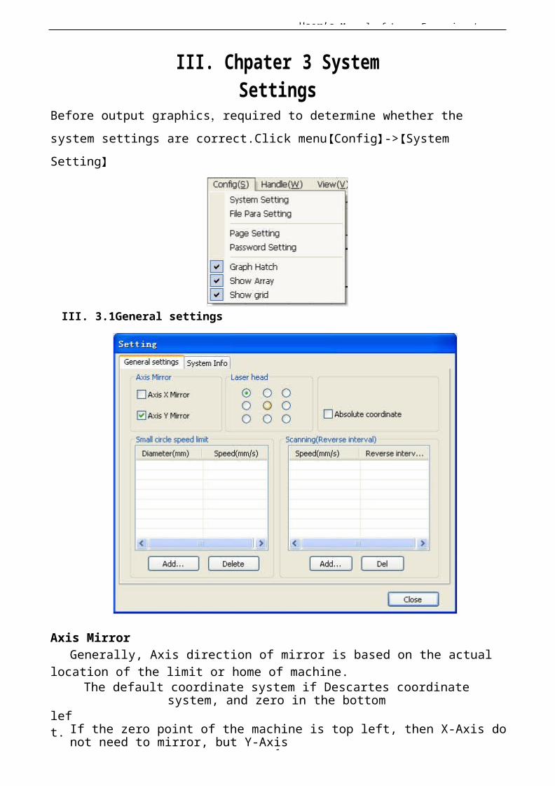
1
User’s Manual of Laser Engraving /
III. Chpater 3 SystemSettings
Before output graphics,required to determine whether the system settings are correct.Click menu【Config】->【System Setting】
III. 3.1General settings
Axis MirrorGenerally, Axis direction of mirror is based on the actual
location of the limit or home of machine.The default coordinate system if Descartes coordinate
system, and zero in the bottomleft. If the zero point of the machine is top left, then X-Axis do
not need to mirror, but Y-Axis

1
User’s Manual of Laser Engraving / need to mirror.If the zero point of the machine is top right, then both X-
Axis and Y-Axis are all need to mirror.
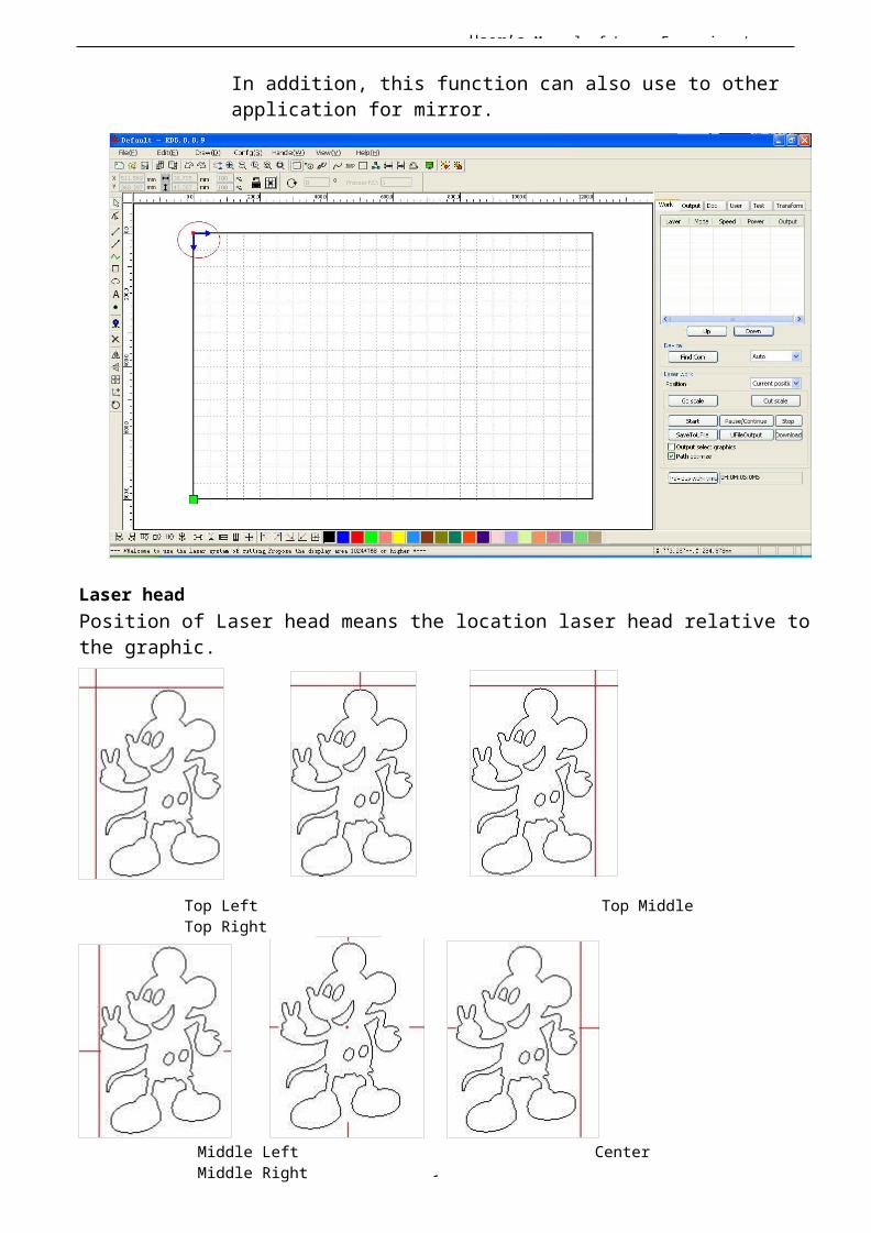
User’s Manual of Laser Engraving /
1
In addition, this function can also use to other application for mirror.
Laser headPosition of Laser head means the location laser head relative tothe graphic.
Top Left Top Middle Top Right
Middle Left Center Middle Right
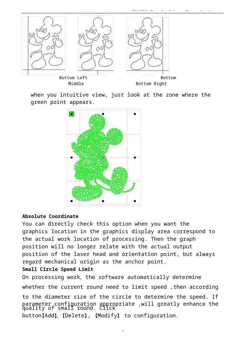
User’s Manual of Laser Engraving /
1
Bottom Left BottomMiddle Bottom Right
when you intuitive view, just look at the zone where the green point appears.
Absolute CoordinateYou can directly check this option when you want the graphics location in the graphics display area correspond tothe actual work location of processing. Then the graph position will no longer relate with the actual output position of the laser head and orientation point, but alwaysregard mechanical origin as the anchor point.Small Circle Speed LimitOn processing work,the software automatically determine whether the current round need to limit speed ,then according to the diameter size of the circle to determine the speed. Ifparameter configuration appropriate ,will greatly enhance the quality of small round. Clickbutton【Add】,【Delete】, 【Modify】 to configuration.
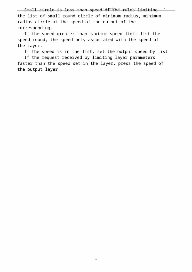
User’s Manual of Laser Engraving /
1
Small circle is less than speed of the rules limiting the list of small round circle of minimum radius, minimum radius circle at the speed of the output of the corresponding.
If the speed greater than maximum speed limit list the speed round, the speed only associated with the speed of the layer.
If the speed is in the list, set the output speed by list.If the request received by limiting layer parameters
faster than the speed set in the layer, press the speed of the output layer.
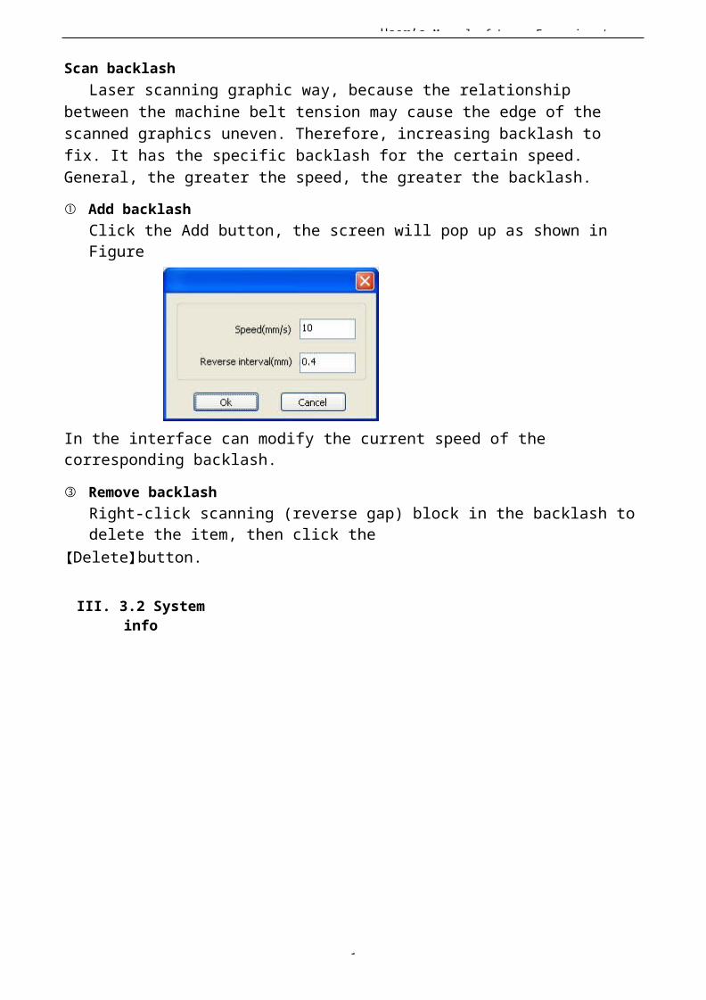
User’s Manual of Laser Engraving /
1
Scan backlashLaser scanning graphic way, because the relationship
between the machine belt tension may cause the edge of the scanned graphics uneven. Therefore, increasing backlash to fix. It has the specific backlash for the certain speed. General, the greater the speed, the greater the backlash.
① Add backlashClick the Add button, the screen will pop up as shown in Figure
In the interface can modify the current speed of the corresponding backlash.
③ Remove backlashRight-click scanning (reverse gap) block in the backlash to delete the item, then click the
【Delete】button.
III. 3.2 Systeminfo
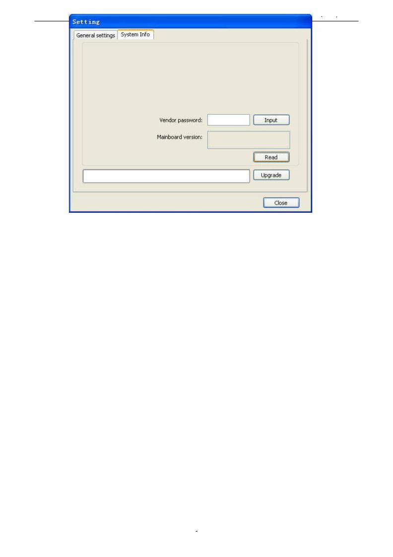
User’s Manual of Laser Engraving /
1
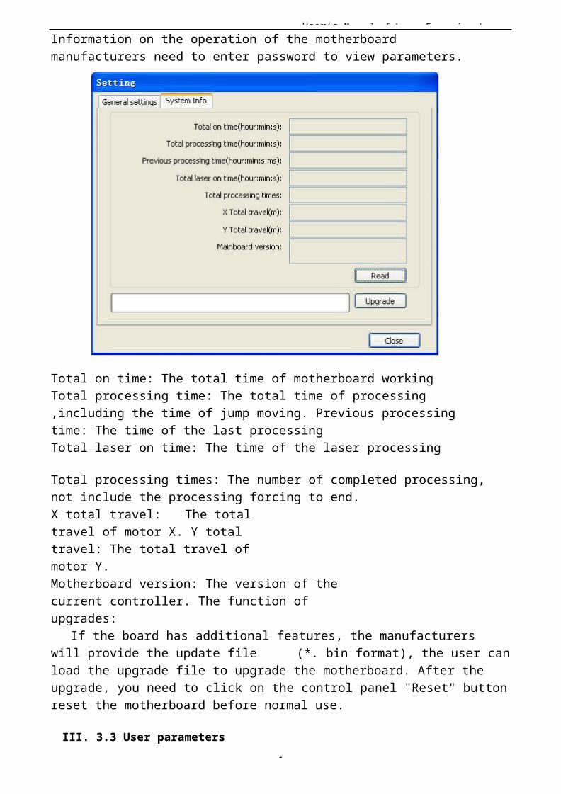
User’s Manual of Laser Engraving /
1
Information on the operation of the motherboard manufacturers need to enter password to view parameters.
Total on time: The total time of motherboard workingTotal processing time: The total time of processing,including the time of jump moving. Previous processing time: The time of the last processingTotal laser on time: The time of the laser processing
Total processing times: The number of completed processing,not include the processing forcing to end.X total travel: The total travel of motor X. Y total travel: The total travel of motor Y.Motherboard version: The version of thecurrent controller. The function of upgrades:
If the board has additional features, the manufacturers will provide the update file (*. bin format), the user canload the upgrade file to upgrade the motherboard. After the upgrade, you need to click on the control panel "Reset" buttonreset the motherboard before normal use.
III. 3.3 User parameters
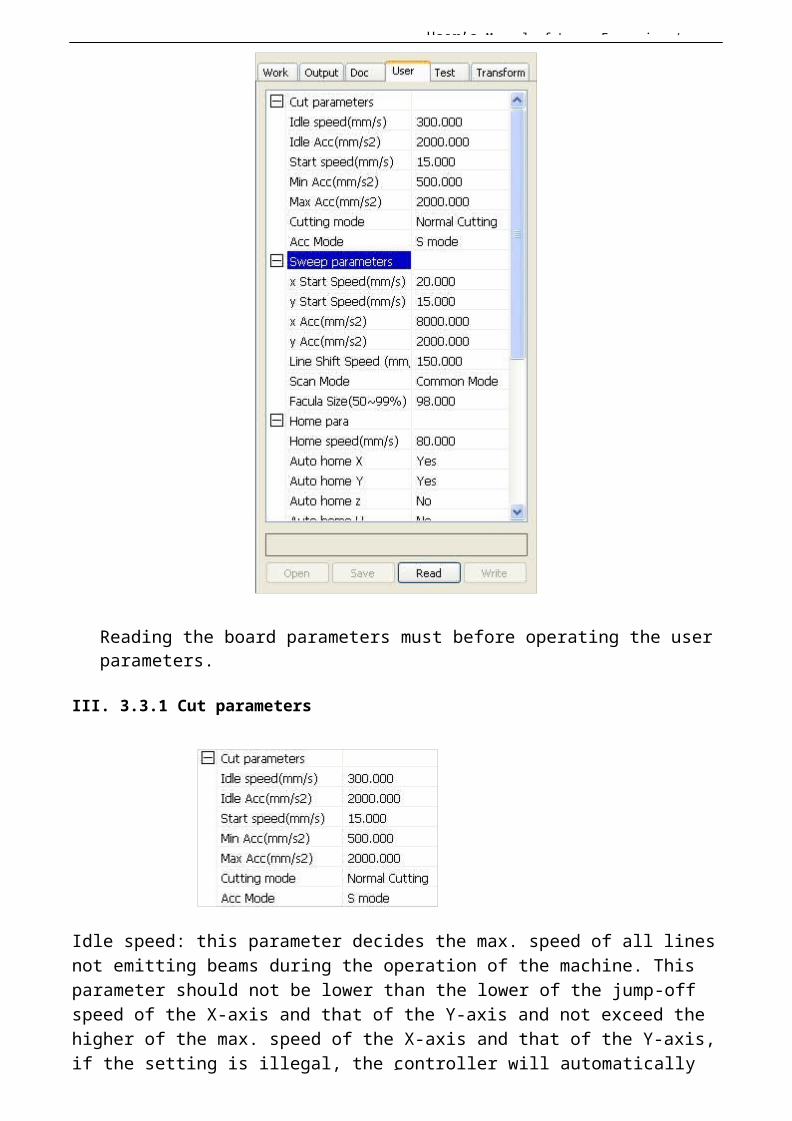
User’s Manual of Laser Engraving /
1
Reading the board parameters must before operating the user parameters.
III. 3.3.1 Cut parameters
Idle speed: this parameter decides the max. speed of all linesnot emitting beams during the operation of the machine. This parameter should not be lower than the lower of the jump-off speed of the X-axis and that of the Y-axis and not exceed the higher of the max. speed of the X-axis and that of the Y-axis,if the setting is illegal, the controller will automatically

User’s Manual of Laser Engraving /
1
set this parameter within the range above; a comparatively high idling speed can shorten theoperation time of the entire figure while excessively high idling speed may cause dithering of the tracks, therefore, youshould take all relevant factors into consideration when setting.
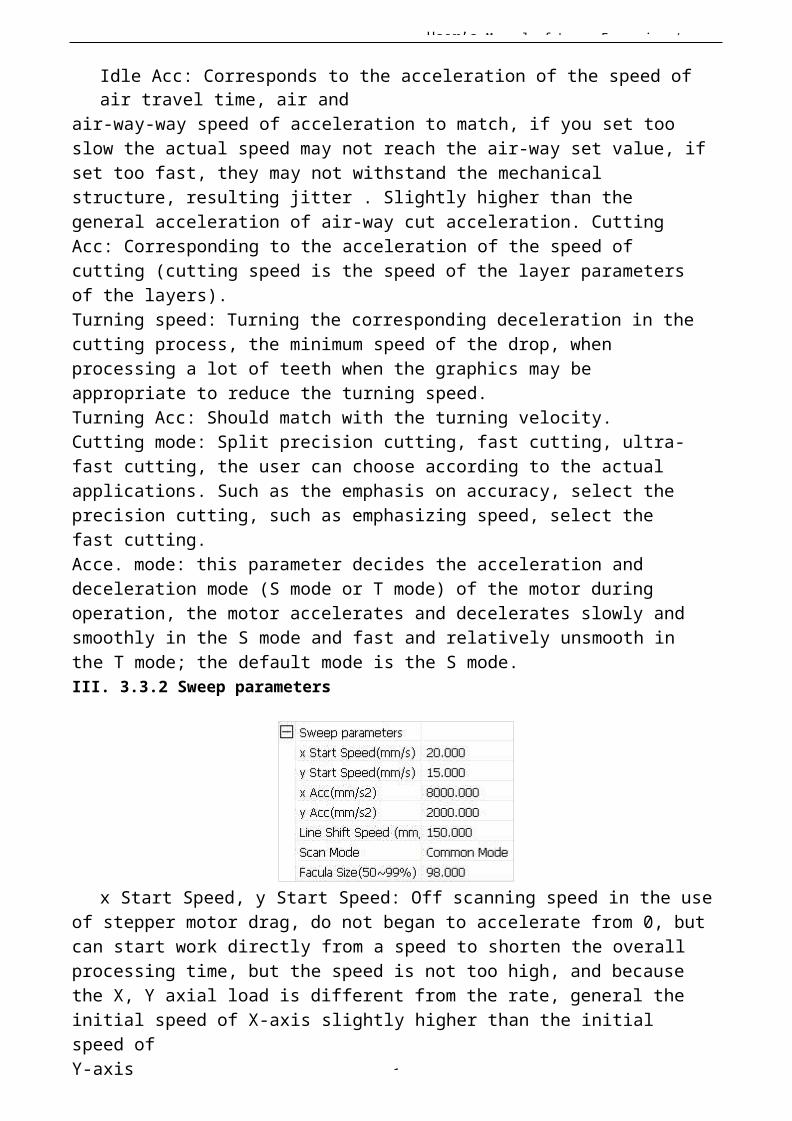
User’s Manual of Laser Engraving /
1
Idle Acc: Corresponds to the acceleration of the speed of air travel time, air and
air-way-way speed of acceleration to match, if you set too slow the actual speed may not reach the air-way set value, ifset too fast, they may not withstand the mechanical structure, resulting jitter . Slightly higher than the general acceleration of air-way cut acceleration. Cutting Acc: Corresponding to the acceleration of the speed of cutting (cutting speed is the speed of the layer parameters of the layers).Turning speed: Turning the corresponding deceleration in the cutting process, the minimum speed of the drop, when processing a lot of teeth when the graphics may be appropriate to reduce the turning speed.Turning Acc: Should match with the turning velocity.Cutting mode: Split precision cutting, fast cutting, ultra-fast cutting, the user can choose according to the actual applications. Such as the emphasis on accuracy, select the precision cutting, such as emphasizing speed, select the fast cutting.Acce. mode: this parameter decides the acceleration and deceleration mode (S mode or T mode) of the motor during operation, the motor accelerates and decelerates slowly and smoothly in the S mode and fast and relatively unsmooth in the T mode; the default mode is the S mode.III. 3.3.2 Sweep parameters
x Start Speed, y Start Speed: Off scanning speed in the useof stepper motor drag, do not began to accelerate from 0, butcan start work directly from a speed to shorten the overall processing time, but the speed is not too high, and because the X, Y axial load is different from the rate, general the initial speed of X-axis slightly higher than the initial speed ofY-axis
User’s Manual of Laser Engraving /
1
x Acc, y Acc: With the scanning speed (the speed of layers in the layer parameters) to match, if set too small, the scan speed to a longer distance, the scanning efficiency. The machine can be set according to the actual structure, load conditions vary. Since X, Y axis load, generally much higher than the X-axis Y-axis accelerometer.
Line shift speed of scanning: this parameter is specially used to control the max. speed of the scanning to shift vertically from one line to the next line below it. If during the scanning, the line space is too large or the block space is too large when scanning block figures while precise positioning for each line or block is required, you can set the line shirt speed of scanning to a comparatively low value.This parameter cannot be less than the jump-offspeed of the corresponding axis during the line shift and cannot be higher than the max. speed of the corresponding axis during the line shift, if the setting is illegal, the controller will automatically set this parameter within therange above.Scan mode: There are two modes for your selection: the generalmode and the special mode, in the general mode, there’s no anytreatment during the scan, in the special mode, light spots will be treated. If the special mode is activated, the power of the laser should be increased
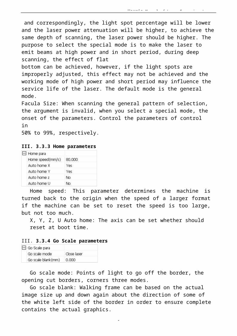
User’s Manual of Laser Engraving /
1
and correspondingly, the light spot percentage will be lower and the laser power attenuation will be higher, to achieve thesame depth of scanning, the laser power should be higher. The purpose to select the special mode is to make the laser to emit beams at high power and in short period, during deep scanning, the effect of flatbottom can be achieved, however, if the light spots are improperly adjusted, this effect may not be achieved and the working mode of high power and short period may influence theservice life of the laser. The default mode is the general mode.Facula Size: When scanning the general pattern of selection,the argument is invalid, when you select a special mode, theonset of the parameters. Control the parameters of control in50% to 99%, respectively.
III. 3.3.3 Home parameters
Home speed: This parameter determines the machine isturned back to the origin when the speed of a larger formatif the machine can be set to reset the speed is too large,but not too much.
X, Y, Z, U Auto home: The axis can be set whether should reset at boot time.
III. 3.3.4 Go Scale parameters
Go scale mode: Points of light to go off the border, the opening cut borders, corners three modes.
Go scale blank: Walking frame can be based on the actual image size up and down again about the direction of some of the white left side of the border in order to ensure complete contains the actual graphics.
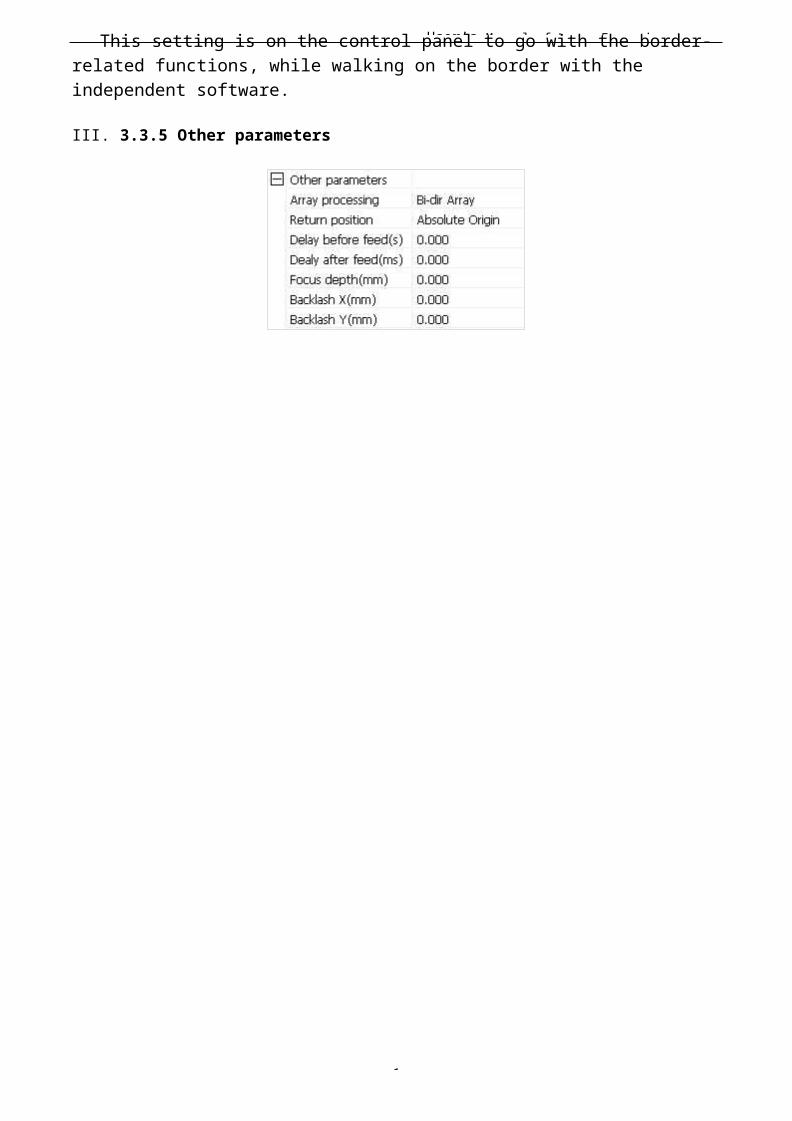
User’s Manual of Laser Engraving /
1
This setting is on the control panel to go with the border-related functions, while walking on the border with the independent software.
III. 3.3.5 Other parameters
User’s Manual of Laser Engraving /
1
Array mode: you can choose the swing mode and the one-way
mode. The Swing mode: cutting the array back and forth in
order; the One-way mode: always cutting the array from one
direction to another. If One-way mode is selected, all array
units have the same movement modes and the same liquidity of
movement, however, this mode will take more time than the
swing mode. The default mode is the Swing mode.
Return position: You can select the locating point and the
machine origin. This parameter decides the position, the
locating point or the machine origin, where the laser head
stops upon completion of each operation.
Delay before feed: Using the feeding device, the delay before
a single feed, users can arrange the time and the like, such
as picking process.
Delay after feed: Refers to the material sent to the feed
device in place, the need for stability after a period of
time for processing.
Focus depth: Auto focus operation to find the corresponding panel.
Backlash X, Y: Used to compensate the backlash caused by the machine drive problems.
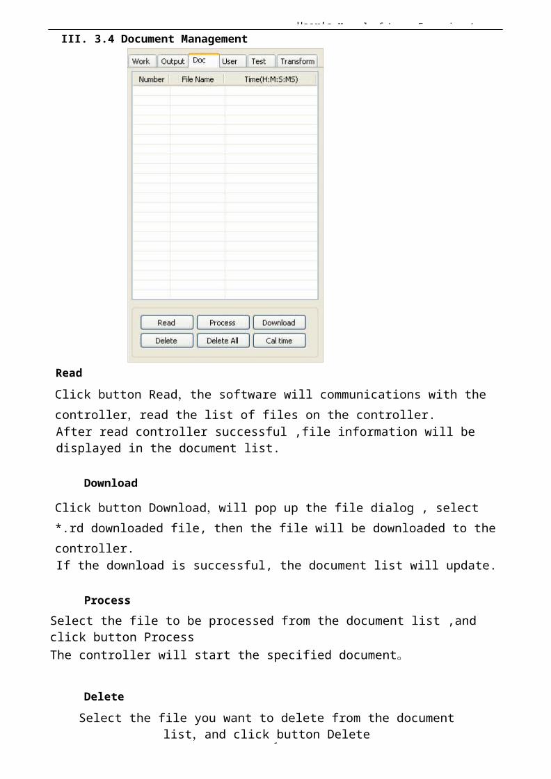
User’s Manual of Laser Engraving /
1
III. 3.4 Document Management
ReadClick button Read,the software will communications with the controller,read the list of files on the controller.After read controller successful ,file information will be displayed in the document list.
Download
Click button Download,will pop up the file dialog , select *.rd downloaded file, then the file will be downloaded to the controller.If the download is successful, the document list will update.
ProcessSelect the file to be processed from the document list ,and click button ProcessThe controller will start the specified document。
DeleteSelect the file you want to delete from the document
list,and click button Delete

User’s Manual of Laser Engraving /
1
The controller will delete the specified document.If the deletion is successful ,the document list will be updated.
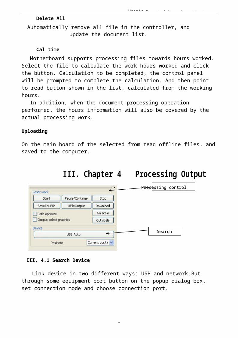
User’s Manual of Laser Engraving /
1
Delete AllAutomatically remove all file in the controller, and
update the document list.
Cal timeMotherboard supports processing files towards hours worked.
Select the file to calculate the work hours worked and click the button. Calculation to be completed, the control panel will be prompted to complete the calculation. And then point to read button shown in the list, calculated from the working hours.
In addition, when the document processing operation performed, the hours information will also be covered by theactual processing work.
Uploading
On the main board of the selected from read offline files, andsaved to the computer.
III. Chapter 4 Processing OutputProcessing control
Search
III. 4.1 Search Device
Link device in two different ways: USB and network.But through some equipment port button on the popup dialog box, set connection mode and choose connection port.
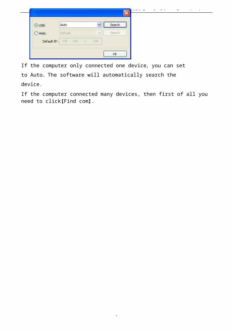
User’s Manual of Laser Engraving /
1
If the computer only connected one device,you can set to Auto。The software will automatically search the device.If the computer connected many devices, then first of all you need to click【Find com】.
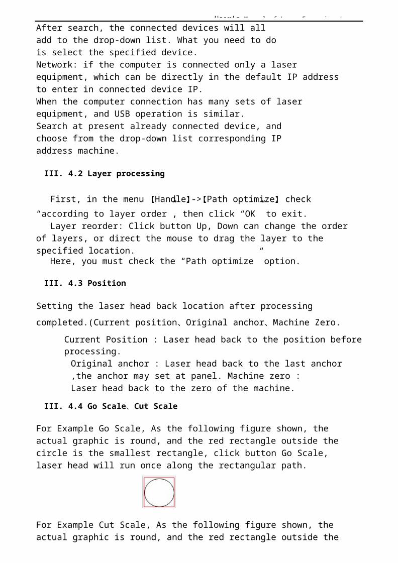
User’s Manual of Laser Engraving /
1
After search, the connected devices will all add to the drop-down list. What you need to dois select the specified device.Network: if the computer is connected only a laser equipment, which can be directly in the default IP address to enter in connected device IP.When the computer connection has many sets of laser equipment, and USB operation is similar.Search at present already connected device, and choose from the drop-down list corresponding IP address machine.
III. 4.2 Layer processing
First, in the menu 【Handle】->【Path optimize】 check “according to layer order”, then click “OK” to exit.
Layer reorder: Click button Up, Down can change the order of layers, or direct the mouse to drag the layer to the specified location.
Here, you must check the “Path optimize” option.
III. 4.3 Position
Setting the laser head back location after processing completed.(Current position、Original anchor、Machine Zero.
Current Position : Laser head back to the position beforeprocessing.Original anchor : Laser head back to the last anchor,the anchor may set at panel. Machine zero : Laser head back to the zero of the machine.
III. 4.4 Go Scale、Cut Scale
For Example Go Scale, As the following figure shown, the actual graphic is round, and the red rectangle outside the circle is the smallest rectangle, click button Go Scale, laser head will run once along the rectangular path.
For Example Cut Scale, As the following figure shown, the actual graphic is round, and the red rectangle outside the

User’s Manual of Laser Engraving /
1
circle is the smallest rectangle, click button Cut Scale, laser head will be cut along the rectangle.
III. 4.5 Start、Pause、Stop、SaveToUFile、UFileOutput、Download
Start:Output the current graphic to the machine for processing. Pause\Continue:Click Pause,will stop the processing work, click the button again toContinueStop:Stop the current processing work
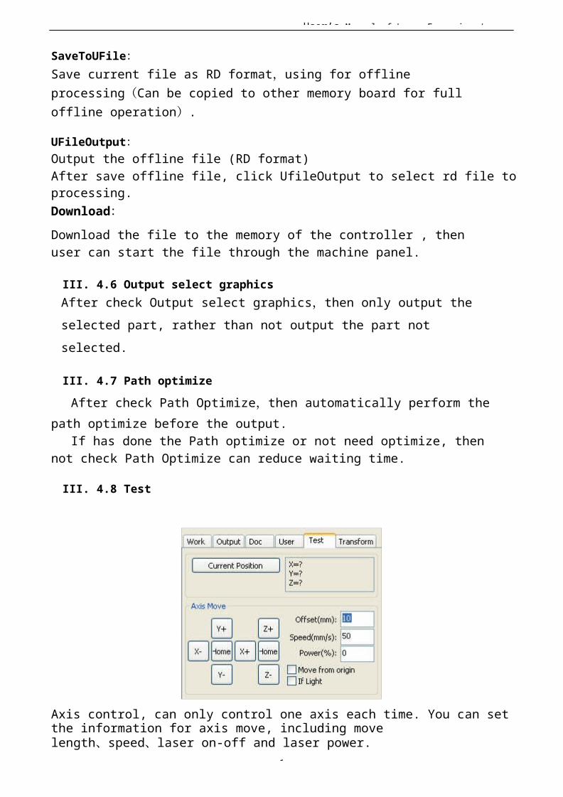
User’s Manual of Laser Engraving /
1
SaveToUFile:Save current file as RD format,using for offline processing(Can be copied to other memory board for full offline operation).
UFileOutput:Output the offline file (RD format)After save offline file, click UfileOutput to select rd file toprocessing.Download:Download the file to the memory of the controller , then user can start the file through the machine panel.
III. 4.6 Output select graphicsAfter check Output select graphics,then only output the selected part, rather than not output the part not selected.
III. 4.7 Path optimizeAfter check Path Optimize,then automatically perform the
path optimize before the output.If has done the Path optimize or not need optimize, then
not check Path Optimize can reduce waiting time.
III. 4.8 Test
Axis control, can only control one axis each time. You can setthe information for axis move, including move length、speed、laser on-off and laser power.
User’s Manual of Laser Engraving /
1
If you check “Move from origin”, then the offset you set meansthe offset to machine zero. If you not check move from origin,then the offset means the offset to the current position. The X-axis, for example, assuming the current position is 100mm, such as the step distance is set to 10mm, then the exercise once, the new location will be 110mm, such as the check
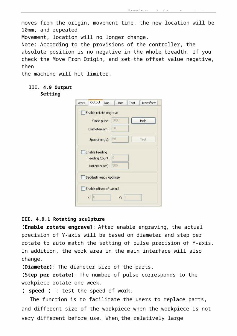
User’s Manual of Laser Engraving /
1
moves from the origin, movement time, the new location will be 10mm, and repeatedMovement, location will no longer change.Note: According to the provisions of the controller, the absolute position is no negative in the whole breadth. If you check the Move From Origin, and set the offset value negative,thenthe machine will hit limiter.
III. 4.9 OutputSetting
III. 4.9.1 Rotating sculpture【Enable rotate engrave】:After enable engraving,the actual precision of Y-axis will be based on diameter and step per rotate to auto match the setting of pulse precision of Y-axis.In addition, the work area in the main interface will also change.【Diameter】:The diameter size of the parts.【Step per rotate】:The number of pulse corresponds to the workpiece rotate one week.【 speed 】 : test the speed of work.
The function is to facilitate the users to replace parts, and different size of the workpiece when the workpiece is notvery different before use. When the relatively large
User’s Manual of Laser Engraving /
1
difference in size of the workpiece, it is recommended to usedirectly modify the motor step approach to implementation.
Rotary engraving is only when using the rotation axis to replace the Y-axis use.
III. 4.9.2 Feed SettingTo use the feed, must first enable the feed.After set feeding parameters,the shaft will be feeding a feeding length, and repeat the process , until the times of processing reach to number of feeding.If the machine is not equipped with feeding devices, in general, enable the feed ban.
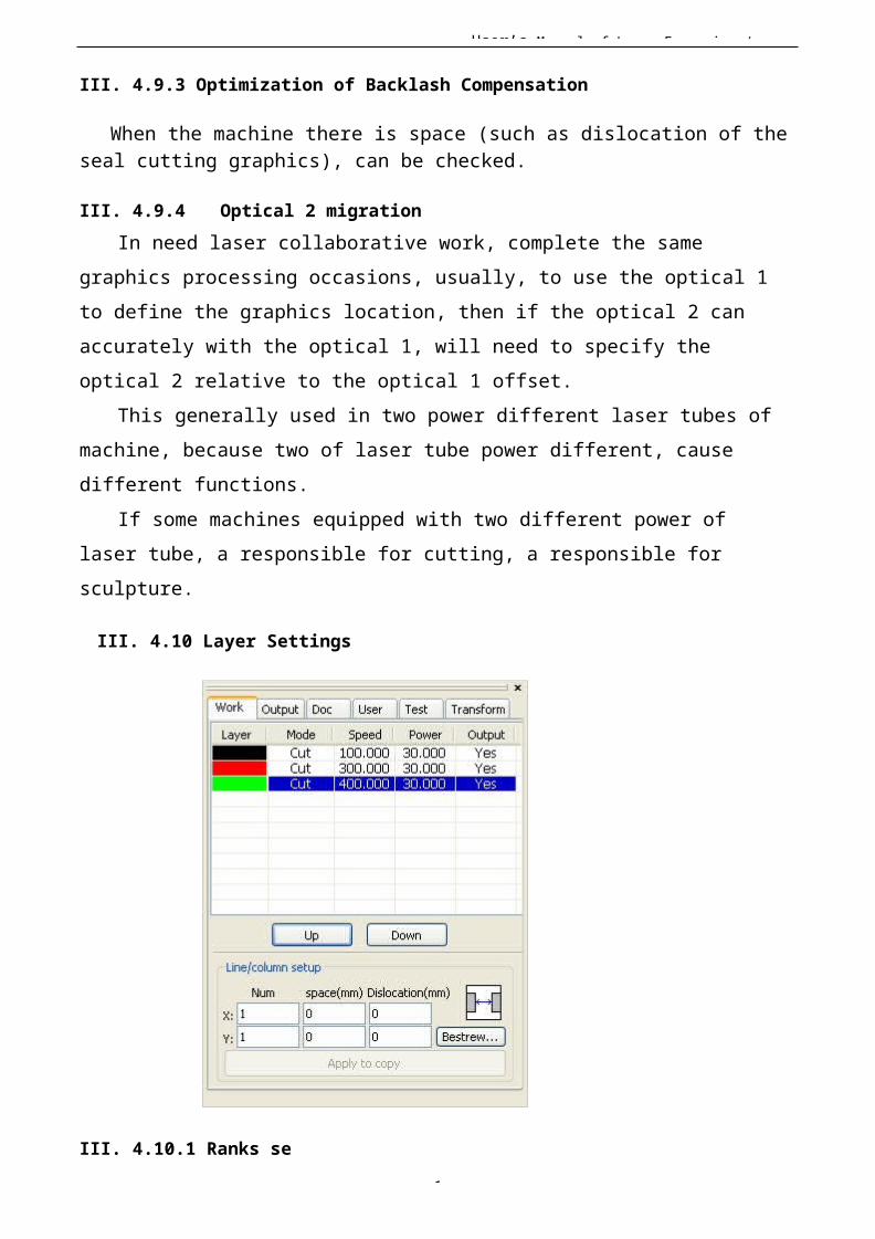
User’s Manual of Laser Engraving /
1
III. 4.9.3 Optimization of Backlash Compensation
When the machine there is space (such as dislocation of theseal cutting graphics), can be checked.
III. 4.9.4 Optical 2 migrationIn need laser collaborative work, complete the same
graphics processing occasions, usually, to use the optical 1 to define the graphics location, then if the optical 2 can accurately with the optical 1, will need to specify the optical 2 relative to the optical 1 offset.
This generally used in two power different laser tubes of machine, because two of laser tube power different, cause different functions.
If some machines equipped with two different power of laser tube, a responsible for cutting, a responsible for sculpture.
III. 4.10 Layer Settings
III. 4.10.1 Ranks se
User’s Manual of Laser Engraving /
1
For convenient to set in machining graphics processing on the array.X numbers and Y numbers, which was the array of columns and rows.X intervals and Y interval, respectively is array of the column spacing and line spacing. Layer: Software use layer to distinguish processing graphics parameters of different
layers.
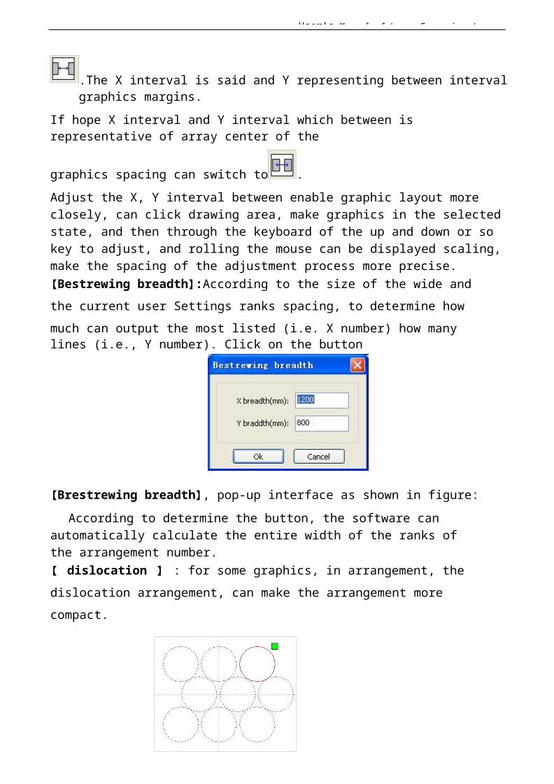
User’s Manual of Laser Engraving /
1
.The X interval is said and Y representing between intervalgraphics margins.
If hope X interval and Y interval which between is representative of array center of the
graphics spacing can switch to .Adjust the X, Y interval between enable graphic layout more closely, can click drawing area, make graphics in the selectedstate, and then through the keyboard of the up and down or so key to adjust, and rolling the mouse can be displayed scaling,make the spacing of the adjustment process more precise.【Bestrewing breadth】:According to the size of the wide and the current user Settings ranks spacing, to determine how much can output the most listed (i.e. X number) how manylines (i.e., Y number). Click on the button
【Brestrewing breadth】, pop-up interface as shown in figure:According to determine the button, the software can
automatically calculate the entire width of the ranks of the arrangement number.【 dislocation 】 : for some graphics, in arrangement, the dislocation arrangement, can make the arrangement more compact.
User’s Manual of Laser Engraving /
1
【The application to copy 】 in good array, chosen to copy graphics, some application to copy, already can duplicate array graphics.
In the layer list to edit the double click inside layer, namely will pop up layer parameter dialog box.
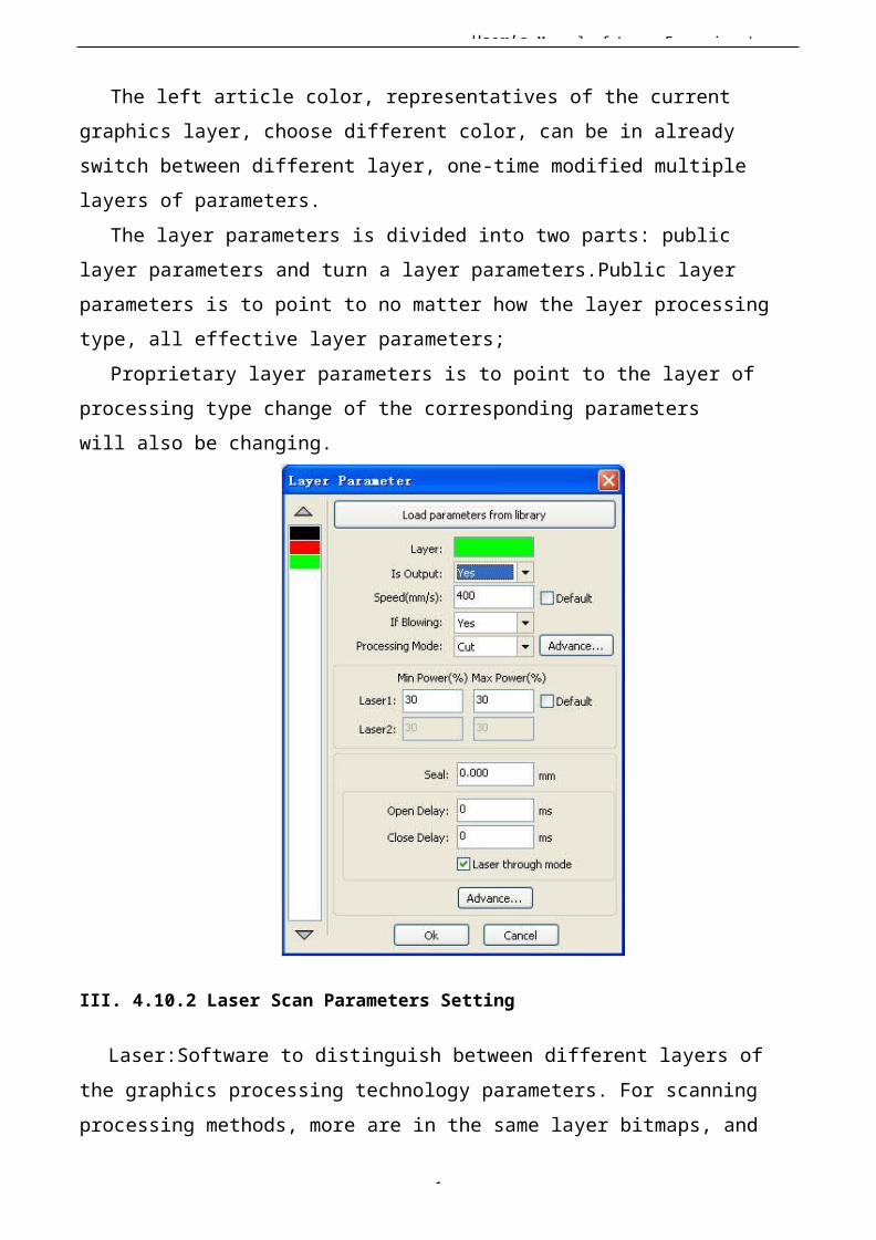
User’s Manual of Laser Engraving /
1
The left article color, representatives of the current graphics layer, choose different color, can be in already switch between different layer, one-time modified multiple layers of parameters.
The layer parameters is divided into two parts: public layer parameters and turn a layer parameters.Public layer parameters is to point to no matter how the layer processing type, all effective layer parameters;
Proprietary layer parameters is to point to the layer ofprocessing type change of the corresponding parameters will also be changing.
III. 4.10.2 Laser Scan Parameters Setting
Laser:Software to distinguish between different layers of the graphics processing technology parameters. For scanning processing methods, more are in the same layer bitmaps, and
User’s Manual of Laser Engraving /
1
whole as a picture output, if hope each bitmap single output, it can be a graphrespectively placed in different layer can.
Is Output:Have two options: yes and no. Choice is, the corresponding layer will output processing; Choose no, won'toutput processing.
Speed:The corresponding processing method of processing speed.For cutting processing is concerned, the slower,
processing the better, the more smooth track; The faster theprocessing results, the worse the trajectory smooth;
User’s Manual of Laser Engraving /
1
To scan for processing, the slower, under the same energy scanning depth, deep and scanning trace the thick, scanning the resolution also reduced.The faster the same energy the shallow depth of the scanning, details distortion increase. To fix for processing, the main change is empty the speed of the move.If, check the "default", the actual speed by panel set up to speed.
If Blowing:f the machine external fan, and fan has enabled,then if choose "is", then this layer data processing, will open the fan, otherwise, will not open the fan. If you do not make can fan, no matter choose "yes" or "no", are meaningless.
Processing methods: says the method of processing corresponding layer;If the currently selected is vector layer (i.e. color
layer), it includes three choices: laser scanning, laser cutting, laser rbis;
If the currently selected is a tutu layer (namely BMP layer), the only include a choice:
laser scanning.Laser 1, laser 2: corresponding to the mainboard laser
signals 1 and 2 of the way way laser output. If it is only head machine, the second road laser meaningless.
The minimum power, the maximum power: the power of the values of the range of 0 to
100, said that in the process of the strength of the laser processing; Big value, the laser is strong, is small, the laser weak. Minimum power loss to the most power is less thanor equalto.
For different processing type has a different meaning.For cutting processing, the actual power is cutting speed
and phase follow, speed, low energy is also low, high speed is
User’s Manual of Laser Engraving /
1
high also, so that we can guarantee the whole process of cutting energy evenly.So the minimum power the speed of the corresponding minimum energy, the minimum speed general is 0, but if set the speed is the minimum speed for takeoff take-offspeed; The maximum power correspond to the layer speed.
Set minimum power, and the most high power flow:1> The minimum power and the maximum power set to the
same value, synchronous adjustment. Until all the cutting curve are already appear.
2> The maximum power unchanged, and gradually reduce the minimum power until the energy of the heavy cutting curve at the lowest level, and all of the cohesion parts can be processed to come out.
3>If not yet to best effect, can be the most appropriate fine-tuning high power, and repeat step 2.
If is cut through, the minimum power loss and the maximum power no significant difference, can be set to give the same.
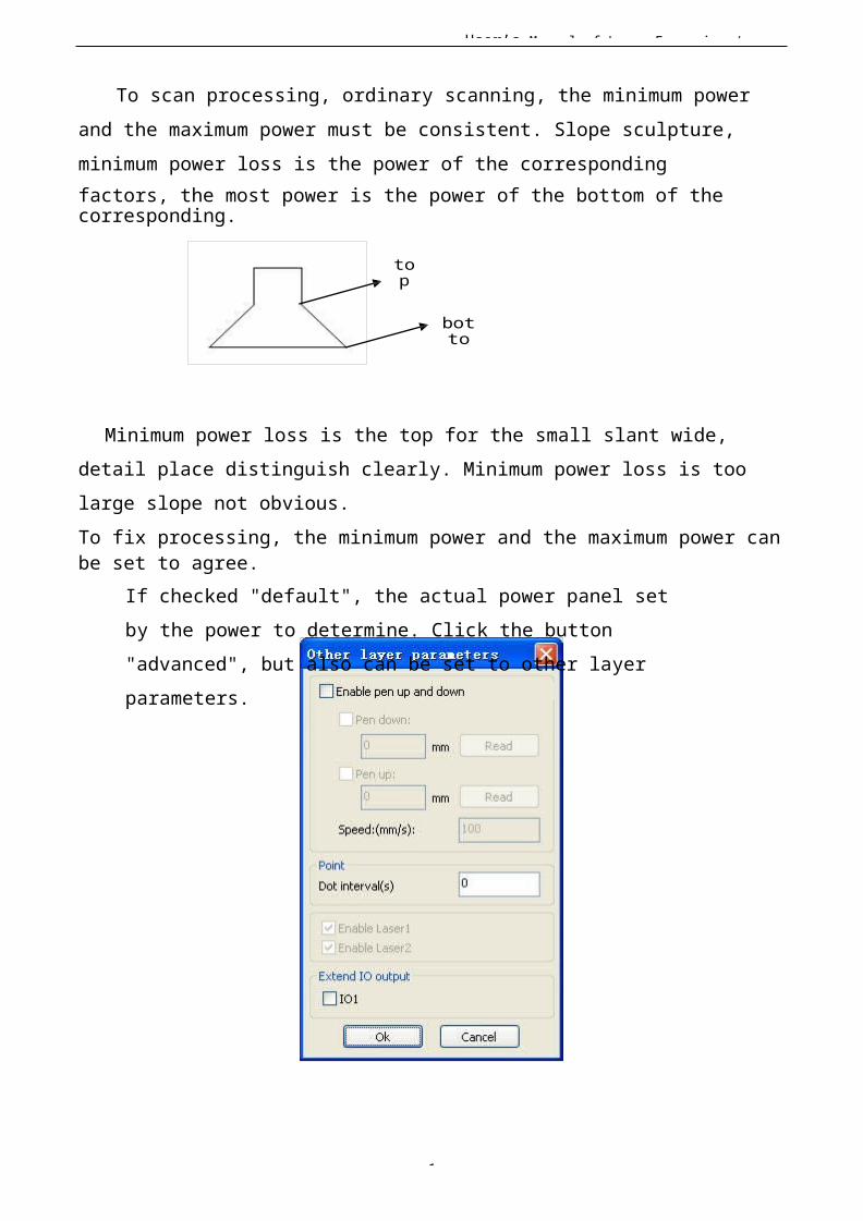
User’s Manual of Laser Engraving /
1
To scan processing, ordinary scanning, the minimum power and the maximum power must be consistent. Slope sculpture, minimum power loss is the power of the correspondingfactors, the most power is the power of the bottom of the corresponding.
top
botto
Minimum power loss is the top for the small slant wide, detail place distinguish clearly. Minimum power loss is too large slope not obvious.To fix processing, the minimum power and the maximum power can be set to agree.
If checked "default", the actual power panel set by the power to determine. Click the button "advanced", but also can be set to other layer parameters.
User’s Manual of Laser Engraving /
1
【Pen up and down】If machines have installed the lift platform, and need to be in a different platform height on the processing, can make can write up function.
Here the corresponding is platform write position in which high on the processing, carried the corresponding is empty penposition before go, platform should be moved to which level inthe optical translation will not again to interfere with the process workpiece. If confirmed the optical not and the translation of the process workpiece to interfere, don't need to set up the pen position.
Use way is:
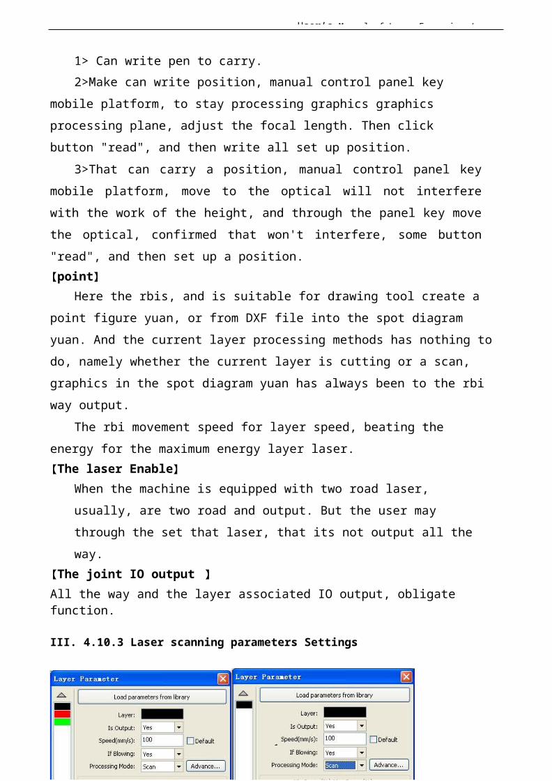
User’s Manual of Laser Engraving /
1
1> Can write pen to carry.2>Make can write position, manual control panel key
mobile platform, to stay processing graphics graphics processing plane, adjust the focal length. Then click button "read", and then write all set up position.
3>That can carry a position, manual control panel keymobile platform, move to the optical will not interferewith the work of the height, and through the panel key movethe optical, confirmed that won't interfere, some button"read", and then set up a position.【point】
Here the rbis, and is suitable for drawing tool create a point figure yuan, or from DXF file into the spot diagram yuan. And the current layer processing methods has nothing todo, namely whether the current layer is cutting or a scan, graphics in the spot diagram yuan has always been to the rbi way output.
The rbi movement speed for layer speed, beating the energy for the maximum energy layer laser.【The laser Enable】
When the machine is equipped with two road laser, usually, are two road and output. But the user may through the set that laser, that its not output all the way.
【The joint IO output 】All the way and the layer associated IO output, obligate function.
III. 4.10.3 Laser scanning parameters Settings
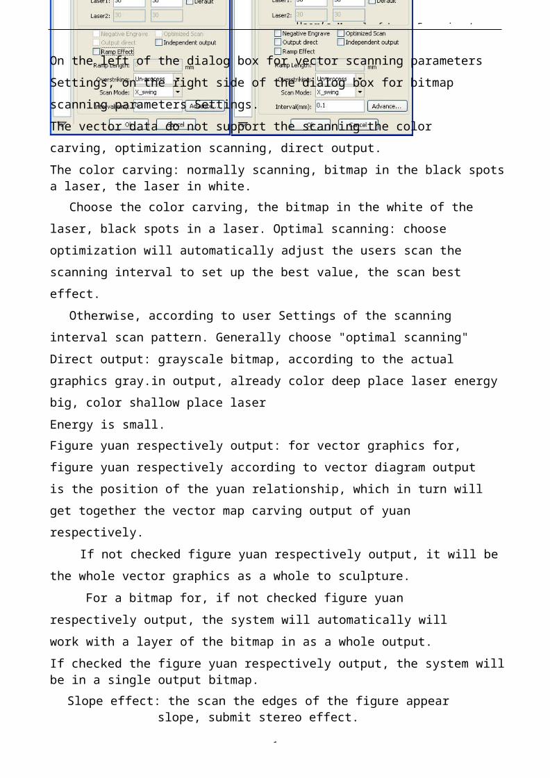
User’s Manual of Laser Engraving /
1
On the left of the dialog box for vector scanning parameters Settings, on the right side of the dialog box for bitmap scanning parameters Settings.The vector data do not support the scanning the color carving, optimization scanning, direct output.The color carving: normally scanning, bitmap in the black spotsa laser, the laser in white.
Choose the color carving, the bitmap in the white of the laser, black spots in a laser. Optimal scanning: choose optimization will automatically adjust the users scan the scanning interval to set up the best value, the scan best effect.
Otherwise, according to user Settings of the scanning interval scan pattern. Generally choose "optimal scanning"Direct output: grayscale bitmap, according to the actual graphics gray.in output, already color deep place laser energybig, color shallow place laserEnergy is small.Figure yuan respectively output: for vector graphics for, figure yuan respectively according to vector diagram output is the position of the yuan relationship, which in turn will get together the vector map carving output of yuan respectively.
If not checked figure yuan respectively output, it will bethe whole vector graphics as a whole to sculpture.
For a bitmap for, if not checked figure yuan respectively output, the system will automatically will work with a layer of the bitmap in as a whole output.If checked the figure yuan respectively output, the system willbe in a single output bitmap.
Slope effect: the scan the edges of the figure appearslope, submit stereo effect.
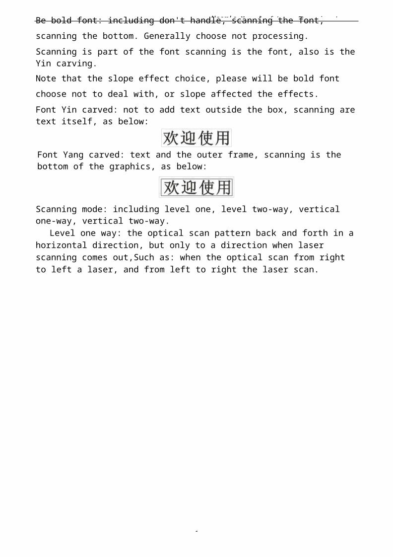
User’s Manual of Laser Engraving /
1
Be bold font: including don't handle, scanning the font, scanning the bottom. Generally choose not processing.Scanning is part of the font scanning is the font, also is the Yin carving.Note that the slope effect choice, please will be bold font choose not to deal with, or slope affected the effects.Font Yin carved: not to add text outside the box, scanning are text itself, as below:
Font Yang carved: text and the outer frame, scanning is the bottom of the graphics, as below:
Scanning mode: including level one, level two-way, vertical one-way, vertical two-way.
Level one way: the optical scan pattern back and forth in ahorizontal direction, but only to a direction when laser scanning comes out,Such as: when the optical scan from right to left a laser, and from left to right the laser scan.
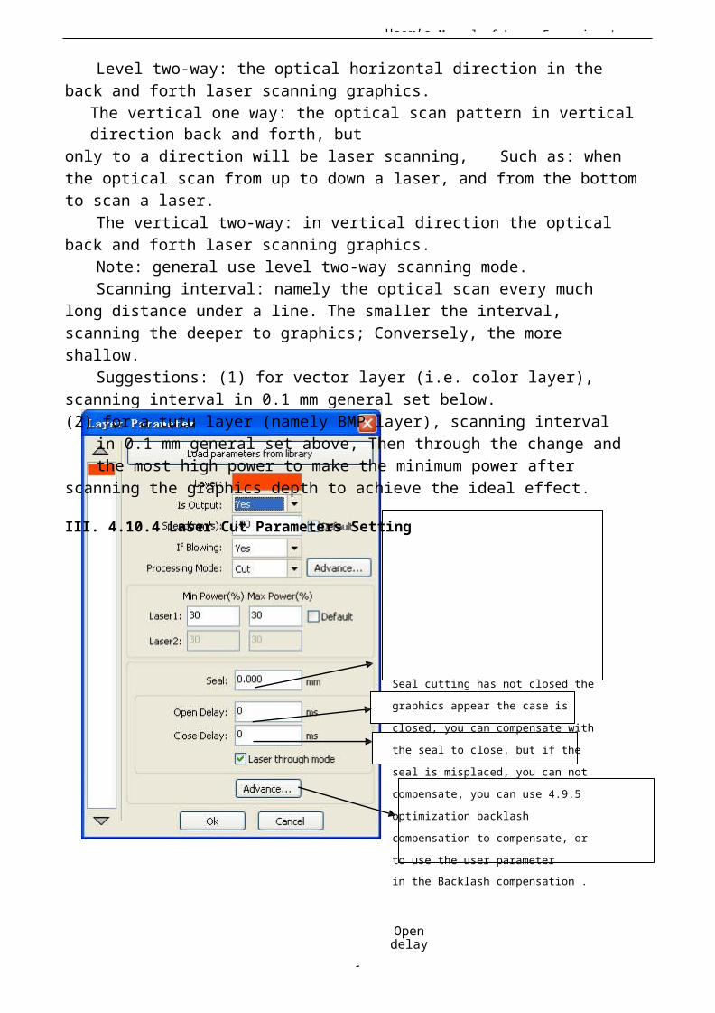
User’s Manual of Laser Engraving /
1
Level two-way: the optical horizontal direction in the back and forth laser scanning graphics.
The vertical one way: the optical scan pattern in vertical direction back and forth, but
only to a direction will be laser scanning, Such as: when the optical scan from up to down a laser, and from the bottom to scan a laser.
The vertical two-way: in vertical direction the opticalback and forth laser scanning graphics.
Note: general use level two-way scanning mode.Scanning interval: namely the optical scan every much
long distance under a line. The smaller the interval, scanning the deeper to graphics; Conversely, the more shallow.
Suggestions: (1) for vector layer (i.e. color layer), scanning interval in 0.1 mm general set below.(2) for a tutu layer (namely BMP layer), scanning interval
in 0.1 mm general set above, Then through the change andthe most high power to make the minimum power after
scanning the graphics depth to achieve the ideal effect.
III. 4.10.4 Laser Cut Parameters Setting
Seal cutting has not closed the
graphics appear the case is
closed, you can compensate with
the seal to close, but if the
seal is misplaced, you can not
compensate, you can use 4.9.5
optimization backlash
compensation to compensate, or
to use the user parameterin the Backlash compensation .
Opendelay
User’s Manual of Laser Engraving /
1
Closedelay
If checked, the light switch delay is playing in time said.Otherwise, the light switch delaysaid islaser movement delay.
Using the slit width compensation can compensate for the offset between the graphics and the actual output graphics that caused by laser cutting.
It only has effective for the closed graph.
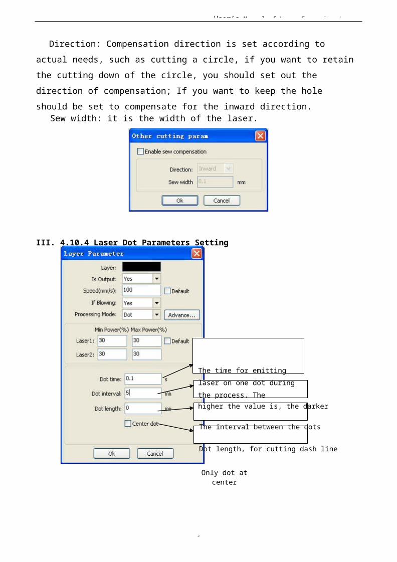
User’s Manual of Laser Engraving /
1
Direction: Compensation direction is set according to actual needs, such as cutting a circle, if you want to retainthe cutting down of the circle, you should set out the direction of compensation; If you want to keep the hole should be set to compensate for the inward direction.
Sew width: it is the width of the laser.
III. 4.10.4 Laser Dot Parameters Setting
The time for emitting laser on one dot duringthe process. Thehigher the value is, the darker
The interval between the dots
Dot length, for cutting dash line
Only dot atcenter
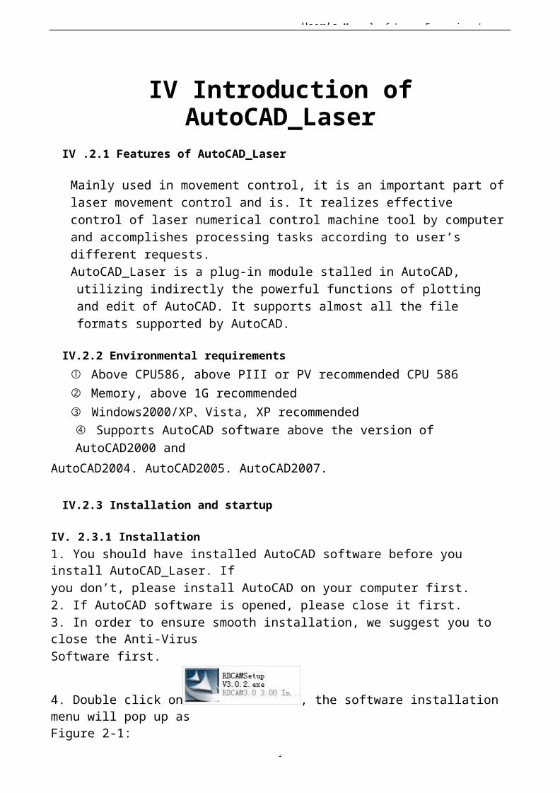
User’s Manual of Laser Engraving /
1
IV Introduction ofAutoCAD_Laser
IV .2.1 Features of AutoCAD_Laser
Mainly used in movement control, it is an important part oflaser movement control and is. It realizes effective control of laser numerical control machine tool by computerand accomplishes processing tasks according to user’s different requests.AutoCAD_Laser is a plug-in module stalled in AutoCAD, utilizing indirectly the powerful functions of plotting and edit of AutoCAD. It supports almost all the file formats supported by AutoCAD.
IV.2.2 Environmental requirements① Above CPU586, above PIII or PV recommended CPU 586② Memory, above 1G recommended③ Windows2000/XP、Vista, XP recommended④ Supports AutoCAD software above the version of AutoCAD2000 and
AutoCAD2004. AutoCAD2005. AutoCAD2007.
IV.2.3 Installation and startup
IV. 2.3.1 Installation1. You should have installed AutoCAD software before you install AutoCAD_Laser. Ifyou don’t, please install AutoCAD on your computer first.2. If AutoCAD software is opened, please close it first.3. In order to ensure smooth installation, we suggest you to close the Anti-VirusSoftware first.
4. Double click on , the software installation menu will pop up asFigure 2-1:
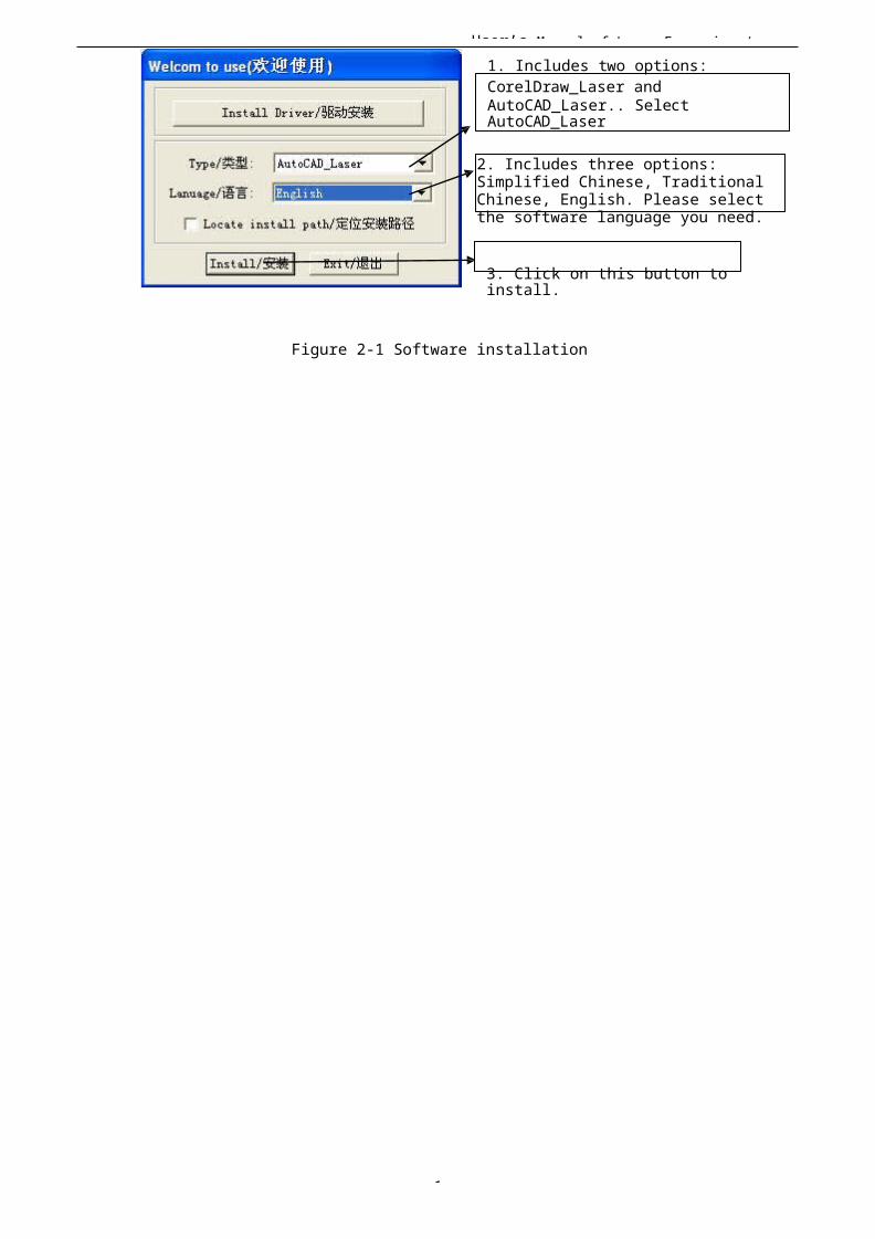
User’s Manual of Laser Engraving /
1
1. Includes two options: CorelDraw_Laser andAutoCAD_Laser.. Select AutoCAD_Laser
2. Includes three options: Simplified Chinese, Traditional Chinese, English. Please select the software language you need.
3. Click on this button to install.
Figure 2-1 Software installation
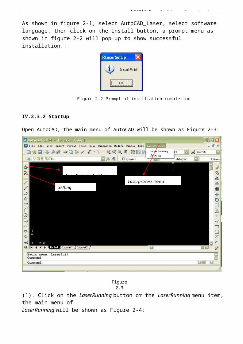
User’s Manual of Laser Engraving /
1
As shown in figure 2-1, select AutoCAD_Laser, select softwarelanguage, then click on the Install button, a prompt menu asshown in figure 2-2 will pop up to show successful installation.:
Figure 2-2 Prompt of instillation completion
IV.2.3.2 Startup
Open AutoCAD, the main menu of AutoCAD will be shown as Figure 2-3:
LaserRunning button
Setting button
Laserprocess menu
Figure2-3
(1). Click on the LaserRunning button or the LaserRunning menu item,the main menu ofLaserRunning will be shown as Figure 2-4:
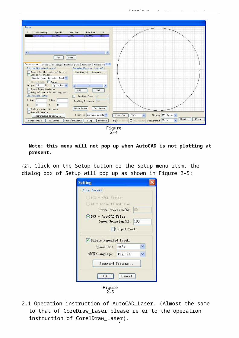
User’s Manual of Laser Engraving /
1
Figure2-4
Note: this menu will not pop up when AutoCAD is not plotting at present.
(2). Click on the Setup button or the Setup menu item, the dialog box of Setup will pop up as shown in Figure 2-5:
Figure2-5
2.1 Operation instruction of AutoCAD_Laser. (Almost the same to that of CoreDraw_Laser please refer to the operation instruction of CorelDraw_Laser).
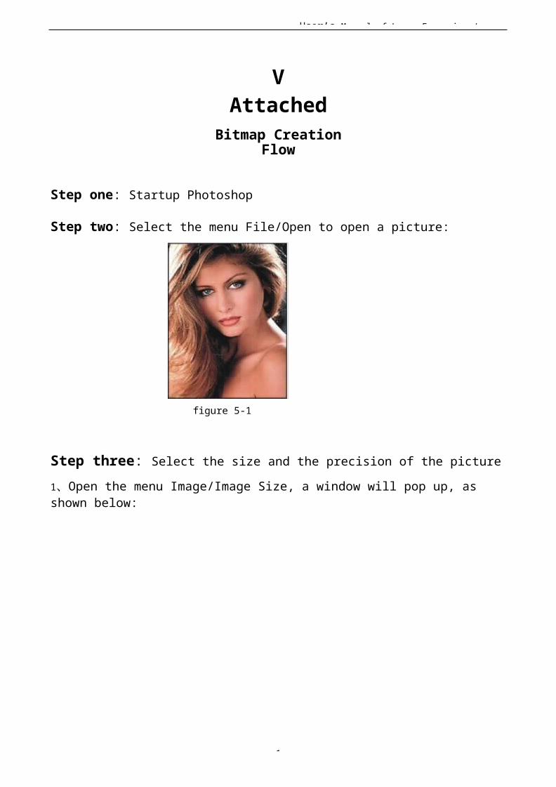
User’s Manual of Laser Engraving /
1
VAttached
Bitmap CreationFlow
Step one: Startup Photoshop
Step two: Select the menu File/Open to open a picture:
figure 5-1
Step three: Select the size and the precision of the picture1、Open the menu Image/Image Size, a window will pop up, as shown below:
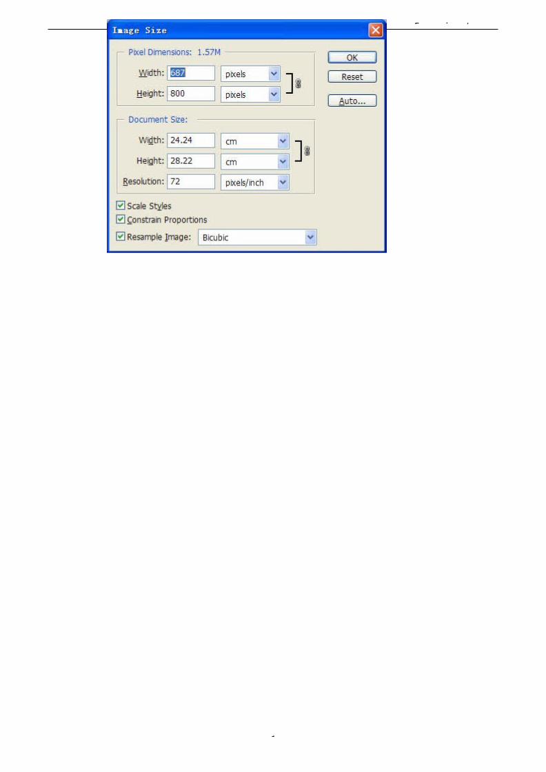
User’s Manual of Laser Engraving /
1
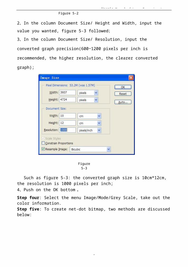
User’s Manual of Laser Engraving /
1
Figure 5-2
2、In the column Document Size/ Height and Width, input the value you wanted, figure 5-3 followed;
3、In the column Document Size/ Resolution, input the
converted graph precision(600~1200 pixels per inch is
recommended, the higher resolution, the clearer converted
graph);
Figure5-3
Such as figure 5-3: the converted graph size is 10cm*12cm, the resolution is 1000 pixels per inch;4、Push on the OK bottom.Step four: Select the menu Image/Mode/Grey Scale, take out thecolor information.Step five: To create net-dot bitmap, two methods are discussedbelow:
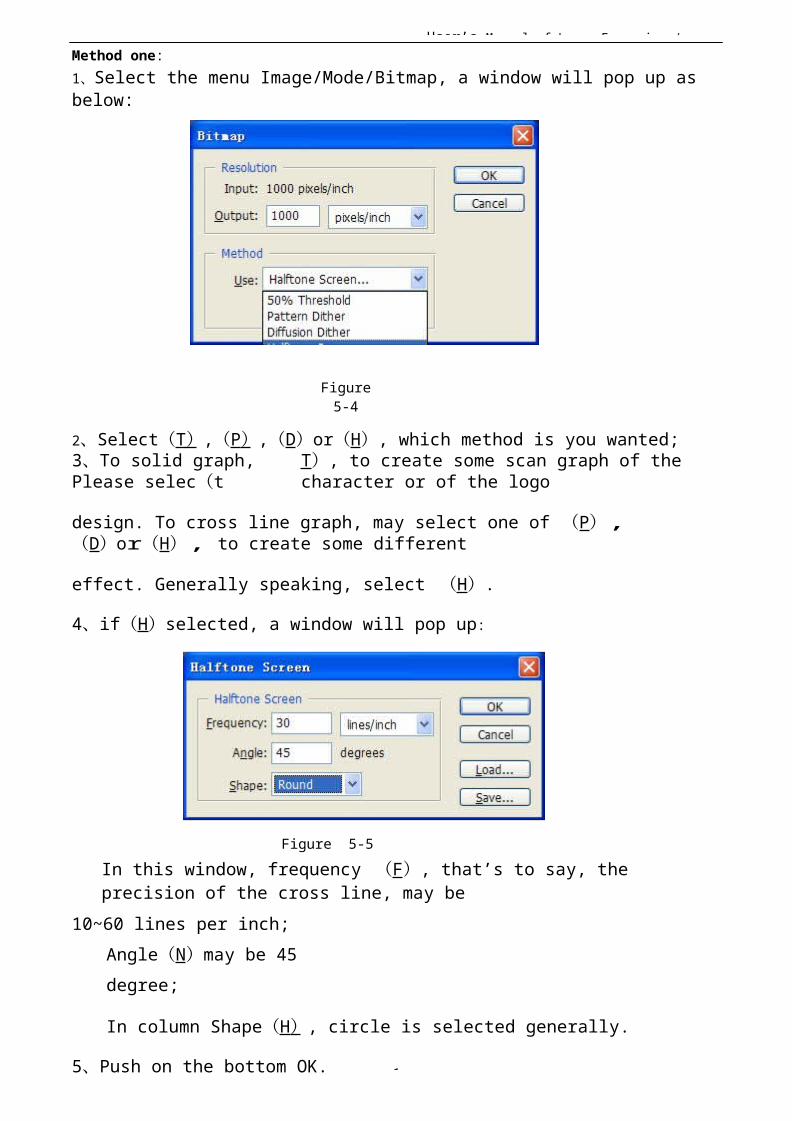
User’s Manual of Laser Engraving /
1
Method one:1、Select the menu Image/Mode/Bitmap, a window will pop up as below:
Figure5-4
2、Select(T ),(P ),(D)or(H), which method is you wanted;3、To solid graph, Please selec(t
T), to create some scan graph of the character or of the logo
design. To cross line graph, may select one of (P),(D)or(H), to create some different
effect. Generally speaking, select (H).
4、if(H)selected, a window will pop up:
Figure 5-5In this window, frequency (F), that’s to say, the precision of the cross line, may be
10~60 lines per inch; Angle(N)may be 45 degree;
In column Shape(H ), circle is selected generally.
5、Push on the bottom OK.

User’s Manual of Laser Engraving /
1
Method two:1、Select Filter/ Pixelate / Color Halftone , a window will popup, such as figure 5-6.
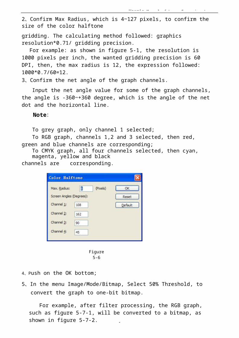
User’s Manual of Laser Engraving /
1
2、Confirm Max Radius, which is 4~127 pixels, to confirm the size of the color halftonegridding. The calculating method followed: graphics resolution*0.71/ gridding precision.
For example: as shown in figure 5-1, the resolution is 1000 pixels per inch, the wanted gridding precision is 60 DPI, then, the max radius is 12, the expression followed:1000*0.7/60=12.3、Confirm the net angle of the graph channels.
Input the net angle value for some of the graph channels, the angle is -360~+360 degree, which is the angle of the net dot and the horizontal line.
Note:
To grey graph, only channel 1 selected;To RGB graph, channels 1,2 and 3 selected, then red,
green and blue channels are corresponding;To CMYK graph, all four channels selected, then cyan, magenta, yellow and black
channels are corresponding.
Figure5-6
4、Push on the OK bottom;
5、In the menu Image/Mode/Bitmap, Select 50% Threshold, to convert the graph to one-bit bitmap.
For example, after filter processing, the RGB graph, such as figure 5-7-1, will be converted to a bitmap, as shown in figure 5-7-2.
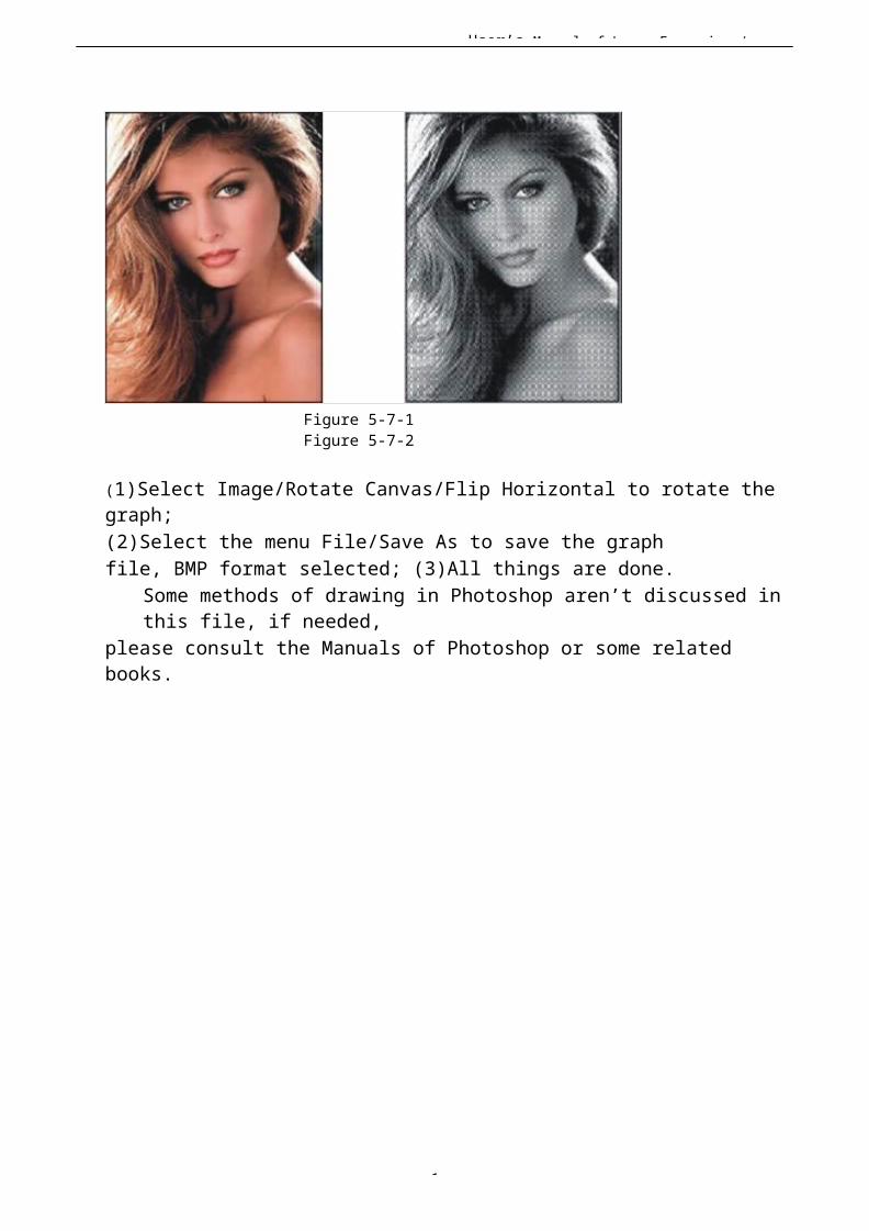
User’s Manual of Laser Engraving /
1
Figure 5-7-1Figure 5-7-2
(1)Select Image/Rotate Canvas/Flip Horizontal to rotate thegraph;(2)Select the menu File/Save As to save the graph file, BMP format selected; (3)All things are done.
Some methods of drawing in Photoshop aren’t discussed inthis file, if needed,
please consult the Manuals of Photoshop or some related books.
User’s Manual of Laser Engraving /
1
VI User Parameters(1) Cutting Parameters (Only affect cutting arts)
Idle Move Speed: this parameter decides the highestspeed of all non-lighting lines for the machine in themovement process.
Idle Move Acceleration: it means the highestacceleration of all non-lighting lines. Idle stroke speedand idle stroke acceleration can be set higher to reducethe working time of the whole figure, but if they are settoo high, it may cause the jarring of track, socomprehensive consideration should be given to thesetting.
Turning Speed: it means the speed of turning at theacute-angle corner, which is also the highest speed inthe whole cutting process.
Turning Acceleration: it means the acceleration ofturning at the acute-angle corner when cutting. If thetwo speeds are set too high, jarring will happen to theturning; if set too low, it will influence the cuttingspeed.
Cutting Acceleration: it means the highest accelerationvalue in the whole cutting process.
Cutting Mode: it is divided into high-speed cuttingand precision cutting. In high-speed cutting, priorityis given to the cutting speed, but in precision cutting,the cutting effect.
Acceleration Mode: it is divided into T accelerationand S acceleration. T accelerate will quicken the wholecutting process, but it will result in that its cuttingeffect is inferior to that of S acceleration.
User’s Manual of Laser Engraving /
1
(2) Scanning Parameters (Only affectscanning arts) X-axle Starting
Speed Y-axleStarting Speed X-axle Acceleration
Y-axleAcceleration
The above four parameters are used to set the startingspeed and acceleration of two axles on the scanning. The higher the two speeds are, the quicker the scanning is.
Scanning Line-feed Speed: this parameter is speciallyused to control the highest speed at which that theprevious line vertically moves to the next line in thescanning mode. If the space between lines is largerduring the scanning or if the distance of each block islarger during the scanning and deblocking of figure, itis necessary to position each line or block accurately.In such a case
1
User’s Manual of Laser Engraving / the speed of scanning line-feed can be setas a lower value.
Scanning Mode: it is divided into general mode and special mode for option.
If special mode is used, the laser power should beincreased. The smaller the speckle percentage is, themore the laser power reduces. The laser power to setshould be larger in order to reach the same scanningdepth. The purpose to select the special mode is to makethe laser light at high power and short time. On thedepth scanning the effect that the bottom is flatter isobtained, but it should be noticeable that if the speckleadjustment is not appropriate, it can achieve this goal.If the high power remains short, the lighting mode willinfluence the life of the laser. The system will defaultthe selection of general mode.
Speckle Size: When the general mode is selected as thescanning mode, this parameter will become ineffective;when the special mode is selected, this parameter willbecome effective. The controller will control thisparameteramong50%~99%.
Prompt
The cutting and scanning parameters can’t exceed the limited ones in the axle parameters. If so, the setting will becomeineffective and the system will automatically coverthe parameters with the axle parameters.
(3) ResetParameters
Reset Speed: it means the speed of X/Y-axle linkagereset to the origin.
1
User’s Manual of Laser Engraving / X-axle StartupReset Y-axleStartup Reset Z-axle StartupReset U-axleStartup Reset
You can select “Yes” or “No” in the field of the above four parameters, which is
used to confirm whether each axle can be reseton the startup.
(4) FrameSetting
Bordering Mode: “Blanked Bordering” means idling tostart border preview; “Outputted Border Cutting” canmanually cut off the well-processed figure; “4-cornerDotting” means to emit the light at four corner points ofthe frame to make a point and turn off light. The sizeand position of this figure can be checked intuitivelythrough the four points. The bordering speed is the speedvalue set on the keyboard when the system is idle. Forlight output, its minimum/maximum power is thecorresponding value set on the keyboard
actu
User’s Manual of Laser Engraving /
1
when the system is idle (The lasering power on the 4-corner dotting means the well-set maximum power).
Margin Distance: It means whether to extend a certain length outside the
al frame of the figure on the preview/cutting of frame.If the frame crosses the border, the interface will prompt it.
Prompt If the Enter key is pressed at this time, the system will cut the border at the maximum/minimum coordinates first, and then border the figure. This bordering can be given up.
(5) Other User Parameters Array Mode: Two-way array or one-way array can beselected. Two-way array means the to-and-fro cuttingof array in sequence; one-way array means thecutting of array from one direction to another.On selecting one-way array, the elements of each arrayare the same in action mode and completely uniform inaction fluency, which takes a little more time thantwo-way array. Two-way array is the default option.
Back Position: The origin (the relative origin) andthe machine’s absolute origin can be selected. Thisparameter decides the parking position of laser headafter each work.
Before-feeding Time Lag: settable at 0~300s. The lagged time can facilitate
user’s feeding and picking on thefeeding device.
After-feeding Time Lag: settable at 0~9.9s. It canfacilitate the feeding device’s delaying in jarring
User’s Manual of Laser Engraving /
1
after moving to the correct position and waiting for the
2nd work after the feeding axle stands still completely. Focus Setting: it means the distance from the focalpoint of laser head lens to Z-axle origin. When there isno automatic focusing function, this parameter becomesinvalid.
Backlash X:The X axes’ backlash, accurate to 1um. Backlash Y:The Y axes’ backlash, accurate to 1um.
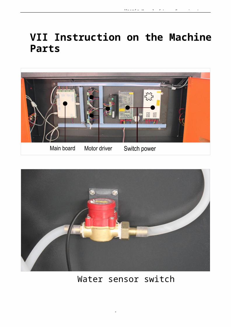
User’s Manual of Laser Engraving /
1
VII Instruction on the MachineParts
Water sensor switch