
Manual HCO English 2_01_13 - Castle Pumps
23
Pag. 1 di 23 HCO PUMPS Open Impeller Mechanical seal centrifugal pumps I I N N S S T T A A L L L L A A T T I I O O N N , , O O P P E E R R A A T T I I O O N N A A N N D D M M A A I I N N T T E E N N A A N N C C E E M M A A N N U U A A L L
-
Upload
khangminh22 -
Category
Documents
-
view
6 -
download
0
Transcript of Manual HCO English 2_01_13 - Castle Pumps
Pag. 1 di 23
HHCCOO PPUUMM PPSS
Open Impeller Mechanical seal centrifugal pumps
II NNSSTTAALL LL AATTII OONN,, OOPPEERRAATTII OONN AANNDD
MM AAII NNTTEENNAANNCCEE MM AANNUUAALL
Pag. 2 di 23
((SSAAFFEETTYY II NNSSTTRRUUCCTTII OONNSS))
INDEX
1. INTRODUCTION.........................................................................................................................4
1.1 General ....................................................................................................................................... 4
1.2 Purpose of the manual ................................................................................................................ 4
1.3 Warning symbols for safety ........................................................................................................ 4
1.4 Qualification and training of the personnel ............................................................................... 4
1.5 Explosive atmosphere zones ....................................................................................................... 5
2. INSTALLATION ........................................................................................................................... 5
Preliminary remarks ......................................................................................................................... 5
2.1 Safety general warnings ............................................................................................................ 5 2.1.1 Introduction about danger .................................................................................................... 5 2.1.2 Indications of danger ............................................................................................................ 5
2.2 Receipt and Inspection ................................................................................................................ 6
2.3 Storage ........................................................................................................................................ 7
2.4 Installation .................................................................................................................................. 7
2.5 Hydraulic system ........................................................................................................................ 7
2.6 Pipes connection ......................................................................................................................... 7
2.7 Monitoring equipment ................................................................................................................ 8
2.8 Motor connection ........................................................................................................................ 8
3. OPERATION ................................................................................................................................. 9
3.1 Use and safety ............................................................................................................................. 9
3.2 Dry-running .............................................................................................................................. 10
3.3 Temperature .............................................................................................................................. 10
3.4 Before starting .......................................................................................................................... 10
3.5 Starting ..................................................................................................................................... 11
3.6 Optimum conditions for use ...................................................................................................... 11
3.7 Shut down.................................................................................................................................. 11
3.8 Long pump inactivity ................................................................................................................ 12
3.9 Noise level ................................................................................................................................. 12
4. MAINTENANCE ......................................................................................................................... 12
Pag. 3 di 23
4.1 General dispositions ................................................................................................................. 12
4.2 Inspections ................................................................................................................................ 13
4.3 Procedure before disassembly .................................................................................................. 13
4.4 Disassembly .............................................................................................................................. 13 4.4.1 Main parts ........................................................................................................................... 13 4.4.2 Disassembly the pump from the motor ............................................................................. 14
4.5 Assembly ................................................................................................................................... 16
4.6 Motor replacement .................................................................................................................... 16
4.7 Tightening torque...................................................................................................................... 16
5. PROBLEM SOLUTIONS ........................................................................................................... 17
6. SPARE PARTS ............................................................................................................................ 18
6.1 How to order spare parts .......................................................................................................... 18
7. DATA ............................................................................................................................................ 18
7.1 Performance curves .................................................................................................................. 18
7.2 Dimensions ............................................................................................................................... 19
7.3 Technical data and limits........................................................................................................................20
8. WARRANTY AND REPAIR ...................................................................................................... 20
8.1 Warranty ................................................................................................................................... 20
8.2 Returned parts and repair ........................................................................................................ 21
8.3 Decontamination Declaration (facsimile) ................................................................................ 22
8.4 CE Certificate for pumps series HCO PP/PVDF ..................................................................... 23
Pag. 4 di 23
11.. II NNTTRROODDUUCCTTII OONN
1.1 General This manual refers to mechanical seal centrifugal pumps series HCO. Pumps HCO are made of thermoplastic materials (Polypropylene or PVDF) and can be of different sizes. Dimensions and capacities available are described in paragraph 7.0.
1.2 Purpose of the manual The main purpose of this manual is to assure that the activities of installation, operation and maintenance of the pumps are executed in a correct and safe way by all the personnel in charge of these operations. This document offers also indications useful for the customer to solve the problems, order spare parts and contact GemmeCotti repair service.
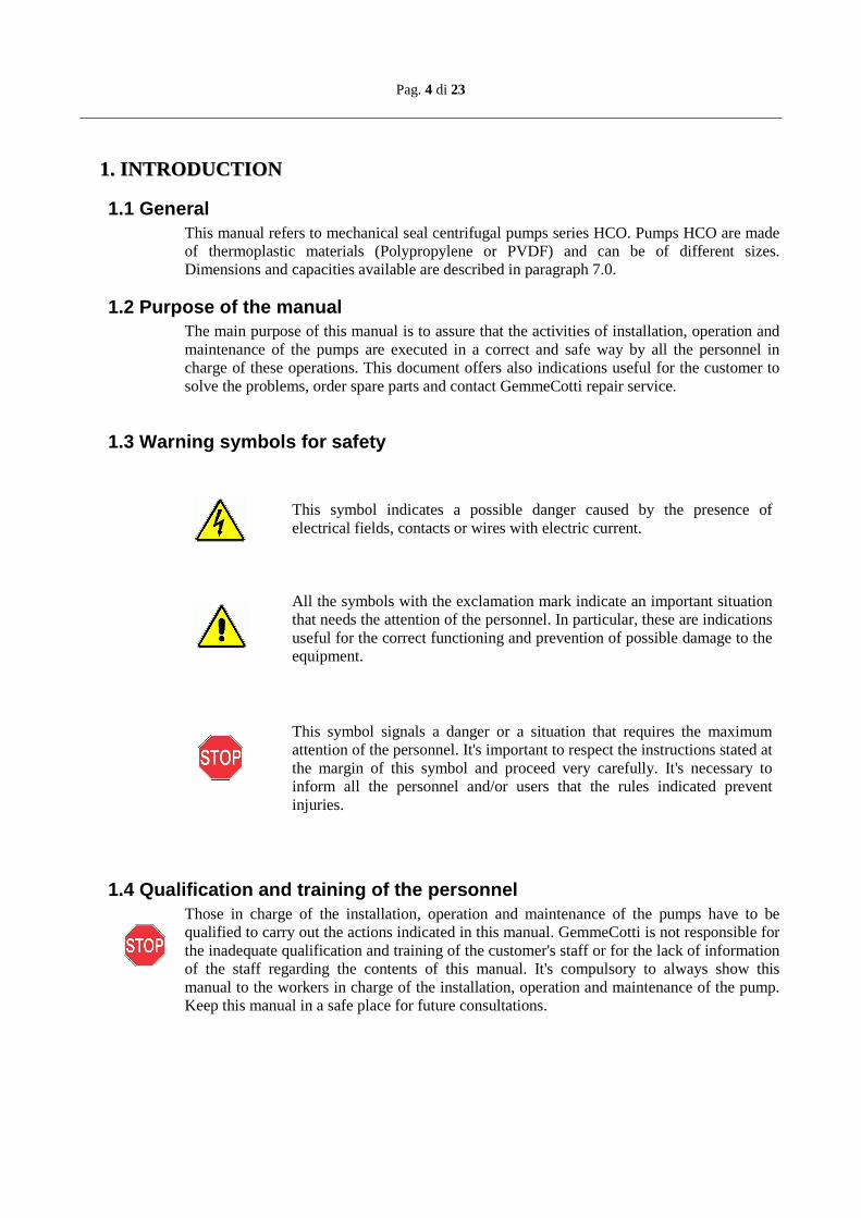
1.3 Warning symbols for safety
This symbol indicates a possible danger caused by the presence of electrical fields, contacts or wires with electric current.
All the symbols with the exclamation mark indicate an important situation that needs the attention of the personnel. In particular, these are indications useful for the correct functioning and prevention of possible damage to the equipment.
This symbol signals a danger or a situation that requires the maximum attention of the personnel. It's important to respect the instructions stated at the margin of this symbol and proceed very carefully. It's necessary to inform all the personnel and/or users that the rules indicated prevent injuries.
1.4 Qualification and training of the personnel Those in charge of the installation, operation and maintenance of the pumps have to be qualified to carry out the actions indicated in this manual. GemmeCotti is not responsible for the inadequate qualification and training of the customer's staff or for the lack of information of the staff regarding the contents of this manual. It's compulsory to always show this manual to the workers in charge of the installation, operation and maintenance of the pump. Keep this manual in a safe place for future consultations.

Pag. 5 di 23
1.5 Explosive Atmosphere Zones The pumps described in this manual CANNOT be used in explosive atmospheres. These uses require special pumps that GemmeCotti manufactures with particular materials and precautions. Customers who want to use special pumps in these kind of zones have to contact the GemmeCotti technical office for the correct choice of the product. WE REMIND YOU THAT THE CLASSIFICATION OF THE ZONE (REF. ATEX 94/9/CE- 2006/42 DIRECTIVE) FOR POTENTIALLY EXPLOSIVE ATMOSHPERE ZONES HAVE TO BE DONE BY THE CUSTOMER AND COMMUNICATED TO GEMMECOTTI FOR THE RIGHT CHOICE OF THE KIND OF PUMP SUITABLE TO WORK IN THESE ZONES. The pumps, manufactured by GemmeCotti, for these kind of applications belong to the series EM-C or EM-T or EM-P. Furthermore, the customer is responsible of the correct installation of the pump in accordance with the requirements stated in the Directive.
22.. IINNSSTTAALLLLAATTIIOONN
Preliminary remarks All the references to the pumps have to be considered applicable also to systems that use these pumps unless it's specified otherwise.
2.1 Safety general warnings1
2.1.1 Introduction about danger ATTENTION: the non-observance of the indications stated in this manual or the inappropriate use of the equipment by unqualified or unauthorized staff, can cause serious personal injuries or death and damages to products and apparatus! The technical assistance office is at the complete disposal; in case of doubts or problems you can contact us by phone (Number +39 02 964.60.406) or write an email to [email protected]. It's strongly recommended that you keep GemmeCotti written answer.
2.1.2 Indications of danger For the safety of those in charge of the installation of the pump it's necessary to use safety clothing and individual safety devices approved by the current provisions of the law (e.g. Safety glass, gloves and safety insulating-shoes) These pumps have been designed and manufactured to be used in specific conditions and within defined limits. The use outside these specifications has to be agreed and approved by GemmeCotti technical service. It must be considered also that, if the pumps are used outside their technical specifications, the CE Certifications and the warranty are no
1 If these warnings are not observed the Certification and the Warranty of the pump can be invalidated
Pag. 6 di 23
longer valid. Furthermore, if the pump is used outside the technical specifications communicated to us at the moment of the quotation and confirmed in our order confirmation, the customer becomes responsible for the issue of a new CE Certification. The pump has to be used only for the applications specified in the order for which GemmeCotti has selected the model, the materials of construction and has tested the pump to respect the specifications. For other uses different from those stated in the order, the customer has to send always a written request to GemmeCotti technical office, which on its part will reply in a written form. There will not be any warranty for repairs or alterations on the product done by the users or third parties not specifically authorized by GemmeCotti. Always shut down the pump before touching or proceeding with any intervention on it or on the circuit of installation. The pump must be empty of pumped liquid and it must be completely decontaminated and successfully rinsed with water before any manual operations or disassembling. Make sure that the electrical system to which the pump will be connected has the adequate power and has the correct protection devices (e.g. Grounding, Life safe). Always switch off the electrical supply before working on the pump for maintenance or part substitution. Always keep an extinguisher next to the pump installed. Always pay maximum attention in the execution of maintenance activities on pumps and on the connected circuits when they are used with dangerous liquids. The use of an electric starter is recommended. A simple switch can be insufficient to start and stop the electric motor connected to the main electric system. An appropriate starter: - can prevent accidental starting after a failed attempt to start: - is a safe switch, protected against water: - protects the electric motor against overloads due to a short circuit (a fuse protects only the wires); - resists against starting in overload on the motor, preventing dangerous electric arc and early wear of the electrical contacts.
2.2 Receipt and Inspection Even if GemmeCotti takes all the necessary precautions during the packaging, we suggest that you carefully check the received material. Check for any missing parts caused by the courier and/or by GemmeCotti. Check the data on the label of the received pump and compare it with those relative to your purchase order. If the pump has been supplied with the motor, remove the protective shield from the fan of the motor and try to rotate the motor shaft by hand. If you feel a strong resistance to rotation or if you hear anomalous noises call your reliable reseller or call the GemmeCotti assistance service directly. Reassemble the protective fan shield before starting the pump.
Pag. 7 di 23
2.3 Storage If the pump is kept in the warehouse make sure that it's placed in a dry and protected position; always use the original package or an equivalent protection. If the pump has to remain stored for a long period and/or in particularly damp places the use of hygroscopic substance (silica gel) is recommended to prevent damages. Don't remove the protections of the flanges until the installation and close, if they are not closed already, the discharge and suction pump connections to prevent the intrusion of foreign bodies. Be informed that a long period of storage of the pumps can provoke: - deterioration of the isolation of the motor due to absorption of dampness - deterioration of the gaskets
2.4 Installation GemmeCotti s.r.l. is not responsible for injury to people or damage to things caused by the wrong installation of the pump or installation executed by non-qualified personnel. Install the pump in a position that guarantees a simple use. The unit motor/pump has to be fixed on a rigid structure that will enable the support of the entire structure. Make sure that the pump is fixed on a plane surface, in this case use shims under the base-plates of the motor. If necessary use “bumpers” to reduce vibrations towards the fixing surface.
2.5 Hydraulic system The pump is generally part of a hydraulic system that can include a various number of components such as, valves, fittings, filters, expansion joints, instruments, etc. The way the piping is arranged and the position of the components has a great influence on the operation and on the life of the pump.
2.6 Pipes Connection 2 Locate the pump as near as possible to the liquid source and under the level of the liquid (under head). Always use pipes as short and straight as possible and limit the number of bends assuring radius of curvature as large as possible. Avoid air siphon that can be created in the long piping line. Avoid the creation of siphon also before the suction of the pump. The piping should be properly supported and kept in line independently from the pump, until its connections, so that the piping doesn't exert loads on the pump. The sizes of the suction and discharge pipes have to be at least as large as the inlet connection of the pump. Diameter restriction of the suction pipe is responsible and cause of
2 If these warnings are not observed the Certification and the Warranty of the pump can be invalidated
Pag. 8 di 23
the cavitation of the pump, creating a loss in the performance of the pump and a rapid wear. It's advisable always to use (if in case) flexible reinforced pipes that don't collapse under a situation of depression. The suction line has to be clean and/or contain a filter to protect the impeller from damage due to impurities, or other foreign particles, especially when starting the plant for the first time. Don't use metallic piping with plastic pumps. Don't use tools to connect piping to plastic pumps. Make sure that the connections are properly tightened otherwise the suction capacity will be reduced. The installation of a proper pressure gauge on both the suction and discharge piping is recommended. The installation of gauges allows an easy control of the correct functioning of the pump in relation with the required working point. In case of cavitation or other dysfunctions, the gauges will show evident pressure fluctuations.
2.7 Monitoring equipment According to the importance of the pumping system, it could be useful to maintain a strict control of the performances and conditions of the process. The use of instruments to monitor the pressure of the suction and discharge circuit is recommended. Even the monitoring of the electric power absorbed by the motor is possible using a wattmeter. If the temperature of the pumped liquid represents a critical element install in the system a thermometer, preferably on suction line. These control instruments can advise of abnormal operating conditions of pumps such as: accidentally closed valves, missing liquid, overloads etc.
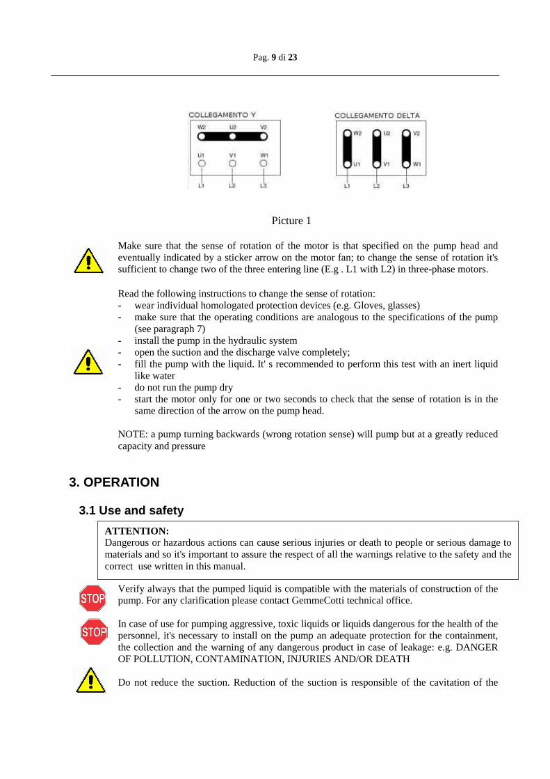
2.8 Motor connection Check that the tension and frequency printed on the label of the motor correspond to those of the electric system to be used. Don't connect the electric motor directly to the main system but protect the dedicated system with a suitable main switch with adequate safety protections against overloads. The electric connections have to be always carried out by an expert qualified electrician. The motors have to be supplied with three-phase tensions or if required by the customer, with single phase tension. The type of connection of the three-phase motors can be Star (Υ) or Delta (∆ ) according with the power supply 380 or 220 VAC (see picture 1).
Pag. 9 di 23
ATTENTION: Dangerous or hazardous actions can cause serious injuries or death to people or serious damage to materials and so it's important to assure the respect of all the warnings relative to the safety and the correct use written in this manual.
Picture 1 Make sure that the sense of rotation of the motor is that specified on the pump head and eventually indicated by a sticker arrow on the motor fan; to change the sense of rotation it's sufficient to change two of the three entering line (E.g . L1 with L2) in three-phase motors. Read the following instructions to change the sense of rotation: - wear individual homologated protection devices (e.g. Gloves, glasses) - make sure that the operating conditions are analogous to the specifications of the pump
(see paragraph 7) - install the pump in the hydraulic system - open the suction and the discharge valve completely; - fill the pump with the liquid. It' s recommended to perform this test with an inert liquid
like water - do not run the pump dry - start the motor only for one or two seconds to check that the sense of rotation is in the
same direction of the arrow on the pump head.
NOTE: a pump turning backwards (wrong rotation sense) will pump but at a greatly reduced capacity and pressure
3. OPERATION
3.1 Use and safety
Verify always that the pumped liquid is compatible with the materials of construction of the pump. For any clarification please contact GemmeCotti technical office. In case of use for pumping aggressive, toxic liquids or liquids dangerous for the health of the personnel, it's necessary to install on the pump an adequate protection for the containment, the collection and the warning of any dangerous product in case of leakage: e.g. DANGER OF POLLUTION, CONTAMINATION, INJURIES AND/OR DEATH Do not reduce the suction. Reduction of the suction is responsible of the cavitation of the
Pag. 10 di 23
pump, which causes a loss of efficiency and a rapid wear. Reduction of the discharge are not advisable, if required, reduction of the capacity can be obtained by means of a valve installed on the discharge pipe. Do not loosen the connection of the pump while it's under pressure. Do not start and/or use the pump if there are signs of leak in the system. The working temperatures have to respect the characteristics of the construction materials of the pump:
• 60 °C polypropylene execution (PP) • 80° C PVDF execution
DO NOT ALLOW THE PUMP TO RUN DRY ( note: the pump design doesn't allow the dry-running functioning because it will damage irrevocably the inner parts of the pump) An accidental failure can generate sprinklings up to considerable distances. In case of vibrations or anomalous noises, stop the pump immediately . Do not pump inflamed liquids. Do not touch the pump while operating. Before touching the motor or the bracket switch off the electric current.
3.2 Dry-running Fill the pump with water or with the liquid to be pumped before starting the unit. This will protect the bearings and the shaft of the pump against dry running. DO NOT ALLOW THE PUMP TO RUN DRY because this can cause serious damage to the internal parts of the pump due to the lack of the necessary lubrication.
3.3 Temperature Increasing the temperature of the pumped liquid can damage the pump and/or the piping/fittings and there can be a situation of serious danger for the people in the nearby. Avoid sudden changes of the temperature and do not exceed the temperature specified in your order. See the value of temperatures of the construction materials of the pumps in the paragraph 3.1.
3.4 Before starting Make sure that the pump is installed in accordance with the instructions supplied in the previous section 2. When the pumping station is new, it's necessary to fill the system with water to control that
Pag. 11 di 23
there are no leaks. WHEN THE PUMP IS INSTALLED OVER HEAD IT HAS TO BE PRIMED, THIS MEANS THAT IT HAS TO BE FILLED WITH THE LIQUID AND THE SUCTION PIPING HAS TO BE KEPT FULL OF LIQUID BEFORE STARTING THE PUMP. ATTENTION: some liquids react with water. VERIFY IF THE LIQUID TO BE PUMPED REACTS WITH WATER. IN THIS CASE THE SYSTEM HAS TO BE COMPLETELY EMPTIED AND DRIED.
3.5 Starting Start the electric motor and gradually open the discharge pipe until you reach the required flow. The pump can't operate more than two or three minutes with the discharge closed. A longer period can cause serious damage to the pump. If the pressure shown on the pressure gauge on the discharge piping does not increase, stop the pump immediately and release the pressure carefully. Repeat the operation of installation of the pump as in paragraph 2. If during the starting procedure there are changes of flow-rate, of density, temperature or viscosity of the liquid, stop the pump and contact GemmeCotti technical service.
3.6 Optimum conditions for use Operating continuously at the maximum performances (maximum capacity/head) there can be an early wear of the pump. As a general rule, we recommend using the pump at half of its maximum capacity (see the paragraph relative to the technical data) The capacity and the head of the pump refer to water pumping at room temperature. If it pumps high temperature liquids or other viscosities and densities, the performances have to be proportionately decreased. Pumps of series HCO work well with liquids having a viscosity up to 100 CPS3 and specific gravity up to 1.93. HOWEVER BOTH THE VISCOSITY AND THE SPECIFIC GRAVITY HAVE TO BE COMMUNICATED AT THE MOMENT OF QUOTATION. The electric motor is selected for the viscosity and the specific gravity communicated. In the case of higher values, the power of the motor could be insufficient.
3.7 Shut down Normally the pump should be shut down only after closing the discharge valve. If the suction valve is closed before the other, cavitation of the pump can occur. If the suction is flooded, close the valve after shutting down the pump. In some cases the pump can be used to empty tanks, in these situations the liquid can stop flowing in the pump while this is still working. In these cases a pump operating without
3 The values indicated are merely indicative and can vary in the series of pumps mod. HCO
Pag. 12 di 23
liquids (that means dry-running) can be dangerously damaged if it's not stopped immediately. For such applications the use of automatic equipment or the constant presence of a person who can shut down the pump is recommended.
3.8 Long pump inactivity If the pump has to remain inactive for a long period, before stopping it, it's recommended to let water flow in the system for several minutes so that you avoid any risk of internal deposits or sediments or precipitations of solid parts. Drain the liquid in the pump. An eventual freezing of the liquid inside the pump can cause damage. Always verify if the pumped liquid reacts with water. In this case contact GemmeCotti to find an alternative solution. If the pump is temporary removed from the system and kept in stock, it's necessary to follow the instructions of paragraph 2.3 “Storage”.
3.9 Noise level In some circumstances, for example when the pump works with high pressure and low capacity the noise increases and can be disturbing for the personnel working in the proximity. In this case it's possible to intervene with:
• earplugs; • protective homologated caps against noises for the personnel in the proximity; • soundproofing canopy for the pump. In these cases make sure that the motor
ventilation is guaranteed.
4. MAINTENANCE
4.1 General dispositions During the warranty period disassembly activities of the pump are allowed only for GemmeCotti personnel or personnel authorized by GemmeCotti. All the operations described in the paragraphs below have to be done exclusively by qualified staff and following step by step all the warnings written in this manual. Clean the external surface of the pumps using only antistatic equipment. Every operation executed on the apparatus has to be done after the disconnection of electric supply. Use exclusively a goods lift to move pumps with weight higher than 16 kg. During the movements of the machine or parts of the machine avoid collisions or falls which can damage the apparatus. Before disassembling the parts of the pump, make sure that the dangerous internal liquids have been removed /washed. THE PUMP HAS TO BE DRAINED AND DECONTAMINATED. Pay attention that some internal liquids can have dangerous reactions in contact with water. During the operations of unloading of dangerous liquids make sure that situations of danger
Pag. 13 di 23
ATTENTION: If the pump has pumped hot liquids, make sure that it's been cooled before the disassembly procedure. It's possible that the pump has pumped toxic and/or dangerous liquids: so it's necessary to wear protection for the skin and the eyes.
for people or environment don't occur.
4.2 Inspections In general mechanical seal pumps do not need a “routine” maintenance and most of all they don't require frequent dismantling. However periodical inspections are advisable to verify the state of wear of the impeller, the shaft and the bearings and if the general conditions of the internal parts of the pump are good. The time between the inspections is strongly dependent on the operation conditions of the pump: the characteristics of the liquid, the temperature, the materials used and obviously the period of operation. If a problem occurred or the pump needs a complete inspection see section “Problem solutions” and “Pump disassembly”.
4.3 Procedure before disassembly
ATTENTION: Make sure that the pump has been carefully decontaminated and cleaned. Wash and neutralize completely the dangerous liquids inside the pump. The liquid has to be collected and eliminated according to the existing environmental laws. After disconnecting the discharge and suction pipes close the extremities.
4.4 Disassembly NOTE: the photos used to show the operations of disassembly refer to a particular pump model of the series HCO and consequently the pump supplied to you can be slightly different from what is shown.
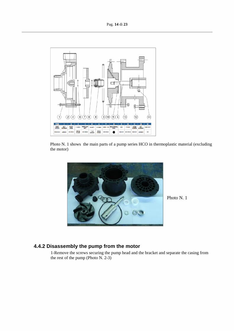
4.4.1 Main parts The drawing below shows a section with all the main parts of a pump series HCO in thermoplastic material (in particular models 110-140).
Pag. 14 di 23
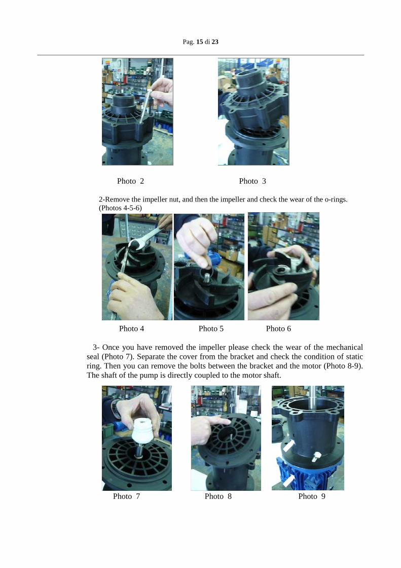
Photo N. 1 shows the main parts of a pump series HCO in thermoplastic material (excluding the motor)
Photo N. 1
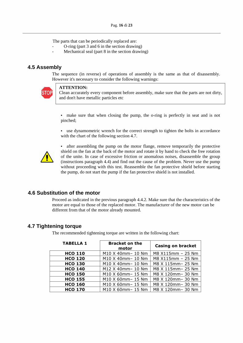
4.4.2 Disassembly the pump from the motor 1-Remove the screws securing the pump head and the bracket and separate the casing from the rest of the pump (Photo N. 2-3)
Pag. 15 di 23
Photo 2 Photo 3
2-Remove the impeller nut, and then the impeller and check the wear of the o-rings. (Photos 4-5-6)
Photo 4 Photo 5 Photo 6 3- Once you have removed the impeller please check the wear of the mechanical seal (Photo 7). Separate the cover from the bracket and check the condition of static ring. Then you can remove the bolts between the bracket and the motor (Photo 8-9). The shaft of the pump is directly coupled to the motor shaft. Photo 7 Photo 8 Photo 9
Pag. 16 di 23
ATTENTION: Clean accurately every component before assembly, make sure that the parts are not dirty, and don't have metallic particles etc
The parts that can be periodically replaced are: - O-ring (part 3 and 6 in the section drawing) - Mechanical seal (part 8 in the section drawing)
4.5 Assembly The sequence (in reverse) of operations of assembly is the same as that of disassembly. However it's necessary to consider the following warnings:
• make sure that when closing the pump, the o-ring is perfectly in seat and is not pinched; • use dynamometric wrench for the correct strength to tighten the bolts in accordance with the chart of the following section 4.7.
• after assembling the pump on the motor flange, remove temporarily the protective shield on the fan at the back of the motor and rotate it by hand to check the free rotation of the unite. In case of excessive friction or anomalous noises, disassemble the group (instructions paragraph 4.4) and find out the cause of the problem. Never use the pump without proceeding with this test. Reassemble the fan protective shield before starting the pump, do not start the pump if the fan protective shield is not installed.
4.6 Substitution of the motor Proceed as indicated in the previous paragraph 4.4.2. Make sure that the characteristics of the motor are equal to those of the replaced motor. The manufacturer of the new motor can be different from that of the motor already mounted.
4.7 Tightening torque The recommended tightening torque are written in the following chart:
TABELLA 1 Bracket on the
motor Casing on bracket
HCO 110 M10 X 40mm– 10 Nm M8 X115mm – 25 Nm
HCO 120 M10 X 40mm– 10 Nm M8 X115mm – 25 Nm
HCO 130 M10 X 40mm– 10 Nm M8 X 115mm– 25 Nm
HCO 140 M12 X 40mm– 10 Nm M8 X 115mm– 25 Nm
HCO 150 M10 X 60mm– 15 Nm M8 X 120mm– 30 Nm
HCO 155 M10 X 60mm– 15 Nm M8 X 120mm– 30 Nm
HCO 160 M10 X 60mm– 15 Nm M8 X 120mm– 30 Nm
HCO 170 M10 X 60mm– 15 Nm M8 X 120mm– 30 Nm
Pag. 17 di 23
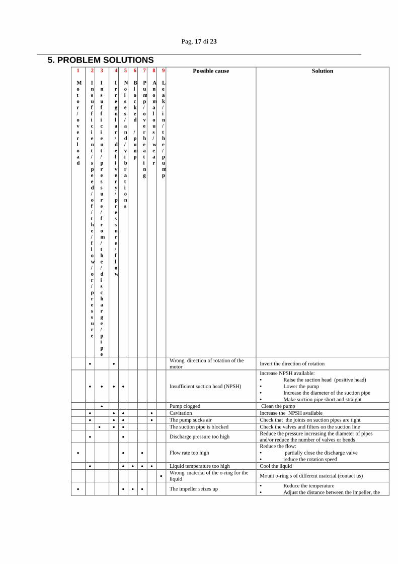
5. PROBLEM SOLUTIONS 1 Motor / overload
2 Insufficient/speed/of /the /flow/or/pressure
3 Insufficient/pressure/from/the /discharge /pipe
4 Irregular/ delivery/pressure/flow
5 Noises/and/vibrations
6 Blocked /pump
7 Pump/overheating
8 Anomalous/wear
9 Leak/in/the/pump
Possible cause
Solution
•••• •••• Wrong direction of rotation of the motor
Invert the direction of rotation
•••• •••• •••• •••• Insufficient suction head (NPSH)
Increase NPSH available: • Raise the suction head (positive head) • Lower the pump • Increase the diameter of the suction pipe • Make suction pipe short and straight
•••• Pump clogged Clean the pump •••• •••• •••• •••• Cavitation Increase the NPSH available •••• •••• •••• •••• The pump sucks air Check that the joints on suction pipes are tight •••• •••• •••• The suction pipe is blocked Check the valves and filters on the suction line
•••• •••• Discharge pressure too high Reduce the pressure increasing the diameter of pipes and/or reduce the number of valves or bends
•••• •••• •••• Flow rate too high Reduce the flow: • partially close the discharge valve • reduce the rotation speed
•••• •••• •••• •••• •••• Liquid temperature too high Cool the liquid
•••• Wrong material of the o-ring for the liquid
Mount o-ring s of different material (contact us)
•••• •••• •••• •••• The impeller seizes up • Reduce the temperature • Adjust the distance between the impeller, the
Pag. 18 di 23
rear casing and the pump head •••• •••• •••• •••• Foreign objects in the liquid Use a filter on the suction side •••• Shut off valve closed on suction side Check and open the valve
•••• Discharge pressure too low Increase the suction pressure: Install an impeller with bigger diameter (contact GemmeCotti)
1 2222 3 4 5 6 7 8 9
6. SPARE PARTS
6.1 How to order spare parts A complete kit of spare parts for these kinds of pumps is available. Please contact GemmeCotti or our distributors. To have the spare parts it's necessary to communicate the model of the pump, the size, the material, the serial number, the year of construction and the number relative to the spare part required. All the references are written directly on the pump label and on the section drawings of the pump. If you don't have the necessary drawings please contact the GemmeCotti sales office (tel. +39 0296460406).
7. DATA
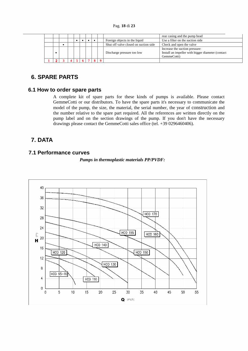
7.1 Performance curves Pumps in thermoplastic materials PP/PVDF:
Pag. 19 di 23
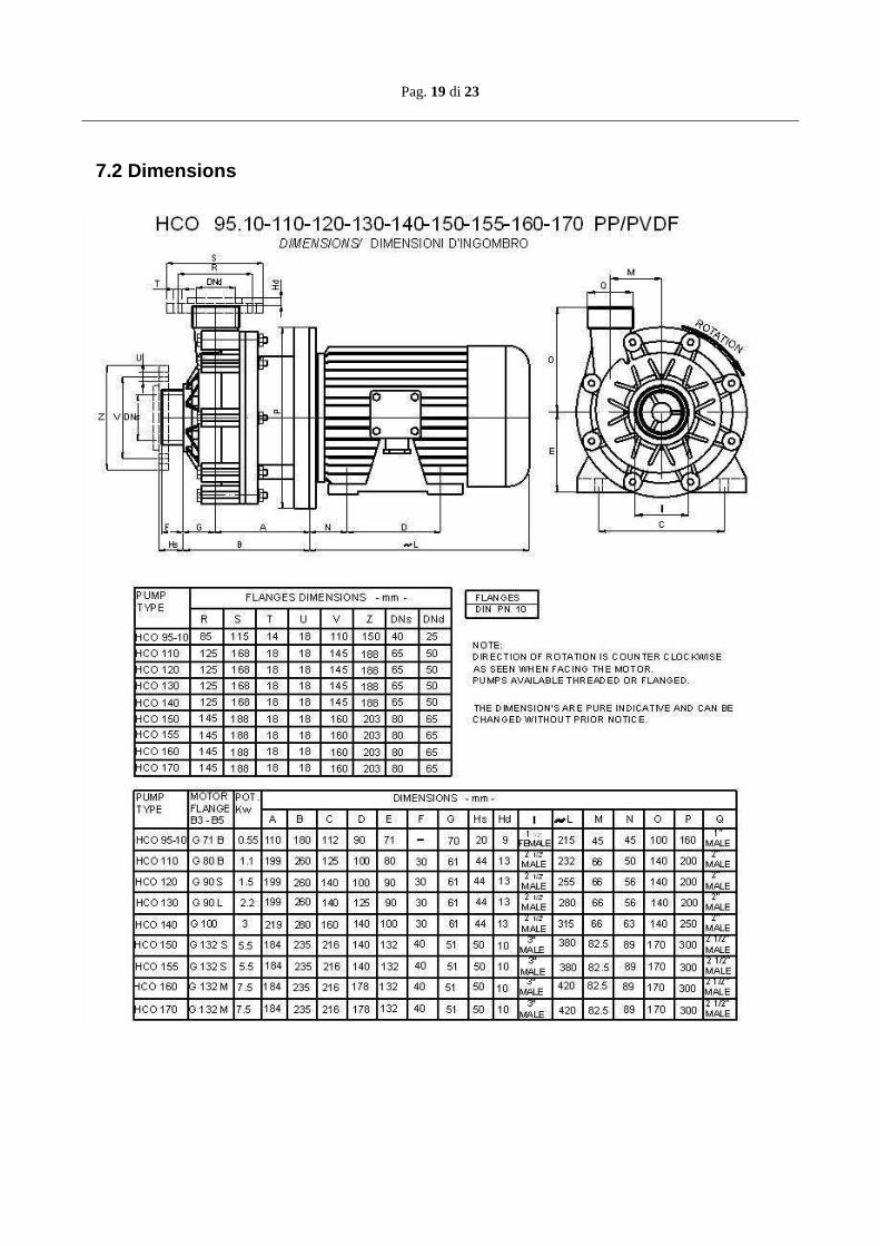
7.2 Dimensions
Pag. 20 di 23
7.3 Technical data and limits
The performance curves are valid for homogeneous liquids with specific gravity =1, viscosity 1cPs and temperature 20°C. If the liquid to be pumped has a specific gravity higher than 1, the absorbed power written on the performance curve has to be increased according to the value of the specific gravity of the liquid. For liquids having specific gravity higher than 2, please contact the GemmeCotti technical service (tel. +390296460406; e-mail [email protected]). The performance curves are valid for homogeneous liquids having viscosity of 1CPS. If the pumped liquid has a viscosity different from 1 CPS the values of Q/H will be altered. The performance of the pump will decrease. For liquids having viscosity lower than 0.5 CPS or greater than 150 CPS please contact the GemmeCotti technical service. Values of required NPSH written on the performance curves are the lower required values. As a rule, for safety reasons, the value of NPSH of the system (NPSH available) should be at least 0,5 m higher than the value of required NPSH (written on the performance curves). Values of performances written on the curves refer to trial pumps during prototype phase. In pumps manufactured in series such values can be lower. Usually these values have to be considered as follows:
• pumps with discharge up to 25mm: - 3 points
• pumps with discharge superior to 25mm: - 2 points Characteristics of pumps series HCO are guaranteed by the manufacturer with tolerances in accordance with UNI EN ISO 9906:2002 regulation. With respect to other specifications or regulations requiring more restricted tolerances, these have to be specifically asked for at the moment of quotation; in this case GemmeCotti will choose a pump more suitable and the required regulations will be considered.
8. WARRANTY AND REPAIR
8.1 Warranty All GemmeCotti products are guaranteed for a period of twelve (12) months starting from the delivery date of the goods. For the warranty service to be applicable the customer must report the defect in writing no later than 8 (eight) days from the moment that the damage occurs, and must return the part (or parts) to GemmeCotti for repair or replacement. Pumps cannot be repaired or substituted on site. In the case of a request of warranty service, it's better to send the complete pump together with its motor to GemmeCotti. The costs of delivery and the relative risks, and possible customs duties have to be paid by the customer. GemmeCotti will not accept the costs of collection and shipment. The manufacturer is not responsible for damages caused during the shipment of the parts or of the pump sent to GemmeCotti to be repaired under warranty. The warranty system provides that, after a careful examination at our factory, GemmeCotti is free to choose to repair or replace the part (or parts) of the pump which is/are defective in
Pag. 21 di 23
materials or in workmanship, or both. We will not give any refund or credit for the defective material or for direct or indirect damages caused by our pumps. In any case, any reimbursement cannot exceed the cost of the pump or of the supplied material. If the pumped liquid and the needed performances have not been communicated to GemmeCotti before the offer and confirmed in the quotation and order confirmation, the customer takes the whole responsibility for the usage of the product, especially if not used in an appropriate way, and the warranty, the conformity to the Machine Directive 2006/42/CE and the relative CE declaration are no longer valid. In this case the customer is the only responsible for the introduction of the pump in the market, for the declaration of conformity to the Machine Directive and the CE mark. In any case the user is considered the one who knows better the chemical compatibility and the reactions between the liquid to be pumped and the material of construction of the pump and consequently the information given in this regard by GemmeCotti is merely indicative. If the returned piece is no longer covered by guarantee, or if after inspection GemmeCotti finds the piece to be not defective, inspection charges will be charged to the customer and the repaired or substituted piece will be returned to the customer at the customer's own expense. Pumps which have been repaired or substituted under guarantee will be supplied on the same delivery conditions as the order and the warranty will not be extended. Warranty does not cover components subject to natural wear due to time, such as mechanical seals, bearings, bushings and lip seals. The customer is solely responsible for the good performance of pumps and for their careful maintenance. Therefore no claims will be allowed when goods have been improperly handled (not stored in a suitable closed dry place, which is necessary because of the fragility of materials), contaminated, handled with negligence, improperly installed, tampered with or not well regulated, incorrectly used in wrong applications. In particular, GemmeCotti will not take any responsibility in the case of wear due to corrosion. Ordinary maintenance and repair executed outside GemmeCotti authorized network, will cause invalidation of the warranty and of the CE declaration of conformity. The warranty does not cover damages due to extraordinary or natural events, such as lightning, ice, fire and others. All the warranty obligations are considered fully satisfied after the repair or substitution of the defective parts. The Warranty service will be suspended in the case of default or delayed payment and the period lost cannot be recovered. This warranty is an integral part of the offer and of the order confirmation. In the case of litigation the court which has jurisdiction is the Busto Arsizio (Italy) Tribunal and the law that will be applied is the Italian Law.
8.2 Returned parts and repair All our distributors offer a complete repair service. Contact your local distributor or GemmeCotti s.r.l. directly. Before sending the pump back to our repair services or to GemmeCotti, the pumps have to be decontaminated from the used dangerous liquids. Before sending the pump the customer has to fill in the Decontamination Declaration and send it by e-mail or fax as per the facsimile document in the next paragraph 8.3.
Pag. 22 di 23
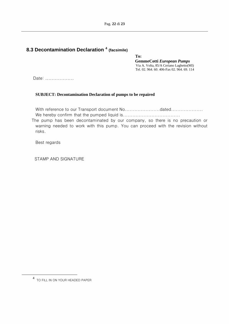
8.3 Decontamination Declaration 4 (facsimile)
To: GemmeCotti European Pumps Via A. Volta, 85/A Ceriano Laghetto(MI)
Tel. 02. 964. 60. 406-Fax 02. 964. 69. 114
Date: .................. SUBJECT: Decontamination Declaration of pumps to be repaired With reference to our Transport document No......................dated.................... We hereby confirm that the pumped liquid is.................................... The pump has been decontaminated by our company, so there is no precaution or warning needed to work with this pump. You can proceed with the revision without risks.
Best regards
STAMP AND SIGNATURE
4 TO FILL IN ON YOUR HEADED PAPER
Pag. 23 di 23
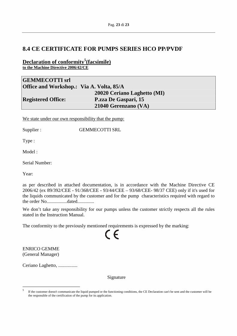
8.4 CE CERTIFICATE FOR PUMPS SERIES HCO PP/PVDF Declaration of conformity5(facsimile) to the Machine Directive 2006/42/CE GEMMECOTTI srl Office and Workshop.: Via A. Volta, 85/A 20020 Ceriano Laghetto (MI) Registered Office: P.zza De Gaspari, 15 21040 Gerenzano (VA) We state under our own responsibility that the pump: Supplier : GEMMECOTTI SRL Type : Model : Serial Number: Year: as per described in attached documentation, is in accordance with the Machine Directive CE 2006/42 (ex 89/392/CEE - 91/368/CEE - 93/44/CEE – 93/68/CEE- 98/37 CEE) only if it's used for the liquids communicated by the customer and for the pump characteristics required with regard to the order No.................dated..............
We don’t take any responsibility for our pumps unless the customer strictly respects all the rules stated in the Instruction Manual. The conformity to the previously mentioned requirements is expressed by the marking:
ENRICO GEMME (General Manager) Ceriano Laghetto, ................ Signature
5 If the customer doesn't communicate the liquid pumped or the functioning conditions, the CE Declaration can't be sent and the customer will be
the responsible of the certification of the pump for its application.