Manual & Guides: Anderson Greenwood Series 200 POSRV ...
13
ANDERSON GREENWOOD SERIES 200 POSRV INSTALLATION AND MAINTENANCE INSTRUCTIONS © 2017 Emerson. All rights reserved. Before installation these instructions must be fully read and understood valves.emerson.com Engineering Doc. #05.9040.268 Rev. K VCIOM-06018-EN 17/05 1 GENERAL VALVE DESCRIPTION AND START-UP 1.1 General The Anderson Greenwood Series 200 Pilot Operated SRV uses the principle of pressurizing the larger top area of a differential area piston with line pressure to hold the piston closed up to set pressure. At set pressure the pilot valve relieves, depressurizing the volume on top of the piston causing the piston to lift and the main valve to relieve. When the pilot reseats, the volume on top of the piston is repressurized and the main valve closes. Set pressure range 25 psig to 10.600 psig. 1.2 Installation Both inlet and outlet may be standard ANSI flanges or threaded connections and are to be installed in accordance with accepted piping practices. 1.3 Start-up There must be pressure at the valve inlet to establish a differential in force across the piston and ‘load’ it in the closed position. Pressure must pass through the pilot supply tube and pilot and exert force on top of the piston. On normal plant start-up, the valve loads itself as pressure increases. It is not uncommon that slight leakage past the main seat occurs until system pressure reaches two or three pounds. This amount of pressure is sometimes needed for the soft seat to form a seal with the nozzle. Block valves are often used under safety valves in order to isolate them when maintenance is required. When putting the safety valve in service be sure the block valve is fully opened. If the block valve is opened after system start-up, the safety valve may briefly relieve before the volume on top of the piston is pressurized. 1.4 Maintenance Anderson Greenwood recommended main valve and pilot maintenance procedures including pilot set pressure adjustment and valve assembly testing are described in the following paragraphs. Following these procedures in a regular pressure relief valve maintenance program appropriate for the specific operating conditions will ensure satisfactory valve performance and provide optimum service life. Should the pressure/media requirements of a pilot operated pressure relief valve be outside the capabilities of the repair facility, contact Anderson Greenwood for specific instructions before starting any maintenance activity. TABLE OF CONTENTS 1. General valve description and start-up ....... 1 2. Main valve maintenance ............................... 2 3. Pilot maintenance ......................................... 7 4. Pilot set pressure adjustment ...................... 9 5. Leak testing assembly .................................. 9 6. Pilot set pressure field test procedure ...... 10 7. Soft goods repair kits .................................. 11 8. Pilot conversion kits .................................... 12 When remote pressure pick-up is used the pilot supply tube is connected to a remote location rather than the inlet neck of the valve. If a block valve is used in the remote pilot supply line, it must be opened before pressurizing the system or opening the isolating block valve under the main valve. NOTE Remote pressure pick-up piping must have the equivalent flow area of ⅜” tubing for lengths up to 100 feet. For lengths greater than this, consult the factory. This manual is provided as a general guide for the maintenance of the safety valves described herein. It does not include procedures covering all valve configurations and variations manufactured by Anderson Greenwood. The user is advised to contact Anderson Greenwood or one of our authorized representatives for assistance with valve configurations and variations not covered in this manual.
-
Upload
khangminh22 -
Category
Documents
-
view
3 -
download
0
Transcript of Manual & Guides: Anderson Greenwood Series 200 POSRV ...

ANDERSON GREENWOOD SERIES 200 POSRVINSTALLATION AND MAINTENANCE INSTRUCTIONS
© 2017 Emerson. All rights reserved.
Before installation these instructions must be fully read and understood
valves.emerson.com
Engineering Doc. #05.9040.268 Rev. K
VCIOM-06018-EN 17/05
1 GENERAL VALVE DESCRIPTION AND START-UP
1.1 GeneralThe Anderson Greenwood Series 200 Pilot Operated SRV uses the principle of pressurizing the larger top area of a differential area piston with line pressure to hold the piston closed up to set pressure. At set pressure the pilot valve relieves, depressurizing the volume on top of the piston causing the piston to lift and the main valve to relieve. When the pilot reseats, the volume on top of the piston is repressurized and the main valve closes.Set pressure range 25 psig to 10.600 psig.
1.2 InstallationBoth inlet and outlet may be standard ANSI flanges or threaded connections and are to be installed in accordance with accepted piping practices.
1.3 Start-upThere must be pressure at the valve inlet to establish a differential in force across the piston and ‘load’ it in the closed position. Pressure must pass through the pilot supply tube and pilot and exert force on top of the piston. On normal plant start-up, the valve loads itself as pressure increases. It is not uncommon that slight leakage past the main seat occurs until system pressure reaches two or three pounds. This amount of pressure is sometimes needed for the soft seat to form a seal with the nozzle.Block valves are often used under safety valves in order to isolate them when maintenance is required. When putting the safety valve in service be sure the block valve is fully opened. If the block valve is opened after system start-up, the safety valve may briefly relieve before the volume on top of the piston is pressurized.
1.4 MaintenanceAnderson Greenwood recommended main valve and pilot maintenance procedures including pilot set pressure adjustment and valve assembly testing are described in the following paragraphs. Following these procedures in a regular pressure relief valve maintenance program appropriate for the specific operating conditions will ensure satisfactory valve performance and provide optimum service life.Should the pressure/media requirements of a pilot operated pressure relief valve be outside the capabilities of the repair facility, contact Anderson Greenwood for specific instructions before starting any maintenance activity.
TABLE OF CONTENTS
1. General valve description and start-up ....... 12. Main valve maintenance ............................... 23. Pilot maintenance ......................................... 74. Pilot set pressure adjustment ...................... 95. Leak testing assembly .................................. 96. Pilot set pressure field test procedure ...... 107. Soft goods repair kits .................................. 118. Pilot conversion kits .................................... 12
When remote pressure pick-up is used the pilot supply tube is connected to a remote location rather than the inlet neck of the valve. If a block valve is used in the remote pilot supply line, it must be opened before pressurizing the system or opening the isolating block valve under the main valve.
NOTERemote pressure pick-up piping must have the equivalent flow area of ⅜” tubing for lengths up to 100 feet. For lengths greater than this, consult the factory.
This manual is provided as a general guide for the maintenance of the safety valves described herein. It does not include procedures covering all valve configurations and variations manufactured by Anderson Greenwood. The user is advised to contact Anderson Greenwood or one of our authorized representatives for assistance with valve configurations and variations not covered in this manual.

2
32
32
.010R.020
Valve size and type Min. nozzleprojection height (in)X = Main valve piston/seat Type, 3 or 9
1/1.5 x 2 Type 24X/25X (D, E and F orifice) 0.0451.5 x 2/3 Type 24X/25X (G and H orifice) 0.0402” Type 24X/25X 0.0353” Type 24X/25X 0.0354” Type 24X/25X 0.0356” Type 24X/25X 0.0358” Type 24X/25X 0.0351.5” Type 26X 0.0352” Type 26X 0.0353” Type 26X 0.0354” Type 26X 0.0306” Type 26X 0.0308 x 88 Type 26X 0.0308 x 10 Type 26X 0.03010” Type 26X 0.030
ANDERSON GREENWOOD SERIES 200 POSRVINSTALLATION AND MAINTENANCE INSTRUCTIONS
2 MAIN VALVE MAINTENANCE
2.1 DisassemblyBefore beginning disassembly, bleed off any pressure trapped in the main valve or pilot.Refer to Figure 1A (piston/seat Type XX3) and Figure 1B (piston/seat Type XX9) for parts description and location.Remove cap (Item 17) from the body (Item 1). Remove the liner seal (Item 6), liner (Item 5) and piston (Item 10). Remove the soft goods from the piston. If the piston is equipped with a wedge ring (Item 15), clean and retain for use during assembly. The dipper tube (Item 4) is swaged in place and no attempt should be made to remove it. The nozzle (Item 3) should not be removed unless it is damaged or the nozzle seal (Item 2) is leaking.
NOTEDo not remove lock pin and lift adjusting bolt (Items 11 and 12) on valves so equipped unless nozzle is removed. This bolt controls the piston lift and hence the valve’s relieving capacity. If either or both the nozzle and lift bolt were removed, then lift must be reset following the procedure of paragraph 2.3.3 (Type XX3) or paragraph 2.3.4 (Type XX9).
2.1.1 Nozzle and nozzle seal disassemblyRefer to Figure 2 for parts description and location.1. Remove lock pin and lift adjusting bolt from
piston, if applicable.2. Place liner in body and piston, without seat
or seat retainer, into liner and on top of nozzle.
3. Place appropriate spacer (see Table II) on top of piston and then the cap over the spacer.
4. Thread the appropriate number of cap bolts (see Table II) into threaded holes on top of body. If two bolts are used, they should be 180° apart. When using four bolts, they should be 90° apart. Always use the shortest cap bolts supplied with the valve unless
Minimum projection
all cap bolts are required. For example, the 1” Type 40/50 is equipped with two 1.50” long bolts and two 1.88” long bolts but only the two 1.50” long bolts should be used. However, the 2” Type 40/50 is equipped with two 1.25” long bolts and two 1.62” long bolts and all four bolts are required for nozzle installation.
5. Tighten cap bolts evenly to the torque listed in Table II to compress nozzle seal.
6. Use a punch or bar with a light hammer and tap on the nozzle retainer teeth to loosen the nozzle retainer. Unthread nozzle retainer approximately ½ turn.
7. Loosen cap bolts to remove load from nozzle. Remove components from main valve.
NameplatePilot valve
Supply tube
Outlet
Inlet
Main valve

3
ANDERSON GREENWOOD SERIES 200 POSRVINSTALLATION AND MAINTENANCE INSTRUCTIONS
2.3 Assembly2.3.1 Nozzle and nozzle seal installation1. Place nozzle seal and nozzle in body.2. Place nozzle retainer over nozzle and thread
into body until it stops on nozzle shoulder. Do not lubricate nozzle retainer threads or mating body threads.
3. Repeat steps 3 through 5 of disassembly procedure to compress nozzle seal. Thread nozzle retainer into body as seal is compressed to keep nozzle retainer from binding against piston.
4. Use a punch or bar with a light hammer and tap on the nozzle retainer teeth to snug the nozzle retainer threads.
5. Loosen cap bolts to remove load from spacer.
6. Remove spacer from valve.
2.3.2 Soft goods installation and main valve reassemblyRefer to Figure 1A (piston/seat Type XX3) and Figure 1B (piston/seat Type XX9) for parts description and location.
2.3.4 Type XX9 piston and seatInstall new piston seal and snap ring along with original wedge ring (if so equipped). Install new seat and reassemble seat retainer and seat retainer screw. Do not apply any lubricant to any of the soft goods.
NOTEOver tightening of seat retainer screw or bolts can distort or damage seat and cause leakage. Retainer screw or bolts should be installed until assembly is snug. Then tighten an additional ¼ to ½ turn to secure assembly.
On 1” to 4” Type 49/59 and 1.5” to 3” Type 69 valves, if the nozzle or lift bolt were removed, then lift needs to be set. If lift setting gages are available, use lift setting procedure 06.2284, otherwise use procedure 05.2284.
Install new liner seal and apply a light coat of lubricant to cap bolt threads. When installing the cap, make sure it is seated squarely into body. Torque cap bolts uniformly so as not to ‘cock’ cap. See Table III for torque values. Such a condition may result in leakage at the liner seal or cause the piston and liner to bind.
2.3.3 Type XX3 piston and seatReplace piston and liner seals. Install piston seals in groove locations shown in Table I. Install new seat and reassemble seat retainer and seat retainer screw or bolts.
NOTEOver tightening of seat retainer screw or bolts can distort or damage seat and cause leakage. Retainer screw or bolts should be installed until assembly is snug. Then tighten an additional ¼ to ½ turn to secure assembly.
Apply a light coat of lubricant on all threads after cleaning. Lubricate upper portion of liner I.D., piston seal and wedge ring or back up ring with Dow Corning No. 33 or equivalent below 275 psig set pressure. At 275 psig and above use Desco 600, or equivalent. Use lubricant sparingly.
On 1” to 4” Type 43/53 and 1.5” to 3” Type 63 valves, if the nozzle or lift bolt were removed, then lift needs to be set. If lift setting gages are available, use lift setting procedure 06.3349, otherwise use procedure 05.2284.
2.2 Main valve nozzle reworkShould the main valve nozzle seating face become nicked or scratched such that the main valve seat does not seal, the imperfections can be removed by polishing the nozzle face with 400 grit sandpaper on a flat surface plate. Certain critical nozzle dimensions and finishes must be maintained and those are shown in the figure and table below.
When installing the cap, make sure it is seated squarely into body. Torque capbolts uniformly so as not to ‘cock’ cap. See Table III for torque values. Such a condition may result in leakage at the liner seal or cause the piston and liner to bind.

4
¼ 75/16 12⅜ 217/16 33½ 459/16 59⅝ 97¾ 130⅞ 2021 2711⅛ 408
ANDERSON GREENWOOD SERIES 200 POSRVINSTALLATION AND MAINTENANCE INSTRUCTIONS
TABLE IValve size Valve type Piston seal location Back-up ring Wedge ring1” to 2” Type 243/253 Top groove Yes No1½” Type 263 Top groove Yes No3” to 8” Type 243/253 Bottom groove No Yes2” to 10” Type 263 Bottom groove No Yes
TABLE IIValve size and type
Spacer P/N Cap bolt thread # Cap bolts to use Cap bolt torque (ft·lb)X = Main valve seat type, 3 or 91/1.5 x 2 Type 24X/25X (D, E and F orifice) 06.5612.001 .500-20 UNF 2 311.5 x 2/3 Type 24X/25X (G and H orifice) 06.5612.002 .500-20 UNF 2 411.5 x 2/3 Type 24X/25X (G and H orifice) 06.5612.002 .625-18 UNF 2 512” Type 24X/25X 06.5612.004 .500-20 UNF 4 272” Type 24X/25X 06.5612.004 .625-18 UNF 4 343” Type 24X/25X 06.5612.006 .500-20 UNF 4 353” Type 24X/25X 06.5612.006 .625-18 UNF 4 444” Type 24X/25X 06.5612.008 .750-16 UNF 4 1304” Type 24X/25X 06.5612.008 .875-14 UNF 4 1516” Type 24X/25X 06.5612.009 .750-16 UNF 2 826” Type 24X/25X 06.5612.009 .875-14 UNF 2 958” Type 24X/25X 06.5612.010 .875-14 UNF 4 1238” Type 24X/25X 06.5612.010 1.000-14 UNS 4 1401.5” Type 26X 06.5612.004 .500-20 UNF 2 192” Type 26X 06.5612.006 .500-20 UNF 2 312” Type 26X 06.5612.006 .625-18 UNF 2 393” Type 26X 06.5612.008 .750-16 UNF 2 1134” Type 26X 06.5612.011 .625-18 UNF 2 636” Type 26X 06.5612.012 .750-16 UNF 2 888 x 88 Type 26X 06.5612.013 .875-14 UNF 4 1198 x 10 Type 26X 06.5612.014 1.125-12 UNF 10 8910” Type 26X 06.5612.015 1.125-12 UNF 10 90
TABLE IIIBolt size Torque value (ft·lbs)

5
115
1416
89
2 224
213
19
7
5
10
13
12
1117186
ANDERSON GREENWOOD SERIES 200 POSRVINSTALLATION AND MAINTENANCE INSTRUCTIONS
PARTS LISTItem no. Part name1 Body2 Nozzle seal [1]
3 Nozzle [1]
4 Dipper tube5 Liner6 Liner seal [2]
7 Seat [2]
8 Seat retainer9 Seat retainer screw10 Piston11 Lift adj. bolt [4]
12 Lock pin [4]
13 Piston seal [2]
14 Back-up ring [2]
15 Wedge ring [3]
16 Dome spring17 Cap18 Cap bolt19 Nozzle retainer21 Supply tube22 Tube connector
NOTES1. Field replaceable only if required.2. Recommended spare parts for repair.3. Used in place of item 14 on 3” and larger Type
243/253 and 2” and larger Type 263.4. Not used on 6”, 8” Type 243/253 and 4” and
larger Type 263.Refer to Section 7.1 for soft goods repair kit part numbers.
FIGURE 1A - MAIN VALVE

6
18 11 17 16 6
14
13
19
3
12
15
5
10
7
2
1
21
22
8 9 4
ANDERSON GREENWOOD SERIES 200 POSRVINSTALLATION AND MAINTENANCE INSTRUCTIONS
Cap bolt
Cap
Spacer
Liner
Piston
Nozzle retainer
Nozzle seal
Body
FIGURE 2
Nozzle
FIGURE 1B - MAIN VALVE
PARTS LISTItem no. Part name1 Body2 Nozzle seal [1]
3 Nozzle [1]
4 Dipper tube5 Liner6 Liner seal [2]
7 Seat [2]
8 Seat retainer9 Seat retainer screw10 Piston11 Lift adj. bolt [4]
12 Lock pin [4]
13 Piston seal [2]
14 Snap ring [2]
15 Wedge ring [3]
16 Dome spring17 Cap18 Cap bolt19 Nozzle retainer21 Supply tube22 Tube connector
NOTES1. Field replaceable only if required.2. Recommended spare parts for repair.3. Used on 1”/1½” (D, E, F orif. liq. only), 2” (liq. only)
and 4” and larger Type 249/259; and 1½” (liq. only), and 3” and larger Type 269.
4. Not used on 6”, 8” Type 249/259 and 4” and larger Type 263.
Refer to Section 7.1 for soft goods repair kit part numbers.

7
ANDERSON GREENWOOD SERIES 200 POSRVINSTALLATION AND MAINTENANCE INSTRUCTIONS
3 PILOT MAINTENANCE
3.1 Disassembly3.1.1 To facilitate assembly, place all parts
in an orderly arrangement as they are removed so the correct parts can be assembled in the proper sequence. Refer to Figure 3 for parts description and location.
Remove spring compression by backing out adjusting screw. Remove bonnet, being careful to catch spring and spring washers when they disengage. Turn pilot upside down to remove internals parts from upper half of body.
Loosen bushing, Item 20, at bottom of pilot and remove blowdown adjustment screw. Remove seat, Item 18, from blowdown adjustment screw and O-ring seated shuttle located inside.
3.1.2 For pilots equipped with a field test assembly (Figure 5) remove the assembly from the pilot body (Figure 5). Unscrew the bushing from the assembly and remove the spring and shuttle.
3.2 AssemblyAssemble valve in reverse order of disassembly. Lubricate all screw threads and bearing ends of spring washers. Use Dow Corning No. 33 Silicone grease, or equivalent. A small amount of lubricant should also be applied to the bonnet seal (Item 8) the blowdown screw seal (Item 24), the bushing seal (Item 19) and the blowdown seal (Item 21). Torque blowdown seal jam nut to 50-55 ft·lbs. The shaft seal (Item 28), nut seal (Item 26) and cam bearing points should also be lubricated on the lift lever pilot.
NOTE1. Do not lubricate or get any lubricant on the spindle
or seat. Lubricant on these surfaces will collect dirt during normal relieving cycles and cause erratic pilot action.
2. If Items 14, 20 and 32 are removed, make sure all the shims, Item 31, have been replaced. Be sure that the smooth unmarked face of jam nut, Item 32, is against the adjacent blowdown bushing face when assembling. If any internal metal parts are replaced, check and adjust the lift of the spindle, Item 6. Refer to Figure 6 for the lift adjustment procedure.
3. On field test assemblies and backflow preventers, lubricate bushing seal(s) only. Do not get any lubricant on the shuttle, shuttle seat(s) and or bushing seat
Refer to Section 7 for soft goods repair kit part numbers.

8
27
29
28
30
26
25
11
6
11
9
8
23
13
12
10
6
7
21
20
19
1
32
14
6
7
2
18
16
15
22
31
4
5
3
17
24
ANDERSON GREENWOOD SERIES 200 POSRVINSTALLATION AND MAINTENANCE INSTRUCTIONS
Dome connectionPilot with optional lift lever
Inlet
PARTS LISTItem no. Part name Item no. Part name1 Body 17 Spacer2 Nozzle seal* 18 Reseat seat3 Nozzle 19 Bushing seal*4 Seat* 20 Bushing5 Retainer 21 Blowdown seal*6 Spindle 22 Piston7 Guide 23 Vent8 Bonnet seal* 24 Blowdown seal*9 Spring washer 25 Gland nut10 Spring 26 Nut seal*11 Bonnet 27 Lever12 Pressure adjustment screw 28 Shaft seal13 Cap 29 Lever spring14 Blowdown adjustment screw 30 Cam and shaft15 Retainer 31 Shim, spindle lift16 Piston seal* 32 Jam nut
NOTE* Recommended spare parts for repair.
FIGURE 3

9
ANDERSON GREENWOOD SERIES 200 POSRVINSTALLATION AND MAINTENANCE INSTRUCTIONS
4 PILOT SET PRESSURE ADJUSTMENT
4.1 GeneralTwo adjustments are provided; one for varying the pressure at which the pilot opens and one for varying the pressure at which the pilot closes.
4.2 Set pressureTo adjust set pressure, a test set-up similar to that shown in Figure 4 should be used. The set pressure adjustment screw should be turned IN most of the way and the blowdown adjustment screw should be turned out most of the way. Increase the supply pressure to the nameplate setting and slowly back the adjustment screw out until the pilot ‘pops’ at the desired set pressure. Lock the adjusting screw with the jam nut and cycle the pilot several times to make sure the setting is correct.
NOTEWhen the pilot ‘pops’, the dome pressure decreases to zero and no flow of gas should be detected at the pilot vent after pop. If gas continues to flow through the vent, the blowdown screw is turned in too far.
4.3 Reseat pressure (blowdown)To adjust reseat, decrease the pressure in the accumulator to the desired reseat pressure and turn the blowdown adjustment screw in until the pilot actuates. When this happens, the dome pressure will immediately increase to the supply pressure level. If the pilot reseats above the desired pressure, turn the blowdown adjustment screw out. Lock the blowdown adjusting screw with the jam nut with the recommended torque of 50-55 ft·lbs and cycle the pilot several times to make sure the setting is correct.
4.4 Range of adjustmentAll pilots can be adjusted ± 5% beyond the nameplate setting.
4.5 Adjustment tolerancesCracking pressure: 95% or more of specified
set pressureSet pressure: ± 3% of specified set
pressure above 70 psig set ± 2 psig for 70 psig and below
Reseat pressure: 90-92% of specified set pressure for internal pressure sense 94-96% of specified set pressure for remote pressure sense
Dome pressure should be zero when pilot is actuated and no gas flow is detected at pilot vent.
Set pressure adjustment (turn in to increase set pressure) (turn out to decrease set pressure)
Dome pressure gauge
Vent valve
Pilot exhaust
Blowdown adjustment (turn in to shorten) (turn out to increase)
Flexible supply hose
Valve ‘A’Mounting stub
Inlet supply pressure gauge
Supply valve
Vent valve
Accumulator (approx. ¼ cu ft)
FIGURE 4
5 LEAK TESTING ASSEMBLY
5.1 GeneralThe complete valve assembly should be leak tested for internal and external leaks using a pressure equal to 30% and 90% of set.
5.2 Internal leak testNozzle: use a piece of wide masking tape to cover the lower part of the main valve outlet, taped across the opening 2” to 3” high. Pour in enough water to cover just the base of the nozzle. If bubbles are detected, the nozzle seal is leaking. Replacement of the seal involves removal of the nozzle. See paragraph 2.1.1 for the nozzle removal procedure.
Main seat: pour in enough water to just cover the bottom of the piston. If bubbles are detected, the main seat is leaking. The nozzle or seat may be damaged or the piston may not
be seating squarely on the nozzle. For improper piston seating on low pressure valves (less than 275 psig set), pressurize dome of main valve to 275 psig to align seat. Improper piston seating may also be due to incorrect assembly of cap to body. Refer to Section 2.
Piston seal: if no bubbles are detected at main seat, increase the water level to cover the lower part of the liner. More masking tape may be used. If bubbles are detected, the piston seal at the top part of the piston is leaking; the piston seal may be defective due to excessive molding flash or the liner may be scratched.

10
ANDERSON GREENWOOD SERIES 200 POSRVINSTALLATION AND MAINTENANCE INSTRUCTIONS
5.3 External leak testFollowing the internal leak test, check for external leakage by applying leak test solution to all joints and seals. Tighten bolts or fittings as required. If a leak is observed between the cap and body, be sure the cap has been assembled squarely against the liner before tightening cap bolts.
6 PILOT SET PRESSURE FIELD TEST PROCEDURE
CAUTIONIt is not necessary to remove the pressure relief valve from service to check the set pressure; however, if the pressure relief valve is not isolated from the process media while performing this test, the main valve will open if there is process pressure at the valve inlet.
6.1 GeneralThe set pressure of valves equipped with a field test accessory can be checked with the valve installed, in operation. The field test accessory consists of a check valve in the pilot supply line through which test pressure from an external source can be supplied to the pilot. A test set-up similar to that shown in Figure 2 and procedure similar to the following should be used.
6.2 Procedurea. Remove dust plug from field test port and
connect flexible hose from test gas bottle.b. Close vent valve ‘C’.c. Open block valve ‘A’ slowly to increase
pressure until pilot ‘pops’ (with process pressure at inlet, main valve opens). The set pressure will be the pressure indicated on the test gauge at the time the pilot ‘pops’.
Flexible hose
Test gauge
Vent valve ‘C’
Block valve ‘A’
Gas bottle
Field test check valve
FIGURE 5
d. Close valve ‘A’ and slowly open valve ‘C’ to reduce the pressure until the pilot actuates as shown by a sudden drop of pressure indicated on the test gauge (with process pressure at inlet, main valve closes). The indicated pressure at the time the pilot actuates is pilot reseat pressure and will be approximately 4% lower than actual reseat pressure if the pilot is equipped for internal pressure pick-up. If remote pressure pick-up is used, the pressure indicated will be the actual reseat pressure.
e. To remove test set-up, close block valve ‘A’, open vent valve ‘C’, remove flexible hose from field test port, and replace dust plug.
11
ANDERSON GREENWOOD SERIES 200 POSRVINSTALLATION AND MAINTENANCE INSTRUCTIONS
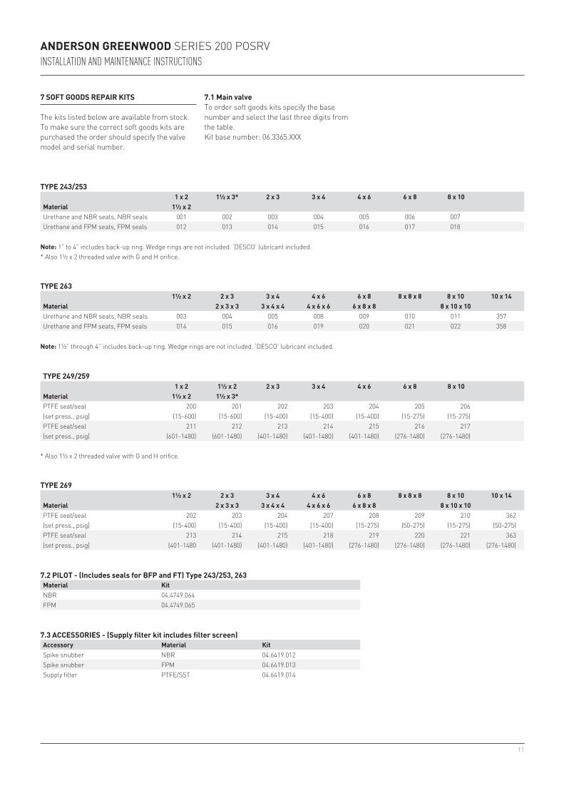
7 SOFT GOODS REPAIR KITS
The kits listed below are available from stock. To make sure the correct soft goods kits are purchased the order should specify the valve model and serial number.
7.1 Main valveTo order soft goods kits specify the base number and select the last three digits from the table.Kit base number: 06.3365.XXX
Note: 1½” through 4” includes back-up ring. Wedge rings are not included. ‘DESCO’ lubricant included.
* Also 1½ x 2 threaded valve with G and H orifice.
7.2 PILOT - (Includes seals for BFP and FT) Type 243/253, 263Material KitNBR 04.4749.064FPM 04.4749.065
7.3 ACCESSORIES - (Supply filter kit includes filter screen)Accessory Material KitSpike snubber NBR 04.6419.012Spike snubber FPM 04.6419.013Supply filter PTFE/SST 04.6419.014
Note: 1” to 4” includes back-up ring. Wedge rings are not included. ‘DESCO’ lubricant included.* Also 1½ x 2 threaded valve with G and H orifice.
TYPE 243/253
Material1 x 2 1½ x 3* 2 x 3 3 x 4 4 x 6 6 x 8 8 x 10
1½ x 2Urethane and NBR seats, NBR seals 001 002 003 004 005 006 007Urethane and FPM seats, FPM seals 012 013 014 015 016 017 018
TYPE 263
Material1½ x 2 2 x 3 3 x 4 4 x 6 6 x 8 8 x 8 x 8 8 x 10 10 x 14
2 x 3 x 3 3 x 4 x 4 4 x 6 x 6 6 x 8 x 8 8 x 10 x 10Urethane and NBR seats, NBR seals 003 004 005 008 009 010 011 357Urethane and FPM seats, FPM seals 014 015 016 019 020 021 022 358
TYPE 249/259
Material1 x 2 1½ x 2 2 x 3 3 x 4 4 x 6 6 x 8 8 x 10
1½ x 2 1½ x 3*PTFE seat/seal 200 201 202 203 204 205 206(set press., psig) (15-600) (15-600) (15-400) (15-400) (15-400) (15-275) (15-275)PTFE seat/seal 211 212 213 214 215 216 217(set press., psig) (601-1480) (601-1480) (401-1480) (401-1480) (401-1480) (276-1480) (276-1480)
TYPE 269
Material1½ x 2 2 x 3 3 x 4 4 x 6 6 x 8 8 x 8 x 8 8 x 10 10 x 14
2 x 3 x 3 3 x 4 x 4 4 x 6 x 6 6 x 8 x 8 8 x 10 x 10PTFE seat/seal 202 203 204 207 208 209 210 362(set press., psig) (15-400) (15-400) (15-400) (15-400) (15-275) (50-275) (15-275) (50-275)PTFE seat/seal 213 214 215 218 219 220 221 363(set press., psig) (401-1480 (401-1480) (401-1480) (401-1480) (276-1480) (276-1480) (276-1480) (276-1480)

12
.010”-.025”
03.4010.001 .025”03.4010.002 .063”03.4010.004 .012”
ANDERSON GREENWOOD SERIES 200 POSRVINSTALLATION AND MAINTENANCE INSTRUCTIONS
8 PILOT CONVERSION KITS8.1 Lift lever conversion kitsPilot set pressure Kit part no.Std. and NACE 25-120 psig 06.3416.003Std. 121-275 psig and NACE 121-182 psig 06.3416.004Std. 276-1480 psig and NACE 183-1480 psig 06.3416.005Std. and NACE above 1480 psig 06.3416.006
Spindle
Add shims here to obtain correct lift
BushingBlowdown stem
FIGURE 6
Procedure1. With pilot assembled as shown without cap,
spring, spring washers and adjusting screw, back blowdown adjustment stem all the way out.
2. Pressurize inlet to 25 psig and measure travel of spindle. Travel must be .010” to .025”
3. Add shims between bushing and blowdown stem to obtain correct lift. To add shims, lower portion of valve must be disassembled.
Shim Thickness

13
AA
ANDERSON GREENWOOD SERIES 200 POSRVINSTALLATION AND MAINTENANCE INSTRUCTIONS
Field test port
From pilot tube
Shuttle seatBushing seal
BushingShuttle
Body
(Standard prior to September 2002)
Shuttle seat
Bushing seal
Bushing seat
Bushing
Spring
Shuttle
Body
With bias spring (Standard beginning in September 2002)
FIGURE 7
Field test assembly