Managing System Hardware - Cisco
12
CHAPTER Send documentation comments to [email protected] 17-1 Cisco MDS 9000 Family Fabric Manager Configuration Guide OL-8007-10, Cisco MDS SAN-OS Release 3.x 17 Managing System Hardware This chapter provides details on how to manage system hardware other than services and switching modules and how to monitor the health of the switch. It includes the following sections: • Displaying Switch Hardware Inventory, page 17-1 • ,Running the CompactFlash Report, page 17-2 • Displaying the Switch Serial Number, page 17-3 • Displaying Power Usage Information, page 17-3 • Power Supply Configuration Modes, page 17-4 • About Crossbar Management, page 17-7 • About Module Temperature, page 17-10 • About Fan Modules, page 17-11 • Default Settings, page 17-12 Displaying Switch Hardware Inventory To view information on the field replaceable units (FRUs) in the switch, including product IDs and serial numbers, follow these steps: Step 1 In Fabric Manager, choose a fabric or switch in the Logical Domains pane, then expand Switches and select Hardware in the Physical Attributes pane. You see a list like the one shown in Figure 17-1. Figure 17-1 Fabric Manager Hardware Inventory
-
Upload
khangminh22 -
Category
Documents
-
view
1 -
download
0
Transcript of Managing System Hardware - Cisco

Send documenta t ion comments to mdsfeedback -doc@c i sco .com
Cisco MDOL-8007-10, Cisco MDS SAN-OS Release 3.x
C H A P T E R 17
Managing System HardwareThis chapter provides details on how to manage system hardware other than services and switching modules and how to monitor the health of the switch. It includes the following sections:
• Displaying Switch Hardware Inventory, page 17-1
• ,Running the CompactFlash Report, page 17-2
• Displaying the Switch Serial Number, page 17-3
• Displaying Power Usage Information, page 17-3
• Power Supply Configuration Modes, page 17-4
• About Crossbar Management, page 17-7
• About Module Temperature, page 17-10
• About Fan Modules, page 17-11
• Default Settings, page 17-12
Displaying Switch Hardware InventoryTo view information on the field replaceable units (FRUs) in the switch, including product IDs and serial numbers, follow these steps:
Step 1 In Fabric Manager, choose a fabric or switch in the Logical Domains pane, then expand Switches and select Hardware in the Physical Attributes pane.
You see a list like the one shown in Figure 17-1.
Figure 17-1 Fabric Manager Hardware Inventory
17-1S 9000 Family Fabric Manager Configuration Guide

Send documenta t ion comments to mdsfeedback -doc@c i sco .com
Chapter 17 Managing System Hardware,Running the CompactFlash Report
Step 2 In Device Manager, choose Physical > Inventory.
You see a list like the one shown in Figure 17-2.
Figure 17-2 Device Manager Hardware Inventory
You see system attributes for multiple switches in Figure 17-1 and Figure 17-2. To see attributes for a single switch in Device Manager, double click the graphic of the switch in the main screen.
Note To configure modules, see Chapter 1, “Managing Modules.”
,Running the CompactFlash ReportIn Cisco SAN-OS Release 3.1(2), you can run the CompactFlash Check Utility to automatically scan your fabric and generate a report that shows the status of CompactFlash on the following modules:
• DS-X9016
• DS-X9032
• DS-X9302-14K9
• DS-X9308-SMIP
• DS-X9304-SMIP
• DS-X9530-SF1-K9
The CompactFlash report can be used on switches running Cisco SAN-OS Release 2.x or later. Before running the CompactFlash report, you must complete the following tasks:
• Upgrade to Cisco Fabric Manager Release 3.1(2).
• Download the CompactFlash Check Utility (m9000-lc1-gplug-mz.1.0.2.bin).
• Run the CompactFlash report.
17-2Cisco MDS 9000 Family Fabric Manager Configuration Guide
OL-8007-10, Cisco MDS SAN-OS Release 3.x

Send documenta t ion comments to mdsfeedback -doc@c i sco .com
Chapter 17 Managing System HardwareDisplaying the Switch Serial Number
Step 1 Download m9000-lc1-gplug-mz.1.0.2.bin from the Software Center on Cisco.com (http://www.cisco.com/cgi-bin/tablebuild.pl/mds-utilities). You must have a CCO account to access the files on the Software Center.
Step 2 Save the CompactFlash Check Utility to a tftp server. You will need the tftp server address.
To run the CompactFlash report using Fabric Manager, follow these steps:
Step 1 Choose Tools > Compact Flash Report.
Note In the Flash Check Utility URL tftp:// field, you must enter the tftp server location where you saved the CompactFlash Check Utility.
Step 2 Deselect the check box for the switch(es) for which you do not want to run the CompactFlash report.
Step 3 Specify where you want the report file to be saved.
Step 4 Click OK to run the report.
Note A green indicator light showing Success: Finished check only indicates that the switch was checked. You must examine the log file for CompactFlash status.
Step 5 If you see the message Error: Failed to copy plugin file, verify that the path you entered in the Flash Check Utility URL tftp:// field is correct.
Step 6 If necessary, enter the correct location in the Flash Check Utility URL tftp:// field.
Step 7 Click OK to run the report again. Open the log file report for detailed information about CompactFlash status.
Displaying the Switch Serial NumberThe serial number of your Cisco MDS 9000 Family switch can be obtained by looking at the serial number label on the back of the switch (next to the power supply) or from Fabric Manager by selecting that switch in the Logical Domains pane, then expanding Switches and selecting Hardware in the Physical Attributes pane in Fabric Manager. The Serial No Primary column in the Information pane shows the serial number.
Displaying Power Usage InformationUse Fabric Manager to display power usage. Select a switch in the Logical Domains pane, expand Switches and select Hardware in the Physical Attributes pane, then click the Power Supplies tab in the Information pane to display actual power usage information for the entire switch. See the first example under Power Supply Configuration Modes.
17-3Cisco MDS 9000 Family Fabric Manager Configuration Guide
OL-8007-10, Cisco MDS SAN-OS Release 3.x
Send documenta t ion comments to mdsfeedback -doc@c i sco .com
Chapter 17 Managing System HardwarePower Supply Configuration Modes
Note In a Cisco MDS 9500 Series switch, power usage is reserved for both supervisorswhether one or both supervisor modules are present.
Power Supply Configuration ModesSwitches in the MDS 9000 Family have two redundant power supply slots. The power supplies can be configured in either redundant or combined mode.
• Redundant mode—Uses the capacity of one power supply only. This is the default mode. In case of power supply failure, the entire switch has sufficient power available in the system.
• Combined mode—Uses the combined capacity of both power supplies. In case of power supply failure, the entire switch can be shut down (depends on the power used) causing traffic disruption. This mode is seldom used, except in cases where the switch has two low power supply capacities but a higher power usage.
Note The chassis in the Cisco MDS 9000 Family uses 1200 W when powered at 110 V, and 2500 W when powered at 220 V.
To configure the power supply mode, follow these steps:
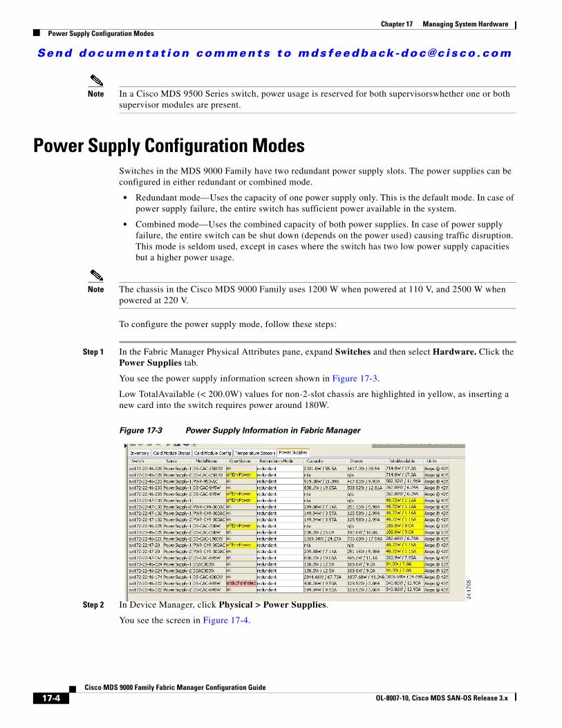
Step 1 In the Fabric Manager Physical Attributes pane, expand Switches and then select Hardware. Click the Power Supplies tab.
You see the power supply information screen shown in Figure 17-3.
Low TotalAvailable (< 200.0W) values for non-2-slot chassis are highlighted in yellow, as inserting a new card into the switch requires power around 180W.
Figure 17-3 Power Supply Information in Fabric Manager
Step 2 In Device Manager, click Physical > Power Supplies.
You see the screen in Figure 17-4.
17-4Cisco MDS 9000 Family Fabric Manager Configuration Guide
OL-8007-10, Cisco MDS SAN-OS Release 3.x

Send documenta t ion comments to mdsfeedback -doc@c i sco .com
Chapter 17 Managing System HardwarePower Supply Configuration Modes
Figure 17-4 Power Supply Information in Device Manager
Step 3 Configure the power attributes for the power supply.
Step 4 Click Apply in Device Manager or click the Apply Changes icon in Fabric Manager.
Note See the “Displaying Power Usage Information” section on page 17-3 to view the current power supply configuration.
Power Supply Configuration GuidelinesFollow these guidelines when configuring power supplies:
1. When power supplies with different capacities are installed in the switch, the total power available differs based on the configured mode, either redundant or combined:
a. Redundant mode—the total power is the lesser of the two power supply capacities. For example, suppose you have the following usage figures configured:
Power supply 1 = 2500 W Additional power supply 2 = not usedCurrent usage = 2000 W Current capacity = 2500 W
Then the following three scenarios differ as specified (see Table 17-1):
Scenario 1: If 1800 W is added as power supply 2, then power supply 2 is shut down.Reason: 1800 W is less than the usage of 2000 W.
Scenario 2: If 2200 W is added as power supply 2, then the current capacity decreases to 2200 W.Reason: 2200 W is the lesser of the two power supplies.
Scenario 3: If 3000 W is added as power supply 2, then the current capacity value remains at 2500 W.Reason: 2500 W is the lesser of the two power supplies.
Table 17-1 Redundant Mode Power Supply Scenarios
Scenario
Power Supply 1 (W)1
Current Usage (W)
Insertion of Power Supply 2 (W)
New Capacity (W) Action Taken by Switch
1 2500 2000 1800 2500 Power supply 2 is shut down.
17-5Cisco MDS 9000 Family Fabric Manager Configuration Guide
OL-8007-10, Cisco MDS SAN-OS Release 3.x

Send documenta t ion comments to mdsfeedback -doc@c i sco .com
Chapter 17 Managing System HardwarePower Supply Configuration Modes
b. Combined mode—the total power is twice the lesser of the two power supply capacities.
For example, suppose you have the following usage figures configured:
Power supply 1 = 2500 WAdditional Power supply 2 = not usedCurrent Usage = 2000 WCurrent capacity = 2500 W
Then, the following three scenarios differ as specified (see Table 17-2):
Scenario 1: If 1800 W is added as power supply 2, then the capacity increases to 3600 W.Reason: 3600 W is twice the minimum (1800 W).
Scenario 2: If 2200 W is added as power supply 2, then the current capacity increases to 4400 W.Reason:4400 W is twice the minimum (2200 W).
Scenario 3: If 3000 W is added as power supply 2, then the current capacity increases to 5000 W.Reason: 5000 W is twice the minimum (2500 W).
2. When you change the configuration from combined to redundant mode and the system detects a power supply that has a capacity lower than the current usage, the power supply is shut down. If both power supplies have a lower capacity than the current system usage, the configuration is not allowed. Several configuration scenarios are summarized in Table 17-3.
Scenario 1: You have the following usage figures configured:
Power supply 1 = 2500 WAdditional Power supply 2 = 1800 WCurrent Usage = 2000 WCurrent mode = combined mode (so current capacity is 3600 W)
You decide to change the switch to redundant mode. Then power supply 2 is shut down.
2 2500 2000 2200 2200 Capacity becomes 2200 W.
3 2500 2000 3300 2500 Capacity remains the same.
1. W = Watts
Table 17-1 Redundant Mode Power Supply Scenarios (continued)
Scenario
Power Supply 1 (W)1
Current Usage (W)
Insertion of Power Supply 2 (W)
New Capacity (W) Action Taken by Switch
Table 17-2 Combined Mode Power Supply Scenarios
Scenario
Power Supply 1 (W)1
1. W = Watts
Current Usage(W)
Insertion of Power Supply 2 (W)
New Capacity(W) Action Taken by Switch
1 2500 2000 1800 3600 Power is never shut down. The new capacity is changed.2 2500 2000 2200 4400
3 2500 2000 3300 5000
17-6Cisco MDS 9000 Family Fabric Manager Configuration Guide
OL-8007-10, Cisco MDS SAN-OS Release 3.x

Send documenta t ion comments to mdsfeedback -doc@c i sco .com
Chapter 17 Managing System HardwareAbout Crossbar Management
Reason: 1800 W is the lesser of the two power supplies and it is less than the system usage.
Scenario 2: You have the following usage figures configured:
Power supply 1 = 2500 WAdditional Power supply 2 = 2200 WCurrent Usage = 2000 WCurrent mode = combined mode (so current capacity is 4400 W).
You decide to change the switch to redundant mode. Then the current capacity decreases to 2200 W.
Reason: 2200 W is the lesser of the two power supplies.
Scenario 3: You have the following usage figures configured:
Power supply 1 = 2500 W Additional Power supply 2 = 1800 W Current Usage = 3000 W Current mode = combined mode (so current capacity is 3600 W).
You decide to change the switch to redundant mode. Then the current capacity decreases to 2500 W and the configuration is rejected.
Reason: 2500 W is less than the system usage (3000 W).
About Crossbar ManagementCisco MDS SAN-OS Release 3.0(1) and later supports two types of hardware for the Cisco MDS 9500 Series Directors: Generation 1 and Generation 2.
Generation 1 consists of all hardware supported by Cisco SAN-OS prior to Release 3.0(1), including the following:
• Cisco MDS 9506 and 9509 Director chassis
• Supervisor-1 module
• 32-port 2-Gbps Fibre Channel switching module
Table 17-3 Combined Mode Power Supply Scenarios
ScenarioPower Supply 1 (W)1
1. W = Watts
Current Mode
Current Usage (W)
Power Supply 2 (W) New Mode
New Capacity (W) Action Taken by Switch
1 2500 combined 2000 1800 N/A 3600 This is the existing configuration.
2500 N/A 2000 1800 redundant 2500 Power supply 2 is shut down
2 2500 combined 2000 2200 N/A 4400 This is the existing configuration.
2500 N/A 2000 2200 redundant 2200 The new capacity is changed.
3 2500 combined 3000 1800 N/A 3600 This is the existing configuration.
2500 N/A 3000 1800 redundant N/A Rejected, so the mode reverts to combined mode.
17-7Cisco MDS 9000 Family Fabric Manager Configuration Guide
OL-8007-10, Cisco MDS SAN-OS Release 3.x
Send documenta t ion comments to mdsfeedback -doc@c i sco .com
Chapter 17 Managing System HardwareAbout Crossbar Management
• 16-port 2-Gbps Fibre Channel switching module
• 8-port IP Storage Services (IPS-8) module
• 4-port IP Storage Services (IPS-4) module
• Storage Services Module (SSM)
• 14/2-port Multiprotocol Services (MPS-14/2) module
Generation 2 consists of all new hardware supported by Cisco SAN-OS Release 3.0(1) and later, including the following:
• Cisco MDS 9513 Director chassis
• Supervisor-2 module
• 48-port 4-Gbps Fibre Channel switching module
• 24-port 4-Gbps Fibre Channel switching module
• 12-port 4-Gbps Fibre Channel switching module
• 4-port 10-Gbps Fibre Channel switching module
The Cisco MDS 9500 Series Directors running Cisco MDS SAN-OS 3.0(1) or later support the following types of crossbars:
• Integrated crossbar—Located on the Supervisor-1 and Supervisor-2 modules. The Cisco MDS 9506 and 9509 Directors only use integrated crossbars.
• External crossbar—Located on an external crossbar switching module. Cisco MDS 9513 Directors require external crossbar modules.
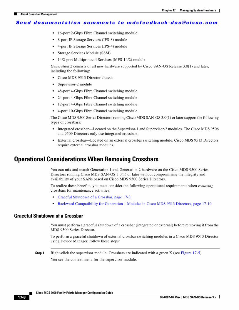
Operational Considerations When Removing CrossbarsYou can mix and match Generation 1 and Generation 2 hardware on the Cisco MDS 9500 Series Directors running Cisco MDS SAN-OS 3.0(1) or later without compromising the integrity and availability of your SANs based on Cisco MDS 9500 Series Directors.
To realize these benefits, you must consider the following operational requirements when removing crossbars for maintenance activities:
• Graceful Shutdown of a Crossbar, page 17-8
• Backward Compatibility for Generation 1 Modules in Cisco MDS 9513 Directors, page 17-10
Graceful Shutdown of a Crossbar
You must perform a graceful shutdown of a crossbar (integrated or external) before removing it from the MDS 9500 Series Director.
To perform a graceful shutdown of external crossbar switching modules in a Cisco MDS 9513 Director using Device Manager, follow these steps:
Step 1 Right-click the supervisor module. Crossbars are indicated with a green X (see Figure 17-5).
You see the context menu for the supervisor module.
17-8Cisco MDS 9000 Family Fabric Manager Configuration Guide
OL-8007-10, Cisco MDS SAN-OS Release 3.x

Send documenta t ion comments to mdsfeedback -doc@c i sco .com
Chapter 17 Managing System HardwareAbout Crossbar Management
Figure 17-5 Shutting Down a Crossbar
Step 2 Select Out of Service to gracefully shut down the integrated crossbar.
Note To reactivate the integrated crossbar, you must remove and reinsert or replace the Supervisor-1 or Supervisor-2 module.
Caution Taking the crossbar out of service may cause a supervisor switchover.
To perform a graceful shutdown of integrated crossbars on the supervisor module in a Cisco MDS 9509 or 9506 Director using Device Manager, follow these steps:
Step 1 Right-click the external crossbar switching module.
You see the context menu for that module.
Step 2 Select Out of Service to gracefully shut down the external crossbar switching module.
Note To reactivate the external crossbar module, you must remove and reinsert or replace the crossbar module.
Caution Taking the crossbar out of service may cause a supervisor switchover.
17-9Cisco MDS 9000 Family Fabric Manager Configuration Guide
OL-8007-10, Cisco MDS SAN-OS Release 3.x
Send documenta t ion comments to mdsfeedback -doc@c i sco .com
Chapter 17 Managing System HardwareAbout Module Temperature
Backward Compatibility for Generation 1 Modules in Cisco MDS 9513 Directors
To provide backward compatibility for a Generation 1 module in a Cisco MDS 9513 chassis, the active and backup Supervisor-2 modules are associated to a specific crossbar module. The Supervisor-2 module in slot 7 is associated with crossbar module 1 and Supervisor-2 module in slot 8 is associated with crossbar module 2. You must plan for the following operational considerations before removing crossbar modules:
• Whenever a crossbar module associated with the active Supervisor-2 module goes offline or is brought online in a system that is already online, a stateful supervisor switchover occurs. This switchover does not disrupt traffic. Events that cause a crossbar module to go offline include the following:
– Out-of-service requests
– Physical removal
– Errors
• Supervisor-2 module switchovers do not occur if the crossbar switching module associated with the backup Supervisor-2 module goes offline.
Note Supervisor-2 module switchovers do not occur when removing crossbar switch modules on a Cisco MDS 9513 that only has Generation 2 modules installed.
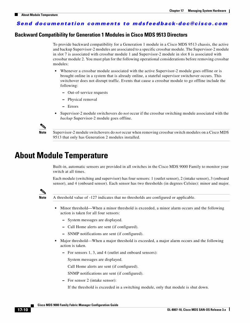
About Module TemperatureBuilt-in, automatic sensors are provided in all switches in the Cisco MDS 9000 Family to monitor your switch at all times.
Each module (switching and supervisor) has four sensors: 1 (outlet sensor), 2 (intake sensor), 3 (onboard sensor), and 4 (onboard sensor). Each sensor has two thresholds (in degrees Celsius): minor and major.
Note A threshold value of -127 indicates that no thresholds are configured or applicable.
• Minor threshold—When a minor threshold is exceeded, a minor alarm occurs and the following action is taken for all four sensors:
– System messages are displayed.
– Call Home alerts are sent (if configured).
– SNMP notifications are sent (if configured).
• Major threshold—When a major threshold is exceeded, a major alarm occurs and the following action is taken.
– For sensors 1, 3, and 4 (outlet and onboard sensors):
System messages are displayed.
Call Home alerts are sent (if configured).
SNMP notifications are sent (if configured).
– For sensor 2 (intake sensor):
If the threshold is exceeded in a switching module, only that module is shut down.
17-10Cisco MDS 9000 Family Fabric Manager Configuration Guide
OL-8007-10, Cisco MDS SAN-OS Release 3.x
Send documenta t ion comments to mdsfeedback -doc@c i sco .com
Chapter 17 Managing System HardwareAbout Fan Modules
If the threshold is exceeded in an active supervisor module with HA-standby or standby present, only that supervisor module is shut down and the standby supervisor module takes over.
If you do not have a standby supervisor module in your switch, you have an interval of 2 minutes to decrease the temperature. During this interval the software monitors the temperature every five (5) seconds and continuously sends system messages as configured.
Tip To realize the benefits of these built-in, automatic sensors on any switch in the Cisco MDS 9500 Series, we highly recommend that you install dual supervisor modules. If you are using a Cisco MDS 9000 Family switch without dual supervisor modules, we recommend that you immediately replace the fan module if even one fan is not working.
Displaying Module TemperatureExpand Switches and then select Hardware in the Physical Attributes pane in Fabric Manager. Click the Temperature Sensors tab in the Information pane to display temperature sensors for each module (see the second example under Power Supply Configuration Modes).
About Fan ModulesHot-swappable fan modules (fan trays) are provided in all switches in the Cisco MDS 9000 Family to manage airflow and cooling for the entire switch. Each fan module contains multiple fans to provide redundancy. The switch can continue functioning in the following situations:
• One or more fans fail within a fan module—Even with multiple fan failures, switches in the Cisco MDS 9000 Family can continue functioning. When a fan fails within a module, the functioning fans in the module increase their speed to compensate for the failed fan(s).
• The fan module is removed for replacement—The fan module is designed to be removed and replaced while the system is operating without presenting an electrical hazard or damage to the system. When replacing a failed fan module in a running switch, be sure to replace the new fan module within five minutes.
Tip If one or more fans fail within a fan module, the Fan Status LED turns red. A fan failure could lead to temperature alarms if not corrected immediately.
The fan status is continuously monitored by the Cisco MDS SAN-OS software. In case of a fan failure, the following action is taken:
• System messages are displayed.
• Call Home alerts are sent (if configured).
• SNMP notifications are sent (if configured).
To display the fan module status, from Device Manager, choose Physical > Fans. The dialog box displays the fan status.
The possible Status field values for a fan module on the Cisco MDS 9500 Series switches are as follows:
• If the fan module is operating properly, the status is ok.
• If the fan is physically absent, the status is absent.
17-11Cisco MDS 9000 Family Fabric Manager Configuration Guide
OL-8007-10, Cisco MDS SAN-OS Release 3.x
Send documenta t ion comments to mdsfeedback -doc@c i sco .com
Chapter 17 Managing System HardwareDefault Settings
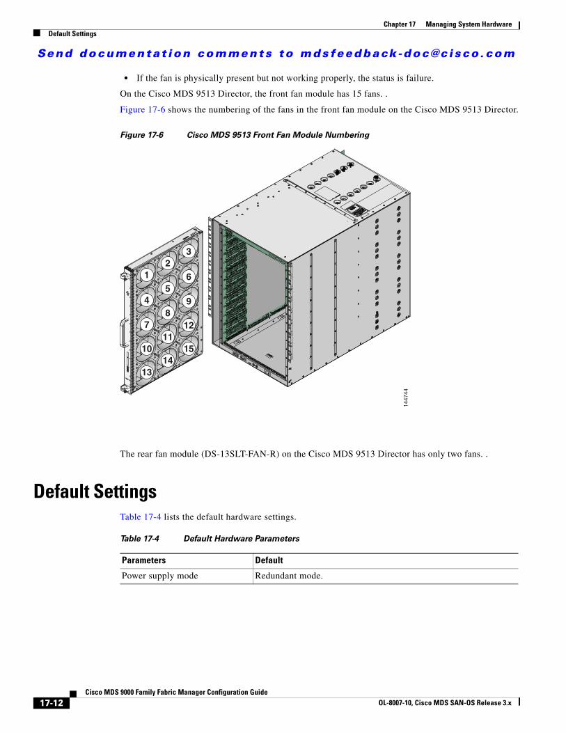
• If the fan is physically present but not working properly, the status is failure.
On the Cisco MDS 9513 Director, the front fan module has 15 fans. .
Figure 17-6 shows the numbering of the fans in the front fan module on the Cisco MDS 9513 Director.
Figure 17-6 Cisco MDS 9513 Front Fan Module Numbering
The rear fan module (DS-13SLT-FAN-R) on the Cisco MDS 9513 Director has only two fans. .
Default SettingsTable 17-4 lists the default hardware settings.
1447
44
12
3
45
6
78
9
1011
12
1314
15
Table 17-4 Default Hardware Parameters
Parameters Default
Power supply mode Redundant mode.
17-12Cisco MDS 9000 Family Fabric Manager Configuration Guide
OL-8007-10, Cisco MDS SAN-OS Release 3.x