man pages section 7: Device and Network Interfaces - Oracle ...
820
man pages section 7: Device and Network Interfaces Sun Microsystems, Inc. 4150 Network Circle Santa Clara, CA 95054 U.S.A. Part No: 817–0669–10 April 2003
-
Upload
khangminh22 -
Category
Documents
-
view
1 -
download
0
Transcript of man pages section 7: Device and Network Interfaces - Oracle ...

man pages section 7: Device andNetwork Interfaces
Sun Microsystems, Inc.4150 Network CircleSanta Clara, CA 95054U.S.A.
Part No: 817–0669–10April 2003

Copyright 2003 Sun Microsystems, Inc. 4150 Network Circle, Santa Clara, CA 95054 U.S.A. All rights reserved.
This product or document is protected by copyright and distributed under licenses restricting its use, copying, distribution, and decompilation. Nopart of this product or document may be reproduced in any form by any means without prior written authorization of Sun and its licensors, if any.Third-party software, including font technology, is copyrighted and licensed from Sun suppliers.
Parts of the product may be derived from Berkeley BSD systems, licensed from the University of California. UNIX is a registered trademark in the U.S.and other countries, exclusively licensed through X/Open Company, Ltd.
Sun, Sun Microsystems, the Sun logo, docs.sun.com, AnswerBook, AnswerBook2, and Solaris are trademarks, registered trademarks, or service marksof Sun Microsystems, Inc. in the U.S. and other countries. All SPARC trademarks are used under license and are trademarks or registered trademarksof SPARC International, Inc. in the U.S. and other countries. Products bearing SPARC trademarks are based upon an architecture developed by SunMicrosystems, Inc.
The OPEN LOOK and Sun™ Graphical User Interface was developed by Sun Microsystems, Inc. for its users and licensees. Sun acknowledges thepioneering efforts of Xerox in researching and developing the concept of visual or graphical user interfaces for the computer industry. Sun holds anon-exclusive license from Xerox to the Xerox Graphical User Interface, which license also covers Sun’s licensees who implement OPEN LOOK GUIsand otherwise comply with Sun’s written license agreements.
Federal Acquisitions: Commercial Software–Government Users Subject to Standard License Terms and Conditions.
DOCUMENTATION IS PROVIDED “AS IS” AND ALL EXPRESS OR IMPLIED CONDITIONS, REPRESENTATIONS AND WARRANTIES,INCLUDING ANY IMPLIED WARRANTY OF MERCHANTABILITY, FITNESS FOR A PARTICULAR PURPOSE OR NON-INFRINGEMENT, AREDISCLAIMED, EXCEPT TO THE EXTENT THAT SUCH DISCLAIMERS ARE HELD TO BE LEGALLY INVALID.
Copyright 2003 Sun Microsystems, Inc. 4150 Network Circle, Santa Clara, CA 95054 U.S.A. Tous droits réservés
Ce produit ou document est protégé par un copyright et distribué avec des licences qui en restreignent l’utilisation, la copie, la distribution, et ladécompilation. Aucune partie de ce produit ou document ne peut être reproduite sous aucune forme, par quelque moyen que ce soit, sansl’autorisation préalable et écrite de Sun et de ses bailleurs de licence, s’il y en a. Le logiciel détenu par des tiers, et qui comprend la technologie relativeaux polices de caractères, est protégé par un copyright et licencié par des fournisseurs de Sun.
Des parties de ce produit pourront être dérivées du système Berkeley BSD licenciés par l’Université de Californie. UNIX est une marque déposée auxEtats-Unis et dans d’autres pays et licenciée exclusivement par X/Open Company, Ltd.
Sun, Sun Microsystems, le logo Sun, docs.sun.com, AnswerBook, AnswerBook2, et Solaris sont des marques de fabrique ou des marques déposées, oumarques de service, de Sun Microsystems, Inc. aux Etats-Unis et dans d’autres pays. Toutes les marques SPARC sont utilisées sous licence et sont desmarques de fabrique ou des marques déposées de SPARC International, Inc. aux Etats-Unis et dans d’autres pays. Les produits portant les marquesSPARC sont basés sur une architecture développée par Sun Microsystems, Inc.
L’interface d’utilisation graphique OPEN LOOK et Sun™ a été développée par Sun Microsystems, Inc. pour ses utilisateurs et licenciés. Sun reconnaîtles efforts de pionniers de Xerox pour la recherche et le développement du concept des interfaces d’utilisation visuelle ou graphique pour l’industriede l’informatique. Sun détient une licence non exclusive de Xerox sur l’interface d’utilisation graphique Xerox, cette licence couvrant également leslicenciés de Sun qui mettent en place l’interface d’utilisation graphique OPEN LOOK et qui en outre se conforment aux licences écrites de Sun.
CETTE PUBLICATION EST FOURNIE “EN L’ETAT” ET AUCUNE GARANTIE, EXPRESSE OU IMPLICITE, N’EST ACCORDEE, Y COMPRIS DESGARANTIES CONCERNANT LA VALEUR MARCHANDE, L’APTITUDE DE LA PUBLICATION A REPONDRE A UNE UTILISATIONPARTICULIERE, OU LE FAIT QU’ELLE NE SOIT PAS CONTREFAISANTE DE PRODUIT DE TIERS. CE DENI DE GARANTIE NES’APPLIQUERAIT PAS, DANS LA MESURE OU IL SERAIT TENU JURIDIQUEMENT NUL ET NON AVENU.
030212@5115

Contents
Preface 11
Introduction 17
Intro(7) 18
Device and Network Interfaces 21
adp(7D) 22afb(7d) 24AH(7P) 25allkmem(7D) 26ARP(7P) 28arp(7P) 31asy(7D) 33ata(7D) 36audio(7I) 40audiocs(7D) 51audioens(7D) 55audio_support(7I) 59audiots(7D) 61authmd5h(7M) 64authsha1(7M) 65bbc_beep(7D) 66bd(7M) 67bge(7D) 69bpp(7D) 72
3

bufmod(7M) 77
bwtwo(7D) 81
cadp160(7D) 82
cadp(7D) 83
cdio(7I) 87
ce(7D) 95
cgeight(7D) 99
cgfour(7D) 100
cgfourteen(7D) 101
cgsix(7D) 102
cgthree(7D) 103
cgtwo(7D) 104
chs(7D) 105
cmdk(7D) 106
connld(7M) 107
console(7D) 108
cpr(7) 109
cvc(7D) 111
cvcredir(7D) 112
dad(7D) 113
dbri(7D) 116
devfs(7FS) 122
devinfo(7D) 123
dkio(7I) 124
dlcosmk(7ipp) 133
dlpi(7P) 134
dman(7D) 135
dmfe(7D) 138
dnet(7D) 140
dpt(7D) 142
dr(7d) 144
drmach(7d) 146
dscpmk(7ipp) 148
ecpp(7D) 149
elx(7D) 155
elxl(7D) 157
encr3des(7M) 159
encraes(7M) 160
4 man pages section 7: Device and Network Interfaces • April 2003

encrbfsh(7M) 161
encrdes(7M) 162
eri(7D) 163
esp(7D) 167
ESP(7P) 173
fas(7D) 175
fbio(7I) 183
fcip(7D) 185
fcp(7D) 188
fctl(7D) 189
fd(7D) 190
fdc(7D) 196
fdio(7I) 202
ffb(7D) 206
flowacct(7ipp) 207
fp(7d) 208
FSS(7) 209
ge(7D) 212
gld(7D) 216
glm(7D) 226
gpio_87317(7D) 231
grbeep(7d) 232
hci1394(7D) 233
hdio(7I) 234
hid(7D) 236
hme(7D) 238
hpfc(7D) 243
hsfs(7FS) 245
hubd(7D) 248
i2o_bs(7D) 250
i2o_scsi(7D) 252
icmp6(7P) 253
ICMP(7P) 255
icmp(7P) 257
idn(7d) 259
ieef(7D) 262
if(7P) 264
ifb(7d) 271
Contents 5

ifp(7D) 272
if_tcp(7P) 276
inet6(7P) 283
inet(7P) 286
ip6(7P) 289
IP(7P) 295
ip(7P) 300
ipgpc(7ipp) 305
ipqos(7ipp) 307
iprb(7D) 309
ipsec(7P) 312
ipsecah(7P) 316
ipsecesp(7P) 317
isdnio(7I) 319
isp(7D) 332
kb(7M) 338
kdmouse(7D) 347
kmem(7D) 348
kstat(7D) 350
ksyms(7D) 351
ldterm(7M) 353
le(7D) 356
lebuffer(7D) 360
ledma(7D) 364
llc1(7D) 368
llc2(7D) 371
lockstat(7D) 377
lofi(7D) 378
lofs(7FS) 379
log(7D) 381
logi(7D) 385
lp(7D) 386
ltem(7D) 388
m64(7D) 389
md(7D) 390
mediator(7D) 394
mem(7D) 397
mhd(7i) 399
6 man pages section 7: Device and Network Interfaces • April 2003

mixer(7I) 404
msglog(7D) 414
msm(7D) 415
mt(7D) 416
mtio(7I) 417
ncrs(7D) 429
ngdr(7d) 436
ngdrmach(7d) 438
null(7D) 440
ocf_escr1(7D) 441
ocf_ibutton(7D) 442
ocf_iscr1(7D) 443
ohci(7D) 444
openprom(7D) 446
pcata(7D) 451
pcelx(7D) 453
pcfs(7FS) 455
pcic(7D) 460
pckt(7M) 462
pcmem(7D) 463
pcn(7D) 464
pcram(7D) 466
pcscsi(7D) 469
pcser(7D) 470
pfb(7D) 472
pf_key(7P) 473
pfmod(7M) 483
pipemod(7M) 486
pln(7D) 487
pm(7D) 488
poll(7d) 492
prnio(7I) 497
ptem(7M) 501
ptm(7D) 502
pts(7D) 504
pty(7D) 506
qfe(7d) 509
qlc(7D) 513
Contents 7

quotactl(7I) 514
random(7D) 516
RARP(7P) 518
rarp(7P) 519
rns_smt(7D) 520
route(7P) 521
routing(7P) 525
sad(7D) 527
sbpro(7D) 530
scman(7D) 535
scmi2c(7d) 538
sc_nct(7D) 539
scsa2usb(7D) 540
scsi_vhci(7D) 544
sd(7D) 547
se(7D) 553
se_hdlc(7D) 557
ses(7D) 560
sesio(7I) 562
sf(7D) 563
sgen(7D) 565
sk98sol(7D) 571
skfp(7D) 577
slp(7P) 579
soc(7D) 581
socal(7D) 583
sockio(7I) 585
sppptun(7M) 586
spwr(7D) 587
ssd(7D) 588
st(7D) 593
stc(7D) 608
stp4020(7D) 620
streamio(7I) 621
su(7D) 637
sxp(7D) 640
symhisl(7D) 643
sysmsg(7D) 646
8 man pages section 7: Device and Network Interfaces • April 2003

TCP(7P) 647
tcp(7P) 652
tcx(7D) 657
termio(7I) 659
termiox(7I) 680
ticlts(7D) 686
ticots(7D) 688
ticotsord(7D) 690
timod(7M) 692
tirdwr(7M) 694
tmpfs(7FS) 696
tokenmt(7ipp) 698
tpf(7D) 701
tswtclmt(7ipp) 702
ttcompat(7M) 703
tty(7D) 712
ttymux(7D) 713
TUN(7M) 714
tun(7M) 718
uata(7D) 722
udfs(7FS) 724
UDP(7P) 725
udp(7P) 728
uhci(7D) 731
urandom(7D) 732
usba(7D) 734
usb_ac(7D) 736
usb_ah(7M) 740
usb_as(7D) 741
usbkbm(7M) 743
usb_mid(7D) 745
usbms(7M) 746
usbprn(7D) 748
uscsi(7I) 753
usoc(7D) 757
visual_io(7I) 759
volfs(7FS) 765
vuid2ps2(7M) 767
Contents 9

vuid3ps2(7M) 770
vuidm3p(7M) 773
vuidm4p(7M) 776
vuidm5p(7M) 779
vuidmice(7M) 782
wrsm(7D) 785
wrsmd(7D) 787
wscons(7D) 788
xmemfs(7FS) 797
zero(7D) 799
zs(7D) 800
zsh(7D) 803
zulu(7d) 807
Index 809
10 man pages section 7: Device and Network Interfaces • April 2003

Preface
Both novice users and those familar with the SunOS operating system can use onlineman pages to obtain information about the system and its features. A man page isintended to answer concisely the question “What does it do?” The man pages ingeneral comprise a reference manual. They are not intended to be a tutorial.
OverviewThe following contains a brief description of each man page section and theinformation it references:
� Section 1 describes, in alphabetical order, commands available with the operatingsystem.
� Section 1M describes, in alphabetical order, commands that are used chiefly forsystem maintenance and administration purposes.
� Section 2 describes all of the system calls. Most of these calls have one or moreerror returns. An error condition is indicated by an otherwise impossible returnedvalue.
� Section 3 describes functions found in various libraries, other than those functionsthat directly invoke UNIX system primitives, which are described in Section 2.
� Section 4 outlines the formats of various files. The C structure declarations for thefile formats are given where applicable.
� Section 5 contains miscellaneous documentation such as character-set tables.� Section 6 contains available games and demos.� Section 7 describes various special files that refer to specific hardware peripherals
and device drivers. STREAMS software drivers, modules and theSTREAMS-generic set of system calls are also described.
11

� Section 9 provides reference information needed to write device drivers in thekernel environment. It describes two device driver interface specifications: theDevice Driver Interface (DDI) and the Driver⁄Kernel Interface (DKI).
� Section 9E describes the DDI/DKI, DDI-only, and DKI-only entry-point routines adeveloper can include in a device driver.
� Section 9F describes the kernel functions available for use by device drivers.� Section 9S describes the data structures used by drivers to share information
between the driver and the kernel.
Below is a generic format for man pages. The man pages of each manual sectiongenerally follow this order, but include only needed headings. For example, if thereare no bugs to report, there is no BUGS section. See the intro pages for moreinformation and detail about each section, and man(1) for more information about manpages in general.
NAME This section gives the names of the commands orfunctions documented, followed by a briefdescription of what they do.
SYNOPSIS This section shows the syntax of commands orfunctions. When a command or file does not existin the standard path, its full path name is shown.Options and arguments are alphabetized, withsingle letter arguments first, and options witharguments next, unless a different argument orderis required.
The following special characters are used in thissection:
[ ] Brackets. The option or argumentenclosed in these brackets is optional. Ifthe brackets are omitted, the argumentmust be specified.
. . . Ellipses. Several values can be providedfor the previous argument, or theprevious argument can be specifiedmultiple times, for example, "filename. . ." .
| Separator. Only one of the argumentsseparated by this character can bespecified at a time.
{ } Braces. The options and/or argumentsenclosed within braces areinterdependent, such that everythingenclosed must be treated as a unit.
12 man pages section 7: Device and Network Interfaces • April 2003

PROTOCOL This section occurs only in subsection 3R toindicate the protocol description file.
DESCRIPTION This section defines the functionality and behaviorof the service. Thus it describes concisely what thecommand does. It does not discuss OPTIONS orcite EXAMPLES. Interactive commands,subcommands, requests, macros, and functions aredescribed under USAGE.
IOCTL This section appears on pages in Section 7 only.Only the device class that supplies appropriateparameters to the ioctl(2) system call is calledioctl and generates its own heading. ioctl callsfor a specific device are listed alphabetically (on theman page for that specific device). ioctl calls areused for a particular class of devices all of whichhave an io ending, such as mtio(7I).
OPTIONS This secton lists the command options with aconcise summary of what each option does. Theoptions are listed literally and in the order theyappear in the SYNOPSIS section. Possiblearguments to options are discussed under theoption, and where appropriate, default values aresupplied.
OPERANDS This section lists the command operands anddescribes how they affect the actions of thecommand.
OUTPUT This section describes the output – standard output,standard error, or output files – generated by thecommand.
RETURN VALUES If the man page documents functions that returnvalues, this section lists these values and describesthe conditions under which they are returned. If afunction can return only constant values, such as 0or –1, these values are listed in tagged paragraphs.Otherwise, a single paragraph describes the returnvalues of each function. Functions declared void donot return values, so they are not discussed inRETURN VALUES.
ERRORS On failure, most functions place an error code inthe global variable errno indicating why theyfailed. This section lists alphabetically all errorcodes a function can generate and describes theconditions that cause each error. When more than
Preface 13

one condition can cause the same error, eachcondition is described in a separate paragraphunder the error code.
USAGE This section lists special rules, features, andcommands that require in-depth explanations. Thesubsections listed here are used to explain built-infunctionality:
CommandsModifiersVariablesExpressionsInput Grammar
EXAMPLES This section provides examples of usage or of howto use a command or function. Wherever possible acomplete example including command-line entryand machine response is shown. Whenever anexample is given, the prompt is shown asexample%, or if the user must be superuser,example#. Examples are followed by explanations,variable substitution rules, or returned values. Mostexamples illustrate concepts from the SYNOPSIS,DESCRIPTION, OPTIONS, and USAGE sections.
ENVIRONMENT VARIABLES This section lists any environment variables thatthe command or function affects, followed by abrief description of the effect.
EXIT STATUS This section lists the values the command returns tothe calling program or shell and the conditions thatcause these values to be returned. Usually, zero isreturned for successful completion, and valuesother than zero for various error conditions.
FILES This section lists all file names referred to by theman page, files of interest, and files created orrequired by commands. Each is followed by adescriptive summary or explanation.
ATTRIBUTES This section lists characteristics of commands,utilities, and device drivers by defining theattribute type and its corresponding value. Seeattributes(5) for more information.
SEE ALSO This section lists references to other man pages,in-house documentation, and outside publications.
14 man pages section 7: Device and Network Interfaces • April 2003

DIAGNOSTICS This section lists diagnostic messages with a briefexplanation of the condition causing the error.
WARNINGS This section lists warnings about special conditionswhich could seriously affect your workingconditions. This is not a list of diagnostics.
NOTES This section lists additional information that doesnot belong anywhere else on the page. It takes theform of an aside to the user, covering points ofspecial interest. Critical information is nevercovered here.
BUGS This section describes known bugs and, whereverpossible, suggests workarounds.
Preface 15

16 man pages section 7: Device and Network Interfaces • April 2003

Introduction
17

Intro – introduction to special files
This section describes various device and network interfaces available on the system.The types of interfaces described include character and block devices, STREAMSmodules, network protocols, file systems, and ioctl requests for driver subsystems andclasses.
This section contains the following major collections:
(7D) The system provides drivers for a variety of hardware devices, such asdisk, magnetic tapes, serial communication lines, mice, and frame buffers,as well as virtual devices such as pseudo-terminals and windows.
This section describes special files that refer to specific hardwareperipherals and device drivers. STREAMS device drivers are alsodescribed. Characteristics of both the hardware device and thecorresponding device driver are discussed where applicable.
An application accesses a device through that device’s special file. Thissection specifies the device special file to be used to access the device aswell as application programming interface (API) information relevant tothe use of the device driver.
All device special files are located under the /devices directory. The/devices directory hierarchy attempts to mirror the hierarchy of systembusses, controllers, and devices configured on the system. Logical devicenames for special files in /devices are located under the /dev directory.Although not every special file under /devices will have a correspondinglogical entry under /dev, whenever possible, an application shouldreference a device using the logical name for the device. Logical devicenames are listed in the FILES section of the page for the device inquestion.
This section also describes driver configuration where applicable. Manydevice drivers have a driver configuration file of the formdriver_name.conf associated with them (see driver.conf(4)). Theconfiguration information stored in the driver configuration file is used toconfigure the driver and the device. Driver configuration files are located in/kernel/drv and /usr/kernel/drv. Driver configuration files forplatform dependent drivers are located in /platform/‘uname-i‘/kernel/drv where ‘uname -i‘ is the output of the uname(1)command with the -i option.
Some driver configuration files may contain user configurable properties.Changes in a driver’s configuration file will not take effect until the systemis rebooted or the driver has been removed and re-added (seerem_drv(1M) and add_drv(1M)).
(7FS) This section describes the programmatic interface for several file systemssupported by SunOS.
Intro(7)
NAME
DESCRIPTION
18 man pages section 7: Device and Network Interfaces • Last Revised 29 Sep 1994

(7I) This section describes ioctl requests which apply to a class of drivers orsubsystems. For example, ioctl requests which apply to most tape devicesare discussed in mtio(7I). Ioctl requests relevant to only a specific deviceare described on the man page for that device. The page for the device inquestion should still be examined for exceptions to the ioctls listed insection 7I.
(7M) This section describes STREAMS modules. Note that STREAMS drivers arediscussed in section 7D. streamio(7I) contains a list of ioctl requests usedto manipulate STREAMS modules and interface with the STREAMSframework. Ioctl requests specific to a STREAMS module will be discussedon the man page for that module.
(7P) This section describes various network protocols available in SunOS.
SunOS supports both socket-based and STREAMS-based networkcommunications. The Internet protocol family, described in inet(7P), is theprimary protocol family supported by SunOS, although the system cansupport a number of others. The raw interface provides low-level services,such as packet fragmentation and reassembly, routing, addressing, andbasic transport for socket-based implementations. Facilities forcommunicating using an Internet-family protocol are generally accessed byspecifying the AF_INET address family when binding a socket; seesocket(3SOCKET) for details.
Major protocols in the Internet family include:
� The Internet Protocol (IP) itself, which supports the universal datagramformat, as described in ip(7P). This is the default protocol forSOCK_RAW type sockets within the AF_INET domain.
� The Transmission Control Protocol (TCP); see tcp(7P). This is thedefault protocol for SOCK_STREAM type sockets.
� The User Datagram Protocol (UDP); see udp(7P). This is the defaultprotocol for SOCK_DGRAM type sockets.
� The Address Resolution Protocol (ARP); see arp(7P).� The Internet Control Message Protocol (ICMP); see icmp(7P).
add_drv(1M), rem_drv(1M), intro(3), ioctl(2), socket(3SOCKET),driver.conf(4), arp(7P), icmp(7P), inet(7P), ip(7P), mtio(7I), st(7D),streamio(7I), tcp(7P), udp(7P)
System Administration Guide: IP Services
STREAMS Programming Guide
Writing Device Drivers
Intro(7)
SEE ALSO
Introduction 19

Intro(7)
20 man pages section 7: Device and Network Interfaces • Last Revised 29 Sep 1994

Device and Network Interfaces
21

adp – Low-level module for controllers based on Adaptec AIC-7870P and AIC-7880PSCSI chips
The adp module provides low-level interface routines between the common disk/tapeI/O system and SCSI (Small Computer System Interface) controllers based on theAdaptec AIC-7870P and AIC-7880P SCSI chips. These controllers include the AdaptecAHA–2940, AHA–2940W, AHA–2940U, AHA–2940UW, AHA–3940, and AHA–3940W,as well as motherboards with embedded AIC-7870P and AIC-7880P SCSI chips.
Supported devices are AIC-7850, AIC-7860, AIC-7870, AIC-7880 and AIC-7895.
The adp module can be configured for disk and streaming tape support for one ormore host adapter boards, each of which must be the sole initiator on a SCSI bus.Auto-configuration code determines if the adapter is present at the configured addressand what types of devices are attached to the adapter.
The Plug N Play SCAM Support option is not supported.
� To use the AHA-3940 or AHA-3940W adapters, the motherboard must have a BIOSthat supports the DEC PCI-to-PCI Bridge chip on the host bus adapter.
� User-level programs have exhibited problems on some PCI systems with anAdaptec AHA-2940 or AHA-2940W card and certain motherboards. If problemswith user-level programs occur, use the BIOS setup to disable write-back CPUcaching (or all caching if there is no control over the caching algorithm). Theaffected motherboards are:
- PCI motherboards with a 60-MHz Pentium chip, with PCI chipset numbers S82433LXZ852 and S82434LX Z850. The part numbers of the Intel motherboards areAA616393-007 and AA615988-009.- PCI motherboards with a 90-MHz Pentium chip, with PCI chipset numbersS82433NX Z895, S82434NX Z895, and S82434NX Z896. The part number of the Intelmotherboard is 541286-005. (Some Gateway 2000 systems use this motherboard.)- AA-619772-002 motherboard with 82433LX Z852 and 82434LX Z882 chips causesrandom memory inconsistencies. Return the motherboard to the vendor for areplacement.
� If the AHA-2940 SCSI adapter does not recognize the Quantum Empire 1080S, HP3323 SE or other SCSI disk drive, reduce the Synchronous Transfer rate on theAdaptec controller to 8 Mbps.
� The AHA-3940 has been certified by Adaptec to work on specific systems; however,some testing has shown that the Solaris operating environment works properly insome of those systems and not in others.
Use the Adaptec configuration utility to perform the following steps:
� Configure each SCSI device to have a unique SCSI ID, then using the adapter’sAdvanced Configuration Options setup menu, set the Plug N Play SCAM Supportoption to Disabled.
adp(7D)
NAME
DESCRIPTION
PRECONFIGURATION
Known Problemsand Limitations
CONFIGURATION
22 man pages section 7: Device and Network Interfaces • Last Revised 10 Oct 2000

� If there is more than one controller (or an embedded controller), try to use one IRQper controller.
� Enable bus mastering for the slots with your host bus adapters, when the choice isgiven.
� For older disk drives, tape drives, and most CD-ROM devices, make sure themaximum SCSI data transfer speed is set to 5.0 Mbps.
� Enable support for disks larger than 1 Gbyte if applicable.
/kernel/drv/adp.conf Configuration file for the adp driver; there are nouser-configurable options in this file
See attributes(5) for descriptions of the following attributes:
ATTRIBUTE TYPE ATTRIBUTE VALUE
Architecture IA
attributes(5)
Solaris (Intel Platform Edition) Hardware Compatibility List
Throughout the release, support of additional devices may be added. See the Solaris(Intel Platform Edition) Hardware Compatibility List for additional information.
The adp driver supports Logical Unit Number (“LUN”) values of 0 through 15. Thisrange exceeds the standard SCSI-2 requirements which call for support of LUNs 0through 7.
adp(7D)
FILES
ATTRIBUTES
SEE ALSO
NOTES
Device and Network Interfaces 23

afb – Elite3D graphics accelerator driver
The afb driver is the device driver for the Sun Elite3D graphics accelerators. Theafbdaemonprocess loads the afb microcode at system startup time and during theresume sequence of a suspend-resume cycle.
/dev/fbs/afbnDevice special file
/usr/lib/afb.ucodeafb microcode
/usr/sbin/afbdaemonafb microcode loader
afbconfig(1M)
afb(7d)
NAME
DESCRIPTION
FILES
SEE ALSO
24 man pages section 7: Device and Network Interfaces • Last Revised 27 Aug 1999

ipsecah, AH – IPsec Authentication Header
drv/ipsecah
The ipsecah module (“AH”) provides strong integrity, authentication, and partialsequence integrity (replay protection) to IP datagrams. AH protects the parts of the IPdatagram that can be predicted by the sender as it will be received by the receiver. Forexample, the IP TTL field is not a predictable field, and is not protected by AH.
AH is inserted between the IP header and the transport header. The transport headercan be TCP, UDP, ICMP, or another IP header, if tunnels are being used. See tun(7M).
AH is implemented as a module that is auto-pushed on top of IP. The entry/dev/ipsecah is used for tuning AH with ndd(1M), as well as to allow futureauthentication algorithms to be loaded on top of AH. Current authenticationalgorithms include HMAC-MD5 and HMAC-SHA-1. See authmd5h(7M) andauthsha1(7P). Each authentication algorithm has its own key size and key formatproperties.
Without replay protection enabled, AH is vulnerable to replay attacks. AH does notprotect against eavesdropping. Data protected with AH can still be seen by anadversary.
See attributes(5) for descriptions of the following attributes:
ATTRIBUTE TYPE ATTRIBUTE VALUE
Availability SUNWcsr (32-bit)
SUNWcarx (64-bit)
Interface Stability Evolving
ipsecconf(1M), ndd(1M), attributes(5), authmd5h(7M), authsha1(7P), ip(7P),ipsec(7P), ipsecesp(7P), tun(7M)
Kent, S. and Atkinson, R.RFC 2402, IP Authentication Header, The Internet Society, 1998.
AH(7P)
NAME
SYNOPSIS
DESCRIPTION
AuthenticationAlgorithms AndThe AH Device
SecurityConsiderations
ATTRIBUTES
SEE ALSO
Device and Network Interfaces 25

mem, kmem, allkmem – physical or virtual memory access
/dev/mem
/dev/kmem
/dev/allkmem
The file /dev/mem is a special file that provides access to the physical memory of thecomputer.
The file /dev/kmem is a special file that provides access to the virtual address space ofthe operating system kernel, excluding memory that is associated with an I/O device.
The file /dev/allkmem is a special file that provides access to the virtual addressspace of the operating system kernel, including memory that is associated with an I/Odevice. You can use any of these devices to examine and modify the system.
Byte addresses in /dev/mem are interpreted as physical memory addresses. Byteaddresses in /dev/kmem and /dev/allkmem are interpreted as kernel virtualmemory addresses. A reference to a non-existent location returns an error. SeeERRORS for more information.
The file /dev/mem accesses physical memory; the size of the file is equal to theamount of physical memory in the computer. This size may be larger than 4GB on asystem running the 32-bit operating environment. In this case, you can access memorybeyond 4GB using a series of read(2) and write(2) calls, a pread64() orpwrite64() call, or a combination of llseek(2) and read(2) or write(2).
EFAULT Occurs when trying to write(2) a read-only location (allkmem),read(2) a write-only location (allkmem), or read(2) or write(2)a non-existent or unimplemented location (mem, kmem, allkmem).
EIO Occurs when trying to read(2) or write(2) a memory locationthat is associated with an I/O device using the /dev/kmem specialfile.
ENXIO Results from attempting to mmap(2) a non-existent physical (mem)or virtual (kmem, allkmem) memory address.
/dev/mem Provides access to the computer’s physical memory.
/dev/kmem Provides access to the virtual address space of the operatingsystem kernel, excluding memory that is associated with an I/Odevice.
/dev/allkmem Provides access to the virtual address space of the operatingsystem kernel, including memory that is associated with an I/Odevice.
llseek(2), mmap(2), read(2), write(2)
allkmem(7D)
NAME
SYNOPSIS
DESCRIPTION
ERRORS
FILES
SEE ALSO
26 man pages section 7: Device and Network Interfaces • Last Revised 18 Feb 2002

Using these devices to modify (that is, write to) the address space of a live runningoperating system or to modify the state of a hardware device is extremely dangerousand may result in a system panic if kernel data structures are damaged or if devicestate is changed.
allkmem(7D)
WARNINGS
Device and Network Interfaces 27

arp, ARP – Address Resolution Protocol
#include <sys/fcntl.h>
#include <sys/socket.h>
#include <net/if_arp.h>
#include <netinet/in.h>
s = socket(AF_INET, SOCK_DGRAM, 0);
d = open ("/dev/arp", oflag);
ARP is a protocol used to map dynamically between Internet Protocol (IP) and10Mb/s Ethernet addresses. It is used by all the 10Mb/s Ethernet datalink providers(interface drivers) and it can be used by other datalink providers that supportbroadcast, such as FDDI and Token Ring. The only network layer supported in thisimplementation is the Internet Protocol, although ARP is not specific to that protocol.
ARP caches IP-to-Ethernet address mappings. When an interface requests a mappingfor an address not in the cache, ARP queues the message that requires the mappingand broadcasts a message on the associated network requesting the address mapping.If a response is provided, ARP caches the new mapping and transmits any pendingmessage. ARP will queue at most four packets while waiting for a response to amapping request; it keeps only the four most recently transmitted packets.
The STREAMS device /dev/arp is not a Transport Level Interface (“TLI)” transportprovider and may not be used with the TLI interface.
To facilitate communications with systems that do not use ARP, ioctl() requests areprovided to enter and delete entries in the IP-to-Ethernet tables.
#include <sys/sockio.h>#include <sys/socket.h>#include <net/if.h>#include <net/if_arp.h>struct arpreq arpreq;ioctl(s, SIOCSARP, (caddr_t)&arpreq);ioctl(s, SIOCGARP, (caddr_t)&arpreq);ioctl(s, SIOCDARP, (caddr_t)&arpreq);
Each ioctl() request takes the same structure as an argument. SIOCSARP sets anARP entry, SIOCGARP gets an ARP entry, and SIOCDARP deletes an ARP entry. Theseioctl() requests may be applied to any Internet family socket descriptor s, or to adescriptor for the ARP device, but only by the privileged user.
The arpreq structure contains:
/** ARP ioctl request*/struct arpreq {
ARP(7P)
NAME
SYNOPSIS
DESCRIPTION
APPLICATIONPROGRAMMING
INTERFACE
28 man pages section 7: Device and Network Interfaces • Last Revised 23 Aug 1994

struct sockaddr arp_pa; /* protocol address */struct sockaddr arp_ha; /* hardware address */int arp_flags; /* flags */
};/* arp_flags field values */
#define ATF_COM 0x2 /* completed entry (arp_ha valid) */#define ATF_PERM 0x4 /* permanent entry */#define ATF_PUBL 0x8 /* publish (respond for other host) */
#define ATF_USETRAILERS 0x10 /* send trailer packets to host */
The address family for the arp_pa sockaddr must be AF_INET; for the arp_hasockaddr, it must be AF_UNSPEC. The only flag bits that may be written areATF_PUBL and ATF_USETRAILERS. ATF_PERM makes the entry permanent if theioctl() request succeeds. The peculiar nature of the ARP tables may cause theioctl() request to fail if too many permanent IP addresses hash to the same slot.ATF_PUBL specifies that the ARP code should respond to ARP requests for theindicated host coming from other machines. This allows a host to act as an “ARPserver”, which may be useful in convincing an ARP-only machine to talk to anon-ARP machine.
ARP is also used to negotiate the use of trailer IP encapsulations. Trailers are analternate encapsulation used to allow efficient packet alignment for large packetsdespite variable-sized headers. Hosts that wish to receive trailer encapsulations soindicate by sending gratuitous ARP translation replies along with replies to IPrequests; trailer encapsulations are also sent in reply to IP translation replies. Thenegotiation is thus fully symmetrical, in that either host or both may request trailers.The ATF_USETRAILERS flag records the receipt of such a reply and enables thetransmission of trailer packets to that host.
ARP watches passively for hosts impersonating the local host (that is, a host whichresponds to an ARP mapping request for the local host’s address).
arp(1M), ifconfig(1M), if_tcp(7P), inet(7P)
Leffler, Sam, and Michael Karels, Trailer Encapsulations, RFC 893, Network InformationCenter, SRI International, Menlo Park, California, April 1984.
Plummer, Dave, An Ethernet Address Resolution Protocol -or- Converting Network ProtocolAddresses to 48.bit Ethernet Addresses for Transmission on Ethernet Hardware, RFC 826,Network Information Center, SRI International, Menlo Park, California, November1982.
IP: Hardware address ’%x:%x:%x:%x:%x:%x’trying to be our address ’%d.%d.%d.%d’!
Duplicate IP address. ARP has discovered another host on the local network whichresponds to mapping requests for the Internet address of this system.
IP: Proxy ARP problem? Hardware address ’%x:%x:%x:%x:%x:%x’thinks it is ’%d.%d.%d.%d’
ARP(7P)
SEE ALSO
DIAGNOSTICS
Device and Network Interfaces 29

This message will appear if arp(1M) has been used to create a published entry, andsome other host on the local network responds to mapping requests for thepublished ARPentry.
ARP(7P)
30 man pages section 7: Device and Network Interfaces • Last Revised 23 Aug 1994

arp, ARP – Address Resolution Protocol
#include <sys/fcntl.h>
#include <sys/socket.h>
#include <net/if_arp.h>
#include <netinet/in.h>
s = socket(AF_INET, SOCK_DGRAM, 0);
d = open ("/dev/arp", oflag);
ARP is a protocol used to map dynamically between Internet Protocol (IP) and10Mb/s Ethernet addresses. It is used by all the 10Mb/s Ethernet datalink providers(interface drivers) and it can be used by other datalink providers that supportbroadcast, such as FDDI and Token Ring. The only network layer supported in thisimplementation is the Internet Protocol, although ARP is not specific to that protocol.
ARP caches IP-to-Ethernet address mappings. When an interface requests a mappingfor an address not in the cache, ARP queues the message that requires the mappingand broadcasts a message on the associated network requesting the address mapping.If a response is provided, ARP caches the new mapping and transmits any pendingmessage. ARP will queue at most four packets while waiting for a response to amapping request; it keeps only the four most recently transmitted packets.
The STREAMS device /dev/arp is not a Transport Level Interface (“TLI)” transportprovider and may not be used with the TLI interface.
To facilitate communications with systems that do not use ARP, ioctl() requests areprovided to enter and delete entries in the IP-to-Ethernet tables.
#include <sys/sockio.h>#include <sys/socket.h>#include <net/if.h>#include <net/if_arp.h>struct arpreq arpreq;ioctl(s, SIOCSARP, (caddr_t)&arpreq);ioctl(s, SIOCGARP, (caddr_t)&arpreq);ioctl(s, SIOCDARP, (caddr_t)&arpreq);
Each ioctl() request takes the same structure as an argument. SIOCSARP sets anARP entry, SIOCGARP gets an ARP entry, and SIOCDARP deletes an ARP entry. Theseioctl() requests may be applied to any Internet family socket descriptor s, or to adescriptor for the ARP device, but only by the privileged user.
The arpreq structure contains:
/** ARP ioctl request*/struct arpreq {
struct sockaddr arp_pa; /* protocol address */
arp(7P)
NAME
SYNOPSIS
DESCRIPTION
APPLICATIONPROGRAMMING
INTERFACE
Device and Network Interfaces 31

struct sockaddr arp_ha; /* hardware address */int arp_flags; /* flags */
};/* arp_flags field values */
#define ATF_COM 0x2 /* completed entry (arp_ha valid) */#define ATF_PERM 0x4 /* permanent entry */#define ATF_PUBL 0x8 /* publish (respond for other host) */
#define ATF_USETRAILERS 0x10 /* send trailer packets to host */
The address family for the arp_pa sockaddr must be AF_INET; for the arp_hasockaddr, it must be AF_UNSPEC. The only flag bits that may be written areATF_PUBL and ATF_USETRAILERS. ATF_PERM makes the entry permanent if theioctl() request succeeds. The peculiar nature of the ARP tables may cause theioctl() request to fail if too many permanent IP addresses hash to the same slot.ATF_PUBL specifies that the ARP code should respond to ARP requests for theindicated host coming from other machines. This allows a host to act as an “ARPserver”, which may be useful in convincing an ARP-only machine to talk to anon-ARP machine.
ARP is also used to negotiate the use of trailer IP encapsulations. Trailers are analternate encapsulation used to allow efficient packet alignment for large packetsdespite variable-sized headers. Hosts that wish to receive trailer encapsulations soindicate by sending gratuitous ARP translation replies along with replies to IPrequests; trailer encapsulations are also sent in reply to IP translation replies. Thenegotiation is thus fully symmetrical, in that either host or both may request trailers.The ATF_USETRAILERS flag records the receipt of such a reply and enables thetransmission of trailer packets to that host.
ARP watches passively for hosts impersonating the local host (that is, a host whichresponds to an ARP mapping request for the local host’s address).
arp(1M), ifconfig(1M), if_tcp(7P), inet(7P)
Leffler, Sam, and Michael Karels, Trailer Encapsulations, RFC 893, Network InformationCenter, SRI International, Menlo Park, California, April 1984.
Plummer, Dave, An Ethernet Address Resolution Protocol -or- Converting Network ProtocolAddresses to 48.bit Ethernet Addresses for Transmission on Ethernet Hardware, RFC 826,Network Information Center, SRI International, Menlo Park, California, November1982.
IP: Hardware address ’%x:%x:%x:%x:%x:%x’trying to be our address ’%d.%d.%d.%d’!
Duplicate IP address. ARP has discovered another host on the local network whichresponds to mapping requests for the Internet address of this system.
IP: Proxy ARP problem? Hardware address ’%x:%x:%x:%x:%x:%x’thinks it is ’%d.%d.%d.%d’
This message will appear if arp(1M) has been used to create a published entry, andsome other host on the local network responds to mapping requests for thepublished ARPentry.
arp(7P)
SEE ALSO
DIAGNOSTICS
32 man pages section 7: Device and Network Interfaces • Last Revised 23 Aug 1994

asy – asynchronous serial port driver
#include <fcntl.h>
#include <sys/termios.h>
open("/dev/ttynn", mode);
open("/dev/ttydn", mode);
open("/dev/cuan", mode);
The asy module is a loadable STREAMS driver that provides basic support for thestandard UARTS that use Intel-8250, National Semiconductor-16450 and 16550hardware, in addition to basic asynchronous communication support. The asymodule supports those termio(7I) device control functions specified by flags in thec_cflag word of the termios structure, and by the IGNBRK, IGNPAR, PARMRK, orINPCK flags in the c_iflag word of the termios structure. All other termio(7I)functions must be performed by STREAMS modules pushed atop the driver. When adevice is opened, the ldterm(7M) and ttcompat(7M) STREAMS modules areautomatically pushed on top of the stream, providing the standard termio(7I)interface.
The character-special devices /dev/tty00 and /dev/tty01 are used to access thetwo standard serial ports ( COM1 and COM2 ) on an x86–based system. The asymodule supports up to four serial ports, including the standard ports. The ttynndevices have minor device numbers in the range 00-03, and may be assigned names ofthe form /dev/ttydn, where n denotes the line to be accessed. These device namesare typically used to provide a logical access point for a dial-in line that is used with amodem.
To allow a single tty line to be connected to a modem and used for incoming andoutgoing calls, a special feature is available that is controlled by the minor devicenumber. By accessing character-special devices with names of the form /dev/cuan, itis possible to open a port without the Carrier Detect signal being asserted, eitherthrough hardware or an equivalent software mechanism. These devices are commonlyknown as dial-out lines.
Note – This module is affected by the setting of certain eeprom variables. Forinformation on parameters that are persistent across reboots, see the eeprom(1M) manpage.
Once a /dev/cuan line is opened, the corresponding tty, or ttyd line cannot beopened until the /dev/cuan line is closed. A blocking open will wait until the/dev/cuan line is closed (which will drop Data Terminal Ready, after whichCarrier Detect will usually drop as well) and carrier is detected again. Anon-blocking open will return an error. If the /dev/ttydn line has been openedsuccessfully (usually only when carrier is recognized on the modem), thecorresponding /dev/cuan line cannot be opened. This allows a modem to be
asy(7D)
NAME
SYNOPSIS
DESCRIPTION
APPLICATIONPROGRAMMING
INTERFACE
Device and Network Interfaces 33

attached to a device, (for example, /dev/ttyd0, which is renamed from/dev/tty00) and used for dial-in (by enabling the line for login in /etc/inittab)or dial-out (by tip(1) or uucp(1C)) as /dev/cua0 when no one is logged in on theline.
The standard set of termio ioctl() calls are supported by asy.
Breaks can be generated by the TCSBRK, TIOCSBRK, and TIOCCBRK ioctl() calls.
The input and output line speeds may be set to any speed that is supported bytermio. The speeds cannot be set independently; for example, when the output speedis set, the input speed is automatically set to the same speed.
When the asy module is used to service the serial console port, it supports a BREAKcondition that allows the system to enter the debugger or the monitor. The BREAKcondition is generated by hardware and it is usually enabled by default.
A BREAK condition originating from erroneous electrical signals cannot bedistinguished from one deliberately sent by remote DCE. The Alternate Breaksequence can be used as a remedy against this. Due to a risk of incorrect sequenceinterpretation, binary protocols such as PPP, SLIP, and others should not be run overthe serial console port when Alternate Break sequence is in effect. By default, theAlternate Break sequence is a three character sequence: carriage return, tilde andcontrol-B (CR ~ CTRL-B), but may be changed by the driver. For more information onbreaking (entering the debugger or monitor) , see kbd(1) and kb(7M)
An open() will fail under the following conditions:
ENXIO The unit being opened does not exist.
EBUSY The dial-out device is being opened while the dial-in device isalready open, or the dial-in device is being opened with a no-delayopen and the dial-out device is already open.
EBUSY The unit has been marked as exclusive-use by another processwith a TIOCEXCL ioctl() call.
EINTR The open was interrupted by the delivery of a signal.
/dev/tty[00-03]hardwired tty lines
/dev/ttyd[0-3]dial-in tty lines
/dev/cua[0-3]dial-out tty lines
/platform/i86pc/kernel/drv/asy.confasy configuration file
asy(7D)
IOCTLS
ERRORS
FILES
34 man pages section 7: Device and Network Interfaces • Last Revised 11 Jun 2001

See attributes(5) for descriptions of the following attributes:
ATTRIBUTE TYPE ATTRIBUTE VALUE
Architecture IA
tip(1), kbd(1), uucp(1C), eeprom(1M), ioctl(2), open(2), termios(3C),attributes(5), ldterm(7M), ttcompat(7M), kb(7M) termio(7I)
asyn : silo overflow.The hardware overrun occurred before the input character could be serviced.
asyn : ring buffer overflow.The driver’s character input ring buffer overflowed before it could be serviced.
asy(7D)
ATTRIBUTES
SEE ALSO
DIAGNOSTICS
Device and Network Interfaces 35
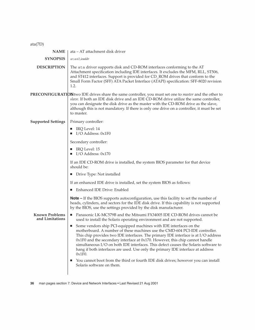
ata – AT attachment disk driver
ata@1,ioaddr
The ata driver supports disk and CD-ROM interfaces conforming to the ATAttachment specification including IDE interfaces. It excludes the MFM, RLL, ST506,and ST412 interfaces. Support is provided for CD_ROM drives that conform to theSmall Form Factor (SFF) ATA Packet Interface (ATAPI) specification: SFF-8020 revision1.2.
If two IDE drives share the same controller, you must set one to master and the other toslave. If both an IDE disk drive and an IDE CD-ROM drive utilize the same controller,you can designate the disk drive as the master with the CD-ROM drive as the slave,although this is not mandatory. If there is only one drive on a controller, it must be setto master.
Primary controller:
� IRQ Level: 14� I/O Address: 0x1F0
Secondary controller:
� IRQ Level: 15� I/O Address: 0x170
If an IDE CD-ROM drive is installed, the system BIOS parameter for that deviceshould be:
� Drive Type: Not installed
If an enhanced IDE drive is installed, set the system BIOS as follows:
� Enhanced IDE Drive: Enabled
Note – If the BIOS supports autoconfiguration, use this facility to set the number ofheads, cylinders, and sectors for the IDE disk drive. If this capability is not supportedby the BIOS, use the settings provided by the disk manufacturer.
� Panasonic LK-MC579B and the Mitsumi FX34005 IDE CD-ROM drives cannot beused to install the Solaris operating environment and are not supported.
� Some vendors ship PCI-equipped machines with IDE interfaces on themotherboard. A number of these machines use the CMD-604 PCI-IDE controller.This chip provides two IDE interfaces. The primary IDE interface is at I/O address0x1F0 and the secondary interface at 0x170. However, this chip cannot handlesimultaneous I/O on both IDE interfaces. This defect causes the Solaris software tohang if both interfaces are used. Use only the primary IDE interface at address0x1F0.
� You cannot boot from the third or fourth IDE disk drives; however you can installSolaris software on them.
ata(7D)
NAME
SYNOPSIS
DESCRIPTION
PRECONFIGURATION
Supported Settings
Known Problemsand Limitations
36 man pages section 7: Device and Network Interfaces • Last Revised 21 Aug 2001

� The Solaris Volume Management software does not work with the Sony CDU-55ECD-ROM drive no matter how it is configured (as the master or the slave).Comment out the following line in the file /etc/vold.conf to prevent vold fromhanging the controller:
# use cdrom drive /dev/rdsk/c*s2 dev_cdrom.so cdrom%d
� NEC CDR-260/CDR-260R/CDR-273 and Sony CDU-55E ATAPI CD-ROM drivesmight fail during installation.
� Sony CDU-701 CD-ROM drives must be upgraded to use firmware version 1.0r orlater to support booting from the CD.
Direct Memory Access is enabled by default. To disable DMA for the ata driver, dothe following steps after you have installed the Solaris operating environment:
1. Run the Solaris (Intel Platform Edition) Device Configuration Assistant from theboot diskette or the installation CD (if your system supports CD-ROM booting).
Note – After you boot using the boot diskette, the new ata-dma-enabledproperty value is preserved on the diskette. This means that the changed value isin effect each time you use the boot diskette.
2. Press F2_Continue to scan for devices.
3. Press F2_Continue to display a list of boot devices on the Boot Solaris menu.
4. Go to the View/Edit Property Settings menu.
5. Press F4_Boot Tasks, select View/Edit Property Settings, and pressF2_Continue.
6. Change the value of the ata-dma-enabled property. A value of 1 indicates thatDMA is enabled and 0 indicates that DMA is disabled.
� Select the ata-dma-disabled property from the list and press F3_Change.� Type 0 and press F2_Continue to disable DMA.� Press F2_Back to return to the Boot Tasks menu.� Press F3_Back to return to the Boot Solaris menu.� Select the device from which you want to install (network adapter or CD-ROM
drive) and press F2_Continue.
The driver initializes itself in accordance with the information found in theconfiguration file ata.conf (see below). The only user configurable items in this fileare:
drive0_block_factordrive1_block_factor ATA controllers support some amount of buffering
(blocking). The purpose is to interrupt the host whenan entire buffer full of data has been read or writteninstead of using an interrupt for each sector. Thisreduces interrupt overhead and significantly increasesthroughput. The driver interrogates the controller tofind the buffer size. Some controllers hang when
ata(7D)
Direct MemoryAccess (DMA) and
PCI-IDE Systems
CONFIGURATION
Device and Network Interfaces 37
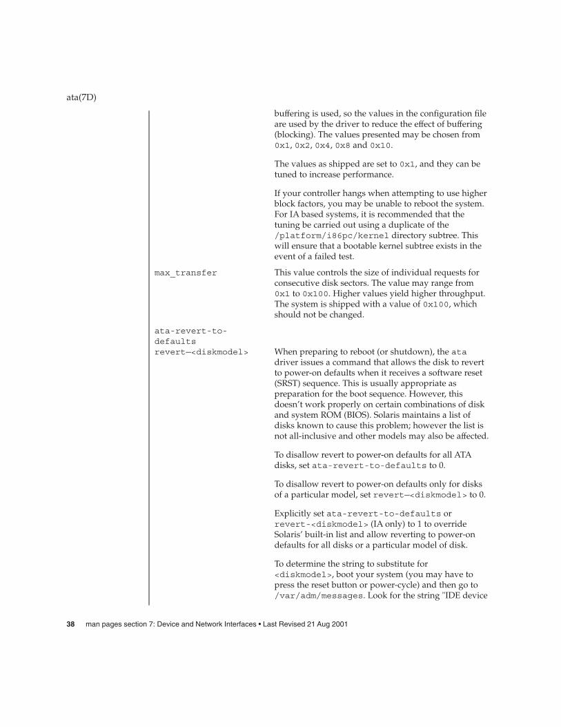
buffering is used, so the values in the configuration fileare used by the driver to reduce the effect of buffering(blocking). The values presented may be chosen from0x1, 0x2, 0x4, 0x8 and 0x10.
The values as shipped are set to 0x1, and they can betuned to increase performance.
If your controller hangs when attempting to use higherblock factors, you may be unable to reboot the system.For IA based systems, it is recommended that thetuning be carried out using a duplicate of the/platform/i86pc/kernel directory subtree. Thiswill ensure that a bootable kernel subtree exists in theevent of a failed test.
max_transfer This value controls the size of individual requests forconsecutive disk sectors. The value may range from0x1 to 0x100. Higher values yield higher throughput.The system is shipped with a value of 0x100, whichshould not be changed.
ata-revert-to-defaultsrevert—<diskmodel> When preparing to reboot (or shutdown), the ata
driver issues a command that allows the disk to revertto power-on defaults when it receives a software reset(SRST) sequence. This is usually appropriate aspreparation for the boot sequence. However, thisdoesn’t work properly on certain combinations of diskand system ROM (BIOS). Solaris maintains a list ofdisks known to cause this problem; however the list isnot all-inclusive and other models may also be affected.
To disallow revert to power-on defaults for all ATAdisks, set ata-revert-to-defaults to 0.
To disallow revert to power-on defaults only for disksof a particular model, set revert—<diskmodel> to 0.
Explicitly set ata-revert-to-defaults orrevert-<diskmodel> (IA only) to 1 to overrideSolaris’ built-in list and allow reverting to power-ondefaults for all disks or a particular model of disk.
To determine the string to substitute for<diskmodel>, boot your system (you may have topress the reset button or power-cycle) and then go to/var/adm/messages. Look for the string "IDE device
ata(7D)
38 man pages section 7: Device and Network Interfaces • Last Revised 21 Aug 2001
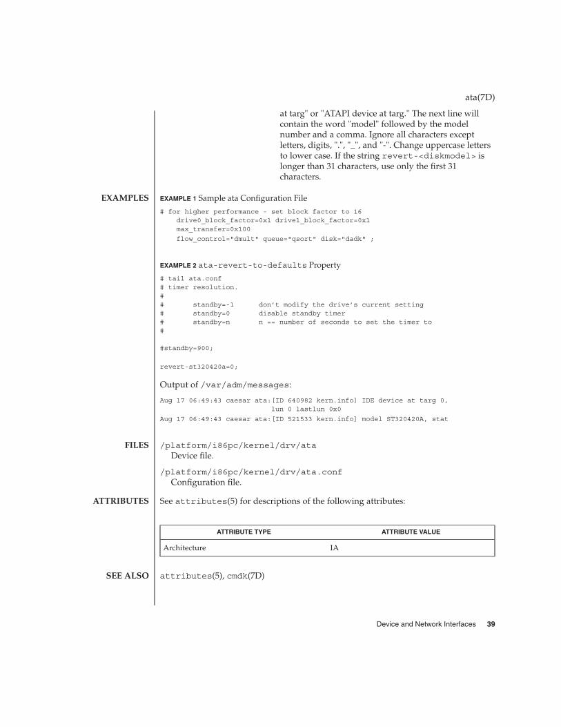
at targ" or "ATAPI device at targ." The next line willcontain the word "model" followed by the modelnumber and a comma. Ignore all characters exceptletters, digits, ".", "_", and "-". Change uppercase lettersto lower case. If the string revert-<diskmodel> islonger than 31 characters, use only the first 31characters.
EXAMPLE 1 Sample ata Configuration File
# for higher performance - set block factor to 16drive0_block_factor=0x1 drive1_block_factor=0x1max_transfer=0x100
flow_control="dmult" queue="qsort" disk="dadk" ;
EXAMPLE 2 ata-revert-to-defaults Property
# tail ata.conf# timer resolution.## standby=-1 don’t modify the drive’s current setting# standby=0 disable standby timer# standby=n n == number of seconds to set the timer to#
#standby=900;
revert-st320420a=0;
Output of /var/adm/messages:
Aug 17 06:49:43 caesar ata:[ID 640982 kern.info] IDE device at targ 0,lun 0 lastlun 0x0
Aug 17 06:49:43 caesar ata:[ID 521533 kern.info] model ST320420A, stat
/platform/i86pc/kernel/drv/ataDevice file.
/platform/i86pc/kernel/drv/ata.confConfiguration file.
See attributes(5) for descriptions of the following attributes:
ATTRIBUTE TYPE ATTRIBUTE VALUE
Architecture IA
attributes(5), cmdk(7D)
ata(7D)
EXAMPLES
FILES
ATTRIBUTES
SEE ALSO
Device and Network Interfaces 39

audio – generic audio device interface
#include <sys/audio.h>
An audio device is used to play and/or record a stream of audio data. Since a specificaudio device may not support all functionality described below, refer to thedevice-specific manual pages for a complete description of each hardware device. Anapplication can use the AUDIO_GETDEV ioctl(2) to determine the current audiohardware associated with /dev/audio.
Digital audio data represents a quantized approximation of an analog audio signalwaveform. In the simplest case, these quantized numbers represent the amplitude ofthe input waveform at particular sampling intervals. To achieve the bestapproximation of an input signal, the highest possible sampling frequency andprecision should be used. However, increased accuracy comes at a cost of increaseddata storage requirements. For instance, one minute of monaural audio recorded inµ-Law format (pronounced mew-law) at 8 KHz requires nearly 0.5 megabytes ofstorage, while the standard Compact Disc audio format (stereo 16-bit linear PCM datasampled at 44.1 KHz) requires approximately 10 megabytes per minute.
Audio data may be represented in several different formats. An audio device’s currentaudio data format can be determined by using the AUDIO_GETINFO ioctl(2)described below.
An audio data format is characterized in the audio driver by four parameters: SampleRate, Encoding, Precision, and Channels. Refer to the device-specific manual pages fora list of the audio formats that each device supports. In addition to the formats thatthe audio device supports directly, other formats provide higher data compression.Applications may convert audio data to and from these formats when playing orrecording.
Sample rate is a number that represents the sampling frequency (in samples persecond) of the audio data.
An encoding parameter specifies the audio data representation. µ-Law encodingcorresponds to CCITT G.711, and is the standard for voice data used by telephonecompanies in the United States, Canada, and Japan. A-Law encoding is also part ofCCITT G.711 and is the standard encoding for telephony elsewhere in the world.A-Law and µ-Law audio data are sampled at a rate of 8000 samples per second with12-bit precision, with the data compressed to 8-bit samples. The resulting audio dataquality is equivalent to that of standard analog telephone service.
Linear Pulse Code Modulation (PCM) is an uncompressed, signed audio format inwhich sample values are directly proportional to audio signal voltages. Each sample isa 2’s complement number that represents a positive or negative amplitude.
Precision indicates the number of bits used to store each audio sample. For instance,u-Law and A-Law data are stored with 8-bit precision. PCM data may be stored atvarious precisions, though 16-bit is the most common.
audio(7I)
NAME
SYNOPSIS
OVERVIEW
AUDIOFORMATS
Sample Rate
Encodings
Precision
40 man pages section 7: Device and Network Interfaces • Last Revised 28 Dec 2001
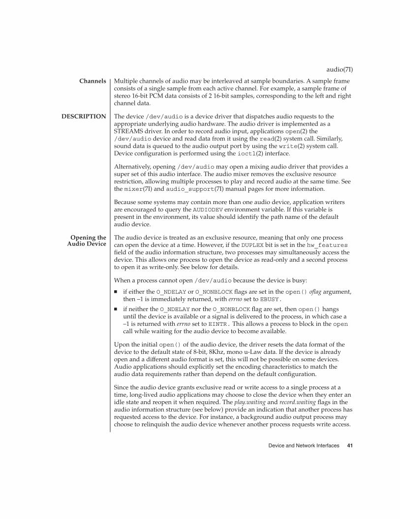
Multiple channels of audio may be interleaved at sample boundaries. A sample frameconsists of a single sample from each active channel. For example, a sample frame ofstereo 16-bit PCM data consists of 2 16-bit samples, corresponding to the left and rightchannel data.
The device /dev/audio is a device driver that dispatches audio requests to theappropriate underlying audio hardware. The audio driver is implemented as aSTREAMS driver. In order to record audio input, applications open(2) the/dev/audio device and read data from it using the read(2) system call. Similarly,sound data is queued to the audio output port by using the write(2) system call.Device configuration is performed using the ioctl(2) interface.
Alternatively, opening /dev/audio may open a mixing audio driver that provides asuper set of this audio interface. The audio mixer removes the exclusive resourcerestriction, allowing multiple processes to play and record audio at the same time. Seethe mixer(7I) and audio_support(7I) manual pages for more information.
Because some systems may contain more than one audio device, application writersare encouraged to query the AUDIODEV environment variable. If this variable ispresent in the environment, its value should identify the path name of the defaultaudio device.
The audio device is treated as an exclusive resource, meaning that only one processcan open the device at a time. However, if the DUPLEX bit is set in the hw_featuresfield of the audio information structure, two processes may simultaneously access thedevice. This allows one process to open the device as read-only and a second processto open it as write-only. See below for details.
When a process cannot open /dev/audio because the device is busy:
� if either the O_NDELAY or O_NONBLOCK flags are set in the open() oflag argument,then –1 is immediately returned, with errno set to EBUSY.
� if neither the O_NDELAY nor the O_NONBLOCK flag are set, then open() hangsuntil the device is available or a signal is delivered to the process, in which case a–1 is returned with errno set to EINTR. This allows a process to block in the opencall while waiting for the audio device to become available.
Upon the initial open() of the audio device, the driver resets the data format of thedevice to the default state of 8-bit, 8Khz, mono u-Law data. If the device is alreadyopen and a different audio format is set, this will not be possible on some devices.Audio applications should explicitly set the encoding characteristics to match theaudio data requirements rather than depend on the default configuration.
Since the audio device grants exclusive read or write access to a single process at atime, long-lived audio applications may choose to close the device when they enter anidle state and reopen it when required. The play.waiting and record.waiting flags in theaudio information structure (see below) provide an indication that another process hasrequested access to the device. For instance, a background audio output process maychoose to relinquish the audio device whenever another process requests write access.
audio(7I)
Channels
DESCRIPTION
Opening theAudio Device
Device and Network Interfaces 41

The read() system call copies data from the system’s buffers to the application.Ordinarily, read() blocks until the user buffer is filled. The I_NREAD ioctl (seestreamio(7I)) may be used to determine the amount of data that may be readwithout blocking. The device may alternatively be set to a non-blocking mode, inwhich case read() completes immediately, but may return fewer bytes thanrequested. Refer to the read(2) manual page for a complete description of thisbehavior.
When the audio device is opened with read access, the device driver immediatelystarts buffering audio input data. Since this consumes system resources, processes thatdo not record audio data should open the device write-only (O_WRONLY).
The transfer of input data to STREAMS buffers may be paused (or resumed) by usingthe AUDIO_SETINFO ioctl to set (or clear) the record.pause flag in the audioinformation structure (see below). All unread input data in the STREAMS queue maybe discarded by using the I_FLUSH STREAMS ioctl (see streamio(7I)). Whenchanging record parameters, the input stream should be paused and flushed beforethe change, and resumed afterward. Otherwise, subsequent reads may return samplesin the old format followed by samples in the new format. This is particularlyimportant when new parameters result in a changed sample size.
Input data can accumulate in STREAMS buffers very quickly. At a minimum, it willaccumulate at 8000 bytes per second for 8-bit, 8 KHz, mono, u-Law data. If the deviceis configured for 16-bit linear or higher sample rates, it will accumulate even faster. Ifthe application that consumes the data cannot keep up with this data rate, theSTREAMS queue may become full. When this occurs, the record.error flag is set in theaudio information structure and input sampling ceases until there is room in the inputqueue for additional data. In such cases, the input data stream contains adiscontinuity. For this reason, audio recording applications should open the audiodevice when they are prepared to begin reading data, rather than at the start ofextensive initialization.
The write() system call copies data from an application’s buffer to the STREAMSoutput queue. Ordinarily, write() blocks until the entire user buffer is transferred.The device may alternatively be set to a non-blocking mode, in which case write()completes immediately, but may have transferred fewer bytes than requested (seewrite(2)).
Although write() returns when the data is successfully queued, the actualcompletion of audio output may take considerably longer. The AUDIO_DRAIN ioctlmay be issued to allow an application to block until all of the queued output data hasbeen played. Alternatively, a process may request asynchronous notification of outputcompletion by writing a zero-length buffer (end-of-file record) to the output stream.When such a buffer has been processed, the play.eof flag in the audio informationstructure (see below) is incremented.
audio(7I)
Recording AudioData
Playing AudioData
42 man pages section 7: Device and Network Interfaces • Last Revised 28 Dec 2001

The final close(2) of the file descriptor hangs until all of the audio output hasdrained. If a signal interrupts the close(), or if the process exits without closing thedevice, any remaining data queued for audio output is flushed and the device isclosed immediately.
The consumption of output data may be paused (or resumed) by using theAUDIO_SETINFO ioctl to set (or clear) the play.pause flag in the audio informationstructure. Queued output data may be discarded by using the I_FLUSH STREAMSioctl. (See streamio(7I)).
Output data is played from the STREAMS buffers at a default rate of at least 8000bytes per second for µ-Law, A-Law or 8–bit PCM data (faster for 16-bit linear data orhigher sampling rates). If the output queue becomes empty, the play.error flag is set inthe audio information structure and output is stopped until additional data is written.If an application attempts to write a number of bytes that is not a multiple of thecurrent sample frame size, an error is generated and the bad data is thrown away.Additional writes are allowed.
The I_SETSIG STREAMS ioctl enables asynchronous notification, through theSIGPOLL signal, of input and output ready condition changes. The O_NONBLOCK flagmay be set using the F_SETFL fcntl(2) to enable non-blocking read() andwrite() requests. This is normally sufficient for applications to maintain an audiostream in the background.
It is sometimes convenient to have an application, such as a volume control panel,modify certain characteristics of the audio device while it is being used by anunrelated process. The /dev/audioctl pseudo-device is provided for this purpose.Any number of processes may open /dev/audioctl simultaneously. However,read() and write() system calls are ignored by /dev/audioctl. TheAUDIO_GETINFO and AUDIO_SETINFO ioctl commands may be issued to/dev/audioctl to determine the status or alter the behavior of /dev/audio. Note:In general, the audio control device name is constructed by appending the letters"ctl" to the path name of the audio device.
Applications that open the audio control pseudo-device may request asynchronousnotification of changes in the state of the audio device by setting the S_MSG flag in anI_SETSIG STREAMS ioctl. Such processes receive a SIGPOLL signal when any ofthe following events occur:
� An AUDIO_SETINFO ioctl has altered the device state.� An input overflow or output underflow has occurred.� An end-of-file record (zero-length buffer) has been processed on output.� An open() or close() of /dev/audio has altered the device state.� An external event (such as speakerbox’s volume control) has altered the device
state.
audio(7I)
Asynchronous I/O
Audio ControlPseudo-Device
Audio StatusChange
Notification
Device and Network Interfaces 43

The state of the audio device may be polled or modified using the AUDIO_GETINFOand AUDIO_SETINFO ioctl commands. These commands operate on theaudio_info structure as defined, in <sys/audioio.h>, as follows:
/** This structure contains state information for audio device* IO streams*/
struct audio_prinfo {/** The following values describe the* audio data encoding*/
uint_t sample_rate; /* samples per second */uint_t channels; /* number of interleaved channels */uint_t precision; /* number of bits per sample */uint_t encoding; /* data encoding method */
/** The following values control audio device* configuration*/
uint_t gain; /* volume level */uint_t port; /* selected I/O port */uint_t buffer_size; /* I/O buffer size */
/** The following values describe the current device* state*/
uint_t samples; /* number of samples converted */uint_t eof; /* End Of File counter (play only) */uchar_t pause; /* non-zero if paused, zero to resume */uchar_t error; /* non-zero if overflow/underflow */uchar_t waiting; /* non-zero if a process wants access */uchar_t balance; /* stereo channel balance *//** The following values are read-only device state* information*/
uchar_t open; /* non-zero if open access granted */uchar_t active; /* non-zero if I/O active */uint_t avail_ports; /* available I/O ports */uint_t mod_ports; /* modifiable I/O ports */
};typedef struct audio_prinfo audioi_prinfo_t;
/** This structure is used in AUDIO_GETINFO and AUDIO_SETINFO ioctl* commands*/
struct audio_info {audio_prinfo_t record; /* input status info */audio_prinfo_t play; /* output status info */uint_t monitor_gain; /* input to output mix */uchar_t output_muted; /* non-zero if output muted */uint_t hw_features; /* supported H/W features */
audio(7I)
Audio InformationStructure
44 man pages section 7: Device and Network Interfaces • Last Revised 28 Dec 2001
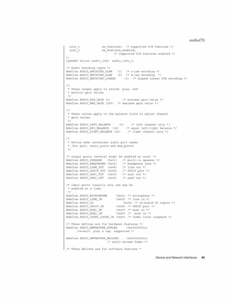
uint_t sw_features; /* supported S/W features */uint_t sw_features_enabled;
/* supported S/W features enabled */};typedef struct audio_info audio_info_t;
/* Audio encoding types */#define AUDIO_ENCODING_ULAW (1) /* u-Law encoding */#define AUDIO_ENCODING_ALAW (2) /* A-Law encoding */#define AUDIO_ENCODING_LINEAR (3) /* Signed Linear PCM encoding */
/** These ranges apply to record, play, and* monitor gain values*/#define AUDIO_MIN_GAIN (0) /* minimum gain value */#define AUDIO_MAX_GAIN (255) /* maximum gain value */
/** These values apply to the balance field to adjust channel* gain values*/#define AUDIO_LEFT_BALANCE (0) /* left channel only */#define AUDIO_MID_BALANCE (32) /* equal left/right balance */#define AUDIO_RIGHT_BALANCE (64) /* right channel only */
/** Define some convenient audio port names* (for port, avail_ports and mod_ports)*/
/* output ports (several might be enabled at once) */#define AUDIO_SPEAKER (0x01) /* built-in speaker */#define AUDIO_HEADPHONE (0x02) /* headphone jack */#define AUDIO_LINE_OUT (0x04) /* line out */#define AUDIO_SPDIF_OUT (0x08) /* SPDIF port */#define AUDIO_AUX1_OUT (0x10) /* aux1 out */#define AUDIO_AUX2_OUT (0x20) /* aux2 out */
/* input ports (usually only one may be* enabled at a time)*/#define AUDIO_MICROPHONE (0x01) /* microphone */#define AUDIO_LINE_IN (0x02) /* line in */#define AUDIO_CD (0x04) /* on-board CD inputs */#define AUDIO_SPDIF_IN (0x08) /* SPDIF port */#define AUDIO_AUX1_IN (0x10) /* aux1 in */#define AUDIO_AUX2_IN (0x20) /* aux2 in */#define AUDIO_CODEC_LOOPB_IN (0x40) /* Codec inter.loopback */
/* These defines are for hardware features */#define AUDIO_HWFEATURE_DUPLEX (0x00000001u)
/*simult. play & cap. supported */
#define AUDIO_HWFEATURE_MSCODEC (0x00000002u)/* multi-stream Codec */
/* These defines are for software features *
audio(7I)
Device and Network Interfaces 45

#define AUDIO_SWFEATURE_MIXER (0x00000001u)/* audio mixer audio pers. mod. */
/** Parameter for the AUDIO_GETDEV ioctl* to determine current audio devices*/
#define MAX_AUDIO_DEV_LEN (16)struct audio_device {
char name[MAX_AUDIO_DEV_LEN];char version[MAX_AUDIO_DEV_LEN];char config[MAX_AUDIO_DEV_LEN];
};typedef struct audio_device audio_device_t;
The play.gain and record.gain fields specify the output and input volume levels. A valueof AUDIO_MAX_GAIN indicates maximum volume. Audio output may also betemporarily muted by setting a non-zero value in the output_muted field. Clearing thisfield restores audio output to the normal state. Most audio devices allow input data tobe monitored by mixing audio input onto the output channel. The monitor_gain fieldcontrols the level of this feedback path.
The play.port field controls the output path for the audio device. It can be set to eitherAUDIO_SPEAKER (built-in speaker), AUDIO_HEADPHONE (headphone jack),AUDIO_LINE_OUT (line-out port), AUDIO_AUX1_OUT (auxilary1 out), orAUDIO_AUX2_OUT (auxilary2 out). For some devices, it may be set to a combination ofthese ports. The play.avail_ports field returns the set of output ports that are currentlyaccessible. The play.mod_ports field returns the set of output ports that may be turnedon and off. If a port is missing from play.mod_ports then that port is assumed to alwaysbe on.
The record.port field controls the input path for the audio device. It can be eitherAUDIO_MICROPHONE (microphone jack), AUDIO_LINE_IN (line-out port), AUDIO_CD(internal CD-ROM), AUDIO_AUX1_IN (auxilary1 in), AUDIO_AUX2_IN (auxilary2 in),or AUDIO_CODEC_LOOPB_IN (internal loopback). The record.avail_ports field returnsthe set of input ports that are currently accessible. The record.mod_ports field returnsthe set of input ports that may be turned on and off. If a port is missing fromrecord.mod_ports, it is assumed to always be on. Input ports are considered to bemutually exclusive.
The play.balance and record.balance fields are used to control the volume between theleft and right channels when manipulating stereo data. When the value is set betweenAUDIO_LEFT_BALANCE and AUDIO_MID_BALANCE, the right channel volume will bereduced in proportion to the balance value. Conversely, when balance is set betweenAUDIO_MID_BALANCE and AUDIO_RIGHT_BALANCE, the left channel will beproportionally reduced.
audio(7I)
46 man pages section 7: Device and Network Interfaces • Last Revised 28 Dec 2001

The play.pause and record.pause flags may be used to pause and resume the transfer ofdata between the audio device and the STREAMS buffers. The play.error andrecord.error flags indicate that data underflow or overflow has occurred. The play.activeand record.active flags indicate that data transfer is currently active in thecorresponding direction.
The play.open and record.open flags indicate that the device is currently open with thecorresponding access permission. The play.waiting and record.waiting flags provide anindication that a process may be waiting to access the device. These flags are setautomatically when a process blocks on open(), though they may also be set usingthe AUDIO_SETINFO ioctl command. They are cleared only when a processrelinquishes access by closing the device.
The play.samples and record.samples fields are zeroed at open() and are incrementedeach time a data sample is copied to or from the associated STREAMS queue. Someaudio drivers may be limited to counting buffers of samples, instead of single samplesfor their samples accounting. For this reason, applications should not assume that thesamples fields contain a perfectly accurate count. The play.eof field incrementswhenever a zero-length output buffer is synchronously processed. Applications mayuse this field to detect the completion of particular segments of audio output.
The record.buffer_size field controls the amount of input data that is buffered in thedevice driver during record operations. Applications that have particular requirementsfor low latency should set the value appropriately. Note however that smaller inputbuffer sizes may result in higher system overhead. The value of this field is specifiedin bytes and drivers will constrain it to be a multiple of the current sample frame size.Some drivers may place other requirements on the value of this field. Refer to theaudio device-specific manual page for more details. If an application changes theformat of the audio device and does not modify the record.buffer_size field, the devicedriver may use a default value to compensate for the new data rate. Therefore, if anapplication is going to modify this field, it should modify it during or after the formatchange itself, not before. When changing the record.buffer_size parameters, the inputstream should be paused and flushed before the change, and resumed afterward.Otherwise, subsequent reads may return samples in the old format followed bysamples in the new format. This is particularly important when new parameters resultin a changed sample size. If you change the record.buffer_size for the first packet, thisprotocol must be followed or the first buffer will be the default buffer size for thedevice, followed by packets of the requested change size.
The record.buffer_size field may be modified only on the /dev/audio device byprocesses that have it opened for reading.
The play.buffer_size field is currently not supported.
The audio data format is indicated by the sample_rate, channels, precision, and encodingfields. The values of these fields correspond to the descriptions in the AUDIO FORMATSsection above. Refer to the audio device-specific manual pages for a list of supporteddata format combinations.
audio(7I)
Device and Network Interfaces 47
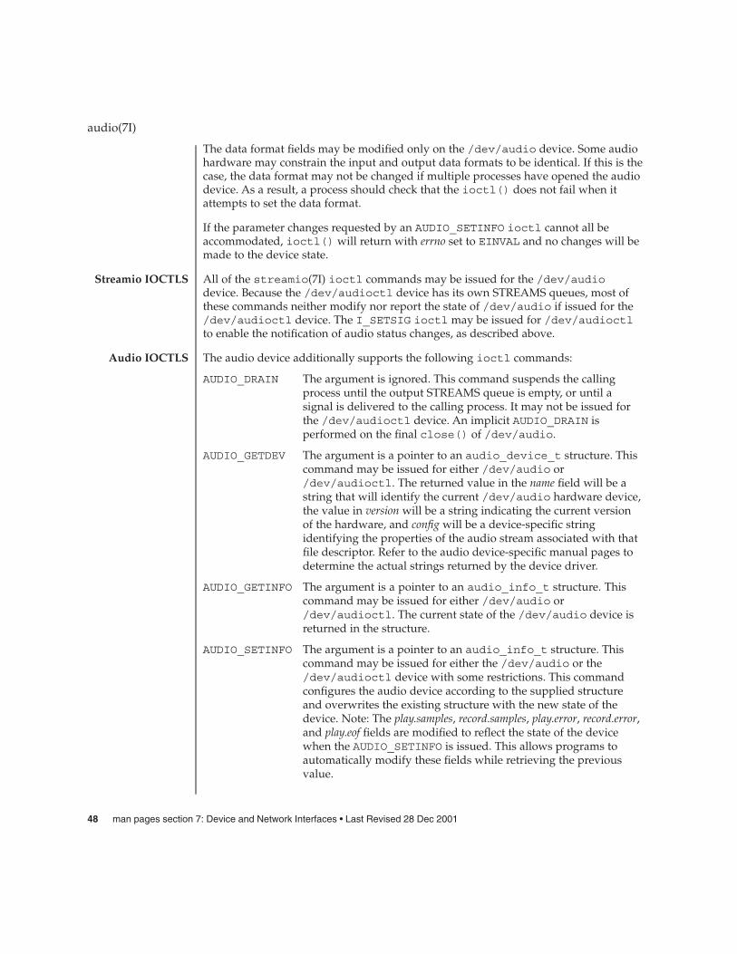
The data format fields may be modified only on the /dev/audio device. Some audiohardware may constrain the input and output data formats to be identical. If this is thecase, the data format may not be changed if multiple processes have opened the audiodevice. As a result, a process should check that the ioctl() does not fail when itattempts to set the data format.
If the parameter changes requested by an AUDIO_SETINFO ioctl cannot all beaccommodated, ioctl() will return with errno set to EINVAL and no changes will bemade to the device state.
All of the streamio(7I) ioctl commands may be issued for the /dev/audiodevice. Because the /dev/audioctl device has its own STREAMS queues, most ofthese commands neither modify nor report the state of /dev/audio if issued for the/dev/audioctl device. The I_SETSIG ioctl may be issued for /dev/audioctlto enable the notification of audio status changes, as described above.
The audio device additionally supports the following ioctl commands:
AUDIO_DRAIN The argument is ignored. This command suspends the callingprocess until the output STREAMS queue is empty, or until asignal is delivered to the calling process. It may not be issued forthe /dev/audioctl device. An implicit AUDIO_DRAIN isperformed on the final close() of /dev/audio.
AUDIO_GETDEV The argument is a pointer to an audio_device_t structure. Thiscommand may be issued for either /dev/audio or/dev/audioctl. The returned value in the name field will be astring that will identify the current /dev/audio hardware device,the value in version will be a string indicating the current versionof the hardware, and config will be a device-specific stringidentifying the properties of the audio stream associated with thatfile descriptor. Refer to the audio device-specific manual pages todetermine the actual strings returned by the device driver.
AUDIO_GETINFO The argument is a pointer to an audio_info_t structure. Thiscommand may be issued for either /dev/audio or/dev/audioctl. The current state of the /dev/audio device isreturned in the structure.
AUDIO_SETINFO The argument is a pointer to an audio_info_t structure. Thiscommand may be issued for either the /dev/audio or the/dev/audioctl device with some restrictions. This commandconfigures the audio device according to the supplied structureand overwrites the existing structure with the new state of thedevice. Note: The play.samples, record.samples, play.error, record.error,and play.eof fields are modified to reflect the state of the devicewhen the AUDIO_SETINFO is issued. This allows programs toautomatically modify these fields while retrieving the previousvalue.
audio(7I)
Streamio IOCTLS
Audio IOCTLS
48 man pages section 7: Device and Network Interfaces • Last Revised 28 Dec 2001

Certain fields in the audio information structure, such as the pause flags, are treated asread-only when /dev/audio is not open with the corresponding access permission.Other fields, such as the gain levels and encoding information, may have a restrictedset of acceptable values. Applications that attempt to modify such fields should checkthe returned values to be sure that the corresponding change took effect. Thesample_rate, channels, precision, and encoding fields treated as read-only for/dev/audioctl, so that applications can be guaranteed that the existing audioformat will stay in place until they relinquish the audio device. AUDIO_SETINFO willreturn EINVAL when the desired configuration is not possible, or EBUSY whenanother process has control of the audio device.
Once set, the following values persist through subsequent open() and close() callsof the device and automatic device unloads: play.gain, record.gain, play.balance,record.balance, play.port, record.port and monitor_gain. For the dbri driver, an automaticdevice driver unload resets these parameters to their default values on the next load.All other state is reset when the corresponding I/O stream of /dev/audio is closed.
The audio_info_t structure may be initialized through the use of theAUDIO_INITINFO macro. This macro sets all fields in the structure to values that areignored by the AUDIO_SETINFO command. For instance, the following code switchesthe output port from the built-in speaker to the headphone jack without modifyingany other audio parameters:
audio_info_t info;AUDIO_INITINFO(&info);info.play.port = AUDIO_HEADPHONE;err = ioctl(audio_fd, AUDIO_SETINFO, &info);
This technique eliminates problems associated with using a sequence ofAUDIO_GETINFO followed by AUDIO_SETINFO.
An open() will fail if:
EBUSY The requested play or record access is busy and either theO_NDELAY or O_NONBLOCK flag was set in the open() request.
EINTR The requested play or record access is busy and a signalinterrupted the open() request.
An ioctl() will fail if:
EINVAL The parameter changes requested in the AUDIO_SETINFO ioctlare invalid or are not supported by the device.
EBUSY The parameter changes requested in the AUDIO_SETINFO ioctlcould not be made because another process has the device openand is using a different format.
The physical audio device names are system dependent and are rarely used byprogrammers. Programmers should use the generic device names listed below.
audio(7I)
ERRORS
FILES
Device and Network Interfaces 49

/dev/audio symbolic link to the system’s primary audio device
/dev/audioctl symbolic link to the control device for /dev/audio
/dev/sound/0 first audio device in the system
/dev/sound/0ctl audio control device for /dev/sound/0
/usr/share/audio/samplesaudio files
See attributes(5) for a description of the following attributes:
ATTRIBUTE TYPE ATTRIBUTE VALUE
Architecture SPARC, IA
Availability SUNWcsu, SUNWcsxu, SUNWaudd, SUNWauddx,SUNWaudh
Stability Level Evolving
close(2), fcntl(2), ioctl(2), open(2), poll(2), read(2), write(2), attributes(5),audiocs(7D), audioens(7D), audiots(7D), dbri(7D), sbpro(7D), usb_ac(7D),audio_support(7I), mixer(7I), streamio(7I)
Due to a feature of the STREAMS implementation, programs that are terminated or exitwithout closing the audio device may hang for a short period while audio outputdrains. In general, programs that produce audio output should catch the SIGINTsignal and flush the output stream before exiting.
On LX machines running Solaris 2.3, catting a demo audio file to the audio device/dev/audio does not work. Use the audioplay command on LX machines insteadof cat.
Future audio drivers should use the mixer(7I) audio device to gain access to newfeatures.
audio(7I)
ATTRIBUTES
SEE ALSO
BUGS
FUTUREDIRECTIONS
50 man pages section 7: Device and Network Interfaces • Last Revised 28 Dec 2001

audiocs – Crystal Semiconductor 4231 Audio driver
The audiocs driver supports the Crystal Semiconductor 4231 Codec to implementthe audio device interface.
This interface is described in the audio(7I) and mixer(7I) man pages.
Applications that open /dev/audio may use the AUDIO_GETDEV ioctl(2) todetermine which audio device is being used. The audiocs driver will return thestring SUNW,CS4231 in the name field of the audio_device structure. The versionfield contains a letter (defined in the table below) and the config field contains thestring onboard1.
Platform Ver. Out H. Phone Speaker In Mic CD
SS-4/5 a Y Y Y Y Y Y
Ultra-1/2 b Y Y Y Y Y N
Ultra-450 f Y Y Y Y Y N
Ultra-30/60/80
g Y Y Y Y Y N
Ultra-5/10
h Y Y Y Y Y Y
Key to the above table: Ver = Version. Out = Line Out. Speaker = Internal Speaker. In =Line In. Mic. = Microphone. CD = CD-ROM.
The audiocs device provides support for the internal speaker, headphone, line out,line in, microphone, and on some platforms, internal CD-ROM audio in. Theplay.avail_ports and record.avail_ports fields retrieved by the AUDIO_GETINFO ioctl (seeaudio(7I)) report which ports are available. The play.mod_ports and record.mod_portsfields indicate which ports may be manipulated.
The configuration file /kernel/drv/audiocs.conf is used to configure theaudiocs driver so that the audio mixer is enabled or disabled. See the mixer(7I)manual page for details. The audio mixer’s mode may be changed at any time usingthe mixerctl(1) or sdtaudiocontrol(1) applications.
The audiocs device supports the audio formats listed in the following table. Whenthe audio mixer is in compatibility mode and the device is open for simultaneousplay and record, the input and output data formats must match. Some sample ratesare supported in compatibility mode (C) that are not supported in mixer mode (M).This is due to the computational overhead for sample rate conversion being too high.
Supported Audio Data Formats
audiocs(7D)
NAME
DESCRIPTION
APPLICATIONPROGRAM
INTERFACEDriver Versions
Audio Mixer Mode
Audio DataFormats
Device and Network Interfaces 51
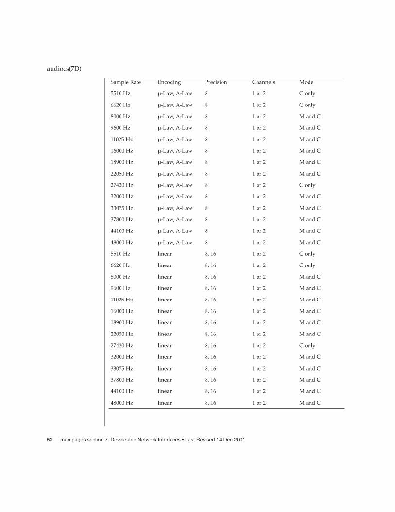
Sample Rate Encoding Precision Channels Mode
5510 Hz µ-Law, A-Law 8 1 or 2 C only
6620 Hz µ-Law, A-Law 8 1 or 2 C only
8000 Hz µ-Law, A-Law 8 1 or 2 M and C
9600 Hz µ-Law, A-Law 8 1 or 2 M and C
11025 Hz µ-Law, A-Law 8 1 or 2 M and C
16000 Hz µ-Law, A-Law 8 1 or 2 M and C
18900 Hz µ-Law, A-Law 8 1 or 2 M and C
22050 Hz µ-Law, A-Law 8 1 or 2 M and C
27420 Hz µ-Law, A-Law 8 1 or 2 C only
32000 Hz µ-Law, A-Law 8 1 or 2 M and C
33075 Hz µ-Law, A-Law 8 1 or 2 M and C
37800 Hz µ-Law, A-Law 8 1 or 2 M and C
44100 Hz µ-Law, A-Law 8 1 or 2 M and C
48000 Hz µ-Law, A-Law 8 1 or 2 M and C
5510 Hz linear 8, 16 1 or 2 C only
6620 Hz linear 8, 16 1 or 2 C only
8000 Hz linear 8, 16 1 or 2 M and C
9600 Hz linear 8, 16 1 or 2 M and C
11025 Hz linear 8, 16 1 or 2 M and C
16000 Hz linear 8, 16 1 or 2 M and C
18900 Hz linear 8, 16 1 or 2 M and C
22050 Hz linear 8, 16 1 or 2 M and C
27420 Hz linear 8, 16 1 or 2 C only
32000 Hz linear 8, 16 1 or 2 M and C
33075 Hz linear 8, 16 1 or 2 M and C
37800 Hz linear 8, 16 1 or 2 M and C
44100 Hz linear 8, 16 1 or 2 M and C
48000 Hz linear 8, 16 1 or 2 M and C
audiocs(7D)
52 man pages section 7: Device and Network Interfaces • Last Revised 14 Dec 2001

At any given time the reported input and output sample counts will vary from theactual sample count by no more than the size of the buffers the audiocs driver istransferring. In general, programs should not rely on the absolute accuracy of theplay.samples and record.samples fields of the audio_info structure.
The driver determines how often play and record interrupts should occur. For playingaudio, this determines how often and how much audio is requested from the audiomixer. The impact of interrupts on recording is minimal. However, if a very small readbuffer size is set, the record interrupt rate should be increased to prevent the bufferfrom overflowing. The play and record interrupt rates are tunable in the/kernel/drv/audiocs.conf file.
As described in the audio(7I) and mixer(7I) man pages, it is possible to requestasynchronous notification of changes in the state of an audio device.
audiocs errors are described in the audio(7I) man pages.
/dev/audioSymbolic link to the system’s primary audio device. (not necessarily an audiocsaudio device).
/dev/audioctlControl device for the above audio device.
/dev/sound/0Represents the first audio device on the system. (not necessarily an audiocs audiodevice).
/dev/sound/0ctlAudio control for above device.
/usr/share/audio/samplesAudio sample files.
/kernel/drv/audiocs32–bit audiocs driver
/kernel/drv/sparcv9/audiocs64–bit audiocs driver.
/kernel/drv/audiocs.confAudiocs driver configuration file.
See attributes(5) for descriptions of the following attributes:
ATTRIBUTE TYPE ATTRIBUTE VALUE
Architecture SPARC
Availability SUNWaudd, SUNWauddx, SUNWauda
Stability level Evolving
audiocs(7D)
SampleGranularity
Interrupt Rate
Audio StatusChange
NotificationERRORS
FILES
ATTRIBUTES
Device and Network Interfaces 53

mixerctl(1), sdtaudiocontrol(1), ioctl(2), attributes(5), audio(7I),mixer(7I), streamio(7I)
Crystal Semiconductor, Inc. CS4231 Data Sheet
http://www.sun.com/io
In addition to being logged, the following messages may appear on the systemconsole:
attach () play interrupt rate set too low.The play interrupt rate specified in audiocs.conf is set too low. It is being resetto the rate specified in the message. Update audiocs.conf to a higher playinterrupt rate.
attach() play interrupt rate set too high.The play interrupt rate specified in audiocs.conf is set too high. It is being resetto the rate specified in the message. Update audiocs.conf to a lower playinterrupt rate.
attach() record interrupt rate set too low.The record interrupt rate specified in audiocs.conf is set too low. It is being reset tothe rate specified in the message. Update audiocs.conf to a higher recordinterrupt rate.
attach() record interrupt rate set too highThe record interrupt rate specified in audiocs.conf is set too high. It is beingreset to the rate specified in the message. Update audiocs.conf to a lower recordinterrupt rate.
audiocs(7D)
SEE ALSO
DIAGNOSTICS
54 man pages section 7: Device and Network Interfaces • Last Revised 14 Dec 2001

audioens – Ensoniq 1371/1373 and Creative Labs 5880 driver support
The audioens driver provides support for the Ensoniq 1371/1373 and Creative Labs5880 audio controllers. Ensoniq 1371/1373 and Creative Labs 5880 chips are found onadd-in PCI cards commonly identified as Audio PCI, CT4740, CT4810, CT5803,CT5808, and ES1371, and on some IA motherboards.
This interface is described in the mixer(7I) and audio(7I) man pages.
Applications that open /dev/audio may use the AUDIO_GETDEV ioctl(2) todetermine which audio device is being used. The audioens driver returns the stringSUNW,audioens in the name field of the audio_device structure. The version fieldcontains a letter (defined in the table below) and the config field contains the stringonboard1.
The driver works on Sun architectures that support PCI slots, including Sparc 32 bit,Sparc 64 bit, and IA 32 bit.
Different cards provide different input and output connectors and may internallyhardwire these connectors. SpeakerOut implies an internal audio amplifier andLineOut implies the output is to go to an amplified speaker. The audioens driverroutes output data to both SpeakerOut and LineOut. The audioens driver supportsinput selection from LineIn or Microphone.
Platform Type: Sun4u/IA
Version: a
Line Out: Yes
Headphone: No
Int. Speaker: Yes
Line In: Yes
Microphone: Yes
CD-ROM: No
The configuration file /kernel/drv/audioens.conf is used to configure theaudioens driver and determines whether the audio mixer is enabled or disabled. Seethe mixer(7I) manual page for details. You can change the audio mixer mode at anytime using the sdtaudiocontrol(1) or mixerctl(1) applications.
The audioens audio device supports the audio data formats shown below. When theaudio mixer is disabled and the device is opened for simultaneous play and record,the input and output data formats may differ. Some sample rates are supported whenthe mixer is disabled (D) that are not supported when the mixer is enabled (E), due tothe overly high computational overhead for sample rate conversion.
audioens(7D)
NAME
DESCRIPTION
APPLICATIONPROGRAM
INTERFACEDriver Versions
Audio Mixer Mode
Audio DataFormats
Device and Network Interfaces 55

Supported data formats.
Sample Rate Encoding Precision Channels Mode
5510 Hz u-Law orA-Law
8 1 or 2 D only
6620 Hz u-Law orA-Law
8 1 or 2 D only
8000 Hz u-law or A-law 8 1 or 2 E and D
9600 Hz u-law or A-law 8 1 or 2 E and D
11025 Hz u-law or A-law 8 1 or 2 E and D
16000 Hz u-law or A-law 8 1 or 2 E and D
18900 Hz u-law or A-law 8 1 or 2 E and D
22050 Hz u-law or A-law 8 1 or 2 E and D
27420 Hz u-law or A-law 8 1 or 2 D only
32000 Hz u-law or A-law 8 1 or 2 E and D
33075 Hz u-law or A-law 8 1 or 2 E and D
37800 Hz u-law or A-law 8 1 or 2 E and D
44100 Hz u-law or A-law 8 1 or 2 E and D
48000 Hz u-law or A-law 8 1 or 2 E and D
5510 Hz linear 16 1 or 2 D only
6620 Hz linear 16 1 or 2 D only
8000 Hz linear 16 1 or 2 E and D
9600 Hz linear 16 1 or 2 E and D
11025 Hz linear 16 1 or 2 E and D
16000 Hz linear 16 1 or 2 E and D
18900 Hz linear 16 1 or 2 E and D
22050 Hz linear 16 1 or 2 E and D
27420 Hz linear 16 1 or 2 D only
32000 Hz linear 16 1 or 2 E and D
33075 Hz linear 16 1 or 2 E and D
37800 Hz linear 16 1 or 2 E and D
audioens(7D)
56 man pages section 7: Device and Network Interfaces • Last Revised 22 Dec 2001
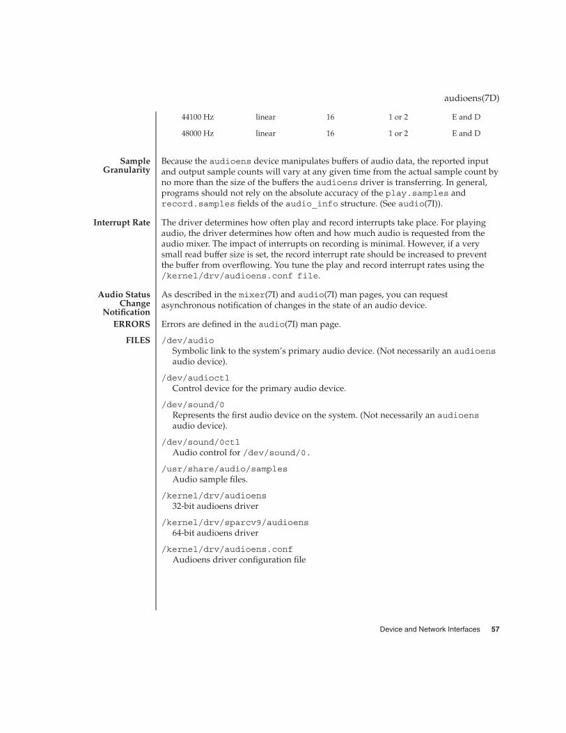
44100 Hz linear 16 1 or 2 E and D
48000 Hz linear 16 1 or 2 E and D
Because the audioens device manipulates buffers of audio data, the reported inputand output sample counts will vary at any given time from the actual sample count byno more than the size of the buffers the audioens driver is transferring. In general,programs should not rely on the absolute accuracy of the play.samples andrecord.samples fields of the audio_info structure. (See audio(7I)).
The driver determines how often play and record interrupts take place. For playingaudio, the driver determines how often and how much audio is requested from theaudio mixer. The impact of interrupts on recording is minimal. However, if a verysmall read buffer size is set, the record interrupt rate should be increased to preventthe buffer from overflowing. You tune the play and record interrupt rates using the/kernel/drv/audioens.conf file.
As described in the mixer(7I) and audio(7I) man pages, you can requestasynchronous notification of changes in the state of an audio device.
Errors are defined in the audio(7I) man page.
/dev/audioSymbolic link to the system’s primary audio device. (Not necessarily an audioensaudio device).
/dev/audioctlControl device for the primary audio device.
/dev/sound/0Represents the first audio device on the system. (Not necessarily an audioensaudio device).
/dev/sound/0ctlAudio control for /dev/sound/0.
/usr/share/audio/samplesAudio sample files.
/kernel/drv/audioens32-bit audioens driver
/kernel/drv/sparcv9/audioens64-bit audioens driver
/kernel/drv/audioens.confAudioens driver configuration file
audioens(7D)
SampleGranularity
Interrupt Rate
Audio StatusChange
NotificationERRORS
FILES
Device and Network Interfaces 57

See attributes(5) for descriptions of the following attributes:
ATTRIBUTE TYPE ATTRIBUTE VALUE
Architecture PCI-based systems
Availability SUNWaudd, SUNWauddx, SUNWauda
mixerctl(1), sdtaudiocontrol(1), ioctl(2), attributes(5), audio(7I),mixer(7I), streamio(7I)
Creative Technology Ltd ES1371 Specification
Creative Technology Ltd ES1373 Specification
Creative Technology Ltd CT5880 Specification
http://www.sun.com/io
In addition to being logged, the following messages may appear on the systemconsole.
init_state() play interrupt rate set too lowThe play interrupt rate specified in audioens.conf is set too low. It has been resetto the rate specified in the message. Update audioens.conf to a higher playinterrupt rate.
init_state() play interrupt rate set too highThe play interrupt rate set in audioens.conf is set too high. It has been reset tothe rate specified in the message. Update audioens.conf to a lower playinterrupt rate.
init_state() record interrupt rate set too lowThe record interrupt rate specified in audioens.conf is set too low. It has beenreset to the rate specified in the message. Update audioens.conf to a higherrecord interrupt rate.
init_state() record interrupt rate set too highThe record interrupt rate specified in audioens.conf is set too high. It is beingreset to the rate specified in the message. Update audioens.conf to a lowerrecord interrupt rate.
audioens(7D)
ATTRIBUTES
SEE ALSO
DIAGNOSTICS
58 man pages section 7: Device and Network Interfaces • Last Revised 22 Dec 2001

audio_support – audio driver support routines and interface
#include <sys/audio.h>
The audio support module supports audio drivers that use the new audio driverarchitecture. It also provides a limited number of ioctl(2) functions for applicationprogrammers.
The following data structures are defined to manage the different audio device typesand channels.
The following enumeration lists a number of generic device types.
typedef enum {UNDEFINED, AUDIO, AUDIOCTL, USER1, USER2, USER3
} audio_device_type_e;
Currently, the Solaris audio mixer implements only the AUDIO and AUDIOCTL audiodevice types. See the mixer(7I) manual page for details. The USER1, USER2 andUSER3 device types allow third parties to write audio personality modules of theirown.
This structure is used to get and set state information on individual channels.
struct audio_channel {pid_t pid; /* application’s process ID */uint_t ch_number; /* device channel */audio_device_type_e dev_type; /* device type */uint_t info_size; /* size of channel’s */
/* info structure */void *info; /* channel state information */
;typedef struct audio_channel audio_channel_t;
The ch_number must specify the specific channel number to get or set. When theioctl() returns, the pid contains the process ID of the process that has that channelopen and dev_type will contain the device type. If pid is 0 (zero), then the channelis not open. The pointer *info must point to a buffer large enough to hold whateveraudio device-related state structure that may be returned. Currently, only theaudio_info_t structure is returned. See the audio(7I) and mixer(7I) man pages formore information.
The audio support driver provides the following ioctls():
AUDIO_GET_CH_NUMBER This ioctl() returns the channel numberpointed to by the file descriptor. It isreturned in the integer pointer of theioctl() argument.
AUDIO_GET_CH_TYPE This ioctl() returns the type of channelthe process has open. It is returned in theaudio_device_type_e enumeration pointer
audio_support(7I)
NAME
SYNOPSIS
DESCRIPTION
DATASTRUCTURES
Device Types
Channel Structure
IOCTLS
Device and Network Interfaces 59

of the ioctl() argument.
AUDIO_GET_NUM_CHS This ioctl() returns the number ofchannels the device supports. It is returnedin the integer pointer of the ioctl()argument.
The following macro can be used to initialize data structures. The establishedconvention is that the state corresponding to a field set to -1 will not be modified.
AUDIO_INIT(I, S)
Where I is a pointer to an info structure and S is the size of that structure.
The following code segment demonstrates how to use this macro:
audio_info_t info;
AUDIO_INIT(&info, sizeof(info));info.play.port = AUDIO_HEADPHONE;err = ioctl(audio_fd, AUDIO_SETINFO, &info);
EINVAL The ioctl() is invalid for this file descriptor. Theaudio_channel_t structure’s info pointer does not point to abuffer, or the ch_number is bad.
ENOMEM The ioctl() failed due to lack of memory.
/usr/share/audio/samplesAudio sample files
See attributes(5) for a description of the following attributes:
ATTRIBUTE TYPE ATTRIBUTE VALUE
Architecture SPARC, IA
Availability SUNWaudd, SUNWauddx, SUNWaudh
Stability Level Evolving
ioctl(2), attributes(5), audio(7I), mixer(7I), streamio(7I)
Over time, additional audio personality modules will be added. Audio applicationprogrammers are encouraged to review this man page with each Solaris release fornew audio personality modules.
audio_support(7I)
MACROS
ERRORS
FILES
ATTRIBUTES
SEE ALSO
FUTUREDIRECTIONS
60 man pages section 7: Device and Network Interfaces • Last Revised 2 January 2002

audiots – Acer Laboratories Inc. M5451 audio processor interface
The audiots device uses the ALI M5451 audio processor and an AC-97 Codec toimplement the audio device interface.
This interface is described in the mixer(7I) and audio(7I) man pages.
Applications that open /dev/audio may use the AUDIO_GETDEV ioctl(2) todetermine which audio device is being used. The audiots driver will return thestring SUNW,audiots in the name field of the audio_device structure. Theversion field will contain a letter (defined in the table below) and the config fieldwill contain the string onboard1.
Platform Ver. Out H. Phone Spkr. In Mic. CD
Sun Blade100
a Y Y Y Y Y N
Key to the above table: Ver. = Version. Out = Line Out. H. Phone = Head Phone. Spkr= Internal Speaker. In = Line In. Mic. = Microphone. CD = CD=ROM
The audiots device provides support for the internal speaker, headphone, line out,line in, and microphone. The play.mod_ports and record.mod_ports fields ofthe audio_info structure (see audio(7I)) indicate which ports may be manipulated.
The configuration file /kernel/drv/audiots.conf is used to configure theaudiots driver so that the audio mixer is enabled or disabled. See the mixer(7I)manual page for details. The audio mixer mode may be changed at any time using thesdtaudiocontrol(1) or mixerctl(1) commands.
The audiots device supports 8–bit µ-law and A-law, 8–bit linear and 16–bit linearencodings in mono and stereo. With the mixer enabled, a continuous range of samplerates from 5510 to 48000 Hz is supported. With the mixer disabled, the followingsample rates are supported: 5510, 6620, 8000, 9600, 11025, 16000, 18900, 22050, 27420,32000, 33075, 37800, 4410, and 48000 Hz. When the audio mixer is disabled and thedevice is opened for simultaneous play and record, the input and out data formatsmay be different.
Because the audiots device manipulates buffers of audio data, the reported inputand output sample counts will vary at any given time from the actual sample count byno more than the size of the buffers the audiots driver is transferring. In general,programs should not rely on the absolute accuracy of the play.samples andrecord.samples fields of the audio_info structure.
audiots(7D)
NAME
DESCRIPTION
APPLICATIONPROGRAM
INTERFACEDriver Versions
Audio Mixer Mode
Audio DataFormats
SampleGranularity
Device and Network Interfaces 61

The driver determines how often play and record interrupts should take place. Forplaying audio, this determines how often and how much audio is requested from theaudio mixer. The impact of interrupts on recording is minimal. However, if a verysmall read buffer size is set, the record interrupt rate should be increased to preventthe buffer from overflowing. The play and record interrupt rates are tunable in the/kernel/drv/audiots.conf file.
As described in the audio(7I) and mixer(7I) man pages, it is possible to requestasynchronous notification of changes in the state of an audio device.
audiots errors are described in the audio(7I) man page.
/dev/audioSymbolic link to the system’s primary audio device. (Not necessarily an audiotsaudio device).
/dev/audioctlControl device for the primary audio device.
/dev/sound/0Represents the first audio device on the system. (Not necessarily an audiots audiodevice).
/dev/sound/0ctlAudio control for /dev/sound/0.
/usr/share/audio/samplesAudio sample files.
/kernel/drv/sparcv9/audiots64–bit audiots driver
/kernel/drv/audiots.confaudiots driver configuration file.
See attributes(5) for a descriptions of the following attributes:
ATTRIBUTE TYPE ATTRIBUTE VALUE
Architecture SPARC
Availability SUNWaudd, SUNWauddx, SUNWauda
Stability level Evolving
mixerctl(1), sdtaudiocontrol(1), ioctl(2), attributes(5), audio(7I),mixer(7I), streamio(7I)
Acer Laboratories Inc. M5451 PCI Audio Processor Technical Specification
http://www.sun.com/io
audiots(7D)
Interrupt Rate
Audio StatusChange
NotificationERRORS
FILES
ATTRIBUTES
SEE ALSO
62 man pages section 7: Device and Network Interfaces • Last Revised 23 Aug 2002

In addition to being logged, the following messages may appear on the systemconsole:
init_state() play interrupt rate set too lowThe play interrupt rate in audiots.conf is set too low. It has been reset to the ratespecified in the message. Update audiots.conf to a higher play interrupt rate.
init_state() play interrupt rate set too highThe play interrupt rate set in audiots.conf is set too high. It has been reset to therate specified in the message. Update audiots.conf to a lower play interruptrate.
init_state() record interrupt rate set too lowThe record interrupt rate in audiots.conf is set too low. It has been reset to therate specified in the message. Update audiots.conf to a higher record interruptrate.
init_state() record interrupt rate set too highThe record interrupt rate in audiots.conf is set too high. It has been reset to therate specified in the message. Update audiots.conf to a lower record interruptrate.
audiots(7D)
DIAGNOSTICS
Device and Network Interfaces 63

authmd5h – HMAC-MD5 Authentication Algorithm Module for IPsec
strmod/authmd5h
This module implements the HMAC-MD5 authentication algorithm using the MD5message-digest algorithm and the HMAC technique documented in RFC 2104. Theauthmd5h module has the following properties:
key size 128 bits
digest size 96 bits (truncated from 128) authmd5h is used by both AH and ESP.
See attributes(5) for descriptions of the following attributes:
ATTRIBUTE TYPE ATTRIBUTE VALUE
Availability SUNWcsr (32-bit)
SUNWcarx (64-bit)
Interface Stability Evolving
ipseckey(1M), attributes(5), pf_key(7P), ipsec(7P), ipsecah(7P),ipsecesp(7P)
Krawczyk, H., Ballare, M., and Canetti, R., RFC 2104, HMAC: Keyed-Hashing forMessage Authentication, The Internet Society, 1997
Madsen, C. and Glenn, R., RFC 2403, The Use of HMAC-MD5-96 within ESP and AH,The Internet Society, 1998.
Rivest, R., RFC 1321, The MD5 Message-Digest Algorithm, The Internet Society, 1992.
authmd5h(7M)
NAME
SYNOPSIS
DESCRIPTION
ATTRIBUTES
SEE ALSO
64 man pages section 7: Device and Network Interfaces • Last Revised 28 Mar 2001

authsha1 – HMAC-SHA-1 Authentication Algorithm Module for IPsec
strmod/authsha1
This module implements the HMAC-SHA-1 authentication algorithm, using theSHA-1 hash algorithm and the HMAC technique set forth in RFC 2104. The authshalmodule has the following properties
key size 160 bits
digest size 96 bits (truncated from 160). authshal is used by both AH andESP.
See attributes(5) for descriptions of the following attributes:
ATTRIBUTE TYPE ATTRIBUTE VALUE
Availability SUNWcsr (32-bit)
SUNWcarx (64-bit)
Interface Stability Evolving
ipseckey(1M), attributes(5), pf_key(7P), ipsec(7P), ipsecah(7P),ipsecesp(7P)
NIST, FIPS PUB 180–1: Secure Hash Standard, April 1995.
Krawczyk, H., Ballare, M., and Canetti, R., RFC 2104, HMAC: Keyed-Hashing forMessage Authentication, The Internet Society, 1997.
Madsen, C. and Glenn, R., RFC 2404, The Use of HMAC-SHA-1-96 within ESP and AH,The Internet Society, 1998.
authsha1(7M)
NAME
SYNOPSIS
DESCRIPTION
ATTRIBUTES
SEE ALSO
Device and Network Interfaces 65

bbc_beep – Platform-dependent Beep driver for BBC-based hardware.
beep@unit-address
The bbc_beep driver generates beeps on platforms (including Sun Blade 1000) thatuse BBC-based registers and USB keyboards. When the KIOCCMD ioctl is issued to theUSB keyboard module (see usbkbm(7M)) with commandKBD_CMD_BELL/KBD_CMD_NOBELL, usbkbm(7M) passes the request to thebbc_beep driver to turn the beep on and off, respectively.
/platform/sun4u/kernel/drv/sparcv9/bbc_beep64–bit ELF kernel driver
See attributes(5) for descriptions of the following attributes:
ATTRIBUTE TYPE ATTRIBUTE VALUE
Architecture BBC-based SPARC
Availability SUNWcarx.u
kbd(1), attributes(5), grbeep(7D), kb(7M), usbkbm(7M)
Writing Device Drivers
None
bbc_beep(7D)
NAME
SYNOPSIS
DESCRIPTION
FILES
ATTRIBUTES
SEE ALSO
DIAGNOSTICS
66 man pages section 7: Device and Network Interfaces • Last Revised 18 Dec 2001
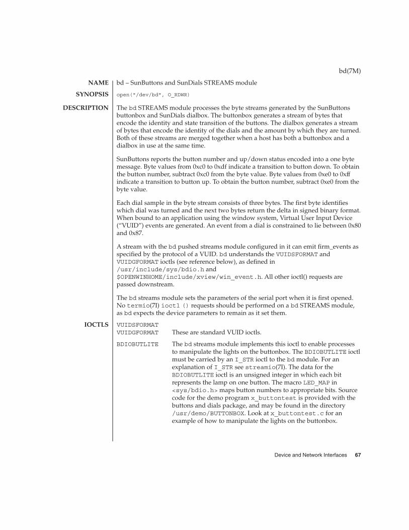
bd – SunButtons and SunDials STREAMS module
open("/dev/bd", O_RDWR)
The bd STREAMS module processes the byte streams generated by the SunButtonsbuttonbox and SunDials dialbox. The buttonbox generates a stream of bytes thatencode the identity and state transition of the buttons. The dialbox generates a streamof bytes that encode the identity of the dials and the amount by which they are turned.Both of these streams are merged together when a host has both a buttonbox and adialbox in use at the same time.
SunButtons reports the button number and up/down status encoded into a one bytemessage. Byte values from 0xc0 to 0xdf indicate a transition to button down. To obtainthe button number, subtract 0xc0 from the byte value. Byte values from 0xe0 to 0xffindicate a transition to button up. To obtain the button number, subtract 0xe0 from thebyte value.
Each dial sample in the byte stream consists of three bytes. The first byte identifieswhich dial was turned and the next two bytes return the delta in signed binary format.When bound to an application using the window system, Virtual User Input Device(“VUID”) events are generated. An event from a dial is constrained to lie between 0x80and 0x87.
A stream with the bd pushed streams module configured in it can emit firm_events asspecified by the protocol of a VUID. bd understands the VUIDSFORMAT andVUIDGFORMAT ioctls (see reference below), as defined in/usr/include/sys/bdio.h and$OPENWINHOME/include/xview/win_event.h. All other ioctl() requests arepassed downstream.
The bd streams module sets the parameters of the serial port when it is first opened.No termio(7I) ioctl () requests should be performed on a bd STREAMS module,as bd expects the device parameters to remain as it set them.
VUIDSFORMATVUIDGFORMAT These are standard VUID ioctls.
BDIOBUTLITE The bd streams module implements this ioctl to enable processesto manipulate the lights on the buttonbox. The BDIOBUTLITE ioctlmust be carried by an I_STR ioctl to the bd module. For anexplanation of I_STR see streamio(7I). The data for theBDIOBUTLITE ioctl is an unsigned integer in which each bitrepresents the lamp on one button. The macro LED_MAP in<sys/bdio.h> maps button numbers to appropriate bits. Sourcecode for the demo program x_buttontest is provided with thebuttons and dials package, and may be found in the directory/usr/demo/BUTTONBOX. Look at x_buttontest.c for anexample of how to manipulate the lights on the buttonbox.
bd(7M)
NAME
SYNOPSIS
DESCRIPTION
IOCTLS
Device and Network Interfaces 67

/usr/include/sys/bdio.h
/usr/include/sys/stropts.h
$OPENWINHOME/share/include/xview/win_event.h
bdconfig(1M), ioctl(2), x_buttontest(6), x_dialtest(6), streamio(7I),termio(7I)
SunButtons Installation and Programmers Guide
SunDials Installation and Programmers Guide
The SunDials dial box must be used with a serial port.
bd(7M)
FILES
SEE ALSO
WARNINGS
68 man pages section 7: Device and Network Interfaces • Last Revised 19 Feb 1992

bge – SUNW,bge Gigabit Ethernet driver for Broadcom BCM5704
/dev/bge*
The bge Gigabit Ethernet driver is a multi-threaded, loadable, clonable, GLD-basedSTREAMS driver supporting the Data Link Provider Interface, dlpi(7P), onBroadcom BCM5703C or BCM5704 Gigabit Ethernet controllers fitted to the systemmotherboard. These devices incorporate both MAC and PHY functions and providethree-speed (copper) Ethernet operation on the RJ-45 connectors.
The bge driver functions include controller initialization, frame transmit and receive,promiscuous and multicast support, and error recovery and reporting.
The bge driver and hardware support ’auto-negotiation,’ a protocol specified by the1000Base-T standard. Auto-negotiation allows each device to advertise its capabilitiesand discover those of its peer (link partner). The highest common denominatorsupported by both link partners is automatically selected, yielding the greatestavailable throughput, while requiring no manual configuration. The bge driver alsoallows you to configure the advertised capabilities to less than the maximum (wherethe full speed of the interface is not required), or to force a specific mode of operation,irrespective of the link partner’s advertised capabilities.
The cloning character-special device, /dev/bge, is used to access all BCM570xdevices fitted to the system motherboard.
The bge driver is dependent on /kernel/misc/gld, a loadable kernel module thatprovides the bge driver with the DLPI and STREAMS functionality required of a LANdriver. See gld(7D) for more details on the primitives supported by the driver.
You must send an explicit DL_ATTACH_REQ message to associate the opened streamwith a particular device (PPA). The PPA ID is interpreted as an unsigned integer datatype and indicates the corresponding device instance (unit) number. The driverreturns an error (DL_ERROR_ACK) if the PPA field value does not correspond to avalid device instance number for the system. The device is initialized on first attachand de-initialized (stopped) at last detach.
The values returned by the driver in the DL_INFO_ACK primitive in response to aDL_INFO_REQ are:
� Maximum SDU is 1500 (ETHERMTU - defined in <sys/ethernet.h>).
� Minimum SDU is 0.
� DLSAP address length is 8.
� MAC type is DL_ETHER.
� SAP length value is -2, meaning the physical address component is followedimmediately by a 2-byte SAP component within the DLSAP address.
� Broadcast address value is the Ethernet/IEEE broadcast address(FF:FF:FF:FF:FF:FF).
bge(7D)
NAME
SYNOPSIS
DESCRIPTION
APPLICATIONPROGRAMMING
INTERFACE
Device and Network Interfaces 69
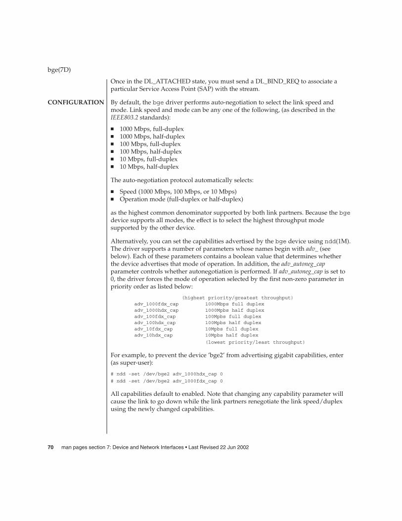
Once in the DL_ATTACHED state, you must send a DL_BIND_REQ to associate aparticular Service Access Point (SAP) with the stream.
By default, the bge driver performs auto-negotiation to select the link speed andmode. Link speed and mode can be any one of the following, (as described in theIEEE803.2 standards):
� 1000 Mbps, full-duplex� 1000 Mbps, half-duplex� 100 Mbps, full-duplex� 100 Mbps, half-duplex� 10 Mbps, full-duplex� 10 Mbps, half-duplex
The auto-negotiation protocol automatically selects:
� Speed (1000 Mbps, 100 Mbps, or 10 Mbps)� Operation mode (full-duplex or half-duplex)
as the highest common denominator supported by both link partners. Because the bgedevice supports all modes, the effect is to select the highest throughput modesupported by the other device.
Alternatively, you can set the capabilities advertised by the bge device using ndd(1M).The driver supports a number of parameters whose names begin with adv_ (seebelow). Each of these parameters contains a boolean value that determines whetherthe device advertises that mode of operation. In addition, the adv_autoneg_capparameter controls whether autonegotiation is performed. If adv_autoneg_cap is set to0, the driver forces the mode of operation selected by the first non-zero parameter inpriority order as listed below:
(highest priority/greatest throughput)adv_1000fdx_cap 1000Mbps full duplexadv_1000hdx_cap 1000Mpbs half duplexadv_100fdx_cap 100Mpbs full duplexadv_100hdx_cap 100Mpbs half duplexadv_10fdx_cap 10Mpbs full duplexadv_10hdx_cap 10Mpbs half duplex
(lowest priority/least throughput)
For example, to prevent the device ’bge2’ from advertising gigabit capabilities, enter(as super-user):
# ndd -set /dev/bge2 adv_1000hdx_cap 0
# ndd -set /dev/bge2 adv_1000fdx_cap 0
All capabilities default to enabled. Note that changing any capability parameter willcause the link to go down while the link partners renegotiate the link speed/duplexusing the newly changed capabilities.
bge(7D)
CONFIGURATION
70 man pages section 7: Device and Network Interfaces • Last Revised 22 Jun 2002

The current settings of the parameters may be found using ndd -get. In addition, thedriver exports the current state, speed, and duplex setting of the link via nddparameters (these are read only and may not be changed). For example, to check linkstate of device bge0:
# ndd -get /dev/bge0 link_status1# ndd -get /dev/bge0 link_speed100# ndd -get /dev/bge0 link_duplex
1
The output above indicates that the link is up and running at 100Mbps full-duplex.
/dev/bge*Character special device
/kernel/drv/sparcv9/bgebge driver binary
/platform/platform-name/kernel/drv/bge.confbge configuration file
See attributes(5) for a description of the following attributes:
ATTRIBUTE TYPE ATTRIBUTE VALUE
Architecture SPARC
attributes(5), gld(7D), streamio(7I), dlpi(7P)
Writing Device Drivers
STREAMS Programming Guide
Network Interfaces Programmer’s Guide
bge(7D)
FILES
ATTRIBUTES
SEE ALSO
Device and Network Interfaces 71
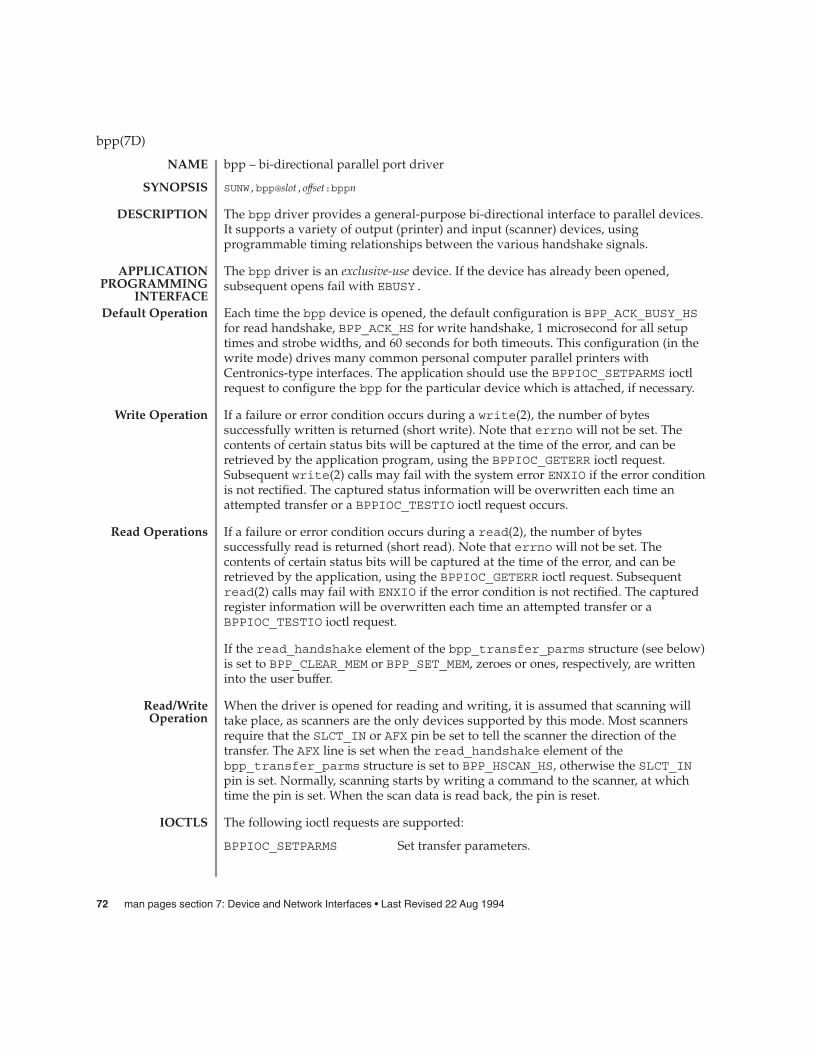
bpp – bi-directional parallel port driver
SUNW,bpp@slot,offset:bppn
The bpp driver provides a general-purpose bi-directional interface to parallel devices.It supports a variety of output (printer) and input (scanner) devices, usingprogrammable timing relationships between the various handshake signals.
The bpp driver is an exclusive-use device. If the device has already been opened,subsequent opens fail with EBUSY.
Each time the bpp device is opened, the default configuration is BPP_ACK_BUSY_HSfor read handshake, BPP_ACK_HS for write handshake, 1 microsecond for all setuptimes and strobe widths, and 60 seconds for both timeouts. This configuration (in thewrite mode) drives many common personal computer parallel printers withCentronics-type interfaces. The application should use the BPPIOC_SETPARMS ioctlrequest to configure the bpp for the particular device which is attached, if necessary.
If a failure or error condition occurs during a write(2), the number of bytessuccessfully written is returned (short write). Note that errno will not be set. Thecontents of certain status bits will be captured at the time of the error, and can beretrieved by the application program, using the BPPIOC_GETERR ioctl request.Subsequent write(2) calls may fail with the system error ENXIO if the error conditionis not rectified. The captured status information will be overwritten each time anattempted transfer or a BPPIOC_TESTIO ioctl request occurs.
If a failure or error condition occurs during a read(2), the number of bytessuccessfully read is returned (short read). Note that errno will not be set. Thecontents of certain status bits will be captured at the time of the error, and can beretrieved by the application, using the BPPIOC_GETERR ioctl request. Subsequentread(2) calls may fail with ENXIO if the error condition is not rectified. The capturedregister information will be overwritten each time an attempted transfer or aBPPIOC_TESTIO ioctl request.
If the read_handshake element of the bpp_transfer_parms structure (see below)is set to BPP_CLEAR_MEM or BPP_SET_MEM, zeroes or ones, respectively, are writteninto the user buffer.
When the driver is opened for reading and writing, it is assumed that scanning willtake place, as scanners are the only devices supported by this mode. Most scannersrequire that the SLCT_IN or AFX pin be set to tell the scanner the direction of thetransfer. The AFX line is set when the read_handshake element of thebpp_transfer_parms structure is set to BPP_HSCAN_HS, otherwise the SLCT_INpin is set. Normally, scanning starts by writing a command to the scanner, at whichtime the pin is set. When the scan data is read back, the pin is reset.
The following ioctl requests are supported:
BPPIOC_SETPARMS Set transfer parameters.
bpp(7D)
NAME
SYNOPSIS
DESCRIPTION
APPLICATIONPROGRAMMING
INTERFACEDefault Operation
Write Operation
Read Operations
Read/WriteOperation
IOCTLS
72 man pages section 7: Device and Network Interfaces • Last Revised 22 Aug 1994

The argument is a pointer to a bpp_transfer_parmsstructure. See below for a description of the elements ofthis structure. If a parameter is out of range, EINVAL isreturned.
BPPIOC_GETPARMS Get current transfer parameters.
The argument is a pointer to a bpp_transfer_parmsstructure. See below for a description of the elements ofthis structure. If no parameters have been configuredsince the device was opened, the contents of thestructure will be the default conditions of theparameters (see Default Operation above).
BPPIOC_SETOUTPINS Set output pin values.
The argument is a pointer to a bpp_pins structure. Seebelow for a description of the elements of thisstructure. If a parameter is out of range, EINVAL isreturned.
BPPIOC_GETOUTPINS
Read output pin values. The argument is a pointer to abpp_pins structure. See below for a description of theelements of this structure.
BPPIOC_GETERR Get last error status.
The argument is a pointer to a bpp_error_statusstructure. See below for a description of the elements ofthis structure. This structure indicates the status of allthe appropriate status bits at the time of the mostrecent error condition during a read(2) or write(2)call, or the status of the bits at the most recentBPPIOC_TESTIO ioctl request. Note: The bits in thepin_status element indicate whether the associatedpin is active, not the actual polarity. The applicationcan check transfer readiness without attemptinganother transfer using the BPPIOC_TESTIO ioctl. Note:The timeout_occurred and bus_error fields willnever be set by the BPPIOC_TESTIO ioctl, only by anactual failed transfer.
BPPIOC_TESTIO Test transfer readiness.
This command checks to see if a read or write transferwould succeed based on pin status, opened mode, andhandshake selected. If a handshake would succeed, 0 isreturned. If a transfer would fail, -1 is returned, and
bpp(7D)
Device and Network Interfaces 73

errno is set to EIO, and the error status information iscaptured. The captured status can be retrieved usingthe BPPIOC_GETERR ioctl call. Note that thetimeout_occurred and bus_error fields will neverbe set by this ioctl.
This structure is defined in <sys/bpp_io.h>.
struct bpp_transfer_parms {enum handshake_t
read_handshake; /* parallel port read handshake mode */int read_setup_time; /* DSS register - in nanoseconds */int read_strobe_width; /* DSW register - in nanoseconds */int read_timeout; /*
* wait this many seconds* before aborting a transfer
*/enum handshake_t
write_handshake; /* parallel port write handshake mode */int write_setup_time; /* DSS register - in nanoseconds */int write_strobe_width; /* DSW register - in nanoseconds */int write_timeout; /*
* wait this many seconds* before aborting a transfer
*/};/* Values for read_handshake and write_handshake fields */
enum handshake_t {BPP_NO_HS, /* no handshake pins */BPP_ACK_HS, /* handshake controlled by ACK line */BPP_BUSY_HS, /* handshake controlled by BSY line */BPP_ACK_BUSY_HS, /*
* handshake controlled by ACK and BSY lines* read_handshake only!
*/BPP_XSCAN_HS, /* xerox scanner mode,
* read_handshake only!*/
BPP_HSCAN_HS, /** HP scanjet scanner mode* read_handshake only!
*/BPP_CLEAR_MEM, /* write 0’s to memory,
* read_handshake only!*/
BPP_SET_MEM, /* write 1’s to memory,* read_handshake only!
*//* The following handshakes are RESERVED. Do not use. */
BPP_VPRINT_HS, /* valid only in read/write mode */BPP_VPLOT_HS /* valid only in read/write mode */
};
bpp(7D)
TransferParameters
Structure
74 man pages section 7: Device and Network Interfaces • Last Revised 22 Aug 1994
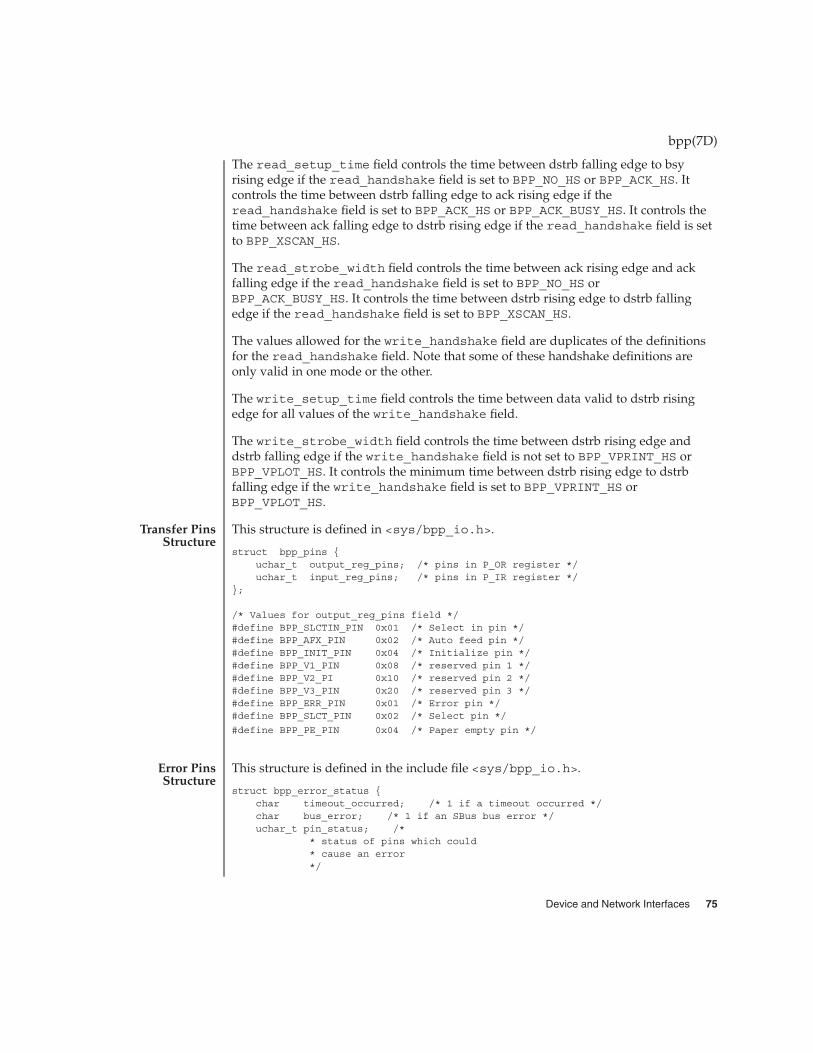
The read_setup_time field controls the time between dstrb falling edge to bsyrising edge if the read_handshake field is set to BPP_NO_HS or BPP_ACK_HS. Itcontrols the time between dstrb falling edge to ack rising edge if theread_handshake field is set to BPP_ACK_HS or BPP_ACK_BUSY_HS. It controls thetime between ack falling edge to dstrb rising edge if the read_handshake field is setto BPP_XSCAN_HS.
The read_strobe_width field controls the time between ack rising edge and ackfalling edge if the read_handshake field is set to BPP_NO_HS orBPP_ACK_BUSY_HS. It controls the time between dstrb rising edge to dstrb fallingedge if the read_handshake field is set to BPP_XSCAN_HS.
The values allowed for the write_handshake field are duplicates of the definitionsfor the read_handshake field. Note that some of these handshake definitions areonly valid in one mode or the other.
The write_setup_time field controls the time between data valid to dstrb risingedge for all values of the write_handshake field.
The write_strobe_width field controls the time between dstrb rising edge anddstrb falling edge if the write_handshake field is not set to BPP_VPRINT_HS orBPP_VPLOT_HS. It controls the minimum time between dstrb rising edge to dstrbfalling edge if the write_handshake field is set to BPP_VPRINT_HS orBPP_VPLOT_HS.
This structure is defined in <sys/bpp_io.h>.
struct bpp_pins {uchar_t output_reg_pins; /* pins in P_OR register */uchar_t input_reg_pins; /* pins in P_IR register */
};
/* Values for output_reg_pins field */#define BPP_SLCTIN_PIN 0x01 /* Select in pin */#define BPP_AFX_PIN 0x02 /* Auto feed pin */#define BPP_INIT_PIN 0x04 /* Initialize pin */#define BPP_V1_PIN 0x08 /* reserved pin 1 */#define BPP_V2_PI 0x10 /* reserved pin 2 */#define BPP_V3_PIN 0x20 /* reserved pin 3 */#define BPP_ERR_PIN 0x01 /* Error pin */#define BPP_SLCT_PIN 0x02 /* Select pin */
#define BPP_PE_PIN 0x04 /* Paper empty pin */
This structure is defined in the include file <sys/bpp_io.h>.
struct bpp_error_status {char timeout_occurred; /* 1 if a timeout occurred */char bus_error; /* 1 if an SBus bus error */uchar_t pin_status; /*
* status of pins which could* cause an error*/
bpp(7D)
Transfer PinsStructure
Error PinsStructure
Device and Network Interfaces 75

};/* Values for pin_status field */#define BPP_ERR_ERR 0x01 /* Error pin active */#define BPP_SLCT_ERR 0x02 /* Select pin active */#define BPP_PE_ERR 0x04 /* Paper empty pin active */#define BPP_SLCTIN_ERR 0x10 /* Select in pin active */
#define BPP_BUSY_ERR 0x40 /* Busy pin active */
EBADF The device is opened for write-only access and a read is attempted,or the device is opened for read-only access and a write isattempted.
EBUSY The device has been opened and another open is attempted. Anattempt has been made to unload the driver while one of the unitsis open.
EINVAL A BPPIOC_SETPARMS ioctl is attempted with an out of rangevalue in the bpp_transfer_parms structure. ABPPIOC_SETOUTPINS ioctl is attempted with an invalid valuein the pins structure. An ioctl is attempted with an invalid valuein the command argument. An invalid command argument isreceived during modload(1M) or modunload(1M).
EIO The driver encountered an SBus bus error when attempting anaccess.
A read or write does not complete properly, due to a peripheralerror or a transfer timeout.
A BPPIOC_TESTIO ioctl call is attempted while a conditionexists which would prevent a transfer (such as a peripheral error).
ENXIO The driver has received an open request for a unit for which theattach failed. The driver has received a read or write request for aunit number greater than the number of units available. The driverhas received a write request for a unit which has an activeperipheral error.
/dev/bppn bi-directional parallel port devices
ioctl(2), read(2), write(2), sbus(4)
bpp(7D)
ERRORS
FILES
SEE ALSO
76 man pages section 7: Device and Network Interfaces • Last Revised 22 Aug 1994
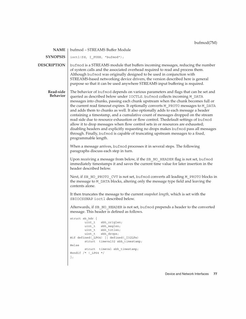
bufmod – STREAMS Buffer Module
ioctl(fd, I_PUSH, "bufmod");
bufmod is a STREAMS module that buffers incoming messages, reducing the numberof system calls and the associated overhead required to read and process them.Although bufmod was originally designed to be used in conjunction withSTREAMS-based networking device drivers, the version described here is generalpurpose so that it can be used anywhere STREAMS input buffering is required.
The behavior of bufmod depends on various parameters and flags that can be set andqueried as described below under IOCTLS. bufmod collects incoming M_DATAmessages into chunks, passing each chunk upstream when the chunk becomes full orthe current read timeout expires. It optionally converts M_PROTO messages to M_DATAand adds them to chunks as well. It also optionally adds to each message a headercontaining a timestamp, and a cumulative count of messages dropped on the streamread side due to resource exhaustion or flow control. Thedefault settings of bufmodallow it to drop messages when flow control sets in or resources are exhausted;disabling headers and explicitly requesting no drops makes bufmod pass all messagesthrough. Finally, bufmod is capable of truncating upstream messages to a fixed,programmable length.
When a message arrives, bufmod processes it in several steps. The followingparagraphs discuss each step in turn.
Upon receiving a message from below, if the SB_NO_HEADER flag is not set, bufmodimmediately timestamps it and saves the current time value for later insertion in theheader described below.
Next, if SB_NO_PROTO_CVT is not set, bufmod converts all leading M_PROTO blocks inthe message to M_DATA blocks, altering only the message type field and leaving thecontents alone.
It then truncates the message to the current snapshot length, which is set with theSBIOCSSNAP ioctl described below.
Afterwards, if SB_NO_HEADER is not set, bufmod prepends a header to the convertedmessage. This header is defined as follows.
struct sb_hdr {uint_t sbh_origlen;uint_t sbh_msglen;uint_t sbh_totlen;uint_t sbh_drops;
#if defined(_LP64) || defined(_I32LPx)struct timeval32 sbh_timestamp;
#elsestruct timeval sbh_timestamp;
#endif /* !_LP64 */
};
bufmod(7M)
NAME
SYNOPSIS
DESCRIPTION
Read-sideBehavior
Device and Network Interfaces 77

The sbh_origlen field gives the message’s original length before truncation in bytes.The sbh_msglen field gives the length in bytes of the message after the truncationhas been done. sbh_totlen gives the distance in bytes from the start of the truncatedmessage in the current chunk (described below) to the start of the next message in thechunk; the value reflects any padding necessary to insure correct data alignment forthe host machine and includes the length of the header itself. sbh_drops reports thecumulative number of input messages that this instance of bufmod has dropped dueto flow control or resource exhaustion. In the current implementation messagedropping due to flow control can occur only if the SB_NO_DROPS flag is not set. (Note:this accounts only for events occurring within bufmod, and does not count messagesdropped by downstream or by upstream modules.) The sbh_timestamp fieldcontains the message arrival time expressed as a struct timeval.
After preparing a message, bufmod attempts to add it to the end of the current chunk,using the chunk size and timeout values to govern the addition. The chunk size andtimeout values are set and inspected using the ioctl() calls described below. Ifadding the new message would make the current chunk grow larger than the chunksize, bufmod closes off the current chunk, passing it up to the next module in line, andstarts a new chunk. If adding the message would still make the new chunk overflow,the module passes it upward in an over-size chunk of its own. Otherwise, the moduleconcatenates the message to the end of the current chunk.
To ensure that messages do not languish forever in an accumulating chunk, bufmodmaintains a read timeout. Whenever this timeout expires, the module closes off thecurrent chunk and passes it upward. The module restarts the timeout period when itreceives a read side data message and a timeout is not currently active. These tworules insure that bufmod minimizes the number of chunks it produces during periodsof intense message activity and that it periodically disposes of all messages duringslack intervals, but avoids any timeout overhead when there is no activity.
bufmod handles other message types as follows. Upon receiving an M_FLUSH messagespecifying that the read queue be flushed, the module clears the currentlyaccumulating chunk and passes the message on to the module or driver above. (Note:bufmod uses zero length M_CTL messages for internal synchronization and does notpass them through.) bufmod passes all other messages through unaltered to its upperneighbor, maintaining message order for non high priority messages by passing upany accumulated chunk first.
If the SB_DEFER_CHUNK flag is set, buffering does not begin until the second messageis received within the timeout window.
If the SB_SEND_ON_WRITE flag is set, bufmod passes up the read side any buffereddata when a message is received on the write side. SB_SEND_ON_WRITE andSB_DEFER_CHUNK are often used together.
bufmod(7M)
78 man pages section 7: Device and Network Interfaces • Last Revised 11 Nov 1997

bufmod intercepts M_IOCTL messages for the ioctls described below. The modulepasses all other messages through unaltered to its lower neighbor. IfSB_SEND_ON_WRITE is set, message arrival on the writer side suffices to close andtransmit the current read side chunk.
bufmod responds to the following ioctls.
SBIOCSTIME Set the read timeout value to the value referred to by the structtimeval pointer given as argument. Setting the timeout value tozero has the side-effect of forcing the chunk size to zero as well, sothat the module will pass all incoming messages upwardimmediately upon arrival. Negative values are rejected with anEINVAL error.
SBIOCGTIME Return the read timeout in the struct timeval pointed to bythe argument. If the timeout has been cleared with theSBIOCCTIME ioctl, return with an ERANGE error.
SBIOCCTIME Clear the read timeout, effectively setting its value to infinity. Thisresults in no timeouts being active and the chunk being deliveredwhen it is full.
SBIOCSCHUNK Set the chunk size to the value referred to by the uint_t pointergiven as argument. See NOTES for a description of effect onstream head high water mark.
SBIOCGCHUNK Return the chunk size in the uint_t pointed to by the argument.
SBIOCSSNAP Set the current snapshot length to the value given in the uint_tpointed to by the ioctl’s final argument. bufmod interprets asnapshot length value of zero as meaning infinity, so it will notalter the message. See NOTES for a description of effect on streamhead high water mark.
SBIOCGSNAP Returns the current snapshot length in the uint_t pointed to bythe ioctl’s final argument.
SBIOCSFLAGS Set the current flags to the value given in the uint_t pointed toby the ioctl’s final argument. Possible values are a combinationof the following.
SB_SEND_ON_WRITE Transmit the read side chunk onarrival of a message on the writeside.
SB_NO_HEADER Do not add headers to read sidemessages.
SB_NO_DROPS Do not drop messages due to flowcontrol upstream.
SB_NO_PROTO_CVT Do not convert M_PROTO messagesinto M_DATA.
bufmod(7M)
Write-sideBehavior
IOCTLS
Device and Network Interfaces 79

SB_DEFER_CHUNK Begin buffering on arrival of thesecond read side message in atimeout interval.
SBIOCGFLAGS Returns the current flags in the uint_t pointed to by the ioctl’sfinal argument.
dlpi(7P), le(7D), pfmod(7M)
Older versions of bufmod did not support the behavioral flexibility controlled by theSBIOCSFLAGS ioctl. Applications that wish to take advantage of this flexibility canguard themselves against old versions of the module by invoking the SBIOCGFLAGSioctl and checking for an EINVAL error return.
When buffering is enabled by issuing an SBIOCSCHUNK ioctl to set the chunk size to anon zero value, bufmod sends a SETOPTS message to adjust the stream head high andlow water marks to accommodate the chunked messages.
When buffering is disabled by setting the chunk size to zero, message truncation canhave a significant influence on data traffic at the stream head and therefore the streamhead high and low water marks are adjusted to new values appropriate for the smallertruncated message sizes.
bufmod does not defend itself against allocation failures, so that it is possible,although very unlikely, for the stream head to use inappropriate high and low watermarks after the chunk size or snapshot length have changed.
bufmod(7M)
SEE ALSO
NOTES
BUGS
80 man pages section 7: Device and Network Interfaces • Last Revised 11 Nov 1997

bwtwo – black and white memory frame buffer
/dev/fbs/bwtwo
The bwtwo interface provides access to monochrome memory frame buffers. Itsupports the ioctls described in fbio(7I).
Reading or writing to the frame buffer is not allowed — you must use the mmap(2)system call to map the board into your address space.
/dev/fbs/bwtwo[0-9] device files
mmap(2), cgfour(7D), fbio(7I)
Use of vertical-retrace interrupts is not supported.
bwtwo(7D)
NAME
SYNOPSIS
DESCRIPTION
FILES
SEE ALSO
BUGS
Device and Network Interfaces 81

cadp160 – Adaptec Ultra160 SCSI host bus adapter driver
scsi@unit-address
The cadp160 host bus adapter driver is a SCSA-compliant nexus driver that supportsthe following Adaptec Ultra160 SCSI devices:
� Adapters: 39160, 29160, 29160N, 29160LP� Chips: AIC-7892B1, AIC-7899A, AIC-7899B2
The cadp160 driver supports standard functions provided by the SCSA interfaceincluding tagged and untagged queuing, wide, fast and ultra SCSI, and auto requestsense. The cadp160 driver does not support linked commands. The cadp160 driversupports hot swap SCSI, hot plug PCI, 64-bit addressing (dual address cycle), domainvalidation, PCI bus clock rates up to 66MHZ and narrow and wide devices at20MB/sec, 40MB/sec, 80MB/sec, and 160MB/sec.
/platform/i86pc/kernel/drv/cadp160ELF kernel module
/boot/solaris/drivers/notisa.010/cadp160.befRealmode BEF driver
/platform/i86pc/kernel/drv/cadp160.confOptional configuration file
See attributes(5) for a description of the following attribute:
ATTRIBUTE TYPE ATTRIBUTE VALUE
Architecture IA
prtconf(1M), driver.conf(4), pci(4), attributes(5), dlpi(7P),scsi_abort(9F), scsi_hba_attach(9F), scsi_ifgetcap(9F),scsi_ifsetcap(9F), scsi_reset(9F), scsi_sync_pkt(9F),scsi_transport(9F), scsi_device(9S), scsi_extended_sense(9S),scsi_inquiry(9S), scsi_pkt(9S)
Writing Device Drivers
Solaris (Intel Platform Edition) Hardware Compatibility List
ANSI Small Computer System Interface-2 (SCSI-2)
cadp160(7D)
NAME
SYNOPSIS
DESCRIPTION
FILES
ATTRIBUTES
SEE ALSO
82 man pages section 7: Device and Network Interfaces • Last Revised 15 September 2000

cadp – Adaptec Ultra-2 SCSI host bus adapter driver
scsi@unit-address
The cadp host bus adapter driver is a SCSA–compliant nexus driver that supports thefollowing Adaptec Ultra-2 SCSI devices:
� Adapters: Adaptec AHA-2940U2W, AHA-2940U2B, AHA-2940U2, AHA-2950U2B,AHA-3950U2B
� Chips: AIC-7896/AIC-7897, AIC-7890/AIC-7890A, AIC-7891, AIC-7890AB,AIC-7890A
The cadp driver supports standard functions provided by the SCSA interface,including tagged and untagged queuing, Wide/Fast/Ultra SCSI, and auto requestsense. The cadp driver does not support linked commands.
� The Plug N Play SCAM Support option is not supported.
� If the BIOS is enabled on the card, ensure that the Adaptec SCSISelect BIOS optionReset SCSI Bus at IC Initialization (under the Advanced Configuration Optionsmenu) is set to Enabled. Run the SCSISelect utility by pressing Ctrl-A when yousee the Adaptec banner during system boot.
� If the adapter is being used in a multi-initiator configuration, do the following: (1)Ensure that the system boot disk is not on the shared (clustered) bus. (2) Set theReset SCSI Bus at IC Initialization option to Disabled. (3) Set the Host AdapterBIOS option (under the Advanced Configuration Options menu) toDisabled:Not scan. (4) Add the allow-bus-reset=0 property to the/kernel/drv/cadp.conf file.
� Reboot the system after you install patches.
� The cadp.bef realmode driver supports only ten adapters at boot time. Therefore,ensure that the boot disk is attached to one of the first ten adapters. Note that alltargets will be available for installation and use by the cadp driver.
� Running the format(1M) command on a Seagate ST19171W 9 GB disk drive fails.
� Some motherboards may have problems supporting channel B with boards basedon the Adaptec AIC-7896 chip. The problem arises because the BIOS doesn’tproperly assign two interrupts for PCI interrupts INTA and INTB on the slotcontaining the AIC-7896 chip. As a result, timeouts and resets on those devicesappear on the console. For some motherboards, you can work around the problemby setting the Advanced/PCI IRQ Mapping feature to ISA Legacy IRQs.
� If you experience problems when using a narrow SCSI CD-ROM drive on theinternal wide interface, disable "negotiate wide," "negotiate sync," or both for thatdevice in the Adaptec configuration utility.
� The Fujitsu narrow disk (M1603SAU) can reselect with an invalid queue tag ID.This violates the SCSI protocol and it causes the cadp driver to behaveerroneously. Because this is difficult to guard against, you should disable taggedqueuing for these targets. Use the iostat --E command to determine if you havea Fujitsu M1603S-512 disk. If you do, edit the /kernel/drv/cadp.conf file and
cadp(7D)
NAME
SYNOPSIS
DESCRIPTION
PRECONFIGURE
Known Problemsand Limitations
Device and Network Interfaces 83

add the property targetn-scsi-options=0x1f78, where n is the targetnumber.
� The IBM external wide disk (DFHSS2W, Revision 1717) is not supported.� When setting up a SCSI bus configuration, avoid connecting wide devices to a
narrow bus. However, if you have such a configuration, add the following entry tothe cadp.conf file: targetn-scsi-options=0x1df8 where n is the target IDof the wide device on the narrow bus. This entry disables wide negotiation for thespecified target. Also ensure that the upper 8 bits of the bus are properlyterminated at both ends of the SCSI chain.
� If you experience installation problems on systems with Intel 440BX/440GXmotherboards, upgrade the motherboard BIOS with the latest revision.
You configure the cadp host bus adapter driver by defining the properties found incadp.conf. The cadp.conf file contains properties that you can modify, including:scsi-options, target<n>-scsi-options, scsi-reset-delay, andscsi-initiator-id. Properties in the cadp.conf file override global SCSIsettings.
The property target<n>-scsi-options overrides the scsi-options propertyvalue for target<n>, where <n> can vary from decimal 0 to 15. The cadp driversupports the following scsi-options: SCSI_OPTIONS_DR, SCSI_OPTIONS_SYNC,SCSI_OPTIONS_TAG, SCSI_OPTIONS_FAST, SCSI_OPTIONS_WIDE,SCSI_OPTIONS_FAST20, and SCSI_OPTIONS_FAST40.
You configure the SCSI devices using the Adaptec configuration utility. Whenconfiguring the devices, you should observe the following guidelines:
� Configure each device using a unique SCSI ID. On the Advanced ConfigurationOptions menu, set Plug N Play SCAM Support to Disabled. Ensure that deviceson either end of the SCSI chain are terminated. When mixing wide (16 bits) andnarrow (8 bits) devices on the same wide chain, ensure that a wide device is at theend of the chain. If you place a narrow device at the end of the chain, wide deviceson the same chain will terminate the low byte, resulting in a illegal configuration.
� If there is more than one controller, or an embedded controller, attempt to use oneIRQ per controller.
� When prompted, enable bus mastering for the slot(s) with your host busadapter(s.)
� Enable support for disks larger than 1 Gbyte, if applicable.
Create a file called /kernel/drv/cadp.conf, then add the following line:
scsi-options=0x78;
The above line disables tagged queuing, Fast/Ultra SCSI, and wide mode for all cadpinstances.
To set scsi-options more specifically per target, add the following lines to/kernel/drv/cadp.conf:
cadp(7D)
CONFIGURATION
EXAMPLES
84 man pages section 7: Device and Network Interfaces • Last Revised 3 Aug 2001

target1-scsi-options=0x78;device-type-scsi-options-list ="SEAGATE ST32550W", "seagate-scsi-options" ;seagate-scsi-options = 0x58;scsi-options=0x3f8;
With the exception of one disk type that has scsi-options set to 0x58, the aboveexample sets scsi-options for target 1 to 0x78, and all remaining targets to 0x3f8.
The scsi-options properties that are specified per target ID have the highestprecedence, followed by scsi-options per device type. Global scsi-options forall cadp instances per bus have the lowest precedence. You must reboot the systemfor the specified scsi options to take effect.
To enable certain features on the cadp driver, the target driver must set capabilities.The following capabilities can be queried and modified by the target driver:synchronous, tagged-qing, wide-xfer, auto-rqsense, qfull-retries, andqfull-retry-interval. All other capabilities are query only.
By default, the tagged-qing, auto-rqsense, and wide-xfer capabilities aredisabled. The disconnect, synchronous, and untagged-qing capabilities arealways enabled. The cadp driver capabilities can only be assigned binary values (0 or1). The default value for qfull-retries is 10 and the default value forqfull-retry-interval is 100. The qfull-retries capability is au_char (0 to255) while qfull-retry-interval is a u_short (0 to 65535).
If a conflict occurs between the value of scsi-options and a capability, the value setin scsi-options prevails. Only whom != 0 is supported in thescsi_ifsetcap(9F)call. See scsi_ifsetcap(9F) and scsi_ifgetcap(9F)for details.
/kernel/drv/cadp ELF kernel module
/kernel/drv/cadp.conf Optional configuration file
See attributes(5) for a description of the following attribute:
ATTRIBUTE TYPE ATTRIBUTE VALUE
Architecture IA
prtconf(1M), driver.conf(4), pci(4), attributes(5), scsi_abort(9F),scsi_hba_attach(9F), scsi_ifgetcap(9F), scsi_ifsetcap(9F),scsi_reset(9F), scsi_sync_pkt(9F), scsi_transport(9F), scsi_device(9S),scsi_extended_sense(9S), scsi_inquiry(9S), scsi_pkt(9S)
Writing Device Drivers
Solaris (Intel Platform Edition) Hardware Compatibility List
cadp(7D)
Driver Capabilities
FILES
ATTRIBUTES
SEE ALSO
Device and Network Interfaces 85

ANSI Small Computer System Interface-2 (SCSI-2)
The cadp driver supports the adapters and chipsets listed in this man page. Forinformation on support of additional devices, see the Solaris (Intel Platform Edition)Hardware Compatibility List a component of the Information Library for Solaris 8 (IntelPlatform Edition).
The cadp driver exports properties indicating (per target) the negotiated transferspeed (target<n>-sync-speed), whether wide bus (target<n>-wide), issupported for that particular target (target<n>-scsi-options), and whethertagged queuing (target<n>-tag-queue) has been enabled. The sync-speedproperty value is the data transfer rate in KB/sec. The target<n>-tag-queue andthe target<n>-wide property have value 1 to indicate that the correspondingcapability is enabled, or 0 to indicate that the capability is disabled. See prtconf(1M)(verbose option) for information on viewing the cadp properties.
Sample output is provided below:
pci9005,f500, instance #2System software properties:
name <interrupt-priorities> length <4>value <0x05000000>.
name <tape> length <5>value <0x7363747000>.
name <disk> length <5>value <0x7363646b00>.
name <queue> length <6>value <0x71736f727400>.
name <flow_control> length <6>value <0x646d756c7400>.
Driver properties:name <target0-tag-queue> length <4>
value <0x01000000>.name <target0-wide> length <4>
value <0x01000000>.name <target0-sync-speed> length <4>
value <0x28000000>.name <chosen-interrupt> length <8>
value <0x0100000000000000>.name <scsi-selection-timeout> length <4>
value <0xfa000000>.name <scsi-options> length <4>
value <0xf81f0000>.name <scsi-watchdog-tick> length <4>
value <0x0a000000>.name <scsi-tag-age-limit> length <4>
value <0x02000000>.name <scsi-reset-delay> length <4>
value <0xb80b0000>.
cadp(7D)
NOTES
86 man pages section 7: Device and Network Interfaces • Last Revised 3 Aug 2001

cdio – CD-ROM control operations
#include <sys/cdio.h>
The set of ioctl(2) commands described below are used to perform audio andCD-ROM specific operations. Basic to these cdio ioctl requests are the definitions in<sys/cdio.h>.
Several CD-ROM specific commands can report addresses either in LBA (Logical BlockAddress) format or in MSF (Minute, Second, Frame) format. The READ HEADER, READSUBCHANNEL, and READ TABLE OF CONTENTS commands have this feature.
LBA format represents the logical block address for the CD-ROM absolute address fieldor for the offset from the beginning of the current track expressed as a number oflogical blocks in a CD-ROM track relative address field. MSF format represents thephysical address written on CD-ROM discs, expressed as a sector count relative toeither the beginning of the medium or the beginning of the current track.
The following I/O controls do not have any additional data passed into or receivedfrom them.
CDROMSTARTThis ioctl() spins up the disc and seeks to the last address requested.
CDROMSTOPThis ioctl() spins down the disc.
CDROMPAUSEThis ioctl() pauses the current audio play operation.
CDROMRESUMEThis ioctl() resumes the paused audio play operation.
CDROMEJECTThis ioctl() ejects the caddy with the disc.
The following I/O controls require a pointer to the structure for that ioctl(), withdata being passed into the ioctl().
CDROMPLAYMSFThis ioctl() command requests the drive to output the audio signals at thespecified starting address and continue the audio play until the specified endingaddress is detected. The address is in MSF format. The third argument of thisioctl() call is a pointer to the type struct cdrom_msf.
/** definition of play audio msf structure*/struct cdrom_msf {
unsigned char cdmsf_min0; /* starting minute*/unsigned char cdmsf_sec0; /* starting second*/unsigned char cdmsf_frame0; /*starting frame*/unsigned char cdmsf_min1; /* ending minute */unsigned char cdmsf_sec1; /* ending second */
cdio(7I)
NAME
SYNOPSIS
DESCRIPTION
IOCTLS
Device and Network Interfaces 87
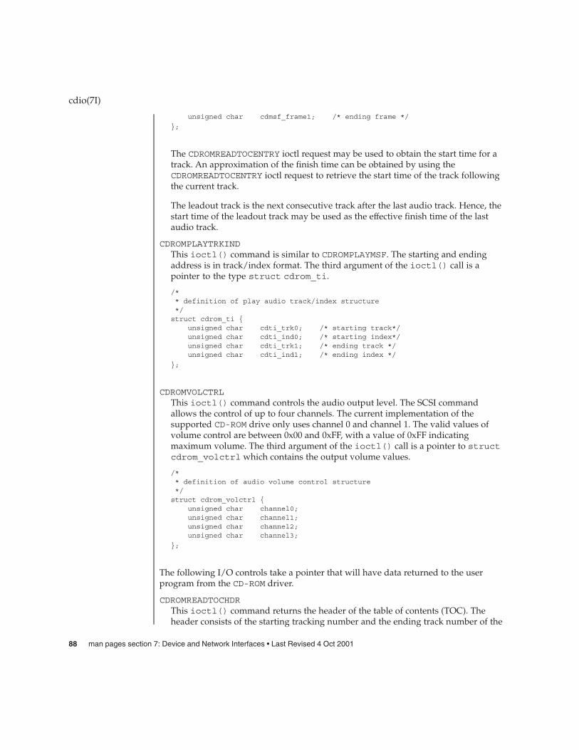
unsigned char cdmsf_frame1; /* ending frame */
};
The CDROMREADTOCENTRY ioctl request may be used to obtain the start time for atrack. An approximation of the finish time can be obtained by using theCDROMREADTOCENTRY ioctl request to retrieve the start time of the track followingthe current track.
The leadout track is the next consecutive track after the last audio track. Hence, thestart time of the leadout track may be used as the effective finish time of the lastaudio track.
CDROMPLAYTRKINDThis ioctl() command is similar to CDROMPLAYMSF. The starting and endingaddress is in track/index format. The third argument of the ioctl() call is apointer to the type struct cdrom_ti.
/** definition of play audio track/index structure*/struct cdrom_ti {
unsigned char cdti_trk0; /* starting track*/unsigned char cdti_ind0; /* starting index*/unsigned char cdti_trk1; /* ending track */unsigned char cdti_ind1; /* ending index */
};
CDROMVOLCTRLThis ioctl() command controls the audio output level. The SCSI commandallows the control of up to four channels. The current implementation of thesupported CD-ROM drive only uses channel 0 and channel 1. The valid values ofvolume control are between 0x00 and 0xFF, with a value of 0xFF indicatingmaximum volume. The third argument of the ioctl() call is a pointer to structcdrom_volctrl which contains the output volume values.
/** definition of audio volume control structure*/struct cdrom_volctrl {
unsigned char channel0;unsigned char channel1;unsigned char channel2;unsigned char channel3;
};
The following I/O controls take a pointer that will have data returned to the userprogram from the CD-ROM driver.
CDROMREADTOCHDRThis ioctl() command returns the header of the table of contents (TOC). Theheader consists of the starting tracking number and the ending track number of the
cdio(7I)
88 man pages section 7: Device and Network Interfaces • Last Revised 4 Oct 2001
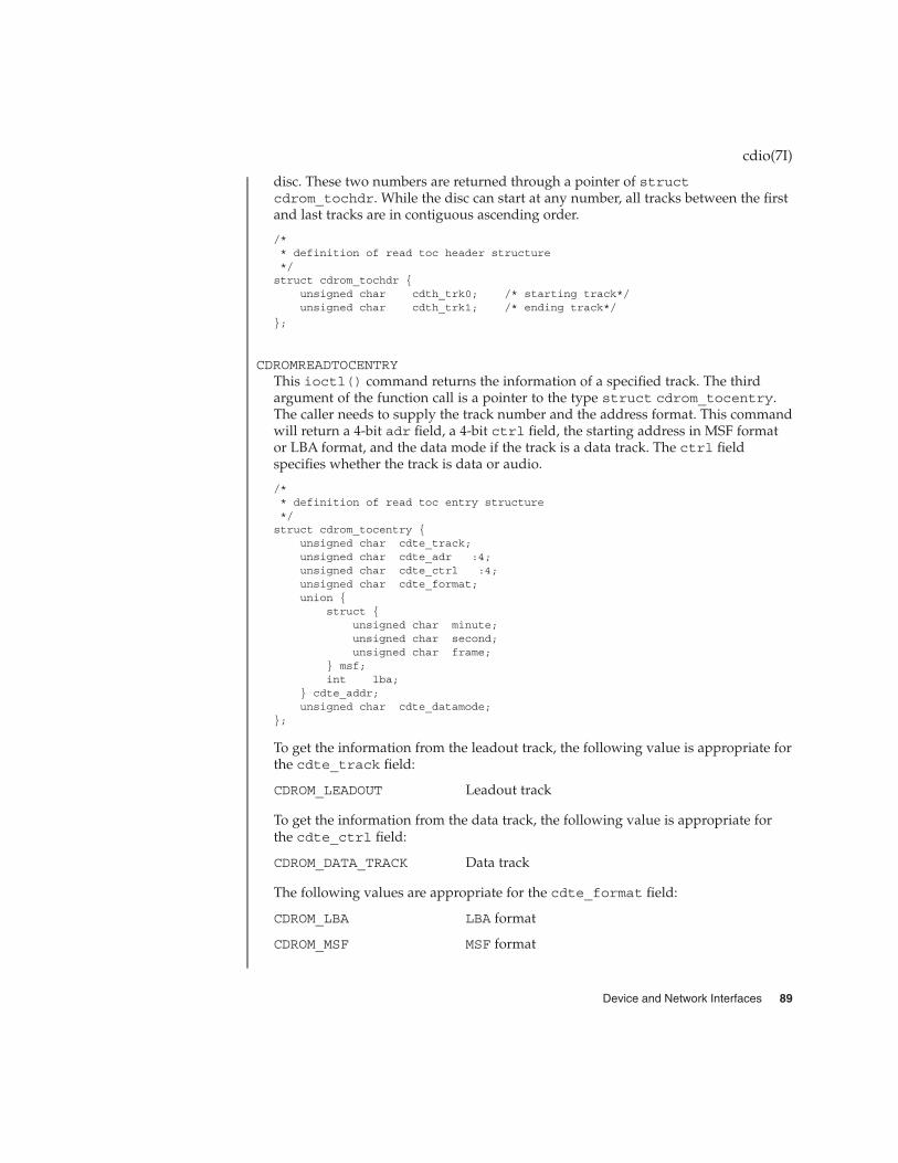
disc. These two numbers are returned through a pointer of structcdrom_tochdr. While the disc can start at any number, all tracks between the firstand last tracks are in contiguous ascending order.
/** definition of read toc header structure*/struct cdrom_tochdr {
unsigned char cdth_trk0; /* starting track*/unsigned char cdth_trk1; /* ending track*/
};
CDROMREADTOCENTRYThis ioctl() command returns the information of a specified track. The thirdargument of the function call is a pointer to the type struct cdrom_tocentry.The caller needs to supply the track number and the address format. This commandwill return a 4-bit adr field, a 4-bit ctrl field, the starting address in MSF formator LBA format, and the data mode if the track is a data track. The ctrl fieldspecifies whether the track is data or audio.
/** definition of read toc entry structure*/struct cdrom_tocentry {
unsigned char cdte_track;unsigned char cdte_adr :4;unsigned char cdte_ctrl :4;unsigned char cdte_format;union {
struct {unsigned char minute;unsigned char second;unsigned char frame;
} msf;int lba;
} cdte_addr;unsigned char cdte_datamode;
};
To get the information from the leadout track, the following value is appropriate forthe cdte_track field:
CDROM_LEADOUT Leadout track
To get the information from the data track, the following value is appropriate forthe cdte_ctrl field:
CDROM_DATA_TRACK Data track
The following values are appropriate for the cdte_format field:
CDROM_LBA LBA format
CDROM_MSF MSF format
cdio(7I)
Device and Network Interfaces 89

CDROMSUBCHNLThis ioctl() command reads the Q sub-channel data of the current block. Thesubchannel data includes track number, index number, absolute CD-ROM address,track relative CD-ROM address, control data and audio status. All information isreturned through a pointer to struct cdrom_subchnl. The caller needs tosupply the address format for the returned address.
struct cdrom_subchnl {unsigned char cdsc_format;unsigned char cdsc_audiostatus;unsigned char cdsc_adr: 4;unsigned char cdsc_ctrl: 4;unsigned char cdsc_trk;unsigned char cdsc_ind;union {
struct {unsigned char minute;unsigned char second;unsigned char frame;
} msf;int lba;
} cdsc_absaddr;union {
struct {unsigned char minute;unsigned char second;unsigned char frame;
} msf;int lba;
} cdsc_reladdr;
};
The following values are valid for the audio status field returned from READSUBCHANNEL command:
CDROM_AUDIO_INVALID Audio status not supported.
CDROM_AUDIO_PLAY Audio play operation in progress.
CDROM_AUDIO_PAUSED Audio play operation paused.
CDROM_AUDIO_COMPLETED Audio play successfully completed.
CDROM_AUDIO_ERROR Audio play stopped due to error.
CDROM_AUDIO_NO_STATUS No current audio status to return.
CDROMREADOFFSETThis ioctl() command returns the absolute CD-ROM address of the first track inthe last session of a Multi-Session CD-ROM. The third argument of the ioctl() callis a pointer to an int.
CDROMCDDAThis ioctl() command returns the CD-DA data or the subcode data. The thirdargument of the ioctl() call is a pointer to the type struct cdrom_cdda. Inaddition to allocating memory and supplying its address, the caller needs to supply
cdio(7I)
90 man pages section 7: Device and Network Interfaces • Last Revised 4 Oct 2001

the starting address of the data, the transfer length in terms of the number of blocksto be transferred, and the subcode options. The caller also needs to issue theCDROMREADTOCENTRY ioctl() to find out which tracks contain CD-DA databefore issuing this ioctl().
/** Definition of CD-DA structure*/struct cdrom_cdda {
unsigned int cdda_addr;unsigned int cdda_length;caddr_t cdda_data;unsigned char cdda_subcode;
};
cdda_addr signifies the starting logical block address.
cdda_length signifies the transfer length in blocks. The length of the blockdepends on the cdda_subcode selection, which is explained below.
To get the subcode information related to CD-DA data, the following values areappropriate for the cdda_subcode field:
CDROM_DA_NO_SUBCODE CD-DA data with no subcode.
CDROM_DA_SUBQ CD-DA data with sub Q code.
CDROM_DA_ALL_SUBCODE CD-DA data with all subcode.
CDROM_DA_SUBCODE_ONLY All subcode only.
To allocate the memory related to CD-DA and/or subcode data, the followingvalues are appropriate for each data block transferred:
CD-DA data with no subcode 2352 bytes
CD-DA data with sub Q code 2368 bytes
CD-DA data with all subcode 2448 bytes
All subcode only 96 bytes
CDROMCDXAThis ioctl() command returns the CD-ROM XA (CD-ROM Extended Architecture)data according to CD-ROM XA format. The third argument of the ioctl() call is apointer to the type struct cdrom_cdxa. In addition to allocating memory andsupplying its address, the caller needs to supply the starting address of the data,the transfer length in terms of number of blocks, and the format. The caller alsoneeds to issue the CDROMREADTOCENTRY ioctl() to find out which tracks containCD-ROM XA data before issuing this ioctl().
/** Definition of CD-ROM XA structure*/struct cdrom_cdxa {
cdio(7I)
Device and Network Interfaces 91

unsigned int cdxa_addr;unsigned int cdxa_length;caddr_t cdxa_data;unsigned char cdxa_format;
};
To get the proper CD-ROM XA data, the following values are appropriate for thecdxa_format field:
CDROM_XA_DATA CD-ROM XA data only
CDROM_XA_SECTOR_DATA CD-ROM XA all sector data
CDROM_XA_DATA_W_ERROR CD-ROM XA data with error flags data
To allocate the memory related to CD-ROM XA format, the following values areappropriate for each data block transferred:
CD-ROM XA data only2048 bytes
CD-ROM XA all sector data2352 bytes
CD-ROM XA data with error flags data2646 bytes
CDROMSUBCODEThis ioctl() command returns raw subcode data (subcodes P ~ W are describedin the "Red Book," see SEE ALSO) to the initiator while the target is playing audio.The third argument of the ioctl() call is a pointer to the type structcdrom_subcode. The caller needs to supply the transfer length in terms of numberof blocks and allocate memory for subcode data. The memory allocated should be amultiple of 96 bytes depending on the transfer length.
/** Definition of subcode structure*/struct cdrom_subcode {
unsigned int cdsc_length;caddr_t cdsc_addr;
};
The next group of I/O controls get and set various CD-ROM drive parameters.
CDROMGBLKMODEThis ioctl() command returns the current block size used by the CD-ROM drive.The third argument of the ioctl() call is a pointer to an integer.
CDROMSBLKMODEThis ioctl() command requests the CD-ROM drive to change from the currentblock size to the requested block size. The third argument of the ioctl() call is aninteger which contains the requested block size.
cdio(7I)
92 man pages section 7: Device and Network Interfaces • Last Revised 4 Oct 2001

This ioctl() command operates in exclusive-use mode only. The caller mustensure that no other processes can operate on the same CD-ROM device beforeissuing this ioctl(). read(2) behavior subsequent to this ioctl() remains thesame: the caller is still constrained to read the raw device on block boundaries andin block multiples.
To set the proper block size, the following values are appropriate:
CDROM_BLK_512 512 bytes
CDROM_BLK_1024 1024 bytes
CDROM_BLK_2048 2048 bytes
CDROM_BLK_2056 2056 bytes
CDROM_BLK_2336 2336 bytes
CDROM_BLK_2340 2340 bytes
CDROM_BLK_2352 2352 bytes
CDROM_BLK_2368 2368 bytes
CDROM_BLK_2448 2448 bytes
CDROM_BLK_2646 2646 bytes
CDROM_BLK_2647 2647 bytes
CDROMGDRVSPEEDThis ioctl() command returns the current CD-ROM drive speed. The thirdargument of the ioctl() call is a pointer to an integer.
CDROMSDRVSPEEDThis ioctl() command requests the CD-ROM drive to change the current drivespeed to the requested drive speed. This speed setting is only applicable whenreading data areas. The third argument of the ioctl() is an integer whichcontains the requested drive speed.
To set the CD-ROM drive to the proper speed, the following values are appropriate:
CDROM_NORMAL_SPEED 150k/second
CDROM_DOUBLE_SPEED 300k/second
CDROM_QUAD_SPEED 600k/second
CDROM_MAXIMUM_SPEED 300k/second (2x drive) 600k/second (4xdrive)
Note that these numbers are only accurate when reading 2048 byte blocks. TheCD-ROM drive will automatically switch to normal speed when playing audio tracksand will switch back to the speed setting when accessing data.
ioctl(2), read(2)
cdio(7I)
SEE ALSO
Device and Network Interfaces 93

N. V. Phillips and Sony Corporation, System Description Compact Disc Digital Audio,("Red Book").
N. V. Phillips and Sony Corporation, System Description of Compact Disc Read OnlyMemory, ("Yellow Book").
N. V. Phillips, Microsoft, and Sony Corporation, System Description CD-ROM XA, 1991.
Volume and File Structure of CD-ROM for Information Interchange, ISO 9660:1988(E).
SCSI-2 Standard, document X3T9.2/86-109
SCSI Multimedia Commands, Version 2 (MMC-2)
The CDROMCDDA, CDROMCDXA, CDROMSUBCODE, CDROMGDRVSPEED,CDROMSDRVSPEED, and some of the block sizes in CDROMSBLKMODE are designed fornew Sun-supported CD-ROM drives and might not work on some of the older CD-ROMdrives.
CDROMCDDA, CDROMCDXA and CDROMSUBCODE will return error if thetransfer length exceeds valid limits as determined appropriate. Example: for MMC-2drives, length can not exceed 3 bytes (i.e. 0xffffff). The same restriction is enforced forolder, pre-MMC-2 drives, as no limit was published for these older drives (and 3 bytesis reasonable for all media). Note that enforcing this limit does not imply that valuespassed in below this limit will actually be applicable for each and every piece ofmedia.
The interface to this device is preliminary and subject to change in future releases.Programs should be written in a modular fashion so that future changes can be easilyincorporated.
cdio(7I)
NOTES
94 man pages section 7: Device and Network Interfaces • Last Revised 4 Oct 2001

ce – Cassini Gigabit-Ethernet device driver
/dev/ce
The ce Sun Gigabit-Ethernet driver is a multi-threaded, loadable, clonable, STREAMShardware driver supporting the connectionless Data Link Provider Interface,dlpi(7P), over all implementations of PCI Cassini Gigabit-Ethernet add-in adapters.Multiple Cassini-based adapters installed within the system are supported by thedriver. The ce driver provides basic support for the Cassini-based Ethernet hardwareand handles the pci108e,abba (PCI Cassini) devices. Functions include chipinitialization, frame transmit and receive, multicast and promiscuous support, anderror recovery and reporting. The Cassini device provides 1000BASE-SX networkinginterfaces using the Cassini ASIC external SERDES and fiber optical transceiver, or10/100/1000BASE-T using a Cassini ASIC attached to a GMII twisted pair coppertransceiver, or 10/100BASE-T using a Cassini ASIC attached to a MII twisted paircopper transceiver.
The 1000Base-SX standard specifies an auto-negotiation protocol to automaticallyselect the mode of operation. In addition to the duplex mode of operation, the CassiniASIC can auto-negotiate for IEEE 802.3x frame-based flow control capabilities. TheCassini PCS can perform auto-negotiation with the link’s remote-end (link partner)and receives the capabilities of the remote end. It selects the highest commondenominator mode of operation based on the priorities. It also supports forced-modeof operation where the driver selects the mode of operation.
The /dev/ce cloning character-special device is used to access all ce controllersinstalled on the system.
The ce driver is a Style 2 data link service provider. All M_PROTO and M_PCPROTOtype messages are interpreted as DLPI primitives. Valid DLPI primitives are defined in<sys/dlpi.h>. Refer to dlpi(7P) for more information. An explicitDL_ATTACH_REQ message by the user is required to associate the opened stream witha particular device (ppa). The ppa ID is interpreted as an unsigned long data typeand indicates the corresponding device instance (unit) number. An error(DL_ERROR_ACK) is returned by the driver if the ppa field value does not correspondto a valid device instance number for this system. The device is initialized on firstattach and de-initialized (stopped) upon last detach.
The values returned by the driver in the DL_INFO_ACK primitive in response to theDL_INFO_REQ are as follows:
� Maximum SDU is 1500 (ETHERMTU - defined in <sys/ethernet.h>).
� Minimum SDU is 0.
� The dlsap address length is 8.
� MAC type is DL_ETHER.
� The sap length value is –2 meaning the physical address component is followedimmediately by a 2 byte sap component within the DLSAP address.
ce(7D)
NAME
SYNOPSIS
DESCRIPTION
APPLICATIONPROGRAMMING
INTERFACEce and DLPI
Device and Network Interfaces 95
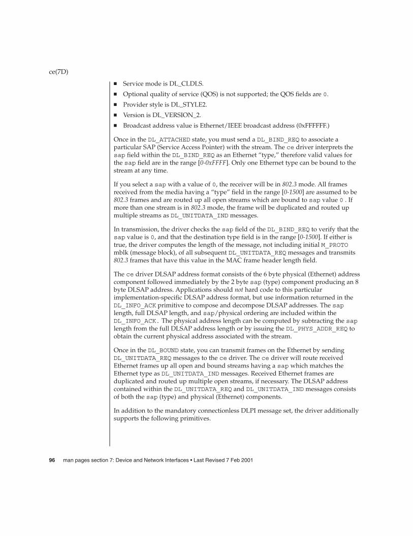
� Service mode is DL_CLDLS.
� Optional quality of service (QOS) is not supported; the QOS fields are 0.
� Provider style is DL_STYLE2.
� Version is DL_VERSION_2.
� Broadcast address value is Ethernet/IEEE broadcast address (0xFFFFFF.)
Once in the DL_ATTACHED state, you must send a DL_BIND_REQ to associate aparticular SAP (Service Access Pointer) with the stream. The ce driver interprets thesap field within the DL_BIND_REQ as an Ethernet “type,” therefore valid values forthe sap field are in the range [0-0xFFFF]. Only one Ethernet type can be bound to thestream at any time.
If you select a sap with a value of 0, the receiver will be in 802.3 mode. All framesreceived from the media having a “type” field in the range [0-1500] are assumed to be802.3 frames and are routed up all open streams which are bound to sap value 0 . Ifmore than one stream is in 802.3 mode, the frame will be duplicated and routed upmultiple streams as DL_UNITDATA_IND messages.
In transmission, the driver checks the sap field of the DL_BIND_REQ to verify that thesap value is 0, and that the destination type field is in the range [0-1500]. If either istrue, the driver computes the length of the message, not including initial M_PROTOmblk (message block), of all subsequent DL_UNITDATA_REQ messages and transmits802.3 frames that have this value in the MAC frame header length field.
The ce driver DLSAP address format consists of the 6 byte physical (Ethernet) addresscomponent followed immediately by the 2 byte sap (type) component producing an 8byte DLSAP address. Applications should not hard code to this particularimplementation-specific DLSAP address format, but use information returned in theDL_INFO_ACK primitive to compose and decompose DLSAP addresses. The saplength, full DLSAP length, and sap/physical ordering are included within theDL_INFO_ACK. The physical address length can be computed by subtracting the saplength from the full DLSAP address length or by issuing the DL_PHYS_ADDR_REQ toobtain the current physical address associated with the stream.
Once in the DL_BOUND state, you can transmit frames on the Ethernet by sendingDL_UNITDATA_REQ messages to the ce driver. The ce driver will route receivedEthernet frames up all open and bound streams having a sap which matches theEthernet type as DL_UNITDATA_IND messages. Received Ethernet frames areduplicated and routed up multiple open streams, if necessary. The DLSAP addresscontained within the DL_UNITDATA_REQ and DL_UNITDATA_IND messages consistsof both the sap (type) and physical (Ethernet) components.
In addition to the mandatory connectionless DLPI message set, the driver additionallysupports the following primitives.
ce(7D)
96 man pages section 7: Device and Network Interfaces • Last Revised 7 Feb 2001

The DL_ENABMULTI_REQ and DL_DISABMULTI_REQ primitives enable/disablereception of individual multicast group addresses. A set of multicast addresses may beiteratively created and modified on a per-stream basis using these primitives. Theseprimitives are accepted by the driver in any state following DL_ATTACHED.
The DL_PROMISCON_REQ and DL_PROMISCOFF_REQ primitives with theDL_PROMISC_PHYS option set in the dl_level field enables/disables reception of all“promiscuous mode” frames on the media, including frames generated by the localhost. When used with the DL_PROMISC_SAP option set, this enables/disablesreception of all sap (Ethernet type) values. When used with the DL_PROMISC_MULTIoption set this enables/disables reception of all multicast group addresses. The effectof each is always on a per-stream basis and independent of the other sap and physicallevel configurations on this stream or other streams.
The DL_PHYS_ADDR_REQ primitive returns the 6 octet Ethernet address currentlyassociated (attached) to the stream in the DL_PHYS_ADDR_ACK primitive. Thisprimitive is valid only in states following a successful DL_ATTACH_REQ.
The DL_SET_PHYS_ADDR_REQ primitive changes the 6 octet Ethernet addresscurrently associated (attached) to this stream. The credentials of the process whichoriginally opened this stream must be superuser. Otherwise EPERM is returned in theDL_ERROR_ACK. This primitive is destructive because it affects all other current andfuture streams attached to this device. An M_ERROR is sent up all other streamsattached to this device when this primitive is successful on this stream. Once changed,all streams subsequently opened and attached to this device will obtain this newphysical address. Once changed, the physical address will remain until this primitiveis used to change the physical address again or the system is rebooted, whichevercomes first.
By default, the ce driver performs auto-negotiation to select the mode and flowcontrol capabilities of the link.
The link can assume one of the following modes:
� 1000 Mbps, full-duplex� 1000 Mbps, half-duplex� Symmetric pause� Asymmetric pause
Speeds and modes are described in the 1000Base-TX standard.
The auto–negotiation protocol automatically selects:
� Operation mode (half-duplex or full-duplex)� Flow control capability (symmetric and/or asymmetric)
The auto–negotiation protocol does the following:
� Gets all modes of operation supported by the link partner.
� Advertises its capabilities to the link partner.
ce(7D)
ce Primitives
ce DRIVER
Device and Network Interfaces 97
� Selects the highest common denominator mode of operation based on thepriorities.
The Cassini hardware can operate in all modes listed above, providingauto-negotiation is used by default to bring up the link and select the common modeof operation with the link partner. The PCS also supports forced-mode of operation inwhich the driver can select the mode of operation and the flow control capabilities,using the ndd utility.
The Cassini device also supports programmable IPG (Inter-Packet Gap) parametersipg1 and ipg2. By default, the driver sets ipg1 and ipg2 to 8 and 4 byte-timesrespectively (which are the standard values). If desired, you can alter these valuesfrom the standard 1000 Mpbs IPG set to 0.096 microseconds.
The ce driver enables the setting and getting of various parameters for the Cassinidevice. The parameter list includes current transceiver status, current link status,inter-packet gap, PCS capabilities and link partner capabilities.
The PCS features two set of capabilities. One set reflects the capabilities of thehardware and are read-only. The second set, which reflects the values you choose, areused in speed selection and possess read/write capabilities. At boot time, these twosets of capabilities are the same. The link partner capabilities are also read-onlybecause the current default value of these parameters can be read but not modified.
/dev/ce ce special character device.
/kernel/drv/ce.conf System-wide default device driverproperties
ndd(1M), netstat(1M), driver.conf(4), ge(7D), hme(7D), le(7D), qfe(7D),dlpi(7P)
ce(7D)
ce Parameter List
FILES
SEE ALSO
98 man pages section 7: Device and Network Interfaces • Last Revised 7 Feb 2001

cgeight – 24-bit color memory frame buffer
/dev/fbs/cgeightn
The cgeight is a 24-bit color memory frame buffer with a monochrome overlay planeand an overlay enable plane implemented optionally on the Sun-4/110, Sun-4/150,Sun-4/260 and Sun-4/280 system models. It provides the standard frame bufferinterface as defined in fbio(7I).
In addition to the ioctls described under fbio(7I) the cgeight interface responds totwo cgeight-specific colormap ioctls, FBIOPUTCMAP and FBIOGETCMAP.FBIOPUTCMAP returns no information other than success/failure using the ioctl returnvalue. FBIOGETCMAP returns its information in the arrays pointed to by the red, green,and blue members of its fbcmap structure argument; fbcmap is defined in<sys/fbio.h> as:
struct fbcmap {int index; /* first element (0 origin) */int count; /* number of elements */unsigned char *red; /* red color map elements */unsigned char *green /* green color map elements */unsigned char *blue; /* blue color map elements */
};
The driver uses color board vertical-retrace interrupts to load the colormap.
The systems have an overlay plane colormap, which is accessed by encoding the planegroup into the index value with the PIX_GROUP macro (see<sys/pr_planegroups.h>).
When using the mmap(2) system call to map in the cgeight frame buffer. The devicelooks like:
DACBASE: 0x200000 -> Brooktree Ramdac 16 bytes0x202000 -> P4 Register 4 bytes
OVLBASE: 0x210000 -> Overlay Plane 1152x900x10x230000 -> Overlay Enable Planea 1152x900x1
0x250000 -> 24-bit Frame Buffera 1152x900x32
/dev/fbs/cgeight0
<sys/fbio.h>
<sys/pr_planegroups.h>
mmap(2), fbio(7I)
cgeight(7D)
NAME
SYNOPSIS
DESCRIPTION
FILES
SEE ALSO
Device and Network Interfaces 99

cgfour – P4-bus 8-bit color memory frame buffer
/dev/fbs/cgfourn
The cgfour is a color memory frame buffer with a monochrome overlay plane and anoverlay enable plane. It provides the standard frame buffer interface as defined infbio(7I).
In addition to the ioctls described under fbio(7I) the cgfour interface responds totwo cgfour-specific colormap ioctls, FBIOPUTCMAP and FBIOGETCMAP.FBIOPUTCMAP returns no information other than success/failure using the ioctl returnvalue. FBIOGETCMAP returns its information in the arrays pointed to by the red, green,and blue members of its fbcmap structure argument; fbcmap is defined in<sys/fbio.h> as:
struct fbcmap {int index; /* first element (0 origin) */int count; /* number of elements */unsigned char *red /* red color map elements */unsigned char *green; /* green color map elements */unsigned char *blue; /* blue color map elements */
};
The driver uses color board vertical-retrace interrupts to load the colormap.
The cgfour has an overlay plane colormap, which is accessed by encoding the planegroup into the index value with the PIX_GROUP macro (see<sys/pr_planegroups.h>).
/dev/fbs/cgfour0
mmap(2), fbio(7I)
cgfour(7D)
NAME
SYNOPSIS
DESCRIPTION
FILES
SEE ALSO
100 man pages section 7: Device and Network Interfaces • Last Revised 27 Mar 1992
cgfourteen – 24-bit color graphics device
/dev/fbs/cgfourteenn
The cgfourteen device driver controls the video SIMM (VSIMM) component of thevideo and graphics subsystem of the Desktop SPARCsystems with SX graphics option.The VSIMM provides 24-bit truecolor visuals in a variety of screen resolutions andpixel depths.
The driver supports multi-threaded applications and has an interface accessiblethrough mmap(2). The user must have an effective user ID of 0 to be able to write to thecontrol space of the cgfourteen device.
There are eight distinct physical spaces the user may map, in addition to the controlspace. The mappings are set up by giving the desired offset to the mmap(2) call.
The cgfourteen device supports the standard frame buffer interface as defined infbio(7I).
The cgfourteen device can serve as a system console device.
See /usr/include/sys/cg14io.h for other device-specific information.
/kernel/drv/cgfourteen cgfourteen device driver
/dev/fbs/cgfourtee.n[0-9] Logical device name.
/usr/include/sys/cg14io.h Header file that contains device specificinformation
/usr/include/sys/cg14reg.h Header file that contains device specificinformation
mmap(2), fbio(7I)
cgfourteen(7D)
NAME
SYNOPSIS
DESCRIPTION
FILES
SEE ALSO
Device and Network Interfaces 101

cgsix – accelerated 8-bit color frame buffer
/dev/fbs/cgsixn
cgsix is a low-end graphics accelerator designed to enhance vector and polygondrawing performance. It has an 8-bit color frame buffer and provides the standardframe buffer interface as defined in fbio(7I).
In addition, cgsix supports the following cgsix-specific IOCTL, defined in<sys/fbio.h>.
FBIOGXINFO Returns cgsix-specific information about the hardware. See thedefinition of cg6_info in <sys/fbio.h> for more information.
cgsix has registers and memory that may be mapped with mmap(2), using the offsetsdefined in <sys/cg6reg.h>.
/dev/fbs/cgsix0
mmap(2), fbio(7I)
cgsix(7D)
NAME
SYNOPSIS
DESCRIPTION
FILES
SEE ALSO
102 man pages section 7: Device and Network Interfaces • Last Revised 27 Mar 1992

cgthree – 8-bit color memory frame buffer
/dev/fbs/cgthreen
cgthree is a color memory frame buffer. It provides the standard frame bufferinterface as defined in fbio(7I).
/dev/fbs/cgthree[0-9]
mmap(2), fbio(7I)
cgthree(7D)
NAME
SYNOPSIS
DESCRIPTION
FILES
SEE ALSO
Device and Network Interfaces 103

cgtwo – color graphics interface
/dev/cgtwon
The cgtwo interface provides access to the color graphics controller board, which isnormally supplied with a 19’’ 66 Hz non-interlaced color monitor. It provides thestandard frame buffer interface as defined in fbio(7I).
The hardware consumes 4 megabytes of VME bus address space. The board starts atstandard address 0x400000. The board must be configured for interrupt level 4.
/dev/cgtwo[0-9]
mmap(2), fbio(7I)
cgtwo(7D)
NAME
SYNOPSIS
DESCRIPTION
FILES
SEE ALSO
104 man pages section 7: Device and Network Interfaces • Last Revised 21 Oct 1991
chs – IBM ServeRAID PCI host adapter driver
The chs driver is the IBM ServeRAID PCI controller driver.
To prevent data loss, a SCSI disk drive that is not defined as part of any physical packwithin a logical drive will not be accessible through the Solaris operating environment.
Auto-configuration code determines whether the adapter is present at the configuredaddress and what types of devices are attached to it. The IBM ServeRAID is primarilyused as a disk array (system drive) controller.
To configure the attached disk arrays, you must configure the controller (using theconfiguration utilities provided by the hardware manufacturer) before booting theSolaris operating environment You use the configuration utilities to set RAID levels,stripe parameters, cache mechanisms and perform other functions. For moreinformation, see the user manual supplied with your hardware.
/kernel/drv/chs.conf chs configuration file
/dev/dsk/cndn[s|p]n block device
/dev/rdsk/cndn[s|p]n raw device where:
cn controller n
dn LUN n (0–7)
sn UNIX system slice n (0–15)
pn fdisk(1M) partition (0)
See attributes(5) for a description of the following attributes:
ATTRIBUTE TYPE ATTRIBUTE VALUE
Architecture IA
fdisk(1M), attributes(5), cmdk(7D)
chs(7D)
NAME
DESCRIPTION
Known Problemsand Limitations
CONFIGURATION
FILES
ATTRIBUTES
SEE ALSO
Device and Network Interfaces 105

cmdk – common disk driver
cmdk@target, lun : [ partition | slice ]
The cmdk device driver is a common interface to various disk devices. The driversupports magnetic fixed disks and magnetic removable disks.
The block-files access the disk using the system’s normal buffering mechanism and areread and written without regard to physical disk records. There is also a "raw"interface that provides for direct transmission between the disk and the user’s read orwrite buffer. A single read or write call usually results in one I/O operation; raw I/Ois therefore considerably more efficient when many bytes are transmitted. The namesof the block files are found in /dev/dsk; the names of the raw files are found in/dev/rdsk.
I/O requests to the magnetic disk must have an offset and transfer length that is amultiple of 512 bytes or the driver returns an EINVAL error.
Slice 0 is normally used for the root file system on a disk, slice 1 as a paging area (forexample, swap), and slice 2 for backing up the entire fdisk partition for Solarissoftware. Other slices may be used for usr file systems or system reserved area.
Fdisk partition 0 is to access the entire disk and is generally used by the fdisk(1M)program.
/dev/dsk/cndn[s|p]n block device (IDE)
/dev/rdsk/cndn[s|p]n raw device (IDE)
where:
cn controller n
dn lun n (0-7)
sn UNIX system slice n (0-15)
pn fdisk partition (0)
See attributes(5) for descriptions of the following attributes:
ATTRIBUTE TYPE ATTRIBUTE VALUE
Architecture IA
fdisk(1M), mount(1M), lseek(2), read(2), write(2), readdir(3C), scsi(4),vfstab(4), attributes(5), dkio(7I)
cmdk(7D)
NAME
SYNOPSIS
DESCRIPTION
FILES
ATTRIBUTES
SEE ALSO
106 man pages section 7: Device and Network Interfaces • Last Revised 9 May 2001

connld – line discipline for unique stream connections
/dev/connld
connld is a STREAMS-based module that provides unique connections betweenserver and client processes. It can only be pushed (see streamio(7I)) onto one end ofa STREAMS-based pipe that may subsequently be attached to a name in the filesystem name space with fattach(3C). After the pipe end is attached, a new pipe iscreated internally when an originating process attempts to open(2) or creat(2) thefile system name. A file descriptor for one end of the new pipe is packaged into amessage identical to that for the ioctl I_SENDFD (see streamio(7I)) and istransmitted along the stream to the server process on the other end. The originatingprocess is blocked until the server responds.
The server responds to the I_SENDFD request by accepting the file descriptor throughthe I_RECVFD ioctl message. When this happens, the file descriptor associated withthe other end of the new pipe is transmitted to the originating process as the filedescriptor returned from open(2) or creat(2).
If the server does not respond to the I_SENDFD request, the stream that the connldmodule is pushed on becomes uni-directional because the server will not be able toretrieve any data off the stream until the I_RECVFD request is issued. If the serverprocess exits before issuing the I_RECVFD request, the open(2) or the creat(2)invocation will fail and return -1 to the originating process.
When the connld module is pushed onto a pipe, it ignores messages going back andforth through the pipe.
On success, an open of connld returns 0. On failure, errno is set to the followingvalues:
EINVAL A stream onto which connld is being pushed is not a pipe or thepipe does not have a write queue pointer pointing to a streamhead read queue.
EINVAL The other end of the pipe onto which connld is being pushed islinked under a multiplexor.
EPIPE connld is being pushed onto a pipe end whose other end is nolonger there.
ENOMEM An internal pipe could not be created.
ENXIO An M_HANGUP message is at the stream head of the pipe ontowhich connld is being pushed.
EAGAIN Internal data structures could not be allocated.
ENFILE A file table entry could not be allocated.
creat(2), open(2), fattach(3C), streamio(7I)
STREAMS Programming Guide
connld(7M)
NAME
SYNOPSIS
DESCRIPTION
ERRORS
SEE ALSO
Device and Network Interfaces 107

console – STREAMS-based console interface
/dev/console
The file /dev/console refers to the system console device. /dev/console shouldbe used for interactive purposes only. Use of /dev/console for logging purposes isdiscouraged; syslog(3C) or msglog(7D) should be used instead.
The identity of this device depends on the EEPROM or NVRAM settings in effect atthe most recent system reboot; by default, it is the ‘‘workstation console’’ deviceconsisting of the workstation keyboard and frame buffer acting in concert to emulatean ASCII terminal (see wscons(7D)).
Regardless of the system configuration, the console device provides asynchronousserial driver semantics so that, in conjunction with the STREAMS line disciplinemodule ldterm(7M), it supports the termio(7I) terminal interface.
syslog(3C), termios(3C), ldterm(7M), termio(7I), msglog(7D), wscons(7D)
In contrast to pre-SunOS 5.0 releases, it is no longer possible to redirect I/O intendedfor /dev/console to some other device. Instead, redirection now applies to theworkstation console device using a revised programming interface (see wscons(7D)).Since the system console is normally configured to be the work station console, theoverall effect is largely unchanged from previous releases.
See wscons(7D) for detailed descriptions of control sequence syntax, ANSI controlfunctions, control character functions and escape sequence functions.
console(7D)
NAME
SYNOPSIS
DESCRIPTION
SEE ALSO
NOTES
108 man pages section 7: Device and Network Interfaces • Last Revised 23 Apr 1999

cpr – Suspend and resume module
/platform/’uname -m’/kernel/misc/cpr
The cpr module is a loadable module used to suspend and resume the entire system.You may wish to suspend a system to save power or to power off temporarily fortransport. The cpr module should not be used in place of a normal shutdown whenperforming any hardware reconfiguration or replacement. In order for the resumeoperation to succeed, it is important that the hardware configuration remain the same.When the system is suspended, the entire system state is preserved in non-volatilestorage until a resume operation is conducted.
dtpower(1M) or power.conf(4) are used to configure the suspend-resume feature.
The speed of suspend and resume operations can range from 15 seconds to severalminutes, depending on the system speed, memory size, and load.
During resume operation, the SIGTHAW signal is sent to all processes to allow them todo any special processing in response to suspend-resume operation. Normallyapplications are not required to do any special processing because of suspend-resume,but some specialized processes can use SIGTHAW to restore the state prior to suspend.For example, X can refresh the screen in response to SIGTHAW.
In some cases the cpr module may be unable to perform the suspend operation. If asystem contains additional devices outside the standard shipped configuration, it ispossible that device drivers for these additional devices might not supportsuspend-resume operations. In this case, the suspend fails and an error message isdisplayed. These devices must be removed or their device drivers unloaded for thesuspend operation to succeed. Contact the device manufacturer to obtain a newversion of device driver that supports suspend-resume.
A suspend may also fail when devices or processes are performing critical ortime-sensitive operations (such as realtime operations). The system will remain in itscurrent running state. Messages reporting the failure will be displayed on the consoleand status returned to the caller. Once the system is successfully suspended theresume operation will succeed, barring external influences such as a hardwarereconfiguration.
Some network-based applications may fail across a suspend and resume cycle. Thislargely depends on the underlying network protocol and the applications involved. Ingeneral, applications that retry and automatically reestablish connections will continueto operate transparently on a resume operation; those applications that do not willlikely fail.
See attributes(5) for descriptions of the following attributes:
cpr(7)
NAME
SYNOPSIS
DESCRIPTION
ATTRIBUTES
Device and Network Interfaces 109

ATTRIBUTE TYPE ATTRIBUTE VALUE
Availability SUNWcpr
Interface stability Unstable
dtpower(1M) (OpenWindows Reference Manual), pmconfig(1M), uadmin(1M),uadmin(2), power.conf(4), attributes(5)
Using Power Management
Writing Device Drivers
Certain device operations such as tape and floppy disk activities are not resumabledue to the nature of removable media. These activities are detected at suspend time,and must be stopped before the suspend operation will complete successfully.
Suspend-resume is currently supported only on a limited set of hardware platforms.Please see the book Using Power Management for a complete list of platforms thatsupport system Power Management. See uname(2) to programatically determine if themachine supports suspend-resume.
cpr(7)
SEE ALSO
NOTES
110 man pages section 7: Device and Network Interfaces • Last Revised 7 May 2001
cvc – virtual console driver
The cvc virtual console driver is a STREAMS-based pseudo driver that supports thenetwork console. The cvc driver interfaces with console(7D).
Logically, the cvc driver sits below the console driver. It redirects console output tothe cvcredir(7D) driver if a network console connection is active. If a networkconsole connection is not active, it redirects console output to an internal hardwareinterface.
The cvc driver receives console input from cvcredir and internal hardware andpasses it to the process associated with /dev/console.
The cvc facility supersedes the SunOS wscons(7D) facility, which should not be usedin conjunction with cvc. The wscons driver is useful for systems with directlyattached consoles (frame buffers and keyboards), but is not useful with platformsusing cvc, which have no local keyboard or frame buffer.
See attributes(5) for descriptions of the following attributes:
ATTRIBUTE TYPE ATTRIBUTE VALUE
Architecture Sun Enterprise 10000 servers, Sun Fire 15000 servers
Availability SUNWcvc.u
cvcd(1M), attributes(5), console(7D), cvcredir(7D), wscons(7D)
Sun Enterprise 10000 SSP Reference Manual
Sun System Management Services (SMS) Reference Manual
cvc(7D)
NAME
DESCRIPTION
NOTES
ATTRIBUTES
SEE ALSO
Device and Network Interfaces 111

cvcredir – virtual console redirection driver
The cvcredir virtual console redirection driver is a STREAMS-based pseudo driverthat supports the network console provided on some platforms. The cvcredir driverinterfaces with the virtual console driver cvc(7D), and the virtual console daemon,cvcd(1M).
The cvcredir driver receives console output from cvc and passes it to cvcd. Itreceives console input from cvcd and passes it to cvc.
See attributes(5) for descriptions of the following attributes:
ATTRIBUTE TYPE ATTRIBUTE VALUE
Architecture Sun Enterprise 10000 servers, Sun Fire 15Kservers
Availability SUNWcvc.u
cvcd(1M), attributes(5), console(7D), cvc(7D)
Sun Enterprise 10000 SSP Reference Manual
Sun System Management Services (SMS) Reference Manual
cvcredir(7D)
NAME
DESCRIPTION
ATTRIBUTES
SEE ALSO
112 man pages section 7: Device and Network Interfaces • Last Revised 15 Sep 2000

dad – driver for IDE disk devices
dad@ target,lun:partition
This driver handles the ide disk drives on SPARC platforms. The type of disk drive isdetermined using the ATA IDE identify device command and by reading the volumelabel stored on block 0 of the drive. The volume label describes the disk geometry andpartitioning; it must be present or the disk cannot be mounted by the system.
The block-files access the disk using the system’s normal buffering mechanism and areread and written without regard to physical disk records. There is also a "raw"interface that provides for direct transmission between the disk and the user’s read orwrite buffer. A single read or write call usually results in one I/O operation; raw I/Ois therefore considerably more efficient when many bytes are transmitted. The namesof the block files are found in /dev/dsk; the names of the raw files are found in/dev/rdsk.
I/O requests to the raw device must be aligned on a 512-byte (DEV_BSIZE) boundaryand must have a length that is a multiple of 512 bytes. Requests which do not meet therestrictions will cause the driver to return an EINVAL error. I/O requests to the blockdevice have no alignment or length restrictions.
Each device maintains I/O statistics both for the device and for each partitionallocated on that device. For each device/partition, the driver accumulates reads,writes, bytes read, and bytes written. The driver also takes hi-resolution time stampsat queue entry and exit points, which facilitates monitoring the residence time andcumulative residence-length product for each queue.
Each device also has error statistics associated with it. These must include counters forhard errors, soft errors and transport errors. Other data may be implemented asrequired.
/dev/dsk/cntndnsn block files
/dev/rdsk/cntndnsn raw files
where:
cn controller n
tn IDE target id n (0-3)
dn Always 0.
sn partition n (0-7)
The target ide numbers are assigned as:
0 Master disk on Primary channel.
1 Slave disk on Primary channel.
2 Master disk on Secondary channel
dad(7D)
NAME
SYNOPSIS
DESCRIPTION
Device StatisticsSupport
FILES
Device and Network Interfaces 113

3 Slave disk on Secondary channel.
Refer to dkio(7I).
EACCES Permission denied.
EBUSY The partition was opened exclusively by another thread.
EFAULT The argument was a bad address.
EINVAL Invalid argument.
EIO An I/O error occurred.
ENOTTY This indicates that the device does not support the requested ioctlfunction.
ENXIO During opening, the device did not exist.
EROFS The device is a read-only device.
format(1M), mount(1M), lseek(2), read(2), write(2), driver.conf(4),vfstab(4), dkio(7I)
X3T10 ATA-4 specifications.
offlineThe driver has decided that the target disk is no longer there.
disk okThe target disk is now responding again.
corrupt label - bad geometryThe disk label is corrupted.
corrupt label - label checksum failedThe disk label is corrupted.
corrupt label - wrong magic numberThe disk label is corrupted.
disk not responding to selectionThe target disk is not responding.
i/o to invalid geometryThe geometry of the drive could not be established.
incomplete read/write - retrying/giving upThere was a residue after the command completed normally.
no bp for disk labelA bp with consistent memory could not be allocated.
no memory for disk labelFree memory pool exhausted.
dad(7D)
IOCTLS
ERRORS
SEE ALSO
DIAGNOSTICS
114 man pages section 7: Device and Network Interfaces • Last Revised 15 Mar 1999

ATA transport failed: reason ’nnnn’: {retrying|giving}The host adapter has failed to transport a command to the target for the reasonstated. The driver will either retry the command or, ultimately, give up.
corrupt label - wrong magic numberThe disk label is corrupted.
corrupt label - label checksum failedThe disk label is corrupted.
corrupt label - bad geometryThe disk label is corrupted.
no mem for propertyFree memory pool exhausted.
transport rejected (<n>)Host adapter driver was unable to accept a command.
Device FaultThere has been a Device Fault - reason for such error is vendor specific.
dad(7D)
Device and Network Interfaces 115

dbri – Dual Basic Rate ISDN and audio Interface
The dbri device uses the T5900FC Dual Basic Rate ISDN Interface (DBRI) andMultimedia Codec chips to implement the audio device interface. This interface isdescribed fully in the audio(7I) manual page.
Applications that open /dev/audio may use the AUDIO_GETDEV ioctl to determinewhich audio device is being used. The dbri driver will return the string "SUNW,dbri"in the name field of the audio_device structure. The version field will contain "e"and the config field will contain one of the following values: "isdn_b" on an ISDN Bchannel stream, "speakerbox" on a /dev/audio stream associated with aSpeakerBox, and lastly "onboard1" on a /dev/audio stream associated with theonboard Multimedia Codec.
The AUDIO_SETINFO ioctl controls device configuration parameters. When anapplication modifies the record.buffer_size field using the AUDIO_SETINFO ioctl, thedriver will constrain it to be non-zero and a multiple of 16 bytes, up to a maximum of8176 bytes.
The SpeakerBox audio peripheral is available for connection to the SpeakerBoxInterface (SBI) port of most dbri equipped systems and provides an integralmonaural speaker as well as stereo line out, stereo line in, stereo headphone, andmonaural microphone connections. The headset output level is adequate to powermost headphones, but may be too low for some external speakers. Powered speakersor an external amplifier may be used with both the headphone and line out ports.
SPARCstation LX systems have the Multimedia Codec integrated onto the CPU boardof the machine thus giving users the option of using it or using a SpeakerBox pluggedinto the AUI/Audio port on the back panel. When using the "onboard" Codec, themicrophone and headphone ports are located on the system back panel - there are noLine In or Line Out ports available for this configuration. In addition, the headphoneand microphone ports do not have the input detection circuitry to determine whetheror not there is currently headphones or a microphone plugged in. If a SpeakerBox isplugged in when the machine is first rebooted and reconfigured, or upon the firstaccess of the audio device, it will be used, otherwise the onboard Codec will be used.
The Sun Microphone is recommended for normal desktop audio recording. When theSun Microphone is used in conjunction with the SpeakerBox, the microphone batteryis bypassed. Other audio sources may be recorded by connecting their line output tothe SpeakerBox line input (audio sources may also be connected from their headphoneoutput if the volume is adjusted properly).
The DBRI controller offers two Basic Rate ISDN (BRI) interfaces. One is a BRI TerminalEquipment (TE) interface and the other is a BRI Network Termination (NT) interface.
The NT connector is switched by a relay so that when system power is not available orwhen software is not accessing the NT port, the TE and NT connectors are electricallyconnected and devices plugged into the NT port will be on the same BRI passive bus.
dbri(7D)
NAME
DESCRIPTION
Audio Interfaces
ISDN Interfaces
116 man pages section 7: Device and Network Interfaces • Last Revised 1 Jan 1997

The dbri device supports the audio formats listed in the following table. When thedevice is open for simultaneous play and record, the input and output data formatsmust match.
Supported Audio Data Formats
Sampe Rate Encoding Precision Channels
8000 Hz mu-law or A-law 8 1
9600 Hz mu-law or A-law 8 1
11025 Hz mu-law or A-law 8 1
16000 Hz mu-law or A-law 8 1
18900 Hz mu-law or A-law 8 1
22050 Hz mu-law or A-law 8 1
32000 Hz mu-law or A-law 8 1
37800 Hz mu-law or A-law 8 1
44100 Hz mu-law or A-law 8 1
48000 Hz mu-law or A-law 8 1
8000 Hz linear 16 1 or 2
9600 Hz linear 16 1 or 2
11025 Hz linear 16 1 or 2
16000 Hz linear 16 1 or 2
18900 Hz linear 16 1 or 2
22050 Hz linear 16 1 or 2
32000 Hz linear 16 1 or 2
37800 Hz linear 16 1 or 2
44100 Hz linear 16 1 or 2
48000 Hz linear 16 1 or 2
ISDN channels implement a subset of audio semantics. The preferred ioctls forquerying or setting the format of a BRI channel are ISDN_GET_FORMAT,ISDN_SET_FORMAT, and ISDN_SET_CHANNEL. In particular, there is no audioformat described in audio(7I) that covers HDLC or transparent data. The dbri driver
dbri(7D)
Audio DataFormats for the
MultimediaCodec/SpeakerBox
Audio DataFormats for BRI
Interfeces
Device and Network Interfaces 117

maps HDLC and transparent data to AUDIO_ENCODING_NONE. ISDN D-channels arealways configured for HDLC encoding of data. The programmer should interpret anencoding value of AUDIO_ENCODING_NONE as an indication that the fd is not beingused to transfer audio data.
B-channels can be configured for mu-law (as in the Greek letter mu), A-law, or HDLCencoding of data. The mu-law and A-law formats are always at 8000 Hz, 8-bit, mono.Although a BRI H-channel is actually 16 bits wide at the physical layer and the 16-bitsample occurs at 8 kHz, the HDLC encoding always presents the data in 8-bitquantities. Therefore, 56 bit-per-second (bps), 64 bps, and 128 bps formats are allpresented to the programmer as 8-bit wide, mono, AUDIO_ENCODING_NONE formatstreams at different sample rates. A line rate of 56kbps results in a 8-bit sample rate of7000 Hz. If the bit stuffing and un-stuffing of HDLC were taken into account, the datarate would be slightly less.
For the sake of compatibility, AUDIO_GETINFO will return one of the following on aISDN channel:
BRI Audio Data Formats
Sample Rate Encoding Precision Channels
8000 Hz mu-law or A-law 8 1
- AUDIO_ENCODING_NONE - -
ISDN_GET_FORMAT will return one of the following for an ISDN channel:
BRI Audio Data Formats
Mode Sample Rate Encoding Precision # Ch Available on
HDLC 2000 Hz NONE 8 1 D
HDLC 7000 Hz NONE 8 1 B1,B2
HDLC 8000 Hz NONE 8 1 B1,B2
HDLC 16000 Hz NONE 8 1 B1,B2
TRANS 8000 Hz mu-law 8 1 B1,B2
TRANS 8000 Hz A-law 8 1 B1,B2
TRANS 8000 Hz NONE 8 1 B1,B2
TRANS 8000 Hz NONE 16 1 B1 only
In the previous table:
dbri(7D)
118 man pages section 7: Device and Network Interfaces • Last Revised 1 Jan 1997

HDLC = ISDN_MODE_HDLC TRANS = ISDN_MODE_TRANSPARENT
Audio ports are not relevant to ISDN D or B channels.
The record.avail_ports and play.avail_ports fields of the audio_info structure report theavailable input and output ports. The dbri device supports two input ports, selectedby setting the record.port field to either AUDIO_MICROPHONE or AUDIO_LINE_IN. Theplay.port field may be set to any combination of AUDIO_SPEAKER,AUDIO_HEADPHONE, and AUDIO_LINE_OUT by OR’ing the desired port namestogether. As noted above, when using the onboard Multimedia Codec on theSPARCstation LX, the Line In and Line Out ports are not available.
Since the dbri device manipulates buffers of audio data, at any given time thereported input and output sample counts will vary from the actual sample count byno more than the size of the buffers it is transferring. Programs should, in general, notrely on absolute accuracy of the play.samples and record.samples fields of theaudio_info structure.
As described in audio(7I), it is possible to request asynchronous notification ofchanges in the state of an audio device. The DBRI driver extends this to the ISDN Bchannels by sending the signal up the data channel instead of the control channel.Asynchronous notification of events on a B-channel only occurs when the channel is ina transparent data mode. When the channel is in HDLC mode, no such notificationwill take place.
In addition to the errors described in audio(7I), an open() will fail if:
ENODEV The driver is unable to communicate with the SpeakerBox,possibly because it is currently not plugged in.
The physical device names are very system dependent and are rarely used byprogrammers. For example:
/devices/sbus@1,f8000000/SUNW,DBRIe@1,10000:te,b2.
The programmer should instead use the generic device names listed below:
/dev/audio symlink to the system’s primary audio device, notnecessarily a dbri based audio device
/dev/audioctl control device for the above audio device
/dev/sound/0* represents the first audio device on the system and isnot necessarily based on dbri or SpeakerBox
/dev/sound/0 first audio device in the system
/dev/sound/0ctl audio control for above device
/dev/isdn/0/* represents the first ISDN device on the system and anyassociated interfaces. This device is not necessarilybased on dbri.
dbri(7D)
Audio Ports
SampleGranularity
Audio StatusChange
Notification
ERRORS
FILES
Device and Network Interfaces 119
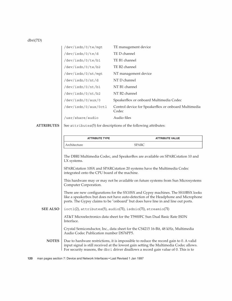
/dev/isdn/0/te/mgt TE management device
/dev/isdn/0/te/d TE D channel
/dev/isdn/0/te/b1 TE B1 channel
/dev/isdn/0/te/b2 TE B2 channel
/dev/isdn/0/nt/mgt NT management device
/dev/isdn/0/nt/d NT D channel
/dev/isdn/0/nt/b1 NT B1 channel
/dev/isdn/0/nt/b2 NT B2 channel
/dev/isdn/0/aux/0 SpeakerBox or onboard Multimedia Codec
/dev/isdn/0/aux/0ctl Control device for SpeakerBox or onboard MultimediaCodec
/usr/share/audio Audio files
See attributes(5) for descriptions of the following attributes:
ATTRIBUTE TYPE ATTRIBUTE VALUE
Architecture SPARC
The DBRI Multimedia Codec, and SpeakerBox are available on SPARCstation 10 andLX systems.
SPARCstation 10SX and SPARCstation 20 systems have the Multimedia Codecintegrated onto the CPU board of the machine.
This hardware may or may not be available on future systems from Sun MicrosystemsComputer Corporation.
There are new configurations for the SX10SX and Gypsy machines. The SS10BSX lookslike a speakerbox but does not have auto-detection of the Headphone and Microphoneports. The Gypsy claims to be "onboard" but does have line in and line out ports.
ioctl(2), attributes(5), audio(7I), isdnio(7I), streamio(7I)
AT&T Microelectronics data sheet for the T5900FC Sun Dual Basic Rate ISDNInterface.
Crystal Semiconductor, Inc., data sheet for the CS4215 16-Bit, 48 kHz, MultimediaAudio Codec Publication number DS76PP5.
Due to hardware restrictions, it is impossible to reduce the record gain to 0. A validinput signal is still received at the lowest gain setting the Multimedia Codec allows.For security reasons, the dbri driver disallows a record gain value of 0. This is to
dbri(7D)
ATTRIBUTES
SEE ALSO
NOTES
120 man pages section 7: Device and Network Interfaces • Last Revised 1 Jan 1997

provide feedback to the user that such a setting is not possible and that a valid inputsignal is still being received. An attempt to set the record gain to 0 will result in thelowest possible non-zero gain. The audio_info structure will be updated with thisvalue when the AUDIO_SETINFO ioctl returns.
When a DBRI channel associated with the SpeakerBox Interface underruns, DBRI maynot always repeat the last sample but instead could repeat more than one sample. Thisbehavior can result in a tone being generated by an audio device connected to the SBIport.
Monitor STREAMs connected to a B1 channel on either the TE or NT interface do notwork because of a DBRI hardware problem. The device driver disallows the creationof such monitors.
dbri(7D)
BUGS
Device and Network Interfaces 121

devfs – Devices file system
The devfs filesystem manages a name space of all devices under the Solaris operatingenvironment and is mounted during boot on the /devices name space.
The /devices name space is dynamic and reflects the current state of accessibledevices under the Solaris operating environment. The names of all attached deviceinstances are present under /devices.
The content under /devices is under the exclusive control of the devfs filesystemand can not be changed.
/device Mount point for devfs file system
devfsadm(1M), vfstab(4), attach(9E)
The /devices name space cannot be unmounted.
All content at or below the /devices name space is an implementation artifact andsubject to incompatible change or removal without notification.
devfs(7FS)
NAME
DESCRIPTION
FILES
SEE ALSO
NOTES
122 man pages section 7: Device and Network Interfaces • Last Revised 12 Jun 2002

devinfo – device information driver
The devinfo driver is a private mechanism used by the libdevinfo interfaces toaccess kernel device configuration data and to guarantee data consistency.
/devices/pseudo/devinfo@0:devinfo
See attributes(5) for descriptions of the following attributes:
ATTRIBUTE TYPE ATTRIBUTE VALUE
Stability Level Private
libdevinfo(3DEVINFO), attributes(5)
Writing Device Drivers
devinfo(7D)
NAME
DESCRIPTION
FILES
ATTRIBUTES
SEE ALSO
Device and Network Interfaces 123
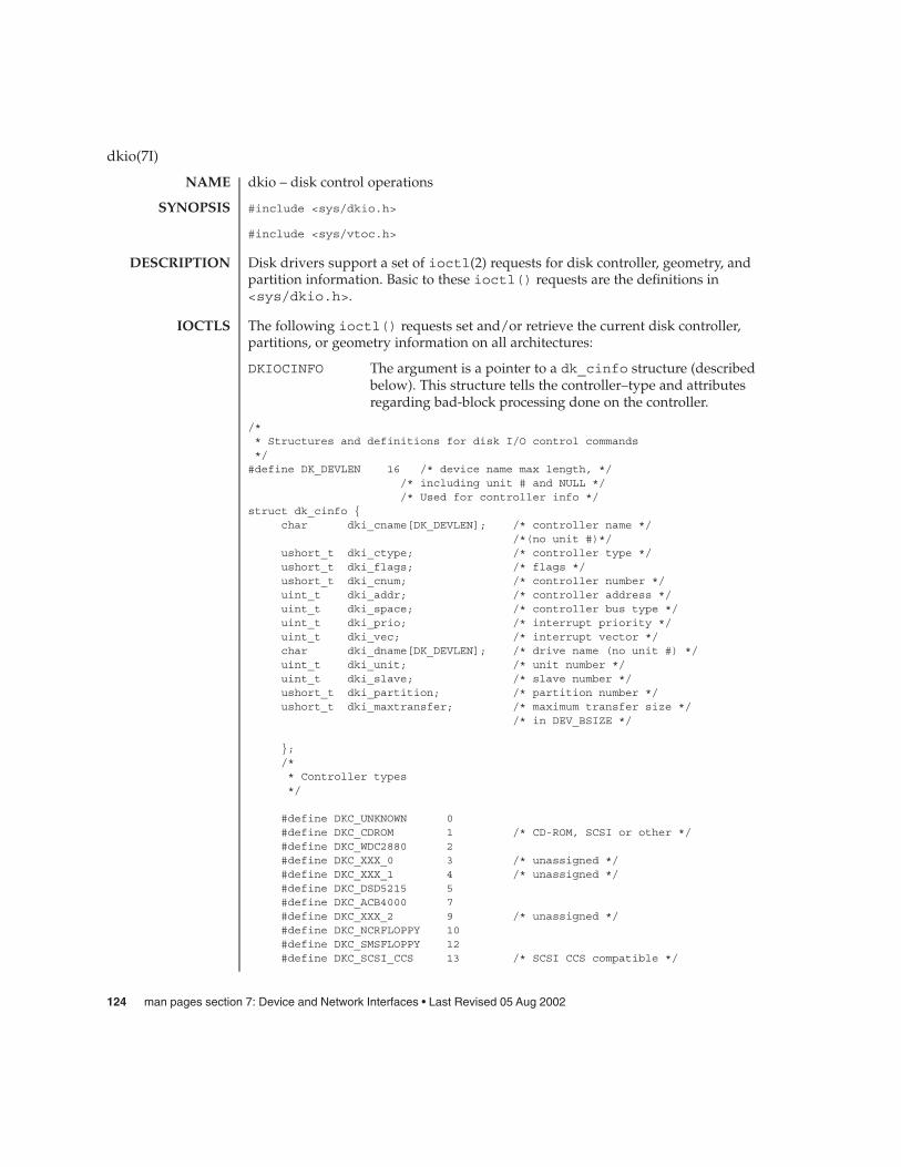
dkio – disk control operations
#include <sys/dkio.h>
#include <sys/vtoc.h>
Disk drivers support a set of ioctl(2) requests for disk controller, geometry, andpartition information. Basic to these ioctl() requests are the definitions in<sys/dkio.h>.
The following ioctl() requests set and/or retrieve the current disk controller,partitions, or geometry information on all architectures:
DKIOCINFO The argument is a pointer to a dk_cinfo structure (describedbelow). This structure tells the controller–type and attributesregarding bad-block processing done on the controller.
/** Structures and definitions for disk I/O control commands*/#define DK_DEVLEN 16 /* device name max length, */
/* including unit # and NULL *//* Used for controller info */
struct dk_cinfo {char dki_cname[DK_DEVLEN]; /* controller name */
/*(no unit #)*/ushort_t dki_ctype; /* controller type */ushort_t dki_flags; /* flags */ushort_t dki_cnum; /* controller number */uint_t dki_addr; /* controller address */uint_t dki_space; /* controller bus type */uint_t dki_prio; /* interrupt priority */uint_t dki_vec; /* interrupt vector */char dki_dname[DK_DEVLEN]; /* drive name (no unit #) */uint_t dki_unit; /* unit number */uint_t dki_slave; /* slave number */ushort_t dki_partition; /* partition number */ushort_t dki_maxtransfer; /* maximum transfer size */
/* in DEV_BSIZE */
};/** Controller types*/
#define DKC_UNKNOWN 0#define DKC_CDROM 1 /* CD-ROM, SCSI or other */#define DKC_WDC2880 2#define DKC_XXX_0 3 /* unassigned */#define DKC_XXX_1 4 /* unassigned */#define DKC_DSD5215 5#define DKC_ACB4000 7#define DKC_XXX_2 9 /* unassigned */#define DKC_NCRFLOPPY 10#define DKC_SMSFLOPPY 12#define DKC_SCSI_CCS 13 /* SCSI CCS compatible */
dkio(7I)
NAME
SYNOPSIS
DESCRIPTION
IOCTLS
124 man pages section 7: Device and Network Interfaces • Last Revised 05 Aug 2002
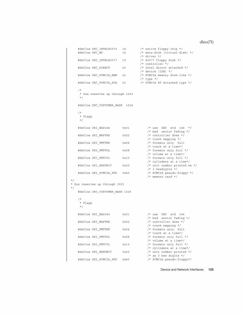
#define DKC_INTEL82072 14 /* native floppy chip */#define DKC_MD 16 /* meta-disk (virtual-disk) */
/* driver */#define DKC_INTEL82077 19 /* 82077 floppy disk */
/* controller */#define DKC_DIRECT 20 /* Intel direct attached */
/* device (IDE) */#define DKC_PCMCIA_MEM 21 /* PCMCIA memory disk-like */
/* type */#define DKC_PCMCIA_ATA 22 /* PCMCIA AT Attached type */
/** Sun reserves up through 1023*/
#define DKC_CUSTOMER_BASE 1024
/** Flags*/
#define DKI_BAD144 0x01 /* use DEC std 144 *//* bad sector fwding */
#define DKI_MAPTRK 0x02 /* controller does *//* track mapping */
#define DKI_FMTTRK 0x04 /* formats only full/* track at a time*/
#define DKI_FMTVOL 0x08 /* formats only full *//* volume at a time*/
#define DKI_FMTCYL 0x10 /* formats only full *//* cylinders at a time*/
#define DKI_HEXUNIT 0x20 /* unit number printed as *//* 3 hexdigits */
#define DKI_PCMCIA_PFD 0x40 /* PCMCIA pseudo-floppy *//* memory card */
*/* Sun reserves up through 1023*/
#define DKC_CUSTOMER_BASE 1024
/** Flags*/
#define DKI_BAD144 0x01 /* use DEC std 144/* bad sector fwding */
#define DKI_MAPTRK 0x02 /* controller does *//* track mapping */
#define DKI_FMTTRK 0x04 /* formats only full/* track at a time*/
#define DKI_FMTVOL 0x08 /* formats only full *//* volume at a time*/
#define DKI_FMTCYL 0x10 /* formats only full *//* cylinders at a time*/
#define DKI_HEXUNIT 0x20 /* unit number printed *//* as 3 hex digits */
#define DKI_PCMCIA_PFD 0x40 /* PCMCIA pseudo-floppy*/
dkio(7I)
Device and Network Interfaces 125

/* memory card */
DKIOCGAPART The argument is a pointer to a dk_allmap structure (describedbelow). This ioctl() gets the controller’s notion of the currentpartition table for disk drive.
DKIOCSAPART The argument is a pointer to a dk_allmap structure (describedbelow). This ioctl() sets the controller’s notion of the partitiontable without changing the disk itself.
/** Partition map (part of dk_label)*/ struct dk_map {
daddr_t dkl_cylno; /* starting cylinder */daddr_t dkl_nblk; /* number of blocks */};
/** Used for all partitions*/struct dk_map {struct dk_allmap {struct dk_map dka_map[NDKMAP];
};
DKIOCGGEOM The argument is a pointer to a dk_geom structure (describedbelow). This ioctl() gets the controller’s notion of the currentgeometry of the disk drive.
DKIOCSGEOM The argument is a pointer to a dk_geom structure (describedbelow). This ioctl() sets the controller’s notion of the geometrywithout changing the disk itself.
DKIOCGVTOC The argument is a pointer to a vtoc structure (described below).This ioctl() returns the device’s current volume table ofcontents (VTOC.)
DKIOCSVTOC The argument is a pointer to a vtoc structure (described below).This ioctl() changes the VTOC associated with the device.
struct partition {ushort_t p_tag; /* ID tag of partition */ushort_t p_flag; /* permission flags */daddr_t p_start; /* start sector of partition */long p_size; /* # of blocks in partition */
};
If DKIOCSVTOC is used with a floppy diskette, the p_start field must be the firstsector of a cylinder. To compute the number of sectors per cylinder, multiply thenumber of heads by the number of sectors per track.
struct vtoc {unsigned long v_bootinfo[3]; /* info needed by mboot
dkio(7I)
126 man pages section 7: Device and Network Interfaces • Last Revised 05 Aug 2002

/* (unsupported)*/unsigned long v_sanity; /* to verify vtoc sanity */unsigned long v_version; /* layout version */char v_volume[LEN_DKL_VVOL]; /* volume name */ushort_t v_sectorsz; \*
sector size in bytes*/ushort_t v_nparts; \*
number of partitions*/unsigned long v_reserved[10]; /* free space */struct partition v_part[V_NUMPAR]; /* partition headers*/time_t timestamp[V_NUMPAR]; /* partition timestamp
/* (unsupported)*/char v_asciilabel[LEN_DKL_ASCII]; /* compatibility */};
/** Partition permission flags*/
#define V_UNMNT 0x01 /* Unmountable partition */#define V_RONLY 0x10 /* Read only */
/** Partition identification tags*/
#define V_UNASSIGNED 0x00 /* unassigned partition */#define V_BOOT 0x01 /* Boot partition */#define V_ROOT 0x02 /* Root filesystem */#define V_SWAP 0x03 /* Swap filesystem */#define V_USR 0x04 /* Usr filesystem */#define V_BACKUP 0x05 /* full disk */#define V_VAR 0x07 /* Var partition */#define V_HOME 0x08 /* Home partition */
#define V_ALTSCTR 0x09 /* Alternate sector partition */
DKIOCEJECT If the drive supports removable media, this ioctl()requests the disk drive to eject its disk.
DKIOCREMOVABLE The argument to this ioctl() is an integer. Aftersuccessful completion, this ioctl() will set thatinteger to a non-zero value if the drive in question hasremovable media. If the media is not removable, thatinteger will be set to 0.
DKIOCSTATE This ioctl() blocks until the state of the drive,inserted or ejected, is changed. The argument is apointer to a dkio_state, enum, whose possibleenumerations are listed below. The initial value shouldbe either the last reported state of the drive, orDKIO_NONE. Upon return, the enum pointed to by theargument is updated with the current state of the drive.
dkio(7I)
Device and Network Interfaces 127

enum dkio_state {DKIO_NONE, /* Return disk’s current state */DKIO_EJECTED, /* Disk state is ’ejected’ */DKIO_INSERTED /* Disk state is ’inserted’ */
};
DKIOCLOCK For devices with removable media, this ioctl()requests the disk drive to lock the door.
DKIOCUNLOCK For devices with removable media, this ioctl()requests the disk drive to unlock the door.
DKIOCGMEDIAINFO The argument to this ioctl() is a pointer to adk_minfo structure. The structure indicates the type ofmedia or the command set profile used by the drive tooperate on the media. The dk_minfo structure alsoindicates the logical media blocksize the drive uses asthe basic unit blocksize of operation and the rawformatted capacity of the media in number of logicalblocks.
/** Used for media info or profile info*/struct dk_minfo {uint_t dki_media_type; /* Media type or profile info */uint_t dki_lbsize; /* Logical blocksize of media */diskaddr_t dki_capacity; /* Capacity as # of dki_lbsize blks */};/** Media types or profiles known*/#define DK_UNKNOWN 0x00 /* Media inserted - type unknown */
/** SFF 8090 Specification Version 3, media types 0x01 - 0xfffe are retained to* maintain compatibility with SFF8090. The following define the* optical media type.*/#define DK_MO_ERASABLE 0x03 /* MO Erasable */#define DK_MO_WRITEONCE 0x04 /* MO Write once */#define DK_AS_MO 0x05 /* AS MO */#define DK_CDROM 0x08 /* CDROM */#define DK_CDR 0x09 /* CD-R */#define DK_CDRW 0x0A /* CD-RW */#define DK_DVDROM 0x10 /* DVD-ROM */#define DK_DVDR 0x11 /* DVD-R */#define DK_DVDRAM 0x12 /* DVD_RAM or DVD-RW */
/** Media types for other rewritable magnetic media*/#define DK_FIXED_DISK 0x10001 /* Fixed disk SCSI or otherwise */#define DK_FLOPPY 0x10002 /* Floppy media */
dkio(7I)
128 man pages section 7: Device and Network Interfaces • Last Revised 05 Aug 2002
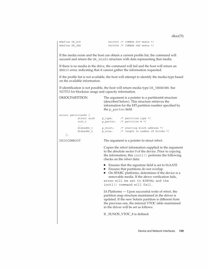
#define DK_ZIP 0x10003 /* IOMEGA ZIP media */
#define DK_JAZ 0x10004 /* IOMEGA JAZ media */
If the media exists and the host can obtain a current profile list, the command willsucceed and return the dk_minfo structure with data representing that media.
If there is no media in the drive, the command will fail and the host will return anENXIO error, indicating that it cannot gather the information requested.
If the profile list is not available, the host will attempt to identify the media-type basedon the available information.
If identification is not possible, the host will return media type DK_UNKNOWN. SeeNOTES for blocksize usage and capacity information.
DKIOCPARTITION The argument is a pointer to a partition64 structure(described below). This structure retrieves theinformation for the EFI partition number specified bythe p_partno field.
struct partition64 {struct uuid p_type; /* partition type */uint_t p_partno; /* partition # */...diskaddr_t p_start; /* starting block address */diskaddr_t p_size; /* length in number of blocks */
};
DKIOCSMBOOT The argument is a pointer to struct mboot.
Copies the mboot information supplied in the argumentto the absolute sector 0 of the device. Prior to copyingthe information, this ioctl() performs the followingchecks on the mboot data:
� Ensures that the signature field is set to 0xAA55.� Ensures that partitions do not overlap.� On SPARC platforms, determines if the device is a
removable media. If the above verification fails,errno will be set to EINVAL and theioctl() command will fail.
IA Platforms — Upon successful write of mboot, thepartition map structure maintained in the driver isupdated. If the new Solaris partition is different fromthe previous one, the internal VTOC table maintainedin the driver will be set as follows:
If _SUNOS_VTOC_8 is defined:
dkio(7I)
Device and Network Interfaces 129

PARTITION START SIZE
0 0 Capacity of device
2 0 Capacity of device
If _SUNOS_VTOC_16 is defined:
PARTITION START SIZE
2 0 Size specified inmboot - 2cylinders
8 0 Sectors/cylinder
9 Sectors/cylinder 2 *sectors/cylinder
To determine if the Solaris partition has changed:
If either offset or the size of the Solaris partition isdifferent from the previous one then it shall be deemedto have changed. In all other cases, the internal VTOCinfo will remain as before.
SPARC Platforms — The VTOC label and mboot bothoccupy the same location, namely sector 0. As a result,following the successful write of mboot info, theinternal VTOC table maintained in the driver will beset as follows:
PARTITION START SIZE
0 0 Capacity of device
2 0 Capacity of device
See the NOTES section for usage of DKIOCSMBOOTwhen modifying Solaris partitions.
DKIOCGMBOOT The argument is a pointer to struct mboot. The 512 bytesof absolute sector 0 of the device is copied to the mbootstructure pointed to by the argument.
Upon successful completion, the value returned is 0. Otherwise, -1 is returned anderrno is set to indicate the error.
dkio(7I)
RETURN VALUES
130 man pages section 7: Device and Network Interfaces • Last Revised 05 Aug 2002

The following ioctl() requests set and/or retrieve the current disk controller,partitions, or geometry information on IA architecture.
DKIOCG_PHYGEOM The argument is a pointer to a dk_geom structure(described below). This ioctl() gets the driver’snotion of the physical geometry of the disk drive. It isfunctionally identical to the DKIOCGGEOM ioctl().
DKIOCG_VIRTGEOM The argument is a pointer to a dk_geom structure(described below). This ioctl() gets the controller’s(and hence the driver’s) notion of the virtual geometryof the disk drive. Virtual geometry is a view of the diskgeometry maintained by the firmware in a host busadapter or disk controller. If the disk is larger than 8Gbytes, this ioctl will fail because a CHS-basedgeometry is not relevant or useful for this drive.
/** Definition of a disk’s geometry*/*/struct dk_geom {unsigned shor dkg_ncyl; /* # of data cylinders */unsigned shor dkg_acyl; /* # of alternate cylinders */unsigned short dkg_bcyl; /* cyl offset (for fixed head area) */unsigned short dkg_nhead; /* # of heads */unsigned short dkg_obs1; /* obsolete */unsigned short dkg_nsect; /* # of sectors per track*/unsigned short dkg_intrlv; /* interleave factor */unsigned short dkg_obs2; /* obsolete */unsigned short dkg_obs3; /* obsolete */unsigned short dkg_apc; /* alternates per cylinder */
/* (SCSI only) */unsigned short dkg_rpm; /* revolutions per min*/unsigned short dkg_pcyl; /* # of physical cylinders */unsigned short dkg_write_reinstruct; /* # sectors to skip, writes*/unsigned short dkg_read_reinstruct; /* # sectors to skip, reads*/unsigned short dkg_extra[7]; /* for compatible expansion*/};#define dkg_gap1 dkg_extra[0] /* for application compatibility*/
#define dkg_gap2 dkg_extra[1] /* for application compatibility*/
DKIOCADDBAD This ioctl() forces the driver to re-examine the alternates sliceand rebuild the internal bad block map accordingly. It should beused whenever the alternates slice is changed by any method otherthan the addbadsec(1M) or format(1M) utilities. DKIOCADDBADcan only be used for software remapping on IDE drives; SCSIdrives use hardware remapping of alternate sectors.
DKIOCPARTINFO The argument is a pointer to a part_info structure (describedbelow). This ioctl() gets the driver’s notion of the size andextent of the partition or slice indicated by the file descriptorargument.
dkio(7I)
IA Only
Device and Network Interfaces 131

/** Used by applications to get partition or slice information*/struct part_info {daddr_t p_start;int p_length;
};
These ioctls may return the following:
EACCESS This device is reserved by another host.
ENOTSUP The disk does not support this operation. For example,the disk has an EFI label but the ioctl is only applicableto disks with VTOCs.
ENOTTY This ioctl is not implemented by this driver.
See ioctl(2) for additional information on errors that could be returned.
fdisk(1M), format(1M), ioctl(2), libefi(3LIB), sd(7D), cdio(7I), fdio(7I)
addbadsec(1M), cmdk(7D)
Blocksize information provided in DKIOCGMEDIAINFO is the size (in bytes) of thedevice’s basic unit of operation and may differ from the blocksize that the Solarisoperating environment exports to the user. Capacity information provided in theDKIOCGMEDIAINFO are for reference only and you are advised to use the valuesreturned by DKIOCGGEOM or other appropriate ioctl for accessing data using thestandard interfaces.
IA only: If the DKIOCSMBOOT command is used to modify the Solaris partitions, theVTOC information should also be set appropriately to reflect the the changes topartition. Failure to do so will lead to unexpected results when the device is closedand re-opened fresh at a later time. This is because a default VTOC is assumed bydriver when a Solaris partition is changed. The default VTOC will persist until theioctl DKIOCSVTOC is called to modify VTOC or the device is closed and re-opened.At that point, the old valid VTOC will be read from the disk if it is still available.
dkio(7I)
ERRORS
SEE ALSO
IA Only
NOTES
132 man pages section 7: Device and Network Interfaces • Last Revised 05 Aug 2002

dlcosmk – Data Layer Class of Service Marker
The dlcosmk marker is an action module that is executed as a result of classifying ormetering packets. It marks the packet with a user priority defined by the IEEE 801.Dstandard. This feature is only possible on a VLAN device.
The 3-bit user priority is part of the 802.1Q VLAN header tag that is part of theethernet header (carrying the IP packet).
The dlcosmk module exports the following statistics through kstat:
Global statistics:
module: dlcosmk instance: <action id>name: dlcosmk statistics class <action name>
crtimesnaptimeb_band <b_band value>dl_max <dl_max value>usr_pri <configured CoS>npackets <number of packets>epackets <number of packets in error>
ipackets <number of packets not processed>
/kernel/ipp/dlcosmk32-bit module
/kernel/ipp/sparcv9/dlcosmk64-bit module
See attributes(5) for descriptions of the following attributes:
ATTRIBUTE TYPE ATTRIBUTE VALUE
Availability SUNWqos (32–bit) SUNWqosx (64–bit)
ipqosconf(1M), dscpmk(7IPP), flowacct(7IPP), ipqos(7IPP), ipgpc(7IPP),tokenmt(7IPP), tswtclmt(7IPP)
dlcosmk(7ipp)
NAME
DESCRIPTION
STATISTICS
FILES
ATTRIBUTES
SEE ALSO
Device and Network Interfaces 133

dlpi – Data Link Provider Interface
#include <sys/dlpi.h>
SunOS STREAMS-based device drivers wishing to support the STREAMS TCP/IP andother STREAMS-based networking protocol suite implementations support Version 2of the Data Link Provider Interface (“DLPI”). DLPI V2 enables a data link service userto access and use any of a variety of conforming data link service providers withoutspecial knowledge of the provider’s protocol. Specifically, the interface is intended tosupport Ethernet, X.25 LAPB, SDLC, ISDN LAPD, CSMA/CD, FDDI, token ring,token bus, Bisync, and other datalink-level protocols.
The interface specifies access to the data link service provider in the form of M_PROTOand M_PCPROTO type STREAMS messages and does not define a specific protocolimplementation. The interface defines the syntax and semantics of primitivesexchanged between the data link user and the data link provider to attach a physicaldevice with physical-level address to a stream, bind a datalink-level address to thestream, get implementation-specific information from the data link provider, exchangedata with a peer data link user in one of three communication modes (connection,connectionless, acknowledged connectionless), enable/disable multicast group andpromiscuous mode reception of datalink frames, get and set the physical addressassociated with a stream, and several other operations.
For details on this interface refer to the <sys/dlpi.h> header and to the STREAMSDLPI Specification, 800-6915-01.
Files in or under /dev.
le(7D), hme(7D), ge(7D), qfe(7D), gld(7D)
Streams drivers for network interface cards (NIC) must meet the following drivername constraints:
� Length — Name cannot exceed 16 characters. Names containing three to eightcharacters are preferred.
� Legal Characters — Legal characters are: alphanumeric (a-z, A-Z, 0-9), and theunderscore (’_’). Additionally, the first and/or last character of a name cannot be adigit.
dlpi(7P)
NAME
SYNOPSIS
DESCRIPTION
FILES
SEE ALSO
NOTES
134 man pages section 7: Device and Network Interfaces • Last Revised 29 Nov 2000
dman – SUNW,dman Sun Fire 15K management network device driver
/dev/dman
The dman(7D) network device driver is a loadable, clonable, STREAMS hardwaredriver that supports the connectionless data link provider interface dlpi(7P) over theSUNW,dman network controller. The dman controller provides a highly available,secure communication channel between the dynamic system domains and the Sun Fire15K system controller.
The dman driver provides basic support for the SUNW,dman controller. Driverfunctions include network initialization, frame transit and receive, multicast andpromiscuous support, and error recovery and reporting.
The dman controller is physically located in each Sun Fire 15K dynamic systemdomain and connects to SUNWscman controllers in the Sun Fire 15K chassis. Seescman(7D). All links are point-to-point and are internal to the Sun Fire 15K chassis.Traffic between the dynamic system domains and the system controller is notaccessible by any third party; for example, another system domain within the Sun Fire15K chassis. Only the system controller is accessible through the dman controller.
The link layer frame format is identical to that used by Ethernet (sys/ethernet.h).
The /dev/dman cloning character-special device is used to access the SUNW,dmancontroller installed on the system.
The dman driver is a style 2 data link provider interface. All M_PROTO and M_PCPROTOtype messages are interpreted as DLPI primitives. Valid DLPI primitives are defined insys/dlpi.h. Refer to dlpi(7P) for more information. An explicit DL_ATTACH_REQmessage by the user is required to associate the opened stream with a particulardevice or physical point of attachment (PPA).
The PPA ID is interpreted as an unsigned long data type and indicates thecorresponding device instance (unit) number. The only valid unit number is 0. Anerror (DL_ERROR_ACK) is returned by the driver if the PPA field value does notcorrespond to a valid device instance number for this system. The device is initializedon the first attach and deinitialized (stopped) upon the last detach.
The values returned by the dman driver in the DL_INFO_ACK primitive in response tothe DL_INFO_REQ from the user are:
� Maximum service data units (SDU) are 1500.� Minimum SDU is 0.� Data link service access point (DLSAP) address length is 8.� Media access control (MAC) type is DL_ETHER.� Service access point (SAP) length value is -2, meaning the physical address
component is followed immediately by a two-byte SAP component within theDLSAP address.
� Service mode is DL_CLDLS.
dman(7D)
NAME
SYNOPSIS
DESCRIPTION
APPLICATIONPROGRAMMING
INTERFACEDLPI
Device and Network Interfaces 135
� Optional quality of service (QOS) support is not included; the QOS fields are 0.
� Provider style is DL_STYLE2.
� Version is DL_VERSION_2.
� Broadcast address value is Ethernet/IEEE broadcast address (0xFFFFFF).
Once in the DL_ATTACHED state, you can transmit a DL_BIND_REQ to associate aparticular SAP with the stream. The dman driver interprets the SAP field within theDL_BIND_REQ as an Ethernet type; as a result, valid values for the SAP field are in the0 through 0xFFFF range. Only one Ethernet type can be bound to the stream at anytime.
If you select the SAP with a value of 0, the receiver will be in 802.3 mode. All framesreceived from the media having a type field in the range from 0 through 1500 areassumed to be 802.3 frames and are routed up all open streams that are bound to SAPvalue 0. If more than one stream is in 802.3 mode, the frame is duplicated and routedup multiple streams as DL_UNITDATA_IND messages.
In transmission, the driver checks the DL_BIND_REQ SAP field to determine if the SAPvalue is 0 and the destination type field is in the range from 0 through 1500. If either istrue, the driver computes the length of the message, not including the initial M_PROTOmessage block (mblk), of all subsequent DL_UNITDATA_REQ messages and transmits802.3 frames that have this value in the MAC frame header length field.
The dman driver DLSAP address format consists of the six-byte physical (Ethernet)address component followed immediately by the two-byte SAP (type) componentproducing an eight-byte DLSAP address. Applications should not be hard-coded to thisimplementation-specific DLSAP address format, but instead use information returnedin the DL_INFO_ACK primitive to compose and decompose DLSAP addresses. The SAPlength, full DLSAP length, and SAP physical ordering are included within theDL_INFO_ACK. The physical address length can be computed by subtracting the SAPlength from the full DLSAP address length or by issuing the DL_PHYS_ADDR_REQ toobtain the current physical address associated with the stream.
Once in the DL_BOUND state, youcan atransmit frames on the Ethernet by sendingDL_UNITDATA_REQ messages to the dman driver. The dman driver routes receivedEthernet frames as DL_UNITDATA_IND messages up all open and bound streamshaving a SAP matching the Ethernet type. Received Ethernet frames are duplicatedand routed up multiple open streams, if necessary. The DLSAP address containedwithin the DL_UNITDATA_REQ and DL_UNITDATA_IND messages consists of both theSAP (type) and physical (Ethernet) components.
In addition to the mandatory connectionless DLPI message set, the dman driversupports the following primitives.
The DL_ENABMULTI_REQ and DL_DISABMULTI_REQ primitives enable or disablereception of individual multicast group addresses. A set of multicast addresses may beiteratively created and modified on a per-stream basis using these primitives. Theseprimitives are accepted by the driver in any state following DL_ATTACHED.
dman(7D)
PRIMITIVES
136 man pages section 7: Device and Network Interfaces • Last Revised 10 Sep 2000

The DL_PROMISCON_REQ and DL_PROMISCOFF_REQ primitives with theDL_PROMISC_PHYS flag set in the dl_level field enables or disables reception of allpromiscuous mode frames on the media, including frames generated by the local host.When used with the DL_PROMISC_SAP flag set, this enables or disables reception ofall SAP (Ethernet type) values. When used with the DL_PROMISC_MULTI flag set, thisenables or disables reception of all multicast group addresses. The effect of each isalways on a per-stream basis and independent of other SAP and physical levelconfigurations on this stream or other streams.
The DL_PHYS_ADDR_REQ primitive returns the six-octet Ethernet address currentlyassociated (attached) to the stream in the DL_PHYS_ADDR_ACK primitive. Thisprimitive is valid only in states following a successful DL_ATTACH_REQ.
The DL_SET_PHYS_ADDR_REQ primitive is not supported.
The dman driver operates at 10 Mbps, full-duplex.
The dman driver allows you to set and get various parameters for the SUNW,dmandevice. The parameter list includes current transceiver status, current link status,interpacket gap, local transceiver capabilities, and link partner capabilities.
See attributes(5) for descriptions of the following attributes:
ATTRIBUTE TYPE ATTRIBUTE VALUE
Architecture Sun Fire 15K servers
Availability SUNWcar
The dman driver utilizes the following files:
/dev/dmanSpecial character device
/platform/SUNW,Sun-Fire-15000/kernel/drv/dman.confSystem-wide default device driver properties
ndd(1M), netstat(1M), driver.conf(4), eri(7D), scman(7D),dlpi(7P)
dman(7D)
dman DRIVER
PARAMETERLIST
ATTRIBUTES
FILES
SEE ALSO
Device and Network Interfaces 137

dmfe – Davicom Fast Ethernet driver for Davicom DM9102A
/platform/SUNW,UltraAX-i2/kernel/drv/sparcv9/dmfe
The dmfe Ethernet device provides 100Base-TX networking interfaces using theDavicom DM9102A chip, which incorporates its own internal transceiver.
The dmfe driver is a multithreaded, loadable, clonable, GLD-based STREAMS driver.Multiple controllers installed within the system are supported by the driver. The dmfedriver functions include controller initialization, frame transmit and receive,promiscuous and multicast support, and error recovery and reporting.
The 100Base-TX standard specifies an auto-negotiation protocol to automatically selectthe mode and speed of operation. The internal transceiver is capable of performingautonegotiation with the remote-end of the link (link partner) and receives thecapabilities of the remote end. It selects the highest common denominator mode ofoperation based on the priorities. The internal transceiver also supports a forced-modeof operation under which the driver selects the operational mode.
The /dev/dmfe cloning character-special device is used to access all DavicomDM9102A devices installed in the system.
The dmfe driver is dependent on /kernel/misc/gld, a loadable kernel module thatprovides the dmfe driver with the DLPI and STREAMS functionality required of aLAN driver. See gld(7D) for more details on the primitives supported by the driver.
You must send an explicit DL_ATTACH_REQ message to associate the opened streamwith a particular device (ppa). The ppa ID is interpreted as an unsigned integer datatype and indicates the corresponding device instance (unit) number. If the ppa fieldvalue does not correspond to a valid device instance number for this system, an error(DL_ERROR_ACK) is returned. The device is initialized on first attach andde-initialized (stopped) at last detach.
The values returned by the driver in the DL_INFO_ACK primitive in response to aDL_INFO_REQ are as follows:
� Maximum SDU is 1500 (ETHERMTU - defined in sys/ethernet.h).� Minimum SDU is 0.� DLSAP address length is 8.� MAC type is DL_ETHER.� The sap length value is -2, meaning the physical address component is followed
immediately by a 2-byte sap component within the DLSAP address.� The broadcast address value is the Ethernet/IEEE broadcast address
(FF:FF:FF:FF:FF:FF).
Once in the DL_ATTACHED state, you must send a DL_BIND_REQ to associate aparticular Service Access Point (SAP) with the stream.
dmfe(7D)
NAME
SYNOPSIS
DESCRIPTION
APPLICATIONPROGRAMMING
INTERFACE
138 man pages section 7: Device and Network Interfaces • Last Revised 30 April 2001
By default, the dmfe driver performs auto-negotiation to select the speed and mode ofthe link. Link speed and mode can be 100 Mbps (full or half-duplex) or 10 Mbps (fullor half-duplex) as described in the 100Base-TX standard.
The auto-negotiation protocol automatically selects speed mode (either 100 Mbps or 10Mbps) and operation mode (either full-duplex or half-duplex) as the highest commondenominator supported by both link partners. Because the dmfe device supports allmodes, this effectively selects the highest-throughput mode supported by the otherdevice.
Alternatively, you can explicitly specify the link parameters by adding entries to thedmfe driver configuration file (/platform/SUNW,UltraAX-i2/kernel/drv/dmfe.conf). You can set the speed parameter to 10 or 100 to forcedmfe devices to operate at the specified speed. Additionally, you can set thefull-duplex parameter to 0 or 1 to disable or force full-duplex operation, respectively.
Note that specifying either "speed" or "full-duplex" explicitly disablesauto-negotiation. To enable the driver to determine the appropriate setting for eachparameter, you should always set both parameters. If it is necessary to force eitherspeed or duplex setting (for example, because the dmfe device is connected to anancient device or hub that does not support auto-negotiation), both parameters shouldbe explicitly specified to match the requirements of the external device.
/dev/dmfeCharacter special device
/platform/SUNW,UltraAX-i2/kernel/drv/dmfe.confdmfe configuration file
See attributes(5) for descriptions of the following attributes:
ATTRIBUTE TYPE ATTRIBUTE VALUE
Architecture IA
attributes(5), gld(7D), dlpi(7P), streamio(7I)
Writing Device Drivers
STREAMS Programming Guide
Network Interfaces Programmer’s Guide
dmfe(7D)
CONFIGURATION
FILES
ATTRIBUTES
SEE ALSO
Device and Network Interfaces 139

dnet – Ethernet driver for DEC 21040, 21041, 21140 Ethernet cards
/kernel/drv/dnet
The dnet Ethernet driver is a multithreaded, loadable, clonable, STREAMS GLDdriver. Multiple controllers installed within the system are supported by the driver.The dnet driver functions include controller initialization, frame transmit and receive,functional addresses, promiscuous and multicast support, and error recovery andreporting.
The cloning character-special device, /dev/dnet, is used to access all DEC21040/21041/21140 devices installed in the system.
The dnet driver is dependent on /kernel/misc/gld, a loadable kernel module thatprovides the dnet driver with the DLPI and STREAMS functionality required of aLAN driver. See gld(7D) for more details on the primitives supported by the driver.
The device is initialized on the first attach and de-initialized (stopped) on the lastdetach.
The values returned by the driver in the DL_INFO_ACK primitive in response to aDL_INFO_REQ from the user are as follows:
� The maximum SDU is 1500 (ETHERMTU - defined in <sys/ethernet.h>).� The minimum SDU is 0.� The DLSAP address length is 8.� The MAC type is DL_ETHER.� The sap length value is −2, meaning the physical address component is followed
immediately by a 2-byte sap component within the DLSAP address.� The broadcast address value is the Ethernet/IEEE broadcast address
(FF:FF:FF:FF:FF:FF).
Once in the DL_ATTACHED state, the user must send a DL_BIND_REQ to associate aparticular Service Access Point (SAP) with the stream.
The PCI configuration process varies from system to system. Follow the instructionsprovided by the vendor.
� On multiport cards (exception: Osicom (Rockwell) RNS2340), the first port is thetop port. (On the Osicom RNS2340, the first port is the bottom port.)
� If the dnet driver fails to determine the correct speed and duplex mode resultingin a corresponding drop in performance, set the speed and duplex mode using thednet.conf file.
� The dnet driver incorrectly counts carrier lost or no carrier errors while infull-duplex mode. There is no carrier signal present when in full-duplex mode andit should not be counted as an error.
� Version 4 SROM formats are not supported.
dnet(7D)
NAME
SYNOPSIS
DESCRIPTION
APPLICATIONPROGRAMMING
INTERFACE
PRECONFIGURATION
Known Problemsand Limitations
140 man pages section 7: Device and Network Interfaces • Last Revised 20 OCT 2000

The /kernel/drv/dnet.conf file supports the following options:
full-duplex For full duplex operation use full-duplex=1, for half duplexuse full-duplex=0. Half-duplex operation gives better resultson older 10mbit networks.
speed For 10mbit operation use speed=10, for 100mbit operation usespeed=100. Certain 21140 based cards will operate at eitherspeed. Use the speed property to override the 100mbit default inthis case.
/dev/dnet character special device
/kernel/drv/dnet.conf dnet configuration file
See attributes(5) for descriptions of the following attributes:
ATTRIBUTE TYPE ATTRIBUTE VALUE
Architecture IA
attributes(5), dlpi(7P), gld(7D) streamio(7I)
Writing Device Drivers
STREAMS Programming Guide
Network Interfaces Programmer’s Guide
dnet(7D)
CONFIGURATION
FILES
ATTRIBUTES
SEE ALSO
Device and Network Interfaces 141
dpt – DPT ServeRAID IV SCSI host bus adapter and RAID adapter driver
The dpt driver is a driver for the DPT (Distributed Processing Technology) family ofSmartRAID IV SCSI HBA and RAID adapters. The following HBA adapters aresupported: PM2024, PM2044UW, PM2044W, PM2124, PM2124W, PM2144UW, andPM2144W.
The following RAID adapters are supported: PM3224, PM3224W, PM3334UW, andPM3334W.
� DPT PM3224 only: Only EPROM 7A and later versions are supported.
� DPT PM2024 and PM2124 only: Only EPROM 6D4 and later versions aresupported.
� Use adapters with SmartROM version 3.B or later versions only.
� Be sure that the controller board is installed in a PCI bus-mastering slot.
� Disable PCI parity checking if your firmware version is earlier than version 7A, ifyour system memory is ECC, or if your system does not check parity.
During system boot, a message may be displayed saying a DPT controller drivercannot be installed. This message indicates that the motherboard installed in yoursystem may contain ECC memory or may not check parity. If you see this message isdisplayed, disable PCI parity checking.
� I/O Address: Auto
Auto-configuration code determines whether the adapter is present at the configuredaddress and what types of devices are attached to it. The DPT ServeRAID is primarilyused as a disk array (system drive) controller.
To configure the attached disk arrays, you must configure the controller (using theconfiguration utilities provided by the hardware manufacturer) before you boot theSolaris operating environment. You use the configuration utilities to set RAID levels,stripe parameters, cache mechanisms and perform other functions. For moreinformation, see the user manual supplied with your hardware.
/kernel/drv/dpt.conf dpt configuration file
/dev/dsk/cndn[s|p]n block device
/dev/rdsk/cndn[s|p]n raw device where:
cn controller n
dn LUN n (0–7)
sn UNIX system slice n (0–15)
pn fdisk(1M) partition (0)
dpt(7D)
NAME
DESCRIPTION
PRECONFIGURATION
Known Problemsand Limitations
Supported Settings
CONFIGURATION
FILES
142 man pages section 7: Device and Network Interfaces • Last Revised 27 November 2000

See attributes(5) for descriptions of the following attributes:
ATTRIBUTE TYPE ATTRIBUTE VALUE
Architecture IA
fdisk(1M), attributes(5), cmdk(7D)
dpt(7D)
ATTRIBUTES
SEE ALSO
Device and Network Interfaces 143

dr, drmach, ngdr, ngdrmach – Sun Enterprise 10000 and Sun Fire 15K dynamicreconfiguration driver
dr
drmach
ngdr
ngdrmach
The dynamic reconfiguration (DR) driver consists of a platform-independent driverand a platform-specific module. The DR driver uses standard features of the Solarisoperating environment whenever possible to control DR operations and calls theplatform specific module as needed. The DR driver creates minor nodes in the filesystem that serve as attachment points for DR operations.
The DR driver provides a pseudo-driver interface to sequence attach and detachoperations on system boards using file system entry points referred to as ”attachmentpoints.” The form of the attachment point depends on the platform.
On the Sun Enterprise 10000 server, the DR driver consists of a platform-independentdriver (ngdr) and a platform-specific module (ngdrmach).
The domain configuration server (DCS) accepts DR requests from the system servicesprocessor (SSP) and uses the libcfgadm(3LIB) interface to initiate the DR operation.After the operation is performed, the results are returned to the SSP. For moreinformation about the DCS on the Sun Enterprise 10000, refer to the dcs(1M) manpage and the Sun Enterprise 10000 Dynamic Reconfiguration User Guide.
The DR driver creates physical attachment points for system board slots that takes thefollowing form:
/devices/pseudo/ngdr@0:SBx
Where x represents the slot number (0 to 15) for a particular board.
The cfgadm_sbd(1M) plugin creates dynamic attachment points that refer tocomponents on system boards, including CPUs, memory, or I/O devices. Refer to thecfgadm_sbd(1M) man page for more details.
On the Sun Fire 15K server, the DR driver consists of a platform-independent driver(dr) and a platform-specific module (drmach).
The domain configuration server (DCS) accepts DR requests from the domainconfiguration agent (DCA) that runs on the Sun Fire 15K system controller. After theDCS accepts a DR request, it uses the libcfgadm(3LIB) interface to initiate the DRoperation. After the operation is performed, the results are returned to the DCA. Formore information about the DCS, refer to the dcs(1M) man page and the Sun Fire 15KDynamic Reconfiguration User Guide. For more information about the DCA, refer to theSystem Management Services (SMS) Dynamic Reconfiguration User Guide.
dr(7d)
NAME
SYNOPSIS
DESCRIPTION
Sun Enterprise10000 Server
Sun Fire 15KServer
144 man pages section 7: Device and Network Interfaces • Last Revised 26 Sep 2001

The DR driver creates physical attachment points for system board slots that take oneof the following forms:
/devices/pseudo/dr@0:SBx
/devices/pseudo/dr@0:IOx
Where x represents the expander number (0 to 17) for a particular board.
The cfgadm_sbd(1M) plugin creates dynamic attachment points. These attachmentpoints refer to components on system boards, including CPUs, memory, or I/Odevices. Refer to the cfgadm_sbd(1M) man page for more details.
cfgadm_sbd(1M), dcs(1M), ioctl(2), libcfgadm(3LIB)
Sun Enterprise 10000 Dynamic Reconfiguration User Guide
Sun Fire 15K Dynamic Reconfiguration User Guide
System Management Services (SMS) Dynamic Reconfiguration User Guide
dr(7d)
SEE ALSO
Device and Network Interfaces 145

dr, drmach, ngdr, ngdrmach – Sun Enterprise 10000 and Sun Fire 15K dynamicreconfiguration driver
dr
drmach
ngdr
ngdrmach
The dynamic reconfiguration (DR) driver consists of a platform-independent driverand a platform-specific module. The DR driver uses standard features of the Solarisoperating environment whenever possible to control DR operations and calls theplatform specific module as needed. The DR driver creates minor nodes in the filesystem that serve as attachment points for DR operations.
The DR driver provides a pseudo-driver interface to sequence attach and detachoperations on system boards using file system entry points referred to as ”attachmentpoints.” The form of the attachment point depends on the platform.
On the Sun Enterprise 10000 server, the DR driver consists of a platform-independentdriver (ngdr) and a platform-specific module (ngdrmach).
The domain configuration server (DCS) accepts DR requests from the system servicesprocessor (SSP) and uses the libcfgadm(3LIB) interface to initiate the DR operation.After the operation is performed, the results are returned to the SSP. For moreinformation about the DCS on the Sun Enterprise 10000, refer to the dcs(1M) manpage and the Sun Enterprise 10000 Dynamic Reconfiguration User Guide.
The DR driver creates physical attachment points for system board slots that takes thefollowing form:
/devices/pseudo/ngdr@0:SBx
Where x represents the slot number (0 to 15) for a particular board.
The cfgadm_sbd(1M) plugin creates dynamic attachment points that refer tocomponents on system boards, including CPUs, memory, or I/O devices. Refer to thecfgadm_sbd(1M) man page for more details.
On the Sun Fire 15K server, the DR driver consists of a platform-independent driver(dr) and a platform-specific module (drmach).
The domain configuration server (DCS) accepts DR requests from the domainconfiguration agent (DCA) that runs on the Sun Fire 15K system controller. After theDCS accepts a DR request, it uses the libcfgadm(3LIB) interface to initiate the DRoperation. After the operation is performed, the results are returned to the DCA. Formore information about the DCS, refer to the dcs(1M) man page and the Sun Fire 15KDynamic Reconfiguration User Guide. For more information about the DCA, refer to theSystem Management Services (SMS) Dynamic Reconfiguration User Guide.
drmach(7d)
NAME
SYNOPSIS
DESCRIPTION
Sun Enterprise10000 Server
Sun Fire 15KServer
146 man pages section 7: Device and Network Interfaces • Last Revised 26 Sep 2001

The DR driver creates physical attachment points for system board slots that take oneof the following forms:
/devices/pseudo/dr@0:SBx
/devices/pseudo/dr@0:IOx
Where x represents the expander number (0 to 17) for a particular board.
The cfgadm_sbd(1M) plugin creates dynamic attachment points. These attachmentpoints refer to components on system boards, including CPUs, memory, or I/Odevices. Refer to the cfgadm_sbd(1M) man page for more details.
cfgadm_sbd(1M), dcs(1M), ioctl(2), libcfgadm(3LIB)
Sun Enterprise 10000 Dynamic Reconfiguration User Guide
Sun Fire 15K Dynamic Reconfiguration User Guide
System Management Services (SMS) Dynamic Reconfiguration User Guide
drmach(7d)
SEE ALSO
Device and Network Interfaces 147

dscpmk – Differentiated Services Code Point Marker
The dscpmk marker is an action module that is executed as a result of classifying ormetering packets. It sets a codepoint in the IP header as defined in RFC-2474:Definition of the Differentiated Services Field (DS Field) in the IPv4 and IPv6 Headers.
The dscpmk module exports the following statistics available through kstat:
Global statistics:
module: dscpmk instance: <action id>name: dscpmk stats class <action name>
crtimesnaptimenpackets <number of packets>epackets <number of packets in error>ipackets <number of packets not processed>dscp_unchanged <number of packets with DSCP unchanged>dscp_changed <number of packets with DSCP changed>
Also, for each DSCP the following is exported:module: dscpmk instance: <action id>name: dscpmk_dscp0x<DSCP> value class: <action name>dscp <DSCP value>
npackets <number of packets for this DSCP>
/kernel/ipp/dscpmk32-bit module
/kernel/ipp/sparcv9/dscpmk64-bit module
See attributes(5) for descriptions of the following attributes:
ATTRIBUTE TYPE ATTRIBUTE VALUE
Availability SUNWqos (32–bit) SUNWqosx (64–bit)
ipqosconf(1M), dlcosmk(7IPP), flowacct(7IPP), ipqos(7IPP), ipgpc(7IPP),tokenmt(7IPP), tswtclmt(7IPP)
RFC 2474, Definition of the Differentiated Services Field (DS Field) in the IPv4 and IPv6Headers K. Nichols, S. Blake, F. Baker, D. Black — The Internet Society, 1998
dscpmk(7ipp)
NAME
DESCRIPTION
STATISTICS
FILES
ATTRIBUTES
SEE ALSO
148 man pages section 7: Device and Network Interfaces • Last Revised 25 Feb 2002
ecpp – IEEE 1284 compliant parallel port driver
#include <sys/types.h>
#include <sys/ecppio.h>
ecpp@unit-address
The ecpp driver provides a bi-directional interface to IEEE 1284 compliant devices aswell as a forward single-directional interface to Centronics devices. In addition to theCentronics protocol, the ecpp driver supports the IEEE 1284Compatibility, Nibble,and ECP protocols. ECPP_COMPAT_MODE and ECPP_CENTRONICS modes of operationhave logically identical handshaking protocols, however devices that supportECPP_COMPAT_MODE are IEEE 1284 compliant devices. IEEE 1284 compliant devicessupport at least ECPP_COMPAT_MODE and ECPP_NIBBLE_MODE. Centronics devicessupport only ECPP_CENTRONICS mode.
By default, ECPP_COMPAT_MODE devices have a strobe handshaking pulse width of500ns. For this mode, forward data transfers are conducted by DMA. By default, thestrobe pulse width for ECPP_CENTRONICS devices is two microseconds. Forwardtransfers for these devices are managed through PIO. The default characteristics forboth ECPP_COMPAT_MODE and ECPP_CENTRONICS devices may be changed throughtunable variables defined in ecpp.conf.
The ecpp driver is an exclusive-use device, meaning that if the device is already open,subsequent opens fail with EBUSY.
Each time the ecpp device is opened, the device is marked as EBUSY and theconfiguration variables are set to their default values. The write_timeout period isset to 90 seconds.
The driver sets the mode variable according to the following algorithm: The driverinitially attempts to negotiate the link into ECPP_ECP_MODE during open(2). If it fails,the driver tries to negotiate into ECPP_NIBBLE_MODE mode. If that fails, the driveroperates in ECPP_CENTRONICS mode. Upon successfully opening the device, IEEE1284 compliant devices will be left idle in either reverse idle phase ofECPP_ECP_MODE or in ECPP_NIBBLE_MODE. Subsequent calls to write(2) invokesthe driver to move the link into either ECPP_COMPAT_MODE or the forward phase ofECPP_ECP_MODE. After the transfer completes, the link returns to idle state.
The application may attempt to negotiate the device into a specific mode or set thewrite_timeout values through the ECPPIOC_SETPARMS ioctl(2) call. For modenegotiation to be successful, both the host workstation and the peripheral mustsupport the requested mode.
Characteristics of the ecpp driver may be tuned by the variables described in/kernel/drv/ecpp.conf. These variables are read by the kernel during systemstartup. To tune the variables, edit the ecpp.conf file and invoke update_drv(1M)to have the kernel read the file again.
ecpp(7D)
NAME
SYNOPSIS
DESCRIPTION
Default Operation
Tunables
Device and Network Interfaces 149
Some Centronics peripherals and certain IEEE 1284 compatible peripherals will notoperate with the parallel port operating in a fast handshaking mode. If printingproblems occur, set "fast-centronics" and "fast-1284-compatible" to "false.” See/kernel/drv/ecpp.conf for more information.
The ecpp driver is a full duplex STREAMS device driver. While an application iswriting to an IEEE 1284 compliant device, another thread may read from it.
A write(2) operation returns the number of bytes successfully written to the streamhead. If a failure occurs while a Centronics device is transferring data, the content ofthe status bits will be captured at the time of the error and can be retrieved by theapplication program using the BPPIOC_GETERR ioctl(2) call. The captured statusinformation is overwritten each time an attempted transfer or a BPPIOC_TESTIOioctl(2) occurs.
If a failure or error condition occurs during a read(2), the number of bytessuccessfully read is returned (short read). When attempting to read a port that has nodata currently available, read(2) returns 0 if O_NDELAY is set. If O_NONBLOCK is set,read(2) returns -1 and sets errno to EAGAIN. If O_NDELAY and O_NONBLOCK areclear, read(2) blocks until data become available.
The ioctl(2) calls described below are supported. Note that when ecpp istransferring data, the driver waits until the data has been sent to the device beforeprocessing the ioctl(2) call.
The ecpp driver supports prnio(7I) interfaces.
Note – The PRNIOC_RESET command toggles the nInit signal for 2 ms, followed bydefault negotiation.
The following ioctl(2) calls are supported for backward compatibility and are notrecommended for new applications:
ECPPIOC_GETPARMSGet current transfer parameters. The argument is a pointer to a structecpp_transfer_parms. See below for a description of the elements of thisstructure. If no parameters have been configured since the device was opened, thestructure will be set to its default configuration. See Default Operation above formore information.
ECPPIOC_SETPARMSSet transfer parameters. The argument is a pointer to a structecpp_transfer_parms. If a parameter is out of range, EINVAL is returned. If theperipheral or host device cannot support the requested mode, EPROTONOSUPPORTis returned. See below for a description of ecpp_transfer_parms and its validparameters.
The Transfer Parameters Structure is defined in <sys/ecppio.h>.
struct ecpp_transfer_parms {int write_timeout;
ecpp(7D)
Read/WriteOperation
Write Operation
Read Operation
IOCTLS
150 man pages section 7: Device and Network Interfaces • Last Revised 19 Dec 2002

int mode;};
The write_timeout field is set to the value of ecpp-transfer-timeoutspecified in the ecpp.conf. The write_timeout field specifies how long thedriver will wait for the peripheral to respond to a transfer request. The value mustbe greater than 0 and less than ECPP_MAX_TIMEOUT. All other values are out ofrange.
The mode field reflects the IEEE 1284 mode to which the parallel port is currentlyconfigured. The mode may be set to one of the following values only:ECPP_CENTRONICS, ECPP_COMPAT_MODE, ECPP_NIBBLE_MODE,ECPP_ECP_MODE. All other values are invalid. If the requested mode is notsupported, ECPPIOC_SETPARMS will return EPROTONOSUPPORT and the modewill be set to ECPP_CENTRONICS mode. Afterwards, the application may changethe mode back to the original mode with ECPPIOC_SETPARMS.
ECPPIOC_GETDEVIDThis ioctl gets the IEEE 1284 device ID from the peripheral in specified mode.Currently, the device ID can be retrieved only in Nibble mode. A pointer to thestructure defined in <sys/ecppsys.h> must be passed as an argument.
The 1284 device ID structure:
struct ecpp_device_id {int mode; /* mode to use for reading device id */int len; /* length of buffer */int rlen; /* actual length of device id string */char *addr; /* buffer address */
};
The mode is the IEEE 1284 mode into which the port will be negotiated to retrievedevice ID information. If the peripheral or host do not support the mode,EPROTONOSUPPORT is returned. Applications should set mode toECPP_NIBBLE_MODE. len is the length of the buffer pointed to by addr. rlen isthe actual length of the device ID string returned from the peripheral. If thereturned rlen is greater than len, the application can call ECPPIOC_GETDEVIDagain with a buffer length equal or greater than rlen. Note that the two lengthbytes of the IEEE 1284 device ID are not taken into account and are not returned inthe user buffer.
After ECPPIOC_GETDEVID successfully completes, the driver returns the link toECPP_COMPAT_MODE. The application is responsible for determining the previousmode the link was operating in and returning the link to that mode.
BPPIOC_TESTIOTests the forward transfer readiness of a peripheral operating in Centronics orCompatibility mode.
TESTIO determines if the peripheral is ready to receive data by checking the openflags and the Centronics status signals. If the current mode of the device isECPP_NIBBLE_MODE, the driver negotiates the link into ECPP_COMPAT_MODE,check the status signals and then return the link to ECPP_NIBBLE_MODE mode. If
ecpp(7D)
Device and Network Interfaces 151
the current mode is ECPP_CENTRONICS or ECPP_COMPAT_MODE, TESTIOexamines the Centronics status signals in the current mode. To receive data, thedevice must have the nErr and Select signals asserted and must not have the PEand Busy signals asserted. If ecpp is transferring data, TESTIO waits until theprevious data sent to the driver is delivered before executing TESTIO. However ifan error condition occurs while a TESTIO is waiting, TESTIO returns immediately.If TESTIO determines that the conditions are ok, 0 is returned. Otherwise, -1 isreturned, errno is set to EIO and the state of the status pins is captured. Thecaptured status can be retrieved using the BPPIOC_GETERR ioctl(2) call. Thetimeout_occurred and bus_error fields will never be set by this ioctl(2).BPPIOC_TESTIO and BPPIOC_GETERR are compatible to the ioctls specified inbpp(7D).
BPPIOC_GETERRGet last error status. The argument is a pointer to a struct bpp_error_statusdefined in <sys/bpp_io.h> header file. The error status structure is:
struct bpp_error_status {char timeout_occurred; /* 1=timeout */char bus_error; /* not used */uchar_t pin_status; /* status of pins which
/* could cause error */};
The pin_status field indicates possible error conditions. The valid bits for pin_statusare: BPP_ERR_ERR, BPP_SLCT_ERR, BPP_PE_ERR, BPP_BUSY_ERR. A set bitindicates that the associated pin is asserted.
This structure indicates the status of all the appropriate status bits at the time of themost recent error condition during a write(2) call, or the status of the bits at themost recent BPPIOC_TESTIO ioctl(2)call.
pin_status indicates possible error conditions under ECPP_CENTRONICS orECPP_COMPAT_MODE. Under these modes, the state of the status pins will indicatethe state of the device. For instance, many Centronics printers lower the nErrsignal when a paper jam occurs. The behavior of the status pins depends on thedevice. Additional status information may be retrieved through the backchannel.
The timeout_occurred value is set when a timeout occurs during write(2).bus_error is not used in this interface.
The following ioctls are used to directly read and write the parallel port status andcontrol signals. If the current mode of the device is ECPP_ECP_MODE orECPP_NIBBLE_MODE, the driver negotiates the link into ECPP_COMPAT_MODE, gets orsets the registers and then returns the link to ECPP_NIBBLE_MODE. If the currentmode is ECPP_CENTRONICS or ECPP_COMPAT_MODE, these ioctls will get/set theregister values in the current mode.
ECPPIOC_GETREGSRead register values. The argument is a pointer to a struct ecpp_regs. Seebelow for a description of this structure.
ecpp(7D)
152 man pages section 7: Device and Network Interfaces • Last Revised 19 Dec 2002
ECPPIOC_SETREGSSet ecpp register values. The argument is a pointer to a struct ecpp_regs. Seebelow for a description of this structure. If a parameter is out of range, EINVAL isreturned.
The Port Register Structure is defined in <sys/ecppio.h>.
struct ecpp_regs {uchar dsr; /* status reg */u_char dcr; /* control reg */
};
The status register is read-only. The ECPPIOC_SETREGS ioctl has no affect on thisregister. Valid bit values for dsr are: ECPP_nERR, ECPP_SLCT, ECPP_PE,ECPP_nACK, ECPP_nBUSY. All other bits are reserved and always return 1.
The control register is read/write. Valid bit values for dcr are: ECPP_STB,ECPP_AFX, ECPP_nINIT, ECPP_SLCTIN. All other bits are reserved. Readingreserved bits always return 1. An attempt to write 0s into these bits results inEINVAL.
/dev/ecppN
/dev/printers/N1284 compliant parallel port device special files appears in both namespaces.
kernel/drv/ecpp 32–bit ELF kernel module
kernel/drv/sparcv9/ecpp64–bit ELF kernel module
kernel/drv/ecpp.conf Driver configuration file
EBADF The device is opened for write-only access and a read is attempted,or the device is opened for read-only access and a write isattempted.
EBUSY The device has been opened and another open is attempted. Anattempt has been made to unload the driver while one of the unitsis open.
EINVAL A ECPPIOC_SETPARMS ioctl() is attempted with anout-of-range value in the ecpp_transfer_parms structure. AECPPIOC_SETREGS ioctl() is attempted with an invalid valuein the ecpp_regs structure. An ioctl() is attempted with aninvalid value in the command argument.An invalid commandargument is received during modload(1M) or modunload(1M).
EIO The driver encountered a bus error when attempting an access. Aread or write did not complete properly, due to a peripheral erroror a transfer timeout.
ENXIO The driver has received an open request for a unit for which theattach failed. The driver has received a write request for a unitwhich has an active peripheral error.
ecpp(7D)
DEVICE SPECIALFILES
FILES
ERRORS
Device and Network Interfaces 153
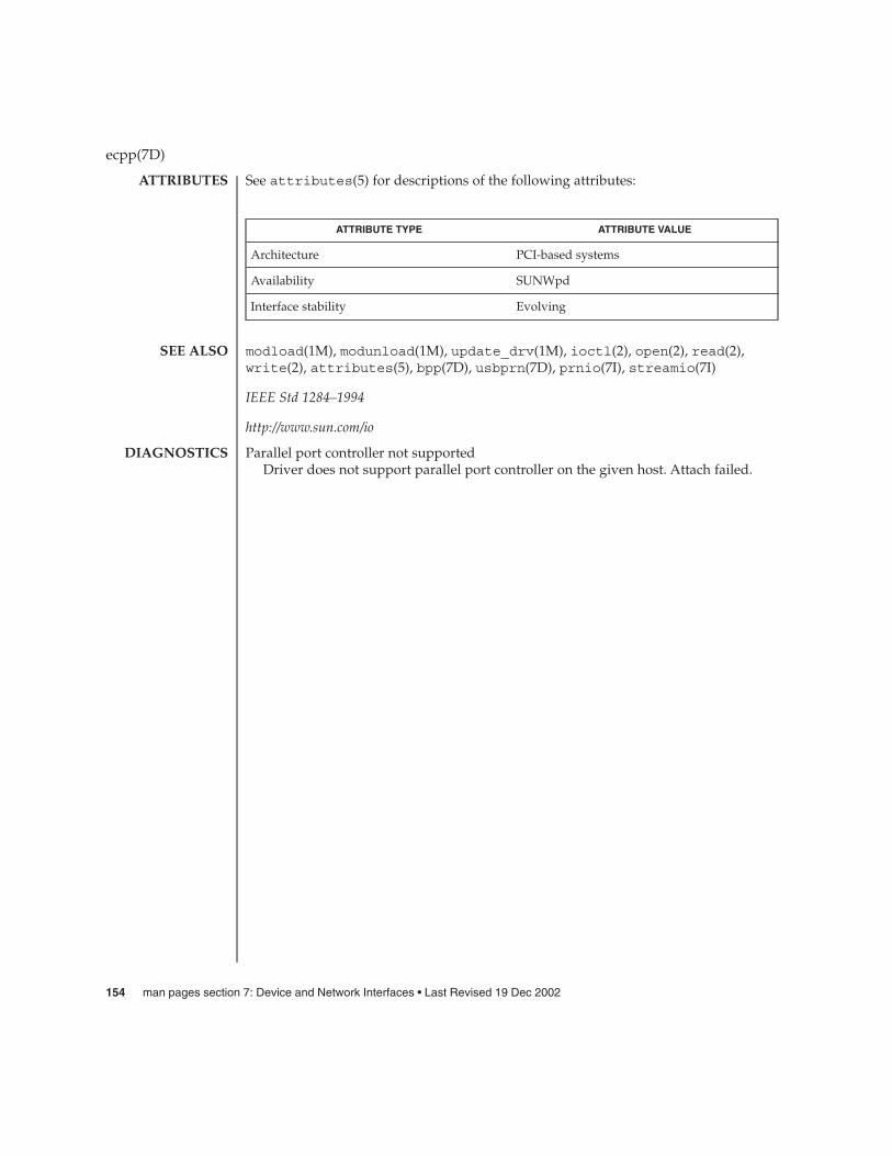
See attributes(5) for descriptions of the following attributes:
ATTRIBUTE TYPE ATTRIBUTE VALUE
Architecture PCI-based systems
Availability SUNWpd
Interface stability Evolving
modload(1M), modunload(1M), update_drv(1M), ioctl(2), open(2), read(2),write(2), attributes(5), bpp(7D), usbprn(7D), prnio(7I), streamio(7I)
IEEE Std 1284–1994
http://www.sun.com/io
Parallel port controller not supportedDriver does not support parallel port controller on the given host. Attach failed.
ecpp(7D)
ATTRIBUTES
SEE ALSO
DIAGNOSTICS
154 man pages section 7: Device and Network Interfaces • Last Revised 19 Dec 2002

elx – 3COM EtherLink III Ethernet device driver
#include <sys/stropts.h>
#include <sys/ethernet.h>
#include <sys/dlpi.h>
#include <sys/gld.h>
The elx Ethernet driver is a multi-threaded, loadable, clonable, STREAMS hardwaredriver supporting the connectionless Data Link Provider Interface, dlpi(7P), over thefollowing 3COM ETHERLINK III Ethernet controllers. For IA based systems: 3C509,3C509B, 3C579 and 3C59x controllers. Multiple EtherLink III controllers installedwithin the system are supported by the driver. The elx driver provides basic supportfor the EtherLink III hardware. Functions include chip initialization, frame transmitand receive, multicast and “promiscuous” support, and error recovery and reporting.
The cloning, character-special device /dev/elx is used to access all EtherLink IIIdevices installed within the system.
The elx driver is dependent on /kernel/misc/gld, a loadable kernel module thatprovides the elx driver with the DLPI and STREAMS functionality required of a LANdriver. See gld(7D) for more details on the primatives supported by the driver.
The values returned by the driver in the DL_INFO_ACK primitive in response to theDL_INFO_REQ from the user are as follows:
� The maximum SDU is 1500 (ETHERMTU).� The minimum SDU is 0. The driver will pad to the mandatory 60-octet minimum
packet size.� The dlsap address length is 8.� The MAC type is DL_ETHER.� The sap length value is −2, meaning the physical address component is followed
immediately by a 2-byte sap component within the DLSAP address.� The broadcast address value is Ethernet/IEEE broadcast address
(FF:FF:FF:FF:FF:FF).
/dev/elxspecial character device
/platform/i86pc/kernel/drv/elx.confconfiguration file for elx driver
See attributes(5) for descriptions of the following attributes:
ATTRIBUTE TYPE ATTRIBUTE VALUE
Architecture IA
elx(7D)
NAME
SYNOPSIS
DESCRIPTION
FILES
ATTRIBUTES
Device and Network Interfaces 155

attributes(5), dlpi(7P), gld(7D)
elx(7D)
SEE ALSO
156 man pages section 7: Device and Network Interfaces • Last Revised 24 Feb 1998

elxl – 3Com Ethernet device driver
/kernel/drv/elxl
The elxl driver currently supports the following network cards: EtherLink XL(3C900-TPO, 3C900-COMBO, 3C900B-TPO, 3C900B-COMBO, and 3C900B-TPC),EtherLink XL 10/100 (3C905-TX Fast, 3C905-T4 Fast, 3C905B-TX Fast, 3C905B-T4 Fast,and 3C905C-TX-M Fast), and EtherLink Server 10/100 (3C980-TX Fast and3C980C-TXM).
The elxl Ethernet driver is a multi-threaded, loadable, clonable, STREAMS hardwaredriver supporting the connectionless Data Link Provider Interface, dlpi(7P). MultipleEtherLink XL controllers installed within the system are supported by the driver. Theelxl driver provides basic support for the EtherLink hardware. Functions includechip initialization, frame transmit and receive, multicast and promiscuous modesupport, and error recovery and reporting.
The cloning, character-special device /dev/elxl is used to access all EtherLinkdevices installed within the system.
The elxl driver is dependent on /kernel/misc/gld, a loadable kernel module thatprovides the elxl driver with the DLPI and STREAMS functionality required of aLAN driver. See gld(7D) for more details on the primatives supported by the driver.
The values returned by the driver in the DL_INFO_ACK primitive in response to theDL_INFO_REQ from the user are as follows:
� Maximum SDU is 1500 (ETHERMTU).� Minimum SDU is 0. The driver will pad to the mandatory 60-octet minimum packet
size.� The dlsap address length is 8.� MAC type is DL_ETHER.� The sap length value is –2, meaning the physical address component is followed
immediately by a 2-byte sap component within the DLSAP address.� The broadcast address value is Ethernet/IEEE broadcast address
(FF:FF:FF:FF:FF:FF).
� Media Type: Auto Select
� 3C905B cards in a Compaq ProLiant 6500 can fail to generate interrupts. There is noknown workaround for this problem. However, because some slots appear to bemore prone to the problem than others, try correcting the problem by moving thecard to another PCI slot. If that fails, try rebooting the machine a number of timesto free the card from the wedged state.
� Early versions of the 3Com 3C905C-TX-M adapter firmware do not support PXEnetwork boot on Solaris systems. If you are using a version earlier than 4.11,upgrade the firmware. The PXE version is indicated by the Managed Boot Agentversion number. This number is not normally displayed during boot, but is shownon the PXE configuration screen.
elxl(7D)
NAME
SYNOPSIS
DESCRIPTION
Supported Settings
Known Problemsand Limitations
Device and Network Interfaces 157

The /kernel/drv/elxl.conf file supports the following option:
full-duplex For full duplex operation use full-duplex=1. For half duplexuse full-duplex=0. Half-duplex operation provides betterresults on older 10-Mbit networks.
/dev/elxl Special character device
/kernel/drv/elxl.conf Configuration file for elxl driver
See attributes(5) for descriptions of the following attributes:
ATTRIBUTE TYPE ATTRIBUTE VALUE
Architecture IA
attributes(5), gld(7D), streamio(7I), dlpi(7P).
elxl(7D)
CONFIGURATION
FILES
ATTRIBUTES
SEE ALSO
158 man pages section 7: Device and Network Interfaces • Last Revised 27 November 2000
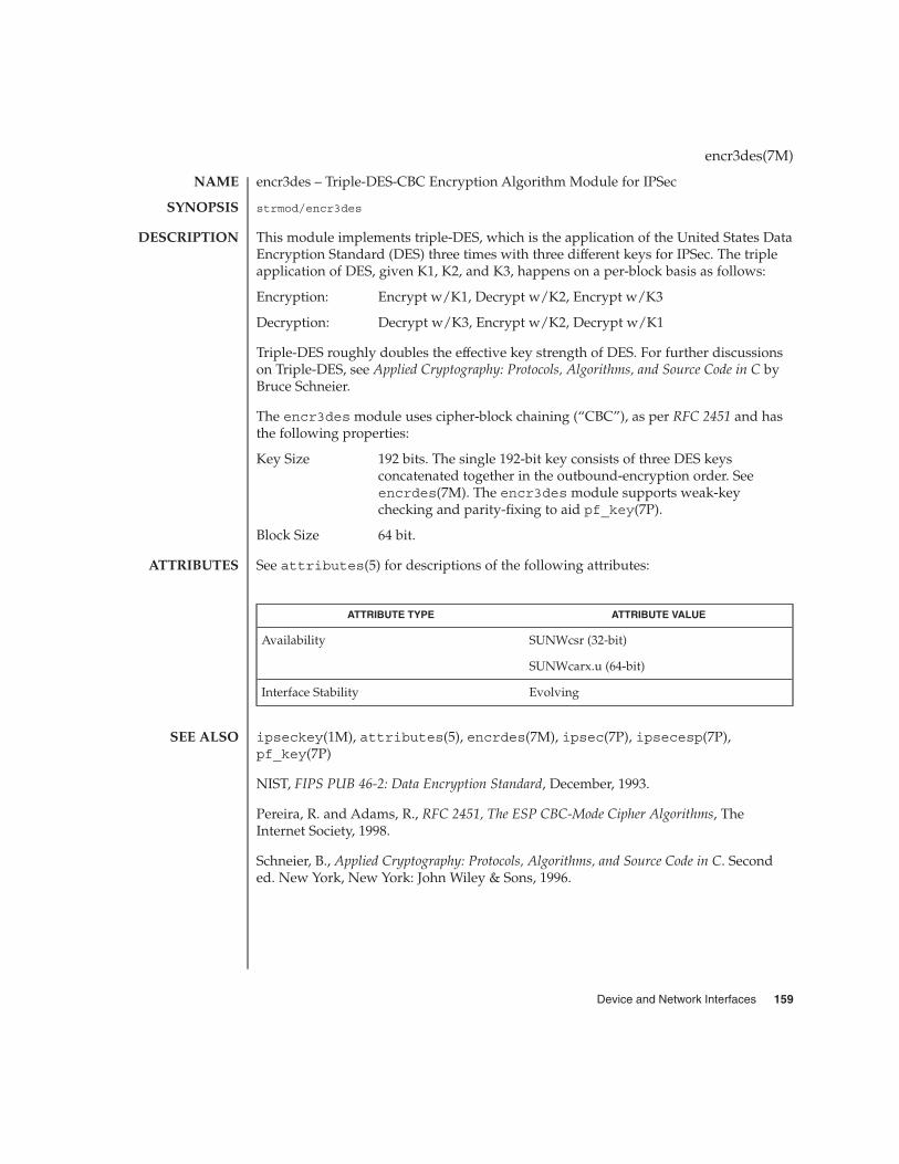
encr3des – Triple-DES-CBC Encryption Algorithm Module for IPSec
strmod/encr3des
This module implements triple-DES, which is the application of the United States DataEncryption Standard (DES) three times with three different keys for IPSec. The tripleapplication of DES, given K1, K2, and K3, happens on a per-block basis as follows:
Encryption: Encrypt w/K1, Decrypt w/K2, Encrypt w/K3
Decryption: Decrypt w/K3, Encrypt w/K2, Decrypt w/K1
Triple-DES roughly doubles the effective key strength of DES. For further discussionson Triple-DES, see Applied Cryptography: Protocols, Algorithms, and Source Code in C byBruce Schneier.
The encr3des module uses cipher-block chaining (“CBC”), as per RFC 2451 and hasthe following properties:
Key Size 192 bits. The single 192-bit key consists of three DES keysconcatenated together in the outbound-encryption order. Seeencrdes(7M). The encr3des module supports weak-keychecking and parity-fixing to aid pf_key(7P).
Block Size 64 bit.
See attributes(5) for descriptions of the following attributes:
ATTRIBUTE TYPE ATTRIBUTE VALUE
Availability SUNWcsr (32-bit)
SUNWcarx.u (64-bit)
Interface Stability Evolving
ipseckey(1M), attributes(5), encrdes(7M), ipsec(7P), ipsecesp(7P),pf_key(7P)
NIST, FIPS PUB 46-2: Data Encryption Standard, December, 1993.
Pereira, R. and Adams, R., RFC 2451, The ESP CBC-Mode Cipher Algorithms, TheInternet Society, 1998.
Schneier, B., Applied Cryptography: Protocols, Algorithms, and Source Code in C. Seconded. New York, New York: John Wiley & Sons, 1996.
encr3des(7M)
NAME
SYNOPSIS
DESCRIPTION
ATTRIBUTES
SEE ALSO
Device and Network Interfaces 159

encraes – AES-CBC encryption algorithm for IPsec
strmod/encraes
The encraes module implements AES, the US Government Advanced EncryptionStandard for IPsec. This module uses the cipher-block chaining mode (CBC) pursuantto RFC 2451. The encraes module has the following properties:
Key size 128, 192, or 256 bits. The key length affects the number of roundsperformed per cipher block, and therefore affects the speed of thealgorithm.
Block Size 128 bits
See attributes(5) for descriptions of the following attributes:
ATTRIBUTE TYPE ATTRIBUTE VALUE
Availability SUNWcryr (32-bit)
SUNWcryrx (64-bit)
Interface Stability Evolving
ipseckey(1M), attributes(5), ipsec(7P), ipsecesp(7P), pf_key(7P)
Pereira, R. and Adams, R. RFC 2451, The ESP CBC-Mode Cipher Algorithms, TheInternet Society, 1998.
encraes(7M)
NAME
SYNOPSIS
DESCRIPTION
ATTRIBUTES
SEE ALSO
160 man pages section 7: Device and Network Interfaces • Last Revised 17 Sep 2001

encrbfsh – Blowfish-CBC Encryption Algorithm Module for IPsec
strmod/encrbfsh
This module implements Blowfish, a cipher developed by Bruce Schneier, for IPsec.The encrbfsh module uses cipher-block chaining (“CBC”) pursuant to RFC 2451.This module has the following properties:
Key Size 32 to 448 bits. Keys are encoded internally as 448–bit quantities. Asmaller key size will repeat its pattern until 448 bits are reached.
Block Size 64 bits.
See attributes(5) for descriptions of the following attributes:
ATTRIBUTE TYPE ATTRIBUTE VALUE
Availability SUNWcryr (32-bit)
SUNWcryrx (64-bit)
Interface Stability Evolving
ipseckey(1M), attributes(5), ipsec(7P), ipsecesp(7P), pf_key(7P)
Pereira, R. and Adams, R., RFC 2451, The ESP CBC-Mode Cipher Algorithms, TheInternet Society, 1998.
Schneier, B., Applied Cryptography: Protocols, Algorithms, and Source Code in C. Seconded. New York, New York: John Wiley & Sons, 1996.
encrbfsh(7M)
NAME
SYNOPSIS
DESCRIPTION
ATTRIBUTES
SEE ALSO
Device and Network Interfaces 161

encrdes – DES-CBC Encryption Algorithm Module for IPsec
strmod/encrdes
This module implements the United States Data Encryption Standard (DES) for IPsec.encrdes uses cipher-block chaining (CBC), as per RFC 2405 and has the followingproperties:
Key Size 64 bits. 56 bit key, plus 8 parity bits. 7 bits of key are followed byone bit of odd parity. For example, the 56-bit key FF FF FF FF FFFF FF would be encoded as FE FE FE FE FE FE FE FE.encrdes supports weak-key checking and parity-fixing to aidpf_key(7P).
Block Size 64 bits.
It is used by ESP.
See attributes(5) for descriptions of the following attributes:
ATTRIBUTE TYPE ATTRIBUTE VALUE
Availability SUNWcsr (32-bit)
SUNWcarx.u (64-bit)
Interface Stability Evolving
ipseckey(1M), attributes(5), ipsec(7P), ipsecesp(7P), pf_key(7P)
Madson, C., and Doraswamy, N, RFC 2405, The ESP DES-CBC Cipher Algorithm withExplicit IV, The Internet Society, 1998.
NIST, FIPS PUB 46-2: Data Encryption Standard, December, 1993.
encrdes(7M)
NAME
SYNOPSIS
DESCRIPTION
ATTRIBUTES
SEE ALSO
162 man pages section 7: Device and Network Interfaces • Last Revised 22 Oct 2001

eri – eri Fast-Ethernet device driver
/dev/eri
The eri Fast Ethernet driver is a multi-threaded, loadable, clonable,STREAMS—based hardware driver supporting the connectionless Data Link ProviderInterface dlpi(7P) over an eri Fast-Ethernet controller. Multiple eri devicesinstalled within the system are supported by the driver.
The eri driver provides basic support for the eri hardware and handles the eridevice. Functions include chip initialization, frame transit and receive, multicast andpromiscuous support, and error recovery and reporting.
The eri device provides 100Base-TX networking interfaces using the SUN RIO ASICand an internal transceiver. The RIO ASIC provides the PCI interface and MACfunctions. The physical layer functions are provided by the internal transceiver whichconnects to a RJ-45 connector.
The 100Base-TX standard specifies an auto-negotiation protocol to automatically selectthe mode and speed of operation. The internal transceiver is capable of performingauto-negotiation using the remote-end of the link (link partner) and receives thecapabilities of the remote end. It selects the highest common denominator mode ofoperation based on the priorities. It also supports a forced-mode of operation underwhich the driver selects the mode of operation.
The cloning character-special device /dev/eri is used to access all eri controllersinstalled within the system.
The eri driver is a “style 2” Data Link Service provider. All M_PROTO andM_PCPROTO type messages are interpreted as DLPI primitives. Valid DLPI primitivesare defined in <sys/dlpi.h>. Refer to dlpi(7P) for more information.
An explicit DL_ATTACH_REQ message by the user is required to associate the openedstream with a particular device (ppa). The ppa ID is interpreted as an unsignedinteger data type and indicates the corresponding device instance (unit) number. Anerror (DL_ERROR_ACK) is returned by the driver if the ppa field value does notcorrespond to a valid device instance number for this system. The device is initializedon first attach and de-initialized (stopped) at last detach.
The values returned by the driver in the DL_INFO_ACK primitive in response to theDL_INFO_REQ from the user are as follows:
� The maximum SDU is 1500 (ETHERMTU - defined in <sys/ethernet.h> ).� The minimum SDU is 0.� The dlsap address length is 8.� The MAC type is DL_ETHER.� The sap length values is –2, meaning the physical address component is followed
immediately by a 2 byte sap component within the DLSAP address.� The service mode is DL_CLDLS.
eri(7D)
NAME
SYNOPSIS
DESCRIPTION
APPLICATIONPROGRAMMING
INTERFACEeri and DLPI
Device and Network Interfaces 163

� Optional quality of service (QOS) is not currently supported so QOS fields are 0.� The provider style is DL_STYLE.� The version is DL_VERSION_2.� The broadcast address value is Ethernet/IEEE broadcast address (0xFFFFFF).
Once in the DL_ATTACHED state, the user must send a DL_BIND_REQ to associate aparticular SAP (Service Access Pointer) with the stream. The eri driver interprets thesap field within the DL_BIND_REQ as an Ethernet “type,” therefore valid values forthe sap field are in the [0-0xFFFF] range. Only one Ethernet type can be bound to thestream at any time.
If the user selects a sap with a value of 0, the receiver will be in IEEE 802.3 mode. Allframes received from the media having a Ethernet type field in the range [0-1500] areassumed to be 802.3 frames and are routed up all open Streams which are bound tosap value 0. If more than one Stream is in 802.3 mode, the frame will be duplicatedand routed up multiple Streams as DL_UNITDATA_IND messages.
In transmission, the driver checks the sap field of the DL_BIND_REQ to determine ifthe value is 0 or if the Ethernet type field is in the range [0-1500]. If either is true, thedriver computes the length of the message, not including initial M_PROTO mblk(message block), of all subsequent DL_UNITDATA_REQ messages, and transmits 802.3frames that have this value in the MAC frame header length field.
The eri driver’s DLSAP address format consists of the 6 byte physical (Ethernet)address component followed immediately by the 2 byte sap (type) component,producing an 8 byte DLSAP address. Applications should not hardcode to thisparticular implementation-specific DLSAP address format but use informationreturned in the DL_INFO_ACK primitive to compose and decompose DLSAPaddresses. The sap length, full DLSAP length, and sap/physical ordering areincluded within the DL_INFO_ACK. The physical address length can be computed bysubtracting the sap length from the full DLSAP address length or by issuing theDL_PHYS_ADDR_REQ to obtain the current physical address associated with thestream.
Once in the DL_BOUND state, the user may transmit frames on the Ethernet by sendingDL_UNITDATA_REQ messages to the eri driver. The eri driver will route receivedEthernet frames up all open and bound streams having a sap which matches theEthernet type as DL_UNITDATA_IND messages. Received Ethernet frames areduplicated and routed up multiple open streams if necessary. The DLSAP addresscontained within the DL_UNITDATA_REQ and DL_UNITDATA_IND messages consistsof both the sap (type) and physical (Ethernet) components.
In addition to the mandatory connectionless DLPI message set, the driver alsosupports the following primitives:
eri(7D)
eri Primitives
164 man pages section 7: Device and Network Interfaces • Last Revised 1 Mar 2000
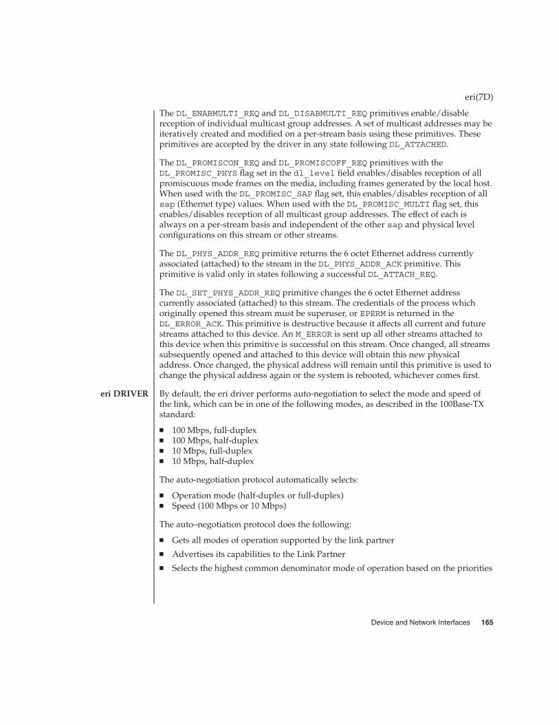
The DL_ENABMULTI_REQ and DL_DISABMULTI_REQ primitives enable/disablereception of individual multicast group addresses. A set of multicast addresses may beiteratively created and modified on a per-stream basis using these primitives. Theseprimitives are accepted by the driver in any state following DL_ATTACHED.
The DL_PROMISCON_REQ and DL_PROMISCOFF_REQ primitives with theDL_PROMISC_PHYS flag set in the dl_level field enables/disables reception of allpromiscuous mode frames on the media, including frames generated by the local host.When used with the DL_PROMISC_SAP flag set, this enables/disables reception of allsap (Ethernet type) values. When used with the DL_PROMISC_MULTI flag set, thisenables/disables reception of all multicast group addresses. The effect of each isalways on a per-stream basis and independent of the other sap and physical levelconfigurations on this stream or other streams.
The DL_PHYS_ADDR_REQ primitive returns the 6 octet Ethernet address currentlyassociated (attached) to the stream in the DL_PHYS_ADDR_ACK primitive. Thisprimitive is valid only in states following a successful DL_ATTACH_REQ.
The DL_SET_PHYS_ADDR_REQ primitive changes the 6 octet Ethernet addresscurrently associated (attached) to this stream. The credentials of the process whichoriginally opened this stream must be superuser, or EPERM is returned in theDL_ERROR_ACK. This primitive is destructive because it affects all current and futurestreams attached to this device. An M_ERROR is sent up all other streams attached tothis device when this primitive is successful on this stream. Once changed, all streamssubsequently opened and attached to this device will obtain this new physicaladdress. Once changed, the physical address will remain until this primitive is used tochange the physical address again or the system is rebooted, whichever comes first.
By default, the eri driver performs auto-negotiation to select the mode and speed ofthe link, which can be in one of the following modes, as described in the 100Base-TXstandard:
� 100 Mbps, full-duplex� 100 Mbps, half-duplex� 10 Mbps, full-duplex� 10 Mbps, half-duplex
The auto-negotiation protocol automatically selects:
� Operation mode (half-duplex or full-duplex)� Speed (100 Mbps or 10 Mbps)
The auto–negotiation protocol does the following:
� Gets all modes of operation supported by the link partner� Advertises its capabilities to the Link Partner� Selects the highest common denominator mode of operation based on the priorities
eri(7D)
eri DRIVER
Device and Network Interfaces 165

The internal transceiver is capable of all of the operating speeds and modes listedabove. By default, auto-negotiation is used to select the speed and the mode of the linkand the common mode of operation with the link partner.
For users who want to select the speed and mode of the link, the eri device supportsprogrammable IPG (Inter-Packet Gap) parameters ipg1 and ipg2. Sometimes, theuser may want to alter these values depending on whether the driver supports 10Mbps or 100 Mpbs and accordingly, IPG will be set to 9.6 or 0.96 microseconds.
The eri driver provides for setting and getting various parameters for the eri device.The parameter list includes current transceiver status, current link status, inter-packetgap, local transceiver capabilities and link partner capabilities.
The local transceiver has two set of capabilities: one set reflects hardware capabilities,which are read-only (RO) parameters. The second set reflects the values chosen by theuser and is used in speed selection and possess read/write (RW) capability. At boottime, these two sets of capabilities will be the same. Because the current default valueof these parameters can only be read and not modified, the link partner capabilities arealso read only.
/dev/eri eri special character device.
/kernel/drv/eri.conf System wide default device driverproperties
/kernel/drv/sparcv9/eri 64 bit device driver
ndd(1M), netstat(1M), driver.conf(4), hme(7D), qfe(7D), dlpi(7P)
eri(7D)
eri Parameter List
FILES
SEE ALSO
166 man pages section 7: Device and Network Interfaces • Last Revised 1 Mar 2000

esp – ESP SCSI Host Bus Adapter Driver
esp@sbus-slot,80000
The esp Host Bus Adapter driver is a SCSA compliant nexus driver that supports theEmulex family of esp SCSI chips (esp100, esp100A, esp236, fas101, fas236).
The esp driver supports the standard functions provided by the SCSA interface. Thedriver supports tagged and untagged queuing, fast SCSI (on FAS esp’s only), almostunlimited transfer size (using a moving DVMA window approach), and auto requestsense; but it does not support linked commands.
The esp driver can be configured by defining properties in esp.conf which overridethe global SCSI settings. Supported properties are: scsi-options,target<n>-scsi-options, scsi-reset-delay, scsi-watchdog-tick,scsi-tag-age-limit, scsi-initiator-id.
target<n>-scsi-options overrides the scsi-options property value fortarget<n>. <n> can vary from 0 to 7.
Refer to scsi_hba_attach(9F) for details.
EXAMPLE 1 A sample of esp configuration file.
Create a file /kernel/drv/esp.conf and add this line:
scsi-options=0x78;
This will disable tagged queuing, fast SCSI, and Wide mode for all esp instances. Todisable an option for one specific esp (refer to driver.conf(4)):
name="esp"parent="/iommu@f,e0000000/sbus@f,e0001000/espdma@f,400000"
reg=0xf,0x800000,0x40target1-scsi-options=0x58scsi-options=0x178 scsi-initiator-id=6;
Note that the default initiator ID in OBP is 7 and that the change to ID 6 will occur atattach time. It may be preferable to change the initiator ID in OBP.
The above would set scsi-options for target 1 to 0x58 and for all other targets onthis SCSI bus to 0x178. The physical pathname of the parent can be determined usingthe /devices tree or following the link of the logical device name:
example# ls -l /dev/rdsk/c0t3d0s0lrwxrwxrwx 1 root root 88 Aug 22 13:29 /dev/rdsk/c0t3d0s0 ->../../devices/iommu@f,e0000000/sbus@f,e0001000/espdma@f,400000/
esp@f,800000/sd@3,0:a,raw
The register property values can be determined from prtconf(1M) output (-voption):
esp, instance #0....
Register Specifications:Bus Type=0xf, Address=0x800000, Size=40
esp(7D)
NAME
SYNOPSIS
DESCRIPTION
CONFIGURATION
EXAMPLES
Device and Network Interfaces 167
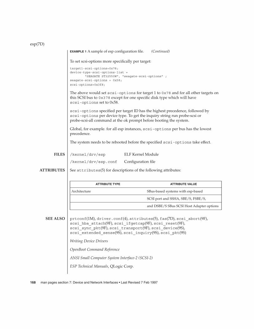
EXAMPLE 1 A sample of esp configuration file. (Continued)
To set scsi-options more specifically per target:
target1-scsi-options=0x78;device-type-scsi-options-list =
"SEAGATE ST32550W", "seagate-scsi-options" ;seagate-scsi-options = 0x58;
scsi-options=0x3f8;
The above would set scsi-options for target 1 to 0x78 and for all other targets onthis SCSI bus to 0x378 except for one specific disk type which will havescsi-options set to 0x58.
scsi-options specified per target ID has the highest precedence, followed byscsi-options per device type. To get the inquiry string run probe-scsi orprobe-scsi-all command at the ok prompt before booting the system.
Global, for example. for all esp instances, scsi-options per bus has the lowestprecedence.
The system needs to be rebooted before the specified scsi-options take effect.
/kernel/drv/esp ELF Kernel Module
/kernel/drv/esp.conf Configuration file
See attributes(5) for descriptions of the following attributes:
ATTRIBUTE TYPE ATTRIBUTE VALUE
Architecture SBus-based systems with esp-based
SCSI port and SSHA, SBE/S, FSBE/S,
and DSBE/S SBus SCSI Host Adapter options
prtconf(1M), driver.conf(4), attributes(5), fas(7D), scsi_abort(9F),scsi_hba_attach(9F), scsi_ifgetcap(9F), scsi_reset(9F),scsi_sync_pkt(9F), scsi_transport(9F), scsi_device(9S),scsi_extended_sense(9S), scsi_inquiry(9S), scsi_pkt(9S)
Writing Device Drivers
OpenBoot Command Reference
ANSI Small Computer System Interface-2 (SCSI-2)
ESP Technical Manuals, QLogic Corp.
esp(7D)
FILES
ATTRIBUTES
SEE ALSO
168 man pages section 7: Device and Network Interfaces • Last Revised 7 Feb 1997

The messages described below are some that may appear on the system console, aswell as being logged.
The first four messages may be displayed while the esp driver is trying to attach;these messages mean that the esp driver was unable to attach. All of these messagesare preceded by "esp%d", where "%d" is the instance number of the esp controller.
Device in slave-only slotThe SBus device has been placed in a slave-only slot and will not be accessible;move to non-slave-only SBus slot.
Device is using a hilevel intrThe device was configured with an interrupt level that cannot be used with thisesp driver. Check the SBus device.
Unable to map registersDriver was unable to map device registers; check for bad hardware. Driver did notattach to device; SCSI devices will be inaccessible.
Cannot find dma controllerDriver was unable to locate a dma controller. This is an auto-configuration error.
Disabled TQ since disconnects are disabledTagged queuing was disabled because disconnects were disabled inscsi-options.
Bad clock frequency- setting 20mhz, asynchronous modeCheck for bad hardware.
Sync pkt failedSyncing a SCSI packet failed. Refer to scsi_sync_pkt(9F).
Slot %x: All tags in use!!!The driver could not allocate another tag number. The target devices do notproperly support tagged queuing.
Target %d.%d cannot alloc tag queue\nThe driver could not allocate space for tag queue.
Gross error in esp status (%x)The driver experienced severe SCSI bus problems. Check cables and terminator.
Spurious interruptThe driver received an interrupt while the hardware was not interrupting.
Lost state in phasemanageThe driver is confused about the state of the SCSI bus.
Unrecoverable DMA error during selectionThe DMA controller experienced host SBus problems. Check for bad hardware.
Bad sequence step (0x%x) in selectionThe esp hardware reported a bad sequence step. Check for bad hardware.
esp(7D)
DIAGNOSTICS
Device and Network Interfaces 169

Undetermined selection failureThe selection of a target failed unexpectedly. Check for bad hardware.
>2 reselection IDs on the busTwo targets selected simultaneously, which is illegal. Check for bad hardware.
Reconnect: unexpected bus freeA reconnect by a target failed. Check for bad hardware.
Timeout on receiving tag msgSuspect target f/w failure in tagged queue handling.
Parity error in tag msgA parity error was detected in a tag message. Suspect SCSI bus problems.
Botched tagThe target supplied bad tag messages. Suspect target f/w failure in tagged queuehandling.
Parity error in reconnect msg’sThe reconnect failed because of parity errors.
Target <n> didn’t disconnect after sending <message>The target unexpectedly did not disconnect after sending <message>.
No support for multiple segsThe esp driver can only transfer contiguous data.
No dma window?Moving the DVMA window failed unexpectedly.
No dma window on <type> operationMoving the DVMA window failed unexpectedly.
Cannot set new dma windowMoving the DVMA window failed unexpectedly.
Unable to set new window at <address> for <type> operationMoving the DVMA window failed unexpectedly.
Illegal dma boundary? %xAn attempt was made to cross a boundary that the driver could not handle.
Unwanted data out/in for Target <n>The target went into an unexpected phase.
Spurious <name> phase from target <n>The target went into an unexpected phase.
SCSI bus DATA IN phase parity errorThe driver detected parity errors on the SCSI bus.
SCSI bus MESSAGE IN phase parity errorThe driver detected parity errors on the SCSI bus.
esp(7D)
170 man pages section 7: Device and Network Interfaces • Last Revised 7 Feb 1997

SCSI bus STATUS phase parity errorThe driver detected parity errors on the SCSI bus.
Premature end of extended messageAn extended SCSI bus message did not complete. Suspect a target f/w problem.
Premature end of input messageA multibyte input message was truncated. Suspect a target f/w problem.
Input message botchThe driver is confused about messages coming from the target.
Extended message <n> is too longThe extended message sent by the target is longer than expected.
<name> message <n> from Target <m> garbledTarget <m> sent message <name> of value <n> which the driver did notunderstand.
Target <n> rejects our message <name>Target <n> rejected a message sent by the driver.
Rejecting message <name> from Target <n>The driver rejected a message received from target <n>
Cmd dma errorThe driver was unable to send out command bytes.
Target <n> refused message resendThe target did not accept a message resend.
Two-byte message <name> <value> rejectedThe driver does not accept this two-byte message.
Unexpected selection attemptAn attempt was made to select this host adapter by another initiator.
Polled cmd failed (target busy)A polled command failed because the target did not complete outstandingcommands within a reasonable time.
Polled cmd failedA polled command failed because of timeouts or bus errors.
Disconnected command timeout for Target <id>.<lun>A timeout occurred while target/lun was disconnected. This is usually a target f/wproblem. For tagged queuing targets, <n> commands were outstanding when thetimeout was detected.
Disconnected tagged cmds (<n>) timeout for Target <id>.<lun>A timeout occurred while target/lun was disconnected. This is usually a target f/wproblem. For tagged queuing targets, <n> commands were outstanding when thetimeout was detected.
esp(7D)
Device and Network Interfaces 171

Connected command timeout for Target <id>.<lun>This is usually a SCSI bus problem. Check cables and termination.
Target <id>.<lun> reverting to async. modeA data transfer hang was detected. The driver attempts to eliminate this problem byreducing the data transfer rate.
Target <id>.<lun> reducing sync. transfer rateA data transfer hang was detected. The driver attempts to eliminate this problem byreducing the data transfer rate.
Reverting to slow SCSI cable modeA data transfer hang was detected. The driver attempts to eliminate this problem byreducing the data transfer rate.
Reset SCSI bus failedAn attempt to reset the SCSI bus failed.
External SCSI bus resetAnother initiator reset the SCSI bus.
The esp hardware does not support Wide SCSI mode. Only FAS-type esp’s supportfast SCSI (10 MB/sec).
The esp driver exports properties indicating per target the negotiated transfer speed(target<n>-sync-speed) and whether tagged queuing has been enabled(target<n>-TQ). The sync-speed property value is the data transfer rate inKB/sec. The target-TQ property has no value. The existence of the propertyindicates that tagged queuing has been enabled. Refer to prtconf(1M) (verboseoption) for viewing the esp properties.
dma, instance #3Register Specifications:
Bus Type=0x2, Address=0x81000, Size=10esp, instance #3
Driver software properties:name <target3-TQ> length <0> − <no
value>.name <target3-sync-speed> length <4>
value <0x00002710>.name <scsi-options> length <4>
value <0x000003f8>.name <scsi-watchdog-tick> length <4>
value <0x0000000a>.name <scsi-tag-age-limit> length <4>
value <0x00000008>.name <scsi-reset-delay> length <4>
value <0x00000bb8>.
esp(7D)
WARNINGS
NOTES
172 man pages section 7: Device and Network Interfaces • Last Revised 7 Feb 1997

ipsecesp, ESP – IPsec Encapsulating Security Payload
drv/ipsecesp
The ipsecesp module provides confidentiality, integrity, authentication, and partialsequence integrity (replay protection) to IP datagrams. The encapsulating securitypayload (ESP) encapsulates its data, enabling it to protect data that follows in thedatagram. For TCP packets, ESP encapsulates the TCP header and its data only. If thepacket is an IP in IP datagram, ESP protects the inner IP datagram. Per-socket policyallows "self-encapsulation" so ESP can encapsulate IP options when necessary. Seeipsec(7P).
Unlike the authentication header (AH), ESP allows multiple varieties of datagramprotection. (Using a single datagram protection form can expose vulnerabilities.) Forexample, only ESP can be used to provide confidentiality. But protectingconfidentiality alone exposes vulnerabilities in both replay attacks and cut-and-pasteattacks. Similarly, if ESP protects only integrity and does not fully protect againsteavesdropping, it may provide weaker protection than AH. See ipsecah(7P).
ESP is implemented as a module that is auto-pushed on top of IP. Use the/dev/ipsecesp entry to tune ESP with ndd(1M), as well as to allow futurealgorithms to be loaded on top of ESP. ESP allows encryption algorithms to be pushedon top of it, in addition to the authentication algorithms that can be used in AH.Authentication algorithms include HMAC-MD5 and HMAC-SHA-1. Seeauthmd5h(7M) and authsha1(7M). Encryption algorithms include DES, Triple-DES,Blowfish and AES. See encrdes(7M), encr3des(7M), encrbfsh(7M) andencraes(7M). Each authentication and encryption algorithm contain key size and keyformat properties. Because of export laws in the United States, not all encryptionalgorithms are available outside of the United States.
ESP without authentication exposes vulnerabilities to cut-and-paste cryptographicattacks as well as eavesdropping attacks. Like AH, ESP is vulnerable to eavesdroppingwhen used without confidentiality.
See attributes(5) for descriptions of the following attributes:
ATTRIBUTE TYPE ATTRIBUTE VALUE
Availability SUNWcsr (32-bit)
SUNWcarx (64-bit)
Interface Stability Evolving
ipsecconf(1M), ndd(1M), attributes(5), authmd5h(5), authsha1(7M),encrdes(7M), encr3des(7M), encrbfsh(7M), ip(7P), ipsec(7P), ipsecah(7P)
Kent, S. and Atkinson, R.RFC 2406, IP Encapsulating Security Payload (ESP), TheInternet Society, 1998.
ESP(7P)
NAME
SYNOPSIS
DESCRIPTION
Algorithms andthe ESP Device
SecurityConsiderations
ATTRIBUTES
SEE ALSO
Device and Network Interfaces 173

Due to United States export control laws, encryption strength available on ESP variesfor versions of the SunOS sold outside the United States.
See authmd5h(7M) and authsha1(7M). Encryption algorithms include DES,Triple-DES, Blowfish and AES. See encrdes(7M), encr3des(7M), andencrbfsh(7M).
ESP(7P)
NOTES
174 man pages section 7: Device and Network Interfaces • Last Revised 20 Mar 2001

fas – FAS SCSI Host Bus Adapter Driver
fas@sbus-slot,0x8800000
The fas Host Bus Adapter driver is a SCSA compliant nexus driver that supports theQlogic FAS366 SCSI chip.
The fas driver supports the standard functions provided by the SCSA interface. Thedriver supports tagged and untagged queuing, wide and fast SCSI, almost unlimitedtransfer size (using a moving DVMA window approach), and auto request sense; butit does not support linked commands.
The fas driver can be configured by defining properties in fas.conf which overridethe global SCSI settings. Supported properties are: scsi-options,target<n>-scsi-options, scsi-reset-delay, scsi-watchdog-tick,scsi-tag-age-limit, scsi-initiator-id.
target<n>-scsi-options overrides the scsi-options property value fortarget<n>. <n> can vary from decimal 0 to 15. The supported scsi-options are:SCSI_OPTIONS_DR, SCSI_OPTIONS_SYNC, SCSI_OPTIONS_TAG,SCSI_OPTIONS_FAST, and SCSI_OPTIONS_WIDE.
After periodic interval scsi-watchdog-tick, the fas driver searches all currentand disconnected commands for timeouts.
scsi-tag-age-limit is the number of times that the fas driver attempts toallocate a particular tag ID that is currently in use after going through all tag IDs in acircular fashion. After finding the same tag ID in use scsi-tag-age-limit times,no more commands will be submitted to this target until all outstanding commandscomplete or timeout.
Refer to scsi_hba_attach(9F) for details.
EXAMPLE 1 A sample of fas configuration file
Create a file called /kernel/drv/fas.conf and add this line:
scsi-options=0x78;
This disables tagged queuing, Fast SCSI, and Wide mode for all fas instances. Thefollowing example disables an option for one specific fas (refer to driver.conf(4)for more details):
name="fas" parent="/iommu@f,e0000000/sbus@f,e0001000"reg=3,0x8800000,0x10,3,0x8810000,0x40target1-scsi-options=0x58
scsi-options=0x178 scsi-initiator-id=6;Note that the default initiator ID inOBP is 7 and that the change to ID 6 will occur at attach time. It may be preferable tochange the initiator ID in OBP.
The example above sets scsi-options for target 1 to 0x58 and all other targets onthis SCSI bus to 0x178.
fas(7D)
NAME
SYNOPSIS
DESCRIPTION
DriverConfiguration
EXAMPLES
Device and Network Interfaces 175
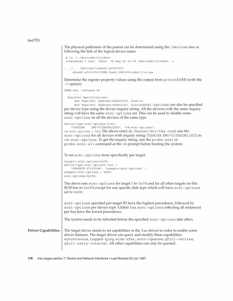
The physical pathname of the parent can be determined using the /devices tree orfollowing the link of the logical device name:
# ls -l /dev/rdsk/c1t3d0s0lrwxrwxrwx 1 root other 78 Aug 28 16:05 /dev/rdsk/c1t3d0s0 ->
. . /. . /devices/iommu@f,e0000000\
sbus@f,e0001000/SUNW,fas@3,8800000/sd@3,0:a,raw
Determine the register property values using the output from prtconf(1M) (with the-v option):
SUNW,fas, instance #0. . . .Register Specifications:
Bus Type=0x3, Address=0x8800000, Size=10
Bus Type=0x3, Address=0x8810000, Size=40scsi-options can also be specifiedper device type using the device inquiry string. All the devices with the same inquirystring will have the same scsi-options set. This can be used to disable somescsi-options on all the devices of the same type.
device-type-scsi-options-list="TOSHIBA XM5701TASUN12XCD", "cd-scsi-options";
cd-scsi-options = 0x0;The above entry in /kernel/drv/fas.conf sets thescsi-options for all devices with inquiry string TOSHIBA XM5701TASUN12XCD tocd-scsi-options. To get the inquiry string, run the probe-scsi orprobe-scsi-all command at the ok prompt before booting the system.
To set scsi-options more specifically per target:
target1-scsi-options=0x78;device-type-scsi-options-list =
"SEAGATE ST32550W", "seagate-scsi-options" ;seagate-scsi-options = 0x58;
scsi-options=0x3f8;
The above sets scsi-options for target 1 to 0x78 and for all other targets on thisSCSI bus to 0x3f8 except for one specific disk type which will have scsi-optionsset to 0x58.
scsi-options specified per target ID have the highest precedence, followed byscsi-options per device type. Global fas scsi-options (effecting all instances)per bus have the lowest precedence.
The system needs to be rebooted before the specified scsi-options take effect.
The target driver needs to set capabilities in the fas driver in order to enable somedriver features. The target driver can query and modify these capabilities:synchronous, tagged-qing, wide-xfer, auto-rqsense, qfull-retries,qfull-retry-interval. All other capabilities can only be queried.
fas(7D)
Driver Capabilities
176 man pages section 7: Device and Network Interfaces • Last Revised 20 Jun 1997

By default, tagged-qing, auto-rqsense, and wide-xfer capabilities are disabled,while disconnect, synchronous, and untagged-qing are enabled. Thesecapabilities can only have binary values (0 or 1). The default value forqfull-retries is 10 and the default value for qfull-retry-interval is 100.The qfull-retries capability is a uchar_t (0 to 255) while qfull-retry-interval is a ushort_t (0 to 65535).
The target driver needs to enable tagged-qing and wide-xfer explicitly. Theuntagged-qing capability is always enabled and its value cannot be modified,because fas can queue commands even when tagged-qing is disabled.
Whenever there is a conflict between the value of scsi-options and a capability, thevalue set in scsi-options prevails. Only whom != 0 is supported in thescsi_ifsetcap(9F) call.
Refer to scsi_ifsetcap(9F) and scsi_ifgetcap(9F) for details.
/kernel/drv/fas ELF Kernel Module
/kernel/drv/fas.conf Optional configuration file
See attributes(5) for descriptions of the following attributes:
ATTRIBUTE TYPE ATTRIBUTE VALUE
Architecture Limited to Sparc SBus-based systems withFAS366-based SCSI port and SunSWIFT SBus SCSIHost Adapter/Fast Ethernet option.
prtconf(1M), driver.conf(4), attributes(5), scsi_abort(9F),scsi_hba_attach(9F), scsi_ifgetcap(9F), scsi_ifsetcap(9F),scsi_reset(9F), scsi_sync_pkt(9F), scsi_transport(9F), scsi_device(9S),scsi_extended_sense(9S), scsi_inquiry(9S), scsi_pkt(9S)
Writing Device Drivers
ANSI Small Computer System Interface-2 (SCSI-2)
QLogic Corporation, FAS366 Technical Manuals.
The messages described below are some that may appear on the system console, aswell as being logged.
The first five messages may be displayed while the fas driver is trying to attach; thesemessages mean that the fas driver was unable to attach. All of these messages arepreceded by "fas%d", where "%d" is the instance number of the fas controller.
Device in slave-only slotThe SBus device has been placed in a slave-only slot and will not be accessible;move to non-slave-only SBus slot.
fas(7D)
FILES
ATTRIBUTES
SEE ALSO
DIAGNOSTICS
Device and Network Interfaces 177
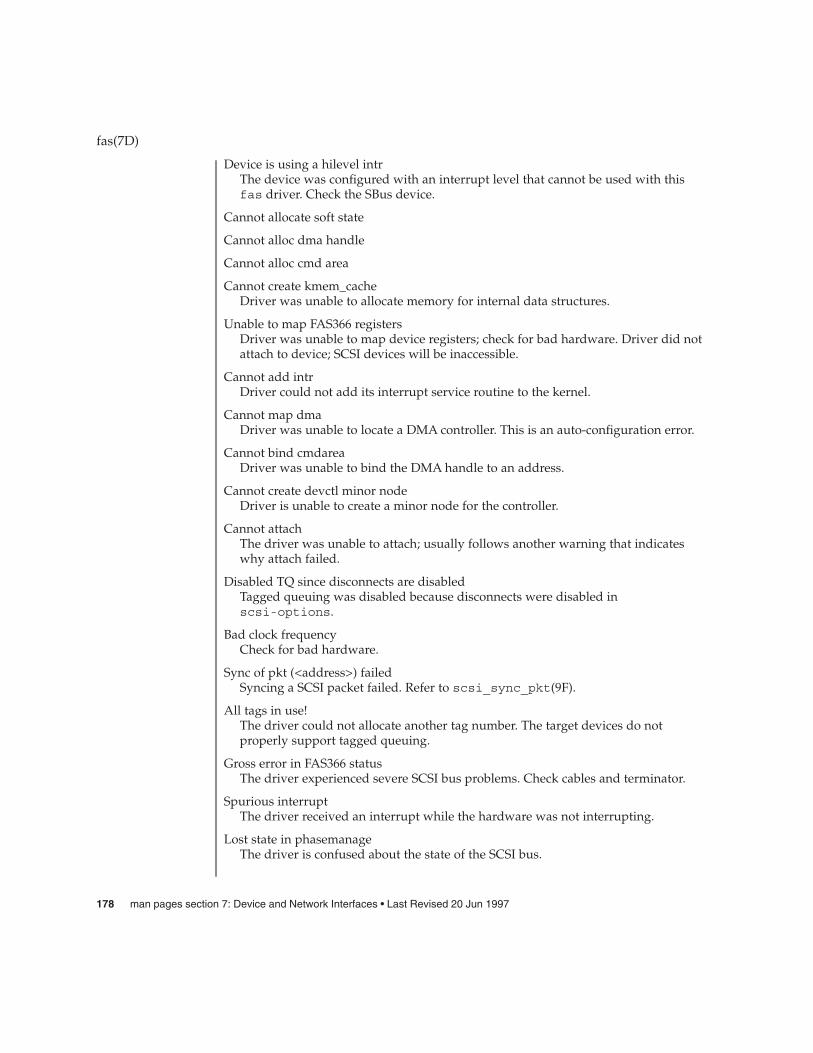
Device is using a hilevel intrThe device was configured with an interrupt level that cannot be used with thisfas driver. Check the SBus device.
Cannot allocate soft state
Cannot alloc dma handle
Cannot alloc cmd area
Cannot create kmem_cacheDriver was unable to allocate memory for internal data structures.
Unable to map FAS366 registersDriver was unable to map device registers; check for bad hardware. Driver did notattach to device; SCSI devices will be inaccessible.
Cannot add intrDriver could not add its interrupt service routine to the kernel.
Cannot map dmaDriver was unable to locate a DMA controller. This is an auto-configuration error.
Cannot bind cmdareaDriver was unable to bind the DMA handle to an address.
Cannot create devctl minor nodeDriver is unable to create a minor node for the controller.
Cannot attachThe driver was unable to attach; usually follows another warning that indicateswhy attach failed.
Disabled TQ since disconnects are disabledTagged queuing was disabled because disconnects were disabled inscsi-options.
Bad clock frequencyCheck for bad hardware.
Sync of pkt (<address>) failedSyncing a SCSI packet failed. Refer to scsi_sync_pkt(9F).
All tags in use!The driver could not allocate another tag number. The target devices do notproperly support tagged queuing.
Gross error in FAS366 statusThe driver experienced severe SCSI bus problems. Check cables and terminator.
Spurious interruptThe driver received an interrupt while the hardware was not interrupting.
Lost state in phasemanageThe driver is confused about the state of the SCSI bus.
fas(7D)
178 man pages section 7: Device and Network Interfaces • Last Revised 20 Jun 1997

Unrecoverable DMA error during selectionThe DMA controller experienced host SBus problems. Check for bad hardware.
Bad sequence step (<step number>) in selectionThe FAS366 hardware reported a bad sequence step. Check for bad hardware.
Undetermined selection failureThe selection of a target failed unexpectedly. Check for bad hardware.
Target <n>: failed reselection (bad reselect bytes)A reconnect failed, target sent incorrect number of message bytes. Check for badhardware.
Target <n>: failed reselection (bad identify message)A reconnect failed, target didn’t send identify message or it got corrupted. Checkfor bad hardware.
Target <n>: failed reselection (not in msgin phase)Incorrect SCSI bus phase after reconnection. Check for bad hardware.
Target <n>: failed reselection (unexpected bus free)Incorrect SCSI bus phase after reconnection. Check for bad hardware.
Target <n>: failed reselection (timeout on receiving tag msg)A reconnect failed; target failed to send tag bytes. Check for bad hardware.
Target <n>: failed reselection (botched tag)A reconnect failed; target failed to send tag bytes. Check for bad hardware.
Target <n>: failed reselection (invalid tag)A reconnect failed; target sent incorrect tag bytes. Check for bad hardware.
Target <n>: failed reselection (Parity error in reconnect msg’s)A reconnect failed; parity error detected. Check for bad hardware.
Target <n>: failed reselection (no command)A reconnect failed; target accepted abort or reset, but still tries to reconnect.Check for bad hardware.
Unexpected bus freeTarget disconnected from the bus without notice. Check for bad hardware.
Target <n> didn’t disconnect after sending <message>The target unexpectedly did not disconnect after sending <message>.
Bad sequence step (0x?) in selectionThe sequence step register shows an improper value. The target might bemisbehaving.
Illegal dma boundary?An attempt was made to cross a boundary that the driver could not handle.
Unwanted data xfer direction for Target <n>The target went into an unexpected phase.
fas(7D)
Device and Network Interfaces 179

Unrecoverable DMA error on dma <send/receive>There is a DMA error while sending/receiving data. The host DMA controller isexperiencing some problems.
SCSI bus DATA IN phase parity errorThe driver detected parity errors on the SCSI bus.
SCSI bus MESSAGE IN phase parity errorThe driver detected parity errors on the SCSI bus.
SCSI bus STATUS phase parity errorThe driver detected parity errors on the SCSI bus.
Premature end of extended messageAn extended SCSI bus message did not complete. Suspect a target firmwareproblem.
Premature end of input messageA multibyte input message was truncated. Suspect a target firmware problem.
Input message botchThe driver is confused about messages coming from the target.
Extended message <n> is too longThe extended message sent by the target is longer than expected.
<name> message <n> from Target <m> garbledTarget <m> sent message <name> of value <n> which the driver did notunderstand.
Target <n> rejects our message <name>Target <n> rejected a message sent by the driver.
Rejecting message <name> from Target <n>The driver rejected a message received from target <n>.
Cmd transmission errorThe driver was unable to send out command bytes.
Target <n> refused message resendThe target did not accept a message resend.
MESSAGE OUT phase parity errorThe driver detected parity errors on the SCSI bus.
Two byte message <name> <value> rejectedThe driver does not accept this two byte message.
Gross error in fas status <stat>The fas chip has indicated a gross error like FIFO overflow.
Polled cmd failed (target busy)A polled command failed because the target did not complete outstandingcommands within a reasonable time.
fas(7D)
180 man pages section 7: Device and Network Interfaces • Last Revised 20 Jun 1997

Polled cmd failedA polled command failed because of timeouts or bus errors.
Auto request sense failedDriver is unable to get request sense from the target.
Disconnected command timeout for Target <id>.<lun>A timeout occurred while target id/lun was disconnected. This is usually a targetfirmware problem. For tagged queuing targets, <n> commands were outstandingwhen the timeout was detected.
Disconnected tagged cmds (<n>) timeout for Target <id>.<lun>A timeout occurred while target id/lun was disconnected. This is usually a targetfirmware problem. For tagged queuing targets, <n> commands were outstandingwhen the timeout was detected.
Connected command timeout for Target <id>.<lun>This is usually a SCSI bus problem. Check cables and termination.
Target <id>.<lun> reverting to async. modeA data transfer hang was detected. The driver attempts to eliminate this problem byreducing the data transfer rate.
Target <id>.<lun> reducing sync. transfer rateA data transfer hang was detected. The driver attempts to eliminate this problem byreducing the data transfer rate.
Reverting to slow SCSI cable modeA data transfer hang was detected. The driver attempts to eliminate this problem byreducing the data transfer rate.
Target <id> reducing sync. transfer rate
Target <id> reverting to async. mode
Target <id> disabled wide SCSI modeDue to problems on the SCSI bus, the driver goes into more conservative mode ofoperation to avoid further problems.
Reset SCSI bus failedAn attempt to reset the SCSI bus failed.
External SCSI bus resetAnother initiator reset the SCSI bus.
The fas hardware (FAS366) supports both Wide and Fast SCSI mode, but fast20 is notsupported. The maximum SCSI bandwidth is 20 MB/sec. Initiator mode blocksequence (IBS) is not supported.
The fas driver exports properties indicating per target the negotiated transfer speed(target<n>-sync-speed), whether wide bus is supported (target<n>-wide),scsi-options for that particular target (target<n>-scsi-options), and whethertagged queuing has been enabled (target<n>-TQ). The sync-speed property value
fas(7D)
WARNINGS
NOTES
Device and Network Interfaces 181

is the data transfer rate in KB/sec. The target<n>-TQ and the target<n>-wideproperty have value 1 to indicate that the corresponding capability is enabled, or 0 toindicate that the capability is disabled for that target. Refer to prtconf(1M) (verboseoption) for viewing the fas properties.
SUNW,fas,instance #1Driver software properties:
name <target3-TQ> length <4>value <0x00000001>.
name <target3-wide> length <4>value <0x00000000>.
name <target3-sync-speed> length <4>value <0x00002710>.
name <target3-scsi-options> length <4>value <0x000003f8>.
name <target0-TQ> length <4>value <0x00000001>.
name <pm_norm_pwr> length <4>value <0x00000001>.
name <pm_timestamp> length <4>value <0x30040346>.
name <scsi-options> length <4>value <0x000003f8>.
name <scsi-watchdog-tick> length <4>value <0x0000000a>.
name <scsi-tag-age-limit> length <4>value <0x00000002>.
name <scsi-reset-delay> length <4>value <0x00000bb8>.
Register Specifications:Bus Type=0x3, Address=0x8800000, Size=10Bus Type=0x3, Address=0x8810000, Size=40
Interrupt Specifications:
Interrupt Priority=0x35 (ipl 5)
fas(7D)
182 man pages section 7: Device and Network Interfaces • Last Revised 20 Jun 1997

fbio – frame buffer control operations
The frame buffers provided with this release support the same general interface that isdefined by <sys/fbio.h>. Each responds to an FBIOGTYPE ioctl(2) request whichreturns information in a fbtype structure.
Each device has an FBTYPE which is used by higher-level software to determine howto perform graphics functions. Each device is used by opening it, doing anFBIOGTYPE ioctl() to see which frame buffer type is present, and thereby selectingthe appropriate device-management routines.
FBIOGINFO returns information specific to the GS accelerator.
FBIOSVIDEO and FBIOGVIDEO are general-purpose ioctl() requests for controllingpossible video features of frame buffers. These ioctl() requests either set or returnthe value of a flags integer. At this point, only the FBVIDEO_ON option is available,controlled by FBIOSVIDEO. FBIOGVIDEO returns the current video state.
The FBIOSATTR and FBIOGATTR ioctl() requests allow access to special features ofnewer frame buffers. They use the fbsattr and fbgattr structures.
Some color frame buffers support the FBIOPUTCMAP and FBIOGETCMAP ioctl()requests, which provide access to the colormap. They use the fbcmap structure.
Also, some framebuffers with multiple colormaps will either encode the colormapidentifier in the high-order bits of the "index" field in the fbcmap structure, or use theFBIOPUTCMAPI and FBIOGETCMAPI ioctl() requests.
FBIOVERTICAL is used to wait for the start of the next vertical retrace period.
FBIOVRTOFFSET Returns the offset to a read-only vertical retrace page for thoseframebuffers that support it. This vertical retrace page may be mapped into user spacewith mmap(2). The first word of the vertical retrace page (type unsigned int) is acounter that is incremented every time there is a vertical retrace. The user process canuse this counter in a variety of ways.
FBIOMONINFO returns a mon_info structure which contains information about themonitor attached to the framebuffer, if available.
FBIOSCURSOR, FBIOGCURSOR, FBIOSCURPOS and FBIOGCURPOS are used tocontrol the hardware cursor for those framebuffers that have this feature.FBIOGCURMAX returns the maximum sized cursor supported by the framebuffer.Attempts to create a cursor larger than this will fail.
Finally FBIOSDEVINFO and FBIOGDEVINFO are used to transfer variable-length,device-specific information into and out of framebuffers.
ioctl(2), mmap(2), bwtwo(7D), cgeight(7D), cgfour(7D), cgsix(7D),cgthree(7D), cgtwo(7D)
fbio(7I)
NAME
DESCRIPTION
SEE ALSO
Device and Network Interfaces 183

The FBIOSATTR and FBIOGATTR ioctl() requests are only supported by framebuffers which emulate older frame buffer types. For example, cgfour(7D) framebuffers emulate bwtwo(7D) frame buffers. If a frame buffer is emulating another framebuffer, FBIOGTYPE returns the emulated type. To get the real type, use FBIOGATTR.
The FBIOGCURPOS ioctl was incorrectly defined in previous operating systems, andolder code running in binary compatibility mode may get incorrect results.
fbio(7I)
BUGS
184 man pages section 7: Device and Network Interfaces • Last Revised 27 Mar 1992

fcip – IP/ARP over Fibre Channel datagram encapsulation driver
/dev/fcip
The fcip driver is a Fibre Channel upper layer protocol module for encapsulating IP(IPv4) and ARP datagrams over Fibre Channel. The fcip driver is a loadable,clonable, STREAMS driver supporting the connectionless Data Link ProviderInterface, dlpi(7P) over any Sun Fibre Channel transport layer-compliant hostadapter.
The fcip driver complies with the RFC 2625 specification for encapsulating IP/ARPdatagrams over Fibre Channel, and allows encapsulation of IPv4 only, as specified inRFC 2625. The fcip driver interfaces with the fp(7D) Sun Fibre Channel port driver.
The cloning character-special device /dev/fcip is used to access all Fibre Channelports capable of supporting IP/ARP traffic on the system.
The fcip driver is a "style 2" Data Link Service Provider. All M_PROTO andM_PCPROTO type messages are interpreted as DLPI primitives. Valid DLPI primitivesare defined in <sys/dlpi.h>. Refer to dlpi(7P) for more information on DLPIprimitives.
An explicit DL_ATTACH_REQ message must be sent to associate the opened streamwith a particular Fibre Channel port (ppa). The ppa ID is interpreted as an unsignedlong data type and indicates the corresponding Fibre Channel port driver instancenumber. An error (DL_ERROR_ACK) is returned by the driver if the ppa field valuedoes not correspond to a valid port driver instance number or if the Fibre Channelport is not ONLINE. Refer to fp(7D) for more details on the Fibre Channel port driver.
The values returned by the driver in the DL_INFO_ACK primitive in response to aDL_INFO_REQ from the user are as follows:
� Maximum SDU is 65280 (defined in RFC 2625).� Minimum SDU is 0.� DLSAP address length is 8.� MAC type is DL_ETHER.� SAP length is -2.� Service mode is DL_CLDLS.� Optional quality of service (QOS) fields are set to 0.� Provider style is DL_STYLE2.� Provider version is DL_VERSION_2.� Broadcast address value is 0xFFFFFFFF.
Once in DL_ATTACHED state, the user must send a DL_BIND_REQ to associate aparticular SAP (Service Access Point) with the stream. The fcip driver DLSAPaddress format consists of the 6–byte physical address component followedimmediately by the 2–byte SAP component producing an 8–byte DLSAP address.Applications should not be programmed to use this implementation-specific DLSAPaddress format, but use information returned in the DL_INFO_ACK primitive tocompose and decompose DLSAP addresses. The SAP length, full DLSAP length, and
fcip(7D)
NAME
SYNOPSIS
DESCRIPTION
APPLICATIONPROGRAMMING
INTERFACEfcip and DLPI
Device and Network Interfaces 185

SAP/physical ordering are included within the DL_INFO_ACK. The physical addresslength is the full DLSAP address length minus the SAP length. The physical addresslength can also be computed by issuing the DL_PHYS_ADDR_REQ primitive to obtainthe current physical address associated with the stream.
Once in the DL_BOUND state, the user can transmit frames on the fibre by sendingDL_UNITDATA_REQ messages to the fcip driver. The fcip driver will route receivedframes up any of the open and bound streams having a SAP which matches thereceived frame’s SAP type as DL_UNITDATA_IND messages. Received Fibre Channelframes are duplicated and routed up multiple open streams if necessary. The DLSAPaddress contained within the DL_UNITDATA_REQ and DL_UNITDATA_IND messagesconsists of both the SAP (type) and physical address (WorldWideName) components.
In Fibre Channel, multicasting is defined as an optional service for Fibre Channelclasses three and six only. If required, the Fibre Channel broadcast service can be usedfor multicasting. The RFC 2625 specification does not support IP multicasting orpromiscuous mode.
The fcip driver will use the FARP Fibre Channel Extended Link Service (ELS), wheresupported, to resolve WorldWide Names (MAC address) to FC PortIdentifiers(Port_ID). The fcip driver also supports InARP to resolve WorldWideName and Port_ID to an IP address.
/dev/fcipfcip character-special device
/kernel/drv/fcip32-bit ELF kernel driver
/kernel/drv/sparcv9/fcip64-bit ELF kernel driver
/kernel/drv/fcip.conffcip driver configuration file
See attributes(5) for descriptions of the following attributes:
ATTRIBUTE TYPE ATTRIBUTE VALUE
Architecture SPARC
Availability SUNWfcip
netstat(1M), prtconf(1M), driver.conf(4), fp(7D), dlpi(7P)
Writing Device Drivers
IP and ARP over Fibre Channel, RFC 2625 M. Rajagopal, R. Bhagwat, W. Rickard.Gadzoox Networks, June 1999
fcip(7D)
Other Primitives
fcip Fibre ChannelELS
FILES
ATTRIBUTES
SEE ALSO
186 man pages section 7: Device and Network Interfaces • Last Revised 11 Jan 2000

ANSI X3.230-1994, Fibre Channel Physical and Signalling Interface (FC-PH)
ANSI X3.272-1996, Fibre Channel Arbitrated Loop (FC-AL)
If you use a Fibre Channel adapter with two or more ports that each share a commonNode WorldWideName, the fcip driver will likely attach to the first port on theadapter.
RFC 2625 requires that both source and destination WorldWideNames have their 4 bitNAA identifiers set to binary ’0001,’ indicating that an IEEE 48–bit MAC address iscontained in the lower 48 bits of the network address fields. For additional details, seethe RFC 2625 specification.
fcip(7D)
NOTES
Device and Network Interfaces 187

fcp – Fibre Channel protocol driver
The fcp driver is the upper layer protocol that supports mechanisms for transportingSCSI-3 commands over Fibre Channel. The fcp driver, which interfaces with the SunFibre Channel transport library fctl(7D), supports the standard functions providedby the SCSA interface.
/kernel/drv/fcp32–bit ELF kernel driver
/kernel/drv/sparcv9/fcp64–bit ELF kernel driver
See attributes(5) for descriptions of the following attributes:
ATTRIBUTE TYPE ATTRIBUTE VALUE
Architecture SPARC
Interface stability Unknown
Availability SUNWfcp
prtconf(1M), driver.conf(4), fctl(7D), fp(7D), usoc(7D)
Writing Device Drivers
Fibre Channel Physical and Signaling Interface (FC-PH) ANSI X3.230: 1994
Fibre Channel Generic Services (FC-GS-2) Project 1134-D
Fibre Channel Arbitrated Loop (FC-AL) ANSI X3.272-1996
Fibre Channel Protocol for SCSI (FCP) ANSI X3.269-1996
SCSI-3 Architecture Model (SAM) Fibre Channel Private Loop SCSI Direct Attach(FC-PLDA) ANSI X3.270-1996
Fabric Loop Attachment (FC-FLA), NCITS TR-20:1998
fcp(7D)
NAME
DESCRIPTION
FILES
ATTRIBUTES
SEE ALSO
188 man pages section 7: Device and Network Interfaces • Last Revised 20 Jul 1999
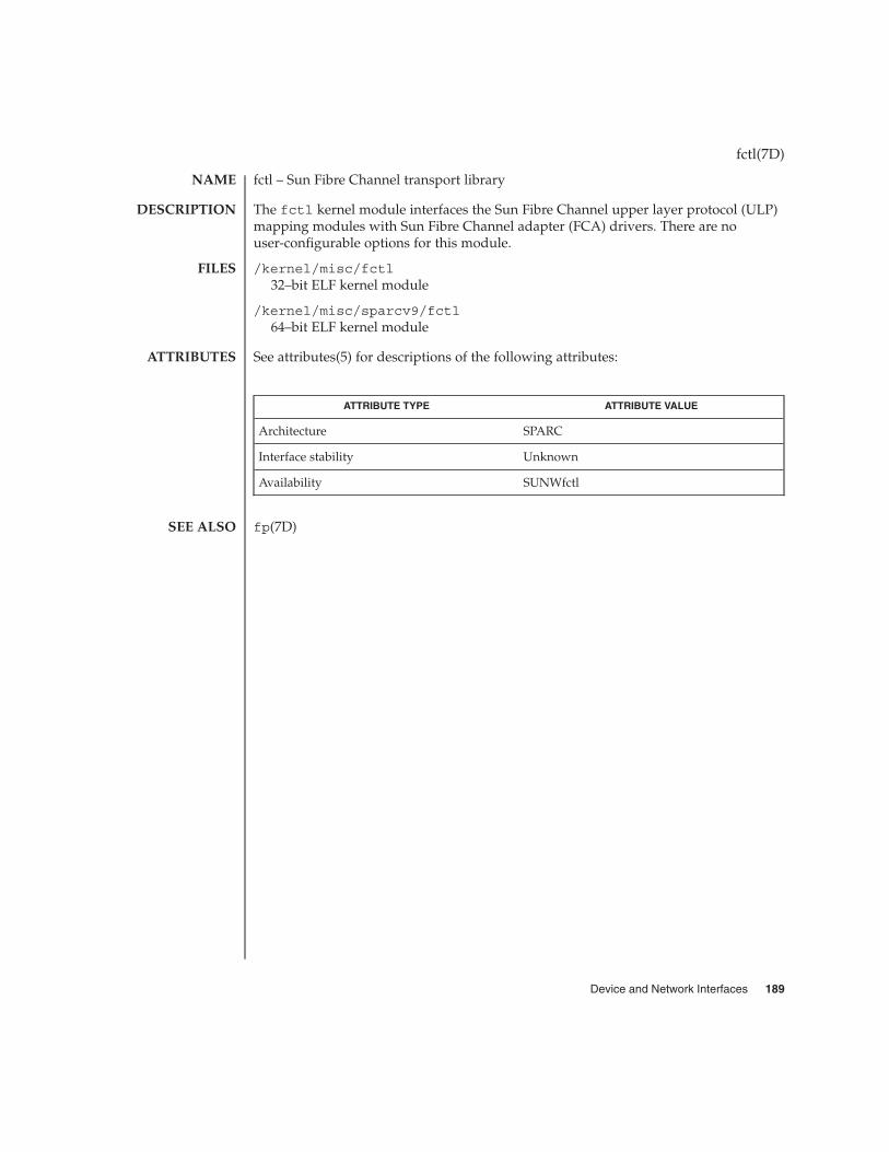
fctl – Sun Fibre Channel transport library
The fctl kernel module interfaces the Sun Fibre Channel upper layer protocol (ULP)mapping modules with Sun Fibre Channel adapter (FCA) drivers. There are nouser-configurable options for this module.
/kernel/misc/fctl32–bit ELF kernel module
/kernel/misc/sparcv9/fctl64–bit ELF kernel module
See attributes(5) for descriptions of the following attributes:
ATTRIBUTE TYPE ATTRIBUTE VALUE
Architecture SPARC
Interface stability Unknown
Availability SUNWfctl
fp(7D)
fctl(7D)
NAME
DESCRIPTION
FILES
ATTRIBUTES
SEE ALSO
Device and Network Interfaces 189

fd, fdc – drivers for floppy disks and floppy disk controllers
/dev/diskette0
/dev/rdiskette0
/dev/diskette[0-1]
/dev/rdiskette[0-1]
The fd driver provides the interfaces to the floppy disks using the Intel 82072 onsun4c systems and the Intel 82077 on sun4m systems.
The fd and fdc drivers provide the interfaces to floppy disks using the Intel 8272,Intel 82077, NEC 765, or compatible disk controllers on IA based systems.
The default partitions for the floppy driver are:
a All cylinders except the last
b Only the last cylinder
c Entire diskette
The fd driver autosenses the density of the diskette.
When the floppy is first opened the driver looks for a SunOS label in logical block 0 ofthe diskette. If attempts to read the SunOS label fail, the open will fail. If block 0 isread successfully but a SunOS label is not found, auto-sensed geometry and defaultpartitioning are assumed.
The fd driver supports both block and “raw” interfaces.
The block files (/dev/diskette*) access the diskette using the system’s normalbuffering mechanism and may be read and written without regard to physical disketterecords.
There is also a “raw” (/dev/rdiskette*) interface that provides for directtransmission between the diskette and the user’s read or write buffer. A single read(2)or write(2) call usually results in one I/O operation; therefore raw I/O isconsiderably more efficient when larger blocking factors are used. A blocking factor ofno less than 8 Kbytes is recommended. See the Notes section, below, for informationon the number of sectors per track.
For 3.5" double-sided diskettes, the following densities are supported:
1.7 Mbyte density 80 cylinders, 21 sectors per track, 1.7 Mbyte capacity
high density 80 cylinders, 18 sectors per track, 1.44 Mbyte capacity
double density 80 cylinders, 9 sectors per track, 720 Kbyte capacity
medium density 77 cylinders, 8 sectors per track, 1.2 Mbyte capacity(sun4m only)
fd(7D)
NAME
SPARC
IA
DESCRIPTION
3.5" Diskettes
SPARC
190 man pages section 7: Device and Network Interfaces • Last Revised 24 Feb 1998

extended density 80 cylinders, 36 sectors per track, 2.88 Mbyte capacity
1.7 Mbyte density 80 cylinders, 21 sectors per track, 1.7 Mbyte capacity
high density 80 cylinders, 18 sectors per track, 1.44 Mbyte capacity
double density 80 cylinders, 9 sectors per track, 760 Kbyte capacity
For 5.25" double-sided diskettes on IA platforms, the densities listed below aresupported:
5.25" diskettes are not supported on SPARC platforms.
high density 80 cylinders, 15 sectors per track, 1.2 Mbyte capacity
double density 40 cylinders, 9 sectors per track, 360 Kbyte capacity
double density 40 cylinders, 8 sectors per track, 320 Kbyte capacity
quad density 80 cylinders, 9 sectors per track, 720 Kbyte capacity
double density 40 cylinders, 16 sectors per track (256 bytes per sector),320 Kbyte capacity
double density 40 cylinders, 4 sectors per track (1024 bytes per sector),320 Kbyte capacity
EBUSY During opening, the partition has been opened forexclusive access and another process wants to open thepartition. Once open, this error is returned if the floppydisk driver attempted to pass a command to the floppydisk controller when the controller was busy handlinganother command. In this case, the application shouldtry the operation again.
EFAULT An invalid address was specified in an ioctl command(see fdio(7I)).
EINVAL The number of bytes read or written is not a multipleof the diskette’s sector size. This error is also returnedwhen an unsupported command is specified using theFDIOCMD ioctl command (see fdio(7I)).
EIO During opening, the diskette does not have a label orthere is no diskette in the drive. Once open, this error isreturned if the requested I/O transfer could not becompleted.
ENOSPC An attempt was made to write past the end of thediskette.
ENOTTY The floppy disk driver does not support the requestedioctl functions (see fdio(7I)).
fd(7D)
IA
5.25" Diskettes
SPARC
IA
ERRORS
Device and Network Interfaces 191

ENXIO The floppy disk device does not exist or the device isnot ready.
EROFS The floppy disk device is opened for write access andthe diskette in the drive is write protected.
ENOSYS The floppy disk device does not support the requestedioctl function ( FDEJECT).
The driver attempts to initialize itself using the information found in the configurationfile, /platform/i86pc/kernel/drv/fd.conf.
name="fd" parent="fdc" unit=0;
name="fd" parent="fdc" unit=1;
/platform/sun4c/kernel/drv/fd driver module
/platform/sun4m/kernel/drv/fd driver module
/platform/sun4u/kernel/drv/fd driver module
/usr/include/sys/fdreg.h structs and definitions for Intel 82072 and82077 controllers
/usr/include/sys/fdvar.h structs and definitions for floppy drivers
/dev/diskette device file
/dev/diskette0 device file
/dev/rdiskette raw device file
/dev/rdiskette0 raw device file
For ucb Compatibility
/dev/fd0[a-c] block file
/dev/rfd0[a-c] raw file
/vol/dev/diskette0 directory containing volume managementcharacter device file
/vol/dev/rdiskette0 directory containing the volumemanagement raw character device file
/vol/dev/aliases/floppy0 symbolic link to the entry in/vol/dev/rdiskette0
/platform/i86pc/kernel/drv/fddriver module
/platform/i86pc/kernel/drv/fd.confconfiguration file for floppy driver
fd(7D)
IA Only
IACONFIGURATION
SPARC
IA
192 man pages section 7: Device and Network Interfaces • Last Revised 24 Feb 1998

/platform/i86pc/kernel/drv/fdcfloppy-controller driver module
/platform/i86pc/kernel/drv/fdc.confconfiguration file for the floppy-controller
/usr/include/sys/fdc.hstructs and definitions for IA floppy devices
/usr/include/sys/fdmedia.hstructs and definitions for IA floppy media
IA First Drive
/dev/diskette device file
/dev/diskette0 device file
/dev/rdiskette raw device file
/dev/rdiskette0 raw device file
For ucb Compatibility
/dev/fd0[a-c] block file
/dev/rfd0[a-c] raw file
/vol/dev/diskette0 directory containing volume managementcharacter device file
/vol/dev/rdiskette0 directory containing the volumemanagement raw character device file
/vol/dev/aliases/floppy0 symbolic link to the entry in/vol/dev/rdiskette0
IA Second Drive
/dev/diskette1 device file
/dev/rdiskette1 raw device file
For ucb Compatibility
/dev/fd1[a-c] block file
/dev/rfd1[a-c] raw file
/vol/dev/diskette1 directory containing volume managementcharacter device file
/vol/dev/rdiskette1 directory containing the volumemanagement raw character device file
/vol/dev/aliases/floppy1 symbolic link to the entry in/vol/dev/rdiskette1
fd(7D)
Device and Network Interfaces 193

fdformat(1), dd(1M), drvconfig(1M), vold(1M), read(2), write(2),driver.conf(4), dkio(7I) fdio(7I)
fd<n>: <command name> failed (<sr1> <sr2> <sr3>)The <command name> failed after several retries on drive <n>. The three hexvalues in parenthesis are the contents of status register 0, status register 1, andstatus register 2 of the Intel 8272, the Intel 82072, and the Intel 82077 Floppy DiskController on completion of the command, as documented in the data sheet for thatpart. This error message is usually followed by one of the following, interpretingthe bits of the status register:
fd<n>: not writable
fd<n>: crc error blk <block number>
There was a data error on <block number>.
fd<n>: bad format
fd<n>: timeout
fd<n>: drive not ready
fd<n>: unformatted diskette or no diskette in drive
fd<n>: block <block number> is past the end!
(nblk=<total number of blocks>)
The operation tried to access a block number that is greater thanthe total number of blocks.
fd<n>: b_bcount 0x<op_size> not % 0x<sect_size>
The size of an operation is not a multiple of the sector size.
fd<n>: overrun/underrun
fd<n>: host bus error. There was a hardware error on a systembus.
Overrun/underrun errors occur when accessing a diskette while the system is heavilyloaded. Decrease the load on the system and retry the diskette access.
3.5" high density diskettes have 18 sectors per track and 5.25" high density disketteshave 15 sectors per track. They can cross a track (though not a cylinder) boundarywithout losing data, so when using dd(1M) or read(2)/write(2) calls to or from the“raw” diskette, you should specify bs=18k or multiples thereof for 3.5" diskettes, andbs=15k or multiples thereof for 5.25" diskettes.
The SPARC fd driver is not an unloadable module.
fd(7D)
SEE ALSO
All Platforms
SPARC Only
NOTES
194 man pages section 7: Device and Network Interfaces • Last Revised 24 Feb 1998

Under Solaris (Intel Platform Edition), the configuration of the floppy drives isspecified in CMOS configuration memory. Use the BIOS setup program or an EISAconfiguration program for the system to define the diskette size and density/capacityfor each installed drive. Note that MS-DOS may operate the floppy drives correctly,even though the CMOS configuration may be in error. Solaris (Intel Platform Edition)relies on the CMOS configuration to be accurate.
fd(7D)
Device and Network Interfaces 195

fd, fdc – drivers for floppy disks and floppy disk controllers
/dev/diskette0
/dev/rdiskette0
/dev/diskette[0-1]
/dev/rdiskette[0-1]
The fd driver provides the interfaces to the floppy disks using the Intel 82072 onsun4c systems and the Intel 82077 on sun4m systems.
The fd and fdc drivers provide the interfaces to floppy disks using the Intel 8272,Intel 82077, NEC 765, or compatible disk controllers on IA based systems.
The default partitions for the floppy driver are:
a All cylinders except the last
b Only the last cylinder
c Entire diskette
The fd driver autosenses the density of the diskette.
When the floppy is first opened the driver looks for a SunOS label in logical block 0 ofthe diskette. If attempts to read the SunOS label fail, the open will fail. If block 0 isread successfully but a SunOS label is not found, auto-sensed geometry and defaultpartitioning are assumed.
The fd driver supports both block and “raw” interfaces.
The block files (/dev/diskette*) access the diskette using the system’s normalbuffering mechanism and may be read and written without regard to physical disketterecords.
There is also a “raw” (/dev/rdiskette*) interface that provides for directtransmission between the diskette and the user’s read or write buffer. A single read(2)or write(2) call usually results in one I/O operation; therefore raw I/O isconsiderably more efficient when larger blocking factors are used. A blocking factor ofno less than 8 Kbytes is recommended. See the Notes section, below, for informationon the number of sectors per track.
For 3.5" double-sided diskettes, the following densities are supported:
1.7 Mbyte density 80 cylinders, 21 sectors per track, 1.7 Mbyte capacity
high density 80 cylinders, 18 sectors per track, 1.44 Mbyte capacity
double density 80 cylinders, 9 sectors per track, 720 Kbyte capacity
medium density 77 cylinders, 8 sectors per track, 1.2 Mbyte capacity(sun4m only)
fdc(7D)
NAME
SPARC
IA
DESCRIPTION
3.5" Diskettes
SPARC
196 man pages section 7: Device and Network Interfaces • Last Revised 24 Feb 1998

extended density 80 cylinders, 36 sectors per track, 2.88 Mbyte capacity
1.7 Mbyte density 80 cylinders, 21 sectors per track, 1.7 Mbyte capacity
high density 80 cylinders, 18 sectors per track, 1.44 Mbyte capacity
double density 80 cylinders, 9 sectors per track, 760 Kbyte capacity
For 5.25" double-sided diskettes on IA platforms, the densities listed below aresupported:
5.25" diskettes are not supported on SPARC platforms.
high density 80 cylinders, 15 sectors per track, 1.2 Mbyte capacity
double density 40 cylinders, 9 sectors per track, 360 Kbyte capacity
double density 40 cylinders, 8 sectors per track, 320 Kbyte capacity
quad density 80 cylinders, 9 sectors per track, 720 Kbyte capacity
double density 40 cylinders, 16 sectors per track (256 bytes per sector),320 Kbyte capacity
double density 40 cylinders, 4 sectors per track (1024 bytes per sector),320 Kbyte capacity
EBUSY During opening, the partition has been opened forexclusive access and another process wants to open thepartition. Once open, this error is returned if the floppydisk driver attempted to pass a command to the floppydisk controller when the controller was busy handlinganother command. In this case, the application shouldtry the operation again.
EFAULT An invalid address was specified in an ioctl command(see fdio(7I)).
EINVAL The number of bytes read or written is not a multipleof the diskette’s sector size. This error is also returnedwhen an unsupported command is specified using theFDIOCMD ioctl command (see fdio(7I)).
EIO During opening, the diskette does not have a label orthere is no diskette in the drive. Once open, this error isreturned if the requested I/O transfer could not becompleted.
ENOSPC An attempt was made to write past the end of thediskette.
ENOTTY The floppy disk driver does not support the requestedioctl functions (see fdio(7I)).
fdc(7D)
IA
5.25" Diskettes
SPARC
IA
ERRORS
Device and Network Interfaces 197
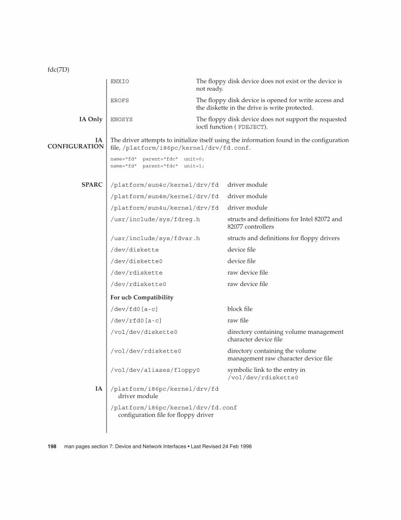
ENXIO The floppy disk device does not exist or the device isnot ready.
EROFS The floppy disk device is opened for write access andthe diskette in the drive is write protected.
ENOSYS The floppy disk device does not support the requestedioctl function ( FDEJECT).
The driver attempts to initialize itself using the information found in the configurationfile, /platform/i86pc/kernel/drv/fd.conf.
name="fd" parent="fdc" unit=0;
name="fd" parent="fdc" unit=1;
/platform/sun4c/kernel/drv/fd driver module
/platform/sun4m/kernel/drv/fd driver module
/platform/sun4u/kernel/drv/fd driver module
/usr/include/sys/fdreg.h structs and definitions for Intel 82072 and82077 controllers
/usr/include/sys/fdvar.h structs and definitions for floppy drivers
/dev/diskette device file
/dev/diskette0 device file
/dev/rdiskette raw device file
/dev/rdiskette0 raw device file
For ucb Compatibility
/dev/fd0[a-c] block file
/dev/rfd0[a-c] raw file
/vol/dev/diskette0 directory containing volume managementcharacter device file
/vol/dev/rdiskette0 directory containing the volumemanagement raw character device file
/vol/dev/aliases/floppy0 symbolic link to the entry in/vol/dev/rdiskette0
/platform/i86pc/kernel/drv/fddriver module
/platform/i86pc/kernel/drv/fd.confconfiguration file for floppy driver
fdc(7D)
IA Only
IACONFIGURATION
SPARC
IA
198 man pages section 7: Device and Network Interfaces • Last Revised 24 Feb 1998

/platform/i86pc/kernel/drv/fdcfloppy-controller driver module
/platform/i86pc/kernel/drv/fdc.confconfiguration file for the floppy-controller
/usr/include/sys/fdc.hstructs and definitions for IA floppy devices
/usr/include/sys/fdmedia.hstructs and definitions for IA floppy media
IA First Drive
/dev/diskette device file
/dev/diskette0 device file
/dev/rdiskette raw device file
/dev/rdiskette0 raw device file
For ucb Compatibility
/dev/fd0[a-c] block file
/dev/rfd0[a-c] raw file
/vol/dev/diskette0 directory containing volume managementcharacter device file
/vol/dev/rdiskette0 directory containing the volumemanagement raw character device file
/vol/dev/aliases/floppy0 symbolic link to the entry in/vol/dev/rdiskette0
IA Second Drive
/dev/diskette1 device file
/dev/rdiskette1 raw device file
For ucb Compatibility
/dev/fd1[a-c] block file
/dev/rfd1[a-c] raw file
/vol/dev/diskette1 directory containing volume managementcharacter device file
/vol/dev/rdiskette1 directory containing the volumemanagement raw character device file
/vol/dev/aliases/floppy1 symbolic link to the entry in/vol/dev/rdiskette1
fdc(7D)
Device and Network Interfaces 199
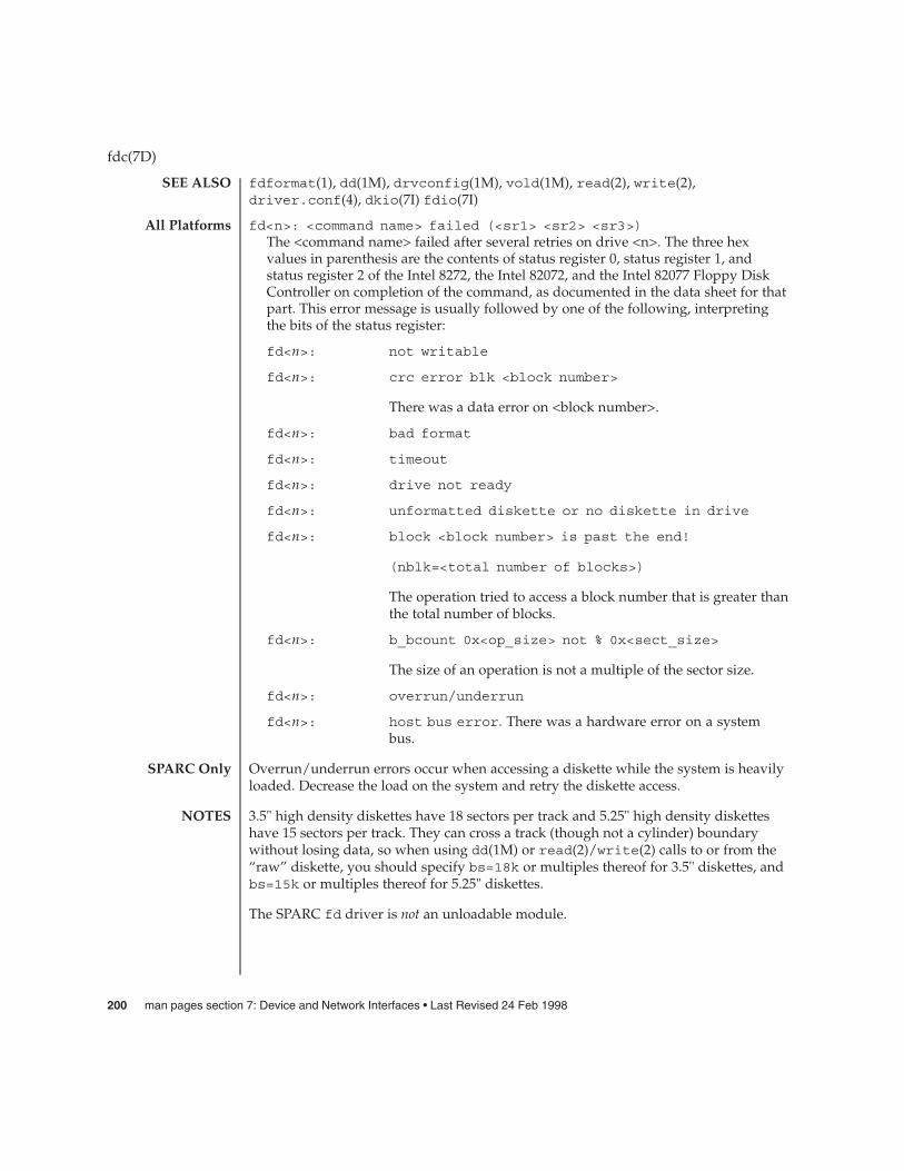
fdformat(1), dd(1M), drvconfig(1M), vold(1M), read(2), write(2),driver.conf(4), dkio(7I) fdio(7I)
fd<n>: <command name> failed (<sr1> <sr2> <sr3>)The <command name> failed after several retries on drive <n>. The three hexvalues in parenthesis are the contents of status register 0, status register 1, andstatus register 2 of the Intel 8272, the Intel 82072, and the Intel 82077 Floppy DiskController on completion of the command, as documented in the data sheet for thatpart. This error message is usually followed by one of the following, interpretingthe bits of the status register:
fd<n>: not writable
fd<n>: crc error blk <block number>
There was a data error on <block number>.
fd<n>: bad format
fd<n>: timeout
fd<n>: drive not ready
fd<n>: unformatted diskette or no diskette in drive
fd<n>: block <block number> is past the end!
(nblk=<total number of blocks>)
The operation tried to access a block number that is greater thanthe total number of blocks.
fd<n>: b_bcount 0x<op_size> not % 0x<sect_size>
The size of an operation is not a multiple of the sector size.
fd<n>: overrun/underrun
fd<n>: host bus error. There was a hardware error on a systembus.
Overrun/underrun errors occur when accessing a diskette while the system is heavilyloaded. Decrease the load on the system and retry the diskette access.
3.5" high density diskettes have 18 sectors per track and 5.25" high density disketteshave 15 sectors per track. They can cross a track (though not a cylinder) boundarywithout losing data, so when using dd(1M) or read(2)/write(2) calls to or from the“raw” diskette, you should specify bs=18k or multiples thereof for 3.5" diskettes, andbs=15k or multiples thereof for 5.25" diskettes.
The SPARC fd driver is not an unloadable module.
fdc(7D)
SEE ALSO
All Platforms
SPARC Only
NOTES
200 man pages section 7: Device and Network Interfaces • Last Revised 24 Feb 1998

Under Solaris (Intel Platform Edition), the configuration of the floppy drives isspecified in CMOS configuration memory. Use the BIOS setup program or an EISAconfiguration program for the system to define the diskette size and density/capacityfor each installed drive. Note that MS-DOS may operate the floppy drives correctly,even though the CMOS configuration may be in error. Solaris (Intel Platform Edition)relies on the CMOS configuration to be accurate.
fdc(7D)
Device and Network Interfaces 201

fdio – floppy disk control operations
#include <sys/fdio.h>
The Solaris floppy driver supports a set of ioctl(2) requests for getting and settingthe floppy drive characteristics. Basic to these ioctl( ) requests are the definitions in<sys/fdio.h>.
The following ioctl( ) requests are available on the Solaris floppy driver.
FDDEFGEOCHAR IA based systems: This ioctl( ) forces the floppy driver to restorethe diskette and drive characteristics and geometry, and partitioninformation to default values based on the device configuration.
FDGETCHANGE The argument is a pointer to an int. This ioctl( ) returns thestatus of the diskette-changed signal from the floppy interface. Thefollowing defines are provided for cohesion.
Note: For IA based systems, use FDGC_DETECTED (which is available only on IAbased systems) instead of FDGC_HISTORY.
/** Used by FDGETCHANGE, returned state of the sense disk change bit.*/#define FDGC_HISTORY 0x01 /* disk has changed since last call */#define FDGC_CURRENT 0x02 /* current state of disk change */#define FDGC_CURWPROT 0x10 /* current state of write protect */
#define FDGC_DETECTED 0x20 /* previous state of DISK CHANGE */
FDIOGCHAR The argument is a pointer to an fd_char structure (describedbelow). This ioctl( ) gets the characteristics of the floppy diskettefrom the floppy controller.
FDIOSCHAR The argument is a pointer to an fd_char structure (describedbelow). This ioctl( ) sets the characteristics of the floppy diskettefor the floppy controller. Typical values in the fd_char structurefor a high density diskette:
field valuefdc_medium 0fdc_transfer_rate 500fdc_ncyl 80fdc_nhead 2fdc_sec_size 512fdc_secptrack 18
fdc_steps -1 { This field doesn’t apply. }
/** Floppy characteristics*/struct fd_char {uchar_t fdc_medium; /* equals 1 if floppy is medium density format */int fdc_transfer_rate; /* transfer rate */int fdc_ncyl; /* number of cylinders */
fdio(7I)
NAME
SYNOPSIS
DESCRIPTION
IOCTLS
202 man pages section 7: Device and Network Interfaces • Last Revised 26 April 2001

int fdc_nhead; /* number of heads */int fdc_sec_size; /* sector size */int fdc_secptrack; /* sectors per track */int fdc_steps; /* no. of steps per data track */
};
FDGETDRIVECHAR The argument to this ioctl( ) is a pointer to anfd_drive structure (described below). This ioctl( )gets the characteristics of the floppy drive from thefloppy controller.
FDSETDRIVECHAR IA based systems: The argument to this ioctl( ) is apointer to an fd_drive structure (described below).This ioctl( ) sets the characteristics of the floppydrive for the floppy controller. Only fdd_steprate,fdd_headsettle, fdd_motoron, andfdd_motoroff are actually used by the floppy diskdriver.
/** Floppy Drive characteristics*/struct fd_drive {
int fdd_ejectable; /* does the drive support eject? */int fdd_maxsearch; /* size of per-unit search table */int fdd_writeprecomp; /* cyl to start write precompensation */int fdd_writereduce; /* cyl to start recucing write current */int fdd_stepwidth; /* width of step pulse in 1 us units */int fdd_steprate; /* step rate in 100 us units */int fdd_headsettle; /* delay, in 100 us units */int fdd_headload; /* delay, in 100 us units */int fdd_headunload; /* delay, in 100 us units */int fdd_motoron; /* delay, in 100 ms units */int fdd_motoroff; /* delay, in 100 ms units */int fdd_precomplevel; /* bit shift, in nano-secs */int fdd_pins; /* defines meaning of pin 1, 2, 4 and 34 */int fdd_flags; /* TRUE READY, Starting Sector #, & Motor On */
};
FDGETSEARCH Not available.
FDSETSEARCH Not available.
FDEJECT SPARC: This ioctl( ) requests the floppy drive to eject thediskette.
FDIOCMD The argument is a pointer to an fd_cmd structure (describedbelow). This ioctl( ) allows access to the floppy diskette usingthe floppy device driver. Only the FDCMD_WRITE, FDCMD_READ,and FDCMD_FORMAT_TRACK commands are currently available.
struct fd_cmd {ushort_t fdc_cmd; /* command to be executed */int fdc_flags; /* execution flags (IA only) */
fdio(7I)
Device and Network Interfaces 203

daddr_t fdc_blkno; /* disk address for command */int fdc_secnt; /* sector count for command */caddr_t fdc_bufaddr; /* user’s buffer address */uint_t fdc_buflen; /* size of user’s buffer */
};Please note that the fdc_buflen field is currently unused. The fdc_secnt field isused to calculate the transfer size, and the buffer is assumed to be large enough toaccommodate the transfer.
{/** Floppy commands*/#define FDCMD_WRITE 1#define FDCMD_READ 2#define FDCMD_SEEK 3#define FDCMD_REZERO 4#define FDCMD_FORMAT_UNIT 5#define FDCMD_FORMAT_TRACK 6
};
FDRAW The argument is a pointer to an fd_raw structure (describedbelow). This ioctl( ) allows direct control of the floppy driveusing the floppy controller. Refer to the appropriatefloppy-controller data sheet for full details on required commandbytes and returned result bytes. The following commands aresupported.
/** Floppy raw commands*/#define FDRAW_SPECIFY 0x03#define FDRAW_READID 0x0a (IA only)#define FDRAW_SENSE_DRV 0x04#define FDRAW_REZERO 0x07#define FDRAW_SEEK 0x0f#define FDRAW_SENSE_INT 0x08 (IA only)#define FDRAW_FORMAT 0x0d#define FDRAW_READTRACK 0x02#define FDRAW_WRCMD 0x05#define FDRAW_RDCMD 0x06#define FDRAW_WRITEDEL 0x09
#define FDRAW_READDEL 0x0cPlease note that when using FDRAW_SEEK orFDRAW_REZERO, the driver automatically issues a FDRAW_SENSE_INT command toclear the interrupt from the FDRAW_SEEK or the FDRAW_REZERO. The result bytesreturned by these commands are the results from the FDRAW_SENSE_INT command.Please see the floppy-controller data sheet for more details on FDRAW_SENSE_INT.
/** Used by FDRAW*/struct fd_raw {char fdr_cmd[10]; /* user-supplied command bytes */short fdr_cnum; /* number of command bytes */char fdr_result[10]; /* controller-supplied result bytes */
fdio(7I)
204 man pages section 7: Device and Network Interfaces • Last Revised 26 April 2001

ushort_t fdr_nbytes; /* number to transfer if read/write command */char *fdr_addr; /* where to transfer if read/write command */
};
ioctl(2), dkio(7I), fd(7D), hdio(7I)
fdio(7I)
SEE ALSO
Device and Network Interfaces 205

ffb – 24-bit UPA color frame buffer and graphics accelerator
ffb is a 24-bit UPA-based color frame buffer and graphics accelerator which comes inthe two configurations: single buffered frame and double buffered frame.
Single buffered frame buffer Consists of 32 video memory planes of 1280x 1024 pixels, including 24-bitsingle-buffering and 8-bit X planes.
Double buffered frame buffer Consists of 96 video memory planes of 1280x 1024 pixels, including 24-bitdouble-buffering, 8-bit X planes, 28-bitZ-buffer planes and 4-bit Y planes.
The driver supports the following frame buffer ioctls which are defined in fbio(7I):
FBIOPUTCMAP, FBIOGETCMAP, FBIOSVIDEO, FBIOGVIDEO, FBIOVERTICAL,FBIOSCURSOR, FBIOGCURSOR, FBIOSCURPOS, FBIOGCURPOS, FBIOGCURMAX,
FBIO_WID_PUT, FBIO_WID_GET
/dev/fbs/ffb0 device special file
ffbconfig(1M), mmap(2), fbio(7I)
ffb(7D)
NAME
DESCRIPTION
FILES
SEE ALSO
206 man pages section 7: Device and Network Interfaces • Last Revised 10 Jun 1997

flowacct – Flow Accouting module
The flow accounting module flowacct enables you to record flow details. You useflow details to gather statistics and/or for billing purposes. Accounting consists ofrecording flow details in a location you designate and in a format that you can retrieveat a later stage. IPQoS accounting relies on the exacct mechanism to store and retrieveflow information.
A flow is defined by the 5-tuple - saddr, sport, daddr, dport and protocol.
Typically, the accounting module is the last datapath element in a sequence of actions.Flow attributes include ToS/DS, user id, project id, creation time (time the flow wascreated), last seen (when pkts for the flow were last seen), action name (instance thatrecorded the flow information), nbytes and npackets. Attributes are split into groupsentitled basic and extended. The basic group records only the nbytes, npackets andaction name, while the extended group is a superset of the basic group and records allattributes. The attributes to be recorded, in addition to the accounting file that containsflow details, are selected using acctadmn(1M). The flowacct module does notprovide a mechanism to retrieve flow information from the accounting file nor tointerpret the retrieved information.
The flowacct module exports the following statistics available through kstat:
module: flowacct instance: <action id>name: Flowacct statistics class <action name>
bytes_in_tbl <bytes in the flow table>epackets <packets in error>flows_in_tbl <flow records in the flow table>nbytes <number of bytes through this instance>npackets <number of packets>
usedmem <memory, in bytes, used by the flow table>
/kernel/ipp/flowacct32-bit module
/kernel/ipp/sparcv9/flowacct64-bit module
See attributes(5) for descriptions of the following attributes:
ATTRIBUTE TYPE ATTRIBUTE VALUE
Availability SUNWqos (32–bit) SUNWqosx (64–bit)
ipqosconf(1M), acctadm(1M), libexacct3LIB, dlcosmk(7IPP), dscpmk(7IPP),ipqos(7IPP), ipgpc(7IPP), tokenmt(7IPP), tswtclmt(7IPP)
flowacct(7ipp)
NAME
DESCRIPTION
STATISTICS
FILES
ATTRIBUTES
SEE ALSO
Device and Network Interfaces 207

fp – Sun Fibre Channel port driver
The fp driver is a Sun Fibre Channel nexus driver that enables Fibre Channeltopology discovery, device discovery, Fibre Channel adapter port management andother capabilities through well-defined Fibre Channel adapter driver interfaces.
The fp driver requires the presence of a fabric name server in fabric and public looptopologies to discover fibre channel devices. In private loop topologies, the driverdiscovers devices by performing PLOGI to all valid AL_PAs, provided that devices donot participate in LIRP and LILP stages of loop initialization.
/kernel/drv/fp32–bit ELF kernel driver
/kernel/drv/sparcv9/fp64–bit ELF kernel driver
/kernel/drv/fp.conffp driver configuration file
See attributes(5) for descriptions of the following attributes:
ATTRIBUTE TYPE ATTRIBUTE VALUE
Architecture SPARC
Interface stability Unknown
Availability SUNWfctl
prtconf(1M), driver.conf(4), fctl(7D)
Writing Device Drivers,
Fibre Channel Physical and Signaling Interface (FC-PH) ANSI X3.230: 1994,
Fibre Channel Generic Services (FC-GS-2) Project 1134-D,
Fibre Channel Arbitrated Loop (FC-AL) ANSI X3.272-1996,
Fibre Channel Protocol for SCSI (FCP) ANSI X3.269-1996,
SCSI-3 Architecture Model (SAM) Fibre Channel Private Loop SCSI Direct Attach(FC-PLDA) ANSI X3.270-1996,
SCSI Direct Attach (FC-PLDA) NCITS TR-19:1998,
Fabric Loop Attachment (FC-FLA), NCITS TR-20:1998
fp(7d)
NAME
DESCRIPTION
FILES
ATTRIBUTES
SEE ALSO
208 man pages section 7: Device and Network Interfaces • Last Revised 20 Jul 1999

FSS – Fair share scheduler
The fair share scheduler (FSS) guarantees application performance by explicitlyallocating shares of CPU resources to projects. A share indicates a project’s entitlementto available CPU resources. Because shares are meaningful only in comparison withother project’s shares, the absolute quantity of shares is not important. Any numberthat is in proportion with the desired CPU entitlement can be used.
The goals of the FSS scheduler differ from the traditional time-sharing scheduling class(TS). In addition to scheduling individual LWPs, the FSS scheduler schedules projectsagainst each other, making it impossible for any project to acquire more CPU cyclessimply by running more processes concurrently.
A project’s entitlement is individually calculated by FSS independently for eachprocessor set if the project contains processes bound to them. If a project is running onmore than one processor set, it can have different entitlements on every set. A project’sentitlement is defined as a ratio between the number of shares given to a project andthe sum of shares of all active projects running on the same processor set. An activeproject is one that has at least one running or runnable process. Entitlements arerecomputed whenever any project becomes active or inactive, or whenever thenumber of shares is changed.
Processor sets represent virtual machines in the FSS scheduling class and processes arescheduled independently in each processor set. That is, processes compete with eachother only if they are running on the same processor set. When a processor set isdestroyed, all processes that were bound to it are moved to the default processor set,which always exists. Empty processor sets (that is, sets without processors in them)have no impact on the FSS scheduler behavior.
If a processor set contains a mix of TS/IA and FSS processes, the fairness of the FSSscheduling class can be compromised because these classes use the same range ofpriorities. Fairness is most significantly affected if processes running in the TSscheduling class are CPU-intensive and are bound to processors within the processorset. As a result, you should avoid having processes from TS/IA and FSS classes sharethe same processor set. RT and FSS processes use disjoint priority ranges and thereforecan share processor sets.
As projects execute, their CPU usage is accumulated over time. The FSS schedulerperiodically decays CPU usages of every project by multiplying it with a decay factor,ensuring that more recent CPU usage has greater weight when taken into account forscheduling. The FSS scheduler continually adjusts priorities of all processes to makeeach project’s relative CPU usage converge with its entitlement.
While FSS is designed to fairly allocate cycles over a long-term time period, it ispossible that projects will not receive their allocated shares worth of CPU cycles due touneven demand. This makes one-shot, instantaneous analysis of FSS performance dataunreliable.
FSS(7)
NAME
DESCRIPTION
Device and Network Interfaces 209

Note that share is not the same as utilization. A project may be allocated 50% of thesystem, although on the average, it uses just 20%. Shares serve to cap a project’s CPUusage only when there is competition from other projects running on the sameprocessor set. When there is no competition, utilization may be larger than entitlementbased on shares. Allocating a small share to a busy project slows it down but does notprevent it from completing its work if the system is not saturated.
The configuration of CPU shares is managed by the name server as a property of theproject(4) database. In the following example, an entry in the /etc/project filesets the number of shares for project "x-files" to 10:
x-files:100::::project.cpu-shares=(privileged,10,none)
Projects with undefined number of shares are given one share each. This means thatsuch projects are treated with equal importance. Projects with 0 shares only run whenthere are no projects with non-zero shares competing for the same processor set. Themaximum number of shares that can be assigned to one project is 65535.
You can use the prctl(1) command to determine the current share assignment for agiven project:
$ prctl -n project.cpu-shares -i project x-files
or to change the amount of shares if you have root privileges:
# prctl -r -n project.cpu-shares -v 5 -i project x-files
See the prctl(1) man page for additional information on how to modify and examineresource controls associated with active processes, tasks, or projects on the system.
By default, project "system" (project ID 0) includes all system daemons started byinitialization scripts and has an "unlimited" amount of shares. That is, it is alwaysscheduled first no matter how many shares are given to other projects.
The following command sets FSS as the default scheduler for the system:
# dispadmin -d FSS
This change will take effect on the next reboot. Alternatively, you can move processesfrom the time-share scheduling class (as well as the special case of init) into the FSSclass without changing your default scheduling class and rebooting by becomingroot, and then using the priocntl(1) command, as shown in the following example:
# priocntl -s -c FSS -i class TS# priocntl -s -c FSS -i pid 1
You can use the dispadmin(1M) command to examine and "tune" the FSS scheduler’stime quantum value. Time quantum is the amount of time that a thread is allowed torun before it must relinquish the processor. The following example dumps the currenttime quantum for the fair share scheduler:
$ dispadmin -g -c FSS## Fair Share Scheduler Configuration
FSS(7)
CONFIGURINGSCHEDULER
WITHDISPADMIN
210 man pages section 7: Device and Network Interfaces • Last Revised 13 April 2001
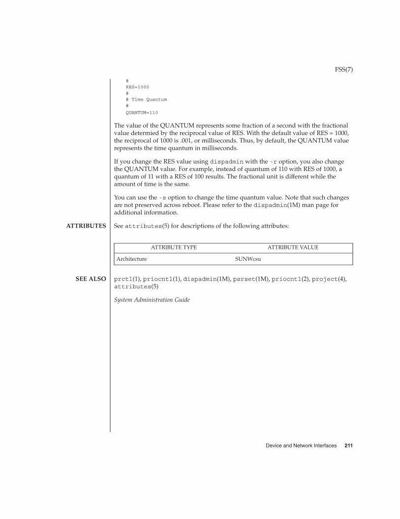
#RES=1000## Time Quantum#
QUANTUM=110
The value of the QUANTUM represents some fraction of a second with the fractionalvalue determied by the reciprocal value of RES. With the default value of RES = 1000,the reciprocal of 1000 is .001, or milliseconds. Thus, by default, the QUANTUM valuerepresents the time quantum in milliseconds.
If you change the RES value using dispadmin with the -r option, you also changethe QUANTUM value. For example, instead of quantum of 110 with RES of 1000, aquantum of 11 with a RES of 100 results. The fractional unit is different while theamount of time is the same.
You can use the -s option to change the time quantum value. Note that such changesare not preserved across reboot. Please refer to the dispadmin(1M) man page foradditional information.
See attributes(5) for descriptions of the following attributes:
ATTRIBUTE TYPE ATTRIBUTE VALUE
Architecture SUNWcsu
prctl(1), priocntl(1), dispadmin(1M), psrset(1M), priocntl(2), project(4),attributes(5)
System Administration Guide
FSS(7)
ATTRIBUTES
SEE ALSO
Device and Network Interfaces 211

ge – GEM Gigabit-Ethernet device driver
/dev/ge
The ge Gigabit-Ethernet driver is a multi-threaded, loadable, clonable, STREAMShardware driver supporting the connectionless Data Link Provider Interface, dlpi(7P)over GEM, SBus and PCI Gigabit-Ethernet add-in adapters. Multiple GEM-basedadapters installed within the system are supported by the driver. The ge driverprovides basic support for the GEM-based Ethernet hardware and handles theSUNW,sbus-gem (SBus GEM) and pci108e,2bad (PCI GEM) devices. Functionsinclude chip initialization, frame transmit and receive, multicast and promiscuoussupport, and error recovery and reporting.
The GEM device provides 1000BASE-SX networking interfaces using the GEM ASICexternal SERDES and fiber optical transceiver. The GEM ASIC provides theappropriate bus interface, MAC functions and physical code sub-layer (PCS)functions. The external SERDES connects to a fiber transceiver and provides thephysical connection.
The 1000Base-SX standard specifies an auto-negotiation protocol to automaticallyselect the mode of operation. In addition to duplex operation, the GEM ASIC canauto-negotiate for IEEE 802.3x frame based flow control capabilities. The GEM PCS iscapable of performing auto-negotiation using the remote (or link partner) link end andreceives the capabilities of the remote end. It selects the highest common demoninatormode of operation based on priorities. The ge driver also supports forced-modeoperation under which the driver selects the mode of operation.
The cloning character-special device /dev/ge is used to access all ge controllersinstalled within the system.
The ge driver is a Style 2 data link service provider. All M_PROTO and M_PCPROTOtype messages are interpreted as DLPI primitives. Valid DLPI primitives are defined in<sys/dlpi.h>. Refer to dlpi(7P) for more information.
You must send an explicit DL_ATTACH_REQ message to associate the opened streamwith a particular device (ppa). The ppa ID is interpreted as an unsigned long datatype and indicates the corresponding device instance (unit) number. An error(DL_ERROR_ACK) is returned by the driver if the ppa field value does not correspondto a valid device instance number for the system. The device is initialized on firstattach and de-initialized (stopped) upon last detach.
The values returned by the driver in the DL_INFO_ACK primitive in response to theDL_INFO_REQ are:
� Maximum SDU is 1500 (ETHERMTU - defined in <sys/ethernet.h> ).� Minimum SDU is 0.� dlsap address length is 8.� MAC type is DL_ETHER.
ge(7D)
NAME
SYNOPSIS
DESCRIPTION
APPLICATIONPROGRAMMING
INTERFACEge and DLPI
212 man pages section 7: Device and Network Interfaces • Last Revised 10 Oct 2000

� sap length value is –2, meaning the physical address component is followedimmediately by a 2 byte sap component within the DLSAP address.
� Service mode is DL_CLDLS.� Quality of service (QOS) is not supported; accordingly, QOS fields are 0.� Provider style is DL_STYLE2.� Version is DL_VERSION_2.� Broadcast address value is Ethernet/IEEE broadcast address (0xFFFFFF).
Once in the DL_ATTACHED state, you must send a DL_BIND_REQ to associate aparticular Service Access Pointer (SAP) with the stream. The ge driver interprets thesap field within the DL_BIND_REQ as an Ethernet type; accordingly, valid values forthe sap field are in the [0-0xFFFF] range. Only one Ethernet type can be bound to thestream at any time.
If you select a sap with a value of 0, the receiver will be in 802.3 mode. All framesreceived from the media with a type field in the range [0-1500] are assumed to be802.3 frames and are routed up all open streams bound to sap value 0. If more thanone stream is in 802.3 mode, the frame will be duplicated and routed up multiplestreams as DL_UNITDATA_IND messages.
In transmission, the driver checks the sap field of the DL_BIND_REQ to determine ifthe sap value is 0 and the destination type field is in the range [0-1500]. If either istrue, the driver computes the length of the message, not including initial M_PROTOmblk (message block), of all subsequent DL_UNITDATA_REQ messages and transmits802.3 frames of that value in the MAC frame header length field.
The ge driver DLSAP address format consists of the 6 byte physical (Ethernet) addresscomponent followed immediately by the 2 byte sap (type) component producing an 8byte DLSAP address. Applications should not hard code to this particularimplementation-specific DLSAP address format, but use information returned in theDL_INFO_ACK primitive to compose and decompose DLSAP addresses. The saplength, full DLSAP length and sap physical ordering are included within theDL_INFO_ACK. The physical address length can be computed by subtracting the saplength from the full DLSAP address length or by issuing the DL_PHYS_ADDR_REQ toobtain the current physical address associated with the stream.
Once in the DL_BOUND state, you may transmit frames on the Ethernet by sendingDL_UNITDATA_REQ messages to the ge driver. The ge driver will route receivedEthernet frames up all open and bound streams having a sap which matches theEthernet type as DL_UNITDATA_IND messages. Received Ethernet frames areduplicated and routed up multiple open streams if necessary. The DLSAP addresscontained within the DL_UNITDATA_REQ and DL_UNITDATA_IND messages consistsof both the sap (type) and physical (Ethernet) components.
In addition to the mandatory connectionless DLPI message set, the driver additionallysupports ge primitives.
ge(7D)
Device and Network Interfaces 213

The DL_ENABMULTI_REQ and DL_DISABMULTI_REQ primitives enable/disablereception of individual multicast group addresses. A set of multicast addresses may beiteratively created and modified on a per-stream basis using these primitives. TheDL_ENABMULTI_REQ and DL_DISABMULTI_REQ primitives are accepted by thedriver in any state following DL_ATTACHED.
With the DL_PROMISC_PHYS flag set in the dl_level field, the DL_PROMISCON_REQand DL_PROMISCOFF_REQ primitives enable/disable reception of all promiscuousmode frames on the media including frames generated by the local host. When usedwith the DL_PROMISC_SAP flag set, this enables/disables reception of all sap(Ethernet type) values. When used with the DL_PROMISC_MULTI flag set, thisenables/disables reception of all multicast group addresses. The effect of each isalways on a per-stream basis and independent of the other sap and physical levelconfigurations on the stream or other streams.
The DL_PHYS_ADDR_REQ primitive returns the six octet Ethernet address currentlyassociated (attached) to the stream in the DL_PHYS_ADDR_ACK primitive. Thisprimitive is valid only in states following a successful DL_ATTACH_REQ.
The DL_SET_PHYS_ADDR_REQ primitive changes the 6 octet Ethernet addresscurrently associated (attached) to the stream. The credentials of the process whichoriginally opened the stream must be superuser or EPERM is returned in theDL_ERROR_ACK. The DL_SET_PHYS_ADDR_REQ primitive is destructive and affectsall other current and future streams attached to this device. A M_ERROR is sent up allother streams attached to the device when DL_SET_PHYS_ADDR_REQ is successful onthe stream. Once changed, all streams subsequently opened and attached to the devicewill obtain the new physical address. Once changed, the physical address will remainuntil DL_SET_PHYS_ADDR_REQ is used to change the physical address again or thesystem is rebooted, whichever comes first.
By default, the ge driver performs auto-negotiation to select the mode and flowcontrol capabilities of the link. The link can be in one of the following modes:
� 1000 Mbps, full-duplex� 1000 Mbps, half-duplex� Symmetric pause� Asymmetric pause
Speeds and modes are described in the 1000Base-TX standard.
The auto-negotation protocol automatically selects:
� Operation mode (half-duplex or full-duplex)� Flow control capability (Symmetric and/or Asymmetric)
The auto–negotiation protocol:
� Gets all the modes of operation supported by the link partner.� Advertises its capabilities to the link partner.
ge(7D)
ge Primitives
ge DRIVER
214 man pages section 7: Device and Network Interfaces • Last Revised 10 Oct 2000

� Selects the highest common denominator mode of operation based on thepriorities.
When by default, auto-negotiation is used to bring up the link and select the commonmode of operation with the link partner, the GEM hardware is capable of all of theoperating modes listed above. The PCS also supports forced-mode of operation underwhich the driver can select the mode of operation and flow control capabilities usingthe ndd utility.
The GEM device also supports programmable Inter-Packet Gap (IPG) parameters ipg1and ipg2. By default, the driver sets ipg1 to 8 byte-times and ipg2 to 4 byte-times,(the standard values.) You may want to alter these values from the standard 1000Mpbs IPG set to 0.096 microseconds.
You can use the ge driver to set and get parameters for the GEM device. Theparameter list includes current transceiver status, current link status, inter-packet gap,PCS capabilities and link partner capabilities.
The PCS has two set of capabilities. One set reflects the capabilities of the hardwareand are read-only. The second set are read/write and are used in speed selection andreflect the values you choose. At boot time, both sets will be the same. The link partnercapabilities are read only and cannot be modified.
/dev/ge ge special character device
/kernel/drv/ge.conf System wide default device driverproperties
ndd(1M), netstat(1M), driver.conf(4), dlpi(7P), le(7D), hme(7D), qfe(7D)
ge(7D)
ge Parameter List
FILES
SEE ALSO
Device and Network Interfaces 215

gld – Generic LAN Driver
#include <sys/stropts.h>
#include <sys/stream.h>
#include <sys/dlpi.h>
#include <sys/gld.h>
Solaris architecture specific (Solaris DDI).
GLD is a multi-threaded, clonable, loadable kernel module providing support forSolaris local area network (LAN) device drivers. LAN drivers in Solaris areSTREAMS-based drivers that use the Data Link Provider Interface (DLPI) tocommunicate with network protocol stacks. These protocol stacks use the networkdrivers to send and receive packets on a local area network. A network device drivermust implement and adhere to the requirements imposed by the DDI/DKIspecification, STREAMS specification, DLPI specification, and programmatic interfaceof the device itself.
GLD implements most STREAMS and DLPI functionality required of a Solaris LANdriver. Several Solaris network drivers are implemented using GLD.
A Solaris network driver implemented using GLD comprises two distinct parts: ageneric component that deals with STREAMS and DLPI interfaces, and adevice-specific component that deals with the particular hardware device. Thedevice-specific module indicates its dependency on the GLD module and registersitself with GLD from within the driver’s attach(9E) function. Once it is successfullyloaded, the driver is DLPI-compliant. The device-specific part of the driver callsgld(9F) functions when it receives data or needs some service from GLD. GLD makescalls into the gld(9E) entry points of the device-specific driver through pointersprovided to GLD by the device-specific driver when it registered itself with GLD. Thegld_mac_info(9S) structure is the main data interface between GLD and thedevice-specific driver.
The GLD facility currently supports devices of type DL_ETHER, DL_TPR, andDL_FDDI. GLD drivers are expected to process fully-formed MAC-layer packets andshould not perform logical link control (LLC) handling.
In some cases, it may be necessary or desirable to implement a full DLPI-compliantdriver without using the GLD facility. This is true for devices that are not IEEE802-style LAN devices, or where a device type or DLPI service not supported by GLDis required.
The name of the device-specific driver module must adhere to the naming constraintsoutlined in the NOTES section of dlpi(7P).
gld(7D)
NAME
SYNOPSIS
INTERFACELEVEL
DESCRIPTION
Device NamingConstraints
216 man pages section 7: Device and Network Interfaces • Last Revised 31 May 2000

For devices designated type DL_ETHER, GLD provides support for both Ethernet V2and ISO 8802-3 (IEEE 802.3) packet processing. Ethernet V2 enables a data link serviceuser to access and use any of a variety of conforming data link service providerswithout special knowledge of the provider’s protocol. A service access point (SAP) isthe point through which the user communicates with the service provider.
Streams bound to SAP values in the range [0-255] are treated as equivalent and denotethat the user wishes to use 802.3 mode. If the value of the SAP field of theDL_BIND_REQ is within this range, GLD computes the length, not including the14-byte MAC header, of each subsequent DL_UNITDATA_REQ message on that streamand transmits 802.3 frames having that length in the MAC frame header type field.Such lengths will never exceed 1500.
All frames received from the media that have a type field in the range [0-1500] areassumed to be 802.3 frames and are routed up all open streams that are in 802.3 mode,(those streams bound to a SAP value in the [0-255] range). If more than one stream isin 802.3 mode, the incoming frame will be duplicated and routed up each such stream.
Streams bound to SAP values > 1500 receive incoming packets whose Ethernet MACheader type value exactly matches the value of the SAP to which the stream is bound.
For media types DL_TPR and DL_FDDI, GLD implements minimal SNAP (Sub-NetAccess Protocol) processing for any stream bound to a SAP value greater than 255.SAP values in the range [0-255] are LLC SAP values and are carried naturally by themedia packet format. SAP values greater than 255 require a SNAP header, under theLLC header, to carry the 16-bit Ethernet V2-style SAP value.
SNAP headers are carried under LLC headers with destination SAP 0xAA. Foroutgoing packets with SAP values greater than 255, GLD creates an LLC+ SNAPheader that always looks like:
‘‘AA AA 03 00 00 00 XX XX’’
where ‘‘XX XX’’ represents the 16-bit SAP, corresponding to the Ethernet V2 style‘‘type.’’ This is the only class of SNAP header supported — non-zero OUI fields, andLLC control fields other than 03 are considered to be LLC packets with SAP 0xAA.Clients wishing to use SNAP formats other than this one must use LLC and bind toSAP 0xAA.
Incoming packets are examined to ascertain whether they fall into the format specifiedabove. Packets that do will be matched to streams bound to the packet’s 16-bit SNAPtype, as well as being considered to match the LLC SNAP SAP 0xAA.
Packets received for any LLC SAP are passed up all streams that are bound to an LLCSAP, as described for media type DL_ETHER above.
gld(7D)
Type DL_ETHER:Ethernet V2 and
ISO 8802-3 (IEEE802.3)
Types DL_TPRand DL_FDDI:
SNAP Processing
Device and Network Interfaces 217

For type DL_TPR devices, GLD implements minimal support for source routing.Source routing enables a station that is sending a packet across a bridged medium tospecify (in the packet MAC header) routing information that determines the route thatthe packet will take through the network.
Functionally, the source routing support provided by GLD learns routes, solicits andresponds to requests for information about possible multiple routes and selects amongthe multiple routes that are available. It adds Routing Information Fields to the MACheaders of outgoing packets and recognizes such fields in incoming packets.
GLD’s source routing support does not implement the full Route Determination Entity(RDE) specified in ISO 8802-2 (IEEE 802.2) Section 9. However, it is designed tointeroperate with any such implementations that may exist in the same (or a bridged)network.
GLD implements both Style 1 and Style 2 providers. A physical point of attachment(PPA) is the point at which a system attaches itself to a physical communicationmedium. All communication on that physical medium funnels through the PPA. TheStyle 1 provider attaches the stream to a particular PPA based on the major/minordevice that has been opened. The Style 2 provider requires the DLS user to explicitlyidentify the desired PPA using DL_ATTACH_REQ. In this case, open(9E) creates astream between the user and GLD and DL_ATTACH_REQ subsequently associates aparticular PPA with that stream. Style 2 is denoted by a minor number of zero. If adevice node whose minor number is not zero is opened, Style 1 is indicated and theassociated PPA is the minor number minus 1. In both Style 1 and Style 2 opens, thedevice is cloned.
GLD implements the following DLPI primitives:
The DL_INFO_REQ primitive requests information about the DLPI stream. Themessage consists of one M_PROTO message block. GLD returns device-dependentvalues in the DL_INFO_ACK response to this request, based on information theGLD-based driver specified in the gld_mac_info(9S) structure passed togld_register(). However GLD returns the following values on behalf of allGLD-based drivers:
� The version is DL_VERSION_2.
� The service mode is DL_CLDLS — GLD implements connectionless-mode service.
� The provider style is DL_STYLE1 or DL_STYLE2, depending on how the streamwas opened.
� No optional Quality Of Service (QOS) support is present and the QOS fields arezero.
The DL_ATTACH_REQ primitive is called to associate a PPA with a stream. This requestis needed for Style 2 DLS providers to identify the physical medium over which thecommunication will transpire. Upon completion, the state changes from
gld(7D)
Type DL_TPR:Source Routing
Style 1 and 2Providers
ImplementedDLPI Primitives
218 man pages section 7: Device and Network Interfaces • Last Revised 31 May 2000
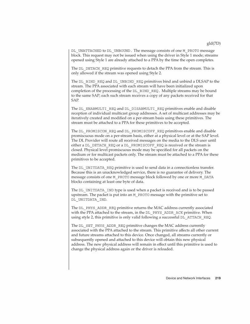
DL_UNATTACHED to DL_UNBOUND. The message consists of one M_PROTO messageblock. This request may not be issued when using the driver in Style 1 mode; streamsopened using Style 1 are already attached to a PPA by the time the open completes.
The DL_DETACH_REQ primitive requests to detach the PPA from the stream. This isonly allowed if the stream was opened using Style 2.
The DL_BIND_REQ and DL_UNBIND_REQ primitives bind and unbind a DLSAP to thestream. The PPA associated with each stream will have been initialized uponcompletion of the processing of the DL_BIND_REQ. Multiple streams may be boundto the same SAP; each such stream receives a copy of any packets received for thatSAP.
The DL_ENABMULTI_REQ and DL_DISABMULTI_REQ primitives enable and disablereception of individual multicast group addresses. A set of multicast addresses may beiteratively created and modified on a per-stream basis using these primitives. Thestream must be attached to a PPA for these primitives to be accepted.
The DL_PROMISCON_REQ and DL_PROMISCOFF_REQ primitives enable and disablepromiscuous mode on a per-stream basis, either at a physical level or at the SAP level.The DL Provider will route all received messages on the media to the DLS user untileither a DL_DETACH_REQ or a DL_PROMISCOFF_REQ is received or the stream isclosed. Physical level promiscuous mode may be specified for all packets on themedium or for multicast packets only. The stream must be attached to a PPA for theseprimitives to be accepted.
The DL_UNITDATA_REQ primitive is used to send data in a connectionless transfer.Because this is an unacknowledged service, there is no guarantee of delivery. Themessage consists of one M_PROTO message block followed by one or more M_DATAblocks containing at least one byte of data.
The DL_UNITDATA_IND type is used when a packet is received and is to be passedupstream. The packet is put into an M_PROTO message with the primitive set toDL_UNITDATA_IND.
The DL_PHYS_ADDR_REQ primitive returns the MAC address currently associatedwith the PPA attached to the stream, in the DL_PHYS_ADDR_ACK primitive. Whenusing style 2, this primitive is only valid following a successful DL_ATTACH_REQ.
The DL_SET_PHYS_ADDR_REQ primitive changes the MAC address currentlyassociated with the PPA attached to the stream. This primitive affects all other currentand future streams attached to this device. Once changed, all streams currently orsubsequently opened and attached to this device will obtain this new physicaladdress. The new physical address will remain in effect until this primitive is used tochange the physical address again or the driver is reloaded.
gld(7D)
Device and Network Interfaces 219

The DL_GET_STATISTICS_REQ primitive requests a DL_GET_STATISTICS_ACKresponse containing statistics information associated with the PPA attached to thestream. Style 2 streams must be attached to a particular PPA using DL_ATTACH_REQbefore this primitive will be successful.
GLD implements the ioctl ioc_cmd function described below. If GLD receives an ioctlcommand that it does not recognize, it passes it to the device-specific driver’sgldm_ioctl() routine as described in gld(9E).
The DLIOCRAW ioctl function is used by some DLPI applications, most notably thesnoop(1M) command. The DLIOCRAW command puts the stream into a raw mode,which, upon receive, causes the the full MAC-level packet to be sent upstream in anM_DATA message instead of it being transformed into the DL_UNITDATA_IND formnormally used for reporting incoming packets. Packet SAP filtering is still performedon streams that are in raw mode; if a stream user wants to receive all incoming packetsit must also select the appropriate promiscuous modes. After successfully selectingraw mode, the application is also allowed to send fully formatted packets to the driveras M_DATA messages for transmission. DLIOCRAW takes no arguments. Once enabled,the stream remains in this mode until closed.
GLD-based drivers must include the header file <sys/gld.h>.
GLD-based drivers must also include the following declaration:
char _depends_on[] = "misc/gld";
GLD implements the open(9E) and close(9E) functions and the required STREAMSput(9E) and srv(9E) functions on behalf of the device-specific driver. GLD alsoimplements the getinfo(9E) function for the driver.
The mi_idname element of the module_info(9S) structure is a string specifying thename of the driver. This must exactly match the name of the driver module as it existsin the file system.
The read-side qinit(9S) structure should specify the following elements as shownbelow:
qi_putp NULL
qi_srvp gld_rsrv
qi_qopen gld_open
qi_qclose gld_close
The write-side qinit(9S) structure should specify the following elements as shownbelow:
qi_putp gld_wput
qi_srvp gld_wsrv
gld(7D)
Implemented ioctlFunctions
Requirements onGLD Drivers
220 man pages section 7: Device and Network Interfaces • Last Revised 31 May 2000

qi_qopen NULL
qi_qclose NULL
The devo_getinfo element of the dev_ops(9S) structure should specifygld_getinfo as the getinfo(9E) routine.
The driver’s attach(9E) function does all the work of associating thehardware-specific device driver with the GLD facility and preparing the device anddriver for use.
The attach(9E) function allocates a gld_mac_info(9S) (‘‘macinfo’’) structure usinggld_mac_alloc(). The driver usually needs to save more information per devicethan is defined in the macinfo structure; it should allocate the additional required datastructure and save a pointer to it in the gldm_private member of thegld_mac_info(9S) structure.
The attach(9E) routine must initialize the macinfo structure as described ingld_mac_info(9S) and then call gld_register() to link the driver with the GLDmodule. The driver should map registers if necessary and be fully initialized andprepared to accept interrupts before calling gld_register(). The attach(9E)function should add interrupts but not enable the device to generate them. The drivershould reset the hardware before calling gld_register() to ensure it is quiescent;the device must not be started or put into a state where it may generate an interruptbefore gld_register() is called. That will be done later when GLD calls thedriver’s gldm_start() entry point described in gld(9E). Once gld_register()succeeds, the gld(9E) entry points may be called by GLD at any time.
The attach(9E) routine should return DDI_SUCCESS if gld_register() succeeds.If gld_register() fails, it returns DDI_FAILURE and the attach(9E) routineshould deallocate any resources it allocated before calling gld_register() and thenalso return DDI_FAILURE. Under no circumstances should a failed macinfo structurebe reused; it should be deallocated using gld_mac_free().
The detach(9E) function should attempt to unregister the driver from GLD. This isdone by calling gld_unregister() described in gld(9F). The detach(9E) routinecan get a pointer to the needed gld_mac_info(9S) structure from the device’s privatedata using ddi_get_driver_private(9F). gld_unregister() checks certainconditions that could require that the driver not be detached. If the checks fail,gld_unregister() returns DDI_FAILURE, in which case the driver’s detach(9E)routine must leave the device operational and return DDI_FAILURE. If the checkssucceed, gld_unregister() ensures that the device interrupts are stopped, callingthe driver’s gldm_stop() routine if necessary, unlinks the driver from the GLDframework, and returns DDI_SUCCESS. In this case, the detach(9E) routine shouldremove interrupts, deallocate any data structures allocated in the attach(9E) routine,using gld_mac_free() to deallocate the macinfo structure, and returnDDI_SUCCESS. It is important to remove the interrupt before callinggld_mac_free().
gld(7D)
Device and Network Interfaces 221
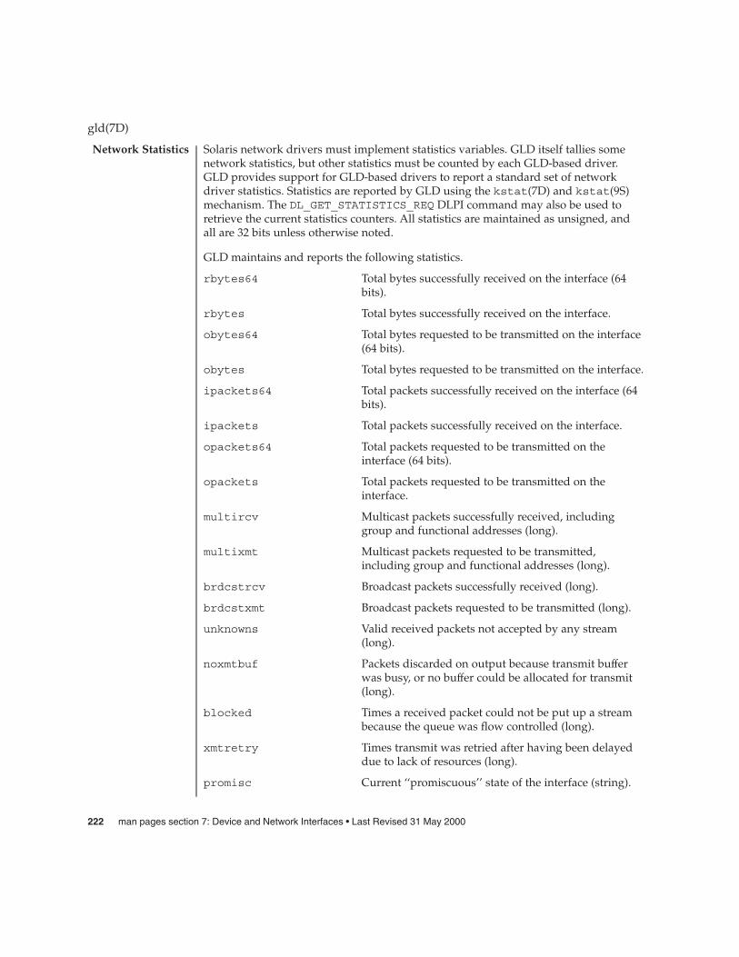
Solaris network drivers must implement statistics variables. GLD itself tallies somenetwork statistics, but other statistics must be counted by each GLD-based driver.GLD provides support for GLD-based drivers to report a standard set of networkdriver statistics. Statistics are reported by GLD using the kstat(7D) and kstat(9S)mechanism. The DL_GET_STATISTICS_REQ DLPI command may also be used toretrieve the current statistics counters. All statistics are maintained as unsigned, andall are 32 bits unless otherwise noted.
GLD maintains and reports the following statistics.
rbytes64 Total bytes successfully received on the interface (64bits).
rbytes Total bytes successfully received on the interface.
obytes64 Total bytes requested to be transmitted on the interface(64 bits).
obytes Total bytes requested to be transmitted on the interface.
ipackets64 Total packets successfully received on the interface (64bits).
ipackets Total packets successfully received on the interface.
opackets64 Total packets requested to be transmitted on theinterface (64 bits).
opackets Total packets requested to be transmitted on theinterface.
multircv Multicast packets successfully received, includinggroup and functional addresses (long).
multixmt Multicast packets requested to be transmitted,including group and functional addresses (long).
brdcstrcv Broadcast packets successfully received (long).
brdcstxmt Broadcast packets requested to be transmitted (long).
unknowns Valid received packets not accepted by any stream(long).
noxmtbuf Packets discarded on output because transmit bufferwas busy, or no buffer could be allocated for transmit(long).
blocked Times a received packet could not be put up a streambecause the queue was flow controlled (long).
xmtretry Times transmit was retried after having been delayeddue to lack of resources (long).
promisc Current ‘‘promiscuous’’ state of the interface (string).
gld(7D)
Network Statistics
222 man pages section 7: Device and Network Interfaces • Last Revised 31 May 2000

The device dependent driver counts the following statistics, keeping track of them in aprivate per-instance structure. When GLD is asked to report statistics, it calls thedriver’s gldm_get_stats() entry point, as described in gld(9E), to update thedevice-specific statistics in the gld_stats(9S) structure. GLD then reports theupdated statistics using the named statistics variables below.
ifspeed Current estimated bandwidth of the interface in bitsper second (64 bits).
media Current media type in use by the device (string).
intr Times interrupt handler was called and claimed theinterrupt (long).
norcvbuf Times a valid incoming packet was known to havebeen discarded because no buffer could be allocated forreceive (long).
ierrors Total packets received that couldn’t be processedbecause they contained errors (long).
oerrors Total packets that weren’t successfully transmittedbecause of errors (long).
missed Packets known to have been dropped by the hardwareon receive (long).
uflo Times FIFO underflowed on transmit (long).
oflo Times receiver overflowed during receive (long).
The following group of statistics applies to networks of type DL_ETHER; these aremaintained by device-specific drivers of that type, as above.
align_errors Packets received with framing errors (not an integralnumber of octets) (long).
fcs_errors Packets received with CRC errors (long).
duplex Current duplex mode of the interface (string).
carrier_errors Times carrier was lost or never detected on atransmission attempt (long).
collisions Ethernet collisions during transmit (long).
ex_collisions Frames where excess collisions occurred on transmit,causing transmit failure (long).
tx_late_collisions Times a transmit collision occurred late (after 512 bittimes) (long).
defer_xmts Packets without collisions where first transmit attemptwas delayed because the medium was busy (long).
gld(7D)
Device and Network Interfaces 223

first_collisions Packets successfully transmitted with exactly onecollision.
multi_collisions Packets successfully transmitted with multiplecollisions.
sqe_errors Times SQE test error was reported.
macxmt_errors Packets encountering transmit MAC failures, exceptcarrier and collision failures.
macrcv_errors Packets received with MAC errors, except align, fcs,and toolong errors.
toolong_errors Packets received larger than the maximum permittedlength.
runt_errors Packets received smaller than the minimum permittedlength (long).
The following group of statistics applies to networks of type DL_TPR; these aremaintained by device-specific drivers of that type, as above.
line_errors Packets received with non-data bits or FCS errors.
burst_errors Times an absence of transitions for five half-bit timerswas detected.
signal_losses Times loss of signal condition on the ring was detected.
ace_errors Times an AMP or SMP frame in which A is equal to Cis equal to 0, was followed by another such SMP framewithout an intervening AMP frame.
internal_errors Times the station recognized an internal error.
lost_frame_errors Times the TRR timer expired during transmit.
frame_copied_errors Times a frame addressed to this station was receivedwith the FS field A bit set to 1.
token_errors Times the station acting as the active monitorrecognized an error condition that needed a tokentransmitted.
freq_errors Times the frequency of the incoming signal differedfrom the expected frequency.
The following group of statistics applies to networks of type DL_FDDI; these aremaintained by device-specific drivers of that type, as above.
mac_errors Frames detected in error by this MAC that had notbeen detected in error by another MAC.
gld(7D)
224 man pages section 7: Device and Network Interfaces • Last Revised 31 May 2000

mac_lost_errors Frames received with format errors such that the framewas stripped.
mac_tokens Number of tokens received (total of non-restricted andrestricted).
mac_tvx_expired Number of times that TVX has expired.
mac_late Number of TRT expirations since this MAC was resetor a token was received.
mac_ring_ops Number of times the ring has entered the‘‘Ring_Operational’’ state from the ‘‘Ring NotOperational’’ state.
/kernel/misc/gld loadable kernel module
kstat(7D), dlpi(7P), attach(9E), gld(9E), open(9E), gld(9F), gld_mac_info(9S),gld_stats(9S), kstat(9S)
Writing Device Drivers
Contrary to the DLPI specification, GLD returns the device’s correct address lengthand broadcast address in DL_INFO_ACK even before the stream has been attached to aPPA.
Promiscuous mode may only be entered by streams that are attached to a PPA.
The physical address of a PPA may be changed by the superuser while other streamsare bound to the same PPA.
gld(7D)
FILES
SEE ALSO
WARNINGS
Device and Network Interfaces 225

glm – GLM SCSI Host Bus Adapter Driver
scsi@unit-address
The glm Host Bus Adapter driver is a SCSA compliant nexus driver that supports theLSI 53c810, LSI 53c875, LSI 53c876, LSI 53C896 and LSI 53C1010 SCSI chips
It supports the standard functions provided by the SCSA interface. That is, it supportstagged and untagged queuing, Narrow/Wide/Fast/Ultra SCSI/Ultra SCSI 2/UltraSCSI 3, and auto request sense, but it does not support linked commands.
Configure the glm driver by defining properties in glm.conf. These propertiesoverride the global SCSI settings. glm supports these properties which can bemodified by the user: scsi-options, target<n>-scsi-options,scsi-reset-delay, scsi-tag-age-limit, scsi-watchdog-tick, andscsi-initiator-id.
target<n>-scsi-options overrides the scsi-options property value fortarget<n>. <n> can vary from decimal 0 to 15. glm supports these scsi-options:SCSI_OPTIONS_DR, SCSI_OPTIONS_SYNC, SCSI_OPTIONS_TAG,SCSI_OPTIONS_FAST, SCSI_OPTIONS_WIDE, SCSI_OPTIONS_FAST20,SCSI_OPTIONS_FAST40 and SCSI_OPTIONS_FAST80.
After periodic interval scsi-watchdog-tick, the glm driver searches through allcurrent and disconnected commands for timeouts.
scsi-tag-age-limit is the number of times that the glm driver attempts toallocate a particular tag ID that is currently in use after going through all tag IDs in acircular fashion. After finding the same tag ID in use scsi-tag-age-limit times,no more commands will be submitted to this target until all outstanding commandscomplete or timeout.
Refer to scsi_hba_attach(9F).
EXAMPLE 1 Using the glm Configuration File
Create a file called /kernel/drv/glm.conf and add the following line:
scsi-options=0x78;
This disables tagged queuing, Fast/Ultra SCSI and wide mode for all glm instances.
The following example disables an option for one specific glm (refer todriver.conf(4) and pci(4) for more details):
name="glm" parent="/pci@1f,4000"unit-address="3"target1-scsi-options=0x58scsi-options=0x178 scsi-initiator-id=6;
Note that the default initiator ID in OBP is 7 and that the change to ID 6 will occur atattach time. It may be preferable to change the initiator ID in OBP.
glm(7D)
NAME
SYNOPSIS
DESCRIPTION
DriverConfiguration
EXAMPLES
226 man pages section 7: Device and Network Interfaces • Last Revised 20 Jul 2001

EXAMPLE 1 Using the glm Configuration File (Continued)
The example above sets scsi-options for target 1 to 0x58 and all other targets onthis SCSI bus to 0x178.
The physical pathname of the parent can be determined using the /devices tree orfollowing the link of the logical device name:
# ls -l /dev/rdsk/c0t0d0s0lrwxrwxrwx 1 root root 45 May 16 10:08 /dev/rdsk/c0t0d0s0 ->
. . / . . /devices/pci@1f,4000/scsi@3/sd@0,0:a,raw
In this case, like the example above, the parent is /pci@1f,4000 and theunit-address is the number bound to the scsi@3 node.
To set scsi-options more specifically per target:
target1-scsi-options=0x78;device-type-scsi-options-list =
"SEAGATE ST32550W", "seagate-scsi-options" ;seagate-scsi-options = 0x58;scsi-options=0x3f8;
The above sets scsi-options for target 1 to 0x78 and for all other targets on thisSCSI bus to 0x3f8 except for one specific disk type which will have scsi-optionsset to 0x58.
scsi-options specified per target ID have the highest precedence, followed byscsi-options per device type. Global scsi-options (for all glm instances) perbus have the lowest precedence.
The system needs to be rebooted before the specified scsi-options take effect.
The target driver needs to set capabilities in the glm driver in order to enable somedriver features. The target driver can query and modify these capabilities:synchronous, tagged-qing, wide-xfer, auto-rqsense, qfull-retries,qfull-retry-interval. All other capabilities can only be queried.
By default, tagged-qing, auto-rqsense, and wide-xfer capabilities are disabled,while disconnect, synchronous, and untagged-qing are enabled. Thesecapabilities can only have binary values (0 or 1). The default value forqfull-retries is 10 and the default value for qfull-retry-interval is 100.The qfull-retries capability is a uchar_t (0 to 255) while qfull-retry-interval is a ushort_t (0 to 65535).
The target driver needs to enable tagged-qing and wide-xfer explicitly. Theuntagged-qing capability is always enabled and its value cannot be modified.
Whenever there is a conflict between the value of scsi-options and a capability, thevalue set in scsi-options prevails. Only whom != 0 is supported in thescsi_ifsetcap(9F) call.
glm(7D)
Driver Capabilities
Device and Network Interfaces 227

Refer to scsi_ifsetcap(9F) and scsi_ifgetcap(9F) for details.
/kernel/drv/glm ELF Kernel Module
/kernel/drv/glm.conf Optional configuration file
See attributes(5) for descriptions of the following attributes:
ATTRIBUTE TYPE ATTRIBUTE VALUE
Architecture Limited to PCI-based systems with LSI 53c810, LSI53c875, LSI 53c876, LSI 53c896 and LSI 53c1010 SCSII/O processors
prtconf(1M), driver.conf(4), pci(4), attributes(5), scsi_abort(9F),scsi_hba_attach(9F), scsi_ifgetcap(9F), scsi_ifsetcap(9F),scsi_reset(9F), scsi_sync_pkt(9F), scsi_transport(9F), scsi_device(9S),scsi_extended_sense(9S), scsi_inquiry(9S), scsi_pkt(9S)
Writing Device Drivers
ANSI Small Computer System Interface-2 (SCSI-2),
LSI Logi Inc (formerly Symbios Logic Inc.):
� SYM53c810 PCI-SCSI I/O processor with Narrow operation� SYM53c875 PCI-SCSI I/O Processor With Fast-20� SYM53c876 PCI-SCSI I/O processor Dual channel Fast-20� SYM53c896 PCI-SCSI I/O processor Dual channel Fast-40� SYM53c1010 PCI-SCSI I/O processor Dual Channel Fast-80
The messages described below are some that may appear on the system console, aswell as being logged.
Device is using a hilevel intrThe device was configured with an interrupt level that cannot be used with thisglm driver. Check the PCI device.
map setup failedDriver was unable to map device registers; check for bad hardware. Driver did notattach to device; SCSI devices will be inaccessible.
glm_script_alloc failedThe driver was unable to load the SCRIPTS for the SCSI processor, check for badhardware. Driver did not attach to device; SCSI devices will be inaccessible.
cannot map configuration space.The driver was unable to map in the configuration registers. Check for badhardware. SCSI devices will be inaccessible.
glm(7D)
FILES
ATTRIBUTES
SEE ALSO
DIAGNOSTICS
228 man pages section 7: Device and Network Interfaces • Last Revised 20 Jul 2001

attach failedThe driver was unable to attach; usually preceded by another warning thatindicates why attach failed. These can be considered hardware failures.
SCSI bus DATA IN phase parity errorThe driver detected parity errors on the SCSI bus.
SCSI bus MESSAGE IN phase parity errorThe driver detected parity errors on the SCSI bus.
SCSI bus STATUS phase parity errorThe driver detected parity errors on the SCSI bus.
Unexpected bus freeTarget disconnected from the bus without notice. Check for bad hardware.
Disconnected command timeout for Target <id>.<lun>A timeout occurred while target id/lun was disconnected. This is usually a targetfirmware problem. For tagged queuing targets, <n> commands were outstandingwhen the timeout was detected.
Disconnected tagged cmd(s) (<n>) timeout for Target <id>.<lun>A timeout occurred while target id/lun was disconnected. This is usually a targetfirmware problem. For tagged queuing targets, <n> commands were outstandingwhen the timeout was detected.
Connected command timeout for Target <id>.<lun>This is usually a SCSI bus problem. Check cables and termination.
Target <id> reducing sync. transfer rateA data transfer hang or DATA-IN phase parity error was detected. The driverattempts to eliminate this problem by reducing the data transfer rate.
Target <id> reverting to async. modeA second data transfer hang was detected for this target. The driver attempts toeliminate this problem by reducing the data transfer rate.
Target <id> disabled wide SCSI modeA second data phase hang was detected for this target. The driver attempts toeliminate this problem by disabling wide SCSI mode.
auto request sense failedAn attempt to start an auto request packet failed. Another auto request packet mayalready be in transport.
invalid reselection (<id>.<lun>)A reselection failed; target accepted abort or reset, but still tries to reconnect.Check for bad hardware.
invalid intcodeThe SCRIPTS processor generated an invalid SCRIPTS interrupt. Check for badhardware.
The glm driver supports the following LSI chips:
glm(7D)
NOTES
Device and Network Interfaces 229

� LSI 53C810, which supports Narrow, Fast SCSI mode. The maximum SCSIbandwidth is 10 MB/sec.
� LSI 53C875, which supports Wide, Fast, and Ultra SCSI mode. The maximum SCSIbandwidth is 40 MB/sec.
� LSI 53C896, which supports Wide, Fast and Ultra SCSI 2 mode. The maximum LVDSCSI bandwidth is 80 MB/sec.
� LSI 53c1010, which supports wide, Fast and Ultra SCSI 3 mode. The maximumLVD SCSI bandwidth is 160 MB/sec.
The glm driver exports properties indicating per target the negotiated transfer speed(target<n>-sync-speed), whether wide bus is supported (target<n>-wide), forthat particular target (target<n>-scsi-options), and whether tagged queuing hasbeen enabled (target<n>-TQ). The sync-speed property value is the data transferrate in KB/sec. The target<n>-TQ and the target<n>-wide property have value 1to indicate that the corresponding capability is enabled, or 0 to indicate that thecapability is disabled for that target. Refer to prtconf(1M) (verbose option) forviewing the glm properties.
scsi, instance #0Driver properties:
name <target6-TQ> length <4>value <0x00000000>.
name <target6-wide> length <4>value <0x00000000>.
name <target6-sync-speed> length <4>value <0x00002710>.
name <target1-TQ> length <4>value <0x00000001>.
name <target1-wide> length <4>value <0x00000000>.
name <target1-sync-speed> length <4>value <0x00002710>.
name <target0-TQ> length <4>value <0x00000001>.
name <target0-wide> length <4>value <0x00000001>.
name <target0-sync-speed> length <4>value <0x00009c40>.
name <scsi-options> length <4>value <0x000007f8>.
name <scsi-watchdog-tick> length <4>value <0x0000000a>.
name <scsi-tag-age-limit> length <4>value <0x00000002>.
name <scsi-reset-delay> length <4>value <0x00000bb8>.
name <latency-timer> length <4>value <0x00000088>.
name <cache-line-size> length <4>
value <0x00000010>.
glm(7D)
230 man pages section 7: Device and Network Interfaces • Last Revised 20 Jul 2001
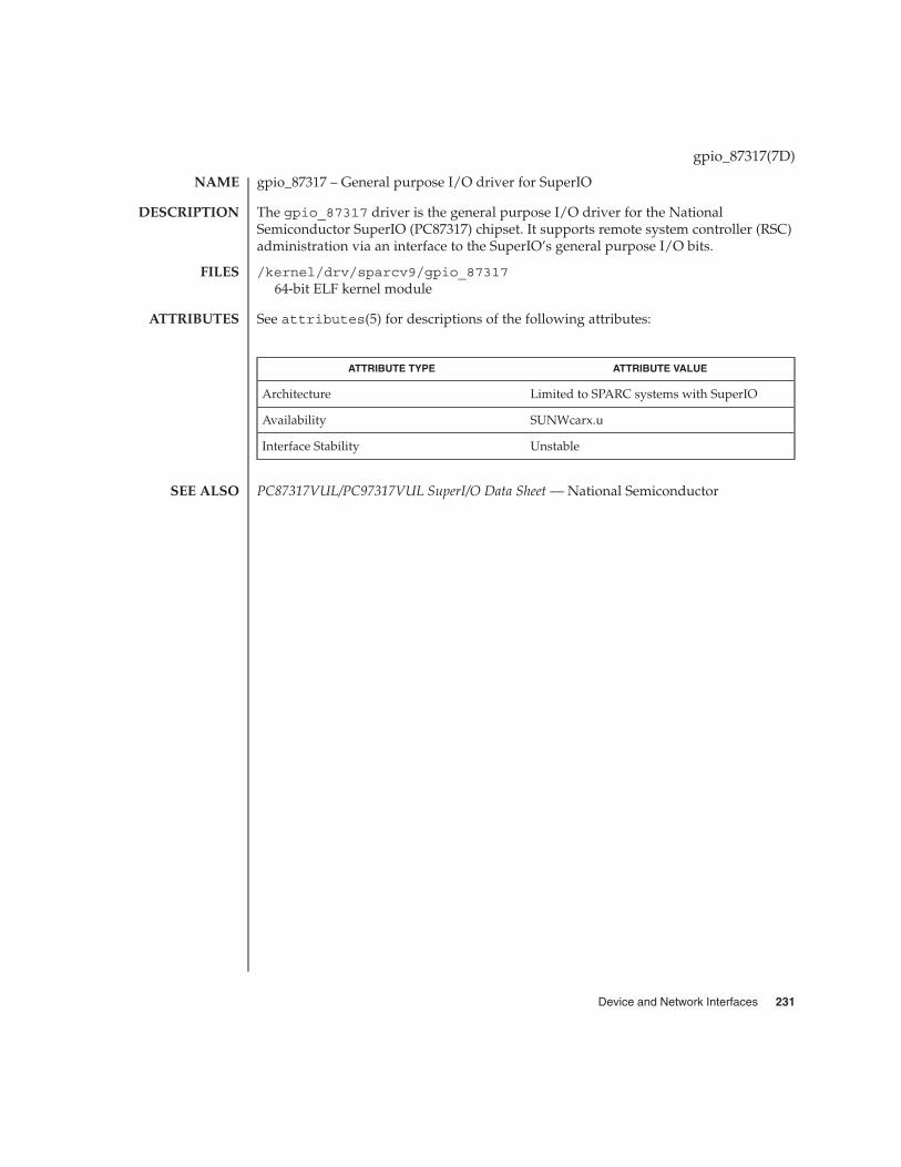
gpio_87317 – General purpose I/O driver for SuperIO
The gpio_87317 driver is the general purpose I/O driver for the NationalSemiconductor SuperIO (PC87317) chipset. It supports remote system controller (RSC)administration via an interface to the SuperIO’s general purpose I/O bits.
/kernel/drv/sparcv9/gpio_8731764-bit ELF kernel module
See attributes(5) for descriptions of the following attributes:
ATTRIBUTE TYPE ATTRIBUTE VALUE
Architecture Limited to SPARC systems with SuperIO
Availability SUNWcarx.u
Interface Stability Unstable
PC87317VUL/PC97317VUL SuperI/O Data Sheet — National Semiconductor
gpio_87317(7D)
NAME
DESCRIPTION
FILES
ATTRIBUTES
SEE ALSO
Device and Network Interfaces 231

grbeep – Platform-dependent beep driver for SMBus-based hardware
beep@unit-address
The grbeep driver generates beeps on platforms (including Sun Blade 100, 150, 1500,2500) that use SMBbus-based registers and USB keyboards. When the KIOCCMD ioctl isissued to the USB keyboard module (see usbkbm(7M)) with commandKBD_CMD_BELL/KBD_CMD_NOBELL, usbkbm(7M) passes the request to the grbeepdriver to turn the beep on and off, respectively.
/platform/sun4u/kernel/drv/sparcv9/grbeep64–bit ELF kernel driver
See attributes(5) for descriptions of the following attributes:
ATTRIBUTE TYPE ATTRIBUTE VALUE
Architecture SMBus-based SPARC
Availability SUNWcarx.u
kbd(1), attributes(5), bbc_beep(7D), kb(7M), usbkbm(7M)
Writing Device Drivers
None
grbeep(7d)
NAME
SYNOPSIS
DESCRIPTION
FILES
ATTRIBUTES
SEE ALSO
DIAGNOSTICS
232 man pages section 7: Device and Network Interfaces • Last Revised 18 Dec 2001

hci1394 – 1394 OpenHCI host controller driver
firewire@unit-address
The hci1394 host controller driver is an IEEE 1394 compliant nexus driver thatsupports the 1394 Open Host Controller Interface Specification 1.0, an industry standarddeveloped by Sun, Apple, Compaq, Intel, Microsoft, National Semconductor, andTexas Instruments. The hci1394 driver supports asynchronous transfers,isochronous transfers, and bus reset management. The hci1394 driver also supportsthe nexus device control interface.
/kernel/drv/sparcv9/hci139464–bit ELF kernel module
See attributes(5) for a description of the following attributes:
ATTRIBUTE TYPE ATTRIBUTE VALUE
Architecture Limited to PCI-based SPARC systems
Availability SUNW1394x
Interface Stability Unstable
IEEE 1394 - IEEE Standard for a High Performance Serial Bus
1394 Open Host Controller Interface Specification 1.0
hci1394(7D)
NAME
SYNOPSIS
DESCRIPTION
FILES
ATTRIBUTES
SEE ALSO
Device and Network Interfaces 233

hdio – SMD and IPI disk control operations
#include <sys/hdio.h>
Note – The SMC and IPI drivers have been discontinued. dkio(7I) is now thepreferred method for retrieving disk information.
The SMD and IPI disk drivers supplied with this release support a set of ioctl(2)requests for diagnostics and bad sector information. Basic to these ioctl() requestsare the definitions in <sys/hdio.h>.
HDKIOCGTYPE The argument is a pointer to a hdk_type structure (describedbelow). This ioctl() gets specific information from the harddisk.
HDKIOCSTYPE The argument is a pointer to a hdk_type structure (describedbelow). This ioctl() sets specific information about the harddisk.
/** Used for drive info*/struct hdk_type {ushort_t hdkt_hsect; /* hard sector count (read only) */ushort_t hdkt_promrev; /* prom revision (read only) */uchar_t hdkt_drtype; /* drive type (ctlr specific) */uchar_t hdkt_drstat; /* drive status (ctlr specific, ro) */
};
HDKIOCGBAD The argument is a pointer to a hdk_badmap structure (describedbelow). This ioctl() is used to get the bad sector map from thedisk.
HDKIOCSBAD The argument is a pointer to a hdk_badmap structure (describedbelow). This ioctl() is used to set the bad sector map on thedisk.
/** Used for bad sector map*/struct hdk_badmap {
caddr_t hdkb_bufaddr; /* address of user’s map buffer */
};
HDKIOCGDIAG The argument is a pointer to a hdk_diag structure (describedbelow). This ioctl() gets the most recent command that failedalong with the sector and error number from the hard disk.
/** Used for disk diagnostics*/struct hdk_diag {ushort_t hdkd_errcmd; /* most recent command in error */daddr_t hdkd_errsect; /* most recent sector in error */uchar_t hdkd_errno; /* most recent error number */
hdio(7I)
NAME
SYNOPSIS
DESCRIPTION
IOCTLS
234 man pages section 7: Device and Network Interfaces • Last Revised 13 Aug 2002

uchar_t hdkd_severe; /* severity of most recent error */
};
ioctl(2), dkio(7I)
hdio(7I)
SEE ALSO
Device and Network Interfaces 235

hid – Human interface device (HID) class driver
keyboard@unit-addressmouse@unit-address
input@unit-address:consumer_control
The hid driver is a USBA (Solaris USB Architecture) compliant client driver thatsupports the Human Interface Device Class (HID) 1.0 specification. The Human InterfaceDevice (HID) class encompasses devices controlled by humans to operate computersystems. Typical examples of HID devices include keyboards, mice, trackballs, andjoysticks. HID also covers front-panel controls such as knobs, switches, and buttons. AUSB device with multiple interfaces may have one interface for audio and a HIDinterface to define the buttons that control the audio.
The hid driver is general and primarily handles the USB functionality of the deviceand generic HID functionality. For example, HID interfaces are required to have aninterrupt pipe for the device to send data packets, and the hid driver opens the pipeto the interrupt endpoint and starts polling. The hid driver is also responsible formanaging the device through the default control pipe. In addition to being a USBclient driver, the hid driver is also a STREAMS driver so that modules may be pushedon top of it.
The HID specification is flexible, and HID devices dynamically describe their packetsand other parameters through a HID report descriptor. The HID parser is a miscmodule that parses the HID report descriptor and creates a database of informationabout the device. The hid driver queries the HID parser to find out the type andcharacteristics of the HID device. The HID specification predefines packet formats forthe boot protocol keyboard and mouse.
/kernel/drv/hid32 bit ELF kernel module
/kernel/drv/sparcv9/hid64 bit ELF kernel module
/kernel/misc/hidparser/kernel/misc/sparcv9/hidparser
See attributes(5) for descriptions of the following attributes:
ATTRIBUTE TYPE ATTRIBUTE VALUE
Architecture PCI-based systems
Availability SUNWusb, SUNWusbx
cfgadm_usb(1M), attributes(5), usba(7D)
Writing Device Drivers
hid(7D)
NAME
SYNOPSIS
DESCRIPTION
FILES
ATTRIBUTES
SEE ALSO
236 man pages section 7: Device and Network Interfaces • Last Revised 19 Dec 2001

STREAMS Programming Guide
Universal Serial Bus Specification 1.0 and 1.1
Device Class Definition for Human Interface Devices (HID) 1.1
System Administration Guide: Basic Administration
http://www.sun.com/io
None.
The hid driver currently supports only keyboard, mouse and audio HID controldevice.
hid(7D)
DIAGNOSTICS
NOTES
Device and Network Interfaces 237

hme – SUNW,hme Fast-Ethernet device driver
/dev/hme
The SUNW,hme Fast-Ethernet driver is a multi-threaded, loadable, clonable, STREAMShardware driver supporting the connectionless Data Link Provider Interface,dlpi(7P), over a SUNW,hme Fast-Ethernet controller. The motherboard and add-inSBus SUNW,hme controllers of several varieties are supported. Multiple SUNW,hmecontrollers installed within the system are supported by the driver.
The hme driver provides basic support for the SUNW,hme hardware. It is used tohandle the SUNW,hme device. Functions include chip initialization, frame transit andreceive, multicast and promiscuous support, and error recovery and reporting.SUNW,hme The SUNW,hme device provides 100Base-TX networking interfaces usingSUN’s FEPS ASIC and an Internal Transceiver. The FEPS ASIC provides the Sbusinterface and MAC functions and the Physical layer functions are provided by theInternal Transceiver which connects to a RJ-45 connector. In addition to the RJ-45connector, an MII (Media Independent Interface) connector is also provided on allSUNW,hme devices except the SunSwith SBus adapter board. The MII interface is usedto connect to an External Transceiver which may use any physical media (copper orfiber) specified in the 100Base-TX standard. When an External Transceiver is connectedto the MII, the driver selects the External Transceiver and disables the InternalTransceiver.
The 100Base-TX standard specifies an “auto-negotiation” protocol to automaticallyselect the mode and speed of operation. The Internal transceiver is capable of doing“auto-negotiation” with the remote-end of the link (Link Partner) and receives thecapabilities of the remote end. It selects the Highest Common Denominator modeof operation based on the priorities. It also supports forced-mode of operationwhere the driver can select the mode of operation.
The cloning character-special device /dev/hme is used to access all SUNW,hmecontrollers installed within the system.
The hme driver is a “style 2” Data Link Service provider. All M_PROTO andM_PCPROTO type messages are interpreted as DLPI primitives. Valid DLPI primitivesare defined in <sys/dlpi.h>. Refer to dlpi(7P) for more information. An explicitDL_ATTACH_REQ message by the user is required to associate the opened stream witha particular device (ppa). The ppa ID is interpreted as an unsigned long data typeand indicates the corresponding device instance (unit) number. An error(DL_ERROR_ACK) is returned by the driver if the ppa field value does not correspondto a valid device instance number for this system. The device is initialized on firstattach and de-initialized (stopped) at last detach.
The values returned by the driver in the DL_INFO_ACK primitive in response to theDL_INFO_REQ from the user are as follows:
� The maximum SDU is 1500 (ETHERMTU - defined in <sys/ethernet.h> ).� The minimum SDU is 0.
hme(7D)
NAME
SYNOPSIS
DESCRIPTION
APPLICATIONPROGRAMMING
INTERFACEhme and DLPI
238 man pages section 7: Device and Network Interfaces • Last Revised 5 Sep 1995
� The dlsap address length is 8.� The MAC type is DL_ETHER.� The sap length values is −2 meaning the physical address component is followed
immediately by a 2 byte sap component within the DLSAP address.� The service mode is DL_CLDLS.� No optional quality of service (QOS) support is included at present so the QOS
fields are 0.� The provider style is DL_STYLE2.� The version is DL_VERSION_2.� The broadcast address value is Ethernet/IEEE broadcast address (0xFFFFFF).
Once in the DL_ATTACHED state, the user must send a DL_BIND_REQ to associate aparticular SAP (Service Access Pointer) with the stream. The hme driver interprets thesap field within the DL_BIND_REQ as an Ethernet “type” therefore valid values forthe sap field are in the [0-0xFFFF] range. Only one Ethernet type can be bound to thestream at any time.
If the user selects a sap with a value of 0, the receiver will be in “802.3 mode”. Allframes received from the media having a “type” field in the range [0-1500] areassumed to be 802.3 frames and are routed up all open Streams which are bound tosap value 0. If more than one Stream is in “802.3 mode” then the frame will beduplicated and routed up multiple Streams as DL_UNITDATA_IND messages.
In transmission, the driver checks the sap field of the DL_BIND_REQ if the sap valueis 0, and if the destination type field is in the range [0-1500]. If either is true, thedriver computes the length of the message, not including initial M_PROTO mblk(message block), of all subsequent DL_UNITDATA_REQ messages and transmits 802.3frames that have this value in the MAC frame header length field.
The hme driver DLSAP address format consists of the 6 byte physical (Ethernet)address component followed immediately by the 2 byte sap (type) componentproducing an 8 byte DLSAP address. Applications should not hardcode to thisparticular implementation-specific DLSAP address format but use informationreturned in the DL_INFO_ACK primitive to compose and decompose DLSAPaddresses. The sap length, full DLSAP length, and sap/physical ordering are includedwithin the DL_INFO_ACK. The physical address length can be computed bysubtracting the sap length from the full DLSAP address length or by issuing theDL_PHYS_ADDR_REQ to obtain the current physical address associated with thestream.
Once in the DL_BOUND state, the user may transmit frames on the Ethernet by sendingDL_UNITDATA_REQ messages to the hme driver. The hme driver will route receivedEthernet frames up all those open and bound streams having a sap which matches theEthernet type as DL_UNITDATA_IND messages. Received Ethernet frames are
hme(7D)
Device and Network Interfaces 239
duplicated and routed up multiple open streams if necessary. The DLSAP addresscontained within the DL_UNITDATA_REQ and DL_UNITDATA_IND messages consistsof both the sap (type) and physical (Ethernet) components.
In addition to the mandatory connectionless DLPI message set the driver additionallysupports the following primitives.
The DL_ENABMULTI_REQ and DL_DISABMULTI_REQ primitives enable/disablereception of individual multicast group addresses. A set of multicast addresses may beiteratively created and modified on a per-stream basis using these primitives. Theseprimitives are accepted by the driver in any state following DL_ATTACHED.
The DL_PROMISCON_REQ and DL_PROMISCOFF_REQ primitives with theDL_PROMISC_PHYS flag set in the dl_level field enables/disables reception of all(“promiscuous mode”) frames on the media including frames generated by the localhost. When used with the DL_PROMISC_SAP flag set this enables/disables receptionof all sap (Ethernet type) values. When used with the DL_PROMISC_MULTI flag setthis enables/disables reception of all multicast group addresses. The effect of each isalways on a per-stream basis and independent of the other sap and physical levelconfigurations on this stream or other streams.
The DL_PHYS_ADDR_REQ primitive returns the 6 octet Ethernet address currentlyassociated (attached) to the stream in the DL_PHYS_ADDR_ACK primitive. Thisprimitive is valid only in states following a successful DL_ATTACH_REQ.
The DL_SET_PHYS_ADDR_REQ primitive changes the 6 octet Ethernet addresscurrently associated (attached) to this stream. The credentials of the process whichoriginally opened this stream must be superuser. Otherwise EPERM is returned in theDL_ERROR_ACK. This primitive is destructive in that it affects all other current andfuture streams attached to this device. An M_ERROR is sent up all other streamsattached to this device when this primitive is successful on this stream. Once changed,all streams subsequently opened and attached to this device will obtain this newphysical address. Once changed, the physical address will remain until this primitiveis used to change the physical address again or the system is rebooted, whichevercomes first.
By default, the hme driver performs “auto-negotiation” to select the mode and speedof the link, when the Internal Transceiver is used.
When an External Transceiver is connected to the MII interface, the driver selects theExternal Transceiver for networking operations. If the External Transceiver supports“auto-negotiation”, the driver uses the auto-negotiation procedure to select the linkspeed and mode. If the External Transceiver does not support auto-negotiation, it willselect the highest priority mode supported by the transceiver.
� 100 Mbps, full-duplex� 100 Mbps, half-duplex� 10 Mbps, full-duplex� 10 Mbps, half-duplex
hme(7D)
hme Primitives
hme DRIVER
240 man pages section 7: Device and Network Interfaces • Last Revised 5 Sep 1995
The link can be in one of the 4 following modes:
These speeds and modes are described in the 100Base-TX standard.
The auto−negotiation protocol automatically selects:
� Operation mode (half-duplex or full-duplex)� Speed (100 Mbps or 10 Mbps)
The auto−negotiation protocol does the following:
� Gets all the modes of operation supported by the Link Partner� Advertises its capabilities to the Link Partner� Selects the highest common denominator mode of operation based on the priorities
The internal transceiver is capable of all of the operating speeds and modes listedabove. When the internal transceiver is used, by default, auto-negotiation is used toselect the speed and the mode of the link and the common mode of operation with theLink Partner.
When an external transceiver is connected to the MII interface, the driver selects theexternal transceiver for networking operations. If the external transceiver supportsauto-negotiation:
� The driver uses the auto-negotiation procedure to select the link speed and mode.
If the external transceiver does not support auto-negotiation
� The driver selects the highest priority mode supported by the transceiver.
Sometimes, the user may want to select the speed and mode of the link. TheSUNW,hme device supports programmable “IPG” (Inter-Packet Gap) parameters ipg1and ipg2. By default, the driver sets ipg1 to 8 byte-times and ipg2 to 4byte-times (which are the standard values). Sometimes, the user may want to alterthese values depending on whether the driver supports 10 Mbps or 100 Mpbs andaccordingly, IPG will be set to 9.6 or 0.96 microseconds.
The hme driver provides for setting and getting various parameters for the SUNW,hmedevice. The parameter list includes:
current transceiver statuscurrent link statusinter-packet gaplocal transceiver capabilitieslink partner capabilities
The local transceiver has two set of capabilities: one set reflects the capabilities of thehardware, which are read-only (RO) parameters and the second set reflects thevalues chosen by the user and is used in speed selection. There are read/write
hme(7D)
hme ParameterList
Device and Network Interfaces 241

(RW) capabilities. At boot time, these two sets of capabilities will be the same. TheLink Partner capabilities are also read only parameters because the current defaultvalue of these parameters can only be read and cannot be modified.
/dev/hme hme special character device
/kernel/drv/hme.conf System-wide default device driver properties
ndd(1M), netstat(1M), driver.conf(4), dlpi(7P), le(7D)
hme(7D)
FILES
SEE ALSO
242 man pages section 7: Device and Network Interfaces • Last Revised 5 Sep 1995

hpfc – Agilent fibre channel host bus adapter
PCI pci103c
The hpfc fibre channel host bus adapter is a SCSA compliant nexus driver thatsupports all Agilent fibre channel host bus adapters, including the HHBA5100x,HHBA5101x, and HHBA5121x models. Agilent host bus adapters support the fibrechannel protocol on private fibre channel arbitrated loops and fabrics. The driversupports up to ten host bus adapters, with a maximum of 125 fibre channel devices oneach host bus adapter. The hpfc driver supports a maximum of 256 LUNs per target.
The hpfc driver does not support the BIOS Int 13 feature, which enables the bootingof an operating system. As a result, you should not install an operating system ondevices attached to the hpfc driver.
The hpfc driver attempts to configure itself using the information in the/kernel/drv/hpfc.conf configuration file.
By default, the driver supports only LUN 0 for each target device. To add multipleLUN support, modify the /kernel/drv/sd.conf file.
Before upgrading the hpfc driver, backup the sd.conf file to save customized LUNsettings and then use pkgrm(1M) to remove the old version of the driver.
The host bus adapter port is initialized to FL_Port when connected to a fabric switch.To change it to F_Port, add the init_as_nport=1 entry to the hpfc.conf file andreboot the system.
To conserve system resources, at least one disk drive must be attached to the hpfcdriver. If no devices are attached, the driver will not load.
/kernel/drv/hpfc 32–bit ELF kernel module
/kernel/drv/sparcv9/hpfc 64–bit ELF kernel module
/kernel/drv/hpfc.conf Driver configuration file
/kernel/drv/sd.conf SCSI disk configuration file
See attributes(5) for descriptions of the following attributes:
ATTRIBUTE TYPE ATTRIBUTE VALUE
Architecture IA, SPARC
luxadm(1M), pkgrm(1M), prtconf(1M), driver.conf(4), attributes(5),ses(7D), ssd(7D)
ANSI X3.272–1996, Fibre Channel Arbitrated Loop (FC-AL),
hpfc(7D)
NAME
SYNOPSIS
DESCRIPTION
CONFIGURATION
FILES
ATTRIBUTES
SEE ALSO
Device and Network Interfaces 243

ANSI X3.269-1996, Fibre Channel Protocol for SCSI (FCP),
ANSI X3.270-1996, SCSI-3 Architecture Model (SAM),
Fibre Channel Private Loop SCSI Direct Attach (FC-PLDA)
hpfc(7D)
244 man pages section 7: Device and Network Interfaces • Last Revised 10 Oct 2000

hsfs – High Sierra & ISO 9660 CD-ROM file system
HSFS is a file system type that allows users access to files on High Sierra or ISO 9660format CD-ROM disks from within the SunOS operating system. Once mounted, aHSFS file system provides standard SunOS read-only file system operations andsemantics. That is, users can read files and list files in a directory on a High Sierra orISO 9660 CD-ROM, and applications can use standard UNIX system calls on these filesand directories.
This file system also contains support for the Rock Ridge Extensions. If the extensionsare contained on the CD-ROM, then the file system will provide all of the file systemsemantics and file types of UFS, except for writability and hard links.
If your /etc/vfstab file contains a line similar to
/dev/dsk/c0t6d0s0 −/hsfs hsfs -no roand /hsfs exists, you can mount an HSFS filesystem with either of the following commands:
mount -F hsfs -o ro device-special directory-nameor
mount /hsfs
Normally, if Rock Ridge extensions exist on the CD-ROM, the file system willautomatically use those extensions. If you do not want to use the Rock Ridgeextensions, use the ‘‘nrr’’ (No Rock Ridge) mount option. The mount command wouldthen be:
mount -F hsfs -o ro,nrr device-special directory-nameFiles on a High Sierra or ISO 9660CD-ROM disk have names of the form filename.ext;version, where filename and theoptional ext consist of a sequence of uppercase alphanumeric characters (including‘‘_’’), while the version consists of a sequence of digits, representing the versionnumber of the file. HSFS converts all the uppercase characters in a file name tolowercase, and truncates the ‘‘;’’ and version information. If more than one version ofa file is present on the CD-ROM, only the file with the highest version number isaccessible.
Conversion of uppercase to lowercase characters may be disabled by using the -onomaplcase option to mount(1M). (See mount_hsfs(1M)).
If the CD-ROM contains Rock Ridge extensions, the file names and directory namesmay contain any character supported under UFS. The names may also be upperand/or lower case and will be case sensitive. File name lengths can be as long as thoseof UFS.
Files accessed through HSFS have mode 555 (owner, group and world readable andexecutable), uid 0 and gid 3. If a directory on the CD-ROM has read permission, HSFSgrants execute permission to the directory, allowing it to be searched.
hsfs(7FS)
NAME
DESCRIPTION
Device and Network Interfaces 245

With Rock Ridge extensions, files and directories can have any permissions that aresupported on a UFS file system; however, despite any write permissions, the filesystem is read-only, with EROFS returned to any write operations.
High Sierra and ISO 9660 CD-ROMs support only regular files and directories, thusHSFS supports only these file types. A Rock Ridge CD-ROM can support regular files,directories, and symbolic links, as well as device nodes, such as block, character, andFIFO.
EXAMPLE 1 Sample Display of File System Files
If there is a file BIG.BAR on a High Sierra or ISO 9660 format CD-ROM it will showup as big.bar when listed on a HSFS file system.
If there are three files
BAR.BAZ;1
BAR.BAZ;2
and
BAR.BAZ;3
on a High Sierra or ISO 9660 format CD-ROM, only the file BAR.BAZ;3 will beaccessible. It will be listed as bar.baz.
mount(1M), mount_hsfs(1M), vfstab(4)
N. V. Phillips and Sony Corporation, System Description Compact Disc Digital Audio,("Red Book").
N. V. Phillips and Sony Corporation, System Description of Compact Disc Read OnlyMemory, ("Yellow Book").
IR "Volume and File Structure of CD-ROM for Information Interchange", ISO9660:1988(E).
hsfs: Warning: the file system...does not conform to the ISO-9660 spec
The specific reason appears on the following line. You might be attempting tomount a CD-ROM containing a different file system, such as UFS.
hsfs: Warning: the file system...contains a file [with an] unsupported type
The hsfs file system does not support the format of some file or directory on theCD-ROM, for example a record structured file.
hsfs: hsnode table full, %d nodes allocatedThere are not enough HSFS internal data structure elements to handle all the filescurrently open. This problem may be overcome by adding a line of the form sethsfs:nhsnode=number to the /etc/system system configuration file andrebooting. See system(4).
hsfs(7FS)
EXAMPLES
SEE ALSO
DIAGNOSTICS
246 man pages section 7: Device and Network Interfaces • Last Revised 25 Apr 1994

Do not physically eject a CD-ROM while the device is still mounted as a HSFS filesystem.
Under MS-DOS (for which CD-ROMs are frequently targeted), files with no extensionmay be represented either as
filename.or
filenamethat is, with or without a trailing period. These names are not equivalent underUNIX systems. For example, the names
BAR.and
BARare not names for the same file under the UNIX system. This may cause confusionif you are consulting documentation for CD-ROMs originally intended for MS-DOSsystems.
Use of the -o notraildot option to mount(1M) makes it optional to specify thetrailing dot. (See mount_hsfs(1M)).
No translation of any sort is done on the contents of High Sierra or ISO 9660 formatCD-ROMs; only directory and file names are subject to interpretation by HSFS.
hsfs(7FS)
WARNINGS
NOTES
Device and Network Interfaces 247

hubd – USB hub driver
hub@unit-address
The hubd is a USBA (Solaris USB Architecture) compliant client driver that supportsUSB hubs conforming to the Universal Serial Bus Specification 1.0 and 1.1. The hubddriver supports bus–powered and self–powered hubs. The driver supports hubs withindividual port power, ganged power and no power switching.
When a device is attached to a hub port, the hubd driver enumerates the device bydetermining its type and assigning an address to it. For multi-configuration devices,hubd sets the preferred configuration (refer to cfgadm_usb(1M) to select aconfiguration). The hubd driver attaches a driver to the device if one is available forthe default or selected configuration. When the device is disconnected from the hubport, the hubd driver offlines any driver instance attached to the device.
/kernel/drv/hubd32 bit ELF kernel module
/kernel/drv/sparcv9/hubd64 bit ELF kernel module
See attributes(5) for a description of the following attributes:
ATTRIBUTE TYPE ATTRIBUTE VALUE
Architecture PCI-based systems
Availability SUNWusb, SUNWusbx
cfgadm_usb(1M), attributes(5), usba(7D)
Writing Device Drivers
Universal Serial Bus Specification 1.0 and 1.1
System Administration Guide: Basic Administration
http://www.sun.com/io
In addition to being logged, the following messages may also appear on the systemconsole. All messages are formatted in the following manner:
WARNING: <device path> <usb<instance number>>: Error message...
where <instance number> is the instance number of hubd and <device path> isthe physical path to the device in /devices directory. Messages from the root hub aredisplayed with a usb<instance number> prefix instead of hub<instancenumber> as the root hub is an integrated part of the host controller.
hubd(7D)
NAME
SYNOPSIS
DESCRIPTION
FILES
ATTRIBUTES
SEE ALSO
DIAGNOSTICS
248 man pages section 7: Device and Network Interfaces • Last Revised 12 Dec 2001

Connecting device on port <number> failed.The driver failed to enumerate the device connected on port <number> of hub. Ifenumeration fails, disconnect and re-connect.
Global over current condition. Please disconnect.The driver detected an over current condition. This means that the aggregatecurrent being drawn by the devices on the downstream port exceeds a preset value.Refer to section 7.2.1.2.1 and 11.13.5 of the Universal Serial Bus Specification 1.1. Youmust remove and insert this hub to render it and its downstream devices functionalagain. If this message continues to display for a particular hub, you may need toremove downstream devices to eliminate the problem.
Cannot access device. Please reconnect <device name>.This hub has been disconnected because a device other than the original one hasbeen inserted. The driver informs you of this fact by displaying the name of theoriginal device.
Devices not identical to the previous one on this port. Please disconnect and reconnect.Same condition as described above; however in this case, the driver is unable toidentify the original device with a name string.
Local power has been lost, please disconnect hub.A USB self-powered hub has lost external power. All USB devices connecteddown-stream from this hub will cease to function. Disconnect the hub, plug in theexternal power-supply and then plug in the hub again.
Hub driver supports max of <n> ports on hub. Hence, using the first <number ofphysical ports> of <n> ports available.
The current hub driver supports hubs that have <n> ports or less. A hub with morethan <n> ports has been plugged in. Only the first <n> out of the total <number ofphysical ports> ports are usable.
hubd(7D)
Device and Network Interfaces 249

i2o_bs – Block Storage OSM for I2O
disk@local target id#:a through u
disk@local target id#:a through u raw
The I2O Block Storage OSM abstraction (BSA, which also is referred to as blockstorage class) layer is the primary interface that Solaris operating environments use toaccess block storage devices. A block storage device provides random access to apermanent storage medium. The i2o_bs device driver uses I2O Block Storage classmessages to control the block device; and provides the same functionality (ioctls,for example) that is present in the Solaris device driver like ’cmdk, dadk’ on IA fordisk. The maximum size disk supported by i2o_bs is the same as what is availableon IA.
The i2o_bs is currently implemented version 1.5 of Intelligent IO specification.
The block files access the disk using the system’s normal buffering mechanism and areread and written without regard to physical disk records. There is also a "raw"interface that provides for direct transmission between the disk and the user’s read orwrite buffer. A single read or write call usually results in one I/O operation; raw I/Ois therefore considerably more efficient when many bytes are transmitted. The namesof the block files are found in /dev/dsk; the names of the raw files are found in/dev/rdsk.
I2O associates each block storage device with a unique ID called a local target id that isassigned by I2O hardware. This information can be acquired by the block storageOSM through I2O Block Storage class messages. For Block Storage OSM, nodes arecreated in /devices/pci#/pci# which include the local target ID as one componentof device name that the node refers to. However the /dev names and the names in/dev/dsk and /dev/rdsk do not encode the local target id in any part of the name.
For example, you might have the following:
/devices/ /dev/dsk name---------------------------------------------------------------/devices/pci@0,0/pci101e,0@10,1/disk@10:a /dev/dsk/c1d0s0
I/O requests to the disk must have an offset and transfer length that is a multiple of512 bytes or the driver returns an EINVAL error.
Slice 0 is normally used for the root file system on a disk, slice 1 is used as a pagingarea (for example, swap), and slice 2 for backing up the entire fdisk partition forSolaris software. Other slices may be used for usr file systems or system reservedarea.
Fdisk partition 0 is to access the entire disk and is generally used by the fdisk(1M)program.
/dev/dsk/cndn[s|p]n block device
/dev/rdsk/cndn[s|p]n raw device
i2o_bs(7D)
NAME
SYNOPSIS
DESCRIPTION
FILES
250 man pages section 7: Device and Network Interfaces • Last Revised 21 Jul 1998

where:
cn controller n
dn instance number
sn UNIX system slice n (0-15)
pn fdisk partition (0)
/kernel/drv/i2o_bs i2o_bs driver
/kernel/drv/i2o_bs.conf Configuration file
See attributes(5) for descriptions of the following attributes:
ATTRIBUTE TYPE ATTRIBUTE VALUE
Architecture IA
fdisk(1M), format(1M)mount(1M),lseek(2), read(2), write(2), readdir(3C),vfstab(4), acct(3HEAD), attributes(5), dkio(7I)
i2o_bs(7D)
ATTRIBUTES
SEE ALSO
Device and Network Interfaces 251

i2o_scsi – an I2O OS specific module that supports SCSA interface.
The i2o_scsi OSM module is a SCSI HBA driver that supports the SCSA interface. Itsupports both SCSI Adapter Class and SCSI Peripheral Class functions. It translatesthe SCSI packet coming down from the SCSA into an I2O SCSI Peripheral Classmessage, passes it along to the IOP which in turn passes it to the HDM (hardwarespecific module).
It also uses SCSI Adapter Class functions to manage the SCSI adapter and SCSI bus.For each SCSI Adapter Class I2O device (a SCSI controller), it claims the SCSIPeripheral class devices which are attached to that port. The existing SCSI targetdrivers which use the SCSA interface should only work with i2o_scsi. This includestarget drivers like sd, st and so on.
/kernel/drv/i2o_scsi.conf configuration file for the i2o_scsi driver;there are no user-configurable options inthis file
See attributes(5) for descriptions of the following attributes:
ATTRIBUTE TYPE ATTRIBUTE VALUE
Architecture IA
attributes(5)
Solaris 9 Installation Guide
i2o_scsi(7D)
NAME
DESCRIPTION
FILES
ATTRIBUTES
SEE ALSO
252 man pages section 7: Device and Network Interfaces • Last Revised 23 Jan 2001
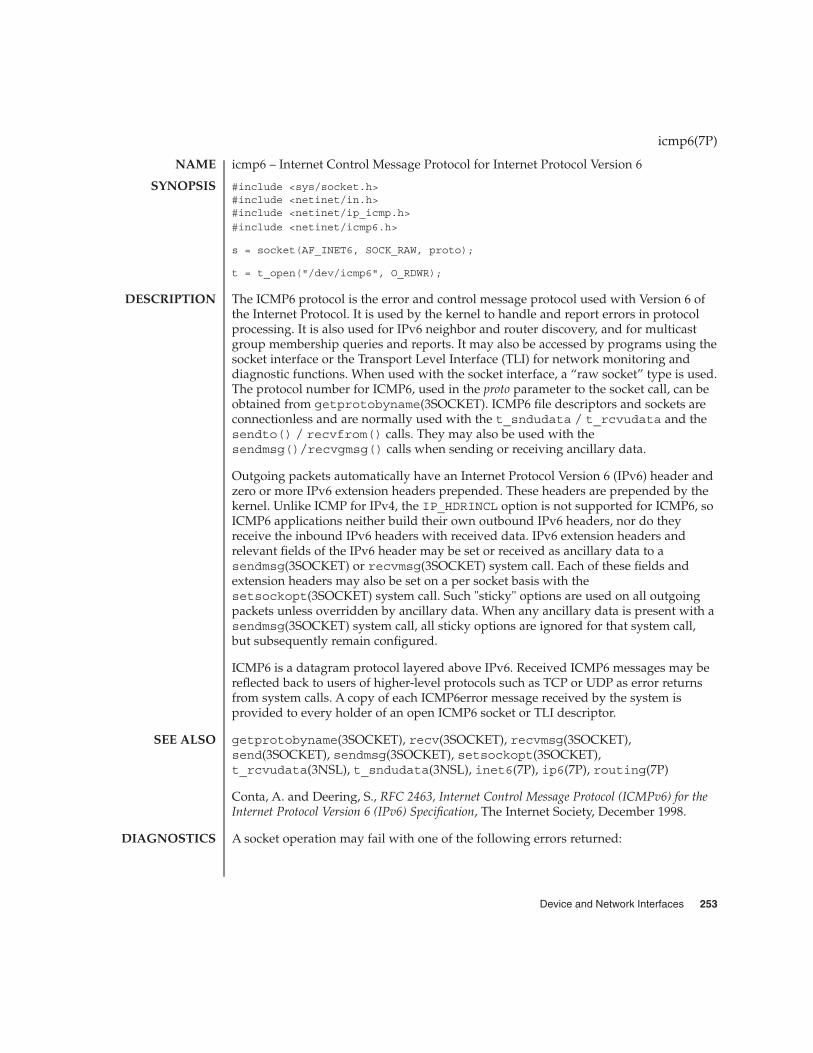
icmp6 – Internet Control Message Protocol for Internet Protocol Version 6
#include <sys/socket.h>#include <netinet/in.h>#include <netinet/ip_icmp.h>
#include <netinet/icmp6.h>
s = socket(AF_INET6, SOCK_RAW, proto);
t = t_open("/dev/icmp6", O_RDWR);
The ICMP6 protocol is the error and control message protocol used with Version 6 ofthe Internet Protocol. It is used by the kernel to handle and report errors in protocolprocessing. It is also used for IPv6 neighbor and router discovery, and for multicastgroup membership queries and reports. It may also be accessed by programs using thesocket interface or the Transport Level Interface (TLI) for network monitoring anddiagnostic functions. When used with the socket interface, a “raw socket” type is used.The protocol number for ICMP6, used in the proto parameter to the socket call, can beobtained from getprotobyname(3SOCKET). ICMP6 file descriptors and sockets areconnectionless and are normally used with the t_sndudata / t_rcvudata and thesendto() / recvfrom() calls. They may also be used with thesendmsg()/recvgmsg() calls when sending or receiving ancillary data.
Outgoing packets automatically have an Internet Protocol Version 6 (IPv6) header andzero or more IPv6 extension headers prepended. These headers are prepended by thekernel. Unlike ICMP for IPv4, the IP_HDRINCL option is not supported for ICMP6, soICMP6 applications neither build their own outbound IPv6 headers, nor do theyreceive the inbound IPv6 headers with received data. IPv6 extension headers andrelevant fields of the IPv6 header may be set or received as ancillary data to asendmsg(3SOCKET) or recvmsg(3SOCKET) system call. Each of these fields andextension headers may also be set on a per socket basis with thesetsockopt(3SOCKET) system call. Such "sticky" options are used on all outgoingpackets unless overridden by ancillary data. When any ancillary data is present with asendmsg(3SOCKET) system call, all sticky options are ignored for that system call,but subsequently remain configured.
ICMP6 is a datagram protocol layered above IPv6. Received ICMP6 messages may bereflected back to users of higher-level protocols such as TCP or UDP as error returnsfrom system calls. A copy of each ICMP6error message received by the system isprovided to every holder of an open ICMP6 socket or TLI descriptor.
getprotobyname(3SOCKET), recv(3SOCKET), recvmsg(3SOCKET),send(3SOCKET), sendmsg(3SOCKET), setsockopt(3SOCKET),t_rcvudata(3NSL), t_sndudata(3NSL), inet6(7P), ip6(7P), routing(7P)
Conta, A. and Deering, S., RFC 2463, Internet Control Message Protocol (ICMPv6) for theInternet Protocol Version 6 (IPv6) Specification, The Internet Society, December 1998.
A socket operation may fail with one of the following errors returned:
icmp6(7P)
NAME
SYNOPSIS
DESCRIPTION
SEE ALSO
DIAGNOSTICS
Device and Network Interfaces 253

EISCONN An attempt was made to establish a connection on asocket which already has one, or when trying to send adatagram with the destination address specified andthe socket is already connected.
ENOTCONN An attempt was made to send a datagram, but nodestination address is specified, and the socket has notbeen connected.
ENOBUFS The system ran out of memory for an internal datastructure.
EADDRNOTAVAIL An attempt was made to create a socket with a networkaddress for which no network interface exists.
ENOMEM The system was unable to allocate memory for aninternal data structure.
ENOPROTOOPT An attempt was made to set an IPv4 socket option onan IPv6 socket.
EINVAL An attempt was made to set an invalid or malformedsocket option.
EAFNOSUPPORT An attempt was made to bind or connect to an IPv4 ormapped address, or to specify an IPv4 or mappedaddress as the next hop.
icmp6(7P)
254 man pages section 7: Device and Network Interfaces • Last Revised 10 Nov 1999

icmp, ICMP – Internet Control Message Protocol
#include <sys/socket.h>#include <netinet/in.h>#include <netinet/ip_icmp.h>s = socket(AF_INET, SOCK_RAW, proto);
t = t_open("/dev/icmp", O_RDWR);
ICMP is the error and control message protocol used by the Internet protocol family. Itis used by the kernel to handle and report errors in protocol processing. It may also beaccessed by programs using the socket interface or the Transport Level Interface (TLI)for network monitoring and diagnostic functions. When used with the socketinterface, a “raw socket” type is used. The protocol number for ICMP, used in the protoparameter to the socket call, can be obtained from getprotobyname(3SOCKET).ICMP file descriptors and sockets are connectionless, and are normally used with thet_sndudata / t_rcvudata and the sendto() / recvfrom() calls.
Outgoing packets automatically have an Internet Protocol (IP) header prepended tothem. Incoming packets are provided to the user with the IP header and options intact.
ICMP is an datagram protocol layered above IP. It is used internally by the protcolcode for various purposes including routing, fault isolation, and congestion control.Receipt of an ICMP “redirect” message will add a new entry in the routing table, ormodify an existing one. ICMP messages are routinely sent by the protocol code.Received ICMP messages may be reflected back to users of higher-level protocols suchas TCP or UDP as error returns from system calls. A copy of all ICMP messagereceived by the system is provided to every holder of an open ICMP socket or TLIdescriptor.
getprotobyname(3SOCKET), recv(3SOCKET), send(3SOCKET),t_rcvudata(3NSL), t_sndudata(3NSL), inet(7P), ip(7P), routing(7P)
Postel, Jon, Internet Control Message Protocol — DARPA Internet Program ProtocolSpecification, RFC 792, Network Information Center, SRI International, Menlo Park,Calif., September 1981.
A socket operation may fail with one of the following errors returned:
EISCONN An attempt was made to establish a connection on asocket which already has one, or when trying to send adatagram with the destination address specified andthe socket is already connected.
ENOTCONN An attempt was made to send a datagram, but nodestination address is specified, and the socket has notbeen connected.
ENOBUFS The system ran out of memory for an internal datastructure.
ICMP(7P)
NAME
SYNOPSIS
DESCRIPTION
SEE ALSO
DIAGNOSTICS
Device and Network Interfaces 255

EADDRNOTAVAIL An attempt was made to create a socket with a networkaddress for which no network interface exists.
Replies to ICMP “echo” messages which are source routed are not sent back usinginverted source routes, but rather go back through the normal routing mechanisms.
ICMP(7P)
NOTES
256 man pages section 7: Device and Network Interfaces • Last Revised 3 Jul 1990

icmp, ICMP – Internet Control Message Protocol
#include <sys/socket.h>#include <netinet/in.h>#include <netinet/ip_icmp.h>s = socket(AF_INET, SOCK_RAW, proto);
t = t_open("/dev/icmp", O_RDWR);
ICMP is the error and control message protocol used by the Internet protocol family. Itis used by the kernel to handle and report errors in protocol processing. It may also beaccessed by programs using the socket interface or the Transport Level Interface (TLI)for network monitoring and diagnostic functions. When used with the socketinterface, a “raw socket” type is used. The protocol number for ICMP, used in the protoparameter to the socket call, can be obtained from getprotobyname(3SOCKET).ICMP file descriptors and sockets are connectionless, and are normally used with thet_sndudata / t_rcvudata and the sendto() / recvfrom() calls.
Outgoing packets automatically have an Internet Protocol (IP) header prepended tothem. Incoming packets are provided to the user with the IP header and options intact.
ICMP is an datagram protocol layered above IP. It is used internally by the protcolcode for various purposes including routing, fault isolation, and congestion control.Receipt of an ICMP “redirect” message will add a new entry in the routing table, ormodify an existing one. ICMP messages are routinely sent by the protocol code.Received ICMP messages may be reflected back to users of higher-level protocols suchas TCP or UDP as error returns from system calls. A copy of all ICMP messagereceived by the system is provided to every holder of an open ICMP socket or TLIdescriptor.
getprotobyname(3SOCKET), recv(3SOCKET), send(3SOCKET),t_rcvudata(3NSL), t_sndudata(3NSL), inet(7P), ip(7P), routing(7P)
Postel, Jon, Internet Control Message Protocol — DARPA Internet Program ProtocolSpecification, RFC 792, Network Information Center, SRI International, Menlo Park,Calif., September 1981.
A socket operation may fail with one of the following errors returned:
EISCONN An attempt was made to establish a connection on asocket which already has one, or when trying to send adatagram with the destination address specified andthe socket is already connected.
ENOTCONN An attempt was made to send a datagram, but nodestination address is specified, and the socket has notbeen connected.
ENOBUFS The system ran out of memory for an internal datastructure.
icmp(7P)
NAME
SYNOPSIS
DESCRIPTION
SEE ALSO
DIAGNOSTICS
Device and Network Interfaces 257

EADDRNOTAVAIL An attempt was made to create a socket with a networkaddress for which no network interface exists.
Replies to ICMP “echo” messages which are source routed are not sent back usinginverted source routes, but rather go back through the normal routing mechanisms.
icmp(7P)
NOTES
258 man pages section 7: Device and Network Interfaces • Last Revised 3 Jul 1990
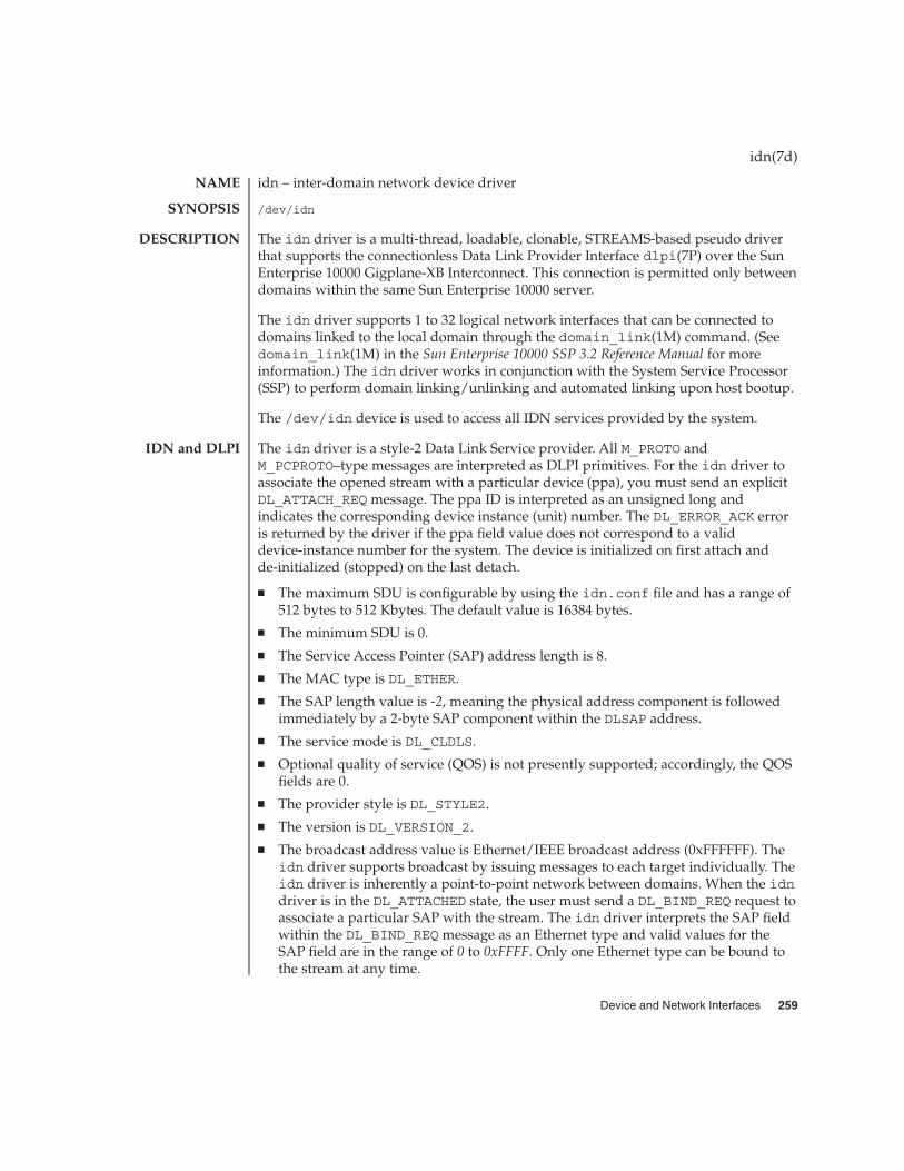
idn – inter-domain network device driver
/dev/idn
The idn driver is a multi-thread, loadable, clonable, STREAMS-based pseudo driverthat supports the connectionless Data Link Provider Interface dlpi(7P) over the SunEnterprise 10000 Gigplane-XB Interconnect. This connection is permitted only betweendomains within the same Sun Enterprise 10000 server.
The idn driver supports 1 to 32 logical network interfaces that can be connected todomains linked to the local domain through the domain_link(1M) command. (Seedomain_link(1M) in the Sun Enterprise 10000 SSP 3.2 Reference Manual for moreinformation.) The idn driver works in conjunction with the System Service Processor(SSP) to perform domain linking/unlinking and automated linking upon host bootup.
The /dev/idn device is used to access all IDN services provided by the system.
The idn driver is a style-2 Data Link Service provider. All M_PROTO andM_PCPROTO–type messages are interpreted as DLPI primitives. For the idn driver toassociate the opened stream with a particular device (ppa), you must send an explicitDL_ATTACH_REQ message. The ppa ID is interpreted as an unsigned long andindicates the corresponding device instance (unit) number. The DL_ERROR_ACK erroris returned by the driver if the ppa field value does not correspond to a validdevice-instance number for the system. The device is initialized on first attach andde-initialized (stopped) on the last detach.
� The maximum SDU is configurable by using the idn.conf file and has a range of512 bytes to 512 Kbytes. The default value is 16384 bytes.
� The minimum SDU is 0.
� The Service Access Pointer (SAP) address length is 8.
� The MAC type is DL_ETHER.
� The SAP length value is -2, meaning the physical address component is followedimmediately by a 2-byte SAP component within the DLSAP address.
� The service mode is DL_CLDLS.
� Optional quality of service (QOS) is not presently supported; accordingly, the QOSfields are 0.
� The provider style is DL_STYLE2.
� The version is DL_VERSION_2.
� The broadcast address value is Ethernet/IEEE broadcast address (0xFFFFFF). Theidn driver supports broadcast by issuing messages to each target individually. Theidn driver is inherently a point-to-point network between domains. When the idndriver is in the DL_ATTACHED state, the user must send a DL_BIND_REQ request toassociate a particular SAP with the stream. The idn driver interprets the SAP fieldwithin the DL_BIND_REQ message as an Ethernet type and valid values for theSAP field are in the range of 0 to 0xFFFF. Only one Ethernet type can be bound tothe stream at any time.
idn(7d)
NAME
SYNOPSIS
DESCRIPTION
IDN and DLPI
Device and Network Interfaces 259

If a SAP with a value of 0 is selected, the receiver will be in 802.3 mode. All framesreceived from the media having a type field in the range of 0 to 1500 are assumed tobe 802.3 frames and are routed up all open streams which are bound to SAP value 0. Ifmore than one stream is in 802.3 mode, then the frame will be duplicated and routedup as multiple stream DL_UNITDATA_IND messages.
In transmission, the driver checks the SAP field of the DL_BIND_REQ to determine ifthe SAP value is 0, and if the destination type field is in the range of 0 to 1500. If eitheris true, the driver computes the length of the message, (excluding the initial messageblock M_PROTO mblk) of all subsequent DL_UNITDATA_REQ messages and transmits802.3 frames that have this value in the MAC frame header length field.
The driver also supports raw M_DATA mode. When the user sends a DLIOCRAW ioctl,the particular stream is put in raw mode. A complete frame and a proper ether headeris expected as part of the data.
The DLSAP address format consists of the 6-byte, physical address component(Ethernet) followed immediately by the 2-byte SAP component (type), producing an8-byte DLSAP address. Applications should not hardcode to this particularimplementation-specific DLSAP address format, but instead should use informationreturned in the DL_INFO_ACK primitive to compose and decompose DLSAPaddresses. The SAP length, full DLSAP length, and SAP physical ordering areincluded within the DL_INFO_ACK primitive. The physical address length can becomputed by subtracting the SAP length from the full DLSAP address length or byissuing the DL_PHYS_ADDR_REQ message to obtain the current physical addressassociated with the stream.
When the idn driver is in the DL_BOUND state, you can transmit frames on the IDN bysending DL_UNITDATA_REQ messages to the driver. The driver then routes receivedIDN frames up the open and bound streams having a SAP which matches the Ethernettype as DL_UNITDATA_IND messages. If necessary, received IDN frames areduplicated and routed up multiple open streams. The DLSAP address containedwithin the DL_UNITDATA_REQ and DL_UNITDATA_IND messages consists of both theSAP (type) and physical (Ethernet) components.
In addition to the mandatory connectionless DLPI message set, the idn driversupports the following primitives:
The DL_ENABMULTI_REQ and DL_DISABMULTI_REQ primitives which enable ordisable, respectively, the reception of individual multicast group addresses. A set ofmulticast addresses may be iteratively created and modified on a per-stream basisusing these primitives. These primitives are accepted by the driver in any statefollowing the DL_ATTACHED state.
The DL_PROMISCON_REQ and DL_PROMISCOFF_REQ primitives, which with theDL_PROMISC_PHYS flag set in the dl_level field, enable or disable, respectively, thereception of all promiscuous frames on the media, including frames generated by thelocal domain. When used with the DL_PROMISC_SAP flag set in the dl_level field,
idn(7d)
IDN Primitives
260 man pages section 7: Device and Network Interfaces • Last Revised 3 Jun 1999

these primitives enable or disable, respectively, the reception of all SAP (Ethernet type)values. When used with the DL_PROMISC_MULTI flag set in the dl_level field,these primitives enable or disable, respectively, the reception of all multicast groupaddresses. The effect of each is always on a per-stream basis and independent of theother SAP and physical level configurations on this stream or other streams.
The DL_PHYS_ADDR_REQ primitive which returns the 6-octet, Ethernet addressassociated with (or attached to) the stream in the DL_PHYS_ADDR_ACK primitive. Thisprimitive is valid only in states following a successful DL_ATTACH_REQ request.
Because the driver maintains domain address information in the address to directpackets to the correct destination, the DL_SET_PHYS_ADDR_REQ primitive is notallowed.
The following files are supported:
/dev/idnIDN special character device
/platform/SUNW,Ultra-Enterprise-10000/kernel/drv/idn.confSystem-wide and per-interface default device driver properties
netstat(1M), ndd(1M), dlpi(7P)
domain_link(1M) in the Sun Enterprise 10000 SSP 3.2 Reference Manual.
Sun Enterprise 10000 InterDomain Networks User Guide
The idn driver supports a set of properties that can be set by using the driver.conffile for the IDN. See the Sun Enterprise 10000 InterDomain Networks User Guide for moreinformation about the properties in the driver.conf(4), (idn.conf, for IDNs).
idn(7d)
FILES
SEE ALSO
NOTES
Device and Network Interfaces 261

ieef – Intel Ethernet device driver
/kernel/drv/ieef
The ieef driver currently supports the Intel EtherExpress Flash (ISA) and Intel 82256EEpro100 Ethernet (PCI) network cards.
The ieef Ethernet driver is a multi-threaded, loadable, clonable, STREAMS hardwaredriver supporting the connectionless Data Link Provider Interface, dlpi(7P). Multiplecontrollers installed within the system are supported by the driver. The ieef driverprovides basic support for the hardware. Functions include chip initialization, frametransmit and receive, multicast and promiscuous mode support, and error recoveryand reporting.
The cloning, character-special device /dev/ieef is used to access all Intel devicesinstalled within the system.
The ieef driver is dependent on /kernel/misc/gld, a loadable kernel module thatprovides the ieef driver with the DLPI and STREAMS functionality required of aLAN driver. See gld(7D) for more details on the primatives supported by the driver.
The values returned by the driver in the DL_INFO_ACK primitive in response to theDL_INFO_REQ from the user are as follows:
� Maximum SDU is 1500 (ETHERMTU).
� Minimum SDU is 0. The driver will pad to the mandatory 60-octet minimum packetsize.
� The dlsap address length is 8.
� MAC type is DL_ETHER.
� The sap length value is –2, meaning the physical address component is followedimmediately by a 2-byte sap component within the DLSAP address.
� The broadcast address value is Ethernet/IEEE broadcast address(FF:FF:FF:FF:FF:FF).
The ieef driver provides 100-Mbps Ethernet support. Note that the driver does notcurrently transfer data at rates expected of a 100-Mbps interface.
The /kernel/drv/ieef.conf file supports the following options:
ioaddr
intr
/dev/ieef Special character device
/kernel/drv/ieef.conf Driver configuration file
ieef(7D)
NAME
SYNOPSIS
DESCRIPTION
Known Problemsand Limitations
CONFIGURATION
FILES
262 man pages section 7: Device and Network Interfaces • Last Revised 27 November 2000

See attributes(5) for descriptions of the following attributes:
ATTRIBUTE TYPE ATTRIBUTE VALUE
Architecture IA
attributes(5), gld(7D), streamio(7I), dlpi(7P)
ieef(7D)
ATTRIBUTES
SEE ALSO
Device and Network Interfaces 263

if_tcp, if – general properties of Internet Protocol network interfaces
A network interface is a device for sending and receiving packets on a network. It isusually a hardware device, although it can be implemented in software. Networkinterfaces used by the Internet Protocol (IPv4 or IPv6) must be STREAMS devicesconforming to the Datalink Provider Interface (DLPI). See dlpi(7P).
An interface becomes available to IP when it is opened and the IP module is pushedonto the stream with the I_PUSH ioctl(2) command (see streamio(7I)), and theSIOCSLIFNAME ioctl(2) is issued to specify the name of the interface and whether itis IPv4 or IPv6. This may be initiated by the kernel at boot time or by a user programafter the system is running. Each interface must be assigned an IP address with theSIOCSLIFADDR ioctl() before it can be used. On interfaces where thenetwork-to-link layer address mapping is static, only the network number is takenfrom the ioctl() request; the remainder is found in a hardware specific manner. Oninterfaces which provide dynamic network-to-link layer address mapping facilities(for example, 10Mb/s Ethernets using arp(7P)), the entire address specified in theioctl() is used. A routing table entry for destinations on the network of the interfaceis installed automatically when an interface’s address is set.
The following ioctl() calls may be used to manipulate IP network interfaces. Unlessspecified otherwise, the request takes an lifreq structure as its parameter. Thisstructure has the form:
/* Interface request structure used for socket ioctls. All *//* interface ioctls must have parameter definitions which *//* begin with ifr_name. The remainder may be interface specific. */struct lifreq {#define LIFNAMSIZ 32
char lfr_name[LIFNAMSIZ]; /* if name, for example "le1" */union {
int lifru_addrlen; /* for subnet/token etc */uint_t lifru_ppa; /* SIOCSLIFNAME */
} lifr_lifru1;union {
struct sockaddr_storage lifru_addr;struct sockaddr_storage lifru_dstaddr;struct sockaddr_storage lifru_broadaddr;struct sockaddr_storage lifru_token; /* With lifr_addrlen */struct sockaddr_storage lifru_subnet; /* With lifr_addrlen */int lifru_index; /* interface index */uint64_t lifru_flags; /* SIOC?LIFFLAGS */int lifru_metric;uint_t lifru_mtu;char lifru_data[1]; /* intfce.dep. data/char lifru_enaddr[6];int lif_muxid[2]; /* mux id’s for arp and ip */struct lif_nd_req lifru_nd_req;struct lif_ifinfo_req lifru_ifinfo_req;
} lifr_lifru;
#define lifr_addrlen lifr_lifru1.lifru_addrlen#define lifr_ppa lifr_lifru1.lifru_ppa /* Driver’s ppa */#define lifr_addr lifr_lifru.lifru_addr /* address */
if(7P)
NAME
DESCRIPTION
APPLICATIONPROGRAMMING
INTERFACE
IOCTLS
264 man pages section 7: Device and Network Interfaces • Last Revised 13 Nov 2001
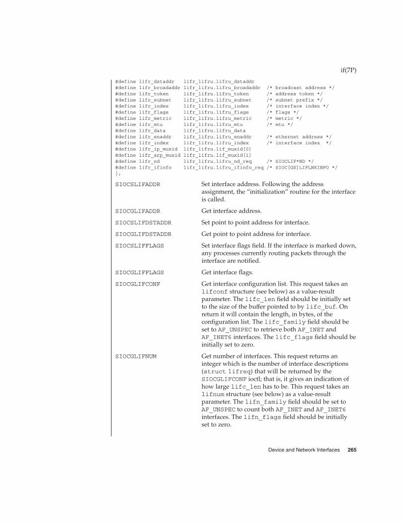
#define lifr_dstaddr lifr_lifru.lifru_dstaddr#define lifr_broadaddr lifr_lifru.lifru_broadaddr /* broadcast address */#define lifr_token lifr_lifru.lifru_token /* address token */#define lifr_subnet lifr_lifru.lifru_subnet /* subnet prefix */#define lifr_index lifr_lifru.lifru_index /* interface index */#define lifr_flags lifr_lifru.lifru_flags /* flags */#define lifr_metric lifr_lifru.lifru_metric /* metric */#define lifr_mtu lifr_lifru.lifru_mtu /* mtu */#define lifr_data lifr_lifru.lifru_data#define lifr_enaddr lifr_lifru.lifru_enaddr /* ethernet address */#define lifr_index lifr_lifru.lifru_index /* interface index */#define lifr_ip_muxid lifr_lifru.lif_muxid[0]#define lifr_arp_muxid lifr_lifru.lif_muxid[1]#define lifr_nd lifr_lifru.lifru_nd_req /* SIOCLIF*ND */#define lifr_ifinfo lifr_lifru.lifru_ifinfo_req /* SIOC[GS]LIFLNKINFO */};
SIOCSLIFADDR Set interface address. Following the addressassignment, the “initialization” routine for the interfaceis called.
SIOCGLIFADDR Get interface address.
SIOCSLIFDSTADDR Set point to point address for interface.
SIOCGLIFDSTADDR Get point to point address for interface.
SIOCSLIFFLAGS Set interface flags field. If the interface is marked down,any processes currently routing packets through theinterface are notified.
SIOCGLIFFLAGS Get interface flags.
SIOCGLIFCONF Get interface configuration list. This request takes anlifconf structure (see below) as a value-resultparameter. The lifc_len field should be initially setto the size of the buffer pointed to by lifc_buf. Onreturn it will contain the length, in bytes, of theconfiguration list. The lifc_family field should beset to AF_UNSPEC to retrieve both AF_INET andAF_INET6 interfaces. The lifc_flags field should beinitially set to zero.
SIOCGLIFNUM Get number of interfaces. This request returns aninteger which is the number of interface descriptions(struct lifreq) that will be returned by theSIOCGLIFCONF ioctl; that is, it gives an indication ofhow large lifc_len has to be. This request takes anlifnum structure (see below) as a value-resultparameter. The lifn_family field should be set toAF_UNSPEC to count both AF_INET and AF_INET6interfaces. The lifn_flags field should be initiallyset to zero.
if(7P)
Device and Network Interfaces 265

SIOCSLIFMTU Set the maximum transmission unit (MTU) size forinterface. Place the result of this request in lifru_mtufield. The MTU can not exceed the physical MTUlimitation (which is reported in the DLPIDL_INFO_ACK message).
SIOCGLIFMTU Get the maximum transmission unit size for interface.Place the result of this request in ifru_mtu field.
SIOCSLIFMETRIC Set the metric associated with the interface. The metricis used by routine daemons such as in.routed(1M).
SIOCGLIFMETRIC Get the metric associated with the interface.
SIOCGLIFMUXID Get the ip and arp muxid associated with theinterface.
SIOCSLIFMUXID Set the ip and arp muxid associated with theinterface.
SIOCGLIFINDEX Get the interface index associated with the interface.
SIOCSLIFINDEX Set the interface index associated with the interface.
SIOCLIFADDIF Add a new logical interface on a physical interfaceusing an unused logical unit number.
SIOCLIFREMOVEIF Remove a logical interface by specifying its IP addressor logical interface name.
SIOCSLIFTOKEN Set the address token used to form IPv6 link-localaddresses and for stateless address autoconfiguration.
SIOCGLIFTOKEN Get the address token used to form IPv6 link-localaddresses and for stateless address autoconfiguration.
SIOCSLIFSUBNET Set the subnet prefix associated with the interface.
SIOCGLIFSUBNET Get the subnet prefix associated with the interface.
SIOCSLIFLNKINFO Set link specific parameters for the interface.
SIOCGLIFLNKINFO Get link specific parameters for the interface.
SIOCLIFDELND Delete a neighbor cache entry for IPv6.
SIOCLIFGETND Get a neighbor cache entry for IPv6.
SIOCLIFSETND Set a neighbor cache entry for IPv6.
SIOCTMYADDR Test if the address is assigned to this node. This requesttakes an sioc_addrreq structure (see below) as avalue-result parameter. The sa_addr field should beset to the address to test. The sa_res field will containa non-zero value if the address is assigned to this node.
if(7P)
266 man pages section 7: Device and Network Interfaces • Last Revised 13 Nov 2001
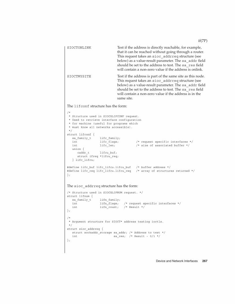
SIOCTONLINK Test if the address is directly reachable, for example,that it can be reached without going through a router.This request takes an sioc_addrreq structure (seebelow) as a value-result parameter. The sa_addr fieldshould be set to the address to test. The sa_res fieldwill contain a non-zero value if the address is onlink.
SIOCTMYSITE Test if the address is part of the same site as this node.This request takes an sioc_addrreq structure (seebelow) as a value-result parameter. The sa_addr fieldshould be set to the address to test. The sa_res fieldwill contain a non-zero value if the address is in thesame site.
The lifconf structure has the form:
/** Structure used in SIOCGLIFCONF request.* Used to retrieve interface configuration* for machine (useful for programs which* must know all networks accessible).*/struct lifconf {
sa_family_t lifc_family;int lifc_flags; /* request specific interfaces */int lifc_len; /* size of associated buffer */union {
caddr_t lifcu_buf;struct ifreq *lifcu_req;
} lifc_lifcu;
#define lifc_buf lifc_lifcu.lifcu_buf /* buffer address */#define lifc_req lifc_lifcu.lifcu_req /* array of structures returned */
};
The sioc_addrreq structure has the form:
/* Structure used in SIOCGLIFNUM request. */struct lifnum {
sa_family_t lifn_family;int lifn_flags; /* request specific interfaces */int lifn_count; /* Result */
};
/** Argument structure for SIOCT* address testing ioctls.*/struct sioc_addrreq {
struct sockaddr_storage sa_addr; /* Address to test */int sa_res; /* Result - 0/1 */
};
if(7P)
Device and Network Interfaces 267

The following ioctl() calls are maintained for compatibility but only apply to IPv4network interfaces, since the data structures are to small to hold an IPv6 address.Unless specified otherwise, the request takes an ifreq structure as its parameter. Thisstructure has the form:
/* Interface request structure used for socket ioctls. All *//* interface ioctls must have parameter definitions which *//* begin with ifr_name. The remainder may be interface specific. */struct ifreq {#define IFNAMSIZ 16
char ifr_name[IFNAMSIZ]; /* if name, for example *//* "le1" */
union {struct sockaddr ifru_addr;struct sockaddr ifru_dstaddr;char ifru_oname[IFNAMSIZ]; /* other if name */struct sockaddr ifru_broadaddr;short ifru_flags;int ifru_metric;char ifru_data[1]; /* intfce. depen. data */char ifru_enaddr[6];int if_muxid[2]; /* mux id’s for arp and ip */int ifru_index; /* interface index */
} ifr_ifru;
#define ifr_addr ifr_ifru.ifru_addr /* address */#define ifr_dstaddr ifr_ifru.ifru_dstaddr /* other end of p-to-p link */#define ifr_oname ifr_ifru.ifru_oname /* other if name */#define ifr_broadaddr ifr_ifru.ifru_broadaddr /* broadcast address */#define ifr_flags ifr_ifru.ifru_flags /* flags */#define ifr_index ifr_ifru.ifru_index /* interface index */#define ifr_metric ifr_ifru.ifru_metric /* metric */#define ifr_data ifr_ifru.ifru_data /* for use by interface */#define ifr_enaddr ifr_ifru.ifru_enaddr a/* ethernet address */
};
SIOCSIFADDR Set interface address. Following the addressassignment, the “initialization” routine for the interfaceis called.
SIOCGIFADDR Get interface address.
SIOCSIFDSTADDR Set point to point address for interface.
SIOCGIFDSTADDR Get point to point address for interface.
SIOCSIFFLAGS Set interface flags field. If the interface is marked down,any processes currently routing packets through theinterface are notified.
SIOCGIFFLAGS Get interface flags.
SIOCGIFCONF Get interface configuration list. This request takes anifconf structure (see below) as a value-resultparameter. The ifc_len field should be initially set to
if(7P)
268 man pages section 7: Device and Network Interfaces • Last Revised 13 Nov 2001
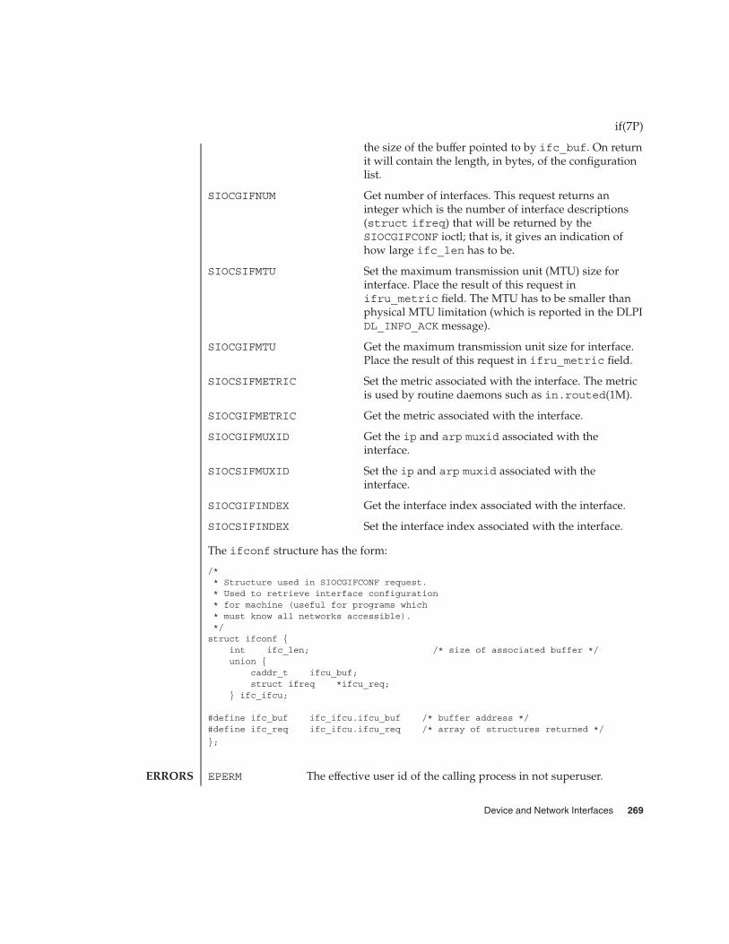
the size of the buffer pointed to by ifc_buf. On returnit will contain the length, in bytes, of the configurationlist.
SIOCGIFNUM Get number of interfaces. This request returns aninteger which is the number of interface descriptions(struct ifreq) that will be returned by theSIOCGIFCONF ioctl; that is, it gives an indication ofhow large ifc_len has to be.
SIOCSIFMTU Set the maximum transmission unit (MTU) size forinterface. Place the result of this request inifru_metric field. The MTU has to be smaller thanphysical MTU limitation (which is reported in the DLPIDL_INFO_ACK message).
SIOCGIFMTU Get the maximum transmission unit size for interface.Place the result of this request in ifru_metric field.
SIOCSIFMETRIC Set the metric associated with the interface. The metricis used by routine daemons such as in.routed(1M).
SIOCGIFMETRIC Get the metric associated with the interface.
SIOCGIFMUXID Get the ip and arp muxid associated with theinterface.
SIOCSIFMUXID Set the ip and arp muxid associated with theinterface.
SIOCGIFINDEX Get the interface index associated with the interface.
SIOCSIFINDEX Set the interface index associated with the interface.
The ifconf structure has the form:
/** Structure used in SIOCGIFCONF request.* Used to retrieve interface configuration* for machine (useful for programs which* must know all networks accessible).*/struct ifconf {
int ifc_len; /* size of associated buffer */union {
caddr_t ifcu_buf;struct ifreq *ifcu_req;
} ifc_ifcu;
#define ifc_buf ifc_ifcu.ifcu_buf /* buffer address */#define ifc_req ifc_ifcu.ifcu_req /* array of structures returned */
};
EPERM The effective user id of the calling process in not superuser.
if(7P)
ERRORS
Device and Network Interfaces 269
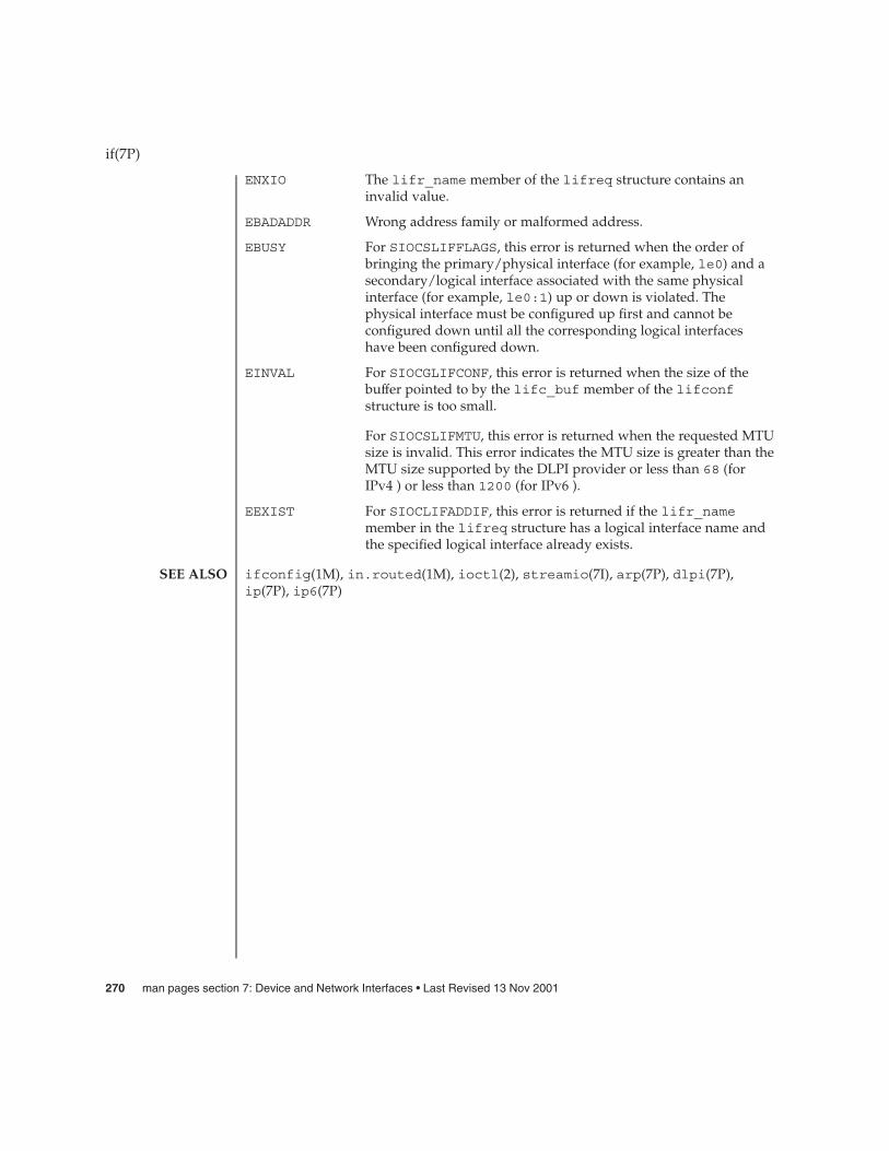
ENXIO The lifr_name member of the lifreq structure contains aninvalid value.
EBADADDR Wrong address family or malformed address.
EBUSY For SIOCSLIFFLAGS, this error is returned when the order ofbringing the primary/physical interface (for example, le0) and asecondary/logical interface associated with the same physicalinterface (for example, le0:1) up or down is violated. Thephysical interface must be configured up first and cannot beconfigured down until all the corresponding logical interfaceshave been configured down.
EINVAL For SIOCGLIFCONF, this error is returned when the size of thebuffer pointed to by the lifc_buf member of the lifconfstructure is too small.
For SIOCSLIFMTU, this error is returned when the requested MTUsize is invalid. This error indicates the MTU size is greater than theMTU size supported by the DLPI provider or less than 68 (forIPv4 ) or less than 1200 (for IPv6 ).
EEXIST For SIOCLIFADDIF, this error is returned if the lifr_namemember in the lifreq structure has a logical interface name andthe specified logical interface already exists.
ifconfig(1M), in.routed(1M), ioctl(2), streamio(7I), arp(7P), dlpi(7P),ip(7P), ip6(7P)
if(7P)
SEE ALSO
270 man pages section 7: Device and Network Interfaces • Last Revised 13 Nov 2001

ifb – 24-bit PCI color frame buffer and graphics accelerator driver
The ifb driver is the device driver for the Sun Expert3D graphics accelerators. TheExpert3D is a high resolution, high performance PCI graphics framebuffer providinghardware texture mapping. The Expert3D also supports 1920x1200 double buffered,z-buffered display and 1280 x 1024 stereo.
The ifbdaemon process loads the ifb microcode at system startup time and duringthe resume sequence of a suspend-resume cycle.
/dev/fbs/ifbnDevice special file
/usr/lib/ifb.ucodeifb microcode
/usr/sbin/ifbdaemonifb microcode loader
SUNWifb_config(1M)
ifb(7d)
NAME
DESCRIPTION
FILES
SEE ALSO
Device and Network Interfaces 271

ifp – ISP2100 Family Fibre Channel Host Bus Adapter Driver
PCI SUNW,ifp@pci-slot
The ifp Host Bus Adapter is a SCSA compliant nexus driver for the QlogicISP2100/ISP2100A chips. These chips support Fibre Channel Protocol for SCSI onPrivate Fibre Channel Arbitrated loops.
The ifp driver interfaces with SCSI disk target driver, ssd(7D), and the SCSI-3Enclosure Services driver, ssd(7D). Only SCSI devices of type disk and ses aresupported at present time.
The ifp driver supports the standard functions provided by the SCSA interface. Itsupports auto request sense (cannot be turned off) and tagged queueing by default.The driver requires that all devices have unique hard addresses defined by switchsettings in hardware. Devices with conflicting hard addresses will not be accessible.
/kernel/drv/ifp ELF Kernel Module
/kernel/drv/sparcv9/ifp ELF Kernel Module (64–bit version)
/kernel/drv/ifp.conf Driver configuration file
See attributes(5) for descriptions of the following attributes:
ATTRIBUTE TYPE ATTRIBUTE VALUE
Availability SPARC
luxadm(1M),prtconf(1M),driver.conf(4),attributes(5),ses(7D),ssd(7D)
Writing Device Drivers,
ANSI X3.272–1996, Fibre Channel Arbitrated Loop (FC-AL),
ANSI X3.269-1996, Fibre Channel Protocol for SCSI (FCP),
ANSI X3.270-1996, SCSI-3 Architecture Model (SAM),
Fibre Channel Private Loop SCSI Direct Attach (FC-PLDA),
ISP2100 Firmware Interface Specification, QLogic Corporation
The messages described below are some that may appear on the system console, aswell as being logged.
This first set of messages may be displayed while the ifp driver is initially trying toattach. All of these messages mean that the ifp driver was unable to attach. Thesemessages are preceded by "ifp<number>", where "<number>" is the instance numberof the ISP2100 Host Bus Adapter.
ifp(7D)
NAME
SYNOPSIS
DESCRIPTION
FILES
ATTRIBUTES
SEE ALSO
DIAGNOSTICS
272 man pages section 7: Device and Network Interfaces • Last Revised 22 Jul 1998

Device is using a hilevel intr, unusedThe device was configured with an interrupt level that cannot be used with this ifpdriver. Check the device.
Failed to alloc soft stateDriver was unable to allocate space for the internal state structure. Driver did notattach to device; SCSI devices will be inaccessible.
Bad soft stateDriver requested an invalid internal state structure. Driver did not attach to device;SCSI devices will be inaccessible.
Unable to map pci config registersUnable to map biu registers
Driver was unable to map device registers; check for bad hardware. Driver did notattach to device; SCSI devices will be inaccessible.
Cannot alloc tranDriver was unable to obtain a transport handle to be able to communicate withSCSA framework. Driver did not attach to device; SCSI devices will be inaccessible.
ddi_create_minor_node failedDriver was unable to create devctl minor node that is used by luxadm(1M) foradministering the loop. Driver did not attach to device; SCSI devices will beinaccessible.
Cannot alloc dma handleDriver was unable allocate a dma handle for communicating with the Host BusAdapter. Driver did not attach to device; SCSI devices will be inaccessible.
Cannot alloc cmd areaDriver was unable allocate dma memory for request and response queues. Driverdid not attach to device; SCSI devices will be inaccessible.
Cannot bind cmd areaDriver was unable to bind dma handle to the cmd area. Driver did not attach todevice; SCSI devices will be inaccessible.
Cannot alloc fcal handleDriver was unable allocate a dma handle for retrieving loop map from the Host BusAdapter. Driver did not attach to device; SCSI devices will be inaccessible.
Cannot bind portdbDriver was unable to bind fcal port handle to the memory used for obtaining portdatabase. Driver did not attach to device; SCSI devices will be inaccessible.
scsi_hba_attach failedDriver was unable to attach to the SCSA framework. Driver did not attach todevice; SCSI devices will be inaccessible.
Unable to create hotplug threadDriver was not able to create the kernel thread used for hotplug support. Driver didnot attach to device; SCSI devices will be inaccessible.
ifp(7D)
Device and Network Interfaces 273

Cannot add intrDriver was not able to add the interrupt routine to the kernel. Driver did not attachto device; SCSI devices will be inaccessible.
Unable to attachDriver was unable to attach to the hardware for some reason that may be printed.Driver did not attach to device; SCSI devices will be inaccessible.
The following set of messages may be display at any time. They will be printed withthe full device pathname followed by the shorter form described above.
Firmware checksum incorrectFirmware has an invalid checksum and will not be downloaded.
Chip reset timeoutISP chip failed to reset in the time allocated; may be bad hardware.
Stop firmware failedStopping the firmware failed; may be bad hardware.
Load ram failedUnable to download new firmware into the ISP chip.
DMA setup failedThe DMA setup failed in the host adapter driver on a scsi_pkt. This will returnTRAN_BADPKT to a SCSA target driver.
Bad request pkt typeBad request pktBad request pkt hdrBad req pkt order
The ISP Firmware rejected the packet as being set up incorrectly. This will cause theifp driver to call the target completion routine with the reason of CMD_TRAN_ERRset in the scsi_pkt. Check the target driver for correctly setting up the packet.
Firmware errorThe ISP chip encountered a firmware error of some kind. This error will cause theifp driver to do error recovery by resetting the chip.
DMA Failure (event)The ISP chip encountered a DMA error while reading from the request queue(event is 8003) or writing to the response queue (event is 8004). This error will causethe ifp driver to do error recovery by resetting the chip.
Fatal error, resetting interfaceThis is an indication that the ifp driver is doing error recovery. This will cause alloutstanding commands that have been transported to the ifp driver to becompleted via the scsi_pkt completion routine in the target driver with reason ofCMD_RESET and status of STAT_BUS_RESET set in the scsi_pkt.
target t, duplicate port wwnsThe driver detected target t to be having the same port WWN as a different target;this is not supposed to happen. Target t will become inaccessible.
ifp(7D)
274 man pages section 7: Device and Network Interfaces • Last Revised 22 Jul 1998

target t, duplicate switch settingsThe driver detected devices with the same switch setting t. All such devices willbecome inaccessible.
WWN changed on target tThe World Wide Name (WWN) has changed on the device with switch setting t.
target t, unknown device type dtThe driver does not know the device type dt reported by the device with switchsetting t.
ifp(7D)
Device and Network Interfaces 275

if_tcp, if – general properties of Internet Protocol network interfaces
A network interface is a device for sending and receiving packets on a network. It isusually a hardware device, although it can be implemented in software. Networkinterfaces used by the Internet Protocol (IPv4 or IPv6) must be STREAMS devicesconforming to the Datalink Provider Interface (DLPI). See dlpi(7P).
An interface becomes available to IP when it is opened and the IP module is pushedonto the stream with the I_PUSH ioctl(2) command (see streamio(7I)), and theSIOCSLIFNAME ioctl(2) is issued to specify the name of the interface and whether itis IPv4 or IPv6. This may be initiated by the kernel at boot time or by a user programafter the system is running. Each interface must be assigned an IP address with theSIOCSLIFADDR ioctl() before it can be used. On interfaces where thenetwork-to-link layer address mapping is static, only the network number is takenfrom the ioctl() request; the remainder is found in a hardware specific manner. Oninterfaces which provide dynamic network-to-link layer address mapping facilities(for example, 10Mb/s Ethernets using arp(7P)), the entire address specified in theioctl() is used. A routing table entry for destinations on the network of the interfaceis installed automatically when an interface’s address is set.
The following ioctl() calls may be used to manipulate IP network interfaces. Unlessspecified otherwise, the request takes an lifreq structure as its parameter. Thisstructure has the form:
/* Interface request structure used for socket ioctls. All *//* interface ioctls must have parameter definitions which *//* begin with ifr_name. The remainder may be interface specific. */struct lifreq {#define LIFNAMSIZ 32
char lfr_name[LIFNAMSIZ]; /* if name, for example "le1" */union {
int lifru_addrlen; /* for subnet/token etc */uint_t lifru_ppa; /* SIOCSLIFNAME */
} lifr_lifru1;union {
struct sockaddr_storage lifru_addr;struct sockaddr_storage lifru_dstaddr;struct sockaddr_storage lifru_broadaddr;struct sockaddr_storage lifru_token; /* With lifr_addrlen */struct sockaddr_storage lifru_subnet; /* With lifr_addrlen */int lifru_index; /* interface index */uint64_t lifru_flags; /* SIOC?LIFFLAGS */int lifru_metric;uint_t lifru_mtu;char lifru_data[1]; /* intfce.dep. data/char lifru_enaddr[6];int lif_muxid[2]; /* mux id’s for arp and ip */struct lif_nd_req lifru_nd_req;struct lif_ifinfo_req lifru_ifinfo_req;
} lifr_lifru;
#define lifr_addrlen lifr_lifru1.lifru_addrlen#define lifr_ppa lifr_lifru1.lifru_ppa /* Driver’s ppa */#define lifr_addr lifr_lifru.lifru_addr /* address */
if_tcp(7P)
NAME
DESCRIPTION
APPLICATIONPROGRAMMING
INTERFACE
IOCTLS
276 man pages section 7: Device and Network Interfaces • Last Revised 13 Nov 2001

#define lifr_dstaddr lifr_lifru.lifru_dstaddr#define lifr_broadaddr lifr_lifru.lifru_broadaddr /* broadcast address */#define lifr_token lifr_lifru.lifru_token /* address token */#define lifr_subnet lifr_lifru.lifru_subnet /* subnet prefix */#define lifr_index lifr_lifru.lifru_index /* interface index */#define lifr_flags lifr_lifru.lifru_flags /* flags */#define lifr_metric lifr_lifru.lifru_metric /* metric */#define lifr_mtu lifr_lifru.lifru_mtu /* mtu */#define lifr_data lifr_lifru.lifru_data#define lifr_enaddr lifr_lifru.lifru_enaddr /* ethernet address */#define lifr_index lifr_lifru.lifru_index /* interface index */#define lifr_ip_muxid lifr_lifru.lif_muxid[0]#define lifr_arp_muxid lifr_lifru.lif_muxid[1]#define lifr_nd lifr_lifru.lifru_nd_req /* SIOCLIF*ND */#define lifr_ifinfo lifr_lifru.lifru_ifinfo_req /* SIOC[GS]LIFLNKINFO */};
SIOCSLIFADDR Set interface address. Following the addressassignment, the “initialization” routine for the interfaceis called.
SIOCGLIFADDR Get interface address.
SIOCSLIFDSTADDR Set point to point address for interface.
SIOCGLIFDSTADDR Get point to point address for interface.
SIOCSLIFFLAGS Set interface flags field. If the interface is marked down,any processes currently routing packets through theinterface are notified.
SIOCGLIFFLAGS Get interface flags.
SIOCGLIFCONF Get interface configuration list. This request takes anlifconf structure (see below) as a value-resultparameter. The lifc_len field should be initially setto the size of the buffer pointed to by lifc_buf. Onreturn it will contain the length, in bytes, of theconfiguration list. The lifc_family field should beset to AF_UNSPEC to retrieve both AF_INET andAF_INET6 interfaces. The lifc_flags field should beinitially set to zero.
SIOCGLIFNUM Get number of interfaces. This request returns aninteger which is the number of interface descriptions(struct lifreq) that will be returned by theSIOCGLIFCONF ioctl; that is, it gives an indication ofhow large lifc_len has to be. This request takes anlifnum structure (see below) as a value-resultparameter. The lifn_family field should be set toAF_UNSPEC to count both AF_INET and AF_INET6interfaces. The lifn_flags field should be initiallyset to zero.
if_tcp(7P)
Device and Network Interfaces 277

SIOCSLIFMTU Set the maximum transmission unit (MTU) size forinterface. Place the result of this request in lifru_mtufield. The MTU can not exceed the physical MTUlimitation (which is reported in the DLPIDL_INFO_ACK message).
SIOCGLIFMTU Get the maximum transmission unit size for interface.Place the result of this request in ifru_mtu field.
SIOCSLIFMETRIC Set the metric associated with the interface. The metricis used by routine daemons such as in.routed(1M).
SIOCGLIFMETRIC Get the metric associated with the interface.
SIOCGLIFMUXID Get the ip and arp muxid associated with theinterface.
SIOCSLIFMUXID Set the ip and arp muxid associated with theinterface.
SIOCGLIFINDEX Get the interface index associated with the interface.
SIOCSLIFINDEX Set the interface index associated with the interface.
SIOCLIFADDIF Add a new logical interface on a physical interfaceusing an unused logical unit number.
SIOCLIFREMOVEIF Remove a logical interface by specifying its IP addressor logical interface name.
SIOCSLIFTOKEN Set the address token used to form IPv6 link-localaddresses and for stateless address autoconfiguration.
SIOCGLIFTOKEN Get the address token used to form IPv6 link-localaddresses and for stateless address autoconfiguration.
SIOCSLIFSUBNET Set the subnet prefix associated with the interface.
SIOCGLIFSUBNET Get the subnet prefix associated with the interface.
SIOCSLIFLNKINFO Set link specific parameters for the interface.
SIOCGLIFLNKINFO Get link specific parameters for the interface.
SIOCLIFDELND Delete a neighbor cache entry for IPv6.
SIOCLIFGETND Get a neighbor cache entry for IPv6.
SIOCLIFSETND Set a neighbor cache entry for IPv6.
SIOCTMYADDR Test if the address is assigned to this node. This requesttakes an sioc_addrreq structure (see below) as avalue-result parameter. The sa_addr field should beset to the address to test. The sa_res field will containa non-zero value if the address is assigned to this node.
if_tcp(7P)
278 man pages section 7: Device and Network Interfaces • Last Revised 13 Nov 2001

SIOCTONLINK Test if the address is directly reachable, for example,that it can be reached without going through a router.This request takes an sioc_addrreq structure (seebelow) as a value-result parameter. The sa_addr fieldshould be set to the address to test. The sa_res fieldwill contain a non-zero value if the address is onlink.
SIOCTMYSITE Test if the address is part of the same site as this node.This request takes an sioc_addrreq structure (seebelow) as a value-result parameter. The sa_addr fieldshould be set to the address to test. The sa_res fieldwill contain a non-zero value if the address is in thesame site.
The lifconf structure has the form:
/** Structure used in SIOCGLIFCONF request.* Used to retrieve interface configuration* for machine (useful for programs which* must know all networks accessible).*/struct lifconf {
sa_family_t lifc_family;int lifc_flags; /* request specific interfaces */int lifc_len; /* size of associated buffer */union {
caddr_t lifcu_buf;struct ifreq *lifcu_req;
} lifc_lifcu;
#define lifc_buf lifc_lifcu.lifcu_buf /* buffer address */#define lifc_req lifc_lifcu.lifcu_req /* array of structures returned */
};
The sioc_addrreq structure has the form:
/* Structure used in SIOCGLIFNUM request. */struct lifnum {
sa_family_t lifn_family;int lifn_flags; /* request specific interfaces */int lifn_count; /* Result */
};
/** Argument structure for SIOCT* address testing ioctls.*/struct sioc_addrreq {
struct sockaddr_storage sa_addr; /* Address to test */int sa_res; /* Result - 0/1 */
};
if_tcp(7P)
Device and Network Interfaces 279

The following ioctl() calls are maintained for compatibility but only apply to IPv4network interfaces, since the data structures are to small to hold an IPv6 address.Unless specified otherwise, the request takes an ifreq structure as its parameter. Thisstructure has the form:
/* Interface request structure used for socket ioctls. All *//* interface ioctls must have parameter definitions which *//* begin with ifr_name. The remainder may be interface specific. */struct ifreq {#define IFNAMSIZ 16
char ifr_name[IFNAMSIZ]; /* if name, for example *//* "le1" */
union {struct sockaddr ifru_addr;struct sockaddr ifru_dstaddr;char ifru_oname[IFNAMSIZ]; /* other if name */struct sockaddr ifru_broadaddr;short ifru_flags;int ifru_metric;char ifru_data[1]; /* intfce. depen. data */char ifru_enaddr[6];int if_muxid[2]; /* mux id’s for arp and ip */int ifru_index; /* interface index */
} ifr_ifru;
#define ifr_addr ifr_ifru.ifru_addr /* address */#define ifr_dstaddr ifr_ifru.ifru_dstaddr /* other end of p-to-p link */#define ifr_oname ifr_ifru.ifru_oname /* other if name */#define ifr_broadaddr ifr_ifru.ifru_broadaddr /* broadcast address */#define ifr_flags ifr_ifru.ifru_flags /* flags */#define ifr_index ifr_ifru.ifru_index /* interface index */#define ifr_metric ifr_ifru.ifru_metric /* metric */#define ifr_data ifr_ifru.ifru_data /* for use by interface */#define ifr_enaddr ifr_ifru.ifru_enaddr a/* ethernet address */
};
SIOCSIFADDR Set interface address. Following the addressassignment, the “initialization” routine for the interfaceis called.
SIOCGIFADDR Get interface address.
SIOCSIFDSTADDR Set point to point address for interface.
SIOCGIFDSTADDR Get point to point address for interface.
SIOCSIFFLAGS Set interface flags field. If the interface is marked down,any processes currently routing packets through theinterface are notified.
SIOCGIFFLAGS Get interface flags.
SIOCGIFCONF Get interface configuration list. This request takes anifconf structure (see below) as a value-resultparameter. The ifc_len field should be initially set to
if_tcp(7P)
280 man pages section 7: Device and Network Interfaces • Last Revised 13 Nov 2001

the size of the buffer pointed to by ifc_buf. On returnit will contain the length, in bytes, of the configurationlist.
SIOCGIFNUM Get number of interfaces. This request returns aninteger which is the number of interface descriptions(struct ifreq) that will be returned by theSIOCGIFCONF ioctl; that is, it gives an indication ofhow large ifc_len has to be.
SIOCSIFMTU Set the maximum transmission unit (MTU) size forinterface. Place the result of this request inifru_metric field. The MTU has to be smaller thanphysical MTU limitation (which is reported in the DLPIDL_INFO_ACK message).
SIOCGIFMTU Get the maximum transmission unit size for interface.Place the result of this request in ifru_metric field.
SIOCSIFMETRIC Set the metric associated with the interface. The metricis used by routine daemons such as in.routed(1M).
SIOCGIFMETRIC Get the metric associated with the interface.
SIOCGIFMUXID Get the ip and arp muxid associated with theinterface.
SIOCSIFMUXID Set the ip and arp muxid associated with theinterface.
SIOCGIFINDEX Get the interface index associated with the interface.
SIOCSIFINDEX Set the interface index associated with the interface.
The ifconf structure has the form:
/** Structure used in SIOCGIFCONF request.* Used to retrieve interface configuration* for machine (useful for programs which* must know all networks accessible).*/struct ifconf {
int ifc_len; /* size of associated buffer */union {
caddr_t ifcu_buf;struct ifreq *ifcu_req;
} ifc_ifcu;
#define ifc_buf ifc_ifcu.ifcu_buf /* buffer address */#define ifc_req ifc_ifcu.ifcu_req /* array of structures returned */
};
EPERM The effective user id of the calling process in not superuser.
if_tcp(7P)
ERRORS
Device and Network Interfaces 281

ENXIO The lifr_name member of the lifreq structure contains aninvalid value.
EBADADDR Wrong address family or malformed address.
EBUSY For SIOCSLIFFLAGS, this error is returned when the order ofbringing the primary/physical interface (for example, le0) and asecondary/logical interface associated with the same physicalinterface (for example, le0:1) up or down is violated. Thephysical interface must be configured up first and cannot beconfigured down until all the corresponding logical interfaceshave been configured down.
EINVAL For SIOCGLIFCONF, this error is returned when the size of thebuffer pointed to by the lifc_buf member of the lifconfstructure is too small.
For SIOCSLIFMTU, this error is returned when the requested MTUsize is invalid. This error indicates the MTU size is greater than theMTU size supported by the DLPI provider or less than 68 (forIPv4 ) or less than 1200 (for IPv6 ).
EEXIST For SIOCLIFADDIF, this error is returned if the lifr_namemember in the lifreq structure has a logical interface name andthe specified logical interface already exists.
ifconfig(1M), in.routed(1M), ioctl(2), streamio(7I), arp(7P), dlpi(7P),ip(7P), ip6(7P)
if_tcp(7P)
SEE ALSO
282 man pages section 7: Device and Network Interfaces • Last Revised 13 Nov 2001

inet6 – Internet protocol family for Internet Protocol version 6
#include <sys/types.h>
#include <netinet/in.h>
The inet6 protocol family implements a collection of protocols that are centeredaround the Internet Protocol version 6 (IPv6) and share a common address format. Theinet6 protocol family can be accessed using the socket interface, where it supportsthe SOCK_STREAM, SOCK_DGRAM, and SOCK_RAW socket types, or the Transport LevelInterface (TLI), where it supports the connectionless (T_CLTS) and connectionoriented (T_COTS_ORD) service types.
The Internet protocol family for IPv6 included the Internet Protocol Version 6 (IPv6),the Neighbor Discovery Protocol (NDP), the Internet Control Message Protocol(ICMPv6), the Transmission Control Protocol (TCP), and the User Datagram Protocol(UDP).
TCP supports the socket interface’s SOCK_STREAM abstraction and TLI’s T_COTS_ORDservice type. UDP supports the SOCK_DGRAM socket abstraction and the TLI T_CLTSservice type. See tcp(7P) and udp(7P). A direct interface to IPv6 is available using thesocket interface. See ip6(7P). ICMPv6 is used by the kernel to handle and reporterrors in protocol processing. It is also accessible to user programs. See icmp6(7P).NDP is used to translate 128-bit IPv6 addresses into 48–bit Ethernet addresses.
IPv6 addresses come in three types: unicast, anycast, and multicast. A unicast addressis an identifier for a single network interface. An anycast address is an identifier for aset of interfaces; a packet sent to an anycast address is delivered to the "nearest"interface identified by that address, pursuant to the routing protocol’s measure ofdistance. A multicast address is an identifier for a set of interfaces; a packet sent to amulticast address is delivered to all interfaces identified by that address. There are nobroadcast addresses as such in IPv6; their functionality is superseded by multicastaddresses.
For IPv6 addresses, there are three scopes within which unicast addresses areguaranteed to be unique. The scope is indicated by the address prefix. The threevarieties are link-local (the address is unique on that physical link), site-local (theaddress is unique within that site), and global (the address is globally unique).
The three highest order bits for global unicast addresses are set to 001. The ten highestorder bits for site-local addresses are set to 1111 1110 11. The ten highest order bitsfor link-local addresses are set to 1111 1110 11. For multicast addresses, the eighthighest order bits are set to 1111 1111. Anycast addresses have the same format asunicast addresses.
IPv6 addresses do not follow the concept of "address class" seen in IP.
A global unicast address is divided into the following segments:
� The first three bits are the Format Prefix identifying a unicast address.
inet6(7P)
NAME
SYNOPSIS
DESCRIPTION
PROTOCOLS
Device and Network Interfaces 283
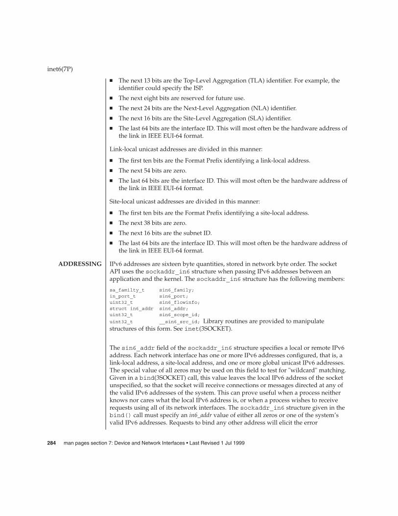
� The next 13 bits are the Top-Level Aggregation (TLA) identifier. For example, theidentifier could specify the ISP.
� The next eight bits are reserved for future use.
� The next 24 bits are the Next-Level Aggregation (NLA) identifier.
� The next 16 bits are the Site-Level Aggregation (SLA) identifier.
� The last 64 bits are the interface ID. This will most often be the hardware address ofthe link in IEEE EUI-64 format.
Link-local unicast addresses are divided in this manner:
� The first ten bits are the Format Prefix identifying a link-local address.
� The next 54 bits are zero.
� The last 64 bits are the interface ID. This will most often be the hardware address ofthe link in IEEE EUI-64 format.
Site-local unicast addresses are divided in this manner:
� The first ten bits are the Format Prefix identifying a site-local address.
� The next 38 bits are zero.
� The next 16 bits are the subnet ID.
� The last 64 bits are the interface ID. This will most often be the hardware address ofthe link in IEEE EUI-64 format.
IPv6 addresses are sixteen byte quantities, stored in network byte order. The socketAPI uses the sockaddr_in6 structure when passing IPv6 addresses between anapplication and the kernel. The sockaddr_in6 structure has the following members:
sa_familty_t sin6_family;in_port_t sin6_port;uint32_t sin6_flowinfo;struct in6_addr sin6_addr;uint32_t sin6_scope_id;
uint32_t __sin6_src_id; Library routines are provided to manipulatestructures of this form. See inet(3SOCKET).
The sin6_addr field of the sockaddr_in6 structure specifies a local or remote IPv6address. Each network interface has one or more IPv6 addresses configured, that is, alink-local address, a site-local address, and one or more global unicast IPv6 addresses.The special value of all zeros may be used on this field to test for "wildcard" matching.Given in a bind(3SOCKET) call, this value leaves the local IPv6 address of the socketunspecified, so that the socket will receive connections or messages directed at any ofthe valid IPv6 addresses of the system. This can prove useful when a process neitherknows nor cares what the local IPv6 address is, or when a process wishes to receiverequests using all of its network interfaces. The sockaddr_in6 structure given in thebind() call must specify an in6_addr value of either all zeros or one of the system’svalid IPv6 addresses. Requests to bind any other address will elicit the error
inet6(7P)
ADDRESSING
284 man pages section 7: Device and Network Interfaces • Last Revised 1 Jul 1999
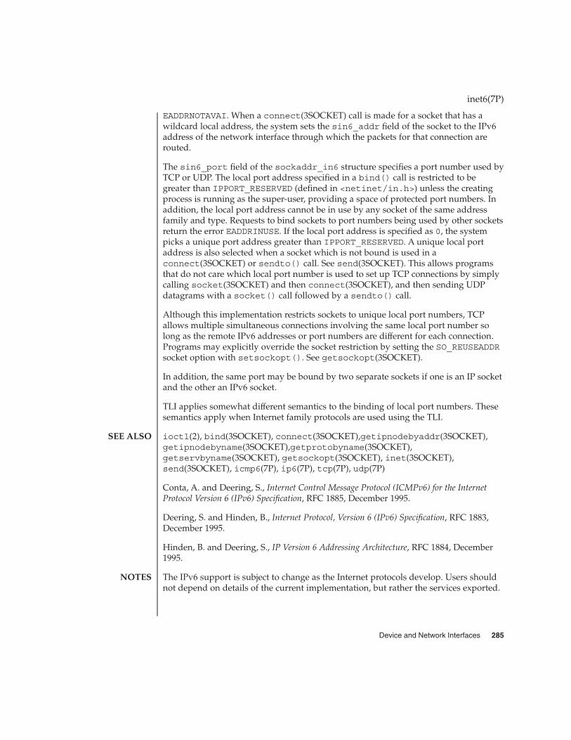
EADDRNOTAVAI. When a connect(3SOCKET) call is made for a socket that has awildcard local address, the system sets the sin6_addr field of the socket to the IPv6address of the network interface through which the packets for that connection arerouted.
The sin6_port field of the sockaddr_in6 structure specifies a port number used byTCP or UDP. The local port address specified in a bind() call is restricted to begreater than IPPORT_RESERVED (defined in <netinet/in.h>) unless the creatingprocess is running as the super-user, providing a space of protected port numbers. Inaddition, the local port address cannot be in use by any socket of the same addressfamily and type. Requests to bind sockets to port numbers being used by other socketsreturn the error EADDRINUSE. If the local port address is specified as 0, the systempicks a unique port address greater than IPPORT_RESERVED. A unique local portaddress is also selected when a socket which is not bound is used in aconnect(3SOCKET) or sendto() call. See send(3SOCKET). This allows programsthat do not care which local port number is used to set up TCP connections by simplycalling socket(3SOCKET) and then connect(3SOCKET), and then sending UDPdatagrams with a socket() call followed by a sendto() call.
Although this implementation restricts sockets to unique local port numbers, TCPallows multiple simultaneous connections involving the same local port number solong as the remote IPv6 addresses or port numbers are different for each connection.Programs may explicitly override the socket restriction by setting the SO_REUSEADDRsocket option with setsockopt(). See getsockopt(3SOCKET).
In addition, the same port may be bound by two separate sockets if one is an IP socketand the other an IPv6 socket.
TLI applies somewhat different semantics to the binding of local port numbers. Thesesemantics apply when Internet family protocols are used using the TLI.
ioctl(2), bind(3SOCKET), connect(3SOCKET),getipnodebyaddr(3SOCKET),getipnodebyname(3SOCKET),getprotobyname(3SOCKET),getservbyname(3SOCKET), getsockopt(3SOCKET), inet(3SOCKET),send(3SOCKET), icmp6(7P), ip6(7P), tcp(7P), udp(7P)
Conta, A. and Deering, S., Internet Control Message Protocol (ICMPv6) for the InternetProtocol Version 6 (IPv6) Specification, RFC 1885, December 1995.
Deering, S. and Hinden, B., Internet Protocol, Version 6 (IPv6) Specification, RFC 1883,December 1995.
Hinden, B. and Deering, S., IP Version 6 Addressing Architecture, RFC 1884, December1995.
The IPv6 support is subject to change as the Internet protocols develop. Users shouldnot depend on details of the current implementation, but rather the services exported.
inet6(7P)
SEE ALSO
NOTES
Device and Network Interfaces 285

inet – Internet protocol family
#include <sys/types.h>
#include <netinet/in.h>
The Internet protocol family implements a collection of protocols which are centeredaround the Internet Protocol (“IP”) and which share a common address format. TheInternet family protocols can be accessed using the socket interface, where theysupport the SOCK_STREAM, SOCK_DGRAM, and SOCK_RAW socket types, or theTransport Level Interface (TLI), where they support the connectionless (T_CLTS) andconnection oriented (T_COTS_ORD) service types.
The Internet protocol family is comprised of the Internet Protocol (“IP”), the AddressResolution Protocol (“ARP”), the Internet Control Message Protocol (“ICMP”), theTransmission Control Protocol (“TCP”), and the User Datagram Protocol (“UDP”).
TCP supports the socket interface’s SOCK_STREAM abstraction and TLI’s T_COTS_ORDservice type. UDP supports the SOCK_DGRAM socket abstraction and the TLI T_CLTSservice type. See tcp(7P) and udp(7P). A direct interface to IP is available using bothTLI and the socket interface (see ip(7P)). ICMP is used by the kernel to handle andreport errors in protocol processing. It is also accessible to user programs (seeicmp(7P)). ARP is used to translate 32-bit IP addresses into 48-bit Ethernet addresses.See arp(7P).
The 32-bit IP address is divided into network number and host number parts. It isfrequency-encoded. The most-significant bit is zero in Class A addresses, in which thehigh-order 8 bits represent the network number. Class B addresses have their highorder two bits set to 10 and use the high-order 16 bits as the network number field.Class C addresses have a 24-bit network number part of which the high order threebits are 110. Sites with a cluster of IP networks may chose to use a single networknumber for the cluster; this is done by using subnet addressing. The host numberportion of the address is further subdivided into subnet number and host numberparts. Within a subnet, each subnet appears to be an individual network. Externally,the entire cluster appears to be a single, uniform network requiring only a singlerouting entry. Subnet addressing is enabled and examined by the following ioctl(2)commands. They have the same form as the SIOCSIFADDR command.
SIOCSIFNETMASK Set interface network mask. The network mask definesthe network part of the address; if it contains more ofthe address than the address type would indicate, thensubnets are in use.
SIOCGIFNETMASK Get interface network mask.
IP addresses are four byte quantities, stored in network byte order. IP addressesshould be manipulated using the byte order conversion routines. Seebyteorder(3SOCKET).
inet(7P)
NAME
SYNOPSIS
DESCRIPTION
PROTOCOLS
ADDRESSING
286 man pages section 7: Device and Network Interfaces • Last Revised 3 Aug 2000

Addresses in the Internet protocol family use the sockaddr_in structure, which hasthat following members:
short sin_family;ushort_t sin_port;struct in_addr sin_addr;
char sin_zero[8];Library routines are provided to manipulate structures of thisform; See inet(3SOCKET).
The sin_addr field of the sockaddr_in structure specifies a local or remote IPaddress. Each network interface has its own unique IP address. The special valueINADDR_ANY may be used in this field to effect “wildcard” matching. Given in abind(3SOCKET) call, this value leaves the local IP address of the socket unspecified,so that the socket will receive connections or messages directed at any of the valid IPaddresses of the system. This can prove useful when a process neither knows nor careswhat the local IP address is or when a process wishes to receive requests using all ofits network interfaces. The sockaddr_in structure given in the bind(3SOCKET) callmust specify an in_addr value of either INADDR_ANY or one of the system’s valid IPaddresses. Requests to bind any other address will elicit the error EADDRNOTAVAIL.When a connect(3SOCKET) call is made for a socket that has a wildcard localaddress, the system sets the sin_addr field of the socket to the IP address of thenetwork interface that the packets for that connection are routed through.
The sin_port field of the sockaddr_in structure specifies a port number used byTCP or UDP. The local port address specified in a bind(3SOCKET) call is restricted tobe greater than IPPORT_RESERVED (defined in <<netinet/in.h>>) unless thecreating process is running as the superuser, providing a space of protected portnumbers. In addition, the local port address must not be in use by any socket of sameaddress family and type. Requests to bind sockets to port numbers being used byother sockets return the error EADDRINUSE. If the local port address is specified as 0,then the system picks a unique port address greater than IPPORT_RESERVED. Aunique local port address is also picked when a socket which is not bound is used in aconnect(3SOCKET) or sendto (see send(3SOCKET)) call. This allows programswhich do not care which local port number is used to set up TCP connections bysimply calling socket(3SOCKET) and then connect(3SOCKET), and to send UDPdatagrams with a socket(3SOCKET) call followed by a sendto() call.
Although this implementation restricts sockets to unique local port numbers, TCPallows multiple simultaneous connections involving the same local port number solong as the remote IP addresses or port numbers are different for each connection.Programs may explicitly override the socket restriction by setting the SO_REUSEADDRsocket option with setsockopt (see getsockopt(3SOCKET)).
TLI applies somewhat different semantics to the binding of local port numbers. Thesesemantics apply when Internet family protocols are used using the TLI.
inet(7P)
Device and Network Interfaces 287

ioctl(2), bind(3SOCKET), byteorder(3SOCKET), connect(3SOCKET),gethostbyname(3NSL), getnetbyname(3SOCKET), getprotobyname(3SOCKET),getservbyname(3SOCKET), getsockopt(3SOCKET), send(3SOCKET),socket(3SOCKET), arp(7P), icmp(7P), ip(7P), tcp(7P), udp(7P)
Network Information Center, DDN Protocol Handbook (3 vols.), Network InformationCenter, SRI International, Menlo Park, Calif., 1985.
The Internet protocol support is subject to change as the Internet protocols develop.Users should not depend on details of the current implementation, but rather theservices exported.
inet(7P)
SEE ALSO
NOTES
288 man pages section 7: Device and Network Interfaces • Last Revised 3 Aug 2000

ip6 – Internet Protocol Version 6
#include <sys/socket.h>#include <netinet/in.h>,
#include <netinet/ip6.h>
s = socket(AF_INET6, SOCK_RAW, proto);
t = t_open ("/dev/rawip6", O_RDWR);
The IPv6 protocol is the next generation of the internetwork datagram deliveryprotocol of the Internet protocol family. Programs may use IPv6 through higher-levelprotocols such as the Transmission Control Protocol (TCP) or the User DatagramProtocol (UDP), or may interface directly to IPv6. See tcp(7P) and udp(7P). Directaccess may be by means of the socket interface, using a “raw socket,” or by means ofthe Transport Level Interface (TLI). The protocol options and IPv6 extension headersdefined in the IPv6 specification may be set in outgoing datagrams.
The STREAMS driver /dev/rawip6 is the TLI transport provider that provides rawaccess to IPv6.
Raw IPv6 sockets are connectionless and are normally used with the sendto() andrecvfrom() calls (see send(3SOCKET) and recv(3SOCKET)), although theconnect(3SOCKET) call may also be used to fix the destination for future datagrams.In this case, the read(2) or recv(3SOCKET) and write(2) or send(3SOCKET) callsmay be used. Ancillary data may also be sent or received over raw IPv6 sockets usingthe sendmsg(3SOCKET) and recvmsg(3SOCKET) system calls.
Unlike raw IP, IPv6 applications do not include a complete IPv6 header when sending;there is no IPv6 analog to the IP IP_HDRINCL socket option. IPv6 header values maybe specified or received as ancillary data to a sendmsg(3SOCKET) orrecvmsg(3SOCKET) system call, or may be specified as "sticky" options on aper-socket basis by using the setsockopt(3SOCKET) system call. Such sticky optionsare applied to all outbound packets unless overridden by ancillary data. If anyancillary data is specified in a sendmsg(3SOCKET) call, all sticky options notexplicitly overridden revert to default values for that datagram only; the sticky optionspersist as set for subsequent datagrams.
Since sendmsg(3SOCKET) is not supported for SOCK_STREAM upper level protocolssuch as TCP, ancillary data is unsupported for TCP. Sticky options, however, aresupported.
Since sendmsg(3SOCKET) is supported for SOCK_DGRAM upper level protocols, bothancillary data and sticky options are supported for UDP, ICMP6, and raw IPv6sockets.
The socket options supported at the IPv6 level are:
IPV6_BOUND_IF Limit reception transmission of packets to thisinterface. Takes an integer as an argument; the integeris the selected interace index.
ip6(7P)
NAME
SYNOPSIS
DESCRIPTION
APPLICATIONPROGRAMMING
INTERFACE
Device and Network Interfaces 289
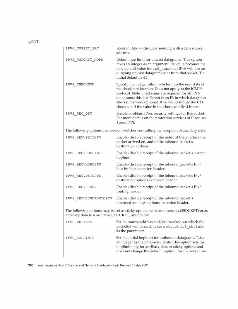
IPV6_UNSPEC_SRC Boolean. Allow/disallow sending with a zero sourceaddress.
IPV6_UNICAST_HOPS Default hop limit for unicast datagrams. This optiontakes an integer as an argument. Its value becomes thenew default value for ip6_hops that IPv6 will use onoutgoing unicast datagrams sent from that socket. Theinitial default is 60.
IPV6_CHECKSUM Specify the integer offset in bytes into the user data ofthe checksum location. Does not apply to the ICMP6protocol. Note: checksums are required for all IPv6datagrams; this is different from IP, in which datagramchecksums were optional. IPv6 will compute the ULPchecksum if the value in the checksum field is zero.
IPV6_SEC_OPT Enable or obtain IPsec security settings for this socket.For more details on the protection services of IPsec, seeipsec(7P).
The following options are boolean switches controlling the reception of ancillary data:
IPV6_RECVPKTINFO Enable/disable receipt of the index of the interface thepacket arrived on, and of the inbound packet’sdestination address.
IPV6_RECVHOPLIMIT Enable/disable receipt of the inbound packet’s currenthoplimit.
IPV6_RECVHOPOPTS Enable/disable receipt of the inbound packet’s IPv6hop-by-hop extension header.
IPV6_RECVDSTOPTS Enable/disable receipt of the inbound packet’s IPv6destination options extension header.
IPV6_RECVRTHDR Enable/disable receipt of the inbound packet’s IPv6routing header.
IPV6_RECVRTHDRDSTOPTS Enable/disable receipt of the inbound packet’sintermediate-hops options extension header.
The following options may be set as sticky options with setsockopt(3SOCKET) or asancillary data to a sendmsg(3SOCKET) system call:
IPV6_PKTINFO Set the source address and/or interface out which thepacket(s) will be sent. Takes a struct ip6_pktinfoas the parameter.
IPV6_HOPLIMIT Set the initial hoplimit for outbound datagrams. Takesan integer as the parameter. Note: This option sets thehoplimit only for ancillary data or sticky options anddoes not change the default hoplimit for the socket; see
ip6(7P)
290 man pages section 7: Device and Network Interfaces • Last Revised 18 Apr 2001

IPV6_UNICAST_HOPS and IPV6_MULTICAST_HOPSto change the socket’s default hoplimit.
IPV6_NEXTHOP Specify the IPv6 address of the first hop, which must bea neighbor of the sending host. Takes a structsockaddr_in6 as the parameter. When this optionspecifies the same address as the destination IPv6address of the datagram, this is equivalent to theexisting SO_DONTROUTE option.
IPV6_HOPOPTS Specify one or more hop-by-hop options. Variablelength. Takes a complete IPv6 hop-by-hop optionsextension header as the parameter.
IPV6_DSTOPTS Specify one or more destination options. Variablelength. Takes a complete IPv6 destination optionsextension header as the parameter.
IPV6_RTHDR Specify the IPv6 routing header. Variable length. Takesa complete IPv6 routing header as the parameter.Currently, only type 0 routing headers are supported.
IPV6_RTHDRDSTOPTS Specify one or more destination options for allintermediate hops. May be configured, but will not beapplied unless an IPv6 routing header is alsoconfigured. Variable length. Takes a complete IPv6destination options extension header as the parameter.
The following options affect the socket’s multicast behavior:
IPV6_JOIN_GROUP Join a multicast group. Takes a struct ipv6_mreq asthe parameter; the structure contains a multicastaddress and an interface index.
IPV6_LEAVE_GROUP Leave a multicast group. Takes a struct ipv6_mreqas the parameter; the structure contains a multicastaddress and an interface index.
IPV6_MULTICAST_IF The outgoing interface for multicast packets. Thisoption takes an integer as an argument; the integer isthe interface index of the selected interface.
IPV6_MULTICAST_HOPS Default hop limit for multicast datagrams. This optiontakes an integer as an argument. Its value becomes thenew default value for ip6_hops that IPv6 will use onoutgoing multicast datagrams sent from that socket.The initial default is 1.
IPV6_MULTICAST_LOOP Loopback for multicast datagrams. Normally multicastdatagrams are delivered to members on the sendinghost. Setting the unsigned character argument to 0 willcause the opposite behavior.
ip6(7P)
Device and Network Interfaces 291

The multicast socket options can be used with any datagram socket type in the IPv6family.
At the socket level, the socket option SO_DONTROUTE may be applied. This optionforces datagrams being sent to bypass routing and forwarding by forcing the IPv6hoplimit field to 1, meaning that the packet will not be forwarded by routers.
Raw IPv6 datagrams can also be sent and received using the TLI connectionlessprimitives.
Datagrams flow through the IPv6 layer in two directions: from the network up to userprocesses and from user processes down to the network. Using this orientation, IPv6 islayered above the network interface drivers and below the transport protocols such asUDP and TCP. The Internet Control Message Protocol (ICMPv6) for the InternetProtocol Version 6 (IPv6) is logically a part of IPv6. See icmp6(7P).
Unlike IP, IPv6 provides no checksum of the IPv6 header. Also unlike IP, upper levelprotocol checksums are required. IPv6 will compute the ULP/data portion checksumif the checksum field contains a zero (see IPV6_CHECKSUM option above).
IPv6 extension headers in received datagrams are processed in the IPv6 layeraccording to the protocol specification. Currently recognized IPv6 extension headersinclude hop-by-hop options header, destination options header, routing header(currently, only type 0 routing headers are supported), and fragment header.
The IPv6 layer will normally act as a router (forwarding datagrams that are notaddressed to it, among other things) when the machine has two or more IPv6interfaces that are up. This behavior can be overridden by using ndd(1M) to set the/dev/ip6 variable, ip6_forwarding. The value 0 means do not forward; the value1 means forward. The initialization scripts (see /etc/init.d/inetinit) set thisvalue at boot time based on the number of "up" interfaces and whether or not theneighbor discovery protocol daemon configuration file /etc/inet/ndpd.confexists. The default value is zero; ip6_forwarding is set to 1 only if more than oneinterface has been configured for IPv6 and if /etc/inet/ndpd.conf exists.
Additionally, finer grained forwarding can be configured in IPv6. Each interface willcreate an ifname:ip6_forwarding /dev/ip6 variable that can be modified usingndd(1M). If a per-interface :ip6_forwarding variable is set to 0, packets will neitherbe forwarded from this interface to others, nor forwarded to this interface. Setting theip6_forwarding variable will toggle all of the per-interface :ip6_forwardingvariables to the setting of ip6_forwarding.
The IPv6 layer will send an ICMP6 message back to the source host in many caseswhen it receives a datagram that can not be handled. A "time exceeded" ICMP6message will be sent if the ip6_hops field in the IPv6 header drops to zero in theprocess of forwarding a datagram. A "destination unreachable" message will besent by a router or by the originating host if a datagram can not be sent on becausethere is no route to the final destination; it will be sent by a router when it encountersa firewall prohibition; it will be sent by a destination node when the transport protocol
ip6(7P)
292 man pages section 7: Device and Network Interfaces • Last Revised 18 Apr 2001
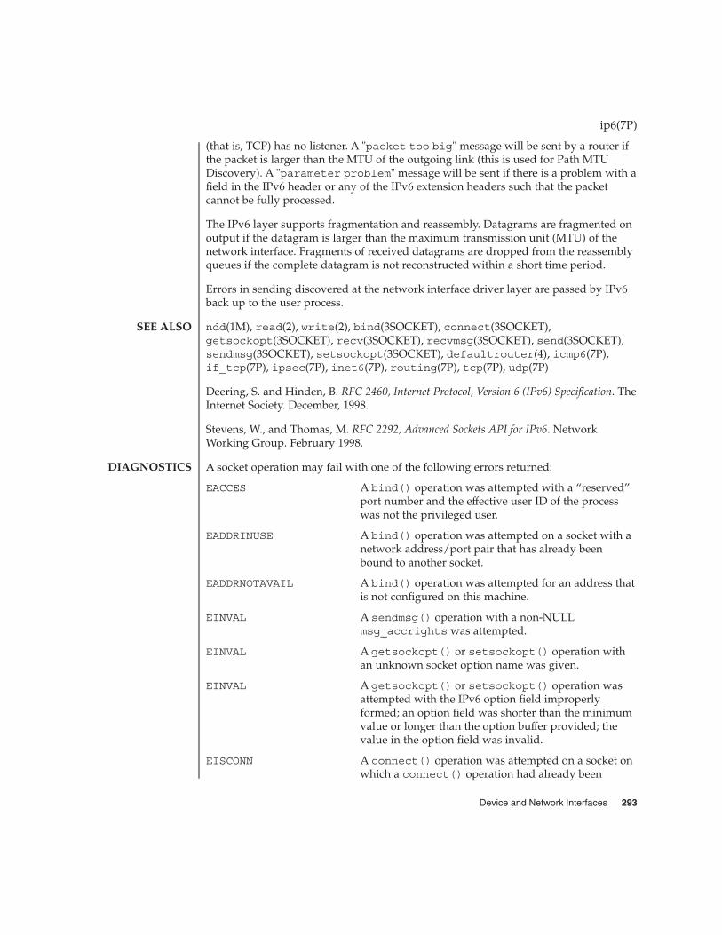
(that is, TCP) has no listener. A "packet too big" message will be sent by a router ifthe packet is larger than the MTU of the outgoing link (this is used for Path MTUDiscovery). A "parameter problem" message will be sent if there is a problem with afield in the IPv6 header or any of the IPv6 extension headers such that the packetcannot be fully processed.
The IPv6 layer supports fragmentation and reassembly. Datagrams are fragmented onoutput if the datagram is larger than the maximum transmission unit (MTU) of thenetwork interface. Fragments of received datagrams are dropped from the reassemblyqueues if the complete datagram is not reconstructed within a short time period.
Errors in sending discovered at the network interface driver layer are passed by IPv6back up to the user process.
ndd(1M), read(2), write(2), bind(3SOCKET), connect(3SOCKET),getsockopt(3SOCKET), recv(3SOCKET), recvmsg(3SOCKET), send(3SOCKET),sendmsg(3SOCKET), setsockopt(3SOCKET), defaultrouter(4), icmp6(7P),if_tcp(7P), ipsec(7P), inet6(7P), routing(7P), tcp(7P), udp(7P)
Deering, S. and Hinden, B. RFC 2460, Internet Protocol, Version 6 (IPv6) Specification. TheInternet Society. December, 1998.
Stevens, W., and Thomas, M. RFC 2292, Advanced Sockets API for IPv6. NetworkWorking Group. February 1998.
A socket operation may fail with one of the following errors returned:
EACCES A bind() operation was attempted with a “reserved”port number and the effective user ID of the processwas not the privileged user.
EADDRINUSE A bind() operation was attempted on a socket with anetwork address/port pair that has already beenbound to another socket.
EADDRNOTAVAIL A bind() operation was attempted for an address thatis not configured on this machine.
EINVAL A sendmsg() operation with a non-NULLmsg_accrights was attempted.
EINVAL A getsockopt() or setsockopt() operation withan unknown socket option name was given.
EINVAL A getsockopt() or setsockopt() operation wasattempted with the IPv6 option field improperlyformed; an option field was shorter than the minimumvalue or longer than the option buffer provided; thevalue in the option field was invalid.
EISCONN A connect() operation was attempted on a socket onwhich a connect() operation had already been
ip6(7P)
SEE ALSO
DIAGNOSTICS
Device and Network Interfaces 293

performed, and the socket could not be successfullydisconnected before making the new connection.
EISCONN A sendto() or sendmsg() operation specifying anaddress to which the message should be sent wasattempted on a socket on which a connect()operation had already been performed.
EMSGSIZE A send(), sendto(), or sendmsg() operation wasattempted to send a datagram that was too large for aninterface, but was not allowed to be fragmented (suchas broadcasts).
ENETUNREACH An attempt was made to establish a connection viaconnect(), or to send a datagram by means ofsendto() or sendmsg(), where there was nomatching entry in the routing table; or if an ICMP“destination unreachable” message wasreceived.
ENOTCONN A send() or write() operation, or a sendto() orsendmsg() operation not specifying an address towhich the message should be sent, was attempted on asocket on which a connect() operation had notalready been performed.
ENOBUFS The system ran out of memory for fragmentationbuffers or other internal data structures.
ENOMEM The system was unable to allocate memory for an IPv6socket option or other internal data structures.
ENOPROTOOPT An IP socket option was attempted on an IPv6 socket,or an IPv6 socket option was attempted on an IPsocket.
Applications using the sockets API must use the Advanced Sockets API for IPv6 (RFC2292) to see elements of the inbound packet’s IPv6 header or extension headers.
ip6(7P)
NOTES
294 man pages section 7: Device and Network Interfaces • Last Revised 18 Apr 2001

ip, IP – Internet Protocol
#include <sys/socket.h>
#include <netinet/in.h>
s = socket(AF_INET, SOCK_RAW, proto);
t = t_open ("/dev/rawip", O_RDWR);
IP is the internetwork datagram delivery protocol that is central to the Internetprotocol family. Programs may use IP through higher-level protocols such as theTransmission Control Protocol (TCP) or the User Datagram Protocol (UDP), or mayinterface directly to IP. See tcp(7P) and udp(7P). Direct access may be by means of thesocket interface, using a “raw socket,” or by means of the Transport Level Interface(TLI). The protocol options defined in the IP specification may be set in outgoingdatagrams.
Packets sent to or from this system may be subject to IPsec policy; see ipsec(7P) formore information.
The STREAMS driver /dev/rawip is the TLI transport provider that provides rawaccess to IP.
Raw IP sockets are connectionless and are normally used with the sendto() andrecvfrom() calls (see send(3SOCKET) and recv(3SOCKET)), although theconnect(3SOCKET) call may also be used to fix the destination for future datagram.In this case, the read(2) or recv(3SOCKET) and write(2) or send(3SOCKET) callsmay be used. If proto is IPPROTO_RAW or IPPROTO_IGMP, the application is expectedto include a complete IP header when sending. Otherwise, that protocol number willbe set in outgoing datagrams and used to filter incoming datagrams and an IP headerwill be generated and prepended to each outgoing datagram. In either case, receiveddatagrams are returned with the IP header and options intact.
If an application uses IP_HDRINCL and provides the IP header contents, the IP stackdoes not modify the following supplied fields under any conditions: Type of Service,DF Flag, Protocol, and Destination Address. The IP Options and IHL fields are set byuse of IP_OPTIONS, and Total Length is updated to include any options. Version isset to the default. Identification is chosen by the normal IP ID selection logic. Thesource address is updated if none was specified and the TTL is changed if the packethas a broadcast destination address. Since an applicaton cannot send down fragments(as IP assigns the IP ID), Fragment Offset is always 0. The IP Checksum field iscomputed by IP. None of the data beyond the IP header are changed, including theapplication-provided transport header.
The socket options supported at the IP level are:
IP_OPTIONS IP options for outgoing datagrams. This socket optionmay be used to set IP options to be included in eachoutgoing datagram. IP options to be sent are set withsetsockopt() (see getsockopt(3SOCKET)). The
IP(7P)
NAME
SYNOPSIS
DESCRIPTION
APPLICATIONPROGRAMMING
INTERFACE
Device and Network Interfaces 295

getsockopt(3SOCKET) call returns the IP options setin the last setsockopt() call. IP options on receiveddatagrams are visible to user programs only using rawIP sockets. The format of IP options given insetsockopt() matches those defined in the IPspecification with one exception: the list of addressesfor the source routing options must include thefirst-hop gateway at the beginning of the list ofgateways. The first-hop gateway address will beextracted from the option list and the size adjustedaccordingly before use. IP options may be used withany socket type in the Internet family.
IP_SEC_OPT Enable or obtain IPsec security settings for this socket.For more details on the protection services of IPsec, seeipsec(7P).
IP_ADD_MEMBERSHIP Join a multicast group.
IP_DROP_MEMBERSHIP Leave a multicast group.
These options take a struct ip_mreq as the parameter. The structure contains amulticast address which has to be set to the CLASS-D IP multicast address, and aninterface address. Normally the interface address is set to INADDR_ANY which causesthe kernel to choose the interface to join on.
IP_MULTICAST_IF The outgoing interface for multicast packets. Thisoption takes a struct in_addr as an argument, andit selects that interface for outgoing IP multicastpackets. If the address specified is INADDR_ANY, it willuse the unicast routing table to select the outgoinginterface (which is the default behavior).
IP_MULTICAST_TTL Time to live for multicast datagrams. This option takesan unsigned character as an argument. Its value is theTTL that IP will use on outgoing multicast datagrams.The default is 1.
IP_MULTICAST_LOOP Loopback for multicast datagrams. Normally multicastdatagrams are delivered to members on the sendinghost. Setting the unsigned character argument to 0 willcause the opposite behavior.
IP_TOS This option takes an integer argument as its inputvalue. The least significant 8 bits of the value are usedto set the Type Of Service field in the IP header of theoutgoing packets.
The multicast socket options can be used with any datagram socket type in theInternet family.
IP(7P)
296 man pages section 7: Device and Network Interfaces • Last Revised 7 Feb 2002

At the socket level, the socket option SO_DONTROUTE may be applied. This optionforces datagrams being sent to bypass routing and forwarding by forcing the IP TimeTo Live field to 1, meaning that the packet will not be forwarded by routers.
Raw IP datagrams can also be sent and received using the TLI connectionlessprimitives.
Datagrams flow through the IP layer in two directions: from the network up to userprocesses and from user processes down to the network. Using this orientation, IP islayered above the network interface drivers and below the transport protocols such asUDP and TCP. The Internet Control Message Protocol (ICMP) is logically a part of IP.See icmp(7P).
IP provides for a checksum of the header part, but not the data part, of the datagram.The checksum value is computed and set in the process of sending datagrams andchecked when receiving datagrams.
IP options in received datagrams are processed in the IP layer according to theprotocol specification. Currently recognized IP options include: security, loose sourceand record route (LSRR), strict source and record route (SSRR), record route, andinternet timestamp.
The IP layer will normally act as a router when the machine has two or moreinterfaces that are up, forwarding datagrams that are not addressed to it, among otherthings. This behavior can be overridden by using ndd(1M) to set the /dev/ipvariable, ip_forwarding. The value 0 means do not forward; the value 1 meansforward. The initialization scripts set this value at boot time based on the number of"up" interfaces, but will not turn on IP forwarding at all if the file /etc/notrouterexists. See /etc/init.d/inetinit. When the IP module is loaded,ip_forwarding is 0 and remains so if:
� one non-DHCP-managed interface is up (the most common case)� file /etc/notrouter exists and DHCP does not say that IP forwarding is on� file /etc/defaultrouter exists and DHCP does not say IP forwarding is on
Otherwise, ip_forwarding is set to 1.
Additionally, finer-grained forwarding can be configured in IP. Each interface createsan <ifname>:ip_forwarding /dev/ip variable that can be modified usingndd(1M). If a per-interface :ip_forwarding variable is set to 0, packets will neitherbe forwarded from this interface to others, nor forwarded to this interface. Setting theip_forwarding variable toggles all of the per-interface :ip_forwarding variablesto the setting of ip_forwarding.
The IP layer sends an ICMP message back to the source host in many cases when itreceives a datagram that can not be handled. A “time exceeded” ICMP message is sentif the “time to live” field in the IP header drops to zero in the process of forwarding adatagram. A “destination unreachable” message is sent if a datagram can not beforwarded because there is no route to the final destination, or if it can not be
IP(7P)
Device and Network Interfaces 297

fragmented. If the datagram is addressed to the local host but is destined for aprotocol that is not supported or a port that is not in use, a destination unreachablemessage is also sent. The IP layer may send an ICMP “source quench” message if it isreceiving datagrams too quickly. ICMP messages are only sent for the first fragment ofa fragmented datagram and are never returned in response to errors in other ICMPmessages.
The IP layer supports fragmentation and reassembly. Datagrams are fragmented onoutput if the datagram is larger than the maximum transmission unit (MTU) of thenetwork interface. Fragments of received datagrams are dropped from the reassemblyqueues if the complete datagram is not reconstructed within a short time period.
Errors in sending discovered at the network interface driver layer are passed by IPback up to the user process.
ndd(1M), read(2), write(2), bind(3SOCKET), connect(3SOCKET),getsockopt(3SOCKET), recv(3SOCKET), send(3SOCKET), defaultrouter(4),icmp(7P), if_tcp(7P), inet(7P), ip6(7P), ipsec(7P),routing(7P), tcp(7P), udp(7P)
Braden, R., RFC 1122, Requirements for Internet Hosts − Communication Layers,Information Sciences Institute, University of Southern California, October 1989.
Postel, J., RFC 791, Internet Protocol − DARPA Internet Program Protocol Specification,Information Sciences Institute, University of Southern California, September 1981.
A socket operation may fail with one of the following errors returned:
EACCES A bind() operation was attempted with a “reserved”port number and the effective user ID of the processwas not the privileged user.
EADDRINUSE A bind() operation was attempted on a socket with anetwork address/port pair that has already beenbound to another socket.
EADDRNOTAVAIL A bind() operation was attempted for an address thatis not configured on this machine.
EINVAL A sendmsg() operation with a non-NULLmsg_accrights was attempted.
EINVAL A getsockopt() or setsockopt() operation withan unknown socket option name was given.
EINVAL A getsockopt() or setsockopt() operation wasattempted with the IP option field improperly formed;an option field was shorter than the minimum value orlonger than the option buffer provided.
EISCONN A connect() operation was attempted on a socket onwhich a connect() operation had already been
IP(7P)
SEE ALSO
DIAGNOSTICS
298 man pages section 7: Device and Network Interfaces • Last Revised 7 Feb 2002
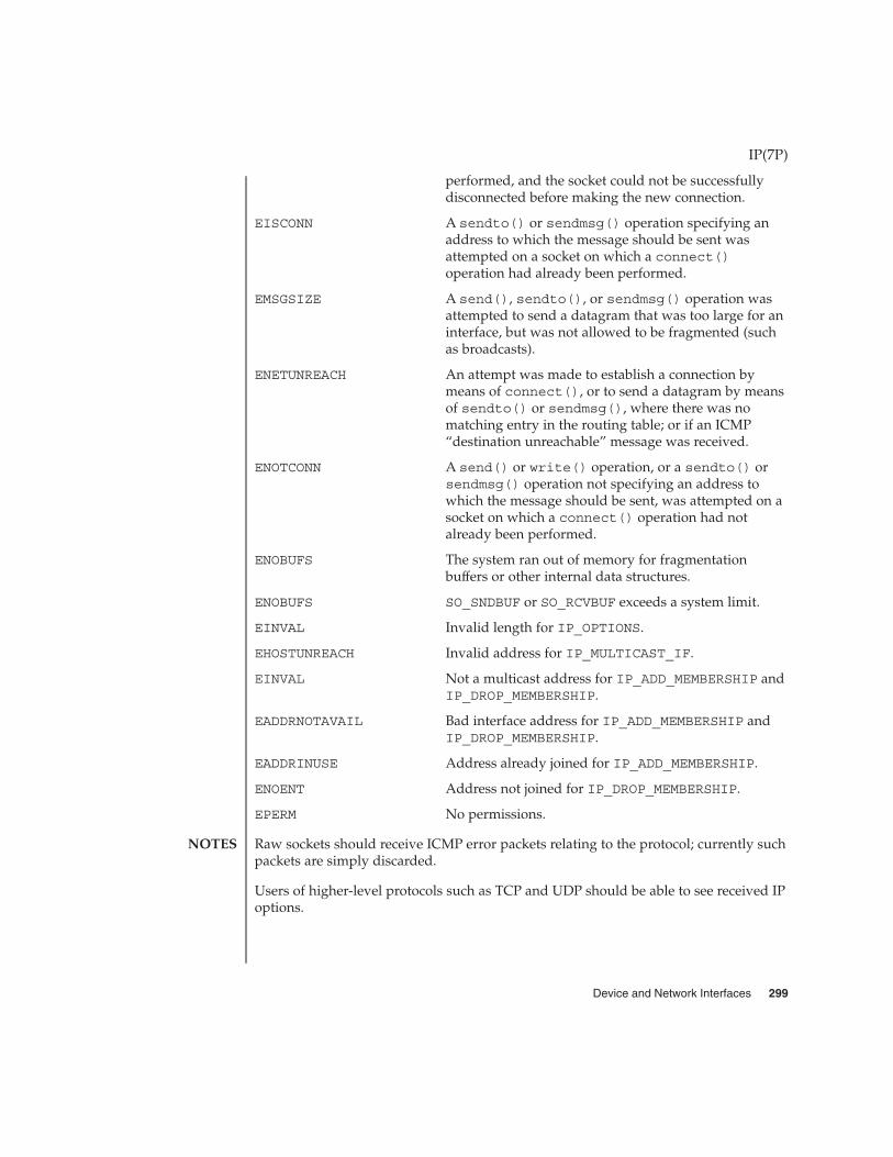
performed, and the socket could not be successfullydisconnected before making the new connection.
EISCONN A sendto() or sendmsg() operation specifying anaddress to which the message should be sent wasattempted on a socket on which a connect()operation had already been performed.
EMSGSIZE A send(), sendto(), or sendmsg() operation wasattempted to send a datagram that was too large for aninterface, but was not allowed to be fragmented (suchas broadcasts).
ENETUNREACH An attempt was made to establish a connection bymeans of connect(), or to send a datagram by meansof sendto() or sendmsg(), where there was nomatching entry in the routing table; or if an ICMP“destination unreachable” message was received.
ENOTCONN A send() or write() operation, or a sendto() orsendmsg() operation not specifying an address towhich the message should be sent, was attempted on asocket on which a connect() operation had notalready been performed.
ENOBUFS The system ran out of memory for fragmentationbuffers or other internal data structures.
ENOBUFS SO_SNDBUF or SO_RCVBUF exceeds a system limit.
EINVAL Invalid length for IP_OPTIONS.
EHOSTUNREACH Invalid address for IP_MULTICAST_IF.
EINVAL Not a multicast address for IP_ADD_MEMBERSHIP andIP_DROP_MEMBERSHIP.
EADDRNOTAVAIL Bad interface address for IP_ADD_MEMBERSHIP andIP_DROP_MEMBERSHIP.
EADDRINUSE Address already joined for IP_ADD_MEMBERSHIP.
ENOENT Address not joined for IP_DROP_MEMBERSHIP.
EPERM No permissions.
Raw sockets should receive ICMP error packets relating to the protocol; currently suchpackets are simply discarded.
Users of higher-level protocols such as TCP and UDP should be able to see received IPoptions.
IP(7P)
NOTES
Device and Network Interfaces 299

ip, IP – Internet Protocol
#include <sys/socket.h>
#include <netinet/in.h>
s = socket(AF_INET, SOCK_RAW, proto);
t = t_open ("/dev/rawip", O_RDWR);
IP is the internetwork datagram delivery protocol that is central to the Internetprotocol family. Programs may use IP through higher-level protocols such as theTransmission Control Protocol (TCP) or the User Datagram Protocol (UDP), or mayinterface directly to IP. See tcp(7P) and udp(7P). Direct access may be by means of thesocket interface, using a “raw socket,” or by means of the Transport Level Interface(TLI). The protocol options defined in the IP specification may be set in outgoingdatagrams.
Packets sent to or from this system may be subject to IPsec policy; see ipsec(7P) formore information.
The STREAMS driver /dev/rawip is the TLI transport provider that provides rawaccess to IP.
Raw IP sockets are connectionless and are normally used with the sendto() andrecvfrom() calls (see send(3SOCKET) and recv(3SOCKET)), although theconnect(3SOCKET) call may also be used to fix the destination for future datagram.In this case, the read(2) or recv(3SOCKET) and write(2) or send(3SOCKET) callsmay be used. If proto is IPPROTO_RAW or IPPROTO_IGMP, the application is expectedto include a complete IP header when sending. Otherwise, that protocol number willbe set in outgoing datagrams and used to filter incoming datagrams and an IP headerwill be generated and prepended to each outgoing datagram. In either case, receiveddatagrams are returned with the IP header and options intact.
If an application uses IP_HDRINCL and provides the IP header contents, the IP stackdoes not modify the following supplied fields under any conditions: Type of Service,DF Flag, Protocol, and Destination Address. The IP Options and IHL fields are set byuse of IP_OPTIONS, and Total Length is updated to include any options. Version isset to the default. Identification is chosen by the normal IP ID selection logic. Thesource address is updated if none was specified and the TTL is changed if the packethas a broadcast destination address. Since an applicaton cannot send down fragments(as IP assigns the IP ID), Fragment Offset is always 0. The IP Checksum field iscomputed by IP. None of the data beyond the IP header are changed, including theapplication-provided transport header.
The socket options supported at the IP level are:
IP_OPTIONS IP options for outgoing datagrams. This socket optionmay be used to set IP options to be included in eachoutgoing datagram. IP options to be sent are set withsetsockopt() (see getsockopt(3SOCKET)). The
ip(7P)
NAME
SYNOPSIS
DESCRIPTION
APPLICATIONPROGRAMMING
INTERFACE
300 man pages section 7: Device and Network Interfaces • Last Revised 7 Feb 2002

getsockopt(3SOCKET) call returns the IP options setin the last setsockopt() call. IP options on receiveddatagrams are visible to user programs only using rawIP sockets. The format of IP options given insetsockopt() matches those defined in the IPspecification with one exception: the list of addressesfor the source routing options must include thefirst-hop gateway at the beginning of the list ofgateways. The first-hop gateway address will beextracted from the option list and the size adjustedaccordingly before use. IP options may be used withany socket type in the Internet family.
IP_SEC_OPT Enable or obtain IPsec security settings for this socket.For more details on the protection services of IPsec, seeipsec(7P).
IP_ADD_MEMBERSHIP Join a multicast group.
IP_DROP_MEMBERSHIP Leave a multicast group.
These options take a struct ip_mreq as the parameter. The structure contains amulticast address which has to be set to the CLASS-D IP multicast address, and aninterface address. Normally the interface address is set to INADDR_ANY which causesthe kernel to choose the interface to join on.
IP_MULTICAST_IF The outgoing interface for multicast packets. Thisoption takes a struct in_addr as an argument, andit selects that interface for outgoing IP multicastpackets. If the address specified is INADDR_ANY, it willuse the unicast routing table to select the outgoinginterface (which is the default behavior).
IP_MULTICAST_TTL Time to live for multicast datagrams. This option takesan unsigned character as an argument. Its value is theTTL that IP will use on outgoing multicast datagrams.The default is 1.
IP_MULTICAST_LOOP Loopback for multicast datagrams. Normally multicastdatagrams are delivered to members on the sendinghost. Setting the unsigned character argument to 0 willcause the opposite behavior.
IP_TOS This option takes an integer argument as its inputvalue. The least significant 8 bits of the value are usedto set the Type Of Service field in the IP header of theoutgoing packets.
The multicast socket options can be used with any datagram socket type in theInternet family.
ip(7P)
Device and Network Interfaces 301

At the socket level, the socket option SO_DONTROUTE may be applied. This optionforces datagrams being sent to bypass routing and forwarding by forcing the IP TimeTo Live field to 1, meaning that the packet will not be forwarded by routers.
Raw IP datagrams can also be sent and received using the TLI connectionlessprimitives.
Datagrams flow through the IP layer in two directions: from the network up to userprocesses and from user processes down to the network. Using this orientation, IP islayered above the network interface drivers and below the transport protocols such asUDP and TCP. The Internet Control Message Protocol (ICMP) is logically a part of IP.See icmp(7P).
IP provides for a checksum of the header part, but not the data part, of the datagram.The checksum value is computed and set in the process of sending datagrams andchecked when receiving datagrams.
IP options in received datagrams are processed in the IP layer according to theprotocol specification. Currently recognized IP options include: security, loose sourceand record route (LSRR), strict source and record route (SSRR), record route, andinternet timestamp.
The IP layer will normally act as a router when the machine has two or moreinterfaces that are up, forwarding datagrams that are not addressed to it, among otherthings. This behavior can be overridden by using ndd(1M) to set the /dev/ipvariable, ip_forwarding. The value 0 means do not forward; the value 1 meansforward. The initialization scripts set this value at boot time based on the number of"up" interfaces, but will not turn on IP forwarding at all if the file /etc/notrouterexists. See /etc/init.d/inetinit. When the IP module is loaded,ip_forwarding is 0 and remains so if:
� one non-DHCP-managed interface is up (the most common case)� file /etc/notrouter exists and DHCP does not say that IP forwarding is on� file /etc/defaultrouter exists and DHCP does not say IP forwarding is on
Otherwise, ip_forwarding is set to 1.
Additionally, finer-grained forwarding can be configured in IP. Each interface createsan <ifname>:ip_forwarding /dev/ip variable that can be modified usingndd(1M). If a per-interface :ip_forwarding variable is set to 0, packets will neitherbe forwarded from this interface to others, nor forwarded to this interface. Setting theip_forwarding variable toggles all of the per-interface :ip_forwarding variablesto the setting of ip_forwarding.
The IP layer sends an ICMP message back to the source host in many cases when itreceives a datagram that can not be handled. A “time exceeded” ICMP message is sentif the “time to live” field in the IP header drops to zero in the process of forwarding adatagram. A “destination unreachable” message is sent if a datagram can not beforwarded because there is no route to the final destination, or if it can not be
ip(7P)
302 man pages section 7: Device and Network Interfaces • Last Revised 7 Feb 2002

fragmented. If the datagram is addressed to the local host but is destined for aprotocol that is not supported or a port that is not in use, a destination unreachablemessage is also sent. The IP layer may send an ICMP “source quench” message if it isreceiving datagrams too quickly. ICMP messages are only sent for the first fragment ofa fragmented datagram and are never returned in response to errors in other ICMPmessages.
The IP layer supports fragmentation and reassembly. Datagrams are fragmented onoutput if the datagram is larger than the maximum transmission unit (MTU) of thenetwork interface. Fragments of received datagrams are dropped from the reassemblyqueues if the complete datagram is not reconstructed within a short time period.
Errors in sending discovered at the network interface driver layer are passed by IPback up to the user process.
ndd(1M), read(2), write(2), bind(3SOCKET), connect(3SOCKET),getsockopt(3SOCKET), recv(3SOCKET), send(3SOCKET), defaultrouter(4),icmp(7P), if_tcp(7P), inet(7P), ip6(7P), ipsec(7P),routing(7P), tcp(7P), udp(7P)
Braden, R., RFC 1122, Requirements for Internet Hosts − Communication Layers,Information Sciences Institute, University of Southern California, October 1989.
Postel, J., RFC 791, Internet Protocol − DARPA Internet Program Protocol Specification,Information Sciences Institute, University of Southern California, September 1981.
A socket operation may fail with one of the following errors returned:
EACCES A bind() operation was attempted with a “reserved”port number and the effective user ID of the processwas not the privileged user.
EADDRINUSE A bind() operation was attempted on a socket with anetwork address/port pair that has already beenbound to another socket.
EADDRNOTAVAIL A bind() operation was attempted for an address thatis not configured on this machine.
EINVAL A sendmsg() operation with a non-NULLmsg_accrights was attempted.
EINVAL A getsockopt() or setsockopt() operation withan unknown socket option name was given.
EINVAL A getsockopt() or setsockopt() operation wasattempted with the IP option field improperly formed;an option field was shorter than the minimum value orlonger than the option buffer provided.
EISCONN A connect() operation was attempted on a socket onwhich a connect() operation had already been
ip(7P)
SEE ALSO
DIAGNOSTICS
Device and Network Interfaces 303

performed, and the socket could not be successfullydisconnected before making the new connection.
EISCONN A sendto() or sendmsg() operation specifying anaddress to which the message should be sent wasattempted on a socket on which a connect()operation had already been performed.
EMSGSIZE A send(), sendto(), or sendmsg() operation wasattempted to send a datagram that was too large for aninterface, but was not allowed to be fragmented (suchas broadcasts).
ENETUNREACH An attempt was made to establish a connection bymeans of connect(), or to send a datagram by meansof sendto() or sendmsg(), where there was nomatching entry in the routing table; or if an ICMP“destination unreachable” message was received.
ENOTCONN A send() or write() operation, or a sendto() orsendmsg() operation not specifying an address towhich the message should be sent, was attempted on asocket on which a connect() operation had notalready been performed.
ENOBUFS The system ran out of memory for fragmentationbuffers or other internal data structures.
ENOBUFS SO_SNDBUF or SO_RCVBUF exceeds a system limit.
EINVAL Invalid length for IP_OPTIONS.
EHOSTUNREACH Invalid address for IP_MULTICAST_IF.
EINVAL Not a multicast address for IP_ADD_MEMBERSHIP andIP_DROP_MEMBERSHIP.
EADDRNOTAVAIL Bad interface address for IP_ADD_MEMBERSHIP andIP_DROP_MEMBERSHIP.
EADDRINUSE Address already joined for IP_ADD_MEMBERSHIP.
ENOENT Address not joined for IP_DROP_MEMBERSHIP.
EPERM No permissions.
Raw sockets should receive ICMP error packets relating to the protocol; currently suchpackets are simply discarded.
Users of higher-level protocols such as TCP and UDP should be able to see received IPoptions.
ip(7P)
NOTES
304 man pages section 7: Device and Network Interfaces • Last Revised 7 Feb 2002
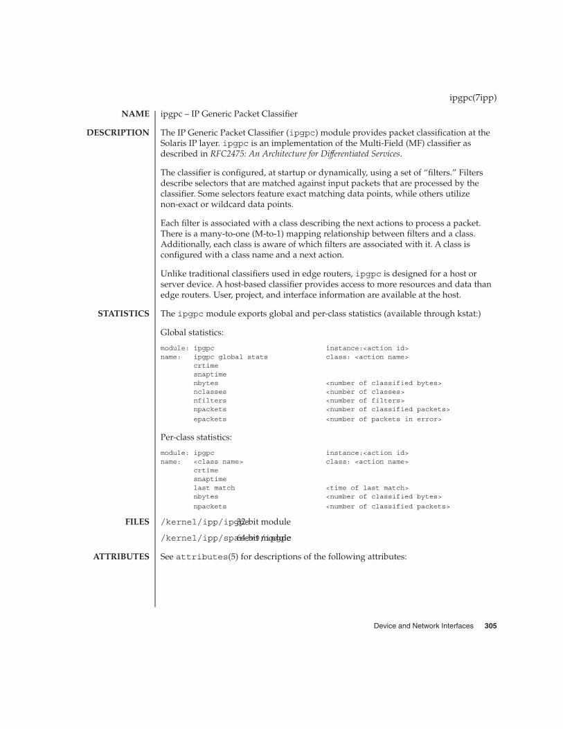
ipgpc – IP Generic Packet Classifier
The IP Generic Packet Classifier (ipgpc) module provides packet classification at theSolaris IP layer. ipgpc is an implementation of the Multi-Field (MF) classifier asdescribed in RFC2475: An Architecture for Differentiated Services.
The classifier is configured, at startup or dynamically, using a set of “filters.” Filtersdescribe selectors that are matched against input packets that are processed by theclassifier. Some selectors feature exact matching data points, while others utilizenon-exact or wildcard data points.
Each filter is associated with a class describing the next actions to process a packet.There is a many-to-one (M-to-1) mapping relationship between filters and a class.Additionally, each class is aware of which filters are associated with it. A class isconfigured with a class name and a next action.
Unlike traditional classifiers used in edge routers, ipgpc is designed for a host orserver device. A host-based classifier provides access to more resources and data thanedge routers. User, project, and interface information are available at the host.
The ipgpc module exports global and per-class statistics (available through kstat:)
Global statistics:
module: ipgpc instance:<action id>name: ipgpc global stats class: <action name>
crtimesnaptimenbytes <number of classified bytes>nclasses <number of classes>nfilters <number of filters>npackets <number of classified packets>
epackets <number of packets in error>
Per-class statistics:
module: ipgpc instance:<action id>name: <class name> class: <action name>
crtimesnaptimelast match <time of last match>nbytes <number of classified bytes>
npackets <number of classified packets>
/kernel/ipp/ipgpc32-bit module
/kernel/ipp/sparcv9/ipgpc64-bit module
See attributes(5) for descriptions of the following attributes:
ipgpc(7ipp)
NAME
DESCRIPTION
STATISTICS
FILES
ATTRIBUTES
Device and Network Interfaces 305

ATTRIBUTE TYPE ATTRIBUTE VALUE
Availability SUNWqos (32–bit) SUNWqosx (64–bit)
ipqosconf(1M), dlcosmk(7IPP), dscpmk(7IPP), flowacct(7IPP), ipqos(7IPP),tokenmt(7IPP), tswtclmt(7IPP)
RFC 2475, An Architecture for Differentiated Services S. Blake, D. Black, M. Carlson, E.Davies, Z. Wang, W. Weiss — The Internet Society, 1998
ipgpc(7ipp)
SEE ALSO
306 man pages section 7: Device and Network Interfaces • Last Revised 25 Feb 2002

ipqos – IP Quality of Service
ipqos is an implementation of the Differentiated Services model defined in RFC2475:An Architecture for Differentiated Services, which defines the following entities:multi-field classifier, meter, marker, and dropper. The Solaris implementation ofipqos adds a flow accounting entity.
These entities can be combined into processing paths that constitute a series of actionsthat are performed on groups of flows. The classifier groups together flows and directsthem in a given processing path. Classifier configuration and path construction areachieved using the ipqosconf(1M) command.
A summary of the ipqos entities follows. For more information, refer to thecorresponding man page for each entity.
ipgpcAn implementation of the classifier defined in the model. ipgpc has been extendedand is able to select traffic based on IP header parameters, user id, project id,interface name, interface group and direction.
tokenmt, tswtclmtThese modules implement different metering algorithms. tokenmt implementsboth RFC2697: A Single Rate Three Color Marker and RFC 2698: A Two Rate Three ColorMarker. tswtclmt implements RFC2859: A Time Sliding Window Three Color Marker.These modules only implement the metering functions defined in the RFCs.
dlcosmkA marker entity that allows the setting of the user priority field of Ethernet framesas defined in the IEEE 802.1D specification. dlcosmk is only available with VLANcapable network interfaces.
dscpmkA marker entity that enables the setting of the Differentiated Services Code PointValue in the IP header as defined in RFC 2474: Definition of the Differentiated ServicesField (DS Field) in the IPv4 and IPv6 headers.
flowacctAn accounting module that utilizes the Solaris extended accounting facility.flowacct logs all flows with parameters used to build a charge back mechanism.
ipqos modules export statistics through the kstat facility. Exported statistics containthe following common parameters:
module module name
instance dynamic parameter identifying a specific instance
name a string for global statistics (for example, ipgpc globalstat) or a class name for per-class statistics for aclassifier action
ipqos(7ipp)
NAME
DESCRIPTION
STATISTICS
Device and Network Interfaces 307

To verify classifier configuration, generate traffic for each of the configured classes andcheck that the statistic counters for the expected class are increased. If you’re unsureabout the parameters for your traffic, you can use snoop(1M) to determine them.
Some actions have the instance id of the next configured action in their statistics. Thisinstance id can be used to follow the action processing path. Instance id’s -1 and -2 arethe built-in actions continue and drop, respectively.
Examples:
To retrieve all statistics for ipgpc:
kstat -m ipgpc
To retrieve statistics for the class http:
kstat -m ipgpc -c http
See attributes(5) for descriptions of the following attributes:
ATTRIBUTE TYPE ATTRIBUTE VALUE
Availability SUNWqos (32–bit) SUNWqosx (64–bit)
ipqosconf(1M), dlcosmk(7IPP), dscpmk(7IPP), flowacct(7IPP), ipgpc(7IPP),tokenmt(7IPP), tswtclmt(7IPP)
RFC 2475, An Architecture for Differentiated Services S. Blake, D. Black, M. Carlson, E.Davies, Z. Wang, W. Weiss — The Internet Society, 1998
RFC 2474, Definition of the Differentiated Services Field (DS Field) in the IPv4 and IPv6Headers K. Nichols, S. Blake, F. Baker, D. Black — The Internet Society, 1998
RFC 2697, A Single Rate Three Color Marker J. Heinanen, R. Guerin — The InternetSociety, 1999
RFC 2698, A Two Rate Three Color Marker J. Heinanen, R. Guerin — The Internet Society,1999
RFC 2859, A Time Sliding Window Three Colour Marker (TSWTCM) W. Fang, N. Seddigh,B. Nandy — The Internet Society, 2000
ipqos(7ipp)
ATTRIBUTES
SEE ALSO
308 man pages section 7: Device and Network Interfaces • Last Revised 25 Feb 2002

iprb – Intel 82557, 82558, 82559–controlled network interface controllers
/dev/iprb
The iprb Ethernet driver is a multi-threaded, loadable, clonable, STREAMS hardwaredriver supporting the connectionless Data Link Provider Interface, dlpi(7P), overIntel D100 82557, 82558, and 82559 controllers. Multiple 82557, 82558, and 82559controllers installed within the system are supported by the driver. The iprb driverprovides basic support for the 82557, 82558, and 82559 hardware. Functions includechip initialization, frame transmit and receive, multicast support, and error recoveryand reporting.
The cloning, character-special device /dev/iprb is used to access all 82557, 82558,and 82559 devices installed within the system.
The iprb driver is dependent on /kernel/misc/gld, a loadable kernel module thatprovides the iprb driver with the DLPI and STREAMS functionality required of aLAN driver. See gld(7D) for more details on the primitives supported by the driver.
The values returned by the driver in the DL_INFO_ACK primitive in response to theDL_INFO_REQ from the user are as follows:
� Maximum SDU is 1500 (ETHERMTU).� Minimum SDU is 0. The driver will pad to the mandatory 60-octet minimum
packet size.� The dlsap address length is 8.� MAC type is DL_ETHER.� The sap length value is −2, meaning the physical address component is followed
immediately by a 2-byte sap component within the DLSAP address.� Broadcast address value is Ethernet/IEEE broadcast address
(FF:FF:FF:FF:FF:FF).
IA based systems with the Intel EtherExpress PRO/100B or the Intel EtherExpressPRO/100+ might hang when the interface is brought down at the very instant that apacket is being received. To avoid this, wait until the system is experiencing light orno network traffic before bringing the interface down.
Early versions of the firmware on Intel EtherExpress PRO/100+ and Intel PRO/100+Management adapters do not support PXE network boot on Solaris systems. Upgradethe firmware if the version is lower than 078. PXE firmware versions are expressed asthree-digit build numbers. The build number is typically displayed by the firmwareduring boot. If the PXE build number is not displayed during boot, change the systemBIOS or adapter BIOS configuration to display PXE messages during boot.
iprb Device special file
/kernel/drv/iprb.conf iprb configuration file
<sys/stropts.h> stropts network header file
iprb(7D)
NAME
SYNOPSIS
DESCRIPTION
APPLICATIONPROGRAMMING
INTERFACEiprb and DLPI
Known Problemsand Limitations
FILES
Device and Network Interfaces 309
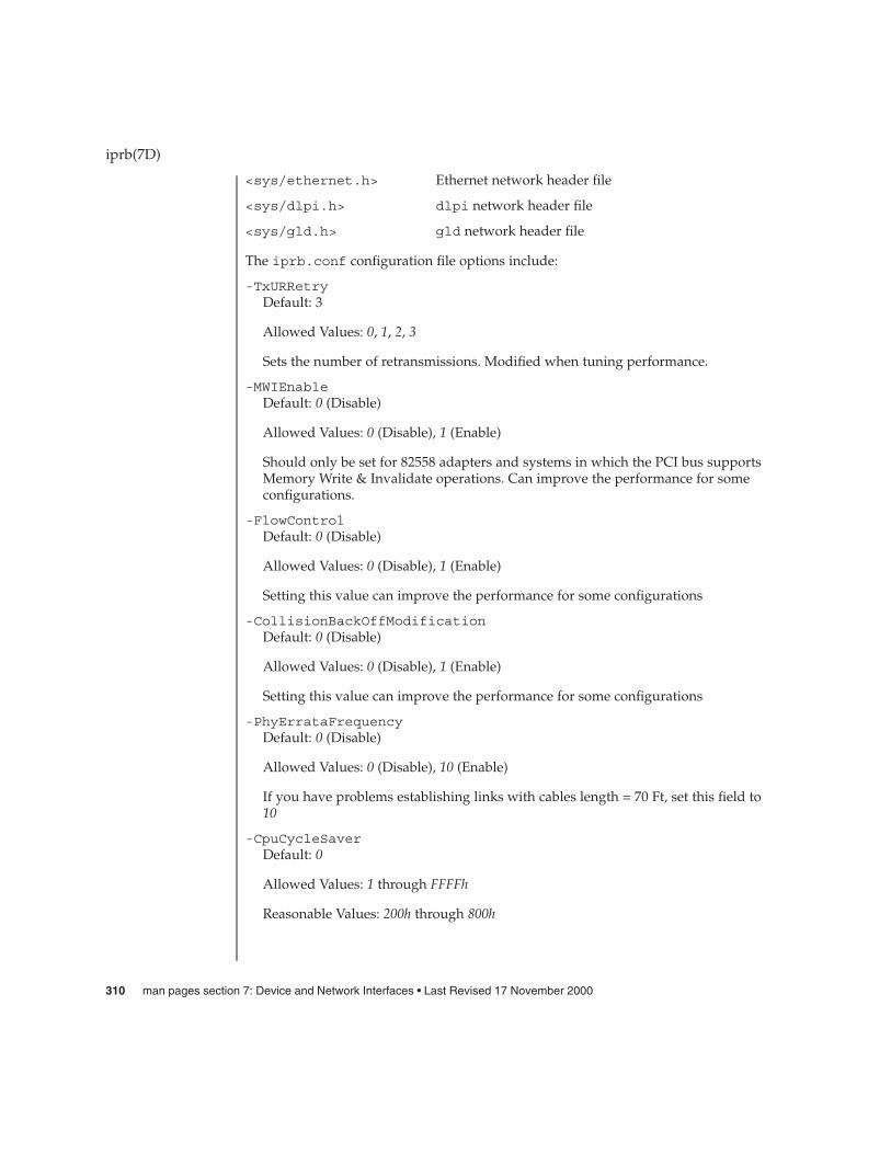
<sys/ethernet.h> Ethernet network header file
<sys/dlpi.h> dlpi network header file
<sys/gld.h> gld network header file
The iprb.conf configuration file options include:
-TxURRetryDefault: 3
Allowed Values: 0, 1, 2, 3
Sets the number of retransmissions. Modified when tuning performance.
-MWIEnableDefault: 0 (Disable)
Allowed Values: 0 (Disable), 1 (Enable)
Should only be set for 82558 adapters and systems in which the PCI bus supportsMemory Write & Invalidate operations. Can improve the performance for someconfigurations.
-FlowControlDefault: 0 (Disable)
Allowed Values: 0 (Disable), 1 (Enable)
Setting this value can improve the performance for some configurations
-CollisionBackOffModificationDefault: 0 (Disable)
Allowed Values: 0 (Disable), 1 (Enable)
Setting this value can improve the performance for some configurations
-PhyErrataFrequencyDefault: 0 (Disable)
Allowed Values: 0 (Disable), 10 (Enable)
If you have problems establishing links with cables length = 70 Ft, set this field to10
-CpuCycleSaverDefault: 0
Allowed Values: 1 through FFFFh
Reasonable Values: 200h through 800h
iprb(7D)
310 man pages section 7: Device and Network Interfaces • Last Revised 17 November 2000

The CPUSaver algorithm improves the system’s P/E ratio by reducing the numberof interrupts generated by the card. The algorithm bundles multiple receive framestogether, then generates a single interrupt for the bundle. Because the microcodedoes not support run-time configuration, configuration must be done prior to themicro code being loaded into the chip. Changing this value from its default meansthat the driver will have to be unloaded and loaded for the change to take affect.Setting the CpuCycleSaver option to 0 prevents the algorithm from being used.Because it varies for different network environments, the optimal value for thisparameter is impossible to predict. Accordingly, developers should run tests todetermine the effect that changing this value has on bandwidth and CPUutilization.
-ForceSpeedDuplexDefault: 5 (Auto-negotiate)
Allowed Values: 4 (100 FDX)
3 (100 HDX)
2 (10 FDX)
1 (10 HDX)
Specify the speed and duplex mode for each instance.
Example: ForceSpeedDuplex=5,4;
Sets iprb0 to autonegotiate and iprb1 to 100 FDX.
See attributes(5) for descriptions of the following attributes:
ATTRIBUTE TYPE ATTRIBUTE VALUE
Architecture IA
attributes(5), dlpi(7P), gld(7D)
iprb(7D)
ATTRIBUTES
SEE ALSO
Device and Network Interfaces 311
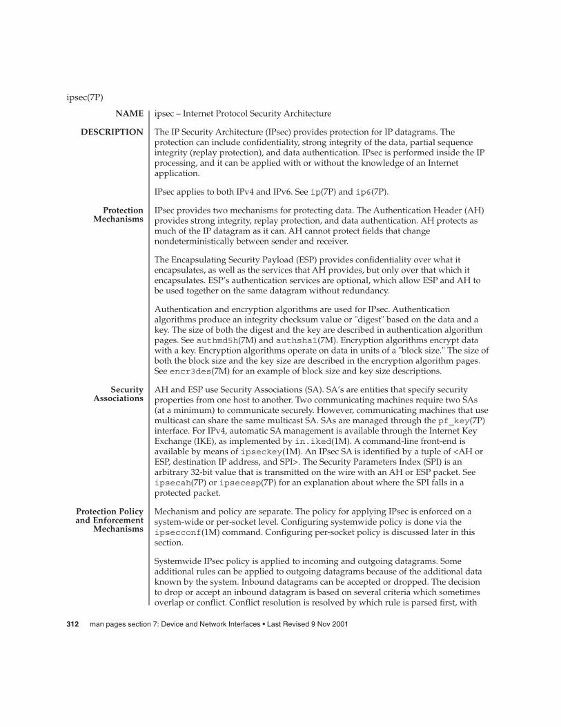
ipsec – Internet Protocol Security Architecture
The IP Security Architecture (IPsec) provides protection for IP datagrams. Theprotection can include confidentiality, strong integrity of the data, partial sequenceintegrity (replay protection), and data authentication. IPsec is performed inside the IPprocessing, and it can be applied with or without the knowledge of an Internetapplication.
IPsec applies to both IPv4 and IPv6. See ip(7P) and ip6(7P).
IPsec provides two mechanisms for protecting data. The Authentication Header (AH)provides strong integrity, replay protection, and data authentication. AH protects asmuch of the IP datagram as it can. AH cannot protect fields that changenondeterministically between sender and receiver.
The Encapsulating Security Payload (ESP) provides confidentiality over what itencapsulates, as well as the services that AH provides, but only over that which itencapsulates. ESP’s authentication services are optional, which allow ESP and AH tobe used together on the same datagram without redundancy.
Authentication and encryption algorithms are used for IPsec. Authenticationalgorithms produce an integrity checksum value or "digest" based on the data and akey. The size of both the digest and the key are described in authentication algorithmpages. See authmd5h(7M) and authsha1(7M). Encryption algorithms encrypt datawith a key. Encryption algorithms operate on data in units of a "block size." The size ofboth the block size and the key size are described in the encryption algorithm pages.See encr3des(7M) for an example of block size and key size descriptions.
AH and ESP use Security Associations (SA). SA’s are entities that specify securityproperties from one host to another. Two communicating machines require two SAs(at a minimum) to communicate securely. However, communicating machines that usemulticast can share the same multicast SA. SAs are managed through the pf_key(7P)interface. For IPv4, automatic SA management is available through the Internet KeyExchange (IKE), as implemented by in.iked(1M). A command-line front-end isavailable by means of ipseckey(1M). An IPsec SA is identified by a tuple of <AH orESP, destination IP address, and SPI>. The Security Parameters Index (SPI) is anarbitrary 32-bit value that is transmitted on the wire with an AH or ESP packet. Seeipsecah(7P) or ipsecesp(7P) for an explanation about where the SPI falls in aprotected packet.
Mechanism and policy are separate. The policy for applying IPsec is enforced on asystem-wide or per-socket level. Configuring systemwide policy is done via theipsecconf(1M) command. Configuring per-socket policy is discussed later in thissection.
Systemwide IPsec policy is applied to incoming and outgoing datagrams. Someadditional rules can be applied to outgoing datagrams because of the additional dataknown by the system. Inbound datagrams can be accepted or dropped. The decisionto drop or accept an inbound datagram is based on several criteria which sometimesoverlap or conflict. Conflict resolution is resolved by which rule is parsed first, with
ipsec(7P)
NAME
DESCRIPTION
ProtectionMechanisms
SecurityAssociations
Protection Policyand Enforcement
Mechanisms
312 man pages section 7: Device and Network Interfaces • Last Revised 9 Nov 2001
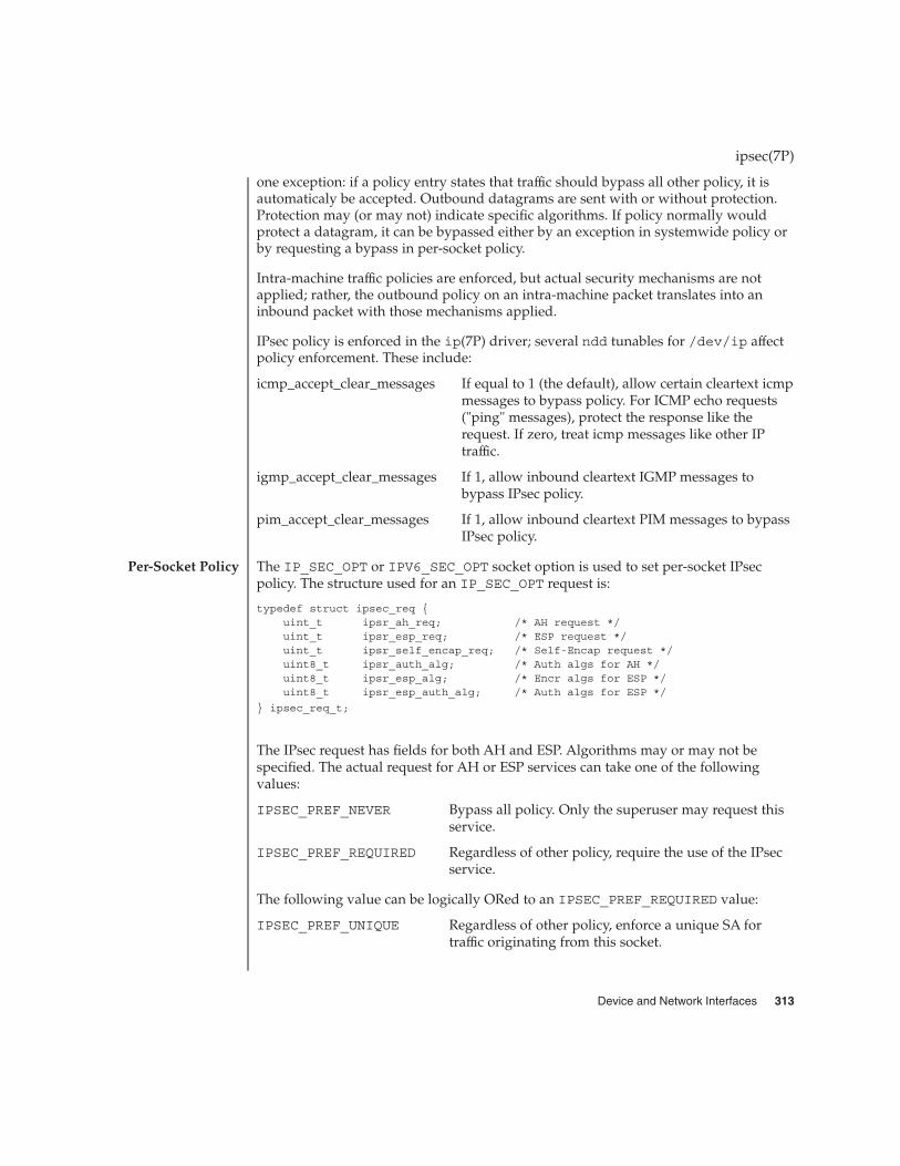
one exception: if a policy entry states that traffic should bypass all other policy, it isautomaticaly be accepted. Outbound datagrams are sent with or without protection.Protection may (or may not) indicate specific algorithms. If policy normally wouldprotect a datagram, it can be bypassed either by an exception in systemwide policy orby requesting a bypass in per-socket policy.
Intra-machine traffic policies are enforced, but actual security mechanisms are notapplied; rather, the outbound policy on an intra-machine packet translates into aninbound packet with those mechanisms applied.
IPsec policy is enforced in the ip(7P) driver; several ndd tunables for /dev/ip affectpolicy enforcement. These include:
icmp_accept_clear_messages If equal to 1 (the default), allow certain cleartext icmpmessages to bypass policy. For ICMP echo requests("ping" messages), protect the response like therequest. If zero, treat icmp messages like other IPtraffic.
igmp_accept_clear_messages If 1, allow inbound cleartext IGMP messages tobypass IPsec policy.
pim_accept_clear_messages If 1, allow inbound cleartext PIM messages to bypassIPsec policy.
The IP_SEC_OPT or IPV6_SEC_OPT socket option is used to set per-socket IPsecpolicy. The structure used for an IP_SEC_OPT request is:
typedef struct ipsec_req {uint_t ipsr_ah_req; /* AH request */uint_t ipsr_esp_req; /* ESP request */uint_t ipsr_self_encap_req; /* Self-Encap request */uint8_t ipsr_auth_alg; /* Auth algs for AH */uint8_t ipsr_esp_alg; /* Encr algs for ESP */uint8_t ipsr_esp_auth_alg; /* Auth algs for ESP */
} ipsec_req_t;
The IPsec request has fields for both AH and ESP. Algorithms may or may not bespecified. The actual request for AH or ESP services can take one of the followingvalues:
IPSEC_PREF_NEVER Bypass all policy. Only the superuser may request thisservice.
IPSEC_PREF_REQUIRED Regardless of other policy, require the use of the IPsecservice.
The following value can be logically ORed to an IPSEC_PREF_REQUIRED value:
IPSEC_PREF_UNIQUE Regardless of other policy, enforce a unique SA fortraffic originating from this socket.
ipsec(7P)
Per-Socket Policy
Device and Network Interfaces 313

In the event IP options not normally encapsulated by ESP need to be, theipsec_self_encap_req is used to add an additional IP header outside the originalone. Algorithm values from <net/pfkeyv2.h> are as follows:
SADB_AALG_MD5HMAC Uses the MD5-HMAC (RFC 2403) algorithm forauthentication. See authmd5h(7M).
SADB_AALG_SHA1HMAC Uses the SHA1-HMAC (RFC 2404) algorithm forauthentication. See authsha1(7M).
SADB_EALG_DESCBC Uses the DES (RFC 2405) algorithm for encryption. Seeencrdes(7M).
SADB_EALG_3DESCBC Uses the Triple DES (RFC 2451) algorithm forencryption. See encr3des(7M).
SADB_EALG_BLOWFISH Uses the Blowfish (RFC 2451) algorithm for encryption.See encrbfsh(7M).
SADB_EALG_AES Uses the Advanced Encryption Standard algorithm forencryption. See encraes(7M).
An application should use either the getsockopt(3SOCKET) or thesetsockopt(3SOCKET) call to manipulate IPsec requests. For example:
#include <sys/socket.h>#include <netinet/in.h>#include <net/pfkeyv2.h> /* For SADB_*ALG_* *//* .... socket setup skipped */rc = setsockopt(s, IPPROTO_IP, IP_SEC_OPT,
(const char *)&ipsec_req, sizeof (ipsec_req_t));
While IPsec is an effective tool in securing network traffic, it will not make securityproblems disappear. Security issues beyond the mechanisms that IPsec offers may bediscussed in similar “Security Consideration” sections within individual referencemanual pages.
While a non-root user cannot bypass IPsec, a non-root user can set policy to bedifferent from the system-wide policy. For ways to prevent this, consult the ndd(1M)variables in /dev/ip.
See attributes(5) for descriptions of the following attributes:
ATTRIBUTE TYPE ATTRIBUTE VALUE
Interface Stability Evolving
ipsec(7P)
SECURITYCONSIDERATIONS
ATTRIBUTES
314 man pages section 7: Device and Network Interfaces • Last Revised 9 Nov 2001

in.iked(1M), ipsecconf(1M), ipseckey(1M), ndd(1M), getsockopt(3SOCKET),setsockopt(3SOCKET), attributes(5), authmd5h(7M), authsha1(7M),encraes(7M), encrbfsh(7M), encrdes(7M), encr3des(7M), inet(7P), ip(7P),ip6(7P), ipsecah(7P), ipsecesp(7P), pf_key(7P)
Kent, S., and Atkinson, R., RFC 2401, Security Architecture for the Internet Protocol, TheInternet Society, 1998.
Kent, S. and Atkinson, R., RFC 2406, IP Encapsulating Security Payload (ESP), TheInternet Society, 1998.
Madson, C., and Doraswamy, N., RFC 2405, The ESP DES-CBC Cipher Algorithm withExplicit IV, The Internet Society, 1998.
Madsen, C. and Glenn, R., RFC 2403, The Use of HMAC-MD5-96 within ESP and AH,The Internet Society, 1998.
Madsen, C. and Glenn, R., RFC 2404, The Use of HMAC-SHA-1-96 within ESP and AH,The Internet Society, 1998.
Pereira, R. and Adams, R., RFC 2451, The ESP CBC-Mode Cipher Algorithms, TheInternet Society, 1998.
ipsec(7P)
SEE ALSO
Device and Network Interfaces 315

ipsecah, AH – IPsec Authentication Header
drv/ipsecah
The ipsecah module (“AH”) provides strong integrity, authentication, and partialsequence integrity (replay protection) to IP datagrams. AH protects the parts of the IPdatagram that can be predicted by the sender as it will be received by the receiver. Forexample, the IP TTL field is not a predictable field, and is not protected by AH.
AH is inserted between the IP header and the transport header. The transport headercan be TCP, UDP, ICMP, or another IP header, if tunnels are being used. See tun(7M).
AH is implemented as a module that is auto-pushed on top of IP. The entry/dev/ipsecah is used for tuning AH with ndd(1M), as well as to allow futureauthentication algorithms to be loaded on top of AH. Current authenticationalgorithms include HMAC-MD5 and HMAC-SHA-1. See authmd5h(7M) andauthsha1(7P). Each authentication algorithm has its own key size and key formatproperties.
Without replay protection enabled, AH is vulnerable to replay attacks. AH does notprotect against eavesdropping. Data protected with AH can still be seen by anadversary.
See attributes(5) for descriptions of the following attributes:
ATTRIBUTE TYPE ATTRIBUTE VALUE
Availability SUNWcsr (32-bit)
SUNWcarx (64-bit)
Interface Stability Evolving
ipsecconf(1M), ndd(1M), attributes(5), authmd5h(7M), authsha1(7P), ip(7P),ipsec(7P), ipsecesp(7P), tun(7M)
Kent, S. and Atkinson, R.RFC 2402, IP Authentication Header, The Internet Society, 1998.
ipsecah(7P)
NAME
SYNOPSIS
DESCRIPTION
AuthenticationAlgorithms AndThe AH Device
SecurityConsiderations
ATTRIBUTES
SEE ALSO
316 man pages section 7: Device and Network Interfaces • Last Revised 28 Mar 2001
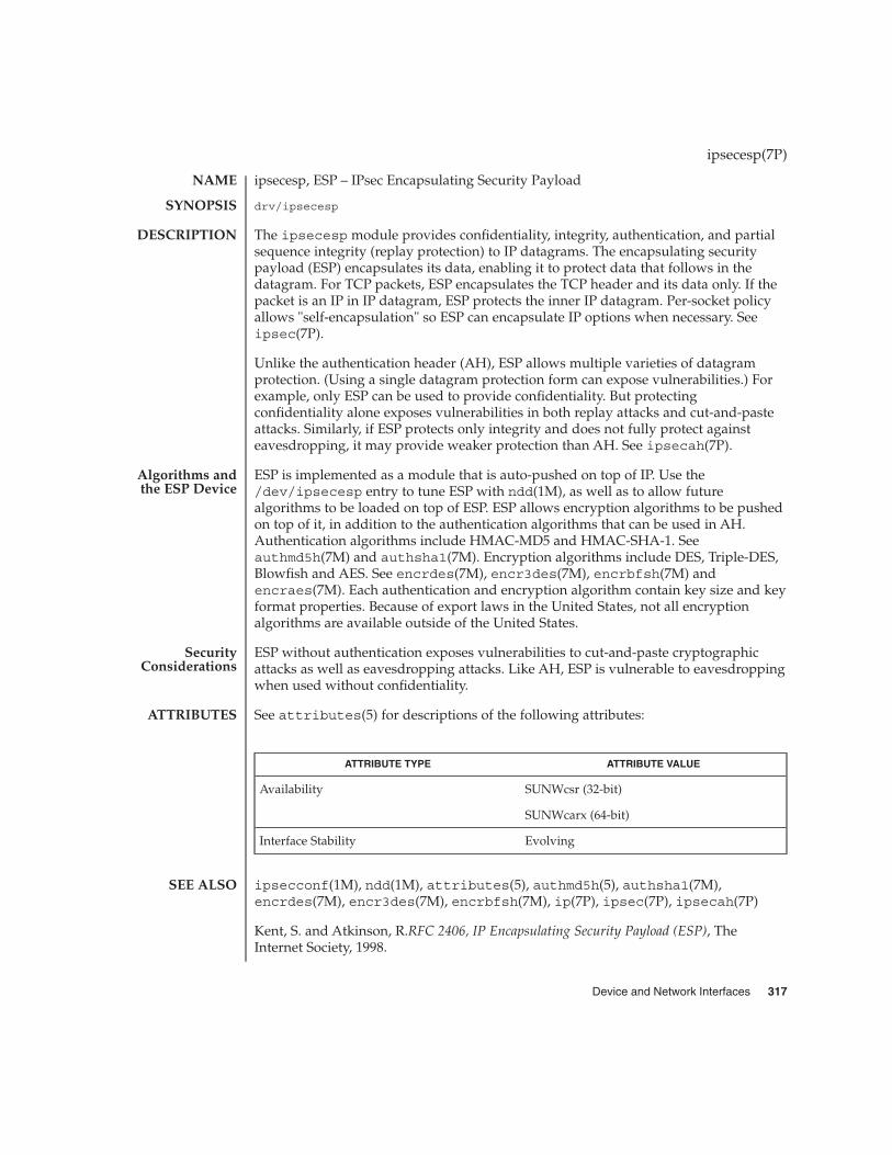
ipsecesp, ESP – IPsec Encapsulating Security Payload
drv/ipsecesp
The ipsecesp module provides confidentiality, integrity, authentication, and partialsequence integrity (replay protection) to IP datagrams. The encapsulating securitypayload (ESP) encapsulates its data, enabling it to protect data that follows in thedatagram. For TCP packets, ESP encapsulates the TCP header and its data only. If thepacket is an IP in IP datagram, ESP protects the inner IP datagram. Per-socket policyallows "self-encapsulation" so ESP can encapsulate IP options when necessary. Seeipsec(7P).
Unlike the authentication header (AH), ESP allows multiple varieties of datagramprotection. (Using a single datagram protection form can expose vulnerabilities.) Forexample, only ESP can be used to provide confidentiality. But protectingconfidentiality alone exposes vulnerabilities in both replay attacks and cut-and-pasteattacks. Similarly, if ESP protects only integrity and does not fully protect againsteavesdropping, it may provide weaker protection than AH. See ipsecah(7P).
ESP is implemented as a module that is auto-pushed on top of IP. Use the/dev/ipsecesp entry to tune ESP with ndd(1M), as well as to allow futurealgorithms to be loaded on top of ESP. ESP allows encryption algorithms to be pushedon top of it, in addition to the authentication algorithms that can be used in AH.Authentication algorithms include HMAC-MD5 and HMAC-SHA-1. Seeauthmd5h(7M) and authsha1(7M). Encryption algorithms include DES, Triple-DES,Blowfish and AES. See encrdes(7M), encr3des(7M), encrbfsh(7M) andencraes(7M). Each authentication and encryption algorithm contain key size and keyformat properties. Because of export laws in the United States, not all encryptionalgorithms are available outside of the United States.
ESP without authentication exposes vulnerabilities to cut-and-paste cryptographicattacks as well as eavesdropping attacks. Like AH, ESP is vulnerable to eavesdroppingwhen used without confidentiality.
See attributes(5) for descriptions of the following attributes:
ATTRIBUTE TYPE ATTRIBUTE VALUE
Availability SUNWcsr (32-bit)
SUNWcarx (64-bit)
Interface Stability Evolving
ipsecconf(1M), ndd(1M), attributes(5), authmd5h(5), authsha1(7M),encrdes(7M), encr3des(7M), encrbfsh(7M), ip(7P), ipsec(7P), ipsecah(7P)
Kent, S. and Atkinson, R.RFC 2406, IP Encapsulating Security Payload (ESP), TheInternet Society, 1998.
ipsecesp(7P)
NAME
SYNOPSIS
DESCRIPTION
Algorithms andthe ESP Device
SecurityConsiderations
ATTRIBUTES
SEE ALSO
Device and Network Interfaces 317

Due to United States export control laws, encryption strength available on ESP variesfor versions of the SunOS sold outside the United States.
See authmd5h(7M) and authsha1(7M). Encryption algorithms include DES,Triple-DES, Blowfish and AES. See encrdes(7M), encr3des(7M), andencrbfsh(7M).
ipsecesp(7P)
NOTES
318 man pages section 7: Device and Network Interfaces • Last Revised 20 Mar 2001

isdnio – ISDN interfaces
#include <sun/audioio.h>
#include <sun/isdnio.h>
int ioctl(int fd, int command, /* arg */ ...);
ISDN ioctl commands are a subset of ioctl(2) commands that perform a variety ofcontrol functions on Integrated Services Digital Network (ISDN) STREAMS devices.The arguments command and arg are passed to the file designated by fd and areinterpreted by the ISDN device driver.
fd is an open file descriptor that refers to a stream. command determines the controlfunction to be performed as described in the IOCTLS section of this document. argrepresents additional information that is needed by command. The type of arg dependsupon the command, but generally it is an integer or a pointer to a command-specificdata structure.
Since these ISDN commands are a subset of ioctl and streamio(7I), they aresubject to errors as described in those interface descriptions.
This set of generic ISDN ioctl commands is meant to control various types of ISDNSTREAMS device drivers. The following paragraphs give some background onvarious types of ISDN hardware interfaces and data formats, and other devicecharacteristics.
This manual page discusses operations on, and facilities provided by ISDN controllers,interfaces and channels. A controller is usually a hardware peripheral device thatprovides one or more ISDN interfaces and zero or more auxiliary interfaces. In thiscontext, the term interface is synonymous with the term “port”. Each interface canprovide one or more channels.
ISDN BRI-TE, BRI-NT, and PRI interfaces are all examples of Time DivisionMultiplexed Serial Interfaces. As an example, a Basic Rate ISDN (BRI) TerminalEquipment (TE) interface provides one D-channel and two B-channels on the same setof signal wires. The BRI interface, at the S reference point, operates at a bit rate of192,000 bits per second. The bits are encoded using a pseudoternary coding systemthat encodes a logic one as zero volts, and a logic zero as a positive or negativevoltage. Encoding rules state that adjacent logic zeros must be encoded with oppositevoltages. Violations of this rule are used to indicate framing information such thatthere are 4000 frames per second, each containing 48 bits. These 48 bits are dividedinto channels. Not including framing and synchronization bits, the frame is dividedinto 8 bits for the B1-channel, 1 bit for the D-channel, 8 bits for B2, 1 bit for D, 8 bits forB1, 1 bit for D, and 8 bits for B2. This results in a 64,000 bps B1-channel, a 64,000 bpsB2-channel, and a 16,000 bps D-channel, all on the same serial interface.
A Basic Rate ISDN (BRI) interface consists of a 16000 bit per second Delta Channel(D-channel) for signaling and X.25 packet transmission, and two 64000 bit per secondBearer Channels (B-channels) for transmission of voice or data.
isdnio(7I)
NAME
SYNOPSIS
DESCRIPTION
Controllers,Interfaces, and
Channels
Time DivisionMultiplexed Serial
Interfaces
Basic Rate ISDN
Device and Network Interfaces 319
The CCITT recommendations on ISDN Basic Rate interfaces, I.430, identify several“reference points” for standardization. From (Stallings89): Reference point T (terminal)corresponds to a minimal ISDN network termination at the customer’s premises. Itseparates the network provider’s equipment from the user’s equipment. Referencepoint S (system) corresponds to the interface of individual ISDN terminals. It separatesuser terminal equipment from network-related communications functions. Referencepoint R (rate) provides a non-ISDN interface between user equipment that is notISDN-compatible and adaptor equipment. . . . The final reference point . . . isreference point U (user). This interface describes the full-duplex data signal on thesubscriber line.
Some older technology components of some ISDN networks occasionally steal the loworder bit of an ISDN B-channel octet in order to transmit in-band signalinginformation between switches or other components of the network. Even whenout-of-band signaling has been implemented in these networks, and the in-bandsignaling is no longer needed, the bit-robbing mechanism may still be present. This bitrobbing behavior does not appreciably affect a voice call, but it will limit the usablebandwidth of a data call to 56000 bits per second instead of 64000 bits per second.These older network components only seem to exist in the United States of America,Canada and Japan. ISDN B-channel data calls that have one end point in the UnitedStates, Canada or Japan may be limited to 56000 bps usable bandwidth instead of thenormal 64000 bps. Sometimes the ISDN service provider may be able to supply 56kbpsfor some calls and 64kbps for other calls. On an international call, the local ISDNservice provider may advertise the call as 64kbps even though only 56kbps are reliablydelivered because of bit-robbing in the foreign ISDN that is not reported to the localswitch.
A Basic Rate Interface implements either a Terminal Equipment (TE) interface or aNetwork Termination (NT) interface. TE’s can be ISDN telephones, a Group 4 fax, orother ISDN terminal equipment. A TE connects to an NT in order to gain access to apublic or private ISDN network. A private ISDN network, such as provided by aPrivate Branch Exchange (PBX), usually provides access to the public network.
If multi-point configurations are allowed by an NT, it may be possible to connect up toeight TE’s to a single NT interface. All of the TE’s in a multipoint configuration sharethe same D and B-channels. Contention for B-Channels by multiple TEs is resolved bythe ISDN switch (NT) through signaling protocols on the D-channel.
Contention for access to the D-channel is managed by a collision detection andpriority mechanism. D-channel call control messages have higher priority than otherpackets. This media access function is managed at the physical layer.
A BRI-TE interface may implement a “Q-channel”, the Q-channel is a slow speed, 800bps, data path from a TE to an NT. Although the structure of the Q-channel is definedin the I.430 specification, the use of the Q-channel is for further study.
A BRI-NT interface may implement an “S-channel”, the S-channel is a slow speed,4000 bps, data path from a NT to an TE. The use of the S-channel is for further study.
isdnio(7I)
320 man pages section 7: Device and Network Interfaces • Last Revised 7 Apr 1998

Primary Rate ISDN (PRI) interfaces are either 1.544Mbps (T1 rate) or 2.048Mbps (E1rate) and are typically organized as 23 B-channels and one D-Channel (23B+D) for T1rates, and 30 B-Channels and one D-Channel (30B+D) for E1 rates. The D-channels ona PRI interface operate at 64000 bits per second. T1 rate PRI interface is the standard inthe United States, Canada and Japan while E1 rate PRI interface is the standard inEuropean countries. Some E1 rate PRI interface implementations allow access tochannel zero which is used for framing.
ISDN channels fall into several categories; D-channels, bearer channels, andmanagement pseudo channels. Each channel has a corresponding device namesomewhere under the directory /dev/isdn/ as documented in the appropriatehardware specific manual page.
D-channelsThere is at most one D-channel per ISDN interface. The D-channel carries signalinginformation for the management of ISDN calls and can also carry X.25 packet data.In the case of a PRI interface, there may actually be no D-channel if Non-FacilityAssociated Signaling is used. D-channels carry data packets that are framed andchecked for transmission errors according to the LAP-D protocol. LAP-D usesframing and error checking identical to the High Speed Data Link (HDLC) protocol.
B-channelsBRI interfaces have two B-channels, B1 and B2. On a BRI interface, the only othertype of channel is an H-channel which is a concatenation of the B1 and B2 channels.An H-channel is accessed by opening the “base” channel, B1 in this case, and usingthe ISDN_SET_FORMAT ioctl to change the configuration of the B-channel from8-bit, 8 kHz to 16-bit, 8kHz.
On a primary rate interface, B channels are numbered from 0 to 31 in Europe and 1to 23 in the United States, Canada and Japan.
H-ChannelsA BRI or PRI interface can offer multiple B-channels concatenated into a single,higher bandwidth channel. These concatenated B-channels are referred to as an“H-channels” on a BRI interface. The PRI interface version of an H-channel isreferred to as an Hn-channels where n is a number indicating how the B-channelshave been aggregated into a single channel.
� A PRI interface H0 channel is 384 kbps allowing 3H0+D on a T1 rate PRIinterface and 4H0+D channels on an E1 rate PRI interface.
� A T1 PRI interface H11 channel is 1536 kbps (24×64000bps). This will consumethe channel normally reserved for the D-channel, so signaling must be donewith Non-Facility Associated Signaling (NFAS) from another PRI interface.
� An E1 PRI interface H12 channel is 1920 kbps (30×64000bps). An H12-channelleaves room for the framing-channel as well as the D-channel.
Auxiliary channelsAuxiliary channels are non-ISDN hardware interfaces that are closely tied to theISDN interfaces. An example would be a video or audio coder/decoder (codec).The existence of an auxiliary channel usually implies that one or more B-channelscan be “connected” to an auxiliary interface in hardware.
isdnio(7I)
Primary RateISDN
Channel Types
Device and Network Interfaces 321
Management pseudo-channelsA management pseudo-channel is used for the management of a controller,interface, or hardware channel. Management channels allow for out-of-band controlof hardware interfaces and for out-of-band notification of status changes. There is atleast one management device per hardware interface.
There are three different types of management channels implemented by ISDNhardware drivers:
� A controller management device handles all ioctls that simultaneously affecthardware channels on different interfaces. Examples include resetting acontroller, mu-code (as in the Greek letter mu) downloading of a controller, orthe connection of an ISDN B-channel to an auxiliary channel that represents anaudio coder/decoder (codec). The latter case would be accomplished using theISDN_SET_CHANNEL ioctl.
� An interface management device handles all ioctls that affect multiple channelson the same interface. Messages associated with the activation and deactivationof an interface arrive on the management device associated with the D channelof an ISDN interface.
� Auxiliary interfaces may also have management devices. See the hardwarespecific man pages for operations on auxiliary devices.
Trace pseudo-channelsA device driver may choose to implement a trace device for a data or managementchannel. Trace channels receive a special M_PROTO header with the originalchannel’s original M_PROTO or M_DATA message appended to the special header.The header is described by:
typedef struct {uint_t seq; /* Sequence number */int type; /* device dependent */struct timeval timestamp;char _f[8]; /* filler */
} audtrace_hdr_t;
The isdn_chan_t type enumerates the channels available on ISDN interfaces. If aparticular controller implements any auxiliary channels then those auxiliary channelswill be described in a controller specific manual page. The defined channels aredescribed by the isdn_chan_t type as shown below:
/* ISDN channels */typedef enum {
ISDN_CHAN_NONE = 0x0, /* No channel given */ISDN_CHAN_SELF, /* The channel performing the ioctl */ISDN_CHAN_HOST, /* Unix STREAM */ISDN_CHAN_CTRL_MGT, /* Controller management */
/* TE channel defines */
ISDN_CHAN_TE_MGT, /* Receives activation/deactivation */ISDN_CHAN_TE_D_TRACE, /* Trace device for protocol analysis apps */ISDN_CHAN_TE_D,
isdnio(7I)
ISDN Channeltypes
322 man pages section 7: Device and Network Interfaces • Last Revised 7 Apr 1998

ISDN_CHAN_TE_B1,ISDN_CHAN_TE_B2,
/* NT channel defines */
ISDN_CHAN_NT_MGT, /* Receives activation/deactivation */ISDN_CHAN_NT_D_TRACE, /* Trace device for protocol analysis apps */ISDN_CHAN_NT_D,ISDN_CHAN_NT_B1,ISDN_CHAN_NT_B2,
/* Primary rate ISDN */
ISDN_CHAN_PRI_MGT,ISDN_CHAN_PRI_D,ISDN_CHAN_PRI_B0, ISDN_CHAN_PRI_B1,ISDN_CHAN_PRI_B2, ISDN_CHAN_PRI_B3,ISDN_CHAN_PRI_B4, ISDN_CHAN_PRI_B5,ISDN_CHAN_PRI_B6, ISDN_CHAN_PRI_B7,ISDN_CHAN_PRI_B8, ISDN_CHAN_PRI_B9,ISDN_CHAN_PRI_B10, ISDN_CHAN_PRI_B11,ISDN_CHAN_PRI_B12, ISDN_CHAN_PRI_B13,ISDN_CHAN_PRI_B14, ISDN_CHAN_PRI_B15,ISDN_CHAN_PRI_B16, ISDN_CHAN_PRI_B17,ISDN_CHAN_PRI_B18, ISDN_CHAN_PRI_B19,ISDN_CHAN_PRI_B20, ISDN_CHAN_PRI_B21,ISDN_CHAN_PRI_B22, ISDN_CHAN_PRI_B23,ISDN_CHAN_PRI_B24, ISDN_CHAN_PRI_B25,ISDN_CHAN_PRI_B26, ISDN_CHAN_PRI_B27,ISDN_CHAN_PRI_B28, ISDN_CHAN_PRI_B29,ISDN_CHAN_PRI_B30, ISDN_CHAN_PRI_B31,
/* Auxiliary channel defines */
ISDN_CHAN_AUX0, ISDN_CHAN_AUX1, ISDN_CHAN_AUX2, ISDN_CHAN_AUX3,ISDN_CHAN_AUX4, ISDN_CHAN_AUX5, ISDN_CHAN_AUX6, ISDN_CHAN_AUX7
} isdn_chan_t;
The isdn_interface_t type enumerates the interfaces available on ISDNcontrollers. The defined interfaces are described by the isdn_interface_t type asshown below:
/* ISDN interfaces */typedef enum {
ISDN_TYPE_UNKNOWN = -1, /* Not known or applicable */ISDN_TYPE_SELF = 0, /*
* For queries, application may* put this value into "type" to* query the state of the file* descriptor used in an ioctl.*/
ISDN_TYPE_OTHER, /* Not an ISDN interface */ISDN_TYPE_TE,ISDN_TYPE_NT,ISDN_TYPE_PRI,
} isdn_interface_t;
isdnio(7I)
ISDN Interfacetypes
Device and Network Interfaces 323
The management device associated with an ISDN D-channel is used to requestactivation, deactivation and receive information about the activation state of theinterface. See the descriptions of the ISDN_PH_ACTIVATE_REQ andISDN_MPH_DEACTIVATE_REQ ioctls. Changes in the activation state of an interfaceare communicated to the D-channel application through M_PROTO messages sentup-stream on the management device associated with the D-channel. If the D-channelprotocol stack is implemented as a user process, the user process can retrieve theM_PROTO messages using the getmsg(2) system call.
These M_PROTO messages have the following format:
typedef struct isdn_message {unsigned int magic; /* set to ISDN_PROTO_MAGIC */isdn_interface_t type; /* Interface type */isdn_message_type_t message; /* CCITT or vendor Primitive */unsigned int vendor[5]; /* Vendor specific content */
} isdn_message_t;typedef enum isdn_message_type {
ISDN_VPH_VENDOR = 0, /* Vendor specific messages */ISDN_PH_AI, /* Physical: Activation Ind */ISDN_PH_DI, /* Physical: Deactivation Ind */ISDN_MPH_AI, /* Management: Activation Ind */ISDN_MPH_DI, /* Management: Deactivation Ind */ISDN_MPH_EI1, /* Management: Error 1 Indication */ISDN_MPH_EI2, /* Management: Error 2 Indication */ISDN_MPH_II_C, /* Management: Info Ind, connection */ISDN_MPH_II_D /* Management: Info Ind, disconn. */
} isdn_message_type_t;
All of the streamio(7I) ioctl commands may be issued for a device conforming tothe the isdnio interface.
ISDN interfaces that allow access to audio data should implement a reasonable subsetof the audio(7I) interface.
ISDN_PH_ACTIVATE_REQRequest ISDN physical layer activation. This command is valid for both TE and NTinterfaces. fd must be a D-channel file descriptor. arg is ignored.
TE activation will occur without use of the ISDN_PH_ACTIVATE_REQ ioctl if thedevice corresponding to the TE D-channel is open, “on”, and the ISDN switch isrequesting activation.
ISDN_MPH_DEACTIVATE_REQfd must be an NT D-channel file descriptor. arg is ignored.
This command requests ISDN physical layer de-activation. This is not valid for TEinterfaces. A TE interace may be turned off by use of the ISDN_PARAM_POWERcommand or by close(2) on the associated fd.
ISDN_ACTIVATION_STATUSfd is the file descriptor for a D-channel, the management device associated with anISDN interface, or the management device associated with the controller. arg is a
isdnio(7I)
Activation andDeactivation of
ISDN Interfaces
STREAMSIOCTLS
ISDN ioctls
324 man pages section 7: Device and Network Interfaces • Last Revised 7 Apr 1998
pointer to an isdn_activation_status_t structure. Although it is possible forapplications to determine the current activation state with this ioctl, a D-channelprotocol stack should instead process messages from the management pseudochannel associated with the D-channel.
typedef struct isdn_activation_status {isdn_interface_t type;enum isdn_activation_state activation;
} isdn_activation_status_t;typedef enum isdn_activation_state {
ISDN_OFF = 0, /* Interface is powered down */ISDN_UNPLUGGED, /* Power but no-physical connection */ISDN_DEACTIVATED_REQ, /* Pending Deactivation, NT Only */ISDN_DEACTIVATED, /* Activation is permitted */ISDN_ACTIVATE_REQ, /* Attempting to activate */ISDN_ACTIVATED, /* Interface is activated */
} isdn_activation_state_t;
The type field should be set to ISDN_TYPE_SELF. The device specific interfacetype will be returned in the type field.
The isdn_activation_status_t structure contains the interface type and thecurrent activation state. type is the interface type and should be set by the caller toISDN_TYPE_SELF.
ISDN_INTERFACE_STATUSThe ISDN_INTERFACE_STATUS ioctl retrieves the status and statistics of an ISDNinterface. The requesting channel must own the interface whose status is beingrequested or the ioctl will fail. fd is the file descriptor for an ISDN interfacemanagement device. arg is a pointer to a struct isdn_interface_info. If theinterface field is set to ISDN_TYPE_SELF, it will be changed in the returnedstructure to reflect the proper device-specific interface of the requesting fd.
typedef struct isdn_interface_info {isdn_interface_t interface;enum isdn_activation_state activation;unsigned int ph_ai; /* Physical: Activation Ind */unsigned int ph_di; /* Physical: Deactivation Ind */unsigned int mph_ai; /* Management: Activation Ind */unsigned int mph_di; /* Management: Deactivation Ind */unsigned int mph_ei1; /* Management: Error 1 Indication */unsigned int mph_ei2; /* Management: Error 2 Indication */unsigned int mph_ii_c; /* Management: Info Ind, connection */unsigned int mph_ii_d; /* Management: Info Ind, disconn. */
} isdn_interface_info_t;
ISDN_CHANNEL_STATUSThe ISDN_CHANNEL_STATUS ioctl retrieves the status and statistics of an ISDNchannel. The requesting channel must own the channel whose status is beingrequested or the ioctl will fail. fd is any file descriptor. arg is a pointer to a struct
isdnio(7I)
Device and Network Interfaces 325
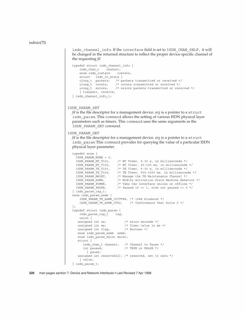
isdn_channel_info. If the interface field is set to ISDN_CHAN_SELF, it willbe changed in the returned structure to reflect the proper device-specific channel ofthe requesting fd.
typedef struct isdn_channel_info {isdn_chan_t channel;enum isdn_iostate iostate;struct isdn_io_stats {ulong_t packets; /* packets transmitted or received */ulong_t octets; /* octets transmitted or received */ulong_t errors; /* errors packets transmitted or received */} transmit, receive;
} isdn_channel_info_t;
ISDN_PARAM_SETfd is the file descriptor for a management device. arg is a pointer to a structisdn_param. This command allows the setting of various ISDN physical layerparameters such as timers. This command uses the same arguments as theISDN_PARAM_GET command.
ISDN_PARAM_GETfd is the file descriptor for a management device. arg is a pointer to a structisdn_param This command provides for querying the value of a particular ISDNphysical layer parameter.
typedef enum {ISDN_PARAM_NONE = 0,ISDN_PARAM_NT_T101, /* NT Timer, 5-30 s, in milliseconds */ISDN_PARAM_NT_T102, /* NT Timer, 25-100 ms, in milliseconds */ISDN_PARAM_TE_T103, /* TE Timer, 5-30 s, in milliseconds */ISDN_PARAM_TE_T104, /* TE Timer, 500-1000 ms, in milliseconds */ISDN_PARAM_MAINT, /* Manage the TE Maintenance Channel */ISDN_PARAM_ASMB, /* Modify Activation State Machine Behavior */ISDN_PARAM_POWER, /* Take the interface online or offline */ISDN_PARAM_PAUSE, /* Paused if == 1, else not paused == 0 */
} isdn_param_tag_t;enum isdn_param_asmb {
ISDN_PARAM_TE_ASMB_CCITT88, /* 1988 bluebook */ISDN_PARAM_TE_ASMB_CTS2, /* Conformance Test Suite 2 */
};typedef struct isdn_param {
isdn_param_tag_t tag;union {unsigned int us; /* micro seconds */unsigned int ms; /* Timer value in ms */unsigned int flag; /* Boolean */enum isdn_param_asmb asmb;enum isdn_param_maint maint;struct {
isdn_chan_t channel; /* Channel to Pause */int paused; /* TRUE or FALSE */
} pause;unsigned int reserved[2]; /* reserved, set to zero */} value;
} isdn_param_t;
isdnio(7I)
326 man pages section 7: Device and Network Interfaces • Last Revised 7 Apr 1998

ISDN_PARAM_POWERIf an implementation provides power on and off functions, then power should beon by default. If flag is ISDN_PARAM_POWER_OFF then a TE interface is forcedinto state F0, NT interfaces are forced into state G0. If flag isISDN_PARAM_POWER_ON then a TE interface will immediately transition to state F3when the TE D-channel is opened. If flag is one, an NT interface will transition tostate G1 when the NT D-channel is opened.
Implementations that do not provide ISDN_POWER return failure with errno set toENXIO.ISDN_POWER is different from ISDN_PH_ACTIVATE_REQ since CCITTspecification requires that if a BRI-TE interface device has power, then it permitsactivation.
ISDN_PARAM_NT_T101This parameter accesses the NT timer value T1. The CCITT recommendationsspecify that timer T1 has a value from 5 to 30 seconds. Other standards may differ.
ISDN_PARAM_NT_T102This parameter accesses the NT timer value T2. The CCITT recommendationsspecify that timer T2 has a value from 25 to 100 milliseconds. Other standards maydiffer.
ISDN_PARAM_TE_T103This parameter accesses the TE timer value T3. The CCITT recommendationsspecify that timer T3 has a value from 5 to 30 seconds. Other standards may differ.
ISDN_PARAM_TE_T104This parameter accesses the TE timer value T4. The CTS2 specifies that timer T4 iseither not used or has a value from 500 to 1000 milliseconds. Other standards maydiffer. CTS2 requires that timer T309 be implemented if T4 is not available.
ISDN_PARAM_MAINTThis parameter sets the multi-framing mode of a BRI-TE interface. For normaloperation this parameter should be set to ISDN_PARAM_MAINT_ECHO. Other usesof this parameter are dependent on the definition and use of the BRI interface S andQ channels.
ISDN_PARAM_ASMBThere are a few differences in the BRI-TE interface activation state machinestandards. This parameter allows the selection of the appropriate standard. At thistime, only ISDN_PARAM_TE_ASMB_CCITT88 and ISDN_PARAM_TE_ASMB_CTS2are available.
ISDN_PARAM_PAUSEThis parameter allows a management device to pause the IO on a B-channel.pause.channel is set to indicate which channel is to be paused or un-paused.pause.paused is set to zero to un-pause and one to pause. fd is associated with anISDN interface management device. arg is a pointer to a struct isdn_param.
ISDN_SET_LOOPBACKfd is the file descriptor for an ISDN interface’s management device. arg is a pointerto an isdn_loopback_request_t structure.
isdnio(7I)
Device and Network Interfaces 327

typedef enum {ISDN_LOOPBACK_LOCAL,ISDN_LOOPBACK_REMOTE,
} isdn_loopback_type_t;typedef enum {
ISDN_LOOPBACK_B1 = 0x1,ISDN_LOOPBACK_B2 = 0x2,
ISDN_LOOPBACK_D = 0x4,ISDN_LOOPBACK_E_ZERO = 0x8,ISDN_LOOPBACK_S = 0x10,ISDN_LOOPBACK_Q = 0x20,
} isdn_loopback_chan_t;typedef struct isdn_loopback_request {
isdn_loopback_type_t type;int channels;
} isdn_loopback_request_t;
An application can receive D-channel data during D-Channel loopback but cannottransmit data. The field type is the bitwise OR of at least one of the followingvalues:
ISDN_LOOPBACK_B1 (0x1) /* loopback on B1-channel */ISDN_LOOPBACK_B2 (0x2) /* loopback on B2-channel */ISDN_LOOPBACK_D (0x4) /* loopback on D-channel */ISDN_LOOPBACK_E_ZERO (0x8) /* force E-channel to Zero if */
/* fd is for NT interface */ISDN_LOOPBACK_S (0x10) /* loopback on S-channel */
ISDN_LOOPBACK_Q (0x20) /* loopback on Q-channel */
ISDN_RESET_LOOPBACKarg is a pointer to an isdn_loopback_request_t structure.ISDN_RESET_LOOPBACK turns off the selected loopback modes.
The isdn_format_t type is meant to be a complete description of the various datamodes and rates available on an ISDN interface. Several macros are available forsetting the format fields. The isdn_format_t structure is shown below:
/* ISDN channel data format */typedef enum {
ISDN_MODE_NOTSPEC, /* Not specified */ISDN_MODE_HDLC, /* HDLC framing and error checking */ISDN_MODE_TRANSPARENT /* Transparent mode */
} isdn_mode_t;
/* Audio encoding types (from audioio.h) */
#define AUDIO_ENCODING_NONE (0) /* no encoding*/#define AUDIO_ENCODING_ULAW (1) /* mu-law */#define AUDIO_ENCODING_ALAW (2) /* A-law */#define AUDIO_ENCODING_LINEAR (3) /* Linear PCM */typedef struct isdn_format {
isdn_mode_t mode;unsigned int sample_rate; /* sample frames/sec*/unsigned int channels; /* # interleaved chans */
isdnio(7I)
ISDN Data Format
328 man pages section 7: Device and Network Interfaces • Last Revised 7 Apr 1998

unsigned int precision; /* bits per sample */unsigned int encoding; /* data encoding */
} isdn_format_t;/** These macros set the fields pointed* to by the macro argument (isdn_format_t*)fp in preparation* for the ISDN_SET_FORMAT ioctl.*/ISDN_SET_FORMAT_BRI_D(fp) /* BRI D-channel */ISDN_SET_FORMAT_PRI_D(fp) /* PRI D-channel */ISDN_SET_FORMAT_HDLC_B64(fp) /* BRI B-ch @ 56kbps */ISDN_SET_FORMAT_HDLC_B56(fp) /* BRI B-ch @ 64kbps */ISDN_SET_FORMAT_VOICE_ULAW(fp) /* BRI B-ch voice */ISDN_SET_FORMAT_VOICE_ALAW(fp) /* BRI B-ch voice */
ISDN_SET_FORMAT_BRI_H(fp) /* BRI H-channel */
Every STREAMS stream that carries data to or from the ISDN serial interfaces isclassified as a channel-stream datapath. A possible ISDN channel-stream datapathdevice name for a TE could be /dev/isdn/0/te/b1.
On some hardware implementations, it is possible to route the data from hardwarechannel to hardware channel completely within the chip or controller. This is classifiedas a channel-channel datapath. There does not need to be any open file descriptor foreither channel in this configuration. Only when data enters the host and utilizes aSTREAMS stream is this classified as an ISDN channel-stream datapath.
A management stream is a STREAMS stream that exists solely for control purposesand is not intended to carry data to or from the ISDN serial interfaces. A possiblemanagement device name for a TE could be /dev/isdn/0/te/mgt.
The following ioctls describe operations on individual channels and the connection ofmultiple channels.
ISDN_SET_FORMATfd is a data channel, the management pseudo-channel associated with the datachannel, or the management channel associated with the data channel’s interface orcontroller. arg is a pointer to a struct isdn_format_req. TheISDN_SET_FORMAT ioctl sets the format of an ISDN channel-stream datapath. Itmay be issued on both an open ISDN channel-stream datapath Stream or an ISDNManagement Stream. Note that an open(2) call for a channel-stream datapath willfail if an ISDN_SET_FORMAT has never been issued after a reset, as the mode for allchannel-stream datapaths is initially biased to ISDN_MODE_NOTSPEC. arg is apointer to an ISDN format type (isdn_format_req_t*).
typedef struct isdn_format_req {isdn_chan_t channel;isdn_format_t format; /* data format */int reserved[4]; /* future use - must be 0 */
} isdn_format_req_t;
isdnio(7I)
ISDN DatapathTypes
ISDNManagement
Stream
ChannelManagement
IOCTLS
Device and Network Interfaces 329

If there is not an open channel-stream datapath for a requested channel, the defaultformat of that channel will be set for a subsequent open(2).
To modify the format of an open STREAM, the driver will disconnect the hardwarechannel, flush the internal hardware queues, set the new default configuration, andfinally reconnect the data path using the newly specified format. Upon taking effect,all state information will be reset to initial conditions, as if a channel was justopened. It is suggested that the user flush the interface as well as consult thehardware specific documentation to insure data integrity.
If a user desires to connect more than one B channel, such as an H-channel, theB-channel with the smallest offset should be specified, then the precision should bespecified multiples of 8. For an H-channel the precision value would be 16. Theuser should subsequently open the base B-channel. If any of the sequentialB-channels are busy the open will fail, otherwise all of the B-channels that are to beused in conjunction will be marked as busy.
The returned failure codes and their descriptions are listed below:
EPERM /* No permission for intented operation */EINVAL /* Invalid format request */
EIO /* Set format attempt failed. */
ISDN_SET_CHANNELThe ISDN_SET_CHANNEL ioctl sets up a data connection within an ISDN controller.The ISDN_SET_CHANNEL ioctl can only be issued from an ISDN managementstream to establish or modify channel-channel datapaths. The ioctl parameter arg isa pointer to an ISDN connection request (isdn_conn_req_t*). Once a data path isestablished, data flow is started as soon as the path endpoints become active. Upontaking effect, all state information is reset to initial conditions, as if a channel wasjust opened.
The isdn_conn_req_t structure is shown below. The five fields include thereceive and transmit ISDN channels, the number of directions of the data path, aswell as the data format. The reserved field must always be set to zero.
/* Number of directions for data flow */typedef enum {
ISDN_PATH_NOCHANGE = 0, /* Invalid value */ISDN_PATH_DISCONNECT, /* Disconnect data path */ISDN_PATH_ONEWAY, /* One way data path */ISDN_PATH_TWOWAY, /* Bi-directional data path */
} isdn_path_t;typedef struct isdn_conn_req {
isdn_chan_t from;isdn_chan_t to;isdn_path_t dir; /* uni/bi-directional or disconnect */isdn_format_t format; /* data format */int reserved[4]; /* future use - must be 0 */
} isdn_conn_req_t;
isdnio(7I)
330 man pages section 7: Device and Network Interfaces • Last Revised 7 Apr 1998
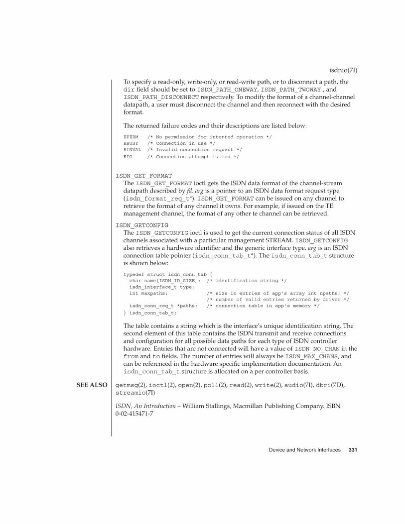
To specify a read-only, write-only, or read-write path, or to disconnect a path, thedir field should be set to ISDN_PATH_ONEWAY, ISDN_PATH_TWOWAY , andISDN_PATH_DISCONNECT respectively. To modify the format of a channel-channeldatapath, a user must disconnect the channel and then reconnect with the desiredformat.
The returned failure codes and their descriptions are listed below:
EPERM /* No permission for intented operation */EBUSY /* Connection in use */EINVAL /* Invalid connection request */
EIO /* Connection attempt failed */
ISDN_GET_FORMATThe ISDN_GET_FORMAT ioctl gets the ISDN data format of the channel-streamdatapath described by fd. arg is a pointer to an ISDN data format request type(isdn_format_req_t*). ISDN_GET_FORMAT can be issued on any channel toretrieve the format of any channel it owns. For example, if issued on the TEmanagement channel, the format of any other te channel can be retrieved.
ISDN_GETCONFIGThe ISDN_GETCONFIG ioctl is used to get the current connection status of all ISDNchannels associated with a particular management STREAM. ISDN_GETCONFIGalso retrieves a hardware identifier and the generic interface type. arg is an ISDNconnection table pointer (isdn_conn_tab_t*). The isdn_conn_tab_t structureis shown below:
typedef struct isdn_conn_tab {char name[ISDN_ID_SIZE]; /* identification string */isdn_interface_t type;int maxpaths; /* size in entries of app’s array int npaths; */
/* number of valid entries returned by driver */isdn_conn_req_t *paths; /* connection table in app’s memory */
} isdn_conn_tab_t;
The table contains a string which is the interface’s unique identification string. Thesecond element of this table contains the ISDN transmit and receive connectionsand configuration for all possible data paths for each type of ISDN controllerhardware. Entries that are not connected will have a value of ISDN_NO_CHAN in thefrom and to fields. The number of entries will always be ISDN_MAX_CHANS, andcan be referenced in the hardware specific implementation documentation. Anisdn_conn_tab_t structure is allocated on a per controller basis.
getmsg(2), ioctl(2), open(2), poll(2), read(2), write(2), audio(7I), dbri(7D),streamio(7I)
ISDN, An Introduction – William Stallings, Macmillan Publishing Company. ISBN0-02-415471-7
isdnio(7I)
SEE ALSO
Device and Network Interfaces 331

isp – ISP SCSI Host Bus Adapter Driver
QLGC,isp@sbus-slot,10000
SUNW,isptwo@pci-slot
The ISP Host Bus Adapter is a SCSA compliant nexus driver that supports the QlogicISP1000 SCSI and the ISP1040B SCSI chips. The ISP1000 chip works on SBus and theISP1040B chip works on PCI bus. The ISP is an intelligent SCSI Host Bus Adapter chipthat reduces the amount of CPU overhead used in a SCSI transfer.
The isp driver supports the standard functions provided by the SCSA interface. Thedriver supports tagged and untagged queuing, fast and wide SCSI, and auto requestsense, but does not support linked commands. The PCI version ISP Host bus adapterbased on ISP1040B also supports Fast-20 scsi devices.
The isp driver can be configured by defining properties in isp.conf which overridethe global SCSI settings. Supported properties are scsi-options,target<n>-scsi-options, scsi-reset-delay, scsi-watchdog-tick,scsi-tag-age-limit, scsi-initiator-id, and scsi-selection-timeout.
target<n>-scsi-options overrides the scsi-options property value fortarget<n>. <n> is a hex value that can vary from 0 to f. Refer toscsi_hba_attach(9F) for details.
Both the ISP1000 and ISP1040B support only certain SCSI selection timeout values.The valid values are 25, 50, 75, 100, 250, 500, 750 and 1000. These properties are inunits of milliseconds.
EXAMPLE 1 SCSI Options
Create a file called /kernel/drv/isp.conf and add this line:
scsi-options=0x78;
This will disable tagged queuing, fast SCSI, and Wide mode for all isp instances. Thefollowing will disable an option for one specific ISP (refer to driver.conf(4)):
name="isp" parent="/iommu@f,e0000000/sbus@f,e0001000"reg=1,0x10000,0x450target1-scsi-options=0x58
scsi-options=0x178 scsi-initiator-id=6;
Note that the default initiator ID in OBP is 7 and that the change to ID 6 will occur atattach time. It may be preferable to change the initiator ID in OBP.
The above would set scsi-options for target 1 to 0x58 and for all other targets onthis SCSI bus to 0x178.
The physical pathname of the parent can be determined using the /devices tree orfollowing the link of the logical device name:
example# ls -l /dev/rdsk/c2t0d0s0lrwxrwxrwx 1 root root 76 Aug 22 13:29 /dev/rdsk/c2t0d0s0 ->
isp(7D)
NAME
Sbus
PCI
DESCRIPTION
CONFIGURATION
EXAMPLES
332 man pages section 7: Device and Network Interfaces • Last Revised 12 Jan 1998
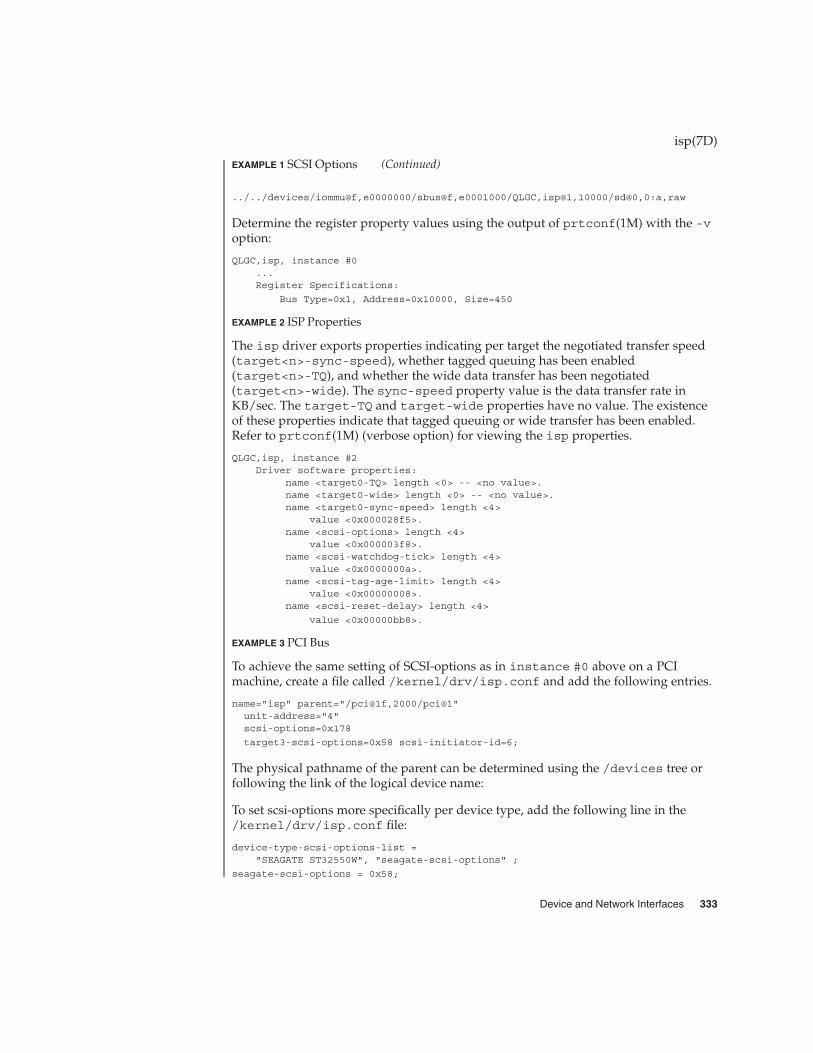
EXAMPLE 1 SCSI Options (Continued)
../../devices/iommu@f,e0000000/sbus@f,e0001000/QLGC,isp@1,10000/sd@0,0:a,raw
Determine the register property values using the output of prtconf(1M) with the -voption:
QLGC,isp, instance #0...Register Specifications:
Bus Type=0x1, Address=0x10000, Size=450
EXAMPLE 2 ISP Properties
The isp driver exports properties indicating per target the negotiated transfer speed(target<n>-sync-speed), whether tagged queuing has been enabled(target<n>-TQ), and whether the wide data transfer has been negotiated(target<n>-wide). The sync-speed property value is the data transfer rate inKB/sec. The target-TQ and target-wide properties have no value. The existenceof these properties indicate that tagged queuing or wide transfer has been enabled.Refer to prtconf(1M) (verbose option) for viewing the isp properties.
QLGC,isp, instance #2Driver software properties:
name <target0-TQ> length <0> -- <no value>.name <target0-wide> length <0> -- <no value>.name <target0-sync-speed> length <4>
value <0x000028f5>.name <scsi-options> length <4>
value <0x000003f8>.name <scsi-watchdog-tick> length <4>
value <0x0000000a>.name <scsi-tag-age-limit> length <4>
value <0x00000008>.name <scsi-reset-delay> length <4>
value <0x00000bb8>.
EXAMPLE 3 PCI Bus
To achieve the same setting of SCSI-options as in instance #0 above on a PCImachine, create a file called /kernel/drv/isp.conf and add the following entries.
name="isp" parent="/pci@1f,2000/pci@1"unit-address="4"scsi-options=0x178
target3-scsi-options=0x58 scsi-initiator-id=6;
The physical pathname of the parent can be determined using the /devices tree orfollowing the link of the logical device name:
To set scsi-options more specifically per device type, add the following line in the/kernel/drv/isp.conf file:
device-type-scsi-options-list ="SEAGATE ST32550W", "seagate-scsi-options" ;
seagate-scsi-options = 0x58;
isp(7D)
Device and Network Interfaces 333

EXAMPLE 3 PCI Bus (Continued)
All device which are of this specific disk type will have scsi-options set to 0x58.
scsi-options specified per target ID has the highest precedence, followed byscsi-options per device type. Global (for all isp instances) scsi-options perbus has the lowest precedence.
The system needs to be rebooted before the specified scsi-options take effect.
EXAMPLE 4 Driver Capabilities
The target driver needs to set capabilities in the isp driver in order to enable somedriver features. The target driver can query and modify these capabilities:synchronous, tagged-qing, wide-xfer, auto-rqsense, qfull-retries,qfull-retry-interval. All other capabilities can only be queried.
By default, tagged-qing, auto-rqsense, and wide-xfer capabilities are disabled,while disconnect, synchronous, and untagged-qing are enabled. Thesecapabilities can only have binary values (0 or 1). The default values forqfull-retries and qfull-retry-interval are both 10. The qfull-retriescapability is a uchar_t (0 to 255) while qfull-retry-interval is a ushort_t (0to 65535).
The target driver needs to enable tagged-qing and wide-xfer explicitly. Theuntagged-qing capability is always enabled and its value cannot be modified,because isp can queue commands even when tagged-qing is disabled.
Whenever there is a conflict between the value of scsi-options and a capability, thevalue set in scsi-options prevails. Only whom != 0 is supported in thescsi_ifsetcap(9F) call.
Refer to scsi_ifsetcap(9F) and scsi_ifgetcap(9F) for details.
/kernel/drv/isp ELF Kernel Module
/kernel/drv/isp.conf Configuration file
See attributes(5) for descriptions of the following attributes:
ATTRIBUTE TYPE ATTRIBUTE VALUE
Architecture SPARC
prtconf(1M), driver.conf(4), attributes(5), scsi_abort(9F),scsi_hba_attach(9F), scsi_ifgetcap(9F), scsi_reset(9F),scsi_transport(9F), scsi_device(9S), scsi_extended_sense(9S),scsi_inquiry(9S), scsi_pkt(9S)
isp(7D)
FILES
ATTRIBUTES
SEE ALSO
334 man pages section 7: Device and Network Interfaces • Last Revised 12 Jan 1998

Writing Device Drivers
ANSI Small Computer System Interface-2 (SCSI-2)
QLogic Corporation, ISP1000 Firmware Interface Specification
QLogic Corporation, ISP1020 Firmware Interface Specification
QLogic Corporation, ISP1000 Technical Manual
QLogic Corporation, ISP1020a/1040a Technical Manual
QLogic Corporation, Differences between the ISP1020a/1040a and the ISP1020B/1040B -Application Note
The messages described below may appear on the system console as well as beinglogged.
The first set of messages may be displayed while the isp driver is first trying toattach. All of these messages mean that the isp driver was unable to attach. Thesemessages are preceded by "isp<number>", where "<number>" is the instance numberof the ISP Host Bus Adapter.
Device in slave-only slot, unusedThe SBus device has been placed in a slave-only slot and will not be accessible;move to non-slave-only SBus slot.
Device is using a hilevel intr, unusedThe device was configured with an interrupt level that cannot be used with thisisp driver. Check the device.
Failed to alloc soft stateDriver was unable to allocate space for the internal state structure. Driver did notattach to device; SCSI devices will be inaccessible.
Bad soft stateDriver requested an invalid internal state structure. Driver did not attach to device;SCSI devices will be inaccessible.
Unable to map registersDriver was unable to map device registers; check for bad hardware. Driver did notattach to device; SCSI devices will be inaccessible.
Cannot add intrDriver was not able to add the interrupt routine to the kernel. Driver did not attachto device; SCSI devices will be inaccessible.
Unable to attachDriver was unable to attach to the hardware for some reason that may be printed.Driver did not attach to device; SCSI devices will be inaccessible.
The next set of messages can be displayed at any time. They will be printed with thefull device pathname followed by the shorter form described above.
isp(7D)
DIAGNOSTICS
Device and Network Interfaces 335

Firmware should be < 0x<number> bytesFirmware size exceeded allocated space and will not download firmware. Thiscould mean that the firmware was corrupted somehow. Check the isp driver.
Firmware checksum incorrectFirmware has an invalid checksum and will not be downloaded.
Chip reset timeoutISP chip failed to reset in the time allocated; may be bad hardware.
Stop firmware failedStopping the firmware failed; may be bad hardware.
Load ram failedUnable to download new firmware into the ISP chip.
DMA setup failedThe DMA setup failed in the host adapter driver on a scsi_pkt. This will returnTRAN_BADPKT to a SCSA target driver.
Bad request pktThe ISP Firmware rejected the packet as being set up incorrectly. This will cause theisp driver to call the target completion routine with the reason of CMD_TRAN_ERRset in the scsi_pkt. Check the target driver for correctly setting up the packet.
Bad request pkt headerThe ISP Firmware rejected the packet as being set up incorrectly. This will cause theisp driver to call the target completion routine with the reason of CMD_TRAN_ERRset in the scsi_pkt. Check the target driver for correctly setting up the packet.
Polled command timeout on <number>.<number>A polled command experienced a timeout. The target device, as noted by the targetlun (<number>.<number>) information, may not be responding correctly to thecommand, or the ISP chip may be hung. This will cause an error recovery to beinitiated in the isp driver. This could mean a bad device or cabling.
SCSI Cable/Connection problem
Hardware/Firmware errorThe ISP chip encountered a firmware error of some kind. The problem is probablydue to a faulty scsi cable or improper cable connection. This error will cause theisp driver to do error recovery by resetting the chip.
Received unexpected SCSI ResetThe ISP chip received an unexpected SCSI Reset and has initiated its own internalerror recovery, which will return all the scsi_pkt with reason set to CMD_RESET.
Fatal timeout on target <number>.<number>The isp driver found a command that had not completed in the correct amount oftime; this will cause error recovery by the isp driver. The device that experiencedthe timeout was at target lun (<number>.<number>).
isp(7D)
336 man pages section 7: Device and Network Interfaces • Last Revised 12 Jan 1998

Fatal error, resetting interfaceThis is an indication that the isp driver is doing error recovery. This will cause alloutstanding commands that have been transported to the isp driver to becompleted via the scsi_pkt completion routine in the target driver with reason ofCMD_RESET and status of STAT_BUS_RESET set in the scsi_pkt.
isp(7D)
Device and Network Interfaces 337

kb – keyboard STREAMS module
#include <sys/types.h>
#include <sys/stream.h>
#include <sys/stropts.h>
#include <sys/vuid_event.h>
#include <sys/kbio.h>
#include <sys/kbd.h>
ioctl(fd, I_PUSH, "kb");
The kb STREAMS module processes byte streams generated by a keyboard attached toa CPU serial port. Definitions for altering keyboard translation and reading eventsfrom the keyboard are contained in <sys/kbio.h> and <sys/kbd.h>.
The kb STREAMS module utilizes a set of keyboard tables to recognize which keyshave been typed. Each translation table is an array of 128 16-bit words (unsignedshorts). If a table entry is less than 0x100, the entry is treated as an ISO 8859/1character. Higher values indicate special characters that invoke more complicatedactions.
The keyboard can be in one of the following translation modes:
TR_NONEKeyboard translation is turned off and up/down key codes are reported.
TR_ASCIIISO 8859/1 codes are reported.
TR_EVENTfirm_events are reported.
TR_UNTRANS_EVENTfirm_events containing unencoded keystation codes are reported for all inputevents within the window system.
All instances of the kb module share seven translation tables that convert rawkeystation codes to event values. The tables are:
Unshifted Used when a key is depressed and no shifts are in effect.
Shifted Used when a key is depressed and a Shift key is held down.
Caps Lock Used when a key is depressed and Caps Lock is in effect.
Alt Graph Used when a key is depressed and the Alt Graph key is helddown.
Num Lock Used when a key is depressed and Num Lock is in effect.
kb(7M)
NAME
SYNOPSIS
DESCRIPTION
KeyboardTranslation Mode
KeyboardTranslation-Table
Entries
338 man pages section 7: Device and Network Interfaces • Last Revised 14 May 1999

Controlled Used when a key is depressed and the Control key is held down.(Regardless of whether a Shift key or the Alt Graph is being helddown, or whether Caps Lock or Num Lock is in effect).
Key Up Used when a key is released.
Each key on the keyboard has a key station code that represents a number from 0to 127. The number is used as an index into the translation table that is currently ineffect. If the corresponding entry in the translation table is a value from 0 to 255, thevalue is treated as an ISO 8859/1 character, and the character is the result of thetranslation.
If the entry in the translation table is higher than 255, it is a special entry. Special entryvalues are classified according to the value of the high-order bits. The high-order valuefor each class is defined as a constant, as shown below. When added to the constant,the value of the low-order bits distinguish between keys within each class:
SHIFTKEYS 0x100A shift key. The value of the particular shift key is added to determine which shiftmask to apply:
CAPSLOCK 0 Caps Lock key.
SHIFTLOCK 1 “Shift Lock” key.
LEFTSHIFT 2 Left-hand Shift key.
RIGHTSHIFT 3 Right-hand Shift key.
LEFTCTRL 4 Left-hand (or only) Control key.
RIGHTCTRL 5 Right-hand Control key.
ALTGRAPH 9 Alt Graph key.
ALT 10 Alternate or Alt key.
NUMLOCK 11 Num Lock key.
BUCKYBITS 0x200Used to toggle mode-key-up/down status without altering the value of anaccompanying ISO 8859/1 character. The actual bit-position value, minus 7, isadded.
METABIT 0 The Meta key was pressed along with the key. This is the onlyuser-accessible bucky bit. It is ORed in as the 0x80 bit; since thisbit is a legitimate bit in a character, the only way to distinguishbetween, for example, 0xA0 as META+0x20 and 0xA0 as an8-bit character is to watch for META key up and META keydown events and keep track of whether the META key wasdown.
SYSTEMBIT 1 The System key was pressed. This is a place holder to indicatewhich key is the system-abort key.
kb(7M)
Device and Network Interfaces 339

FUNNY 0x300Performs various functions depending on the value of the low 4 bits:
NOP 0x300 Does nothing.
OOPS 0x301 Exists, but is undefined.
HOLE 0x302 There is no key in this position on the keyboard, and theposition-code should not be used.
RESET 0x306 Keyboard reset.
ERROR 0x307 The keyboard driver detected an internal error.
IDLE 0x308 The keyboard is idle (no keys down).
COMPOSE 0x309 The COMPOSE key; the next two keys should comprise atwo-character COMPOSE key sequence.
NONL 0x30A Used only in the Num Lock table; indicates that this key is notaffected by the Num Lock state, so that the translation table touse to translate this key should be the one that would have beenused had Num Lock not been in effect.
0x30B — 0x30F Reserved for non-parameterized functions.
FA_CLASS 0x400A floating accent or “dead key.” When this key is pressed, the next key generates anevent for an accented character; for example, “floating accent grave” followed bythe “a” key generates an event with the ISO 8859/1 code for the “a with graveaccent” character. The low-order bits indicate which accent; the codes for theindividual “floating accents” are as follows:
FA_UMLAUT 0x400 umlaut
FA_CFLEX 0x401 circumflex
FA_TILDE 0x402 tilde
FA_CEDILLA 0x403 cedilla
FA_ACUTE 0x404 acute accent
FA_GRAVE 0x405 grave accent
STRING 0x500The low-order bits index a table of strings. When a key with a STRING entry isdepressed, the characters in the null-terminated string for that key are sent,character-by-character. The maximum length is defined as:
KTAB_STRLEN 10 Individual string numbers are defined as:
HOMEARROW0x00
UPARROW0x01
kb(7M)
340 man pages section 7: Device and Network Interfaces • Last Revised 14 May 1999

DOWNARROW0x02
LEFTARROW0x03
RIGHTARROW0x04
String numbers 0x05 — 0x0F are available for custom entries.
FUNCKEYS 0x600There are 64 keys reserved for function keys. The actual positions are usually on theleft/right/top/bottom of the keyboard.
The next-to-lowest 4 bits indicate the group of function keys:
LEFTFUNC 0x600
RIGHTFUNC 0x610
TOPFUNC 0x610 0x610
BOTTOMFUNC 0x630 The low 4 bits indicate the function keynumber within the group:
LF(n) (LEFTFUNC+(n)-1)
RF(n) (RIGHTFUNC+(n)-1)
TF(n) (TOPFUNC+(n)-1)
BF(n) (BOTTOMFUNC+(n)-1)
PADKEYS 0x700A “numeric keypad key.” These entries should appear only in the Num Locktranslation table; when Num Lock is in effect, these events will be generated bypressing keys on the right-hand keypad. The low-order bits indicate which key. Thecodes for the individual keys are:
PADEQUAL 0x700 “=” key
PADSLASH 0x701 “/” key
PADSTAR 0x702 “*” key
PADMINUS 0x703 “-” key
PADSEP 0x704 “,” key
PAD7 0x705 “7” key
PAD8 0x706 “8” key
PAD9 0x707 “9” key
PADPLUS 0x708 “+” key
kb(7M)
Device and Network Interfaces 341

PAD4 0x709 “4” key
PAD5 0x70A “5” key
PAD6 0x70B “6” key
PAD1 0x70C “1” key
PAD2 0x70D “2” key
PAD3 0x70E “3” key
PAD0 0x70F “0” key
PADDOT 0x710 “.” key
PADENTER 0x711 “Enter” key
When a function key is pressed in TR_ASCII mode, the following escape sequence issent:
ESC[0 . . .. 9z
where ESC is a single escape character and “0 . .. 9” indicates the decimalrepresentation of the function-key value. For example, function key R1 sends thesequence:
ESC[208z
because the decimal value of RF(1) is 208. In TR_EVENT mode, if there is a VUID eventcode for the function key in question, an event with that event code is generated;otherwise, individual events for the characters of the escape sequence are generated.
When started, the kb STREAMS module is in the compatibility mode. When thekeyboard is in the TR_EVENT translation mode, ISO 8859/1 characters from the upperhalf of the character set (that is, characters with the eighth bit set) , are presented asevents with codes in the ISO_FIRST range (as defined in <<sys/vuid_event.h>>).For backwards compatibility with older versions of the keyboard driver, the eventcode is ISO_FIRST plus the character value. When compatibility mode is turned off,ISO 8859/1 characters are presented as events with codes equal to the character code.
The following ioctl() requests set and retrieve the current translation mode of akeyboard:
KIOCTRANS Pointer to an int. The translation mode is set to the value in theint pointed to by the argument.
KIOCGTRANS Pointer to an int. The current translation mode is stored in theint pointed to by the argument.
ioctl() requests for changing and retrieving entries from the keyboard translationtable use the kiockeymap structure:
kb(7M)
KeyboardCompatibility
Mode
DESCRIPTION
342 man pages section 7: Device and Network Interfaces • Last Revised 14 May 1999

struct kiockeymap {int kio_tablemask; /* Translation table (one of: 0, CAPSMASK,
* SHIFTMASK, CTRLMASK, UPMASK,* ALTGRAPHMASK, NUMLOCKMASK)*/
#define KIOCABORT1 –1 /* Special “mask”: abort1 keystation */#define KIOCABORT2 –2 /* Special “mask”: abort2 keystation */
uchar_t kio_station; /* Physical keyboard key station (0-127) */ushort_t kio_entry; /* Translation table station’s entry */char kio_string[10]; /* Value for STRING entries (null terminated) */
};
KIOCSKEY Pointer to a kiockeymap structure. The translation table entryreferred to by the values in that structure is changed. Thekio_tablemask request specifies which of the followingtranslation tables contains the entry to be modified:
UPMASK 0x0080 “Key Up” translationtable.
NUMLOCKMASK 0x0800 “Num Lock” translationtable.
CTRLMASK 0x0030 “Controlled” translationtable.
ALTGRAPHMASK 0x0200 “Alt Graph” translationtable.
SHIFTMASK 0x000E “Shifted” translationtable.
CAPSMASK 0x0001 “Caps Lock” translationtable.
(No shift keys pressed or locked) “Unshifted” translationtable.
The kio_station request specifies the keystation code for the entry to be modified.The value of kio_entry is stored in the entry in question. If kio_entry is betweenSTRING and STRING+15, the string contained in kio_string is copied to theappropriate string table entry. This call may return EINVAL if there are invalidarguments.
Special values of kio_tablemask can affect the two step “break to the PROMmonitor” sequence. The usual sequence is L1-a or Stop-. If kio_tablemask isKIOCABORT1, then the value of kio_station is set to be the first keystation in thesequence. If kio_tablemask, is KIOCABORT2 then the value of kio_station is setto be the second keystation in the sequence. An attempt to change the "break to thePROM monitor" sequence without having superuser permission results in an EPERMerror.
kb(7M)
Device and Network Interfaces 343

KIOCGKEY The argument is a pointer to a kiockeymap structure. The currentvalue of the keyboard translation table entry specified bykio_tablemask and kio_station is stored in the structurepointed to by the argument. This call may return EINVAL if thereare invalid arguments.
KIOCTYPE The argument is a pointer to an int. A code indicating the type ofthe keyboard is stored in the int pointed to by the argument:
KB_SUN3 Sun Type 3 keyboard
KB_SUN4 Sun Type 4 keyboard
KB_ASCII ASCII terminal masquerading as keyboard
KB_PC Type 101 PC keyboard
KB_DEFAULT Stored in the int pointed to by the argument ifthe keyboard type is unknown. In case of error,-1 is stored in the int pointed to by theargument.
KIOCLAYOUT The argument is a pointer to an int. On a Sun Type 4 keyboard,the layout code specified by the keyboard’s DIP switches is storedin the int pointed to by the argument.
KIOCCMD The argument is a pointer to an int. The command specified bythe value of the int pointed to by the argument is sent to thekeyboard. The commands that can be sent are:
Commands to the Sun Type 3 and Sun Type 4 keyboards:
KBD_CMD_RESET Reset keyboard as if power-up.
KBD_CMD_BELL Turn on the bell.
KBD_CMD_NOBELL Turn off the bell.
KBD_CMD_CLICK Turn on the click annunciator.
KBD_CMD_NOCLICK Turn off the click annunciator.Commands to the Sun Type 4 keyboard:
KBD_CMD_SETLED Set keyboard LEDs.
KBD_CMD_GETLAYOUT Request that keyboard indicatelayout.
Inappropriate commands for particular keyboard types are ignored. Since there is noreliable way to get the state of the bell or click (because the keyboard cannot bequeried and a process could do writes to the appropriate serial driver —circumventing this ioctl() request) an equivalent ioctl() to query its state is notprovided.
kb(7M)
344 man pages section 7: Device and Network Interfaces • Last Revised 14 May 1999

KIOCSLED The argument is a pointer to an char. On the Sun Type 4keyboard, the LEDs are set to the value specified in that char. Thevalues for the four LEDs are:
LED_CAPS_LOCK “Caps Lock” light.
LED_COMPOSE “Compose” light.
LED_SCROLL_LOCK “Scroll Lock” light.
LED_NUM_LOCK “Num Lock” light.
On some Japanese layouts, the value for the fifth LED is:
LED_KANA “Kana” light.
KIOCGLED Pointer to a char. The current state of the LEDs is stored in thechar pointed to by the argument.
KIOCSCOMPAT Pointer to an int. “Compatibility mode” is turned on if the inthas a value of 1, and is turned off if the int has a value of 0.
KIOCGCOMPAT Pointer to an int. The current state of “compatibility mode” isstored in the int pointed to by the argument.
The following ioctl() request allows the default effect of the keyboard abortsequence to be changed.
KIOCSKABORTENPointer to an int. The keyboard abort sequence effect (typically L1-A or Stop-A onthe keyboard on SPARC systems, F1–A on IA systems, and BREAK on the serialconsole device) is enabled if the int has a value of KIOCABORTENABLE(1). If thevalue is KIOCABORTDISABLE(0) , the keyboard abort sequence effect is disabled.If the value is KIOCABORTALTERNATE(2), the Alternate Break sequence is ineffect and is defined by the serial console drivers zs(7D ) se(7D) and asy(7D). Anyother value of the parameter for this ioctl() is treated as enable. The AlternateBreak sequence is applicable to the serial console devices only. When the AlternateBreak sequence is in effect, binary protocols including PPP, SLIP, file transfer andothers should not be run over the console serial port.
This ioctl()will be active and retain state even if there is no physical keyboard inthe system. The default effect (enable) causes the operating system to suspend andenter the kernel debugger (if present) or the system prom (on most systems withOpenBoot proms). The default effect is enabled on most systems, but may bedifferent on server systems with key switches in the ’secure’ position. On thesesystems, the effect is always disabled when the key switch is in the ’secure’position. This ioctl()returns EPERM if the caller is not the superuser.
These ioctl() requests are supported for compatibility with the system keyboarddevice /dev/kbd.
kb(7M)
Device and Network Interfaces 345

KIOCSDIRECTHas no effect.
KIOCGDIRECTAlways returns 1.
See attributes(5) for descriptions of the following attributes:
ATTRIBUTE TYPE ATTRIBUTE VALUE
Interface Stability Stable
kbd(1), loadkeys(1), kadb(1M), keytables(4), attributes(5), zs(7D), se(7D),asy(7D) termio(7I)
Many of the keyboards released after Sun Type 4 keyboard also report themselves asSun Type 4 keyboard.
kb(7M)
ATTRIBUTES
SEE ALSO
NOTES
346 man pages section 7: Device and Network Interfaces • Last Revised 14 May 1999

kdmouse – built-in mouse device interface
The kdmouse driver supports machines with built-in PS/2 mouse interfaces. It allowsapplications to obtain information about the mouse’s movements and the status of itsbuttons.
Programs are able to read directly from the device. The data returned corresponds tothe byte sequences as defined in the IBM PS/2 Technical Reference Manual.
/dev/kdmouse device file
See attributes(5) for descriptions of the following attributes:
ATTRIBUTE TYPE ATTRIBUTE VALUE
Architecture IA
attributes(5), vuidmice(7M)
IBM PS/2 Technical Reference Manual.
kdmouse(7D)
NAME
DESCRIPTION
FILES
ATTRIBUTES
SEE ALSO
Device and Network Interfaces 347

mem, kmem, allkmem – physical or virtual memory access
/dev/mem
/dev/kmem
/dev/allkmem
The file /dev/mem is a special file that provides access to the physical memory of thecomputer.
The file /dev/kmem is a special file that provides access to the virtual address space ofthe operating system kernel, excluding memory that is associated with an I/O device.
The file /dev/allkmem is a special file that provides access to the virtual addressspace of the operating system kernel, including memory that is associated with an I/Odevice. You can use any of these devices to examine and modify the system.
Byte addresses in /dev/mem are interpreted as physical memory addresses. Byteaddresses in /dev/kmem and /dev/allkmem are interpreted as kernel virtualmemory addresses. A reference to a non-existent location returns an error. SeeERRORS for more information.
The file /dev/mem accesses physical memory; the size of the file is equal to theamount of physical memory in the computer. This size may be larger than 4GB on asystem running the 32-bit operating environment. In this case, you can access memorybeyond 4GB using a series of read(2) and write(2) calls, a pread64() orpwrite64() call, or a combination of llseek(2) and read(2) or write(2).
EFAULT Occurs when trying to write(2) a read-only location (allkmem),read(2) a write-only location (allkmem), or read(2) or write(2)a non-existent or unimplemented location (mem, kmem, allkmem).
EIO Occurs when trying to read(2) or write(2) a memory locationthat is associated with an I/O device using the /dev/kmem specialfile.
ENXIO Results from attempting to mmap(2) a non-existent physical (mem)or virtual (kmem, allkmem) memory address.
/dev/mem Provides access to the computer’s physical memory.
/dev/kmem Provides access to the virtual address space of the operatingsystem kernel, excluding memory that is associated with an I/Odevice.
/dev/allkmem Provides access to the virtual address space of the operatingsystem kernel, including memory that is associated with an I/Odevice.
llseek(2), mmap(2), read(2), write(2)
kmem(7D)
NAME
SYNOPSIS
DESCRIPTION
ERRORS
FILES
SEE ALSO
348 man pages section 7: Device and Network Interfaces • Last Revised 18 Feb 2002

Using these devices to modify (that is, write to) the address space of a live runningoperating system or to modify the state of a hardware device is extremely dangerousand may result in a system panic if kernel data structures are damaged or if devicestate is changed.
kmem(7D)
WARNINGS
Device and Network Interfaces 349

kstat – kernel statistics driver
The kstat driver is the mechanism used by the kstat(3KSTAT) library to extractkernel statistics. This is NOT a public interface.
/dev/kstat kernel statistics driver
kstat(3KSTAT), kstat(9S)
kstat(7D)
NAME
DESCRIPTION
FILES
SEE ALSO
350 man pages section 7: Device and Network Interfaces • Last Revised 26 May 1994
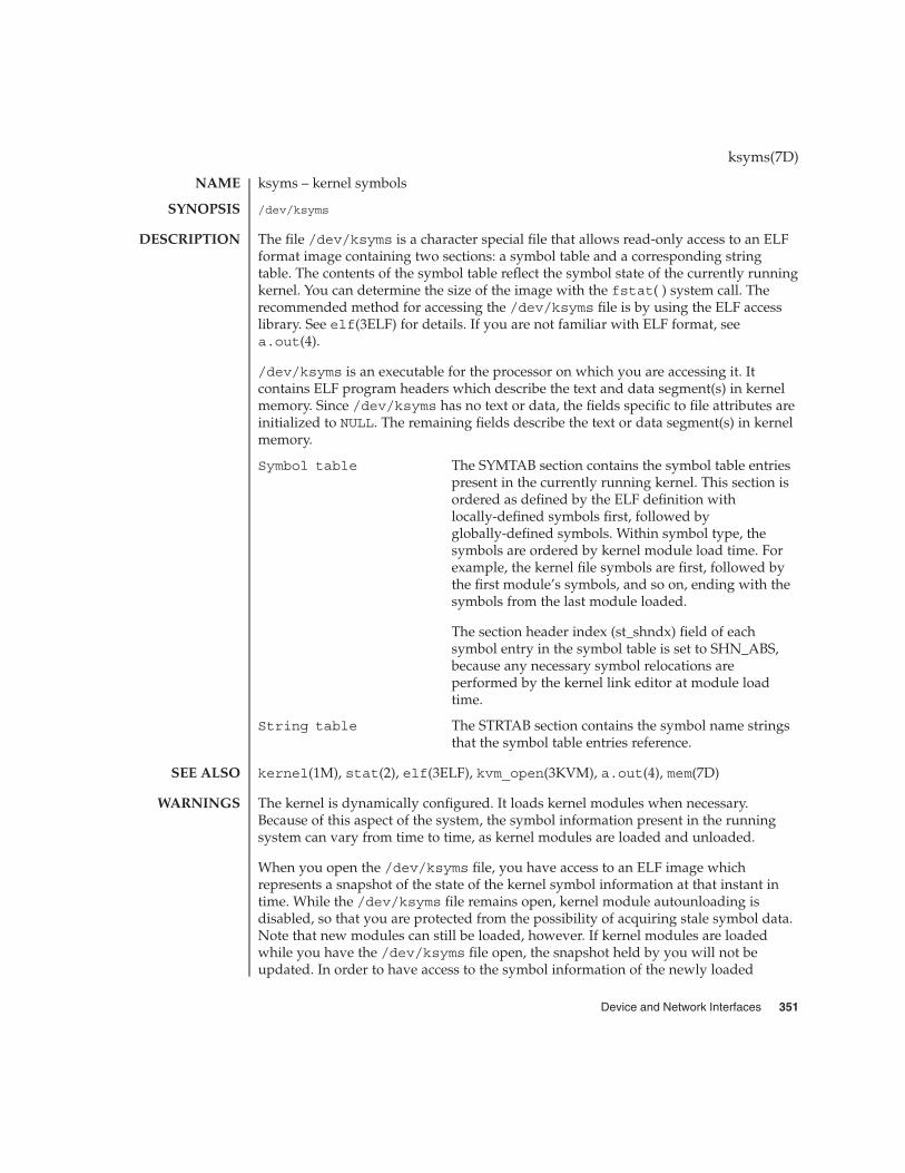
ksyms – kernel symbols
/dev/ksyms
The file /dev/ksyms is a character special file that allows read-only access to an ELFformat image containing two sections: a symbol table and a corresponding stringtable. The contents of the symbol table reflect the symbol state of the currently runningkernel. You can determine the size of the image with the fstat( ) system call. Therecommended method for accessing the /dev/ksyms file is by using the ELF accesslibrary. See elf(3ELF) for details. If you are not familiar with ELF format, seea.out(4).
/dev/ksyms is an executable for the processor on which you are accessing it. Itcontains ELF program headers which describe the text and data segment(s) in kernelmemory. Since /dev/ksyms has no text or data, the fields specific to file attributes areinitialized to NULL. The remaining fields describe the text or data segment(s) in kernelmemory.
Symbol table The SYMTAB section contains the symbol table entriespresent in the currently running kernel. This section isordered as defined by the ELF definition withlocally-defined symbols first, followed byglobally-defined symbols. Within symbol type, thesymbols are ordered by kernel module load time. Forexample, the kernel file symbols are first, followed bythe first module’s symbols, and so on, ending with thesymbols from the last module loaded.
The section header index (st_shndx) field of eachsymbol entry in the symbol table is set to SHN_ABS,because any necessary symbol relocations areperformed by the kernel link editor at module loadtime.
String table The STRTAB section contains the symbol name stringsthat the symbol table entries reference.
kernel(1M), stat(2), elf(3ELF), kvm_open(3KVM), a.out(4), mem(7D)
The kernel is dynamically configured. It loads kernel modules when necessary.Because of this aspect of the system, the symbol information present in the runningsystem can vary from time to time, as kernel modules are loaded and unloaded.
When you open the /dev/ksyms file, you have access to an ELF image whichrepresents a snapshot of the state of the kernel symbol information at that instant intime. While the /dev/ksyms file remains open, kernel module autounloading isdisabled, so that you are protected from the possibility of acquiring stale symbol data.Note that new modules can still be loaded, however. If kernel modules are loadedwhile you have the /dev/ksyms file open, the snapshot held by you will not beupdated. In order to have access to the symbol information of the newly loaded
ksyms(7D)
NAME
SYNOPSIS
DESCRIPTION
SEE ALSO
WARNINGS
Device and Network Interfaces 351

modules, you must first close and then reopen the /dev/ksyms file. Be aware that thesize of the /dev/ksyms file will have changed. You will need to use the fstat()function (see stat(2)) to determine the new size of the file.
Avoid keeping the /dev/ksyms file open for extended periods of time, either byusing kvm_open(3KVM) of the default namelist file or with a direct open. There aretwo reasons why you should not hold /dev/ksyms open. First, the system’s ability todynamically configure itself is partially disabled by the locking down of loadedmodules. Second, the snapshot of symbol information held by you will not reflect thesymbol information of modules loaded after your initial open of /dev/ksyms.
Note that the ksyms driver is a loadable module, and that the kernel driver modulesare only loaded during an open system call. Thus it is possible to run stat(2) on the/dev/ksyms file without causing the ksyms driver to be loaded. In this case, the filesize returned is UNKNOWN_SIZE. A solution for this behavior is to first open the/dev/ksyms file, causing the ksyms driver to be loaded (if necessary). You can thenuse the file descriptor from this open in a fstat( ) system call to get the file’s size.
The kernel virtual memory access library (libkvm) routines use /dev/ksyms as thedefault namelist file. See kvm_open(3KVM) for details.
ksyms(7D)
NOTES
352 man pages section 7: Device and Network Interfaces • Last Revised 11 Dec 2000

ldterm – standard STREAMS terminal line discipline module
#include <sys/stream.h>
#include <sys/termios.h>
int ioctl(fd,I_PUSH,"ldterm");
The ldterm STREAMS module provides most of the termio(7I) terminal interface.The vis module does not perform the low-level device control functions specified byflags in the c_cflag word of the termio/termios structure, or by the IGNBRK,IGNPAR, PARMRK, or INPCK flags in the c_iflag word of the termio/termiosstructure. Those functions must be performed by the driver or by modules pushedbelow the ldterm module. The ldterm module performs all othertermio/termios functions, though some may require the cooperation of the driveror modules pushed below ldterm and may not be performed in some cases. Theseinclude the IXOFF flag in the c_iflag word and the delays specified in the c_oflagword.
The ldterm module also handles single and multi-byte characters from variouscodesets including both Extended Unix Code (EUC) and non-EUC codesets.
The remainder of this section describes the processing of various STREAMS messageson the read- and write-side.
Various types of STREAMS messages are processed as follows:
M_BREAK Depending on the state of the BRKINT flag, either an interruptsignal is generated or the message is treated as if it were anM_DATA message containing a single ASCII NUL character whenthis message is received.
M_DATA This message is normally processed using the standard termioinput processing. If the ICANON flag is set, a single input record(‘‘line’’) is accumulated in an internal buffer and sent upstreamwhen a line-terminating character is received. If the ICANON flag isnot set, other input processing is performed and the processeddata are passed upstream.
If output is to be stopped or started as a result of the arrival ofcharacters (usually CNTRL-Q and CNTRL-S), M_STOP andM_START messages are sent downstream. If the IXOFF flag is setand input is to be stopped or started as a result of flow-controlconsiderations, M_STOPI and M_STARTI messages are sentdownstream.
M_DATA messages are sent downstream, as necessary, to performechoing.
ldterm(7M)
NAME
SYNOPSIS
DESCRIPTION
Read-sideBehavior
Device and Network Interfaces 353

If a signal is to be generated, an M_FLUSH message with a flag byteof FLUSHR is placed on the read queue. If the signal is also to flushoutput, an M_FLUSH message with a flag byte of FLUSHW is sentdownstream.
All other messages are passed upstream unchanged.
Various types of STREAMS messages are processed as follows:
M_FLUSH The write queue of the module is flushed of all its data messagesand the message is passed downstream.
M_IOCTL The function of this ioctl is performed and the message ispassed downstream in most cases. The TCFLSH and TCXONCioctls can be performed entirely in the ldterm module, so thereply is sent upstream and the message is not passed downstream.
M_DATA If the OPOST flag is set, or both the XCASE and ICANON flags areset, output processing is performed and the processed message ispassed downstream along with any M_DELAY messages generated.Otherwise, the message is passed downstream without change.
M_CTL If the size of the data buffer associated with the message is the sizeof struct iocblk, ldterm will perform functional negotiationto determine where the termio(7I) processing is to be done. If thecommand field of the iocblk structure (ioc_cmd) is set toMC_NO_CANON, the input canonical processing normallyperformed on M_DATA messages is disabled and those messagesare passed upstream unmodified. (This is for the use of modules ordrivers that perform their own input processing, such as apseudo-terminal in TIOCREMOTE mode connected to a programthat performs this processing). If the command is MC_DO_CANON,all input processing is enabled. If the command isMC_PART_CANON, then an M_DATA message containing a termiosstructure is expected to be attached to the original M_CTL message.The ldterm module will examine the iflag, oflag, and lflagfields of the termios structure and from that point on, willprocess only those flags that have not been turned ON. If none ofthe above commands are found, the message is ignored. In anycase, the message is passed upstream.
M_FLUSH The read queue of the module is flushed of all its data messagesand all data in the record being accumulated are also flushed. Themessage is passed upstream.
M_IOCACK The data contained within the message, which is to be returned tothe process, are augmented if necessary, and the message is passedupstream.
All other messages are passed downstream unchanged.
ldterm(7M)
Write-sideBehavior
354 man pages section 7: Device and Network Interfaces • Last Revised 7 Jun1999

The ldterm module processes the following TRANSPARENT ioctls. All others arepassed downstream.
TCGETS/TCGETAThe message is passed downstream. If an acknowledgment is seen, the dataprovided by the driver and modules downstream are augmented and theacknowledgement is passed upstream.
TCSETS/TCSETSW/TCSETSF/TCSETA/TCSETAW/TCSETAFThe parameters that control the behavior of the ldterm module are changed. If amode change requires options at the stream head to be changed, an M_SETOPTSmessage is sent upstream. If the ICANON flag is turned on or off, the read mode atthe stream head is changed to message-nondiscard or byte-stream mode,respectively. If the TOSTOP flag is turned on or off, the tostop mode at the streamhead is turned on or off, respectively. In any case, ldterm passes the ioctl ondownstream for possible additional processing.
TCFLSHIf the argument is 0, an M_FLUSH message with a flag byte of FLUSHR is sentdownstream and placed on the read queue. If the argument is 1, the write queue isflushed of all its data messages and an M_FLUSH message with a flag byte ofFLUSHW is sent upstream and downstream. If the argument is 2, the write queue isflushed of all its data messages and an M_FLUSH message with a flag byte ofFLUSHRW is sent downstream and placed on the read queue.
TCXONCIf the argument is 0 and output is not already stopped, an M_STOP message is sentdownstream. If the argument is 1 and output is stopped, an M_START message issent downstream. If the argument is 2 and input is not already stopped, anM_STOPI message is sent downstream. If the argument is 3 and input is stopped,an M_STARTI message is sent downstream.
TCSBRKThe message is passed downstream, so the driver has a chance to drain the dataand then send an M_IOCACK message upstream.
EUC_WSETThis call takes a pointer to an eucioc structure, and uses it to set the EUC linediscipline’s local definition for the code set widths to be used for subsequentoperations. Within the stream, the line discipline may optionally notify othermodules of this setting using M_CTL messages. When this call is received and theeuciocstructure contains valid data, the line discipline changes into EUC handlingmode once the euciocdata is completely transferred to an internal data structure.
EUC_WGETThis call takes a pointer to an eucioc structure, and returns in it the EUC code setwidths currently in use by the EUC line discipline. If the current codeset of the linediscipline is not an EUC one, the result is meaningless.
termios(3C), console(7D), termio(7I)
STREAMS Programming Guide
ldterm(7M)
IOCTLS
SEE ALSO
Device and Network Interfaces 355

le, lebuffer, ledma – Am7990 (LANCE) Ethernet device driver
/dev/le
The Am7990 (“LANCE”) Ethernet driver is a multi-threaded, loadable, clonable,STREAMS hardware driver supporting the connectionless Data Link ProviderInterface, dlpi(7P) over a LANCE Ethernet controller. The motherboard and add-inSBus LANCE controllers of several varieties are supported. Multiple LANCEcontrollers installed within the system are supported by the driver. The le driverprovides basic support for the LANCE hardware. Functions include chip initialization,frame transmit and receive, multicast and promiscuous support, and error recoveryand reporting.
The cloning character-special device /dev/le is used to access all LANCE controllersinstalled within the system.
The lebuffer and ledma device drivers are bus nexus drivers which cooperate withthe le leaf driver in supporting the LANCE hardware functions over several distinctslave-only and DVMA LANCE -based Ethernet controllers. The lebuffer and ledmabus nexi drivers are not directly accessible to the user.
The le driver is a “style 2” Data Link Service provider. All M_PROTO and M_PCPROTOtype messages are interpreted as DLPI primitives. Valid DLPI primitives are definedin <sys/dlpi.h>. Refer to dlpi(7P) for more information. An explicitDL_ATTACH_REQ message by the user is required to associate the opened stream witha particular device (ppa). The ppa ID is interpreted as an unsigned long data typeand indicates the corresponding device instance (unit) number. An error(DL_ERROR_ACK) is returned by the driver if the ppa field value does not correspondto a valid device instance number for this system. The device is initialized on firstattach and de-initialized (stopped) on last detach.
The values returned by the driver in the DL_INFO_ACK primitive in response to theDL_INFO_REQ from the user are as follows:
� The maximum SDU is 1500 (ETHERMTU - defined in <sys/ethernet.h>).� The minimum SDU is 0.� The dlsap address length is 8.� The MAC type is DL_ETHER.� The sap length value is −2 meaning the physical address component is followed
immediately by a 2 byte sap component within the DLSAP address.� The service mode is DL_CLDLS.� No optional quality of service (QOS) support is included at present so the QOS
fields are 0.� The provider style is DL_STYLE2.� The version is DL_VERSION_2.� The broadcast address value is Ethernet/IEEE broadcast address (0xFFFFFF).
le(7D)
NAME
SYNOPSIS
DESCRIPTION
APPLICATIONPROGRAMMING
INTERFACE
le and DLPI
356 man pages section 7: Device and Network Interfaces • Last Revised 23 Aug 1994

Once in the DL_ATTACHED state, the user must send a DL_BIND_REQ to associate aparticular SAP (Service Access Pointer) with the stream. The le driver interprets thesap field within the DL_BIND_REQ as an Ethernet “type” therefore valid values forthe sap field are in the [0-0xFFFF] range. Only one Ethernet type can be bound to thestream at any time.
If the user selects a sap with a value of 0, the receiver will be in “802.3 mode”. Allframes received from the media having a “type” field in the range [0-1500] areassumed to be 802.3 frames and are routed up all open Streams which are bound tosap value 0. If more than one Stream is in “802.3 mode” then the frame will beduplicated and routed up multiple Streams as DL_UNITDATA_IND messages.
In transmission, the driver checks the sap field of the DL_BIND_REQ if the sap valueis 0, and if the destination type field is in the range [0-1500]. If either is true, thedriver computes the length of the message, not including initial M_PROTO mblk(message block), of all subsequent DL_UNITDATA_REQ messages and transmits 802.3frames that have this value in the MAC frame header length field.
The le driver DLSAP address format consists of the 6 byte physical (Ethernet) addresscomponent followed immediately by the 2 byte sap (type) component producing an 8byte DLSAP address. Applications should not hardcode to this particularimplementation-specific DLSAP address format but use information returned in theDL_INFO_ACK primitive to compose and decompose DLSAP addresses. The saplength, full DLSAP length, and sap/physical ordering are included within theDL_INFO_ACK. The physical address length can be computed by subtracting the saplength from the full DLSAP address length or by issuing the DL_PHYS_ADDR_REQ toobtain the current physical address associated with the stream.
Once in the DL_BOUND state, the user may transmit frames on the Ethernet by sendingDL_UNITDATA_REQ messages to the le driver. The le driver will route receivedEthernet frames up all those open and bound streams having a sap which matches theEthernet type as DL_UNITDATA_IND messages. Received Ethernet frames areduplicated and routed up multiple open streams if necessary. The DLSAP addresscontained within the DL_UNITDATA_REQ and DL_UNITDATA_IND messages consistsof both the sap (type) and physical (Ethernet) components.
In addition to the mandatory connectionless DLPI message set the driver additionallysupports the following primitives.
The DL_ENABMULTI_REQ and DL_DISABMULTI_REQ primitives enable/disablereception of individual multicast group addresses. A set of multicast addresses may beiteratively created and modified on a per-stream basis using these primitives. Theseprimitives are accepted by the driver in any state following DL_ATTACHED.
The DL_PROMISCON_REQ and DL_PROMISCOFF_REQ primitives with theDL_PROMISC_PHYS flag set in the dl_level field enables/disables reception of all(“promiscuous mode”) frames on the media including frames generated by the localhost.
le(7D)
le Primitives
Device and Network Interfaces 357

When used with the DL_PROMISC_SAP flag set this enables/disables reception of allsap (Ethernet type) values. When used with the DL_PROMISC_MULTI flag set thisenables/disables reception of all multicast group addresses. The effect of each isalways on a per-stream basis and independent of the other sap and physical levelconfigurations on this stream or other streams.
The DL_PHYS_ADDR_REQ primitive returns the 6 octet Ethernet address currentlyassociated (attached) to the stream in the DL_PHYS_ADDR_ACK primitive. Thisprimitive is valid only in states following a successful DL_ATTACH_REQ.
The DL_SET_PHYS_ADDR_REQ primitive changes the 6 octet Ethernet addresscurrently associated (attached) to this stream. The credentials of the process whichoriginally opened this stream must be superuser. Otherwise EPERM is returned in theDL_ERROR_ACK. This primitive is destructive in that it affects all other current andfuture streams attached to this device. An M_ERROR is sent up all other streamsattached to this device when this primitive is successful on this stream. Once changed,all streams subsequently opened and attached to this device will obtain this newphysical address. Once changed, the physical address will remain until this primitiveis used to change the physical address again or the system is rebooted, whichevercomes first.
/dev/le le special character device.
/kernel/drv/options.conf System wide default device driverproperties
netstat(1M), driver.conf(4), dlpi(7P)
SPARCstation 10 Twisted-Pair Ethernet Link Test
Twisted-Pair Ethernet Link Test
le%d: msg too big: %dThe message length exceeded ETHERMAX.
le%d: Babble error − sent a packet longer than 1518 bytesWhile transmitting a packet, the LANCE chip has noticed that the packet’s lengthexceeds the maximum allowed for Ethernet. This error indicates a kernel bug.
le%d: No carrier − transceiver cable problem?The LANCE chip has lost input to its carrier detect pin while trying to transmit apacket.
le%d: Memory Error!The LANCE chip timed out while trying to acquire the bus for a DVMA transfer.
If you are using twisted pair Ethernet (TPE), you need to be aware of the link testfeature. The IEEE 10Base-T specification states that the link test should always beenabled at the host and the hub. Complications may arise because:
1. Some older hubs do not provide link pulses2. Some hubs are configured to not send link pulses
le(7D)
FILES
SEE ALSO
DIAGNOSTICS
NOTES
358 man pages section 7: Device and Network Interfaces • Last Revised 23 Aug 1994

Under either of these two conditions the host translates the lack of link pulses into alink failure unless it is programmed to ignore link pulses. To program your system toignore link pulses (also known as disabling the link test) do the following at theOpenBoot PROM prompt:
<#0> OK SETENV TPE-LINK-TEST? FALSE
TPE-LINK-TEST? = FALSEThe above command will work forSPARCstation-10, SPARCstation-20 and SPARCclassic systems that comewith built in twisted pair Ethernet ports. For other systems and for add-on boardswith twisted pair Ethernet refer to the documentation that came with the system orboard for information on disabling the link test.
SPARCstation-10, SPARCstation-20 and SPARCclassic systems come with achoice of built in AUI (using an adapter cable) and TPE ports. In Solaris 2.2 anauto-selection scheme was implemented in the le driver that will switch between AUIand TPE depending on which interface is active. Auto-selection uses the presence orabsence of the link test on the TPE interface as one indication of whether that interfaceis active. In the special case where you wish to use TPE with the link-test disabled youshould manually override auto-selection so that the system will use only the twistedpair port.
This override can be performed by defining the cable-selection property in theoptions.conf file to force the system to use TPE or AUI as appropriate. Theexample below sets the cable selection to TPE.
example# cd /kernel/drv
example# echo ’cable-selection="tpe";’ >> options.confNote that the standardoptions.conf file contains important information; the only change to the file shouldbe the addition of the cable-selection property. Be careful to type this line exactly asshown above, ensuring that you append to the existing file, and include theterminating semi-colon. Alternatively, you can use a text editor to append thefollowing line to the end of the file:
cable-selection="tpe";Please refer to the SPARCstation 10 Twisted-Pair Ethernet LinkTest (801-2481-10), Twisted-Pair Ethernet Link Test (801-6184-10) and thedriver.conf(4) man page for details of the syntax of driver configuration files.
le(7D)
Device and Network Interfaces 359

le, lebuffer, ledma – Am7990 (LANCE) Ethernet device driver
/dev/le
The Am7990 (“LANCE”) Ethernet driver is a multi-threaded, loadable, clonable,STREAMS hardware driver supporting the connectionless Data Link ProviderInterface, dlpi(7P) over a LANCE Ethernet controller. The motherboard and add-inSBus LANCE controllers of several varieties are supported. Multiple LANCEcontrollers installed within the system are supported by the driver. The le driverprovides basic support for the LANCE hardware. Functions include chip initialization,frame transmit and receive, multicast and promiscuous support, and error recoveryand reporting.
The cloning character-special device /dev/le is used to access all LANCE controllersinstalled within the system.
The lebuffer and ledma device drivers are bus nexus drivers which cooperate withthe le leaf driver in supporting the LANCE hardware functions over several distinctslave-only and DVMA LANCE -based Ethernet controllers. The lebuffer and ledmabus nexi drivers are not directly accessible to the user.
The le driver is a “style 2” Data Link Service provider. All M_PROTO and M_PCPROTOtype messages are interpreted as DLPI primitives. Valid DLPI primitives are definedin <sys/dlpi.h>. Refer to dlpi(7P) for more information. An explicitDL_ATTACH_REQ message by the user is required to associate the opened stream witha particular device (ppa). The ppa ID is interpreted as an unsigned long data typeand indicates the corresponding device instance (unit) number. An error(DL_ERROR_ACK) is returned by the driver if the ppa field value does not correspondto a valid device instance number for this system. The device is initialized on firstattach and de-initialized (stopped) on last detach.
The values returned by the driver in the DL_INFO_ACK primitive in response to theDL_INFO_REQ from the user are as follows:
� The maximum SDU is 1500 (ETHERMTU - defined in <sys/ethernet.h>).� The minimum SDU is 0.� The dlsap address length is 8.� The MAC type is DL_ETHER.� The sap length value is −2 meaning the physical address component is followed
immediately by a 2 byte sap component within the DLSAP address.� The service mode is DL_CLDLS.� No optional quality of service (QOS) support is included at present so the QOS
fields are 0.� The provider style is DL_STYLE2.� The version is DL_VERSION_2.� The broadcast address value is Ethernet/IEEE broadcast address (0xFFFFFF).
lebuffer(7D)
NAME
SYNOPSIS
DESCRIPTION
APPLICATIONPROGRAMMING
INTERFACE
le and DLPI
360 man pages section 7: Device and Network Interfaces • Last Revised 23 Aug 1994

Once in the DL_ATTACHED state, the user must send a DL_BIND_REQ to associate aparticular SAP (Service Access Pointer) with the stream. The le driver interprets thesap field within the DL_BIND_REQ as an Ethernet “type” therefore valid values forthe sap field are in the [0-0xFFFF] range. Only one Ethernet type can be bound to thestream at any time.
If the user selects a sap with a value of 0, the receiver will be in “802.3 mode”. Allframes received from the media having a “type” field in the range [0-1500] areassumed to be 802.3 frames and are routed up all open Streams which are bound tosap value 0. If more than one Stream is in “802.3 mode” then the frame will beduplicated and routed up multiple Streams as DL_UNITDATA_IND messages.
In transmission, the driver checks the sap field of the DL_BIND_REQ if the sap valueis 0, and if the destination type field is in the range [0-1500]. If either is true, thedriver computes the length of the message, not including initial M_PROTO mblk(message block), of all subsequent DL_UNITDATA_REQ messages and transmits 802.3frames that have this value in the MAC frame header length field.
The le driver DLSAP address format consists of the 6 byte physical (Ethernet) addresscomponent followed immediately by the 2 byte sap (type) component producing an 8byte DLSAP address. Applications should not hardcode to this particularimplementation-specific DLSAP address format but use information returned in theDL_INFO_ACK primitive to compose and decompose DLSAP addresses. The saplength, full DLSAP length, and sap/physical ordering are included within theDL_INFO_ACK. The physical address length can be computed by subtracting the saplength from the full DLSAP address length or by issuing the DL_PHYS_ADDR_REQ toobtain the current physical address associated with the stream.
Once in the DL_BOUND state, the user may transmit frames on the Ethernet by sendingDL_UNITDATA_REQ messages to the le driver. The le driver will route receivedEthernet frames up all those open and bound streams having a sap which matches theEthernet type as DL_UNITDATA_IND messages. Received Ethernet frames areduplicated and routed up multiple open streams if necessary. The DLSAP addresscontained within the DL_UNITDATA_REQ and DL_UNITDATA_IND messages consistsof both the sap (type) and physical (Ethernet) components.
In addition to the mandatory connectionless DLPI message set the driver additionallysupports the following primitives.
The DL_ENABMULTI_REQ and DL_DISABMULTI_REQ primitives enable/disablereception of individual multicast group addresses. A set of multicast addresses may beiteratively created and modified on a per-stream basis using these primitives. Theseprimitives are accepted by the driver in any state following DL_ATTACHED.
The DL_PROMISCON_REQ and DL_PROMISCOFF_REQ primitives with theDL_PROMISC_PHYS flag set in the dl_level field enables/disables reception of all(“promiscuous mode”) frames on the media including frames generated by the localhost.
lebuffer(7D)
le Primitives
Device and Network Interfaces 361

When used with the DL_PROMISC_SAP flag set this enables/disables reception of allsap (Ethernet type) values. When used with the DL_PROMISC_MULTI flag set thisenables/disables reception of all multicast group addresses. The effect of each isalways on a per-stream basis and independent of the other sap and physical levelconfigurations on this stream or other streams.
The DL_PHYS_ADDR_REQ primitive returns the 6 octet Ethernet address currentlyassociated (attached) to the stream in the DL_PHYS_ADDR_ACK primitive. Thisprimitive is valid only in states following a successful DL_ATTACH_REQ.
The DL_SET_PHYS_ADDR_REQ primitive changes the 6 octet Ethernet addresscurrently associated (attached) to this stream. The credentials of the process whichoriginally opened this stream must be superuser. Otherwise EPERM is returned in theDL_ERROR_ACK. This primitive is destructive in that it affects all other current andfuture streams attached to this device. An M_ERROR is sent up all other streamsattached to this device when this primitive is successful on this stream. Once changed,all streams subsequently opened and attached to this device will obtain this newphysical address. Once changed, the physical address will remain until this primitiveis used to change the physical address again or the system is rebooted, whichevercomes first.
/dev/le le special character device.
/kernel/drv/options.conf System wide default device driverproperties
netstat(1M), driver.conf(4), dlpi(7P)
SPARCstation 10 Twisted-Pair Ethernet Link Test
Twisted-Pair Ethernet Link Test
le%d: msg too big: %dThe message length exceeded ETHERMAX.
le%d: Babble error − sent a packet longer than 1518 bytesWhile transmitting a packet, the LANCE chip has noticed that the packet’s lengthexceeds the maximum allowed for Ethernet. This error indicates a kernel bug.
le%d: No carrier − transceiver cable problem?The LANCE chip has lost input to its carrier detect pin while trying to transmit apacket.
le%d: Memory Error!The LANCE chip timed out while trying to acquire the bus for a DVMA transfer.
If you are using twisted pair Ethernet (TPE), you need to be aware of the link testfeature. The IEEE 10Base-T specification states that the link test should always beenabled at the host and the hub. Complications may arise because:
1. Some older hubs do not provide link pulses2. Some hubs are configured to not send link pulses
lebuffer(7D)
FILES
SEE ALSO
DIAGNOSTICS
NOTES
362 man pages section 7: Device and Network Interfaces • Last Revised 23 Aug 1994
Under either of these two conditions the host translates the lack of link pulses into alink failure unless it is programmed to ignore link pulses. To program your system toignore link pulses (also known as disabling the link test) do the following at theOpenBoot PROM prompt:
<#0> OK SETENV TPE-LINK-TEST? FALSE
TPE-LINK-TEST? = FALSEThe above command will work forSPARCstation-10, SPARCstation-20 and SPARCclassic systems that comewith built in twisted pair Ethernet ports. For other systems and for add-on boardswith twisted pair Ethernet refer to the documentation that came with the system orboard for information on disabling the link test.
SPARCstation-10, SPARCstation-20 and SPARCclassic systems come with achoice of built in AUI (using an adapter cable) and TPE ports. In Solaris 2.2 anauto-selection scheme was implemented in the le driver that will switch between AUIand TPE depending on which interface is active. Auto-selection uses the presence orabsence of the link test on the TPE interface as one indication of whether that interfaceis active. In the special case where you wish to use TPE with the link-test disabled youshould manually override auto-selection so that the system will use only the twistedpair port.
This override can be performed by defining the cable-selection property in theoptions.conf file to force the system to use TPE or AUI as appropriate. Theexample below sets the cable selection to TPE.
example# cd /kernel/drv
example# echo ’cable-selection="tpe";’ >> options.confNote that the standardoptions.conf file contains important information; the only change to the file shouldbe the addition of the cable-selection property. Be careful to type this line exactly asshown above, ensuring that you append to the existing file, and include theterminating semi-colon. Alternatively, you can use a text editor to append thefollowing line to the end of the file:
cable-selection="tpe";Please refer to the SPARCstation 10 Twisted-Pair Ethernet LinkTest (801-2481-10), Twisted-Pair Ethernet Link Test (801-6184-10) and thedriver.conf(4) man page for details of the syntax of driver configuration files.
lebuffer(7D)
Device and Network Interfaces 363

le, lebuffer, ledma – Am7990 (LANCE) Ethernet device driver
/dev/le
The Am7990 (“LANCE”) Ethernet driver is a multi-threaded, loadable, clonable,STREAMS hardware driver supporting the connectionless Data Link ProviderInterface, dlpi(7P) over a LANCE Ethernet controller. The motherboard and add-inSBus LANCE controllers of several varieties are supported. Multiple LANCEcontrollers installed within the system are supported by the driver. The le driverprovides basic support for the LANCE hardware. Functions include chip initialization,frame transmit and receive, multicast and promiscuous support, and error recoveryand reporting.
The cloning character-special device /dev/le is used to access all LANCE controllersinstalled within the system.
The lebuffer and ledma device drivers are bus nexus drivers which cooperate withthe le leaf driver in supporting the LANCE hardware functions over several distinctslave-only and DVMA LANCE -based Ethernet controllers. The lebuffer and ledmabus nexi drivers are not directly accessible to the user.
The le driver is a “style 2” Data Link Service provider. All M_PROTO and M_PCPROTOtype messages are interpreted as DLPI primitives. Valid DLPI primitives are definedin <sys/dlpi.h>. Refer to dlpi(7P) for more information. An explicitDL_ATTACH_REQ message by the user is required to associate the opened stream witha particular device (ppa). The ppa ID is interpreted as an unsigned long data typeand indicates the corresponding device instance (unit) number. An error(DL_ERROR_ACK) is returned by the driver if the ppa field value does not correspondto a valid device instance number for this system. The device is initialized on firstattach and de-initialized (stopped) on last detach.
The values returned by the driver in the DL_INFO_ACK primitive in response to theDL_INFO_REQ from the user are as follows:
� The maximum SDU is 1500 (ETHERMTU - defined in <sys/ethernet.h>).� The minimum SDU is 0.� The dlsap address length is 8.� The MAC type is DL_ETHER.� The sap length value is −2 meaning the physical address component is followed
immediately by a 2 byte sap component within the DLSAP address.� The service mode is DL_CLDLS.� No optional quality of service (QOS) support is included at present so the QOS
fields are 0.� The provider style is DL_STYLE2.� The version is DL_VERSION_2.� The broadcast address value is Ethernet/IEEE broadcast address (0xFFFFFF).
ledma(7D)
NAME
SYNOPSIS
DESCRIPTION
APPLICATIONPROGRAMMING
INTERFACE
le and DLPI
364 man pages section 7: Device and Network Interfaces • Last Revised 23 Aug 1994

Once in the DL_ATTACHED state, the user must send a DL_BIND_REQ to associate aparticular SAP (Service Access Pointer) with the stream. The le driver interprets thesap field within the DL_BIND_REQ as an Ethernet “type” therefore valid values forthe sap field are in the [0-0xFFFF] range. Only one Ethernet type can be bound to thestream at any time.
If the user selects a sap with a value of 0, the receiver will be in “802.3 mode”. Allframes received from the media having a “type” field in the range [0-1500] areassumed to be 802.3 frames and are routed up all open Streams which are bound tosap value 0. If more than one Stream is in “802.3 mode” then the frame will beduplicated and routed up multiple Streams as DL_UNITDATA_IND messages.
In transmission, the driver checks the sap field of the DL_BIND_REQ if the sap valueis 0, and if the destination type field is in the range [0-1500]. If either is true, thedriver computes the length of the message, not including initial M_PROTO mblk(message block), of all subsequent DL_UNITDATA_REQ messages and transmits 802.3frames that have this value in the MAC frame header length field.
The le driver DLSAP address format consists of the 6 byte physical (Ethernet) addresscomponent followed immediately by the 2 byte sap (type) component producing an 8byte DLSAP address. Applications should not hardcode to this particularimplementation-specific DLSAP address format but use information returned in theDL_INFO_ACK primitive to compose and decompose DLSAP addresses. The saplength, full DLSAP length, and sap/physical ordering are included within theDL_INFO_ACK. The physical address length can be computed by subtracting the saplength from the full DLSAP address length or by issuing the DL_PHYS_ADDR_REQ toobtain the current physical address associated with the stream.
Once in the DL_BOUND state, the user may transmit frames on the Ethernet by sendingDL_UNITDATA_REQ messages to the le driver. The le driver will route receivedEthernet frames up all those open and bound streams having a sap which matches theEthernet type as DL_UNITDATA_IND messages. Received Ethernet frames areduplicated and routed up multiple open streams if necessary. The DLSAP addresscontained within the DL_UNITDATA_REQ and DL_UNITDATA_IND messages consistsof both the sap (type) and physical (Ethernet) components.
In addition to the mandatory connectionless DLPI message set the driver additionallysupports the following primitives.
The DL_ENABMULTI_REQ and DL_DISABMULTI_REQ primitives enable/disablereception of individual multicast group addresses. A set of multicast addresses may beiteratively created and modified on a per-stream basis using these primitives. Theseprimitives are accepted by the driver in any state following DL_ATTACHED.
The DL_PROMISCON_REQ and DL_PROMISCOFF_REQ primitives with theDL_PROMISC_PHYS flag set in the dl_level field enables/disables reception of all(“promiscuous mode”) frames on the media including frames generated by the localhost.
ledma(7D)
le Primitives
Device and Network Interfaces 365

When used with the DL_PROMISC_SAP flag set this enables/disables reception of allsap (Ethernet type) values. When used with the DL_PROMISC_MULTI flag set thisenables/disables reception of all multicast group addresses. The effect of each isalways on a per-stream basis and independent of the other sap and physical levelconfigurations on this stream or other streams.
The DL_PHYS_ADDR_REQ primitive returns the 6 octet Ethernet address currentlyassociated (attached) to the stream in the DL_PHYS_ADDR_ACK primitive. Thisprimitive is valid only in states following a successful DL_ATTACH_REQ.
The DL_SET_PHYS_ADDR_REQ primitive changes the 6 octet Ethernet addresscurrently associated (attached) to this stream. The credentials of the process whichoriginally opened this stream must be superuser. Otherwise EPERM is returned in theDL_ERROR_ACK. This primitive is destructive in that it affects all other current andfuture streams attached to this device. An M_ERROR is sent up all other streamsattached to this device when this primitive is successful on this stream. Once changed,all streams subsequently opened and attached to this device will obtain this newphysical address. Once changed, the physical address will remain until this primitiveis used to change the physical address again or the system is rebooted, whichevercomes first.
/dev/le le special character device.
/kernel/drv/options.conf System wide default device driverproperties
netstat(1M), driver.conf(4), dlpi(7P)
SPARCstation 10 Twisted-Pair Ethernet Link Test
Twisted-Pair Ethernet Link Test
le%d: msg too big: %dThe message length exceeded ETHERMAX.
le%d: Babble error − sent a packet longer than 1518 bytesWhile transmitting a packet, the LANCE chip has noticed that the packet’s lengthexceeds the maximum allowed for Ethernet. This error indicates a kernel bug.
le%d: No carrier − transceiver cable problem?The LANCE chip has lost input to its carrier detect pin while trying to transmit apacket.
le%d: Memory Error!The LANCE chip timed out while trying to acquire the bus for a DVMA transfer.
If you are using twisted pair Ethernet (TPE), you need to be aware of the link testfeature. The IEEE 10Base-T specification states that the link test should always beenabled at the host and the hub. Complications may arise because:
1. Some older hubs do not provide link pulses2. Some hubs are configured to not send link pulses
ledma(7D)
FILES
SEE ALSO
DIAGNOSTICS
NOTES
366 man pages section 7: Device and Network Interfaces • Last Revised 23 Aug 1994

Under either of these two conditions the host translates the lack of link pulses into alink failure unless it is programmed to ignore link pulses. To program your system toignore link pulses (also known as disabling the link test) do the following at theOpenBoot PROM prompt:
<#0> OK SETENV TPE-LINK-TEST? FALSE
TPE-LINK-TEST? = FALSEThe above command will work forSPARCstation-10, SPARCstation-20 and SPARCclassic systems that comewith built in twisted pair Ethernet ports. For other systems and for add-on boardswith twisted pair Ethernet refer to the documentation that came with the system orboard for information on disabling the link test.
SPARCstation-10, SPARCstation-20 and SPARCclassic systems come with achoice of built in AUI (using an adapter cable) and TPE ports. In Solaris 2.2 anauto-selection scheme was implemented in the le driver that will switch between AUIand TPE depending on which interface is active. Auto-selection uses the presence orabsence of the link test on the TPE interface as one indication of whether that interfaceis active. In the special case where you wish to use TPE with the link-test disabled youshould manually override auto-selection so that the system will use only the twistedpair port.
This override can be performed by defining the cable-selection property in theoptions.conf file to force the system to use TPE or AUI as appropriate. Theexample below sets the cable selection to TPE.
example# cd /kernel/drv
example# echo ’cable-selection="tpe";’ >> options.confNote that the standardoptions.conf file contains important information; the only change to the file shouldbe the addition of the cable-selection property. Be careful to type this line exactly asshown above, ensuring that you append to the existing file, and include theterminating semi-colon. Alternatively, you can use a text editor to append thefollowing line to the end of the file:
cable-selection="tpe";Please refer to the SPARCstation 10 Twisted-Pair Ethernet LinkTest (801-2481-10), Twisted-Pair Ethernet Link Test (801-6184-10) and thedriver.conf(4) man page for details of the syntax of driver configuration files.
ledma(7D)
Device and Network Interfaces 367

llc1 – Logical Link Control Protocol Class 1 Driver
#include <sys/stropts.h>
#include <sys/ethernet.h>
#include <sys/dlpi.h>
#include <sys/llc1.h>
The llc1 driver is a multi-threaded, loadable, clonable, STREAMS multiplexingdriver supporting the connectionless Data Link Provider Interface, dlpi(7P),implementing IEEE 802.2 Logical Link Control Protocol Class 1 over a STREAM to aMAC level driver. Multiple MAC level interfaces installed within the system can besupported by the driver. The llc1 driver provides basic support for the LLC1protocol. Functions provided include frame transmit and receive, XID, and TEST,multicast support, and error recovery and reporting.
The cloning, character-special device, /dev/llc1, is used to access all LLC1controllers configured under llc1.
The llc1 driver is a “Style 2” Data Link Service provider. All messages of typesM_PROTO and M_PCPROTO are interpreted as DLPI primitives. An explicitDL_ATTACH_REQ message by the user is required to associate the opened stream witha particular device (ppa). The ppa ID is interpreted as an unsigned long and indicatesthe corresponding device instance (unit) number. An error (DL_ERROR_ACK) isreturned by the driver if the ppa field value does not correspond to a valid deviceinstance number for this system.
The values returned by the driver in the DL_INFO_ACK primitive in response to theDL_INFO_REQ from the user are as follows:
� The maximum Service Data UNIT (SDU) is derived from the MAC layer linkedbelow the driver. In the case of an Ethernet driver, the SDU will be 1497.
� The minimum SDU is 0.
� The MAC type is DL_CSMACD or DL_TPR as determined by the driver linked underllc1. If the driver reports that it is DL_ETHER, it will be changed toDL_CSMACD; otherwise the type is the same as the MAC type.
� The sap length value is −1, meaning the physical address component is followedimmediately by a 1-octet sap component within the DLSAP address.
� The service mode is DL_CLDLS.
� The MAC type is DL_CSMACD or DL_TPR as determined by the driver linked underllc1. If the driver reports that it is DL_ETHER, it will be changed toDL_CSMACD; otherwise the type is the same as the MAC type.
� The dlsap address length is 7.
� No optional quality of service (QOS) support is included at present, so the QOSfields should be initialized to 0.
� The DLPI version is DL_VERSION_2.
llc1(7D)
NAME
SYNOPSIS
DESCRIPTION
368 man pages section 7: Device and Network Interfaces • Last Revised 13 Feb 1997

� The provider style is DL_STYLE2.� The broadcast address value is the broadcast address returned from the lower level
driver.
Once in the DL_ATTACHED state, the user must send a DL_BIND_REQ to associate aparticular Service Access Point (SAP) with the stream. The llc1 driver interprets thesap field within the DL_BIND_REQ as an IEEE 802.2 “SAP,” therefore valid values forthe sap field are in the [0-0xFF] range with only even values being legal.
The llc1 driver DLSAP address format consists of the 6-octet physical (e.g., Ethernet)address component followed immediately by the 1-octet sap (type) componentproducing a 7-octet DLSAP address. Applications should not hard-code to thisparticular implementation-specific DLSAP address format, but use informationreturned in the DL_INFO_ACK primitive to compose and decompose DLSAPaddresses. The sap length, full DLSAP length, and sap/physical ordering areincluded within the DL_INFO_ACK. The physical address length can be computed bysubtracting the absolute value of the sap length from the full DLSAP address lengthor by issuing the DL_PHYS_ADDR_REQ to obtain the current physical addressassociated with the stream.
Once in the DL_BOUND state, the user may transmit frames on the LAN by sendingDL_UNITDATA_REQ messages to the llc1 driver. The llc1 driver will route receivedframes up all open and bound streams having a sap which matches the IEEE 802.2DSAP as DL_UNITDATA_IND messages. Received frames are duplicated and routedup multiple open streams if necessary. The DLSAP address contained within theDL_UNITDATA_REQ and DL_UNITDATA_IND messages consists of both the sap (type)and physical (Ethernet) components.
In addition to the mandatory, connectionless DLPI message set, the driver additionallysupports the following primitives:
The DL_ENABMULTI_REQ and DL_DISABMULTI_REQ primitives enable/disablereception of specific multicast group addresses. A set of multicast addresses may beiteratively created and modified on a per-stream basis using these primitives. Theseprimitives are accepted by the driver in any driver state that is valid while still beingattached to the ppa.
The DL_PHYS_ADDR_REQ primitive returns the 6-octet physical address currentlyassociated (attached) to the stream in the DL_PHYS_ADDR_ACK primitive. Thisprimitive is valid only in states following a successful DL_ATTACH_REQ.
The DL_SET_PHYS_ADDR_REQ primitive changes the 6-octet physical addresscurrently associated (attached) to this stream. Once changed, all streams subsequentlyopened and attached to this device will obtain this new physical address. Oncechanged, the physical address will remain set until this primitive is used to change thephysical address again or the system is rebooted, whichever occurs first.
llc1(7D)
Device and Network Interfaces 369

The DL_XID_REQ/DL_TEST_REQ primitives provide the means for a user to issue anLLC XID or TEST request message. A response to one of these messages will be in theform of a DL_XID_CON/DL_TEST_CON message.
The DL_XID_RES/DL_TEST_RES primitives provide a way for the user to respond tothe receipt of an XID or TEST message that was received as aDL_XID_IND/DL_TEST_IND message.
XID and TEST will be automatically processed by llc1 if theDL_AUTO_XID/DL_AUTO_TEST bits are set in the DL_BIND_REQ.
/dev/llc1 cloning, character-special device
See attributes(5) for descriptions of the following attributes:
ATTRIBUTE TYPE ATTRIBUTE VALUE
Architecture IA
attributes(5), dlpi(7P)
llc1(7D)
FILES
ATTRIBUTES
SEE ALSO
370 man pages section 7: Device and Network Interfaces • Last Revised 13 Feb 1997

llc2 – Class II logical link control driver
The llc2 logical link control driver interfaces network software (NetBIOS, SNA, OSI,and so on) running under the Solaris operating environment to a physical LANnetwork controlled by one of the supported communications adapters. The llc2driver, which appears as a STREAMS driver to the network software, resides in thekernel and is accessed by standard UNIX STREAMS functions.
This version of the llc2 driver includes support for both connectionless andconnection-oriented logical link control class II (llc2) operations for Ethernet, TokenRing, and FDDI adapters when accessed through the appropriate Solaris MAC layerdriver. The Data Link Provider Interface (DLPI) to the llc2 driver enables multipleand different protocol stacks, (including NetBIOS and SNA), to operatesimultaneously over one or more local area networks.
To start the llc2 driver by default, rename file /etc/llc2/llc2_start.defaultto /etc/llc2/llc2_start. This allows the /etc/rc2.d/S40llc2 script to buildup the configuration file for each ppa interface in /etc/llc2/default/llc2.* andstart llc2 on each interface. To verify the configuration files, manually run/usr/lib/llc2/llc2_autoconfig.
For more information on the llc2 driver, see the IEEE standard 802.2 Logical LinkControl.
You can obtain LLC2 statistics or reset the statistics counter to zero using theILD_LLC2 ioctl. The ILD_LLC2 ioctl has a number of subcommands. The followingretrieve LLC2 statistics:
Name Function
LLC2_GET_STA_STATS Get station statistics
LLC2_GET_SAP_STATS Get SAP statistics
LLC2_GET_CON_STATS Get connection statistics
The structure used depends on the subcommand sent.
The LLC2_GET_STA_STATS command retrieves statistics on a particular PhysicalPoint of Attachment (PPA).
When sending the LLC2_GET_STA_STATS command, the llc2GetStaStats structure isused:
typedef struct llc2GetStaStats {uint_t ppa;uint_t cmd;uchar_t clearFlag;uchar_t state;ushort_t numSaps;uchar_t saps[LLC2_MAX_SAPS];
llc2(7D)
NAME
DESCRIPTION
OBTAINING LLC2STATISTICS
LLC2_GET_STA_STATS
Device and Network Interfaces 371

uint_t nullSapXidCmdRcvd;uint_t nullSapXidRspSent;uint_t nullSapTestCmdRcvd;uint_t nullSapTestRspSent;uint_t outOfState;uint_t allocFail;uint_t protocolError;
} llc2GetStaStats_t;
The members of the structure are:
Member Description
cmd LLC2_GET_STA_STATS
clearFlag Clear counters flag. Set this to 0 to retreive statistics andto 1 to reset all counters to 0.
state Station component state. Possible values are ?????
numSaps Number of active SAPs in the saps array
saps An array of active SAP values
nullSapXidCmdRcvd Number of NULL SAP XID commands received
nullSapXidRspSent Number of NULL SAP XID responses sent
nullSapTestCmdRcvd Number of NULL SAP TEST commands received
nullSapTestRspSent Number of NULL SAP TEST responses sent
outOfState Number of invalid events received
allocFail Number of buffer allocation failures
protocolError Number of protocol errors
The LLC2_GET_SAP_STATS command retrieves statistics related to a particular SAP.When sending the LLC2_GET_SAP_STATS command, the llc2GetSapStats structure isused:
typedef struct llc2GetSapStats {uint_t ppa;uint_t cmd;uchar_t sap;uchar_t clearFlag;uchar_t state;uint_t numCons;ushort_t cons[LLC2_MAX_CONS];uint_t xidCmdSent;uint_t xidCmdRcvd;uint_t xidRspSent;uint_t xidRspRcvd;uint_t testCmdSent;uint_t testCmdRcvd;
llc2(7D)
LLC2_GET_SAP_STATS
372 man pages section 7: Device and Network Interfaces • Last Revised 12 Aug 1999

uint_t testRspSent;uint_t testRspRcvd;uint_t uiSent;uint_t uiRcvd;uint_t outOfState;uint_t allocFail;uint_t protocolError;
} llc2GetSapStats_t;
The members are:
Member Description
ppa Physical Point of Attachment number
cmd LLC2_GET_SAP_STATS
sap SAP value
clearFlag Clear counters flag. Set this to 0 to retreive statistics and to 1 toreset all counters to 0.
state SAP component state
numCons Number of active connections in the cons array
cons Array of active connection indexes
xidCmdSent Number of XID commands sent
xidCmdRcvd Number of XID responses received
xidRspSent Number of XID responses sent
xidRspRcvd Number of XID responses received
testCmdSent Number of TEST commands sent
testCmdRcvd Number of TEST commands received
testRspSent Number of TEST responses sent
testRspRcvd Number of TEST responses received
uiSent Number of UI frames sent
uiRcvd Number of UI frames received
outOfState Number of invalid events received
allocFail Number of buffer allocation failures
protocolError Number of protocol errors
llc2(7D)
Device and Network Interfaces 373

The LLC2_GET_CON_STATS command retrieves statistics related to a particularconnection component. When sending the LLC2_GET_CON_STATS command, thellc2GetConStats structure is used:
typedef struct llc2GetConStats {uint_t ppa;uint_t cmd;uchar_t sap;ushort_t con;uchar_t clearFlag;uchar_t stateOldest;uchar_t stateOlder;uchar_t stateOld;uchar_t state;ushort_t sid;dlsap_t rem;ushort_t flag;uchar_t dataFlag;uchar_t k;uchar_t vs;uchar_t vr;uchar_t nrRcvd;ushort_t retryCount;uint_t numToBeAcked;uint_t numToResend;uint_t macOutSave;uint_t macOutDump;uchar_t timerOn;uint_t iSent;uint_t iRcvd;uint_t frmrSent;uint_t frmrRcvd;uint_t rrSent;uint_t rrRcvd;uint_t rnrSent;uint_t rnrRcvd;uint_t rejSent;uint_t rejRcvd;uint_t sabmeSent;uint_t sabmeRcvd;uint_t uaSent;uint_t uaRcvd;uint_t discSent;uint_t outOfState;uint_t allocFail;uint_t protocolError;uint_t localBusy;uint_t remoteBusy;uint_t maxRetryFail;uint_t ackTimerExp;uint_t pollTimerExp;uint_t rejTimerExp;uint_t remBusyTimerExp;uint_t inactTimerExp;uint_t sendAckTimerExp;
} llc2GetConStats_t;
The members of the structure are:
llc2(7D)
LLC2_GET_CON_STATS
374 man pages section 7: Device and Network Interfaces • Last Revised 12 Aug 1999

Member Description
ppa Physical Point of Attachment number
cmd LLC2_GET_CON_STATS
sap SAP value
con Connection index
clearFlag Clear counters flag. Set this to 0 to retreive statisticsand to 1 to reset all counters to 0.
stateOldest, stateOlder, stateOld, state The four previous dlpi states of the connection
sid SAP value and connection index
dlsap_t rem Structure containing the remote MAC address andSAP
flag Connection component processing flag
dataFlag DATA_FLAG
k transmit window size
vs Sequence number of the next I-frame to send
vr Sequence number of the next I-frame expected
nrRcvd Sequence number of the last I-frame acknowledgedby the remote node
retryCount Number of timer expirations
numToBeAcked Number of outbound I-frames to be acknowledged
numToResend Number of outbound I-frames to be re-sent
macOutSave Number of outbound I-frames held by the MACdriver to be saved on return to LLC2
macOutDump Number of outbound I-frames held by the MACdriver to be dumped on return to LLC2
timerOn Timer activity flag
iSent Number of I-frames sent
iRcvd Number of I-frames received
frmrSent Number of frame rejects sent
frmrRcvd Number of frame rejects received
rrSent Number of RRs sent
rrRcvd Number of RRs received
llc2(7D)
Device and Network Interfaces 375

Member Description
rnrRcvd Number of RNRs received
rejSent Number of rejects sent
rejRcvd Number of rejects received
sabmeSent Number of SABMEs sent
sabmeRcvd Number of SABMEs received
uaSent Number of UAs sent
uaRcvd Number of UAs received
discSent Number of DISCs sent
outOfState Number of invalid events received
allocFail Number of buffer allocation failures
protocolError Number of protocol errors
localBusy Number of times in a local busy state
remoteBusy Number of times in a remote busy state
maxRetryFail Number of failures due to reaching maxRetry
ackTimerExp Number of ack timer expirations
pollTimerExp Number of P-timer expirations
rejTimerExp Number of reject timer expirations
remBusyTimerExp Number of remote busy timer expirations
inactTimerExp Number of inactivity timer expirations
sendAckTimerExp Number of send ack timer expirations
/dev/llc2 Clone device used to access the driver/etc/llc2/default/llc2.? configuration files(One file per ppa interface.)
See attributes(5) for a description of the following attribute:
ATTRIBUTE TYPE ATTRIBUTE VALUE
Availability SUNWllc
llc2_autoconfig(1), llc2_config(1), llc2(4)
llc2(7D)
FILES
ATTRIBUTES
SEE ALSO
376 man pages section 7: Device and Network Interfaces • Last Revised 12 Aug 1999

lockstat – kernel lock statistics driver
The lockstat driver is the mechanism used by the lockstat(1M) command toextract kernel lock statistics. This is not a public interface.
/dev/lockstat kernel lock statistics driver
lockstat(1M)
lockstat(7D)
NAME
DESCRIPTION
FILES
SEE ALSO
Device and Network Interfaces 377

lofi – Loopback file driver
The lofi file driver exports a file as a block device. Reads and writes to the blockdevice are translated to reads and writes on the underlying file. This is useful whenthe file contains a file system image. Exporting it as a block device through the lofifile driver allows normal system utilities to operate on the image through the blockdevice (like fstyp(1M)fsck(1M), and mount(1M). This is useful for accessingCD-ROM and FAT floppy images. See lofiadm(1M) for examples.
File block device entries are contained in /dev/lofi, while /dev/rlofi containsthe character (or raw) device entries. Entries are in the form of decimal numbers whichare assigned through lofiadm(1M). When created, these device entries are owned byroot, in group sys, and have permissions 0600. While ownership, group, andpermission settings can be altered, there are possible ramifications. See lofiadm(1M)for more information.
/dev/lofictlMaster control device
/dev/lofi/nBlock device for file n
/dev/rlofi/nCharacter device for file n
/kernel/drv/lofi32–bit driver
/kernel/drv/lofi.confDriver configuration file. (Should not be altered.)
/kernel/drv/sparcv9/lofi64–bit driver
See attributes(5) for descriptions of the following attributes:
ATTRIBUTE TYPE ATTRIBUTE VALUE
Availability SUNWcsr, SUNWcarx.u
lofiadm(1M), fsck(1M), fstyp(1M), mount(1M), newfs(1M), attributes(5),lofs(7FS)
Just as you would not directly access a disk device that has mounted file systems, youshould not access a file associated with a block device except through the lofi filedriver.
For compatability purposes, a raw device is also exported along with the block device.For example, newfs(1M) requires one.
lofi(7D)
NAME
DESCRIPTION
FILES
ATTRIBUTES
SEE ALSO
NOTES
378 man pages section 7: Device and Network Interfaces • Last Revised 30 Jul 1999
lofs – loopback virtual file system
#include <sys/param.h>
#include <sys/mount.h>
int mount (const char* dir, const char* virtual, int mflag, lofs, NULL,0);
The loopback file system device allows new, virtual file systems to be created, whichprovide access to existing files using alternate pathnames. Once the virtual file systemis created, other file systems can be mounted within it, without affecting the originalfile system. However, file systems which are subsequently mounted onto the originalfile system are visible to the virtual file system, unless or until the correspondingmount point in the virtual file system is covered by a file system mounted there.
virtual is the mount point for the virtual file system. dir is the pathname of the existingfile system. mflag specifies the mount options; the MS_DATA bit in mflag must be set. Ifthe MS_RDONLY bit in mflag is not set, accesses to the loop back file system are thesame as for the underlying file system. Otherwise, all accesses in the loopback filesystem will be read-only. All other mount(2) options are inherited from the underlyingfile systems.
A loopback mount of ’/’ onto /tmp/newroot allows the entire file system hierarchyto appear as if it were duplicated under /tmp/newroot, including any file systemsmounted from remote NFS servers. All files would then be accessible either from apathname relative to ’/’ or from a pathname relative to /tmp/newroot until suchtime as a file system is mounted in /tmp/newroot, or any of its subdirectories.
Loopback mounts of ’/’ can be performed in conjunction with the chroot(2) systemcall, to provide a complete virtual file system to a process or family of processes.
Recursive traversal of loopback mount points is not allowed. After the loopbackmount of /tmp/newroot, the file /tmp/newroot/tmp/newroot does not containyet another file system hierarchy; rather, it appears just as /tmp/newroot did beforethe loopback mount was performed (for example, as an empty directory).
lofs file systems are mounted using:
mount-F lofs /tmp /mnt
lofiadm(1M), mount(1M), chroot(2), mount(2), sysfs(2), vfstab(4), lofi(7D)
Loopback mounts must be used with care; the potential for confusing users andapplications is enormous. A loopback mount entry in /etc/vfstab must be placedafter the mount points of both directories it depends on. This is most easilyaccomplished by making the loopback mount entry the last in /etc/vfstab.
Files can be modified on a read-only loopback mounted file system, and a loopbackmounted file system can be unmounted even if there is an open regular file on that filesystem. The loopback file system works by shadowing directories of the underlyingfile system. Because no other file types are shadowed, the loopback file system can not
lofs(7FS)
NAME
SYNOPSIS
DESCRIPTION
Examples
SEE ALSO
WARNINGS
BUGS
Device and Network Interfaces 379

enforce read-only access to non-directory files located on a read-only mountedloopback file system. Thus, write access to regular files located on a loopback mountedfile system is determined by the underlying file system. In addition, the loopback filesystem can not correctly determine whether a loopback mounted file system can beunmounted or not. It can only detect when a directory is active or not, not when a filewithin a directory is active. Thus, a loopback mounted file system may be unmountedif there are no active directories on the file system, even if there are open files on thefile system.
lofs(7FS)
380 man pages section 7: Device and Network Interfaces • Last Revised 10 Apr 2001

log – interface to STREAMS error logging and event tracing
#include <sys/strlog.h>
#include <sys/log.h>
log is a STREAMS software device driver that provides an interface for consolelogging and for the STREAMS error logging and event tracing processes (seestrerr(1M), and strace(1M)). log presents two separate interfaces: a function callinterface in the kernel through which STREAMS drivers and modules submit logmessages; and a set of ioctl(2) requests and STREAMS messages for interaction witha user level console logger, an error logger, a trace logger, or processes that need tosubmit their own log messages.
log messages are generated within the kernel by calls to the function strlog():
strlog(short mid,short sid,char level,ushort_t flags,char *fmt,unsigned arg1 . . .
);
Required definitions are contained in <sys/strlog.h>, <sys/log.h>, and<sys/syslog.h>. mid is the STREAMS module id number for the module or driversubmitting the log message. sid is an internal sub-id number usually used to identifya particular minor device of a driver. level is a tracing level that allows for selectivescreening out of low priority messages from the tracer. flags are any combination ofSL_ERROR (the message is for the error logger), SL_TRACE (the message is for thetracer), SL_CONSOLE (the message is for the console logger), SL_FATAL (advisorynotification of a fatal error), and SL_NOTIFY (request that a copy of the message bemailed to the system administrator). fmt is a printf(3C) style format string, exceptthat %s, %e, %E, %g, and %G conversion specifications are not handled. Up toNLOGARGS (in this release, three) numeric or character arguments can be provided.
log is implemented as a cloneable device, it clones itself without intervention fromthe system clone device. Each open of /dev/log obtains a separate stream to log. Inorder to receive log messages, a process must first notify log whether it is an errorlogger, trace logger, or console logger using a STREAMS I_STR ioctl call (seebelow). For the console logger, the I_STR ioctl has an ic_cmd field of I_CONSLOG,with no accompanying data. For the error logger, the I_STR ioctl has an ic_cmdfield of I_ERRLOG, with no accompanying data. For the trace logger, the ioctl has anic_cmd field of I_TRCLOG, and must be accompanied by a data buffer containing anarray of one or more struct trace_ids elements.
struct trace_ids {short ti_mid;short ti_sid;char ti_level;
};
log(7D)
NAME
SYNOPSIS
DESCRIPTION
Kernel Interface
User Interface
Device and Network Interfaces 381
Each trace_ids structure specifies a mid, sid, and level from which messages will beaccepted. strlog(9F) will accept messages whose mid and sid exactly match those inthe trace_ids structure, and whose level is less than or equal to the level given inthe trace_ids structure. A value of −1 in any of the fields of the trace_idsstructure indicates that any value is accepted for that field.
Once the logger process has identified itself using the ioctl call, log will beginsending up messages subject to the restrictions noted above. These messages areobtained using the getmsg(2) function. The control part of this message contains alog_ctl structure, which specifies the mid, sid, level, flags, time in ticks since boot thatthe message was submitted, the corresponding time in seconds since Jan. 1, 1970, asequence number, and a priority. The time in seconds since 1970 is provided so thatthe date and time of the message can be easily computed, and the time in ticks sinceboot is provided so that the relative timing of log messages can be determined.
struct log_ctl {short mid;short sid;char level; /* level of message for tracing */short flags; /* message disposition */
#if defined(_LP64) || defined(_I32LPx)clock32_t ltime; /* time in machine ticks since boot */time32_t ttime; /* time in seconds since 1970 */
#elseclock_t ltime;time_t ttime;
#endifint seq_no; /* sequence number */int pri; /* priority = (facility|level) */
};
The priority consists of a priority code and a facility code, found in<sys/syslog.h>. If SL_CONSOLE is set in flags, the priority code is set as follows: IfSL_WARN is set, the priority code is set to LOG_WARNING; If SL_FATAL is set, thepriority code is set to LOG_CRIT; If SL_ERROR is set, the priority code is set toLOG_ERR; If SL_NOTE is set, the priority code is set to LOG_NOTICE; If SL_TRACE isset, the priority code is set to LOG_DEBUG; If only SL_CONSOLE is set, the priority codeis set to LOG_INFO. Messages originating from the kernel have the facility code set toLOG_KERN. Most messages originating from user processes will have the facility codeset to LOG_USER.
Different sequence numbers are maintained for the error and trace logging streams,and are provided so that gaps in the sequence of messages can be determined (duringtimes of high message traffic some messages may not be delivered by the logger toavoid hogging system resources). The data part of the message contains theunexpanded text of the format string (null terminated), followed by NLOGARGS wordsfor the arguments to the format string, aligned on the first word boundary followingthe format string.
log(7D)
382 man pages section 7: Device and Network Interfaces • Last Revised 11 Mar 1998

A process may also send a message of the same structure to log, even if it is not anerror or trace logger. The only fields of the log_ctl structure in the control part of themessage that are accepted are the level, flags, and pri fields; all other fields are filled inby log before being forwarded to the appropriate logger. The data portion mustcontain a null terminated format string, and any arguments (up to NLOGARGS) mustbe packed, 32-bits each, on the next 32-bit boundary following the end of the formatstring.
ENXIO is returned for I_TRCLOG ioctls without any trace_ids structures, or for anyunrecognized ioctl calls. The driver silently ignores incorrectly formatted logmessages sent to the driver by a user process (no error results).
Processes that wish to write a message to the console logger may direct their output to/dev/conslog, using either write(2) or putmsg(2).
The following driver configuration properties may be defined in the log.conf file.
msgid=1 If msgid=1, each message will be preceded by a message ID asdescribed in syslogd(1M).
msgid=0 If msgid=0, message IDs will not be generated. This property isunstable and may be removed in a future release.
EXAMPLE 1 I_ERRLOG registration.
struct strioctl ioc;ioc.ic_cmd = I_ERRLOG;ioc.ic_timout = 0; /* default timeout (15 secs.) */ioc.ic_len = 0;ioc.ic_dp = NULL;ioctl(log, I_STR, &ioc);
EXAMPLE 2 I_TRCLOG registration.
struct trace_ids tid[2];tid[0].ti_mid = 2;tid[0].ti_sid = 0;tid[0].ti_level = 1;tid[1].ti_mid = 1002;tid[1].ti_sid = −1; /* any sub-id will be allowed */tid[1].ti_level = −1; /* any level will be allowed */ioc.ic_cmd = I_TRCLOG;ioc.ic_timout = 0;ioc.ic_len = 2 * sizeof(struct trace_ids);ioc.ic_dp = (char *)tid;ioctl(log, I_STR, &ioc);
Example of submitting a log message (no arguments):
struct strbuf ctl, dat;struct log_ctl lc;char *message = "Don’t forget to pick up some milk
on the way home";ctl.len = ctl.maxlen = sizeof(lc);
log(7D)
DriverConfiguration
EXAMPLES
Device and Network Interfaces 383

EXAMPLE 2 I_TRCLOG registration. (Continued)
ctl.buf = (char *)&lc;dat.len = dat.maxlen = strlen(message);dat.buf = message;lc.level = 0;lc.flags = SL_ERROR|SL_NOTIFY;putmsg(log, &ctl, &dat, 0);
/dev/log Log driver.
/dev/conslog Write only instance of the log driver, for consolelogging.
/kernel/drv/log.conf Log configuration file.
strace(1M), strerr(1M), intro(3), getmsg(2), ioctl(2), putmsg(2), write(2),printf(3C), strlog(9F)
STREAMS Programming Guide
log(7D)
FILES
SEE ALSO
384 man pages section 7: Device and Network Interfaces • Last Revised 11 Mar 1998

logi – LOGITECH Bus Mouse device interface
/dev/logi
The logi driver supports the LOGITECH Bus Mouse. It allows applications to obtaininformation about the mouse’s movements and the status of its buttons. The data isread in the Five Byte Packed Binary Format, also called MSC format.
/dev/logi
See attributes(5) for descriptions of the following attributes:
ATTRIBUTE TYPE ATTRIBUTE VALUE
Architecture IA
attributes(5)
logi(7D)
NAME
SYNOPSIS
DESCRIPTION
FILES
ATTRIBUTES
SEE ALSO
Device and Network Interfaces 385

lp – driver for parallel port
include <sys/bpp_io.h>
fd = open("/dev/lpn", flags);
The lp driver provides the interface to the parallel ports used by printers for IA basedsystems. The lp driver is implemented as a STREAMS device.
BPPIOC_TESTIO Test transfer readiness. This command checks to see if aread or write transfer would succeed based on pinstatus. If a transfer would succeed, 0 is returned. If atransfer would fail, −1 is returned, and errno is set toEIO. The error status can be retrieved using theBPPIOC_GETERR ioctl() call.
BPPIOC_GETERR Get last error status. The argument is a pointer to astruct bpp_error_status. See below for adescription of the elements of this structure. Thisstructure indicates the status of all the appropriatestatus bits at the time of the most recent error conditionduring a read(2) or write(2) call, or the status of thebits at the most recent BPPIOC_TESTIO ioctl(2) call.The application can check transfer readiness withoutattempting another transfer using the BPPIOC_TESTIOioctl().
This structure and symbols are defined in the include file <sys/bpp_io.h>:
struct bpp_error_status {char timeout_occurred; /* Not use */char bus_error; /* Not use */uchar_t pin_status; /* Status of pins which could cause an error */
};
/* Values for pin_status field */#define BPP_ERR_ERR 0x01 /* Error pin active */#define BPP_SLCT_ERR 0x02 /* Select pin active */
#define BPP_PE_ERR 0x04 /* Paper empty pin active */
Note: Other pin statuses are defined in <sys/bpp_io.h>, but BPP_ERR_ERR,BPP_SLCT_ERR and BPP_PE_ERR are the only ones valid for the IA lp driver.
EIO A BPPIOC_TESTIO ioctl() call is attempted while a conditionexists that would prevent a transfer (such as a peripheral error).
EINVAL An ioctl() is attempted with an invalid value in the commandargument.
/platform/i86pc/kernel/drv/lp.confconfiguration file for lp driver
lp(7D)
NAME
SYNOPSIS
DESCRIPTION
IOCTLS
Error PinsStructure
ERRORS
FILES
386 man pages section 7: Device and Network Interfaces • Last Revised 21 May 1997

See attributes(5) for descriptions of the following attributes:
ATTRIBUTE TYPE ATTRIBUTE VALUE
Architecture IA
sysbus(4), attributes(5), streamio(7I)
A read operation on a bi-directional parallel port is not supported.
lp(7D)
ATTRIBUTES
SEE ALSO
NOTES
Device and Network Interfaces 387

ltem – ANSI Layered Console Driver
#include <sys/types.h>
#include <fcntl.h>
#include <visual.h>
#include <sys/ltem.h>
The ltem driver provides a general-purpose ANSI interface to the system consoledevice. ltem is a layered device driver which on one side provides the kernel with aconsistent interface to the system console device (and therefore to the consoleframebuffer) and on the other side uses ioctls to send data to the framebuffer driver(see visual_io(7I)).
The following ioctl(2) calls are supported:
VIS_CONS_MODE_CHANGE Notifies ltem that the resolution of the underlyingframebuffer has been changed. ltem will stop consoleoutput, notify the framebuffer (by passing this ioctl on),reset the terminal emulator (using the VIS_DEVFINIand VIS_DEVINIT ioctls), and allow console outputagain.
/dev/ltem/* ANSI console layered driver
ioctl(2), visual_io(7I)
ltem(7D)
NAME
SYNOPSIS
DESCRIPTION
IOCTLS
FILES
SEE ALSO
388 man pages section 7: Device and Network Interfaces • Last Revised 11 Dec 1995

m64 – PGX, PGX24, and PGX64 frame buffers device driver
The m64 driver is the Sun PGX graphics accelerator device driver.
/dev/fbs/m64\fIn Device special file
m64config(1M)
m64(7D)
NAME
DESCRIPTION
FILES
SEE ALSO
Device and Network Interfaces 389

md – user configurable pseudo device driver
md is a user configurable pseudo device driver that provides disk concatenation,striping, mirroring, RAID5 metadevices, trans metadevices, and hot spare utilities.
The block devices access the disk using the system’s normal buffering mechanism andare read and written without regard to physical disk records. There is also a ‘‘raw’’device which provides for direct transmission between the disk and the user’s read orwrite buffer. A single read or write call usually results in one I/O operation; raw I/Ois therefore considerably more efficient when many bytes are transmitted. The namesof the block devices are found in /dev/md/dsk; the names of the raw devices arefound in /dev/md/rdsk. Metadevices have the appearance of whole disks; there areno slices (partitions).
I/O requests (such as lseek (2)) to the metadevices must have an offset that is amultiple of 512 bytes (DEV_BSIZE), or the driver returns an EINVAL error. If thetransfer length is not a multiple of 512 bytes, the tranfer count is rounded up by thedriver.
The md pseudo device drivers support all disk devices on all Solaris 2.4 or later Solarissystems.
This section provides a list of the ioctls supported by the metadisk driver.
The following ioctls are valid when issued to the raw metadevice, such as/dev/md/rdsk/d0. See dkio(7) for additional information.
DKIOCGGEOM This ioctl is used to get the disk geometry. The metadisk driver fillsin the dkg_nhead, dkg_nsect, dkg_rpm,dkg_write_reinstruct and dkg_read_reinstruct from thefirst component of the metadevice (at metainit time). dkg_ncylis calculated using the size of the metadevice (reported bymetastat) divided by (dkg_nhead * dkg_nsect). The total size isalways a multiple of (dkg_nhead * dkg_nsect). If the firstcomponent of a metadevice does not start on cylinder number 0,then the dkg_ncyl is increased by one cylinder; becauseDKIOCGVTOC reports the metadevice as starting on cylinder 1.The side effect here is that it looks like cylinder 0 is not being used,but all the arithmetic works out correctly. If the metadevice is notset up, then ENXIO is returned.
DKIOCINFO When issued to the administrative device or metadevice, this ioctlsets dki_unit to the unit number of the metadevice, dki_ctypeto a value of DKC_MD, and dki_partition to 0, because thereare no slices.
DKIOCGVTOC This ioctl returns the current vtoc. If one has not been written, thena default vtoc is returned. v_nparts is always 1.v_part[0].p_start is 0 if the first component of themetadevice starts on cylinder 0. Otherwise, the p_start field is
md(7D)
NAME
DESCRIPTION
IOCTLS
390 man pages section 7: Device and Network Interfaces • Last Revised 4 Sept 2002
the starting sector of cylinder 1. v_part[0].p_size is the sameas the total size reported by metastat.
DKIOCSVTOC This ioctl stores the vtoc in the metadevice state database so it ispersistent across reboots.
The informative log messages include:
md: dnum: Hotspared device dev with dev
The first device name listed has been hot spare replaced with the second device namelisted.
md: dnum: Hotspared device dev(num,num) with dev(num,num)
The first device number listed has been hot spare replaced with the second devicenumber listed.
md: Could not load misc /dev
The named misc module is not loadable. It is possibly missing, or something else hasbeen copied over it.
md: dnum: no mem for property dev
Memory could not be allocated in the prop_op entry point.
md: db: Parsing error on ’dev’
Set command in /kernel/drv/md.conf for the mddb.bootlist <number> is notin the correct format. metadb -p can be run to put the correct set commands into the/kernel/drv/md.conf file.
md: dnum: dev(num,num) needs maintenancemd: dnum: dev needs maintenance
An I/O or open error has occurred on a device within a mirror causing a componentin the mirror to change to the Maintenance state.
md: dnum: dev(num,num) last erred md: dnum: dev last erred
An I/O or open error has occurred on a device within a mirror and the data is notreplicated elsewhere in the mirror. This is causing the component in the mirror tochange to the Last Erred state.
The warning log messages include:
md: dnum: not configurable, check /kernel/drv/md.conf
md(7D)
Notice LogMessages
Warning LogMessages
Device and Network Interfaces 391
This error occurs when the number of metadevices as specified by the nmd parameterin the /kernel/drv/md.conf file is lower than the number of configuredmetadevices on the system. It can also occur if the md_nsets parameter for disksets islower than the number of configured disksets on the system. To fix this problem,examine the md.conf file and increase the value of either nmd or md_nsets asneeded.
md: State database is stale
This error message comes when there are not enough usable replicas for the statedatabase to be able to update records in the database. All accesses to the metadevicedriver will fail. To fix this problem, more replicas need to be added or inaccessiblereplicas need to be deleted.
md: dnum: read error on devmd: dnum: write error on dev
A read or write error has occurred on the specified submirror, at the specified devicename. This happens if any read or write errors occur on a submirror.
md: dnum: read error on dev(num,num)md: dnum: write error on dev(num,num)
A read or write error has occurred on the specified submirror, at the specified devicenumber. This happens if any read or write errors occur on a submirror.
md: State database commit failedmd: State database delete failed
These messages occur when there have been device errors on components where thestate database replicas reside. These errors only occur when more than half of thereplicas have had device errors returned to them. For instance, if you have threecomponents with state database replicas and two of the components report errors,then these errors may occur. The state database commit or delete is retriedperiodically. If a replica is added, then the commit or delete will finish and the systemwill be operational. Otherwise the system will timeout and panic.
md: dnum: Cannot load dev driver
Underlying named driver module is not loadable (for example, sd, id, xy, or athird-party driver). This could indicate that the driver module has been removed.
md: Open error of hotspare devmd: Open error of hotspare dev(num,num)
Named hotspare is not openable, or underlying driver is not loadable.
The panic log messages include:
md: dnum: Unknown close typemd: dnum: Unknown open type
Metadevice is being opened/closed with an unknown open type (OTYP).
md: State database problem
Failed metadevice state database commit or delete has been retried the default 100times.
md(7D)
Panic LogMessages
392 man pages section 7: Device and Network Interfaces • Last Revised 4 Sept 2002
/dev/md/dsk/dn block device (where n is the device number)
/dev/md/rdsk/dn raw device (where n is the device number)
/dev/md/setname/dsk/dn block device (where setname is the name ofthe diskset and n is the device number)
/dev/md/setname/rdsk/dn raw device (where setname is the name ofthe diskset and n is the device number)
/dev/md/admin administrative device
/kernel/drv/md driver module
/kernel/drv/md.conf driver configuration file
/kernel/misc/md_stripe stripe driver misc module
/kernel/misc/md_mirror mirror driver misc module
/kernel/misc/md_hotspares hotspares driver misc module
/kernel/misc/md_trans metatrans driver for UFS logging
/kernel/misc/md_raid RAID5 driver misc module
metaclear(1M), metadb(1M), metadetach(1M), metahs(1M), metainit(1M),metaoffline(1M), metaonline(1M), metaparam(1M), metareplace(1M),metaroot(1M), metastat(1M), metasync(1M), metattach(1M), dkio(7I),md.tab(4), md.cf(4), mddb.cf(4)
Solaris Volume Manager Administration Guide
md(7D)
FILES
SEE ALSO
Device and Network Interfaces 393

mediator – support for HA configurations consisting of two strings of drives
Beginning with a prior version, Solaris Volume Manager provided support forhigh-availability (HA) configurations consisting of two hosts that share at least threestrings of drives and that run software enabling exclusive access to the data on thosedrives from one host. (Note: Volume Manager, by itself, does not actually provide ahigh-availability environment. The diskset feature is an enabler for HAconfigurations.)
Volume Manager provides support for a low-end HA solution consisting of two hoststhat share only two strings of drives. The hosts in this type of configuration, referredto as mediators, run a special daemon, rpc.metamedd(1M). The mediator hosts takeon additional responsibilities to ensure that data is available in the case of host ordrive failures.
In a mediator configuration, two hosts are physically connected to two strings ofdrives. This configuration can survive the failure of a single host or a single string ofdrives, without administrative intervention. If both a host and a string of drives fail(multiple failures), the integrity of the data cannot be guaranteed. At this point,administrative intervention is required to make the data accessible.
The following definitions pertain to a mediator configuration:
diskset A set of drives containing metadevices and hot sparesthat can be shared exclusively (but not concurrently) bytwo hosts.
Volume Manager statedatabase
A replicated database that stores metadeviceconfiguration and state information.
mediator host A host that runs the rpc.metamedd(1M) daemon andthat has been added to a diskset. The mediator hostparticipates in checking the state database and themediator quorum.
mediator quorum The condition achieved when the number of accessiblemediator hosts is equal to half+1 the total number ofconfigured mediator hosts. Because it is expected thatthere will be two mediator hosts, this number willnormally be 2 ([(2/2) + 1] = 2.)
replica A single copy of the Volume Manager metadevice statedatabase.
replica quorum The condition achieved when the number of accessiblereplicas is equal to half+1 the total number ofconfigured replicas. For example, if a system isconfigured with ten replicas, the quorum is met whensix are accessible ([(10/2) + 1 = 6]).
mediator(7D)
NAME
DESCRIPTION
394 man pages section 7: Device and Network Interfaces • Last Revised 20 September 2000

A mediator host running the rpc.metamedd(1M) daemon keeps track of replicaupdates. As long as the following conditions are met, access to data occurs withoutany administrative intervention:
� The replica quorum is not met.� Half of the replicas is still accessible.� The mediator quorum is met.
The following conditions describe the operation of mediator hosts:
1. If the replica quorum is met, access to the diskset is granted. At this point nomediator host is involved.
2. If the replica quorum is not met, half of the replicas is accessible, the mediatorquorum is met, and the replica and mediator data match, access to the diskset isgranted. The mediator host contributes the deciding vote.
3. If the replica quorum is not met, half of the replicas is accessible, the mediatorquorum is not met, half of the mediator hosts is accessible, and the replica andmediator data match, the system prompts you to grant or deny access to thediskset.
4. If the replica quorum is not met, half of the replicas is accessible, the mediatorquorum is met, and the replica and mediator data do not match, access to thediskset is read-only. You can delete replicas, release the diskset, and retake thediskset to gain read-write access to the data in the diskset.
5. In all other cases, the diskset access is read-only. You can delete replicas, releasethe diskset, and retake the diskset to gain read-write access to the data in thediskset.
The metaset(1M) command administers disksets and mediator hosts. The followingoptions to the metaset command pertain only to administering mediator hosts.
-a -m mediator_host_list Adds mediator hosts to the named set. Amediator_host_list is the nodename of the mediator hostto be added and up to 2 other aliases for the mediatorhost. The nodename and aliases for each mediator hostare separated by commas. Up to 2 mediator hosts canbe specified for the named diskset.
-d -m mediator_host_list Deletes mediator hosts from the named diskset.Mediator hosts are deleted from the diskset byspecifying the nodename of mediator host to delete.
-q Displays an enumerated list of tags pertaining to‘‘tagged data’’ that may be encountered during a takeof the ownership of a diskset.
-t [-f] -y Takes ownership of a diskset safely, unless -f is used,in which case the take is unconditional. If metasetfinds that another host owns the set, this host will notbe allowed to take ownership of the set. If the set is not
mediator(7D)
Device and Network Interfaces 395

owned by any other host, all the disks within the setwill be owned by the host on which metaset wasexecuted. The metadevice state database is read in andthe shared metadevices contained in the set becomeaccessible. The -t option will take a diskset that hasstale databases. When the databases are stale, metasetwill exit with code 66, and a message will be printed.At that point, the only operations permitted are theaddition and deletion of replicas. Once the addition ordeletion of the replicas has been completed, the disksetshould be released and retaken to gain full access to thedata. If mediator hosts have been configured, someadditional exit codes are possible. If half of the replicasand half of the mediator hosts are operating properly,the take will exit with code 3. At this point, you canadd or delete replicas, or use the -y option on asubsequent take. If the take operation encounters‘‘tagged data,’’ the take operation will exit with code 2.You can then run the metaset command with the -qoption to see an enumerated list of tags.
-t [-f] -u tagnumber Once a tag has been selected, a subsequent take with-u tagnumber can be executed to select the dataassociated with the given tagnumber.
metaset(1M), md(7D), rpc.metamedd(1M), rpc.metad(1M)
Sun Cluster documentation, Solaris Volume Manager Administration Guide
Diskset administration, including the addition and deletion of hosts and drives,requires all hosts in the set to be accessible from the network.
mediator(7D)
SEE ALSO
NOTES
396 man pages section 7: Device and Network Interfaces • Last Revised 20 September 2000

mem, kmem, allkmem – physical or virtual memory access
/dev/mem
/dev/kmem
/dev/allkmem
The file /dev/mem is a special file that provides access to the physical memory of thecomputer.
The file /dev/kmem is a special file that provides access to the virtual address space ofthe operating system kernel, excluding memory that is associated with an I/O device.
The file /dev/allkmem is a special file that provides access to the virtual addressspace of the operating system kernel, including memory that is associated with an I/Odevice. You can use any of these devices to examine and modify the system.
Byte addresses in /dev/mem are interpreted as physical memory addresses. Byteaddresses in /dev/kmem and /dev/allkmem are interpreted as kernel virtualmemory addresses. A reference to a non-existent location returns an error. SeeERRORS for more information.
The file /dev/mem accesses physical memory; the size of the file is equal to theamount of physical memory in the computer. This size may be larger than 4GB on asystem running the 32-bit operating environment. In this case, you can access memorybeyond 4GB using a series of read(2) and write(2) calls, a pread64() orpwrite64() call, or a combination of llseek(2) and read(2) or write(2).
EFAULT Occurs when trying to write(2) a read-only location (allkmem),read(2) a write-only location (allkmem), or read(2) or write(2)a non-existent or unimplemented location (mem, kmem, allkmem).
EIO Occurs when trying to read(2) or write(2) a memory locationthat is associated with an I/O device using the /dev/kmem specialfile.
ENXIO Results from attempting to mmap(2) a non-existent physical (mem)or virtual (kmem, allkmem) memory address.
/dev/mem Provides access to the computer’s physical memory.
/dev/kmem Provides access to the virtual address space of the operatingsystem kernel, excluding memory that is associated with an I/Odevice.
/dev/allkmem Provides access to the virtual address space of the operatingsystem kernel, including memory that is associated with an I/Odevice.
llseek(2), mmap(2), read(2), write(2)
mem(7D)
NAME
SYNOPSIS
DESCRIPTION
ERRORS
FILES
SEE ALSO
Device and Network Interfaces 397

Using these devices to modify (that is, write to) the address space of a live runningoperating system or to modify the state of a hardware device is extremely dangerousand may result in a system panic if kernel data structures are damaged or if devicestate is changed.
mem(7D)
WARNINGS
398 man pages section 7: Device and Network Interfaces • Last Revised 18 Feb 2002

mhd – multihost disk control operations
#include <sys/mhd.h>
The mhd ioctl(2) control access rights of a multihost disk, using disk reservations onthe disk device.
The stability level of this interface (see attributes(5)) is evolving. As a result, theinterface is subject to change and you should limit your use of it.
The mhd ioctls fall into two major categories:
ioctls fornon-sharedmultihostdisks
ioctls forsharedmultihostdisks.
One ioctl, MHIOCENFAILFAST, is applicable to both non-shared and shared multihostdisks. It is described after the first two categories.
All the ioctls require root privilege.
For all of the ioctls, the caller should obtain the file descriptor for the device by callingopen(2) with the O_NDELAY flag; without the O_NDELAY flag, the open may fail dueto another host already having a conflicting reservation on the device. Some of theioctls below permit the caller to forcibly clear a conflicting reservation held by anotherhost, however, in order to call the ioctl, the caller must first obtain the open filedescriptor.
Non-shared multihost disks ioctls consist of MHIOCTKOWN, MHIOCRELEASE,HIOCSTATUS, and MHIOCQRESERVE. These ioctl requests control the access rights ofnon-shared multihost disks. A non-shared multihost disk is one that supportsserialized, mutually exclusive I/O mastery by the connected hosts. This is in contrastto the shared-disk model, in which concurrent access is allowed from more than onehost (see below).
A non-shared multihost disk can be in one of two states:
� Exclusive access state, where only one connected host has I/O access
� Non-exclusive access state, where all connected hosts have I/O access. An externalhardware reset can cause the disk to enter the non-exclusive access state.
mhd(7i)
NAME
SYNOPSIS
DESCRIPTION
Non-sharedmultihost disks
Device and Network Interfaces 399
Each multihost disk driver views the machine on which it’s running as the "local host";each views all other machines as "remote hosts". For each I/O or ioctl request, therequesting host is the local host.
Note that the non-shared ioctls are designed to work with SCSI-2 disks. The SCSI-2RESERVE/RELEASE command set is the underlying hardware facility in the devicethat supports the non-shared ioctls.
The function prototypes for the non-shared ioctls are:
ioctl(fd, MHIOCTKOWN);ioctl(fd, MHIOCRELEASE);ioctl(fd, MHIOCSTATUS);ioctl(fd, MHIOCQRESERVE);
MHIOCTKOWN Forcefully acquires exclusive access rights to the multihost disk forthe local host. Revokes all access rights to the multihost disk fromremote hosts. Causes the disk to enter the exclusive access state.
Implementation Note: Reservations (exclusive access rights)broken via random resets should be reinstated by the driver upontheir detection, for example, in the automatic probe functiondescribed below.
MHIOCRELEASE Relinquishes exclusive access rights to the multihost disk for thelocal host. On success, causes the disk to enter the non- exclusiveaccess state.
MHIOCSTATUS Probes a multihost disk to determine whether the local host hasaccess rights to the disk. Returns 0 if the local host has access tothe disk, 1 if it doesn’t, and -1 with errno set to EIO if the probefailed for some other reason.
MHIOCQRESERVE Issues, simply and only, a SCSI-2 Reserve command. If the attemptto reserve fails due to the SCSI error Reservation Conflict (whichimplies that some other host has the device reserved), then theioctl will return –1 with errno set to EACCES. TheMHIOCQRESERVE ioctl does NOT issue a bus device reset or busreset prior to attempting the SCSI-2 reserve command. It also doesnot take care of re-instating reservations that disappear due to busresets or bus device resets; if that behavior is desired, then thecaller can call MHIOCTKOWN after the MHIOCQRESERVE hasreturned success. If the device does not support the SCSI-2 Reservecommand, then the ioctl returns –1 with errno set to ENOTSUP.The MHIOCQRESERVE ioctl is intended to be used byhigh-availability or clustering software for a "quorum" disk, hence,the "Q" in the name of the ioctl.
mhd(7i)
400 man pages section 7: Device and Network Interfaces • Last Revised 24 Jan 2002
Shared multihost disks ioctls control access to shared multihost disks. The ioctls aremerely a veneer on the SCSI-3 Persistent Reservation facility. Therefore, the underlyingsemantic model is not described in detail here, see instead the SCSI-3 standard. TheSCSI-3 Persistent Reservations support the concept of a group of hosts all sharingaccess to a disk.
The function prototypes and descriptions for the shared multihost ioctls are as follows:
ioctl(fd, MHIOCGRP_INKEYS, (mhioc_inkeys_t) *k);Issues the SCSI-3 command Persistent Reserve In Read Keys to the device. Oninput, the field k->li should be initialized by the caller with k->li.listsizereflecting how big of an array the caller has allocated for the k->li.list field andwith k->li.listlen == 0. On return, the field k->li.listlen is updated toindicate the number of reservation keys the device currently has: if this value islarger than k->li.listsize then that indicates that the caller should havepassed a bigger k->li.list array with a bigger k->li.listsize. The numberof array elements actually written by the callee into k->li.list is the minimumof k->li.listlen and k->li.listsize. The field k->generation is updatedwith the generation information returned by the SCSI-3 Read Keys query. If thedevice does not support SCSI-3 Persistent Reservations, then this ioctl returns –1with errno set to ENOTSUP.
ioctl(fd, MHIOCGRP_INRESVS, (mhioc_inresvs_t) *r);Issues the SCSI-3 command Persistent Reserve In Read Reservations to the device.Remarks similar to MHIOCGRP_INKEYS apply to the array manipulation. If thedevice does not support SCSI-3 Persistent Reservations, then this ioctl returns –1with errno set to ENOTSUP.
ioctl(fd, MHIOCGRP_REGISTER, (mhioc_register_t) *r);Issues the SCSI-3 command Persistent Reserve Out Register. The fields of structurer are all inputs; none of the fields are modified by the ioctl. The field r->aptplshould be set to true to specify that registrations and reservations should persistacross device power failures, or to false to specify that registrations andreservations should be cleared upon device power failure; true is the recommendedsetting. The field r->oldkey is the key that the caller believes the device mayalready have for this host initiator; if the caller believes that that this host initiator isnot already registered with this device, it should pass the special key of all zeros. Toachieve the effect of unregistering with the device, the caller should pass its currentkey for the r->oldkey field and an r->newkey field containing the special key ofall zeros. If the device returns the SCSI error code Reservation Conflict, this ioctlreturns –1 with errno set to EACCES.
ioctl(fd, MHIOCGRP_RESERVE, (mhioc_resv_desc_t) *r);Issues the SCSI-3 command Persistent Reserve Out Reserve. The fields of structure rare all inputs; none of the fields are modified by the ioctl. If the device returns theSCSI error code Reservation Conflict, this ioctl returns –1 with errno set toEACCES.
mhd(7i)
Shared MultihostDisks
Device and Network Interfaces 401

ioctl(fd, MHIOCGRP_PREEMPTANDABORT, (mhioc_preemptandabort_t) *r);Issues the SCSI-3 command Persistent Reserve Out Preempt-And-Abort. The fieldsof structure r are all inputs; inputs; none of the fields are modified by the ioctl. Thekey of the victim host is specified by the field r->victim_key. The fieldr->resvdesc supplies the preempter’s key and the reservation that it isrequesting as part of the SCSI-3 Preempt-And-Abort command. If the devicereturns the SCSI error code Reservation Conflict, this ioctl returns –1 with errnoset to EACCES.
ioctl(fd, MHIOCGRP_PREEMPT, (mhioc_preemptandabort_t) *r);Similar to MHIOCGRP_PREEMPTANDABORT, but instead issues the SCSI-3 commandPersistent Reserve Out Preempt.
ioctl(fd, MHIOCGRP_CLEAR, (mhioc_resv_key_t) *r);Issues the SCSI-3 command Persistent Reserve Out Clear. The input parameter r isthe reservation key of the caller, which should have been already registered withthe device, by an earlier call to MHIOCGRP_REGISTER.
For each device, the non-shared ioctls should not be mixed with the Persistent ReserveOut shared ioctls, and vice-versa, otherwise, the underlying device is likely to returnerrors, because SCSI does not permit SCSI-2 reservations to be mixed with SCSI-3reservations on a single device. It is, however, legitimate to call the Persistent ReserveIn ioctls, because these are query only. Issuing the MHIOCGRP_INKEYS ioctl is therecommended way for a caller to determine if the device supports SCSI-3 PersistentReservations (the ioctl will return –1 with errno set to ENOTSUP if the device doesnot).
The MHIOCENFAILFAST ioctl is applicable for both non-shared and shared disks, andmay be used with either the non-shared or shared ioctls.
ioctl(fd, MHIOENFAILFAST, (unsigned int *) millisecs);Enables or disables the failfast option in the multihost disk driver and enables ordisables automatic probing of a multihost disk, described below. The argument isan unsigned integer specifying the number of milliseconds to wait betweenexecutions of the automatic probe function. An argument of zero disables thefailfast option and disables automatic probing. If the MHIOCENFAILFAST ioctl isnever called, the effect is defined to be that both the failfast option and automaticprobing are disabled.
The MHIOCENFAILFAST ioctl sets up a timeout in the driver to periodically scheduleautomatic probes of the disk. The automatic probe function works in this manner: Thedriver is scheduled to probe the multihost disk every n milliseconds, rounded up tothe next integral multiple of the system clock’s resolution. If
1. the local host no longer has access rights to the multihost disk, and2. access rights were expected to be held by the local host,
the driver immediately panics the machine to comply with the failfast model.
If the driver makes this discovery outside the timeout function, especially during aread or write operation, it is imperative that it panic the system then as well.
mhd(7i)
MHIOCENFAILFASTIoctl
Automatic Probing
402 man pages section 7: Device and Network Interfaces • Last Revised 24 Jan 2002

Each request returns –1 on failure and sets errno to indicate the error.
EPERM Caller is not root.
EACCES Access rights were denied.
EIO The multihost disk or controller was unable to successfullycomplete the requested operation.
EOPNOTSUP The multihost disk does not support the operation. For example, itdoes not support the SCSI-2 Reserve/Release command set, or theSCSI-3 Persistent Reservation command set.
See attributes(5) for a description of the following attributes:
ATTRIBUTE TYPE ATTRIBUTE VALUE
Availability SUNWhea
Stability Evolving
ioctl(2), open(2), attributes(5)open(2)
The ioctls for shared multihost disks and the MHIOCQRESERVE ioctl are currentlyimplemented only for SPARC and only for the following disk device drivers: sd(7D),ssd(7D).
mhd(7i)
RETURN VALUES
ATTRIBUTES
SEE ALSO
NOTES
Device and Network Interfaces 403

mixer – audio mixer audio personality module interface
#include <sys/mixer.h>
The audio mixer extends the audio(7I) interface, allowing more then one process toplay or record audio at the same time. Understanding the audio(7I) interfacethoroughly is a prerequisite to understanding the mixer(7I) interface.
It is possible to disable the mixing function and return to 100% backwardcompatibility with the audio(7I) interface. These two modes of operation are referredto as the mixer mode and the compatible mode. This is done by using either themixerctl(1) or sdtaudiocontrol(1) applications, or by editing the audio driver’s.conf file and then unloading and reloading the audio driver.
The audio mixer supports multi-stream Codecs. Examples of these Codecs are theCrystal Semiconductor 4410/4422 and the Aureal 8820/8830. These devices have DSPengines that provide sample rate conversion and other features. Each play/recordchannel is mapped to an individual channel straight into the Codec. The audio mixerdoes not perform sample rate or encoding conversion. (See below). However, theprogramming interfaces remain the same and applications cannot distinguish betweenmulti-stream Codec and traditional Codec.
An application can use the audio information structure to set the size of theplay/record buffers. As with the audio(7i) interface, the audio mixer does not supportchanging of the play buffer size. Instead, the audio driver takes sound samples as itcan handle them, regardless of how many are delivered to the driver with each write.
The audio mixer supports changing of the record buffer size. When captured by theaudio driver, buffer size bytes are sent to the application for reading.
See the audio(7I) manual page for a brief discussion of audio formats. To mix thevarious audio streams, the audio mixer must convert all audio formats to a commonformat. The following describes how the audio mixer deals with these differentcomponents.
When /dev/audio is opened, the initial sample rate is 8KHz, as defined inaudio(7I).
In mixer mode, the audio mixer always configures the Codec for the highest possiblesample rate for both play and record. This ensures that none of the audio streamsrequire compute-intensive low pass filtering. The result is that high sample rate audiostreams are not degraded by filtering.
Sample rate conversion can be a compute-intensive operation, depending on thenumber of channels and a device’s sample rate. For example, an 8KHz signal can beeasily converted to 48KHz, requiring a low cost up sampling by 6. However,converting from 44.1KHz to 48KHz is compute intensive because it must be upsampled by 160 and then down sampled by 147. (This is only done using integermultipliers.)
mixer(7I)
NAME
SYNOPSIS
OVERVIEW
BackwardCompatibility
Multi-StreamCodecs
Buffer Size
AUDIOFORMATS
Sample Rate
404 man pages section 7: Device and Network Interfaces • Last Revised 31 Dec 2001

Applications can greatly reduce the impact of sample rate conversion by carefullypicking the sample rate. Applications should always use the highest sample rate thedevice supports. An application can also do its own sample rate conversion (to takeadvantage of floating point and accelerated instruction) or use small integers for upand down sampling.
In compatible mode, the audio mixer programs the Codec to the sample rate set by theapplication to avoid incurring any sample rate conversion overhead. If the Codeccannot support different play and record sample rates, the AUDIO_SETINFO ioctl(2)fails.
When /dev/audio is opened, initial encoding and precision is 8-bit µ-Law (as in theGreek letter mu) . (As defined in audio(7I.))
In mixer mode, the audio mixer supports formats in the following precisions:
Encoding Precision Channels
Signed Linear PCM 16-bit Mono or Stereo
Signed Linear PCM 8-bit Mono or Stereo
µ-Law 8-bit Mono or Stereo
A-Law 8-bit Mono or Stereo
The audio mixer converts all audio streams to 16–bit Linear PCM before mixing. Aftermixing, conversion is made to the best possible Codec format. The conversion processis not compute intensive and audio applications can choose the encoding format thatbest meets its needs.
In compatibility mode, the audio mixer sets the Codec to the encoding and precisionset by the application. If the Codec cannot support different play and record encodingsor precisions, the AUDIO_SETINFO ioctl(2) call fails.
When /dev/audio is opened, the number of initial channels is 1, left channel mono.(As defined in audio(7I)). Most Codecs play or record mono audio on the left channel.
In mixer mode, the audio mixer sets the Codec to the maximum number of channelssupported. If a mono signal is played or recorded, it is mixed on the first (usually theleft) channel only. Silence is mixed on the remaining channels.
In compatible mode, the audio mixer sets the Codec to the number of channels set bythe application. If the Codec cannot support a different number of play and recordchannels, the AUDIO_SETINFO ioctl(2) call fails.
The device /dev/audio is a device driver that dispatches audio requests to theappropriate underlying audio personality module. The audio driver is implemented asa STREAMS driver. To record audio input, applications open(2) the /dev/audio
mixer(7I)
Encodings andPrecision
Channels
DESCRIPTION
Device and Network Interfaces 405
device and read data from it using the read(2) system call. Similarly, sound data isqueued to the audio output port by using the write(2) system call. Deviceconfiguration is performed using the ioctl(2) interface.
In mixer mode, the audio device is no longer treated as an exclusive resource. Eachprocess may open the audio device once unless the process has made anAUDIO_MIXER_MULTIPLE_OPEN ioctl(2) call. See below for details.
Each open() will complete as long as there are channels available to be allocated. Ifno channels are available to be allocated:
� if either the O_NDELAY or O_NONBLOCK flags are set in the open() oflag argument,–1 is immediately returned, with errno set to EBUSY.
� if neither the O_NDELAY nor the O_NONBLOCK flags are set, then open() hangsuntil a channel becomes available or a signal is delivered to the process. In thelatter case, a –1 is returned with errno set to EINTR.
Upon the initial open() of the audio channel, the audio mixer sets the data format ofthe audio channel to the default state of 8-bit, 8Khz, mono µ-Law data. If the audiodevice does not support this configuration, it informs the audio mixer of the initialconfiguration. Audio applications should explicitly set the encoding characteristics tomatch the audio data requirements, and not depend on the default configuration. Seethe audio(7I) manual page for details on how the audio mixer behaves when incompatible mode.
The read(2) system call copies data from the system buffers to the application.Ordinarily, read() blocks until the user buffer is filled. The I_NREAD ioctl (seestreamio(7I)) may be used to determine the amount of data that may be readwithout blocking. The device may also be set to a non-blocking mode, where read()completes immediately but may return fewer bytes than requested. See the read(2)manual page for a complete description of this behavior.
When the audio device is opened with read access, the device driver immediatelystarts buffering audio input data. Because this consumes system resources, processesthat do not record audio data should open the device write-only (O_WRONLY).
The transfer of input data to STREAMS buffers may be paused (or resumed) by usingthe AUDIO_SETINFO ioctl to set (or clear) the record.pause flag in the audioinformation structure. (See audio(7)). All unread input data in the STREAMS queuemay be discarded by using the I_FLUSH STREAMS ioctl (see streamio(7I)). Whenchanging record parameters, the input stream should first be paused and flushedbefore the change. Otherwise, subsequent reads may return samples in the old format,followed by samples in the new format.
Input data accumulates in STREAMS buffers rapidly. For 8-bit, 8 KHz, mono µ-Lawdata, it accumulates at 8000 bytes per second. If a device is configured for 16-bit linearor higher sample rates, it accumulates even faster. If the application that consumes thedata is unable to meet the input data rate, the STREAMS queue may become full.When this happens, the record.error flag is set in the audio information structure
mixer(7I)
Opening theAudio Device
Recording AudioData
406 man pages section 7: Device and Network Interfaces • Last Revised 31 Dec 2001

and input sampling ceases until there is room for additional data, resulting in a datastream discontinuity. To prevent this, audio recording applications should open theaudio device when they are ready to begin reading data and not at the start ofextensive initialization.
The write(2) system call copies data from an application’s buffer to the STREAMSoutput queue. Ordinarily, write() blocks until the entire user buffer is transferred.The device may alternatively be set to a non-blocking mode, in which case write()completes immediately, but may transfer fewer bytes than requested. (See thewrite(2) manual page for a complete description of this behavior).
Although write() returns when the data is successfully queued, the actualcompletion of audio output may take considerably longer. The AUDIO_DRAIN ioctlmay be issued to allow an application to block until all of the queued output data hasbeen played. Alternatively, a process may request asynchronous notification of outputcompletion by writing a zero-length buffer (end-of-file record) to the output stream.When such a buffer has been processed, the play.eof flag in the audio informationstructure (see below) is incremented.
The final close(2) of the audio device file descriptor hangs until all of the process’remaining audio output has drained. If a signal interrupts the close() or if theprocess exits without closing the audio device, any remaining data queued for audiooutput is flushed and the audio device is closed immediately.
The conversion of output data may be paused (or resumed) by using theAUDIO_SETINFO ioctl to set (or clear) the play.pause flag in the audioinformation structure. Queued output data may be discarded by using the I_FLUSHSTREAMS ioctl. (See streamio(7I).)
Output data is played from the STREAMS buffers at a default rate of 8000 bytes persecond for µ-Law, A-Law, or 8–bit PCM data, or at a faster rate for 16-bit linear data orhigher sampling rates. If the output queue becomes empty, the play.error flag is setin the audio information structure and output is stopped until additional data isqueued. If an application attempts to write a number of bytes that is not a multiple ofthe current sample frame size, an error is generated and the bad data is thrown away.Additional writes are allowed.
The I_SETSIG STREAMS ioctl (see streamio(7I)) enables asynchronousnotification through the SIGPOLL signal of input and output ready conditions. TheO_NONBLOCK flag may be set using the F_SETFL fcntl(2) to enable non-blockingread() and write() requests. This is normally sufficient for applications to maintaina background audio stream.
The /dev/audioctl pseudo-device enables an application to modify characteristicsof the audio device while it is being used by an unrelated process. Any number ofprocesses may open the /dev/audioctl pseudo device simultaneously./dev/audioctl ignores read() and write() system calls.
Note – The audio control device name is constructed by appending the letters "ctl"to the path name of the audio device.
mixer(7I)
Playing AudioData
Asynchronous I/O
Audio ControlPseudo-Device
Device and Network Interfaces 407

Applications that open the audio control pseudo-device may request asynchronousnotification of changes in the state of the audio device by setting the S_MSG flag in anI_SETSIG STREAMS ioctl. (See streamio(7I)). Such processes receive a SIGPOLLsignal when any of the following events occur:
� AUDIO_SETINFO, AUDIO_MIXERCTL_SETINFO,AUDIO_MIXERCTL_SET_CHINFO, or AUDIO_MIXERCTL_SET_MODE ioctl () hasaltered the device state.
� Input overflow or output underflow has occurred.� End-of-file record (zero-length buffer) has been processed on output.� open() or close() of /dev/audio has altered the device state.� An external event (such as speakerbox’s volume control) has altered the device
state.
The audio mixer implements all the ioctl()s defined in audio(7I) and uses theaudio_prinfo_t, audio_info_t, and audio_device_t structures. See theaudio(7I) manual page for details on these ioctl()s and structures. The audiomixer also uses the data structures described below.
The state of the audio device may be polled or modified using theAUDIO_MIXERCTL_GETINFO and AUDIO_MIXERCTL_SETINFO ioctl commands.
struct am_control {audio_info_t dev_info; /* the audio device’s state */int8_t ch_open[1]; /* variable sized array of */
/* of open channels */};
typedef struct am_control_t;
See CODE EXAMPLES for sample code on how to use this structure and the relatedmacro AUDIO_MIXER_CTL_STRUCT_SIZE(num_ch).
The following structure is used by the AUDIO_MIXER_GET_SAMPLE_RATES ioctl toget a list of all the supported sample rates.
struct am_sample_rates {
uint_t type; /* play or capture */uint_t flags;uint_t num_samp_rates; /* number of elements */
/* in samp_rates[] */uint_t samp_rates[1]; /*variable sized array */
/* of sample rates */};typedef struct am_sample_rates am_sample_rates_t;
#define AUDIO_PLAY 1 /* output */#define AUDIO_RECORD 2 /* input */
#define MIXER_SR_LIMITS 0x00000001/* sample rates */
/* set limits */
mixer(7I)
Audio StatusChange
Notification
IOCTLS
Audio MixerControl Structure
Audio MixerSample Rates
Structure
408 man pages section 7: Device and Network Interfaces • Last Revised 31 Dec 2001
See CODE EXAMPLES for example code on how to use this structure and the relatedmacro AUDIO_MIXER_SAMP_RATES_STRUCT_SIZE(num_srs).
When in mixer mode, the AM_MIXER bit in the audio_info_t structure’ssw_features_enabled field is set. When in compatibility mode, that bit is clear.
The defines for the sw_features and the sw_features_enabled fields are:
#define AM_MIXER 0x00000001 /* mixer is present/enabled */
All streamio(7I) ioctl commands may be issued for the /dev/audio and/dev/audioctl devices. I_SETSIG ioctl may be issued for /dev/audioctl toenable the notification of audio status changes as described above.
Except for AUDIO_MIXER_GET_SAMPLE_RATE, AUDIO_MIXERCTL_GET_MODE, andAUDIO_MIXERCTL_SET_MODE, these ioctl()s are valid only in mixer mode. Usingthem in compatible mode returns an EINVAL error.
AUDIO_MIXER_MULTIPLE_OPENThis command allows an individual process to open /dev/audio more than oncefor play or record. The argument is ignored. This feature is useful for mixing panelsthat may control multiple audio streams.
AUDIO_MIXER_SINGLE_OPENThis command gets a list of supported sample rates for either play or record for theaudio mixer’s current mode. The argument is ignored. This command returns/dev/audio back to an exclusive access device on per process basis after anAUDIO_MIXER_MULTIPLE_OPEN ioctl() is executed. This ioctl() fails if theprocess has more than one play or record stream open.
AUDIO_MIXER_GET_SAMPLE_RATESThis command retrieves sample rates. The argument is a pointer to anam_samples_rates_t structure. It is legal for the supported sample rates to bedifferent for mixer mode vs. compatible mode. The type field must be set to eitherAUDIO_PLAY or AUDIO_RECORD to get a list of either play or record sample rates,respectively. Setting to both or neither is an error. The num_samp_rates field is setto the number of sample rates that the samp_rates[] array may hold. When theioctl returns, num_samp_rates is set either to the number of sample rates in thearray samp_rates[], or the total number of sample rates available if there aremore than the array can hold. In the former case, there are num_samp_rates validsample rates in the array. In the latter case, all the elements of the array have validsample rates, but there are more available. The size of the array should be increasedto get all available sample rates. If the flags field has the MIXER_SR_LIMITS flagset, the returned sample rates are the lowest and the highest rates possible, with allsample rates in-between being legal. Some Codecs that have DSP engines on themhave this capability.
AUDIO_MIXERCTL_GETINFOThis command gets device and channel state information. The argument is apointer to an am_control_t structure. The dev_info field contains the state of
mixer(7I)
Audio InfoStructure
Streamio IOCTLS
Audio MixerIOCTLS
Device and Network Interfaces 409

the hardware device. It provides a convenient way to determine the hardware’sstate. The ch_open array is used to specify which channels are open and which areclosed. Open channels have non-zero values, closed channels are set to zero, Thechannel number corresponds to the array index. The number of elements in thech_open array may change over time and a macro is provided to allocate thecorrect amount of space. The MACROS section below provides more information.
AUDIO_MIXERCTL_SETINFOThis command sets the device state but cannot modify any channel’s state. (UseAUDIO_MIXERCTL_SET_CHINFO (below) to modify a channel’s state.) Theargument is a pointer to an am_control_t structure. The dev_info field sets thedevice state. The dev_info field is used to set the device state. However, there areseveral limitations. Only the gain, balance, port and pause fields for play and record,monitor_gain and output_muted fields may be modified. (Modifying other fieldswould interfere with how the audio mixer programs the audio device.) Thech_open array is not used when setting the audio device and may be set to a sizeof one.
AUDIO_MIXERCTL_GET_CHINFOThis command gets a channel’s state information. The argument is a pointer to anaudio_channel_t structure. This command gets a channel’s state information. Toenable the audio mixer to determine channel information, set the ch_number fieldbefore making the ioctl() call. The info_size field must be set to the size of theaudio_info_t structure. The *info field must point to an audio_info_tstructure. When the ioctl() returns, the pid field should be checked. If it is set to0, the remaining data in the audio_channel_t structure is invalid because thechannel has not been allocated. The dev_type field describes the type of channel; the*info pointer points to a buffer where the audio_info_t structure for the audiochannel is populated.
AUDIO_MIXERCTL_SET_CHINFOThis command sets a channel’s state information. The argument is a pointer to anaudio_channel_t structure. Prior to issuing the ioctl call, specify the channel tobe set in the argument’s ch_number field, set *info to point to an audio_info_tstructure containing info used to program the state of the channel, and set theinfo_size field to the size of an audio_info_t structure. When the ioctl()returns, the pid field contains the process ID of the process that has the channelopen, and dev_type contains the type of the device. If pid is 0 (zero), the channel isnot open.
AUDIO_MIXERCTL_GET_MODEThis command retrieves the mode of the audio mixer. The argument is a pointer toan integer that contains the audio mixer’s mode upon return. It is set to eitherAM_MIXER_MODE for mixer mode or AM_COMPAT_MODE for compatible mode.
AUDIO_MIXERCTL_SET_MODEThis command sets the mode of the audio mixer. The argument is a pointer to aninteger that contains the audio mixer mode to be set. It must be set to eitherAM_MIXER_MODE or AM_COMPAT_MODE. The audio mixer may be set to mixer modeat any time, but can only be set to compatible mode when there is a single
mixer(7I)
410 man pages section 7: Device and Network Interfaces • Last Revised 31 Dec 2001

read/write open within one process, or a single read process and a single writeprocess. Otherwise the ioctl() will fail. Because the Codec is beingreprogrammed to a different data format, there may be brief pause or burst of noisewhen the mode changes. This can be eliminated by pausing the input and output orby closing all streams before changing modes. The sdtaudiocontrol(1) ormixerctl(1) commands may be used to change the audio mixer’s mode.
The following macro is used to determine how large an am_control_t structure iswhen it points to an audio_info_t structure.
AUDIO_MIXER_CTL_STRUCT_SIZE(num_ch)
Where num_ch is the number of channels the device supports. The number ofchannels can be determined using the AUDIO_GET_NUM_CHS ioctl().
This macro is used when allocating an am_sample_rates_t structure.
AUDIO_MIXER_SAMP_RATES_STRUCT_SIZE(num_srs)
Where num_srs is the number of samples rates requested.
The following examples illustrate how these new data structures and ioctls can beused.
The following code demonstrates how to use the audio support and the audio mixerioctl()s to get state information on /dev/audio.
audio_channel_t ch;audio_info_t info;am_control_t *ctl;int num;
err = ioctl(audio_fd, AUDIO_GET_NUM_CHS, &num);
ctl = (am_control_t *)malloc(AUDIO_MIXER_CTL_STRUCT_SIZE(num));
err = ioctl(audio_fd, AUDIO_MIXERCTL_GETINFO, ctl);
ch.info = &info;ch.info_size = sizeof (audio_info_t);
for (i = 0; i < num; i++) {if (ctl->ch_open[i] != 0) {
ch.ch_number = i;if (ioctl(audio_fd, AUDIO_MIXERCTL_GET_CHINFO, &ch) < 0) {
printf("Channel # %d isn’t an audio/audioctl device\n", i);
} else {printf("Ch# %d, PID = %d, Type = %d\n",
i, ch.pid, ch.dev_type);}
}}
mixer(7I)
MACROS
CODE EXAMPLES
Example 1
Device and Network Interfaces 411

The following code demonstrates how to use theAUDIO_MIXER_GET_SAMPLE_RATES ioctl to get the number of supported playsample rates. It also shows how to deal with allocating a samp_rates[] array that istoo small.
#define LARGE_NUMBER 10000;am_sample_rates_t *sr;int num;
for (num = 4; num < LARGE_NUMBER; num += 2) {sr = (am_sample_rates_t *)
malloc(AUDIO_MIXER_SAMP_RATES_STRUCT_SIZE(num));
sr->num_samp_rates = num;sr->type = AUDIO_PLAY;
err = ioctl(audio_fd, AUDIO_MIXER_GET_SAMPLE_RATES, sr);
if (sr->num_samp_rates <= num) {break;
}free(sr);
}(void) printf("Supported play sample rates:\n");for (i = 0; i < sr->num_samp_rates; i++) {
(void) printf(" %d\n", sr->samp_rates[i]);}
An open() fails if:
EBUSY The requested play or record access is busy and either theO_NDELAY or O_NONBLOCK flag was set in the open() request.
ENOMEM Memory was not available to be allocated for the channel.
EINTR The requested play or record access is busy and a signalinterrupted the open() request.
EIO There has been an error opening the device. An error message isprinted on the console explaining the failure.
An ioctl() will fail if:
EBUSY The parameter changes requested in the AUDIO_SETINFO ioctlcould not be made because another process has the device openand is using a different format.
EINTR The ioctl() was interrupted by a signal.
EINVAL The parameter changes requested in the AUDIO_SETINFO ioctlare invalid or are not supported by the device, or the audio mixeris in compatible mode and a mixer-mode-only audio mixer ioctlwas issued.
EIO There has been an error with the ioctl(). An error message isprinted on the console explaining the failure.
mixer(7I)
Example 2
ERRORS
412 man pages section 7: Device and Network Interfaces • Last Revised 31 Dec 2001

ENOMEM The ioctl() failed because memory couldn’t be allocated.
The physical audio device names are system dependent and are rarely used byprogrammers. The programmer should use the generic device names listed below.
/dev/audio symbolic link to the system’s primary audio device
/dev/audioctl symbolic link to the control device for /dev/audio
/dev/sound/0 first audio device in the system
/dev/sound/0ctl audio control device for /dev/sound/0
/dev/sound/x additional audio devices
/dev/sound/xctl audio control device for /dev/sound/x
See attributes(5) for a description of the following attributes:
ATTRIBUTE TYPE ATTRIBUTE VALUE
Architecture SPARC, IA
Availability SUNWaudd, SUNWauddx, SUNWaudh, SUNWauda
Stability Level Evolving
mixerctl(1), sdtaudiocontrol(1), close(2), fcntl(2), ioctl(2), open(2),poll(2), read(2), write(2), attributes(5), audiocs(7D), audioens(7D),audiots(7D), usb_ac(7D), audio(7I), audio_support(7I), streamio(7I)
Due to a feature of the STREAMS implementation, programs that are terminated orexit without closing the audio device may hang for a short period while audio outputdrains. In general, programs that produce audio output should catch the SIGINTsignal and flush the output stream before exiting.
mixer(7I)
FILES
ATTRIBUTES
SEE ALSO
BUGS
Device and Network Interfaces 413

msglog – message output collection from system startup or background applications
/dev/msglog
Output from system startup (“rc”) scripts is directed to /dev/msglog, whichdispatches it appropriately.
See attributes(5) for descriptions of the following attributes:
ATTRIBUTE TYPE ATTRIBUTE VALUE
Availability SUNWcsr
Interface Stability Stable
syslogd(1M), syslog(3C), attributes(5), sysmsg(7D)
In the current version of Solaris, /dev/msglog is an alias for /dev/sysmsg. In futureversions of Solaris, writes to /dev/msglog may be directed into a more generallogging mechanism such as syslogd(1M).
syslog(3C) provides a more general logging mechanism than /dev/msglog andshould be used in preference to /dev/msglog whenever possible.
msglog(7D)
NAME
SYNOPSIS
DESCRIPTION
ATTRIBUTES
SEE ALSO
NOTES
414 man pages section 7: Device and Network Interfaces • Last Revised 13 Oct 1998

msm – Microsoft Bus Mouse device interface
The msm driver supports the Microsoft Bus Mouse. It allows applications to obtaininformation about the mouse’s movements and the status of its buttons. The data isread in the Five Byte Packed Binary Format, also called MSC format.
/dev/msm
See attributes(5) for descriptions of the following attributes:
ATTRIBUTE TYPE ATTRIBUTE VALUE
Architecture IA
attributes(5)
msm(7D)
NAME
DESCRIPTION
FILES
ATTRIBUTES
SEE ALSO
Device and Network Interfaces 415

mt – tape interface
The files rmt/* refer to tape controllers and associated tape drives.
The labelit(1M) command requires these magnetic tape file names to work correctlywith the tape controllers. No other tape controller commands require these file names.
/dev/rmt/*
labelit(1M)
mt(7D)
NAME
DESCRIPTION
FILES
SEE ALSO
416 man pages section 7: Device and Network Interfaces • Last Revised 3 Jul 1990

mtio – general magnetic tape interface
#include <sys/types.h>#include <sys/ioctl.h>
#include <sys/mtio.h>
1/2”, 1/4”, 4mm, and 8mm magnetic tape drives all share the same general characterdevice interface.
There are two types of tape records: data records and end-of-file (EOF) records. EOFrecords are also known as tape marks and file marks. A record is separated byinterrecord (or tape) gaps on a tape.
End-of-recorded-media (EOM) is indicated by two EOF marks on 1/2” tape; by oneEOF mark on 1/4”, 4mm, and 8mm cartridge tapes.
Data bytes are recorded in parallel onto the 9-track tape. Since it is a variable-lengthtape device, the number of bytes in a physical record may vary.
The recording formats available (check specific tape drive) are 800 BPI, 1600 BPI, 6250BPI, and data compression. Actual storage capacity is a function of the recordingformat and the length of the tape reel. For example, using a 2400 foot tape, 20 Mbytecan be stored using 800 BPI, 40 Mbyte using 1600 BPI, 140 Mbyte using 6250 BPI, or upto 700 Mbyte using data compression.
Data is recorded serially onto 1/4” cartridge tape. The number of bytes per record isdetermined by the physical record size of the device. The I/O request size must be amultiple of the physical record size of the device. For QIC-11, QIC-24, and QIC-150tape drives, the block size is 512 bytes.
The records are recorded on tracks in a serpentine motion. As one track is completed,the drive switches to the next and begins writing in the opposite direction, eliminatingthe wasted motion of rewinding. Each file, including the last, ends with one file mark.
Storage capacity is based on the number of tracks the drive is capable of recording. Forexample, 4-track drives can only record 20 Mbyte of data on a 450 foot tape; 9-trackdrives can record up to 45 Mbyte of data on a tape of the same length. QIC-11 is theonly tape format available for 4-track tape drives. In contrast, 9-track tape drives canuse either QIC-24 or QIC-11. Storage capacity is not appreciably affected by usingeither format. QIC-24 is preferable to QIC-11 because it records a reference signal tomark the position of the first track on the tape, and each block has a unique blocknumber.
The QIC-150 tape drives require DC-6150 (or equivalent) tape cartridges for writing.However, they can read other tape cartridges in QIC-11, QIC-24, or QIC-120 tapeformats.
mtio(7I)
NAME
SYNOPSIS
DESCRIPTION
1/2” Reel Tape
1/4” Cartridge Tape
Device and Network Interfaces 417
Data is recorded serially onto 8mm helical scan cartridge tape. Since it is avariable-length tape device, the number of bytes in a physical record may vary. Therecording formats available (check specific tape drive) are standard 2Gbyte, 5Gbyte,and compressed format.
Data is recorded either in Digital Data Storage (DDS) tape format or in Digital DataStorage, Data Compressed (DDS-DC) tape format. Since it is a variable-length tapedevice, the number of bytes in a physical record may vary. The recording formatsavailable are standard 2Gbyte and compressed format.
Persistent error handling is a modification of the current error handling behaviors,BSD and SVR4. With persistent error handling enabled, all tape operations after anerror or exception will return immediately with an error. Persistent error handling canbe most useful with asynchronous tape operations that use the aioread(3AIO) andaiowrite(3AIO) functions.
To enable persistent error handling, the ioctl MTIOCPERSISTENT must be issued. Ifthis ioctl succeeds, then persistent error handling is enabled and changes the currenterror behavior. This ioctl will fail if the device driver does not support persistent errorhandling.
With persistent error handling enabled, all tape operations after an exception or errorwill return with the same error as the first command that failed; the operations willnot be executed. An exception is some event that might stop normal tape operations,such as an End Of File (EOF) mark or an End Of Tape (EOT) mark. An example of anerror is a media error. The MTIOCLRERR ioctl must be issued to allow normal tapeoperations to continue and to clear the error.
Disabling persistent error handling returns the error behavior to normal SVR4 errorhandling, and will not occur until all outstanding operations are completed.Applications should wait for all outstanding operations to complete before disablingpersistent error handling. Closing the device will also disable persistent error handlingand clear any errors or exceptions.
The Read Operation and Write Operation subsections contain more pertinentinformation reguarding persistent error handling.
The read(2) function reads the next record on the tape. The record size is passed backas the number of bytes read, provided it is not greater than the number requested.When a tape mark or end of data is read, a zero byte count is returned; all successivereads after the zero read will return an error and errno will be set to EIO. To move tothe next file, an MTFSF ioctl can be issued before or after the read causing the error.This error handling behavior is different from the older BSD behavior, where anotherread will fetch the first record of the next tape file. If the BSD behavior is required,device names containing the letter b (for BSD behavior) in the final component shouldbe used. If persistent error handling was enabled with either the BSD or SVR4 tapedevice behavior, all operations after this read error will return EIO errors until theMTIOCLRERR ioctl is issued. An MTFSF ioctl can then he issued.
mtio(7I)
8mm CartridgeTape
4mm DAT Tape
Persistent ErrorHandling
Read Operation
418 man pages section 7: Device and Network Interfaces • Last Revised 14 Jan 1997

Two successful successive reads that both return zero byte counts indicate EOM on thetape. No further reading should be performed past the EOM.
Fixed-length I/O tape devices require the number of bytes read to be a multiple of thephysical record size. For example, 1/4” cartridge tape devices only read multiples of512 bytes. If the blocking factor is greater than 64,512 bytes (minphys limit),fixed-length I/O tape devices read multiple records.
Most tape devices which support variable-length I/O operations may read a range of1 to 65,535 bytes. If the record size exceeds 65,535 bytes, the driver reads multiplerecords to satisfy the request. These multiple records are limited to 65,534 bytes.Newer variable-length tape drivers may relax the above limitation and allowapplications to read record sizes larger than 65,534. Refer to the specific tape driverman page for details.
Reading past logical EOT is transparent to the user. A read operation should never hitphysical EOT.
Read requests that are lesser than a physical tape record are not allowed. Appropriateerror is returned.
The write(2) function writes the next record on the tape. The record has the samelength as the given buffer.
Writing is allowed on 1/4” tape at either the beginning of tape or after the last writtenfile on the tape. With the Exabyte 8200, data may be appended only at the beginningof tape, before a filemark, or after the last written file on the tape.
Writing is not so restricted on 1/2”, 4mm, and the other 8mm cartridge tape drives.Care should be used when appending files onto 1/2” reel tape devices, since an extrafile mark is appended after the last file to mark the EOM. This extra file mark must beoverwritten to prevent the creation of a null file. To facilitate write append operations,a space to the EOM ioctl is provided. Care should be taken when overwriting records;the erase head is just forward of the write head and any following records will also beerased.
Fixed-length I/O tape devices require the number of bytes written to be a multiple ofthe physical record size. For example, 1/4” cartridge tape devices only write multiplesof 512 bytes.
Fixed-length I/O tape devices write multiple records if the blocking factor is greaterthan 64,512 bytes (minphys limit). These multiple writes are limited to 64,512 bytes.For example, if a write request is issued for 65,536 bytes using a 1/4” cartridge tape,two writes are issued; the first for 64,512 bytes and the second for 1024 bytes.
Most tape devices which support variable-length I/O operations may write a range of1 to 65,535 bytes. If the record size exceeds 65,535 bytes, the driver writes multiplerecords to satisfy the request. These multiple records are limited to 65,534 bytes. As anexample, if a write request for 65,540 bytes is issued, two records are written; one for
mtio(7I)
Write Operation
Device and Network Interfaces 419
65,534 bytes followed by another record for 6 bytes. Newer variable-length tapedrivers may relax the above limitation and allow applications to write record sizeslarger than 65,534. Refer to the specific tape driver man page for details.
When logical EOT is encountered during a write, that write operation completes andthe number of bytes successfully transferred is returned (note that a ’short write’ mayhave occurred and not all the requested bytes would have been transferred. The actualamount of data written will depend on the type of device being used). The next writewill return a zero byte count. A third write will successfully transfer some bytes (asindicated by the returned byte count, which again could be a short write); the fourthwill transfer zero bytes, and so on, until the physical EOT is reached and all writes willfail with EIO.
When logical EOT is encountered with persistent error handling enabled, the currentwrite may complete or be a short write. The next write will return a zero byte count.At this point an application should act appropriately for end of tape cleanup or issueyet another write, which will return the error ENOSPC. After clearing the exceptionwith MTIOCLRERR, the next write will succeed (possibly short), followed by anotherzero byte write count, and then another ENOSPC error.
Allowing writes after LEOT has been encountered enables the flushing of buffers.However, it is strongly recommended to terminate the writing and close the file assoon as possible.
Seeks are ignored in tape I/O.
Magnetic tapes are rewound when closed, except when the “no-rewind” devices havebeen specified. The names of no-rewind device files use the letter n as the end of thefinal component. The no-rewind version of /dev/rmt/0l is /dev/rmt/0ln. In caseof error for a no-rewind device, the next open rewinds the device.
If the driver was opened for reading and a no-rewind device has been specified, theclose advances the tape past the next filemark (unless the current file position is atEOM), leaving the tape correctly positioned to read the first record of the next file.However, if the tape is at the first record of a file it doesn’t advance again to the firstrecord of the next file. These semantics are different from the older BSD behavior. IfBSD behavior is required where no implicit space operation is executed on close, thenon-rewind device name containing the letter b (for BSD behavior) in the finalcomponent should be specified.
If data was written, a file mark is automatically written by the driver upon close. If therewinding device was specified, the tape will be rewound after the file mark is written.If the user wrote a file mark prior to closing, then no file mark is written upon close. Ifa file positioning ioctl, like rewind, is issued after writing, a file mark is written beforerepositioning the tape.
All buffers are flushed on closing a tape device. Hence, it is strongly recommendedthat the application wait for all buffers to be flushed before closing the device. This canbe done by writing a filemark via MTWEOF, even with a zero count.
mtio(7I)
Close Operation
420 man pages section 7: Device and Network Interfaces • Last Revised 14 Jan 1997
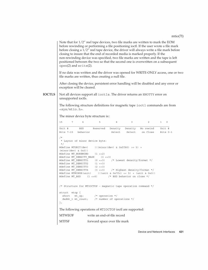
Note that for 1/2” reel tape devices, two file marks are written to mark the EOMbefore rewinding or performing a file positioning ioctl. If the user wrote a file markbefore closing a 1/2” reel tape device, the driver will always write a file mark beforeclosing to insure that the end of recorded media is marked properly. If thenon-rewinding device was specified, two file marks are written and the tape is leftpositioned between the two so that the second one is overwritten on a subsequentopen(2) and write(2).
If no data was written and the driver was opened for WRITE-ONLY access, one or twofile marks are written, thus creating a null file.
After closing the device, persistent error handling will be disabled and any error orexception will be cleared.
Not all devices support all ioctls. The driver returns an ENOTTY error onunsupported ioctls.
The following structure definitions for magnetic tape ioctl commands are from<sys/mtio.h>.
The minor device byte structure is::
15 7 6 5 4 3 2 1 0________________________________________________________________________Unit # BSD Reserved Density Density No rewind Unit #
Bits 7-15 behavior Select Select on Close Bits 0-1
/** Layout of minor device byte:*/#define MTUNIT(dev) (((minor(dev) & 0xff80) >> 5) +(minor(dev) & 0x3))#define MT_NOREWIND (1 <<2)#define MT_DENSITY_MASK (3 <<3)#define MT_DENSITY1 (0 <<3) /* Lowest density/format */#define MT_DENSITY2 (1 <<3)#define MT_DENSITY3 (2 <<3)#define MT_DENSITY4 (3 <<3) /* Highest density/format */#define MTMINOR(unit) (((unit & 0x7fc) << 5) + (unit & 0x3))#define MT_BSD (1 <<6) /* BSD behavior on close */
/* Structure for MTIOCTOP − magnetic tape operation command */
struct mtop {short mt_op; /* operation */daddr_t mt_count; /* number of operations */
};
The following operations of MTIOCTOP ioctl are supported:
MTWEOF write an end-of-file record
MTFSF forward space over file mark
mtio(7I)
IOCTLS
Device and Network Interfaces 421

MTBSF backward space over file mark (1/2", 8mm only)
MTFSR forward space to inter-record gap
MTBSR backward space to inter-record gap
MTREW rewind
MTOFFL rewind and take the drive off-line
MTNOP no operation, sets status only
MTRETEN retension the tape (cartridge tape only)
MTERASE erase the entire tape and rewind
MTEOM position to EOM
MTNBSF backward space file to beginning of file
MTSRSZ set record size
MTGRSZ get record size
MTLOAD load the next tape cartridge into the tape drive
/* structure for MTIOCGET − magnetic tape get status command */
struct mtget {short mt_type; /* type of magtape device */
/* the following two registers are device dependent */short mt_dsreg; /* “drive status” register */short mt_erreg; /* “error” register */
/* optional error info. */daddr_t mt_resid; /* residual count */daddr_t mt_fileno; /* file number of current position */daddr_t mt_blkno; /* block number of current position */ushort_t mt_flags;short mt_bf; /* optimum blocking factor */
};/* structure for MTIOCGETDRIVETYPE − get tape config data command */struct mtdrivetype_request {
int size;struct mtdrivetype *mtdtp;
};struct mtdrivetype {
char name[64]; /* Name, for debug */char vid[25]; /* Vendor id and product id */char type; /* Drive type for driver */int bsize; /* Block size */int options; /* Drive options */int max_rretries; /* Max read retries */int max_wretries; /* Max write retries */uchar_t densities[MT_NDENSITIES]; /* density codes,low->hi */uchar_t default_density; /* Default density chosen */uchar_t speeds[MT_NSPEEDS]; /* speed codes, low->hi */ushort_t non_motion_timeout; /* Seconds for non-motion */ushort_t io_timeout; /* Seconds for data to from tape */ushort_t rewind_timeout; /* Seconds to rewind */
mtio(7I)
422 man pages section 7: Device and Network Interfaces • Last Revised 14 Jan 1997
ushort_t space_timeout; /* Seconds to space anywhere */ushort_t load_timeout; /* Seconds to load tape and ready */ushort_t unload_timeout; /* Seconds to unload */ushort_t erase_timeout; /* Seconds to do long erase */
};
The MTWEOF ioctl is used for writing file marks to tape. Not only does this signify theend of a file, but also usually has the side effect of flushing all buffers in the tape driveto the tape medium. A zero count MTWEOF will just flush all the buffers and will notwrite any file marks. Because a successful completion of this tape operation willguarantee that all tape data has been written to the tape medium, it is recommendedthat this tape operation be issued before closing a tape device.
When spacing forward over a record (either data or EOF), the tape head is positionedin the tape gap between the record just skipped and the next record. When spacingforward over file marks (EOF records), the tape head is positioned in the tape gapbetween the next EOF record and the record that follows it.
When spacing backward over a record (either data or EOF), the tape head ispositioned in the tape gap immediately preceding the tape record where the tape headis currently positioned. When spacing backward over file marks (EOF records), thetape head is positioned in the tape gap preceding the EOF. Thus the next read wouldfetch the EOF.
Record skipping does not go past a file mark; file skipping does not go past the EOM.After an MTFSR <huge number> command, the driver leaves the tape logicallypositioned before the EOF. A related feature is that EOFs remain pending until the tapeis closed. For example, a program which first reads all the records of a file up to andincluding the EOF and then performs an MTFSF command will leave the tapepositioned just after that same EOF, rather than skipping the next file.
The MTNBSF and MTFSF operations are inverses. Thus, an “ MTFSF −1” is equivalent toan “ MTNBSF 1”. An “ MTNBSF 0” is the same as “ MTFSF 0”; both position the tapedevice at the beginning of the current file.
MTBSF moves the tape backwards by file marks. The tape position will end on thebeginning of the tape side of the desired file mark. An “ MTBSF 0” will position thetape at the end of the current file, before the filemark.
MTBSR and MTFSR operations perform much like space file operations, except thatthey move by records instead of files. Variable-length I/O devices (1/2” reel, forexample) space actual records; fixed-length I/O devices space physical records(blocks). 1/4” cartridge tape, for example, spaces 512 byte physical records. The statusioctl residual count contains the number of files or records not skipped.
mtio(7I)
Device and Network Interfaces 423
MTOFFL rewinds and, if appropriate, takes the device off-line by unloading the tape. Itis recommended that the device be closed after offlining and then re-opened after atape has been inserted to facilitate portability to other platforms and other operatingsystems. Attempting to re-open the device with no tape will result in an error unlessthe O_NDELAY flag is used. (See open(2).)
The MTRETEN retension ioctl applies only to 1/4” cartridge tape devices. It is used torestore tape tension, improving the tape’s soft error rate after extensive start-stopoperations or long-term storage.
MTERASE rewinds the tape, erases it completely, and returns to the beginning of tape.Erasing may take a long time depending on the device and/or tapes. For time details,refer to the the drive specific manual.
MTEOM positions the tape at a location just after the last file written on the tape. For1/4” cartridge and 8mm tape, this is after the last file mark on the tape. For 1/2” reeltape, this is just after the first file mark but before the second (and last) file mark onthe tape. Additional files can then be appended onto the tape from that point.
Note the difference between MTBSF (backspace over file mark) and MTNBSF(backspace file to beginning of file). The former moves the tape backward until itcrosses an EOF mark, leaving the tape positioned before the file mark. The latter leavesthe tape positioned after the file mark. Hence, "MTNBSF n" is equivalent to "MTBSF(n+1)" followed by "MTFSF 1". The 1/4” cartridge tape devices do not support MTBSF.
MTSRSZ and MTGRSZ are used to set and get fixed record lengths. The MTSRSZ ioctlallows variable length and fixed length tape drives that support multiple record sizesto set the record length. The mt_count field of the mtop struct is used to pass therecord size to/from the st driver. A value of 0 indicates variable record size. TheMTSRSZ ioctl makes a variable-length tape device behave like a fixed-length tapedevice. Refer to the specific tape driver man page for details.
MTLOAD loads the next tape cartridge into the tape drive. This is generally only usedwith stacker and tower type tape drives which handle multiple tapes per tape drive. Atape device without a tape inserted can be opened with the O_NDELAY flag, in order toexecute this operation.
The MTIOCGET get status ioctl call returns the drive ID (mt_type), sense key error(mt_erreg), file number (mt_fileno), optimum blocking factor (mt_bf) and record number(mt_blkno) of the last error. The residual count (mt_resid) is set to the number of bytesnot transferred or files/records not spaced. The flags word (mt_flags) containsinformation such as whether the device is SCSI, whether it is a reel device, andwhether the device supports absolute file positioning.
The MTIOCGETDRIVETYPE get drivetype ioctl call returns the name of the tape driveas defined in st.conf (name), Vendor ID and model (product), ID (vid), type of tapedevice (type), block size (bsize), drive options (options), maximum read retry count(max_rretries), maximum write retry count (max_wretries), densities supported by thedrive (densities), and default density of the tape drive (default_density).
mtio(7I)
424 man pages section 7: Device and Network Interfaces • Last Revised 14 Jan 1997

MTIOCPERSISTENT enables/disables persistent error handling
MTIOCPERSISTENTSTATUS queries for persistent error handling
MTIOCLRERR clears persistent error handling
MTIOCGUARANTEEDORDER checks whether driver guarantees order ofI/O’s
The MTIOCPERSISTENT ioctl enables or disables persistent error handling. It takes asan argument a pointer to an integer that turns it either on or off. If the ioctl succeeds,the desired operation was successful. It will wait for all outstanding I/O’s to completebefore changing the persistent error handling status. For example,
int on = 1;ioctl(fd, MTIOCPERSISTENT, &on);int off = 0;
ioctl(fd, MTIOCPERSISTENT, &off);
The MTIOCPERSISTENTSTATUS ioctl enables or disables persistent error handling. Ittakes as an argument a pointer to an integer inserted by the driver. The integer can beeither 1 if persistent error handling is ’on’, or 0 if persistent error handling is ’off’. Itwill not wait for outstanding I/O’s. For example,
int query;
ioctl(fd, MTIOCPERSISTENTSTATUS, &query);
The MTIOCLRERR ioctl clears persistent error handling and allows tape operations tocontinual normally. This ioctl requires no argument and will always succeed, even ifpersistent error handling has not been enabled. It will wait for any outstanding I/O’sbefore it clears the error.
The MTIOCGUARANTEEDORDER ioctl is used to determine whether the driverguarantees the order of I/O’s. It takes no argument. If the ioctl succeeds, the driverwill support guaranteed order. If the driver does not support guaranteed order, then itshould not be used for asynchronous I/O with libaio. It will wait for anyoutstanding I/O’s before it returns. For example,
ioctl(fd, MTIOCGUARANTEEDORDER)
See the Persistent Error Handling subsection above for more information onpersistent error handling.
MTIOCSTATE This ioctl blocks until the state of the drive, inserted or ejected, ischanged. The argument is a pointer to a mtio_state, enum,whose possible enumerations are listed below. The initial valueshould be either the last reported state of the drive, orMTIO_NONE. Upon return, the enum pointed to by the argument isupdated with the current state of the drive.
mtio(7I)
Persistent ErrorHandling IOCTLs
and AsynchronousTape Operations
Asynchronous andState Change
IOCTLS
Device and Network Interfaces 425

enum mtio_state {MTIO_NONE /* Return tape’s current state */MTIO_EJECTED /* Tape state is “ejected” */MTIO_INSERTED /* Tape state is “inserted” */
;
When using asynchronous operations, most ioctls will wait for all outstandingcommands to complete before they are executed.
MTIOCRESERVE reserve the tape drive
MTIOCRELEASE revert back to the default behavior ofreserve on open/release on close
MTIOCFORCERESERVE reserve the tape unit by breakingreservation held by another host
The MTIOCRESERVE ioctl reserves the tape drive such that it does not release the tapedrive at close. This changes the default behavior of releasing the device upon close.Reserving the tape drive that is already reserved has no effect. For example,
ioctl(fd, MTIOCRESERVE);
The MTIOCRELEASE ioctl reverts back to the default behavior of reserve onopen/release on close operation, and a release will occur during the next close.Releasing the tape drive that is already released has no effect. For example,
ioctl(fd, MTIOCRELEASE);
The MTIOCFORCERESERVE ioctl breaks a reservation held by another host,interrupting any I/O in progress by that other host, and then reserves the tape unit.This ioctl can be executed only with super-user privileges. It is recommended to openthe tape device in O_NDELAY mode when this ioctl needs to be executed, otherwise theopen will fail if another host indeed has it reserved. For example,
ioctl(fd, MTIOCFORCERESERVE);
MTIOCSHORTFMK enables/disable support for writing shortfilemarks. This is specific to Exabyte drives.
MTIOCREADIGNOREILI enables/disable supress incorrect lengthindicator support during reads
MTIOCREADIGNOREEOFS enables/disable support for reading pasttwo EOF marks which otherwise indicateEnd-Of-recording-Media (EOM) in the caseof 1/2" reel tape drives
mtio(7I)
IOCTLS forMulti-initiatorConfigurations
IOCTLS forHandling TapeConfiguration
Options
426 man pages section 7: Device and Network Interfaces • Last Revised 14 Jan 1997
The MTIOCSHORTFMK ioctl enables or disables support for short filemarks. This ioctl isonly applicable to Exabyte drives which support short filemarks. As an argument, ittakes a pointer to an integer. If 0 (zero) is the specified integer, then long filemarks willbe written. If 1 is the specified integer, then short filemarks will be written. Thespecified tape bahavior will be in effect until the device is closed.
For example:
int on = 1;int off = 0;/* enable short filemarks */ioctl(fd, MTIOSHORTFMK, &on);/* disable short filemarks */
ioctl(fd, MTIOCSHORTFMK, &off);
Tape drives which do not support short filemarks will return an errno of ENOTTY.
The MTIOCREADIGNOREILI ioctl enables or disables the suppress incorrect lengthindicator (SILI) support during reads. As an argument, it takes a pointer to an integer.If 0 (zero) is the specified integer, SILI will not be used during reads and incorrectlength indicator will not be supressed. If 1 is the specified integer, SILI will be usedduring reads and incorrect length indicator will be supressed. The specified tapebahavior will be in effect until the device is closed.
For example:
int on = 1;int off = 0;ioctl(fd, MTIOREADIGNOREILI, &on);
ioctl(fd, MTIOREADIGNOREILI, &off);
The MTIOCREADIGNOREEOFS ioctl enables or disables support for reading pastdouble EOF marks which otherwise indicate End-Of-recorded-media (EOM) in thecase of 1/2" reel tape drives. As an argument, it takes a pointer to an integer. If 0 (zero)is the specified integer, then double EOF marks indicate End-Of-recodred-media(EOD). If 1 is the specified integer, the double EOF marks no longer indicate EOM,thus allowing applications to read past two EOF marks. In this case it is theresponsibility of the application to detect end-of-recorded-media (EOM). The specifiedtape bahavior will be in effect until the device is closed.
For example:
int on = 1;int off = 0;ioctl(fd, MTIOREADIGNOREEOFS, &on);
ioctl(fd, MTIOREADIGNOREEOFS, &off);
Tape drives other than 1/2" reel tapes will return an errno of ENOTTY.
mtio(7I)
Device and Network Interfaces 427

EXAMPLE 1 Tape Positioning and Tape Drives
Suppose you have written three files to the non-rewinding 1/2” tape device,/dev/rmt/0ln, and that you want to go back and dd(1M) the second file off thetape. The commands to do this are:
mt -F /dev/rmt/0lbn bsf 3mt -F /dev/rmt/0lbn fsf 1
dd if=/dev/rmt/0ln
To accomplish the same tape positioning in a C program, followed by a get status ioctl:
struct mtop mt_command;struct mtget mt_status;mt_command.mt_op = MTBSF;mt_command.mt_count = 3;ioctl(fd, MTIOCTOP, &mt_command);mt_command.mt_op = MTFSF;mt_command.mt_count = 1;ioctl(fd, MTIOCTOP, &mt_command);
ioctl(fd, MTIOCGET, (char *)&mt_status);
or
mt_command.mt_op = MTNBSF;mt_command.mt_count = 2;ioctl(fd, MTIOCTOP, &mt_command);
ioctl(fd, MTIOCGET, (char *)&mt_status);
To get information about the tape drive:
struct mtdrivetype mtdt;struct mtdrivetype_request mtreq;mtreq.size = sizeof(struct mtdrivetype);mtreq.mtdtp = &mtdt;
ioctl(fd, MTIOCGETDRIVETYPE, &mtreq);
/dev/rmt/<unit number><density>[<BSD behavior>][<no rewind>]
Where density can be l, m, h, u/c (low, medium, high, ultra/compressed,respectively), the BSD behavior option is b, and the no rewind option is n.
For example, /dev/rmt/0hbn specifies unit 0, high density, BSD behavior and norewind.
mt(1), tar(1), dd(1M), open(2), read(2), write(2), aioread(3AIO),aiowrite(3AIO), ar(3HEAD), st(7D)
1/4 Inch Tape Drive Tutorial
mtio(7I)
EXAMPLES
FILES
SEE ALSO
428 man pages section 7: Device and Network Interfaces • Last Revised 14 Jan 1997

ncrs – SCSI host bus adapter driver
scsi@unit-address
The ncrs host bus adapter driver is a SCSA-compliant nexus driver that supports theLSI Logic (formerly Symbios Logic or NCR) 53C810, 53C810A, 53C815, 53C820,53C825, 53C825A, 53C860, 53C875, 53C875J, 53C876, and 53C895 SCSI (SmallComputer Systems Interface) chips.
The ncrs driver supports standard functions provided by the SCSA interface,including tagged and untagged queuing, Wide/Fast/Ultra/Ultra2 SCSI, and autorequest sense. The ncrs driver does not support linked commands.
� The LSI BIOS and the Solaris fdisk program may be incompatible. To avoidproblems, you should create an entry in the FDISK partition table using the DOSversion of FDISK (or equivalent utility) before installing the Solaris software. Toensure your system will reboot following Solaris installation, create a DOSpartition at least 1–cylinder in size that starts at cylinder 0.
� Add-in cards containing 53C815, 53C820, 53C825, or 53C825A controllers must beused in bus-mastering PCI slots. PCI slots on dual PCI slot motherboards aregenerally bus-master capable. However, motherboards that contain three or morePCI slots, or motherboards that feature several embedded PCI controllers maycontain PCI slots that are not bus-master capable.
� PCI motherboards that feature LSI Logic SDMS BIOS and an embedded 53C810 or53C810A controller may not be compatible with 53C82x add-in cards equippedwith LSI Logic SDMS BIOs. To prevent conflicts, it may be necessary to upgradethe motherboard BIOS, the add-in card, or both.
� Early PCI systems that are equipped with an 53C810 motherboard chip maycontain unconnected interrupt pins. These systems cannot be used with Solarissoftware.
� Wide-to–narrow target connections are not supported by Solaris software; as aresult, you should not attempt to connect wide targets to narrow connectors on anyof the supported devices.
� If your adapter supports the LSI Logic SCSI configuration utility, the value of thehost SCSI ID (found under the Adapter Setup menu) must be set to 7. (You canaccess the Symbios Logic SCSI configuration utility using Control-C.)
� If you experience problems with old target devices, add the following to the/kernel/drv/ncrs.conf file:
targetn-scsi-options = 0x0;
where n is the ID of the failing target.
� If you are using a Conner 1080S narrow SCSI drive, the system may display thefollowing warnings:
WARNING: /pci@0,0/pci1000,f@d (ncrs0):invalid reselection (0,0)
ncrs(7D)
NAME
SYNOPSIS
DESCRIPTION
Known Problemsand Limitations
Device and Network Interfaces 429

WARNING: /pci@0,0/pci1000,f@d/sd@0,0 (sd0);SCSI transport failed: ’reset: retrying command’
To supress these warnings, disable tagged queuing in the ncrs.conf file.
� Pentium motherboards (Intel NX chipset) using P90 or slower processors maycause the ncrs driver to hang. If this occurs, the following messages are displayedon the console:
WARNING: /pci@0,0/pci1000,3@6 (ncrs0)Unexpected DMA state:active dstat=c0<DMA-FIFO-empty,master-data-parity-error>
This is an unrecoverable state and the system will not install using the ncrs driver.
� The ncrs driver supports the 53C875 chipset Revision 4, or later versions only.Pre-release versions of the chip are not supported.
� On rare occasions, use of an SDT7000/SDT9000 tape drive may result in thefollowing message being displayed on the console:
Unexpected DMA state: ACTIVE. dstat=81<DMA-FIFO-empty,illegal-instruction>
After the above message is displayed, the system and tape drive will recover andremain usable.
The ncrs host bus adapter driver is configured by defining the properties found inncrs.conf. Properties in the ncrs.conf file that can be modified by the userinclude: scsi-options, target<n>-scsi-options, scsi-reset-delay,scsi-tag-age-limit, scsi-watchdog-tick, scsi-initiator-id, andncrs-iomap. Properties in the ncrs.conf file override global SCSI settings.
The property target<n>-scsi-options overrides the scsi-options propertyvalue for target<n>, where <n> can vary from decimal 0 to 15. The ncrs driversupports the following SCSI options: SCSI_OPTIONS_DR(0x8),SCSI_OPTIONS_SYNC(0x20), SCSI_OPTIONS_TAG(0x80), SCSI_OPTIONS_FAST(0x100), SCSI_OPTIONS_WIDE(0x200), SCSI_OPTIONS_FAST20(0x400), andSCSI_OPTIONS_FAST40(0x800).
After periodic interval scsi-watchdog-tick, the ncrs driver searches through allcurrent and disconnected commands for timeouts.
The scsi-tag-age-limit property represents the number of times that the ncrsdriver attempts to allocate a tag ID that is currently in use after going through all tagIDs in a circular fashion. When encountering the same tag ID usedscsi-tag-age-limit times, no additional commands are submitted to the targetuntil all outstanding commands complete or timeout.
The ncrs-iomap property enables the driver to utilize IO mapping (rather thanmemory mapping) of registers.
Refer to scsi_hba_attach(9F) for details.
ncrs(7D)
DRIVERCONFIGURATION
430 man pages section 7: Device and Network Interfaces • Last Revised 10 Oct 2000

EXAMPLE 1 A sample ncrs configuration file
Create a file called /kernel/drv/ncrs.conf, then add the following line:
scsi-options=0x78;
The above example disables tagged queuing, Fast/Ultra SCSI, and wide mode for allncrs instances.
The following example disables an option for one specific ncrs device. Seedriver.conf(4) and pci(4) for more details.
name="ncrs" parent="/pci@1f,4000"unit-address="3"target1-scsi-options=0x58scsi-options=0x178 scsi-initiator-id=6;
In the example, the default initiator ID in OBP is 7; the change to ID 6 will occur atattach time. The scsi-options property is set for target 1 to 0x58 and all othertargets set to 0x178. Note that it may be preferable to change the initiator ID in OBP.
The physical path name of the parent can be determined using the /devices tree orby following the link of the logical device name:
# ls -l /dev/rdsk/c0t0d0s0lrwxrwxrwx 1 root root 45 May 16 10:08 /dev/rdsk/c0t0d0s0 ->
. . / . . /devices/pci@1f,4000/scsi@3/sd@0,0:a,raw
In the example above, the parent is /pci@1f,4000 and the unit-address is thenumber bound to the scsi@3 node.
To set scsi-options more specifically per target, do the following:
target1-scsi-options=0x78;device-type-scsi-options-list ="SEAGATE ST32550W", "seagate-scsi-options" ;seagate-scsi-options = 0x58;scsi-options=0x3f8;
With the exception of one specific disk type that has scsi-options set to 0x58, theexample above sets scsi-options for target 1 to 0x78 and all other targets to0x3f8.
The scsi-options properties that are specified per target ID have the highestprecedence, followed by scsi-options per device type. Global scsi-options (forall ncrs instances) per bus have the lowest precedence.
To turn on IO mapping for all ncrs cards in the system, do the following:
ncrs-iomap=1;
The above action will noticeably slow the performance of the driver. You must rebootthe system for the specified scsi-options to take effect.
ncrs(7D)
EXAMPLES
Device and Network Interfaces 431
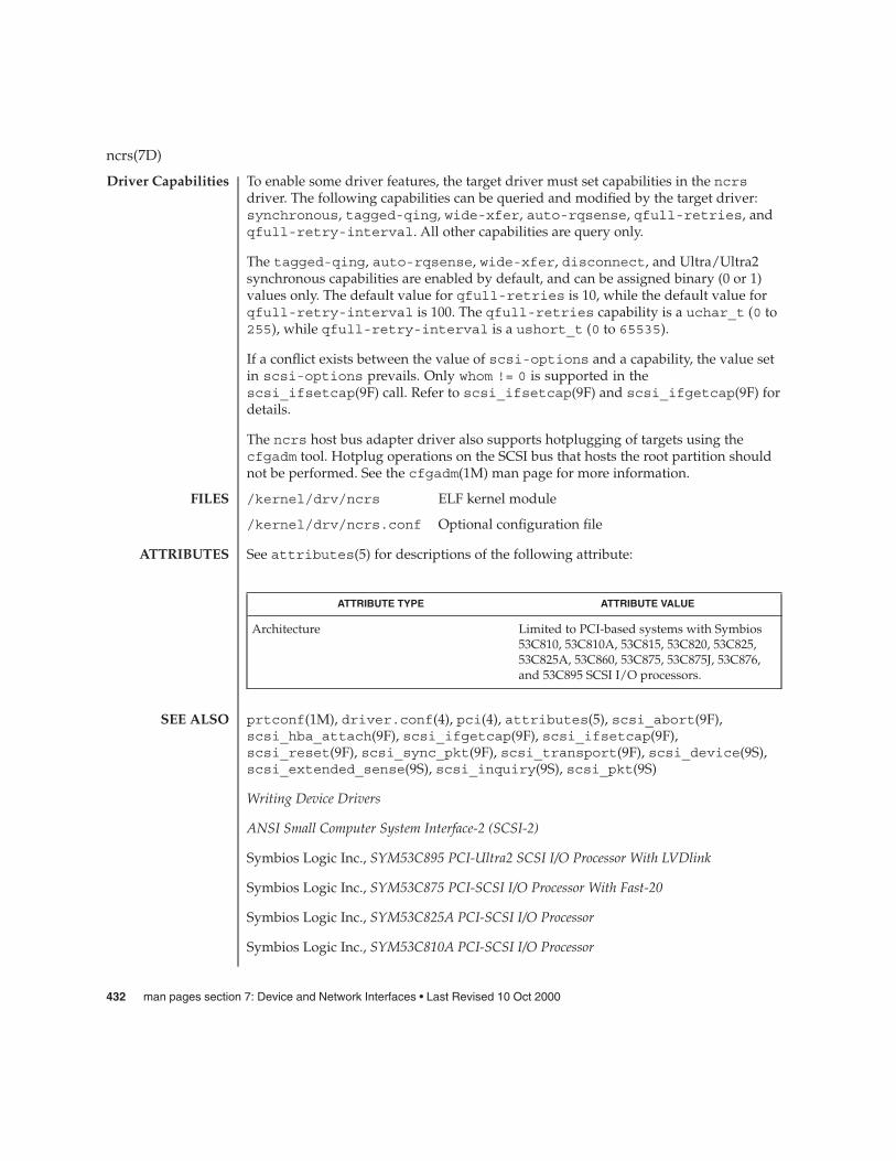
To enable some driver features, the target driver must set capabilities in the ncrsdriver. The following capabilities can be queried and modified by the target driver:synchronous, tagged-qing, wide-xfer, auto-rqsense, qfull-retries, andqfull-retry-interval. All other capabilities are query only.
The tagged-qing, auto-rqsense, wide-xfer, disconnect, and Ultra/Ultra2synchronous capabilities are enabled by default, and can be assigned binary (0 or 1)values only. The default value for qfull-retries is 10, while the default value forqfull-retry-interval is 100. The qfull-retries capability is a uchar_t (0 to255), while qfull-retry-interval is a ushort_t (0 to 65535).
If a conflict exists between the value of scsi-options and a capability, the value setin scsi-options prevails. Only whom != 0 is supported in thescsi_ifsetcap(9F) call. Refer to scsi_ifsetcap(9F) and scsi_ifgetcap(9F) fordetails.
The ncrs host bus adapter driver also supports hotplugging of targets using thecfgadm tool. Hotplug operations on the SCSI bus that hosts the root partition shouldnot be performed. See the cfgadm(1M) man page for more information.
/kernel/drv/ncrs ELF kernel module
/kernel/drv/ncrs.conf Optional configuration file
See attributes(5) for descriptions of the following attribute:
ATTRIBUTE TYPE ATTRIBUTE VALUE
Architecture Limited to PCI-based systems with Symbios53C810, 53C810A, 53C815, 53C820, 53C825,53C825A, 53C860, 53C875, 53C875J, 53C876,and 53C895 SCSI I/O processors.
prtconf(1M), driver.conf(4), pci(4), attributes(5), scsi_abort(9F),scsi_hba_attach(9F), scsi_ifgetcap(9F), scsi_ifsetcap(9F),scsi_reset(9F), scsi_sync_pkt(9F), scsi_transport(9F), scsi_device(9S),scsi_extended_sense(9S), scsi_inquiry(9S), scsi_pkt(9S)
Writing Device Drivers
ANSI Small Computer System Interface-2 (SCSI-2)
Symbios Logic Inc., SYM53C895 PCI-Ultra2 SCSI I/O Processor With LVDlink
Symbios Logic Inc., SYM53C875 PCI-SCSI I/O Processor With Fast-20
Symbios Logic Inc., SYM53C825A PCI-SCSI I/O Processor
Symbios Logic Inc., SYM53C810A PCI-SCSI I/O Processor
ncrs(7D)
Driver Capabilities
FILES
ATTRIBUTES
SEE ALSO
432 man pages section 7: Device and Network Interfaces • Last Revised 10 Oct 2000

The messages described below are logged and may also appear on the system console.
Device is using a hilevel intr
The device was configured with an interrupt level that cannot be used with this ncrsdriver. Check the PCI device.
map setup failed
The driver was unable to map device registers; check for bad hardware. Driver did notattach to device; SCSI devices will be inaccessible.
glm_script_alloc failed
The driver was unable to load the SCRIPTS for the SCSI processor; check for badhardware. Driver did not attach to device; SCSI devices will be inaccessible.
cannot map configuration space
The driver was unable to map in the configuration registers. Check for bad hardware.SCSI devices will be inaccessible
attach failed
The driver was unable to attach; usually preceded by another warning that indicateswhy attach failed. These can be considered hardware failures.
SCSI bus DATA IN phase parity error
The driver detected parity errors on the SCSI bus.
SCSI bus MESSAGE IN phase parity error
The driver detected parity errors on the SCSI bus.
SCSI bus STATUS phase parity error
The driver detected parity errors on the SCSI bus.
Unexpected bus free
Target disconnected from the bus without notice. Check for bad hardware.
Disconnected command timeout for Target <id>.<lun>
A timeout occurred while target id/lun was disconnected. This is usually a targetfirmware problem. For tagged queuing targets, <n> commands were outstandingwhen the timeout was detected.
Disconnected tagged cmd(s) (<n>) timeout for Target <id>.<lun>
A timeout occurred while target id/lun was disconnected. This is usually a targetfirmware problem. For tagged queuing targets, <n> commands were outstandingwhen the timeout was detected.
Connected command timeout for Target <id>.<lun>
ncrs(7D)
DIAGNOSTICS
Device and Network Interfaces 433

This is usually a SCSI bus problem. Check cables and termination.
Target <id> reducing sync. transfer rate
A data transfer hang or DATA-IN phase parity error was detected. The driver attemptsto eliminate this problem by reducing the data transfer rate.
Target <id> reverting to async. mode
A second data transfer hang was detected for this target. The driver attempts toeliminate this problem by reducing the data transfer rate.
Target <id> disabled wide SCSI mode
A second data phase hang was detected for this target. The driver attempts toeliminate this problem by disabling wide SCSI mode.
auto request sense failed
An attempt to start an auto request packet failed. Another auto request packet mayalready be in transport.
invalid reselection (<id>.<lun>)
A reselection failed; target accepted abort or reset, but still tries to reconnect. Checkfor bad hardware.
invalid intcode
The SCRIPTS processor generated an invalid SCRIPTS interrupt. Check for badhardware.
The ncrs hardware (53C875) supports Wide, Fast, and Ultra SCSI mode. Themaximum SCSI bandwidth is 40 MB/sec.
The ncrs hardware (53C895) supports Wide, Fast, Ultra and Ultra2 SCSI mode using aLVD bus. The maximum SCSI bandwidth is 80 MB/second.
The ncrs driver exports properties indicating the negotiated transfer speed per target(target<n>-sync-speed), whether wide bus is supported (target<n>-wide) forthat particular target (target<n>-scsi-options), and whether tagged queuing hasbeen enabled (target<n>-TQ). The sync-speed property value indicates the datatransfer rate in KB/sec. The target<n>-TQ and the target<n>-wide propertyhave value 1 (to indicate that the corresponding capability is enabled for that target),or 0 (to indicate that the capability is disabled for that targe). See prtconf(1M)(verbose option) for details on viewing the ncrs properties.
scsi, instance #0Driver properties:
name <target6-TQ> length <4>value <0x00000000>.
name <target6-wide> length <4>value <0x00000000>.
name <target6-sync-speed> length <4>
ncrs(7D)
NOTES
434 man pages section 7: Device and Network Interfaces • Last Revised 10 Oct 2000

value <0x00002710>.name <target1-TQ> length <4>
value <0x00000001>.name <target1-wide> length <4>
value <0x00000000>.name <target1-sync-speed> length <4>
value <0x00002710>.name <target0-TQ> length <4>
value <0x00000001>.name <target0-wide> length <4>
value <0x00000001>.name <target0-sync-speed> length <4>
value <0x00009c40>.name <scsi-options> length <4>
value <0x000007f8>.name <scsi-watchdog-tick> length <4>
value <0x0000000a>.name <scsi-tag-age-limit> length <4>
value <0x00000002>.name <scsi-reset-delay> length <4>
value <0x00000bb8>.name <latency-timer> length <4>
value <0x00000088>.name <cache-line-size> length <4>
value <0x00000010>.
ncrs(7D)
Device and Network Interfaces 435

dr, drmach, ngdr, ngdrmach – Sun Enterprise 10000 and Sun Fire 15K dynamicreconfiguration driver
dr
drmach
ngdr
ngdrmach
The dynamic reconfiguration (DR) driver consists of a platform-independent driverand a platform-specific module. The DR driver uses standard features of the Solarisoperating environment whenever possible to control DR operations and calls theplatform specific module as needed. The DR driver creates minor nodes in the filesystem that serve as attachment points for DR operations.
The DR driver provides a pseudo-driver interface to sequence attach and detachoperations on system boards using file system entry points referred to as ”attachmentpoints.” The form of the attachment point depends on the platform.
On the Sun Enterprise 10000 server, the DR driver consists of a platform-independentdriver (ngdr) and a platform-specific module (ngdrmach).
The domain configuration server (DCS) accepts DR requests from the system servicesprocessor (SSP) and uses the libcfgadm(3LIB) interface to initiate the DR operation.After the operation is performed, the results are returned to the SSP. For moreinformation about the DCS on the Sun Enterprise 10000, refer to the dcs(1M) manpage and the Sun Enterprise 10000 Dynamic Reconfiguration User Guide.
The DR driver creates physical attachment points for system board slots that takes thefollowing form:
/devices/pseudo/ngdr@0:SBx
Where x represents the slot number (0 to 15) for a particular board.
The cfgadm_sbd(1M) plugin creates dynamic attachment points that refer tocomponents on system boards, including CPUs, memory, or I/O devices. Refer to thecfgadm_sbd(1M) man page for more details.
On the Sun Fire 15K server, the DR driver consists of a platform-independent driver(dr) and a platform-specific module (drmach).
The domain configuration server (DCS) accepts DR requests from the domainconfiguration agent (DCA) that runs on the Sun Fire 15K system controller. After theDCS accepts a DR request, it uses the libcfgadm(3LIB) interface to initiate the DRoperation. After the operation is performed, the results are returned to the DCA. Formore information about the DCS, refer to the dcs(1M) man page and the Sun Fire 15KDynamic Reconfiguration User Guide. For more information about the DCA, refer to theSystem Management Services (SMS) Dynamic Reconfiguration User Guide.
ngdr(7d)
NAME
SYNOPSIS
DESCRIPTION
Sun Enterprise10000 Server
Sun Fire 15KServer
436 man pages section 7: Device and Network Interfaces • Last Revised 26 Sep 2001
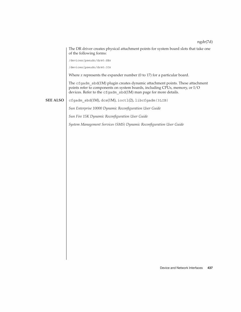
The DR driver creates physical attachment points for system board slots that take oneof the following forms:
/devices/pseudo/dr@0:SBx
/devices/pseudo/dr@0:IOx
Where x represents the expander number (0 to 17) for a particular board.
The cfgadm_sbd(1M) plugin creates dynamic attachment points. These attachmentpoints refer to components on system boards, including CPUs, memory, or I/Odevices. Refer to the cfgadm_sbd(1M) man page for more details.
cfgadm_sbd(1M), dcs(1M), ioctl(2), libcfgadm(3LIB)
Sun Enterprise 10000 Dynamic Reconfiguration User Guide
Sun Fire 15K Dynamic Reconfiguration User Guide
System Management Services (SMS) Dynamic Reconfiguration User Guide
ngdr(7d)
SEE ALSO
Device and Network Interfaces 437

dr, drmach, ngdr, ngdrmach – Sun Enterprise 10000 and Sun Fire 15K dynamicreconfiguration driver
dr
drmach
ngdr
ngdrmach
The dynamic reconfiguration (DR) driver consists of a platform-independent driverand a platform-specific module. The DR driver uses standard features of the Solarisoperating environment whenever possible to control DR operations and calls theplatform specific module as needed. The DR driver creates minor nodes in the filesystem that serve as attachment points for DR operations.
The DR driver provides a pseudo-driver interface to sequence attach and detachoperations on system boards using file system entry points referred to as ”attachmentpoints.” The form of the attachment point depends on the platform.
On the Sun Enterprise 10000 server, the DR driver consists of a platform-independentdriver (ngdr) and a platform-specific module (ngdrmach).
The domain configuration server (DCS) accepts DR requests from the system servicesprocessor (SSP) and uses the libcfgadm(3LIB) interface to initiate the DR operation.After the operation is performed, the results are returned to the SSP. For moreinformation about the DCS on the Sun Enterprise 10000, refer to the dcs(1M) manpage and the Sun Enterprise 10000 Dynamic Reconfiguration User Guide.
The DR driver creates physical attachment points for system board slots that takes thefollowing form:
/devices/pseudo/ngdr@0:SBx
Where x represents the slot number (0 to 15) for a particular board.
The cfgadm_sbd(1M) plugin creates dynamic attachment points that refer tocomponents on system boards, including CPUs, memory, or I/O devices. Refer to thecfgadm_sbd(1M) man page for more details.
On the Sun Fire 15K server, the DR driver consists of a platform-independent driver(dr) and a platform-specific module (drmach).
The domain configuration server (DCS) accepts DR requests from the domainconfiguration agent (DCA) that runs on the Sun Fire 15K system controller. After theDCS accepts a DR request, it uses the libcfgadm(3LIB) interface to initiate the DRoperation. After the operation is performed, the results are returned to the DCA. Formore information about the DCS, refer to the dcs(1M) man page and the Sun Fire 15KDynamic Reconfiguration User Guide. For more information about the DCA, refer to theSystem Management Services (SMS) Dynamic Reconfiguration User Guide.
ngdrmach(7d)
NAME
SYNOPSIS
DESCRIPTION
Sun Enterprise10000 Server
Sun Fire 15KServer
438 man pages section 7: Device and Network Interfaces • Last Revised 26 Sep 2001

The DR driver creates physical attachment points for system board slots that take oneof the following forms:
/devices/pseudo/dr@0:SBx
/devices/pseudo/dr@0:IOx
Where x represents the expander number (0 to 17) for a particular board.
The cfgadm_sbd(1M) plugin creates dynamic attachment points. These attachmentpoints refer to components on system boards, including CPUs, memory, or I/Odevices. Refer to the cfgadm_sbd(1M) man page for more details.
cfgadm_sbd(1M), dcs(1M), ioctl(2), libcfgadm(3LIB)
Sun Enterprise 10000 Dynamic Reconfiguration User Guide
Sun Fire 15K Dynamic Reconfiguration User Guide
System Management Services (SMS) Dynamic Reconfiguration User Guide
ngdrmach(7d)
SEE ALSO
Device and Network Interfaces 439

null – the null file, also called the null device
/dev/null
Data written on the null special file, /dev/null, is discarded.
Reads from a null special file always return 0 bytes.
Mapping a null special file creates an address reservation of a length equal to thelength of the mapping, and rounded up to the nearest page size as returned bysysconf(3C). No resources are consumed by the reservation. Mappings can be placedin the resulting address range via subsequent calls to mmap with the -MAP_FIXEDoption set.
/dev/null
mmap(2), sysconf(3C)
null(7D)
NAME
SYNOPSIS
DESCRIPTION
FILES
SEE ALSO
440 man pages section 7: Device and Network Interfaces • Last Revised 4 April 2001

ocf_escr1 – Sun external serial smart card terminal driver
The ocf_escr1 driver is an OpenCard Framework (OCF)-compliant card terminaldriver for the Sun external serial smart card reader.
The ocf_escr1 driver is part of the OCF framework stack and is started by the OCFstartup script. The Sun serial smart card reader requires a host serial port and isaccessed through the character-special devices. The reader is powered from thekeyboard port.
/usr/share/lib/smartcard/scmrsr3.jarJava-archived driver class files
/dev/cua/xAsynchronous serial line using port x
ports(1M), smartcard(1M), smartcard(5)
ocf_escr1(7D)
NAME
DESCRIPTION
APPLICATIONPROGRAMMING
INTERFACE
FILES
SEE ALSO
Device and Network Interfaces 441

ocf_ibutton – iButton Smart Card terminal driver
The ocf_ibutton smart card terminal driver is an OpenCard Framework(OCF)-compliant terminal driver for the Dallas Semiconductor iButton reader.
The ocf_ibutton smart card terminal driver is part of the OCF framework stack andis started by the OCF startup script. The iButton reader requires a host serial port andis accessed through the character-special devices.
/usr/share/lib/smartcard/ibutton.jarJava-archived driver class files
/dev/cua/xAsynchronous serial line using port x
ports(1M), smartcard(1M), smartcard(5)
ocf_ibutton(7D)
NAME
DESCRIPTION
APPLICATIONPROGRAMMING
INTERFACE
FILES
SEE ALSO
442 man pages section 7: Device and Network Interfaces • Last Revised 8 Jul 1999

ocf_iscr1 – I2C smart card card terminal driver
The ocf_iscr1 I2C smart card card terminal driver is an OpenCard Framework(OCF)-compliant terminal driver for SCM Microsystems Smart Transporter chips thatfeature the I2C bus interface.
The ocf_iscr1 I2C driver is part of the OCF framework stack and is started by theOCF server deamon. The smart card reader requires the/platform/sun4u/kernel/drv/sparcv9/scmi2c Solaris hardware device driverto be installed and present to work. The smart card reader driver also requires devicenode /dev/scmi2cn, where n is the nth SCM I2C card terminal reader installed.
/usr/share/lib/smartcard/scmiscr.jarJava-archived driver class files
/usr/share/lib/smartcard/smartos.jarSCM Microsystems SmartOS Java-archived driver class file
/dev/scmi2cnSCM Microsystems Smart Transporter chip device node
/platform/sun4u/kernel/drv/sparcv9/scmi2cSCM Microsystems Smart Transporter chip kernel module
smartcard(1M), smartcard(5)
ocf_iscr1(7D)
NAME
DESCRIPTION
APPLICATIONPROGRAMMING
INTERFACE
FILES
SEE ALSO
Device and Network Interfaces 443

ohci – OpenHCI host controller driver
usb@unit-address
The ohci driver is a USBA (Solaris USB Architecture) compliant nexus driver thatsupports the Open Host Controller Interface Specification 1.0a, an industry standarddeveloped by Compaq, Microsoft, and National Semiconductor.
The ohci driver supports bulk, interrupt, control and isochronous transfers.
/kernel/drv/ohci32 bit ELF kernel module
/kernel/drv/sparcv9/ohci64 bit ELF kernel module
/kernel/drv/ohci.confdriver configuration file
See attributes(5) for descriptions of the following attributes:
ATTRIBUTE TYPE ATTRIBUTE VALUE
Architecture PCI-based SPARC
Availability SUNWusb, SUNWusbx
attributes(5), hubd(7D), usba(7D)
Writing Device Drivers
Universal Serial Bus Specification 1.0 and 1.1
Open Host Controller Interface Specification for USB 1.0a
System Administration Guide: Basic Administration
http://www.sun.com/io
All host controller errors are passed to the client drivers. Root errors are documentedin hubd(7D).
In addition to being logged, the following messages may appear on the systemconsole. All messages are formatted in the following manner:
WARNING: <device path> <ohci<instance number>>: Error message...
Unrecoverable USB Hardware Error. There was an unrecoverable USB hardwareerror reported by the OHCI Controller. Pleasereboot the system. If this problem persists,contact your system vendor.
ohci(7D)
NAME
SYNOPSIS
DESCRIPTION
FILES
ATTRIBUTES
SEE ALSO
DIAGNOSTICS
444 man pages section 7: Device and Network Interfaces • Last Revised 18 Dec 2001

No SOF interrupts. The USB hardware is not generating StartOf Frame interrupts. Please reboot thesystem. If this problem persists, contact yoursystem vendor.
ohci(7D)
Device and Network Interfaces 445
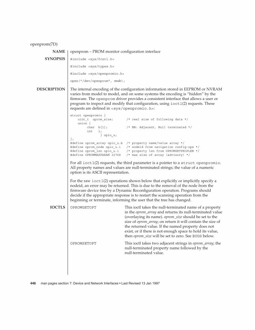
openprom – PROM monitor configuration interface
#include <sys/fcntl.h>
#include <sys/types.h>
#include <sys/openpromio.h>
open("/dev/openprom", mode);
The internal encoding of the configuration information stored in EEPROM or NVRAMvaries from model to model, and on some systems the encoding is “hidden” by thefirmware. The openprom driver provides a consistent interface that allows a user orprogram to inspect and modify that configuration, using ioctl(2) requests. Theserequests are defined in <sys/openpromio.h>:
struct openpromio {uint_t oprom_size; /* real size of following data */union {
char b[1]; /* NB: Adjacent, Null terminated */int i;
} opio_u;};#define oprom_array opio_u.b /* property name/value array */#define oprom_node opio_u.i /* nodeid from navigation config-ops */#define oprom_len opio_u.i /* property len from OPROMGETPROPLEN */#define OPROMMAXPARAM 32768 /* max size of array (advisory) */
For all ioctl(2) requests, the third parameter is a pointer to a struct openpromio.All property names and values are null-terminated strings; the value of a numericoption is its ASCII representation.
For the raw ioctl(2) operations shown below that explicitly or implicitly specify anodeid, an error may be returned. This is due to the removal of the node from thefirmware device tree by a Dynamic Reconfiguration operation. Programs shoulddecide if the appropriate response is to restart the scanning operation from thebeginning or terminate, informing the user that the tree has changed.
OPROMGETOPT This ioctl takes the null-terminated name of a propertyin the oprom_array and returns its null-terminated value(overlaying its name). oprom_size should be set to thesize of oprom_array; on return it will contain the size ofthe returned value. If the named property does notexist, or if there is not enough space to hold its value,then oprom_size will be set to zero. See BUGS below.
OPROMSETOPT This ioctl takes two adjacent strings in oprom_array; thenull-terminated property name followed by thenull-terminated value.
openprom(7D)
NAME
SYNOPSIS
DESCRIPTION
IOCTLS
446 man pages section 7: Device and Network Interfaces • Last Revised 13 Jan 1997

OPROMSETOPT2 This ioctl is similar to OPROMSETOPT, except that ituses the difference between the actual user array sizeand the length of the property name plus its nullterminator.
OPROMNXTOPT This ioctl is used to retrieve properties sequentially.The null-terminated name of a property is placed intooprom_array and on return it is replaced with thenull-terminated name of the next property in thesequence, with oprom_size set to its length. A null stringon input means return the name of the first property;an oprom_size of zero on output means there are nomore properties.
OPROMNXTOPROMCHILDOPROMGETPROPOPROMNXTPROP These ioctls provide an interface to the raw config_ops
operations in the PROM monitor. One can use them totraverse the system device tree; see prtconf(1M).
OPROMGETPROPLEN This ioctl provides an interface to the property lengthraw config op. It takes the name of a property in thebuffer, and returns an integer in the buffer. It returnsthe integer -1 if the property does not exist; 0 if theproperty exists, but has no value (a boolean property);or a positive integer which is the length of the propertyas reported by the PROM monitor. See BUGS below.
OPROMGETVERSION This ioctl returns an arbitrary and platform-dependentNULL-terminated string in oprom_array, representingthe underlying version of the firmware.
EAGAIN There are too many opens of the /dev/openprom device.
EFAULT A bad address has been passed to an ioctl(2) routine.
EINVAL The size value was invalid, or (for OPROMSETOPT) the propertydoes not exist, or an invalid ioctl is being issued, or the ioctl is notsupported by the firmware, or the nodeid specified does not existin the firmware device tree.
ENOMEM The kernel could not allocate space to copy the user’s structure.
EPERM Attempts have been made to write to a read-only entity, or readfrom a write only entity.
ENXIO Attempting to open a non-existent device.
openprom(7D)
ERRORS
Device and Network Interfaces 447

EXAMPLE 1 oprom_array Data Allocation and Reuse
The following example shows how the oprom_array is allocated and reused for datareturned by the driver.
/** This program opens the openprom device and prints the platform* name (root node name property) and the prom version.** NOTE: /dev/openprom is readable only by user ’root’ or group ’sys’.*/#include <stdio.h>#include <string.h>#include <fcntl.h>#include <errno.h>#include <unistd.h>#include <stdlib.h>#include <sys/openpromio.h>#define min(a, b) (a < b ? a : b)#define max(a, b) (a > b ? a : b)#define MAXNAMESZ 32 /* Maximum property *name* size */#define BUFSZ 1024 /* A Handly default buffer size */#define MAXVALSZ (BUFSZ - sizeof (int))static char *promdev = "/dev/openprom";/** Allocate an openpromio structure big enough to contain* a bufsize’d oprom_array. Zero out the structure and* set the oprom_size field to bufsize.*/static struct openpromio *opp_zalloc(size_t bufsize){
struct openpromio *opp;opp = malloc(sizeof (struct openpromio) + bufsize);(void) memset(opp, 0, sizeof (struct openpromio) + bufsize);opp->oprom_size = bufsize;return (opp);
}/** Free a ’struct openpromio’ allocated by opp_zalloc*/static voidopp_free(struct openpromio *opp){
free(opp);}/** Get the peer node of the given node. The root node is the peer of zero.* After changing nodes, property lookups apply to that node. The driver* ’remembers’ what node you are in.*/static intpeer(int nodeid, int fd){
struct openpromio *opp;int i;opp = opp_zalloc(sizeof (int));
openprom(7D)
EXAMPLES
448 man pages section 7: Device and Network Interfaces • Last Revised 13 Jan 1997

EXAMPLE 1 oprom_array Data Allocation and Reuse (Continued)
opp->oprom_node = nodeid;if (ioctl(fd, OPROMNEXT, opp) < 0) {
perror("OPROMNEXT");exit(1);
}i = opp->oprom_node;opp_free(opp);return(i);
}intmain(void){
struct openpromio *opp;int fd, proplen;size_t buflen;if ((fd = open(promdev, O_RDONLY)) < 0) {
fprintf(stderr, "Cannot open openprom device\n");exit(1);
}/** Get and print the length and value of the* root node ’name’ property*/(void) peer(0, fd); /* Navigate to the root node *//** Allocate an openpromio structure sized big enough to* take the string "name" as input and return the int-sized* length of the ’name’ property.* Then, get the length of the ’name’ property.*/buflen = max(sizeof (int), strlen("name") + 1);opp = opp_zalloc(buflen);(void) strcpy(opp->oprom_array, "name");if (ioctl(fd, OPROMGETPROPLEN, opp) < 0) {
perror("OPROMGETPROPLEN");/* exit(1); */proplen = 0; /* down-rev driver? */
} elseproplen = opp->oprom_len;
opp_free(opp);if (proplen == -1) {
printf("’name’ property does not exist!\n");exit (1);
}/** Allocate an openpromio structure sized big enough* to take the string ’name’ as input and to return* ’proplen + 1’ bytes. Then, get the value of the* ’name’ property. Note how we make sure to size the* array at least one byte more than the returned length* to guarantee NULL termination.*/buflen = (proplen ? proplen + 1 : MAXVALSZ);buflen = max(buflen, strlen("name") + 1);
openprom(7D)
Device and Network Interfaces 449
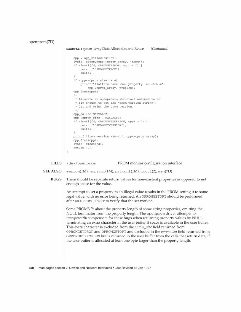
EXAMPLE 1 oprom_array Data Allocation and Reuse (Continued)
opp = opp_zalloc(buflen);(void) strcpy(opp->oprom_array, "name");if (ioctl(fd, OPROMGETPROP, opp) < 0) {
perror("OPROMGETPROP");exit(1);
}if (opp->oprom_size != 0)
printf("Platform name <%s> property len <%d>\n",opp->oprom_array, proplen);
opp_free(opp);/** Allocate an openpromio structure assumed to be* big enough to get the ’prom version string’.* Get and print the prom version.*/opp_zalloc(MAXVALSZ);opp->oprom_size = MAXVALSZ;if (ioctl(fd, OPROMGETVERSION, opp) < 0) {
perror("OPROMGETVERSION");exit(1);
}printf("Prom version <%s>\n", opp->oprom_array);opp_free(opp);(void) close(fd);return (0);
}
/dev/openprom PROM monitor configuration interface
eeprom(1M), monitor(1M), prtconf(1M), ioctl(2), mem(7D)
There should be separate return values for non-existent properties as opposed to notenough space for the value.
An attempt to set a property to an illegal value results in the PROM setting it to somelegal value, with no error being returned. An OPROMGETOPT should be performedafter an OPROMSETOPT to verify that the set worked.
Some PROMS lie about the property length of some string properties, omitting theNULL terminator from the property length. The openprom driver attempts totransparently compensate for these bugs when returning property values by NULLterminating an extra character in the user buffer if space is available in the user buffer.This extra character is excluded from the oprom_size field returned fromOPROMGETPROP and OPROMGETOPT and excluded in the oprom_len field returned fromOPROMGETPROPLEN but is returned in the user buffer from the calls that return data, ifthe user buffer is allocated at least one byte larger than the property length.
openprom(7D)
FILES
SEE ALSO
BUGS
450 man pages section 7: Device and Network Interfaces • Last Revised 13 Jan 1997
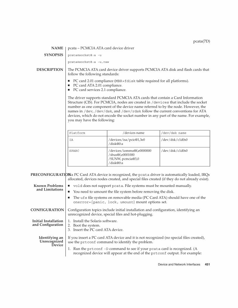
pcata – PCMCIA ATA card device driver
pcata@socket#:a -u
pcata@socket#:a -u,raw
The PCMCIA ATA card device driver supports PCMCIA ATA disk and flash cards thatfollow the following standards:
� PC card 2.01 compliance (MBR+fdisk table required for all platforms).� PC card ATA 2.01 compliance.� PC card services 2.1 compliance.
The driver supports standard PCMCIA ATA cards that contain a Card InformationStructure (CIS). For PCMCIA, nodes are created in /devices that include the socketnumber as one component of the device name referred to by the node. However, thenames in /dev, /dev/dsk, and /dev/rdsk follow the current conventions for ATAdevices, which do not encode the socket number in any part of the name. For example,you may have the following:
Platform /devices name /dev/dsk name
IA /devices/isa/pcic@1,3e0/disk@0:a
/dev/dsk/c1d0s0
SPARC /devices/iommu@f,e0000000/sbus@f,e0001000/SUNW, pcmcia@3,0/disk@0:a
/dev/dsk/c1d0s0
If a PC Card ATA device is recognized, the pcata driver is automatically loaded, IRQsallocated, devices nodes created, and special files created (if they do not already exist).
� vold does not support pcata. File systems must be mounted manually.� You need to umount the file system before removing the disk.� The ufs file systems on removable media (PC Card ATA) should have one of the
onerror={panic, lock, umount} mount options set.
Configuration topics include initial installation and configuration, identifying anunrecognized device, special files and hot-plugging.
1. Install the Solaris software.2. Boot the system.3. Insert the PC card ATA device.
If you insert a PC card ATA device and it is not recognized (no special files created),use the prtconf command to identify the problem.
1. Run the prtconf -D command to see if your pcata card is recognized. (Arecognized device will appear at the end of the prtconf output. For example:
pcata(7D)
NAME
SYNOPSIS
DESCRIPTION
PRECONFIGURATION
Known Problemsand Limitations
CONFIGURATION
Initial Installationand Configuration
Identifying anUnrecognized
Device
Device and Network Interfaces 451
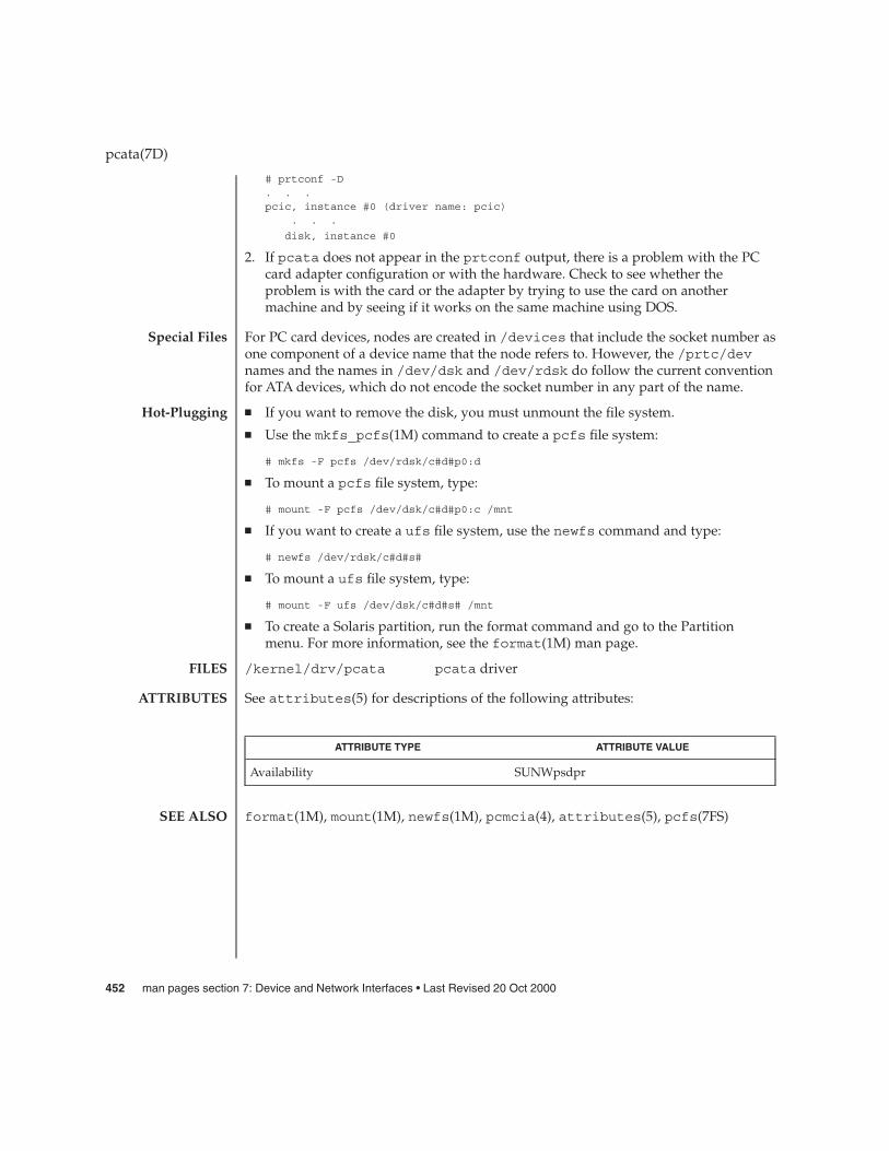
# prtconf -D. . .pcic, instance #0 (driver name: pcic)
. . .
disk, instance #0
2. If pcata does not appear in the prtconf output, there is a problem with the PCcard adapter configuration or with the hardware. Check to see whether theproblem is with the card or the adapter by trying to use the card on anothermachine and by seeing if it works on the same machine using DOS.
For PC card devices, nodes are created in /devices that include the socket number asone component of a device name that the node refers to. However, the /prtc/devnames and the names in /dev/dsk and /dev/rdsk do follow the current conventionfor ATA devices, which do not encode the socket number in any part of the name.
� If you want to remove the disk, you must unmount the file system.
� Use the mkfs_pcfs(1M) command to create a pcfs file system:
# mkfs -F pcfs /dev/rdsk/c#d#p0:d
� To mount a pcfs file system, type:
# mount -F pcfs /dev/dsk/c#d#p0:c /mnt
� If you want to create a ufs file system, use the newfs command and type:
# newfs /dev/rdsk/c#d#s#
� To mount a ufs file system, type:
# mount -F ufs /dev/dsk/c#d#s# /mnt
� To create a Solaris partition, run the format command and go to the Partitionmenu. For more information, see the format(1M) man page.
/kernel/drv/pcata pcata driver
See attributes(5) for descriptions of the following attributes:
ATTRIBUTE TYPE ATTRIBUTE VALUE
Availability SUNWpsdpr
format(1M), mount(1M), newfs(1M), pcmcia(4), attributes(5), pcfs(7FS)
pcata(7D)
Special Files
Hot-Plugging
FILES
ATTRIBUTES
SEE ALSO
452 man pages section 7: Device and Network Interfaces • Last Revised 20 Oct 2000

pcelx – 3COM EtherLink III PCMCIA Ethernet Adapter
network@<socket>:pcelx<socket>
The pcelx driver supports the 3COM EtherLink III PCMCIA PC Card as a standardEthernet type of device conforming to the DLPI interface specification. The driversupports the hot-plugging of the PC Card.
The PPA (Physical Point of Attachment) is defined by the socket number the PC Cardis inserted in. This means that for IP use, the PC Card should always be plugged intothe same socket that the network interface was initially brought up on or else anetwork reconfiguration should be done to take down the old interface and bring upthe new one.
The 3C589, 3C589B, and 3C589C versions of the PC Card are supported on the IAplatform. The 3C589B and 3C589C are supported on the SPARC platform.
� For IBM ThinkPad 760E series systems and systems using the TI PCI1130PCI-to-CardBus chip (such as the Dell Latitude XPi CD) only: Before bringing thesystem onto the network, put the PC Card into 8-bit mode by creating a file called/kernel/drv/pcelx.conf containing force-8bit=1;.
� It is not possible to boot or install the Solaris software using a 3Com EtherLink IIIPC Card device.
� If the 3Com PC Card device is recognized, the pcelx driver is automaticallyloaded, ports and IRQs allocated, and special files created (if they don’t alreadyexist). No manual configuration of the hardware is necessary or possible.
Network services are automatically started when the system is booted. These servicesare not started when a network interface is added or shut down after the system hasbeen brought up.
Configuration procedures include initial installation and configuration, identifying anunrecognized card and configuring two or more cards.
For initial installation and configuration, do the following steps:
1. Install the Solaris software.2. Boot the system.3. Insert the 3Com EtherLink III PC Card device.
If you insert a 3C589 card and it is not recognized (no special files created), use theprtconf command and attempt to identify the problem:
1. Become root.
2. Run the prtconf -D command to see if your 3C589 card is recognized. Arecognized device will appear in the prtconf output. For example:
# prtconf -D. . .pcic, instance #0 (driver name: pcic). . .
pcelx(7D)
NAME
SYNOPSIS
DESCRIPTION
PRECONFIGURATION
Known Problemsand Limitations
CONFIGURATION
Initial Installationand Configuration
Identifying anUnrecognized
Card
Device and Network Interfaces 453

network, instance #0 (driver name: pcelx)
3. If pcelx does not appear in the prtconf output, there is a problem with the PCCard adapter configuration or with the hardware. You can determine whether theproblem is with the card or the adapter by attempting to use the card on anothermachine or by using it on the same machine using DOS.
Because the 3C589 card is not supported during Solaris installation, you must updatenetwork configuration files before it can be used as a network interface:
1. Create a /etc/hostname.pcelx# file (where # is a socket number) to specify thehost name to be associated with this interface.
2. Add an IP address for the new host name to the /etc/inet/hosts file.
3. Ensure that the associated network is listed in /etc/inet/netmasks.
4. Ensure that the Name Service Switch /etc/nssswitch.conf configuration fileincludes the network and local services you need.
5. Reboot the system.
Device naming in /dev follows standard LAN device naming with the exception thatthe PPA (physical point of attachment) unit number is the socket where the cardresides, not the instance. For the pcelx driver, /dev/pcelx0 (or PPA 0 of/dev/pcelx) is the card in socket 0, while a card in socket 1 is /dev/pcelx1 (orPPA 1 of /dev/pcelx).
If you remove the 3C589 card, any information you send is discarded, and no errormessages are given.
When you reinsert the card in the same socket, the device operates normally. Thebehavior is similar to temporarily disconnecting the device from the network.
/kernel/drv/pcelx pcelx driver
/dev/pcelx DLPI Style 2 device
/dev/pcelxn DLPI Style 1 device where: n is the PCMCIA physicalsocket number.
pcmcia(4)
pcelx(7D)
Configuring Twoor More Cards
Special Files
Hot Plugging
FILES
SEE ALSO
454 man pages section 7: Device and Network Interfaces • Last Revised 20 Oct 2000
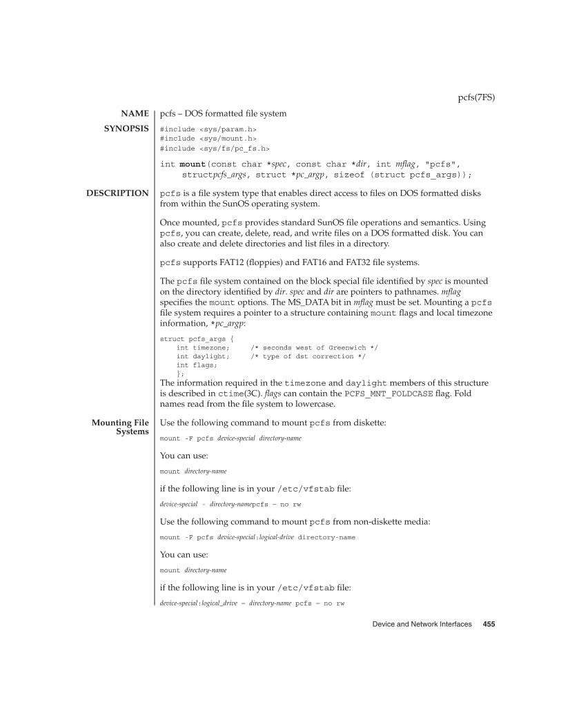
pcfs – DOS formatted file system
#include <sys/param.h>#include <sys/mount.h>
#include <sys/fs/pc_fs.h>
int mount(const char *spec, const char *dir, int mflag, "pcfs",structpcfs_args, struct *pc_argp, sizeof (struct pcfs_args));
pcfs is a file system type that enables direct access to files on DOS formatted disksfrom within the SunOS operating system.
Once mounted, pcfs provides standard SunOS file operations and semantics. Usingpcfs, you can create, delete, read, and write files on a DOS formatted disk. You canalso create and delete directories and list files in a directory.
pcfs supports FAT12 (floppies) and FAT16 and FAT32 file systems.
The pcfs file system contained on the block special file identified by spec is mountedon the directory identified by dir. spec and dir are pointers to pathnames. mflagspecifies the mount options. The MS_DATA bit in mflag must be set. Mounting a pcfsfile system requires a pointer to a structure containing mount flags and local timezoneinformation, *pc_argp:
struct pcfs_args {int timezone; /* seconds west of Greenwich */int daylight; /* type of dst correction */int flags;};
The information required in the timezone and daylight members of this structureis described in ctime(3C). flags can contain the PCFS_MNT_FOLDCASE flag. Foldnames read from the file system to lowercase.
Use the following command to mount pcfs from diskette:
mount -F pcfs device-special directory-name
You can use:
mount directory-name
if the following line is in your /etc/vfstab file:
device-special - directory-namepcfs − no rw
Use the following command to mount pcfs from non-diskette media:
mount -F pcfs device-special:logical-drive directory-name
You can use:
mount directory-name
if the following line is in your /etc/vfstab file:
device-special:logical_drive − directory-name pcfs − no rw
pcfs(7FS)
NAME
SYNOPSIS
DESCRIPTION
Mounting FileSystems
Device and Network Interfaces 455

device-special specifies the special block device file for the diskette (/dev/disketteN)or the entire hard disk (/dev/dsk/cNtNdNp0 for a SCSI disk, and/dev/dsk/cNdNp0 for IDE disks) or the PCMCIA pseudo-floppy memory card(/dev/dsk/cNtNdNsN).
logical-drive specifies either the DOS logical drive letter (c through z) or a drivenumber (1 through 24). Drive letter c is equivalent to drive number 1 and representsthe Primary DOS partition on the disk; drive letters d through z are equivalent todrive numbers 2 through 24, and represent DOS drives within the Extended DOSpartition. Note that device-special and logical-drive must be separated by a colon.
directory-name specifies the location where the file system is mounted.
For example, to mount the Primary DOS partition from a SCSI hard disk, use:
mount -F pcfs /dev/dsk/cNtNdNp0:c /pcfs/c
To mount the first logical drive in the Extended DOS partition from an IDE hard disk,use:
mount -F pcfs /dev/dsk/cNdNp0:d /pcfs/d
To mount a DOS diskette in the first floppy drive when Volume Management is notrunning (see vold(1M)) use:
mount -F pcfs /dev/diskette /pcfs/a
If Volume Management is running, run volcheck(1) to automatically mount thefloppy and some removable disks.
To mount a PCMCIA pseudo-floppy memory card, with Volume Management notrunning (or not managing the PCMCIA media), use:
mount -F pcfs /dev/dsk/cNtNdNsN /pcfs
Files and directories created through pcfs must comply with either the DOS short filename convention or the long file name convention introduced with Windows 95. TheDOS short file name convention is of the form filename[.ext], where filename generallyconsists of from one to eight upper-case characters, while the optional ext consists offrom one to three upper-case characters.
The long file name convention is much closer to Solaris file names. A long file namecan consist of any characters valid in a short file name, lowercase letters, non-leadingspaces, the characters +,;=[], any number of periods, and can be up to 255 characterslong. Long file names have an associated short file name for systems that do notsupport long file names (including earlier releases of Solaris). The short file name isnot visible if the system recognizes long file names. pcfs generates a unique shortname automatically when creating a long file name.
pcfs(7FS)
Conventions
456 man pages section 7: Device and Network Interfaces • Last Revised 10 Apr 2001

Given a long file name such as This is a really long filename.TXT, the shortfile name will generally be of the form THISIS~N.TXT, where N is a number. Thelong file name will probably get the short name THISIS~1.TXT, or THISIS~2.TXT ifTHISIS~1.TXT already exits (or THISIS~3.TXT if both exist, and so forth). If youuse pcfs file systems on systems that do not support long file names, you may wantto continue following the short file name conventions. See EXAMPLES.
When creating a file name, pcfs creates a short file name if it fits the DOS short filename format, otherwise it creates a long file name. This is because long file names takemore directory space. Because the root directory of a pcfs file system is fixed size,long file names in the root directory should be avoided if possible.
When displaying file names, pcfs shows them exactly as they are on the media. Thismeans that short names are displayed as uppercase and long file names retain theircase. Earlier versions of pcfs folded all names to lowercase, which can be forced withthe PCFS_MNT_FOLDCASE mount option. All file name searches within pcfs,however, are treated as if they were uppercase, so readme.txt and ReAdMe.TxTrefer to the same file.
To format a diskette or a PCMCIA pseudo-floppy memory card in DOS format in theSunOS system, use either the fdformat -d or the DOS FORMAT command.
On IA systems, hard drives may contain an fdisk partition reserved for the Solarisboot utilities. These partitions are special instances of pcfs. You can mount an IA bootpartition with the command:
mount -F pcfs device-special:boot directory-name
or you can use:
mount directory-name
if the following line is in your /etc/vfstab file:
device-special:boot − directory-name pcfs − no rw
device-special specifies the special block device file for the entire hard disk(/dev/dsk/cNtNdNp0)
directory-name specifies the location where the file system is mounted.
All files on a boot partition are owned by super-user. Only the super-user may create,delete, or modify files on a boot partition.
EXAMPLE 1 Sample Displays of File Names
If you copy a file financial.data from a UNIX file system to pcfs, it displays asfinancial.data in pcfs, but may show up as FINANC~1.DAT in systems that donot support long file names.
The following are legal long file names. They are also illegal short file names:
pcfs(7FS)
Boot Partitions
EXAMPLES
Device and Network Interfaces 457

EXAMPLE 1 Sample Displays of File Names (Continued)
test.sh.origdata+.login
Other systems that do not support long file names may see:
TESTSH~1.ORIDATA~1LOGIN~1
The short file name is generated from the initial characters of the long file name, sodifferentiate names in the first few characters. For example, these names:
WorkReport.January.DataWorkReport.February.DataWorkReport.March.Data
result in these short names, which are not distinguishable:
WORKRE~1.DATWORKRE~2.DATWORKRE~13.DAT
These names, however:
January.WorkReport.DataFebruary.WorkReport.DataMarch.WorkReport.Data
result in the more descriptive short names:
JANUAR~1.DATFEBRUA~1.DATMARCHW~1.DAT
/usr/lib/fs/pcfs/mount pcfs mount command
/usr/kernel/fs/pcfs 32-bit kernel module
/usr/kernel/fs/sparcv9/pcfs 64-bit kernel module
pcfs(7FS)
FILES
458 man pages section 7: Device and Network Interfaces • Last Revised 10 Apr 2001

chgrp(1), chown(1), dos2unix(1), eject(1), fdformat(1), unix2dos(1),volcheck(1), mount(1M), mount_pcfs(1M), vold(1M), ctime(3C), vfstab(4),pcmem(7D)
Do not physically eject a DOS floppy while the device is mounted as pcfs. If VolumeManagement is managing a device, use the eject(1) command before physicallyremoving media.
When mounting pcfs on a hard disk, make sure the first block on that device containsa valid fdisk partition table.
Because pcfs has no provision for handling owner-IDs or group-IDs on files,chown(1) or chgrp(1) may generate various errors. This is a limitation of pcfs, but itshould not cause problems other than error messages.
Only the following characters are allowed in pcfs short file names and extensions:
0-9A-Z$#&@!%()-{}<>‘_^~|’
SunOS and DOS use different character sets and have different requirements for thetext file format. Use the dos2unix(1) and unix2dos(1) commands to convert filesbetween them.
pcfs offers a convenient transportation vehicle for files between Sun workstationsand PCs. Because the DOS disk format was designed for use under DOS, it does notoperate efficiently under the SunOS system and should not be used as the format for aregular local storage. Instead, use ufs for local storage within the SunOS system.
Although long file names can contain spaces (just as in UNIX file names), someutilities may be confused by them.
This implementation of pcfs conforms to the behavior exhibited by Windows 95version 4.00.950.
pcfs should handle the disk change condition in the same way that DOS does, so youdo not need to unmount the file system to change floppies.
When listing or searching a directory, pcfs does not include files with the hidden orsystem bits set.
pcfs(7FS)
SEE ALSO
WARNINGS
NOTES
BUGS
Device and Network Interfaces 459

pcic – Intel i82365SL PC Card Interface Controller
The Intel i82365SL PC Card interface controller provides one or more PCMCIA PCcard sockets. The pcic driver implements a PCMCIA bus nexus driver.
The driver provides basic support for the Intel 82365SL and compatible chips. Thechips that have been tested are:
� Intel 82365SL� Cirrus Logic PD6710/PD6720/PD6722� Vadem VG365/VG465/VG468/VG469� Toshiba PCIC and ToPIC� Ricoh RF5C366� Texas Instruments PCI1130/PCI1131/PCI1031
While most systems using one of the above chips will work, some systems will not besupported due to hardware designs options that may not be software detectable. Notethat systems with CardBus interfaces are only supported in the non-legacy mode.Systems that only initialize the bridge to legacy mode and do not configure the PCImemory will not be supported.
Direct access to the PCMCIA hardware is not supported. All device access must bethrough the Card Services interface of the DDI.
� Install your add-in PC Card adapter prior to the Solaris installation.
� Some systems have their built-in PC Card adapter disabled by default. Enable itprior to Solaris installation.
� Requirements for a system depend on the combination of devices to be used. Atypical two-socket system needs at least 8 Kbytes of address space, 16 bytes of I/Ospace, and three free IRQs. Following are general guidelines:
Addressspace
At least 8 Kbytes are required with 4 Kbytes per socket in the 640K-1MB range(not necessarily contiguous); if there are three sockets, at least 12 Kbytes areneeded.
I/O space At least 8 and preferably 16 bytes per socket.
IRQs One per socket, plus an IRQ for the pcic device driver itself.
There is one driver configuration property defined in the pcic.conf file.
interrupt-priorities=11; This property must be defined and must notbe modified from the default value.
To perform initial installation and configuration, do the following steps:
1. Consult the Configuration Assistant for address space, I/O space, and IRQsalready used by system devices.
pcic(7D)
NAME
DESCRIPTION
PRECONFIGURATION
CONFIGURATION
Initial Installationand Configuration
460 man pages section 7: Device and Network Interfaces • Last Revised 20 Oct 2000

2. Insert the PC Card adapter.
3. Install the Solaris software.
4. Reboot the system.
To add PC card support to a previously installed system, do the following:
1. Become root.
2. Do a reconfiguration reboot to reallocate resources:
# touch /reconfigure
# reboot
3. Insert the PC Card adapter and turn on the machine.
4. Boot the system so that the PC Card device driver begins running with the newresources allocated.
To allocate the IRQs, do the following:
1. Boot with the Configuration Assistant so you can review the resource usage.
2. Select View/Edit Devices from the Device Tasks menu, and review the list ofdevices to see how many IRQs are being used. (There are 16 IRQs, from 0-15.Several IRQs are already assigned. For example, IRQ 3 is reserved for the secondserial port, COM2, and IRQ 7 is reserved for the parallel port.)
3. If your system has an unused COM2 or parallel port, delete the device to free theIRQ resource for a PC Card. To do this, select the serial port device using IRQ 3 orthe parallel port using IRQ 7, and choose Delete Device. Next, choose Continue toreturn to the Device Tasks menu, then save the configuration.
4. Boot the Solaris software.
/kernel/drv/pcic pcic driver
/kernel/drv/pcic.conf pcic configuration file
pcmcia(4), stp4020(7D)
pcic(7D)
Adding PC CardSupport to a
PreviouslyInstalled System
Allocating IRQs
FILES
SEE ALSO
Device and Network Interfaces 461

pckt – STREAMS Packet Mode module
int ioctl( fd, I_PUSH, "pckt");
pckt is a STREAMS module that may be used with a pseudo terminal to packetizecertain messages. The pckt module should be pushed (see I_PUSH on streamio(7I))onto the master side of a pseudo terminal.
Packetizing is performed by prefixing a message with an M_PROTO message. Theoriginal message type is stored in the 1 byte data portion of the M_PROTO message.
On the read-side, only the M_PROTO, M_PCPROTO, M_STOP, M_START, M_STOPI,M_STARTI, M_IOCTL, M_DATA, M_FLUSH, and M_READ messages are packetized. Allother message types are passed upstream unmodified.
Since all unread state information is held in the master’s stream head read queue,flushing of this queue is disabled.
On the write-side, all messages are sent down unmodified.
With this module in place, all reads from the master side of the pseudo terminalshould be performed with the getmsg(2) or getpmsg() function. The control part ofthe message contains the message type. The data part contains the actual dataassociated with that message type. The onus is on the application to separate the datainto its component parts.
getmsg(2), ioctl(2), ldterm(7M), ptem(7M), streamio(7I), termio(7I)
STREAMS Programming Guide
pckt(7M)
NAME
SYNOPSIS
DESCRIPTION
SEE ALSO
462 man pages section 7: Device and Network Interfaces • Last Revised 3 Jul 1990

pcmem – PCMCIA memory card nexus driver
The pcmem driver identifies the type of memory card in the system and will allowfuture support of other memory device types.
The PCMCIA memory card nexus driver supports PCMCIA memory card clientdrivers. There are no user-configurable options for this driver.
/kernel/drv/pcmem pcmem driver
pcram(7D)
pcmem(7D)
NAME
DESCRIPTION
FILES
SEE ALSO
Device and Network Interfaces 463

pcn – AMD PCnet Ethernet controller device driver
/dev/pcn
The pcn Ethernet driver is a multi-threaded, loadable, clonable driver for the AMDPCnet family of Ethernet controllers that use the Generic LAN Driver (GLD) facility toimplement the required STREAMS and Data Link Provider (see dlpi(7P)) interfaces.
This driver supports a number of integrated motherboards and add-in adapters basedon the AMD PCnet-ISA, PCnet-PCI, and PCnet-32 controller chips. The pcn driverfunctions include controller initialization, frame transmit and receive, functionaladdresses, promiscuous and multicast support, and error recovery and reporting.
The cloning character-special device, /dev/pcn, is used to access all PCnet devicesinstalled in the system.
The pcn driver uses the Solaris GLD module which handles all the STREAMS andDLPI specific functions of the driver. It is a style 2 DLPI driver and therefore supportsonly the connectionless mode of data transfer. Thus, a DLPI user should issue aDL_ATTACH_REQ primitive to select the device to be used. Valid DLPI primitives aredefined in <sys/dlpi.h>. Refer to dlpi(7P) for more information.
The device is initialized on the first attach and de-initialized (stopped) on the lastdetach.
The values returned by the driver in the DL_INFO_ACK primitive in response to aDL_INFO_REQ from the user are:
� Maximum SDU is 1500 (ETHERMTU - defined in <sys/ethernet.h>).
� Minimum SDU is 0.
� DLSAP address length is 8.
� MAC type is DL_ETHER.
� sap length value is −2, meaning the physical address component is followedimmediately by a 2-byte sap component within the DLSAP address.
� Service mode is DL_CLDLS.
� No optional quality of service (QOS) support is included at present, accordingly,the QOS fields are 0.
� Provider style is DL_STYLE2.
� Version is DL_VERSION_2.
� Broadcast address value is the Ethernet/IEEE broadcast address(FF:FF:FF:FF:FF:FF).
Once in the DL_ATTACHED state, the user must send a DL_BIND_REQ to associate aparticular Service Access Point (SAP) with the stream.
pcn(7D)
NAME
SYNOPSIS
DESCRIPTION
APPLICATIONPROGRAMMING
INTERFACEpcn and DLPI
464 man pages section 7: Device and Network Interfaces • Last Revised 20 Oct 2000

� Occasional data corruption has occurred when pcn and pcscsi drivers in HPVectra XU 5/90 and Compaq Deskpro XL systems are used under high networkand SCSI loads. These drivers do not perform well in a production server. Apossible workaround is to disable the pcn device with the system BIOS and use aseparate add-in network interface.
� The Solaris pcn driver does not support IRQ 4.
/dev/pcn Character special device
/kernel/drv/pcn.conf Configuration file
See attributes(5) for descriptions of the following attributes:
ATTRIBUTE TYPE ATTRIBUTE VALUE
Architecture IA
attributes(5), standards(5), dlpi(7P), streamio(7I)
Writing Device Drivers
STREAMS Programming Guide
pcn(7D)
Known Problemsand Limitations
FILES
ATTRIBUTES
SEE ALSO
Device and Network Interfaces 465

pcram – PCMCIA RAM memory card device driver
memory@<socket>/pcram@<technology>,0:c
memory@<socket>/pcram@<technology>,0:c,raw
The PCMCIA RAM memory card device driver supports disk-like I/O access to anystandard PCMCIA static random access memory (SRAM) card and dynamic randomaccess memory (DRAM) card. The driver supports standard PCMCIA SRAM/DRAMcards that contain a Card Information Structure (CIS). RAM card densities in the512Kilobytes to 64Mbyte range are supported.
If a PC card memory device is recognized, the pcram device driver is automaticallyloaded, the physical address allocated, and special files created (if they do not alreadyexist).
The Solaris pcmem driver is not capable of handling "combo" memory cards withmultiple types of memory on them (for example, combined SRAM and nonvolatileFLASH). Inserting such a card into a system running the Solaris software may cause asystem panic.
Because the PC card memory device is designed as a pseudo-floppy diskette type, theonly utility that can be used for formatting is fdformat(1).
Configuration topics include initial installation and configuration, identifying anunrecognized device, special files, using PC card memory devices, and hot-plugging.
1. Install the Solaris software.2. Boot the system.3. Insert the card.
If you insert a memory device and it is not recognized (no special files created), usethe prtconf command.
1. Become root.
2. Run the prtconf -D command to display the configuration recognized by thesystem. A recognized device will appear in the prtconf output. For example:
# prtconf -D. . .pcic, instance #0 (driver name: pcic)
. . .memory, instance #0 (driver name: pcmem)
pcram, instance #0 (driver name: pcram)
3. If your memory device does not appear at the end of the prtconf output, it is notsupported and cannot be used with the pcram driver.
The special files created for PC card memory devices act like disks and have names inthe form /dev/dsk/c#t#d#p# or /dev/dsk/c#t#d#s#. Abbreviations used in thenames are:
� c# Controller #
pcram(7D)
NAME
SYNOPSIS
DESCRIPTION
PRECONFIGURATION
Known Problemsand Limitations
CONFIGURATION
Initial Installationand Configuration
Identifying anUnrecognized
Device
Special Files
466 man pages section 7: Device and Network Interfaces • Last Revised 23 Oct 2000
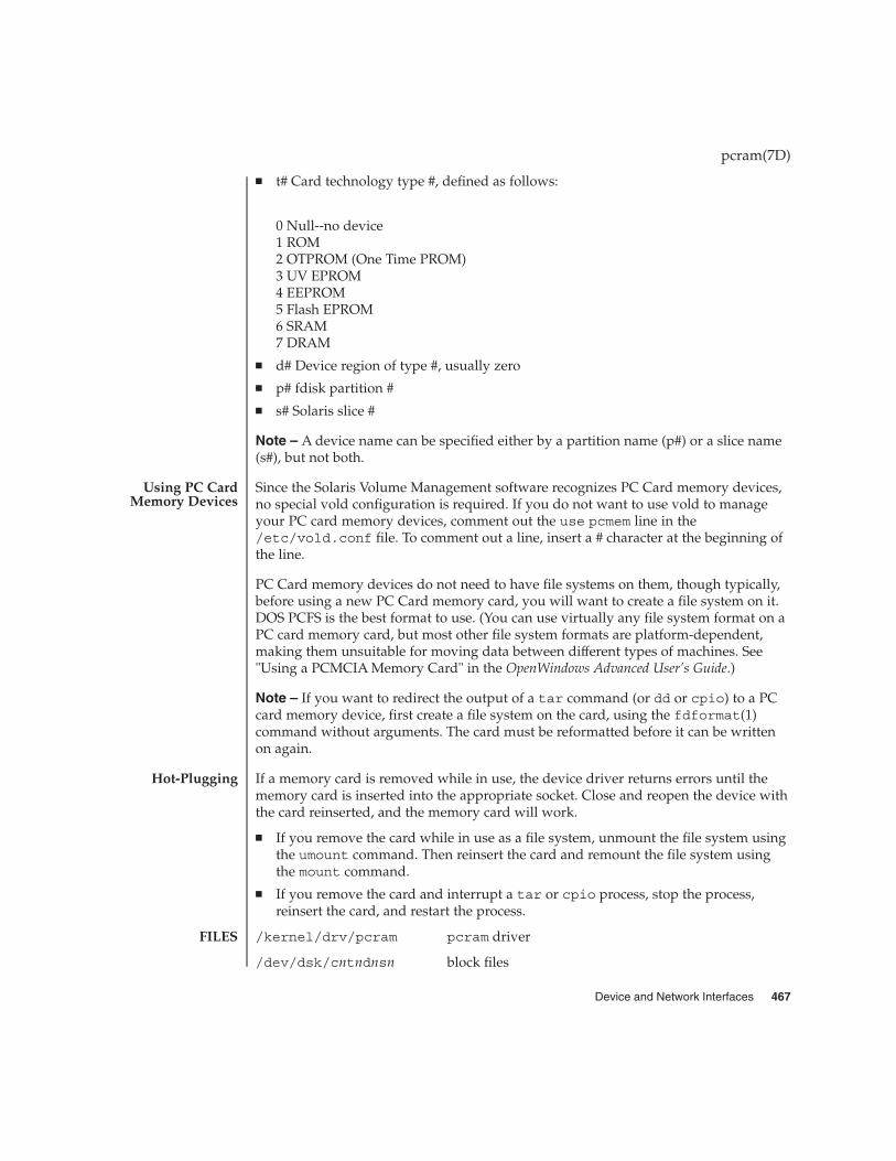
� t# Card technology type #, defined as follows:
0 Null--no device1 ROM2 OTPROM (One Time PROM)3 UV EPROM4 EEPROM5 Flash EPROM6 SRAM7 DRAM
� d# Device region of type #, usually zero
� p# fdisk partition #
� s# Solaris slice #
Note – A device name can be specified either by a partition name (p#) or a slice name(s#), but not both.
Since the Solaris Volume Management software recognizes PC Card memory devices,no special vold configuration is required. If you do not want to use vold to manageyour PC card memory devices, comment out the use pcmem line in the/etc/vold.conf file. To comment out a line, insert a # character at the beginning ofthe line.
PC Card memory devices do not need to have file systems on them, though typically,before using a new PC Card memory card, you will want to create a file system on it.DOS PCFS is the best format to use. (You can use virtually any file system format on aPC card memory card, but most other file system formats are platform-dependent,making them unsuitable for moving data between different types of machines. See"Using a PCMCIA Memory Card" in the OpenWindows Advanced User’s Guide.)
Note – If you want to redirect the output of a tar command (or dd or cpio) to a PCcard memory device, first create a file system on the card, using the fdformat(1)command without arguments. The card must be reformatted before it can be writtenon again.
If a memory card is removed while in use, the device driver returns errors until thememory card is inserted into the appropriate socket. Close and reopen the device withthe card reinserted, and the memory card will work.
� If you remove the card while in use as a file system, unmount the file system usingthe umount command. Then reinsert the card and remount the file system usingthe mount command.
� If you remove the card and interrupt a tar or cpio process, stop the process,reinsert the card, and restart the process.
/kernel/drv/pcram pcram driver
/dev/dsk/cntndnsn block files
pcram(7D)
Using PC CardMemory Devices
Hot-Plugging
FILES
Device and Network Interfaces 467
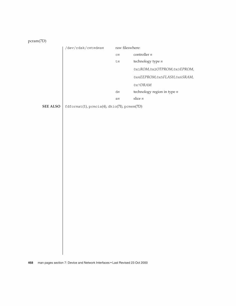
/dev/rdsk/cntndnsn raw fileswhere:
cn controller n
tn technology type n
0x1ROM,0x2OTPROM,0x3EPROM,
0x4EEPROM,0x5FLASH,0x6SRAM,
0x7DRAM
dn technology region in type n
sn slice n
fdformat(1), pcmcia(4), dkio(7I), pcmem(7D)
pcram(7D)
SEE ALSO
468 man pages section 7: Device and Network Interfaces • Last Revised 23 Oct 2000
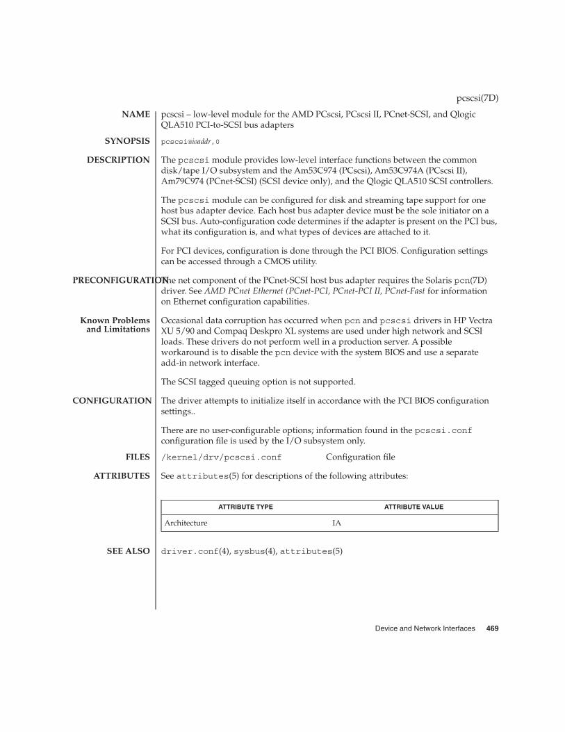
pcscsi – low-level module for the AMD PCscsi, PCscsi II, PCnet-SCSI, and QlogicQLA510 PCI-to-SCSI bus adapters
pcscsi@ioaddr,0
The pcscsi module provides low-level interface functions between the commondisk/tape I/O subsystem and the Am53C974 (PCscsi), Am53C974A (PCscsi II),Am79C974 (PCnet-SCSI) (SCSI device only), and the Qlogic QLA510 SCSI controllers.
The pcscsi module can be configured for disk and streaming tape support for onehost bus adapter device. Each host bus adapter device must be the sole initiator on aSCSI bus. Auto-configuration code determines if the adapter is present on the PCI bus,what its configuration is, and what types of devices are attached to it.
For PCI devices, configuration is done through the PCI BIOS. Configuration settingscan be accessed through a CMOS utility.
The net component of the PCnet-SCSI host bus adapter requires the Solaris pcn(7D)driver. See AMD PCnet Ethernet (PCnet-PCI, PCnet-PCI II, PCnet-Fast for informationon Ethernet configuration capabilities.
Occasional data corruption has occurred when pcn and pcscsi drivers in HP VectraXU 5/90 and Compaq Deskpro XL systems are used under high network and SCSIloads. These drivers do not perform well in a production server. A possibleworkaround is to disable the pcn device with the system BIOS and use a separateadd-in network interface.
The SCSI tagged queuing option is not supported.
The driver attempts to initialize itself in accordance with the PCI BIOS configurationsettings..
There are no user-configurable options; information found in the pcscsi.confconfiguration file is used by the I/O subsystem only.
/kernel/drv/pcscsi.conf Configuration file
See attributes(5) for descriptions of the following attributes:
ATTRIBUTE TYPE ATTRIBUTE VALUE
Architecture IA
driver.conf(4), sysbus(4), attributes(5)
pcscsi(7D)
NAME
SYNOPSIS
DESCRIPTION
PRECONFIGURATION
Known Problemsand Limitations
CONFIGURATION
FILES
ATTRIBUTES
SEE ALSO
Device and Network Interfaces 469

pcser – PCMCIA serial card device driver
serial@<socket>:pcser
serial@<socket>:pcser,cu
The pcser PCMCIA serial card device driver supports asynchronous serial I/O accessto any PCMCIA card that that complies with Revision 2.1 of the PCMCIA standardand which represents an 8250-type UART interface.
If a PC card modem or serial device is recognized, the pcser device driver isautomatically loaded, ports and IRQs allocated, and special files created (if they don’talready exist).
Configuration steps include initial installation and configuration, identifying anunrecognized device and misidentifying a recognized device, .
1. Install the Solaris software.2. Boot the system.3. Insert the modem or serial device.
If you insert a PC card modem or serial device and it is not recognized (that is, nospecial files are created under /dev/cua or /dev/term), use the prtconf commandto find the problem:
1. Become root.
2. Run the prtconf -D command to see if your modem or serial device isrecognized. An unrecognized device will appear at the end of the prtconf output.For example:
# prtconf -D. . .pcic, instance #0 (driver name: pcic)
. . .
pccard111.222 (driver not attached)
3. If your device is not recognized, use the add_drv command to add the name ofyour device as another known alias for pcser devices. For example, type thefollowing at the command line:
# add_drv -i’"pccard111.222"’ pcser
Note – Include the double quotes in single quotes to keep the shell from strippingout the double quotes. Use the identification string listed in the prtconf output. Usethe entire string in the add_drv command. See add_drv(1M).
1. Run the prtconf -D command to see if your modem or serial device iserroneously recognized as a memory card. If the device is incorrectly recognized asa memory card, the output of the prtconf command could show:
# prtconf -D
. . .pcic, instance #0 (driver name: pcic)
. . .
pcser(7D)
NAME
SYNOPSIS
DESCRIPTION
PRECONFIGURATION
CONFIGURATION
Initial Installationand Configuration
Identifying anUnrecognized
Device
Misidentifying aRecognized Device
470 man pages section 7: Device and Network Interfaces • Last Revised 23 Oct 2000
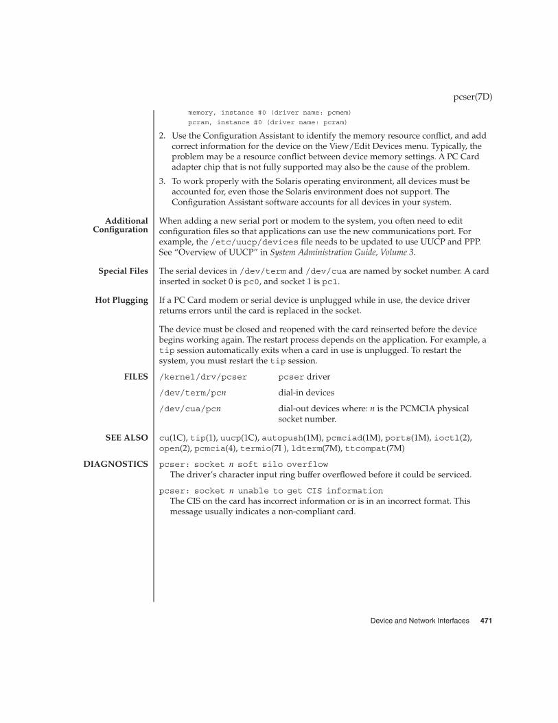
memory, instance #0 (driver name: pcmem)
pcram, instance #0 (driver name: pcram)
2. Use the Configuration Assistant to identify the memory resource conflict, and addcorrect information for the device on the View/Edit Devices menu. Typically, theproblem may be a resource conflict between device memory settings. A PC Cardadapter chip that is not fully supported may also be the cause of the problem.
3. To work properly with the Solaris operating environment, all devices must beaccounted for, even those the Solaris environment does not support. TheConfiguration Assistant software accounts for all devices in your system.
When adding a new serial port or modem to the system, you often need to editconfiguration files so that applications can use the new communications port. Forexample, the /etc/uucp/devices file needs to be updated to use UUCP and PPP.See “Overview of UUCP” in System Administration Guide, Volume 3.
The serial devices in /dev/term and /dev/cua are named by socket number. A cardinserted in socket 0 is pc0, and socket 1 is pc1.
If a PC Card modem or serial device is unplugged while in use, the device driverreturns errors until the card is replaced in the socket.
The device must be closed and reopened with the card reinserted before the devicebegins working again. The restart process depends on the application. For example, atip session automatically exits when a card in use is unplugged. To restart thesystem, you must restart the tip session.
/kernel/drv/pcser pcser driver
/dev/term/pcn dial-in devices
/dev/cua/pcn dial-out devices where: n is the PCMCIA physicalsocket number.
cu(1C), tip(1), uucp(1C), autopush(1M), pcmciad(1M), ports(1M), ioctl(2),open(2), pcmcia(4), termio(7I ), ldterm(7M), ttcompat(7M)
pcser: socket n soft silo overflowThe driver’s character input ring buffer overflowed before it could be serviced.
pcser: socket n unable to get CIS informationThe CIS on the card has incorrect information or is in an incorrect format. Thismessage usually indicates a non-compliant card.
pcser(7D)
AdditionalConfiguration
Special Files
Hot Plugging
FILES
SEE ALSO
DIAGNOSTICS
Device and Network Interfaces 471

pfb – Sun XVR-100 Graphics Accelerator device driver
The pfb driver is the device driver for the Sun XVR-100 Graphics Accelerator.
/dev/fbs/pfb\fIndevice special file for XVR-100 single screen
/dev/fbs/pfb\fIn\fPadevice special file for the XVR-100 first video out
/dev/fbs/pfb\fIn\fPbdevice special file for the XVR-100 second video out
SUNWpfb_config(1M)
pfb(7D)
NAME
DESCRIPTION
FILES
SEE ALSO
472 man pages section 7: Device and Network Interfaces • Last Revised 26 Nov 2002

pf_key – security association database
#include <sys/types.h>#include <sys/socket.h>
#include <net/pfkeyv2.h>
int socket(PF_KEY,SOCK_RAW,PF_KEY_V2);
Keying information for IPsec security services is maintained in security associationdatabases (SADBs). The security associations (SAs) are used to protect both inboundand outbound packets.
A user process (or possibly multiple co-operating processes) maintains SADBs bysending messages over a special kind of socket. This is analogous to the methoddescribed in route(7P). Only a superuser may access an SADB.
SunOS applications that use PF_KEY include ipseckey(1M) and in.iked(1M).
The operating system may spontaneously emit messages in response to externalevents, such as a request for a new SA for an outbound datagram, or to report theexpiration of an existing SA.
One opens the channel for passing SADB control messages by using the socket callshown in the SYNOPSIS section above. More than one key socket can be open persystem.
Messages are formed by a small base header, followed by a number, zero or more, ofextension messages, some of which require additional data following them. The basemessage and all extensions must be eight-byte aligned. An example message is theGET message, which requires the base header, the SA extension, and theADDRESS_DST extension.
Messages include:
#define SADB_GETSPI /* Get a new SPI value from the system. */#define SADB_UPDATE /* Update an SA. */#define SADB_ADD /* Add a fully-formed SA. */#define SADB_DELETE /* Delete an SA. */#define SADB_GET /* Get an SA */#define SADB_ACQUIRE /* Kernel needs a new SA. */#define SADB_REGISTER /* Register to receive ACQUIRE messages. */#define SADB_EXPIRE /* SA has expired. */#define SADB_FLUSH /* Flush all SAs. */#define SADB_DUMP /* Get all SAs. (Unreliable) */#define SADB_X_PROMISC /* Listen promiscuously */#define SADB_X_INVERSE_ACQUIRE /* Query kernel policy,
get an ACQUIRE in return. */
The base message header consists of:
struct sadb_msg {uint8_t sadb_msg_version; /* Set to PF_KEY_V2, for compatibility */uint8_t sadb_msg_type; /* Message type */uint8_t sadb_msg_errno; /* Why message failed */
pf_key(7P)
NAME
SYNOPSIS
DESCRIPTION
Messages
Device and Network Interfaces 473

uint8_t sadb_msg_satype; /* Which security service */uint16_t sadb_msg_len; /* Length in 8-byte units */uint16_t sadb_msg_reserved; /* Zero out */
#define sadb_x_msg_diagnostic sadb_msg_reserved/* Extended diagnostics for errors */
uint32_t sadb_msg_seq; /* For message originator */uint32_t sadb_msg_pid; /* Identify originator */
};
Extension types include:
#define SADB_EXT_SA /* SA information */#define SADB_EXT_LIFETIME_HARD /* Hard lifetime */#define SADB_EXT_LIFETIME_SOFT /* Soft lifetime */#define SADB_EXT_ADDRESS_SRC /* Source address */#define SADB_EXT_ADDRESS_DST /* Destination address */#define SADB_EXT_ADDRESS_PROXY /* Proxy address */#define SADB_EXT_KEY_AUTH /* Authentication key */#define SADB_EXT_KEY_ENCRYPT /* Encryption key */#define SADB_EXT_IDENTITY_SRC /* Source certificate ID */#define SADB_EXT_IDENTITY_DST /* Destination certificate ID */#define SADB_EXT_SENSITIVITY /* Sensitivity information */#define SADB_EXT_PROPOSAL /* Security proposal */#define SADB_EXT_SUPPORTED_AUTH /* Supported authentication algorithms */#define SADB_EXT_SUPPORTED_ENCRYPT /* Supported encryption algorithms */#define SADB_EXT_SPIRANGE /* Range of possible SPIs *#define SADB_X_EXT_EREG /* Register for extended ACQUIRE */#define SADB_X_EXT_EPROP /* Extended ACQUIRE proposals */
#define SADB_X_EXT_KM_COOKIE /* Indicates which KM derived SA. */
Extension headers include:
Generic Extension Header
struct sadb_ext {uint16_t sadb_ext_len; /* In 64-bit words, inclusive */uint16_t sadb_ext_type; /* 0 is reserved */
};
Security Association Information Extension
struct sadb_sa {uint16_t sadb_sa_len;uint16_t sadb_sa_exttype; /* ASSOCIATION */uint32_t sadb_sa_spi;uint8_t sadb_sa_replay;uint8_t sadb_sa_state;uint8_t sadb_sa_auth;uint8_t sadb_sa_encrypt;uint32_t sadb_sa_flags;
};
Lifetime Extension
pf_key(7P)
474 man pages section 7: Device and Network Interfaces • Last Revised 18 Sep 2001
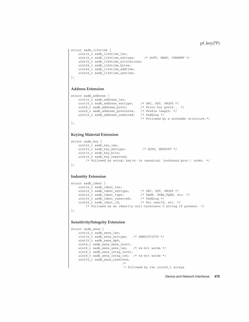
struct sadb_lifetime {uint16_t sadb_lifetime_len;uint16_t sadb_lifetime_exttype; /* SOFT, HARD, CURRENT */uint32_t sadb_lifetime_allocations;uint64_t sadb_lifetime_bytes;uint64_t sadb_lifetime_addtime;uint64_t sadb_lifetime_usetime;
};
Address Extension
struct sadb_address {uint16_t sadb_address_len;uint16_t sadb_address_exttype; /* SRC, DST, PROXY */uint8_t sadb_address_proto; /* Proto for ports... */uint8_t sadb_address_prefixlen; /* Prefix length. */uint16_t sadb_address_reserved; /* Padding */
/* Followed by a sockaddr structure.*/
};
Keying Material Extension
struct sadb_key {uint16_t sadb_key_len;uint16_t sadb_key_exttype; /* AUTH, ENCRYPT */uint16_t sadb_key_bits;uint16_t sadb_key_reserved;
/* Followed by actual key(s) in canonical (outbound proc.) order. */
};
Indentity Extension
struct sadb_ident {uint16_t sadb_ident_len;uint16_t sadb_ident_exttype; /* SRC, DST, PROXY */uint16_t sadb_ident_type; /* FQDN, USER_FQDN, etc. */uint16_t sadb_ident_reserved; /* Padding */uint64_t sadb_ident_id; /* For userid, etc. */
/* Followed by an identity null-terminate C string if present. */
};
Sensitivity/Integrity Extension
struct sadb_sens {uint16_t sadb_sens_len;uint16_t sadb_sens_exttype; /* SENSITIVITY */uint32_t sadb_sens_dpd;uint8_t sadb_sens_sens_level;uint8_t sadb_sens_sens_len; /* 64-bit words */uint8_t sadb_sens_integ_level;uint8_t sadb_sens_integ_len; /* 64-bit words */uint32_t sadb_sens_reserved;
/** followed by two uint64_t arrays
pf_key(7P)
Device and Network Interfaces 475

* uint64_t sadb_sens_bitmap[sens_bitmap_len];* uint64_t integ_bitmap[integ_bitmap_len];*/
};
Proposal Extension
struct sadb_prop {uint16_t sadb_prop_len;uint16_t sadb_prop_len;uint16_t sadb_prop_exttype; /* PROPOSAL, X_EPROP */union {
struct {uint8_t sadb_prop_lenres_replay;uint8_t sadb_prop_lenres_eres;uint16_t sadb_prop_lenres_numecombs;
} sadb_prop_lenres;struct {
uint8_t sadb_prop_oldres_replay;uint8_t sadb_prop_oldres_reserved[3];
} sadb_prop_oldres;} sadb_prop_u;
#define sadb_prop_replay sadb_prop_u.sadb_prop_lenres.sadb_prop_lenres_replay#define sadb_prop_reserved \
sadb_prop_u.sadb_prop_oldres.sadb_prop_oldres_reserved#define sadb_x_prop_ereserved \
sadb_prop_u.sadb_prop_lenres.sadb_prop_lenres_eres#define sadb_x_prop_numecombs \
sadb_prop_u.sadb_prop_lenres.sadb_prop_lenres_numecombs \
/* Followed by sadb_comb[] array or sadb_ecomb[] array. */};
};
Combination Instance for a Proposal
struct sadb_comb {uint8_t sadb_comb_auth;uint8_t sadb_comb_encrypt;uint16_t sadb_comb_flags;uint16_t sadb_comb_auth_minbits;uint16_t sadb_comb_auth_maxbits;uint16_t sadb_comb_encrypt_minbits;uint16_t sadb_comb_encrypt_maxbits;uint32_t sadb_comb_reserved;uint32_t sadb_comb_soft_allocations;uint32_t sadb_comb_hard_allocations;uint64_t sadb_comb_soft_bytes;uint64_t sadb_comb_hard_bytes;uint64_t sadb_comb_soft_addtime;uint64_t sadb_comb_hard_addtime;uint64_t sadb_comb_soft_usetime;uint64_t sadb_comb_hard_usetime;
pf_key(7P)
476 man pages section 7: Device and Network Interfaces • Last Revised 18 Sep 2001
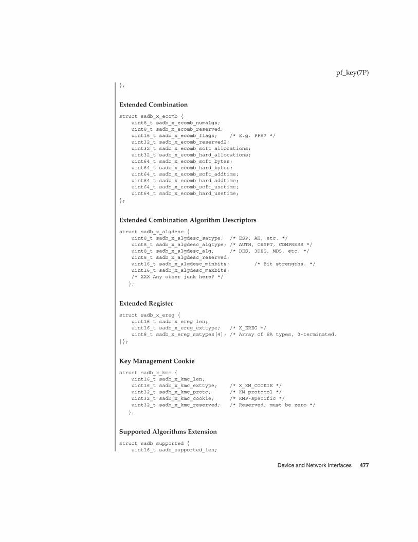
};
Extended Combination
struct sadb_x_ecomb {uint8_t sadb_x_ecomb_numalgs;uint8_t sadb_x_ecomb_reserved;uint16_t sadb_x_ecomb_flags; /* E.g. PFS? */uint32_t sadb_x_ecomb_reserved2;uint32_t sadb_x_ecomb_soft_allocations;uint32_t sadb_x_ecomb_hard_allocations;uint64_t sadb_x_ecomb_soft_bytes;uint64_t sadb_x_ecomb_hard_bytes;uint64_t sadb_x_ecomb_soft_addtime;uint64_t sadb_x_ecomb_hard_addtime;uint64_t sadb_x_ecomb_soft_usetime;uint64_t sadb_x_ecomb_hard_usetime;
};
Extended Combination Algorithm Descriptors
struct sadb_x_algdesc {uint8_t sadb_x_algdesc_satype; /* ESP, AH, etc. */uint8_t sadb_x_algdesc_algtype; /* AUTH, CRYPT, COMPRESS */uint8_t sadb_x_algdesc_alg; /* DES, 3DES, MD5, etc. */uint8_t sadb_x_algdesc_reserved;uint16_t sadb_x_algdesc_minbits; /* Bit strengths. */uint16_t sadb_x_algdesc_maxbits;/* XXX Any other junk here? */
};
Extended Register
struct sadb_x_ereg {uint16_t sadb_x_ereg_len;uint16_t sadb_x_ereg_exttype; /* X_EREG */uint8_t sadb_x_ereg_satypes[4]; /* Array of SA types, 0-terminated.
|};
Key Management Cookie
struct sadb_x_kmc {uint16_t sadb_x_kmc_len;uint16_t sadb_x_kmc_exttype; /* X_KM_COOKIE */uint32_t sadb_x_kmc_proto; /* KM protocol */uint32_t sadb_x_kmc_cookie; /* KMP-specific */uint32_t sadb_x_kmc_reserved; /* Reserved; must be zero */
};
Supported Algorithms Extension
struct sadb_supported {uint16_t sadb_supported_len;
pf_key(7P)
Device and Network Interfaces 477

uint16_t sadb_supported_exttype;uint32_t sadb_supported_reserved;
};
Algorithm Instance
struct sadb_alg {uint8_t sadb_alg_id; /* Algorithm type. */uint8_t sadb_alg_ivlen; /* IV len, in bits */uint16_t sadb_alg_minbits; /* Min. key len (in bits) */uint16_t sadb_alg_maxbits; /* Max. key length */uint16_t sadb_alg_reserved;
};
SPI Extension Range
struct sadb_spirange {uint16_t sadb_spirange_len;uint16_t sadb_spirange_exttype; /* SPI_RANGE */uint32_t sadb_spirange_minuint32_t sadb_spirange_max;uint32_t sadb_spirange_reserved;
};
Each message has a behavior. A behavior is defined as where the initial messagetravels, for example, user to kernel, and what subsequent actions are expected to takeplace. Contents of messages are illustrated as:
<base, REQUIRED EXTENSION, REQ., (OPTIONAL EXTENSION), (OPT)>
The SA extension is sometimes used only for its SPI field. If all other fields must beignored, this is represented by SA(*).
The lifetime extensions are represented with one to three letters after the wordlifetime, representing (H)ARD, (S)OFT, and (C)URRENT.
The address extensions are represented with one to three letters after the word"address," representing (S)RC, (D)ST, (P)ROXY.
Note that when an error occurs, only the base header is sent. Typical errors include:
EINVAL Various message improprieties, including SPI ranges that aremalformed, weak keys, and others. If EINVAL is returned, anapplication should look at the sadb_x_msg_diagnostic field ofthe sadb_msg structure. It contains one of many possible causesfor EINVAL. See net/pfkeyv2.h for values, all of the formSADB_X_DIAGNOSTIC_.
ENOMEM Needed memory was not available.
ENSGSIZ Message exceeds the maximum length allowed.
pf_key(7P)
Message Use andBehavior
478 man pages section 7: Device and Network Interfaces • Last Revised 18 Sep 2001

EEXIST SA (that is being added or created with GETSPI) already exists.
ESRCH SA could not be found.
The following are examples of message use and behavior:
SADB_GETSPI
Send a SADB_GETSPI message from a user process to the kernel.
<base, address, SPI range>
The kernel returns the SADB_GETSPI message to all listening processes.
<base, SA(*), address (SD)>
SADB_UPDATE
Send a SADB_UPDATE message from a user process to the kernel.
<base, SA, (lifetime(HS),) address(SD), (address(P), key (AE),
(identity(SD),) (sensitivity)>c
The kernel returns the SADB_UPDATE message to all listening processes.
<base, SA(*), address (SD)>
SADB_ADD
Send a SADB_ADD message from a user process to the kernel.
<base, SA, (lifetime(HS),) address(SD), (address(P),) key (AE),
(identity(SD),) (sensitivity)>
The kernel returns the SADB_ADD message to all listening processes.
<base, SA, (lifetime(HS),) address (SD),
(identity (SD),) (sensitivity)>
SADB_DELETE
Send a SADB_DELETE message from a user process to the kernel.
<base, SA (*), address (SD)>
The kernel returns the SADB_DELETE message to all listening processes.
<base, SA (*), address (SD)>
SADB_GET
pf_key(7P)
Device and Network Interfaces 479

Send a SADB_GET message from a user process to the kernel.
<base, SA (*), address (SD)>
The kernel returns the SADB_GET message to the socket that sent the SADB_GETmessage.
<base, SA , (lifetime (HSC),) address SD), (address (P),) key (AE),
(identity (SD),) (sensitivity)>
SADB_ACQUIRE
The kernel sends a SADB_ACQUIRE message to registered sockets. Note that anyGETSPI, ADD, or UPDATE calls in reaction to an ACQUIRE must fill in thesadb_msg_seq of those messages with the one in the ACQUIRE message. The address(SD) extensions must have the port fields filled in with the port numbers of the sessionrequiring keys if appropriate.
<base, address (SD), (address(P)), (identity(SD),)
(sensitivity,) proposal>
Extended ACQUIRE will have a slightly different format. The sadb_msg_satypefield is 0, and the extension contains the desired combination(s) of security protocols.
<base, address (SD), (address(P)), (identity(SD),)
(sensitivity,) eprop>
If key management fails, send an SADB_ACQUIRE to indicate failure.
<base>
SADB_X_INVERSE_ACQUIRE
For inbound Key Management processing, a Key Management application may wishto consult the kernel for its policy. The application should send to the kernel:
<base, address (SD)>
The kernel returns a message similar to a kernel-generated extended ACQUIRE:
<base, address (SD), (address(P)), (identity(SD),)
(sensitivity,) eprop>
SADB_REGISTER
Send a SADB_REGISTER message from a user process to the kernel.
<base>
pf_key(7P)
480 man pages section 7: Device and Network Interfaces • Last Revised 18 Sep 2001

The kernel returns the SADB_REGISTER message to registered sockets, with algorithmtypes supported by the kernel being indicated in the supported algorithms field. Notethat this message may arrive asynchronously due to an algorithm being loaded orunloaded into a dynamically linked kernel.
<base, supported>
There is also the extended REGISTER, which will allow this process to receiveextended ACQUIREs.
<base, ereg>
Which returns a series of SADB_REGISTER replies (one for each security protocolregistered) from the kernel.
SADB_EXPIRE
The kernel sends a SADB_EXPIRE message to all listeners when the soft lmit of asecurity association has been expired.
<base, SA, lifetime (C and one of HS), address (SD)>
SADB_FLUSH
Send a SADB_FLUSH message from a user process to the kernel.
<base>
The kernel returns the SADB_FLUSH message to all listening sockets.
<base>
SADB_DUMP
Send a SADB_DUMP message from a user process to the kernel.
<base>
Several SADB_DUMP messages will return from the kernel to the sending socket.
<base, SA, (lifetime (HSC),) address (SD), (address (P),) key (AE),
(identity (SD),) sensitivity)>
To mark the end of a dump a single base header arrives with its sadb_mdg_seq set to0.
<base>
SADB_X_PROMISC
pf_key(7P)
Device and Network Interfaces 481

Send a SADB_X_PROMISC message from a user process to the kernel.
<base>
The kernel returns the SADB_X_PROMISC message to all listening processes.
<base>
See attributes(5) for descriptions of the following attributes:
ATTRIBUTE TYPE ATTRIBUTE VALUE
Availability SUNWcsr (32-bit)
SUNWcarx (64-bit)
Interface Stability Evolving
in.iked(1M), ipseckey(1M), ipsec(7P), ipsecah(7P), ipsecesp(7P), route(7P)
McDonald, D.L., Metz, C.W., and Phan, B.G., RFC 2367, PF_KEY Key Management API,Version 2, The Internet Society, July 1998.
Time-based lifetimes may not expire with exact precision in seconds because kernelload may affect the aging of SA’s.
pf_key(7P)
ATTRIBUTES
SEE ALSO
NOTES
482 man pages section 7: Device and Network Interfaces • Last Revised 18 Sep 2001

pfmod – STREAMS Packet Filter Module
#include <sys/pfmod.h>
ioctl(fd, IPUSH, "pfmod");
pfmod is a STREAMS module that subjects messages arriving on its read queue to apacket filter and passes only those messages that the filter accepts on to its upstreamneighbor. Such filtering can be very useful for user-level protocol implementations andfor networking monitoring programs that wish to view only specific types of events.
pfmod applies the current packet filter to all M_DATA and M_PROTO messages arrivingon its read queue. The module prepares these messages for examination by firstskipping over all leading M_PROTO message blocks to arrive at the beginning of themessage’s data portion. If there is no data portion, pfmod accepts the message andpasses it along to its upstream neighbor. Otherwise, the module ensures that the partof the message’s data that the packet filter might examine lies in contiguous memory,calling the pullupmsg(9F) utility routine if necessary to force contiguity. (Note: thisaction destroys any sharing relationships that the subject message might have hadwith other messages.) Finally, it applies the packet filter to the message’s data, passingthe entire message upstream to the next module if the filter accepts, and discarding themessage otherwise. See PACKET FILTERS below for details on how the filter works.
If there is no packet filter yet in effect, the module acts as if the filter exists but doesnothing, implying that all incoming messages are accepted. The IOCTLS section belowdescribes how to associate a packet filter with an instance of pfmod.
pfmod passes all other messages through unaltered to its upper neighbor.
pfmod intercepts M_IOCTL messages for the ioctl described below. The module passesall other messages through unaltered to its lower neighbor.
pfmod responds to the following ioctl.
PFIOCSETF This ioctl directs the module to replace its current packet filter, ifany, with the filter specified by the struct packetfilt pointernamed by its final argument. This structure is defined in<sys/pfmod.h> as:
struct packetfilt {uchar_t Pf_Priority; /* priority of filter */uchar_t Pf_FilterLen; /* length of filter cmd list */ushort_t Pf_Filter[ENMAXFILTERS]; /* filter command list */
};
The Pf_Priority field is included only for compatibility with other packet filterimplementations and is otherwise ignored. The packet filter itself is specified in thePf_Filter array as a sequence of two-byte commands, with the Pf_FilterLenfield giving the number of commands in the sequence. This implementation restrictsthe maximum number of commands in a filter (ENMAXFILTERS) to 255. The nextsection describes the available commands and their semantics.
pfmod(7M)
NAME
SYNOPSIS
DESCRIPTION
Read-sideBehavior
Write-sideBehavior
IOCTLS
Device and Network Interfaces 483

A packet filter consists of the filter command list length (in units of ushort_ts), andthe filter command list itself. (The priority field mentioned above is ignored in thisimplementation.) Each filter command list specifies a sequence of actions that operateon an internal stack of ushort_ts (“shortwords”). Each shortword of the commandlist specifies one of the actions ENF_PUSHLIT, ENF_PUSHZERO, ENF_PUSHONE,ENF_PUSHFFFF, ENF_PUSHFF00, ENF_PUSH00FF, or ENF_PUSHWORD+n, whichrespectively push the next shortword of the command list, zero, one, 0xFFFF, 0xFF00,0x00FF, or shortword n of the subject message on the stack, and a binary operator fromthe set {ENF_EQ, ENF_NEQ, ENF_LT, ENF_LE, ENF_GT, ENF_GE, ENF_AND, ENF_OR,ENF_XOR} which then operates on the top two elements of the stack and replaces themwith its result. When both an action and operator are specified in the same shortword,the action is performed followed by the operation.
The binary operator can also be from the set {ENF_COR, ENF_CAND, ENF_CNOR,ENF_CNAND}. These are “short-circuit” operators, in that they terminate the executionof the filter immediately if the condition they are checking for is found, and continueotherwise. All pop two elements from the stack and compare them for equality;ENF_CAND returns false if the result is false; ENF_COR returns true if the result is true;ENF_CNAND returns true if the result is false; ENF_CNOR returns false if the result istrue. Unlike the other binary operators, these four do not leave a result on the stack,even if they continue.
The short-circuit operators should be used when possible, to reduce the amount oftime spent evaluating filters. When they are used, you should also arrange the order ofthe tests so that the filter will succeed or fail as soon as possible; for example, checkingthe IP destination field of a UDP packet is more likely to indicate failure than thepacket type field.
The special action ENF_NOPUSH and the special operator ENF_NOP can be used to onlyperform the binary operation or to only push a value on the stack. Since both are(conveniently) defined to be zero, indicating only an action actually specifies theaction followed by ENF_NOP, and indicating only an operation actually specifiesENF_NOPUSH followed by the operation.
After executing the filter command list, a non-zero value (true) left on top of the stack(or an empty stack) causes the incoming packet to be accepted and a zero value (false)causes the packet to be rejected. (If the filter exits as the result of a short-circuitoperator, the top-of-stack value is ignored.) Specifying an undefined operation oraction in the command list or performing an illegal operation or action (such aspushing a shortword offset past the end of the packet or executing a binary operatorwith fewer than two shortwords on the stack) causes a filter to reject the packet.
The packet filter module is not dependent on any particular device driver or modulebut is commonly used with datalink drivers such as the Ethernet driver. If theunderlying datalink driver supports the Data Link Provider Interface (DLPI) message
pfmod(7M)
PACKET FILTERS
EXAMPLES
484 man pages section 7: Device and Network Interfaces • Last Revised 18 Sep 1992

set, the appropriate STREAMS DLPI messages must be issued to attach the stream to aparticular hardware device and bind a datalink address to the stream before theunderlying driver will route received packets upstream. Refer to the DLPI Version 2specification for details on this interface.
The reverse ARP daemon program may use code similar to the following fragment toconstruct a filter that rejects all but RARP packets. That is, is accepts only packetswhose Ethernet type field has the value ETHERTYPE_REVARP.
struct ether_header eh; /* used only for offset values */struct packetfilt pf;register ushort_t *fwp = pf.Pf_Filter;ushort_t offset;int fd;/** Push packet filter streams module.*/if (ioctl(fd, I_PUSH, "pfmod") < 0)
syserr("pfmod");
/** Set up filter. Offset is the displacement of the Ethernet* type field from the beginning of the packet in units of* ushort_ts.*/offset = ((uint_t) &eh.ether_type - (uint_t) &eh.ether_dhost) /
sizeof (us_short);*fwp++ = ENF_PUSHWORD + offset;*fwp++ = ENF_PUSHLIT;*fwp++ = htons(ETHERTYPE_REVARP);*fwp++ = ENF_EQ;
pf.Pf_FilterLen = fwp - &pf.Pf_Filter[0];
This filter can be abbreviated by taking advantage of the ability to combine actionsand operations:
*fwp++ = ENF_PUSHWORD + offset;*fwp++ = ENF_PUSHLIT | ENF_EQ;
*fwp++ = htons(ETHERTYPE_REVARP);
bufmod(7M), dlpi(7P), le(7D), pullupmsg(9F)
pfmod(7M)
SEE ALSO
Device and Network Interfaces 485

pipemod – STREAMS pipe flushing module
The typical stream is composed of a stream head connected to modules andterminated by a driver. Some stream configurations such as pipes and FIFOs do nothave a driver and hence certain features commonly supported by the driver need to beprovided by other means. Flushing is one such feature, and it is provided by thepipemod module.
Pipes and FIFOs in their simplest configurations only have stream heads. A write sideis connected to a read side. This remains true when modules are pushed. The twistoccurs at a point known as the mid-point. When an M_FLUSH message is passed froma write queue to a read queue the FLUSHR and/or FLUSHW bits have to be switched.The mid-point of a pipe is not always easily detectable, especially if there arenumerous modules pushed on either end of the pipe. In that case there needs to be amechanism to intercept all message passing through the stream. If the message is anM_FLUSH message and it is at the mid-point, the flush bits need to be switched. Thisbit switching is handled by the pipemod module.
pipemod should be pushed onto a pipe or FIFO where flushing of any kind will takeplace. The pipemod module can be pushed on either end of the pipe. The onlyrequirement is that it is pushed onto an end that previously did not have modules onit. That is, pipemod must be the first module pushed onto a pipe so that it is at themid-point of the pipe itself.
The pipemod module handles only M_FLUSH messages. All other messages are passedon to the next module using the putnext() utility routine. If an M_FLUSH message ispassed to pipemod and the FLUSHR and FLUSHW bits are set, the message is notprocessed but is passed to the next module using the putnext() routine. If only theFLUSHR bit is set, the FLUSHR bit is turned off and the FLUSHW bit is set. The messageis then passed on to the next module using putnext(). Similarly, if the FLUSHW bit isthe only bit set in the M_FLUSH message, the FLUSHW bit is turned off and the FLUSHRbit is turned on. The message is then passed to the next module on the stream.
The pipemod module can be pushed on any stream that desires the bit switching. Itmust be pushed onto a pipe or FIFO if any form of flushing must take place.
STREAMS Programming Guide
pipemod(7M)
NAME
DESCRIPTION
SEE ALSO
486 man pages section 7: Device and Network Interfaces • Last Revised 21 Aug 1992

pln – SPARCstorage Array SCSI Host Bus Adapter Driver
pln@SUNW,pln@a0000800,200611b9
The pln Host Bus Adapter (HBA) driver is a SCSA compliant nexus driver whichsupports the SPARC Storage Array. The SPARC Storage Array is a disk array devicewhich supports multiple disk drives. The drives are located on several SCSI busseswithin the SPARC Storage Array. A SPARC microprocessor controls the SPARCStorage Array. Non-volatile RAM is used as a disk cache. The SPARC Storage Arrayinterfaces to the host system using Fibre Channel. An SBus card called the SOC card(see soc(7D)) connects the Fibre Channel to the host system.
The pln driver interfaces with the SOC device driver, soc(7D), and the SPARCStorage Array SCSI target driver, ssd(7D).
The pln driver supports the standard functions provided by the SCSA interface. Thedriver supports tagged and untagged queuing and auto request sense.
/kernel/drv/pln ELF kernel module
/kernel/drv/pln.conf configuration file
prtconf(1M), ssaadm(1M), driver.conf(4), soc(7D), ssd(7D)
Writing Device Drivers
ANSI Small Computer System Interface-2 (SCSI-2)
The messages described below may appear on the system console and in the systemlog.
This following messages indicate the pln driver was unable to attach to the device.These messages are preceded by "pln%d", where "%d" is the instance number of thepln controller.
Failed to alloc soft stateDriver was unable to allocate space for the internal state structure. Driver did notattach to device. SCSI devices will be inaccessible.
Bad soft stateDriver requested an invalid internal state structure. Driver did not attach to device.SCSI devices will be inaccessible.
Unable to attachDriver was unable to attach to the hardware for some reason that may be printed.SCSI devices will be inaccessible.
pln(7D)
NAME
SYNOPSIS
DESCRIPTION
FILES
SEE ALSO
DIAGNOSTICS
Device and Network Interfaces 487

pm – Power Management driver
/dev/pm
The Power Management ( pm) driver provides an interface for applications toconfigure devices within the system for Power Management. The interface is providedthrough ioctl(2) commands. The pm driver may be accessed using /dev/pm.
The Power Management framework model allows the system to be viewed as acollection of devices. Each device is a collection of components that comprise thesmallest power manageable units. The device driver controls the definition of adevice’s power manageable components.
A component can either be busy or idle at the current power level. Normally, the PowerManagement framework takes an idle component to the next lower power level. ThePower Management framework uses two factors to determine this transition: thecomponent must have been idle for at least the threshold time, and the device towhich the component belongs must satisfy any dependency requirements. Adependency occurs when a device requires another device to be power managedbefore it can be power managed. Dependencies occur on a per device basis: when adependency exists, no components of a device may be managed unless all the devicesit depends upon are first power managed.
Using the commands below, an application may take control of the PowerManagement of a device from the Power Management framework driver and managethe transition of device power levels directly.
For this set of ioctl commands, arg (see ioctl(2)) points to a structure of type pm_reqdefined in <sys/pm.h>:
typedef struct pm_req {char *physpath; /* physical path of device to configure */
/* see libdevinfo(3) */int component; /* the component of the device */int value; /* power level, threshold value, or count */void *data; /* command-dependent variable sized data */size_t datasize; /* size of data buffer */
} pm_req_t;
The fields should contain the following data:
physpath Pointer to the physical path of a device. See libdevinfo(3). Forexample, for the device /devices/pseudo/pm@0:pm thephyspath value would be /pseudo/pm@0.
component Non-negative integer specifying which component is beingconfigured. The numbering starts at zero.
value Non-negative integer specifying the threshold value in seconds orthe desired power level, or the number of levels being specified.
pm(7D)
NAME
SYNOPSIS
DESCRIPTION
PowerManagement
Framework
488 man pages section 7: Device and Network Interfaces • Last Revised 20 Sep 1999

data Pointer to a buffer which contains or receives variable-sized data,such as the name of a device upon which this device has adependency.
size Size of the data buffer.
Not all fields are used in each command.
PM_DIRECT_PMThe device named by physpath is disabled from being power managed by theframework. The caller will power manage the device directly using thePM_DIRECT_NOTIFY, PM_GET_TIME_IDLE and PM_GET_CURRENT_POWER,PM_GET_FULL_POWER and PM_SET_CURRENT_POWER commands. If the deviceneeds to have its power level changed either because its driver callspm_raise_power(9F ), pm_lower_power(9F ), or pm_power_has_changed(9F)or because the device is the parent of another device that is changing power level ora device that this device depends on is changing power level, then the power levelchange of the device will be blocked and the caller will be notified as describedbelow for the PM_DIRECT_NOTIFY command.
Error codes:
EBUSY Device already disabled for Power Management by framework.
EPERM Caller is neither superuser nor effective group ID of 0.
PM_RELEASE_DIRECT_PMThe device named by physpath (which must have been the target of aPM_DIRECT_PM command) is re-enabled for Power Management by theframework.
Error codes:
EINVAL Device component out of range.
PM_DIRECT_NOTIFY PM_DIRECT_NOTIFY_WAITThese commands allow the process that is directly power managing a device to benotified of events that could change the power level of the device. When such anevent occurs, this command returns information about the event.
arg (see ioctl(2)) points to a structure of type pm_state_change defined in<sys/pm.h>:
typedef struct pm_state_change {char *physpath; /* device which has changed state */int component; /* which component changed state */
#if defined(_BIG_ENDIAN)ushort_t flags; /* PSC_EVENT_LOST, PSC_ALL_LOWEST */ushort_t event; /* type of event */
#elseushort_t event; /* type of event *ushort_t flags; /* PSC_EVENT_LOST, PSC_ALL_LOWEST */
#endiftime_t timestamp; /* time of state change */+
pm(7D)
Device and Network Interfaces 489

int old_level; /* power level changing from */int new_level; /* power level changing to */size_t size; /* size of buffer physpath points to */
} pm_state_change_t;
When an event occurs, the struct pointed to by arg is filled in. If the event type isPSC_PENDING_CHANGE, then the information in the rest of the struct describes anaction that the framework would have taken if the device were not directly powermanaged by the caller. The caller is responsible for completing the indicated levelchanges using PM_SET_CURRENT_POWER below.
An event type of PSC_HAS_CHANGED indicates that the driver for the directlypower managed device has called pm_power_has_changed(9F) due to the devicechanging power on its own. It is provided to allow the caller to track the powerstate of the device.
The system keeps events in a circular buffer. If the buffer overflow, the oldest eventsare lost and when the event that next follows a lost event is retrieved it will havePSC_EVENT_LOST set in flags.
PM_DIRECT_NOTIFY returns EWOULDBLOCK if no event is pending, andPM_DIRECT_NOTIFY_WAIT blocks until an event is available.
pm also supports the poll(2) interface. When an event is pending a poll(2) callthat includes a file descriptor for /dev/pm and that has POLLIN or POLLRDNORMset in its event mask will return.
PM_SET_CURRENT_POWERComponent component of the device named by physpath (which must contain thephysical path of a device against which the process has issued a PM_DIRECT_PMcommand) is set to power level value. If all components of the device named byphyspath were at level 0, value is non-zero and some device has a dependency onthis device, then all components of that device will be brought to full power beforethis command returns. Similarly, if the parent of the target device is powered off,then it will be brought up as needed before this command returns. WhenPM_SET_CURRENT_POWER is issued against a device, the resulting powerchange is included in the event list for PM_DIRECT_NOTIFY.
Error codes:
EINVAL Device component out of range, or power level < 0.
EIO Failed to power device or its ancestors or the devices on whichthis device has dependency or their ancestors. Note that thismay not indicate a failure, the device driver may have rejectedthe command as inappropriate because the component hasbecome busy.
EPERM Caller has not previously issued a successful PM_DIRECT_PMcommand against this device.
pm(7D)
490 man pages section 7: Device and Network Interfaces • Last Revised 20 Sep 1999

PM_GET_FULL_POWERThe highest supported power level of component component of the device named byphyspath is returned.
PM_GET_CURRENT_POWERThe current power level of component component of the device named by physpath isreturned.
Error codes:
EAGAIN Device component power level is not currently known.
PM_GET_TIME_IDLEPM_GET_TIME_IDLE returns the number of seconds that component component ofthe device named by physpath has been idle. If the device is not idle, then 0 isreturned.
Note that because the state of the device may change between the time the processissues the PM_GET_TIME_IDLE command and the time the process issues aPM_SET_CURRENT_POWER command to reduce the power level of an idlecomponent, the process must be prepared to deal with a PM_SET_CURRENT_POWERcommand returning failure because the driver has rejected the command asinappropriate because the device component has become busy. This can bedifferentiated from other types of failures by issuing the PM_GET_TIME_IDLEcommand again to see if the component has become busy.
Upon error, the commands will return −1, and set errno. In addition to the error codeslisted above by command, the following error codes are common to all commands:
EFAULT Bad address passed in as argument.
ENODEV Device is not power manageable, or device is not configured.
ENXIO Too many opens attempted.
See attributes(5) for descriptions of the following attributes:
ATTRIBUTE TYPE ATTRIBUTE VALUE
Interface stability Unstable
pmconfig(1M), intro(2), ioctl(2), power.conf(4), attributes(5), attach(9E),detach(9E), power(9E), pm_busy_component(9F), pm_idle_component(9F),pm_lower_power(9F), pm_power_has_changed(9F), pm_raise_power(9F)
Writing Device Drivers
pm(7D)
ERRORS
ATTRIBUTES
SEE ALSO
Device and Network Interfaces 491

poll – driver for fast poll on many file descriptors
#include <sys/devpoll.h>int fd = open("/dev/poll", O_RDWR);ssize_t n = write(int fd, struct pollfd buf[], int bufsize);int n = ioctl(int fd, DP_POLL, struct dvpoll* arg);
int n = ioctl(int fd, DP_ISPOLLED, struct pollfd* pfd);
fd Open file descriptor that refers to the /dev/poll driver.
path /dev/poll
buf Array of pollfd structures.
bufsize Size of buf in bytes.
arg Pointer to pollcall structure.
pfd Pointer to pollfd structure.
The /dev/poll driver is a special driver that enables you to monitor multiple sets ofpolled file descriptors. By using the /dev/poll driver, you can efficiently poll largenumbers of file descriptors. Access to the /dev/poll driver is provided throughopen(2), write(2), and ioctl(2) system calls.
Writing an array of pollfd struct to the /dev/poll driver has the effect of addingthese file descriptors to the monitored poll file descriptor set represented by the fd.To monitor multiple file descriptor sets, open the /dev/poll driver multiple times.Each fd corresponds to one set. For each pollfd struct entry (defined insys/poll.h):
struct pollfd {int fd;short events;short revents;
}
The fd field specifies the file descriptor being polled. The events field indicates theinterested poll events on the file descriptor. If a pollfd array contains multiplepollfd entries with the same fd field, the "events" field in each pollfd entry isOR’ed. A special POLLREMOVE event in the events field of the pollfd structureremoves the fd from the monitored set. The revents field is not used. Write returnsthe number of bytes written successfully or -1 when write fails.
The DP_POLL ioctl is used to retrieve returned poll events occured on the polledfile descriptors in the monitored set represented by fd. arg is a pointer to the devpollstructures which are defined as follows:
struct dvpoll {struct pollfd* dp_fds;int dp_nfds;int dp_timeout;
}
The dp_fds points to a buffer that holds an array of returned pollfd structures. Thedp_nfds field specifies the size of the buffer in terms of the number of pollfd entries
poll(7d)
NAME
SYNOPSIS
PARAMETERS
DESCRIPTION
492 man pages section 7: Device and Network Interfaces • Last Revised 15 May 2001
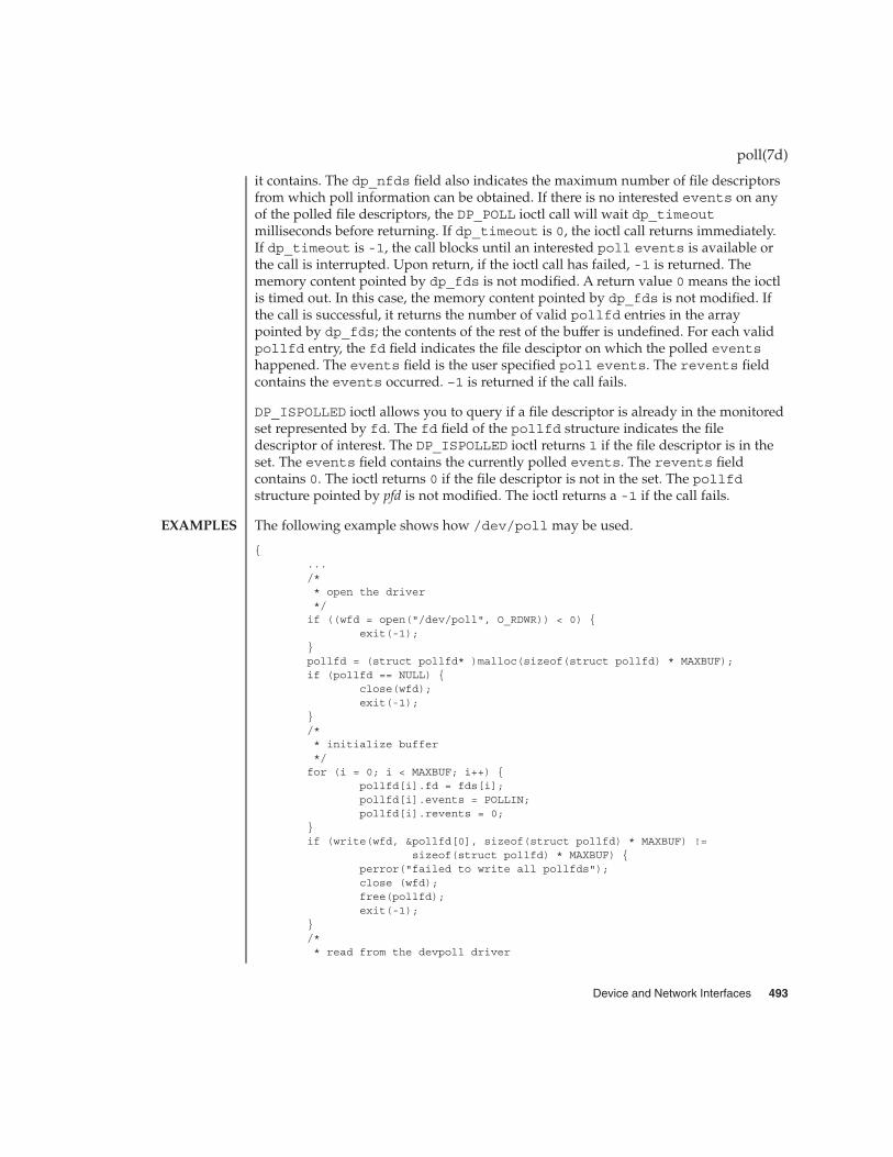
it contains. The dp_nfds field also indicates the maximum number of file descriptorsfrom which poll information can be obtained. If there is no interested events on anyof the polled file descriptors, the DP_POLL ioctl call will wait dp_timeoutmilliseconds before returning. If dp_timeout is 0, the ioctl call returns immediately.If dp_timeout is -1, the call blocks until an interested poll events is available orthe call is interrupted. Upon return, if the ioctl call has failed, -1 is returned. Thememory content pointed by dp_fds is not modified. A return value 0 means the ioctlis timed out. In this case, the memory content pointed by dp_fds is not modified. Ifthe call is successful, it returns the number of valid pollfd entries in the arraypointed by dp_fds; the contents of the rest of the buffer is undefined. For each validpollfd entry, the fd field indicates the file desciptor on which the polled eventshappened. The events field is the user specified poll events. The revents fieldcontains the events occurred. –1 is returned if the call fails.
DP_ISPOLLED ioctl allows you to query if a file descriptor is already in the monitoredset represented by fd. The fd field of the pollfd structure indicates the filedescriptor of interest. The DP_ISPOLLED ioctl returns 1 if the file descriptor is in theset. The events field contains the currently polled events. The revents fieldcontains 0. The ioctl returns 0 if the file descriptor is not in the set. The pollfdstructure pointed by pfd is not modified. The ioctl returns a -1 if the call fails.
The following example shows how /dev/poll may be used.
{.../** open the driver*/if ((wfd = open("/dev/poll", O_RDWR)) < 0) {
exit(-1);}pollfd = (struct pollfd* )malloc(sizeof(struct pollfd) * MAXBUF);if (pollfd == NULL) {
close(wfd);exit(-1);
}/** initialize buffer*/for (i = 0; i < MAXBUF; i++) {
pollfd[i].fd = fds[i];pollfd[i].events = POLLIN;pollfd[i].revents = 0;
}if (write(wfd, &pollfd[0], sizeof(struct pollfd) * MAXBUF) !=
sizeof(struct pollfd) * MAXBUF) {perror("failed to write all pollfds");close (wfd);free(pollfd);exit(-1);
}/** read from the devpoll driver
poll(7d)
EXAMPLES
Device and Network Interfaces 493

*/dopoll.dp_timeout = -1;dopoll.dp_nfds = MAXBUF;dopoll.dp_fds = pollfd;result = ioctl(wfd, DP_POLL, &dopoll);if (result < 0) {
perror("/dev/poll ioctl DP_POLL failed");close (wfd);free(pollfd);exit(-1);
}for (i = 0; i < result; i++) {
read(dopoll.dp_fds[i].fd, rbuf, STRLEN);}
...
}
The following example is part of a test program which shows how DP_ISPOLLED()ioctl may be used.
{...
loopcnt = 0;while (loopcnt < ITERATION) {
rn = random();rn %= RANGE;if (write(fds[rn], TESTSTRING, strlen(TESTSTRING)) !=
strlen(TESTSTRING)) {perror("write to fifo failed.");close (wfd);free(pollfd);error = 1;goto out1;
}dpfd.fd = fds[rn];dpfd.events = 0;dpfd.revents = 0;result = ioctl(wfd, DP_ISPOLLED, &dpfd);if (result < 0) {
perror("/dev/poll ioctl DP_ISPOLLED failed");printf("errno = %d\n", errno);close (wfd);free(pollfd);error = 1;goto out1;
}if (result != 1) {
printf("DP_ISPOLLED returned incorrect result: %d.\n",result);
close (wfd);free(pollfd);error = 1;goto out1;
}if (dpfd.fd != fds[rn]) {
printf("DP_ISPOLLED returned wrong fd %d, expect %d\n",
poll(7d)
494 man pages section 7: Device and Network Interfaces • Last Revised 15 May 2001

dpfd.fd, fds[rn]);close (wfd);free(pollfd);error = 1;goto out1;
}if (dpfd.revents != POLLIN) {
printf("DP_ISPOLLED returned unexpected revents %d\n",dpfd.revents);
close (wfd);free(pollfd);error = 1;goto out1;
}if (read(dpfd.fd, rbuf, strlen(TESTSTRING)) !=
strlen(TESTSTRING)) {perror("read from fifo failed");close (wfd);free(pollfd);error = 1;goto out1;
}loopcnt++;
}
EACCES A process does not have permission to access the content cached in/dev/poll.
EINTR A signal was caught during the execution of the ioctl(2)function.
EFAULT The request argument requires a data transfer to or from a bufferpointed to by arg, but arg points to an illegal address.
EINVAL The request or arg parameter is not valid for this device.
ENXIO The O_NONBLOCK flag is set, the named file is a FIFO, theO_WRONLY flag is set, and no process has the file open for reading;or the named file is a character special or block special file and thedevice associated with this special file does not exist.
See attributes(5) for a description of the following attributes:
ATTRIBUTE TYPE ATTRIBUTE VALUE
Architecture SPARC, Intel
Availability SUNWcarx.u, SUNWcsxu (64-bit Solaris)
SUNWcsr, SUNWcsu (32-bit Solaris on Intel)
SUNWhea (header files)
Interface Stability Evolving
poll(7d)
ERRORS
ATTRIBUTES
Device and Network Interfaces 495

MT-Level Safe
open(2), poll(2), write(2), attributes(5)
The /dev/poll API is particularly beneficial to applications that poll a large numberof file descriptors repeatedly. Applications will exhibit the best performance gain if thepolled file descriptor list rarely change.
When using the /dev/poll driver, you should remove a closed file descriptor from amonitored poll set. Failure to do so may result in a POLLNVAL revents beingreturned for the closed file descriptor. When a file descriptor is closed but not removedfrom the monitored set, and is reused in subsequent open of a different device, youwill be polling the device associated with the reused file descriptor. In a multithreadedapplication, careful coordination among threads doing close and DP_POLL ioctl isrecommended for consistent results.
The /dev/poll driver caches a list of polled file descriptors, which are specific to aprocess. Therefore, the /dev/poll file descriptor of a process will be inherited by itschild process, just like any other file descriptors. But the child process will have verylimited access through this inherited /dev/poll file descriptor. Any attempt to writeor do ioctl by the child process will result in an EACCES error. The child processshould close the inherited /dev/poll file descriptor and open its own if desired.
The /dev/poll driver does not yet support polling. Polling on a /dev/poll filedescriptor will result in POLLERR being returned in the revents field of pollfdstructure.
poll(7d)
SEE ALSO
NOTES
496 man pages section 7: Device and Network Interfaces • Last Revised 15 May 2001

prnio – generic printer interface
#include <sys/prnio.h>
The prnio generic printer interface defines ioctl commands and data structures forprinter device drivers.
prnio defines and provides facilities for five basic phases of the printing process:
� Identification — Retrieve device information/attributes� Setup — Set device attributes� Transfer — Transfer data to or from the device� Cleanup — Transfer phase conclusion� Abort — Transfer phase interruption
During the Identification phase, the application retrieves a set of device capabilitiesand additional information using the PRNIOC_GET_IFCAP, PRNIOC_GET_STATUS,PRNIOC_GET_TIMEOUTS, PRNIOC_GET_IFINFO and PRNIOC_GET_1284_DEVIDcommands.
During the Setup phase the application sets some interface attributes and probablyresets the printer as described in the PRNIOC_SET_IFCAP, PRNIOC_SET_TIMEOUTSand PRNIOC_RESET sections.
During the Transfer phase, data is transferred in a forward (host to peripheral) orreverse direction (peripheral to host). Transfer is accomplished using write(2) andread(2) system calls. For prnio compliant printer drivers, forward transfer support ismandatory, while reverse transfer support is optional. Applications can also usePRNIOC_GET_STATUS and PRNIOC_GET_1284_STATUS commands during thetransfer to monitor the device state.
The Cleanup phase is accomplished by closing the device using close(2). Devicedrivers supporting prnio may set non-zero error code as appropriate. Applicationsshould explicitly close(2) a device before exiting and check errno value.
The Abort phase is accomplished by interrupting the write(2) and read(2) systemcalls. The application can perform some additional cleanup during the Abort phase asdescribed in PRNIOC_GET_IFCAP section.
PRNIOC_GET_IFCAPApplication can retrieve printer interface capabilities using this command. Theioctl(2) argument is a pointer to uint_t, a bit field representing a set ofproperties and services provided by a printer driver. Set bit means supportedcapability. The following values are defined:
PRN_BIDI - When this bit is set, the interface operates in a bidirectional mode,instead of forward-only mode.PRN_HOTPLUG - If this bit is set, the interface allows device hot-plugging.PRN_1284_DEVID - If this bit is set, the device is capable of returning 1284 deviceID (see PRNIOC_GET_1284_DEVID.)
prnio(7I)
NAME
SYNOPSIS
DESCRIPTION
IOCTLS
Device and Network Interfaces 497

PRN_1284_STATUS - If this bit is set, the device driver can return device statuslines (see PRNIOC_GET_1284_STATUS). Some devices support this ioctl inunidirectional mode only.PRN_TIMEOUTS - If this bit is set the peripheral may stall during the transfer phaseand the driver can timeout and return from the write(2) and read(2) returning thenumber of bytes that have been transferred. If PRN_TIMEOUTS is set, the driversupports this functionality and the timeout values can be retrieved and modifiedvia the PRNIOC_GET_TIMEOUTS and PRNIOC_SET_TIMEOUTS ioctls. Otherwise,applications can implement their own timeouts and abort phase.PRN_STREAMS - This bit impacts the application abort phase behaviour. If thedevice claimed PRN_STREAMS capability, the application must issue an I_FLUSHioctl(2) before close(2) to dismiss the untransferred data. Only STREAMSdrivers can support this capability.
PRNIOC_SET_IFCAPThis ioctl can be used to change interface capabilities. The argument is a pointer touint_t bit field that is described in detail in the PRNIOC_GET_IFCAP section.Capabilities should be set one at a time; otherwise the command will returnEINVAL. The following capabilities can be changed by this ioctl:
PRN_BIDI - When this capability is set, the interface operates in a bidirectionalmode, instead of forward-only mode. Devices that support only one mode will notreturn error; applications should use PRNIOC_GET_IFCAP to check if the modewas successfully changed. Because some capabilities may be altered as a side effectof changing other capabilities, this command should be followed byPRNIOC_GET_IFCAP.
PRNIOC_GET_IFINFOThis command can be used to retrieve printer interface info string, which is anarbitrary format string usually describing the bus type. The argument is a pointerto struct prn_interface_info as described below.
struct prn_interface_info {uint_t if_len; /* length of buffer */uint_t if_rlen; /* actual info length */char *if_data; /* buffer address */
};
The application allocates a buffer and sets if_data and if_len values to its addressand length, respectively. The driver returns the string to this buffer and sets if_len toits length. If if_len is less that if_rlen, the driver must return the first if_lenbytes of the string. The application may then repeat the command with a bigger buffer.
Although prnio does not limit the contents of the interface info string, some valuesare recommended and defined in <sys/prnio.h> by the following macros:
PRN_PARALLEL - Centronics or IEEE 1284 compatible devicesPRN_SERIAL - EIA-232/EIA-485 serial ports
prnio(7I)
498 man pages section 7: Device and Network Interfaces • Last Revised 2 Jan 2002

PRN_USB - Universal Serial Bus printersPRN_1394 - IEEE 1394 peripheralsPrinter interface info string is for information only: no implications should be madefrom its value.
PRNIOC_RESETSome applications may want to reset the printer state during Setup and/or Cleanupphase using PRNIOC_RESET command. Reset semantics are device-specific, and ingeneral, applications using this command should be aware of the printer type.
Each prnio compliant driver is required to accept this request, although performedactions are completely driver-dependent. More information on the PRNIOC_RESETimplementation for the particular driver is available in the corresponding man pageand printer manual.
PRNIOC_GET_1284_DEVIDThis command can be used to retrieve printer device ID as defined by IEEE1284-1994.The ioctl(2) argument is a pointer to struct prn_1284_device_idas described below.
struct prn_1284_device_id {uint_t id_len; /* length of buffer */uint_t id_rlen; /* actual ID length */char *id_data; /* buffer address */
};
For convenience, the two-byte length field is not considered part of device ID stringand is not returned in the user buffer. Instead, id_rlen value shall be set to (length -2) by the driver, where length is the ID length field value. If buffer length is less thanid_rlen, the driver returns the first id_len bytes of the ID.
The printer driver must return the most up-to-date value of the device ID.
PRNIOC_GET_STATUSThis command can be used by applications to retrieve current device status. Theargument is a pointer to uint_t, where the status word is returned. Status is acombination of the following bits:
PRN_ONLINE - For devices that support PRN_HOTPLUG capability, this bit is set whenthe device is online, otherwise the device is offline. Devices without PRN_HOTPLUGsupport should always have this bit set.PRN_READY - This bit indicates if the device is ready to receive/send data.Applications may use this bit for an outbound flow control
PRNIOC_GET_1284_STATUSDevices that support PRN_1284_STATUS capability accept this ioctl to retrieve thedevice status lines defined in IEEE 1284 for use in Compatibility mode. Thefollowing bits may be set by the driver:
PRN_1284_NOFAULT - Device is not in error state
prnio(7I)
Device and Network Interfaces 499

PRN_1284_SELECT - Device is selectedPRN_1284_PE - Paper errorPRN_1284_BUSY - Device is busy
PRNIOC_GET_TIMEOUTSThis command retrieves current transfer timeout values for the driver. Theargument is a pointer to struct prn_timeouts as described below.
struct prn_timeouts {uint_t tmo_forward; /* forward transfer timeout */uint_t tmo_reverse; /* reverse transfer timeout */
};
tmo_forward and tmo_reverse define forward and reverse transfer timeouts inseconds. This command is only valid for drivers that support PRN_TIMEOUTScapability.
PRNIOC_SET_TIMEOUTSThis command sets current transfer timeout values for the driver. The argument is apointer to struct prn_timeouts. See PRNIOC_GET_TIMEOUTS for descriptionof this structure. This command is only valid for drivers that supportPRN_TIMEOUTS capability.
See attributes(5) for descriptions of the following attributes:
ATTRIBUTE TYPE ATTRIBUTE VALUE
Architecture SPARC, IA
Interface Stability Evolving
close(2), ioctl(2), read(2), write(2), attributes(5), ecpp(7D), usbprn(7D),lp(7D)
IEEE Std 1284-1994
prnio(7I)
ATTRIBUTES
SEE ALSO
500 man pages section 7: Device and Network Interfaces • Last Revised 2 Jan 2002

ptem – STREAMS Pseudo Terminal Emulation module
int ioctl(fd, I_PUSH, "ptem");
ptem is a STREAMS module that, when used in conjunction with a line discipline andpseudo terminal driver, emulates a terminal.
The ptem module must be pushed (see I_PUSH, streamio(7I)) onto the slave side ofa pseudo terminal STREAM, before the ldterm(7M) module is pushed.
On the write-side, the TCSETA, TCSETAF, TCSETAW, TCGETA, TCSETS, TCSETSW,TCSETSF, TCGETS, TCSBRK, JWINSIZE, TIOCGWINSZ, and TIOCSWINSZ termioioctl(2) messages are processed and acknowledged. If remote mode is not in effect,ptem handles the TIOCSTI ioctl by copying the argument bytes into an M_DATAmessage and passing it back up the read side. Regardless of the remote mode setting,ptem acknowledges the ioctl and passes a copy of it downstream for possible furtherprocessing. A hang up (that is, stty 0) is converted to a zero length M_DATA messageand passed downstream. Termio cflags and window row and column informationare stored locally one per stream. M_DELAY messages are discarded. All othermessages are passed downstream unmodified.
On the read-side all messages are passed upstream unmodified with the followingexceptions. All M_READ and M_DELAY messages are freed in both directions. ATCSBRK ioctl is converted to an M_BREAK message and passed upstream and anacknowledgement is returned downstream. A TIOCSIGNAL ioctl is converted into anM_PCSIG message, and passed upstream and an acknowledgement is returneddownstream. Finally a TIOCREMOTE ioctl is converted into an M_CTL message,acknowledged, and passed upstream; the resulting mode is retained for use insubsequent TIOCSTI parsing.
<sys/ptem.h>
stty(1), ioctl(2), ldterm(7M), pckt(7M), streamio(7I), termio(7I)
STREAMS Programming Guide
ptem(7M)
NAME
SYNOPSIS
DESCRIPTION
FILES
SEE ALSO
Device and Network Interfaces 501

ptm – STREAMS pseudo-tty master driver
The pseudo-tty subsystem simulates a terminal connection, where the master siderepresents the terminal and the slave represents the user process’s special device endpoint. In order to use the pseudo-tty subsystem, a node for the master side driver/dev/ptmx and N number of nodes for the slave driver must be installed. Seepts(7D). The master device is set up as a cloned device where its major devicenumber is the major for the clone device and its minor device number is the major forthe ptm driver. There are no nodes in the file system for master devices. The masterpseudo driver is opened using the open(2) system call with /dev/ptmx as the deviceparameter. The clone open finds the next available minor device for the ptm majordevice.
A master device is available only if it and its corresponding slave device are notalready open. When the master device is opened, the corresponding slave device isautomatically locked out. Only one open is allowed on a master device. Multipleopens are allowed on the slave device. After both the master and slave have beenopened, the user has two file descriptors which are the end points of a full duplexconnection composed of two streams which are automatically connected at the masterand slave drivers. The user may then push modules onto either side of the stream pair.
The master and slave drivers pass all messages to their adjacent queues. Only theM_FLUSH needs some processing. Because the read queue of one side is connected tothe write queue of the other, the FLUSHR flag is changed to the FLUSHW flag and viceversa. When the master device is closed an M_HANGUP message is sent to the slavedevice which will render the device unusable. The process on the slave side gets theerrno EIO when attempting to write on that stream but it will be able to read any dataremaining on the stream head read queue. When all the data has been read, read()returns 0 indicating that the stream can no longer be used. On the last close of theslave device, a 0-length message is sent to the master device. When the application onthe master side issues a read() or getmsg() and 0 is returned, the user of the masterdevice decides whether to issue a close() that dismantles the pseudo-terminalsubsystem. If the master device is not closed, the pseudo-tty subsystem will beavailable to another user to open the slave device.
If O_NONBLOCK or O_NDELAY is set, read on the master side returns −1 with errno setto EAGAIN if no data is available, and write returns −1 with errno set to EAGAIN ifthere is internal flow control.
The master driver supports the ISPTM and UNLKPT ioctls that are used by thefunctions grantpt(3C), unlockpt(3C) and ptsname(3C). The ioctl ISPTMdetermines whether the file descriptor is that of an open master device. On success, itreturns the 0. The ioctl UNLKPT unlocks the master and slave devices. It returns 0 onsuccess. On failure, the errno is set to EINVAL indicating that the master device is notopen.
/dev/ptmx master clone device
/dev/pts/M slave devices (M = 0 -> N-1)
ptm(7D)
NAME
DESCRIPTION
IOCTLS
FILES
502 man pages section 7: Device and Network Interfaces • Last Revised 5 Feb 1997

grantpt(3C), ptsname(3C), unlockpt(3C), pckt(7M), pts(7D)
STREAMS Programming Guide
ptm(7D)
SEE ALSO
Device and Network Interfaces 503

pts – STREAMS pseudo-tty slave driver
The pseudo-tty subsystem simulates a terminal connection, where the master siderepresents the terminal and the slave represents the user process’s special device endpoint. In order to use the pseudo-tty subsystem, a node for the master side driver/dev/ptmx and N nodes for the slave driver (N is determined at installation time)must be installed. The names of the slave devices are /dev/pts/M where M has thevalues 0 through N-1. When the master device is opened, the corresponding slavedevice is automatically locked out. No user may open that slave device until itspermissions are adjusted and the device unlocked by calling functions grantpt(3C)and unlockpt(3C). The user can then invoke the open system call with the name thatis returned by the ptsname(3C) function. See the example below.
Only one open is allowed on a master device. Multiple opens are allowed on the slavedevice. After both the master and slave have been opened, the user has two filedescriptors which are end points of a full duplex connection composed of two streamsautomatically connected at the master and slave drivers. The user may then pushmodules onto either side of the stream pair. The user needs to push the ptem(7M) andldterm(7M) modules onto the slave side of the pseudo-terminal subsystem to getterminal semantics.
The master and slave drivers pass all messages to their adjacent queues. Only theM_FLUSH needs some processing. Because the read queue of one side is connected tothe write queue of the other, the FLUSHR flag is changed to the FLUSHW flag and viceversa. When the master device is closed an M_HANGUP message is sent to the slavedevice which will render the device unusable. The process on the slave side gets theerrno EIO when attempting to write on that stream but it will be able to read any dataremaining on the stream head read queue. When all the data has been read, readreturns 0 indicating that the stream can no longer be used. On the last close of theslave device, a 0-length message is sent to the master device. When the application onthe master side issues a read() or getmsg() and 0 is returned, the user of the masterdevice decides whether to issue a close() that dismantles the pseudo-terminalsubsystem. If the master device is not closed, the pseudo-tty subsystem will beavailable to another user to open the slave device. Since 0-length messages are used toindicate that the process on the slave side has closed and should be interpreted thatway by the process on the master side, applications on the slave side should not write0-length messages. If that occurs, the write returns 0, and the 0-length message isdiscarded by the ptem module.
The standard STREAMS system calls can access the pseudo-tty devices. The slavedevices support the O_NDELAY and O_NONBLOCK flags.
int fdm fds;char *slavename;extern char *ptsname();
fdm = open("/dev/ptmx", O_RDWR); /* open master */grantpt(fdm); /* change permission of slave */unlockpt(fdm); /* unlock slave */slavename = ptsname(fdm); /* get name of slave */
pts(7D)
NAME
DESCRIPTION
EXAMPLES
504 man pages section 7: Device and Network Interfaces • Last Revised 21 Aug 1992

fds = open(slavename, O_RDWR); /* open slave */ioctl(fds, I_PUSH, "ptem"); /* push ptem */
ioctl(fds, I_PUSH, "ldterm"); /* push ldterm*/
/dev/ptmx master clone device
/dev/pts/M slave devices (M = 0 -> N-1)
grantpt(3C), ptsname(3C), unlockpt(3C), ldterm(7M), ptm(7D), ptem(7M)
STREAMS Programming Guide
pts(7D)
FILES
SEE ALSO
Device and Network Interfaces 505
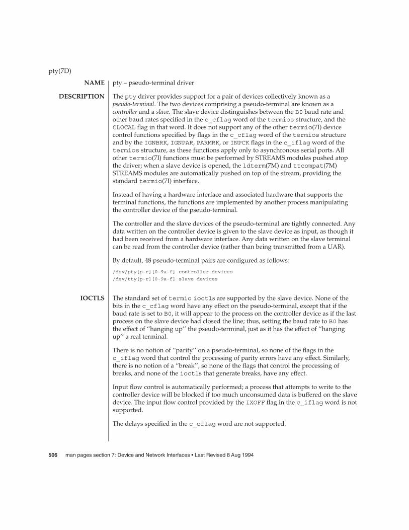
pty – pseudo-terminal driver
The pty driver provides support for a pair of devices collectively known as apseudo-terminal. The two devices comprising a pseudo-terminal are known as acontroller and a slave. The slave device distinguishes between the B0 baud rate andother baud rates specified in the c_cflag word of the termios structure, and theCLOCAL flag in that word. It does not support any of the other termio(7I) devicecontrol functions specified by flags in the c_cflag word of the termios structureand by the IGNBRK, IGNPAR, PARMRK, or INPCK flags in the c_iflag word of thetermios structure, as these functions apply only to asynchronous serial ports. Allother termio(7I) functions must be performed by STREAMS modules pushed atopthe driver; when a slave device is opened, the ldterm(7M) and ttcompat(7M)STREAMS modules are automatically pushed on top of the stream, providing thestandard termio(7I) interface.
Instead of having a hardware interface and associated hardware that supports theterminal functions, the functions are implemented by another process manipulatingthe controller device of the pseudo-terminal.
The controller and the slave devices of the pseudo-terminal are tightly connected. Anydata written on the controller device is given to the slave device as input, as though ithad been received from a hardware interface. Any data written on the slave terminalcan be read from the controller device (rather than being transmitted from a UAR).
By default, 48 pseudo-terminal pairs are configured as follows:
/dev/pty[p-r][0-9a-f] controller devices
/dev/tty[p-r][0-9a-f] slave devices
The standard set of termio ioctls are supported by the slave device. None of thebits in the c_cflag word have any effect on the pseudo-terminal, except that if thebaud rate is set to B0, it will appear to the process on the controller device as if the lastprocess on the slave device had closed the line; thus, setting the baud rate to B0 hasthe effect of ‘‘hanging up’’ the pseudo-terminal, just as it has the effect of ‘‘hangingup’’ a real terminal.
There is no notion of ‘‘parity’’ on a pseudo-terminal, so none of the flags in thec_iflag word that control the processing of parity errors have any effect. Similarly,there is no notion of a ‘‘break’’, so none of the flags that control the processing ofbreaks, and none of the ioctls that generate breaks, have any effect.
Input flow control is automatically performed; a process that attempts to write to thecontroller device will be blocked if too much unconsumed data is buffered on the slavedevice. The input flow control provided by the IXOFF flag in the c_iflag word is notsupported.
The delays specified in the c_oflag word are not supported.
pty(7D)
NAME
DESCRIPTION
IOCTLS
506 man pages section 7: Device and Network Interfaces • Last Revised 8 Aug 1994

As there are no modems involved in a pseudo-terminal, the ioctls that return oralter the state of modem control lines are silently ignored.
A few special ioctls are provided on the controller devices of pseudo-terminals toprovide the functionality needed by applications programs to emulate real hardwareinterfaces:
TIOCSTOP The argument is ignored. Output to the pseudo-terminal issuspended, as if a STOP character had been typed.
TIOCSTART The argument is ignored. Output to the pseudo-terminal isrestarted, as if a START character had been typed.
TIOCPKT The argument is a pointer to an int. If the value of the int isnon-zero, packet mode is enabled; if the value of the int is zero,packet mode is disabled. When a pseudo-terminal is in packetmode, each subsequent read(2) from the controller device willreturn data written on the slave device preceded by a zero byte(symbolically defined as TIOCPKT_DATA), or a single bytereflecting control status information. In the latter case, the byte isan inclusive-or of zero or more of the bits:
TIOCPKT_FLUSHREAD whenever the read queue for theterminal is flushed.
TIOCPKT_FLUSHWRITE whenever the write queue for theterminal is flushed.
TIOCPKT_STOP whenever output to the terminal isstopped using ^S.
TIOCPKT_START whenever output to the terminal isrestarted.
TIOCPKT_DOSTOP whenever XON/XOFF flow controlis enabled after being disabled; it isconsidered ‘‘enabled’’ when theIXON flag in the c_iflag word isset, the VSTOP member of the c_ccarray is ^S and the VSTARTmember of the c_cc array is ^Q.
TIOCPKT_NOSTOP whenever XON/XOFF flow controlis disabled after being enabled.
TIOCREMOTE The argument is a pointer to an int. If the value of the int isnon-zero, remote mode is enabled; if the value of the int is zero,remote mode is disabled. This mode can be enabled or disabledindependently of packet mode. When a pseudo-terminal is inremote mode, input to the slave device of the pseudo-terminal isflow controlled and not input edited (regardless of the mode theslave side of the pseudo-terminal). Each write to the controller
pty(7D)
Device and Network Interfaces 507
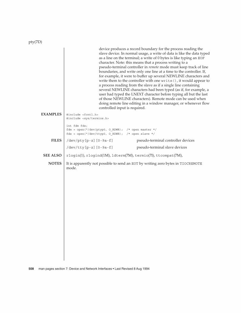
device produces a record boundary for the process reading theslave device. In normal usage, a write of data is like the data typedas a line on the terminal; a write of 0 bytes is like typing an EOFcharacter. Note: this means that a process writing to apseudo-terminal controller in remote mode must keep track of lineboundaries, and write only one line at a time to the controller. If,for example, it were to buffer up several NEWLINE characters andwrite them to the controller with one write(), it would appear toa process reading from the slave as if a single line containingseveral NEWLINE characters had been typed (as if, for example, auser had typed the LNEXT character before typing all but the lastof those NEWLINE characters). Remote mode can be used whendoing remote line editing in a window manager, or whenever flowcontrolled input is required.
#include <fcntl.h>#include <sys/termios.h>
int fdm fds;fdm = open("/dev/ptyp0, O_RDWR); /* open master */
fds = open("/dev/ttyp0, O_RDWR); /* open slave */
/dev/pty[p-z][0-9a-f] pseudo-terminal controller devices
/dev/tty[p-z][0-9a-f] pseudo-terminal slave devices
rlogin(1), rlogind(1M), ldterm(7M), termio(7I), ttcompat(7M),
It is apparently not possible to send an EOT by writing zero bytes in TIOCREMOTEmode.
pty(7D)
EXAMPLES
FILES
SEE ALSO
NOTES
508 man pages section 7: Device and Network Interfaces • Last Revised 8 Aug 1994
qfe – SUNW,qfe Quad Fast-Ethernet device driver
/dev/qfe
The SUNW,qfe Quad Fast-Ethernet driver is a multi-threaded, loadable, clonable,STREAMS hardware driver supporting the connectionless Data Link ProviderInterface, dlpi(7P), over a SUNW,qfe Quad Fast-Ethernet controller. MultipleSUNW,qfe controllers installed within the system are supported by the driver. Theqfe driver provides basic support for the SUNW,qfe hardware. It is used to handle theSUNW,qfe device. Functions include chip initialization, frame transit and receive,multicast and promiscuous support, and error recovery and reporting.
The SUNW,qfe device provides a 100Base-TX networking interface. There are twotypes of SUNW,qfe device: one supporting Sbus and the other supporting the PCI businterface. The Sbus SUNW,qfe device uses Sun’s FEPS ASIC, which provides the Sbusinterface and MAC functions. The PCI SUNW,qfe device uses Sun’s PFEX ASIC toprovide the PCI interface and MAC functions. Both connect with the 100Base-TXon-board transceiver, which connects to a RJ45 connector to provide the Physicallayer functions and external connection.
The 100Base-TX standard specifies an “auto-negotiation” protocol to automaticallyselect the mode and speed of operation. The internal transceiver is capable of doingauto-negotiation with the remote-end of the link (link partner) and receives thecapabilities of the remote end. It selects the Highest Common Denominator modeof operation based on the priorities. It also supports forced-mode of operationwhere the driver can select the mode of operation.
The cloning character-special device /dev/qfe is used to access all SUNW,qfecontrollers installed within the system.
The qfe driver is a “style 2” data link service provider. All M_PROTO and M_PCPROTOtype messages are interpreted as DLPI primitives. Valid DLPI primitives are definedin <sys/dlpi.h>. Refer to dlpi(7P) for more information. An explicitDL_ATTACH_REQ message by the user is required to associate the opened stream witha particular device (ppa). The ppa ID is interpreted as an unsigned long data typeand indicates the corresponding device instance (unit) number. The driver returns anerror (DL_ERROR_ACK) if the ppa field value does not correspond to a valid deviceinstance number for this system. The device is initialized on first attach andde-initialized (stopped) at last detach.
The values returned by the driver in the DL_INFO_ACK primitive in response to theDL_INFO_REQ from the user are as follows:
� The maximum SDU is 1500 (ETHERMTU - defined in <sys/ethernet.h>).
� The minimum SDU is 0.
� The dlsap address length is 8.
� The MAC type is DL_ETHER.
qfe(7d)
NAME
SYNOPSIS
DESCRIPTION
SUNW,qfe
APPLICATIONPROGRAMMING
INTERFACEqfe and DLPI
Device and Network Interfaces 509

� The sap length values is −2 meaning the physical address component is followedimmediately by a 2 byte sap component within the DLSAP address.
� The service mode is DL_CLDLS.
� No optional quality of service (QOS) support is included at present so the QOSfields are 0.
� The provider style is DL_STYLE2.
� The version is DL_VERSION_2.
� The broadcast address value is Ethernet/IEEE broadcast address (0xFFFFFF).
Once in the DL_ATTACHED state, the user must send a DL_BIND_REQ to associate aparticular service access pointer SAP with the stream. The qfe driver interprets the sapfield within the DL_BIND_REQ as an Ethernet “type” therefore valid values for thesap field are in the [0-0xFFFF] range. Only one Ethernet type can be bound to thestream at any time.
If the user selects a sap with a value of 0, the receiver will be in “802.3 mode”. Allframes received from the media having a “type” field in the range [0-1500] areassumed to be 802.3 frames and are routed up all open streams which are bound tosap value 0. If more than one stream is in “802.3 mode” then the frame will beduplicated and routed up multiple streams as DL_UNITDATA_IND messages.
In transmission, the driver checks the sap field of the DL_BIND_REQ if the sap valueis 0, and if the destination type field is in the range [0-1500]. If either is true, thedriver computes the length of the message, not including initial M_PROTO mblk(message block), of all subsequent DL_UNITDATA_REQ messages and transmits 802.3frames that have this value in the MAC frame header length field.
The qfe driver DLSAP address format consists of the 6 byte physical (Ethernet)address component followed immediately by the 2 byte sap (type) componentproducing an 8 byte DLSAP address. Applications should not hardcode to thisparticular implementation-specific DLSAP address format but use informationreturned in the DL_INFO_ACK primitive to compose and decompose DLSAPaddresses. The sap length, full DLSAP length, and sap/physical ordering are includedwithin the DL_INFO_ACK. The physical address length can be computed bysubtracting the sap length from the full DLSAP address length or by issuing theDL_PHYS_ADDR_REQ to obtain the current physical address associated with thestream.
Once in the DL_BOUND state, the user may transmit frames on the Ethernet by sendingDL_UNITDATA_REQ messages to the qfe driver. The qfe driver will route receivedEthernet frames up all those open and bound streams having a sap which matches theEthernet type as DL_UNITDATA_IND messages. Received Ethernet frames areduplicated and routed up multiple open streams if necessary. The DLSAP addresscontained within the DL_UNITDATA_REQ and DL_UNITDATA_IND messages consistsof both the sap (type) and physical (Ethernet) components.
qfe(7d)
510 man pages section 7: Device and Network Interfaces • Last Revised 6 May 1998
In addition to the mandatory connectionless DLPI message set the driver alsosupports the following primitives.
The DL_ENABMULTI_REQ and DL_DISABMULTI_REQ primitives enable or disablereception of individual multicast group addresses. A set of multicast addresses may beiteratively created and modified on a per-stream basis using these primitives. Thedriver accepts these primitives in any state following DL_ATTACHED.
The DL_PROMISCON_REQ and DL_PROMISCOFF_REQ primitives with theDL_PROMISC_PHYS flag set in the dl_level field enables or disables reception of allframes on the media (“promiscuous mode”), including frames generated by the localhost.
When used with the DL_PROMISC_SAP flag set this enables or disables reception of allsap (Ethernet type) values. When used with the DL_PROMISC_MULTI flag set thisenables or disables reception of all multicast group addresses. The effect of each isalways on a per-stream basis and independent of the other sap and physical levelconfigurations on this stream or other streams.
The DL_PHYS_ADDR_REQ primitive returns the 6 octet Ethernet address currentlyassociated (attached) to the stream in the DL_PHYS_ADDR_ACK primitive. Thisprimitive is valid only in states following a successful DL_ATTACH_REQ.
The DL_SET_PHYS_ADDR_REQ primitive changes the 6 octet Ethernet addresscurrently associated (attached) to this stream. The credentials of the process whichoriginally opened this stream must be root. Otherwise EPERM is returned in theDL_ERROR_ACK. This primitive is destructive in that it affects all other current andfuture streams attached to this device. An M_ERROR is sent up all other streamsattached to this device when this primitive is successful on this stream. Once changed,all streams subsequently opened and attached to this device will obtain this newphysical address. Once changed, the physical address will remain until this primitiveis used to change the physical address again or the system is rebooted, whichevercomes first.
By default, the qfe driver performs “auto-negotiation” to select the mode and speedof the link.
The link can be in one of the four following modes:
� 100 Mbps, full-duplex� 100 Mbps, half-duplex� 10 Mbps, full-duplex� 10 Mbps, half-duplex
These speeds and modes are described in the 100Base-TX standard.
The auto−negotiation protocol automatically selects:
� Operation mode (half-duplex or full-duplex)� Speed (100 Mbps or 10 Mbps)
qfe(7d)
qfe Primitives
qfe Driver
Device and Network Interfaces 511

The auto−negotiation protocol does the following:
� Gets all the modes of operation supported by the Link Partner
� Advertises its capabilities to the Link Partner
� Selects the highest common denominator mode of operation based on thepriorities.
� The highest priority is given to the 100 Mbps, full-duplex; lowest priority is givento 10 Mbps, half-duplex.
The 100Base-TX transceiver is capable of all of the operating speeds and modes listedabove. By default, auto-negotiation is used to select the speed and the mode of the linkand the common mode of operation with the link partner.
Sometimes, the user may want to select the speed and mode of the link. TheSUNW,qfe device supports programmable "IPG" (Inter-Packet Gap) parameters ipg1and ipg2. By default, the driver sets ipg1 to 8 byte-times and ipg2 to 4byte-times (which are the standard values). Sometimes, the user may want to alterthese values depending on whether the driver supports 10 Mbps or 100 Mpbs andaccordingly, IPG will be set to 9.6 or 0.96 microseconds.
The qfe driver provides for setting and getting various parameters for the SUNW,qfedevice. The parameter list includes:
� current transceiver status� current link status� inter-packet gap� local transceiver capabilities� link partner capabilities
The local transceiver has two sets of capabilities: one set reflects the capabilities of thehardware, which are read-only (RO) parameters, and the second set, which reflects thevalues chosen by the user, is used in speed selection. There are read/write (RW)capabilities. At boot time, these two sets of capabilities will be the same. The LinkPartner capabilities are also read-only parameters because the current default value ofthese parameters can only be read and cannot be modified.
/dev/qfe qfe special character device
/kernel/drv/qfe.conf system wide default device driver properties
ndd(1M), netstat(1M), driver.conf(4), dlpi(7P), le(7D)
qfe(7d)
qfe Parameter List
FILES
SEE ALSO
512 man pages section 7: Device and Network Interfaces • Last Revised 6 May 1998
qlc – ISP2200 Family Fibre Channel host bus adapter driver
SUNW,qlc@pci-slot
The qlc host bus adapter driver is a Sun Fibre Channel transport layer-compliantnexus driver for the Qlogic ISP2200/ISP2200A/ISP 2202 adapters. These adapterssupport Fibre Channel SCSI and IP Protocols, FC-AL public loop profile,point-to-point fabric connection and Fibre Channel service classes two and three.
The qlc driver interfaces with the Sun Fibre Channel transport layer to support thestandard functions provided by the SCSA interface. It supports auto request sense andtagged queueing by default. The driver requires that all devices have unique hardaddresses in private loop configurations. Devices with conflicting hard addresses willnot be accessible.
/kernel/drv/qlcELF kernel module
/kernel/drv/sparcv9/qlc64-bit ELF kernel module
/kernel/drv/qlc.confDriver configuration file
See attributes(5) for descriptions of the following attributes:
ATTRIBUTE TYPE ATTRIBUTE VALUE
Architecture SPARC
Availability SUNWqlc
prtconf(1M), driver.conf(4), fcp(7D), fp(7D)
Writing Device Drivers
ANSI X3.230:1994, Fibre Channel Physical Signaling (FC-PH)
Project 1134-D, Fibre Channel Generic Services (FC-GS-2)
ANSI X3.269-1996, Fibre Channel Arbitrated Loop (FC-AL)
ANSI X3.270-1996, Fibre Channel Protocol for SCSI (FCP-SCSI)
ANSI X3.270-1996, SCSI-3 Architecture Model (SAM)
Fibre Channel Private Loop SCSI Direct Attach (FC-PLDA)
Fabric Loop Attachment (FC-FLA)
ISP2200 Firmware Interface Specification, QLogic Corporation
qlc(7D)
NAME
SYNOPSIS
DESCRIPTION
FILES
ATTRIBUTES
SEE ALSO
Device and Network Interfaces 513

quotactl – manipulate disk quotas
#include <sys/fs/ufs_quota.h>
int ioctl(int fd, Q_QUOTACTL, struct quotcl *qp)
This ioctl() call manipulates disk quotas. fd is the file descriptor returned by theopen() system call after opening the quotas file (located in the root directory of thefilesystem running quotas.) Q_QUOTACTL is defined in/usr/include/sys/fs/ufs_quota.h. qp is the address of the quotctl structurewhich is defined as
struct quotctl {int op;uid_t uid;caddr_t addr;
};
op indicates an operation to be applied to the user ID uid. (See below.) addr is theaddress of an optional, command specific, data structure which is copied in or out ofthe system. The interpretation of addr is given with each value of op below.
Q_QUOTAON Turn on quotas for a file system. addr points to the full pathnameof the quotas file. uid is ignored. It is recommended that uid havethe value of 0. This call is restricted to the super-user.
Q_QUOTAOFF Turn off quotas for a file system. addr and uid are ignored. It isrecommended that addr have the value of NULL and uid have thevalue of 0. This call is restricted to the super-user.
Q_GETQUOTA Get disk quota limits and current usage for user uid. addr is apointer to a dqblk structure (defined in<sys/fs/ufs_quota.h>). Only the super-user may get thequotas of a user other than himself.
Q_SETQUOTA Set disk quota limits and current usage for user uid. addr is apointer to a dqblk structure (defined in sys/fs/ufs_quota.h).This call is restricted to the super-user.
Q_SETQLIM Set disk quota limits for user uid. addr is a pointer to a dqblkstructure (defined in sys/fs/ufs_quota.h). This call isrestricted to the super-user.
Q_SYNC Update the on-disk copy of quota usages for this file system. addrand uid are ignored.
Q_ALLSYNC Update the on-disk copy of quota usages for all file systems withactive quotas. addr and uid are ignored.
This ioctl() returns:
0 on success.
−1 on failure and sets errno to indicate the error.
quotactl(7I)
NAME
SYNOPSIS
DESCRIPTION
RETURN VALUES
514 man pages section 7: Device and Network Interfaces • Last Revised 14 Sep 1995

EFAULT addr is invalid.
EINVAL The kernel has not been compiled with the QUOTA option. op isinvalid.
ENOENT The quotas file specified by addr does not exist.
EPERM The call is privileged and the caller was not the super-user.
ESRCH No disk quota is found for the indicated user. Quotas have notbeen turned on for this file system.
EUSERS The quota table is full.
If op is Q_QUOTAON, ioctl() may set errno to:
EACCES The quota file pointed to by addr exists but is not a regular file. Thequota file pointed to by addr exists but is not on the file systempointed to by special.
EIO Internal I/O error while attempting to read the quotas filepointed to by addr.
/usr/include/sys/fs/ufs_quota.hquota-related structure/function definitions and defines
quota(1M), quotacheck(1M), quotaon(1M), getrlimit(2), mount(2)
There should be some way to integrate this call with the resource limit interfaceprovided by setrlimit() and getrlimit(2).
This call is incompatible with Melbourne quotas.
quotactl(7I)
ERRORS
FILES
SEE ALSO
BUGS
Device and Network Interfaces 515
random, urandom – Strong random number generator device
/dev/random
/dev/urandom
The /dev/random and /dev/urandom files are special files that are a source forrandom bytes generated by the kernel random number generator device. The/dev/random and /dev/urandom files are suitable for applications requiring highquality random numbers for cryptographic purposes.
The generator device produces random numbers from data and devices available tothe kernel and estimates the amount of randomness (or "entropy”) collected fromthese sources. The entropy level determines the amount of high quality randomnumbers that are produced at a given time.
Applications retrieve random bytes by reading /dev/random or /dev/urandom. The/dev/random interface returns random bytes only when sufficient amount of entropyhas been collected. If there is no entropy to produce the requested number of bytes,/dev/random blocks until more entropy can be obtained. Non-blocking I/O modecan be used to disable the blocking behavior. The /dev/random interface alsosupports poll(2). Note that using poll(2) will not increase the speed at whichrandom numbers can be read.
Bytes retrieved from /dev/random provide the highest quality random numbersproduced by the generator, and can be used to generate long term keys and other highvalue keying material.
The /dev/urandom interface returns bytes regardless of the amount of entropyavailable. It does not block on a read request due to lack of entropy. While bytesproduced by the /dev/urandom interface are of lower quality than bytes producedby /dev/random, they are nonetheless suitable for less demanding and shorter termcryptographic uses such as short term session keys, paddings, and challenge strings.
Data can be written to /dev/random and /dev/urandom. Data written to eitherspecial file is added to the generator’s internal state. Data that is difficult to predict byother users may contribute randomness to the generator state and help improve thequality of future generated random numbers.
By default, write access is restricted to the super-user. An administrator may changethe default read/write restriction by changing the permissions on the appropriatespecial files.
EAGAIN O_NDELAY or O_NONBLOCK was set and no random bytes areavailable for reading from /dev/random.
EINTR A signal was caught while reading and no data was transferred.
/dev/random
/dev/urandom
random(7D)
NAME
SYNOPSIS
DESCRIPTION
ERRORS
FILES
516 man pages section 7: Device and Network Interfaces • Last Revised 01 Mar 2001

See attributes(5) for descriptions of the following attributes:
ATTRIBUTE TYPE ATTRIBUTE VALUE
Availability SUNWcsr (32-bit)
SUNWcarx (64-bit)
Interface Stability Evolving
poll(2), attributes(5)
An implementation of the /dev/random and /dev/urandom kernel-based randomnumber generator first appeared in Linux 1.3.30.
A /dev/random interface for Solaris first appeared as part of the CryptoRandimplementation.
random(7D)
ATTRIBUTES
SEE ALSO
NOTES
Device and Network Interfaces 517

rarp, RARP – Reverse address resolution protocol
You use the RARP protocol to map dynamically between the Internet Protocol (IP) andnetwork interface MAC addresses. RARP is often used to boot a Solaris client. RARPclients include the SPARC boot PROM, x86 boot floppy, SunOS kernel, andifconfig(1M). in.rarpd(7D) provides the server-side implementation.
RARP request timeout behavior in application-layer clients is governed by the/etc/inet/rarp default file. To tune the number of retries an application attemptsbefore giving up, set the RARP_RETRIES variable in /etc/inet/rarp. If the file isnot present or RARP_RETRIES is not initialized within it, applications will retry amaximum of five times with a five second wait between retries.
/etc/inet/rarp
See attributes(5) for descriptions of the following attributes:
ATTRIBUTE TYPE ATTRIBUTE VALUE
Interface Stability (protocol) Standard
Interface Stability (defaults file) Unstable
Interface Stability (RARP_RETRIES) Unstable
ifconfig(1M), in.rarpd(7D), arp(7P)
Reverse Address Resolution Protocol RFC 903. June, 1994 R. Finlayson, T. Mann, J.C.Mogul, M. Theimer
RARP(7P)
NAME
DESCRIPTION
FILES
ATTRIBUTES
SEE ALSO
518 man pages section 7: Device and Network Interfaces • Last Revised 8 Nov 2001
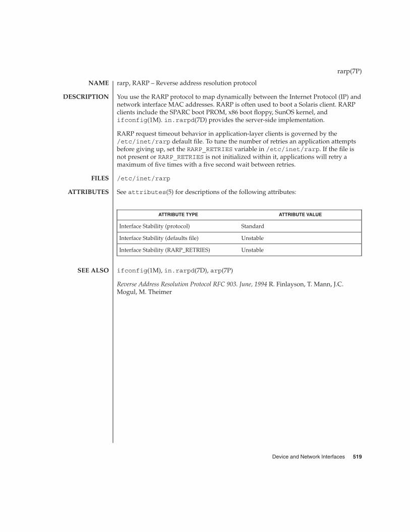
rarp, RARP – Reverse address resolution protocol
You use the RARP protocol to map dynamically between the Internet Protocol (IP) andnetwork interface MAC addresses. RARP is often used to boot a Solaris client. RARPclients include the SPARC boot PROM, x86 boot floppy, SunOS kernel, andifconfig(1M). in.rarpd(7D) provides the server-side implementation.
RARP request timeout behavior in application-layer clients is governed by the/etc/inet/rarp default file. To tune the number of retries an application attemptsbefore giving up, set the RARP_RETRIES variable in /etc/inet/rarp. If the file isnot present or RARP_RETRIES is not initialized within it, applications will retry amaximum of five times with a five second wait between retries.
/etc/inet/rarp
See attributes(5) for descriptions of the following attributes:
ATTRIBUTE TYPE ATTRIBUTE VALUE
Interface Stability (protocol) Standard
Interface Stability (defaults file) Unstable
Interface Stability (RARP_RETRIES) Unstable
ifconfig(1M), in.rarpd(7D), arp(7P)
Reverse Address Resolution Protocol RFC 903. June, 1994 R. Finlayson, T. Mann, J.C.Mogul, M. Theimer
rarp(7P)
NAME
DESCRIPTION
FILES
ATTRIBUTES
SEE ALSO
Device and Network Interfaces 519

rns_smt – Rockwell Station Management driver
/dev/rns_smt
On the Rockwell FDDI adapter boards, the rns_smt driver implements the FDDIStation Management protocol ( SMT ). The Station Management protocol includesConnection Management, Ring Management and all frame services. The rns_sntdriver is a loadable, clonable STREAMS driver that can support multiple instances ofthe FDDI interface, as well as multiple application layer clients.
The cloning character-oriented devices /dev/rns_smt are used to access therns_snt driver that supports Rockwell FDDI adapters. The /dev/rns_smt device isan interface used only for Station Management applications, such as those that gatherMIB statistics or other Station information.
The SMT driver supports DLPI and SPI interfaces. All M_PROTO and M_PCPROTO typemessages are interpreted as DLPI or SPI. SPI ( SMT provider interface) is a Rockwellproprietary interface that is used during communication between the SMT and relatedapplications. rns_smt is a "style 2" data link service provider, which means that anexplicit DL_ATTACH_REQ is required to associate the opened stream with a particulardevice or physical point of attachment ( PPA ).
/dev/rns_smt interface used for Station Managementapplications
/kernel/drv/rns_smt.conf configuration file
rns_smt(7D)
NAME
SYNOPSIS
DESCRIPTION
FILES
520 man pages section 7: Device and Network Interfaces • Last Revised 10 Apr 1996

route – kernel packet forwarding database
#include <sys/types.h>#include <sys/socket.h>#include <net/if.h>
#include <net/route.h>
int socket(PF_ROUTE, SOCK_RAW, int protocol);
UNIX provides some packet routing facilities. The kernel maintains a routinginformation database, which is used in selecting the appropriate network interfacewhen transmitting packets.
A user process (or possibly multiple co-operating processes) maintains this databaseby sending messages over a special kind of socket. This supplants fixed sizeioctl(2)’s specified in routing(7P). Routing table changes may only be carried outby the superuser.
The operating system may spontaneously emit routing messages in response toexternal events, such as receipt of a re-direct, or failure to locate a suitable route for arequest. The message types are described in greater detail below.
Routing database entries come in two flavors: entries for a specific host, or entries forall hosts on a generic subnetwork (as specified by a bit mask and value under themask). The effect of wildcard or default route may be achieved by using a mask of allzeros, and there may be hierarchical routes.
When the system is booted and addresses are assigned to the network interfaces, theinternet protocol family installs a routing table entry for each interface when it isready for traffic. Normally the protocol specifies the route through each interface as adirect connection to the destination host or network. If the route is direct, the transportlayer of a protocol family usually requests the packet be sent to the same hostspecified in the packet. Otherwise, the interface is requested to address the packet tothe gateway listed in the routing entry, that is, the packet is forwarded.
When routing a packet, the kernel attempts to find the most specific route matchingthe destination. If no entry is found, the destination is declared to be unreachable, anda routing-miss message is generated if there are any listeners on the routing controlsocket (described below). If there are two different mask and value-under-the-maskpairs that match, the more specific is the one with more bits in the mask. A route to ahost is regarded as being supplied with a mask of as many ones as there are bits in thedestination.
A wildcard routing entry is specified with a zero destination address value, and amask of all zeroes. Wildcard routes are used when the system fails to find other routesmatching the destination. The combination of wildcard routes and routing redirectscan provide an economical mechanism for routing traffic.
route(7P)
NAME
SYNOPSIS
DESCRIPTION
Device and Network Interfaces 521

One opens the channel for passing routing control messages by using the socket callshown in the SYNOPSIS section above. There can be more than one routing socketopen per system.
Messages are formed by a header followed by a small number of sockaddrs, whoselength depend on the address family. sockaddrs are interpreted by position. Anexample of a type of message with three addresses might be a CIDR prefix route:Destination, Netmask, and Gateway. The interpretation of which addresses are presentis given by a bit mask within the header, and the sequence is least significant to mostsignificant bit within the vector.
Any messages sent to the kernel are returned, and copies are sent to all interestedlisteners. The kernel provides the process ID of the sender, and the sender may use anadditional sequence field to distinguish between outstanding messages. However,message replies may be lost when kernel buffers are exhausted.
The protocol parameter specifies which messages an application listening on therouting socket is interested in seeing, based on the the address family of thesockaddrs present. Currently, you can specify AF_INET and AF_INET6 to filter themessages seen by the listener, or alternatively, you can specify AF_UNSPEC to indicatethat the listener is interested in all routing messages.
The kernel may reject certain messages, and will indicate this by filling in thertm_errno field of the rt_msghdr struct (see below). The following codes may bereturned:
EEXIST If requested to duplicate an existing entry
ESRCH If requested to delete a non-existent entry
ENOBUFS If insufficient resources were available to install a new route.
In the current implementation, all routing processes run locally, and the values forrtm_errno are available through the normal errno mechanism, even if the routingreply message is lost.
A process may avoid the expense of reading replies to its own messages by issuing asetsockopt(3SOCKET) call indicating that the SO_USELOOPBACK option at theSOL_SOCKET level is to be turned off. A process may ignore all messages from therouting socket by doing a shutdown(3SOCKET) system call for further input.
If a route is in use when it is deleted, the routing entry is marked down and removedfrom the routing table, but the resources associated with it are not reclaimed until allreferences to it are released.
User processes can obtain information about the routing entry to a specific destinationby using a RTM_GET message.
Messages include:
route(7P)
Messages
522 man pages section 7: Device and Network Interfaces • Last Revised 9 Nov 1999

#define RTM_ADD 0x1 /* Add Route */#define RTM_DELETE 0x2 /* Delete Route */#define RTM_CHANGE 0x3 /* Change Metrics, Flags, or Gateway */#define RTM_GET 0x4 /* Report Information */#define RTM_LOSING 0x5 /* Kernel Suspects Partitioning */#define RTM_REDIRECT 0x6 /* Told to use different route */#define RTM_MISS 0x7 /* Lookup failed on this address */#define RTM_LOCK 0x8 /* fix specified metrics */#define RTM_OLDADD 0x9 /* caused by SIOCADDRT */#define RTM_OLDDEL 0xa /* caused by SIOCDELRT */#define RTM_RESOLVE 0xb /* request to resolve dst to LL addr */#define RTM_NEWADDR 0xc /* address being added to iface */#define RTM_DELADDR 0xd /* address being removed from iface */#define RTM_IFINFO 0xe /* iface going up/down etc. */
A message header consists of:
struct rt_msghdr {ushort_t rtm_msglen; /* to skip over non-understood messages */uchar_t rtm_version; /* future binary compatibility */uchar_t rtm_type; /* message type */ushort_t rtm_index; /* index for associated ifp */pid_t rtm_pid; /* identify sender */int rtm_addrs; /* bitmask identifying sockaddrs in msg */int rtm_seq; /* for sender to identify action */int rtm_errno; /* why failed */int rtm_flags; /* flags, incl kern & message, e.g., DONE */int rtm_use; /* from rtentry */uint_t rtm_inits; /* which values we are initializing */
struct rt_metrics rtm_rmx; /* metrics themselves */};
where
struct rt_metrics {uint32_t rmx_locks; /* Kernel must leave these values alone */uint32_t rmx_mtu; /* MTU for this path */uint32_t rmx_hopcount; /* max hops expected */uint32_t rmx_expire; /* lifetime for route, e.g., redirect */uint32_t rmx_recvpipe; /* inbound delay-bandwidth product */uint32_t rmx_sendpipe; /* outbound delay-bandwidth product */uint32_t rmx_ssthresh; /* outbound gateway buffer limit */uint32_t rmx_rtt; /* estimated round trip time */uint32_t rmx_rttvar; /* estimated rtt variance */uint32_t rmx_pksent; /* packets sent using this route */};
/* Flags include the values */
#define RTF_UP 0x1 /* route usable */#define RTF_GATEWAY 0x2 /* destination is a gateway */#define RTF_HOST 0x4 /* host entry (net otherwise) */#define RTF_REJECT 0x8 /* host or net unreachable */#define RTF_DYNAMIC 0x10 /* created dynamically(by redirect) */#define RTF_MODIFIED 0x20 /* modified dynamically(by redirect) */#define RTF_DONE 0x40 /* message confirmed */
route(7P)
Device and Network Interfaces 523

#define RTF_MASK 0x80 /* subnet mask present */#define RTF_CLONING 0x100 /* generate new routes on use */#define RTF_XRESOLVE 0x200 /* external daemon resolves name */#define RTF_LLINFO 0x400 /* generated by ARP */#define RTF_STATIC 0x800 /* manually added */#define RTF_BLACKHOLE 0x1000 /* just discard pkts (during updates) */#define RTF_PRIVATE 0x2000 /* do not advertise this route */#define RTF_PROTO2 0x4000 /* protocol specific routing flag #2 */#define RTF_PROTO1 0x8000 /* protocol specific routing flag #1 */
/* Specifiers for metric values in rmx_locks and rtm_inits are */
#define RTV_MTU 0x1 /* init or lock _mtu */#define RTV_HOPCOUNT 0x2 /* init or lock _hopcount */#define RTV_EXPIRE 0x4 /* init or lock _expire */#define RTV_RPIPE 0x8 /* init or lock _recvpipe */#define RTV_SPIPE 0x10 /* init or lock _sendpipe */#define RTV_SSTHRESH 0x20 /* init or lock _ssthresh */#define RTV_RTT 0x40 /* init or lock _rtt */#define RTV_RTTVAR 0x80 /* init or lock _rttvar */
/* Specifiers for which addresses are present in the messages are */
#define RTA_DST 0x1 /* destination sockaddr present */#define RTA_GATEWAY 0x2 /* gateway sockaddr present */#define RTA_NETMASK 0x4 /* netmask sockaddr present */#define RTA_GENMASK 0x8 /* cloning mask sockaddr present */#define RTA_IFP 0x10 /* interface name sockaddr present */#define RTA_IFA 0x20 /* interface addr sockaddr present */#define RTA_AUTHOR 0x40 /* sockaddr for author of redirect */#define RTA_BRD 0x80 /* for NEWADDR, broadcast or p-p dest addr */
ioctl(2), setsockopt(3SOCKET), shutdown(3SOCKET), routing(7P)
Some of the metrics may not be implemented and return zero. The implementedmetrics are set in rtm_inits.
route(7P)
SEE ALSO
NOTES
524 man pages section 7: Device and Network Interfaces • Last Revised 9 Nov 1999

routing – system support for packet network routing
The network facilities provide general packet routing. The routing interfacedescribed here can be used to maintain the system’s IPv4 routing table. It has beenmaintained for compatibility with older applications. The recommended interface formaintaining the system’s routing tables is the routing socket, described at route(7P).The routing socket can be used to manipulate both the IPv4 and IPv6 routing tables ofthe system. Routing table maintenance may be implemented in applications processes.
A simple set of data structures compose a “routing table” used in selecting theappropriate network interface when transmitting packets. This table contains a singleentry for each route to a specific network or host. The routing table was designed tosupport routing for the Internet Protocol (IP), but its implementation is protocolindependent and thus it may serve other protocols as well. User programs maymanipulate this data base with the aid of two ioctl(2) commands, SIOCADDRT andSIOCDELRT. These commands allow the addition and deletion of a single routingtable entry, respectively. Routing table manipulations may only be carried out byprivileged user.
A routing table entry has the following form, as defined in/usr/include/net/route.h:
struct rtentry {unit_t rt_hash; /* to speed lookups */struct sockaddr rt_dst; /* key */struct sockaddr rt_gateway; /* value */short rt_flags; /* up/down?, host/net */short rt_refcnt; /* # held references */unit_t rt_use; /* raw # packets forwarded */
/** The kernel does not use this field, and without it the structure is* datamodel independent.*/#if !defined(_KERNEL)
struct ifnet *rt_ifp; /* the answer: interface to use */#endif /* !defined(_KERNEL) */
};
with rt_flags defined from:
#define RTF_UP 0x1 /* route usable */#define RTF_GATEWAY 0x2 /* destination is a gateway */
#define RTF_HOST 0x4 /* host entry (net otherwise) */
There are three types of routing table entries: those for a specific host, those for allhosts on a specific network, and those for any destination not matched by entries ofthe first two types, called a wildcard route. Each network interface installs a routingtable entry when it is initialized. Normally the interface specifies if the route through itis a “direct” connection to the destination host or network. If the route is direct, the
routing(7P)
NAME
DESCRIPTION
Device and Network Interfaces 525
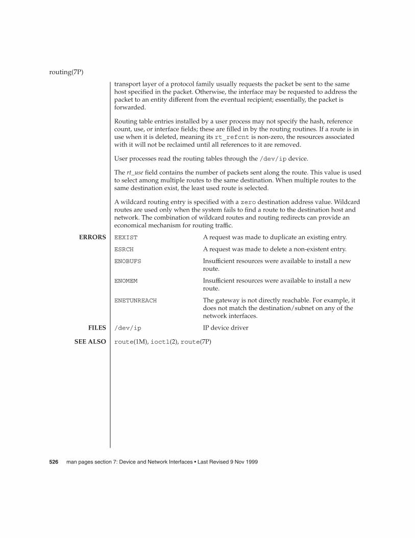
transport layer of a protocol family usually requests the packet be sent to the samehost specified in the packet. Otherwise, the interface may be requested to address thepacket to an entity different from the eventual recipient; essentially, the packet isforwarded.
Routing table entries installed by a user process may not specify the hash, referencecount, use, or interface fields; these are filled in by the routing routines. If a route is inuse when it is deleted, meaning its rt_refcnt is non-zero, the resources associatedwith it will not be reclaimed until all references to it are removed.
User processes read the routing tables through the /dev/ip device.
The rt_use field contains the number of packets sent along the route. This value is usedto select among multiple routes to the same destination. When multiple routes to thesame destination exist, the least used route is selected.
A wildcard routing entry is specified with a zero destination address value. Wildcardroutes are used only when the system fails to find a route to the destination host andnetwork. The combination of wildcard routes and routing redirects can provide aneconomical mechanism for routing traffic.
EEXIST A request was made to duplicate an existing entry.
ESRCH A request was made to delete a non-existent entry.
ENOBUFS Insufficient resources were available to install a newroute.
ENOMEM Insufficient resources were available to install a newroute.
ENETUNREACH The gateway is not directly reachable. For example, itdoes not match the destination/subnet on any of thenetwork interfaces.
/dev/ip IP device driver
route(1M), ioctl(2), route(7P)
routing(7P)
ERRORS
FILES
SEE ALSO
526 man pages section 7: Device and Network Interfaces • Last Revised 9 Nov 1999

sad – STREAMS Administrative Driver
#include <sys/types.h>
#include <sys/conf.h>
#include <sys/sad.h>
#include <sys/stropts.h>
int ioctl(int fildes, int command, int arg);
The STREAMS Administrative Driver provides an interface for applications toperform administrative operations on STREAMS modules and drivers. The interface isprovided through ioctl(2) commands. Privileged operations may access the saddriver using /dev/sad/admin. Unprivileged operations may access the sad driverusing /dev/sad/user.
The fildes argument is an open file descriptor that refers to the sad driver. Thecommand argument determines the control function to be performed as describedbelow. The arg argument represents additional information that is needed by thiscommand. The type of arg depends upon the command, but it is generally an integeror a pointer to a command-specific data structure.
The autopush facility (see autopush(1M)) allows one to configure a list of modules tobe automatically pushed on a stream when a driver is first opened. Autopush iscontrolled by the following commands:
SAD_SAP Allows the administrator to configure the given device’s autopushinformation. arg points to a strapush structure, which containsthe following members:
unit_t ap_cmd;major_t sap_major;minor_t sap_minor;minor_t sap_lastminor;unit_t sap_npush;
unit_t sap_list [MAXAPUSH] [FMNAMESZ + 1];
The sap_cmd field indicates the type of configuration being done.It may take on one of the following values:
SAP_ONE Configure one minor device of a driver.
SAP_RANGE Configure a range of minor devices of a driver.
SAP_ALL Configure all minor devices of a driver.
SAP_CLEAR Undo configuration information for a driver.
The sap_major field is the major device number of the device tobe configured. The sap_minor field is the minor device numberof the device to be configured. The sap_lastminor field is used
sad(7D)
NAME
SYNOPSIS
DESCRIPTION
COMMANDFUNCTIONS
Device and Network Interfaces 527
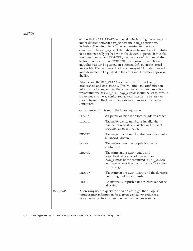
only with the SAP_RANGE command, which configures a range ofminor devices between sap_minor and sap_lastminor,inclusive. The minor fields have no meaning for the SAP_ALLcommand. The sap_npush field indicates the number of modulesto be automatically pushed when the device is opened. It must beless than or equal to MAXAPUSH , defined in sad.h. It must alsobe less than or equal to NSTRPUSH, the maximum number ofmodules that can be pushed on a stream, defined in the kernelmaster file. The field sap_list is an array of NULL-terminatedmodule names to be pushed in the order in which they appear inthe list.
When using the SAP_CLEAR command, the user sets onlysap_major and sap_minor. This will undo the configurationinformation for any of the other commands. If a previous entrywas configured as SAP_ALL, sap_minor should be set to zero. Ifa previous entry was configured as SAP_RANGE , sap_minorshould be set to the lowest minor device number in the rangeconfigured.
On failure, errno is set to the following value:
EFAULT arg points outside the allocated address space.
EINVAL The major device number is invalid, thenumber of modules is invalid, or the list ofmodule names is invalid.
ENOSTR The major device number does not represent aSTREAMS driver.
EEXIST The major-minor device pair is alreadyconfigured.
ERANGE The command is SAP_RANGE andsap_lastminor is not greater thansap_minor, or the command is SAP_CLEARand sap_minor is not equal to the first minorin the range.
ENODEV The command is SAP_CLEAR and the device isnot configured for autopush.
ENOSR An internal autopush data structure cannot beallocated.
SAD_GAP Allows any user to query the sad driver to get the autopushconfiguration information for a given device. arg points to astrapush structure as described in the previous command.
sad(7D)
528 man pages section 7: Device and Network Interfaces • Last Revised 16 Apr 1997

The user should set the sap_major and sap_minor fields of thestrapush structure to the major and minor device numbers,respectively, of the device in question. On return, the strapushstructure will be filled in with the entire information used toconfigure the device. Unused entries in the module list will bezero-filled.
On failure, errno is set to one of the following values:
EFAULT arg points outside the allocated address space.
EINVAL The major device number is invalid.
ENOSTR The major device number does not represent aSTREAMS driver.
ENODEV The device is not configured for autopush.
SAD_VML Allows any user to validate a list of modules (that is, to see if theyare installed on the system). arg is a pointer to a str_liststructure with the following members:
int sl_nmods;
struct str_mlist *sl_modlist;The str_mlist structure hasthe following member:
char l_name[FMNAMESZ+1];
sl_nmods indicates the number of entries the user has allocatedin the array and sl_modlist points to the array of modulenames. The return value is 0 if the list is valid, 1 if the list containsan invalid module name, or −1 on failure. On failure, errno is setto one of the following values:
EFAULT arg points outside the allocated address space.
EINVAL The sl_nmods field of the str_liststructure is less than or equal to zero.
intro(2), ioctl(2), open(2)
STREAMS Programming Guide
Unless otherwise specified, the return value from ioctl() is 0 upon success and −1upon failure with errno set as indicated.
sad(7D)
SEE ALSO
DIAGNOSTICS
Device and Network Interfaces 529

sbpro – Sound Blaster Pro, Sound Blaster 16, and Sound Blaster AWE32 audio devicedriver
sbpro:sound,sbpro
sbpro:sound,sbproctl
The Creative Labs Sound Blaster family of audio cards comprises DMA-capable ISAbus plug-in cards that provide 8 and 16 bit mono and stereo digitized sound recordingand playback over a wide range of sampling rates. Each card includes a digital soundprocessor and mixing capability. Some of the cards also support more advanced audiofeatures such as FM synthesis, advanced signal processing, advanced wave effects,and MIDI capability; however, the sbpro driver does not currently support thoseadvanced features. The features and interfaces supported by the Solaris sbpro driverare described here and in audio(7I).
Some Sound Blaster cards support optional non-audio capabilities such as SCSIinterfaces and CD-ROM interfaces. These interfaces are not supported by the sbprodriver. The Sound Blaster 16 optional SCSI-2 interface is supported by the aic(7D)driver.
The sbpro driver also supports certain Sound Blaster-compatible audio devices,including some based on the ESS688 audio chip.
In addition, the driver supports some devices based on the Analog Devices AD1847and AD1848, and Crystal Semiconductor CS4231 chips. Any CS4231-based devicessupported by this driver are programmed in AD1848 compatibility mode. There is nospecial support in this driver for the more advanced CS4231 features. This family ofdevices will be referred to as the "AD184x family."
The Sound Blaster device is treated as an exclusive resource, meaning that only oneprocess may open the device at a time. Since the Sound Blaster hardware does notsupport simultaneous sound input and output, the sbpro driver does not allow thesimultaneous access of the device by two processes, even if one tries to open itread-only and the other write-only.
The sbpro driver will return "SUNW,sbpro" or "SUNW,sb16" in the name field ofthe audio_device structure. The version field will contain the version number of thecard’s DSP chip, and the config field will be set to "SBPRO" or "SB16". The AWE32 iscurrently identified as an SB16. In all subjects covered in this man page, , the SoundBlaster AWE32 behaves the same as the Sound Blaster 16.
The Sound Blaster Pro handles 8-bit samples. In mono mode, audio data may besampled at rates from 4,000 to 44,100 samples per second. In stereo mode, samplesmay be handled at the rates of 11,025 and 22,050 samples per second. The SB-16 cansample 8-bit or 16-bit mono or stereo data in the range of 5,000 to 44,100 Hz. Devicesin the AD184x family can handle sample rates up to 48,000 Hz.
sbpro(7D)
NAME
SYNOPSIS
DESCRIPTION
APPLICATIONPROGRAMMING
INTERFACE
Audio DataFormats
530 man pages section 7: Device and Network Interfaces • Last Revised 16 January 2001
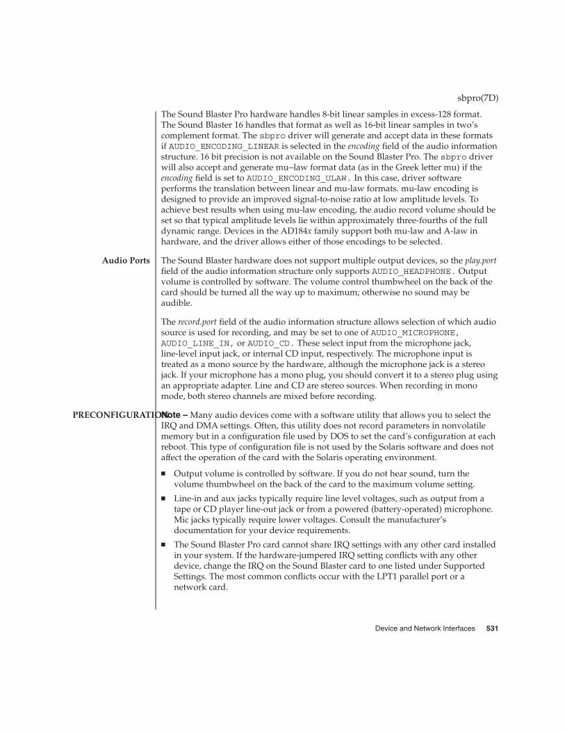
The Sound Blaster Pro hardware handles 8-bit linear samples in excess-128 format.The Sound Blaster 16 handles that format as well as 16-bit linear samples in two’scomplement format. The sbpro driver will generate and accept data in these formatsif AUDIO_ENCODING_LINEAR is selected in the encoding field of the audio informationstructure. 16 bit precision is not available on the Sound Blaster Pro. The sbpro driverwill also accept and generate mu−law format data (as in the Greek letter mu) if theencoding field is set to AUDIO_ENCODING_ULAW. In this case, driver softwareperforms the translation between linear and mu-law formats. mu-law encoding isdesigned to provide an improved signal-to-noise ratio at low amplitude levels. Toachieve best results when using mu-law encoding, the audio record volume should beset so that typical amplitude levels lie within approximately three-fourths of the fulldynamic range. Devices in the AD184x family support both mu-law and A-law inhardware, and the driver allows either of those encodings to be selected.
The Sound Blaster hardware does not support multiple output devices, so the play.portfield of the audio information structure only supports AUDIO_HEADPHONE. Outputvolume is controlled by software. The volume control thumbwheel on the back of thecard should be turned all the way up to maximum; otherwise no sound may beaudible.
The record.port field of the audio information structure allows selection of which audiosource is used for recording, and may be set to one of AUDIO_MICROPHONE,AUDIO_LINE_IN, or AUDIO_CD. These select input from the microphone jack,line-level input jack, or internal CD input, respectively. The microphone input istreated as a mono source by the hardware, although the microphone jack is a stereojack. If your microphone has a mono plug, you should convert it to a stereo plug usingan appropriate adapter. Line and CD are stereo sources. When recording in monomode, both stereo channels are mixed before recording.
Note – Many audio devices come with a software utility that allows you to select theIRQ and DMA settings. Often, this utility does not record parameters in nonvolatilememory but in a configuration file used by DOS to set the card’s configuration at eachreboot. This type of configuration file is not used by the Solaris software and does notaffect the operation of the card with the Solaris operating environment.
� Output volume is controlled by software. If you do not hear sound, turn thevolume thumbwheel on the back of the card to the maximum volume setting.
� Line-in and aux jacks typically require line level voltages, such as output from atape or CD player line-out jack or from a powered (battery-operated) microphone.Mic jacks typically require lower voltages. Consult the manufacturer’sdocumentation for your device requirements.
� The Sound Blaster Pro card cannot share IRQ settings with any other card installedin your system. If the hardware-jumpered IRQ setting conflicts with any otherdevice, change the IRQ on the Sound Blaster card to one listed under SupportedSettings. The most common conflicts occur with the LPT1 parallel port or anetwork card.
sbpro(7D)
Audio Ports
PRECONFIGURATION
Device and Network Interfaces 531

� For Sound Blaster 16 cards that have an on-board SCSI subsystem, the audiosubsystem needs its own I/O (port) address and an IRQ, distinct from those of theSCSI subsystem.
Note – Default settings differ slightly between the SB Pro, SB Pro-2 and SB 16, SBAWE32, SB Vibra 16 cards. Only the 0x220 and 0x240 settings are supported for SB Proand SB Pro-2 while additional addresses are supported for the SB 16, SB AWE32, andSB Vibra 16 cards.
If your card supports Plug and Play, your device resources are configuredautomatically. Use the following settings for devices that don’t support Plug and Play.Defaults settings are shown in italics.
� IRQ Level: 2, 5, 7, 10� I/O Address: 0x220, 0x240, 0x260, 0x280� 8-bit DMA Channel: 0, 1, 3� 16-bit DMA Channel: 5, 6, 7
Settings for the Compaq Deskpro XL and Turtle Beach Tropez Card are providedbelow. For each device, the sbpro driver automatically chooses an unused DMAchannel and IRQ line.
� Compaq Deskpro XL Business Audio With Built-in AD1847 Chip — I/O Address:0x530, 0x604, 0xE80, 0xF40
Note – The sbpro support for the AD1848 and compatibles uses one DMA channelfor both play and record; simultaneous play/record is not supported.
� Turtle Beach Tropez Card With CS4231 Chip — I/O Address: 0x530 (The MWSSI/O address on the Turtle Beach Tropez card is 0x530 at power-up. It can only bechanged by software after the system is booted, a function that the Solarisoperating environment does not perform. Therefore, the Tropez card is onlysupported at I/O address 0x530).
Note – The Tropez card comes with a software utility for selecting the IRQ, DMA,and MWSS compatibility I/O address settings used by the card. However, thatutility does not record those parameters in nonvolatile memory, but in aconfiguration file used by DOS to set the card’s configuration at each reboot. Thistype of configuration file is not used by the Solaris software and does not affect theoperation of the card with the Solaris operating environment.
� Any Crystal Semiconductor CS4231-based devices supported by this driver areprogrammed in AD1848-compatibility mode. This driver does not include supportfor advanced CS4231 features; in particular, simultaneous play/record.
� The Sound Blaster card cannot share IRQ settings with any other card installed inyour system. The most common conflicts occur with the LPT1 parallel port or anetwork card.
� Some devices can detect that the IRQ is in use by another device in the system. Ifthis occurs, the driver prints an error message:
sbpro(7D)
Supported Settings
Known Problemsand Limitations
532 man pages section 7: Device and Network Interfaces • Last Revised 16 January 2001

sbpro: MWSS_AD184x IRQ 7 is ’in use.’
To correct this, change the IRQ setting of either the audio device or the conflictingdevice. (Some devices are not able to detect such a conflict. The driver will try touse the card, but that will likely result in the system hanging when the card is firstused. Thus, it is important to check that the IRQ that does not conflict with anotherdevice.)
� Although the sbpro driver supports A-law encoding on AD1848 and compatibledevices, audiotool does not and produces an error message if you select A-lawencoding. Use audioplay(1) to play A-law encoded audio files, or useaudioconvert(1) to convert the A-law sample into a format that audiotool willaccept, such as 16-bit linear. User-written applications can select A-law formatusing the sbpro driver on AD1848 and compatible devices.
Note – Some Compaq Deskpro XL Business Audio system units with built-in AD184xchip have the headphone jack wired with its left and right channels reversed. As aresult, left and right output is reversed. The line-out jack at the back of the unit worksas expected. For optimum sound quality, use external microphone and speakers andnot the ones built into the keyboard.
� Non-Plug and Play Sound Blaster 16, Sound Blaster Vibra 16, and Sound BlasterAWE32 cards are recognized as Sound Blaster 16 cards.
� The ISA version IBM Token Ring and compatible adapters will not work in asystem that contains a Sound Blaster card that is configured at the default I/O portaddress (0x220). If possible, move the Sound Blaster card to port address 0x240;otherwise, remove the Sound Blaster device from the system.
/dev/audio Linked to s/dev/sound/0
/dev/audioctl Linked to /dev/sound/0ctl
/dev/sound/0 First audio device in the system
/dev/sound/0ctl Audio control for first audio device
/usr/share/audio Audio files
See attributes(5) for descriptions of the following attributes:
ATTRIBUTE TYPE ATTRIBUTE VALUE
Architecture IA
audioconvert(1), ioctl(2), attributes(5), aic(7D), audio(7I), streamio(7I)
Creative Labs, Inc. Sound Blaster Pro User Reference Manual
The current driver implementation does not support the A-law encoding mode forSound Blaster and compatible devices.
sbpro(7D)
FILES
ATTRIBUTES
SEE ALSO
BUGS
Device and Network Interfaces 533

The conversion of mu-law to 8-bit linear format for Sound Blaster and compatibledevices can cause a loss of precision, resulting in poor sound quality in cases wherethe original recording level was well below normal. If this occurs while using theSound Blaster 16 card, audioconvert(1) can be used to convert the original mu-lawdata to 16-bit linear format before play. This will preserve all the precision from theoriginal mu-law sample.
sbpro(7D)
534 man pages section 7: Device and Network Interfaces • Last Revised 16 January 2001
scman – SUNW,scman Sun Fire 15K management network device driver
/dev/scman
The scman (7D) network device driver is a loadable, clonable, STREAMS hardwaredriver that supports the dlpi connectionless data link provider interface over theSUNW,scman network controller. The scman controller provides a highly available,secure communication channel between the Sun Fire 15K system controller anddynamic system domains.
The scman driver provides basic support for the SUNW,scman controller. Driverfunctions include network initialization, frame transit and receive, multicast andpromiscuous support, and error recovery and reporting.
The scman controller is physically located in the Sun Fire 15K system controller andconnects to SUNWdman controllers found in each active dynamic system domain in aSun Fire 15K chassis. See dman(7D). All links are point-to-point and are internal to theSun Fire 15K chassis. Traffic between the system controller and the dynamic systemdomains is not accessible by any third party; for example, another system domainwithin the Sun Fire 15K chassis. All system domains are accessible through the scmancontroller.
The link layer frame format is identical to that used by Ethernet (sys/ethernet.h).
The /dev/scman cloning character-special device is used to access the SUNW,scmancontroller installed on the system.
The scman driver is a style 2 data link provider interface. All M_PROTO andM_PCPROTO type messages are interpreted as DLPI primitives. Valid DLPI primitivesare defined in sys/dlpi.h. Refer to dlpi(7P) for more information. An explicitDL_ATTACH_REQ message by the user is required to associate the opened stream witha particular device or physical point of attachment (PPA).
The PPA ID is interpreted as an unsigned long data type and indicates thecorresponding device instance (unit) number. The only valid unit number is 0. Anerror (DL_ERROR_ACK) is returned by the driver if the PPA field value does notcorrespond to a valid device instance number for this system. The device is initializedon the first attach and deinitialized (stopped) upon the last detach.
The values returned by the scman driver in the DL_INFO_ACK primitive in responseto the DL_INFO_REQ from the user are:
� Maximum service data units (SDU) are 1500.
� Minimum SDU is 0.
� Data link service access point (DLSAP) address length is 8.
� Media access control (MAC) type is DL_ETHER.
� Service access point (SAP) length value is -2, meaning the physical addresscomponent is followed immediately by a two-byte SAP component within theDLSAP address.
scman(7D)
NAME
SYNOPSIS
DESCRIPTION
APPLICATIONPROGRAMMING
INTERFACEDLPI
Device and Network Interfaces 535

� Service mode is DL_CLDLS.� Optional quality of service (QOS) support is not included; the QOS fields are 0.� Provider style is DL_STYLE2.� Version is DL_VERSION_2.� Broadcast address value is Ethernet/IEEE broadcast address (0xFFFFFF).
Once in the DL_ATTACHED state, you can transmit DL_BIND_REQ to associate aparticular SAP with the stream. The scman driver interprets the SAP field within theDL_BIND_REQ as an Ethernet type; as a result, valid values for the SAP field are in the0 through 0xFFFF range. Only one Ethernet type can be bound to the stream at anytime.
If you select the SAP with a value of 0, the receiver will be in 802.3 mode. All framesreceived from the media having a type field in the range from 0 through 1500 areassumed to be 802.3 frames and are routed up all open streams that are bound to SAPvalue 0. If more than one stream is in 802.3 mode, then the frame is duplicated androuted up multiple streams as DL_UNITDATA_IND messages.
In transmission, the driver checks the DL_BIND_REQ SAP field to determine if the SAPvalue is 0 and the destination type field is in the range from 0 through 1500. If either istrue, the driver computes the length of the message, not including the initial M_PROTOmessage block (mblk), of all subsequent DL_UNITDATA_REQ messages and transmits802.3 frames that have this value in the MAC frame header length field.
The scman driver DLSAP address format consists of the six-byte physical (Ethernet)address component followed immediately by the two-byte SAP (type) componentproducing an eight-byte DLSAP address. Applications should not be hard-coded to thisimplementation-specific DLSAP address format, but instead use information returnedin the DL_INFO_ACK primitive to compose and decompose DLSAP addresses. The SAPlength, full DLSAP length, and SAP physical ordering are included within theDL_INFO_ACK. The physical address length can be computed by subtracting the SAPlength from the full DLSAP address length or by issuing the DL_PHYS_ADDR_REQ toobtain the current physical address associated with the stream.
Once in the DL_BOUND state, you can transmit frames on the Ethernet by sendingDL_UNITDATA_REQ messages to the scman driver. The scman driver routes receivedEthernet frames as DL_UNITDATA_IND messages up all open and bound streamshaving a SAP matching the Ethernet type. Received Ethernet frames are duplicatedand routed up multiple open streams, if necessary. The DLSAP address containedwithin the DL_UNITDATA_REQ and DL_UNITDATA_IND messages consists of both theSAP (type) and physical (Ethernet) components.
In addition to the mandatory connectionless DLPI message set, the scman driversupports the following primitives.
scman(7D)
PRIMITIVES
536 man pages section 7: Device and Network Interfaces • Last Revised 10 Sep 2000

The DL_ENABMULTI_REQ and DL_DISABMULTI_REQ primitives enable or disablereception of individual multicast group addresses. A set of multicast addresses may beiteratively created and modified on a per-stream basis using these primitives. Theseprimitives are accepted by the driver in any state following DL_ATTACHED.
The DL_PROMISCON_REQ and DL_PROMISCOFF_REQ primitives with theDL_PROMISC_PHYS flag set in the dl_level field enables or disables reception of allpromiscuous mode frames on the media, including frames generated by the local host.When used with the DL_PROMISC_SAP flag set, this enables or disables reception ofall SAP (Ethernet type) values. When used with the DL_PROMISC_MULTI flag set, thisenables or disables reception of all multicast group addresses. The effect of each isalways on a per-stream basis and independent of other SAP and physical levelconfigurations on this stream or other streams.
The DL_PHYS_ADDR_REQ primitive returns the six-octet Ethernet address currentlyassociated (attached) to the stream in the DL_PHYS_ADDR_ACK primitive. Thisprimitive is valid only in states following a successful DL_ATTACH_REQ.
The DL_SET_PHYS_ADDR_REQ primitive is not supported.
The scman driver operates at 10 Mbps, full-duplex.
The scman driver allows you to set and get various parameters for the SUNW,scmandevice. The parameter list includes current transceiver status, current link status,interpacket gap, local transceiver capabilities, and link partner capabilities.
See attributes(5) for descriptions of the following attributes:
ATTRIBUTE TYPE ATTRIBUTE VALUE
Architecture Sun Fire 15K servers
Availability SUNWscdvr
The scman driver utilizes the following files:
/dev/scmanSpecial character device
/platform/sun4u/kernel/drv/scman.confSystem-wide default device driver properties
ndd(1M), netstat(1M), driver.conf(4), dman(7D), eri(7D),
dlpi(7P)
scman(7D)
scman DRIVER
PARAMETERLIST
ATTRIBUTES
FILES
SEE ALSO
Device and Network Interfaces 537

scmi2c – Smart Transporter chip device driver
The scmi2c Smart Transporter device driver is a kernel-loadable Solaris device driverfor the Sun Microsystems Smart Transporter chip that features Sun Smartcard internalreader support using the I2C bus interface.
dev/scmi2cnSCM Microsystems Smart Transporter chip device node
/platform/sun4u/kernel/drv/sparcv9/scmi2cSCM Microsystems Smart Transporter chip kernel module
smartcard(1M), smartcard(5), ocf_iscr1(7D)
scmi2c(7d)
NAME
DESCRIPTION
FILES
SEE ALSO
538 man pages section 7: Device and Network Interfaces • Last Revised 3 April 2000

sc_nct – NetraCT-40/60 system management controller (SMC) I2C nexus driver
type=ddi_pseudo;name=nct-ds80ch11-smc
The sc_nct driver is an I2C nexus driver used specifically for the DallasSemiconductor DS80CH11 microController on the NetraCT-40/60 platform. The drivercommunicates with the system controller board, power supply, fan tray, and otherdevices on the I2C bus.
SUNW,UltraSPARC-IIe-NetraCT-40/kernel/drv/sparcv9/sc_nct32 bit ELF kernel module
/kernel/drv/sparcv9/sc_nct64 bit ELF kernel module
See attributes(5) for descriptions of the following attributes:
ATTRIBUTE TYPE ATTRIBUTE VALUE
Architecture SPARC (NetraCT series only)
Availability SUNWcti2x.u
Writing Device Drivers
sc_nct(7D)
NAME
SYNOPSIS
DESCRIPTION
FILES
ATTRIBUTES
SEE ALSO
Device and Network Interfaces 539

scsa2usb – SCSI to USB bridge driver
storage@unit-address
The scsa2usb driver is a USBA (Solaris USB architecture) compliant nexus driverthat supports the USB Bulk Only Mass Storage Specification 1.0 and USBControl/Bulk/Interrupt (CBI) Transport 1.0. The scsa2usb driver also supports USBstorage devices that implement CBI Transport without the interrupt completion forstatus (that is, Control/Bulk (CB) devices.) It supports bus-powered and self-poweredUSB mass storage devices. This nexus driver is both a USB client driver and a SCSAHBA driver. As such, the scsa2usb driver only supports disk devices that utilize theabove two transports.
The scsa2usb nexus driver maps SCSA target driver requests to USBA client driverrequests.
The scsa2usb driver creates a child device info node for each logical unit (LUN) onthe mass storage device. The standard Solaris SCSI disk driver is attached to thosenodes. Refer to sd(7D).
This driver supports multiple LUN devices and creates a separate child device infonode for each LUN. All child LUN nodes attach to sd(7D).
A USB mass storage device can be managed by rmformat(1). With or without VolumeManager, you can mount, eject, hot remove and hot insert a USB mass storage device,as the following sections explain.
Some devices may be supported by the USB mass storage driver even though they donot identify themselves as compliant with the USB mass storage class.
The scsa2usb.conf file contains an attribute-override-list that lists thevendor ID, product ID, and revision for matching mass storage devices, as well asfields for overriding the default device attributes. The entries in this list arecommented out by default, and may be uncommented to enable support of particulardevices.
Follow the information given in the scsa2usb.conf file to see if a particular devicecan be supported using the override information. Also see http://www.sun.com/io.
Mass storage devices are managed by Volume Manager. vold(1M) creates a devicenickname which can be listed with eject(1). The device is mounted usingvolrmmount(1) under /rmdisk/label.
See volrmmount(1M) to unmount the device and eject(1) to eject the media. If thedevice is ejected while it is mounted, vold(1M) unmounts the device before ejecting it.It also kills any active applications that are accessing the device.
Hot removing a mass storage device with vold(1M) active will fail with a consolewarning. To hot remove or insert a USB storage device, first stop vold(1M) by issuingthe command /etc/init.d/volmgt stop. After the device has been removed orinserted, restart vold(1M) by issuing the command /etc/init.d/volmgt start.
scsa2usb(7D)
NAME
SYNOPSIS
DESCRIPTION
Using VolumeManagement
540 man pages section 7: Device and Network Interfaces • Last Revised 28 Dec 2001

You can also permanently disable vold for removable devices by commenting out thermscsi line in vold.conf. See the System Administration Guide, Volume I and SolarisCommon Desktop Environment: User’s Guide for details on how to manage a removabledevice with CDE and Removable Media Manager. See dtfile.1X under CDE forinformation on how to use Removable Media Manager.
Use mount(1M) to mount the device and umount(1M) to unmount the device. Useeject(1) to eject the media. No vold nicknames can be used. (vold.1m is disabled.)
Removing the storage device while it is being accessed or mounted will fail with aconsole warning. To hot remove the storage device from the system, unmount the filesystem, then kill all applications accessing the device. Next, hot remove the device. Astorage device can be hot inserted at any time.
For a comprehensive listing of (non-bootable) USB mass-storage devices that arecompatible with this driver, see www.sun.com/io_technologies/storagesolutions.html.
Block special file names are located in /dev/dsk; raw file names are located in/dev/rdsk. Input/output requests to the devices must follow the same restrictions asthose for SCSI disks. Refer to sd(7D).
Refer to dkio(7I) and cdio(7I).
Refer to sd(7D).
The device special files for the USB mass storage device are created like those for aSCSI disk. Refer to sd(7D).
/dev/dsk/cntndnsnBlock files
/dev/rdsk/cntndnsnRaw files
/vol/dev/aliases/zip0Symbolic link to the character device for the media in Zip drive 0
/vol/dev/aliases/jaz0Symbolic link to the character device for the media in Jaz drive 0
/vol/dev/aliases/rmdisk0Symbolic link to the character device for the media in removable drive 0. This is ageneric removable media device
/kernel/drv/scsa2usb32-bit ELF kernel module
/kernel/drv/sparcv9/scsa2usb64-bit ELF kernel module
/kernel/drv/scsa2usb.confCan be used to override specific characteristics
scsa2usb(7D)
Using mount(1M)and umount(1M)
DEVICE SPECIALFILES
IOCTLS
ERRORS
FILES
Device and Network Interfaces 541

See attributes(5) for descriptions of the following attributes:
ATTRIBUTE TYPE ATTRIBUTE VALUE
Architecture PCI-based systems
Availability SUNWusb, SUNWusbx
cdrw(1), eject(1), rmformat(1), volrmmount(1), cfgadm_scsi(1M),cfgadm_usb(1M), fdisk(1M), mount(1M), umount(1M), vold(1M), dtfile.1X,scsi(4), attributes(5), sd(7D), usba(7D), pcfs(7FS), cdio(7I), dkio(7I)
Writing Device Drivers
System Administration Guide, Volume I
Solaris Common Desktop Environment: User’s Guide
Universal Serial Bus Specification 1.1
Universal Serial Bus Mass Storage Class Specification Overview 1.0
Universal Serial Bus Mass Storage Class Bulk-Only Transport 1.0
Universal Serial Bus Mass Storage Class Control/Bulk/Interrupt (CBI) Transport 1.0
System Administration Guide: Basic Administration
http://www.sun.com/io
Refer to sd(7D).
In addition to being logged, the following messages may appear on the systemconsole. All messages are formatted in the following manner:
Warning: <device path> (scsa2usb<instance number>): Error Message...
Cannot access device. Please reconnect <name>.There was an error in accessing the mass-storage device during reconnect. Pleasereconnect the device.
Device reported incorrect luns (adjusting to 1).The mass-storage device reported that it supports an invalid number of LUNs. Thedriver has adjusted the number of LUNs supported to 1.
Device is busy and cannot be suspended. Please close files, unmount and eject.The system wide suspend failed because the mass-storage device is busy. Close thedevice, unmount the file system and eject the media before retrying the suspend.
scsa2usb(7D)
ATTRIBUTES
SEE ALSO
DIAGNOSTICS
542 man pages section 7: Device and Network Interfaces • Last Revised 28 Dec 2001
Device is not identical to the previous one on this port. Please disconnect andreconnect.
Another USB device has been inserted on a port that was connected to amass-storage device. Please disconnect the USB device and reconnect themass-storage device back into that port.
Disconnected device was busy, please reconnect.Disconnection of the mass-storage device failed because the device is busy. Pleasereconnect the device.
Reinserted device is accessible again.The mass-storage device that was hot-removed from its USB slot has beenre-inserted to the same slot and is available for access.
Syncing not supported.While a system is panicking, a file system is mounted on the mass-storage media.Syncing is not supported by scsa2usb driver.
The Zip 100 drive does not comply with Universal Serial Bus Specification 1.0 andcannot be power managed. Power Management support for Zip 100 has beendisabled.
If the system panics while a UFS file system is mounted on the mass storage media, nosyncing will take place for the mass-storage device. (Syncing is not supported by thescsa2usb driver.) As a result, the file system on the media will not be consistent onreboot.
If a PCFS file system is mounted, no syncing is needed and the filesystem will beconsistent on reboot.
If a mass-storage device is busy, system suspend cannot proceed and the system willimmediately resume again.
Attempts to remove a mass-storage device from the system will fail. The failure will belogged to the console. An attempt to replace the removed device with some other USBdevice will also fail. To successfully remove a USB mass-storage device you must"close" all references to it.
An Iomega Zip 100Mb disk cannot be formatted on an Iomega Zip250 drive. See theIomega web site at http://www.iomega.com for details.
Concurrent I/O to devices with multiple LUNs on the same device is not supported.
Some USB CD-RW devices may perform inadequately at their advertised speeds. Tocompensate, use USB CD-RW devices at lower speeds (2X versus 4X). See cdrw(1)for details.
This driver also supports CBI devices that do not use USB interrupt pipe for statuscompletion.
scsa2usb(7D)
NOTES
Device and Network Interfaces 543

scsi_vhci – SCSI virtual host controller interconnect driver
The scsi_vhci driver is a SCSA compliant pseudo nexus driver that supportsmultipath services for fibre channel attached SCSI-3 devices. This driver introduces afundamental restructuring of the Solaris device tree to enable a multipath device to berepresented as single device instance rather than as an instance per physical path as inearlier Solaris versions.
The multipath SCSI target devices managed by this driver are identified andrepresented by using SCSI-3 VPD page (0x83) as the device’s unit address.
Symbolic links in /dev/[r]dsk continue to adhere to the cNtNdNsN format. cN isthe logical controller number assigned to this driver instance. tN is the global uniqueidentifier (GUID) of the multipath target device (64/128 bits), represented ashexadecimal numbers.
The following is an example of a system with a A5000 storage array:
.../dev/rdsk/c4t200000203709C3F5d0s0 -> ../../devices/scsi_vhci/
ssd@g200000203709c3f5:a,raw.../dev/rdsk/c4t200000203709C3F5d0s7 -> ../../devices/scsi_vhci/
ssd@g200000203709c3f5:h,ra
...
The following is an example of a system with a T300 storage array:
.../dev/rdsk/c1t60020F200000033939C2C2B60008D4AEd0s0 -> ../../devices/
scsi_vhci/ssd@g60020f200000033939a2c2b60008d4ae:a,raw.../dev/rdsk/c1t60020F200000033939A2C2B60008D4AEd0s7 -> ../../devices/
scsi_vhci/ssd@g60020f200000033939a2c2b60008d4ae:h,raw
The scsi_vhci driver receives naming and transport services from one or morephysical HBA devices. To support multi-pathing, a physical HBA driver must complywith the multipathing services provided by this driver. Currently, the fcp(7D) fibrechannel SCSI protocol driver is the only driver to comply with the services providedby the scsi_vhci driver.
Note – Enabling this feature on an upgraded implementation may result in a newnaming scheme for multipath devices under /dev and /devices. If this happens,older links will be invalid and existing file systems will be unusable.
The scsi_vhci driver supports the standard functions provided by the SCSAinterface.
The scsi_vhci driver can be configured by defining properties in thescsi_vhci.conf file. The scsi_vhci.conf file overrides the default settings. (Seedriver.conf(4)).
The scsi_vhci driver supports the following properties:
scsi_vhci(7D)
NAME
DESCRIPTION
CONFIGURATION
544 man pages section 7: Device and Network Interfaces • Last Revised 26 Feb 2001
PROPERTY NAME DEFAULT POSSIBLE VALUES
mpxio-disable no yes or no
load-balance round robin none or round-robin
The mpxio-disable property determines if the HBA driver instance is attached tothe mpxio framework. By default, HBA drivers register themselves with the mpxioframework. If the mpxio-disable property is set to value “yes,” the device treespace continues to work in the current way, that is, SCSI target devices are createdunder the physical parent node. The mpxio-disable property comprises a systemwide enable/disable. To coexist with other multipath solutions, certain SCSI HBAdrivers must enable/disable the mpxio functionality on a HBA instance basis. TheHBA driver implementation manages this using properties configurable through thedriver.conf file. Please refer to the corresponding HBA driver man page forinformation on how to disable mpxio on a HBA driver instance basis.
By default, the load balance property is ON. You can globally disable it by settingthe load balance string property to “none” through the driver.conf file. Thescsi_vhci driver supports a simple round robin automatic path selection model.
Setting load balance to “round-robin” enables paths in ONLINE state to be selectedfor I/O in a round robin fashion.
A sample configuration file follows:
...# mpxio Global enable/disable configuration# possible values are mpxio-disable="no" or mpxio-disable="yes"#mpxio-disable="no";## Load Balancing global configuration# possible values are load-balance="none" or load-balance="round-robin"#load-balance="round-robin";
#
Sample prtconf(1M) (verbose option) output of scsi_vhci properties is shownbelow:
scsi_vhci, instance #0System properties:
...name <mpxio disable> length <3>
value ’no’name <load balance> length <12>
value ’round-robin’
...
/kernel/drv/scsi_vhci64-bit ELF kernel module
scsi_vhci(7D)
FILES
Device and Network Interfaces 545

/kernel/drv/sparcv9/scsi_vhciAccess system console
/kernel/drv/scsi_vhci.confDriver configuration file
See attributes(5) for descriptions of the following attributes:
ATTRIBUTE TYPE ATTRIBUTE VALUE
Architecture SPARC
Availability SUNWmdi, SUNWmdix (64 bit)
eeprom(1M), prtconf(1M), attributes(5), fcp(7D), fctl(7D), fp(7D), ssd(7D),qlc(9F), scsi_abort(9F), scsi_ifgetcap(9F), scsi_pkt(9S), scsi_reset(9F),scsi_transport(9F), scsi_inquiry(9S), scsi_extended_sense(9S)
Writing Device Drivers
Small Computer System Interface-3 (SCSI-3)
scsi_vhci(7D)
ATTRIBUTES
SEE ALSO
546 man pages section 7: Device and Network Interfaces • Last Revised 26 Feb 2001

sd – SCSI disk and ATAPI/SCSI CD-ROM device driver
sd@target,lun:partition
The sd SCSI and SCSI/ATAPI driver supports embedded SCSI-2 and CCS-compatibleSCSI disk and CD-ROM drives, ATAPI 2.6 (SFF-8020i)-compliant CD-ROM drives,SFF-8090–compliant SCSI/ATAPI DVD-ROM drives, IOMEGA SCSI/ATAPI ZIPdrives, SCSI JAZ drives, and USB mass storage devices (refer to scsa2usb(7D)).
To determine the disk drive type, use the SCSI/ATAPI inquiry command and read thevolume label stored on block 0 of the drive. (The volume label describes the diskgeometry and partitioning and must be present for the disk to be mounted by thesystem.) A volume label is not required for removable, rewritable or read-only media.
The sd driver supports embedded SCSI-2 and CCS-compatible SCSI disk andCD-ROM drives, ATAPI 2.6 (SFF-8020i)-compliant CD-ROM drives,SFF-8090-compliant SCSI/ATAPI DVD-ROM drives, IOMEGA SCSI/ATAPI ZIPdrives, and SCSI JAZ drives.
The IA BIOS legacy requires a master boot record (MBR) and fdisk table in the firstphysical sector of the bootable media. If the IA hard disk contains a Solaris disk label,it is located in the second 512-byte sector of the FDISK partition.
Block-files access the disk using normal buffering mechanism and are read-from andwritten-to without regard to physical disk records. A "raw" interface enables directtransmission between the disk and the user’s read or write buffer. A single read orwrite call usually results in a single I/O operation; raw I/O is therefore moreefficient when many bytes are transmitted. Block files names are found in /dev/dsk;raw file names are found in /dev/rdsk.
I/O requests to the raw device must be aligned on a 512-byte (DEV_BSIZE) boundaryand all I/O request lengths must be in multiples of 512 bytes. Requests that do notmeet these requirements will trigger an EINVAL error. There are no alignment orlength restrictions on I/O requests to the block device.
A CD-ROM disk is single-sided and contains approximately 640 megabytes of data or74 minutes of audio. When the CD-ROM is opened, the eject button is disabled toprevent manual removal of the disk until the last close() is called. No volume labelis required for a CD-ROM. The disk geometry and partitioning information areconstant and never change. If the CD-ROM contains data recorded in a Solaris-awarefile system format, it can be mounted using the appropriate Solaris file systemsupport.
DVD-ROM media can be single or double-sided and can be recorded upon using asingle or double layer structure. Double-layer media provides parallel or oppositetrack paths. A DVD-ROM can hold from between 4.5 Gbytes and 17 Gbytes of data,depending on the layer structure used for recording and if the DVD-ROM is single ordouble-sided.
sd(7D)
NAME
SYNOPSIS
SPARC
IA Only
DEVICE SPECIALFILES
CD-ROM DRIVESUPPORT
DVD-ROMDRIVE SUPPORT
Device and Network Interfaces 547

When the DVD-ROM is opened, the eject button is disabled to prevent the manualremoval of a disk until the last close() is called. No volume label is required for aDVD-ROM. If the DVD-ROM contains data recorded in a Solaris-aware file systemformat, it can be mounted using the appropriate Solaris file system support.
ZIP/JAZ media provide varied data capacity points; a single JAZ drive can store up to2 GBytes of data, while a ZIP-250 can store up to 250MBytes of data. ZIP/JAZ drivescan be read-from or written-to using the appropriate drive.
When a ZIP/JAZ drive is opened, the eject button is disabled to prevent the manualremoval of a disk until the last close() is called. No volume label is required for aZIP/JAZ drive. If the ZIP/JAZ drive contains data recorded in a Solaris-aware filesystem format, it can be mounted using the appropriate Solaris file system support.
Each device maintains I/O statistics for the device and for partitions allocated for thatdevice. For each device/partition, the driver accumulates reads, writes, bytes read,and bytes written. The driver also initiates hi-resolution time stamps at queue entryand exit points to enable monitoring of residence time and cumulativeresidence-length product for each queue.
Not all device drivers make per-partition IO statistics available for reporting. sd andssd(7D) per-partition statistics are enabled by default but may disabled in theirconfiguration files.
Refer to dkio(7I), and cdio(7I)
EACCES Permission denied
EBUSY The partition was opened exclusively by anotherthread
EFAULT The argument features a bad address
EINVAL Invalid argument
ENOTTY The device does not support the requested ioctlfunction
ENXIO During opening, the device did not exist. During close,the drive unlock failed
EROFS The device is read-only
EAGAIN Resource temporarily unavailable
EINTR A signal was caught during the execution of theioctl() function
ENOMEM Insufficient memory
EPERM Insufficent access permission
EIO An I/O error occurred. Refer to notes for details oncopy-protected DVD-ROM media.
sd(7D)
ZIP/JAZ DRIVESUPPORT
DEVICESTATISTICS
SUPPORT
IOCTLS
ERRORS
548 man pages section 7: Device and Network Interfaces • Last Revised 28 Dec 2001

The sd driver can be configured by defining properties in the sd.conf file. The sddriver supports the following properties:
enable-partition-kstatsThe default value is 1, which causes partition IO statistics to be maintained. Set thisvalue to zero to prevent the driver from recording partition statistics. This slightlyreduces the CPU overhead for IO, mimimizes the amount of sar(1) data collectedand makes these statistics unavailable for reporting by iostat(1M) even thoughthe -p/-P option is specified. Regardless of this setting, disk IO statistics arealways maintained.
qfull-retriesThe supplied value is passed as the qfull-retries capability value of the HBAdriver. See scsi_ifsetcap(9F) for details.
qfull-retry-intervalThe supplied value is passed as the qfull-retry interval capability value ofthe HBA driver. See scsi_ifsetcap(9F) for details.
allow-bus-device-resetThe default value is 1, which allows resetting to occur. Set this value to 0 (zero) toprevent the sd driver from calling scsi_reset(9F) with a second argument ofRESET_TARGET when in error-recovery mode. This scsi_reset(9F) call mayprompt the HBA driver to send a SCSI Bus Device Reset message. Thescsi_reset(9F) call with a second argument of RESET_TARGET may result froman explicit request via the USCSICMD ioctl. Some high-availability multi-initiatorsystems may wish to prohibit the Bus Device Reset message; to do this, set theallow-bus-device-reset property to 0.
/kernel/drv/sd.conf driver configuration file
/dev/dsk/cntndnsn block files
/dev/rdsk/cntndnsn raw files
Where:
cn controller n
tn SCSI target id n (0-6)
dn SCSI LUN n (0-7 normally; some HBAs support LUNsto 15 or 32. See the specific manpage for details)
sn partition n (0-7)
/dev/rdsk/cntndnpn raw files
Where:
pn Where n=0 the node corresponds to the entire disk.
sd(7D)
CONFIGURATION
FILES
IA Only
Device and Network Interfaces 549

sar(1), cfgadm_scsi(1M), fdisk(1M), format(1M), iostat(1M), close(2),ioctl(2), lseek(2), read(2), write(2), driver.conf(4), scsi(4), filesystem(5),scsa2usb(7D), ssd(7D), hsfs(7FS), pcfs(7FS), udfs(7FS), cdio(7I), dkio(7I),scsi_ifsetcap(9F), scsi_reset(9F)
ANSI Small Computer System Interface-2 (SCSI-2)
ATA Packet Interface for CD-ROMs, SFF-8020i
Mt.Fuji Commands for CD and DVD, SFF8090v3
http://www.sun.com/io
Error for Command:’<command name>’Error Level: FatalRequested Block: <n>Error Block: <m>Vendor:’<vendorname>’Serial Number:’<serial number>’Sense Key:<sense key name>
ASC: 0x<a> (<ASC name>), ASCQ: 0x<b>, FRU: 0x<c>The command indicated by <command name> failed. The Requested Block is theblock where the transfer started and the Error Block is the block that caused theerror. Sense Key, ASC, and ASCQ information is returned by the target in responseto a request sense command.
Caddy not inserted in driveThe drive is not ready because no caddy has been inserted.
Check Condition on REQUEST SENSEA REQUEST SENSE command completed with a check condition. The originalcommand will be retried a number of times.
Label says <m> blocks Drive says <n> blocksThere is a discrepancy between the label and what the drive returned on the READCAPACITY command.
Not enough sense informationThe request sense data was less than expected.
Request Sense couldn’t get sense dataThe REQUEST SENSE command did not transfer any data.
Reservation ConflictThe drive was reserved by another initiator.
SCSI transport failed: reason ’xxxx’: {retrying|giving up}The host adapter has failed to transport a command to the target for the reasonstated. The driver will either retry the command or, ultimately, give up.
Unhandled Sense Key<n>The REQUEST SENSE data included an invalid sense.
sd(7D)
SEE ALSO
DIAGNOSTICS
550 man pages section 7: Device and Network Interfaces • Last Revised 28 Dec 2001

Unit not ready. Additional sense code 0x<n> The drive is not ready.
Can’t do switch back to mode 1A failure to switch back to read mode 1.
Corrupt label - bad geometryThe disk label is corrupted.
Corrupt label - label checksum failedThe disk label is corrupted.
Corrupt label - wrong magic numberThe disk label is corrupted.
Device busy too longThe drive returned busy during a number of retries.
Disk not responding to selectionThe drive is powered down or died
Failed to handle UAA retry on a Unit Attention condition failed.
I/O to invalid geometryThe geometry of the drive could not be established.
Incomplete read/write - retrying/giving upThere was a residue after the command completed normally.
No bp for direct access device format geometryA bp with consistent memory could not be allocated.
No bp for disk labelA bp with consistent memory could not be allocated.
No bp for fdiskA bp with consistent memory could not be allocated.
No bp for rigid disk geometryA bp with consistent memory could not be allocated.
No mem for propertyFree memory pool exhausted.
No memory for direct access device format geometryFree memory pool exhausted.
No memory for disk labelFree memory pool exhausted.
No memory for rigid disk geometryThe disk label is corrupted.
No resources for dumpingA packet could not be allocated during dumping.
sd(7D)
Device and Network Interfaces 551

OfflineDrive went offline; probably powered down.
Requeue of command failsDriver attempted to retry a command and experienced a transport error.
sdrestart transport failed()Driver attempted to retry a command and experienced a transport error.
Transfer length not moduloIllegal request size.
Transport of request sense fails()Driver attempted to submit a request sense command and failed.
Transport rejected()Host adapter driver was unable to accept a command.
Unable to read labelFailure to read disk label.
Unit does not respond to selectionDrive went offline; probably powered down.
DVD-ROM media containing DVD-Video data may follow/adhere to the requirementsof content scrambling system or copy protection scheme. Reading of copy-protectedsector will cause I/O error. Users are advised to use the appropriate playback softwareto view video contents on DVD-ROM media containing DVD-Video data.
sd(7D)
NOTES
552 man pages section 7: Device and Network Interfaces • Last Revised 28 Dec 2001

se – Siemens 82532 ESCC serial communications driver
se@bus_address:port_name[,cu]
The se module is a loadable STREAMS driver that provides basic support for the82532 ESCC hardware and basic asynchronous and synchronous communicationsupport. This manual page describes the asynchronous protocol interface; forinformation on the synchronous interface, please see the se_hdlc(7D) manual page.
Note – This module is affected by the setting of specific eeprom variables. Forinformation on parameters that are persistent across reboots, see the eeprom(1M) manpage.
The platform specific device bus address for the se module is bus_address. The semodule’s port_name is a single letter (a-z).
Note – During boot up, ttya/b characteristics are read from the/kernel/drv/options.conf file and changed from the PROM defaults to reflectSolaris defaults. Messages displayed on the console after this point are based onsettings in that file. If you switch a characteristic, (for example, the baud rate of theconsole terminal), you must revise the /kernel/drv/options.conf or the consolewill be configured to an unusable configuration and console messages will be garbledby the mismatched serial port settings.
The Siemens 82532 provides two serial input/output channels capable of supporting avariety of communication protocols. A typical system will use one of these devices toimplement two serial ports (port_name), usually configured for RS-423 (which alsosupports most RS-232 equipment). The Siemens 82532 uses 64 character input andoutput FIFOs to reduce system overhead. When receiving characters, the CPU isnotified when 32 characters have arrived (one-half of receive buffer is full) or nocharacter has arrived in the time it would take to receive four characters at the currentbaud rate.
When sending characters, the Siemens 82532 places the first 64 characters to be sentinto its output FIFO and then notifies the CPU when it is half empty (32 charactersleft). Because the se module waits for the Siemens 82532 to transmit the remainingcharacters within its output FIFO before making requested changes, delays may occurwhen the port’s attributes are being modified.
The se module implements CTS/RTS flow control in hardware. To prevent dataoverruns, remove CTS/RTS flow control responsibility from the CPU during periodsof high system load.
In async mode (obtained by opening /dev/cua/[a-z], /dev/term/[a-z] or/dev/tty[a-z]), the driver supports the termio(7I) device control functionsspecified by flags in the c_cflag word of the termios structure, and by theIGNBRK, IGNPAR, PARMRK, or INPCK flags in the c_iflag word. All other
se(7D)
NAME
SYNOPSIS
DESCRIPTION
APPLICATIONPROGRAMMING
INTERFACE
Device and Network Interfaces 553

termio(7I) functions must be performed by STREAMS modules pushed atop thedriver. When a device is opened, the ldterm(7M) and ttcompat(7M) STREAMSmodules are automatically pushed on top of the stream, providing the standardtermio interface.
Each of the following are valid name space entries: /dev/cua/[a-z],/dev/term/[a-z], and /dev/tty[a-z]. The number of entries used in this namespace are machine dependent. The /dev/tty[a-z] device names exist only if theSunOS 4.x Binary Compatibility Package is installed. The /dev/tty[a-z] device namesare created by the ucblinks command, which is available only with the SunOS 4.xBinary Compatibility Package.
You can connect a single tty line to a modem for incoming and outgoing calls using aspecial feature controlled by the minor device number. By accessing character-specialdevices with names of the form /dev/cua/[a-z], it is possible to open a port withoutthe Carrier Detect signal being asserted, either through hardware or an equivalentsoftware mechanism. These devices are commonly known as dial-out lines.
After a /dev/cua/[a-z] line is opened, the corresponding tty line cannot be openeduntil the /dev/cua/[a-z] line is closed. A blocking open will wait until the/dev/cua/[a-z] line is closed (which will drop Data Terminal Ready andCarrier Detect) and carrier is detected again. A non-blocking open will return anerror. If the tty line has been opened successfully (usually only when carrier isrecognized on the modem), the corresponding /dev/cua/[a-z] line cannot be opened.This allows a modem to be attached to a device, (for example, /dev/term/ [a-z]renamed from /dev/tty[a-z]) and used for dial-in (by enabling the line for login in/etc/inittab) and dial-out (by tip(1) or uucp(1C)) as /dev/cua/[a-z] when noone is logged in on the line.
The se module supports the standard set of termio ioctl( ) calls.
Breaks can be generated by the TCSBRK, TIOCSBRK, and TIOCCBRK ioctl() calls.
The state of the DCD, CTS, RTS, and DTR interface signals can be queried through theuse of the TIOCM_CAR, TIOCM_CTS, TIOCM_RTS, and TIOCM_DTR arguments to theTIOCMGET ioctl command, respectively. Due to hardware limitations, only the RTSand DTR signals may be set through their respective arguments to the TIOCMSET,TIOCMBIS, and TIOCMBIC ioctl commands.
The input and output line speeds may be set to all baud rates supported by termio.Input and output line speeds cannot be set independently; when you set the outputspeed, the input speed is automatically set to the same speed.
When using baud rates over 100,000 baud, the software changes the line driverconfiguration to handle the higher data rates. This action decreases the theoreticalmaximum cable length from 70 meters to 30 meters.
When the se module is used to service the serial console port, it supports a BREAKcondition that allows the system to enter the debugger or the monitor. The BREAKcondition is generated by hardware and it is usually enabled by default. A BREAK
se(7D)
IOCTLS
554 man pages section 7: Device and Network Interfaces • Last Revised 12 Apr 2002
condition originating from erroneous electrical signals cannot be distinguished fromone deliberately sent by remote DCE. Due to the risk of incorrect sequenceinterpretation, binary protocols such as PPP, SLIP and others should not be run overthe serial console port when the Alternate Break sequence is in effect. By default, theAlternate Break sequence is a three character sequence: carriage return, tilde andcontrol-B (CR ~ CTRL-B), but may be changed by the driver. For information onbreaking (entering the debugger or monitor), see kadb(1) and kb(7M.)
An open() will fail under the following conditions:
ENXIO The unit being opened does not exist.
EBUSY The dial-out device is being opened and the dial-in device isalready open, or the dial-in device is being opened with a no-delayopen and the dial-out device is already open.
EBUSY The port is in use by another serial protocol.
EBUSY The unit has been marked as exclusive-use by another processwith a TIOCEXCL ioctl( ) call.
EINTR The open was interrupted by the delivery of a signal.
/dev/cua/[a-z] dial-out tty lines
/dev/term/[a-z] dial-in tty lines
/dev/tty[a-z] binary compatibility package device names
/dev/se_hdlc[0-9] synchronous devices - see se_hdlc(7D).
/dev/se_hdlc synchronous control clone device
/kernel/drv/options.confSystem wide default device driver properties
See attributes(5) for descriptions of the following attributes:
ATTRIBUTE TYPE ATTRIBUTE VALUE
Architecture SPARC
tip(1), kadb(1), ucblinks(1B), cu(1C), uucp(1C), eeprom(1M), ports(1M),ioctl(2), open(2), attributes(5),zs(7D), zsh(7D), se_hdlc(7D), termio(7I),ldterm(7M), ttcompat(7M), kb(7M)
sen : fifo overrun The Siemens 82532 internal FIFO received more datathan it could handle. This indicates that Solaris was notservicing data interrupts fast enough and suggests asystem with too many interrupts or a data line with adata rate that is too high.
sen : buffer overrun The se module was unable to store data it removedfrom the Siemens 82532 FIFO. The user process is not
se(7D)
ERRORS
FILES
ATTRIBUTES
SEE ALSO
DIAGNOSTICS
Device and Network Interfaces 555

reading data fast enough, and suggests an overloadedsystem. If possible, the application should enable flowcontrol (either CTSRTS or XONXOFF) to allow thedriver to backpressure the remote system when thelocal buffers fill up.
se(7D)
556 man pages section 7: Device and Network Interfaces • Last Revised 12 Apr 2002

se_hdlc – on-board high-performance serial HDLC interface
se@bus_address:port_number[, hdlc]
The se_hdlc devices are a synchronous hdlc-framing interface for the se serialdevices. Both built-in serial ports (port_number) on platforms which have the se serialdevices, support synchronous data transfer at a maximum rate of 384 kbps. bus_addressis the platform specific se device bus address. port_number is a single digit number(0-9).
The se_hdlcn devices provide a data path which supports the transfer of data viaread(2) and write(2) system calls, as well as ioctl(2) calls. Data path opens areexclusive in order to protect against injection or diversion of data by another process.
The se_hdlc device provides a separate control path for use by programs that needto configure or monitor a connection independent of any exclusive access restrictionsimposed by data path opens. Up to three control paths may be active on a particularserial channel at any one time. Control path accesses are restricted to ioctl(2) callsonly; no data transfer is possible.
When used in synchronous modes, the SAB 82532 ESCC supports several options forclock sourcing and data encolding. Both the transmit and receive clock sources can beset to be the external Transmit clock (TRxC), external Receive Clock (RTxC), theinternal Baud Rate Generator (BRG), or the output of the ESCC ’s Digital Phase-LockLoop (DPLL).
The BRG is a programmable divisor that derives a clock frequency from the PCLKinput signal to the ESCC. The programmed baud rate is translated into a floating point(6-bit mantissa, 4–bit exponent) number time constant that is stored in the ESCC.
A local loopback mode is available, primarily for use by syncloop(1M) for testingpurposes, and should not be confused with SDLC loop mode, which is not supportedon this interface. Also, an auto-echo feature may be selected that causes all incomingdata to be routed to the transmit data line, allowing the port to act as the remote endof a digital loop. Neither of these options should be selected casually, or left in usewhen not needed.
The se driver keeps running totals of various hardware generated events for eachchannel. These include numbers of packets and characters sent and received, abortconditions detected by the receiver, receive CRC errors, transmit underruns, receiveoverruns, input errors and output errors, and message block allocation failures. Inputerrors are logged whenever an incoming message must be discarded, such as when anabort or CRC error is detected, a receive overrun occurs, or when no message block isavailable to store incoming data. Output errors are logged when the data must bediscarded due to underruns, CTS drops during transmission, CTS timeouts, orexcessive watchdog timeouts caused by a cable break.
The se driver supports the following ioctl() commands.
se_hdlc(7D)
NAME
SYNOPSIS
DESCRIPTION
APPLICATIONPROGRAMMING
INTERFACE
IOCTLS
Device and Network Interfaces 557

S_IOCGETMODE Return a struct scc_mode containing parameterscurrently in use. These include the transmit and receiveclock sources, boolean loopback and NRZI mode flagsand the integer baud rate.
S_IOCSETMODE The argument is a struct scc_mode from which theESCC channel will be programmed.
S_IOCGETSTATS Return a struct sl_stats containing the currenttotals of hardware-generated events. These includenumbers of packets and characters sent and receivedby the driver, aborts and CRC errors detected, transmitunderruns, and receive overruns.
S_IOCCLRSTATS Clear the hardware statistics for this channel.
S_IOCGETSPEED Returns the currently set baud rate as an integer. Thismay not reflect the actual data transfer rate if externalclocks are used.
S_IOCGETMCTL Returns the current state of the CTS and DCDincoming modem interface signals as an integer.
The following structures are used with se hdlc ioctl() commands:
struct scc_mode {char sm_txclock; /* transmit clock sources */char sm_rxclock; /* receive clock sources */char sm_iflags; /* data and clock inversion flags (non-zsh) */uchar_t sm_config; /* boolean configuration options */int sm_baudrate; /* real baud rate */int sm_retval; /* reason codes for ioctl failures */};struct sl_stats {long ipack; /* input packets */long opack; /* output packets */long ichar; /* input bytes */long ochar; /* output bytes */long abort; /* abort received */long crc; /* CRC error */long cts; /* CTS timeouts */long dcd; /* Carrier drops */long overrun; /* receive overrun */long underrun; /* transmit underrun */long ierror; /* input error */long oerror; /* output error */long nobuffers; /* receive side memory allocation failure */
};
An open() will fail if a STREAMS message block cannot be allocated or under thefollowing conditions:
ENXIO The unit being opened does not exist.
se_hdlc(7D)
ERRORS
558 man pages section 7: Device and Network Interfaces • Last Revised 1 Jan 1997

EBUSY The device is in use by another serial protocol.
An ioctl() will fail under the following conditions:
EINVAL An attempt was made to select an invalid clocking source.
EINVAL The baud rate specified for use with the baud rate generatorwould translate to a null time constant in the ESCC’s registers.
/dev/se_hdlc[0-1],/dev/se_hdlc
character-special devices
/usr/include/sys/ser_sync.h header file specifying synchronous serialcommunication definitions
See attributes(5) for descriptions of the following attributes:
ATTRIBUTE TYPE ATTRIBUTE VALUE
Architecture SPARC
syncinit(1M), syncloop(1M), syncstat(1M), ioctl(2), open(2), read(2),write(2), attributes(5), se(7D), zsh(7D)
Siemens ESCC2 SAB 82532 Enhanced Serial Communication Controller User’s Manual
se_hdlc clone open failed, no memory, rq=nnnA kernel memory allocation failed for one of the private data structures. The valueof nnn is the address of the read queue passed to open(2).
se_hdlc: clone device must be attached before use!An operation was attempted through a control path before that path had beenattached to a particular serial channel.
se_hdlcn: not initialized, can’t send messageAn M_DATA message was passed to the driver for a channel that had not beenprogrammed at least once since the driver was loaded. The ESCC’s registers werein an unknown state. The S_IOCSETMODE ioctl command performs theprogramming operation.
sen hdlc_start: Invalid message type d on write queuedriver received an invalid message type from streams.
se_hdlcn: transmit hungThe transmitter was not successfully restarted after the watchdog timer expired.This is usually caused by a bad or disconnected cable.
se_hdlc(7D)
FILES
ATTRIBUTES
SEE ALSO
DIAGNOSTICS
Device and Network Interfaces 559
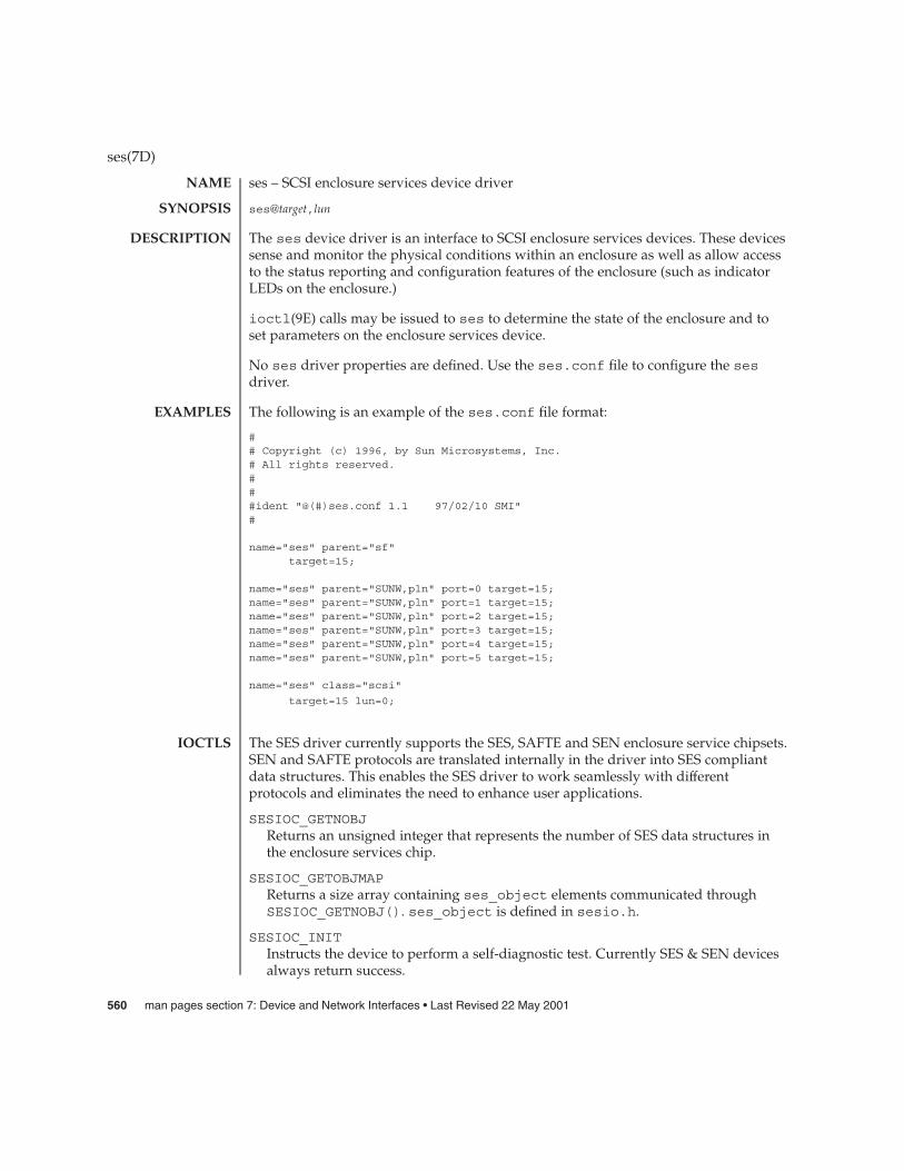
ses – SCSI enclosure services device driver
ses@target,lun
The ses device driver is an interface to SCSI enclosure services devices. These devicessense and monitor the physical conditions within an enclosure as well as allow accessto the status reporting and configuration features of the enclosure (such as indicatorLEDs on the enclosure.)
ioctl(9E) calls may be issued to ses to determine the state of the enclosure and toset parameters on the enclosure services device.
No ses driver properties are defined. Use the ses.conf file to configure the sesdriver.
The following is an example of the ses.conf file format:
## Copyright (c) 1996, by Sun Microsystems, Inc.# All rights reserved.###ident "@(#)ses.conf 1.1 97/02/10 SMI"#
name="ses" parent="sf"target=15;
name="ses" parent="SUNW,pln" port=0 target=15;name="ses" parent="SUNW,pln" port=1 target=15;name="ses" parent="SUNW,pln" port=2 target=15;name="ses" parent="SUNW,pln" port=3 target=15;name="ses" parent="SUNW,pln" port=4 target=15;name="ses" parent="SUNW,pln" port=5 target=15;
name="ses" class="scsi"
target=15 lun=0;
The SES driver currently supports the SES, SAFTE and SEN enclosure service chipsets.SEN and SAFTE protocols are translated internally in the driver into SES compliantdata structures. This enables the SES driver to work seamlessly with differentprotocols and eliminates the need to enhance user applications.
SESIOC_GETNOBJReturns an unsigned integer that represents the number of SES data structures inthe enclosure services chip.
SESIOC_GETOBJMAPReturns a size array containing ses_object elements communicated throughSESIOC_GETNOBJ(). ses_object is defined in sesio.h.
SESIOC_INITInstructs the device to perform a self-diagnostic test. Currently SES & SEN devicesalways return success.
ses(7D)
NAME
SYNOPSIS
DESCRIPTION
EXAMPLES
IOCTLS
560 man pages section 7: Device and Network Interfaces • Last Revised 22 May 2001

SESIOC_GETENCSTATReturns an unsigned character that represents status enclosure as defined by Table25 in Section 7.1.2 of the SES specification NCITS 305-199x.
SESIOC_GETOBJSTATThis ioctl is passed an ses_objarg containing the obj_id you want to set, thenfills in the remaining fields according to element status page of the SESspecification.
SESIOC_SETOBJSTATSets options in the control field. You set control field options by filling out all fieldsin ses_objarg. Field definitions are presented in Section 7.2.2 of the SESspecification.
/kernel/drv/ses.conf driver configuration file
See attributes(5) for descriptions of the following attributes:
ATTRIBUTE TYPE ATTRIBUTE VALUE
Architecture SPARC
ssaadm(1M), driver.conf(4), attributes(5), esp(7D), isp(7D), ioctl(9E)
ses(7D)
FILES
ATTRIBUTES
SEE ALSO
Device and Network Interfaces 561
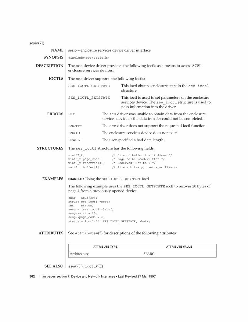
sesio – enclosure services device driver interface
#include<sys/sesio.h>
The ses device driver provides the following ioctls as a means to access SCSIenclosure services devices.
The ses driver supports the following ioctls:
SES_IOCTL_GETSTATE This ioctl obtains enclosure state in the ses_ioctlstructure.
SES_IOCTL_SETSTATE This ioctl is used to set parameters on the enclosureservices device. The ses_ioctl structure is used topass information into the driver.
EIO The ses driver was unable to obtain data from the enclosureservices device or the data transfer could not be completed.
ENOTTY The ses driver does not support the requested ioctl function.
ENXIO The enclosure services device does not exist.
EFAULT The user specified a bad data length.
The ses_ioctl structure has the following fields:
uint32_t; /* Size of buffer that follows */uint8_t page_code: /* Page to be read/written */uint8_t reserved[3]; /* Reserved; Set to 0 */
unit8t buffer[1]; /* Size arbitrary, user specifies */
EXAMPLE 1 Using the SES_IOCTL_GETSTATE ioctl
The following example uses the SES_IOCTL_GETSTATE ioctl to recover 20 bytes ofpage 4 from a previously opened device.
char abuf[30];struct ses_ioctl *sesp;int status;sesp = (ses_ioctl *)abuf;sesp->size = 20;sesp->page_code = 4;
status = ioctl(fd, SES_IOCTL_GETSTATE, abuf);
See attributes(5) for descriptions of the following attributes:
ATTRIBUTE TYPE ATTRIBUTE VALUE
Architecture SPARC
ses(7D), ioctl(9E)
sesio(7I)
NAME
SYNOPSIS
DESCRIPTION
IOCTLS
ERRORS
STRUCTURES
EXAMPLES
ATTRIBUTES
SEE ALSO
562 man pages section 7: Device and Network Interfaces • Last Revised 27 Mar 1997
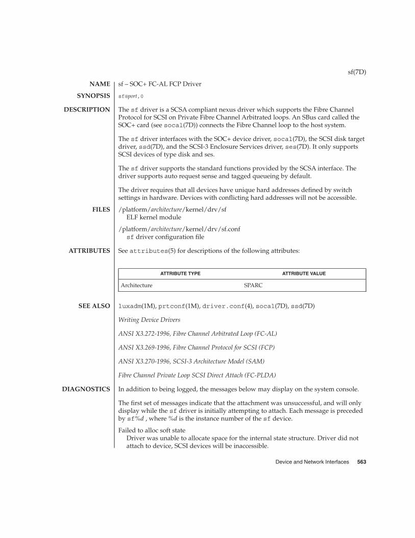
sf – SOC+ FC-AL FCP Driver
sf@port,0
The sf driver is a SCSA compliant nexus driver which supports the Fibre ChannelProtocol for SCSI on Private Fibre Channel Arbitrated loops. An SBus card called theSOC+ card (see socal(7D)) connects the Fibre Channel loop to the host system.
The sf driver interfaces with the SOC+ device driver, socal(7D), the SCSI disk targetdriver, ssd(7D), and the SCSI-3 Enclosure Services driver, ses(7D). It only supportsSCSI devices of type disk and ses.
The sf driver supports the standard functions provided by the SCSA interface. Thedriver supports auto request sense and tagged queueing by default.
The driver requires that all devices have unique hard addresses defined by switchsettings in hardware. Devices with conflicting hard addresses will not be accessible.
/platform/architecture/kernel/drv/sfELF kernel module
/platform/architecture/kernel/drv/sf.confsf driver configuration file
See attributes(5) for descriptions of the following attributes:
ATTRIBUTE TYPE ATTRIBUTE VALUE
Architecture SPARC
luxadm(1M), prtconf(1M), driver.conf(4), socal(7D), ssd(7D)
Writing Device Drivers
ANSI X3.272-1996, Fibre Channel Arbitrated Loop (FC-AL)
ANSI X3.269-1996, Fibre Channel Protocol for SCSI (FCP)
ANSI X3.270-1996, SCSI-3 Architecture Model (SAM)
Fibre Channel Private Loop SCSI Direct Attach (FC-PLDA)
In addition to being logged, the messages below may display on the system console.
The first set of messages indicate that the attachment was unsuccessful, and will onlydisplay while the sf driver is initially attempting to attach. Each message is precededby sf%d , where %d is the instance number of the sf device.
Failed to alloc soft stateDriver was unable to allocate space for the internal state structure. Driver did notattach to device, SCSI devices will be inaccessible.
sf(7D)
NAME
SYNOPSIS
DESCRIPTION
FILES
ATTRIBUTES
SEE ALSO
DIAGNOSTICS
Device and Network Interfaces 563

Bad soft stateDriver requested an invalid internal state structure. Driver did not attach to device,SCSI devices will be inaccessible.
Failed to obtain transport handleDriver was unable to obtain a transport handle to communicate with the socaldriver. Driver did not attach to device, SCSI devices will be inaccessible
Failed to allocate command/response poolDriver was unable to allocate space for commands and responses. Driver did notattach to device, SCSI devices will be inaccessible.
Failed to allocate kmem cacheDriver was unable to allocate space for the packet cache. Driver did not attach todevice, SCSI devices will be inaccessible.
Failed to allocate dma handle forDriver was unable to allocate a dma handle for the loop map. Driver did not attachto device, SCSI devices will be inaccessible.
Failed to allocate lilp mapDriver was unable to allocate space for the loop map. Driver did not attach todevice, SCSI devices will be inaccessible.
Failed to bind dma handle forDriver was unable to bind a dma handle for the loop map. Driver did not attach todevice, SCSI devices will be inaccessible.
Failed to attachDriver was unable to attach for some reason that may be printed. Driver did notattach to device, SCSI devices will be inaccessible.
The next set of messages may display at any time. The full device pathname, followedby the shorter form described above, will precede the message.
Invalid lilp mapThe driver did not obtain a valid lilp map from the socal driver. SCSI device will beinaccessible.
Target t, AL-PA x and hardThe device with a switch setting t has an AL-PA x which does not match its hardaddress y. The device will not be accessible.
Duplicate switch settingsThe driver detected devices with the same switch setting. All such devices will beinaccessible.
WWN changed on target tThe World Wide Name (WWN) has changed on the device with switch setting t.
Target t, unknown device typeThe driver does not know the device type reported by the device with switchsetting t.
sf(7D)
564 man pages section 7: Device and Network Interfaces • Last Revised 27 Mar 1997

sgen – Generic SCSI device driver
#include <sys/scsi/targets/sgendef.h>
sgen@target,lun:<devtype>
The sgen driver exports the uscsi(7I) interfaces to user processes. The sgen drivercan be configured to bind to SCSI devices for which no system driver is available.Examples of such devices include SCSI scanners and SCSI processor devices.
Typically, drivers which export the uscsi(7I) interface unconditionally require thatthe user present superuser credentials. The sgen driver does not, and relies on thefilesystem permissions on its device special file to govern who may access that device.By default, access is restricted and device nodes created by the sgen driver arereadable and writable by the superuser exclusively.
It is important to understand that SCSI devices coexisting on the same SCSI bus maypotentially interact with each other. This may result from firmware bugs in SCSIdevices, or may be made to happen programmatically by sending appropriate SCSIcommands to a device. Potentially, any application controlling a device via the sgendriver can introduce data integrity or security problems in that device or any otherdevice sharing the same SCSI bus.
Granting unprivileged users access to an sgen-controlled SCSI device may createother problems. It may be possible for a user to instruct a target device to gather datafrom another target device on the same bus. It may also be possible for malicious usersto install new firmware onto a device to which they are granted access. Inenvironments where security is a concern but user access to devices controlled by thesgen driver is nontheless desired, it is recommended that the devices be separatedonto a dedicated SCSI bus to mitigate the risk of data corruption and securityviolations.
The sgen driver is configurable via the sgen.conf file. In addition to standard SCSIdevice configuration directives (see scsi(4)), administrators can set several additionalproperties for the sgen driver.
By default, the sgen driver will not claim or bind to any devices on the system. To doso, it must be configured by the administrator using the inquiry-config-listand/or the device-type-config-list properties.
As with other SCSI drivers, the sgen.conf configuration file enumerates the targetssgen should use. See scsi(4) for more details. For each target enumerated in thesgen.conf file, the sgen driver sends a SCSI INQUIRY command to gatherinformation about the device present at that target. The inquiry-config-listproperty specifies that the sgen driver should bind to a particular device returning aparticular set of inquiry data. The device-type-config-list specifies that thesgen driver should bind to every device that is of a particular SCSI device type. Whenexamining the device, the sgen driver tests to see if it matches an entry in thedevice-type-config-list or the inquiry-config-list. For more detail onthese two properties, see the PROPERTIES section.
sgen(7D)
NAME
SYNOPSIS
DESCRIPTION
SECURITY ANDDATA
INTEGRITY
CONFIGURATION
Device and Network Interfaces 565

When a match against the INQUIRY data presented by a device is made, the sgendriver attaches to that device and creates a device node and link in the /devices and/dev hierarchies. See the FILES section for more information about how these files arenamed.
It is important for the administrator to ensure that devices claimed by the sgen driverdo not conflict with existing target drivers on the system. For example, if the sgendriver is configured to bind to a direct access device, the standard sd.conf file willusually cause sd to claim the device as well. This can cause unpredictable results. Ingeneral, the uscsi(7I) interface exported by sd(7D) or st(7D) should be used to gainaccess to direct access and sequential devices.
The sgen driver is disabled by default. The sgen.conf file is shipped with all of the’name="sgen" class="scsi" target=...’ entries commented out to shortenboot time and to prevent the driver from consuming kernel resources. To use the sgendriver effectively on desktop systems, simply uncomment all of the name="sgen"lines in sgen.conf file. On larger systems with many SCSI controllers, carefully editthe sgen.conf file so that sgen binds only where needed. Refer to driver.conf(4)for further details.
inquiry-config-listThe inquiry-config-list property is a list of pairs of strings that enumerates alist of specific devices to which the sgen driver will bind. Each pair of strings isreferred to as <vendorid, productid> in the discussion below.
vendoridis used to match the Vendor ID reported by the device. The SCSI specification limitsVendor IDs to eight characters. Correspondingly, the length of this string should notexceed eight characters. As a special case, "*" may be used as a wildcard whichmatches any Vendor ID. This is useful in situations where more than one vendorproduces a particular model of a product. vendorid is matched against the VendorID reported by the device in a case-insensitive manner.
productidis used to match the product ID reported by the device. The SCSI specificationlimits product IDs to sixteen characters (unused characters are filled with thewhitespace characters). Correspondingly, the length of productid should notexceed sixteen characters. When examining the product ID of the device, sgenexamines the length l of productid and performs a match against only the first lcharacters in the device’s product ID. productid is matched against the productID reported by the device in a case-insensitive manner.
For example, to match some fictitious devices from ACME corp, theinquiry-config-list can be configured as follows:
inquiry-config-list = "ACME", "UltraToast 3000",
"ACME", "UltraToast 4000",
sgen(7D)
PROPERTIES
566 man pages section 7: Device and Network Interfaces • Last Revised 29 Sep 1999

"ACME", "UltraToast 5000";
To match "UltraToast 4000" devices, regardless of vendor, inquiry-config-list ismodified as follows:
inquiry-config-list = "*", "UltraToast 4000";
To match every device from ACME in the "UltraToast" series (i.e UltraToast 3000, 4000,5000, ...), inquiry-config-list is modified as follows:
inquiry-config-list = "ACME" "UltraToast";
Whitespace characters are significant when specifying productid. For example, aproductid of "UltraToast 1000" is fifteen characters in length. If a device reported itsID as "UltraToast 10000", the sgen driver would bind to it because only the first fifteencharacters are considered significant when matching. To remedy this situation, specifyproductid as "UltraToast 1000 ", (note trailing space). This forces the sgen driver toconsider all sixteen characters in the product ID to be significant.
device-type-config-listThe device-type-config-list property is a list of strings that enumerate a listof device types to which the sgen driver will bind. The valid device typescorrespond to those defined by the SCSI-3 SPC Draft Standard, Rev. 11a. These typesare:
Type Name Inquiry Type ID
direct 0x00
sequential 0x01
printer 0x02
processor 0x03
worm 0x04
rodirect 0x05
scanner 0x06
optical 0x07
changer 0x08
comm 0x09
sgen(7D)
Device and Network Interfaces 567

Type Name Inquiry Type ID
prepress1 0x0a
prepress2 0x0b
array_ctrl 0x0c
ses 0x0d
rbc 0x0e
ocrw 0x0f
bridge 0x10
type_unknown 0x1f
Alternately, you can specify device types by INQUIRY type ID. To do this, specifytype_0x<typenum> in the sgen-config-list. Case is not significant whenspecifying device type names.
sgen-diagThe sgen-diag property sets the diagnostic output level. This property can be setglobally and/or per target/lun pair. sgen-diag is an integer property, and can beset to 0, 1, 2 or 3. Illegal values will silently default to 0. The meaning of eachdiagnostic level is as follows:
0 No error reporting [default]
1 Report driver configuration information, unusual conditions, and indicatewhen sense data has been returned from the device.
2 Trace the entry into and exit from routines inside the driver, and provideextended diagnostic data. No error reporting [default].
3 Provide detailed output about command characteristics, driver state, andthe contents of each CDB passed to the driver.
In ascending order, each level includes the diagnostics that the previous level reports.See the IOCTLS section for more infomation on the SGEN_IOC_DIAG ioctl.
sgen.confDriver configuration file. See CONFIGURATION for more details.
/dev/scsi/<devtype>/cntndnThe sgen driver categorizes each device in a separate directory by its SCSI devicetype. The files inside the directory are named according to their controller number,target ID and LUN as follows:
cn is the controller number, tn is the SCSI target id and dn is the SCSI LUN
sgen(7D)
FILES
568 man pages section 7: Device and Network Interfaces • Last Revised 29 Sep 1999

This is analogous to the {controller;target;device} naming scheme, and thecontroller numbers correspond to the same controller numbers which are used fornaming disks. For example, /dev/dsk/c0t0d0s0 and/dev/scsi/scanner/c0t5d0 are both connected to controller c0.
The sgen driver exports the uscsi(7I) interface for each device it manages. Thisallows a user process to talk directly to a SCSI device for which there is no other driverinstalled in the system. Additionally, the sgen driver supports the following ioctls:
SGEN_IOC_READYSend a TEST UNIT READY command to the device and return 0 upon success,non-zero upon failure. This ioctl accepts no arguments.
SGEN_IOC_DIAGChange the level of diagnostic reporting provided by the driver. This ioctl accepts asingle integer argument between 0 and 3. The levels have the same meaning as inthe sgen-diag property discussed in PROPERTIES above.
EBUSY The device was opened by another thread or process. The drivermaintains a strict exclusive-open policy for each device.
ENXIO During opening, the device did not respond to a TEST UNITREADY SCSI command.
ENOTTY Indicates that the device does not support the requested ioctlfunction.
Here is an example of how sgen can be configured to bind to scanner devices on thesystem:
device-type-config-list = "scanner";
The administrator should subsequently uncomment the appropriatename="sgen"... lines for the SCSI target ID to which the scanner corresponds. Inthis example, the scanner is at target 4.
name= "sgen" class= "scsi" target=4 lun=0;
If it is expected that the scanner will be moved from target to target over time, or thatmore scanners might be added in the future, it is recommended that all of thename="sgen"... lines be uncommented, so that sgen checks all of the targets on thebus.
For large systems where boot times are a concern, it is recommended that theparent="" property be used to specify which SCSI bus sgen should examine.
driver.conf(4), scsi(4), sd(7D), st(7D), uscsi(7I)
Writing Device Drivers
sgen(7D)
IOCTLS
ERRORS
EXAMPLES
SEE ALSO
Device and Network Interfaces 569

ANSI Small Computer System Interface-2 (SCSI-2)
SCSI-3 SPC Draft Standard, Rev. 11a
sgen(7D)
570 man pages section 7: Device and Network Interfaces • Last Revised 29 Sep 1999

sk98sol – SysKonnect Gigabit Ethernet SK-98xx device driver
/dev/skge
/kernel/drv/sk98sol
The sk98sol driver is a multi-threaded, loadable, clonable, STREAMS hardwaredriver supporting the connectionless Data Link Provider Interface (DLPI), over aSysKonnect Gigabit Ethernet adapter (SK-98xx series). The driver supports multipleinstalled SysKonnect SK-98xx adapters. Functions include chip initialization, frametransmit and receive, multicast and promiscuous support, and error recovery andreporting.
The driver provides the /dev/skge cloning character-special device as well asper-adapter character-special devices /dev/skgex, where x represents the deviceinstance number.
The sk98sol driver is a Style 1 and Style 2 Data Link Service (DLS) provider. AllM_PROTO and M_PCPROTO type messages are interpreted as DLPI primitives. ValidDLPI primitives are defined in <sys/dlpi.h>. See dlpi(7P).
An explicit DL_ATTACH_REQ message by the user is required to associate the openedStream with a particular device (ppa). This is unnecessary and invalid for DLPI Style 1.The ppa ID is interpreted as an unsigned long data type and indicates thecorresponding device instance (unit) number. An error (DL_ERROR_ACK) is returnedby the driver if the ppa field value does not correspond to a valid device instancenumber for the system.
The device is initialized on first attach and de-initialized (stopped) upon last detach.Valid device numbers for all detected adapters are displayed on the console at driverstartup time and are written to the /var/adm/messages log file.
The values returned in the DL_INFO_ACK primitive in response to the DL_INFO_REQrequest are:
� Maximum SDU is 1500 (9000 if JumboFrames are enabled).
� Minimum SDU is 0.
� DLSAP address length is 8 bytes.
� MAC type is DL_CSMACD.
� SAP length value is –2, meaning the physical address component is followedimmediately by a 2-byte SAP component within the DLSAP address.
� Service mode is DL_CLDLS.
� Optional quality of service (QOS) support is not included; as a result, the QOS fieldvalues are 0.
� Provider style is DL_STYLE2.
� Version is DL_VERSION_2.
sk98sol(7D)
NAME
SYNOPSIS
DESCRIPTION
APPLICATIONPROGRAMMING
INTERFACE
sk98sol and DLPI
Device and Network Interfaces 571

Parameters are set in the /kernel/drv/sk98sol.conf configuration file, which iscreated during installation. See driver.conf(4). You can edit the/kernel/drv/sk98sol.conf file to reflect your settings and reboot the system touse the new parameter values. If the file exists prior to driver installation, the newparameter values will be used as soon as the driver is installed.
String parameter values must be surrounded with double quotes ("), while integerparameter values are not. Parameter names and values are case sensitive and youshould use them exactly as shown.
The parameters discussed in this section can be set for each port on the adapter.
In each of the following descriptions, ? represents port A or B.
AutoNegotiation_?
Type: String
Values: On, Off, Sense
Default: Sense (for SK-984x fiber adapters).
Default: On (for SK-982x copper adapters.)
The Sense value automatically detects whether the link partner supportsautonegotiation. If your link partner is configured to half duplex with autonegotiationturned off, set the AutoNegotiation_? and DuplexCapabilities_? parameters manually. Donot set the AutoNegotiation_? parameter value to Sense, as it will fail.
Do not use Sense for 1000Base-T (copper) adapters. If Sense is selected, it will bemapped to On automatically.
DuplexCapabilities_?
Type: String
Values: Half, Full, Both
Default: Both
Set the DuplexCapabilities_? parameter only if the AutoNegotiation_? parameter is set tothe On or Off values. If AutoNegotiation_? is set to On, all three AutoNegotiation_?values are possible; however, if set to Off, only the Full and Half values areallowed.
Use the DuplexCapabilities_? parameter if your link partner does not support allpossible combinations.
sk98sol(7D)
OPTIONS
Per-PortParameters
572 man pages section 7: Device and Network Interfaces • Last Revised 10 Oct 2000

FlowControl_?
Type: String
Values: Sym, SymOrRem, LocSend, None
Default: SymOrRem
Use the FlowControl_? parameter to set the flow control capabilities reported by theport during autonegotiation:
Sym Symetric flow control, where both link partners are allowed tosend PAUSE frames.
SymOrRem SymetricOrRemote flow control, where both link partners or onlythe remote partner are allowed to send PAUSE frames.
LocSend LocalSend flow control, where only the local link partner isallowed to send PAUSE frames.
None No flow control, where no link partner is allowed to send PAUSEframes.
The FlowControl_? parameter is ignored if AutoNegotiation_? is set to "Off."
Role_?
Type: String
Values: Auto, Master, Slave
Default: Auto
Use the Role_? parameter only for the SK-9821 and SK-9822 adapters.
1000Base-T communication between two ports requires one port to act as the master(and provide timing information) and the other as slave. Normally, this is negotiatedbetween the two ports during link establishment. If this fails, use the Role_? parameterto force the master and slave roles on the ports. If AutoNegotiation_? is set to "Off,"then the Role_? parameter must be set manually.
PreferredPort
Type: String
Values: A, B
Default: A
sk98sol(7D)
Per-AdapterParameters
Device and Network Interfaces 573
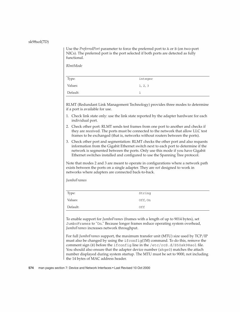
Use the PreferredPort parameter to force the preferred port to A or B (on two-portNICs). The preferred port is the port selected if both ports are detected as fullyfunctional.
RlmtMode
Type: integer
Values: 1, 2, 3
Default: 1
RLMT (Redundant Link Management Technology) provides three modes to determineif a port is available for use.
1. Check link state only: use the link state reported by the adapter hardware for eachindividual port.
2. Check other port: RLMT sends test frames from one port to another and checks ifthey are received. The ports must be connected to the network that allow LLC testframes to be exchanged (that is, networks without routers between the ports).
3. Check other port and segmentation: RLMT checks the other port and also requestsinformation from the Gigabit Ethernet switch next to each port to determine if thenetwork is segmented between the ports. Only use this mode if you have GigabitEthernet switches installed and configured to use the Spanning Tree protocol.
Note that modes 2 and 3 are meant to operate in configurations where a network pathexists between the ports on a single adapter. They are not designed to work innetworks where adapters are connected back-to-back.
JumboFrames
Type: String
Values: Off, On
Default: Off
To enable support for JumboFrames (frames with a length of up to 9014 bytes), setJumboFrames to "On." Because longer frames reduce operating system overhead,JumboFrames increases network throughput.
For full JumboFrames support, the maximum transfer unit (MTU) size used by TCP/IPmust also be changed by using the ifconfig(1M) command. To do this, remove thecomment sign (#) before the ifconfig line in the /etc/rcS.d/S50sk98sol file.You should also ensure that the adapter device number (skge0) matches the attachnumber displayed during system startup. The MTU must be set to 9000, not includingthe 14 bytes of MAC address header.
sk98sol(7D)
574 man pages section 7: Device and Network Interfaces • Last Revised 10 Oct 2000
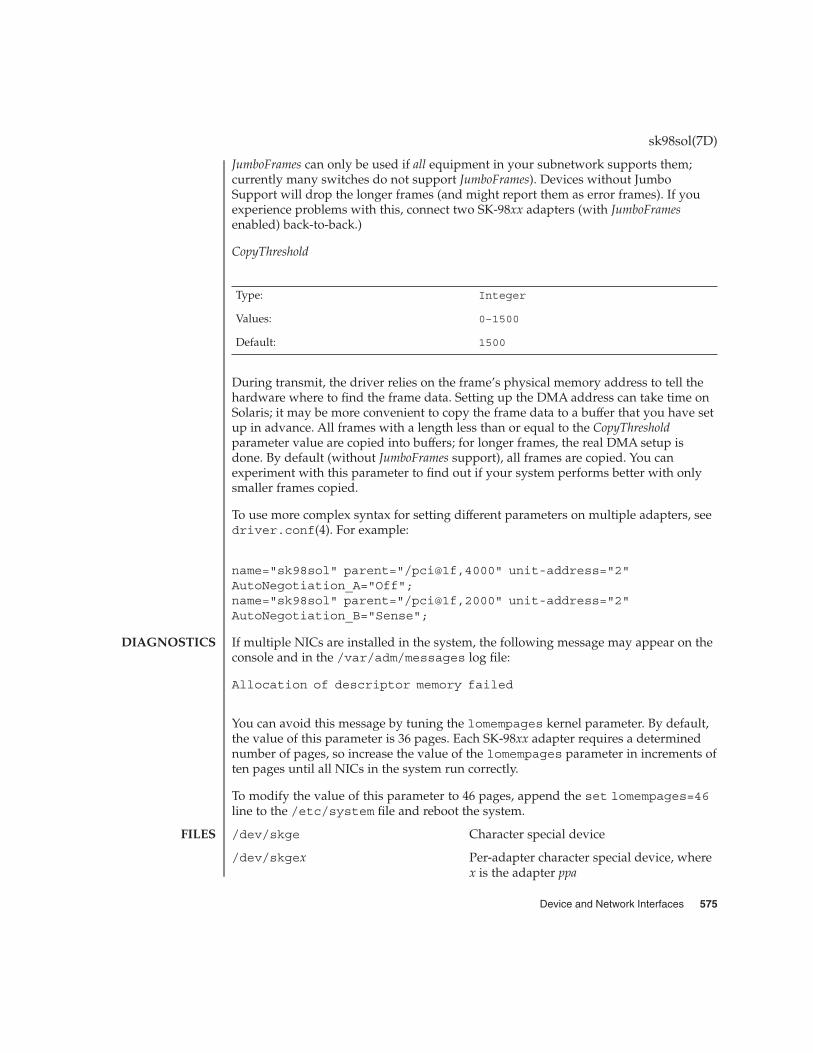
JumboFrames can only be used if all equipment in your subnetwork supports them;currently many switches do not support JumboFrames). Devices without JumboSupport will drop the longer frames (and might report them as error frames). If youexperience problems with this, connect two SK-98xx adapters (with JumboFramesenabled) back-to-back.)
CopyThreshold
Type: Integer
Values: 0–1500
Default: 1500
During transmit, the driver relies on the frame’s physical memory address to tell thehardware where to find the frame data. Setting up the DMA address can take time onSolaris; it may be more convenient to copy the frame data to a buffer that you have setup in advance. All frames with a length less than or equal to the CopyThresholdparameter value are copied into buffers; for longer frames, the real DMA setup isdone. By default (without JumboFrames support), all frames are copied. You canexperiment with this parameter to find out if your system performs better with onlysmaller frames copied.
To use more complex syntax for setting different parameters on multiple adapters, seedriver.conf(4). For example:
name="sk98sol" parent="/pci@1f,4000" unit-address="2"AutoNegotiation_A="Off";name="sk98sol" parent="/pci@1f,2000" unit-address="2"AutoNegotiation_B="Sense";
If multiple NICs are installed in the system, the following message may appear on theconsole and in the /var/adm/messages log file:
Allocation of descriptor memory failed
You can avoid this message by tuning the lomempages kernel parameter. By default,the value of this parameter is 36 pages. Each SK-98xx adapter requires a determinednumber of pages, so increase the value of the lomempages parameter in increments often pages until all NICs in the system run correctly.
To modify the value of this parameter to 46 pages, append the set lomempages=46line to the /etc/system file and reboot the system.
/dev/skge Character special device
/dev/skgex Per-adapter character special device, wherex is the adapter ppa
sk98sol(7D)
DIAGNOSTICS
FILES
Device and Network Interfaces 575

/kernel/drv/sk98sol ELF kernel module
/kernel/drv/sparcv9/sk98sol ELF kernel module (64-bit SPARC version)
/kernel/drv/sk98sol.conf Driver configuration file
See attributes(5) for descriptions of the following attributes:
ATTRIBUTE TYPE ATTRIBUTE VALUE
Architecture IA, SPARC
ifconfig(1M), netstat(1M), driver.conf(4), attributes(5), dlpi(7P).
sk98sol.txt driver README file — Included in the driver package; also availablefrom www.syskonnect.com.
sk98sol(7D)
ATTRIBUTES
SEE ALSO
576 man pages section 7: Device and Network Interfaces • Last Revised 10 Oct 2000

skfp – SysKonnect FDDI PCI device driver
/dev/skfp
The skfp FDDI driver is a multi-threaded, loadable, clonable, STREAMS hardwaredriver supporting the connectionless Data Link Provider Interface (DLPI) over aSysKonnect FDDI PCI adapter. The driver supports multiple installed SysKonnectFDDI PCI adapters. Functions include chip initialization, frame transit and receive,multicast and promiscuous support, and error recovery and reporting.
The skfp driver supports all SysKonnect SK-NET FDDI PCI adapters (SK-55xx(32-bit) and SK-58xx (64-bit) series) on 32-bit systems, and the SK-58xx series on 64-bitsystems.
The skfp driver provides the /dev/skfp cloning character-special device thataccesses all SK-NET FDDI PCI adapters using Data Link Service (DLS) Style 2. It alsoprovides per-adapter character-special devices /dev/skfpx, (where x represents thedevice instance number) that access a special NIC using DLS Style 1.
The skfp driver is a Style 1 and Style 2 DLS provider. All M_PROTO and M_PCPROTOtype messages are interpreted as DLPI primitives. Valid DLPI primitives are defined in<sys/dlpi.h>. See dlpi(7P).
An explicit DL_ATTACH_REQ message by the user is required to associate the openedStream with a particular device (ppa). This is unnecessary and invalid for DLPI Style 1.The ppa ID is interpreted as an unsigned long data type and indicates thecorresponding device instance (unit) number. An error (DL_ERROR_ACK) is returnedby the driver if the ppa field value does not correspond to a valid device instancenumber for the system.
The device is initialized on first attach and de-initialized (stopped) upon last detach.Valid device numbers for all detected adapters are displayed on the console at driverstartup time and written to the /var/adm/messages log file.
The values returned in the DL_INFO_ACK primitive in response to the DL_INFO_REQrequest are:
� Maximum SDU is 4470.� Minimum SDU is 0.� DSLAP address length is 8 bytes.� MAC type is DL_FDDI.� SAP length value is –2, meaning the physical address component is followed
immediately by a 2-byte SAP component within the DLSAP address.� Service mode is DL_CLDLS.� Optional quality of service (QOS) support is not included; as a result, the QOS field
values are 0.� Provider style is DL_STYLE2.
skfp(7D)
NAME
SYNOPSIS
DESCRIPTION
APPLICATIONPROGRAMMING
INTERFACE
skfp and DLPI
Device and Network Interfaces 577

� Version is DL_VERSION_2.
Options are not required for normal operation. In special cases, FDDI StationManagement (SMT) parameters can be modified by using the /usr/bin/smtparautility (see the driver README files). The smtpara utility should be used only bythose very familiar with FDDI.
If multiple NICs are installed in the system, the following message may appear on theconsole and in the /var/adm/messages log file:
skfp: DMA memory allocation failed !
You can avoid this message by tuning the lomempages kernel parameter. By default,the value of this parameter is 36 pages. Each SK-FDDI PCI adapter requires ninepages, so increase the value of the lomempages parameter in increments of ninepages until all NICs in the system run correctly.
To modify the value of this parameter to 45 pages, you can, for example, append theset lomempages=45 line to the /etc/system file and reboot the system.
/dev/skfp Character special device
/dev/skfpx Per-adapter character special device, wherex is the adapter ppa
/kernel/drv/skfp ELF kernel module
/kernel/drv/sparcv9/skfpx ELF kernel module (64-bit SPARC version)
/kernel/drv/skfp.conf Driver configuration file
/usr/bin/smtpara SMT parameter utility
/etc/fddi.cfg smtpara configuration file
<sys/dlpi.h> DLPI definitions
See attributes(5) for descriptions of the following attributes:
ATTRIBUTE TYPE ATTRIBUTE VALUE
Architecture IA, SPARC
ifconfig(1M), netstat(1M), attributes(5), dlpi(7P)
skfp.txt (32-bit driver) and skfpx.txt (64-bit driver) README files — Includedin the driver package or available from www.syskonnect.com.
skfp(7D)
OPTIONS
DIAGNOSTICS
FILES
ATTRIBUTES
SEE ALSO
578 man pages section 7: Device and Network Interfaces • Last Revised 7 Sep 2000

slp – Service Location Protocol
The Service Location Protocol (SLP) is a dynamic service discovery protocol that runson top of the Internet Protocol (IP). The protocol is specified by the IETFstandard-track documents RFC 2165, RFC 2608, RFC 2609; the API is documented inRFC 2614. .
There are two components to the SLP technology. The first is a daemon, slpd(1M),which coordinates SLP operations. The second is a software library, slp_api(3slp),through which processes access a public API. Both components are configured bymeans of the SLP configuration file, slp.conf(4).
The SLP API is useful for two types of processes:
Client Applications Services and service information can be requested fromthe API. Clients do not need to know the location of arequired service, only the type of service, andoptionally, the service characteristics. SLP will supplythe location and other information to the client throughthe API.
Server Processes Programs that offer network services use the SLP APIto advertise their location as well as other serviceinformation. The advertisement can optionally includeattributes describing the service. Advertisements areaccompanied by a lifetime; when the lifetime expires,the advertisement is flushed, unless it is refreshed priorto expiration.
API libraries are available for both the C and Java languages.
SLP provides the following additional features:
� slpd(1M) can be configured to function as a transparent directory agent. Thisfeature makes SLP scalable to the enterprise. System administrators can configuredirectory agents to achieve a number of different strategies for scalability.
� SLP service advertising and discovery is performed in scopes. Unless otherwiseconfigured, all discovery and all advertisements are in the scope default. In the caseof a larger network, scopes can be used to group services and client systems so thatusers will only find those services which are physically near them, belong to theirdepartment, or satisfy the specified criteria. Administrators can configure thesescopes to achieve different service provider strategies.
� Services may be registered by proxy through a serialized registration file. This is analternative to registering services through the API. See slpd.reg(4) for moreinformation.
slp(7P)
NAME
DESCRIPTION
Device and Network Interfaces 579

See attributes(5) for descriptions of the following attributes:
ATTRIBUTE TYPE ATTRIBUTE VALUE
Availability SUNWslpu
CSI CSI-enabled
Interface Stability Standard
MT-Level MT-Safe
slpd(1m), slp_api(3slp), slp.conf(4), slpd.reg(4), attributes(5)
Guttman, E., Perkins, C., Veizades, J., and Day, M., RFC 2608, Service Location Protocol,Version 2, The Internet Society, June 1999.
Guttman, E., Perkins, C., and Kempf, J., RFC 2609, Service Templates and Service:Schemes, The Internet Society, June 1999.
Kempf, J. and Guttman, E., RFC 2614, An API for Service Location, The Internet Society,June 1999.
Veizades, J., Guttman, E., Perkins, C., and Kaplan, S., RFC 2165, Service LocationProtocol, Network Working Group, 1997.
slp(7P)
ATTRIBUTES
SEE ALSO
580 man pages section 7: Device and Network Interfaces • Last Revised 17 Nov 1999

soc – Serial Optical Controller (SOC) device driver
soc@sbus-slot,0
The Fibre Channel Host Bus Adapter is an SBus card which implements two fullduplex Fibre Channel interfaces. Each Fibre Channel interface supports a point topoint interface to another Fibre Channel device.
The soc device driver is a nexus driver. The soc driver implements portions of theFC-2 and FC-4 layers of the Fibre Channel.
/kernel/drv/soc ELF Kernel Module
sbus(4), pln(7D), ssd(7D)
Writing Device Drivers
The messages described below are some that may appear on system console, as well asbeing logged.
On the console these messages are preceded by
soc%d: port %awhere %d is the instance number of the soc controller and %a is the porton the host adapter.
Fibre Channel is ONLINEThe Fibre Channel is now online to the device.
Fibre Channel is OFFLINEThe Fibre Channel connection is now offline.
INCORRECT WWN: Found: xxxx,xxxxxxxx Expected: yyyy,yyyyyyyyThis message means that the soc re-logged into a device after the Fibre Channelconnection went offline and back online and the World Wide Name of the device isnow different. This probably means the cable has been plugged into another device.
attach failed: unable to map eepromDriver was unable to map device memory; check for bad hardware. Driver did notattach to device, devices will be inaccessible.
attach failed: unable to map XRAMDriver was unable to map device memory; check for bad hardware. Driver did notattach to device, devices will be inaccessible.
attach failed: unable to map registersDriver was unable to map device registers; check for bad hardware. Driver did notattach to device, devices will be inaccessible.
attach failed: unable to access status registerDriver was unable to map device registers; check for bad hardware. Driver did notattach to device, devices will be inaccessible.
soc(7D)
NAME
SYNOPSIS
DESCRIPTION
FILES
SEE ALSO
DIAGNOSTICS
Device and Network Interfaces 581

attach failed: unable to install interrupt handlerDriver was not able to add the interrupt routine to the kernel. Driver did not attachto device, devices will be inaccessible.
attach failed: could not alloc offline packet structureDriver was unable to allocate space for the internal state structure. Driver did notattach to device, devices will be inaccessible.
soc(7D)
582 man pages section 7: Device and Network Interfaces • Last Revised 6 Apr 1995
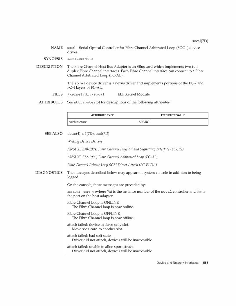
socal – Serial Optical Controller for Fibre Channel Arbitrated Loop (SOC+) devicedriver
socal@sbus-slot,0
The Fibre Channel Host Bus Adapter is an SBus card which implements two fullduplex Fibre Channel interfaces. Each Fibre Channel interface can connect to a FibreChannel Arbitrated Loop (FC-AL).
The socal device driver is a nexus driver and implements portions of the FC-2 andFC-4 layers of FC-AL.
/kernel/drv/socal ELF Kernel Module
See attributes(5) for descriptions of the following attributes:
ATTRIBUTE TYPE ATTRIBUTE VALUE
Architecture SPARC
sbus(4), sf(7D), ssd(7D)
Writing Device Drivers
ANSI X3.230-1994, Fibre Channel Physical and Signalling Interface (FC-PH)
ANSI X3.272-1996, Fibre Channel Arbitrated Loop (FC-AL)
Fibre Channel Private Loop SCSI Direct Attach (FC-PLDA)
The messages described below may appear on system console in addition to beinglogged.
On the console, these messages are preceded by:
socal%d: port %awhere %d is the instance number of the socal controller and %a isthe port on the host adapter.
Fibre Channel Loop is ONLINEThe Fibre Channel loop is now online.
Fibre Channel Loop is OFFLINEThe Fibre Channel loop is now offline.
attach failed: device in slave-only slot.Move soc+ card to another slot.
attach failed: bad soft state.Driver did not attach, devices will be inaccessible.
attach failed: unable to alloc xport struct.Driver did not attach, devices will be inaccessible.
socal(7D)
NAME
SYNOPSIS
DESCRIPTION
FILES
ATTRIBUTES
SEE ALSO
DIAGNOSTICS
Device and Network Interfaces 583

attach failed: unable to map eepromDriver was unable to map device memory; check for bad hardware. Driver did notattach to device, devices will be inaccessible.
attach failed: unable to map XRAMDriver was unable to map device memory; check for bad hardware. Driver did notattach to device, devices will be inaccessible.
attach failed: unable to map registersDriver was unable to map device registers; check for bad hardware. Driver did notattach to device, devices will be inaccessible.
attach failed: unable to access status registerDriver was unable to map device registers; check for bad hardware. Driver did notattach to device, devices will be inaccessible.
attach failed: unable to install interrupt handlerDriver was not able to add the interrupt routine to the kernel. Driver did not attachto device, devices will be inaccessible.
attach failed: unable to access host adapter XRAMDriver was unable to access device RAM; check for bad hardware. Driver did notattach to device, devices will be inaccessible.
attach failed: unable to write host adapter XRAMDriver was unable to write device RAM; check for bad hardware. Driver did notattach to device, devices will be inaccessible.
attach failed: read/write mismatch in XRAMDriver was unable to verify device RAM; check for bad hardware. Driver did notattach to device, devices will be inaccessible.
socal(7D)
584 man pages section 7: Device and Network Interfaces • Last Revised 9 May 1997

sockio – ioctls that operate directly on sockets
#include <sys/sockio.h>
The ioctls listed in this manual page apply directly to sockets, independent of anyunderlying protocol. The setsockopt() call (see getsockopt(3SOCKET)) is theprimary method for operating on sockets, rather than on the underlying protocol ornetwork interface. ioctls for a specific network interface or protocol are documentedin the manual page for that interface or protocol.
SIOCSPGRP The argument is a pointer to an int. Set the process-group ID thatwill subsequently receive SIGIO or SIGURG signals for the socketreferred to by the descriptor passed to ioctl to the value of thatint. The argument must be either positive (in which case it mustbe a process ID) or negative (in which case it must be a processgroup).
SIOCGPGRP The argument is a pointer to an int. Set the value of that int tothe process-group ID that is receiving SIGIO or SIGURG signalsfor the socket referred to by the descriptor passed to ioctl.
SIOCCATMARK The argument is a pointer to an int. Set the value of that int to 1if the read pointer for the socket referred to by the descriptorpassed to ioctl points to a mark in the data stream for anout-of-band message. Set the value of that int to 0 if the readpointer for the socket referred to by the descriptor passed toioctl does not point to a mark in the data stream for anout-of-band message.
ioctl(2), getsockopt(3SOCKET)
sockio(7I)
NAME
SYNOPSIS
DESCRIPTION
SEE ALSO
Device and Network Interfaces 585

sppptun – PPP tunneling pseudo-driver
/dev/sppptun
The /dev/sppptun pseudo-driver provides an interface for tunneling PPP sessions.This interface provides PPP over Ethernet (PPPoE) service with Solaris PPP.
/dev/sppptun Solaris PPP tunneling device driver.
pppoec(1M), pppoed(1M), sppptun(1M)
RFC 2516 — A Method for Transmitting PPP Over Ethernet (PPPoE). Mamakos, et. al.February 1999.
sppptun(7M)
NAME
SYNOPSIS
DESCRIPTION
FILES
SEE ALSO
586 man pages section 7: Device and Network Interfaces • Last Revised 2001

spwr – SMC EtherPower II 10/100 (9432) Ethernet device driver
/dev/spwr
The spwr Ethernet driver is a multi-threaded, loadable, clonable, STREAMS hardwaredriver supporting the connectionless Data Link Provider Interface, dlpi(7P), overSMC EtherPower II 10/100 controllers. Multiple EtherPower II controllers installedwithin the system are supported by the driver. The spwr driver provides basicsupport for the SMC EtherPower II hardware. Functions include chip initialization,frame transmit and receive, multicast support, and error recovery and reporting.
The cloning character-special device /dev/spwr is used to access all SMC EtherPowerII devices installed within the system.
The spwr driver is dependent on /kernel/misc/gld, a loadable kernel module thatprovides the spwr driver with the DLPI and STREAMS functionality required of aLAN driver. See gld(7d) for more details on the primitives supported by the driver.
The values returned by the driver in the DL_INFO_ACK primitive in response to theDL_INFO_REQ from the user are as follows:
� The maximum SDU is 1500 ( ETHERMTU).
� The minimum SDU is 0. The spwr driver will pad to the mandatory 60-octetminimum packet size.
� The DLSAP address length is 8.
� The MAC type is DL_ETHER.
� The SAP length value is –2, meaning the physical address component is followedimmediately by a 2-byte SAP component within the DLSAP address.
� The broadcast address value is Ethernet/IEEE broadcast address(FF:FF:FF:FF:FF:FF).
/dev/spwrCharacter special device.
/kernel/drv/spwr.confDriver configuration file
See attributes(5) for descriptions of the following attributes:
ATTRIBUTE TYPE ATTRIBUTE VALUE
Architecture IA
attributes(5), dlpi(7P), gld(7D)
spwr(7D)
NAME
SYNOPSIS
DESCRIPTION
APPLICATIONPROGRAMMING
INTERFACE
FILES
ATTRIBUTES
SEE ALSO
Device and Network Interfaces 587

ssd – driver for SPARCstorage Array and Fibre Channel Arbitrated Loop disk devices
ssd@port,target:partition
This driver handles both SCSI-2 disks in the SPARCstorage Array and Fibre ChannelArbitrated Loop (FC-AL) disks on Private loops.
The specific type of each disk is determined by the SCSI inquiry command andreading the volume label stored on block 0 of the drive. The volume label describes thedisk geometry and partitioning; it must be present or the disk cannot be mounted bythe system.
The block-files access the disk using the system’s normal buffering mechanism and areread and written without regard to physical disk records. There is also a “raw”interface that provides for direct transmission between the disk and the user’s read orwrite buffer. A single read or write call usually results in one I/O operation; raw I/Ois therefore considerably more efficient when many bytes are transmitted. The namesof the block files are found in /dev/dsk; the names of the raw files are found in/dev/rdsk.
I/O requests (such as lseek(2)) to the SCSI disk must have an offset that is a multipleof 512 bytes (DEV_BSIZE), or the driver returns an EINVAL error. If the transfer lengthis not a multiple of 512 bytes, the transfer count is rounded up by the driver.
Partition 0 is normally used for the root file system on a disk, partition 1 as a pagingarea (for example, swap), and partition 2 for backing up the entire disk. Partition 2normally maps the entire disk and may also be used as the mount point for secondarydisks in the system. The rest of the disk is normally partition 6. For the primary disk,the user file system is located here.
Each device also has error statistics associated with it. These must include counters forhard errors, soft errors and transport errors. Other data may be implemented asrequired.
Each device maintains I/O statistics for the device and for partitions allocated for thatdevice. For each device/partition, the driver accumulates reads, writes, bytes read,and bytes written. The driver also initiates hi-resolution time stamps at queue entryand exit points to enable monitoring of residence time and cumulativeresidence-length product for each queue.
Not all device drivers make per-partition IO statistics available for reporting. ssd andsd(7D) per-partition statistics are enabled by default but may disabled in theirconfiguration files.
Refer to dkio(7I).
EACCES Permission denied.
EBUSY The partition was opened exclusively by another thread.
EFAULT The argument was a bad address.
ssd(7D)
NAME
SYNOPSIS
DESCRIPTION
DEVICESTATISTICS
SUPPORT
IOCTLS
ERRORS
588 man pages section 7: Device and Network Interfaces • Last Revised 21 Feb 2001

EINVAL Invalid argument.
EIO An I/O error occurred.
ENOTTY The device does not support the requested ioctl function.
ENXIO When returned during open(2), this error indicates the devicedoes not exist.
EROFS The device is a read-only device.
The ssd driver can be configured by defining properties in the ssd.conf file. Thessd driver supports the following properties:
enable-partition-kstatsThe default value is 1, which causes partition IO statistics to be maintained. Set thisvalue to zero to prevent the driver from recording partition statistics. This slightlyreduces the CPU overhead for IO, mimimizes the amount of sar(1) data collectedand makes these statistics unavailable for reporting by iostat(1M) even thoughthe -p/-P option is specified. Regardless of this setting, disk IO statistics arealways maintained.
ssd.conf driver configuration file
/dev/dsk/cntndnsn block files
/dev/rdsk/cntndnsn raw files
where, for the SPARCstorage Array:
cn is the controller number on the system. Each SPARCstorage Array willhave a unique controller number
tn port number within the SPARCstorage Array n
dn SCSI target n
sn partition n
and for all FC-AL disks:
cn is the controller number on the system.
tn 7-bit disk loop identifier, such as switch setting
dn SCSI lun n
sn partition n (0-7)
sar(1), format(1M), iostat(1M), ioctl(2), lseek(2), open(2), read(2), write(2),driver.conf(4), cdio(7I), dkio(7I)
ANSI Small Computer System Interface-2 (SCSI-2)
SPARCstorage Array User’s Guide
ssd(7D)
CONFIGURATION
FILES
SEE ALSO
Device and Network Interfaces 589

ANSI X3.272-1996, Fibre Channel Arbitrated Loop (FC-AL)
Fibre Channel - Private Loop SCSI Direct Attach (FC-PLDA)
Error for command ’<command name>’ Error Level: Fatal Requested Block <n>,Error Block: <m>, Sense Key: <sense key name>, Vendor ’<vendor name>’:
ASC = 0x<a> (<ASC name>), ASCQ = 0x<b>, FRU = 0x<c>
The command indicated by <command name> failed. The Requested Block is theblock where the transfer started and the Error Block is the block that caused the error.Sense Key, ASC, and ASCQ information is returned by the target in response to arequest sense command.
Check Condition on REQUEST SENSE
A REQUEST SENSE command completed with a check condition. The originalcommand will be retried a number of times.
Label says <m> blocks Drive says <n> blocks
There is a discrepancy between the label and what the drive returned on the READCAPACITY command.
Not enough sense information
The request sense data was less than expected.
Request Sense couldn’t get sense data
The REQUEST SENSE command did not transfer any data.
Reservation Conflict
The drive was reserved by another initiator.
SCSI transport failed: reason ’xxxx’ : {retrying|giving up}
The host adapter has failed to transport a command to the target for the reason stated.The driver will either retry the command or, ultimately, give up.
Unhandled Sense Key <n>
The REQUEST SENSE data included an invalid sense key.
Unit not Ready. Additional sense code 0x<n>
The drive is not ready.
corrupt label - bad geometry
The disk label is corrupted.
corrupt label - label checksum failed
The disk label is corrupted.
ssd(7D)
DIAGNOSTICS
590 man pages section 7: Device and Network Interfaces • Last Revised 21 Feb 2001

corrupt label - wrong magic number
The disk label is corrupted.
device busy too long
The drive returned busy during a number of retries.
disk not responding to selection
The drive was probably powered down or died.
i/o to invalid geometry
The geometry of the drive could not be established.
incomplete read/write - retrying/giving up
There was a residue after the command completed normally.
logical unit not ready
The drive is not ready.
no bp for disk label
A bp with consistent memory could not be allocated.
no mem for property
Free memory pool exhausted.
no memory for disk label
Free memory pool exhausted.
no resources for dumping
A packet could not be allocated during dumping.
offline
Drive went offline; probably powered down.
requeue of command fails<n>
Driver attempted to retry a command and experienced a transport error.
ssdrestart transport failed <n>
Driver attempted to retry a command and experienced a transport error.
transfer length not modulo <n>
Illegal request size.
transport rejected <n>
ssd(7D)
Device and Network Interfaces 591

Host adapter driver was unable to accept a command.
unable to read label
Failure to read disk label.
unit does not respond to selection
Drive went offline; probably powered down.
ssd(7D)
592 man pages section 7: Device and Network Interfaces • Last Revised 21 Feb 2001
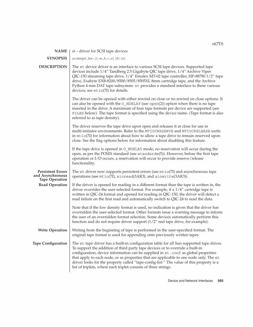
st – driver for SCSI tape devices
st@target,lun:[l,m,h,c,u][b][n]
The st device driver is an interface to various SCSI tape devices. Supported tapedevices include 1/4” Tandberg 2.5 Gigabyte QIC tape drive, 1/4” Archive ViperQIC-150 streaming tape drive, 1/4” Emulex MT-02 tape controller, HP-88780 1/2” tapedrive, Exabyte EXB-8200/8500/8505/8505XL 8mm cartridge tape, and the ArchivePython 4 mm DAT tape subsystem. st provides a standard interface to these variousdevices; see mtio(7I) for details.
The driver can be opened with either rewind on close or no rewind on close options. Itcan also be opened with the O_NDELAY (see open(2)) option when there is no tapeinserted in the drive. A maximum of four tape formats per device are supported (seeFILES below). The tape format is specified using the device name. (Tape format is alsoreferred to as tape density).
The driver reserves the tape drive upon open and releases it at close for use inmulti-initiator environments. Refer to the MTIOCRESERVE and MTIOCRELEASE ioctlsin mtio(7I) for information about how to allow a tape drive to remain reserved uponclose. See the flag options below for information about disabling this feature.
If the tape drive is opened in O_NDELAY mode, no reservation will occur during theopen, as per the POSIX standard (see standards(5)). However, before the first tapeoperation or I/O occurs, a reservation will occur to provide reserve/releasefunctionality.
The st driver now supports persistent errors (see mtio(7I) and asynchronous tapeoperations (see mtio(7I), aioread(3AIO), and aiowrite(3AIO)).
If the driver is opened for reading in a different format than the tape is written in, thedriver overrides the user-selected format. For example, if a 1/4” cartridge tape iswritten in QIC-24 format and opened for reading in QIC-150, the driver will detect aread failure on the first read and automatically switch to QIC-24 to read the data.
Note that if the low density format is used, no indication is given that the driver hasoverridden the user-selected format. Other formats issue a warning message to informthe user of an overridden format selection. Some devices automatically perform thisfunction and do not require driver support (1/2” reel tape drive, for example).
Writing from the beginning of tape is performed in the user-specified format. Theoriginal tape format is used for appending onto previously written tapes.
The st tape driver has a built-in configuration table for all Sun supported tape drives.To support the addition of third party tape devices or to override a built-inconfiguration, device information can be supplied in st.conf as global propertiesthat apply to each node, or as properties that are applicable to one node only. The stdriver looks for the property called “tape-config-list.” The value of this property is alist of triplets, where each triplet consists of three strings.
st(7D)
NAME
SYNOPSIS
DESCRIPTION
Persistent Errorsand Asynchronous
Tape OperationRead Operation
Write Operation
Tape Configuration
Device and Network Interfaces 593
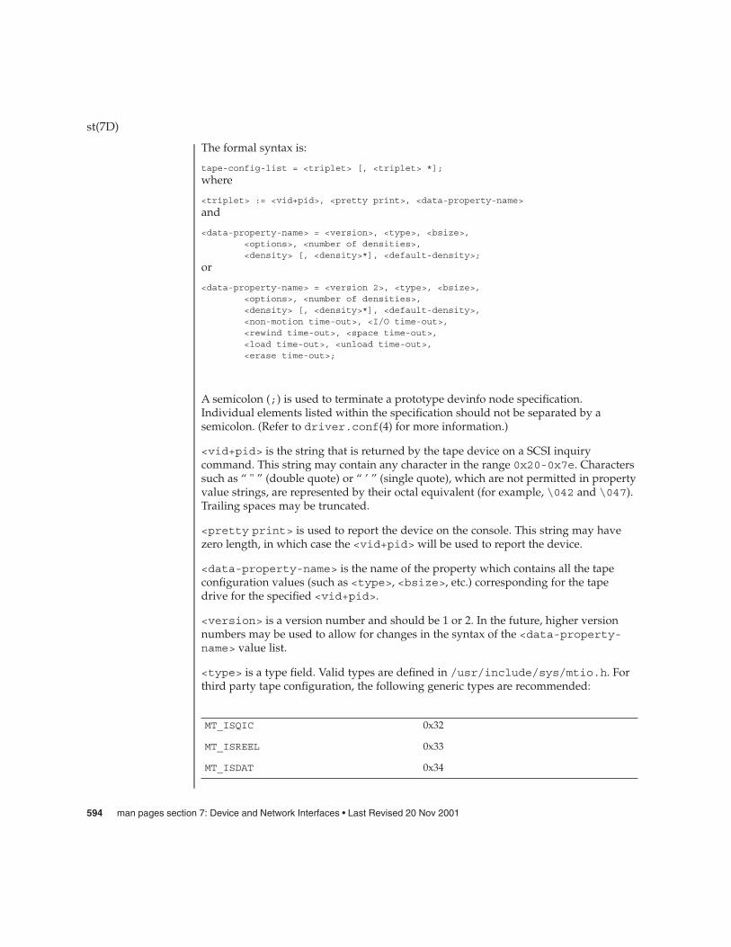
The formal syntax is:
tape-config-list = <triplet> [, <triplet> *];
where
<triplet> := <vid+pid>, <pretty print>, <data-property-name>
and
<data-property-name> = <version>, <type>, <bsize>,<options>, <number of densities>,<density> [, <density>*], <default-density>;
or
<data-property-name> = <version 2>, <type>, <bsize>,<options>, <number of densities>,<density> [, <density>*], <default-density>,<non-motion time-out>, <I/O time-out>,<rewind time-out>, <space time-out>,<load time-out>, <unload time-out>,<erase time-out>;
A semicolon (;) is used to terminate a prototype devinfo node specification.Individual elements listed within the specification should not be separated by asemicolon. (Refer to driver.conf(4) for more information.)
<vid+pid> is the string that is returned by the tape device on a SCSI inquirycommand. This string may contain any character in the range 0x20-0x7e. Characterssuch as “ " ” (double quote) or “ ’ ” (single quote), which are not permitted in propertyvalue strings, are represented by their octal equivalent (for example, \042 and \047).Trailing spaces may be truncated.
<pretty print> is used to report the device on the console. This string may havezero length, in which case the <vid+pid> will be used to report the device.
<data-property-name> is the name of the property which contains all the tapeconfiguration values (such as <type>, <bsize>, etc.) corresponding for the tapedrive for the specified <vid+pid>.
<version> is a version number and should be 1 or 2. In the future, higher versionnumbers may be used to allow for changes in the syntax of the <data-property-name> value list.
<type> is a type field. Valid types are defined in /usr/include/sys/mtio.h. Forthird party tape configuration, the following generic types are recommended:
MT_ISQIC 0x32
MT_ISREEL 0x33
MT_ISDAT 0x34
st(7D)
594 man pages section 7: Device and Network Interfaces • Last Revised 20 Nov 2001

MT_IS8MM 0x35
MT_ISOTHER 0x36
<bsize> is the preferred block size of the tape device. The value should be 0 forvariable block size devices.
<options> is a bit pattern representing the devices, as defined in/usr/include/sys/scsi/targets/stdef.h. Valid flags for tape configurationare:
ST_VARIABLE 0x0001
ST_QIC 0x0002
ST_REEL 0x0004
ST_BSF 0x0008
ST_BSR 0x0010
ST_LONG_ERASE 0x0020
ST_AUTODEN_OVERRIDE 0x0040
ST_NOBUF 0x0080
ST_KNOWS_EOD 0x0200
ST_UNLOADABLE 0x0400
ST_SOFT_ERROR_REPORTING 0x0800
ST_LONG_TIMEOUTS 0x1000
ST_NO_RECSIZE_LIMIT 0x8000
ST_MODE_SEL_COMP 0x10000
ST_NO_RESERVE_RELEASE 0x20000
ST_READ_IGNORE_ILI 0x40000
ST_READ_IGNORE_EOFS 0x80000
ST_SHORT_FILEMARKS 0x100000
ST_EJECT_TAPE_ON_CHANGER_FAILURE 0x200000
ST_RETRY_ON_RECOVERED_DEFERRED_ERROR0x400000
ST_VARIABLEThe flag indicates the tape device supports variable length record sizes.
st(7D)
Device and Network Interfaces 595

ST_QICThe flag indicates a Quarter Inch Cartridge (QIC) tape device.
ST_REELThe flag indicates a 1/2−inch reel tape device.
ST_BSFIf flag is set, the device supports backspace over EOF marks (bsf - see mt(1)).
ST_BSRIf flag is set, the tape device supports the backspace record operation (bsr - seemt(1)). If the device does not support bsr, the st driver emulates the action byrewinding the tape and using the forward space record (fsf) operation to forwardthe tape to the correct file. The driver then uses forward space record (fsr - seemt(1)) to forward the tape to the correct record.
ST_LONG_ERASEThe flag indicates the tape device needs a longer time than normal to erase.
ST_AUTODEN_OVERRIDEThe auto-density override flag. The device is capable of determining the tapedensity automatically without issuing a “mode-select”/“mode-sense command.”
ST_NOBUFThe flag disables the device’s ability to perform buffered writes. A buffered writeoccurs when the device acknowledges the completion of a write request after thedata has been written to the device’s buffer, but before all of the data has beenwritten to the tape.
ST_KNOWS_EODIf flag is set, the device can determine when EOD (End of Data) has been reached.When this flag is set, the st driver uses fast file skipping. Otherwise, file skippinghappens one file at a time.
ST_UNLOADABLEThe flag indicates the device will not complain if the st driver is unloaded andloaded again (see modload(1M) and modunload(1M)). That is, the driver willreturn the correct inquiry string.
ST_SOFT_ERROR_REPORTINGThe flag indicates the tape device will perform a “request sense” or “log sense”command when the device is closed. Currently, only Exabyte and DAT drivessupport this feature.
ST_LONG_TIMEOUTSThe flag indicates the tape device requires timeouts that are five times longer thanusual for normal operation.
ST_BUFFERED_WRITESThis option is obsolete; if specified, it is ignored. Installations which previouslyused this feature should refer to the documentation on asynchronous I/O:aioread(3AIO) and aiowrite(3AIO).
st(7D)
596 man pages section 7: Device and Network Interfaces • Last Revised 20 Nov 2001

ST_NO_RECSIZE_LIMIT (SPARC Only)The flag applies to variable-length tape devices. If this flag is set, the record size isnot limited to a 64 Kbyte record size. The record size is only limited by the smallerof either the record size supported by the device or the maximum DMA transfersize of the system. (Refer to Large Record Sizes and WARNINGS.)
ST_MODE_SEL_COMPIf the ST_MODE_SEL_COMP flag is set, the driver determines which of the two modepages the device supports for selecting or deselecting compression. It first tries theData Compression mode page (0x0F); if this fails, it tries the Device Configurationmode page (0x10). Some devices, however, may need a specific density code forselecting or deselecting compression. Please refer to the device specific SCSImanual. When the flag is set, compression will be enabled only if the "c" or "u"device is used. For any other device densities, compression will be disabled.
ST_NO_RESERVE_RELEASEThe ST_NO_RESERVE_RELEASE flag disables the use of reserve on open andrelease on close. If an attempt to use a ioctl of MTRESERVE or MTRELEASE on adrive with this flag set, it will return an error of ENOTTY (inappropriate ioctl fordevice).
ST_READ_IGNORE_ILIThe ST_READ_IGNORE_ILI flag is applicable only to variable block devices whichsupport the SILI bit option. The ST_READ_IGNORE_ILI flag indicates that SILI(supress incorrect length indicator) bit will be set during reads. When this flag isset, short reads (requested read size is less than the record size on the tape) will besuccessful and the number of bytes transferred will be equal to the record size onthe tape. The tape will be positioned at the start of the next record skipping overthe extra data (the remaining data has been has been lost). Long reads (requestedread size is more than the record size on the tape) will see a large performance gainwhen this flag is set, due to overhead reduction. When this flag is not set, shortreads will return an error of ENOMEM.
ST_READ_IGNORE_EOFSThe ST_READ_IGNORE_EOFS flag is applicable only to 1/2" Reel Tape drives andwhen performing consecutive reads only. It should not be used for any other tapecommand. Usually End-of-recorded-media (EOM) is indicated by two EOF markson 1/2" tape and application cannot read past EOM. When this flag is set, two EOFmarks no longer indicate EOM allowing applications to read past two EOF marks.In this case it is the responsibility of the application to detect end-of-recorded-media (EOM). When this flag is set, tape operations (like MTEOM) which positionsthe tape at end-of-recorded-media will fail since detection of end-of-recorded-media (EOM) is to be handled by the application. This flag should be used whenbackup applications have embedded double filemarks between files.
ST_SHORT_FILEMARKSThe ST_SHORT_FILEMARKS flag is applicable only to EXABYTE 8mm tape driveswhich supports short filemarks. When this flag is set, short filemarks will be used
st(7D)
Device and Network Interfaces 597

for writing filemarks. Short filemarks could lead to tape incompatible with someotherwise compatible device. By default long filemarks will be used for writingfilemarks.
ST_EJECT_TAPE_ON_CHANGER_FAILUREIf ST_EJECT_TAPE_ON_CHANGER_FAILURE flag is set, the tape will be ejectedautomatically if the tape cartridge is trapped in the medium due to positioningproblems of the medium changer.
The following ASC/ASCQ keys are defined to the reasons for causing tape ejectionif ST_EJECT_TAPE_ON_CHANGER_FAILURE option is set to 0x200000:
Sense ASC/ASCQ Description
Key
4 15/01 Mechanical Failure
4 44/00 Internal Target Failure
2 53/00 Media Load or Eject Failed
4 53/00 Media Load or Eject Failed
4 53/01 Unload Tape Failure
ST_RETRY_ON_RECOVERED_DEFERRED_ERRORIf ST_RETRY_ON_RECOVERED_DEFERRED_ERROR flag is set, the st driver willretry the last write if this cmd caused a check condition with error code 0x71 andsense code 0x01. Some tape drives, notably the IBM 3090, require this option.
<number of densities> is the number of densities specified. Each tape drive cansupport up to four densities. The value entered should therefore be between 1 and 4;if less than 4, the remaining densities will be assigned a value of 0x0.
<density> is a single-byte hexadecimal number. It can either be found in the devicespecification manual or be obtained from the device vendor.
<default-density> has a value between 0 and (<number of densities> - 1).
<non-motion time-out> Time in seconds that the drive should be able to performany SCSI command that doesn’t require tape to be moved. This includes mode sense,mode select, reserve, release, read block limits, and test unit ready.
<I/O time-out> Time in seconds to perform data transfer I/O to or from tapeincluding worst case error recovery.
<rewind time-out> Time in seconds to rewind from anywhere on tape to BOTincluding worst case recovery forcing buffered write data to tape.
st(7D)
598 man pages section 7: Device and Network Interfaces • Last Revised 20 Nov 2001

<space time-out> Time in seconds to space to any file, block or end of data ontape. Including worst case when any form of cataloging is invalid.
<load time-out> Time in seconds to load tape and be ready to transfer first block.This should include worst case recovery reading tape catalog or drive specificoperations done at load.
<unload time-out> Time in seconds to unload tape. Should include worst casetime to write to catalog, unthread, and tape cartridge unloading. Also should includeworst case time for any drive specific operations that are preformed at unload. Shouldnot include rewind time as the driver rewinds tape before issuing the unload.
<erase time-out> Time in seconds to preform a full (BOT to EOT) erase of longestmedium with worst case error recovery.
Each device maintains I/O statistics both for the device and for each partitionallocated on that device. For each device/partition, the driver accumulates reads,writes, bytes read, and bytes written. The driver also takes hi-resolution time stampsat queue entry and exit points, which facilitates monitoring the residence time andcumulative residence-length product for each queue.
Each device also has error statistics associated with it. These must include counters forhard errors, soft errors and transport errors. Other data may be implemented asrequired.
The behavior of SCSI tape positioning ioctls is the same across all devices whichsupport them. (Refer to mtio(7I).) However, not all devices support all ioctls. Thedriver returns an ENOTTY error on unsupported ioctls.
The retension ioctl only applies to 1/4” cartridge tape devices. It is used to restore tapetension, thus improving the tape’s soft error rate after extensive start-stop operationsor long-term storage.
In order to increase performance of variable-length tape devices (particularly whenthey are used to read/write small record sizes), two operations in the MTIOCTOP ioctl,MTSRSZ and MTGRSZ, can be used to set and get fixed record lengths. The ioctl alsoworks with fixed-length tape drives which allow multiple record sizes. The min/maxlimits of record size allowed on a driver are found by using a SCSI-2 READ BLOCKLIMITS command to the device. If this command fails, the default min/max recordsizes allowed are 1 byte and 63k bytes. An application that needs to use a differentrecord size opens the device, sets the size with the MTSRSZ ioctl, and then continueswith I/O. The scope of the change in record size remains until the device is closed.The next open to the device resets the record size to the default record size (retrievedfrom st.conf).
Note that the error status is reset by the MTIOCGET get status ioctl call or by the nextread, write, or other ioctl operation. If no error has occurred (sense key is 0), thecurrent file and record position is returned.
st(7D)
Device StatisticsSupport
IOCTLS
Device and Network Interfaces 599

EACCES The driver is opened for write access and the tape iswrite-protected or the tape unit is reserved by anotherhost.
EBUSY The tape drive is in use by another process. Only oneprocess can use the tape drive at a time. The driver willallow a grace period for the other process to finishbefore reporting this error.
EINVAL The number of bytes read or written is not a multipleof the physical record size (fixed-length tape devicesonly).
EIO During opening, the tape device is not ready becauseeither no tape is in the drive, or the drive is not on-line.Once open, this error is returned if the requested I/Otransfer could not be completed.
ENOTTY This indicates that the tape device does not support therequested ioctl function.
ENXIO During opening, the tape device does not exist.
ENOMEM This indicates that the record size on the tape drive ismore than the requested size during read operation.
EXAMPLE 1 Global tape-config list property
The following is an example of a global tape-config-list property:
tape-config-list ="Magic DAT", "Magic 4mm Helical Scan", "magic-data","Major Appliance", "Major Appliance Tape", "major-tape";
magic-data = 1,0x34,1024,0x1639,4,0,0x8c,0x8c,0x8c,3;major-tape = 2,0x3c,0,0x18619,4,0x0,0x0,0x0,0x0,3,0,0,30,120,0,0,36000;
name="st" class="scsi"target=0 lun=0;
name="st" class="scsi"target=1 lun=0;
name="st" class="scsi"target=2 lun=0;...
name="st" class="scsi"
target=6 lun=0;
EXAMPLE 2 Tape-config-list property applicable to target 2 only
The following is an example of a tape-config-list property applicable to target 2 only:
st(7D)
ERRORS
EXAMPLES
600 man pages section 7: Device and Network Interfaces • Last Revised 20 Nov 2001

EXAMPLE 2 Tape-config-list property applicable to target 2 only (Continued)
name="st" class="scsi"target=0 lun=0;
name="st" class="scsi"target=1 lun=0;
name="st" class="scsi"target=2 lun=0tape-config-list ="Magic DAT", "Magic 4mm Helical Scan", "magic-data"magic-data = 1,0x34,1024,0x1639,4,0,0x8c,0x8c,0x8c,3;
name="st" class="scsi"target=3 lun=0;
.
.
.name="st" class="scsi"
target=6 lun=0;
To support applications such as seismic programs that require large record sizes, theflag ST_NO_RECSIZE_LIMIT must be set in drive option in the configuration entry. ASCSI tape drive that needs to transfer large records should OR this flag with otherflags in the ’options’ field in st.conf. (Refer to Tape Configuration.) By default,this flag is set for the built-in config entries of Archive DAT and Exabyte drives.
If this flag is set, the st driver issues a SCSI-2 READ BLOCK LIMITS command to thedevice to determine the maximum record size allowed by it. If the command fails, stcontinues to use the maximum record sizes mentioned in the mtio(7I) man page.
If the command succeeds, st restricts the maximum transfer size of a variable-lengthdevice to the minimum of that record size and the maximum DMA size that the hostadapter can handle. Fixed-length devices are bound by the maximum DMA sizeallocated by the machine. Note that tapes created with a large record size may not bereadable by earlier releases or on other platforms.
(Refer to the WARNINGS section for more information.)
The Emulex drives have only a physical end of tape (PEOT); thus it is not possible towrite past EOT. All other drives have a logical end of tape (LEOT) before PEOT toguarantee flushing the data onto the tape. The amount of storage between LEOT andPEOT varies from less than 1 Mbyte to about 20 Mbyte, depending on the tape drive.
If EOT is encountered while writing an Emulex, no error is reported but the number ofbytes transferred is 0 and no further writing is allowed. On all other drives, the firstwrite that encounters EOT will return a short count or 0. If a short count is returned,then the next write will return 0. After a zero count is returned, the next write returnsa full count or short count. A following write returns 0 again. It is important that thenumber and size of trailer records be kept as small as possible to prevent data loss.Therefore, writing after EOT is not recommended.
st(7D)
Large Record Sizes
EOT Handling
Device and Network Interfaces 601

Reading past EOT is transparent to the user. Reading is stopped only by readingEOF’s. For 1/2” reel devices, it is possible to read off the end of the reel if one readspast the two file marks which mark the end of recorded media.
/kernel/drv/st.confdriver configuration file
/usr/include/sys/mtio.hstructures and definitions for mag tape io control commands
/usr/include/sys/scsi/targets/stdef.hdefinitions for SCSI tape drives
/dev/rmt/[0− 127][l,m,h,u,c][b][n]where l,m,h,u,c specifies the density (low, medium, high, ultra/compressed), bthe optional BSD behavior (see mtio(7I)), and n the optional no rewind behavior.For example, /dev/rmt/0lbn specifies unit 0, low density, BSD behavior, and norewind.
For 1/2” reel tape devices (HP-88780), the densities are:
l 800 BPI density
m 1600 BPI density
h 6250 BPI density
c data compression
(not supported on all modules)
For 8mm tape devices (Exabyte 8200/8500/8505):
l Standard 2 Gbyte format
m 5 Gbyte format (8500, 8505 only)
h,c 5 Gbyte compressed format (8505 only)
For 4mm DAT tape devices (Archive Python):
l Standard format
m,h,c data compression
For all QIC (other than QIC-24) tape devices:
st(7D)
FILES
602 man pages section 7: Device and Network Interfaces • Last Revised 20 Nov 2001
l,m,h,c density of the tape cartridge type
(not all devices can read and
write all formats)
For QIC-24 tape devices (Emulex MT−02):
l QIC-11 Format
m,h,c QIC-24 Format
mt(1), modload(1M), modunload(1M), open(2), read(2), write(2), aioread(3AIO),aiowrite(3AIO), kstat(3KSTAT), driver.conf(4), scsi(4), standards(5),esp(7D), isp(7D), mtio(7I), ioctl(9E)
The st driver diagnostics may be printed to the console or messages file.
Each diagnostic is dependent on the value of the system variable st_error_level.st_error_level may be set in the /etc/system file. The default setting forst_error_level is 4 (SCSI_ERR_RETRYABLE) which is suitable for mostconfigurations since only actual fault diagnostics are printed. Settings range fromvalues 0 (SCSI_ERR_ALL) which is most verbose, to 6 (SCSI_ERR_NONE) which isleast verbose. See stdef.h for the full list of error-levels. SCSI_ERR_ALL level theamount of diagnostic information is likely to be excessive and unnecessary.
The ST driver diagnostics are described below:
Error for Command: <scsi_cmd_name()> Error Level:<error_class>Requested Block: <blkno> Error Block: <err_blkno>Vendor: <name>: Serial Number: <inq_serial>Sense Key: <es_key> ASC: 0x<es_add_code> (scsi_asc_ascq_name()>), ASCQ:0x<es_qual_code>, FRU: 0x<ex_fru_code>
where <error_class> may be any one of the following: "All", "Unknown","Informational","Recovered", "Retryable", "Fatal"
The command indicated by <scsi_cmd_name> failed. Requested Block represents theblock where the transfer started. Error Block represents the block that caused the error.Sense Key, ASC, ASCQ and FRU information is returned by the target in response to arequest sense command. See SCSI protocol documentation for description of SenseKey, ASC, ASCQ, FRU.
Write/read: not modulo <n> block size
The request size for fixed record size devices must be a multiple of the specified blocksize.
Recovery by resets failed
st(7D)
SEE ALSO
DIAGNOSTICS
Device and Network Interfaces 603

After a transport error, the driver attempted to recover by issuing a device reset andthen a bus reset if device reset failed. These recoveries failed.
Periodic head cleaning required
The driver reported that periodic head cleaning is now required. This diagnostic isgenerated either due to a threshold number of retries, or due to the devicecommunicating to the driver that head cleaning is required.
Soft error rate (<n>%) during writing/reading was too high
The soft error rate has exceeded the threshold specified by the vendor.
SCSI transport failed: reason ’xxxx’: {retrying|giving up}
The Host Bus Adapter (HBA) has failed to transport a command to the target for thereason stated. The driver will either retry the command or, ultimately, give up.
Tape not inserted in drive
A media access command was attempted while there was no tape inserted into thespecified drive. In this case, the drive returns sense key of DRIVE NOT READY.
Transport rejected
The Host Bus Adapter (HBA) driver is not accepting commands after failing tosuccessfully transport a scsi packet to the target. The actual status received by the stdriver from the underlying HBA driver was either TRAN_FATAL_ERROR orTRAN_BADPKT.
Retrying command
The st driver failed to complete a command. However the command is retryable andwill be retried.
Giving up
The st driver has exhausted retries or otherwise is unable to retry the command andso is giving up.
No target struct for st%d
The st driver failed to obtain state information because the requested state structurewas not allocated. The specified device was probably not attached.
File mark detected
The operation detected an end of file mark. (File marks signify the end of a file on thetape media).
End-of-media detected
The operation reached the end of the tape media.
Exabyte soft error reporting failed. DAT soft error reporting failed
st(7D)
604 man pages section 7: Device and Network Interfaces • Last Revised 20 Nov 2001
The st driver was unable to determine if the soft error threshold had been exceededbecause it did not successfully read the data it requires or did not obtain enough data.This data is retrieved using the log sense command.
Log sense parameter code does not make sense
The log sense command retrieves hardware statistics that are stored on the drive (forexample, soft error counts and retries.) If the data retrieved from the drive is invalid,this message is printed and the data is not used.
Restoring tape position at fileno=%x, blkno=%lx....
The st driver is positioning to the specified file and block. This occurs on an open.
Failed to restore the last <file/block> position:
In this state, tape will be loaded at BOT during next open
The st driver could not position to the specified location and will revert to thebeginning of the tape when the next open is attempted.
Device does not support compression
The compression facility of the device was requested. However the device does nothave a hardware compression capability.
DAT soft error reset failed
After DAT soft error reporting, the counters within the device that accumulate thissense data need to be re-set. This operation failed.
Errors after pkt alloc (b_flags=0x%x, b_error=0x%x)
Memory allocation for a scsi packet failed.
Incorrect length indicator set
The drive reported the length of data requested in a READ operation, was incorrect.Incorrect Length Indicator (ILI) is a very commonly used facility in SCSI tape protocoland should not be seen as an error per-se. Applications typically probe a new tapewith a read of any length, using the returned length to the read system call for futurereads. Along with this operation, an underlying ILI error is received. ILI errors aretherefore informational only and are masked at the default st_error_level.
Data property (%s) has no valueData property (%s) incomplete
Version # for data property (%s) greater than 1
These diagnostics indicate problems in retrieving the values of the various propertysettings. The st driver is in the process of setting the property/parameter values forthe tape drive using information from either the built-in table within the driver orfrom uncommented entries in the st.conf file. The effect on the system may be thatthe tape drive may be set with default or generic driver settings which may not beappropriate for the actual type of tape drive being used.
st(7D)
Device and Network Interfaces 605
st_attach-RESUME: tape failure tape position will be lost
On a resume after a power management suspend, the previously known tape positionis no longer valid. This can occur if the tape was changed while the system was inpower management suspend. The operation will not be retried.
Write Data Buffering has been deprecated. Your applications shouldcontinue to work normally. However, they should be ported to use
Asynchronous I/O.
Indicates that buffering has been removed from Solaris.
Cannot detach: fileno=%x, blkno=%lx
The st driver cannot unload because the tape is not positioned at BOT (beginning oftape). May indicate hardware problems with the tape drive.
Variable record length I/O
Fixed record length (%d byte blocks) I/O
Tape-drives can use either Fixed or Variable record length. If the drive uses Fixedlength records, then the built in property table or the st.conf file will contain anon-zero record-length property. Most DAT, Exabyte and DLT drives support Variablerecord lengths. Many QIC format tape drives have historically been of Fixed recordlength.
Command will be retried
un_ncmds: %d can’t retry cmd
These diagnostics are only seen with tape drives with theST_RETRY_ON_RECOVERED_DEFERRED_ERROR bit set. See stdef.h forexplanation of the specific usage of this setting.
Effective with Solaris 2.4, the ST_NO_RECSIZE_LIMIT flag is set for the built-inconfig entries of the Archive DAT and Exabyte drivers by default. (Refer to LargeRecord Sizes.) Tapes written with large block sizes prior to Solaris 2.4 may causesome applications to fail if the number of bytes returned by a read request is less thanthe requested block size (for example, asking for 128 Kbytes and receiving less than 64Kbytes).
The ST_NO_RECSIZE_LIMIT flag can be disabled in the config entry for the device asa work-around. (Refer to Tape Configuration.) This action disables the ability toread and write with large block sizes and allows the reading of tapes written prior toSolaris 2.4 with large block sizes.
(Refer to mtio(7I) for a description of maximum record sizes.)
Tape devices that do not return a BUSY status during tape loading prevent usercommands from being held until the device is ready. The user must delay issuing anytape operations until the tape device is ready. This is not a problem for tape devicessupplied by Sun Microsystems.
st(7D)
WARNINGS
BUGS
606 man pages section 7: Device and Network Interfaces • Last Revised 20 Nov 2001

Tape devices that do not report a blank check error at the end of recorded media maycause file positioning operations to fail. Some tape drives, for example, mistakenlyreport media error instead of blank check error.
st(7D)
Device and Network Interfaces 607

stc – Serial Parallel Communications driver for SBus
The SPC/S SBus communications board consists of eight asynchronous serial portsand one IBM PS/2-compatible parallel port. The stc driver supports up to eight SPC/Sboards in an SBus system. Each serial port has full modem control: the CD, DTR, DSR,RTS, and CTS modem control lines are provided, and flow control is supported inhardware for either RTS/CTS hardware flow control or DC1/DC3 software flowcontrol.
The parallel port is unidirectional, with support for the ACK, STROBE, BUSY, PAPEROUT, SELECT, and ERROR interface signals. Both the serial and parallel ports supportthose termio(7I) device control functions specified by flags in the c_cflag word ofthe termios(3C) structure. In addition, the serial ports support the IGNPAR, PARMRK,INPCK, IXON, IXANY, and IXOFF flags in the c_iflag word of the termios(3C)structure. The latter c_iflag functions are performed by the stc driver for the serialports.
Since the parallel port is a unidirectional, output-only port, no input termios(3C)(c_iflag) parameters apply to it. Trying to execute a nonsensical ioctl() on theparallel port is not recommended.
All other termios(3C) functions are performed by STREAMS modules pushed on topof the driver. When an stc device is opened, the ldterm(7M) and ttcompat(7M)STREAMS modules are automatically pushed on top of the stream if they are specifiedin the /etc/iu.ap file (the default condition), providing the standard termio(7I)interface.
Device names of the form /dev/term/n or /dev/ttyyn specify the serial I/O portsprovided on the SPC/S board, conventionally as incoming lines. Device names of theform /dev/cua/n or /dev/ttyn specify the serial I/O ports provided on the SPC/Sboard, conventionally as outgoing lines. Device names of the form/dev/printers/n specify the parallel port, while a device name of the form/dev/sad/stcn specifies a special control port per board.
To allow a single tty line to be connected to a modem and used for both incoming andoutgoing calls, a special feature, controlled by the minor device number, has beenadded. Minor device numbers in the range 128-191 correspond to the same physicallines as those in the range 0-63 (that is, the same line as the minor device numberminus 128).
A dial-in line has a minor device in the range 0-63 and is conventionally named/dev/term/n where n is a number that indicates which dial-in line it is (so that/dev/term/0 is the first dial-in line). The dial-out line corresponding to that dial-inline has a minor device number 128 greater than the minor device number of thedial-in line and is conventionally named /dev/cua/n wheren is the number of thedial-in line. These devices also have the compatibility names /dev/ttyn.
The /dev/cua/n lines are special in that they can be opened even when there is nocarrier on the line. Once a /dev/cua/n line is opened, the corresponding/dev/term/n line cannot be opened until the /dev/cua/n line is closed; a blocking
stc(7D)
NAME
DESCRIPTION
608 man pages section 7: Device and Network Interfaces • Last Revised 6 Feb 2002
open will wait until the /dev/cua/n line is closed (which drops DTR, after which DCDwill usually drop as well) and carrier is detected again, and a non-blocking open willreturn an error. If the /dev/term/n line is opened successfully (usually only whencarrier is recognized on the modem) the corresponding /dev/cua/n line cannot beopened. This allows a modem to be attached to /dev/term/0, for example, and usedfor dial-in, by enabling the line for login (using pmadm(1M)) and also used for dial-out(by tip(1) or uucp(1C)) as /dev/cua/0 when nobody is logged in on the line.
The control port, named /dev/sad/stcn where n is the SPC/S, is available. Anioctl() is provided for this special file which allow the collection of statisticsmaintained on serial port performance.
The characters o p u u | u l l l correspond to the bits in the minor number. They aremnemonic indicators of the function of the corresponding bit.
o set if this device is an outgoing serial line
p set if this is a parallel port device
u device unit number
l device line number if this is the parallel port line, ’p’ should be 1 and ’lll’should be all 0’s if this is the control line, both ’p’ and ’lll’ should be set toall 1’s
The standard set of termio ioctl() calls is supported by the stc driver on both theserial and parallel ports.
If the CRTSCTS flag in the c_cflag is set and if CTS is high, output will betransmitted; if CTS is low, output will be frozen. If the CRTSCTS flag is clear, the stateof CTS has no effect. Breaks can be generated by the TCSBRK, TIOCSBRK andTIOCCBRK ioctl() calls. The modem control lines TIOCM_CAR, TIOCM_CTS,TIOCM_RTS, TIOCM_DSR and TIOCM_DTR are provided for the serial ports, althoughthe TIOCMGET ioctl() call will not return the state of the TIOCM_RTS orTIOCM_DSR lines, which are output-only signals.
The serial port input and output line speeds may be set to any of the speeds supportedby termio(7I).
The stc driver supports two additional ioctl()s. STC_SPPC(structppc_params_t *) sets parallel port parameters, and STC_GPPC(structppc_params_t *) gets parallel port parameters. Both are valid until changed oruntil a close().
struct ppc_params_t {uint_t flags; /* driver status flag */uint_t state; /* status of the printer interface */uint_t strobe_w; /* strobe width, in microseconds */uint_t data_setup; /* data setup time, in microseconds */uint_t ack_timeout; /* ACK timeout in secs */uint_t error_timeout; /* PAPER OUT, etc... timeout in secs */uint_t busy_timeout; /* BUSY timeout in seconds */
stc(7D)
Minor Numbers
IOCTLS
DEVICE-SPECIFICIOCTLS
Device and Network Interfaces 609

};
The possible values for flags defined in /usr/include/sys/stcio.h are:
PP_PAPER_OUT honor PAPER OUT from port; returned HIGH means PAPER OUT.
PP_ERROR honor ERROR from port; returned HIGH means ERROR.
PP_BUSY honor BUSY from port; returned HIGH means BUSY.
PP_SELECT honor SELECT from port; returned HIGH means OFFLINE.
PP_MSG print console message on every error scan.
PP_SIGNAL send a PP_SIGTYPE (SIGURG) to the process if printer error.
The state field contains the current status of the printer interface. It is analogous to thebit order of flags, but contains the status the driver maintains, masked by the flags thatare set. The result of shifting state PP_SHIFT bits to the left is the actual state of thehardware.
The STC_SPPC and STC_GPPC ioctl() calls are understood only by the parallelport. STC_GSTATS(struct stc_stats_t *) gets or resets driver performancestatistics on serial ports.
struct stc_stats_t {uint_t cmd; /* command */uint_t qpunt; /* punting in stc_drainsilo() */uint_t drain_timer; /* posted a timer in stc_drainsilo() */uint_t no_canput; /* canput() failed in stc_drainsilo() */uint_t no_rcv_drain; /* can’t call stc_drainsilo() in stc_rcv() */uint_t stc_drain; /* STC_DRAIN flag set on this line */uint_t stc_break; /* BREAK requested on XMIT via stc_ioctl() */uint_t stc_sbreak; /* start BREAK requested via stc_ioctl() */uint_t stc_ebreak; /* end BREAK requested via stc_ioctl() */uint_t set_modem; /* set modem control lines in stc_ioctl() */uint_t get_modem; /* get modem control lines in stc_ioctl() */uint_t ioc_error; /* bad ioctl() */uint_t set_params; /* call to stc_param() */uint_t no_start; /* can’t run in stc_start(); already there */uint_t xmit_int; /* transmit interrupts */uint_t rcv_int; /* receive interrupts */uint_t rcvex_int; /* receive exception interrupts */uint_t modem_int; /* modem change interrupts */uint_t xmit_cc; /* characters transmitted */uint_t rcv_cc; /* characters received */uint_t break_cnt; /* BREAKs received */uint_t bufcall; /* times we couldn’t get STREAMS buffer */uint_t canwait; /* stc_drainsilo() called w/pending timer */uint_t reserved; /* this field is meaningless */
};
stc(7D)
610 man pages section 7: Device and Network Interfaces • Last Revised 6 Feb 2002

The STC_GSTATS ioctl() works only on the SPC/S control port. The possible cmdvalues, defined in /usr/include/sys/stcio.h, are STAT_CLEAR, which clears theline statistics, and STAT_GET, which gets the line statistics.
Several methods may be used to enable or disable soft carrier on a particular serial line.The non-programmatic method is to edit the/platform/platform/kernel/drv/stc.conf file. For this change to take effect, themachine must be rebooted. See the next section, SETTING DEFAULT LINEPARAMETERS, for more information on this method. From within an applicationprogram, you can enable or disable the recognition of carrier on a particular line byissuing the TIOCGSOFTCAR ioctl() to the driver.
The default mode of operation for the DTR signal is to assert it on the first open() of aserial line and, if HUPCL is set, to de-assert it on the last close(). To change theoperation of this feature, issue the set on the/platform/platform/kernel/drv/stc.conf parameter flags field bitDTR_ASSERT.
Many default parameters of the serial and parallel ports can be changed using the/platform/platform/kernel/drv/stc.conf file. The format of a line in thestc.conf file is:
device_tag=token[=value][:token[=value]]
For serial ports, the device_tag is stc_n, where n is between 0 and the maximumnumber of serial ports used by the driver. The token and parameters that follow itapply to both the /dev/term/n entries and /dev/cua/n entries.
For parallel ports, the device_tag is stc_pn, where n is between 0 and the number ofparallel ports driven by stc.
The token[=value] specifies a token, and if the token takes a value, the value to assigned.Tokens that don’t take a value are considered boolean. If boolean tokens don’t appearin the stc.conf file, they will be cleared by the driver. If these tokens appear in thestc.conf file, they are set by the driver.
Tokens that take parameters must have a parameter specified in the token=valuecouplet in the stc.conf file. If no parameter or an invalid parameter is specified, thedriver ignores the token and uses the driver’s default value.
Valid boolean tokens for serial ports are:
soft_carrier- Defaullt value, enables the soft carrier on the specifiedline. When the soft carrier is set, transitions on thecarrier detect line will be ignored. Use drt_assert toclear this value.
dtr_assert- Causes the DTR to be asserted on the next open of theport.
stc(7D)
SOFTCAR, DTRand CTS/RTS
FLOW CONTROL
SETTINGDEFAULT LINEPARAMETERS
Tokens for SerialPorts
Device and Network Interfaces 611
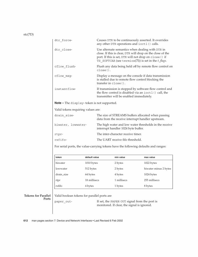
dtr_force- Causes DTR to be continuously asserted. It overridesany other DTR operations and ioctl() calls.
dtr_close- Use alternate semantics when dealing with DTR inclose. If this is clear, DTR will drop on the close of theport. If this is set, DTR will not drop on close() ifTS_SOFTCAR (see termiox(7I)) is set in the t_flags.
cflow_flush- Flush any data being held off by remote flow control onclose().
cflow_msg- Display a message on the console if data transmissionis stalled due to remote flow control blocking thetransfer in close().
instantflow- If transmission is stopped by software flow control andthe flow control is disabled via an ioctl() call, thetransmitter will be enabled immediately.
Note – The display- token is not supported.
Valid tokens requiring values are:
drain_size- The size of STREAMS buffers allocated when passingdata from the receive interrupt handler upstream.
hiwater, lowwater- The high water and low water thresholds in the receiveinterrupt handler 1024 byte buffer.
rtpr- The inter-character receive timer.
rxfifo- The UART receive fifo threshold.
For serial ports, the value-carrying tokens have the following defaults and ranges:
token default value min value max value
hiwater 1010 bytes 2 bytes 1022 bytes
lowwater 512 bytes 2 bytes hiwater minus 2 bytes
drain_size 64 bytes 4 bytes 1024 bytes
rtpr 18 millisecs 1 millisecs 255 millisecs
rxfifo 4 bytes 1 bytes 8 bytes
Valid boolean tokens for parallel ports are
paper_out- If set, the PAPER OUT signal from the port ismonitored. If clear, the signal is ignored.
stc(7D)
Tokens for ParallelPorts
612 man pages section 7: Device and Network Interfaces • Last Revised 6 Feb 2002
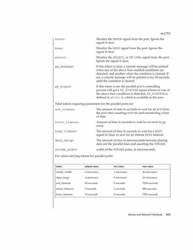
error- Monitor the ERROR signal from the port. Ignore thesignal if clear.
busy- Monitor the BUSY signal from the port. Ignore thesignal if clear.
select- Monitor the SELECT, or ON LINE, signal from the port.Ignore the signal if clear.
pp_message- If this token is clear, a console message will be printedwhen any of the above four enabled conditions aredetected, and another when the condition is cleared. Ifset, a console message will be printed every 60 secondsuntil the condition is cleared.
pp_signal- If this token is set, the parallel port’s controllingprocess will get a PP_SIGTYPE signal whenever one ofthe above four conditions is detected. PP_SIGTYPE isdefined in stcio.h, which is available to the user.
Valid tokens requiring parameters for the parallel ports are
ack_timeout- The amount of time in seconds to wait for an ACK fromthe port after asserting STROBE and transferring a byteof data.
error_timeout- Amount of time in seconds to wait for an error to goaway.
busy_timeout- The amount of time in seconds to wait for a BUSYsignal to clear, or zero for an infinite BUSY timeout.
data_setup- The amount of time in microseconds between placingdata ont the parallel lines and asserting the STROBE.
strobe_width- width of the STROBE pulse, in microseconds.
For value-carrying tokens for parallel ports:
token default value min value max value
strobe_width 2 microsecs 1 microsecs 30 microsecs
data_setup 2 microsecs 0 microsecs 30 microsecs
ack_timeout 60 seconds 5 seconds 7200 seconds
errror_timeout 5 seconds 1 seconds 480 seconds
busy_timeout 10 seconds 0 seconds 7200 seconds
stc(7D)
Device and Network Interfaces 613

The default values of certain parallel port parameters that govern data transferbetween the SPC/S board and the device attached to the parallel port will usuallywork well with most devices; however, some devices don’t strictly adhere to the IBMPS/2-compatible (Centronics-compatible) data transfer and device control/status protocol,and may require modification of one or more of the default parallel port parameters.Some printers, for example, have non-standard timing on their SELECT line, whichmanifests itself if you start sending data to the printer and then take it off line; whenyou put it back on line, the printer will not assert it’s SELECT line until after the nextcharacter is sent to the printer. Since the stc driver will not send data to the device ifit’s SELECT line is de-asserted, a deadlock condition occurs. To remedy this situation,you can change the default signal list that the stc driver monitors on the parallel portby removing the SELECT signal from the list. This can be done through the/platform/platform/kernel/drv/stc.conf configuration file orprogrammatically through the STC_SPPC ioctl() call.
If you try to unload the driver, and one or more of the ports on one or more of theSPC/S boards is in use (for example, open()) by a process, the driver is notunloaded, and all lines on all SPC/S boards, with the exception of the control ports, willbe marked with an open inhibit flag to prevent further opens until the driver issuccessfully unloaded.
An open() will fail with errno set to:
ENXIO The unit being opened does not exist.
EBUSY The dial-out device is being opened and the dial-in device isalready open, the dial-in device is being opened with a no-delayopen and the dial-out device is already open or the unit has beenmarked as exclusive-use by another process with a TIOCEXCLioctl() call.
EINTR The open was interrupted by the delivery of a signal.
EPERM The control port for the board was opened by a process whose uidwas not root.
An ioctl() will fail with errno set to:
ENOSR A STREAMS data block could not be allocated to return data to thecaller.
EINVAL An invalid value was passed as the data argument to the ioctl()call or an invalid argument or op-field was passed in one of thedriver-specific ioctl()’s.
EPERM An STC_GSTATS ioctl() was requested by a process whose uidwas not root.
ENOTTY An unrecognized ioctl() command was received.
The stc driver uses the following files:
stc(7D)
PARALLEL PORTPARAMETERS
LOADABLEISSUES
ERRORS
FILES
614 man pages section 7: Device and Network Interfaces • Last Revised 6 Feb 2002

/dev/term/[00-3f]
/dev/ttyy[00-3f]Hardwired and dial-in tty lines
/dev/cua/[00-3f]
/dev/ttyz[00-3f]Dial-out tty lines
/dev/printers/[0-7]
/dev/stclp[0-7]Parallel port lines
/dev/stc[0-7]Control port
/platform/platform/kernel/drv/stc.confDriver configuration file
/usr/include/sys/stcio.hHeader file with ioctl()s supported by this driver
tip(1), uucp(1C), pmadm(1M), termios(3C), ldterm(7M), termio(7I), termiox(7I),ttcompat(7M), allocb(9F), bufcall(9F), kmem_zalloc (9F)
All diagnostic messages from the driver appear on the system console. There are threeseverity levels of messages displayed:
FATAL The device driver does not load and any SPC/S boards installed inthe system are inaccessible. Fatal errors usually occur during themodload process.
ERROR Some condition has disrupted the normal operation of the boardand/or device driver. There may be data loss. This class ofmessage mayindicate an impending hardware failure.
ADVISORY The device driver has detected a condition that may be of interest,usually a transient condition that clears itself.
The following messages can be generated during initialization of the driver or board.
stc_attach: can’t allocate memory for unit structsFATAL. kmem_zalloc() failed to allocate memory for the driver’s internal datastructures.
stc_attach: board revision undeterminableFATAL. The driver did not get a hardware revision level from the board’s onboardFCode PROM.
stc_attach: board revision 0x%x not supported by driver.FATAL. This revision of the board is not supported by the driver.
stc(7D)
SEE ALSO
DIAGNOSTICS
Messages DuringInitialization Of
Driver/Board
Device and Network Interfaces 615

stc_attach: oscillator revision undeterminableFATAL. The driver did not get an oscillator revision level from the board’s onboardFCode PROM.
stc_attach: weird oscillator revision (0x%x), assuming 10MhzADVISORY. The board’s onboard FCode PROM returned an unanticipatedbaud-rate oscillator value, so the driver assumes that a 10Mhz oscillator is installed.
stc_attach: error initializing stc%dFATAL. An error occured while trying to initialize the board; perhaps a memoryaccess failed.
stc_attach: bad number of interrupts: %dFATAL. An incorrect number of interrupts was read from the board’s onboardFCode PROM.
stc_attach: bad number of register sets: %dFATAL. An incorrect number of register sets was read from the board’s onboardFCode PROM.
stc_init: stc%d GIVR was not 0x0ff, was: 0x%xFATAL. Either the cd-180 8-channel UART failed to initialize properly or a memoryfault occured while trying to access the chip.
cd180_init: stc%d GIVR was not 0x0ff, was: 0x%xFATAL. Either the cd-180 8-channel UART failed to initialize properly or a memoryfault occured while trying to access the chip.
stc%d: board revision: 0x%x should be updatedADVISORY. Two versions of the FCode PROM on the SPC/S card, V1.0 (0x4) andV1.1 (0x5), have been released. The V1.1 PROM fixes some incompatabilitiesbetween the V1.0 FCode PROM on the SPC/S and the V2.0 OpenBOOT PROM onyour system. An SPC/S card in a system running Solaris 2.X. requires a V1.1PROM.
stc%d: system boot PROM revision V%d.%d should be updatedADVISORY. Your system’s BOOT PROM should be updated to at least V1.3 becauseprior versions of the BOOT PROM did not correctly map the SBus interrupt levelsthat the SPC/S uses.
SET_CCR: CCR timeoutERROR. The cd-180’s CCR register did not return to zero within the specified timeoutperiod after it was issued a command
PUTSILO: unit %d line %d soft silo overflowERROR. The driver’s internal receive data silo for the enunciated line hasoverflowed because the system has not gotten around to pulling data out of thesilo. Make sure you are using the correct flow control and that all data in the silo isflushed. This message frequently appears becasue of a hardware crosstalk problemthat was fixed in later releases of the board.
stc(7D)
Messages RelatedTo The Serial Port
616 man pages section 7: Device and Network Interfaces • Last Revised 6 Feb 2002

stc_rcvex: unit %d line %d receiver overrun, char: 0x%xERROR. The driver could not get around to service the cd-180 receive data interruptbefore the cd-180’s receive data FIFO filled up. This message frequently appearsbecasue of a hardware crosstalk problem that was fixed in later releases of theboard.
stc_drainsilo: unit %d line %d can’t allocate streams bufferERROR. The driver could not get a STREAMS message buffer from bufcall(9F).All data in the driver’s receive data silo is flushed.
stc_drainsilo: unit %d line %d punting put retriesERROR. After trying several times to send data down the stream from the driver tothe application and finding the path blocked, the driver gives up. All data in thedriver’s receive data silo is flushed.
stc_modem: unit %d line %d interesting modem controlADVISORY. The cd-180 posted a modem control line change interrupt, but uponexamination by the driver, no modem control lines had changed state since the lasttime a scan was conducted. If you see this problem frequently, it is likely that yourdata cables are either too long or picking up induced noise.
ppc_stat: unit %d PAPER OUTADVISORY. The device connected to the parallel port on the enumerated BOARD hassignalled that it is out of paper (PAPER OUT line asserted).
ppc_stat: unit %d PAPER OUT condition clearedADVISORY. The previously-detected PAPER OUT condition has been cleared by thedevice connected to the parallel port on the enumerated board (PAPER OUT linede-asserted).
ppc_stat: unit %d OFFLINEADVISORY. The device connected to the parallel port on the enumerated board hassignaled that it is offline (SLCT line de-asserted).
ppc_stat: unit %d OFFLINE condition clearedADVISORY. The previously-detected off line condition has been cleared by thedevice connected to the parallel port on the enumerated board (SLCT line asserted).
ppc_stat: unit %d ERRORADVISORY. The device connected to the parallel port on the enumerated board hassignalled that it has encountered an error of some sort (ERROR line asserted).
ppc_stat: unit %d ERROR condition clearedADVISORY. The previously-detected error condition has been cleared by the deviceconnected to the parallel port on the enumerated board (ERROR line de-asserted).
ppc_acktimeout: unit %d ACK timeoutERROR. The ACK line from the device connected to the parallel port did not assertitself within the configurable timeout period. Check to be sure that the device isconnected and powered on.
stc(7D)
Messages RelatedTo The Parallel
Port
Device and Network Interfaces 617

ppc_acktimeout: unit %d BUSY timeoutERROR. The BUSY line from the device connected to the parallel port did notde-assert itself within the configurable timeout period. Check to be sure that thedevice is connected and powered on.
ppc_int: unit %d stray interruptADVISORY. The parallel port controller (ppc) chip generated an interrupt while thedevice was closed. This was unexpected, and if you see it frequently, your parallelcable may be picking up induced noise, causing the ppc to generate an unwantedinterrupt; or this could indicate an internal problem in the ppc.
ppc_acktimeout: unit %d can’t get pointer to read qERROR. The driver’s internal ppc data structure became corrupted.
ppc_acktimeout: unit %d can’t send M_ERROR messageERROR. The driver can’t send an M_ERROR STREAMS message to the application.
ppc_signal: unit %d can’t get pointer to read qERROR. The driver’s internal ppc data structure became corrupted.
ppc_signal: unit %d can’t send M_PCSIG(PP_SIGTYPE 0x%x) messageERROR. The driver can’t send an M_PCSIG STREAMS message to the application(which could cause a signal to be posted).
stc_wput: unit %d trying to M_STARTI on ppc or control deviceADVISORY. An M_STARTI STREAMS message was sent to the parallel port or theboard control device, which should only happen if an application explicitly sendsthis message.
stc_wput: unit %d line %d unknown message: 0x%xADVISORY. An unknown STREAMS message was sent to the driver. Check yourapplication coding.
stc_start: unit %d line %d unknown message: 0x%xADVISORY. An unknown STREAMS message was sent to the driver. Check yourapplication coding.
stc_ioctl: unit %d line %d can’t allocate streams buffer for ioctlERROR. The driver could not get a STREAMS message buffer from bufcall() forthe requested ioctl(); theioctl() will not be executed.
stc_ioctl: unit %d line %d can’t allocate STC_DCONTROL blockERROR. The driver could not allocate a data block from allocb(9F) for theSTC_DCONTROL return value; the ioctl() does not get executed.
stc_ioctl: unit %d line %d can’t allocate STC_GPPC blockERROR. The driver could not allocate a data block from allocb() for theSTC_GPPC return value; the ioctl() does not get executed.
stc_ioctl: unit %d line %d can’t allocate TIOCMGET blockERROR. The driver could not allocate a data block from allocb() for theTIOCMGET return value; the ioctl() does not get executed.
stc(7D)
Messages RelatedTo STREAMS
Processing
Messages RelatedTo Serial Port
Control
618 man pages section 7: Device and Network Interfaces • Last Revised 6 Feb 2002

stc_vdcmd: unit %d cd-180 firmware revision: 0x%xADVISORY. This message displays the firmware revision level of the cd-180 whenthe driver is first loaded.
stc(7D)
Device and Network Interfaces 619

stp4020 – STP 4020 PCMCIA Adapter
The STP 4020 PCMCIA Adapter provides for two PCMCIA PC Card sockets. Thestp4020 adapter driver provides an interface between the PCMCIA sockets and thePCMCIA nexus. The driver supports the Sun PCMCIA Interface/Sbus card.
Direct access to the PCMCIA hardware is not supported. The driver exists solely tosupport the PCMCIA nexus.
/kernel/drv/stp4020 stp4020 driver.
pcmcia(4)
stp4020(7D)
NAME
DESCRIPTION
FILES
SEE ALSO
620 man pages section 7: Device and Network Interfaces • Last Revised 27 Jul 1999

streamio – STREAMS ioctl commands
#include <sys/types.h>#include <stropts.h>
#include <sys/conf.h>
int ioctl(int fildes, int command, ... /*arg*/);
STREAMS (see intro(3)) ioctl commands are a subset of the ioctl(2) commandsand perform a variety of control functions on streams.
The fildes argument is an open file descriptor that refers to a stream. The commandargument determines the control function to be performed as described below. The argargument represents additional information that is needed by this command. The typeof arg depends upon the command, but it is generally an integer or a pointer to acommand-specific data structure. The command and arg arguments are interpreted bythe STREAM head. Certain combinations of these arguments may be passed to amodule or driver in the stream.
Since these STREAMS commands are ioctls, they are subject to the errors describedin ioctl(2). In addition to those errors, the call will fail with errno set to EINVAL,without processing a control function, if the STREAM referenced by fildes is linkedbelow a multiplexor, or if command is not a valid value for a stream.
Also, as described in ioctl(2), STREAMS modules and drivers can detect errors. Inthis case, the module or driver sends an error message to the STREAM headcontaining an error value. This causes subsequent calls to fail with errno set to thisvalue.
The following ioctl commands, with error values indicated, are applicable to allSTREAMS files:
I_PUSH Pushes the module whose name is pointed to by arg onto the topof the current stream, just below the STREAM head. If theSTREAM is a pipe, the module will be inserted between the streamheads of both ends of the pipe. It then calls the open routine of thenewly-pushed module. On failure, errno is set to one of thefollowing values:
EINVAL Invalid module name.
EFAULT arg points outside the allocated address space.
ENXIO Open routine of new module failed.
ENXIO Hangup received on fildes.
I_POP Removes the module just below the STREAM head of theSTREAM pointed to by fildes. To remove a module from a piperequires that the module was pushed on the side it is beingremoved from. arg should be 0 in an I_POP request. On failure,errno is set to one of the following values:
streamio(7I)
NAME
SYNOPSIS
DESCRIPTION
IOCTLS
Device and Network Interfaces 621

EINVAL No module present in the stream.
ENXIO Hangup received on fildes.
EPERM Attempt to pop through an anchor by anunpriviledged process.
I_ANCHOR Positions the stream anchor to be at the STREAMS module directlybelow the STREAM head. Once this has been done, only aprivileged process may pop modules below the anchor on thestream. arg must be 0 in an I_ANCHOR request. On failure, errnois set to the following value:
EINVAL Request to put an anchor on a pipe.
I_LOOK Retrieves the name of the module just below the STREAM head ofthe STREAM pointed to by fildes, and places it in a null terminatedcharacter string pointed at by arg. The buffer pointed to by argshould be at least FMNAMESZ+1 bytes long. This requires thedeclaration #include <sys/conf.h>. On failure, errno is setto one of the following values:
EFAULT arg points outside the allocated address space.
EINVAL No module present in stream.
I_FLUSH This request flushes all input and/or output queues, depending onthe value of arg. Legal arg values are:
FLUSHR Flush read queues.
FLUSHW Flush write queues.
FLUSHRW Flush read and write queues.
If a pipe or FIFO does not have any modules pushed, the readqueue of the STREAM head on either end is flushed depending onthe value of arg.
If FLUSHR is set and fildes is a pipe, the read queue for that end ofthe pipe is flushed and the write queue for the other end isflushed. If fildes is a FIFO, both queues are flushed.
If FLUSHW is set and fildes is a pipe and the other end of the pipeexists, the read queue for the other end of the pipe is flushed andthe write queue for this end is flushed. If fildes is a FIFO, bothqueues of the FIFO are flushed.
If FLUSHRW is set, all read queues are flushed, that is, the readqueue for the FIFO and the read queue on both ends of the pipeare flushed.
streamio(7I)
622 man pages section 7: Device and Network Interfaces • Last Revised 19 Apr 1999

Correct flush handling of a pipe or FIFO with modules pushed isachieved via the pipemod module. This module should be the firstmodule pushed onto a pipe so that it is at the midpoint of the pipeitself.
On failure, errno is set to one of the following values:
ENOSR Unable to allocate buffers for flush messagedue to insufficient STREAMS memoryresources.
EINVAL Invalid arg value.
ENXIO Hangup received on fildes.
I_FLUSHBAND Flushes a particular band of messages. arg points to a bandinfostructure that has the following members:
unsigned char bi_pri;int bi_flag;
The bi_flag field may be one of FLUSHR, FLUSHW, or FLUSHRWas described earlier.
I_SETSIG Informs the STREAM head that the user wishes the kernel to issuethe SIGPOLL signal (see signal(3C)) when a particular event hasoccurred on the STREAM associated with fildes. I_SETSIGsupports an asynchronous processing capability in STREAMS. Thevalue of arg is a bitmask that specifies the events for which theuser should be signaled. It is the bitwise OR of any combination ofthe following constants:
S_INPUT Any message other than an M_PCPROTO hasarrived on a STREAM head read queue. Thisevent is maintained for compatibility withprevious releases. This event is triggered evenif the message is of zero length.
S_RDNORM An ordinary (non-priority) message hasarrived on a STREAM head read queue. Thisevent is triggered even if the message is of zerolength.
S_RDBAND A priority band message (band > 0) has arrivedon a stream head read queue. This event istriggered even if the message is of zero length.
S_HIPRI A high priority message is present on theSTREAM head read queue. This event istriggered even if the message is of zero length.
S_OUTPUT The write queue just below the STREAM headis no longer full. This notifies the user that
streamio(7I)
Device and Network Interfaces 623

there is room on the queue for sending (orwriting) data downstream.
S_WRNORM This event is the same as S_OUTPUT.
S_WRBAND A priority band greater than 0 of a queuedownstream exists and is writable. Thisnotifies the user that there is room on thequeue for sending (or writing) priority datadownstream.
S_MSG A STREAMS signal message that contains theSIGPOLL signal has reached the front of theSTREAM head read queue.
S_ERROR An M_ERROR message has reached theSTREAM head.
S_HANGUP An M_HANGUP message has reached theSTREAM head.
S_BANDURG When used in conjunction with S_RDBAND,SIGURG is generated instead of SIGPOLLwhen a priority message reaches the front ofthe stream head read queue.
A user process may choose to be signaled only of high prioritymessages by setting the arg bitmask to the value S_HIPRI.
Processes that wish to receive SIGPOLL signals must explicitlyregister to receive them using I_SETSIG. If several processesregister to receive this signal for the same event on the samestream, each process will be signaled when the event occurs.
If the value of arg is zero, the calling process will be unregisteredand will not receive further SIGPOLL signals. On failure, errno isset to one of the following values:
EINVAL arg value is invalid or arg is zero and process isnot registered to receive the SIGPOLL signal.
EAGAIN Allocation of a data structure to store thesignal request failed.
I_GETSIG Returns the events for which the calling process is currentlyregistered to be sent a SIGPOLL signal. The events are returned asa bitmask pointed to by arg, where the events are those specified inthe description of I_SETSIG above. On failure, errno is set to oneof the following values:
EINVAL Process not registered to receive the SIGPOLLsignal.
streamio(7I)
624 man pages section 7: Device and Network Interfaces • Last Revised 19 Apr 1999

EFAULT arg points outside the allocated address space.
I_FIND Compares the names of all modules currently present in theSTREAM to the name pointed to by arg, and returns 1 if the namedmodule is present in the stream. It returns 0 if the named moduleis not present. On failure, errno is set to one of the followingvalues:
EFAULT arg points outside the allocated address space.
EINVAL arg does not contain a valid module name.
I_PEEK Allows a user to retrieve the information in the first message onthe STREAM head read queue without taking the message off thequeue. I_PEEK is analogous to getmsg(2) except that it does notremove the message from the queue. arg points to a strpeekstructure, which contains the following members:
struct strbuf ctlbuf;struct strbuf databuf;long flags;
The maxlen field in the ctlbuf and databuf strbuf structures(see getmsg(2)) must be set to the number of bytes of controlinformation and/or data information, respectively, to retrieve.flags may be set to RS_HIPRI or 0. If RS_HIPRI is set, I_PEEKwill look for a high priority message on the STREAM head readqueue. Otherwise, I_PEEK will look for the first message on theSTREAM head read queue.
I_PEEK returns 1 if a message was retrieved, and returns 0 if nomessage was found on the STREAM head read queue. It does notwait for a message to arrive. On return, ctlbuf specifiesinformation in the control buffer, databuf specifies information inthe data buffer, and flags contains the value RS_HIPRI or 0. Onfailure, errno is set to the following value:
EFAULT arg points, or the buffer area specified inctlbuf or databuf is, outside the allocatedaddress space.
EBADMSG Queued message to be read is not valid forI_PEEK.
EINVAL Illegal value for flags.
I_SRDOPT Sets the read mode (see read(2)) using the value of the argumentarg. Legal arg values are:
RNORM Byte-stream mode, the default.
RMSGD Message-discard mode.
RMSGN Message-nondiscard mode.
streamio(7I)
Device and Network Interfaces 625

In addition, the STREAM head’s treatment of control messagesmay be changed by setting the following flags in arg:
RPROTNORM Reject read() with EBADMSG if a controlmessage is at the front of the STREAM headread queue.
RPROTDAT Deliver the control portion of a message asdata when a user issues read(). This is thedefault behavior.
RPROTDIS Discard the control portion of a message,delivering any data portion, when a user issuesa read( ).
On failure, errno is set to the following value:
EINVAL arg is not one of the above legal values, or argis the bitwise inclusive OR of RMSGD andRMSGN.
I_GRDOPT Returns the current read mode setting in an int pointed to by theargument arg. Read modes are described in read( ). On failure,errno is set to the following value:
EFAULT arg points outside the allocated address space.
I_NREAD Counts the number of data bytes in data blocks in the first messageon the STREAM head read queue, and places this value in thelocation pointed to by arg. The return value for the command is thenumber of messages on the STREAM head read queue. Forexample, if zero is returned in arg, but the ioctl return value isgreater than zero, this indicates that a zero-length message is nexton the queue. On failure, errno is set to the following value:
EFAULT arg points outside the allocated address space.
I_FDINSERT Creates a message from specified buffer(s), adds information aboutanother STREAM and sends the message downstream. Themessage contains a control part and an optional data part. Thedata and control parts to be sent are distinguished by placement inseparate buffers, as described below.
The arg argument points to a strfdinsert structure, whichcontains the following members:
struct strbuf ctlbuf;struct strbuf databuf;t_uscalar_t flags;int fildes;int offset;
The len member in the ctlbuf strbuf structure (seeputmsg(2)) must be set to the size of a t_uscalar_t plus the
streamio(7I)
626 man pages section 7: Device and Network Interfaces • Last Revised 19 Apr 1999

number of bytes of control information to be sent with themessage. The fildes member specifies the file descriptor of theother STREAM, and the offset member, which must be suitablyaligned for use as a t_uscalar_t, specifies the offset from thestart of the control buffer where I_FDINSERT will store at_uscalar_t whose interpretation is specific to the STREAMend. The len member in the databuf strbuf structure must beset to the number of bytes of data information to be sent with themessage, or to 0 if no data part is to be sent.
The flags member specifies the type of message to be created. Anormal message is created if flags is set to 0, and a high-prioritymessage is created if flags is set to RS_HIPRI. For non-prioritymessages, I_FDINSERT will block if the STREAM write queue isfull due to internal flow control conditions. For priority messages,I_FDINSERT does not block on this condition. For non-prioritymessages, I_FDINSERT does not block when the write queue isfull and O_NDELAY or O_NONBLOCK is set. Instead, it fails and setserrno to EAGAIN.
I_FDINSERT also blocks, unless prevented by lack of internalresources, waiting for the availability of message blocks in theSTREAM, regardless of priority or whether O_NDELAY orO_NONBLOCK has been specified. No partial message is sent.
The ioctl() function with the I_FDINSERT command will fail if:
EAGAIN A non-priority message is specified, theO_NDELAY or O_NONBLOCK flag is set, and theSTREAM write queue is full due to internalflow control conditions.
ENOSR Buffers can not be allocated for the messagethat is to be created.
EFAULT The arg argument points, or the buffer areaspecified in ctlbuf or databuf is, outside theallocated address space.
EINVAL One of the following: The fildes member ofthe strfdinsert structure is not a valid,open STREAM file descriptor; the size of at_uscalar_t plus offset is greater than thelen member for the buffer specified throughctlptr; the offset member does not specifya properly-aligned location in the data buffer;or an undefined value is stored in flags.
streamio(7I)
Device and Network Interfaces 627

ENXIO Hangup received on the fildes argument ofthe ioctl call or the fildes member of thestrfdinsert structure.
ERANGE The len field for the buffer specified throughdatabuf does not fall within the rangespecified by the maximum and minimumpacket sizes of the topmost STREAM module;or the len member for the buffer specifiedthrough databuf is larger than the maximumconfigured size of the data part of a message;or the len member for the buffer specifiedthrough ctlbuf is larger than the maximumconfigured size of the control part of amessage.
I_FDINSERT can also fail if an error message was received by theSTREAM head of the STREAM corresponding to the fildesmember of the strfdinsert structure. In this case, errno will beset to the value in the message.
I_STR Constructs an internal STREAMS ioctl message from the datapointed to by arg, and sends that message downstream.
This mechanism is provided to send user ioctl requests todownstream modules and drivers. It allows information to be sentwith the ioctl, and will return to the user any information sentupstream by the downstream recipient. I_STR blocks until thesystem responds with either a positive or negativeacknowledgement message, or until the request "times out" aftersome period of time. If the request times out, it fails with errnoset to ETIME.
To send requests downstream, arg must point to a strioctlstructure which contains the following members:
int ic_cmd;int ic_timout;int ic_len;char *ic_dp;
ic_cmd is the internal ioctl command intended for adownstream module or driver and ic_timout is the number ofseconds (-1 = infinite, 0 = use default, >0 = as specified) an I_STRrequest will wait for acknowledgement before timing out. ic_lenis the number of bytes in the data argument and ic_dp is apointer to the data argument. The ic_len field has two uses: oninput, it contains the length of the data argument passed in, and onreturn from the command, it contains the number of bytes beingreturned to the user (the buffer pointed to by ic_dp should be
streamio(7I)
628 man pages section 7: Device and Network Interfaces • Last Revised 19 Apr 1999

large enough to contain the maximum amount of data that anymodule or the driver in the STREAM can return).
At most one I_STR can be active on a stream. Further I_STR callswill block until the active I_STR completes via a positive ornegative acknowlegment, a timeout, or an error condition at theSTREAM head. By setting the ic_timout field to 0, the user isrequesting STREAMS to provide the "DEFAULT" timeout. Thedefault timeout is specific to the STREAMS implementation andmay vary depending on which release of Solaris you are using. ForSolaris 8 (and earlier versions), the default timeout is fifteenseconds. The O_NDELAY and O_NONBLOCK (see open(2)) flags haveno effect on this call.
The STREAM head will convert the information pointed to by thestrioctl structure to an internal ioctl command message andsend it downstream. On failure, errno is set to one of thefollowing values:
ENOSR Unable to allocate buffers for the ioctlmessage due to insufficient STREAMS memoryresources.
EFAULT Either arg points outside the allocated addressspace, or the buffer area specified by ic_dpand ic_len (separately for data sent and datareturned) is outside the allocated addressspace.
EINVAL ic_len is less than 0 or ic_len is larger thanthe maximum configured size of the data partof a message or ic_timout is less than -1.
ENXIO Hangup received on fildes.
ETIME A downstream ioctl timed out beforeacknowledgement was received.
An I_STR can also fail while waiting for an acknowledgement if amessage indicating an error or a hangup is received at theSTREAM head. In addition, an error code can be returned in thepositive or negative acknowledgement message, in the event theioctl command sent downstream fails. For these cases, I_STR willfail with errno set to the value in the message.
I_SWROPT Sets the write mode using the value of the argument arg. Legal bitsettings for arg are:
SNDZERO Send a zero-length message downstream whena write of 0 bytes occurs.
streamio(7I)
Device and Network Interfaces 629
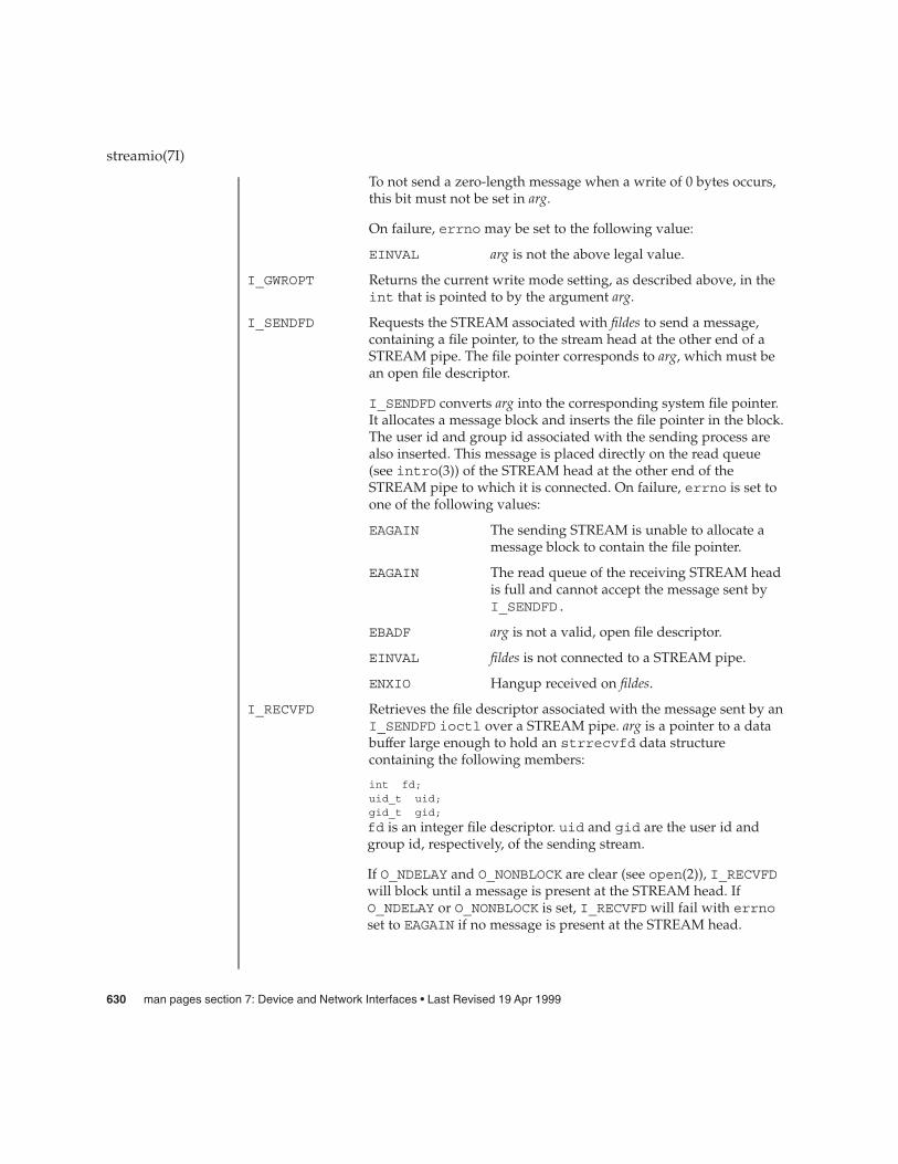
To not send a zero-length message when a write of 0 bytes occurs,this bit must not be set in arg.
On failure, errno may be set to the following value:
EINVAL arg is not the above legal value.
I_GWROPT Returns the current write mode setting, as described above, in theint that is pointed to by the argument arg.
I_SENDFD Requests the STREAM associated with fildes to send a message,containing a file pointer, to the stream head at the other end of aSTREAM pipe. The file pointer corresponds to arg, which must bean open file descriptor.
I_SENDFD converts arg into the corresponding system file pointer.It allocates a message block and inserts the file pointer in the block.The user id and group id associated with the sending process arealso inserted. This message is placed directly on the read queue(see intro(3)) of the STREAM head at the other end of theSTREAM pipe to which it is connected. On failure, errno is set toone of the following values:
EAGAIN The sending STREAM is unable to allocate amessage block to contain the file pointer.
EAGAIN The read queue of the receiving STREAM headis full and cannot accept the message sent byI_SENDFD.
EBADF arg is not a valid, open file descriptor.
EINVAL fildes is not connected to a STREAM pipe.
ENXIO Hangup received on fildes.
I_RECVFD Retrieves the file descriptor associated with the message sent by anI_SENDFD ioctl over a STREAM pipe. arg is a pointer to a databuffer large enough to hold an strrecvfd data structurecontaining the following members:
int fd;uid_t uid;gid_t gid;
fd is an integer file descriptor. uid and gid are the user id andgroup id, respectively, of the sending stream.
If O_NDELAY and O_NONBLOCK are clear (see open(2)), I_RECVFDwill block until a message is present at the STREAM head. IfO_NDELAY or O_NONBLOCK is set, I_RECVFD will fail with errnoset to EAGAIN if no message is present at the STREAM head.
streamio(7I)
630 man pages section 7: Device and Network Interfaces • Last Revised 19 Apr 1999
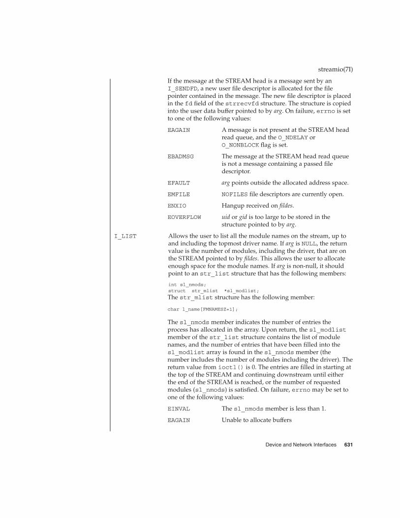
If the message at the STREAM head is a message sent by anI_SENDFD, a new user file descriptor is allocated for the filepointer contained in the message. The new file descriptor is placedin the fd field of the strrecvfd structure. The structure is copiedinto the user data buffer pointed to by arg. On failure, errno is setto one of the following values:
EAGAIN A message is not present at the STREAM headread queue, and the O_NDELAY orO_NONBLOCK flag is set.
EBADMSG The message at the STREAM head read queueis not a message containing a passed filedescriptor.
EFAULT arg points outside the allocated address space.
EMFILE NOFILES file descriptors are currently open.
ENXIO Hangup received on fildes.
EOVERFLOW uid or gid is too large to be stored in thestructure pointed to by arg.
I_LIST Allows the user to list all the module names on the stream, up toand including the topmost driver name. If arg is NULL, the returnvalue is the number of modules, including the driver, that are onthe STREAM pointed to by fildes. This allows the user to allocateenough space for the module names. If arg is non-null, it shouldpoint to an str_list structure that has the following members:
int sl_nmods;struct str_mlist *sl_modlist;
The str_mlist structure has the following member:
char l_name[FMNAMESZ+1];
The sl_nmods member indicates the number of entries theprocess has allocated in the array. Upon return, the sl_modlistmember of the str_list structure contains the list of modulenames, and the number of entries that have been filled into thesl_modlist array is found in the sl_nmods member (thenumber includes the number of modules including the driver). Thereturn value from ioctl() is 0. The entries are filled in starting atthe top of the STREAM and continuing downstream until eitherthe end of the STREAM is reached, or the number of requestedmodules (sl_nmods) is satisfied. On failure, errno may be set toone of the following values:
EINVAL The sl_nmods member is less than 1.
EAGAIN Unable to allocate buffers
streamio(7I)
Device and Network Interfaces 631

I_ATMARK Allows the user to see if the current message on the stream headread queue is ‘‘marked’’ by some module downstream. argdetermines how the checking is done when there may be multiplemarked messages on the STREAM head read queue. It may takethe following values:
ANYMARK Check if the message is marked.
LASTMARK Check if the message is the last one marked onthe queue.
The return value is 1 if the mark condition is satisfied and 0otherwise. On failure, errno is set to the following value:
EINVAL Invalid arg value.
I_CKBAND Check if the message of a given priority band exists on the streamhead read queue. This returns 1 if a message of a given priorityexists, 0 if not, or −1 on error. arg should be an integer containingthe value of the priority band in question. On failure, errno is setto the following value:
EINVAL Invalid arg value.
I_GETBAND Returns the priority band of the first message on the STREAMhead read queue in the integer referenced by arg. On failure,errno is set to the following value:
ENODATA No message on the STREAM head read queue.
I_CANPUT Check if a certain band is writable. arg is set to the priority band inquestion. The return value is 0 if the priority band arg is flowcontrolled, 1 if the band is writable, or −1 on error. On failure,errno is set to the following value:
EINVAL Invalid arg value.
I_SETCLTIME Allows the user to set the time the STREAM head will delay whena stream is closing and there are data on the write queues. Beforeclosing each module and driver, the STREAM head will delay forthe specified amount of time to allow the data to drain. Note,however, that the module or driver may itself delay in its closeroutine; this delay is independent of the STREAM head’s delayand is not settable. If, after the delay, data are still present, datawill be flushed. arg is the number of milliseconds to delay,rounded up to the nearest legal value on the system. The default isfifteen seconds. On failure, errno is set to the following value:
EINVAL Invalid arg value.
I_GETCLTIME Returns the close time delay in the integer pointed by arg.
I_SERROPT Sets the error mode using the value of the argument arg.
streamio(7I)
632 man pages section 7: Device and Network Interfaces • Last Revised 19 Apr 1999

Normally STREAM head errors are persistent; once they are setdue to an M_ERROR or M_HANGUP, the error condition will remainuntil the STREAM is closed. This option can be used to set theSTREAM head into non-persistent error mode i.e. once the errorhas been returned in response to a read(2), getmsg(2), ioctl(2),write(2), or putmsg(2) call the error condition will be cleared.The error mode can be controlled independently for read andwrite side errors. Legal arg values are either none or one of:
RERRNORM Persistent read errors, the default.
RERRNONPERSIST Non-persistent read errors.
OR’ed with either none or one of:
WERRNORM Persistent write errors, the default.
WERRNONPERSIST Non-persistent write errors.
When no value is specified e.g. forthe read side error behavior thenthe behavior for that side will beleft unchanged.
On failure, errno is set to the following value:
EINVAL arg is not one of the above legal values.
I_GERROPT Returns the current error mode setting in an int pointed to by theargument arg. Error modes are described above for I_SERROPT.On failure,errno is set to the following value:
EFAULT arg points outside the allocated address space.
The following four commands are used for connecting and disconnecting multiplexedSTREAMS configurations.
I_LINK Connects two streams, where fildes is the file descriptor of thestream connected to the multiplexing driver, and arg is the filedescriptor of the STREAM connected to another driver. TheSTREAM designated by arg gets connected below the multiplexingdriver. I_LINK requires the multiplexing driver to send anacknowledgement message to the STREAM head regarding thelinking operation. This call returns a multiplexor ID number (anidentifier used to disconnect the multiplexor, see I_UNLINK) onsuccess, and -1 on failure. On failure, errno is set to one of thefollowing values:
ENXIO Hangup received on fildes.
ETIME Time out before acknowledgement messagewas received at STREAM head.
streamio(7I)
Device and Network Interfaces 633

EAGAIN Temporarily unable to allocate storage toperform the I_LINK.
ENOSR Unable to allocate storage to perform theI_LINK due to insufficient STREAMS memoryresources.
EBADF arg is not a valid, open file descriptor.
EINVAL fildes STREAM does not support multiplexing.
EINVAL arg is not a stream, or is already linked under amultiplexor.
EINVAL The specified link operation would cause a‘‘cycle’’ in the resulting configuration; that is, adriver would be linked into the multiplexingconfiguration in more than one place.
EINVAL fildes is the file descriptor of a pipe or FIFO.
EINVAL Either the upper or lower stream has a majornumber >= the maximum major number onthe system.
An I_LINK can also fail while waiting for the multiplexing driverto acknowledge the link request, if a message indicating an erroror a hangup is received at the STREAM head of fildes. In addition,an error code can be returned in the positive or negativeacknowledgement message. For these cases, I_LINK will fail witherrno set to the value in the message.
I_UNLINK Disconnects the two streams specified by fildes and arg. fildes is thefile descriptor of the STREAM connected to the multiplexingdriver. arg is the multiplexor ID number that was returned by theI_LINK. If arg is -1, then all streams that were linked to fildes aredisconnected. As in I_LINK, this command requires themultiplexing driver to acknowledge the unlink. On failure, errnois set to one of the following values:
ENXIO Hangup received on fildes.
ETIME Time out before acknowledgement messagewas received at STREAM head.
ENOSR Unable to allocate storage to perform theI_UNLINK due to insufficient STREAMSmemory resources.
EINVAL arg is an invalid multiplexor ID number orfildes is not the STREAM on which the I_LINKthat returned arg was performed.
streamio(7I)
634 man pages section 7: Device and Network Interfaces • Last Revised 19 Apr 1999

EINVAL fildes is the file descriptor of a pipe or FIFO.
An I_UNLINK can also fail while waiting for the multiplexingdriver to acknowledge the link request, if a message indicating anerror or a hangup is received at the STREAM head of fildes. Inaddition, an error code can be returned in the positive or negativeacknowledgement message. For these cases, I_UNLINK will failwith errno set to the value in the message.
I_PLINK Connects two streams, where fildes is the file descriptor of thestream connected to the multiplexing driver, and arg is the filedescriptor of the STREAM connected to another driver. TheSTREAM designated by arg gets connected via a persistent linkbelow the multiplexing driver. I_PLINK requires the multiplexingdriver to send an acknowledgement message to the STREAM headregarding the linking operation. This call creates a persistent linkthat continues to exist even if the file descriptor fildes associatedwith the upper STREAM to the multiplexing driver is closed. Thiscall returns a multiplexor ID number (an identifier that may beused to disconnect the multiplexor, see I_PUNLINK) on success,and -1 on failure. On failure, errno is set to one of the followingvalues:
ENXIO Hangup received on fildes.
ETIME Time out before acknowledgement messagewas received at the STREAM head.
EAGAIN Unable to allocate STREAMS storage toperform the I_PLINK.
EBADF arg is not a valid, open file descriptor.
EINVAL fildes does not support multiplexing.
EINVAL arg is not a STREAM or is already linked undera multiplexor.
EINVAL The specified link operation would cause a‘‘cycle’’ in the resulting configuration; that is, ifa driver would be linked into the multiplexingconfiguration in more than one place.
EINVAL fildes is the file descriptor of a pipe or FIFO.
An I_PLINK can also fail while waiting for the multiplexingdriver to acknowledge the link request, if a message indicating anerror on a hangup is received at the STREAM head of fildes. Inaddition, an error code can be returned in the positive or negativeacknowledgement message. For these cases, I_PLINK will failwith errno set to the value in the message.
streamio(7I)
Device and Network Interfaces 635

I_PUNLINK Disconnects the two streams specified by fildes and arg that areconnected with a persistent link. fildes is the file descriptor of theSTREAM connected to the multiplexing driver. arg is themultiplexor ID number that was returned by I_PLINK when aSTREAM was linked below the multiplexing driver. If arg isMUXID_ALL then all streams that are persistent links to fildes aredisconnected. As in I_PLINK, this command requires themultiplexing driver to acknowledge the unlink. On failure, errnois set to one of the following values:
ENXIO Hangup received on fildes.
ETIME Time out before acknowledgement messagewas received at the STREAM head.
EAGAIN Unable to allocate buffers for theacknowledgement message.
EINVAL Invalid multiplexor ID number.
EINVAL fildes is the file descriptor of a pipe or FIFO.
An I_PUNLINK can also fail while waiting for the multiplexingdriver to acknowledge the link request if a message indicating anerror or a hangup is received at the STREAM head of fildes. Inaddition, an error code can be returned in the positive or negativeacknowledgement message. For these cases, I_PUNLINK will failwith errno set to the value in the message.
Unless specified otherwise above, the return value from ioctl() is 0 upon successand −1 upon failure, with errno set as indicated.
intro(3), close(2), fcntl(2), getmsg(2), ioctl(2), open(2), poll(2), putmsg(2),read(2), write(2), signal(3C), signal(3HEAD),
STREAMS Programming Guide
streamio(7I)
RETURN VALUES
SEE ALSO
636 man pages section 7: Device and Network Interfaces • Last Revised 19 Apr 1999

su – asynchronous serial port driver
#include <fcntl.h>#include <sys/termios.h>open("/dev/tty[a-z]", _mode);open("/dev/term[a-z]", _mode);open("/dev/cua[a-z]", _mode);
The su module is a loadable STREAMS driver that provides basic support forstandard UARTS that use Intel-8250, National Semiconductor-16450/16550 hardwareand Southbridge 1535D (16550 compatable) Super I/O hardware. The module alsoprovides keyboard and mouse I/O support for Sun machines using those same Intel,National Semiconductor and Southbridge chipsets. The su driver provides basicasynchronous communication support for serial ports. Both the serial devices andkeyboard/mouse devices will have streams built with appropriate modules pushedatop the su driver by means of either the autopush(1M) or dacf.conf(4) facilities,depending on the OS revision and architecture in use.
The su module supports those termio(7I) device control functions specified by flagsin the c_cflag word of the termios structure, and by the IGNBRK, IGNPAR,PARMRK, or INPCK flags in the c_iflag word of the termios structure. All othertermio(7I) functions must be performed by STREAMS modules pushed atop thedriver. When a device is opened, the ldterm(7M) and ttcompat(7M) STREAMSmodules are automatically pushed on top of the stream, providing the standardtermio(7I) interface.
The character-special devices /dev/ttya and /dev/ttyb are used to access the twostandard serial ports. The su module supports up to ten serial ports, including thestandard ports. The tty[a-z] devices have minor device numbers in the range 00-03,and may be assigned names of the form /dev/ttyd_n_, where _n_ denotes the line tobe accessed. These device names are typically used to provide a logical access pointfor a _dial-in_ line that is used with a modem.
To allow a single tty line to be connected to a modem and used for incoming andoutgoing calls, a special feature is available that is controlled by the minor devicenumber. By accessing character-special devices with names of the form /dev/cua_n,it is possible to open a port without the Carrier Detect signal being asserted,either through hardware or an equivalent software mechanism. These devices arecommonly known as _dial-out_ lines.
Once a /dev/cua_n_ line is opened, the corresponding tty, or ttyd line cannot beopened until the /dev/cua_n_ line is closed. A blocking open will wait until the/dev/cua_n_ line is closed (which will drop Data Terminal Ready, after whichCarrier Detect will usually drop as well) and carrier is detected again. Anon-blocking open will return an error. If the /dev/ttyd_n_ line has been openedsuccessfully (usually only when carrier is recognized on the modem), thecorresponding /dev/cua_n_ line cannot be opened. This allows a modem to be
su(7D)
NAME
SYNOPSIS
DESCRIPTION
APPLICATIONPROGRAMMING
INTERFACE
Device and Network Interfaces 637

attached to a device, (for example, /dev/ttyd0, which is renamed from/dev/tty00) and used for dial-in (by enabling the line for login in /etc/inittab)or dial-out (by tip(1) or uucp(1C)) as /dev/cua0 when no one is logged in on theline.
The standard set of termio ioctl() calls are supported by su.
Breaks can be generated by the TCSBRK, TIOCSBRK, and TIOCCBRK ioctl() calls.
The input and output line speeds may be set to any of the following baud rates: 0, 50,75, 110, 134, 150, 200, 300, 600, 1200, 1800, 2400, 4800, 9600, 19200, 38400, 57600 or115200. The speeds cannot be set independently; for example, when the output speedis set, the input speed is automatically set to the same speed.
When the su module is used to service the serial console port, it supports a BREAKcondition that allows the system to enter the debugger or the monitor. The BREAKcondition is generated by hardware and it is usually enabled by default.
A BREAK condition originating from erroneous electrical signals cannot bedistinguished from one deliberately sent by remote DCE. The Alternate Breaksequence can be used as a remedy against this. Due to a risk of incorrect sequenceinterpretation, binary protocols such as PPP, SLIP, and others should not be run overthe serial console port when Alternate Break sequence is in effect. By default, theAlternate Break sequence is a three character sequence: carriage return, tilde andcontrol-B (CR ~ CTRL-B), but may be changed by the driver. For more information onbreaking (entering the debugger or monitor), see kbd(1) and kb(7M).
An open() will fail under the following conditions:
ENXIO The unit being opened does not exist.
EBUSY The dial-out device is being opened while the dial-in device isalready open, or the dial-in device is being opened with a no-delayopen and the dial-out device is already open.
EBUSY The unit has been marked as exclusive-use by another processwith a TIOCEXCL ioctl() call.
/dev/cua/[a-z] dial-out tty lines
/dev/term/[a-z] dial-in tty lines
/dev/tty[a-z] binary compatibility package device names
See attributes(5) for descriptions of the following attributes:
ATTRIBUTE TYPE ATTRIBUTE VALUE
Architecture SPARC
su(7D)
IOCTLS
ERRORS
FILES
ATTRIBUTES
638 man pages section 7: Device and Network Interfaces • Last Revised 14 Jan 2001

strconf(1), kbd(1), tip(1),uucp(1C), autopush(1M), ioctl(2), open(2),termios(3C), dacf.conf(4), attributes(5), kb(7M), ldterm(7M),ttcompat(7M), termio(7I)
su(7D)
SEE ALSO
Device and Network Interfaces 639

sxp – Rockwell 2200 SNAP Streams Driver
/dev/sxp
The sxp (also known as the SNAP ) driver is a loadable, clonable, STREAMS driverthat supports the connectionless Data Link Provider Interface ( dlpi(7P)) over one ormore FDDI adapters (Rockwell 2200 Series). The cloning character-special devices(/dev/sxp, /dev/snap, /dev/llc, /dev/mac) are used to access the 2200 Seriesadapter(s). The /dev/sxp device is equivalent to /dev/snap. /dev/sxp is used sothat the name SXP will show up in ifconfig. All messages transmitted on a SNAPdevice have the 802.2 LLC and Sub-Network Access Protocol (SNAP) and the FDDIMAC headers ( RFC -1188) prepended. For an LLC device, the LLC and MAC headersare prepended, and for a MAC device only the MAC header is prepended. ReceivedFDDI frames are delivered to the appropriate open device. In response to aDL_INFO_REQ, the SNAP driver returns the following values in the DL_INFO_ACKprimitive:
� The maximum SDU is 4500.
� The minimum SDU is 0.
� The DLSAP address length is 8 (always true in the Solaris environment).
� The address offset is 0 (prior to being attached).
� The MAC type is DL_FDDI.
� The sap length value is −2, which indicates that within the DLSAP address, thephysical address component is followed immediately by a 2-byte service accesspoint ( SAP ) component.
� The service mode is DL_CLDLS.
� The quality of service (QOS) fields are 0, because optional QOS is not supported.
� The provider style is DL_STYLE2.
� The broadcast address value is the IEEE broadcast address (FF:FF:FF:FF:FF:FF).
Because the SNAP driver is a "style 2" Data Link Service provider, an explicitDL_ATTACH_REQ message from the user is required to associate the opened streamwith a particular network device (that is, ppa). The dl_ppa field within theDL_ATTACH_REQ indicates the instance (unit) number of the network device. If nocurrently attached ppa has the same instance number and there are no unattached ppasavailable, the driver returns an error (DL_ERROR_ACK). Once in the DL_ATTACHEDstate, a DL_BIND_REQ is required to associate a particular SAP with the stream.
Once in the DL_ATTACHED state, a DL_BIND_REQ is required to associate a particularService Access Point ( SAP ) with the stream. For the sap field within theDL_BIND_REQ, valid values are in the range [0-0xFFFF]. Values for 0-0xFF will giveLLC 802.2 service without SNAP encapsulation, unless a laterDL_HIERARCHIAL_BIND DL_SUBS_BIND_REQ is made. Values from 0x100-0xFFFFwill give LLC 802.2 with SNAP encapsulation without the need for aDL_SUBS_BIND_REQ. Note that DL_HIERARCHIAL_BIND class
sxp(7D)
NAME
SYNOPSIS
DESCRIPTION
640 man pages section 7: Device and Network Interfaces • Last Revised 1 Jan 1997

DL_SUBS_BIND_REQs are only supported on streams bound to the 0xAA SAP. Aftersuccessful completion of the DL_BIND_REQ, the ppa is initialized and the stream isready for use. In addition to the DL_HIERARCHIAL_BIND class ofDL_SUBS_BUD_REQ, the DL_PEER_BIND class can be used to bind multiple SAP swith a stream.
Frames may be transmitted on the FDDI ring by sending DL_UNITDATA_REQmessages to the SNAP driver. The DLSAP address contained within theDL_UNITDATA_REQ must consist of both the SAP and physical (FDDI) components.For a SNAP device, the SAP portion of the DLSAP address is placed in the EtherTypefield of the 802.2 SNAP header. The DSAP and SSAP fields of the 802.2 LLC header areboth set to the value 170, indicating a SNAP message and a MAC frame_type ofLLC. For an LLC device, the SAP portion of the DLSAP address is placed in the DSAPfield of the 802.2 LLC header. The SSAP field is set to the SAP bound to the stream.The MAC frame_type is LLC. For a MAC device, the SAP portion of the DLSAPaddress is placed in the frame_control field of the MAC header. Received FDDIframes are routed up the correct stream(s) as DL_UNITDATA_IND messages(containing the DLSAP address). The stream(s) are found by:
1. Comparing the EtherType field of the SNAP header with the bound SAP of all ofthe SNAP streams
2. Comparing the DSAP field of the LLC header with the bound SAP of all the LLCstreams
3. Comparing the frame_control field of the MAC header with the bound SAP ofall the MAC streams.
If necessary, messages are duplicated. In addition to the mandatory connectionlessDLPI message set, the driver also supports the following primitives:DL_ENABMULTI_REQ, DL_DISABMULTI_REQ, DL_PROMISCON_REQ,DL_PROMISCOFF_REQ, DL_PHYS_ADDR_REQ.
The DL_ENABMULTI_REQ and DL_DISABMULTI_REQ primitives enable or disablereception of individual multicast group addresses. Using these primitives, a set ofmulticast group addresses may be iteratively created and modified on a per-streambasis. These primitives are accepted by the driver in any state following a successfulDL_ATTACH_REQ. The DL_PROMISCON_REQ and DL_PROMISCOFF_REQ primitives(with the DL_PROMISC_PHYS flag set in the dl_levelfield) enable or disablereception of all (promiscuous mode) frames on the media, including frames generatedby the local host. When used with the DL_PROMISC_SAP flag (set), this enables ordisables reception of all sap values. When used with the DL_PROMISC_MULTI flag(set), this enables or disables reception of all multicast group addresses. The affect ofeach primitive is always on a per-stream basis, and is independent of the other sapand physical level configurations on this stream (or other streams). In theDL_PHYS_ADDR_ACK message, the DL_PHYS_ADDR_REQ primitive returns the 6-octetFDDI address (in canonical form) currently associated with the stream. This primitiveis valid only in states following a successful DL_ATTACH_REQ. The driver alsosupports the following ioctls (I/O controls): DLIOCRAW, SL_RAW,SL_DATA_ENABLE, SL_DATA_DISABLE, and DRV_CONFIG. As defined by Solaris,
sxp(7D)
Device and Network Interfaces 641

the DLIOCRAW ioctl puts the stream into raw mode, which causes the driver to sendthe full MAC -level packet up the stream in an M_DATA message, instead oftransforming it to the DL_UNITDATA_IND form. On this stream, the driver will alsoaccept formatted M_DATA messages for transmission. To disable raw mode, the streammust be closed. The DLIOCRAW ioctl requires no arguments. As defined by Rockwell,the SL_RAW ioctl puts the stream into raw mode, similar to the DLIOCRAW ioctl exceptthat the frame-type field of the MAC header is considered to be a long word instead ofa byte, preserving alignment. The SL_RAW ioctl requires no arguments. As defined byRockwell, the SL_DATA_ENABLE and SL_DATA_DISABLE ioctls enable or disable thetransmission of data on the stream. By default, transmission is enabled. TheSL_DATA_ENABLE and SL_DATA_DISABLE ioctls require no arguments.
/dev/sxp SXP special character device
kernel/drv/sys_core SXP loadable module
kernel/drv/sxp.conf SXP configuration file
See attributes(5) for descriptions of the following attributes:
ATTRIBUTE TYPE ATTRIBUTE VALUE
Architecture IA
attributes(5), dlpi(7P), rns_smt(7D)
sxp(7D)
FILES
ATTRIBUTES
SEE ALSO
642 man pages section 7: Device and Network Interfaces • Last Revised 1 Jan 1997

symhisl – symhisl SCSI Host Bus Adapter Driver
scsi@unit-address
The symhisl host bus adapter driver is a SCSA-compliant nexus driver that supportsthe LSI Logic SYM21002 (SYM53C896), SYM22910 (SYM53C896), SYM53C895A,SYM53C896, SYM53C1010-33, and SYM53C1010-66 SCSI controller chips.
The symhisl driver supports the standard functions provided by the SCSA interface,including tagged and untagged queuing, Wide, Fast, Ultra, Ultra2, and Ultra3 SCSI,and auto request sense. The symhisl driver does not support linked commands.
You configure the symhisl driver by defining properties in the symhisl.conf file.Properties in the symhisl.conf file override the global SCSI settings. The driversupports the following user-modifiable properties:
scsi-optionstarget<n>-scsi-optionsscsi-reset-delayscsi-watchdog-tickscsi-initiator-idsymFlags
target<n>-scsi-options overrides the scsi-options property value fortarget<n>. <n> can vary from hex 0 to f. symhisl supports the followingscsi-options: SCSI_OPTIONS_DR, SCSI_OPTIONS_SYNC, SCSI_OPTIONS_FAST,SCSI_OPTIONS_ULTRA, SCSI_OPTIONS_ULTRA2, SCSI_OPTIONS_TAG, andSCSI_OPTIONS_WIDE.
SCSI_OPTIONS_PARITY is supported for the scsi-options setting only anddisables host adapter parity checking.
After periodic interval scsi-watchdog-tick (seconds), the symhisl driversearches through all current and disconnected commands for timeouts.
symFlags is a driver-specific bit-mask you can use to enable or disable driverproperties.
bit 0 When set, the driver will not reset the SCSI bus at initialization.Certain CD-ROM, tape, and other devices will not work properlywhen this bit is set. The default state for this bit is cleared.
bit 1 When set, the driver will not export the DMI ioctl interface. Setthis bit only if you want to disable the ioctl interface for securityreasons. The default state for this bit is cleared.
bit 2 When set, the driver disables 64-bit addressing capability. Whenclear, the driver enables 64-bit addressing capability. The defaultstate for this bit is cleared.
symhisl(7D)
NAME
SYNOPSIS
DESCRIPTION
CONFIGURATION
Device and Network Interfaces 643

bit 3 When set, the driver disables SCSI domain validation for alldevices on any adapters controlled by the driver.
Refer to scsi_hba_attach(9F) for more information on driver configuration.
Edit the file /kernel/drv/symhisl.conf and add the following line:
scsi-options=0x78;
This disables tagged queuing, Fast, Ultra, and Ultra2 SCSI and wide mode for allsymhisl instances.
The following example disables an option for one specific symhisl instance (refer todriver.conf(4) and pci(4) for more details):
name="symhisl" parent="/pci@1f,4000"unit-address="3"target1-scsi-options=0x58scsi-options=0x178 scsi-initiator-id=6;
Note that the initiator ID can only be changed for symhisl adapters that do not usethe LSI Logic Boot ROM Configuration Utility. For adapters that can use the LSI LogicBoot ROM Configuration Utility, scsi-initiator-id has no effect.
The example above sets scsi-options for target 1 to 0x58 and all other targets onthis SCSI bus to 0x178.
The physical path name of the parent can be determined using the /devices tree orfollowing the link of the logical device name:
# ls –l /dev/rdsk/c0t0d0s0lrwxrwxrwx 1 root root 45 May 16 10:08 /dev/rdsk/c0t0d0s0 ->
. . / . . /devices/pci@1f,4000/scsi@3/sd@0,0:a,raw
In this case, the parent is /pci@1f,4000 and the unit-address is the number bound tothe scsi@3 node.
scsi-options specified per target ID have the highest precedence, followed byscsi-options per device type. Global scsi-options (for all symhisl instances)per bus have the lowest precedence.
The system must be rebooted for the specified scsi-options to take effect.
The target driver sets capabilities in the symhisl driver to enable some driverfeatures. The target driver can query and modify the following capabilities:disconnect, synchronous, wide-xfer, tagged-qing, and auto-rqsense. Allother capabilities are query only.
By default, tagged-qing capabilities are disabled, while disconnect,synchronous, wide-xfer, auto-rqsense, and untagged-qing are enabled.These capabilities can only have binary values (0 or 1).
symhisl(7D)
EXAMPLES
Driver Capabilities
644 man pages section 7: Device and Network Interfaces • Last Revised 13 Sep 2001

The target driver must enable tagged-qing explicitly. The untagged-qingcapability is always enabled and its value cannot be modified.
If a conflict exists between the value of scsi-options and a capability, the value setin scsi-options prevails. Only whom != 0 is supported in thescsi_ifsetcap(9F) call. Refer to scsi_ifsetcap(9F) and scsi_ifgetcap(9F) fordetails.
/kernel/drv/symhisl ELF kernel module
/kernel/drv/symhisl.confConfiguration file
See attributes(5) for descriptions of the following attributes:
ATTRIBUTE TYPE ATTRIBUTE VALUE
Architecture Limited to PCI-based systems with LSI LogicSYM21002, SYM22910, SYM53C895A,SYM53C896, SYM53C1010-33, andSYM53C1010-66 SCSI I/O processors.
prtconf(1M), driver.conf(4), pci(4), attributes(5), scsi_abort(9F),scsi_hba_attach(9F), scsi_ifgetcap(9F), scsi_ifsetcap(9F),scsi_reset(9F), scsi_sync_pkt(9F), scsi_transport(9F), scsi_device(9S),scsi_extended_sense(9S), scsi_inquiry(9S), scsi_pkt(9S)
Writing Device Drivers
ANSI Small Computer System Interface-2 (SCSI-2),
LSI Logic Corporation, SYM53C896 PCI-SCSI I/O Processor
LSI Logic Corporation, SYM53C895A PCI-SCSI I/O Processor
LSI Logic Corporation, SYM53C1010 PCI-SCSI I/O Processor
The symhisl SYM53C895A and SYM53C896 (SYM21002 and SYM22910) hardwareand software support Wide, Fast, SCSI Ultra, and Ultra2 synchronous speeds.SYM53C1010-33 and SYM53C1010-66 also support Ultra3 synchronous speeds. Themaximum SCSI bandwidth for Ultra2 transfers is 80 Mbytes/sec and 160 Mbytes/secfor Ultra3.
symhisl(7D)
FILES
ATTRIBUTES
SEE ALSO
NOTES
Device and Network Interfaces 645

sysmsg – system message routing to console devices
/dev/sysmsg
The file /dev/sysmsg routes output to a variable set of console devices. Writes to/dev/sysmsg are always directed to the system console /dev/console, and are inaddition directed to a set of auxiliary console devices managed by consadm(1M).
Only root has permission to write to this device.
See attributes(5) for descriptions of the following attributes:
ATTRIBUTE TYPE ATTRIBUTE VALUE
Availability SUNWcsr
Interface Stability Stable
consadm(1M), syslogd(1M) , attributes(5), console(7D)
sysmsg(7D)
NAME
SYNOPSIS
DESCRIPTION
ATTRIBUTES
SEE ALSO
646 man pages section 7: Device and Network Interfaces • Last Revised 13 Oct 1998

tcp, TCP – Internet Transmission Control Protocol
#include <sys/socket.h>
#include <netinet/in.h>
s = socket(AF_INET, SOCK_STREAM, 0);
s = socket(AF_INET6, SOCK_STREAM, 0);
t = t_open("/dev/tcp", O_RDWR);
t = t_open("/dev/tcp6", O_RDWR);
TCP is the virtual circuit protocol of the Internet protocol family. It provides reliable,flow-controlled, in order, two-way transmission of data. It is a byte-stream protocollayered above the Internet Protocol (IP), or the Internet Protocol Version 6 (IPv6), theInternet protocol family’s internetwork datagram delivery protocol.
Programs can access TCP using the socket interface as a SOCK_STREAM socket type, orusing the Transport Level Interface (TLI) where it supports the connection-oriented(T_COTS_ORD) service type.
TCP uses IP’s host-level addressing and adds its own per-host collection of “portaddresses.” The endpoints of a TCP connection are identified by the combination of anIP or IPv6 address and a TCP port number. Although other protocols, such as the UserDatagram Protocol (UDP), may use the same host and port address format, the portspace of these protocols is distinct. See inet(7P) and inet6(7p) for details on thecommon aspects of addressing in the Internet protocol family.
Sockets utilizing TCP are either “active” or “passive.” Active sockets initiateconnections to passive sockets. Both types of sockets must have their local IP or IPv6address and TCP port number bound with the bind(3SOCKET) system call after thesocket is created. By default, TCP sockets are active. A passive socket is created bycalling the listen(3SOCKET) system call after binding the socket with bind(). Thisestablishes a queueing parameter for the passive socket. After this, connections to thepassive socket can be received with the accept(3SOCKET) system call. Active socketsuse the connect(3SOCKET) call after binding to initiate connections.
By using the special value INADDR_ANY with IP, or the unspecified address (all zeroes)with IPv6, the local IP address can be left unspecified in the bind() call by eitheractive or passive TCP sockets. This feature is usually used if the local address is eitherunknown or irrelevant. If left unspecified, the local IP or IPv6 address will be bound atconnection time to the address of the network interface used to service the connection.
Once a connection has been established, data can be exchanged using the read(2) andwrite(2) system calls.
Under most circumstances, TCP sends data when it is presented. When outstandingdata has not yet been acknowledged, TCP gathers small amounts of output to be sentin a single packet once an acknowledgement has been received. For a small number ofclients, such as window systems that send a stream of mouse events which receive no
TCP(7P)
NAME
SYNOPSIS
DESCRIPTION
Device and Network Interfaces 647

replies, this packetization may cause significant delays. To circumvent this problem,TCP provides a socket-level boolean option, TCP_NODELAY. TCP_NODELAY is definedin <netinet/tcp.h>, and is set with setsockopt(3SOCKET) and tested withgetsockopt(3SOCKET). The option level for the setsockopt() call is the protocolnumber for TCP, available from getprotobyname(3SOCKET).
Another socket level option, SO_RCVBUF, can be used to control the window thatTCP advertises to the peer. IP level options may also be used with TCP. See ip(7P) andip6(7p).
TCP provides an urgent data mechanism, which may be invoked using theout-of-band provisions of send(3SOCKET). The caller may mark one byte as “urgent”with the MSG_OOB flag to send(3SOCKET). This sets an “urgent pointer” pointing tothis byte in the TCP stream. The receiver on the other side of the stream is notified ofthe urgent data by a SIGURG signal. The SIOCATMARK ioctl(2) request returns avalue indicating whether the stream is at the urgent mark. Because the system neverreturns data across the urgent mark in a single read(2) call, it is possible to advance tothe urgent data in a simple loop which reads data, testing the socket with theSIOCATMARK ioctl() request, until it reaches the mark.
Incoming connection requests that include an IP source route option are noted, andthe reverse source route is used in responding.
A checksum over all data helps TCP implement reliability. Using a window-basedflow control mechanism that makes use of positive acknowledgements, sequencenumbers, and a retransmission strategy, TCP can usually recover when datagrams aredamaged, delayed, duplicated or delivered out of order by the underlyingcommunication medium.
If the local TCP receives no acknowledgements from its peer for a period of time, aswould be the case if the remote machine crashed, the connection is closed and an erroris returned to the user. If the remote machine reboots or otherwise loses stateinformation about a TCP connection, the connection is aborted and an error isreturned to the user.
SunOS supports TCP Extensions for High Performance (RFC 1323) which includes thewindow scale and time stamp options, and Protection Against Wrap Around SequenceNumbers (PAWS). SunOS also supports Selective Acknowledgment (SACK)capabilities (RFC 2018) and Explicit Congestion Notification (ECN) mechanism (RFC3168).
Turn on the window scale option in one of the following ways:
� An application can set SO_SNDBUF or SO_RCVBUF size in the setsockopt()option to be larger than 64K. This must be done before the program calls listen()or connect(), because the window scale option is negotiated when theconnection is established. Once the connection has been made, it is too late toincrease the send or receive window beyond the default TCP limit of 64K.
TCP(7P)
648 man pages section 7: Device and Network Interfaces • Last Revised 24 Sep 2001

� For all applications, use ndd(1M) to modify the configuration parametertcp_wscale_always. If tcp_wscale_always is set to 1, the window scaleoption will always be set when connecting to a remote system. Iftcp_wscale_always is 0, the window scale option will be set only if the userhas requested a send or receive window larger than 64K. The default value oftcp_wscale_always is 0.
� Regardless of the value of tcp_wscale_always, the window scale option willalways be included in a connect acknowledgement if the connecting system hasused the option.
Turn on SACK capabilities in the following way:
� Use ndd to modify the configuration parameter tcp_sack_permitted. Iftcp_sack_permitted is set to 0, TCP will not accept SACK or send out SACKinformation. If tcp_sack_permitted is set to 1, TCP will not initiate aconnection with SACK permitted option in the SYN segment, but will respond withSACK permitted option in the SYN|ACK segment if an incoming connection requesthas the SACK permitted option. This means that TCP will only accept SACKinformation if the other side of the connection also accepts SACK information. Iftcp_sack_permitted is set to 2, it will both initiate and accept connections withSACK information. The default for tcp_sack_permitted is 2 (active enabled).
Turn on TCP ECN mechanism in the following way:
� Use ndd to modify the configuration parameter tcp_ecn_permitted. Iftcp_ecn_permitted is set to 0, TCP will not negotiate with a peer that supportsECN mechanism. If tcp_ecn_permitted is set to 1 when initiating a connection,TCP will not tell a peer that it supports ECN mechanism. However, it will tell apeer that it supports ECN mechanism when accepting a new incoming connectionrequest if the peer indicates that it supports ECN mechanism in the SYN segment.If tcp_ecn_permitted is set to 2, in addition to negotiating with a peer on ECNmechanism when accepting connections, TCP will indicate in the outgoing SYNsegment that it supports ECN mechanism when TCP makes active outgoingconnections. The default for tcp_ecn_permitted is 1.
Turn on the time stamp option in the following way:
� Use ndd to modify the configuration parameter tcp_tstamp_always. Iftcp_tstamp_always is 1, the time stamp option will always be set whenconnecting to a remote machine. If tcp_tstamp_always is 0, the timestampoption will not be set when connecting to a remote system. The default fortcp_tstamp_always is 0.
� Regardless of the value of tcp_tstamp_always, the time stamp option willalways be included in a connect acknowledgement (and all succeeding packets) ifthe connecting system has used the time stamp option.
Use the following procedure to turn on the time stamp option only when the windowscale option is in effect:
TCP(7P)
Device and Network Interfaces 649

� Use ndd to modify the configuration parameter tcp_tstamp_if_wscale. Settingtcp_tstamp_if_wscale to 1 will cause the time stamp option to be set whenconnecting to a remote system, if the window scale option has been set. Iftcp_tstamp_if_wscale is 0, the time stamp option will not be set whenconnecting to a remote system. The default for tcp_tstamp_if_wscale is 1.
Protection Against Wrap Around Sequence Numbers (PAWS) is always used when thetime stamp option is set.
SunOS also supports multiple methods of generating initial sequence numbers. One ofthese methods is the improved technique suggested in RFC 1948. We HIGHLYrecommend that you set sequence number generation parameters to be as close to boottime as possible. This prevents sequence number problems on connections that use thesame connection-ID as ones that used a different sequence number generation. The/etc/init.d/inetinit script contains commands which configure initial sequencenumber generation. The script reads the value contained in the configuration file/etc/default/inetinit to determine which method to use.
The /etc/default/inetinit file is an unstable interface, and may change infuture releases.
TCP may be configured to report some information on connections that terminate bymeans of an RST packet. By default, no logging is done. If the ndd(1M) parametertcp_trace is set to 1, then trace data is collected for all new connections established afterthat time.
The trace data consists of the TCP headers and IP source and destination addresses ofthe last few packets sent in each direction before RST occurred. Those packets arelogged in a series of strlog(9F) calls. This trace facility has a very low overhead, andso is superior to such utilities as snoop(1M) for non-intrusive debugging forconnections terminating by means of an RST.
ndd(1M), ioctl(2), read(2), write(2), accept(3SOCKET), bind(3SOCKET),connect(3SOCKET), getprotobyname(3SOCKET), getsockopt(3SOCKET),listen(3SOCKET), send(3SOCKET), inet(7P), inet6(7P), ip(7P), ip6(7P)
Ramakrishnan, K., Floyd, S., Black, D., RFC 3168, The Addition of Explicit CongestionNotification (ECN) to IP, September 2001.
Mathias, M. and Hahdavi, J. Pittsburgh Supercomputing Center; Ford, S. LawrenceBerkeley National Laboratory; Romanow, A. Sun Microsystems, Inc. RFC 2018, TCPSelective Acknowledgement Options, October 1996.
Bellovin, S., RFC 1948, Defending Against Sequence Number Attacks, May 1996.
Jacobson, V., Braden, R., and Borman, D., RFC 1323, TCP Extensions for HighPerformance, May 1992.
TCP(7P)
SEE ALSO
650 man pages section 7: Device and Network Interfaces • Last Revised 24 Sep 2001

Postel, Jon, RFC 793, Transmission Control Protocol - DARPA Internet Program ProtocolSpecification, Network Information Center, SRI International, Menlo Park, CA.,September 1981.
A socket operation may fail if:
EISCONN A connect() operation was attempted on a socket onwhich a connect() operation had already beenperformed.
ETIMEDOUT A connection was dropped due to excessiveretransmissions.
ECONNRESET The remote peer forced the connection to be closed(usually because the remote machine has lost stateinformation about the connection due to a crash).
ECONNREFUSED The remote peer actively refused connectionestablishment (usually because no process is listeningto the port).
EADDRINUSE A bind() operation was attempted on a socket with anetwork address/port pair that has already beenbound to another socket.
EADDRNOTAVAIL A bind() operation was attempted on a socket with anetwork address for which no network interface exists.
EACCES A bind() operation was attempted with a “reserved”port number and the effective user ID of the processwas not the privileged user.
ENOBUFS The system ran out of memory for internal datastructures.
TCP(7P)
DIAGNOSTICS
Device and Network Interfaces 651

tcp, TCP – Internet Transmission Control Protocol
#include <sys/socket.h>
#include <netinet/in.h>
s = socket(AF_INET, SOCK_STREAM, 0);
s = socket(AF_INET6, SOCK_STREAM, 0);
t = t_open("/dev/tcp", O_RDWR);
t = t_open("/dev/tcp6", O_RDWR);
TCP is the virtual circuit protocol of the Internet protocol family. It provides reliable,flow-controlled, in order, two-way transmission of data. It is a byte-stream protocollayered above the Internet Protocol (IP), or the Internet Protocol Version 6 (IPv6), theInternet protocol family’s internetwork datagram delivery protocol.
Programs can access TCP using the socket interface as a SOCK_STREAM socket type, orusing the Transport Level Interface (TLI) where it supports the connection-oriented(T_COTS_ORD) service type.
TCP uses IP’s host-level addressing and adds its own per-host collection of “portaddresses.” The endpoints of a TCP connection are identified by the combination of anIP or IPv6 address and a TCP port number. Although other protocols, such as the UserDatagram Protocol (UDP), may use the same host and port address format, the portspace of these protocols is distinct. See inet(7P) and inet6(7p) for details on thecommon aspects of addressing in the Internet protocol family.
Sockets utilizing TCP are either “active” or “passive.” Active sockets initiateconnections to passive sockets. Both types of sockets must have their local IP or IPv6address and TCP port number bound with the bind(3SOCKET) system call after thesocket is created. By default, TCP sockets are active. A passive socket is created bycalling the listen(3SOCKET) system call after binding the socket with bind(). Thisestablishes a queueing parameter for the passive socket. After this, connections to thepassive socket can be received with the accept(3SOCKET) system call. Active socketsuse the connect(3SOCKET) call after binding to initiate connections.
By using the special value INADDR_ANY with IP, or the unspecified address (all zeroes)with IPv6, the local IP address can be left unspecified in the bind() call by eitheractive or passive TCP sockets. This feature is usually used if the local address is eitherunknown or irrelevant. If left unspecified, the local IP or IPv6 address will be bound atconnection time to the address of the network interface used to service the connection.
Once a connection has been established, data can be exchanged using the read(2) andwrite(2) system calls.
Under most circumstances, TCP sends data when it is presented. When outstandingdata has not yet been acknowledged, TCP gathers small amounts of output to be sentin a single packet once an acknowledgement has been received. For a small number of
tcp(7P)
NAME
SYNOPSIS
DESCRIPTION
652 man pages section 7: Device and Network Interfaces • Last Revised 24 Sep 2001
clients, such as window systems that send a stream of mouse events which receive noreplies, this packetization may cause significant delays. To circumvent this problem,TCP provides a socket-level boolean option, TCP_NODELAY. TCP_NODELAY is definedin <netinet/tcp.h>, and is set with setsockopt(3SOCKET) and tested withgetsockopt(3SOCKET). The option level for the setsockopt() call is the protocolnumber for TCP, available from getprotobyname(3SOCKET).
Another socket level option, SO_RCVBUF, can be used to control the window thatTCP advertises to the peer. IP level options may also be used with TCP. See ip(7P) andip6(7p).
TCP provides an urgent data mechanism, which may be invoked using theout-of-band provisions of send(3SOCKET). The caller may mark one byte as “urgent”with the MSG_OOB flag to send(3SOCKET). This sets an “urgent pointer” pointing tothis byte in the TCP stream. The receiver on the other side of the stream is notified ofthe urgent data by a SIGURG signal. The SIOCATMARK ioctl(2) request returns avalue indicating whether the stream is at the urgent mark. Because the system neverreturns data across the urgent mark in a single read(2) call, it is possible to advance tothe urgent data in a simple loop which reads data, testing the socket with theSIOCATMARK ioctl() request, until it reaches the mark.
Incoming connection requests that include an IP source route option are noted, andthe reverse source route is used in responding.
A checksum over all data helps TCP implement reliability. Using a window-basedflow control mechanism that makes use of positive acknowledgements, sequencenumbers, and a retransmission strategy, TCP can usually recover when datagrams aredamaged, delayed, duplicated or delivered out of order by the underlyingcommunication medium.
If the local TCP receives no acknowledgements from its peer for a period of time, aswould be the case if the remote machine crashed, the connection is closed and an erroris returned to the user. If the remote machine reboots or otherwise loses stateinformation about a TCP connection, the connection is aborted and an error isreturned to the user.
SunOS supports TCP Extensions for High Performance (RFC 1323) which includes thewindow scale and time stamp options, and Protection Against Wrap Around SequenceNumbers (PAWS). SunOS also supports Selective Acknowledgment (SACK)capabilities (RFC 2018) and Explicit Congestion Notification (ECN) mechanism (RFC3168).
Turn on the window scale option in one of the following ways:
� An application can set SO_SNDBUF or SO_RCVBUF size in the setsockopt()option to be larger than 64K. This must be done before the program calls listen()or connect(), because the window scale option is negotiated when theconnection is established. Once the connection has been made, it is too late toincrease the send or receive window beyond the default TCP limit of 64K.
tcp(7P)
Device and Network Interfaces 653
� For all applications, use ndd(1M) to modify the configuration parametertcp_wscale_always. If tcp_wscale_always is set to 1, the window scaleoption will always be set when connecting to a remote system. Iftcp_wscale_always is 0, the window scale option will be set only if the userhas requested a send or receive window larger than 64K. The default value oftcp_wscale_always is 0.
� Regardless of the value of tcp_wscale_always, the window scale option willalways be included in a connect acknowledgement if the connecting system hasused the option.
Turn on SACK capabilities in the following way:
� Use ndd to modify the configuration parameter tcp_sack_permitted. Iftcp_sack_permitted is set to 0, TCP will not accept SACK or send out SACKinformation. If tcp_sack_permitted is set to 1, TCP will not initiate aconnection with SACK permitted option in the SYN segment, but will respond withSACK permitted option in the SYN|ACK segment if an incoming connection requesthas the SACK permitted option. This means that TCP will only accept SACKinformation if the other side of the connection also accepts SACK information. Iftcp_sack_permitted is set to 2, it will both initiate and accept connections withSACK information. The default for tcp_sack_permitted is 2 (active enabled).
Turn on TCP ECN mechanism in the following way:
� Use ndd to modify the configuration parameter tcp_ecn_permitted. Iftcp_ecn_permitted is set to 0, TCP will not negotiate with a peer that supportsECN mechanism. If tcp_ecn_permitted is set to 1 when initiating a connection,TCP will not tell a peer that it supports ECN mechanism. However, it will tell apeer that it supports ECN mechanism when accepting a new incoming connectionrequest if the peer indicates that it supports ECN mechanism in the SYN segment.If tcp_ecn_permitted is set to 2, in addition to negotiating with a peer on ECNmechanism when accepting connections, TCP will indicate in the outgoing SYNsegment that it supports ECN mechanism when TCP makes active outgoingconnections. The default for tcp_ecn_permitted is 1.
Turn on the time stamp option in the following way:
� Use ndd to modify the configuration parameter tcp_tstamp_always. Iftcp_tstamp_always is 1, the time stamp option will always be set whenconnecting to a remote machine. If tcp_tstamp_always is 0, the timestampoption will not be set when connecting to a remote system. The default fortcp_tstamp_always is 0.
� Regardless of the value of tcp_tstamp_always, the time stamp option willalways be included in a connect acknowledgement (and all succeeding packets) ifthe connecting system has used the time stamp option.
Use the following procedure to turn on the time stamp option only when the windowscale option is in effect:
tcp(7P)
654 man pages section 7: Device and Network Interfaces • Last Revised 24 Sep 2001

� Use ndd to modify the configuration parameter tcp_tstamp_if_wscale. Settingtcp_tstamp_if_wscale to 1 will cause the time stamp option to be set whenconnecting to a remote system, if the window scale option has been set. Iftcp_tstamp_if_wscale is 0, the time stamp option will not be set whenconnecting to a remote system. The default for tcp_tstamp_if_wscale is 1.
Protection Against Wrap Around Sequence Numbers (PAWS) is always used when thetime stamp option is set.
SunOS also supports multiple methods of generating initial sequence numbers. One ofthese methods is the improved technique suggested in RFC 1948. We HIGHLYrecommend that you set sequence number generation parameters to be as close to boottime as possible. This prevents sequence number problems on connections that use thesame connection-ID as ones that used a different sequence number generation. The/etc/init.d/inetinit script contains commands which configure initial sequencenumber generation. The script reads the value contained in the configuration file/etc/default/inetinit to determine which method to use.
The /etc/default/inetinit file is an unstable interface, and may change infuture releases.
TCP may be configured to report some information on connections that terminate bymeans of an RST packet. By default, no logging is done. If the ndd(1M) parametertcp_trace is set to 1, then trace data is collected for all new connections established afterthat time.
The trace data consists of the TCP headers and IP source and destination addresses ofthe last few packets sent in each direction before RST occurred. Those packets arelogged in a series of strlog(9F) calls. This trace facility has a very low overhead, andso is superior to such utilities as snoop(1M) for non-intrusive debugging forconnections terminating by means of an RST.
ndd(1M), ioctl(2), read(2), write(2), accept(3SOCKET), bind(3SOCKET),connect(3SOCKET), getprotobyname(3SOCKET), getsockopt(3SOCKET),listen(3SOCKET), send(3SOCKET), inet(7P), inet6(7P), ip(7P), ip6(7P)
Ramakrishnan, K., Floyd, S., Black, D., RFC 3168, The Addition of Explicit CongestionNotification (ECN) to IP, September 2001.
Mathias, M. and Hahdavi, J. Pittsburgh Supercomputing Center; Ford, S. LawrenceBerkeley National Laboratory; Romanow, A. Sun Microsystems, Inc. RFC 2018, TCPSelective Acknowledgement Options, October 1996.
Bellovin, S., RFC 1948, Defending Against Sequence Number Attacks, May 1996.
Jacobson, V., Braden, R., and Borman, D., RFC 1323, TCP Extensions for HighPerformance, May 1992.
tcp(7P)
SEE ALSO
Device and Network Interfaces 655

Postel, Jon, RFC 793, Transmission Control Protocol - DARPA Internet Program ProtocolSpecification, Network Information Center, SRI International, Menlo Park, CA.,September 1981.
A socket operation may fail if:
EISCONN A connect() operation was attempted on a socket onwhich a connect() operation had already beenperformed.
ETIMEDOUT A connection was dropped due to excessiveretransmissions.
ECONNRESET The remote peer forced the connection to be closed(usually because the remote machine has lost stateinformation about the connection due to a crash).
ECONNREFUSED The remote peer actively refused connectionestablishment (usually because no process is listeningto the port).
EADDRINUSE A bind() operation was attempted on a socket with anetwork address/port pair that has already beenbound to another socket.
EADDRNOTAVAIL A bind() operation was attempted on a socket with anetwork address for which no network interface exists.
EACCES A bind() operation was attempted with a “reserved”port number and the effective user ID of the processwas not the privileged user.
ENOBUFS The system ran out of memory for internal datastructures.
tcp(7P)
DIAGNOSTICS
656 man pages section 7: Device and Network Interfaces • Last Revised 24 Sep 2001

tcx – 24-bit SBus color memory frame buffer
SUNW,tcx@sbus-slot,offset:tcxX
tcx is a 8/24-bit color frame buffer and graphics accelerator, with 8-bit colormap andoverlay/enable planes. It provides the standard frame buffer interface defined infbio(7I). sbus-slot is the Sbus slot number. (See sbus(4) for more information.) offset isthe device offset. X is the kernel-assigned device number.
tcx has two control planes which define how the underlying pixel is displayed. Thedisplay modes are 8-bit (8 bits taken from low-order 8 bits of pixel) through acolormap; 24-bit through a gamma-correction table; 24-bit through the colormap; or24-bit direct. The colormap is shared by both 24-bit and 8-bit modes.
The tcx has registers and memory that may be mapped with mmap(2).
There is an 8-bit only version of tcx which operates the same as the 24-bit version,except that the 24-bit-related mappings can not be made.
tcx accepts the following ioctl(2) calls, defined in <sys/fbio.h> and<sys/visual_io.h>, and implemented as described in fbio(7I).
FBIOGATTR FBIOGCURSOR
FBIOGTYPE FBIOSCURPOS
FBIOPUTCMAP FBIOGCURPOS
FBIOGETCMAP FBIOGCURMAX
FBIOSATTR FBIOGXINFO
FBIOSVIDEO FBIOMONINFO
FBIOGVIDEO FBIOVRTOFFSET
FBIOVERTICAL VIS_GETIDENTIFIER
FBIOSCURSOR
VIS_GETIDENTIFIER returns "SUNW,tcx".
Emulation mode (FBIOGATTR, FBIOSATTR) may be either FBTYPE_SUN3COLOR orFBTYPE_MEMCOLOR. Set emulation mode to 21 (FBTYPE_LASTPLUSONE) to turnemulation off. Changes to emulation mode (via FBIOSATTR) take place immediately.Emulation may be turned off manually by setting emu_type field of the fbsattrstructure to 21. Emulation mode is reset to default on reboot.
FBIOPUTCMAP returns immediately, although the actual colormap update may bedelayed until the next vertical retrace. If vertical retrace is currently in progress, thenew colormap takes effect immediately.
tcx(7D)
NAME
SYNOPSIS
DESCRIPTION
APPLICATIONPROGRAMMING
INTERFACE
IOCTLS
Device and Network Interfaces 657

FBIOGETCMAP returns immediately with the currently-loaded colormap, unless acolormap write is pending (see above), in which case it waits until the colormap isupdated before returning. This may be used to synchronize software with colormapupdates.
The size and linebytes values returned by FBIOGATTR, FBIOGTYPE andFBIOGXINFO are the sizes of the 8-bit framebuffer. The proper way to compute thesize of a framebuffer mapping is:
size=linebytes*height*bytes_per_pixel
The information returned in the dev_specific field by the FBIOGATTR ioctl is asfollows:
dev_specific[0] is the tcx capabilities mask:
Name Hex Value Meaning
STIP_ALIGN 0xf stipple alignment constraint
C_PLANES 0xf0 # of control planes
BLIT_WIDTH 0xf00 maximum blit width
BLIT_HEIGHT 0xf000 maximum blit height
STIP_ROP 0x10000 stipple-with-rop supported
BLIT_ROP 0x20000 blit-with-rop supported
24_BIT 0x40000 24-bit support
HW_CURSOR 0x80000 hardware cursor
PLANE_MASK 0x100000 plane mask support for 8-bit stipple
dev_specific[1] is the kernel address for 8-bit mapping. This is useful only toother device drivers, and should not be used outside the kernel.
/dev/fbs/tcx device special file
/dev/fb default frame buffer
See attributes(5) for descriptions of the following attributes:
ATTRIBUTE TYPE ATTRIBUTE VALUE
Architecture SPARCstation 4, SPARCstation 5
ioctl(2), mmap(2), sbus(4), attributes(5), fbio(7I)
tcx(7D)
FILES
ATTRIBUTES
SEE ALSO
658 man pages section 7: Device and Network Interfaces • Last Revised 1 Jan 1997

termio – general terminal interface
#include <termio.h>
ioctl(int fildes, int request, struct termio *arg);
ioctl(int fildes, int request, int arg);
#include <termios.h>
ioctl(int fildes, int request, struct termios *arg);
This release supports a general interface for asynchronous communications ports thatis hardware-independent. The user interface to this functionality is using function calls(the preferred interface) described in termios(3C) or ioctl commands described inthis section. This section also discusses the common features of the terminal subsystemwhich are relevant with both user interfaces.
When a terminal file is opened, it normally causes the process to wait until aconnection is established. In practice, user programs seldom open terminal files; theyare opened by the system and become a user’s standard input, output, and error files.The first terminal file opened by the session leader that is not already associated witha session becomes the controlling terminal for that session. The controlling terminalplays a special role in handling quit and interrupt signals, as discussed below. Thecontrolling terminal is inherited by a child process during a fork(2). A process canbreak this association by changing its session using setsid() (see getsid(2)).
A terminal associated with one of these files ordinarily operates in full-duplex mode.Characters may be typed at any time, even while output is occurring, and are only lostwhen the character input buffers of the system become completely full, which is rare.For example, the number of characters in the line discipline buffer may exceed{MAX_CANON} and IMAXBEL (see below) is not set, or the user may accumulate {MAX_INPUT} number of input characters that have not yet been read by someprogram. When the input limit is reached, all the characters saved in the buffer up tothat point are thrown away without notice.
A control terminal will distinguish one of the process groups in the session associatedwith it to be the foreground process group. All other process groups in the session aredesignated as background process groups. This foreground process group plays aspecial role in handling signal-generating input characters, as discussed below. Bydefault, when a controlling terminal is allocated, the controlling process’s processgroup is assigned as foreground process group.
Background process groups in the controlling process’s session are subject to a jobcontrol line discipline when they attempt to access their controlling terminal. Processgroups can be sent signals that will cause them to stop, unless they have made otherarrangements. An exception is made for members of orphaned process groups.
The operating system will not normally send SIGTSTP, SIGTTIN, or SIGTTOU signalsto a process that is a member of an orphaned process group.
termio(7I)
NAME
SYNOPSIS
DESCRIPTION
SessionManagement (Job
Control)
Device and Network Interfaces 659
These are process groups which do not have a member with a parent in anotherprocess group that is in the same session and therefore shares the same controllingterminal. When a member’s orphaned process group attempts to access its controllingterminal, errors will be returned. since there is no process to continue if it stops.
If a member of a background process group attempts to read its controlling terminal,its process group will be sent a SIGTTIN signal, which will normally cause themembers of that process group to stop. If, however, the process is ignoring or holdingSIGTTIN, or is a member of an orphaned process group, the read will fail with errnoset to EIO, and no signal is sent.
If a member of a background process group attempts to write its controlling terminaland the TOSTOP bit is set in the c_lflag field, its process group is sent a SIGTTOUsignal, which will normally cause the members of that process group to stop. If,however, the process is ignoring or holding SIGTTOU, the write will succeed. If theprocess is not ignoring or holding SIGTTOU and is a member of an orphaned processgroup, the write will fail with errno set to EIO, and no signal will be sent.
If TOSTOP is set and a member of a background process group attempts to ioctl itscontrolling terminal, and that ioctl will modify terminal parameters (for example,TCSETA, TCSETAW, TCSETAF, or TIOCSPGRP), its process group will be sent aSIGTTOU signal, which will normally cause the members of that process group tostop. If, however, the process is ignoring or holding SIGTTOU, the ioctl will succeed. Ifthe process is not ignoring or holding SIGTTOU and is a member of an orphanedprocess group, the write will fail with errno set to EIO, and no signal will be sent.
Normally, terminal input is processed in units of lines. A line is delimited by a newline(ASCII LF) character, an end-of-file (ASCII EOT) character, or an end-of-line character.This means that a program attempting to read will be suspended until an entire linehas been typed. Also, no matter how many characters are requested in the read call, atmost one line will be returned. It is not necessary, however, to read a whole line atonce; any number of characters may be requested in a read, even one, without losinginformation.
During input, erase and kill processing is normally done. The ERASE character (bydefault, the character DEL ) erases the last character typed. The WERASE character(the character Control-w) erases the last “word” typed in the current input line (butnot any preceding spaces or tabs). A “word” is defined as a sequence of non-blankcharacters, with tabs counted as blanks. Neither ERASE nor WERASE will erasebeyond the beginning of the line. The KILL character (by default, the character NAK)kiills (deletes) the entire input line, and optionally outputs a newline character. Allthese characters operate on a key stroke basis, independent of any backspacing ortabbing that may have been done. The REPRINT character (the character Control-r)prints a newline followed by all characters that have not been read. Reprinting alsooccurs automatically if characters that would normally be erased from the screen arefouled by program output. The characters are reprinted as if they were being echoed;consequencely, if ECHO is not set, they are not printed.
termio(7I)
Canonical ModeInput Processing
660 man pages section 7: Device and Network Interfaces • Last Revised 14 April 2002
The ERASE and KILL characters may be entered literally by preceding them with the‘\’ (escape) character. In this case, the escape character is not read. The erase and killcharacters may be changed.
In non-canonical mode input processing, input characters are not assembled into lines,and erase and kill processing does not occur. The MIN and TIME values are used todetermine how to process the characters received.
MIN represents the minimum number of characters that should be received when theread is satisfied (that is, when the characters are returned to the user). TIME is a timerof 0.10-second granularity that is used to timeout bursty and short-term datatransmissions. The four possible values for MIN and TIME and their interactions aredescribed below.
Case A: MIN > 0, TIME > 0 In this case, TIME serves as anintercharacter timer and is activated afterthe first character is received. Since it is anintercharacter timer, it is reset after acharacter is received. The interactionbetween MIN and TIME is as follows: assoon as one character is received, theintercharacter timer is started. If MINcharacters are received before theintercharacter timer expires (note that thetimer is reset upon receipt of eachcharacter), the read is satisfied. If the timerexpires before MIN characters are received,the characters received to that point arereturned to the user. Note that if TIMEexpires, at least one character will bereturned because the timer would not havebeen enabled unless a character wasreceived. In this case (MIN > 0, TIME > 0),the read sleeps until the MIN and TIMEmechanisms are activated by the receipt ofthe first character. If the number ofcharacters read is less than the number ofcharacters available, the timer is notreactivated and the subsequent read issatisfied immediately.
Case B: MIN > 0, TIME = 0 In this case, since the value of TIME is zero,the timer plays no role and only MIN issignificant. A pending read is not satisfieduntil MIN characters are received (thepending read sleeps until MIN charactersare received). A program that uses this caseto read record based terminal I/O mayblock indefinitely in the read operation.
termio(7I)
Non-canonicalMode Input
Processing
Device and Network Interfaces 661
Case C: MIN = 0, TIME > 0 In this case, since MIN = 0, TIME no longerrepresents an intercharacter timer: it nowserves as a read timer that is activated assoon as a read is done. A read is satisfiedas soon as a single character is received orthe read timer expires. Note that, in thiscase, if the timer expires, no character isreturned. If the timer does not expire, theonly way the read can be satisfied is if acharacter is received. In this case, the readwill not block indefinitely waiting for acharacter; if no character is received withinTIME *.10 seconds after the read is initiated,the read returns with zero characters.
Case D: MIN = 0, TIME = 0 In this case, return is immediate. Theminimum of either the number ofcharacters requested or the number ofcharacters currently available is returnedwithout waiting for more characters to beinput.
Some points to note about MIN and TIME :
� In the following explanations, note that the interactions of MIN and TIME are notsymmetric. For example, when MIN > 0 and TIME = 0, TIME has no effect.However, in the opposite case, where MIN = 0 and TIME > 0, both MIN and TIMEplay a role in that MIN is satisfied with the receipt of a single character.
� Also note that in case A (MIN > 0, TIME > 0), TIME represents an intercharactertimer, whereas in case C ( MIN = 0, TIME > 0), TIME represents a read timer.
These two points highlight the dual purpose of the MIN/TIME feature. Cases A and B,where MIN > 0, exist to handle burst mode activity (for example, file transferprograms), where a program would like to process at least MIN characters at a time.In case A, the intercharacter timer is activated by a user as a safety measure; in case B,the timer is turned off.
Cases C and D exist to handle single character, timed transfers. These cases are readilyadaptable to screen-based applications that need to know if a character is present inthe input queue before refreshing the screen. In case C, the read is timed, whereas incase D, it is not.
Another important note is that MIN is always just a minimum. It does not denote arecord length. For example, if a program does a read of 20 bytes, MIN is 10, and 25characters are present, then 20 characters will be returned to the user.
termio(7I)
ComparingDifferent Cases of
MIN, TIMEInteraction
662 man pages section 7: Device and Network Interfaces • Last Revised 14 April 2002

When one or more characters are written, they are transmitted to the terminal as soonas previously written characters have finished typing. Input characters are echoed asthey are typed if echoing has been enabled. If a process produces characters morerapidly than they can be typed, it will be suspended when its output queue exceedssome limit. When the queue is drained down to some threshold, the program isresumed.
Certain characters have special functions on input. These functions and their defaultcharacter values are summarized as follows:
INTR (Control-c or ASCII ETX) generates a SIGINT signal. SIGINT issent to all foreground processes associated with the controllingterminal. Normally, each such process is forced to terminate, butarrangements may be made either to ignore the signal or to receivea trap to an agreed upon location. (See signal(3HEAD)).
QUIT (Control-| or ASCII FS) generates a SIGQUIT signal. Its treatmentis identical to the interrupt signal except that, unless a receivingprocess has made other arrangements, it will not only beterminated but a core image file (called core) will be created inthe current working directory.
ERASE (DEL) erases the preceding character. It does not erase beyond thestart of a line, as delimited by a NL, EOF, EOL, or EOL2 character.
WERASE (Control-w or ASCII ETX) erases the preceding “word”. It does noterase beyond the start of a line, as delimited by a NL, EOF, EOL, orEOL2 character.
KILL (Control-u or ASCII NAK) deletes the entire line, as delimited by aNL, EOF, EOL, or EOL2 character.
REPRINT (Control-r or ASCII DC2) reprints all characters, preceded by anewline, that have not been read.
EOF (Control-d or ASCII EOT) may be used to generate an end-of-filefrom a terminal. When received, all the characters waiting to beread are immediately passed to the program, without waiting for anewline, and the EOF is discarded. Thus, if no characters arewaiting (that is, the EOF occurred at the beginning of a line) zerocharacters are passed back, which is the standard end-of-fileindication. Unless escaped, the EOF character is not echoed.Because EOT is the default EOF character, this prevents terminalsthat respond to EOT from hanging up.
NL (ASCII LF) is the normal line delimiter. It cannot be changed orescaped.
EOL (ASCII NULL) is an additional line delimiter, like NL . It is notnormally used.
EOL2 is another additional line delimiter.
termio(7I)
Writing Characters
Special Characters
Device and Network Interfaces 663

SWTCH (Control-z or ASCII EM) Header file symbols related to this specialcharacter are present for compatibility purposes only and thekernel takes no special action on matching SWTCH (except todiscard the character).
SUSP (Control-z or ASCII SUB) generates a SIGTSTP signal. SIGTSTPstops all processes in the foreground process group for thatterminal.
DSUSP (Control-y or ASCII EM). It generates a SIGTSTP signal as SUSPdoes, but the signal is sent when a process in the foregroundprocess group attempts to read the DSUSP character, rather thanwhen it is typed.
STOP (Control-s or ASCII DC3) can be used to suspend outputtemporarily. It is useful with CRT terminals to prevent output fromdisappearing before it can be read. While output is suspended,STOP characters are ignored and not read.
START (Control-q or ASCII DC1) is used to resume output. Output hasbeen suspended by a STOP character. While output is notsuspended, START characters are ignored and not read.
DISCARD (Control-o or ASCII SI) causes subsequent output to be discarded.Output is discarded until another DISCARD character is typed,more input arrives, or the condition is cleared by a program.
LNEXT (Control-v or ASCII SYN) causes the special meaning of the nextcharacter to be ignored. This works for all the special charactersmentioned above. It allows characters to be input that wouldotherwise be interpreted by the system (for example KILL, QUIT ).The character values for INTR, QUIT, ERASE, WERASE, KILL,REPRINT, EOF, EOL, EOL2, SWTCH, SUSP, DSUSP, STOP, START,DISCARD, and LNEXT may be changed to suit individual tastes. Ifthe value of a special control character is _POSIX_VDISABLE (0),the function of that special control character is disabled. TheERASE, KILL, and EOF characters may be escaped by a precedingbackslash (‘ \’) character, in which case no special function is done.Any of the special characters may be preceded by the LNEXTcharacter, in which case no special function is done.
When a modem disconnect is detected, a SIGHUP signal is sent to the terminal’scontrolling process. Unless other arrangements have been made, these signals causethe process to terminate. If SIGHUP is ignored or caught, any subsequent read returnswith an end-of-file indication until the terminal is closed.
If the controlling process is not in the foreground process group of the terminal, aSIGTSTP is sent to the terminal’s foreground process group. Unless otherarrangements have been made, these signals cause the processes to stop.
termio(7I)
ModemDisconnect
664 man pages section 7: Device and Network Interfaces • Last Revised 14 April 2002
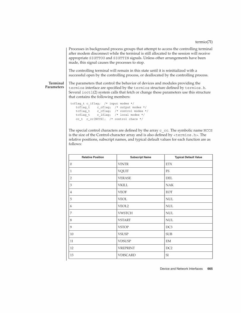
Processes in background process groups that attempt to access the controlling terminalafter modem disconnect while the terminal is still allocated to the session will receiveappropriate SIGTTOU and SIGTTIN signals. Unless other arrangements have beenmade, this signal causes the processes to stop.
The controlling terminal will remain in this state until it is reinitialized with asuccessful open by the controlling process, or deallocated by the controlling process.
The parameters that control the behavior of devices and modules providing thetermios interface are specified by the termios structure defined by termios.h.Several ioctl(2) system calls that fetch or change these parameters use this structurethat contains the following members:
tcflag_t c_iflag; /* input modes */tcflag_t c_oflag; /* output modes */tcflag_t c_cflag; /* control modes */tcflag_t c_lflag; /* local modes */
cc_t c_cc[NCCS]; /* control chars */
The special control characters are defined by the array c_cc. The symbolic name NCCSis the size of the Control-character array and is also defined by <termios.h>. Therelative positions, subscript names, and typical default values for each function are asfollows:
Relative Position Subscript Name Typical Default Value
0 VINTR ETX
1 VQUIT FS
2 VERASE DEL
3 VKILL NAK
4 VEOF EOT
5 VEOL NUL
6 VEOL2 NUL
7 VWSTCH NUL
8 VSTART NUL
9 VSTOP DC3
10 VSUSP SUB
11 VDSUSP EM
12 VREPRINT DC2
13 VDISCARD SI
termio(7I)
TerminalParameters
Device and Network Interfaces 665

Relative Position Subscript Name Typical Default Value
14 VWERASE ETB
15 VLNEXT SYN
16-19 Reserved
The c_iflag field describes the basic terminal input control:
IGNBRK Ignore break condition.
BRKINT Signal interrupt on break.
IGNPAR Ignore characters with parity errors.
PARMRK Mark parity errors.
INPCK Enable input parity check.
ISTRIP Strip character.
INLCR Map NL to CR on input.
IGNCR Ignore CR.
ICRNL Map CR to NL on input.
IUCLC Map upper-case to lower-case on input.
IXON Enable start/stop output control.
IXANY Enable any character to restart output.
IXOFF Enable start/stop input control.
IMAXBEL Echo BEL on input line too long.
If IGNBRK is set, a break condition (a character framing error with data all zeros)detected on input is ignored, that is, not put on the input queue and therefore not readby any process. If IGNBRK is not set and BRKINT is set, the break condition shall flushthe input and output queues and if the terminal is the controlling terminal of aforeground process group, the break condition generates a single SIGINT signal tothat foreground process group. If neither IGNBRK nor BRKINT is set, a break conditionis read as a single \0 (ASCII NULL) character, or if PARMRK is set, as \377, \0, \0.
If IGNPAR is set, a byte with framing or parity errors (other than break) is ignored.
If PARMRK is set, and IGNPAR is not set, a byte with a framing or parity error (otherthan break) is given to the application as the three-character sequence: \377, \0, X,where X is the data of the byte received in error. To avoid ambiguity in this case, ifISTRIP is not set, a valid character of \377 is given to the application as \377, \377. Ifneither IGNPAR nor PARMRK is set, a framing or parity error (other than break) is givento the application as a single \0 (ASCII NULr) character.
termio(7I)
Input Modes
666 man pages section 7: Device and Network Interfaces • Last Revised 14 April 2002

If INPCK is set, input parity checking is enabled. If INPCK is not set, input paritychecking is disabled. This allows output parity generation without input parity errors.Note that whether input parity checking is enabled or disabled is independent ofwhether parity detection is enabled or disabled. If parity detection is enabled butinput parity checking is disabled, the hardware to which the terminal is connected willrecognize the parity bit, but the terminal special file will not check whether this is setcorrectly or not.
If ISTRIP is set, valid input characters are first stripped to seven bits, otherwise alleight bits are processed.
If INLCR is set, a received NL character is translated into a CR character. If IGNCR isset, a received CR character is ignored (not read). Otherwise, if ICRNL is set, a receivedCR character is translated into a NL character.
If IUCLC is set, a received upper case, alphabetic character is translated into thecorresponding lower case character.
If IXON is set, start/stop output control is enabled. A received STOP charactersuspends output and a received START character restarts output. The STOP andSTART characters will not be read, but will merely perform flow control functions. IfIXANY is set, any input character restarts output that has been suspended.
If IXOFF is set, the system transmits a STOP character when the input queue is nearlyfull, and a START character when enough input has been read so that the input queueis nearly empty again.
If IMAXBEL is set, the ASCII BEL character is echoed if the input stream overflows.Further input is not stored, but any input already present in the input stream is notdisturbed. If IMAXBEL is not set, no BEL character is echoed, and all input present inthe input queue is discarded if the input stream overflows.
The c_oflag field specifies the system treatment of output:
OPOST Post-process output.
OLCUC Map lower case to upper on output.
ONLCR Map NL to CR-NL on output.
OCRNL Map CR to NL on output.
ONOCR No CR output at column 0.
ONLRET NL performs CR function.
OFILL Use fill characters for delay.
OFDEL Fill is DEL, else NULL.
NLDLY Select newline delays:
termio(7I)
Output Modes
Device and Network Interfaces 667

NL0NL1
CRDLY Select carriage-return delays:
CR0CR1CR2CR3
TABDLY Select horizontal tab delays or tab expansion:
TAB0
TAB1
TAB2
TAB3 Expand tabs to spaces
XTABS Expand tabs to spaces
BSDLY Select backspace delays:
BS0BS1
VTDLY Select vertical tab delays:
VT0VT1
FFDLY Select form feed delays:
FF0FF1
If OPOST is set, output characters are post-processed as indicated by the remainingflags; otherwise, characters are transmitted without change.
If OLCUC is set, a lower case alphabetic character is transmitted as the correspondingupper case character. This function is often used in conjunction with IUCLC.
If ONLCR is set, the NL character is transmitted as the CR-NL character pair. If OCRNLis set, the CR character is transmitted as the NL character. If ONOCR is set, no CRcharacter is transmitted when at column 0 (first position). If ONRET is set, the NLcharacter is assumed to do the carriage-return function; the column pointer is set to 0and the delays specified for CR are used. Otherwise, the NL character is assumed todo just the line-feed function; the column pointer remains unchanged. The columnpointer is also set to 0 if the CR character is actually transmitted.
termio(7I)
668 man pages section 7: Device and Network Interfaces • Last Revised 14 April 2002
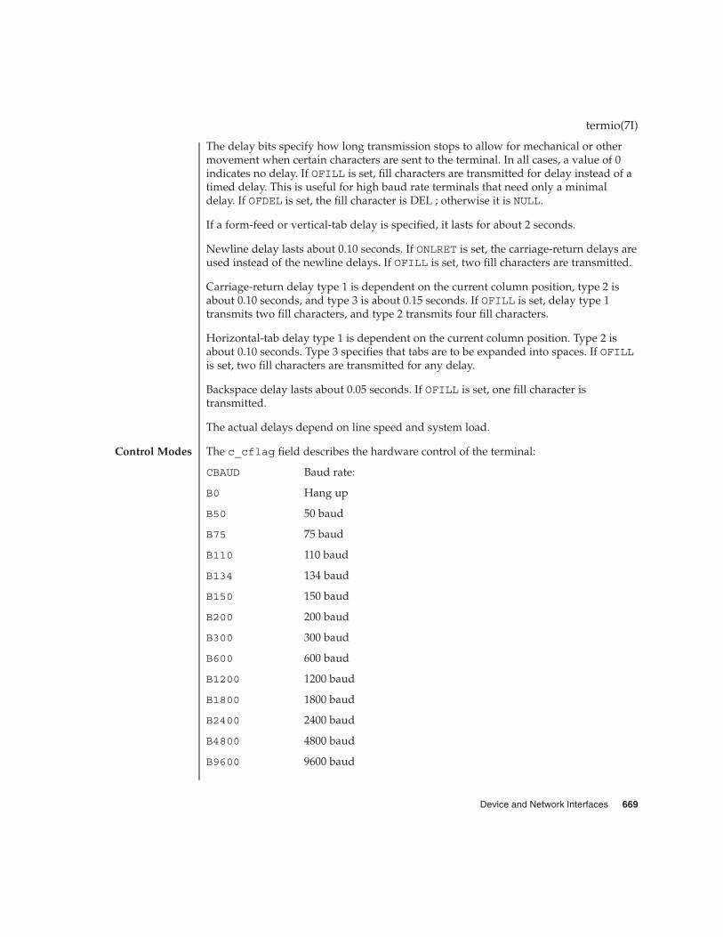
The delay bits specify how long transmission stops to allow for mechanical or othermovement when certain characters are sent to the terminal. In all cases, a value of 0indicates no delay. If OFILL is set, fill characters are transmitted for delay instead of atimed delay. This is useful for high baud rate terminals that need only a minimaldelay. If OFDEL is set, the fill character is DEL ; otherwise it is NULL.
If a form-feed or vertical-tab delay is specified, it lasts for about 2 seconds.
Newline delay lasts about 0.10 seconds. If ONLRET is set, the carriage-return delays areused instead of the newline delays. If OFILL is set, two fill characters are transmitted.
Carriage-return delay type 1 is dependent on the current column position, type 2 isabout 0.10 seconds, and type 3 is about 0.15 seconds. If OFILL is set, delay type 1transmits two fill characters, and type 2 transmits four fill characters.
Horizontal-tab delay type 1 is dependent on the current column position. Type 2 isabout 0.10 seconds. Type 3 specifies that tabs are to be expanded into spaces. If OFILLis set, two fill characters are transmitted for any delay.
Backspace delay lasts about 0.05 seconds. If OFILL is set, one fill character istransmitted.
The actual delays depend on line speed and system load.
The c_cflag field describes the hardware control of the terminal:
CBAUD Baud rate:
B0 Hang up
B50 50 baud
B75 75 baud
B110 110 baud
B134 134 baud
B150 150 baud
B200 200 baud
B300 300 baud
B600 600 baud
B1200 1200 baud
B1800 1800 baud
B2400 2400 baud
B4800 4800 baud
B9600 9600 baud
termio(7I)
Control Modes
Device and Network Interfaces 669

B19200 19200 baud
EXTA External A
B38400 38400 baud
EXTB External B
B57600 57600 baud
B76800 76800 baud
B115200 115200 baud
B153600 153600 baud
B230400 230400 baud
B307200 307200 baud
B460800 460800 baud
CSIZE Character size:
CS5 5 bits
CS6 6 bits
CS7 7 bits
CS8 8 bits
CSTOPB Send two stop bits, else one
CREAD Enable receiver
PARENB Parity enable
PARODD Odd parity, else even
HUPCL Hang up on last close
CLOCAL Local line, else dial-up
CIBAUD Input baud rate, if different from output rate
PAREXT Extended parity for mark and space parity
CRTSXOFF Enable inbound hardware flow control
CRTSCTS Enable outbound hardware flow control
CBAUDEXT Bit to indicate output speed > B38400
CIBAUDEXT Bit to indicate input speed > B38400
The CBAUD bits together with the CBAUDEXT bit specify the output baud rate. Toretrieve the output speed from the termios structure pointed to by termios_p seethe following code segment.
termio(7I)
670 man pages section 7: Device and Network Interfaces • Last Revised 14 April 2002
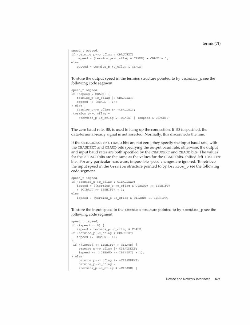
speed_t ospeed;if (termios_p->c_cflag & CBAUDEXT)
ospeed = (termios_p->c_cflag & CBAUD) + CBAUD + 1;else
ospeed = termios_p->c_cflag & CBAUD;
To store the output speed in the termios structure pointed to by termios_p see thefollowing code segment.
speed_t ospeed;if (ospeed > CBAUD) {
termios_p->c_cflag |= CBAUDEXT;ospeed -= (CBAUD + 1);
} elsetermios_p->c_cflag &= ~CBAUDEXT;
termios_p->c_cflag =
(termios_p->c_cflag & ~CBAUD) | (ospeed & CBAUD);
The zero baud rate, B0, is used to hang up the connection. If B0 is specified, thedata-terminal-ready signal is not asserted. Normally, this disconnects the line.
If the CIBAUDEXT or CIBAUD bits are not zero, they specify the input baud rate, withthe CBAUDEXT and CBAUD bits specifying the output baud rate; otherwise, the outputand input baud rates are both specified by the CBAUDEXT and CBAUD bits. The valuesfor the CIBAUD bits are the same as the values for the CBAUD bits, shifted left IBSHIFTbits. For any particular hardware, impossible speed changes are ignored. To retrievethe input speed in the termios structure pointed to by termios_p see the followingcode segment.
speed_t ispeed;if (termios_p->c_cflag & CIBAUDEXT)
ispeed = ((termios_p->c_cflag & CIBAUD) >> IBSHIFT)+ (CIBAUD >> IBSHIFT) + 1;
else
ispeed = (termios_p->c_cflag & CIBAUD) >> IBSHIFT;
To store the input speed in the termios structure pointed to by termios_p see thefollowing code segment.
speed_t ispeed;if (ispeed == 0) {
ispeed = termios_p->c_cflag & CBAUD;if (termios_p->c_cflag & CBAUDEXT)
ispeed += (CBAUD + 1);}if ((ispeed << IBSHIFT) > CIBAUD) {
termios_p->c_cflag |= CIBAUDEXT;ispeed -= ((CIBAUD >> IBSHIFT) + 1);
} elsetermios_p->c_cflag &= ~CIBAUDEXT;termios_p->c_cflag =(termios_p->c_cflag & ~CIBAUD) |
termio(7I)
Device and Network Interfaces 671
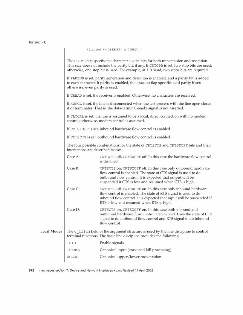
((ispeed << IBSHIFT) & CIBAUD);
The CSIZE bits specify the character size in bits for both transmission and reception.This size does not include the parity bit, if any. If CSTOPB is set, two stop bits are used;otherwise, one stop bit is used. For example, at 110 baud, two stops bits are required.
If PARENB is set, parity generation and detection is enabled, and a parity bit is addedto each character. If parity is enabled, the PARODD flag specifies odd parity if set;otherwise, even parity is used.
If CREAD is set, the receiver is enabled. Otherwise, no characters are received.
If HUPCL is set, the line is disconnected when the last process with the line open closesit or terminates. That is, the data-terminal-ready signal is not asserted.
If CLOCAL is set, the line is assumed to be a local, direct connection with no modemcontrol; otherwise, modem control is assumed.
If CRTSXOFF is set, inbound hardware flow control is enabled.
If CRTSCTS is set, outbound hardware flow control is enabled.
The four possible combinations for the state of CRTSCTS and CRTSXOFF bits and theirinteractions are described below.
Case A: CRTSCTS off, CRTSXOFF off. In this case the hardware flow controlis disabled.
Case B: CRTSCTS on, CRTSXOFF off. In this case only outbound hardwareflow control is enabled. The state of CTS signal is used to dooutbound flow control. It is expected that output will besuspended if CTS is low and resumed when CTS is high.
Case C: CRTSCTS off, CRTSXOFF on. In this case only inbound hardwareflow control is enabled. The state of RTS signal is used to doinbound flow control. It is expected that input will be suspended ifRTS is low and resumed when RTS is high.
Case D: CRTSCTS on, CRTSXOFF on. In this case both inbound andoutbound hardware flow control are enabled. Uses the state of CTSsignal to do outbound flow control and RTS signal to do inboundflow control.
The c_lflag field of the argument structure is used by the line discipline to controlterminal functions. The basic line discipline provides the following:
ISIG Enable signals.
ICANON Canonical input (erase and kill processing).
XCASE Canonical upper/lower presentation.
termio(7I)
Local Modes
672 man pages section 7: Device and Network Interfaces • Last Revised 14 April 2002
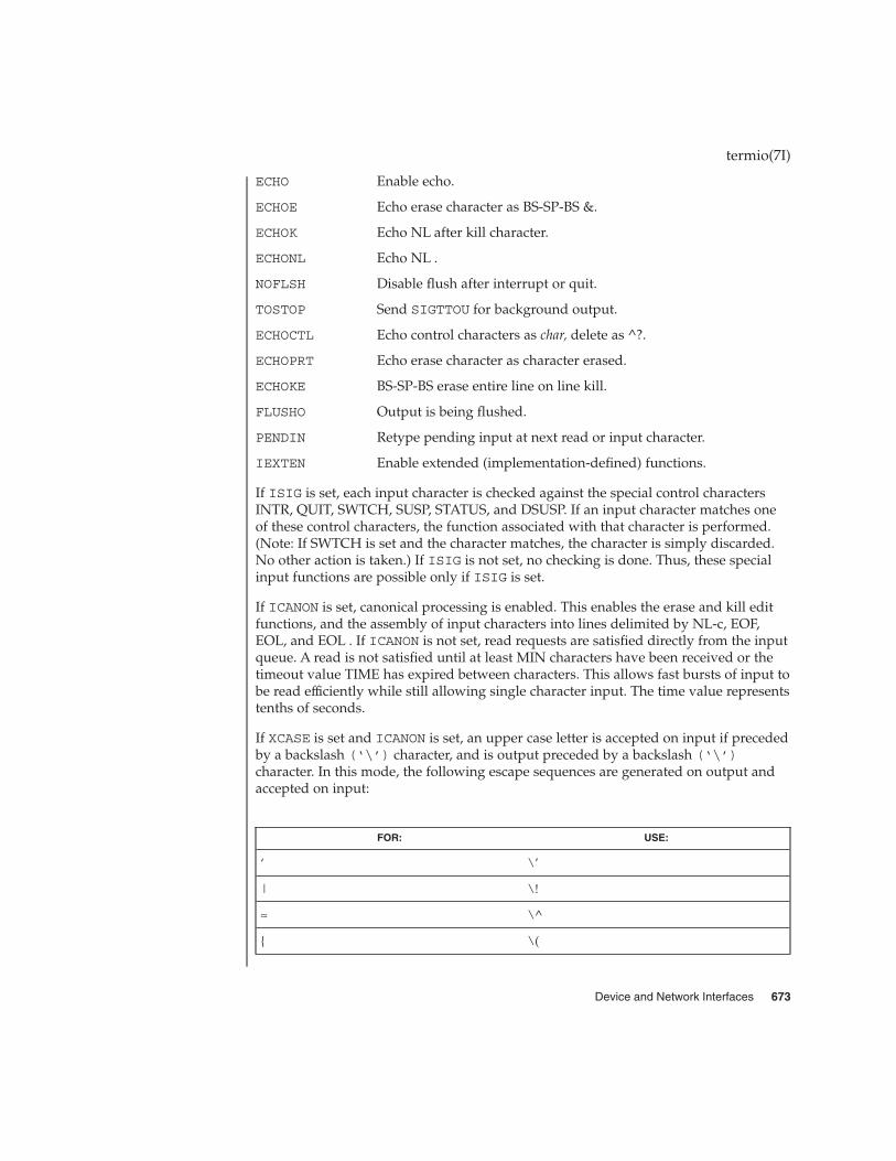
ECHO Enable echo.
ECHOE Echo erase character as BS-SP-BS &.
ECHOK Echo NL after kill character.
ECHONL Echo NL .
NOFLSH Disable flush after interrupt or quit.
TOSTOP Send SIGTTOU for background output.
ECHOCTL Echo control characters as char, delete as ^?.
ECHOPRT Echo erase character as character erased.
ECHOKE BS-SP-BS erase entire line on line kill.
FLUSHO Output is being flushed.
PENDIN Retype pending input at next read or input character.
IEXTEN Enable extended (implementation-defined) functions.
If ISIG is set, each input character is checked against the special control charactersINTR, QUIT, SWTCH, SUSP, STATUS, and DSUSP. If an input character matches oneof these control characters, the function associated with that character is performed.(Note: If SWTCH is set and the character matches, the character is simply discarded.No other action is taken.) If ISIG is not set, no checking is done. Thus, these specialinput functions are possible only if ISIG is set.
If ICANON is set, canonical processing is enabled. This enables the erase and kill editfunctions, and the assembly of input characters into lines delimited by NL-c, EOF,EOL, and EOL . If ICANON is not set, read requests are satisfied directly from the inputqueue. A read is not satisfied until at least MIN characters have been received or thetimeout value TIME has expired between characters. This allows fast bursts of input tobe read efficiently while still allowing single character input. The time value representstenths of seconds.
If XCASE is set and ICANON is set, an upper case letter is accepted on input if precededby a backslash (‘\’) character, and is output preceded by a backslash (‘\’)character. In this mode, the following escape sequences are generated on output andaccepted on input:
FOR: USE:
‘ \’
| \!
≈ \^
{ \(
termio(7I)
Device and Network Interfaces 673

FOR: USE:
} \)
\ \\
For example, input A as \a, \n as \\n, and \N as \\\n.
If ECHO is set, characters are echoed as received.
When ICANON is set, the following echo functions are possible.
� If ECHO and ECHOE are set, and ECHOPRT is not set, the ERASE and WERASEcharacters are echoed as one or more ASCII BS SP BS, which clears the lastcharacter(s) from a CRT screen.
� If ECHO, ECHOPRT, and IEXTEN are set, the first ERASE and WERASE character ina sequence echoes as a ‘\’ (backslash), followed by the characters being erased.Subsequent ERASE and WERASE characters echo the characters being erased, inreverse order. The next non-erase character causes a ‘/’ (slash) to be typed before itis echoed. ECHOPRT should be used for hard copy terminals.
� If ECHOKE and IEXTEN are set, the kill character is echoed by erasing eachcharacter on the line from the screen (using the mechanism selected by ECHOE andECHOPRa).
� If ECHOK is set, and ECHOKE is not set, the NL character is echoed after the killcharacter to emphasize that the line is deleted. Note that a ‘\’ (escape) character oran LNEXT character preceding the erase or kill character removes any specialfunction.
� If ECHONL is set, the NL character is echoed even if ECHO is not set. This is usefulfor terminals set to local echo (so called half-duplex).
If ECHOCTL and IEXTEN are set, all control characters (characters with codes between0 and 37 octal) other than ASCII TAB, ASCII NL, the START character, and the STOPcharacter, ASCII CR, and ASCII BS are echoed as ^ X, where X is the character givenby adding 100 octal to the code of the control character (so that the character with octalcode 1 is echoed as ^ A), and the ASCII DEL character, with code 177 octal, is echoedas ^ ?.
If NOFLSH is set, the normal flush of the input and output queues associated with theINTR, QUIT, and SUSP characters is not done. This bit should be set when restartingsystem calls that read from or write to a terminal (see sigaction(2) ).
If TOSTOP and IEXTEN are set, the signal SIGTTOU is sent to a process that tries towrite to its controlling terminal if it is not in the foreground process group for thatterminal. This signal normally stops the process. Otherwise, the output generated bythat process is output to the current output stream. Processes that are blocking orignoring SIGTTOU signals are excepted and allowed to produce output, if any.
termio(7I)
674 man pages section 7: Device and Network Interfaces • Last Revised 14 April 2002

If FLUSHO and IEXTEN are set, data written to the terminal is discarded. This bit is setwhen the FLUSH character is typed. A program can cancel the effect of typing theFLUSH character by clearing FLUSHO.
If PENDIN and IEXTEN are set, any input that has not yet been read is reprinted whenthe next character arrives as input. PENDIN is then automatically cleared.
If IEXTEN is set, the following implementation-defined functions are enabled: specialcharacters ( WERASE, REPRINT, DISCARD, and LNEXT) and local flags ( TOSTOP,ECHOCTL, ECHOPRT, ECHOKE, FLUSHO, and PENDIN).
The MIN and TIME values were described previously, in the subsection,Non-canonical Mode Input Processing. The initial value of MIN is 1, and theinitial value of TIME is 0.
The number of lines and columns on the terminal’s display is specified in thewinsize structure defined by sys/termios.h and includes the following members:
unsigned short ws_row; /* rows, in characters */unsigned short ws_col; /* columns, in characters */unsigned short ws_xpixel; /* horizontal size, in pixels */
unsigned short ws_ypixel; /* vertical size, in pixels */
The SunOS/SVR4 termio structure is used by some ioctls; it is defined bysys/termio.h and includes the following members:
unsigned short c_iflag; /* input modes */unsigned short c_oflag; /* output modes */unsigned short c_cflag; /* control modes */unsigned short c_lflag; /* local modes */char c_line; /* line discipline */
unsigned char c_cc[NCC]; /* control chars */
The special control characters are defined by the array c_cc. The symbolic name NCCis the size of the Control-character array and is also defined by termio.h. Therelative positions, subscript names, and typical default values for each function are asfollows:
Relative Positions Subscript Names Typical Default Values
0 VINTR EXT
1 VQUIT FS
2 VERASE DEL
3 VKILL NAK
4 VEOF EOT
termio(7I)
Minimum andTimeout
Terminal Size
Termio Structure
Device and Network Interfaces 675

Relative Positions Subscript Names Typical Default Values
5 VEOL NUL
6 VEOL2 NUL
7 Reserved
The MIN values is stored in the VMIN element of the c_cc array; the TIME value isstored in the VTIME element of the c_cc array. The VMIN element is the same elementas the VEOF element; the VTIME element is the same element as the VEOL element.
The calls that use the termio structure only affect the flags and control characters thatcan be stored in the termio structure; all other flags and control characters areunaffected.
On special files representing serial ports, modem control lines can be read. Controllines (if the underlying hardware supports it) may also be changed. Status lines areread-only. The following modem control and status lines may be supported by adevice; they are defined by sys/termios.h:
TIOCM_LE line enable
TIOCM_DTR data terminal ready
TIOCM_RTS request to send
TIOCM_ST secondary transmit
TIOCM_SR secondary receive
TIOCM_CTS clear to send
TIOCM_CAR carrier detect
TIOCM_RNG ring
TIOCM_DSR data set ready
TIOCM_CD is a synonym for TIOCM_CAR, and TIOCM_RI is a synonym forTIOCM_RNG. Not all of these are necessarily supported by any particular device; checkthe manual page for the device in question.
The software carrier mode can be enabled or disabled using the TIOCSSOFTCARioctl. If the software carrier flag for a line is off, the line pays attention to thehardware carrier detect (DCD) signal. The tty device associated with the line cannotbe opened until DCD is asserted. If the software carrier flag is on, the line behaves as ifDCD is always asserted.
The software carrier flag is usually turned on for locally connected terminals or otherdevices, and is off for lines with modems.
termio(7I)
Modem Lines
676 man pages section 7: Device and Network Interfaces • Last Revised 14 April 2002

To be able to issue the TIOCGSOFTCAR and TIOCSSOFTCAR ioctl calls, the tty lineshould be opened with O_NDELAY so that the open(2) will not wait for the carrier.
The initial termios values upon driver open is configurable. This is accomplished bysetting the “ttymodes” property in the file /kernel/drv/options.conf. Since thisproperty is assigned during system initialization, any change to the “ttymodes”property will not take effect until the next reboot. The string value assigned to thisproperty should be in the same format as the output of the stty(1) command with the-g option.
If this property is undefined, the following termios modes are in effect. The initialinput control value is BRKINT, ICRNL, IXON, IMAXBEL. The initial output controlvalue is OPOST, ONLCR, TAB3. The initial hardware control value is B9600, CS8,CREAD. The initial line-discipline control value is ISIG, ICANON, IEXTEN, ECHO,ECHOK, ECHOE, ECHOKE, ECHOCTL.
The ioctls supported by devices and STREAMS modules providing thetermios(3C) interface are listed below. Some calls may not be supported by alldevices or modules. The functionality provided by these calls is also available throughthe preferred function call interface specified on termios.
TCGETS The argument is a pointer to a termios structure. The currentterminal parameters are fetched and stored into that structure.
TCSETS The argument is a pointer to a termios structure. The currentterminal parameters are set from the values stored in thatstructure. The change is immediate.
TCSETSW The argument is a pointer to a termios structure. The currentterminal parameters are set from the values stored in thatstructure. The change occurs after all characters queued for outputhave been transmitted. This form should be used when changingparameters that affect output.
TCSETSF The argument is a pointer to a termios structure. The currentterminal parameters are set from the values stored in thatstructure. The change occurs after all characters queued for outputhave been transmitted; all characters queued for input arediscarded and then the change occurs.
TCGETA The argument is a pointer to a termio structure. The currentterminal parameters are fetched, and those parameters that can bestored in a termio structure are stored into that structure.
TCSETA The argument is a pointer to a termio structure. Those terminalparameters that can be stored in a termio structure are set fromthe values stored in that structure. The change is immediate.
TCSETAW The argument is a pointer to a termio structure. Those terminalparameters that can be stored in a termio structure are set fromthe values stored in that structure. The change occurs after all
termio(7I)
Default Values
IOCTLS
Device and Network Interfaces 677

characters queued for output have been transmitted. This formshould be used when changing parameters that affect output.
TCSETAF The argument is a pointer to a termio structure. Those terminalparameters that can be stored in a termio structure are set fromthe values stored in that structure. The change occurs after allcharacters queued for output have been transmitted; all charactersqueued for input are discarded and then the change occurs.
TCSBRK The argument is an int value. Wait for the output to drain. If theargument is 0, then send a break (zero valued bits for 0.25seconds).
TCXONC Start/stop control. The argument is an int value. If the argumentis 0, suspend output; if 1, restart suspended output; if 2, suspendinput; if 3, restart suspended input.
TCFLSH The argument is an int value. If the argument is 0, flush the inputqueue; if 1, flush the output queue; if 2, flush both the input andoutput queues.
TIOCGPGRP The argument is a pointer to a pid_t. Set the value of that pid_tto the process group ID of the foreground process groupassociated with the terminal. See termios(3C) for a description ofTCGETPGRP.
TIOCSPGRP The argument is a pointer to a pid_t. Associate the process groupwhose process group ID is specified by the value of that pid_twith the terminal. The new process group value must be in therange of valid process group ID values. Otherwise, the errorEPERM is returned. See termios(3C) for a description ofTCSETPGRP.
TIOCGSID The argument is a pointer to a pid_t. The session ID of theterminal is fetched and stored in the pid_t.
TIOCGWINSZ The argument is a pointer to a winsize structure. The terminaldriver’s notion of the terminal size is stored into that structure.
TIOCSWINSZ The argument is a pointer to a winsize structure. The terminaldriver’s notion of the terminal size is set from the values specifiedin that structure. If the new sizes are different from the old sizes, aSIGWINCH signal is set to the process group of the terminal.
TIOCMBIS The argument is a pointer to an int whose value is a maskcontaining modem control lines to be turned on. The control lineswhose bits are set in the argument are turned on; no other controllines are affected.
termio(7I)
678 man pages section 7: Device and Network Interfaces • Last Revised 14 April 2002

TIOCMBIC The argument is a pointer to an int whose value is a maskcontaining modem control lines to be turned off. The control lineswhose bits are set in the argument are turned off; no other controllines are affected.
TIOCMGET The argument is a pointer to an int. The current state of themodem status lines is fetched and stored in the int pointed to bythe argument.
TIOCMSET The argument is a pointer to an int containing a new set ofmodem control lines. The modem control lines are turned on oroff, depending on whether the bit for that mode is set or clear.
TIOCSPPS The argument is a pointer to an int that determines whetherpulse-per-second event handling is to be enabled (non-zero) ordisabled (zero). If a one-pulse-per-second reference clock isattached to the serial line’s data carrier detect input, the localsystem clock will be calibrated to it. A clock with a high error, thatis, a deviation of more than 25 microseconds per tick, is ignored.
TIOCGPPS The argument is a pointer to an int, in which the state of the evenhandling is returned. The int is set to a non-zero value ifpulse-per-second (PPS) handling has been enabled. Otherwise, it isset to zero.
TIOCGSOFTCAR The argument is a pointer to an int whose value is 1 or 0,depending on whether the software carrier detect is turned on oroff.
TIOCSSOFTCAR The argument is a pointer to an int whose value is 1 or 0. Thevalue of the integer should be 0 to turn off software carrier, or 1 toturn it on.
TIOCGPPSEV The argument is a pointer to a struct ppsclockev. Thisstructure contains the following members:
struct timeval tv;
uint32_t serial;“tv” is the system clock timestamp when theevent (pulse on the DCD pin) occurred. “serial” is the ordinal ofthe event, which each consecutive event being assigned the nextordinal. The first event registered gets a “serial” value of 1. TheTIOCGPPSEV returns the last event registered; multiple calls willpersistently return the same event until a new one is registered. Inaddition to time stamping and saving the event, if it is ofone-second period and of consistently high accuracy, the localsystem clock will automatically calibrate to it.
Files in or under /dev
stty(1), fork(2), getsid(2), ioctl(2), setsid(2), sigaction(2), signal(3C),termios(3C), signal(3HEAD), streamio(7I)
termio(7I)
FILES
SEE ALSO
Device and Network Interfaces 679

termiox – extended general terminal interface
The extended general terminal interface supplements the termio(7I) general terminalinterface by adding support for asynchronous hardware flow control, isochronousflow control and clock modes, and local implementations of additional asynchronousfeatures. Some systems may not support all of these capabilities because of eitherhardware or software limitations. Other systems may not permit certain functions tobe disabled. In these cases the appropriate bits will be ignored. See<sys/termiox.h> for your system to find out which capabilities are supported.
Hardware flow control supplements the termio(7I) IXON, IXOFF, and IXANYcharacter flow control. Character flow control occurs when one device controls thedata transfer of another device by the insertion of control characters in the data streambetween devices. Hardware flow control occurs when one device controls the datatransfer of another device using electrical control signals on wires (circuits) of theasynchronous interface. Isochronous hardware flow control occurs when one devicecontrols the data transfer of another device by asserting or removing the transmitclock signals of that device. Character flow control and hardware flow control may besimultaneously set.
In asynchronous, full duplex applications, the use of the Electronic IndustriesAssociation’s EIA-232-D Request To Send (RTS) and Clear To Send (CTS) circuits is thepreferred method of hardware flow control. An interface to other hardware flowcontrol methods is included to provide a standard interface to these existing methods.
The EIA-232-D standard specified only unidirectional hardware flow control - the DataCircuit-terminating Equipment or Data Communications Equipment (DCE) indicatesto the Data Terminal Equipment (DTE) to stop transmitting data. The termioxinterface allows both unidirectional and bidirectional hardware flow control; whenbidirectional flow control is enabled, either the DCE or DTE can indicate to each otherto stop transmitting data across the interface. Note: It is assumed that theasynchronous port is configured as a DTE. If the connected device is also a DTE andnot a DCE, then DTE to DTE (for example, terminal or printer connected to computer)hardware flow control is possible by using a null modem to interconnect theappropriate data and control circuits.
Isochronous communication is a variation of asynchronous communication wherebytwo communicating devices may provide transmit and/or receive clock signals to oneanother. Incoming clock signals can be taken from the baud rate generator on the localisochronous port controller, from CCITT V.24 circuit 114, Transmitter Signal ElementTiming - DCE source (EIA-232-D pin 15), or from CCITT V.24 circuit 115, ReceiverSignal Element Timing - DCE source (EIA-232-D pin 17). Outgoing clock signals can besent on CCITT V.24 circuit 113, Transmitter Signal Element Timing - DTE source(EIA-232-D pin 24), on CCITT V.24 circuit 128, Receiver Signal Element Timing - DTEsource (no EIA-232-D pin), or not sent at all.
termiox(7I)
NAME
DESCRIPTION
Hardware FlowControl Modes
Clock Modes
680 man pages section 7: Device and Network Interfaces • Last Revised 3 Jul 1990
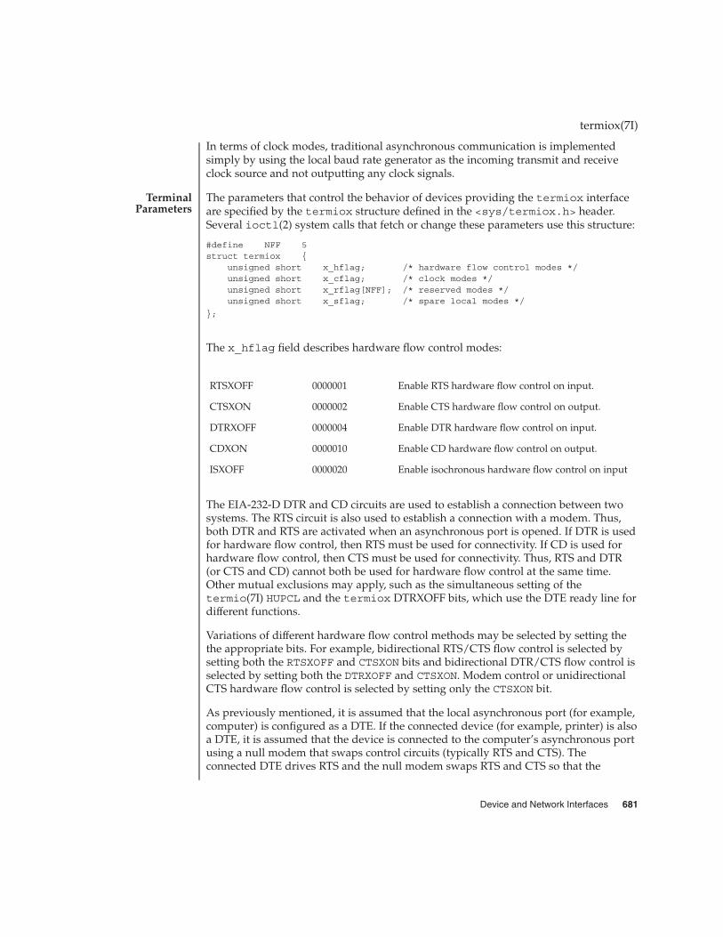
In terms of clock modes, traditional asynchronous communication is implementedsimply by using the local baud rate generator as the incoming transmit and receiveclock source and not outputting any clock signals.
The parameters that control the behavior of devices providing the termiox interfaceare specified by the termiox structure defined in the <sys/termiox.h> header.Several ioctl(2) system calls that fetch or change these parameters use this structure:
#define NFF 5struct termiox {
unsigned short x_hflag; /* hardware flow control modes */unsigned short x_cflag; /* clock modes */unsigned short x_rflag[NFF]; /* reserved modes */unsigned short x_sflag; /* spare local modes */
};
The x_hflag field describes hardware flow control modes:
RTSXOFF 0000001 Enable RTS hardware flow control on input.
CTSXON 0000002 Enable CTS hardware flow control on output.
DTRXOFF 0000004 Enable DTR hardware flow control on input.
CDXON 0000010 Enable CD hardware flow control on output.
ISXOFF 0000020 Enable isochronous hardware flow control on input
The EIA-232-D DTR and CD circuits are used to establish a connection between twosystems. The RTS circuit is also used to establish a connection with a modem. Thus,both DTR and RTS are activated when an asynchronous port is opened. If DTR is usedfor hardware flow control, then RTS must be used for connectivity. If CD is used forhardware flow control, then CTS must be used for connectivity. Thus, RTS and DTR(or CTS and CD) cannot both be used for hardware flow control at the same time.Other mutual exclusions may apply, such as the simultaneous setting of thetermio(7I) HUPCL and the termiox DTRXOFF bits, which use the DTE ready line fordifferent functions.
Variations of different hardware flow control methods may be selected by setting thethe appropriate bits. For example, bidirectional RTS/CTS flow control is selected bysetting both the RTSXOFF and CTSXON bits and bidirectional DTR/CTS flow control isselected by setting both the DTRXOFF and CTSXON. Modem control or unidirectionalCTS hardware flow control is selected by setting only the CTSXON bit.
As previously mentioned, it is assumed that the local asynchronous port (for example,computer) is configured as a DTE. If the connected device (for example, printer) is alsoa DTE, it is assumed that the device is connected to the computer’s asynchronous portusing a null modem that swaps control circuits (typically RTS and CTS). Theconnected DTE drives RTS and the null modem swaps RTS and CTS so that the
termiox(7I)
TerminalParameters
Device and Network Interfaces 681

remote RTS is received as CTS by the local DTE. In the case that CTSXON is set forhardware flow control, printer’s lowering of its RTS would cause CTS seen by thecomputer to be lowered. Output to the printer is suspended until the printer’s raisingof its RTS, which would cause CTS seen by the computer to be raised.
If RTSXOFF is set, the Request To Send (RTS) circuit (line) will be raised, and if theasynchronous port needs to have its input stopped, it will lower the Request To Send(RTS) line. If the RTS line is lowered, it is assumed that the connected device will stopits output until RTS is raised.
If CTSXON is set, output will occur only if the Clear To Send (CTS) circuit (line) israised by the connected device. If the CTS line is lowered by the connected device,output is suspended until CTS is raised.
If DTRXOFF is set, the DTE Ready (DTR) circuit (line) will be raised, and if theasynchronous port needs to have its input stopped, it will lower the DTE Ready (DTR)line. If the DTR line is lowered, it is assumed that the connected device will stop itsoutput until DTR is raised.
If CDXON is set, output will occur only if the Received Line Signal Detector (CD) circuit(line) is raised by the connected device. If the CD line is lowered by the connecteddevice, output is suspended until CD is raised.
If ISXOFF is set, and if the isochronous port needs to have its input stopped, it willstop the outgoing clock signal. It is assumed that the connected device is using thisclock signal to create its output. Transit and receive clock sources are programmedusing the x_cflag fields. If the port is not programmed for external clock generation,ISXOFF is ignored. Output isochronous flow control is supported by appropriateclock source programming using the x_cflag field and enabled at the remoteconnected device.
The x_cflag field specifies the system treatment of clock modes.
XMTCLK 0000007 Transmit clock source:
XCIBRG 0000000 Get transmit clock from internal baud rategenerator.
XCTSET 0000001 Get transmit clock from transmitter signal elementtiming (DCE source) lead, CCITT V.24 circuit 114,EIA-232-D pin 15.
XCRSET 0000002 Get transmit clock from receiver signal elementtiming (DCE source) lead, CCITT V.24 circuit 115,EIA-232-D pin 17.
RCVCLK 0000070 Receive clock source:
RCIBRG 0000000 Get receive clock from internal baud rategenerator.
termiox(7I)
682 man pages section 7: Device and Network Interfaces • Last Revised 3 Jul 1990

RCTSET 0000010 Get receive clock from transmitter signal elementtiming (DCE source) lead, CCITT V.24 circuit 114,EIA-232-D pin 15.
RCRSET 0000020 Get receive clock from receiver signal elementtiming (DCE source) lead, CCITT V.24 circuit 115,EIA-232-D pin 17.
TSETCLK 0000700 Transmitter signal element timing (DTE source)lead, CCITT V.24 circuit 113, EIA-232-D pin 24,clock source:
TSETCOFF 0000000 TSET clock not provided.
TSETCRBRG 0000100 Output receive baud rate generator on circuit 113.
TSETCTBRG 0000200 Output transmit baud rate generator on circuit 113
TSETCTSET 0000300 Output transmitter signal element timing (DCEsource) on circuit 113.
TSETCRSET 0000400 Output receiver signal element timing (DCEsource) on circuit 113.
RSETCLK 0007000 Receiver signal element timing (DTE source) lead,CCITT V.24 circuit 128, no EIA-232-D pin, clocksource:
RSETCOFF 0000000 RSET clock not provided.
RSETCRBRG 0001000 Output receive baud rate generator on circuit 128.
RSETCTBRG 0002000 Output transmit baud rate generator on circuit 128.
RSETCTSET 0003000 Output transmitter signal element timing (DCEsource) on circuit 128.
RSETCRSET 0004000 Output receiver signal element timing (DCE) oncircuit 128.
If the XMTCLK field has a value of XCIBRG the transmit clock is taken from thehardware internal baud rate generator, as in normal asynchronous transmission. IfXMTCLK = XCTSET the transmit clock is taken from the Transmitter Signal ElementTiming (DCE source) circuit. If XMTCLK = XCRSET the transmit clock is taken from theReceiver Signal Element Timing (DCE source) circuit.
If the RCVCLK field has a value of RCIBRG the receive clock is taken from thehardware Internal Baud Rate Generator, as in normal asynchronous transmission. IfRCVCLK = RCTSET the receive clock is taken from the Transmitter Signal ElementTiming (DCE source) circuit. If RCVCLK = RCRSET the receive clock is taken from theReceiver Signal Element Timing (DCE source) circuit.
termiox(7I)
Device and Network Interfaces 683

If the TSETCLK field has a value of TSETCOFF the Transmitter Signal Element Timing(DTE source) circuit is not driven. If TSETCLK = TSETCRBRG the Transmitter SignalElement Timing (DTE source) circuit is driven by the Receive Baud Rate Generator. IfTSETCLK = TSETCTBRG the Transmitter Signal Element Timing (DTE source) circuit isdriven by the Transmit Baud Rate Generator. If TSETCLK = TSETCTSET theTransmitter Signal Element Timing (DTE source) circuit is driven by the TransmitterSignal Element Timing (DCE source). If TSETCLK = TSETCRBRG the Transmitter SignalElement Timing (DTE source) circuit is driven by the Receiver Signal Element Timing(DCE source).
If the RSETCLK field has a value of RSETCOFF the Receiver Signal Element Timing(DTE source) circuit is not driven. If RSETCLK = RSETCRBRG the Receiver SignalElement Timing (DTE source) circuit is driven by the Receive Baud Rate Generator. IfRSETCLK = RSETCTBRG the Receiver Signal Element Timing (DTE source) circuit isdriven by the Transmit Baud Rate Generator. If RSETCLK = RSETCTSET the ReceiverSignal Element Timing (DTE source) circuit is driven by the Transmitter SignalElement Timing (DCE source). If RSETCLK = RSETCRBRG the Receiver Signal ElementTiming (DTE source) circuit is driven by the Receiver Signal Element Timing (DCEsource).
The x_rflag is reserved for future interface definitions and should not be used byany implementations. The x_sflag may be used by local implementations wishing tocustomize their terminal interface using the termiox ioctl system calls.
The ioctl(2) system calls have the form:
ioctl (fildes, command, arg) struct termiox * arg; The commands using this form are:
TCGETX The argument is a pointer to a termiox structure. The currentterminal parameters are fetched and stored into that structure.
TCSETX The argument is a pointer to a termiox structure. The currentterminal parameters are set from the values stored in thatstructure. The change is immediate.
TCSETXW The argument is a pointer to a termiox structure. The currentterminal parameters are set from the values stored in thatstructure. The change occurs after all characters queued for outputhave been transmitted. This form should be used when changingparameters that will affect output.
TCSETXF The argument is a pointer to a termiox structure. The currentterminal parameters are set from the values stored in thatstructure. The change occurs after all characters queued for outputhave been transmitted; all characters queued for input arediscarded and then the change occurs.
/dev/*
stty(1), ioctl(2), termio(7I)
termiox(7I)
IOCTLS
FILES
SEE ALSO
684 man pages section 7: Device and Network Interfaces • Last Revised 3 Jul 1990

The termiox(7I) system call is provided for compatibility with previous releases andits use is discouraged. Instead, the termio(7I) system call is recommended. Seetermio(7I) for usage information.
termiox(7I)
NOTES
Device and Network Interfaces 685

ticlts, ticots, ticotsord – loopback transport providers
#include <sys/ticlts.h>
#include <sys/ticots.h>
#include <sys/ticotsord.h>
The devices known as ticlts, ticots, and ticotsord are ‘‘loopback transportproviders,’’ that is, stand-alone networks at the transport level. Loopback transportproviders are transport providers in every sense except one: only one host (the localmachine) is ‘‘connected to’’ a loopback network. Loopback transports present a TPI(STREAMS-level) interface to application processes and are intended to be accessedvia the TLI (application-level) interface. They are implemented as clone devices andsupport address spaces consisting of ‘‘flex-addresses,’’ that is, arbitrary sequences ofoctets of length > 0, represented by a netbuf structure.
ticlts is a datagram-mode transport provider. It offers (connectionless) service oftype T_CLTS. Its default address size is TCL_DEFAULTADDRSZ. ticlts prints thefollowing error messages (see t_rcvuderr(3NSL)):
TCL_BADADDR bad address specification
TCL_BADOPT bad option specification
TCL_NOPEER bound
TCL_PEERBADSTATE peer in wrong state
ticots is a virtual circuit-mode transport provider. It offers (connection-oriented)service of type T_COTS. Its default address size is TCO_DEFAULTADDRSZ. ticotsprints the following disconnect messages (see t_rcvdis(3NSL)):
TCO_NOPEER no listener on destination address
TCO_PEERNOROOMONQ peer has no room on connect queue
TCO_PEERBADSTATE peer in wrong state
TCO_PEERINITIATED peer-initiated disconnect
TCO_PROVIDERINITIATED provider-initiated disconnect
ticotsord is a virtual circuit-mode transport provider, offering service of typeT_COTS_ORD (connection-oriented service with orderly release). Its default addresssize is TCOO_DEFAULTADDRSZ. ticotsord prints the following disconnect messages(see t_rcvdis(3NSL)):
TCOO_NOPEER no listener on destination address
TCOO_PEERNOROOMONQ peer has no room on connect queue
TCOO_PEERBADSTATE peer in wrong state
TCOO_PEERINITIATED provider-initiated disconnect
ticlts(7D)
NAME
SYNOPSIS
DESCRIPTION
686 man pages section 7: Device and Network Interfaces • Last Revised 3 Jul 1990

TCOO_PROVIDERINITIATED peer-initiated disconnect
Loopback transports support a local IPC mechanism through the TLI interface.Applications implemented in a transport provider-independent manner on aclient-server model using this IPC are transparently transportable to networkedenvironments.
Transport provider-independent applications must not include the headers listed inthe synopsis section above. In particular, the options are (like all transport provideroptions) provider dependent.
ticlts and ticots support the same service types (T_CLTS and T_COTS)supported by the OSI transport-level model.
ticotsord supports the same service type (T_COTSORD) supported by the TCP/IPmodel.
/dev/ticlts
/dev/ticots
/dev/ticotsord
t_rcvdis(3NSL), t_rcvuderr(3NSL)
ticlts(7D)
USAGE
FILES
SEE ALSO
Device and Network Interfaces 687

ticlts, ticots, ticotsord – loopback transport providers
#include <sys/ticlts.h>
#include <sys/ticots.h>
#include <sys/ticotsord.h>
The devices known as ticlts, ticots, and ticotsord are ‘‘loopback transportproviders,’’ that is, stand-alone networks at the transport level. Loopback transportproviders are transport providers in every sense except one: only one host (the localmachine) is ‘‘connected to’’ a loopback network. Loopback transports present a TPI(STREAMS-level) interface to application processes and are intended to be accessedvia the TLI (application-level) interface. They are implemented as clone devices andsupport address spaces consisting of ‘‘flex-addresses,’’ that is, arbitrary sequences ofoctets of length > 0, represented by a netbuf structure.
ticlts is a datagram-mode transport provider. It offers (connectionless) service oftype T_CLTS. Its default address size is TCL_DEFAULTADDRSZ. ticlts prints thefollowing error messages (see t_rcvuderr(3NSL)):
TCL_BADADDR bad address specification
TCL_BADOPT bad option specification
TCL_NOPEER bound
TCL_PEERBADSTATE peer in wrong state
ticots is a virtual circuit-mode transport provider. It offers (connection-oriented)service of type T_COTS. Its default address size is TCO_DEFAULTADDRSZ. ticotsprints the following disconnect messages (see t_rcvdis(3NSL)):
TCO_NOPEER no listener on destination address
TCO_PEERNOROOMONQ peer has no room on connect queue
TCO_PEERBADSTATE peer in wrong state
TCO_PEERINITIATED peer-initiated disconnect
TCO_PROVIDERINITIATED provider-initiated disconnect
ticotsord is a virtual circuit-mode transport provider, offering service of typeT_COTS_ORD (connection-oriented service with orderly release). Its default addresssize is TCOO_DEFAULTADDRSZ. ticotsord prints the following disconnect messages(see t_rcvdis(3NSL)):
TCOO_NOPEER no listener on destination address
TCOO_PEERNOROOMONQ peer has no room on connect queue
TCOO_PEERBADSTATE peer in wrong state
TCOO_PEERINITIATED provider-initiated disconnect
ticots(7D)
NAME
SYNOPSIS
DESCRIPTION
688 man pages section 7: Device and Network Interfaces • Last Revised 3 Jul 1990

TCOO_PROVIDERINITIATED peer-initiated disconnect
Loopback transports support a local IPC mechanism through the TLI interface.Applications implemented in a transport provider-independent manner on aclient-server model using this IPC are transparently transportable to networkedenvironments.
Transport provider-independent applications must not include the headers listed inthe synopsis section above. In particular, the options are (like all transport provideroptions) provider dependent.
ticlts and ticots support the same service types (T_CLTS and T_COTS)supported by the OSI transport-level model.
ticotsord supports the same service type (T_COTSORD) supported by the TCP/IPmodel.
/dev/ticlts
/dev/ticots
/dev/ticotsord
t_rcvdis(3NSL), t_rcvuderr(3NSL)
ticots(7D)
USAGE
FILES
SEE ALSO
Device and Network Interfaces 689
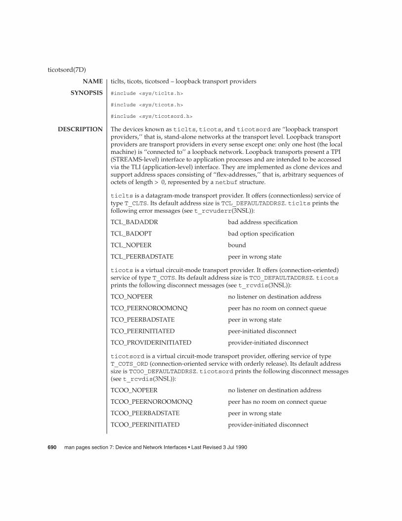
ticlts, ticots, ticotsord – loopback transport providers
#include <sys/ticlts.h>
#include <sys/ticots.h>
#include <sys/ticotsord.h>
The devices known as ticlts, ticots, and ticotsord are ‘‘loopback transportproviders,’’ that is, stand-alone networks at the transport level. Loopback transportproviders are transport providers in every sense except one: only one host (the localmachine) is ‘‘connected to’’ a loopback network. Loopback transports present a TPI(STREAMS-level) interface to application processes and are intended to be accessedvia the TLI (application-level) interface. They are implemented as clone devices andsupport address spaces consisting of ‘‘flex-addresses,’’ that is, arbitrary sequences ofoctets of length > 0, represented by a netbuf structure.
ticlts is a datagram-mode transport provider. It offers (connectionless) service oftype T_CLTS. Its default address size is TCL_DEFAULTADDRSZ. ticlts prints thefollowing error messages (see t_rcvuderr(3NSL)):
TCL_BADADDR bad address specification
TCL_BADOPT bad option specification
TCL_NOPEER bound
TCL_PEERBADSTATE peer in wrong state
ticots is a virtual circuit-mode transport provider. It offers (connection-oriented)service of type T_COTS. Its default address size is TCO_DEFAULTADDRSZ. ticotsprints the following disconnect messages (see t_rcvdis(3NSL)):
TCO_NOPEER no listener on destination address
TCO_PEERNOROOMONQ peer has no room on connect queue
TCO_PEERBADSTATE peer in wrong state
TCO_PEERINITIATED peer-initiated disconnect
TCO_PROVIDERINITIATED provider-initiated disconnect
ticotsord is a virtual circuit-mode transport provider, offering service of typeT_COTS_ORD (connection-oriented service with orderly release). Its default addresssize is TCOO_DEFAULTADDRSZ. ticotsord prints the following disconnect messages(see t_rcvdis(3NSL)):
TCOO_NOPEER no listener on destination address
TCOO_PEERNOROOMONQ peer has no room on connect queue
TCOO_PEERBADSTATE peer in wrong state
TCOO_PEERINITIATED provider-initiated disconnect
ticotsord(7D)
NAME
SYNOPSIS
DESCRIPTION
690 man pages section 7: Device and Network Interfaces • Last Revised 3 Jul 1990

TCOO_PROVIDERINITIATED peer-initiated disconnect
Loopback transports support a local IPC mechanism through the TLI interface.Applications implemented in a transport provider-independent manner on aclient-server model using this IPC are transparently transportable to networkedenvironments.
Transport provider-independent applications must not include the headers listed inthe synopsis section above. In particular, the options are (like all transport provideroptions) provider dependent.
ticlts and ticots support the same service types (T_CLTS and T_COTS)supported by the OSI transport-level model.
ticotsord supports the same service type (T_COTSORD) supported by the TCP/IPmodel.
/dev/ticlts
/dev/ticots
/dev/ticotsord
t_rcvdis(3NSL), t_rcvuderr(3NSL)
ticotsord(7D)
USAGE
FILES
SEE ALSO
Device and Network Interfaces 691

timod – Transport Interface cooperating STREAMS module
#include <sys/stropts.h>
ioctl(fildes, I_STR, &my_strioctl);
timod is a STREAMS module for use with the Transport Interface (“TI”) functions ofthe Network Services library. The timod module converts a set of ioctl(2) calls intoSTREAMS messages that may be consumed by a transport protocol provider thatsupports the Transport Interface. This allows a user to initiate certain TI functions asatomic operations.
The timod module must be pushed onto only a stream terminated by a transportprotocol provider that supports the TI.
All STREAMS messages, with the exception of the message types generated from theioctl commands described below, will be transparently passed to the neighboringmodule or driver. The messages generated from the following ioctl commands arerecognized and processed by the timod module. The format of the ioctl call is:
#include <sys/stropts.h>--
struct strioctl my_strioctl;--
strioctl.ic_cmd = cmd;strioctl.ic_timout = INFTIM;strioctl.ic_len = size;strioctl.ic_dp = (char *)bufioctl(fildes, I_STR, &my_strioctl);
On issuance, size is the size of the appropriate TI message to be sent to the transportprovider and on return size is the size of the appropriate TI message from thetransport provider in response to the issued TI message. buf is a pointer to a bufferlarge enough to hold the contents of the appropriate TI messages. The TI messagetypes are defined in <sys/tihdr.h>. The possible values for the cmd field are:
TI_BIND Bind an address to the underlying transport protocol provider. Themessage issued to the TI_BIND ioctl is equivalent to the TImessage type T_BIND_REQ and the message returned by thesuccessful completion of the ioctl is equivalent to the TI messagetype T_BIND_ACK.
TI_UNBIND Unbind an address from the underlying transport protocolprovider. The message issued to the TI_UNBIND ioctl is equivalentto the TI message type T_UNBIND_REQ and the message returnedby the successful completion of the ioctl is equivalent to the TImessage type T_OK_ACK.
TI_GETINFO Get the TI protocol specific information from the transportprotocol provider. The message issued to the TI_GETINFO ioctl is
timod(7M)
NAME
SYNOPSIS
DESCRIPTION
692 man pages section 7: Device and Network Interfaces • Last Revised 26 Mar 1993

equivalent to the TI message type T_INFO_REQ and the messagereturned by the successful completion of the ioctl is equivalentto the TI message type T_INFO_ACK.
TI_OPTMGMT Get, set, or negotiate protocol specific options with the transportprotocol provider. The message issued to the TI_OPTMGMT ioctl isequivalent to the TI message type T_OPTMGMT_REQ and themessage returned by the successful completion of the ioctl isequivalent to the TI message type T_OPTMGMT_ACK.
<sys/timod.h> ioctl definitions
<sys/tiuser.h> TLI interface declaration and structure file
<sys/tihdr.h> TPI declarations and user-level code
<sys/errno.h> system error messages file. Please see errno(3C).
intro(3), ioctl(2), errno(3C), tirdwr(7M)
STREAMS Programming Guide
If the ioctl returns with a value greater than 0, the lower 8 bits of the return valuewill be one of the TI error codes as defined in <sys/tiuser.h>. If the TI error is oftype TSYSERR, then the next 8 bits of the return value will contain an error as definedin <sys/errno.h> (see intro(3)).
timod(7M)
FILES
SEE ALSO
DIAGNOSTICS
Device and Network Interfaces 693
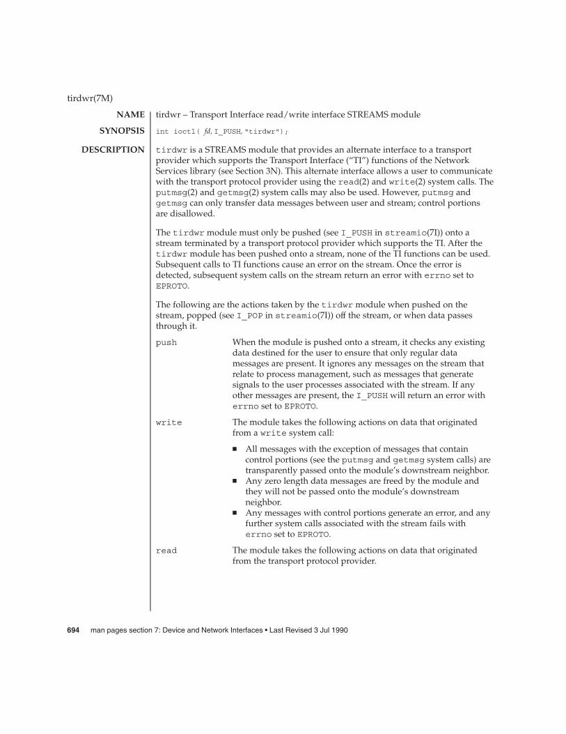
tirdwr – Transport Interface read/write interface STREAMS module
int ioctl( fd, I_PUSH, "tirdwr");
tirdwr is a STREAMS module that provides an alternate interface to a transportprovider which supports the Transport Interface (“TI”) functions of the NetworkServices library (see Section 3N). This alternate interface allows a user to communicatewith the transport protocol provider using the read(2) and write(2) system calls. Theputmsg(2) and getmsg(2) system calls may also be used. However, putmsg andgetmsg can only transfer data messages between user and stream; control portionsare disallowed.
The tirdwr module must only be pushed (see I_PUSH in streamio(7I)) onto astream terminated by a transport protocol provider which supports the TI. After thetirdwr module has been pushed onto a stream, none of the TI functions can be used.Subsequent calls to TI functions cause an error on the stream. Once the error isdetected, subsequent system calls on the stream return an error with errno set toEPROTO.
The following are the actions taken by the tirdwr module when pushed on thestream, popped (see I_POP in streamio(7I)) off the stream, or when data passesthrough it.
push When the module is pushed onto a stream, it checks any existingdata destined for the user to ensure that only regular datamessages are present. It ignores any messages on the stream thatrelate to process management, such as messages that generatesignals to the user processes associated with the stream. If anyother messages are present, the I_PUSH will return an error witherrno set to EPROTO.
write The module takes the following actions on data that originatedfrom a write system call:
� All messages with the exception of messages that containcontrol portions (see the putmsg and getmsg system calls) aretransparently passed onto the module’s downstream neighbor.
� Any zero length data messages are freed by the module andthey will not be passed onto the module’s downstreamneighbor.
� Any messages with control portions generate an error, and anyfurther system calls associated with the stream fails witherrno set to EPROTO.
read The module takes the following actions on data that originatedfrom the transport protocol provider.
tirdwr(7M)
NAME
SYNOPSIS
DESCRIPTION
694 man pages section 7: Device and Network Interfaces • Last Revised 3 Jul 1990

All messages with the exception of those that contain controlportions (see the putmsg and getmsg system calls) aretransparently passed onto the module’s upstream neighbor. Theaction taken on messages with control portions will be as follows:
� Any data messages with control portions have the controlportions removed from the message before to passing themessage on to the upstream neighbor.
� Messages that represent an orderly release indication from thetransport provider generate a zero length data message,indicating the end of file, which will be sent to the reader of thestream. The orderly release message itself is freed by themodule.
� Messages that represent an abortive disconnect indication fromthe transport provider cause all further write and putmsgsystem calls to fail with errno set to ENXIO. All further readand getmsg system calls return zero length data (indicatingend of file) once all previous data has been read.
� With the exception of the above rules, all other messages withcontrol portions generate an error and all further system callsassociated with the stream will fail with errno set to EPROTO.
Any zero length data messages are freed by the module and theyare not passed onto the module’s upstream neighbor.
pop When the module is popped off the stream or the stream is closed,the module takes the following action:
� If an orderly release indication has been previously received,then an orderly release request will be sent to the remote sideof the transport connection.
intro(3), getmsg(2), putmsg(2), read(2), write(2), intro(3), streamio(7I),timod(7M)
STREAMS Programming Guide
tirdwr(7M)
SEE ALSO
Device and Network Interfaces 695

tmpfs – memory based file system
#include <sys/mount.h>
mount (special, directory, MS_DATA, "tmpfs", NULL, 0);
tmpfs is a memory based file system which uses kernel resources relating to the VMsystem and page cache as a file system. Once mounted, a tmpfs file system providesstandard file operations and semantics. tmpfs is so named because files anddirectories are not preserved across reboot or unmounts, all files residing on a tmpfsfile system that is unmounted will be lost.
tmpfs file systems can be mounted with the command:
mount -F tmpfs swap directory
Alternatively, to mount a tmpfs file system on /tmp at multi-user startup time(maximizing possible performance improvements), add the following line to/etc/vfstab:
swap −/tmp tmpfs − yes −
tmpfs is designed as a performance enhancement which is achieved by caching thewrites to files residing on a tmpfs file system. Performance improvements are mostnoticeable when a large number of short lived files are written and accessed on atmpfs file system. Large compilations with tmpfs mounted on /tmp are a goodexample of this.
Users of tmpfs should be aware of some constraints involved in mounting a tmpfsfile system. The resources used by tmpfs are the same as those used when commandsare executed (for example, swap space allocation). This means that large sized tmpfsfiles can affect the amount of space left over for programs to execute. Likewise,programs requiring large amounts of memory use up the space available to tmpfs.Users running into this constraint (for example, running out of space on tmpfs) canallocate more swap space by using the swap(1M) command.
Another constraint is that the number of files available in a tmpfs file system iscalculated based on the physical memory of the machine and not the size of the swapdevice/partition. If you have too many files, tmpfs will print a warning message andyou will be unable to create new files. You cannot increase this limit by adding swapspace.
Normal file system writes are scheduled to be written to a permanent storage mediumalong with all control information associated with the file (for example, modificationtime, file permissions). tmpfs control information resides only in memory and neverneeds to be written to permanent storage. File data remains in core until memorydemands are sufficient to cause pages associated with tmpfs to be reused at whichtime they are copied out to swap.
tmpfs(7FS)
NAME
SYNOPSIS
DESCRIPTION
696 man pages section 7: Device and Network Interfaces • Last Revised 9 Oct 1990

An additional mount option can be specified to control the size of an individualtmpfs file system.
df(1M), mount(1M), mount_tmpfs(1M), swap(1M), mmap(2), mount(2), umount(2),vfstab(4)
System Administration Guide: Basic Administration
If tmpfs runs out of space, one of the following messages will display in the console.
directory: File system full, swap space limit exceededThis message appears because a page could not be allocated while writing to a file.This can occur if tmpfs is attempting to write more than it is allowed, or ifcurrently executing programs are using a lot of memory. To make more spaceavailable, remove unnecessary files, exit from some programs, or allocate moreswap space using swap(1M).
directory: File system full, memory allocation failedtmpfs ran out of physical memory while attempting to create a new file ordirectory. Remove unnecessary files or directories or install more physical memory.
Files and directories on a tmpfs file system are not preserved across reboots orunmounts. Command scripts or programs which count on this will not work asexpected.
Compilers do not necessarily use /tmp to write intermediate files therefore missingsome significant performance benefits. This can be remedied by setting theenvironment variable TMPDIR to /tmp. Compilers use the value in this environmentvariable as the name of the directory to store intermediate files.
swap to a tmpfs file is not supported.
df(1M) output is of limited accuracy since a tmpfs file system size is not static andthe space available to tmpfs is dependent on the swap space demands of the entiresystem.
tmpfs(7FS)
SEE ALSO
DIAGNOSTICS
WARNINGS
NOTES
Device and Network Interfaces 697
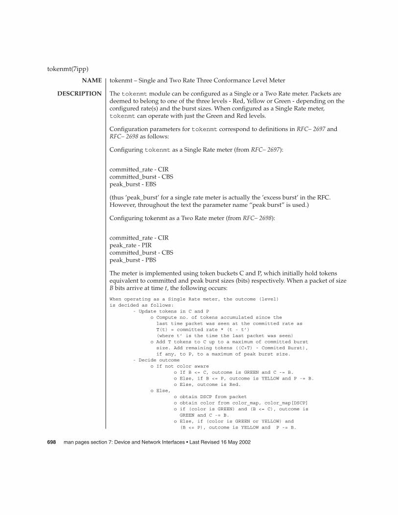
tokenmt – Single and Two Rate Three Conformance Level Meter
The tokenmt module can be configured as a Single or a Two Rate meter. Packets aredeemed to belong to one of the three levels - Red, Yellow or Green - depending on theconfigured rate(s) and the burst sizes. When configured as a Single Rate meter,tokenmt can operate with just the Green and Red levels.
Configuration parameters for tokenmt correspond to definitions in RFC– 2697 andRFC– 2698 as follows:
Configuring tokenmt as a Single Rate meter (from RFC– 2697):
committed_rate - CIRcommitted_burst - CBSpeak_burst - EBS
(thus ’peak_burst’ for a single rate meter is actually the ’excess burst’ in the RFC.However, throughout the text the parameter name “peak burst” is used.)
Configuring tokenmt as a Two Rate meter (from RFC– 2698):
committed_rate - CIRpeak_rate - PIRcommitted_burst - CBSpeak_burst - PBS
The meter is implemented using token buckets C and P, which initially hold tokensequivalent to committed and peak burst sizes (bits) respectively. When a packet of sizeB bits arrive at time t, the following occurs:
When operating as a Single Rate meter, the outcome (level)is decided as follows:
- Update tokens in C and Po Compute no. of tokens accumulated since the
last time packet was seen at the committed rate asT(t) = committed rate * (t - t’)(where t’ is the time the last packet was seen)
o Add T tokens to C up to a maximum of committed burstsize. Add remaining tokens ((C+T) - Commited Burst),if any, to P, to a maximum of peak burst size.
- Decide outcomeo If not color aware
o If B <= C, outcome is GREEN and C -= B.o Else, if B <= P, outcome is YELLOW and P -= B.o Else, outcome is Red.
o Else,o obtain DSCP from packeto obtain color from color_map, color_map[DSCP]o if (color is GREEN) and (B <= C), outcome is
GREEN and C -= B.o Else, if (color is GREEN or YELLOW) and
(B <= P), outcome is YELLOW and P -= B.
tokenmt(7ipp)
NAME
DESCRIPTION
698 man pages section 7: Device and Network Interfaces • Last Revised 16 May 2002
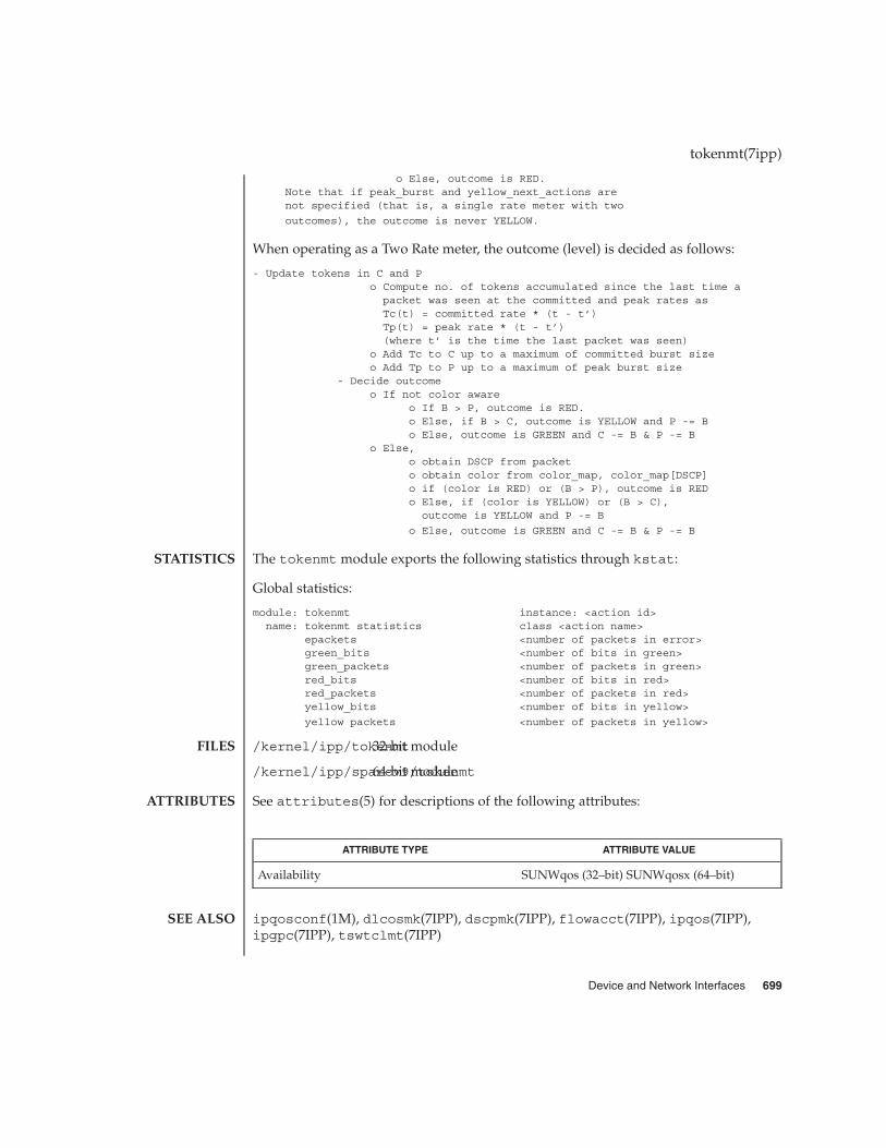
o Else, outcome is RED.Note that if peak_burst and yellow_next_actions arenot specified (that is, a single rate meter with two
outcomes), the outcome is never YELLOW.
When operating as a Two Rate meter, the outcome (level) is decided as follows:
- Update tokens in C and Po Compute no. of tokens accumulated since the last time a
packet was seen at the committed and peak rates asTc(t) = committed rate * (t - t’)Tp(t) = peak rate * (t - t’)(where t’ is the time the last packet was seen)
o Add Tc to C up to a maximum of committed burst sizeo Add Tp to P up to a maximum of peak burst size
- Decide outcomeo If not color aware
o If B > P, outcome is RED.o Else, if B > C, outcome is YELLOW and P -= Bo Else, outcome is GREEN and C -= B & P -= B
o Else,o obtain DSCP from packeto obtain color from color_map, color_map[DSCP]o if (color is RED) or (B > P), outcome is REDo Else, if (color is YELLOW) or (B > C),
outcome is YELLOW and P -= B
o Else, outcome is GREEN and C -= B & P -= B
The tokenmt module exports the following statistics through kstat:
Global statistics:
module: tokenmt instance: <action id>name: tokenmt statistics class <action name>
epackets <number of packets in error>green_bits <number of bits in green>green_packets <number of packets in green>red_bits <number of bits in red>red_packets <number of packets in red>yellow_bits <number of bits in yellow>
yellow packets <number of packets in yellow>
/kernel/ipp/tokenmt32-bit module
/kernel/ipp/sparcv9/tokenmt64-bit module
See attributes(5) for descriptions of the following attributes:
ATTRIBUTE TYPE ATTRIBUTE VALUE
Availability SUNWqos (32–bit) SUNWqosx (64–bit)
ipqosconf(1M), dlcosmk(7IPP), dscpmk(7IPP), flowacct(7IPP), ipqos(7IPP),ipgpc(7IPP), tswtclmt(7IPP)
tokenmt(7ipp)
STATISTICS
FILES
ATTRIBUTES
SEE ALSO
Device and Network Interfaces 699

RFC 2697, A Single Rate Three Color Marker J. Heinanen, R. Guerin — The InternetSociety, 1999
RFC 2698, A Two Rate Three Color Marker J. Heinanen, R. Guerin — The Internet Society,1999
tokenmt(7ipp)
700 man pages section 7: Device and Network Interfaces • Last Revised 16 May 2002

tpf – Platform Specific Module (PSM) for Tricord Systems Enterprise Server ModelsES3000, ES4000 and ES5000.
tpf provides the platform dependent functions for Solaris IA MP support. Thesefunctions adhere to the PSMI Specifications. (Platform Specific Module InterfaceSpecifications.) Tricord Systems Enterprise Servers are Intel APIC based MP platformswhich run from 1 to 12 Intel processors. The tpf psm supports dynamic interruptdistribution across all processors in an MP configuration.
The psm is automatically invoked on an ESxxxx platform at system boot time.
/kernel/mach/tpf MP module.
See attributes(5) for descriptions of the following attributes:
ATTRIBUTE TYPE ATTRIBUTE VALUE
Architecture IA
attributes(5)
tpf(7D)
NAME
DESCRIPTION
FILES
ATTRIBUTES
SEE ALSO
Device and Network Interfaces 701

tswtclmt – Time Sliding Window Three Conformance Level Meter
The Time Sliding Window Three Conformance level meter (tswtcl) meters a trafficstream and determines the conformance level of its packets.
Packets are deemed to belong to one of the three levels, Red, Yellow or Green,depending on the committed and peak rate.
The meter provides an estimate of the running average bandwidth. It takes intoaccount burstiness and smoothes out its estimate to approximate the longer-termmeasured sending rate of the traffic stream.
The estimated bandwidth approximates the running average bandwidth of the trafficstream over a specific window (time interval). tswtcl estimates the averagebandwidth using a time-based estimator. When a packet arrives for a class, tswtclre-computes the average rate by using the rate in the last window (time interval) andthe size of the arriving packet. The window is then slid to start at the current time (thepacket arrival time). If the computed rate is less than the committed configurationparameter, the packet is deemed Green; else if the rate is less than the peak rate, it isYellow; else Red. To avoid dropping multiple packets within a TCP window, tswtclprobabilistically assigns one of the three conformance level to the packet.
The tswtcl module exports global and per-class statistics through kstat:
Global statistics:
module: tswtclmt instance: <action id>name: tswtclmt statistics class <action name>
green_bits <number of bit in green>green_packets <number of packets in green>red_bits <number of bits in red>red_packets <number of packets in red>yellow_bits <number of bits in yellow>
yellow_packets <number of packets in yellow>
/kernel/ipp/tswtclmt32-bit module
/kernel/ipp/sparcv9/tswtclmt64-bit module
See attributes(5) for descriptions of the following attributes:
ATTRIBUTE TYPE ATTRIBUTE VALUE
Availability SUNWqos (32–bit) SUNWqosx (64–bit)
ipqosconf(1M), dlcosmk(7IPP), dscpmk(7IPP), flowacct(7IPP), ipqos(7IPP),ipgpc(7IPP), tokenmt(7IPP)
RFC 2859, A Time Sliding Window Three Colour Marker (TSWTCM) W. Fang, N. Seddigh,B. Nandy — The Internet Society, 2000
tswtclmt(7ipp)
NAME
DESCRIPTION
STATISTICS
FILES
ATTRIBUTES
SEE ALSO
702 man pages section 7: Device and Network Interfaces • Last Revised 25 Feb 2002
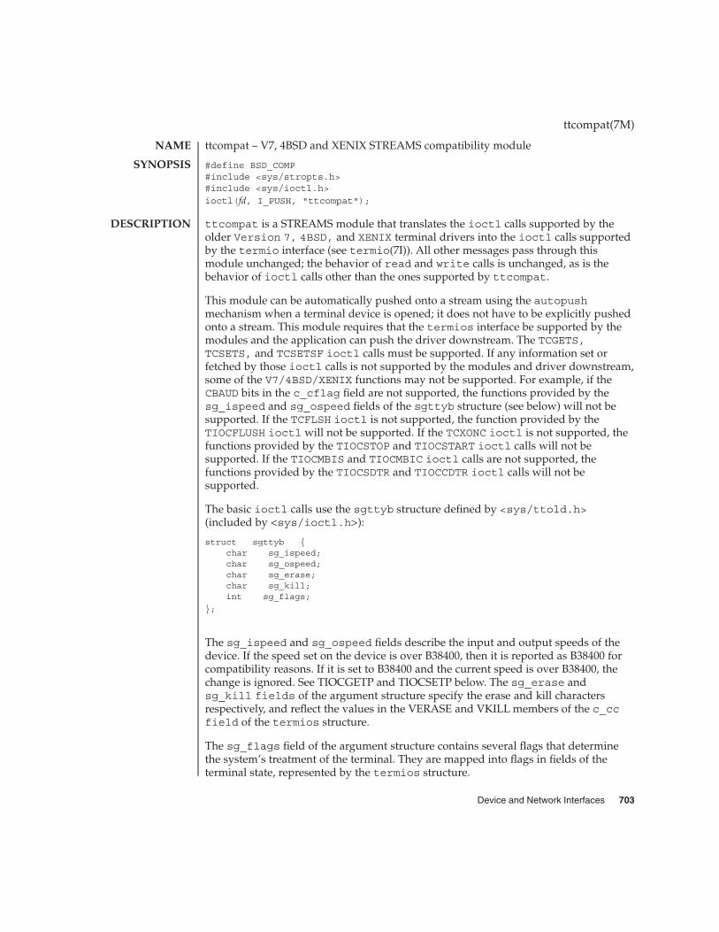
ttcompat – V7, 4BSD and XENIX STREAMS compatibility module
#define BSD_COMP#include <sys/stropts.h>#include <sys/ioctl.h>
ioctl(fd, I_PUSH, "ttcompat");
ttcompat is a STREAMS module that translates the ioctl calls supported by theolder Version 7, 4BSD, and XENIX terminal drivers into the ioctl calls supportedby the termio interface (see termio(7I)). All other messages pass through thismodule unchanged; the behavior of read and write calls is unchanged, as is thebehavior of ioctl calls other than the ones supported by ttcompat.
This module can be automatically pushed onto a stream using the autopushmechanism when a terminal device is opened; it does not have to be explicitly pushedonto a stream. This module requires that the termios interface be supported by themodules and the application can push the driver downstream. The TCGETS,TCSETS, and TCSETSF ioctl calls must be supported. If any information set orfetched by those ioctl calls is not supported by the modules and driver downstream,some of the V7/4BSD/XENIX functions may not be supported. For example, if theCBAUD bits in the c_cflag field are not supported, the functions provided by thesg_ispeed and sg_ospeed fields of the sgttyb structure (see below) will not besupported. If the TCFLSH ioctl is not supported, the function provided by theTIOCFLUSH ioctl will not be supported. If the TCXONC ioctl is not supported, thefunctions provided by the TIOCSTOP and TIOCSTART ioctl calls will not besupported. If the TIOCMBIS and TIOCMBIC ioctl calls are not supported, thefunctions provided by the TIOCSDTR and TIOCCDTR ioctl calls will not besupported.
The basic ioctl calls use the sgttyb structure defined by <sys/ttold.h>(included by <sys/ioctl.h>):
struct sgttyb {char sg_ispeed;char sg_ospeed;char sg_erase;char sg_kill;int sg_flags;
};
The sg_ispeed and sg_ospeed fields describe the input and output speeds of thedevice. If the speed set on the device is over B38400, then it is reported as B38400 forcompatibility reasons. If it is set to B38400 and the current speed is over B38400, thechange is ignored. See TIOCGETP and TIOCSETP below. The sg_erase andsg_kill fields of the argument structure specify the erase and kill charactersrespectively, and reflect the values in the VERASE and VKILL members of the c_ccfield of the termios structure.
The sg_flags field of the argument structure contains several flags that determinethe system’s treatment of the terminal. They are mapped into flags in fields of theterminal state, represented by the termios structure.
ttcompat(7M)
NAME
SYNOPSIS
DESCRIPTION
Device and Network Interfaces 703
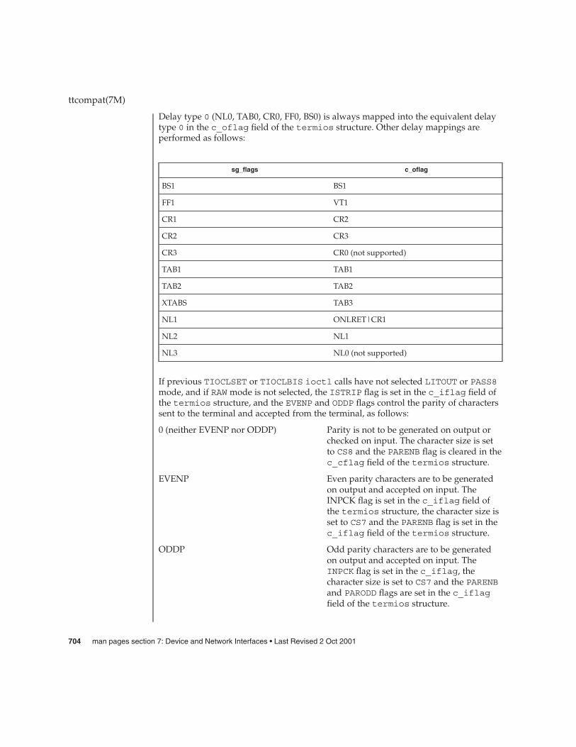
Delay type 0 (NL0, TAB0, CR0, FF0, BS0) is always mapped into the equivalent delaytype 0 in the c_oflag field of the termios structure. Other delay mappings areperformed as follows:
sg_flags c_oflag
BS1 BS1
FF1 VT1
CR1 CR2
CR2 CR3
CR3 CR0 (not supported)
TAB1 TAB1
TAB2 TAB2
XTABS TAB3
NL1 ONLRET|CR1
NL2 NL1
NL3 NL0 (not supported)
If previous TIOCLSET or TIOCLBIS ioctl calls have not selected LITOUT or PASS8mode, and if RAW mode is not selected, the ISTRIP flag is set in the c_iflag field ofthe termios structure, and the EVENP and ODDP flags control the parity of characterssent to the terminal and accepted from the terminal, as follows:
0 (neither EVENP nor ODDP) Parity is not to be generated on output orchecked on input. The character size is setto CS8 and the PARENB flag is cleared in thec_cflag field of the termios structure.
EVENP Even parity characters are to be generatedon output and accepted on input. TheINPCK flag is set in the c_iflag field ofthe termios structure, the character size isset to CS7 and the PARENB flag is set in thec_iflag field of the termios structure.
ODDP Odd parity characters are to be generatedon output and accepted on input. TheINPCK flag is set in the c_iflag, thecharacter size is set to CS7 and the PARENBand PARODD flags are set in the c_iflagfield of the termios structure.
ttcompat(7M)
704 man pages section 7: Device and Network Interfaces • Last Revised 2 Oct 2001
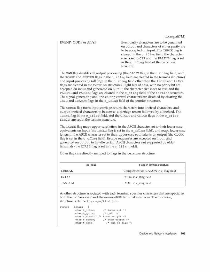
EVENP|ODDP or ANYP Even parity characters are to be generatedon output and characters of either parity areto be accepted on input. The INPCK flag iscleared in the c_iflag field, the charactersize is set to CS7 and the PARENB flag is setin the c_iflag field of the termiosstructure.
The RAW flag disables all output processing (the OPOST flag in the c_oflag field, andthe XCASE and IEXTEN flags in the c_iflag field are cleared in the termios structure)and input processing (all flags in the c_iflag field other than the IXOFF and IXANYflags are cleared in the termios structure). Eight bits of data, with no parity bit areaccepted on input and generated on output; the character size is set to CS8 and thePARENB and PARODD flags are cleared in the c_cflag field of the termios structure.The signal-generating and line-editing control characters are disabled by clearing theISIG and ICANON flags in the c_iflag field of the termios structure.
The CRMOD flag turns input carriage return characters into linefeed characters, andoutput linefeed characters to be sent as a carriage return followed by a linefeed. TheICRNL flag in the c_iflag field, and the OPOST and ONLCR flags in the c_oflagfield, are set in the termios structure.
The LCASE flag maps upper-case letters in the ASCII character set to their lower-caseequivalents on input (the IUCLC flag is set in the c_iflag field), and maps lower-caseletters in the ASCII character set to their upper-case equivalents on output (the OLCUCflag is set in the c_oflag field). Escape sequences are accepted on input, andgenerated on output, to handle certain ASCII characters not supported by olderterminals (the XCASE flag is set in the c_lflag field).
Other flags are directly mapped to flags in the termios structure:
sg_flags Flags in termios structure
CBREAK Complement of ICANON in c_lflag field
ECHO ECHO in c_lflag field
TANDEM IXOFF in c_iflag field
Another structure associated with each terminal specifies characters that are special inboth the old Version 7 and the newer 4BSD terminal interfaces. The followingstructure is defined by <sys/ttold.h>:
struct tchars {char t_intrc; /* interrupt */char t_quitc; /* quit */char t_startc; /* start output */char t_stopc; /* stop output */char t_eofc; /* end-of-file */
ttcompat(7M)
Device and Network Interfaces 705

char t_brkc; /* input delimiter (like nl) */
};
XENIX defines the tchar structure as tc. The characters are mapped to members ofthe c_cc field of the termios structure as follows:
tchars c_cc indext_intrc VINTRt_quitc VQUITt_startc VSTARTt_stopc VSTOPt_eofc VEOF
t_brkc VEOL
Also associated with each terminal is a local flag word (TIOCLSET and TIOCLGET),specifying flags supported by the new 4BSD terminal interface. Most of these flags aredirectly mapped to flags in the termios structure:
Local flags Flags in termios structure
LCRTBS Not supported
LPRTERA ECHOPRT in the c_lflag field
LCRTERA ECHOE in the c_lflag field
LTILDE Not supported
LMDMBUF Not supported
LTOSTOP TOSTOP in the c_lflag field
LFLUSHO FLUSHO in the c_lflag field
LNOHANG CLOCAL in the c_cflag field
LCRTKIL ECHOKE in the c_lflag field
LPASS8 CS8 in the c_cflag field
LCTLECH CTLECH in the c_lflag field
LPENDIN PENDIN in the c_lflag field
LDECCTQ Complement of IXANY in the c_iflag field
LNOFLSH NOFLSH in the c_lflag field
Each flag has a corresponding equivalent sg_flags value. The sg_flags definitionsomit the leading "L”; for example, TIOCSETP with sg_flags set to TOSTOP isequivalent to TIOCLSET with LTOSTOP.
ttcompat(7M)
706 man pages section 7: Device and Network Interfaces • Last Revised 2 Oct 2001
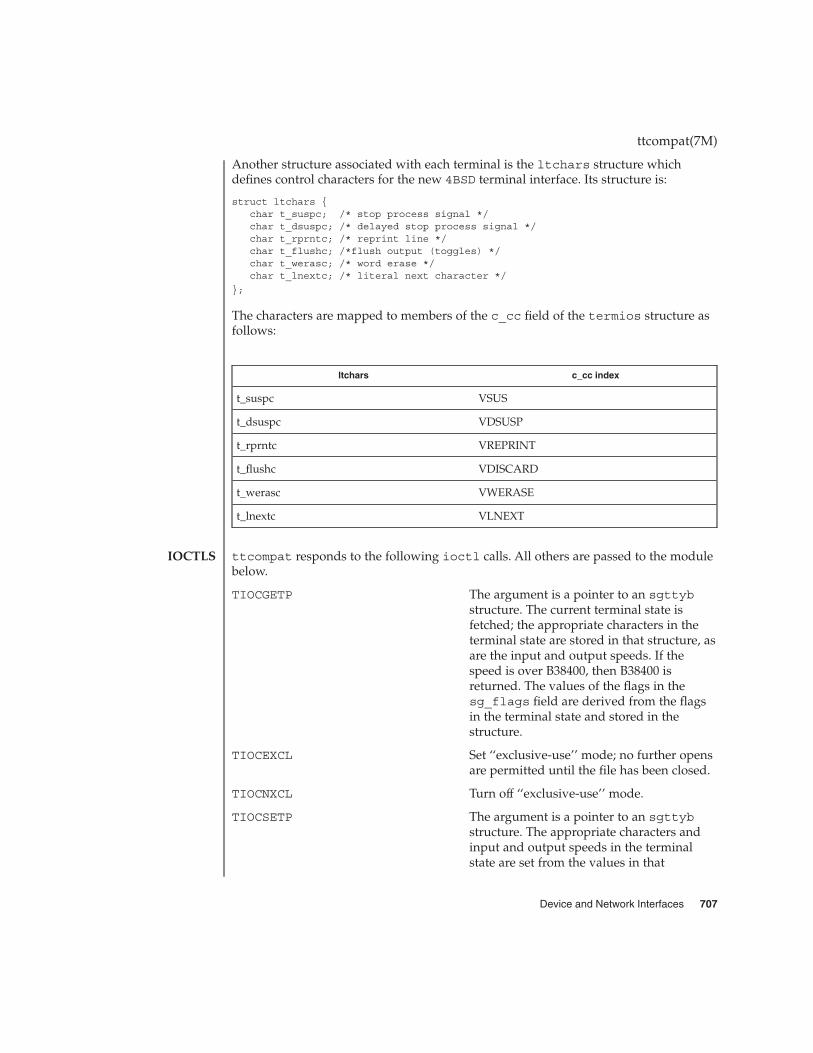
Another structure associated with each terminal is the ltchars structure whichdefines control characters for the new 4BSD terminal interface. Its structure is:
struct ltchars {char t_suspc; /* stop process signal */char t_dsuspc; /* delayed stop process signal */char t_rprntc; /* reprint line */char t_flushc; /*flush output (toggles) */char t_werasc; /* word erase */char t_lnextc; /* literal next character */
};
The characters are mapped to members of the c_cc field of the termios structure asfollows:
ltchars c_cc index
t_suspc VSUS
t_dsuspc VDSUSP
t_rprntc VREPRINT
t_flushc VDISCARD
t_werasc VWERASE
t_lnextc VLNEXT
ttcompat responds to the following ioctl calls. All others are passed to the modulebelow.
TIOCGETP The argument is a pointer to an sgttybstructure. The current terminal state isfetched; the appropriate characters in theterminal state are stored in that structure, asare the input and output speeds. If thespeed is over B38400, then B38400 isreturned. The values of the flags in thesg_flags field are derived from the flagsin the terminal state and stored in thestructure.
TIOCEXCL Set ‘‘exclusive-use’’ mode; no further opensare permitted until the file has been closed.
TIOCNXCL Turn off ‘‘exclusive-use’’ mode.
TIOCSETP The argument is a pointer to an sgttybstructure. The appropriate characters andinput and output speeds in the terminalstate are set from the values in that
ttcompat(7M)
IOCTLS
Device and Network Interfaces 707
structure, and the flags in the terminal stateare set to match the values of the flags inthe sg_flags field of that structure. Thestate is changed with a TCSETSF ioctl sothat the interface delays until output isquiescent, then throws away any unreadcharacters, before changing the modes. Ifthe current device speed is over B38400 foreither input or output speed, and B38400 isspecified through this interface for thatspeed, the actual device speed is notchanged. If the device speed is B38400 orlower or if some speed other than B38400 isspecified, then the actual speed specified isset.
TIOCSETN The argument is a pointer to an sgttybstructure. The terminal state is changed asTIOCSETP would change it, but a TCSETSioctl is used, so that the interface neitherdelays nor discards input.
TIOCHPCL The argument is ignored. The HUPCL flag isset in the c_cflag word of the terminalstate.
TIOCFLUSH The argument is a pointer to an intvariable. If its value is zero, all characterswaiting in input or output queues areflushed. Otherwise, the value of the int istreated as the logical OR of the FREAD andFWRITE flags defined by <sys/file.h>. Ifthe FREAD bit is set, all characters waitingin input queues are flushed, and if theFWRITE bit is set, all characters waiting inoutput queues are flushed.
TIOCSBRK The argument is ignored. The break bit isset for the device. (This is not supported byttcompat. The underlying driver mustsupport TIOCSBRK.)
TIOCCBRK The argument is ignored. The break bit iscleared for the device. (This is notsupported by ttcompat. The underlyingdriver must support TIOCCBRK.)
TIOCSDTR The argument is ignored. The DataTerminal Ready bit is set for the device.
ttcompat(7M)
708 man pages section 7: Device and Network Interfaces • Last Revised 2 Oct 2001
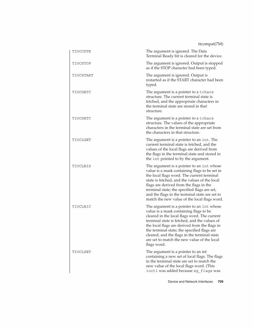
TIOCCDTR The argument is ignored. The DataTerminal Ready bit is cleared for the device.
TIOCSTOP The argument is ignored. Output is stoppedas if the STOP character had been typed.
TIOCSTART The argument is ignored. Output isrestarted as if the START character had beentyped.
TIOCGETC The argument is a pointer to a tcharsstructure. The current terminal state isfetched, and the appropriate characters inthe terminal state are stored in thatstructure.
TIOCSETC The argument is a pointer to a tcharsstructure. The values of the appropriatecharacters in the terminal state are set fromthe characters in that structure.
TIOCLGET The argument is a pointer to an int. Thecurrent terminal state is fetched, and thevalues of the local flags are derived fromthe flags in the terminal state and stored inthe int pointed to by the argument.
TIOCLBIS The argument is a pointer to an int whosevalue is a mask containing flags to be set inthe local flags word. The current terminalstate is fetched, and the values of the localflags are derived from the flags in theterminal state; the specified flags are set,and the flags in the terminal state are set tomatch the new value of the local flags word.
TIOCLBIC The argument is a pointer to an int whosevalue is a mask containing flags to becleared in the local flags word. The currentterminal state is fetched, and the values ofthe local flags are derived from the flags inthe terminal state; the specified flags arecleared, and the flags in the terminal stateare set to match the new value of the localflags word.
TIOCLSET The argument is a pointer to an intcontaining a new set of local flags. The flagsin the terminal state are set to match thenew value of the local flags word. (Thisioctl was added because sg_flags was
ttcompat(7M)
Device and Network Interfaces 709
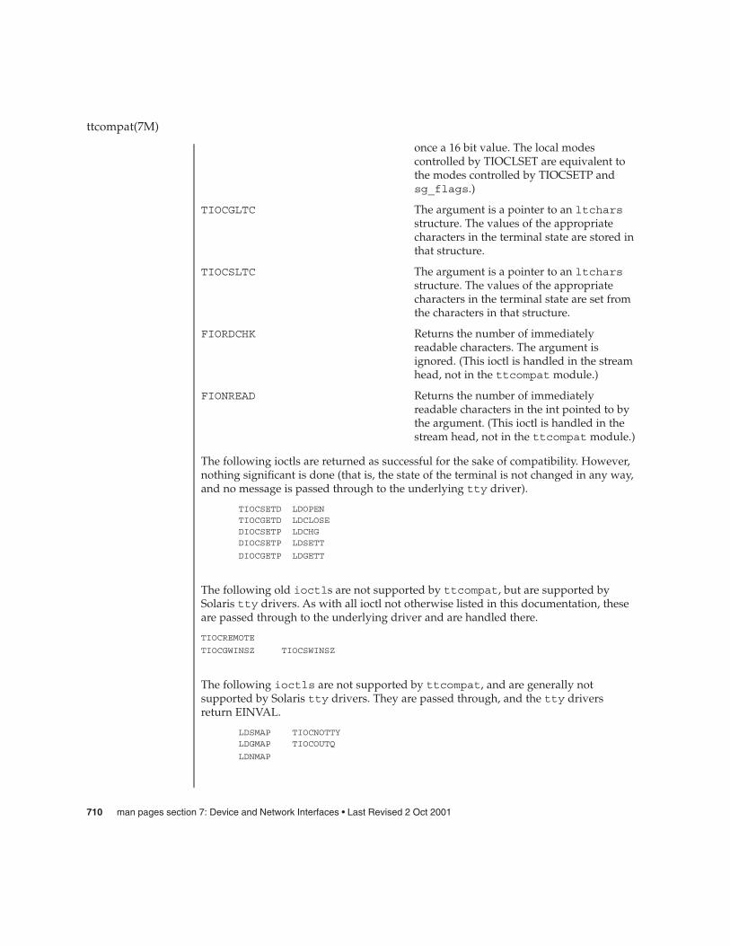
once a 16 bit value. The local modescontrolled by TIOCLSET are equivalent tothe modes controlled by TIOCSETP andsg_flags.)
TIOCGLTC The argument is a pointer to an ltcharsstructure. The values of the appropriatecharacters in the terminal state are stored inthat structure.
TIOCSLTC The argument is a pointer to an ltcharsstructure. The values of the appropriatecharacters in the terminal state are set fromthe characters in that structure.
FIORDCHK Returns the number of immediatelyreadable characters. The argument isignored. (This ioctl is handled in the streamhead, not in the ttcompat module.)
FIONREAD Returns the number of immediatelyreadable characters in the int pointed to bythe argument. (This ioctl is handled in thestream head, not in the ttcompat module.)
The following ioctls are returned as successful for the sake of compatibility. However,nothing significant is done (that is, the state of the terminal is not changed in any way,and no message is passed through to the underlying tty driver).
TIOCSETD LDOPENTIOCGETD LDCLOSEDIOCSETP LDCHGDIOCSETP LDSETT
DIOCGETP LDGETT
The following old ioctls are not supported by ttcompat, but are supported bySolaris tty drivers. As with all ioctl not otherwise listed in this documentation, theseare passed through to the underlying driver and are handled there.
TIOCREMOTE
TIOCGWINSZ TIOCSWINSZ
The following ioctls are not supported by ttcompat, and are generally notsupported by Solaris tty drivers. They are passed through, and the tty driversreturn EINVAL.
LDSMAP TIOCNOTTYLDGMAP TIOCOUTQ
LDNMAP
ttcompat(7M)
710 man pages section 7: Device and Network Interfaces • Last Revised 2 Oct 2001

(Note: LDSMAP, LDGMAP, and LDNMAP are defined in <sys/termios.h>.)
ioctl(2), termios(3C), ldterm(7M), termio(7I)
ttcompat(7M)
SEE ALSO
Device and Network Interfaces 711

tty – controlling terminal interface
The file /dev/tty is, in each process, a synonym for the control terminal associatedwith the process group of that process, if any. It is useful for programs or shellsequences that wish to be sure of writing messages on the terminal no matter howoutput has been redirected. It can also be used for programs that demand the name ofa file for output, when typed output is desired and it is tiresome to find out whatterminal is currently in use.
/dev/tty
/dev/tty*
ports(1M), console(7D)
tty(7D)
NAME
DESCRIPTION
FILES
SEE ALSO
712 man pages section 7: Device and Network Interfaces • Last Revised 3 Jul 1990

ttymux – Serial I/O multiplexing STREAMS device driver
multiplexer@0,0:input
multiplexer@0,0:output
ttymux is a STREAMS multiplexer driver that connects multiple serial devices to thesystem console. Using this driver, input from multiple physical devices can bemultiplexed onto a single input stream for the system console. Output written to theconsole can be distributed to multiple physical devices to provide redundant consoleinterfaces to a system. Input and output can be multiplexed to or from a separate listof devices.
ttymux is a STREAM’s multiplexer for serial drivers (such as se(7D)) that complywith the Solaris terminal subsystem interface.
Currently, multiplexer interfaces are provided for system console I/O only and not forgeneral serial I/O multiplexing. Multiplexer interfaces are currently not available forall platforms. Please see NOTES.
/kernel/drv/sparcv9/ttymux64– bit ELF kernel module
See attributes(5) for descriptions of the following attributes:
ATTRIBUTE TYPE ATTRIBUTE VALUE
Architecture SPARC (NetraCT series only)
se(7D), termio(7I)
Writing Device Drivers
Successful loading of this driver and its services depends on the EEPROM or NVRAMsettings in effect at the most recent system reboot. Without the platform firmwaresupport, this feature cannot be enabled. Currently, this support is provided only on aNetraCT product family.
Use caution when enabling this feature to perform console input multiplexing,particularly during super-user login. Because no security measures are enabled whenthe driver is in operation, you must clearly understand the security implicationsinvolved in using this feature and take appropriate measures to provide maximumprotection to the host. This can include such steps as enabling input to physicallysecured console devices only.
The ttymux driver does not handle the behavioral differences in controlcharacteristics of different terminal types (for example, an ESCAPE sequence.) As aresult, multiple terminal types are not supported simultaneously. Please refer to theplatform user guide for more information.
ttymux(7D)
NAME
SYNOPSIS
DESCRIPTION
FILES
ATTRIBUTES
SEE ALSO
NOTES
Device and Network Interfaces 713
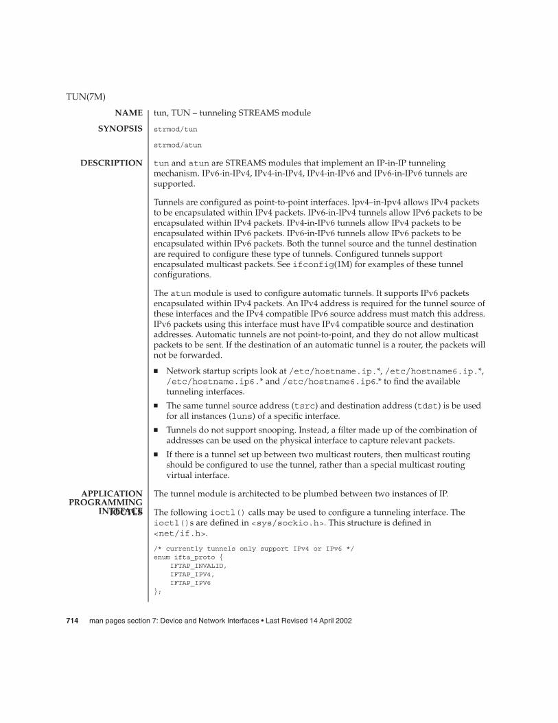
tun, TUN – tunneling STREAMS module
strmod/tun
strmod/atun
tun and atun are STREAMS modules that implement an IP-in-IP tunnelingmechanism. IPv6-in-IPv4, IPv4-in-IPv4, IPv4-in-IPv6 and IPv6-in-IPv6 tunnels aresupported.
Tunnels are configured as point-to-point interfaces. Ipv4–in-Ipv4 allows IPv4 packetsto be encapsulated within IPv4 packets. IPv6-in-IPv4 tunnels allow IPv6 packets to beencapsulated within IPv4 packets. IPv4-in-IPv6 tunnels allow IPv4 packets to beencapsulated within IPv6 packets. IPv6-in-IPv6 tunnels allow IPv6 packets to beencapsulated within IPv6 packets. Both the tunnel source and the tunnel destinationare required to configure these type of tunnels. Configured tunnels supportencapsulated multicast packets. See ifconfig(1M) for examples of these tunnelconfigurations.
The atun module is used to configure automatic tunnels. It supports IPv6 packetsencapsulated within IPv4 packets. An IPv4 address is required for the tunnel source ofthese interfaces and the IPv4 compatible IPv6 source address must match this address.IPv6 packets using this interface must have IPv4 compatible source and destinationaddresses. Automatic tunnels are not point-to-point, and they do not allow multicastpackets to be sent. If the destination of an automatic tunnel is a router, the packets willnot be forwarded.
� Network startup scripts look at /etc/hostname.ip.*, /etc/hostname6.ip.*,/etc/hostname.ip6.* and /etc/hostname6.ip6.* to find the availabletunneling interfaces.
� The same tunnel source address (tsrc) and destination address (tdst) is be usedfor all instances (luns) of a specific interface.
� Tunnels do not support snooping. Instead, a filter made up of the combination ofaddresses can be used on the physical interface to capture relevant packets.
� If there is a tunnel set up between two multicast routers, then multicast routingshould be configured to use the tunnel, rather than a special multicast routingvirtual interface.
The tunnel module is architected to be plumbed between two instances of IP.
The following ioctl() calls may be used to configure a tunneling interface. Theioctl()s are defined in <sys/sockio.h>. This structure is defined in<net/if.h>.
/* currently tunnels only support IPv4 or IPv6 */enum ifta_proto {
IFTAP_INVALID,IFTAP_IPV4,IFTAP_IPV6
};
TUN(7M)
NAME
SYNOPSIS
DESCRIPTION
APPLICATIONPROGRAMMING
INTEFACEIOCTLS
714 man pages section 7: Device and Network Interfaces • Last Revised 14 April 2002

#define IFTUN_SECINFOLEN 8#define IFTUN_VERSION 1
/* tunnel configuration structure */
struct iftun_req {char ifta_lifr_name[LIFNAMSIZ]; /* if name */struct sockaddr_storage ifta_saddr; /* source address */struct sockaddr_storage ifta_daddr; /* destination address */uint_t ifta_flags; /* See below */
/* IP version information is read only */enum ifta_proto ifta_upper; /* IP version above tunnel */enum ifta_proto ifta_lower; /* IP versin below tunnel */uint_t ifta_vers; /* Version number */uint32_t ifta_secinfo[IFTUN_SECINFOLEN]; /* Security prefs. */int16_t ifta_encap_lim; /* Encapsulation limit */uint8_t ifta_hop_limit; /* Hop limit */
};/* These flags are set to indicate which members are valid */
#define IFTUN_SRC 0x01#define IFTUN_DST 0x02#define IFTUN_SECURITY 0x04#define IFTUN_ENCAP 0x08
#define IFTUN_HOPLIMIT 0x10
The ifta_vers field indicates what IPsec request structure is overlayed on top ofifta_secinfo. The current value of IFTUN_VERSION implies an overlay ofipsec_req_t. See ipsec(7P).
SIOCSTUNPARAMSet tunnel parameters. This ioctl() allows the tunnel’s source or destination addressor hop limit or encapsulation limit to be set. The IFTUN_SRC bit set in ta_flagsindicates that the tunnel should bound to the source address supplied inta_saddr. The source must be a valid configured interface IP address. TheIFTUN_DST bit set in ta_flags indicates that the tunnel should bound to thedestination address supplied in ta_daddr. The destination address must bereachable. The IFTUN_ENCAP bit set in ifta_flags indicates that the tunnel’sencapsulation limit should be set to the value supplied in ifta_encap_lim. Theencapsulation limit is valid only for IPv4-in-IPv6 and IPv6-in-IPv6 tunnels. Validencapsulation limit values are 0 through 255. Negative values indicate that noencapsulation limit is desired. The IFTUN_HOPLIMIT bit set in ta_flags indicatesthat the tunnel’s hop limit should be set to the value supplied inifta_hop_limit. In the case of IPv4-in-IPv4 and IPv6-in-IPv4 tunnels, the hoplimit is placed in the IPv4 header’s TTL field. In the case of IPv4-in-IPv6 andIPv6-in-IPv6 tunnels, the hop limit is placed in the IPv6 header’s hop limit field.
SIOCGTUNPARAMGet tunnel parameters. Valid fields are indicated by the returned value ofta_flags bitmask. The version of IP plumbed above or below the tunnel may bedetermined by inspecting ta_upper and ta_lower by comparing the membersagainst the mutually exclusive defined values IFTAP_INVALID, IFTAP_IPV4, and
TUN(7M)
Device and Network Interfaces 715

IFTAP_IPV6.
The tunnel module is a DLPI style 2 service provider. All M_PROTO and M_PCPROTOtype messages are interpreted as DLPIprimitives. Valid DLPI primitives are defined in<sys/dlpi.h>. Refer to dlpi(7P) for more information. An explicitDL_ATTACH_REQ message by the user is required to associate the opened stream witha particular device (ppa). The ppa indicates the corresponding device instance (unit)number. The device is initialized on first attach and deinitialized (stopped) on lastdetach.
The values returned by the module in the DL_INFO_ACK primitive in response to theDL_INFO_REQ from the user are as follows:
� The maximum SDU is usually 4196 ("ip_max_mtu - size of IP header").� The minimum SDU is 1.� The dlsap address length is 0 for configured tunnels and non-zero for automatic
tunnels.� The MAC type is DL_OTHER.� The sap length value is 0.� The service mode is DL_CLDLS.� No optional quality of service (QOS) support is included at present so the QOS
fields are 0.� The provider style is DL_STYLE2.� The version is DL_VERSION_2.� The broadcast address value is 0
Once in the DL_ATTACHED state, the user must send a DL_BIND_REQ to associate aparticular SAP (Service Access Pointer) with the stream. The tunneling moduleinterprets the sap field within the DL_BIND_REQ as an IP "type" therefore the validvalue for the sap field is IP_DL_SAP.
Once in the DL_BOUND state, the user may transmit packets through the tunnel bysending DL_UNITDATA_REQ messages to the tunnel module. Configured tunnels willencapsulate the packet with the appropriate IP header using the source anddestination specified by tsrc and tdst parameters of ifconfig(1M). The tunnelmodule will decapsulate received packets and route them to the first open and boundstream having a sap, tsrc and tdst which matches the the configured information.Packets are routed to exactly one open stream and not duplicated.
The module does not support additional primitives. DL_ERROR_ACK with thedl_error set to DL_UNSUPPORTED will be returned in the case that an unsupportedDLPI primitive is encountered.
A tunnel creates what appears to be a physical interface to IP. It can be "trusted" as aphysical link only so far as the underlying security protocols, if used, can be trusted. Ifthe security associations (see ipsec(7P) are securely set up then the tunnel can be
TUN(7M)
Tunnels and DLPI
SECURITYCONSIDERATIONS
716 man pages section 7: Device and Network Interfaces • Last Revised 14 April 2002

trusted in that packets that come off the tunnel came from the peer specified in thetunnel destination. If this trust exists, per-interface IP forwarding can be used to createa Virtual Private Network (“VPN”). See ip(7P).
See attributes(5) for descriptions of the following attributes:
ATTRIBUTE TYPE ATTRIBUTE VALUE
Availability SUNWcsr (32-bit)
SUNWcarx (64-bit)
Interface Stability Evolving
ifconfig(1M), attributes(5),ip(7P),ipsec(7P)
System Administration Guide: IP Services
Gilligan, R. and Nordmark, E., RFC 1933, Transition Mechanisms for IPv6 Hosts andRouters, The Internet Society, 1996.
Conta, A. and Deering, S., RFC 2473, Generic Packet Tunneling in IPv6 Specification, TheInternet Society, 1998.
TUN(7M)
ATTRIBUTES
SEE ALSO
Device and Network Interfaces 717

tun, TUN – tunneling STREAMS module
strmod/tun
strmod/atun
tun and atun are STREAMS modules that implement an IP-in-IP tunnelingmechanism. IPv6-in-IPv4, IPv4-in-IPv4, IPv4-in-IPv6 and IPv6-in-IPv6 tunnels aresupported.
Tunnels are configured as point-to-point interfaces. Ipv4–in-Ipv4 allows IPv4 packetsto be encapsulated within IPv4 packets. IPv6-in-IPv4 tunnels allow IPv6 packets to beencapsulated within IPv4 packets. IPv4-in-IPv6 tunnels allow IPv4 packets to beencapsulated within IPv6 packets. IPv6-in-IPv6 tunnels allow IPv6 packets to beencapsulated within IPv6 packets. Both the tunnel source and the tunnel destinationare required to configure these type of tunnels. Configured tunnels supportencapsulated multicast packets. See ifconfig(1M) for examples of these tunnelconfigurations.
The atun module is used to configure automatic tunnels. It supports IPv6 packetsencapsulated within IPv4 packets. An IPv4 address is required for the tunnel source ofthese interfaces and the IPv4 compatible IPv6 source address must match this address.IPv6 packets using this interface must have IPv4 compatible source and destinationaddresses. Automatic tunnels are not point-to-point, and they do not allow multicastpackets to be sent. If the destination of an automatic tunnel is a router, the packets willnot be forwarded.
� Network startup scripts look at /etc/hostname.ip.*, /etc/hostname6.ip.*,/etc/hostname.ip6.* and /etc/hostname6.ip6.* to find the availabletunneling interfaces.
� The same tunnel source address (tsrc) and destination address (tdst) is be usedfor all instances (luns) of a specific interface.
� Tunnels do not support snooping. Instead, a filter made up of the combination ofaddresses can be used on the physical interface to capture relevant packets.
� If there is a tunnel set up between two multicast routers, then multicast routingshould be configured to use the tunnel, rather than a special multicast routingvirtual interface.
The tunnel module is architected to be plumbed between two instances of IP.
The following ioctl() calls may be used to configure a tunneling interface. Theioctl()s are defined in <sys/sockio.h>. This structure is defined in<net/if.h>.
/* currently tunnels only support IPv4 or IPv6 */enum ifta_proto {
IFTAP_INVALID,IFTAP_IPV4,IFTAP_IPV6
};
tun(7M)
NAME
SYNOPSIS
DESCRIPTION
APPLICATIONPROGRAMMING
INTEFACEIOCTLS
718 man pages section 7: Device and Network Interfaces • Last Revised 14 April 2002

#define IFTUN_SECINFOLEN 8#define IFTUN_VERSION 1
/* tunnel configuration structure */
struct iftun_req {char ifta_lifr_name[LIFNAMSIZ]; /* if name */struct sockaddr_storage ifta_saddr; /* source address */struct sockaddr_storage ifta_daddr; /* destination address */uint_t ifta_flags; /* See below */
/* IP version information is read only */enum ifta_proto ifta_upper; /* IP version above tunnel */enum ifta_proto ifta_lower; /* IP versin below tunnel */uint_t ifta_vers; /* Version number */uint32_t ifta_secinfo[IFTUN_SECINFOLEN]; /* Security prefs. */int16_t ifta_encap_lim; /* Encapsulation limit */uint8_t ifta_hop_limit; /* Hop limit */
};/* These flags are set to indicate which members are valid */
#define IFTUN_SRC 0x01#define IFTUN_DST 0x02#define IFTUN_SECURITY 0x04#define IFTUN_ENCAP 0x08
#define IFTUN_HOPLIMIT 0x10
The ifta_vers field indicates what IPsec request structure is overlayed on top ofifta_secinfo. The current value of IFTUN_VERSION implies an overlay ofipsec_req_t. See ipsec(7P).
SIOCSTUNPARAMSet tunnel parameters. This ioctl() allows the tunnel’s source or destination addressor hop limit or encapsulation limit to be set. The IFTUN_SRC bit set in ta_flagsindicates that the tunnel should bound to the source address supplied inta_saddr. The source must be a valid configured interface IP address. TheIFTUN_DST bit set in ta_flags indicates that the tunnel should bound to thedestination address supplied in ta_daddr. The destination address must bereachable. The IFTUN_ENCAP bit set in ifta_flags indicates that the tunnel’sencapsulation limit should be set to the value supplied in ifta_encap_lim. Theencapsulation limit is valid only for IPv4-in-IPv6 and IPv6-in-IPv6 tunnels. Validencapsulation limit values are 0 through 255. Negative values indicate that noencapsulation limit is desired. The IFTUN_HOPLIMIT bit set in ta_flags indicatesthat the tunnel’s hop limit should be set to the value supplied inifta_hop_limit. In the case of IPv4-in-IPv4 and IPv6-in-IPv4 tunnels, the hoplimit is placed in the IPv4 header’s TTL field. In the case of IPv4-in-IPv6 andIPv6-in-IPv6 tunnels, the hop limit is placed in the IPv6 header’s hop limit field.
SIOCGTUNPARAMGet tunnel parameters. Valid fields are indicated by the returned value ofta_flags bitmask. The version of IP plumbed above or below the tunnel may bedetermined by inspecting ta_upper and ta_lower by comparing the membersagainst the mutually exclusive defined values IFTAP_INVALID, IFTAP_IPV4, and
tun(7M)
Device and Network Interfaces 719

IFTAP_IPV6.
The tunnel module is a DLPI style 2 service provider. All M_PROTO and M_PCPROTOtype messages are interpreted as DLPIprimitives. Valid DLPI primitives are defined in<sys/dlpi.h>. Refer to dlpi(7P) for more information. An explicitDL_ATTACH_REQ message by the user is required to associate the opened stream witha particular device (ppa). The ppa indicates the corresponding device instance (unit)number. The device is initialized on first attach and deinitialized (stopped) on lastdetach.
The values returned by the module in the DL_INFO_ACK primitive in response to theDL_INFO_REQ from the user are as follows:
� The maximum SDU is usually 4196 ("ip_max_mtu - size of IP header").� The minimum SDU is 1.� The dlsap address length is 0 for configured tunnels and non-zero for automatic
tunnels.� The MAC type is DL_OTHER.� The sap length value is 0.� The service mode is DL_CLDLS.� No optional quality of service (QOS) support is included at present so the QOS
fields are 0.� The provider style is DL_STYLE2.� The version is DL_VERSION_2.� The broadcast address value is 0
Once in the DL_ATTACHED state, the user must send a DL_BIND_REQ to associate aparticular SAP (Service Access Pointer) with the stream. The tunneling moduleinterprets the sap field within the DL_BIND_REQ as an IP "type" therefore the validvalue for the sap field is IP_DL_SAP.
Once in the DL_BOUND state, the user may transmit packets through the tunnel bysending DL_UNITDATA_REQ messages to the tunnel module. Configured tunnels willencapsulate the packet with the appropriate IP header using the source anddestination specified by tsrc and tdst parameters of ifconfig(1M). The tunnelmodule will decapsulate received packets and route them to the first open and boundstream having a sap, tsrc and tdst which matches the the configured information.Packets are routed to exactly one open stream and not duplicated.
The module does not support additional primitives. DL_ERROR_ACK with thedl_error set to DL_UNSUPPORTED will be returned in the case that an unsupportedDLPI primitive is encountered.
A tunnel creates what appears to be a physical interface to IP. It can be "trusted" as aphysical link only so far as the underlying security protocols, if used, can be trusted. Ifthe security associations (see ipsec(7P) are securely set up then the tunnel can be
tun(7M)
Tunnels and DLPI
SECURITYCONSIDERATIONS
720 man pages section 7: Device and Network Interfaces • Last Revised 14 April 2002
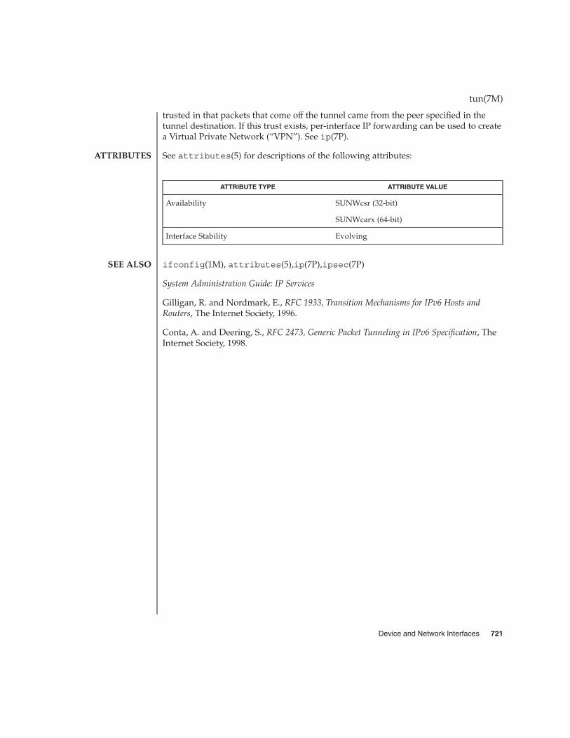
trusted in that packets that come off the tunnel came from the peer specified in thetunnel destination. If this trust exists, per-interface IP forwarding can be used to createa Virtual Private Network (“VPN”). See ip(7P).
See attributes(5) for descriptions of the following attributes:
ATTRIBUTE TYPE ATTRIBUTE VALUE
Availability SUNWcsr (32-bit)
SUNWcarx (64-bit)
Interface Stability Evolving
ifconfig(1M), attributes(5),ip(7P),ipsec(7P)
System Administration Guide: IP Services
Gilligan, R. and Nordmark, E., RFC 1933, Transition Mechanisms for IPv6 Hosts andRouters, The Internet Society, 1996.
Conta, A. and Deering, S., RFC 2473, Generic Packet Tunneling in IPv6 Specification, TheInternet Society, 1998.
tun(7M)
ATTRIBUTES
SEE ALSO
Device and Network Interfaces 721

uata – IDE Host Bus Adapter Driver
ide@unit-address
The uata host bus adapter driver is a nexus driver that supports the ide interface onSPARC platforms. The driver supports ultra DMA mode-4 (ATA66). The driver alsoattempts to set the disk and ATAPI CD-ROM drive to maximum supported speed forthe device.
Currently, the uata driver supports IDE controllers CMD646U and Acer SouthbridgeM5229.
The uata driver supports two channels concurrently with two devices connected perchannel. The devices are logically numbered from 0 to 3:
0 Master disk on primary channel
1 Slave disk on primary channel
2 Master disk on secondary channel
3 Slave disk on secondary channel
/kernel/drv/uata
prtconf(1M), driver.conf(4), attributes(5)
Writing Device Drivers
X3T10 ATA-4 specifications
In addition to being logged, the following messages may appear on the systemconsole:
ddi_get_iblock_cookie failedThe driver could not obtain the interrupt cookie; the attach may fail.
Drive not ready before set_featuresIndicates a fatal problem; the drives are not ready to be programmed and featurescannot be set. (During the driver initialization process, the driver must set thefeatures for the drive, including dma and pio.)
Interrupt not seen after set_featuresIndicates a fatal problem with the drive; features could not be set.
ata_controller - set features failedIndicates a fatal problem with the drive; features could not be set.
? target <number> lun 0Displayed at boot up time to indicate that the target <number> was identified,where <number> is a decimal value.
uata(7D)
NAME
SYNOPSIS
DESCRIPTION
FILES
SEE ALSO
DIAGNOSTICS
722 man pages section 7: Device and Network Interfaces • Last Revised 5 Sep 2001
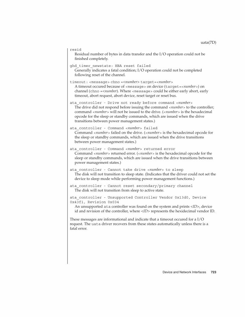
residResidual number of bytes in data transfer and the I/O operation could not befinished completely.
ghd_timer_newstate: HBA reset failedGenerally indicates a fatal condition; I/O operation could not be completedfollowing reset of the channel.
timeout: <message> chno =<number> target=<number>A timeout occured because of <message> on device (target=<number>) onchannel (chno =<number). Where <message> could be either early abort, earlytimeout, abort request, abort device, reset target or reset bus.
ata_controller - Drive not ready before command <number>The drive did not respond before issuing the command <number> to the controller;command <number> will not be issued to the drive. (<number> is the hexadecimalopcode for the sleep or standby commands, which are issued when the drivetransitions between power management states.)
ata_controller - Command <number> failedCommand <number> failed on the drive. (<number> is the hexadecimal opcode forthe sleep or standby commands, which are issued when the drive transitionsbetween power management states.)
ata_controller - Command <number> returned errorCommand <number> returned error. (<number> is the hexadecimal opcode for thesleep or standby commands, which are issued when the drive transitions betweenpower management states.)
ata_controller - Cannot take drive <number> to sleepThe disk will not transition to sleep state. (Indicates that the driver could not set thedevice to sleep mode while performing power management functions.)
ata_controller - Cannot reset secondary/primary channelThe disk will not transition from sleep to active state.
ata_controller - Unsupported Controller Vendor 0x13d0, Device0x43f1, Revision 0x034
An unsupported ata controller was found on the system and prints <ID>, deviceid and revision of the controller, where <ID> represents the hexidecimal vendor ID.
These messages are informational and indicate that a timeout occured for a I/Orequest. The uata driver recovers from these states automatically unless there is afatal error.
uata(7D)
Device and Network Interfaces 723

udfs – universal disk format file system
The udfs file system is a file system type that allows user access to files on UniversalDisk Format (UDF) disks from within the Solaris operating environment. Oncemounted, a udfs file system provides standard Solaris file system operations andsemantics. That is, users can read files, write files, and list files in a directory on a UDFdevice and applications can use standard UNIX system calls on these files anddirectories.
Because udfs is a platform-independent file system, the same media can be written toand read from by any operating system or vendor.
udfs file systems are mounted using:
mount-F udfs -o rw/ro device-special
Use:
mount /udfs
if the /udfs and device special file /dev/dsk/c0t6d0s0 are valid and the followingline (or similar line) appears in your /etc/vfstab file:
/dev/dsk/c0t6d0s0 - /udfs udfs - no ro
The udfs file system provides read-only support for ROM, RAM, andsequentially–recordable media and read-write support on RAM media.
The udfs file system also supports regular files, directories, and symbolic links, aswell as device nodes such as block, character, FIFO, and Socket.
mount(1M), mount_udfs(1M), vfstab(4)
Invalid characters such as “NULL” and "/” and invalid file names such as "." and ".."will be translated according to the following rule:
Replace the invalid character with an “_," then append the file name with # followedby a 4 digit hex representation of the 16-bit CRC of the original FileIdentifier.For example, the file name ".." will become "__#4C05"
udfs(7FS)
NAME
DESCRIPTION
Mounting FileSystems
SEE ALSO
NOTES
724 man pages section 7: Device and Network Interfaces • Last Revised 29 Mar 1999

udp, UDP – Internet User Datagram Protocol
#include <sys/socket.h>
#include <netinet/in.h>
s = socket(AF_INET, SOCK_DGRAM, 0);
s = socket(AF_INET6, SOCK_DGRAM, 0);
t = t_open("/dev/udp", O_RDWR);
t = t_open("/dev/udp6", O_RDWR);
UDP is a simple datagram protocol which is layered directly above the InternetProtocol (“IP”) or the Internet Protocol Version 6 (“IPv6”). Programs may access UDPusing the socket interface, where it supports the SOCK_DGRAM socket type, or usingthe Transport Level Interface (“TLI”), where it supports the connectionless (T_CLTS)service type.
Within the socket interface, UDP is normally used with the sendto(), sendmsg(),recvfrom(), and recvmsg() calls (see send(3SOCKET) and recv(3SOCKET)). Ifthe connect(3SOCKET) call is used to fix the destination for future packets, then therecv(3SOCKET) or read(2) and send(3SOCKET) or write(2) calls may be used.
UDP address formats are identical to those used by the Transmission Control Protocol(“TCP”). Like TCP, UDP uses a port number along with an IPor IPv6 address toidentify the endpoint of communication. The UDP port number space is separate fromthe TCP port number space, that is, a UDP port may not be “connected” to a TCP port.The bind(3SOCKET) call can be used to set the local address and port number of aUDP socket. The local IP or IPv6 address may be left unspecified in the bind() call byusing the special value INADDR_ANY for IP, or the unspecified address (all zeroes) forIPv6. If the bind() call is not done, a local IP or IPv6 address and port number will beassigned to the endpoint when the first packet is sent. Broadcast packets may be sent,assuming the underlying network supports this, by using a reserved “broadcastaddress.” This address is network interface dependent. Broadcasts may only be sentby the privileged user.
IPv6 does not support broadcast addresses; their function is supported by IPv6multicast addresses.
Options at the IP level may be used with UDP; see ip(7P) or ip6(7p).
There are a variety of ways that a UDP packet can be lost or corrupted, including afailure of the underlying communication mechanism. UDP implements a checksumover the data portion of the packet. If the checksum of a received packet is in error, thepacket will be dropped with no indication given to the user. A queue of receivedpackets is provided for each UDP socket. This queue has a limited capacity. Arrivingdatagrams which will not fit within its high-water capacity are silently discarded.
UDP(7P)
NAME
SYNOPSIS
DESCRIPTION
Device and Network Interfaces 725

UDP processes Internet Control Message Protocol (“ICMP”) and Internet ControlMessage Protocol Version 6 (“ICMP6”) error messages received in response to UDPpackets it has sent. See icmp(7P) and icmp6(7p).
ICMP “source quench” messages are ignored. ICMP “destination unreachable,” “timeexceeded” and “parameter problem” messages disconnect the socket from its peer sothat subsequent attempts to send packets using that socket will return an error. UDPwill not guarantee that packets are delivered in the order they were sent. As well,duplicate packets may be generated in the communication process.
ICMP6 “destination unreachable” packets are ignored unless the enclosed codeindicates that the port is not in use on the target host, in which case, the application isnotified. ICMP6 “parameter problem” notifications are similarly passed upstream. Allother ICMP6 messages are ignored.
read(2), write(2), bind(3SOCKET), connect(3SOCKET), recv(3SOCKET),send(3SOCKET), icmp(7P), icmp6(7P), inet(7P), inet6(7P), ip(7P), ip6(7P),tcp(7P)
Postel, Jon, RFC 768, User Datagram Protocol, Network Information Center, SRIInternational, Menlo Park, Calif., August 1980
A socket operation may fail if:
EISCONN A connect() operation was attempted on a socket onwhich a connect() operation had already beenperformed, and the socket could not be successfullydisconnected before making the new connection.
EISCONN A sendto() or sendmsg() operation specifying anaddress to which the message should be sent wasattempted on a socket on which a connect()operation had already been performed.
ENOTCONN A send() or write() operation, or a sendto() orsendmsg() operation not specifying an address towhich the message should be sent, was attempted on asocket on which a connect() operation had notalready been performed.
EADDRINUSE A bind() operation was attempted on a socket with anetwork address/port pair that has already beenbound to another socket.
EADDRNOTAVAIL A bind() operation was attempted on a socket with anetwork address for which no network interface exists.
EINVAL A sendmsg() operation with a non-NULLmsg_accrights was attempted.
UDP(7P)
SEE ALSO
DIAGNOSTICS
726 man pages section 7: Device and Network Interfaces • Last Revised 4 Nov 1999

EACCES A bind() operation was attempted with a “reserved”port number and the effective user ID of the processwas not the privileged user.
ENOBUFS The system ran out of memory for internal datastructures.
UDP(7P)
Device and Network Interfaces 727

udp, UDP – Internet User Datagram Protocol
#include <sys/socket.h>
#include <netinet/in.h>
s = socket(AF_INET, SOCK_DGRAM, 0);
s = socket(AF_INET6, SOCK_DGRAM, 0);
t = t_open("/dev/udp", O_RDWR);
t = t_open("/dev/udp6", O_RDWR);
UDP is a simple datagram protocol which is layered directly above the InternetProtocol (“IP”) or the Internet Protocol Version 6 (“IPv6”). Programs may access UDPusing the socket interface, where it supports the SOCK_DGRAM socket type, or usingthe Transport Level Interface (“TLI”), where it supports the connectionless (T_CLTS)service type.
Within the socket interface, UDP is normally used with the sendto(), sendmsg(),recvfrom(), and recvmsg() calls (see send(3SOCKET) and recv(3SOCKET)). Ifthe connect(3SOCKET) call is used to fix the destination for future packets, then therecv(3SOCKET) or read(2) and send(3SOCKET) or write(2) calls may be used.
UDP address formats are identical to those used by the Transmission Control Protocol(“TCP”). Like TCP, UDP uses a port number along with an IPor IPv6 address toidentify the endpoint of communication. The UDP port number space is separate fromthe TCP port number space, that is, a UDP port may not be “connected” to a TCP port.The bind(3SOCKET) call can be used to set the local address and port number of aUDP socket. The local IP or IPv6 address may be left unspecified in the bind() call byusing the special value INADDR_ANY for IP, or the unspecified address (all zeroes) forIPv6. If the bind() call is not done, a local IP or IPv6 address and port number will beassigned to the endpoint when the first packet is sent. Broadcast packets may be sent,assuming the underlying network supports this, by using a reserved “broadcastaddress.” This address is network interface dependent. Broadcasts may only be sentby the privileged user.
IPv6 does not support broadcast addresses; their function is supported by IPv6multicast addresses.
Options at the IP level may be used with UDP; see ip(7P) or ip6(7p).
There are a variety of ways that a UDP packet can be lost or corrupted, including afailure of the underlying communication mechanism. UDP implements a checksumover the data portion of the packet. If the checksum of a received packet is in error, thepacket will be dropped with no indication given to the user. A queue of receivedpackets is provided for each UDP socket. This queue has a limited capacity. Arrivingdatagrams which will not fit within its high-water capacity are silently discarded.
udp(7P)
NAME
SYNOPSIS
DESCRIPTION
728 man pages section 7: Device and Network Interfaces • Last Revised 4 Nov 1999

UDP processes Internet Control Message Protocol (“ICMP”) and Internet ControlMessage Protocol Version 6 (“ICMP6”) error messages received in response to UDPpackets it has sent. See icmp(7P) and icmp6(7p).
ICMP “source quench” messages are ignored. ICMP “destination unreachable,” “timeexceeded” and “parameter problem” messages disconnect the socket from its peer sothat subsequent attempts to send packets using that socket will return an error. UDPwill not guarantee that packets are delivered in the order they were sent. As well,duplicate packets may be generated in the communication process.
ICMP6 “destination unreachable” packets are ignored unless the enclosed codeindicates that the port is not in use on the target host, in which case, the application isnotified. ICMP6 “parameter problem” notifications are similarly passed upstream. Allother ICMP6 messages are ignored.
read(2), write(2), bind(3SOCKET), connect(3SOCKET), recv(3SOCKET),send(3SOCKET), icmp(7P), icmp6(7P), inet(7P), inet6(7P), ip(7P), ip6(7P),tcp(7P)
Postel, Jon, RFC 768, User Datagram Protocol, Network Information Center, SRIInternational, Menlo Park, Calif., August 1980
A socket operation may fail if:
EISCONN A connect() operation was attempted on a socket onwhich a connect() operation had already beenperformed, and the socket could not be successfullydisconnected before making the new connection.
EISCONN A sendto() or sendmsg() operation specifying anaddress to which the message should be sent wasattempted on a socket on which a connect()operation had already been performed.
ENOTCONN A send() or write() operation, or a sendto() orsendmsg() operation not specifying an address towhich the message should be sent, was attempted on asocket on which a connect() operation had notalready been performed.
EADDRINUSE A bind() operation was attempted on a socket with anetwork address/port pair that has already beenbound to another socket.
EADDRNOTAVAIL A bind() operation was attempted on a socket with anetwork address for which no network interface exists.
EINVAL A sendmsg() operation with a non-NULLmsg_accrights was attempted.
udp(7P)
SEE ALSO
DIAGNOSTICS
Device and Network Interfaces 729

EACCES A bind() operation was attempted with a “reserved”port number and the effective user ID of the processwas not the privileged user.
ENOBUFS The system ran out of memory for internal datastructures.
udp(7P)
730 man pages section 7: Device and Network Interfaces • Last Revised 4 Nov 1999

uhci – host controller driver
pcivid,pid@unit-address
The uhci host controller driver is a USBA (Solaris USB Architecture) compliant nexusdriver that supports the Universal Host Controller Interface Specification 1.1, an industrystandard developed by Intel. The uhci driver supports all USB transfers, includinginterrupt, control, isochronous and bulk.
/kernel/drv/uhci 32–bit ELF Kernel Module
/kernel/drv/uhci.conf Driver configuration file
See attributes(5) for descriptions of the following attributes:
ATTRIBUTE TYPE ATTRIBUTE VALUE
Architecture PCI-based IA
Availability SUNWusb
attributes(5), usba(7D)
Writing Device Drivers
Universal Host Controller Interface Specification for USB 1.1
Universal Serial Bus Specification 1.0 & 1.1
System Administration Guide: Basic Administration
http://www.sun.com/io
None.
uhci(7D)
NAME
SYNOPSIS
DESCRIPTION
FILES
ATTRIBUTES
SEE ALSO
DIAGNOSTICS
Device and Network Interfaces 731

random, urandom – Strong random number generator device
/dev/random
/dev/urandom
The /dev/random and /dev/urandom files are special files that are a source forrandom bytes generated by the kernel random number generator device. The/dev/random and /dev/urandom files are suitable for applications requiring highquality random numbers for cryptographic purposes.
The generator device produces random numbers from data and devices available tothe kernel and estimates the amount of randomness (or "entropy”) collected fromthese sources. The entropy level determines the amount of high quality randomnumbers that are produced at a given time.
Applications retrieve random bytes by reading /dev/random or /dev/urandom. The/dev/random interface returns random bytes only when sufficient amount of entropyhas been collected. If there is no entropy to produce the requested number of bytes,/dev/random blocks until more entropy can be obtained. Non-blocking I/O modecan be used to disable the blocking behavior. The /dev/random interface alsosupports poll(2). Note that using poll(2) will not increase the speed at whichrandom numbers can be read.
Bytes retrieved from /dev/random provide the highest quality random numbersproduced by the generator, and can be used to generate long term keys and other highvalue keying material.
The /dev/urandom interface returns bytes regardless of the amount of entropyavailable. It does not block on a read request due to lack of entropy. While bytesproduced by the /dev/urandom interface are of lower quality than bytes producedby /dev/random, they are nonetheless suitable for less demanding and shorter termcryptographic uses such as short term session keys, paddings, and challenge strings.
Data can be written to /dev/random and /dev/urandom. Data written to eitherspecial file is added to the generator’s internal state. Data that is difficult to predict byother users may contribute randomness to the generator state and help improve thequality of future generated random numbers.
By default, write access is restricted to the super-user. An administrator may changethe default read/write restriction by changing the permissions on the appropriatespecial files.
EAGAIN O_NDELAY or O_NONBLOCK was set and no random bytes areavailable for reading from /dev/random.
EINTR A signal was caught while reading and no data was transferred.
/dev/random
/dev/urandom
urandom(7D)
NAME
SYNOPSIS
DESCRIPTION
ERRORS
FILES
732 man pages section 7: Device and Network Interfaces • Last Revised 01 Mar 2001

See attributes(5) for descriptions of the following attributes:
ATTRIBUTE TYPE ATTRIBUTE VALUE
Availability SUNWcsr (32-bit)
SUNWcarx (64-bit)
Interface Stability Evolving
poll(2), attributes(5)
An implementation of the /dev/random and /dev/urandom kernel-based randomnumber generator first appeared in Linux 1.3.30.
A /dev/random interface for Solaris first appeared as part of the CryptoRandimplementation.
urandom(7D)
ATTRIBUTES
SEE ALSO
NOTES
Device and Network Interfaces 733

usba – Solaris USB Architecture (USBA)
USB provides a low-cost means for attaching peripheral devices, includingmass-storage devices, keyboards, mice, and printers, to a system. For completeinformation on USB, go to the USB website at http://www.usb.org.
USB supports 126 hot-pluggable USB devices per USB bus. The maximum datatransfer rate is 12 Mbits per second (Mbps).
USB adheres to the Universal Serial Bus 1.1 specification and provides a transport layerabstraction to USB client drivers.
Drivers and modules which either utilize or are utilized by USBA are:
CLIENT DRIVER FUNCTION/DEVICE
/kernel/drv/[sparcv9]/hid HID class
/kernel/drv/[sparcv9]/hubd hub class
/kernel/drv/[sparcv9]/scsa2usb mass storage class
/kernel/drv/[sparcv9]/usbprn printer class
/kernel/drv/[sparcv9]/usb_as audio streaming
/kernel/drv/[sparcv9]/usb_ac audio control
/kernel/drv/[sparcv9]/usb_mid multi-interface device
CLIENT STREAMS MODULES FUNCTION/DEVICE
/kernel/strmod/[sparcv9]/usbkbm Keyboard
/kernel/strmod/[sparcv9]/usbms Mouse
/kernel/strmod/[sparcv9]/usb_ah audio HID
HOST CONTROLLER INTERFACE DRIVERS DEVICE
/kernel/drv/[sparcv9]/ohci Open HCI
/kernel/drv/[sparcv9]/uhci Universal HCI
See attributes(5) for a description of the following attributes:
ATTRIBUTE TYPE ATTRIBUTE VALUE
Architecture PCI-based systems
usba(7D)
NAME
DESCRIPTION
FILES
ATTRIBUTES
734 man pages section 7: Device and Network Interfaces • Last Revised 28 Dec 2001
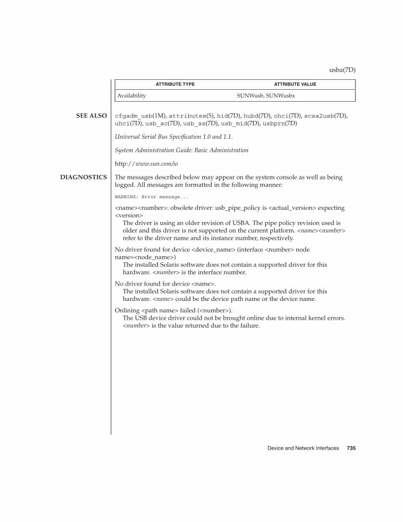
ATTRIBUTE TYPE ATTRIBUTE VALUE
Availability SUNWusb, SUNWusbx
cfgadm_usb(1M), attributes(5), hid(7D), hubd(7D), ohci(7D), scsa2usb(7D),uhci(7D), usb_ac(7D), usb_as(7D), usb_mid(7D), usbprn(7D)
Universal Serial Bus Specification 1.0 and 1.1.
System Administration Guide: Basic Administration
http://www.sun.com/io
The messages described below may appear on the system console as well as beinglogged. All messages are formatted in the following manner:
WARNING: Error message...
<name><number>: obsolete driver: usb_pipe_policy is <actual_version> expecting<version>
The driver is using an older revision of USBA. The pipe policy revision used isolder and this driver is not supported on the current platform. <name><number>refer to the driver name and its instance number, respectively.
No driver found for device <device_name> (interface <number> nodename=<node_name>)
The installed Solaris software does not contain a supported driver for thishardware. <number> is the interface number.
No driver found for device <name>.The installed Solaris software does not contain a supported driver for thishardware. <name> could be the device path name or the device name.
Onlining <path name> failed (<number>).The USB device driver could not be brought online due to internal kernel errors.<number> is the value returned due to the failure.
usba(7D)
SEE ALSO
DIAGNOSTICS
Device and Network Interfaces 735

usb_ac – USB audio control driver
sound-control@unit-address
The usb_ac driver is a USBA (Solaris USB Architecture) compliant client driver thatsupports the USB Audio Class 1.0 specification.
The audio control driver is a USB class driver and offers functionality similar to theaudiocs (sun4u) and audiots (Sun Blade 100) drivers which use the Solaris audiomixer framework (mixer(7I)). Unlike the audiocs and audiots drivers, the USBaudio device may have play-only or record-only capability.
Drivers corresponding to other USB audio interfaces on the device, including theusb_as(7D) audio streaming driver or the hid(7D) driver, are plumbed under theUSB audio control driver and do not directly interface with user applications.
The usb_ac driver supports USB audio class compliant devices with a feature unit.For a list of recommended devices, visit: www.sun.com/io.
This interface is described in the mixer(7I) and audio(7I) man pages.
Applications that open /dev/audio may use the AUDIO_GETDEV ioctl() todetermine which audio device is being used. The USB audio driver returns the string"USB Audio" in the name field of the audio_device structure. The version fielddisplays the version number and the config field displays the string "external."
The USB audio device provides support for an external speaker and microphone.
The configuration file /kernel/drv/usb_ac.conf is used to configure the USBaudio driver and determines whether the audio mixer is enabled or disabled. See themixer(7I) manual page for details. You can change the audio mixer mode at any timeby using the mixerctl(1) or sdtaudiocontrol(1) applications.
The USB audio device supports the audio data formats shown below. Please note thatat a minimum, the device must support a sampling frequency of 44100 Hz or 48000Hz. In the table below, mode "M" indicates that mixer mode is enabled, while "C"indicates that mixer mode is disabled or in compatibility mode.
Sample Rate Encoding Precision Channels Mode
8000 Hz u-Law orA-Law
8 1 or 2 M and C
9600 Hz u-Law orA-Law
8 1 or 2 M and C
11025 Hz u-law or A-law 8 1 or 2 M and C
16000 Hz u-law or A-law 8 1 or 2 M and C
18900 Hz u-law or A-law 8 1 or 2 M and C
usb_ac(7D)
NAME
SYNOPSIS
DESCRIPTION
APPLICATIONPROGRAM
INTERFACEDriver Versions
Audio Mixer Mode
Audio DataFormats
736 man pages section 7: Device and Network Interfaces • Last Revised 28 Dec 2001
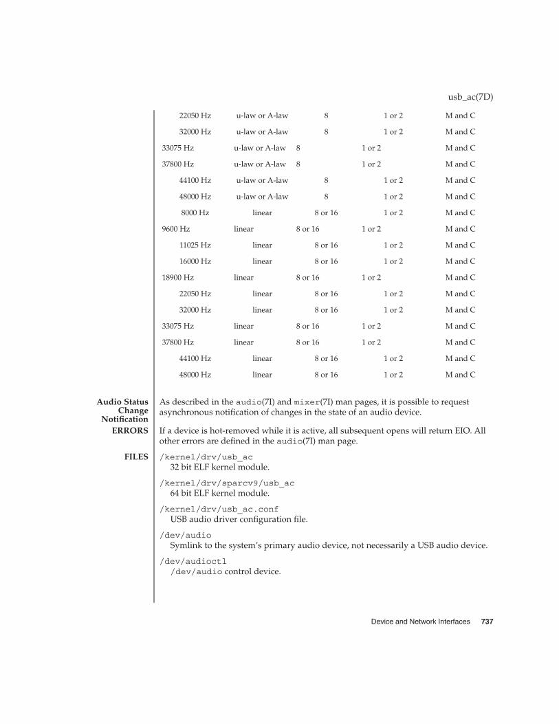
22050 Hz u-law or A-law 8 1 or 2 M and C
32000 Hz u-law or A-law 8 1 or 2 M and C
33075 Hz u-law or A-law 8 1 or 2 M and C
37800 Hz u-law or A-law 8 1 or 2 M and C
44100 Hz u-law or A-law 8 1 or 2 M and C
48000 Hz u-law or A-law 8 1 or 2 M and C
8000 Hz linear 8 or 16 1 or 2 M and C
9600 Hz linear 8 or 16 1 or 2 M and C
11025 Hz linear 8 or 16 1 or 2 M and C
16000 Hz linear 8 or 16 1 or 2 M and C
18900 Hz linear 8 or 16 1 or 2 M and C
22050 Hz linear 8 or 16 1 or 2 M and C
32000 Hz linear 8 or 16 1 or 2 M and C
33075 Hz linear 8 or 16 1 or 2 M and C
37800 Hz linear 8 or 16 1 or 2 M and C
44100 Hz linear 8 or 16 1 or 2 M and C
48000 Hz linear 8 or 16 1 or 2 M and C
As described in the audio(7I) and mixer(7I) man pages, it is possible to requestasynchronous notification of changes in the state of an audio device.
If a device is hot-removed while it is active, all subsequent opens will return EIO. Allother errors are defined in the audio(7I) man page.
/kernel/drv/usb_ac32 bit ELF kernel module.
/kernel/drv/sparcv9/usb_ac64 bit ELF kernel module.
/kernel/drv/usb_ac.confUSB audio driver configuration file.
/dev/audioSymlink to the system’s primary audio device, not necessarily a USB audio device.
/dev/audioctl/dev/audio control device.
usb_ac(7D)
Audio StatusChange
NotificationERRORS
FILES
Device and Network Interfaces 737

/dev/sound/[0-N]Represents the audio devices on the system and is not necessarily a USB audiodevice.
/dev/sound/[0-N]ctl/dev/sound audio control device.
See attributes(5) for descriptions of the following attributes:
ATTRIBUTE TYPE ATTRIBUTE VALUE
Architecture PCI-based systems
Availability SUNWusb, SUNWusbx
Stability level Evolving
mixerctl(1), cfgadm_usb(1M), ioctl(2), attributes(5), hid(7D), usba(7D),usb_as(7D), audio(7I), mixer(7I), streamio(7I), usb_ah(7M)
Writing Device Drivers
Universal Serial Bus Specification 1.0 and 1.1
Universal Serial Bus Device Class Definition for Audio Devices, Release 1.0
System Administration: Basic Administration
http://www.sun.com/io
In addition to being logged, the following messages may appear on the systemconsole. All messages are formatted in the following manner:
Warning: <device path> (usb_ac<instance num>): Error Message...
Failure to plumb audio streams drivers.The usb audio streaming driver or the hid driver could not be plumbed under theaudio control driver and the device is not usable.
Device was disconnected while open. Data may have been lost.The device was hot-removed or powered off while it was open and a possible datatransfer was in progress. The job was aborted.
Cannot access device. Please reconnect <name>.There was an error in accessing the device during reconnect. Please reconnect thedevice.
Device is not identical to the previous one on this port. Please disconnect andreconnect.
A USB audio device was hot-removed while open. A new device was hot-insertedwhich is not identical to the original USB audio device. Please disconnect the USBdevice and reconnect the device to the same port.
usb_ac(7D)
ATTRIBUTES
SEE ALSO
DIAGNOSTICS
738 man pages section 7: Device and Network Interfaces • Last Revised 28 Dec 2001

Busy device has been reconnected.A device that was hot-removed from a USB port has been re-inserted again.
The USB audio device will be power managed if the device is idle.
USB audio devices do not have line out or port control.
If a USB audio device is hot-removed while active, it prints a console warningmessage requesting you to put the device back in the same port and informing youthat there may be data loss. Hot-removal of an active audio device is stronglydiscouraged.
Close all applications before hot-removing or hot-inserting a device. If an applicationis open when a device is hot-removed, inserting the device in a different port willcreate new /dev/sound links but /dev/audio will not be affected. Hotplugging anactive device is not recommended.
On slower IA machines and with higher frequency sample rates, you may encountersome audio quality problems.
To make a USB audio device the primary audio device (for example: /dev/audio),close all audio applications, disconnect all USB audio devices, modunload all otheraudio drivers and then simply reconnect the USB audio device. This will cause/dev/audio to point to the USB audio /dev/sound entry.
Most Solaris audio applications and 3rd party audio applications available on Solariswork well with USB audio devices. For details of the application behavior with USBaudio devices, visit www.sun.com/io.
usb_ac(7D)
NOTES
Device and Network Interfaces 739
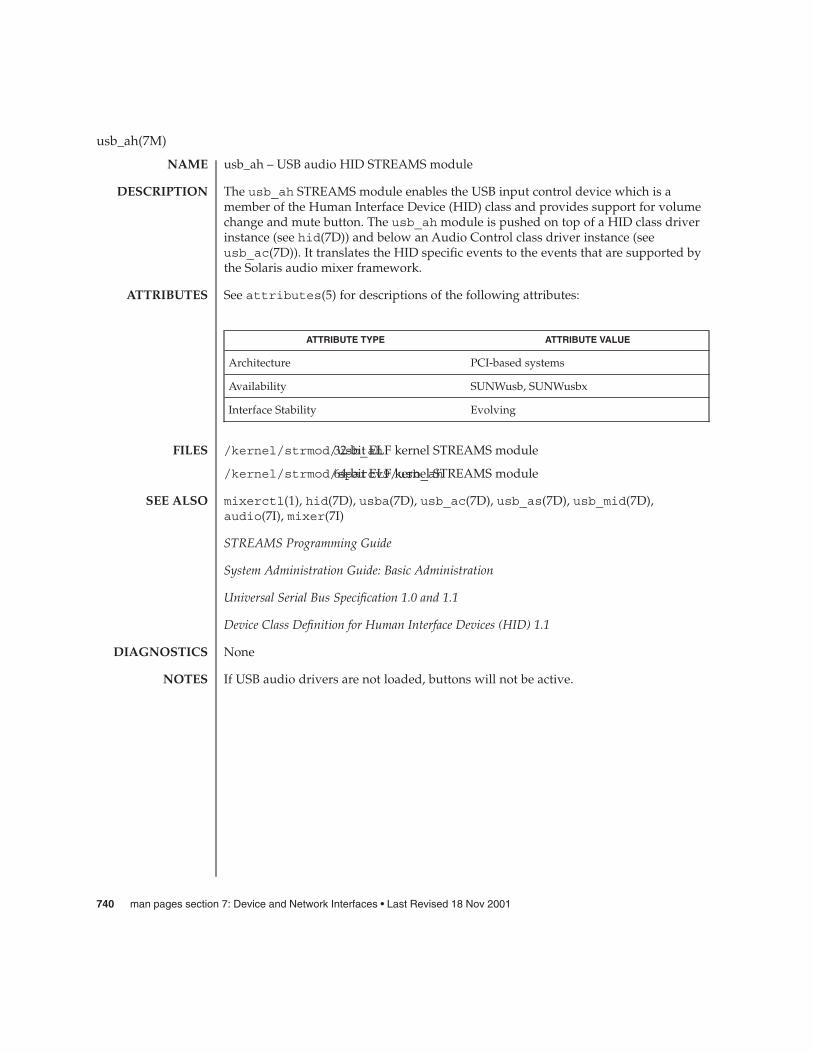
usb_ah – USB audio HID STREAMS module
The usb_ah STREAMS module enables the USB input control device which is amember of the Human Interface Device (HID) class and provides support for volumechange and mute button. The usb_ah module is pushed on top of a HID class driverinstance (see hid(7D)) and below an Audio Control class driver instance (seeusb_ac(7D)). It translates the HID specific events to the events that are supported bythe Solaris audio mixer framework.
See attributes(5) for descriptions of the following attributes:
ATTRIBUTE TYPE ATTRIBUTE VALUE
Architecture PCI-based systems
Availability SUNWusb, SUNWusbx
Interface Stability Evolving
/kernel/strmod/usb_ah32-bit ELF kernel STREAMS module
/kernel/strmod/sparcv9/usb_ah64-bit ELF kernel STREAMS module
mixerctl(1), hid(7D), usba(7D), usb_ac(7D), usb_as(7D), usb_mid(7D),audio(7I), mixer(7I)
STREAMS Programming Guide
System Administration Guide: Basic Administration
Universal Serial Bus Specification 1.0 and 1.1
Device Class Definition for Human Interface Devices (HID) 1.1
None
If USB audio drivers are not loaded, buttons will not be active.
usb_ah(7M)
NAME
DESCRIPTION
ATTRIBUTES
FILES
SEE ALSO
DIAGNOSTICS
NOTES
740 man pages section 7: Device and Network Interfaces • Last Revised 18 Nov 2001

usb_as – USB audio streaming driver
sound@unit-address
The usb_as driver is a USBA (Solaris USB Architecture) compliant client driver thatsupports the USB Audio Class 1.0 specification.
The usb_as driver processes audio data messages during play and record and setssample frequency, precision, encoding and other functions on request from the USBaudio control driver. See usb_ac(7D).
This driver is plumbed under the USB audio control driver and does not directlyinterface with the user application.
/kernel/drv/usb_as32 bit ELF kernel module
/kernel/drv/sparcv9/usb_as64 bit ELF kernel module
See attributes(5) for descriptions of the following attributes:
ATTRIBUTE TYPE ATTRIBUTE VALUE
Architecture PCI-based systems
Availability SUNWusb, SUNWusbx
Stability level Evolving
mixerctl(1), attributes(5), usba(7D), usb_ac(7D), audio(7I), mixer(7I),streamio(7I)
Writing Device Drivers
Universal Serial Bus Specification 1.0 and 1.1
System Administration Guide: Basic Administration
http://www.sun.com/io
In addition to being logged, the following messages may appear on the systemconsole. All messages are formatted in the following manner:
Warning: <device path> (usb_as<instance num>): Error Message...
where <device path> is the physical path to the device in /devices directory.
No bandwidth available.There is no bandwidth available for the isochronous pipe. As a result, no data willbe transferred during play and record.
usb_as(7D)
NAME
SYNOPSIS
DESCRIPTION
FILES
ATTRIBUTES
SEE ALSO
DIAGNOSTICS
Device and Network Interfaces 741

Cannot access device. Please reconnect <name>.There was an error in accessing the device during reconnect. Please reconnect thedevice.
Device is not identical to the previous one on this port. Please disconnect andreconnect.
A USB audio streaming interface was hot-removed while open. A new device washot-inserted which is not identical to the original USB audio device. Pleasedisconnect the USB device and reconnect the device to the same port.
The USB audio streaming interface will be power managed if device is idle.
usb_as(7D)
NOTES
742 man pages section 7: Device and Network Interfaces • Last Revised 2 Jan 2002

usbkbm – keyboard STREAMS module for Sun USB Keyboard
open("/dev/kbd", O_RDWR)
The usbkbm STREAMS module processes byte streams generated by a keyboardattached to a USB port. USB keyboard is a member of Human Interface Device (HID)Class, and usbkbm only supports the keyboard protocol defined in the specification.Definitions for altering keyboard translation and reading events from the keyboard arein <sys/kbio.h> and <sys/kbd.h>.
The usbkbm STREAMS module adheres to the interfaces exported by kb(7M). Refer tothe DESCRIPTION section of kb(7M) for a discussion of the keyboard translationmodes and the IOCTL section for the supported ioctl(2) requests.
USB Keyboard usbkbm returns different values for the following ioctls than kb(7M):
KIOCTYPE This ioctl() returns a new keyboard type defined for the USBkeyboard. All types are listed below:
KB_SUN3 Sun Type 3 keyboardKB_SUN4 Sun Type 4 keyboardKB_ASCII ASCII terminal masquerading as keyboardKB_PC Type 101 PC keyboardKB_USB USB keyboard
The USB keyboard type is KB_USB; usbkbm will return KB_USB in response to theKIOCTYPE ioctl.
KIOCLAYOUT The argument is a pointer to an int. The layout code specified bythe bCountryCode value returned in the HID descriptor isreturned in the int pointed to by the argument. Thecountrycodes are defined in 6.2.1 of the HID 1.0 specifications.
KIOCCMD
KBD_CMD_CLICK/KBD_CMD_NOCLICK The kb(7M) indicatesthat inappropriatecommands forparticular keyboards areignored. Becauseclicking is notsupported on the USBkeyboard, usbkbmignores this command
KBD_CMD_SETLED Set keyboard LEDs.Same as kb(7M).
KBD_CMD_GETLAYOUT The country codesdefined in 6.2.1 of theHID 1.0 specification arereturned.
usbkbm(7M)
NAME
SYNOPSIS
DESCRIPTION
IOCTLS
Device and Network Interfaces 743
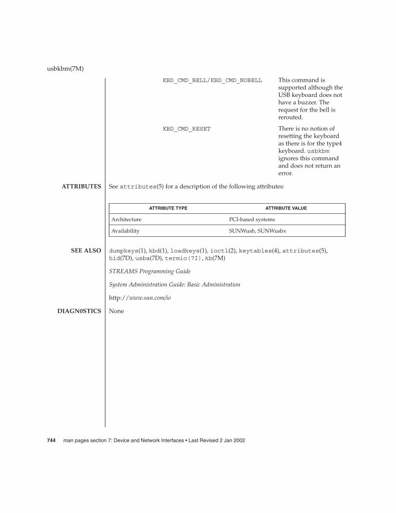
KBD_CMD_BELL/KBD_CMD_NOBELL This command issupported although theUSB keyboard does nothave a buzzer. Therequest for the bell isrerouted.
KBD_CMD_RESET There is no notion ofresetting the keyboardas there is for the type4keyboard. usbkbmignores this commandand does not return anerror.
See attributes(5) for a description of the following attributes:
ATTRIBUTE TYPE ATTRIBUTE VALUE
Architecture PCI-based systems
Availability SUNWusb, SUNWusbx
dumpkeys(1), kbd(1), loadkeys(1), ioctl(2), keytables(4), attributes(5),hid(7D), usba(7D), termio(7I), kb(7M)
STREAMS Programming Guide
System Administration Guide: Basic Administration
http://www.sun.com/io
None
usbkbm(7M)
ATTRIBUTES
SEE ALSO
DIAGN0STICS
744 man pages section 7: Device and Network Interfaces • Last Revised 2 Jan 2002

usb_mid – USB Multi Interface Driver
device@unit-address
The usb_mid driver is a USBA (Solaris Universal Serial Bus Architecture) compliantnexus driver that binds to device level nodes of a composite (multi interface) device ifno vendor or class specific driver is available. The usb_mid driver attempts to binddrivers to each of the composite device’s interfaces.
/kernel/drv/usb_mid 32-bit ELF kernel module
/kernel/drv/sparcv9/usb_mid 64-bit ELF kernel module
See attributes(5) for descriptions of the following attributes:
ATTRIBUTE TYPE ATTRIBUTE VALUE
Architecture PCI-based systems
Availability SUNWusb, SUNWusbx
cfgadm_usb(1M), attributes(5), usba(7D)
Writing Device Drivers
Universal Serial Bus Specification 1.0 and 1.1
System Administration Guide: Basic Administration
http://www.sun.com/io
In addition to being logged, the following messages may appear on the systemconsole. All messages are formatted in the following manner:
Warning: <device path> (usb_mid<instance number>): Error Message...
Cannot access device. Please reconnect <device name>.This device has been disconnected because a device other than the original one hasbeen inserted. The driver informs you of this fact by displaying the name of theoriginal device.
Device not identical to the previous one on this port. Please disconnect and reconnect.Same condition as described above; however in this case, the driver is unable toidentify the original device with a name string.
usb_mid(7D)
NAME
SYNOPSIS
DESCRIPTION
FILES
ATTRIBUTES
SEE ALSO
DIAGNOSTICS
Device and Network Interfaces 745

usbms – USB mouse STREAMS module
#include <sys/vuid_event.h>
#include <sys/msio.h>
#include <sys/msreg.h>
The usbms STREAMS module processes byte streams generated by a USB mouse. AUSB mouse is a member of the Human Interface Device (HID) class and the usbmsmodule supports only the mouse boot protocol defined in the HID specification. Theusbms module must be pushed on top of the HID class driver (see hid(7D)). In theVUID_FIRM_EVENT mode, the usbms module translates packets from the USB mouseinto Firm events. The Firm event structure is defined in <sys/vuid_event.h>. TheSTREAMS module state is initially set to raw or VUID_NATIVE mode which performsno message processing. See the HID 1.0 specification for the raw format of the mousepackets. To initiate mouse protocol conversion to Firm events, change the state toVUID_FIRM_EVENT.
VUIDGFORMAT This option returns the current state of the STREAMS module. Thestate of the usbms STREAMS module may be eitherVUID_NATIVE (no message processing) or VUID_FIRM_EVENT(convert to Firm events).
VUIDSFORMAT The argument is a pointer to an int. Set the state of the STREAMSmodule to the int pointed to by the argument.
typedef struct vuid_addr_probe {short base; /* default vuid device addr directed too */union {
short next; /* next addr for default when VUIDSADDR */short current; /* current addr of default when VUIDGADDR */
} data;} Vuid_addr_probe;
VUIDSADDR The argument is a pointer to a Vuid_addr_probe structure.VUIDSADDR sets the virtual input device segment addressindicated by base to next.
If base does not equal VKEY_FIRST, ENODEV is returned.
VUIDGADDR The argument is a pointer to a Vuid_addr_probe structure.Return the address of the virtual input device segment indicatedby base to current.
If base does not equal VKEY_FIRST, ENODEV is returned.
ioctl() requests for changing and retrieving mouse parameters use the Ms_parmsstructure:
typedef struct {int jitter_thresh;
usbms(7M)
NAME
SYNOPSIS
DESCRIPTION
IOCTLS
746 man pages section 7: Device and Network Interfaces • Last Revised 2 Jan 2002

int speed_law;int speed_limit;
} Ms_parms;
jitter_thresh is the "jitter threshold" of the mouse. Motions fewer thanjitter_thresh units along both axes are accumulated and then sent up the streamafter 1/12 second.
speed_law indicates whether extremely large motions are to be ignored. If it is 1, a"speed limit" is applied to mouse motions. Motions along either axis of more thanspeed_limit units are discarded.
MSIOGETPARMS The argument is a pointer to a Ms_params structure. The usbmsmodule parameters are returned in the structure.
MSIOSETPARMS The argument is a pointer to a Ms_params structure. The usbmsmodule parameters are set according to the values in the structure.
See attributes(5) for a description of the following attributes:
ATTRIBUTE TYPE ATTRIBUTE VALUE
Architecture PCI-based systems
Availability SUNWusb, SUNWusbx
ioctl(2), attributes(5), hid(7D), usba(7D)
System Administration Guide: Basic Administration
http://www/sun.com/io
None
usbms(7M)
ATTRIBUTES
SEE ALSO
DIAGNOSTICS
Device and Network Interfaces 747
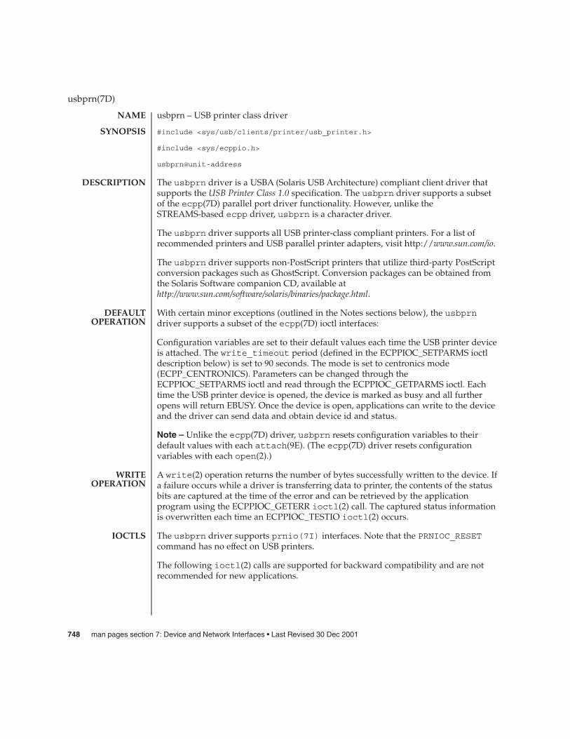
usbprn – USB printer class driver
#include <sys/usb/clients/printer/usb_printer.h>
#include <sys/ecppio.h>
usbprn@unit-address
The usbprn driver is a USBA (Solaris USB Architecture) compliant client driver thatsupports the USB Printer Class 1.0 specification. The usbprn driver supports a subsetof the ecpp(7D) parallel port driver functionality. However, unlike theSTREAMS-based ecpp driver, usbprn is a character driver.
The usbprn driver supports all USB printer-class compliant printers. For a list ofrecommended printers and USB parallel printer adapters, visit http://www.sun.com/io.
The usbprn driver supports non-PostScript printers that utilize third-party PostScriptconversion packages such as GhostScript. Conversion packages can be obtained fromthe Solaris Software companion CD, available athttp://www.sun.com/software/solaris/binaries/package.html.
With certain minor exceptions (outlined in the Notes sections below), the usbprndriver supports a subset of the ecpp(7D) ioctl interfaces:
Configuration variables are set to their default values each time the USB printer deviceis attached. The write_timeout period (defined in the ECPPIOC_SETPARMS ioctldescription below) is set to 90 seconds. The mode is set to centronics mode(ECPP_CENTRONICS). Parameters can be changed through theECPPIOC_SETPARMS ioctl and read through the ECPPIOC_GETPARMS ioctl. Eachtime the USB printer device is opened, the device is marked as busy and all furtheropens will return EBUSY. Once the device is open, applications can write to the deviceand the driver can send data and obtain device id and status.
Note – Unlike the ecpp(7D) driver, usbprn resets configuration variables to theirdefault values with each attach(9E). (The ecpp(7D) driver resets configurationvariables with each open(2).)
A write(2) operation returns the number of bytes successfully written to the device. Ifa failure occurs while a driver is transferring data to printer, the contents of the statusbits are captured at the time of the error and can be retrieved by the applicationprogram using the ECPPIOC_GETERR ioctl(2) call. The captured status informationis overwritten each time an ECPPIOC_TESTIO ioctl(2) occurs.
The usbprn driver supports prnio(7I) interfaces. Note that the PRNIOC_RESETcommand has no effect on USB printers.
The following ioctl(2) calls are supported for backward compatibility and are notrecommended for new applications.
usbprn(7D)
NAME
SYNOPSIS
DESCRIPTION
DEFAULTOPERATION
WRITEOPERATION
IOCTLS
748 man pages section 7: Device and Network Interfaces • Last Revised 30 Dec 2001

ECPPIOC_GETPARMSGets current transfer parameters. The argument is a pointer to structecpp_transfer_parms. If parameters are not configured after the device isopened, the structure will be set to its default configuration.
Note – Unlike the ecpp(7D) driver, only the ECPP_CENTRONICS mode iscurrently supported in usbprn.
ECPPIOC_SETPARMSSets transfer parameters. The argument is a pointer to a structecpp_transfer_parms. If a parameter is out of range, EINVAL is returned. If theperipheral or host device cannot support the requested mode, EPROTONOSUPPORTis returned.
The transfer parameters structure is defined in <sys/ecppio.h>:
struct ecpp_transfer_parms {int write_timeout;int mode;
};
The write_timeout field, which specifies how long the driver will take totransfer 8192 bytes of data to the device, is set to a default value of 90 seconds. Thewrite_timeout field must be greater than one second and less than 300 seconds(five minutes.)
Note – Unlike the ecpp(7D) driver, only the ECPP_CENTRONICS mode iscurrently supported in usbprn. Also, the semantics of write_timeout in usbprndiffer from ecpp(7D). Refer to ecpp(7D) for information.
BPPIOC_TESTIOTests the transfer readiness of a print device and checks status bits to determine if awrite(2) will succeed. If status bits are set, a transfer will fail. If a transfer willsucceed, zero is returned. If a transfer fails, the driver returns EIO and the state ofthe status bits are captured. The captured status can be retrieved using theBPPIOC_GETERR ioctl(2) call. BPPIOC_TESTIO and BPPIOC_GETERR arecompatible to the ioctls specified in bpp(7D).
Note – Unlike the ecpp(7D) driver, only the ECPP_CENTRONICS mode iscurrently supported in usbprn. Additionally, bus_error andtimeout_occurred fields are not used in the usbprn interface. (In ecpp(7D),timeout_occurred is used.)
BPPIOC_GETERRGet last error status. The argument is a pointer to a struct bpp_error_status.This structure indicates the status of all the appropriate status bits at the time of themost recent error condition during a write(2) call, or the status of the bits at themost recent BPPIOC_TESTIO ioctl(2) call.
struct bpp_error_status {char timeout_occurred; /* not used */char bus_error; /* not used */uchar_t pin_status; /* status of pins which
usbprn(7D)
Device and Network Interfaces 749
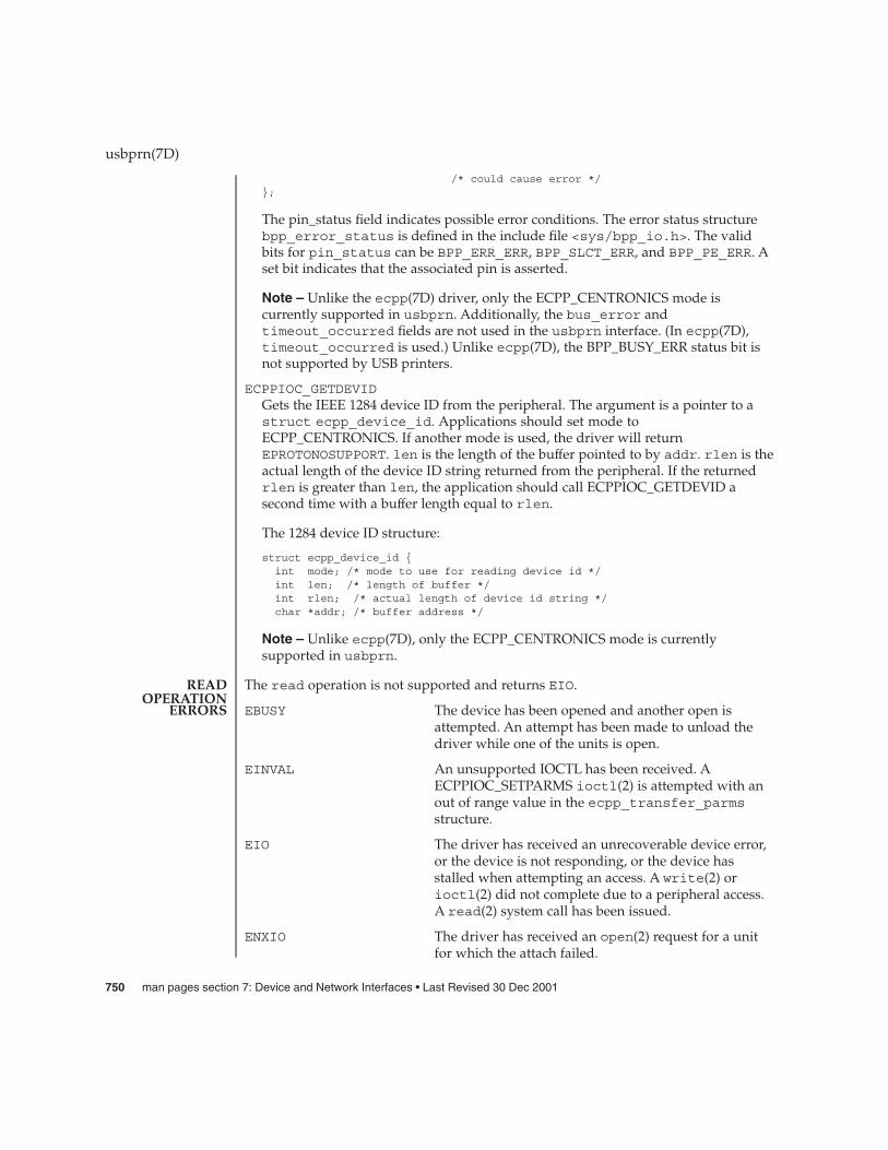
/* could cause error */};
The pin_status field indicates possible error conditions. The error status structurebpp_error_status is defined in the include file <sys/bpp_io.h>. The validbits for pin_status can be BPP_ERR_ERR, BPP_SLCT_ERR, and BPP_PE_ERR. Aset bit indicates that the associated pin is asserted.
Note – Unlike the ecpp(7D) driver, only the ECPP_CENTRONICS mode iscurrently supported in usbprn. Additionally, the bus_error andtimeout_occurred fields are not used in the usbprn interface. (In ecpp(7D),timeout_occurred is used.) Unlike ecpp(7D), the BPP_BUSY_ERR status bit isnot supported by USB printers.
ECPPIOC_GETDEVIDGets the IEEE 1284 device ID from the peripheral. The argument is a pointer to astruct ecpp_device_id. Applications should set mode toECPP_CENTRONICS. If another mode is used, the driver will returnEPROTONOSUPPORT. len is the length of the buffer pointed to by addr. rlen is theactual length of the device ID string returned from the peripheral. If the returnedrlen is greater than len, the application should call ECPPIOC_GETDEVID asecond time with a buffer length equal to rlen.
The 1284 device ID structure:
struct ecpp_device_id {int mode; /* mode to use for reading device id */int len; /* length of buffer */int rlen; /* actual length of device id string */char *addr; /* buffer address */
Note – Unlike ecpp(7D), only the ECPP_CENTRONICS mode is currentlysupported in usbprn.
The read operation is not supported and returns EIO.
EBUSY The device has been opened and another open isattempted. An attempt has been made to unload thedriver while one of the units is open.
EINVAL An unsupported IOCTL has been received. AECPPIOC_SETPARMS ioctl(2) is attempted with anout of range value in the ecpp_transfer_parmsstructure.
EIO The driver has received an unrecoverable device error,or the device is not responding, or the device hasstalled when attempting an access. A write(2) orioctl(2) did not complete due to a peripheral access.A read(2) system call has been issued.
ENXIO The driver has received an open(2) request for a unitfor which the attach failed.
usbprn(7D)
READOPERATION
ERRORS
750 man pages section 7: Device and Network Interfaces • Last Revised 30 Dec 2001

ENODEV The driver has received an open(2) request for a devicethat has been disconnected.
EPROTONOSUPPORT The driver has received a ECPPIOC_SETPARMSioctl(2) for a mode argument other thanECPP_CENTRONICS in the ecpp_transfer_parmsstructure.
/kernel/drv/usbprn32 bit ELF kernel module
/kernel/drv/sparcv9/usbprn64 bit ELF kernel module
/dev/printers/nCharacter special files
See attributes(5) for descriptions of the following attributes:
ATTRIBUTE TYPE ATTRIBUTE VALUE
Architecture PCI-based systems
Availability SUNWusb, SUNWusbx
cfgadm_usb(1M), printmgr(1M), ioctl(2), open(2), read(2), write(2),attributes(5), bpp(7D), ecpp(7D), usba(7D)prnio(7I), attach(9E)
Writing Device Drivers
Universal Serial Bus Specification 1.0 and 1.1
USB Device Class Definition for Printing Devices 1.0
System Administration Guide: Basic Administration
http://www.sun.com/io
In addition to being logged, the following messages may appear on the systemconsole. All messages are formatted in the following manner:
Warning: <device path> (usbprn<instance num>): Error Message...
Device was disconnected while open. Data may have been lost.The device has been hot-removed or powered off while it was open and a possibledata transfer was in progress. The job may be aborted.
Cannot access device. Please reconnect <device name>.There was an error in accessing the printer during reconnect. Please reconnect thedevice.
usbprn(7D)
FILES
ATTRIBUTES
SEE ALSO
DIAGNOSTICS
Device and Network Interfaces 751

Device is not identical to the previous one on this port. Please disconnect andreconnect.
A USB printer was hot-removed while open. A new device was hot-inserted whichis not identical to the original USB printer. Please disconnect the USB device andreconnect the printer to the same port.
Device has been reconnected, but data may have been lost.The printer that was hot-removed from its USB port has been re-inserted again tothe same port. It is available for access but the job that was running prior to thehot-removal may be lost.
The USB printer will be power managed if the device is closed.
If a printer is hot-removed before a job completes, the job is terminated and the driverwill return EIO. All subsequent opens will return ENODEV. If a printer is hot-removed,an LP reconfiguration may not be needed if a printer is re-inserted on the same port. Ifre-inserted on a different port, an LP reconfiguration may be required.
The USB Parallel Printer Adapter is not hotpluggable. The printer should be connectedto USB Parallel Printer Adapter before plugging the USB cable into host or hub portand should be removed only after disconnecting the USB cable of USB Parallel PrinterAdapter from the host or hub port.
usbprn(7D)
NOTES
752 man pages section 7: Device and Network Interfaces • Last Revised 30 Dec 2001

uscsi – user SCSI command interface
#include <sys/scsi/impl/uscsi.h>
ioctl(int fildes, int request, struct uscsi_cmd *cmd);
The uscsi command is very powerful and somewhat dangerous; therefore it hassome permission restrictions. See WARNINGS for more details.
Drivers supporting this ioctl(2) provide a general interface allowing user-levelapplications to cause individual SCSI commands to be directed to a particular SCSI orATAPI device under control of that driver. The uscsi command is supported by thesd driver for SCSI disks and ATAPI CD-ROM drives, and by the st driver for SCSItape drives. uscsi may also be supported by other device drivers; see the specificdevice driver manual page for complete information.
Applications must not assume that all Solaris disk device drivers support the uscsiioctl command. The SCSI command may include a data transfer to or from that device,if appropriate for that command. Upon completion of the command, the userapplication can determine how many bytes were transferred and the status returnedby the device. Also, optionally, if the command returns a Check Condition status, thedriver will automatically issue a Request Sense command and return the sense dataalong with the original status. See the USCSI_RQENABLE flag below for this RequestSense processing. The uscsi_cmd structure is defined in<sys/scsi/impl/uscsi.h> and includes the following members:
int uscsi_flags; /* read, write, etc. see below */short uscsi_status; /* resulting status */short uscsi_timeout; /* Command Timeout */caddr_t uscsi_cdb /* CDB to send to target */caddr_t uscsi_bufaddr; /* i/o source/destination */size_t uscsi_buflen; /* size of i/o to take place*/size_t uscsi_resid; /* resid from i/o operation */uchar_t uscsi_cdblen; /* # of valid CDB bytes */uchar_t uscsi_rqlen; /* size of uscsi_rqbuf */uchar_t uscsi_rqstatus; /* status of request sense cmd */uchar_t uscsi_rqresid; /* resid of request sense cmd */caddr_t uscsi_rqbuf; /* request sense buffer */
void *uscsi_reserved_5; /* Reserved for future use */
The fields of the uscsi_cmd structure have the following meanings:
uscsi_flags The I/O direction and other details of how to carry outthe SCSI command. Possible values are describedbelow.
uscsi_status The SCSI status byte returned by the device is returnedin this field.
uscsi_timeout Time in seconds to allow for completion of thecommand.
uscsi(7I)
NAME
SYNOPSIS
DESCRIPTION
Device and Network Interfaces 753

uscsi_cdb A pointer to the SCSI CDB (command descriptor block)to be transferred to the device in command phase.
uscsi_bufaddr The user buffer containing the data to be read from orwritten to the device.
uscsi_buflen The length of uscsi_bufaddr.
uscsi_resid If a data transfer terminates without transferring theentire requested amount, the remainder, or residue, isreturned in this field.
uscsi_cdblen The length of the SCSI CDB to be transferred to thedevice in command phase.
uscsi_rqlen The length of uscsi_rqbuf, the application’s RequestSense buffer.
uscsi_rqstatus The SCSI status byte returned for the Request Sensecommand executed automatically by the driver inresponse to a Check Condition status return.
uscsi_rqresid The residue, or untransferred data length, of theRequest Sense data transfer (the number of bytes, lessthan or equal to uscsi_rqlen, which were not filledwith sense data).
uscsi_rqbuf Points to a buffer in application address space to whichthe results of an automatic Request Sense command arewritten.
uscsi_reserved_5 Reserved for future use.
The uscsi_flags field defines the following:
USCSI_WRITE /* send data to device */USCSI_SILENT /* no error messages */USCSI_DIAGNOSE /* fail if any error occurs */USCSI_ISOLATE /* isolate from normal commands */USCSI_READ /* get data from device */USCSI_ASYNC /* set bus to asynchronous mode */USCSI_SYNC /* return bus to sync mode if possible */USCSI_RESET /* reset target */USCSI_RESET_ALL /* reset all targets */USCSI_RQENABLE /* enable request sense extensions */
USCSI_RENEGOT /* renegotiate wide/sync on next I/O */
The uscsi_flags bits have the following interpretation:
USCSI_WRITE Data will be written from the initiator to the target.
USCSI_SILENT The driver should not print any console error messagesor warnings regarding failures associated with thisSCSI command.
uscsi(7I)
754 man pages section 7: Device and Network Interfaces • Last Revised 24 May 2001

USCSI_DIAGNOSE The driver should not attempt any retries or otherrecovery mechanisms if this SCSI command terminatesabnormally in any way.
USCSI_ISOLATE This SCSI command should not be executed with othercommands.
USCSI_READ Data will be read from the target to the initiator.
USCSI_ASYNC Set the SCSI bus to asynchronous mode before runningthis command.
USCSI_SYNC Set the SCSI bus to synchronous mode before runningthis command.
USCSI_RESET Send a SCSI Bus Device Reset Message to this target.
USCSI_RESET_ALL Cause a SCSI Bus Reset on the bus associated with thistarget.
USCSI_RQENABLE Enable Request Sense extensions. If the user applicationis prepared to receive sense data, this bit must be set,the fields uscsi_rqbuf and uscsi_rqbuflen mustbe non-zero, and the uscsi_rqbuf must point tomemory writable by the application.
USCSI_RENEGOT Tells USCSI to renegotiate wide mode and synchronoustransfer speed before the transmitted SCSI command isexecuted. This flag in effects tells the target driver topass the FLAG_RENEGOTIATE_WIDE_SYNC flag in theSCSI packet before passing the command to an adapterdriver for transport.
See the scsi_pkt(9S) flagFLAG_RENEGOTIATE_WIDE_SYNC for moreinformation.
The ioctl supported by drivers providing the uscsi interface is:
USCSICMD The argument is a pointer to a uscsi_cmd structure. The SCSIdevice addressed by that driver is selected, and given the SCSIcommand addressed by uscsi_cdb. If this command requires adata phase, the uscsi_buflen and uscsi_bufaddr fields mustbe set appropriately; if data phase occurs, the uscsi_resid isreturned as the number of bytes not transferred. The status of thecommand, as returned by the device, is returned in theuscsi_status field. If the command terminates with CheckCondition status, and Request Sense is enabled, the sense dataitself is returned in uscsi_rqbuf. The uscsi_rqresid providesthe residue of the Request Sense data transfer.
EINVAL A parameter has an incorrect, or unsupported, value.
uscsi(7I)
IOCTLS
ERRORS
Device and Network Interfaces 755

EIO An error occurred during the execution of the command.
EPERM A process without root credentials tried to execute the USCSICMDioctl.
EFAULT The uscsi_cmd itself, the uscsi_cdb, the uscsi_buf, or theuscsi_rqbuf point to an invalid address.
See attributes(5) for descriptions of the following attributes:
ATTRIBUTE TYPE ATTRIBUTE VALUE
Availability SUNWhea
ioctl(2), attributes(5), sd(7D), st(7D)
ANSI Small Computer System Interface-2 (SCSI-2)
The uscsi command is very powerful, but somewhat dangerous, and so its use isrestricted to processes running as root, regardless of the file permissions on the devicenode. The device driver code expects to own the device state, and uscsi commandscan change the state of the device and confuse the device driver. It is best to useuscsi commands only with no side effects, and avoid commands such as ModeSelect, as they may cause damage to data stored on the drive or system panics. Also,as the commands are not checked in any way by the device driver, any block may beoverwritten, and the block numbers are absolute block numbers on the driveregardless of which slice number is used to send the command.
The uscsi interface is not recommended for very large data transfers (typically morethan 16MB). If the requested transfer size exceeds the maximum transfer size of theDMA engine, it will not be broken up into multiple transfers and DMA errors mayresult.
uscsi(7I)
ATTRIBUTES
SEE ALSO
WARNINGS
756 man pages section 7: Device and Network Interfaces • Last Revised 24 May 2001

usoc – universal serial optical controller for Fibre Channel arbitrated loop (SOC+)device driver
The Fibre Channel adapter is an SBus card that implements two full duplex FibreChannel interfaces. Each interface can connect to a Fibre Channel arbitrated loop(FC-AL). The usoc device driver is a nexus driver and implements portions of the FC-2and FC-4 layers of FC-AL.
/kernel/drv/usoc32–bit ELF kernel module
/kernel/drv/sparcv9/usoc64–bit ELF kernel module
See attributes(5) for descriptions of the following attributes:
ATTRIBUTE TYPE ATTRIBUTE VALUE
Architecture SPARC
Interface stability Unknown
Availability SUNWusoc
fctl(7D), sbus(4), fcp(7D), fp(7D), ssd(7D)
Writing Device Drivers
Fibre Channel Physical and Signaling Interface (FC-PH) ANSI X3.230: 1994
Fibre Channel Arbitrated Loop (FC-AL) ANSI X3.272-1996
Fibre Channel Private Loop SCSI Direct Attach (FC-PLDA) NCITS TR-19:1998
Fabric Channel Loop Attachment (FC-FLA), NCITS TR-20:1998
The following messages are logged and may also appear on the system console. Onthe console these messages are preceded by:
usoc%d:
where
usoc%d:
is the per-port instance number of the usoc controller.
Fibre Channel is ONLINE
The Fibre Channel loop is now online.
Fibre Channel Loop is ONLINE
The Fibre Channel loop is now online.
usoc(7D)
NAME
DESCRIPTION
FILES
ATTRIBUTES
SEE ALSO
DIAGNOSTICS
Device and Network Interfaces 757

Fibre Channel Loop is OFFLINE
The Fibre Channel loop is now offline.
attach failed: device in slave-only slot.
Move soc+ card to another slot.
attach failed: alloc soft state.
Driver did not attach, devices will be inaccessible.
attach failed: bad soft state.
Driver did not attach, devices will be inaccessible.
attach failed: unable to map eeprom
Driver was unable to map device memory; check for bad hardware. Driver did notattach to device, devices will be inaccessible.
attach failed: unable to map XRAM
Driver was unable to map device memory; check for bad hardware. Driver did notattach to device, devices will be inaccessible.
attach failed: unable to map registers
Driver was unable to map device registers; check for bad hardware. Driver did notattach to device, devices will be inaccessible.
attach failed: unable to access status register
Driver was unable to map device registers; check for bad hardware. Driver did notattach to device, devices will be inaccessible.
attach failed: unable to install interrupt handler
Driver was not able to add the interrupt routine to the kernel. Driver did not attach todevice, devices will be inaccessible.
attach failed: unable to access host adapter XRAM
Driver was unable to access device RAM; check for bad hardware. Driver did notattach to device, devices will be inaccessible.
attach failed: unable to write host adapter XRAM
Driver was unable to write device RAM; check for bad hardware. Driver did notattach to device, devices will be inaccessible.
attach failed: read/write mismatch in XRAM
Driver was unable to verify device RAM; check for bad hardware. Driver did notattach to device, devices will be inaccessible.
usoc(7D)
758 man pages section 7: Device and Network Interfaces • Last Revised 20 Jul 1999

visual_io – Solaris VISUAL I/O control operations
#include <sys/visual_io.h>
The Solaris VISUAL environment defines a small set of ioctl()s for controllinggraphics and imaging devices.
One ioctl(), VIS_GETIDENTIFIER, is mandatory, and must be implemented indevice drivers for graphics devices using the Solaris VISUAL environment. TheVIS_GETIDENTIFIER ioctl() is defined to return a device identifier from thedevice driver. This identifier must be a uniquely-defined string.
Two other sets of ioctl()ls exist. One set supports mouse tracking via hardwarecursor operations. These are optional, but if a graphics device has hardware cursorsupport and implements these ioctl()s the mouse tracking performance will beimproved.
The other set supports the device being the system console device. These are optional,but if a graphics device is to be used as the system console device, it must implementthese ioctl()s.
VIS_GETIDENTIFIERThis ioctl() returns an identifier string to uniquely identify a device used in theSolaris VISUAL environment. This is a mandatory ioctl() and must return aunique string. We suggest that the name be formed as<companysymbol><devicetype>. For example, the cgsix driver returns SUNWcg6.
VIS_GETIDENTIFIER takes a vis_identifier structure as its parameter. Thisstructure has the form:
#define VIS_MAXNAMELEN 128struct vis_identifier {
char name[VIS_MAXNAMELEN];
};
VIS_GETCURSORVIS_SETCURSOR
These ioctl()s fetch and set various cursor attributes, using the vis_cursorstructure.
struct vis_cursorpos {short x; /* cursor x coordinate */short y; /* cursor y coordinate */
};
struct vis_cursorcmap {int version; /* version */int reserved;unsigned char *red; /* red color map elements */unsigned char *green;/* green color map elements */unsigned char *blue; /* blue color map elements */
};
visual_io(7I)
NAME
SYNOPSIS
DESCRIPTION
IOCTLS
Device and Network Interfaces 759

#define VIS_CURSOR_SETCURSOR 0x01 /* set cursor */#define VIS_CURSOR_SETPOSITION 0x02 /* set cursor position */#define VIS_CURSOR_SETHOTSPOT 0x04 /* set cursor hot spot */#define VIS_CURSOR_SETCOLORMAP 0x08 /* set cursor colormap */#define VIS_CURSOR_SETSHAPE 0x10 /* set cursor shape */#define VIS_CURSOR_SETALL \
(VIS_CURSOR_SETCURSOR | VIS_CURSOR_SETPOSITION | \VIS_CURSOR_SETHOTSPOT | VIS_CURSOR_SETCOLORMAP | \VIS_CURSOR_SETSHAPE)
struct vis_cursor {short set; /* what to set */short enable; /* cursor on/off */struct vis_cursorpos pos; /* cursor position */struct vis_cursorpos hot; /* cursor hot spot */struct vis_cursorcmap cmap; /* color map info */struct vis_cursorpos size; /* cursor bitmap size */char *image; /* cursor image bits */char *mask; /* cursor mask bits */
};
The vis_cursorcmap structure should contain pointers to two elements,specifying the red, green, and blue values for foreground and background.
VIS_SETCURSORPOSVIS_MOVECURSOR
These ioctl()s fetch and move the current cursor position, using thevis_cursorpos structure.
The following set of ioctl()s are used by graphics drivers that are to be part of thesystem console device. All of the ioctl()s must be implemented to be a consoledevice. In addition, if the system does not have a prom or the prom goes away duringboot, the special standalone ioctl()ls (listed below) must also be implemented.
The coordinate system for the console device places 0,0 at the upper left corner of thedevice, with rows increasing toward the bottom of the device and columns increasingfrom left to right.
VIS_PUTCMAPVIS_GETCMAP
Set or get color map entries.
The argument is a pointer to a vis_cmap structure, which contains the followingfields:
struct vis_cmap {int index;int count;uchar_t *red;uchar_t *green;uchar_t *blue;
}
visual_io(7I)
Console optionalioctls
760 man pages section 7: Device and Network Interfaces • Last Revised 6 Dec 1995

index is the starting index in the color map where you want to start setting orgetting color map entries.
count is the number of color map entries to set or get. It also is the size of the red,green, and blue color arrays.
*red, *green, and *blue are pointers to unsigned character arrays which containthe color map info to set or where the color map info is placed on a get.
VIS_DEVINITInitializes the graphics driver as a console device.
The argument is a pointer to a vis_devinit structure. The graphics driver isexpected to allocate any local state information needed to be a console device andfill in this structure.
struct vis_devinit {int version;screen_size_t width;screen_size_t height;screen_size_t linebytes;unit_t size;int depth;short mode;
};
version is the version of this structure and should be set to VIS_CONS_REV.
width and height are the width and height of the device. If mode (see below) isVIS_TEXT then width and height are the number of characters wide and high ofthe device. If mode is VIS_PIXEL then width and height are the number ofpixels wide and high of the device.
linebytes is the number of bytes per line of the device.
size is the total size of the device in pixels.
depth is the pixel depth it bits of the device. Currently supported depths are: 1, 4,8 and 24.
mode is the mode of the device. One of VIS_PIXEL (data to be displayed is inbitmap format) or VIS_TEXT (data to be displayed is in ascii format).
VIS_DEVFINITells the graphics driver that it is no longer the system console device. There is noargument to this ioctl(). The driver is expected to free any locally kept stateinformation related to the console.
VIS_CONS_MODE_CHANGETells the graphics driver that the framebuffer resolution has been reset by the userprogram. The framebuffer is expected to reload any state information that it iskeeping.
visual_io(7I)
Device and Network Interfaces 761

The argument to this ioctl() is private to the user program and the device driver.That is, the user program may wish to directly change the framebuffer mode andthen just use this ioctl() to notify the graphics driver or it may pass modechange information along to the graphics driver and have it do the mode change.
VIS_CONSCURSORDescribes the size and placement of the cursor on the screen. The graphics driver isexpected to display or hide the cursor at the indicated position.
The argument is a pointer to a vis_conscursor structure which contains thefollowing fields:
struct vis_conscursor {int version;screen_pos_t row;screen_pos_t col;screen_size_t width;screen_size_t heightcolor_t fg_color;color_t bg_color;short action;
};
version is set to VIS_CURSOR_VERSION and should be check by the driver. If theversion does not match, the driver should reject this ioctl().
row and col are the first row and column (upper left corner of the cursor).
width and height are the width and height of the cursor.
If mode in the VIS_DEVINIT ioctl() was set to VIS_PIXEL, then col, row,width and height are in pixels. If mode in the VIS_DEVINIT ioctl() was set toVIS_TEXT, then col, row, width and height are in characters.
fg_color and bg_color are the foreground and background color map indexesto use when the action (see below) is set to VIS_DISPLAY_CURSOR.
action is whether to display or hide the cursor. It is set to one of:VIS_HIDE_CURSOR or VIS_DISPLAY_CURSOR.
VIS_CONSDISPLAYDisplay data on the graphics device. The graphics driver is expected to display thedata contained in the vis_display structure at the specified position on theconsole.
The vis_display structure contains the following fields:
struct vis_display {int version;screen_pos_t row;screen_pos_t col;screen_size_t width;screen_size_t height;
visual_io(7I)
762 man pages section 7: Device and Network Interfaces • Last Revised 6 Dec 1995
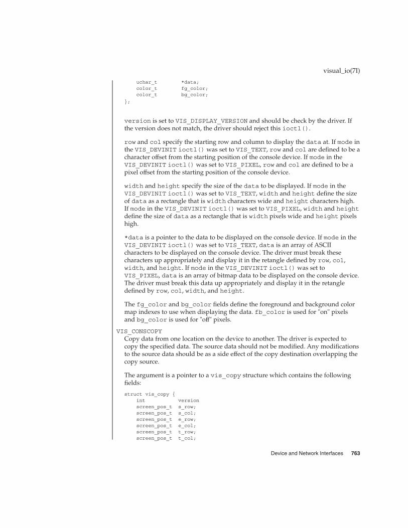
uchar_t *data;color_t fg_color;color_t bg_color;
};
version is set to VIS_DISPLAY_VERSION and should be check by the driver. Ifthe version does not match, the driver should reject this ioctl().
row and col specify the starting row and column to display the data at. If mode inthe VIS_DEVINIT ioctl() was set to VIS_TEXT, row and col are defined to be acharacter offset from the starting position of the console device. If mode in theVIS_DEVINIT ioctl() was set to VIS_PIXEL, row and col are defined to be apixel offset from the starting position of the console device.
width and height specify the size of the data to be displayed. If mode in theVIS_DEVINIT ioctl() was set to VIS_TEXT, width and height define the sizeof data as a rectangle that is width characters wide and height characters high.If mode in the VIS_DEVINIT ioctl() was set to VIS_PIXEL, width and heightdefine the size of data as a rectangle that is width pixels wide and height pixelshigh.
*data is a pointer to the data to be displayed on the console device. If mode in theVIS_DEVINIT ioctl() was set to VIS_TEXT, data is an array of ASCIIcharacters to be displayed on the console device. The driver must break thesecharacters up appropriately and display it in the retangle defined by row, col,width, and height. If mode in the VIS_DEVINIT ioctl() was set toVIS_PIXEL, data is an array of bitmap data to be displayed on the console device.The driver must break this data up appropriately and display it in the retangledefined by row, col, width, and height.
The fg_color and bg_color fields define the foreground and background colormap indexes to use when displaying the data. fb_color is used for "on" pixelsand bg_color is used for "off" pixels.
VIS_CONSCOPYCopy data from one location on the device to another. The driver is expected tocopy the specified data. The source data should not be modified. Any modificationsto the source data should be as a side effect of the copy destination overlapping thecopy source.
The argument is a pointer to a vis_copy structure which contains the followingfields:
struct vis_copy {int versionscreen_pos_t s_row;screen_pos_t s_col;screen_pos_t e_row;screen_pos_t e_col;screen_pos_t t_row;screen_pos_t t_col;
visual_io(7I)
Device and Network Interfaces 763
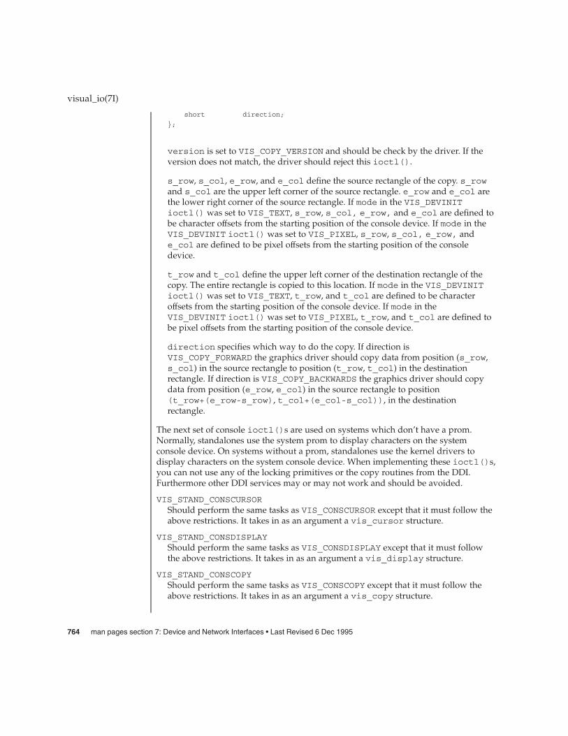
short direction;
};
version is set to VIS_COPY_VERSION and should be check by the driver. If theversion does not match, the driver should reject this ioctl().
s_row, s_col, e_row, and e_col define the source rectangle of the copy. s_rowand s_col are the upper left corner of the source rectangle. e_row and e_col arethe lower right corner of the source rectangle. If mode in the VIS_DEVINITioctl() was set to VIS_TEXT, s_row, s_col, e_row, and e_col are defined tobe character offsets from the starting position of the console device. If mode in theVIS_DEVINIT ioctl() was set to VIS_PIXEL, s_row, s_col, e_row, ande_col are defined to be pixel offsets from the starting position of the consoledevice.
t_row and t_col define the upper left corner of the destination rectangle of thecopy. The entire rectangle is copied to this location. If mode in the VIS_DEVINITioctl() was set to VIS_TEXT, t_row, and t_col are defined to be characteroffsets from the starting position of the console device. If mode in theVIS_DEVINIT ioctl() was set to VIS_PIXEL, t_row, and t_col are defined tobe pixel offsets from the starting position of the console device.
direction specifies which way to do the copy. If direction isVIS_COPY_FORWARD the graphics driver should copy data from position (s_row,s_col) in the source rectangle to position (t_row, t_col) in the destinationrectangle. If direction is VIS_COPY_BACKWARDS the graphics driver should copydata from position (e_row, e_col) in the source rectangle to position(t_row+(e_row-s_row), t_col+(e_col-s_col)), in the destinationrectangle.
The next set of console ioctl()s are used on systems which don’t have a prom.Normally, standalones use the system prom to display characters on the systemconsole device. On systems without a prom, standalones use the kernel drivers todisplay characters on the system console device. When implementing these ioctl()s,you can not use any of the locking primitives or the copy routines from the DDI.Furthermore other DDI services may or may not work and should be avoided.
VIS_STAND_CONSCURSORShould perform the same tasks as VIS_CONSCURSOR except that it must follow theabove restrictions. It takes in as an argument a vis_cursor structure.
VIS_STAND_CONSDISPLAYShould perform the same tasks as VIS_CONSDISPLAY except that it must followthe above restrictions. It takes in as an argument a vis_display structure.
VIS_STAND_CONSCOPYShould perform the same tasks as VIS_CONSCOPY except that it must follow theabove restrictions. It takes in as an argument a vis_copy structure.
visual_io(7I)
764 man pages section 7: Device and Network Interfaces • Last Revised 6 Dec 1995

volfs – Volume Management file system
volfs is the Volume Management file system rooted at root_dir. The default locationfor root-dir is /vol, but this can be overridden using the -d option of vold (seevold(1M)). This file system is maintained by the Volume Management daemon, vold,and will be considered to be /vol for this description.
Media can be accessed in a logical manner (no association with a particular piece ofhardware), or a physical manner (associated with a particular piece of hardware).
Logical names for media are referred to through /vol/dsk and /vol/rdsk./vol/dsk provides block access to random access devices. /vol/rdsk providescharacter access to random access devices.
The /vol/rdsk and /vol/dsk directories are mirrors of one another. Any change toone is reflected in the other immediately. The dev_t for a volume will be the same forboth the block and character device.
The default permissions for /vol are mode=0555, owner=root, group=sys. Thedefault permissions for /vol/dsk and /vol/rdsk are mode=01777, owner=root,group=sys.
Physical references to media are obtained through /vol/dev. This hierarchy reflectsthe structure of the /dev name space. The default permissions for all directories in the/vol/dev hierarchy are mode=0555, owner=root, group=sys.
mkdir(2), rmdir(2), unlink(2) (rm), symlink(2) (ln -s), link(2) (ln), andrename(2) (mv) are supported, subject to normal file and directory permissions.
The following system calls are not supported in the /vol filesystem: creat(2), onlywhen creating a file, and mknod(2).
If the media does not contain file systems that can be automatically mounted byrmmount(1M), users can gain access to the media through the following /vollocations:
Location State of Media
/vol/dev/diskette0/unnamed_floppy formatted unnamed floppy-blockdevice access
/vol/dev/rdiskette0/unnamed_floppy formatted unnamed floppy-raw deviceaccess
/vol/dev/diskette0/unlabeled unlabeled floppy-block device access
/vol/dev/rdiskette0/unlabeled unlabeled floppy-raw device access
/vol/dev/dsk/c0t6/unnamed_cdrom CD-ROM-block device access
volfs(7FS)
NAME
DESCRIPTION
Device and Network Interfaces 765

Location State of Media
/vol/dev/rdsk/c0t6/unnamed_cdrom CD-ROM-raw device access
For more information on the location of CD-ROM and floppy media, see SystemAdministration Guide: Basic Administration or rmmount(1M).
Some media support the concept of a partition. If the label identifies partitions on themedia, the name of the media becomes a directory with partitions under it. Only validpartitions are represented. Partitions cannot be moved out of a directory.
For example, if disk volume ’foo’ has three valid partitions, 0, 2, and 5, then:
/vol/dsk/foo/s0/vol/dsk/foo/s2/vol/dsk/foo/s5
for block access and
/vol/rdsk/foo/s0/vol/rdsk/foo/s2/vol/rdsk/foo/s5
for character access.
If a volume is relabeled to reflect different partitions, the name space changes to reflectthe new partition layout.
A format program can check to see if there are others with the volume open and notallow the format to occur if it is. Volume Management, however, does not explicitlyprevent the rewriting of a label while others have the volume open. If a partition of avolume is open, and the volume is relabeled to remove that partition, it will appearexactly as if the volume were missing. A notify event will be generated and the usermay cancel the operation with volcancel(1), if desired.
volcancel(1), volcheck(1), volmissing(1) rmmount(1M), vold(1M),rmmount.conf(4), vold.conf(4)
System Administration Guide: Basic Administration
volfs(7FS)
Partitions
SEE ALSO
766 man pages section 7: Device and Network Interfaces • Last Revised 8 Feb 1995

vuidmice, vuidm3p, vuidm4p, vuidm5p, vuid2ps2, vuid3ps2 – converts mouseprotocol to Firm Events
#include <sys/stream.h>
#include <sys/vuid_event.h>
int ioctl(fd, I_PUSH, vuidm3p);
int ioctl(fd, I_PUSH, vuidm4p);
int ioctl(fd, I_PUSH, vuidm5p);
int ioctl(fd, I_PUSH, vuid2ps2);
int ioctl(fd, I_PUSH, vuid3ps2);
The STREAMS modules vuidm3p, vuidm4p, vuidm5p, vuid2ps2, and vuid3ps2convert mouse protocols to Firm events. The Firm event structure is described in<sys/vuid_event.h>. Pushing a STREAMS module does not automatically enablemouse protocol conversion to Firm events. The STREAMS module state is initially setto raw or VUID_NATIVE mode which performs no message processing. The user willneed to change the state to VUID_FIRM_EVENT mode in order to initiate mouseprotocol conversion to Firm events. This can be accomplished by the following code:
int format;format = VUID_FIRM_EVENT;
ioctl(fd, VUIDSFORMAT, &format);
The user can also query the state of the STREAMS module by using the VUIDGFORMAToption.
int format;int fd; /* file descriptor */ioctl(fd, VUIDGFORMAT, &format);if ( format == VUID_NATIVE );
/* The state of the module is in raw mode.* Message processing is not enabled.*/
if ( format == VUID_FIRM_EVENT );/* Message processing is enabled.* Mouse protocol conversion to Firm events
* are performed.
The remainder of this section describes the processing of STREAMS messages on theread- and write-side.
M_DATA The messages coming in are queued and converted to Firm events.
M_FLUSH The read queue of the module is flushed of all its data messagesand all data in the record being accumulated are also flushed. Themessage is passed upstream.
vuid2ps2(7M)
NAME
SYNOPSIS
DESCRIPTION
Read SideBehavior
Device and Network Interfaces 767

M_IOCTL Messages sent downstream as a result of an ioctl(2) system call.There are two valid ioctl options processed by the vuidmicemodules VUIDGFORMAT and VUIDSFORMAT.
VUIDGFORMAT This option returns the current state of theSTREAMS module. The state of the vuidmiceSTREAMS module may either beVUID_NATIVE (no message processing) orVUID_FIRM_EVENT (convert to Firm events).
VUIDSFORMAT This option sets the state of the STREAMSmodule to VUID_FIRM_EVENT. If the state ofthe STREAMS module is already inVUID_FIRM_EVENT then this option isnon-operational. It is not possible to set thestate back to VUID_NATIVE once the statebecomes VUID_FIRM_EVENT. To disablemessage processing, pop the STREAMSmodule out by calling ioctl(fd, 1I_POP,vuid*).
M_FLUSH The write queue of the module is flushed of all its data messagesand the message is passed downstream.
Module Protocol Type Device
vuidm3p 3-Byte Protocol Microsoft 2 Button SerialMouse
/dev/tty*
vuidm4p 4-Byte Protocol Logitech 3 ButtonMouseman
/dev/tty*
vuidm5p Logitech 3 Button Bus Mouse MicrosoftBus Mouse
/dev/logi/ dev/msm
vuid2ps2 PS/2 Protocol 2 Button PS/2 CompatibleMouse
/dev/kdmouse
vuid3ps2 PS/2 Protocol 3 Button PS/2 CompatibleMouse
/dev/kdmouse
See attributes(5) for descriptions of the following attributes:
ATTRIBUTE TYPE ATTRIBUTE VALUE
Architecture IA
attributes(5)
vuid2ps2(7M)
Write SideBehavior
MouseConfigurations
ATTRIBUTES
SEE ALSO
768 man pages section 7: Device and Network Interfaces • Last Revised 1 Jan 1997

STREAMS Programming Guide
vuid2ps2(7M)
Device and Network Interfaces 769
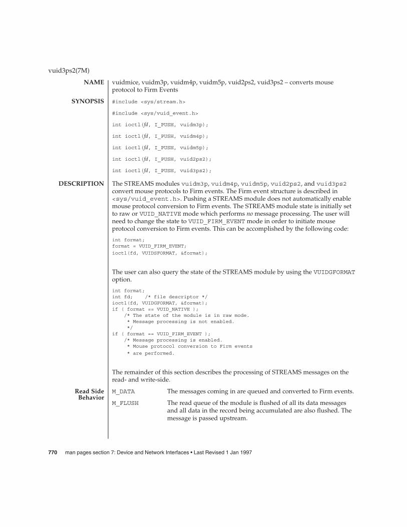
vuidmice, vuidm3p, vuidm4p, vuidm5p, vuid2ps2, vuid3ps2 – converts mouseprotocol to Firm Events
#include <sys/stream.h>
#include <sys/vuid_event.h>
int ioctl(fd, I_PUSH, vuidm3p);
int ioctl(fd, I_PUSH, vuidm4p);
int ioctl(fd, I_PUSH, vuidm5p);
int ioctl(fd, I_PUSH, vuid2ps2);
int ioctl(fd, I_PUSH, vuid3ps2);
The STREAMS modules vuidm3p, vuidm4p, vuidm5p, vuid2ps2, and vuid3ps2convert mouse protocols to Firm events. The Firm event structure is described in<sys/vuid_event.h>. Pushing a STREAMS module does not automatically enablemouse protocol conversion to Firm events. The STREAMS module state is initially setto raw or VUID_NATIVE mode which performs no message processing. The user willneed to change the state to VUID_FIRM_EVENT mode in order to initiate mouseprotocol conversion to Firm events. This can be accomplished by the following code:
int format;format = VUID_FIRM_EVENT;
ioctl(fd, VUIDSFORMAT, &format);
The user can also query the state of the STREAMS module by using the VUIDGFORMAToption.
int format;int fd; /* file descriptor */ioctl(fd, VUIDGFORMAT, &format);if ( format == VUID_NATIVE );
/* The state of the module is in raw mode.* Message processing is not enabled.*/
if ( format == VUID_FIRM_EVENT );/* Message processing is enabled.* Mouse protocol conversion to Firm events
* are performed.
The remainder of this section describes the processing of STREAMS messages on theread- and write-side.
M_DATA The messages coming in are queued and converted to Firm events.
M_FLUSH The read queue of the module is flushed of all its data messagesand all data in the record being accumulated are also flushed. Themessage is passed upstream.
vuid3ps2(7M)
NAME
SYNOPSIS
DESCRIPTION
Read SideBehavior
770 man pages section 7: Device and Network Interfaces • Last Revised 1 Jan 1997
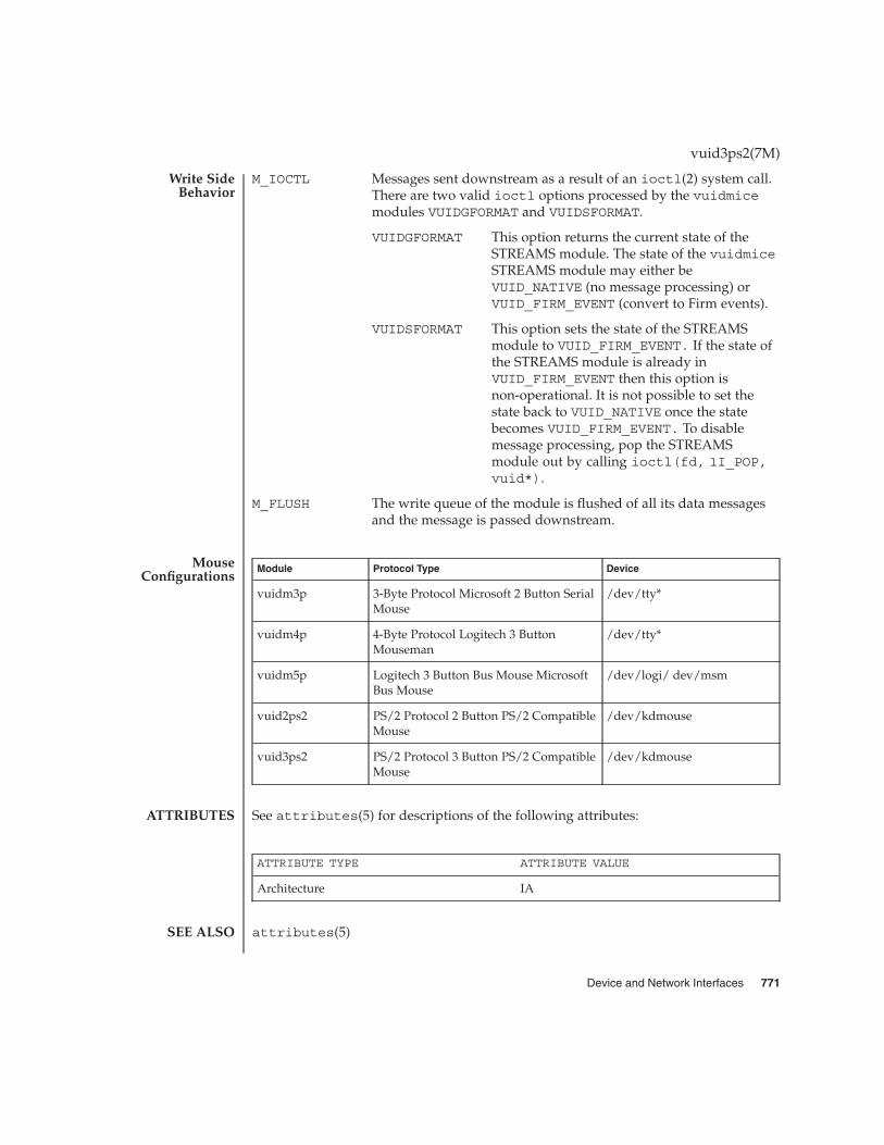
M_IOCTL Messages sent downstream as a result of an ioctl(2) system call.There are two valid ioctl options processed by the vuidmicemodules VUIDGFORMAT and VUIDSFORMAT.
VUIDGFORMAT This option returns the current state of theSTREAMS module. The state of the vuidmiceSTREAMS module may either beVUID_NATIVE (no message processing) orVUID_FIRM_EVENT (convert to Firm events).
VUIDSFORMAT This option sets the state of the STREAMSmodule to VUID_FIRM_EVENT. If the state ofthe STREAMS module is already inVUID_FIRM_EVENT then this option isnon-operational. It is not possible to set thestate back to VUID_NATIVE once the statebecomes VUID_FIRM_EVENT. To disablemessage processing, pop the STREAMSmodule out by calling ioctl(fd, 1I_POP,vuid*).
M_FLUSH The write queue of the module is flushed of all its data messagesand the message is passed downstream.
Module Protocol Type Device
vuidm3p 3-Byte Protocol Microsoft 2 Button SerialMouse
/dev/tty*
vuidm4p 4-Byte Protocol Logitech 3 ButtonMouseman
/dev/tty*
vuidm5p Logitech 3 Button Bus Mouse MicrosoftBus Mouse
/dev/logi/ dev/msm
vuid2ps2 PS/2 Protocol 2 Button PS/2 CompatibleMouse
/dev/kdmouse
vuid3ps2 PS/2 Protocol 3 Button PS/2 CompatibleMouse
/dev/kdmouse
See attributes(5) for descriptions of the following attributes:
ATTRIBUTE TYPE ATTRIBUTE VALUE
Architecture IA
attributes(5)
vuid3ps2(7M)
Write SideBehavior
MouseConfigurations
ATTRIBUTES
SEE ALSO
Device and Network Interfaces 771

STREAMS Programming Guide
vuid3ps2(7M)
772 man pages section 7: Device and Network Interfaces • Last Revised 1 Jan 1997
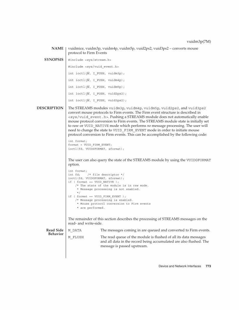
vuidmice, vuidm3p, vuidm4p, vuidm5p, vuid2ps2, vuid3ps2 – converts mouseprotocol to Firm Events
#include <sys/stream.h>
#include <sys/vuid_event.h>
int ioctl(fd, I_PUSH, vuidm3p);
int ioctl(fd, I_PUSH, vuidm4p);
int ioctl(fd, I_PUSH, vuidm5p);
int ioctl(fd, I_PUSH, vuid2ps2);
int ioctl(fd, I_PUSH, vuid3ps2);
The STREAMS modules vuidm3p, vuidm4p, vuidm5p, vuid2ps2, and vuid3ps2convert mouse protocols to Firm events. The Firm event structure is described in<sys/vuid_event.h>. Pushing a STREAMS module does not automatically enablemouse protocol conversion to Firm events. The STREAMS module state is initially setto raw or VUID_NATIVE mode which performs no message processing. The user willneed to change the state to VUID_FIRM_EVENT mode in order to initiate mouseprotocol conversion to Firm events. This can be accomplished by the following code:
int format;format = VUID_FIRM_EVENT;
ioctl(fd, VUIDSFORMAT, &format);
The user can also query the state of the STREAMS module by using the VUIDGFORMAToption.
int format;int fd; /* file descriptor */ioctl(fd, VUIDGFORMAT, &format);if ( format == VUID_NATIVE );
/* The state of the module is in raw mode.* Message processing is not enabled.*/
if ( format == VUID_FIRM_EVENT );/* Message processing is enabled.* Mouse protocol conversion to Firm events
* are performed.
The remainder of this section describes the processing of STREAMS messages on theread- and write-side.
M_DATA The messages coming in are queued and converted to Firm events.
M_FLUSH The read queue of the module is flushed of all its data messagesand all data in the record being accumulated are also flushed. Themessage is passed upstream.
vuidm3p(7M)
NAME
SYNOPSIS
DESCRIPTION
Read SideBehavior
Device and Network Interfaces 773

M_IOCTL Messages sent downstream as a result of an ioctl(2) system call.There are two valid ioctl options processed by the vuidmicemodules VUIDGFORMAT and VUIDSFORMAT.
VUIDGFORMAT This option returns the current state of theSTREAMS module. The state of the vuidmiceSTREAMS module may either beVUID_NATIVE (no message processing) orVUID_FIRM_EVENT (convert to Firm events).
VUIDSFORMAT This option sets the state of the STREAMSmodule to VUID_FIRM_EVENT. If the state ofthe STREAMS module is already inVUID_FIRM_EVENT then this option isnon-operational. It is not possible to set thestate back to VUID_NATIVE once the statebecomes VUID_FIRM_EVENT. To disablemessage processing, pop the STREAMSmodule out by calling ioctl(fd, 1I_POP,vuid*).
M_FLUSH The write queue of the module is flushed of all its data messagesand the message is passed downstream.
Module Protocol Type Device
vuidm3p 3-Byte Protocol Microsoft 2 Button SerialMouse
/dev/tty*
vuidm4p 4-Byte Protocol Logitech 3 ButtonMouseman
/dev/tty*
vuidm5p Logitech 3 Button Bus Mouse MicrosoftBus Mouse
/dev/logi/ dev/msm
vuid2ps2 PS/2 Protocol 2 Button PS/2 CompatibleMouse
/dev/kdmouse
vuid3ps2 PS/2 Protocol 3 Button PS/2 CompatibleMouse
/dev/kdmouse
See attributes(5) for descriptions of the following attributes:
ATTRIBUTE TYPE ATTRIBUTE VALUE
Architecture IA
attributes(5)
vuidm3p(7M)
Write SideBehavior
MouseConfigurations
ATTRIBUTES
SEE ALSO
774 man pages section 7: Device and Network Interfaces • Last Revised 1 Jan 1997

STREAMS Programming Guide
vuidm3p(7M)
Device and Network Interfaces 775

vuidmice, vuidm3p, vuidm4p, vuidm5p, vuid2ps2, vuid3ps2 – converts mouseprotocol to Firm Events
#include <sys/stream.h>
#include <sys/vuid_event.h>
int ioctl(fd, I_PUSH, vuidm3p);
int ioctl(fd, I_PUSH, vuidm4p);
int ioctl(fd, I_PUSH, vuidm5p);
int ioctl(fd, I_PUSH, vuid2ps2);
int ioctl(fd, I_PUSH, vuid3ps2);
The STREAMS modules vuidm3p, vuidm4p, vuidm5p, vuid2ps2, and vuid3ps2convert mouse protocols to Firm events. The Firm event structure is described in<sys/vuid_event.h>. Pushing a STREAMS module does not automatically enablemouse protocol conversion to Firm events. The STREAMS module state is initially setto raw or VUID_NATIVE mode which performs no message processing. The user willneed to change the state to VUID_FIRM_EVENT mode in order to initiate mouseprotocol conversion to Firm events. This can be accomplished by the following code:
int format;format = VUID_FIRM_EVENT;
ioctl(fd, VUIDSFORMAT, &format);
The user can also query the state of the STREAMS module by using the VUIDGFORMAToption.
int format;int fd; /* file descriptor */ioctl(fd, VUIDGFORMAT, &format);if ( format == VUID_NATIVE );
/* The state of the module is in raw mode.* Message processing is not enabled.*/
if ( format == VUID_FIRM_EVENT );/* Message processing is enabled.* Mouse protocol conversion to Firm events
* are performed.
The remainder of this section describes the processing of STREAMS messages on theread- and write-side.
M_DATA The messages coming in are queued and converted to Firm events.
M_FLUSH The read queue of the module is flushed of all its data messagesand all data in the record being accumulated are also flushed. Themessage is passed upstream.
vuidm4p(7M)
NAME
SYNOPSIS
DESCRIPTION
Read SideBehavior
776 man pages section 7: Device and Network Interfaces • Last Revised 1 Jan 1997

M_IOCTL Messages sent downstream as a result of an ioctl(2) system call.There are two valid ioctl options processed by the vuidmicemodules VUIDGFORMAT and VUIDSFORMAT.
VUIDGFORMAT This option returns the current state of theSTREAMS module. The state of the vuidmiceSTREAMS module may either beVUID_NATIVE (no message processing) orVUID_FIRM_EVENT (convert to Firm events).
VUIDSFORMAT This option sets the state of the STREAMSmodule to VUID_FIRM_EVENT. If the state ofthe STREAMS module is already inVUID_FIRM_EVENT then this option isnon-operational. It is not possible to set thestate back to VUID_NATIVE once the statebecomes VUID_FIRM_EVENT. To disablemessage processing, pop the STREAMSmodule out by calling ioctl(fd, 1I_POP,vuid*).
M_FLUSH The write queue of the module is flushed of all its data messagesand the message is passed downstream.
Module Protocol Type Device
vuidm3p 3-Byte Protocol Microsoft 2 Button SerialMouse
/dev/tty*
vuidm4p 4-Byte Protocol Logitech 3 ButtonMouseman
/dev/tty*
vuidm5p Logitech 3 Button Bus Mouse MicrosoftBus Mouse
/dev/logi/ dev/msm
vuid2ps2 PS/2 Protocol 2 Button PS/2 CompatibleMouse
/dev/kdmouse
vuid3ps2 PS/2 Protocol 3 Button PS/2 CompatibleMouse
/dev/kdmouse
See attributes(5) for descriptions of the following attributes:
ATTRIBUTE TYPE ATTRIBUTE VALUE
Architecture IA
attributes(5)
vuidm4p(7M)
Write SideBehavior
MouseConfigurations
ATTRIBUTES
SEE ALSO
Device and Network Interfaces 777

STREAMS Programming Guide
vuidm4p(7M)
778 man pages section 7: Device and Network Interfaces • Last Revised 1 Jan 1997

vuidmice, vuidm3p, vuidm4p, vuidm5p, vuid2ps2, vuid3ps2 – converts mouseprotocol to Firm Events
#include <sys/stream.h>
#include <sys/vuid_event.h>
int ioctl(fd, I_PUSH, vuidm3p);
int ioctl(fd, I_PUSH, vuidm4p);
int ioctl(fd, I_PUSH, vuidm5p);
int ioctl(fd, I_PUSH, vuid2ps2);
int ioctl(fd, I_PUSH, vuid3ps2);
The STREAMS modules vuidm3p, vuidm4p, vuidm5p, vuid2ps2, and vuid3ps2convert mouse protocols to Firm events. The Firm event structure is described in<sys/vuid_event.h>. Pushing a STREAMS module does not automatically enablemouse protocol conversion to Firm events. The STREAMS module state is initially setto raw or VUID_NATIVE mode which performs no message processing. The user willneed to change the state to VUID_FIRM_EVENT mode in order to initiate mouseprotocol conversion to Firm events. This can be accomplished by the following code:
int format;format = VUID_FIRM_EVENT;
ioctl(fd, VUIDSFORMAT, &format);
The user can also query the state of the STREAMS module by using the VUIDGFORMAToption.
int format;int fd; /* file descriptor */ioctl(fd, VUIDGFORMAT, &format);if ( format == VUID_NATIVE );
/* The state of the module is in raw mode.* Message processing is not enabled.*/
if ( format == VUID_FIRM_EVENT );/* Message processing is enabled.* Mouse protocol conversion to Firm events
* are performed.
The remainder of this section describes the processing of STREAMS messages on theread- and write-side.
M_DATA The messages coming in are queued and converted to Firm events.
M_FLUSH The read queue of the module is flushed of all its data messagesand all data in the record being accumulated are also flushed. Themessage is passed upstream.
vuidm5p(7M)
NAME
SYNOPSIS
DESCRIPTION
Read SideBehavior
Device and Network Interfaces 779

M_IOCTL Messages sent downstream as a result of an ioctl(2) system call.There are two valid ioctl options processed by the vuidmicemodules VUIDGFORMAT and VUIDSFORMAT.
VUIDGFORMAT This option returns the current state of theSTREAMS module. The state of the vuidmiceSTREAMS module may either beVUID_NATIVE (no message processing) orVUID_FIRM_EVENT (convert to Firm events).
VUIDSFORMAT This option sets the state of the STREAMSmodule to VUID_FIRM_EVENT. If the state ofthe STREAMS module is already inVUID_FIRM_EVENT then this option isnon-operational. It is not possible to set thestate back to VUID_NATIVE once the statebecomes VUID_FIRM_EVENT. To disablemessage processing, pop the STREAMSmodule out by calling ioctl(fd, 1I_POP,vuid*).
M_FLUSH The write queue of the module is flushed of all its data messagesand the message is passed downstream.
Module Protocol Type Device
vuidm3p 3-Byte Protocol Microsoft 2 Button SerialMouse
/dev/tty*
vuidm4p 4-Byte Protocol Logitech 3 ButtonMouseman
/dev/tty*
vuidm5p Logitech 3 Button Bus Mouse MicrosoftBus Mouse
/dev/logi/ dev/msm
vuid2ps2 PS/2 Protocol 2 Button PS/2 CompatibleMouse
/dev/kdmouse
vuid3ps2 PS/2 Protocol 3 Button PS/2 CompatibleMouse
/dev/kdmouse
See attributes(5) for descriptions of the following attributes:
ATTRIBUTE TYPE ATTRIBUTE VALUE
Architecture IA
attributes(5)
vuidm5p(7M)
Write SideBehavior
MouseConfigurations
ATTRIBUTES
SEE ALSO
780 man pages section 7: Device and Network Interfaces • Last Revised 1 Jan 1997

STREAMS Programming Guide
vuidm5p(7M)
Device and Network Interfaces 781

vuidmice, vuidm3p, vuidm4p, vuidm5p, vuid2ps2, vuid3ps2 – converts mouseprotocol to Firm Events
#include <sys/stream.h>
#include <sys/vuid_event.h>
int ioctl(fd, I_PUSH, vuidm3p);
int ioctl(fd, I_PUSH, vuidm4p);
int ioctl(fd, I_PUSH, vuidm5p);
int ioctl(fd, I_PUSH, vuid2ps2);
int ioctl(fd, I_PUSH, vuid3ps2);
The STREAMS modules vuidm3p, vuidm4p, vuidm5p, vuid2ps2, and vuid3ps2convert mouse protocols to Firm events. The Firm event structure is described in<sys/vuid_event.h>. Pushing a STREAMS module does not automatically enablemouse protocol conversion to Firm events. The STREAMS module state is initially setto raw or VUID_NATIVE mode which performs no message processing. The user willneed to change the state to VUID_FIRM_EVENT mode in order to initiate mouseprotocol conversion to Firm events. This can be accomplished by the following code:
int format;format = VUID_FIRM_EVENT;
ioctl(fd, VUIDSFORMAT, &format);
The user can also query the state of the STREAMS module by using the VUIDGFORMAToption.
int format;int fd; /* file descriptor */ioctl(fd, VUIDGFORMAT, &format);if ( format == VUID_NATIVE );
/* The state of the module is in raw mode.* Message processing is not enabled.*/
if ( format == VUID_FIRM_EVENT );/* Message processing is enabled.* Mouse protocol conversion to Firm events
* are performed.
The remainder of this section describes the processing of STREAMS messages on theread- and write-side.
M_DATA The messages coming in are queued and converted to Firm events.
M_FLUSH The read queue of the module is flushed of all its data messagesand all data in the record being accumulated are also flushed. Themessage is passed upstream.
vuidmice(7M)
NAME
SYNOPSIS
DESCRIPTION
Read SideBehavior
782 man pages section 7: Device and Network Interfaces • Last Revised 1 Jan 1997

M_IOCTL Messages sent downstream as a result of an ioctl(2) system call.There are two valid ioctl options processed by the vuidmicemodules VUIDGFORMAT and VUIDSFORMAT.
VUIDGFORMAT This option returns the current state of theSTREAMS module. The state of the vuidmiceSTREAMS module may either beVUID_NATIVE (no message processing) orVUID_FIRM_EVENT (convert to Firm events).
VUIDSFORMAT This option sets the state of the STREAMSmodule to VUID_FIRM_EVENT. If the state ofthe STREAMS module is already inVUID_FIRM_EVENT then this option isnon-operational. It is not possible to set thestate back to VUID_NATIVE once the statebecomes VUID_FIRM_EVENT. To disablemessage processing, pop the STREAMSmodule out by calling ioctl(fd, 1I_POP,vuid*).
M_FLUSH The write queue of the module is flushed of all its data messagesand the message is passed downstream.
Module Protocol Type Device
vuidm3p 3-Byte Protocol Microsoft 2 Button SerialMouse
/dev/tty*
vuidm4p 4-Byte Protocol Logitech 3 ButtonMouseman
/dev/tty*
vuidm5p Logitech 3 Button Bus Mouse MicrosoftBus Mouse
/dev/logi/ dev/msm
vuid2ps2 PS/2 Protocol 2 Button PS/2 CompatibleMouse
/dev/kdmouse
vuid3ps2 PS/2 Protocol 3 Button PS/2 CompatibleMouse
/dev/kdmouse
See attributes(5) for descriptions of the following attributes:
ATTRIBUTE TYPE ATTRIBUTE VALUE
Architecture IA
attributes(5)
vuidmice(7M)
Write SideBehavior
MouseConfigurations
ATTRIBUTES
SEE ALSO
Device and Network Interfaces 783

STREAMS Programming Guide
vuidmice(7M)
784 man pages section 7: Device and Network Interfaces • Last Revised 1 Jan 1997

wrsm – WCI Remote Shared Memory (WRSM) device driver
wci@<slot>,0:wrsm
wrsm@<instance>:ctrl
wrsm@ffff,0:admin
The wrsm driver is a nexus driver that manages WCI devices and wrsm controllers.
A WCI device on a WCI Interface Board (WIB) sits directly on the host backplane andprovides clustering communication between Solaris instances that are memorytransaction-based. The WCI replaces a schizo or CPU in Sun Fire servers and acts as amemory controller on the system backplane. The wrsm driver programs registers onthe WCI to accept network read/write requests on certain exported cluster addressesfrom incoming links. The registers translate the requests into local read/write bustransactions that use local physical memory ranges that you specify. The driverprograms additional WCI registers to forward local system backplane read/writetransactions within a particular physical address range to a remote WCI. A WCIdevice in the format wci@slot,0:wrsm appears in the device tree.
A wrsm controller is a pseudo device that manages a set of WCIs. A device entry in theformat wrsm@<instance>:ctrl appears in the device tree. A wrsm controllerpresents a Sun proprietary protocol to clients, enabling them to set up the network andto communicate through the WCIs. To configure a wrsm controller, you download aconfiguration into the driver using the wrsmconf(1M) command or through otherexternal WCI network management software. Status information on each WCI andwrsm controller is available by using the wrsmstat(1M) command.
The wrsm admin device is used internally by the driver to manage the I/O addressesassociated with remote memory. A device entry in the format wrsm@ffff,0:adminappears in the device tree
/platform/sun4u/kernel/drv/sparcv9/wrsmELF kernel module
wrsmconf(1M), wrsmstat(1M)
Writing Device Drivers
The messages described below may appear on the system console as well as beinglogged. These messages generally include the string wrsm%d, where %d is the instancenumber of the wrsm device. The message context indicates whether the device is aWCI or a wrsm controller. Some messages include the string wci %a, where %a is thebus slot of the WCI device.
wrsm%d: unable to map register set %d
Driver was unable to map device registers; check for bad hardware. Driver did notattach device, device will be inaccessible.
wrsm_detach:cf_remove_controller failed for wrsm%d
wrsm(7D)
NAME
SYNOPSIS
DESCRIPTION
FILES
SEE ALSO
DIAGNOSTICS
Device and Network Interfaces 785

Driver did not detach device; device is inaccessible.
wrsm_detach:cf_remove_wci failed for wrsm%d
Driver did not detach device. This WCI is the last WCI in wrsm controller.
register_controller of wrsm%d failed with error %d
The wrsm controller could not register with the Sun proprietary protocol framework.Communication is not possible through this controller.
wrsm%d, wci %a, SRAM CE ERROR, at address: 0x%x, syndrome: 0x%x
There was a correctable error in the WCI’s SRAM. This indicates that the memory onthis WCI module should be replaced.
wrsm%d, wci %a, SRAM UE ERROR, at address: 0x%x, syndrome: 0x%x
There was an uncorrectable error in the WCI’s SRAM. This indicates that the memoryon this WCI module should be replaced. In addition, attempts to access local memoryfrom remote nodes may fail.
wrsm(7D)
786 man pages section 7: Device and Network Interfaces • Last Revised 17 Jan 2001

wrsmd – WCI Remote Shared Memory (WRSM) DLPI driver
wrsmd
The wrsmd device driver is a pseudo driver that presents a type II DLPI interface. Thedriver uses a Sun proprietary interface over the wrsm driver to provide IP-basedcommunication over the WCI network.
Before using DLPI over a WCI network, you must first configure the wrsm controlleron that network. See wrsmconf(1M) for more information. Each wrsmd device isassociated with a wrsm controller with a matching id.
/platform/sun4u/kernel/drv/sparcv9/wrsmdELF kernel module
wrsmconf(1M), wrsm(7D)
Writing Device Drivers
wrsmd(7D)
NAME
SYNOPSIS
DESCRIPTION
FILES
SEE ALSO
Device and Network Interfaces 787

wscons – workstation console
#include <sys/strredir.h>
ioctl(fd, SRIOCSREDIR, target);
ioctl(fd, SRIOCISREDIR, target);
The wscons workstation console consists of a workstation keyboard and frame bufferthat act together to emulate an ASCII terminal. It includes a redirection facility thatallows I/O issued to the workstation console to be diverted to a STREAMS device,enabling window systems to redirect output that would otherwise appear directly onthe frame buffer in corrupted form.
The wscons redirection facility maintains a list of devices that are designated asredirection targets through the SRIOCSREDIR ioctl described below. Only the currententry is active; when the active entry is closed, the most recent remaining entrybecomes active. The active entry acts as a proxy for the device being redirected andhandles all read(2), write(2), ioctl(2), and poll(2) calls issued against theredirectee.
The ioctls described below control the redirection facility. In both cases, fd is adescriptor for the device being redirected (or workstation console) and target is adescriptor for a STREAMS device.
SRIOCSREDIR Designates target as the source and destination of I/Oostensibly directed to the device denoted by fd.
SRIOCISREDIR Returns 1 if target names the device currently acting asproxy for the device denoted by fd, and 0 if it is not.
On SPARC systems, the PROM monitor emulates an ANSI X3.64 terminal.
On IA systems, the Solaris console subsystem provides ANSI X3.64 emulation.
Note: The VT100 adheres the ANSI X3.64 standard. However, because the VT100features nonstandard extensions to ANSI X3.64, it is incompatible with Sun terminalemulators.
The SPARC console displays 34 lines of 80 ASCII characters per line. The IA consoledisplays 25 lines of 80 ASCII characters per line. Devices with smaller text capacitiesmay display less. On SPARC systems, the screen-#rows screen-#columnsshould be set to 34 or 80 respectively, or text capacities will vary from those describedabove. On SPARC systems, the screen-#rows and screen-#columns fields arestored in NVRAM/EEPROM. See eeprom(1M) for more information. Both SPARCand IA consoles offer scrolling, (x, y) cursor addressing ability, and a number of othercontrol functions.
wscons(7D)
NAME
SYNOPSIS
DESCRIPTION
Redirection
ANSI StandardTerminal
Emulation
788 man pages section 7: Device and Network Interfaces • Last Revised 22 Sep 2000

The console cursor marks the current line and character position on the screen. ASCIIcharacters between 0x20 (space) and 0x7E (tilde) inclusive are printing characters.When a print character is written to the console (and is not part of an escapesequence), it is displayed at the current cursor position and the cursor moves oneposition to the right on the current line.
On SPARC based systems, later PROM revisions have the full 8-bit ISO Latin-1 (ISO8859-1) character set. Earlier PROM revisions display characters in the range 0xA0through 0xFE as spaces.
When the cursor is at the right edge of the screen, it moves to the first characterposition on the next line. When the cursor is at the screen’s right-bottom edge, theline-feed function is performed (see CTRL-J below). The line-feed function scrolls thescreen up by one or more lines before moving the cursor to the first character positionon the next line.
The wscons console defines a number of control sequences that may occur duringinput. When a control sequence is written to the console, it affects one of the controlfunctions described below. Control sequences are not displayed on screen.
A number of control sequences (or control character functions) are of the form:
CTRL-x
where x represents a singe character., such as CNTRL-J for a line feed.
Other ANSI control sequences are of the form:
ESC [ params char
Note – Spaces are included only for readability; these characters must occur in thegiven sequence without the intervening spaces.
ESC ASCII escape character (ESC, CTRL-[, 0x1B).
[ Left square bracket ‘[’ (0x5B).
params Sequence of zero or more decimal numbers made up ofdigits between 0 and 9, separated by semicolons.Parameters are represented by n in the syntaxdescriptions for escape sequence functions.
char Function character, which is different for each controlsequence and it represented by x in the syntaxdescriptions for control character functions.
In the following examples of syntactically valid escape sequences, ESC represent thesingle ASCII character, Escape:
ESC[m Select graphic rendition with default parameter
wscons(7D)
Control SequenceSyntax
Device and Network Interfaces 789

ESC[7m Select graphic rendition with reverse image
ESC[33;54H Set cursor position
ESC[123;456;0;;3;B Move cursor down
Syntactically valid control characters and ANSI escape sequences that are notcurrently interpreted by the console are ignored.
Each control function requires a specified number of parameters. If fewer parametersare supplied, the remaining parameters (which certain exceptions that are notedbelow) default to 1. For example, if more than the required number of parameters aresupplied, only the last n is used, where n is the number required by that particularcommand character.
Parameters which are omitted or set to 0 are reset to the default value of 1 (withcertain exceptions). For example, the command character M requires one parameter.ESC[;M, ESC[0M, ESC[M and ESC[23;15;32;1M are all equivalent to ESC[1M andprovide a parameter value of 1. Note that ESC[;5M (interpreted as ‘ESC[5M’) is notequivalent to ESC[5;M (interpreted as ‘ESC[5;1M’) which is ultimately interpreted as‘ESC[1M’).
The following paragraphs specify the ANSI control functions implemented by theconsole. Each description provides:
� Control sequence syntax
� Hexadecimal equivalent of control characters where applicable
� Control function name and ANSI or Sun abbreviation (if any).
� Description of parameters required, if any
� Description of the control function
� Initial setting of the mode for functions that set a mode. To restore the initialsettings, use the SUNRESET escape sequence.
The wscons control character functions are:
Bell (BEL),CTRL-G0x7
Used for consoles that are not equipped with an audible bell. Current Sunworkstation models also flash the screen if the keyboard is not the console inputdevice.
Backspace (BS),CTRL-H,0x8
The cursor moves one position to the left on the current line. If it is already at theleft edge of the screen, no change takes place.
wscons(7D)
ANSI ControlFunctions
Control CharacterFunctions
790 man pages section 7: Device and Network Interfaces • Last Revised 22 Sep 2000

Tab (TAB),CTRL-I,0x9
The cursor moves right on the current line to the next tab stop. The tab stops arefixed at every multiple of eight columns. If the cursor is already at the right edge ofthe screen, nothing change takes place. Otherwise, the cursor moves right aminimum of one and a maximum of eight character positions.
Line-feed (LF),CTRL-J,0xA
The cursor, while remaining at the same character position on the line, moves downone line. If the cursor is at the bottom line, the screen either scrolls up or wrapsaround depending on the setting of an internal variable n (initially 1) . The internalvariable can be changed using the ESC[r control sequence. If n is greater than zero,the entire screen (including the cursor) is scrolled up by n lines before executing theline-feed. The top n lines scroll off the screen and are lost. New blank lines n scrollonto the bottom of the screen. After scrolling, move the cursor down one line toexecute the line feed.
If n is zero, wrap-around mode is entered. The ESC [ 1 r exits back to scrollmode. If a line-feed occurs on the bottom line in wrap mode, the cursor goes to thesame character position in the top line of the screen. During line-feeds, the line thatthe cursor moves to is cleared and no scrolling occurs. Wrap-around mode is notimplemented in the window system.
On SPARC based systems, the speed at which the screen scrolls is dependent on theamount of data waiting to be printed. Whenever a scroll occurs and the console isin normal scroll mode (ESC [ 1 r), it scans the rest of the data awaiting printing tosee how many line-feeds occur in it. This scan stops when the console finds acontrol character from the set {VT, FF, SO, SI, DLE, DC1, DC2, DC3, DC4, NAK, SYN,ETB, CAN, EM, SUB, ESC, FS, GS, RS, US} . At that point, the screen is scrolled by nlines (n ≥ 1) and processing continues. The scanned text is processed normally andfills in the newly created lines. As long as escape codes or other control charactersare not intermixed with the text, this results in faster scrolling
Reverse Line-feed,CTRL-K,0xB
While remaining at the same character position on the line, the cursor moves upone line. If the cursor is already at the top line, no change takes place.
Form-feed (FF)CTRL-L,0xC
The cursor is positioned to the home position (upper-left corner) and the entirescreen is cleared.
Return (CR),CTRL-M,
wscons(7D)
Device and Network Interfaces 791

0xDThe cursor moves to the leftmost character position on the current line.
The wscons escape sequence functions are:
Escape (ESC),CTRL-[,0x1B
The escape character. Escape initiates a multi-character control sequence.
Insert Character (ICH)ESC[#@
Takes one parameter, n (default 1). Inserts n spaces at the current cursor position.The current line, starting at the current cursor position inclusive, is shifted to theright by n character positions to make room for the spaces. The rightmost ncharacter positions shift off the line and are lost. The position of the cursor isunchanged.
Cursor Up (CUU),ESC[#A
Takes one parameter, n (default 1). Moves the cursor up n lines. If the cursor isfewer than n lines from the top of the screen, moves the cursor to the topmost lineon the screen. The character position of the cursor on the line is unchanged.
Cursor Down (CUD),ESC[#B
Takes one parameter, (default 1). Moves the cursor down n lines. If the cursor isfewer than n lines from the bottom of the screen, move the cursor to the last line onthe screen. The character position of the cursor on the line is unchanged.
Cursor Forward (CUF),ESC[#C
Takes one parameter, n (default 1). Moves the cursor to the right by n characterpositions on the current line. If the cursor is fewer than n positions from the rightedge of the screen, moves the cursor to the rightmost position on the current line.
Cursor Backward (CUB),ESC[#D
Takes one parameter, n (default 1). Moves the cursor to the left by n characterpositions on the current line. If the cursor is fewer than n positions from the leftedge of the screen, moves the cursor to the leftmost position on the current line.
Cursor Next Line (CNL),ESC[#E
Takes one parameter, n (default 1). Positions the cursor at the leftmost characterposition on the n-th line below the current line. If the current line is less than n linesfrom the bottom of the screen, positions the cursor at the leftmost character positionon the bottom line.
Horizontal and Vertical Position (HVP),ESC[#1;#2f
or
wscons(7D)
Escape SequenceFunctions
792 man pages section 7: Device and Network Interfaces • Last Revised 22 Sep 2000

Cursor Position (CUP),ESC[#1;#2H
Takes two parameters, n1 and n2 (default 1, 1). Moves the cursor to the n2-thcharacter position on the n1-th line. Character positions are numbered from 1 at theleft edge of the screen; line positions are numbered from 1 at the top of the screen.Hence, if both parameters are omitted, the default action moves the cursor to thehome position (upper left corner). If only one parameter is supplied, the cursormoves to column 1 of the specified line.
Erase in Display (ED),ESC[J
Takes no parameters. Erases from the current cursor position inclusive to the end ofthe screen, that is, to the end of the current line and all lines below the current line.The cursor position is unchanged.
Erase in Line (EL),ESC[K
Takes no parameters. Erases from the current cursor position inclusive to the end ofthe current line. The cursor position is unchanged.
Insert Line (IL),ESC[#L
Takes one parameter, n (default 1). Makes room for n new lines starting at thecurrent line by scrolling down by n lines the portion of the screen from the currentline inclusive to the bottom. The n new lines at the cursor are filled with spaces; thebottom n lines shift off the bottom of the screen and are lost. The position of thecursor on the screen is unchanged.
Delete Line (DL),ESC[#M
Takes one parameter, n (default 1). Deletes n lines beginning with the current line.The portion of the screen from the current line inclusive to the bottom is scrolledupward by n lines. The n new lines scrolling onto the bottom of the screen are filledwith spaces; the n old lines beginning at the cursor line are deleted. The position ofthe cursor on the screen is unchanged.
Delete Character (DCH),ESC[#P
Takes one parameter, n (default 1). Deletes n characters starting with the currentcursor position. Shifts the tail of the current line to the left by n character positionsfrom the current cursor position, inclusive, to the end of the line. Blanks are shiftedinto the rightmost n character positions. The position of the cursor on the screen isunchanged.
Select Graphic Rendition (SGR),ESC[#m
Takes one parameter, n (default 0). Note that unlike most escape sequences, theparameter defaults to zero if omitted. Invokes the graphic rendition specified by theparameter. All following printing characters in the data stream are renderedaccording to the parameter until the next occurrence of this escape sequence in thedata stream. Currently only two graphic renditions are defined:
wscons(7D)
Device and Network Interfaces 793

0 Normal rendition
7 Negative (reverse) image
Negative image displays characters as white-on-black if the screen mode iscurrently black-on white, and vice-versa. Any non-zero value of n is currentlyequivalent to 7 and selects the negative image rendition.
On IA systems only, the following ISO 6429-1983 graphic rendition values supportcolor text:
30 black foreground
31 red foreground
32 green foreground
33 brown foreground
34 blue foreground
35 magenta foreground
36 cyan foreground
37 white foreground
40 black background
41 red background
42 green background
43 brown background
44 blue background
45 magenta background
46 cyan background
47 white background
Black On White (SUNBOW),ESC[p
Takes no parameters. Sets the screen mode to black-on-white. If the screen mode isalready black-on-white, has no effect. In this mode spaces display as solid white,other characters as black-on-white. The cursor is a solid black block. Charactersdisplayed in negative image rendition (see ‘Select Graphic Rendition’ above) iswhite-on-black. This comprises the initial setting of the screen mode on reset.
White On Black (SUNWOB),ESC[q
Takes no parameters. Sets the screen mode to white-on-black. If the screen mode isalready white-on-black, has no effect. In this mode spaces display as solid black,other characters as white-on-black. The cursor is a solid white block. Characters
wscons(7D)
794 man pages section 7: Device and Network Interfaces • Last Revised 22 Sep 2000

displayed in negative image rendition (see ‘Select Graphic Rendition’ above) isblack-on-white in this mode. The initial setting of the screen mode on reset is blackon white.
ESC[#rSet Scrolling (SUNSCRL)
Takes one parameter, n (default 0). Sets to n an internal register which determineshow many lines the screen scrolls up when a line-feed function is performed withthe cursor on the bottom line. A parameter of 2 or 3 introduces a small amount ofjump when a scroll occurs. A parameter of 34 clears the screen rather than scrolling.The initial setting is 1 on reset.
A parameter of zero initiates wrap mode instead of scrolling. If a linefeed occurs onthe bottom line during wrap mode, the cursor goes to the same character positionin the top line of the screen. When a line feed occurs, the line that the cursor movesto is cleared and no scrolling occurs. ESC [ 1 r exits back to scroll mode.
For more information, see the description of the Line-feed (CTRL-J) controlfunction above.
ESC[sReset terminal emulator (SUNRESET)
Takes no parameters. Resets all modes to default, restores current font from PROM.Screen and cursor position are unchanged.
When there are no errors, the redirection ioctls have return values as described above.Otherwise, they return −1 and set errno to indicate the error. If the target stream is inan error state, errno is set accordingly.
If the target stream is in an error state, errno is set accordingly.
EBADF target does not denote an open file.
ENOSTR target does not denote a STREAMS device.
/dev/wscons Workstation console, accessedvia the redirection facility
/dev/systty Devices that must be opened for the SRIOCSREDIRand SRIOCISREDIR ioctls.
/dev/syscon Access system console
/dev/console Access system console
See attributes(5) for descriptions of the following attributes:
ATTRIBUTE TYPE ATTRIBUTE VALUE
Interface Stability Stable
wscons(7D)
RETURN VALUES
ERRORS
FILES
ATTRIBUTES
Device and Network Interfaces 795

cvcd(1M), eeprom(1M), ioctl(2), poll(2), read(2), write(2), cvc(7D),console(7D)
The redirection ioctls block while there is I/O outstanding on the device instancebeing redirected. If you try to redirect the workstation console while there is aoutstanding read, the workstation console will hang until the read completes.
The cvc facility supersedes the SunOS wscons facility and should not be used withwscons.
wscons(7D)
SEE ALSO
WARNINGS
NOTES
796 man pages section 7: Device and Network Interfaces • Last Revised 22 Sep 2000

xmemfs – extended memory file system
#include <sys/mount.h>
mount(special_file, directory, MS_DATA, "xmemfs", dataptr, datalen);
The xmemfs file system is an extended memory file system that provides an efficientmechanism for managing and accessing physical memory that exceeds 4 Gbytes insize. Currently, the xmemfs file system is supported on IA32 architecture systems only.
The Physical Address Extension (PAE) is the xmemfs internal processor feature thatenables a 36–bit physical memory address that supports up to 64 Gbytes of physicalmemory. Once mounted, the xmemfs file system provides standard file operations andsemantics on directories and regular files only. Because xmemfs does not allowexecute permissions to be set on regular files, execution of object files is prevented.
With xmemfs, the special_file argument, (typically the device on which filesystems reside), is ignored and serves only as a placeholder. File data and metadata inxmemfs are always memory-resident. The dataptr argument must (at a minimum)contain the required size specific option. See mount_xmemfs(1M) for moreinformation.
Because xmemfs is a memory-based file system, files and directories that are createdare not persistent across reboots or unmounts.
To mount the xmemfs file system, do the following: mount -F xmemfs -osize=4gxmem directory
You can also mount a xmemfs file system on /xmem at multi-user startup time prior tophysical memory becoming fragmented. To do this, add the following line to your/etc/vfstab file: xmem - /xmem xmemfs - yes largebsize,size=4g
The xmemfs file system is expressly designed for performance-driven applications (forexample, RDBMS) that require large amounts of physical memory. The xmemfs filesystem provides file system semantics to manage and access extended memory spacesthat exceed 4 Gbytes. From an application perspective, extended memory under thecontrol of a mounted xmemfs file system is viewed as a single, large memory pool thatcan be partitioned as needed through file creation. You can obtain windows into eachmemory partition by using mmap(2).
Memory controlled by xmemfs can be partitioned by creating files of the required sizein the file system. The xmemfs file system allocates sufficient block-sized memorypages for a file based on the file’s size. Files can be created using any standard fileutility, including mkfile(1M) and dd(1M). The xmemfs file system optimizes thecreation of large files that initially contain all zeroes by allocating memory pages forthe file ’hole’ that is created by writing beyond the end of file.
If sufficient xmemfs extended memory is available, an application can quickly createan 8 Gbyte file in the xmemfs file system by using llseek(2) to offset 8GB-1 and thenwrite(2) a one-byte buffer containing zero. With xmemfs, you can share and protectpartitioned memory by setting appropriate file permissions. To avoid wasting memory
xmemfs(7FS)
NAME
SYNOPSIS
DESCRIPTION
EXTENDEDDESCRIPTION
Device and Network Interfaces 797

resources, (especially with the -largebsize option specified), newly createdoption-specified files should be a multiple of the block size of the xmemfs file system.Creation of many small files is strongly discouraged. See statvfs(2) for informationon determining file system block sizes.
The xmemfs file system should only be used with performance-driven applicationsthat require quick access to large amounts of physical memory. Using xmemfs forother applications may result in non-optimal use of system resources and possiblesystem performance degradation.
To maximize xmemfs ability to access a file’s extended memory partition, use mmap(2).The initial mmap(2) call enables the system to assign a map size containing as muchmemory as an application may actively access at any time. The map size is constrainedby the application’s virtual address space, (usually a maximum of 3 Gbytes onmachines with more than 4 Gbytes of physical memory). To access extended memorythat is not contained in the existing mapping, use mmap(2) with the -MAP_FIXED flagto remap a window within the address range returned by the initial mmap call.
See attributes(5) for descriptions of the following attributes:
ATTRIBUTE TYPE ATTRIBUTE VALUE
Architecture i386
Interface Stability Evolving
df(1M), mount(1M), mount_xmemfs(1M), mmap(2), statvfs(2), mount(2),umount(2), vfstab(4)
If the xmemfs file system runs out of space, the following message is displayed in theconsole indicating that there is insufficient memory to satisfy a write(2) request:
directory: File system full, no memory
Files and directories on an xmemfs file system are not preserved across reboots orunmounts.
xmemfs(7FS)
ATTRIBUTES
SEE ALSO
DIAGNOSTICS
WARNINGS
798 man pages section 7: Device and Network Interfaces • Last Revised 25 May 1999

zero – source of zeroes
A zero special file is a source of zeroed unnamed memory.
Reads from a zero special file always return a buffer full of zeroes. The file is of infinitelength.
Writes to a zero special file are always successful, but the data written is ignored.
Mapping a zero special file creates a zero-initialized unnamed memory object of alength equal to the length of the mapping and rounded up to the nearest page size asreturned by sysconf. Multiple processes can share such a zero special file objectprovided a common ancestor mapped the object MAP_SHARED.
/dev/zero
fork(2), mmap(2), sysconf(3C)
zero(7D)
NAME
DESCRIPTION
FILES
SEE ALSO
Device and Network Interfaces 799

zs – Zilog 8530 SCC serial communications driver
#include <fcntl.h>
#include <sys/termios.h>
open("/dev/term/n", mode);
open("/dev/ttyn", mode);
open("/dev/cua/n", mode);
The Zilog 8530 provides two serial input/output channels capable of supporting avariety of communication protocols. A typical system uses two or more of thesedevices to implement essential functions, including RS-423 ports (which also supportmost RS-232 equipment), and the console keyboard and mouse devices.
The zs module is a loadable STREAMS driver that provides basic support for theZilog 8530 hardware and basic asynchronous communication support. The driversupports the termio(7I) device control functions specified by flags in the c_cflagword of the termios structure and by the IGNBRK, IGNPAR, PARMRK, or INPCKflags in the c_iflag word. All other termio(7I) functions must be performed bySTREAMS modules pushed atop the driver. When a device is opened, theldterm(7M) and ttcompat(7M) STREAMS modules are automatically pushed on topof the stream, providing the standard termio( 7I) interface.
The character-special devices /dev/term/a and /dev/term/b are used to access thetwo serial ports on the CPU board.
Valid name space entries are /dev/cua/[a-z], /dev/term/[a-z] and /dev/tty[a-z].The number of entries used in a name space are machine dependent.
The /dev/tty[n] device names only exist if the SunOS 4.x Binary Compatibility Packageis installed. The /dev/tty[n] device names are created by the ucblinks command,which is available only with the SunOS 4.x Binary Compatibility Package.
To allow a single tty line to be connected to a modem and used for both incoming andoutgoing calls, a special feature is available that is controlled by the minor devicenumber. By accessing character-special devices with names of the form/dev/cua/[n], it is possible to open a port without the Carrier Detect signalbeing asserted, either through hardware or an equivalent software mechanism. Thesedevices are commonly known as dial-out lines.
Once a /dev/cua/[n] line is opened, the corresponding tty line cannot be openeduntil the /dev/cua/n line is closed. A blocking open will wait until the/dev/cua/[n] line is closed (which will drop Data Terminal Ready, and CarrierDetect) and carrier is detected again. A non-blocking open will return an error. If thetty line has been opened successfully (usually only when carrier is recognized on themodem) , the corresponding /dev/cua/[n] line cannot be opened. This allows a
zs(7D)
NAME
SYNOPSIS
DESCRIPTION
800 man pages section 7: Device and Network Interfaces • Last Revised 11 Jun 2001

modem to be attached to /dev/term/[n] (renamed from /dev/tty[n]) and used fordial-in (by enabling the line for login in /etc/inittab) and also used for dial-out(by tip(1) or uucp(1C)) as /dev/cua/[n] when no one is logged in on the line.
Note – This module is affected by the setting of specific eeprom variables. Forinformation on parameters that are persistent across reboots, see the eeprom(1M) manpage.
The zs module supports the standard set of termio ioctl( ) calls.
If the CRTSCTS flag in the c_cflag field is set, output will be generated only if CTS ishigh; if CTS is low, output will be frozen. If the CRTSCTS flag is clear, the state of CTShas no effect.
If the CRTSXOFF flag in the c_cflag field is set, input will be received only if RTS ishigh; if RTS is low, input will be frozen. If the CRTSXOFF flag is clear, the state of RTShas no effect.
The termios CRTSCTS (respectively CRTSXOFF) flag and termiox CTSXON(respectively RTSXOFF) can be used interchangeably.
Breaks can be generated by the TCSBRK, TIOCSBRK, and TIOCCBRK ioctl( ) calls.
The state of the DCD, CTS, RTS, and DTR interface signals may be queried throughthe use of the TIOCM_CAR, TIOCM_CTS, TIOCM_RTS, and TIOCM_DTR arguments tothe TIOCMGET ioctl command, respectively. Due to hardware limitations, only theRTS and DTR signals may be set through their respective arguments to the TIOCMSET,TIOCMBIS, and TIOCMBIC ioctl commands.
The input and output line speeds may be set to any of the speeds supported bytermio. The input and output line speeds cannot be set independently; for example,when you set the the output speed, the input speed is automatically set to the samespeed.
When the driver is used to service the serial console port, it supports a BREAKcondition that allows the system to enter the debugger or the monitor. The BREAKcondition is generated by hardware and it is usually enabled by default. A BREAKcondition originating from erroneous electrical signals cannot be distinguished fromone deliberately sent by remote DCE. The Alternate Break sequence can be used toremedy this.
Due to a risk of incorrect sequence interpretation, binary protocols such as PPP, SLIP,and others should not be run over the serial console port when Alternate Breaksequence is in effect. By default, the Alternate Break sequence is three characters:carriage return, tilde and control-B (CR ~ CTRL-B), but may be changed by the driver.For more information on breaking (entering the debugger or monitor, see kbd(1) andkb(7M).
An open will fail under the following conditions:
zs(7D)
IOCTLS
ERRORS
Device and Network Interfaces 801
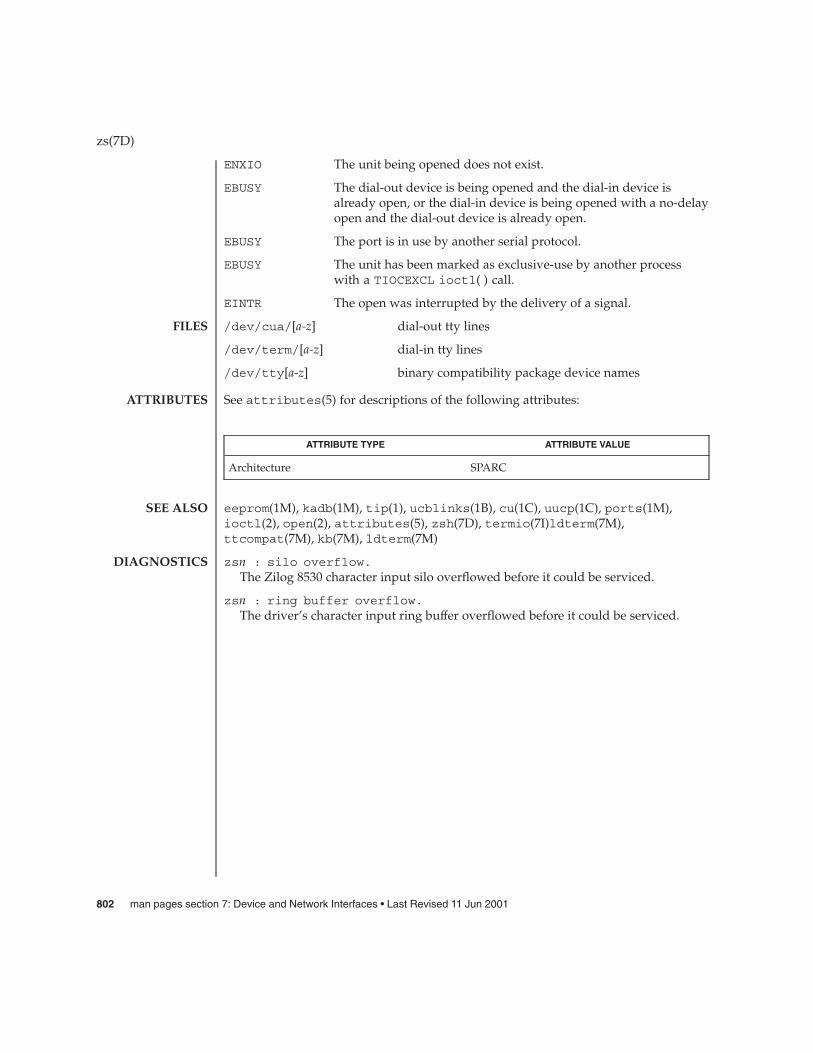
ENXIO The unit being opened does not exist.
EBUSY The dial-out device is being opened and the dial-in device isalready open, or the dial-in device is being opened with a no-delayopen and the dial-out device is already open.
EBUSY The port is in use by another serial protocol.
EBUSY The unit has been marked as exclusive-use by another processwith a TIOCEXCL ioctl( ) call.
EINTR The open was interrupted by the delivery of a signal.
/dev/cua/[a-z] dial-out tty lines
/dev/term/[a-z] dial-in tty lines
/dev/tty[a-z] binary compatibility package device names
See attributes(5) for descriptions of the following attributes:
ATTRIBUTE TYPE ATTRIBUTE VALUE
Architecture SPARC
eeprom(1M), kadb(1M), tip(1), ucblinks(1B), cu(1C), uucp(1C), ports(1M),ioctl(2), open(2), attributes(5), zsh(7D), termio(7I)ldterm(7M),ttcompat(7M), kb(7M), ldterm(7M)
zsn : silo overflow.The Zilog 8530 character input silo overflowed before it could be serviced.
zsn : ring buffer overflow.The driver’s character input ring buffer overflowed before it could be serviced.
zs(7D)
FILES
ATTRIBUTES
SEE ALSO
DIAGNOSTICS
802 man pages section 7: Device and Network Interfaces • Last Revised 11 Jun 2001
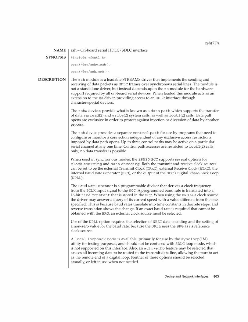
zsh – On-board serial HDLC/SDLC interface
#include <fcntl.h>
open(/dev/zshn, mode );
open(/dev/zsh, mode );
The zsh module is a loadable STREAMS driver that implements the sending andreceiving of data packets as HDLC frames over synchronous serial lines. The module isnot a standalone driver, but instead depends upon the zs module for the hardwaresupport required by all on-board serial devices. When loaded this module acts as anextension to the zs driver, providing access to an HDLC interface throughcharacter-special devices.
The zshn devices provide what is known as a data path which supports the transferof data via read(2) and write(2) system calls, as well as ioctl(2) calls. Data pathopens are exclusive in order to protect against injection or diversion of data by anotherprocess.
The zsh device provides a separate control path for use by programs that need toconfigure or monitor a connection independent of any exclusive access restrictionsimposed by data path opens. Up to three control paths may be active on a particularserial channel at any one time. Control path accesses are restricted to ioctl(2) callsonly; no data transfer is possible.
When used in synchronous modes, the Z8530 SCC supports several options forclock sourcing and data encoding. Both the transmit and receive clock sourcescan be set to be the external Transmit Clock (TRxC), external Receive Clock (RTxC), theinternal Baud Rate Generator (BRG), or the output of the SCC’s Digital Phase-Lock Loop(DPLL).
The Baud Rate Generator is a programmable divisor that derives a clock frequencyfrom the PCLK input signal to the SCC. A programmed baud rate is translated into a16-bit time constant that is stored in the SCC. When using the BRG as a clock sourcethe driver may answer a query of its current speed with a value different from the onespecified. This is because baud rates translate into time constants in discrete steps, andreverse translation shows the change. If an exact baud rate is required that cannot beobtained with the BRG, an external clock source must be selected.
Use of the DPLL option requires the selection of NRZI data encoding and the setting ofa non-zero value for the baud rate, because the DPLL uses the BRG as its referenceclock source.
A local loopback mode is available, primarily for use by the syncloop(1M)utility for testing purposes, and should not be confused with SDLC loop mode, whichis not supported on this interface. Also, an auto-echo feature may be selected thatcauses all incoming data to be routed to the transmit data line, allowing the port to actas the remote end of a digital loop. Neither of these options should be selectedcasually, or left in use when not needed.
zsh(7D)
NAME
SYNOPSIS
DESCRIPTION
Device and Network Interfaces 803

The zsh driver keeps running totals of various hardware generated events for eachchannel. These include numbers of packets and characters sent and received, abortconditions detected by the receiver, receive CRC errors, transmit underruns, receiveoverruns, input errors and output errors, and message block allocation failures. Inputerrors are logged whenever an incoming message must be discarded, such as when anabort or CRC error is detected, a receive overrun occurs, or when no message block isavailable to store incoming data. Output errors are logged when the data must bediscarded due to underruns, CTS drops during transmission, CTS timeouts, orexcessive watchdog timeouts caused by a cable break.
The zsh driver supports several ioctl() commands, including:
S_IOCGETMODE Return a struct scc_mode containing parameterscurrently in use. These include the transmit and receiveclock sources, boolean loopback and NRZI mode flagsand the integer baud rate.
S_IOCSETMODE The argument is a struct scc_mode from which theSCC channel will be programmed.
S_IOCGETSTATS Return a struct sl_stats containing the currenttotals of hardware-generated events. These includenumbers of packets and characters sent and receivedby the driver, aborts and CRC errors detected, transmitunderruns, and receive overruns.
S_IOCCLRSTATS Clear the hardware statistics for this channel.
S_IOCGETSPEED Returns the currently set baud rate as an integer. Thismay not reflect the actual data transfer rate if externalclocks are used.
S_IOCGETMCTL Returns the current state of the CTS and DCD incomingmodem interface signals as an integer.
The following structures are used with zsh ioctl() commands:
struct scc_mode {char sm_txclock; /* transmit clock sources */char sm_rxclock; /* receive clock sources */char sm_iflags; /* data and clock inversion flags (non-zsh) */uchar_t sm_config; /* boolean configuration options */int sm_baudrate; /* real baud rate */int sm_retval; /* reason codes for ioctl failures */
};struct sl_stats {
long ipack; /* input packets */long opack; /* output packets */long ichar; /* input bytes */long ochar; /* output bytes */long abort; /* abort received */long crc; /* CRC error */long cts; /* CTS timeouts */long dcd; /* Carrier drops */
zsh(7D)
IOCTLS
804 man pages section 7: Device and Network Interfaces • Last Revised 1 Jan 1997

long overrun; /* receive overrun */long underrun; /* transmit underrun */long ierror; /* input error */long oerror; /* output error */long nobuffers; /* receive side memory allocation failure */
};
An open() will fail if a STREAMS message block cannot be allocated, or:
ENXIO The unit being opened does not exist.
EBUSY The device is in use by another serial protocol.
An ioctl() will fail if:
EINVAL An attempt was made to select an invalid clocking source.
EINVAL The baud rate specified for use with the baud rate generatorwould translate to a null time constant in the SCC’s registers.
/dev/zsh[0-1],/dev/zsh character-special devices
/usr/include/sys/ser_sync.h header file specifying synchronous serialcommunication definitions
See attributes(5) for descriptions of the following attributes:
ATTRIBUTE TYPE ATTRIBUTE VALUE
Architecture IA
syncinit(1M), syncloop(1M), syncstat(1M), ioctl(2), open(2), read(2),write(2), attributes(5), zs(7D)
Refer to the Zilog Z8530 SCC Serial Communications Controller Technical Manual fordetails of the SCC’s operation and capabilities.
zsh data open failed, no memory, rq=nnn
zsh clone open failed, no memory, rq=nnnA kernel memory allocation failed for one of the private data structures. The valueof nnn is the address of the read queue passed to open(2).
zsh_open: can’t alloc message blockThe open could not proceed because an initial STREAMS message block could notbe made available for incoming data.
zsh: clone device d must be attached before use!An operation was attempted through a control path before that path had beenattached to a particular serial channel.
zsh(7D)
ERRORS
FILES
ATTRIBUTES
SEE ALSO
DIAGNOSTICS
Device and Network Interfaces 805

zshn: invalid operation for clone dev.An inappropriate STREAMS message type was passed through a control path. OnlyM_IOCTL and M_PROTO message types are permitted.
zshn: not initialized, can’t send messageAn M_DATA message was passed to the driver for a channel that had not beenprogrammed at least once since the driver was loaded. The SCC’s registers were inan unknown state. The S_IOCSETMODE ioctl command performs the programmingoperation.
zshn: transmit hungThe transmitter was not successfully restarted after the watchdog timer expired.
zsh(7D)
806 man pages section 7: Device and Network Interfaces • Last Revised 1 Jan 1997

zulu – Sun XVR-4000 Graphics Accelerator driver
The zulu driver is the device driver for the Sun XVR-4000 Graphics Accelerator.
/dev/fbs/zulundevice special file
/usr/lib/zulu.ucodezulu microcode
See attributes(5) for descriptions of the following attributes:
ATTRIBUTE TYPE ATTRIBUTE VALUE
Availability SUNWzulux
SUNWzulu_config(1M), zuludaemon(1M), attributes(5)
In the current release, the zulu system does not properly handle watchpoints (seeproc(4)) on zulu DMA buffers. If a watchpoint is placed on a DMA buffer and thezulu DMA engine accesses the page containing that watchpoint, the process will bestopped. When the process is continued (using prun and kill), the process will bekilled. See prun(1) and kill(1).
zulu(7d)
NAME
DESCRIPTION
FILES
ATTRIBUTES
SEE ALSO
BUGS
Device and Network Interfaces 807

zulu(7d)
808 man pages section 7: Device and Network Interfaces • Last Revised 8 Oct 2002
Index
Numbers and Symbols1394 OpenHCI host controller driver —
hci1394, 23324-bit UPA color frame buffer and graphics
accelerator — ffb, 2063COM EtherLink III Ethernet device driver —
elx, 1553COM EtherLink III PCMCIA Ethernet Adapter
— pcelx, 4533Com Ethernet device driver — elxl, 1574BSD compatibility module — ttcompat, 703
AAcer Laboratories Inc. M5451 audio processor
interface — audiots, 61Address Resolution Protocol
See ARPadp — low-level module for controllers based
on Adaptec AIC-7870P and AIC-7880P SCSIchips, 22
afb— Elite3D graphics accelerator driver, 24ifb— IFB graphics accelerator driver, 271Am7990 (LANCE) Ethernet device driver
— le, 356— lebuffer, 356— ledma, 356
AMD PCnet Ethernet controller device driver —pcn, 464
an I2O OS sepcific module that supports SCSAinterface, an I2O, 252
ANSI Layered Console Driver — ltem, 388
ANSI standard terminal emulation —wscons, 788
arp — Address Resolution Protocol, 31arp ioctl
SIOCDARP — delete arp entry, 31SIOCGARP — get arp entry, 31SIOCSARP — set arp entry, 31
asy — asynchronous serial port driver, 33asynchronous serial port driver — asy, 33asynchronous serial port driver — su, 637AT attachment disk driver — ata, 36ata — AT attachment disk driver, 36audio — audio device interface, 40audio device, Sound Blaster 16/Pro/AWE32 —
sbpro, 530audio_support — audio device independent
driver interface, 59audiocs — Crystal Semiconductor 4231 Audio
driver, 51audiocs — Crystal Semiconductor 4231 audio
InterfaceAudio Data Formats for the Multimedia 4231
Codec, 51audiocs — Crystal Semiconductor 4231 Audio
driver, Audio Interfaces, 51audiots — Acer Laboratories Inc. M5451 audio
processor interfaceAudio Interfaces, 61
audiocs — Crystal Semiconductor 4231 audioInterfaceAudio Status Change Notification, 53Driver Version, 51Sample Granularity, 53
809

audiocs — Crystal Semiconductor 4231 audioInterface (Continued)
Setting Audio Mixer Mode, 51audiots — Acer Laboratories Inc. M5451 audio
processor interface, 61Audio Status Change Notification, 62Driver Version, 61Sample Granularity, 61
authsha1 — HMAC-SHA-1 AuthenticationAlgorithm Module for IPsec, 65
Bbbc_beep — Platform-dependent Beep driver
for BBC-based hardware, 66bd — SunButtons and SunDials STREAMS
module, 67bge — Broadcom BCM5704 Gigabit Ethernet
driver, 69bpp — bi-directional parallel port, 72Broadcom BCM5704 Gigabit Ethernet driver —
bge, 69bufmod — STREAMS Buffer module, 77built-in mouse device interface —
kdmouse, 347bwtwo — black and white frame buffer, 81
Ccadp — SCSI host bus adapter driver, 83cadp160 — SCSI host bus adapter driver, 82CD-ROM — ISO 9660 CD-ROM filesystem —
hsfs, 245cdio— CD-ROM control operations, 87CDROM control operations —cdio, 87ce — ce Gigabit-Ethernet device driver, 95
ce Primitives, 97ce Gigabit-Ethernet device driver — ce, 95cgeight — 24-bit color memory frame buffer, 99cgfour — P4-bus 8-bit color memory frame
buffer, 100cgfourteen — 24-bit color graphics device, 101cgsix — accelerated 8-bit color frame
buffer, 102cgthree — 8-bit color memory frame buffer, 103cgtwo — color graphics interface, 104
chs — IBM ServeRAID PCI host adapterdriver, 105
Data Layer Class of Service Marker—dlcosmk, 133
cmdk — common disk driver, 106Differentiated Services Code Point Marker—
dscpmk, 148Cogent EM960/EM100 Ethernet controller
device driver — dnet, 140color graphics interface
24-bit color memory frame buffer —cgeight, 99
8-bit color memory frame buffer —cgthree, 103
accelerated 8-bit color frame buffer —cgsix, 102
standard frame buffer — cgtwo, 104P4-bus 8-bit color memory frame buffer —
cgfour, 100Sun color memory frame buffer — tcx, 657
common disk driver — cmdk, 106Single and Two Rate Three Conformance Level
Meter— tokenmt, 698connections, unique stream, line discipline —
connld, 107connld — line discipline for unique
connections, 107console devices, sysmsg, 646console, STREAMS-based console interface, 108converts mouse protocol to Firm Events —
vuidmice, 782vuid2ps2, 782vuid3ps2, 782vuidm3p, 782vuidm4p, 782vuidm5p, 782
core memory, image — mem, 397cpr — suspend and resume module, 109Crystal Semiconductor 4231 Audio driver —
audiocs, 51cvc — virtual console driver, 111cvcredir — virtual console redirection
driver, 112
810 man pages section 7: Device and Network Interfaces • April 2003
DD-LINK Ethernet controller device driver —
dnet, 140dad — driver for IDE disk devices, 113
Device Statistics Support, 113Data Link Provider Interface, — dlpi, 134Davicom Fast Ethernet driver for Davicom
DM9102A — dmfe, 138dbri — ISDN and audio interface, 116dbri — Dual Basic Rate ISDN and audio
InterfaceAudio Data Formats for BRI Interfeces, 117Audio Data Formats for the Multimedia
Codec/SpeakerBox, 117Audio Interfaces, 116Audio Ports, 119Audio Status Change Notification, 119ISDN Interfaces, 116Sample Granularity, 119
delete arp entry ioctl — SIOCDARP, 31devfs— devices file system, 122device interface, Microsoft Bus Mouse —
msm, 415devices, cgfourteen, 101devices file system, devices file system —
devfs, 122disk control operations — dkio, 124disk driver, fd — floppy, 190disk quotas — quotactl(), 514dkio — disk control operations, 124dlcosmk —Data Layer Class of Service
Marker, 133dlpi — Data Link Provider Interface, 134dmfe — Davicom Fast Ethernet driver for
Davicom DM9102A, 138dnet — DEC 21040/21140-based Ethernet
Controllers, 140DOS, DOS formatted file system — pcfs, 455dpt — DPT ServeRAID IV SCSI host bus
adapter and RAID adapter driver, 142DPT ServeRAID IV SCSI host bus adapter and
RAID adapter driver — dpt, 142dynamic reconfiguration driver — Sun
Enterprise 10000 and Sun Fire 15K, 144Sun Enterprise 10000 and Sun Fire 15K dynamic
reconfiguration driver, 144driver for fast poll on many file descriptors —
poll, 492
driver for IDE disk devices — dad, 113driver for parallel port — lp, 386driver for SPARC Storage Array disk devices —
ssd, 588drivers for floppy disks and floppy disk
controllers — fd, 190fdc, 190
drivers, SCSI tape devices — st, 593dscpmk —Differentiated Services Code Point
Marker, 148Dual Basic Rate ISDN and audio Interface —
dbri, 116
Eecpp — bi-directional parallel port, 149Elite3D graphics accelerator driver — afb, 24elx — 3COM ETHERLINK III Ethernet device
driver, 155elx — 3COM EtherLink III Ethernet device
driver, elx Primitives, 155elxl — 3Com Ethernet device driver, 157eri — eri Fast-Ethernet device driver, 163esp — ESP SCSI Host Bus Adapter Driver, 167ESP SCSI Host Bus Adapter Driver — esp, 167Ethernet device driver, SMC EtherPower II
10/100 (9432) Ethernet device driver —spwr, 587
extended memory file system — xmemfs, 797
FFair share scheduler — FS, 209FS — Fair share scheduler, 209fas — FAS SCSI Host Bus Adapter Driver, 175FAS SCSI Host Bus Adapter Driver — fas, 175fbio — frame buffer control operations, 183fcip — IP/ARP over Fibre Channel datagram
encapsulation driver, 185fcp — Fibre Channel protocol driver, 188fctl — Sun Fibre Channel transport library, 189fd — drivers for floppy disks and floppy disk
controllers, 190fdc — drivers for floppy disks and floppy disk
controllers, 190
Index 811

FDGETCHANGE — get status of diskchanged, 202
fdio — disk control operations, 202FDIOGCHAR — get floppy characteristics, 202FDIOGCHAR — set floppy characteristics, 202FDKEJECT — eject floppy, 202ffb — 24-bit UPA color frame buffer and
graphics accelerator, 206Sun Fibre Channel port driver — fp, 208Fibre Channel protocol driver — fcp, 188file system, quotactl() — disk quotas, 514floppy disk driver — fd, 190floppy disk control operations — fdio, 202Flow Accouting module— flowacct, 207flowacct —Flow Accouting module, 207fp — Sun Fibre Channel port driver, 208frame buffer, black and whirte frame buffer —
bwtwo, 81frame buffer control operations, — fbio, 183
Gge — Gigabit-Ethernet device driver, 212
ge Primitives, 214Gigabit-Ethernet device driver — ge, 212general properties of Internet Protocol network
interfaces — if, 276general properties of Internet Protocol network
interfaces — if_tcp, 276General purpose I/O driver for SuperIO —
gpio_87317, 231general terminal interface — termio, 659Generic LAN Driver — gld, 216Generic printer interface — prnio, 497prnio — Generic printer interface, 497Generic SCSI device driver – sgen, 565gld — Generic LAN Driver, 216
FDDI SNAP processing, 217Implemented DLPI Primitives, 218Implemented ioctl Functions, 220Network Statistics, 222Style 1 and 2 Providers, 218Token Ring SNAP processing, 217Token Ring Source Routing, 218
glm — GLM SCSI Host Bus AdapterDriver, 226
GLM SCSI Host Bus Adapter Driver —glm, 226
gpio_87317— General purpose I/O driver forSuperIO, 231
grbeep — Platform-dependent Beep driver forSMBus-based hardware, 232
Hhci1394 — 1394 OpenHCI host controller
driver, 233hdio — SMD and IPI disk control
operations, 234— Human Interface Device (HID) class
driver, 236High Sierra filesystem
See hsfsHMAC-SHA-1 Authentication Algorithm
Module for IPsec — authsha1, 65hme — SUNW,hme Fast-Ethernet device
driver, 238hme Primitives, 240
hsfs, filesystem — hsfs, 245hubd — USB hub driver, 248Human Interface Device (HID) class driver —
hid, 236
II/O
data link provider interface — dlpi, 134extended terminal interface — termiox, 680ioctls that operate directly on sockets —
sockio, 585STREAMS ioctl commands — streamio, 621
I2C smart card card terminal driver —ocf_iscr1, 443
IBM ServeRAID PCI host adapter driver —chs, 105
iButton smart card terminal driver —ocf_ibutton, 442
icmp — Internet Control Message Protocol, 257icmp6 — Internet Control Message Protocol for
Internet Protocol Version 6, 253IDE Host Bus Adapter Driver — uata, 722ieef — Intel Ethernet device driver, 262
812 man pages section 7: Device and Network Interfaces • April 2003

if — general properties of Internet Protocolnetwork interfaces, 276
if_tcp — general properties of Internet Protocolnetwork interfaces, 276Application Programming Interface, 276
IFB graphics accelerator driver — ifb, 271inet — Internet protocol family, 286inet6 — Internet protocol family for Internet
Protocol version 6, 283Intel D100 Ethernet device driver — iprb, 309Intel Ethernet device driver — ieef, 262Intel i82365SL PC Card Interface Controller —
pcic, 460Intel Ethernet device driver, Intel — iprb, 309Internet Control Message Protocol — icmp, 257Internet Protocol — ip, 300Internet Transmission Control Protocol —
tcp, 652Internet User Datagram Protocol — udp, 728Internet Control Message Protocol for Internet
Protocol Version 6 — icmp6, 253Internet Protocol, to Ethernet addresses —
arp, 31Internet protocol family — inet, 286Internet protocol family for Internet Protocol
version 6 — inet6, 283Internet Protocol Security Architecture —
ipsec, 312Internet Protocol Version 6 — ip6, 289Internet Protocol Version 6— ip6, 289ioctls for sockets
SIOCDARP — delete arp entry, 31ioctl’s for sockets, SIOCGARP — get arp
entry, 31ioctls for Internet socket descriptors, SIOCSARP
— set arp entry, 31ioctls for floppy
FDEJECT — eject floppy, 202FDGETCHAGE — get status of disk
changed, 202FDIOCHAR — get floppy
characteristics, 202FDIOCHAR — set floppy
characteristics, 202ioctls for sockets
SIOCADDRT — add route, 525SIOCDELRT — delete route, 525
ioctl’s for terminalsTIOCPKT — set/clear packet mode
(pty), 507TIOCREMOTE — remote input editing, 507TIOCSTART — start output (like
control-Q), 507TIOCSTOP — stop output (like
control-S), 507ip — Internet Protocol, 300IP/ARP over Fibre Channel datagram
encapsulation driver — fcip, 185IP Generic Packet Classifier— ipgpc, 305IP quality of service — ipqos, 307ip6 — Internet Protocol Version 6, 289ipgpc — IP Generic Packet Classifier, 305ipqos — IP quality of service, 307iprb — D100 Ethernet device driver, 309ipsec — Internet Protocol Security
Architecture, 312isdnio — generic ISDN interface, 319ISO 9660 — ISO 9660 CD-ROM filesystem —
hsfs, 245isp — ISP SCSI Host Bus Adapter Driver, 332ISP SCSI Host Bus Adapter Driver — isp, 332ISP2200 Family Fibre Channel host bus adapter
driver — qlc, 513
Kkb — keyboard STREAMS module, 338
Keyboard Compatibility Mode, 342Keyboard Translation Mode, 338Keyboard Translation-Table Entries, 338
kdmouse — built-in mouse deviceinterface, 347
kernel lock statistics driver — lockstat, 377kernel packet forwarding database —
route, 521kernel statistics driver — kstat, 350kernel symbols — ksyms, 351keyboard STREAMS module — kb, 338keyboard STREAMS module for Sun USB
Keyboard — usbkbm, 743kstat — kernel statistics driver, 350kyms — kernel symbols, 351
Index 813

LLAN support module — gld, 216ldterm — line discipline for STREAMS terminal
module, 353le — Am7990 (LANCE) Ethernet device
driver, 356lebuffer — Am7990 (LANCE) Ethernet device
driver, 356ledma — Am7990 (LANCE) Ethernet device
driver, 356line discipline for unique stream connections
—connld, 107llc1 — Logical Link Control Protocol Class 1
Driver, 368lockstat — kernel lock statistics driver, 377lofi — loopback file driver, 378lofs — loopback virtual file system, 379log — interface to STREAMS error logging and
event tracing, 381logi — LOGITECH bus mouse device
interface, 385Logical Link Control Protocol Class 1 Driver —
llc1, 368LOGITECH Bus Mouse device interface —
logi, 385loopback file driver — lofi, 378loopback transport providers
— ticlts, 686— ticots, 686— ticotsord, 686
loopback virtual file system — lofs, 379low-level module for controllers based on
Adaptec AIC-7870P and AIC-7880P SCSIchips — adp, 22
low-level module for the AMD PCscsi, PCscsi II,PCnet-SCSI, and Qlogic QLA510 PCI-to-SCSIbus adapters — pcscsi, 469
lp — driver for parallel port, 386ltem — ANSI Layered Console Driver, 388
Mm64 — frame buffers device driver, 389magnetic tape interface, — mtio, 417md — pseudo device driver for
metadevice, 390mem— image of core memory, 397
memory, core, image — mem, 397memory, zeroed unnamed, source — zero, 799memory based filesystem — tmpfs, 696message output collection, msglog, 414mhd — multihost disk control operations, 399
Automatic Probing, 402MHIOCENFAILFAST Ioctl, 402Non-shared multihost disks:, 399Shared Multihost Disks, 401
Microsoft Bus Mouse device interface —msm, 415
mixer — audio mixer device interface, 404monitor, PROM monitor configuration interface
— openprom, 446monochrome frame buffer — bwtwo, 81Mouse device interface, LOGITECH Bus Mouse
device interface — logi, 385msglog, message output collection, 414msm — Microsoft Bus Mouse device
interface, 415mtio — general magnetic tape interface, 417multihost disk control operations — mhd, 399
Nllc2— llc2 Class II logical link control
driver, 371ncrs — SCSI host bus adapter driver, 429ncrs — ncrs SCSI Host Bus Adapter Driver,
Driver Configuration, 430dman — Network device driver, 135Network device driver — dman, 135Network device driver — scman, 535scman — Network device driver, 535network packet routing device — routing, 525null — null file, 440
Oocf_escr1 — serial smart card terminal
driver, 441ocf_ibutton — iButton smart card terminal
driver, 442ocf_iscr1 — I2C smart card card terminal
driver, 443ohci — OpenHCI host controller driver, 444
814 man pages section 7: Device and Network Interfaces • April 2003
OpenHCI host controller driver — ohci, 444openprom — PROM monitor configuration
interface, 446
Ppacket routing device — routing, 525packet routing ioctls
SIOCADDRT — add route, 525SIOCDELRT — delete route, 525
parallel port, bi-directional — bpp, 72parallel port, bi-directional — ecpp, 149parallel port, driver for parallel port — lp, 386pcata — PCMCIA ATA card device driver, 451pcelx — 3COM EtherLink III PCMCIA Ethernet
Adapter, 453pcfs — DOS formatted file system, 455pcic — Intel i82365SL PC Card Interface
Controller, 460pckt — STREAMS Packet Mode module, 462PCMCIA ATA card device driver — pcata, 451PCMCIA memory card nexus driver —
pcmem, 463PCMCIA RAM memory card device driver —
pcram, 466PCMCIA serial card device driver — pcser, 470pcmem — PCMCIA memory card nexus
driver, 463pcn — AMD PCnet Ethernet controller device
driver, 464pcram — PCMCIA RAM memory card device
driver, 466pcscsi — low-level module for the AMD PCscsi,
PCscsi II, PCnet-SCSI, and Qlogic QLA510PCI-to-SCSI bus adapters, 469
pcser — PCMCIA serial card device driver, 470pf_key — security association database, 473pfb — Sun XVR-100 Graphics Accelerator
device driver, 472pfmod — STREAMS packet filter module, 483pipemod — STREAMS pipe flushing
module, 486Platform-dependent Beep driver for BBC-based
hardware — bbc_beep, 66Platform-dependent Beep driver for
SMBus-based hardware — grbeep, 232
Platform Specific Module (PSM) for TricordSystems Enterprise Server Models ES3000,ES4000 and ES5000 — tpf, 701
pln — SPARC Storage Array SCSI Host Busadapter driver, 487
PLN SCSI Host Bus Adapter driver — pln, 487pm — Power Management Driver, 488poll — driver for fast poll on many file
descriptors, 492Power Management Driver — pm, 488PPP tunneling pseudo-driver — sppptun, 586PROM, monitor configuration interface —
openprom, 446pseudo-terminal driver — pty, 506Pseudo Terminal Emulation module, STREAMS
— ptem, 501ptem — STREAMS Pseudo Terminal Emulation
module, 501ptm — STREAMS Buffer module, 502pts — STREAMS pseudo-tty slave driver, 504pty — pseudo-terminal driver, 506
Qqfe — SUNW,qfe Quad Fast-Ethernet device
driver, 509qfe Primitives, 511
qlc — ISP2200 Family Fibre Channel host busadapter driver, 513
quotactl() — disk quotas, 514
Rrandom — strong random number generator
device, 516rarp — Reverse address resolution
protocol, 519remote input editing ioctl —
TIOCREMOTE, 507WCI Remote Shared Memory (WRSM) DLPI
driver — wrsmd, 787rns_smt — Rockwell Station Management
driver, 520Rockwell 2200 SNAP Streams Driver —
sxp, 640
Index 815

Rockwell Station Management driver —rns_smt, 520
route — kernel packet forwardingdatabase, 521Messages, 522
routing — local network packet routing, 525routing ioctls
SIOCADDRT — add route, 525SIOCDELRT — delete route, 525
Ssbpro — Creative Labs Sound Blaster audio
device, 530scsa2usb — SCSI to USB bridge host bus
adapter driver, 540SCSI enclosure services device driver —
ses, 560Class II logical link control driver — llc2, 371ncrs SCSI host bus adapter driver — ncrs, 429SCSI host bus adapter driver — cadp160, 82SCSI host bus adapter driver — cadp, 83SCSI tape devices, driver — st, 593SCSI to USB bridge host bus adapter driver —
scsa2usb, 540SCSI virtual host controller interconnect driver
— scsi_vhci, 544SCSI disk and ATAPI/SCSI CD-ROM device
driver — sd, 547sd — SCSI disk and ATAPI/SCSI CD-ROM
device driver, 547se — Siemens 82532 ESCC serial
communications driver, 553security association database — pf_key, 473serial communications driver — zs, 800Serial Optical Controller device driver —
soc, 581Serial Optical Controller for Fibre Channel
Arbitrated Loop (SOC+) device driver —socal, 583
Serial Parallel Communications driver for SBus— stc, 608
serial smart card terminal driver —ocf_escr1, 441
Service Location Protocol — slp, 579ses — SCSI enclosure services device
driver, 560
set/clear, packet mode (pty) ioctl —TIOCPKT, 507
sgen – Generic SCSI device driver, 565zsh — On-board serial HDLC interface, 557,
803Shared Memory (WRSM) device driver —
wrsm, 785Siemens 82532 ESCC serial communications
driver — se, 553SIOCDARP — delete arp entry, 31SIOCGARP — get arp entry, 31SIOCSARP — set arp entry, 31slp — Service Location Protocol, 579SMC Ethernet device drivers, spwr — SMC
EtherPower II 10/100 (9432) Ethernet devicedriver, 587
SMC EtherPower 8432BT Ethernet controllerdevice driver — dnet, 140
SMC EtherPower II 10/100 (9432) Ethernetdevice driver — spwr, 587
SMD and IPI disk control operations —hdio, 234
soc — Serial Optical Controller DeviceDriver, 581
socal — Serial Optical Controller for FibreChannel Arbitrated Loop (SOC+) devicedriver, 583
sockio — ioctls that operate directly onsockets, 585
sockets, ioctls that operate directly —sockio, 585
Solaris USB architecture — usba, 734Solaris VISUAL I/O control operations, 759Sound Blaster 16/Pro/AWE32 audio devices —
sbpro, 530SPARCstorage Array
disk devices driver — ssd, 588SCSI Host Bus Adapter driver — pln, 487
spwr — SMC EtherPower II 10/100 (9432)Ethernet device driver, 587
ssd — driver for SPARC Storage Array diskdevices, 588
st — driver for SCSI tape devices, 593start output (like control-Q) ioctl —
TIOCSTART, 507stc — Serial Parallel Communications driver for
SBus, 608
816 man pages section 7: Device and Network Interfaces • April 2003
stop output (like control-S) ioctl —TIOCSTOP, 507
STP 4020 PCMCIA Adapter, STP 4020 PCMCIAAdapter, 620
stp4020 — STP 4020 PCMCIA Adapter, 620STREAMS
interface to error logging — log, 381interface to event tracing — log, 381line discipline for unique stream connections
— connld, 107loopback transport providers — ticlts, ticots,
ticotsord, 686On-board serial HDLC interface —
se_hdlc, 557On-board serial HDLC interface — zsh, 803standard terminal line discipline module —
ldterm, 353Transport Interface cooperating module —
timod, 692Transport Interface read/write interface
module — tirdwr, 694V7, 4BSD, XENIX compatibility module —
ttcompat, 703STREAMS Administrative Driver — sad, 527STREAMS-based console interface, console, 108STREAMS-based serial I/O multiplexer
interface, ttymux, 713STREAMS Buffer module — bufmod, 77STREAMS Buffer module — ptm, 502STREAMS ioctl commands — streamio, 621STREAMS module, SunButtons and SunDials —
bd, 67STREAMS Packet Filter Module — pfmod, 483STREAMS Packet Mode module — pckt, 462STREAMS pipe flushing module —
pipemod, 486STREAMS Pseudo Terminal Emulation module
— ptem, 501STREAMS pseudo-tty slave driver — pts, 504strong random number generator device —
random, 516su — asynchronous serial port driver, 637Sun Fibre Channel transport library — fctl, 189Sun XVR-4000 Graphics Accelerator driver —
zulu, 807SunButtons and SunDials STREAMS module —
bd, 67
SUNW,hme Fast-Ethernet device driver —hme, 238
SUNW,qfe Quad Fast-Ethernet device driver —qfe, 509
eri Fast-Ethernet device driver — eri, 163suspend and resume module — cpr, 109sxp — Rockwell 2200 SNAP Streams
Driver, 640symhisl — SCSI Host Bus Adapter Driver, 643SCSI Host Bus Adapter Driver — symhisl, 643sysmsg
console devices, 646system message routing, 646
system message routing, sysmsg, 646
Ttape, magnetic interface, — mtio, 417tape interface — mt, 416tcp — Internet Transmission Control
Protocol, 652tcx — Sun low-range graphics accelerator with
color memory frame buffer, 657terminal, standard STREAMS, line discipline
module — ldterm, 353terminal emulation, ANSI — wscons, 788terminal interface, — termio, 659terminal interface, extended, — termiox, 680terminal parameters — termiox, 680termio — general terminal interface, 659
Canonical mode input processing, 660Comparison of the different cases of MIN,
TIME interaction, 662Control Modes, 669Default values, 677Input modes, 666Local modes, 672Minimum and Timeout, 675Modem disconnect, 664Modem lines, 676Non-canonical mode input processing, 661Output modes, 667Special Characters, 663Terminal parameters, 665Terminal size, 675Termio structure, 675Writing characters, 663
Index 817

termiox — extended general terminalinterface, 680
Time Sliding Window Three Conformance LevelMeter— tswtclmt, 702
ticlts — loopback transport provider, 686ticots — loopback transport provider, 686ticotsord — loopback transport provider, 686timod — Transport Interface cooperating
module, 692timod — Transport Interface read/write
interface module, 694TIOCPKT — set/clear packet mode (pty), 507TIOCREMOTE — remote input editing, 507TIOCSTART — start output (like
control-Q), 507TIOCSTOP — stop output (like control-S), 507tmpfs — memory based filesystem, 696tokenmt — Single and Two Rate Three
Conformance Level Meter, 698tpf — Platform Specific Module (PSM) for
Tricord Systems Enterprise Server ModelsES3000, ES4000 and ES5000, 701
Transport Interface cooperating STREAMSmodule — timod, 692
Transport Interface read/write interfaceSTREAMS module — timod, 694
tswtclmt — Time Sliding Window ThreeConformance Level Meter, 702
ttcompat — V7, 4BSD and XENIX STREAMScompatibility module, 703
tty — controlling terminal interface, 712ttymux, STREAMS-based serial I/O multiplexer
interface, 713
Uuata — IDE Host Bus Adapter Driver, 722udfs— universal disk format file system, 724udp — Internet User Datagram Protocol, 728universal disk, universal disk format file system
— udfs, 724universal serial optical controller for Fibre
Channel arbitrated loop (SOC+) devicedriver — usoc, 757
unnamed zeroed memory, source — zero, 799audioens — Ensoniq 1371/1373 and Creative
Labs 5880 driver support, 55
usb_ac — USB audio control driver, 736usb_as — USB audio control driver, 741USB audio HID STREAMS module —
usb_ah, 740USB hub driver — hubd, 248usb_mid — USB Multi Interface Driver, 745USB mouse STREAMS module — usbms, 746USB Multi Interface Driver — usb_mid, 745usbprn — USB printer class driver, 748usba — Solaris USB architecture, 734usbkbm — keyboard STREAMS module for Sun
USB Keyboard, 743usbkbm — keyboard STREAMS module for
Sun, IOCTLS, 743usbms — USB mouse STREAMS module, 746uscsi — user SCSI command interface, 753user SCSI command interface — uscsi, 753usoc— universal serial optical controller for
Fibre Channel arbitrated loop (SOC+) devicedriver, 757
VV7 compatibility module — ttcompat, 703virtual console driver — cvc, 111virtual console redirection driver —
cvcredir, 112volfs — Volume Management file system, 765Volume Management, file system — volfs, 765vuid2ps2 — converts mouse protocol to Firm
Events, 782vuid3ps2 — converts mouse protocol to Firm
Events, 782vuidm3p — converts mouse protocol to Firm
Events, 782vuidm4p — converts mouse protocol to Firm
Events, 782vuidm5p — converts mouse protocol to Firm
Events, 782vuidmice — converts mouse protocol to Firm
Events, 782
Wworkstation console — wscons, 788
818 man pages section 7: Device and Network Interfaces • April 2003

wrsm — Shared Memory (WRSM) devicedriver, 785
wrsmd — WCI Remote Shared Memory(WRSM) DLPI driver, 787
XXENIX compatibility module — ttcompat, 703xmemfs — extended memory file system, 797Sun XVR-100 Graphics Accelerator device
driver— pfb, 472
Zzero — source of zeroes, 799Zilog 8530 SCC serial communications driver —
zs, 800zs — zilog 8530 SCC serial communications
driver, 800zulu — Sun XVR-4000 Graphics Accelerator
driver, 807
Index 819

820 man pages section 7: Device and Network Interfaces • April 2003