Maintenance Manual Supplement - Kubicek Balloons
98
A-1 Edition 3 / Revision 0, TBD B.3205-USBEA Maintenance Manual Supplement Aerostar (Raven) Baskets and Burners Type: ............................................ Model: ........................................... Serial No.: ............................................ Registration: ............................................ This balloon Maintenance Manual Supplement is initially approved by EASA under major change approval number 10070614, dated 26 July 2019. Subsequent revisions are approved either by EASA or by authority of DOA, no. EASA.21J.277 as detailed on USBEA-3. This balloon Maintenance Manual Supplement is approved in accordance with 14 CFR Section 21.29 for U.S. registered aircraft and is approved by the Federal Aviation Administration. Initial date of approval: 31 July 2019 This balloon is to be preserved in an airworthy condition in compliance with instructions and information contained herein.
-
Upload
khangminh22 -
Category
Documents
-
view
2 -
download
0
Transcript of Maintenance Manual Supplement - Kubicek Balloons
A-1 Edition 3 / Revision 0, TBD
B.3205-USBEA
Maintenance Manual Supplement
Aerostar (Raven) Baskets and Burners
Type: ............................................
Model: ...........................................
Serial No.: ............................................
Registration: ............................................
This balloon Maintenance Manual Supplement is initially approved by EASA under major change
approval number 10070614, dated 26 July 2019.
Subsequent revisions are approved either by EASA or by authority of DOA, no. EASA.21J.277 as detailed
on USBEA-3.
This balloon Maintenance Manual Supplement is approved in accordance with 14 CFR Section 21.29
for U.S. registered aircraft and is approved by the Federal Aviation Administration. Initial date of
approval: 31 July 2019
This balloon is to be preserved in an airworthy condition in compliance with instructions and
information contained herein.

B.3205-USBEA MAINTENANCE MANUAL SUPPLEMENT for use with the Aerostar bottom-ends
USBEA-2 Edition 3 / Revision 0, TBD
INTENTIONALLY LEFT BLANK
B.3205-USBEA MAINTENANCE MANUAL SUPPLEMENT for use with the Aerostar bottom-ends
USBEA-3 Edition 3 / Revision 0, TBD
0.1 Record of revisions
Any revision of this Manual must be recorded in the following table.
Revision Number
Affected Section
Affected Pages
Date of Issue
Revisions to this Manual are published on the Kubicek balloons web site at www.kubicekballoons.eu.
The new or amended text in the revised page is indicated by a black vertical line in the outer margin, and the
revision number and the date is shown on the bottom of the page.
CAUTION Mandatory revisions are introduced by a Service Bulletin published on the Kubicek Balloons web site www.kubicekballoons.eu.

B.3205-USBEA MAINTENANCE MANUAL SUPPLEMENT for use with the Aerostar bottom-ends
USBEA-4 Edition 3 / Revision 0, TBD
INTENTIONALLY LEFT BLANK
B.3205-USBEA MAINTENANCE MANUAL SUPPLEMENT for use with the Aerostar bottom-ends
USBEA-5 Edition 3 / Revision 0, TBD
Contents 0.1 Record of revisions ........................................................................................................... USBEA-3
SECTION 1 – GENERAL ................................................................................................................ USBEA-7
1.1 INTRODUCTION ........................................................................................................... USBEA-7
1.2 APPLICABILITY ............................................................................................................. USBEA-7
1.3 MAINTENANCE CATEGORIES ...................................................................................... USBEA-7
DOCUMENTATION OF WORK ............................................................................................. USBEA-8
1.6 Definitions and Abbreviations.......................................................................................... USBEA-8
1.7 Balloon Technical Description .......................................................................................... USBEA-8
BASKETS .............................................................................................................................. USBEA-8
BURNERS ........................................................................................................................... USBEA-12
SECTION 2 - AIRWORTHINESS LIMITATIONS ............................................................................ USBEA-16
2.4 Inspection Procedure ..................................................................................................... USBEA-16
2.5 Life Limited Items ........................................................................................................... USBEA-16
SECTION 3 - ENVELOPE REPAIRS AND MAINTENANCE ............................................................ USBEA-21
SECTION 4 - BASKET REPAIR AND MAINTENANCE .................................................................. USBEA-21
BASKETS ................................................................................................................................ USBEA-21
SECTION 5 - BURNER REPAIRS AND MAINTENANCE ............................................................... USBEA-22
SECTION 6– FUEL CYLINDERS REPAIRS AND MAINTENANCE .................................................. USBEA-23
SECTION 7 – INSTRUMENT REPAIRS AND MAINTENANCE ...................................................... USBEA-24
SECTION 8 – INSPECTION SCHEDULE ........................................................................................ USBEA-24
8.1 General ............................................................................................................................ USBEA-24
8.2 Scheduled Inspections .................................................................................................... USBEA-24
8.4 100 Hour/Annual Inspection .......................................................................................... USBEA-25
8.15 Inspection Criteria / Techniques .................................................................................. USBEA-25
8.15.3 Baskets .................................................................................................................... USBEA-25
8.15.4 Burner and Frame .................................................................................................. USBEA-33
8.16 Fuel Cylinders ............................................................................................................ USBEA-43
8.19 Non-scheduled Inspections .......................................................................................... USBEA-48
BASKET .............................................................................................................................. USBEA-48
BURNER AND FUEL SYSTEM ............................................................................................. USBEA-49
8.20 Life Limited Items ......................................................................................................... USBEA-49
SECTION 9 – APPENDICES .................................................................................................................... A-1
APPENDIX 3 – BASKET AND SUSP.SYSTEM MAINTENANCE AND REPAIR INSTR. (‘’Section 6.4’’) A-1
APPENDIX 4 – BURNER AND FUEL SYSTEM MAINTEN. AND REPAIR INST. (‘’Sec. 6.2 and 6.3’’) A-13
APPENDIX 5 – 100 HOUR/ANNUAL INSPECTION CHECKLIST ........................................................ A-41
SECTION 10 – SUPPLEMENTS ............................................................................................................. A-46

B.3205-USBEA MAINTENANCE MANUAL SUPPLEMENT for use with the Aerostar bottom-ends
USBEA-6 Edition 3 / Revision 0, TBD
List of applicable Service Bulletins: ............................................................................................... A-46
List of applicable Maintenance Bulletins: ..................................................................................... A-48

B.3205-USBEA MAINTENANCE MANUAL SUPPLEMENT for use with the Aerostar bottom-ends
USBEA-7 Edition 3 / Revision 0, TBD
SECTION 1 – GENERAL
1.1 INTRODUCTION This is a Maintenance Manual Supplement for the use for balloons combining Aerostar (Raven)
bottom-end with Kubicek Balloons envelope.
This supplement was created by adopting applicable pages of the original Aerostar Continued
Airworthiness Instructions by Aerostar International, PART I and PART II, Revision E, February 4, 2013
and its appendices. The original Maintenance Manual is available from www.ravenaerostar.com.
1.2 APPLICABILITY All balloons combining Aerostar International, Inc. bottom-ends (included in TCDS A15CE) with Kubicek
Balloons envelopes.
1.3 MAINTENANCE CATEGORIES The following items may be considered preventive maintenance and may be performed by the holder
of a private pilot or commercial pilot certificate on any aircraft that he/she owns or operates that is
not used in air carrier service:
(1) Removing dust, soot and debris from basket and/or burner that does not require disassembly of
any basket primary structure or burner assembly components.
(2) Removing dirt and debris from hook and pile fastener tape.
(3) Moistening or applying protective materials to basket wicker. Also refinishing or applying protective
material to decorative furnishings of the basket such as leather upholstery which does not require
disassembly of any primary structure or interfere with the integrity of the fuel system.
(4) Replacing prefabricated fuel hoses. This constitutes only complete hose assemblies generally with
POL or CGA-555 fitting type connectors and/or (JIC) flare fittings, not involving disassembly and re-
assembly of threaded pipe fittings.
(5) Replacing or cleaning spark plugs or electrodes on electric ignition system. Piezo-electric igniter
cleaning and adjustment are considered applicable here (See Figure 2.3).
(6) Replacing small standard parts, where disassembly of primary structures or components is not
required in order to replace the part, such as quick release pins, instrument batteries, fuel line hand
turn POL O-rings, external envelope handling lines and 4-pt burner block adjustment. Also, tightening
nuts and bolts on the superstructure and burner frame.
(7) Installation of or removal of gondola seats designed for use with 20 and 25-gallon horizontal fuel
cylinders, where disassembly of primary structures or components is not required for the installation
or removal.
(8) Interchanging balloon baskets, burners and cables that are specifically designed for quick removal
and installation, when such removal/installation can be accomplished by the pilot; provided that
baskets are interchanged as listed in the Flight Manual for that envelope. (See limitations in FMS
B.3105-FMS_USBEA)
(9) Horizontal and vertical rattan repairs using approved materials and not requiring skid or floor
disassembly or removal. Repairs not to exceed 8 adjacent horizontal or vertical reeds or combination
thereof, except at skid line where repairs may not exceed 4 adjacent reeds.
Most repairs and maintenance are NOT considered preventive maintenance and must therefore be
accomplished by authorized personnel at a FAA certified Repair Facility. The following are examples of
repairs or maintenance that MUST be performed by a FAA certified Repair Facility:

B.3205-USBEA MAINTENANCE MANUAL SUPPLEMENT for use with the Aerostar bottom-ends
USBEA-8 Edition 3 / Revision 0, TBD
(1) Burner maintenance requiring ANY valve or component disassembly. Other than normal fuel hose
removal or attachment, any repair/replacement to the burner plumbing cannot be construed as
owner/operator-authorized preventive maintenance.
(2) Fuel cylinder valve maintenance requiring valve or component disassembly.
(3) Repair or replacement of basket skids, weaving frame or basket floor. Repair of wicker exceeding 8
adjacent horizontal or vertical rows or combination thereof, or repair of more than 4 vertical rows of
wicker at skid line, constitutes a sizable weaving repair and cannot be construed as preventative
maintenance.
(4) Repairs to, or replacement of aluminum or stainless-steel basket frame. Replacement of any
connector fittings other than 4-pt burner blocks. (Pre-assembled frames designed for quick
disassembly and re-assembly are excluded here).
(source: Aerostar Continued Airworthiness Instructions by Aerostar International, PART I, Revision E,
February 4, 2013 – Aerostar International, Inc.; page 1 and 2, Section 2, chapter 2.0 Preventive
Maintenance)
DOCUMENTATION OF WORK The holder of a private pilot or commercial pilot certificate may perform preventive maintenance on
any aircraft that he/she owns or operates that is not used in air carrier service. A logbook entry must
be made that the aircraft is returned to service after conducting preventive maintenance. This entry
must be made in accordance with FAR Part 43.
WARNING
All replacement parts installed in Aerostar/Raven hot air balloons must be FAA approved parts (with the exception of instrument batteries). Failure to comply with this requirement will render the aircraft UNAIRWORTHY, and may result in severe damage, injury or death.
(source: Aerostar Continued Airworthiness Instructions by Aerostar International, PART I, Revision E,
February 4, 2013 – Aerostar International, Inc.; page 1, Section 2, chapter 2.0 Preventive Maintenance)
1.6 Definitions and Abbreviations AER AEROSTAR INTERNATIONAL, INC.
MM Maintenance Manual
MMS Maintenance Manual Supplement
1.7 Balloon Technical Description
BASKETS The models CW, CWS, RWS, RWSW, RB5, RB6, RB8 and RB12 baskets have the same basic structure
and features. The aluminum or stainless-steel support tubes located on the upper portion of the
structure are used to transfer the basket load to the envelope and also as a means of mounting the
burner assembly. The support tubes are connected using quick release pins or aircraft bolts to the
aluminum or stainless-steel lower frame tubes. The lower frame tubes support the floor, permitting
the floor loading to be transferred to the lower frames. The plywood floor is bolted to an oak
framework that adds rigidity and a point of abrasive resistance to the floor. The rattan sidewalls
surround and protect the occupants and equipment. Exclusive to the RB5, RB6 RB8 and RB12 is a
padded center divider or passenger compartments.
Model CW-AFX and RWSW-AFX utilize flexible synthetic rods for uprights that fit into sockets at the
top frame and lower tubes (handrail height). The primary load is carried by suspension cables attached
B.3205-USBEA MAINTENANCE MANUAL SUPPLEMENT for use with the Aerostar bottom-ends
USBEA-9 Edition 3 / Revision 0, TBD
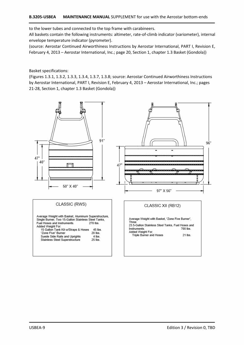
to the lower tubes and connected to the top frame with carabineers.
All baskets contain the following instruments: altimeter, rate-of-climb indicator (variometer), internal
envelope temperature indicator (pyrometer).
(source: Aerostar Continued Airworthiness Instructions by Aerostar International, PART I, Revision E,
February 4, 2013 – Aerostar International, Inc.; page 20, Section 1, chapter 1.3 Basket (Gondola))
Basket specifications:
(Figures 1.3.1, 1.3.2, 1.3.3, 1.3.4, 1.3.7, 1.3.8; source: Aerostar Continued Airworthiness Instructions
by Aerostar International, PART I, Revision E, February 4, 2013 – Aerostar International, Inc.; pages
21-28, Section 1, chapter 1.3 Basket (Gondola))

B.3205-USBEA MAINTENANCE MANUAL SUPPLEMENT for use with the Aerostar bottom-ends
USBEA-10 Edition 3 / Revision 0, TBD

B.3205-USBEA MAINTENANCE MANUAL SUPPLEMENT for use with the Aerostar bottom-ends
USBEA-11 Edition 3 / Revision 0, TBD

B.3205-USBEA MAINTENANCE MANUAL SUPPLEMENT for use with the Aerostar bottom-ends
USBEA-12 Edition 3 / Revision 0, TBD
BURNERS Propane fuel is used to heat the air and generate buoyancy for flight. The propane is stored in one or
more fuel tanks located in the basket. A withdrawal tube attached to the liquid tank valve permits
liquid propane to be drawn from the bottom of the fuel tanks and supplied to the burner assembly
through the fuel hoses that connect the fuel tanks and burner assembly. Since fuel is withdrawn at a
very high rate, check valves (or excess flow valves) are not used on the fuel tanks. Such valves must
NOT be installed since they may operate on normal burner fuel demand and thus disable the burner.
With a liquid pilot light, liquid propane is taken from the main supply at the burner via a pilot shut off
valve. The fuel goes through a vapor converter and regulator and is distributed through a pilot head.
A piezo igniter (red button) that is located in close proximity to the shut off valve is used to light the
pilot.
With a vapor pilot light, another fuel hose is used to supply vapor from the pilot light tank valve located
on top of the fuel tank to the burner assembly pilot light. A regulator is used to decrease the pressure
of the propane vapor for better pilot operation. A pilot light valve located on the burner controls the
flow of propane vapor to the pilot light. A small filter in the assembly prevents contaminants from
reaching the pilot light.
The liquid tank valve controls the flow of liquid propane to the burner. The blast valve, metering valve
or the glow valve controls fuel flow at the burner. With the liquid tank valve open, opening the burner
blast valve or metering valve will permit liquid propane to enter the heat exchange coil where it is
either completely or partially vaporized. After exiting the heat exchange coil through the orifices in the
nozzle coil, propane will then be ignited by the pilot light. Opening the optional glow valve allows
propane to flow to the glow burner head located at the top of the heat exchange coils, which is then
ignited by the pilot light.
The fittings used to construct the fuel hoses, fuel tanks, and burner assemblies are high quality
commercial fittings of four general types:
(1) Flare fittings (JIC), used to connect the fuel hoses to the burner, and in some instances connects
the fuel hose to the fuel cylinder.
(2) Compression fittings used on the tubing connections.
(3) Pipe fittings, used to connect valves, tubing, or hoses together.
(4) Hand turn POL fittings or CGA-555 fittings, used to connect the main fuel hose to the fuel tank
withdrawal valve.
If components are disassembled for repair, fittings can be considered reusable if undamaged. Fuel hose
end fittings must not be removed from the raw hose. Fuel hoses should be replaced as complete units
only.
ONLY FUEL LINES APPROVED BY AN FAA PC, PMA OR STC ARE TO BE USED IN AN AEROSTAR/RAVEN
HOT AIR BALLOON.
(source: Aerostar Continued Airworthiness Instructions by Aerostar International, PART I, Revision E,
February 4, 2013 – Aerostar International, Inc.; page 13, Section 1, chapter 1.2 Burner and Fuel System)
B.3205-USBEA MAINTENANCE MANUAL SUPPLEMENT for use with the Aerostar bottom-ends
USBEA-13 Edition 3 / Revision 0, TBD
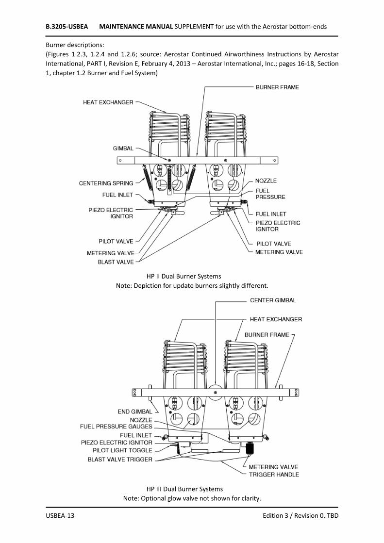
Burner descriptions:
(Figures 1.2.3, 1.2.4 and 1.2.6; source: Aerostar Continued Airworthiness Instructions by Aerostar
International, PART I, Revision E, February 4, 2013 – Aerostar International, Inc.; pages 16-18, Section
1, chapter 1.2 Burner and Fuel System)
HP II Dual Burner Systems
Note: Depiction for update burners slightly different.
HP III Dual Burner Systems
Note: Optional glow valve not shown for clarity.

B.3205-USBEA MAINTENANCE MANUAL SUPPLEMENT for use with the Aerostar bottom-ends
USBEA-14 Edition 3 / Revision 0, TBD
HP III Triple Burner

B.3205-USBEA MAINTENANCE MANUAL SUPPLEMENT for use with the Aerostar bottom-ends
USBEA-15 Edition 3 / Revision 0, TBD
Vertical fuel tank description:
(Figure 1.2.1; source: Aerostar Continued Airworthiness Instructions by Aerostar International, PART I,
Revision E, February 4, 2013 – Aerostar International, Inc.; page 14, Section 1, chapter 1.2 Burner and
Fuel System)
A further description of the balloon, its systems, controls and equipment is provided in the Kubicek
Balloons Flight Manual Supplement (document no. B.3105-FMS_USBEA), section 6.

B.3205-USBEA MAINTENANCE MANUAL SUPPLEMENT for use with the Aerostar bottom-ends
USBEA-16 Edition 3 / Revision 0, TBD
SECTION 2 - AIRWORTHINESS LIMITATIONS
2.4 Inspection Procedure The annual/100 hour inspection of the AER bottom-end combined with KB envelope are to be
performed in accordance with description is provided in section 8 of this supplement. Checklist is
provided in Appendix 5 of this supplement.
2.5 Life Limited Items In accordance with Federal Aviation Regulations 14CFR:
§ 31, Appendix A A31.4: “The Airworthiness Limitations Section is FAA approved and specifies
maintenance required under §§43.16 and 91.403 of the Federal Aviation Regulations.”
§ 43.16 states: “Each person performing an inspection or other maintenance specified in an
Airworthiness Limitations section of a manufacturer’s maintenance manual or Instructions for
Continued Airworthiness shall perform the inspections or other maintenance in accordance with that
section, or in accordance with operations specifications approved by the Administrator under Parts
121,123, 127, or 135 or an inspection program approved under §91.409(e).”
Burner Assemblies Airworthiness Limitations
Component / Applicability Life Limit and Damage Limitation Remarks
Blast valve / Servicing of Rego valves 7553S, 7553T, Sherwood valve LV440 on all burner assemblies manufactured by Aerostar Int’l., (Raven) under Type certificate A15CE.
At intervals not to exceed 100 hours or 12 calendar months, whichever expires first, the burner blast valve(s) must be disassembled, cleaned, and inspected for damage or scoring to the interior bonnet wall that may cause the valve to leak. If the bonnet is damaged, a new bonnet assembly must be installed. A new blast valve O-ring and copper gasket must be installed. The blast valve O-ring and copper gasket must be lubricated with a light application of Krytox grease. The blast valve(s) must be tested to ensure that the valve is free of leaks, operates smoothly, and shuts off completely.
DO NOT interchange parts between Rego and Sherwood valve assemblies. The only parts that can be used in either valve assembly are the blast valve assembly is the blast valve O-ring, copper gasket, and the Teflon spacer ring. Triggers on HP3 burners must have 1/16” to 1/8” of free play. See Service Bulletins #102 and #118. Reference section 8.15.4 Burner and Frame of this supplement.
Metering valve(s) / Nupro and Hoke style valves on all burner assemblies manufactured by Aerostar Int’l., (Raven) under Type certificate A15CE.
If a preflight check on scheduled inspection reveals that the metering valve leaks, does not operate smoothly, or does not shut off completely, the valve must be repaired or replaced prior to further flight.
Reference section 8.15.4 Burner and Frame of this supplement.
Liquid pilot light assemblies / All HP2 update and all HP3 burners manufactured by Aerostar Int’l., (Raven) under Type certificate A15CE.
At intervals not to exceed 100 hours or 12 calendar months, whichever expires first, the pilot light vapor converter must be removed, cleaned, lubricated, reassembled, and tested for proper operation. The pilot light orifice must be removed and inspected using a .011 “go gauge” to ensure that it is not obstructed. Replace if needed.
Apply only a very thin film of Krytox grease to lubricate the vapor converter O-rings. Reference section 8.15.4 Burner and Frame of this supplement, Aerostar Maintenance Bulletin #805001.
All pilot light assemblies/ All burners manufactured by Aerostar Int’l., (Raven)
If a preflight check or scheduled inspection reveals that the pilot light valve leaks or binds
The pilot light flame must burn mostly blue with yellow tips.

B.3205-USBEA MAINTENANCE MANUAL SUPPLEMENT for use with the Aerostar bottom-ends
USBEA-17 Edition 3 / Revision 0, TBD
under Type certificate A15CE.
during operation of the valve, the valve must be repaired or replace prior to further flight. If the pilot light does not stay lit or does not operate with a steady flame, the pilot light must be serviced prior to further flight.
Reference section 8.15.4 Burner and Frame of this supplement.
All Nupro valves B4JNAR2, B-4JAR2 for vapor and/or liquid control / All burner assemblies manufactured by Aerostar Int’l., (Raven) under Type certificate A15CE.
If a preflight or scheduled inspection reveals that the packing nut is loose, the packing nut must be tightened in a clockwise direction to a torque value of 60 in. lbs. or 5 ft. lbs.
Important: Torque values of greater than 60 in. lbs. may make the valve difficult to operate. Reference section 8.15.4 Burner and Frame of this supplement.
All burner assemblies manufactured by Aerostar Int’l., (Raven) under Type certificate A15CE.
If a preflight check or scheduled inspection reveals that any of the following operations of the burner is malfunctioning, the burner must be repaired prior to further flight. • Burner fittings including internal plumbing, no leaks present. • The pressure gauge(s) must operate properly and be easily read by the operator. • The burner must ignite easily from the pilot light(s) and have proper flame alignment. • Gimbal burners must move freely without binding and return to center when released. • Electric blast controls, valves, and fittings must be free from leaks and shut off completely.
See Service Bulletin #113. See Service Bulletin #131 for HPIII Burners. See Service Bulletin #110. Reference section 8.15.4 Burner and Frame of this supplement.
(source: chart 302; Aerostar Continued Airworthiness Instructions by Aerostar International, PART I,
Revision E, February 4, 2013 – Aerostar International, Inc.; pages 3 and 4, Section 3, chapter 3.0
Airworthiness Limitations)
Fuel System Airworthiness Limitations
Component / Applicability Life Limit and Damage Limitation Remarks
All Fuel Cylinders/ Certified for use in Aerostar Int’l., (Raven) hot air balloon systems manufactured under Type certificate A15CE. Tank models: V10 V15 V18 V23 H20 H25
At intervals not to exceed 100 hours or 12 calendar months, whichever expires first, fuel cylinders MUST be inspected for the following: • To ensure that there are no leaks at: o All welded seams. o Around all tank fittings, valves, or plugs. • To ensure that there are(is): o No digs, dents, gouges, or bulges (beyond specified limits found in Appendix E). o No evidence of heat or fire damage. • To ensure that all valves: o Operate properly (no binding). o Are free from leaks and shut off completely. • To ensure that vapor regulators (if installed): o Provide the needed fuel flow for proper pilot light operation. o Do not leak.
See Service Bulletin #135. See Service Letter #104.

B.3205-USBEA MAINTENANCE MANUAL SUPPLEMENT for use with the Aerostar bottom-ends
USBEA-18 Edition 3 / Revision 0, TBD
• To ensure that fuel gauges(s): o Operate properly & do not leak. o Are easily read by the operator. o Four retaining screws are checked for tightness.
Reference section 8.16 Fuel Cylinders and Appendix 5 of this supplement.
All Fuel Cylinders/ Certified for use in Aerostar Int’l., (Raven) hot air balloon systems manufactured under Type certificate A15CE. Tank models: V10 V15 V18 V23 H20 H25
At an interval not to exceed 144 calendar months from the original date of tank manufacture, each fuel cylinder must be inspected and re-qualified. Subsequent inspections and re-qualification must be performed at intervals not to exceed 144 calendar months based on the type of requalification method used.
Cylinders must be inspected in accordance with Appendix II-E of the ACAI. See Service Letter #137. Reference section 8.16 Fuel Cylinders and Appendix 5 of this supplement.
All Nupro valves B4JNAR2, B-4JAR2, BJR2 for vapor and/or liquid control / Fuel cylinder assemblies manufactured by Aerostar Int’l., (Raven) under Type certificate A15CE.
If a preflight check or scheduled inspection reveals that the packing nut is loose, the packing nut must be tightened in a clockwise direction to a torque value of 60 in. lbs. or 5 ft. lbs.
Important: torque values of greater than 60 in. lbs. may make the valve difficult to operate. Reference section 8.16 Fuel Cylinders of this supplement.
All fuel hoses and fittings / Certified for use in Aerostar Int’l., (Raven) hot air balloon systems manufactured under Type certificate A15CE.
At intervals not to exceed 120 calendar months from the date of manufacture, new fuel hoses must be installed. At intervals not to exceed 100 hours or 12 calendar months whichever expires first, fuel hoses MUST be leak tested by submersing the fuel hose in water and pressurizing the hose to a minimum of 120 psi.
See Service Bulletins #120 & #132 Reference section 8.16 Fuel Cylinders of this supplement.
Pressure relief safety valves installed in 10 gallon aluminum fuel cylinders / Certified for use in Aerostar Int’l., (Raven) hot air balloon systems manufactured under Type certificate A15CE.
At an interval not to exceed 60 calendar months a new pressure relief safety valve (Aerostar P/N 52435), must be installed. If a preflight check or scheduled inspection reveals evidence of leaks or signs of discharge, a new pressure relief safety valve must be installed.
Instructions for the replacement of the pressure relief safety valve on 10 gallon cylinders can be found in section 6.3.9 of the ACAI manual. Reference section 8.16 Fuel Cylinders of this supplement.
(source: chart 303; Aerostar Continued Airworthiness Instructions by Aerostar International, PART I,
Revision E, February 4, 2013 – Aerostar International, Inc.; pages 10 and 11, Section 3, chapter 3.0
Airworthiness Limitations)
Gondola Airworthiness Limitations
Component / Applicability Life Limit and Damage Limitation Remarks
Rattan / All woven rattan gondolas manufactured by Aerostar Int’l., (Raven) under Type certificate A15CE. Models: RW RWS RWSW CW CWS CW-AFX RSWS-AFX RB5 RB6 RB8 RB12
If a preflight check or scheduled inspection reveals damage to the rattan greater than 4 inches in diameter or within 18 inches of another damaged area, that damage must be repaired prior to further flight.
See Service Bulletin #117. Reference section 8.15.3 Baskets of this supplement.

B.3205-USBEA MAINTENANCE MANUAL SUPPLEMENT for use with the Aerostar bottom-ends
USBEA-19 Edition 3 / Revision 0, TBD
Plywood floors / All plywood floors used in gondolas manufactured by Aerostar Int’l., (Raven) under Type certificate A15CE. Models: RW RWS RWSW CW CWS CW-AFX RSWS-AFX RB5 RB6 RB8 RB12
If a preflight check or scheduled inspection reveals damage to the plywood floor (i.e. damage due to decay, delamination, impact, or punctures), or other damage that might affect the strength, the floor must be repaired or replaced prior to further flight.
See Service Bulletin #107. Reference section 8.15.3 Baskets of this supplement.
Tank straps and moorings / Used in all models of gondolas manufactured by Aerostar Int’l., (Raven) under Type certificate A15CE.
If a preflight check or scheduled inspection reveals damage to a tank strap that exceed 20% of the cross section of the webbing, the tank strap must be replace prior to further flight.
See Service Bulletins #101 & #128. Reference section 8.15.3 Baskets of this supplement.
Gondola hardware / Used in all models of gondolas manufactured by Aerostar Int’l., (Raven) under Type certificate A15CE.
If a preflight check or scheduled inspection reveals that there is damage to any of the following hardware used in the gondola, the defective part must be replaced prior to further flight. Quick Pins: The pin must not be bent, must have both ball bearings at the tip of the pin, the head must not turn independently from the shank. Wirelock Pins: The pin must not be bent; the spring gate must require some effort to snap into place when installed. Misc. Bolts and Locknuts: Bolts must not be bent, cross-threaded, stripped, or show signs of metal fatigue or stress. Locknuts must not be cross-threaded or stripped and must require more than 8 in. lbs. of torque to be loosed.
Reference section 8.15.3 Baskets of this supplement.
Skids / Used on gondolas manufactured by Aerostar Int’l., (Raven) under Type certificate A15CE. Models: RW RWS RWSW CW CWS CW-AFX RSWS-AFX RB5 RB6 RB8 RB12
If a preflight check or scheduled inspection reveals that a skid is:
• not securely fastened, • damaged from decay and/or serious cracks that will affect the strength and/or function of the skid, • worn to the point of abrasion of the skid hardware,
The skid must be repaired or replaced prior to further flight.
See Service Letter #106. Reference section 8.15.3 Baskets of this supplement.
Aluminum and stainless-steel tubing / All models of gondolas manufactured by Aerostar Int’l., (Raven) under Type certificate A15CE.
If a preflight check or scheduled inspection reveals that the tubing is damaged, the tube must be replaced prior to further flight. Aluminum Tubing: • No uncontrolled localized bends. • No uncontrolled gradual bends. • No signs of cracking, kinking, buckling, collapse, or localized overstress. • No signs of corrosion, scratches, gouges, deeper than 1/32”. Stainless Steel Tubing: • No uncontrolled localized bends.
See Service Letter #109
B.3205-USBEA MAINTENANCE MANUAL SUPPLEMENT for use with the Aerostar bottom-ends
USBEA-20 Edition 3 / Revision 0, TBD
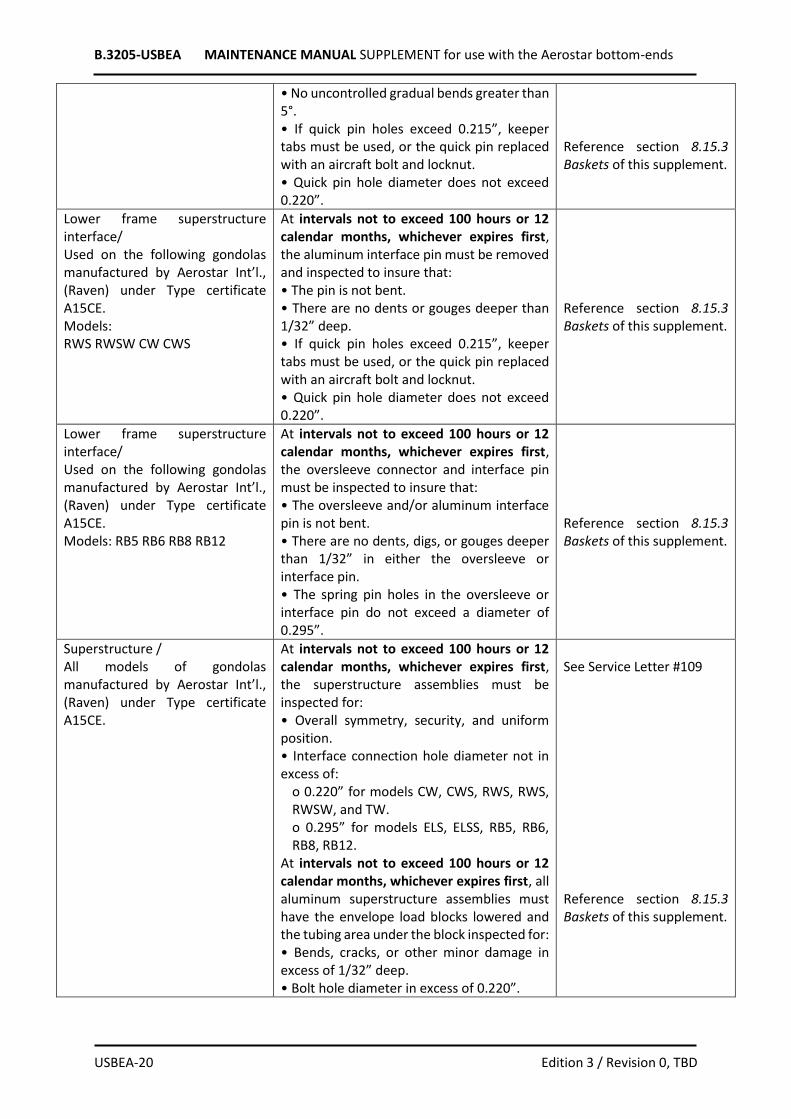
• No uncontrolled gradual bends greater than 5°. • If quick pin holes exceed 0.215”, keeper tabs must be used, or the quick pin replaced with an aircraft bolt and locknut. • Quick pin hole diameter does not exceed 0.220”.
Reference section 8.15.3 Baskets of this supplement.
Lower frame superstructure interface/ Used on the following gondolas manufactured by Aerostar Int’l., (Raven) under Type certificate A15CE. Models: RWS RWSW CW CWS
At intervals not to exceed 100 hours or 12 calendar months, whichever expires first, the aluminum interface pin must be removed and inspected to insure that: • The pin is not bent. • There are no dents or gouges deeper than 1/32” deep. • If quick pin holes exceed 0.215”, keeper tabs must be used, or the quick pin replaced with an aircraft bolt and locknut. • Quick pin hole diameter does not exceed 0.220”.
Reference section 8.15.3 Baskets of this supplement.
Lower frame superstructure interface/ Used on the following gondolas manufactured by Aerostar Int’l., (Raven) under Type certificate A15CE. Models: RB5 RB6 RB8 RB12
At intervals not to exceed 100 hours or 12 calendar months, whichever expires first, the oversleeve connector and interface pin must be inspected to insure that: • The oversleeve and/or aluminum interface pin is not bent. • There are no dents, digs, or gouges deeper than 1/32” in either the oversleeve or interface pin. • The spring pin holes in the oversleeve or interface pin do not exceed a diameter of 0.295”.
Reference section 8.15.3 Baskets of this supplement.
Superstructure / All models of gondolas manufactured by Aerostar Int’l., (Raven) under Type certificate A15CE.
At intervals not to exceed 100 hours or 12 calendar months, whichever expires first, the superstructure assemblies must be inspected for: • Overall symmetry, security, and uniform position. • Interface connection hole diameter not in excess of:
o 0.220” for models CW, CWS, RWS, RWS, RWSW, and TW. o 0.295” for models ELS, ELSS, RB5, RB6, RB8, RB12.
At intervals not to exceed 100 hours or 12 calendar months, whichever expires first, all aluminum superstructure assemblies must have the envelope load blocks lowered and the tubing area under the block inspected for: • Bends, cracks, or other minor damage in excess of 1/32” deep. • Bolt hole diameter in excess of 0.220”.
See Service Letter #109 Reference section 8.15.3 Baskets of this supplement.

B.3205-USBEA MAINTENANCE MANUAL SUPPLEMENT for use with the Aerostar bottom-ends
USBEA-21 Edition 3 / Revision 0, TBD
All AFX gondolas manufactured by Aerostar Int’l., (Raven) under Type certificate A15CE. Models: CW-AFX RWSW-AFX
At intervals not to exceed 100 hours or 12 calendar months, whichever expires first, the: • AFX burner frame must be disassembled and inspected to ensure that the
o Bolt holes in either the frame tubes or load blocks do not exceed a diameter of 0.220”. o AFX load fittings are not bent, cracked, or have other damage deeper than 1/32”. o AFX load block lugs interior is not worn beyond a minimum thickness of 0.160”.
• Lower AFX rod sockets must be inspected to insure that:
o the socket tube is not bent. o the socket tube is free of dents, digs, gouges, or scratches deeper than 1/32”.
• The AFX support cables must be inspected to ensure that they are free of:
o Rust and corrosion. o Broken wire strands.
• The polycarbonate rods must be inspected to ensure that they are free of:
o nicks, scoring, and gouges. o bends or signs of heat damage.
See Service Letter #112 Reference section 8.15.3 Baskets of this supplement.
Mode G Gondola manufactured by Aerostar Int’l., (Raven) under Type certificate A15CE.
If a preflight check or scheduled inspection reveals that the square aluminum tubing is cracked, broken, or has weld failures, the tubing must be replaced
See Service Bulletin #106 Reference section 8.15.3 Baskets of this supplement.
(source: chart 304; Aerostar Continued Airworthiness Instructions by Aerostar International, PART I,
Revision E, February 4, 2013 – Aerostar International, Inc.; pages 12-16, Section 3, chapter 3.0
Airworthiness Limitations)
SECTION 3 - ENVELOPE REPAIRS AND MAINTENANCE No change.
SECTION 4 - BASKET REPAIR AND MAINTENANCE The following section concern inspection and preventive maintenance for which the owner or operator
of the balloon is primarily responsible. If the owner/operator uncovers any damage outside the
allowable damage limits, those repairs MUST be made only by authorized repair personnel at a
qualified Repair Facility, prior to further flight.
BASKETS BEFORE EACH FLIGHT, inspect basket for general integrity noting particularly:
(1) Bolts and nuts - check for no damaged threads, bent bolts, and proper tightness.
(2) Quick pins - check for proper operation and locking capability, no bent pins or pins with the head
loose from the shank. If necessary, lubricate with spray silicone or light oil.

B.3205-USBEA MAINTENANCE MANUAL SUPPLEMENT for use with the Aerostar bottom-ends
USBEA-22 Edition 3 / Revision 0, TBD
(3) Fire extinguisher - check the gauge to see that the extinguisher is properly charged. Check that the
nozzle is unobstructed. Keep the fire extinguisher clean. Be familiar with the operating instructions,
cautions and maintenance instructions on the fire extinguisher nameplate.
NOTE
EVERY SIX YEARS the fire extinguisher must be discharged and then recharged by an authorized fire extinguisher service company. EVERY TWO MONTHS the extinguisher should be removed from its mounts and inverted several times to prevent the dry agent from caking.
(source: Aerostar Continued Airworthiness Instructions by Aerostar International, PART I, Revision E,
February 4, 2013 – Aerostar International, Inc.; page 12, Section 2, chapter 2.4 Basket (Gondola))
To keep the wicker from becoming brittle, remoisten it every two to three months. Remove the
instruments and keep the leather dry when doing this. To help the wicker retain moisture, apply a
silicone solution to it after moistening. Non-flammable wicker treatments such as Armor-All® brand
may be used.
To preserve and protect the suede leather used on the basket, occasionally use a commercial product
sold in most shoe stores that is intended for this purpose. Use a brush to remove dirt and grime. Scuff
marks may be removed by lightly sanding.
Use shoe oil to extend the life of the leather scuff protectors used in some baskets. Apply liberally.
(source: Aerostar Continued Airworthiness Instructions by Aerostar International, PART I, Revision E,
February 4, 2013 – Aerostar International, Inc.; page 13, Section 2, chapter 2.5 Storage)
For maintenance and repair instructions for baskets and suspension systems, see Appendix 3 of this
Supplement.
SECTION 5 - BURNER REPAIRS AND MAINTENANCE The following section concern inspection and preventive maintenance for which the owner or operator
of the balloon is primarily responsible. If the owner/operator uncovers any damage outside the
allowable damage limits, those repairs MUST be made only by authorized repair personnel at a
qualified Repair Facility, prior to further flight.
BEFORE EACH FLIGHT, inspect burner for general integrity and operation, noting particularly:
(1) Visually inspect for no loose or missing nuts and bolts.
(2) Burner blast valves - check for proper valve opening and closing by actuating the valve handle or
trigger. The valve should shut off when it is returned to the closed position. The valve handle or trigger
should move smoothly with no sticky or stiff action.
Dirt or debris between the curved surface of the valve handle and the nylon blast valve washer may
prevent the handle from moving smoothly. Wipe away the dirt or debris from the valve handle with a
dry cloth. DO NOT use solvent because the solvent could contact the valve stem O-ring and damage
the O-ring.
(3) Metering valve - check for proper operation.
(4) Pilot light valve - check for proper operation.
(5) Pilot light - check for proper operation.
(6) Electric blast valve (if equipped) - check for proper operation, inspect power cable for no damage
or loose connections, verify that the battery is charged.
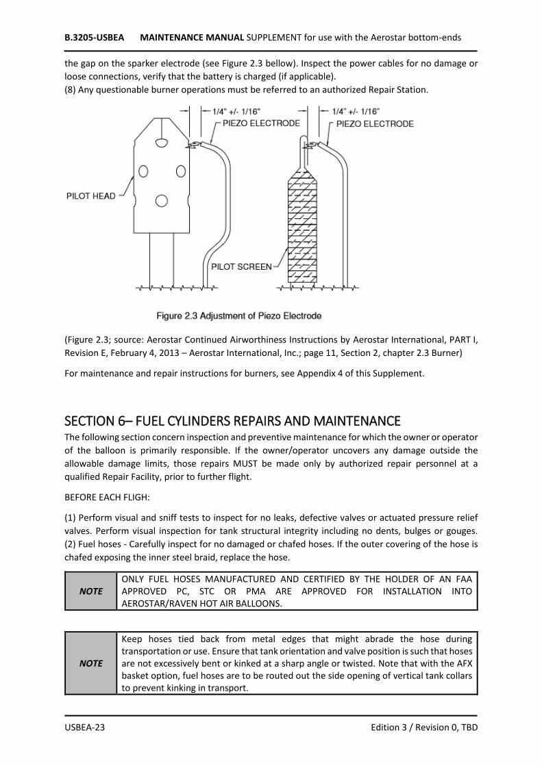
(7) Electric ignition or piezo - check that the electric sparker ignites the pilot light when activated, check
B.3205-USBEA MAINTENANCE MANUAL SUPPLEMENT for use with the Aerostar bottom-ends
USBEA-23 Edition 3 / Revision 0, TBD
the gap on the sparker electrode (see Figure 2.3 bellow). Inspect the power cables for no damage or
loose connections, verify that the battery is charged (if applicable).
(8) Any questionable burner operations must be referred to an authorized Repair Station.
(Figure 2.3; source: Aerostar Continued Airworthiness Instructions by Aerostar International, PART I,
Revision E, February 4, 2013 – Aerostar International, Inc.; page 11, Section 2, chapter 2.3 Burner)
For maintenance and repair instructions for burners, see Appendix 4 of this Supplement.
SECTION 6– FUEL CYLINDERS REPAIRS AND MAINTENANCE The following section concern inspection and preventive maintenance for which the owner or operator
of the balloon is primarily responsible. If the owner/operator uncovers any damage outside the
allowable damage limits, those repairs MUST be made only by authorized repair personnel at a
qualified Repair Facility, prior to further flight.
BEFORE EACH FLIGH:
(1) Perform visual and sniff tests to inspect for no leaks, defective valves or actuated pressure relief
valves. Perform visual inspection for tank structural integrity including no dents, bulges or gouges.
(2) Fuel hoses - Carefully inspect for no damaged or chafed hoses. If the outer covering of the hose is
chafed exposing the inner steel braid, replace the hose.
NOTE ONLY FUEL HOSES MANUFACTURED AND CERTIFIED BY THE HOLDER OF AN FAA APPROVED PC, STC OR PMA ARE APPROVED FOR INSTALLATION INTO AEROSTAR/RAVEN HOT AIR BALLOONS.
NOTE
Keep hoses tied back from metal edges that might abrade the hose during transportation or use. Ensure that tank orientation and valve position is such that hoses are not excessively bent or kinked at a sharp angle or twisted. Note that with the AFX basket option, fuel hoses are to be routed out the side opening of vertical tank collars to prevent kinking in transport.

B.3205-USBEA MAINTENANCE MANUAL SUPPLEMENT for use with the Aerostar bottom-ends
USBEA-24 Edition 3 / Revision 0, TBD
(3) Open and close fuel tank valves. To open, turn valve handle until stop is felt. To close, turn the valve
handle until the seat is felt, then tighten gently.
CAUTION Overtightening of the valve on closure can damage the seat and cause leakage, necessitating repair or replacement of the valve.
(source: Aerostar Continued Airworthiness Instructions by Aerostar International, PART I, Revision E,
February 4, 2013 – Aerostar International, Inc.; page 12, Section 2, chapter 2.4 Basket (Gondola))
WARNING
NEVER store fuel tanks containing propane or propane vapor in garages or enclosed buildings where sources of ignition are present or where no ventilation is available. Propane must not be stored in structures where people reside. Instead, remove the tanks from the system and store the tanks outdoors. Propane vapors are heavier than air. Even if there is a very slight leak, vapors will build up inside baskets, low spots or in enclosed areas. A tiny leak can provide enough fuel for a large explosion if left overnight. Fuel tanks that have been pressurized using nitrogen should never be stored in temperatures greater than 30°F higher than the temperature at which they were originally pressurized. In long term storage, the tank's vapor should be purged into open space for several minutes to allow the nitrogen to escape.
(source: Aerostar Continued Airworthiness Instructions by Aerostar International, PART I, Revision E,
February 4, 2013 – Aerostar International, Inc.; page 13, Section 2, chapter 2.5 Storage)
For maintenance and repair instructions for the fuel cylinders, see Appendix 4 of this MMS.
SECTION 7 – INSTRUMENT REPAIRS AND MAINTENANCE No change.
SECTION 8 – INSPECTION SCHEDULE
8.1 General This section describes inspection schedule for all balloons combining Kubicek Balloons envelopes with
AER bottom-ends (basket, burner, burner frame and fuel system).
8.2 Scheduled Inspections 1. Balloons: 100 hour/annual inspection
2. Life limited items: for intervals of inspections of the life limited items, see chapter 2.5 of this
supplement
B.3205-USBEA MAINTENANCE MANUAL SUPPLEMENT for use with the Aerostar bottom-ends
USBEA-25 Edition 3 / Revision 0, TBD
8.4 100 Hour/Annual Inspection The 100 hour/annual inspection must include all items listed in the 100 Hour/Annual Inspection
Checklist. For the checklist applicable to AER bottom-ends (when combined with KB envelopes) - see
Appendix 5 of this supplement.
8.15 Inspection Criteria / Techniques The following maintenance and inspection MUST BE PERFORMED at each Annual/100 hour
inspection. FAR 91.409 requires that this inspection to be in accordance with the manufacturer's
most recent instructions for Continued Airworthiness.
8.15.3 Baskets Begin the gondola inspection by assessing the overall condition of the gondola. Evaluate the shape of
the lower woven portion of the basket. Areas of broken or scuffed rattan or leather may be indications
of possible hidden structural damage. With the uprights installed evaluate the proper alignment of
the gondola frame. This can best be accomplished by viewing the basket from a short distance in order
to see the gondola as a complete assembly. Pay particular attention to any suspected damaged areas
during the following inspections.
Rattan
The rattan must be sufficiently intact so that the occupants and their equipment are enclosed and
protected. Repair areas with vertical or horizontal damage greater than 4 inches or within 18 inches
of another damaged area. Trim any broken rattan that protrudes into the basket and could injure
occupants. If there are more than two adjacent vertical rattans broken at the skid, repair as per point
6.4.1 (Appendix 3 of this supplement).
Plywood Floors
Plywood floors must be free from damage due to decay, delamination, or other damage that might
affect their strength. Damage to the floor can be considered “minor damage” if it does not penetrate
more than 2 plies of the floor and has a diameter of no more than ¾ inch. Minor damage may be
repaired as specified in point 6.4.2 (Appendix 3 of this supplement).
If damage is extensive, affecting the security of the floor, floors of RWS, RWSW, ELS, ELSS, CW, CWS
and RB gondolas must be replaced.
TW & RW floors may be repaired by any method approved by Aerostar, since their floors are not
replaceable. Consult with the factory to evaluate damage, and for recommendations for proper repair
techniques.
Tank Straps and Moorings
Check all fasteners, webbing, stitching, buckles, etc. in the assembly that holds the fuel tank in the
gondola. Slight abrasion of the webbing is allowed, but no more than 20% of the webbing material
may be damaged or missing. Wear or breakage of any part that may cause failure of the tank restraint
system is grounds for replacement of that part. In vertical tank systems, check vertical stakes for
breakage where the webbing passes through. Cracking of vertical stakes at that location is acceptable,
but total failure of the stake calls for replacement of the failed piece, (see section 6.4.1, Appendix 3 of

B.3205-USBEA MAINTENANCE MANUAL SUPPLEMENT for use with the Aerostar bottom-ends
USBEA-26 Edition 3 / Revision 0, TBD
this supplement).
When 15 gallon or larger vertical tanks are installed in the basket, ensure that the upper tank strap
securing the tank to the gondola passes up and over the shoulder of the tank so as to apply downward
pressure on the tank holding it in place.
Tank Pads or Shoes (Optional on some models)
Inspect the tank shoes or pads (if installed) to insure they are securely fastened to the gondola floor.
If they are damaged to the extent that they no longer protect the floor from possible damage they
must be replaced. (see section 6.4.4, (Appendix 3 of this supplement).
Fire Extinguisher
The fire extinguisher must be in good overall condition, including the safety pin and actuation handle.
Check the extinguisher gauge to ensure that it is properly charged. Check to see if the extinguisher
bracket or pouch is properly secured in the gondola. Verify the required recharge of extinguisher has
been performed as specified in SECTION 4 - BASKET REPAIR AND MAINTENANCE, chapter Baskets,
paragraph (3).
Interior Passenger Handles (where applicable)
Inspect the interior passenger handle ropes for damage that may affect their strength or ability to
restrain the passenger in a hard landing. Inspect the handle attachment points for possible damage
that may allow them to break loose during a rough landing, this may include vertical canes, siderail
frames, etc.
Exterior Carrying Handles
Inspect the exterior carrying handles and their ropes for any damage that may affect their strength
and/ or security, replace any damaged parts.
Scuff Leather
The leather scuff protector at the bottom of the basket must protect the rattan beneath it from
abrasion. If the leather is loose, reattach or repair as needed. Replace severely worn leather that
exhibits abraded holes or tears that in turn expose the rattan or lower frames to possible damage.
Hardware (Including quick pins, wirelock pins, superstructure bolts and locknuts, floor and skid
hardware and optional seat hardware)
Inspect all gondola hardware for damage that might affect its strength. Any hardware that is worn,
bent, cross-threaded, stripped or shows sign of metal fatigue or stress must be replaced with FAA
approved parts. Inspect the following hardware for specific damage:
(1) Quick Pins
For Model RW, RWS, RWSW, CW, CWV, CWS, RB or TW baskets, replace bent pins, pins with
the head loose from the shank or pins with any of the ball bearings missing from the tip.
Lubricate with a silicone spray, Tri Flow or similar lubricant. If the quick release pins used to
connect the support tubes to the lower frame tubes are in good condition, but they can still
B.3205-USBEA MAINTENANCE MANUAL SUPPLEMENT for use with the Aerostar bottom-ends
USBEA-27 Edition 3 / Revision 0, TBD
be removed without depressing the release button, replace with a quick pin with a keeper
plate or a bolt and locknut.
NOTE
Some models of baskets, mfr'd after 5/86 have a retaining plate attached. Should the support tube holes elongate enough to allow the pin to be removed without depressing the release button, the pin lanyard may be released from the basket and re-attached closer to the holes so that the retaining plate may be used.
(2) Wirelock pins
Wirelock pins used on the ELS, ELSS and RB baskets, are two completely different strength
grades very similar in appearance. The ELS, ELSS pins are stamped with the letter "A" on the
head, while the RB pin is stamped "S".
CAUTION Either “A” or “S” style pins may be used on the ELS and ELSS gondolas, however the “S” style pin MUST be used on all RB model gondolas.
The spring gate should require some effort to snap it into place. The ends may be compressed
together to increase the closing effort required. Otherwise, if the spring is non-functional or
the pin is bent, replace the entire pin assembly. RB wirelock pins should always be installed
with the heads toward the exterior of the basket.
(3) Aircraft Bolts and Locknuts
Damaged or excessively worn bolts or locknuts must be replaced. Check to be sure that all
bolts/nut are snug and that the end of the bolt extends through the edge of the locknut.
(4) Floor and skid hardware
Check to ensure the floor and skids are held securely in place. Replace any hardware that is
damaged or does not adequately hold the item in place. Replace any skid hardware that
extends to the bottom edge of the skid and is worn. (See section 6.4.10, Appendix 4 of this
supplement for repair techniques.)
(5) Seat Hardware
A variety of hardware has been used throughout the years to secure the optional seats over
horizontal 20 and 25-gallon fuel cylinders. For older seat assemblies inspect the coated cable,
rapid links, nylon straps, buckles and anchors for damage that might affect the security of the
seat. For gondola seats build after 1995 inspect the u-bolts, locknuts, hinges and spacer blocks
for damage that might affect the security of the seat installation. Replace any damaged parts.
Skids
(1) Model CW, CWV or CWS Baskets (Old style)
The skid made from oak 2” x 4” must be securely fastened to the floor, at its corner butt joints, free
from decay, without serious cracks, and without excessive wear. If skid bolts are wearing, replace or
repair the skid.
(2) Model RW, RWS or TW-1 Baskets
The skid is made from oak 1” x 4”. It must be securely fastened to the gondola substrate and
floorboard. It must be free from decay and excessive wear. Replace the skid if it is worn enough to
expose the skid attaching bolts to abrasion. Replace splintered skid boards. Replacement of the skid
is accomplished by removal of attaching bolts through the floor. Use new mounting hardware if worn
or broken.
If the edge of the skid board is worn so that the weaving substrate above it is exposed to abrasions,
replace the skid board.

B.3205-USBEA MAINTENANCE MANUAL SUPPLEMENT for use with the Aerostar bottom-ends
USBEA-28 Edition 3 / Revision 0, TBD
If the 2” x 4” substrate becomes cracked, the crack may be filled with waterproof carpenter's glue and
the board clamped until cured.
(3) Model TW-2
The skid for the TW-2 made from oak 1¼” x 3. ”. It must be securely fastened to the gondola substrate
and floorboard. It must be free from decay and excessive wear. Replace the skid if it is worn enough
to expose the skid attaching bolts to abrasion. Replace splintered skid boards. Replacement of the
skid is accomplished by removal of attaching bolts through the floor. Use new mounting hardware if
worn or broken.
If the edge of the skid board is worn so that the weaving substrate above it is exposed to abrasions,
replace the skid board.
If the 2” x 4” substrate becomes cracked, the crack may be filled with waterproof carpenter's glue and
the board clamped until cured.
(4) ELS, ELSS or RWSW (Aurora) Baskets The skid for the RWSW and ELS, ELSS basket (Aurora 54K) is
constructed using 1½” x 2½” oak. The skid should be replaced if it is worn down to the attachment or
lag bolts. Also replace it if cracks threaten the strength of the board.
(5) Model CW, CWS, RB5, RB6, RB8 or RB12 Baskets (New Style)
The skid made from 2” x 4” must be securely fastened at its corner and butt joints, free from decay,
without serious cracks and without excessive wear.
NOTE
Poly skid protectors (alternative wear-resistant materials) are available from Aerostar as optional retrofit kits to be installed in addition to the skid board on all models. These poly skid protectors are standard on RB5, RB6, RB8 and RB12 baskets. (See allowable skid damage prior to installation.)
NOTE All baskets manufactured since February 1, 1992 are equipped with readily removable skids for ease of replacement.
Aluminum and Stainless-Steel Tubing
The tubing that is used to form the structural load-carrying portion of the basket is made of either
aircraft grade aluminum or stainless steel. You may identify stainless steel by the manufacture’s
markings, shinier appearance and heavier weight when compared to aluminum.
The tubing, regardless of type must not show signs of cracking, kinking, buckling, collapse, localized
overstress, or corrosion/scratches/gouges other than minor (less than 1/32” deep) surface scratches.
There are three types of bends that may be present on the tubing:
1) controlled designed bends- used to form the shapes of the basket components.
2) Uncontrolled localized bends- abrupt bends occurring during use due to impact or excessive stress
where the bend occurs at a distinct location.
3) Uncontrolled gradual bends- a bend that occurs over a length of tube due to the application of
excessive force.
The aluminum and stainless-steel tubing must not be bent in an uncontrolled localized manner. Any
visible signs of bending in this manner and/or distinct crease lines from such a bend indicates that the
part MUST be replaced. Uncontrolled bend radius deformation of tubing may weaken it below
acceptable limits.
The aluminum tubing must not be bent in an uncontrolled gradual manner. Any visible signs of bending
in this manner on aluminum tubing dictate that the part MUST be replaced. Stainless steel tubing may

B.3205-USBEA MAINTENANCE MANUAL SUPPLEMENT for use with the Aerostar bottom-ends
USBEA-29 Edition 3 / Revision 0, TBD
be bent back into its original shape if the bend does not exceed 5°.
The various components of the basket may be subjected to forces sufficient to slightly straighten or
over-bend components formed with controlled designed bends. In the event the basket appears to
be misshapen, leans, or it is difficult to install the uprights on the basket, this may indicate that a
change has taken place to one or more of the shaped components of the structure of the basket.
Contact Aerostar customer service for specifications to be checked to determine whether the basket
remains serviceable.
Particular care should be taken when inspecting superstructures, which may use a combination of
aluminum and stainless-steel tubing (through the exercise of options, replacement parts, etc.). In
these instances, the added strength of the stainless-steel members may induce extra bending stresses
in the aluminum tubing and result in localized tube damage.
NOTE There may be a combination of aluminum and stainless-steel superstructure parts in some baskets. These combinations may be acceptable. For example: Stainless steel support tubes and aluminum side frames.
Lower Gondola Frame
Depending on model of gondola the lower frames may be aluminum or stainless steel. Inspect the
lower frame tubes to ensure that there is no bending or other damage that exceeds the limitations as
stated in section 8.15.3 Baskets, chapter Aluminum and Stainless-Steel Tubing. Check to see that the
lower frames are properly secured to the gondola floor or skids, depending on model.
Lower Frame / Superstructure Interface
The connection of the superstructure or uprights to the lower gondola is accomplished with a variety
of assemblies depending on model of gondola. The components (lower frames, support tubes and
assorted hardware), that make up these interfaces should be inspected as specified in their
appropriate paragraphs of this section.
Inspect each type of interface as follows:
(1) Model RW gondola:
This interface is accomplished by inserting the superstructure tubes inside the lower frame tubes and
is secured with eight quick release pins. Inspect to see that the quick pinholes are properly aligned
with the uprights installed. If the quick pinholes exceed .215 in. keeper tab must be used or the pin
should be replaced with an aircraft bolt and locknut. If the diameter of the quick pins hole exceeds
.220 in. the parts must be replaced
(2) Model CW, CWS, RWS, and TW gondolas:
This interface is accomplished with an aluminum interface pin that is bolted into the side frames of the
superstructure. The interface pins are then inserted into the lower frame and secured with eight quick
release pins. The interface pin MUST be completely removed and inspected. The interface pin MUST
not be bent or show signs of damage other than minor (less than 1/32 “ deep). If the quick pin holes
in either the support tubes or the interface pin exceed .215 in., a keeper tab must be used, or the pin
should be replaced with an aircraft bolt and locknut. If the diameter of the holes exceeds .220 in. the
part must be replaced.
(3) Model RWSW gondola:
This interface is accomplished with an aluminum interface pin that is bolted into the lower frame. The
superstructure is then placed over the interface pin and secured with eight quick release pins. The
B.3205-USBEA MAINTENANCE MANUAL SUPPLEMENT for use with the Aerostar bottom-ends
USBEA-30 Edition 3 / Revision 0, TBD
interface pin must be completely removed and inspected. The interface pin MUST not be bent or show
signs of damage other than minor damage (less than 1/32 inch deep). If the quick pin holes in either
the support tubes or the interface pin exceed .215 in., a keeper tab must be used, or the pin should be
replaced with an aircraft bolt and locknut. If the diameter of the holes exceeds .220 in. the part must
be replaced.
(4) Model ELS, ELSS gondola:
This interface is accomplished with an aluminum or stainless-steel removable over-sleeves that fits
over both the lower frame and the superstructure support tubes. The oversleeve has two upper holes
and two lower holes in order for the operator to adjust the height of the uprights and burner. The
oversleeve is secured to the lower and upper frames by the use of eight wirelock pins. The oversleeve
must be inspected to ensure that it is not bent, twisted or has any other damage other than minor
damage (less than 1/32 inch deep). If any of the holes in the support tubes or the oversleeve exceed
.295 in. the part must be replaced.
(5) Model RB gondolas
This interface is accomplished with an aluminum interface pin in combination with a steel oversleeve
which are both bolted to the lower frame. The superstructure is then place over the interface pin while
inside the oversleeve and is then secured with four steel wirelock pins. It is not required to remove
either the interface pin or the oversleeve, however both should be inspected to ensure that the
wirelock pin holes are not elongated. They should also be inspected to ensure that they are not bent,
twisted, out of alignment or have damage other than minor damage (less than 1/32 in. deep). If any
of the holes in the interface pin, oversleeve or the support tubes exceed .295 in. the part must be
replaced.
Superstructure
Gondola superstructure or upright tubes may be aluminum or stainless steel. The main support tubes
or side frames are connected to the crossbar sections using a variety of extruded fittings and / or load
blocks. In addition, the connections are secured with several different kinds of hardware, including
aircraft bolts, locknuts, quick release pins and wirelock pins. Inspect the individual components as
outlined in the appropriate section. Inspect each superstructure as follows.
(1) Inspect for bends per section 8.15.3 Baskets, chapter Aluminum and Stainless-Steel Tubing.
(2) It is recommended that the upright covers and /or pads be removed to perform a thorough
inspection of the superstructure tubing and fittings.
(3) Inspect the superstructure for overall symmetry. Inspect the extruded connector fittings for
security and uniform position. Check to ensure that all associated hardware is tight and /or in good
condition.
(4) On all aluminum 4-point superstructures the load blocks must be lower and the holes through the
superstructure tubing inspected for cracks, breaks or significant fretting corrosion.
(5) Install the burner onto the superstructure in order to inspect the burner blocks for proper
positioning and alignment with the burner holes. Adjust the superstructure or burner blocks if needed
to improve alignment. See point 6.4.16 (Appendix 3 of this supplement).
NOTE Aerostar Service Bulletin # 133 requires that a cable back up redundancy system be installed to any RWS, CW and CWS 4-point gondola with aluminum superstructure tubes.

B.3205-USBEA MAINTENANCE MANUAL SUPPLEMENT for use with the Aerostar bottom-ends
USBEA-31 Edition 3 / Revision 0, TBD
4-Point Load Blocks
4-point load blocks can be for either A-block style envelope load fittings or carabiner connectors. The
blocks must not be bent, damaged, cracked or have damage other than minor (less than 3/32” deep).
Replace any unairworthy parts. All hardware must be tightened as specified in point 6.4.16 (Appendix
3 of this supplement).
Burner Blocks (4-Point & AFX)
There are two styles of the burner block. The standard block has a set of holes for burner installation.
The speed block has a set of oblong holes in place of the standard burner holes. One speed block may
be installed as an option.
The burner block must not be bent, damaged, cracked or have damage other than minor (less than
3/32” deep). Replace any unairworthy parts. All hardware must be tightened as specified in point
6.4.16 (Appendix 3 of this supplement).
2-Point Load/Burner Blocks
Inspect the load blocks to ensure that they are not bent, cracked or have damage other than minor
(less than 3/32” deep). Check to see that the block is secured in place and is properly aligned for burner
and envelope load block installation. Replace any unairworthy parts.
RB Passenger Ride Gondolas
The RB series of partitioned ride gondolas are designed to separate and protect multiple passengers.
These gondolas contain additional structural components that must be inspected as part of each
annual / 100 hour inspection.
The metal siderail frame including compartment siderails must be inspected to ensure that the frame
in intact. Check all welded or clamped connections for possible breaks or loose fittings. See point
6.4.18 (Appendix 3 of this supplement) for repair techniques.
Inspect each compartment to ensure that the interior pads are in place. The cable lacing the upper
portion of the partitions or pads must be intact. Inspect the interior passenger handles per section
8.15.3 Baskets, chapter Interior Passenger Handles.
RB6, RB 8 and RB 12 gondola incorporate secondary lower frame tubes that are utilized for additional
structural support and to secure the fuel cylinders into the pilot compartment. These gondolas also
include a protective frame that bolts into the siderail frame and continue over the collars of the fuel
cylinders. These tubes may have small dents (less than 1inch in. diameter), minor surface damage (less
than 3/32 in depth), or minor bends (not to exceed a 5º bend).
The pilot compartment may contain a small plywood sub floor with one, two, or three foam spacers
used to elevate the pilot platform to the desired height. The sub floor and any installed spacers must
be removed to properly inspect the gondola floor. The pilot sub floor and spacers must be inspected
for damage. Replace any broken components. The RB series of gondolas include additional passenger
entry steps. Inspect the support ribs and leather covers to ensure that no sharp edges protrude
through the rattan.
AFX Gondola (CW and RWSW)
Refer to point 6.4.19 (Appendix 3 of this supplement) for repair and replacement of components.

B.3205-USBEA MAINTENANCE MANUAL SUPPLEMENT for use with the Aerostar bottom-ends
USBEA-32 Edition 3 / Revision 0, TBD
(1) Inspect the top frame load fittings to ensure that damage does not exceed the following limitations:
(A) Main Load Blocks: no dents, digs gouges, scratches or damage other than minor (deeper than
3/32”).
(B) Socket Tubes : no dents, digs, gouges, scratches or damage other than minor (deeper than 1/32”),
the tube MUST not be bent or collapsed, the welds connecting the socket to the main block MUST
not be cracked.
(C) Lugs : Must not be bent or cracked, the carabiner and cables MUST fit easily into the lugs, the
interior of the lug may be worn, but MUST have minimum thickness of .160”.
(source: Aerostar Continued Airworthiness Instructions by Aerostar International, PART II, Revision E,
February 4, 2013 – Aerostar International, Inc.; pages 41-50, Section 5, chapter 5.4 Gondola Inspection)
(Figure 5.4.19; source: Aerostar Continued Airworthiness Instructions by Aerostar International,
PART II, Revision E, February 4, 2013 – Aerostar International, Inc.; page 50, Section 5, chapter 5.4
Gondola Inspection)
NOTE In 2003 a modular AFX load block was introduced allowing the replacement of damaged components instead of the entire block assembly.
In addition, inspect the hardware as specified in section 8.15.3 Baskets, chapter Hardware and replace
any unairworthy parts.
(2) Inspect carabiners for smooth operation and locking collar function. Replace if bent, abraded or
excessively worn. USE ONLY PROPERLY CERTIFIED, FAA APPROVED CARABINEERS.
(3) Remove and closely examine support rods for nicks, scoring, gouges, bending or signs of heat
damage. REPLACE WITH PROPERLY CERTIFIED, FAA APPROVED PARTS.
(4) Remove leather cover by cutting nylon "zip tie" in bottom hem, undoing small rapid link to the
cable at the top, and pulling cover off over lower socket. Inspect leather for wear in the "hinge" area
at the bottom. The lower portion (approximately 8") can be replaced if excessively worn, without
replacing the entire cover.
(5) Ensure that the stitching is intact at the webbing where the cable rapid link is attached, and at the
top of the hose sleeve.

B.3205-USBEA MAINTENANCE MANUAL SUPPLEMENT for use with the Aerostar bottom-ends
USBEA-33 Edition 3 / Revision 0, TBD
(6) Disassemble lower rod socket by removing bolts, washers, cable thimble and nuts. Inspect rod
sockets and top of lower frame tubes for cracks, bends, and bolt hole distortion
NOTE
Aerostar Service Letter #112 outlines the instructions for the replacement of the lower AFX cable with a cable constructed from Stainless Steel cable in place of the Galvanized cable used prior to November 1999. After this retrofit is completed it is not required to disassemble the lower rod socket, remove and inspect the lower cable.
(7) Inspect the cables, both upper and lower, for fraying or other damage. This may be done by
running the cables through a soft cloth or cloth gloves slowly and feeling for sharp spots that may
snag indicating a broken wire. Cable should be free of rust and corrosion. Damaged parts must be
replaced with new.
(8) Check stabilizer brace for integrity and security. Tighten bolts and nuts. Replace damaged parts
with factory obtained parts if needed.
(9) Inspect nuts, bolts and washers for damage, and replace with new parts if needed.
(source: Aerostar Continued Airworthiness Instructions by Aerostar International, PART II, Revision E,
February 4, 2013 – Aerostar International, Inc.; pages 50 and 51, Section 5, chapter 5.4 Gondola
Inspection)
8.15.4 Burner and Frame Burner Assembly
Inspect burner system for general structural integrity. Check the following:
(1) Tighten screws and bolts if necessary. Replace screws or bolts that have damaged threads.
(2) Replace or reshape burner cans that are severely distorted.
(3) Ensure that the reducing union nuts and the swivel fittings are tight. Avoid overtightening, which
may crack the pilot light (screen type) reducing union nuts.
(4) Inspect burner coils. Replace if cracks, deep gouges or pressure rupture are evident.
(5) Inspect burner frame for no cracked welds. If damaged, they must be returned to Aerostar for
inspection and repair/replacement.
(6) Inspect fuel inlet fittings. Replace them if they show a significant amount of overtightening,
corrosion or crossthreading. Tighten them if loose.
(7) Inspect for foreign material in nozzle coil orifices. Use a wire of suitable gauge or similar device to
remove it.
NOTE To remove any obstructions, remove the nozzle coil if necessary. Clear orifice with wire or similar device. Clear coil with high pressure air and reinstall.
(source: Aerostar Continued Airworthiness Instructions by Aerostar International, PART II, Revision E,
February 4, 2013 – Aerostar International, Inc.; page 20, Section 5, chapter 5.2 Burner System)
B.3205-USBEA MAINTENANCE MANUAL SUPPLEMENT for use with the Aerostar bottom-ends
USBEA-34 Edition 3 / Revision 0, TBD
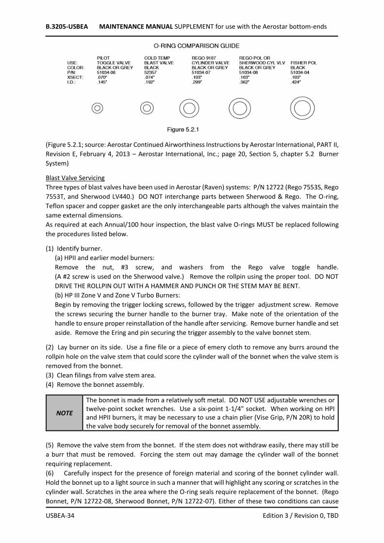
(Figure 5.2.1; source: Aerostar Continued Airworthiness Instructions by Aerostar International, PART II,
Revision E, February 4, 2013 – Aerostar International, Inc.; page 20, Section 5, chapter 5.2 Burner
System)
Blast Valve Servicing
Three types of blast valves have been used in Aerostar (Raven) systems: P/N 12722 (Rego 7553S, Rego
7553T, and Sherwood LV440.) DO NOT interchange parts between Sherwood & Rego. The O-ring,
Teflon spacer and copper gasket are the only interchangeable parts although the valves maintain the
same external dimensions.
As required at each Annual/100 hour inspection, the blast valve O-rings MUST be replaced following
the procedures listed below.
(1) Identify burner.
(a) HPII and earlier model burners:
Remove the nut, #3 screw, and washers from the Rego valve toggle handle.
(A #2 screw is used on the Sherwood valve.) Remove the rollpin using the proper tool. DO NOT
DRIVE THE ROLLPIN OUT WITH A HAMMER AND PUNCH OR THE STEM MAY BE BENT.
(b) HP III Zone V and Zone V Turbo Burners:
Begin by removing the trigger locking screws, followed by the trigger adjustment screw. Remove
the screws securing the burner handle to the burner tray. Make note of the orientation of the
handle to ensure proper reinstallation of the handle after servicing. Remove burner handle and set
aside. Remove the Ering and pin securing the trigger assembly to the valve bonnet stem.
(2) Lay burner on its side. Use a fine file or a piece of emery cloth to remove any burrs around the
rollpin hole on the valve stem that could score the cylinder wall of the bonnet when the valve stem is
removed from the bonnet.
(3) Clean filings from valve stem area.
(4) Remove the bonnet assembly.
NOTE
The bonnet is made from a relatively soft metal. DO NOT USE adjustable wrenches or twelve-point socket wrenches. Use a six-point 1-1/4" socket. When working on HPI and HPII burners, it may be necessary to use a chain plier (Vise Grip, P/N 20R) to hold the valve body securely for removal of the bonnet assembly.
(5) Remove the valve stem from the bonnet. If the stem does not withdraw easily, there may still be
a burr that must be removed. Forcing the stem out may damage the cylinder wall of the bonnet
requiring replacement.
(6) Carefully inspect for the presence of foreign material and scoring of the bonnet cylinder wall.
Hold the bonnet up to a light source in such a manner that will highlight any scoring or scratches in the
cylinder wall. Scratches in the area where the O-ring seals require replacement of the bonnet. (Rego
Bonnet, P/N 12722-08, Sherwood Bonnet, P/N 12722-07). Either of these two conditions can cause
B.3205-USBEA MAINTENANCE MANUAL SUPPLEMENT for use with the Aerostar bottom-ends
USBEA-35 Edition 3 / Revision 0, TBD
valve leakage. Inspect the security of rubber blast valve seal and its attachment to the brass seal
holder. If attaching rivet shows signs of loosening, replace entire assembly.
NOTE Do not interchange Sherwood and Rego valve bodies and bonnet assemblies. Use only Sherwood bonnets in Sherwood valve bodies and likewise use only Rego bonnets in Rego Valve bodies.
(7) Remove O-ring, Teflon back up ring and copper gasket.
(8) Lubricate a new O-ring (Part Number 52357) with KRYTOX fluorinated grease lubricant, #240 AC
(P/N 51008-52). DO NOT SUBSTITUTE ANY OTHER LUBRICANT.
(9) Install the new stem seal O-ring. Do not slide the new O-ring over the rollpin hole in the stem
without protection. The edges of the hole may be sharp and cut the O-ring. A small piece of balloon
fabric may be laid over the end of the stem and the O-ring slid over this. A permanent tool may be
made by placing a 1" piece of heat shrink tubing over a stem just shy of the groove and heating. A
bullet shaped tool may be cut from a large crochet needle (#13) or by soldering a 5/16" rod inside a
5/16" I.D. tube (available at hobby shops) and grinding or turning the end.
NOTE
The O-ring 52357 replaces all previous O-rings in blast valves. It is slightly larger and has much better sealing capacity in cold temperatures. It will not fit well in Rego 7553S bonnets. "S" type bonnets have a one-piece stem and seal holder. New Rego bonnets for 7553T must be used for replacement. "T" type bonnets have a two-piece design that allows the seal holder to swivel independently from the stem. Do not use any other O-ring. See Figure 5.2.1.
(10) Inspect and reinstall the Teflon wiper ring, replace if damaged or misshapen.
NOTE Make sure to install the O-ring stem seal on the pressure side of the stem and the Teflon backup washer on the handle side of the stem.
(11) Ensure that bonnet threads are clear of previous Teflon tape, dirt or other debris. Place two
wraps of ½ inch or less Teflon tape on bonnet threads to prevent galling. Keep the two lower threads
of the bonnet clear of Teflon tape.
(12) Reassemble valve using a new copper gasket 51040-55 for both Rego and Sherwood valves.
NOTE To ensure a proper seal and compression of the copper gasket, lubricate with Krytox O-ring lubricant.
(13) Torque the hex blast valve bonnet to 60 ft-lbs.
(14) Reinstall blast actuation:
(a) HP II and earlier model burners: Position the toggle handle over the valve stem and press the
rollpin back into place. Reinstall nut, screw and washers. DO NOT USE A HAMMER TO DRIVE IN
THE ROLLPIN.
(b) HPIII Zone V and Zone V Turbo Burners: Reinstall the burner handle in the proper orientation as
noted when removed. Secure the handle to the burner tray, start the trigger locking screws but do
not tighten. Insert the trigger adjustment screw and adjust as described in section 5.2.4. Tighten
the trigger locking screws.
NOTE Use Loctite 242 when installing the 3 types of screws used in step 14 (b).
(source: Aerostar Continued Airworthiness Instructions by Aerostar International, PART II, Revision E,
February 4, 2013 – Aerostar International, Inc.; pages 21-23, Section 5, chapter 5.2 Burner System)

B.3205-USBEA MAINTENANCE MANUAL SUPPLEMENT for use with the Aerostar bottom-ends
USBEA-36 Edition 3 / Revision 0, TBD
Blast Valve Operation
The blast valve must be free from leaks, operate smoothly, and shut off completely. Check the valve
stem area for leaks as the blast valve is opened and closed. Check for leaks past the bonnet threads.
Valve stem area leaks will require disassembly as outlined in section 8.15.4 Burner and Frame, chapter
Blast Valve Servicing.
If propane leaks past the bonnet threads, torque the hex bonnet up to an additional 20 ft-lbs. If there
is still a leakage past the bonnet threads, disassemble the valve and replace the copper gasket, (section
8.15.4 Burner and Frame, chapter Blast Valve Servicing). Lubricate the copper gasket with the O-ring
type lubricant to help create a better seal by allowing more compression of the gasket for the same
bonnet torque value. If the leak persists, replace blast valve bonnet insert assembly.
HPIII Blast Valve Trigger
Blast valve triggers of the HPIII burner must operate smoothly with 1/16"-1/8" free play. If the trigger
is adjusted with no free play, the blast valve may not close completely. Conversely, if there is too much
play, the valve will not open completely, and burner output will be reduced. Adjust trigger play as
explained in Section 6.2.1(B)(3) (Appendix 4 of this supplement).
Metering Valve
The metering valve must be free from leaks, operate without binding and shut off completely. Check
the valve stem area for leaks throughout the opening range from closed to open. Check the valve stem
for wobble when fully opened.
Tighten valve stem packing nut if:
- There are leaks around the valve stem
- The valve stem wobbles when open
- The valve turns with little or no resistance
NOTE Metering valve knobs on HPIII burners have some play in the stem. Do not mistake this for stem wobble and overtighten the packing nut.
To tighten packing nut: (NUPRO valve)
The nupro valve is distinguishable by an all brass valve body and bonnet assembly and a small red
plastic handle, which is held in place by an allen set screw through the side of the handle.
(1) Open the valve enough to prevent damage to the seat and stem.
(2) Loosen the panel mounting on the outside of the burner tray.
(3) Use a 9/16 inch modified "crow's foot" or open-end wrench to adjust the valve stem packing
nut on the inside of the burner can. Tighten the packing nut so that the valve turns with moderate
resistance.
(4) DO NOT over-tighten the valve stem packing nut. This will make it difficult to open and close
the valve.
If the valve cannot be adjusted acceptably to be free from leaks and excessive binding, replace the
valve. If the valve knob is loose, tighten the set screw.
If the valve knob is still loose after tightening the set screw, remove the knob. File a small flat spot on
the valve stem where the set screw locates. Use a drop of medium strength (Loctite 242) thread
locking compound on the set screw. Be careful not to allow the filings to enter the valve. Reinstall the
valve knob with the set screw seated on the flat.

B.3205-USBEA MAINTENANCE MANUAL SUPPLEMENT for use with the Aerostar bottom-ends
USBEA-37 Edition 3 / Revision 0, TBD
To tighten packing nut: (HOKE valve)
The Hoke style valve is distinguishable by a steel valve body and bonnet. The old-style handle is a
black plastic handle, the handle on the HPIII burners is a red aluminum handle. Both handles are
secured in place with a small nut through the top of either style handle.
(1) Open valves enough to prevent valve damage. Valves on HPIII burners must be opened far
enough to allow access to the packing nut.
(2) Use a 7/16" open-end wrench to adjust nut (located on outside of burner tray). Tighten the
packing nut so the valve turns with moderate resistance.
(3) Do not overtighten packing nut.
(source: Aerostar Continued Airworthiness Instructions by Aerostar International, PART II, Revision E,
February 4, 2013 – Aerostar International, Inc.; pages 23-25, Section 5, chapter 5.2 Burner System)
Pilot Light (HP II Update, HP III Standard and Turbo)
As required at each Annual/100 hour inspection, the pilot light vapor convertor MUST be serviced
following the procedures listed below.
As detailed in Aerostar Maintenance Bulletin 08-05-11, and in accordance with Chart Burner
Assemblies Airworthiness Limitations in Section 2.5 of this supplement, the following action must be
taken;
Action: To ensure that the orifice is open or clear to design specifications, a .011 “go gauge” tool should
be used to verify that the pilot light orifice has a sufficient opening to provide the proper fuel flow to
the pilot light head. This “go gauge” is to be used during each Annual Inspection, 100-hour inspection
and or servicing of the pilot light assembly.
(1) Pilot light Vapor Convertor Disassembly
NOTE For burners with the glow option installed, the glow burner pilot light tube should be removed at the base of the copper tube. This can be accomplished by loosening the ferrule nut with a 7/16 wrench.
(a) With a 1-1/8 inch open-end wrench, enter through the side of the burner. Place the wrench on
the upper portion of the vapor converter. Loosen the upper portion of the vapor convertor. If the
entire convertor begins to rotate, use a modified 1-1/8 inch crows foot on an extension to hold the
lower portion of the vapor convertor, while removing the upper portion.
(b) When removing the upper portion of the vapor convertor be careful not to lose any of the
internal components.
(c) The internal piston of the vapor convertor can be removed by using a wobble motion while
pulling it out of the regulator body.
(d) Place the upper convertor body in a bench vice. Place a mark on the converter body and the
stem of the pilot light head, this can be used during re-assembly for proper alignment of the pilot
light head.
(e) Place a metal punch or the shaft of a Phillips-tip screwdriver, through the holes in the pilot light
head and loosen the pilot light head from the vapor Convertor body.
(f) The pilot light orifice can then be removed from the upper portion of the vapor convertor.
(g) Clean all parts with a dry silicone spray (True Test Brand Silicone Spray) wipe all parts clean. Be
sure the spray used to clean the parts does not leave any residue.
(h) Replace the O-rings on the piston if they appear stretched, damaged, or deformed. Apply a very
thin film of Krytox lubricant on O-rings prior to re-assembly.
(i) Clean pilot light orifice with silicone spray or compressed air. Push a .011 tip of a “go gauge”

B.3205-USBEA MAINTENANCE MANUAL SUPPLEMENT for use with the Aerostar bottom-ends
USBEA-38 Edition 3 / Revision 0, TBD
through the opening in the pilot light orifice stating from the backside of the orifice. This action will
verify that the orifice is open to the specification necessary for the proper operation of the pilot
light. Some loosely held contaminates may become dislodged during this action; if so, make sure
that the contaminants are not pulled back into the orifice when removing the go gauge. If the “go
gauge” will not pass freely through the pilot light orifice, install a new orifice (P/N 52153) Look
through the orifice to ensure that the orifice is clear. If the orifice remains obstructed install a new
orifice.
(j) Reassemble the pilot light and vapor convertor in the reverse order, with the exception of the
glow pilot tube (if installed). Attach the glow pilot light tube to the glow valve prior to re-installing
the upper portion of the vapor convertor. Use Loctite 290 when installing the pilot head into the
upper vapor convertor.
NOTE Be careful to use only a small amount of Loctite when reassembling the pilot head. If an excessive amount is used the excess may drip down to the pilot light orifice, thus clogging the orifice.
(2) HPII Update & HPIII Pilot Light Troubleshooting
Tall Noisy Flame or Erratic Flame
Washer excessively cupped - both washers and the orifice should be removed and replaced with
orifice, P/N 52153 (requiring no washers)
Pilot head not tight enough – tighten pilot head an additional 1/8 turn.
Regulator is malfunctioning - disassemble, clean & lube w/blast valve lube. Replace if necessary.
Low Quiet Flame, Easily Extinguished
Orifice plugged or dirty - clean with fine wire or air, or replace orifice
Inlet filter plugged - replace (Burner Assembly Figure 6.2.6A & B, Appendix 4 of this supplement)
Slug plugged – clean, or replace
Regulator malfunctioning - disassemble, clean and lubricate. Replace if continued malfunction.
Slow Shut Off Time
Convertor, Slug and valve body not properly seated. Tighten 1/8 turn. If shut-off time is still excessive,
repeat. Replace slug if the ends are damaged, Convertor may require replacement if the seating is
surface damaged.
(3) The pilot light must also be inspected for proper operation, as specified below. Use a propane
source of 120 psi or greater. Refer to Section 6.2 (Appendix 4) for repairs.
(a) Turn on pilot. Igniter should light flame within 2-3 tries. Electrode must be 1/4" from hole in
shoulder of pilot head. Adjust electrode or replace sparker if necessary. If pilot refuses to light,
proceed to troubleshooting.
(b) Open blast valve and burn 5-10 seconds to ensure that liquid propane is available at pilot.
(c) Flame should be 4-6" tall, primarily blue with yellow tips. If not, proceed to troubleshooting.
(d) Flame should not extinguish easily - try blowing it out. If it does, proceed to troubleshooting.
(e) The pilot light should operate steadily with no extreme flame disruptions (indicated by change
in sound).
(f) Turn off pilot valve. Flame should extinguish within 3 seconds. If not, proceed to
troubleshooting.
(source: Aerostar Continued Airworthiness Instructions by Aerostar International, PART II, Revision E,
February 4, 2013 – Aerostar International, Inc.; pages 25-27, Section 5, chapter 5.2 Burner System)

B.3205-USBEA MAINTENANCE MANUAL SUPPLEMENT for use with the Aerostar bottom-ends
USBEA-39 Edition 3 / Revision 0, TBD
Liquid Pilot Light Valve Servicing
Inspect the valve for proper operation and to ensure that there are no leaks past the valve stem. If
leaks are found service as detailed in section 6.2.7 (Appendix 4 of this supplement).
HPII update burners use a small brass toggle handle to open and close the valve. Apply a small amount
of spray lubricant between the toggle handle and the washer on top of the valve body. HPIII standard
and Turbo burners use a swivel style pilot light handle composed of a pilot handle barrel, the pilot
handle and a retainer pin and e-clip that attach to the valve stem. Apply a small amount of spray
lubricant between the barrel and handle assembly and also to the retainer pin.
Pilot Light (Screen Head Style)
The pilot light should burn properly. With the burner pilot light valve open 1/2 turn or more, ignite
the pilot light. If the pilot light is being operated off a tank with a vapor pressure regulator, the pilot
should burn steadily with slight yellow tips in the flame with no further adjustment of the pilot light
valves. Non-regulated pilot lights will require a finer adjustment of the pilot light valve to achieve
proper pilot light operation.
Remove the pilot light assembly to clean or replace it, if
- The pilot light will not stay lit.
- Burning is erratic.
- The pilot light does not ignite the burner properly.
If the pilot light screen is corroded severely with voids in the screen material, replace it. See section
6.2.8 (Appendix 4 of this supplement), Screen Head Pilot.
Vapor Pilot Light Valve Servicing
As required by 3.10 tighten the valve stem packing nut on Nupro pilot light valves using the following
procedure:
The Nupro valve is distinguishable by an all brass valve body and bonnet assembly and a small red
plastic handle which is held in place by an allen set screw through the side of the handle.
(1) Open the valve by rotating the valve handle COUNTERCLOCKWISE TWO COMPLETE TURNS
from the closed position.
NOTE This prevents damage to the valve stem tip when the valve stem packing nut is tightened.
(2) Tighten the valve stem packing nut in a CLOCKWISE direction to a torque value of 60 in-lbs. or
5 ft-lbs. (IMPORTANT: Torque values greater than 60 in-lbs. may make the valve difficult to
operate.)
Tools:
- Torque wrench calibrated in inch-lbs.
- 9/16" "crow's foot" wrench. (When using, orient the "crow's foot” 90 degrees to the torque
wrench to prevent inaccurate torque readings. (See figure 5.2.9. on following page)
- OR -
- Torque wrench calibrated in inch-lbs. and a 9/16" socket. (Remove the valve handle before
tightening the valve stem packing nut).

B.3205-USBEA MAINTENANCE MANUAL SUPPLEMENT for use with the Aerostar bottom-ends
USBEA-40 Edition 3 / Revision 0, TBD
(Figure 5.2.9; source:
Aerostar Continued Airworthiness Instructions by Aerostar International, PART II, Revision E, February
4, 2013 – Aerostar International, Inc.; page 29, Section 5, chapter 5.2 Burner System)
When reinstalling the valve handle use a drop of medium-strength thread locking compound, such as
Loctite 242, on the set screw.)
If the handle is still loose after tightening the set screw, remove the handle and file a small flat spot on
the valve stem where the set screw sets. DO NOT allow the filings to fall around the valve stem.
Reinstall the valve handle with the set screw seated on the flat area.
(3) With the valve stem packing nut properly tightened, some resistance should be felt as the valve
handle is rotated after the initial opening force is overcome.
(4) Replace valve if defective.
(source: Aerostar Continued Airworthiness Instructions by Aerostar International, PART II, Revision E,
February 4, 2013 – Aerostar International, Inc.; pages 28 and 29, Section 5, chapter 5.2 Burner System)
Burner Fitting Leak Check
Pressurize system to at least 120 psi fuel pressure. All fittings must be free from leaks. Check fittings
upstream of the blast and metering valves with the blast and metering valves in their closed positions.
To check for leaks in burner fittings downstream of the blast and metering valves, one of the two valves
must be open, with burner operating.
NOTE
Several changes were made to internal burner fittings with HPII update burners. If replacement of a fitting is required, be sure not to interchange parts between the two types of fittings. To differentiate, Swagelok fittings are identifiable by a small "C" on the fitting body or "Swagelok". Parker fittings are identifiable by a "P" or "Parker".
Pressure Gauge
The pressure gauge must be free from leaks and operate properly, the indicated pressure must be read
easily. With all the burner valves in the closed position, the pressure gauge should indicate tank
pressure. If the gauge is not functioning properly, replace it. If the pressure gauge lens is cracked,
broken or damaged in a way making the gauge unreadable, replace the lens or the entire gauge
depending on gauge type.
NOTE A small amount of condensation can build up inside the pressure gauge. If this small amount does not interfere with the proper operation or readability of the gauge, the gauge does not require replacement.
B.3205-USBEA MAINTENANCE MANUAL SUPPLEMENT for use with the Aerostar bottom-ends
USBEA-41 Edition 3 / Revision 0, TBD
NOTE If the gauge is a Wika or McDaniel gauge, the type with red, yellow and green ranges, the lens is not replaceable as it is a sealed unit.
If a gauge does not work properly in an HPII burner, it may indicate that the push check in the gauge
inlet is plugged with foreign material. (See Aerostar Service Bulletin #113) See Section 6.2.1(A)
(Appendix 4 of this supplement) for HPII Burner Disassembly.
Burner Operation
When the blast valve is opened, the pilot light should ignite the burner readily. The flame should have
good directional control. It should bathe the coils in flame but not be directed out the side of the
burner between the coil and burner can where it might contact the suspension cables during flight.
After the blast valve or metering valve is closed, there will be a period, up to several seconds when
residual fuel exits the heat exchanger coils. If the flame burns continuously after this period, the blast
valve or metering valve is not shutting off completely. Take the appropriate valve apart and check for
foreign material in the valve seat area or damage to the valve seat or stem. Clean or replace as
necessary.
NOTE Burner tests should be done in low light conditions to properly observe flame quality.
To adjust the flame on HPII nine-hole "S" coil:
(1) Use a 1/8 inch diameter punch.
(2) Insert the punch into the nozzle orifices and pry toward the center of the burner to redirect the
propane gas jets.
(3) DO NOT redirect the flame further inward than necessary to remove large "spurs" from the flame.
The burner coils might not receive enough heat to vaporize the fuel properly.
(4) Replace the nozzle coil if there is a serious flame misalignment.
To adjust the flame of HPII update & HPIII nozzle (Standard19 jet, Turbo 13 jet):
(1) Use a 5/32 I.D. tube or similar device that fits snugly over the jet to prevent pinching on the 19 jet
HPIII Standard. (Aerostar nozzle adjusting tool available from factory at no charge).
(2) Use a 3 /8 “ deep well socket and a 12 – 24” one-piece extension to adjust the nozzles on the 13 jet
HPIII Turbo.
(3) Adjust the jets to allow flame impingement on the coils without causing spurs.
CAUTION THE HPII BURNER NOZZLE MUST NOT BE ADJUSTED TOO TIGHTLY AS FLAMEOUTS MAY OCCUR AT HIGHER ALTITUDES AS WELL AS SEVERE CARBON BUILDUP ON THE BURNER COILS.
NOTE Jets located at corners of nozzle coil, nearest coil supports, should be directed slightly toward heat exchange coil supports (away from center). Adjusting the nozzle coil for greater flame impingement will reduce coil carbon-buildup.
Proper operation can be checked for both HPII and HPIII burners by operating the burner for about five
seconds. After the burner "settles in" (after one or two seconds) observe the quality of propane
vaporization between the nozzle jets and the flame front.
If the burner runs too "lean", there will be no visible propane, and the heat exchange coils will be hot
with little or no water condensation on them. The cause, a wide flame pattern that is transferring too
much heat into the heat exchange coils. The cure is to tighten the flame pattern.
Conversely, if the burner runs too "rich", there will be abundant liquid propane from the jets, frost may
B.3205-USBEA MAINTENANCE MANUAL SUPPLEMENT for use with the Aerostar bottom-ends
USBEA-42 Edition 3 / Revision 0, TBD
appear on the nozzle coil with excessive amounts of water condensation on the heat exchange coils.
The cause, a tight flame pattern that is not transferring enough heat into the heat exchange coils. The
cure is to widen the flame pattern.
The ultimate goal is to find a compromise between these two conditions. There should be primarily
vapor with an occasional spurt of liquid propane visible at the jets.
(source: Aerostar Continued Airworthiness Instructions by Aerostar International, PART II, Revision E,
February 4, 2013 – Aerostar International, Inc.; pages 30-32, Section 5, chapter 5.2 Burner System)
Gimbal Operation
Check gimbal action for freedom of movement.
Burner gimbal should move freely without binding and return to center when released. On HPII and
early HPIII single burners replace springs that are stretched or heat damaged. On HPIII burners verify
that the drive pins are tight and not backing out. On HPIII dual and later model single burners,
inspect the ½" pin at the gimbal blocks and replace if bent. (See Service Bulletin 131).
Burner with Electric Blast
If the burner is equipped with an optional electric blast valve, check the following:
(1) Verify that battery is charged. Recharge or replace as necessary
NOTE Lack of charge or charging may be caused either by the battery or the charger.
(2) Inspect power cables and connectors. Replace any damaged components.
(3) With fuel turned on, check valve for no leaks. Operate burner using the electric solenoid
valve. If the valve does not operate properly, replace with valve obtained from the factory.
NOTE Foreign particles imbedded in the valve seat can keep the electric blast from fully closing. If it is suspected that there are foreign particles in the valve seat, disassemble the solenoid valve, clean it, reassemble and test for proper operation.
Burner with Electric Ignition
If the burner is equipped with an optional electric ignition system, check the following:
(1) Verify that battery is charged, recharge or replace as necessary.
(2) Inspect power cables and connectors. Replace any damaged components.
(3) Inspect and clean or replace igniter as required:
With fuel shut off operate igniter and observe spark quality at spark plug electrode. Turn pilot light
fuel supply on, operate igniter to ensure positive ignition of pilot light. Adjust orientation of pilot head
and spark plug, if necessary to obtain reliable ignition.
Piezo Electric Igniter
Clean any soot buildup from the exposed portion of the electrode, check for proper operation. Adjust
the electrode as shown in Figure 2.3 (SECTION 5 - BURNER REPAIRS AND MAINTENANCE). If there is
no spark or it is weak (yellow rather than blue), replace the piezoelectric igniter.

B.3205-USBEA MAINTENANCE MANUAL SUPPLEMENT for use with the Aerostar bottom-ends
USBEA-43 Edition 3 / Revision 0, TBD
Glow Valve Option
The glow valve option, fitted on HPIII burners only, must be free from leaks, operate smoothly, ignite
readily when activated and shut off completely.
The handle should be free from damage, and unable to rotate or lock in the on position.
The nozzle bracket should be tight and free from excessive heat damage, replace if damage affects
alignment or integrity of the glow head.
Nozzle orifices are to be unobstructed, clear any obstructions with a small wire or similar device.
The copper pilot tube should be directed past the main burner pilot light and towards the glow burner
nozzle head to ensure immediate ignition of propane at the nozzle head. The flame from the glow
burner pilot light should not hit the inside of heat exchange coils.
(source: Aerostar Continued Airworthiness Instructions by Aerostar International, PART II, Revision E,
February 4, 2013 – Aerostar International, Inc.; pages 32 and 33, Section 5, chapter 5.2 Burner System)
8.16 Fuel Cylinders Tank Servicing and Inspection
WARNING
Aerostar Service Bulletin #137 specifies that ALL 10 GALLON ALUMINUM FUEL CYLINDERS MUST BE REMOVED FROM SERVICE. The continued use of these cylinders poses a serious safety risk in the event of an onboard fire or contact with power lines. Refer to Aerostar Service Bulletin #137 for additional information.
In order to perform a proper and thorough inspection of the fuel cylinder, remove all tank covers, pads
and / or heat tapes. It may be necessary to clean any excessive adhesive residues left from the
installation of heat tapes to perform the required leak tests. Inspect each fuel cylinder as follows.
(A) Fuel tanks MUST be inspected to ensure that there are no leaks. Apply a liquid soap solution or a
liquid commercial leak detector to all welded seams, around all tank fittings, valves or plugs, or any
area of the fuel tank that is suspected of a leak. The leak inspection should be performed at a tank
pressure of 100 psi. or higher.
(B) Fuel tanks MUST be visually inspected during the Annual/100 hour inspection. A cylinder that has
leaks, defective valves, safety devices, or quantity gauges must be repaired. A cylinder that is bulged
or has evidence of physical abuse such as fire or heat damage, detrimental rusting, corrosion, dents or
gouges beyond specified limits must be removed from service and marked as unairworthy.
NOTE
National laws (equivalent to United States DOT Regulations) vary slightly from one country to another. All fuel tanks must be tested, inspected and maintained in accordance with the applicable laws of the country of registration. These regulations may be more stringent than the servicing and inspection procedures defined herein. Compliance with these regulations may also apply.
(C) Each fuel tank must be re-inspected periodically. The first requalification is required 12 years after
manufacture of the tank with each subsequent retest at 5year intervals. A repair station may perform
the visual requalification.
Certified repair stations or qualified test facilities MUST perform the tests in accordance with the visual
test methods as described in DOT code 173.34(e) (10) and NLPGA pamphlet 118-91. Record the retest
date on the tank collar by stamping or etching. (Note: Stainless steel tank damage limits are those
specified for 60 lb. cylinders with .078 wall thickness).

B.3205-USBEA MAINTENANCE MANUAL SUPPLEMENT for use with the Aerostar bottom-ends
USBEA-44 Edition 3 / Revision 0, TBD
NOTE
Appendix E of this manual contains the damage limitations for the different types of fuel cylinders used in Aerostar (Raven) hot air balloons. In addition, it contains the instructions for the stamping or tagging of fuel cylinders following the recertification inspection, as well as the proper procedures for identification and disposal of fuel cylinders that are found to be in an unairworthy condition.
(D) Pressure relief valves on 10-gallon fuel tanks MUST be replaced every 5 years. A logbook entry
including tank serial number must be made to document that the replacement has been accomplished.
Tank Liquid Valves
Inspect tank valves to insure compliance with Aerostar Service Bulletin No. 135. If not in compliance,
replace valve bonnet as directed in the Service Bulletin.
The tank liquid valve must operate without binding, be free from leaks, and shut off completely. Be
sure to check the valve stem for leaks when the valve is in a partially open position and also in the full
open position. Check the valve handle for looseness and tighten its attachment screw if necessary. A
defective valve MUST be replaced.
In single burner multiple-tank systems, check each tank valve bonnet with its valve closed, and with
one of the remaining tank valves opened to pressurize the bonnet in question. Open and close that
valve several times to break loose the O-ring. If the valve leaks through its bonnet - replace the O-ring.
If bonnet inner walls are scored or pitted, replace the bonnet.
Defective O-rings may be replaced with: (See Figure 5.2.1, chapter 8.15.4 Burner and Frame of this
supplement)
Valve O-Ring Bonnet
Rego 9101CI P/N 51034-07 P/N N/A
Sherwood 3250(15 & 20 gal tank) P/N 51034-08 P/N 52275-05
Tank Pilot Light Valves (Nupro) if installed (includes new style Nupro valve with additional locking nut,
used for liquid withdrawal on ELS and ELSS gondolas with horizontal tanks)
For systems using vapor pilot lights, a Nupro valve is used to control the fuel flow from the fuel tank.
Check for leaks at the valve stem area as the valve is opened and closed. Also, check that the valve
shuts off completely when closed. As required in section 3.3, tighten the valve stem-packing nut on
Nupro pilot light valves using the following procedure:
(1) Remove all ignition sources from work area.
(2) Ensure fuel line is connected to both tank and burner to prevent fuel leakage.
(3) Open the valve by rotating the valve handle COUNTERCLOCKWISE TWO COMPLETE TURNS from
the closed position, this prevents damage to the valve stem tip when the valve stem-packing nut is
tightened.
(4) Loosen locking nut if applicable to the valve being serviced.
(5) Tighten the valve stem packing nut in a CLOCKWISE direction to a torque value of 60 in-lbs. or 5 ft-
lbs. (IMPORTANT: Torque values greater than 60 in-lbs. may make the valve difficult to operate.)
WARNING
If a fuel cylinders has any amount of propane remaining in the tank and the valve stem-packing nut is rotated in a counterclockwise or loosening direction, the valve bonnet may come loose from the valve body resulting in propane being expelled from the tank at a high rate.
B.3205-USBEA MAINTENANCE MANUAL SUPPLEMENT for use with the Aerostar bottom-ends
USBEA-45 Edition 3 / Revision 0, TBD
Recommended Tools:
- Torque wrench calibrated in inch-lbs.
- 9/16" "crow's foot" wrench. (When using, orient the "crow's foot” 90 to the torque wrench to
prevent inaccurate torque readings. (See Figure 5.2.2)
- OR -
- Torque wrench calibrated in inch-lbs. and a 9/16" socket.
(6) With the valve stem-packing nut properly tightened, some resistance should be felt as the valve
handle is rotated after the initial opening force is overcome.
(7) Snug locking nut if installed.
(8) Replace valve if defective.
Pilot Light Regulators (Vapor pilot lights only)
The regulators must be leak-free. Three types of regulators are used on the fuel tanks:
- A non-adjustable, long, brass-bodied regulator, Part No. 51043-27.
- An adjustable, aluminum alloy bodied regulator, Part No. 51043-10.
- A non-adjustable, short, brass-bodied regulator, Part No.51043-03.
The pressure supplied to the pilot light should provide a flame 4"-8" tall. Regulator P/N 51043-10 may
be adjusted using the adjustment screw on the bottom of the regulator. Turn the screw clockwise to
increase output, counterclockwise to decrease output. If the regulator cannot be adjusted into
tolerance, replace it with regulator P/N 51043-27. If the regulator P/N 51043-03 does not provide a
proper flame, replace it with regulator P/N 51043-27.
Fuel Quantity Gauges
Check the four retaining screws on the fuel gauge for tightness. The fuel gauge must not leak. If there
is a leak and the retaining screws are tight, the rubber gasket is damaged and must be replaced. To
replace the fuel gauge gasket, FIRST drain the tank, remove the gauge assembly by removing the four
retaining screws. Remove the damaged gasket and replace with a new gasket.
Check the fuel quantity gauge for proper operation. On the top of each quantity gauge is an arrow
that indicates the direction of the float device attached to the gauge assembly. To check the operation
of a vertical fuel tank with an indicated quantity of 40% or higher, tip the fuel tank in the opposite
direction of the arrow. The fuel gauge should indicate a decreasing fuel quantity. With an indicated
fuel quantity of 40% or lower, tip the fuel tank in the direction of the arrow. The gauge should indicate
an increasing fuel quantity. For horizontal fuel tanks use the same technique but determine the
direction to tip the tank based on an indicated fuel quantity above or below 50%.
If the fuel quantity gauge does not operate properly or sticks during testing, drain the fuel tank,
remove the gauge assembly. Inspect the gear assembly for possible defects. Repair if applicable or
install a new gauge assembly. See section 6.3.5 (Appendix 4 of this supplement) for repair procedures.
The fuel quantity gauge dial must be readable. If the dial is damaged or is unreadable for any reason,
install a new dial. The dial can be replaced without draining the tank and removing the entire fuel
quantity gauge assembly.
B.3205-USBEA MAINTENANCE MANUAL SUPPLEMENT for use with the Aerostar bottom-ends
USBEA-46 Edition 3 / Revision 0, TBD
Fuel Hoses
Perform a visual inspection of each fuel hose looking for any minor abrasions to the outer braided
cover. If the outer covering is worn exposing the inner metal braid the hose MUST be replaced. Run
your hand slowly down the length of each hose, noting any bulges, kinks or other imperfections.
Perform a leak test by submerging each fuel hose in water and pressurizing the hose to a minimum of
120 psi. using any non-flammable compressed gas source available. (Nitrogen, compressed air) Allow
time for the outer braid to become saturated in order to release any bubbles contained in the outer
braid. Any continuous trails of bubbles are an indication of a leak in the fuel hose. Replace any
defective fuel hose.
NOTE Do Not use Helium gas for the purpose of leak testing fuel hoses
Inspect the hose end connections to ensure that fittings are not corroded, overly worn or have
stripped threads. On those fuel hoses equipped with hand-operated POL fuel tank connections,
replace the O-ring on the male POL fitting as follows (See Figure 5.2.1, chapter 8.15.4 Burner and Frame
of this supplement).
If the male POL fitting is: Use:
Fisher P/N 51042-01 (M388) Fisher O-ring P/N 51034-04
(TI2945)
Rego P/N 7193 C-10 (Do Not Stock) Rego O-ring P/N 51034-03
(7193-1)
Fuel hoses used in Aerostar (Raven) systems requires a one-time inspection to verify that the
manufacture date of that hose is not 3Q84, 4Q84, 1Q92, 2Q92, 3Q92, or 4Q92. A logbook entry must
appear stating that this one-time inspection has been performed. See Service Bulletins 120 and 132.
This bulletin applies to balloon systems and fuel lines manufactured prior to September 1993.
NOTE Fuel hoses must be replaced at 10-year intervals. A logbook entry must be made to properly document this replacement.
NOTE Starting in 1996 all fuel hoses manufactured by Aerostar were stamped with the quarter and year on the fitting at one end of each individual hose assembly.
NOTE
For fuel hoses manufactured prior to 1996, if the hose manufacturing date, (year and quarter), is clearly readable on the fuel hose outer braid, etch the date and quarter onto the hose end fitting for future reference. If the date cannot be clearly identified, do not mark the hose end fitting.
Fittings
All fittings must be free from leaks. Replace fittings that show a significant amount of overtightening,
corrosion or crossthreading.

B.3205-USBEA MAINTENANCE MANUAL SUPPLEMENT for use with the Aerostar bottom-ends
USBEA-47 Edition 3 / Revision 0, TBD
Fuel Supply System (Operational and Leak Check)
To test the fuel supply system for leaks, use a household soap and water solution or a commercial
product such as Nupro Snoop Liquid Leak Detector. For temperatures below freezing, use Nupro Real
Cool Snoop Leak Detector. Cover the test area with the leak detecting solution. Leaks are indicated
where the solution foams or bubbles. Flush with water to remove the leak solution after testing.
Test the following areas for leaks and check for proper operation or condition: Tank valves in a partially
open and fully open position, fuel line fittings at tank and at burner, fuel hose connections, additional
fittings and regulators (if so equipped).
The operational checks should be performed in conjunction with the burner operational tests required
in section 8.15.4 Burner and Frame.
When the blast valve is opened, the pressure gauge will normally indicate a pressure drop of 5 to 20
psi., with the larger pressure drop occurring with the higher tank pressures. There is a fuel supply
problem if:
- Pressure drops more than 20 psi.
- Operating pressure decreases rapidly during a burn of 20 to 30 seconds.
The cause of the problem could be:
- The liquid tank valve is not open fully.
- The fuel line or burner is obstructed.
- The tank liquid withdrawal tube is obstructed, cracked or disconnected.
To isolate and remedy the malfunction, interchange properly working components (tanks, fuel lines,
burners) with components that have questionable operation.
Pressure relief valve
Inspect the pressure relief valve for leaks or for signs of discharge; ensure that all adapters and dust
caps (if applicable) are in place.
On 10 gallon aluminum fuel cylinders verify that the valve has been replaced at the required intervals.
If the valve is out of the five-year requirement, replace the valve as described in chapter 6.3.9
(Appendix 4 of this supplement).
Liquid Level Valve
Inspect the liquid level valve or spit valve for proper operation and to ensure that there are no leaks
past the valve seal. If leaks or defects are found, repair as specified in chapter 6.3.10 (Appendix 4 of
this supplement).
(source: Aerostar Continued Airworthiness Instructions by Aerostar International, PART II, Revision E,
February 4, 2013 – Aerostar International, Inc.; pages 34-40, Section 5, chapter 5.3 Fuel Systems)

B.3205-USBEA MAINTENANCE MANUAL SUPPLEMENT for use with the Aerostar bottom-ends
USBEA-48 Edition 3 / Revision 0, TBD
8.19 Non-scheduled Inspections
NOTE
This section includes ANY incidents that may have caused shock loading, impact damage, unusual stress concentrations, or hidden structural damage. This would include hard impact landings vertically, or high speed impact landings horizontally, or both, as well as many other kinds of incidents.
Whether in transportation, in flight, or anchored to the ground. (tether or launch restraint), hard
contact with the ground, any objects attached to or growing out of the ground, as well as any other
airborne objects can cause this kind of damage. Launch restraint or tether in high wind speeds or gusty
wind conditions can cause twisting or oscillations which may cause damage. If the balloon has
experienced a hard landing, a high wind tether incident, a windy launch restraint shock loading or any
similar high-stress or concentrated-loading circumstance, the following checks MUST be performed
BEFORE the next flight.
Procedures beyond the owner/operator-authorized Preventative Maintenance (defined in Sections 4,
5 and 6 of this supplement) must be carried out by authorized personnel only at a certified Repair
Station using Aerostar and FAA approved materials. Appropriate logbook entries are to be completed
to return the aircraft to service.
(source: Aerostar Continued Airworthiness Instructions by Aerostar International, PART I, Revision E,
February 4, 2013 – Aerostar International, Inc.; page 1, Section 4, chapter 4.0 Inspection after abnormal
stress)
BASKET Aluminum or Stainless-Steel Tubing
(1) Check for distorted or bent section.
(2) Check all quick pin and bolt holes for cracks.
Superstructure Connections
(1) Check tube connector fitting and tubing for cracks around bolt and QR pin holes.
(2) Check aluminum interface pins for bends or cracks.
(3) Check extruded connector fittings for cracks or deformation.
(4) Check load fittings for bends or cracks.
Plywood Floors
Check for breakage. Broken floors must be replaced by Repair Station.
Oak Skid
Check for breakage or cracks. Broken skids must be replaced by Repair Station.
Burner Support Block
Inspect for slippage.
Quick Release Pins
(1) Check for bent pins or pins with the head loose from the shank.
(2) Check for proper operation
(3) Replace if damaged.
Rattan
Check for holes and/or broken rattan. Inspect to ensure that there are no areas with vertical or
horizontal damage greater than 4 inches or within 18 inches of other damage. Inspect to ensure that
there is no damaged wicker at skid line in excess of 2 adjacent vertical canes, repairs must be
performed by an appropriately rated repair facility.

B.3205-USBEA MAINTENANCE MANUAL SUPPLEMENT for use with the Aerostar bottom-ends
USBEA-49 Edition 3 / Revision 0, TBD
Leather Scuff Protector
Check for loose leather, tears or abrasion holes that would leave the wicker unprotected.
Optional AFX Baskets (Model CW and RWSW only)
(1) Remove Support Rods and inspect for breaks, fractures or bending. SYSTEM MUST NOT BE FLOWN
WITH DAMAGED OR MISSING SUPPORT RODS.
(2) Rods may be replaced by owner/operator as preventive maintenance. Replacement rods MUST BE
FAA APPROVED PARTS OBTAINED FROM THE HOLDER OF AN FAA STC OR PMA.
(3) Check top frame and corner load fittings for bends, cracks or distortion.
(4) Check bolts, nuts, and bolt holes for damage
(source: Aerostar Continued Airworthiness Instructions by Aerostar International, PART I, Revision E,
February 4, 2013 – Aerostar International, Inc.; pages 2 and 3, Section 4, chapter 4.0 Inspection after
abnormal stress)
BURNER AND FUEL SYSTEM Burner and Connections
(1) Check for distorted, bent or otherwise damaged components. Replace as necessary (by a Repair
Station).
(2) Turn fuel on. Perform leak checks and operational checks.
Fuel Tanks and Tank Straps
(1) Check all fasteners, webbings, buckles, etc., for abrasion, cuts, wear or breakage.
(2) Visually inspect after each incident. DO NOT USE a cylinder that leaks, is bulged, dented, has
defective valves or safety devices, bears evidence of physical abuse, fire or heat damage, detrimental
rusting or corrosion UNTIL it has been properly repaired and inspected.
(source: Aerostar Continued Airworthiness Instructions by Aerostar International, PART I, Revision E,
February 4, 2013 – Aerostar International, Inc.; page 2, Section 4, chapter 4.0 Inspection after abnormal
stress)
8.20 Life Limited Items See chapter 2.5 Life Limited Items of this supplement.

A-1 Edition 3 / Revision 0, TBD
SECTION 9 – APPENDICES
APPENDIX 3 – BASKET AND SUSPENSION SYSTEM MAINTENANCE AND REPAIR
INSTRUCTIONS (‘’Section 6.4’’)

B.3205-USBEA MAINTENANCE MANUAL SUPPLEMENT for use with the Aerostar bottom-ends
A-2 Edition 3 / Revision 0, TBD

B.3205-USBEA MAINTENANCE MANUAL SUPPLEMENT for use with the Aerostar bottom-ends
A-3 Edition 3 / Revision 0, TBD

B.3205-USBEA MAINTENANCE MANUAL SUPPLEMENT for use with the Aerostar bottom-ends
A-4 Edition 3 / Revision 0, TBD

B.3205-USBEA MAINTENANCE MANUAL SUPPLEMENT for use with the Aerostar bottom-ends
A-5 Edition 3 / Revision 0, TBD

B.3205-USBEA MAINTENANCE MANUAL SUPPLEMENT for use with the Aerostar bottom-ends
A-6 Edition 3 / Revision 0, TBD

B.3205-USBEA MAINTENANCE MANUAL SUPPLEMENT for use with the Aerostar bottom-ends
A-7 Edition 3 / Revision 0, TBD

B.3205-USBEA MAINTENANCE MANUAL SUPPLEMENT for use with the Aerostar bottom-ends
A-8 Edition 3 / Revision 0, TBD

B.3205-USBEA MAINTENANCE MANUAL SUPPLEMENT for use with the Aerostar bottom-ends
A-9 Edition 3 / Revision 0, TBD

B.3205-USBEA MAINTENANCE MANUAL SUPPLEMENT for use with the Aerostar bottom-ends
A-10 Edition 3 / Revision 0, TBD

B.3205-USBEA MAINTENANCE MANUAL SUPPLEMENT for use with the Aerostar bottom-ends
A-11 Edition 3 / Revision 0, TBD

B.3205-USBEA MAINTENANCE MANUAL SUPPLEMENT for use with the Aerostar bottom-ends
A-12 Edition 3 / Revision 0, TBD

B.3205-USBEA MAINTENANCE MANUAL SUPPLEMENT for use with the Aerostar bottom-ends
A-13 Edition 3 / Revision 0, TBD
APPENDIX 4 – BURNER AND FUEL SYSTEM MAINTENANCE AND REPAIR INSTRUCTIONS
(‘’Section 6.2” and “Section 6.3’’)

B.3205-USBEA MAINTENANCE MANUAL SUPPLEMENT for use with the Aerostar bottom-ends
A-14 Edition 3 / Revision 0, TBD

B.3205-USBEA MAINTENANCE MANUAL SUPPLEMENT for use with the Aerostar bottom-ends
A-15 Edition 3 / Revision 0, TBD

B.3205-USBEA MAINTENANCE MANUAL SUPPLEMENT for use with the Aerostar bottom-ends
A-16 Edition 3 / Revision 0, TBD

B.3205-USBEA MAINTENANCE MANUAL SUPPLEMENT for use with the Aerostar bottom-ends
A-17 Edition 3 / Revision 0, TBD

B.3205-USBEA MAINTENANCE MANUAL SUPPLEMENT for use with the Aerostar bottom-ends
A-18 Edition 3 / Revision 0, TBD

B.3205-USBEA MAINTENANCE MANUAL SUPPLEMENT for use with the Aerostar bottom-ends
A-19 Edition 3 / Revision 0, TBD

B.3205-USBEA MAINTENANCE MANUAL SUPPLEMENT for use with the Aerostar bottom-ends
A-20 Edition 3 / Revision 0, TBD
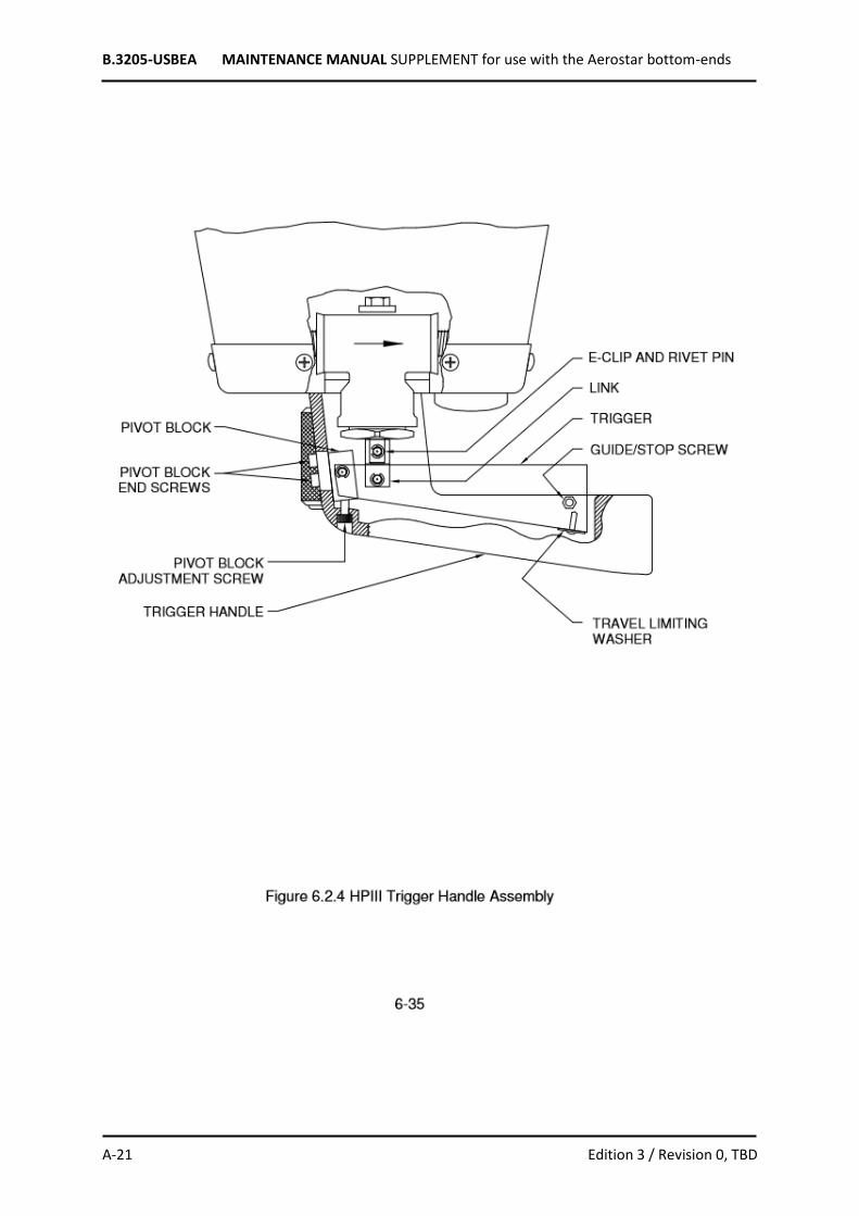
B.3205-USBEA MAINTENANCE MANUAL SUPPLEMENT for use with the Aerostar bottom-ends
A-21 Edition 3 / Revision 0, TBD
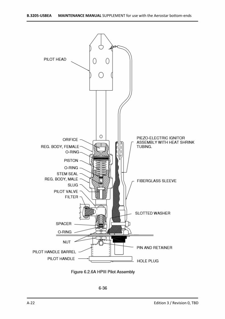
B.3205-USBEA MAINTENANCE MANUAL SUPPLEMENT for use with the Aerostar bottom-ends
A-22 Edition 3 / Revision 0, TBD
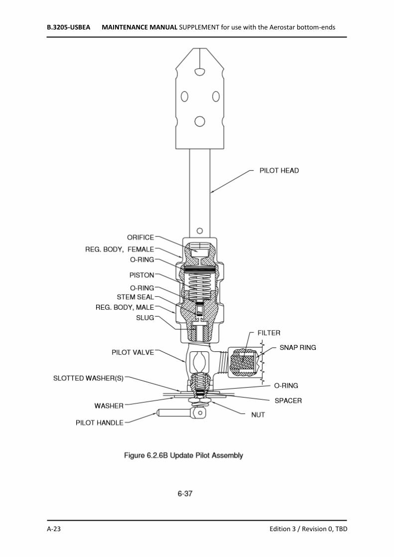
B.3205-USBEA MAINTENANCE MANUAL SUPPLEMENT for use with the Aerostar bottom-ends
A-23 Edition 3 / Revision 0, TBD

B.3205-USBEA MAINTENANCE MANUAL SUPPLEMENT for use with the Aerostar bottom-ends
A-24 Edition 3 / Revision 0, TBD
B.3205-USBEA MAINTENANCE MANUAL SUPPLEMENT for use with the Aerostar bottom-ends
A-25 Edition 3 / Revision 0, TBD
B.3205-USBEA MAINTENANCE MANUAL SUPPLEMENT for use with the Aerostar bottom-ends
A-26 Edition 3 / Revision 0, TBD
B.3205-USBEA MAINTENANCE MANUAL SUPPLEMENT for use with the Aerostar bottom-ends
A-27 Edition 3 / Revision 0, TBD
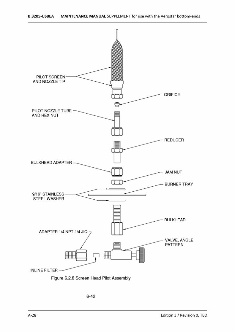
B.3205-USBEA MAINTENANCE MANUAL SUPPLEMENT for use with the Aerostar bottom-ends
A-28 Edition 3 / Revision 0, TBD

B.3205-USBEA MAINTENANCE MANUAL SUPPLEMENT for use with the Aerostar bottom-ends
A-29 Edition 3 / Revision 0, TBD

B.3205-USBEA MAINTENANCE MANUAL SUPPLEMENT for use with the Aerostar bottom-ends
A-30 Edition 3 / Revision 0, TBD

B.3205-USBEA MAINTENANCE MANUAL SUPPLEMENT for use with the Aerostar bottom-ends
A-31 Edition 3 / Revision 0, TBD

B.3205-USBEA MAINTENANCE MANUAL SUPPLEMENT for use with the Aerostar bottom-ends
A-32 Edition 3 / Revision 0, TBD
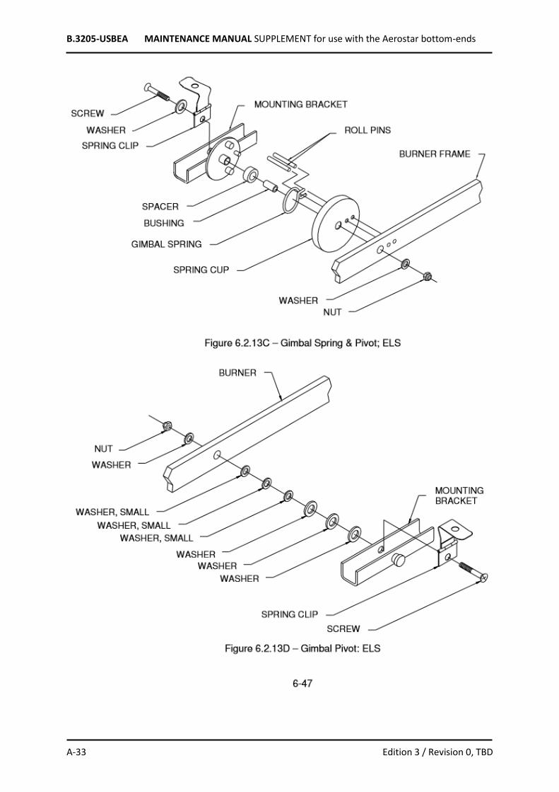
B.3205-USBEA MAINTENANCE MANUAL SUPPLEMENT for use with the Aerostar bottom-ends
A-33 Edition 3 / Revision 0, TBD

B.3205-USBEA MAINTENANCE MANUAL SUPPLEMENT for use with the Aerostar bottom-ends
A-34 Edition 3 / Revision 0, TBD

B.3205-USBEA MAINTENANCE MANUAL SUPPLEMENT for use with the Aerostar bottom-ends
A-35 Edition 3 / Revision 0, TBD

B.3205-USBEA MAINTENANCE MANUAL SUPPLEMENT for use with the Aerostar bottom-ends
A-36 Edition 3 / Revision 0, TBD

B.3205-USBEA MAINTENANCE MANUAL SUPPLEMENT for use with the Aerostar bottom-ends
A-37 Edition 3 / Revision 0, TBD

B.3205-USBEA MAINTENANCE MANUAL SUPPLEMENT for use with the Aerostar bottom-ends
A-38 Edition 3 / Revision 0, TBD

B.3205-USBEA MAINTENANCE MANUAL SUPPLEMENT for use with the Aerostar bottom-ends
A-39 Edition 3 / Revision 0, TBD
B.3205-USBEA MAINTENANCE MANUAL SUPPLEMENT for use with the Aerostar bottom-ends
A-40 Edition 3 / Revision 0, TBD

B.3205-USBEA MAINTENANCE MANUAL SUPPLEMENT for use with the Aerostar bottom-ends
A-41 Edition 3 / Revision 0, TBD
APPENDIX 5 – 100 HOUR/ANNUAL INSPECTION CHECKLIST
Burner Systems Initial Appropriate Boxes
Item Inspect For Passed Failed
Maint. Performed
Repaired Replaced
Burner Assembly General Integrity
Blast Valve Servicing Replace O-Ring And Copper Gasket Lubricate With Krytox
Blast Valve Operation Proper Operation And No Leaks
HPIII Trigger Assy. Smooth Operation
Metering Valve Proper Operation, No Leaks
Valve Stem Straight
Packing Nut Tight
HPII Update Pilot, HPIII Vapor Convertor Serviced
Pilot Light Orifice Removed, Cleaned, Inspected for Damage and Orifice Checked With .011 Go Gauge
Proper Operation
Liquid Pilot Light Valve Servicing
Proper Operation
Lubricate Handle
Pilot Light
(Screen Head Style)
Proper Operation
Vapor Pilot Light Valve Servicing
Check Valve Stem Packing Nut
Burner Fitting Integrity, No Leaks
Pressure Gauge Proper Operation, No Leaks
Burner Operation Proper Flame Alignment,
Proper Operation
Gimbal Proper Operation
Burner W/Elec. Blast
Battery
Power Cables & Connections
Proper Operation
Verify Charge
Damage
Burner W/Elec. Ignition Proper Operation
Battery Verify Charge
Power Cables & Connections Damage
Piezo Electric Igniter Proper Operation - Adjust Electrode
Clean Or Replace
Glow Valve Proper Operation
Handle Free From Damage
Nozzle Bracket Loose, Heat Damage
Nozzle Orifice Unobstructed
Pilot Tube Adjustment
Compliance With All Applicable Service Bulletins And Airworthiness Directives
Notes:
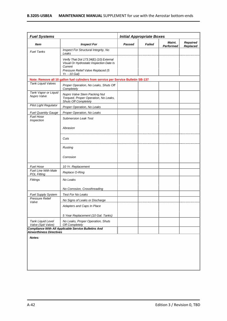
B.3205-USBEA MAINTENANCE MANUAL SUPPLEMENT for use with the Aerostar bottom-ends
A-42 Edition 3 / Revision 0, TBD
Fuel Systems Initial Appropriate Boxes
Item Inspect For Passed Failed Maint.
Performed Repaired Replaced
Fuel Tanks Inspect For Structural Integrity, No Leaks
Verify That Dot 173.34(E) (10) External Visual Or Hydrostatic Inspection Date Is Current
Pressure Relief Valve Replaced (5 Yr. - 10 Gal)
Note: Remove all 10 gallon fuel cylinders from service per Service Bulletin SB-137
Tank Liquid Valves Proper Operation, No Leaks, Shuts Off Completely
Tank Vapor or Liquid Nupro Valve
Nupro Valve Stem Packing Nut Torqued, Proper Operation, No Leaks, Shuts Off Completely
Pilot Light Regulator Proper Operation, No Leaks
Fuel Quantity Gauge Proper Operation, No Leaks
Fuel Hose Inspection
Submersion Leak Test
Abrasion
Cuts
Rusting
Corrosion
Fuel Hose 10 Yr. Replacement
Fuel Line With Male POL Fitting
Replace O-Ring
Fittings No Leaks
No Corrosion, Crossthreading
Fuel Supply System Test For No Leaks
Pressure Relief Valve
No Signs of Leaks or Discharge
Adapters and Caps In Place
5 Year Replacement (10 Gal. Tanks)
Tank Liquid Level Valve (Spit Valve)
No Leaks, Proper Operation, Shuts Off Completely
Compliance With All Applicable Service Bulletins And Airworthiness Directives
Notes:
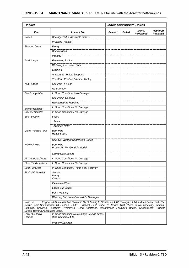
B.3205-USBEA MAINTENANCE MANUAL SUPPLEMENT for use with the Aerostar bottom-ends
A-43 Edition 3 / Revision 0, TBD
Basket Initial Appropriate Boxes
Item Inspect For Passed Failed Maint.
Performed Repaired Replaced
Rattan Damage Within Allowable Limits
Previous Repairs
Plywood floors Decay
Delamination
Integrity
Tank Straps Fasteners, Buckles
Webbing Abrasions, Cuts
Stitching
Anchors & Vertical Supports
Top Strap Position (Vertical Tanks)
Tank Shoes Secured To Floor
No Damage
Fire Extinguisher In Good Condition / No Damage
Secured In Gondola
Recharged As Required
Interior Handles In Good Condition / No Damage
Exterior Handles In Good Condition / No Damage
Scuff Leather Loose
Tears
Abraded Holes
Quick Release Pins Bent Pins Heads Loose
Removal Without Depressing Button
Wirelock Pins Bent Pins Proper Pin For Gondola Model
Spring Gate Secure
Aircraft Bolts / Nuts In Good Condition / No Damage
Floor /Skid Hardware In Good Condition / No Damage
Seat Hardware In Good Condition / Holds Seat Securely
Skids (All Models) Secure Decay
Cracks
Excessive Wear
Loose Butt Joints
Bolts Wearing
Weaving Substrate Cracked Or Damaged
Note : ٭ Inspect All Aluminum And Stainless Steel Tubing In Sections 5.4.12 Through 5.4.14 In Accordance With The Details And Specification Of Section 5.4.11. Inspect Each Tube To Insure That There Is No Cracking, Kinking, Buckling, Collapse, Localized Overstress, Deep Scratches, Uncontrolled Localized Bends, Uncontrolled Gradual Bends, Beyond Acceptable Limits.
Lower Gondola Frames
In Good Condition No Damage Beyond Limits (See Section 5.4.11) Properly Secured

B.3205-USBEA MAINTENANCE MANUAL SUPPLEMENT for use with the Aerostar bottom-ends
A-44 Edition 3 / Revision 0, TBD
Basket (continued) Initial Appropriate Boxes
Item Inspect For Passed Failed Maint.
Performed Repaired Replaced
Lower Frame / Superstructure Interface (All Models)
No Oversized Holes In Tubing
Holes Properly Aligned
Interface Pin Removed & Inspected
Over-sleeves Removed & Inspected
Quick Pin Keeper Installed (If Needed0
All Hardware In Good Condition And Properly Tightened
Superstructures (All Models)
In Good Condition No Damage Beyond Limits (See Section 5.4.11 - Appendix)
All Hardware Secure And In Good Condition
Burner Block Alignment
4-Point Aluminum Lower Load Blocks Inspect For Damage
Verify SB# 133 Compliance (Redundancy Cable)
4-Point Load Blocks Secure / No Damage
Burner Block (4-Point & AFX)
Secure / No Damage / Proper Alignment
2-Point Burner / Load Block
Secure / No Damage / Proper Alignment
RB Ride Gondolas
Side-Rail Frame In Good Condition
Welded And Clamped Connections
Interior Passenger Pads / Dividers
Entry / Exit Steps
RB6, RB8, RB12 Secondary Lower Frames
Pilot Compartment /Floor / Spacers
AFX Top Frame Tubes
Bends
Cracks
Damage
AFX Load Fittings Main Blocks
Socket Tubes
Lugs
AFX Carabiners Smooth Operation
Excessive Wear
AFX Support Rods
Surface Damage
Bends
Heat Damage
AFX Leather Cover
“Hinge” Damage
Webbing Stitching Intact
AFX Lower Frame Rod Socket
Cracks
Bends
Hole Distortion
AFX Stabilizer Brace
Secure

B.3205-USBEA MAINTENANCE MANUAL SUPPLEMENT for use with the Aerostar bottom-ends
A-45 Edition 3 / Revision 0, TBD
Basket (continued) Initial Appropriate Boxes
Item Inspect For Passed Failed Maint.
Performed Repaired Replaced
AFX Cables (Upper And Lower)
Broken Srands
Lower AFX Cable Service Letter #112 Compliance
AFX Hardware Secure / Undamaged
Compliance With All Applicable Service Bulletins And Airworthiness Directives
Notes:

B.3205-USBEA MAINTENANCE MANUAL SUPPLEMENT for use with the Aerostar bottom-ends
A-46 Edition 3 / Revision 0, TBD
SECTION 10 – SUPPLEMENTS List of applicable Service Bulletins:
(All service bulletins can be found on www.ravenaerostar.com)
SB-101 (1974) -- Horizontal Tank Strap Assembly
Straight-type strap fittings needed to be reinforced with a safety cable.
SB-102 (1975) -- Rego Blast Valves
Some Rego valves on 4-barrel burner assemblies were not completely closing when their pull cable
was released, so the nylon washer under the handle was replaced with a thinner one.
SB-103 (8/19/75) -- Warning Signs
Installation of signs on fuel tanks and precaution against filling tanks in the basket, especially with an
open valve on the liquid level gauge in the Rally RX-6.
SB-108 (6/13/78) -- Load Fitting Wear
Inspections of Rally RX-6 baskets with frequent or long transportation with load fitting attached for
aluminum superstructure wear and deformation.
SB-109 (3/19/79) -- Electric Ignition Modification
An S-55A and S-60A with plug-in instrument panel could present a hazard if the electric blast valve
cord's plug is inserted into its instrument panel jack with the power on, thus momentarily activating
the blast valve.
SB-110 (4/13/79) -- Electric Blast System Instrument Console
Potential sluggish or intermittent operation of the electric blast valve if detachable jack-plug for push-
button cord is connected and instrument panel's latch is engaged, so the panel chassis completes a
circuit to the battery.
SB-113 (11/24/81) -- Push-Checks in HP-II Burner
Installation of push-checks in all HP-II burner pressure gauges to prevent melting of a solder connection
and causing a hazardous leak.
SB-114 (7/15/83) -- Pilot Light Valve
Precaution for packing nut on valve stem of vapor pilot light valve which can be loosened in service
and cause severe propane leak.
SB-117 (6/25/84) -- Classic Stretch Wicker Baskets
Possible breakage of the vertical canes directly below the step at the skid interface forced installation
of a reinforcement plate.
SB-118 (8/28/85) -- O-ring Replacement
Possibility of incorrect O-rings causing the blast valve stem to leak and forcing the replacement of O-
rings in some systems.
SB-120 (5/15/86) -- Faulty Fuel Hose
After some leaks were experienced, Aeroquip fuel hoses were suspected of being faulty and required
return to the factory for inspection, analysis, and reconstruction as required. (3Q84 and 4Q84.)

B.3205-USBEA MAINTENANCE MANUAL SUPPLEMENT for use with the Aerostar bottom-ends
A-47 Edition 3 / Revision 0, TBD
SB-123A (8/28/89) -- AFT Cables
All cables using the Web Davis fittings are affected except those tangs shown in the diagram with .45"
holes in both ends do not apply.
SB-124 (7/19/89) -- All AFT Cables Proper Care and Handling
Applicable to all Aerostar systems with AFT suspension.
SB-125 (11/1/88) -- All AFT Cables
A) Inspection Procedures,
B) Approved Maintenance Procedures. Applicable to all Aerostar systems with AFT suspension.
SB-126 (7/25/90) -- All 2-pt AFT Cable Systems
Replacement of load fittings.
SB-127 (7/25/90) -- AFT Rally Load Fitting
Replace with Stainless Steel cables at next annual inspection.
SB-129 (11/28/90)
Undetectable premature strength loss in AFT suspension cables.
SB-130 (2/20/92)
Replacement of aluminum support tubes on Classic Limited Stretch or Classic Limited baskets.
SB-131 (10/01/92)
Replacement of Gimbal spring plate and shaft on "Zone Five" burner.
SB-132 (8/12/93)
Aeroquip hose recall 1992 dating.
SB-133 (8/23/94)
Installation of cable redundancy kits with 4-point aluminum superstructures in Classic, Classic Limited
and Classic Limited Stretch baskets.
SB-134 (11/14/94)
Installation of oversleeves on interface pins in all Classic VIII (RB5), Classic IX (RB6) and Classic X (RB8)
baskets.
SB-135 (7/15/96)
Rego 9107 Cylinder Valves and Valve Bonnet Replacement in REGO 9109 Series.
SB-136 (1/28/00)
Installation of stainless-steel spring latch on all Aurora style HP3S burner assemblies.
SB-137 (7/15/03)
Remove all 10-gallon aluminum fuel cylinders from service immediately.
SB-138 (8/10/11)
Suspected faulty fuel hose (PARKER)

B.3205-USBEA MAINTENANCE MANUAL SUPPLEMENT for use with the Aerostar bottom-ends
A-48 Edition 3 / Revision 0, TBD
List of applicable Maintenance Bulletins: (All maintenance bulletins can be found on www.ravenaerostar.com)
Maintenance Bulletin 08 05 001
Inspection of pilot light orifice (HP2-update and HP3 burners)
Maintenance Bulletin 06 11 002
Rework and repair of pilot light vapor converter (HP2-update and HP3 burners)

B.3205-USBEA MAINTENANCE MANUAL SUPPLEMENT for use with the Aerostar bottom-ends
A-49 Edition 3 / Revision 0, TBD
LET US HELP YOU!
In case that you have any suggestion, difficulty, problem or comment, please contact our technical
department at:
+420 545 422 638
BALÓNY KUBÍČEK spol. s r. o. e-mail: [email protected] • www.kubicekballoons.eu Seat: Brno
61400 • Jarní 2a • Czech Republic tel.: +420 545 422 620, • fax: +420 545 422 621
© Copyright BALÓNY KUBÍČEK spol. s r.o. 2018