Magnetization switching modes in nanopillar spin valve under the external field
8
SCIENCE CHINA Physics, Mechanics & Astronomy © Science China Press and Springer-Verlag Berlin Heidelberg 2011 phys.scichina.com www.springerlink.com *Corresponding author (email: [email protected]) • Research Paper • July 2011 Vol.54 No.7: 1227–1234 Special Topic: Magnetic Materials at Nano-scale doi: 10.1007/s11433-011-4313-1 Magnetization switching modes in nanopillar spin valve under the external field HUANG HouBing 1 , MA XingQiao 1* , YUE Tao 1 , XIAO ZhiHua 1 , SHI SanQiang 3 & CHEN LongQing 2 1 Department of Physics, University of Science and Technology Beijing, Beijing 100083, China; 2 Department of Materials Science and Engineering, The Pennsylvania State University, University Park, PA 16802, USA; 3 Department of Mechanical Engineering, The Hong Kong Polytechnic University, Hung Hom, Kowloon, Hong Kong, China Received December 15, 2010; accepted February 28, 2011; published online May 24, 2011 The current-induced magnetic switching is studied in Co/Cu/Co nanopillar with an in-plane magnetization traversed under the perpendicular-to-plane external field. Magnetization switching is found to take place when the current density exceeds a threshold. By analyzing precessional trajectories, evolutions of domain walls and magnetization switching times under the perpendicular magnetic field, there are two different magnetization switching modes: nucleation and domain wall motion re- versal; uniform magnetization reversal. The first mode occurs at lower current density, which is realized by the formation of the reversal nucleus and domain wall motion; while the second mode occurs through complete magnetization reversal at higher current density. Furthermore, the switching time reduces as the spin-polarized current density increases, which can also be grouped into two reversal modes. current-induced nanopillar, spin transfer torque, magnetization switching, domain wall motion reversal, uniform mag- netization reversal PACS: 72.25.Pn 1 Introduction A torque, called spin transfer torque (STT) [1,2], is exerted on the local magnetic moments of a ferromagnet when a spin-polarized current is injected into a ferromagnetic thin film. The origin of STT is the “s-d” exchange interactions between the spin moments of the conduction electrons and the local magnetic moments of a ferromagnet, which con- sequently leads to a reversal or precession of the magnetic moments. The effects of STT on driving magnetization switching have been verified by experimental and theoreti- cal studies in a variety of nanostructures [3–7]. Depending on the direction of the current, STT can either force the free layer into parallel or antiparallel alignment compared to the fixed layer when STT is strong enough to overcome the coercive field of the free layer. Furthermore, when an ex- ternal magnetic field is applied, the effect of STT leads to the excitation of spin wave precessional modes in the free layer [8–11]. One key to memory applications is the reduc- tion of the current required to reverse the magnetization of the free layer and the shortening of the switching time while maintaining thermal stability. There has been a range of approaches to lower the critical currents [7,12–15]. One of the most crucial requirements for lowering critical currents is the clear description of the process of the magnetization switching. We have investigated the magnetization dynam- ics of Co/Cu/Co nanoscale spin valve at various current densities by micro-magnetic simulations and illustrated the different dynamic modes when zero field is applied [16,17]. Guo et al. [18] reported the magnetization dynamics of a
-
Upload
independent -
Category
Documents
-
view
0 -
download
0
Transcript of Magnetization switching modes in nanopillar spin valve under the external field
SCIENCE CHINA Physics, Mechanics & Astronomy
© Science China Press and Springer-Verlag Berlin Heidelberg 2011 phys.scichina.com www.springerlink.com
*Corresponding author (email: [email protected])
• Research Paper • July 2011 Vol.54 No.7: 1227–1234
Special Topic: Magnetic Materials at Nano-scale doi: 10.1007/s11433-011-4313-1
Magnetization switching modes in nanopillar spin valve under the external field
HUANG HouBing1, MA XingQiao1*, YUE Tao1, XIAO ZhiHua1, SHI SanQiang3 & CHEN LongQing2
1 Department of Physics, University of Science and Technology Beijing, Beijing 100083, China; 2 Department of Materials Science and Engineering, The Pennsylvania State University, University Park, PA 16802, USA;
3 Department of Mechanical Engineering, The Hong Kong Polytechnic University, Hung Hom, Kowloon, Hong Kong, China
Received December 15, 2010; accepted February 28, 2011; published online May 24, 2011
The current-induced magnetic switching is studied in Co/Cu/Co nanopillar with an in-plane magnetization traversed under the perpendicular-to-plane external field. Magnetization switching is found to take place when the current density exceeds a threshold. By analyzing precessional trajectories, evolutions of domain walls and magnetization switching times under the perpendicular magnetic field, there are two different magnetization switching modes: nucleation and domain wall motion re-versal; uniform magnetization reversal. The first mode occurs at lower current density, which is realized by the formation of the reversal nucleus and domain wall motion; while the second mode occurs through complete magnetization reversal at higher current density. Furthermore, the switching time reduces as the spin-polarized current density increases, which can also be grouped into two reversal modes.
current-induced nanopillar, spin transfer torque, magnetization switching, domain wall motion reversal, uniform mag-netization reversal
PACS: 72.25.Pn
1 Introduction
A torque, called spin transfer torque (STT) [1,2], is exerted on the local magnetic moments of a ferromagnet when a spin-polarized current is injected into a ferromagnetic thin film. The origin of STT is the “s-d” exchange interactions between the spin moments of the conduction electrons and the local magnetic moments of a ferromagnet, which con-sequently leads to a reversal or precession of the magnetic moments. The effects of STT on driving magnetization switching have been verified by experimental and theoreti-cal studies in a variety of nanostructures [3–7]. Depending on the direction of the current, STT can either force the free layer into parallel or antiparallel alignment compared to the
fixed layer when STT is strong enough to overcome the coercive field of the free layer. Furthermore, when an ex-ternal magnetic field is applied, the effect of STT leads to the excitation of spin wave precessional modes in the free layer [8–11]. One key to memory applications is the reduc-tion of the current required to reverse the magnetization of the free layer and the shortening of the switching time while maintaining thermal stability. There has been a range of approaches to lower the critical currents [7,12–15]. One of the most crucial requirements for lowering critical currents is the clear description of the process of the magnetization switching. We have investigated the magnetization dynam-ics of Co/Cu/Co nanoscale spin valve at various current densities by micro-magnetic simulations and illustrated the different dynamic modes when zero field is applied [16,17]. Guo et al. [18] reported the magnetization dynamics of a

1228 Huang H B, et al. Sci China Phys Mech Astron July (2011) Vol. 54 No. 7
pseudo-spin-valve structure with in-plane anisotropy, which is induced by the passage of a perpendicular-to-plane spin-polarized current. Their micro-magnetic simulation results reveal two magnetization excitation modes: complete magnetization reversal and persistent spin precession. Lehndorff et al. [19] experimentally and theoretically stud-ied current-driven high frequency excitations of spin torque nano-oscillators (STNOs) for two fundamental magnetiza-tion states of the free layer, namely, vortex state and uni-form in-plane magnetization. Higher agility, wider tuning range, and higher output power are all advantageous for the application of the vortex state in STNOs. Nikonov et al. [20] showed magnetization projections versus time and the tra-jectory of magnetization for collinear polarization switching, 90° in-plane polarization, 135° in-plane polarization and perpendicular out-of-plane polarization. They demonstrated that the short-pulse precessional switching with perpen-dicularly polarized current requires a shorter time and smaller energy than the switching with collinear in-plane spin polarization. However, up till now, few papers depict-ing the domain structure evolution in the magnetization re-versal under the Slonczewski torque are found. Therefore, we describe the different switching modes and domain evo-lution in the various current densities. In addition, we also focus on the relation between the switching time and current density, which might provide guidance for the design of magnetic random access memory (MRAM) devices.
In this paper, the current-induced free layer magnetiza-tion switching is investigated under the influence of a spin-polarized current and the perpendicular-to-plan applied field using the modified Landau-Lifshitz-Gilbert (LLG) equation. Our simulation shows that the magnetization switching at perpendicular magnetic field, like at zero field, has two reversal modes according to the value of current density: (a) nucleation and domain wall motion reversal and (b) uniform magnetization reversal. The first of the mag-netization reversals is by domain wall motion, which is by way of the reversal nucleus formation and domain wall propagation at lower current density. The second is through complete magnetization reversal by STT input at higher current density. In addition, it is found by studying the switching time as a function of current density that the magnetization reversal is faster at the perpendicular external field than that at no external field.
2 Model description
The numerical model taking into account the effect of the spin-polarized current was used to perform the three-di- mensional (3D) simulations. The modified LLG equation can be written as [1]:
eff eff
d( )
d st M
M
M H M M H
B2 3
s
B2 2
s
2( , ) ( )
(1 )
2( , )( )
(1 )
Jg
edM
Jg
edM
M P M M P
M P M P
(1)
where M and P are the magnetization vectors of the free layer and pinned layer. The first term on the right-hand side of eq. (1) is a conventional magnetic torque with gyromag-netic ratio , where ′=/(1+2), is the Gilbert damping constant. The second torque is determined by an effective field derived from the total energy E of the free layer:
eff0
1.
E
M
H (2)
Regarding the STT term, μB, J, d, e, Ms are the Bohr magneton, the current density, the thickness of the free layer, the electron charge and the saturation magnetization, re-spectively. The scalar function is given by [1]
3 2 3/2 1( , ) [ 4 (1 ) (3 / ) / 4 ] .sg M M P M P (3)
The effective field includes the anisotropy field, the de-magnetization field, the external field and the exchange field, Heff=Hex+Hanis+Hdem+Hext. The classical Oersted field is generated by conduction electrons scales as 1/r, where r is the lateral size of the free layer, while the STT scales as 1/r2. Therefore, for small r like a nanopillar with the cross- section of 64×64 nm2, the STT dominates over the classical Oersted field. The Oersted field is neglected in this case [21] and the effect of thermal activation is not considered in this work. We employ a Cartesian coordinate system in which the x-axis and y-axis are parallel to the film plane while the z-axis is perpendicular to it. The direction of P points to the x-axis. The free layer is discrete in computa-tional cells of 2×2×2 nm2, and the time step used is 14.875 fs and the current is considered positive for a flow of elec-trons from the fixed layer toward the free layer.
The magnetic parameters are the saturation magnetiza-tion Ms=1.446×10⁶ A/m, the exchange constant A=2.0×10¹¹
J/m and the Gilbert damping parameter =0.01 [16,17]. The initial states of the free layer, the magnetization, devi-ate from the parallel or antiparallel configuration. If M is parallel or antiparallel to P (=0° or =180°), the STT is zero as M×P =0. In our simulations, we assumed =0.1° (or =179.9°) for parallel (or antiparallel) configurations at the beginning. The external field is perpendicular to the plane along the z-axis direction, whereas the dynamic simulation is performed by numerically solving the modified time- dependent LLG equation using the Gauss-Seidel projection method [22–24].
3 Results and discussion
The temporal evolutions of three magnetization components
Huang H B, et al. Sci China Phys Mech Astron July (2011) Vol. 54 No. 7 1229
are presented in the threshold current density. Under per-pendicular-to-plane external field, the different magnetiza-tion switching modes, which are determined by their char-acteristics and the applied current densities, are shown. Then, we discuss the relationships between switching time and current density.
3.1 Critical switching current
In the regions of ∞<J10.0×107 A/cm2 and 5.5×10⁷
A/cm2J<∞, the magnetization can be switched by STT. In this state, the magnetization can be switched back and forth between two stable states: parallel or antiparallel configura-tions. The threshold current densities are Jc1
APS PS→ =5.5×10⁷
A/cm2 from antiparallel state (APS) to parallel state (PS) and Jc1
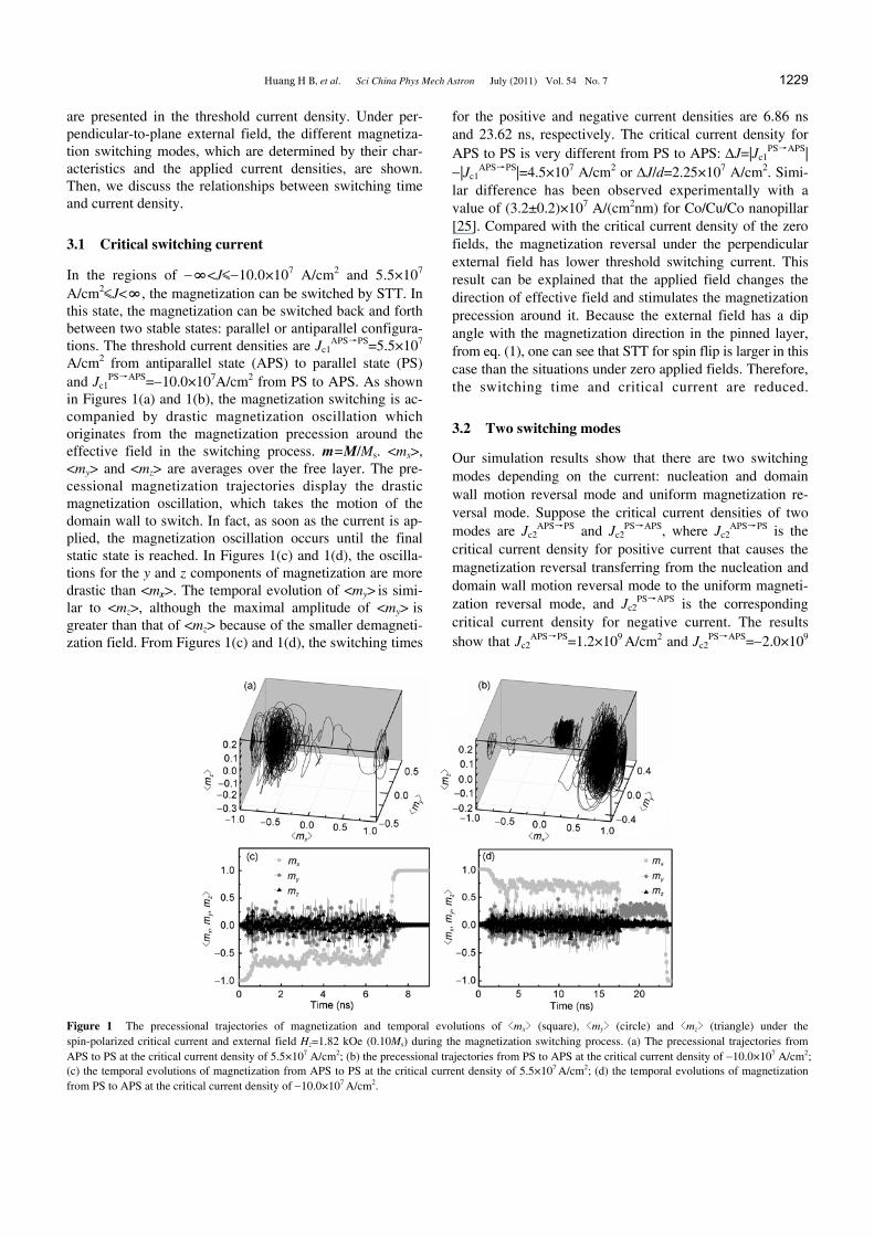
PS APS→ =10.0×10⁷A/cm2 from PS to APS. As shown in Figures 1(a) and 1(b), the magnetization switching is ac-companied by drastic magnetization oscillation which originates from the magnetization precession around the effective field in the switching process. m=M/Ms. <mx>, <my> and <mz> are averages over the free layer. The pre-cessional magnetization trajectories display the drastic magnetization oscillation, which takes the motion of the domain wall to switch. In fact, as soon as the current is ap-plied, the magnetization oscillation occurs until the final static state is reached. In Figures 1(c) and 1(d), the oscilla-tions for the y and z components of magnetization are more drastic than <mx>. The temporal evolution of <my> is simi-lar to <mz>, although the maximal amplitude of <my> is greater than that of <mz> because of the smaller demagneti-zation field. From Figures 1(c) and 1(d), the switching times
for the positive and negative current densities are 6.86 ns and 23.62 ns, respectively. The critical current density for APS to PS is very different from PS to APS: J=|Jc1
PS APS→ | |Jc1
APS PS→ |=4.5×10⁷ A/cm2 or J/d=2.25×107 A/cm2. Simi-lar difference has been observed experimentally with a value of (3.2±0.2)×107 A/(cm2nm) for Co/Cu/Co nanopillar [25]. Compared with the critical current density of the zero fields, the magnetization reversal under the perpendicular external field has lower threshold switching current. This result can be explained that the applied field changes the direction of effective field and stimulates the magnetization precession around it. Because the external field has a dip angle with the magnetization direction in the pinned layer, from eq. (1), one can see that STT for spin flip is larger in this case than the situations under zero applied fields. Therefore, the switching time and critical current are reduced.
3.2 Two switching modes
Our simulation results show that there are two switching modes depending on the current: nucleation and domain wall motion reversal mode and uniform magnetization re-versal mode. Suppose the critical current densities of two modes are Jc2
APS PS→ and Jc2PS APS→ , where Jc2
APS PS→ is the critical current density for positive current that causes the magnetization reversal transferring from the nucleation and domain wall motion reversal mode to the uniform magneti-zation reversal mode, and Jc2
PS AP→ S is the corresponding critical current density for negative current. The results show that Jc2
APS PS→ =1.2×10⁹ A/cm2 and Jc2PS APS→ =2.0×10⁹
Figure 1 The precessional trajectories of magnetization and temporal evolutions of <mx> (square), <my> (circle) and <mz> (triangle) under the spin-polarized critical current and external field Hz=1.82 kOe (0.10Ms) during the magnetization switching process. (a) The precessional trajectories from APS to PS at the critical current density of 5.5×10⁷ A/cm2; (b) the precessional trajectories from PS to APS at the critical current density of 10.0×10⁷ A/cm2; (c) the temporal evolutions of magnetization from APS to PS at the critical current density of 5.5×10⁷ A/cm2; (d) the temporal evolutions of magnetization from PS to APS at the critical current density of 10.0×10⁷ A/cm2.
1230 Huang H B, et al. Sci China Phys Mech Astron July (2011) Vol. 54 No. 7
A/cm2. In the regions of Jc1APS PS→ J<Jc2
APS PS→ and |Jc1
PS APS→ ||J|< |Jc2PS APS→ |, the magnetization is reversed by
means of moving the domain wall, while the uniform mag-netization reversal will happen in the regions of JJc2
APS PS→ and |J||Jc2
PS APS→ |. The two switching modes do not have a clear boundary, it gradually changes from one to the other in a region.
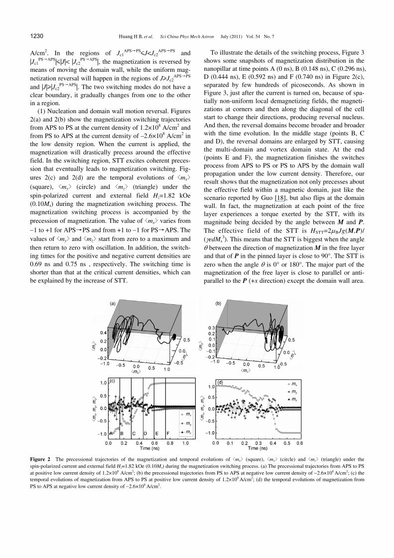
(1) Nucleation and domain wall motion reversal. Figures 2(a) and 2(b) show the magnetization switching trajectories from APS to PS at the current density of 1.2×10⁸ A/cm2 and from PS to APS at the current density of –2.6×10⁸ A/cm2 in the low density region. When the current is applied, the magnetization will drastically precess around the effective field. In the switching region, STT excites coherent preces-sion that eventually leads to magnetization switching. Fig-ures 2(c) and 2(d) are the temporal evolutions of <mx>
(square), <my> (circle) and <mz> (triangle) under the spin-polarized current and external field Hz=1.82 kOe (0.10Ms) during the magnetization switching process. The magnetization switching process is accompanied by the precession of magnetization. The value of <mx> varies from
1 to +1 for APS PS and from +1 to → 1 for PS APS. The →
values of <my> and <mz> start from zero to a maximum and then return to zero with oscillation. In addition, the switch-ing times for the positive and negative current densities are 0.69 ns and 0.75 ns , respectively. The switching time is shorter than that at the critical current densities, which can be explained by the increase of STT.
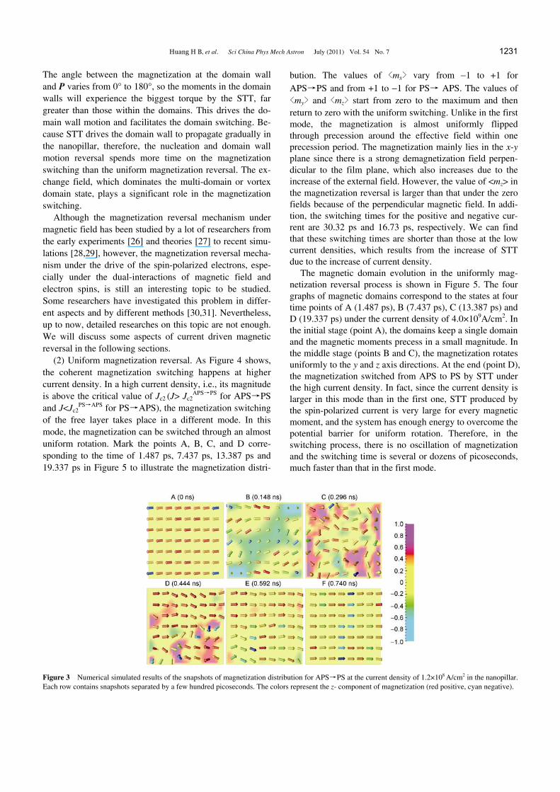
To illustrate the details of the switching process, Figure 3 shows some snapshots of magnetization distribution in the nanopillar at time points A (0 ns), B (0.148 ns), C (0.296 ns), D (0.444 ns), E (0.592 ns) and F (0.740 ns) in Figure 2(c), separated by few hundreds of picoseconds. As shown in Figure 3, just after the current is turned on, because of spa-tially non-uniform local demagnetizing fields, the magneti-zations at corners and then along the diagonal of the cell start to change their directions, producing reversal nucleus. And then, the reversal domains become broader and broader with the time evolution. In the middle stage (points B, C and D), the reversal domains are enlarged by STT, causing the multi-domain and vortex domain state. At the end (points E and F), the magnetization finishes the switches process from APS to PS or PS to APS by the domain wall propagation under the low current density. Therefore, our result shows that the magnetization not only precesses about the effective field within a magnetic domain, just like the scenario reported by Guo [18], but also flips at the domain wall. In fact, the magnetization at each point of the free layer experiences a torque exerted by the STT, with its magnitude being decided by the angle between M and P. The effective field of the STT is HSTT=2BJg(M,P)/ (edMs
3). This means that the STT is biggest when the angle between the direction of magnetization M in the free layer and that of P in the pinned layer is close to 90°. The STT is zero when the angle is 0° or 180°. The major part of the magnetization of the free layer is close to parallel or anti-parallel to the P (+x direction) except the domain wall area.
Figure 2 The precessional trajectories of the magnetization and temporal evolutions of <mx> (square), <my> (circle) and <mz> (triangle) under the spin-polarized current and external field Hz=1.82 kOe (0.10Ms) during the magnetization switching process. (a) The precessional trajectories from APS to PS at positive low current density of 1.2×10⁸ A/cm2; (b) the precessional trajectories from PS to APS at negative low current density of 2.6×10⁸ A/cm2; (c) the temporal evolutions of magnetization from APS to PS at positive low current density of 1.2×10⁸ A/cm2; (d) the temporal evolutions of magnetization from PS to APS at negative low current density of 2.6×10⁸ A/cm2.
Huang H B, et al. Sci China Phys Mech Astron July (2011) Vol. 54 No. 7 1231
The angle between the magnetization at the domain wall and P varies from 0° to 180°, so the moments in the domain walls will experience the biggest torque by the STT, far greater than those within the domains. This drives the do-main wall motion and facilitates the domain switching. Be-cause STT drives the domain wall to propagate gradually in the nanopillar, therefore, the nucleation and domain wall motion reversal spends more time on the magnetization switching than the uniform magnetization reversal. The ex-change field, which dominates the multi-domain or vortex domain state, plays a significant role in the magnetization switching.
Although the magnetization reversal mechanism under magnetic field has been studied by a lot of researchers from the early experiments [26] and theories [27] to recent simu-lations [28,29], however, the magnetization reversal mecha-nism under the drive of the spin-polarized electrons, espe-cially under the dual-interactions of magnetic field and electron spins, is still an interesting topic to be studied. Some researchers have investigated this problem in differ-ent aspects and by different methods [30,31]. Nevertheless, up to now, detailed researches on this topic are not enough. We will discuss some aspects of current driven magnetic reversal in the following sections.
(2) Uniform magnetization reversal. As Figure 4 shows, the coherent magnetization switching happens at higher current density. In a high current density, i.e., its magnitude is above the critical value of Jc2 (J> Jc2
APS P→ S for APS P→ S and J<Jc2
PS AP→ S for PS AP→ S), the magnetization switching of the free layer takes place in a different mode. In this mode, the magnetization can be switched through an almost uniform rotation. Mark the points A, B, C, and D corre-sponding to the time of 1.487 ps, 7.437 ps, 13.387 ps and 19.337 ps in Figure 5 to illustrate the magnetization distri-
bution. The values of <mx> vary from 1 to +1 for APS P→ S and from +1 to 1 for PS→ APS. The values of <my> and <mz> start from zero to the maximum and then return to zero with the uniform switching. Unlike in the first mode, the magnetization is almost uniformly flipped through precession around the effective field within one precession period. The magnetization mainly lies in the x-y plane since there is a strong demagnetization field perpen-dicular to the film plane, which also increases due to the increase of the external field. However, the value of <mz> in the magnetization reversal is larger than that under the zero fields because of the perpendicular magnetic field. In addi-tion, the switching times for the positive and negative cur-rent are 30.32 ps and 16.73 ps, respectively. We can find that these switching times are shorter than those at the low current densities, which results from the increase of STT due to the increase of current density.
The magnetic domain evolution in the uniformly mag-netization reversal process is shown in Figure 5. The four graphs of magnetic domains correspond to the states at four time points of A (1.487 ps), B (7.437 ps), C (13.387 ps) and D (19.337 ps) under the current density of 4.0×10⁹A/cm2. In the initial stage (point A), the domains keep a single domain and the magnetic moments precess in a small magnitude. In the middle stage (points B and C), the magnetization rotates uniformly to the y and z axis directions. At the end (point D), the magnetization switched from APS to PS by STT under the high current density. In fact, since the current density is larger in this mode than in the first one, STT produced by the spin-polarized current is very large for every magnetic moment, and the system has enough energy to overcome the potential barrier for uniform rotation. Therefore, in the switching process, there is no oscillation of magnetization and the switching time is several or dozens of picoseconds, much faster than that in the first mode.
Figure 3 Numerical simulated results of the snapshots of magnetization distribution for APS PS at the current density of → 1.2×10⁸ A/cm2 in the nanopillar. Each row contains snapshots separated by a few hundred picoseconds. The colors represent the z- component of magnetization (red positive, cyan negative).

1232 Huang H B, et al. Sci China Phys Mech Astron July (2011) Vol. 54 No. 7
Figure 4 The precessional trajectories of magnetization and temporal evolutions of <mx> (square), <my> (circle) and <mz> (triangle) under the spin-polarized current and external field Hz=1.82 kOe (0.10Ms) during the magnetization switching process. (a) The precessional trajectories from APS to PS at positive high current density of 4.0×10⁹ A/cm2; (b) the precessional trajectories from PS to APS at negative high current density of 9.0×10⁹ A/cm2; (c) the temporal evolutions of magnetization from APS to PS at positive high current density of 4.0×10⁹ A/cm2; (d) the temporal evolutions of magnetization from PS to APS at negative high current density of 9.0×10⁹ A/cm2.
Figure 5 Numerical simulated results of snapshots of magnetization distribution for APS PS at the current density of → 4.0×10⁹ A/cm2 in the nanopillar. Each row contains snapshots separated by few hundreds of picoseconds. The colors represent z-component of magnetization (red positive, cyan negative).
3.3 Switching time
The increase of current density drives the magnetization precession more rapidly, which causes the reduction of the switching time. Our simulated results show that the switch-ing time, as a function of current density, is faster at a per-pendicular applied magnetic field than at zero external fields.
For a given current density above the critical value, there is a unique switching time. In Figures 6(a) and 6(b), we show the temporal evolution of <mx> under the different spin-polarized current density during the switching process. The switching time reduces as the increase of spin-polarized current density, from which one can distinguish the two reversal modes. The magnetization reversal process consists of the fast and slow switching, which correspond to nuclea-tion and domain wall motion reversal and uniform mag-netization reversal, respectively. For example, in Figures 6 (a) and 6(b), the switching time is the largest at the current density of 7.0×10⁷ A/cm2 for APS to PS and 1.4×10⁸
A/cm2 for PS to APS. Moreover, the switching times are larger than that at higher current density of 4.0×10⁹ A/cm2 for APS to PS and 3.0×10⁹
A/cm2 for PS to APS. There-fore, when JJc2
APS P→ S and J|Jc2PS→APS|, the magnetization
switching is very fast and the magnetic moments finish the flip within one precession cycle. The STT drives the mag-netization rapidly and settles in its equilibrium orientation. As shown in Figure 6, there is an overall reversal of the free magnetization from its initial orientation along the x (or x) direction to the direction of the fixed layer magnetization along the x (or x) direction. However, if the current density is lower than Jc2
APS P→ S or |Jc2PS→APS|, the magnetization
switching times are slower than the former. The free layer is reversed by means of the domain wall propagation in the nanopillar, i.e., the magnetization undergoes several cycles of precession in its switching trajectory. It should be noted that the exchange energy has an influence on the switching

Huang H B, et al. Sci China Phys Mech Astron July (2011) Vol. 54 No. 7 1233
Figure 6 (Color online) The temporal evolution of <mx> under different values of spin-polarized current during the switching process and H=1.82 kOe (0.10Ms). (a) APS PS→ ; (b) PS→APS.
when the free layer is not a single domain at lower current densities, and the switching times increase for the presence of multi-domain in the switching process.
4 Conclusions
Our systematic computer simulations of current-induced magnetization switching in Co/Cu/Co nanopillar show that under perpendicular-to-plane applied field, the critical cur-rent value is smaller than that at zero external fields. The process of magnetization switching can be grouped into two different switching modes at different current density, which are nucleation and domain wall motion reversal and uniform magnetization reversal. The first mode occurs at lower current density and presents the multi-domain or vor-tex domain structure. The magnetic moments precess within the domains around their local effective field and flip at the domain wall. The second mode is complete reversal driven by STT input in higher current density and almost has a single domain structure. Additionally, by analyzing the switching time versus the current density, the first mode corresponds to a slow switching while the second mode corresponds to a fast switching.
This work was supported by the National Natural Science Foundation of China (Grant No. 5042810).
1 Slonczewski J C. Current-driven excitation of magnetic multilayers. J Magn Magn Mater, 1996, 159: L1–L7
2 Berger L. Emission of spin waves by a magnetic multilayer traversed by a current. Phys Rev B, 1996, 54: 9353–9358
3 Urazhdin S, Birge N O, Pratt W P, et al. Switching current versus magnetoresistance in magnetic multilayer nanopillars. Appl Phys Lett, 2004, 84: 1516–1518
4 Fuchs G D, Emley N C, Krivorotov I N, et al. Spin-transfer effects in nanoscale magnetic tunnel junctions. Appl Phys Lett, 2004, 85: 1205–1207
5 Manschot J, Brataas A, Bauer G E W. Reducing the critical switching current in nanoscale spin valves. Appl Phys Lett, 2004, 85: 3250– 3252
6 Jiang Y, Nozaki T, Abe S, et al. Substantial reduction of critical cur-
rent for magnetization switching in an exchange-biased spin valve. Nat Mater, 2004, 3: 361–364
7 Mangin S, Ravelosona D, Katine J A, et al. Current-induced mag-netization reversal in nanopillars with perpendicular anisotropy. Nat Mater, 2006, 5: 210–215
8 Tsoi M, Jansen A G M, Bass J, et al. Excitation of a magnetic multi-layer by an electric current. Phys Rev Lett, 1998, 80: 4281–4284
9 Myers E B, Ralph D C, Katine J A, et al. Current-induced switching of domains in magnetic multilayer devices. Science, 1999, 285: 867–870
10 Katine J A, Albert F J, Buhrman R A, et al. Current-driven magneti-zation reversal and spin-wave excitations in Co/Cu/Co pillars. Phys Rev Lett, 2000, 84: 3149–3152
11 Rezende S M, De Aguiar F M, Lucena M A, et al. Magnon excitation by spin injection in thin Fe/Cr/Fe films. Phys Rev Lett, 2000, 84: 4212–4215
12 Chiba D, Sato Y, Kita T, et al. Current-driven magnetization reversal in a ferromagnetic semiconductor (Ga,Mn)As/GaAs/(Ga,Mn) as tun-nel junction. Phys Rev Lett, 2004, 93: 216602
13 Braganca P M, Krivorotov I N, Ozatay O, et al. Reducing the critical current for short-pulse spin-transfer switching of nanomagnets. Appl Phys Lett, 2005, 87: 112507
14 Ozatay O, Gowtham P G, Tan K W, et al. Sidewall oxide effects on spin-torque- and magnetic-field-induced reversal characteristics of thin-film nanomagnets. Nat Mater, 2008, 7: 567–573
15 Diao Z, Li Z, Wang S, et al. Spin-transfer torque switching in mag-netic tunnel junctions and spin-transfer torque random access mem-ory. J Phys-Condens Matter, 2009, 19: 165209
16 Xiao Z H, Ma X Q, Wu P P, et al. Micromagnetic simulations of cur-rent-induced magnetization switching in Co∕Cu∕Co nanopillars. J Appl Phys, 2007, 102: 093907
17 Ma X Q, Xiao Z H, Wu P P, et al. Current-induced magnetization dynamics in Co∕Cu∕Co nanopillars. J Appl Phys, 2008, 103: 07B111
18 Guo J, Jalil M B A, Tan S G. Current-induced magnetization excita-tion in a pseudo-spin-valve with in-plane anisotropy. Appl Phys Lett, 2008, 92: 182103
19 Lehndorff R, Bürgler D E, Gliga S, et al. Magnetization dynamics in spin torque nano-oscillators: vortex state versus uniform state. Phys Rev B, 2009, 80: 054412
20 Nikonov D E, Bourianoff G I, Rowlands G, et al. Strategies and tol-erances of spin transfer torque switching. J Appl Phys, 2010, 107: 113910
21 Sun J Z. Spin angular momentum transfer in current-perpendicular nanomagnetic junctions. IBM J Res Dev, 2006, 50: 81–100
22 Wang X P, Garcia-Cervera C J, Weinan E. A Gauss–Seidel projec-tion method for micromagnetics simulations. J Comput Phys, 2001, 171: 357–372

1234 Huang H B, et al. Sci China Phys Mech Astron July (2011) Vol. 54 No. 7
23 Zhang J X, Chen L Q. Phase-field microelasticity theory and micro-magnetic simulations of domain structures in giant magnetostrictive materials. Acta Mater, 2005, 53: 2845–2855
24 Zhang J X, Chen L Q. Magnetic reversal of double-layer patterned nanosquares. J Appl Phys, 2005, 97: 084313
25 Albert F J, Emley N C, Myers E B, et al. Quantitative study of mag-netization reversal by spin-polarized current in magnetic multilayer nanopillars. Phys Rev Lett, 2002, 89: 226802
26 Sixtus K J, Tonks L. Propagation of large barkhausen discontinuities. Phys Rev, 1931, 37: 930–958
27 Aharoni A. Theoretical search for domain nucleation. Rev Mod Phys,
1962, 34: 227–238 28 Zhao G P, Zhao M G, Lim H S, et al. From nucleation to coercivity.
Appl Phys Lett, 2005, 87: 162513 29 Zhao G P, Wang X L. Nucleation, pinning, and coercivity in mag-
netic nanosystems: An analytical micromagnetic approach. Phys Rev B, 2006, 74: 012409
30 Shibata J, Tatara G. Effect of spin current on uniform ferromagnetism: Domain nucleation. Phys Rev Lett, 2005, 94: 076601
31 Li X, Zhang Z Z, Jin Q Y, et al. Domain nucleation mediated spin-transfer switching in magnetic nanopillars with perpendicular anisotropy. Appl Phys Lett, 2008, 92: 122502