
Google Workspace & Microsoft Office 365 coexistence overview
Upload
khangminh22Category
view
5download
0
HAL Id: hal-01937599https://hal.archives-ouvertes.fr/hal-01937599
Submitted on 5 Dec 2018
HAL is a multi-disciplinary open accessarchive for the deposit and dissemination of sci-entific research documents, whether they are pub-lished or not. The documents may come fromteaching and research institutions in France orabroad, or from public or private research centers.
L’archive ouverte pluridisciplinaire HAL, estdestinée au dépôt et à la diffusion de documentsscientifiques de niveau recherche, publiés ou non,émanant des établissements d’enseignement et derecherche français ou étrangers, des laboratoirespublics ou privés.
Magnetic order, hysteresis, and phase coexistence inmagnetoelectric LiCoPO 4
Ellen Fogh, Rasmus Toft-Petersen, E. Ressouche, Christof Niedermayer, SonjaLindahl Holm, Maciej Bartkowiak, Oleksandr Prokhnenko, Steffen Sloth,
Frederik Werner Isaksen, David Vaknin, et al.
To cite this version:Ellen Fogh, Rasmus Toft-Petersen, E. Ressouche, Christof Niedermayer, Sonja Lindahl Holm, et al..Magnetic order, hysteresis, and phase coexistence in magnetoelectric LiCoPO 4. Physical ReviewB: Condensed Matter and Materials Physics (1998-2015), American Physical Society, 2017, 96 (10),pp.104420. �10.1103/PhysRevB.96.104420�. �hal-01937599�

PHYSICAL REVIEW B 96, 104420 (2017)
Magnetic order, hysteresis, and phase coexistence in magnetoelectric LiCoPO4
Ellen Fogh,1,* Rasmus Toft-Petersen,1 Eric Ressouche,2 Christof Niedermayer,3 Sonja Lindahl Holm,3,4 Maciej Bartkowiak,5
Oleksandr Prokhnenko,5 Steffen Sloth,1 Frederik Werner Isaksen,1 David Vaknin,6 and Niels Bech Christensen1
1Department of Physics, Technical University of Denmark, DK-2800 Kongens Lyngby, Denmark2INAC-SPSMS, CEA & Universite Grenoble Alpes, 38000 Grenoble, France
3Laboratory for Neutron Scattering and Imaging, Paul Scherrer Institute, Villigen CH-5232, Switzerland4Nano-Science Center, Niels Bohr Institute, University of Copenhagen, DK-2100 Copenhagen Ø, Denmark
5Helmholtz-Zentrum Berlin für Materialien und Energie, D-14109 Berlin, Germany6Ames Laboratory and Department of Physics and Astronomy, Iowa State University, Ames, Iowa 50011, USA
(Received 10 June 2017; published 15 September 2017)
The magnetic phase diagram of magnetoelectric LiCoPO4 is established using neutron diffraction andmagnetometry in fields up to 25.9 T applied along the crystallographic b axis. For fields greater than 11.9 T, themagnetic unit cell triples in size with propagation vector Q = (0, 1
3 ,0). A magnetized elliptic cycloid is formedwith spins in the (b,c) plane and the major axis oriented along b. Such a structure allows for the magnetoelectriceffect with an electric polarization along c induced by magnetic fields applied along b. Intriguingly, additionalordering vectors Q ≈ (0, 1
4 ,0) and Q ≈ (0, 12 ,0) appear for increasing fields in the hysteresis region below the
transition field. Traces of this behavior are also observed in the magnetization. A simple model based on amean-field approach is proposed to explain these additional ordering vectors. In the field interval 20.5–21.0 T,the propagation vector Q = (0, 1
3 ,0) remains but the spins orient differently compared to the cycloid phase. Above21.0 T and up until saturation, a commensurate magnetic structure exists with a ferromagnetic component alongb and an antiferromagnetic component along c.
DOI: 10.1103/PhysRevB.96.104420
I. INTRODUCTION
The rich physics of magnetically frustrated systems, al-though studied theoretically and experimentally for half acentury [1,2], continues to attract interest in condensed matterresearch. Frustration is imposed either by the geometry of thespin lattice or by competing interactions. In either case, the sys-tem can not minimize all interaction energies simultaneously.One possible outcome is a magnetically disordered and highlydegenerate state where the system fluctuates between manydifferent configurations down to very low temperatures. In thiscase, one encounters exotic materials such as spin ices [3] andquantum spin liquids [4] displaying magnetic monopoles andspinon excitations. Alternatively, a frustrated system may findan ordered configuration in which the interaction terms in thespin Hamiltonian are not all minimized. This often brings aboutnoncollinear and/or incommensurate magnetic structures [5].In turn, these structures are closely linked to multiferroicity,magnetostriction, and magnetoelectricity [5], just to mentiona few profound curiosities of technological and fundamentalinterest. The symmetries of the nuclear and magnetic structuresgovern how the individual material properties are manifested.Finally, in combination with disorder, frustrated interactionsmay ultimately result in spin glasses where spin directions arefrozen in at random [6].
The lithium orthophosphates, LiMPO4 (M = Co, Ni, Mn,Fe), are a family of compounds with orthorhombic symmetry(space group Pnma) which all exhibit commensurate antifer-romagnetism as well as the magnetoelectric effect in theirground states [7,8]. In these materials, the coupling betweenferroelectricity and antiferromagnetism is governed by the
*Corresponding author: [email protected]
magnetic structure [8,9], the details of which are also believedto explain the effect in LiCoPO4 [10,11]. Previously it hasbeen shown that the magnetoelectric effect in LiNiPO4 isclosely related to a field-induced spin canting facilitated by theDzyaloshinskii-Moriya interaction [12]. The magnetoelectriceffect in LiCoPO4 is by far the strongest in the lithiumorthophosphate family [13] but the microscopic mechanismbehind it is yet to be understood. We also note that in additionto being exciting magnetoelectric materials, the members ofthe lithium orthophosphate family, and especially LiFePO4, areof significant scientific and technological interest as cathodematerials for batteries [14–16].
LiCoPO4 has cell parameters a = 10.20 A, b = 5.92 A,and c = 4.70 A [17] and the four magnetic Co2+ ions(S = 3
2 ) of the crystallographic unit cell form an almostface-centered structure with the position vectors r1 =(1/4 + ε,1/4,1 − δ), r2 = (3/4 + ε,1/4,1/2 + δ), r3 = (3/4− ε,3/4,δ), and r4 = (1/4 − ε,3/4,1/2 − δ) where ε =0.0286 and δ = 0.0207 [18]. The displacement ε of theions gives rise to a toroidal moment as demonstrated boththeoretically [19,20] and experimentally [21,22]. The easyaxis for the Co2+ ions is along b as deduced from magneticsusceptibility data [23] showing that LiCoPO4 is magnetizedtwice as readily along b as compared to along a andc in the paramagnetic phase. Furthermore, although thesusceptibilities along a and c are of similar magnitude, a isthe harder axis. A priori density functional theory calculationsagree with these measurements [24]. Hence, the single-ionanisotropy of the Co2+ ions is largely axial and with theeasy axis along b. Below TN = 21.6 K, LiCoPO4 ordersantiferromagnetically with spins along the easy axis in acommensurate (↑↑↓↓) arrangement [7,25]. Here, ↑ and ↓denote spin up and down, respectively, for the ion sites inforthcoming order, i.e., in the above case spins 1 and 2 are upand spins 3 and 4 are down. In addition, a small spin rotation
2469-9950/2017/96(10)/104420(10) 104420-1 ©2017 American Physical Society

ELLEN FOGH et al. PHYSICAL REVIEW B 96, 104420 (2017)
FIG. 1. Magnetic phase diagram of LiCoPO4 for fields up to25.9 T applied along b as measured by magnetization (squaresymbols) and neutron diffraction (triangular symbols). The graysymbols are from Ref. [8]. The transition fields and temperaturesare determined for increasing fields and upon cooling below 16 Tand upon heating above. The propagation vectors identified fromneutron diffraction are shown in the respective phases. The zero-fieldmagnetic unit cell with exchange interactions indicated is shown asan inset. Note that only the major spin component along b is shown(see text).
away from the b axis as well as a weak ferromagnetic momenthave been reported [10,26,27].
Pulsed-field magnetic susceptibility measurements up to29 T at liquid He temperatures show a number of phase transi-tions [28]. At ∼12 T, the magnetization jumps to a plateau of13 of its saturation value MS = 3.6 μB /Co ion. Next, at ∼22 T,it gradually increases to 2/3 MS and then finally increaseslinearly until saturation is achieved at μ0HS = 28.3 T. Themagnetolectric tensor element αab was recently probed ina pulsed-field electric polarization experiment (Pi = αijHj
where i,j = {a,b,c}, Pi is the induced electric polarizationand Hj the applied magnetic field). The measurements showthat the phase in the interval 22–28 T supports the magneto-electric effect but with considerably smaller magnetoelectriccoefficient compared to the commensurate low-field phase[29]. The intermediate phase displaying the 1
3 magnetizationplateau does not, on the other hand, exhibit the magnetoelectriceffect for the coefficient αab.
The magnetic exchange interactions of LiCoPO4 are shownin the inset of Fig. 1 together with the magnetic unit cell ofthe commensurate low-field structure. The interactions in thelithium orthophosphates are generally frustrated leading to amultitude of phases as a function of temperature and appliedmagnetic field [30–32]. The nearest-neighbor interaction Jbc isantiferromagnetic but so are Jb and Jab (terminology adoptedfrom Ref. [33]). The interactions Jc and Jac are weak and maydiffer in sign depending on the magnetic ion in question [34].
The exchange interactions are mediated via superexchangepaths such as M-O-M or M-O-P-O-M [10,11,25]. In Ref. [28],the values of Jbc, Jb, and Jc were estimated for LiCoPO4
from the transition field values using a model for the magneticstructures based on magnetization measurements exclusively.Collinear structures with moments along b and propagationvector along c were assumed in all phases. In another study,the spin wave spectrum was measured and although the fittedexchange parameters are subject to large uncertainties, theyoffer a reasonable estimate for the interactions [35,36].
In this work, we investigate the phase diagram of LiCoPO4
up to 25.9 T for magnetic fields applied along b. We presentmagnetization and neutron diffraction results for the field-induced transition at 11.9 T. These provide direct evidencethat the ordering vector of the phase with 1
3 magnetizationis Q = (0, 1
3 ,0) and the spin arrangement is a superpositionof a cycloid structure in the (b,c) plane and a ferromagneticcomponent. Furthermore, hysteresis is observed as well aspronounced differences in the way the transition occursdepending on field ramp direction. For increasing field, severalmagnetic Bragg peaks signifying different incommensuratespin structures coexist in the region below the transition,11.4–11.9 T. For decreasing field, the transition appearsabruptly but for a broadening of the commensurate peakat the transition. We also present neutron diffraction resultsfor the phases at 20.5–21.0 T and above 21.0 T. The formerhas propagation vector Q = (0, 1
3 ,0) too but a different spinorientation compared to the cycloid phase. The latter iscommensurate, most likely with a ferromagnetic componentalong b as well as an antiferromagnetic component along c.
II. EXPERIMENTAL DETAILS
Magnetization measurements were carried out using thevibrating sample method with a standard CRYOGENICcryogen free measurement system. Magnetic fields of 0 �μ0H � 16 T were applied along the b axis for temperaturesin the interval 2 K � T � 300 K.
Neutron diffraction experiments were performed at thetriple-axis spectrometer RITA-II at the Paul Scherrer In-stitute with a PG(002) vertically focusing monochromatorand 80′ collimation between monochromator and sample.The instrument was operated with incoming and outgoingwavelength λ = 4.04 A and a cooled Be filter before theanalyzer. Vertical magnetic fields up to 15 T were appliedalong b and momentum transfers were confined to the (H,0,L)plane.
Studies with magnetic fields up to 12 T along the b
axis took place at the diffractometer D23 at the InstituteLaue-Langevin utilizing neutrons of wavelength λ = 1.279 Aand with no collimation. A lifting detector and vertical fieldcryomagnet with asymmetric opening angles allowed formeasurements of momentum transfers with significant out-of-plane components. This proved pivotal for identifying thepropagation vector in the 1
3 magnetization phase. For crystaland magnetic structure determination, 86 commensurate peakswere collected at (30 K,0 T), (2 K,0 T), and (2 K,12 T) and91 incommensurate peaks were collected at (2 K,12 T). Circu-lar diaphragms of 15 and 6 mm were used for peak collectionand for high-resolution scans along (3,K,1), respectively.
104420-2

MAGNETIC ORDER, HYSTERESIS, AND PHASE . . . PHYSICAL REVIEW B 96, 104420 (2017)
Further measurements with fields greater than 12 T wereperformed at the high magnetic field facility for neutronscattering at the Helmholtz-Zentrum Berlin, which consistsof the extreme environment diffractometer (EXED) and thehigh field magnet (HFM) [37–39]. This truly unique horizontalhybrid solenoid magnet allowed for direct probing of allmagnetic phases up to 25.9 T dc field. The magnet has30◦ conical opening angles, which combined with magnetrotation with respect to the incident neutron beam and thetime-of-flight neutron technique implemented on EXED, givesaccess to a substantial region of reciprocal space. In ourcase, the crystal was oriented with (0,1,0) and (1,0,1) in thehorizontal scattering plane and magnetic fields were appliedalong the b axis with temperatures in the range 1.1–30 K. Twodifferent magnet and EXED chopper settings were employedfor measuring Bragg peaks occurring in the forward scatteringand backscattering detectors, respectively: (i) magnet rotation−11.83◦ with respect to the incoming beam, wavelength band0.7–1.7 A (wavelength resolution ∼4%–2%) and (ii) magnetrotation −10.5◦, wavelength band 4.8–12.0 A (wavelengthresolution ∼0.6% − 0.2%).
The same high-quality LiCoPO4 single crystal measuring∼2×2×5 mm3 (21.4 mg) was used for both magnetizationmeasurements and neutron diffraction experiments. In allcases, the crystal was aligned such that H ‖ b within about1◦ except at HFM/EXED where the alignment was within 3◦.
III. RESULTS
A. Phase diagram
Using magnetization measurements and by tracking thetemperature and field dependencies of selected magnetic Bragg
0
0.2
0.4
0.6
0.8
1.0
1.2
1.4 T = 3K
M/
μ B/C
o−io
n
(a)
10 10.5 11 11.5 12 12.5 130
0.2
0.4
0.6
0.8
1.0
1.2
1.4 T = 6K
Magnetic field [T]
M/
μ B/C
o−io
n
(b)
10.9 11
0
0.2
0.4
0.6
0.8
1
Nor
mal
ized
inte
nsit
y
(c)
(301)1.5K
10 10.5 11 11.5 12 12.5 130
0.2
0.4
0.6
0.8
1
Magnetic field [T]
Nor
mal
ized
inte
nsit
y
(d)
(301)6.0K
FIG. 2. Magnetization and neutron diffraction data from RITA-IIas a function of field for both increasing (green squares) anddecreasing (blue triangles) field. (a), (b) Show the magnetizationat 3 and 6 K, respectively. The material exhibits hysteresis and theinset and arrows emphasize the special features at 3 K discussedin Sec. III C. These features are absent at 6 K. The dashed linesindicate 1
3 and 14 of the saturation magnetization. (c), (d) Show the
integrated intensity of the magnetic Bragg peak (3,0,1) at 1.5 and6 K, respectively. The solid lines are guides to the eye. Blue andgreen arrows indicate the field ramp directions.
peaks, the magnetic phase boundaries of LiCoPO4 weredetermined for fields up to 25.9 T applied along b (see Figs. 1and 2). The phase boundary as a function of temperature forfields in the interval 16–20 T is reproduced from Ref. [8]and fits well with our results. The transition temperature inzero field is found to be TN = 21.6(1) K in good agreementwith literature, and the refined zero-field magnetic structureis consistent with the (↑↑↓↓) configuration of spins alongb as previously reported by others [7,10,25]. Field-inducedphase transitions were observed at 11.9, 20.5, and 21.0 Tat liquid He temperatures. These transition fields correlatereasonably well with features observed in the pulsed-fieldmagnetization data of Ref. [28]. The Curie-Weiss temperature,θCW = 121(1) K, was determined from the inverse magneticsusceptibility (not shown) at 0.5 T applied along b. Thus, thefrustration parameter [1], f = θCW
TN≈ 5, indicates the presence
of moderate frustration in the system.The shape of the phase boundary as a function of tem-
perature is somewhat unusual with the transition temperaturebeing considerably suppressed at 12 T compared to zero field,TN (H = 1/3 HS) ≈ 1/2 TN (H = 0), and to an even greaterextent at 21 T, TN (H = 3/4 HS) ≈ 1/5 TN (H = 0). In con-trast, for the sister compound LiNiPO4, an incommensuratephase exists at higher temperatures for fields up to 17.3 T[12]. In LiCoPO4, however, no phase transition is observedabove 10 K at 16 T, neither in the magnetization nor in theheat capacity (not shown here). This explains why the authorsof Ref. [29] observed no magnetoelectric effect at 14 K forfields above ∼13 T. Although peculiar compared to the sistercompounds, the shape of the phase boundary is similar to thatfound in other Co2+ Ising systems such as BaCo2V2O8 [40].This is true even if crystal structure and single-ion anisotropiesdiffer greatly from those of LiCoPO4.
B. Magnetic structure at intermediate fields
Neutron diffraction was employed to determine the mag-netic structure in the field interval 11.9–20.5 T with 1
3magnetization. Having observed the disappearance of theBragg peaks characteristic of the commensurate low-fieldphase [see Figs. 2(c) and 2(d)], we searched extensively forBragg peaks in the (H,0,L) scattering plane but with nosuccess. Hence, the ordering vector is neither along a nor c
nor a number of superpositions of those two directions. In thesister compound LiNiPO4 the ordering vector is (0,K,0) withK attaining both rational and irrational values depending onfield and temperature [30]. It is therefore tempting to infer thatthe propagation vector is along b for LiCoPO4 too. However,with the field applied vertically along this direction one needsa magnet with a sufficiently large opening angle and a detectorwith the ability to measure momentum transfers with finiteout-of-plane components. Fortunately, D23 at the InstituteLaue-Langevin offers such a setup. High-resolution scansalong (3,K,1) were performed at various field strengths andfor increasing and decreasing field. Figure 3 shows intensityprofiles as a function of K along the (3,K,1) direction atselected field values. Figure 4 shows color plots producedfrom a series of such scans performed at 2 and 6 K. Theordering vector of the structure was determined to be Q =[0,0.33(1),0] ≈ (0, 1
3 ,0) based on Gaussian fits to the observed
104420-3

ELLEN FOGH et al. PHYSICAL REVIEW B 96, 104420 (2017)
−0.2 0 0.2 0.4 0.6 0.8
0
200
400
600
800
1000(a)
10.00TT = 2KH↑
0
50
100
150
200(b)
11.45T
Cou
nts/
2x10
5 mon
itor
−0.2 0 0.2 0.4 0.6 0.80
100
200
300
400 (c)11.98T
(3K1) [r.l.u.]
−0.2 0 0.2 0.4 0.6 0.8
0
200
400
600
800
1000(d)
10.50TT = 2KH↓
0
50
100
150
200(e)
11.10T
−0.2 0 0.2 0.4 0.6 0.80
100
200
300
400(f)11.80T
(3K1) [r.l.u.]
FIG. 3. Neutron scattering intensity as a function of (3,K,1) forselected fields at 2 K for (a)–(c) increasing and (d)–(f) decreasingfield. The selected fields are in the low-field commensurate phase(top panels), in the transition region (middle panels), and in the Q =(0, 1
3 ,0) phase (bottom panels). The actual field values are given in theplots. The solid lines are fits to the respective data sets as describedin the text.
resolution-limited incommensurate peaks at 2 K and 11.98 T[cf. Fig. 3(c)]. Consequently, the magnetic unit cell in the 1
3magnetization phase is tripled along the crystallographic b
direction.From the 91 incommensurate peaks collected at (2 K,12 T),
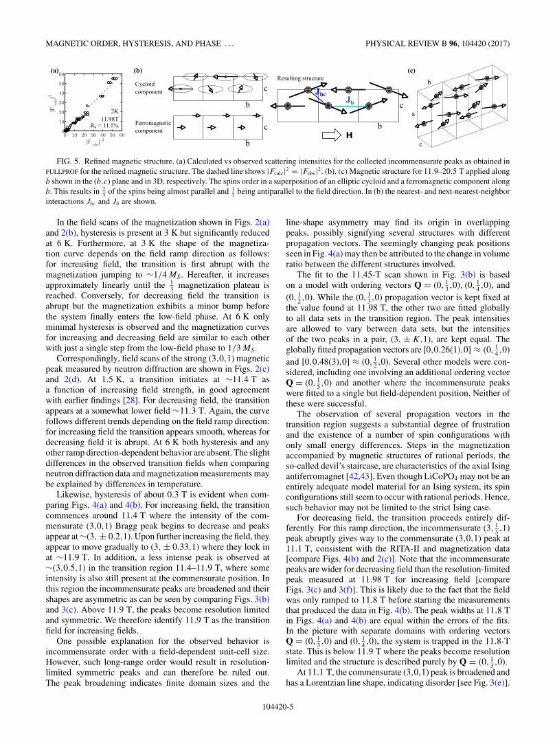
an elliptic cycloid structure was refined using FULLPROF [41].Here, all spins on Co sites having identical spatial coordinatey, along the b axis, are aligned and form a ferromagneticlayer in the (a,c) plane. Spins in subsequent layers rotate∼120◦ in the (b,c) plane upon advancing along the b axis.The ratio between the major and minor axes of the envelopingellipse is 3.2(5) with the major axis along b. The calculatedversus observed intensities are shown in Fig. 5(a). Refinementresults for the crystal structure and Fourier components of themagnetic structure are given in Table I.
The 13 magnetization implies an additional ferromagnetic
component to be combined with the incommensurate structure.For the cycloid part of the structure there is as always anindeterminable phase shift which in this case has been set toπ/3. This choice maximizes all spin lengths and allows 1
3 ofthe spins to be along the easy b axis. The energy cost associatedwith the single-ion anisotropy is independent of the phase shiftangle. Assuming MS = 3.6 μB [28] and choosing the phaseshift to π/3 the cycloid and ferromagnetic components resultin the structure illustrated in Figs. 5(b) and 5(c).
C. Hysteresis and phase coexistence
Hysteresis is observed both in the magnetization measure-ments and in the neutron diffraction data at the transition fromthe low-field collinear phase to the magnetized cycloid phase.At a first-order transition, one expects hysteresis to be present,but in the case of LiCoPO4 the transition is accompanied by
Mag
neti
c fi
eld
[T]
H ↑T = 2K (a)
−0.2 0 0.2 0.4 0.6 0.8
10.5
10.6
10.7
10.8
10.9
11.0
11.1
11.2
11.3
11.4
11.5
11.6
11.7
11.8
11.9
H ↓T = 2K (b)
050
100
150
200
250
300
350
400
450
Cou
nts/
2x10
5 mon
itor
−0.2 0 0.2 0.4 0.6 0.8
Mag
neti
c fi
eld
[T]
(3K1) [r.l.u.]
H ↑T = 6K (c)
−0.2 0 0.2 0.4 0.6 0.810.5
10.6
10.7
10.8
10.9
11.0
11.1
11.2
11.3
11.4
11.5
11.6
11.7
11.8
(3K1) [r.l.u.]
H ↓T = 6K (d)
−0.2 0 0.2 0.4 0.6 0.8
FIG. 4. Color plots of the intensity of (3,K,1) as a function ofmagnetic field applied along b at (a), (b) 2 K and (c), (d) 6 K forboth increasing and decreasing field as measured at D23. The whitecrosses to the right in each color plot denote the field values for whichscans have been performed. Note the relatively few points in (d) andthe difference in maximum field between the top and bottom panels.No data were collected in the hatched area.
additional field ramp direction-dependent characteristics. Howthis is manifested is described in the following paragraphs.
TABLE I. Atomic positions for LiCoPO4 obtained from FULL-PROF refinement (RF = 5.23%) of 86 commensurate peaks collectedat D23 at (30 K, 0 T) and using the Pnma space group. TheDebye-Waller factor was refined globally to Biso = 0.08 and aBecker-Coppens–type extinction correction has been applied. Fouriercomponents for the cycloid formed by the magnetic Co2+ ions aregiven in the two rightmost columns. These were refined (RF =11.1%) from 91 incommensurate peaks collected at (2 K, 12 T).Rm and Im denote the real and imaginary Fourier coefficients,respectively. These correspond to the moment sizes in μB along themajor and minor axes of the enveloping ellipsoid.
Atom Site x y z Rm Im
Li 4a 0 0 0Co 4c 0.2771(9) 0.25 0.980(3) 4.13(5) 1.3(2)P 4c 0.0951(6) 0.25 0.414(1)O1 4c 0.0975(4) 0.25 0.744(1)O2 4c 0.4542(4) 0.25 0.208(1)O3 8d 0.1663(2) 0.2814(5)
104420-4
MAGNETIC ORDER, HYSTERESIS, AND PHASE . . . PHYSICAL REVIEW B 96, 104420 (2017)
0 10 20 30 40 50 600
10
20
30
40
50
60
|Fca
lc|2
|Fobs
| 2
FIG. 5. Refined magnetic structure. (a) Calculated vs observed scattering intensities for the collected incommensurate peaks as obtained inFULLPROF for the refined magnetic structure. The dashed line shows |Fcalc|2 = |Fobs|2. (b), (c) Magnetic structure for 11.9–20.5 T applied alongb shown in the (b,c) plane and in 3D, respectively. The spins order in a superposition of an elliptic cycloid and a ferromagnetic component alongb. This results in 2
3 of the spins being almost parallel and 13 being antiparallel to the field direction. In (b) the nearest- and next-nearest-neighbor
interactions Jbc and Jb are shown.
In the field scans of the magnetization shown in Figs. 2(a)and 2(b), hysteresis is present at 3 K but significantly reducedat 6 K. Furthermore, at 3 K the shape of the magnetiza-tion curve depends on the field ramp direction as follows:for increasing field, the transition is first abrupt with themagnetization jumping to ∼1/4 MS . Hereafter, it increasesapproximately linearly until the 1
3 magnetization plateau isreached. Conversely, for decreasing field the transition isabrupt but the magnetization exhibits a minor bump beforethe system finally enters the low-field phase. At 6 K onlyminimal hysteresis is observed and the magnetization curvesfor increasing and decreasing field are similar to each otherwith just a single step from the low-field phase to 1/3 MS .
Correspondingly, field scans of the strong (3,0,1) magneticpeak measured by neutron diffraction are shown in Figs. 2(c)and 2(d). At 1.5 K, a transition initiates at ∼11.4 T asa function of increasing field strength, in good agreementwith earlier findings [28]. For decreasing field, the transitionappears at a somewhat lower field ∼11.3 T. Again, the curvefollows different trends depending on the field ramp direction:for increasing field the transition appears smooth, whereas fordecreasing field it is abrupt. At 6 K both hysteresis and anyother ramp direction-dependent behavior are absent. The slightdifferences in the observed transition fields when comparingneutron diffraction data and magnetization measurements maybe explained by differences in temperature.
Likewise, hysteresis of about 0.3 T is evident when com-paring Figs. 4(a) and 4(b). For increasing field, the transitioncommences around 11.4 T where the intensity of the com-mensurate (3,0,1) Bragg peak begins to decrease and peaksappear at ∼(3, ± 0.2,1). Upon further increasing the field, theyappear to move gradually to (3, ± 0.33,1) where they lock inat ∼11.9 T. In addition, a less intense peak is observed at∼(3,0.5,1) in the transition region 11.4–11.9 T, where someintensity is also still present at the commensurate position. Inthis region the incommensurate peaks are broadened and theirshapes are asymmetric as can be seen by comparing Figs. 3(b)and 3(c). Above 11.9 T, the peaks become resolution limitedand symmetric. We therefore identify 11.9 T as the transitionfield for increasing fields.
One possible explanation for the observed behavior isincommensurate order with a field-dependent unit-cell size.However, such long-range order would result in resolution-limited symmetric peaks and can therefore be ruled out.The peak broadening indicates finite domain sizes and the
line-shape asymmetry may find its origin in overlappingpeaks, possibly signifying several structures with differentpropagation vectors. The seemingly changing peak positionsseen in Fig. 4(a) may then be attributed to the change in volumeratio between the different structures involved.
The fit to the 11.45-T scan shown in Fig. 3(b) is basedon a model with ordering vectors Q = (0, 1
3 ,0), (0, 14 ,0), and
(0, 12 ,0). While the (0, 1
3 ,0) propagation vector is kept fixed atthe value found at 11.98 T, the other two are fitted globallyto all data sets in the transition region. The peak intensitiesare allowed to vary between data sets, but the intensitiesof the two peaks in a pair, (3, ± K,1), are kept equal. Theglobally fitted propagation vectors are [0,0.26(1),0] ≈ (0, 1
4 ,0)and [0,0.48(3),0] ≈ (0, 1
2 ,0). Several other models were con-sidered, including one involving an additional ordering vectorQ = (0, 1
5 ,0) and another where the incommensurate peakswere fitted to a single but field-dependent position. Neither ofthese were successful.
The observation of several propagation vectors in thetransition region suggests a substantial degree of frustrationand the existence of a number of spin configurations withonly small energy differences. Steps in the magnetizationaccompanied by magnetic structures of rational periods, theso-called devil’s staircase, are characteristics of the axial Isingantiferromagnet [42,43]. Even though LiCoPO4 may not be anentirely adequate model material for an Ising system, its spinconfigurations still seem to occur with rational periods. Hence,such behavior may not be limited to the strict Ising case.
For decreasing field, the transition proceeds entirely dif-ferently. For this ramp direction, the incommensurate (3, 1
3 ,1)peak abruptly gives way to the commensurate (3,0,1) peak at11.1 T, consistent with the RITA-II and magnetization data[compare Figs. 4(b) and 2(c)]. Note that the incommensuratepeaks are wider for decreasing field than the resolution-limitedpeak measured at 11.98 T for increasing field [compareFigs. 3(c) and 3(f)]. This is likely due to the fact that the fieldwas only ramped to 11.8 T before starting the measurementsthat produced the data in Fig. 4(b). The peak widths at 11.8 Tin Figs. 4(a) and 4(b) are equal within the errors of the fits.In the picture with separate domains with ordering vectorsQ = (0, 1
3 ,0) and (0, 14 ,0), the system is trapped in the 11.8-T
state. This is below 11.9 T where the peaks become resolutionlimited and the structure is described purely by Q = (0, 1
3 ,0).At 11.1 T, the commensurate (3,0,1) peak is broadened and
has a Lorentzian line shape, indicating disorder [see Fig. 3(e)].
104420-5

ELLEN FOGH et al. PHYSICAL REVIEW B 96, 104420 (2017)
Fitting a Lorentzian convoluted with a Gaussian describing theresolution, one can obtain the correlation length as ξ = b
2πκ,
where b is the lattice parameter and κ is the Lorentzian width.The resolution is found by fitting the commensurate peak at10.5 T (well below the transition) to a Gaussian [see Fig. 3(d)].The correlation length is then found to be ∼120 times smallerjust at the transition (11.1 T) compared to below (10.5 T). Theobserved peak broadening correlates with the bump seen inthe magnetization [see Fig. 2(a)].
D. Magnetic structures at high fields
To access fields approaching the saturation field μ0HS =28.3 T, a neutron diffraction experiment was performed atthe HFM/EXED instrument. The maximum field was 25.9 Tand thus enabled direct probing of the remaining magneticphases at high fields indicated by the magnetization data ofRef. [28]. The required crystal orientation and the openingangle of the magnet limited the number of accessible Braggpeaks to (3,0,1), (2,0,1), (1,0,1), (1,0,1), (1,0,0), (0,0,1),and (0,K,0) for K � 10. All peaks except (0,K,0) wereobserved in the forward scattering detectors and, unfortunately,due to low flux at the required wavelengths, the neutronstatistics of these peaks were only sufficient for alignment andconfirmation of the zero-field structure. However, magneticintensity above 20.5 T was observed in the backscatteringdetectors at the (0,K,0) position. Intensity was found at K = 4
3for 20.5–21.0 T and at K = 1 above 21.0 T with the two peakscoexisting at 21.0 T. Neutron counts as a function of K along(0,K,0) were obtained by integrating over a slice in reciprocalspace of dimensions (given in r.l.u.) H = 0.3 and L = 0.2and with bin sizes K = 1 × 10⁻³ and 3 × 10⁻³ for K = 1and 4
3 , respectively. Background-subtracted line profiles atselected field strengths are shown in Fig. 6(a) and integrated
0100020003000 (a)
0100020003000
0100020003000
0.99 1 1.01
0100020003000N
eutr
on c
ount
s / 1
07 mon
itor
(0,K,0) [r.l.u]
0
1
2
3
4
5
6
(0,1,0)
(b)
Inte
grat
ed in
tens
ity
/ 107 m
onit
or
0.00T
20.75T
21.00T
1.3 1.32 1.34 1.36
24.00T
(0,K,0) [r.l.u]12 14 16 18 20 22 24 26 28
0
1
2
3
4
5
6
(0,1.33,0)
(c)
Magnetic field [T]
FIG. 6. Neutron diffraction results from HFM/EXED. (a) Neu-tron counts as a function of (0,K,0) around K = 1 (left panels) andK = 4
3 (right panels) at selected field values. Linear backgroundshave been fitted and subtracted for each data set. The orange lines aresubsequential Gaussian fits. (b), (c) Integrated intensity as a functionof magnetic field up to 25.9 T of (0,1,0) and (0, 4
3 ,0), respectively.The star symbol in (b) shows the expected zero intensity of (0,1,0) atsaturation [28]. The dashed line is a guide to the eye.
intensities of (0,1,0) and (0, 43 ,0) found from Gaussian fits are
shown in Figs. 6(b) and 6(c), respectively.The ordering vector in the interval 20.5–21.0 T is thus
Q = (0, 13 ,0). This is the same as for 11.9–20.5 T but the
(0, 43 ,0) Bragg peak was not observed at 12 and 15 T, i.e.,
it is not present in the cycloid phase. Although the period ofthe magnetic structure stays the same, the spin orientation mustthen change around 20.5 T. In Fig. 6(c) the transition appearsabrupt, while it seems continuous in the magnetization data ofRef. [28]. One possibility consistent with these observationsis a gradual transition from the cycloid to a conical structurewith the cone base perpendicular to the propagation vector. Insuch a structure, the spins rotate in the (a,c) plane and havea ferromagnetic component along the b axis. However, sinceonly a single magnetic Bragg peak was observed, a rigorousstructure determination was impossible.
Above 21.0 T the neutron intensity at (0, 43 ,0) vanishes and a
new peak appears at (0,1,0). This peak reflects a commensuratespin structure with symmetry (↑↑↓↓), the same as in thezero-field phase where the spins are predominantly along b.Since neutron scattering is only sensitive to spin componentsperpendicular to the scattering vector, this Bragg peak isnot observed in the zero-field phase. Conversely, the finitepeak intensity above 21.0 T implies antiferromagnetic spincomponents along either a or c instead of b. Both susceptibilitymeasurements and the magnetic structure refinement in thecycloid phase suggest that the c axis is easier than a. Therefore,we infer that above 21.0 T the major antiferromagnetic spincomponent is along c. In addition, there is a ferromagneticcomponent with 2/3 MS at 21.0 T which increases approxi-mately linearly until saturation is achieved at 28.3 T [28]. Themagnetic structure above 21.0 T may therefore be described asa magnetized spin-flop structure. The spins rotate towards the b
axis with increasing field and the intensity of (0,1,0) decreaseswith field accordingly. In fact, the field dependence of (0,1,0)is consistent with its complete disappearance at saturation[see Fig. 6(b)].
The Bragg peaks at (0, 43 ,0) and (0,1,0) coexist in a
short field interval [see Fig. 6(a)], suggesting that the phasetransition from the Q = (0, 1
3 ,0) to the commensurate phase isof first order. This is also substantiated by hysteresis observedin previous pulsed-field magnetization measurements [28].
IV. DISCUSSION
A. Cycloid structure and a possible magnetoelectric effect
At first glance, the cycloid structure [Figs. 5(b) and 5(c)]seems counterintuitive when regarding the axial single-ionanisotropy and antiferromagnetic nearest-neighbor interac-tions. Neither exchange nor the single-ion anistropy energiesare minimized. However, the deviations of the momentsfrom the b axis remain relatively small such that interactingspin pairs are either nearly antiparallel or parallel. It is alsonoteworthy that the spins are in the (b,c) plane as opposed tothe (a,b) plane, signifying that the energy cost for spins alongc is smaller than along a as expected from both susceptibilitymeasurements [23] and density functional theory [24].
LiCoPO4 has a strong magnetoelectric effect in the com-mensurate low-field phase [9]. Here, an electric polarization
104420-6

MAGNETIC ORDER, HYSTERESIS, AND PHASE . . . PHYSICAL REVIEW B 96, 104420 (2017)
Pa is induced along a for magnetic fields applied along b
and vice versa. The magnetoelectric properties of the phasewith the 1
3 magnetization plateau have also been studiedwith the conclusion that this phase does not display thesame magnetoelectric effect [8,29]. However, from symmetryanalysis the cycloid structure does actually support a magne-toelectric effect [5] but via a different mechanism: the inverseDzyaloshinskii-Moriya effect. The direction of the allowedelectric polarization is along Q × (Si × Sj ), and in the caseof the cycloid in LiCoPO4, Q ‖ b and (Si × Sj ) ‖ a. Hence,the polarization would be along the c axis for magnetic fieldsapplied along b. To our best knowledge, only Pa was measuredin the previous studies and the allowed component Pc has notyet been probed. Therefore, the possibility of a magnetoelectriceffect in the Q = (0, 1
3 ,0) cycloid structure is not definitelyrejected and should be further investigated.
B. Hysteresis and stacking faults
The features observed in the magnetization and the oc-currence of the (3, 1
3 ,1), (3, 14 ,1), and (3, 1
2 ,1) incommensuratepeaks in the interval 11.4–11.9 T are consistent with thebehavior of the (3,0,1) intensity as a function of appliedfield seen in the RITA-II experiment. Similarly, field rampdirection-dependent differences in the curve shapes of theelectric polarization were presented in Ref. [29]. Hence, extrafeatures in the transition regime are established in severalmeasurable quantities. Upon increasing the temperature, theeffects weaken: at T � 6 K the difference in curve shape in themagnetization is absent and the transition regime with multipleordering vectors is largely reduced for increasing field as wellas the Lorentzian broadening for decreasing field (comparetop and bottom panels in both Figs. 2 and 4). In the following,a relatively simple model based on a mean-field approach isproposed in an attempt to understand these observations.
The magnetic structure above 11.9 T [Figs. 5(b) and 5(c)]provides a starting point for our model. The period of thisstructure is n = 3 (i.e., the size of the magnetic unit celltriples) and spins with the same spatial y coordinate forma layer in the (a,c) plane. The spins of each layer are thenrotated with respect to those in the next layer upon advancingalong b. In the present model, we crudely assume that allmoments have maximum length, MS = 3.6 μB , and that theyare purely oriented along the easy axis. Hence, the canting of∼20◦ away from the b axis for 2
3 of the spins is completelyignored here. This structure consists of two kinds of layersor building blocks: (i) layers with spins parallel to b and (ii)layers with spins antiparallel to b. Each crystallographic unitcell consists of two such layers. These blocks are denoted “+”and “−,” respectively, and the n = 3 structure can then bedescribed by the stacking sequence [+ + − + +−].
Additional magnetic structures are now constructed fromthe same building blocks such that they have period n ∈ N forn > 1 and magnetization (1/n) MS . This is done by addingor removing layers of + and − in pairs along b. Thus, then = 4 structure becomes [+ + − + + − +−] [see Fig. 7(a)].It can be described by introducing stacking faults to the n =3 structure in analogy with stacking faults in closed packedstructures with layer stacking in, e.g., either ABABAB orABCABC type sequences.
Note that the constructed structures are not associated with asingle (0,1/n,0) ordering vector but require higher harmonicsfor a full description. However, the associated Bragg peaksare too weak to be detected in our experiment. Furthermore,sufficiently large domains of a structure of period n must existin the sample in order to observe an (0,1/n,0) ordering vector.At this point, it should also be emphasized that the proposedmodel is not the outcome of a full statistical treatment butrather the proposed stacking fault structures are deliberatelychosen to be consistent with experimental observations. It istherefore fully possible that other choices yield similar results.Nevertheless, as we shall see below, this rather crude modelprovides an explanation of the observed coexistence of severalpropagation vectors in the transition region.
To describe the energy of the system, the followingHamiltonian is employed:
H = −∑i,j
Jij Si · Sj − μH∑
i
Si .
Here, only Jbc and Jb are taken into account as the remain-ing exchange constants are generally small in the lithiumorthophosphate family [33–35]. Since the easy axis is along b
and the assumed spin structures have no components along a
or c, no single-ion anisotropy terms are taken into account. H
is the strength of the applied field along b and μ = gμBS withthe g-factor g ≈ 2, the Bohr magneton μB , and S = 3
2 . Theenergy per Co2+ ion of the assumed stacking fault structureswith period n is then
En = 1
n([2(n − 2)Jbc + (4 − n)Jb]S2 − μH ),n > 2, n ∈ N.
The zero-field structure, i.e., n = 1 (see Fig. 1), has the energyper ion E1 = (2Jbc − Jb)S2. By solving E1 = En one candetermine the transition field from the zero-field structure toany stacking fault structure accordingly:
HC = 4S2
μ(−Jbc + Jb), n > 2, n ∈ N.
Peculiarly, the transition field is independent of the period n
and, hence, all configurations of this particular kind are de-generate exactly at the phase transition. The energy differencebetween any two states m and n is readily calculated:
Em − En =(
m − n
nm
)μ (H − HC), n,m > 2, n,m ∈ N.
Hence, the energy difference does not depend directly onexchange interactions but merely on m and n as well as thefield deviation from the transition value.
A short note on the n = 2 state is in place since the abovecalculations are only valid for n > 2. For n = 2 the stackingsequence results in a different expression for the energy, E2 =− 1
2μH , and a larger transition field follows. It is thereforeunlikely that this structure is realized. Alternatively, the n = 2Bragg peak seen in Fig. 4(a) could be due to nuclear distortionlinked to the n = 4 magnetic structure or simply a completelydifferent magnetic structure with period n = 2. An x-ray orpolarized neutron experiment is needed in order to clarify thispoint.
Assuming Jbc ≈ 2Jb and using the measured transition fieldof 11.9 T, the nearest-neighbor coupling strength is estimated
104420-7

ELLEN FOGH et al. PHYSICAL REVIEW B 96, 104420 (2017)
0 2 4 6 8 10 12 14 16 18
−1.8
−1.6
−1.4
−1.2
−1
−0.8
Magnetic field [T]
Ene
rgy
per
ion
[meV
]
n = 4
n = 3 n = 2
n = 1
Jbc
= 2 Jb
FIG. 7. Stacking faults. (a) Possible stacking fault structures with period n ∈ N for n > 1 and with magnetization (1/n) MS . Spin directionis denoted by the ion color: green (along b) and blue (along b). Only one layer of ions in the (b,c) plane is shown here. (b) Energy per magneticion as a function of applied field calculated from the stacking fault structures. Jbc = 2Jb is assumed. The zero-field energy E1 is shown withthe solid blue line and En → E1 for n → ∞. The energies for n > 2 cross at this level exactly at the transition field HC = 11.9 T as shownwith the vertical line.
to Jbc ≈ −0.46 meV. With this assumption, energies fordifferent n configurations are shown as a function of appliedfield in Fig. 7(b). The estimate of the relative strengths ofJbc and Jb is based on the other members of the lithiumorthophosphate family [33,34,44,45]. The resulting value ofthe nearest-neighbor interaction is remarkably close to thosefound in LiFePO4 [Jbc = −0.46(2) meV [44]] and LiMnPO4
[Jbc = −0.48(5) meV [45]] and reasonably close to thatmeasured for LiCoPO4 [Jbc = −0.7(2) meV [35,36], notethe large uncertainty]. Additionally, in Ref. [28] the nearest-neighbor interaction of LiCoPO4 was estimated to Jbc =−0.23 meV. However, this result is based on an incorrectmagnetic propagation vector explaining the discrepancy fromour result. It is worth emphasizing here that our result isobtained merely from a few simple but reasonable assumptionstogether with the measured transition field value.
It is clear from Fig. 7(b) that the energy difference betweendifferent m and n states is small close to the transition field.Hence, at low temperatures the thermal relaxation time maybe sufficiently long such that regions of the sample are trappedin states with n �= 3 in agreement with the observation ofn = 4 order in the transition interval 11.4–11.9 T. At 11.9 Tthe n = 3 structure stabilizes and the other structures withdraw.At higher temperatures, the system is assisted by thermalfluctuations and rapidly finds its stable configuration. Thus,based on the disappearance of hysteresis at higher temperatures(T � 6 K), it is suggested that more states, e.g., n = 5,6,may be populated at very low temperatures (mK regime) andthat the hysteresis region is significantly expanded. Furtherexperiments are needed in order to falsify or substantiate thishypothesis.
For decreasing field, the transition to the low-field an-tiferromagnetic ground state occurs abruptly even at lowtemperatures. A broadening of the commensurate Bragg peakis observed in a short-field interval at the transition around11.1 T. Although very speculative, it may be suggested tooriginate from long-wavelength stacking fault structures likethose introduced above, i.e., for n 1. When a large numberof [+−] layer pairs are added, the magnetization approacheszero and the structure resembles the zero-field structure.
The reason for the transition to occur more readily fordecreasing field as compared to increasing field remainsunexplained, but an analogy may be found in the watersolid-liquid transition. Upon heating water ice it slowly melts
when the temperature is above 0 ◦C. However, because of theneed for nucleation sites, upon cooling, liquid water can reachtemperatures below the freezing temperature (supercooling)before suddenly entering the ice phase. In this analogy, heatingcorresponds to increasing field.
C. Commensurability and magnetoelectric effect
Although only a single magnetic peak was observed above21.0 T, it is possible to argue that the magnetic structure inthis high-field phase is a commensurate, magnetized spin-flopstructure with the same main antiferromagnetic symmetrycomponent (↑↑↓↓) as the zero-field structure. Remarkably,this phase is magnetoelectric as was recently reported byKharchenko et al. [29]. They found that an electric polarizationPa is induced along the a axis for a magnetic field appliedalong b. Thus, the active magnetoelectric tensor element αab
is the same as in the low-field phase but ∼5 times weaker.Such reentrant magnetoelectric behavior has previously beenobserved in the sister compound LiNiPO4 [29,32]. In Ref. [32],it was shown that an extension of the microscopic modelexplaining the low-field magnetoelectric effect succeeds inaccounting for the high-field effect too. In LiCoPO4 there isof yet no such microscopic model, but the two compoundshave one characteristic in common: the magnetoelectriceffect is linked to commensurate magnetic structures. Thisis interesting since other magnetoelectric materials such asCr2BeO4 [46] and RMn2O5 [47] (R = rare earth) generallydisplay incommensurate magnetic structures [5]. However,when recalling the above discussion on the possibility ofa magnetoelectric effect in the cycloid structure, it appearsthat LiCoPO4 may support a magnetoelectric effect for bothcommensurate and incommensurate structures. If this is thecase, the effects are most likely caused by two differentmechanisms.
V. CONCLUSIONS
We studied the phase diagram of LiCoPO4 for fields up to25.9 T applied along b using magnetization measurements andneutron diffraction. The magnetic structure for 11.9–20.5 Twas determined. The ordering vector is Q = (0, 1
3 ,0), demon-strating a tripling of the magnetic unit cell in the b direction.The spin configuration is an elliptic cycloid with spins in the
104420-8

MAGNETIC ORDER, HYSTERESIS, AND PHASE . . . PHYSICAL REVIEW B 96, 104420 (2017)
(b,c) plane in superposition with a ferromagnetic component.The ratio of the major and minor axes is 3.2(5) with themajor axis along b. The resulting structure has the spindirection alternating with 2
3 of the spins almost parallel toand 1
3 antiparallel to the field, consistent with the observed 13
magnetization plateau [28]. This structure maintains the axialsingle-ion anisotropy character of LiCoPO4. Furthermore, therefined structure allows for a magnetoelectric effect withan electric polarization induced along c for magnetic fieldsapplied along b. The existence of this effect is still to be rejectedor confirmed by further measurements.
The transition from the low-field to the cycloid phaseexhibits hysteresis and the way the transition proceedsdepends heavily on the field ramp direction. For increasingfield, we have evidence for three coexisting propagationvectors: Q = (0, 1
4 ,0), Q = (0, 13 ,0), and Q = (0, 1
2 ,0), in thefield interval 11.4–11.9 T. The occurrence of the additionalordering vectors may be rationalized by introducing stackingfaults in the cycloid structure leading to states sufficientlyclose in energy to be populated until a single phase stabilizesat 11.9 T. For decreasing field, the transition is more abruptand the commensurate peak has a Lorentzian line shape at thetransition.
We identified further phase transitions at 20.5 and 21.0 Tand determined the corresponding propagation vectors. Inthe field range 20.5–21.0 T the propagation vector is Q =(0, 1
3 ,0) but the spin orientation is different compared to thecycloid phase. Above 21.0 T, the structure is commensuratewith an antiferromagnetic component along c as well as aferromagnetic component along b.
ACKNOWLEDGMENTS
We greatly acknowledge N. H. Andersen for many fruitfuldiscussions and O. Rivin, X. Liu, R. Wahle, and S. Gerischerfor their support at the HFM/EXED facility at the Helmholtz-Zentrum Berlin. This work was supported by the DanishAgency for Science and Higher Education under DANSCATT.Neutron experiments were performed at the Swiss spallationneutron source SINQ at the Paul Scherrer Institute, Villigen,Switzerland, at the research reactor at the Institut Laue-Langevin, Grenoble, France and at the BER II researchreactor at the Helmholtz-Zentrum Berlin, Germany. Researchat Ames Laboratory is supported by the U.S. Department ofEnergy, Office of Basic Energy Sciences, Division of MaterialsSciences and Engineering under Contract No. DE-AC02-07CH11358.
[1] A. P. Ramirez, Strongly geometrically frustrated magnets,Annu. Rev. Mater. Sci. 24, 453 (1994).
[2] L. Balents, Spin liquids in frustrated magnets, Nature (London)464, 199 (2010).
[3] M. J. Harris, S. T. Bramwell, D. F. McMorrow, T. Zeiske, andK. W. Godfrey, Geometrical Frustration in the FerromagneticPyrochlore Ho2Ti2O7, Phys. Rev. Lett. 79, 2554 (1997).
[4] P. W. Anderson, Resonating valence bonds: A new kind ofinsulators? Mater. Res. Bull. 8, 153 (1973).
[5] T. Kimura, Spiral magnets as magnetoelectrics, Annu. Rev.Mater. Res. 37, 387 (2007).
[6] K. Moorjani and S. K. Ghatak, Random exchange interactionsand the “frustration effect,” Solid State Commun. 26, 357(1978).
[7] R. P. Santoro, D. J. Segal, and R. E. Newnham, Magneticproperties of LiCoPO4 and LiNiPO4, J. Phys. Chem. Solids27, 1192 (1966).
[8] H. Wiegelmann, Magnetoelectric effects in strong magneticfields, Ph.D. thesis, Universität Konstanz, 1994.
[9] M. Mercier, Étude de l’effet magnetoelectrique sur de composésde type olivine, perovskite et grenat, Ph.D. thesis, Université deGrenoble, 1969.
[10] D. Vaknin, J. L. Zarestky, L. L. Miller, J.-P. Rivera, and H.Schmid, Weakly coupled antiferromagnetic planes in single-crystal LiCoPO4, Phys. Rev. B 65, 224414 (2002).
[11] I. Kornev, M. Bichurin, J.-P. Rivera, S. Gentil, H. Schmid,A. G. M. Jansen, and P. Wyder, Magnetoelectric properties ofLiCoPO4 and LiNiPO4, Phys. Rev. B 62, 12247 (2000).
[12] T. B. S. Jensen, N. B. Christensen, M. Kenzelmann, H. M.Rφnnow, C. Niedermayer, N. H. Andersen, K. Lefmann, J.Schefer, M. Zimmermann et al., Field-induced magnetic phasesand electric polarization in LiNiPO4, Phys. Rev. B 79, 092412(2009).
[13] W. S. Wieglhofer and A. Lakhtakia, Introduction to ComplexMediums for Optics and Electromagnetics (SPIE, Bellingham,WA, 2003).
[14] A. K. Padhi, K. S. Nanjundaswamy, and J. B. Goodenough,Phospho-olivines as positive-electrode materials for recharge-able lithium batteries, J. Electrochem. Soc. 144, 1188 (1997).
[15] K. Amine, H. Yasuda, and M. Yamachi, Olivine LiCoPO4 as4.8 V electrode material for lithium batteries, Electrochem.Solid-State Lett. 3, 178 (2000).
[16] S.-Y. Chung, J. T. Bloking, and Y.-M. Chiang, Electronicallyconductive phospho-plivines as lithium storage electrodes,Nat. Mater. 1, 123 (2002).
[17] R. E. Newnham and M. J. Redman, Crystallographic data forLiMgPO4, LiCoPO4 and LiNiPO4, J. Am. Ceram. Soc. 48, 547(1965).
[18] F. Kubel, Crystal structure of lithium cobalt double orthophos-phate, LiCoPO4, Z. Kristallogr.-Cryst. Mater. 209, 755 (1994).
[19] C. Ederer and N. A. Spaldin, Towards a microscopic theory oftoroidal moments in bulk periodic crystals, Phys. Rev. B 76,214404 (2007).
[20] N. A. Spaldin, M. Fiebig, and M. Mostovoy, The toroidalmoment in condensed-matter physics and its relation to themagnetoelectric effect, J. Phys.: Condens. Matter 20, 434203(2008).
[21] B. B. Van Aken, J.-P. Rivera, H. Schmid, and M. Fiebig,Observation of ferrotoroidic domains, Nature 449, 702 (2007).
[22] A. S. Zimmermann, D. Meier, and M. Fiebig, Ferroic nature ofmagnetic toroidal order, Nat. Commun. 5, 4796 (2014).
[23] J. G. Creer and G. J. Troup, The magnetic susceptibility ofLiFePO4 and LiCoPO4, Phys. Lett. A 32, 439 (1970).
[24] K. Yamauchi and S. Picozzi, Magnetic anisotropy in li-phosphates and origin of magnetoelectricity in LiNiPO4,Phys. Rev. B 81, 024110 (2010).
104420-9

ELLEN FOGH et al. PHYSICAL REVIEW B 96, 104420 (2017)
[25] A. Szewczyk, M. U. Gutowska, J. Wieckowski, A. Wisniewski,R. Puzniak, R. Diduszko, Y. Kharchenko, M. F. Kharchenko,and H. Schmid, Phase transitions in single-crystalline magneto-electric LiCoPO4, Phys. Rev. B 84, 104419 (2011).
[26] J.-P. Rivera, The linear magnetoelectric effect in LiCoPO4
revisited, Ferroelectrics 161, 147 (1994).[27] Y. Kharchenko, N. Kharchenko, M. Baran, and R. Szymczak,
Magnetoelectric Interaction Phenomena in Crystals (MEIPIC-5), edited by M. Fiebig, V. V. Eremenko, and I. E. Chupis(Kluwer-Academic, Dordrecht, 2004), p. 227.
[28] N. F. Kharchenko, V. M. Khrustalev, and V. N. Savitskii, Mag-netic field induced spin reorientation in the strongly anisotropicantiferromagnetic crystal LiCoPO4, Low Temp. Phys. 36, 558(2010).
[29] V. M. Khrustalyov, V. M. Savytsky, and M. F. Kharchenko,Magnetoelectric effect in antiferromagnetic LiCoPO4 in pulsedmagnetic fields, Low Temp. Phys. 42, 280 (2016).
[30] R. Toft-Petersen, J. Jensen, T. B. S. Jensen, N. H. Andersen,N. B. Christensen, C. Niedermayer, M. Kenzelmann, M. Sk-oulatos, M. D. Le, K. Lefmann et al., High-field magnetic phasetransitions and spin excitations in magnetoelectric LiNiPO4,Phys. Rev. B 84, 054408 (2011).
[31] R. Toft-Petersen, N. H. Andersen, H. Li, J. Li, W. Tian, S. L.Bud’ko, T. B. S. Jensen, C. Niedermayer, M. Laver, O.Zaharko, J. W. Lynn, and D. Vaknin, Magnetic phase dia-gram of magnetoelectric LiMnPO4, Phys. Rev. B 85, 224415(2012).
[32] R. Toft-Petersen, E. Fogh, T. Kihara, J. Jensen, K. Fritsch, J.Lee, G. E. Granroth, M. B. Stone, D. Vaknin, H. Nojiri, andN. B. Christensen, Field-induced reentrant magnetoelectricphase in LiNiPO4, Phys. Rev. B 95, 064421 (2017).
[33] T. B. S. Jensen, N. B. Christensen, M. Kenzelmann, H. M.Rφnnow, C. Niedermayer, N. H. Andersen, K. Lefmann,M. Jiménez-Ruiz, F. Demmel, J. Li et al., Anomalous spinwaves and the commensurate-incommensurate magnetic phasetransition in LiNiPO4, Phys. Rev. B 79, 092413 (2009).
[34] R. Toft-Petersen, M. Reehuis, T. B. S. Jensen, N. H. Andersen,J. Li, M. D. Le, M. Laver, C. Niedermayer, B. Klemke, K.Lefmann, and D. Vaknin, Anomalous magnetic structure andspin dynamics in magnetoelectric LiFePO4, Phys. Rev. B 92,024404 (2015).
[35] W. Tian, J. Li, J. W. Lynn, J. L. Zarestky, and D. Vaknin, Spindynamics in the magnetoelectric effect compound LiCoPO4,Phys. Rev. B 78, 184429 (2008).
[36] We have examined crystals from the same batch as that used inRef. [35] and find a significantly lower transition temperatureTN = 17.3(1)K. Furthermore, a Rietveld refinement of ourneutron diffraction data yields satisfactory results exclusivelywhen introducing Ni as well as Co on the magnetic site. Hence,our results suggest that the crystals may not be pure LiCoPO4,but possibly Ni doped from a crucible growth.
[37] P. Smeibidl, M. Bird, H. Ehmler, I. Dixon, J. Heinrich, M.Hoffmann, S. Kempfer, S. Bole, J. Toth, O. Prokhnenko,and B. Lake, First hybrid magnet for neutron scattering athelmholtz-zentrum berlin, IEEE Trans. Appl. Supercond. 26,4301606 (2016).
[38] O. Prokhnenko, W.-D. Stein, H.-J. Bleif, M. Fromme, M.Bartkowiak, and T. Wilpert, Time-of-flight extreme environmentdiffractometer at the Helmholtz-Zentrum Berlin, Rev. Sci.Instrum. 86, 033102 (2015).
[39] O. Prokhnenko, M. Bartkowiak, W.-D. Stein, N. Stuesser, H.-J.Bleif, M. Fromme, K. Prokes, P. Smeibidl, M. Bird, and B.Lake, in Proceedings of the 21st Meeting of the InternationalCollaboration on Advanced Neutron Sources (ICANS XXI)(JAEA, 2016), pp. 278–285.
[40] S. Kimura, M. Matsuda, T. Masuda, S. Hondo, K. Kaneko, N.Metoki, M. Hagiwara, T. Takeuchi, K. Okunishi, Z. He et al.,Longitudinal Spin Density Wave Order in a Quasi-1d Ising-Like Quantum Antiferromagnet, Phys. Rev. Lett. 101, 207201(2008).
[41] J. Rodriguez-Carvajal, Recent advances in magnetic struc-ture determination by neutron powder diffraction, Phys. B(Amsterdam) 192, 55 (1993).
[42] P. Bak, One-Dimensional Ising Model and the Complete Devil’sStaircase, Phys. Rev. Lett. 49, 249 (1982).
[43] P. Bak, The Devil’s staircase, Phys. Today 39(12), 38 (1986).[44] Y. Yiu, M. D. Le, R. Toft-Peterson, G. Ehlers, R. McQueeney,
and D. Vaknin, Hybrid excitations due to crystal-field, spin-orbitcoupling and spin-waves in LiFePO4, Phys. Rev. B 95, 104409(2017).
[45] J. Li, W. Tian, Y. Chen, J. L. Zarestky, J. W. Lynn, and D. Vaknin,Antiferromagnetism in the magnetoelectric effect single crystalLiMnPO4, Phys. Rev. B 79, 144410 (2009).
[46] R. E. Newnham, J. J. Kramer, W. A. Schulze, and L. E.Cross, Magnetoferroelectricity in Cr204, J. Appl. Phys. 49, 6088(1978).
[47] H. Nakamura and K. Kohn, Magnetoelectric effect of rare earthmanganese oxide RMn2O5, Ferroelectrics 204, 107 (1997).
104420-10
Copyright © 2022 FDOKUMEN