Magnetic Anisotropy and Mechanism of Magnetic Relaxation in Er(III) Single-Ion Magnets
11
Magnetic Anisotropy and Mechanism of Magnetic Relaxation in Er(III) Single-Ion Magnets Saurabh Kumar Singh, Tulika Gupta, and Gopalan Rajaraman* Department of Chemistry, Indian Institute of Technology−Bombay, Mumbai 400076, India * S Supporting Information ABSTRACT: Magnetic anisotropy is a key component in the design of single- molecule magnets (SMMs) possessing a large barrier height for magnetization reversal. Lanthanide-based SMMs are the most promising candidates in this arena as they offer a large magnetic anisotropy due to the presence of strong spin−orbit coupling. Among lanthanides, Er(III) complexes are gaining attention in the area of SMMs, because of their intriguing magnetic properties and attractive blocking temperatures. Here, we have undertaken detailed ab initio calculations on four structurally diverse Er(III) SMMs to shed light on how the magnetic anisotropy is influenced by the role of symmetry and structural distortions. The employed CASSCF+RASSI calculations have offered rationale for the observed differences in the estimated U eff values for the studied complexes and also offered hints to the mechanism of magnetic relaxation. The differences in the mechanism of magnetic relaxations are further analyzed based on the Er−ligand interactions, which is obtained by analyzing the charges, densities, luminescent behavior and the frontier molecular orbitals. Our calculations, for the first time, have highlighted the importance of high symmetry environment and ligand donor strength in obtaining large U eff values for the Er(III) complexes. We have examined these possibilities by modeling several structures with variable coordination numbers and point group symmetry. These results signify the need of a detailed understanding on the shape of the anisotropy and the point group symmetry in order to achieve large U eff values in Er(III) single-ion magnets. 1. INTRODUCTION After the discovery of the first single-ion magnet [TbPc 2 ] − (where Pc 2 − = pthalocyanine dianion), 1 lanthanide based complexes have gained momentum in the area of molecular magnetism as they exhibit slow relaxation of magnetization at low temperatures. 1,2 Thanks to their unquenched orbital angular momentum and inherent magnetic anisotropy, the number of lanthanide-based single-molecule magnets (SMMs) reported to-date is increasing exponentially. 2e,f,3 Beyond fundamental interest, these molecules are also proposed to have great deal of potential applications ranging from highly dense information storage devices, Q-bits in quantum computing, to spintronics devices. 2b−d,4 Despite tremendous efforts on the synthesis of polynuclear SMMs based on lanthanides, the SMM characteristics of many polynuclear SMMs are single ion in origin. 3e,5 An example that illustrates this category is the report of {Dy 5 } cluster exhibiting a barrier height (U eff ) of 800 K, which originates from a single Dy(III) ion. 6 The presence of strong exchange-coupling between lanthanides and transition metals 3d,7 or radicals 8 generally leads to superior SMMs. Elegant examples to this category are the reports of {Dy 2 Cr 2 } SMM and {TbN 2 3− } complexes, 7b,8d,e showing blocking temperatures of 3.7 and 14 K, respectively. The future success in the synthesis of new- generation lanthanide SMMs relies heavily on a perceivable approach to obtain symmetric structures and ways to control the quantum tunnelling of magnetization (QTM), which diminishes the SMM behavior. In this regard, numerous mononuclear single- ion magnets (SIMs) have been synthesized to gain clear understanding on the QTM effects and the magnetic relaxation phenomena. The most prolific example in this category is the anisotropic Dy(III) ion, which holds the maximum number of SMMs reported in the lanthanide series. 2g,3b,d,5a,c,d,7a−c,g,8c,9 Lanthanide complexes possessing a half-integer ground state (Kramers ions), are considered superior to non-Kramers ions for the SMM behavior, and, thus, they are natural target for the synthetic chemists. 10 Apart from the choice of the metal ions, the ligand design also plays an important role, as illustrated in the case of [TbPc 2 ] − , where a high-symmetry environment leads to a large barrier height, even for a non-Kramers Tb(III) ion. Recently, Long et al. 3e reported a detailed description of achieving large magnetic anisotropy in lanthanide-based complexes and explored the importance of crystal field environment in the lanthanide series. The elaborated concept based on ligand field theory highlights the importance of the ligand field environment (prolate/oblate shape 11 of electron cloud) in achieving larger U eff values. Besides, the lanthanide SMMs also exhibit exquisite properties, such as luminescence, when they combine with the apt ligands and this feature expands its potential applications to other territories. 9a,12 Received: April 3, 2014 Article pubs.acs.org/IC © XXXX American Chemical Society A dx.doi.org/10.1021/ic500772f | Inorg. Chem. XXXX, XXX, XXX−XXX
Transcript of Magnetic Anisotropy and Mechanism of Magnetic Relaxation in Er(III) Single-Ion Magnets
Magnetic Anisotropy and Mechanism of Magnetic Relaxation inEr(III) Single-Ion MagnetsSaurabh Kumar Singh, Tulika Gupta, and Gopalan Rajaraman*
Department of Chemistry, Indian Institute of Technology−Bombay, Mumbai 400076, India
*S Supporting Information
ABSTRACT: Magnetic anisotropy is a key component in the design of single-molecule magnets (SMMs) possessing a large barrier height for magnetization reversal.Lanthanide-based SMMs are the most promising candidates in this arena as they offera large magnetic anisotropy due to the presence of strong spin−orbit coupling. Amonglanthanides, Er(III) complexes are gaining attention in the area of SMMs, because oftheir intriguing magnetic properties and attractive blocking temperatures. Here, wehave undertaken detailed ab initio calculations on four structurally diverse Er(III)SMMs to shed light on how the magnetic anisotropy is influenced by the role ofsymmetry and structural distortions. The employed CASSCF+RASSI calculations haveoffered rationale for the observed differences in the estimated Ueff values for thestudied complexes and also offered hints to the mechanism of magnetic relaxation. Thedifferences in the mechanism of magnetic relaxations are further analyzed based on theEr−ligand interactions, which is obtained by analyzing the charges, densities,luminescent behavior and the frontier molecular orbitals. Our calculations, for the first time, have highlighted the importanceof high symmetry environment and ligand donor strength in obtaining large Ueff values for the Er(III) complexes. We haveexamined these possibilities by modeling several structures with variable coordination numbers and point group symmetry. Theseresults signify the need of a detailed understanding on the shape of the anisotropy and the point group symmetry in order toachieve large Ueff values in Er(III) single-ion magnets.
1. INTRODUCTION
After the discovery of the first single-ion magnet [TbPc2]−
(where Pc2− = pthalocyanine dianion),1 lanthanide based
complexes have gained momentum in the area of molecularmagnetism as they exhibit slow relaxation of magnetization atlow temperatures.1,2 Thanks to their unquenched orbitalangular momentum and inherent magnetic anisotropy, thenumber of lanthanide-based single-molecule magnets (SMMs)reported to-date is increasing exponentially.2e,f,3 Beyondfundamental interest, these molecules are also proposed tohave great deal of potential applications ranging from highlydense information storage devices, Q-bits in quantumcomputing, to spintronics devices.2b−d,4
Despite tremendous efforts on the synthesis of polynuclearSMMs based on lanthanides, the SMM characteristics of manypolynuclear SMMs are single ion in origin.3e,5 An example thatillustrates this category is the report of {Dy5} cluster exhibitinga barrier height (Ueff) of 800 K, which originates from a singleDy(III) ion.6 The presence of strong exchange-couplingbetween lanthanides and transition metals3d,7 or radicals8
generally leads to superior SMMs. Elegant examples to thiscategory are the reports of {Dy2Cr2} SMM and {TbN2
3−}complexes,7b,8d,e showing blocking temperatures of 3.7 and 14K, respectively.The future success in the synthesis of new- generation
lanthanide SMMs relies heavily on a perceivable approach toobtain symmetric structures and ways to control the quantum
tunnelling of magnetization (QTM), which diminishes theSMM behavior. In this regard, numerous mononuclear single-ion magnets (SIMs) have been synthesized to gain clearunderstanding on the QTM effects and the magnetic relaxationphenomena. The most prolific example in this category is theanisotropic Dy(III) ion, which holds the maximum number ofSMMs reported in the lanthanide series.2g,3b,d,5a,c,d,7a−c,g,8c,9
Lanthanide complexes possessing a half-integer ground state(Kramers ions), are considered superior to non-Kramers ionsfor the SMM behavior, and, thus, they are natural target for thesynthetic chemists.10 Apart from the choice of the metal ions,the ligand design also plays an important role, as illustrated inthe case of [TbPc2]
−, where a high-symmetry environmentleads to a large barrier height, even for a non-Kramers Tb(III)ion. Recently, Long et al.3e reported a detailed description ofachieving large magnetic anisotropy in lanthanide-basedcomplexes and explored the importance of crystal fieldenvironment in the lanthanide series. The elaborated conceptbased on ligand field theory highlights the importance of theligand field environment (prolate/oblate shape11 of electroncloud) in achieving larger Ueff values. Besides, the lanthanideSMMs also exhibit exquisite properties, such as luminescence,when they combine with the apt ligands and this featureexpands its potential applications to other territories.9a,12
Received: April 3, 2014
Article
pubs.acs.org/IC
© XXXX American Chemical Society A dx.doi.org/10.1021/ic500772f | Inorg. Chem. XXXX, XXX, XXX−XXX
One of the challenging tasks in the area of lanthanides is tofind a way to characterize and understand the Stark levels.13
Over the years, Chibotaru et al.3d,5b,6,7b,9d,g,10,14,48,49 havedeveloped and employed the rigorous ab initio calculations toshed light on this issue. In addition, they have offered a pseudo-spin Hamiltonian approach to access the energies of Stark levelsand the associated anisotropy. This method has now beenadapted by several groups to verify the observed magneticproperties2e,9e,l,m,7c,15 and has also been proved useful tovalidate the magnetic anisotropy data obtained from EPRmeasurement.9m,10,16,10,16e,17d,18 The majority of the lanthanide-based SMMs reported to date contain oblate ions, such asDy(III), Tb(III), and Ho(III), while SMMs based on prolateions are rather limited in number. The Er(III) complexes arethe only ones known in the prolate series to exhibit SMMcharacteristics.17,18 This is rather intriguing as both type of theions, subject to the ligand design, have equal probability toexhibit SMM characteristics.Although strong L+S coupling has been advocated to
rationalize the preferred choice of the ions, the prolate typeions such as Er(III) also possess strong L+S coupling, but theobservation of SMM characteristics in these ions is ratherscarce.17b−g,18 Recently, Pablo et al.19 reported a mononuclearEr(III) complex possessing a square antiprismatic coordinationenvironment with tris(2,2,6,6-tetramethyl-3,5-heptanedionato)and mono (bathophenanthroline) ligands. This complexexhibits slow relaxation of magnetization with a Ueff value of22.4 K in the presence of an applied external magnetic field of0.05 T (field-induced SMM,20 fSMM). This complex alsoshows luminescent properties in the near-infrared (NIR)region. On the other hand, Gao et al. have reported a Er(III)complex [Er(acac)3(H2O)2] that also possesses a squareantiprismatic coordination environment, but does not showany SMM characteristics.5d,9k,21 An elegant addition to thisarray is the [ErCp*(COT)] complex, which is a natural SMM(nSMM) with a blocking temperature (TB) of ∼5 K.22,23 In asimilar context, Long et al. have recently reported amononuclear highly symmetric [Er(COT)2]
− complex,17f andthis is, again, a nSMM with a Ueff value of 216 K and possessesthe second-largest TB value reported for any SMMs (10 K).This is followed by a report of another complex, [Er-(COT″)2]−, which has trimethylsilyl (SiMe3) substituents atthe 1,4 positions and this is also a nSMM with Ueff = 187 K andTB = 8 K.17c
The lack of SMM behavior in the majority of the Er(III)complexes and the presence of large TB values in some otherEr(III) complexes have attracted our attention. This illustratesthat ligand field design plays a crucial role for the observance ofSMM behavior in Er(III) complexes. To resolve some of theintriguing questions in this area, here, we have modeled fourEr(III) complexes: [Er(thd)3(bath)], where thd = (2,2,6,6-tetramethyl-3,5-heptanedionate) and bath = bathophenanthro-line (1); [Er(COT)2]
−, where COT= (cyclooctatetraenyldianion) (2); [Er(COT”)2]
−, where COT″ = 1,4-bis-(trimethylsilyl) cyclooctatetraenyl dianion (3), and [Er(COT)-Cp*]−, where Cp* = pentamethylcyclopentadienide and COT= cyclooctatetraenyl dianion (4). By modeling these fourstructures, our objective is to answer the following intriguingquestions:
(i) What are the origin of magnetic anisotropy and themechanism of magnetization relaxation in these SMMs?
(ii) Why is one of them a field-induced SMM while theothers are zero-field SMMs?
(iii) What is the role of geometry and coordination number,with regard to the Ueff values?
2. COMPUTATIONAL DETAILSHere, we have performed all the ab initio calculations using MOLCAS7.8 suite.24 We have employed the [ANO-RCC25...7s6p4d2f1g.] basisset for Er atoms, the [ANO-RCC...3s2p.] basis set for C atoms, the[ANO-RCC...2s.] basis set for H atoms, the [ANO-RCC...3s2p1d.]basis set for N atoms, the [ANO-RCC...4s3p.] basis set for Si atoms,and the [ANO-RCC...3s2p1d.] basis set for O atoms. The ground-statef-electron configuration for Er(III) is 4f,11 and this yields a 4I15/2multiplet as the ground state. First, we have performed CASSCF26
calculations with an active space of 11 active electrons in seven 4forbitals (11,7). With this active space, we have computed 35 quartetsas well 112 doublet states in the Configuration Interaction (CI)procedure. After computing these excited states, we have mixed all 35of these quartets and all 112 of these doublets using RASSI-SO26
module to compute the spin−orbit coupled states. Furthermore, wehave taken these computed SO states into the SINGLE_ANISO27
program to compute the g-tensors. The Er(III) ion has eight low-lyingKramers doublets for which the anisotropic g-tensors have beencomputed. The Cholesky decomposition for two electron integrals isemployed throughout our calculations. Using the SINGLE_ANISOcode, we have also extracted the crystal field parameters asimplemented in MOLCAS 7.8. The transition matrix elements arecomputed using a MOLCAS routine provided by Prof. L. Chibotaru(University of Leuven, Belgium).28 There are several reports onEr(III) complexes that utilize the same methodology as the one above,although there are some reports that emphasize the importance ofdynamic correlation to improve the description of magneticanisotropy.26,47 Structural optimization, Mulliken charges, and thespin densities have been computed using DFT calculations employingthe Gaussian 0929 suite. Here, we have employed the B3LYP30
functional, along with the Cundari−Stevens double-ζ polarizationbasis set,31 for the Er(III) ions and the Ahlrichs triple-ζ basis set32 hasbeen employed for the rest of the atoms. Absorption spectrum hasbeen computed using time-dependent density functional (TD-DFT)theory,33 as implemented in ORCA34 software suite. Thesecalculations also employ B3LYP functional along with the Ahlrichstriple-ζ basis set32 for all of the lighter elements. This calculation hasbeen performed incorporating solvation effects using ContinuumSuper Conductor Model (COSMO) solvation model35 and employingmethanol as the solvent.
3. RESULTS AND DISCUSSIONHere, we have chosen four structures for our study: these arelabeled as complexes 1−4. Complex 1 consists of eightcoordinate Er(III) in square antiprismatic coordinating environ-ment, composed of six O atoms from the three −thd ligandsand two N atoms from the −bath ligand (see Figure 1a). Onthe other hand, the 2−4 sandwich complexes comprise COTligands where essentially the aromatic π orbitals arecoordinating to the metal ion. Complex 2 specifically has aC8 principal axis of symmetry with the point group close to thatof D8h (see Figure 1b). Complex 3 is structurally similar to 2and it possesses two trimethylsilyl (SiMe3) substituent at the1,4 positions of the COT ligands, which destroys the C8-axis(see Figure 1c). Complex 4 is also based on the COT ligand,but it additionally possesses a Cp* ligand trans to COT (seeFigure 1d). Before we begin our discussion on the computedmagnetic anisotropy, we would like to ascertain confidence onthe computed parameters by simulating the magneticsusceptibility for complexes 1−4, using CASSCF energies.Although minor variations are visible (see Figure 2), generally,
Inorganic Chemistry Article
dx.doi.org/10.1021/ic500772f | Inorg. Chem. XXXX, XXX, XXX−XXXB
the computed susceptibility reproduces the experimental data,particularly both the shapes and minor differences in the room-temperature χmT values among complexes 1−4 are nicelyreproduced.For complex 1, the computed ground-state anisotropies are
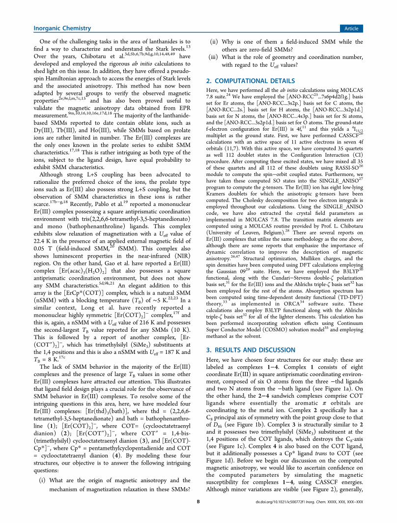
gxx = 0.6742, gyy = 1.4119, and gzz = 14.8817; this is a ratheraxial set of anisotropy and lacks pure Ising nature (see Table 1and Table S2 in the Supporting Information for details). All theeight Kramers doublets (KDs) are found to span over anenergy window of 325 cm−1. The relative energies of the eightlow-lying KDs, along with the computed anisotropy, are givenin Table 1 (also see Tables S1 and S2 and Figure S1 in theSupporting Information). The computed gzz orientation for theground-state KD in 1 is found to be directed toward one of the−N donors of bathophenanthroline ligand and is tilted 25.8°from the Er−N bond vector (see Figure 1a). The orientation ofthe gzz vector in this case is not surprising, since it has chosen toalign with the ligand possessing the least electrostatic repulsion.
Since all the oxygen atoms carry a formal negative charge, theEr−N bond direction is preferred for the gzz vector orientation.The computed NPA charges illustrate the above points that allthe oxygen atoms are found to possess an average negativecharge of −0.32 while nitrogen atoms possess an averagenegative charge of −0.18 (see Table S3 in the SupportingInformation). Orientation of magnetic anisotropy as well asmagnetic moment computed has been found to minimize theelectrostatic energy (i.e., electrostatic repulsion between ligandsand electron density of the metals).36
To probe the mechanism of relaxation, data beyond theground-state KDs must be analyzed. The magnetic relaxation inlanthanides is found to occur essentially because of threefactors, in the absence of intermolecular interactions:5b,37
(i) via QTM between the ground-state KDs, which occursdue to large transverse anisotropy of the ground-stateKDs;
(ii) via the Orbach/Raman process38 which accounts for therelaxation via the excited KDs and occurs essentially dueto the noncoincidence of the principal anisotropic axes;and
(iii) via thermally assisted QTM (TA-QTM), which accountsfor relaxation via the excited states due to the non-Isingnature of the excited KDs.
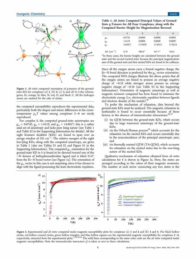
Qualitative mechanism of relaxation obtained from ab initiocalculations for 1 is shown in Figure 3a. Here, the states arearranged according to the values of their magnetic moments.The number at each arrow connecting any two states is the
Figure 1. Ab initio computed orientation of g-tensors of the ground-state KDs for complexes (a) 1, (b) 2, (c) 3, and (d) 4. Color scheme:green, Er; orange, Si; blue, N; red, O; and black, C. All the hydrogenatoms are omitted for the sake of clarity.
Figure 2. Experimental and ab initio computed molar magnetic susceptibility plots for complexes (a) 1 and 2 and (b) 3 and 4. The black hollowcircles, red hollow crossed circles, green hollow triangles, and blue hollow squares are the experimental magnetic susceptibility for complexes 1−4,respectively, extracted from the experimental plots.17c,f,19,22 The solid lines corresponding to the same color code are the ab initio computed molarmagnetic susceptibilities. Note the intermolecular interaction zJ is taken as zero in these calculations.
Table 1. Ab Initio Computed Principal Values of Ground-State g-Tensors for All Four Complexes, along with theComputed Barrier Height for Magnetization Reversal
1 2 3 4
gxx 0.6742 0.0000 0.0000 0.0004gyy 1.4119 0.0000 0.0000 0.0009gzz 14.8817 17.9439 17.9413 17.9214
ΔE (cm−1) 37.0 280.4a 247.1a 164.5aIn these cases, the barrier heights are calculated between the groundstate and the second excited state, because the principal magnetizationaxes of the ground start and first excited KDs are found to be collinear.
Inorganic Chemistry Article
dx.doi.org/10.1021/ic500772f | Inorg. Chem. XXXX, XXX, XXX−XXXC
mean absolute value of the matrix elements of the transitionmagnetic moments between the corresponding states. For 1,the computed g-tensors show significant transverse componentwith (gxx = 0.6742 , gyy = 1.4119) in the ground state. Thisclearly suggest that the major relaxation is likely to the be QTMin the ground state. Our calculations also affirm this point asshown in Figure 3a. The next excited KD is located at 37 cm−1
and possesses much larger transverse anisotropy. The gzz-axis inthis case is found to lie at the intersection of N and O donorligand and deviates from the ground-state KD by 20°. Thisactivates the Orbach/Raman relaxation via the first excited stateand as expected a significant magnetic moment matrix elementhas also been observed for this process (see Figure 3a).39 Sincethe transverse anisotropy of the first excited KD is large, thisalso leads to a significant TA-QTM process, and this is alsoreflected in the computed numbers.The first excited KD in this complex is located at 37 cm−1
(53.24 K) higher from the ground state. Since the majorrelaxation occurs via the first excited state, this gap of 37 cm−1
between the ground state and the first excited state can betaken as the Ueff value, which can be further directly comparedto the reported experimental Ueff values.
19 Complex 1 exhibitstwo relaxations in the AC susceptibility studies, where the firstone characterized to be a fast relaxation yields a barrier heightof 15.58 K, while the other is a slow relaxation with an effectivebarrier height of 22.37 K.19 These two relaxations wereattributed to the presence of different conformation of themethyl groups present in the −thd ligands or the presence oftwo distinct but closely related crystallographic phases. To testthis hypothesis of conformational-dependent relaxation, we
have modeled a complex from the X-ray structure of 1 (model1a) where these methyl groups are kept in eclipsedconformations (see Figures S2 and S6 and Table S4 in theSupporting Information for details). Our calculations on model1a also yield exactly the same barrier heights, anisotropies, andenergy spectra, compared to the parent complex, and nonoticeable electronic differences are witnessed, which supportsthe conclusion that methyl rotation has no influence on themagnitude of Ueff values. This illustrates that the methyl groupconformations are not strong enough to perturb the magneticanisotropy at the Er(III) center. Since methyl groups are notdirectly attached to the Er(III) center, this is rather expected.However, there are literature precedents where the orientationsof the H atoms present at the coordinating water molecules arefound to drastically influence the orientation of the g-tensorsand the magnetic relaxation.9e Thus, our rationale here is thatthe observed slow relaxation could be due to TA-QTM/Orbach/Raman process and thus can be compared to ourestimated Ueff value of 53.24 K and the fast relaxation is likelyto be due to QTM. Other analysis such as conformational/structural optimization with DFT also does not provide arationale for two relaxation phenomena observed23 (see TablesS5 and S6, and Figure S3, in the Supporting Information fordetails).For complex 2, the gzz-axis is found to orient along the
principal C8-axis, passing through the center of the COT ligand(see Figure 1b), despite significant negative charges on thecarbon atoms (DFT calculations; see Table S7 in theSupporting Information for details). Although the C2-axesbeing perpendicular to the C8 are likely to be in the less
Figure 3. Ab initio computed magnetization blocking barrier for all complexes 1−4: (a) complex 1, (b) complex 2, (c) complex 3, and (d) complex4. The thick black line indicates the Kramers doublets (KDs), as a function of magnetic moment. The dotted green lines show the possible pathwayof the Orbach process. The dotted blue lines show the most probable relaxation pathways for magnetization reversal. The dotted red lines representthe presence of QTM/TA-QTM between the connecting pairs. The numbers provided at each arrow are the mean absolute value for thecorresponding matrix element of transition magnetic moment.42
Inorganic Chemistry Article
dx.doi.org/10.1021/ic500772f | Inorg. Chem. XXXX, XXX, XXX−XXXD
repulsive direction, this would not preserve the overallsymmetry of the molecule and is not a unique axis of directionfor the anisotropy. This is also in accordance with previousobservations on similar higher symmetry structures, where theanisotropy is found to align always along the principal axis ofsymmetry, independent of the electrostatic repulsion.6 Similarsituation is encountered also in complexes 3 and 4 (see Figures3b and 3c). The energy spectra of the eight low-lying KDs in 2and 3 are found to spread over a range of 500 cm−1, which islarger than that of complex 4 (ca. 325 cm−1). For complexes 2−4, the computed g-tensors are of Ising type (see Table 1 andTables S8−S13, and Figure S4, in the Supporting Information)with the gxx and gyy values being essentially zero, whereas the gzzvalues exceed 17.92 in all of the cases. This reveals interestingdifferences between complex 1 and complexes 2−4, where thelater set is found to be superior over complex 1. The computedUeff values for complexes 2−4 are 403.5, 355.5, and 243.5 K,respectively, and this is in agreement with the experimental data(216, 187, and 197 K for 2, 3, and 4, respectively),22,17c,f
although the computed values are overestimating the Ueffvalues. Discrepancy between computed and the experimentalvalues are expected as the computed values assume inherentlyno QTM between the ground-state KDs and no intermolecularinteractionsthese are conditions that are very stringent anddifficult to meet. Our calculated Ueff values are in goodagreement with the earlier reports.23 We would like to notehere that, although no magnetic field has been applied,anisotropy field contribution to the effective magnetic fieldcauses the magnetic moment to be oriented along certaincrystallographic directions.40
The computed QTM effect between the ground-state KDs inall cases are found to be very small (see Figures 3b−d) with thecalculated matrix coefficients increasing in the following order:2 < 3 < 4. Interestingly, the computed Ueff value has also beenfound to decrease in the same order. For complexes 2 and 3,the anisotropy axis of the ground-state KD is found to becollinear with the first five excited KDs. (Note that thedeviations are found to be <2°;6 also see Tables S9 and S11 inthe Supporting Information for details). This suggests that the
relaxation, in principle, should happen via the sixth KD;however, the mJ = ±1/2 energy level is found to be stabilized asthe second excited state in both cases. This enforces relaxationat this point via TA-QTM process as this possesses a significanttransverse anisotropy (see Figures 4b and 4c). Thus, thepresence of high symmetry leads to collinear magnetization axisand suppress the magnetization relaxation via the first excitedlevel for complexes 2 and 3, although the absolute Ueff valuethat is computed varies from experimental observations.7,16b,14e
On the other hand, in case of complexes 1 and 4, thenoncoincidence of the principal axes of magnetization ofground-state and first excited KDs activates the magneticrelaxation via first excited state KD (see Tables S2 and S13 inthe Supporting Information for details). This observeddifference in complex 4 is likely to be attributed to the lackof a higher-order symmetry axis and to the fact that thestructure is rather bent, with an acute COT−Er−Cp* angle(∼170°). The presence of Cp* ligand in 4 causes largerrepulsion on the axial direction, and this results in stabilizationof low-magnitude mJ orientations as the first excited state.Besides, the first excited state is tilted, with respect to theground state, and this activates relaxation to be operative via thefirst excited state.To gain more insight into the mechanism of magnetic
relaxation, we have also computed the crystal field parameters.Assuming that intermolecular and hyperfine interactions aresmall or negligible, the probability of QTM between theground-state KDs is best described by the crystal field (CF)parameters.5b,41,50,51 The corresponding crystal field Hamil-tonian is given as HCF = Bk
qOkq, where Bk
q is the crystal fieldparameter while Ok
q is the Steven’s operator. The QTM effectsare expected to be dominant in a system where the nonaxial Bk
q
(where k ≠ 0, and q = 2, 4, 6) terms are larger than the axial Bkq
(where k = 0, and q = 2, 4, 6) terms. The computed CFparameters for all four complexes 1−4 are given in Table S14 inthe Supporting Information. In the case of complex 1, asignificant transverse anisotropy has been observed (gxx =0.6742, gyy = 1.4119) for the ground state and this is reflected incomputed CF parameters, where the nonaxial B2
1, B22, B4
−3, and
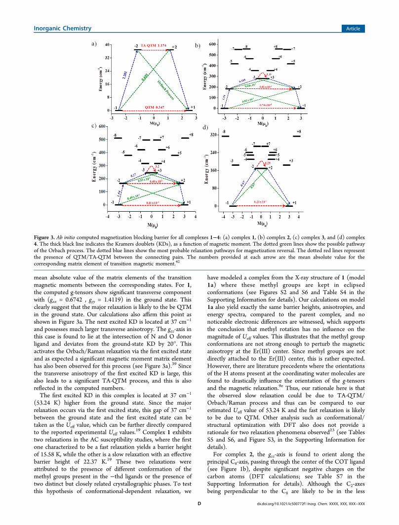
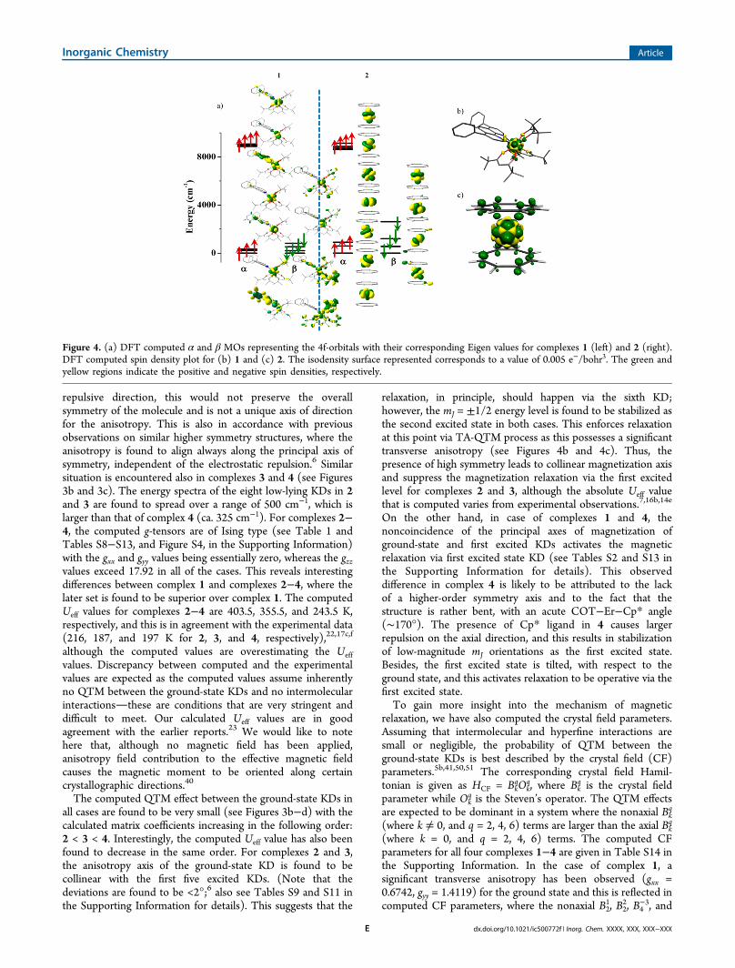
Figure 4. (a) DFT computed α and β MOs representing the 4f-orbitals with their corresponding Eigen values for complexes 1 (left) and 2 (right).DFT computed spin density plot for (b) 1 and (c) 2. The isodensity surface represented corresponds to a value of 0.005 e−/bohr3. The green andyellow regions indicate the positive and negative spin densities, respectively.
Inorganic Chemistry Article
dx.doi.org/10.1021/ic500772f | Inorg. Chem. XXXX, XXX, XXX−XXXE
B65 terms are significantly larger than the axial terms (B2
0, B40, B6
0;see Table S14 in the Supporting Information). The lack ofcrystallographic symmetry and asymmetric CF interactionsleads to large transverse anisotropy, and this activates theground-state QTM effect, which destroys the SMM behavior.The application of the magnetic field lifts the degeneracy of the±mJ levels leading to the suppression of QTM effect andobservation of field-induced SMM characteristics with tworelaxation phenomena. Although the applied magnetic fieldreduces the ground-state QTM effects to a certain extent, otherrelaxation processes are still dominant, leading to a very smallUeff value for complex 1. On the other hand, the computed CFparameters for complexes 2 and 3 reveal that axial terms arerelatively large for this set of complexes. Quite interestingly, theaxial B2,4,6
0 terms are found to decrease in the same order (2 > 3> 4 > 1) as that of the computed Ueff value.This is clearly correlated to the point group symmetry of
complexes 1−4. Particularly, the axial terms are found to bemore than an order of magnitude larger, compared to thenonaxial terms for complexes 2 and 3, while complexes 1 and 4possess significant nonaxial terms. It is noteworthy to mentionhere that the Bk
q parameters are vanishing in the presence ofhigh symmetry, and this opens up a viable way to control theQTM by fine-tuning the local symmetry around the metal ions.To further understand the role of CF parameters and the 4f-
ligand interactions, we have analyzed the 4f orbital energies,charges, and spin densities obtained from DFT calculations.Attention has been paid particularly to complexes 1 and 2. In 2,all the carbon atoms are found to carry equal negative charge of−0.12, whereas in 1, a positive charge exists on nitrogen atomsand a significant negative charge is present on oxygen atoms(see Tables S3 and S7 in the Supporting Information fordetails). The computed spin density plots for 1 and 2 areshown in Figures 4b and 4c. Interestingly, for complex 1, amixture of spin delocalization and polarization is detected withpredominant spin polarization on the nitrogen donor atoms.For complex 2, a dominant spin delocalization with significant
spin densities on the π-orbitals of the COT ligands has beenobserved. Thus, the way the spins are propagated within thesetwo molecules are markedly different. This is in fact attributedto the difference in bonding between 1 and 2. The computedMO diagram for the 4f orbitals along with their energies for 1and 2 are shown in Figure 4a. In both complexes, the 4f α-orbitals are found to split, but the interaction with the ligands isparticularly visible in complex 1. Of particular interest are thefour β-orbitals energies where larger splitting is detected withcomplex 2 than complex 1. Since the 4f β-orbital densities arecorrelated to the ground-state mJ levels,36b this splitting isfurther analyzed. In complex 2, the COT σ*-orbitals are foundto interact with the 4f β-orbitals and the orbital ordering arefound to relate to the nature of the interaction with the σ*-orbitals and the number of nodal planes present in them. Forcomplex 1, however, the interactions are not very strong andthis might be related to the orbital energies and the liganddonor abilities.Apart from the SMM behavior, lanthanide complexes also
exhibit luminescence properties.2e,9a,12b This is particularly truefor the Er(III) complexes, which exhibit characteristic features,and these transitions reveal intrinsic details of magneticanisotropy,9e as well as lanthanide−ligand bonding interactions.Characteristic luminescence spectrum for complex 1 in dilutedmethanol solution has been reported.19 Two peaks ofsignificance are observed: one at 289 nm and another at 342nm.19 Furthermore, several f-f transitions have also beenobserved in the range of 400−700 nm. To gain insights intothese two particular intense transitions, we have performedtime-dependent DFT (TD-DFT) calculations on the organicligand backbone using ORCA suite of program, although thismethod is very qualitative, the computed transitions are foundto be in agreement with the experimental results (for moredetails, see the Supporting Information and, in particular,Figure S5).
Role of Geometry and the Coordination Numbers onthe Ueff Values: Building Highly Anisotropic SMMs. Since
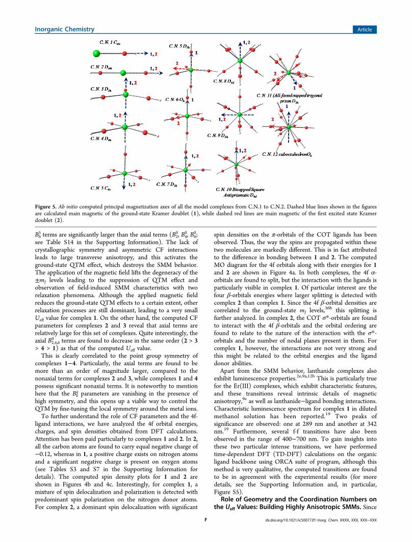
Figure 5. Ab initio computed principal magnetization axes of all the model complexes from C.N.1 to C.N.2. Dashed blue lines shown in the figuresare calculated main magnetic of the ground-state Kramer doublet (1), while dashed red lines are main magnetic of the first excited state Kramerdoublet (2).
Inorganic Chemistry Article
dx.doi.org/10.1021/ic500772f | Inorg. Chem. XXXX, XXX, XXX−XXXF

the effect of ligand field and the role of symmetry5b,14b on themagnetic relaxation on Er(III)-based SIMs are alreadyestablished, here, we have taken one step forward to predictthe role of point group symmetry and the coordination numberon the computed magnetic anisotropy. To best of ourknowledge, there are no such quantitative studies reported inthe literature, where in silico fine tunings are attempted. Thereare certainly two factors at play for the fine tuning of themagnetic anisotropy. The first, being the electrostatic potentialof the ligands and its importance, has been discussed at lengthfor Dy(III) SMMs earlier.7b,15c,36 In this context, the ligandfield approach popularized by Long et al.3e must be mentioned,since this is frequently used to rationalize the presence/absenceof SMM characteristics in lanthanide-based molecular magnets.However, this approach inherently assumes the absence ofQTM/TA-QTM effects, which are found to be the majorrelaxation mechanism for the lanthanide-based molecularmagnets.43 The second factor at play here is the coordinationsymmetry, where highly symmetric lanthanide complexes arefound to be superior in exhibiting SMM characteristics.Although the importance of this factor in dictating SMMcharacteristics has been realized earlier, the potential of thiseffect on the magnetic relaxation has not been explored indetail.3e,6,17f Interestingly, complex 2 shows the second-largestTB value for any SMM; however, the ligand field effects of theCOT ligands are ideally suited to enhance the SMM characterof oblate ions.17f This suggests that perhaps controllingsymmetry in a given complex is more important than fine-tuning the electrostatic potential of the ligands. This is clearlymanifested in the magnetic properties of complexes 3 and 4,where the symmetry loss leads to a significant reduction in theobserved Ueff values. Keeping this in mind, we have decided toexplore the role of coordination numbers on the magneticanisotropy, and this has been done by modeling structures withvarying coordination numbers, from 1 to 12. All of the modelstructures are generated also by maintaining the closest higher-order symmetry to achieve large Ueff values. For this purpose,we have chosen [Er(OH)n]
m∓ models where the Er−Odistances are kept at 2.3 Å, the O−H bond distances arefixed at 1 Å, and the Er−O−H bond angle(s) are fixed at 180°to preserve the symmetry for all of the models. We would liketo note here that the models considered here are fictitious andare employed here only to probe the role of symmetry andcoordination number; however, the linear coordination testedhere might be achievable with ligands such as cyanides.44
Models studied here are shown in Figure 5, along with thecomputed gzz anisotropy axis and the energies of low-lying eightKDs for model complexes from C.N.1 to C.N.12 are providedin the Supporting Information (see Table S16).The following points emerge from our predictions:(i) The C.N.1 and C.N.2 (C∞v and D∞h) models do not
possess any equatorial ligation, because of which the mJ = ±1/2level becomes the ground state. This state has large transverseanisotropy and therefore is unlikely to yield any SMMcharacter. This is contrary to what has been proposed for theDy(III) SMMs,14c and this is also well-reproduced in ourcomputational studies on Dy(III) model analogues (see theSupporting Information for details).(ii) High symmetry such as D3h and D4h associated with
C.N.3 and C.N.4 offer a large magnetic anisotropy and possessan Ising-type ground state with the gzz passing always throughthe principal axis of symmetry. Because of the high symmetry,the colinearity of the gzz axis is maintained for all the eight KDs,
leading to a large Ueff value measured as the gap between theground state and the highest excited state. However, as theelectrostatic potential on the −xy plane increases withincreasing coordination number, the Ueff value for the C.N.4model has been found to be higher, compared to the C.N.3model (see the Table S16 in the Supporting Information fordetails). Thus, our calculations predict a barrier height of nearly1150 K for the four coordinate models with D4h symmetry (seeFigure 5). Although low-coordination-number lanthanidecomplexes are reported as early as in the 1990s,45 the magneticproperties have not been thoroughly measured. A recent reportby Tang et al. sheds light on this issue where the three-coordinated Er(III) complex is found to be a superior SMMwith Ueff = 120 K.46 This strongly supports our predictions.(iii) The addition of more ligands is assumed to occur in the
axial direction for C.N.5−C.N.7. Since addition along the axialdirection is unfavorable for the prolate ions, this alters the mJlevels. For C.N.5, square pyramidal geometry and trigonalbipyramidal geometries are modeled where square pyramidalstructure is found to yield larger Ueff, compared to trigonalbipyramidal D3h structure. In the D3h structure, the two axialligands destabilize the mJ = ±15/2 states and lower mJ levelsbecome the ground state which bring forth a large transverseanisotropy. A similar situation is encountered also for the C.N.6and C.N.7 models (see Table S16 in the SupportingInformation), although for the C.N.7 model, large mJ is gettingstabilized, which leads to the expectation of moderate SMMbehavior for this structure. This is similar to the case reportedfor Dy(III) complexes where D5h point group molecules arepredicted to be superior to the Oh point group structure.5b
(iv) For C.N.8, a square antiprismatic structure with the D4dpoint group is assumed. Since all the ligands are nonaxial, theprolate density faces repulsion only on the edges and thiscertainly improves the magnetic behavior with mJ = ±15/2 andmJ = ±13/2 as the ground state and the first excited state,respectively. However, the repulsion on the edges stabilizes mJ= ±1/2 as the second excited state and this enforces relaxationvia this state and brings down the net Ueff values. Thisessentially yields an “M” shape energy level and a similar energypattern has been observed also for complex 2.(v) Higher coordination number (i.e., >8) does not offer
significant improvement because the additional ligands occupythe axial positions.(vi) A similar model study has also been undertaken for
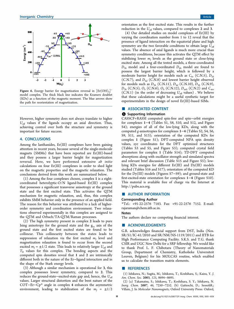
Dy(III) ion (see Figure S7 and Table S16 in the SupportingInformation) for comparison. Among all the models studied forthe Dy(III), the C.N.2 model (D∞h symmetry) is found to havethe largest effective barrier height (Ueff = 3035 K). This is dueto the collinearity of all the excited KDs, with respect to theground-state KDs. Remarkably, the CN 2 model of Er(III) doesnot expect to exhibit any SMM behavior, because of theabsence of equatorial ligation, whereas the same model withDy(III) shows the largest effective barrier for magnetizationreversal. This difference observed is attributed to the nature off-electron density in both ions, i.e., prolate vs oblate for Dy(III)and Er(III) ions, respectively. (The energy barrier formagnetization reversal in the [Er(OH)4]
− model complex isshown in Figure 6; for a discussion of other Dy(III) models, seethe Supporting Information).Overall, the model studies suggest that maintaining
symmetry is extremely important, because this yields acomplete collinearity of the principal magnetization axesamong all the KDs. This enhances the Ueff value significantly.
Inorganic Chemistry Article
dx.doi.org/10.1021/ic500772f | Inorg. Chem. XXXX, XXX, XXX−XXXG
However, higher symmetry does not always translate to higherUeff values if the ligands occupy an axial direction. Thus,achieving control over both the structure and symmetry isimportant for future success.
4. CONCLUSIONSAmong the lanthanides, Er(III) complexes have been gainingattention in recent years, because several of the single-moleculemagnets (SMMs) that have been reported are Er(III)-basedand they possess a larger barrier height for magnetizationreversal. Here, we have performed extensive ab initiocalculations on four Er(III) complexes in order to shed lighton the magnetic properties and the magnetic relaxation. Theconclusions derived from this work are summarized below.(1) Among the four complexes chosen, complex 1 is a eight-
coordinated heterolyptic-O/N ligand-based Er(III) complexthat possesses a significant transverse anisotropy at the groundstate and the first excited state. This activates the QTMmechanism for magnetic relaxation, and, thus, this complexexhibits SMM behavior only in the presence of an applied field.The reason for this behavior was attributed to a lack of higher-order symmetry and coordination environment. Two relaxa-tions observed experimentally in this complex are assigned tothe QTM and Orbach/TA-QTM/Raman processes.(2) The high symmetry present in complex 2 leads to pure
Ising anisotropy for the ground state and the gzz axis of theground state and the first excited states are found to becollinear. This collinearity between the states leads tosuppression of relaxation via the first excited mJ level andmagnetization relaxation is found to occur from the secondexcited mJ = ±1/2 state. This leads to relatively larger Ueff andTB values for this complex. The bonding aspects and thecomputed spin densities reveal that 1 and 2 are intrinsicallydifferent both in the nature of the Er−ligand interaction and inthe shape of the Stark energy levels.(3) Although a similar mechanism is operational for 3, this
complex possesses lower symmetry, compared to 2. Thisreduces the ground-state−excited-state gap and, hence, the Ueffvalues. Larger structural distortion and the bent nature of theCOT−Er−Cp* angle in complex 4 enhances the asymmetricenvironment, leading to stabilization of the mJ = ±1/2
orientation as the first excited state. This results in the furtherreduction in the Ueff values, compared to complexes 2 and 3.(4) Our detailed studies on model complexes of Er(III) by
varying the coordination number from 1 to 12 reveal that thepresence of ligand interaction on the equatorial plane and highsymmetry are the two favorable conditions to obtain large Ueffvalues. The absence of axial ligands is much more crucial thansymmetry conditions, because this activates the QTM effect bystabilizing lower mJ levels as the ground state or close-lyingexcited state. Among all the tested models, a three-coordinatedD3h model and a four-coordinated D4h model are found topossess the largest barrier height, which is followed by amoderate barrier height for models such as C4v (C.N.5), D5h(C.N.7), and D4d (C.N.8) and lowest barrier height observedfor models such as D3h (C.N.11), D4d (C.N.10), D3h (C.N.9),D3h (C.N.5), Oh (C.N.6), Oh (C.N.12), D∞h (C.N.2) and C∞v(C.N.1) (in the order of decreasing Ueff values) . We believethat these calculations might be a useful synthetic target forexperimentalists in the design of novel Er(III)-based SIMs.
■ ASSOCIATED CONTENT*S Supporting InformationCASSCF+RASSI computed spin-free and spin−orbit energiesfor complexes 1−4 (Tables S1, S8, S10, and S12, and FigureS4); energies of all of the low-lying KDs, along with thecomputed g-anisotropies for complexes 1−4 (Tables S2, S4, S6,S9, S11, and S13); orientation of the computed KDs forcomplex 1 (Figure S1); DFT-computed NPA spin densityvalues, xyz coordinates for the DFT optimized structures(Tables S3 and S5, and Figure S3); computed crystal fieldparameters for complex 1 (Table S14); TD-DFT computedabsorptions along with oscillator strength and simulated spectraand relevant brief discussion (Table S15 and Figure S5); low-lying KDs energies for different Er(III) and Dy(III) modelsstudied (Tables S16 and S17); orientation of the computed KDfor the Dy(III) models (Figures S7−S9); and ground-state andfirst-excited-state orientation for complexes 1−4 (Figure S10).This material is available free of charge via the Internet athttp://pubs.acs.org.
■ AUTHOR INFORMATIONCorresponding Author*Tel.: +91-22-2576 7183. Fax: +91-22-2576 7152. E-mail:[email protected] authors declare no competing financial interest.
■ ACKNOWLEDGMENTSG.R. acknowledges financial support from DST, India (Nos.SR/S1/IC-41/2010 and SR/NM/NS-1119/2011) and IITB forHigh Performance Computing Facility. S.K.S. and T.G. thankCSIR and UGC New Delhi for a SRF fellowship. We would liketo thank Prof. L. F. Chibotaru (Theory of NanomaterialsGroup, Department of Chemistry, Katholieke UniversiteitLeuven, Belgium) for his MOLCAS routine, which enabledus to calculate the transition matrix elements.
■ REFERENCES(1) Ishikawa, N.; Sugita, M.; Ishikawa, T.; Koshihara, S.; Kaizu, Y. J.Am. Chem. Soc. 2003, 125, 8694−8695.(2) (a) Takamatsu, S.; Ishikawa, T.; Koshihara, S. Y.; Ishikawa, N.Inorg. Chem. 2007, 46, 7250−7252. (b) Gatteschi, D.; SessoliR.;Villain, J. In Molecular Nanomagnets; Oxford University Press: Oxford,
Figure 6. Energy barrier for magnetization reversal in [Er(OH)4]−
model complex. The thick black line indicates the Kramers doublet(KDs) as a function of the magnetic moment. The blue arrows showthe path for reorientation of magnetization.
Inorganic Chemistry Article
dx.doi.org/10.1021/ic500772f | Inorg. Chem. XXXX, XXX, XXX−XXXH
U.K., 2006. (c) Christou, G.; Gatteschi, D.; Hendrickson, D. N.;Sessoli, R. MRS Bull. 2000, 25, 66−71. (d) Sessoli, R.; Gatteschi, D.;Caneschi, A.; Novak, M. A. Nature 1993, 365, 141−143. (e) Luzon, J.;Sessoli, R. Dalton Trans. 2012, 41, 13556−13567. (f) Sorace, L.;Benelli, C.; Gatteschi, D. Chem. Soc. Rev. 2011, 40, 3092−3104.(g) Guo, Y. N.; Xu, G. F.; Guo, Y.; Tang, J. K. Dalton Trans. 2011, 40,9953−9963. (h) Ishikawa, N. Polyhedron 2007, 26, 2147−2153.(3) (a) Woodruff, D. N.; Winpenny, R. E.; Layfield, R. A. Chem. Rev.2013, 113, 5110−5148. (b) Woodruff, D. N.; Tuna, F.; Bodensteiner,M.; Winpenny, R. E. P.; Layfield, R. A. Organometallics 2013, 32,1224−1229. (c) Zhang, P.; Zhang, L.; Xue, S.; Lin, S.; Tang, J. Chin.Sci. Bull. 2012, 57, 2517−2524. (d) Mondal, K. C.; Sundt, A.; Lan, Y.;Kostakis, G. E.; Waldmann, O.; Ungur, L.; Chibotaru, L. F.; Anson, C.E.; Powell, A. K. Angew. Chem., Int. Ed. Engl. 2012, 51, 7550−7554.(e) Rinehart, J. D.; Long, J. R. Chem. Sci. 2011, 2, 2078−2085.(f) Sessoli, R.; Powell, A. K. Coord. Chem. Rev. 2009, 253, 2328−2341.(4) (a) Aromi, G.; Aguila, D.; Gamez, P.; Luis, F.; Roubeau, O. Chem.Soc. Rev. 2012, 41, 537−546. (b) Winpenny, R. E. P. Angew. Chem., Int.Ed. 2008, 47, 7992−7994. (c) Ardavan, A.; Rival, O.; Morton, J. J. L.;Blundell, S. J.; Tyryshkin, A. M.; Timco, G. A.; Winpenny, R. E. P.Phys. Rev. Lett. 2007, 98, 057201−057204. (d) Affronte, M.; Troiani,F.; Ghirri, A.; Candini, A.; Evangelisti, M.; Corradini, V.; Carretta, S.;Santini, P.; Amoretti, G.; Tuna, F.; Timco, G.; Winpenny, R. E. P. J.Phys. D: Appl. Phys. 2007, 40, 2999−3004. (e) Leuenberger, M. N.;Loss, D. Physica E 2001, 10, 452−457. (f) Coronado, E.; Day, P.Chem. Rev. 2004, 104, 5419. (g) Bogani, L.; Wernsdorfer, W. Nat.Mater. 2008, 7, 179−186. (h) Baldoví, J. J.; Cardona-Serra, S.;Clemente-Juan, J. M.; Coronado, E.; Gaita-Arino, A.; Palii, A. Inorg.Chem. 2012, 51, 12565−12574.(5) (a) Wang, Z.-G.; Lu, J.; Gao, C.-Y.; Wang, C.; Tian, J.-L.; Gu, W.;Liu, X.; Yan, S.-P. Inorg. Chem. Commun. 2013, 27, 127−130. (b) Liu,J.-L.; Chen, Y.-C.; Zheng, Y.-Z.; Lin, W.-Q.; Ungur, L.; Wernsdorfer,W.; Chibotaru, L. F.; Tong, M.-L. Chem. Sci. 2013, 4, 3310−3316.(c) Chen, G. J.; Guo, Y. N.; Tian, J. L.; Tang, J.; Gu, W.; Liu, X.; Yan,S. P.; Cheng, P.; Liao, D. Z. Chem.Eur. J. 2012, 18, 2484−2487.(d) Cardona-Serra, S.; Clemente-Juan, J. M.; Coronado, E.; Gaita-Arino, A.; Camon, A.; Evangelisti, M.; Luis, F.; Martinez-Perez, M. J.;Sese, J. J. Am. Chem. Soc. 2012, 134, 14982−14990.(6) Blagg, R. J.; Ungur, L.; Tuna, F.; Speak, J.; Comar, P.; Collison,D.; Wernsdorfer, W.; McInnes, E. J. L.; Chibotaru, L. F.; Winpenny, R.E. P. Nat. Chem. 2013, 5, 673−678.(7) (a) Xiong, G.; Qin, X.-Y.; Shi, P.-F.; Hou, Y.-L.; Cui, J.-Z.; Zhao,B. Chem. Commun. 2014, 50, 4255−4257 (DOI: 10.1039/c3cc49342c). (b) Langley, S. K.; Wielechowski, D. P.; Vieru, V.;Chilton, N. F.; Moubaraki, B.; Abrahams, B. F.; Chibotaru, L. F.;Murray, K. S. Angew. Chem., Int. Ed. Engl. 2013, 52, 12014−12019.(c) Colacio, E.; Ruiz, J.; Mota, A. J.; Palacios, M. A.; Ruiz, E.;Cremades, E.; Hanninen, M. M.; Sillanpaa, R.; Brechin, E. K. C. R.Chim. 2012, 15, 878−888. (d) Baskar, V.; Gopal, K.; Helliwell, M.;Tuna, F.; Wernsdorfer, W.; Winpenny, R. E. Dalton Trans. 2010, 39,4747−4750. (e) Zhang, C.; Chen, Y.; Ma, H.; Yu, T.; Liu, B.; Pang, H.New J. Chem. 2013, 37, 1364−1370. (f) Murugesu, M.; Mishra, A.;Wernsdorfer, W.; Abboud, K. A.; Christou, G. Polyhedron 2006, 25,613−625. (g) Mishra, A.; Wernsdorfer, W.; Parsons, S.; Christou, G.;Brechin, E. K. Chem. Commun. (Cambridge) 2005, 2086−2088.(h) Osa, S.; Kido, T.; Matsumoto, N.; Re, N.; Pochaba, A.; Mrozinski,J. J. Am. Chem. Soc. 2004, 126, 420−421.(8) (a) Murakami, R.; Nakamura, T.; Ishida, T. Dalton Trans 2014,43, 5893−5898. (b) Mei, X. L.; Wang, X. F.; Wang, J. J.; Ma, Y.; Li, L.C.; Liao, D. Z. New J. Chem. 2013, 37, 3620−3626. (c) Gao, Y.-y.;Wang, Y.-l.; Hu, P.; Yang, M.-f.; Ma, Y.; Wang, Q.-l.; Li, L.-c.; Liao, D.-z. Inorg. Chem. Commun. 2013, 27, 31−35. (d) Rinehart, J. D.; Fang,M.; Evans, W. J.; Long, J. R. Nat. Chem. 2011, 3, 538−542.(e) Rinehart, J. D.; Fang, M.; Evans, W. J.; Long, J. R. J. Am. Chem. Soc.2011, 133, 14236−14239. (f) Wang, X. L.; Li, L. C.; Liao, D. Z. Inorg.Chem. 2010, 49, 4735−4737. (g) Xu, J.-X.; Ma, Y.; Liao, D.-z.; Xu, G.-F.; Tang, J.; Wang, C.; Zhou, N.; Yan, S.-P.; Cheng, P.; Li, L.-C. Inorg.Chem. 2009, 48, 8890−8896. (h) Mei, X.-L.; Ma, Y.; Li, L.-C.; Liao,D.-Z. Dalton Trans. 2012, 41, 505−511.
(9) (a) Wang, Y.-L.; Ma, Y.; Yang, X.; Tang, J.; Cheng, P.; Wang, Q.-L.; Li, L.-C.; Liao, D.-Z. Inorg. Chem. 2013, 52, 7380−7386. (b) Ren,M.; Pinkowicz, D.; Yoon, M.; Kim, K.; Zheng, L. M.; Breedlove, B. K.;Yamashita, M. Inorg. Chem. 2013, 52, 8342−8348. (c) Menelaou, M.;Ouharrou, F.; Rodriguez, L.; Roubeau, O.; Teat, S. J.; Aliaga-Alcalde,N. Chem.Eur. J. 2012, 18, 11545−11549. (d) Guo, P. H.; Liu, J. L.;Zhang, Z. M.; Ungur, L.; Chibotaru, L. F.; Leng, J. D.; Guo, F. S.;Tong, M. L. Inorg. Chem. 2012, 51, 1233−1235. (e) Cucinotta, G.;Perfetti, M.; Luzon, J.; Etienne, M.; Car, P. E.; Caneschi, A.; Calvez,G.; Bernot, K.; Sessoli, R. Angew. Chem., Int. Ed. Engl. 2012, 51, 1606−1610. (f) Habib, F.; Lin, P. H.; Long, J.; Korobkov, I.; Wernsdorfer,W.; Murugesu, M. J. Am. Chem. Soc. 2011, 133, 8830−8833. (g) Guo,Y. N.; Xu, G. F.; Wernsdorfer, W.; Ungur, L.; Guo, Y.; Tang, J. K.;Zhang, H. J.; Chibotaru, L. F.; Powell, A. K. J. Am. Chem. Soc. 2011,133, 11948−11951. (h) Blagg, R. J.; Muryn, C. A.; McInnes, E. J. L.;Tuna, F.; Winpenny, R. E. P. Angew. Chem., Int. Ed. 2011, 50, 6530−6533. (i) Li, D. P.; Wang, T. W.; Li, C. H.; Liu, D. S.; Li, Y. Z.; You, X.Z. Chem. Commun. 2010, 46, 2929−2931. (j) Ke, H.; Xu, G. F.; Guo,Y. N.; Gamez, P.; Beavers, C. M.; Teat, S. J.; Tang, J. Chem. Commun.2010, 46, 6057−6059. (k) Jiang, S. D.; Wang, B. W.; Su, G.; Wang, Z.M.; Gao, S. Angew. Chem., Int. Ed. 2010, 49, 7448−7451. (l) Hewitt, I.J.; Tang, J.; Madhu, N. T.; Anson, C. E.; Lan, Y.; Luzon, J.; Etienne,M.; Sessoli, R.; Powell, A. K. Angew. Chem., Int. Ed. 2010, 49, 6352−6356. (m) Bernot, K.; Luzon, J.; Bogani, L.; Etienne, M.; Sangregorio,C.; Shanmugam, M.; Caneschi, A.; Sessoli, R.; Gatteschi, D. J. Am.Chem. Soc. 2009, 131, 5573−5579. (n) Lin, P. H.; Burchell, T. J.;Clerac, R.; Murugesu, M. Angew. Chem., Int. Ed. 2008, 47, 8848−8851.(o) Lin, P. H.; Burchell, T. J.; Ungur, L.; Chibotaru, L. F.;Wernsdorfer, W.; Murugesu, M. Angew. Chem., Int. Ed. 2009, 48,9489−9492.(10) Chibotaru, L. F.; Ungur, L.; Soncini, A. Angew. Chem., Int. Ed.Engl. 2008, 47, 4126−4129.(11) Note: These are quadrupole moment of the f-electron chargecloud, where prolate electron density signifies that the electron chargecloud is axially elongated, the preferred geometry is equatoriallycoordinated, and, for oblate electron density, the electron charge cloudis equatorially expanded; the crystal field should lie above and belowthe XY plane.(12) (a) Wang, Y.-L.; Gu, B.; Ma, Y.; Xing, C.; Wang, Q.-L.; Li, L.-C.;Cheng, P.; Liao, D.-Z. CrystEngComm 2014, 16, 2283−2289.(b) Pointillart, F.; Le Guennic, B.; Cauchy, T.; Golhen, S.; Cador,O.; Maury, O.; Ouahab, L. Inorg. Chem. 2013, 52, 5978−5990.(c) Liang, L.; Peng, G.; Li, G.; Lan, Y.; Powell, A. K.; Deng, H. DaltonTrans. 2012, 41, 5816−5823. (d) Yamase, T. Chem. Rev. 1998, 98,307−325.(13) Note: In lanthanide chemistry, the splitting of the mJ states dueto the weak crystal field is often referred to as the Stark splitting, andthe states themselves are referred to as Stark sublevels.(14) (a) Leng, J. D.; Liu, J. L.; Zheng, Y. Z.; Ungur, L.; Chibotaru, L.F.; Guo, F. S.; Tong, M. L. Chem. Commun. 2013, 49, 158−160.(b) Ungur, L.; Chibotaru, L. F. Phys. Chem. Chem. Phys. 2011, 13,20086−20090. (c) Swerts, B.; Chibotaru, L. F.; Lindh, R.; Seijo, L.;Barandiaran, Z.; Clima, S.; Pierloot, K.; Hendrickx, M. F. A. J. Chem.Theory Comput. 2008, 4, 586−594. (d) Ungur, L.; Van den Heuvel,W.; Chibotaru, L. F. New J. Chem. 2009, 33, 1224−1229. (e) Ungur,L.; Le Roy, J. J.; Korobkov, I.; Murugesu, M.; Chibotaru, L. F. Angew.Chem., Int. Ed. Engl. 2014, 53, DOI: 10.1002/anie.201310451.(f) Chibotaru, L.; Ceulemans, A.; Bolvin, H. Phys. Rev. Lett. 2008,101, 033003−4.(15) (a) Leng, J. D.; Liu, J. L.; Lin, W. Q.; Gomez-Coca, S.; Aravena,D.; Ruiz, E.; Tong, M. L. Chem. Commun. 2013, 49, 9341−9343.(b) Cremades, E.; Ruiz, E. Inorg. Chem. 2011, 50, 4016−4020.(c) Chilton, N. F.; Langley, S. K.; Moubaraki, B.; Soncini, A.; Batten, S.R.; Murray, K. S. Chem. Sci. 2013, 4, 1719−1730. (d) Jung, J.; daCunha, T. T.; Le Guennic, B.; Pointillart, F.; Pereira, C. L. M.; Luzon,J.; Golhen, S.; Cador, O.; Maury, O.; Ouahab, L. Eur. J. Inorg. Chem.2014, 2014, 3888−3894 (DOI: 10.1002/ejic.201400121).(16) (a) Ghosh, S.; Datta, S.; Friend, L.; Cardona-Serra, S.; Gaita-Arino, A.; Coronado, E.; Hill, S. Dalton Trans. 2012, 41, 13697−
Inorganic Chemistry Article
dx.doi.org/10.1021/ic500772f | Inorg. Chem. XXXX, XXX, XXX−XXXI

13704. (b) Baniodeh, A.; Lan, Y.; Novitchi, G.; Mereacre, V.;Sukhanov, A.; Ferbinteanu, M.; Voronkova, V.; Anson, C. E.; Powell,A. K. Dalton Trans. 2013, 42, 8926−8938. (c) Marx, R.; Moro, F.;Dorfel, M.; Ungur, L.; Waters, M.; Jiang, S. D.; Orlita, M.; Taylor, J.;Frey, W.; Chibotaru, L. F.; van Slageren, J. Chem. Sci. 2014, 5, 3287−3293. (d) Luzon, J.; Bernot, K.; Hewitt, I. J.; Anson, C. E.; Powell, A.K.; Sessoli, R. Phys. Rev. Lett. 2008, 100, 247204−5. (e) Pedersen, K.S.; Ungur, L.; Sigrist, M.; Sundt, A.; Schau-Magnussen, M.; Vieru, V.;Mutka, H.; Rols, S.; Weihe, H.; Waldmann, O.; Chibotaru, L. F.;Bendix, J.; Dreiser, J. Chem. Sci. 2014, 5, 1650−1660.(17) (a) Koo, B. H.; Lim, K. S.; Ryu, D. W.; Lee, W. R.; Koh, E. K.;Hong, C. S. Chem. Commun. 2012, 48, 2519−2521. (b) Feltham, H. L.C.; Klower, F.; Cameron, S. A.; Larsen, D. S.; Lan, Y.; Tropiano, M.;Faulkner, S.; Powell, A. K.; Brooker, S. Dalton Trans. 2011, 40,11425−11432. (c) Le Roy, J. J.; Korobkov, I.; Murugesu, M. Chem.Commun. 2014, 50, 1602−1604. (d) Girginova, P. I.; Pereira, L. C. J.;Coutinho, J. T.; Santos, I. C.; Almeida, M. Dalton Trans. 2014, 43,1897−1905. (e) Zhang, Y. Q.; Luo, C. L.; Wang, B. W.; Gao, S. J. Phys.Chem. A 2013, 117, 10873−10880. (f) Meihaus, K. R.; Long, J. R. J.Am. Chem. Soc. 2013, 135, 17952−17957. (g) Yamashita, A.;Watanabe, A.; Akine, S.; Nabeshima, T.; Nakano, M.; Yamamura, T.;Kajiwara, T. Angew. Chem., Int. Ed. 2011, 50, 4016−4020.(18) Silva, M. R.; Martín-Ramos, P.; Coutinho, J. T.; Pereira, L. C. J.;Martín-Gil, J. Dalton Trans. 2014, 43, 6752−6761 (DOI: 10.1039/c4dt00168k).(19) Martín-Ramos, P.; Ramos Silva, M.; Coutinho, J. T.; Pereira, L.C. J.; Chamorro-Posada, P.; Martín-Gil, J. Eur. J. Inorg. Chem. 2014,2014, 511−517.(20) Note: Single-molecule magnets (SMMs) in which prominentslow relaxation of magnetization has been observed upon applicationof magnetic field, compared to that in zero field.(21) (a) Ishida, T.; Watanabe, R.; Fujiwara, K.; Okazawa, A.; Kojima,N.; Tanaka, G.; Yoshii, S.; Nojiri, H. Dalton Trans. 2012, 41, 13609−13619. (b) Kajiwara, T.; Nakano, M.; Takahashi, K.; Takaishi, S.;Yamashita, M. Chem.Eur. J. 2011, 17, 196−205. (c) Mereacre, V.;Akhtar, M. N.; Lan, Y.; Ako, A. M.; Clerac, R.; Anson, C. E.; Powell, A.K. Dalton Trans. 2010, 39, 4918−4927.(22) Jiang, S. D.; Wang, B. W.; Sun, H. L.; Wang, Z. M.; Gao, S. J.Am. Chem. Soc. 2011, 133, 4730−4733.(23) Boulon, M. E.; Cucinotta, G.; Liu, S. S.; Jiang, S. D.; Ungur, L.;Chibotaru, L. F.; Gao, S.; Sessoli, R. Chem.Eur. J. 2013, 19, 13726−13731.(24) (a) Duncan, J. A. J. Am. Chem. Soc. 2009, 131, 2416−2416.(b) Aquilante, F.; De Vico, L.; Ferre, N.; Ghigo, G.; Malmqvist, P. A.;Neogrady, P.; Pedersen, T. B.; Pitonak, M.; Reiher, M.; Roos, B. O.;Serrano-Andres, L.; Urban, M.; Veryazov, V.; Lindh, R. J. Comput.Chem. 2010, 31, 224−247. (c) Veryazov, V.; Widmark, P. O.; Serrano-Andres, L.; Lindh, R.; Roos, B. O. Int. J. Quantum Chem. 2004, 100,626−635. (d) Karlstrom, G.; Lindh, R.; Malmqvist, P. A.; Roos, B. O.;Ryde, U.; Veryazov, V.; Widmark, P. O.; Cossi, M.; Schimmelpfennig,B.; Neogrady, P.; Seijo, L. Comput. Mater. Sci. 2003, 28, 222−239.(25) Roos, B. O.; Lindh, R.; Malmqvist, P. A.; Veryazov, V.;Widmark, P. O.; Borin, A. C. J. Phys.Chem. A 2008, 112, 11431−11435.(26) Malmqvist, P. A.; Roos, B. O.; Schimmelpfennig, B. Chem. Phys.Lett. 2002, 357, 230−240.(27) Chibotaru, L. F.; Ungur, L. J. Chem. Phys. 2012, 137, 064112−64112.(28) (a) Langley, S. K.; Ungur, L.; Chilton, N. F.; Moubaraki, B.;Chibotaru, L. F.; Murray, K. S. Inorg. Chem. 2014, 53, 4303−4315.(b) Habib, F.; Luca, O. R.; Vieru, V.; Shiddiq, M.; Korobkov, I.;Gorelsky, S. I.; Takase, M. K.; Chibotaru, L. F.; Hill, S.; Crabtree, R.H.; Murugesu, M. Angew. Chem., Int. Ed. 2013, 52, 11290−11293.(29) Frisch, M. J.; Trucks, G. W.; Schlegel, H. B.; Scuseria, G. E.;Robb, M. A.; Cheeseman, J. R.; Scalmani, G.; Barone, V.; Mennucci,B.; Petersson, G. A.; Nakatsuji, H.; Caricato, M.; Li, X.; Hratchian, H.P.; Izmaylov, A. F.; Bloino, J.; Zheng, G.; Sonnenberg, J. L.; Hada, M.;Ehara, M.; Toyota, K.; Fukuda, R.; Hasegawa, J.; Ishida, M.; Nakajima,T.; Honda, Y.; Kitao, O.; Nakai, H.; Vreven, T.; Montgomery, J. A., Jr.;
Peralta, J. E.; Ogliaro, F.; Bearpark, M.; Heyd, J. J.; Brothers, E.; Kudin,K. N.; Staroverov, V. N.; Kobayashi, R.; Normand, J.; Raghavachari, K.;Rendell, A.; Burant, J. C.; Iyengar, S. S.; Tomasi, J.; Cossi, M.; Rega,N.; Millam, N. J.; Klene, M.; Knox, J. E.; Cross, J. B.; Bakken, V.;Adamo, C.; Jaramillo, J.; Gomperts, R.; Stratmann, R. E.; Yazyev, O.;Austin, A. J.; Cammi, R.; Pomelli, C.; Ochterski, J. W.; Martin, R. L.;Morokuma, K.; Zakrzewski, V. G.; Voth, G. A.; Salvador, P.;Dannenberg, J. J.; Dapprich, S.; Daniels, A. D.; Farkas, O.;Foresman, J. B.; Ortiz, J. V.; Cioslowski, J.; Fox, D. J. Gaussian 09;Gaussian, Inc.: Wallingford, CT, 2009.(30) (a) Stephens, P. J.; Devlin, F. J.; Chabalowski, C. F.; Frisch, M. J.J. Phys. Chem. 1994, 98, 11623−11627. (b) Becke, A. D. J. Chem. Phys.1993, 98, 5648−5652. (c) Lee, C. T.; Yang, W. T.; Parr, R. G. Phys.Rev. B 1988, 37, 785−789. (d) Becke, A. D. Phys. Rev. A 1988, 38,3098−3100.(31) Cundari, T. R.; Stevens, W. J. J. Chem. Phys. 1993, 98, 5555−5565.(32) Schafer, A.; Huber, C.; Ahlrichs, R. J. Chem. Phys. 1994, 100,5829−5835.(33) Runge, E.; Gross, E. K. U. Phys. Rev. Lett. 1984, 52, 997−1000.(34) Neese, F. WIREs Comput. Mol. Sci. 2012, 2, 73−78.(35) Klamt, A.; Schuurmann, G. J. Chem. Soc., Perkin Trans. 2 1993,799−805.(36) (a) Chilton, N. F.; Collison, D.; McInnes, E. J. L.; Winpenny, R.E. P.; Soncini, A. Nature Commun. 2013, 4, Article No. 2551 (DOI:10.1038/Ncomms3551). (b) Aravena, D.; Ruiz, E. Inorg. Chem. 2013,52, 13770−13778.(37) (a) Ishikawa, N.; Sugita, M.; Ishikawa, T.; Koshihara, S.; Kaizu,Y. J. Phys. Chem. B 2004, 108, 11265−11271. (b) Abragam, A.;Bleaney, B. Electron Paramagnetic Resonance of Transition Ions; DoverPublications: Dover, NY, 1986.(38) Note: (a) Orbach process is a type of spin-lattice relaxation anddepends on the splitting pattern of the three involved states. The ratefor this process vanishes for T → 0 K exponentially.. (b) Ramanprocess is a type of two-phonon direct spin-lattice relaxationmechanism, where the spin system is under non-adiabatic conditions.Such analysis permits us to make a detailed study of this process,including the case of multilevel ground states (S-electron ions withhyperfine interaction), as well as the case of the sharp resonant modesassociated with the paramagnetic impurities..(39) Ungur, L.; Thewissen, M.; Costes, J.-P.; Wernsdorfer, W.;Chibotaru, L. F. Inorg. Chem. 2013, 52, 6328−6337.(40) Schrefl, T.; Fidler, J.; Suess, D.; Scholz, W.; Tsiantos, V. InMicromagnetic Simulation of Dynamic and Thermal Effects; Institute ofApplied and Technical Physics, Vienna University of Technology,Wien, Germany.(41) Gorller-Walrand, C.; Gschneidner, K. A., Jr.; Eyring, L. InHandbook on the Physics and Chemistry of Rare Earths, Vol. 23; North−Holland: Amsterdam, 1996.(42) Note: It is important to note here that Raman and Orbachprocesses cannot be directly determined by these matrix elements.These matrix elements can be useful as the indicator toward theseprocesses.(43) Konig, S. N.; Chilton, N. F.; Maichle-Mossmer, C.; Pineda, E.M.; Pugh, T.; Anwander, R.; Layfield, R. A. Dalton Trans. 2014, 43,3035−3038.(44) Note: (a) studied models are fictitious and not optimizedstructures, thus the Er-O-H angles are expected to be non-linear.Other possible linear arrangements are Er-C-N moiety which are alsoreported in the literature.. (b) Jank, S.; Guttenberger, C.; Reddmann,H.; Hanss, J.; Amberger, H. D. Z. Anorg. Allg. Chem. 2006, 632, 2429−2438. (c) Chen, W. T.; Wu, A. Q.; Guo, G. C.; Wang, M. S.; Cai, L. Z.;Huang, J. S. Eur. J. Inorg. Chem. 2010, 2826−2835. (d) Tian, Y. P.; Li,L.; Zhou, Y. H.; Wang, P.; Zhou, H. P.; Wu, J. Y.; Hu, Z. J.; Yang, J. X.;Kong, L.; Xu, G. B.; Tao, X. T.; Jiang, M. H. Cryst. Growth Des. 2009,9, 1499−1504. (e) de Oliveira, G. M.; Machado, A.; Gomes, G. W.;Monteiro, J. H. S. K.; Davolos, M. R.; Abram, U.; Jagst, A. Polyhedron2011, 30, 851−859.
Inorganic Chemistry Article
dx.doi.org/10.1021/ic500772f | Inorg. Chem. XXXX, XXX, XXX−XXXJ
(45) (a) Herrmann, W. A.; Anwander, R.; Munck, F. C.; Scherer, W.;Dufaud, V.; Huber, N. W.; Artus, G. R. J. Z. Naturforsch., B: Chem. Sci.1994, 49, 1789−1797. (b) Bradley, D. C.; Ghotra, J. S.; Hart, F. A. J.Chem. Soc.,Chem. Commun. 1972, 349−350.(46) Zhang, P.; Zhang, L.; Wang, C.; Xue, S.; Lin, S.-Y.; Tang, J. J.Am. Chem. Soc. 2014, 136, 4484−4487.(47) Boulon, M.-E.; Cucinotta, G.; Luzon, J.; Degl’Innocenti, C.;Perfetti, M.; Bernot, K.; Calvez, G.; Caneschi, A.; Sessoli, R. Angew.Chem., Int. Ed. 2013, 52, 350−354.(48) Le Roy, J. J.; Ungur, L.; Korobkov, I.; Chibotaru, L. F.;Murugesu, M. J. Am. Chem. Soc. 2014, 136, 8003−8010.(49) Ungur, L.; Le Roy, J. J.; Korobkov, I.; Murugesu, M.; Chibotaru,L. F. Angew. Chem., Int. Ed. 2014, 53, 4413−4417.(50) Le Roy, J. J.; Jeletic, M.; Gorelsky, S. I.; Korobkov, I.; Ungur, L.;Chibotaru, L. F.; Murugesu, M. J. Am. Chem. Soc. 2013, 135, 3502−3510.(51) Langley, S. K.; Wielechowski, D. P.; Vieru, V.; Chilton, N. F.;Moubaraki, B.; Chibotaru, L. F.; Murray, K. S. Chem. Sci. 2014, 5,3246−3256.
Inorganic Chemistry Article
dx.doi.org/10.1021/ic500772f | Inorg. Chem. XXXX, XXX, XXX−XXXK