Magnetic patterning perpendicular anisotropy FePd alloy films by masked ion irradiation
8
Magnetic patterning perpendicular anisotropy FePd alloy films by masked ion irradiation D. G. Merkel, L. Bottyán, F. Tanczikó, Z. Zolnai, N. Nagy, G. Vértesy, J. Waizinger, and L. Bommer Citation: Journal of Applied Physics 109, 124302 (2011); doi: 10.1063/1.3596535 View online: http://dx.doi.org/10.1063/1.3596535 View Table of Contents: http://scitation.aip.org/content/aip/journal/jap/109/12?ver=pdfcov Published by the AIP Publishing Articles you may be interested in NiO/Fe(001): Magnetic anisotropy, exchange bias, and interface structure J. Appl. Phys. 113, 234315 (2013); 10.1063/1.4811528 Large change in perpendicular magnetic anisotropy induced by an electric field in FePd ultrathin films Appl. Phys. Lett. 98, 232510 (2011); 10.1063/1.3599492 Study on nanoscale patterning using ferro-antiferromagnetic transition in [001]-oriented L10 FePtRh film J. Appl. Phys. 109, 07B705 (2011); 10.1063/1.3537947 Modification of local order in FePd films by low energy He + irradiation J. Appl. Phys. 104, 013901 (2008); 10.1063/1.2938027 Chemical ordering of epitaxial FePd deposited on ZnSe and the surfactant effect of segregated Se Appl. Phys. Lett. 76, 1455 (2000); 10.1063/1.126062 [This article is copyrighted as indicated in the article. Reuse of AIP content is subject to the terms at: http://scitation.aip.org/termsconditions. Downloaded to ] IP: 160.103.2.236 On: Fri, 10 Jul 2015 14:59:24
-
Upload
independent -
Category
Documents
-
view
0 -
download
0
Transcript of Magnetic patterning perpendicular anisotropy FePd alloy films by masked ion irradiation

Magnetic patterning perpendicular anisotropy FePd alloy films by masked ionirradiationD G Merkel L Bottyaacuten F Tanczikoacute Z Zolnai N Nagy G Veacutertesy J Waizinger and L Bommer Citation Journal of Applied Physics 109 124302 (2011) doi 10106313596535 View online httpdxdoiorg10106313596535 View Table of Contents httpscitationaiporgcontentaipjournaljap10912ver=pdfcov Published by the AIP Publishing Articles you may be interested in NiOFe(001) Magnetic anisotropy exchange bias and interface structure J Appl Phys 113 234315 (2013) 10106314811528 Large change in perpendicular magnetic anisotropy induced by an electric field in FePd ultrathin films Appl Phys Lett 98 232510 (2011) 10106313599492 Study on nanoscale patterning using ferro-antiferromagnetic transition in [001]-oriented L10 FePtRh film J Appl Phys 109 07B705 (2011) 10106313537947 Modification of local order in FePd films by low energy He + irradiation J Appl Phys 104 013901 (2008) 10106312938027 Chemical ordering of epitaxial FePd deposited on ZnSe and the surfactant effect of segregated Se Appl Phys Lett 76 1455 (2000) 1010631126062
[This article is copyrighted as indicated in the article Reuse of AIP content is subject to the terms at httpscitationaiporgtermsconditions Downloaded to ] IP
1601032236 On Fri 10 Jul 2015 145924
Magnetic patterning perpendicular anisotropy FePd alloy films by maskedion irradiation
D G Merkel1a) L Bottyan1 F Tancziko1 Z Zolnai2 N Nagy2 G Vertesy2 J Waizinger2
and L Bommer31KFKI Research Institute for Particle and Nuclear Physics POB 49 H 1525 Budapest Hungary2Hungarian Academy of Sciences Research Institute for Technical Physics and Materials SciencePOB 49 H 1525 Budapest Hungary3Max-Planck-Institut for Metals Research Heisenbergstr 3 70569 Stuttgart Germany
(Received 15 January 2011 accepted 29 April 2011 published online 16 June 2011)
The nanopatterning of magnetic films by ion implantation is reported Highly L10-ordered Fe47Pd53
epitaxial alloy films on a MgO(001) substrate were covered by a monolayer of silica spheres in a
Langmuir film balance Using this sphere layer as an implantation mask the samples were
irradiated by Nethorn or Fethorn ions with energies of 35 keV and 100 keV respectively After the silica
mask was removed the samples were characterized via conversion electron Mossbauer
spectroscopy longitudinal and polar magneto-optical Kerr effect and atomic force and magnetic
force microscopy We find that the magnetic stripe domains observed in the nonirradiated sample
were converted into a regular 2D magnetic pattern of hcp character upon 1 1015cm2 35 keV
neon or 1 1014cm2 100 keV iron irradiation with the direction of magnetization remaining out
of plane in the nodes of the hcp lattice and relaxed into the film plane in the inter-node region
resulting in an overall in-plane magnetic softening of the film VC 2011 American Institute ofPhysics [doi10106313596535]
I INTRODUCTION
In the past decade studies of materials with perpendicular
magnetic anisotropy (PMA) especially Fe(PdPt) and
Co(PdPt) remained in the forefront of academic and industrial
research alike due to their foreseen role in ultrahigh density
magnetic recording1ndash3 The equilibrium phase of FexPd1x in
the 05lt xlt 06 composition range at room temperature
exhibits an L10 (CuAu(I)-type) structure consisting of alternat-
ing Fe and Pd planes along the [001] direction resulting in a
large anisotropy energy of the order of 107ergcm34ndash6 How-
ever FePd can also form a disordered fcc structure with no
preferred orientation of the local magnetic moment a property
that is disadvantageous for magnetic recording
The thin-film media in magnetic hard-disk drives faces a
physical limit caused by the superparamagnetic effect by
which the individual grains in the medium become so small
that they are no longer stable against thermal fluctuations
There have been several proposed solutions for extending
the superparamagnetic limit to higher bit densities and one
of them is perpendicular patterned media In this approach a
periodic array of magnetic nanoparticles of perpendicular
magnetic anisotropy is defined lithographically on a non-
magnetic substrate7ndash9 Many approaches to the preparation
of metal nanoparticles have been reported10 including chem-
ical reduction11 UV photolysis12 thermal decomposition13
metal-vapor decomposition14 electrochemical synthesis15
and even sonochemical decomposition16 Nanopatterned
structures achieved via ion implantation using silica spheres
were investigated elsewhere in detail17
A magnetic pattern created by low energy Hethorn irradia-
tion in CoPt alloys was reported18 The pattern was formed
by 35 keV Hethorn ions using a platinum mask of 1 lm 1 lm
square dots created via electron beam photoresist lithogra-
phy The resulting magnetic pattern reflected the mask struc-
ture Another group studied the He-irradiation-induced 11
replication of features drilled in a SiC stencil mask to the
magnetic properties19 With these techniques a very uniform
patterning was possible the size of the mask however was
rather limited Moreover the minimum mask cell dimension
was of the order of 1 lm
In a recent study we investigated low energy (130 keV)
Hethorn-irradiated L10 FePd alloy films and found that ion irra-
diation destroys the L10 order20 Using this effect it is possi-
ble to create magnetically patterned media provided a
suitable nanomask is used during irradiation As has been
demonstrated ion irradiation combined with nanosphere li-
thography can be used to achieve local patterning on a sub-
micron scale21 Here we introduce a novel method for
magnetic patterning thin films that can be beneficial for
future applications The resulting atomic and periodic mag-
netic structure was characterized via conversion electron
Mossbauer spectroscopy (CEMS) longitudinal and polar
magneto-optical Kerr effect (MOKE) atomic force micros-
copy (AFM) and magnetic force microscopy (MFM)
II EXPERIMENTAL PROCEDURES
The Cr(3 nm)Pd(15 nm)57Fe47Pd53(30 nm)Pd(1 nm)
sample was grown on a MgO(001) substrate using a MBE
system made by MECA-2000 The base pressure of
33 1010 mbar in the evaporation chamber was increased
to 75 109 mbar during deposition The Cr and Pd layers
a)Author to whom correspondence should be addressed Electronic mail
merkelrmkikfkihu
0021-89792011109(12)1243027$3000 VC 2011 American Institute of Physics109 124302-1
JOURNAL OF APPLIED PHYSICS 109 124302 (2011)
[This article is copyrighted as indicated in the article Reuse of AIP content is subject to the terms at httpscitationaiporgtermsconditions Downloaded to ] IP
1601032236 On Fri 10 Jul 2015 145924
were deposited using an electron gun the deposition rates
were 01 and 015 As respectively The 57Fe47Pd53 alloy
layer was deposited via co-evaporation of Pd and 57Fe (the
latter from a Knudsen cell with a BeO crucible) with deposi-
tion rates of 008 As and 0055 As respectively Deposi-
tions were controlled by quartz microbalance thickness
monitors The sample was rotated during the deposition for
improved lateral homogeneity The substrate temperature
was held at 350 C during the deposition in order to promote
the formation of an epitaxial FePd alloy of L10 structure
with the c-axis out of the film plane22 With similar growth
conditions we previously reported20 ordered FePd films with
an L10 fraction of 81 and an order parameter of 087
A single monolayer of silica spheres with a nominal di-
ameter of 200 nm was deposited on top of the as prepared
FePd film sample using the Langmuir technique2324 The
silica spheres were prepared with Stoberrsquos method25 via the
controlled hydrolysis of tetraethyl-orthosilicate The silica
sphere film deposition was carried out using a KSV2000 film
balance First the sample was immersed vertically into the
water and then the solution containing silica spheres was
spread onto the water surface in the Langmuir film balance
After evaporation of the spreading liquid the layer was com-
pressed with two barriers while its surface pressure was
monitored At about 80 of the collapse pressure of the sam-
ple the immersed MgO substrate was gradually pulled out
from the water vertically at constant surface pressure By
this careful adjustment an ordered single monolayer of silica
spheres was formed and maintained on top of the FePd film
MgO substrate system Further details of the silica synthesis
and film deposition can be found in Ref 21 and the referen-
ces therein
AFM analysis of the nanosphere-covered sample was
performed using an AIST-NT SmartSPM 1010 system
before and after ion irradiation and the evaluation of the
AFM images was carried out with Gwyddion software26
The AFM image of the sample with the deposited spheres in
Fig 1 (left) shows an almost perfect single layer coverage by
the spheres with a structural coherence length of a few
microns From further analysis of the AFM image the grain
size distribution was deduced (Fig 1 right) with a median
grain size and full width at half maximum of 195 nm and 79
nm respectively In the short range the arrangement of the
spheres shows a hexagonal local symmetry but on a longer
scale the hexagonal cells determined by the first neighbors
follow a twisted pattern This feature is the consequence of
the size distribution of the silica spheres and the domainlike
structure of the deposited monolayer
The covered sample was cut into several pieces with an
average size of 4 4 mm2 The pieces were then irradiated
by 35 keV Nethorn ions of (1-50) 1014cm2 or 100 keV Fethorn
ions with a fluence of (5-100) 1012cm2 The energy was
calculated (using the SRIM code27) so that the impinging ions
would not pass the silica spheres to reach the FePd layer and
the covered surface would remain of an L10 structure with
PMA but between the silica spheres the irradiation might
cause structural disordering and magnetization reversal into
the sample plane
The silica sphere layer was removed from the surface
using Scotch tape The CEMS experiments were performed
after removal of the spheres using a 25 mCi 57Co(Rh) single-
line Mossbauer source with a homemade gas-flow single-
wire proportional counter operating with He mixed with
47 CH4 extinction gas at a bias voltage of 800 6 10 V
Longitudinal and polar MOKE measurements with max-
imum available external magnetic fields of 400 and 430 mT
respectively were carried out on all samples using a diode
laser at a wavelength of 670 nm The size of the laser spot on
the sample surface was about 1 mm2 Enhanced sensitivity
was achieved by modulating the power supply of the diode
laser and using a digital lock-in for registering the signal of
the photodiode detector
Magnetic force microscopy was performed using a
Veeco Multimode microscope (with a Nanoscope V control-
ler) without an applied external field in lift-mode and the
spacing between the tip and the sample was kept constant at
FIG 1 (Color online) (left) AFM image of 200 nm silica spheres deposited on the FePd surface and (right) the size distribution of the spheres The median
grain size and full width at half maximum are 195 nm and 79 nm respectively
124302-2 Merkel et al J Appl Phys 109 124302 (2011)
[This article is copyrighted as indicated in the article Reuse of AIP content is subject to the terms at httpscitationaiporgtermsconditions Downloaded to ] IP
1601032236 On Fri 10 Jul 2015 145924
80 nm At such a height van der Waals force contributions
vanish and only magnetic forces are detected Standard sili-
con cantilevers with CoCr coating were used
III RESULTS AND DISCUSSION
CEMS spectra (Fig 2 left) were recorded in perpendic-
ular incidence on each sample in order to follow the struc-
tural changes caused by the 35 keV Nethorn or 100 keV Fethorn
irradiation The spectra were fitted by the NORMOS code28
allowing for three sextets with histogram-type hyperfine (hf)
field distributions The fitting was realized so that all of the
distributions remained close to symmetric The direction of
the hyperfine field was calculated from the relative line
intensities of 3x11x3 of the corresponding sextet where
x depends on the angle between the hyperfine field and the
c-ray direction29 as
x frac14 4 1 cos2 H1thorn cos2 H
(1)
According to this expression an in-plane hf field local envi-
ronment gives a subspectrum with intensity ratios of
341143 and a local environment with the hf field point-
ing perpendicular to the surface of the film gives ratios of
301103 A random orientation of the magnetic domains
gives an unweighted average of 32112329
The corresponding magnetic hyperfine field distributions
were calculated from the CEMS spectra and are shown in
Fig 2 (right)
In the as-deposited sample all three of the previously
reported iron environments were observed2030 namely the
low-hf-field ordered L10 species (at 26T stripes) the
large-hf field iron-rich species (at 35T) and the intermedi-
ate-hf-field disordered fcc species (at 31T stripes) In
the best fit the hf field in the low-hf-field and high-hf-field
species point out of plane whereas in the intermediate hf
field species it has a nearly random orientation The fraction
of the low-field L10 spectral component relative to the full
spectrum intensity is 75 Its quadrupole splitting is 042
mms and the isomer shifts are 021 mm (somewhat higher
than that of the bulk L10 FePd) 038 mms and 018 mms
respectively31
The variation of the spectral fractions of the three dis-
tinct environments as a function of the fluence of neon and
iron irradiation is displayed in Fig 3 The spectral fraction
will be considered as the fraction of the given structure in
the sample with no accounting for the possibly somewhat
different Lamb-Mossbauer coefficients
It has been reported32 that the iron irradiation of ordered
FePd might result in the disordering of the film structure As
one can see in Fig 3 with increasing neon and iron irradia-
tion fluence the L10 component of FePd transforms into fcc
FIG 2 (Color online) (left) Conversion electron Mossbauer spectroscopy spectra and (right) the calculated hyperfine field distributions corresponding to the
as-deposited 35 keV Nethorn and 100 keV Fethorn irradiated samples
124302-3 Merkel et al J Appl Phys 109 124302 (2011)
[This article is copyrighted as indicated in the article Reuse of AIP content is subject to the terms at httpscitationaiporgtermsconditions Downloaded to ] IP
1601032236 On Fri 10 Jul 2015 145924
which results in a decay of the L10 contribution as compared
to the disordered fcc fraction In the case of neon irradiation
almost the entire sample evolved into the disordered fcc
FePd with the highest irradiation fluence used here (5 1015
cm2) whereas in the case of iron irradiation about 30 of
the ordered component remained at a fluence of 1 1014
cm2 The iron-rich environment gradually disappears with
increasing fluence and does not seem to play an important
role in the samplersquos magnetic properties Ion irradiation
destroys the L10 order therefore the presence of ordered
regions corresponds to the regions below the silica spheres
where the impinging ions do not reach the FePd layer The
inter-node regions are converted into fcc thereby allowing a
magnetic and structural pattern to develop in the sample
Because the fraction of the fcc structure increases with
increasing irradiation fluence on average the hf field direc-
tion declines with increasing irradiation fluence (Fig 4 solid
line) In the nonirradiated sample the disordered fcc compo-
nent has a nearly random hf field orientation (46 relative to
the direction of the incident c-beam) and with increasing flu-
ence it rotates toward the sample planemdash70 and 62 relative
to the direction of the incident c-beam for the maximum flu-
ence used in the Ne and Fe cases respectively This tendency
might be due to magnetic coupling of the L10 and disordered
fcc components As expected the direction of the average
magnetization (weighted average for all three iron environ-
ments) of the sample also declines as the spectral ratio of the
ordered component decreases with fluence (from 9 to 68
and 44 for the cases of neon and iron respectively) (Fig 4
dashed line) Because the CEMS spectra provide an average
orientation for the sphere-protected and irradiation converted
regions a quantitative evaluation of the magnetization orien-
tations is difficult based on the CEMS spectra alone There-
fore a magnetic force microscopic analysis was performed
on selected regions of the samples
MFM analysis (Fig 5) shows the well-known stripe do-
main structure in the as-deposited (virgin) sample33 For the
lowest fluence used the magnetic pattern remained similar to
that of the virgin sample irrespective of the irradiating ion
Subsequent to an irradiation fluence of 1 1015cm2 of Ne and
1 1015cm2 of Fe the stripe domain character vanishes and
develops into a magnetic pattern reflecting the silica sphere
distribution Because the ions have no access to the volume
under the spheres (besides lateral straggling) the magnetiza-
tion remained perpendicular to the surface under the silica
spheres but the magnetization relaxed toward the sample
plane in the inter-sphere regions According to the MFM
image analysis the area of the circular dots was about 30 of
the full substrate area This is in good agreement with CEMS
results which show a decrease of the fraction of the perpendic-
ular component from 75 to 25 in the investigated Nethorn flu-
ence range ie to about one-third of the initial amount This
means that 33 of the L10 structural component did not trans-
form to fcc with the used irradiation energies and fluences We
obtained an average diameter of 140 nm for the circular
PMA magnetic dots with an average spacing of 230 nm
between the nearest neighbors A similar geometry was found
for Fe irradiation at a fluence of 1 1014cm2 When the sam-
ple was irradiated with a neon fluence of 5 1015cm2 the pat-
tern almost completely faded out and according to the CEMS
results only a fraction of the 3 L10 remained in the sample
This latter result underlines the role of the lateral straggling
FIG 3 (Color online) Variation of the
spectral fractions of the distinct iron
environments following (left) Nethorn and
(right) Fethorn irradiation
FIG 4 (Color online) The fluence de-
pendence of the angle between the c-ray
and the hyperfine field for (left) neon
and (right) iron irradiation Solid line hf
field direction for the disordered Fe
environment Dashed line weighted av-
erage for all three iron environments
124302-4 Merkel et al J Appl Phys 109 124302 (2011)
[This article is copyrighted as indicated in the article Reuse of AIP content is subject to the terms at httpscitationaiporgtermsconditions Downloaded to ] IP
1601032236 On Fri 10 Jul 2015 145924
In order to study the average in-plane magnetization of
the layers longitudinal MOKE loops were recorded on each
sample (Fig 6) Apart from the as-deposited and the lowest
fluence Fethorn-irradiated sample the available 400 mT in-plane
external field was sufficient for full saturation With increasing
fluence of the neon irradiation the squareness (defined by the
ratio of the remanence (Ms) to the saturation magnetization
(Mr)) of the longitudinal hysteresis loops increased while the
coercivity decreased (Fig 6 left) At the highest neon fluence
where the layer mainly contains disordered fcc FePd the sam-
ple fully saturates the coercivity decreases to 10 mT and
the squareness of the hysteresis loop increases from below
003 to 097 (see Fig 6 left inset) In the partially saturated
cases the indicated values provide an upper limit for the
squareness A similar tendency can be seen in the case of iron
irradiation (Fig 6 right) however the applied Fethorn irradiation
fluence was not enough to completely convert the L10 struc-
tural regions in the layer into fcc Thus the coercivity dropped
to only 30 mT at the highest Fethorn fluence of 1014 ionscm2
and the squareness increased to only 068
The behavior of the out-of-plane magnetization was fol-
lowed by recording polar MOKE hysteresis loops (Fig 7)
Although the available 430 mT external magnetic field was
insufficient to completely saturate the irradiated samples in
the polar geometry it can be seen that the out-of-plane satu-
ration field (loop closing field) and the out-of-plane domain
contribution to the magnetization decrease with increasing
fluence but no significant change in the coercivity is observ-
able As a result the loops gradually flatten out and the
higher fluence magnetization curves are dominated by the
in-plane fcc grains and the shape anisotropy contribution
The results from the virgin sample indicate that at about 400
mT all magnetic moments point out of the film plane The
range of coercivity and the irregular ldquonarrow waistrdquo shape of
the hysteresis loop are characteristic of a continuous L10
maze domain structure34 The out-of-plane domains are rela-
tively easily saturated by domain wall movement but they
are difficult to demagnetize due to a high nucleation field35
FIG 5 (Color online) MFM images for (left) neon and (right) iron irradia-
tion at the fluences indicated in the figure
FIG 6 (Color online) Longitudinal MOKE loops taken for FePd film samples irradiated with (left) Nethorn and (right) Fethorn at the fluences indicated in the figure
In the insets the corresponding squareness (MrMs) values are plotted
124302-5 Merkel et al J Appl Phys 109 124302 (2011)
[This article is copyrighted as indicated in the article Reuse of AIP content is subject to the terms at httpscitationaiporgtermsconditions Downloaded to ] IP
1601032236 On Fri 10 Jul 2015 145924
Even the smallest applied irradiation fluence produces a suf-
ficient amount of domain nucleation centers to change the
hysteresis loop back to a regular shape
Note that according to SRIM simulations the projected
range (Rp) and its straggle (DRp) in silica are about 95 6 30
nm for 100 keV Fethorn and 85 6 35 nm for 35 keV Nethorn ions
respectively while the lateral straggling in FePd is about 20
nm for both cases Therefore the geometrical conditions for
masking and substrate patterning are quite similar However
considering that the amount of irradiation-induced disorder in
FePd is proportional to the number of displacements per atom
(dpa) it follows that the normalized fluence should be about
four times higher for Fethorn than for Nethorn irradiation Indeed
SRIM gives about 15 displacements per Nethorn ion and about 60
displacements per Fethorn ion for a unit depth of 1 nm at the dam-
age peak respectively As expected the fluence dependences
in Figs 4 5 6 7 and 8 are similar for neon and iron if they
are transformed to the corresponding dpa scales
IV CONCLUSION
Silica spheres of submicron size combined with the
Langmuir technique were efficiently applied as a periodic
ion-irradiation mask in order to produce magnetically nano-
patterned FePd films in the lateral direction Highly ordered
Fe47Pd53 alloy films were irradiated with Nethorn and Fethorn ions
through the sphere mask The stripe domains in the virgin
state transform into a lateral magnetic pattern at a fluence of
1 1015cm2 and 1 1014cm2 in the cases of neon and iron
respectively The origin of the lateral magnetic pattern is the
result of the alternation of the ordered L10 and disordered
regions appearing as the 2D projection of the silica sphere
mask pattern onto the FePd film surface
The ratios of the ordered and disordered structures were
extracted from CEMS spectral fractions and the magnetic
pattern geometry (dot spacing and size) was determined
from AFM and MFM the two values show agreement within
the experimental error Longitudinal and polar MOKE mag-
netometry fully supports the above-mentioned microscopic
picture These methods are suitable for describing the modi-
fication of local magnetic properties on a submicron scale
The density of magnetic bits in recording media can be
increased by lowering the diameter of the masking silica
spheres As an earlier publication shows36 silica spheres with
a diameter of 50 nm could be produced but with decreasing
mask size lower irradiation energies must be used in order to
hinder the irradiating ions from crossing the masking spheres
Therefore the presented concept calls for application with
spheres consisting of heavier elements (such as Ausilica core-
shell37 TiO238 etc) in order to increase the ion stopping in
the nanomask Further efforts are underway to improve the
long range ordering of the sphere mask technique
ACKNOWLEDGMENTS
This work was supported by the Hungarian National
Science Fund (OTKA) and by the National Office for
Research and Technology of Hungary under contract K
62272 and NAP-VENEUSrsquo05 Support from Janos Bolyai
Scholarships of the HAS for Z Zolnai and N Nagy are
appreciated The authors would like to thank Theresa Dragon
(MPI Metallforschung Stuttgart) for the technical support in
MFM as well as Dr Janos Major (MPI Metallforschung
Stuttgart) and Laszlo F Kiss (Research Institute for Solid
State Physics and Optics Budapest) for fruitful discussions
1T Devolder H Bernas D Ravelosona C Chappert S Pizzini J Vogel
J Ferre J P Jamet J Chen and V Mathet Nucl Instrum Methods Phys
Res B 175ndash177 375 (2001)2K Piao D Lee and D Wei J Magn Magn Mater 303 e39 (2006)3T Suzuki K Harada N Honda and K Ouchi J Magn Magn Mater
193 85 (1999)4M R Visokay and R Sinclair Appl Phys Lett 66 1692 (1995)5H Shima K Oikawa A Fujita K Fukamichi K Ishida and A Sakuma
Phys Rev B 70 224408 (2004)6O Ersen V Parasote V Pierron-Bohnes M C Cadeville and C Ulhaq-
Bouillet J Appl Phys 93 5 (2003)7C T Rettner S Anders J E E Baglin T Thomson and B D Terris
Appl Phys Lett 80 279 (2002)8B D Terris D Weller L Folks J E E Baglin A J Kellock H Rothui-
zen and P Vettiger J Appl Phys 87 7004 (2000)
FIG 7 (Color online) Polar MOKE loops taken for FePd film samples irradiated with (left) Nethorn and (right) Fethorn at the fluences indicated in the figure
124302-6 Merkel et al J Appl Phys 109 124302 (2011)
[This article is copyrighted as indicated in the article Reuse of AIP content is subject to the terms at httpscitationaiporgtermsconditions Downloaded to ] IP
1601032236 On Fri 10 Jul 2015 145924
9C Chappert H Bernas J Ferre V Kottler J-P Jamet Y Chen E Cam-
bril T Devolder F Rousseaux V Mathet and H Launois Science 280
1919 (1998)10C Burda X Chen R Narayanan and M A El-Sayed Chem Rev 105
1025 (2005)11S Sun E E Fullerton D Weller and C B Murray IEEE Trans Magn
37 1239 (2001)12K Kakizaki Y Yamada Y Kuboki H Suda K Shibata and N Hirat-
suka J Magn Magn Mater 272 2200 (2004)13M T Reetz and W Helbig J Am Chem Soc 116 7401 (1994)14K S Suslick M Fang and T Hyeon J Am Chem Soc 118 11960 (1996)15T Hyeon Chem Commun 8 927 (2003)16T Thomson B D Terris M F Toney S Raoux J E E Baglin S L
Lee and S Sun J Appl Phys 95 6738 (2004)17Z Zolnai A Deak N Nagy A L Toth E Kotai and G Battistig Nucl
Instrum Methods Phys Res B 268 79 (2010)18M Abes J Venuat D Muller A Carvalho G Schmerber E Beaurep-
aire A Dinia and V Pierron-Bohnes J Appl Phys 96 7420 (2004)19T Devolder C Chappert and H Bernas J Magn Magn Mater 249 452
(2002)20D G Merkel F Tancziko Sz Sajti M Major A Nemeth L Bottyan Z
E Horvath J Waizinger S Stankov and A Kovacs J Appl Phys 104
013901 (2008)21N Nagy A E Pap E Horvath J Volk I Barsony A Deak and Z Hor-
volgyi Appl Phys Lett 89 063104 (2006)22V Gehanno P Auric A Marty and B Gilles J Magn Magn Mater
188 310 (1998)23K B Blodgett and I Langmuir Phys Rev 51 964 (1937)24M E Diaz and R L Cerro Physicochemistry and Hydrodynamics of Lang-
muir-Blodgett Depositions (VDM Verlag Saarbrucken Germany 2008)
25W Stober A Fink and E J Bohn J Colloid Interface Sci 26 62
(1968)26See httpgwyddionnet for more details about the program27J F Ziegler J P Biersack and U Littmark The Stopping and Range of
Ions in Solids (Pergamon New York) details about the srim code can be
found at wwwsrimorg First Edition edition (August 1985)28R Brand J Lauerm and D M Herlach J Phys F Met Phys 13 675
(1983)29G Schatz and A Weidinger Nuclear Condensed Matter PhysicsmdashNuclear
Methods and Applications (Wiley amp Sons Chichester England 1996) p
5530C Issro M Abes W Puschl B Sepiol W Pfeiler P F Rogl G
Schmerber W A Soffa R Kozubski and V Pierron-Bohnes Metall
Trans A 37 3415 (2006)31V A Tsurin A E Ermakov Yu G Lebedev and B N Filipov Phys
Status Solidi 33 325 (1976)32J Fassbender D Ravelosona and Y Samson J Phys D Appl Phys 37
R179 (2004)33V Gehanno A Marty B Gilles and Y Samson Phys Rev B 55 18
(1997)34G Q Li H Takahoshi H Ito H Saito S Ishio T Shima and K Taka-
nashi J Appl Phys 94 5672 (2003)35G Q Li H Saito S Ishio T Shima K Takanashi and Z Xiong J
Magn Magn Mater 315 126 (2007)36A Deak E Hild A L Kovacs and Z Horvolgyi Phys Chem Chem
Phys 9 6359 (2007)37P Mulvaney L M Liz-Marzan M Giersig and T Ung J Mater Chem
10 1259 (2000)38J Jensen M Skupinski K Hjort and R Sanz Nucl Instrum Methods
Phys Res B 266 3113 (2008)
124302-7 Merkel et al J Appl Phys 109 124302 (2011)
[This article is copyrighted as indicated in the article Reuse of AIP content is subject to the terms at httpscitationaiporgtermsconditions Downloaded to ] IP
1601032236 On Fri 10 Jul 2015 145924
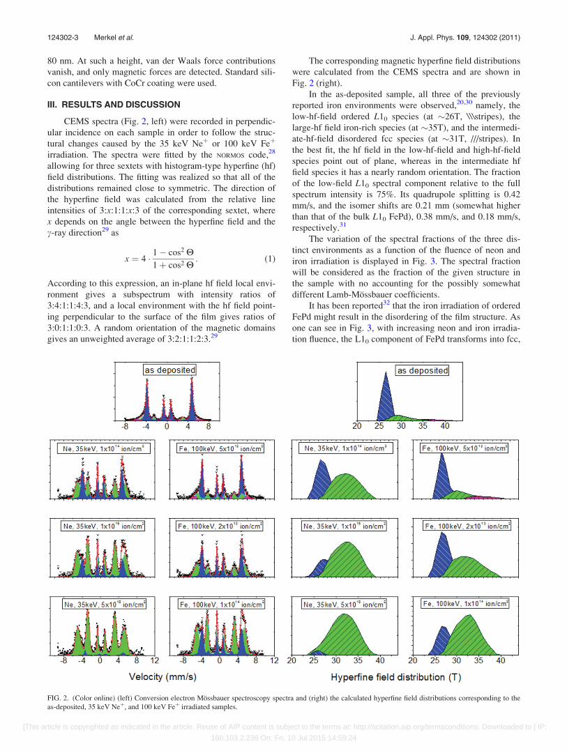