MADSEN Astera 2 - User Guide (EN) - Natus Partner
52
Madsen® Astera² User Guide Doc. No.7-50-1350-EN/13 Part No.7-50-13500-EN
-
Upload
khangminh22 -
Category
Documents
-
view
4 -
download
0
Transcript of MADSEN Astera 2 - User Guide (EN) - Natus Partner

Madsen® Astera²User Guide
Doc. No.7-50-1350-EN/13Part No.7-50-13500-EN

Copyright notice© 2013, 2021 Natus Medical Denmark ApS. All rights reserved. ® Natus, the Natus Icon, Aurical,Madsen, HI-PRO 2,Otoscan, ICSand HORTMANN are registered trademarks of Natus Medical Denmark ApS in the U.S.A. and/or other countries.
Version release date2021-06-01 (221163)
Technical service and supportPlease contact your supplier.
Madsen® Astera²2

Table of Contents
1 Device description 4
2 Intended use 4
3 Unpacking 5
4 Installation 5
5 Powering the device 12
6 Connecting Madsen® Astera² to Otosuite 12
7 On-screen controls 13
8 PC keyboard controls 13
9 Toolbar icons in the Audiometry Module 13
10 The Sunshine Panel 15
11 Proper transducer placement 18
12 Performing tone audiometry 20
13 Performing speech audiometry 21
14 Maintenance 24
15 Other references 25
16 Technical specifications 26
17 Definition of symbols 41
18 Warnings, Cautions, and Notes 46
19 Manufacturer 51
Madsen® Astera² 3

1 Device description
Madsen® Astera² is a PC-controlled audiometer for testing a person's hearing.The audiometer is operated from the Oto-suite Audiometry Module PC software.
With Madsen® Astera² you can perform standard audiometric tests, tone and speech audiometry and special tests.
• You can operate Madsen® Astera² from the PC’s keyboard/mouse, or from the Madsen® Astera² Audiometer ControlPanel (ACP) with the Otosuite Audiometry Software Module acting as the display.
• From the Otosuite Audiometry Software Module, which is NOAH compatible, you can monitor test results, createUser Tests, store and export data, and print reports.
Test intensities and frequencies as well as the current test settings and other information are shown on the PC mon-itor.
2 Intended useMadsen® Astera² and the AudiometrymoduleUsers: audiologists, ENTs and other health care professionals in testing the hearing of their patients.Use: diagnostic and clinical audiometric testing.
Intended Patient PopulationThe intended patient population is patients in all age groups, who are able to respond to the stimuli.
Clinical BenefitMadsen® Astera²is used to conduct diagnostic and clinical audiometric testing, thereby providing a means to determinethe presence, type and degree of hearing loss, assist in the diagnosis of otologic disorders, and provide input for hearing aidprogramming.
2.1 Typographical conventions
The use ofWarning, Caution and NoteTo draw your attention to information regarding safe and appropriate use of the device or software, the manual uses pre-cautionary statements as follows:
Warning• Indicates that there is a risk of death or serious injury to the user or patient.
4 Madsen® Astera²
1 Device description

Caution• Indicates that there is a risk of injury to the user or patient or risk of damage to data or the device.
Note • Indicates that you should take special notice.
To obtain a free printed copy of the user documentation, contact Natus Medical Denmark ApS (www.natus.com).
3 Unpacking1. Unpack the device carefully.
When you unpack the device and accessories, keep the packing material in which they were delivered. If you need tosend the device in for service, the original packing material will protect against damage during transport.
2. Visually inspect the equipment for possible damage.If damage has occurred, do not put the device into operation. Contact your local distributor for assistance.
3. Check with the packing list to make sure that you have received all necessary parts and accessories. If your package isincomplete, contact your local distributor.
4. Check the Calibration Certificate to make sure that the transducers (headphones and bone conductor) are the correctones, and that they comply with the ordered calibration standards.
4 InstallationInstall Otosuite on the PC before you connect Madsen® Astera² to the PC.
For Otosuite installation instructions, see the Otosuite Installation Guide, on the Otosuite installation medium.
To mount Madsen® Astera² on the wall or under the desktop, see the Madsen® Astera² Reference Manual.
Warning•To connect Madsen® Astera² to the PC, use the supplied USB cable. The cable length must notexceed 3 m (approx. 10 feet).
Madsen® Astera² is fully assembled on delivery, and you simply have to connect the cables.
Madsen® Astera² 5
3 Unpacking

Remove the cable cover
1. To remove the cable cover from Madsen® Astera² press the releaseson both sides of the cable cover, swing the cover up into verticalposition and lift it off Madsen® Astera².
2. Lift off the cable cover.
Connect accessoriesSee Connecting accessories to Madsen® Astera² 10.
Connect the ACPIf you are using the ACP:
See Connecting the ACP to Madsen® Astera² 7 and Connecting the ACP to the PC 8.
Secure cables toMadsen® Astera²
1. Secure the cables to the back of Madsen® Astera² with the rubberbands provided.
Remount the cable cover
1. Remount the cable cover by inserting the blue tags of the cable coverinto the grooves of Madsen® Astera² and swinging the cover into placeuntil you hear a click.
6 Madsen® Astera²
4 Installation

ConnectingMadsen® Astera² to Otosuite• Run the Otosuite Configuration Wizard to connect to and set up communication with Madsen® Astera²: Select Tools >
ConfigurationWizard (Tools > Configuration Wizard)
4.1 Connecting the ACP to Madsen® Astera²
Note • Install Otosuite on the PC before you connect Madsen® Astera² to the PC.
1. Remove the cable cover fromMadsen® Astera².
2. Connect the ACP to the Mad-sen® Astera² connection panel.
The connections are located atthe back of the ACP in the"From Main Unit" group.
All four cables for connecting the ACP to Madsen® Astera² are joined in a bundle and color-coded for easy connection.
Warning•Make sure that each jack, as depicted on each end of the cable, connects with the specific sockets onthe ACP and Madsen® Astera².
Operator desktop microphone• Connect the yellow cable in the cable bundle from the Operator desktopmicrophone
socket in the Madsen® Astera² rear panel to the Operator desktopmicrophone socketin the ACP.
Operator monitor headset with boom microphone• Connect the green cable in the cable bundle from the Operator monitor headset - head-
phones socket in the Madsen® Astera² rear panel to the Operator monitor headset -headphones socket in the ACP.
• Connect the pink cable in the cable bundle from the Operator monitor headset - boommicrophone socket in the Madsen® Astera² rear panel to the Operator monitor headset- boom microphone socket in the ACP.
Madsen® Astera² 7
4 Installation

Speaker, built into the ACP• Connect the gray cable in the cable bundle from the Operator monitor speaker socket
in the MADSEN Astera² rear panel to the Operator monitor speaker socket in the ACP.
3. When you have connected the accessories, slide the cable cover onto Madsen® Astera² and click it into place.
4.2 Connecting the ACP to the PCThe ACP is powered from the PC through a USB connection.
Note • Install Otosuite on the PC before you connect the ACP to the PC.
Warning•To connect the ACP to the PC, use the supplied USB cable. The cable length must not exceed 3 m(approx. 10 feet).
Note •Do not connect the ACP to the PC using a bus powered hub (USB hub without external power supply). It can-not provide sufficient power to the ACP. The Power on LED on the ACP will flash to indicate an error. Use instead aUSB hub with external power supply.
The following applies only when used with the specified power supply, External power supply, Delta Elec-tronics Inc., typeMDS-090AAS24:
The installation must be carried out in accordance with :
• ANSI/AAMI ES60601-1 (2005/(R)2012 + A1:2012,C1:2009/(R)2012 + A2:2010/(R)2012) (Medical Elec-trical Equipment - Part 1: General Requirements for Basic Safety and Essential Performance)
• CAN/CSA-C22.2 No. 60601-1:2014 (Medical electrical equipment – Part 1: General requirements forbasic safety and essential performance) - Edition 3 - Revision Date 2014/03
• ES60601-1:2005/(R)2012 and A1:2012
• Medical Electrical Systems clause 16 in IEC 60601-1 (3rd), AAMI ES60601-1 and CSA C22.2 NO. 60601-1:2014
Warning•Any equipment connected with the device or used in the proximity of the patient mustcomply with IEC 60601-1-2 (4th Edition) and IEC 60601-1 (3rd).
8 Madsen® Astera²
4 Installation
The following applies only when used with the specified power supply, XP Power, type PCM80PS24:
The installation must be carried out in accordance with IEC 60601-1, UL 60601-1. The supplementary pro-visions on the reliability of electro-medical systems.
Warning•Any equipment connected with the device or used in the proximity of the patient mustcomply with IEC 60601-1 (Edition 2) and IEC 60601-1-2:2014.
Any PC connected to the ACP must comply with the requirements of UL/IEC 62368-1, "Safety of informationtechnology equipment, including electrical business equipment".
Only the supplied cable must be used for the connection.
Direct connection to PC using single USB cable
Warning•Make sure that the total length of the USB cable used for connecting the ACP to the PC does notexceed 3 meters (10 feet).
1. Unfold the feet of the ACP.
2. Place the ACP in front of the PC monitor.
3. Plug one end of the USB cable into the USB socket located in the ACP rear panel and the other end of thecable into a USB socket on the PC.
Connection to PC using externally powered USB hub
Caution• If the PC, the externally powered USB hub and the ACP are connected, make sure that you switch onpower to the hub before or right when you switch on the PC. This is to ensure that the USB connection between thePC and the hub is established correctly. This connection is established when the PC is switched on.
Warning• If you are using an externally powered hub, no individual USB cable must exceed 3 meters (10 feet).
Power up sequence with externally powered USB hub
1. Connect the externally powered USB hub to the mains socket and switch it on.
2. Plug the single USB cable from the externally powered USB hub directly into a USB socket on the PC.
3. Connect the USB cable from the externally powered USB hub to the USB socket located in the ACP rearpanel.
Madsen® Astera² 9
4 Installation

4.3 Connecting accessories to Madsen® Astera²
Caution• Install Otosuite on the PC before you connect Madsen® Astera² to the PC.
The following applies only when used with the specified power supply, XP Power, type PCM80PS24:
The installation must be carried out in accordance with IEC 60601-1, UL 60601-1. The supplementary pro-visions on the reliability of electro-medical systems.
Warning•Any equipment connected with the device or used in the proximity of the patient mustcomply with IEC 60601-1 (Edition 2) and IEC 60601-1-2:2014.
except for the PC, and equipment connected to the line in and the line out sockets of Madsen® Astera².
The following applies only when used with the specified power supply, External power supply, Delta Elec-tronics Inc., typeMDS-090AAS24:
The installation must be carried out in accordance with :
• ANSI/AAMI ES60601-1 (2005/(R)2012 + A1:2012,C1:2009/(R)2012 + A2:2010/(R)2012) (Medical Elec-trical Equipment - Part 1: General Requirements for Basic Safety and Essential Performance)
• CAN/CSA-C22.2 No. 60601-1:2014 (Medical electrical equipment – Part 1: General requirements forbasic safety and essential performance) - Edition 3 - Revision Date 2014/03
• ES60601-1:2005/(R)2012 and A1:2012
• Medical Electrical Systems clause 16 in IEC 60601-1 (3rd), AAMI ES60601-1 and CSA C22.2 NO. 60601-1:2014
Warning•Any equipment connected with the device or used in the proximity of the patient mustcomply with IEC 60601-1-2 (4th Edition) and IEC 60601-1 (3rd).
• Except for the PC, and equipment connected to the line in and the line out sockets of Madsen® Astera².
See also Connector warnings 46 and General warnings 47.
For a detailed description of the connection panel, see the Madsen® Astera² Reference Manual.
Connection panel - Madsen® Astera²The connections are located at the back of Madsen® Astera².
10 Madsen® Astera²
4 Installation

A. Patient RespondersB. Insert earphonesC. Headphones - air conductionD. High-frequency headphones - air conductionE. Bone conductorF. Operator monitor headset - headphonesG. Operator monitor headset - boom microphoneH. Operator monitor speaker
I. Operator desktop microphoneJ. Talkback microphoneK. Assistant monitor headsetL. Sound field speakers (power output)M. External power supplyN. PC/USB connectionO. Line-inP. Sound field speakers (line output)
Note •Blue corresponds to Left and red corresponds to Right.
Note •Use only the power supply provided by Natus.
Caution•When you connect other electrical equipment to Madsen® Astera², remember that equipment that doesnot comply with the same safety standards as Madsen® Astera² can lead to a general reduction in the system's safetylevel.
Connection panel - ACP
A. PC/USB connection • USB cable
B. Connections from Madsen® Astera² • Speaker built into the ACP
• Operator monitor headset with boom microphone
• Operator desktop microphone
C. Connections to accessories • Operator desktop microphone
• Operator monitor headset with boom microphone
Madsen® Astera² 11
4 Installation

5 Powering the deviceMadsen® Astera² is powered through an external power supply connected directly to the mains outlet.
Switching onMadsen® Astera²
Use only the power supply provided by Natus.
1. Connect the mains plug of the external power supply directly to an AC mains outlet with a three-wireprotective ground.
2. Switch on the mains supply.
3. The On/Off indicator on Madsen® Astera² lights green.
Press the ON/OFF button on the front of Madsen® Astera².
Switching off Madsen® Astera²1. To switch off Madsen® Astera², press the ON/OFF button on the front of Madsen® Astera².
Note •To switch off the mains supply, disconnect the power supply from the mains outlet.
6 Connecting Madsen® Astera² to OtosuiteWhen you use Madsen® Astera² for the first time, run the Configuration Wizard to set up the connection between Mad-sen® Astera² and Otosuite. After you have configured Otosuite for the first time, if Madsen® Astera² is turned on when youopen the Control Panel in Otosuite, then Madsen® Astera² will connect to Otosuite automatically. Otherwise, you can con-nect Madsen® Astera² as follows:
1. Switch on the device.
2. Launch Otosuite.
3. In the Otosuite toolbar, click Control Panel (Control Panel).
4. In the Control Panel, click Connect (Connect).
12 Madsen® Astera²
5 Powering the device
7 On-screen controlsTest controls provide a means of operating the audiometer if you use the mouse and on-screen options to perform tests.
• To enable test controls, select Tools > Options > Audiometry > General > On-screen controls > Show > On (Tools >Options > Audiometry > General > On-screen controls > Show > On).
Silence ModeSilence Mode allows you to control tone levels and presentation by hovering the mouse cursor over the respective on-screen controls. This is particularly useful when the operator of the audiometer and the person being tested are in thesame room.
• To enable silence mode, select Tools > Options > Audiometry > General > On-screen controls > Silence Mode > On(Tools > Options > Audiometry > General > On-screen controls > Silence Mode > On).
• To change the level and frequency by more than one click at a time, use the mouse scroll wheel.
8 PC keyboard controlsYou can open a separate PDF-file to have a proper view of the keyboard short-cuts.
After you install Otosuite, you can find Otosuite manuals and related doc-umentation on your PC. In the Start (Start) menu, open Otosuite Manuals,which contains an overview with links to all manuals.
Note •The actual position of the keys may depend on your keyboardtype.
9 Toolbar icons in the Audiometry ModuleThe icons available in the toolbar depend on the test function that you have selected.
Madsen® Astera² 13
7 On-screen controls

Audiometry icons
Tone audiometry
Speech audiometry
Menu item Icon Description
Combined Audiogram(Combined Audiogram)
Click to toggle between viewing both ears in a single audiogram (com-bined audiogram) or both a left and a right audiogram on your screen.
Combined View (Combined View)• Click to view both ears in a single audiogram.
Split View (Split View)• Click to view separate audiograms for each ear.
Masking Assistant(Masking Assistant)
Enable or disable the Masking Assistant.
The Masking Assistant causes an unmasked threshold to flashrepeatedly if masking is recommended.
Standard Frequencies(StandardFrequencies)/All Fre-quencies (All Fre-quencies)/ HighFrequencies (High Fre-quencies)
The graph shows up to 20000 Hz. Madsen® Astera² presents stimulusup to 12500 Hz.
• Click to choose between viewing:
Standard Frequencies (Standard Frequencies)Displays the audiogram from 125 Hz to 8000 Hz.
All Frequencies (All Frequencies)Displays the audiogram from 125 Hz to 20000 Hz.
High Frequencies (High Frequencies)Displays the audiogram from 8000 Hz to 20000 Hz.
New Audiogram (NewAudiogram)
Select new audiogram. You will be prompted to save or cancel currentdata.
14 Madsen® Astera²
9 Toolbar icons in the Audiometry Module

Menu item Icon Description
Frequency Resolution(Frequency Resolution)
The options for frequency resolutions are 1/6, 1/12, 1/24 and 1/48octave as well as 1 Hz. Select the different tone stimulus resolutionsfrom the toolbar or from Tools > Options > Audiometry > General(Tools > Options > Audiometry > General).
You can store up to 24 points for each audiometry curve. You will beprompted if you try to store more than the maximum number ofpoints.
Monitoring (Mon-itoring)
Enables or disables the monitor speaker for monitoring stimuli presen-ted to the patient from the Stimulus (Stimulus) orMasking (Masking)channel.
Desktop/HeadsetMicrophone(Desktop/HeadsetMicrophone)
Toggle microphone types (Toggle microphone types)Click to toggle between the operator headset boom microphones anddesktop microphone used to communicate with the patient and/or theassistant. The one displayed is the one currently active.
Enable Talk to Assist-ant (Enable Talk toAssistant)
Click to enable or disable talking to another party (usually a secondtester) in the booth.
Talk Forward (Talk For-ward)
Enables communicating with the patient in the sound booth. This willdisplay the Talk Forward (Talk Forward) dialog box, where you can con-trol the talk forward microphone sensitivity and the output level in dBHL to the patient.
Select Orientation(Select Orientation)
Click to select the perspective of the patient's ears as presented on thescreen for graph and table views.
You can also select the location of the stimulus control.
Sunshine Panel (Sun-shine Panel)
When you have enabled the Control Panel icon on the toolbar, you canchoose between using the Classic Control Panel and the SunshinePanel.
Live Video Otoscopy Click to launch a Live Video Otoscopy.
10 The Sunshine PanelClick the Control Panel (Control Panel) icon in the toolbar to activate the Control Panel.
Click the Sunshine Panel (Sunshine Panel) icon in the toolbar to select or deselect the Sunshine Panel ineither Tone (Tone) or Speech (Speech) testing.
Madsen® Astera² 15
10 The Sunshine Panel

Tone testing Speech testing
Use the Sunshine Panel to quickly select the main settings for testing.
In the Sunshine Panel you can quickly select test ear, transducer, masking,and test type.
You can control the monitor level, activate the Talk Forward (Talk For-ward) dialog, and select the Test Selector (Test Selector) for quicklyselecting the relevant user test.
Your selections are shown in the Stimulus (Stimulus) bar and as symbolsin the audiogram.
See also
• Performing tone audiometry 20
• Performing speech audiometry 21.
Customizing the Sunshine PanelYou can customize the Sunshine Panel to display one or several buttons for some of the functions. For instance you can dis-play one or more of the curve selection buttons on the panel.
When the right-click menu for a button includes the selection Add/Remove buttons (Add/Remove buttons) you can cus-tomize the setup.
1. Enable/disable the button(s) you wish to display.
2. Click to disable the selection Use Single Button (Use Single Button). The enabled buttons are displayed immediatelyin the panel.
Using the Sunshine panel• Click on the buttons to toggle the selection
or
• Right-click on a button to select a combination of functions.
16 Madsen® Astera²
10 The Sunshine Panel

Function Icon Description
Stimulus Ear Selection(Stimulus Ear Selec-tion)
Click to select test ear:
• Right (Right)
• Binaural (Binaural)
• Left (Left)
Transducer Selection(Transducer Selection)
Click to select the transducer used for the test ear:
• Insert (Insert) (earphones)
• Phone (Phone) (standard headphones)
• High Frequency (High Frequency) (headphones)
• Bone (Bone) (conductor)
• SF Unaided (SF Unaided) (Sound Field speaker, unaided)
• SF Aided 1 (SF Aided 1) and SF Aided 2 (SF Aided 2) (Sound field speaker -Aided 1 and 2
• Multispeaker (Multispeaker)
Masking TransducerSelection (MaskingTransducer Selection)
Click to select the transducer used for the masked ear:
• Insert (Insert) (earphones)
• Phone (Phone) (standard headphones)
• High Frequency (High Frequency) (headphones)
• Bone (Bone) (conductor)
• SF (SF) (Sound Field speaker)
• SF Aided 1 (SF Aided 1) and SF Aided 2 (SF Aided 2) (Sound field speaker -Aided 1 and 2)
Masking Options(Masking Options)
Mask(Mask)
Click to enable or disable masking.
Stimulus Selection(Stimulus Selection)
Click to select stimulus type.
• Tone (Tone testing)
• Warble (Tone testing)
• FRESH noise (Tone testing)
• Pre-recorded stimulus (Speech)
• Microphone to present live speech stimulus (Speech)
Madsen® Astera² 17
10 The Sunshine Panel

Function Icon Description
Curve Selection (CurveSelection)
Click to select the curve type:
• THR (THR) (Threshold level) (Tone)
• MCL (MCL) (Most Comfortable Loudness level)
• UCL (UCL) (Uncomfortable Loudness level)
• SDT (SDT) (Speech Detection Threshold) (Speech)
• SRT (SRT) (Speech Recognition Threshold) (Speech)
• WRS/SRS (WRS/SRS) (Word Recognition Score/Sentence RecognitionScore) (Speech)
Talk Forward (Talk For-ward)
The Talk Forward (Talk Forward) dialog is described in the Madsen® Aster-a²Reference Manual.
Monitor/Level (Mon-itor/Level)
• Monitor (Monitor)Click to enable monitoring of the stimulus channel.
• Level (Level)Adjust the slider to set the preferred monitoring level for the respectiveaudiometer channels.
Test Selector (TestSelector)
The Test Selector (Test Selector) dialog is described in the OtosuiteUserGuide.
11 Proper transducer placementHeadphones1. Loosen the headband and place both the left and right side of the headphones simultaneously.
Note • If the headphones are not placed properly, there is risk of causing the ear canal to collapse which will result inelevated thresholds.
2. Aim the center of the headphones towards the patient's ear canals and gently place them against the ears.
3. Tighten the headband while holding the headphones in place with your thumbs.
4. Examine the placement of the headphones to make sure they are level, and properly positioned.
Insert Earphones1. Select the largest foam eartip that will fit into the patient's ear.
If the eartip is too small the sound will leak out and the sound level will not be accurate at the eardrum.
Insert earphones have greater attenuation between ears especially at the low frequencies; this reduces the need formasking.
18 Madsen® Astera²
11 Proper transducer placement

2. It is best to clip the insert earphone transducers behind the child or on the back of their clothing and then fit thefoam eartip into the child's ears.
Bone Conductor
Note •For unmasked bone thresholds, you can store binaural data:
If there is a difference of 10 dB or greater between the bone conduction threshold and the air conduction threshold ofthe same ear, masking is needed. The Masking Assistant can assist you in determining which thresholds need to bemasked.
If the SRT of the test ear and the bone conduction PTA of the nontest ear differ by 45 dB or more, masking is needed.
Mastoid placement1. Move any hair covering the mastoid out of the way and place the flat round part of the bone conductor securely on
the boniest portion of the mastoid without any part of the transducer touching the external ear.
2. Make sure the bone conductor is tight on the mastoid but still comfortable.
3. If you are going to perform masking with earphones, position the other end of the bone conductor headband over thepatient's temple on the opposite side of the head so that the headband of the earphones and bone conductor fit onthe patient's head.
Forehead placement1. For frontal bone placement, place the flat round part of the bone conductor securely on the middle of the forehead
about an inch (2.5 cm) below the hairline.
2. Make sure the bone conductor is tight on the forehead but still comfortable.
Madsen® Astera² 19
11 Proper transducer placement

12 Performing tone audiometrySunshine PanelA. Ear selectionB. Stimulus transducerC. Masking, transducer and On/OffD. Stimulus typeE. Test typeF. Talk Forward dialogG. Monitor/LevelH. Test Selector
Classic Control PanelA. Control PanelB. Test Options panelC. Monitor/Level panel
Whenever the test buttons and other functions are used, you can use the corresponding keys on the keyboard, or the on-screen controls located at the top of the screen or in the Control Panel to the left.
For detailed examples of audiometric testing, see the Madsen® Astera² Reference Manual.
1. Select the Tone (Tone) screen in the Otosuite Audiometry module.
2. Prepare the patient. If you wish to instruct the patient after you have placed the transducers on the head of thepatient, you can use the Talk Forward (Talk Forward) button. You can talk to the patient to adjust the patient com-munication levels when Talk Forward (Talk Forward) is active.
3. In the Control Panel, select test conditions for ear, transducer, unmasked/masked, and test type.
4. Select the test frequency with the Right/Left arrow buttons (or on keypad).
5. Select the stimulus level with the Up/Down arrow buttons (or on keypad).
6. Present the tone stimulus with the Present (Present) button or the space bar on the keypad.
20 Madsen® Astera²
12 Performing tone audiometry

7. Use the Store (Store) button (the S key on the keypad) to store the data point and proceed to the next frequency.
8. Repeat steps 4 to 7 until all the measurements you need have been completed. If needed, did you test:
– Both ears
– Air conduction
– Bone conduction
– Masking (Mask (Mask) button or M on the keypad
– Audiogram threshold, MCL (MCL) and UCL (UCL)
9. Save the audiogram.
Note • If you are using white noise instead of the recommended narrow band noise in pure tone masking, see Mad-sen® Astera² 26
13 Performing speech audiometrySunshine PanelA. Ear selectionB. Stimulus transducerC. Masking, transducer and On/OffD. Stimulus typeE. Test typeF. Talk Forward dialogG. Monitor/LevelH. Test Selector
Madsen® Astera² 21
13 Performing speech audiometry

Classic Control PanelA. Control PanelB. Test Options panelC. Monitor/Level panel
Whenever the test buttons and other functions are used, you can use the corresponding keys on the keyboard, or the on-screen controls located at the top of the screen or in the Control Panel to the left.
For detailed examples of audiometric testing, see the Madsen® Astera² Reference Manual.
1. Select the Speech (Speech) screen in the Otosuite Audiometry module.
2. If needed, click the Scoring and Playing (Scoring and Playing) icon to set up word orphoneme scoring.
3. Prepare the patient. If you wish to instruct the patient after you have placed the transducers on the head of thepatient, you can use the Talk Forward (Talk Forward) button. You can talk to the patient to adjust the patient com-munication levels when Talk Forward (Talk Forward) is active.
4. In the Control Panel, select test conditions for ear, transducer, unmasked/masked, and test type.
5. Select the stimulus level with the Up/Down arrow buttons (or on keypad).
6. Select speech input signals.
You can choose from either microphone input or recorded input source. Combining recorded Source A (Source A) andSource B (Source B) as Input (Input) sources in the Test Options (Test Options) section of the Control Panel (ControlPanel) will replace the audiometer speech masking with a recorded input.
7. Select your speech input from the right-click menu in the control panel.
– Int. CD (Int. CD) (CD material in CD/DVD drive)
– () (integrated Otosuite Speech Material or regular sound files)
– Line In (Line In) (analog input from external sound players, e.g. CD, MD, MP3 or cassette recorders connected tothe audiometer via the Line In (Line In) input).'
Note • If an external playback device is used to generate speech stimuli via the line input, care must be taken toensure that the player has a flat frequency response in the range 125 Hz to 6300 Hz. The maximum allowabledeviation from the average response level is +/-1 dB; the average response level should be measured over the
22 Madsen® Astera²
13 Performing speech audiometry
range 250 Hz to 4000 Hz.
The headset microphone should be turned to a position just below the operator’s mouth.
If an external playback device is used to generate speech stimuli via the line input of Madsen® Astera², only ahigh quality CD player or similar device should be used; tape recordings may not provide a sufficient signal tonoise ratio. Preferably, the external device should deliver its output via a fixed-level line out connector. The inputgain on Madsen® Astera² should be adjusted to obtain a 0 dBVU reading when the calibration signal is played bythe external device.
8. You can find speech material files in the File/track/list selection (File/track/list selection) drop-down list.
Note •You should only use speech materials with a stated relationship between the level of the speech signal andthe calibration signal.
Speech materials delivered on CD or other media are normally accompanied by a description of this relationship.You should follow the instructions supplied with the speech materials, using the VU-meter in Otosuite for adjust-ment of input gain
If you are using built-in speech materials supplied with Otosuite, the speech levels have been adjusted accordingto the original speech material instructions.
Note •Speech signals are calibrated in dB HL.
If you are using an integrated word list, the word list is shown on the screen.
9. Present the word lists with the Play (Play) button.
10. Use the Correct (Correct) (+) and Incorrect (Incorrect) (-) buttons or click directly on thekey word to score.
11. Store the current data as the result, either by clicking Store (Store) in the highlightedfield, or by pressing (S (S)) on the keyboard.
12. Repeat until all the measurements you need have been completed.
DosimeterA dosimeter is built into Madsen® Astera². If you are using live speech, it will be working in the background as a safety pre-caution. The system monitors the sound level versus duration of exposure(1).
Madsen® Astera² 23
13 Performing speech audiometry

If the patient is exposed to excessive levels of noise during the session, the system will interrupt the signal and display awarning.(1)Noise Exposure: Explanation of OSHA and NIOSH Safe.Exposure Limits and the Importance of Noise Dosimetry by PatriciaA. Niquette, AuD, Etymotic Research Inc.
14 MaintenanceMadsen® Astera² requires regular maintenance to continue operating as designed. This includes visual inspection, clean-ing, and calibration. If the equipment shows signs of damage or material degradation, do not use the device and contactyour supplier.
Warning•Under no circumstances disassemble Madsen® Astera². Contact your supplier. Parts inside Madsen®Astera² must only be checked or serviced by authorized personnel.
14.1 Service
Warning•For the sake of safety and in order not to void the warranty, service and repair of electro-medicalequipment should be carried out only by the equipment manufacturer or by service personnel at authorized work-shops. In case of any defects, make a detailed description of the defect(s) and contact your supplier. Do not use adefective device.
14.2 CleaningThere are no specific requirements to sterilization or disinfection of the device.
Caution•Device and accessories shall be cleaned between every patient use
The device• Remove dust using a soft brush.
• Use a soft, slightly damp cloth with a small amount of mild detergent.
Warning•Keep the unit away from liquids. Do not allow moisture inside the unit. Moisture inside the unit candamage the instrument and it may result in a risk of electrical shock to the user or patient.
Accessories• Headphones
24 Madsen® Astera²
14 Maintenance
Use a non-alcohol based wipe (e.g. Audiowipe) to clean the headphones between patients.
• Eartips for Insert Earphones
The eartips are single use and should be disposed of after use.
• Bone conductor
Clean the bone conductor between patients, e.g. with a non-alcohol based antibacterial wipe, such as Audiowipes.
DisposalThere are no special requirements for the disposal of eartips, i.e. they can be discarded according to local regulations.
14.3 Calibration
Annual calibrationThe audiometer, headphones, bone conductors, and sound field speakers must be calibrated once a year by your author-ized service department.
Remote calibrationYou can order a transducer and get the calibration data installed via remote support. The calibration data is included inyour shipment on a USB memory stick (or supplied by technical support during the installation).
To import calibration data:
1. Connect the new transducer to your audiometer.
2. Connect the audiometer to your Otosuite PC.
3. Insert the USB memory stick in an empty slot on your PC.
4. Call your Natus technical support team. They will use the application TeamViewer to ensure correct remote install-ation of the new calibration data on your system.
TeamViewer is located at Help (Help) > Remote support (Remote support).
The technician installs the calibration data via the menu function Tools (Tools) > Audiometer service (Audiometer ser-vice). The data is password protected.
5. When the installation has ended, hold the new transducer within hearing distance and cautiously perform a listeningcheck.
The purpose of the check is to ascertain that the transducer is functioning correctly (without wrong or excessive soundlevels), not to verify the exact calibration.
Caution•Note that calibration has been performed only on the transducers supplied. If you wish to use any othertransducer for testing with the device, please contact your local distributor first.
15 Other referencesFor more information, see the online Help in Otosuite, which contains detailed reference information about Madsen®Astera² and the Otosuite modules.
For Otosuite installation instructions, see the Otosuite Installation Guide, on the Otosuite installation medium.
Madsen® Astera² 25
15 Other references

For Troubleshooting information, refer to the Madsen® Astera² Reference Manual.
16 Technical specifications
16.1 Madsen® Astera²
Type identificationMadsen® Astera² is type 1066 from Natus Medical Denmark ApS.
Channels
Two separate and identical channels
Frequency range
TDH39 earphones: Standard frequencies: 125 Hz - 12500 Hz
HDA 300 earphones: Standard frequencies: 125 Hz - 20000 Hz
Insert earphones: Standard frequencies: 125 Hz - 8000 Hz
BC: Standard frequencies: 250 Hz - 8000 Hz
SF: Standard frequencies: 125 Hz - 20000 Hz
Tone accuracy: > 0.03%
FRESH noise stimulus: Available in entire frequency range within the transducer specified range.(ForSF 125 Hz - 12500 Hz). Accuracy 0.3%
Narrow Band Noise masking: Available in entire frequency range
Frequency resolution: 1/48, 1/24, 1/12, and 1/6 oct, 1 Hz step
Stimulus types
• Tone
• Warble
• Pulsed tone
• Pulsed warble
• FRESH noise Frequency-specific hearing assessment noise.Consists of noise bands, with frequency-specific filter width.The FRESH noise is filtered to obtain very steep slopes outside the passband.
• Pulsed FRESH noise
26 Madsen® Astera²
16 Technical specifications

Masking types
• Narrow Band Noise
– AC and BC
– SF
Correlated
Non-correlatedA
• Speech Weighted Noise
– AC and BC
– SF
Correlated
Non-correlatedA
• White Noise (Wide band noise)
– AC and BC
– SF
Correlated
Non-correlatedA
A. A maximum of 3 non-correlated simultaneous masking signals.
White noise for Pure Tone maskingConversion between displayed “effective masking level” and sound pressure level
The level of white noise used for masking of pure tones is indicated in dB of “effective masking level” in Otosuite. Thismeans that the sound pressure level of the power contained in a third-octave band around the presented pure tone fre-quency will equal the attenuator setting, plus the RETSPL at the pure tone frequency, plus the noise correction factorfrom ISO 389-4:1994, Table 1.
The following tables can be used to calculate the actual sound pressure level of the white noise signal for a given atten-uator setting (Table 1), or to select the attenuator setting required to obtain a specific level in dB SPL (Table 2).
Note: As the sound pressure level of the white noise signal will be quite high even for moderate attenuator settings, awarning sign will be displayed in Otosuite for levels above 100 dB HL.
Table 1 - Offset from Effective Masking Level to Sound Pressure Level
Frequency (Hz) 125 250 500 750 1000 1500 2000 3000 4000 6000 8000 9000 10000 11200 12500
Offset (dB) N/A* 53 37 32 31 29 30 29 27 31 27 26 26 25 25
This table indicates the number (“Offset”) to be added to the displayed masking level in order to calculate the sound pres-sure level in dB SPL.
* White masking noise is not available at 125 Hz
Table 2 - Attenuator settings required to obtain a white noise level of 80 dB SPL
Frequency (Hz) 125 250 500 750 1000 1500 2000 3000 4000 6000 8000 9000 10000 11200 12500
Attenuator setting to
obtain 80 dB SPL
N/A* 27 43 48 49 51 50 51 53 49 53 54 54 55 55
This table indicates the attenuator settings required to obtain a sound pressure level of 80 dB SPL at indicated frequencies.
Madsen® Astera² 27
16 Technical specifications

Stimulusmodulation
FM (Warble): Adjustable modulation rate and depth
• Modulation rate: 1Hz -20 Hz (default: 5 Hz).
• Modulation depth: 1-25% of center frequency (default: 5%).
SISI: 5, 2, 1 dB increments
Accuracy of sound level
Entire level range (AC): 125 Hz to 5000 Hz: ±3 dB5000 Hz to 20000 Hz: ±5 dB
Entire level range (BC): 250 Hz to 5000 Hz: ±4 dB5000 Hz to 8000 Hz: ±5 dB
Level resolution
1, 2, or 5 dB step resolution over the entire range
HL Range
Maximum output will be limited by the transducer.
AC: -10 dB HL to 120 dB HL (500 Hz to 4000 Hz; supra-aural earphones)
AC HF: -10 dB HL to 110 dB HL (500 Hz to 4,000 Hz; circum-aural earphones)*
BC: -10 dB HL to 80 dB HL (1500 Hz to 3000 Hz; mastoid placement)
SF: 103 dB HL (Note: with external amplifier)
* Due to the frequency response of the Sennheiser HDA300 headset, the system does not fulfill the maximum output levelabove 6 kHz for Type 1 audiometers regarding IEC 60645-1:2017 and ANSI/ASA S3.6-2004. Note: This is only the case withthis specific headset.
Total harmonic distortion
Air < 2.5 %
Bone < 5 %
Selectable transducers
AC: TDH39, HDA 300, and Insert Earphones
BC: Bone conductor (Mastoid / Forehead)
SF: • Passive sound field speaker, using the built-in amplifier in Madsen® Astera²,or
• Sound field speaker with built-in amplifier or external amplifier, with bothtypes using the line output from Madsen® Astera².
Transducer options depend on how Madsen® Astera² is ordered and calibrated.
28 Madsen® Astera²
16 Technical specifications

Outputs
AC: 3 x 2 mono jacks, 1/4 "
BC: 2 x mono jacks, 1/4 "
SF power output: 5 x terminals,5 x 40 W peak, 8Ω load
SF line output: 3 x mini XLR 6 pin5 x +6 dBu, balanced
External inputs
CD/Analog line in: 0.2 to 2.0 Vrms, 10 kΩ 2 x RCA phone
Talk Back microphone: • Electret microphone
• Input voltage: 0.002 to 0.02 Vrms
• Input resistance: 2.21 kΩ.
• 3.5 mm jack
Stimulus presentation
Normal: The signal is presented when the Stimulate button is pressed.
Continuous ON: The signal is interrupted when the Stimulate button is pressed.
Pulse: The signal is pulsed.
Pulse duration: 225 ms on and 225 ms off (default).
Operator accessories
Operator monitor speaker • 1.5W 8Ω , connected between tip and ring, sleeve floating
• 3.5 mm jack
Operator monitor headset - headphones • 40 mW 16Ω• 3.5 mm jack
Operator monitor headset - boom micro-phone
• Electret microphone
• Input voltage: 0.002 to 0.02 Vrms,
• Input resistance: 2.21 kΩ.
• 3.5 mm jack
Operator desktop microphone • Electret microphone
• Input voltage: 0.002 to 0.02 Vrms,
• Input resistance: 2.21 kΩ.
• 3.5 mm jack
Assistant monitor headset • 40 mW 16Ω• 3.5 mm jack
Madsen® Astera² 29
16 Technical specifications

Static force of transducer headbands
TDH 39: 4.5 N ±0.5 N
Bone vibrator: 5.4 N ±0.5 N
HDA 300: 10 N
USB interface
Connector Type: USB Type B (Astera2), USB Type A (PC)
Interface: USB 1.1 (compatible with USB 2.0, USB 3.0, USB 3.1 and USB 3.2 perwww.USB.org)
Transport and storage
Temperature: -30°C to +60°C (-22°F to 140°F)
Air humidity: 10% to 90%, non-condensing
Air pressure: 50 kPa to 106 kPa
Operating environment
Mode of operation: Continuous
Temperature: +15°C to +35°C (59°F to 95°F)
Air humidity: 20% to 90%, non-condensing
Air pressure: 70 kPa to 106 kPa
Note •Recalibrate device if used in low air pressure.
(Operation in temperatures exceeding -20°C (-4°F) or +60°C (140°F) may cause permanent damage.)
Warm-up time
< 5 min.
Note •Should be extended if Madsen® Astera² has been stored in a cold environment.
Disposal
Madsen® Astera² can be disposed of as normal electronic waste, according to WEEE and local regulations.
30 Madsen® Astera²
16 Technical specifications

Dimensions
Approx. 325 x 255 x 60 mm (12.8 x 10 x 2.4 inches)
Weight
Approx. 1.3 kg (2.85 lb)
Power supply
External power supply, types:
Delta Electronics, Inc.MDS-090AAS24
Output: 24 V DC, 3.75 AInput: 100-240 V AC, 50-60 Hz, 1.5 A - 0.75 A
Patient Safety when used with the specified power supply, Delta Electronics,Inc., type MDS-090AAS24:• Complies with ES60601-1:2005/(R)2012 and A1:2012
• CAN/CSA C22.2 NO 60601-1-14:2014
• IEC 60601-1:2005/A1:2012 (Edition 3.1)
• ES60601-1:2005/(R)2012 and A1:2012
• EMC: IEC 60601-1-2:2014
• IEC 60601-1 (3rd Edition) Class I, Type B
XP PowerPCM80PS24
Output: 24 V DC, 3.33 A maxInput: 100-240 V AC, 47-63 Hz, 1.1 A - 0.45 A
Patient Safety when used with the specified power supply, XP Power, typePCM80PS24:• Complies with IEC 60601-1 (2nd Edition), Class 1, Type B; UL 60601-1.
Power consumption
< 90 VA
Essential performanceMadsen® Astera² has no essential performance.
Madsen® Astera² 31
16 Technical specifications

Standards
Audiometer: EN 60645-1:2017 Type 1, Class B, IEC 60645-1:2017, and ANSI S3.6:2004
Patient Safety: Patient Safety when used with the specified power supply, Delta Electronics,Inc., type MDS-090AAS24:• Complies with ES60601-1:2005/(R)2012 and A1:2012
• CAN/CSA C22.2 NO 60601-1-14:2014
• IEC 60601-1:2005/A1:2012 (Edition 3.1)
• ES60601-1:2005/(R)2012 and A1:2012
• EMC: IEC 60601-1-2:2014
Patient Safety when used with the specified power supply, XP Power, typePCM80PS24:• Complies with IEC 60601-1 (2nd Edition), Class 1, Type B; UL 60601-1.
EMC: IEC 60601-1-2:2007, EN 60601-1-2:2007, IEC 60601-1-2:2014 and EN 60601-1-2:2015
16.2 Advanced Control Panel
Outputs
Monitor headphone 3.5 mm jack (32 Ω.)
Boom microphone 3.5 mm jack
Desktop microphone 3.5 mm jack
Inputs
Monitor headphone 3.5 mm jack (32 Ω.)
Boom microphone 3.5 mm jack
Desktop microphone 3.5 mm jack
Built-in monitor speaker 3.5 mm jack (8 Ω.)
Operator interface
• 76 buttons (61 with built-in LEDs)
2 rotary knobs (32 steps in each rotation)
USB interface
Type: USB device port
Compliant: USB 2.0
32 Madsen® Astera²
16 Technical specifications

Transport and storage
Temperature: -30°C to +60°C (-22°F to 140°F)
Air humidity: 10% to 90%, non-condensing
Air pressure 50 kPa to 106 kPa
Operating environment
Mode of operation: Continuous
Temperature: +15°C to +30°C (59°F to 95°F)
Air humidity: 20% to 90%, non-condensing
Air pressure 70 kPa to 106 kPa
(Operation in temperatures exceeding -20°C (-4°F) or +60°C (140°F) may cause permanent damage.)
Warm-up time
< 1 minute
Disposal
Madsen® Astera² ACP can be disposed of as normal electronic waste, according to WEEE and local regulations.
Dimensions
Approx. 410 x 290 x 36 mm (16.1 x 11.4 x 1.4 inches)
Weight
Approx. 2.1 kg (4.6 lb)
Power supply
No external power supply. Supplied by the USB (5 V).
Note • If you are using a USB hub, use a powered USB hub.
Power consumption
Normal operation: < 360 mA 5 V
Suspend mode: < 500 µA 5 V
Madsen® Astera² 33
16 Technical specifications
Standards
Patient Safety: Complies with IEC 60601-1 Edition 3.1:2012, Class 1, Type B; UL 60601-1;CAN/CSA-C22.2 NO 60101.1-14.
EMC: IEC 60601-1-2:2014, IEC 60601-1-2:2007, EN 60601-1-2:2015, and EN 60601-1-2:2007
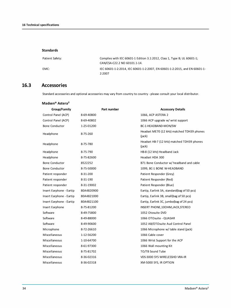
16.3 AccessoriesStandard accessories and optional accessories may vary from country to country - please consult your local distributor.
Madsen® Astera²Group/Family Part number Accessory Details
Control Panel (ACP) 8-69-40800 1066, ACP ASTERA 2
Control Panel (ACP) 8-69-40802 1066 ACP upgrade w/ wrist support
Bone Conductor 1-25-01200 BC-1-HEADBAND-MON/SW
Headphone 8-75-260Headset ME70 (12 kHz) matched TDH39 phones(jack)
Headphone 8-75-780Headset HB-7 (12 kHz) matched TDH39 phones(jack)
Headphone 8-75-790 HB-8 (12 kHz) Headband Jack
Headphone 8-75-82600 Headset HDA 300
Bone Conductor 8522252 B71 Bone Conductor w/ headband and cable
Bone Conductor 8-75-50000 1099, BC-1 BONE W-HEADBAND
Patient responder 8-31-200 Patient Responder (Grey)
Patient responder 8-31-190 Patient Responder (Red)
Patient responder 8-31-19002 Patient Responder (Blue)
Insert Earphone - Eartip 80A4820900 Eartip, Earlink 3A, standard(bag of 50 pcs)
Insert Earphone - Eartip 80A4821000 Eartip, Earlink 3B, small(bag of 50 pcs)
Insert Earphone - Eartip 80A4821100 Eartip, Earlink 3C, jumbo(bag of 24 pcs)
Insert Earphone 8-75-81200 INSERT PHONE,10OHM,JACK,STEREO
Software 8-49-75800 1052 Otosuite DVD
Software 8-49-88000 1066 OTOsuite - QUASAR
Software 8-49-90600 1052 AB/OTOsuite Aud Control Panel
Microphone 8-72-26610 1066 Microphone w/ table stand (jack)
Miscellaneous 1-12-56200 1066 Cable cover
Miscellaneous 1-10-64700 1066 Wrist Support for the ACP
Miscellaneous 8-61-97300 1066 Wall mounting Kit
Miscellaneous 8-75-81702 TO/TB Sound Tube
Miscellaneous 8-36-02316 VDS-3000 SYS WIRELESSHD VRA-IR
Miscellaneous 8-36-02318 XM-5000 SYS, IR OPTION
34 Madsen® Astera²
16 Technical specifications

Group/Family Part number Accessory DetailsMiscellaneous 8-36-02319 XM-5000 SYS,RE OPTION
Miscellaneous 49321077 Speaker Stand
Headset/Speaker 8-75-69003 1066, MONITOR HEADSET
Headset/Speaker 2-18-04200 Headset Monitoring
Headset/Speaker 8-02-450 FF LOUDSPEAKER SET,C 115
Power Supply 5-01-11300 Power Supply
Power Supply 5-01-10100 Power Supply, 24VDC, 80W
Cables 8-71-79100 Cable USB (3m)
Cables 8-71-79200 Cable USB (2m)
Cables 7-08-017 Power cord, US (UL approved)
Cables 8-71-86400 Power cord, CN
Cables 8-71-240 Power cord (Schuko)
Cables 7-08-027 Power cord, CH
Cables 8-71-290 Power cord, DK
Cables 8-71-80200 Power cord, UK
Cables 8-71-82700 Power cord, AUS
Cables 8-71-90600 Power cord, Class 1. for Brazil
Cables 8-71-86900 1066 Cable Multi (Mini jack, Male/Female)
Cables 8-71-86800 1066 Cable Multi (Mini jack, Male/Male)
Cables 8-71-87700 1066 Cable for Operator Headset (Mini Jack)
Cables 8-71-92100 1066 Cable for 5 Speaker - RCA line out
Cables 8-71-92200 1066 Cable for 2 Speaker - RCA line out
Cables 8-71-92300 1066 Cable for 5 Speaker - XLR line out
Cables 8-71-92400 1066 Cable for 2 Speaker - XLR line out
16.4 Notes on EMC (Electromagnetic Compatibility)• Madsen® Astera² is part of a medical electrical system and is thus subject to special safety precautions. For this reason,
the installation and operating instructions provided in this document should be followed closely.
• Portable and mobile high-frequency communication devices, such as mobile phones, may interfere with the func-tioning of Madsen® Astera².
IEC 60601-1-2:2014 and EN 60601-1-2:2015
Guidance and manufacturer's declaration - electromagnetic emissions for all equipment and systems
Madsen®Astera² is intended for use in the electromagnetic environment specified below. The user of Madsen®Astera² should ensure that it is used in such an
environment.
Emissions test Compliance Electromagnetic environment - guidance
Madsen® Astera² 35
16 Technical specifications

RF emissions
CISPR11
Group 1 Madsen®Astera² uses RF energy only for its internal function. Therefore, its RF emissions are very
low and are not likely to cause any interference in nearby electronic equipment.
RF emissions
CISPR11
Class A Madsen®Astera² is suitable for use in hospital and clinic environments.
Note: The EMISSIONS characteristics of this equipment make it suitable for use in industrial areas
and hospitals (CISPR 11 class A). If it is used in a residential environment (for which CISPR 11 class
B is normally required) this equipment might not offer adequate protection to radio-frequency
communication services. The user might need to takemitigation measures, such as relocating or
re-orienting the equipment.
Harmonic emissions IEC
61000-3-2
Complies
Voltage fluctuations/flicker
emissions IEC 61000-3-3
Complies
Guidance and manufacturer's declaration - electromagnetic immunity for all equipment and systems
Madsen®Astera² is intended for use in the electromagnetic environment specified below. The user of Madsen®Astera² should ensure that it is used in such an
environment.
Immunity test IEC 60601
test level
Compliance level Electromagnetic environment - guidance
Electrostatic discharge (ESD)
IEC 61000-4-2
+/- 8 kV contact
+/- 2 kV, +/- 4 kV,
+/- 8 kV, +/- 15 kV air
+/- 8 kV contact
+/- 2 kV, +/- 4 kV,
+/- 8 kV, +/- 15 kV air
Floors should bewood, concrete or ceramic tile. If floors
are covered with synthetic material, the relative humid-
ity should be at least 30%.
Electrical fast transient/burst
IEC 61000-4-4
+/- 2 kV for power supply lines
+/- 1 kV for input/output lines
+/- 2 kV for power supply lines
+/- 1 kV for input/output lines
Mains power quality should be that of a typical com-
mercial or hospital environment.
Surge
IEC 61000-4-5
+/- 1 kV line(s) to line(s)
+/- 2 kV line(s) to earth
+/- 2 kV DC input line(s) to earth
+/- 1 kV DC input line(s) to line(s)
+/- 2 kV I/O line(s) to earth
+/- 1 kV line(s) to line(s)
+/- 2 kV line(s) to earth
+/- 2 kV DC input line(s) to earth
+/- 1 kV DC input line(s) to line(s)
+/- 2 kV I/O line(s) to earth
Mains power quality should be that of a typical com-
mercial or hospital environment.
Voltage dips, short inter-
ruptions and voltage vari-
ations on power supply input
lines
IEC 61000-4-11
0%UT; 0.5 cycleAt 0°, 45°, 90°, 135°, 180°, 225°, 270°
and 315°
0%UT; 1 cycleand
70%UT; 25/30 cyclesSingle phase: at 0°
0%UT; 0.5 cycleAt 0°, 45°, 90°, 135°, 180°, 225°, 270°
and 315°
0%UT; 1 cycleand
70%UT; 25/30 cyclesSingle phase: at 0°
Mains power quality should be that of a typical com-
mercial or hospital environment. If the user of theMad-
sen®Astera² requires continued operation during power
mains interruptions, it is recommended that theMad-
sen®Astera² be powered from an uninterruptible power
supply or a battery.
Voltage interruptions on
power supply input lines
IEC 61000-4-11
0%UT; 250/300 cycles 0%UT; 250/300 cycles
Power frequency
(50/60Hz) magnetic field
IEC 61000-4-8
30A/m No relevant ports that could be
affected
Power frequency magnetic fields should be at levels char-
acteristic of a typical location in a typical commercial or
hospital environment.
UT is the AC mains voltage prior to application of the test level.
36 Madsen® Astera²
16 Technical specifications

Guidance and manufacturer's declaration - electromagnetic immunity - for equipment and systemswithin Professional Healthcare use environment
Madsen®Astera² is intended for use in the electromagnetic environment specified below. The user of Madsen®Astera² should ensure that it is used in such an
environment.
Immunity test IEC 60601
test level
Compliance level Electromagnetic environment - guidance
Conducted RF
IEC 61000-4-6
3V rms
150 kHz to 80MHz
6V rms
ISMBands
3V rms
150 kHz to 80MHz
6V rms
ISMBands
Radiated RF
IEC 61000-4-3
3V/m
80MHz to 2.7GHz
3V/m
80MHz to 2.7GHz
Proximity fields from RF wireless com-
munications
IEC 61000-4-3
27V/m
385MHz
28V/m
450MHz
9V/m
710MHz, 745MHz, 780MHz
28V/m
810MHz, 870MHz, 930MHz
28V/m
1720MHz, 1845MHz, 1970MHz
28V/m
2450MHz
9V/m
5240MHz, 5500MHz, 5785MHz
27V/m
385MHz
28V/m
450MHz
9V/m
710MHz, 745MHz, 780MHz
28V/m
810MHz, 870MHz, 930MHz
28V/m
1720MHz, 1845MHz, 1970MHz
28V/m
2450MHz
9V/m
5240MHz, 5500MHz, 5785MHz
Separation distance between any electronic
parts of Madsen®Astera² and any RF wireless
communication equipment must bemore
than 30 cm (11.8 inches).
Note 1: At 80MHz and 800MHz the separation distance for the higher frequency range applies.
Note 2: These guidelinesmay not apply in all situations. Electromagnetic propagation is affected by absorption and reflection from structures, objects and
people.
a. Field strengths from fixed transmitters, such as base stations for radio (cellular/cordless) telephones and land mobile radios, amateur radio, AMand FMradio
broadcast and TV broadcast cannot be predicted theoretically with accuracy. To assess the electromagnetic environment due to fixed RF transmitters, an
electromagnetic site survey should be considered. If themeasured field strength in the location in which Madsen®Astera² is used exceeds the applicable RF
compliance level above, theMadsen®Astera² should be observed to verify normal operation. If abnormal performance is observed, additional measures
might be necessary, such as reorienting or relocatingMadsen®Astera².
b. Over the frequency range 150 kHz to 80MHz, field strengths should be less than 3V/m.
Recommended separation distances between portable and mobile RF communications equipment and Madsen®Astera²
TheMadsen®Astera² is intended for use in an electromagnetic environment in which radiated RF disturbances are controlled. The customer or the user of the
Madsen®Astera² can help prevent electromagnetic interference by maintaining aminimum distance between portable and mobile RF communications equip-
ment (transmitters) and theMadsen®Astera² as recommended below, according to themaximum output power of the communications equipment.
Madsen® Astera² 37
16 Technical specifications

Rated maximum output power of
transmitter
W
Separation distance according to frequency of transmitter
m
150 kHz to 80MHz
d = 1.2
80MHz to 800MHz
d = 1.2
800MHz to 2.5GHz
d = 2.3
0.01 0.12 0.12 0.23
0.1 0.38 0.38 0.73
1 1.2 1.2 2.3
10 3.8 3.8 7.3
100 12 12 23
For transmitters rated at amaximum output power not listed above, the recommended separation distance d in meters (m) can be estimated using the equa-
tion applicable to the frequency of the transmitter, whereP is themaximum output power rating of the transmitter in watts (W) according to the transmitter
manufacturer.
Note 1: At 80MHz and 800MHz the separation distance for the higher frequency range applies.
Note 2: These guidelinesmay not apply in all situations. Electromagnetic propagation is affected by absorption and reflection from structures, objects and
people.
IEC 60601-1-2:2007 and EN 60601-1-2:2007
Guidance and manufacturer's declaration - electromagnetic emissions for all equipment and systems
Madsen®Astera² is intended for use in the electromagnetic environment specified below. The user of Madsen®Astera² should ensure that it is used in such an
environment.
Emissions test Compliance Electromagnetic environment - guidance
RF emissions
CISPR11
Group 1 Madsen®Astera² uses RF energy only for its internal function. Therefore, its RF emissions are very
low and are not likely to cause any interference in nearby electronic equipment.
RF emissions
CISPR11
Class A Madsen®Astera² is suitable for use in all environments, including domestic environments and
those directly connected to the public low-voltage power supply network that supplies buildings
used for domestic purposes.
Note: The EMISSIONS characteristics of this equipment make it suitable for use in industrial areas
and hospitals (CISPR 11 class A). If it is used in a residential environment (for which CISPR 11 class
B is normally required) this equipment might not offer adequate protection to radio-frequency
communication services. The user might need to takemitigation measures, such as relocating or
re-orienting the equipment.
Harmonic emissions IEC
61000-3-2
Complies
Voltage fluctuations/flicker
emissions IEC 61000-3-3
Complies
Guidance and manufacturer's declaration - electromagnetic immunity for all equipment and systems
Madsen®Astera² is intended for use in the electromagnetic environment specified below. The user of Madsen®Astera² should ensure that it is used in such an
environment.
38 Madsen® Astera²
16 Technical specifications

Immunity test IEC 60601
test level
Compliance level Electromagnetic environment - guidance
Electrostatic discharge (ESD)
IEC 61000-4-2
+/- 6 kV contact
+/- 8 kV air
+/- 6 kV contact
+/- 8 kV air
Floors should bewood, concrete or ceramic tile. If floors are
covered with synthetic material, the relative humidity should
be at least 30%.
Electrical fast transient/burst
IEC 61000-4-4
+/- 2 kV for power supply lines
+/- 1 kV for input/output lines
+/- 2 kV for power supply lines
+/- 1 kV for input/output lines
Mains power quality should be that of a typical commercial or
hospital environment.
Surge
IEC 61000-4-5
+/- 1 kV line(s) to line(s)
+/- 2 kV line(s) to earth
+/- 1 kV line(s) to line(s)
+/- 2 kV line(s) to earth
Mains power quality should be that of a typical commercial or
hospital environment.
Voltage dips, short inter-
ruptions and voltage vari-
ations on power supply input
lines
IEC 61000-4-11
<5%UT (>95% dip in UT)for 0.5 cycle
40%UT (60% dip in UT) for5 cycles
70%UT (30% dip in UT) for25 cycles
<5%UT (>95% dip in UT)for 5 s
<5%UT (>95% dip in UT)for 0.5 cycle
40%UT (60% dip in UT) for5 cycles
70%UT (30% dip in UT) for25 cycles
<5%UT (>95% dip in UT)for 5 s
Mains power quality should be that of a typical commercial or
hospital environment. If the user of theMadsen®Astera²
requires continued operation during power mains inter-
ruptions, it is recommended that theMadsen®Astera² be
powered from an uninterruptible power supply or a battery.
Power frequency
(50/60Hz) magnetic field
IEC 61000-4-8
3A/m 3A/m Power frequency magnetic fields should be at levels char-
acteristic of a typical location in a typical commercial or hos-
pital environment.
UT is the AC mains voltage prior to application of the test level.
Guidance and manufacturer's declaration - electromagnetic immunity - for equipment and systems that areNOT life-supporting
Madsen®Astera² is intended for use in the electromagnetic environment specified below. The user of Madsen®Astera² should ensure that it is used in such an
environment.
Immunity test IEC 60601
test level
Compliance level Electromagnetic environment - guidance
Madsen® Astera² 39
16 Technical specifications

Conducted RF
IEC 61000-4-6
3V rms
150 kHz to 80MHz
3V rms
150 kHz to 80MHz
Portable and mobile RF communications equip-
ment should be used no closer to any part of Mad-
sen®Astera², including cables, than the
recommended separation distance calculated from
the equation applicable to the frequency of the
transmitter.
Recommended separation distance:
d = 1.2
d = 1.2 for 80MHz to 800MHz
d = 2.3 for 80MHz to 2.5GHz,
whereP is themaximum output power rating of the
transmitter in watts (W) according to the trans-
mitter manufacturer and d is the recommended sep-
aration distance in metres (m).
Field strengths from fixed RF transmitters, as determ-
ined by an electromagnetic site survey, a should be
less than the compliance level in each frequency
range. b
Interferencemay occur in the vicinity of equipment
marked with this symbol:
Radiated RF
IEC 61000-4-3
3V/m
80MHz to 2.5GHz
3V/m
80MHz to 2.5GHz
Note 1: At 80MHz and 800MHz the separation distance for the higher frequency range applies.
Note 2: These guidelinesmay not apply in all situations. Electromagnetic propagation is affected by absorption and reflection from structures, objects and
people.
a. The ISM (industrial, scientific and medical) bands between 150 kHz and 80MHz are 6.765MHz to 6.795MHz; 13.553MHz to 13.567MHz; 26.957MHz to 27.283
MHz; and 40.66MHz to 40,70MHz.
b. The compliance levels in the ISM frequency bands between 150 kHz and 80MHz and in the frequency range 80MHz to 2.5GHz are intended to decrease the
likelihood that mobile/portable communications equipment could cause interference if it is inadvertently brought into patient areas. For this reason, an
additional factor of 10/3 is used in calculating the recommended separation distance for transmitters in these frequency ranges.
c. Field strengths from fixed transmitters, such as base stations for radio (cellular/cordless) telephones and land mobile radios, amateur radio, AMand FMradio
broadcast and TV broadcast cannot be predicted theoretically with accuracy. To assess the electromagnetic environment due to fixed RF transmitters, an
electromagnetic site survey should be considered. If themeasured field strength in the location in which Madsen®Astera² is used exceeds the applicable RF
compliance level above, theMadsen®Astera² should be observed to verify normal operation. If abnormal performance is observed, additional measures
might be necessary, such as reorienting or relocatingMadsen®Astera².
d. Over the frequency range 150 kHz to 80MHz, field strengths should be less than 3V/m.
Recommended separation distances between portable and mobile RF communications equipment and Madsen®Astera²
TheMadsen®Astera² is intended for use in an electromagnetic environment in which radiated RF disturbances are controlled. The customer or the user of the
Madsen®Astera² can help prevent electromagnetic interference by maintaining aminimum distance between portable and mobile RF communications equip-
ment (transmitters) and theMadsen®Astera² as recommended below, according to themaximum output power of the communications equipment.
Rated maximum output power of
transmitter
W
Separation distance according to frequency of transmitter
m
150 kHz to 80MHz
d = 1.2
80MHz to 800MHz
d = 1.2
800MHz to 2.5GHz
d = 2.3
40 Madsen® Astera²
16 Technical specifications

0.01 0.12 0.12 0.23
0.1 0.38 0.38 0.73
1 1.2 1.2 2.3
10 3.8 3.8 7.3
100 12 12 23
For transmitters rated at amaximum output power not listed above, the recommended separation distance d in meters (m) can be estimated using the equa-
tion applicable to the frequency of the transmitter, whereP is themaximum output power rating of the transmitter in watts (W) according to the transmitter
manufacturer.
Note 1: At 80MHz and 800MHz the separation distance for the higher frequency range applies.
Note 2: These guidelinesmay not apply in all situations. Electromagnetic propagation is affected by absorption and reflection from structures, objects and
people.
17 Definition of symbolsSymbol Standards
ReferenceStandard Title of Symbol Symbol Title as
per ReferencedStandard
Explanation
EU MedicalDevice Regu-lations2017/745
REGULATION (EU) 2017/745OF THE EUROPEANPARLIAMENT AND OF THECOUNCIL of 5 April 2017 onmedical devices, amending Dir-ective 2001/83/ EC, Regu-lation (EC) No 178/2002 andRegulation (EC) No 1223/2009and repealing Council Dir-ectives 90/385/ EEC and93/42/EEC
CE marking (43) ‘CE marking of con-formity’ or ‘CE marking’means a marking by whicha manufacturer indicatesthat a device is in con-formity with the applic-able requirements set outin this Regulation andother applicable Unionharmonisation legislationproviding for its affixing
ISO 15223-1:2016 Refer-ence no.5.1.1 (ISO7000-3082)
Medical devices — Symbols tobe used with medical devicelabels, labelling and inform-ation to be supplied.
Manufacturer Indicates the medicaldevice manufacturer.
Madsen® Astera² 41
17 Definition of symbols

ISO 15223-1:2016 Refer-ence no.5.1.3. (ISO7000-2497)
Medical devices — Symbols tobe used with medical devicelabels, labelling and inform-ation to be supplied – Part 1:General requirements.
Date of man-ufacture
Indicates the date whenthe medical device wasmanufactured.
ISO 15223-1:2016 Refer-ence no.5.1.4. (ISO7000-2607)
Medical devices — Symbols tobe used with medical devicelabels, labeling, and inform-ation to be supplied – Part 1:General requirements.
Use-by date Indicates the date afterwhich the medical deviceis not to be used.
ISO 15223-1Referenceno. 5.1.5
Medical devices — Symbols tobe used with medical devicelabels, labelling and inform-ation to be supplied.
Batch or Lot code Indicates the man-ufacturer's batch code sothat the batch or lot canbe identified.
ISO 15223-1Referenceno. 5.1.6
Medical devices — Symbols tobe used with medical devicelabels, labelling and inform-ation to be supplied.
Catalogue number Indicates the man-ufacturer’s catalogue num-ber so that the medicaldevice can be identified.
ISO 15223-1:2016 Refer-ence no.5.1.7. (ISO7000-2498)
Medical devices — Symbols tobe used with medical devicelabels, labeling, and inform-ation to be supplied – Part 1:General requirements.
Serial number Indicates the man-ufacturer's serial numberso that a specific medicaldevice can be identified
ISO 15223-1:2016 Refer-ence no.5.3.1. (ISO7000-0621)
Medical devices — Symbols tobe used with medical devicelabels, labeling, and inform-ation to be supplied – Part 1:General requirements.
Fragile, handlewith care
Indicates a medical devicethat can be broken ordamaged if not handledcarefully
ISO 15223-1:2016
Referenceno. 5.3.4.(ISO 7000-0626)
Medical devices — Symbols tobe used with medical devicelabels, labeling, and inform-ation to be supplied – Part 1:General requirements.
Keep dry
Keep away fromrain
Indicates a medical devicethat needs protectionfrom moisture
ISO 15223 Keep dry
ISO 7000 Keep away fromrain
ISO 15223-1Referenceno. 5.3.7(ISO7000-0632)
Medical devices —Symbols tobe used with medical devicelabels, labelling and inform-ation to be supplied.
Temperature lim-itations
Indicates the temperaturelimits to which the med-ical device can be safelyexposed
42 Madsen® Astera²
17 Definition of symbols

ISO 15223-1:2016 Refer-ence no.5.3.8. (ISO7000-2620)
Medical devices —Symbols tobe used with medical devicelabels, labelling and inform-ation to be supplied.
Humidity lim-itations
Indicates the range of(storage) humidity towhich the medical devicecan be safely exposed.
ISO 15223-1:2016 Refer-ence no.5.3.9 (ISO7000-2621)
Medical devices — Symbols tobe used with medical devicelabels, labeling, and inform-ation to be supplied – Part
1: General requirements.
Atmospheric pres-sure limitation
To indicate the accept-able upper and lower lim-its of atmosphericpressure for transport andstorage.
ISO 15223 Atmosphericpressure limitation
ISO 7000 AtmosphericPressure limitation
ISO 15223-1:2016 Refer-ence no.5.2.8. (ISO7000-2606)
Medical devices —Symbols tobe used with medical devicelabels, labelling and inform-ation to be supplied.
Do not use if pack-age is damaged
Indicates a medical devicethat should not be used ifthe package has been dam-aged or opened and thatthe user should consultthe instructions for use foradditional information
ISO 15223-1:2016
Referenceno. 5.4.2.(ISO 7000-1051)
Medical devices — Symbols tobe used with medical devicelabels, labeling, and inform-ation to be supplied – Part 1:General requirements.
Do not re-use Indicates a medical devicethat is intended for onesingle use only
NOTE: Synonyms for “Donot reuse” are “singleuse” and “use only once”.
ISO 15223-1:2016 Refer-ence no.5.4.3. (ISO7000-1641)
Medical devices — Symbols tobe used with medical devicelabels, labelling and inform-ation to be supplied.
Consult instruc-tions for use Oper-ator's manual;operating instruc-tions
Indicates the need for theuser to consult the instruc-tions for use
ISO 15223-1,Clause 5.4.4
ISO 60601-1Table D.1symbol 10
Medical devices — Symbols tobe used with medical devicelabels, labelling and inform-ation to be supplied.
Medical electrical equipment— Part 1: General require-ments for basic safety andessential performance.
Caution: Read allwarnings and pre-cautions in instruc-tions for use
Indicates the need for theuser to consult the instruc-tions for use for importantcautionary informationsuch as warnings and pre-cautions that cannot, for avariety of reasons, bepresented on the medicaldevice itself.
Madsen® Astera² 43
17 Definition of symbols
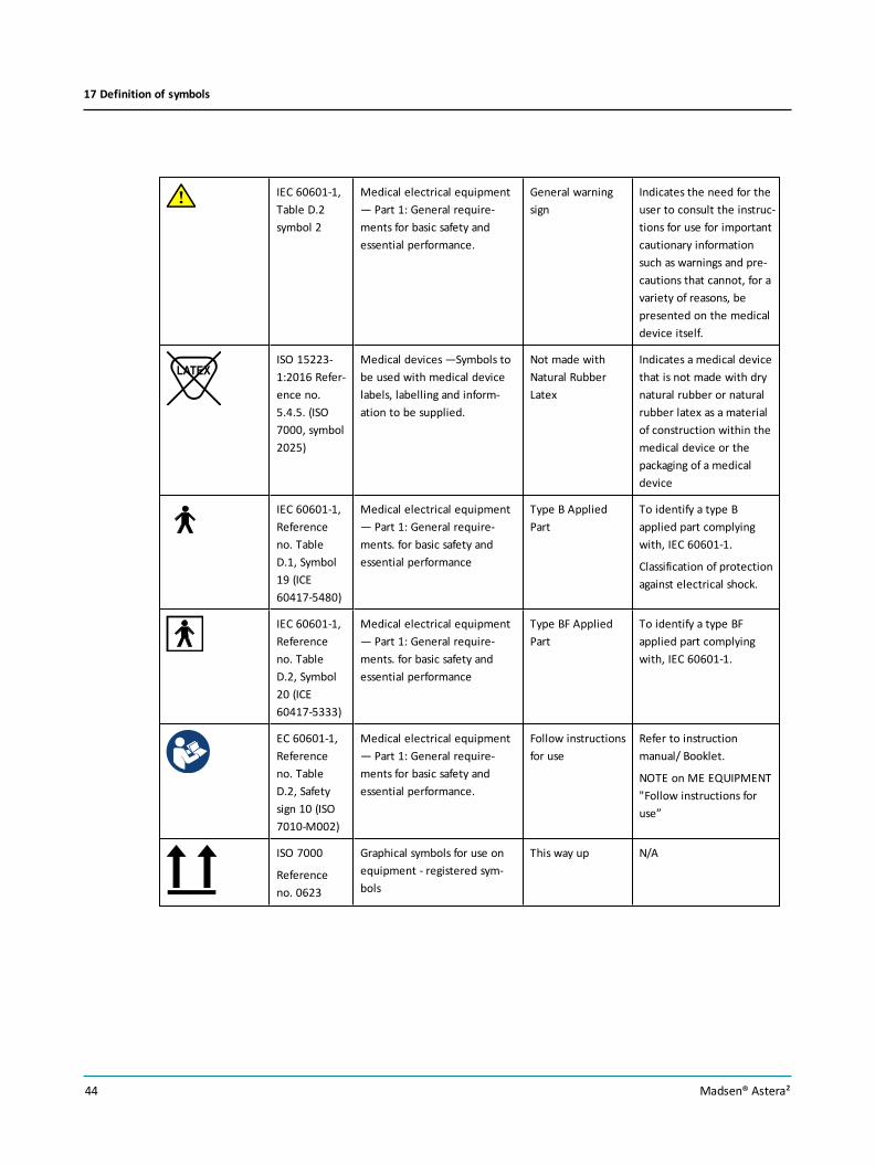
IEC 60601-1,Table D.2symbol 2
Medical electrical equipment— Part 1: General require-ments for basic safety andessential performance.
General warningsign
Indicates the need for theuser to consult the instruc-tions for use for importantcautionary informationsuch as warnings and pre-cautions that cannot, for avariety of reasons, bepresented on the medicaldevice itself.
ISO 15223-1:2016 Refer-ence no.5.4.5. (ISO7000, symbol2025)
Medical devices —Symbols tobe used with medical devicelabels, labelling and inform-ation to be supplied.
Not made withNatural RubberLatex
Indicates a medical devicethat is not made with drynatural rubber or naturalrubber latex as a materialof construction within themedical device or thepackaging of a medicaldevice
IEC 60601-1,Referenceno. TableD.1, Symbol19 (ICE60417-5480)
Medical electrical equipment— Part 1: General require-ments. for basic safety andessential performance
Type B AppliedPart
To identify a type Bapplied part complyingwith, IEC 60601-1.
Classification of protectionagainst electrical shock.
IEC 60601-1,Referenceno. TableD.2, Symbol20 (ICE60417-5333)
Medical electrical equipment— Part 1: General require-ments. for basic safety andessential performance
Type BF AppliedPart
To identify a type BFapplied part complyingwith, IEC 60601-1.
EC 60601-1,Referenceno. TableD.2, Safetysign 10 (ISO7010-M002)
Medical electrical equipment— Part 1: General require-ments for basic safety andessential performance.
Follow instructionsfor use
Refer to instructionmanual/ Booklet.
NOTE on ME EQUIPMENT"Follow instructions foruse”
ISO 7000
Referenceno. 0623
Graphical symbols for use onequipment - registered sym-bols
This way up N/A
44 Madsen® Astera²
17 Definition of symbols

Directive2012/19/EU
Waste Electrical and Elec-tronic Equipment (WEEE)
Disposal at end ofoperating lifeinstructions
Indicates that electricaland electronic wasteequipment waste shouldnot be discarded togetherwith unseparated wastebut must be collected sep-arately.
- - An indication ofMedical device
The product is a medicaldevice.
21 CFR Part801.109(b)(1)
Labeling-Prescription devices. Prescription only Indicates the product isauthorized for sale by oron the order of a licensedhealthcare practitioner.
UL Listing N/A N/A Nationally RecognizedTesting Laboratories(NRTL) certifications
INMETRO inconjunctionwith UL forLatin America
InMetro and UL marking ofconformity
MEDICAL - Gen-eral MedicalEquipment as toelectrical shock,fire and mech-anical hazards onlyin accordancewith:
ANSI/AAMIES60601-1:2005/(R)2012
IEC 60601-1-6
CAN/CSA-C22.2No. 60601-1:14
CAN/CSA-C22.2No. 60601-1-6
INMETRO in conjunctionwith the Mark of theNational Institute of Met-rology, Standardizationand Industrial Quality inBrazil
China RoHS 2Marking
N/A N/A Restriction of 6 hazardoussubstances for electronicand electrical productssold in the People’sRepublic of China
Madsen® Astera² 45
17 Definition of symbols
Disposal InstructionsNatus is committed to meeting the requirements of the European Union WEEE (Waste Electrical and Electronic Equip-ment) Directive 2012/19/EU. These regulations state that electrical and electronic waste must be separately collected forthe proper treatment and recovery to ensure that WEEE is reused or recycled safely. In line with that commitment Natusmay pass along the obligation for take back and recycling to the end user, unless other arrangements have been made.Please contact us for details on the collection and recovery systems available to you in your region at www.natus.com.
Electrical and electronic equipment (EEE) contains materials, components and substances that may be hazardous andpresent a risk to human health and the environment when WEEE is not handled correctly. Therefore, end users also have arole to play in ensuring that WEEE is reused and recycled safely. Users of electrical and electronic equipment must not dis-card WEEE together with other wastes. Users must use the municipal collection schemes or the producer/importers take-back obligation or licensed waste carriers to reduce adverse environmental impacts in connection with disposal of wasteelectrical and electronic equipment and to increase opportunities for reuse, recycling and recovery of waste electrical andelectronic equipment.
Equipment marked with the crossed-out wheeled bin is electrical and electronic equipment. The crossed-out wheeled binsymbol indicates that waste electrical and electronic equipment should not be discarded together with unseparated wastebut must be collected separately.
18 Warnings, Cautions, and NotesThis manual contains information, which must be followed to ensure the safe performance of the devices and softwarecovered by this manual. Local government rules and regulations, if applicable, should also be followed at all times.
Standards and safety-related issues relating to the Madsen® Astera² Audiometer Control Panel (ACP) are comprised by theMadsen® Astera² symbols, standards and this safety information.
Note •Any serious incident that has occurred in relation to the device should be reported to the manufacturer and tothe competent authority of the country or the EU Member State in which the user and/or patient is established.
See Definition of symbols 41, Connector warnings 46 and General warnings 47.
18.1 Connector warnings
Warning•Never mix connections between the Direct Connectors & Isolated Connectors
Direct connectors• All connectors within the red frame are connected directly to patient transducers.
46 Madsen® Astera²
18 Warnings, Cautions, and Notes

Fig. 1 Sockets with direct connections to patient transducers - Madsen® Astera² connection panel
Isolated connectors• All connectors within the red frame are isolated from patient transducers.
Note •The safety standards listed in Technical specifications 26 do not apply to the isolated connectors used inthe Madsen® Astera² audiometer.
Fig. 2 Connectors isolated from patient transducers - Madsen® Astera² connection panel
18.2 General warnings
Warning•Do not store or operate the device at temperatures and humidity exceeding those stated in the Tech-nical Specifications, Transport and storage.
Warning•Do not use the instrument in the presence of flammable agents (gases) or in an oxygen-rich envir-onment.
Warning•To avoid the risk of electric shock, this equipment must only be connected to a mains supply with pro-tective ground.
Warning•The device and any device to be connected which has its own power supply should be turned off beforeany connections are established. To disconnect the device from the mains supply, pull the mains plug out of thewall mains outlet. Do not position the unit so that it is difficult to pull the mains plug out of the wall mains.
Madsen® Astera² 47
18 Warnings, Cautions, and Notes

Warning•The device should not be stacked with other equipment or placed in a poorly ventilated space as thismay affect the performance of the device. If it is stacked or placed adjacent to other equipment, make sure the oper-ation of the device is not affected.
Warning•Unwanted noise may occur if the device is exposed to a strong radio field. Such noise may interferewith the performance of the device. Many types of electrical devices, e.g. mobile telephones, may generate radiofields. We recommend that the use of such devices in the vicinity of Madsen® Astera² be restricted.
Warning•The instrument is not used in the vicinity of devices sensitive to electromagnetic fields.
Warning• If an electro-medical device is connected to a multiple-socket power outlet, this can result in a reducedlevel of safety.
Warning•When assembling an electro-medical system, the person carrying out the assembly must take intoaccount that other connected equipment which does not comply with the same safety requirements as this product(e.g. PC and/or printer) may lead to a reduction in the overall safety level of the system. The equipment must complywith IEC 62368-1:2020.
Warning•Provided power supply shall be used to isolate Medical Equipment from mains power supply.
Warning•The following applies only when used with the specified power supply, XP Power, type PCM80PS24:When selecting accessories connected to the device, the following points must be considered:• Use of connected equipment in a patient environment.
• Proof that connected equipment has been tested in accordance with IEC 60601-1 (2nd).
Warning•The following applies only when used with the specified power supply, External power supply, DeltaElectronics Inc., type MDS-090AAS24:When selecting accessories connected to the device, the following points must be considered:Use of connected equip-ment in a patient environment.Proof that connected equipment has been tested in accordance with IEC 60601-1 (Edi-tion 3.1), AAMI ES60601-1 and CAN/CSA-C22.2 NO. 60601-1-14:2014, ES60601-1:2005/(R)2012 and A1:2012.
Warning•Do not touch the output DC plug of the power supply or connectors of the device or connected devicesand the patient at the same time.
48 Madsen® Astera²
18 Warnings, Cautions, and Notes

Warning•To comply with Medical Electrical Systems in IEC 60601-1 (Edition 3.1) computer and printer must beplaced at least 1.5 meters/5 ft away from the patient, so that the patient cannot reach the computer or printer.
Warning•Do not touch the patient at the same time you touch the output DC plug of the power supply or con-nectors of the device or connected devices.
Warning•Accidental damage and incorrect handling can have a negative effect on the functionality of thedevice. Contact your supplier for advice.
Warning•Keep the unit away from liquids. Do not allow moisture inside the unit. Moisture inside the unit candamage the instrument and it may result in a risk of electrical shock to the user or patient.
Warning•This class of equipment is allowed in professional healthcare establishments when used under the jur-isdiction of a health care professional.
Warning•Madsen® Astera² is suitable for use in hospital and clinic environments.
Warning•Do not touch non-medical parts, such as the laptop/computer or printer and the patient at the sametime.
Warning•Any PC connected to the ACP (Audiometer Control Panel) must comply with the requirements of IEC62368-1:2020.
Warning•For wall mounting of Madsen Astera2, screws specifically suited for the type of wall, must be used.
Warning•Avoid ElectroStatic Discharge (ESD) when installing the system.
Warning• Install the unit in an environment that minimizes the amount of static electricity. For example, anti-static carpeting is recommended.”
Madsen® Astera² 49
18 Warnings, Cautions, and Notes

18.3 General cautions
Caution•Madsen® Astera² is intended for diagnostic and clinical use by audiologists, ENTs, and other trainedhealth care professionals in testing the hearing of their patients.
Caution•For the sake of safety and in order not to void the warranty, service and repair of electro-medical equip-ment should be carried out only by the equipment manufacturer or by service personnel at authorized workshops. Incase of any defects, make a detailed description of the defect(s) and contact your supplier. Do not use a defectivedevice.
Caution•No parts may be eaten, burnt, or in any way used for purposes other than the applications defined inthe Intended Use section of this manual.
Caution•Annual calibration must be performed on accessories containing transducers. Furthermore, it is recom-mended that calibration be performed if the equipment has suffered any potential damage.
Caution•Note that calibration has been performed only on the transducers supplied. If you wish to use any othertransducer for testing with the device, please contact your local distributor first.
Caution•Disposable accessories, such as eartips, should not be reused and must be replaced between patients toprevent cross-infection.
Caution•Changes or modifications not expressly approved by the manufacturer could void the user's authority tooperate the equipment.
Caution•The manufacturer reserves the right to disclaim all responsibility for the operating safety, reliability andperformance of equipment serviced or repaired by other parties. Following repair, a qualified electronics engineershould verify the safety of all equipment.
Caution•Madsen® Astera² and Otosuite must always be installed in accordance with the instructions in the Mad-sen® Astera² Reference Manual and User Guide and the Otosuite Reference Manual and User Guide
50 Madsen® Astera²
18 Warnings, Cautions, and Notes

18.4 General notes
Note •Use only the specified power supply.
Note •Unwanted background noise must not be present during audiometry tests.
Note •For automatic level shift, the sound level will not exceed 80 dB HL for safety reasons.
Note •To hide patient's confidential data from measurement reports, see the Otosuite User Guide
Note •For safety reasons and due to effects on EMC, accessories connected to the equipment's outlet fittings must beidentical to the type supplied with the system.
19 ManufacturerNatus Medical Denmark ApSHoerskaetten 9, 2630 TaastrupDenmark
+45 45 75 55 55www.natus.com
19.1 Responsibility of the manufacturerThe manufacturer is to be considered responsible for effects on safety, reliability, and performance of the equipment onlyif:
• All assembly operations, extensions, re-adjustments, modifications or repairs are carried out by the equipment man-ufacturer or personnel authorized by the manufacturer.
• The electrical installation to which the equipment is connected complies with the requirements specified in the Tech-nical Specifications section of this manual.
• The equipment is used in accordance with the instructions for use.
Madsen® Astera² 51
19 Manufacturer

The manufacturer reserves the right to disclaim all responsibility for the operating safety, reliability and performance ofequipment serviced or repaired by other parties.
52 Madsen® Astera²
19 Manufacturer