Machine protection: availability for particle accelerators
170
DISSERTATION Machine Protection: Availability for Particle Accelerators Ausgef¨ uhrt zum Zwecke der Erlangung des akademischen Grades eines Doktors der technischen Wissenschaften unter der Leitung von PRIVATDOZ. DIPL.-ING. DR.TECHN. MICHAEL BENEDIKT Institutsnummer: E141 Atominstitut der ¨ Osterreichischen Universit¨ aten PROF. DR. R ¨ UDIGER SCHMIDT CERN, TE-MPE-PE eingereicht an der Technischen Universit¨ at Wien FAKULT ¨ AT F ¨ UR PHYSIK von ANDREA APOLLONIO Matrikelnummer 1128515 438 Rue des Vertes Campagnes, F-01170 Gex Wien, im M¨ arz 2015
-
Upload
khangminh22 -
Category
Documents
-
view
1 -
download
0
Transcript of Machine protection: availability for particle accelerators

DISSERTATION
Machine Protection: Availability for Particle
Accelerators
Ausgefuhrt zum Zwecke der Erlangung des akademischen Grades eines Doktors der
technischen Wissenschaften unter der Leitung von
PRIVATDOZ. DIPL.-ING. DR.TECHN. MICHAEL BENEDIKT
Institutsnummer: E141
Atominstitut der Osterreichischen Universitaten
PROF. DR. RUDIGER SCHMIDT
CERN, TE-MPE-PE
eingereicht an der Technischen Universitat Wien
FAKULTAT FUR PHYSIK
von
ANDREA APOLLONIO
Matrikelnummer 1128515
438 Rue des Vertes Campagnes, F-01170 Gex
Wien, im Marz 2015

ii

Abstract
Machine availability is a key indicator for the performance of the next gener-
ation of particle accelerators. Availability requirements need to be carefully
considered during the design phase to achieve challenging objectives in dif-
ferent fields, as e.g. particle physics and material science. For existing
and future High-Power facilities, such as ESS (European Spallation Source)
and HL-LHC (High-Luminosity LHC), operation with unprecedented beam
power requires highly dependable Machine Protection Systems (MPS) to
avoid any damage-induced downtime. Due to the high complexity of accel-
erator systems, finding the optimal balance between equipment safety and
accelerator availability is challenging. The MPS architecture, as well as the
choice of electronic components, have a large influence on the achievable
level of availability. In this thesis novel methods to address the availabil-
ity of accelerators and their protection systems are presented. Examples
of studies related to dependable MPS architectures are given in the thesis,
both for Linear accelerators (Linac4, ESS) and circular particle colliders
(LHC and HL-LHC). A study of suitable architectures for interlock systems
of future availability-critical facilities is presented.
Different methods have been applied to assess the anticipated levels of ac-
celerator availability. The thesis presents the prediction of the performance
(integrated luminosity for a particle collider) of LHC and future LHC up-
grades, based on a Monte Carlo model that allows reproducing a realistic
timeline of LHC operation. This model does not only account for the con-
tribution of MPS, but extends to all systems relevant for LHC operation.
Results are extrapolated to LHC run 2, run 3 and HL-LHC to derive indi-
vidual system requirements, based on the target integrated luminosity.

iv

To Sergio, Irma and Giulia

ii

Acknowledgements
My sincere gratitude goes to professor Benedikt for giving me the opportu-
nity of being enrolled as a PhD student at TU Wien. This has been for me
an extremely valuable professional and personal experience.
The biggest ’thank you’ goes to my CERN supervisor, R. Schmidt, who I
consider my professional mentor and a great person. In these three years
I had the chance of learning an incredible amount of things working with
him. I’ve always felt free to work and take initiatives, being at the same
time closely followed and guided. I will always be grateful for the constant
support shown for the duration of my studies.
I would also like to thank all the other people working on Machine Pro-
tection (D. Wollmann, M. Zerlauth, J. Wenninger, A. Verweij, M. Jonker
and many others) for the precious discussions during the past years and the
constant availability to share their knowledge with students and colleagues.
I believe this is one of the key ingredients of the success of CERN and in
particular of our group.
Similarly I would like to thank B. Todd and L. Ponce for proposing me as
a scientific secretary of the Availability Working Group (AWG). This was
for me an important experience in a multidisciplinary domain and gave me
the chance to learn a lot. I am convinced we will see during LHC run 2 the
results of our efforts and studies over the last years.
I would like to thank A. Nordt for giving me the chance of collaborating on
a challenging and interesting project as ESS. I particularly enjoyed being
in Lund and getting to know a different working environment than CERN.
I would like to thank my office mates for the nice atmosphere we always had
in the office and the support we gave to each other with daily questions and

doubts. A special mention is for the technical students I’ve been working
with (Volkan, Jakub and Tobias): it has been a great pleasure and a great
chance working with you. Following the work of other people definitely
stimulates a deeper understanding of things also on the supervisor’s side.
As last, but most important, I would like to thank my family.
Vorrei ringraziare mio padre Sergio, un irraggiungibile esempio dal punto
di vista umano e un punto di riferimento costante della mia vita.
Vorrei ringraziare mia madre Irma per il suo infinito amore e il dispiacere
ben celato per la lontananza di un figlio da ormai piu di 4 anni.
Ringrazio Giulia perche mi rende orgoglioso ogni giorno di essere suo fratello
maggiore. Gli incredibili risultati universitari non sono altro che lo specchio
di una maturita e una consapevolezza rara in una ragazza cosı giovane.
Infine ringrazio Irene per essere una donna straordinaria, gentile d’animo e
allo stesso tempo forte come sarebbe difficile immaginare.
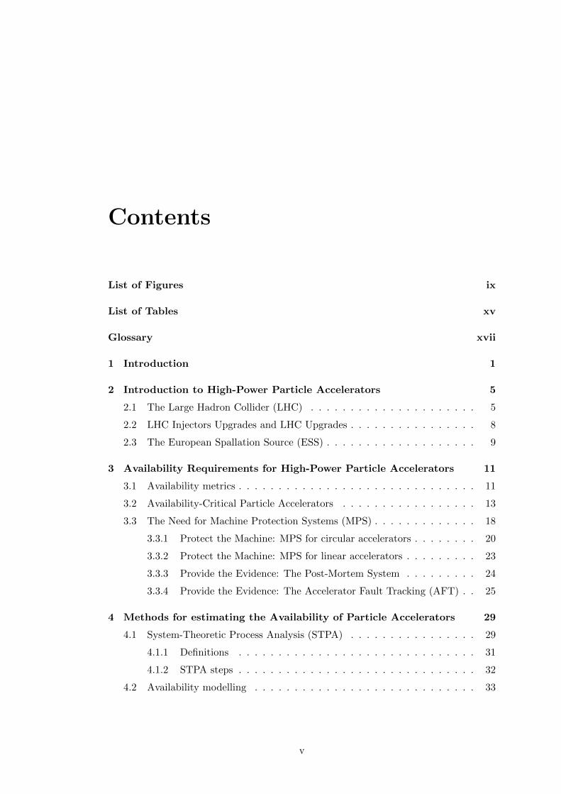
Contents
List of Figures ix
List of Tables xv
Glossary xvii
1 Introduction 1
2 Introduction to High-Power Particle Accelerators 5
2.1 The Large Hadron Collider (LHC) . . . . . . . . . . . . . . . . . . . . . 5
2.2 LHC Injectors Upgrades and LHC Upgrades . . . . . . . . . . . . . . . . 8
2.3 The European Spallation Source (ESS) . . . . . . . . . . . . . . . . . . . 9
3 Availability Requirements for High-Power Particle Accelerators 11
3.1 Availability metrics . . . . . . . . . . . . . . . . . . . . . . . . . . . . . . 11
3.2 Availability-Critical Particle Accelerators . . . . . . . . . . . . . . . . . 13
3.3 The Need for Machine Protection Systems (MPS) . . . . . . . . . . . . . 18
3.3.1 Protect the Machine: MPS for circular accelerators . . . . . . . . 20
3.3.2 Protect the Machine: MPS for linear accelerators . . . . . . . . . 23
3.3.3 Provide the Evidence: The Post-Mortem System . . . . . . . . . 24
3.3.4 Provide the Evidence: The Accelerator Fault Tracking (AFT) . . 25
4 Methods for estimating the Availability of Particle Accelerators 29
4.1 System-Theoretic Process Analysis (STPA) . . . . . . . . . . . . . . . . 29
4.1.1 Definitions . . . . . . . . . . . . . . . . . . . . . . . . . . . . . . 31
4.1.2 STPA steps . . . . . . . . . . . . . . . . . . . . . . . . . . . . . . 32
4.2 Availability modelling . . . . . . . . . . . . . . . . . . . . . . . . . . . . 33
v

CONTENTS
4.2.1 Estimates of Component Failure Rates . . . . . . . . . . . . . . . 34
4.2.2 Reliability Block Diagrams . . . . . . . . . . . . . . . . . . . . . 35
4.3 Monte-Carlo approach for Availability Simulations in MATLAB . . . . . 36
5 Availability-driven Design of MPS for Particle Accelerators 39
5.1 Derivation of Availability Requirements . . . . . . . . . . . . . . . . . . 39
5.1.1 Linac4 Layout and Parameters . . . . . . . . . . . . . . . . . . . 40
5.1.2 Linac4 STPA . . . . . . . . . . . . . . . . . . . . . . . . . . . . . 41
5.2 Definition of Interlock System Architectures . . . . . . . . . . . . . . . 49
5.2.1 Linac4 Beam Interlock System . . . . . . . . . . . . . . . . . . . 50
5.2.2 ESS Beam Interlock System . . . . . . . . . . . . . . . . . . . . . 54
5.2.2.1 ESS Layout and Parameters . . . . . . . . . . . . . . . 54
5.2.2.2 Interlocking Strategy . . . . . . . . . . . . . . . . . . . 56
5.2.2.3 BIS: Architecture . . . . . . . . . . . . . . . . . . . . . 63
5.2.3 Interlock Loops for MPS . . . . . . . . . . . . . . . . . . . . . . . 64
5.2.3.1 Quench Loop Architectures . . . . . . . . . . . . . . . 68
5.2.3.2 Sensor Interface and Quench Loop Architectures . . . 72
5.2.4 Impact of Newly Designed Systems on Availability . . . . . . . 76
6 Availability-driven Optimization of Accelerator Performance 81
6.1 2010-2012 LHC performance . . . . . . . . . . . . . . . . . . . . . . . . 81
6.1.1 Availability and Integrated Luminosity . . . . . . . . . . . . . . 81
6.1.2 Study of 2010-2012 data . . . . . . . . . . . . . . . . . . . . . . 84
6.1.3 Integrated Luminosity and Availability: Analytical Model . . . 92
6.1.4 Integrated Luminosity and Availability: Monte Carlo Model . . 93
6.1.5 Model Validation against 2012 Operation . . . . . . . . . . . . 97
6.2 LHC performance for Post-LS1 operation . . . . . . . . . . . . . . . . 99
6.2.1 Impact of Future Operational Scenarios . . . . . . . . . . . . . 99
6.2.2 Integrated Luminosity Predictions and Sensitivity Analyses . . 101
6.2.3 Integrated Luminosity Optimization through Availability . . . 110
6.3 LHC performance in the High-Luminosity era . . . . . . . . . . . . . . 114
6.3.1 Impact of Future Operational Scenarios . . . . . . . . . . . . . 114
6.3.2 Integrated Luminosity Predictions and Sensitivity Analyses . . 117
6.3.3 Integrated Luminosity Optimization through Availability . . . 121
vi
CONTENTS
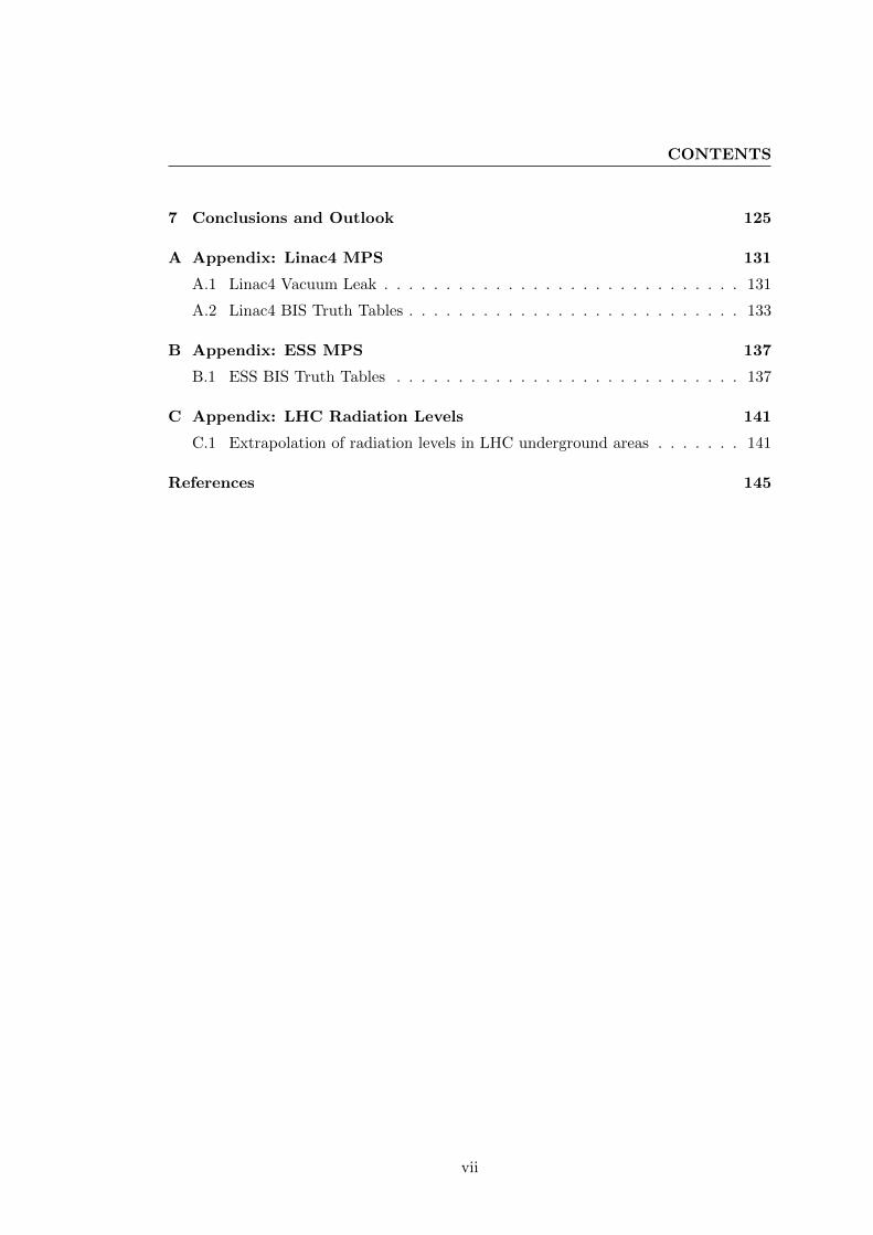
7 Conclusions and Outlook 125
A Appendix: Linac4 MPS 131
A.1 Linac4 Vacuum Leak . . . . . . . . . . . . . . . . . . . . . . . . . . . . . 131
A.2 Linac4 BIS Truth Tables . . . . . . . . . . . . . . . . . . . . . . . . . . . 133
B Appendix: ESS MPS 137
B.1 ESS BIS Truth Tables . . . . . . . . . . . . . . . . . . . . . . . . . . . . 137
C Appendix: LHC Radiation Levels 141
C.1 Extrapolation of radiation levels in LHC underground areas . . . . . . . 141
References 145
vii

CONTENTS
viii

List of Figures
2.1 The Large Hadron Collider (LHC). . . . . . . . . . . . . . . . . . . . . . 6
2.2 A schematic view of the CERN accelerator complex. The proton beam is
produced and accelerated by Linac2 and injected into the four rings of the
Proton Synchrotron Booster (PSB). The beam is then recombined and
injected in the Proton Synchrotron (PS) and then in the Super Prtron
Synchrotron (SPS). At the energy of 450 GeV the beam can finally be
extracted towards the LHC, with dedicated 3 km long transfer lines. . . 7
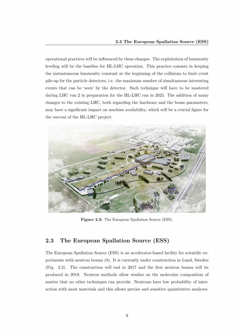
2.3 The European Spallation Source (ESS). . . . . . . . . . . . . . . . . . . 9
3.1 Integrated Luminosity production recorded by the ATLAS experiment
at CERN in 2011 and 2012. . . . . . . . . . . . . . . . . . . . . . . . . . 14
3.2 Layout of the CERN LHC. . . . . . . . . . . . . . . . . . . . . . . . . . 20
3.3 LHC Beam Loss Monitors placed on the side of superconducting quadrupoles. 21
3.4 Schematic view of the LHC dipole circuit. . . . . . . . . . . . . . . . . . 22
3.5 ’Cardiogram’ of LHC operation. . . . . . . . . . . . . . . . . . . . . . . . 26
5.1 Linac4 layout. . . . . . . . . . . . . . . . . . . . . . . . . . . . . . . . . . 41
5.2 High-Level control structure: The figure shows the basic control struc-
ture derived from requirements R1-R5. . . . . . . . . . . . . . . . . . . . 43
5.3 High-Level control structure: The figure shows a refined control structure
derived from requirements R1-R5. . . . . . . . . . . . . . . . . . . . . . 44
5.4 Schematic view of the functionality of an interlock system for particle
accelerators. . . . . . . . . . . . . . . . . . . . . . . . . . . . . . . . . . . 50
5.5 The Tree-Architecture of the BIS. . . . . . . . . . . . . . . . . . . . . . . 51
5.6 Layout of the Linac4 BIS. . . . . . . . . . . . . . . . . . . . . . . . . . . 53
ix
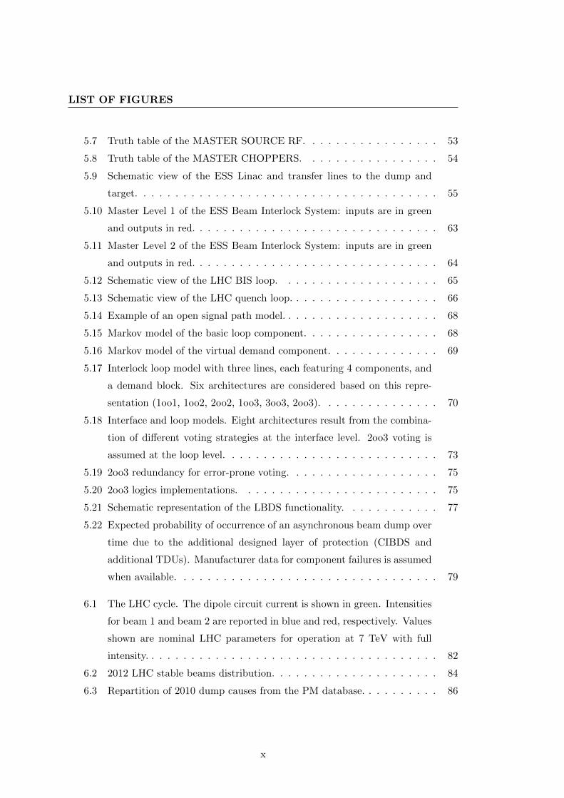
LIST OF FIGURES
5.7 Truth table of the MASTER SOURCE RF. . . . . . . . . . . . . . . . . 53
5.8 Truth table of the MASTER CHOPPERS. . . . . . . . . . . . . . . . . 54
5.9 Schematic view of the ESS Linac and transfer lines to the dump and
target. . . . . . . . . . . . . . . . . . . . . . . . . . . . . . . . . . . . . . 55
5.10 Master Level 1 of the ESS Beam Interlock System: inputs are in green
and outputs in red. . . . . . . . . . . . . . . . . . . . . . . . . . . . . . . 63
5.11 Master Level 2 of the ESS Beam Interlock System: inputs are in green
and outputs in red. . . . . . . . . . . . . . . . . . . . . . . . . . . . . . . 64
5.12 Schematic view of the LHC BIS loop. . . . . . . . . . . . . . . . . . . . 65
5.13 Schematic view of the LHC quench loop. . . . . . . . . . . . . . . . . . . 66
5.14 Example of an open signal path model. . . . . . . . . . . . . . . . . . . . 68
5.15 Markov model of the basic loop component. . . . . . . . . . . . . . . . . 68
5.16 Markov model of the virtual demand component. . . . . . . . . . . . . . 69
5.17 Interlock loop model with three lines, each featuring 4 components, and
a demand block. Six architectures are considered based on this repre-
sentation (1oo1, 1oo2, 2oo2, 1oo3, 3oo3, 2oo3). . . . . . . . . . . . . . . 70
5.18 Interface and loop models. Eight architectures result from the combina-
tion of different voting strategies at the interface level. 2oo3 voting is
assumed at the loop level. . . . . . . . . . . . . . . . . . . . . . . . . . . 73
5.19 2oo3 redundancy for error-prone voting. . . . . . . . . . . . . . . . . . . 75
5.20 2oo3 logics implementations. . . . . . . . . . . . . . . . . . . . . . . . . 75
5.21 Schematic representation of the LBDS functionality. . . . . . . . . . . . 77
5.22 Expected probability of occurrence of an asynchronous beam dump over
time due to the additional designed layer of protection (CIBDS and
additional TDUs). Manufacturer data for component failures is assumed
when available. . . . . . . . . . . . . . . . . . . . . . . . . . . . . . . . . 79
6.1 The LHC cycle. The dipole circuit current is shown in green. Intensities
for beam 1 and beam 2 are reported in blue and red, respectively. Values
shown are nominal LHC parameters for operation at 7 TeV with full
intensity. . . . . . . . . . . . . . . . . . . . . . . . . . . . . . . . . . . . . 82
6.2 2012 LHC stable beams distribution. . . . . . . . . . . . . . . . . . . . . 84
6.3 Repartition of 2010 dump causes from the PM database. . . . . . . . . . 86
x

LIST OF FIGURES
6.4 Repartition of 2011 dump causes from the PM database. . . . . . . . . . 87
6.5 Repartition of 2012 dump causes from the PM database. . . . . . . . . . 87
6.6 2012 LHC fault time distribution. . . . . . . . . . . . . . . . . . . . . . . 89
6.7 Fault time distribution for R2E-induced failures in 2012. . . . . . . . . . 91
6.8 Example of timeline produced by the Monte Carlo model of LHC opera-
tion. All quantities in the drawing are randomly generated by the Monte
Carlo model. . . . . . . . . . . . . . . . . . . . . . . . . . . . . . . . . . 93
6.9 Comparison of the instantaneous luminosity fit for the LHC fill 3135 in
2012. . . . . . . . . . . . . . . . . . . . . . . . . . . . . . . . . . . . . . . 94
6.10 Relative error distribution of a single exponential fit of the integrated
luminosity. . . . . . . . . . . . . . . . . . . . . . . . . . . . . . . . . . . 95
6.11 Peak luminosity (top) and luminosity lifetime (bottom) resulting from a
single exponential fit of 2012 data recorded by LHC experiments. Red
lines indicate a machine technical stop for maintenance. . . . . . . . . . 96
6.12 Model statistics of relevant simulated quantities for quantifying the im-
pact of availability on integrated luminosity. Results are relative to 1000
cycles of the Monte Carlo model. . . . . . . . . . . . . . . . . . . . . . . 98
6.13 Distribution of integrated luminosity for standard 25 ns beams during
LHC run 2. . . . . . . . . . . . . . . . . . . . . . . . . . . . . . . . . . . 102
6.14 Distribution of integrated luminosity for BCMS beams during LHC run 2.103
6.15 Distribution of integrated luminosity for standard operation with Linac4
beams during LHC run 3. . . . . . . . . . . . . . . . . . . . . . . . . . . 104
6.16 Distribution of integrated luminosity for standard 25 ns beams during
LHC run 2, considering the effect of R2E mitigations. . . . . . . . . . . 106
6.17 Distribution of integrated luminosity for BCMS beams during LHC run
2, considering the effect of R2E mitigations. . . . . . . . . . . . . . . . . 106
6.18 Distribution of integrated luminosity for standard operation with Linac4
beams during LHC run 3, considering the effect of R2E mitigations. . . 107
6.19 Sensitivity analysis of the integrated luminosity to average fault time
and machine failure rate for standard 25 ns beams during LHC run 2. . 108
6.20 Sensitivity analysis of the integrated luminosity to average fault time
and machine failure rate for BCMS beams during LHC run 2. . . . . . . 109
xi

LIST OF FIGURES
6.21 Sensitivity analysis of the integrated luminosity to average fault time
and machine failure rate for standard beams with Linac4 during LHC
run 3. . . . . . . . . . . . . . . . . . . . . . . . . . . . . . . . . . . . . . 109
6.22 Simulated timeline of LHC operation with BCMS beams. . . . . . . . . 113
6.23 Distribution of produced integrated luminosity for HL-LHC, assuming
2012 availability. . . . . . . . . . . . . . . . . . . . . . . . . . . . . . . . 118
6.24 Distribution of produced integrated luminosity for HL-LHC, with R2E
mitigations deployed during the long shutdown 1. . . . . . . . . . . . . . 119
6.25 Sensitivity analysis of the integrated luminosity to average fault time
and machine failure rate for HL-LHC. . . . . . . . . . . . . . . . . . . . 120
6.26 Simulated timeline of HL-LHC operation. . . . . . . . . . . . . . . . . . 122
A.1 Linac4: a damaged bellow due to beam losses in the MEBT. . . . . . . . 131
A.2 Truth table of the Linac4 slave controller. . . . . . . . . . . . . . . . . . 133
A.3 Truth table of the Linac4 dump line slave controller. . . . . . . . . . . . 134
A.4 Truth table of the Linac4 transfer line slave controller. . . . . . . . . . . 134
A.5 Truth table of the emittance measurement line slave controller. . . . . . 134
A.6 Truth table of the first slave controller monitoring beam injection in the
PSB. . . . . . . . . . . . . . . . . . . . . . . . . . . . . . . . . . . . . . . 135
A.7 Truth table of the second slave controller monitoring beam injection in
the PSB. . . . . . . . . . . . . . . . . . . . . . . . . . . . . . . . . . . . . 135
A.8 Truth table of the slave controller monitoring the status of the PSB. . . 135
B.1 Truth table of the master controller 1, acting on the source and on the
LEBT chopper. . . . . . . . . . . . . . . . . . . . . . . . . . . . . . . . . 137
B.2 Truth table of the master controller 2, acting on the MEBT chopper and
providing an input to the master controller 1. . . . . . . . . . . . . . . . 138
B.3 Truth table of the slave controller 1, monitoring the status of the MEBT. 138
B.4 Truth table of the slave controller 2, monitoring the status of the DTL. 138
B.5 Truth table of the slave controller 3, monitoring the status of the spokes
cavities plus a part of the medium-beta cavities. . . . . . . . . . . . . . 139
B.6 Truth table of the slave controller 4, monitoring the status of the second
part of the medium-beta cavities plus the high-beta cavities. . . . . . . . 139
xii

LIST OF FIGURES
B.7 Truth table of the slave controller 5, monitoring the status of the dump
line. . . . . . . . . . . . . . . . . . . . . . . . . . . . . . . . . . . . . . . 139
B.8 Truth table of the slave controller 6, monitoring the status of the target
line. . . . . . . . . . . . . . . . . . . . . . . . . . . . . . . . . . . . . . . 140
C.1 Layout of LHC underground areas. . . . . . . . . . . . . . . . . . . . . . 142
C.2 Extrapolation of HEH fluence and total dose in the different LHC un-
derground areas for future runs and LHC upgrades. . . . . . . . . . . . . 143
xiii

LIST OF FIGURES
xiv
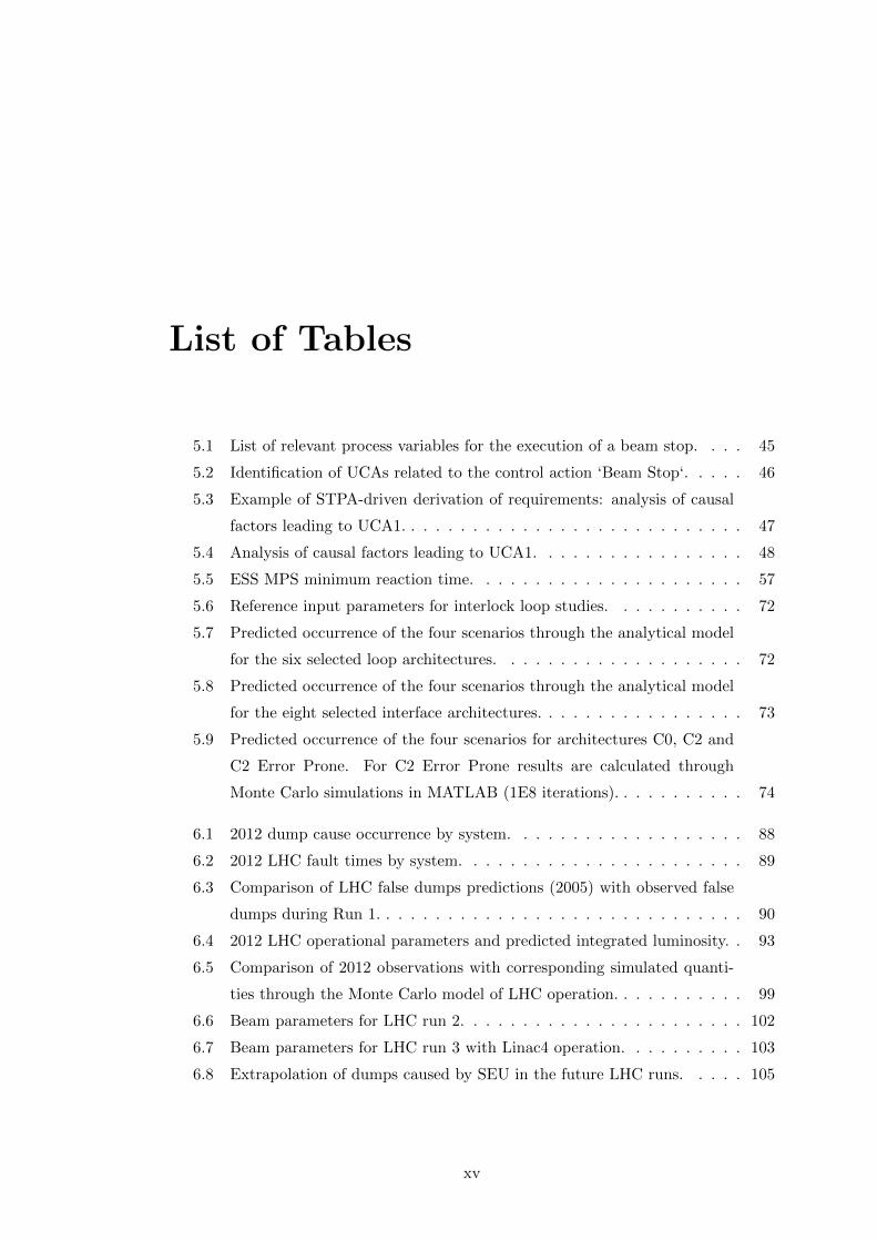
List of Tables
5.1 List of relevant process variables for the execution of a beam stop. . . . 45
5.2 Identification of UCAs related to the control action ‘Beam Stop‘. . . . . 46
5.3 Example of STPA-driven derivation of requirements: analysis of causal
factors leading to UCA1. . . . . . . . . . . . . . . . . . . . . . . . . . . . 47
5.4 Analysis of causal factors leading to UCA1. . . . . . . . . . . . . . . . . 48
5.5 ESS MPS minimum reaction time. . . . . . . . . . . . . . . . . . . . . . 57
5.6 Reference input parameters for interlock loop studies. . . . . . . . . . . 72
5.7 Predicted occurrence of the four scenarios through the analytical model
for the six selected loop architectures. . . . . . . . . . . . . . . . . . . . 72
5.8 Predicted occurrence of the four scenarios through the analytical model
for the eight selected interface architectures. . . . . . . . . . . . . . . . . 73
5.9 Predicted occurrence of the four scenarios for architectures C0, C2 and
C2 Error Prone. For C2 Error Prone results are calculated through
Monte Carlo simulations in MATLAB (1E8 iterations). . . . . . . . . . . 74
6.1 2012 dump cause occurrence by system. . . . . . . . . . . . . . . . . . . 88
6.2 2012 LHC fault times by system. . . . . . . . . . . . . . . . . . . . . . . 89
6.3 Comparison of LHC false dumps predictions (2005) with observed false
dumps during Run 1. . . . . . . . . . . . . . . . . . . . . . . . . . . . . . 90
6.4 2012 LHC operational parameters and predicted integrated luminosity. . 93
6.5 Comparison of 2012 observations with corresponding simulated quanti-
ties through the Monte Carlo model of LHC operation. . . . . . . . . . . 99
6.6 Beam parameters for LHC run 2. . . . . . . . . . . . . . . . . . . . . . . 102
6.7 Beam parameters for LHC run 3 with Linac4 operation. . . . . . . . . . 103
6.8 Extrapolation of dumps caused by SEU in the future LHC runs. . . . . 105
xv

LIST OF TABLES
6.9 Extrapolation of dumps caused by SEU in the future LHC runs. . . . . 107
6.10 Optimized integrated luminosity for different failure scenarios. . . . . . . 112
6.11 Beam parameters for HL-LHC operation. . . . . . . . . . . . . . . . . . 117
6.12 Extrapolation of dumps caused by SEU in the future LHC runs. . . . . 118
6.13 Extrapolation of acceptable R2E failure budget per system in the HL-
LHC era. . . . . . . . . . . . . . . . . . . . . . . . . . . . . . . . . . . . 119
xvi

Glossary
Abort Gap Particle-free gap in the LHC beam
for synchronization with the extrac-
tion kickers
AC Alternate Current
ALICE A Large Ion Collider Experiment
ATLAS A Large Toroidal LHC Apparatus
BCMS Batch Compression bunch Merging
and Splitting
Beam Abort/Dump/Stop A controlled re-
moval of circulating beam in the ac-
celerator
Beam Permit Loops Communication chan-
nels connecting the Beam Interlock
Systems to the Beam Dumping Sys-
tem
Beam Intensity Number of particles (e.g. pro-
tons) in the beam
BEAM PERMIT Signal indicating, when
TRUE, permission for beam oper-
ation
BIC Beam Interlock Controller
BIS Beam Interlock System
BLM Beam Loss Monitor
CCC CERN Control Center
CCDTL Cell-Coupled DTL
CERN European Centre for Nuclear Re-
search
CIBDS Controls Interlocks Beam Dumping
System
CIBG Controls Interlocks Beam Generator
- The generator of the permit loop
frequency
CIBM Controls Interlocks Beam Manager -
The Manager board
CIBU Controls Interlocks Beam User - The
User Interface
CMS Compact Muon Solenoid
DC Direct Current - a synonym for con-
stant
DCCT AC/DC current sensor
DTL Drift Tube Linac
eV electron-Volt
ESS European Spallation Source - An ac-
celerator based neutron source built
in Lund, Sweden
EOF End Of Fill, intentional beam dump
from LHC operators performed for
luminosity optimization
False dump/stop Preventive beam abort
caused by an internal failure of the
MPS
Fill Beams going through the LHC cycle
FIT Failures In Time - failures per billion
operating hours
FMCM Fast Magnet Current change Monitor
FMECA Failure Modes, Effects and Critical-
ity Analysis
FPGA Field Programmable Gate Array
HL-LHC High-Luminosity LHC
Integrated Luminosity A measure of the per-
formance of a particle collider, pro-
portional to the number of interest-
ing events observed by the experi-
ments
xvii

GLOSSARY
IP Interaction Point in the LHC ring
LBDS LHC Beam Dumping System
LEBT Low-Energy Beam Transport
LHC Large Hadron Collider
LHC-b LHC beauty - an experiment of the
LHC
LINAC LINear ACcelerator
LINAC4 A Linear accelerator under construc-
tion at CERN
LIU LHC Injectors Upgrade project
LOCAL BEAM PERMIT A signal given by
a Beam Interlock Controller that
evaluates to TRUE when all locally
connected User Systems give permis-
sion for beam operation
LS1 First Long Shutdown of the LHC
(2013-2015)
Luminosity Lifetime Time constant of the lu-
minosity exponential decay over time
MD Machine Development
MEBT Medium-Energy Beam Transport
MFR Machine Failure Rate
MPS Machine Protection Systems
MTBF Mean Time Between Failures
Open-Loop An interlock loop that signals the
necessity of a MPS action
PDF Probability Density Function
Peak Luminosity Maximum value of luminos-
ity achieved during a fill
PIC Power Interlock Controllers
Pile-up Number of simultaneous events seen
by a particle detector
PIMS PI-Mode Structure
PLC Programmable Logic Controller
PM Post-Mortem, a process that is car-
ried out following a Beam Abort, this
involves reading data from protection
systems to ensure that the system
functions were all carried out and
that the system safety was not com-
promised
PS Proton Synchrotron
PSB Proton Synchrotron Booster
QPS Quench Protection System
R2E Radiation to Electronics
RF Radio Frequency
RFQ Radio Frequency Quadrupole
SEU Single Event Upset, causing failures
of electronic components due to ion-
ising radiation
SIS Software Interlock System
SNS Spallation Neutron Source - An
accelerator-based neutron source
built in Tennessee, USA
SPS Super Proton Synchrotron
STPA System-Theoretic Process Analysis
UCA Unsafe Control Action
UFO Unidentified Falling Object
User System A system which is connected as
an input to a Beam Interlock System
WIC Warm Magnet Interlock Controllers
xviii

1
Introduction
Machine availability and reliability are becoming key indicators for the performance
of particle accelerators. In the future, optimizing accelerator availability will be fun-
damental in order to achieve the new challenging objectives of different facilities. For
particle physics the aim is to fully exploit the potential of an accelerator for new discov-
eries. Furthermore, new user-oriented facilities are being designed to investigate open
scientific questions regarding the microscopic structure of matter. Many synchrotron
light sources are already operational around the world. Neutron scattering represents a
complementary option for this type of studies. To produce the neutron beam, a proton
beam is accelerated to high-energy (in the range of some GeV) in a linear accelerator.
Neutrons are generated via a spallation process in a target made of a high-density ma-
terial. Neutron beams are also of interest for the so-called Accelerator-Driven Systems
(ADS), in which a sub-critical nuclear reactor is coupled with a particle accelerator.
In such facilities the generated neutrons are used to sustain nuclear fission in a safer,
more controlled way than in traditional reactors.
For the aforementioned accelerator applications the interest is to push beam per-
formance to the limits. For particle physics studies, the number of interesting events
recorded by the experiments depends on the collision rate and the collision energy,
which in turn depend on the beam intensity (i.e. the number of particles in the beam)
and energy. For neutron facilities, the neutron flux for user experiments depends on
beam energy, intensity and the repetition rate at which the target is hit by the particle
beam. In all facilities, the search for unparalleled beam performance leads to high
1
1. INTRODUCTION
stored power in the beams. This determines a significant damage potential in case of
sudden and uncontrolled release of the beams.
For High-Power accelerators, operation with unprecedented beam power requires
sophisticated Machine Protection Systems (MPS) to avoid any damage-induced down-
time. Examples of high-power accelerators are the European Spallation Source (ESS,
Lund, Sweden), the Large Hadron Collider (LHC, CERN, Geneva) and its upgrade to
High-Luminosity LHC (HL-LHC). Machine protection systems make use of interlock
systems to anticipate or mitigate the consequences of beam losses and other equipment
failures. Upon the detection of a critical failure, the interlock system is responsible for
bringing the accelerator in a safe state. The design of interlock systems has, thus, to be
highly dependable to avoid damage of expensive equipment and unnecessary downtime
of the facility. For the LHC, the damage in case of a catastrophic failure can cause
damage beyond the possibility of repair.
Due to the high complexity of accelerator systems, finding the optimal balance
between equipment safety and accelerator availability is challenging. On one hand
machine protection systems preserve availability by preventing damage to accelerator
equipment, on the other hand they reduce availability due to internal failures that
can inhibit accelerator operation. The interlock system architecture, as well as the
choice of the components to be used, have a large influence on the achievable level
of dependability. Dedicated studies should therefore be performed in parallel to the
design of machine protection systems. The studies should be consistently updated as
the design evolves, considering all possible system dependencies on other systems and
interactions with different users.
In this thesis novel methods to address the availability of accelerators and their
protection systems are presented. Examples of studies related to existing interlock sys-
tem architectures are given, both for linear accelerators and circular particle colliders.
The challenge of designing new interlock architectures with demanding availability re-
quirements extends to facilities other than particle accelerators, e.g. the International
Thermonuclear Experimental Reactor (ITER). This aspect of interlock system design
is addressed in detail in the following.
Based on the experience from the first run of the CERN’s Large Hadron Collider
(LHC), the thesis presents availability and performance predictions of the LHC and its
2

future upgrades. The performance of a particle collider is measured in terms of ‘inte-
grated luminosity‘, which is proportional to the number of interesting events recorded
by the experiments.
The scope of this thesis is therefore to address the impact of availability on acceler-
ator performance and quantify the gain that could be obtained by applying availability
studies in different phases of the accelerator lifetime, from the conceptual design to its
final exploitation.
Chapter 2 gives an overview of the facilities that will be taken as examples in the
following for the application of availability studies. Both linear accelerators and
circular colliders are considered.
Chapter 3 introduces the concept of availability for particle accelerators. An overview
on the machine protection requirements and strategies for high-power particle
accelerators is presented. The relationship between accelerator availability and
machine protection is described in detail, as well as the tools used for availability
tracking.
Chapter 4 describes the methodologies that are adopted for availability studies. The
derivation of requirements for machine protection systems is performed with the
System-Theoretic Process Analysis (STPA). An overview of the tools used for
availability modelling is presented. It includes custom-developed Monte Carlo
models, built for reproducing unique aspects of accelerator operation, as well as
models built with commercially available tools.
Chapter 5 shows the application of an availability-driven design of MPS and its impact
on interlock system architectures. Availability requirements for Linac4 are derived
based on the STPA method. The adopted strategy to ensure high-dependability
of machine protection systems is shown. The architecture of both Linac4 and
ESS interlock systems is presented. A study on interlock system architectures for
future availability-critical facilities is also presented. Results from these analyses
allow giving clear guidelines for the design of future machine protection systems.
Chapter 6 addresses the problem of availability-driven optimization of accelerator
performance. Data from LHC run 1 (2010-2012) is taken as a reference for LHC
3

1. INTRODUCTION
performance predictions. A Monte Carlo model of accelerator operation is used
to quantify the impact of future operational scenarios on LHC performance, for
future LHC runs and High-Luminosity LHC. The benefit of optimizing the time
with colliding beams is also discussed.
Chapter 7 presents a summary of the described methodology and draws conclusions
on the importance of availability for particle accelerators. Finally, the outlook on
future applications of availability studies for particle accelerators is presented.
4

2
Introduction to High-Power
Particle Accelerators
2.1 The Large Hadron Collider (LHC)
The Large Hadron Collider (LHC) is the world’s largest and most complex particle
collider ever built. Its 27 km circumference is housed in a tunnel, about 100 m un-
derground, in the area below the French-Swiss border close to Geneva (Fig. 2.1). The
LHC has four main experiments (ATLAS, CMS, ALICE, LHCb) aimed at studying the
open mysteries of the universe, from the discovery of the missing pieces of the standard
model, to super-symmetry. The recent history of the LHC culminated in 2012 with
the announcement of the discovery of a new particle of the standard model, the Higgs
boson (1) (2).
The history of the LHC dates back in 1984, when the first concept of a new ac-
celerator was proposed to replace the existing Large Electron-Positron Collider (LEP)
(3). The idea behind the LHC was to build a machine capable to reach unprecedented
energies and intensities for more efficient particle collisions, resulting in an increased
number of statistics for physics experiments in unexplored ranges of energies. The
dream of building such a machine had nevertheless to face major technological chal-
lenges, from the design of 9 T superconducting magnets to the development of suitable
Machine Protection Systems (MPS). The LHC is in fact one of the first particle accel-
erators with damage potential beyond repair. The cost of repair and replacement of
some LHC systems (e.g. magnets) is in fact so high that a major failure of the LHC,
5

2. INTRODUCTION TO HIGH-POWER PARTICLE ACCELERATORS
Figure 2.1: The Large Hadron Collider (LHC).
resulting in extensive damage of equipment in the tunnel, could not be faced, probably
compromising particle physics studies on a worldwide scale.
The commissioning and tests in situ of LHC systems started in 2008. In Septem-
ber 2008 an accident involving the magnet powering system was the cause of one year
of forced downtime for the replacement of several magnets in the tunnel (4). It was
discovered that the splices of the superconducting busbars (NbTi plus copper as a sta-
bilizer) feeding the magnets could have manufacturing defects in the copper electrical
continuity. This prevents the correct current flow in case of local loss of superconduc-
tivity (quench). Thanks to the prompt reaction to the accident and the design of new
electronics to cope with the newly discovered failure mode, LHC operation was resumed
in 2009. For safety reasons it was decided to limit the energy from the nominal target
of 7 TeV per beam to 3.5 TeV per beam. In 2010 the first significant achievements of
the LHC were reached, with the first collisions at 3.5 TeV.
The performance of the LHC is defined in terms of the integrated luminosity de-
livered to the experiments. This quantity gives a measure of the number of relevant
events observed at the experiments, i.e. the production of rare particles as the Higgs
6

2.1 The Large Hadron Collider (LHC)
Boson. Luminosity is measured in inverse barn [b−1] and more practically for the LHC
in inverse femtobarn fb−1. The 2011 and 2012 runs were very successful and the LHC
was able to deliver about 30 fb−1 to the main experiments over its first three years
of proton run. The LHC is not only capable of performing proton-proton collisions.
A running period during the year is also dedicated to proton-ion (lead) collisions or
ion-ion collisions.
The success of the LHC has to be retraced also in the performance of its injectors
(Fig. 2.2). The beam produced by the Linac2 is accelerated in the Proton Synchrotron
Booster (PSB), the Proton Synchrotron (PS), then injected in the Super Proton Syn-
chrotron (SPS) before finally reaching the LHC.
Figure 2.2: A schematic view of the CERN accelerator complex. The proton beam
is produced and accelerated by Linac2 and injected into the four rings of the Proton
Synchrotron Booster (PSB). The beam is then recombined and injected in the Proton
Synchrotron (PS) and then in the Super Prtron Synchrotron (SPS). At the energy of 450
GeV the beam can finally be extracted towards the LHC, with dedicated 3 km long transfer
lines.
In the years 2013 and 2014 the LHC underwent a period of extensive maintenance
and consolidation, the so-called Long Shutdown 1 (LS1) (5). All the outstanding fail-
ure modes affecting LHC operation during run 1 were mitigated. The largest efforts
7

2. INTRODUCTION TO HIGH-POWER PARTICLE ACCELERATORS
during the LS1 were devoted to consolidate the discovered imperfections in the copper
continuity of the superconducting busbars. Careful quality insurance procedures were
put in place to prepare the LHC restart, foreseen in April 2015. The machine will thus
be able to resume operation with increased energy, 6.5 TeV as compared to 3.5 TeV
in 2010. This will ensure increased statistics for the experiments and offer the poten-
tial for new discoveries. During the LS1, significant changes have been introduced in
the machine and will require a progressive recovery of stable operation, on the base of
what was achieved in 2012. Only then, it will be possible to tune and optimize LHC
operation, based on the experience collected during the LHC run 1.
2.2 LHC Injectors Upgrades and LHC Upgrades
The LHC performance is directly influenced by the performance of its injectors. To push
the LHC to its limits in terms of beam brightness and luminosity production, significant
upgrades of the LHC and of its injector chain are required. The LHC Injectors Upgrade
Project (LIU) was launched at CERN to guarantee the required beam characteristics
for increased LHC performance (6). All the injectors will require consolidations and
upgrades to reach the ambitious LHC goals. In particular the existing Linac2, the
first element in the injector chain, will be replaced by the Linac4. Linac4 is an H−
linear accelerator with an output energy of 160 MeV, whose goal is to provide beam
brightness out of the PSB increased by a factor 2 compared to the currently achieved
values. Linac4 has entered the commissioning phase in 2013 and will be connected to
the PSB by a dedicated transfer line after the Long Shutdown 2 (2019).
Efforts invested in the injectors will only be part of the necessary modifications. The
High-Luminosity LHC Project (HL-LHC) was launched with the scope of increasing
LHC integrated luminosity by a factor 10 beyond the design value (7). Significant
hardware upgrades will be required, for both experiments and accelerator equipment.
The use of new technologies for different applications was the base for a large research
and development campaign. As an example, new superconducting Nb3Sn magnets
are currently under study to replace the existing ones close to the Interaction Points
(IPs). The use of crab cavities will ensure perfect overlapping of colliding bunches
and will improve luminosity production. Such changes will have huge implications on
the machine, that will require newly designed optics and MPS, amongst others. Also
8
2.3 The European Spallation Source (ESS)
operational practices will be influenced by these changes. The exploitation of luminosity
leveling will be the baseline for HL-LHC operation. This practice consists in keeping
the instantaneous luminosity constant at the beginning of the collisions to limit event
pile-up for the particle detectors, i.e. the maximum number of simultaneous interesting
events that can be ‘seen‘ by the detector. Such technique will have to be mastered
during LHC run 2 in preparation for the HL-LHC run in 2025. The addition of many
changes to the existing LHC, both regarding the hardware and the beam parameters,
may have a significant impact on machine availability, which will be a crucial figure for
the success of the HL-LHC project.
Figure 2.3: The European Spallation Source (ESS).
2.3 The European Spallation Source (ESS)
The European Spallation Source (ESS) is an accelerator-based facility for scientific ex-
periments with neutron beams (8). It is currently under construction in Lund, Sweden
(Fig. 2.3). The construction will end in 2017 and the first neutron beams will be
produced in 2019. Neutron methods allow studies on the molecular composition of
matter that no other techniques can provide. Neutrons have low probability of inter-
action with most materials and this allows precise and sensitive quantitative analyses.
9
2. INTRODUCTION TO HIGH-POWER PARTICLE ACCELERATORS
In addition neutrons allow studying samples even under extremely low temperature
conditions. Due to their neutral charge, neutrons offer the possibility to investigate
the microscopic magnetic structure of matter. The goal of neutron science is to study
properties of assemblies at scales which are small enough to exhibit quantum effects.
Such studies may give new insights towards a deeper understanding of nature and open
new prospects for technological progress in many fields. As an example the search for
renewable energy sources will benefit for detailed analyses of materials for solar cells,
batteries and much more. In the health domain, neutron science provides the means
for analyses on materials for implants and drug delivery systems, amongst others.
The ESS will accelerate proton beams in a linear accelerator up to 2 GeV, featuring
both normal conducting and superconducting cavities, and guide them to a tungsten
target for the production of neutrons through a spallation process. Neutron beams will
be guided to different user experiments, covering a wide spectrum of applications and
research. The design of ESS will enable unparalleled high neutron brightness and a
unique long-pulse structure, with neutron pulses of 2.86 ms at low-frequency (14 Hz).
The nominal average beam power of ESS will reach 5 MW per pulse (125 MW peak
power), which is at least a factor five times higher than for similar existing facilities in
the world, as the Spallation Neutron Source, SNS (9).
10

3
Availability Requirements for
High-Power Particle Accelerators
In the present chapter the definition of availability in the context of particle accelerators
is presented. The focus of the work is on high-power particle accelerators, for which
the importance of availability is discussed. A description of the relationship between
accelerator availability and MPS is given, for different types of machines.
3.1 Availability metrics
The definition of availability in the context of accelerator facilities is often subject to
interpretations, as different types of machines and operational modes lead to different
definitions. In this paragraph three definitions of availability are proposed and should
apply to most particle accelerators.
A common definition of availability in literature is taken as a reference (10):
”The availability is the probability that a system is in a functional condition at the
time t or during a defined time span, under the condition that it is operated and main-
tained correctly.”
Different definitions of availability arise from the interpretation of the term “func-
tional“ in the context of particle accelerators. If the above definition would be used,
an accelerator could be defined functional if all the related sub-systems are ready for
11
3. AVAILABILITY REQUIREMENTS FOR HIGH-POWER PARTICLEACCELERATORS
operation. Nonetheless this is not a sufficient condition for availability from an ex-
perimental perspective. A circular accelerator like the LHC, besides being functional,
requires beams injected from the SPS in order to serve its experiments. What is com-
mon to different types of accelerators is the need for a ’setup’ time in order to reach
the nominal conditions (particle energy, intensity, beam-size) before being able to de-
liver beams to the experiments or to the next accelerators. This time varies widely
depending on the machine type, from some minutes to several hours.
The following quantities are defined for a particle accelerator:
Run Time (RT): scheduled operational time of the accelerator.
Fault Time (FT): time needed to clear a system fault, i.e. the time elapsed between
the fault occurrence and the time when accelerator operation is not inhibited
by the fault. This eventually includes the time to contact system experts for
diagnostics and the logistics time if an intervention is necessary, in addition to
the actual recovery time of the systems.
Turnaround Time (TT): time needed to achieve nominal operating conditions of
the accelerator, when no faults occur.
Beam Delivery Time (DT): effective time for beam delivery to experiments or
other accelerators.
Based on these quantities, two definitions of availability can be given:
Beam Availability (BA): it is the probability that an accelerator can be operated
with beam at time t (BA = TT+DTRT , assuming that beam could be provided to
the accelerator).
Availability for Physics (PA) or Physics Efficiency: it is the probability that
an accelerator provides beam to the experiments for measurements or to the
next accelerators (PA = DTRT , assuming that beam could be provided to the
accelerator).
The underlying assumption for these two definitions is that beam is present in the
accelerator, i.e. these are strictly related to an experimental perspective. Accelerators
are nevertheless operated even without beam, e.g. for commissioning and tests. A third
definition of availability is therefore given from an equipment perspective:
12

3.2 Availability-Critical Particle Accelerators
Machine Availability (MA): it is the probability that an accelerator can be op-
erated at time t, even without beam (MA = RT−FTRT , even without beam in the
accelerator).
The status of individual accelerator systems is transparent to the previous defi-
nitions, as long as it doesn’t impact accelerator operation. Some systems could be
operated even in a degraded mode, still not compromising Machine Availability. It
could be for example acceptable to have a temporary loss of redundancy in a MPS.
In a Linac, operation could be carried out without a faulty RF cavity, following the
necessary deconditioning and compensations (11). For individual accelerator systems
the general definition of availability from literature can be used.
The following inequality holds for the given quantities:
PA < BA ≤MA (3.1)
Where the equality sign is only theoretical, as it would be verified only in case no
commissioning nor machine tests would be executed during the accelerator run.
All the three availabilities are relevant for accelerator performance. In particular
for the evaluation of the experimental outcome of the accelerator run, the Availability
for Physics is the parameter to optimize. This must be achieved by increasing the
beam delivery time, either by reducing the fault frequency, decreasing the fault time
or optimizing the turnaround time.
3.2 Availability-Critical Particle Accelerators
Traditionally not all particle accelerators are considered as ’availability critical’. Only
user-oriented facilities as synchrotron light sources and medical accelerators are de-
signed with strict availability requirements. In such cases availability is a crucial aspect
for the success of the facility. Both the number of users and the related income of the
facility can be significantly compromised if the target level of availability would not be
reached. The costs to be faced to overcome design bottlenecks having an impact on
availability can be so high that it could result more convenient suspending accelerator
operation rather than going through such process of redesign. Future machines and
13

3. AVAILABILITY REQUIREMENTS FOR HIGH-POWER PARTICLEACCELERATORS
Accelerator Driven-Systems (ADS) (12) will have even more demanding requirements
in this respect.
In this thesis it will be shown that high-power particle accelerators should be consid-
ered as availability critical facilities, given their large damage and downtime potential.
In order to reach the challenging goals of newly designed accelerators and accelerator
systems, emphasis must be put on availability-driven design from the beginning of a
project. This practice allows considering all relevant aspects for machine performance
and work towards optimized exploitation of the facility.
Figure 3.1: Integrated Luminosity production recorded by the ATLAS experiment at
CERN in 2011 and 2012.
The first LHC run (2010-2012) is a good example of the impact of availability
optimization and increasing machine understanding on accelerator performance. Fig.
3.1 shows the integrated luminosity over time during the 2011 and 2012 runs of the
LHC (13). It can be seen that a significant increase of the integrated luminosity can
be observed in the years 2011 and 2012. Many factors play an important role in this
respect. The acquired understanding of beam-related phenomena, as beam losses and
14

3.2 Availability-Critical Particle Accelerators
instabilities, and the consolidation of operational procedures, e.g. improvement of beam
injection, and increased beam parameters (energy and intensity), are all important
factors towards higher luminosity.
Increased availability is also directly influencing the luminosity production. The
Availability for Physics amounted to 32% in 2011 and to 36% in 2012 (14). Even if
complex dependencies exist among beam parameters, fault occurrence and machine
availability, this picture is used to qualitatively show that availability is one of the
factors that directly translates in higher scientific outcome of an accelerator based-
facility. In the past the most efficient way to increase the integrated luminosity of a
collider for example was to increase the peak luminosity. For the LHC nowadays the
limit to the maximum peak luminosity is imposed by the number of pile-up events
per bunch crossing in the experiments, i.e. the number of interactions per bunch
crossing (15). Alternative ways to increase the integrated luminosity should therefore
be explored.
High-Luminosity LHC (HL-LHC) High-Luminosity LHC is the CERN project
aiming at the production of 3000 fb−1 over ten years of HL-LHC run (16), starting
from 2025. Major changes in the machine will be required to achieve such challenging
goals. The so-called crab cavities (17) will be installed to improve the efficiency of
beam collisions. New superconducting magnets (18) in the beam interaction regions
are under design. Feasibility studies of High-Temperature Superconducting (HTS)
links for magnet powering are ongoing to ensure long-term operation of equipment in a
radiation-free environment (19). A new generation of electronic systems for equipment
protection is under study. This will have to cope with increased radiation levels and
failure modes associated to the new systems, still assuring the same level of protection.
A new collimation system is under development to limit beam losses to the same levels
of LHC run 1 (20). The significant increase of luminosity will determine an increase
of the thermal load on the magnets at the interaction points. New cryo-plants will be
installed to decouple such magnets from the rest of the sector magnets (21). The same
strategy applies to the superconducting cavities in the LHC point 4, which will also be
decoupled from the sector cryogenic system. In the HL-LHC era machine performance
will be pushed to the limits and stress levels on components will be unprecedented.
Considering availability as a crucial requirement for the design of these systems is vital
15
3. AVAILABILITY REQUIREMENTS FOR HIGH-POWER PARTICLEACCELERATORS
for the achievement of the project goals. Requirements for the availability of HL-LHC
have to be expressed in terms of a tolerable yearly failure budget per system in order
to reach 300 fb−1. Details on this subject will be given in Chapter 6 of this thesis.
Linac4 Linac4 is the linear accelerator that will provide proton beams to the CERN
complex from 2019, replacing the existing Linac2 (22). Linac2 is operating since 1978
with excellent availability performance (98 % Availability for Physics). Linac4 will
accelerate H- ions from the source up to the injection in a dedicated transfer line at 160
MeV. Electrons will be stripped at the injection in the PSB by dedicated stripping foils
(23). This a common practice for other accelerators in the world (24), but experience
will have to be gained at CERN in this respect. Linac4 will reach 160 MeV, as compared
to 50 MeV from Linac2. Even low energy, low power beams have significant damage
potential, as delicate equipment can be damaged due to the beam energy deposition
confined over very small volumes. Accidents could result in significant downtime of the
Linac, which would compromise the activity of all accelerators in the CERN complex.
To prevent the occurrence of such accidents a new interlock system based on LHC
experience has been designed and is already operational during the commissioning
of Linac4. The goals of the interlock system is to prevent beam-induced damage to
equipment, while minimizing the number of spurious beam stops due to false triggers.
At the same time, beam delivery to the different destinations and experiments must be
optimized. The target for Availability for Physics of Linac4 has been set to 95 %.
The European Spallation Source (ESS) ESS operation aims at delivering bright
neutron beams to user experiments. From the user perspective, the ESS is the most
similar machine to synchrotron light sources and medical accelerators. The require-
ments for high-availability directly reflect this user-oriented approach. These can be
summarized as follows, assuming that a failure occurs when the accelerator provides a
beam of less than 50 % of the nominal power for more than 1 minute:
Reliability: 95.5 % probability of not having a failure over 1 hour period.
Availability for Physics: 95 % of uptime over the scheduled yearly time for opera-
tion.
16

3.2 Availability-Critical Particle Accelerators
ESS will face the challenge of combining the complexity of accelerator design with
that of the design of the target and of the neutron instruments. Damage to any of
these elements would result in major costs for repair and downtime, therefore the MPS
will play a crucial role to ensure safe operation. Suitable maintenance strategies and
design measures will have to be chosen to cope with these effects. Neutrons will be
produced by a spallation process, generated by a proton beam impacting on a helium
cooled tungsten target, rotating at 14 Hz. If the 5 MW beam would hit the target
repetitively in the same spot for example, the damage limit would be reached in less
than 10 beam pulses. A rastering system ensures that the target will only be hit in the
same area at a predefined maximum frequency. This is achieved by partitioning the
target into segments and by directing different proton bunches towards different points
of a segment.
The Future Circular Collider The recent discoveries of the LHC opened new per-
spectives for the design of the next generation of particle accelerators. The success
of the first LHC run gave a strong push to the design of particle accelerators aiming
at higher centre-of-mass energies. The preliminary studies for the design of a Future
Circular Collider (FCC) have therefore begun at CERN in January 2014 (25). Several
options for this machine are being discussed (p-p, e+e-). The FCC p-p has a target of
100 TeV centre-of-mass energy. Assuming that the technology of 16 T Nb3Sn dipoles
will be available for large scale production, such a machine would have a circumfer-
ence of about 100 km. Two proton experiments and two additional special-purpose
experiments are foreseen and the machine will be designed for a peak luminosity of
5∗1034cm−2s−1. Besides the research and development needed for the future technolo-
gies in the different fields, one of the challenges of the FCC will be the dependability of
its systems. Given the complexity and the wide variety of systems involved (electronic,
mechanical, software), reliability and maintainability of such systems will be crucial
aspects for the success of the FCC. Maintenance and repair strategies will have a huge
impact on the scientific outcome of the machine, as logistic time will be one of the
dominating parameters in the downtime, considering the unprecedented dimensions of
the machine. To enforce safety and availability constraints a complex and distributed
Machine Protection System (MPS) has to be designed. Dependability studies for the
future MPS, as well as for other relevant accelerator systems, are necessary to assess the
17

3. AVAILABILITY REQUIREMENTS FOR HIGH-POWER PARTICLEACCELERATORS
feasibility of the project. Complex extrapolations on the current technologies for elec-
tronics and accelerator systems should be carried out (26). As an example, commercial
electronic systems are nowadays far from reaching the required level of complexity.
3.3 The Need for Machine Protection Systems (MPS)
In high-power particle accelerators the damage potential is determined by the energy
stored in the beams and by the timescale for the release of such energy. The damage
potential for large storage rings is primarily associated to the very high beam stored
energies (e.g. 362 MJ for LHC nominal parameters, over one LHC turn of 89 µs). For
pulsed Linacs it is instead related to the high beam currents and repetition rates. In
case superconducting magnets are used, the powering system is also a source of large
stored energy and, hence, damage potential. A sudden and uncontrolled release of
these stored energies can provoke major damage of accelerator equipment. This both
implies enormous costs for repair and a downtime of the facility for an extended period
of time. The downtime depends on the damage level, availability of spare components
and personnel resources. The focus of MPS for particle accelerators is thus devoted to
protection of equipment. Personnel and environmental protection are outside the scope
of MPS. The term ’safety’ will be used in the following referring to ‘machine safety‘.
The objectives of MPS can be listed as follows:
1. Protect the machine (safety)
2. Protect the beam (availability)
3. Provide the evidence and diagnostics (maintainability)
A sophisticated MPS is necessary to cope with stringent safety requirements. The
probability of a missed detection of a dangerous machine configuration can result in ma-
jor damage of equipment and should therefore be minimized. For MPS it is mandatory
to have designs based on fail-safe architectures. This implies that a failure of the MPS
should always result in an action taking the machine to a safe state. Safety-critical fea-
tures should be redundant and implemented in hardware. Risks are not only associated
to component unreliability, but can result from unforeseen interactions or modifications
18
3.3 The Need for Machine Protection Systems (MPS)
of the designed systems. As an example, critical parameters should only be changed ac-
cording to predefined procedures and not remotely. All these considerations contribute
to ‘protect the machine‘ (1). The implementation of a complex MPS is nevertheless
also subject to failures. The aim of the MPS is ideally to be transparent with respect to
machine operation and to act only when critical failures occur. Every time an internal
failure of the MPS is detected, an action is taken to prevent the uncontrolled release of
stored energies in the beams and in the magnets. This action prevents normal beam
operation of the accelerator, i.e. it compromises availability (’false dump’). Beam op-
eration has to be ‘protected‘ by an excessive number of MPS failures (2, ‘Protect the
beam‘). Finally, powerful diagnostics should be deployed for efficient follow-up and
understanding of all machine failures in order to verify the correct functionality of the
MPS (3, ‘Provide the evidence‘).
Modern accelerators require both passive protection and active protection to cope
with all possible failure scenarios. Passive elements, as absorbers, dumps and collima-
tors, are used to protect the accelerator when the timescale of the failures is too small
to be handled by the active protection layer. For particular failure cases, beam losses
can develop in very short timescales. In general losses occurring in the ns to µs scale
can only be handled by passive devices, whereas losses going from several tens of µs to
seconds can be managed by the active protection. The latter consists in a distributed
electronic system monitoring relevant quantities to anticipate or identify potentially
dangerous machine configurations and allow acting on the beams and on the magnet
powering system before an accident can occur. The strategy for the actuation of an
emergency action depends on the machine and its layout.
Protecting the machine from beam-induced damage requires dedicated analyses
of beam loss patterns and material damage. Energy, intensity, beam size and loss
distributions and timescales are all important figures to consider when evaluating the
damage potential of a failure scenario. Simulations of energy deposition in different
materials, as well as material damage experiments, should be carried out to estimate
the damage limits. In the case of superconducting magnets and cavities, this applies
also to the definition of beam-induced quench levels (27). The impact of long-term
effects of radiation on materials should also be quantified for an assessment of the
lifetime of components.
19
3. AVAILABILITY REQUIREMENTS FOR HIGH-POWER PARTICLEACCELERATORS
3.3.1 Protect the Machine: MPS for circular accelerators
Thanks to their layout, circular accelerators have the possibility of reaching the highest
beam energies, as particles can be accelerated by the same RF cavities at every passage
in the ring. The LHC will be taken here as an example to illustrate general concepts
that apply for all circular accelerators (28). For the LHC, the particle energy per
beam is 7 TeV and the total number of protons (i.e. the beam intensity) is 3.2 ∗ 1014.
This results in a maximum stored energy of 362 MJ per beam. A circular accelerator
is usually subdivided in sectors for independent powering. The use of this powering
scheme in the LHC allows limiting the stored energy in the magnets to about 1.1 GJ for
each of the 8 sectors (29). In a circular accelerator, straight sections housing relevant
accelerator equipment are alternated with bending sections dominated by the presence
of magnets (dipoles, quadrupoles and higher order correctors). For the LHC, each of
the straight sections has a well defined role. Points 1, 2, 5 and 8 of the LHC house the
experiments and their detectors. Point 3 and 7 the collimation system. Point 4 the RF
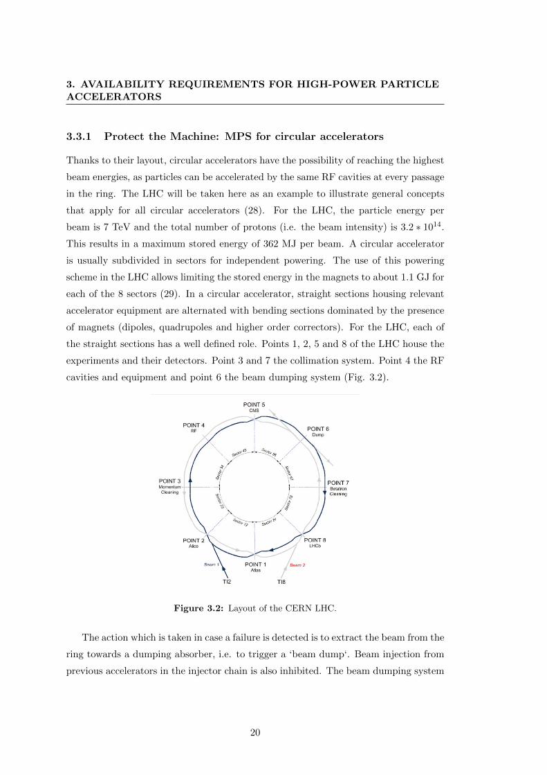
cavities and equipment and point 6 the beam dumping system (Fig. 3.2).
Figure 3.2: Layout of the CERN LHC.
The action which is taken in case a failure is detected is to extract the beam from the
ring towards a dumping absorber, i.e. to trigger a ‘beam dump‘. Beam injection from
previous accelerators in the injector chain is also inhibited. The beam dumping system
20

3.3 The Need for Machine Protection Systems (MPS)
(30) is located in point 6, thus the beams always have to reach this point before being
able to be safely extracted. Special magnets, called kickers, have fast rising magnetic
fields to deflect the beam towards the beam dump. The current rise time of the kickers
is 3 µs, therefore a particle-free gap (abort gap) of the same duration must be left in
the beam to avoid significant losses while extracting the beams. Once extracted, the
beam is defocused to reduce its energy density and guided towards the beam dump,
the only element in the machine capable of withstanding a full beam impact.
The fault detection is initiated by different types of sensors that communicate to
a central distributed system, the Beam Interlock System (BIS) (31). Beam losses for
example are monitored with Beam Loss Monitors (BLMs, Fig. 3.3, (32)). These devices
measure the ionization produced in a gas by the scattered lost particles from the beam
trajectory. They consist of a ionization chamber filled with a noble gas (e.g. Argon)
and electronics able to readout the signal produced by the ionization chamber. The
signal is compared with predefined thresholds for the identification of dangerous beam
losses. The fastest reaction time of the BLM system is 40 µs.
Figure 3.3: LHC Beam Loss Monitors placed on the side of superconducting quadrupoles.
The BIS is in charge of gathering signals coming from local equipment surveillance
and trigger a beam dump in case it recognizes a dangerous machine configuration.
This system is highly critical and must be designed for high dependability (33). The
challenge in this case is having a dependable and distributed system over the machine
circumference. The beam dumping system (LBDS) is the most critical system of the
21
3. AVAILABILITY REQUIREMENTS FOR HIGH-POWER PARTICLEACCELERATORS
LHC. In case of a failure of the LBDS, the beams cannot be extracted from the machine.
Its design is therefore very complex and features the use of diverse redundancy to ensure
the execution of a beam dump even in case of failures.
Failures occurring at timescales which cannot be handled by the BIS are dealt with
by using passive devices. As an example, a highly critical step during the LHC cycle is
the injection of beams from the SPS at 450 GeV. The damage potential of the beam at
this energy has been quantified, both with a dedicated experiment at CERN (34) and
through Monte Carlo calculations of energy deposition into matter. Such calculations
are performed with the software FLUKA (35) (36). To prevent beam-induced damage
during injection, passive absorbers (TDI) are placed in a dedicated location to intercept
mis-injected beams (37). The same strategy is adopted in the extraction area near the
LBDS. In addition a multi-stage halo collimation system is necessary to protect the
LHC magnets from beam-induced quenches (38).
In case of superconducting magnets, the damage potential of the powering circuits
can compromise the machine integrity. The MPS should monitor relevant parameters to
detect the possible loss of superconductivity (quench). Voltages across superconducting
magnets are monitored by the Quench Protection System (QPS) (29). In case of a
quench detection, the stored energy in the magnet circuits must be extracted in the
shortest possible time. An energy extraction system composed of a bank of DC switches
in parallel with an extraction resistor, capable of absorbing the stored energy and reduce
the time constant of the current decay, is also part of the magnet circuit. During
nominal operation the switches allow bypassing the resistor, but are then opened in
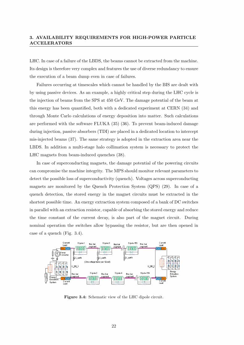
case of a quench (Fig. 3.4).
Figure 3.4: Schematic view of the LHC dipole circuit.
22
3.3 The Need for Machine Protection Systems (MPS)
Furthermore in case of a quench, both active and passive protection measures can
be put in place. The natural development of a voltage in the superconducting magnets
is sufficient to activate cold diodes that allow bypassing the quenching area (passive).
At the same time, to reduce the energy density of the quench, this needs to be spread
over a larger surface in the magnet. This can be achieved with the so-called quench
heaters or with the innovative Coupling Loss Induced Quench (CLIQ) (active) (39),
currently under study at CERN. In the first case, a quench of the all magnet is induced
by forcing a current to flow in dedicated strips placed on top of magnet coils. The
CLIQ is instead based on an induced oscillation of the transport current in the coils,
that generates locally a fast variation of the magnetic field, which in turn translates
into a high coupling current loss that allows a fast spread of the quench in the magnet.
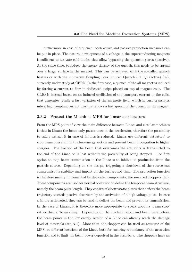
3.3.2 Protect the Machine: MPS for linear accelerators
From the MPS point of view the main difference between Linacs and circular machines
is that in Linacs the beam only passes once in the accelerator, therefore the possibility
to safely extract it in case of failures is reduced. Linacs use different ‘actuators‘ to
stop beam operation in the low-energy section and prevent beam propagation to higher
energies. The fraction of the beam that overcomes the actuators is transmitted to
the end of the Linac or is lost without the possibility of being stopped. The first
option to stop beam transmission in the Linac is to inhibit its production from the
particle source. Depending on the design, triggering a shutdown of the source can
compromise its stability and impact on the turnaround time. The protection function
is therefore mainly implemented by dedicated components, the so-called choppers (40).
These components are used for normal operation to define the temporal beam structure,
namely the beam pulse length. They consist of electrostatic plates that deflect the beam
trajectory towards passive absorbers by the activation of a high-voltage pulse. In case
a failure is detected, they can be used to deflect the beam and prevent its transmission.
In the case of Linacs, it is therefore more appropriate to speak about a ’beam stop’
rather than a ’beam dump’. Depending on the machine layout and beam parameters,
the beam power in the low energy section of a Linac can already reach the damage
level of materials (see A.1). More than one chopper can be used as actuator of the
MPS, at different locations of the Linac, both for ensuring redundancy of the actuation
function and to limit the beam power deposited in the absorbers. The choppers have an
23

3. AVAILABILITY REQUIREMENTS FOR HIGH-POWER PARTICLEACCELERATORS
intrinsic field rise time necessary to reach the required deflection. Such rise time should
be minimised, depending on the timescales over which damage could occur. During the
time that goes from a failure detection to the activation of an actuator by the MPS
the beam is not deflected and is propagated to the higher-energy sections of the Linac,
potentially being lost under dangerous conditions.
The detection of beam losses in a Linac is performed with two different methods.
As for circular machines, BLMs are used, depending on the energy reached by the
Linac. Depending on the particle type and impact angle, BLMs are only capable of
detecting losses through the ionization process from a given energy. Assuming protons
and an impact parallel to the BLM axis, protons give a significant response only above
50-100 MeV (41). In the low-energy section alternative methods must therefore be
implemented. Beam Current Monitors (BCMs) are used to measure the beam current
at different locations of the Linac and compare the beam transmission (42). If a poor
transmission is detected this implies that beam losses occur between the two reference
BCMs and beam operation needs to be stopped.
Beam losses in Linacs can also be the cause of phenomena which cannot be observed
in other types of machines. As an example, ’errant beams’ (43) can be the cause of
progressive degradation of cavity performance. This is a consequence of beam losses
in the superconducting cavities that contribute to build-up a favourable environment
for arcing, leading to possible damage of the cavity surface. In the worst case the
replacement of a cavity module can be necessary and take up to several weeks (44).
Monitoring beam losses originated in the warm section of the Linac can contribute to
prevent the occurrence of such failure mode.
3.3.3 Provide the Evidence: The Post-Mortem System
For a complex machine like a particle accelerator, it is of vital importance to be able to
perform off-line analyses of observed phenomena occurring during the accelerator run.
A thorough understanding of the machine, the interaction among its components and
the sensitivity of its behaviour to relevant parameters is necessary towards performance
optimization. For the LHC for example, it is of particular interest to analyse events
which are relevant for machine protection, as magnet quenches, beam losses, Uniden-
tified Falling Objects (UFOs, (45)) and Single Event Upsets (SEU) due to radiation
to electronics (R2E). UFOs are charged dust particles (e.g. soot or thermal-insulation
24
3.3 The Need for Machine Protection Systems (MPS)
fragments) that can interact with the beam (46), generating losses which are detected
via the BLM system. SEUs are random failure events caused by the effects of radiation
on electronic systems. A SEU consists in a bit flip induced in a digital element due to
an ionizing particle (47). No permanent damage is induced as the bit can be rewritten.
A SEU on bits carrying sensitive information can lead to unnecessary beam dumps.
As shown in this thesis, detailed analyses of these phenomena allow for a more
efficient balance between machine safety and availability. A system gathering informa-
tion for such analyses should therefore be designed and foreseen from the beginning of
operation, to learn from the experience gained at every stage of the machine lifetime.
Capturing this information for a very complex machine poses the challenge of the col-
lection of high-quality data. At CERN a Post-Mortem system (PM) was developed for
capturing data coming from the LHC in case a beam dump is issued (48). A snapshot
of the status of the different systems is recorded every time the beams are dumped in
order to retrace the root cause initiating the beam dump. This allows the verification
of the correct functionality of individual systems and is particularly important to verify
the correct functionality of the MPS. A series of dedicated post-operational checks are
automatically carried out on MPS for this purpose.
3.3.4 Provide the Evidence: The Accelerator Fault Tracking (AFT)
Analysing the occurrence and root cause of beam aborts does not give a full overview
of the relevant quantities for consistent availability studies of an accelerator. Fig. 3.5
shows a visual representation of the relevant quantities for availability tracking for the
LHC (49).
The horizontal axis shows the LHC run time. The accelerator mode and an entry
indicating if the machine is in access for interventions are shown in the top part of the
picture. Particle energy (black) and beam intensities (blue and red) are also given.
The characteristic trend of these quantities led to the naming of this visualization as
the ‘cardiogram of LHC operation‘. The green lines indicate the time for experiment
data-taking and purple crosses PM events. Red lines instead indicate equipment faults,
sorted by accelerator system. Such visualization was produced ’manually’ by combining
entries from different databases for the first LHC run and yielded significant hints for
the identification of variables and parameter towards efficient fault tracking. As a con-
sequence, a project was launched at CERN to develop an online system for capturing
25
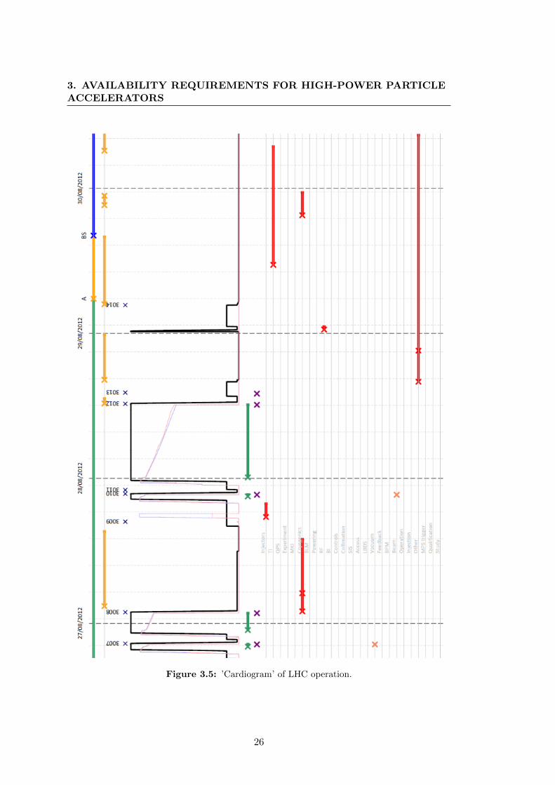
3. AVAILABILITY REQUIREMENTS FOR HIGH-POWER PARTICLEACCELERATORS
Figure 3.5: ’Cardiogram’ of LHC operation.
26

3.3 The Need for Machine Protection Systems (MPS)
fault data during operation (50). This is a fundamental tool for availability studies,
providing dynamic fault and turnaround time distributions from the beginning of LHC
run 2 in 2015. As will be explained in par. 6.2.2, modelling the dependency of accelera-
tor performance on availability allows identifying the weaknesses of machine operation
and the areas where the investment of new resources would bring the biggest benefit
for luminosity production. During the first LHC run fault data analyses have been car-
ried out independently by working groups focusing on different aspects of accelerator
performance (e.g. R2E). Getting a consistent picture of all relevant dependencies on
beam parameters and operational choices is very difficult without dedicated tools in
place. At the same time a full automation for gathering fault data may not be ideal.
The root cause of particular failure events can be discovered only after careful expert
analyses, which can take up to several weeks. Currently there are few failure events
form the first LHC run for which the root cause is still unidentified. A continuous effort
to maintain a consistent view on accelerator faults should be foreseen.
27

3. AVAILABILITY REQUIREMENTS FOR HIGH-POWER PARTICLEACCELERATORS
28

4
Methods for estimating the
Availability of Particle
Accelerators
Chapter 4 presents an overview on the methods used in Chapters 5 and 6 for availability-
driven design of MPS and performance optimization for particle accelerators. This
thesis shows that availability is a key parameter for particle accelerators, from the
design phase to the final exploitation. A top-down approach to availability driven
design is more suitable for early design stages of a project. For individual system
design, as well as for newly introduced systems in an operating machine, a bottom-up
approach can be more convenient. The System-Theoretic Process Analysis (STPA) is
therefore chosen for early hazard analyses and to derive requirements for individual
systems. Dedicated studies, triggered by the STPA procedure, can be used to address
particular aspects of the design. Due to the complexity of the systems under study,
availability modelling has been mostly based on Monte Carlo simulations, rather than
analytical calculations. The adopted simulation environments are MATLAB (51) and
Isograph (52).
4.1 System-Theoretic Process Analysis (STPA)
STPA is a novel hazard analysis technique that applies the principles of systems theory
to the design of safety-critical systems (53).
29

4. METHODS FOR ESTIMATING THE AVAILABILITY OFPARTICLE ACCELERATORS
Traditional hazard analysis techniques are based on the assumption that failures
and interactions in a system occur randomly. This inevitably leads to a reactive ap-
proach to hazard management. Nowadays, the concurrent use of hardware, software
and mechanical components is diffused in a wide variety of domains. System complexity
is thus a crucial aspect to be taken into account when dealing with hazard analyses. For
a complex system as a particle accelerator the assumption of event randomness leading
to an accident is not appropriate. The goal of the hazard analysis shifts towards finding
patterns and conditions leading to accidents, in order to identify proactive measures to
mitigate or eliminate them. This concept is based on the research of ’systemic causes’ of
accidents, as opposed to traditional causality models, which assume that an accident is
the result of a chain of events leading to a loss (Chain-of-Events model or Swiss Cheese
model). Such events are mostly failures of system components (hardware, software,
humans). In this perspective, it is natural to think that increasing the system safety
can be achieved by increasing components’ reliability and by interrupting the chain of
events with additional measures. In a complex environment, events leading to accidents
have to be interpreted as uncontrolled interactions or behavioural events. The system
is seen as a hierarchical structure of levels. Each level manages the relationships of the
next lower level of the hierarchy, by imposing constraints on the behaviour and inter-
actions of its components. STAMP (System-Theoretic Accident Model and Processes)
is an accident model based on systems theory for which safety is an emergent property
relative to the interaction of components with a larger environment. An accident oc-
curs when the constraints imposed at a given level of the hierarchy are violated (are
insufficient) by component interactions. The role of safety engineering therefore regards
the enforcement of safety constraints to control the behaviour of the overall system.
This is achieved through hierarchical safety control structures, i.e. control structures
that operate from one level to the other. Each controller has a logic or algorithm to
decide what action needs to be provided to the lower level (or process) to enforce the
constraints. As from control theory, such algorithm has to be ’informed’ of the state
of process, based on a process model. Assuming that a safety-control structure exists,
then an accident occurs due to (53):
1. Unhandled environmental disturbances or conditions
2. Unhandled or uncontrolled component failures
30
4.1 System-Theoretic Process Analysis (STPA)
3. Unsafe interactions among components
4. Inadequately coordinated control actions by multiple controllers
STPA has its foundation in the STAMP accident causality model. Thus it does not
produce probabilistic assessments of risks and accident occurrence, but allows identi-
fying more effectively hazards related to software, human behaviour and design pro-
cesses. The advantage of STPA over traditional hazard-analysis methods is that it can
be used since early design stages. It follows a top-down approach for the design of
safety control structures, starting from the definition of high-level safety requirements
and corresponding constraints. The latter can be refined as the design progresses and
translated into more detailed requirements for components belonging to lower abstrac-
tion levels. This allows an iterative design, which reduces the risk of facing enormous
costs of re-engineering in case major changes are found necessary late in the design. It
has to be noted that the basic principle of STPA is very general and allows defining
both technical requirements and organizational needs for a structured management of
procedures and operation, as will be shown in chapter 5. Considerations on operational
practices arise from the same process that generates the technical requirements.
4.1.1 Definitions
The following definitions of ’accident’ and ’hazard’ are used for the STPA, as explained
in (53):
• Accident: An accident is an undesired and unplanned event that results in a loss,
including a loss of human life or human injury, property damage, environmental
pollution, mission loss, financial loss, etc.
• Hazard: A system state or set of conditions that together with a worst-case set
of environmental conditions, will lead to an accident (loss)
As from the definition, depending on the application, the term ’loss’ can be related
to very different quantities. The choice of what has to be considered as a ’loss’ sets
the boundaries and goals of the analysis. The definition of hazard differs slightly but
significantly from traditional ones. It implies that hazards must be identified within the
system boundaries, i.e. within quantities that can be controlled. Furthermore, some
31

4. METHODS FOR ESTIMATING THE AVAILABILITY OFPARTICLE ACCELERATORS
worst-case conditions must exist that could potentially lead to a loss. Such conditions
do not coincide in general with component failures. A failure is an event and not a
system state, therefore a failure can be the cause of a hazard, but not the hazard itself.
A top level definition of accidents and hazards is then independent from the technical
system implementation. This is particularly useful in early design stages.
4.1.2 STPA steps
The iteration of the following four steps guides the STPA application (53):
1. Establish the system engineering foundation for the analysis and for the system
development
2. Identify potentially unsafe control actions
3. Use the identified unsafe control actions to create safety requirements and con-
straints
4. Determine how each potentially hazardous control action could occur
The first step consists in identifying the system accidents and related hazards,
according to the definitions given in 4.1.1. Hazards can then be translated into safety
constraints and requirements. Based on these, a high-level functional control structure
can be sketched and represents the base of the next STPA iterations. This last step
represents the peculiarity of the STPA, as compared to other hazard analyses. The
control structure serves as a useful representation of the functional behaviour of the
system. In the first iteration, the control structure is normally represented by a single
controller and a controlled process, with basic interactions. Each of these parts can
be decomposed and further refined. Control actions and responsibilities are assigned
to the newly defined components. Communication among the different parts has to be
explicitly depicted.
Once the control structure has been defined, the Unsafe Control Actions (UCA)
must be identified, namely the conditions under which:
1. A control action required for safety is not provided
2. An unsafe control action is provided that leads to a hazard
32

4.2 Availability modelling
3. A potentially safe control action is provided too late, too early, or out of sequence
4. A safe control action is stopped too soon or applied too long (for a continuous or
non-discrete control action)
The next step is thus to identify the causes of the above unsafe control actions,
by looking at the control loop and its elements. This step is fundamental as it allows
defining additional safety constraints and give guidelines for mitigation of hazard causes.
Delays and time dependencies are important factors to be taken into account at this
stage. The result of this process is usually summarized in a table, for each of the unsafe
control actions. The hazard causes can be refined in this iterative process. When a
suitable mitigation is identified, then the iteration can stop. The application of this top-
down procedure requires significantly less resources than traditional hazard analyses in
the definition of effective mitigation strategies.
4.2 Availability modelling
The development and application of a method for estimating the reliability and avail-
ability of a given system architecture can be useful for several reasons. Primarily,
comparing different design options gives the idea of the relative worth of each design.
Nevertheless, besides availability and reliability, other factors play a significant role in
the choice of the architecture, as costs, complexity and maintainability. These quanti-
ties are interdependent and strictly related to reliability and availability. For example
a very complex and costly architecture may lead to the desired reliability performance,
but may be difficult and expensive to maintain. The the best trade-off with available
resources should be found. Once the preliminary choice of the system architecture has
been made, reliability predictions allow for the identification of performance bottle-
necks, at the sub-system or component level, and guide the required designed improve-
ments before the final configuration of the system is selected for production. As an
example in the case of accelerators, systems might work under extreme environmental
conditions. Reliability studies highlight the need of environmental control measures.
Furthermore, reliability and availability could strongly depend on operational modes
and maintenance practices. From the availability perspective, reliability estimates allow
for advanced considerations on the maintenance strategy to be adopted, which allows
33
4. METHODS FOR ESTIMATING THE AVAILABILITY OFPARTICLE ACCELERATORS
in turn to minimize the downtime of the facility. The costs to be faced for redesign
of a system in advanced phases of a project can be prohibitive, therefore such studies
should always be developed in parallel to the system design.
4.2.1 Estimates of Component Failure Rates
The study of reliability and availability figures are used for describing the failure be-
haviour of the system and identify potential bottle neck in the system design. Experi-
ence guides through the difficult process of estimating failure rates for a very specific
application as for particle accelerators. Evaluating the consequences of a failure of a
component on the overall accelerator behaviour requires a deep understanding of the
functionality of the system and its interactions in a complex environment. In chapter
5 an example of the application of the estimates of component failure rates and the
related study of the effects on the overall accelerator performance is presented. The
analysis has been carried out in Isograph (52), a commercial tool used at CERN for
reliability and availability studies. Isograph offers the possibility of selecting differ-
ent standards for the prediction of component failure rates, depending on the type of
system. For electronic components the Reliability Prediction of Electronic Equipment
(MIL-HDBK-217F) (54) or the Telcordia (55) standards can be used. For mechanical
components the NWSC (Naval Surface Warfare Center (56)) is available. The MIL-
HDBK-217F is taken in the following as the reference for the calculation of failure rates
of electronic components. It is based on the definition of a basic failure rate which is
conveniently adjusted with additional factors to account for stress levels, environmental
conditions and different quality of components. Isograph allows for the specification of
such relevant factors and an automatic calculation of failure rates. Manufacturer’s data
relative to the failure rate, resulting from accelerated lifetime tests, should nevertheless
be preferred in the analysis of a system and will therefore be used, when available. For
non-standardized commercial components for specific accelerator applications, failure
rates and time-to-repair are deduced from experts’ experience.
What is important for the scope of the present work is to derive the consequences
of a failure of a single component or system on accelerator performance. It is therefore
important to study the impact of different failure modes of the components, besides
their rate of occurrence. Some failures could result having no effect on the accelerator
and not being relevant for its performance. For electronic components, the repartition of
34

4.2 Availability modelling
the calculated failure rates to the different failure modes is done according to ’Electronic
Reliability Design Handbook’ (MIL-HDBK-338B). The consequences of each failure
mode on the accelerator are derived by defining the high-level accelerator scenarios
which could result from a component failure (see 4.3).
4.2.2 Reliability Block Diagrams
The Reliability Block Diagrams (RBD) and Fault Trees (FT) allow estimating the
reliability of complex systems, for which basic failure modes and rates are defined as
described in the previous paragraph. A RBD is made of blocks and nodes connected
together in parallel or series. A voting strategy can be defined for parallel cases. In
FTs, the same structure can be reproduced by means of logical gates (AND, OR,
etc). In Isograph different distributions (e.g. Poisson, Weibull, Lognormal, etc.) and
standards can be used while defining failure modes. The Weibull package in Isograph
is capable of assigning failure distributions to historical data; these can be used to
perform simulations to reproduce the system behaviour in case of failures. In the
Availability Workbench (52) the blocks in a RBD can be used to model component
failures, as well as other events, such as operational decisions influencing the availability
of the system. Different maintenance strategies can be defined (planned, corrective,
condition-based). Once all parameters for faults and repairs are defined, a simulation
of the system behaviour for a given observation time can be performed. The simulation
process is based on the ’open path’ model. An open path is a continuous path in
the structure that does not include failed components. The software checks whether
open paths exist in the structure created by the user and determines if the system is
still functional. Simulation results can be followed on a so-called ’simulation watch’,
showing the sequence of the simulated failure events and repair actions. This provides
the means to check the consistency of maintenance tasks and identify errors in the RBD
or FT model. Results are presented in terms of mean unavailability, number of outages
and mean repair times at the system or the sub-systems level. An analysis of costs of
components, spares and personnel can also be executed with this workbench. These
considerations constitute a quantitative base for the analysis of the relative worth of
different design options and maintenance strategies.
35
4. METHODS FOR ESTIMATING THE AVAILABILITY OFPARTICLE ACCELERATORS
4.3 Monte-Carlo approach for Availability Simulations in
MATLAB
Commercial tools allow performing a wide spectrum of analyses but have difficulties to
reproduce very specific aspects of accelerator operation. Part of the availability analyses
presented in this thesis have been developed in MATLAB and are based on Monte Carlo
models of accelerator operation. Two different approaches have been identified for the
study of availability for particle accelerators. The first follows a bottom-up approach
and starts from the component level aiming at evaluating of the consequences of a
component failure on accelerator operation. The second is based on a top-down view
of accelerator operation and availability and relates this with accelerator performance.
Bottom-up model of accelerator availability The bottom-up approach is partic-
ularly suited to model systems or sub-systems which are already known and for which
further design options have to be investigated. It is based on the definition of the basic
failure behaviour of components. The degree of detail in the description of such failure
behaviour can be chosen depending on the context of the analysis. In Chapter 4 the
analysis is based on a Markov-description of the failure behaviour of components. The
assumption which will be made is that all the components exhibit the same failure
behaviour. This might not be valid in other contexts and be conveniently changed if
necessary. Markov models allow a simple description of the component functionality
that is particularly suited for building a structured model of a complex system (57).
The model is based on the ’open path’ verification, as in Isograph, but does not focus
only on the availability or unavailability of the system. It allows identifying more com-
plex configurations of the machine, by the definition of high-level operational scenarios.
A single or a combined failure of several components leads to one of such scenarios.
By estimating the frequency of occurrence of each of the defined scenarios, one can
infer the availability of the system and study measures to cope with the requirements,
finding a suitable balance with machine safety.
The bottom-up approach for the study of system availability could be summarized
in the following steps:
1. Definition of component failure behaviour.
36
4.3 Monte-Carlo approach for Availability Simulations in MATLAB
2. Definition of system architecture (a system is composed of several components).
3. Definition of high-level operational scenarios (at the system-level, or higher).
4. Derivation of the frequency of occurrence of each scenario through Monte Carlo
simulations.
5. Estimation of system (or machine) availability.
An application of this approach relative to identification of the best architecture for
the LHC quench loop will be presented in Chapter 5.
Top-down model of accelerator availability The top-down approach aims at
quantifying the impact of relevant aspects of accelerator operation on its performance.
Knowing the dependencies among the involved quantities allows obtaining realistic esti-
mates of accelerator performance even for machines under design or for future upgrades
(e.g. High-Luminosity LHC). A top-down view of accelerator operation is based on the
identification of high-level machine states. A definition of such high-level states is
given in 3.1. Depending on the focus of the analysis, further machine states can be
considered, as commissioning and tests, maintenance, etc. Among these, performance-
relevant states can be identified, i.e. those states whose duration should be optimized
for improving the scientific outcome of the facility. All states have a variable duration,
depending on operational parameters. Estimating the distributions of such durations,
either by observations or by dedicated calculations, and the probability of occurrence
of each of the states allows re-producing a realistic timeline of machine operation. As
a result, the scientific outcome can be estimated based on the integrated time spent in
the performance-relevant machine state.
This approach could be summarized in the following steps:
1. Definition of high-level machine states.
2. Identification of the performance-relevant machine state(s).
3. Estimation (or derivation) of the distribution of the duration of the defined ma-
chine states.
37

4. METHODS FOR ESTIMATING THE AVAILABILITY OFPARTICLE ACCELERATORS
4. Estimation of occurrence of the performance-relevant machine states through
Monte Carlo simulations as a function of different parameters.
5. Quantification of accelerator performance given the estimated occurrence of the
performance-relevant machine states.
An application of this approach will be presented in Chapter 5 for the predictions
of LHC integrated luminosity during the future runs and for the HL upgrade.
38

5
Availability-driven Design of
MPS for Particle Accelerators
Chapter 5 focuses on availability-driven design of MPS for particle accelerators. The
STPA (4.1.2) is used to guide the early design phase of the MPS, deriving the functional
requirements to cope with safety and availability constraints. An example relative
to the derivation of availability requirements for Linac4 is given. The second part
of the chapter focuses on the analysis of different architectures of interlock systems,
with a particular emphasis on finding the optimal balance between machine safety and
availability.
5.1 Derivation of Availability Requirements
The design of MPS for particle accelerators has to face the challenging task of managing
the complexity and variety of systems to be protected. Mechanical and electronic
systems, as well as software, are all to be taken into account in the design, together
with the many dependencies and possible interactions with human beings. In industry
several examples of such complex systems exist, e.g. in the automotive domain, but on
a much smaller scale. Taking the LHC as an example, only the superconducting magnet
system is composed of 1232 superconducting dipoles, fed by dedicated power converters
and cooled by a complex cryogenic system. Mechanical parts of the rotating machinery
of cryogenic cold compressors, converter currents and magnet voltages are only some
of the quantities to be consistently monitored and recorded. Common hazard analysis
39

5. AVAILABILITY-DRIVEN DESIGN OF MPS FOR PARTICLEACCELERATORS
techniques are not suitable to deal with large system complexities, as required for the
design of MPS. In the past the design of MPS has been based mainly on experts’
experience with previous accelerators, not following a rigorous approach. The top-
down approach used by STPA is conceptually suited for MPS design, as it allows a
structured process, accounting for the dependencies among all relevant MPS actors. In
the following paragraphs an example of the application of STPA to the design of MPS
for particle accelerators is given, taking Linac4 as a case study.
5.1.1 Linac4 Layout and Parameters
Linac4 is the linear accelerator currently under construction and commissioning at
CERN that will provide proton beams to the injector chain as of 2019. Linac4 will
accelerate H− ions up to an energy of 160 MeV (Fig. 5.1) for injection into the Pro-
ton Synchrotron Booster (PSB). The H− beam is produced by a RF Source, with an
output energy of 45 keV. A Low-Energy Beam Transfer (LEBT, 45 keV) houses a pre-
chopper, transports and matches the beam to a Radio Frequency Quadrupole (RFQ)
(58). The RFQ bunches and accelerates the beam up to 3 MeV. A Medium-Energy
Beam Transfer (MEBT, 3 MeV) houses a chopper and matches the beam with the sub-
sequent accelerating structures. For normal operation the pre-chopper is used to define
the beam pulse length and the chopper is used to create the correct beam structure to
reduce losses at injection in the Proton Synchrotron Booster (PSB). In case of faults
requiring beam interruption, the choppers allow stopping the full beam at low energy
(45 keV or 3 MeV). Three accelerating structures (DTL, CCDTL and PIMS) allow
reaching the output energy of 160 MeV (59) (60) (61). A beam dump is placed at the
end of the linac to absorb the beam, if required by machine operation (62). A series of
three bending magnets can instead deflect the beam towards the transfer lines. These
guide the H− beam to the injection region in the PSB, where a stripping foil allows
obtaining protons from H− ions (24). Protons accelerated in the PSB can then be sent
to different destinations. The ISOLDE Radioactive Ion Beam facility is the only user
experiment connected to the PSB. The beam can alternatively be sent to an emittance
measurement line or to the PS.
By 2019 Linac4 will have to meet strict requirements in terms of availability to
ensure continuous beam delivery to the CERN complex, possibly reaching the perfor-
mance of Linac2 operation (98 % availability). As opposed to Linac2, Linac4 will be
40

5.1 Derivation of Availability Requirements
equipped with a dedicated Beam Interlock System (BIS) to mitigate the consequences
of beam losses on accelerator equipment.
Figure 5.1: Linac4 layout.
The studies related to Linac4 were developed to guide the definition of the functional
specifications of the Linac4 BIS. The first step of the studies was to verify that the
functional specifications would meet all the requirements arising from the application
of the STPA procedure. In the following paragraphs a description of the Linac4 BIS
architecture will be given, based on the outcomes of the STPA applied to Linac4.
5.1.2 Linac4 STPA
The first step of the STPA is to identify the set of accidents that may affect the system
(see 4.1.2). Four high-level accidents (A1-A4) were identified for the case of Linac4.
• A1: Lack of beam for other accelerators
• A2: Damage to the accelerator equipment
• A3: Injuries to staff members
• A4: Release of radioactive material in the environment
System hazards (H1-H4) are then identified and correlated with each accident sce-
nario. The goal of this analysis is the design of a MPS for Linac4. As the responsibility
of MPS is only the protection of the machine and its equipment, A3 and A4 will not be
further investigated, though some correlations exist with A1 and A2 and will be taken
into account when necessary.
• H1: Accelerator equipment is not ready for operation [A1, A2]
• H2: The beam is lost before reaching the transfer line [A1, A2]
41

5. AVAILABILITY-DRIVEN DESIGN OF MPS FOR PARTICLEACCELERATORS
• H3: The beam is stopped before reaching the transfer line when it is not necessary
[A1]
• H4: The beam doesn’t have the required quality for the injector chain [A1]
The translation of system hazards to high-level requirements (R1-R4) for the control
structure is straightforward:
• R1: Accelerator equipment must be operational [H1]
• R2: The beam must not be lost before reaching the transfer line [H2]
• R3: The beam must not be stopped when it is not necessary [H3]
• R4: The beam must have the required quality for the injector chain [H4]
Given these constraints (R1-R4), a preliminary control structure can be sketched
for Linac4 (Fig. 5.2). From this structure the functional behaviour of the control
system can easily be deduced. The Linac has to provide feedback on its status through
suitable sensors. The resulting information has to be propagated to both personnel
working on the Linac and to the control system. The personnel can take actions
influencing the behaviour of the machine via the control system. At the same time, the
control system should have the possibility to act automatically upon the detection of
particular machine states requiring an intervention on a reduced time scale. The control
system is composed of sub-systems, each with a specific functionality derived from
requirements R1-R4. ‘Equipment Control‘ verifies the correct behaviour of all Linac
hardware systems. The ‘Beam Trajectory Control‘ checks that the beam is following the
designed trajectory and is not lost under dangerous circumstances. The ‘Beam Quality
Control‘ allows establishing if the requirements imposed by the following accelerators
in terms of beam performance are met. The ‘Beam Delivery Control‘ ensures optimized
delivery of the beam to different beam destinations. Furthermore, a link to personnel
protection is explicitly foreseen in the control structure (‘Access control‘).
The described high-level control structure can then be refined to account for more
detailed interactions among the identified components (Fig. 5.3). The Linac is now in-
cluding hardware subsystems and instrumentation for feedback to personnel and control
system. The functional dependencies and responsibilities of each block can be deduced
42

5.1 Derivation of Availability Requirements
Figure 5.2: High-Level control structure: The figure shows the basic control structure
derived from requirements R1-R5.
by actions/feedback indicated by arrows in the structure. The main control action of
the control system is the ‘Beam Stop‘, that allows interrupting the beam transmission if
required by any of the subsystems connected (directly or indirectly) to the Equipment
Control.
Based on Fig. 5.3 and according to what described in 4.1.2, the next step is to
study the potentially Unsafe Control Actions (UCAs). The analysis focuses on the
main control action of the control system, the ‘Beam Stop‘. A beam stop can either
be initiated by an operator or automatically if a sensor or instrumentation detects a
non-nominal operating condition. The information of a beam stop request has to be
propagated from the source requesting it to the actuators (i.e. the choppers). The
process variables related to the control action ’Beam Stop’ have been identified and are
reported in Table 5.1. These are the relevant factors to be taken into account when
trying to identify the UCAs.
Combining the possible configurations of the defined process variables brings to the
definition of the possible operational scenarios in which a beam stop is executed (63).
As a result it can be evaluated whether performing or not the control action can result
in a hazard. This leads eventually to the identification of unsafe control actions (UCAs,
Table 5.2).
The following unsafe control actions were identified through the described proce-
dure:
43

5. AVAILABILITY-DRIVEN DESIGN OF MPS FOR PARTICLEACCELERATORS
Figure 5.3: High-Level control structure: The figure shows a refined control structure
derived from requirements R1-R5.
44

5.1 Derivation of Availability Requirements
Process Variable Possible Values Notes
Trigger of beam
stop request
Manual
Automatic
None
A beam stop can be requested by an operator
with a manual command (’Manual’). A beam
stop can be automatically initiated by a sensor
in case non-nominal operating conditions are
detected (’Automatic’). A beam stop cannot
be initiated at all (’None’).
Validity of beam
stop request
Valid
Invalid
A beam stop can be necessary, following the
detection of non-nominal operating conditions
(’Valid’), or not necessary in case of operator
mistake or wrong sensor detection (’Invalid’)
Beam Quality
Acceptable
Not Acceptable
The beam must have a minimum quality for
the different destinations (’Acceptable’). The
possibility exists that the beam quality is not
sufficient (’Not Acceptable’).
Actuator status
Ready
Not ready
The actuator must be operational for a correct
execution of a beam stop (’Ready’). In case the
actuator is not operational, the beam stop
cannot be executed (’Not ready’).
Status of beam
destinations
Available
Not Available
Beam destinations must be available to
receive beam from the Linac during nominal
operation (’Available’). The possibility exists
that no destination is available (’Not Available’)
Accelerator Mode
Access
Beam Operation
The accelerator is normally operated with beam
(’Beam Operation’), but maintenance with direct
interventions on accelerator equipment is
executed during predefined time periods or
following equipment failures (’Access’).
Table 5.1: List of relevant process variables for the execution of a beam stop.
45

5. AVAILABILITY-DRIVEN DESIGN OF MPS FOR PARTICLEACCELERATORS
CA provided in hazardous state: Beam stop executed
ID Trigger ValidityBeam
QualityActuator
Other
AcceleratorsMode Hazardous? Hazard UCA
1.1 - Invalid - Ready Available -
Unnecessary stop of beam
delivery to the destinations.
Loss of beam availability.
H3 UCA1
CA provided in hazardous state: Beam stop not executed
ID Trigger ValidityBeam
QualityActuator
Other
AcceleratorMode Hazardous? Hazard UCA
1.2 - Valid - Not ready -Beam
Operation
The beam is not stopped and
can cause damage to the
accelerator equipment
H2 UCA2
1.3 - Valid - Not ready - Access
The beam is not stopped and
personnel can be exposed to
radiation
(H) UCA3
1.4 None Valid - Ready - -
The beam is not stopped and
can cause damage to the
accelerator equipment
H2 UCA4
1.5 None Valid Not OK Ready AvailableBeam
Operation
The beam is not stopped
despite the poor qualityH4 UCA5
Table 5.2: Identification of UCAs related to the control action ‘Beam Stop‘.
UCA1 The beam is stopped when it is not necessary (automatically or by an operator)
UCA2 The beam is not stopped in a detected emergency situation (automatically or
by an operator) due to the unavailability of an actuator
UCA3 The beam is not stopped while personnel has access to the linac
UCA4 The beam is not stopped following the missed detection of an undesirable
accelerator configuration
UCA5 The beam is not stopped when the beam quality is not sufficient for the injec-
tors
Given the above unsafe control actions, the next step of the STPA analysis consists
in the identification of causal scenarios of each of the unsafe control actions. As the
focus of the analysis is on availability of the control system, the details relative to UCA1
are reported in Tables 5.3 and 5.4.
Refined requirements are found by defining the causal factors leading to the UCA.
These requirements can directly be allocated to new components in the structure or
trigger further design studies. It is interesting to notice the different nature of the
46
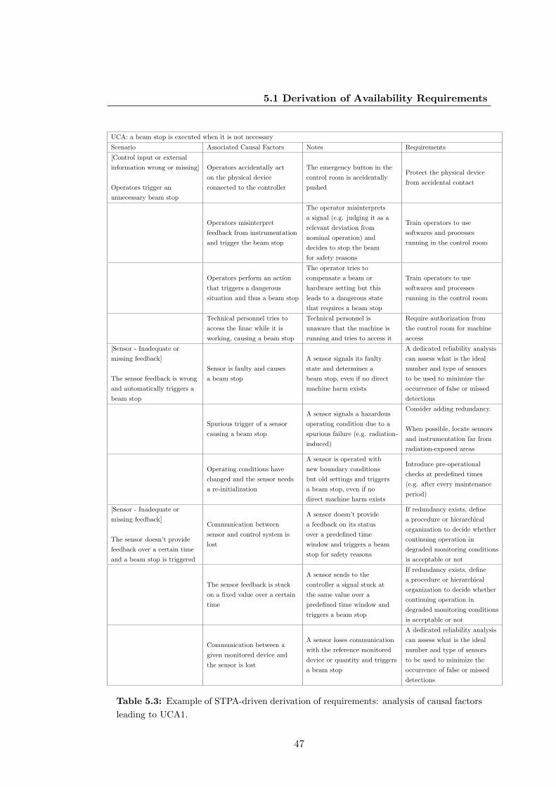
5.1 Derivation of Availability Requirements
UCA: a beam stop is executed when it is not necessary
Scenario Associated Causal Factors Notes Requirements
[Control input or external
information wrong or missing]
Operators trigger an
unnecessary beam stop
Operators accidentally act
on the physical device
connected to the controller
The emergency button in the
control room is accidentally
pushed
Protect the physical device
from accidental contact
Operators misinterpret
feedback from instrumentation
and trigger the beam stop
The operator misinterprets
a signal (e.g. judging it as a
relevant deviation from
nominal operation) and
decides to stop the beam
for safety reasons
Train operators to use
softwares and processes
running in the control room
Operators perform an action
that triggers a dangerous
situation and thus a beam stop
The operator tries to
compensate a beam or
hardware setting but this
leads to a dangerous state
that requires a beam stop
Train operators to use
softwares and processes
running in the control room
Technical personnel tries to
access the linac while it is
working, causing a beam stop
Technical personnel is
unaware that the machine is
running and tries to access it
Require authorization from
the control room for machine
access
[Sensor - Inadequate or
missing feedback]
The sensor feedback is wrong
and automatically triggers a
beam stop
Sensor is faulty and causes
a beam stop
A sensor signals its faulty
state and determines a
beam stop, even if no direct
machine harm exists
A dedicated reliability analysis
can assess what is the ideal
number and type of sensors
to be used to minimize the
occurrence of false or missed
detections
Spurious trigger of a sensor
causing a beam stop
A sensor signals a hazardous
operating condition due to a
spurious failure (e.g. radiation-
induced)
Consider adding redundancy.
When possible, locate sensors
and instrumentation far from
radiation-exposed areas
Operating conditions have
changed and the sensor needs
a re-initialization
A sensor is operated with
new boundary conditions
but old settings and triggers
a beam stop, even if no
direct machine harm exists
Introduce pre-operational
checks at predefined times
(e.g. after every maintenance
period)
[Sensor - Inadequate or
missing feedback]
The sensor doesn’t provide
feedback over a certain time
and a beam stop is triggered
Communication between
sensor and control system is
lost
A sensor doesn’t provide
a feedback on its status
over a predefined time
window and triggers a beam
stop for safety reasons
If redundancy exists, define
a procedure or hierarchical
organization to decide whether
continuing operation in
degraded monitoring conditions
is acceptable or not
The sensor feedback is stuck
on a fixed value over a certain
time
A sensor sends to the
controller a signal stuck at
the same value over a
predefined time window and
triggers a beam stop
If redundancy exists, define
a procedure or hierarchical
organization to decide whether
continuing operation in
degraded monitoring conditions
is acceptable or not
Communication between a
given monitored device and
the sensor is lost
A sensor loses communication
with the reference monitored
device or quantity and triggers
a beam stop
A dedicated reliability analysis
can assess what is the ideal
number and type of sensors
to be used to minimize the
occurrence of false or missed
detections
Table 5.3: Example of STPA-driven derivation of requirements: analysis of causal factors
leading to UCA1.
47

5. AVAILABILITY-DRIVEN DESIGN OF MPS FOR PARTICLEACCELERATORS
UCA: a beam stop is executed when it is not necessary
Scenario Associated Causal Factors Notes Requirements
[Controlled process -
unidentified or out-of- range
disturbance]
The operating conditions have
a sudden change due to
external disturbances and
cause a beam stop, even if
nominal conditions would be
automatically recovered
Electrical disturbances
affecting magnet power
converters
Sudden electrical disturbances
may affect the beam trajectory
and result in a beam stop, even
if the effect would not be
observed or observed for a
short time (not leading to a
hazardous situation)
Design filters and logics to
prevent beam stops triggered
by electrical disturbances
Electrical disturbances
affecting RF powering
Sudden electrical disturbances
may affect the beam quality
and result in a beam stop, even
if the effect would not be
observed or observed for a
short time (not leading to a
hazardous situation)
Design filters and logics to
prevent beam stops triggered
by electrical disturbances
[Controller - Process Model
inconsistent, incomplete, or
incorrect]
The controller, based on the
feedback from the sensors,
triggers a beam stop when it
is not needed
Wrong settings are used
for the beam stop trigger
The controller algorithm is fed
with wrong inputs for the
computation of the controller
action to be taken (e.g. wrong
choice of beam loss thresholds)
Perform dedicate campaign for
computation of relevant
parameters for the controller
algorithm
Wrong settings are loaded in
the controller
Wrong settings are manually
entered in the controller
Deploy a role-based system for
loading the settings, such that
only people with access rights
can modify critical parameters
[Controller - Inadequate
Control Algorithm]
The controller spuriously
triggers a beam stop
A beam stop is triggered
following a random hardware
failure of the controller
The controller hardware
generates a beam stop trigger
even if the control algorithm
doesn’t detect a hazardous
operating condition (e.g. due
to radiation-induced effects)
A dedicated reliability analysis
can assess what are the critical
components of the controller
and determine if redundancy
should be added to minimize
the occurrence of such effects.
Electrical disturbances
Sudden electrical disturbances
may result in a signal that can be
interpreted as a beam stop
trigger by the actuator
A dedicated reliability analysis
can assess what are the critical
components of the controller
and determine if redundancy
should be added to minimize
the occurrence of such effects.
[Controller - Inadequate
Control Algorithm]
The controller cannot find
a valid beam destination and
triggers a beam stop
Missing logic to calculate
valid beam destinations
The unavailability of the
scheduled destination is not
handled correctly by the control
system
A dedicated system managing
dynamically the calculation of
beam destinations should be
foreseen
[Actuator - Inadequate
Operation]
The actuator spuriously
triggers a beam stop
A beam stop is triggered
following a random hardware
failure of the actuator
The actuator executes a beam
stop, but this is not initiated by
the control system. A hardware
fault, e.g. of the actuator
powering can lead to a spurious
beam stop.
The occurrence of hardware
failures of the actuator must be
minimized.
Table 5.4: Analysis of causal factors leading to UCA1.
48
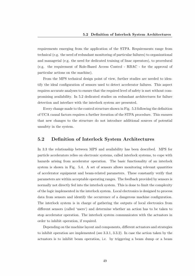
5.2 Definition of Interlock System Architectures
requirements emerging from the application of the STPA. Requirements range from
technical (e.g. the need of redundant monitoring of particular failures) to organizational
and managerial (e.g. the need for dedicated training of linac operators), to procedural
(e.g. the requirement of Role-Based Access Control - RBAC - for the approval of
particular actions on the machine).
From the MPS technical design point of view, further studies are needed to iden-
tify the ideal configuration of sensors used to detect accelerator failures. This aspect
requires accurate analyses to ensure that the required level of safety is met without com-
promising availability. In 5.2 dedicated studies on redundant architectures for failure
detection and interface with the interlock system are presented.
Every change made to the control structure shown in Fig. 5.3 following the definition
of UCA causal factors requires a further iteration of the STPA procedure. This ensures
that new changes to the structure do not introduce additional sources of potential
unsafety in the system.
5.2 Definition of Interlock System Architectures
In 3.3 the relationship between MPS and availability has been described. MPS for
particle accelerators relies on electronic systems, called interlock systems, to cope with
hazards arising from accelerator operation. The basic functionality of an interlock
system is shown in Fig. 5.4. A set of sensors allows monitoring relevant quantities
of accelerator equipment and beam-related parameters. These constantly verify that
parameters are within acceptable operating ranges. The feedback provided by sensors is
normally not directly fed into the interlock system. This is done to limit the complexity
of the logic implemented in the interlock system. Local electronics is designed to process
data from sensors and identify the occurrence of a dangerous machine configuration.
The interlock system is in charge of gathering the outputs of local electronics from
different sensors (called ‘users‘) and determine whether an action has to be taken to
stop accelerator operation. The interlock system communicates with the actuators in
order to inhibit operation, if required.
Depending on the machine layout and components, different actuators and strategies
to inhibit operation are implemented (see 3.3.1, 3.3.2). In case the action taken by the
actuators is to inhibit beam operation, i.e. by triggering a beam dump or a beam
49
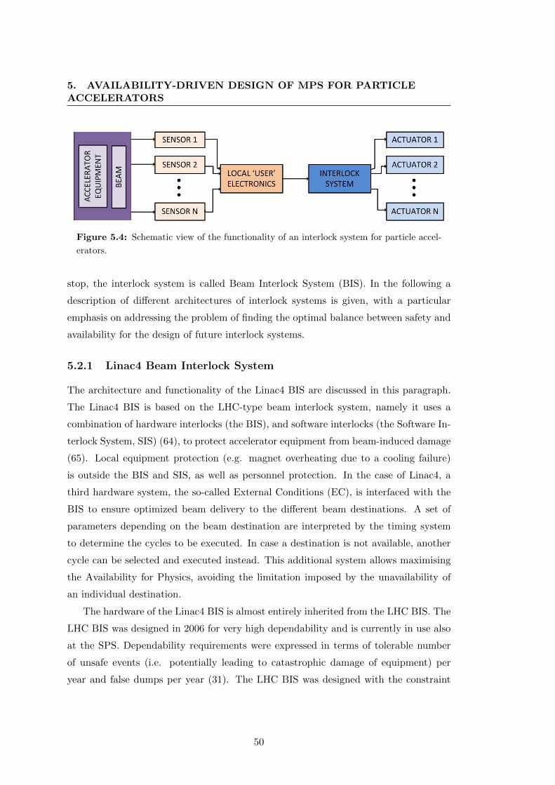
5. AVAILABILITY-DRIVEN DESIGN OF MPS FOR PARTICLEACCELERATORS
Figure 5.4: Schematic view of the functionality of an interlock system for particle accel-
erators.
stop, the interlock system is called Beam Interlock System (BIS). In the following a
description of different architectures of interlock systems is given, with a particular
emphasis on addressing the problem of finding the optimal balance between safety and
availability for the design of future interlock systems.
5.2.1 Linac4 Beam Interlock System
The architecture and functionality of the Linac4 BIS are discussed in this paragraph.
The Linac4 BIS is based on the LHC-type beam interlock system, namely it uses a
combination of hardware interlocks (the BIS), and software interlocks (the Software In-
terlock System, SIS) (64), to protect accelerator equipment from beam-induced damage
(65). Local equipment protection (e.g. magnet overheating due to a cooling failure)
is outside the BIS and SIS, as well as personnel protection. In the case of Linac4, a
third hardware system, the so-called External Conditions (EC), is interfaced with the
BIS to ensure optimized beam delivery to the different beam destinations. A set of
parameters depending on the beam destination are interpreted by the timing system
to determine the cycles to be executed. In case a destination is not available, another
cycle can be selected and executed instead. This additional system allows maximising
the Availability for Physics, avoiding the limitation imposed by the unavailability of
an individual destination.
The hardware of the Linac4 BIS is almost entirely inherited from the LHC BIS. The
LHC BIS was designed in 2006 for very high dependability and is currently in use also
at the SPS. Dependability requirements were expressed in terms of tolerable number
of unsafe events (i.e. potentially leading to catastrophic damage of equipment) per
year and false dumps per year (31). The LHC BIS was designed with the constraint
50
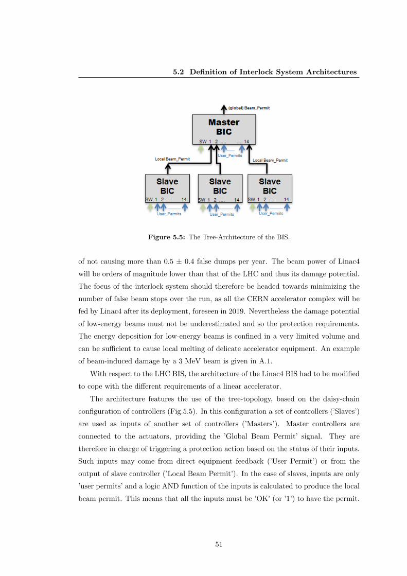
5.2 Definition of Interlock System Architectures
Figure 5.5: The Tree-Architecture of the BIS.
of not causing more than 0.5 ± 0.4 false dumps per year. The beam power of Linac4
will be orders of magnitude lower than that of the LHC and thus its damage potential.
The focus of the interlock system should therefore be headed towards minimizing the
number of false beam stops over the run, as all the CERN accelerator complex will be
fed by Linac4 after its deployment, foreseen in 2019. Nevertheless the damage potential
of low-energy beams must not be underestimated and so the protection requirements.
The energy deposition for low-energy beams is confined in a very limited volume and
can be sufficient to cause local melting of delicate accelerator equipment. An example
of beam-induced damage by a 3 MeV beam is given in A.1.
With respect to the LHC BIS, the architecture of the Linac4 BIS had to be modified
to cope with the different requirements of a linear accelerator.
The architecture features the use of the tree-topology, based on the daisy-chain
configuration of controllers (Fig.5.5). In this configuration a set of controllers (’Slaves’)
are used as inputs of another set of controllers (’Masters’). Master controllers are
connected to the actuators, providing the ’Global Beam Permit’ signal. They are
therefore in charge of triggering a protection action based on the status of their inputs.
Such inputs may come from direct equipment feedback (’User Permit’) or from the
output of slave controller (’Local Beam Permit’). In the case of slaves, inputs are only
’user permits’ and a logic AND function of the inputs is calculated to produce the local
beam permit. This means that all the inputs must be ’OK’ (or ’1’) to have the permit.
51

5. AVAILABILITY-DRIVEN DESIGN OF MPS FOR PARTICLEACCELERATORS
For master controllers the logic to give the beam permit can be more complex and is
defined by a truth table. Every row in a truth table represents a valid configuration
of the inputs to give a valid global beam permit (’1’). The status ”x” (‘don’t care‘)
implies that the condition associated to the given input is NOT RELEVANT for giving
the beam permit.
Each controller has a maximum of 15 inputs, one of which is always dedicated to the
SIS. The SIS is used to monitor slow-changing parameters or to implement complex
logic, which would be difficult to reproduce via hardware. It is used as a second
layer of protection, as critical processes are always monitored by hardware interlocks.
The SIS is also exploited to implement temporary interlocks for particular phases of
the accelerator lifetime (e.g. commissioning), when operational flexibility for correct
machine tuning must be ensured (66).
A schematic overview of the Linac4 BIS architecture is shown in Fig. 5.6. The BIS
is composed of two master controllers, the MASTER SOURCE RF and the MASTER
CHOPPERS (65). The first is responsible to trigger the RF controller of the ion source
in case a danger is detected in the first part of the linac (i.e. before the DTL). For
redundancy the pre-chopper is also triggered by the same signal. All inputs of this
controller are user permits, i.e. no slave controller is providing an input.
The MASTER CHOPPERS is in charge of triggering a beam stop in case a failure
is detected in the second part of the Linac (i.e. downstream the DTL), in the transfer
lines to the different beam destinations or in the dump line. The injection in the PS
Booster is also monitored, to eventually inhibit beam transmission in case no beam
destinations are available. Each of the mentioned sections monitored by the BIS are
indicated as ’interlock zones’ and are served by a dedicated slave controller. A total
of 7 slave controllers provide inputs to the MASTER CHOPPERS. The beam stop in
this case is executed by triggering both the pre-chopper and chopper. As an additional
measure to control the beam in case of a failure, also the RF system of the PSB is
switched-off. The truth tables of the two master controllers are shown in Fig. 5.7 and
5.8 for exemplification and those of the slave devices in A.2.
52

5.2 Definition of Interlock System Architectures
Figure 5.6: Layout of the Linac4 BIS.
Figure 5.7: Truth table of the MASTER SOURCE RF.
53
5. AVAILABILITY-DRIVEN DESIGN OF MPS FOR PARTICLEACCELERATORS
Figure 5.8: Truth table of the MASTER CHOPPERS.
5.2.2 ESS Beam Interlock System
5.2.2.1 ESS Layout and Parameters
ESS is an accelerator-driven facility for neutron experiments (8). It includes a 600
m long Linear accelerator and a transfer line connecting a high-power proton beam
(average current: 62 mA, pulse length: 2.86 ms, repetition rate: 14 Hz) to a rotating,
helium cooled 6 T tungsten target. Neutrons are produced via a spallation process
by the interaction of the proton beam with the target and are then guided to user
experiments. ESS protection systems should not only cover the accelerator section,
preventing beam-induced damage to equipment located in the tunnel, but also the
target and neutron experiments. The high power proton beam can cause severe damage
of expensive equipment, therefore a dependable BIS is one of the fundamental elements
for the operation of this facility.
The ESS accelerator layout is shown in Fig. 5.9. It is composed of a warm low-
energy section and a superconducting section. Protons are produced by a magnetron
source. The warm section is then composed of a Low-energy beam transfer, a Radio
Frequency Quadrupole (RFQ), a Medium energy beam transfer and a set of normal
conducting cavities (DTL). In the LEBT the beam is focused and matched to the RFQ,
where is then bunched and accelerated up to 3 MeV. The MEBT ensures focusing and
matching to the Drift Tube Linac (DTL) where the beam is accelerated up to 78 MeV.
54
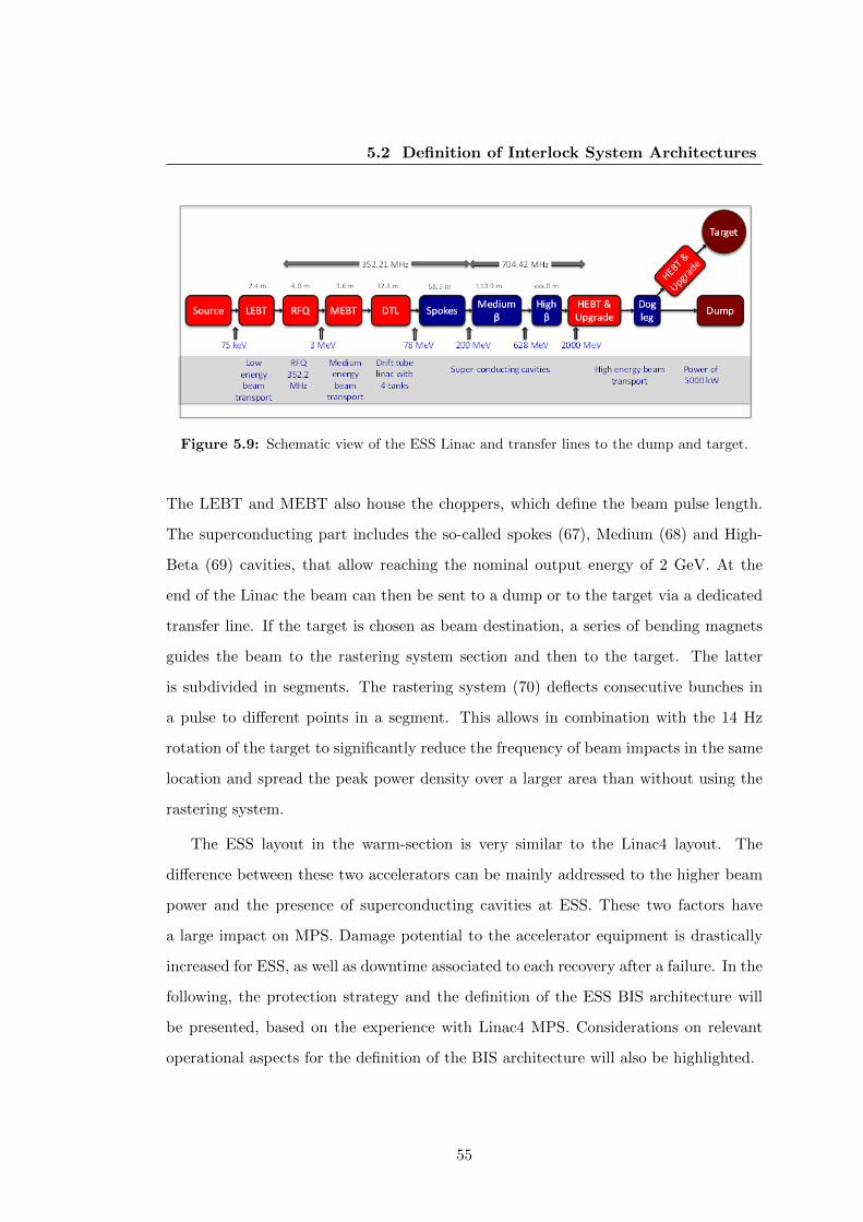
5.2 Definition of Interlock System Architectures
Figure 5.9: Schematic view of the ESS Linac and transfer lines to the dump and target.
The LEBT and MEBT also house the choppers, which define the beam pulse length.
The superconducting part includes the so-called spokes (67), Medium (68) and High-
Beta (69) cavities, that allow reaching the nominal output energy of 2 GeV. At the
end of the Linac the beam can then be sent to a dump or to the target via a dedicated
transfer line. If the target is chosen as beam destination, a series of bending magnets
guides the beam to the rastering system section and then to the target. The latter
is subdivided in segments. The rastering system (70) deflects consecutive bunches in
a pulse to different points in a segment. This allows in combination with the 14 Hz
rotation of the target to significantly reduce the frequency of beam impacts in the same
location and spread the peak power density over a larger area than without using the
rastering system.
The ESS layout in the warm-section is very similar to the Linac4 layout. The
difference between these two accelerators can be mainly addressed to the higher beam
power and the presence of superconducting cavities at ESS. These two factors have
a large impact on MPS. Damage potential to the accelerator equipment is drastically
increased for ESS, as well as downtime associated to each recovery after a failure. In the
following, the protection strategy and the definition of the ESS BIS architecture will
be presented, based on the experience with Linac4 MPS. Considerations on relevant
operational aspects for the definition of the BIS architecture will also be highlighted.
55

5. AVAILABILITY-DRIVEN DESIGN OF MPS FOR PARTICLEACCELERATORS
5.2.2.2 Interlocking Strategy
A suitable interlocking strategy is needed to cope with all relevant failure scenarios
that might occur during accelerator operation. Despite the similarities with Linac4,
which suggest adopting a similar BIS architecture for ESS, some careful considerations
on the protection of sensitive equipment due to the increased beam power are needed.
The beam power in the low-energy section of the ESS Linac amounts to some kW,
assuming nominal beam parameters. This implies that the damage level of materials
(e.g. copper) is already reached in the warm Linac. A full beam pulse impacting
on accelerator equipment can never be tolerated. Three actuators, namely the RF
magnetron of the proton source and the LEBT and MEBT choppers, are used to stop
the beam production in case a failure is detected. This allows limiting the amount
of beam losses potentially caused by the failure. Redundancy in the actuation of the
protection function is needed to ensure that a beam stop is performed even in case
of a failure of one of the actuators. The actuators have different reaction times. If
the RF magnetron of the proton source is switched-off, beam production is stopped
within 100 µs. The LEBT chopper can be switched ON (i.e. deflecting the beam
out of the nominal trajectory) within 300 ns. The MEBT chopper can be switched
ON within 10 ns. For fast reaction times one has to rely on the choppers. These are
capable of deflecting the beam towards dedicated absorbers in a significantly reduced
time compared to the source de-activation. Nevertheless given the high beam power,
absorbers are not capable of withstanding a full beam pulse even at low energy, therefore
the source always needs to be switched off ultimately. A fourth option to inhibit the
beam transmission to the high-energy section of the Linac4 is represented by the trigger
of a power shutdown of the RFQ, but is not assumed here as the baseline.
Fast reaction times of the actuators are necessary to limit the amount of beam which
is transmitted to a given destination while while beam operations is being inhibited.
It has been quantified that the time allowed until beam is being switched-off is in the
order of 10 µs (71). Table 5.5 summarizes the contributions to the overall reaction
time. Assuming that BLMs are capable of detecting a fast beam loss in about 2 µs,
the information has to be propagated to the BIS, after being validated. This takes less
than 1 µs, considering a negligible distance between the BLMs hardware and the BIS
hardware. The BIS receives the change of beam permit and issues a beam stop request.
56
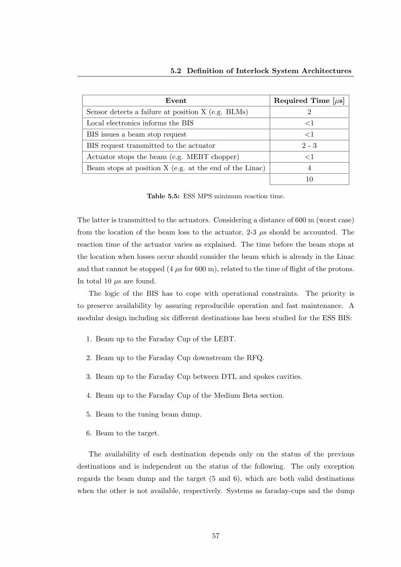
5.2 Definition of Interlock System Architectures
Event Required Time [µs]
Sensor detects a failure at position X (e.g. BLMs) 2
Local electronics informs the BIS <1
BIS issues a beam stop request <1
BIS request transmitted to the actuator 2 - 3
Actuator stops the beam (e.g. MEBT chopper) <1
Beam stops at position X (e.g. at the end of the Linac) 4
10
Table 5.5: ESS MPS minimum reaction time.
The latter is transmitted to the actuators. Considering a distance of 600 m (worst case)
from the location of the beam loss to the actuator, 2-3 µs should be accounted. The
reaction time of the actuator varies as explained. The time before the beam stops at
the location when losses occur should consider the beam which is already in the Linac
and that cannot be stopped (4 µs for 600 m), related to the time of flight of the protons.
In total 10 µs are found.
The logic of the BIS has to cope with operational constraints. The priority is
to preserve availability by assuring reproducible operation and fast maintenance. A
modular design including six different destinations has been studied for the ESS BIS:
1. Beam up to the Faraday Cup of the LEBT.
2. Beam up to the Faraday Cup downstream the RFQ.
3. Beam up to the Faraday Cup between DTL and spokes cavities.
4. Beam up to the Faraday Cup of the Medium Beta section.
5. Beam to the tuning beam dump.
6. Beam to the target.
The availability of each destination depends only on the status of the previous
destinations and is independent on the status of the following. The only exception
regards the beam dump and the target (5 and 6), which are both valid destinations
when the other is not available, respectively. Systems as faraday-cups and the dump
57
5. AVAILABILITY-DRIVEN DESIGN OF MPS FOR PARTICLEACCELERATORS
are designed in order to accept only beams with given parameters, below nominal
values. A full power beam can only be sent to the target. The definition of different
destinations has thus to be complemented with the definition of operational modes.
Each operational mode is identified by limits set on acceptable beam parameters. If
feedback from beam instrumentation measures beam parameters outside the tolerances
of the given operational mode, then beam operation has to be stopped. The definition
of beam destinations and beam parameters combined into specific operational modes
is particularly useful for machine commissioning and tests. On one hand it allows
safely changing beam parameters and machine settings, on the other hand it allows
a ‘modular‘ operation of different accelerator sections, without requiring a change of
the interlock logic. This is a huge advantage for maintenance of the BIS and of other
accelerator equipment.
In the following, a description of the interlocking strategy for each of the ESS
sections shown in Fig. 5.9 is given. Monitored parameters to be connected to the BIS
are highlighted. As explained in 5.4, it is assumed that a combination of interlock
signals for a given set of sensors is executed locally and that only few signals are sent
for feedback to the BIS. This ensures limiting the complexity of a highly critical system,
as desirable.
Proton Source The proton source should provide to the BIS a signal representing
its readiness for operation. This combines the status of the water cooling circuit, a
measurement of the water conductivity, the status of power supplies and feedback from
vacuum valves position and magnetic field measurements.
Low Energy Beam Transport (LEBT) The LEBT houses two solenoids and two
steering magnets (one per solenoid) for beam focusing and trajectory corrections. An
iris is used to control the beam current by a variable aperture. The LEBT chopper is one
of the actuators of the BIS. Both its powering and water cooling should be monitored
and connected to the BIS. A Faraday Cup and two Allison scanners (horizontal and
vertical) allow measurements of beam characteristics. Even at low energy (75 keV), the
long pulse length (6 ms including the time for the pulse stabilization) together with the
high repetition rate (14 Hz) and high beam current (up to 100 mA) the beam damage
potential is significant. In case of a solenoid failure or a wrong deflection by the steering
58
5.2 Definition of Interlock System Architectures
magnets for example, the beam could be lost in the LEBT. The pulse energy is 45 J and
the power 630 W. This is sufficient to damage delicate equipment. This implies that an
interlock for the currents of both solenoids and steering magnets is required. Failure
modes associated to the powering of steering magnets can lead to faster beam losses
than in the case of solenoids, with more focused beams. The Allison scanners and the
faraday cup are movable devices that are inserted in the beam for measurements. It
is assumed that only one device can move into the beam at a time. End-switches will
monitor the position of such devices and should provide an interlock in case of wrong
positions, according to the operational mode.
The iris used to adjust the beam current has a delicate and complex design. It
is composed of eight movable blades (each a few mm thick), possibly requiring water-
cooling. If the water-cooling stops, beam operation needs to be stopped to prevent
damage to the iris.
Radio Frequency Quadrupole (RFQ) The RFQ requires interlocking, as other
RF components, relative to the status of the powering system (i.e. power supply,
cooling).
Medium Energy Beam Transport (MEBT) The MEBT houses three buncher
cavities and quadrupole magnets for correct matching of the beam to the accelerating
cavities. Compact collimators (6 cm) are used to limit the transverse beam tails. Wire
scanners allow measuring both the horizontal and vertical profiles. The MEBT chopper
is the last actuator of the BIS.
The status of the buncher cavities powering should be monitored. Only operation
without the second buncher cavity can be accepted, reducing the output power up to 50
% of the nominal. The beam has to be stopped in case of a failure of a buncher cavity,
therefore an interlock is foreseen. Similarly to the case of the LEBT, both cooling
and powering of quadrupoles and chopper in the MEBT should be interlocked. The
chopper absorber in the MEBT cannot withstand a full pulse at nominal current and
is only capable of absorbing a pulse length up to 0.5 ms. An interlock monitoring the
secondary emission signal from the absorber could be used to monitor the maximum
allowed energy deposition in the device. If the signal duration exceeds a predefined time
59
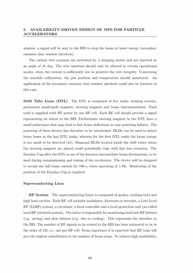
5. AVAILABILITY-DRIVEN DESIGN OF MPS FOR PARTICLEACCELERATORS
window, a signal will be sent to the BIS to stop the beam at lower energy (secondary
emission time window interlock).
The carbon wire scanners are activated by a stepping motor and are inserted at
an angle of 45 deg. The wire insertion should only be allowed in certain operational
modes, when the current is sufficiently low to preserve the wire integrity. Concerning
the movable collimators, the jaw position and temperature should monitored. An
application of the secondary emission time window interlock could also be foreseen in
this case.
Drift Tube Linac (DTL) The DTL is composed of five tanks, housing cavities,
permanent quadrupole magnets, steering magnets and beam instrumentation. Each
tank is supplied with RF power by one RF cell. Each RF cell should provide a signal
representing its status to the BIS. Furthermore steering magnets in the DTL have a
small inductance that may lead to fast beam deflections in case powering failures. The
powering of these devices has therefore to be interlocked. BLMs can be used to detect
beam losses in the last DTL tanks, whereas for the first DTL tanks the beam energy
is too small to be detected (41). Diamond BLMs located inside the drift tubes where
the steering magnets are placed could potentially cope with fast loss scenarios. The
Faraday Cup after the DTL is one of the foreseen intermediate beam destinations, to be
used during commissioning and tuning of the accelerator. The device will be designed
to accept the full beam current for 100 s, when operating at 1 Hz. Monitoring of the
position of the Faraday Cup is required.
Superconducting Linac
RF System The superconducting Linac is composed of spokes, medium beta and
high beta cavities. Each RF cell includes modulator, klystrons or tetrodes, a Low-Level
RF (LLRF) system, a circulator, a local controller and a local protection unit (so-called
local RF interlock system). The latter is responsible for monitoring both fast RF failures
(e.g. arcing) and slow failures (e.g. due to cooling). This represents the interface to
the BIS. The number of RF signals to be routed to the BIS has been estimated to be in
the order of 125, i.e. one per RF cell. From experience it is expected that RF trips will
give the highest contribution to the number of beam stops. To achieve high availability,
60
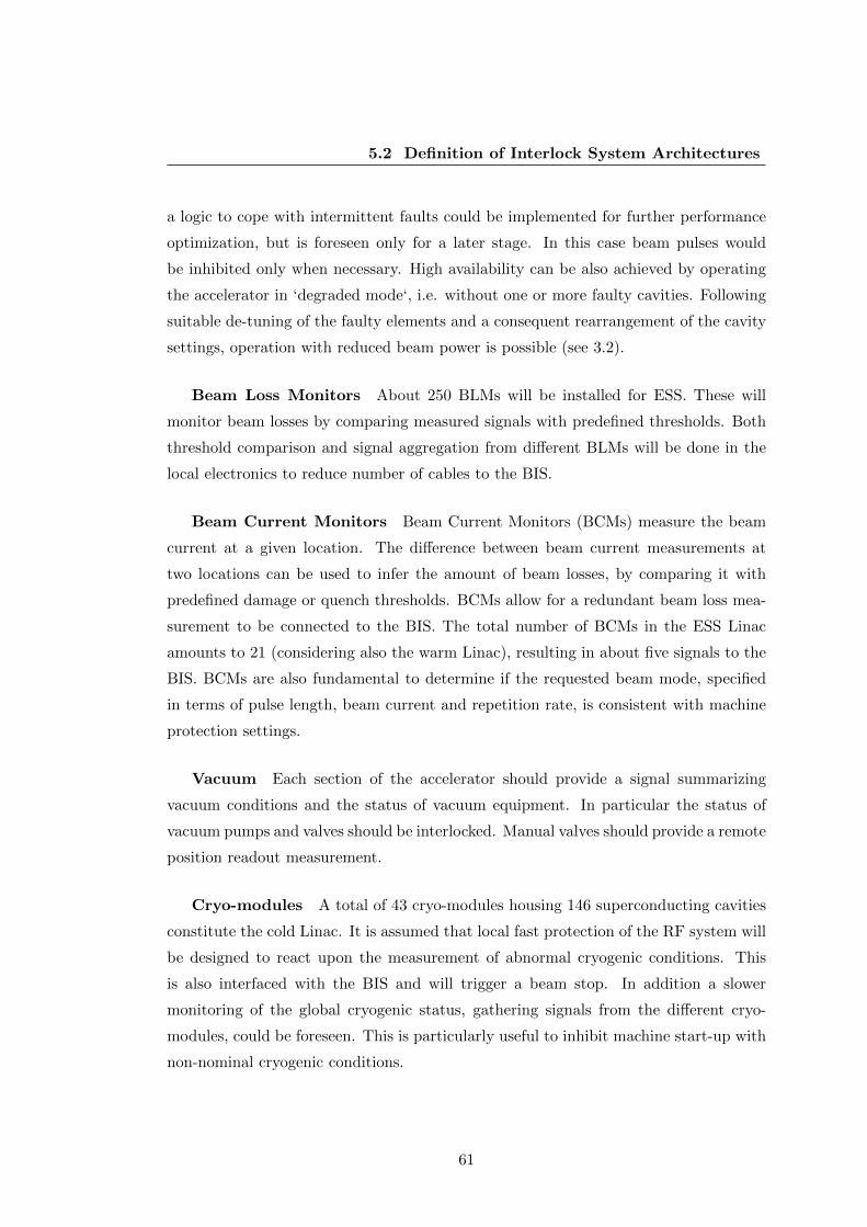
5.2 Definition of Interlock System Architectures
a logic to cope with intermittent faults could be implemented for further performance
optimization, but is foreseen only for a later stage. In this case beam pulses would
be inhibited only when necessary. High availability can be also achieved by operating
the accelerator in ‘degraded mode‘, i.e. without one or more faulty cavities. Following
suitable de-tuning of the faulty elements and a consequent rearrangement of the cavity
settings, operation with reduced beam power is possible (see 3.2).
Beam Loss Monitors About 250 BLMs will be installed for ESS. These will
monitor beam losses by comparing measured signals with predefined thresholds. Both
threshold comparison and signal aggregation from different BLMs will be done in the
local electronics to reduce number of cables to the BIS.
Beam Current Monitors Beam Current Monitors (BCMs) measure the beam
current at a given location. The difference between beam current measurements at
two locations can be used to infer the amount of beam losses, by comparing it with
predefined damage or quench thresholds. BCMs allow for a redundant beam loss mea-
surement to be connected to the BIS. The total number of BCMs in the ESS Linac
amounts to 21 (considering also the warm Linac), resulting in about five signals to the
BIS. BCMs are also fundamental to determine if the requested beam mode, specified
in terms of pulse length, beam current and repetition rate, is consistent with machine
protection settings.
Vacuum Each section of the accelerator should provide a signal summarizing
vacuum conditions and the status of vacuum equipment. In particular the status of
vacuum pumps and valves should be interlocked. Manual valves should provide a remote
position readout measurement.
Cryo-modules A total of 43 cryo-modules housing 146 superconducting cavities
constitute the cold Linac. It is assumed that local fast protection of the RF system will
be designed to react upon the measurement of abnormal cryogenic conditions. This
is also interfaced with the BIS and will trigger a beam stop. In addition a slower
monitoring of the global cryogenic status, gathering signals from the different cryo-
modules, could be foreseen. This is particularly useful to inhibit machine start-up with
non-nominal cryogenic conditions.
61
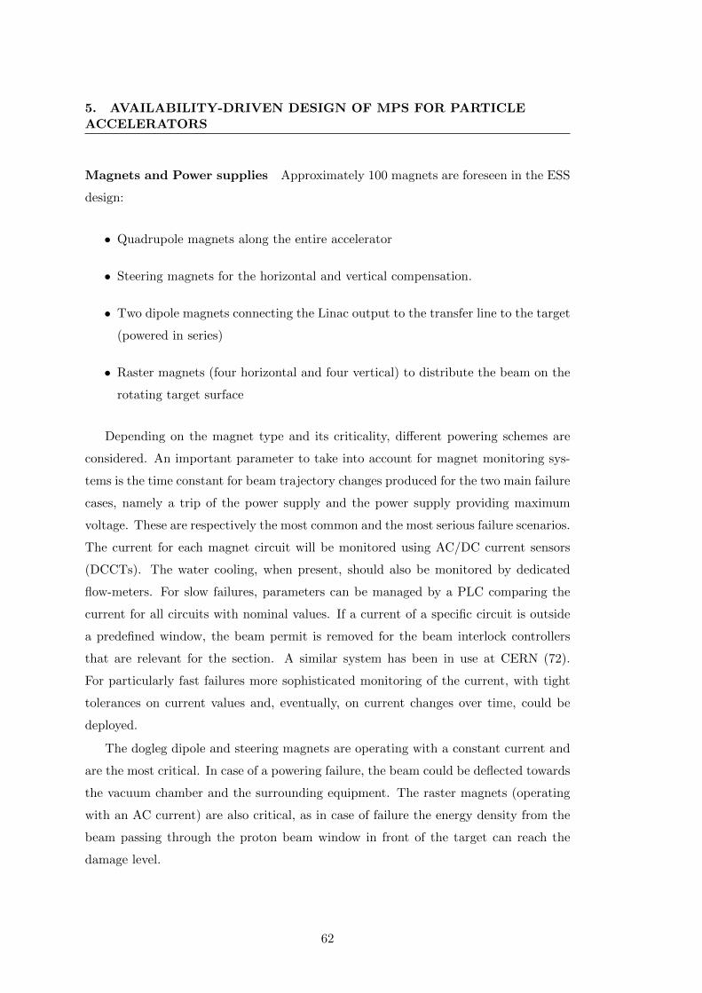
5. AVAILABILITY-DRIVEN DESIGN OF MPS FOR PARTICLEACCELERATORS
Magnets and Power supplies Approximately 100 magnets are foreseen in the ESS
design:
• Quadrupole magnets along the entire accelerator
• Steering magnets for the horizontal and vertical compensation.
• Two dipole magnets connecting the Linac output to the transfer line to the target
(powered in series)
• Raster magnets (four horizontal and four vertical) to distribute the beam on the
rotating target surface
Depending on the magnet type and its criticality, different powering schemes are
considered. An important parameter to take into account for magnet monitoring sys-
tems is the time constant for beam trajectory changes produced for the two main failure
cases, namely a trip of the power supply and the power supply providing maximum
voltage. These are respectively the most common and the most serious failure scenarios.
The current for each magnet circuit will be monitored using AC/DC current sensors
(DCCTs). The water cooling, when present, should also be monitored by dedicated
flow-meters. For slow failures, parameters can be managed by a PLC comparing the
current for all circuits with nominal values. If a current of a specific circuit is outside
a predefined window, the beam permit is removed for the beam interlock controllers
that are relevant for the section. A similar system has been in use at CERN (72).
For particularly fast failures more sophisticated monitoring of the current, with tight
tolerances on current values and, eventually, on current changes over time, could be
deployed.
The dogleg dipole and steering magnets are operating with a constant current and
are the most critical. In case of a powering failure, the beam could be deflected towards
the vacuum chamber and the surrounding equipment. The raster magnets (operating
with an AC current) are also critical, as in case of failure the energy density from the
beam passing through the proton beam window in front of the target can reach the
damage level.
62

5.2 Definition of Interlock System Architectures
Figure 5.10: Master Level 1 of the ESS Beam Interlock System: inputs are in green and
outputs in red.
Target The target station will be protected by a dedicated system. This system
should be interfaced with the BIS to inhibit beam transmission to the target in case
of failures. The rotation of the target wheel must be synchronized to the incoming
beam. Therefore the target monitoring system should provide to the BIS a signal
indicating if the correct position for receiving beam is maintained. Furthermore slowly
varying conditions determining if the target is ready to receive beam (e.g. temperature)
should be monitored. The status of the proton beam window separating the accelerator
vacuum from the helium for target cooling should be monitored as well.
5.2.2.3 BIS: Architecture
Given the similarities in the layout with Linac4, for the ESS BIS the tree-architecture
is also chosen (see Fig. 5.5). It makes use of the daisy-chain feature, where an output of
one beam interlock controller (slave) is connected to the input of another beam interlock
controller (master). Based on the configuration of the inputs of master devices, beam
transmission in the Linac is allowed or stopped by the actuators.
The ESS interlock architecture is composed of master and slave controllers as shown
in Fig.s 5.10 and 5.11.
63
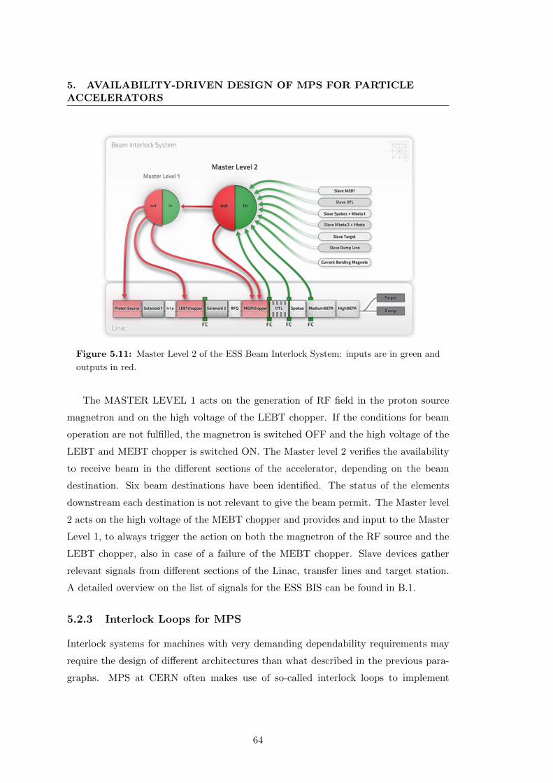
5. AVAILABILITY-DRIVEN DESIGN OF MPS FOR PARTICLEACCELERATORS
Figure 5.11: Master Level 2 of the ESS Beam Interlock System: inputs are in green and
outputs in red.
The MASTER LEVEL 1 acts on the generation of RF field in the proton source
magnetron and on the high voltage of the LEBT chopper. If the conditions for beam
operation are not fulfilled, the magnetron is switched OFF and the high voltage of the
LEBT and MEBT chopper is switched ON. The Master level 2 verifies the availability
to receive beam in the different sections of the accelerator, depending on the beam
destination. Six beam destinations have been identified. The status of the elements
downstream each destination is not relevant to give the beam permit. The Master level
2 acts on the high voltage of the MEBT chopper and provides and input to the Master
Level 1, to always trigger the action on both the magnetron of the RF source and the
LEBT chopper, also in case of a failure of the MEBT chopper. Slave devices gather
relevant signals from different sections of the Linac, transfer lines and target station.
A detailed overview on the list of signals for the ESS BIS can be found in B.1.
5.2.3 Interlock Loops for MPS
Interlock systems for machines with very demanding dependability requirements may
require the design of different architectures than what described in the previous para-
graphs. MPS at CERN often makes use of so-called interlock loops to implement
64

5.2 Definition of Interlock System Architectures
Figure 5.12: Schematic view of the LHC BIS loop.
protection functions. The basic principle is that several systems (i.e. sensors) are inter-
faced with the loop and can potentially interrupt the signal transmission in the loop to
indicate to the actuators the occurrence of a failure. Accordingly two failure scenarios
can occur: 1) not triggering the actuator(s) in case of a sensor signal and 2) trigger-
ing the actuator(s) in absence of a sensor signal. The first failure scenario interferes
with machine safety and can generally be described as a missed action. The second
interferes with machine availability and can be described as a spurious action. MPS
dependability requirements associated to the protection function implemented by the
interlock loop can be met by adding redundancy at the loop level (and/or at the sensor
level) and a suitable voting strategy. For future facilities with critical MPS and depend-
ability requirements, as e.g. ITER (73) or the FCC, the choice of a suitable interlock
system architecture is a vital aspect of machine design. In the following, examples of
existing interlock loops at CERN are given and studies on extended architectures based
on advanced redundancy and voting are presented.
LHC Beam Permit Loop Fig. 5.12 shows as example the principle of the Beam
Permit loop in the LHC BIS (31). The information transmitted by the loop is a flag
called BEAM PERMIT, which can take the Boolean values TRUE or FALSE reflecting
the presence or absence of the correct value of the frequency in the loop. The frequency
is generated by a frequency generator (FSM / CIBG). If all switches in the loop are
closed, each requiring the LOCAL BEAM PERMIT signal to be TRUE, the frequency
propagates and is read and communicated by the detectors as BEAM PERMIT TRUE.
The BEAM PERMIT signal is used by the LHC injection system and the LHC
and SPS Beam Dumping System (LBDS / SPS BDS) to control the activation of
injection and extraction kicker magnets. BEAM PERMIT TRUE means all the (local)
systems interfaced with the loop allow for beam operation. If either one of the LOCAL
65
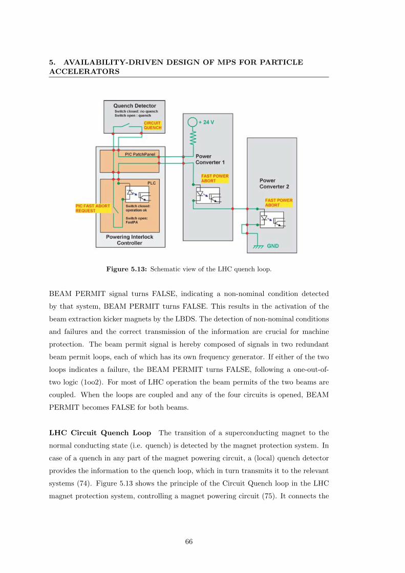
5. AVAILABILITY-DRIVEN DESIGN OF MPS FOR PARTICLEACCELERATORS
Figure 5.13: Schematic view of the LHC quench loop.
BEAM PERMIT signal turns FALSE, indicating a non-nominal condition detected
by that system, BEAM PERMIT turns FALSE. This results in the activation of the
beam extraction kicker magnets by the LBDS. The detection of non-nominal conditions
and failures and the correct transmission of the information are crucial for machine
protection. The beam permit signal is hereby composed of signals in two redundant
beam permit loops, each of which has its own frequency generator. If either of the two
loops indicates a failure, the BEAM PERMIT turns FALSE, following a one-out-of-
two logic (1oo2). For most of LHC operation the beam permits of the two beams are
coupled. When the loops are coupled and any of the four circuits is opened, BEAM
PERMIT becomes FALSE for both beams.
LHC Circuit Quench Loop The transition of a superconducting magnet to the
normal conducting state (i.e. quench) is detected by the magnet protection system. In
case of a quench in any part of the magnet powering circuit, a (local) quench detector
provides the information to the quench loop, which in turn transmits it to the relevant
systems (74). Figure 5.13 shows the principle of the Circuit Quench loop in the LHC
magnet protection system, controlling a magnet powering circuit (75). It connects the
66
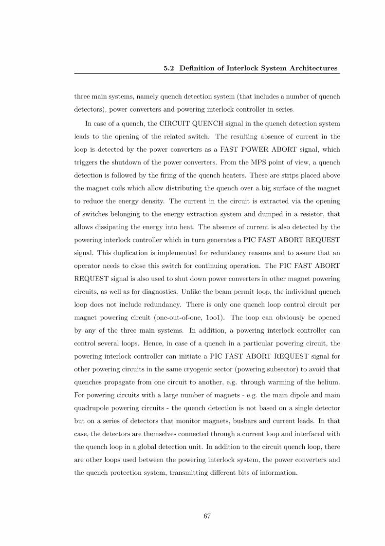
5.2 Definition of Interlock System Architectures
three main systems, namely quench detection system (that includes a number of quench
detectors), power converters and powering interlock controller in series.
In case of a quench, the CIRCUIT QUENCH signal in the quench detection system
leads to the opening of the related switch. The resulting absence of current in the
loop is detected by the power converters as a FAST POWER ABORT signal, which
triggers the shutdown of the power converters. From the MPS point of view, a quench
detection is followed by the firing of the quench heaters. These are strips placed above
the magnet coils which allow distributing the quench over a big surface of the magnet
to reduce the energy density. The current in the circuit is extracted via the opening
of switches belonging to the energy extraction system and dumped in a resistor, that
allows dissipating the energy into heat. The absence of current is also detected by the
powering interlock controller which in turn generates a PIC FAST ABORT REQUEST
signal. This duplication is implemented for redundancy reasons and to assure that an
operator needs to close this switch for continuing operation. The PIC FAST ABORT
REQUEST signal is also used to shut down power converters in other magnet powering
circuits, as well as for diagnostics. Unlike the beam permit loop, the individual quench
loop does not include redundancy. There is only one quench loop control circuit per
magnet powering circuit (one-out-of-one, 1oo1). The loop can obviously be opened
by any of the three main systems. In addition, a powering interlock controller can
control several loops. Hence, in case of a quench in a particular powering circuit, the
powering interlock controller can initiate a PIC FAST ABORT REQUEST signal for
other powering circuits in the same cryogenic sector (powering subsector) to avoid that
quenches propagate from one circuit to another, e.g. through warming of the helium.
For powering circuits with a large number of magnets - e.g. the main dipole and main
quadrupole powering circuits - the quench detection is not based on a single detector
but on a series of detectors that monitor magnets, busbars and current leads. In that
case, the detectors are themselves connected through a current loop and interfaced with
the quench loop in a global detection unit. In addition to the circuit quench loop, there
are other loops used between the powering interlock system, the power converters and
the quench protection system, transmitting different bits of information.
67

5. AVAILABILITY-DRIVEN DESIGN OF MPS FOR PARTICLEACCELERATORS
Figure 5.14: Example of an open signal path model.
Figure 5.15: Markov model of the basic loop component.
5.2.3.1 Quench Loop Architectures
The objective of the study on interlock loop architectures is to quantify the performance
of different architectures in terms of machine safety and availability (76). To account
for this, a Markov description of components’ failure behaviour was used in an open
signal path model (Fig. 5.14).
Each component of the loop (sensor, actuator, etc.) is modelled as a switch that
can interrupt the signal path, ideally with the scope of turning the machine to a safe
state. In this representation the nominal function of the system is fulfilled if the signal
is able to propagate from the Start (S) to the End (E). The state of the switches is a
boolean variable (1 - close, 0 - open). The Markov model of the switch is shown in Fig.
5.15.
Components are normally in the ’ready’ state. Each component can open following
a spurious (’false’) detection. The component can also turn into a state where opening
is inhibited (’blind’). The transition to one of these two alternative states occurs
68

5.2 Definition of Interlock System Architectures
Figure 5.16: Markov model of the virtual demand component.
according to two different failure rates, λb and λf , assuming exponentially distributed
failures. The assumption is that the two failure states (’blind’ and ’false’) are exclusive,
i.e. no transition exists between the two.
The system demand, i.e. the occurrence of a dangerous machine state, is mod-
elled by an additional virtual component with two states (Fig 5.16). ’Silent’ is the
default state, when no dangerous configurations for the machine are present. ’System
demanding’ is the state representing the need for an emergency action to be taken by
the interlock system. The transition to the ’System demanding’ state is also assumed
to be exponentially distributed, with a demand rate X. Based on the open path model,
four operational scenarios can be identified over a given observation time (Tf ) (i.e. a
‘mission‘) of the system:
1. Mission completed: No false trigger, successful emergency shutdown or missed
emergency shutdown.
2. False trigger: False signal triggered in system component and transmitted to
E, with no demand signal.
3. Demand success: demand signal triggered in S and propagated to E.
4. Demand missed: demand signal triggered in S and not propagated to E.
At time 0, all components are in their nominal state, i.e. the switches are ’ready’
and the demand component is ’silent’. The observation of the system is stopped if one
among scenarios 2, 3 or 4 occurs. If this is not the case, the given observation time Tf
is reached, leading to scenario 1. Scenario 1 represents nominal system operation (no
demand for emergency shutdowns nor spurious emergency shutdowns). Maximizing
the occurrence of this scenario implies optimizing Machine Availability. Scenario 4 is
69

5. AVAILABILITY-DRIVEN DESIGN OF MPS FOR PARTICLEACCELERATORS
Figure 5.17: Interlock loop model with three lines, each featuring 4 components, and a
demand block. Six architectures are considered based on this representation (1oo1, 1oo2,
2oo2, 1oo3, 3oo3, 2oo3).
instead the worst case scenario where there the emergency shutdown is not executed
following a system demand. This scenario gives a direct measure of the system Safety.
The model allows estimating the probabilities for the occurrence of the four above
scenarios as a function of relevant input parameters. These are:
Observation Time [Tf ]: The time over which the system behaviour is evaluated.
False rate [λf ]: the rate of spurious opening of each loop component.
Blind rate [λb]: the rate of blind failure of each loop component.
Demand rate [X]: the rate for demands of emergency shutdowns.
A description of the models for different loop architectures and voting strategies is
presented. As a first step, six architectures for the quench loop with fault-free voting
are considered (Fig.5.17). The loop is composed of up to three identical lines, featuring
the same number of components, and a demand block.
1oo1: single-line architecture, no redundancy
1oo2: two redundant lines with 1-out-of-2 logic
2oo2: two redundant lines with 2-out-of-2 logic
70

5.2 Definition of Interlock System Architectures
1oo3: three redundant lines with 1-out-of-3 logic
2oo3: three redundant lines with 2-out-of-3 voting
3oo3: three redundant lines with 3-out-of-3 logic
The definition of the basic scenarios proposed above applies directly only to the
1oo1 architecture. Definitions need to be extended for the other architectures. Taking
the 2oo3 architecture as an example, a mission completed will occur if at least 2 lines
of the loop will still be closed (i.e. not failed) at the end of the observation time and no
emergency shutdown request was issued. Similarly a false trigger will be identified if at
least 2 lines are open without an emergency shutdown request. A demand success will
be identified if at least 2 lines open (i.e. fail) following an emergency shutdown request.
A missed emergency shutdown will occur in case less than 2 lines open following a
shutdown request.
Both analytical (76) and simulation-based models for the described systems were
developed. The analytical model is based on probability theory and considers the chosen
probability density functions in different architectures to calculate the probability of
occurrence of each of the six scenarios. The simulation approach is Monte Carlo-based
and is implemented in MATLAB (51) or Simulink (77). The model allows reproducing
the signal propagation in the different architectures, according to randomly generated
failures and demands, given the chosen input parameters. The system behaviour is
evaluated over the observation time and scenarios identified based on the configuration
of the different loop lines. The Simulink model is used when the model complexity
would be too high to be managed by the analytical approach or the corresponding
MATLAB implementation. Nevertheless the calculation in Simulink is the slowest
among the three. In the following, unless explicitly specified, results are produced with
the analytical model. The advantage of this approach is that the occurrence of rare
events can be easily taken into account, whereas with simulation a large number of
cycles is necessary to have significant statistics for comparison. A thorough process of
verification of the analytical results has been performed by reproducing the probability
of occurrence of the four scenarios also via the simulation models. The absolute errors
lie in the range between 1E-7 and 1E-3 for the first three scenarios and between 1E-8
and 1E-4 for the demand missed.
71

5. AVAILABILITY-DRIVEN DESIGN OF MPS FOR PARTICLEACCELERATORS
Tf 720 h
λb 10−5h−1
λf 10−4h−1
X 2 ∗ 10−4h−1
Table 5.6: Reference input parameters for interlock loop studies.
The reference input parameters for the calculations are shown in Table 5.6.
The results for the six architectures are then presented in Table 5.7.
1oo1 1oo2 2oo2 1oo3 2oo3 3oo3
Mission completed 6.50E-01 4.88E-01 8.12E-01 3.66E-01 7.31E-01 8.52E-01
False trigger 2.33E-01 4.10E-01 5.68E-02 5.43E-01 1.42E-01 1.40E-02
Demand success 1.17E-01 1.03E-01 1.30E-01 9.08E-02 1.27E-01 1.32E-01
Demand missed 3.99E-04 1.54E-06 7.97E-04 6.57E-09 4.60E-06 1.19E-03
Table 5.7: Predicted occurrence of the four scenarios through the analytical model for
the six selected loop architectures.
Results highlight the 2oo3 loop architecture being the best compromise between
availability (scenario 1) and safety (scenario 4). If the primary focus of the system
is on safety, then the best architecture would be 1oo3, showing the lowest probability
of occurrence of scenario 4. If the focus is on availability, then the 3oo3 architecture
maximizes the probability of scenario 1.
5.2.3.2 Sensor Interface and Quench Loop Architectures
Based on these results for the loop architecture, the study can be further extended by
taking into account the configuration of sensors that would represent the best interface
between the loop elements and the demand block. The 2oo3 architecture is assumed
as the reference at the loop level in this analysis. This leads to the definition of 8 new
system architectures, including different sensor interfaces and voting (Fig.5.18). The
components at the interface level are assumed to have the same failure behaviour as
the loop components (the same failure model and input parameters are taken). The
assumption is still to have fault-free voting at this stage.
The calculation of the probability of occurrence of the four scenarios introduced
above yields the results in Table 5.8.
72

5.2 Definition of Interlock System Architectures
Figure 5.18: Interface and loop models. Eight architectures result from the combination
of different voting strategies at the interface level. 2oo3 voting is assumed at the loop level.
A B1 B2 C1 C2 C3 C0
Mission completed 7.95E-01 7.40E-01 8.50E-01 6.89E-01 8.42E-01 8.54E-01 8.24E-01
False trigger 7.62E-02 1.36E-01 1.68E-02 1.91E-01 2.48E-02 1.28E-02 4.44E-02
Demand success 1.28E-01 1.25E-01 1.32E-01 1.20E-01 1.33E-01 1.32E-02 1.32E-01
Demand missed 4.62E-04 7.96E-06 9.16E-04 5.96E-06 1.25E-05 1.37E-03 2.31E-05
Table 5.8: Predicted occurrence of the four scenarios through the analytical model for
the eight selected interface architectures.
As done for the loop studies, it can be observed that the 1oo3 architecture at the
interface level (C1) represents the best choice for safety (lowest probability of scenario
4). The 3oo3 architecture at the interface level (C3) is instead the best choice to
preserve availability. Architecture C2, that features 2oo3 voting both at the loop as
well as the interface level, is the best compromise between safety and availability as it
is among the best three architectures for both safety and availability. A comparable
performance to C2 is achieved by architecture C0, without any voting strategy at the
interface level. C0 needs a significantly lower amount of logic to be implemented and
this poses the problem of quantifying the impact of the increased voting complexity
of different architectures on safety and availability. This is done by considering error-
prone voting, i.e. by assigning to the voting logic the same failure behaviour as the
other components of the loop and interface. Table 5.9 highlights the results for the C0
and C2 architectures, with fault free voting, and C2 with error-prone voting. For the
73

5. AVAILABILITY-DRIVEN DESIGN OF MPS FOR PARTICLEACCELERATORS
latter the results are calculated through Monte Carlo simulations in MATLAB (1E8
iterations), due to the limitations of the analytical approach with increasing system
complexity.
C0 C2 C2 Error Prone
Mission completed 0.824 0.842 0.784
False trigger 0.044 0.025 0.087
Demand success 0.132 0.133 0.128
Demand missed 2.3E-05 1.2E-05 4.62E-04
Table 5.9: Predicted occurrence of the four scenarios for architectures C0, C2 and C2
Error Prone. For C2 Error Prone results are calculated through Monte Carlo simulations
in MATLAB (1E8 iterations).
Results show that considering error prone-voting the C2 option exhibits worse per-
formance than C0 (and C2, as expected) both in terms of safety and availability. C2
Error Prone shows about a factor 10 higher probability of occurrence of scenario 4. The
error-prone voting introduces a reliability bottle neck for the architecture. The possi-
bility of introducing redundancy for the component implementing the voting logic was
therefore studied. Three redundant voting blocks were considered in 2oo3 configuration
(Fig.5.19) and simulations were performed based on the Simulink implementation of
the model, which only allowed a limited number of simulation iterations.
Results show an increase of Mission Completed (comparable to C0) and the decrease
of the Demand Missed probability by one order of magnitude, back to the range of C0
and C2. This result is still based on the assumption that all components have the same
failure behaviour, i.e. same failure model and same input parameters λf and λb. This
is not realistic if one considers the hardware implementation of the voting logic, based
on few logic gates, and current technologies. Three hardware implementations were
then considered for the voting logic (Fig.5.20).
The first option is the basic implementation of the 2oo3 logic (3 AND gates and
one OR gate). The second adds redundancy at the level of the OR gates in order
to have each loop line connected to one output of an OR gate. The third considers
full redundancy, by triplicating the implementation of the first option. Each gate was
assumed to be an error-prone component at this stage, but in this case both λf and
74

5.2 Definition of Interlock System Architectures
Figure 5.19: 2oo3 redundancy for error-prone voting.
Figure 5.20: 2oo3 logics implementations.
75

5. AVAILABILITY-DRIVEN DESIGN OF MPS FOR PARTICLEACCELERATORS
λb were assumed to be 10E-6/h (while keeping the other components at the reference
input values).
With these assumptions, results for the C2 error-prone voting recover the perfor-
mance of the C2 fault-free architecture (Table 5.9) for scenario 1. Both the first and
second implementations show an increase of the probability of occurrence of scenario 4,
whereas the third implementation didn’t produce any ’demand missed’, possibly indi-
cating that also the probability for scenario 4 goes back to the range of the C2 fault-free
architecture. It has to be noted that in this case result accuracy is limited by the low
number of simulation runs (1E4).
An important outcome of this study is the identification of the 2oo3 voting being the
best compromise between safety and availability. In view of future system developments
for new facilities (e.g. ITER) and upgrades of existing systems with stringent safety and
availability requirements, 2oo3 voting is recommended as the baseline for the design.
Nevertheless in the decision for the final architecture choice other factors could play a
crucial role, e.g. the cost of design, production and maintenance of a complex system.
5.2.4 Impact of Newly Designed Systems on Availability
During operation of an accelerator, it is not excluded that unpredicted failure modes
might appear and require immediate mitigations to be deployed. In the worst case of
a failure that could compromise machine safety, the design of new systems might be
required to enhance the protection of the machine.
In 3.3.1 it was explained that the LBDS is one of the most critical MPS of the LHC,
as it is the only way to safely extract the LHC beams and send them to the beam dump.
A critical failure of such system implies that the beam dump could not be performed.
Fig. 5.21 shows a schematic view of the LBDS and its subsystems. Two redundant
front-end electronic systems (Trigger Synchronization Units, TSU) are interfaced with
the BIS to detect the necessity of triggering a beam dump. The BIS is composed of
two electronic sub-systems, the Controls Interlocks Beam Manager (CIBM) and the
Controls Interlocks Beam Generator (CIBG). An incoming beam dump request has to
be propagated via the Trigger Fan Out (TFO) to the 15 kicker magnets that extract
the beam from the LHC ring to the transfer lines towards the beam dump block. The
rise time of the kicker magnets is 3 µs, therefore a particle free gap (abort gap) is
needed in the beam for a safe beam extraction (78). The TSUs are also in charge
76
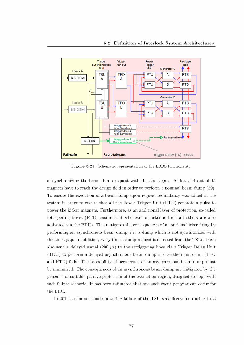
5.2 Definition of Interlock System Architectures
Figure 5.21: Schematic representation of the LBDS functionality.
of synchronizing the beam dump request with the abort gap. At least 14 out of 15
magnets have to reach the design field in order to perform a nominal beam dump (29).
To ensure the execution of a beam dump upon request redundancy was added in the
system in order to ensure that all the Power Trigger Unit (PTU) generate a pulse to
power the kicker magnets. Furthermore, as an additional layer of protection, so-called
retriggering boxes (RTB) ensure that whenever a kicker is fired all others are also
activated via the PTUs. This mitigates the consequences of a spurious kicker firing by
performing an asynchronous beam dump, i.e. a dump which is not synchronized with
the abort gap. In addition, every time a dump request is detected from the TSUs, these
also send a delayed signal (200 µs) to the retriggering lines via a Trigger Delay Unit
(TDU) to perform a delayed asynchronous beam dump in case the main chain (TFO
and PTU) fails. The probability of occurrence of an asynchronous beam dump must
be minimized. The consequences of an asynchronous beam dump are mitigated by the
presence of suitable passive protection of the extraction region, designed to cope with
such failure scenario. It has been estimated that one such event per year can occur for
the LHC.
In 2012 a common-mode powering failure of the TSU was discovered during tests
77
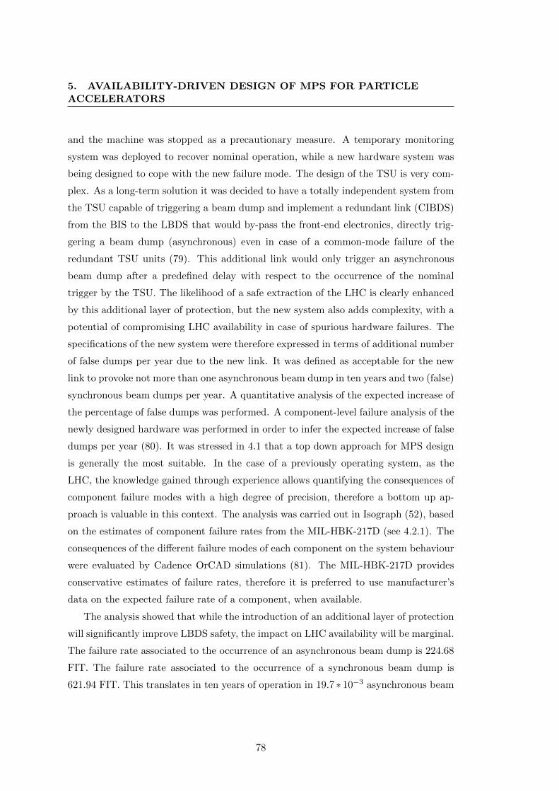
5. AVAILABILITY-DRIVEN DESIGN OF MPS FOR PARTICLEACCELERATORS
and the machine was stopped as a precautionary measure. A temporary monitoring
system was deployed to recover nominal operation, while a new hardware system was
being designed to cope with the new failure mode. The design of the TSU is very com-
plex. As a long-term solution it was decided to have a totally independent system from
the TSU capable of triggering a beam dump and implement a redundant link (CIBDS)
from the BIS to the LBDS that would by-pass the front-end electronics, directly trig-
gering a beam dump (asynchronous) even in case of a common-mode failure of the
redundant TSU units (79). This additional link would only trigger an asynchronous
beam dump after a predefined delay with respect to the occurrence of the nominal
trigger by the TSU. The likelihood of a safe extraction of the LHC is clearly enhanced
by this additional layer of protection, but the new system also adds complexity, with a
potential of compromising LHC availability in case of spurious hardware failures. The
specifications of the new system were therefore expressed in terms of additional number
of false dumps per year due to the new link. It was defined as acceptable for the new
link to provoke not more than one asynchronous beam dump in ten years and two (false)
synchronous beam dumps per year. A quantitative analysis of the expected increase of
the percentage of false dumps was performed. A component-level failure analysis of the
newly designed hardware was performed in order to infer the expected increase of false
dumps per year (80). It was stressed in 4.1 that a top down approach for MPS design
is generally the most suitable. In the case of a previously operating system, as the
LHC, the knowledge gained through experience allows quantifying the consequences of
component failure modes with a high degree of precision, therefore a bottom up ap-
proach is valuable in this context. The analysis was carried out in Isograph (52), based
on the estimates of component failure rates from the MIL-HBK-217D (see 4.2.1). The
consequences of the different failure modes of each component on the system behaviour
were evaluated by Cadence OrCAD simulations (81). The MIL-HBK-217D provides
conservative estimates of failure rates, therefore it is preferred to use manufacturer’s
data on the expected failure rate of a component, when available.
The analysis showed that while the introduction of an additional layer of protection
will significantly improve LBDS safety, the impact on LHC availability will be marginal.
The failure rate associated to the occurrence of an asynchronous beam dump is 224.68
FIT. The failure rate associated to the occurrence of a synchronous beam dump is
621.94 FIT. This translates in ten years of operation in 19.7 ∗ 10−3 asynchronous beam
78

5.2 Definition of Interlock System Architectures
Figure 5.22: Expected probability of occurrence of an asynchronous beam dump over
time due to the additional designed layer of protection (CIBDS and additional TDUs).
Manufacturer data for component failures is assumed when available.
dumps and 5.45 ∗ 10−3 synchronous beam dumps expected due to the newly designed
system. Fig. 5.22 shows for example the expected probability of occurrence of an
asynchronous beam dump over time. In both cases, the results have a minor impact
on LBDS figures for the total number of false dumps, resulting orders of magnitude
below the tolerated values. This was expected, as the additional complexity added by
the new system is negligible if compared with the complexity of whole LBDS.
79

5. AVAILABILITY-DRIVEN DESIGN OF MPS FOR PARTICLEACCELERATORS
80
6
Availability-driven Optimization
of Accelerator Performance
Chapter 6 focuses on accelerator exploitation and performance optimization through
availability. The LHC is taken as a reference for the analysis.
6.1 2010-2012 LHC performance
In this paragraph the performance of the LHC will be discussed and related to system
availability during LHC run 1 (2010-2012). A particular emphasis will be put on 2012,
as this was the most reproducible and stable year of operation and represents the
reference for the future LHC runs.
6.1.1 Availability and Integrated Luminosity
The main figure of merit of a particle collider is the integrated luminosity L. This
is a direct measure of the number of interesting events per second RE recorded by
the experiments, that can be calculated knowing the probability (i.e. the so-called
production cross-section σp) of generating such events during the collision process (Eq.
6.1).
RE = L ∗ σp (6.1)
A common expression for luminosity is given in Eq. 6.2 (83):
81
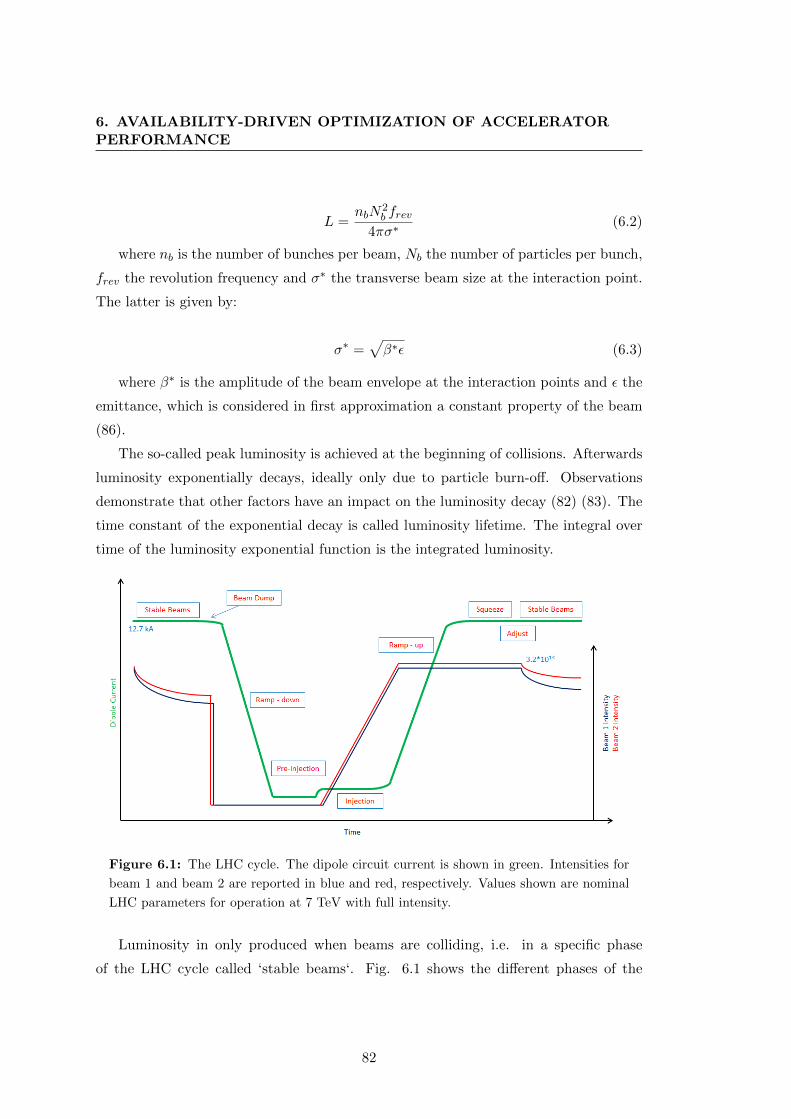
6. AVAILABILITY-DRIVEN OPTIMIZATION OF ACCELERATORPERFORMANCE
L =nbN
2b frev
4πσ∗(6.2)
where nb is the number of bunches per beam, Nb the number of particles per bunch,
frev the revolution frequency and σ∗ the transverse beam size at the interaction point.
The latter is given by:
σ∗ =√β∗ε (6.3)
where β∗ is the amplitude of the beam envelope at the interaction points and ε the
emittance, which is considered in first approximation a constant property of the beam
(86).
The so-called peak luminosity is achieved at the beginning of collisions. Afterwards
luminosity exponentially decays, ideally only due to particle burn-off. Observations
demonstrate that other factors have an impact on the luminosity decay (82) (83). The
time constant of the exponential decay is called luminosity lifetime. The integral over
time of the luminosity exponential function is the integrated luminosity.
Figure 6.1: The LHC cycle. The dipole circuit current is shown in green. Intensities for
beam 1 and beam 2 are reported in blue and red, respectively. Values shown are nominal
LHC parameters for operation at 7 TeV with full intensity.
Luminosity in only produced when beams are colliding, i.e. in a specific phase
of the LHC cycle called ‘stable beams‘. Fig. 6.1 shows the different phases of the
82

6.1 2010-2012 LHC performance
LHC cycle. The beams extracted from the SPS at 450 GeV are sent to the LHC via
dedicated transfer lines. A safe (i.e. with negligible damage potential) probe beam
to verify the correct behaviour of all accelerator system is injected first (84). Only
afterwards injection of full intensity beams is allowed (‘injection‘) and the machine is
filled with proton bunches. Different filling schemes can be followed, with a variable
number of proton bunches and a variable spacing in time between two consecutive
bunches (i.e. the bunch spacing). The maximum number of bunches in the LHC
is 2808 with 25 ns bunch spacing. In the 2010-2012 run, 50 ns bunch spacing was
adopted as the operational baseline. The injection process takes about 50 min (85).
The magnetic field in the dipole magnets is ramped up while accelerating particles to
LHC top energy (‘ramp-up‘). In 2010-2012 the energy has been limited to a maximum
of 4 TeV and the minimum ramp time was about 770 s. For LHC run 2 the energy will
be increased to 6.5 TeV, requiring a ramp time of 1300 s. Once the beams reach top
energy, the beam size at the interaction points σ∗ is reduced to improve the collision
rate (‘squeeze‘). This is achieved by reducing the β∗. Up to this point in the cycle the
beams are kept separated and therefore do not collide.
Finally the beams are put in collision (‘adjust‘). Collisions ideally take place for
several hours and data is collected by the experiments (‘stable beams‘). Beams going
through the LHC cycle are referred to as a machine ‘fill‘. Fig. 6.2 shows the length
probability distribution of stable beams in 2012. Many fills were dumped soon after
reaching stable beams, mainly due to the fact that beam losses are highest at the
beginning of the collisions. Only few fills reach more than 10 h in stable beams, as
70 % are dumped earlier after a detection of a failure by the MPS or by the operators.
Once beams are extracted from the LHC, magnets are ramped down to prepare the
injection of beams for the next fill (‘ramp-down‘ and ‘pre-injection‘).
According to the definition given in 3.1, the LHC is only available for physics during
stable beams, when luminosity is produced. The rest of the LHC cycle is part of the
turnaround time and should therefore be minimized. The scope of this chapter is to
quantify the impact of accelerator availability on luminosity production. In the past
the most efficient way to increase the integrated luminosity was to increase the peak
luminosity (83). The limit to the peak luminosity that the LHC can reach is determined
by the event pile-up in the experiments, namely by the number of simultaneous events
that can be processed and recorded by the experiments measuring the outcome of the
83

6. AVAILABILITY-DRIVEN OPTIMIZATION OF ACCELERATORPERFORMANCE
Figure 6.2: 2012 LHC stable beams distribution.
collisions. Technological limitations of the experiments set a constraint on the pile-up
and therefore on the peak luminosity. New strategies have to be defined to overcome this
limitation. Given the fixed peak luminosity, the integrated luminosity can be maximized
by extending the time in stable beams, i.e. by maximising the Availability for Physics
(3.1). Due to a limited luminosity lifetime, the duration of stable beams nevertheless
should not be indefinitely extended. An optimum point in time for balancing the loss
of of integrated luminosity resulting from the luminosity exponential decay and from
the turnaround time can be calculated. This point in time is a function of the average
fault time, the turnaround time and the luminosity lifetime. As will be discussed in
the present chapter, the optimization of availability poses major challenges.
6.1.2 Study of 2010-2012 data
As explained in the previous paragraph, a LHC fill can be aborted by a system failure
- through the MPS - or intentionally by the operators for optimization of luminosity
production. The Machine Failure Rate (MFR) is defined as in Eq. 6.4, where NF is
the number of fills dumped due to failures and NP is the total number of physics fills.
84
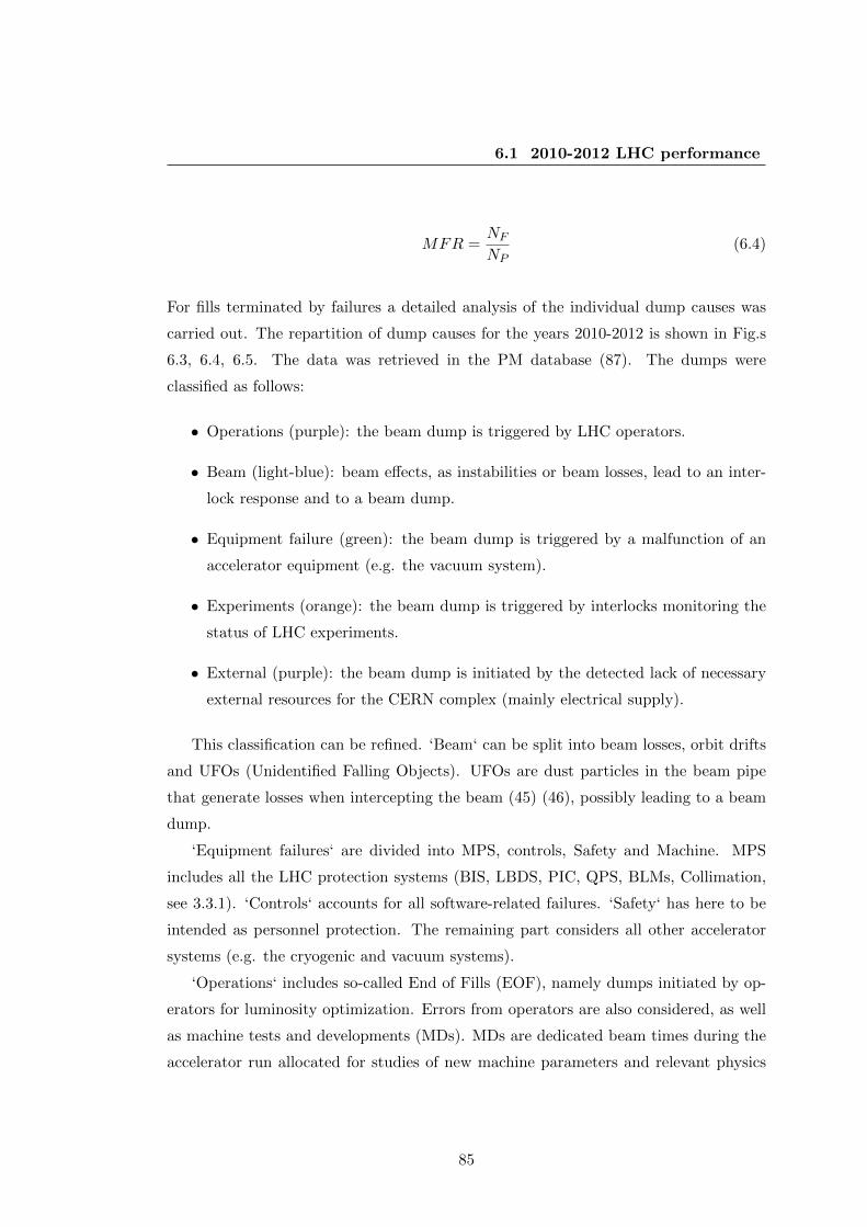
6.1 2010-2012 LHC performance
MFR =NF
NP(6.4)
For fills terminated by failures a detailed analysis of the individual dump causes was
carried out. The repartition of dump causes for the years 2010-2012 is shown in Fig.s
6.3, 6.4, 6.5. The data was retrieved in the PM database (87). The dumps were
classified as follows:
• Operations (purple): the beam dump is triggered by LHC operators.
• Beam (light-blue): beam effects, as instabilities or beam losses, lead to an inter-
lock response and to a beam dump.
• Equipment failure (green): the beam dump is triggered by a malfunction of an
accelerator equipment (e.g. the vacuum system).
• Experiments (orange): the beam dump is triggered by interlocks monitoring the
status of LHC experiments.
• External (purple): the beam dump is initiated by the detected lack of necessary
external resources for the CERN complex (mainly electrical supply).
This classification can be refined. ‘Beam‘ can be split into beam losses, orbit drifts
and UFOs (Unidentified Falling Objects). UFOs are dust particles in the beam pipe
that generate losses when intercepting the beam (45) (46), possibly leading to a beam
dump.
‘Equipment failures‘ are divided into MPS, controls, Safety and Machine. MPS
includes all the LHC protection systems (BIS, LBDS, PIC, QPS, BLMs, Collimation,
see 3.3.1). ‘Controls‘ accounts for all software-related failures. ‘Safety‘ has here to be
intended as personnel protection. The remaining part considers all other accelerator
systems (e.g. the cryogenic and vacuum systems).
‘Operations‘ includes so-called End of Fills (EOF), namely dumps initiated by op-
erators for luminosity optimization. Errors from operators are also considered, as well
as machine tests and developments (MDs). MDs are dedicated beam times during the
accelerator run allocated for studies of new machine parameters and relevant physics
85
6. AVAILABILITY-DRIVEN OPTIMIZATION OF ACCELERATORPERFORMANCE
phenomena (e.g. study of quench levels), which do not contribute to luminosity pro-
duction.
Excluding EOF and external dump causes, all other dumps are due to CERN sys-
tems and cause unnecessary un-availability of the LHC. The occurrence of such events
must therefore be minimized. Among unnecessary dumps, spurious failures of the MPS
leading to a dump are referred to as ’false dumps’.
Figure 6.3: Repartition of 2010 dump causes from the PM database.
Table 6.1 shows the absolute number of times an LHC system caused a beam dump
in 2012. The color code adopted in Fig. 6.5 was kept to relate each system to the
previously defined categories.
Comparing the dump causes of 2010, 2011 and 2012 one can see that the percentage
of EOF consistently increases over the three years. This indicates a clear learning trend
and an improvement in operational practices due to an increased machine understand-
ing. The MFR decreased from 80 % in 2010 to 70 % in 2012. Similarly, the number of
fills that were injected in the LHC increased from 355 in 2010 to 585 in 2012. These
figures were achieved while increasing the peak luminosity (higher intensity, lower β∗).
86

6.1 2010-2012 LHC performance
Figure 6.4: Repartition of 2011 dump causes from the PM database.
Figure 6.5: Repartition of 2012 dump causes from the PM database.
87
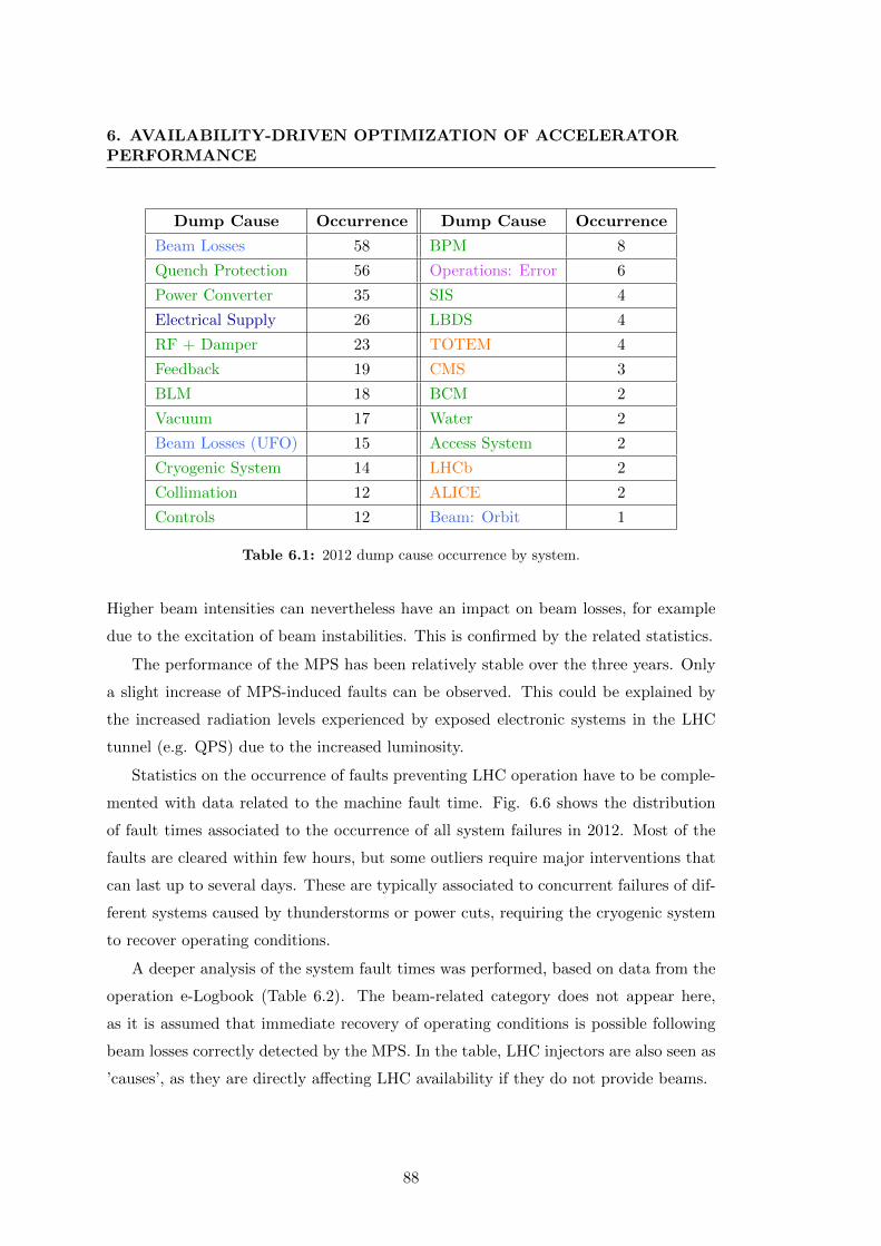
6. AVAILABILITY-DRIVEN OPTIMIZATION OF ACCELERATORPERFORMANCE
Dump Cause Occurrence Dump Cause Occurrence
Beam Losses 58 BPM 8
Quench Protection 56 Operations: Error 6
Power Converter 35 SIS 4
Electrical Supply 26 LBDS 4
RF + Damper 23 TOTEM 4
Feedback 19 CMS 3
BLM 18 BCM 2
Vacuum 17 Water 2
Beam Losses (UFO) 15 Access System 2
Cryogenic System 14 LHCb 2
Collimation 12 ALICE 2
Controls 12 Beam: Orbit 1
Table 6.1: 2012 dump cause occurrence by system.
Higher beam intensities can nevertheless have an impact on beam losses, for example
due to the excitation of beam instabilities. This is confirmed by the related statistics.
The performance of the MPS has been relatively stable over the three years. Only
a slight increase of MPS-induced faults can be observed. This could be explained by
the increased radiation levels experienced by exposed electronic systems in the LHC
tunnel (e.g. QPS) due to the increased luminosity.
Statistics on the occurrence of faults preventing LHC operation have to be comple-
mented with data related to the machine fault time. Fig. 6.6 shows the distribution
of fault times associated to the occurrence of all system failures in 2012. Most of the
faults are cleared within few hours, but some outliers require major interventions that
can last up to several days. These are typically associated to concurrent failures of dif-
ferent systems caused by thunderstorms or power cuts, requiring the cryogenic system
to recover operating conditions.
A deeper analysis of the system fault times was performed, based on data from the
operation e-Logbook (Table 6.2). The beam-related category does not appear here,
as it is assumed that immediate recovery of operating conditions is possible following
beam losses correctly detected by the MPS. In the table, LHC injectors are also seen as
’causes’, as they are directly affecting LHC availability if they do not provide beams.
88
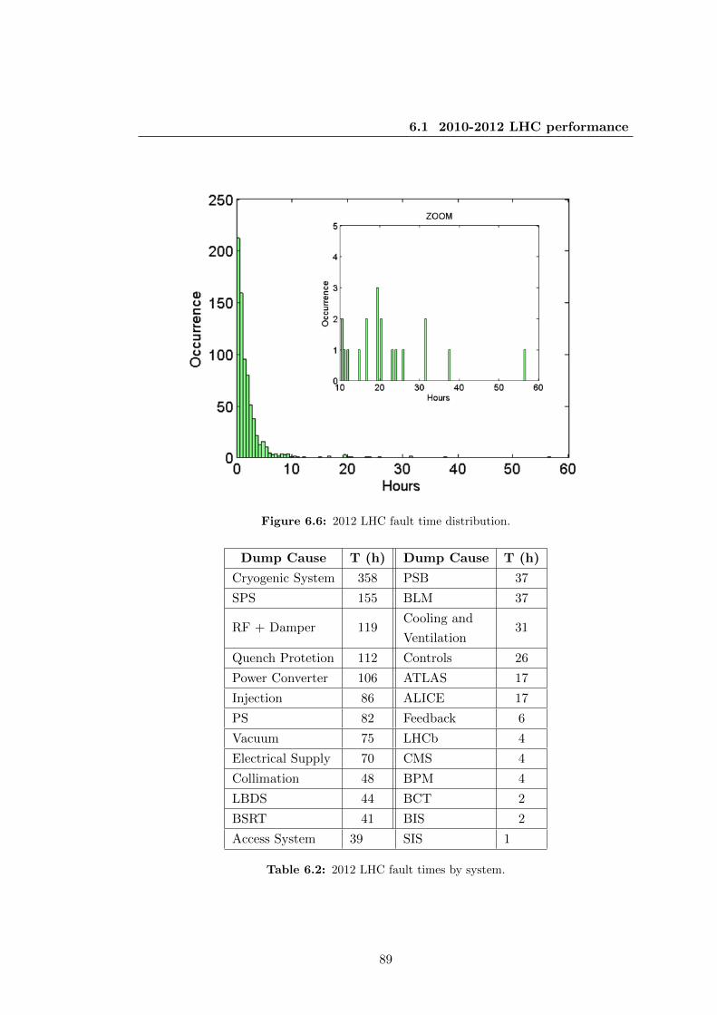
6.1 2010-2012 LHC performance
Figure 6.6: 2012 LHC fault time distribution.
Dump Cause T (h) Dump Cause T (h)
Cryogenic System 358 PSB 37
SPS 155 BLM 37
RF + Damper 119Cooling and
Ventilation31
Quench Protetion 112 Controls 26
Power Converter 106 ATLAS 17
Injection 86 ALICE 17
PS 82 Feedback 6
Vacuum 75 LHCb 4
Electrical Supply 70 CMS 4
Collimation 48 BPM 4
LBDS 44 BCT 2
BSRT 41 BIS 2
Access System 39 SIS 1
Table 6.2: 2012 LHC fault times by system.
89
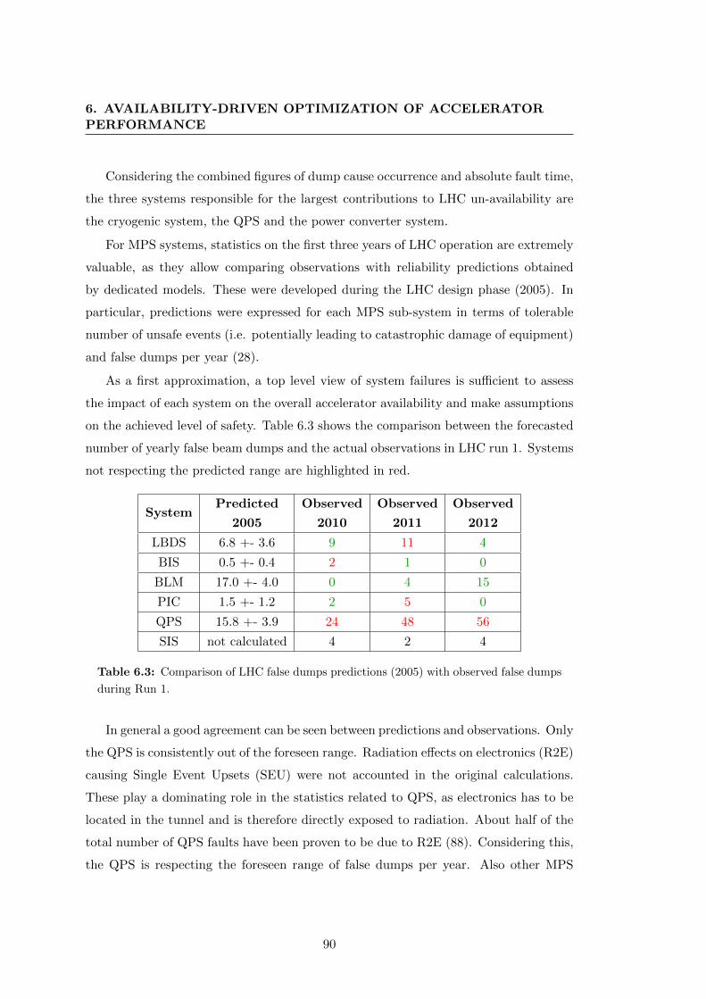
6. AVAILABILITY-DRIVEN OPTIMIZATION OF ACCELERATORPERFORMANCE
Considering the combined figures of dump cause occurrence and absolute fault time,
the three systems responsible for the largest contributions to LHC un-availability are
the cryogenic system, the QPS and the power converter system.
For MPS systems, statistics on the first three years of LHC operation are extremely
valuable, as they allow comparing observations with reliability predictions obtained
by dedicated models. These were developed during the LHC design phase (2005). In
particular, predictions were expressed for each MPS sub-system in terms of tolerable
number of unsafe events (i.e. potentially leading to catastrophic damage of equipment)
and false dumps per year (28).
As a first approximation, a top level view of system failures is sufficient to assess
the impact of each system on the overall accelerator availability and make assumptions
on the achieved level of safety. Table 6.3 shows the comparison between the forecasted
number of yearly false beam dumps and the actual observations in LHC run 1. Systems
not respecting the predicted range are highlighted in red.
SystemPredicted
2005
Observed
2010
Observed
2011
Observed
2012
LBDS 6.8 +- 3.6 9 11 4
BIS 0.5 +- 0.4 2 1 0
BLM 17.0 +- 4.0 0 4 15
PIC 1.5 +- 1.2 2 5 0
QPS 15.8 +- 3.9 24 48 56
SIS not calculated 4 2 4
Table 6.3: Comparison of LHC false dumps predictions (2005) with observed false dumps
during Run 1.
In general a good agreement can be seen between predictions and observations. Only
the QPS is consistently out of the foreseen range. Radiation effects on electronics (R2E)
causing Single Event Upsets (SEU) were not accounted in the original calculations.
These play a dominating role in the statistics related to QPS, as electronics has to be
located in the tunnel and is therefore directly exposed to radiation. About half of the
total number of QPS faults have been proven to be due to R2E (88). Considering this,
the QPS is respecting the foreseen range of false dumps per year. Also other MPS
90

6.1 2010-2012 LHC performance
systems were affected by radiation effects and were relocated already during LHC run
1 to avoid R2E-induced downtime.
The fact that predictions related to availability are in line with observations gives
good confidence in the developed reliability models and leads to the qualitative assump-
tion that also the desired safety levels are respected. Nevertheless verifying this aspect
rigorously requires more accurate studies that are outside the scope of this work. A
detailed study of LBDS safety and availability during LHC run 1 was performed and
are results presented in (89).
The QPS is not the only system whose availability performance has been strongly
affected by R2E effects. Various types of electronic devices belonging to different sys-
tems were located during the first LHC run in areas exposed to radiation. A detailed
analysis of each failure suspected to be caused by R2E has been carried out (88). A
total of 57 beam dumps during the 2012 LHC run was caused by SEUs on different
systems. A distinction is made between ‘soft‘ SEU, not requiring the replacement of the
faulty electronic device, and ‘hard‘ SEU, requiring a repair action. These may require
access in the tunnel for diagnostics and reset. Fig. 6.7 shows the fault time distribution
due to R2E-induced failures. Fault times range from about 30 minutes (in case of soft
SEUs) to many hours for failures involving the controls of the cryogenic system.
Figure 6.7: Fault time distribution for R2E-induced failures in 2012.
91
6. AVAILABILITY-DRIVEN OPTIMIZATION OF ACCELERATORPERFORMANCE
6.1.3 Integrated Luminosity and Availability: Analytical Model
A simple analytical description of luminosity as a function of availability can be devel-
oped based on the studies of availability figures from LHC run 1.
The distribution of stable beams (Fig. 6.2) can be approximated by an exponential
Probability Density Function (PDF) (90), as shown in Eq. 6.5. This is a first order
approximation made for simplicity that nevertheless yields valuable results.
f(x) =1
τfe− xτf (6.5)
The average time in stable beams is given by:
Tf =
∫ ∞0
f(x) dx (6.6)
The instantaneous luminosity exhibits an exponential decay over time (see 6.1.1),
as expressed in Eq. 6.7.
L(x) = Lpe− xτf (6.7)
Combining Eq. 6.5 and Eq. 6.7, a convenient analytical calculation of the average
integrated luminosity per fill can be derived (91). This is given in Eq.s 6.8 and 6.9.
< LInt >=
∫ ∞0
LInt(t)f(t) dt = LpτLτf
∫ ∞0
(1 − e− xτL )e
− xτf dt (6.8)
< LInt >= LpτLτf
(τf −τfτLτf + τL
) = LpτLτfτf + τL
= Lpτfe (6.9)
The number of physics fills per year Nf can be deduced from the average fault time
(TFAT ), the average turnaround time (TTAT ) and the total length of the LHC run Trun.
As a result, the yearly integrated luminosity is given in Eq. 6.10.
< LInt >run= Nf < LInt >=Trun
Tf + TFAT + TTAT< LInt > (6.10)
Table 6.4 shows the baseline input parameters of the model for the calculation of
the 2012 integrated luminosity. The delivered luminosity to the experiments in 2012
amounted to 23.27 [fb−1], while the analytical model yields 24.9 [fb−1]. Despite the
strong assumptions made for simplicity, the model is able to reproduce the yearly
luminosity with an accuracy of 5 %.
92
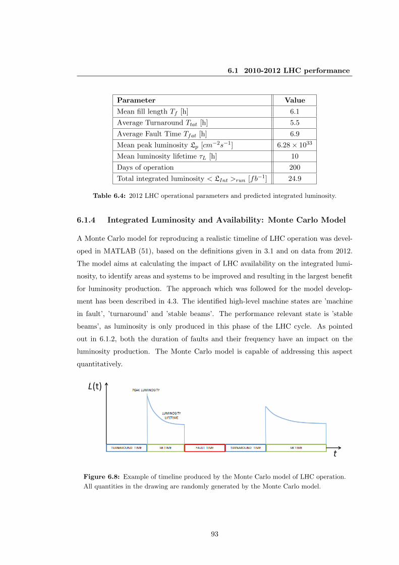
6.1 2010-2012 LHC performance
Parameter Value
Mean fill length Tf [h] 6.1
Average Turnaround Ttat [h] 5.5
Average Fault Time Tfat [h] 6.9
Mean peak luminosity Lp [cm−2s−1] 6.28 × 1033
Mean luminosity lifetime τL [h] 10
Days of operation 200
Total integrated luminosity < LInt >run [fb−1] 24.9
Table 6.4: 2012 LHC operational parameters and predicted integrated luminosity.
6.1.4 Integrated Luminosity and Availability: Monte Carlo Model
A Monte Carlo model for reproducing a realistic timeline of LHC operation was devel-
oped in MATLAB (51), based on the definitions given in 3.1 and on data from 2012.
The model aims at calculating the impact of LHC availability on the integrated lumi-
nosity, to identify areas and systems to be improved and resulting in the largest benefit
for luminosity production. The approach which was followed for the model develop-
ment has been described in 4.3. The identified high-level machine states are ’machine
in fault’, ’turnaround’ and ’stable beams’. The performance relevant state is ’stable
beams’, as luminosity is only produced in this phase of the LHC cycle. As pointed
out in 6.1.2, both the duration of faults and their frequency have an impact on the
luminosity production. The Monte Carlo model is capable of addressing this aspect
quantitatively.
Figure 6.8: Example of timeline produced by the Monte Carlo model of LHC operation.
All quantities in the drawing are randomly generated by the Monte Carlo model.
93
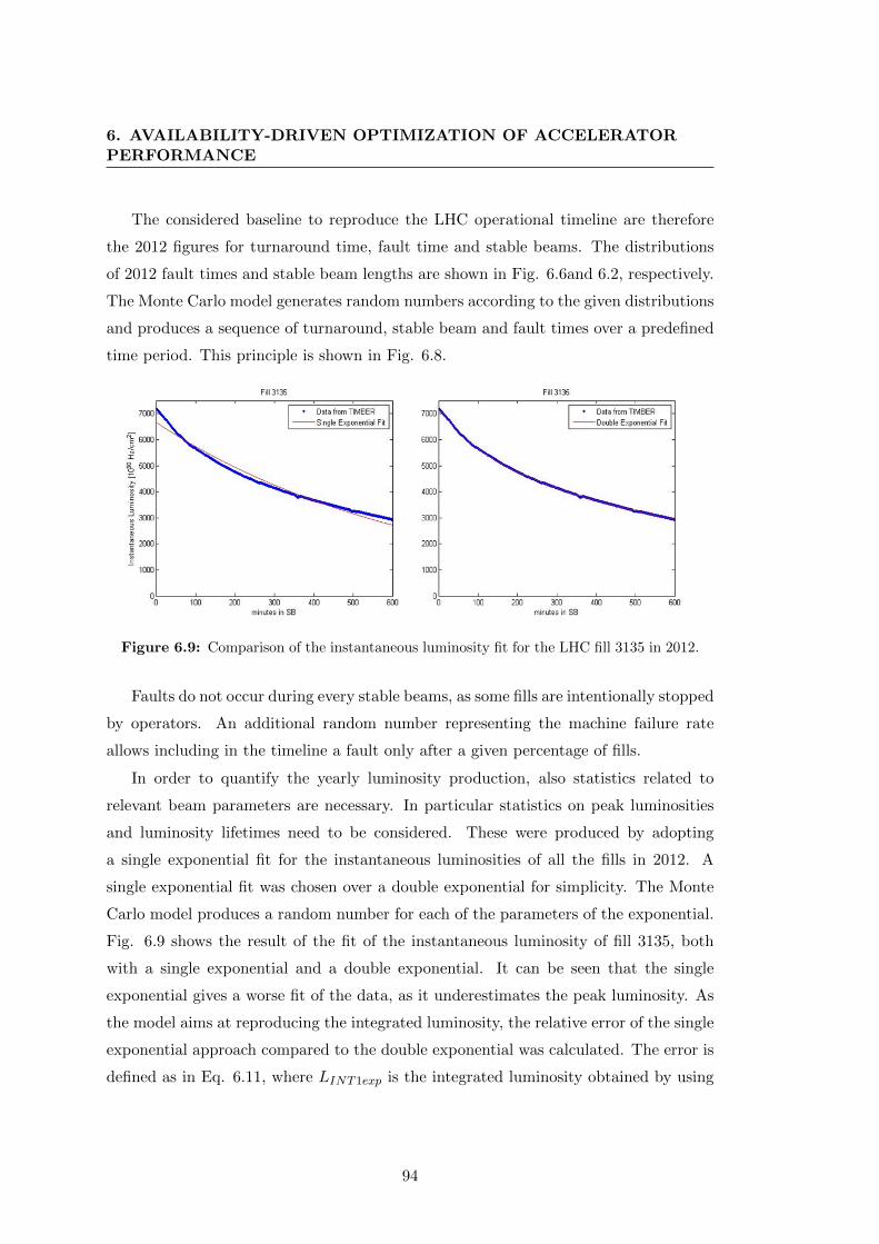
6. AVAILABILITY-DRIVEN OPTIMIZATION OF ACCELERATORPERFORMANCE
The considered baseline to reproduce the LHC operational timeline are therefore
the 2012 figures for turnaround time, fault time and stable beams. The distributions
of 2012 fault times and stable beam lengths are shown in Fig. 6.6and 6.2, respectively.
The Monte Carlo model generates random numbers according to the given distributions
and produces a sequence of turnaround, stable beam and fault times over a predefined
time period. This principle is shown in Fig. 6.8.
Figure 6.9: Comparison of the instantaneous luminosity fit for the LHC fill 3135 in 2012.
Faults do not occur during every stable beams, as some fills are intentionally stopped
by operators. An additional random number representing the machine failure rate
allows including in the timeline a fault only after a given percentage of fills.
In order to quantify the yearly luminosity production, also statistics related to
relevant beam parameters are necessary. In particular statistics on peak luminosities
and luminosity lifetimes need to be considered. These were produced by adopting
a single exponential fit for the instantaneous luminosities of all the fills in 2012. A
single exponential fit was chosen over a double exponential for simplicity. The Monte
Carlo model produces a random number for each of the parameters of the exponential.
Fig. 6.9 shows the result of the fit of the instantaneous luminosity of fill 3135, both
with a single exponential and a double exponential. It can be seen that the single
exponential gives a worse fit of the data, as it underestimates the peak luminosity. As
the model aims at reproducing the integrated luminosity, the relative error of the single
exponential approach compared to the double exponential was calculated. The error is
defined as in Eq. 6.11, where LINT1exp is the integrated luminosity obtained by using
94

6.1 2010-2012 LHC performance
a single exponential fit and LINT2exp using the double exponential.
ERRORREL =LINT1exp − LINT2exp
LINT1exp(6.11)
Figure 6.10: Relative error distribution of a single exponential fit of the integrated lumi-
nosity.
The histogram of the relative error is shown in Fig. 6.10 for all fills in 2012. It
can be seen that the error on the integrated luminosity is consistently below 1%. Two
peaks can be seen, one around 0% and one around -0.2%. Fig 6.9 illustrates that
for average stable beams durations (6 h), the underestimation of the peak luminosity
is approximately compensated by the overestimation of the instantaneous luminosity
towards the end of the fill, producing the peak around 0% in the error histogram. For
fills longer than 8 h, as the one in the figure, the fit underestimates the instantaneous
luminosity, leading to a negative relative error.
Results for a single exponential fit of all fills in 2012 are shown in Fig. 6.11. The
figure highlights the fast intensity ramp-up of 2012, going from fill 2450 to 2650. In this
phase, the total beam intensity was progressively increased from one fill to the next in
order to reach top beam performance in steps. It can be seen that after each of the three
technical stops (red dashed lines) few fills with lower intensities are injected in the LHC
before going back to maximum peak luminosities. The luminosity lifetime ranges from
95
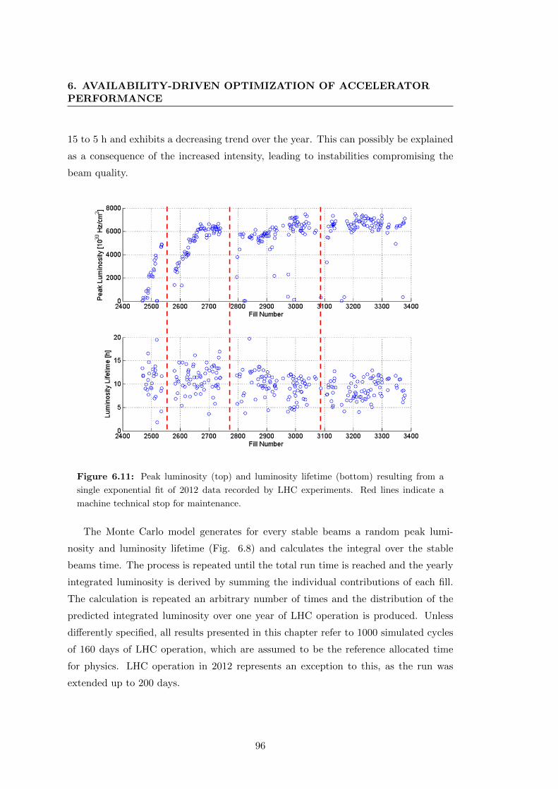
6. AVAILABILITY-DRIVEN OPTIMIZATION OF ACCELERATORPERFORMANCE
15 to 5 h and exhibits a decreasing trend over the year. This can possibly be explained
as a consequence of the increased intensity, leading to instabilities compromising the
beam quality.
Figure 6.11: Peak luminosity (top) and luminosity lifetime (bottom) resulting from a
single exponential fit of 2012 data recorded by LHC experiments. Red lines indicate a
machine technical stop for maintenance.
The Monte Carlo model generates for every stable beams a random peak lumi-
nosity and luminosity lifetime (Fig. 6.8) and calculates the integral over the stable
beams time. The process is repeated until the total run time is reached and the yearly
integrated luminosity is derived by summing the individual contributions of each fill.
The calculation is repeated an arbitrary number of times and the distribution of the
predicted integrated luminosity over one year of LHC operation is produced. Unless
differently specified, all results presented in this chapter refer to 1000 simulated cycles
of 160 days of LHC operation, which are assumed to be the reference allocated time
for physics. LHC operation in 2012 represents an exception to this, as the run was
extended up to 200 days.
96
6.1 2010-2012 LHC performance
The model was also extended to account for the possibility of performing luminosity
levelling in the early part of stable beams (92). This practice aims at overcoming the
limitations imposed by events pile-up, by providing to the LHC experiments a lower
luminosity than what could be theoretically achieved. Levelled operation has been
in use during the first run of the LHC for one of its experiments, LHCb. There are
proposals to adopt it also during LHC run 2 for some operational scenarios in view of
the HL-LHC era, when luminosity levelling will become a necessity. Several options
are available to implement such technique. One possibility is to start collisions with
a larger β∗ than what could be achieved. The latter is then decreased in a controlled
way during the fill. In this way the instantaneous luminosity stays constant for a given
period of time, after which the adopted compensation stops being effective, and the
natural exponential decay of the luminosity takes place. The duration of luminosity
levelling tlev can be approximately calculated as shown in Eq. 6.12, assuming that
the luminosity lifetime is mainly determined by particle burn-off. This assumption is
particularly oriented to HL-LHC operation.
Llev = Lpe− tlev
τ (6.12)
where Llev is the chosen value of instantaneous luminosity allowing to limit event
pile-up.
6.1.5 Model Validation against 2012 Operation
The Monte Carlo model was validated against 2012 operation to quantify the error
on the estimated yearly integrated luminosity (90). Distributions were produced for
the integrated luminosity, stable beams, fault and turnaround times over 1000 cycles
of the model to verify the correspondence of all relevant quantities related to machine
availability to observations. Results are presented in Fig. 6.12.
Table 6.5 shows the comparison of 2012 yearly figures with the average of the
corresponding simulated quantities. The model error for the prediction of integrated
luminosity amounts to 1%, which is acceptable for the purpose of this work, whose
focus is on identifying areas and systems for significant performance improvements and
major limitations for operation.
97
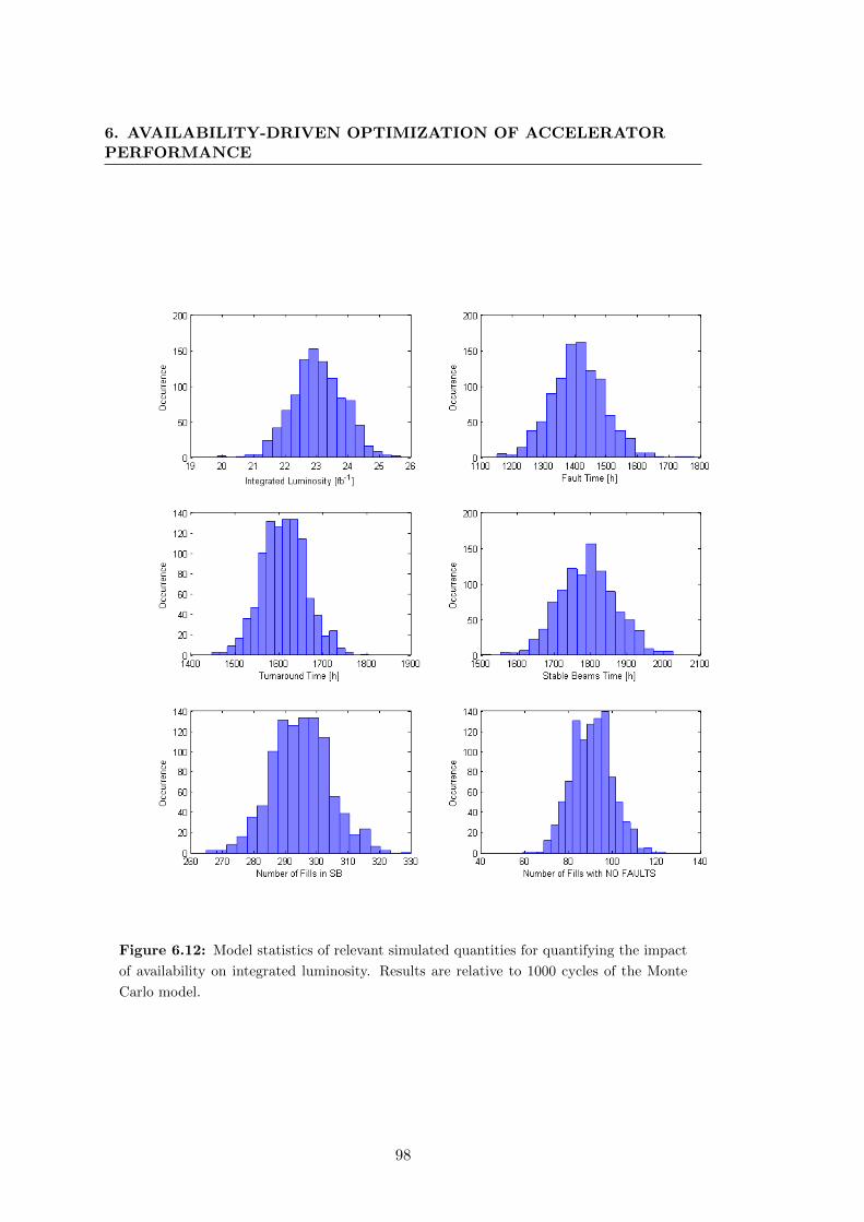
6. AVAILABILITY-DRIVEN OPTIMIZATION OF ACCELERATORPERFORMANCE
Figure 6.12: Model statistics of relevant simulated quantities for quantifying the impact
of availability on integrated luminosity. Results are relative to 1000 cycles of the Monte
Carlo model.
98

6.2 LHC performance for Post-LS1 operation
Quantity MeasuredSimulation
(Average)Error (%)
Integrated Luminosity [fb−1] 23.27 23.04 0.9
Total Fault Time [h] 1418 1410 0.6
Total Turnaround Time [h] 1612 1613 <0.1
Total Stable Beams Time [h] 1794 1791 0.2
Number of fills to Stable Bemas 295 295 <0.1
Number of fills with no faults 90 90 <0.1
Table 6.5: Comparison of 2012 observations with corresponding simulated quantities
through the Monte Carlo model of LHC operation.
6.2 LHC performance for Post-LS1 operation
6.2.1 Impact of Future Operational Scenarios
In 2012 the cryogenic system had the largest contribution to LHC downtime, though
the absolute number of failure events has been lower than for other systems. Cryogenic
stops have long recovery times, ranging from some hours to few days, with an average
of 9.6 h. After LS1 the resistive heat load as well as the synchrotron radiation levels
will increase significantly due to the higher energy (6.5 TeV), resulting in an operat-
ing point closer to design values. Failures of rotating machinery will have a higher
impact on availability. Furthermore it will take longer to recover operating conditions
after magnet quenches. Mitigation strategies for the cryogenic system consist in major
overhauls of rotating machinery, reinforcement of magnetic bearing controllers in the
cold compressors against electro-magnetic coupling and implementation of mitigations
against SEUs in point 2, 4 and 6 of the LHC.
A significant contribution to LHC downtime is caused by failures of the power
converters. A total of about 1700 power converters are used to feed LHC magnets. Re-
covery times are shorter than for the cryogenic system (the average fault time amounts
to 1.6 h), but failures are more frequent. A power converter for the LHC is composed
of two main blocks: a voltage source and a Function Generator Controller (FGC). The
voltage source is the main power part of the power converter. The task of the voltage
source is to receive the mains power and convert it to a suitable DC output voltage,
controlled by a reference input. The FGC executes a digital regulation loop, comparing
99

6. AVAILABILITY-DRIVEN OPTIMIZATION OF ACCELERATORPERFORMANCE
the reference value and the feedback on current measurements to calculate the appro-
priate control value for the voltage source periodically. Known failure modes have been
addressed during LS1 with dedicated solutions. In particular voltage sources are being
consolidated to be more reliable than during run 1. A project for the replacement of
the current power converter controllers (FGC2) was launched with the scope of having
a radiation-tolerant system in the future (FGClite (93)). This system will not be in
place for the restart of the LHC in 2015, but will be deployed before the second year
of run 2. When first deployed, care must be given to reduce failures caused by infant
mortalities of the new system, such that the machine availability will not be affected
significantly.
Also the Quench Protection System (QPS) caused in 2012 a high number of rel-
atively short stops (with an average fault time of 2.2 h). These were mainly due to
sensitivity of electronic components to radiation in exposed areas and to bad connec-
tions leading to spurious triggers of the quench detection electronics and the energy
extraction system. A campaign was launched to mitigate such effects: the relocation
of electronics in combination with the use of radiation-tolerant electronics should mit-
igate most of the radiation-induced faults. Cabling will be carefully checked before
the restart. In addition a remote-reset functionality has been implemented to mitigate
failure due to lost communication with quench detection electronics. These measures
should reduce the number of faults and the average fault time.
For all other LHC systems, consolidation of failure modes identified during run 1
has been carried out during the long shutdown 1 (5). In this respect, the philosophy
being followed is to first improve safety and then availability. As it is intuitive, the
increased number of interlock channels enhances the probability of having spurious
dumps. Therefore some of the consolidation measures could potentially reduce avail-
ability in order to ensure higher safety. An example is the LHC Beam Dumping System
(LBDS) retriggering line via the BIS, which will provide an independent means of trig-
gering a beam dump in case of a complete failure of the LBDS redundant triggering
(see 5.2.4). A dedicated study was performed to verify that the introduction of this
additional system would not affect availability (80). The study revealed in fact that the
overall impact on availability will be negligible. Another example is the implementation
of additional interlocking channels in the Software Interlock Systems (SIS), which were
not present during run 1. During run 2, the interlock for monitoring of the abort gap
100

6.2 LHC performance for Post-LS1 operation
population will ensure a clean abort gap, avoiding large particle losses during the rise
time of the LBDS kicker pulse.
Considering beam-related effects and availability, the extrapolation of observed
UFOs to 6.5-7 TeV forecasts up to 100 dumps per year after LS1 (45). The analy-
sis of UFO events in the first LHC run reveals that losses generated by dust particles
can be observed in the machine at particular locations (e.g. near the injection kicker
magnets). Such losses may not be above the BLM thresholds and therefore do not
necessarily cause a beam dump. The increasing beam energy will nevertheless strongly
enhance beam losses produced by dust particles. UFOs have shown a clear conditioning
trend during LHC run 1, however deconditioning is expected following the consolida-
tions in the machine vacuum segments. Relocation of BLMs to catch UFO events will
ensure maintaining a high level of protection while allowing to increase BLM thresh-
olds at the quadrupole locations (27). The redefinition of BLM thresholds, according
to recent studies on quench limits, should allow the right balance between detection of
dangerous events versus unnecessary LHC stops to be found. UFOs are an example of
a failure mode of the machine which was not taken into account in the design phase,
as it was believed that similar effects would not be observed in hadron machines.
6.2.2 Integrated Luminosity Predictions and Sensitivity Analyses
The Monte Carlo model was used to predict the achievable integrated luminosity during
LHC run 2 and 3, taking into account mitigations and operational constraints described
in 6.2.1.
Predictions for 2012-like availability The starting point of the analysis is rep-
resented by figures from 2012 (see 6.1.1). This assumption was made in the attempt
to describe stable and reproducible LHC operation. The presented results for run 2
are therefore to be intended for nominal LHC operation, starting from 2016. Full ex-
ploitation of 25 ns bunch spacing beams will be the primary goal of the 2015 run.
Standard beams, as well as high brightness beams, obtained by Batch Compression
bunch Merging and Splitting (BCMS (94)), could be used. The key parameters for
these two options are summarized in Table 6.6. For the BCMS option, the possibility
of reliable operation with 25 ns bunch spacing still has to be validated in 2015. In this
case, it is assumed to exploit luminosity levelling (92).
101
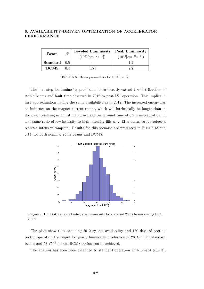
6. AVAILABILITY-DRIVEN OPTIMIZATION OF ACCELERATORPERFORMANCE
Beam β∗Leveled Luminosity
(1034[cm−2s−1])
Peak Luminosity
(1034[cm−2s−1])
Standard 0.5 - 1.2
BCMS 0.4 1.54 2.2
Table 6.6: Beam parameters for LHC run 2.
The first step for luminosity predictions is to directly extend the distributions of
stable beams and fault time observed in 2012 to post-LS1 operation. This implies in
first approximation having the same availability as in 2012. The increased energy has
an influence on the magnet current ramps, which will intrinsically be longer than in
the past, resulting in an estimated average turnaround time of 6.2 h instead of 5.5 h.
The same ratio of low-intensity to high-intensity fills as 2012 is taken, to reproduce a
realistic intensity ramp-up. Results for this scenario are presented in Fig.s 6.13 and
6.14, for both nominal 25 ns beams and BCMS.
Figure 6.13: Distribution of integrated luminosity for standard 25 ns beams during LHC
run 2.
The plots show that assuming 2012 system availability and 160 days of proton-
proton operation the target for yearly luminosity production of 28 fb−1 for standard
beams and 53 fb−1 for the BCMS option can be achieved.
The analysis has then been extended to standard operation with Linac4 (run 3),
102

6.2 LHC performance for Post-LS1 operation
Figure 6.14: Distribution of integrated luminosity for BCMS beams during LHC run 2.
assuming the beam parameters shown in Table 6.7. The predicted integrated luminosity
during run 3 amounts to 53 fb−1 (Fig. 6.15). It can be observed that operation with
Linac4 and with BCMS beams yields very similar outcomes in terms of luminosity
production, as reported in (95).
Beam β∗Leveled Luminosity
(1034[cm−2s−1])
Peak Luminosity
(1034[cm−2s−1])
Standard
Linac40.4 1.65 2.1
Table 6.7: Beam parameters for LHC run 3 with Linac4 operation.
Extension of 2012 figures for future LHC operation The distributions derived
in 2012 are a good starting point for the analysis of future scenarios. An extension of
these distributions is considered to account for the efforts invested in the mitigation of
failure modes affecting LHC run 1. Furthermore, the impact of new beam parameters
on previously observed phenomena, as e.g. UFOs and R2E, has to be considered.
The distribution of R2E-induced downtime was shown in Fig. 6.7 for 2012. Consid-
ering LS1 mitigations and future system upgrades, the number of R2E-induced faults
103
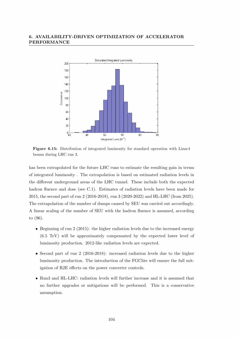
6. AVAILABILITY-DRIVEN OPTIMIZATION OF ACCELERATORPERFORMANCE
Figure 6.15: Distribution of integrated luminosity for standard operation with Linac4
beams during LHC run 3.
has been extrapolated for the future LHC runs to estimate the resulting gain in terms
of integrated luminosity . The extrapolation is based on estimated radiation levels in
the different underground areas of the LHC tunnel. These include both the expected
hadron fluence and dose (see C.1). Estimates of radiation levels have been made for
2015, the second part of run 2 (2016-2018), run 3 (2020-2022) and HL-LHC (from 2025).
The extrapolation of the number of dumps caused by SEU was carried out accordingly.
A linear scaling of the number of SEU with the hadron fluence is assumed, according
to (96).
• Beginning of run 2 (2015): the higher radiation levels due to the increased energy
(6.5 TeV) will be approximately compensated by the expected lower level of
luminosity production. 2012-like radiation levels are expected.
• Second part of run 2 (2016-2018): increased radiation levels due to the higher
luminosity production. The introduction of the FGClite will ensure the full mit-
igation of R2E effects on the power converter controls.
• Run3 and HL-LHC: radiation levels will further increase and it is assumed that
no further upgrades or mitigations will be performed. This is a conservative
assumption.
104
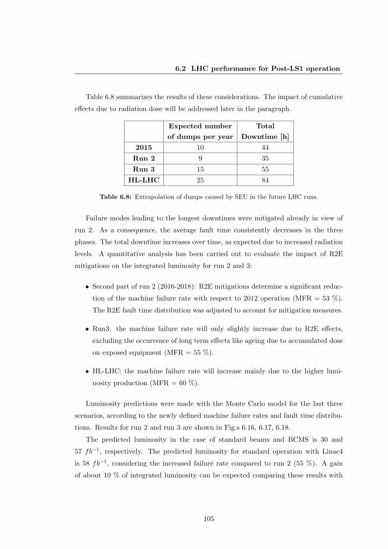
6.2 LHC performance for Post-LS1 operation
Table 6.8 summarizes the results of these considerations. The impact of cumulative
effects due to radiation dose will be addressed later in the paragraph.
Expected number
of dumps per year
Total
Downtime [h]
2015 10 44
Run 2 9 35
Run 3 15 55
HL-LHC 25 84
Table 6.8: Extrapolation of dumps caused by SEU in the future LHC runs.
Failure modes leading to the longest downtimes were mitigated already in view of
run 2. As a consequence, the average fault time consistently decreases in the three
phases. The total downtime increases over time, as expected due to increased radiation
levels. A quantitative analysis has been carried out to evaluate the impact of R2E
mitigations on the integrated luminosity for run 2 and 3:
• Second part of run 2 (2016-2018): R2E mitigations determine a significant reduc-
tion of the machine failure rate with respect to 2012 operation (MFR = 53 %).
The R2E fault time distribution was adjusted to account for mitigation measures.
• Run3: the machine failure rate will only slightly increase due to R2E effects,
excluding the occurrence of long term effects like ageing due to accumulated dose
on exposed equipment (MFR = 55 %).
• HL-LHC: the machine failure rate will increase mainly due to the higher lumi-
nosity production (MFR = 60 %).
Luminosity predictions were made with the Monte Carlo model for the last three
scenarios, according to the newly defined machine failure rates and fault time distribu-
tions. Results for run 2 and run 3 are shown in Fig.s 6.16, 6.17, 6.18.
The predicted luminosity in the case of standard beams and BCMS is 30 and
57 fb−1, respectively. The predicted luminosity for standard operation with Linac4
is 58 fb−1, considering the increased failure rate compared to run 2 (55 %). A gain
of about 10 % of integrated luminosity can be expected comparing these results with
105
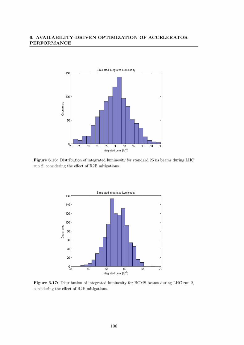
6. AVAILABILITY-DRIVEN OPTIMIZATION OF ACCELERATORPERFORMANCE
Figure 6.16: Distribution of integrated luminosity for standard 25 ns beams during LHC
run 2, considering the effect of R2E mitigations.
Figure 6.17: Distribution of integrated luminosity for BCMS beams during LHC run 2,
considering the effect of R2E mitigations.
106

6.2 LHC performance for Post-LS1 operation
Figure 6.18: Distribution of integrated luminosity for standard operation with Linac4
beams during LHC run 3, considering the effect of R2E mitigations.
the ones obtained using 2012-like distributions. A direct comparison on luminosity
production for the different scenarios can be found in Table 6.9.
Integrated Luminosity
(2012 availability)
Integrated Luminosity
(R2E mitigations)
Run 2 (std) 28 fb−1 30 fb−1
Run 2 (BCMS) 53 fb−1 57 fb−1
Run 3 (std + Linac4) 53 fb−1 58 fb−1
Table 6.9: Extrapolation of dumps caused by SEU in the future LHC runs.
The predicted gain obtained from R2E mitigations is considered to be a conservative
estimate. R2E effects are more likely to be observed in the early part of stable beams,
when higher peak luminosity leads to higher radiation, causing a more significant loss
of luminosity. Considering this aspect, R2E mitigations could lead to an additional
gain in terms of luminosity production.
In addition to this study, a qualitative analysis of the impact of fault frequency and
fault time on integrated luminosity can be carried out with the Monte Carlo model.
This allows reproducing qualitatively the results obtained with the detailed R2E fault
data analysis and making extrapolations for other availability-relevant scenarios. A
107
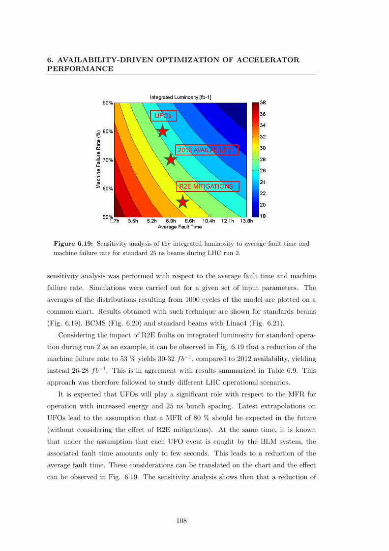
6. AVAILABILITY-DRIVEN OPTIMIZATION OF ACCELERATORPERFORMANCE
Figure 6.19: Sensitivity analysis of the integrated luminosity to average fault time and
machine failure rate for standard 25 ns beams during LHC run 2.
sensitivity analysis was performed with respect to the average fault time and machine
failure rate. Simulations were carried out for a given set of input parameters. The
averages of the distributions resulting from 1000 cycles of the model are plotted on a
common chart. Results obtained with such technique are shown for standards beams
(Fig. 6.19), BCMS (Fig. 6.20) and standard beams with Linac4 (Fig. 6.21).
Considering the impact of R2E faults on integrated luminosity for standard opera-
tion during run 2 as an example, it can be observed in Fig. 6.19 that a reduction of the
machine failure rate to 53 % yields 30-32 fb−1, compared to 2012 availability, yielding
instead 26-28 fb−1. This is in agreement with results summarized in Table 6.9. This
approach was therefore followed to study different LHC operational scenarios.
It is expected that UFOs will play a significant role with respect to the MFR for
operation with increased energy and 25 ns bunch spacing. Latest extrapolations on
UFOs lead to the assumption that a MFR of 80 % should be expected in the future
(without considering the effect of R2E mitigations). At the same time, it is known
that under the assumption that each UFO event is caught by the BLM system, the
associated fault time amounts only to few seconds. This leads to a reduction of the
average fault time. These considerations can be translated on the chart and the effect
can be observed in Fig. 6.19. The sensitivity analysis shows then that a reduction of
108

6.2 LHC performance for Post-LS1 operation
Figure 6.20: Sensitivity analysis of the integrated luminosity to average fault time and
machine failure rate for BCMS beams during LHC run 2.
Figure 6.21: Sensitivity analysis of the integrated luminosity to average fault time and
machine failure rate for standard beams with Linac4 during LHC run 3.
109

6. AVAILABILITY-DRIVEN OPTIMIZATION OF ACCELERATORPERFORMANCE
the integrated luminosity of up to 10 % can be expected due to the increased UFO
rate.
A realistic scenario for future LHC operation must account for both the reduced
impact of SEUs and increased number of UFO events. Considering these two factors, a
2012-like availability could be achieved during run 2. The challenges to be faced have
been discussed in 6.2.1.
During run 3, the effects of ageing due to cumulative radiation effects could start
to be observed in the machine. If the maximum tolerated dose would be reached for
a given equipment, then several failures have to be expected in a very short time.
This can be interpreted in the sensitivity analysis as a sudden increase of the machine
failure rate (e.g. by 10 %). Fig. 6.21 shows a consequent reduction of about 10 % of
the integrated luminosity, assuming no major impact on the average fault time. This is
reasonable in case of failures regarding electronic systems for which a sufficient number
of spare parts is available.
6.2.3 Integrated Luminosity Optimization through Availability
The limitations imposed by the event pile-up in the experiments justify the efforts
invested for improving system availability. In this section it will be shown that given
a certain level of availability, a further gain in terms of integrated luminosity can be
achieved by optimizing the time in stable beams. This aspect is particularly relevant
when dealing with leveled operation. The exploitation of luminosity levelling ensures
that luminosity production is still effective even after several hours in stable beams.
It is intuitive that in this case luminosity production would benefit from longer stable
beams. Luminosity optimization based on measured availability and time in stable
beams becomes then a relevant aspect for improving the performance.
The ideal time to be spent in stable beams can be found by applying a constrained
nonlinear optimization algorithm to the integrated luminosity. Such an algorithm has
been developed in MATLAB (51) to determine the optimum number of fills and stable
beams. The algorithm takes as inputs the average turnaround time, the average fault
time and the machine failure rate. As beam parameters the peak luminosity and the lu-
minosity lifetime are considered. Constraints are set to model the desired dependencies
among these variables and the parameters to optimize.
110

6.2 LHC performance for Post-LS1 operation
Six ’abstract scenarios’ with different assumptions for the input parameters were
defined and the maximum achievable integrated luminosity calculated, assuming BCMS
as an operational baseline and 160 days of operation:
1. Optimized luminosity without machine faults, i.e. the maximum achievable lu-
minosity; (machine failure rate = 0 %, turnaround time =4 h)
2. Optimized luminosity including external faults, i.e. faults out of CERNs control
(e.g. electrical network) (machine failure rate = 0.08 %, turnaround time = 4 h,
fault time = 2.7 h)
3. Optimized luminosity with figures from 2012 (machine failure rate = 70 %,
turnaround time = 6.2 h, fault time = 7 h)
4. Optimized luminosity in case all machine faults would require no access in the
tunnel to be solved (machine failure rate = 70 %, turnaround time = 6.2 h, fault
time = 1 h)
5. Optimized luminosity in case all machine faults would require one access (machine
failure rate = 70 %, turnaround time = 6.2 h, fault time = 4 h)
6. Optimized luminosity in case all machine faults would require major interventions
(machine failure rate = 70 %, turnaround time = 6.2 h, fault time = 12 h)
The results for these six scenarios are summarized in Table 6.10. It shows the
maximum achievable integrated luminosity for optimized stable beams lengths. In all
scenarios it is assumed to have 2.1 h of levelling, followed by the natural exponential
decay of the luminosity. The optimization is only applied to fills which are intentionally
aborted by operators. These results exhibit purely theoretical values, as such optimiza-
tion can be performed only after measuring fault distributions that occurred during the
run. Every time a fault occurs during operation, the optimum working point in terms
of ideal stable beams length changes. The latter becomes longer with increasing fault
times, as could be assumed intuitively.
Nevertheless, the optimization algorithm could be used to assist daily LHC oper-
ation. It could provide to LHC operators the necessary information to dynamically
optimize luminosity by acting on the duration of stable beams. In order to verify
111
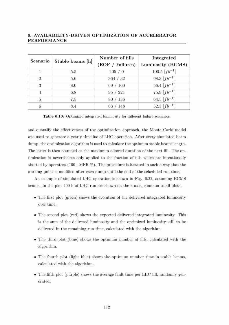
6. AVAILABILITY-DRIVEN OPTIMIZATION OF ACCELERATORPERFORMANCE
Scenario Stable beams [h]Number of fills
(EOF / Failures)
Integrated
Luminosity (BCMS)
1 5.5 405 / 0 100.5 [fb−1]
2 5.6 364 / 32 98.3 [fb−1]
3 8.0 69 / 160 56.4 [fb−1]
4 6.8 95 / 221 75.9 [fb−1]
5 7.5 80 / 186 64.5 [fb−1]
6 8.4 63 / 148 52.3 [fb−1]
Table 6.10: Optimized integrated luminosity for different failure scenarios.
and quantify the effectiveness of the optimization approach, the Monte Carlo model
was used to generate a yearly timeline of LHC operation. After every simulated beam
dump, the optimization algorithm is used to calculate the optimum stable beams length.
The latter is then assumed as the maximum allowed duration of the next fill. The op-
timization is nevertheless only applied to the fraction of fills which are intentionally
aborted by operators (100 - MFR %). The procedure is iterated in such a way that the
working point is modified after each dump until the end of the scheduled run-time.
An example of simulated LHC operation is shown in Fig. 6.22, assuming BCMS
beams. In the plot 400 h of LHC run are shown on the x-axis, common to all plots.
• The first plot (green) shows the evolution of the delivered integrated luminosity
over time.
• The second plot (red) shows the expected delivered integrated luminosity. This
is the sum of the delivered luminosity and the optimized luminosity still to be
delivered in the remaining run time, calculated with the algorithm.
• The third plot (blue) shows the optimum number of fills, calculated with the
algorithm.
• The fourth plot (light blue) shows the optimum number time in stable beams,
calculated with the algorithm.
• The fifth plot (purple) shows the average fault time per LHC fill, randomly gen-
erated.
112

6.2 LHC performance for Post-LS1 operation
Figure 6.22: Simulated timeline of LHC operation with BCMS beams.
113

6. AVAILABILITY-DRIVEN OPTIMIZATION OF ACCELERATORPERFORMANCE
After 400 h, 6 fb−1 have already been delivered (green). The prediction for the
optimized luminosity (red) yields 65 fb−1 to be produced in total in 160 days, if 180
stable beams could be reached (blue) and aiming to dump the beam after 13-14 h
(light blue) for optimization. The optimum number of fills (blue) tends to zero, as it
is function of the remaining run time. The optimum time in stable beams consistently
increases with the average fault time, as intuitively longer stable beams are desirable
with longer fault times. This can be observed in particular at the beginning of the run,
when the fault time amounts to 3 h, leading to 15 h of ideal stable beams duration.
The next failure brings the average fault time to 5 h, which increases the optimum time
in stable beams and significantly worsens the expected luminosity production (about
50 fb−1).
A quantification of the gain that could be achieved by performing online optimiza-
tion of stable beams during LHC operation has been carried out.
1. Considering 2012-like availability and BCMS beams, an integrated luminosity of
53 fb−1 was predicted (Table 6.9). Applying the optimization for 2012 availability
allows reaching 55 fb−1, yielding a gain of about 3.5 % of integrated luminosity.
2. Considering a machine failure rate of 53 % (i.e. is taking into account R2E
mitigations), an integrated luminosity of 57 fb−1 was predicted (Table 6.9). Ap-
plying the optimization allows reaching 62 fb−1, yielding a gain of about 9 % of
integrated luminosity.
As expected, the effectiveness of the optimization is enhanced for a lower machine
failure rate, as this implies that the number of fills to be optimized by the operators
increases.
6.3 LHC performance in the High-Luminosity era
6.3.1 Impact of Future Operational Scenarios
The CERN HL-LHC era will start in 2025, setting unprecedented targets in terms of
integrated luminosity and availability for a circular collider. The HL-LHC goal is to
provide to the LHC experiments 250-300 fb−1 per year. For ultimate HL-LHC beam
114

6.3 LHC performance in the High-Luminosity era
parameters, the integrated luminosity could go up to 400 fb−1 per year. A major series
of upgrades is foreseen in order to achieve this challenging target.
Firstly, in order to overcome the limits imposed by event pile-up, the experiments
will be substantially upgraded. The maximum pile-up of the detectors during run 1 has
been set from design to 25. Upgrades will ensure an improvement up to a pile-up of 140
(97) (98). This will be achieved by improved performance of both particle detectors
and read-out electronics.
From the accelerator perspective, the superconducting triplets close to the main
experiments will be replaced by Nb3Sn triplets. The triplets currently in use in the
LHC were designed for a total integrated dose of 300 fb−1, which will be reached by
2023.
Advanced collimator designs and materials (e.g. Molybdenum-Graphite) are under
study to cope with the increased power stored in the beam halo.
An innovative concept will be used for improving beam collisions. The beams are
normally put into collisions introducing a deflection in their orbit by a certain angle,
called the crossing angle. This implies that due to the geometry of the collisions, the
beams are not fully overlapping at the interaction points. A so-called geometric factor
is used in the calculation of luminosity to account for this effect. The crab cavities (17)
are capable of tilting the beam close to the interaction point to ensure an optimized
overlap of colliding bunches. The original beam configuration is then restored to match
the LHC lattice.
Reaching increased luminosity will have a significant impact on the thermal load on
the superconducting magnets at the interaction points. New cryo-plants will therefore
be installed to decouple such magnets from the rest of the sector. Similarly, the super-
conducting cavities in the LHC point 4 will also be decoupled from the sector cryogenic
system.
The introduction of new systems and particularly of the crab cavities may have
strong implications on the MPS. New strategies to cope with new possible failure modes
are already under discussion (99) to keep the same level of safety of the current LHC. On
one hand additional monitoring and protection for the new systems is needed to prevent
major consequences in case of failures (preserving availability). On the other hand
the introduction of additional systems and their monitoring implies the possibility of
introducing new sources of false dumps, with a potential impact on the total downtime
115

6. AVAILABILITY-DRIVEN OPTIMIZATION OF ACCELERATORPERFORMANCE
(affecting availability). Managing new systems and the related protection is the main
concern in view of HL-LHC also in terms of availability.
Beam performance of HL-LHC will also play a significant role with respect to avail-
ability. Luminosity leveling, aiming at the increase of integrated luminosity by the
extension of the time in collisions, will be the baseline for HL-LHC operation. Leveling
is possible thanks to high beam intensities and will lead to higher integrated luminosity
than in the past, both factors that directly affect radiation levels in the LHC tunnel.
It has been estimated that in specific areas a factor 20 higher hadron fluence should
be expected for ultimate HL-LHC parameters, leading to 25-40 dumps per year due
to R2E, in case no additional mitigations will be deployed after the Long Shutdown
3 (6.8). For example, it is already under consideration that certain power converters
could be relocated and moved from the tunnel to the surface areas to prevent R2E-
induced faults. This entails the necessity of designing superconducting links from the
power converters to the magnets (19).
The aforementioned factors imply that increasing the availability for physics will
be challenging, but crucial for reaching the HL-LHC goals. As shown in this thesis,
this can only be achieved by the combined reduction of the fault frequency and time.
For some systems the fault time is imposed by physical constraints. For the cryogenic
system for example, the recovery from a quench at 7 TeV takes around 12 h. Electronic
systems have instead significant margins for improvement for what regards the fault
time, for example by the enhancement of remote diagnostics and reset capabilities in
case of false dumps.
For the reduction of the fault frequency, efforts will be required for the design of
even more reliable systems. Considering R2E failures for example, effective measures as
relocation of equipment, shielding and use of radiation tolerant components have been
already applied during LS1 (100) and will have to be enforced in the future. As shown
in 5.2, detailed studies on advanced architectures for the next generation of interlock
systems would allow significant improvements in terms of availability. Obsolescence of
components, especially for electronic systems designed in 2005 and before, may become
an issue when approaching the HL-LHC era. Management of spare parts to cope with
the onset of component wear-out should be carefully evaluated to ensure a sufficient
stock of spares parts while still commercially available.
116
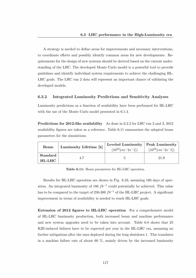
6.3 LHC performance in the High-Luminosity era
A strategy is needed to define areas for improvements and necessary interventions,
to coordinate efforts and possibly identify common areas for new developments. Re-
quirements for the design of new systems should be derived based on the current under-
standing of the LHC. The developed Monte Carlo model is a powerful tool to provide
guidelines and identify individual system requirements to achieve the challenging HL-
LHC goals. The LHC run 2 data will represent an important chance of validating the
developed models.
6.3.2 Integrated Luminosity Predictions and Sensitivity Analyses
Luminosity predictions as a function of availability have been performed for HL-LHC
with the use of the Monte Carlo model presented in 6.1.4.
Predictions for 2012-like availability As done in 6.2.2 for LHC run 2 and 3, 2012
availability figures are taken as a reference. Table 6.11 summarizes the adopted beam
parameters for the simulations.
Beam Luminosity Lifetime [h]Leveled Luminosity
(1034[cm−2s−1])
Peak Luminosity
(1034[cm−2s−1])
Standard
HL-LHC4.7 5 21.9
Table 6.11: Beam parameters for HL-LHC operation.
Results for HL-LHC operation are shown in Fig. 6.23, assuming 160 days of oper-
ation. An integrated luminosity of 186 fb−1 could potentially be achieved. This value
has to be compared to the target of 250-300 fb−1 of the HL-LHC project. A significant
improvement in terms of availability is needed to reach HL-LHC goals.
Extension of 2012 figures to HL-LHC operation For a comprehensive model
of HL-LHC luminosity production, both increased beam and machine performance
and new system upgrades need to be taken into account. Table 6.8 shows that 25
R2E-induced failures have to be expected per year in the HL-LHC era, assuming no
further mitigations after the ones deployed during the long shutdown 1. This translates
in a machine failure rate of about 60 %, mainly driven by the increased luminosity
117
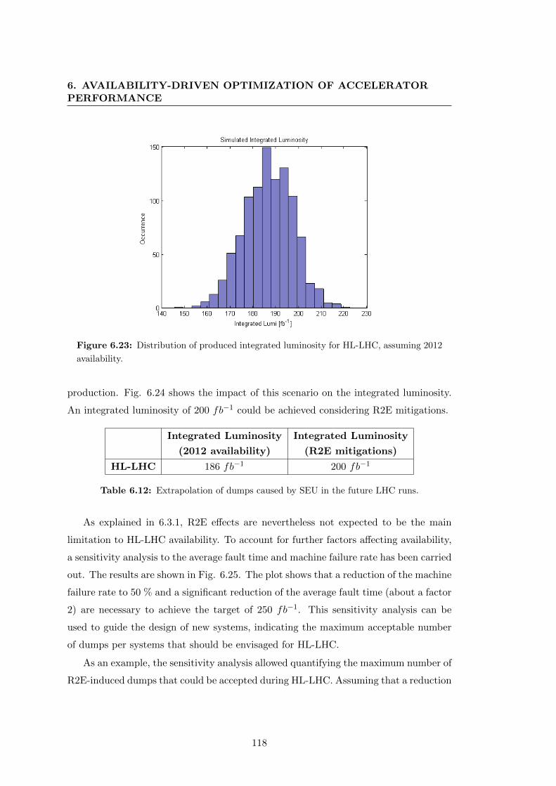
6. AVAILABILITY-DRIVEN OPTIMIZATION OF ACCELERATORPERFORMANCE
Figure 6.23: Distribution of produced integrated luminosity for HL-LHC, assuming 2012
availability.
production. Fig. 6.24 shows the impact of this scenario on the integrated luminosity.
An integrated luminosity of 200 fb−1 could be achieved considering R2E mitigations.
Integrated Luminosity
(2012 availability)
Integrated Luminosity
(R2E mitigations)
HL-LHC 186 fb−1 200 fb−1
Table 6.12: Extrapolation of dumps caused by SEU in the future LHC runs.
As explained in 6.3.1, R2E effects are nevertheless not expected to be the main
limitation to HL-LHC availability. To account for further factors affecting availability,
a sensitivity analysis to the average fault time and machine failure rate has been carried
out. The results are shown in Fig. 6.25. The plot shows that a reduction of the machine
failure rate to 50 % and a significant reduction of the average fault time (about a factor
2) are necessary to achieve the target of 250 fb−1. This sensitivity analysis can be
used to guide the design of new systems, indicating the maximum acceptable number
of dumps per systems that should be envisaged for HL-LHC.
As an example, the sensitivity analysis allowed quantifying the maximum number of
R2E-induced dumps that could be accepted during HL-LHC. Assuming that a reduction
118
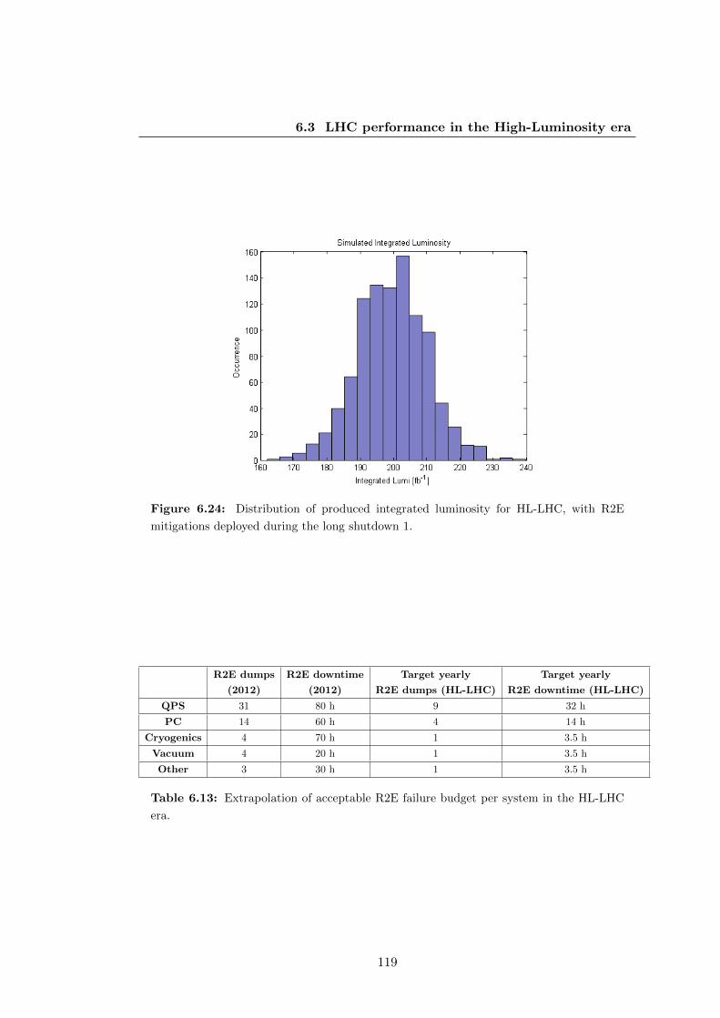
6.3 LHC performance in the High-Luminosity era
Figure 6.24: Distribution of produced integrated luminosity for HL-LHC, with R2E
mitigations deployed during the long shutdown 1.
R2E dumps
(2012)
R2E downtime
(2012)
Target yearly
R2E dumps (HL-LHC)
Target yearly
R2E downtime (HL-LHC)
QPS 31 80 h 9 32 h
PC 14 60 h 4 14 h
Cryogenics 4 70 h 1 3.5 h
Vacuum 4 20 h 1 3.5 h
Other 3 30 h 1 3.5 h
Table 6.13: Extrapolation of acceptable R2E failure budget per system in the HL-LHC
era.
119
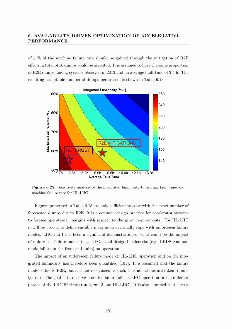
6. AVAILABILITY-DRIVEN OPTIMIZATION OF ACCELERATORPERFORMANCE
of 5 % of the machine failure rate should be gained through the mitigation of R2E
effects, a total of 16 dumps could be accepted. It is assumed to have the same proportion
of R2E dumps among systems observed in 2012 and an average fault time of 3.5 h. The
resulting acceptable number of dumps per system is shown in Table 6.13.
Figure 6.25: Sensitivity analysis of the integrated luminosity to average fault time and
machine failure rate for HL-LHC.
Figures presented in Table 6.13 are only sufficient to cope with the exact number of
forecasted dumps due to R2E. It is a common design practice for accelerator systems
to foresee operational margins with respect to the given requirements. For HL-LHC
it will be crucial to define suitable margins to eventually cope with unforeseen failure
modes. LHC run 1 has been a significant demonstration of what could be the impact
of unforeseen failure modes (e.g. UFOs) and design bottlenecks (e.g. LBDS common
mode failure in the front-end units) on operation.
The impact of an unforeseen failure mode on HL-LHC operation and on the inte-
grated luminosity has therefore been quantified (101). It is assumed that the failure
mode is due to R2E, but it is not recognized as such, thus no actions are taken to mit-
igate it. The goal is to observe how this failure affects LHC operation in the different
phases of the LHC lifetime (run 2, run 3 and HL-LHC). It is also assumed that such a
120
6.3 LHC performance in the High-Luminosity era
failure would be discovered during LHC run 2. The impact on luminosity was derived
with the following procedure:
• Considering up to a factor 20 higher hadron fluence for ultimate HL parameters,
this failure could translate into 20 failures during HL-LHC operation.
• The downtime due to R2E stops in 2012 ranged from 30 minutes to 30 h.
• A potential of 10 h (20 failures, each 30 min long) to 600 h (20 failures, each 30
h long) of lost time due to this failure is found.
• HL-LHC aims at 300 fb−1 over 160 days of operation, i.e. 1.9 fb−1 per day.
• The lost luminosity would be between 0.8 fb−1 (1.9 fb−1 * 10 h) and 47 fb−1
(1.9 fb−1 * 600 h).
• The lost luminosity for an average R2E stop (3.5 h) would amount to 5.5 fb−1.
Figures and predictions shown in this paragraph are based on the current knowl-
edge on future system designs and upgrades, and are therefore subject to uncertainties
depending on design changes. Nevertheless the model shows that a consistent and co-
ordinated effort to address availability as a key requirement for future operation is vital
to reach the challenging goals of the HL-LHC project.
6.3.3 Integrated Luminosity Optimization through Availability
In 6.2.3 the outcome of the application of availability optimization on integrated lu-
minosity was presented for BCMS beams. Similarly, it is interesting to quantify what
could be the gain for HL-LHC operation. Fig. 6.26 shows an example of online opti-
mization of stable beams duration for HL-LHC.
After 400 h, about 35 fb−1 have been produced in the simulation, with a predicted
total luminosity production of about 210 fb−1. After few hours of run, a long stop
occurs (about 1 day) leading to a sudden increase of the average fault time. This
results in a drastic reduction of the expected luminosity, from 300 fb−1 to 200 fb−1,
having also an effect on the optimum stable beams duration. The latter consistently
increases to cope with longer faults.
121

6. AVAILABILITY-DRIVEN OPTIMIZATION OF ACCELERATORPERFORMANCE
Figure 6.26: Simulated timeline of HL-LHC operation.
122

6.3 LHC performance in the High-Luminosity era
It is expected that optimization of stable beams length for HL-LHC should be even
more effective than for the BCMS case, as luminosity leveling could be exploited for up
to 6 hours. The Monte-Carlo model in combination with the optimization algorithm
was used to quantify the gain that could be obtained by optimizing the time in stable
beams.
1. Considering 2012-like availability and BCMS beams, an integrated luminosity
of 186 fb−1 was predicted (Table 6.12). Applying the optimization for 2012
availability allows reaching 196 fb−1, yielding a gain of about 5 % of integrated
luminosity.
2. Considering a machine failure rate of 60 % (i.e. is taking into account R2E
mitigations), an integrated luminosity of 200 fb−1 was predicted (Table 6.12).
Applying the optimization allows reaching 227 fb−1, yielding a gain of about 13
% of integrated luminosity.
These results confirm that for longer luminosity leveling times, the optimization
of stable beams duration will be even more effective (see 6.2.3 for comparison). Such
operational aspect will therefore be one of the important factors to take into account
while aiming at 300 fb−1. Reaching ideal fill lengths both by tuning the duration of
stable beams and reducing the turnaround time will bring a significant increase of the
yearly integrated luminosity.
123

6. AVAILABILITY-DRIVEN OPTIMIZATION OF ACCELERATORPERFORMANCE
124

7
Conclusions and Outlook
Availability is becoming a key figure of merit in the design of particle accelerators. The
potential for new discoveries of accelerators depends on both peak beam performance
and integrated time for data production for the experiments, i.e. on machine avail-
ability. High-power particle accelerators require the presence of Machine Protection
Systems (MPS) to prevent damage resulting from the uncontrolled release of energy
stored in the beam and in the magnet powering system. The MPS monitor relevant
parameters and inhibit accelerator operation in case of detection of dangerous condi-
tions. The huge complexity of systems interfacing with the MPS, as well as that of the
MPS itself, can lead to spurious failures, resulting in the interruption of beam operation
(false failures). Therefore the MPS on one hand preserve availability by mitigating or
anticipating the impact of machine failures, while on the other contribute to decrease
availability due to the false detection of dangerous conditions. The priority of the MPS
is to protect the accelerator and its assets, therefore the architecture of MPS has to be
fail safe. A failure of the MPS must always result in an action bringing the machine
to a safe state. At the same time the number of spurious failures has to be minimized.
Once having consolidated procedures and reproducible operation, the focus shifts on
optimising the availability. The design of MPS should follow a top-down approach in
order to identify all possible sources of unsafety. These do not necessarily result from
individual system or component failures, but can be produced by unforeseen interac-
tions among software, hardware systems and humans. A top-down approach is more
suitable to account for the combination of these elements during the design phase,
to derive requirements and constraints for system behaviour. In this thesis a novel
125

7. CONCLUSIONS AND OUTLOOK
method to study complex systems (STPA (53)) has been used to derive availability
requirements for a linear accelerator, Linac4, currently under construction at CERN.
The advantage of this method over traditional hazard analyses relies on the possibility
of addressing different aspects of safety-driven design with a single procedure. The
thesis shows that the possible sources of un-availability during accelerator operation
derive from very different causal factors. As an example, unavailability can be due
to a malfunction of accelerator equipment, as well as to an unnecessary beam abort
triggered in the control room by an inexperienced operator. A complete analysis of
such causal factors was carried out and will allow for availability optimization during
operation.
Linac4 will be the first element of the CERN’s injector complex, starting from 2019.
All accelerators will rely on beams provided by Linac4, therefore high availability is the
crucial requirement to be addressed. The definition of the Linac4 MPS architecture
has been carried out taking into account the outcomes of the STPA study. The thesis
describes in detail the architecture of the Linac4 Beam Interlock System (BIS), based
on a so-called tree structure. Equipment protection is ensured by diverse redundancy of
the BIS actuators, which stop the beam in case a failure is detected. High availability is
instead enhanced by a dedicated system, the so-called External Conditions, which allow
to dynamically optimize the beam delivery to different destinations. If one destination is
not available but is supposed to receive beam from Linac4 in a given cycle, then another
available destination is calculated and the corresponding cycle executed instead. This
ensures maximizing the exploitation of all destinations.
Considering the similarities in the layout, but also the significant differences of the
beam parameters, the interlocking strategy for the ESS is also discussed in the thesis.
ESS is a user-oriented facility with strict requirements in terms of availability. User
experiments can perform valuable measurements only if continuous beam is delivered
to the target. The downtime of the facility has therefore to be minimized. This requires
highly dependable MPS to prevent any damage-induced downtime caused by a sudden
loss of the proton beam (5 MW average power per pulse). Furthermore, the downtime
can be reduced by designing systems with enhanced maintainability. Following these
principles and the outcome of the Linac4 studies, the preliminary ESS BIS architecture
has been derived in the thesis. A particular stress has been given to the choice of a
modular design, which allows for commissioning and testing different sections of the
126
accelerator independently. This should ensure high maintainability and faster recovery
times.
For future availability-critical facilities, a new generation of interlock systems will
need to be designed, based on advanced architectures. A quantitative analysis to as-
sess the achievable levels of machine safety and availability has been carried out for
different architectures based on interlock loops. Results were calculated both with an
analytical and a Monte Carlo approach. This has ensured at the same time gaining
confidence in the results and in the model implementations. The developed models al-
lowed identifying the 2oo3 architecture being the best compromise between safety and
availability, both for failure detection and protection. Even assuming error prone voting
and considering possible hardware implementations of the 2oo3 voting, the 2oo3 option
can be considered the optimal solution. A trade off between costs and architecture
performance should nevertheless be considered.
During machine operation new requirements for the MPS often arise to mitigate
failure modes that were not considered during the initial design phase. The introduction
of new systems, or the modification of existing ones, can have a severe impact on the
achieved levels of safety and availability, if not carefully addressed. In the thesis the
introduction of an additional layer of protection for the LHC beam dumping system
was considered as an example, showing its impact on the overall expected availability
of the LHC. A common mode powering failure in the front-end units of the dumping
system was discovered during the first run of the LHC. This required the design of an
alternative path to ensure the execution of a beam dump even in case of a failure of
the front end units. In the latter case, the beam dump would be asynchronous, i.e. not
synchronized with the particle-free gap left in the beam for the kicker current rise time.
A bottom-up approach was followed for this analysis, given the acquired experience
with the system, that allows effectively addressing the impact of individual component
failures on LHC operation. The analysis showed that the additional protection layer
will not affect LHC availability, being responsible of a negligible increase of the number
of asynchronous beam dumps, while significantly decreasing the likelihood of a missed
beam dump.
Availability optimization will become crucial for the success of the next genera-
tion of high-power circular colliders. In the past, from an experimental perspective,
peak beam performance has always been the priority while designing a new machine.
127

7. CONCLUSIONS AND OUTLOOK
Given the limitations imposed by the so-called event pile-up at the detectors of particle
physics experiments, future colliders will have to be designed to ensure high availability
to maximize the number of collisions. In the thesis the LHC and its upgrade to HL-LHC
have been taken as an example to demonstrate the importance of availability-driven
optimization of accelerator performance. A Monte Carlo model capable of reproducing
a realistic timeline of LHC operation was developed to quantify the impact of differ-
ent availability scenarios on the integrated luminosity during LHC run 2, run 3 and
HL-LHC. Potential availability bottlenecks for the future runs have been identified, as
e.g. UFOs (Unidentified Falling Objects) and Single Event Upsets (SEUs) caused by
radiation to electronics. The impact of such failure modes on integrated luminosity
was calculated. It was estimated that the occurrence of failures impacting on machine
operation costs on average 5.5 hours (the so-called turnaround time) of time dedicated
to beam collisions. The exploitation of luminosity leveling as a baseline for HL-LHC op-
eration implies that the effective duration of stable beams will become longer compared
to operation without leveling. This will require even more available systems than what
was achieved in the last LHC run. By extrapolating the integrated luminosity based
on 2012 availability to HL-LHC, about 200 fb−1 per year could be produced, lower
than the HL-LHC target (300 fb−1). Availability requirements for individual systems
can be deduced based on the outcome of the Monte Carlo model, providing predictions
of integrated luminosity as a function of machine failure rate and average fault time.
The calculation of the target system availability for future LHC runs has been carried
out with respect to radiation-induced faults. Furthermore, given an observed machine
failure rate and average fault time, an ideal stable beams length that maximizes the
integrated luminosity can be calculated through an non-linear constrained optimization
algorithm. The gain of adopting such optimization has been quantified by combining
the Monte Carlo model and the algorithm in order to reproduce a realistic timeline
of LHC operation. This approach simulates a possible application of the algorithm
to assist daily LHC operation. Results show that a gain of up to 15 % in integrated
luminosity could be achieved compared to operation with non-optimized stable beams
length. This gain is, as intuitive, enhanced for increasing leveling times.
The methodologies applied in this thesis have general validity, as demonstrated by
the application of the described studies to different accelerators. Further studies will
be performed at CERN in the next years in the field of dependability for MPS. A
128
continuation of the work carried out for Linac4 is required to follow the commissioning
steps of the accelerator and the beam interlock system. A partial relaxation of the
protection requirements is needed during commissioning to allow for flexible operation
and tuning, but this can only be done under certain conditions, i.e. when an acceptable
risk can be assumed. As already done for the first commissioning steps, these scenarios
must be identified and documented to allow, if needed, masking certain inputs of the
beam interlock system.
The design of dependable MPS architectures will be one of the priorities for many
future facilities. As mentioned in the thesis, ADS and ITER will be at the cutting
edge of the design of a new generation of interlock systems. The results presented in
this thesis could give valuable guidelines for such designs. The developed models for
interlock loop architectures are flexible and allow extending the availability calculations
to an increased number of components, while changing input parameters to reproduce
operating conditions of different facilities.
The predictions of LHC luminosity and availability will be compared with run 2
data. The LHC fault tracker will allow a more consistent recording of availability data,
that will be used to validate the existing models and possibly improve them. New
dependencies could be added in the models, for example considering the impact of
beam parameters on the occurrence of particular failure modes (e.g. beam intensity
having an effect on single event upsets). New probability distributions of fault times
could be used to address the impact of new system designs and upgrades. As done in
the thesis for the case of R2E-induced faults, the calculation of the acceptable failure
budget per system could be performed to derive system requirements for the HL-LHC
upgrade.
Finally, for future machines aiming at higher centre-of-mass energies compared to
existing colliders, as the FCC p-p (100 TeV), one of the main challenges will be to
identify design solutions to ensure high system availability and maintainability. A top-
down description of the accelerator would allow identifying availability bottlenecks and
key parameters to be optimized. Given the size of such machines, in the order of 100
km, enhanced diagnostics capabilities and failure prediction strategies will be required
to limit interventions on accelerator equipment.
129

7. CONCLUSIONS AND OUTLOOK
130

Appendix A
Appendix: Linac4 MPS
A.1 Linac4 Vacuum Leak
On December 12th 2013 a severe vacuum leak was measured in the Linac4 MEBT line
(see 5.1) during beam tests (102). The vacuum leak was caused by a damaged bellow
located downstream the first buncher cavity. Fig. A.1 shows a picture of the damaged
bellow, following a detailed analysis of the incident.
Figure A.1: Linac4: a damaged bellow due to beam losses in the MEBT.
131

A. APPENDIX: LINAC4 MPS
During machine tests, interlocks monitoring beam losses were intentionally masked
to allow the necessary flexibility during operation. The beam current amounted to 12.5
mA, far from the nominal value (40 mA). The beam energy in the MEBT is 3 MeV
and the adopted pulse duration for the tests was 300 µs (instead of the nominal 400
µs) with a repetition rate of 1 Hz. The goal of the test was to measure the beam profile
with one of the available wire scanners under a non-nominal configuration of the MEBT
quadrupoles (i.e. first quadrupole at nominal current, second and third not powered).
With these settings the beam is very focused in the vertical plane and very wide in the
horizontal plane. This implies that even small misalignments in the horizontal plane
can lead to beam losses. Due to the focusing in the vertical plane, the energy density in
the case of beam losses can be significant. The low energy confines the deposition over
a very small volume. Furthermore, during days preceding the accident, measurements
had shown a misalignment between the RFQ and the MEBT of 1 mm in the horizontal
plane. The phase advance was such that losses were exactly located at the lip of the
bellow, with a thickness of only 200 µm.
Detailed calculations revealed that considering the grazing angle, under the given
assumptions, the melting point of stainless steel could be reached after a few pulses
(102). Due to the impossibility of detecting beam losses, the beam was continuously
lost for several minutes on the bellow before the detection of the vacuum leak.
This recent example shows that even low-energy beams have the potential to cause
significant damage to sensitive equipment and consequent downtime due to a necessary
repair action.
132

A.2 Linac4 BIS Truth Tables
A.2 Linac4 BIS Truth Tables
In 5.2.1 the layout of the Linac4 Beam Interlock System (BIS) was presented. The
tree-architecture, making use of a daisy chain connection of different controllers, is
used for the implementation of the BIS. This configuration is particularly suited for
machine protection of linear machines. Master controllers receive inputs from slaves
controllers and are interfaced with machine protection actuators. In case of a failure,
actuators are activated by master controllers and the beam transmission in the high-
energy sections of the Linac is interrupted. Slave controllers gather relevant inputs
from machine sensors to detect critical machine failures and give a feedback to master
controllers. The number of inputs of each controller is limited to 15, including one
input dedicated to the Software Interlock System. In the following, the truth tables of
slave devices of the Linac4 BIS are reported (Fig.s A.2 to A.8). These represent the
set of conditions which need to be verified in order to allow beam operation (’1’= OK,
’0’= NOK).
Figure A.2: Truth table of the Linac4 slave controller.
133

A. APPENDIX: LINAC4 MPS
Figure A.3: Truth table of the Linac4 dump line slave controller.
Figure A.4: Truth table of the Linac4 transfer line slave controller.
Figure A.5: Truth table of the emittance measurement line slave controller.
134

A.2 Linac4 BIS Truth Tables
Figure A.6: Truth table of the first slave controller monitoring beam injection in the
PSB.
Figure A.7: Truth table of the second slave controller monitoring beam injection in the
PSB.
Figure A.8: Truth table of the slave controller monitoring the status of the PSB.
135

A. APPENDIX: LINAC4 MPS
136

Appendix B
Appendix: ESS MPS
B.1 ESS BIS Truth Tables
In 5.2.2.3 the layout of the ESS Beam Interlock System was shown. It is composed
of two master controllers and six slave controllers. In this appendix the truth tables
showing the logic to be implemented in the different controllers is presented (Fig.s B.1
to B.8.
Figure B.1: Truth table of the master controller 1, acting on the source and on the LEBT
chopper.
137
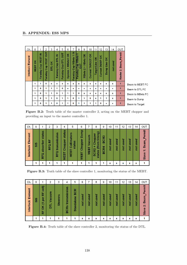
B. APPENDIX: ESS MPS
Figure B.2: Truth table of the master controller 2, acting on the MEBT chopper and
providing an input to the master controller 1.
Figure B.3: Truth table of the slave controller 1, monitoring the status of the MEBT.
Figure B.4: Truth table of the slave controller 2, monitoring the status of the DTL.
138

B.1 ESS BIS Truth Tables
Figure B.5: Truth table of the slave controller 3, monitoring the status of the spokes
cavities plus a part of the medium-beta cavities.
Figure B.6: Truth table of the slave controller 4, monitoring the status of the second
part of the medium-beta cavities plus the high-beta cavities.
Figure B.7: Truth table of the slave controller 5, monitoring the status of the dump line.
139

B. APPENDIX: ESS MPS
Figure B.8: Truth table of the slave controller 6, monitoring the status of the target line.
140
Appendix C
Appendix: LHC Radiation Levels
C.1 Extrapolation of radiation levels in LHC underground
areas
In Chapter 6, predictions on the expected availability of the LHC during future runs
and for the High-Luminosity upgrade are presented. One of the major contributors to
the number of dumps during the first LHC run has been radiation to electronics causing
single event upsets in exposed equipment in the LHC tunnel and underground areas. An
extensive consolidation campaign to cope with such failures has been launched at CERN
during the Long-Shutdown 1. Nevertheless it is fundamental to correctly extrapolate
the radiation levels in the tunnel for the future LHC runs. This allows designing
appropriate measures to withstand the high radiation levels. Such measures range
from shielding of the most exposed areas to the use of radiation tolerant components
for electronic systems. Radiation levels are mostly a consequence of beam losses near the
collimation sections (LHC point 3 and 7) and collision debris from the high-luminosity
experiments (LHC point 1 and 5) (96). Fig. C.1 shows a schematic view of the LHC
and related underground areas.
Predictions on the number of single event upsets in the future LHC runs presented in
Chapter 6 are based on the estimated fluence of High-Energy Hadrons (HEH) reported
in Table C.2. The assumption is to have a linear scaling of the total number of observed
dumps due to radiation to electronics with the HEH fluence (96). In the table, both
HEH fluence and total dose are considered. These are both quantities heavily affecting
exposed equipment in the tunnel.
141

C. APPENDIX: LHC RADIATION LEVELS
Figure C.1: Layout of LHC underground areas.
142

C.1 Extrapolation of radiation levels in LHC underground areas
Figure C.2: Extrapolation of HEH fluence and total dose in the different LHC under-
ground areas for future runs and LHC upgrades.
143

C. APPENDIX: LHC RADIATION LEVELS
144
References
[1] ATLAS Collaboration. Observation of a new parti-
cle in the search for the Standard Model Higgs
boson with the ATLAS detector at the LHC.
Physics Letters B, 2012. 5
[2] CMS Collaboration. Observation of a new boson at
a mass of 125 GeV with the CMS experiment at
the LHC. Physics Letters B, 2012. 5
[3] CERN. LEP Design Report, 1984. 5
[4] P. Lebrun. Report of the Task Force on the Inci-
dent of 19 September 2008 at the LHC. Technical
report, CERN, 2009. 6
[5] F. Bordry. The First Long Shutdown (LS1) for the
LHC. In IPAC’13, Shanghai, China, 2013. 7, 100
[6] K. Hanke. Status of the LIU Project at CERN. In
IPAC’14, Dresden, Germany, 2014. 8
[7] L. Rossi. High Luminosity Large Hadron Col-
lider: A description for the European Strategy
Preparatory Group. Technical report, CERN, 2012.
8
[8] S. Peggs et al. ESS Technical Design Report. Tech-
nical report, ESS, 2013. 9, 54
[9] T.A. Gabriel. Status Report on the Spallation
Neutron Source. Technical report, SNS, 1998. 10
[10] B. Bertsche. Reliability in Automotive and Mechanical
Engineering, 356-358. Springer, 2007. 11
[11] E. Bargallo. IFMIF Accelerator Facility RAMI Analyses
in the Engineering Design Phase. PhD thesis, Universi-
tat Politecnica de Catalunya, 2014. 71. 13
[12] European Technical Working Group on ADS. A Eu-
ropean Roadmap for Developing Accelerator-
driven Systems (ADS) for Nuclear Waste Incin-
eration, 2001. 14
[13] ATLAS collaboration. ATLAS Experiment - Lumi-
nosity Public Results, 2012. 14
[14] A. Macpherson. LHC Availability and Performance
in 2012. In CERN, Proceedings of the 2012 Evian Work-
shop on LHC Beam Operation, Evian, France, 2012. 15
[15] S. Fartoukh. Pile-up Management at the High-
Luminosity LHC and Introduction to the Crab-
Kissing Concept. Physical Review Special Topics - Ac-
celerators and Beams, 2014. 15
[16] L. Rossi. Vision from LHC to HL-LHC operation.
R2E and Availability Workshop, 2014. 15
[17] R. Calaga. Crab Cavities for the LHC Upgrade.
In CERN, Proceedings of the 2012 Chamonix Workshop
on LHC Performance, Chamonix, France, 2012. 15, 115
[18] E. Todesco. Dipoles for High-Energy LHC. Tech-
nical report, CERN, 2014. 15
[19] A. Ballarino. Altenrative Design Concepts for
Multi-Circuit HTS Limk Systems. IEEE Trans-
actions on Applied Superconductivity, 2011. 15, 116
[20] S. Redaelli. Do We Really Need a Collimator Up-
grade? In CERN, Proceedings of the 2012 Evian Work-
shop on LHC Beam Operation, Evian, France, 2012. 15
[21] L. Tavian. Cryogenics for HL-LHC. 2nd Joint Hi-
Lumi LHC-LARP Annual Meeting, 2012. 15
[22] F. Gerigk et al. Linac4 Technical Design Report.
Technical report, CERN, 2006. 16
[23] W. Weterings. Status of the 160 MeV Injection
into the CERN PSB. In IPAC’12, New Orleans,
Louisiana, USA, 2012. 16
[24] J. Beebe-Wang et al. Injection Carbon Stripping
Foil Issues in the SNS Accumulator Ring. In
Proceedings of the 2001 Particle Accelerator Conference,
Chicago, USA, 2001. 16, 40
[25] M. Benedikt. Future Circular Collider Study:
Hadron Collider Parameters. Technical report,
CERN, 2014. 17
[26] A. Apollonio. FCC: Preliminary Machine Protec-
tion and Dependability Studies. Technical report,
CERN, 2015. 18
[27] B. Auchmann et al. Testing the Beam-Induced
Quench Levels of LHC superconducting Magnets
in Run1. Physical Review ST Accelerators and Beams,
In preparation. 19, 101
[28] R. Schmidt. Protection of the CERN Large Hadron
Collider. New Journal of Physics, 2006. 20, 90
[29] O. S. Bruning; P. Collier; P. Lebrun; S. Myers; R. Os-
tojic; J. Poole; P. Proudlock. LHC Design Report
Volume 1: Powering and Protection. Technical
report, CERN, 2004. 20, 22, 77
[30] O. S. Bruning; P. Collier; P. Lebrun; S. Myers; R. Os-
tojic; J. Poole; P. Proudlock. LHC Design Report
Volume 1: Beam Dumping System. Technical re-
port, CERN, 2004. 21
[31] B. Todd. A Beam Interlock System for CERN High En-
ergy Accelerators. PhD thesis, Brunel University West
London, 2006. 21, 50, 65
[32] B. Dehning. The LHC Beam Loss Measurement
System. In PAC’07, Albuquerque, New Mexico, USA,
2007. 21
145

REFERENCES
[33] R. Filippini. Dependability Analysis of a Safety Critical
System : the LHC Beam Dumping System at CERN. PhD
thesis, Univerista’ di Pisa, 2006. 21
[34] J. Blanco Sancho. An experiment on hydrodynamic
tunneling of the SPS high-intensity proton beam
at the HiRadMat facility. In Proceedings of HB2012,
Beijing, China, 2012. 22
[35] A. Ferrari et al. FLUKA: a Multi-Particle Trans-
port Code, 2005. 22
[36] G. Battistoni et al. The FLUKA Code: Description
and Benchmarking. In Proceedings of the Hadronic
Shower Simulation Workshop 2006, Fermilab, Illinois,
USA, 2006. 22
[37] O. S. Bruning; P. Collier; P. Lebrun; S. Myers; R. Osto-
jic; J. Poole; P. Proudlock. LHC Design Report Vol-
ume 1: Injection System. Technical report, CERN,
2004. 22
[38] E. Robert-Demolaize. Design and Performance Opti-
mization of the LHC Collimation System. PhD thesis,
Ecole Nationale Superieure de Physique de Grenoble,
2003. 22
[39] E. Ravaioli. New, Coupling Loss Induced, Quench
Protection System for Superconducting Acceler-
ator Magnets. Applied Superconductivity, 2014. 23
[40] S. Nath et al. Conceptual Designs of Beam Chop-
pers for RFQ Linacs. In Proceedings of the Particle
Accelerator Conference 1995, Dallas, Texas, USA, 1995.
23
[41] M. Sapinski. Response Functions of Ionisation
Chamber Beam Loss Monitor. Technical report,
CERN, 2010. 24, 60
[42] H. Hassanzadegan et al. System Overview and Pre-
liminary Test Results of the ESS Beam Current
Monitor System. In Proceedings of the IBIC2013, Ox-
ford, UK, 2013. 24
[43] W. Blokland. A New Differential and Errant Beam
Current Monitor for the SNS Accelerator. In IBIC
2013, Oxford, United Kingdom, 2013. 24
[44] E. Bargallo. IFMIF Accelerator Facility RAMI Analyses
in the Engineering Design Phase. PhD thesis, Universi-
tat Politecnica de Catalunya, 2014. 115. 24
[45] T. Baer. Very Fast Losses of the Circulating LHC Beam,
their Mitigation and Machine Protection. PhD thesis,
University of Hamburg, 2013. 24, 85, 101
[46] F. Zimmermann et al. Trapped Macroparticles in
Electron Storage Rings. IEEE Proceedings of the
1995 Particle Accelerator Conference, 1995. 25, 85
[47] R. Garcia Alia. Introduction to Radiation Effects
and Modeling of Radiation Damage. CERN, 2014.
25
[48] M. Zerlauth. The LHC Post-Mortem Analysis
Framework. In ICALEPCS’09, Kobe, Japan, 2014.
25
[49] A. Apollonio. Availability for Post-LS1 Operation.
In CERN, Proceedings of the 2014 Evian Workshop on
LHC Beam Operation, Evian, France, 2014. 25
[50] J. Janczyk. Tracking of Faults and Follow-up. R2E
and Availability Workshop, 2014. 27
[51] The MathWorks Inc. MATLAB. 29, 71, 93, 110
[52] Isograph Ltd. 1986-2015. ISOGRAPH. 29, 34, 35, 78
[53] N. Leveson. An STPA Primer, 2013. 29, 30, 31, 32,
126
[54] USA Department of Defense, Washington DC. Relia-
bility Prediction of Electronic Equipment, 1990.
34
[55] Telcordia. Reliability Prediction Procedure of
Electronic Equipment, 2011. 34
[56] USA Naval Surface Warfare Center, Maryland. Hand-
book of Reliability Prediction of Procedures for
Mechanical Equipment, 2011. 34
[57] B. Bertsche. Reliability in Automotive and Mechanical
Engineering, 365,366. Springer, 2007. 36
[58] C. Rossi et al. The Radiofrequency Quadrupole
Accelerator for the Linac4. In Proceedings of the
Linac’08, Victoria, Canada, 2008. 40
[59] S. Ramberger et al. Drift Tube Linac Design and
Prototyping for the CERN Linac4. In Proceedings
of the Linac’08, Victoria, Canada, 2008. 40
[60] Y. Cuvet et al. Development of a Cell-Coupled
Drift Tube Linac (CCDTL) for Linac4. In Pro-
ceedings of the Linac’08, Victoria, Canada, 2008. 40
[61] P. Bourquin et al. Development status of the Pi-
Mode Accelerating Structure (PIMS) for Linac4.
In Proceedings of the Linac’08, Victoria, Canada, 2008.
40
[62] L. Bruno. Study of Energy Deposition and Activa-
tion for the Linac4 Dump. Technical report, CERN,
2008. 40
[63] B. Antoine. Systems Theoretic Hazard Analysis (STPA)
Applied to the Risk Review of Complex Systems: an Ex-
ample from the Medical Device Industry. PhD thesis,
Massachusetts Institute of Technology, 2013. 43
[64] J. Wozniak et al. Software Interlock System. In
Proceedings of ICALEPCS’07, Knoxville, Tennessee,
Canada, 2007. 50
[65] B. Mikulec; B. Puccio et al. Beam Interlock Speci-
ications for Linac4, Transfer Lines and PS
Booster with Linac4. Technical report, CERN, 2013.
50, 52
[66] B. Mikulec; B. Puccio et al. The Commissioning
Steps of the Linac4 Beam Interlock System. Tech-
nical report, CERN, 2014. 52
[67] P. Duschesne et al. Design of the 352 MHz, Beta
0,50, Double-Spoke Cavity for ESS. In Proceedings
of the SRF2013, Paris, France, 2013. 55
146
REFERENCES
[68] Accelerator Division European Spallation Source.
Medium Beta Elliptical Cavity-Cryomodule
Technology Demonstrator. Technical report, ESS,
2012. 55
[69] F. Peauger et al. Status and First Test results of
Two High Beta Prototype Elliptical Cavities for
ESS. In IPAC’14, Dresden, Germany, 2014. 55
[70] H. D. Thomsen et al. The Design of the Fast raster
System for the European Spallation Source. In
IPAC’14, Dresden, Germany, 2014. 55
[71] A. Nordt et al. Architecture of the ESS Beam In-
terlock System. Technical report, ESS, 2014. 56
[72] P. Dahlen; R. Mompo; M. Zerlauth. The Warm Mag-
net Interlock System for Linac4. CERN. 62
[73] International Atomic Energy Agency. ITER Concep-
tual Design Report. Technical report, 1991. 65
[74] K. Dahlerup-Petersen; R. Denz; K. H. Mess. Electronic
Systems for the Protection of Superconducting
Devices in the LHC. In EPAC’08, Genova, Italy,
2008. 66
[75] M. Zerlauth. Powering and Machine Protection of the
Superconducting LHC Accelerator. PhD thesis, Graz
University of Technology, 2004. 66
[76] S. Wagner. LHC Machine Protection Systems: Method
for Balancing Machine Safety and Beam Availability.
PhD thesis, ETH Zurich, 2010. 68, 71
[77] The MathWorks Inc. SIMULINK. 71
[78] M. Meddahi et al. LHC Abort Gap Monitoring and
Cleaning. In IPAC’10, Kyoto, Japan, 2010. 76
[79] S. Gabourin et al. Changes to the LHC Beam
Dumping System for LHC Run 2. In IPAC’14,
Dresden, Germany, 2014. 78
[80] V. Vatansever. Reliability Analysis of the new
Link between the Beam Interlock System and
the LHC Beam Dumping System. Technical re-
port, CERN, 2014. 78, 100
[81] Inc. 1988-2015 Cadence Design Systems. OrCAD. 78
[82] O. S. Bruning; P. Collier; P. Lebrun; S. Myers; R. Os-
tojic; J. Poole; P. Proudlock. LHC Design Report
Volume 1: Layout and Performance. Technical re-
port, CERN, 2004. 82
[83] W. Herr; B. Muratori. Concept of Luminosity. Tech-
nical report, CERN, 2007. 81, 82, 83
[84] M. Benedikt et al. Low-Intensity Beams for LHC
Commissioning from the CERN PS-Booster.
Technical report, CERN, 2006. 83
[85] M. Solfaroli. Operational Cycle. In CERN, Proceed-
ings of the 2012 Evian Workshop on LHC Beam Opera-
tion, Evian, France, 2012. 83
[86] D. Mohl et al. Sources of Emittance Growth. In
CAS 2003, Zeuthen, Germany, 2003. 82
[87] B. Todd. A Look Back on 2012 LHC Availability.
In CERN, Proceedings of the 2012 Evian Workshop on
LHC Beam Operation, Evian, France, 2012. 85
[88] G. Spiezia. R2E - Experience and Outlook. In
CERN, Proceedings of the 2012 Evian Workshop on LHC
Beam Operation, Evian, France, 2012. 90, 91
[89] R. Filippini. Review of the LBDS Safety and Reli-
ability Analysis in the Light of the Operational
Experience during the Period 2010-2012. Techni-
cal report, CERN, 2013. 91
[90] A. Apollonio. HL-LHC: Integrated Luminosity and
Availability. In IPAC’13, Shanghai, China, 2013. 92,
97
[91] J. Wenninger. Simple Models for the Integrated
Luminosity. Technical report, CERN, 2013. 92
[92] A. Gorzawski. Implementation of Luminosity Lev-
eling by Betatron Function Adjustment at the
LHC Interaction Points. In IPAC’14, Dresden, Ger-
many, 2014. 97, 101
[93] B. Todd. Radiation Tolerant Power Converter
Controls. In Proceedings of TWEPP 2012, Oxford,
United Kingdom, 2012. 100
[94] H. Damerau. RF Manipulations for Higher Bright-
ness LHC-Type Beams. Technical report, CERN,
2013. 101
[95] F. Zimmermann. RLIUP: Review of LHC Injector
Upgrade Plans. In CERN, Archamps, France, Octo-
ber, 2013. 103
[96] R. Garcia Alia. Radiation Fields in High Energy Accel-
erators and theit Impact on Single Event Effects. PhD
thesis, University of Montpellier, 2014. 17. 104, 141
[97] P. Vankov et al. ATLAS Upgrade for the HL-LHC:
Meeting the Challenges of a Five-Fold Increase
in Collision Rate. Technical report, CERN, 2011. 115
[98] J. Nash et al. Technical proposal for the upgrade
of the CMS detector through 2020. Technical re-
port, CERN, 2011. 115
[99] R. Schmidt. Machine Protection Challenges for
HL-LHC. In IPAC’14, Dresden, Germany, 2014. 115
[100] A. L. Perrot et al. Optimization and Implementa-
tion of the R2E Shielding and Relocation Mit-
igation Measures at the LHC During LS1. In
IPAC’14, Dresden, Germany, 2014. 116
[101] A. Apollonio. Availability and Integrated Lumi-
nosity. R2E and Availability Workshop, 2014. 120
[102] A. Lombardi et al. Report on the accident of
12.12.2013. Technical report, CERN, 2013. 131, 132
147

REFERENCES
148