Assessing Youth's Buying Behaviour towards Sports Shoes (A ...
Machine Design II Prof. K.Gopinath & Prof. M.M.Mayuram
Indian Institute of Technology Madras
Drum Brakes
Among the various types of devices to be studied, based on their practical use,
the discussion will be limited to “Drum brakes” of the following types which are
mainly used in automotive vehicles and cranes and elevators.
Drum Brake Types:
• Rim types with internal expanding shoes
• Rim types with external contracting shoes
Internal expanding Shoe
The rim type internal expanding shoe is widely used for braking systems in
automotive applications and is generally referred as internal shoe drum brake.
The basic approach applied for its analysis is known as long-rigid shoe brake
analysis. Long –rigid Shoe Analysis
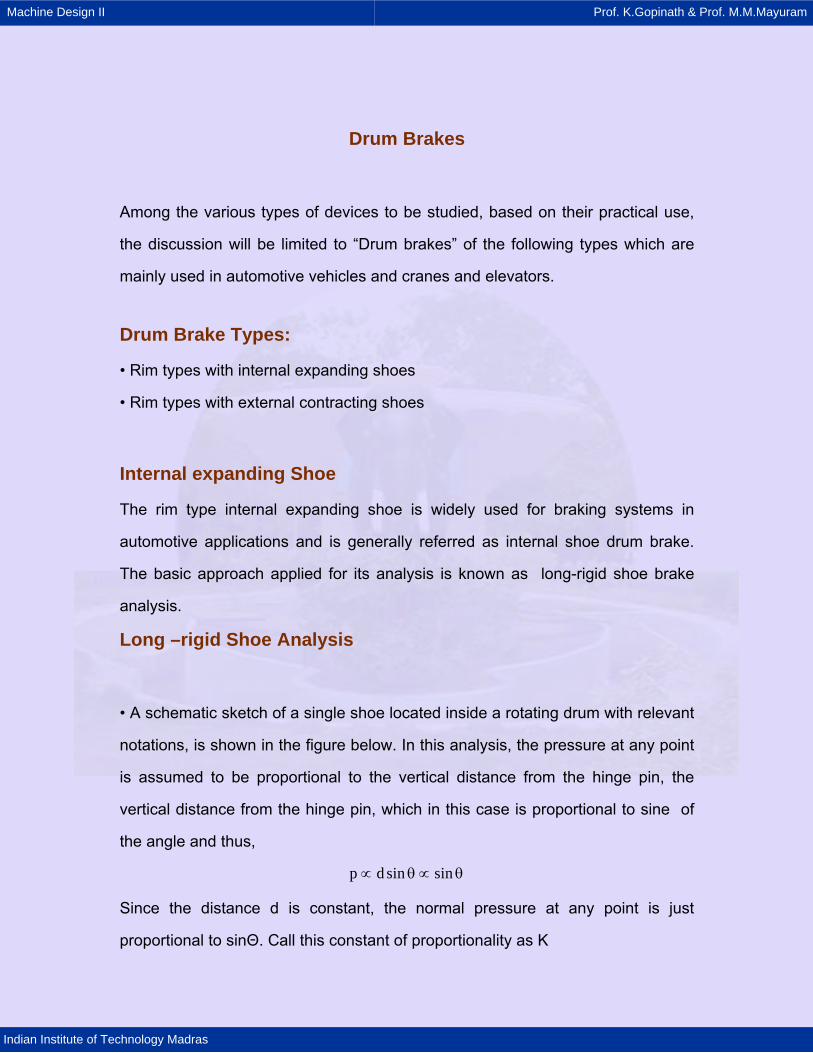
• A schematic sketch of a single shoe located inside a rotating drum with relevant
notations, is shown in the figure below. In this analysis, the pressure at any point
is assumed to be proportional to the vertical distance from the hinge pin, the
vertical distance from the hinge pin, which in this case is proportional to sine of
the angle and thus,
p d sin sin∝ θ ∝ θ
Since the distance d is constant, the normal pressure at any point is just
proportional to sinΘ. Call this constant of proportionality as K

Machine Design II Prof. K.Gopinath & Prof. M.M.Mayuram
Indian Institute of Technology Madras
>
><
X
Y
RX
dNcos
d dN
N Ndf
sindNcos
df NsinF
FX
FY
RY
d
θ θ
θθf
θ
dθ
Figure 3.1.4
Thus p K sin= θ
It the maximum allowable pressure for the lining material is pmax then the constant
K can be defined as
max
max
ppKsin sin
= =θ θ
max
max
pp s
sinin= θ
θ

Machine Design II Prof. K.Gopinath & Prof. M.M.Mayuram
Indian Institute of Technology Madras
• The normal force dN is computed as the product of pressure and area and the
frictional force as the product of normal force and frictional coefficient i.e. f dN.•
By integrating these over the shoe length in terms of its angle the braking torque
T, and other brake parameters are computed.
To determine the actuating force F, the moment equilibrium about the pivot point
is applied. For this we need to determine the moment of the normal force MN and
moment of the frictional force about the pivot point. Moment of the normal force
is equal to the normal force times its moment arm about the pivot point. From
the figure it is clear that the moment arm in this case is equal to d sin Θ where d
is the distance between the drum center and pivot center
1 1
2 2
1
2
2max
M p.b.r.d .d sin b.p.r.d.sin .dN
p = b.d.r. sin d
sin
θ θ
θ θ
θ
θ
= θ θ = θ
θ θθ
∫ ∫
∫
θ
( )p b.d.r 1 1maxM (sin 2 sin 2 )N 2 1 2sin 2 4a1
⎡ ⎤= θ − θ − θ − θ⎢ ⎥θ ⎣ ⎦
On similar lines the moment of friction force is computed
( )
( )
1
2
1
2
max
max
M f.p.b.r.d r d sinF
p = f .b.r. sin r d sin d
sin
θ
θ
θ
θ
= θ − θ
θ − θθ
∫
∫ θ
( ) ( )max.
a
f .p b.r d 2 2M r cos cos sin sif 2 1 2sin 2⎡ ⎤= − θ − θ − θ − θ⎢ ⎥θ ⎣ ⎦
n 1

Machine Design II Prof. K.Gopinath & Prof. M.M.Mayuram
Indian Institute of Technology Madras
The actuating force F is determined by the summation of the moments of normal
and frictional forces about the hinge pin and equating it to zero.
Summing the moment about point O gives
M MN fFc
±=
where,
• MN and Mf are the moment of the normal and frictional forces respectively,
about the shoe pivot point.
The sign depends upon the direction of drum rotation,
(- sign for self energizing and + sign for non self energizing shoe)Where the
lower sigh is for a self energizing shoe and the upper one for a self deenergizing
shoe.
The reaction forces are determined by applying force summation and equilibrium
( ) ( )
2 2
1 1
2 2
1 1
2max max
max max
max.b
max
R dN.cos dF.sinx
b.r.p cos d f b.r.psin d
p p b.r. sin cos d f b.r. sin d
sin sin
p r 1 1 1 1 2 2( ) sin 2 sin 2 f sin sin2 1 2 1 2 1sin 2 2 4 2
θ θ
θ θ
θ θ
θ θ
= θ + θ
= θ θ + θ θ
= θ θ θ + θ θθ θ
⎛ ⎞⎡ ⎤= θ − θ − θ − θ ± θ −⎜ ⎟⎢ ⎥θ ⎣ ⎦⎝ ⎠
∫ ∫
∫ ∫
∫ ∫
θ
The equations can be simplified and put as
p braR (Ax sin a
=θ
∓ fB)
p braR (B fA)y xsin aF= ± −
θ
Where
( )1 2 2A sin sin2 12= θ − θ

Machine Design II Prof. K.Gopinath & Prof. M.M.Mayuram
Indian Institute of Technology Madras
1 1 1B ( ) sin 2 sin 22 2 42 1 2 1⎡ ⎤⎛ ⎞= θ − θ − θ − θ⎢ ⎥⎜ ⎟
⎝ ⎠⎣ ⎦
The braking torque T on the drum by the shoe is of the frictional forces f.dN times
the radius of the drum and resulting equation is,
1
1
1
1
2
max
T f .b.p.r.d .r
pmax = fbr sin dsin
θ
θ
θ
θ
= θ
θ θθ
∫
∫
2fdp r (cos cos )a 1Tsin a
2θ − θ=
θ
T
Double Shoe Brakes Twin Shoe Brakes
Behavior of a single shoe has been discussed at length. Two
such shoes are combined into a complete practical brake unit,
two being used to cover maximum area and to minimize the
unbalanced forces on the drum, shaft and bearings.
• If both the shoes are arranged such that both are leading shoes in which
self energizing are prevailing, then all the other parameters will remain
same and the total braking torque on the drum will be twice the value
obtained in the analysis.
• However in most practical applications the shoes are arranged such that
one will be leading and the other will be trailing for a given direction of
drum rotation

Machine Design II Prof. K.Gopinath & Prof. M.M.Mayuram
Indian Institute of Technology Madras
• If the direction of drum rotation changes then the leading shoe will
become trailing and vice versa.
• Thus this type of arrangement will be equally effective for either direction
of drum rotation. Further the shoes can be operated upon using a single
cam or hydraulic cylinder thus provide for ease of operation
One leading shoe & one trailing
Two Leading shoe
Figure 3.1.5
However the total braking torque will not be the twice the value of a single
shoe, if the same normal force is applied or created at the point of force
application on both the brake shoes which is the normal practice as they
are actuated using a common cam or hydraulic cylinder.
• This is because the effective contact pressure (force) on the trailing shoe
will not be the same, as the moment of the friction force opposes the
normal force, there by reducing its actual value as in most applications

Machine Design II Prof. K.Gopinath & Prof. M.M.Mayuram
Indian Institute of Technology Madras
the same normal force is applied or created at the point of force
application on the brake shoe as noted above
• Consequently we may write the actual or effective pressure prevailing on
a trailing shoe
F.a'p p .a a (M M )n f
⎡ ⎤= ⎢ ⎥
+⎢ ⎥⎣ ⎦
Resulting equation for the braking torque
p2 aT f .w.r . (cos - cos )(p pB 1 2sin a= θ θ
θ')a a+
Some pictorial illustrations of the automotive drum brakes are presented
below
Figure 3.1.6

Machine Design II Prof. K.Gopinath & Prof. M.M.Mayuram
Indian Institute of Technology Madras
Figure 3.1.7
Oblong Cam Actuator
Leading shoe
Rotating Drum
Pivot point(Fixed axis)
The anatomy of the single leading shoe drum Brake
Trailing shoe
Animation

Machine Design II Prof. K.Gopinath & Prof. M.M.Mayuram
Indian Institute of Technology Madras
Figure 3.1.9
Figure 3.1.10

Machine Design II Prof. K.Gopinath & Prof. M.M.Mayuram
Indian Institute of Technology Madras
External Contracting Shoe
• The same analysis can be extended to a drum brake with external contracting
type of shoes, typically used in elevators and cranes.
A schematic sketch of as single shoe located external to the rotating drum is with
all relevant notations is shown in the figure below.
Figure 3.1.11
• Corresponding contact geometry is shown in the figure
• The resulting equations for moment of normal and frictional force as well as the
actuating force and braking torque are same as seen earlier.
• For convenience they are reproduced here again
( )2fbp r cos cosa 1Tsin a
2θ − θ=
θ
Machine Design II Prof. K.Gopinath & Prof. M.M.Mayuram
Indian Institute of Technology Madras
M MN fFc
±=
( )p bra 1 1aM (sin 2 sin 2 )N 2 1 2sin 2 4a1
⎡ ⎤= θ − θ − θ − θ⎢ ⎥θ ⎣ ⎦
( )a
a
fp br d 2 2M r cos cos (sin sinf 1 2 2sin 2⎡ ⎤= θ − θ − θ −⎢ ⎥θ ⎣ ⎦
)1θ
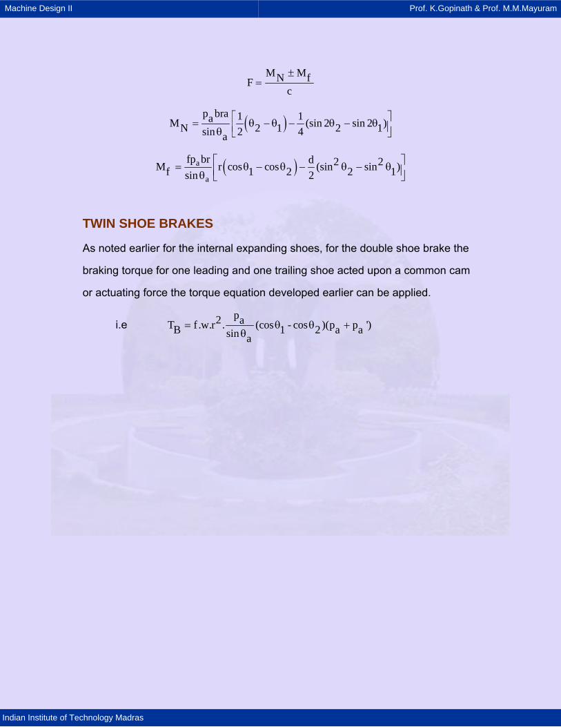
TWIN SHOE BRAKES
As noted earlier for the internal expanding shoes, for the double shoe brake the
braking torque for one leading and one trailing shoe acted upon a common cam
or actuating force the torque equation developed earlier can be applied.
i.e p2 aT f .w.r . (cos - cos )(p pB 1 2sin a
= θ θθ
')a a+
Copyright © 2022 FDOKUMEN