
M A X I M I Z I N G Y O U R P E R F O R M A N C E A T S E A
33
MAXIMIZING YOUR PERFORMANCE AT SEA
-
Upload
khangminh22 -
Category
Documents
-
view
2 -
download
0
Transcript of M A X I M I Z I N G Y O U R P E R F O R M A N C E A T S E A

M A X I M I Z I N G Y O U R P E R F O R M A N C E A T S E A


Simrad WP30Wheelpilot
M A N U A L
III

IV
The technical data, information and illustrations contained in this publication were to the best of our knowledge correct at the timeof going to print. We reserve the right to change specifications, equipment, installation and maintenance instructions without noticeas part of our policy of continuous development and improvement.No part of this publication may be reproduced, stored in a retrieval system or transmitted in any form, electronic or otherwise with-out prior permission from Simrad Ltd. No liability can be accepted for any inaccuracies or omissions in the publication, althoughevery care has been taken to make it as complete and accurate as possible. Part No. E03549 Issue 1.3 MDL/CR 01/12/03
© 2003 Simrad Ltd

Instruction manual
CONTENTS
1. General
1.1 Introduction1.2 Technical Summary
2. Operation
2.1 General2.2 Engaging the Clutch2.3 Autopilot Mode2.4 Adjusting Course2.5 Autotack2.6 Rudder Movement (Gain)2.7 Seastate2.8 Autotrim
3. Advanced Features
3.1 Nav Mode3.2 Sail To Wind3.3 Using External Compass
4. Configuration
4.1 Scaling4.2 Calibration Mode4.3 Adjusting Gain4.4 Adjusting Seastate
5. Installation
5.1 Fitting the Wheelpilot5.2 Electrical Installation5.3 Interfacing Via NMEA5.4 NMEA Sentences Received
6. Appendix
6.1 Advice On Operation6.2 Fault Finding6.3 Auto Compass Calibration6.4 Adjusting Belt Tension6.5 Spares & Accessories6.6 Servicing6.7 Warranty
V

Page 6
Wheelpilot WP30
1 General
1.1 Introduction
The Simrad Wheelpilot WP30 is a self-containedautomatic pilot suitable for a wide variety of wheelsteered sailing yachts up to 12.8m (42ft) in length.Combining highly sophisticated electronics withadvanced software and a powerful mechanicaldrive, it is capable of providing reliable and accu-rate steering performance under a variety of differ-ent conditions with minimal current consumption.
The WP30 has been designed so that, while it rep-resents the state of the art in marine autopilots withmany advanced features, it remains very simple tooperate, using only five keys to access all functions.
Sophisticated functions available include Sail ToWind mode and Nav mode (Steer To GPS) usingexternal equipment linked directly to the Wheel-pilot via its inbuilt NMEA0183 interface.
There is also the option to operate the Wheelpilotremotely, using the HR20 Hand Remote.
To ensure the best results from your Wheelpilot, it isessential that the unit is installed correctly. Pleaseread this manual thoroughly before installation.
Thank you for choosing Simrad!
If you are pleased with your Wheelpilot, we hopeyou will be interested in our range of marine elec-tronic equipment, which is manufactured to thesame high standards as the Wheelpilot. Please contact your nearest Simrad Agent for acatalogue showing our increasing range of high-tech navigational instruments, GPS, Autopilots,Radar, Chartplotters, Fishfinders and VHF radiosets.
Simrad operate a policy of continual developmentand reserve the right to alter and improve thespecification of their products without notice.
Wheelpilot® is a Registered Trademark ofSimrad Ltd.
WP30
Wheelpilot WP30

Page 7
Instruction manual
1.2 Technical Summary
WHEELPILOT WP30 SPECIFICATIONS
Supply Voltage 12v DC (10v-16v)Power Consumption 0.06A (Standby)(Typical) 0.75A (Auto)
WP30
Fig 1.1 - Wheelpilot dimensions
388m
m (
15.2
5 in
)
348m
m (
13.7
in)
165mm (6.5 in) 550mm (21.6 in)
234mm (9.2 in)

Page 8
Wheelpilot WP30
Fig 2.1 - Engaging clutch
STBY
TACK
STBYAUTOSTBYAUTO
Fig 2.2 - Engaging autopilot mode
STBY
NAV
TACK
STBYAUTO
Fig 2.3 - Course adjustment to Port
2 Operation
2.1 General
The WP30 powers up in Standby mode, indicated by aflashing LED next to the STBY/AUTO key. The twodirection LEDs above the Port and Starboard keys arealways dimly lit, which provides night illumination forthe keypad. All functions are confirmed audibly by a“beep” and visually by the LEDs, so the status of theunit can always be confirmed at a glance.
2.2 Engaging the clutch
The Wheelpilot will not drive in any mode unless thedrive clutch is engaged first. The clutch is controlledby the lever on the left side of the unit (Fig 2.1). Whenthe lever is in the upward position, the clutch is disen-gaged, and the wheel is free to turn by hand. Toengage the clutch, push the lever down fully until it isflush with the motor housing. The wheel will then beheld firmly by the Wheelpilot – hand steering will notbe possible until the clutch is disengaged.
2.3 Autopilot Mode
To lock the vessel onto the current heading, simplysteer a straight course, engage the clutch and press theSTBY/AUTO key to switch to Auto Mode, indicatedby the LED next to the STBY/AUTO key lighting per-manently (Fig 2.2).
To lock the pilot onto the desired course, simply steerthe correct course and then engage the autopilot. Thewheel should always be in the centreline positionbefore engaging the Wheelpilot.
If the STBY/AUTO key is pressed and held, the pilotwill beep a second time and lock onto the previouslyused heading (this feature will not be available if theunit has just been switched on).
To disengage the pilot, press the STBY AUTO key andlift the clutch lever. Always switch the pilot toStandby mode when disengaging the clutch.
2.4 Adjusting Course
While in Autopilot mode, precise course adjustmentscan be easily made -
Clutch On
Clutch Off

Page 9
Instruction manual
To make a 1º adjustment, press either the Port orStarboard key once. This is confirmed by a single beep,and the relevant Port or Starboard LED will flash once.
To make a 10º adjustment, press and hold the key,which is confirmed by a double beep and a doubleflash of the Port or Starboard LED (Fig 2.3).
N.B. – When in Nav mode (see section 3.1), theWheelpilot will gradually return to the original track.
2.5 Autotack
The Wheelpilot has a built-in autotack facility, allow-ing easy tacking of the vessel when single or shorthanded. An autotack is only possible when in Auto-pilot mode.
To initiate autotack, press and hold the TACK key, fol-lowed by either the Port or Starboard key, dependingon which direction you wish to tack (Fig 2.4).
The operation of the Wheelpilot will differ during anautotack depending on whether the pilot is in Sail ToCompass or Sail To Wind mode:
2.5.1 Autotacking in Compass Mode
If in Sail To Compass Mode (default), the Wheelpilotwill then tack the vessel in the selected direction. TheWP30 has a factory preset autotack angle of 100º.
2.5.2 Autotacking in Wind Mode (cf. section 3.2)
The Wheelpilot will only allow an autotack if theapparent wind is less than 90º i.e autotack is disabledif sailing downwind. The Wheelpilot will tack the ves-sel through to the same apparent wind angle, but onthe opposite tack.
N.B. – In this mode, the Wheelpilot automatically pre-vents tacking in the wrong direction, e.g. if on Porttack, only an autotack onto Starboard tack will be pos-sible.
In all cases, the autotack is confirmed by a long beep,with the relevant Port or Starboard LED flashing dur-ing the course change.
2.5.3 Nav Mode (cf. section 3.1)
The autotack facility is disabled while in Nav mode.
STBY
TACK
STBYAUTO
STBY
TACK
STBYAUTO
TACK
TACK
Fig 2.4 - Initiating Starboard autotack

Page 10
Wheelpilot WP30
2.6 Rudder Movement (Gain)
The Wheelpilot uses highly advanced steering soft-ware, which constantly assesses how the vessel isbeing affected by the prevailing conditions. Byadjusting its own performance, the pilot is able tomaintain the most accurate course for these condi-tions, just as a human pilot would. Thus, in a roughsea the pilot is not overworked and battery drain iskept to a minimum.
The pilot will make corrections to compensate forheading errors, in order to keep the boat on course.The amount of rudder correction made is set by theGain (sometimes referred to as the rudder ratio).
The Gain setting can be compared to driving a motorvehicle – at high speeds, very little wheel movementis necessary to steer the vehicle (LOW Gain). Whendriving at slow speeds, more wheel movement isnecessary (HIGH Gain).
Fig 2.5A shows the effect of setting the Gain toolow: the boat takes a long time to return to the cor-rect heading. Fig 2.5B is ideal, where errors arequickly corrected. Fig 2.5C occurs when the Gaintoo high, causing the boat to “S”, or oscillate aroundthe correct heading. Excessive Gain (Fig 2.5D) caus-es instability of course, leading to increasing error.
To adjust Gain, please refer to section 4.3.
2.7 Seastate
In rough weather, more variations in heading will bedetected by the Wheelpilot due to the heavy seasyawing the vessel. If no account of this was taken,then the Wheelpilot would be overworked, causingunnecessary strain on the unit and excessive drainon the batteries. All Simrad Wheelpilots will contin-uously monitor corrections applied to the wheelover the course of a voyage, and allow a “deadband” within which the boat can go off course with-out corrections being made (Fig 2.6).
The dead band is automatically set and updatedby the Wheelpilot to give the best compromisebetween course holding and battery consumption.However, this can be manually set if so desired.
To manually adjust the Seastate, please refer tosection 4.4.
A B C DFig 2.5 - Effects of Gain setting
D E A D B A N D º
Fig 2.6 - Seastate “deadband”
Ave
rage
Co
urse

Page 11
Instruction manual
2.8 Autotrim
Under differing conditions a rudder bias (sometimes known as standing helm or rudder trim) isapplied in order to steer a straight course. An example is when sailing close hauled, where the ves-sel will normally pull into the wind, and the helmsman applies a standing helm to leeward in orderto maintain course. The amount of this standing helm varies according to factors such as strengthof wind, boat speed, sail trim and amount of sail set. If no account of these were taken, then thevessel would tend to veer off course, or pull around head to wind if sailing close hauled.
The Wheelpilot continuously monitors the average course error and applies a bias to the wheel tocompensate until the optimum condition is reached. This bias or standing helm is applied gradual-ly, so as not to upset the normal performance of the Wheelpilot. Thus, it may take up to a minuteor so to fully compensate after changing tack. Once optimum trim is reached, the pilot will stillmonitor for changes in the prevailing conditions and update the trim accordingly.

Page 12
Wheelpilot WP30
3 Advanced Features
The Wheelpilot WP30 contains many advancedfeatures, one of which is the ability to acceptcourse data from a variety of sources apart fromthe internal fluxgate compass, including NMEA-compatible navigational receivers (GPS, etc) andwindvanes. An external compass option is alsoavailable via the inbuilt network connection.
Section 3 describes in detail the advanced facili-ties available with the Wheelpilot when inter-faced with other equipment.
3.1 Nav Mode
The WP30 Wheelpilot has a built-in NMEA inter-face which allows direct connection with NMEA-0183-compatible equipment, such as GPS, Chart-plotters, etc.
Once interfaced with navigation equipment viaNMEA, the Wheelpilot can steer using data fromthis source in addition to the internal compass,allowing a highly accurate course to waypoint.
To access Nav mode the unit must be in Autopilotmode. Simply activate a waypoint or route pro-grammed into the navigational receiver, and pressthe NAV key. The LED next to the NAV key willlight and the Wheelpilot will steer to the first way-point, using Cross Track Error and Bearing ToWaypoint information from the navigationalreceiver to maintain an accurate course.
On arrival at the target waypoint an intermittentalarm will sound. As a safety feature to avoid anunexpected course change, the next waypoint willnot be automatically loaded until the NAV key ispressed. When the vessel reaches the final way-point, the Wheelpilot will continue its currentcourse under Compass mode.
Note, that some of the standard key stroke func-tions may have a different effect in Nav modethan when in Compass mode. Please refer to sec-tions 2.5.2 and 2.5.3.
NM
EA
WP30
NMEA CompatibleEquipment
WP30
Fig 3.1 - Nav interfacing
STBY
NAV
TACK
STBYAUTO
NAV
Fig 3.2 - Initiating Nav Mode
Page 13
Instruction manual
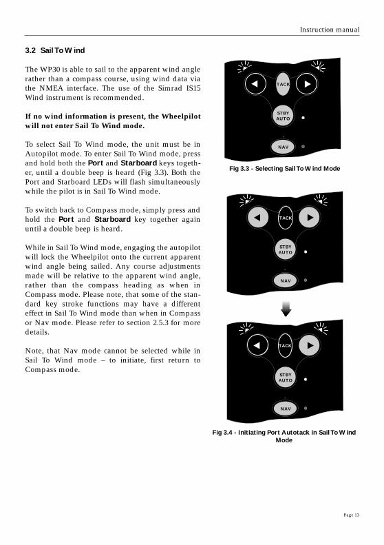
3.2 Sail To Wind
The WP30 is able to sail to the apparent wind anglerather than a compass course, using wind data viathe NMEA interface. The use of the Simrad IS15Wind instrument is recommended.
If no wind information is present, the Wheelpilotwill not enter Sail To Wind mode.
To select Sail To Wind mode, the unit must be inAutopilot mode. To enter Sail To Wind mode, pressand hold both the Port and Starboard keys togeth-er, until a double beep is heard (Fig 3.3). Both thePort and Starboard LEDs will flash simultaneouslywhile the pilot is in Sail To Wind mode.
To switch back to Compass mode, simply press andhold the Port and Starboard key together againuntil a double beep is heard.
While in Sail To Wind mode, engaging the autopilotwill lock the Wheelpilot onto the current apparentwind angle being sailed. Any course adjustmentsmade will be relative to the apparent wind angle,rather than the compass heading as when inCompass mode. Please note, that some of the stan-dard key stroke functions may have a differenteffect in Sail To Wind mode than when in Compassor Nav mode. Please refer to section 2.5.3 for moredetails.
Note, that Nav mode cannot be selected while inSail To Wind mode – to initiate, first return toCompass mode.
STBY
NAV
TACK
STBYAUTO
Fig 3.3 - Selecting Sail To Wind Mode
STBY
NAV
TACK
STBYAUTO
TACK
STBY
NAV
TACK
STBYAUTO
TACK
Fig 3.4 - Initiating Port Autotack in Sail To WindMode
Page 14
Wheelpilot WP30
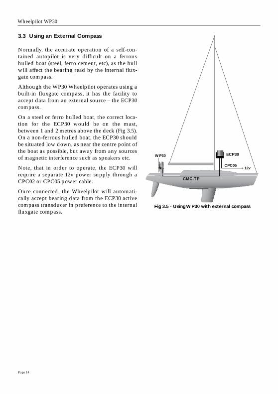
3.3 Using an External Compass
Normally, the accurate operation of a self-con-tained autopilot is very difficult on a ferroushulled boat (steel, ferro cement, etc), as the hullwill affect the bearing read by the internal flux-gate compass.
Although the WP30 Wheelpilot operates using abuilt-in fluxgate compass, it has the facility toaccept data from an external source – the ECP30compass.
On a steel or ferro hulled boat, the correct loca-tion for the ECP30 would be on the mast,between 1 and 2 metres above the deck (Fig 3.5).On a non-ferrous hulled boat, the ECP30 shouldbe situated low down, as near the centre point ofthe boat as possible, but away from any sourcesof magnetic interference such as speakers etc.
Note, that in order to operate, the ECP30 willrequire a separate 12v power supply through aCPC02 or CPC05 power cable.
Once connected, the Wheelpilot will automati-cally accept bearing data from the ECP30 activecompass transducer in preference to the internalfluxgate compass.
ECP30WP30
CMC-TP
CPC0512v
Fig 3.5 - Using WP30 with external compass

Page 15
Instruction manual
4 Configuration
4.1 Scaling
Before using the Wheelpilot, it is necessary to pro-gram in the steering sensitivity, which is related tothe number of turns that the wheel makes betweenend stops. This will determine the amount of stee-ring correction the Wheelpilot applies.
With the power off, press and hold the TACK andNAV keys, and switch on the power. Both Port andStarboard LEDs will illuminate, the Nav LED willflash, and a repeated sequence of beeps will beheard. The number of flashes and beeps in the se-quence indicates the current scaling factor.
The scaling factor is the total number of half turnsfrom lock to lock. For example, if the wheel hasthree complete turns from lock to lock, the scalingfactor will be 6. If there are 1 1⁄2 turns from lock tolock, then the factor will be 3.
Press the Starboard key to increase the scaling fac-tor by one, to a maximum value of 10 (= 5 turnslock-to-lock). Press the Port key to decrease thescaling factor by one, to a minimum value of 2 (= 1turn lock-to-lock).
To confirm scaling setting and return to Standbymode, press the NAV key.
STBY
NAV
TACK
STBYAUTO
TACK
NAV
STBY
NAV
TACK
STBYAUTO
STBY
NAV
TACK
STBYAUTO
NAV
Fig 4.1 - Reducing scaling factor by one
POWER ON
Setting(No. beeps/flashes)
2345678910
Turns Lock To Lock
111⁄22
21⁄23
31⁄24
41⁄25

Page 16
Wheelpilot WP30
TACKTACK
STBY
NAV
TACK
STBYAUTO
Fig 4.2 - Entering Calibration Mode
Fig 4.4 - Increasing Gain level
4.2 Calibration Mode
The Gain and Seastate settings of the Wheelpilot canbe adjusted in Calibration mode, which can be donewhilst the Wheelpilot is in either Standby or Auto-pilot mode.
Press and hold the TACK, followed by NAV (Fig 4.2).The Starboard LED will illuminate to indicate thatthe pilot is in Gain mode. To toggle between Gainand Seastate Mode, press TACK (Fig 4.3). The PortLED will illuminate to indicate Seastate mode.
4.3 Adjusting Gain
When Gain Mode is selected (indicated by the Star-board LED illuminated), the Nav LED will flash anda repeated sequence of beeps will be heard. The num-ber of flashes and beeps in the sequence indicates thelevel of the Gain setting.
Press the Starboard key to increase the Gain, to amaximum level of 9 (Fig 4.4). To decrease the Gainpress the Port key the required number of times, to aminimum level of 1.
For example, if the Gain was set at 4 (indicated by asequence of four flashes of the Nav LED and fourbeeps) and needed to be increased to 7, pressing theStarboard key three times would adjust the Gainaccordingly. The Nav LED would then flash seventimes and seven beeps would be heard.
4.4 Adjusting Seastate
When adjusting Seastate (indicated by the Port LEDilluminated), the Seastate level is indicated by thenumber of audible beeps and flashes of the Nav LED.No beeps or flashes of the Nav LED indicates that theWheelpilot is set to automatic Seastate (see section2.7).
To switch from auto to manual Seastate and increasethe Seastate level, press the Starboard key therequired number of times to a maximum level of 9.To decrease the Seastate press the Port key therequired number of times, to a minimum level of 0,this will switch the Wheelpilot back to Auto Seastate.
To confirm Gain/Seastate settings and return tonormal operation, press the NAV key.
STBY
TACK
STBYAUTO
Fig 4.3 - Toggling between Adjust Gain andSeastate
TACK
STBY
NAV
TACK
STBYAUTO
TACK
NAV

Page 17
Instruction manual
5 Installation
5.1 Fitting the Wheelpilot
With correct preparation, the Wheelpilot can beinstalled in under an hour. However, it is impor-tant that it is fitted correctly to operate to its max-imum efficiency. – Please read this section thor-oughly before attempting installation.
The fixing point of the Wheelpilot is the pedestalmount, which is fixed to the pedestal using twoband clamps. The Wheelpilot unit attaches to thismount using two metal guide rods, which slideinto slots on either side of the clamp. Thus, noholes need to be drilled to install the pilot, and itcan be easily and quickly removed if necessary.
The pedestal mount supplied will fit most pedes-tals 100–140mm (4.0–5.5in) in diameter. Two pack-ing pieces are supplied for use with a standard100mm (4.0in) pedestal (Fig 5.1). The pedestal mount has three sets of slots for theband clamps to suit the pedestal being fitted to(Fig 5.2). For pedestals over 140mm (5.5in) dia-meter, a larger clamp is available as a separateaccessory (part no. PED200:BK).
The two guide rods are not fitted to the Wheel-pilot itself when supplied and will need to beattached. As these will support any loads theWheelpilot is subjected to, it is important that theyare securely fitted. The ends of the rods have flatson them, which will allow a 12mm spanner to beused to tighten them (Fig 5.3).
1. Remove the wheel.
2. Position the pedestal mount on the front of thepedestal. The vertical distance between the centresof the circular slots and the centre of the wheelshaft should be 125mm (5.0in) and the clampshould be exactly parallel with the wheel in bothplanes (Fig 5.4).
3. The exposed section of the band clamps are slot-ed through the sleeving provided which coversthe clip and also prevents it form scratching thepedestal when tightened. It is recommended thatthe sleeving length is reduced to approx. 25mm(1.0in) shorter than the length of the band clampswhen tightened around the pedestal to avoid foul-ing the slots in the pedestal mount.
Fig 5.4 - Correct positioning of pedestal mount
Fig 5.3 - Attaching guide rods
Fig 5.1 - Fitting to 250mm (4.0 in) pedestal
Fig 5.2 - Rear view of pedestal mount
Slots for band clamps
Packing pieces
125m
m (
5.0
in)
Sleeving
Band clamps
PedestalMount

Page 18
Wheelpilot WP30
Note, that if the sleeving has already been fittedto the clamps, it will need to be removed to facil-itate fitting.
4. The self-adhesive neoprene pad suppliedshould be attached to the inside face of the pedes-tal mount. This not only increases the grip of thepedestal mount, but also protects the pedestalfrom being scratched by the mount.
5. Slide the sleeving over the band clamps andthread the first clamp through the pedestal mount(using slots appropriate to the pedestal), aroundthe pedestal and back in through the correspond-ing slot on the other side of the mount (Fig 4.5).Locate the clamp in either the top or the bottom ofthe slot in the pedestal mount to ensure that thereis room to fit the second clamp.
6. Tighten the band clamp as far as possible untilthe pedestal mount is held firmly in place and can-not be moved. Fit the second clamp following thesame procedure. Fit the front plate, but do nottighten the four socket head bolts at this point.
7. Fit the Wheelpilot to the pedestal mount byinserting the two guide rods into the slots on thepedestal mount. Check that the Wheelpilot ring iscentralised around the wheel shaft (Fig 5.6). If nec-essary, reposition the pedestal mount by removingthe pilot and the front plate and loosening theband clamp.
8. With the clutch lever disengaged, rotate theWheelpilot ring until the two spoke pillars are atthe top.
9. Refit the wheel, ensuring that the top spoke sitsbetween the two spoke clamps.
10. Two rubber clamps are supplied, that fit overthe toothed spoke pillars. The holes in the clampsare offset so that by rotating them the gap betweenthe pillars can be increased or decreased, until thewheel spoke is held securely (Fig 5.7).
11. If necessary, move the Wheelpilot forward orback along the guide rods, until the wheel spokefits equally between the clamps.
12. Clip the badge to the spoke clamps (Fig 5.8).
13. Spin the wheel from lock to lock and checkthat the Wheelpilot rotates freely and smoothly.
Fig 5.7 - Offset rubber spoke clamps
Fig 5.5 - Attaching clamp using band clamps
Front Plate
Pedestal
Pedestal Mount
Fig 5.6 - Pilot should be central to wheel shaft
NeoprenePad

Page 19
Instruction manual
Fig 5.8 - Fitting of Wheelpilot
Fig 5.9 - Keypad sun cover
If there is any oscillation at any point of rotation, thisis due to the Wheelpilot being mounted slightly off-centre. Check that the pedestal clamp is not too lowor too high, and that the pedestal mount and thepilot are exactly parallel to the wheel.
14. Tighten the four socket head bolts on each side ofthe pedestal mount, so that the guide rods are heldfirmly in place. Do not overtighten.
The Wheelpilot is supplied with a clip-on sun cover(Fig 5.9) to protect the keypad and control unit fromthe elements and the effects of UV light while thepilot is not in use.
Apart from this cover, the Wheelpilot is fully pro-tected from the elements due to its weatherproofdesign, and can be left fitted to the pedestal withoutrequiring any additional protection.
Badge
Wheel nut
Spokeclamps
Socket headbolts
AttachingBadge
Page 20
Wheelpilot WP30
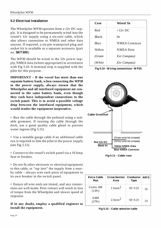
Fig 5.10 - Wiring connections - WP30
5.2 Electrical Installation
The Wheelpilot WP30 operates from a 12v DC sup-ply. It is designed to be permanently wired into thevessel’s 12v supply using a six-core cable, whichalso allows connection to NMEA and other datasources. If required, a six-pin waterproof plug andsocket kit is available as a separate accessory (partno. SKT300).
The WP30 should be wired to the 12v power sup-ply, NMEA data (where appropriate) in accordancewith Fig 5.10. A terminal strip is supplied with thepilot for this purpose.
IMPORTANT – If the vessel has more than oneseparate battery bank, when connecting the WP30to the power supply, always ensure that theWheelpilot and all interfaced equipment are con-nected to the same battery bank, even thoughthey each have independent connections to theswitch panel. This is to avoid a possible voltagedrop between the interfaced equipment, whichwould render the equipment inoperative.
• Run the cable through the pedestal using a suit-able grommet. If running the cable through thedeck, use a good quality cable gland to preventwater ingress (Fig 5.11).
• Use a suitable gauge cable if an additional cablerun is required to link the pilot to the power supply(see Fig 5.12).
• Connect to the vessel’s switch panel via a 10 Ampfuse or breaker.
• Do not fit other electronic or electrical equipmentto this cable, or “tap into” the supply from a near-by cable – always wire each piece of equipment toits own breaker in the switch panel.
• Ensure all wire ends are tinned, and any connec-tions are well made. Poor contact will result in lossof torque from the Wheelpilot and slower speed ofresponse.
If in any doubt, employ a qualified engineer toinstall the equipment. Fig 5.12 - Cable selection table
Core Wired To
Red +12v DC
Black 0v
Blue NMEA Common
Yellow NMEA Data
(Green Ext Compass)
(White Ext Compass)
WP30
Fig 5.11 - Cable runs
Red 12v DCBlack 0v
(Green external compass)(White external compass)
Yellow NMEA DataBlue NMEA Common
Cable Grommet
Extra CableRun
Under 4M(13Ft)
4-8M(27Ft)
Cross SectionArea
1.5mm2
2.5mm2
ConductorType
30/0.25
50/0.25
AWG
16
14

Page 21
Instruction manual
The WP30 is linked to the ECP30 external compassvia a connecting lead CMC-TP (not supplied), whichis wired to the Wheelpilot’s green & white wires andplugged into the Compass.
The CMC-TP is used purely to supply compass datato the WP30 – the ECP30 must always have it’s own12v power supply.
5.3 Interfacing via NMEA
The WP30 Wheelpilot’s state-of-the-art electronicsinclude a built-in NMEA processor, which means thatNMEA0183-compatible equipment can be connect-ed directly to the Wheelpilot without any need for aseparate interface unit (Fig 5.13).
Due to the vast number of different manufacturersand models of navigational equipment, Simrad can-not guarantee correct operation and installation ofthis equipment. Therefore, before connecting anyequipment to the Wheelpilot, it is important that theunit’s manual is referred to with regard to interfac-ing via NMEA.
When connecting to the Wheelpilot’s NMEA inter-face, two wires are used – a DATA wire and a COM-MON (Com) wire. These should be linked to theWheelpilot cable as follows:
It should be noted, that some manufacturers’ equip-ment does not have a dedicated Common connec-tion. In this case, the DATA connection will usuallybe labelled NMEA OUT, and the NMEA Commonconnection on the Wheelpilot (Blue) should be con-nected directly to 0v (Black). If in any doubt, refer to the manufacturer, or Simradtechnical support for advice.
If a navigational receiver (GPS, etc) is connected tothe Wheelpilot, it can extract the NMEA sentencesnecessary for the Nav function to operate. Otherfunctions such as Sail To Wind may also be availableif NMEA0183-compatible equipment transmittingthe correct NMEA sentences is interfaced.
12v DCNMEA
WP30
Fig 5.13 - Interfacing to Wheelpilot via NMEA
Core Wired To
Blue NMEA Common (-)
Yellow NMEA-Data (+)

5.4 NMEA Sentences Received
The NMEA0183 information required for full functionality whilst in Nav mode is as follows:
– Cross track error
– Bearing to destination waypoint
– Arrival at waypoint indication
– Magnetic Variation
This information is extracted from the following NMEA0183 sentences :
NOTE – The Cross Track Error (XTE) information has a maximum value of 1.21 Nautical Miles. Ifthe XTE exceeds this while using Nav mode, the Wheelpilot will sound an alarm, exit Nav modemode and return to Compass Auto mode.
The WP30 also extracts the apparent wind angle from the following NMEA0183 sentences:
Received Data
VWR Apparent Wind Speed & Angle
MWV Wind Speed & Angle
Page 22
Wheelpilot WP30
Received Data
XTE Cross Track Error and Arrival At Waypoint
BWC Bearing To Destination Waypoint and Arrival At Waypoint (Great Circle)
BWR Bearing To Destination Waypoint and Arrival At Waypoint (Rhumb Line)
APA Cross Track Error, Bearing To Destination Waypoint and Arrival At Waypoint
APB Cross Track Error, Bearing To Destination Waypoint and Arrival At Waypoint
RMA Speed Over Ground (SOG) & Magnetic Variation
RMB Cross Track Error, Bearing To Destination Waypoint and Arrival At Waypoint
RMC Speed Over Ground (SOG) & Magnetic Variation

Page 23
Instruction manual
6 Appendix
6.1 Advice On Operation
The Simrad Wheelpilot, when used correctly, can maintain as good a course, on most points of sailas a skilled helmsman, with the advantage that they never lose concentration where a human maybegin to show lapses of concentration after as little as ten minutes.
There are certain circumstances, however, a human pilot has the advantage in being able to antici-pate events which no autopilot can sense, typically in a heavy following sea. The following adviceshould improve efficiency when sailing using Wheelpilot:
1. When sailing close to the wind, it is easy to forget to trim the mainsail, allowing excessive weath-er helm to build up. Where a human helmsman would quickly complain, the autopilot will strug-gle on, and the boat will be sailed less efficiently. Whereas a human normally likes to feel someweather helm, this is not necessary for the functioning of the Wheelpilot. Power consumption,wear and drag will be greatly reduced if the mainsail is freed or reefed a little sooner than normalwhen sailing manually.
2. It is also advisable, when sailing close hauled, to set a course a few degrees free of that normal-ly sailed under manual control, to avoid luffing into the wind.
3. When running dead downwind, a human pilot can see visual signs warning him if the boat isabout to gybe, which the Wheelpilot cannot sense. Therefore, when under autopilot it is advisablenot to sail as close to the gybe as you may do when sailing manually.
4. When broad reaching or running fast, particularly with quartering waves, a helmsman willnaturally apply periodic larger angles of helm than when beating or sailing slowly. This is theequivalent of increasing rudder Gain, and it may be a good idea to adjust the Gain on the Wheel-pilot. Many people prefer to find a compromise setting which is used for all sailing, but with prac-tice it can be optimised for different conditions, e.g. low for motoring in a calm sea or high for run-ning fast. If the Gain is set too low, the boat will yaw, because insufficient rudder is applied in time;if the Gain is too high, the boat will continually overcorrect on each deviation, increasing powerconsumption.
5. While the clutch is engaged, the wheel cannot be turned manually. In an emergency situation,manual control can only be achieved by lifting the clutch lever. Do not attempt to force the wheelwhile the clutch is engaged, as you may damage the Wheelpilot or break the internal drive belt.
6. The Wheelpilot is a highly advanced piece of equipment – as such, it is a valuable aid to enjoy-able sailing. However, it would be a mistake to become complacent. As with all electronic naviga-tional equipment, it is an aid to navigation and should not be used as a substitute for convention-al navigational practice. Remember – Maritime Law* requires that you keep a good look out atall times.
*IMO International Regulations for Preventing Collisions at Sea, Part B Rule 5 (1972)
Wheelpilot WP30
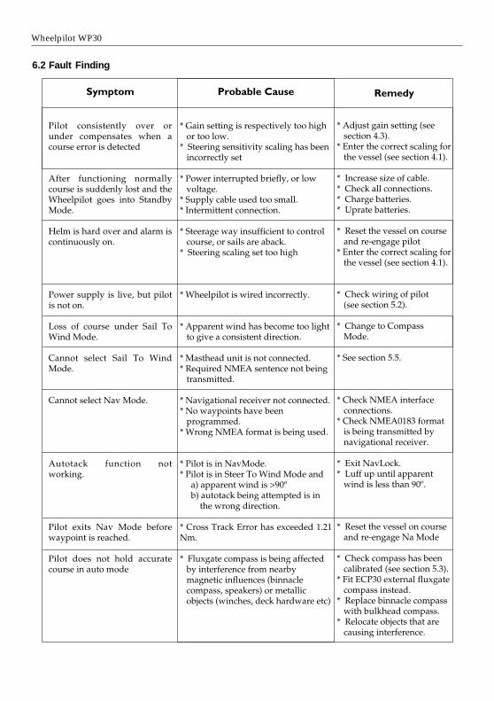
6.2 Fault Finding

Page 25
Instruction manual
6.3 Auto Compass Calibration
Although the Wheelpilot internal compass is extremelyaccurate, after installation it is necessary to calibrate thecompass to compensate for any deviations caused byobjects surrounding it on board the vessel.
With the vessel motoring along slowly (2–3 knots) incalm conditions and the Wheelpilot in Standby mode,press the Starboard key a number of times to induce aslow clockwise rotation of the vessel. Press and hold theTACK key, followed by the Port and Starboard keyssimultaneously to enter Auto Compass Calibration mode(Fig 6.1). The Port and Starboard LEDs will both light.Allow the vessel to turn through a minimum of 11/4
turns (450º) in approximately two minutes, during whichtime the fluxgate compass will automatically calibrateitself.
If the rate of turn or the boat speed is too high, the PortLED will flash (Fig 6.2) indicating that it is necessary toeither slow the boat or decrease the angle of turn. If therate of turn or boat speed is too slow, the Starboard LEDwill flash, indicating that it is necessary increase toeither the boat speed or the angle of turn. A short beep(3 seconds) will indicate that the calibration has beensuccessful and the Wheelpilot will return to Standbymode. If the calibration has been unsuccessful, after aperiod of four minutes a long beep (6 seconds) willsound. Try again, carefully following the above direc-tions.
Note, that this function is only available for autocali-brating the internal fluxgate compass.
6.4 Adjusting Belt Tension
The belt tension is set when the Wheelpilot is assem-bled, however, it may be necessary to adjust this duringthe lifetime of the pilot.
The tension is adjusted by means of a screw situatedunderneath the clutch lever. This screw is only accessi-ble when the lever is in the up (disengaged) position. Todecrease the clutch tension, turn the screw clockwise. Toincrease the tension, turn the screw anticlockwise. Thescale next to the screw indicates the current tension set-ting. When the pointer is at the top, the clutch is at max-imum tension. Minimum tension is indicated when thepointer is at the bottom.
TACK
TACK
TACK
TACK
Fig 6.1 - Auto Compass Calibration
TACK
Fig 6.2 - Rate of turn too fast
Fig 6.3 - Belt tensioner
Indicator pointer
Adjusting screw
Scale

Page 26
Wheelpilot WP30
STBY
TACK
STBYAUTO
HR20
Hand Remote Unit
ECP30
ExternalCompass
SKT300
6-Way WaterproofPlug and Socket kit
PED200:BK
Large Pedestal Mount kitfor pedestals 175 to 200mm
diameter (7.0 to 8.0 in).
E03011Spare spoke clamps(supplied individually)
E03529
Replacement badge
CMC-TP
ECP30 interface cable(5m)
E03235Extra long guide rods
6.5 Spares & Accessories
The following spares and accessories are available through your local Simrad agent. Please quotethe correct part number when ordering.

Page 27
Instruction manual
6.6 Servicing
Although your Wheelpilot should seldom need servicing, for optimum performance we recom-mend that the belt is replaced every three or four seasons. Replacement belts are available fromyour local Simrad agent, and we recommend that the belt is replaced professionally to ensure cor-rect fitment and calibration.
The Wheelpilot will also benefit from an application of silicone or Teflon grease to the connectorseach season, and by keeping the control unit and the connector’s protective cover in place whennot in use.
6.7 Warranty
The unit is guaranteed for 24 months from date of retail sale. If it is necessary to have the unitrepaired, return it carriage prepaid to the agent in the country of purchase with a copy of thereceipted invoice showing the date of purchase. Where possible, return all the components unlessyou are certain that you have located the source of the fault. If the original packing is not available,ensure that it is well cushioned in packing; the rigours of freight handling can be very differentfrom the loads encountered in the marine environment for which the unit is designed.
For Worldwide Warranty details, please refer to the Warranty Card supplied with this unit.
A list of official worldwide Simrad dealers is included in the Warranty Card.


M A X I M I Z I N G Y O U R P E R F O R M A N C E A T S E A
www.simrad.com