Ludlow & Ellesmere EC5W - AGA
28
This appliance is hot while in operation and retains its heat for a long period of time after use. Children, aged or infirm persons should be supervised at all times and should not be allowed to touch the hot working surfaces while in use or until the appliance has thoroughly cooled. This stove has an Efficiency Rating of “A” and has passed the Eco-design 2022 Standard and has the met the Standards as defined by DEFRA for Burning Wood in Smoke Free Areas (Can only be used in a Smoke Free Zone when the DEFRA Tube kit is fitted) PLEASE RETAIN Ludlow & Ellesmere EC5W 5.0kW Wide Model Multi-Fuel Stove INSTALLATION AND OPERATING INSTRUCTIONS
-
Upload
khangminh22 -
Category
Documents
-
view
6 -
download
0
Transcript of Ludlow & Ellesmere EC5W - AGA
This appliance is hot while in operation and retains its heat for a long period of time after use. Children,
aged or infirm persons should be supervised at all times and should not be allowed to touch the hot
working surfaces while in use or until the appliance has thoroughly cooled.
This stove has an Efficiency Rating of “A” and has passed the Eco-design 2022 Standard and has the met the Standards as defined by DEFRA for Burning Wood in Smoke Free Areas
(Can only be used in a Smoke Free Zone when the DEFRA Tube kit is fitted)
PLEASE RETAIN
Ludlow & Ellesmere EC5W
5.0kW Wide Model Multi-Fuel Stove
INSTALLATION AND OPERATING INSTRUCTIONS

Page 1 of 27 AGA Ludlow & Ellesmere Wide EC5W Revision 1.5 – Issued June 2021
TABLE OF CONTENTS
1. Installation Information, Technical Data, DEFRA & AGA Solid Fuel Stove Warranty Summary.. . .
2. Installation Checklist . . . . . . . . . . . . . . . . . . . . . . . . . . . . . . . . . . . . . . . . . . . . . . . . . . . . . . . . . . . . .
3. Important Operation/ Maintenance Notes . . . . . . . . . . . . . . . . . . . . . . . . . . . . . . . . . . . . . . . . . . . .
4. Installation & Operating Instructions . . . . . . . . . . . . . . . . . . . . . . . . . . . . . . . . . . . . . . . . . . . . . . . . .
5. General . . . . . . . . . . . . . . . . . . . . . . . . . . . . . . . . . . . . . . . . . . . . . . . . . . . . . . . . . . . . . . . . . . . . . . .
6. Flues . . . . . . . . . . . . . . . . . . . . . . . . . . . . . . . . . . . . . . . . . . . . . . . . . . . . . . . . . . . . . . . . . . . . . . . . .
7. Chimney . . . . . . . . . . . . . . . . . . . . . . . . . . . . . . . . . . . . . . . . . . . . . . . . . . . . . . . . . . . . . . . . . . . . . .
8. Flue Exit (Top and Rear) . . . . . . . . . . . . . . . . . . . . . . . . . . . . . . . . . . . . . . . . . . . . . . . . . . . . . . . . . .
9. Down Draughts . . . . . . . . . . . . . . . . . . . . . . . . . . . . . . . . . . . . . . . . . . . . . . . . . . . . . . . . . . . . . . . . .
10. Ventilation & Combustion Air Requirements . . . . . . . . . . . . . . . . . . . . . . . . . . . . . . . . . . . . . . . . . . .
11. External Ducted Air . . . . . . . . . . . . . . . . . . . . . . . . . . . . . . . . . . . . . . . . . . . . . . . . . . . . . . . . . . . . . .
12. Heat Recovery Ventilation (HRV) . . . . . . . . . . . . . . . . . . . . . . . . . . . . . . . . . . . . . . . . . . . . . . . . . . .
13. Location . . . . . . . . . . . . . . . . . . . . . . . . . . . . . . . . . . . . . . . . . . . . . . . . . . . . . . . . . . . . . . . . . . . . . . .
14. Clearance To Combustibles . . . . . . . . . . . . . . . . . . . . . . . . . . . . . . . . . . . . . . . . . . . . . . . . . . . . . . . .
15. Floor Protection . . . . . . . . . . . . . . . . . . . . . . . . . . . . . . . . . . . . . . . . . . . . . . . . . . . . . . . . . . . . . . . . .
16. Stove Dimensions . . . . . . . . . . . . . . . . . . . . . . . . . . . . . . . . . . . . . . . . . . . . . . . . . . . . . . . . . . . . . . .
17. Commissioning and Handover . . . . . . . . . . . . . . . . . . . . . . . . . . . . . . . . . . . . . . . . . . . . . . . . . . . . .
18. Operation . . . . . . . . . . . . . . . . . . . . . . . . . . . . . . . . . . . . . . . . . . . . . . . . . . . . . . . . . . . . . . . . . . . . . .
19. Air Controls . . . . . . . . . . . . . . . . . . . . . . . . . . . . . . . . . . . . . . . . . . . . . . . . . . . . . . . . . . . . . . . . . . . .
20. Recommended Fuels . . . . . . . . . . . . . . . . . . . . . . . . . . . . . . . . . . . . . . . . . . . . . . . . . . . . . . . . . . . .
21. Technical Data . . . . . . . . . . . . . . . . . . . . . . . . . . . . . . . . . . . . . . . . . . . . . . . . . . . . . . . . . . . . . . . . . .
22. Lighting . . . . . . . . . . . . . . . . . . . . . . . . . . . . . . . . . . . . . . . . . . . . . . . . . . . . . . . . . . . . . . . . . . . . . . .
23. Lighting The Stove . . . . . . . . . . . . . . . . . . . . . . . . . . . . . . . . . . . . . . . . . . . . . . . . . . . . . . . . . . . . . .
24. Refuelling . . . . . . . . . . . . . . . . . . . . . . . . . . . . . . . . . . . . . . . . . . . . . . . . . . . . . . . . . . . . . . . . . . . . .
25. Slow Burning . . . . . . . . . . . . . . . . . . . . . . . . . . . . . . . . . . . . . . . . . . . . . . . . . . . . . . . . . . . . . . . . . . .
26. Disposal of Ashes . . . . . . . . . . . . . . . . . . . . . . . . . . . . . . . . . . . . . . . . . . . . . . . . . . . . . . . . . . . . . . .
27. Monthly Maintenance . . . . . . . . . . . . . . . . . . . . . . . . . . . . . . . . . . . . . . . . . . . . . . . . . . . . . . . . . . . .
28. Periodic Maintenance . . . . . . . . . . . . . . . . . . . . . . . . . . . . . . . . . . . . . . . . . . . . . . . . . . . . . . . . . . . .
29. Chimney Cleaning . . . . . . . . . . . . . . . . . . . . . . . . . . . . . . . . . . . . . . . . . . . . . . . . . . . . . . . . . . . . . .
30. Glass Cleaning . . . . . . . . . . . . . . . . . . . . . . . . . . . . . . . . . . . . . . . . . . . . . . . . . . . . . . . . . . . . . . . . .
31. Cleaning a Matt Black Stove …………….. . . . . . . . . . . . . . . . . . . . . . . . . . . . . . . . . . . . . . . . . . . . .
32. Prolonged Periods of Non Use . . . . . . . . . . . . . . . . . . . . . . . . . . . . . . . . . . . . . . . . . . . . . . . . . . . . .
33. Fire Safety . . . . . . . . . . . . . . . . . . . . . . . . . . . . . . . . . . . . . . . . . . . . . . . . . . . . . . . . . . . . . . . . . . . . .
34. Glass Replacement . . . . . . . . . . . . . . . . . . . . . . . . . . . . . . . . . . . . . . . . . . . . . . . . . . . . . . . . . . . . . .
35. CO Alarm . . . . . . . . . . . . . . . . . . . . . . . . . . . . . . . . . . . . . . . . . . . . . . . . . . . . . . . . . . . . . . . . . . . . . .
36. Exploded View . . . . . . . . . . . . . . . . . . . . . . . . . . . . . . . . . . . . . . . . . . . . . . . . . . . . . . . . . . . . . . . . .
37 Appendix 1 - Annual Servicing Records. . . . . . . . . . . . . . . . . . . . . . . . . . . . . . . . . . . . . . . . . . . . . . .
38 Detailed Warranty . . . . . . . . . . . . . . . . . . . . . . . . . . . . . . . . . . . . . . . . . . . . . . . . . . . . . . . . . . . ..
39 Energy Efficiency Label Europe & the United Kingdom . . . . . . . . . . . . . . . . . .. . . . . . . . . . . . . . .

Page 2 of 27 AGA Ludlow & Ellesmere Wide EC5W Revision 1.5 – Issued June 2021
Installation Information Please complete the following form for reference when required:
Ref. Description
Please Complete
1
Which retailer did you purchase the stove from?
Name & Address of Retailer:
2
What date did you purchase your new stove?
Date:
3
What was the name of the approved fitter that installed your stove?
Full Name: Contact Number:
4
What is the installer HETAS Registration Number?
HETAS Registration No.:
5
What is the serial Number of your stove? This can we found inside the front door above the bottom hinge
Serial Number:
6
What date was your stove installed?
Date:
7.
The AGA Name, Model & Fuel Type reference for this stove is
Name - Ellesmere or Ludlow (please circle)
Model – EC5W Wide Body Model Fuel Type – Multi-Fuel
Technical Data Summary:
Reference Description Data
1 Maximum Heat Output – High Burn 5.0 kW Nominal Heat
2 Minimum Heat Output – Low Burn 2.0 kW
3 Efficiency % 77.6% (Wood) 79.5% (MSF)
4 Energy Label Rating (EEL Eco Labelling) “A”
5 Eco-Designed Status Eco-Design Approved 2022
6 Approved for use in DEFRA Smoke Free Zone YES
KEY STOVE TECHNICAL DATA OVERLEAF

Page 3 of 27 AGA Ludlow & Ellesmere Wide EC5W Revision 1.5 – Issued June 2021
TECHNICAL FICHE DATA
ALSO ADDRESSING ECO-DESIGN 2022 AND DEFRA SMOKE EXCEMPTION
GENERAL PRODUCT INFORMATION:
Model Reference: AGA Ludlow & Ellesmere EC5W – Multi-Fuel Stove (Wide Body Model)
Energy Efficiency Class of Model: A
Net Efficiencies: Wood: - 77.6% & Ancit (Smokeless Fuel): 79.5%
Eco-Design Standard 2022 Compliant: Yes – Approved to the Standard
Direct Heat Output: 5.0 kW
Indirect Heating Functionality: No – Air to Air Convectional & Radiant Heat only – No Hot Water
Type of Heat Output Room Temperature Control:
Two or more manual stages, no temperature control
Other Control Options: N/a
DEFRA – Compliant to the Standard: Yes – Approved to be used in Smoke Exempt Zones/Areas
Hearth Construction – Approved for: Needs to be a minimum of 125 mm (5”) and made of solid construction (concrete, stone, brick) If the stove is fitted to the AGA Log store the hearth can be a superimposed 12 mm deep and made of non-combustible material such as (Glass, Steel, Stone or Concrete)
Flue Collar & Flue Pipe Diameter: Fit 125mm diameter (5.0”) Flue (Single or Twin Walled)
Approved Fuel Types: Multi-fuel – Dried Wood & Ancit based Smokeless Fuels
Stove Construction: - 5mm thick - Steel Outer Stove Body & 8mm thick Removable Lid - Cast Iron Door & Handle (Handle with Stainless Steel Outer) - 4mm thick - Ceramic Heatproof Glass - Vermiculate High Temperature - Firebox Liner
AGA - 3 way Air Management System: Primary, Secondary & Tertiary Air Inlets via 2 x Controls Knobs
External Air Input kit: Yes – Optional Extra
Stove Directly Fits onto a Log-Store: Yes – AGA Log-Store Stand 350mm high - Optional Extra
Top or Rear Flue Exit: Yes - Top or Rear Flue Exit options built in
Rear Heat Shield: Yes – Rear Heat Shield Fitted as Standard onto the Rear of the Stove
Convection & Radiant Heat Sources Outputs:
Yes – Radiant Heat from Both Sides & Front, with Additional Convectional Heat Ducts from the Rear & Top Outlets
Warranty Period: 5 years – (Excluding Consumable Items – see Operating Manual for full
details) Log Length: 425 mm in Length
Sweep Flue through Stove: Yes – 2 x Removable Top Baffle Plates to Sweep
Grate Type: Multi-Fuel Grate - Complete with Ash Pan Underneath
Adjustable Bottom Feet for Levelling: 4 x M6 pads fitted to the bottom of feet for adjustment
What’s included with this Stove: Glove, Ash Pan, Cast Flue Collar, Rear Heat Shield Flue Collar, Cast Log Retainer & Rear Flue Exit Blanking Plate (Fitted to the Stove)
Minimum Flue Height/Pascals Rating: 4.6m High and the flue tested at 12 Pascals
STOVE EFFICIENCY & PERFORMANCE:
Efficiency (%) Energy Nominal Heat Output (kW)
Fuel Type
Net
Gross
Efficiency Index
Total
To Space
To Water CO
(% @13% Oxygen)
Wood Logs 77.6% 70.9% 103 5.0 kW 5.0 kW N/a 0.12
Maxibrite (MSF*)
79.5% 77.5% N/A 5.0 kW 5.0 kW N/a 0.08
*MSF = Manufactured Smokeless Fuel
Appliance Manufacturer:
AGA Rangemaster
Station Road, Ketley Telford, Shropshire, TF1 5AQ
www.agaliving.co.uk

Page 4 of 27 AGA Ludlow & Ellesmere Wide EC5W Revision 1.5 – Issued June 2021
STOVE EFFICIENCY & PERFORMANCE:
Specific Precautions during Assembling, Installing & Maintenance: See installation instructions for more information PRODUCT RECYCLING
PRODUCT END-OF-LIFE/RECYCLING: To dispose of the stove after the product life has expired, please observe the following information
Dispose of the items correctly i.e. separate the parts to be disposed of in material groups
Always dispose of items in a way that is as sustainable as possible and that is in line with the current
environmental protection, reprocessing/recycling and disposal technology
o ALL METAL PARTS TO BE RECYCLED o ALL GLASS TO BE RECYCLED o ALL OTHER COMPONENTS TO BE DISPOSED IN A MANNER ACCORDING TO
ENVIRONMENTAL REGULATIONS
MINIMUM DISTANCES TO COMBUSTIBLE MATERIALS:
MINIMUM DISTANCES TO COMBUSTIBLE MATERIALS:
Minimum Distances to Combustible Materials (Walls)
Flue Fitted – Main Rear Stove Heat Shield Fitted as Supplied
Back Wall Side Wall
Fitted with twin walled insulated flue and rear heat shield flue collar extension fitted
200mm 500mm
Fitted with single walled flue with rear heat shield flue collar extension fitted
250mm 500mm
MINIMUM DISTANCES TO NON-COMBUSTIBLE MATERIALS: We recommend a minimum clearance of 100mm to both sides & the back of this stove when being installed next to NON - COMBUSTIBLE MATERIALS into a fireplace opening constructed of solid brickwork
SPACE HEATING PERFORMANCE AT NOMINAL OUTPUT
Fuel(s) Primary
Fuel
Seasonal Efficiency
(%)
(mg/m³)
PM OGC CO NOx
Wood Logs Yes 67.6 22 117 1500 91
Smokeless Fuel No 69.5 20.0 11 1000 100
PERFORMANCE WHEN OPERATED ON PRIMARY FUEL
Rated Heat Output (kW) 5.0 Nominal Net Efficiency (%) 77.6%
Electrical Consumption Nominal (kW) N/A Electrical Consumption Minimum (kW) N/A
Electrical Consumption Standby (kW) N/A Energy Efficiency Index 103 EEI Rating A
Page 5 of 27 AGA Ludlow & Ellesmere Wide EC5W Revision 1.5 – Issued June 2021
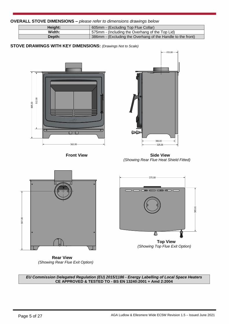
OVERALL STOVE DIMENSIONS – please refer to dimensions drawings below
Height: 605mm - (Excluding Top Flue Collar)
Width: 575mm - (Including the Overhang of the Top Lid)
Depth: 386mm - (Excluding the Overhang of the Handle to the front)
STOVE DRAWINGS WITH KEY DIMENSIONS: (Drawings Not to Scale)
Front View Side View (Showing Rear Flue Heat Shield Fitted)
Rear View (Showing Rear Flue Exit Option)
EU Commission Delegated Regulation (EU) 2015/1186 - Energy Labelling of Local Space Heaters CE APPROVED & TESTED TO - BS EN 13240:2001 + Amd 2:2004
Top View (Showing Top Flue Exit Option)
Page 6 of 27 AGA Ludlow & Ellesmere Wide EC5W Revision 1.5 – Issued June 2021
THE CLEAN AIR ACT 1993 AND SMOKE CONTROL AREAS – DEFRA LISTING This AGA Multi-fuel stove is able to be used smoke controlled areas and is listed on the DEFRA website for this exempt but only under the following conditions
Correct Approved fuel is used, with a moisture content of less than 20%
The limiter tube is fitted to the Secondary and Tertiary Air Control Rod
The stove is not overloaded with fuel
The stove is operated as stated in the operating manual supplied
The stove is not overloaded with fuel
Refuelling onto a low fire bed in the corect manner
Not operating the stove with door left open
Under the Clean Air Act local authorities may declare the whole or part of the district of the authority to be smoke control area. It is an offence to emit smoke from a chimney of a building, from a furnace or from any fixed boiler if located in a designated smoke control area. It is also an offence to acquire an “unauthorised fuel” for use within a smoke control area unless it is used in an “exempt” appliance (“exempt” from the controls which generally apply in the smoke control area) In England appliances are exempt by publication on the list by the Secretary of State in accordance with changes made to sections 20 and 21 of the Clean Air Act 1993 by section 15 of the Deregulation Act 2015. Similarly in Scotland appliances are exempt by publication on the list by Scottish Minister under section 50 of the Regulatory Reform (Scotland) Act 2014 In Wales and Northern Ireland these are authorised by regulations made by Welsh Ministers and by the Department of Environment respectively Further information on the requirements of the Clean Air Act can be found here at: https://www.gov.uk/smoke-control-area-rules Your local authority is responsible for implementing the Clean Air Act 1993 including designation and supervision of smoke control areas and you can contact them for details of the Clean Air Act requirements REQUIREMENTS FOR THIS AGA STOVE WHEN BEING USED IN A SMOKE CONTROLLED AREA APPROVED FUELS TO BE USED What can I burn in my AGA Multi-fuel Stove - When using this clean burn stove we recommend you use kiln dried or well seasoned wood with a moisture content of less than 20% this will give you the optimum burn and the highest efficiency with minimal smoke which emits the harmful Particulate Matters (PMs) into the environment. This will also give you maximum heat output and use the minimal amount of wood. When burning Green wood or unseasoned wood with a moisture content of greater than 20% you risk discolouration on the door glass and it will most likely use up to twice the amount of fuel to achieve a lesser heat output than if you used the correct fuel. Using Kiln dried or well-seasoned wood will give you greater heat outputs, improved efficiency and therefore running costs, all of which is kinder to our environment and the air that we breathe
FUEL OVERLOADING
The maximum amount of fuel specified in this manual should not be exceeded, overloading can cause excess smoke.
REFUELLING ONTO A LOW FIRE BED
If there is insufficient burning material in the firebed to light a new fuel charge, excessive smoke emission can occur.Refuelling must be carried out onto a sufficient quantity of glowing embers and ash that the new fuel charge will ignite in a reasonable period.If there are too few embers in the fire bed add suitable kindling to prevent excess smoke.
Page 7 of 27 AGA Ludlow & Ellesmere Wide EC5W Revision 1.5 – Issued June 2021
DAMPERS LEFT OPEN Operation with the air control or appliance dampers open can cause excess smoke. The appliance must not be operated with air controls, appliance dampers or door left open except as directed in the instructions.
OPERATION WITH DOOR LEFT OPEN
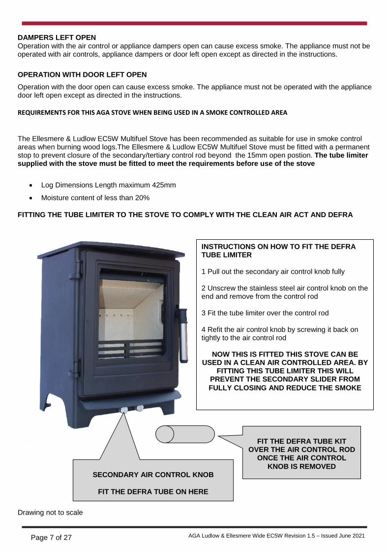
Operation with the door open can cause excess smoke. The appliance must not be operated with the appliance door left open except as directed in the instructions. REQUIREMENTS FOR THIS AGA STOVE WHEN BEING USED IN A SMOKE CONTROLLED AREA The Ellesmere & Ludlow EC5W Multifuel Stove has been recommended as suitable for use in smoke control areas when burning wood logs.The Ellesmere & Ludlow EC5W Multifuel Stove must be fitted with a permanent stop to prevent closure of the secondary/tertiary control rod beyond the 15mm open postion. The tube limiter supplied with the stove must be fitted to meet the requirements before use of the stove
Log Dimensions Length maximum 425mm
Moisture content of less than 20% FITTING THE TUBE LIMITER TO THE STOVE TO COMPLY WITH THE CLEAN AIR ACT AND DEFRA
Drawing not to scale
INSTRUCTIONS ON HOW TO FIT THE DEFRA TUBE LIMITER 1 Pull out the secondary air control knob fully 2 Unscrew the stainless steel air control knob on the end and remove from the control rod 3 Fit the tube limiter over the control rod 4 Refit the air control knob by screwing it back on tightly to the air control rod
NOW THIS IS FITTED THIS STOVE CAN BE USED IN A CLEAN AIR CONTROLLED AREA. BY
FITTING THIS TUBE LIMITER THIS WILL PREVENT THE SECONDARY SLIDER FROM
FULLY CLOSING AND REDUCE THE SMOKE
SECONDARY AIR CONTROL KNOB
FIT THE DEFRA TUBE ON HERE
FIT THE DEFRA TUBE KIT
OVER THE AIR CONTROL ROD ONCE THE AIR CONTROL
KNOB IS REMOVED
Page 8 of 27 AGA Ludlow & Ellesmere Wide EC5W Revision 1.5 – Issued June 2021
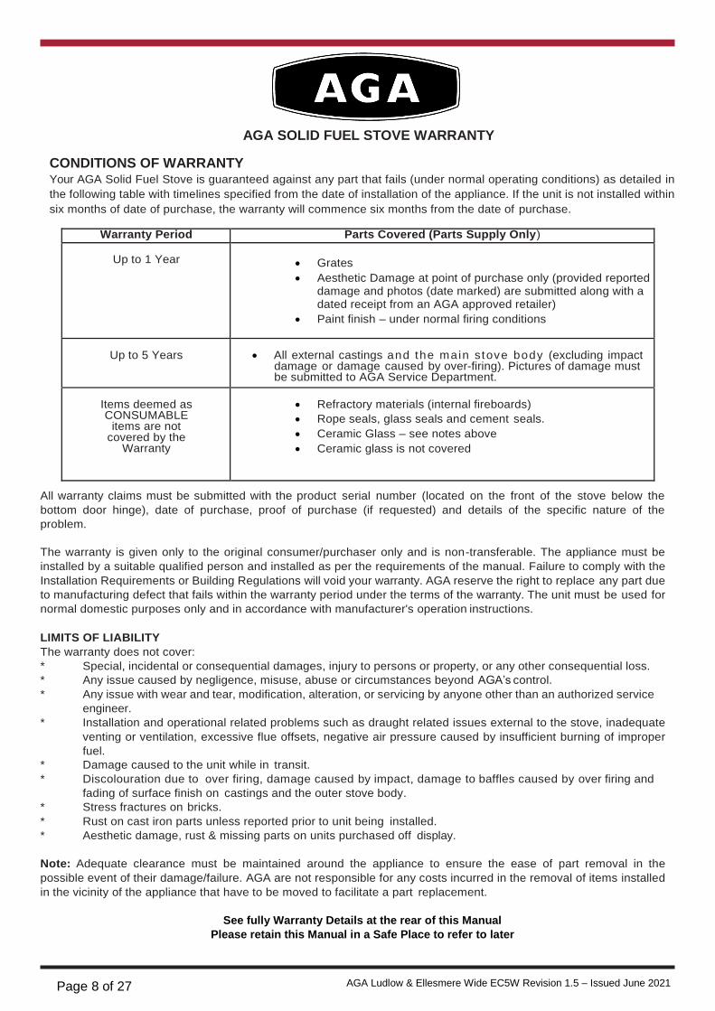
AGA SOLID FUEL STOVE WARRANTY
CONDITIONS OF WARRANTY Your AGA Solid Fuel Stove is guaranteed against any part that fails (under normal operating conditions) as detailed in
the following table with timelines specified from the date of installation of the appliance. If the unit is not installed within
six months of date of purchase, the warranty will commence six months from the date of purchase.
Warranty Period Parts Covered (Parts Supply Only)
Up to 1 Year
Grates
Aesthetic Damage at point of purchase only (provided reported damage and photos (date marked) are submitted along with a dated receipt from an AGA approved retailer)
Paint finish – under normal firing conditions
Up to 5 Years
All external castings and the main stove body (excluding impact
damage or damage caused by over-firing). Pictures of damage must be submitted to AGA Service Department.
Items deemed as CONSUMABLE
items are not covered by the
Warranty
Refractory materials (internal fireboards)
Rope seals, glass seals and cement seals.
Ceramic Glass – see notes above
Ceramic glass is not covered
All warranty claims must be submitted with the product serial number (located on the front of the stove below the
bottom door hinge), date of purchase, proof of purchase (if requested) and details of the specific nature of the
problem.
The warranty is given only to the original consumer/purchaser only and is non-transferable. The appliance must be
installed by a suitable qualified person and installed as per the requirements of the manual. Failure to comply with the
Installation Requirements or Building Regulations will void your warranty. AGA reserve the right to replace any part due
to manufacturing defect that fails within the warranty period under the terms of the warranty. The unit must be used for
normal domestic purposes only and in accordance with manufacturer's operation instructions.
LIMITS OF LIABILITY
The warranty does not cover:
* Special, incidental or consequential damages, injury to persons or property, or any other consequential loss.
* Any issue caused by negligence, misuse, abuse or circumstances beyond AGA’s control.
* Any issue with wear and tear, modification, alteration, or servicing by anyone other than an authorized service
engineer.
* Installation and operational related problems such as draught related issues external to the stove, inadequate
venting or ventilation, excessive flue offsets, negative air pressure caused by insufficient burning of improper
fuel.
* Damage caused to the unit while in transit.
* Discolouration due to over firing, damage caused by impact, damage to baffles caused by over firing and
fading of surface finish on castings and the outer stove body.
* Stress fractures on bricks.
* Rust on cast iron parts unless reported prior to unit being installed.
* Aesthetic damage, rust & missing parts on units purchased off display.
Note: Adequate clearance must be maintained around the appliance to ensure the ease of part removal in the
possible event of their damage/failure. AGA are not responsible for any costs incurred in the removal of items installed
in the vicinity of the appliance that have to be moved to facilitate a part replacement.
See fully Warranty Details at the rear of this Manual
Please retain this Manual in a Safe Place to refer to later

Page 9 of 27 AGA Ludlow & Ellesmere Wide EC5W Revision 1.5 – Issued June 2021
Tick
Flue System
INSTALLATION CHECK LIST
1. Minimum Flue Height of 4.6 metres (15 feet).
2. Appliance should be connected to a 125mm (5”) diameter flue pipe throughout
3. All flue pipework passing through walls must be sleeved & adequately insulated in line
with current Building Regulations.
4. Appliance should be connected to a chimney of less than 200mm (8”) in diameter
(otherwise the chimney must be lined with a minimum 125mm (5”) flue liner).
5. The chimney/ flue termination must be located in accordance with building regulations part J.
6. The chimney serving this appliance should not serve any other appliance.
7. Access should be provided to the chimney serving the appliance to allow for cleaning.
8. It is a requirement by Building Regulations to have a carbon monoxide alarm
fitted to any room with a solid fuel appliance.
9. Ensure a test point is fitted into the flue so the PASALS can be measured
Location
10. Clearance to combustible materials must be adhered to as described in the Clearance
to Combustible section.
11. The stove needs to be installed onto a minimum of 125 mm (5”) thick non combustible
hearth and extends to these minimum dimensions 300mm (12”) to the front,
200mm (8”) to the sides and back.
12. Clearance must be maintained to allow for maintenance and part replacement.
Ventilation & Combustion Air Requirements
13. The room in which the appliance is located should have air flow of adequate
proportion to support correct combustion (see Ventilation & Combustion Air
Requirement Section for specific details).
14. The stove must not be installed in the same room as an extractor fan.
Page 10 of 27 AGA Ludlow & Ellesmere Wide EC5W Revision 1.5 – Issued June 2021
IMPORTANT OPERATION / MAINTENANCE NOTES
Now that your AGA Solid Fuel Stove is installed and no doubt you are looking forward to the many comforts it
will provide, we would like to give you some tips on how to get the best results from your stove.
1. We would like if you could take some time to read the operating instructions/hints, which we are
confident, will be of great benefit to you.
2. Do not burn fuel with a high moisture content, such as a damp peat or unseasoned timber. This
will only result in a build up of tar in the stove and in the chimney. Only burn well seasoned wood
with a moisture content of less than 20%
PLEASE NOTE – this AGA stove has been tested by KIWA (who are a leading Test Organisation based in the UK for compliance to the BS EN 13240 Standard, Eco Design 2022 Standard, and the DEFRA Smoke Exempt Standard on Wood Logs and Manufactured Smokeless Briquettes only
IMPORTANT: The first few fires should be relatively small to permit the refractory and
paint to set properly and season the stove. During these firings it is recommended to
ventilate the room as an unpleasant (not toxic) odour and smoke may be emitted as
the paint is completing curement.
LEAVE THE DOOR SLIGHTLY AJAR DURING THE FIRST FIRING TO PREVENT THE ROPE
FROM STICKING TO THE PAINT DURING THE CURING PROCESS.
3. Inspect the flue-ways of the stove weekly and ensure that there are no blockages. Check flue
ways before lighting especially after a shut down period. Please see chimney cleaning
section.
4. Never allow a build up of ashes in the ash pan, as this will cause the grate to burn out prematurely.
Empty the ashpan when refuelling.
5. Avoid slow burning of damp or unseasoned fuel as this will result in tarring flue ways and chimney i.e.
peat or timber.
6. Additionally slow burner/slumbering the stove. This can also cause crazing of the glass once the glass has
been crazed it will go cloudy with lines all over the glass once this has occurred the glass needs to be
replaced this is not covered by any warranty whatsoever, to help avoid this burn the fire on maximum for a
minimum of 5 minutes in every 60 minutes as this help to burned off any substances on the glass
7. Allow adequate air ventilation to ensure plenty of air for combustion.
8. Do not burn rubbish/household plastic.
9. Clean the chimney at least twice a year.
10. Burning soft fuels such as timber and peat will stain the glass. Regular cleaning will prevent permanent staining. Clean with soapy water when cool.
11. Keep all combustible materials a safe distance away from unit, please see section for
clearances to combustibles.
12. Never use aerosol spray near the appliance when it is in operation.
13. For safety reasons never leave children or the elderly unaccompanied while stove is in use. Use
a fire guard.
14. Avoid contact with the appliance when in use as stove reaches very high operating temperatures.
15. This appliance should be regularly maintained by a competent service engineer.

Page 11 of 27 AGA Ludlow & Ellesmere Wide EC5W Revision 1.5 – Issued June 2021
GENERAL
INSTALLATION & OPERATING INSTRUCTIONS
Please refer to the current standards, BS EN 15287-
When installing, operating and maintaining your
AGA Stove respect basic standards of fire safety.
Read these instructions carefully before
commencing the installation. Failure to do so may
result in damage to persons and property. Consult
your local Municipal office and your insurance
representative to determine what regulations are in
force. Save these instructions for future reference.
Please note that it is a legal requirement under
England & Wales Building Regulations that the
installation of the stove is either carried out under
Local Authority Building Control approval or is
installed by a Competent Person registered with a
Government approved Competent Persons
Scheme. HETAS Ltd operate such a scheme and a
listing of their Registered Competent Persons can
be found on their website at www.hetas.co.uk.
Special care must be taken when installing the stove
such that the requirements of the Health & Safety at
Work Act are met.
Handling
Adequate facilities must be available for loading,
unloading and site handling.
Fire Cement
Some types of fire cement are caustic and should
not be allowed to come into contact with the skin. In
case of contact with the skin wash immediately with
plenty of water.
Asbestos
This stove contains no asbestos. If there is a
possibility of disturbing any asbestos in the course
of installation then please seek specialist guidance
and use appropriate protective equipment.
Metal Parts
When installing or servicing this stove care should
be taken to avoid the possibility of personal injury.
“IMPORTANT WARNING”
This stove must not be installed into a chimney that
serves any other heating appliance.
1:2007 Design, Installation and Commissioning of
chimneys. BS EN 14336:2004: Heating Systems in
Buildings. Installation & Commissioning of Water
Based Heating Systems. BS EN 12828: 2003;
Heating Systems in Buildings. Design of Water
Based Heating Systems. BS EN 12831: 2003;
Heating Systems in Buildings. method for
calculation of the design heat load.
Your AGA stove is supplied with the following
items:
• Flue Pipe Heat Shield
• Back Heat Shield – fitted to the stove
• Ashpan with integrated handle & Glove
• Flue Spigot for 125mm diameter flue
FLUES
Flues should be vertical wherever possible and
where a bend is necessary, it should not make an
angle of more than 45o with the vertical. Horizontal
flue runs should be avoided except in the case of a
back outlet from the appliance, when the length of
the horizontal section should not exceed 150mm.
In order to minimise flue resistance and to make
sweeping easier it is recommended to use 2 x 45o
bends rather than a 90o bend.
CHIMNEY
Do not connect to a chimney serving another
appliance.
The stove is a radiant room heater and must be
connected to a chimney of the proper size and
type.
The stove is designed to be installed with a 5”
(125mm) flue throughout. The stove is supplied
with a 5” flue spigot. It is best to connect to a
chimney of the same size, as connection to a
larger size may result in a somewhat less draught.
A flue that has proved to be unsatisfactory,
particularly with regard to down draught should not
be used for venting this appliance until it has been
examined and any faults corrected. An existing
masonry chimney should be inspected and if
necessary repaired by a competent mason or relined
using an approved lining system. The complete installation must be done in accordance with current Standards and Local
Codes. It should be noted that the requirements and these publications may be superseded during
the life of this manual.

Page 12 of 27 AGA Ludlow & Ellesmere Wide EC5W Revision 1.5 – Issued June 2021
All register plates, restrictor plates, damper etc.,
which could obstruct the flue at a future date should
be removed before connecting this appliance.
If connecting to an existing chimney with a flue
diameter of more than 200mm (8”) it is
recommend to line the flue using a suitable
stainless steel flue liner.
Where a masonry chimney is not available a
proprietary type of 5”/125mm - twin wall, fully
insulated pipe may be used. The pipe must
terminate at a point not lower than the main ridge
of adjacent outside obstructions. With such
installation, access to the chimney must be
provided for cleaning purposes.
A chimney / flue termination must be located to
minimise wind effects, a basic guide is that the
distance from the termination to the roof should be
at be at least 2300mm when measured
horizontally and at least 1000mm when measured
vertically, (see Fig.1). In circumstances where
there are adjoining buildings/ structures/ roof
openings there are additional requirements, please
refer to building regulations part J.
Fig.1
FLUE EXIT (TOP & REAR)
The stove is designed to allow the chimney to be
cleaned through the stove. If the chimney cannot be
cleaned through the stove it is necessary to provide
a soot box/ access door in the flue for cleaning. See
Fig.2 for recommended locations. Fit it to the stove
as shown in Fig.2.
The stove comes partially configured for top outlet
and requires the flue spigot (supplied in the firebox)
to be fitted to the top outlet flue connection as shown
in Fig 3 using the nuts & bolts provided.
To configure for back outlet flue connection, remove
the top plate and remove the back heat shield by
lifting it up to remove it from its four fixing points.
Remove the flue blanking plate from the back outlet
connection. Remove the flue spigot from the top
connection and fit it to the back outlet connection. Fit
the flue blanking plate to the top outlet connection.
Remove the cut-out on the back heat shield and refit
the heat shield. Refit the hob and fit the hob
blanking plate (see Fig 4).
Fig.2
Fig.3

Page 13 of 27 AGA Ludlow & Ellesmere Wide EC5W Revision 1.5 – Issued June 2021
Fig.4
Back
Outlet
VENTILATION & COMBUSTION AIR REQUIRE- MENTS
It is imperative that there is sufficient air supply to the stove in order to support correct combustion. The air supply to this appliance must comply with current Building Regulations Part J, Heat Providing Appliances. If another appliance is fitted in an adjacent room it will be necessary to calculate an additional air supply.
The minimum effective air requirement for this appliance is 8.25cm². When calculating combustion air requirements for this appliance use the following equation:
550mm² per each kw of rated output above 5kw should be provided, where a flue draught stabiliser is
DOWN DRAUGHTS
However well designed constructed and positioned,
the satisfactory performance of the flue can be
adversely affected by down draught caused by near-
by hills, adjacent tall buildings or trees. These can
deflect wind to blow directly down the flue or create
a zone of low pressure over the terminal.
A suitable terminal or cowl will usually effectively
combat direct down blow but no cowl is likely to pre-
vent down draught due to a low pressure zone.
(See Fig.5).
Fig.5
used the total free area shall be increased by 300mm² for each kw of rated output.
NOTE:
There must not be an extractor fan fitted in the same
room as the stove as this can cause the stove to
emit smoke and fumes into the room.
All materials used in the manufacture of air vents should be such that the vent is dimensionally stable, corrosion resistant, and no provision for closure.
The effective free area of any vent should be ascertained before installation. The effect of any grills should be allowed for when determining the effective free area of any vent.
Air vents should be positioned so that they are not
liable to blockage.
Air vents direct to the outside of the building should
be located so that any air current produced will not
pass through normally occupied areas of the room.
An air vent outside the building should not be
located less than the dimensions specified within
the Building Regulations and B.S. 8303: Part 1 from
any part of any flue terminal. These air vents must
also be satisfactorily fire proofed as per Building
Regulations and B.S. 8303: Part 1.
Air vents in internal walls should not communicate
with bedrooms, bedsits, toilets, bathrooms or rooms
containing a shower.
Air vents traversing cavity walls should include a
continuous duct across the cavity. The duct should
be installed in such a manner as not to impair the
weather resistance of the cavity.
Joints between air vents and outside walls should be
sealed to prevent the ingress of moisture. Existing
air vents should be of the correct size and
unobstructed for the appliance in use.
Direction of wind
Pressure zone
Direction of wind
Suction zone
Pressure zone
Direction of wind
Suction zone
Pressure zone Suction zone

Page 14 of 27 AGA Ludlow & Ellesmere Wide EC5W Revision 1.5 – Issued June 2021
Note: When Installing
outside air pipe adhere
to ‘Clearance to
Combustible’ Section.
If there is an extraction fan fitted in adjacent rooms
where this appliance is fitted, additional air vents
may be required to alleviate the possibility of
spillage of products of combustion from the
appliance/flue while the fan is in operation. Refer to
B.S. 8303 Part 1.
Where such an installation exists, a test for spillage
should be made with the fan or fans and other
appliances using air in operation at full rate, (i.e.
extraction fans, tumble dryers) with all external
doors and windows closed.
If spillage occurs following the above operation, an
additional air vent of sufficient size to prevent this
occurrence should be installed.
Especially Airtight Properties:-
If the stove is being fitted in a property where the
design air permeability is less than 5m3 / (h.m2) (normally newer properties built from 2006), then a permanent ventilation must be fitted to provide
550mm2 of ventilation for each kW of rated output. If a draught stabiliser is also fitted then the
requirement is 850mm2 per kW of rated output. We recommend an external air duct is fitted
EXTERNAL DUCTED AIR
An outside air kit which will allow for the air supply
for the stove to be ducted from outside and is avail-
able to order for connection to the stove.
It is recommended to bring the air supply for the
stove into the house using a 76mm diameter 3”
plastic pipe. Where the pipe meets the outside wall
make sure a vent cover is fitted properly to ensure
no rodents can enter via the vent pipe.
The vent pipe should be located to prevent the
ingress of moisture and in a location where it will not
get blocked with leaves or any other debris. As wind
effects can create suction and pressure zones of
opposite sides of the dwelling it is recommended to
run the air vent from opposite poles (North, South,
East & West) of the dwelling and tee off for the air
supply to the stove. This should negate the effect
of suction and pressure zones. See Fig.6
‘HETAS product approval covers this appliance
when installed in accordance with the
manufacturer’s instructions and relevant
standards. As there is currently no standard for
Ducted Combustion Air Supply this does not fall
within the remit for HETAS product approval.
Responsibility for the specification of this and for
appropriate manufacturer’s instructions is carried
by the appliance manufacturer, as allowed for
under the Building Regulations.’
Fig.6

Page 15 of 27 AGA Ludlow & Ellesmere Wide EC5W Revision 1.5 – Issued June 2021
HEAT RECOVERY VENTILATION
Where a stove is to be installed in a dwelling with
Heat Recovery Ventilation (HRV) a number of
precautionary measures must be undertaken:
Where the product is to be installed with a
Mechanical Ventilation, the stove must be
connected to an external air supply, The ductwork
for the external air supply must be no longer than 6
metres and the air inlet terminal to the ductwork
must have a cross sectional area of at least
80cm2.
LOCATION
There are several conditions to be considered in
selecting a location for your AGA Stove.
a. Position in the area to be heated, central
locations are usually best.
b. Allowances for proper clearances to
combustibles.
c. Allowances for proper clearances for
maintenance work.
CLEARANCES TO COMBUSTIBLES
Maintain at least the following clearances to all
combustible material:
Fig.7
Vertical Heat
Shield
Back Heat
Shield
FLOOR PROTECTION
When installing this heater, it is required to be installed on a CONSTRUCTIONAL HEARTH. Needs to be a minimum of 125 mm (5”) and made of solid construction (concrete, stone, brick). In accordance with Building Regulations document J for guidance and compliance.
This hearth is required to cover the area under the
heater and extend at least 300mm at the front,
200mm to the sides & the rear. This will provide
protection from sparks and embers which may fall
out from the door when stoking on refuelling. See
Fig.8. – Please refer to Building Regulations
document J for guidance
Fig.8
From the Front – HOT ZONE 1000mm (39”)
BACK WALL - Fitted with twin
walled insulated flue, rear heat
shield & flue collar extension fitted
– see fig 7
200mm (8”)
BACK WALL - Fitted with single walled flue with rear heat shield & flue collar extension fitted
250mm (14”)
SIDE WALL - Fitted with twin walled insulated flue, rear heat shield & flue collar extension fitted
500mm (213/4”)
SIDE WALL - Fitted with single walled flue with rear heat shield & flue collar extension fitted
500mm (10”)
Mantle Clearance Refer to Building Regs
Brick wall minimum clearance, but allow access
for controls and servicing.
8”
8” 8”
12”
Page 16 of 27 AGA Ludlow & Ellesmere Wide EC5W Revision 1.5 – Issued June 2021
Fig.9
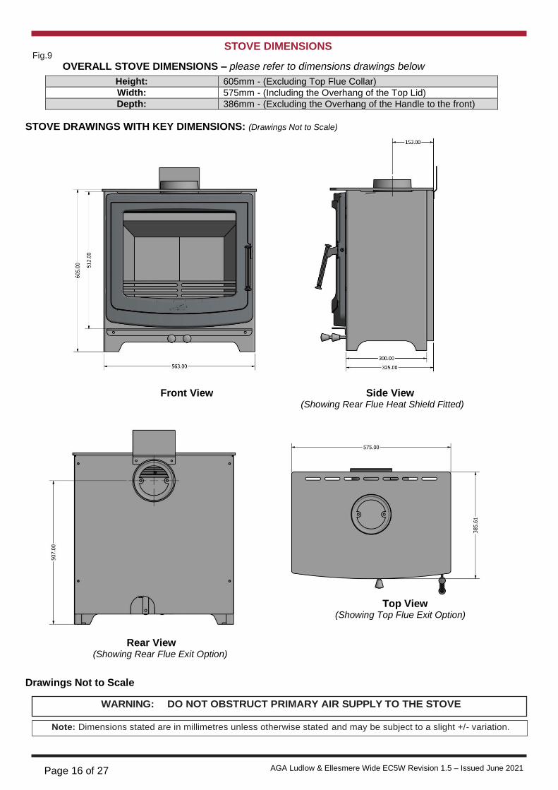
STOVE DIMENSIONS
OVERALL STOVE DIMENSIONS – please refer to dimensions drawings below
Height: 605mm - (Excluding Top Flue Collar)
Width: 575mm - (Including the Overhang of the Top Lid)
Depth: 386mm - (Excluding the Overhang of the Handle to the front)
STOVE DRAWINGS WITH KEY DIMENSIONS: (Drawings Not to Scale)
Front View Side View (Showing Rear Flue Heat Shield Fitted)
Rear View (Showing Rear Flue Exit Option)
Drawings Not to Scale
WARNING: DO NOT OBSTRUCT PRIMARY AIR SUPPLY TO THE STOVE
Note: Dimensions stated are in millimetres unless otherwise stated and may be subject to a slight +/- variation.
Top View (Showing Top Flue Exit Option)

Page 17 of 27 AGA Ludlow & Ellesmere Wide EC5W Revision 1.5 – Issued June 2021
COMMISSIONING AND HANDOVER
On completion of the installation allow a suitable
period of time for any fire cement and mortar to dry
out, when a small fire may be lit and checked to
ensure the smoke and fumes are taken from the
stove up the chimney and emitted safely to the
atmosphere. Do not run at full output for at least
24 hours.
Ensure that the operating instructions for the stove
are left with the customer. Ensure to advise the cus
tomer on the correct use of the appliance with the
OPERATION
Check that all dampers and catches are operating
correctly and ensure that all flue connections are
thoroughly sealed.
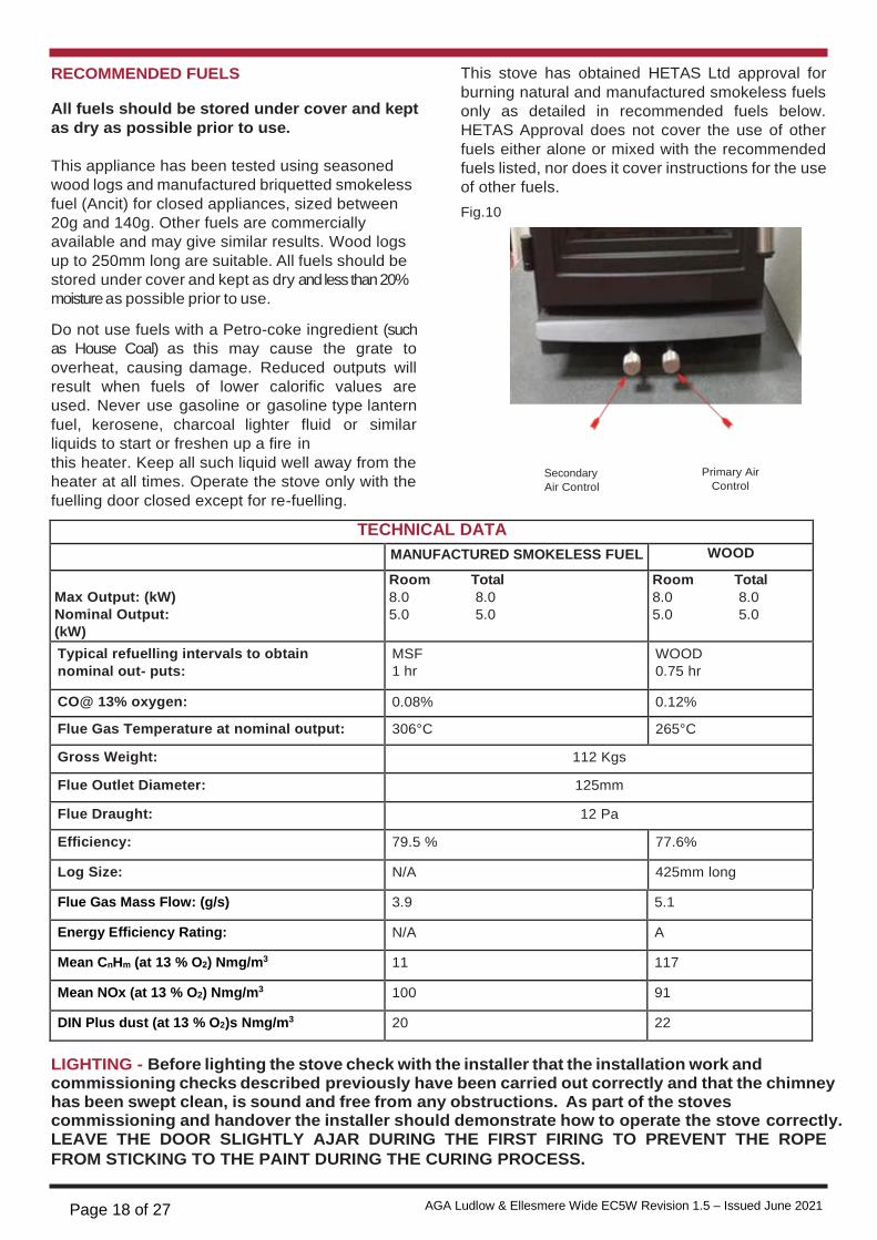
AIR CONTROLS
The stove has two independent air controls:
1. The Primary Air Control Lever which controls
the primary air (See Fig 10). Pull out to open
fuels likely to be used on the stove and warn them to
use only the recommended fuels for the stove.
Advise the user what to do should smoke or fumes
be emitted from the stove.
2.
Note:
& push in to close.
The Secondary Air Control Lever which
controls the secondary air and air wash (See
Fig 10). Pull out to open & push in to close.
The customer should be warned to use a fireguard to BS 8432: 2010 in the presence of children, aged
and/or infirm persons.
The controls may become hot when the stove is in
operation, use glove provided to adjust the controls
when the stove is hot.
& push in to close
Page 18 of 27 AGA Ludlow & Ellesmere Wide EC5W Revision 1.5 – Issued June 2021
RECOMMENDED FUELS
All fuels should be stored under cover and kept
as dry as possible prior to use.
This appliance has been tested using seasoned
wood logs and manufactured briquetted smokeless
fuel (Ancit) for closed appliances, sized between
20g and 140g. Other fuels are commercially
available and may give similar results. Wood logs
up to 250mm long are suitable. All fuels should be
stored under cover and kept as dry and less than 20%
moisture as possible prior to use.
Do not use fuels with a Petro-coke ingredient (such
as House Coal) as this may cause the grate to
overheat, causing damage. Reduced outputs will
result when fuels of lower calorific values are
used. Never use gasoline or gasoline type lantern
fuel, kerosene, charcoal lighter fluid or similar
liquids to start or freshen up a fire in
This stove has obtained HETAS Ltd approval for
burning natural and manufactured smokeless fuels
only as detailed in recommended fuels below.
HETAS Approval does not cover the use of other
fuels either alone or mixed with the recommended
fuels listed, nor does it cover instructions for the use
of other fuels.
Fig.10
this heater. Keep all such liquid well away from the
heater at all times. Operate the stove only with the
fuelling door closed except for re-fuelling.
Secondary
Air Control
Primary Air
Control
TECHNICAL DATA
MANUFACTURED SMOKELESS FUEL WOOD
Max Output: (kW)
Nominal Output:
(kW)
Room Total
8.0 8.0
5.0 5.0
Room Total
8.0 8.0
5.0 5.0
Typical refuelling intervals to obtain
nominal out- puts:
MSF
1 hr
WOOD
0.75 hr
CO@ 13% oxygen: 0.08% 0.12%
Flue Gas Temperature at nominal output: 306°C 265°C
Gross Weight: 112 Kgs
Flue Outlet Diameter: 125mm
Flue Draught: 12 Pa
Efficiency: 79.5 % 77.6%
Log Size: N/A 425mm long
Flue Gas Mass Flow: (g/s) 3.9 5.1
Energy Efficiency Rating: N/A A
Mean CnHm (at 13 % O2) Nmg/m3 11 117
Mean NOx (at 13 % O2) Nmg/m3 100 91
DIN Plus dust (at 13 % O2)s Nmg/m3 20 22
LIGHTING - Before lighting the stove check with the installer that the installation work and commissioning checks described previously have been carried out correctly and that the chimney has been swept clean, is sound and free from any obstructions. As part of the stoves commissioning and handover the installer should demonstrate how to operate the stove correctly. LEAVE THE DOOR SLIGHTLY AJAR DURING THE FIRST FIRING TO PREVENT THE ROPE
FROM STICKING TO THE PAINT DURING THE CURING PROCESS.

Page 19 of 27 AGA Ludlow & Ellesmere Wide EC5W Revision 1.5 – Issued June 2021
LIGHTING THE STOVE
NOTE: When operating the stove, it is
recommended to use the Glove provided to
open the fire door as the door handle will
become hot.
1. Open the fire door and open the primary air
control by pulling it fully out.
2. Open the secondary air inlet by pulling the
control fully out.
3. Cover the grate with crumpled pieces of
paper and lay 10-12 pieces of kindling on top
of the paper towards the back of the firebox.
4. lgnite and close the fire door.
5. When the kindling is well alight open the fire
door and add more kindling of a larger size
to sustain the fire. Close the fire door.
6. When a hot fire bed is established add the
normal fuel.
7. When well lighted, adjust the air controls as
required depending on the fuel type being
used & the heat output required (see Table
below). Both controls should be adjusted in
conjunction with each other to get the
appropriate burn rate with exact settings on
each control depending on the draught
conditions of the chimney to which the unit is
connected.
Fuel Primary Air Secondary Air
Smokeless
Fuel
Adjust to Desired
Setting
Fully Closed
Wood Max Opening of 50% Adjust to Desired
Setting
WARNING: DO NOT LEAVE BOTH AIR CONTROLS
FULLY OPEN AS THIS CAN CAUSE
THE STOVE TO OVERHEAT,
DAMAGING THE INTERNAL
COMPONENTS.
SLOW BURNING
Slow burning will cause the window glass to blacken
and can craze the glass this should not be used
for a long period. It should only be done after the fire
has been established and been running at nominal
output for a period of time. For a prolonged slow
burn, fill the firebox of fuel up to a maximum height
just below the top of the fire fence at the front of the
door opening. Push the primary air control knob in to
close the primary air to the minimum setting and
push the secondary air control in to set the
secondary air to the minimum setting. Please refer
to Page 8 items 6 & 7
DISPOSAL OF ASHES
Your stove is provided with an ashpan. This ashpan
should be emptied every day.
If ashes are allowed to build to grate level you could
damage the grate by overheating. We recommend
that you remove ashes after you have riddled the fire
when the stove is thoroughly cooled.
Ashes should be placed in a metal or other non-
combustible container with a tight fitting lid. The
closed container of ashes should be placed on a
non-combustible material, pending final disposal. If
ashes are buried in soil, or otherwise dumped they
should be retained in the closed container until they
are thoroughly cooled.
Open the firedoor and remove the ashpan using the
integrated handle on the front of the ashpan, see
Fig 11. Close the firedoor. When the ash is
disposed of replace the ashpan.
Fig.11
REFUELLING
Before opening the door, open the primary air
control fully as this will help to eliminate any
smoke or fly ash resident in the combustion
chamber. Add fuel to fire, close fire door and adjust
the primary air control to the desired position.
Ashpan

Page 20 of 27 AGA Ludlow & Ellesmere Wide EC5W Revision 1.5 – Issued June 2021
MONTHLY MAINTENANCE
Cleaning Stove Flue Pathways
It is recommended that the flue pathways in the
stove are cleaned on a monthly basis (or less
depending on the soot build-up created by the fuel
being used) and the chimney cleaned annually. To
access the chimney pathways, use the following
procedure:
1. Lift up the front of the bottom baffle to allow
the two side bricks to drop into the firebox &
be removed (see Fig 12).
2. Angle the fire fence back into the firebox to
allow it to be removed.
3. Angle the bottom baffle up on the RHS to
allow the LH edge of the baffle to drop into
the firebox, allowing for its removal.
4. Lift the back of the top baffle upwards, whilst
pushing it back to allow the front edge to
drop into the firebox (see Fig 13).
5. Replace the components in reverse order
when cleaning is complete, ensuring that the
long face of the top baffle is facing
downwards when fitted.
Fig.12
Fig.13
PERIODIC MAINTENANCE
Adjusting the Door Catch
Over time, the fire door latch can loosen due to the
continual compression and hardening of the rope
seal between the door and the front casting. The
tightness of the door seal should be checked
periodically and it is recommended that the rope
seals on the stove are changed at least
every two years or sooner if the seal loses its
integrity.
CHIMNEY CLEANING
The chimney should be cleaned twice annually or if
the stove is not used for a prolonged period during
the summer period, it should be cleaned prior to
commencement of usage. The chimney can be
cleaned through the stove depending on the flue
configuration and the flue liner should be cleaned in
accordance with manufacturer's instructions. Always
use a brush with plastic bristles that is the correct
size to reach all areas of the flue.
GLASS CLEANING
The stove glass will self-clean when there is
sufficient heat generated by the burning fuel i.e.
when the unit is operated at the maximum air
settings. If a build-up of creosote occurs on the
glass it may be due to low draft conditions, poor
quality fuel or operating the stove at the minimum
air settings for long periods of time. The glass
should be cleaned when cool and cleaned with a
non-abrasive cloth using warm soapy water. For
stubborn deposits, a grade 0 steel wool can be
used whilst taking care not to scratch the glass
with any coal/ash deposits.
CLEANING A MATT BLACK PAINTED
STOVE
Cleaning should be done when the stove is cold by
removing any dust or dirt using a dry cloth. Do not
use any water on the matt black/senotherm finish as
this will cause it to rust.
PROLONGED PERIODS OF NON USE
If the stove is to be left unused for a prolonged
period of time then it should be given a thorough
clean to remove ash and unburned fuel residues.
To enable a good flow of air through the appliance
to reduce condensation and subsequent damage,
leave the air controls fully open.
It is important that the flue connection, any appliance
baffles or throat plates and the chimney are swept
prior to lighting up after a prolonged shutdown
period.
Lift Bottom Baffle
Drop Top Edge
of Side Brick
Drop Top Edge
of Side Brick
& Push Backwards
Lift Back Edge Up
Page 21 of 27 AGA Ludlow & Ellesmere Wide EC5W Revision 1.5 – Issued June 2021
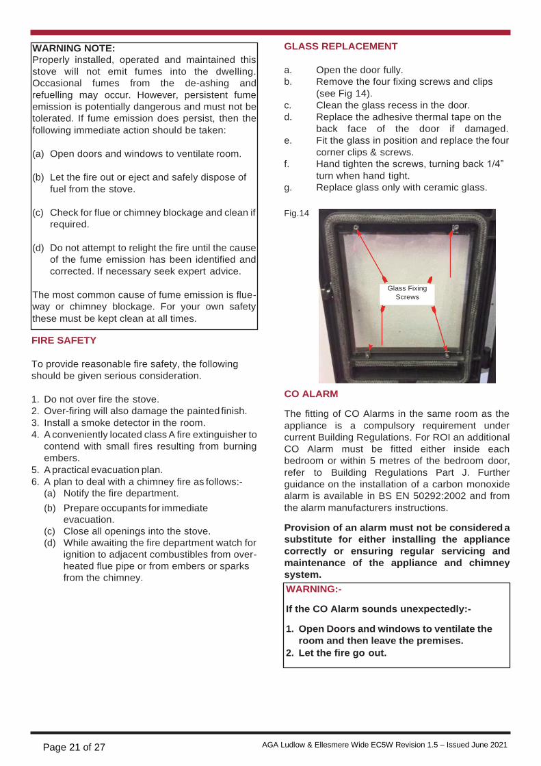
GLASS REPLACEMENT
a. Open the door fully.
b. Remove the four fixing screws and clips
(see Fig 14).
c. Clean the glass recess in the door.
d. Replace the adhesive thermal tape on the
back face of the door if damaged.
e. Fit the glass in position and replace the four
corner clips & screws.
f. Hand tighten the screws, turning back 1/4”
turn when hand tight.
g. Replace glass only with ceramic glass.
Fig.14
FIRE SAFETY
To provide reasonable fire safety, the following
should be given serious consideration.
1. Do not over fire the stove.
2. Over-firing will also damage the painted finish.
3. Install a smoke detector in the room.
4. A conveniently located class A fire extinguisher to
contend with small fires resulting from burning
embers.
5. A practical evacuation plan.
6. A plan to deal with a chimney fire as follows:-
(a) Notify the fire department.
(b) Prepare occupants for immediate
evacuation.
(c) Close all openings into the stove.
(d) While awaiting the fire department watch for
ignition to adjacent combustibles from over-
heated flue pipe or from embers or sparks
from the chimney.
CO ALARM
The fitting of CO Alarms in the same room as the
appliance is a compulsory requirement under
current Building Regulations. For ROI an additional
CO Alarm must be fitted either inside each
bedroom or within 5 metres of the bedroom door,
refer to Building Regulations Part J. Further
guidance on the installation of a carbon monoxide
alarm is available in BS EN 50292:2002 and from
the alarm manufacturers instructions.
Provision of an alarm must not be considered a
substitute for either installing the appliance
correctly or ensuring regular servicing and
maintenance of the appliance and chimney
system.
Glass Fixing
Screws
WARNING:-
If the CO Alarm sounds unexpectedly:-
1. Open Doors and windows to ventilate the
room and then leave the premises.
2. Let the fire go out.
WARNING NOTE:
Properly installed, operated and maintained this
stove will not emit fumes into the dwelling.
Occasional fumes from the de-ashing and
refuelling may occur. However, persistent fume
emission is potentially dangerous and must not be
tolerated. If fume emission does persist, then the
following immediate action should be taken:
(a) Open doors and windows to ventilate room.
(b) Let the fire out or eject and safely dispose of
fuel from the stove.
(c) Check for flue or chimney blockage and clean if
required.
(d) Do not attempt to relight the fire until the cause
of the fume emission has been identified and
corrected. If necessary seek expert advice.
The most common cause of fume emission is flue-
way or chimney blockage. For your own safety
these must be kept clean at all times.

Page 22 of 27 AGA Ludlow & Ellesmere Wide EC5W Revision 1.5 – Issued June 2021
EXPLODED VIEW
1. LH BACK REFRACTORY BRICK - A5W-BB
2. RH BACK REFRACTORY BRICK - A5W-BB_MIR
3. LHS REFRACTORY BRICK - A5W-SB LH
4. RHS REFRACTORY BRICK - A5W-SB
5. TOP BAFFLE - A5W-TB
6. BOTTOM BAFFLE - A5W-MB
7. AIR INLET ASSEMBLY - A4-AI-ASSY
8. CONTROL KNOB - A4-KNOB
9. TOP PLATE - A5W-09
10. ASH SHELF - A5W-10
12. OUTSIDE AIR KIT - AOSSOL
13. FLUE SPIGOT - A4 COLLAR
14. ASHPAN - A5W-ASHTRAY
15. HEATSHIELD - A5W HS RE
16. FIRE DOOR – ELLESMERE or LUDLOW EC5W DOOR
17. AIR CONTROL ROD - A5W AIR CONTROL ROD
18. FIRE FENCE - A5W RET BAR CAST
19. GRATE - W5 CAST GRATE LR
21. DOOR GLASS – A5W FD9
22. FLUE BLANKING PLATE -A4-04 REAR BLANK
23. TOP PLATE FILLER - A4 BLANK PLUG
24. HINGE PIN - 6X50 RIVET
25. HANDLE ASSEMBLY - HANDLE ASSY
26. HANDLE SLEEVE - HANDLE SLEEVE
27. GLASS GASKET – A5W FD9 GASKET
28. GLASS CLIP - BB GLASS CLIP
29. MAIN BODY - A5W MAIN BODY ASSY
30. GRATE FRAME - A5W GRATE RISER
31. PRIMARY AIR INLET COVER - INLET COVER
32. LOCK ROLLER - A455W8 ROLLER
AGA Rangemaster
AGA, Station Road, Ketley, Telford,
Shropshire, TF1 5AQ, UK
With AGA Rangemaster’s policy of continuous product improvement, the Company reserves the right to change
specifications and make modifications to the appliance described and illustrated at
any time
Page 23 of 27 AGA Ludlow & Ellesmere Wide EC5W Revision 1.5 – Issued June 2021
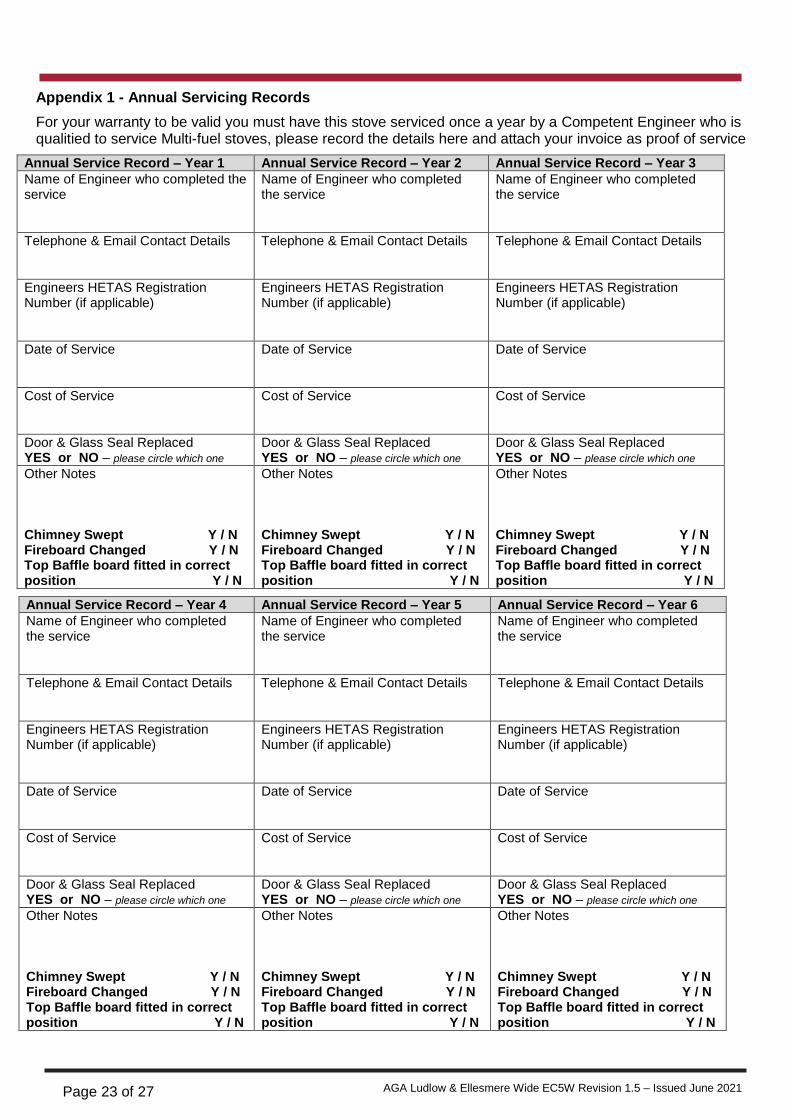
Appendix 1 - Annual Servicing Records
For your warranty to be valid you must have this stove serviced once a year by a Competent Engineer who is qualitied to service Multi-fuel stoves, please record the details here and attach your invoice as proof of service
Annual Service Record – Year 1 Annual Service Record – Year 2 Annual Service Record – Year 3
Name of Engineer who completed the service
Name of Engineer who completed the service
Name of Engineer who completed the service
Telephone & Email Contact Details
Telephone & Email Contact Details
Telephone & Email Contact Details
Engineers HETAS Registration Number (if applicable)
Engineers HETAS Registration Number (if applicable)
Engineers HETAS Registration Number (if applicable)
Date of Service
Date of Service
Date of Service
Cost of Service
Cost of Service
Cost of Service
Door & Glass Seal Replaced YES or NO – please circle which one
Door & Glass Seal Replaced YES or NO – please circle which one
Door & Glass Seal Replaced YES or NO – please circle which one
Other Notes Chimney Swept Y / N Fireboard Changed Y / N Top Baffle board fitted in correct position Y / N
Other Notes Chimney Swept Y / N Fireboard Changed Y / N Top Baffle board fitted in correct position Y / N
Other Notes Chimney Swept Y / N Fireboard Changed Y / N Top Baffle board fitted in correct position Y / N
Annual Service Record – Year 4 Annual Service Record – Year 5 Annual Service Record – Year 6
Name of Engineer who completed the service
Name of Engineer who completed the service
Name of Engineer who completed the service
Telephone & Email Contact Details
Telephone & Email Contact Details
Telephone & Email Contact Details
Engineers HETAS Registration Number (if applicable)
Engineers HETAS Registration Number (if applicable)
Engineers HETAS Registration Number (if applicable)
Date of Service
Date of Service
Date of Service
Cost of Service
Cost of Service
Cost of Service
Door & Glass Seal Replaced YES or NO – please circle which one
Door & Glass Seal Replaced YES or NO – please circle which one
Door & Glass Seal Replaced YES or NO – please circle which one
Other Notes Chimney Swept Y / N Fireboard Changed Y / N Top Baffle board fitted in correct position Y / N
Other Notes Chimney Swept Y / N Fireboard Changed Y / N Top Baffle board fitted in correct position Y / N
Other Notes Chimney Swept Y / N Fireboard Changed Y / N Top Baffle board fitted in correct position Y / N
Page 24 of 27 AGA Ludlow & Ellesmere Wide EC5W Revision 1.5 – Issued June 2021
AGA Stoves – Ludlow & Ellesmere Multi-Fuel Stove – 5 Year Warranty It’s important to know what requirements need to be met in order to qualify for our 5 year warranty, as well as being aware of exactly what it covers. This warranty only applies to our stoves. If you have purchased your stove from an authorised stockist within our Premium Retailer Network, then automatically your product will carry a 5 year warranty. The start date for the warranty period is the date of purchase. You do not need to register your stove for the warranty to apply, but you must retain your proof of purchase from the AGA retailer, which must have your name, address and the date of the purchase. Then from the serial number on your stove we can then action your warranty, you must have the stove serviced every 12 months and keep the service receipt for the warranty to be valid. Any product purchased outside of our Premium Retailer Network will carry a standard 12 month, non-extendable warranty. It is a condition of the Warranty that the installation complies with relevant Building Regulations and the rules in force, and is carried out by a suitably trained and qualified individual HETAS registered in the United Kingdom (or equivalent in other countries) with a certificate of installation and the appropriate commissioning report completed and retained by the end-user. Please refer to Appendix 1 - Annual Servicing Records It is also a condition of the Warranty that your AGA Stove is regularly serviced (every 12 months) by a suitably trained and qualified individual, ideally HETAS registered in the United Kingdom (or equivalent in other countries). Records and receipts of annual services will be required in the event of a warranty claim during the period of the warranty. Please refer to Appendix 1 - Annual Servicing Records This warranty is not transferable, and solely for, the benefit of the original purchaser of the stove. Please retain your dated sales receipt as a proof of purchase. During your warranty period, only genuine AGA spare parts must be used in the servicing and maintenance of your stove, these spare parts can be ordered via the Premium Retailer directly. Consumable items such as glass, paint, grate parts, log retainers, ceramic fire boards (internal linings), and rope seals which are either subject to normal wear and tear or parts that require replacement in connection with normal maintenance are not covered, either by the Warranty. The Flue system is not covered by any warranty from AGA Stoves. Should you experience problems with your stove, any claim must be submitted first to the Premium Retailer from where the stove was purchased. Your Premium Retailer will either be able to offer immediate assistance or make contact with AGA Stoves on your behalf. Warranty Exclusions and Limitations No Warranty is extended to consumable service parts. Repair or replacement of parts which are subject to normal wear and tear during the warranty period or parts that will require replacement in connection with normal maintenance. Such parts include but are not limited to glass, paint, rope seals, grate parts, log retainers, and internal linings. The AGA Stoves Warranty does not cover:
a) In normal usage the paint finish of your AGA Stove may change colour slightly. As these circumstances are considered normal, they are not covered by the warranty. The stove paint must be cured as detailed in this manual
b) Enamelled components where these parts are subjected to abnormally high temperatures, chemical abrasion or thermal shocks, resulting in chipping, cracking, bubbling or discolouration and crazing of the enamelled finish.
Page 25 of 27 AGA Ludlow & Ellesmere Wide EC5W Revision 1.5 – Issued June 2021
c) Damage resulting from installation and usage where the appliance has not been installed or used in accordance with the AGA Stoves installation and operation instructions, or if the installation does not conform to local building, fire and safety regulations. This includes the entire flue system whether purchased from AGA Stoves or not d) Defects or faults caused by specific local conditions such as draught problems, water damage, condensation and chimney defects. e) The Warranty does not cover damage caused by over-firing of the appliance. (Please see your Installation and Operating Instructions for further information) f) The entire flue system g) Misuse of the stove including water/liquid/heat damage h) Damage caused by unauthorised modifications, use or repair. i) Damage or defects caused by the product being stored in a damp, unheated environment. j) Consequential loss (to the extent permitted by law) relating to other associated products that have not been supplied by AGA Stoves. k) Consequential loss (to the extent permitted by law) related to decorations, furnishings or other household assets. l) Delivery to/or return transport costs. Removal and re-installation costs, or any labour cost to fit parts Repaired or replaced products are covered only for the remainder of the original warranty period. If you should ever wish to make a warranty claim because of a product fault or defect, you must inform your retailer within a reasonable amount of time, this is within 14 days from the date on which the fault or defect first became apparent. If the product fault or defect is notified after 14 days from the date on which the fault or defect became apparent, AGA Stoves cannot accept any liability for events or issues which arise after the 14 day period or which are caused or increased by the lack of notification which therefore prevented action being taken to restrict or eliminate any consequences arising from the fault or defect at an earlier date.
In the event of a product fault occurring during the warranty period, AGA Stoves will send the appropriate component or goods necessary to rectify the fault, free of charge, but does not cover any labour cost to fit them.
Nothing in the Warranty shall make AGA Stoves liable for any or special, incidental or consequential damages, injury to persons or property, or any other consequential loss beyond the consumer’s statutory rights. The liability on these issues is covered by AGA Stoves Terms and Conditions of Sale.
AGA Stoves’ total liability extends only to the purchase price paid for the goods by the Premium Retailer,
The AGA Stoves Warranty does not affect your statutory rights.
The above warranty terms and conditions came into effect on 1st January 2013 and are applicable for all relevant products purchased after this date.
Please note: This warranty is applicable for purchases within the United Kingdom and the Republic of Ireland
Page 26 of 27 AGA Ludlow & Ellesmere Wide EC5W Revision 1.5 – Issued June 2021
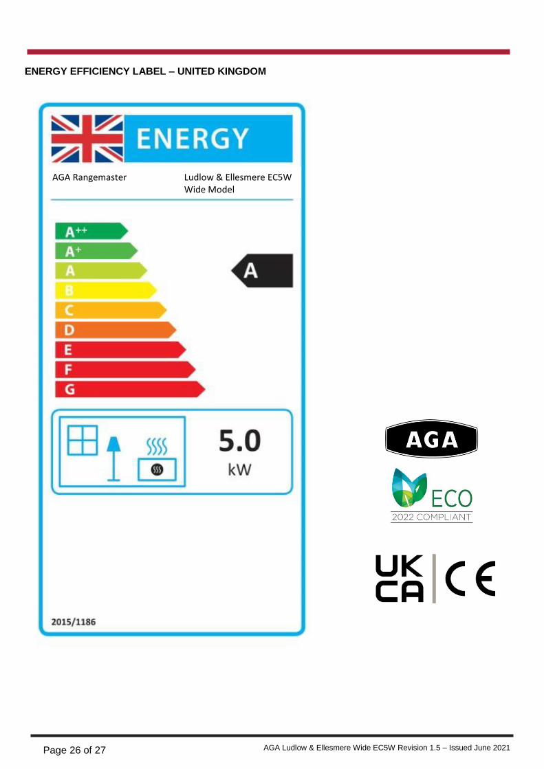
ENERGY EFFICIENCY LABEL – UNITED KINGDOM
AGA Rangemaster Ludlow & Ellesmere EC5W Wide Model Multi-Fuel
Page 27 of 27 AGA Ludlow & Ellesmere Wide EC5W Revision 1.5 – Issued June 2021
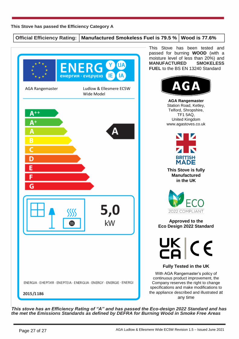
This Stove has passed the Efficiency Category A
Official Efficiency Rating: Manufactured Smokeless Fuel is 79.5 % Wood is 77.6%
This stove has an Efficiency Rating of “A” and has passed the Eco-design 2022 Standard and has the met the Emissions Standards as defined by DEFRA for Burning Wood in Smoke Free Areas
AGA Rangemaster Ludlow & Ellesmere EC5W Wide Model Multi-Fuel
AGA Rangemaster Station Road, Ketley, Telford, Shropshire,
TF1 5AQ, United Kingdom
www.agastoves.co.uk
This Stove is fully
Manufactured
in the UK
Approved to the
Eco Design 2022 Standard
Fully Tested in the UK
With AGA Rangemaster’s policy of continuous product improvement, the Company reserves the right to change
specifications and make modifications to
the appliance described and illustrated at any time
This Stove has been tested and passed for burning WOOD (with a moisture level of less than 20%) and MANUFACTURED SMOKELESS
FUEL to the BS EN 13240 Standard