
Influence of Lubrication Systems on the Fatigue Strength of ...
Upload
khangminh22Category
view
4download
0
N°d’ordre NNT : 2018LYSEI060
THESE de DOCTORAT DE L’UNIVERSITE DE LYON opérée au sein de
INSA de LYON
Ecole Doctorale N° 162
Ecole doctorale des Sciences pour l’Ingénieur de Lyon :
Mécanique, Energétique, Génie Civil, Acoustique (MEGA)
Spécialité/ discipline de doctorat :
Génie Mécanique
Soutenue publiquement le 11/07/2018, par :
Stéphane Tromp
Lubrication with a refrigerant: an industrial
challenge investigated through multiscale modeling based on fluid/surface chemistry
Devant le jury composé de :
Cobian, Manuel Maître de Conférences / Ecole Centrale Lyon Examinateur
Dini, Daniele Professeur / Imperial College London Rapporteur
Fillot, Nicolas Maître de Conférences - HDR / INSA-Lyon Directeur
Joly, Laurent Professeur / Université Claude Bernard Lyon 1 Co-directeur
Leonard, Céline Professeur / Université Paris-Est Marne-La-Vallée Examinatrice
Moseler, Michael Professeur / University of Freiburg Rapporteur
Cette thèse est accessible à l'adresse : http://theses.insa-lyon.fr/publication/2018LYSEI060/these.pdf © [S. Tromp], [2018], INSA Lyon, tous droits réservés

Cette thèse est accessible à l'adresse : http://theses.insa-lyon.fr/publication/2018LYSEI060/these.pdf © [S. Tromp], [2018], INSA Lyon, tous droits réservés
Département FEDORA – INSA Lyon - Ecoles Doctorales – Quinquennal 2016-2020
SIGLE ECOLE DOCTORALE NOM ET COORDONNEES DU RESPONSABLE
CHIMIE CHIMIE DE LYON
http://www.edchimie-lyon.fr Sec. : Renée EL MELHEM Bât. Blaise PASCAL, 3e étage [email protected] INSA : R. GOURDON
M. Stéphane DANIELE Institut de recherches sur la catalyse et l’environnement de Lyon IRCELYON-UMR 5256 Équipe CDFA 2 Avenue Albert EINSTEIN 69 626 Villeurbanne CEDEX [email protected]
E.E.A. ÉLECTRONIQUE, ÉLECTROTECHNIQUE, AUTOMATIQUE
http://edeea.ec-lyon.fr Sec. : M.C. HAVGOUDOUKIAN [email protected]
M. Gérard SCORLETTI École Centrale de Lyon 36 Avenue Guy DE COLLONGUE 69 134 Écully Tél : 04.72.18.60.97 Fax 04.78.43.37.17 [email protected]
E2M2 ÉVOLUTION, ÉCOSYSTÈME,
MICROBIOLOGIE, MODÉLISATION
http://e2m2.universite-lyon.fr Sec. : Sylvie ROBERJOT Bât. Atrium, UCB Lyon 1 Tél : 04.72.44.83.62 INSA : H. CHARLES [email protected]
M. Philippe NORMAND UMR 5557 Lab. d’Ecologie Microbienne Université Claude Bernard Lyon 1 Bâtiment Mendel 43, boulevard du 11 Novembre 1918 69 622 Villeurbanne CEDEX [email protected]
EDISS INTERDISCIPLINAIRE
SCIENCES-SANTÉ
http://www.ediss-lyon.fr Sec. : Sylvie ROBERJOT Bât. Atrium, UCB Lyon 1 Tél : 04.72.44.83.62 INSA : M. LAGARDE [email protected]
Mme Emmanuelle CANET-SOULAS INSERM U1060, CarMeN lab, Univ. Lyon 1 Bâtiment IMBL 11 Avenue Jean CAPELLE INSA de Lyon 69 621 Villeurbanne Tél : 04.72.68.49.09 Fax : 04.72.68.49.16 [email protected]
INFOMATHS INFORMATIQUE ET
MATHÉMATIQUES
http://edinfomaths.universite-lyon.fr Sec. : Renée EL MELHEM Bât. Blaise PASCAL, 3e étage Tél : 04.72.43.80.46 Fax : 04.72.43.16.87 [email protected]
M. Luca ZAMBONI Bât. Braconnier 43 Boulevard du 11 novembre 1918 69 622 Villeurbanne CEDEX Tél : 04.26.23.45.52 [email protected]
Matériaux
MATÉRIAUX DE LYON
http://ed34.universite-lyon.fr Sec. : Marion COMBE Tél : 04.72.43.71.70 Fax : 04.72.43.87.12 Bât. Direction [email protected]
M. Jean-Yves BUFFIÈRE INSA de Lyon MATEIS - Bât. Saint-Exupéry 7 Avenue Jean CAPELLE 69 621 Villeurbanne CEDEX Tél : 04.72.43.71.70 Fax : 04.72.43.85.28 [email protected]
MEGA MÉCANIQUE, ÉNERGÉTIQUE,
GÉNIE CIVIL, ACOUSTIQUE
http://edmega.universite-lyon.fr Sec. : Marion COMBE Tél : 04.72.43.71.70 Fax : 04.72.43.87.12 Bât. Direction [email protected]
M. Jocelyn BONJOUR INSA de Lyon Laboratoire CETHIL Bâtiment Sadi-Carnot 9, rue de la Physique 69 621 Villeurbanne CEDEX [email protected]
ScSo ScSo*
http://ed483.univ-lyon2.fr Sec. : Viviane POLSINELLI Brigitte DUBOIS INSA : J.Y. TOUSSAINT Tél : 04.78.69.72.76 [email protected]
M. Christian MONTES Université Lyon 2 86 Rue Pasteur 69 365 Lyon CEDEX 07 [email protected]
*ScSo : Histoire, Géographie, Aménagement, Urbanisme, Archéologie, Science politique, Sociologie, Anthropologie Cette thèse est accessible à l'adresse : http://theses.insa-lyon.fr/publication/2018LYSEI060/these.pdf © [S. Tromp], [2018], INSA Lyon, tous droits réservés

Cette thèse est accessible à l'adresse : http://theses.insa-lyon.fr/publication/2018LYSEI060/these.pdf © [S. Tromp], [2018], INSA Lyon, tous droits réservés
Remerciements
Je tiens a remercier mes directeurs de these, Nicolas Fillot et Laurent Joly qui m’ont
offert l’opportunite de realiser cette these au LaMCoS et a l’ILM. Merci pour votre
disponibilite, vos conseils, et votre gentillesse. De plus je tiens a remercier chaleureuse-
ment Manuel Cobian qui s’est greffe au projet des le debut et qui a ete d’une tres grande
aide dans ce projet, en particulier pour toute la partie ab-initio.
Mes remerciements vont ensuite a mes deux rapporteurs de these, Daniele Dini et
Michael Moseler pour avoir pris le temps de relire et juger ce travail et a Celine Leonard
pour l’avoir examine.
Merci a Nathalie Bouscharain et Guillermo Morales-Espejel qui m’ont apporte respec-
tivement leurs connaissances sur la chimie des refrigerants et sur les applications indus-
trielles.
Cette these ayant ete realisee grace au financement du labex iMUST, je tiens a remercier
Amandine Ducreux pour sa grande reactivite lors de mes differents congres et missions.
Un merci particulier a Vincent Strubel sans qui cette these n’aurait tout simplement
pas eu lieu, puisque c’est lui qui m’a presente a Nicolas Fillot en 2014. Bien sur grace a
toi, beaucoup d’autres choses tres positives se sont produites durant ces annees. Merci
egalement a Nicolas Voeltzel qui a passe beaucoup de temps a me transmettre ce qu’il
savait sur la dynamique moleculaire et a Alejandro Porras Vazquez et Rafael Pereira De
Matos pour nos nombreuses discussions sur cette methode. Merci egalement a Sayed
Albahrani pour nos discussions tres variees sur la physique et la tribologie.
Je n’oublie pas de remercier chaleureusement les autres membres de l’equipe TMI et plus
generalement du LaMCoS avec qui j’ai pu interagir durant ces annees. Grace a vous,
j’ai pu m’epanouir professionnellement et personnellement. Merci egalement a tous les
membres de l’equipe du badminton de ces trois annees.
Lors des nombreux congres auxquels j’ai participe durant ma these, j’ai pu discuter
avec des scientifiques de differents horizons et pays. Cela m’a beaucoup apporte et je
veux pour cela remercier mes directeurs de these qui m’ont fait confiance en me lais-
sant presenter ces travaux. J’ai egalement eu la chance de pouvoir enseigner en TD de
vCette thèse est accessible à l'adresse : http://theses.insa-lyon.fr/publication/2018LYSEI060/these.pdf © [S. Tromp], [2018], INSA Lyon, tous droits réservés

mathematiques pour des etudiants ingenieurs en 3e annee. Ce fut une experience parti-
culierement enrichissante. Pour cela je remercie Etienne Parizet. De plus je remercie ici
aussi Nicolas Fillot qui m’a permis de co-encadrer deux etudiants de Master lors de leur
stage de fin d’etudes. Pour leur aide logistique, je tiens a remercier Emmanuel Montero
et Sophie De Oliveira.
Je ne vais pas faire une liste de tous les doctorants, postdoc, et stagiaires, avec qui j’ai
passe de super moments au labo et egalement beaucoup en dehors, ils se reconnaıtront.
Merci pour toutes ces marches, bars, sorties ski,. . . !
Je conclus ces remerciements en les adressant a toute ma famille qui m’a soutenu durant
ma scolarite et enfin merci a Laurence de m’avoir supporte, particulierement durant ces
derniers mois.
Cette thèse est accessible à l'adresse : http://theses.insa-lyon.fr/publication/2018LYSEI060/these.pdf © [S. Tromp], [2018], INSA Lyon, tous droits réservés
Abstract
In large refrigeration systems, using the refrigerant as lubricant instead of oil can help
to simplify the design, lighten the systems, and reduce their environmental impact.
However, the very low viscosity of refrigerants leads to ultra-thin films separating the
surfaces, with a thickness comparable to surface roughness. Nevertheless, experiments
with the R1233zd refrigerant suggests that lubrication is still possible in that situation
thanks to an adsorbed layer formed on iron oxide surfaces. Experimental in situ analy-
sis area is very difficult because of high confinement and high pressure. That is why a
multiscale numerical approach is developed here, to explore the impact of chemical reac-
tions and physical processes at the refrigerant-surface interface on large-scale lubrication
properties. Density functional theory is used to quantify the adsorption of a refrigerant
molecule on an iron oxide surface at the quantum level. Binding energies ranging from
-0.92 eV to -0.22 eV are measured and related to different adsorption cases. These
results are then used to parametrize an interfacial force field, whose predictions of inter-
facial molecular structure differs from those obtained using potentials based on standard
mixing rules. Large-scale molecular dynamics simulations involving this parametrized
force field confirm the existence of a strongly adsorbed layer of R1233zd molecules on
Fe2O3 surface. With atomically smooth surfaces, and a refrigerant film thickness as
small as 2 nm, the adsorbed refrigerant layers resists pressures as high as 4 GPa and
sliding velocities as high as 100 m/s. A minimum value of 5 refrigerant molecules per
nm2 is necessary to the formation of two adsorbed layers at 0.5 GPa. Moreover, sliding
simulations with a rough surface reveal total film breakdown for around 13 GPa.
Keywords: Lubrication, Refrigerants, Fluid/Surface Physical Chemistry, Molecular Dy-
namics, Density Functional Theory.
viiCette thèse est accessible à l'adresse : http://theses.insa-lyon.fr/publication/2018LYSEI060/these.pdf © [S. Tromp], [2018], INSA Lyon, tous droits réservés

Cette thèse est accessible à l'adresse : http://theses.insa-lyon.fr/publication/2018LYSEI060/these.pdf © [S. Tromp], [2018], INSA Lyon, tous droits réservés
Resume
Dans les grands systemes de refrigeration, l’utilisation de refrigerants comme lubrifi-
ants, a la place des huiles, simplifie la conception du systeme, l’allege et reduit son
impact environnemental. La tres faible viscosite du refrigerant conduit a une epaisseur
de film separant les deux surfaces comparable a leur rugosite. Neanmoins, des travaux
experimentaux avec le refrigerant R1233zd suggerent que la lubrification est possible
dans ces conditions grace a la formation d’une couche adsorbee sur la surface d’oxyde de
fer. Les analyses experimentales in situ dans le contact sont tres difficiles a cause des con-
ditions de fort confinement et haute pression. C’est pourquoi une approche numerique
multi-echelles est developpee, afin d’etudier l’impact des reactions physico-chimiques a
l’interface refrigerant-surface sur les proprietes de lubrification. La theorie de la fonc-
tionnelle de la densite est utilisee pour quantifier au niveau quantique, l’adsorption d’une
molecule de refrigerant sur une surface d’oxyde de fer. Des energies de liaison allant de
-0,92 eV a -0,22 eV sont observees et reliees a differents cas d’adsorption. Ces resultats
sont exploites pour parametrer un champ de forces interfacial, qui predit des structures
moleculaires a l’interface, differentes de celles obtenues avec des potentiels bases sur
les regles de melange classiques. Des simulations de dynamique moleculaire utilisant
ce champ de forces parametre confirment l’existence d’une couche fortement adsorbee
de R1233zd sur une surface de Fe2O3. Avec des surfaces atomiques lisses et seulement
2 nm d’epaisseur de film de refrigerant, les couches adsorbees resistent a des pressions
allant jusqu’a 4 GPa et des vitesses de cisaillement atteignant 100 m/s. Une valeur
minimale de 5 molecules de refrigerant par nm2 est necessaire a la formation de deux
couches adsorbees a 0,5 GPa. De plus, des simulations en cisaillement avec une surface
rugueuse predisent une rupture totale du film a environ 13 GPa.
Mots-cles: Lubrification, Refrigerants, Physico-Chimie Fluide/Surface, Dynamique Mole-
culaire, Theorie de la Fonctionnelle de Densite.
ixCette thèse est accessible à l'adresse : http://theses.insa-lyon.fr/publication/2018LYSEI060/these.pdf © [S. Tromp], [2018], INSA Lyon, tous droits réservés

Cette thèse est accessible à l'adresse : http://theses.insa-lyon.fr/publication/2018LYSEI060/these.pdf © [S. Tromp], [2018], INSA Lyon, tous droits réservés

Resume etendu
0.1 Introduction generale et contexte
La lubrification consiste a introduire un lubrifiant entre deux surfaces en mouvement
l’une par rapport a l’autre afin de reduire le frottement et l’usure. En reduisant la
contrainte entre les elements mobiles, elle ameliore la duree de vie des composants
mecaniques. Neanmoins, la lubrification necessite souvent une conception lourde, avec
par exemple l’ajout de pompes a lubrifiant, alors que la tendance actuelle est a l’allegement
des systemes mecaniques.
Dans les grands systemes de refrigeration, la conception peut etre simplifier en utilisant le
fluide dit actif, ici le refrigerant, pour lubrifier les roulements. Cependant, les refrigerants
possedent de faibles viscosites, contraignant le film de refrigerant separant les deux
surfaces a atteindre localement une epaisseur de quelques nanometres, donc du meme
ordre de grandeur que les rugosites des surfaces. C’est pour cette raison qu’une quantite
minimum de refrigerant doit etre entraınee entre les asperites pour eviter que les surfaces
ne rentrent en contact.
Avec ce regime de lubrification a tres faible epaisseur, seules quelques molecules separent
localement les surfaces. Dans ce contexte, la physicochimie a l’interface entre le refrigerant
et les surfaces joue un role predominant. La litterature revele qu’une couche adsorbee
de molecules de refrigerant a ete observee sur les surfaces d’acier du roulement, lors d’un
test de lubrification avec refrigerant pur.
Neanmoins, les conditions severes de grand confinement et haute pression rendent dif-
ficiles les analyses experimentales in situ. C’est pour cette raison qu’une approche de
modelisation multi-echelles est consideree dans cette these pour etudier les performances
tribologiques d’un systeme lubrifie avec un refrigerant pur tel que le R1233zd, confine
entre deux surfaces de fer.
Tout d’abord, des simulations quantiques basees sur la theorie de la fonctionnelle de la
densite (DFT, pour density functional theory) permettent d’analyser la physicochimie
a l’interface entre le refrigerant et la surface. Puis, des simulations de dynamique
xiCette thèse est accessible à l'adresse : http://theses.insa-lyon.fr/publication/2018LYSEI060/these.pdf © [S. Tromp], [2018], INSA Lyon, tous droits réservés

moleculaire (DM) a plus large echelle, parametrees a l’aide des resultats ab-initio, sont
utilisees pour etudier la structure et le comportement dynamique du refrigerant confine
sous conditions tribologiques extremes.
La refrigeration est le processus durant lequel la temperature d’un espace clos est reduite
par deplacement de la chaleur vers un autre endroit. Les refrigerants sont des flu-
ides utilises dans plusieurs types de systemes tels que les chauffages, climatisations ou
equipements de refroidissement.
Les refrigerants sont classes en plusieurs familles selon les differents types d’atomes et
structures moleculaires du refrigerant. Des contraintes environnementales et de securite
ont conduit a l’apparition d’une toute nouvelle generation de refrigerant composee
d’hydrofluorolefines (HFO). Le HCFO-1233zd(E), plus communement nomme R1233zd,
fait partie de cette nouvelle generation et est particulier car sa molecule possede un
atome de chlore, faisant de lui une molecule hydrochlorofluorolefine (HCFO).
Le R1233zd : un refrigerant de nouvelle generation
En raison de son point d’ebullition relativement eleve (environ 19◦C a pression atmo-
spherique), le R1233zd est considere comme un refrigerant alternatif pour plusieurs
types de systemes tels que les pompes a chaleur a haute temperature, ou les systemes
de refrigeration a basse pression. Ce projet se concentre sur l’etude de systemes de
refrigeration utilises pour refroidir de grands batiments ou procedes industriels. Durant
un cycle classique de refrigeration, le refrigerant est compresse a l’aide d’un compresseur
compose entres autres par des roulements. Ces roulements sont classiquement lubrifies
avec un melange huile-refrigerant. Cependant, le but de cette etude et d’etudier la
faisabilite de lubrifier les roulements a l’aide d’un refrigerant R1233zd pur. Ce type de
systeme s’appelle PRL (pour “pure refrigerant lubrication”).
Lubrification dans les systemes de refrigeration
Les roulements dans les technologies PRL sont hybrides. En effet, les billes sont faites
de nitrure de silicium Si3N4 (ceramique), tandis que les bagues interieures et exterieures
sont en acier inoxydable [1, 2, 3].
De plus, ces roulements sont lubrifies dans un regime de lubrification de film tres
mince ou l’epaisseur de film minimale peut etre de quelques nanometres. Des essais
experimentaux portant sur le R1233zd comme lubrifiant, dans des conditions de fonc-
tionnement variables (pression de contact hertzienne d’environ 1.2 GPa en moyenne)
ont ete realises par la societe SKF [4, 5]. Ils ont observe que cette lubrification extreme
n’avait pas cause de degat aux surfaces du roulement et qu’un depot solide s’etait cree
sur les surface en acier. L’analyse XPS de ces dernieres a revele que:
• la surface etait principalement constituee d’oxydes de fer(II) FeO et d’oxyde de
xiiCette thèse est accessible à l'adresse : http://theses.insa-lyon.fr/publication/2018LYSEI060/these.pdf © [S. Tromp], [2018], INSA Lyon, tous droits réservés
PhD thesis - Stephane TROMP
fer(III) Fe2O3,
• les elements constituant les molecules de R1233zd comme le chlore et fluor sont
detectes sur la couche adsorbee,
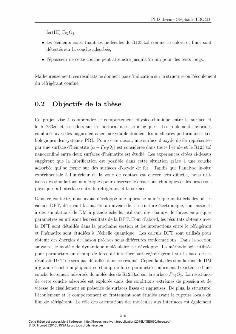
• l’epaisseur de cette couche peut atteindre jusqu’a 25 nm pour des tests longs.
Malheureusement, ces resultats ne donnent pas d’indication sur la structure ou l’ecoulement
du refrigerant confine.
0.2 Objectifs de la these
Ce projet vise a comprendre le comportement physico-chimique entre la surface et
le R1233zd et ses effets sur les performances tribologiques. Les roulements hybrides
combines avec des bagues en acier inoxydable donnent les meilleures performances tri-
bologiques des systemes PRL. Pour cette raison, une surface d’oxyde de fer representee
par une surface d’hematite (α−Fe2O3) est consideree dans toute l’etude et le R1233zd
nanoconfine entre deux surfaces d’hematite est etudie. Les experiences citees ci-dessus
suggerent que la lubrification est possible dans cette situation grace a une couche
adsorbee qui se forme sur des surfaces d’oxyde de fer. Tandis que l’analyse in-situ
experimentale a l’interieur de la zone de contact est encore tres difficile, nous util-
isons des simulations numeriques pour observer les reactions chimiques et les processus
physiques a l’interface entre le refrigerant et la surface.
Dans ce contexte, nous avons developpe une approche numerique multi-echelles ou les
calculs DFT, decrivant la matiere au niveau de sa structure electronique, sont associes
a des simulations de DM a grande echelle, utilisant des champs de forces empiriques
parametres en utilisant les resultats de la DFT. Tout d’abord, les resultats obtenus avec
la DFT sont detailles dans la prochaine section et les interactions entre le refrigerant
et l’hematite sont etudiees a l’echelle quantique. Les calculs DFT sont utilises pour
obtenir des energies de liaison precises sous differentes conformations. Dans la section
suivante, le modele de dynamique moleculaire est developpe. La methodologie utilisee
pour parametrer un champ de force a l’interface surface/refrigerant sur la base de ces
resultats DFT ne sera pas detaillee dans ce resume. Cependant, des simulations de DM
a grande echelle impliquant ce champ de force parametre confirment l’existence d’une
couche fortement adsorbee de molecules de R1233zd sur la surface Fe2O3. La resistance
de cette couche adsorbee est exploree dans des conditions extremes de pression et de
vitesse de cisaillement en presence de surfaces lisses et rugueuses. De plus, la structure,
l’ecoulement et le comportement en frottement sont etudies avant la rupture locale du
film de refrigerant. Le role des orientations des molecules aux interfaces est egalement
xiiiCette thèse est accessible à l'adresse : http://theses.insa-lyon.fr/publication/2018LYSEI060/these.pdf © [S. Tromp], [2018], INSA Lyon, tous droits réservés

discute.
0.3 Physicochimie a l’interface refrigerant-surface dans
un systeme lubrifie : une etude ab-initio
Les resultats de cette section ont ete en partie publies dans “Journal of Physical Chem-
istry C” [6].
Durant les dernieres decennies, l’interet pour les calculs quantiques permettant de
predire la structure electronique de la matiere, a augmente. Du point de vue de la
physico-chimie et meme de l’interet industriel, les proprietes electroniques sont primor-
diales. Les methodes ab-initio visent a resoudre des equations de mecanique quantique,
qui sont generalement des formes simplifiees de l’equation de Schrodinger. En effet,
cette derniere est tres difficile a resoudre des lors que le plusieurs electrons sont presents
dans le systeme. L’une des methodes les plus populaires est la theorie de la fonction-
nelle de la densite (DFT), qui utilise la densite electronique pour resoudre un probleme
a plusieurs corps. Les calculs DFT ont ete testes pour decrire divers phenomenes dans
differents domaines de la science. Par exemple, elle permet de decrire des processus
chimiques comme la synthese d’ammoniac ou l’hydrogenation [7], ainsi que le comporte-
ment mecanique du a la fragilisation des metaux, ou meme d’etudier les proprietes des
materiaux au cours de la formation des planetes [8]. En particulier, la DFT offre la pos-
sibilite d’etudier les phenomenes de lubrification. En effet, cette methode a ete testee
pour etudier le frottement au travers des reactions chimiques a l’interface solide-liquide
[9]. La DFT a egalement ete utilisee pour parametrer des champs de forces entre le
lubrifiant et les surfaces dans les contacts lubrifies [10, 11].
Dans cette section, le modele utilise dans cette etude ab-initio est detaille. L’adsorption
de la molecule R1233zd sur une surface d’oxyde de fer (hematite) est etudiee, et en
particulier les energies de liaisons sont calculees. De plus, la distribution des charges
durant le procede d’adsorption est examinee.
0.3.1 Modele : systeme R1233zd-hematite et energies de liai-
son
Dans cette section, nous etudions l’adsorption des molecules de refrigerant au niveau
quantique en considerant un ensemble de positions et d’orientations d’une molecule
proche de la surface. Ceci vise a imiter des situations probables dans un contact lubrifie
reel. Afin de representer une surface en acier situee dans un roulement, un oxyde de fer
est considere. Comme represente sur la Figure 1, la surface d’oxyde de fer est decrite avec
xivCette thèse est accessible à l'adresse : http://theses.insa-lyon.fr/publication/2018LYSEI060/these.pdf © [S. Tromp], [2018], INSA Lyon, tous droits réservés
PhD thesis - Stephane TROMP
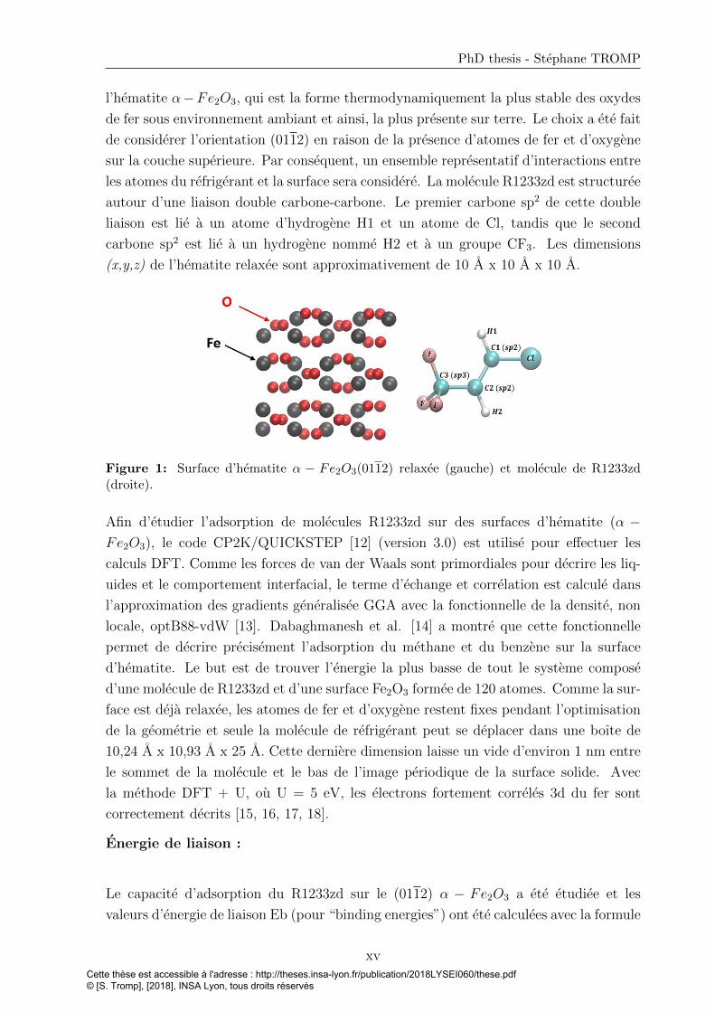
l’hematite α−Fe2O3, qui est la forme thermodynamiquement la plus stable des oxydes
de fer sous environnement ambiant et ainsi, la plus presente sur terre. Le choix a ete fait
de considerer l’orientation (0112) en raison de la presence d’atomes de fer et d’oxygene
sur la couche superieure. Par consequent, un ensemble representatif d’interactions entre
les atomes du refrigerant et la surface sera considere. La molecule R1233zd est structuree
autour d’une liaison double carbone-carbone. Le premier carbone sp2 de cette double
liaison est lie a un atome d’hydrogene H1 et un atome de Cl, tandis que le second
carbone sp2 est lie a un hydrogene nomme H2 et a un groupe CF3. Les dimensions
(x,y,z) de l’hematite relaxee sont approximativement de 10 A x 10 A x 10 A.
Figure 1: Surface d’hematite α − Fe2O3(0112) relaxee (gauche) et molecule de R1233zd(droite).
Afin d’etudier l’adsorption de molecules R1233zd sur des surfaces d’hematite (α −Fe2O3), le code CP2K/QUICKSTEP [12] (version 3.0) est utilise pour effectuer les
calculs DFT. Comme les forces de van der Waals sont primordiales pour decrire les liq-
uides et le comportement interfacial, le terme d’echange et correlation est calcule dans
l’approximation des gradients generalisee GGA avec la fonctionnelle de la densite, non
locale, optB88-vdW [13]. Dabaghmanesh et al. [14] a montre que cette fonctionnelle
permet de decrire precisement l’adsorption du methane et du benzene sur la surface
d’hematite. Le but est de trouver l’energie la plus basse de tout le systeme compose
d’une molecule de R1233zd et d’une surface Fe2O3 formee de 120 atomes. Comme la sur-
face est deja relaxee, les atomes de fer et d’oxygene restent fixes pendant l’optimisation
de la geometrie et seule la molecule de refrigerant peut se deplacer dans une boıte de
10,24 A x 10,93 A x 25 A. Cette derniere dimension laisse un vide d’environ 1 nm entre
le sommet de la molecule et le bas de l’image periodique de la surface solide. Avec
la methode DFT + U, ou U = 5 eV, les electrons fortement correles 3d du fer sont
correctement decrits [15, 16, 17, 18].
Energie de liaison :
Le capacite d’adsorption du R1233zd sur le (0112) α − Fe2O3 a ete etudiee et les
valeurs d’energie de liaison Eb (pour “binding energies”) ont ete calculees avec la formule
xvCette thèse est accessible à l'adresse : http://theses.insa-lyon.fr/publication/2018LYSEI060/these.pdf © [S. Tromp], [2018], INSA Lyon, tous droits réservés

suivante:
Eb = E{surface+1molR1233zd} − Esurface − E1molR1233zd(1)
ou Esurface+1molR1233zdest l’energie totale du systeme adsorbat-substrat relaxe, Esurface
est l’energie de la surface isolee et E1molR1233zdest l’energie de la molecule R1233zd
isolee. Les deux derniers termes sont calcules en utilisant la meme geometrie que celle
optimisee pour le systeme {surface + 1molR1233zd}. Une valeur negative de l’energie de
liaison signifie que la geometrie obtenue est plus stable que l’etat non lie.
0.3.2 Adsorption du R1233zd sur des surfaces d’oxydes de fer
Seize configurations initiales differentes ont ete obtenues par translations et rotations
aleatoires de la molecule de refrigerant par rapport aux trois directions de l’espace.
Comme indique dans le Tableau 1 ci-dessous, l’adsorption peut se produire suivant six
cas differents (correspondant chacun a des positions et orientations similaires), associes
a six gammes d’energie de liaison. Tous les resultats d’adsorption sont visualises avec
le logiciel “visual molecular dynamics” (VMD) [19].
Table 1: Six cas d’adsorption differents associes a leurs valeurs d’energie de liaison et leurnumero d’optimisation de geometrie.
Le premier resultat important est que les atomes de chlore interagissent fortement avec
xviCette thèse est accessible à l'adresse : http://theses.insa-lyon.fr/publication/2018LYSEI060/these.pdf © [S. Tromp], [2018], INSA Lyon, tous droits réservés
PhD thesis - Stephane TROMP
les atomes de fer, comme le montre le cas 1 du Tableau 1. Lors de l’optimisation de
la geometrie, il est egalement possible que la molecule de refrigerant s’incline et que
l’hydrogene H1 situe pres du chlore stabilise la molecule adsorbee, comme indique dans
le cas 2. Le cas 3 montre que le fluor peut egalement participer a l’adsorption, avec une
liaison plus forte que dans le cas 2, et qui atteint ici une valeur de -0,65 eV. L’hypothese
d’une interaction possible entre les atomes de fer et de fluor a deja ete soulevee dans la
litterature [20], mais pour un autre refrigerant. Le cas 4 represente l’adsorption la plus
forte. En effet, les energies de liaison avec la molecule de refrigerant parallele a la surface
d’hematite ont une amplitude plus grande que celles avec les orientations verticales de
la molecule. Par consequent, cela signifie que les positions horizontales des molecules de
refrigerant sont plus stables que celles verticales. En effet, la surface interagit d’un cote
avec le chlore, mais egalement avec les fluors. De plus, la liaison π entre les carbones sp2
pourrait jouer un role. Pour le cas 5, la molecule a subi une rotation le long de l’axe de la
double liaison carbone-carbone ; le chlore, le fluor et l’hydrogene H2 lie au carbone situe
au milieu de la molecule, interagissent avec la surface. Dans le cas 6, seuls les atomes de
fluor interagissent avec la surface. Cette derniere orientation de la molecule s’est trouvee
en pratique etre la plus difficile a obtenir car le processus d’optimisation de la geometrie
ne convergeait pas facilement. Il est egalement interessant d’observer qu’il est possible
d’obtenir la meme valeur d’energie de liaison avec une molecule adsorbee soit grace aux
trois atomes de fluor, soit seulement avec l’atome de chlore. Cette derniere observation
appuie certaines supposition trouvees dans la litterature avec un autre refrigerant, le
R12, a propos d’une formation de revetement chlore-fer [21]. En effet, les atomes de
chlore et de fer interagissent fortement et la molecule R1233zd peut etre adsorbee avec
une contribution majeure des interactions de van der Waals entre ces deux atomes et
bien sur a cause de toutes les interactions coulombiennes. De plus, Akram et al. ont
rapporte la formation d’un film enrichi en fluor FeF3 pour le HFO-1234yf [22]. Il est
donc possible de lier cette observation a la geometrie optimisee du cas 6.
Apres voir introduit notre modele DFT, les resultats concernant l’adsorption de molecules
de R1233zd sur la surface de l’oxyde de fer ont ete presentes. Cette section represente
un complement ideal pour repondre a certaines lacunes experimentales presentes dans
la litterature. Le point delicat etait d’utiliser la methode DFT + U avec une fonction-
nelle vdW combinee a un systeme polarise en spin. Les principaux resultats, incluant
une etude supplementaire sur la distribution des charges, non detaillee dans ce resume,
peuvent etre rapportees comme suit:
• on observe une plage de valeurs d’energie de liaison de la molecule de refrigerant
sur la surface d’oxyde de fer allant de -0,92 eV a -0,22 eV,
• les atomes de fer jouent un role majeur dans le processus d’adsorption,
• l’hydrogene H1 situe a proximite du chlore joue un role non negligeable de stabil-
xviiCette thèse est accessible à l'adresse : http://theses.insa-lyon.fr/publication/2018LYSEI060/these.pdf © [S. Tromp], [2018], INSA Lyon, tous droits réservés

isation,
• les positions horizontales des molecules de refrigerant sont les plus stables avec
une valeur d’energie de liaison d’environ -0,92 eV,
• aucun phenomene de dissociation du refrigerant sur l’hematite n’a ete observe,
• entre la molecule R1233zd et la surface, seuls de petits echanges de charge sont
obtenus avec une valeur maximale de 0,1e. Les molecules de R1233zd sont ph-
ysisorbees sur les surfaces d’hematite α − Fe2O3(0112) et aucune chimisorption
n’est observee. De plus, aucune rupture de la double liaison carbone-carbone n’est
constatee.
Dans cette etude ab-initio, nous avons montre que la molecule R1233zd pouvait etre
fortement adsorbee sur une surface d’oxyde de fer. Cette adsorption a ete caracterisee
en considerant un ensemble de positions et d’orientations de la molecule au-dessus de la
surface, recouvrant ce qui pourrait etre trouve dans un contact lubrifie. Ces informations
sur la reactivite de la surface avec le refrigerant, obtenues a partir des calculs DFT sont
ensuite conservees dans un champ de force afin d’etudier des systemes beaucoup plus
grands avec des simulations de dynamique moleculaire, comme detaille dans la prochaine
section.
0.4 Dynamique Moleculaire : performance tribologique
du R1233zd en extreme confinement
La dynamique moleculaire (DM) est une methode numerique basee sur la resolution
dans le temps de l’equation du mouvement de Newton sur tous les atomes interagissant
dans un systeme moleculaire [23]. En DM, contrairement a la DFT, les interactions entre
atomes sont decrites par des champs de force (FF, pour “force field”) [23]. Puisque les
simulations de DM sont dependantes du temps, des phenomenes hors equilibre peuvent
etre explores et un grand nombre de caracteristiques concernant le cisaillement de films
minces (frottement, conductivite thermique, profil de vitesse, etc.) peuvent etre obtenus
[24, 25, 26, 11, 27, 28, 29]. C’est pour ces raisons que des simulations de DM sont realisees
dans ce projet pour caracteriser des systemes confines sous cisaillement.
Comme indique dans le chapitre precedent, les couts de calcul eleves necessaires a la
DFT empechent son utilisation pour etudier de plus gros systemes. C’est pourquoi, dans
cette section, des simulations DM sont utilisees pour les systemes a plus grande echelle
afin d’etudier les comportements tribologiques dans differentes conditions extremes. En
particulier, les effets des fortes interactions refrigerant/hematite observees en ab-initio,
sur la resistance du film dans le contact lubrifie, sont etudies.
xviiiCette thèse est accessible à l'adresse : http://theses.insa-lyon.fr/publication/2018LYSEI060/these.pdf © [S. Tromp], [2018], INSA Lyon, tous droits réservés

PhD thesis - Stephane TROMP
0.4.1 Modele et methodes
Tous les calculs de DM dans cette section sont effectues en utilisant le logiciel LAMMPS
(version: 14 mai 2016) [30]. Des surfaces d’hematite d’orientation (0112) et avec des
dimensions (x × y × z) d’environ 30 A × 33 A × 10 A sont utilisees dans tous les
calculs. Au lieu d’utiliser un champ de force de la litterature qui, dans le meilleur
des cas, reproduirait approximativement les parametres de mailles, chaque atome de la
surface est relie avec un ressort a un atome virtuel situe a sa position d’equilibre. A 0
K, la surface virtuelle se superpose donc a la surface reelle. Aucune interaction n’est
definie a l’interieur de la surface virtuelle, entre les deux surfaces virtuelles, ou entre
les surfaces virtuelles et le refrigerant. Les seuls interactions avec les surfaces virtuelles
sont les ressorts qui les relient aux surface reelles. La surface superieure est obtenue par
rotation de 180 degres de la surface inferieure. Chaque surface est composee de 1080
atomes (sans compter les atomes virtuels).
Figure 2: Representation d’un systeme de R1233zd confine entre deux surfaces d’hematite.
Le refrigerant liquide est compose de 192 molecules, soit 1728 atomes. Le champ de
force de Raabe est utilise pour decrire les interactions du R1233zd [31, 32]. Dans la
section precedente, la capacite d’adsorption du R1233zd sur la surface de l’hematite
a ete etudiee. Un champ de force a ete adapte de ces resultats pour l’interface en-
tre le refrigerant et la surface. Le choix a ete fait de transcrire les interactions entre
le refrigerant et la surface en utilisant deux potentiels, un potentiel de Coulomb et
un potentiel de Lennard-Jones (LJ) 12-6 entre chaque paire d’atomes. L’algorithme
d’integration de Verlet est utilise avec un pas de temps de 1 fs.
Toutes les configurations initiales sont obtenues avec le logiciel Moltemplate [33]. Un
espace vide d’environ 30 A dans la direction z entre les molecules de refrigerant et la sur-
face est etabli initialement, afin de ne pas perturber la minimisation de l’energie avant
d’appliquer la charge normale. Comme ilustre sur la Figure 2, la pression Pz = 500 MPa
est controlee en appliquant une force externe supplementaire a la surface virtuelle de telle
xixCette thèse est accessible à l'adresse : http://theses.insa-lyon.fr/publication/2018LYSEI060/these.pdf © [S. Tromp], [2018], INSA Lyon, tous droits réservés
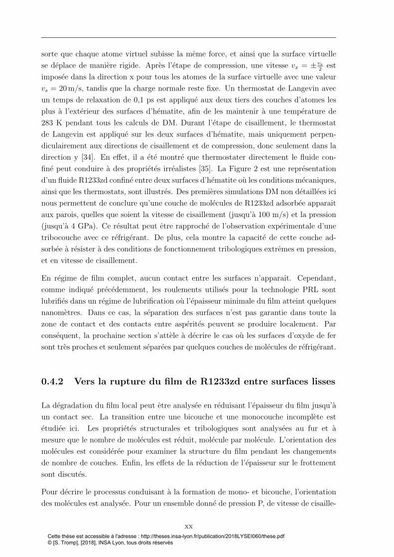
sorte que chaque atome virtuel subisse la meme force, et ainsi que la surface virtuelle
se deplace de maniere rigide. Apres l’etape de compression, une vitesse vx = ±vs2
est
imposee dans la direction x pour tous les atomes de la surface virtuelle avec une valeur
vs = 20 m/s, tandis que la charge normale reste fixe. Un thermostat de Langevin avec
un temps de relaxation de 0,1 ps est applique aux deux tiers des couches d’atomes les
plus a l’exterieur des surfaces d’hematite, afin de les maintenir a une temperature de
283 K pendant tous les calculs de DM. Durant l’etape de cisaillement, le thermostat
de Langevin est applique sur les deux surfaces d’hematite, mais uniquement perpen-
diculairement aux directions de cisaillement et de compression, donc seulement dans la
direction y [34]. En effet, il a ete montre que thermostater directement le fluide con-
fine peut conduire a des proprietes irrealistes [35]. La Figure 2 est une representation
d’un fluide R1233zd confine entre deux surfaces d’hematite ou les conditions mecaniques,
ainsi que les thermostats, sont illustres. Des premieres simulations DM non detaillees ici
nous permettent de conclure qu’une couche de molecules de R1233zd adsorbee apparaıt
aux parois, quelles que soient la vitesse de cisaillement (jusqu’a 100 m/s) et la pression
(jusqu’a 4 GPa). Ce resultat peut etre rapproche de l’observation experimentale d’une
tribocouche avec ce refrigerant. De plus, cela montre la capacite de cette couche ad-
sorbee a resister a des conditions de fonctionnement tribologiques extremes en pression,
et en vitesse de cisaillement.
En regime de film complet, aucun contact entre les surfaces n’apparaıt. Cependant,
comme indique precedemment, les roulements utilises pour la technologie PRL sont
lubrifies dans un regime de lubrification ou l’epaisseur minimale du film atteint quelques
nanometres. Dans ce cas, la separation des surfaces n’est pas garantie dans toute la
zone de contact et des contacts entre asperites peuvent se produire localement. Par
consequent, la prochaine section s’attele a decrire le cas ou les surfaces d’oxyde de fer
sont tres proches et seulement separees par quelques couches de molecules de refrigerant.
0.4.2 Vers la rupture du film de R1233zd entre surfaces lisses
La degradation du film local peut etre analysee en reduisant l’epaisseur du film jusqu’a
un contact sec. La transition entre une bicouche et une monocouche incomplete est
etudiee ici. Les proprietes structurales et tribologiques sont analysees au fur et a
mesure que le nombre de molecules est reduit, molecule par molecule. L’orientation des
molecules est consideree pour examiner la structure du film pendant les changements
de nombre de couches. Enfin, les effets de la reduction de l’epaisseur sur le frottement
sont discutes.
Pour decrire le processus conduisant a la formation de mono- et bicouche, l’orientation
des molecules est analysee. Pour un ensemble donne de pression P, de vitesse de cisaille-
xxCette thèse est accessible à l'adresse : http://theses.insa-lyon.fr/publication/2018LYSEI060/these.pdf © [S. Tromp], [2018], INSA Lyon, tous droits réservés

PhD thesis - Stephane TROMP
ment vs et de nombre de molecules de refrigerant dans le contact Nzd, 60 configurations
de toutes les positions atomiques sont determinees tout au long de l’etape de cisaille-
ment de 3 ns, pour calculer les orientations moleculaires. Pour chaque configuration et
molecule, l’angle αz-ClH2 entre les directions Cl-H2 et l’axe z est calcule. Les molecules
sont ensuite classees selon la valeur de cet angle puis, les resultats sont moyennes sur
tous les configurations. Le choix de cet angle est justifie en raison de sa capacite a
representer les molecules perpendiculaires ou les atomes de chlore sont situes proches
de la surface et les groupes CF3 eloignes de l’interface. Une petite valeur de αz-ClH2
correspond donc a une molecule perpendiculaire a la surface inferieure. Une molecule
est consideree comme perpendiculaire lorsque | αz-ClH2 | est inferieur a 30◦ ou compris
entre 150◦ et 180◦. La Figure 3 superpose la densite du film (en orange) et le pourcent-
age de molecules perpendiculaires (en bleu) entre les deux surfaces. Ces caracteristiques
sont dessinees en fonction de Nzd a P = 0,5 GPa et pour une vitesse de cisaillement
vs = 20 m/s
Figure 3: Pourcentage de molecules perpendiculaires (en bleu) en fonction du nombre totalde molecules de refrigerant dans le contact, en comparaison avec la densite (en orange), a P= 0,5 GPa et pour une vitesse de cisaillement vs = 20 m/s.
Ces courbes donnent des informations sur le processus de transition des dernieres couches.
En effet, lorsque la quantite de refrigerant est progressivement reduite, la densite du film
augmente brusquement juste avant d’atteindre une bicouche complete a 84 molecules
ou avant une monocouche a 44 molecules. La signification physique de ces augmenta-
tions est que le volume diminue rapidement en reduisant le nombre de molecules. Ce
processus peut etre lie a l’orientation des molecules dans cette zone. En effet, le nom-
bre de molecules perpendiculaires aux surfaces croıt fortement au cours de ces deux
augmentations de densite lorsque la quantite de refrigerant est reduite. Ce pourcent-
age de molecules perpendiculaires s’eleve au maximum a environ 13% du nombre total
xxiCette thèse est accessible à l'adresse : http://theses.insa-lyon.fr/publication/2018LYSEI060/these.pdf © [S. Tromp], [2018], INSA Lyon, tous droits réservés

de molecules. Il correspond a la tendance des molecules a relier les couches (par des
ponts) jusqu’a la fusion des couches en une seule. Ensuite, ce pourcentage diminue
fortement et seulement 4% du nombre total des molecules sont orientees perpendicu-
lairement lorsqu’une mono- ou bicouche complete est atteinte. En reduisant encore la
quantite de refrigerant apres avoir atteint la monocouche, le pourcentage de molecules
perpendiculaires atteint zero en raison d’une orientation plate des molecules restantes.
A l’echelle nanometrique, la structure du film est tres differente de celle d’un fluide en
volume et la densite, ainsi que les profils de vitesse, peuvent fournir des informations
supplementaires a la comprehension des phenomenes. La molecule R1233zd est com-
posee de plusieurs types d’atomes avec differentes masses molaires. Ainsi, afin de mieux
representer la distribution des atomes a travers l’epaisseur du film, la densite definie
comme le nombre de particules par unite de volume, est calculee a la place de la den-
site massique. La Figure 4 represente quatre cas caracteristiques de structuration et
de dynamique particuliere a travers l’epaisseur du film, a une pression appliquee de 0,5
GPa. En reduisant la quantite de refrigerant, le cas a) decrit une bicouche complete (8,4
molecules par nm2) ; le cas b) (5,0 molecules par nm2) represente le Nzd le plus eleve
pour lequel un glissement aux parois apparaıt ; le cas c) est representatif d’une mono-
couche complete (4,4 molecules par nm2); enfin, le cas d) represente une monocouche a
moitie remplie, soit 2,2 molecules par nm2.
Pour une bicouche complete (cas a), les molecules de refrigerant se situent dans une
epaisseur de film d’environ 10 A. Dans ce cas, les deux couches sont accrochees cha-
cune sur la surface la plus proche, en raison des interactions interfaciales elevees. Par
consequent, le profil de vitesse montre que le cisaillement se produit entre les deux
couches (localisation centrale). Il est particulierement interessant de souligner que les
deux couches de R1233zd sont toujours adsorbees sur les surfaces, meme a un taux de
cisaillement extremement eleve (superieur a 1010 s−1). Cette remarque contribue a ex-
pliquer pourquoi une couche protectrice est attendue meme dans des conditions severes
de fonctionnement, comme observe experimentalement [4, 5]. Cela permet egalement
de caracteriser la limite de lubrification avec un tel refrigerant. Le cas b represente la
premiere situation ou un glissement se produit a la paroi refrigerant/surface. En effet,
on observe une chute de la vitesse entre la surface et le refrigerant au niveau de la paroi.
Plus specifiquement, a l’interface fluide/surface inferieure (a z = 10 A), le point bleu
situe directement apres l’interface a une vitesse differente de celle de la surface. Cepen-
dant, cette chute de vitesse est moins distincte a l’interface avec la surface superieure
(a z = 17,4 A), ou une faible adsorption semble persister. Au milieu du profil de den-
site, le nombre d’atomes est plus grand que dans le cas a (bicouche complete), ce qui
signifie que des ponts apparaissent entre les deux couches. En consequence, l’epaisseur
de chacune des deux couches est reduite ; cela est represente par une largeur des pics de
densite qui diminue. Le cas c decrit une monocouche complete ou un large glissement
xxiiCette thèse est accessible à l'adresse : http://theses.insa-lyon.fr/publication/2018LYSEI060/these.pdf © [S. Tromp], [2018], INSA Lyon, tous droits réservés

PhD thesis - Stephane TROMP
Figure 4: Profils de densite et de vitesse dans l’epaisseur du film pour quatre Nzd differents –a)Nzd = 84, b)Nzd = 50, c)Nzd = 44, d)Nzd = 22 – a 0,5 GPa, avec une vitesse de cisaillementde 20 m/s and une temperature de la surface fixee a 283 K.
xxiiiCette thèse est accessible à l'adresse : http://theses.insa-lyon.fr/publication/2018LYSEI060/these.pdf © [S. Tromp], [2018], INSA Lyon, tous droits réservés
aux parois est observe. Une partie de la difference de vitesse entre les surfaces et le
refrigerant est absorbee par le cisaillement de la monocouche elle-meme, les molecules se
deplacant independamment les unes des autres. Dans le cas d, le pic de densite est plus
mince car les molecules sont orientees de facon plane, comme detaille precedemment, et
le glissement a la paroi est predominant.
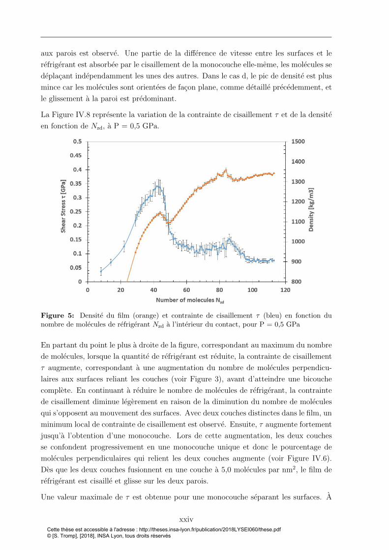
La Figure IV.8 represente la variation de la contrainte de cisaillement τ et de la densite
en fonction de Nzd, a P = 0,5 GPa.
Figure 5: Densite du film (orange) et contrainte de cisaillement τ (bleu) en fonction dunombre de molecules de refrigerant Nzd a l’interieur du contact, pour P = 0,5 GPa
En partant du point le plus a droite de la figure, correspondant au maximum du nombre
de molecules, lorsque la quantite de refrigerant est reduite, la contrainte de cisaillement
τ augmente, correspondant a une augmentation du nombre de molecules perpendicu-
laires aux surfaces reliant les couches (voir Figure 3), avant d’atteindre une bicouche
complete. En continuant a reduire le nombre de molecules de refrigerant, la contrainte
de cisaillement diminue legerement en raison de la diminution du nombre de molecules
qui s’opposent au mouvement des surfaces. Avec deux couches distinctes dans le film, un
minimum local de contrainte de cisaillement est observe. Ensuite, τ augmente fortement
jusqu’a l’obtention d’une monocouche. Lors de cette augmentation, les deux couches
se confondent progressivement en une monocouche unique et donc le pourcentage de
molecules perpendiculaires qui relient les deux couches augmente (voir Figure IV.6).
Des que les deux couches fusionnent en une couche a 5,0 molecules par nm2, le film de
refrigerant est cisaille et glisse sur les deux parois.
Une valeur maximale de τ est obtenue pour une monocouche separant les surfaces. A
xxivCette thèse est accessible à l'adresse : http://theses.insa-lyon.fr/publication/2018LYSEI060/these.pdf © [S. Tromp], [2018], INSA Lyon, tous droits réservés
PhD thesis - Stephane TROMP
ce stade, le glissement aux parois est inevitable. En effet, les deux surfaces se deplacent
dans des directions opposees et le cisaillement ne se produit qu’a l’interieur d’une couche
de refrigerant. Par consequent, seules les interactions interfaciales refrigerant/surface
determinent le comportement en frottement. En consequence de la parametrisation
du champ de force a l’interface, le terme ε du potentiel de Lennard-Jones est eleve
pour representer la capacite d’adsorption de la molecule de R1233zd sur les surfaces
d’hematite. Ces fortes interactions conduisent a une contrainte de cisaillement tres
elevee τ = 0,34 GPa a P = 0,5 GPa. De plus, l’epaisseur du film etant tres faible
avec seulement une monocouche separant les deux surfaces, l’adherence entre les deux
surfaces, dues aux forces de Van der Waals et aux interactions electrostatiques, peut
augmenter le frottement [36].
Ensuite, la contrainte de cisaillement τ diminue lorsque le nombre de molecules de
refrigerant est reduit davantage. Moins de molecules de R1233zd doivent etre cisaillees,
impliquant une plus faible resistance au mouvement des surfaces et donc une force
tangentielle inferieure. Par consequent, un τ inferieur est trouve en comparaison avec
une monocouche complete.
La prochaine section a pour but de considerer un contact entre une asperite et une
surface lisse afin d’etudier la resistance de la couche adsorbee dans des cas extremes
plus realistes. En effet, la rugosite peut avoir un impact severe sur la structure et
l’ecoulement du fluide nanoconfine [37].
0.4.3 Structure et rupture du film avec surfaces rugueuses
La conception de la rugosite et son implication sur le systeme sont tout d’abord ex-
pliquees. Ensuite, la structure et la resistance de la couche adsorbee situee dans la zone
de contact avec la rugosite seront etudiees a differentes pressions et vitesses de cisaille-
ment. Pour analyser les effets de rugosite, des systemes plus grands que ceux consideres
precedemment doivent etre utilises. Dans les systemes reels, la rugosite quadratique
moyenne (RMS) peut atteindre plusieurs nanometres [3] mais pour limiter les couts de
calculs, nous considererons ici un systeme plus petit et representatif du sommet d’une
asperite. Une surface (0112) d’hematite, avec des dimensions (x × y × z) environ egales
a 205 A × 33 A × 10 A, est utilisee dans cette section pour la surface superieure.
De plus, la surface inferieure est construite en deformant sa forme avec une fonction
gaussienne d’amplitude A = 15 A, comme suit.
Zrugosite : x 7−→ Zinit + Ae−(x−Lx
2 )2
2σ2 (2)
Ou σ est choisi pour avoir une largeur a mi-hauteur H = 2√
2ln(2)σ = Lx4
avec Lx la
xxvCette thèse est accessible à l'adresse : http://theses.insa-lyon.fr/publication/2018LYSEI060/these.pdf © [S. Tromp], [2018], INSA Lyon, tous droits réservés

longueur totale de la surface de 205 A, Zinit la coordonnee initiale suivant la direction
z de chaque atome et Zrugosite les nouvelles coordonnees suivant la direction z. Cette
fonction est egalement appliquee aux atomes de la surface virtuelle. La longueur de la
surface est choisie assez grande pour augmenter le rayon de courbure au sommet, donne
par σ2
A= 31 A.
Differentes quantites de molecules de refrigerant ont ete testees pour assurer une couche
adsorbee repartie sur toute la surface mais egalement pour permettre qu’une bulle reste
piegee entre les parties planes des surfaces apres compression et pour chaque pression.
Le but de cette procedure est de s’assurer que nous testons bien la resistance de la
couche adsorbee, et non la compressibilite du fluide. 600 molecules de R1233zd sont
mises en place dans le systeme et chaque surface est composee de 7200 atomes (sans
compter les atomes virtuels). Les deux etapes de compression et de cisaillement durent
5 ns chacune. Contrairement aux precedentes etudes de DM, seule la surface superieure
se deplace. Des pressions de 50 MPa a 3 GPa sont appliquees a la surface superieure
virtuelle. La vitesse est appliquee suivant la direction x pour tous les atomes virtuels
de la surface superieure avec une valeur de la vitesse de cisaillement vs variant de 2 m/s
a 50 m/s.
Les effets de la vitesse de cisaillement sur la resistance et la structure de la couche
adsorbee sont analyses. Quatre vitesses de cisaillement differentes (2, 5, 10, 50) m/s
sont considerees avec les pressions suivantes: 0,05, 0,1, 0,3, 0,5, 1, 1,5, 2, 3 GPa. Comme
la force entre les deux surfaces est transmise a travers une tres petite zone de contact,
la pression locale dans cette zone est beaucoup plus grande que la pression moyenne
imposee dans les simulations. Pour estimer la pression locale dans la zone de contact, la
methodologie suivante est utilisee pour mesurer la longueur de contact, comme indique
sur la Figure 6.
Comme la surface inferieure ne bouge pas, le pic de rugosite reste localise a la position
x0, qui correspond au milieu de la longueur totale Lx = 205 A de la boıte de simulation.
Considerant la sortie du divergent de la region de contact avec l’asperite, une zone
de vide peut etre identifiee a partir de la position xc (voir Figure 6). Une estimation
grossiere de la longueur reelle du contact Lc est proposee comme Lc = 2(xc − x0). A
partir de la pression P appliquee uniformement sur les atomes de la surface superieure
virtuelle, on peut deduire la pression de contact effective Pc comme:
Pc = PLxLc, (3)
ou la limite de contact xc varie autour de 118 A, correspondant a un rapport LxLc
constant
pour tous les cas: LxLc
= 6,6. Pc represente une estimation approximative de la pression
reelle subie par les couches de refrigerant, a des fins de comparaison.
xxviCette thèse est accessible à l'adresse : http://theses.insa-lyon.fr/publication/2018LYSEI060/these.pdf © [S. Tromp], [2018], INSA Lyon, tous droits réservés

PhD thesis - Stephane TROMP
Figure 6: Estimation visuelle de la zone de contact utilisee pour estimer la pression de contactpar rapport a la pression appliquee globalement.
Le Tableau 2 rassemble les informations sur la resistance et la structure des couches de
refrigerant sous compression et cisaillement. De plus, les pressions estimees Pc dans la
zone de contact sont fournies.
A P = 0,05 GPa (Pc ≈ 0,3 GPa), la bicouche resiste. Pour le cas intermediaire avec
P = 0,1 GPa (Pc ≈ 0,7 GPa), une vitesse de cisaillement vs elevee, qui est ici egale
a la vitesse d’entraınement du fluide dans le contact, est benefique pour conserver la
formation d’une bicouche (vs = 10 m/s et 50 m/s). Au contraire, pour des petites
vitesses, le mouvement de cisaillement tend a destabiliser la structure en bicouche qui
perdurait en regime stationnaire sans cisaillement, et donc a favoriser une monocouche.
A plus hautes pressions, aucune bicouche n’est observee.
xxviiCette thèse est accessible à l'adresse : http://theses.insa-lyon.fr/publication/2018LYSEI060/these.pdf © [S. Tromp], [2018], INSA Lyon, tous droits réservés

Table 2: Resistance et structure des couches adsorbees compressees et cisaillees a l’interieurd’un contact lisse/rugueux, a 0,05, 0,1, 0,3, 0,5, 1, 1,5, 2, 3 GPa et a des vitesses de cisaillementde 2, 5, 10, 50 m/s.
xxviiiCette thèse est accessible à l'adresse : http://theses.insa-lyon.fr/publication/2018LYSEI060/these.pdf © [S. Tromp], [2018], INSA Lyon, tous droits réservés
PhD thesis - Stephane TROMP
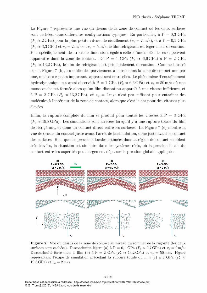
La Figure 7 represente une vue du dessus de la zone de contact ou les deux surfaces
sont cachees, dans differentes configurations typiques. En particulier, a P = 0,3 GPa
(Pc ≈ 2 GPa) pour la plus petite vitesse de cisaillement (vs = 2 m/s), et a P = 0,5 GPa
(Pc ≈ 3,3 GPa) et vs = 2 m/s ou vs = 5 m/s, le film refrigerant est legerement discontinu.
Plus specifiquement, des trous de dimensions egale a celles d’une molecule seule, peuvent
apparaıtre dans la zone de contact. De P = 1 GPa (Pc ≈ 6,6 GPa) a P = 2 GPa
(Pc ≈ 13,2 GPa), le film de refrigerant est principalement discontinu. Comme illustre
sur la Figure 7 (b), les molecules parviennent a entrer dans la zone de contact une par
une, mais des espaces importants apparaissent entre elles. Le phenomene d’entraınement
hydrodynamique est aussi observe a P = 1 GPa (Pc ≈ 6,6 GPa) et vs = 50 m/s ou une
monocouche est formee alors qu’un film discontinu apparaıt a une vitesse inferieure, et
a P = 2 GPa (Pc ≈ 13,2 GPa), ou vs = 2 m/s n’est pas suffisant pour entraıner des
molecules a l’interieur de la zone de contact, alors que c’est le cas pour des vitesses plus
elevees.
Enfin, la rupture complete du film se produit pour toutes les vitesses a P = 3 GPa
(Pc ≈ 19,8 GPa). Les simulations sont arretees lorsqu’il y a une rupture totale du film
de refrigerant, et donc un contact direct entre les surfaces. La Figure 7 (c) montre la
vue de dessus du contact juste avant l’arret de la simulation, donc juste avant le contact
des surfaces. Bien que les pressions locales estimees dans la region de contact semblent
tres elevees, la situation est similaire dans les systemes reels, ou la pression locale du
contact entre les asperites peut largement depasser la pression globale appliquee.
Figure 7: Vue du dessus de la zone de contact au niveau du sommet de la rugosite (les deuxsurfaces sont cachees). Discontinuite legere (a) a P = 0,1 GPa (Pc ≈ 0,7 GPa) et vs = 2 m/s.Discontinuite forte dans le film (b) a P = 2 GPa (Pc ≈ 13,2 GPa) et vs = 50 m/s. Figurerepresentant l’etape de simulation precedant la rupture totale du film (c) a 3 GPa (Pc ≈19,8 GPa) et vs = 2 m/s.
xxixCette thèse est accessible à l'adresse : http://theses.insa-lyon.fr/publication/2018LYSEI060/these.pdf © [S. Tromp], [2018], INSA Lyon, tous droits réservés

0.5 Conclusion generale
En utilisant une approche de modelisation multi-echelles, cette these a explore l’influence
de la physicochimie a l’interface entre un refrigerant et une surface d’oxyde de fer sur la
performance tribologique dans un contact lubrifie, sous des conditions de lubrification
avec refrigerant pur (PRL).
Tout d’abord, des calculs quantiques bases sur la theorie de la fonctionnelle de la densite
(DFT) ont ete realises afin d’etudier l’adsorption du refrigerant R1233zd sur la surface
d’oxyde de fer. Les molecules de R1233zd sont physisorbees sur des surfaces d’hematite
α−Fe2O3(0112) et aucune chimisorption et aucune rupture de double liaisons carbone-
carbone ne sont observes. De plus, la dissociation du refrigerant a l’approche de la
surface n’est pas constatee. Seuls de faibles echanges de charge sont trouves entre la
molecule R1233zd et la surface, avec une valeur maximale de 0,1e. Une gamme de valeurs
d’energies de liaison allant de -0,92 eV a -0,22 eV est observee avec seize orientations et
positions differentes de la molecule R1233zd sur le dessus de la surface. Les positions
horizontales des molecules de refrigerant sont les plus stables avec une valeur d’energie
de liaison d’environ -0,92 eV. Les atomes de fer jouent un role majeur dans le processus
d’adsorption et l’hydrogene H1 situe a proximite du chlore joue un role non negligeable
de stabilisation.
Ces resultats ab-initio sont ensuite utilises pour parametrer un champ de forces a
l’interface refrigerant-surface qui est utilise dans des simulations a plus grande echelle
a l’aide de la dynamique moleculaire (DM). Avec ces simulations, une couche adsorbee
de R1233zd sur les surfaces d’oxydes de fer est observee, corroborant les resultats
experimentaux. La resistance de cette couche adsorbee et sa capacite a proteger la
surface contre l’usure sont testees. Les simulations de DM ont permis d’etudier des cas
tribologiques differents, des conditions les moins extremes a celles les plus severes. La
premiere etude de cas a considere une epaisseur de film de 2,1-2,5 nm, confinee entre
deux surfaces atomiquement lisses sous une pression normale allant jusqu’a 4 GPa et
avec une vitesse de cisaillement allant jusqu’a 100 m/s. La principale decouverte est
qu’une couche de R1233zd reste adsorbee sur les deux surfaces d’oxyde de fer, quelles que
soient les conditions operatoires testees. Ceci est coherent avec l’analyse XPS realisee
sur des surfaces de roulements reels dans diverses conditions.
La deuxieme etude de cas considere une epaisseur de film ultra-mince de 1,5 nm a 0,5
nm, avec des surfaces lisses, une pression P = 0,5 GPa et une vitesse de cisaillement
vs = 20 m/s. Dans ces conditions, le film de refrigerant developpe des couches paralleles
aux surfaces. Avec 8,4 molecules de R1233zd par nm2, deux couches saturees sont
formees, chacune adherant a la surface la plus proche. Dans ce cas, le cisaillement
se localise dans la partie centrale du film et est represente par un plan de glissement
xxxCette thèse est accessible à l'adresse : http://theses.insa-lyon.fr/publication/2018LYSEI060/these.pdf © [S. Tromp], [2018], INSA Lyon, tous droits réservés

PhD thesis - Stephane TROMP
entre les deux couches. Avec deux couches distinctes dans le film, un minimum local
de contrainte de cisaillement est observe. Cependant, lorsque le nombre de molecules
diminue, des molecules perpendiculaires aux surfaces sont observees, et les deux couches
se confondent progressivement en une seule monocouche. La contrainte de cisaillement
augmente fortement pendant cette transition, et le maximum est atteint lorsque la
monocouche est saturee, avec 4,4 molecules par nm2 a P = 0,5 GPa, et 4,7 molecules
par nm2 a P = 1,5 GPa. Des que les deux couches fusionnent en une monocouche, le
film de refrigerant est cisaille, accompagne de glissement aux parois.
Enfin, la troisieme etude de cas visait a representer un contact plus realiste. Une asperite
longitudinale rigide de forme gaussienne est creee sur une surface fixe, tandis que l’autre
surface est lisse. Au repos, donc sans cisaillement, sous une pression maximale de P = 3
GPa (c’est-a-dire une pression de contact moyenne Pc ≈ 19,8 GPa) le film de refrigerant
supporte la charge normale. Une transition apparaıt a P = 0,3 GPa (Pc ≈ 2 GPa) ou
la structure du film passe d’une bicouche a une monocouche. Lorsqu’une vitesse de
cisaillement est appliquee, la resistance du film de refrigerant decroıt. Pour la vitesse de
cisaillement la plus faible, la transition de la bicouche a la monocouche apparaıt a P =
0,05 - 0,1 GPa (Pc ≈ 0,3−0,7 GPa), et la monocouche se divise en molecules individuelles
entrant une a une dans le contact a partir de P = 1 GPa (Pc ≈ 6,6 GPa). Ici, la vitesse
de cisaillement imposee represente egalement la vitesse d’entraınement hydrodynamique
des molecules de R1233zd dans la zone de contact, ce qui explique pourquoi le film de
refrigerant, a une valeur de P = 1 GPa (Pc ≈ 6,6 GPa), resiste mieux a des vitesses plus
elevees. A P = 3 GPa (Pc ≈ 19,8 GPa), la rupture totale du film apparaıt a n’importe
quelle vitesse de cisaillement testee, et les surfaces solides se touchent.
xxxiCette thèse est accessible à l'adresse : http://theses.insa-lyon.fr/publication/2018LYSEI060/these.pdf © [S. Tromp], [2018], INSA Lyon, tous droits réservés

Cette thèse est accessible à l'adresse : http://theses.insa-lyon.fr/publication/2018LYSEI060/these.pdf © [S. Tromp], [2018], INSA Lyon, tous droits réservés
Contents
Remerciements v
Abstract vii
Resume viii
Resume etendu xi
0.1 Introduction generale et contexte . . . . . . . . . . . . . . . . . . . . . . xi
0.2 Objectifs de la these . . . . . . . . . . . . . . . . . . . . . . . . . . . . . xiii
0.3 Physicochimie a l’interface refrigerant-surface dans un systeme lubrifie :
une etude ab-initio . . . . . . . . . . . . . . . . . . . . . . . . . . . . . . xiv
0.3.1 Modele : systeme R1233zd-hematite et energies de liaison . . . . . xiv
0.3.2 Adsorption du R1233zd sur des surfaces d’oxydes de fer . . . . . . xvi
0.4 Dynamique Moleculaire : performance tribologique du R1233zd en extreme
confinement . . . . . . . . . . . . . . . . . . . . . . . . . . . . . . . . . . xviii
0.4.1 Modele et methodes . . . . . . . . . . . . . . . . . . . . . . . . . xix
0.4.2 Vers la rupture du film de R1233zd entre surfaces lisses . . . . . . xx
0.4.3 Structure et rupture du film avec surfaces rugueuses . . . . . . . . xxv
0.5 Conclusion generale . . . . . . . . . . . . . . . . . . . . . . . . . . . . . . xxx
Contents 1
List of Figures 5
List of Tables 9
Main abbreviations 11
Introduction 13
I Context and State of the art 15
I.1 Refrigeration systems . . . . . . . . . . . . . . . . . . . . . . . . . . . . . 17
I.2 The refrigerants . . . . . . . . . . . . . . . . . . . . . . . . . . . . . . . . 19
1Cette thèse est accessible à l'adresse : http://theses.insa-lyon.fr/publication/2018LYSEI060/these.pdf © [S. Tromp], [2018], INSA Lyon, tous droits réservés
Contents
I.2.1 The refrigerants and their strong environmental impact . . . . . . 19
I.2.2 The fourth generation of refrigerants: HFOs and HCFOs family . 22
I.2.3 HCFO-1233zd(E) . . . . . . . . . . . . . . . . . . . . . . . . . . . 24
I.3 Lubrication in refrigeration systems . . . . . . . . . . . . . . . . . . . . . 27
I.3.1 Lubrication . . . . . . . . . . . . . . . . . . . . . . . . . . . . . . 27
I.3.2 Refrigerants as lubricants . . . . . . . . . . . . . . . . . . . . . . 28
I.3.2.1 The unavoidable mixing of oil and refrigerant in lubri-
cated systems . . . . . . . . . . . . . . . . . . . . . . . . 28
I.3.2.2 Two issues encountered by lubricating with refrigerants:
surface distress and corrosion . . . . . . . . . . . . . . . 31
I.3.2.3 An alternative: pure refrigerant lubricated (PRL) sys-
tems with special hybrid rolling bearings . . . . . . . . . 32
I.3.3 A very thin film lubrication regime in refrigeration compressors
with PRL . . . . . . . . . . . . . . . . . . . . . . . . . . . . . . . 34
I.4 Molecular scale investigation . . . . . . . . . . . . . . . . . . . . . . . . . 36
I.4.1 Investigation methods to study molecular lubrication . . . . . . . 37
I.4.1.1 Experimental tools . . . . . . . . . . . . . . . . . . . . . 37
I.4.1.2 Numerical simulations . . . . . . . . . . . . . . . . . . . 38
I.4.2 Structure and rheological properties of thin films . . . . . . . . . 40
I.4.2.1 Structuration of lubricant at the interface . . . . . . . . 40
I.4.2.2 Interfacial flow: locking/slip effect . . . . . . . . . . . . 41
I.4.2.3 Rheology of nanoconfined fluid . . . . . . . . . . . . . . 43
I.4.2.4 Thermal effects . . . . . . . . . . . . . . . . . . . . . . . 44
I.4.3 Role of adsorbed layers of refrigerant on the surface . . . . . . . . 45
I.5 Objectives of the PhD . . . . . . . . . . . . . . . . . . . . . . . . . . . . 46
II Chemical physics at interfaces within a refrigerant-lubricated contact:
an electronic structure study 49
II.1 Density Functional Theory . . . . . . . . . . . . . . . . . . . . . . . . . . 51
II.1.1 Basic elements of quantum mechanic . . . . . . . . . . . . . . . . 51
II.1.1.1 Born-Oppenheimer approximation . . . . . . . . . . . . 51
II.1.1.2 The Schrodinger equation . . . . . . . . . . . . . . . . . 52
II.1.1.3 The electron density . . . . . . . . . . . . . . . . . . . . 52
II.1.2 Principles of Density Functional Theory . . . . . . . . . . . . . . 53
II.1.2.1 Hohenberg-Kohn theorems . . . . . . . . . . . . . . . . . 53
II.1.2.2 Kohn-Sham equations . . . . . . . . . . . . . . . . . . . 54
II.1.2.3 SCF: self-consistent field procedure: solutions of Kohn-
Sham equations . . . . . . . . . . . . . . . . . . . . . . . 54
II.1.2.4 Exchange-correlation functionals . . . . . . . . . . . . . 55
II.1.2.5 The core electrons . . . . . . . . . . . . . . . . . . . . . 56
2Cette thèse est accessible à l'adresse : http://theses.insa-lyon.fr/publication/2018LYSEI060/these.pdf © [S. Tromp], [2018], INSA Lyon, tous droits réservés
PhD thesis - Stephane TROMP
II.1.2.6 Basis sets . . . . . . . . . . . . . . . . . . . . . . . . . . 56
II.1.3 DFT+U calculations . . . . . . . . . . . . . . . . . . . . . . . . . 57
II.2 Our model . . . . . . . . . . . . . . . . . . . . . . . . . . . . . . . . . . . 58
II.2.1 Materials . . . . . . . . . . . . . . . . . . . . . . . . . . . . . . . 58
II.2.2 Standard DFT - DFT+U setup . . . . . . . . . . . . . . . . . . . 59
II.2.3 Binding energy . . . . . . . . . . . . . . . . . . . . . . . . . . . . 60
II.3 Adsorption behavior of R1233zd molecule on iron oxide surfaces . . . . . 61
II.3.1 Binding energies . . . . . . . . . . . . . . . . . . . . . . . . . . . 61
II.3.2 Basis set superposition error . . . . . . . . . . . . . . . . . . . . . 63
II.3.3 Dipole correction . . . . . . . . . . . . . . . . . . . . . . . . . . . 63
II.3.4 Charge analysis: physisorption or chemisorption? . . . . . . . . . 64
II.4 Conclusion . . . . . . . . . . . . . . . . . . . . . . . . . . . . . . . . . . . 67
IIITowards large-scale molecular dynamics simulations 69
III.1 Introduction to molecular dynamics . . . . . . . . . . . . . . . . . . . . . 71
III.1.1 Numerical methods . . . . . . . . . . . . . . . . . . . . . . . . . . 71
III.1.1.1 Molecular dynamics principles . . . . . . . . . . . . . . . 71
III.1.1.2 Integration methods . . . . . . . . . . . . . . . . . . . . 72
III.1.2 Force fields . . . . . . . . . . . . . . . . . . . . . . . . . . . . . . 72
III.1.2.1 Different kinds of force fields . . . . . . . . . . . . . . . 72
III.1.2.2 Classical force fields formulation . . . . . . . . . . . . . 73
III.1.3 Importance of the force field for nanoconfined systems . . . . . . 76
III.2 Parametrization of interfacial force field . . . . . . . . . . . . . . . . . . . 77
III.2.1 R1233zd force field . . . . . . . . . . . . . . . . . . . . . . . . . . 77
III.2.2 Force field of the hematite (α− Fe2O3) surface . . . . . . . . . . 79
III.2.3 Influence of the timestep . . . . . . . . . . . . . . . . . . . . . . . 80
III.2.4 Parametrization of interfacial force field between R1233zd and
hematite surfaces . . . . . . . . . . . . . . . . . . . . . . . . . . . 82
III.2.4.1 Methodology . . . . . . . . . . . . . . . . . . . . . . . . 82
III.2.4.2 Results and analysis . . . . . . . . . . . . . . . . . . . . 85
III.3 Assessment of the new parametrized force field: comparison with stan-
dard mixing rules . . . . . . . . . . . . . . . . . . . . . . . . . . . . . . . 86
III.3.1 System setup . . . . . . . . . . . . . . . . . . . . . . . . . . . . . 86
III.3.2 Temperature-pressure regulation and initialization stages . . . . . 87
III.3.3 Simulations setup: compression and shearing . . . . . . . . . . . . 88
III.3.4 Consequences of interfacial FF parametrization . . . . . . . . . . 89
III.3.4.1 Velocity profiles . . . . . . . . . . . . . . . . . . . . . . . 89
III.3.4.2 Density profiles . . . . . . . . . . . . . . . . . . . . . . . 90
III.3.4.3 Orientation at the interface . . . . . . . . . . . . . . . . 91
III.4 Conclusion . . . . . . . . . . . . . . . . . . . . . . . . . . . . . . . . . . . 92
3Cette thèse est accessible à l'adresse : http://theses.insa-lyon.fr/publication/2018LYSEI060/these.pdf © [S. Tromp], [2018], INSA Lyon, tous droits réservés

Contents
IV Tribological performance of R1233zd in extreme confinement 93
IV.1 R1233zd confined between two smooth iron oxide surfaces . . . . . . . . 94
IV.1.1 Mobility of confined R1233zd . . . . . . . . . . . . . . . . . . . . 95
IV.1.2 Frictional behavior . . . . . . . . . . . . . . . . . . . . . . . . . . 97
IV.2 Towards film breakdown of R1233zd confined between smooth surfaces . 99
IV.2.1 Film thickness and density . . . . . . . . . . . . . . . . . . . . . . 100
IV.2.2 Molecule orientation . . . . . . . . . . . . . . . . . . . . . . . . . 102
IV.2.3 Structure and flow . . . . . . . . . . . . . . . . . . . . . . . . . . 103
IV.2.4 Consequences on the shear stress . . . . . . . . . . . . . . . . . . 105
IV.3 Layers formation and film breakdown within a rough contact . . . . . . . 108
IV.3.1 Load bearing capacity at equilibrium . . . . . . . . . . . . . . . . 109
IV.3.2 Resistance to shearing . . . . . . . . . . . . . . . . . . . . . . . . 110
IV.4 Conclusion . . . . . . . . . . . . . . . . . . . . . . . . . . . . . . . . . . . 114
Conclusion 117
Appendice 121
Bibliography 123
4Cette thèse est accessible à l'adresse : http://theses.insa-lyon.fr/publication/2018LYSEI060/these.pdf © [S. Tromp], [2018], INSA Lyon, tous droits réservés

List of Figures
1 Surface d’hematite α − Fe2O3(0112) relaxee (gauche) et molecule de
R1233zd (droite). . . . . . . . . . . . . . . . . . . . . . . . . . . . . . . . xv
2 Representation d’un systeme de R1233zd confine entre deux surfaces
d’hematite. . . . . . . . . . . . . . . . . . . . . . . . . . . . . . . . . . . xix
3 Pourcentage de molecules perpendiculaires (en bleu) en fonction du nom-
bre total de molecules de refrigerant dans le contact, en comparaison avec
la densite (en orange), a P = 0,5 GPa et pour une vitesse de cisaillement
vs = 20 m/s. . . . . . . . . . . . . . . . . . . . . . . . . . . . . . . . . . . xxi
4 Profils de densite et de vitesse dans l’epaisseur du film pour quatre Nzd
differents – a)Nzd = 84, b)Nzd = 50, c)Nzd = 44, d)Nzd = 22 – a 0,5
GPa, avec une vitesse de cisaillement de 20 m/s and une temperature de
la surface fixee a 283 K. . . . . . . . . . . . . . . . . . . . . . . . . . . . xxiii
5 Densite du film (orange) et contrainte de cisaillement τ (bleu) en fonction
du nombre de molecules de refrigerant Nzd a l’interieur du contact, pour
P = 0,5 GPa . . . . . . . . . . . . . . . . . . . . . . . . . . . . . . . . . xxiv
6 Estimation visuelle de la zone de contact utilisee pour estimer la pression
de contact par rapport a la pression appliquee globalement. . . . . . . . . xxvii
7 Vue du dessus de la zone de contact au niveau du sommet de la rugosite
(les deux surfaces sont cachees). Discontinuite legere (a) a P = 0,1 GPa
(Pc ≈ 0,7 GPa) et vs = 2 m/s. Discontinuite forte dans le film (b) a P
= 2 GPa (Pc ≈ 13,2 GPa) et vs = 50 m/s. Figure representant l’etape
de simulation precedant la rupture totale du film (c) a 3 GPa (Pc ≈19,8 GPa) et vs = 2 m/s. . . . . . . . . . . . . . . . . . . . . . . . . . . . xxix
I.1 Vapor-compression refrigeration system. . . . . . . . . . . . . . . . . . . 17
I.2 Two kinds of refrigerant compressor: a) screw compressor and b) cen-
trifugal compressor. . . . . . . . . . . . . . . . . . . . . . . . . . . . . . . 18
I.3 Refrigerants evolution. . . . . . . . . . . . . . . . . . . . . . . . . . . . . 19
I.4 HFOs and HCFOs family. . . . . . . . . . . . . . . . . . . . . . . . . . . 22
I.5 Representation of the trans-1-chloro-3,3,3-trifluoropropene 1233zd(E) molecule. 26
I.6 Conventional chiller design. . . . . . . . . . . . . . . . . . . . . . . . . . 29
5Cette thèse est accessible à l'adresse : http://theses.insa-lyon.fr/publication/2018LYSEI060/these.pdf © [S. Tromp], [2018], INSA Lyon, tous droits réservés

List of Figures
I.7 Variation of the viscosity as a function of the weight percent of R134a
in the mixture, at fixed temperatures and pressures (left). Viscosity-
pressure coefficient as a function of the temperature, at fixed weight per-
cent of R134a in the mixture (right). . . . . . . . . . . . . . . . . . . . . 31
I.8 Surface distress in a raceway bearing surface. . . . . . . . . . . . . . . . . 32
I.9 pure refrigerant lubricated chiller design. . . . . . . . . . . . . . . . . . . 33
I.10 Example of pressures and film thickness results obtained numerically with
an entrainment speed of 2 m/s. . . . . . . . . . . . . . . . . . . . . . . . 34
I.11 Numerical solution for the minimum fim thickness compared with the
experimental results and the Chevalier prediction (T=10◦C, SRR=0 and
p=0.52GPa). . . . . . . . . . . . . . . . . . . . . . . . . . . . . . . . . . 35
I.12 Representation of different scales available for simulations of tribological
systems, from quantum mechanical to continuum descriptions, linked to
MD simulations. . . . . . . . . . . . . . . . . . . . . . . . . . . . . . . . . 39
I.13 Density profiles across the lubricant film (z-direction) for a confined Lennard-
Jones fluid. The distance h between the walls (dotted lines) is varied from
24 to 9 A, corresponding to 7 to 2 molecular layers. Results from Gao et
al. . . . . . . . . . . . . . . . . . . . . . . . . . . . . . . . . . . . . . . . 41
I.14 Representation of locking/slip phenomena at the interface in a nanocon-
fined fluid under shearing. . . . . . . . . . . . . . . . . . . . . . . . . . . 42
I.15 Velocity profiles across a linear and branched decane films confined be-
tween CuO and Fe2O3 surfaces. . . . . . . . . . . . . . . . . . . . . . . . 42
I.16 Generalized map in arbitrary units for the effective viscosity of confined
films as a function of the shear rate, load and film thickness. Inspired by
Luengo et al. and modified by Savio. . . . . . . . . . . . . . . . . . . . . 44
I.17 Typical temperature profile of sheared ionic liquid, for a shear velocity of
40 m/s, a pressure of 500MPa and a wall temperature of 350 K. . . . . . 45
II.1 Hematite α − Fe2O3(0112) relaxed surface (left) and R1233zd molecule
(right). . . . . . . . . . . . . . . . . . . . . . . . . . . . . . . . . . . . . . 58
II.2 Exchanged charges of R1233zd molecules with the surface during adsorp-
tion process. These charges are calculated in 6 representative cases, in
reference to the ones in Table II.1. . . . . . . . . . . . . . . . . . . . . . . 65
II.3 Exchanged charges of R1233zd molecules with the surface during adsorp-
tion process. The distribution is represented for each refrigerant atom
and theses charges are calculated in 6 representative cases, in reference
to the ones in Table II.1. . . . . . . . . . . . . . . . . . . . . . . . . . . . 66
III.1 Schematic representation of bonded interactions. . . . . . . . . . . . . . . 75
III.2 Hematite (α− Fe2O3) surface of around 30 A × 33 A × 10 A. . . . . . . 79
6Cette thèse est accessible à l'adresse : http://theses.insa-lyon.fr/publication/2018LYSEI060/these.pdf © [S. Tromp], [2018], INSA Lyon, tous droits réservés

PhD thesis - Stephane TROMP
III.3 Temperature distribution in the hematite slab for a sliding velocity of
20 m/s (left) and 10 m/s (right). The results are obtained with three
different values of real-virtual spring stiffness of 200, 300 and 400 kcal/mol. 80
III.4 Energy drift of the total energy over time for bulk simulations with 1000
molecules of R1233zd. . . . . . . . . . . . . . . . . . . . . . . . . . . . . 81
III.5 Postprocess algorithm in order to obtain LJ 12-6 parameters between
R1233zd molecule and hematite surface. . . . . . . . . . . . . . . . . . . 84
III.6 Representative system setup for the NEMD simulations of R1233zd con-
fined between two hematite surfaces. . . . . . . . . . . . . . . . . . . . . 88
III.7 Flow velocity profile with Pz = 500 MPa, vx = ±10 m/s and wall temper-
ature T = 283 K. Blue points represent the velocity profile in the x direc-
tion with the optimized FF and the orange crosses with the non-optimized
FF. Each point is an average over a 2 A thick layer in z direction. The
red crossed lines indicate the position of the surfaces. . . . . . . . . . . . 89
III.8 Number density profiles in the contact, with Pz = 500 MPa, vx = ±10 m/s
and wall temperature T = 283 K. a) with the non-optimized FF, thus
obtained with classical Lorentz-Berthelot mixing rules; b) with the opti-
mized FF. . . . . . . . . . . . . . . . . . . . . . . . . . . . . . . . . . . . 90
III.9 Angle between C2-C3 bond and z direction obtained with parametrized
FF (blue) and classical one (orange). . . . . . . . . . . . . . . . . . . . . 91
IV.1 Variation of velocity (blue) and number density (orange) profiles within
the contact at three different pressures (0.5, 1.5, 4) GPa for vs = 100 m/s
and at three sliding velocities vs: 5 m/s, 10 m/s and 100 m/s for P = 4
GPa. . . . . . . . . . . . . . . . . . . . . . . . . . . . . . . . . . . . . . . 95
IV.2 Variation of the locking length as a function of pressure for three sliding
velocities: 5 m/s, 20 m/s and 100 m/s. . . . . . . . . . . . . . . . . . . . 96
IV.3 Variation of Cf as a function of the sliding velocity for 4 pressures: 0.5
GPa, 1.5 GPa, 3 GPa, 4GPa. The values of the maximum temperature
increase in the lubricant film ∆Tmax at vs = 5 m/s and vs = 100 m/s are
also indicated. . . . . . . . . . . . . . . . . . . . . . . . . . . . . . . . . . 97
IV.4 Film thickness as a function of the number of refrigerant molecules within
the contact with a sliding velocity vs = 20 m/s, at P = 0.5 GPa (orange)
and P = 1.5 GPa (blue). . . . . . . . . . . . . . . . . . . . . . . . . . . . 100
IV.5 Film Density as a function of the number of refrigerant molecules within
the contact, with a sliding velocity vs = 20 m/s, at P = 0.5 GPa (orange)
and P = 1.5 GPa (blue). . . . . . . . . . . . . . . . . . . . . . . . . . . . 101
IV.6 Percentage of perpendicular molecules (in blue) as a function of number of
molecules within the contact in comparison with the density (in orange),
at P = 0.5 GPa and with a sliding velocity vs = 20 m/s. . . . . . . . . . . 103
7Cette thèse est accessible à l'adresse : http://theses.insa-lyon.fr/publication/2018LYSEI060/these.pdf © [S. Tromp], [2018], INSA Lyon, tous droits réservés
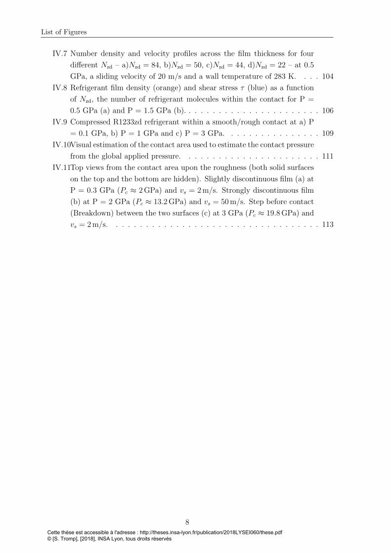
List of Figures
IV.7 Number density and velocity profiles across the film thickness for four
different Nzd – a)Nzd = 84, b)Nzd = 50, c)Nzd = 44, d)Nzd = 22 – at 0.5
GPa, a sliding velocity of 20 m/s and a wall temperature of 283 K. . . . 104
IV.8 Refrigerant film density (orange) and shear stress τ (blue) as a function
of Nzd, the number of refrigerant molecules within the contact for P =
0.5 GPa (a) and P = 1.5 GPa (b). . . . . . . . . . . . . . . . . . . . . . . 106
IV.9 Compressed R1233zd refrigerant within a smooth/rough contact at a) P
= 0.1 GPa, b) P = 1 GPa and c) P = 3 GPa. . . . . . . . . . . . . . . . 109
IV.10Visual estimation of the contact area used to estimate the contact pressure
from the global applied pressure. . . . . . . . . . . . . . . . . . . . . . . 111
IV.11Top views from the contact area upon the roughness (both solid surfaces
on the top and the bottom are hidden). Slightly discontinuous film (a) at
P = 0.3 GPa (Pc ≈ 2 GPa) and vs = 2 m/s. Strongly discontinuous film
(b) at P = 2 GPa (Pc ≈ 13.2 GPa) and vs = 50 m/s. Step before contact
(Breakdown) between the two surfaces (c) at 3 GPa (Pc ≈ 19.8 GPa) and
vs = 2 m/s. . . . . . . . . . . . . . . . . . . . . . . . . . . . . . . . . . . 113
8Cette thèse est accessible à l'adresse : http://theses.insa-lyon.fr/publication/2018LYSEI060/these.pdf © [S. Tromp], [2018], INSA Lyon, tous droits réservés
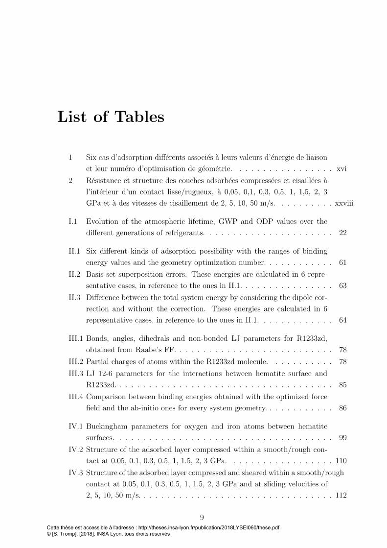
List of Tables
1 Six cas d’adsorption differents associes a leurs valeurs d’energie de liaison
et leur numero d’optimisation de geometrie. . . . . . . . . . . . . . . . . xvi
2 Resistance et structure des couches adsorbees compressees et cisaillees a
l’interieur d’un contact lisse/rugueux, a 0,05, 0,1, 0,3, 0,5, 1, 1,5, 2, 3
GPa et a des vitesses de cisaillement de 2, 5, 10, 50 m/s. . . . . . . . . . xxviii
I.1 Evolution of the atmospheric lifetime, GWP and ODP values over the
different generations of refrigerants. . . . . . . . . . . . . . . . . . . . . . 22
II.1 Six different kinds of adsorption possibility with the ranges of binding
energy values and the geometry optimization number. . . . . . . . . . . . 61
II.2 Basis set superposition errors. These energies are calculated in 6 repre-
sentative cases, in reference to the ones in II.1. . . . . . . . . . . . . . . . 63
II.3 Difference between the total system energy by considering the dipole cor-
rection and without the correction. These energies are calculated in 6
representative cases, in reference to the ones in II.1. . . . . . . . . . . . . 64
III.1 Bonds, angles, dihedrals and non-bonded LJ parameters for R1233zd,
obtained from Raabe’s FF. . . . . . . . . . . . . . . . . . . . . . . . . . . 78
III.2 Partial charges of atoms within the R1233zd molecule. . . . . . . . . . . 78
III.3 LJ 12-6 parameters for the interactions between hematite surface and
R1233zd. . . . . . . . . . . . . . . . . . . . . . . . . . . . . . . . . . . . . 85
III.4 Comparison between binding energies obtained with the optimized force
field and the ab-initio ones for every system geometry. . . . . . . . . . . . 86
IV.1 Buckingham parameters for oxygen and iron atoms between hematite
surfaces. . . . . . . . . . . . . . . . . . . . . . . . . . . . . . . . . . . . . 99
IV.2 Structure of the adsorbed layer compressed within a smooth/rough con-
tact at 0.05, 0.1, 0.3, 0.5, 1, 1.5, 2, 3 GPa. . . . . . . . . . . . . . . . . . 110
IV.3 Structure of the adsorbed layer compressed and sheared within a smooth/rough
contact at 0.05, 0.1, 0.3, 0.5, 1, 1.5, 2, 3 GPa and at sliding velocities of
2, 5, 10, 50 m/s. . . . . . . . . . . . . . . . . . . . . . . . . . . . . . . . . 112
9Cette thèse est accessible à l'adresse : http://theses.insa-lyon.fr/publication/2018LYSEI060/these.pdf © [S. Tromp], [2018], INSA Lyon, tous droits réservés

IV.4 Comparison between the rough estimated pressures and the pressures
obtained from the local atomic stress tensor. . . . . . . . . . . . . . . . . 121
Cette thèse est accessible à l'adresse : http://theses.insa-lyon.fr/publication/2018LYSEI060/these.pdf © [S. Tromp], [2018], INSA Lyon, tous droits réservés

Main abbreviations
DFT Density Functional Theory
EHL Elasto-Hydrodynamic Lubrication
FF Force Field
GWP Global Warming Potential
HCFO HydroChloroFluoroOlefin
HFO HydroFluoroOlefin
MD Molecular Dynamics
ODP Ozone Depletion Potential
PRL Pure Refrigerant Lubrication
VTF Very Thin Film
11Cette thèse est accessible à l'adresse : http://theses.insa-lyon.fr/publication/2018LYSEI060/these.pdf © [S. Tromp], [2018], INSA Lyon, tous droits réservés

Cette thèse est accessible à l'adresse : http://theses.insa-lyon.fr/publication/2018LYSEI060/these.pdf © [S. Tromp], [2018], INSA Lyon, tous droits réservés
Introduction
Lubrication consists in introducing a lubricant between two surfaces in contact mov-
ing one with respect to the other in order to reduce friction and wear. By reducing
the stress between moving elements, this process improves the life of mechanical compo-
nents. Nonetheless, lubrication often requires a heavy design – with for example addition
of lubricant pumps, while the actual trend is to decrease the weight of mechanical sys-
tems. In large refrigeration systems, using the working fluid – here the refrigerant –
as lubricant instead of oils simplifies the design. However, refrigerants are low-viscosity
fluids. As a consequence, the lubricant film thickness separating the surfaces can reach
the nanometric scale locally, and thus be on the same order of magnitude as surface
roughness.
In this very thin film regime of lubrication, few refrigerant molecules separate the asper-
ities. In this context, fluid/surface physical chemistry is of primary importance for the
control and optimization of the tribological performance of the system. Among many
existing refrigerants, R1233zd has been developed to replace environmentally harmful
ones. The literature reports that an adsorbed layer of R1233zd refrigerant molecules
was observed on steel bearing surfaces under pure refrigerant lubrication conditions,
suggesting good tribological performances.
Nonetheless, the severe operating conditions of lubricated contacts such as confinement
and high pressure make experimental in situ analysis very difficult. Therefore, this
work presents a multiscale modeling approach to explore the tribological performance
of a pure refrigerant (R1233zd) lubricated contact confined between steel surfaces.
First, density functional theory (DFT) calculations will analyze the refrigerant/surface
chemical physics. Second, large-scale molecular dynamics (MD) simulations, parametrized
with the help of the DFT results, will study the structure and dynamics of the confined
refrigerant under severe tribological conditions.
This manuscript contains four chapters.
Chapter 1 provides an overview of the scientific and industrial contexts of this thesis.
The refrigeration systems are introduced and a historical overview of the development of
refrigerants is presented. Then, the lubrication in refrigeration compressors is discussed,
13Cette thèse est accessible à l'adresse : http://theses.insa-lyon.fr/publication/2018LYSEI060/these.pdf © [S. Tromp], [2018], INSA Lyon, tous droits réservés

involving either an oil-refrigerant mixture or pure refrigerant. Under these conditions,
molecular lubrication regime prevails. Moreover, the ability of some refrigerants to
adsorb on surfaces is reviewed. To conclude this Chapter, the objectives of this PhD
are exposed.
Chapter 2 is dedicated to quantum calculations with the DFT. First, the principles
of DFT are explained. Then, our model is detailed. The choice to consider hematite
(α − Fe2O3) representative of bearing steel surfaces is presented. Finally, R1233zd
molecule adsorption on hematite surfaces is discussed. Binding energies are derived from
these calculations under different conformations. Moreover, the type of the observed
sorption is determined from a charge analysis.
Chapter 3 develops the principles of MD simulations used for larger scale systems.
In MD, interatomic interactions are described by empirical potentials, often referred
to as force fields (FF). Classical FF for the refrigerant and the surface are described.
Afterwards, the methodology used to parametrize a FF dedicated to the refrigerant-
surface interface based on the previous DFT results is presented. This approach is then
implemented in large-scale MD simulations of R1233zd molecules confined between two
hematite (α − Fe2O3) surfaces. The existence of an adsorbed layer is then studied
numerically. Moreover, orientations of the molecules at the refrigerant/surface interface
are discussed.
Chapter 4 exploits the parametrized FF to study the tribological behavior of R1233zd
confined between smooth surfaces under extreme conditions. The strength of the ad-
sorbed layer is tested and friction is evaluated on a range of pressures and sliding veloc-
ities. Reducing the amount of confined refrigerant, one molecule at a time, structure,
flow, and friction are investigated, until the film breaks down locally. Afterwards, con-
tact between a rough surface and a smooth surface is studied, where the local pressure
supported by the refrigerant film is far bigger.
This manuscript ends with a general conclusion, where the main results of this thesis
throughout the different chapters are gathered and perspectives arise.
Cette thèse est accessible à l'adresse : http://theses.insa-lyon.fr/publication/2018LYSEI060/these.pdf © [S. Tromp], [2018], INSA Lyon, tous droits réservés
Chapter I
Context and State of the art
Contents
I.1 Refrigeration systems . . . . . . . . . . . . . . . . . . . . . . . 17
I.2 The refrigerants . . . . . . . . . . . . . . . . . . . . . . . . . . 19
I.2.1 The refrigerants and their strong environmental impact . . . 19
I.2.2 The fourth generation of refrigerants: HFOs and HCFOs family 22
I.2.3 HCFO-1233zd(E) . . . . . . . . . . . . . . . . . . . . . . . . . 24
I.3 Lubrication in refrigeration systems . . . . . . . . . . . . . . 27
I.3.1 Lubrication . . . . . . . . . . . . . . . . . . . . . . . . . . . . 27
I.3.2 Refrigerants as lubricants . . . . . . . . . . . . . . . . . . . . 28
I.3.2.1 The unavoidable mixing of oil and refrigerant in lu-
bricated systems . . . . . . . . . . . . . . . . . . . . 28
I.3.2.2 Two issues encountered by lubricating with refriger-
ants: surface distress and corrosion . . . . . . . . . 31
I.3.2.3 An alternative: pure refrigerant lubricated (PRL)
systems with special hybrid rolling bearings . . . . . 32
I.3.3 A very thin film lubrication regime in refrigeration compres-
sors with PRL . . . . . . . . . . . . . . . . . . . . . . . . . . 34
I.4 Molecular scale investigation . . . . . . . . . . . . . . . . . . 36
I.4.1 Investigation methods to study molecular lubrication . . . . . 37
I.4.1.1 Experimental tools . . . . . . . . . . . . . . . . . . . 37
I.4.1.2 Numerical simulations . . . . . . . . . . . . . . . . . 38
I.4.2 Structure and rheological properties of thin films . . . . . . . 40
I.4.2.1 Structuration of lubricant at the interface . . . . . . 40
I.4.2.2 Interfacial flow: locking/slip effect . . . . . . . . . . 41
15Cette thèse est accessible à l'adresse : http://theses.insa-lyon.fr/publication/2018LYSEI060/these.pdf © [S. Tromp], [2018], INSA Lyon, tous droits réservés
Chapter I. Context and State of the art
I.4.2.3 Rheology of nanoconfined fluid . . . . . . . . . . . . 43
I.4.2.4 Thermal effects . . . . . . . . . . . . . . . . . . . . . 44
I.4.3 Role of adsorbed layers of refrigerant on the surface . . . . . 45
I.5 Objectives of the PhD . . . . . . . . . . . . . . . . . . . . . . 46
16Cette thèse est accessible à l'adresse : http://theses.insa-lyon.fr/publication/2018LYSEI060/these.pdf © [S. Tromp], [2018], INSA Lyon, tous droits réservés

PhD thesis - Stephane TROMP
This chapter provides a thread guiding the reader to the objectives of this PhD thesis.
First, refrigeration systems are introduced. Second, a historical overview of the devel-
opment of refrigerants is presented to explain the choice made in this project to study
the HCFO-1233zd(E) refrigerant. Then, lubrication in refrigeration compressors, from
classical lubrication with oil-refrigerant mixtures to the new pure refrigerant lubrication
(PRL) technology, is detailed. Moreover, the lubrication regimes reached in refriger-
ation systems are exposed. The fourth section is dedicated to molecular lubrication.
A literature review concerning the ability of some refrigerants to be adsorbed on the
surface is performed. To conclude, the objectives of this PhD are presented.
I.1 Refrigeration systems
Refrigeration is the process in which the temperature of an enclosed space is reduced
by heat removal. Refrigerants are fluids used in several different kinds of systems,
such as heating, ventilation, air conditioning and refrigeration equipments. While in
1955, air conditioning systems were only equipping 2% of American residences, the
amount increased continuously and reached 87% in 2015[38, 39]. The same rate of air
conditioning increase can be found for urban chinese households[40, 41].
Vapor-compression refrigeration systems are the most widely used for air-conditioning
of large buildings. In these systems, the refrigerant is the working fluid, which takes
heat from an enclosed space and rejects it elsewhere. As represented in Figure I.1,
these systems are composed of four main components: a compressor, a condenser, an
expansion valve and an evaporator.
Figure I.1: Vapor-compression refrigeration system.
In this cycle, the flowing refrigerant enters the compressor as a saturated vapor, and is
compressed to a higher pressure, resulting in a higher temperature as well. This com-
pressed and hot vapor (superheated vapor) is then condensed thanks to cooling air or
water flowing across tubes in the condenser. Hence, this component of the global sys-
tem enables to reject heat into the cooling air/water. Afterwards the condensed liquid
refrigerant (saturated liquid) is going through the expansion valve. This component
17Cette thèse est accessible à l'adresse : http://theses.insa-lyon.fr/publication/2018LYSEI060/these.pdf © [S. Tromp], [2018], INSA Lyon, tous droits réservés

Chapter I. Context and State of the art
is a flow-restricting device in which the working fluid undergoes a pressure reduction
resulting in an adiabatic flash evaporation of a fraction of the liquid refrigerant, associ-
ated with a temperature decrease. Finally, in the evaporator, a fan circulates the warm
air from the enclosed space across coils or tubes carrying the cold refrigerant mixture.
That warm air evaporates the liquid part of the mixture, so that the refrigerant exit
the evaporator as a saturated vapor. The evaporator is where the circulating refrigerant
absorbs heat from the enclosed space. The refrigeration cycle is then completed. In this
project, we only investigate the compressors.
Figure I.2: Two kinds of refrigerant compressor: a) screw compressor and b) centrifugalcompressor [2].
The compressor is a system compressing gas, thus rising the pressure. Two main tech-
niques can be distinguished, as shown in Figure I.2[2]:
• the positive displacement compressors: the volume available for the gas is reduced
in order to increase the pressure. It is for example the case with the screw com-
pressor, as shown in Figure I.2[2]. The gas is mechanically displaced through
screws, named rotors, and compressed. The compressed gas is then ejected of the
compressor at the end of the screws. The radial and axial position of the rotors is
maintained by bearings, which are also supporting rotors load.
• the dynamic turbo-machinery: the gas is accelerated to high velocity in a contin-
uous flow and kinetic energy is converted to an increased pressure. The two main
sort of dynamic turbomachines are the axial and centrifugal compressors. The last
one is sometimes also called radial compressor. The difference between these two
turbomachines is the direction of the flow through the system. The centrifugal
compressor is shown in Figure I.2[2]. It is one of the most widely used in refriger-
ation industry. In centrifugal compressors, the gas is accelerated through rotating
18Cette thèse est accessible à l'adresse : http://theses.insa-lyon.fr/publication/2018LYSEI060/these.pdf © [S. Tromp], [2018], INSA Lyon, tous droits réservés
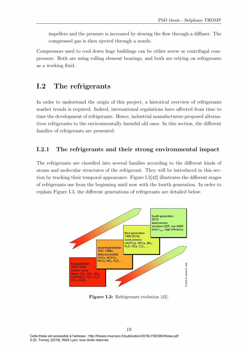
PhD thesis - Stephane TROMP
impellers and the pressure is increased by slowing the flow through a diffuser. The
compressed gas is then ejected through a nozzle.
Compressors used to cool down huge buildings can be either screw or centrifugal com-
pressors. Both are using rolling element bearings, and both are relying on refrigerants
as a working fluid.
I.2 The refrigerants
In order to understand the origin of this project, a historical overview of refrigerants
market trends is required. Indeed, international regulations have affected from time to
time the development of refrigerants. Hence, industrial manufacturers proposed alterna-
tives refrigerants to the environmentally harmful old ones. In this section, the different
families of refrigerants are presented.
I.2.1 The refrigerants and their strong environmental impact
The refrigerants are classified into several families according to the different kinds of
atoms and molecular structures of the refrigerant. They will be introduced in this sec-
tion by tracking their temporal appearance. Figure I.3[42] illustrates the different stages
of refrigerants use from the beginning until now with the fourth generation. In order to
explain Figure I.3, the different generations of refrigerants are detailed below.
Figure I.3: Refrigerants evolution [42].
19Cette thèse est accessible à l'adresse : http://theses.insa-lyon.fr/publication/2018LYSEI060/these.pdf © [S. Tromp], [2018], INSA Lyon, tous droits réservés
Chapter I. Context and State of the art
First generation: whatever worked
For about a century (1830-1930), the first generation of refrigerants, named “whatever
worked” in Figure I.3, was used for refrigeration and air conditioning systems. These re-
frigerants are composed of molecules such as carbon dioxide CO2, ammonia NH3 (widely
used in industrial refrigeration), sulfure dioxide SO2 (used in home refrigerators), hy-
drocarbons (HCs). However, the flammable and toxic behavior of some molecules led
to accidents [42, 43].
Second generation: safety and durability
The growth of refrigeration market forced industry to propose safer synthetic alternatives
composed of chlorofluorocarbons (CFCs) and hydrochlorofluorocarbons (HCFCs). This
generation being safer than the first generation of refrigerant, the number of accidents
decreased [2]. In refrigeration compressors, the low-pressure trichlorofluoromethane
(CFC-11), the medium-pressure dichlorodifluoromethane (CFC-12) and the chlorodi-
fluoromethane (HCFC-22) were mainly used[2]. The “low-pressure” aptitude, e.g. for
CFC-11 refrigerant, arises from the high boiling point of the fluid, which thus can work
at low pressure without evaporation. Hence, the CFC-12 and HCFC-22, having a lower
boiling point, are named “medium-pressure” refrigerants, because they need a higher
operating pressure than the CFC-11, meaning that the mechanical design is more com-
plex.
Unfortunately, some of these refrigerants were harmful to the environment. Thanks
to the publication of Molina and Rowland in 1974 [44], efforts were made concerning
environmental impact recognition of chlorofluorocarbons (CFCs). In particular, it was
shown that CFCs and HCFCs molecules deplete the ozone layer, which protects life on
earth against harmful ultraviolet radiations. Indeed, due to stratospheric ultraviolet
radiation, CFCs release chlorine atoms Cl [45], which catalyze the conversion of ozone
into O2 [44]. In order to quantify the ozone depleting behavior, the ozone depletion
potential was introduced.
The Ozone Depletion Potential (ODP) describes the destruction effect of the ozone layer
by ozone depleting substances (ODS). The tricholorofluoromethane CFC-11 is taken as
the reference with an ODP value of 1, to calculate the ODP of other substances. As
detailed below, this parameter was used to phase down some refrigerants classified as
ODS. The substances with low ODP values are preferred. In the following section, the
ODP is used in Table I.1 to differentiate the different generations of refrigerants. The
ODP parameter was used to justify the phase-out of CFCs and some HCFCs during the
Montreal Protocol in 1987 because they were depleting the ozone layer[46].
20Cette thèse est accessible à l'adresse : http://theses.insa-lyon.fr/publication/2018LYSEI060/these.pdf © [S. Tromp], [2018], INSA Lyon, tous droits réservés
PhD thesis - Stephane TROMP
Third generation: ozone protection
Hydrofluorocarbons (HFC) with zero ODP and new HCFCs with low ODP were pro-
posed as alternative refrigerants. The 1,1,1,2-tetrafluoroethane HFC-134a replaced the
CFC-12 in automotive air-conditioning systems[47]. The 2,2-Dichloro-1,1,1-trifluoroethane
HCFC-123, with its very low ODP, became a substitute for CFC-11 in building refrig-
eration systems [2, 48]. However they were characterized as greenhouse gases because
of long atmospheric lifetime, due to their low chemical reactivity with atmosphere. In
order to quantify this effect, the global warming potential is introduced.
The Global Warming Potential (GWP) is used to measure greenhouse effect of a gas rel-
ative to carbon dioxide CO2, which has a GWP value of 1. This parameter is calculated
over a given time period. For example GWP100yr is the GWP value over 100 years.
The larger the GWP, the more a gas will participate to Earth warming in comparison
with CO2 [49]. Therefore, gases with lowest GWP values are preferred. For example,
HFC-134a has a GWP of around 1360 [50]. In the following section, the GWP is used
in Table I.1 to differentiate the different generations of refrigerants.
With the Kyoto Protocol signed in 1997, some countries agreed on the reduction of
greenhouse gases. However major countries did not sign, and the protocol was never
entirely implemented [2]. More recently on 15th October 2016, 197 countries adopted
in Kigali an amendment of the Montreal Protocol to phase down HFCs[51]. New refrig-
erants are developed in order to replace them. This fourth generation of refrigerants is
composed of Hydrofluoroolefins (HFOs) and Hydrochlorofluoroolefins (HCFOs).
21Cette thèse est accessible à l'adresse : http://theses.insa-lyon.fr/publication/2018LYSEI060/these.pdf © [S. Tromp], [2018], INSA Lyon, tous droits réservés

Chapter I. Context and State of the art
I.2.2 The fourth generation of refrigerants: HFOs and HCFOs
family
Hydrofluoroolefins (HFOs) are developed as alternative refrigerants in order to replace
the progressively forbidden ones [52, 53]. They are synthetic fluids containing a dou-
ble carbon bond. Figure I.4 [52] summarizes the most important HFOs and HCFOs
molecules.
Figure I.4: HFOs and HCFOs family [52].
Their double carbons bond ensures a low atmospheric lifetime providing a low GWP.
Besides, pure HFO molecules are not composed of chlorine atoms, and have thus a zero
ODP. As shown in Table I.1, the HCFO molecule is the only one of this new generation
composed of one chlorine atom and therefore has a finite, but very low ODP. They could
therefore replace HFC and HCFC molecules in industrial systems [52]. This provides a
new outlook to limit the environmental impact related to the worldwide increasing use
of refrigerants.
Table I.1: Evolution of the atmospheric lifetime, GWP over 100 years and ODP over thedifferent generations of refrigerants. Values found in [50, 54, 55, 56, 57, 58].
These new refrigerants have to replace the old ones in systems such as Mobile Air
Conditioning (MAC) systems, Organic Rankine Cycle (ORC) and chillers.
22Cette thèse est accessible à l'adresse : http://theses.insa-lyon.fr/publication/2018LYSEI060/these.pdf © [S. Tromp], [2018], INSA Lyon, tous droits réservés
PhD thesis - Stephane TROMP
The most widely used refrigerant for MAC systems of automobiles is the HFC-134a with
a GWP of 1360 [50]. Leakage of HFC-134a from the air-conditioning system increases
its presence in the atmosphere and the effect on the global warming becomes conse-
quent due to its high GWP. Leakage can be reduced by improving components design.
Alternatively, refrigerants with lower GWP can be used. For instance, the 2,3,3,3-
tetrafluoropropene (HFO-1234yf) refrigerant is considered as replacement of HFC-134a
in MAC systems, for having compatible thermo-physical properties and lower GWP
[59, 60, 53]. Both HFO-1234yf and HFO-1234ze(E) show lower coefficient of perfor-
mance (COP) and cooling capacity than HFC-134a [61, 62, 63, 64]. Nonetheless the
modification of the system itself can improve the performance of systems based on
HFO-1234yf [65]. For instance, Moles et al. [66] found that using an expander or an
ejector as expansion device increases the COP in comparison to basic cycle working with
HFC-134a.
The Organic Rankine Cycle (ORC) is a thermodynamic system (mostly composed of the
same components that the vapor-compression refrigeration system (see Figure I.1), used
to create electricity from low temperature heat sources. This heat can come from dif-
ferent processes, such as biomass combustion, industrial waste heat, geothermal or solar
heat [67, 68]. This heat is used to evaporate the working fluid. HFC-245fa is commonly
used for ORC at low temperature. However, with its 1030 GWP, some new working
fluids have to be found as replacement. Cis-1,1,1,4,4,4-hexafluoro-2-butene, also named
HCFO-1336mzz(Z) and trans-1-chloro-3,3,3-trifluoropropene, or HCFO-1233zd(E), are
investigated as alternatives to HFC-245fa [69, 70] for ORC systems. Moles et al. [71]
found that the use of HFO-1336mzz(Z) as the ORC working fluid gives a slightly higher
system thermal efficiency. In supercritical ORC, HFO-1234ze(E) could also replace
HFC-134a [72, 73]. Mota-Babiloni et al. [74] proposed system modifications to increase
HFO-1234ze(E) cooling capacity and compared it with features obtaind with R134a.
Concerning the low pressure centrifugal chillers used to cool down huge buildings,
HCFO-1233zd is envisaged to replace the HCFC-123 refrigerant [31, 75, 76].
The regulations have also reintroduced interests about “natural refrigerants” (for in-
stance: NH3, CO2, H2O, hydrocarbons, air) of the first generation[77, 78]. CO2 is for
example easily available and cheap but need a high operating pressure compared with
other refrigerants. Therefore, the cost of refrigeration systems enabling high pressures is
one of the main issues to address [43]. However, CO2 refrigerant properties make it one
of the promising HFC replacements in some systems [79]. Hydrocarbons (HCs) have
also been proposed as alternatives for domestic refrigeration to replace R-134a [80, 81].
However, due to their flammability, restriction have been applied [82].
As mentioned above, refrigerants have various ranges of application pressure, depending
on their boiling point. In order to replace an old refrigerant with a new, more envi-
23Cette thèse est accessible à l'adresse : http://theses.insa-lyon.fr/publication/2018LYSEI060/these.pdf © [S. Tromp], [2018], INSA Lyon, tous droits réservés
Chapter I. Context and State of the art
ronmentally friendly one, the user has to verify the range of pressures that the new
refrigerant can sustain.
Forced by scientific discovers about environmental aspects, this fourth generation of
refrigerants opens a new hope in refrigeration industry. These zero ODP and very low
GWP molecules could answer to regulatory requirements. However, Vollmer et al. [83]
published first observations of the presence of medium pressure refrigerants HFO-1234yf
and HFO-1234ze(E) and low pressure refrigerant HCFO-1233zd(E) in atmosphere, show-
ing that even with their short atmospheric lifetime, the emission growth of the fourth
generation of refrigerant remains detectable. These three new refrigerants are the most
promising ones [2].
However, new HFOs such as HFO-1234yf and HFO-1234ze(E) are flammable and have
lower volumetric refrigerant capacities than the old HFCs [52, 84]. This latter feature is
defined as the cooling capacity per unit of vapor volume at the exit of the evaporator.
In order to increase the cooling capacity and to suppress flammability, HFC refrigerants
can be used in HFO/HFC compounds. In some cases, HFC added to HFO can even
increase the COP in comparison with pure HFO [85, 73]. Nonetheless the high GWP
values of HFC have to be considered to design the HFO/HFC blends due to the new
regulations regarding to GWP levels. Moreover, CO2 is non-flammable and has a GWP
of 1. Therefore it is a good candidate for blending with HFO compounds [86].
These issues regarding flammable behavior of some HFOs are suppressed by considering
HCFO-1233zd, making it especially interesting.
I.2.3 HCFO-1233zd(E)
The trans-1-chloro-3,3,3-trifluoropropene 1233zd(E), also called HCFO-1233zd(E) or R-
1233zd or even R1233zd, belongs to the fourth generation of refrigerants. It is a hy-
drochlorofluoroolefin (HCFO) because the molecule contains a chlorine atom. Its appli-
cations are presented and then, a literature review on its physical and environmental
properties is performed.
Note that for more clarity, the HCFO-1233zd(E) refrigerant will be named R1233zd in
the following sections and chapters. More generally, every refrigerant molecules will be
named that way. HFC-134a will be called R134a and HCFC-123 named R123.
Because of its relatively high boiling point, R1233zd is considered as an alternative re-
frigerant to replace e.g. R245fa for ORC and for high temperature heat pumps, or R123
for low pressure centrifugal chillers [31, 75, 76, 87]. In fact the U.S. Environmental Pro-
tection Agency approved the use of R1233zd for chiller applications. In 2014 the Trane
24Cette thèse est accessible à l'adresse : http://theses.insa-lyon.fr/publication/2018LYSEI060/these.pdf © [S. Tromp], [2018], INSA Lyon, tous droits réservés

PhD thesis - Stephane TROMP
inc. manufacturer commercialized the first chiller in the world using this refrigerant
[88]. R1233zd is also proposed as spray foam for building roof insulation [58].
Eyerer et al. [89] concluded that R1233zd can be used as a substitute for R245fa in
existing ORC systems, leading to an increasing thermal efficiency. They found that
R1233zd performs 6.92% better than R245fa for the highest achieved thermal efficiency.
However, R245fa performed 12.17% better regarding the maximal gross power output.
Moles et al. [69] found from the theory that the use of R1233zd as the ORC working
fluid for low temperature heat recovery could increase by up to 10.6% the net cycle
efficiency as compared to using R245fa. Nonetheless, in a following paper [90], they
found from experiments a mass flow rate 20% lower for R1233zd than for R245fa, leading
to a reduced thermal efficiency. For geothermal powerplants based on ORC, Welzl
et al. [91] found that R245fa performs better than R1233zd. Lavernia et al. [92]
found a theoretical thermal efficiency of 14.79% with ORC system using the R1233zd
working fluid in residential applications. Guillaume et al. [93] considered small scale
ORC systems used to convert the waste heat coming from the exhaust gases of a truck
combustion engine. In this study, the bearings are lubricated with the refrigerant itself.
They experimentally found that R1233zd represents a better choice than R245fa in this
kind of application. Furthermore, Ju et al. [94] found different R1233zd/hydrocarbons
blends to replace R22 or R134a in heat pump water heaters. Of course, these results have
to be considered carefully because they depend on what system is considered and each
ORC system manufacturer can have used different processes, materials or components
design.
Whereas several studies are conducted to replace R245fa with R1233zd for ORC systems,
only very few papers relate to the replacement of R123 by R1233zd for low pressure
centrifugal chiller [3, 2]. In comparison with some others refrigerants, such as R1234yf,
the literature is still poor regarding R1233zd.
We now turn to the environmental and physical properties of this new refrigerant. Be-
cause of the chlorine atom of the R1233zd molecule, it is classified as HCFO and not
HFO. However, due to its short atmospheric lifetime of around 26 days [56, 58] caused
by the double carbon bond, R1233zd still has a low ODP of 0.0005 [95, 96]. Patten el
al. [57] also found a close ODP value of 0.00034. Note, however, that Orkins et al. [95]
proposed a larger atmospheric lifetime value of 46 days and besides, they pointed out
that the lifetime can be drastically increased with the latitude of the emission and the
season. Sulbaek Andersen et al. [56, 97] studied the reactions in the atmosphere with
R1233zd. They discovered that OH radicals react with the refrigerant through the two
carbons of the double bond. Thanks to these results, they calculated the atmospheric
lifetime of 26 days, depending on the OH concentration in atmosphere. In any case, this
lifetime is much lower than the ones of R134a and R245fa, respectively of 51 and 7.4
25Cette thèse est accessible à l'adresse : http://theses.insa-lyon.fr/publication/2018LYSEI060/these.pdf © [S. Tromp], [2018], INSA Lyon, tous droits réservés

Chapter I. Context and State of the art
years [98]. Moreover, R1233zd has a GWP upper limit of 14 for time horizons of 100
years [95]. The literature often makes reference to a GWP value of 7 for a 100-year time
horizon, given by Sulbaek Andersen et al. [56]. Unlike some other HFO refrigerants
and even with a small ratio of chlorine to hydrogen atoms amount, R1233zd remains
non-flammable. Since it has a bowling point Tb of 291.2 K at ambient pressure [99],
experiments are difficult with R1233zd, due to the evaporation.
Figure I.5: Representation of the trans-1-chloro-3,3,3-trifluoropropene 1233zd(E) molecule.Caption obtained with the VMD software [19]
As represented in Figure I.5, the R1233zd molecule is composed of a CF3 group next to
a double-carbon bond. The sp2 carbon in the middle is linked to a hydrogen named H2
and the second sp2 carbon to one hydrogen H1 and one Cl atom.
A density value ρ of 1.276 g/cm3 and a viscosity value η of 0.506 mPa.s at 19◦C and
150 kPa are experimentaly found by Honeywell [100]. A small amount of experimen-
tal works have been performed by different research groups but most of them present
thermophysical properties at low pressure only. Vapor pressure studies have been pub-
lished [99, 101, 100], as well as speed of sound data [101] and surface tension [100, 102].
Moreover, liquid and vapor density data sets have also been published [103, 104, 100],
but with low values of pressure. For instance, Fedele et al. [103] reached a saturation
pressure of 35 MPa while Romeo et al. [104] stopped at 30 MPa. Therefore, these re-
sults cannot be directly used in studies of lubricated contacts. Furthermore, Perkins et
al. [105] experimentally measured the thermal conductivity of R1233zd at pressures up
to 67 MPa. Data sets of pressure-density-temperature (P,ρ,T) [101, 106] and pressure-
specific volume-temperature (P,v,T) [103] have been published as well.
One key issue in the literature on R1233zd is that no data is available for high pressure
studies, except the one published by Morales-Espejel et al. [3] and a review of rolling
bearing technology for refrigerant compressors [2].
In this project, only chiller systems composed of centrifugal compressors and employed
to cool down large buildings or industrial process are considered. Indeed, it will be
explained in the next section that systems used in mobile air conditioning systems for
example cannot be treated with the same conditions (regarding local pressure, shearing
velocity, refrigerant that can be used) in comparison with systems implemented in huge
26Cette thèse est accessible à l'adresse : http://theses.insa-lyon.fr/publication/2018LYSEI060/these.pdf © [S. Tromp], [2018], INSA Lyon, tous droits réservés
PhD thesis - Stephane TROMP
buildings.
I.3 Lubrication in refrigeration systems
After introducing the main features of refrigerants in general refrigeration systems, this
section aims to develop the lubrication principles in the contact area within the com-
pressor systems.
I.3.1 Lubrication
The science of lubrication consists in introducing a lubricant between two surfaces mov-
ing one with respect to the other in order to reduce friction and wear. By reducing
the tangential stress between moving elements, the life of mechanical components is im-
proved. In centrifugal compressors, the rotation is ensured by rolling elements bearings.
Rolling element bearings are composed of two rings separated by rolling elements (balls,
rollers, etc.), which are held within cages. In most applications, one of the rings is
fixed to the housing and the other one to a shaft. The rolling bearings sustain loads
and reduce friction in rotating mechanisms. Their lubrication ensures surface separa-
tion, load transmission, speed accommodation, cooling-down of the contacting solids
and debris removal [107, 108]. The lubricant is usually oil or grease according to ap-
plications, environment and operating conditions. In some cases, it can be the working
fluid (refrigerants in refrigeration systems, fuel in engines).
The surface separation is characterized with the thickness of the lubricant film, usually
denoted h. This contact caracteristic has to be compared to the surfaces roughness in
order to define the lubrication regime.
In the full film regime, the normal load is entirely supported by the hydrodynamic lift.
The lubricant film is thick enough to ensure a full separation of the surfaces. The full
film regime can be divided into two sub-regimes: hydrodynamic lubrication (HL) and
the elasto-hydrodynamic lubrication (EHL) regimes.
Hydrodynamic lubrication often involves conforming surfaces, for example within journal
bearings. Indeed, the lubrication and load occur in a large (∼ cm2-dm2) contact area
and thus, the lubricant pressure is in the range of 0.1-10 MPa [109]. These small pressure
values yield to negligible elastic deformation of surfaces.
The second sub-regime is named Elasto-Hydrodynamic Lubrication (EHL) and concerns
non-conforming geometries, like ball-on-plane contacts. The small contact area (∼mm2)
generates a high local pressure (0.5-5 GPa), leading to non negligible elastic deformation
27Cette thèse est accessible à l'adresse : http://theses.insa-lyon.fr/publication/2018LYSEI060/these.pdf © [S. Tromp], [2018], INSA Lyon, tous droits réservés

Chapter I. Context and State of the art
of surfaces, hence the “elasto” term in EHL. The high pressure induces a change of
lubricant properties through viscosity-pressure and viscosity-temperature dependence,
and compressibility.
The mixed lubrication regime appears at smaller film thickness. In this regime, the
surfaces are not fully separated by the lubricant and the asperities can come in contact,
supporting a fraction of the load.
In the boundary lubrication regime, the load is fully carried out by direct contact be-
tween asperities. Additives can be used to protect the surface from direct asperities
contact [110, 28, 27]. An adsorbed layer of lubricant additives can protect the surface
from wear issues thanks to chemi- or physisorption phenomena.
Classical lubricants such as oils or greases in rolling element bearing complicate the
design of refrigerant systems, since it involves an additional fluid to the working fluid
(the refrigerant). Moreover, the refrigerant can mix with the lubricant fluid.
I.3.2 Refrigerants as lubricants
In this section, two possibilities of lubricating rolling bearing in refrigeration compressors
are presented. The first one, which is currently the most available, is lubricating the
bearing with an oil-refrigerant mixture. The origins of this mixture and the issues
encountered with refrigerant in the lubricated contact will be detailed. Then, systems
lubricated with pure refrigerants will be presented and the advantages of this solution
will also be explained.
I.3.2.1 The unavoidable mixing of oil and refrigerant in lubricated systems
The conventional chiller design is represented in Figure I.6 [4].
The oil cycle and refrigerant cycle are theoretically separated with sealing. However, an
impeccable sealing remains hard to design. The oil used to lubricate the compressor can
be discharged into the refrigeration cycle and decreases heat transfer efficiency around
the heat exchanger [111, 112, 3]. On the other side, rolling bearings in compressors
are usually lubricated with an oil-refrigerant mixture. The dilution of refrigerant in oil
reduces not only the viscosity but the viscosity-pressure dependence as well, and thus
impacts the ability to build a separating film in the lubricated contact[113, 114, 60, 115,
116, 117, 118, 119, 120, 121, 122, 120].
Indeed, in lubricated contacts, the film thickness depends mainly on two lubricant prop-
erties: the viscosity and the viscosity-pressure coefficient. The viscosity η varies with
28Cette thèse est accessible à l'adresse : http://theses.insa-lyon.fr/publication/2018LYSEI060/these.pdf © [S. Tromp], [2018], INSA Lyon, tous droits réservés
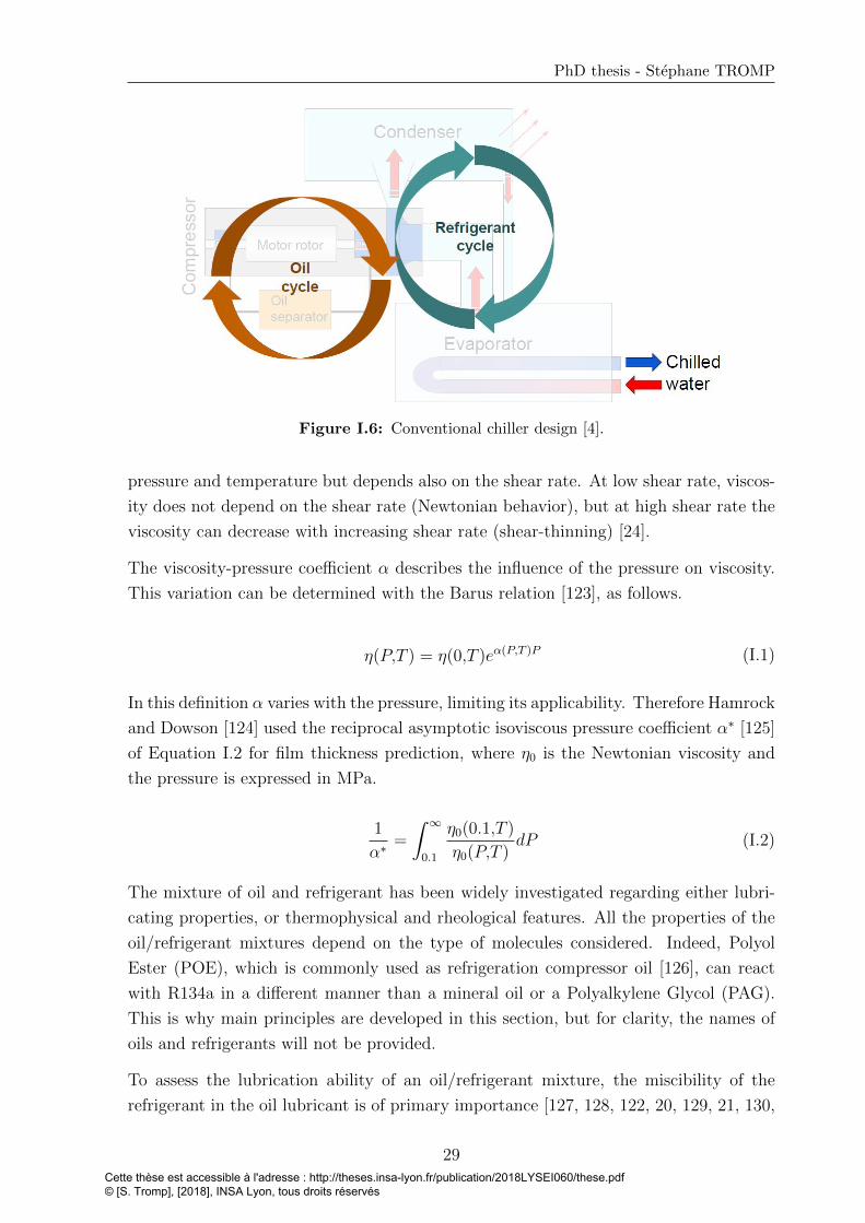
PhD thesis - Stephane TROMP
Figure I.6: Conventional chiller design [4].
pressure and temperature but depends also on the shear rate. At low shear rate, viscos-
ity does not depend on the shear rate (Newtonian behavior), but at high shear rate the
viscosity can decrease with increasing shear rate (shear-thinning) [24].
The viscosity-pressure coefficient α describes the influence of the pressure on viscosity.
This variation can be determined with the Barus relation [123], as follows.
η(P,T ) = η(0,T )eα(P,T )P (I.1)
In this definition α varies with the pressure, limiting its applicability. Therefore Hamrock
and Dowson [124] used the reciprocal asymptotic isoviscous pressure coefficient α∗ [125]
of Equation I.2 for film thickness prediction, where η0 is the Newtonian viscosity and
the pressure is expressed in MPa.
1
α∗=
∫ ∞0.1
η0(0.1,T )
η0(P,T )dP (I.2)
The mixture of oil and refrigerant has been widely investigated regarding either lubri-
cating properties, or thermophysical and rheological features. All the properties of the
oil/refrigerant mixtures depend on the type of molecules considered. Indeed, Polyol
Ester (POE), which is commonly used as refrigeration compressor oil [126], can react
with R134a in a different manner than a mineral oil or a Polyalkylene Glycol (PAG).
This is why main principles are developed in this section, but for clarity, the names of
oils and refrigerants will not be provided.
To assess the lubrication ability of an oil/refrigerant mixture, the miscibility of the
refrigerant in the oil lubricant is of primary importance [127, 128, 122, 20, 129, 21, 130,
29Cette thèse est accessible à l'adresse : http://theses.insa-lyon.fr/publication/2018LYSEI060/these.pdf © [S. Tromp], [2018], INSA Lyon, tous droits réservés
Chapter I. Context and State of the art
121, 131]. The dissolution rate depends on the refrigerants and has to be determined to
predict the film thickness [20, 129]. In particular, the difference in refrigerant molecular
polarity can affect the dissolution in oil and thus the simple replacement of an old
refrigerant with a new one is not automatically possible [2]. A more branched lubricant
is more affected by dilution of refrigerant than a linear fluid [132, 133].
Adding only 9% by weight of refrigerant in an oil can decrease the film thickness to half
its value, and the viscosity-pressure coefficient can be divided by two by adding 35%
by weight of refrigerant [134]. The variation of the compressibility of the oil/refrigerant
mixture with the quantity of refrigerant is still unclear. Some research groups found an
increase of the compressibility with the amount of refrigerant [135] while other groups
found the opposite [126].
Thanks to micro Fourier Transform Infrared (FT-IR) spectroscopy, it was found that
the concentration distribution of the refrigerant in an EHD contact decreases in the inlet
zone and in the Hertzian contact area. However, the refrigerant concentration increases
in the side region of the contact [136]. Moreover, the concentration distribution of the
refrigerant is affected by the sliding velocity and the temperature. Bair et al. [113] also
found that increasing the inlet pressure reduces the film thickness due to an increasing
solubility of the refrigerant in oil. However, they revealed an unusual behavior, when
they pointed out that the inlet temperature can either reduce or increase the film thick-
ness. On the one hand, by increasing the temperature the viscosity decreases and this
tends to reduce the film thickness. But on the other hand, increasing the temperature
reduces the concentration of refrigerant and thus leads to increase the mixture viscosity.
There is a competition between these two effects. For low inlet pressure, the first effect
is dominant while the second one appears more likely at high pressure.
Since oil/refrigerant mixtures have been widely studied in the literature, it is not the
aim here to make a complete review but to show the research directions regarding these
blends in lubricated contacts. One of the key results is that a dilution rate of refrigerant
in oil limit of 20% to 30% has been found to lubricate a conventional all-steel bearings
[2, 137].
Furthermore, the development of new viscometers operating at high pressure for oil/refrigerant
mixtures opens the possibility to obtain accurately the viscosity, which is used in numer-
ical models to predict the film thickness in EHL [138]. Recently, Bair [138] published
results of the decrease in viscosity and viscosity-pressure coefficient for a POE/R134a
mixture depending on the weight percentage of R134a in the blend. Some of these re-
sults are presented in Figure I.7, showing a considerable reduction of the viscosity and
of the viscosity-pressure dependence with increasing weight percentage of R134a.
Besides, the high flow velocity might involve a non-equilibrium state of the solution.
Depending on the surface temperature and on the oil-refrigerant mixture boiling point,
30Cette thèse est accessible à l'adresse : http://theses.insa-lyon.fr/publication/2018LYSEI060/these.pdf © [S. Tromp], [2018], INSA Lyon, tous droits réservés
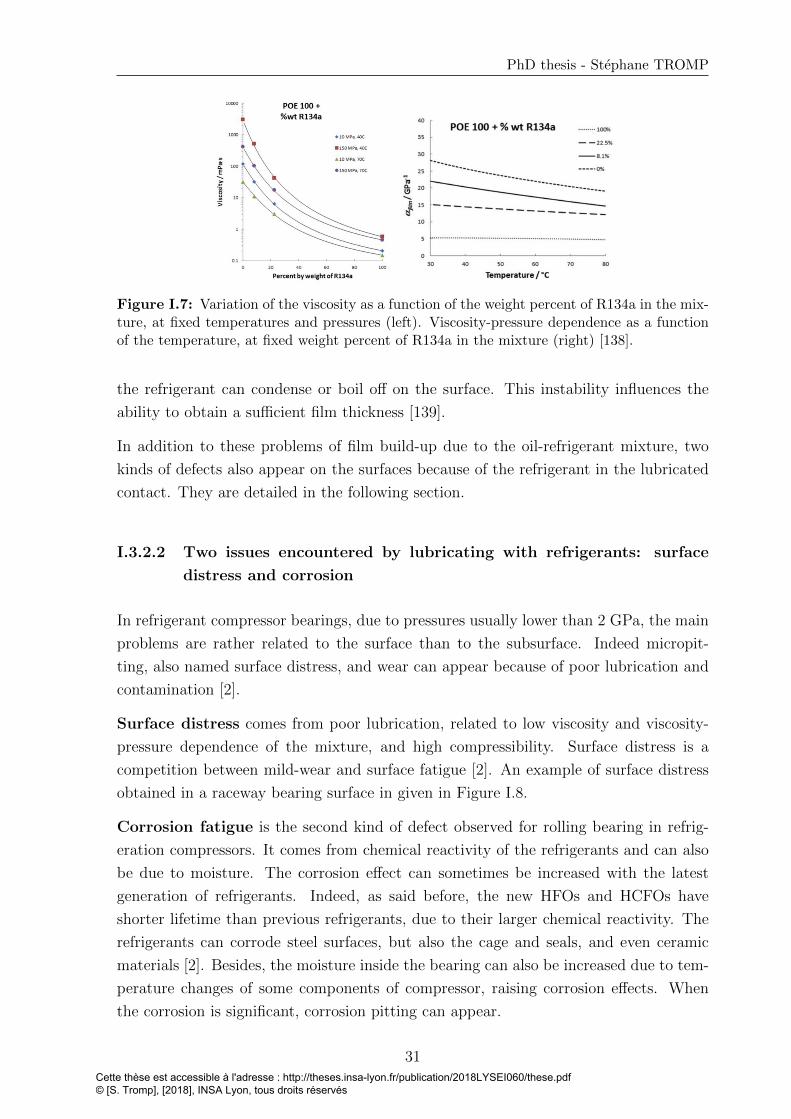
PhD thesis - Stephane TROMP
Figure I.7: Variation of the viscosity as a function of the weight percent of R134a in the mix-ture, at fixed temperatures and pressures (left). Viscosity-pressure dependence as a functionof the temperature, at fixed weight percent of R134a in the mixture (right) [138].
the refrigerant can condense or boil off on the surface. This instability influences the
ability to obtain a sufficient film thickness [139].
In addition to these problems of film build-up due to the oil-refrigerant mixture, two
kinds of defects also appear on the surfaces because of the refrigerant in the lubricated
contact. They are detailed in the following section.
I.3.2.2 Two issues encountered by lubricating with refrigerants: surface
distress and corrosion
In refrigerant compressor bearings, due to pressures usually lower than 2 GPa, the main
problems are rather related to the surface than to the subsurface. Indeed micropit-
ting, also named surface distress, and wear can appear because of poor lubrication and
contamination [2].
Surface distress comes from poor lubrication, related to low viscosity and viscosity-
pressure dependence of the mixture, and high compressibility. Surface distress is a
competition between mild-wear and surface fatigue [2]. An example of surface distress
obtained in a raceway bearing surface in given in Figure I.8.
Corrosion fatigue is the second kind of defect observed for rolling bearing in refrig-
eration compressors. It comes from chemical reactivity of the refrigerants and can also
be due to moisture. The corrosion effect can sometimes be increased with the latest
generation of refrigerants. Indeed, as said before, the new HFOs and HCFOs have
shorter lifetime than previous refrigerants, due to their larger chemical reactivity. The
refrigerants can corrode steel surfaces, but also the cage and seals, and even ceramic
materials [2]. Besides, the moisture inside the bearing can also be increased due to tem-
perature changes of some components of compressor, raising corrosion effects. When
the corrosion is significant, corrosion pitting can appear.
31Cette thèse est accessible à l'adresse : http://theses.insa-lyon.fr/publication/2018LYSEI060/these.pdf © [S. Tromp], [2018], INSA Lyon, tous droits réservés
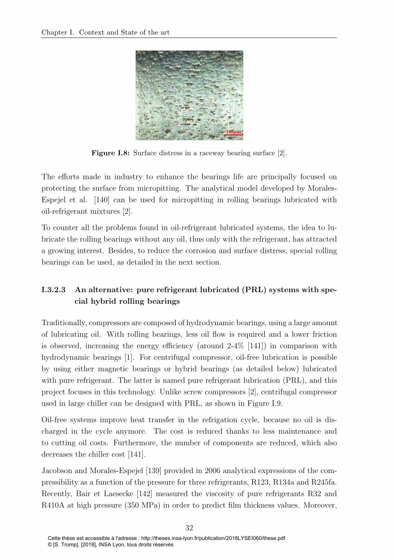
Chapter I. Context and State of the art
Figure I.8: Surface distress in a raceway bearing surface [2].
The efforts made in industry to enhance the bearings life are principally focused on
protecting the surface from micropitting. The analytical model developed by Morales-
Espejel et al. [140] can be used for micropitting in rolling bearings lubricated with
oil-refrigerant mixtures [2].
To counter all the problems found in oil-refrigerant lubricated systems, the idea to lu-
bricate the rolling bearings without any oil, thus only with the refrigerant, has attracted
a growing interest. Besides, to reduce the corrosion and surface distress, special rolling
bearings can be used, as detailed in the next section.
I.3.2.3 An alternative: pure refrigerant lubricated (PRL) systems with spe-
cial hybrid rolling bearings
Traditionally, compressors are composed of hydrodynamic bearings, using a large amount
of lubricating oil. With rolling bearings, less oil flow is required and a lower friction
is observed, increasing the energy efficiency (around 2-4% [141]) in comparison with
hydrodynamic bearings [1]. For centrifugal compressor, oil-free lubrication is possible
by using either magnetic bearings or hybrid bearings (as detailed below) lubricated
with pure refrigerant. The latter is named pure refrigerant lubrication (PRL), and this
project focuses in this technology. Unlike screw compressors [2], centrifugal compressor
used in large chiller can be designed with PRL, as shown in Figure I.9.
Oil-free systems improve heat transfer in the refrigation cycle, because no oil is dis-
charged in the cycle anymore. The cost is reduced thanks to less maintenance and
to cutting oil costs. Furthermore, the number of components are reduced, which also
decreases the chiller cost [141].
Jacobson and Morales-Espejel [139] provided in 2006 analytical expressions of the com-
pressibility as a function of the pressure for three refrigerants, R123, R134a and R245fa.
Recently, Bair et Laesecke [142] measured the viscosity of pure refrigerants R32 and
R410A at high pressure (350 MPa) in order to predict film thickness values. Moreover,
32Cette thèse est accessible à l'adresse : http://theses.insa-lyon.fr/publication/2018LYSEI060/these.pdf © [S. Tromp], [2018], INSA Lyon, tous droits réservés

PhD thesis - Stephane TROMP
Figure I.9: Pure Refrigerant Lubricated chiller design [4].
it was found that it is possible to form a separating film because of an increase of vis-
cosity with the very high pressure located in the contact between the rolling elements
and the bearing raceways. This increase is not as large as with classic oils but sufficient
to build a very thin lubricant film [1]. With conventional all-steel bearings, it would be
inadequate for lubrication but the SKF compagny developed special hybrid bearings (as
detailed below) enabling a PRL technology [1].
PRL rolling bearings require special materials. Special hybrid rolling bearing in PRL
technology are composed of silicone nitride Si3N4 rolling elements, and cages made of
glass fiber-reinforced PEEK material. The inner and outer rings are made of stain-
less high nitrogen through-hardened steel, heat-treated. This steel has very good anti-
corrosion features, and super fine microstructure, making it suitable for this poor lu-
brication case [1, 2, 143]. The same composition could also be found for hybrid roller
bearings. Moreover, hybrid contacts are less prone to micro-welding of asperities. In
the case of PRL, corrosion can appear with hybrid bearings [2]. Therefore, additives
could be added to prevent the risk of chemical reactions between the refrigerant and the
surfaces. However, the ring surfaces are greatly protected against corrosion by using
stainless high nitrogen through-hardened steel [3].
In poor lubrication conditions, hybrid bearings show advantages in comparison with
all-steel bearings. A lower friction is obtained and the materials do not weld at high
temperatures, contrary to steel-steel contacts [1]. Besides, for all-steel bearings, coat-
ings could be applied on steel surfaces, but it was observed that the refrigerant could
penetrate the coating through the pores and by reaching the steel surface, it can corrode
the surface below the coating [2].
Next section focuses on the regime occurring with refrigerant lubricated systems.
33Cette thèse est accessible à l'adresse : http://theses.insa-lyon.fr/publication/2018LYSEI060/these.pdf © [S. Tromp], [2018], INSA Lyon, tous droits réservés
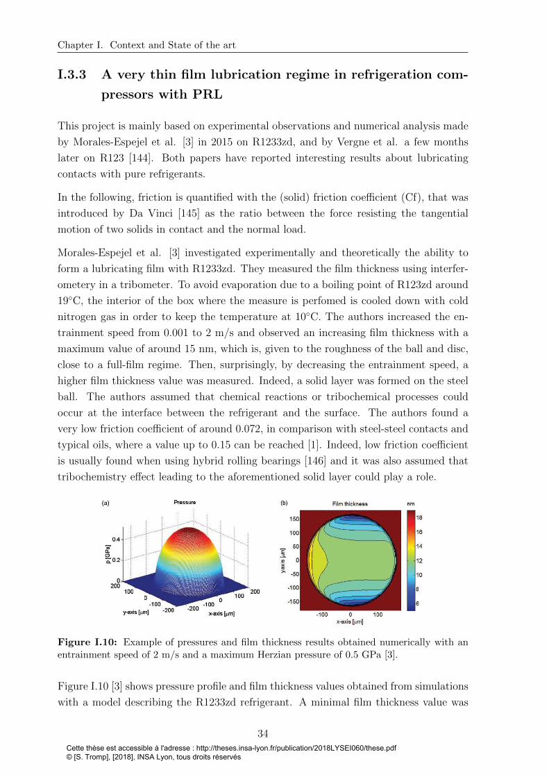
Chapter I. Context and State of the art
I.3.3 A very thin film lubrication regime in refrigeration com-
pressors with PRL
This project is mainly based on experimental observations and numerical analysis made
by Morales-Espejel et al. [3] in 2015 on R1233zd, and by Vergne et al. a few months
later on R123 [144]. Both papers have reported interesting results about lubricating
contacts with pure refrigerants.
In the following, friction is quantified with the (solid) friction coefficient (Cf), that was
introduced by Da Vinci [145] as the ratio between the force resisting the tangential
motion of two solids in contact and the normal load.
Morales-Espejel et al. [3] investigated experimentally and theoretically the ability to
form a lubricating film with R1233zd. They measured the film thickness using interfer-
ometery in a tribometer. To avoid evaporation due to a boiling point of R123zd around
19◦C, the interior of the box where the measure is perfomed is cooled down with cold
nitrogen gas in order to keep the temperature at 10◦C. The authors increased the en-
trainment speed from 0.001 to 2 m/s and observed an increasing film thickness with a
maximum value of around 15 nm, which is, given to the roughness of the ball and disc,
close to a full-film regime. Then, surprisingly, by decreasing the entrainment speed, a
higher film thickness value was measured. Indeed, a solid layer was formed on the steel
ball. The authors assumed that chemical reactions or tribochemical processes could
occur at the interface between the refrigerant and the surface. The authors found a
very low friction coefficient of around 0.072, in comparison with steel-steel contacts and
typical oils, where a value up to 0.15 can be reached [1]. Indeed, low friction coefficient
is usually found when using hybrid rolling bearings [146] and it was also assumed that
tribochemistry effect leading to the aforementioned solid layer could play a role.
Figure I.10: Example of pressures and film thickness results obtained numerically with anentrainment speed of 2 m/s and a maximum Herzian pressure of 0.5 GPa [3].
Figure I.10 [3] shows pressure profile and film thickness values obtained from simulations
with a model describing the R1233zd refrigerant. A minimal film thickness value was
34Cette thèse est accessible à l'adresse : http://theses.insa-lyon.fr/publication/2018LYSEI060/these.pdf © [S. Tromp], [2018], INSA Lyon, tous droits réservés

PhD thesis - Stephane TROMP
obtained in the side lobes of the contacts. The reduction of thickness at the contact
exit is less apparent than usually in EHD contacts with oils: these observations were
explained with respect to the small viscosity and viscosity-pressure coefficient of the
refrigerant.
Most published data for R1233zd are at saturation pressure, which is much lower than
contact pressure. Therefore Morales-Espejel et al. used data furnished by the manu-
facturer Honeywell in their study [147, 3]. To the knowledge of the author, there is no
data available in the literature for the viscosity-pressure coefficient of R1233zd. Since
it plays a crucial role in the prediction of the film thickness in EHL, Morales-Espejel et
al. used a value published for a similar low-pressure refrigerant α∗ = 4.36 GPa−1, cor-
responding to the refrigerant fluid A in the paper of Habchi et al. [148]. These values
of the viscosity-pressure coefficient and viscosity should also be compared with the ones
found in literature for two other refrigerants. Vergne et al. [144] give an α∗ value of
6.4 GPa−1 and a viscosity η0 = 0.4 mPa.s for R123 at 25◦C, while Bair [138] reported
a value of 5.0 GPa−1 and Laesecke and Bair [149] gave a viscosity η0 = 0.2 mPa.s at
40◦C, both values for R134a. These small values of viscosity-pressure coefficients for the
refrigerants do not favor the build-up of the film thickness. Indeed, it is interesting to
compare these values with classical oil values, which have a viscosity η0 of around 20
mPa.s and an α∗ of around 20.0 GPa−1 [2].
The same observations made with pure R1233zd about the film thickness distribution,
were observed with pure R123 [144]. In Figure I.11, the minimal film thickness value ob-
tained from experimental, numerical and analytical analysis is drawn. The entrainement
velocity ue in Figure I.11 is the mean velocity of the two surfaces.
Figure I.11: Numerical solution for the minimum fim thickness compared with the exper-imental results and the Chevalier [150] prediction (T=10◦C, SRR=0 and p=0.52GPa) withpure R123 [144].
These values found for the minimal thickness are small. However it still corresponds to
35Cette thèse est accessible à l'adresse : http://theses.insa-lyon.fr/publication/2018LYSEI060/these.pdf © [S. Tromp], [2018], INSA Lyon, tous droits réservés
Chapter I. Context and State of the art
20 to 30 R123 molecule sizes. Furthermore, these order of magnitude for the thickness
values are the same than the ones observed by Morales-Espejel et al. with R1233zd
[3]. They also carried out density calculations as a function of pressure because the
more compressible the refrigerant, the thinner central film thickness will be. Also here,
no damage was observed on the surface and a possible explanation was made about a
minimal film thickness localized in very restricted area. Vergne et al. [144] concluded
that the R123 refrigerant can indeed build up a reasonable film thickness for lubricating
rolling point contacts.
After polishing, the roughness maximum value σ of the surfaces was about 5 nm. The
authors considered the λ parameter, defined as follows, with hm the minimal thickness:
λ =hmσ
(I.3)
It is usually accepted that the full film EHL regime is reached for a λ value higher
than 3. This value was obtained for an entrainment velocity ue higher than 5 m/s. It
means that a limit is reached for ue lower than this value and the lubrication occurs in
a mixed regime. Nonetheless, as no damage was observed on the surfaces, it could be
considered that the lubrication appears between a full EHL regime and a mixed regime.
This “in-between” regime is sometimes named “very thin film” (VTF) regime [144].
These two studies guided the direction of this project in order to explore the effects of
this very small minimal film thickness, corresponding to a molecular lubrication. The
main result here is the presence of a solid layer on the steel ball surface when lubricating
with R1233zd and that no damage was observed on this surface.
As a conclusion of this section, in comparison with common lubricants (oils), refrigerants
show both a very low viscosity and a low viscosity-pressure dependence. A refrigerant
used as a lubricant can cause a lower ability to lubricate in the so-called full film lubri-
cation regime, where solid surfaces are fully separated by the lubricant. At the same
time, this smaller viscosity induces a poor load bearing capacity. As a consequence,
pure refrigerant-lubricated contacts often work in a VTF lubrication regime.
I.4 Molecular scale investigation
Combined to very thin film of refrigerants, progresses in surface manufacturing enable
to design really smooth steel surfaces with a root mean square (RMS) of around 5
nm [144], which favor molecular lubrication [151]. In this section, experimental and
numerical investigation methods for molecular lubrication are presented. An overview
of the features of the nanoconfined lubricant behavior is reported. Finally, a focus
36Cette thèse est accessible à l'adresse : http://theses.insa-lyon.fr/publication/2018LYSEI060/these.pdf © [S. Tromp], [2018], INSA Lyon, tous droits réservés

PhD thesis - Stephane TROMP
on adsorbed layers of lubricant will be discussed with examples concerning the new
refrigerants.
I.4.1 Investigation methods to study molecular lubrication
I.4.1.1 Experimental tools
In 1961 [152], the fabrication of the Surface Force Apparatus (SFA) enabled observa-
tions of a molecularly-thin film located between two perpendicular cylinders brought in
contact. The position of the cylinders is driven thanks to piezoelectric elements with
a precision of tipically 0.1 nm. Optical interferometry or capacitive methods [153] are
used to measure the distance between the surfaces.
In 1981 [154], the scanning tunneling microscope (STM) was invented. A STM is an
instrument for imaging surfaces, as well as lubricant molecules, using the quantum tun-
neling of electrons between a conducting tip and the surface/object under investigation.
The tip is approached to the surface and a difference of electric potential is applied
between the tip and the surface. When the tip is moved across the surface, the tunnel-
ing current is measured. Thanks to a control system, this current is kept constant by
adjusting the surface height, which is mapped in order to represent the surface.
The Atomic Force Microscope (AFM), invented in 1985 [155], can characterize interac-
tions at the molecular scale. The AFM is composed of a cantilever with a nanometer
scale tip at its end. The tip is moved above the surface or in direct contact, and the force
between the tip and the surface leads to a deflection of the cantilever. This deflection is
measured for example with a laser beam. This allows force measurement, imaging and
atoms manipulation. Thanks to AFM, forces can be measured directly on the surface,
or on an adsorbed fluid layer, providing information on wear. Modification of AFM for
applications in tribology led to the Friction Force Microscope (FFM) that can measure
tangential forces.
The maybe most interesting instrument for this project uses the X-Ray photoelectron
spectrometry (XPS) method [156]. The first commercial XPS was built in the late
1960s. The material is irradiated with a X-ray beam while kinetic energy and number
of electrons that are ejected, are measured. From the collected data, one can evaluate
the sample chemical composition of the topmost few nm. Moreover, by using abacus,
the results are compared to the reference and one can determine information about local
chemical bonding and in particular about chemisorption. This last point is for instance
a key point to study the chemical composition of adsorbed layers.
By using different experimental tools, one can determine the chemical composition and
the topographical behavior of an adsorbed layer, as well as the frictional behavior of a
37Cette thèse est accessible à l'adresse : http://theses.insa-lyon.fr/publication/2018LYSEI060/these.pdf © [S. Tromp], [2018], INSA Lyon, tous droits réservés

Chapter I. Context and State of the art
system under shear. However, it remains difficult to get information about the adsorbed
layer formation during the frictional process. Therefore, numerical approaches have to
be considered.
I.4.1.2 Numerical simulations
At the same time, the improvement of computers performance gives the possibility
to study molecular lubrication thanks to different atomistic simulations tools. In this
subsection, a listing of the mostly used atomistic and electronic methods is provided.
The monte-carlo (MC) is a method using a stochastic approach to determine the equi-
librium properties and configuration of molecular systems in defined thermodynamic
ensembles [157]. Atomic configurations are randomly generated and are kept only if
they verify a condition depending on their energy states. Since time is not consid-
ered in this approach, non-equilibrium behavior related to fluid flow in nanoconfined
system cannot be studied. If time-dependent features are needed, molecular dynamics
simulations are preferred.
Molecular dynamics (MD) simulation is a deterministic method [23]. The evolution of a
system of atoms can be simulated along time and the trajectory of particles is calculated
numerically by solving Newton’s equations of motion. For each timestep, the forces
acting on every atoms are determined thanks to a force field describing interactions
between atoms. Hence, a numerical integration of the subsequent accelerations gives
the positions of atoms at the following step. Since MD simulations are time-dependent,
non-equilibrium phenomena can be explored and a variety of features (friction, thermal
conductivity, velocity profile, etc) can be obtained. Therefore MD simulations will be
used in this project to characterize nanoconfined systems under shearing. A complete
explanation of the MD model will be given in Chapter 3.
The tight-binding (TB) method uses the superposition of wave functions for isolated
atoms to calculate the electronic band structure. Coupled with MD simulations, it has
already shown ability to treat adsorption phenomena of fatty acids on iron surfaces [158]
or to study wear phenomena between two surfaces [159, 160]. However this approach
will not be presented in this work. Indeed, parameters describing interactions between
orbitals within the solid, the refrigerant, and the interface, would have to be determined
first.
Density functional theory (DFT) calculations can be used to analyze electronic structure
of a static system [8]. This method can be used to obtain the density of state, the
binding energy, the charges and the equilibrium geometry. Features of a many-electrons
system can be studied thanks to functionals, which describe (in an approximate manner)
electronic exchange and correlations. Some functionals have been recently improved in
38Cette thèse est accessible à l'adresse : http://theses.insa-lyon.fr/publication/2018LYSEI060/these.pdf © [S. Tromp], [2018], INSA Lyon, tous droits réservés
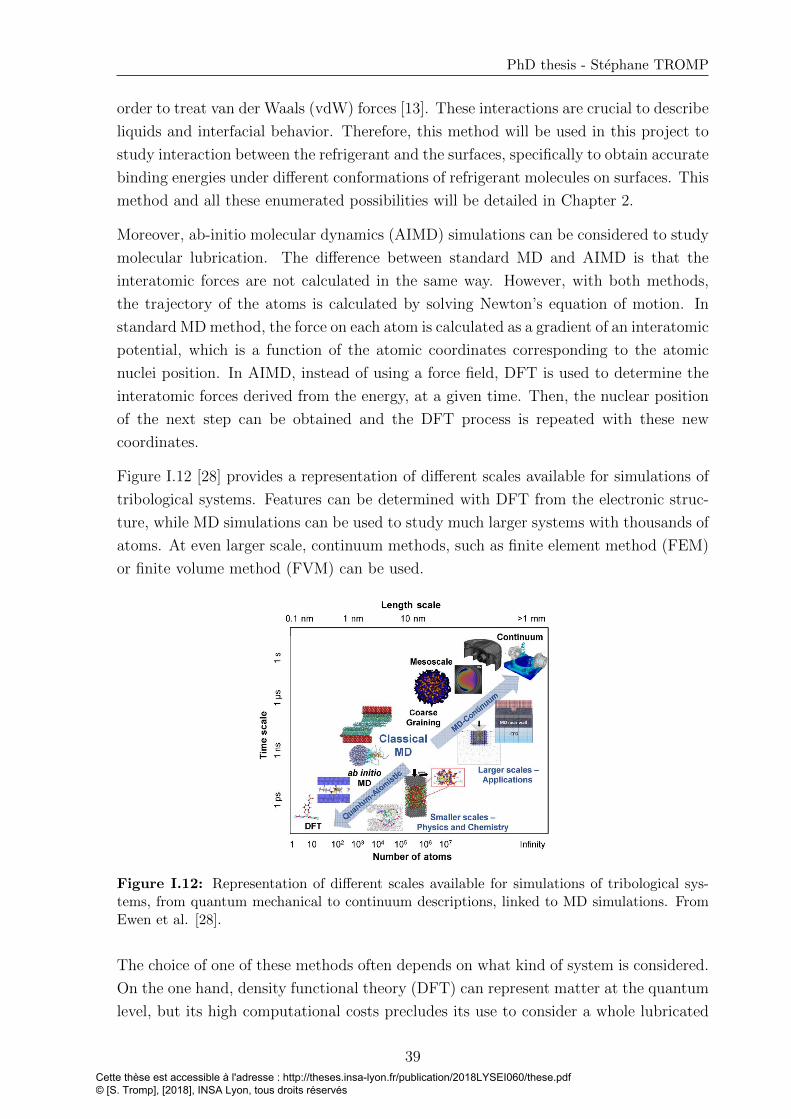
PhD thesis - Stephane TROMP
order to treat van der Waals (vdW) forces [13]. These interactions are crucial to describe
liquids and interfacial behavior. Therefore, this method will be used in this project to
study interaction between the refrigerant and the surfaces, specifically to obtain accurate
binding energies under different conformations of refrigerant molecules on surfaces. This
method and all these enumerated possibilities will be detailed in Chapter 2.
Moreover, ab-initio molecular dynamics (AIMD) simulations can be considered to study
molecular lubrication. The difference between standard MD and AIMD is that the
interatomic forces are not calculated in the same way. However, with both methods,
the trajectory of the atoms is calculated by solving Newton’s equation of motion. In
standard MD method, the force on each atom is calculated as a gradient of an interatomic
potential, which is a function of the atomic coordinates corresponding to the atomic
nuclei position. In AIMD, instead of using a force field, DFT is used to determine the
interatomic forces derived from the energy, at a given time. Then, the nuclear position
of the next step can be obtained and the DFT process is repeated with these new
coordinates.
Figure I.12 [28] provides a representation of different scales available for simulations of
tribological systems. Features can be determined with DFT from the electronic struc-
ture, while MD simulations can be used to study much larger systems with thousands of
atoms. At even larger scale, continuum methods, such as finite element method (FEM)
or finite volume method (FVM) can be used.
Figure I.12: Representation of different scales available for simulations of tribological sys-tems, from quantum mechanical to continuum descriptions, linked to MD simulations. FromEwen et al. [28].
The choice of one of these methods often depends on what kind of system is considered.
On the one hand, density functional theory (DFT) can represent matter at the quantum
level, but its high computational costs precludes its use to consider a whole lubricated
39Cette thèse est accessible à l'adresse : http://theses.insa-lyon.fr/publication/2018LYSEI060/these.pdf © [S. Tromp], [2018], INSA Lyon, tous droits réservés

Chapter I. Context and State of the art
contact area. DFT provides accurate adsorption information at the atomic level but is
generally limited to static calculations. On the other hand, classical non-equilibrium
molecular dynamics (NEMD) simulations, which are based on empirical force fields
(FF), are widely used for large systems to characterize the rheology as well as the
molecular structure of lubricants over reasonable timescales in some nanometric patch
inside lubricated contacts [24, 161, 37, 27, 26]. Ab-initio molecular dynamics (AIMD)
calculations become affordable on some systems [162, 110] but is still too demanding
for other materials, e.g. those involving magnetism. Ewen et al. [27] used NEMD
simulations in order to describe the behavior of stearic acid molecules adsorbed on a
hematite surface while Doig et al. [163] considered the structures and friction of different
fatty-acids adsorbed on iron-oxide surfaces. Ta et al. [10] used DFT calculations to
parametrize a classical force field for the adsorption of n-alkanes on iron and iron oxide
surfaces. Then, this force field was implemented into larger scale molecular dynamics
simulations to study the tribological behavior of alkanes confined by iron and iron oxide
surfaces under shear [26, 11]. Moreover, Vega et al. [164] and Lısal et al. [165] used MD
simulations for some HFC and HCFC refrigerants in order to predict thermophysical
properties. However, to the best of our knowledge, no numerical study of adsorption
phenomena was achieved with any refrigerant. Besides, no MD simulations with confined
refrigerants was found in the literature.
I.4.2 Structure and rheological properties of thin films
In this section, the main phenomena occurring in nanoconfined liquid, influencing fric-
tional behavior, are described.
I.4.2.1 Structuration of lubricant at the interface
When the two solid surfaces approach, a particular structure of the fluid appears and the
distribution of the lubricant molecules in the contact is influenced. Ordered structures
were first observed with Monte Carlo simulations for Lennard-Jones liquids [166, 167].
In 1981, Surface Force Apparatus was used by Horn and Israelachvili [152] to study
nanoconfined octamethylcyclotetrasiloxane (OMCTS). They showed that the force be-
tween two surfaces does not follow a smooth evolution with the distance between the
two surfaces, as predicted by the Van der Waals theory, but oscillates between attractive
and repulsive forces with a periodicity approximately equal to the molecular diameter.
This phenomenon was called solvation force.
A particular arrangement of the molecules appears at the interfaces between the solids
and the liquid. The molecules build a layered structure with distinct densities and the
40Cette thèse est accessible à l'adresse : http://theses.insa-lyon.fr/publication/2018LYSEI060/these.pdf © [S. Tromp], [2018], INSA Lyon, tous droits réservés

PhD thesis - Stephane TROMP
highest one near the surface, as shown in Figure I.13. The first density peak near the
surfaces can have a density of several times the bulk one.
Figure I.13: Density profiles across the lubricant film (z-direction) for a confined Lennard-Jones fluid. The distance h between the walls (dotted lines) is varied from 24 to 9 A, corre-sponding to 7 to 2 molecular layers. Results from Gao et al. [168].
This layering phenomenon comes from the solid/liquid interactions and can be influenced
by the size and form of molecules and the smoothness of the surfaces. Indeed, nanometer
scale roughness can preclude the formation of ordered layer structures [37, 169, 170, 171].
This structuration can be observed to a distance from the surface roughly equal to ten
molecular diameters [172]. With ticker film thickness, the lubricant becomes isotropic
and continuum mechanics apply. Furthermore, the high shearing and the temperature
have no influence on this layering [173, 152, 174, 175] Besides, this layering can affect
locally transport properties, like the viscosity [25, 176].
I.4.2.2 Interfacial flow: locking/slip effect
In continuum mechanics, a no-slip boundary condition is often assumed at the solid-
liquid interface, implying that the lubricant flows at the same speed as the solid. However
in molecularly thin film lubrication, two different phenomena can appear at the interface
between the fluid and the solid affecting the flowing ability: locking and slip. The
influence ensuing for lubrication properties is non-negligible, specially at small film
thickness. A representation of these two phenomena is given in Figure I.14.
Locking appears when the interactions at the liquid/solid interface are strong [177].
Therefore, one or more layers of lubricant are locked on the surface, meaning that no
41Cette thèse est accessible à l'adresse : http://theses.insa-lyon.fr/publication/2018LYSEI060/these.pdf © [S. Tromp], [2018], INSA Lyon, tous droits réservés
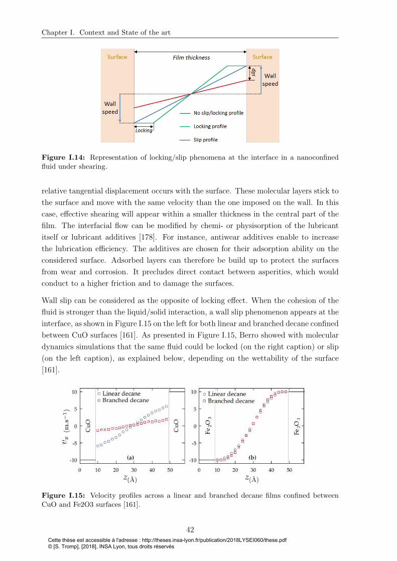
Chapter I. Context and State of the art
Figure I.14: Representation of locking/slip phenomena at the interface in a nanoconfinedfluid under shearing.
relative tangential displacement occurs with the surface. These molecular layers stick to
the surface and move with the same velocity than the one imposed on the wall. In this
case, effective shearing will appear within a smaller thickness in the central part of the
film. The interfacial flow can be modified by chemi- or physisorption of the lubricant
itself or lubricant additives [178]. For instance, antiwear additives enable to increase
the lubrication efficiency. The additives are chosen for their adsorption ability on the
considered surface. Adsorbed layers can therefore be build up to protect the surfaces
from wear and corrosion. It precludes direct contact between asperities, which would
conduct to a higher friction and to damage the surfaces.
Wall slip can be considered as the opposite of locking effect. When the cohesion of the
fluid is stronger than the liquid/solid interaction, a wall slip phenomenon appears at the
interface, as shown in Figure I.15 on the left for both linear and branched decane confined
between CuO surfaces [161]. As presented in Figure I.15, Berro showed with molecular
dynamics simulations that the same fluid could be locked (on the right caption) or slip
(on the left caption), as explained below, depending on the wettability of the surface
[161].
Figure I.15: Velocity profiles across a linear and branched decane films confined betweenCuO and Fe2O3 surfaces [161].
42Cette thèse est accessible à l'adresse : http://theses.insa-lyon.fr/publication/2018LYSEI060/these.pdf © [S. Tromp], [2018], INSA Lyon, tous droits réservés

PhD thesis - Stephane TROMP
For both effects, two properties at the solid/liquid interface will define the fluid flow
behavior: commensurability, which is linked to the geometry of the surface compared to
the size of the fluid molecules [179, 37], and the corrugation [178] which describes the
energy needed to initiate a relative tangential motion at the fluid/solid interface.
The influence of environmental parameters on the interfacial flow can be obtained with
MD simulations. As an example, wall slip is increased with shear rate [180, 181]. Voeltzel
et al. [25] also observed that the larger the slip, the lower the effective shear rate in the
liquid, so that the fluid is less heated.
Furthermore, the molecule length and shape can also influence slip. Indeed, the longer
and the more complex chains are, the stronger is the fluid cohesion and thus it will
enhance slip [182, 161]. As for the layering structuration, the topography influence the
interfacial flow. It was shown experimentally [183, 184, 185] and numerically [25, 36,
170, 186, 180] that roughness reduces wall slip.
I.4.2.3 Rheology of nanoconfined fluid
The effective viscosity ηeff of nanoconfined fluids has to be distinguished from the bulk
viscosity η. This latter describes the resistance of a fluid to flow and only depends
on three factors: pressure P, temperature T and shear rate γ so that η = η(P,T,γ).
However, in nanoconfined fluids, the distance between the two surfaces influences the
fluid flow. In nanoconfined systems, the effective viscosity ηeff represents the resistance
to flow in a molecularly thin fluid. It is defined as the shear stress divided by effective
shear rate. Under high confinement, various studies see varied behaviors, which range
from no change to viscosity increase by several orders of magnitude, depending on the
liquid and the solid [187, 188].
The viscosity increase can be linked to the layering effect. Indeed, the high density
observed near the surfaces generates an increase in viscosity, or even a phenomenon
of locking. In both cases, the apparent viscosity rises. For this reason, this increase
in viscosity occurs only when the thickness of the contact becomes comparable to the
thickness of the structured layers formed close to the surfaces. Indeed, SFA experiments
showed a rise of the viscosity when less than 10 molecular layers of hexadecane were
present in the contact [189]. This observation was confirmed with simulations of n-
dodecane [190] and model fluids [174, 191]. Moreover, when the film is thicker than
10 molecular layers, the effective viscosity is comprised within 10% of the bulk value
[192]. When the film becomes even thinner with only 1-2 molecular layers, the lubricant
crystalizes and a solid-like behavior is assumed, leading to an increase of the effective
viscosity [189, 193]. In this case, a stick-slip behavior at the liquid-solid interface was
confirmed experimentally [193] , as well as with numerical simulations [191, 194].
43Cette thèse est accessible à l'adresse : http://theses.insa-lyon.fr/publication/2018LYSEI060/these.pdf © [S. Tromp], [2018], INSA Lyon, tous droits réservés

Chapter I. Context and State of the art
Furthermore, as shown in Figure I.16, the effective viscosity shows different regimes,
according to the shear rate. At relatively low shear rate, the transition from a solid-like
to a liquid-like behavior appears when a critical yield stress is reached [195, 196, 191,
197, 169]. At high shear rate, viscosity decreases with γ. This phenomenon is called
shear thinning.
Figure I.16: Generalized map in arbitrary units for the effective viscosity of confined filmsas a function of the shear rate, load and film thickness. Inspired by Luengo et al. [195] andmodified by Savio [37].
I.4.2.4 Thermal effects
High shear produces heat in the contact. In return, heat can be evacuated either by
the lubricant flow towards the exit of the contact, or by conduction through the solid
surfaces.
Thanks to molecular dynamics simulations, Voeltzel et al. [198] have drawn a typi-
cal temperature profile obtained for nanoconfined ionic liquid between two iron oxide
surfaces. As shown in Figure I.17, they observed an interfacial thermal slip due to a
finite thermal resistance of the interface. They also found that this thermal resistance
increases with the effective shear rate.
In conclusion, continuous theories cannot be used anymore for molecular lubrication.
Indeed, many properties of the fluid (e.g. slip at the wall, inhomogeneity through the
film thickness) deviate from classical continuum assumptions when confined between two
surfaces. Nanoconfined systems, though widely studied in the literature, still require
investigations. Especially, the physico-chemical behavior at the interface between the
lubricant and the surface remains poorly described in literature when considering real
surfaces. Besides, as explained above, molecular lubrication with refrigerants is an open
field of research.
44Cette thèse est accessible à l'adresse : http://theses.insa-lyon.fr/publication/2018LYSEI060/these.pdf © [S. Tromp], [2018], INSA Lyon, tous droits réservés

PhD thesis - Stephane TROMP
Figure I.17: Typical temperature profile of sheared ionic liquid, for a shear velocity of 40m/s, a pressure of 500MPa and a wall temperature of 350 K. Results from Voeltzel et al. [198].
I.4.3 Role of adsorbed layers of refrigerant on the surface
Some refrigerants can chemically react with the bearing surfaces. For example, under
high velocity and high pressure, ammonia reacts with the oxide layers and free water
is released, so that the surface loses its protective oxide layer up to a few millimeters
per day. As a consequence, wear increases and the mechanical system fail [139]. In
classical lubricants, anti-wear additives can improve tribological performance. Besides,
as shown in this Chapter, some refrigerants are prone to react with surfaces and to
build-up adsorbed layers protecting the surfaces.
The new HFOs and HCFOs refrigerants have a carbon-carbon double bond C=C, which
is known to be more reactive than the single carbon bond. Indeed, the electrons of the
π-bonds are less stable than the ones of the σ-bonds. In a lubricated contact, material
removal can appear, for example because of two asperities contact, involving breaking
bonds in the surface. As a consequence dangling bonds are created at the interface with
the refrigerant. The unstable C=C bonds are then inclined to react with these dangling
bonds. The formation of this adsorbed layer depends on different parameters.
First, the oil blended with the refrigerant can influence the ability of the adsorption pro-
cess. As an illustration, the tribological properties of the R1234yf refrigerant were exper-
imentally investigated between two gray cast iron surfaces [119, 22]. During tribotesting,
a protective layer appeared. Thanks to X-ray photoelectron spectroscopy (XPS) anal-
ysis, the chemical composition of this layer was investigated and fluorine-based species
were observed. With gray cast iron surfaces and R1234yf environment representing
45Cette thèse est accessible à l'adresse : http://theses.insa-lyon.fr/publication/2018LYSEI060/these.pdf © [S. Tromp], [2018], INSA Lyon, tous droits réservés
Chapter I. Context and State of the art
an aggressive air-conditioning compressor systems in mixed lubrication regime, differ-
ent oil-refrigerant mixture were used [114]. An adsorbed layer appeared in the case
of PAG/R1234yf and mineral oil/R1233yf, but not with the mixture POE/R1234yf,
leading to abrasive wear with micro-pitting and break-down of the surface.
Second, the temperature dependence on the formation of protective layer was tested in
the same studies. The increase of temperature changed the ability to form an adsorbed
layer. At room temperature with R1234yf/PAG and R1234yf/mineral oil mixtures, no
sorption appeared, but at 110◦C, fluorine-based layer was observed. The pressure can
also influence the formation of a tribolayer, as observed with R134a on alumina and
zirconia surfaces [199].
Finally, even with R134a or natural CO2 refrigerants without carbon-carbon double
bond, tribolayers were observed on different iron oxides, alumina, zirconia and polymeric
coatings [200, 201, 202, 203]. The better tribological performance with CO2 refrigerant
compared to R134a in cast iron air-conditioning compressor was attributed with XPS
to the partial transformation of iron oxide into iron carbonates, reducing friction and
preventing wear [204, 122].
Muraki et al. [20] observed with XPS the formation of FeF2 showing antiwear behavior
when considering the refrigerant R245mc. Byung Chul Na et al. [21] supposed an iron-
chloride coating formation with the former refrigerant dichlorodifluoromethane (R12) to
justify a decreasing friction.
However, concerning the HCFO-1233zd in a steel contact no experimental or numerical
result about the formation of an adsorbed layer was found in the literature except
the experimental works published by Morales-Espejel [3] and Hauleitner et al. [4, 5].
This thesis aims at filling the gap in the point of view of numerical simulations and at
providing information about the formation of this layer and its influence on tribological
performance in such PRL systems.
I.5 Objectives of the PhD
One of the main industrial challenges consists in reducing the size, weight and environ-
mental impact of tribological systems. In refrigeration systems, compressors are usually
lubricated with an oil-refrigerant mixture instead of oil lubricant. However the current
trend is to build oil-free systems with compressors only lubricated with pure refrigerants
(PRL systems), which are low-viscosity working fluids and have low viscosity-pressure
coefficients. Hence, the thickness of lubricant films separating the surfaces can reach
the nanometric scale locally and thus the same order of magnitude as surface roughness
(few nm). Therefore, contacts between asperities could happen and it would provoke
46Cette thèse est accessible à l'adresse : http://theses.insa-lyon.fr/publication/2018LYSEI060/these.pdf © [S. Tromp], [2018], INSA Lyon, tous droits réservés

PhD thesis - Stephane TROMP
wear. In the literature, experiments have shown that no damage or wear were observed
on the stainless steel surface under certain experimental conditions with PRL systems
lubricated using R1233zd. This project aims at understanding the physical chemistry
behavior between a steel surface and the new refrigerant R1233zd and its effects on
tribological performances.
Experiments with the R1233zd refrigerant suggest that lubrication is still possible in that
situation thanks to an adsorbed layer formed on steel surfaces. Because experimental in-
situ analysis inside the contact area is still very difficult, we aim at providing numerical
simulations to observe the chemical reactions and physical processes at the interface
between the refrigerant and the surface.
In that context, we develop a multiscale numerical methodology where DFT calcula-
tions, describing matter at the level of its electronic structure, are combined with large
scale molecular dynamics simulations, using empirical force fields adapted on the basis
of the DFT results. First, the results obtained with DFT are detailed in Chapter 2
and the interactions between refrigerant and hematite are explained. DFT calculations
are used to obtain accurate binding energies under different conformations. Then, the
methodology used to parametrize a force field at the refrigerant-surface interface based
on these DFT results is discussed in Chapter 3. MD simultations are used to predict
the difference of interfacial structure observed with the parametrized force field and
from those obtained using standard mixing rules. In Chapter 4, large-scale molecular
dynamics simulations involving this parametrized force field analyze the existence of a
strongly adsorbed layer of R1233zd molecules. The strength of this adsorbed layer is
explored under extreme conditions in pressure and sliding velocity in presence of smooth
and rough surfaces.
47Cette thèse est accessible à l'adresse : http://theses.insa-lyon.fr/publication/2018LYSEI060/these.pdf © [S. Tromp], [2018], INSA Lyon, tous droits réservés

Cette thèse est accessible à l'adresse : http://theses.insa-lyon.fr/publication/2018LYSEI060/these.pdf © [S. Tromp], [2018], INSA Lyon, tous droits réservés
Chapter II
Chemical physics at interfaces
within a refrigerant-lubricated
contact: an electronic structure
study
Contents
II.1 Density Functional Theory . . . . . . . . . . . . . . . . . . . . 51
II.1.1 Basic elements of quantum mechanic . . . . . . . . . . . . . . 51
II.1.1.1 Born-Oppenheimer approximation . . . . . . . . . . 51
II.1.1.2 The Schrodinger equation . . . . . . . . . . . . . . . 52
II.1.1.3 The electron density . . . . . . . . . . . . . . . . . . 52
II.1.2 Principles of Density Functional Theory . . . . . . . . . . . . 53
II.1.2.1 Hohenberg-Kohn theorems . . . . . . . . . . . . . . 53
II.1.2.2 Kohn-Sham equations . . . . . . . . . . . . . . . . . 54
II.1.2.3 SCF: self-consistent field procedure: solutions of Kohn-
Sham equations . . . . . . . . . . . . . . . . . . . . 54
II.1.2.4 Exchange-correlation functionals . . . . . . . . . . . 55
II.1.2.5 The core electrons . . . . . . . . . . . . . . . . . . . 56
II.1.2.6 Basis sets . . . . . . . . . . . . . . . . . . . . . . . . 56
II.1.3 DFT+U calculations . . . . . . . . . . . . . . . . . . . . . . . 57
II.2 Our model . . . . . . . . . . . . . . . . . . . . . . . . . . . . . . 58
II.2.1 Materials . . . . . . . . . . . . . . . . . . . . . . . . . . . . . 58
II.2.2 Standard DFT - DFT+U setup . . . . . . . . . . . . . . . . . 59
49Cette thèse est accessible à l'adresse : http://theses.insa-lyon.fr/publication/2018LYSEI060/these.pdf © [S. Tromp], [2018], INSA Lyon, tous droits réservés

Chapter II. Chemical physics at interfaces within a refrigerant-lubricated contact: anelectronic structure study
II.2.3 Binding energy . . . . . . . . . . . . . . . . . . . . . . . . . . 60
II.3 Adsorption behavior of R1233zd molecule on iron oxide
surfaces . . . . . . . . . . . . . . . . . . . . . . . . . . . . . . . 61
II.3.1 Binding energies . . . . . . . . . . . . . . . . . . . . . . . . . 61
II.3.2 Basis set superposition error . . . . . . . . . . . . . . . . . . 63
II.3.3 Dipole correction . . . . . . . . . . . . . . . . . . . . . . . . . 63
II.3.4 Charge analysis: physisorption or chemisorption? . . . . . . . 64
II.4 Conclusion . . . . . . . . . . . . . . . . . . . . . . . . . . . . . 67
50Cette thèse est accessible à l'adresse : http://theses.insa-lyon.fr/publication/2018LYSEI060/these.pdf © [S. Tromp], [2018], INSA Lyon, tous droits réservés

PhD thesis - Stephane TROMP
The results of this chapter have been partially published in the Journal of Physical
Chemistry C [6].
For a few decades, interest for quantum calculations has been increasing. Indeed, quan-
tum calculations can predict the electronic structure of the matter. From physical
chemistry aspects and even now from industrial interests, electronic properties are of
primary importance.
Ab-initio methods aim at solving quantum mechanics equations, which are mostly sim-
plified forms of the Schrodinger equation. Indeed, this latter is very difficult to solve as
soon as many electrons composed the system. One of the most popular among these
methods is the density functional theory (DFT), using the electronic density feature
to solve a many-body problem. DFT calculations have been tested to describe various
phenomena in different areas of science. For example, one can study purely chemical
process like ammonia synthesis or hydrogenation [7], or mechanical behavior of metals
embrittlement, or even study the materials properties during planetary formation [8].
In particular, DFT method offers the possibility to investigate lubrication phenomena.
Indeed, DFT have been tested to investigate friction through chemical reactions at the
solid-liquid interface [9]. DFT has also been used to parametrized force fields between
lubricant and surfaces in lubricated contacts [10, 11].
This Chapter is divided into three main parts. First, the principles of DFT are ex-
plained. Then, our model and its features are detailed. Finally, the results about the
adsorption of the R1233zd molecule on hematite surfaces are presented and discussed.
In particular, DFT calculations are used to obtain accurate binding energies under
different conformations. Moreover, charges analysis are performed with representative
adsorption cases.
II.1 Density Functional Theory
II.1.1 Basic elements of quantum mechanic
II.1.1.1 Born-Oppenheimer approximation
The Born-Oppenheimer approximation [205] is the assumption that the motion of elec-
trons and atomic nuclei can be separated. Indeed each neutron or proton in a nucleus is
more than 1800 times heavier than the electron [8]. Therefore, the electrons move and
interact in the field of a set of immobile nuclei, and the forces between the nuclei can
be computed from the relaxed electronic structure at every time.
51Cette thèse est accessible à l'adresse : http://theses.insa-lyon.fr/publication/2018LYSEI060/these.pdf © [S. Tromp], [2018], INSA Lyon, tous droits réservés

Chapter II. Chemical physics at interfaces within a refrigerant-lubricated contact: anelectronic structure study
II.1.1.2 The Schrodinger equation
With the Born-Oppenheimer approximation, the time-independent Schrodinger equa-
tion for the electrons can be written as follows.
HΨ = (Te + Vn−e + Ve−e)Ψ = EΨ (II.1)
H represents the Hamiltonian operator, which can be decomposed as follows: Te is the
kinetic energy of the electrons,Vn−e is the potential developed by the collection of atomic
nuclei and acting on the electrons, Ve−e describes the electron-electron interactions.
Ψ is a set of solutions of the Schrodinger equations and are the eigenvectors of the
Hamiltonian, and named electronic wave functions. Each wave function Ψn is associated
to its eigenvalue, the energy En. The many-body problem is solved by finding the wave
functions and their ground state energy E0.
If the spin is neglected, the electronic wave function Ψ is dependent of each spatial
coordinates of each N electrons, thus it is a problem with 3N spatial coordinates. With
the spin, each electron is completely defined by its three spatial coordinates and its spin.
The number of electrons makes practically impossible to solve the Equation II.1 for real
systems. The exact solution is limited for very few and small systems such as the H
atom.
The system considered in this chapter, as shown later, is composed of one molecule of
R1233zd and one hematite (α − Fe2O3) surface containing 72 atoms of oxygen and 48
atoms of iron. By neglecting the spin, the full wave function of this system requires 192
dimensions for the refrigerant molecule and 5472 dimensions for the surface. The DFT
has been developed to overcome this very high number. Indeed, instead of considering
5664 dimensions for the wave function, the systems will be solved by using an electronic
density, which is only a 3 dimensional function (when excluding the spin), for 3 spatial
coordinates.
II.1.1.3 The electron density
The electron density is defined as the probability of finding any of the N electrons
within a volume element. The electron density at a particular position in space n(r) is
calculated with the following formula:
n(r) =N∑i=1
| ψi(r) |2 (II.2)
where ψi represents a single-electron wave function and is also named a molecular orbital
52Cette thèse est accessible à l'adresse : http://theses.insa-lyon.fr/publication/2018LYSEI060/these.pdf © [S. Tromp], [2018], INSA Lyon, tous droits réservés
PhD thesis - Stephane TROMP
(MO). Therefore, the term in the sum is the probability that an electron in the molecular
orbital ψi is located at the position r. To consider the magnetism of certain systems,
the spins of electrons have to be considered. These systems are named spin-polarized
and their electron densities depends of three spatial coordinates and one spin each.
II.1.2 Principles of Density Functional Theory
In DFT calculations, the many-body problem of N electrons with 3N spatial coordinates
is reduced to 3 spatial coordinates, through the use of functionals of the electron density.
A functional is a function, which gives a number from a function. The main idea of DFT
is that the ground state energy can be expressed as a functional of the electron density.
Indeed, in DFT calculations, the Hamiltonian can be expressed as a function of the
electron density. This basis of the DFT appeared with the Hohenberg-Kohn theorems.
II.1.2.1 Hohenberg-Kohn theorems
The first Hohenberg-Kohn theorem demonstrates that the ground state properties of a
many-electron system is a unique functional of the electron density.
The second Hohenberg-Kohn theorem provides precisions about the functional. It says
that the electron density that minimizes the energy of the overall functional is the true
electron density corresponding to the full solution of the Schrodinger equation. It means
that the ground state energy can be obtained variationally.
E[n(r)] > E[n0(r)] = E0 (II.3)
Therefore, the aim is to find the lowest energy value, thus the ground state energy of
a system. If the true functional was known, by varying the electron density until the
energy is minimized, it would be possible to obtain the electron density corresponding to
the ground state energy. Thus, according to the two theorems of Hohenberg and Kohn,
one can know the state of an electronic system by determining its electronic density and
one can obtain the electronic density of the ground state by minimizing the energy of
the system.
However, the Hohenberg-Kohn theorems do not give information on how to calculate the
energy with the electron density, i.e. they do not prescribe how to chose or design the
functional. Therefore, approximations have to be done. Only by adding the formulations
of Kohn and Sham, DFT became a practical method to solve a many-body problem.
53Cette thèse est accessible à l'adresse : http://theses.insa-lyon.fr/publication/2018LYSEI060/these.pdf © [S. Tromp], [2018], INSA Lyon, tous droits réservés
Chapter II. Chemical physics at interfaces within a refrigerant-lubricated contact: anelectronic structure study
II.1.2.2 Kohn-Sham equations
Instead of solving the many-body problem (Equation II.1), Kohn and Sham intro-
duced single-electron equations, named Kohn-Sham (KS) equations (Equations II.4).
They replaced the electron-electron potential and the electron kinetic energy of inter-
acting electrons by terms of fictious non interacting electrons system. Effects arising
from many-body interactions between electron-electron are put into a new term, named
exchange-correlation potential. In KS equations, the wave functions Ψ introduced above,
are replaced by single-electron wave functions ψi depending on three spatial variables.
[− ~2
2m∇2 + V (r) + VH(r) + VXC(r)
]ψi(r) = εiψi(r) (II.4)
The first term describes the kinetic energy of the electron, V is the potential energy
of an electron interacting with the collection of atomic nuclei, VH is the Hartree term
describing electron-electron Coulomb repulsion, and VXC is the exchange-correlation
potential. This latter describes the effects of electron-electron interaction, excluding
Coulomb repulsion already considered in Hartree term, and also corrects the kinetic
energy due to the non-interaction. All these four terms are calculated as functions of
the electron density n(r). They are functionals of the density. The aim is to solve these
KS equations.
II.1.2.3 SCF: self-consistent field procedure: solutions of Kohn-Sham equa-
tions
To solve the Kohn-Sham equations, one needs to define the four potentials terms of
Equation II.4, which are depending on the electron density n(r). However the density
depends on the single-electron wave functions ψi which are the solutions of the Kohn-
Sham equations, which are initially needed. Hence, it is a circular problem. Therefore,
an iterative procedure need to be used to find these molecular orbitals ψi. This procedure
is named a self-consistent field (SCF) calculation and the different stages are described
below.
• An initial electron density n0(r) is defined, in general a charge density superposi-
tion of the isolated atoms.
• With this density, the Hamiltonian is calculated and each N KS equations Hψi(r) =
Eψi(r) are solved with this density. Hence, single-particle wave function ψi(r) are
calculated.
• The new electron density n1(r) is determined from the calculated molecular or-
bitals ψi(r) with the Equation II.2.
54Cette thèse est accessible à l'adresse : http://theses.insa-lyon.fr/publication/2018LYSEI060/these.pdf © [S. Tromp], [2018], INSA Lyon, tous droits réservés

PhD thesis - Stephane TROMP
• This new density is then compared to the previous one and if | n1(r) − n0(r) |lower than tolerance, then the SCF calculation stops and the new electron density
n1(r) can be used to obtain energies, forces or other properties. Otherwise, this
new density is used as initial density to restart this procedure at the second step.
To summarize the previous steps, the aim is to find the ground state energy of the
Schrodinger equation. However, because of the many-body feature, it is too compli-
cated for real systems. Thanks to the Hohenberg-Kohn theorems it is possible to obtain
this ground state by minimizing the energy functional depending of the electron density.
With the Kohn-Sham equations, the many-body problem of the beginning is simplified
and from now, single-electron equations will be solved by using a self-consistent proce-
dure. Nonetheless, the exchange-correlation potential VXC(r) has to be approximated.
This latter is linked to an exchange-correlation functional EXC [n(r)] with the following
formula.
VXC(r) =δEXC [n(r)]
δn(r)(II.5)
II.1.2.4 Exchange-correlation functionals
Theoretically, DFT is an exact method but one problem is that no analytical formulation
of the exchange-correlation functional EXC [n(r)] exists. Two of the most usual kinds of
functional are presented here.
The exact exchange-correlation energy can be determined for the case of an uniform
electron gas [206]. This energy is used in the Local Density Approximation (LDA).
In LDA, the XC functional depends only of the density, as described in the following
formula.
ELDAXC [n(r)] =
∫n(r)εxc(n(r))dr (II.6)
Where, at each spatial position r, εxc[n(r)] is the exchange-correlation energy for a
particle in a uniform electron gas at the density n(r). Nonetheless, this approximation
remains a local approximation in which the non-homogeneity of the electronic density
is not considered.
To add more information in the functional that the local electron density, the General-
ized Gradient Approximation (GGA) can be implemented. In GGA, the gradient
of the electron density is included, as shown in the following formula.
EGGAXC [n(r)] =
∫n(r)εxc(n(r),∇n(r))dr (II.7)
55Cette thèse est accessible à l'adresse : http://theses.insa-lyon.fr/publication/2018LYSEI060/these.pdf © [S. Tromp], [2018], INSA Lyon, tous droits réservés
Chapter II. Chemical physics at interfaces within a refrigerant-lubricated contact: anelectronic structure study
The particular vdW functionals. Dispersion interactions (also named van der Waals
interactions or London forces) relate to interactions between instantaneous dipoles. In-
deed, within a molecule, an instantaneous dipole can be produced due to the fluctua-
tion of electrons position. This dipole will interact with instantaneous dipoles of other
molecules. These long-range correlation interactions are difficult to describe with DFT
due to their long-range feature. Indeed, dispersion forces need to be computed in large
simulation cells, which increase drastically the computation costs.
Describing these interactions is one of the limit of DFT calculations. However, two
main solutions exist to improve description of dispersion interactions. One can either
use correction terms which add a dispersion contribution to the total energy between
each pair of atoms in a system. Or, one can use vdW density functional (vdW-DF)
to approximate dispersion interactions. In contrary to the previous solution, this one
implements two terms depending on the electron density, into the exchange-correlation
energy term. In this work, we use a GGA functional modified to take into account
dispersion interactions, the optB88-vdW.
II.1.2.5 The core electrons
The core electrons do not participate in conductivity or creating-breaking bonds but they
have also to be treated. However, consider them in same way than valence electrons
is too computationally expensive. One possibility is to use pseudopotentials, as it will
be done in our study. With this method, the effects of the core electrons are described
through a potential acting on the molecular orbitals of the valence electrons, reducing
the calculation costs.
II.1.2.6 Basis sets
The molecular orbitals, thus the single-electron wave functions, are projected on ba-
sis functions. These functions can be for example plane-waves functions or localized
functions. The plane-waves functions are powerful for calculations involving three di-
mensional periodic boundary conditions. However, when the adsorption phenomena are
studied, a large empty volume is set-up upon the surface. In order to optimize the cal-
culation costs, it is interesting to consider localized functions to keep the vacuum area
without basis functions. With CP2K software [12], localized Gaussian basis functions
are used, as follows.
ψi(r) =
NBF∑α
CiαGα(r) (II.8)
56Cette thèse est accessible à l'adresse : http://theses.insa-lyon.fr/publication/2018LYSEI060/these.pdf © [S. Tromp], [2018], INSA Lyon, tous droits réservés
PhD thesis - Stephane TROMP
Where NBF is the number of basis functions Gα. Ciα represent the coefficients calcu-
lated during the SCF procedure. In practice Gα are linear combinations of “contracted
Gaussian” (CG) basis functions. CGs are composed of Gaussian functions multiplied
by functions depending on spatial coordinates. For example, the single-zeta (SZ) basis
function is composed of one contracted Gaussian function per atomic orbital (AO), while
double-zeta (DZ) owns two CG functions per AO and triple-zeta (TZ) three per AO.
Furthermore, the basis functions can take into account the polarization. Indeed, by
approaching two atoms, the molecular orbitals can be more asymmetrical about the
nucleus than the atomic orbitals. To describe the polarization effect, the CGs can have
higher angular momentum than in the valence orbitals. This flexibility is obtained by
using polarized basis sets, such as double-zeta polarized (DZP) or triple-zeta polar-
ized (TZP) functions. The polarization functions are important to reproduce chemical
bondings and will therefore be used in this study.
Besides, as discussed previously, since the core electrons do not participate in bonding
phenomena, they are treated separately. Hence, the basis sets will only be applied to
valence electrons and not to every electrons of each atoms. For instance, the DZP basis
set becomes the double-zeta valence polarized (DZVP).
One particularity with CP2K software is that a Gaussian and Plane Waves (GWP)
method is used, whereas only Plane Waves (PW) method are used for many other
software, such as VASP [207]. While the molecular orbitals are projected on Gaussian
functions, a multi-grids system is used to define the points where the electronic density is
calculated for hartree and exchange-correlation terms. The distance between two planes
of this grid is directly obtained from an energy cutoff value given for the plane waves.
The higher the cutoff value, the finer the grid and thus the more precise the calculation.
II.1.3 DFT+U calculations
As explained above, electron-electron Coulomb repulsion is described with the Hartree
potential, while all other interactions between electrons are included in the exchange-
correlation term. In the single-electron KS equations, the Hartree potential describes the
repulsive interactions between the electron and the total electron density, including the
considered electron itself. This unphysical repulsive interaction between the electron and
itself leads to an energy named self-interaction energy. Theoretically, this latter should
be corrected in the exchange-correlation term. However, since the exact exchange-
correlation functional is not known, the self-interaction energy can involve non-negligible
effects for highly correlated systems. This is particularly true for systems owning many
localized states in the atomic center. Such systems are referred to as strongly correlated
systems and are for example transition-metal oxides whose d or f shells are incomplete.
57Cette thèse est accessible à l'adresse : http://theses.insa-lyon.fr/publication/2018LYSEI060/these.pdf © [S. Tromp], [2018], INSA Lyon, tous droits réservés
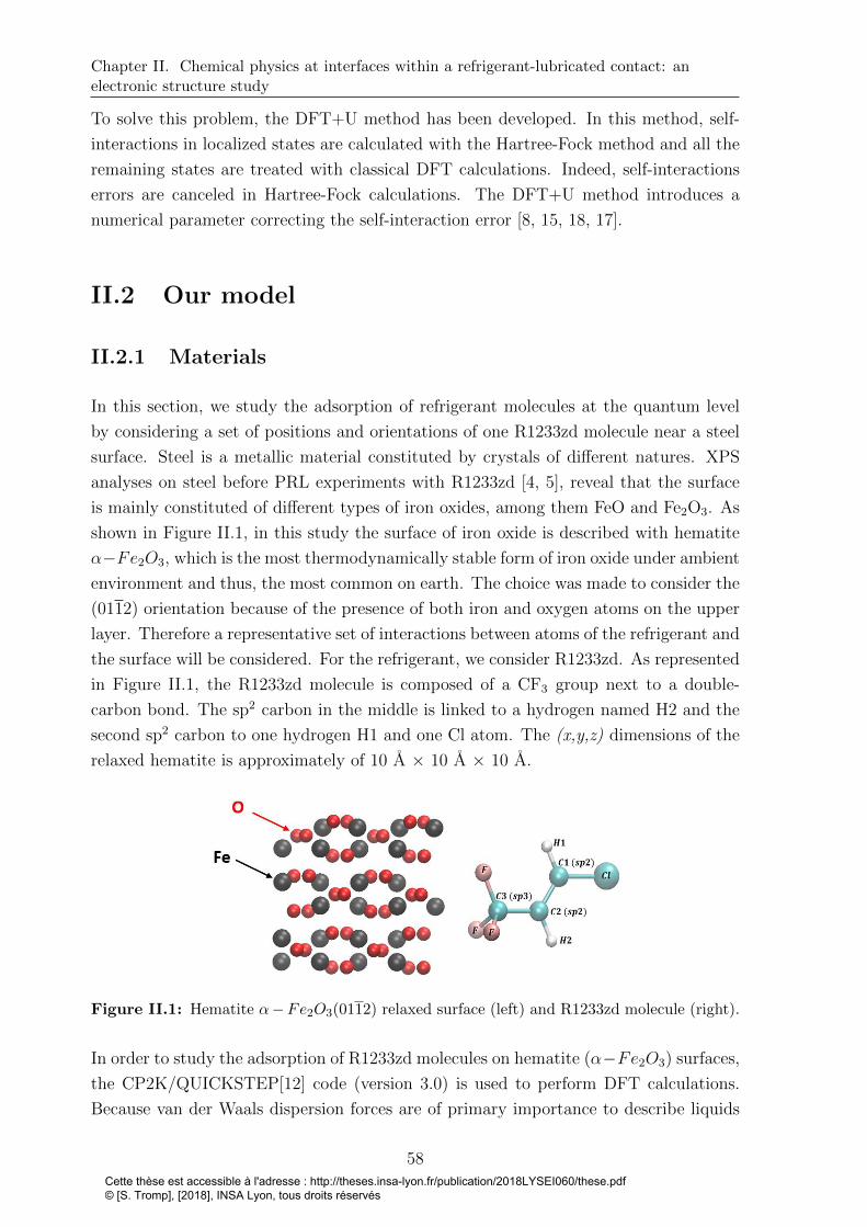
Chapter II. Chemical physics at interfaces within a refrigerant-lubricated contact: anelectronic structure study
To solve this problem, the DFT+U method has been developed. In this method, self-
interactions in localized states are calculated with the Hartree-Fock method and all the
remaining states are treated with classical DFT calculations. Indeed, self-interactions
errors are canceled in Hartree-Fock calculations. The DFT+U method introduces a
numerical parameter correcting the self-interaction error [8, 15, 18, 17].
II.2 Our model
II.2.1 Materials
In this section, we study the adsorption of refrigerant molecules at the quantum level
by considering a set of positions and orientations of one R1233zd molecule near a steel
surface. Steel is a metallic material constituted by crystals of different natures. XPS
analyses on steel before PRL experiments with R1233zd [4, 5], reveal that the surface
is mainly constituted of different types of iron oxides, among them FeO and Fe2O3. As
shown in Figure II.1, in this study the surface of iron oxide is described with hematite
α−Fe2O3, which is the most thermodynamically stable form of iron oxide under ambient
environment and thus, the most common on earth. The choice was made to consider the
(0112) orientation because of the presence of both iron and oxygen atoms on the upper
layer. Therefore a representative set of interactions between atoms of the refrigerant and
the surface will be considered. For the refrigerant, we consider R1233zd. As represented
in Figure II.1, the R1233zd molecule is composed of a CF3 group next to a double-
carbon bond. The sp2 carbon in the middle is linked to a hydrogen named H2 and the
second sp2 carbon to one hydrogen H1 and one Cl atom. The (x,y,z) dimensions of the
relaxed hematite is approximately of 10 A × 10 A × 10 A.
Figure II.1: Hematite α−Fe2O3(0112) relaxed surface (left) and R1233zd molecule (right).
In order to study the adsorption of R1233zd molecules on hematite (α−Fe2O3) surfaces,
the CP2K/QUICKSTEP[12] code (version 3.0) is used to perform DFT calculations.
Because van der Waals dispersion forces are of primary importance to describe liquids
58Cette thèse est accessible à l'adresse : http://theses.insa-lyon.fr/publication/2018LYSEI060/these.pdf © [S. Tromp], [2018], INSA Lyon, tous droits réservés
PhD thesis - Stephane TROMP
and the interfacial behavior, the exchange-correlation term is calculated within the
generalized gradient approximation GGA with the non-local optB88-vdW functional[13].
Dabaghmanesh et al. [14] showed that this functional is accurate for methane and
benzene adsorption on hematite surface. The pseudopotentials of Goedecker-Teter-
Hutte are employed [208].
The aim is to find the lowest energy value of the whole system composed of one molecule
of the R1233zd and one Fe2O3 surface formed with 120 atoms. Because the surface is
already relaxed, iron and oxygen atoms remain fixed during the geometry optimization
and only the molecule of refrigerant can move. Note that to study the reactivity of
the system (e.g. possible dissociation of the refrigerant molecule), it could have been
interesting to let the hematite surface relax. The simulation box dimensions were 10.24
A × 10.93 A × 25 A, which leaves a vacuum gap of ca. 1 nm between the top of the
molecule and the bottom of the periodic image of the solid surface. With the standard
DFT method, the Fe 3d strong correlated electrons are not well described. Therefore
the DFT-GGA+U method, in which a Hubbard-type on-site Coulomb repulsive term is
added to the Hamiltonian, was used. The challenging point we face here is to employ
a van der Waals functional combined with a spin-polarized system by using the named
GGA+U method. The convergence of a geometry optimization process is much more
difficult with the DFT+U method and it is often necessary to use different methods
(standard DFT followed by DFT+U) to perform this convergence.
II.2.2 Standard DFT - DFT+U setup
Standard DFT method:
For calculations without DFT+U method, geometry optimizations were carried out in
order to solve the Kohn-Sham equations. The short range molecularly optimized double-
ζ valence polarized (m-DZVP) Gaussian basis functions were used. A cutoff value of
300 Ry was used for the plane wave expansion. The Kohn-Sham matrix is iteratively
diagonalized with the Orbital Transformation method.
DFT+U method:
All calculations using the DFT+U method were performed spin-polarized by solving the
unrestricted Kohn-Sham equation. In this study, the Dudarev’s approach for DFT+U
method, is used [15]. A value U = 5 eV predicts correctly the hybridization of 3d-
electrons of iron atoms[16, 17]. A ramping method is used from a threshold value of
the self-consistent field (SCF) convergence of 10−4 to incrementally increase the U value
to target U (5 eV) value with an increment of 0.5 eV. Different values were tested
and these latter did show the best capacity to converge the calculus. The short range
molecularly optimized single-ζ valence polarized (m-SZV) Gaussian basis functions were
59Cette thèse est accessible à l'adresse : http://theses.insa-lyon.fr/publication/2018LYSEI060/these.pdf © [S. Tromp], [2018], INSA Lyon, tous droits réservés

Chapter II. Chemical physics at interfaces within a refrigerant-lubricated contact: anelectronic structure study
used for every atom and the final plane-wave cutoff was set to 500 Ry. The modified
Broyden mixing method is used in order to improve the convergence behavior of the SCF
procedure[209]. Moreover, due to the antiferromagnetic behavior of the hematite this
convergence is enhanced by setting an initial multiplicity value to one. The Fermi-Dirac
smearing method was used with an electronic temperature of 3000 K. Since smearing
can lead to occupied molecular orbitals (MOs) in conduction band, additional empty
MOs were added to represent the initially unoccupied orbital in this band. Finally, the
Kohn-Sham matrix was diagonalized with standard methods.
II.2.3 Binding energy
The adsorption behavior of R1233zd on the (0112) α − Fe2O3 was studied and the
binding energy values Eb were calculated with the following formula:
Eb = E{surface+1molR1233zd} − Esurface − E1molR1233zd(II.9)
where Esurface+1molR1233zdis the total energy of the relaxed adsorbate-substrate system,
Esurface is the energy of the clean surface slab and E1molR1233zdis the energy of the isolated
R1233zd molecule. The two last terms are calculated by using the same geometry as the
{surface+ 1molR1233zd} system optimized one. A negative value of the binding energy
means that the obtained geometry is more stable than the unbounded state.
60Cette thèse est accessible à l'adresse : http://theses.insa-lyon.fr/publication/2018LYSEI060/these.pdf © [S. Tromp], [2018], INSA Lyon, tous droits réservés

PhD thesis - Stephane TROMP
II.3 Adsorption behavior of R1233zd molecule on
iron oxide surfaces
II.3.1 Binding energies
Sixteen different initial configurations have been obtained by translating and rotating
randomly the refrigerant molecule with respect to the three directions. As shown in
Table II.1 below, the adsorption possibilities could be classified into six different cases
(each corresponding to similar positions and orientations), associated to six ranges of
binding energy values. Every adsorption results is visualized with the visual molecular
dynamics (VMD) software[19].
Table II.1: Six different kinds of adsorption possibility with the ranges of binding energyvalues and the geometry optimization number.
61Cette thèse est accessible à l'adresse : http://theses.insa-lyon.fr/publication/2018LYSEI060/these.pdf © [S. Tromp], [2018], INSA Lyon, tous droits réservés

Chapter II. Chemical physics at interfaces within a refrigerant-lubricated contact: anelectronic structure study
The first important result is that chlorine atoms strongly interact with iron atoms,
as shown in Table II.1, case 1. The chlorine can interact with the oxygen atoms as
well. However, it involves to decrease the distance between iron and chlorine and the
binding energy will decrease. Therefore we can conclude that the Cl-Fe interaction is
of major importance. During geometry optimization process, it is also possible that the
molecule of refrigerant leans and the hydrogen H1 located near the chlorine will play a
non-negligible role of stabilization, as shown in case 2. In case 3, it is shown that the
fluorine has to be taken into account, with a lower energy value of around -0.65 eV. The
assumption of possible interaction between iron and fluorine atoms had been raised[20],
although it was with another refrigerant. We obtained the strongest interaction for case
4. Indeed, the binding energies with refrigerant molecules parallel to the hematite surface
are higher than the ones with vertical orientations of the molecule. Therefore it means
that the horizontal positions of the refrigerant molecules are more stable than the vertical
ones. Indeed both interactions between fluorine – surface and between chlorine – surface
will play a role. Moreover, the π-bonding of the double carbon bond could play a role.
For case 5, the molecule rotated along the double-carbon bond axis and both chlorine
and fluorine, as well as the hydrogen H2 bonded with the carbon located in the middle
of the molecule, interact with the surface. In case 6, only the fluorine atoms interact
with the surface. The geometry optimization for the latter orientation of the molecule
was the less trivial to obtain numerically. It is also interesting to observe that we could
obtain the same binding energy value with one molecule adsorbed either thanks to the
three fluorine atoms or with only the chlorine atom. It shows what was hypothesized
in the paper of Na et al. [21] with another refrigerant, dichlorodifluoromethane R12,
about an iron-chloride coating formation. Indeed, chlorine and iron atoms strongly
interact and the R1233zd molecule can be adsorbed with a major contribution of van
der Waals interactions between these two atoms and of course because of all coulombic
interactions. Moreover, Akram et al. reported the formation of a fluorine-enriched film
FeF3 for the R1234yf[22]. Therefore it is possible to link this observation to case 6
optimized geometry.
It could happen that organic molecules decompose by approaching a metal surface and
build an amorphous film mostly composed of the molecule atoms[210]. It would be
problematic here because it would mean that the refrigerant would not be able to inter-
act with any iron or oxygen atoms because of presence of an amorphous phase at the
interface. Furthermore, R1233zd molecules may not remain stable when approaching
the surface due to the double-carbon bonds. However, in this study no dissociation
phenomenon was observed.
In this ab-initio study, we have shown that the R1233zd molecule could strongly adsorb
on an iron oxide surface. This adsorption was characterized by considering a set of
position and orientation of the molecule upon the surface, which could be found in a
62Cette thèse est accessible à l'adresse : http://theses.insa-lyon.fr/publication/2018LYSEI060/these.pdf © [S. Tromp], [2018], INSA Lyon, tous droits réservés
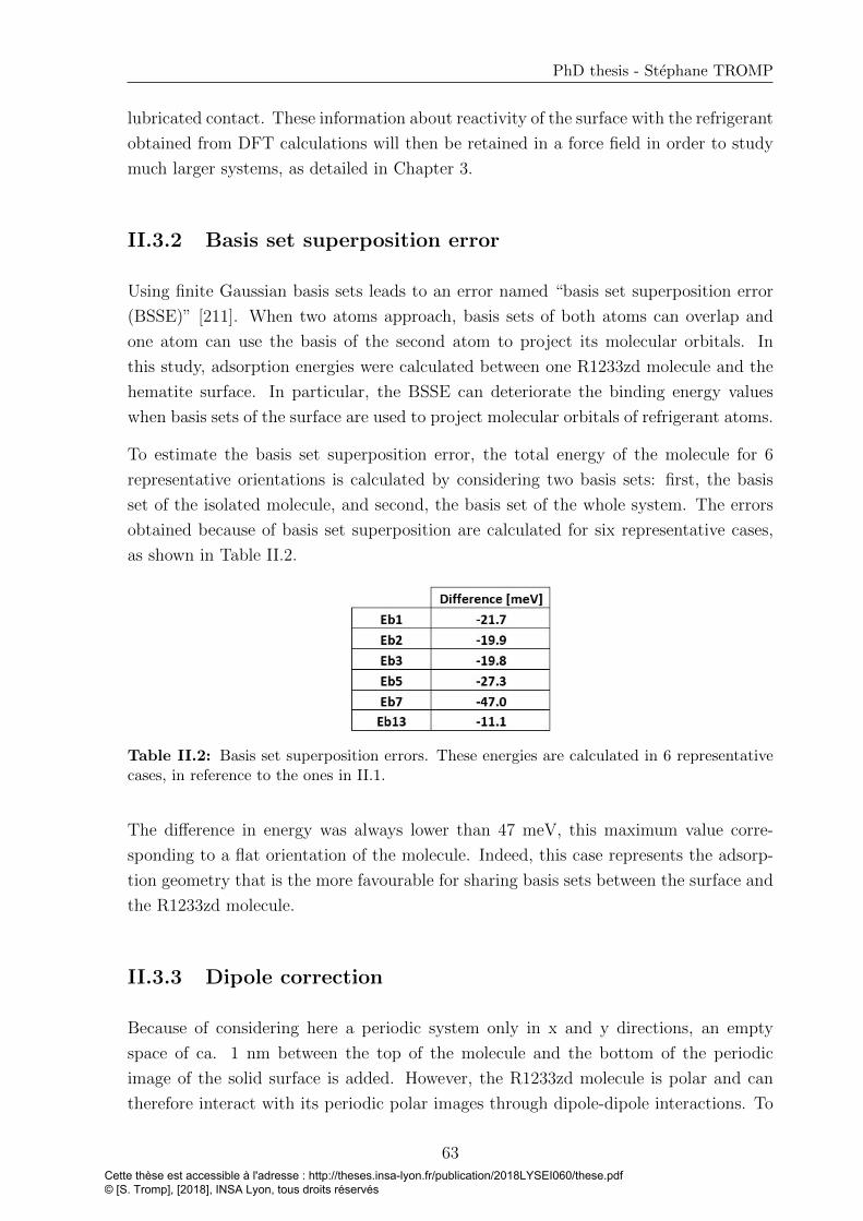
PhD thesis - Stephane TROMP
lubricated contact. These information about reactivity of the surface with the refrigerant
obtained from DFT calculations will then be retained in a force field in order to study
much larger systems, as detailed in Chapter 3.
II.3.2 Basis set superposition error
Using finite Gaussian basis sets leads to an error named “basis set superposition error
(BSSE)” [211]. When two atoms approach, basis sets of both atoms can overlap and
one atom can use the basis of the second atom to project its molecular orbitals. In
this study, adsorption energies were calculated between one R1233zd molecule and the
hematite surface. In particular, the BSSE can deteriorate the binding energy values
when basis sets of the surface are used to project molecular orbitals of refrigerant atoms.
To estimate the basis set superposition error, the total energy of the molecule for 6
representative orientations is calculated by considering two basis sets: first, the basis
set of the isolated molecule, and second, the basis set of the whole system. The errors
obtained because of basis set superposition are calculated for six representative cases,
as shown in Table II.2.
Table II.2: Basis set superposition errors. These energies are calculated in 6 representativecases, in reference to the ones in II.1.
The difference in energy was always lower than 47 meV, this maximum value corre-
sponding to a flat orientation of the molecule. Indeed, this case represents the adsorp-
tion geometry that is the more favourable for sharing basis sets between the surface and
the R1233zd molecule.
II.3.3 Dipole correction
Because of considering here a periodic system only in x and y directions, an empty
space of ca. 1 nm between the top of the molecule and the bottom of the periodic
image of the solid surface is added. However, the R1233zd molecule is polar and can
therefore interact with its periodic polar images through dipole-dipole interactions. To
63Cette thèse est accessible à l'adresse : http://theses.insa-lyon.fr/publication/2018LYSEI060/these.pdf © [S. Tromp], [2018], INSA Lyon, tous droits réservés

Chapter II. Chemical physics at interfaces within a refrigerant-lubricated contact: anelectronic structure study
eliminate these artificial interactions, the dipole correction method can be used where
an additional compensating field is added in the z direction.
In this work, no dipole correction was included in the DFT calculations. However, we
computed the effect of the dipole correction for the six representative cases, reported in
the Table II.3 below.
Table II.3: Difference between the total system energy by considering the dipole correctionand without the correction. These energies are calculated in 6 representative cases, in referenceto the ones in II.1.
The maximum error obtained on total energy of optimized geometries is ca. 18 meV
while the number of steps needed to converge the SCF is doubled when including the
dipole correction. Because of these small error values compared to the high increase of
simulation time, we decided to neglect the dipole correction in z-direction.
II.3.4 Charge analysis: physisorption or chemisorption?
This section is devoted to the analysis of charges within R1233zd molecule during adsorp-
tion process to distinguish the kind of sorption occuring. While methods like CHELPG
(CHarges from ELectrostatic Potentials using a Grid-based method) [212, 31, 213] are
used to calculate atomic charges, other charges distribution analysis schemes give an
answer about the kind of sorption resulting. Besides, CHELPG calculation scheme was
used by Raabe to design atomic charges of R1233zd for Coulombic potential [31].
On the other hand, Bader charges analysis are more adapted to determine exchanged
charges between atoms and molecules. Bader charges are computed using the approach
developed at the Henkelman group [214, 215, 216, 217]. Bader’s theory divides molecules
into atoms, only based on the electron density. In molecular systems, the charge density
reaches a minimum between atoms and therefore, the atoms are separated from each
other at this place, dividing the total volume in smaller volumes assigned to each atoms
in which electron density is calculated. Bader’s theory is known to be useful for charge
analysis. In particular, this approach can be used to describe chemical bonding between
interacting atoms and molecules.
64Cette thèse est accessible à l'adresse : http://theses.insa-lyon.fr/publication/2018LYSEI060/these.pdf © [S. Tromp], [2018], INSA Lyon, tous droits réservés
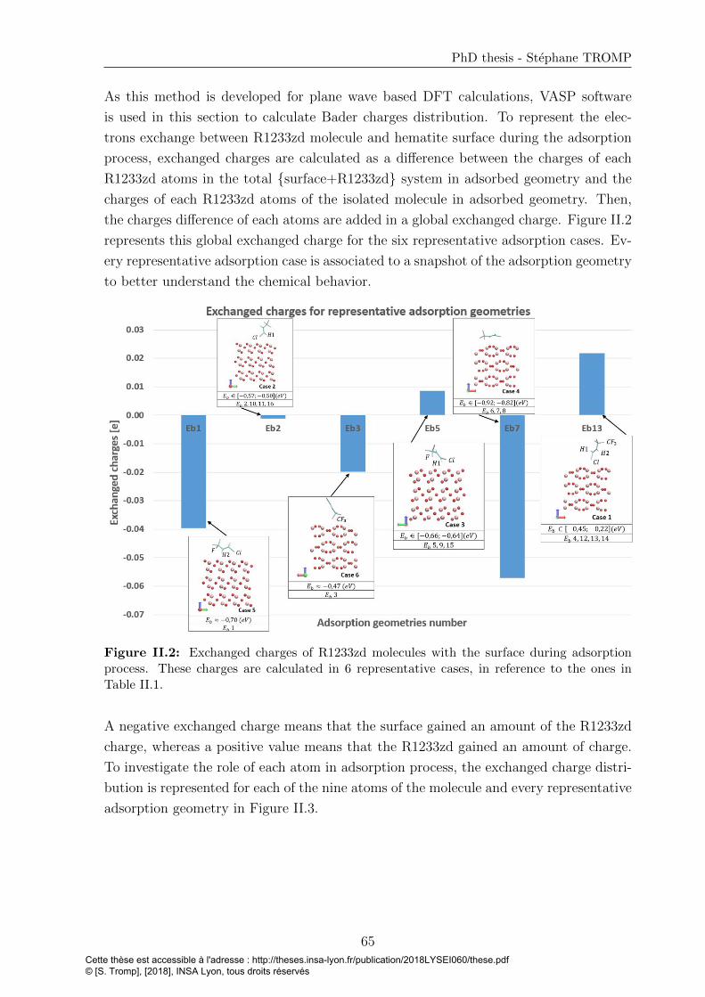
PhD thesis - Stephane TROMP
As this method is developed for plane wave based DFT calculations, VASP software
is used in this section to calculate Bader charges distribution. To represent the elec-
trons exchange between R1233zd molecule and hematite surface during the adsorption
process, exchanged charges are calculated as a difference between the charges of each
R1233zd atoms in the total {surface+R1233zd} system in adsorbed geometry and the
charges of each R1233zd atoms of the isolated molecule in adsorbed geometry. Then,
the charges difference of each atoms are added in a global exchanged charge. Figure II.2
represents this global exchanged charge for the six representative adsorption cases. Ev-
ery representative adsorption case is associated to a snapshot of the adsorption geometry
to better understand the chemical behavior.
Figure II.2: Exchanged charges of R1233zd molecules with the surface during adsorptionprocess. These charges are calculated in 6 representative cases, in reference to the ones inTable II.1.
A negative exchanged charge means that the surface gained an amount of the R1233zd
charge, whereas a positive value means that the R1233zd gained an amount of charge.
To investigate the role of each atom in adsorption process, the exchanged charge distri-
bution is represented for each of the nine atoms of the molecule and every representative
adsorption geometry in Figure II.3.
65Cette thèse est accessible à l'adresse : http://theses.insa-lyon.fr/publication/2018LYSEI060/these.pdf © [S. Tromp], [2018], INSA Lyon, tous droits réservés

Chapter II. Chemical physics at interfaces within a refrigerant-lubricated contact: anelectronic structure study
Figure II.3: Exchanged charges of R1233zd molecules with the surface during adsorptionprocess. The distribution is represented for each refrigerant atom and theses charges arecalculated in 6 representative cases, in reference to the ones in Table II.1.
• Case 1 (Eb13): In this adsorption geometry, R1233zd molecule takes around 0.02e
from the surface. Carbon C1, the closer one of the surface, loses around 0.01e,
the two other carbons takes 0.01e each. In this case, chlorine atom is close to the
surface and loses around 0.03e. Even if the molecule takes 0.02e from the surface,
atoms close to the surface (chlorine and carbon C1) lose both charges, meaning
that this lose is spread all over the molecule. Indeed, the two other carbons C2
and C3, as well as hydrogen H1 et H2 gained around 0.01e each.
• Case 2 (Eb2): This case can be compared to case 1. Indeed, molecule tilts and
hydrogen H1 gained around 0.035e, while Cl atom still loses around the same
charge. Therefore, the total exchanged charge between R1233zd and the surface
becomes negligible. This case is also interesting because it means that the high
binding energy of around 0.5 eV is not due to exchange charges between R1233zd
molecule and the surface.
• Case 3 (Eb5): R1233zd molecule gained almost 0.01e. Here, hydrogen H1 gains
around 0.09e, not from the surface but from the carbon C1 which loses around
0.08e. This difference justify to look at the exchanged charges between all the
atoms inside the molecule and not only between the molecule and the surface.
Besides, chlorine atom still gives 0.02e to the surface.
• Case 4 (Eb7): This case represents a flat molecule on the surface. Here, R1233zd
molecule loosed 0.057e. In contrast to what could be assumed, most of the ex-
changed charges are located in fluorine and chlorine atoms and not in the carbon-
66Cette thèse est accessible à l'adresse : http://theses.insa-lyon.fr/publication/2018LYSEI060/these.pdf © [S. Tromp], [2018], INSA Lyon, tous droits réservés

PhD thesis - Stephane TROMP
carbon double bond area. While the two fluorine atoms near the surface lost
around 0.04e and 0.025e each, the fluorine at the opposite gained only 0.01e.
Chlorine atoms also lost around 0.034e. Only carbon C2 gained 0.025e, thus from
fluorine or chlorine atoms. Furthermore, only for the two other optimized geome-
tries (Eb6 and Eb8) within case 4, the same calculations were performed in order
to obtain more accurately the charge distribution for a flat molecule upon the
surface. In Eb6 and Eb8, only one fluorine atom is located near the surface and
the two others are at higher distance. In these geometries, the lost of electron of
CH3 group is mainly supported only by the fluorine next to surface with a charge
exchange of 0.05e for Eb6 and 0.07e for Eb8. Nevertheless, the same charges
distribution than with Eb7 occurred.
• Case 5 (Eb1): R1233zd molecule gives a total of around 0.04e to surface. In this
case, fluorine atoms play a negligible role, while chlorine lost around 0.03e. The
two sp2 atoms C1 and C2 lost 0.025e and 0.03e, respectively. At the same time,
hydrogen H2 gained around 0.06e.
• Case 6 (Eb3): R1233zd molecule lost around 0.02e. Even if the fluorine atom next
to surface lost around 0.06e, a part of this lost is spread through the molecule due
to a gain in other atoms.
As a more general point of view, the values of total exchanged charges remains small
and always lower than 0.1e in each case. Therefore, we assume that no chemisorption
appears and that R1233zd are only physisorbed on hematite surfaces. In particular, due
to these low exchanged charges relating to both carbons C1 and C2, we conclude that
the double carbon-carbon bonds do not break during the adsorption process.
II.4 Conclusion
In this Chapter, the principles of DFT simulations were firstly presented and our model
was introduced. Ab-initio calculations have been carried out in order to study the
adsorption of R1233zd on an iron oxide Fe2O3 surface, complementing gaps from the
experimental literature. The challenging point was to employ a vdW functional com-
bined with a spin-polarized system by using the GGA+U method. The main findings
can be summarized as follows:
• a range of surface-refrigerant molecule binding energy values of -0.92 eV to -0.22
eV is observed,
• the iron atoms play a major role in the adsorption process,
• the hydrogen H1 located near the chlorine plays a non-negligible role of stabiliza-
67Cette thèse est accessible à l'adresse : http://theses.insa-lyon.fr/publication/2018LYSEI060/these.pdf © [S. Tromp], [2018], INSA Lyon, tous droits réservés

Chapter II. Chemical physics at interfaces within a refrigerant-lubricated contact: anelectronic structure study
tion,
• the horizontal positions of the refrigerant molecules are the most stable with a
binding energy value of around -0.92 eV,
• no dissociation phenomenon of the refrigerant on hematite was observed, nor dou-
ble carbon-carbon bond breaking,
• between R1233zd molecule and surface only small exchanges of charge are found
with a maximum value of 0.1e,
• R1233zd molecules are physisorbed on hematite α−Fe2O3(0112) surfaces and no
chemisorption is observed.
Now that DFT calculations are completed, a parametrization of the interfacial force field
will be performed. In the next chapter, the methods used to calculate the interfacial
potential parameters are presented.
68Cette thèse est accessible à l'adresse : http://theses.insa-lyon.fr/publication/2018LYSEI060/these.pdf © [S. Tromp], [2018], INSA Lyon, tous droits réservés
Chapter III
Towards large-scale molecular
dynamics simulations
Contents
III.1 Introduction to molecular dynamics . . . . . . . . . . . . . . 71
III.1.1 Numerical methods . . . . . . . . . . . . . . . . . . . . . . . . 71
III.1.1.1 Molecular dynamics principles . . . . . . . . . . . . 71
III.1.1.2 Integration methods . . . . . . . . . . . . . . . . . . 72
III.1.2 Force fields . . . . . . . . . . . . . . . . . . . . . . . . . . . . 72
III.1.2.1 Different kinds of force fields . . . . . . . . . . . . . 72
III.1.2.2 Classical force fields formulation . . . . . . . . . . . 73
III.1.3 Importance of the force field for nanoconfined systems . . . . 76
III.2 Parametrization of interfacial force field . . . . . . . . . . . . 77
III.2.1 R1233zd force field . . . . . . . . . . . . . . . . . . . . . . . . 77
III.2.2 Force field of the hematite (α− Fe2O3) surface . . . . . . . . 79
III.2.3 Influence of the timestep . . . . . . . . . . . . . . . . . . . . . 80
III.2.4 Parametrization of interfacial force field between R1233zd and
hematite surfaces . . . . . . . . . . . . . . . . . . . . . . . . . 82
III.2.4.1 Methodology . . . . . . . . . . . . . . . . . . . . . . 82
III.2.4.2 Results and analysis . . . . . . . . . . . . . . . . . . 85
III.3 Assessment of the new parametrized force field: compari-
son with standard mixing rules . . . . . . . . . . . . . . . . . 86
III.3.1 System setup . . . . . . . . . . . . . . . . . . . . . . . . . . . 86
III.3.2 Temperature-pressure regulation and initialization stages . . 87
III.3.3 Simulations setup: compression and shearing . . . . . . . . . 88
69Cette thèse est accessible à l'adresse : http://theses.insa-lyon.fr/publication/2018LYSEI060/these.pdf © [S. Tromp], [2018], INSA Lyon, tous droits réservés

Chapter III. Towards large-scale molecular dynamics simulations
III.3.4 Consequences of interfacial FF parametrization . . . . . . . . 89
III.3.4.1 Velocity profiles . . . . . . . . . . . . . . . . . . . . 89
III.3.4.2 Density profiles . . . . . . . . . . . . . . . . . . . . . 90
III.3.4.3 Orientation at the interface . . . . . . . . . . . . . . 91
III.4 Conclusion . . . . . . . . . . . . . . . . . . . . . . . . . . . . . 92
70Cette thèse est accessible à l'adresse : http://theses.insa-lyon.fr/publication/2018LYSEI060/these.pdf © [S. Tromp], [2018], INSA Lyon, tous droits réservés
PhD thesis - Stephane TROMP
The results of this chapter have been partially published in the Journal of Physical
Chemistry C [6].
III.1 Introduction to molecular dynamics
In molecular dynamics (MD), contrary to DFT, the interactions between atoms are
described within force fields (FF) [23]. Since MD simulations are time-dependent, non-
equilibrium phenomena can be explored and a large set of parameters regarding thin
film shearing (friction, thermal conductivity, velocity profile, etc) can be obtained [24,
25, 26, 11, 27, 28, 29]. Therefore MD simulations are used in this project to characterize
nanoconfined systems under shearing.
As shown in the previous Chapter, the high computational costs needed with DFT
calculations preclude their use to study large systems. That is why, in this chapter, the
principles of MD simulations used for larger scale systems, are presented. Then, the
FF used for the refrigerant and the surface are described. Afterwards, the methodology
used to parametrize a force field at the refrigerant-surface interface based on these DFT
results is discussed. This FF is implemented in non-equilibrium molecular dynamics
(NEMD) simulations in order to compare its predictions with the ones obtained using
standard mixing rules. Specifically, the differences about structure and flow behavior in
a system of refrigerant molecules confined between two hematite (α − Fe2O3) surfaces
are presented. Moreover, orientations of the molecules are calculated to illustrate this
difference at the refrigerant/surface interface. Using this parametrized FF to study
tribological behaviors at different extreme conditions will be the subject of Chapter 4.
III.1.1 Numerical methods
III.1.1.1 Molecular dynamics principles
Molecular Dynamics is a numerical method based on the resolution over the time of
Newton’s equation of motion on all interacting atoms in a molecular system [23]. The
force Fi acting on each atom i located at a position ri is obtained from the potential
energy V :
Fi = −∇riV (III.1)
ri =Fi
mi
(III.2)
71Cette thèse est accessible à l'adresse : http://theses.insa-lyon.fr/publication/2018LYSEI060/these.pdf © [S. Tromp], [2018], INSA Lyon, tous droits réservés
Chapter III. Towards large-scale molecular dynamics simulations
where mi is the atomic mass. The potential energy V used to obtain forces describes
the interactions of atom i with all neighboring atoms. The acceleration vector ri can
then be calculated.
III.1.1.2 Integration methods
MD simulations are time-dependent and the atomic trajectories are computed by solving
equations of motion (Equation III.2). When atomic positions, velocities and accelera-
tions are know at a time t, these features can be computed at the next time t + δt
with finite difference methods. δt is the timestep and the choice of its value influences
the accuracy of the integration. A modified version of the standard Verlet algorithm
is implemented in LAMMPS software, the Velocity-Verlet algorithm. The integration
method of this algorithm is detailed below. First, the position at t + δt is calculated
with the following formula.
ri(t+ δt) = ri(t) + ri(t)δt+1
2ri(t)δt
2 (III.3)
Then, the acceleration ri(t + δt) is calculated from the interaction potential from the
position ri(t+δt). Finally, the velocity at t+δt is determined with the following formula.
ri(t+ δt) = ri(t) +1
2(ri(t) + ri(t+ δt))δt (III.4)
III.1.2 Force fields
III.1.2.1 Different kinds of force fields
Forces fields represent interactions between all particles as a function of their position
in the system. FFs include both functional form of the potential energy representing
these interactions and parameter sets used to calculate it. Several kinds of force fields
exist in the literature.
Classical FFs can be divided into three types depending on different molecular structure
considerations. “All-atom” (AA) FFs define every type of atom in the molecule, whereas
“united-atom” (UA) FFs handle methyl (CH3) and methylene (CH2) groups as a single
“pseudo-atom”, leading to faster computational times. The UA model is particularly
powerful to simulate the behavior of long-chain molecules, decreasing computation times.
However, it can lead to unphysical properties, like under-prediction of the viscosity for
long-chain linear alkanes[218]. Because R1233zd is a small molecule only containing nine
atoms, classical AA force fields will be considered in all MD calculations. The third type
72Cette thèse est accessible à l'adresse : http://theses.insa-lyon.fr/publication/2018LYSEI060/these.pdf © [S. Tromp], [2018], INSA Lyon, tous droits réservés

PhD thesis - Stephane TROMP
of classical FF is the coarse-grained (CG) model, where groups of atoms are replaced by
pseudo-atoms at a larger scale. This last type increases even more the computational
efficiency by reducing the number of degrees of freedom. CG models are widely used for
long time simulations to model biomolecules, like proteins[219, 220].
The literature also proposes reactive force fields (ReaxFF), which consider chemical re-
activity and determine possible breaking and new bonds between pairs of atoms during
MD simulations[221]. In this project, we tried to use this force field. However, despite
several exchanges with the reaxFF authors, we did not succeed to adjust the FF pa-
rameters to obtain an accurate description of the refrigerant. Hence, reaxFF will not
be considered here.
HFO compounds have been in the market for only a few years and therefore experimental
data for these molecules are rare[100, 222]. That is why Raabe et al. [32] recently
developed a force field in order to study this kind of refrigerants. This FF will be named
Raabe’s FF in the following chapters. As detailed later in this chapter, parameters sets
of this FF are obtained from both quantum calculations or by fitting experimental data.
III.1.2.2 Classical force fields formulation
Usually, the functional form of the potential energy is divided into two contributions, as
shown in the formula below [23]. Bonded (or intramolecular) terms represent interac-
tions between atoms that are linked by covalent bonds. Non-bonded (or intermolecular)
terms describe interactions between atoms which are not linked with covalent bond.
Vtotal = Vbonded + Vnon-bonded (III.5)
The bonded and non-bonded terms considered in the present model are detailed here.
Non-bonded interactions
Vnon-bonded = VCoulomb + VLJ (III.6)
In classical force field, non-bonded terms represent Pauli repulsive and Van der Waals
attractive forces, grouped in the so-called Lennard-Jones potential, but also Coulomb
electrostatic interactions. Therefore, two different potentials have to be used.
Lennard-Jones: The following formula represents the Lennard-Jones 12-6 potential
between each atom pair i and j, only applied if the distance between two atoms is lower
than a cutoff distance.
73Cette thèse est accessible à l'adresse : http://theses.insa-lyon.fr/publication/2018LYSEI060/these.pdf © [S. Tromp], [2018], INSA Lyon, tous droits réservés
Chapter III. Towards large-scale molecular dynamics simulations
VLJ(rij) = 4εij
((σijrij
)12
−(σijrij
)6)
(III.7)
Where rij is the distance between two atoms’ nuclei. The εij energy corresponds to the
depth of the potential well and σij the distance corresponding to a zero value of the
potential between both atoms. The equilibrium distance between both atoms is given
by 21/6σij. The denomination 12-6 comes from the power in LJ terms, where the first
term (to the power 12) represents the repulsive feature while the second term (to the
power 6) represents the attractive one.
Values of the parameters σi and εi are affected to each atom i. Lorentz-Berthelot mixing
rules are applied to obtain LJ parameters with two atoms i and j of different natures,
as follows.
εij =√εiεj
σij =σi + σj
2
(III.8)
Buckingham, another option: Sometimes, the Buckingham potential is used instead
of the Lennard-Jones one. As shown in the following formula, the repulsive term is
then modeled with an exponential while the attractive term has the same form as the
Lennard-Jones one.
VBuckingham(rij) =
(Ae−
rijρ − C
r6ij
)(III.9)
Coulombic potential: In order to represent partially charged atoms, electrostatic in-
teractions have to be considered. They are calculated between two charged atoms, either
belonging to the same molecule or not, thanks to a long-range Coulombic potential, as
shown below:
VCoulomb(rij) =qiqj
4πε0rij(III.10)
where qi and qj are the atomic charges of atoms i and j, respectively, rij is the distance
between the two atoms, and ε0 the vacuum permittivity equal to 8.85× 10⁻¹² F/m .
As shown in Equation III.10, Coulombic interactions decrease as 1r, whereas Van der
Waals attractive interactions decrease as 1r6
. Hence, electrostatic interactions can remain
non-negligible at long-range, and thus, have to be considered even farther than the
cutoff value. For distances bigger than the cutoff value, electrostatic interactions can be
determined using the particle-particle particle-mesh (PPPM) algorithm[223]. Indeed,
74Cette thèse est accessible à l'adresse : http://theses.insa-lyon.fr/publication/2018LYSEI060/these.pdf © [S. Tromp], [2018], INSA Lyon, tous droits réservés
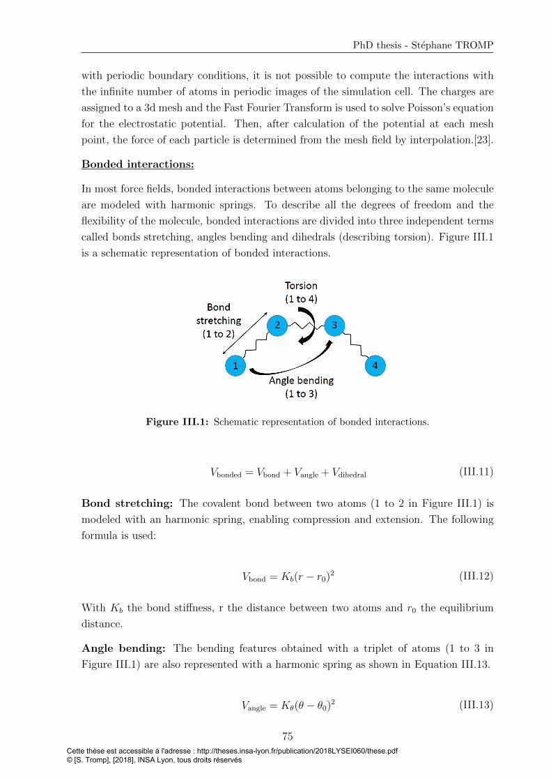
PhD thesis - Stephane TROMP
with periodic boundary conditions, it is not possible to compute the interactions with
the infinite number of atoms in periodic images of the simulation cell. The charges are
assigned to a 3d mesh and the Fast Fourier Transform is used to solve Poisson’s equation
for the electrostatic potential. Then, after calculation of the potential at each mesh
point, the force of each particle is determined from the mesh field by interpolation.[23].
Bonded interactions:
In most force fields, bonded interactions between atoms belonging to the same molecule
are modeled with harmonic springs. To describe all the degrees of freedom and the
flexibility of the molecule, bonded interactions are divided into three independent terms
called bonds stretching, angles bending and dihedrals (describing torsion). Figure III.1
is a schematic representation of bonded interactions.
Figure III.1: Schematic representation of bonded interactions.
Vbonded = Vbond + Vangle + Vdihedral (III.11)
Bond stretching: The covalent bond between two atoms (1 to 2 in Figure III.1) is
modeled with an harmonic spring, enabling compression and extension. The following
formula is used:
Vbond = Kb(r − r0)2 (III.12)
With Kb the bond stiffness, r the distance between two atoms and r0 the equilibrium
distance.
Angle bending: The bending features obtained with a triplet of atoms (1 to 3 in
Figure III.1) are also represented with a harmonic spring as shown in Equation III.13.
Vangle = Kθ(θ − θ0)2 (III.13)
75Cette thèse est accessible à l'adresse : http://theses.insa-lyon.fr/publication/2018LYSEI060/these.pdf © [S. Tromp], [2018], INSA Lyon, tous droits réservés

Chapter III. Towards large-scale molecular dynamics simulations
With Kθ the angle stiffness and θ0 the equilibrium angle.
In this work, for both bond stretching and angle bending terms, the stiffness constant
comprises the classic 12
factor coming from Hooke’s law.
Dihedral torsion: Torsion between four atoms (1 to 4 in Figure III.1) belonging to
the same molecule is represented by a dihedral potential as in Equation III.14:
Vtorsion =m∑i=1
Ki[1 + cos(niφ− di)] (III.14)
where n is the multiplicity and d the phase. To improve the accuracy of the dihedral term
to reproduce torsional behavior, the torsion can be described by a sum of m dihedral
terms.
Non-bonded interactions scaling:
It is usual to exclude or to just include partially (using scaling factors) non-bonded terms
between two atoms in the same molecule bonded with covalent bond, either directly or
via one or two intermediate bonds. Indeed, bonded interactions are usually designed to
describe the whole set of interactions between bonded atoms, including Pauli repulsive,
VdW attractive and electrostatic terms. By keeping non-bonded interactions between
these atoms, they would thus be counted twice.
For example, the Raabe’s FF used in this study to describe the R1233zd interactions,
involves scaling factors from the AMBER FF. In this latter, non-bonded LJ and electro-
static interactions between atoms separated by exactly three bonds (1 to 4 interactions)
are scaled by a factor of 1/2 and 1/1.2, respectively. Non-bonded interactions between
atoms separated by one or two bonds are excluded.
III.1.3 Importance of the force field for nanoconfined systems
The interactions between every atoms control the accuracy of materials behavior descrip-
tion. These interactions are described in the FF. The FF parameter sets will strongly
influence properties of the system. Hence, the parameters have to be carefully chosen
in order to provide realistic results. As shown in the next section, the FF parame-
ter sets used for the refrigerant have been tested in the literature by comparing with
experimental features. Two main issues come by applying FF in nanoconfined systems.
First, a force field is usually developed in a limited range of environmental conditions.
As shown previously, a key point in lubricated systems is that conditions are extremes
regarding temperature, pressure and shearing states. Indeed, a FF parameter set es-
tablished for a pressure as small as a few MPa will not necessarily reflects correctly the
76Cette thèse est accessible à l'adresse : http://theses.insa-lyon.fr/publication/2018LYSEI060/these.pdf © [S. Tromp], [2018], INSA Lyon, tous droits réservés
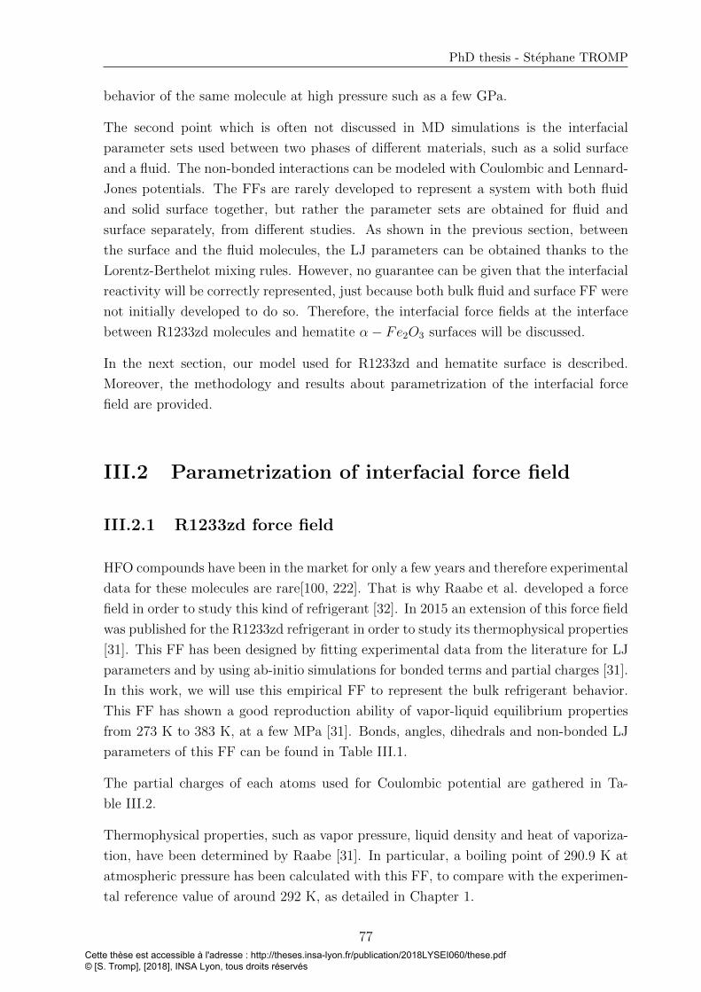
PhD thesis - Stephane TROMP
behavior of the same molecule at high pressure such as a few GPa.
The second point which is often not discussed in MD simulations is the interfacial
parameter sets used between two phases of different materials, such as a solid surface
and a fluid. The non-bonded interactions can be modeled with Coulombic and Lennard-
Jones potentials. The FFs are rarely developed to represent a system with both fluid
and solid surface together, but rather the parameter sets are obtained for fluid and
surface separately, from different studies. As shown in the previous section, between
the surface and the fluid molecules, the LJ parameters can be obtained thanks to the
Lorentz-Berthelot mixing rules. However, no guarantee can be given that the interfacial
reactivity will be correctly represented, just because both bulk fluid and surface FF were
not initially developed to do so. Therefore, the interfacial force fields at the interface
between R1233zd molecules and hematite α− Fe2O3 surfaces will be discussed.
In the next section, our model used for R1233zd and hematite surface is described.
Moreover, the methodology and results about parametrization of the interfacial force
field are provided.
III.2 Parametrization of interfacial force field
III.2.1 R1233zd force field
HFO compounds have been in the market for only a few years and therefore experimental
data for these molecules are rare[100, 222]. That is why Raabe et al. developed a force
field in order to study this kind of refrigerant [32]. In 2015 an extension of this force field
was published for the R1233zd refrigerant in order to study its thermophysical properties
[31]. This FF has been designed by fitting experimental data from the literature for LJ
parameters and by using ab-initio simulations for bonded terms and partial charges [31].
In this work, we will use this empirical FF to represent the bulk refrigerant behavior.
This FF has shown a good reproduction ability of vapor-liquid equilibrium properties
from 273 K to 383 K, at a few MPa [31]. Bonds, angles, dihedrals and non-bonded LJ
parameters of this FF can be found in Table III.1.
The partial charges of each atoms used for Coulombic potential are gathered in Ta-
ble III.2.
Thermophysical properties, such as vapor pressure, liquid density and heat of vaporiza-
tion, have been determined by Raabe [31]. In particular, a boiling point of 290.9 K at
atmospheric pressure has been calculated with this FF, to compare with the experimen-
tal reference value of around 292 K, as detailed in Chapter 1.
77Cette thèse est accessible à l'adresse : http://theses.insa-lyon.fr/publication/2018LYSEI060/these.pdf © [S. Tromp], [2018], INSA Lyon, tous droits réservés
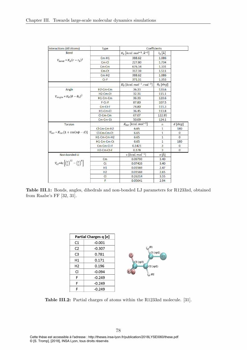
Chapter III. Towards large-scale molecular dynamics simulations
Table III.1: Bonds, angles, dihedrals and non-bonded LJ parameters for R1233zd, obtainedfrom Raabe’s FF [32, 31].
Table III.2: Partial charges of atoms within the R1233zd molecule. [31].
78Cette thèse est accessible à l'adresse : http://theses.insa-lyon.fr/publication/2018LYSEI060/these.pdf © [S. Tromp], [2018], INSA Lyon, tous droits réservés

PhD thesis - Stephane TROMP
III.2.2 Force field of the hematite (α− Fe2O3) surface
As shown in Figure III.2, the size of an elementary cell of hematite (α−Fe2O3) surface
considered in this chapter is 30 A × 33 A × 10 A.
Figure III.2: Hematite (α− Fe2O3) surface of around 30 A × 33 A × 10 A.
In this MD study, the hematite surface built by using ab-initio calculations (Chapter 2)
was duplicated considering periodic boundaries. Moreover, the surface used in Chapter
2 to obtain results of adsorption has to be considered in MD simulations with exactly
the same structure and lattice parameters. Instead of using a FF of the literature that
would, in best case, approximately reproduce the lattice parameters, each atom of the
hematite surface is bonded with a spring to a virtual atom located at its equilibrium
position [224]. At zero temperature, a virtual surface will thus be superimposed with a
real one. No interaction are defined within the virtual surface, between the two virtual
surfaces, and between the virtual surfaces and the refrigerant. The only interactions
between virtual and real surfaces are the springs linking one virtual atom with one real
atom. However, it will have several consequences, as detailed below.
On the one hand, one can not study the surface deformation with this method. Indeed,
the virtual atoms involve an infinite stiffness and no plasticity. Nevertheless, it is not
the aim here to study the surface. In this work, the interest lies on the refrigerant
and the refrigerant/surface behavior. The surface by itself, with only a few atoms
in the thickness, can not have both a quantitative elastic and thermal behavior and
compromises have to be found [161]. Here we chose to focus on ensuring a good thermal
conduction (i.e., much larger than that of the fluid) to the walls.
One the other hand, the value of spring stiffness applied between one real and one
virtual atoms has to be carefully chosen. Indeed, this value influences both mechanical
and thermal features.
• The bond between real and virtual atoms must be stiff enough to prevent any
incursion of fluid atoms inside the surface. This property was qualitatively inves-
tigated by testing different values of spring stiffness.
79Cette thèse est accessible à l'adresse : http://theses.insa-lyon.fr/publication/2018LYSEI060/these.pdf © [S. Tromp], [2018], INSA Lyon, tous droits réservés

Chapter III. Towards large-scale molecular dynamics simulations
• Reproducing exactly the thermal conductivity of hematite surface is not the aim
here. The surface has to evacuate the heat created within the contact. With that
regard, the higher the spring stiffness, the higher the thermal conductivity is.
• However, by increasing the spring stiffness values, the period of atomic vibrations
decreases, requiring a smaller timestep to resolve the vibrations. While large bond
stiffness seemed preferable for the two preceding aspects, this one imposes an upper
limit on the bond stiffness.
Figure III.3 represents the temperature distribution in hematite surface with different
spring stiffness value of 200, 300 and 400 kcal/mol at two sliding velocity of 20 m/s
(left) and 10 m/s (right).
Figure III.3: Temperature distribution in the hematite slab for a sliding velocity of 20 m/s(left) and 10 m/s (right). The results are obtained with three different values of real-virtualspring stiffness of 200, 300 and 400 kcal/mol.
As detailed in the simulation setup in the next section, only the two third outermost
layers of atoms in the hematite slabs are thermostatted (here at 283 K). A value of
200 kcal/mol is chosen for this study. Indeed, the surface remains rigid enough from a
qualitative view and a temperature gradient in the surfaces up to 5 K over 3 angstroms is
found. This latter value is higher than in reality, but the heat produced by the shearing
of the lubricant can still be evacuated through the surface by the thermostat.
The pressure in the contact and the shearing velocities are obtained by applying forces
and velocity on each atom of the virtual surfaces, while the temperature is regulated
through the real surface atoms.
The next section aims at analyzing the influence of the timestep, to justify the last of
the three listed points above.
III.2.3 Influence of the timestep
A timestep of 1 fs is a standard value used in many studies of MD simulations for
nanoconfined lubricants [178, 225, 226, 29]. However in this system, it is possible that
80Cette thèse est accessible à l'adresse : http://theses.insa-lyon.fr/publication/2018LYSEI060/these.pdf © [S. Tromp], [2018], INSA Lyon, tous droits réservés

PhD thesis - Stephane TROMP
this value is too large because of fast-moving hydrogen atoms. One can calculate the
period τ of the fastest vibrating atoms in the system with the following formula.
τ = 2π
√m
k(III.15)
Where m is the mass of hydrogen atoms, and k is the higher spring stiffness coefficient
involving a hydrogen atom. In Raabe’s FF, both kinds of bond linking hydrogen to
carbon atoms (C1-H1 and C2-H2) have the same stiffness constant value, thus k2
=
388.62 kcal/(mol.A2). The calculation gives a period τ of around 11 fs, thus around 10
times higher than a timestep δt of 1 fs, validating the choice made in this study.
As described above, in NVE ensemble, the total energy should be constant. However
in MD simulation, the total energy of a system in NVE ensemble can fluctuate on a
short time scale and drift on a long time scale for Verlet intergrator [227], as shown
in Figure III.4. In order to verify that the drift is acceptable with this system and a
timestep of 1 fs, a pure NVE calculation, thus without any temperature or pressure, is
done. The system is composed of 1000 molecules of refrigerant. The results shown in
Figure III.4 represents the total energy variation as a function of the time.
Figure III.4: Energy drift of the total energy over time for bulk simulations with 1000molecules of R1233zd.
The system stabilizes during around 500 ps and then we observe the energy drift, which
has a value of 4,5.10−5 eV/atom over 1 ns, on the order of 0.1 % of the average kinetic
energy per atom. This negligible energy drift confirms that a timestep of 1 fs is low
enough to ensure well designed simulations.
In this section was exposed FFs used for R1233zd and hematite surfaces, separately.
However and as explained above, one can not have the insurance that the interfacial
FF obtained with mixing rules reproduces accurately the real behavior. Therefore, a
parametrized FF is calculated using the ab-initio results.
81Cette thèse est accessible à l'adresse : http://theses.insa-lyon.fr/publication/2018LYSEI060/these.pdf © [S. Tromp], [2018], INSA Lyon, tous droits réservés
Chapter III. Towards large-scale molecular dynamics simulations
III.2.4 Parametrization of interfacial force field between R1233zd
and hematite surfaces
III.2.4.1 Methodology
In Chapter 2, the adsorption ability of R1233zd on hematite was studied. An adapted
force field of the interface between the refrigerant and the surface will be derived from
this ab-initio behavior. In this section the ab-initio post processing is described and the
force field parameters used at the interface for large scale MD simulations are deter-
mined. Even if periodic boundary condition (PBC) are used for all MD simulations, no
PBC is used for the parametrization, and therefore a larger surface than the one pre-
sented in Chapter 2 has to be considered. Indeed, electrostatic interactions have to be
included with a large amount of pairs between the surface and the refrigerant molecule.
By using the periodicity of the small surface composed of 120 atoms, a new bigger one
was built, multiplying the smaller one by three in the x and y directions. Hence, the new
surface used for ab-initio post processing is composed of 1080 atoms, and the molecule
of refrigerant is placed upon the central small surface with the position obtained at
the end of ab-initio geometry optimization process. In this study 16 different positions
and orientations of the refrigerant molecule on the surface are used and an algorithm
detailed in Figure III.5 is performed to determine the interfacial parameters.
With a similar problematic, Ta et al.[10] studied the adsorption of n-alkanes on various
kinds of iron oxide surfaces. They used a trial-and-error approach in order to adjust the
force field parameters to the DFT results. They ran the adsorption energy calculations
repeatedly until they obtained a good match between ab-initio and MD results. They
also published an interfacial FF between an aqueous copolymer solution and an iron
surface, by deriving parameters from DFT calculations[228].
Here, the choice was made to transcript the refrigerant-surface interactions by using
pairwise Coulombic and Lennard-Jones (LJ) 12-6 potentials between each atom pair i
and j. Equation III.16 represents the model we used for the interfacial interactions.
V =∑i,j
[qiqje
2
4πε0rij+ 4εij
((σijrij
)12
−(σijrij
)6)]
(III.16)
Where qi and qj are atomic charges of atoms i and j, respectively, rij the distance
between atoms i and j, εij the well-depth energy and σij the distance corresponding to
a zero value of the potential between the two atoms. To remain consistent by using the
Raabe’s FF for the refrigerant with large-scale MD calculations, the partial charges of
Raabe[31] will be used for the ab-initio postprocessing and only the 12-6 LJ parameters
between the fluid and the surface will be adjusted. For hematite surface, the partial
82Cette thèse est accessible à l'adresse : http://theses.insa-lyon.fr/publication/2018LYSEI060/these.pdf © [S. Tromp], [2018], INSA Lyon, tous droits réservés
PhD thesis - Stephane TROMP
charge of iron is fixed of qFe = +0.6 and that of oxygen to qO = −0.4. Because LJ
parameters have to be distinguished depending on atom types, sp2 and sp3 carbons are
named Cm and Ct, respectively.
The idea of this postprocessing is explained in this paragraph, to read with the help
of Figure III.5. From ab-initio results, it is possible to find four (k=4,12,13,14 in Fig-
ure III.5) converged geometries related to DFT case 1 (see Table II.1) in which the
chlorine atom is directly placed upon the iron and oxygen atoms. Therefore these four
results are used in order to find in step 1 (i=1 in Figure III.5) the interactions between
chlorine and the surface. Then four other converged geometries (k=2,10,11,16) describ-
ing a molecule adsorbed thanks to chlorine and hydrogen H1 are used within steps i=2
and i=3 in order to obtain the interactions between this hydrogen and the surface. Af-
terwards the parameters between fluorine and the surface are found within steps 4 and
5. Then the interactions parameters between the hydrogen H2 and the surface are found
by using four optimized geometries in steps 6 and 7. In order to reproduce the binding
energies obtained with horizontal positions of the molecule, ε values between surface
and the Ct carbon are adapted as well within steps 8 and 9.
The mathematical approach will now be detailed. Analyzing situations where R1233zd
molecules adsorbed at least partially either with O-Cl or with Fe-Cl interactions, σ(Fe−Cl)
and σ(O−Cl) are fixed to 2.46 A and 2.53 A, respectively, on the basis of adsorption dis-
tances obtained from ab-initio calculations. Moreover, σ values for interactions including
carbons remain fixed as explained below. The values of ε for LJ potential including sp3
carbon will be adapted to take into account the strong interactions obtained between
fluorine atoms and the surface. The ε values for LJ potential including sp2 carbon will
be fixed.
Sixteen unknown LJ parameters remain to be determined. The resolution of the global
system of 16 equations with 16 unknown parameters is difficult, so that the solving
process is split into 9 steps. At every step, only a limited number k of the 16 optimized
geometries is taken into account by choosing the geometries for being relevant to the pa-
rameters calculated in this step. For each of the k corresponding equations, we calculate
each distance between the 9 atoms of the molecule and the 1080 atoms of the surface.
A system composed of k nonlinear equations named fk with an amount of unknown
LJ parameters smaller than k is obtained. Ebk is the binding energy associated to the
geometry optimization number k, while rkij represents the distance between both atoms
i and j for this geometry k. The vector x is composed of the 16 LJ-parameters including
the unknowns, the ones determined on previous steps, and the ones initially fixed as
detailed below, which will be calculated on next steps. By using a trust-region reflective
method we solve the following least squares problem for each step and we find the x
vector minimizing the following sum:
83Cette thèse est accessible à l'adresse : http://theses.insa-lyon.fr/publication/2018LYSEI060/these.pdf © [S. Tromp], [2018], INSA Lyon, tous droits réservés
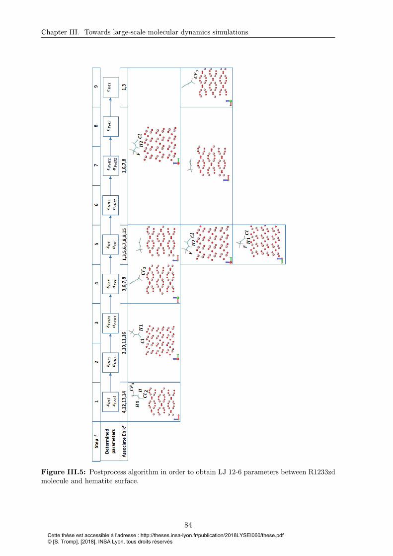
Chapter III. Towards large-scale molecular dynamics simulations
Figure III.5: Postprocess algorithm in order to obtain LJ 12-6 parameters between R1233zdmolecule and hematite surface.
84Cette thèse est accessible à l'adresse : http://theses.insa-lyon.fr/publication/2018LYSEI060/these.pdf © [S. Tromp], [2018], INSA Lyon, tous droits réservés
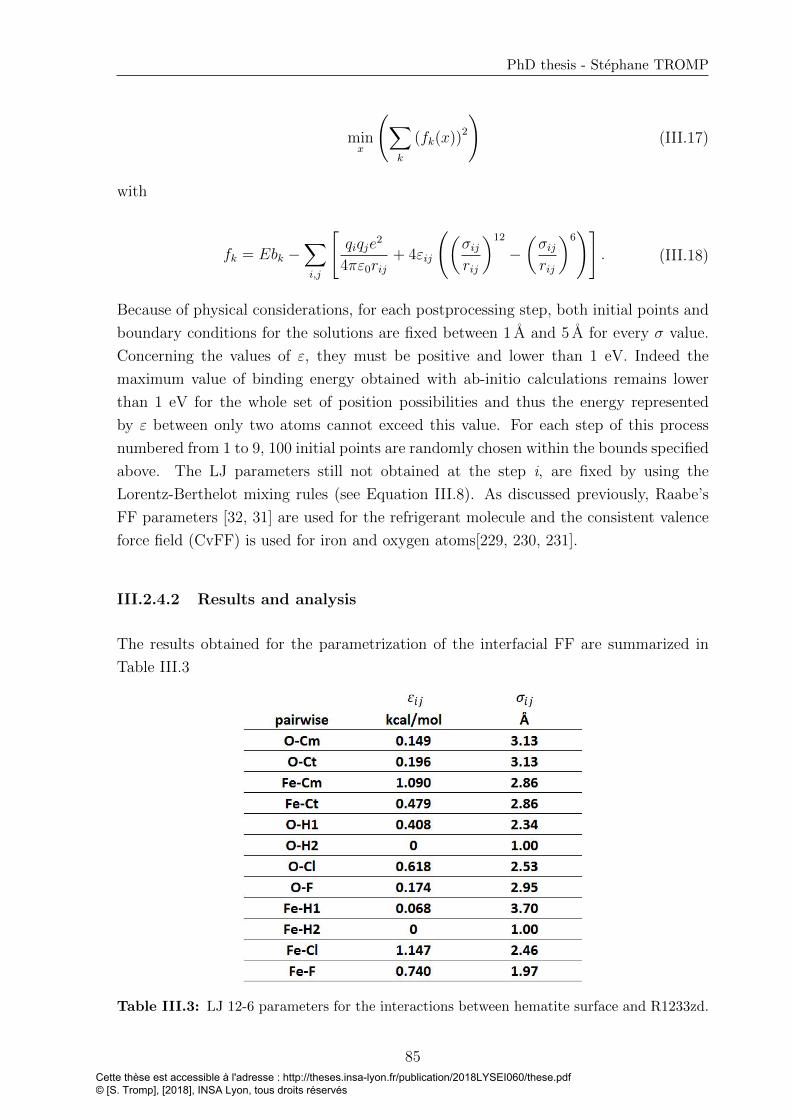
PhD thesis - Stephane TROMP
minx
(∑k
(fk(x))2
)(III.17)
with
fk = Ebk −∑i,j
[qiqje
2
4πε0rij+ 4εij
((σijrij
)12
−(σijrij
)6)]
. (III.18)
Because of physical considerations, for each postprocessing step, both initial points and
boundary conditions for the solutions are fixed between 1 A and 5 A for every σ value.
Concerning the values of ε, they must be positive and lower than 1 eV. Indeed the
maximum value of binding energy obtained with ab-initio calculations remains lower
than 1 eV for the whole set of position possibilities and thus the energy represented
by ε between only two atoms cannot exceed this value. For each step of this process
numbered from 1 to 9, 100 initial points are randomly chosen within the bounds specified
above. The LJ parameters still not obtained at the step i, are fixed by using the
Lorentz-Berthelot mixing rules (see Equation III.8). As discussed previously, Raabe’s
FF parameters [32, 31] are used for the refrigerant molecule and the consistent valence
force field (CvFF) is used for iron and oxygen atoms[229, 230, 231].
III.2.4.2 Results and analysis
The results obtained for the parametrization of the interfacial FF are summarized in
Table III.3
Table III.3: LJ 12-6 parameters for the interactions between hematite surface and R1233zd.
85Cette thèse est accessible à l'adresse : http://theses.insa-lyon.fr/publication/2018LYSEI060/these.pdf © [S. Tromp], [2018], INSA Lyon, tous droits réservés

Chapter III. Towards large-scale molecular dynamics simulations
Iron atoms play a major role in the adsorption process with strong ε values of Fe-Cl
and Fe-F pairs. Moreover, the strong interaction observed for horizontal orientation
is described with a high ε value between iron and sp2-hybridized carbon atoms. The
hydrogen H2 bonded to the second carbon is well described by zero well-depth energy
values with both oxygen and iron. The binding energy values obtained with this op-
timized interfacial force field are compared with the ones determined from ab-initio
calculations. The results summarized in Table III.4 show a maximal difference of 54
meV, and a maximum relative difference of around 10 %. Overall, the new LJ 12-6
parameters reproduce quite well the ab initio results.
Table III.4: Comparison between binding energies obtained with the optimized force fieldand the ab-initio ones for every system geometry.
The optimized interfacial force field will be used in larger scale MD simulations; the
simulations setup and results concerning this following step are presented in the next
subsection.
III.3 Assessment of the new parametrized force field:
comparison with standard mixing rules
III.3.1 System setup
MD calculations in this section are performed by using the LAMMPS software (version:
May 14th 2016)[30]. (0112) slabs of hematite with (x,y,z) dimensions of around 30 A ×
86Cette thèse est accessible à l'adresse : http://theses.insa-lyon.fr/publication/2018LYSEI060/these.pdf © [S. Tromp], [2018], INSA Lyon, tous droits réservés
PhD thesis - Stephane TROMP
33 A × 10 A are used in all simulations. The upper surface is built by rotating the lower
surface by 180◦. Each surface is composed of 1080 atoms (excluding virtual atoms).
The liquid is made of 192 refrigerant molecules, thus 1728 atoms. Raabe’s FF introduced
in the previous section is used to represent the refrgierant in a bulk behavior [31, 32].
The Lorentz-Berthelot mixing rules are applied to determine LJ parameters between
different atoms in the bulk refrigerant (Equation III.8). Surface-refrigerant interactions
are represented with LJ and Coulomb potentials. LJ parameters obtained with the
postprocessing and partial charges exposed in the previous section are implemented. No
LJ interaction are considered within the surfaces.
The Verlet integration algorithm is used with a 1 fs time step. The non-bonded interac-
tions are represented by the LJ 12-6 potential coupled with the long-range Coulombic
interactions including a cutoff value of 12 A for both non-bonded kinds of interactions.
Intramolecular nonbonded interactions between atoms separated by one or two bonds
are set to zero. Scaling factors of 1/2 and 1/1.2 from the AMBER FF are applied
to nonbonded LJ and electrostatic interactions respectively, between atoms separated
by exactly three bonds. Electrostatic interactions were determined using the particle-
particle particle-mesh (PPPM) algorithm. A slab correction is used for the PPPM solver
because of the non-periodic system in z direction [232].
III.3.2 Temperature-pressure regulation and initialization stages
Each simulation is linked to a statistical ensemble. In the NVE ensemble, the number
of atoms, the volume and the total energy, which is the total of the potential and kinetic
energies, is fixed. In the NPT ensemble, the number of atoms is fixed, the pressure is
controlled by a barostat (which affects the volume), and the temperature is controlled
by a thermostat (which affects the energy). The thermostat is particularly important
in NEMD to remove the heat generated by viscous dissipation from the system.
First of all, depending on the initial distance between each molecules, a minimization of
the potential energy can be needed to avoid too large interactions between molecules at
the beginning of the simulation. During MD simulations, the pressure and temperature
can be regulated through different methods depending on the kind of simulation and
system considered.
In NEMD, although the system is not at an equilibrium state, a steady state is required
for averaging over time the studied quantities. Therefore an initialization stage is needed
after the minimization. The initialization stage contains first a compression stage where
a normal load is applied. At the same time, a thermostat is applied to a temperature-
control region in order to keep the surface at a desired temperature during all the MD
calculations. At the end of the compression stage, the thickness of the film separating
87Cette thèse est accessible à l'adresse : http://theses.insa-lyon.fr/publication/2018LYSEI060/these.pdf © [S. Tromp], [2018], INSA Lyon, tous droits réservés

Chapter III. Towards large-scale molecular dynamics simulations
the surfaces is fluctuating around a constant value. During the second (sliding) stage
of initialization, the normal load remains and velocity is applied in a velocity-control
region, which is often the same as the pressure-control one.
III.3.3 Simulations setup: compression and shearing
All initial systems are created with the Moltemplate software[33]. An initial vacuum
gap of around 30 A in the z direction between refrigerant molecules and the surface is
set up, in order not to disrupt energy minimization and refrigerant bulk stabilization
before applying the normal load. The pressure Pz = 500 MPa is controlled by applying
an additional external force to the virtual surface in such a way that every virtual
atom experiences the same force, so that the virtual surface moves rigidly. After the
compression stage, a velocity of vx = ±vs2
is implemented in the x direction for all
virtual atoms with a shearing velocity value vs of 20 m/s, while the normal load remains
fixed. A Langevin thermostat with a damping time of 0.1 ps is applied to the two
third outermost layers of atoms in the hematite slabs, in order to keep them at a
temperature of 283 K during all the MD calculations. Indeed, it was shown that direct
thermostatting of the confined fluid can lead to unrealistic properties [35]. During
the sliding stage, the Langevin thermostat is applied to both hematite surfaces but
only perpendicularly to sliding and compression directions, thus only in y direction[34].
Figure III.6 is a representation of an R1233zd fluid confined between two hematite
surfaces where mechanical conditions, as well as thermostats, are outlined. The shearing
step lasted for 10 ns and results are averaged upon the last 2 ns for the velocity and
density profiles.
Figure III.6: Representative system setup for the NEMD simulations of R1233zd confinedbetween two hematite surfaces.
88Cette thèse est accessible à l'adresse : http://theses.insa-lyon.fr/publication/2018LYSEI060/these.pdf © [S. Tromp], [2018], INSA Lyon, tous droits réservés

PhD thesis - Stephane TROMP
III.3.4 Consequences of interfacial FF parametrization
This section aims at highlighting the differences and similarities of using the parametrized
FF or the standard FF obtained with Lorentz-Berthelot mixing rules associated with
Raabe’s FF [31, 32] and the consistent valence force field (CvFF)[229, 230, 231] for the
solid/liquid interface. Both structure and dynamics of R1233zd confined between two
hematite surfaces are explored in this section. Moreover, orientation of the refrigerants
molecules at the interface is studied.
III.3.4.1 Velocity profiles
Figure III.7 shows the velocity profiles of R1233zd and hematite surfaces with both
standard FF and parametrized FF.
Figure III.7: Flow velocity profile with Pz = 500 MPa, vx = ±10 m/s and wall temperatureT = 283 K. Blue points represent the velocity profile in the x direction with the optimized FFand the orange crosses with the non-optimized FF. Each point is an average over a 2 A thicklayer in z direction. The red crossed lines indicate the position of the surfaces.
R1233zd molecules close to the surface are locked with the two FFs. It means that effec-
tive shearing will occur within a smaller film thickness than without locking effect. This
latter is reminiscent of experimental observations made by Morales-Espejel et al. and
detailed in Chapter 1 about formation of a thick solid layer on the steel ball surface[3].
The layer observed here resists under high pressure (500 MPa) and high shearing with
vx = ±10 m/s. It could protect the bearing surfaces against wear when two asperities
are close, what was firstly assumed by Morales-Espejel et al[3]. The velocity profile does
not vary much by using either the optimized FF or the non-optimized one. However, as
shown in the following section, the density profiles are affected.
89Cette thèse est accessible à l'adresse : http://theses.insa-lyon.fr/publication/2018LYSEI060/these.pdf © [S. Tromp], [2018], INSA Lyon, tous droits réservés
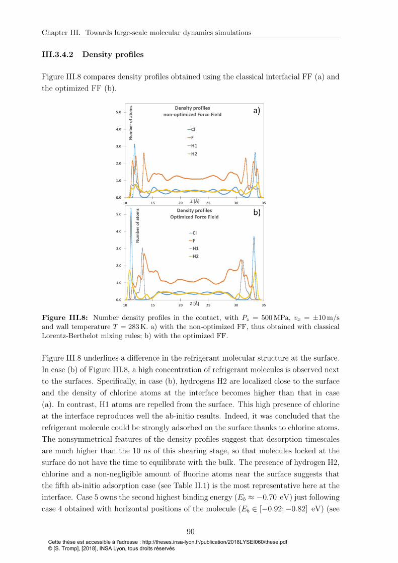
Chapter III. Towards large-scale molecular dynamics simulations
III.3.4.2 Density profiles
Figure III.8 compares density profiles obtained using the classical interfacial FF (a) and
the optimized FF (b).
Figure III.8: Number density profiles in the contact, with Pz = 500 MPa, vx = ±10 m/sand wall temperature T = 283 K. a) with the non-optimized FF, thus obtained with classicalLorentz-Berthelot mixing rules; b) with the optimized FF.
Figure III.8 underlines a difference in the refrigerant molecular structure at the surface.
In case (b) of Figure III.8, a high concentration of refrigerant molecules is observed next
to the surfaces. Specifically, in case (b), hydrogens H2 are localized close to the surface
and the density of chlorine atoms at the interface becomes higher than that in case
(a). In contrast, H1 atoms are repelled from the surface. This high presence of chlorine
at the interface reproduces well the ab-initio results. Indeed, it was concluded that the
refrigerant molecule could be strongly adsorbed on the surface thanks to chlorine atoms.
The nonsymmetrical features of the density profiles suggest that desorption timescales
are much higher than the 10 ns of this shearing stage, so that molecules locked at the
surface do not have the time to equilibrate with the bulk. The presence of hydrogen H2,
chlorine and a non-negligible amount of fluorine atoms near the surface suggests that
the fifth ab-initio adsorption case (see Table II.1) is the most representative here at the
interface. Case 5 owns the second highest binding energy (Eb ≈ −0.70 eV) just following
case 4 obtained with horizontal positions of the molecule (Eb ∈ [−0.92;−0.82] eV) (see
90Cette thèse est accessible à l'adresse : http://theses.insa-lyon.fr/publication/2018LYSEI060/these.pdf © [S. Tromp], [2018], INSA Lyon, tous droits réservés
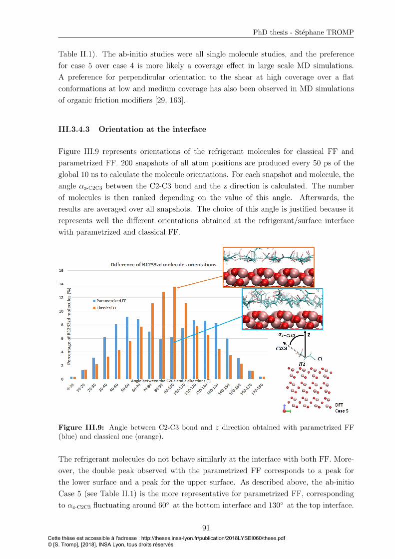
PhD thesis - Stephane TROMP
Table II.1). The ab-initio studies were all single molecule studies, and the preference
for case 5 over case 4 is more likely a coverage effect in large scale MD simulations.
A preference for perpendicular orientation to the shear at high coverage over a flat
conformations at low and medium coverage has also been observed in MD simulations
of organic friction modifiers [29, 163].
III.3.4.3 Orientation at the interface
Figure III.9 represents orientations of the refrigerant molecules for classical FF and
parametrized FF. 200 snapshots of all atom positions are produced every 50 ps of the
global 10 ns to calculate the molecule orientations. For each snapshot and molecule, the
angle αz-C2C3 between the C2-C3 bond and the z direction is calculated. The number
of molecules is then ranked depending on the value of this angle. Afterwards, the
results are averaged over all snapshots. The choice of this angle is justified because it
represents well the different orientations obtained at the refrigerant/surface interface
with parametrized and classical FF.
Figure III.9: Angle between C2-C3 bond and z direction obtained with parametrized FF(blue) and classical one (orange).
The refrigerant molecules do not behave similarly at the interface with both FF. More-
over, the double peak observed with the parametrized FF corresponds to a peak for
the lower surface and a peak for the upper surface. As described above, the ab-initio
Case 5 (see Table II.1) is the more representative for parametrized FF, corresponding
to αz-C2C3 fluctuating around 60◦ at the bottom interface and 130◦ at the top interface.
91Cette thèse est accessible à l'adresse : http://theses.insa-lyon.fr/publication/2018LYSEI060/these.pdf © [S. Tromp], [2018], INSA Lyon, tous droits réservés

Chapter III. Towards large-scale molecular dynamics simulations
On the other hand, with classical FF, the molecules tend to lie flat on the surface, equiv-
alent to αz-C2C3 around 90◦. Therefore, the percentage of molecule with αz-C2C3 around
90◦ is clearly bigger with the classical FF in comparison with orientations obtained with
parametrized FF. The remaining flat oriented (around 90◦) molecules with parametrized
FF are probably located in the center of the film.
III.4 Conclusion
This Chapter firstly presented the MD simulations principles and methods. Then
Raabe’s FF used to describe the R1233zd refrigerant was introduced, as well as the
FF for hematite surfaces. Furthermore, postprocessing methodology is developed to
parametrize a force field at the refrigerant-surface interface on the basis of ab-initio
results presented in Chapter 2. The information about reactivity of the surface with
the refrigerant obtained from DFT calculations is then retained in a parametrized force
field in order to study much larger systems. The binding energy values obtained with
this parametrized interfacial force field are compared with the ones determined from
ab-initio calculations. The maximum difference between MD with parametrized FF and
ab-initio results is 10%.
Larger scale MD simulations including this parametrized force field were analyzed. A
locked layer of refrigerant on hematite surface was observed and resisted to compression
(Pz = 500 MPa) and shearing (vs = 20 m/s). As a consequence the adsorbed molecules
of refrigerant could be able to protect the surface against wear in a lubricated contact.
Moreover, the high binding energy values could in fine lead to the initial formation of a
tribolayer.
Besides, to validate the postprocessing approach, the velocity and density profiles, as
well as orientations of the refrigerant molecules in the contact, are compared to the ones
obtained with classical mixing rules. The velocity profile does not vary much by using
either the parametrized FF or the classical one. However, the density profiles and the
orientations at the refrigerant-solid interface are affected. Indeed, with the classical FF,
molecules tend to lie flat on the surface, while with the parametrized FF, they lie in
direction corresponding to αz-C2C3 fluctuating around 60◦ at the bottom interface and
130◦ at the top interface, describing one of the most probable configuration found with
ab-initio results. In real conditions (high pressure, small film thickness, rough surfaces),
this structural organization might have a large impact on tribological behavior (wear and
fatigue resistance). More generally the parametrized force field developed in this study
provides the opportunity to study complex systems, more representative of lubricated
contact, as detailed in Chapter 4.
92Cette thèse est accessible à l'adresse : http://theses.insa-lyon.fr/publication/2018LYSEI060/these.pdf © [S. Tromp], [2018], INSA Lyon, tous droits réservés

Chapter IV
Tribological performance of
R1233zd in extreme confinement
Contents
IV.1 R1233zd confined between two smooth iron oxide surfaces 94
IV.1.1 Mobility of confined R1233zd . . . . . . . . . . . . . . . . . . 95
IV.1.2 Frictional behavior . . . . . . . . . . . . . . . . . . . . . . . . 97
IV.2 Towards film breakdown of R1233zd confined between smooth
surfaces . . . . . . . . . . . . . . . . . . . . . . . . . . . . . . . 99
IV.2.1 Film thickness and density . . . . . . . . . . . . . . . . . . . 100
IV.2.2 Molecule orientation . . . . . . . . . . . . . . . . . . . . . . . 102
IV.2.3 Structure and flow . . . . . . . . . . . . . . . . . . . . . . . . 103
IV.2.4 Consequences on the shear stress . . . . . . . . . . . . . . . . 105
IV.3 Layers formation and film breakdown within a rough contact108
IV.3.1 Load bearing capacity at equilibrium . . . . . . . . . . . . . . 109
IV.3.2 Resistance to shearing . . . . . . . . . . . . . . . . . . . . . . 110
IV.4 Conclusion . . . . . . . . . . . . . . . . . . . . . . . . . . . . . 114
93Cette thèse est accessible à l'adresse : http://theses.insa-lyon.fr/publication/2018LYSEI060/these.pdf © [S. Tromp], [2018], INSA Lyon, tous droits réservés
Chapter IV. Tribological performance of R1233zd in extreme confinement
As presented in Chapter 1, rolling bearings in PRL technologies are lubricated within a
very thin film (VTF) lubrication regime where the minimum film thickness can be of a
few nanometers. Real bearing experimental tests with pure R1233zd as lubricant under
variable operating conditions (Hertzian contact pressure around 1.2 GPa in average)
were run by SKF company [4, 5]. XPS analysis of the ring steel surfaces revealed that:
• the surface were indeed constituted mainly of iron(II) oxide (FeO) and iron(III)
oxide (Fe2O3),
• elements constitutive of the R1233zd molecules such as chlorine and fluorine were
adsorbed at the surface,
• the thickness of the tribolayer could reach up to 25 nm for long test duration.
These experimental conclusions are qualitatively in line with the main findings of Chap-
ter 3 concerning adsorption of R1233zd at Fe2O3 surfaces. Unfortunately, they do not
tell much about structure or flow of the confined refrigerant. At this stage, large scale
MD simulation of confined R1233zd is an opportunity to test the tribological perfor-
mance of such a system, providing an in situ and ante-mortem analysis.
Orientations and structurations of refrigerant molecules at the refrigerant/surface in-
terface have been identified in Chapter 3, and the existence of an adsorbed layer of
R1233zd at the Fe2O3 surface has been shown. In this Chapter, the parametrized FF is
implemented in MD simulations to investigate extreme conditions of lubrication. The
strength of the adsorbed layer is tested and friction is evaluated at different pressures
and sliding velocities. Reducing the quantity of refrigerant one molecule at a time,
structural, flow, as well as frictional behaviors are investigated until the film can break
down locally. Afterwards, the strength of the adsorbed layer is determined for a contact
between a rough surface and a smooth one, where the local pressure undergone by the
adsorbed layer is far bigger than the averaged one.
IV.1 R1233zd confined between two smooth iron
oxide surfaces
This section aims at studying locking at the refrigerant/surface interface as a function
of pressure and sliding velocity when R1233zd is confined between two Fe2O3 smooth
surfaces. The velocity profiles and the frictional behavior are considered.
We use the system described in Chapter 3, section 3. We consider a 2.1-2.5 nm-thick
film (measured at P = 4 GPa and P = 0.5 GPa, respectively), and the wall temperature
is fixed at 283 K [3]. The systems are first compressed during 2 ns and then sheared with
different sliding velocities from 1 m/s to 100 m/s. In order to compare simulations with
94Cette thèse est accessible à l'adresse : http://theses.insa-lyon.fr/publication/2018LYSEI060/these.pdf © [S. Tromp], [2018], INSA Lyon, tous droits réservés

PhD thesis - Stephane TROMP
the same sliding distance of 30 nm, sliding stage simulations were run during (30, 15,
6, 3, 1.5, 0.6, 0.3) ns for sliding velocities of (1, 2, 5, 10, 20, 50, 100) m/s, respectively.
Due to the periodic boundary conditions, no squeeze-out of the refrigerant molecules is
considered in this section. Therefore, structural, flow and frictional behaviors are only
studied here in the framework of a full separation of the two surfaces.
IV.1.1 Mobility of confined R1233zd
Figure IV.1 represents the velocity and number density profiles of R1233zd confined
between two smooth iron oxide surfaces for three sliding velocities: vs = 5 m/s, 10 m/s
and 100 m/s at P = 4 GPa and for three applied pressures: P = 0.5 GPa, P = 1.5 GPa
and P = 4 GPa at vs = 100 m/s.
Figure IV.1: Variation of velocity (blue) and number density (orange) profiles within thecontact at three different pressures (0.5, 1.5, 4) GPa for vs = 100 m/s and at three slidingvelocities vs: 5 m/s, 10 m/s and 100 m/s for P = 4 GPa.
In all cases, a linear (Couette) velocity profile is observed in the central part of the film
95Cette thèse est accessible à l'adresse : http://theses.insa-lyon.fr/publication/2018LYSEI060/these.pdf © [S. Tromp], [2018], INSA Lyon, tous droits réservés

Chapter IV. Tribological performance of R1233zd in extreme confinement
thickness. However, locking appears at the walls: one layer of R1233zd molecules sticks
to each wall, whatever the pressure and shear velocity, making the velocity profiles all
similar, and refered in the literature [233, 225] as central localization. Both increasing
the pressure and increasing the sliding velocity appear to reduce the thickness of ad-
sorbed layers. However, to ensure a better description of these influences, a more precise
description is needed.
In order to better represent the dependence of the locking with the pressure and sliding
velocity, the locking length is estimated as follows. As a linear velocity profile is observed
in the central part of the film thickness, the locking length is calculated here as the
distance between the highest atom of the lower surface and the crossing point between
the linear part of the velocity profile and the wall speed of the lower surface. The
correlation coefficient of the linear calculated part is always higher than 0.99. Figure IV.2
represents the variation of the locking length as a function of the pressure for three sliding
velocities: vs = 5 m/s, 20 m/s and 100 m/s.
Figure IV.2: Variation of the locking length as a function of pressure for three slidingvelocities: 5 m/s, 20 m/s and 100 m/s.
At the lowest sliding velocity of 5 m/s, the profiles become noisy, especially at the lowest
pressures of 0.1 GPa and 0.25 GPa. Therefore the locking length of the first points is not
represented at vs = 5 m/s in this Figure. Figure IV.2 confirms the previous suggestions.
Indeed, the higher pressure forces refrigerant molecules to approach the surface and due
to the strong refrigerant/surface interactions, these molecules are locked to the surface
in a more compact manner than at lower pressure. Increasing the sliding velocity also
reduces the thickness of adsorbed layers. It is possible to imagine that molecules of this
layer can be pull-off by the fast moving liquid. Furthermore, for high sliding velocities
vs = 20 m/s and 100 m/s and at low pressure (lower than 0.5 GPa), the locking length
96Cette thèse est accessible à l'adresse : http://theses.insa-lyon.fr/publication/2018LYSEI060/these.pdf © [S. Tromp], [2018], INSA Lyon, tous droits réservés

PhD thesis - Stephane TROMP
decreases strongly with the pressure whereas at higher pressure, the decrease is smaller.
The main result is that the adsorbed molecules at the surfaces stay stuck, whatever the
conditions, up to P = 4 GPa and vs = 100 m/s.
IV.1.2 Frictional behavior
The friction coefficient Cf is defined as the ratio between the tangential force resisting to
the motion and the normal load. In practice, the normal load is imposed, and shearing
forces are measured in x direction for each atom of the two virtual surfaces where the
velocity is applied (see Chapter 3 Figure III.6). Indeed, in the steady state regime,
the mechanical equilibrium of the system requires that the shearing force between the
top virtual surface and the top real surface be equal to the shearing force between the
top real surface and the liquid. Following the same reasoning with the real and virtual
bottom surfaces, we calculate Cf from the average of the top and bottom shearing forces,
improving the statistic.
Figure IV.3 presents the variation of Cf with respect to the sliding velocity vs for four
different pressures P = (0.5, 1.5, 3, 4) GPa.
Figure IV.3: Variation of Cf as a function of the sliding velocity for 4 pressures: 0.5 GPa,1.5 GPa, 3 GPa, 4GPa. The values of the maximum temperature increase in the lubricantfilm ∆Tmax at vs = 5 m/s and vs = 100 m/s are also indicated.
At low sliding velocities, the lubricant viscosity is expected to reach a plateau (Newto-
nian viscosity). Accordingly, Cf should be proportional to the sliding velocity, with the
slope being itself proportional to the Newtonian viscosity. The slope should therefore
increase with increasing pressure, following a typical piezo-viscous behavior. This is
compatible with the results presented in Figure IV.3: at the lowest simulated velocity,
97Cette thèse est accessible à l'adresse : http://theses.insa-lyon.fr/publication/2018LYSEI060/these.pdf © [S. Tromp], [2018], INSA Lyon, tous droits réservés

Chapter IV. Tribological performance of R1233zd in extreme confinement
Cf increases with increasing pressure. Figure IV.3 also shows a shear-thinning behavior
at large sliding velocities, i.e. the slope of the Cf versus velocity curves decreases with
increasing velocity. Shear-thinning is more pronounced (the slope decreases faster) for
larger pressures, so that at very large sliding velocity Cf decreases with increasing pres-
sure. At the largest simulated pressures, Cf even seems to reach a plateau as a function
of the sliding velocity.
This friction saturation at high shear velocity was observed by several authors [11, 225,
234]. Its interpretation is delicate, and could involve phase change at high pressure [233,
235], or thermal effects. With that regard, Figure IV.3 shows that at the largest sliding
velocities, the temperature of the lubricant increases strongly, and depends largely on
the pressure. However, differences in shear-thinning behavior as a function of pressure
can already be observed for the lowest simulated velocities, for which the increase of
the lubricant temperature is very small. Consequently, we suggest that, while thermal
effects certainly play a role, they cannot fully explain the observed behavior.
Partial conclusion
In this section, the tribological performance of the R1233zd refrigerant confined be-
tween two smooth α− Fe2O3 surfaces has been studied. MD simulations enriched by
the previously defined parametrized FF show that a layer of R1233zd is adsorbed at
the surfaces. In all tested cases, the adsorbed layers resist, to both sliding velocity up
to 100 m/s and pressure up to 4 GPa. Furthermore, the friction coefficient increases
with the sliding velocity and reaches a plateau-like behavior for pressure higher than
3 GPa at high sliding velocity.
98Cette thèse est accessible à l'adresse : http://theses.insa-lyon.fr/publication/2018LYSEI060/these.pdf © [S. Tromp], [2018], INSA Lyon, tous droits réservés
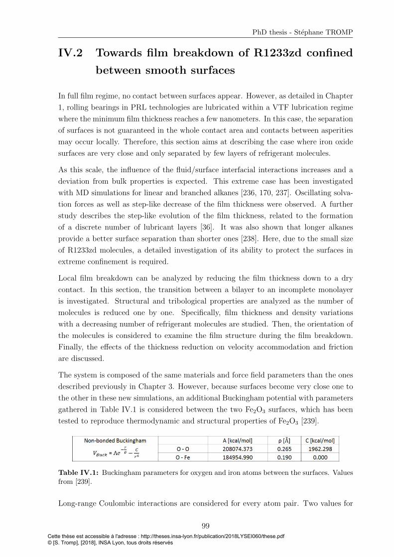
PhD thesis - Stephane TROMP
IV.2 Towards film breakdown of R1233zd confined
between smooth surfaces
In full film regime, no contact between surfaces appear. However, as detailed in Chapter
1, rolling bearings in PRL technologies are lubricated within a VTF lubrication regime
where the minimum film thickness reaches a few nanometers. In this case, the separation
of surfaces is not guaranteed in the whole contact area and contacts between asperities
may occur locally. Therefore, this section aims at describing the case where iron oxide
surfaces are very close and only separated by few layers of refrigerant molecules.
As this scale, the influence of the fluid/surface interfacial interactions increases and a
deviation from bulk properties is expected. This extreme case has been investigated
with MD simulations for linear and branched alkanes [236, 170, 237]. Oscillating solva-
tion forces as well as step-like decrease of the film thickness were observed. A further
study describes the step-like evolution of the film thickness, related to the formation
of a discrete number of lubricant layers [36]. It was also shown that longer alkanes
provide a better surface separation than shorter ones [238]. Here, due to the small size
of R1233zd molecules, a detailed investigation of its ability to protect the surfaces in
extreme confinement is required.
Local film breakdown can be analyzed by reducing the film thickness down to a dry
contact. In this section, the transition between a bilayer to an incomplete monolayer
is investigated. Structural and tribological properties are analyzed as the number of
molecules is reduced one by one. Specifically, film thickness and density variations
with a decreasing number of refrigerant molecules are studied. Then, the orientation of
the molecules is considered to examine the film structure during the film breakdown.
Finally, the effects of the thickness reduction on velocity accommodation and friction
are discussed.
The system is composed of the same materials and force field parameters than the ones
described previously in Chapter 3. However, because surfaces become very close one to
the other in these new simulations, an additional Buckingham potential with parameters
gathered in Table IV.1 is considered between the two Fe2O3 surfaces, which has been
tested to reproduce thermodynamic and structural properties of Fe2O3 [239].
Table IV.1: Buckingham parameters for oxygen and iron atoms between the surfaces. Valuesfrom [239].
Long-range Coulombic interactions are considered for every atom pair. Two values for
99Cette thèse est accessible à l'adresse : http://theses.insa-lyon.fr/publication/2018LYSEI060/these.pdf © [S. Tromp], [2018], INSA Lyon, tous droits réservés
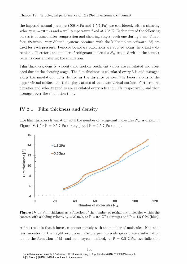
Chapter IV. Tribological performance of R1233zd in extreme confinement
the imposed normal pressure (500 MPa and 1.5 GPa) are considered, with a shearing
velocity vs = 20 m/s and a wall temperature fixed at 283 K. Each point of the following
curves is obtained after compression and shearing stages, each one during 3 ns. There-
fore, 88 initial, very diluted, systems obtained with the Moltemplate software [33] are
used for each pressure. Periodic boundary conditions are applied along the x and y di-
rections. Therefore, the number of refrigerant molecules Nzd trapped within the contact
remains constant during the simulation.
Film thickness, density, velocity and friction coefficient values are calculated and aver-
aged during the shearing stage. The film thickness is calculated every 5 fs and averaged
along the simulation. It is defined as the distance between the lowest atoms of the
upper virtual surface and the highest atoms of the lower virtual surface. Furthermore,
densities and velocity profiles are calculated every 5 fs and 10 fs, respectively, and then
averaged over the simulation time.
IV.2.1 Film thickness and density
The film thickness h variation with the number of refrigerant molecules Nzd is drawn in
Figure IV.4 for P = 0.5 GPa (orange) and P = 1.5 GPa (blue).
Figure IV.4: Film thickness as a function of the number of refrigerant molecules within thecontact with a sliding velocity vs = 20 m/s, at P = 0.5 GPa (orange) and P = 1.5 GPa (blue).
A first result is that h increases monotonously with the number of molecules. Nonethe-
less, monitoring the height evolution molecule per molecule gives precise information
about the formation of bi- and monolayers. Indeed, at P = 0.5 GPa, two inflection
100Cette thèse est accessible à l'adresse : http://theses.insa-lyon.fr/publication/2018LYSEI060/these.pdf © [S. Tromp], [2018], INSA Lyon, tous droits réservés

PhD thesis - Stephane TROMP
points can be observed with Nzd around 44 and 84 molecules respectively, correspond-
ing to the creation/destruction of full layers.
However, it is difficult to locate precisely the inflection points. In particular, the noise
on the curves precludes determining them as the points where the second derivative of
the curves vanish. An alternative approach to estimate the number of molecules forming
full layers is to look at the film density.
The film density is determined as ρ = NzdM1zd
Sh, with Nzd the number of refrigerant
molecules, M1zd the mass of one molecule, S the surface area (roughly 10 nm2) and h the
film thickness between the two virtual surfaces. For comparison, h was also computed
as the minimal distance between real surface atoms, or as the maximal distance between
fluid atoms, but the results presented below were not affected by the different ways of
calculating h. Moreover, the error is calculated as ρ∆hh
, with ∆h the film thickness
standard deviation. Figure IV.5 represents the evolution of the film density with the
number of molecules, for P = 0.5 GPa and P = 1.5 GPa.
Figure IV.5: Film Density as a function of the number of refrigerant molecules within thecontact, with a sliding velocity vs = 20 m/s, at P = 0.5 GPa (orange) and P = 1.5 GPa (blue).
Figure IV.5 shows greater variations in comparison with Figure IV.4. Defining full layers
as corresponding to maxima in density, at P = 0.5 GPa, a full monolayer is obtained
for 4.4± 0.1 molecules per nm2 within the contact. A bilayer is obtained from 5.0± 0.1
to 8.4± 0.1 molecules per nm2, with full twin layers at 8.4± 0.1 molecules per nm2. At
P = 1.5 GPa, the monolayer is found at 4.7± 0.2 molecules per nm2 and a full bilayer
corresponds to 9.0± 0.1 molecules per nm2. Two additional observations can be made.
First, the film density increases slightly with higher pressures. Secondly, the density of
101Cette thèse est accessible à l'adresse : http://theses.insa-lyon.fr/publication/2018LYSEI060/these.pdf © [S. Tromp], [2018], INSA Lyon, tous droits réservés
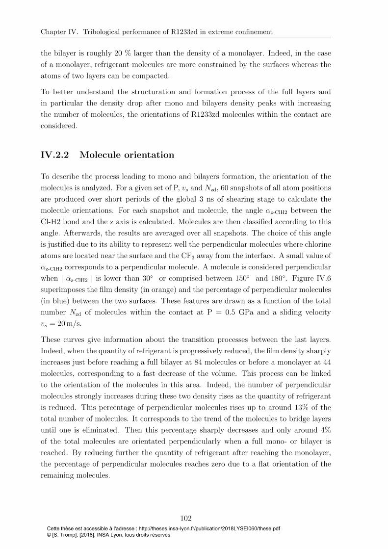
Chapter IV. Tribological performance of R1233zd in extreme confinement
the bilayer is roughly 20 % larger than the density of a monolayer. Indeed, in the case
of a monolayer, refrigerant molecules are more constrained by the surfaces whereas the
atoms of two layers can be compacted.
To better understand the structuration and formation process of the full layers and
in particular the density drop after mono and bilayers density peaks with increasing
the number of molecules, the orientations of R1233zd molecules within the contact are
considered.
IV.2.2 Molecule orientation
To describe the process leading to mono and bilayers formation, the orientation of the
molecules is analyzed. For a given set of P, vs and Nzd, 60 snapshots of all atom positions
are produced over short periods of the global 3 ns of shearing stage to calculate the
molecule orientations. For each snapshot and molecule, the angle αz-ClH2 between the
Cl-H2 bond and the z axis is calculated. Molecules are then classified according to this
angle. Afterwards, the results are averaged over all snapshots. The choice of this angle
is justified due to its ability to represent well the perpendicular molecules where chlorine
atoms are located near the surface and the CF3 away from the interface. A small value of
αz-ClH2 corresponds to a perpendicular molecule. A molecule is considered perpendicular
when | αz-ClH2 | is lower than 30◦ or comprised between 150◦ and 180◦. Figure IV.6
superimposes the film density (in orange) and the percentage of perpendicular molecules
(in blue) between the two surfaces. These features are drawn as a function of the total
number Nzd of molecules within the contact at P = 0.5 GPa and a sliding velocity
vs = 20 m/s.
These curves give information about the transition processes between the last layers.
Indeed, when the quantity of refrigerant is progressively reduced, the film density sharply
increases just before reaching a full bilayer at 84 molecules or before a monolayer at 44
molecules, corresponding to a fast decrease of the volume. This process can be linked
to the orientation of the molecules in this area. Indeed, the number of perpendicular
molecules strongly increases during these two density rises as the quantity of refrigerant
is reduced. This percentage of perpendicular molecules rises up to around 13% of the
total number of molecules. It corresponds to the trend of the molecules to bridge layers
until one is eliminated. Then this percentage sharply decreases and only around 4%
of the total molecules are orientated perpendicularly when a full mono- or bilayer is
reached. By reducing further the quantity of refrigerant after reaching the monolayer,
the percentage of perpendicular molecules reaches zero due to a flat orientation of the
remaining molecules.
102Cette thèse est accessible à l'adresse : http://theses.insa-lyon.fr/publication/2018LYSEI060/these.pdf © [S. Tromp], [2018], INSA Lyon, tous droits réservés
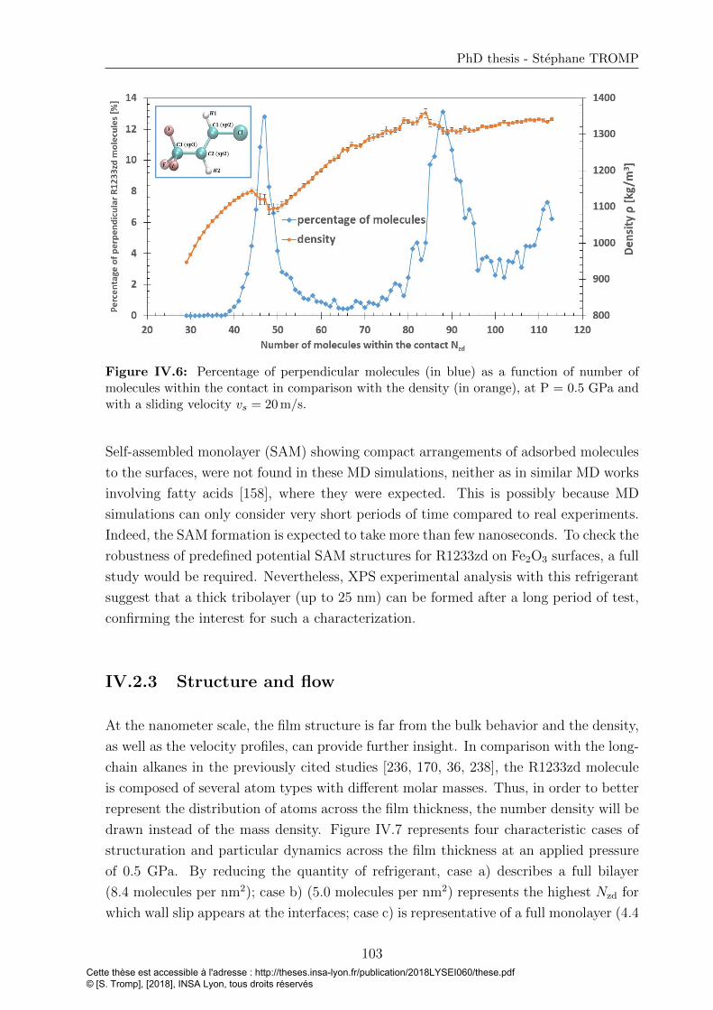
PhD thesis - Stephane TROMP
Figure IV.6: Percentage of perpendicular molecules (in blue) as a function of number ofmolecules within the contact in comparison with the density (in orange), at P = 0.5 GPa andwith a sliding velocity vs = 20 m/s.
Self-assembled monolayer (SAM) showing compact arrangements of adsorbed molecules
to the surfaces, were not found in these MD simulations, neither as in similar MD works
involving fatty acids [158], where they were expected. This is possibly because MD
simulations can only consider very short periods of time compared to real experiments.
Indeed, the SAM formation is expected to take more than few nanoseconds. To check the
robustness of predefined potential SAM structures for R1233zd on Fe2O3 surfaces, a full
study would be required. Nevertheless, XPS experimental analysis with this refrigerant
suggest that a thick tribolayer (up to 25 nm) can be formed after a long period of test,
confirming the interest for such a characterization.
IV.2.3 Structure and flow
At the nanometer scale, the film structure is far from the bulk behavior and the density,
as well as the velocity profiles, can provide further insight. In comparison with the long-
chain alkanes in the previously cited studies [236, 170, 36, 238], the R1233zd molecule
is composed of several atom types with different molar masses. Thus, in order to better
represent the distribution of atoms across the film thickness, the number density will be
drawn instead of the mass density. Figure IV.7 represents four characteristic cases of
structuration and particular dynamics across the film thickness at an applied pressure
of 0.5 GPa. By reducing the quantity of refrigerant, case a) describes a full bilayer
(8.4 molecules per nm2); case b) (5.0 molecules per nm2) represents the highest Nzd for
which wall slip appears at the interfaces; case c) is representative of a full monolayer (4.4
103Cette thèse est accessible à l'adresse : http://theses.insa-lyon.fr/publication/2018LYSEI060/these.pdf © [S. Tromp], [2018], INSA Lyon, tous droits réservés
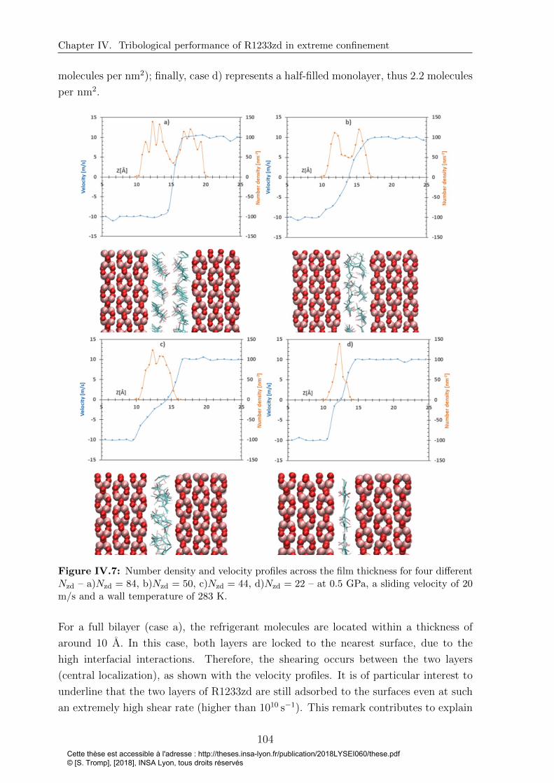
Chapter IV. Tribological performance of R1233zd in extreme confinement
molecules per nm2); finally, case d) represents a half-filled monolayer, thus 2.2 molecules
per nm2.
Figure IV.7: Number density and velocity profiles across the film thickness for four differentNzd – a)Nzd = 84, b)Nzd = 50, c)Nzd = 44, d)Nzd = 22 – at 0.5 GPa, a sliding velocity of 20m/s and a wall temperature of 283 K.
For a full bilayer (case a), the refrigerant molecules are located within a thickness of
around 10 A. In this case, both layers are locked to the nearest surface, due to the
high interfacial interactions. Therefore, the shearing occurs between the two layers
(central localization), as shown with the velocity profiles. It is of particular interest to
underline that the two layers of R1233zd are still adsorbed to the surfaces even at such
an extremely high shear rate (higher than 1010 s−1). This remark contributes to explain
104Cette thèse est accessible à l'adresse : http://theses.insa-lyon.fr/publication/2018LYSEI060/these.pdf © [S. Tromp], [2018], INSA Lyon, tous droits réservés

PhD thesis - Stephane TROMP
why a tribolayer is expected even in severe conditions, as shown experimentally [4, 5]
and how far lubrication with such a refrigerant can be considered. Case b represents the
first situation where a wall slip occurs at the interface. Indeed, the cohesion between
the two layers increases due to bridging molecules, and slip between the layers and the
surfaces becomes favorable. At the lower fluid/surface interface (at z = 10 A), the
speed of the point directly located after the interface is different from that of the wall.
However, it is less clear at the interface with the top surface (at z = 17.4 A), where
a weak locking seems to remain. In the middle of the density profile, the number of
atoms is larger than in case a (full bilayer), meaning that bridges appear between the
two layers. As a consequence, the thicknesses of both layers are reduced, together with
the width of density peaks. Case c describes a full monolayer where a broad foreseeable
wall slip is observed. A large part of the velocity difference between the surfaces is
also accommodated by shear of the monolayer itself, molecules moving independently
from the others. In case d, the density peak is thinner because molecules are in flat
orientations, as detailed previously, and slip at the wall is predominant.
IV.2.4 Consequences on the shear stress
Figure IV.8 represents the variation of the shear stress τ and of the density as a function
of Nzd, the number of refrigerant molecules within the contact, at P = 0.5 GPa and P
= 1.5 GPa.
Starting from the maximum number of molecules, when the quantity of lubricant is
reduced, the shear stress τ increases, corresponding to the appearance of molecules
perpendicular to the surfaces bridging the layers (see Figure IV.6), before reaching
a full bilayer. With two full distinct layers in the film, a local maximum of shear
stress is observed. By reducing the number of refrigerant molecules, the shear stress
decreases slightly because of decreasing the number of molecules countering the surface
movement. Then τ strongly rises until a monolayer is obtained. During this increase,
the two layers progressively merge into a single monolayer and therefore the percentage
of perpendicular molecules, bridging the two layers, rises (see Figure IV.6). As soon as
the two layers are merging into one layer at 5.0 molecules per nm2 for P = 0.5 GPa, the
refrigerant film is sheared, and starts slipping on both walls.
105Cette thèse est accessible à l'adresse : http://theses.insa-lyon.fr/publication/2018LYSEI060/these.pdf © [S. Tromp], [2018], INSA Lyon, tous droits réservés

Chapter IV. Tribological performance of R1233zd in extreme confinement
Figure IV.8: Refrigerant film density (orange) and shear stress τ (blue) as a function of Nzd,the number of refrigerant molecules within the contact for P = 0.5 GPa (a) and P = 1.5 GPa(b).
A maximum value of τ is obtained for a full monolayer separating the surfaces. At this
point, wall slip is unavoidable. Indeed, both surfaces move in opposite directions and the
shearing only occur within one refrigerant layer. Therefore, only the refrigerant/surface
interfacial interactions determine the frictional behavior. As shown in Chapter 3, the
well-depth energy εij of Lennard-Jones potential are high to represent adsorption ability
of the R1233zd molecule on hematite surfaces. These strong interactions lead to a very
high shear stress τ = 0.34 GPa at P = 0.5 GPa and τ = 0.46 GPa at P = 1.5 GPa.
Furthermore, as the film thickness is very small with only a monolayer separating the
two surfaces, adhesion pressures between the two surfaces, due to Van der Waals and
electrostatic interactions can increase friction [36].
Then, the shear stress τ decreases when the number of refrigerant molecules is reduced
further. Less R1233zd molecules have to be sheared involving a lower resistance to the
106Cette thèse est accessible à l'adresse : http://theses.insa-lyon.fr/publication/2018LYSEI060/these.pdf © [S. Tromp], [2018], INSA Lyon, tous droits réservés
PhD thesis - Stephane TROMP
movement of surfaces and thus a lower tangential force. Therefore a lower τ is found in
comparison with a full monolayer.
Comparing Figure IV.8 (a) and (b), the same trends are depicted. Quantitatively, the
shear stress τ at P = 1.5 GPa is always higher than at P = 0.5 GPa. This can be
attributed to the viscosity-pressure dependence.
Partial conclusion
The properties of R1233zd under extreme confinement between two approaching iron
oxides surfaces have been investigated. For P = 0.5 GPa and P = 1.5 GPa, film
density peaks appear when full layers are formed (bilayer, monolayer). The number
of molecules perpendicular to the surfaces increases drastically when decreasing the
number of molecules down to bi- and monolayer, corresponding to bridging molecules
between layers. With two full layers separating the surfaces, the film thickness is
roughly 10 A. With a shear velocity vs = 20 m/s, the two layers are still adsorbed at
the surfaces, despite an extremely high shear rate (higher than 1010 s−1). The adsorbed
layers start slipping the surfaces for less than 5.0 molecules per nm2 (at P = 0.5 GPa).
Finally, a local maximum of shear stress is obtained with two full distinct layers in the
film. Friction reaches its global maximum exactly when a full monolayer is formed.
107Cette thèse est accessible à l'adresse : http://theses.insa-lyon.fr/publication/2018LYSEI060/these.pdf © [S. Tromp], [2018], INSA Lyon, tous droits réservés
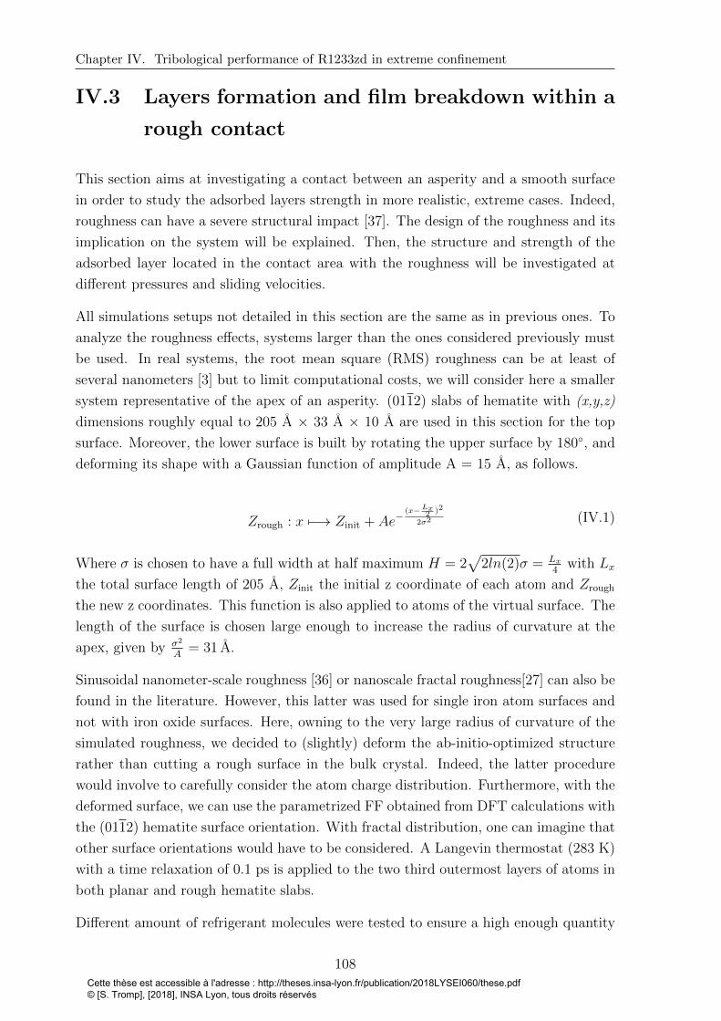
Chapter IV. Tribological performance of R1233zd in extreme confinement
IV.3 Layers formation and film breakdown within a
rough contact
This section aims at investigating a contact between an asperity and a smooth surface
in order to study the adsorbed layers strength in more realistic, extreme cases. Indeed,
roughness can have a severe structural impact [37]. The design of the roughness and its
implication on the system will be explained. Then, the structure and strength of the
adsorbed layer located in the contact area with the roughness will be investigated at
different pressures and sliding velocities.
All simulations setups not detailed in this section are the same as in previous ones. To
analyze the roughness effects, systems larger than the ones considered previously must
be used. In real systems, the root mean square (RMS) roughness can be at least of
several nanometers [3] but to limit computational costs, we will consider here a smaller
system representative of the apex of an asperity. (0112) slabs of hematite with (x,y,z)
dimensions roughly equal to 205 A × 33 A × 10 A are used in this section for the top
surface. Moreover, the lower surface is built by rotating the upper surface by 180◦, and
deforming its shape with a Gaussian function of amplitude A = 15 A, as follows.
Zrough : x 7−→ Zinit + Ae−(x−Lx
2 )2
2σ2 (IV.1)
Where σ is chosen to have a full width at half maximum H = 2√
2ln(2)σ = Lx4
with Lx
the total surface length of 205 A, Zinit the initial z coordinate of each atom and Zrough
the new z coordinates. This function is also applied to atoms of the virtual surface. The
length of the surface is chosen large enough to increase the radius of curvature at the
apex, given by σ2
A= 31 A.
Sinusoidal nanometer-scale roughness [36] or nanoscale fractal roughness[27] can also be
found in the literature. However, this latter was used for single iron atom surfaces and
not with iron oxide surfaces. Here, owning to the very large radius of curvature of the
simulated roughness, we decided to (slightly) deform the ab-initio-optimized structure
rather than cutting a rough surface in the bulk crystal. Indeed, the latter procedure
would involve to carefully consider the atom charge distribution. Furthermore, with the
deformed surface, we can use the parametrized FF obtained from DFT calculations with
the (0112) hematite surface orientation. With fractal distribution, one can imagine that
other surface orientations would have to be considered. A Langevin thermostat (283 K)
with a time relaxation of 0.1 ps is applied to the two third outermost layers of atoms in
both planar and rough hematite slabs.
Different amount of refrigerant molecules were tested to ensure a high enough quantity
108Cette thèse est accessible à l'adresse : http://theses.insa-lyon.fr/publication/2018LYSEI060/these.pdf © [S. Tromp], [2018], INSA Lyon, tous droits réservés

PhD thesis - Stephane TROMP
of molecule spreading on the whole surfaces to form an adsorbed layer and low enough
to ensure that a bubble remains trapped between the flat surface areas after compression
for each pressure. The aim of this procedure is to ensure that we are indeed testing the
strength of the adsorbed layer, and not the compressibility of the fluid. As a result, 600
R1233zd molecules are implemented in the system and each surface is composed of 7200
atoms (not including the virtual atoms). Both compression and shearing stages last 5
ns. Contrary to the previous NEMD studies, only the top surface moves in this section.
Pressures from 50 MPa to 3 GPa are applied to the virtual top surface. The velocity is
implemented in the x direction for all virtual atoms of the top surface with a shearing
velocity value vs varying from 2 m/s to 50 m/s, while the normal load remains fixed.
In the next sections, the structure and strength of the adsorbed layer located in the
contact between the smooth and rough surfaces are analyzed at different pressures and
sliding velocities.
IV.3.1 Load bearing capacity at equilibrium
Figure IV.9 presents two compression cases, without shearing at P = (0.1, 1, 3) GPa.
Figure IV.9: Compressed R1233zd refrigerant within a smooth/rough contact at a) P = 0.1GPa, b) P = 1 GPa and c) P = 3 GPa.
As shown in this Figure, the structure of the adsorbed layer can vary in the contact area.
109Cette thèse est accessible à l'adresse : http://theses.insa-lyon.fr/publication/2018LYSEI060/these.pdf © [S. Tromp], [2018], INSA Lyon, tous droits réservés

Chapter IV. Tribological performance of R1233zd in extreme confinement
At 0.1 GPa, a bilayer separates the surfaces, while a monolayer remains at 1 GPa and
3 GPa. In the three cases, the bubble between both surfaces away from the roughness
allows for a possible breakdown of adsorbed layers. At P = 3 GPa, the bubble becomes
small but can still be observed. Table IV.2 represents the structure of the adsorbed
layers compressed within a smooth/rough contact, at different applied pressures P =
(0.05, 0.1, 0.3, 0.5, 1, 1.5, 2, 3) GPa. Moreover, the estimated pressures Pc in the contact
area are given. The methodology to calculate this local pressure will be explained in
the next section.
Table IV.2: Structure of the adsorbed layer compressed within a smooth/rough contact at0.05, 0.1, 0.3, 0.5, 1, 1.5, 2, 3 GPa.
A bi- or monolayer holds at all tested pressures. However, the structure changes in
the contact area. For pressure lower than 0.3 GPa (Pc ≈ 2 GPa), a bilayer is still
remaining while from 0.5 GPa (Pc ≈ 3.3 GPa) up to 3 GPa (Pc ≈ 19.8 GPa), the
quantity of refrigerant in the contact area decreases and a monolayer appears. At 0.3
GPa (Pc ≈ 2 GPa), the simulations remains in a unstable configuration, with mainly
two layers, but bridges forming at time interval, probably reflecting a transition to a
monolayer.
IV.3.2 Resistance to shearing
The effects of the sliding velocity on the strength and structure of adsorbed layers are
analyzed. Four different sliding velocities (2, 5, 10, 50) m/s are considered with the
110Cette thèse est accessible à l'adresse : http://theses.insa-lyon.fr/publication/2018LYSEI060/these.pdf © [S. Tromp], [2018], INSA Lyon, tous droits réservés
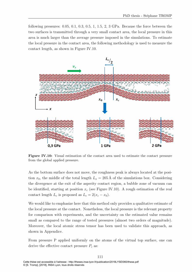
PhD thesis - Stephane TROMP
following pressures: 0.05, 0.1, 0.3, 0.5, 1, 1.5, 2, 3 GPa. Because the force between the
two surfaces is transmitted through a very small contact area, the local pressure in this
area is much larger than the average pressure imposed in the simulations. To estimate
the local pressure in the contact area, the following methodology is used to measure the
contact length, as shown in Figure IV.10.
Figure IV.10: Visual estimation of the contact area used to estimate the contact pressurefrom the global applied pressure.
As the bottom surface does not move, the roughness peak is always located at the posi-
tion x0, the middle of the total length Lx = 205 A of the simulations box. Considering
the divergence at the exit of the asperity contact region, a bubble zone of vacuum can
be identified, starting at position xc (see Figure IV.10). A rough estimation of the real
contact length Lc is proposed as Lc = 2(xc − x0).
We would like to emphasize here that this method only provides a qualitative estimate of
the local pressure at the contact. Nonetheless, the local pressure is the relevant property
for comparison with experiments, and the uncertainty on the estimated value remains
small as compared to the range of tested pressures (almost two orders of magnitude).
Moreover, the local atomic stress tensor has been used to validate this approach, as
shown in Appendice.
From pressure P applied uniformly on the atoms of the virtual top surface, one can
derive the effective contact pressure Pc as:
111Cette thèse est accessible à l'adresse : http://theses.insa-lyon.fr/publication/2018LYSEI060/these.pdf © [S. Tromp], [2018], INSA Lyon, tous droits réservés

Chapter IV. Tribological performance of R1233zd in extreme confinement
Pc = PLxLc, (IV.2)
where contact boundary xc varies around 118 A, thus a ratio LxLc
constant for all cases:LxLc
= 6.6. Pc represents a rough estimation of the real pressure undergone by the
refrigerant layers, for comparison purpose only.
Table IV.3 gathers structure information concerning the refrigerant layers under com-
pression and shearing. Moreover, the estimated pressures Pc in the contact area are
given.
Table IV.3: Structure of the adsorbed layer compressed and sheared within a smooth/roughcontact at 0.05, 0.1, 0.3, 0.5, 1, 1.5, 2, 3 GPa and at sliding velocities of 2, 5, 10, 50 m/s.
At P = 0.05 GPa (Pc ≈ 0.3 GPa), the bilayer resists regardless of the sliding velocity.
For the intermediate case with P = 0.1 GPa (Pc ≈ 0.7 GPa), a high sliding velocity
vs, which is here equal to the entrainment velocity of fluid into the asperity contact, is
beneficial to keep a stable bilayer (vs = 10 m/s and 50 m/s). In contrast, for smaller
sliding velocities, the shearing motion tends to disrupt the bilayer that was stable at
rest, resulting in a stable monolayer. No bilayer was obtained at larger pressures under
shear.
112Cette thèse est accessible à l'adresse : http://theses.insa-lyon.fr/publication/2018LYSEI060/these.pdf © [S. Tromp], [2018], INSA Lyon, tous droits réservés
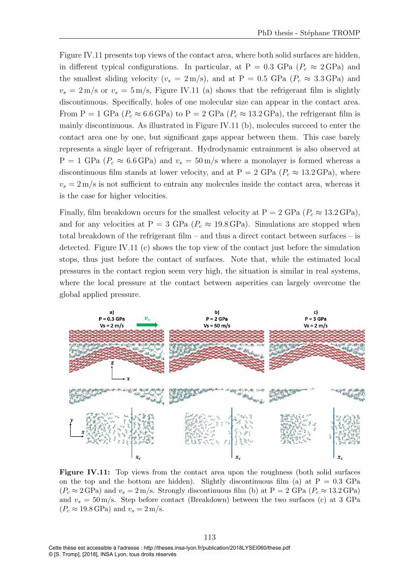
PhD thesis - Stephane TROMP
Figure IV.11 presents top views of the contact area, where both solid surfaces are hidden,
in different typical configurations. In particular, at P = 0.3 GPa (Pc ≈ 2 GPa) and
the smallest sliding velocity (vs = 2 m/s), and at P = 0.5 GPa (Pc ≈ 3.3 GPa) and
vs = 2 m/s or vs = 5 m/s, Figure IV.11 (a) shows that the refrigerant film is slightly
discontinuous. Specifically, holes of one molecular size can appear in the contact area.
From P = 1 GPa (Pc ≈ 6.6 GPa) to P = 2 GPa (Pc ≈ 13.2 GPa), the refrigerant film is
mainly discontinuous. As illustrated in Figure IV.11 (b), molecules succeed to enter the
contact area one by one, but significant gaps appear between them. This case barely
represents a single layer of refrigerant. Hydrodynamic entrainment is also observed at
P = 1 GPa (Pc ≈ 6.6 GPa) and vs = 50 m/s where a monolayer is formed whereas a
discontinuous film stands at lower velocity, and at P = 2 GPa (Pc ≈ 13.2 GPa), where
vs = 2 m/s is not sufficient to entrain any molecules inside the contact area, whereas it
is the case for higher velocities.
Finally, film breakdown occurs for the smallest velocity at P = 2 GPa (Pc ≈ 13.2 GPa),
and for any velocities at P = 3 GPa (Pc ≈ 19.8 GPa). Simulations are stopped when
total breakdown of the refrigerant film – and thus a direct contact between surfaces – is
detected. Figure IV.11 (c) shows the top view of the contact just before the simulation
stops, thus just before the contact of surfaces. Note that, while the estimated local
pressures in the contact region seem very high, the situation is similar in real systems,
where the local pressure at the contact between asperities can largely overcome the
global applied pressure.
Figure IV.11: Top views from the contact area upon the roughness (both solid surfaceson the top and the bottom are hidden). Slightly discontinuous film (a) at P = 0.3 GPa(Pc ≈ 2 GPa) and vs = 2 m/s. Strongly discontinuous film (b) at P = 2 GPa (Pc ≈ 13.2 GPa)and vs = 50 m/s. Step before contact (Breakdown) between the two surfaces (c) at 3 GPa(Pc ≈ 19.8 GPa) and vs = 2 m/s.
113Cette thèse est accessible à l'adresse : http://theses.insa-lyon.fr/publication/2018LYSEI060/these.pdf © [S. Tromp], [2018], INSA Lyon, tous droits réservés

Chapter IV. Tribological performance of R1233zd in extreme confinement
Partial conclusion
In this section a rough contact was simulated in order to study the strength and the
structure of the refrigerant film located in the contact area, at different pressures and
sliding velocities. For pure compression, the film bears up to P = 3 GPa (effective
contact pressure Pc ≈ 19.8 GPa). At P = 0.3 GPa (Pc ≈ 2 GPa) though, a transition
from bilayer presuming adsorbed layer at both surfaces, to monolayer is observed.
During the shearing stage, a discontinuity of the adsorbed layer in the contact area
appears at P = 0.3 GPa (Pc ≈ 2 GPa) and small sliding velocity (vs = 2 m/s). From P
= 1 GPa (Pc ≈ 6.6 GPa) to P = 2 GPa (Pc ≈ 13.2 GPa), the refrigerant film is mainly
discontinuous, meaning that molecules enter one by one in the contact area. A high
sliding velocity proves to be beneficial for the film formation, due to hydrodynamic
entrainment. At P = 2 GPa (Pc ≈ 13.2 GPa) and vs = 2 m/s or at P = 3 GPa
(Pc ≈ 19.8 GPa) regardless of the velocity, a complete breakdown of the refrigerant
film is observed.
IV.4 Conclusion
The goal of Chapter 4 was to analyze the performance of R1233zd lubricated contacts,
with iron oxide (Fe2O3) surfaces and under extreme conditions, using large scale MD
simulations, parametrized by the adapted FF developed in the previous Chapters.
The first case study considers a 2.1-2.5 nm-thick film (measured at P = 4 GPa and P
= 0.5 GPa, respectively), confined between atomically smooth surfaces under normal
pressure up to 4 GPa, with a shear velocity up to 100 m/s. The main finding is that
an adsorbed layer of R1233zd remains adsorbed on both iron oxide surfaces, whatever
the tested operating conditions. This is in accordance with experimental XPS analysis
of real bearings surfaces under various conditions. Friction increases with the sliding
velocity, in a full-film, EHD-like manner, but it saturates for high pressures (P = 3-4
GPa) at very high sliding velocities (Vs = 50-100 m/s, corresponding to shear rates
higher than 1010 s−1).
The second case study considers ultra-thin film thicknesses from 1.5 nm to 0.5 nm,
with atomically smooth surfaces, two pressures of 0.5 GPa and 1.5 GPa and a sliding
velocity of 20 m/s. Under these conditions, the refrigerant film develops layers parallel
to the surfaces. With 8.4 refrigerant molecules per nm2 at 0.5 GPa, two twin saturated
layers are formed, each one adhering to the nearest surface, and forming adsorbed layers.
In this case, the shear velocity is fully accommodated in the central part of the film,
by a slip plane between the two layers. With two full distinct layers in the film, a
local maximum of friction is observed. However, after a slight decrease of shear stress,
when the number of molecules decreases further, molecules perpendicular to the surfaces,
114Cette thèse est accessible à l'adresse : http://theses.insa-lyon.fr/publication/2018LYSEI060/these.pdf © [S. Tromp], [2018], INSA Lyon, tous droits réservés
PhD thesis - Stephane TROMP
bridging the two layers, are observed, and the two layers progressively merge into a single
monolayer. Friction increases drastically during that transition, and the maximum is
reached when the monolayer is saturated, with 4.4 molecules per nm2 at P = 0.5 GPa,
and 4.7 molecules per nm2 at P = 1.5 GPa. As soon as the two layers are merging into
one layer, the refrigerant film is sheared, and slips on both walls. A minimum value of
5 refrigerant molecules per nm2 is necessary at 0.5 GPa for the two adsorbed layers to
stick on the surfaces. Finally, the shear stress continuously decreases when molecules
are removed from the monolayer.
The third case study aims at representing a more realistic rough contact. A rigid
Gaussian-shape longitudinal asperity is created on one fixed surface, while the other
surface is flat. At rest, under up to P = 3 GPa applied pressure (corresponding to an
estimated local pressure on the asperity Pc ≈ 19.8 GPa) the refrigerant film bears the
normal load. A transition appears at P = 0.3 GPa (Pc ≈ 2 GPa) where the structure
of the film changes from a bilayer to a monolayer. When a sliding velocity is applied
to the smooth surface (from Vs = 2 m/s to 50 m/s) , the film strength decays. For
the lowest velocity, transition from bilayer to monolayer appears at P = 0.05 – 0.1 GPa
(Pc ≈ 0.3–0.7 GPa), and the monolayer splits into individual molecules entering one by
one the micro-contact area at P = 1 GPa (Pc ≈ 6.6 GPa). In this pure sliding tests,
the imposed shearing velocity also represents hydrodynamic entrainment velocity of
R1233zd molecules into the micro-contact area. That is why the refrigerant film resists
more at higher velocities. At P = 3 GPa (Pc ≈ 19.8 GPa), film breakdown appears at
any tested sliding velocity, and the solid surfaces touch each other.
115Cette thèse est accessible à l'adresse : http://theses.insa-lyon.fr/publication/2018LYSEI060/these.pdf © [S. Tromp], [2018], INSA Lyon, tous droits réservés

Cette thèse est accessible à l'adresse : http://theses.insa-lyon.fr/publication/2018LYSEI060/these.pdf © [S. Tromp], [2018], INSA Lyon, tous droits réservés

Conclusion and perspectives
Using a multiscale modeling approach, this PhD thesis explored how physical chemistry
of the interface between a refrigerant and an iron oxide surface impacts the tribological
performance in a lubricated contact under pure refrigerant lubrication (PRL) conditions.
First, quantum calculations with density functional theory (DFT) have been carried out
in order to study the adsorption of the R1233zd refrigerant on iron oxide surface (Chap-
ter 2). The challenging point was to employ a van der Waals (vdW) functional combined
with a spin-polarized system by using the DFT+U method. R1233zd molecules are ph-
ysisorbed on hematite α − Fe2O3(0112) surfaces and no chemisorption is observed, as
well as no double carbon-carbon bond breaking, and no dissociation of the refrigerant
on the surface. Between the R1233zd molecule and the surface, only small exchanges of
charge are found with a maximum value of 0.1e. A range of surface-refrigerant molecule
binding energies of -0.92 eV to -0.22 eV is observed with sixteen different orientations
and positions of the R1233zd molecule on top of the surface. The horizontal positions
of the refrigerant molecules are the most stable with a binding energy value of around
-0.92 eV. At the surface, iron atoms play a major role in the adsorption process. In the
refrigerant molecule, the hydrogen H1 located near the chlorine plays a non-negligible
stabilization role.
Second, a postprocessing methodology is developed to parametrize a force field (FF) at
the refrigerant-surface interface on the basis of the ab-initio results (Chapter 3). The
binding energy values obtained with this parametrized interfacial FF implemented in
molecular dynamics (MD) simulations, are compared with the ones determined from
ab-initio calculations. The maximum difference between MD with parametrized FF and
ab-initio results is on the order of 10 %. Besides, larger scale MD simulations including
this parametrized force field were performed. A locked layer of refrigerant on hematite
surface was observed. The existence of this strongly adsorbed layer is reminiscent of
the tribolayer observed at SKF company. Furthermore, to validate this approach, flow,
structure and orientations of R1233zd molecules in the lubricated contact are compared
to the ones obtained using standard mixing rules. The density profiles and the orienta-
tions of the molecules within the adsorbed layer are affected by the specific parametriza-
tion. The orientation of the molecules confirms that the most probable configuration
117Cette thèse est accessible à l'adresse : http://theses.insa-lyon.fr/publication/2018LYSEI060/these.pdf © [S. Tromp], [2018], INSA Lyon, tous droits réservés
found with ab-initio results is described with the parametrized FF, considering coverage
effects.
The parametrized FF developed in this work provides the opportunity to study complex
systems, more representative of lubricated contacts (Chapter 4). In particular, the
strength of the adsorbed layer and its ability to protect the surface against wear are
tested in large scale MD simulations. This study is divided into three parts, from
the less extreme lubrication conditions to the more severe ones. The first case study
considers a 2.1-2.5 nm-thick film, confined between atomically smooth surfaces under
normal pressure up to 4 GPa, with a shear velocity up to 100 m/s. The main finding
is that the adsorbed layer of R1233zd resits on both confining surfaces, whatever the
tested operating conditions. This is in accordance with experimental XPS analysis of real
bearing surfaces under various conditions. Friction increases with the sliding velocity,
in a full-film-like manner, but it saturates for high pressures (3-4 GPa) at very high
sliding velocities (50-100 m/s, corresponding to shear rates higher than 1010 s−1). The
interpretation of this saturation is complex and could involve, among other phenomena,
thermal effects.
The second case study considers ultra-low film thicknesses from 1.5 nm to 0.5 nm, with
atomically smooth surfaces, a pressure of 1.5 GPa and a sliding velocity of 20 m/s. Under
these conditions, the refrigerant film develops layers parallel to the surfaces. With 8.4
refrigerant molecules per nm2, two twin saturated layers are formed, each one adhering
to the nearest surface. In this case, the shear velocity is fully accommodated in the
central part of the film, by a slip plane between the two layers. With two distinct layers
in the film, a local minimum of shear stress is observed. However, when the number of
molecules decreases, molecules perpendicular to the surfaces, bridging the two layers,
are observed, and the two layers progressively merge into a single monolayer. At this
point (5 molecules per nm2), the refrigerant film is sheared, and slips at both walls.
Friction increases drastically during that transition, and the maximum is reached when
the monolayer is saturated, with 4.4 molecules per nm2 at 0.5 GPa normal pressure,
and 4.7 molecules per nm2 at 1.5 GPa. Finally, the shear stress continuously decreases
when molecules are removed from the monolayer.
The third case study aimed at representing a more realistic rough contact. A rigid
Gaussian-shape longitudinal asperity is created on one fixed surface, while the other
surface is flat. At rest, under up to an estimated local pressure on the asperity around
19.8 GPa, the refrigerant film bears the normal load. A transition appears at a local
pressure around 2 GPa, where the structure of the film changes from a bilayer to a
monolayer. When a sliding velocity (from 2 m/s to 50 m/s) is applied to the smooth
surface, the film strength decays. For the lowest velocity, transition from bilayer to
monolayer appears at local pressure in the range 0.3 – 0.7 GPa, and the monolayer
Cette thèse est accessible à l'adresse : http://theses.insa-lyon.fr/publication/2018LYSEI060/these.pdf © [S. Tromp], [2018], INSA Lyon, tous droits réservés
splits into individual molecules entering one by one the asperity contact area at local
pressure around 6.6 GPa. In this pure sliding tests, the imposed shearing velocity also
represents hydrodynamic entrainment velocity of R1233zd molecules into the micro-
contact area. That is why the refrigerant film resists more at higher velocities. At
around 19.8 GPa local pressure, film breakdown appears at any tested sliding velocity,
and the solid surfaces touch each other.
The results of this thesis can help industrial manufacturers to understand the physical
chemistry and lubrication mechanisms involved with the new generation of refrigerants
when dealing with PRL. In the following, perspectives of this work and further investi-
gations are discussed.
• Limits of the current study
One of the main drawback of atomistic numerical models is the prohibitive simulation
time required to reach experimental time scales. This precludes the analysis of the
formation of potentially thick self-assembled monolayers (SAM) of refrigerant molecules
on surfaces, as observed after long experimental tests. A possible continuation of this
work, inspired by literature works on fatty acids [29, 158], is to test predetermined thick
SAM structures with the help of DFT and large scale MD, and analyze the more likely
structures. On the other hand, ab-initio MD (AIMD) should be considered to study
the effects of high pressures on chemical reactions, either in the bulk refrigerant or in
R1233zd confined between iron oxide surfaces, within a very constrained simulations
time.
• Materials
DFT calculations have been shown to be a powerful tool to investigate physical chemistry
at the interface between a refrigerant and iron oxide surfaces. Different surface orien-
tations and different iron oxides types could be studied. More importantly, chromium
oxide could be considered as this material is typically present at the surface of stainless
steel, which is used in PRL bearings. For that purposes, DFT+U simulations have been
shown in the literature to represent well this oxide.
As introduced in Chapter 1, mixture of different refrigerants are considered to suppress
issues encountered with pure HFO refrigerants, like the flammability. It could be of
interest to use the numerical tools to determine the blends properties. In particular,
quantum calculations could be considered to predict chemical reactions between the
different molecules of refrigerant.
Cette thèse est accessible à l'adresse : http://theses.insa-lyon.fr/publication/2018LYSEI060/these.pdf © [S. Tromp], [2018], INSA Lyon, tous droits réservés
• Rheology
Rheological properties of R1233zd and more generally of any new HFO refrigerant,
at high pressure and shear rate, can be investigated further. Indeed, all publications
related to R1233zd physical properties consider very low pressure (a few MPa). As the
pressure can rise to a few GPa in tribological systems, it is questionable to use these
results to predict the film thickness in macroscale models. Experiments with refrigerants
at high pressure would be vital, but remain difficult due to their low boiling point
leading to evaporation during set up of the test. Besides, because of their potentially
high reactivity, HFO molecules can react with elements of high pressure viscometers or
densimeters, in particular with sealing elements. On the other hand, MD simulations
could be used to predict the density and viscosity variations at high pressure.
• Towards macroscopic contacts
A multi-scale approach was developed in this thesis from the electronic structure to
atomistic simulations. A great scientific and industrial breakthrough would be to extend
this strategy up to continuum descriptions of macroscopic lubricated contacts. A nano-
EHL multi-scale approach was developed [240, 241] to bridge the gap between atomistic
simulations and continuous models in presence of interfacial slip behavior. An extension
of this approach would be to implement the occurrence of locking of adsorbed layer into
continuum models such as the Reynolds equation.
Cette thèse est accessible à l'adresse : http://theses.insa-lyon.fr/publication/2018LYSEI060/these.pdf © [S. Tromp], [2018], INSA Lyon, tous droits réservés
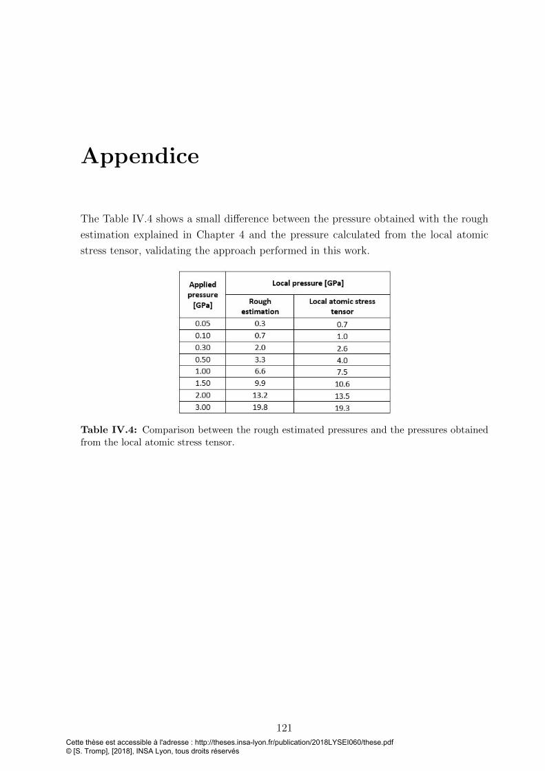
Appendice
The Table IV.4 shows a small difference between the pressure obtained with the rough
estimation explained in Chapter 4 and the pressure calculated from the local atomic
stress tensor, validating the approach performed in this work.
Table IV.4: Comparison between the rough estimated pressures and the pressures obtainedfrom the local atomic stress tensor.
121Cette thèse est accessible à l'adresse : http://theses.insa-lyon.fr/publication/2018LYSEI060/these.pdf © [S. Tromp], [2018], INSA Lyon, tous droits réservés

Cette thèse est accessible à l'adresse : http://theses.insa-lyon.fr/publication/2018LYSEI060/these.pdf © [S. Tromp], [2018], INSA Lyon, tous droits réservés
Bibliography
[1] Guillermo E Morales-Espejel, R Hauleitner, and HH Wallin. Pure re-
frigerant lubrication technology in oil-free centrifugal compressors. Evolu-
tion Online, http://evolution.skf.com/pure-refrigerant-lubrication-technology-in-
oil-free-centrifugal-compressors/ (accessed Fev 21, 2018), 2017.
[2] Guillermo E Morales-Espejel, Hans H Wallin, Rudolf Hauleitner, and Magnus
Arvidsson. Progress in rolling bearing technology for refrigerant compressors. Pro-
ceedings of the Institution of Mechanical Engineers, Part C: Journal of Mechanical
Engineering Science, page DOI: 10.1177/0954406217725772, 2017.
[3] Guillermo E Morales-Espejel, Ralph Meeuwenoord, Armando F Quinonez, and
Rudolf Hauleitner. Film thickness and traction measurements of refrigerant
R1233zd used as lubricant in elastohydrodynamic conditions. Proceedings of the
Institution of Mechanical Engineers, Part C: Journal of Mechanical Engineering
Science, 229:244–253, 2015.
[4] Rudolph Hauleitner, G E Morales-Espejel, and M Arvidsson. Tribological aspects
of rolling bearings lubricated with refrigerant. The 6th World Tribology Congress,
Beijing, China, 2017.
[5] Rudolph Hauleitner, G E Morales-Espejel, and M Arvidsson. Forthcoming com-
munication at Herrick conference. Perdue University, USA, July 9-12, 2018.
[6] Stephane Tromp, Laurent Joly, Manuel Cobian, and Nicolas Fillot. Chem-
ical physics at interfaces within a refrigerant-lubricated contact: From elec-
tronic structure to large scale molecular dynamics simulations. page DOI:
10.1021/acs.jpcc.7b11267, 2018.
[7] Thomas Reichenbach, Krishnakanta Mondal, Marc Jager, Thomas Vent-Schmidt,
Daniel Himmel, Valentin Dybbert, Albert Bruix, Ingo Krossing, Michael Walter,
and Michael Moseler. Ab initio study of co 2 hydrogenation mechanisms on inverse
zno/cu catalysts. Journal of Catalysis, 360:168–174, 2018.
[8] David Sholl and Janice A Steckel. Density functional theory: a practical introduc-
tion. John Wiley & Sons, 2011.
123Cette thèse est accessible à l'adresse : http://theses.insa-lyon.fr/publication/2018LYSEI060/these.pdf © [S. Tromp], [2018], INSA Lyon, tous droits réservés
Bibliography
[9] Laurent Joly, Gabriele Tocci, Samy Merabia, and Angelos Michaelides. Strong
coupling between nanofluidic transport and interfacial chemistry: How defect re-
activity controls liquid–solid friction through hydrogen bonding. The journal of
physical chemistry letters, 7:1381–1386, 2016.
[10] Thi D Ta, A Kiet Tieu, Hongtao Zhu, and Buyung Kosasih. Adsorption of Normal-
Alkanes on Fe(110), FeO(110), and Fe2O3(0001): Influence of Iron Oxide Surfaces.
Journal of Physical Chemistry C, 119:12999–13010, 2015.
[11] Thi Dinh Ta, Anh Kiet Tieu, Hongtao Zhu, Buyung Kosasih, Qiang Zhu, and
HT Phan. The structural, tribological, and rheological dependency of thin hexade-
cane film confined between iron and iron oxide surfaces under sliding conditions.
Tribology International, 113:26–35, 2017.
[12] Joost Vandevondele, Matthias Krack, Fawzi Mohamed, Michele Parrinello,
Thomas Chassaing, and Jurg Hutter. Quickstep: Fast and accurate density func-
tional calculations using a mixed Gaussian and plane waves approach. Computer
Physics Communications, 167:103–128, 2005.
[13] Jirı Klimes, David R Bowler, and Angelos Michaelides. Chemical accuracy for
the van der Waals density functional. Journal of Physics: Condensed Matter,
22:022201, 2010.
[14] Samira Dabaghmanesh, Erik C Neyts, and Bart Partoens. van der waals density
functionals applied to corundum-type sesquioxides: bulk properties and adsorp-
tion of ch3 and c6h6 on (0001) surfaces. Physical Chemistry Chemical Physics,
18:23139–23146, 2016.
[15] SL Dudarev, GA Botton, SY Savrasov, CJ Humphreys, and AP Sutton. Electron-
energy-loss spectra and the structural stability of nickel oxide: An lsda+ u study.
Physical Review B, 57:1505, 1998.
[16] Nelson Y Dzade, Alberto Roldan, and Nora H de Leeuw. A Density Functional
Theory Study of the Adsorption of Benzene on Hematite (α-Fe2O3) Surfaces.
Minerals, 4:89–115, 2014.
[17] Pierre-Alain Garrain. These - Etude ab initio de l’adsorption d’acides amines et
peptide sur surfaces modeles d’acier inoxydable. 2012.
[18] Matteo Cococcioni and Stefano De Gironcoli. Linear response approach to the
calculation of the effective interaction parameters in the lda+ u method. Physical
Review B, 71:035105, 2005.
[19] William Humphrey, Andrew Dalke, and Klaus Schulten. VMD: Visual molecular
dynamics. Journal of Molecular Graphics, 14:33–38, 1996.
124Cette thèse est accessible à l'adresse : http://theses.insa-lyon.fr/publication/2018LYSEI060/these.pdf © [S. Tromp], [2018], INSA Lyon, tous droits réservés

PhD thesis - Stephane TROMP
[20] M Muraki, T Sano, and D Dong. Elastohydrodynamic properties and boundary
lubrication performance of polyolester in a hydrofluoroether refrigerant environ-
ment. Proceedings of the Institution of Mechanical Engineers, Part J: Journal of
Engineering Tribology, 216:19–26, 2002.
[21] Byung Chul Na, Keyoung Jin Chun, and Dong-Chul Han. A tribological study of
refrigeration oils under HFC-134a environment. Tribology international, 30:707–
716, 1997.
[22] M Wasim Akram and Andreas A. Polycarpou. Wear Mechanisms of Gray Cast Iron
in the Presence of Environmentally Friendly Hydrofluoroolefin-Based Refrigerant
and the Effect of Tribofilm Formation. Journal of Tribology, 137:041602, 2015.
[23] Michael P Allen and Tildesley. Computer simulation of liquids. Oxford university
press, 1989.
[24] Nicolas Voeltzel, Philippe Vergne, Nicolas Fillot, Nathalie Bouscharain, and Lau-
rent Joly. Rheology of an Ionic Liquid with Variable Carreau Exponent: A Full
Picture by Molecular Simulation with Experimental Contribution. Tribology Let-
ters, 64:25, 2016.
[25] Nicolas Voeltzel, Nicolas Fillot, Philippe Vergne, and Laurent Joly. Orders of
magnitude changes in the friction of an ionic liquid on carbonaceous surfaces. The
Journal of Physical Chemistry C, 122:2145–2154, 2018.
[26] Thi Dinh Ta, A Kiet Tieu, H. T. Zhu, and Buyung Kosasih. Thin film lubrication
of hexadecane confined by iron and iron oxide surfaces: A crucial role of surface
structure. The Journal of Chemical Physics, 143:164702, 2015.
[27] James P Ewen, Sebastian Echeverri Restrepo, Neal Morgan, and Daniele Dini.
Nonequilibrium molecular dynamics simulations of stearic acid adsorbed on iron
surfaces with nanoscale roughness. Tribology International, 107:264–273, 2017.
[28] JP Ewen, DM Heyes, and D Dini. Advances in nonequilibrium molecular dynamics
simulations of lubricants and additives. Friction, pages 1–38, 2018.
[29] James P Ewen, Chiara Gattinoni, Neal Morgan, Hugh A Spikes, and Daniele
Dini. Nonequilibrium molecular dynamics simulations of organic friction modifiers
adsorbed on iron oxide surfaces. Langmuir, 32:4450–4463, 2016.
[30] Steve Plimpton. Fast Parallel Algorithms for Short – Range Molecular Dynamics.
J Comp Phys, 117:1–19, 1995.
[31] Gabriele Raabe. Molecular Simulation Studies on the Vapor - Liquid Equilibria of
the cis - and trans -HCFO-1233zd and the cis - and trans -HFO-1336mzz. Journal
of Chemical & Engineering Data, 60:2412–2419, 2015.
125Cette thèse est accessible à l'adresse : http://theses.insa-lyon.fr/publication/2018LYSEI060/these.pdf © [S. Tromp], [2018], INSA Lyon, tous droits réservés
Bibliography
[32] Gabriele Raabe and Edward J. Maginn. A force field for 3,3,3-fluoro-1-propenes,
including HFO-1234yf. Journal of Physical Chemistry B, 114:10133–10142, 2010.
[33] A Jewett, A; Lambert. Moltemplate.
[34] Dawid Toton, Christian D Lorenz, Nikolaos Rompotis, Natalia Martsinovich, and
Lev Kantorovich. Temperature control in molecular dynamic simulations of non-
equilibrium processes. Journal of Physics: Condensed Matter, 22:074205, 2010.
[35] Stefano Bernardi, B. D. Todd, and Debra J. Searles. Thermostating highly con-
fined fluids. Journal of Chemical Physics, 132:244706, 2010.
[36] Daniele Savio, Nicolas Fillot, and Philippe Vergne. A molecular dynamics study
of the transition from ultra-thin film lubrication toward local film breakdown.
Tribology Letters, 50:207–220, 2013.
[37] Daniele Savio. Ph.D. Dissertation - Nanoscale phenomena in lubrication : From
atomistic simulations to their integration into continuous models, INSA Lyon -
Karlsruher Institut fur Technologie. 2013.
[38] Energy Information Administration U.S. What’s new in how we use energy at
home: Results from EIA’s 2015 residential energy consumption surfvey (RECS).
https://www.eia.gov/consumption/residential/reports/2015/overview/pdf/ what-
snew home energy use.pdf / (accessed Dec 06, 2017), 2017.
[39] Jeff Biddle. Explaining the spread of residential air conditioning, 1955–1980. Ex-
plorations in Economic History, 45(4):402–423, 2008.
[40] Mat Santamouris. Cooling the buildings–past, present and future. Energy and
Buildings, 128:617–638, 2016.
[41] Michael A McNeil and Virginie E Letschert. Future air conditioning energy con-
sumption in developing countries and what can be done about it: the potential of
efficiency in the residential sector. Lawrence Berkeley National Laboratory, 2008.
[42] James M Calm. The next generation of refrigerants–historical review, considera-
tions, and outlook. international Journal of Refrigeration, 31(7):1123–1133, 2008.
[43] Vijay Wasudeo Bhatkar, VM Kriplani, and GK Awari. Alternative refrigerants in
vapour compression refrigeration cycle for sustainable environment: a review of
recent research. International Journal of Environmental Science and Technology,
10:871–880, 2013.
[44] M.J. Molina and F.S. Rowland. Stratospheric sink for chlorofluoromethanes: chlo-
rine atom-catalysed destruction of ozone. Nature, 249:810 – 812, 1974.
126Cette thèse est accessible à l'adresse : http://theses.insa-lyon.fr/publication/2018LYSEI060/these.pdf © [S. Tromp], [2018], INSA Lyon, tous droits réservés
PhD thesis - Stephane TROMP
[45] J Doucet, P Sauvageau, and C Sandorfy. Vacuum ultraviolet and photoelectron
spectra of fluoro-chloro derivatives of methane. The Journal of Chemical Physics,
58:3708–3716, 1973.
[46] United Nations. Montreal protocol on substances that deplete the
ozone layer. https://treaties.un.org/doc/Treaties/1989/01/19890101%2003-
25%20AM/Ch XXVII 02 ap.pdf / (accessed Oct 26, 2017), 1987.
[47] J Steven Brown, Samuel F Yana-Motta, and Piotr A Domanski. Comparitive
analysis of an automotive air conditioning systems operating with co 2 and r134a.
International Journal of refrigeration, 25:19–32, 2002.
[48] MADHU SRUTHI EMANI, RANENDRA ROYb, and BIJAN KUMAR MAN-
DAL. Development of refrigerants: A brief review. Indian J. Sci. Res, 14:175–181,
2017.
[49] Xiaomin Wu, Shan Hu, and Shaojia Mo. Carbon footprint model for evaluating
the global warming impact of food transport refrigeration systems. Journal of
cleaner production, 54:115–124, 2013.
[50] Report of the refrigeration, air conditioning and heat pumps, technical op-
tions commitee. https://http://conf.montreal-protocol.org/meeting/mop/mop-
27/presession/Background%20Documents%20are%20available%20in%20English
%20only/RTOC-Assessment-Report-2014.pdf (accessed Fev 19, 2018), 2014.
[51] Cindy Newberg. Update on Kigali Amendment to the Montreal Protocol
Montreal Protocol on Substances that Deplete the Ozone Layer, U.S. Envi-
ronmental Protection Agency. https://www.epa.gov/sites/production/files/2016-
11/documents/newberg kigaliamend 122016.pdf / (accessed Oct 26, 2017), 2016.
[52] Gabriele Raabe. Molecular simulation studies in hydrofluoroolefine (HFO) work-
ing fluids and their blends. Science and Technology for the Built Environment,
22:1077–1089, 2016.
[53] Gabriele Raabe and Edward J. Maginn. Molecular Modeling of the Vapor-
Liquid Equilibrium Properties of the Alternative Refrigerant 2,3,3,3-Tetrafluoro-
1-propene (HFO-1234yf). Journal of Physical Chemistry Letters, 1:93–96, 2010.
[54] Chemours. FreonTM 123, Refrigerant (R-123), Properties, Uses, Storage, and Han-
dling. https://www.chemours.com/Refrigerants/en US/assets/downloads/freon-
123-properties-uses-storage-handling.pdf (accessed Fev 19, 2018).
[55] Ole John Nielsen, Meshkat Sadat Javadi, MP Sulbaek Andersen, Michael D Hur-
ley, Timothy J Wallington, and Rajiv Singh. Atmospheric chemistry of cf3cfch2:
127Cette thèse est accessible à l'adresse : http://theses.insa-lyon.fr/publication/2018LYSEI060/these.pdf © [S. Tromp], [2018], INSA Lyon, tous droits réservés

Bibliography
Kinetics and mechanisms of gas-phase reactions with cl atoms, oh radicals, and
o3. Chemical Physics Letters, 439:18–22, 2007.
[56] M. P Sulbaek Andersen, Elna Johanna Kristina Nilsson, Ole John Nielsen,
Matthew Stanley Johnson, Michael D Hurley, and Timothy J Wallington. At-
mospheric chemistry of trans-cf3ch=chcl: Kinetics of the gas-phase reactions with
cl atoms, oh radicals, and o3. Journal of Photochemistry and Photobiology A:
Chemistry, 199:92–97, 2008.
[57] KO Patten and DJ Wuebbles. Atmospheric lifetimes and ozone depletion poten-
tials of trans-1-chloro-3, 3, 3-trifluoropropylene and trans-1, 2-dichloroethylene in
a three-dimensional model. Atmospheric Chemistry and Physics, 10:10867–10874,
2010.
[58] T. J. Wallington, M. P. Sulbaek Andersen, and O. J. Nielsen. Atmospheric
chemistry of short-chain haloolefins: Photochemical ozone creation potentials
(POCPs), global warming potentials (GWPs), and ozone depletion potentials
(ODPs). Chemosphere, 129:135–141, 2015.
[59] Yohan Lee and Dongsoo Jung. A brief performance comparison of r1234yf and
r134a in a bench tester for automobile applications. Applied Thermal Engineering,
35:240–242, 2012.
[60] M Wasim Akram, Jacob L Meyer, and Andreas A Polycarpou. Tribological in-
teractions of advanced polymeric coatings with polyalkylene glycol lubricant and
r1234yf refrigerant. Tribology International, 97:200–211, 2016.
[61] Honghyun Cho and Chasik Park. Experimental investigation of performance and
exergy analysis of automotive air conditioning systems using refrigerant r1234yf
at various compressor speeds. Applied Thermal Engineering, 101:30–37, 2016.
[62] Zhaogang Qi. Performance improvement potentials of r1234yf mobile air condi-
tioning system. International Journal of Refrigeration, 58:35–40, 2015.
[63] Adrian Mota-Babiloni, Joaquın Navarro-Esbrı, Angel Barragan, Francisco Moles,
and Bernardo Peris. Drop-in energy performance evaluation of r1234yf and r1234ze
(e) in a vapor compression system as r134a replacements. Applied Thermal Engi-
neering, 71:259–265, 2014.
[64] Juan Manuel Mendoza-Miranda, Adrian Mota-Babiloni, JJ Ramirez-Minguela,
VD Munoz-Carpio, M Carrera-Rodriguez, Joaquın Navarro-Esbrı, and C Salazar-
Hernandez. Comparative evaluation of r1234yf, r1234ze (e) and r450a as alterna-
tives to r134a in a variable speed reciprocating compressor. Energy, 114:753–766,
2016.
128Cette thèse est accessible à l'adresse : http://theses.insa-lyon.fr/publication/2018LYSEI060/these.pdf © [S. Tromp], [2018], INSA Lyon, tous droits réservés
PhD thesis - Stephane TROMP
[65] Latra Boumaraf, Philippe Haberschill, and Andre Lallemand. Investigation of a
novel ejector expansion refrigeration system using the working fluid r134a and its
potential substitute r1234yf. international journal of refrigeration, 45:148–159,
2014.
[66] Francisco Moles, Joaquın Navarro-Esbrı, Bernardo Peris, Adrian Mota-Babiloni,
and Angel Barragan-Cervera. Theoretical energy performance evaluation of differ-
ent single stage vapour compression refrigeration configurations using r1234yf and
r1234ze (e) as working fluids. International journal of refrigeration, 44:141–150,
2014.
[67] Milad Ashouri, Mohammad H Ahmadi, Michel Feidt, and Fatemeh Razi Astaraei.
Exergy and energy analysis of a regenerative organic rankine cycle based on flat
plate solar collectors. Mechanics & Industry, 18:217, 2017.
[68] Huixing Zhai, Qingsong An, and Lin Shi. Zeotropic mixture active design method
for organic rankine cycle. Applied Thermal Engineering, 129:1171–1180, 2018.
[69] Francisco Moles, Joaquın Navarro-Esbrı, Bernardo Peris, Adrian Mota-Babiloni,
Angel Barragan-Cervera, and Konstantinos Kostas Kontomaris. Low gwp alter-
natives to hfc-245fa in organic rankine cycles for low temperature heat recov-
ery: Hcfo-1233zd-e and hfo-1336mzz-z. Applied Thermal Engineering, 71:204–212,
2014.
[70] Joaquın Navarro-Esbrı, Francisco Moles, Bernardo Peris, Adrian Mota-Babiloni,
and Konstantinos Kontomaris. Experimental study of an organic rankine cycle
with hfo-1336mzz-z as a low global warming potential working fluid for micro-scale
low temperature applications. Energy, 133:79–89, 2017.
[71] Francisco Moles, Joaquın Navarro-Esbrı, Bernardo Peris, Adrian Mota-Babiloni,
and Konstantinos Kostas Kontomaris. Thermodynamic analysis of a combined
organic rankine cycle and vapor compression cycle system activated with low
temperature heat sources using low gwp fluids. Applied Thermal Engineering,
87:444–453, 2015.
[72] Michel Feidt, Abdelhamid Kheiri, Sandrine Pelloux-Prayer, et al. Performance
optimization of low-temperature power generation by supercritical orcs (organic
rankine cycles) using low gwp (global warming potential) working fluids. Energy,
67:513–526, 2014.
[73] Adrian Mota-Babiloni, Joaquın Navarro-Esbrı, Francisco Moles, Angel Barragan
Cervera, Bernardo Peris, and Gumersindo Verdu. A review of refrigerant
r1234ze(e) recent investigations. Applied Thermal Engineering, 95:211–222, 2016.
129Cette thèse est accessible à l'adresse : http://theses.insa-lyon.fr/publication/2018LYSEI060/these.pdf © [S. Tromp], [2018], INSA Lyon, tous droits réservés

Bibliography
[74] Adrian Mota-Babiloni, Joaquın Navarro-Esbrı, Juan Manuel Mendoza-Miranda,
and Bernardo Peris. Experimental evaluation of system modifications to increase
r1234ze (e) cooling capacity. Applied Thermal Engineering, 111:786–792, 2017.
[75] R Hulse, R Singh, and W Spatz. Trans-chloro-3,3,3-trifluoropropene for use in
chiller applications. Patent US 8574451 B2, 2013.
[76] Bala V Datla and Joost J Brasz. Comparing R1233zd And R245fa For Low
Temperature ORC Applications. International Refrigeration and Air Conditioning
Conference, paper 1524, 2014.
[77] Wang Bingming, Wu Huagen, Li Jianfeng, and Xing Ziwen. Experimental inves-
tigation on the performance of nh 3/co 2 cascade refrigeration system with twin-
screw compressor. International Journal of Refrigeration, 32:1358–1365, 2009.
[78] J Alberto Dopazo, Jose Fernandez-Seara, Jaime Sieres, and Francisco J Uhıa. The-
oretical analysis of a co 2–nh 3 cascade refrigeration system for cooling applications
at low temperatures. Applied thermal engineering, 29:1577–1583, 2009.
[79] Adrian Mota-Babiloni, Joaquın Navarro-Esbrı, Angel Barragan-Cervera, Fran-
cisco Moles, Bernardo Peris, and Gumersindo Verdu. Commercial refrigeration–an
overview of current status. International journal of refrigeration, 57:186–196, 2015.
[80] Xiaoqin Liu, Jianlin Yu, and Gang Yan. Theoretical investigation on an ejector–
expansion refrigeration cycle using zeotropic mixture r290/r600a for applications
in domestic refrigerator/freezers. Applied Thermal Engineering, 90:703–710, 2015.
[81] M Mohanraj, S Jayaraj, C Muraleedharan, and P Chandrasekar. Experimen-
tal investigation of r290/r600a mixture as an alternative to r134a in a domestic
refrigerator. International Journal of Thermal Sciences, 48:1036–1042, 2009.
[82] Juan Manuel Belman-Flores, AP Rodriguez-Munoz, C Gutierrez Perez-Reguera,
and Adrian Mota-Babiloni. Experimental study of r1234yf as a drop-in replace-
ment for r134a in a domestic refrigerator. International Journal of Refrigeration,
81:1–11, 2017.
[83] Martin K Vollmer, Stefan Reimann, Matthias Hill, and Dominik Brunner. First
observations of the fourth generation synthetic halocarbons hfc-1234yf, hfc-1234ze
(e), and hcfc-1233zd (e) in the atmosphere. Environmental science & technology,
49:2703–2708, 2015.
[84] Shigeo Kondo, Kenji Takizawa, and Kazuaki Tokuhashi. Flammability limits of
binary mixtures of ammonia with hfo-1234yf, hfo-1234ze, hfc-134a, and hfc-125.
Journal of Fluorine Chemistry, 149:18–23, 2013.
130Cette thèse est accessible à l'adresse : http://theses.insa-lyon.fr/publication/2018LYSEI060/these.pdf © [S. Tromp], [2018], INSA Lyon, tous droits réservés

PhD thesis - Stephane TROMP
[85] Shigeru Koyama, Nobuo Takata, and Sho Fukuda. Drop-in experiments on heat
pump cycle using hfo-1234ze (e) and its mixtures with hfc-32. international refrig-
eration and air conditioning conference at purdue, july 12-15. 2010.
[86] Gabriele Raabe. Molecular simulation studies on the vapor–liquid phase equilibria
of binary mixtures of r-1234yf and r-1234ze (e) with r-32 and co2. Journal of
Chemical & Engineering Data, 58:1867–1873, 2013.
[87] B B Chen, P Bonnet, M Y Elsheikh, B L Van Horn, and L Abbas. Compositions
of Hydrochlorofluoroolefins. Patent 20160257867 A1, 2016.
[88] Series ETM CenTraV acTM chiller product catalog, Trane.
http://www.trane.com/WEBCACHE/RF/CENTRIFUGAL%20LIQUID
%20CHILLERS%20(CTV)/PRODUCT/CTV-PRC015B-EN 11122015.pdf (ac-
cessed Oct 26, 2017).
[89] Sebastian Eyerer, Christoph Wieland, Annelies Vandersickel, and Hartmut Spli-
ethoff. Experimental study of an orc (organic rankine cycle) and analysis of
r1233zd-e as a drop-in replacement for r245fa for low temperature heat utiliza-
tion. Energy, 103:660–671, 2016.
[90] Francisco Moles, Joaquin Navarro-Esbri, Bernardo Peris, and Adrian Mota-
Babiloni. Experimental evaluation of hcfo-1233zd-e as hfc-245fa replacement in an
organic rankine cycle system for low temperature heat sources. Applied Thermal
Engineering, 98:954–961, 2016.
[91] Matthias Welzl, Florian Heberle, and Dieter Bruggemann. Simultaneous exper-
imental investigation of nucleate boiling heat transfer and power output in orc
using r245fa and r1233zd (e). Energy Procedia, 129:435–442, 2017.
[92] Alejandro Lavernia, Davide Ziviani, Bryce Shaffer, Kunal Bansal, and Eckhard A
Groll. Optimization of an organic rankine cycle as bottoming cycle of a 1 kwe
genset for residential applications. Energy Procedia, 129:867–874, 2017.
[93] Ludovic Guillaume, Arnaud Legros, Adriano Desideri, and Vincent Lemort. Per-
formance of a radial-inflow turbine integrated in an orc system and designed for
a whr on truck application: An experimental comparison between r245fa and
r1233zd. Applied Energy, 186:408–422, 2017.
[94] Fujun Ju, Xiaowei Fan, Yaping Chen, Honglin Zhang, Tuanjie Wang, and Xi-
angyang Tang. Performance assessment of heat pump water heaters with r1233zd
(e)/hcs binary mixtures. Applied Thermal Engineering, 123:1345–1355, 2017.
[95] Vladimir L Orkin, Larissa E Martynova, and Michael J Kurylo. Photochemical
properties of trans-1-chloro-3, 3, 3-trifluoropropene (trans-chcl=chcf3): Oh reac-
131Cette thèse est accessible à l'adresse : http://theses.insa-lyon.fr/publication/2018LYSEI060/these.pdf © [S. Tromp], [2018], INSA Lyon, tous droits réservés
Bibliography
tion rate constant, uv and ir absorption spectra, global warming potential, and
ozone depletion potential. The Journal of Physical Chemistry A, 118:5263–5271,
2014.
[96] B L Van Horn, M Y Elsheikh, B B Chen, and P Bonnet. Stable Formulated
Systems with Chloro-3,3,3- Trifluoropropene. Patent US 9254468 B2, 2016.
[97] MP Sulbaek Andersen, Ole John Nielsen, MD Hurley, and TJ Wallington. Atmo-
spheric chemistry of t-cf 3 ch [double bond, length as m-dash] chcl: products and
mechanisms of the gas-phase reactions with chlorine atoms and hydroxyl radicals.
Physical Chemistry Chemical Physics, 14:1735–1748, 2012.
[98] Vladimir L Orkin, Robert E Huie, and Michael J Kurylo. Atmospheric lifetimes of
hfc-143a and hfc-245fa: flash photolysis resonance fluorescence measurements of
the oh reaction rate constants. The Journal of Physical Chemistry, 100:8907–8912,
1996.
[99] Giovanni Di Nicola, Laura Fedele, J Steven Brown, Sergio Bobbo, and Gianluca
Coccia. Saturated pressure measurements of trans-1-chloro-3, 3, 3-trifluoroprop-1-
ene (r1233zd (e)). Journal of Chemical & Engineering Data, 62:2496–2500, 2017.
[100] Ryan J Hulse, Rajat S Basu, Rajiv R Singh, and Raymond H P Thomas. Phys-
ical Properties of HCFO-1233zd(E). Journal of Chemical & Engineering Data,
57:3581–3586, 2012.
[101] Marıa E Mondejar, Mark O McLinden, and Eric W Lemmon. Thermodynamic
properties of trans-1-chloro-3, 3, 3-trifluoropropene (r1233zd (e)): Vapor pres-
sure,(p, ρ, t) behavior, and speed of sound measurements, and equation of state.
Journal of Chemical & Engineering Data, 60:2477–2489, 2015.
[102] Chieko Kondou, Ryuichi Nagata, Noriko Nii, Shigeru Koyama, and Yukihiro Hi-
gashi. Surface tension of low gwp refrigerants r1243zf, r1234ze (z), and r1233zd
(e). International Journal of Refrigeration, 53:80–89, 2015.
[103] Laura Fedele, Mariano Pierantozzi, Giovanni Di Nicola, J Steven Brown, and
Sergio Bobbo. Compressed liquid density and vapor phase pvt measurements of
trans-1-chloro-3, 3, 3-trifluoroprop-1-ene [r1233zd (e)]. Journal of Chemical &
Engineering Data, 63:225–232, 2018.
[104] R Romeo, PA Giuliano Albo, S Lago, and JS Brown. Experimental liquid densities
of cis-1, 3, 3, 3-tetrafluoroprop-1-ene (r1234ze (z)) and trans-1-chloro-3, 3, 3-
trifluoropropene (r1233zd (e)). International Journal of Refrigeration, 79:176–182,
2017.
132Cette thèse est accessible à l'adresse : http://theses.insa-lyon.fr/publication/2018LYSEI060/these.pdf © [S. Tromp], [2018], INSA Lyon, tous droits réservés
PhD thesis - Stephane TROMP
[105] Richard A Perkins, Marcia L Huber, and Marc J Assael. Measurement and correla-
tion of the thermal conductivity of trans-1-chloro-3, 3, 3-trifluoropropene (r1233zd
(e)). Journal of Chemical & Engineering Data, 62:2659–2665, 2017.
[106] Katsuyuki Tanaka. pρt property of trans-1-chloro-3, 3, 3-trifluoropropene (r
1233zd (e)) near critical density. Journal of Chemical & Engineering Data,
61:3570–3572, 2016.
[107] Vincent Strubel. Particle Entrapment in EHD Contacts - Aerospace Applications.
PhD thesis, Lyon, INSA, 2016.
[108] Vincent Strubel, Nicolas Fillot, Fabrice Ville, Jerome Cavoret, Philippe Vergne,
Alexandre Mondelin, and Yves Maheo. Particle entrapment in hybrid lubricated
point contacts. Tribology Transactions, 59:768–779, 2016.
[109] Jean Frene, Daniel Nicolas, Bernard Degueurce, Daniel Berthe, and Maurice
Godet. Hydrodynamic lubrication: bearings and thrust bearings, volume 33. Else-
vier, 1997.
[110] S Loehle, C Matta, C Minfray, T Le Mogne, R Iovine, Y Obara, A Miyamoto,
and JM Martin. Mixed lubrication of steel by c18 fatty acids revisited. part ii:
Influence of some key parameters. Tribology International, 94:207–216, 2016.
[111] Mitsuhiro Fukuta, Junki Sumiyama, Masaaki Motozawa, and Tadashi Yanagisawa.
Surface tension measurement of oil/refrigerant mixture by maximum bubble pres-
sure method. International Journal of Refrigeration, 73:125–133, 2017.
[112] Chaobin Dang, Keitaro Hoshika, and Eiji Hihara. Effect of lubricating oil on the
flow and heat-transfer characteristics of supercritical carbon dioxide. International
Journal of Refrigeration, 35:1410–1417, 2012.
[113] Scott Bair, Wassim Habchi, Mark Baker, and David M Pallister. Quantitative
elastohydrodynamic film-forming for an oil/refrigerant system. Journal of Tribol-
ogy, 139:061501, 2017.
[114] M Wasim Akram, Kyriaki Polychronopoulou, and Andreas A Polycarpou. Tribo-
logical performance comparing different refrigerant–lubricant systems: The case of
environmentally friendly hfo-1234yf refrigerant. Tribology International, 78:176–
186, 2014.
[115] M Akei, K Mizuhara, T Taki, and T Yamamoto. Evaluation of film-forming
capability of refrigeration lubricants in pressurized refrigerant atmosphere. Wear,
196:180–187, 1996.
[116] M Akei and K Mizuhara. The elastohydrodynamic properties of lubricants in
refrigerant environments c©. Tribology transactions, 40:1–10, 1997.
133Cette thèse est accessible à l'adresse : http://theses.insa-lyon.fr/publication/2018LYSEI060/these.pdf © [S. Tromp], [2018], INSA Lyon, tous droits réservés

Bibliography
[117] Kasper Gorny, Arkadiusz Stachowiak, Przemys law Tyczewski, and Wies law
Zwierzycki. Lubricity evaluation of oil–refrigerant mixtures with r134a and r290.
International Journal of Refrigeration, 69:261–271, 2016.
[118] Ian BELL and Arno LAESECKE. Viscosity of refrigerants and other working
fluids from residual entropy scaling. In 16th International Refrigeration and Air
Conditioning Conference at Perdue, July 11-14, 2016.
[119] M Wasim Akram, Kyriaki Polychronopoulou, and Andreas A Polycarpou. Lubric-
ity of environmentally friendly HFO-1234yf refrigerant. Tribiology International,
57:92–100, 2013.
[120] Christopher Ciantar, Mark Hadfield, AM Smith, and A Swallow. The influence
of lubricant viscosity on the wear of hermetic compressor components in hfc-134a
environments. Wear, 236:1–8, 1999.
[121] Hiroyuki Fukui, Ken-ichi Sanechika, and Masanori Ikeda. Novel refrigeration lu-
bricants for use with hfc refrigerants. Tribology international, 33:707–713, 2000.
[122] Emerson Escobar Nunez, Kyriaki Polychronopoulou, and Andreas A Polycarpou.
Lubricity effect of carbon dioxide used as an environmentally friendly refrigerant
in air-conditioning and refrigeration compressors. Wear, 270:46–56, 2010.
[123] Clare McCabe, Shengting Cui, Peter T Cummings, Peter A Gordon, and Roland B
Saeger. Examining the rheology of 9-octylheptadecane to giga-pascal pressures.
The Journal of chemical physics, 114:1887–1891, 2001.
[124] Bernard J Hamrock and Duncan Dowson. Isothermal elastohydrodynamic lubri-
cation of point contacts: part iii—fully flooded results. Journal of Lubrication
Technology, 99:264–275, 1977.
[125] Harmen Blok. Inverse problems in hydrodynamic lubrication and design directives
for lubricated flexible surfaces. In Symp. Lubric. & Wear, pages 1–151, 1963.
[126] Roger Tuomas and Ove Isaksson. Compressibility of oil/refrigerant lubricants in
elasto-hydrodynamic contacts. Journal of tribology, 128:218–220, 2006.
[127] Kasper Gorny, Arkadiusz Stachowiak, and Przemys law Tyczewski. Lubricity eval-
uation of oil–refrigerant mixtures with R134a and R290. International Journal of
Refrigeration, 69:261–271, 2016.
[128] A Yokozeki. Solubility correlation and phase behaviors of carbon dioxide and
lubricant oil mixtures. Applied Energy, 84:159–175, 2007.
[129] Masayoshi Muraki, Takashi Sano, and Daming Dong. Rheological properties of
polyolester under an ehd contact in some refrigerant environments. Journal of
tribology, 123:54–60, 2001.
134Cette thèse est accessible à l'adresse : http://theses.insa-lyon.fr/publication/2018LYSEI060/these.pdf © [S. Tromp], [2018], INSA Lyon, tous droits réservés
PhD thesis - Stephane TROMP
[130] S Kitaichi, S Sato, R Ishidoya, and T Machida. Tribological analysis of metal
interface reactions in lubricant oils/cfc12 and hfc 134a system. In International
Refrigeration and Air Conditioning Conference at Perdue, 1990.
[131] SE Quinones-Cisneros, J Garcıa, Josefa Fernandez, and Matıas Alfonso Monsalvo.
Phase and viscosity behaviour of refrigerant–lubricant mixtures. International
journal of refrigeration, 28:714–724, 2005.
[132] U. J. Jonsson. Lubrication of rolling element bearings with HFC-polyolester mix-
tures. Wear, 232:185–191, 1999.
[133] David R Henderson. Solubility, viscosity and density of refrigerant/lubricant mix-
tures. Technical report, Spauschus Associates, Inc., Stockbridge, GA (United
States); Air-Conditioning and Refrigeration Technology Inst., Inc., Arlington, VA
(United States), 1993.
[134] Bo Jacobson, Erik Hoglund, Ulf Jonsson, FP Wardle, and H Dolfsma. The effect
of refrigerants on the lubrication of rolling element bearings used in screw com-
pressors. In In: Proceedings of inter- national compressor engineering conference
at Purdue, West Lafayette, IN, USA, 1992, pp.523–534, 1992.
[135] Scott Bair, Mark Baker, and David M. Pallister. Revisiting the Compressibility
of Oil/Refrigerant Lubricants. Journal of Tribology, 139:1–4, 2016.
[136] Shinji Tanaka, Tsunamitsu Nakahara, and Keiji Kyogoku. Measurements of two-
dimensional distribution of refrigerant concentration in ehl film using micro ft-ir
and effect of variation of concentration on oil film thickness. Tribology Letters,
14:9–15, 2003.
[137] Ulf J Jonsson and N Hansson. Lubrication limits of rolling element bearings in
refrigeration compressors. 1998.
[138] Scott Bair. A new high-pressure viscometer for oil/refrigerant solutions and pre-
liminary results. Tribology Transactions, 60:392–398, 2017.
[139] Bo O Jacobson and Guillermo E. Morales Espejel. High Pressure Investigation of
Refrigerants HFC245fa, R134a and R123. International Compressor Engineering
Conference, paper C033, 2006.
[140] Guillermo E Morales-Espejel and V Brizmer. Micropitting modelling in rolling–
sliding contacts: application to rolling bearings. Tribology Transactions, 54:625–
643, 2011.
[141] Customer Reference Case SKF. Pure refrigerant lubricated bearings
from skf. http://www.skf.com/binary/76-294546/15640-EN-Pure-refrigerant-
lubricated-bearings-reference-case.pdf/ (accessed Fev 21, 2018), 2015.
135Cette thèse est accessible à l'adresse : http://theses.insa-lyon.fr/publication/2018LYSEI060/these.pdf © [S. Tromp], [2018], INSA Lyon, tous droits réservés
Bibliography
[142] Scott Bair and Arno Laesecke. Viscosity measurements of R32 and R410A to 350
MPa. International Journal of Refrigeration, 83:157–167, 2017.
[143] V Brizmer, Antonio Gabelli, Charlotte Vieillard, and Guillermo E Morales-
Espejel. An experimental and theoretical study of hybrid bearing micropitting
performance under reduced lubrication. Tribology Transactions, 58:829–835, 2015.
[144] Philippe Vergne, N Fillot, N Bouscharain, and N Devaux. An experimental and
modeling assessment of the HCFC-R123 refrigerant capabilities for lubricating
rolling EHD circular contacts. Proceedings of the Institution of Mechanical Engi-
neers, Part J: Journal of Engineering Tribology, 229:950–961, 2015.
[145] Duncan Dowson. History of tribology. Addison-Wesley Longman Limited, 1979.
[146] HH Wallin and GE Morales-Espejel. Hybrid bearings in oil-free air conditioning
and refrigeration compressors. Evolution Online, http://evolution.skf.com/hybrid-
bearings-in-oil-free-air-conditioning-and-refrigeration-compressors/ (accessed Fev
14, 2018), 2002.
[147] Honeywell Solstice Liquid Blowing Agent. Technical information, (hfo-
1233zd(e). https://www.honeywell-blowingagents.com/?document=solstice-lba-
technical-brochure&download=1 (accessed Fev 14, 2018).
[148] Wassim Habchi, Philippe Vergne, Dominique Eyheramendy, and Guillermo E
Morales-Espejel. Numerical investigation of the use of machinery low-viscosity
working fluids as lubricants in elastohydrodynamic lubricated point contacts. Pro-
ceedings of the Institution of Mechanical Engineers, Part J: Journal of Engineering
Tribology, 225:465–477, 2011.
[149] Arno Laesecke and Scott Bair. High-pressure viscosity measurements of 1, 1, 1,
2-tetrafluoroethane. International Journal of Thermophysics, 32:925–941, 2011.
[150] Frederic Chevalier. Modelisation des conditions d’alimentation dans les contacts
elastohydrodynamiques ponctuels. PhD thesis, Lyon, INSA, 1996.
[151] Pieter Martin Lugt, RWM Severt, J Fogelstro, and JH Tripp. Influence of surface
topography on friction, film breakdown and running-in in the mixed lubrication
regime. Proceedings of the Institution of Mechanical Engineers, Part J: Journal
of Engineering Tribology, 215:519–533, 2001.
[152] Roger G Horn and Jacob N Israelachvili. Direct measurement of structural forces
between two surfaces in a nonpolar liquid. The Journal of Chemical Physics,
75:1400–1411, 1981.
136Cette thèse est accessible à l'adresse : http://theses.insa-lyon.fr/publication/2018LYSEI060/these.pdf © [S. Tromp], [2018], INSA Lyon, tous droits réservés

PhD thesis - Stephane TROMP
[153] P Frantz, N Agrait, and M Salmeron. Use of capacitance to measure surface forces.
1. measuring distance of separation with enhanced spatial and time resolution.
Langmuir, 12:3289–3294, 1996.
[154] Gerd Binnig, Heinrich Rohrer, Ch Gerber, and Edmund Weibel. Surface studies
by scanning tunneling microscopy. Physical review letters, 49:57, 1982.
[155] Gerd Binnig, Calvin F Quate, and Ch Gerber. Atomic force microscope. Physical
review letters, 56:930, 1986.
[156] Kai Siegbahn. Electron spectroscopy for atoms, molecules, and condensed matter.
Reviews of Modern Physics, 54:709, 1982.
[157] Nicholas Metropolis, Arianna W Rosenbluth, Marshall N Rosenbluth, Augusta H
Teller, and Edward Teller. Equation of state calculations by fast computing ma-
chines. The journal of chemical physics, 21:1087–1092, 1953.
[158] Sophie Loehle. Ph.D. Dissertation - Understanding of adsorption mechanisms
and tribological behaviors of C18 fatty acids on iron-based surfaces: a molecular
simulation approach, Ecole Centrale de Lyon. 2014.
[159] Anke Peguiron, Gianpietro Moras, Michael Walter, Hiroshi Uetsuka, Lars
Pastewka, and Michael Moseler. Activation and mechanochemical breaking of
c–c bonds initiate wear of diamond (110) surfaces in contact with silica. Carbon,
98:474–483, 2016.
[160] P Koskinen, H Hakkinen, G Seifert, S Sanna, Th Frauenheim, and M Moseler.
Density-functional based tight-binding study of small gold clusters. New Journal
of Physics, 8:9, 2006.
[161] Hassan Berro. Ph.D. Dissertation - A Molecular Dynamics Approach to Nano-
scale Lubrication, INSA Lyon. 2010.
[162] Seiji Kajita and Maria Clelia Righi. A fundamental mechanism for carbon-film
lubricity identified by means of ab initio molecular dynamics. Carbon, 103:193–
199, 2016.
[163] Michael Doig, Chris P Warrens, and Philip J Camp. Structure and friction of
stearic acid and oleic acid films adsorbed on iron oxide surfaces in squalane. Lang-
muir, 30:186–195, 2014.
[164] Carlos Vega, Berthold Saager, and Johann Fischer. Molecular dynamics studies
for the new refrigerant r152a with simple model potentials. Molecular Physics,
68:1079–1093, 1989.
137Cette thèse est accessible à l'adresse : http://theses.insa-lyon.fr/publication/2018LYSEI060/these.pdf © [S. Tromp], [2018], INSA Lyon, tous droits réservés

Bibliography
[165] M Lisal, R Budinsky, V Vacek, and K Aim. Vapor–liquid equilibria of alter-
native refrigerants by molecular dynamics simulations. International journal of
thermophysics, 20:163–174, 1999.
[166] Farid F Abraham. The interfacial density profile of a lennard-jones fluid in contact
with a (100) lennard-jones wall and its relationship to idealized fluid/wall systems:
A monte carlo simulation. The Journal of Chemical Physics, 68:3713–3716, 1978.
[167] IK Snook and W Van Megen. Solvation forces in simple dense fluids. i. The
Journal of Chemical Physics, 72:2907–2913, 1980.
[168] Jianping Gao, WD Luedtke, and Uzi Landman. Layering transitions and dynamics
of confined liquid films. Physical review letters, 79:705, 1997.
[169] Atkinson Jabbarzadeh, JD Atkinson, and RI Tanner. Nanorheology of molecularly
thin films of n-hexadecane in couette shear flow by molecular dynamics simulation.
Journal of non-newtonian fluid mechanics, 77:53–78, 1998.
[170] Jianping Gao, WD Luedtke, and Uzi Landman. Structures, solvation forces and
shear of molecular films in a rough nano-confinement. Tribology letters, 9:3–13,
2000.
[171] A Jabbarzadeh, Peter Harrowell, and RI Tanner. Low friction lubrication between
amorphous walls: Unraveling the contributions of surface roughness and in-plane
disorder. The Journal of chemical physics, 125:034703, 2006.
[172] JJ Magda, M Tirrell, and HT Davis. Molecular dynamics of narrow, liquid-filled
pores. The Journal of chemical physics, 83:1888–1901, 1985.
[173] I Bitsanis, JJ Magda, M Tirrell, and HT Davis. Molecular dynamics of flow in
micropores. The Journal of chemical physics, 87:1733–1750, 1987.
[174] Ioannis Bitsanis, Susan A Somers, H Ted Davis, and Matthew Tirrell. Microscopic
dynamics of flow in molecularly narrow pores. The Journal of Chemical Physics,
93:3427–3431, 1990.
[175] Susan A Somers and H Ted Davis. Microscopic dynamics of fluids confined between
smooth and atomically structured solid surfaces. The Journal of chemical physics,
96:5389–5407, 1992.
[176] Ramesh Singh, Joshua Monk, and Francisco R Hung. Heterogeneity in the dy-
namics of the ionic liquid [bmim+][pf6–] confined in a slit nanopore. The Journal
of Physical Chemistry C, 115:16544–16554, 2011.
[177] Nicolas Voeltzel. Molecular simulation of an ionic liquid as lubricant: from bulk
rheology to nanoconfinement. PhD thesis, Lyon, INSA, 2016.
138Cette thèse est accessible à l'adresse : http://theses.insa-lyon.fr/publication/2018LYSEI060/these.pdf © [S. Tromp], [2018], INSA Lyon, tous droits réservés
PhD thesis - Stephane TROMP
[178] Hassan Berro, Nicolas Fillot, and Philippe Vergne. Molecular dynamics simulation
of surface energy and zddp effects on friction in nano-scale lubricated contacts.
Tribology international, 43:1811–1822, 2010.
[179] Peter A Thompson and Mark O Robbins. Shear flow near solids: Epitaxial order
and flow boundary conditions. Physical review A, 41:6830, 1990.
[180] Uwe Heinbuch and Johann Fischer. Liquid flow in pores: Slip, no-slip, or multi-
layer sticking. Physical Review A, 40:1144, 1989.
[181] Ashlie Martini, Hua-Yi Hsu, Neelesh A Patankar, and Seth Lichter. Slip at high
shear rates. Physical review letters, 100:206001, 2008.
[182] Christopher JS Petrie and Morton M Denn. Instabilities in polymer processing.
AIChE Journal, 22:209–236, 1976.
[183] Eric Lauga, Michael P Brenner, and Howard A Stone. Microfluidics: the no-slip
boundary condition. Perspective, 17, 2006.
[184] Lyderic Bocquet and Jean-Louis Barrat. Flow boundary conditions from nano-to
micro-scales. Soft matter, 3:685–693, 2007.
[185] AV Ramamurthy. Wall slip in viscous fluids and influence of materials of con-
struction. Journal of Rheology, 30:337–357, 1986.
[186] A Jabbarzadeh, JD Atkinson, and RI Tanner. Effect of the wall roughness on
slip and rheological properties of hexadecane in molecular dynamics simulation of
couette shear flow between two sinusoidal walls. Physical review E, 61:690, 2000.
[187] Uri Raviv, Pierre Laurat, and Jacob Klein. Fluidity of water confined to sub-
nanometre films. Nature, 413:51, 2001.
[188] Jianping Gao, Robert Szoszkiewicz, Uzi Landman, Elisa Riedo, et al. Structured
and viscous water in subnanometer gaps. Physical Review B, 75:115415, 2007.
[189] John Van Alsten and Steve Granick. Molecular tribometry of ultrathin liquid
films. Physical Review Letters, 61:2570, 1988.
[190] A Jabbarzadeh, Peter Harrowell, and RI Tanner. Crystal bridge formation marks
the transition to rigidity in a thin lubrication film. Physical review letters,
96:206102, 2006.
[191] Peter A Thompson, Gary S Grest, and Mark O Robbins. Phase transitions and
universal dynamics in confined films. Physical Review Letters, 68:3448, 1992.
[192] Jacob N Israelachvili. Measurement of the viscosity of liquids in very thin films.
Journal of colloid and interface science, 110:263–271, 1986.
139Cette thèse est accessible à l'adresse : http://theses.insa-lyon.fr/publication/2018LYSEI060/these.pdf © [S. Tromp], [2018], INSA Lyon, tous droits réservés

Bibliography
[193] Michelle L Gee, Patricia M McGuiggan, Jacob N Israelachvili, and Andrew M
Homola. Liquid to solidlike transitions of molecularly thin films under shear. The
Journal of chemical physics, 93:1895–1906, 1990.
[194] Jianping Gao, WD Luedtke, and Uzi Landman. Friction control in thin-film lu-
brication. The Journal of Physical Chemistry B, 102:5033–5037, 1998.
[195] Gustavo Luengo, Jacob Israelachvili, and Steve Granick. Generalized effects in
confined fluids: new friction map for boundary lubrication. Wear, 200:328–335,
1996.
[196] Hsuan-Wei Hu, George A Carson, and Steve Granick. Relaxation time of confined
liquids under shear. Physical review letters, 66:2758, 1991.
[197] Mark J Stevens, Maurizio Mondello, Gary S Grest, ST Cui, HD Cochran, and
PT Cummings. Comparison of shear flow of hexadecane in a confined geometry
and in bulk. The Journal of chemical physics, 106:7303–7314, 1997.
[198] Nicolas Voeltzel, Andrew Giuliani, Nicolas Fillot, Philippe Vergne, and Laurent
Joly. Nanolubrication by ionic liquids: molecular dynamics simulations reveal an
anomalous effective rheology. Physical Chemistry Chemical Physics, 17:23226–
23235, 2015.
[199] Peihong Cong, Jun Imai, and Shigeyuki Mori. Effect of gas pressure on tribological
properties and tribochemical reactions of alumina sliding against zirconia in hfc-
134a. Wear, 249:142–148, 2001.
[200] D Dascalescu, K Polychronopoulou, and AA Polycarpou. The significance of
tribochemistry on the performance of ptfe-based coatings in co2 refrigerant envi-
ronment. Surface and Coatings Technology, 204:319–329, 2009.
[201] Geraldine Theiler, Wolfgang Hubner, Thomas Gradt, P Klein, and K Friedrich.
Friction and wear of ptfe composites at cryogenic temperatures1. Tribology Inter-
national, 35:449–458, 2002.
[202] Emerson Escobar Nunez, Seung Min Yeo, Kyriaki Polychronopoulou, and An-
dreas A Polycarpou. Tribological study of high bearing blended polymer-based
coatings for air-conditioning and refrigeration compressors. Surface and Coatings
Technology, 205:2994–3005, 2011.
[203] Seung Min Yeo and Andreas A Polycarpou. Tribological performance of ptfe-
and peek-based coatings under oil-less compressor conditions. Wear, 296:638–647,
2012.
140Cette thèse est accessible à l'adresse : http://theses.insa-lyon.fr/publication/2018LYSEI060/these.pdf © [S. Tromp], [2018], INSA Lyon, tous droits réservés

PhD thesis - Stephane TROMP
[204] Nicholaos G Demas and Andreas A Polycarpou. Tribological investigation of cast
iron air-conditioning compressor surfaces in co 2 refrigerant. Tribology Letters,
22:271–278, 2006.
[205] Max Born and Robert Oppenheimer. Zur quantentheorie der molekeln. Annalen
der Physik, 389:457–484, 1927.
[206] David M Ceperley and BJ Alder. Ground state of the electron gas by a stochastic
method. Physical Review Letters, 45:566, 1980.
[207] Georg Kresse and Jurgen Furthmuller. Efficient iterative schemes for ab initio
total-energy calculations using a plane-wave basis set. Physical review B, 54:11169,
1996.
[208] S Goedecker, M Teter, and Jurg Hutter. Separable dual-space gaussian pseudopo-
tentials. Physical Review B, 54:1703, 1996.
[209] D. D. Johnson. Modified Broyden’s method for accelerating convergence in self-
consistent calculations. Physical Review B, 38:12807–12813, 1988.
[210] H Luth, G W Rubloff, and W D Grobman. Chemisorption and decomposition
reactions of oxygen-containing organic molecules on clean Pd surfaces studied by
UV photoemission. Surface Science, 63:325–338, 1977.
[211] S F Boys and Fiorenza de Bernardi. The calculation of small molecular interac-
tions by the differences of separate total energies. some procedures with reduced
errors. Molecular Physics, 19:553–566, 1970.
[212] Curt M Breneman and Kenneth B Wiberg. Determining atom-centered monopoles
from molecular electrostatic potentials. the need for high sampling density in for-
mamide conformational analysis. Journal of Computational Chemistry, 11:361–
373, 1990.
[213] Patrick Bultinck, Christian Van Alsenoy, Paul W Ayers, and Ramon Carbo-Dorca.
Critical analysis and extension of the hirshfeld atoms in molecules. The Journal
of chemical physics, 126:144111, 2007.
[214] Graeme Henkelman, Andri Arnaldsson, and Hannes Jonsson. A fast and robust
algorithm for bader decomposition of charge density. Computational Materials
Science, 36:354–360, 2006.
[215] Edward Sanville, Steven D Kenny, Roger Smith, and Graeme Henkelman. Im-
proved grid-based algorithm for bader charge allocation. Journal of computational
chemistry, 28:899–908, 2007.
[216] W Tang, E Sanville, and G Henkelman. A grid-based bader analysis algorithm
without lattice bias. Journal of Physics: Condensed Matter, 21:084204, 2009.
141Cette thèse est accessible à l'adresse : http://theses.insa-lyon.fr/publication/2018LYSEI060/these.pdf © [S. Tromp], [2018], INSA Lyon, tous droits réservés

Bibliography
[217] Min Yu and Dallas R Trinkle. Accurate and efficient algorithm for bader charge
integration. The Journal of chemical physics, 134:064111, 2011.
[218] James P Ewen, Chiara Gattinoni, Foram M Thakkar, Neal Morgan, Hugh A
Spikes, and Daniele Dini. A comparison of classical force-fields for molecular
dynamics simulations of lubricants. Materials, 9:651, 2016.
[219] Katie A Maerzke and J Ilja Siepmann. Transferable potentials for phase equilibria-
coarse-grain description for linear alkanes. The Journal of Physical Chemistry B,
115:3452–3465, 2011.
[220] Siewert J Marrink, H Jelger Risselada, Serge Yefimov, D Peter Tieleman, and
Alex H De Vries. The martini force field: coarse grained model for biomolecular
simulations. The journal of physical chemistry B, 111:7812–7824, 2007.
[221] Adri CT Van Duin, Siddharth Dasgupta, Francois Lorant, and William A God-
dard. Reaxff: a reactive force field for hydrocarbons. The Journal of Physical
Chemistry A, 105:9396–9409, 2001.
[222] R Romeo, P.A. Giuliano Albo, S Lago, and J.S. Brown. Experimental liquid den-
sities of cis-1,3,3,3- tetrafluoroprop-1-ene (R1234ze(Z)) and trans-1- chloro-3,3,3-
trifluoropropene (R1233zd(E)). International Journal of Refrigeration, 79:176–
182, 2017.
[223] Roger W Hockney and James W Eastwood. Computer simulation using particles.
crc Press, 1988.
[224] Stefano Bernardi, BD Todd, and Debra J Searles. Thermostating highly confined
fluids. The Journal of chemical physics, 132:244706, 2010.
[225] James P Ewen, Chiara Gattinoni, Jie Zhang, David M Heyes, Hugh A Spikes, and
Daniele Dini. On the effect of confined fluid molecular structure on nonequilibrium
phase behaviour and friction. Physical Chemistry Chemical Physics, 19:17883–
17894, 2017.
[226] Daniele Savio, Nicolas Fillot, Philippe Vergne, and Maurizio Zaccheddu. A model
for wall slip prediction of confined n-alkanes: effect of wall-fluid interaction versus
fluid resistance. Tribology Letters, 46:11–22, 2012.
[227] Robert D Engle, Robert D Skeel, and Matthew Drees. Monitoring energy drift
with shadow hamiltonians. Journal of Computational Physics, 206(2):432–452,
2005.
[228] Thi D. Ta, A. Kiet Tieu, Hongtao Zhu, Qiang Zhu, Prabouno B. Kosasih, Jie
Zhang, and Guanyu Deng. Tribological Behavior of Aqueous Copolymer Lubricant
142Cette thèse est accessible à l'adresse : http://theses.insa-lyon.fr/publication/2018LYSEI060/these.pdf © [S. Tromp], [2018], INSA Lyon, tous droits réservés

PhD thesis - Stephane TROMP
in Mixed Lubrication Regime. ACS Applied Materials and Interfaces, 8:5641–5652,
2016.
[229] Clotilde Minfray, Thierry Le Mogne, Jean-michel Martin, Tasuku Onodera, Shuko
Takahashi, Hideyuki Tsuboi, Michihisa Koyama, Akira Endou, Hiromitsu Takaba,
Momoji Kubo, C.A. Del Carpio, and A Miyamoto. Experimental and Molec-
ular Dynamics Simulations of Tribochemical Reactions with ZDDP: Zinc Phos-
phate–Iron Oxide Reaction. Tribology Transactions, 51:589–601, 2008.
[230] T. Halicioglu and G. M. Pound. Calculation of Potential Energy Parameters from
Crystalline State Properties. Physica Status Solidi (a), 30:619–623, 1975.
[231] Pnina Dauber-Osguthorpe, Victoria A Roberts, David J Osguthorpe, Jon Wolff,
Moniqe Genest, and Arnold T Hagler. Structure and energetics of ligand binding to
proteins: Escherichia coli dihydrofolate reductase-trimethoprim, a drug-receptor
system. Proteins: Structure, Function, and Bioinformatics, 4:31–47, 1988.
[232] In-Chul Yeh and Max L Berkowitz. Ewald summation for systems with slab
geometry. The Journal of chemical physics, 111:3155–3162, 1999.
[233] Laetitia Martinie and Philippe Vergne. Lubrication at extreme conditions: a
discussion about the limiting shear stress concept. Tribology Letters, 63:21, 2016.
[234] Chiara Gattinoni, David M Heyes, Christian D Lorenz, and Daniele Dini. Traction
and nonequilibrium phase behavior of confined sheared liquids at high pressure.
Physical Review E, 88:052406, 2013.
[235] S-N Ndiaye, L Martinie, D Philippon, N Devaux, and P Vergne. A quantita-
tive friction-based approach of the limiting shear stress pressure and temperature
dependence. Tribology Letters, 65:149, 2017.
[236] Jianping Gao, WD Luedtke, and Uzi Landman. Structure and solvation forces
in confined films: Linear and branched alkanes. The Journal of chemical physics,
106:4309–4318, 1997.
[237] Jianping Gao, WD Luedtke, and Uzi Landman. Origins of solvation forces in
confined films. The Journal of Physical Chemistry B, 101:4013–4023, 1997.
[238] Ion Marius Sivebæk, VN Samoilov, and BNJ Persson. Squeezing molecular thin
alkane lubrication films between curved solid surfaces with long-range elasticity:
Layering transitions and wear. The Journal of chemical physics, 119:2314–2321,
2003.
[239] Bertrand Guillot and Nicolas Sator. A computer simulation study of natural
silicate melts. part i: Low pressure properties. Geochimica et Cosmochimica Acta,
71:1249–1265, 2007.
143Cette thèse est accessible à l'adresse : http://theses.insa-lyon.fr/publication/2018LYSEI060/these.pdf © [S. Tromp], [2018], INSA Lyon, tous droits réservés
Bibliography
[240] Daniele Savio, Nicolas Fillot, Philippe Vergne, Hartmut Hetzler, Wolfgang See-
mann, and GE Morales Espejel. A multiscale study on the wall slip effect
in a ceramic–steel contact with nanometer-thick lubricant film by a nano-to-
elastohydrodynamic lubrication approach. Journal of Tribology, 137:031502, 2015.
[241] Nicolas Fillot, Hassan Berro, and Philippe Vergne. From continuous to molecular
scale in modelling elastohydrodynamic lubrication: Nanoscale surface slip effects
on film thickness and friction. Tribology Letters, 43:257–266, 2011.
144Cette thèse est accessible à l'adresse : http://theses.insa-lyon.fr/publication/2018LYSEI060/these.pdf © [S. Tromp], [2018], INSA Lyon, tous droits réservés
Publication and conferences
Publication:
Tromp, S., Joly, L., Cobian, M., Fillot, N. (2018).
Title: Chemical Physics at Interfaces Within a Refrigerant-Lubricated Contact: From
Electronic Structure to Large Scale Molecular Dynamics Simulations. The Journal of
Physical Chemistry C. 2018, 122 (10), pp 5420–5429.
DOI: 10.1021/acs.jpcc.7b11267
Oral presentations:
• Tribology Frontiers Conference, Chicago, USA, 13-15 Nov. 2016.
Title: Refrigerants as lubricants: from molecular dynamics characterization to the
applicability at the contact scale. S. Tromp, L. Joly, M. Cobian, N. Fillot.
• STLE (Society of Tribologists and Lubrication Engineers) 72nd Annual Meeting,
Atlanta, USA, 21-25 May 2017.
Title: Coupling between refrigerant-surface chemistry and lubrication conditions.
S. Tromp, L. Joly, M. Cobian, N. Fillot.
• 6th World Tribology Congress, Beijing, China 17-22 Sept. 2017.
Title: Influence of refrigerant-surface chemistry on lubrication conditions. S.
Tromp, L. Joly, M. Cobian, N. Fillot.
Poster presentations:
• 8th Multiscale Materials Modeling Conference, Dijon, France, 9-14 Oct. 2016.
Title: ReacLub – Strong coupling between flow and physical chemistry in lubri-
cated contacts. S. Tromp, L. Joly, M. Cobian, N. Fillot.
• TriboUK, London, England 27-28 Apr. 2017.
Title: How to translate ab-initio results about adhesion behavior to a larger scale
Molecular Dynamics simulation? S. Tromp, L. Joly, M. Cobian, N. Fillot.
145Cette thèse est accessible à l'adresse : http://theses.insa-lyon.fr/publication/2018LYSEI060/these.pdf © [S. Tromp], [2018], INSA Lyon, tous droits réservés
FOLIO ADMINISTRATIF
THESE DE L’UNIVERSITE DE LYON OPEREE AU SEIN DE L’INSA LYON
NOM : TROMP DATE de SOUTENANCE : 11/07/2018
Prénoms : Stéphane, Arnaud
TITRE : Lubrication with a refrigerant: an industrial challenge investigated through multiscale modeling based on fluid/surface chemistry
NATURE : Doctorat Numéro d'ordre : 2018LYSEI060
Ecole doctorale : Mécanique, Energétique, Génie Civil, Acoustique
Spécialité : Génie Mécanique
RESUME :
Dans les grands systèmes de réfrigération, l’utilisation de réfrigérants comme lubrifiants, à la place des huiles, simplifie la conception du système, l’allège et réduit son impact environnemental. La très faible viscosité du réfrigérant conduit à une épaisseur de film séparant les deux surfaces comparable à leur rugosité. Néanmoins, des travaux expérimentaux avec le réfrigérant R1233zd suggèrent que la lubrification est possible dans ces conditions grâce à la formation d’une couche adsorbée sur la surface d’oxyde de fer. Les analyses expérimentales in situ dans le contact sont très difficiles à cause des conditions de fort confinement et haute pression. C’est pourquoi une approche numérique multi-échelles est développée, afin d’étudier l’impact des réactions physico-chimiques à l’interface réfrigérant-surface sur les propriétés de lubrification. La théorie de la fonctionnelle de la densité est utilisée pour quantifier au niveau quantique, l’adsorption d’une molécule de réfrigérant sur une surface d’oxyde de fer. Des énergies de liaison allant de -0,92 eV à -0,22 eV sont observées et reliées à différents cas d’adsorption. Ces résultats sont exploités pour paramétrer un champ de forces interfacial, qui prédit des structures moléculaires à l’interface, différentes de celles obtenues avec des potentiels basés sur les règles de mélange classiques. Des simulations de dynamique moléculaire utilisant ce champ de forces paramétré confirment l’existence d’une couche fortement adsorbée de R1233zd sur une surface de Fe2O3. Avec des surfaces atomiques lisses et seulement 2 nm d’épaisseur de film de réfrigérant, les couches adsorbées résistent à des pressions allant jusqu’à 4 GPa et des vitesses de cisaillement atteignant 100 m/s. Une valeur minimale de 5 molécules de réfrigérant par nm² est nécessaire à la formation de deux couches adsorbées à 0.5 GPa. De plus, des simulations en cisaillement avec une surface rugueuse prédisent une rupture totale du film à environ 13 GPa. MOTS-CLÉS : Lubrification, Réfrigérants, Physico-Chimie Fluide/Surface, Dynamique Moléculaire, Théorie de la Fonctionnelle de Densité Laboratoire (s) de recherche : Laboratoire de Mécanique des Contacts et des Structures – Institut Lumière Matière Directeur de thèse: Dr. Nicolas Fillot, Prof. Laurent Joly Présidente de jury : Prof. Céline Leonard Composition du jury : Dr. Manuel Cobian (Examinateur) Prof. Daniele Dini (Rapporteur) Dr. Nicolas Fillot (Directeur) Prof. Laurent Joly (Co-directeur) Prof. Céline Leonard (Examinatrice) Prof. Michael Moseler (Rapporteur)
Cette thèse est accessible à l'adresse : http://theses.insa-lyon.fr/publication/2018LYSEI060/these.pdf © [S. Tromp], [2018], INSA Lyon, tous droits réservés
Copyright © 2022 FDOKUMEN