Look-ahead Tracking Controllers for Integrated Longitudinal ...
LOOK-AHEAD INSTRUCTION SCHEDULING FOR DYNAMIC
390
[LOOK-AHEAD INSTRUCTION SCHEDULING FOR DYNAMIC .- EXECUTION IN PIPELINED COMPUTERSj A Thesis Presented to The Faculty of the College of Engineering and Technology Ohio University In Partial Fulfillment of the Requirements for the Degree Master of Science by Vij ay K. Reddy Anam, +.- June, 1990
-
Upload
khangminh22 -
Category
Documents
-
view
0 -
download
0
Transcript of LOOK-AHEAD INSTRUCTION SCHEDULING FOR DYNAMIC

[LOOK-AHEAD INSTRUCTION SCHEDULING FOR DYNAMIC .-
EXECUTION IN PIPELINED COMPUTERSj
A Thesis Presented to
The Faculty of the College of Engineering and Technology
Ohio University
In Partial Fulfillment
of the Requirements for the Degree
Master of Science
by
Vij ay K. Reddy Anam, +.-
June, 1990

TABLE OF CONTENTS
CHAPTER I
Introduction
CHAPTER I1
Design of Look-Ahead Pipelined
Computer System
2.1 Introduction
2.2 Dynamic Instruction Scheduling
2.3 Reducing Branch Penalty
2.4 Hardware System
CHAPTER I11
Design of Dynamic Pipelined
Arithmetic Unit
3.1 Introduction
3.2 Principle of Operation of
the CSA Tree
3.3 Conversion of Unifunction
Pipeline to Multifunction Pipeline
3.4 Dynamic Execution of Instructions
CHAPTER IV
Instruction Execution in the Pipeline
System
CHAPTER V
Computer Simulation and Experimental
Results
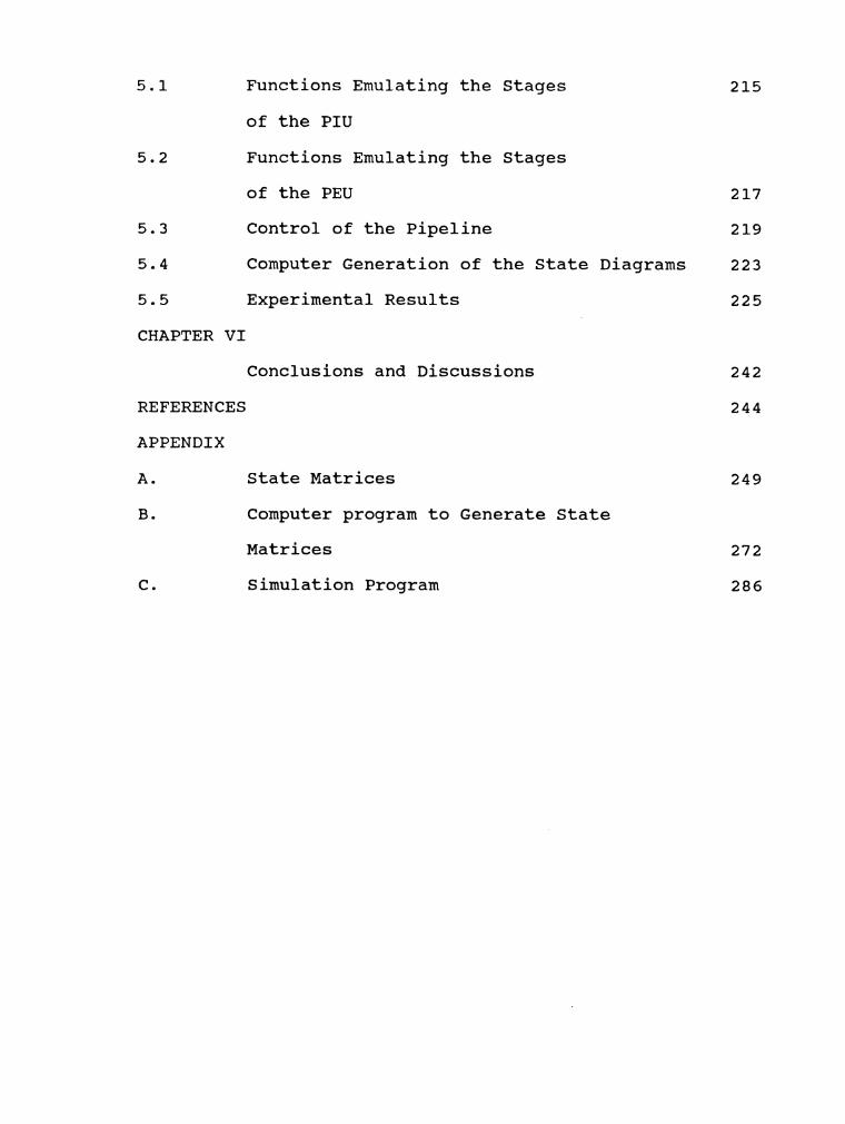
5.1 Functions Emulating the Stages
of the PIU
5.2 Functions Emulating the Stages
of the PEU 217
5.3 Control of the Pipeline 219
5.4 Computer Generation of the State Diagrams 223
5.5 Experimental Results 225
CHAPTER VI
Conclusions and Discussions
REFERENCES
APPENDIX
A.
B.
State Matrices
Computer program to Generate State
Matrices
Simulation Program

CHAPTER ONE
INTRODUCTION
The advances in computer technology are leading to the
advent of high speed computers which are cost effective and
faster than their predecessors. Main frame machines like the
Texas Instruments TI-ASC, IBM System/360 Model 91 and 195,
Burroughs PEPE, CRAY - 1, CDC STAR-100, CDC 6600 and CDC 7600 have to a large extent pipeline processing capabilities
in their instruction and arithmetic units or in the form of
pipelined special purpose functional units [l-41.
Pipelining is a way of imbedding parallelism in a
system. The principle of pipelining is to partition a
process into several subprocesses and execute these
subprocesses concurrently in dedicated individual units.
This is analogous to the operation of an assembly line in
the automotive industry. In a non-pipelined computer system,
the execution of an instruction involves the following
processes: 1) fetching the instruction, 2) decoding the
instruction , 3) fetching the operands, and 4) executing the
instruction. In a pipelined system, instruction execution
can be split into four subprocesses which are performed by
dedicated units functioning concurrently. The advantage of
this operation is that while a unit is operating on an
instruction, the immediately preceding unit can be operating

2
on the next instruction and so on. Thus the throughput of
a pipelined system is much higher than a non-pipelined
system. The overlapped execution is depicted in a space time
diagram in Fig. 1.1.
The second generation and earlier computers employed
arithmetic and logic units which were unsophisticated and
under-utilized. The introduction of pipeline techniques in
the processor design necessitated the advent of new
algorithms to control the instruction flow and resolve any
hazards that might arise in execution of instructions.
Several look-ahead algorithms have been proposed with the
capabilities of executing more than one instruction at the
same time. These algorithms were successfully employed in
many third generation computers involving multiple execution
units.
The look-ahead algorithms were designed at the
processor level and involved the following common tasks: 1)
detecting the instructions that can be executed
concurrently, 2) issuing the instructions to the functional
units, and 3) assigning of the registers to various
operands. The ideal throughput is difficult to achieve due
to dependencies within the instructions of a program. The
data dependencies have to be resolved by either scheduling
the execution of the instruction or by placing the
instruction into a buffer and monitoring the registers for
resolving the instructional dependencies. Tomasulo [5] has

PIPELINE CYCLES
lnstruction 1 lnstruction 2 lnstruction 3 lnstruction 4 lnstruction 5 lnstruction 6 lnstruction 7
a) The structure of a general pipeline computer
b) The ideal flow of instructions in time space.
Fig 1.1 Ideal operation of a pipelined computer system

4
proposed an algorithm to resolve the dependency situation
by creating a reservation station (RS) to hold instructions
that are awaiting execution. Instructions remain in RS until
the operand conflicts are resolved. The RS monitors a common
data bus and captures the operands for the instructions as
they become available. The instruction identifies its
operands by an address tag scheme. Each source register is
assigned a ready bit which determines the usage of a
register. A register is set busy, if it is the destination
of an instruction in execution. If a source register is busy
when an instruction reaches the issue stage, the tag of the
register is obtained and attached to the instruction and the
instruction is forwarded to the RS. If a sink register is
busy, then a new tag is attached to the instruction against
the sink register and the tag is updated on that register.
This system is expensive to implement. Each register has to
be tagged and each tag needs an associative comparison
hardware to carry out the tag matching process. The problem
is compounded if the number of registers is large. Sohi and
Vajapeyam [6] have modified and extended Tumasulo~s
algorithm for CRAY - 1 system. The modifications were made to reduce the hardware needed for tagging a large bank of
registers. The tags are all consolidated into a tag unit
(TU). The tags are issued to registers from the TU unit and
are returned to the common pool as soon as the tag is
released. The reservation stations are combined into a

5
common RS pool and instructions are issued to various
functional units as they become ready. This scheme relies
on the tag comparing hardware for proper execution and still
requires a large number of register tags for all its
registers. In both the algorithms [5] and [6], associative
tags are compared while forwarding a single instruction. If
the instructions that are awaiting execution are large in
number, the process of associative comparison is time
consuming and cannot be avoided. Keller [7] proved that
optimality of resolving dependencies could be achieved by
a control scheme that employs first-in first-out (FIFO)
queues. Unlike the previous algorithms, these queues
eliminate the associative search process. Each queue is
associated with each pair of conflicting operations. An
operation will belong to a queue if it is an operation that
is associated with that queue. The elements stored in the
queue are represented by tokens. Each operation involves a
distinct token. When an instruction enters the issue stage,
it places a token at the tail of each queue to corresponding
to the operation. Before an operation begins, there must be
a corresponding token at the head of each queue to which the
operation belongs. When the operation is completed, the
tokens are removed. Each queue is implemented as a link
list. The disadvantage of this scheme is that if there are
m different binary functions and n different registers, the
number of queues would be (m*n14. Dennis [8] proposed a

6
similar queuing scheme with substantially lesser queues. The
queues are not FIFO in nature. Each queue corresponds to a
single register. Token interchanging can occur in a
nondeterministic fashion, casts doubts on the efficiency of
such an implementation. Tjaden and Flynn [9] have proposed
a scheme wherein a block of M instructions can be executed
simultaneously. The scheme analyses the dependencies of a
block of instructions and issues a set of independent
instructions for execution. This scheme has two
constraints: 1) it cannot handle indirect addressing, 2) the
source operands, the sink result, and the next instruction
must be specified by defining their locations in storage.
Ramamoorthy and Kim [lo] have proposed a scheme called
dynamic sequencing and segmentation model (DSSM) for
efficient sequencing of instructions with very low
overheads. The overheads are reduced by overlapping the
unproductive administrative and bookkeeping computations
with the execution of computational tasks. The end result
is the efficient exploitation of parallelism. Smith and
Weiss[ll] have proposed a modified scheme of Thorton's
algorithm [12] for the Cray-1 system. In this algorithm,
dynamic scheduling is adopted and the associative tag
comparisons are eliminated.
The effectiveness of the above mentioned schemes are
dependent on the availability of functional units. This
problem is alleviated by providing repetitive functional

7
units as provided in the TI-ASC computer [ 1 3 ] and
reconfiguring the units as needed. The general approach is
to provide a static functional unit for each class of
operations. Static functional units can execute instructions
only when the operation defined by the instruction fall
within the same class for which the unit was designed. The
Astronautics ZS-1 [14] operates on a decoupled architecture
and supports two instruction streams. This machine is
capable of forwarding two instructions to the execution
units within a clock period. The dependent instructions are
held at the issue stage until the dependency is resolved.
The two streams are unequal in length and are supported by
multiple static execution units. Data can be copied between
the two units via a copy unit. Queues are used for memory
operands providing a flexible way of relating the memory
access functions and floating point operations. This
provides a dynamic allocation of memory access functions
ahead of the floating point operations. There is no
reordering of instructions within a pipeline.
In this research a system is developed which executes
instructions dynamically. The hardware is a pipelined system
consisting of two fundamental sub-systems: the pipelined
instruction unit (PIU), and the pipelined execution unit
(PEU). The PIU can further be divided into the fetch unit
(FTJ ) , the decode unit (DU), and the issue unit (IU) . The PEU is also divided into the dynamic arithmetic unit (DAU) and
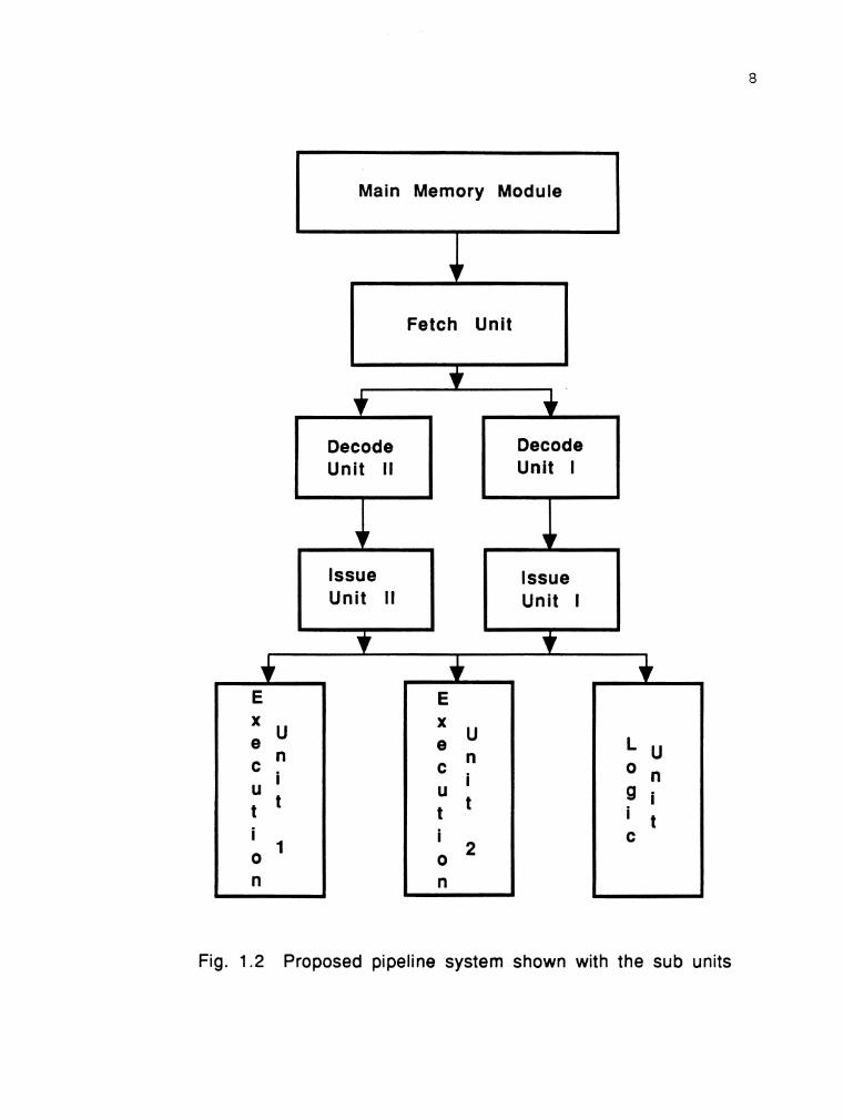
Main Memory Module
Fetch Unit r-l
Unit II Unit I
Fig. 1.2 Proposed pipeline system shown with the sub units

9
the logic unit (LU) . The overall system configuration is illustrated in Fig. 1.2. The operation of the system assumes
no shuffling of instructions by any compiler. The hardware
supports two instruction streams which are necessary for
executing branch instructions. The DAU can execute three
different arithmetic operations independently within the
same pipeline cycle. This improves the performance over a
similar static unit capable of executing a single operation
at a time. A simple tagging system is used to resolve the
dependency within instructions. There are no associative
comparisons necessary in this algorithm. The instructions
are held in delay stations (DS) present in the stages of the
execution units. An instruction is held in a stage only if
it needs the missing operand to enter the next stage. The
data is fed to the DS via a common data bus (CDB).
The remaining of this thesis is organized in six
chapters. Chapter I1 introduces the system and explains the
function of each sub-system along with the scheduling of
instructions. Chapter I11 describes the operation and the
design of the DAU. It also includes the generation of state
diagrams, to predict the latencies and to schedule the
execution of instructions in the DAU. Chapter IV explains
the operation of the proposed system. Chapter V deals with
the computer simulation of the system and the experimental
results. Chapter VI includes discussion and conclusions.

CHAPTER TWO
DESIGN OF THE LOOK-AHEAD PIPELINED COMPUTER SYSTEM
2.1 INTRODUCTION:
As stated in Chapter 1 sequential computers are not
efficient in utilizing their resources. The serial design
principles do not allow any independency to the functional
units present in the central processing unit (CPU). The
instructions are executed serially one at a time. There is
no overlap between two successive instructions in the
execution phase. This leads to many of the functional units
being idle most of the time. The new generation complex
instruction set computers (CISC) such as the Intel 80286,
80386, 80486, Motorola 68020, 68030 have incorporated
pipelining techniques at the fetch level. The general
pipeline system consists of stages devoted to fetch, decode,
issue and execute. These stages operate concurrently.
Elements are provided between the stages to synchronize the
flow of data from one stage to another. This could also be
achieved by incorporating these elements as a part of each
stage. At the beginning of every pipeline cycle, each stage
receives data from the previous stage. The data is processed
and the result is forwarded to the next stage, at the end
of the cycle. During the cycle, the output of a stage will
contain the result obtained from processing the data of the
11
previous cycle. It will change to the current result only
at the end of the current cycle. This is necessary so as to
prevent the result of one stage preemptively influencing the
operations of the next stage. The process is shown in a time
space diagram in Fig. 2.1.
The pipelined system proposed in this research is an
instruction look-ahead system, which consists of four
fundamental units. The system is illustrated in Fig. 2.2.
The first three units comprise the pipelined instruction
unit (PIU) and the last unit is the pipelined execution unit
(PEU). The PIU consists of the following units: the fetch
unit, the decode unit, and the issue unit. The execution
unit is made up of the pipelined arithmetic unit (PAU) and
the logic unit (LU) . The arithmetic unit is subdivided into the dynamic fixed point arithmetic unit (DAU) and the
dynamic floating point arithmetic unit (FPAU) . The pipeline arithmetic units consists of seven stages and can perform
the operations of addittion, subtraction, multiplication and
division. The dynamic nature of the arithmetic unit is
exploited by the system to initiate more than one
instruction in a single pipeline cycle. The individual
operations take different amounts of time to execute. The
table listed in Fig. 2.3 lists the execution time of the
various arithmetic and logic operations. The design of the
PAU is described in more detail in Chapter 3. The design of
the LU and FPAU is left for further research.

Pipeline cycle # 0
Latch 1 Latch 2 Latch 3
Pipeline cycle # 1
Latch 1 Latch 2 Latch 3
t
Decode Issue 'I, unit unit
Fetch un i t
lnstr 1
-
1
Pipeline cycle # 2
Fetch un i t
lnstr 2
Latch 1 Latch 2 Latch 3
- u
Fig. 2.1 Time - space diagram of instruction flow in a pipeline system
- lssue
+ unit *
Fetch un i t
lnstr 3
I
I n s t r 1 -
P u -u I U
+
I
I n s t r 2
-
- +
. Decode unit
lnstr 1
- I n s
* t + r 1
,L
Issue unit
lnstr 1
Decode unit
lnstr 2
-

Fetch unit
Decode unit
Issue unit
Fixed point
+ 1 + +
Floating point
1 i
arithmetic unit
1 1 J .
arithmetic unit
Fig. 2.2 The pipeline system with the various units
2 Logic unit
2
I .
I

Table 2.1
Instruction
Add / Subtract
Multiplication
Division
Store / Load
And / Or / Not
Fig. 2.3 Instructions and their execution times
Instruction Type
Arithmetic
Arithmetic
Arithmetic
Logic
Logic
Execution Time
3
8
2 3
6
3

15
The performance of a pipeline is dependent on the order
o f t h e instructions in the instruction stream. If
consecutive instructions have data and control dependencies
and contend for the same resources then hazards will develop
in the pipeline system and the performance will suffer. To
improve performance, it is often possible to schedule the
instructions, so that the dependencies and resource
conflicts are resolved. There are two different ways that
instruction scheduling can be carried out. Firstly, it can
be done at compile time by the compiler or the linker. This
is referred as static scheduling because it does not change
as the program is being executed. Secondly, it can be done
by hardware at the execution time. This is referred to as
dynamic scheduling. Most compilers for pipelined processors
do some sort of static scheduling. The static scheduling
does not have any information about the dependencies and
hence the optimization is highly relative to the type of
program being compiled. Dynamic scheduling on the other hand
is independent of the compiled instruction code and can take
advantage of the dependency information at the time of
issue. The dependency information is not available during
the compile time. In this research a dynamic instruction
scheduling algorithm is proposed based on the execution time
periods of instructions. The rest of this chapter is
organized in three main sections: 1) dynamic instruction
scheduling, 2) reducing branch overheads, and 3) the

hardware system.
2.2 DYNAMIC INSTRUCTION SCHEDULING:
The main objective of the scheduling algorithm is to
overcome the four main hazards: 1) read after write (RAW),
2) write after write (WAW), 3) write after read (WAR), and
4) operational hazard. Their significance is worth more
elaborate explanation. The registers and memory are known
as resources. A RAW hazard occurs when an instructions tries
to read a resource that has not completed its last write
process. A WAW hazard occurs, if an instruction attempts to
write into a resource that has yet to complete its previous
write operation. A WAR hazard occurs when an instruction
tries to write into a resource which has not completed its
previous read operation.
Consider the following instructions:
load r3, (A) ; ..... . I
load r2, (B) ; ..... . . I add rl, r2, r3; store ( X ) , rl; ..... * * I
load rl;
A potential RAW hazard can occur if the add
instruction is executed before the load instructions could
update either r3 or r2. The add instruction may receive a
value that is outdated, if executed. The hazard is
illustrated in Fig. 2.4. A WAR hazard can occur if the third
load instruction is overlapped with the add instruction. In

17
this case the resource (X) will be loaded with the result
of the third load instruction, before the store instruction
could access rl. In simpler terms, the third load
instruction will reinitialize rl soon after the add
instruction has initialized it. These events would take
place before the store instruction access rl. The hazard is
illustrated in Fig. 2.5. A WAW hazard occurs when the third
load instruction updates rl before the add instruction. This
is shown in Fig. 2.6. The operational hazard takes place if
more than one instruction attempts to use the facilities of
a particular stage during the same pipeline cycle. The
common form of this hazard is that two instructions are
scheduled to start execution at the same time from the same
stage. This hazard can be eliminated by using the state
matrix of the functional pipeline unit, to schedule the
execution of instructions during initiation, into the
arithmetic unit.
2.2.1 RESOLVING THE HAZARDS:
The number of pipeline cycles that an instruction needs
to complete execution is fixed by the design of the
execution unit. This information is used as the basis for
scheduling the instructions. The instruction scheduling is
carried out by the issue unit and the execution unit. The
issue unit schedules the instruction to eliminate the RAW,
WAW and WAR hazards. The execution unit schedules the
instruction to eliminate operational hazard.

Consider the set of instructions listed below:
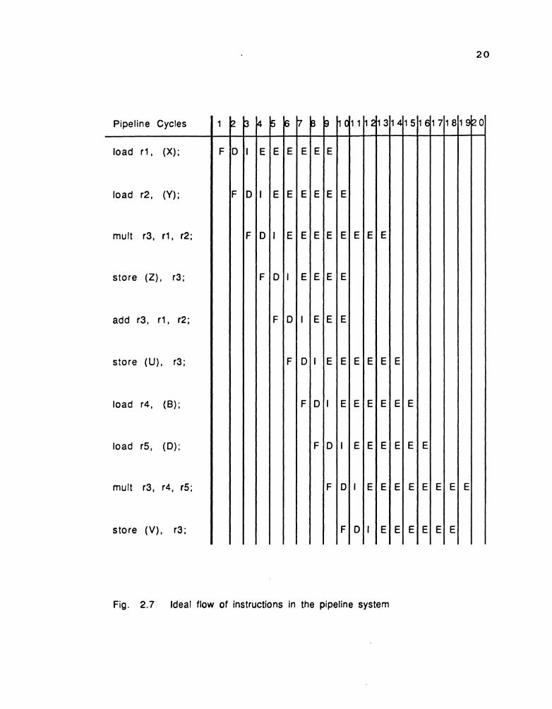
load load mult store add store load load mult store
rl, ( X ) ; rl <-- (X) r2, (Y) ; r2 <-- (Y) r3, rl, r2; r3 <-- rl + r2 ( Z ) , r3; (Z) <-- r3 r3, rl, r2; r3 <-- rl + r2 (U) I r3 ( C ) <--r3 r4, ( B ) ; r5 <-- (B) r5, (D) ; r5 <-- (D) r3, r4, r5; r3 <-- r4 * r5 (V) 1 r3 (C) <-- r3
The Fig. 2.7 illustrates the ideal flow for the
above set of instructions. The domain D(1) of an
instruction is defined as the set of resource objects that
may effect the instruction I. The range R(1)
instruction is defined as the set of resource objects that
are modified by the instruction I. A RAW hazard between an
instruction I and J will be present, if the intersection
between R(1) and D(J) is not a null set. A WAW hazard will
occur, if the intersection between R(1) and R(J) is not a
null set. A WAR hazard will occur if the intersection
between D (I) and R(J) is not a null set. Tabulating the
conditions below:
R(1) 11 D(J) = 0 for RAW (2 1) R(I) n R(J) = for WAW (2.2) D(I) Q R(J) = 0 for WAR (2.3)
The hazards that arise when the instruction flow is
ideal is shown in Fig. 2.8. A hazard free flow is
illustrated in Fig. 2.9. This flow is achieved by scheduling
the execution of the instructions. A time window is provided
for each instruction to start and complete its execution.

ADD instruction is issued for execution while the previous two instructions are in execution. Fig. 2.4 Occurence of RAW hazard.
load R3, (A);
load R2, (B);
add R 1, R2, R3;
F D l E E E E E E
F D l E E E E E E
F D I E E E
STORE instruction is issued after the LOAD instruction has completed execution
Fig. 2.5 Occurence of WAR hazard
0 add R1, R2, R3;
store (X), R1;
load R1, (C);
F D I E E E
F D I E E E E E E
F D l E E E E E E
LOAD instruction completes execution before ADD instruction
Fig. 2.6 Occurance of WAW hazard
C add R1, R2, R3;
store (X), R1;
load R1, (C);
F D I
F D I
F D l
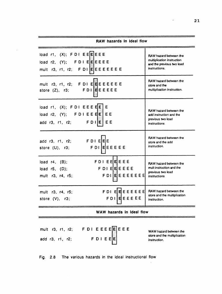
RAW hazards In ideal flow
load r l , (X) ; F D l E E ~ E E E
load r2, (Y); F D I E E E E E E
mult 3 1 2 F D l E E E E E E E E U mult 3 r 2 ; F D I E store (Z), r3;
load r l , (X) ; F D I E E E
load r2, (Y); F D I E E
add r3, r l , r2;
RAW hazard between the multiplication instruction and the previous two load instructions.
RAW hazard between the store and the multiplication instruction.
RAW hazard between the add instruction and the previous two load instructions
WAW hazards in Ideal flow
RAW hazard between the store and the add instruc80n
RAW hazard between the mult instruction and the previous two load instructions
0 add r3, r l , r2; F D I E E E
store (U), r3; F D l E E E E E E
mult r3, r4, r5; E E E E E E
store (V) , r3; E E E
mult 3 r 2 F D I
add r3, r l , r2;
load r4, (B); F D I
load r5, (D); F D l
mutt r3, r4, r5; F D I
RAWhazardbetweenthe store and the multipllcabon instrucbon.
WAW hazard between the store and the multiplication instruction.
Fig. 2.8 The various hazards in the ideal instructional flow
E lJ
E E E E E E
E E E E E E E


Pipeline Cycles
load r l , (X ) ;
load r2, (Y);
mult r3, r1, r2;
store (Z), r3;
add r3, r l , r2;
store (U), r3;
load r4, (B);
load r5, (D) ;
mult r3, r4, r5;
store ( V ) , r3;
Fig. 2.10 Alloting the time window for hazard free execution of instructions

25
The Fig. 2.9 is modified to show the time window in Fig.
2.10. The execution time is fixed for an instruction.
Considering Fig. 2.9, the RAW hazard between the instruction
1 and instruction 3 will be resolved as soon as instruction
1 completes execution. The same argument can be applied
between instruction 2 and instruction 3. Basically, the
condition listed in equation 2.1 must be false. To schedule
the instruction 3 it is necessary to know the time that the
instructions 1 and 2 would complete execution. This is
illustrated in Fig. 2.11. Instruction 4 depends on
instruction 3 which in turn depends on instruction 1 and 2.
Fig. 2.12 illustrates the resolving of RAW hazard between
instruction 1 to instruction 4.It is possible to generalize
that when the instruction I initializes a resource R and an
instruction I+k (k>O) reinitializes the same resource, then
all the instructions between I and I+k will be dependent on
instruction I for the resource R. This dependency will last
as long as the instruction I is in the process of execution.
The concept is illustrated in Fig 2.5~. Thus the time when
instruction I would complete execution is important to
schedule the dependent instructions. In our example, the
time when R1, R2 and R3 would be initialized determines the
exact time window for execution of instructions 3 and 4.
Instruction 3 is delayed for execution until R1 and R2 have
been initialized. Similarly, instruction 4 is delayed until
R3 is updated.

Issue cycle
1 End of execution
0 Start o f execution
Fig. 2.1 1 The various events in pipelined execution of instructions
Issue cycle
0 End of execution
2 '
0 Start of execution
1 1 1 2 1 3 1 4 1 5 1 6 1 7 1 8 1 9 2 0 pipeline cydes
load R1, (X);
Fig. 2.12 Resolving of RAW hazard from instruction 1 to instruction 4
E
1
F
load R2, (Y);
mutt R3, R1, R2;
store (Z), R3;
2 3 4 5 6 7 8 9 1 0
D
E E E E

F D I E E E E E E
store (U), r4; F D l E E E E E E
load r4, (B); F D I E E E E E E
store (V) , r3; F D I E E E E E E
The instructions between the two horizontal lines are dependent on the first multiplication instruction. These instructions will have to be scheduled depending on the availability of the result of the multiplication instruction.
Fig. 2.13 The hifhlighted instructions are dependent on register R3

28
The times when the four instructions would complete
execution are also shown in Fig. 2.13. If no scheduling is
carried out, instruction 3 will be issued during the fifth
pipeline cycle. At this time, instruction 1 would require
two cycles and instruction 2 would require three cycles to
complete execution. To resolve the resource conflicts,
pointers are associated with each resource and these are
used to monitor the write processes of each resource. Let
pointers C1 to CN represent pointers that are associated in
a one-to-one correspondence with the registers R1 to RN.
Each time an instruction is issued for execution, the
pointer corresponding to the sink resource is loaded with
the time that the result would be placed into the resource.
If vp represent the value of the pointer, then the value of
vp is numerically equal to the difference between the time
of issue and the time that the sink resource (associated
with this pointer) is updated with the result. For example,
if the instruction is issued for execution during the fourth
cycle and the result of the instruction will be available
in the sink register during the seventeenth cycle then vp
would be equal to thirteen as shown below:
vp = 17 - 4 = 13 pipeline cycles.
During the cycles that follow, the contents of the pointer
is decremented by a single step in each cycle. This is due
to the fact that the instruction is one step closer to
completion of execution with each passing pipeline cycle.

29
Thus when vp reaches zero, the result will be available in
the sink register (associated with the pointer).
Initialising the pointers at the time of issue and
monitoring the pointers, will give the information as to
when the write process to the resource (associated to the
pointer) is completed. Hence the instructions that are
dependent on this resource, will have to be delayed until
vp decrements to zero. Considering the instruction set, the
value present in C1 will be equal to 2 and C2 will be equal
to 3, at the time instruction 3 is issued. Fig. 2.14
illustrates the pointer values during the ideal instruction
flow. Fig. 2.15 illustrates how Fig. 2.14 is modified to
obtain Fig. 2.13. Using the pointers to denote the time when
each resource would complete its recent update, the
algorithm is developed as follows.
Let the instruction stream be represented by a set of
instructions: IS = { I1 , I2 , I3 , I 4 , . . . . . In } , where n = the
maximum number of instructions in the window in memory at
any pipeline cycle. Let the registers in the system be
represented as a register set R = { r1,r2,r3,..... ) ' m
represents the total number of registers in the system. Let
C = { c1,c2,c3, . . . . , c, } represent a set of counters
(pointers) that are assigned to the register set. There is
a one-to-one correspondence between the counters and the
registers. A counter is assigned to a single register and
vice versa. For simplicity, we assume that a counter denoted

Pipeline Cycles
load r l , (X);
Polnter C1
load r2, (Y);
Pointer . C2
mult r3, r l , (2;
Pointer C3
store (Z), r3 ;
Fig. 2.14 Pointer values associated with the sink registers.


32
by subscript j is assigned to the register with the
subscript j . Each counter carries the information about the
number of pipeline cycles that are needed for the assigned
register to assume the new value, when initialized by the
most recent instruction. The algorithm is based on the
following:
1) The instruction order has to be maintained.
2) The value carried by the counter, which is assigned to
a specific register can change only when the register is
used as the sink register by the instruction that is being
scheduled.
3 ) The maximum number of source registers that can be
specified are two and the number of sink registers is one.
4) The registers and the counters are all initialized to
zero at the start of operations. The first instruction is
executed assuming zero possibility of either hazards or
collision. Let each instruction be represented by Ik = {
OC, rat rb, r,, ca,cb, C, ) , where OC is the op-code of the
instruction, ra,rb,rc are the registers used by the
instructions, and ca,cb,cc are the counters that are
designated to the registers ra,rb, and r, respectively. To
schedule an instruction, there are three possibilities that
need to be investigated: 1) all counter elements associated
with the source registers are zeros, 2) only one counter
element associated with the a single source register is
zero, and 3 ) none of the counters assigned to the source

registers are zeros. Equations for the instruction
scheduling are developed as analysis is carried out for each
case. The equations are then summarized.
CASE 1: In this case no RAW hazard is involved. The data
operands are currently available in their respective source
registers and the instruction can be issued to the execution
unit without assigning any delay. This instruction will
place the result in the sink register after execution. The
result will be assigned to the destination register after
T pipeline cycles which is given by
T = T, + T, (2.4)
where T, is the time required for execution by the execution
unit and is fixed by the system design. T, is the system
delay that is fixed by the overheads in the system. Hence
the result will be placed in the sink register after T
pipeline cycles to the present cycle. Consider the set of
instructions given below:
1. load rl, (X) ; rl <-- (X) 2. load r2, (Y) ; r2 <-- (Y) . . . . . . . . . . . . . .......... 8. mult 3 1 , 2 r3 <-- rl + r2 9. store (Z) , r3; (Z) <-- r3
Let the first instruction be the load instruction. This
is issued to the execution unit and cl is initialized to 6.
It takes six pipeline cycles for rl to read (X). Similarly
in the second pipeline cycle c2 is loaded with 6. The
contents of c, during the second pipeline cycle will be 5.

34
If the multiplication instruction is executed after the
eighth cycle, the data is readily available and the
instruction can be issued without assigning any delay.
In the above example Te is equal to 4 pipeline cycles
and T, is equal to 2 pipeline cycle resulting in T being 6
pipeline cycles. The multiplication instruction is issued
at the ninth pipeline cycle. TteSt is used to check against
the WAW hazard and is numerically equal to the sum of T and
any other delay.
- 'test - + Tadditional delay = ( 2 - 5 )
In this case where no RAW hazard occurs, the additional
delay term is 0 .
The WAW hazard is a possibility if the c , ~ ~ ~ ( ~ ~ ~ ) is not
zero. The subscript llsink(old)ll refers to the current
value of the counter associated with the sink register (
used by the present instruction) which has not yet been
updated by the issue unit. This implies that a previously
initiated instruction I using the same sink register has not
yet been updated. If the present instruction is denoted as
instruction J, then R(1) R ( J ) is not equal to The TSink-
delay is the delay assigned to the instruction by the issue
unit to resolve the WAW dependencies. The calculation of the
delay depends on two cases: A) the value of the counter
Csink(old) is greater than T,,,,, and B) the value of the
counter element c , ~ ~ ~ ( ~ ~ ~ ) is less than TteSt.
CASE A:

Csink(old) is greater than TteSt implies that a WAW hazard
will occur. The instruction has to be delayed until the
in Csink(old) is less than Ttes,. The difference between
Csink(old) and 'test can be set by the system or be a fixed
value. In this research the value is fixed and is equal to
two pipeline cycles. The Tsink-delay is calculated as follows:
- Tsink-delay - Csink(old) + 2 - (Te + 1) (2 6 ,
Let Tinst-delay represent the total time delay assigned to the
instruction to resolve the RAW and WAW hazards. The Tinst-delay
is numerically equal to the Tsi,,k-delay in the absence of the
RAW hazard.
- Tinst-delay - Tsink-delay (2-7)
The new value of c ~ ~ ~ ~ ( ~ ~ ~ ) can be set according to the
following equation :
- Csink(new) - + (Tinst-delay - (2.8)
= Te + Ts + Csink(old) + 2 - (Te+ 1)-1 (2.9)
= Ts + + Csink(old) - 2 (2.10) - - + Csink(old) (2.11)
In equation 2.8 the term lt(Tinst-delay - 1)" is used because of the overlap of the delay value becoming zero and
the begining of execution for the instruction. If a delay
of 10 cycles is assigned to the instruction, then
instruction will start execution when the delay decrements
to 0. Thus the time that the result will be loaded into the
register will be (9 + execution time) rather than (10 +
execution time). For example, to execute the multiplication

36
instruction, the contents of c3 must be evaluated. If c3 is
non zero then there is a possibility of WAW hazard. Let the
contents of c3 be 12 at the time the multiplication
instruction is being issued. This implies that the previous
instruction that has used r3 as its sink has not completed
the execution and there will be an additional 12 cycles
before the previous instruction will update r3. The Te for
the mult instruction is 6 pipeline cycles. From the equation
I Tinst-delay is computed to be 7 pipeline cycles. It is
evident that if the instruction is not delayed, the present
multiplication instruction will initialize the register r3
with the wrong value. This is not acceptable as it gives
rise to WAW hazard. The multiplication instruction should
be executed after 7 pipeline cycles. The result of the
present instruction will be loaded into r3 after 14 pipeline
cycles from the current cycle. Hence c3 is initialized to 14
before the instruction is issued. The new value of c3 is
used to determine WAW hazards with the instructions
logically following the multiplication instruction.
CASE B: The counter element assigned to the sink register
is less than or equal to T,,,,. The possibility of WAW hazard
exists and this warrants that a delay be introduced by the
system. The delay assigned is two pipeline cycles. The
calculation of TsinkSdelay differs from the previous case.
Tsink-delay = (2.12)
if Ttest ' Csink(old) = 0

Tsink-delay =
if 'test - Csink(old) = 1
Tsink-delay = 0
- if Ttest Csink(old) > 2
The new value of c , ~ ~ ~ ( ~ ~ ~ ) is calculated as follows:
- Csink(new) - T + Tinst-delay = T + 2
for equation (2.12) . -
Csink(new) - T + TinSt-delay = T + 1
for equation (2.13) . -
Csink(new) - ' + Tinst-delay =
for equation (2.14) . CASE 2 & 3: In this case the counters associated with
one of the source registers are non-zero. The RAW hazard is
a definite possibility and has to be resolved. The
instruction must necessarily be delayed until the source
dependencies are resolved. Another delay term Ts,c-de,,Y is
introduced in the total delay equation. Tsrc-delay is the
additional delay element in the calculation of Ttest. This
delay term is equal to the non-zero counter value associated
with the source register in case 2 and is equal to the value
computed by equation 2.20, in case 3 . Both cases cannot
exist simultaneously. The Tsr,.delay is necessary as the
execution of an instruction will have to be delayed until
the RAW hazards are resolved. The test total time is now
equal to:

case 2:
- Tsrc-delay - Csource- reg + 1 case 3:
- Tsrc-delay
- ( Csource- reg1 r Csource- reg2 ) + I (2.20)
The WAW hazard is checked in the same manner as in case 1.
The difference between case 2 and case 3 is that Tsrc-delay
has to be taken into consideration in deciding Tinst.delay. The
Tinst-delay is calculated simillar to case 1.
If csink(o1d) > Ttest:
- Tinst-delay - Csink(old) + 2 - (Te + 1) (2.21)
- Csink(new) - + (Tinst-delay - (2.22)
= 'e + Ts + Csink(old) + 2 - (Te + 1) -1 (2.23)
= 's + + Csink(old) - 2 (2.24)
= + Csink(old) (2.25)
If Csink(old) < 'test! the delays are calculated as follows:
if Ttest - Csink(old) = 0
- Tinst-delay - Tsrc-delay + 2 (2.26)
if 'test - Csink(old)=
- Tinst-delay - Tsrc-delay + 1 (2.27)
if Ttest ' Csink(old) > 2 -
Tinst-delay - 'src-delay + 0 (2.28)
The new value of c ~ ~ ~ ~ ( ~ ~ ~ ) is calculated as follows:
- %ink(new) - + (Tinst-delay -
- - + 'src-delay + 1 for equation (2.2 6) .
- Csi nk(new) - + (Tinst-delay -

- - ' + Tsrc-delay
for equation (2.27) . -
Csink(new) - ' + ('inst-delay - - - + (Tsrc-delay -
for equation (2.28) . The equations to resolve the dependencies are summarized
below:
In the abscence of RAW and WAW hazards, the expressions
'test and Csink(nex) are as follows:
'test = T
Csink(new) = T
The values of c ~ ~ ~ ~ ( ~ ~ ~ ) - - Csource- reg1 - - Csource- reg2 = O
In the abscence of RAW hazards, TteSt and Csink(new) are
shown below:
'test = T (2.32) -
'inst-delay - Csink(old) + 2 - (Te - 1) (2.33)
if Csink(old) ' 'test 'inst-delay is equal to zero, one or two
if 'test < %ink(old) '
- Csink(new) - ' + ('inst-delay - if Tinst-delay > 0.
- The csource-regl - Csource- reg2 = 0 .
The equations for determining the delays to resolve RAW
and WAW hazards are summarized below:
- 'test - + ('src-delay - (2.35)
- 'inst-delay - Csink(old) + 2 - (Te - 1) (2.36)

40
if Csink(old) > 'test
Tinst-delay is (Tsrc-de[ay added with zero, one or
two)
if Ttest < Csink(old)'
- Csink(new) - + (Tinst-delay - (2.37)
if Tinst-delay > 0.
The process of scheduling the instructions is shown in
Fig. 2.16. The result of the scheduling process is
illustrated in the Fig. 2.9. The individual RAW and WAW
components are derived and are also illustrated in the Fig.
2.16 for each instruction. The algorithms are based on the
counters that monitor the write process to each register.
It is also necessary for the issue unit to recognize the
capacity in which each register is utilized. This
information is stored in an auxilliary unit which is made
available to the decode and the issue unit. This unit is
known as the instruction status unit. The instruction status
unit is a two dimensional array of fields representing the
decoded instruction. The unit contains four major fields.
The fields are encoded in the following manner: 1) the
opcode field contains the opcode of the present instruction,
2) the execution time field represents the execution time
TI 3) the R field denotes the utilization of the registers
by the instruction. These registers are the general purpose
system registers that are utilized by the functional units.
They can be used as a source or as a destination register

Pipeline Cycle # 3 lnstruction Initial counter values
I load R1, (X); 1 RAW hazard delay I 0 I I J WAW hazard delay
I 0 I lnstruction delay
I 0 I Pipeline Cycle # 4 lnstruction
I load R2, (W; I RAW hazard delay I 0 1 I I WAW hazard delav
I 0 I lnstruction delay
I 0 1 Pipeline Cycle # 5 lnstruction
I mult R3, R1, R2; I RAW hazard delay
i 5 i b J
WAW hazard delay I 0 1 lnstruction delay
Pipeline Cycle # 6 lnstruction
I store (Z), R3; I RAW hazard delay
I 1 2 I t I WAW hazard delav
Instruction delay
I 13 1
Updated counter values
Initial counter values
Updated counter values
Initial counter values
Updated counter values
Initial counter values
Updated counter values
Fig. 2.16 The counter values while scheduling the instructions
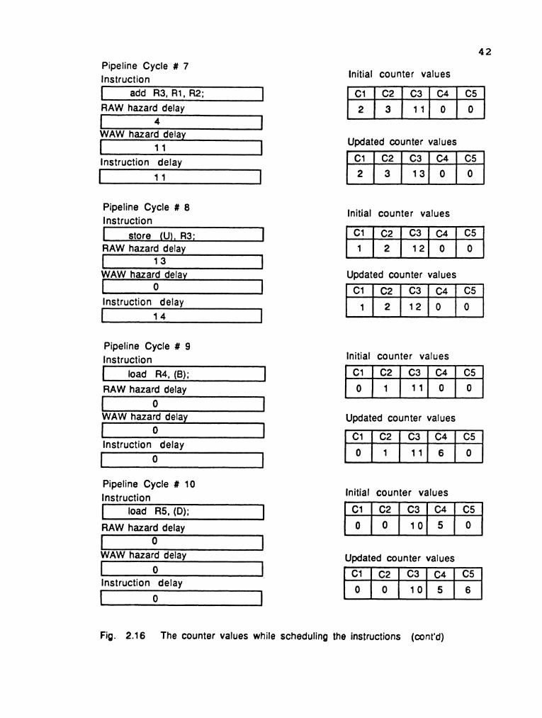
Pipeline Cycle # 7 lnstruction I add R3, R1, R2; 1 RAW hazard delay
I 4 I WAW hazard delav
lnstruction delay I 1 1 I
Pipeline Cycle # 8 lnstruction
I store (U), R3; 1 RAW hazard delay I 1 3 1 1 I WAW hazard delay
0 1 I I
lnstruction delav
Pipeline Cycle # 9 lnstruction
I load R4, (6 ) ; 1 RAW hazard delay I 0 1 1 I WAW hazard delav
-
lnsruction delay
r 0 I
Pipeline Cycle # 10 lnstruction 1 load R5, (D); 1 RAW hazard delay
1 I WAW hazard delay
I 0 I lnstruction delav
lnitial counter values
Initial counter values I=]
Updated counter values
Updated counter values
lnitial counter values
b
Updated counter values r l
, C1 2
C3
lnitial counter values
C2
3
Updated counter values
C4
1 3 0
Fig. 2.1 6 The counter values while scheduling the instructions (cont'd)
C5 0

Pipeline Cycle # 11 lnstruction 1 add R3, R4, R5; I RAW hazard delay 1 6 1 I I
WAW hazard delay +
1 6 I lnstruction delay
Pipeline Cycle # 12 lnstruction
I store (V), R3: I RAW hazard delay I 1 3 I b J
WAW hazard delay 0 I
lnstruction delay b =
lnitial counter values
Updated counter values 1 1 Initial counter values
Updated counter values
Fig. 2.16 The counter values while scheduling the instructions (cont'd)

4 4
by the instruction, and 4) the C field represents the time
when the registers will be initialized to the new value by
the instructions using the registers as sink registers. The
R and C fields are further divided into subfields. The
number of subfields in the R field are equal to the number
of subfields in the C field. The R fields are set by the
decoding unit. Every subfield in the C field is a counter.
Each counter is associated with a single register. The
counter subfield c, represents the time that the register r,
will be initialized to a new value by the most recent
instruction. The subfield c2 represents r2 and so on.
Similarly, every subfield of the R field represents a single
register. The subfields of R are set by the decode unit. The
subfields are set to 1, if the register is used as a source
register, set to 0 , if the register is used as a sink
register and set to 3, if niether are true. The value three
represents don't care. For example, the R1 subfield is set
to 1 by the decode unit, if register R 1 is used as the
source register by the instruction. The counter fields are
updated by the issue unit. The unit is shown in Fig. 2.17.
The change to Fig. 2.2 is illustrated in Fig. 2.18.
The issue unit schedulesthe execution of an
instruction in each pipeline cycle. The execution of the
instruction may be delayed. The delayed instruction must be
stored until it is ready to execute. Two schemes are
possible: 1) hold the instruction in the issue unit and

Opcode is the opcode of the Instruction. lime: Time is the time required to execute the instruction. R - Field : R - field is the field of all registers in the system.. C - Field : The field of the counters that keep track of the registers.
0 Code
Fig. 2.1 7 Instruction status unit.
I l l l l l l l l l l >
Exec Time
C - Field R - Field
C1 R5 C2 R1 R3 C3
I
R2 R4 C4 C5

Fig. 2.18 The modified pipeline system with the instruction status unit
Fetch Unit F
i Decode unit
D Instruction status unit
Issue unit I
4
* t . v
1 1 1 + .c i
E 2
Fixed point - Floating h
ari thmetic point u n l 1 un i t
2 Logic uni t

47
freeze the total PIU until the dependency is resolved and
2) issue the instruction to a buffer provided at the
entrance to the execution units. The former scheme will
reduce the efficiency of the pipeline system. There could
be instructions downstream, that can be executed and not
dependent on the instructions in execution. In our example,
instruction 7 is not dependent on any of theprevious
instructions. If the PIU is freezed, the instruction 7 will
remain in the fetch unit until the PIU is operational again.
A FIFO queue can be introduced between the units of the PIU
to hold the instructions and keep the fetch unit
functioning. This will create a bottleneck as the issue unit
is still disabled and dynamic scheduling will not be
possible. Thus the effective solution is adopt the latter
scheme and place buffers at the entrance to the execution
units. The non-executable instructions can remain in these
buffers until they are ready to execute. This will free the
issue unit to issue instructions to the execution unit. The
execution unit will also be able to start execution of
instructions that are issued for immediate execution by the
issue unit. In our example, instructions 5 and 6 can be
placed in the buffers and execution of the instruction 7 can
begin during the nineth pipeline cycle. The ideal flow
through the PIU is maintained. The space time diagram for
this scheme is illustrated in Fig. 2.9. The changes in the
structure with relation to Fig. 2.18 is shown in Fig. 2.19.

Fig. 2.19 The pipeline system with the buffer units
h w
Fetch Unit F
I
4 Decode unit D
Issue unit I
Instruction status un i t
4
Buffer units
Buffer I units - 8 Floating 8 Logic
un i t Fixed point
Vl arithmet ic point uni un i t I
Buffer units

Fig. 2.20 Instruction listing to illustrate WAR hazard

Fig. 2.21 Resolving WAR hazard using the counters.

51
The WAR hazard arises when the resources are not
distributed to the instructions in the buffer as they become
available. Fig. 2.9 is reproduced to illustrate the
possibility of RAW hazard in Fig. 2.20. The WAR hazard will
exist between the instruction mult r3, rl, r2, store (Z),
r3, and add r3, rl, r2. The instructions are highlighted
in a block in Fig. 2.21. The counter values are also shown
alongwith the instructions. The three instructions are
issued to the buffer. The store instruction must capture the
value of r3, before the add instruction changes the content
of r3. When the store instruction is issued, the counter c3
associated with r3 contains a value of 12. It indicates that
the result of r, * r2 will be loaded into r3 after 12 pipeline cycles. A pointer is introduced in the buffer
holding the store instruction. This pointer is initialized
to the value of c3 at the time of issue. The pointer counts
down by one in each passing pipeline cycle. The pointer is
independent of c3. At the time that the pointer counts down
to 0, the register r3 will be loaded with the result. This
result can be loaded into the buffer before the instruction
begins execution. Fig. 2.22 illustrates the events. The
buffers in each stage are collectively called as a delay
station (DS). Each delay station consists of 10 identical
buffers called as delay buffers (DB). Each delay buffer (DB)
holds an instruction until it is ready to execute. Each
delay buffer is further subdivided into nine fields:

Pipeline Cycles
Polnter c 1 load r l , (XI;
Pointer c 2 load r2, (Y);
Polnter c 3 mult r3, r l , r2 ;
. . . .
. . . .
Pointer c 3 add r3, r l , r 2 ;
. . . . .
. . . . .
Pointer c 4 load r4, (B); ..... Polnter c 5
load r5, (Dl;
. . . . . Pointer c 3 mutt r3, r4, r 5 ;
Fig. 2.22 The various events of the scheduling process

Pr # : Priority number attached to each unit
ASR1 : Address of source register 1 DSR1 : Delay of source register 1. SD1 : Source Data 1. ID : Instruction Delay.
Pr#
Unit 1
Unit 2
Unit 3
Unit 4
Unit 5
Unit 6
Unit 7 2
ASR2 : Address of source register 2 DSR2 : Delay of source register 2. SD2 : Source Data 2. DR : Destination Resource
ID
Each Unit is a Delay Buffer.
DR ASR1
Fig. 2.23 Structure of delay buffers
DSR1 SD1 DSR2 ASR2 SD2

54
1) priority number, 2) address of source registerl (ASRl),
3) delay of source registerl (DSRl), 4) source data1 (SD1) ,
5) address of source register2 (ASR2), 6) delay of source
register2 (DSR2), 7)source data2 ( S D 2 ) , 8) Instruction delay
(ID), and 9) destination register (DR). The structure of the
delay buffers is illustrated in ~ i g . 2.23. The DSRl field
indicates the number of pipeline cycles (fromthe present
cycle) required by the source register1 to initialize itself
to the correct value. The same concept applies to the DSR2
field. The ID field indicates the time that the instruction
is allowed to start the process of execution in the
arithmetic or logic unit. The delay fields essentially
decrement by one step in each pipeline cycle. They do not
count down below zero. The delay fields in the buffers are
the pointers that keep track of the source registers. When
the source operand is not available at the time of issue,
the counter value associated with the source register is
loaded into one of the pointers in the buffer. The address
of the source is also loaded into the address fields in the
buffer. If the value of the counter is loaded into DSR1,
then the address of the source register must be loaded into
ASR1. Regularity is maintained. When any of the delay fields
associated with the sources reach zero, the address of that
source is released from the source address field and the
data is latched in the associated source data field. The
data is read from the common data bus that links each

Fig. 2.24 Connectionist model of delay buffers.
Register 1 Register N Register 2
I b
t T I L . SPLITTER.
I I MUX5to1 -
A
9 I
r
Register 4
> .
PR#
I I 1
Register 3
ASRl DSRl DR Data source 1 ASR2 DSR2 Data source 2 ID.

Fixed point t arithmetic unit
F
+ Floating point unit
Fetch Unit
Fig. 2.25 The pipeline system shown along with the register array
b Decode unit
D -C Instruction
Thick lines status represent unit common data bus.
I Issue unit R a
t e r 9 r i a . s Y
Buffer units 4 b Buffer units 4 b' Buffer units dm' e

57
register to the source data fields in the buffers through
a multiplexer. This multiplexer chooses the data path in
lieu with the source address present in the identification
field. The connectionist model is illustratedin Fig. 2.24.
The changes to the structure are shown in Fig. 2.25.
RESOLVING OPERATIONAL HAZARDS:
This collision hazard occurs when the assigned delays
of two different instructions in the same DS, are nullified
in the same pipeline cycle. This hazard also occurs when an
instruction cannot be executed because of latency not being
available. It can be resolved by introducing extra time
delaysto all instructions that are in the DS. The
scheduling algorithm in the issue unit assigns time slots
for the execution of each instruction. The time slot
assigned to each instruction in the DS is fixed in time,
with respect to the other instructions. In case of a
conflict between two instructions, the instruction with the
highest priority is executed and a fixed amount of delay is
introduced to all the instructions in DS. The delay is added
to the existing delays of the source delay counters and the
instruction delay counters. The source delay counters which
have already counted down to 0 are not updated by this
operation. The counters in the instruction status unit are
also updated with the same amount of delay. This ensures
that the relative positions of the time slots for execution
of instructions are not changed. The captured data in the

Consider the set of instructions below in the time space diagram
lnstruction 1
lnstruction 2
lnstruction 3
lnstruction 4
lnstruction 5
lnstruction 6
F D I E E E E
F D I E E E E
F D I E E E E
F D I .
Operational hazard present between instruction 5 and 6.
lnstruction 1
lnstruction 2
lnstruction 3
lnstruction 4
lnstruction 5
Instruction 6
F D I E E E E
F D I E E E E
F D I E E E E
F D I .... E E E E E E
F D I . . E E E E E
F D I . . . . . . . E E E E E 4
Additional delay introduced by the execution unit.
Fig. 2.26 Resolving the collision of instructions in PEU.

buffers is not lost and the new instructions are scheduled
with the updated countervalues. This principle is
illustrated in Fig. 2.26. In simple terms, the execution
all instructions in DS are moveden-masse in time without
disturbing the order. the instruction cannot be issued
due to lack of latency, the delay required is equal to the
number of pipeline cycles for the first available latency.
This re-scheduling is carried out independent of the issue
unit. This principle is best illustrated in the example
given below. Consider the instruction set listed below:
load rl, 20; load r2, 30; mult r3, r2,rl; mult r4, r2,rl; store r3 ; store r4;
The load instruction will be issued in the third
pipeline cycle followed by the second load instruction in
the fourth pipeline cycle. cl and c2 are set to 6 at the time
of issue. rl will contain the value of 20 in the nineth
pipeline cycle and r2 will be loaded with 30 during the
tenth pipeline cycle. The first multiplication instruction
will be issued in the fifth pipeline cycle. During this
cycle, c, will contain the value of 4 and c2 has the value
of 5. The counter c3 associated with the sink register r3
will be set according to the equation 2.16. There is no WAW
hazard as c3 is initially equal to zero. The instruction
delay is computed as given in eqn 2.19 which is 6 pipeline

60
cycles. Thus c3 will be updated to 14. The result of this
instruction will be in r3 at the nineteenth cycle. The
second multiplication instruction is issued next with a
delay of 5 pipeline cycles. The value of c, is set, similar
to the first instruction and is equal to 13. The events and
the counter values are illustrated in Fig. 2.27. The
counters c, and c2 are decremented, as the event of updating
the registers draws nearer. The first store instruction is
issued during the seventh pipeline cycle. The delay is
computed depending on c3 which is equal to 13 cycles. The
last instruction is issued in the eight cycle with an
assigned delay of 12 cycles. The state of the instructions
in the pipeline during the cycles 7 and 8 are illustrated
in Fig. 2.28. At the eleventh pipeline cycle, both the
multiplication instructions are ready to be executed. Two
generic instructions cannot be executed from the same stage
at the same time. The first instruction has a higher
priority and was loaded into the DS one cycle ahead of the
second multiplication instruction. As a result, the
execution of the second instruction has to be delayed by one
cycle. This implies that all the instructions that are
dependent on the second instruction will also have to be
delayed by one cycle. This has a recursive effect on the
instructions downstream. Since the issue unit fixes the time
slot for execution, the relative placement of the time slots
between the second multiplication instruction and the

Pipeline Cycle # 3 Initial Counter values
load R1, 20; 1 Updated counter values
Pipeline Cycle # 4 Initial Counter values
load R2, 20;
Updated counter values
Pipeline Cycle # 5 Initial Counter values
Updated counter values
mult R3, R2, R1;
Pipeline Cycle # 6 Initial Counter values
4
Updated counter values
mult R4, R2, R1;
Fig. 2.27 Sequence of events and the counter values
5
3 4 1 2 0 0 0
0 0 0 0

Pipeline Cycle # 7 Initial Counter values
store R3;
Updated counter values
Pipeline Cycle # 8 Initial Counter values
Updated counter values
store R4; I -
Pipeline Cycle # Initial Counter values
Updated counter values
1 2 I
Pipeline Cycle # Initial Counter values
Updated counter values
10
Fig. 2.27 Sequence of events and the counter values (cont'd)
1 0

Pipeline Cycle # 7 Initial Counter values
Updated counter values
store R3;
Pipeline Cycle # 8 Initial Counter values
store R4;
3
Updated counter values
Pipeline Cycle # Initial Counter values
1 1
Updated counter values
1 1
Pipeline Cycle # Initial Counter values
I c Updated counter values
Fig. 2.28 Sequence of events and the counter values

Pipeline cyde # m
Let the counter values before updating be :
C1 C2 C3 C4 a
Assuming a delay of 'k' pipeline cycles are needed to resolve the hazard
Counter values after updating are :
Assuming that the contents of DSR1 of unit 1 is 0 and that of DSR2 of the same unit is 3 and the ID field is 7
Updating the delay buffers by adding the offset 'k' to all non zero delay fields. The updated delay station is presented below
Pr # : Priority number attached to each unit ASRl : Address of source register 1 ASR2 : Address of source register 2 DSR1 : Delay of source register 1. DSR2 : Delay of source register 2. SD1 : Source Data 1. SD2 : Source Data 2. ID : Instruction Delay. DR : Destination resource
Each Unit is a Delay Buffer.
Fig. 2.29 Updating of the delays due to collision hazard

65
downstream instructions must not be changed. Hence all the
delays are incremented by one. The non zero source delays
are also incremented in the delay buffers. The value of r3
will remain longer in the register for one extra cycle more
than the original scheduled time. The process is illustrated
in Fig. 2.29. In general, the instruction Ij will influence
Ij+,rather than Ij-, . Hence, this displacement does not affect the previous instructions. It is evident from our example
that the first two instructions are not inconvienced by this
displacement. Graphically it is illustrated in Fig. 2.30.
The logic instructions are also treated in the same manner.
2.3 REDUCING BRANCH PENALTY:
A typical instruction set, of any computer consists of
two types of branch instructions. They are the conditional
branch instructions and unconditional branch instructions.
The unconditional branch instruction will initiate a jump
in the current flow. The conditional jump instruction will
initiate a jump only if the element to be evaluated is
positive to the condition. For example, let a branch
instruction specify a branch to location # 60, if only the
register R5 is equal to zero. The branch will take place
only if the condition is positive i.e., the register R5 is
equal to zero. The sample instruction set listed above is
now modified to include a conditional branch instruction and
is listed below:
1. load rl, (X) ; rl <-- (X) 2. load r2, (Y) ; r2 <-- (Y)

Pipeline cycle # 6
C 1
Before updating
After updating
Before updating
h b m
U
f After updating
f
Pr #
Unit 1
Unit 2
Unit 2
Before updating
ASR1
R1
L 0
9 b
i C f
f After updating U
n i t
ASR1 DSRl SD1 ASR2 DSR2 SD2
Unit 2
DSR1
3
Fig. 2.30 The process of capturing the operands and resolving collisions
SD1 SD2 ASR2
R2
ID
5
DSR2
4
I33
R3
-

Pipeline cycle # 7
C 1
Before updating
After updating
Before updating
h b u f
After updating
Before updating
L
P r #
Unit 1
unit 2
After updating
Fig. 2.30 The process of capturing the operands and resolving collisions (cont'd)
ASRl
R1
R1
DSRl
2
2
SD1 ID
4
4
a?
R3
R4
ASR2
R2
R2
DSR2
3
3
SD2

Pipeline cycle # 8
C 1
Before updating
After updating
Before updating
h b
f After updating
Before updating
Pr #
Unit 1
unit 2
Unit 2
After updating
Fig. 2.30 The process of capturing the operands and resolving collisions (cont'd)
ASRl
R1
R1
DSRl
1
1
SD1 ASR2
R2
R2
DSR2
2
2
ID
3
3
SD2 DR
R3
R4 .

Pipeline cycle # 9
Before updating
After updating
Before updating
h b m
U f
After updating
Before updating
Mem
Pr #
Unit 1
Unit 2
After updating
SD2
Unit 2
ASRl
R1
R1
Fig. 2.30 The process of capturing the operands and resolving collisions (cont'd)
ID
2
2
DR
R3
R4
DSR2
1
1
DSR1
0
0
SD1
2 0
2 0
ASR2
R2
R2

Pipeline cycle # 10
C 1
Before updating
After updating
- - - -
Before updating
h b u f
After updating
Before updating
Mem
Pr #
Unit 1
unit 2
C f f After updating
U
ASRl
R1
R1
Fig. 2.30 The process of capturing the operands and resolving collisions (cont'd)
DSRl
0
0
ID
1
1
SD1
20
20
CR
R3
R 4
ASR2
R2
R2
DSR2
0
0
SD2
30
30

Pipeline cycle # 11
C 1
Before updating
After updating
Before updating
h b " u f
After updating
f
Pr #
Unit 1
unit 2
Unit 2
Before updating
ASR1
R1
R1
Mem
After updating
DSRl
0
0
Mem
Fig. 2.30 The process of capturing the operands and resolving collisions (cont'd)
SD1
2 0
20
ASR2
R2
R2
SD2
3 0
3 0
DSR2
0
0
ID
0
0
a?
R3
R4 A

Pipeline cycle # 12
Before updating
After updating
Before updating
After updating
k
Pr #
Unit 1
Unit 2
Unit 2
-- - --
Before updating
ASRl
R1
g b
i C f
f After updating
U
Unit 2
DSRl
0
Fig. 2.30 The process of capturing the operands and resolving collisions (cont'd)
SD1
2 0
ASR2
R2
ID
0
DSR2
0 R4
-
SD2
3 0

Pipeline cycle # 13
C1
Before updating
After updating
Before updating
After updating
Pr #
Unit 1
Unit 2
Before updating
Mem
ASRl
C f f After updating
U
Unit 2
DSRl
Fig. 2.30 The process of capturing the operands and resolving collisions (cont'd)
SD1 ASR2 DSW SD2 ID

3. add r3 , rl, r2; r3 <-- rl + r2 4 . store (Z) , r3; (Z) <-- r3 5. branchz r3, 100; branch to 100 if r3 = 0 6. load r4, (A) ; r4 <-- (A) 7. load r5, (B) ; r5 <-- (B) 8. mult r3, r4, r5; r3 <-- r4 * r5 9. store (C) I r3 (C) <-- r3
The instruction 6 will be executed depending on the
outcome of instruction 5. Instruction 5 will be fetched by
the fetch unit at the beginning of the fifth pipeline cycle.
It will reach the execution unit at the beginning of eighth
pipeline cycle. It is necessary to stop further issue of new
instructions, until the branch instruction is evaluated. The
PIU is freezed until the validity of the branch instruction
is determined. If the branch is positive, then instruction
at location # 100 will be the next instruction to be issued.
On the other hand, if the result is negative, no branch is
initiated and the next instruction to be issued is
instruction 6. The time from the sixth cycle to the cycle
that the branch instruction is evaluated, is wasted and
furthermore, a few cycles are lost in reconfiguring the
fetch unit. This time can be u s e d t o pre-fetch the
instruction from the destination address and along with
instruction 6. An additional stream is needed to handle the
second fetch. Hence the fetch unit is endowed to feed two
instruction streams. A unit to classify the instruction and
generate the effective address is necessary for the second
stream to become operational. The branch instruction will
not be evaluated until the operand is current. During this

75
time the activity in the decode and the issue units is
suspended, but the fetch unit can prefetch two instructions
and feed two FIFO queues. These queues can hold the
instructions of the current flow and the instructions
starting from the destination address. The queues would be
best placed in the decode unit. Two program counters are
used to fetch instructions to both the streams. A path
controller is necessary to direct the instruction flow to
the two queues. The system is modified as shown in Fig.
2.31. The current stream is known as the present instruction
counter stream (PIC) and the secondary stream is termed as
the effective address counter stream (EAC). To maintain
symmetry, the system consists of two issue and two decode
units, one for each stream. The EAC stream will become the
current stream when the outcome of the branch instruction
is positive. The PIC queue is flushed up to the issue unit.
The instruction flow is resumed from the EAC queue. The
first instruction is fetched from memory by initializing the
program counter of the PIC stream with the starting address.
Subsequent instructions are fetched in each pipeline cycle
by incrementing the program counter. The current instruction
is examined by the instruction classifier to classify the
type of the instruction. If the instruction belongs to the
class of unconditional branch instructions, the program
counter is updated with the new address and the next
instruction will be fetched from the new location. If the

Fig 2.31 The complete pipeline system shown with two streams
F Fetch Unit
CI I PIC queue EAC queue 4 b
- 7 Decode unit
D D L
Instruction
4 4 status
@ I .
un i t
I I
+ e r 9 r i a
- Issue unit R a
Buffer units 4 b Buffer units 4I*r t
4 * t V
4 b e
* r
Buffer units .
5 w Logic unit
3
Floating point unit
It_l Fixed point arithmetic u n i t
Thick lines represent common data bus.
77
instruction belongs to the class of conditional jump
instructions, the destination address is stored in the
program counter of the EAC stream. The EAC stream is non-
functional until the PIC stream encounters the first
conditional jump instruction. In the ensuing cycles, the EAC
stream fetches instructions starting from the destination
address computed from the jump instruction. The pre-fetched
instructions are stored in the EAC queue which is present
in the decode unit. The validity of the jump instruction
will determine the condition of the streams. If the jump is
negative, the EAC queue is flushed and the PIC stream
remains the current stream. If the jump is positive, the EAC
stream becomes the current stream and the PIC stream is
flushed. There is no delay because the next instruction is
available in the EAC queue. The EAC stream remains current
as long as no branch instructions are encountered. If a
branch instruction is encountered, the PIC queue will start
filling up with the instructions from the address provided
in the branch instruction. The afore mentioned scheme will
operate with a single program counter for each stream, when
there are no multiple jump instructions encountered in the
streams, before the current branch instruction is evaluated.
In general case there could be multiple jump instructions
encountered by the fetch unit in both the streams, while
forwarding the instructions to their respective queues. Even
though the decode unit and the issue unit are disabled by

lnstructions starting from address 23 in memory
EAC stream
Instructions starting from address 10 in memory
PIC stream
29
28
,27 26
25
24
23
Fig. 2.32 Sample instructions in memory
Jump (Result = 0) 60
Jump (Carry = 0) 45
Jump (Overflow = 0) 36
Jump (Carry = 0) 28
w
16
15
1 4
1 3
12
1 1
1 0
Jump (Result = 0) 80
Jump (Overflow = 0) 70 -
Jump (Carry = 0) 56
Jump (Overflow = 0) 33
Jump (Carry = 0) 23
79
a branch instruction, the fetch unit will remain active
until queues in the decode unit are filled. Consider the
instructions in memory as listed in Fig. 2.32. Let n, be the
jump instruction encountered by the PIC stream. The program
counter of the EAC stream is initialized with the
destinationaddress. Two instructions are fetched from the
next cycle, one for the PIC stream and the other for the EAC
stream. Branch instructions m, and nz are encountered
simultaneously by the streams. The first branch
instructionn, is currently in the issue unit being
scheduled. Instructions cannot be pre-fetched from the
destination addresses of either m, or n2. A total of four
streams are required to prefetch the new set of
instructions. It is not possible to flush any of the streams
as the jump instruction n, is not evaluated. The jump
instruction cannot be forwarded to the decode unit as the
decode unit does not have the ability to generate an
effective address. Assuming n jump instructions in the PIC
stream and m jump instructions in the EAC stream have been
identified by the fetch unit before it is disabled, a tree
can be formed to illustrate the possible logical paths. For
example, let m = 4 and n = 5. The tree is formed in Fig.
2.33. The parent node is the current jump instruction that
is being processed. The paths to the left indicate the jump
is valid and the paths to the right indicate that the jump
is invalid. The child nodes are the branch instructions

PC = Program counter
The jump instruction n , is being evaluated in the logic unit. The issue unit and the decode unlt have suspended operations until the jump is evaluated
Fig. 2.33 Graphical representation of data path due to branch instruction

81
belonging to both the streams. Starting from the parent
node, the branches to the right or left are deleted as each
node in the path is evaluated. If the jump is valid then the
branches to the right are eliminated along with the child
nodes connected by the branch. Assuming that the branch is
taken by the parent node, the node m, becomes the parent
node for the first branch in the new path. It is evident
that the next branch instruction that has to be evaluated
is directly dependent on the present branch instruction. It
is not possible to accurately indicate the outcome of a
branch instruction until it is evaluated. So when more
branch instructions are encountered in both the streams, the
combination of the program paths is equivalent to 2^n where
n is the number of branch instructions. With a single
program counter for each stream, pre-fetch cannot be carried
out until one of the streams is flushed. The destination
address would be lost if the jump instruction is forwarded
to the decode stage un-processed. The instructions along the
same stream can be accessed by default without changing the
stream. The opposite stream will become the program path,
when the jump instruction to be evaluated initiates a jump.
Hence the destination address of the jump instructions that
await evaluation in the PIC queue must be associated with
the EAC stream. Additional counters which are associated
with the EAC stream record the destination addresses before
they are forwarded to the decode unit. When the jump is
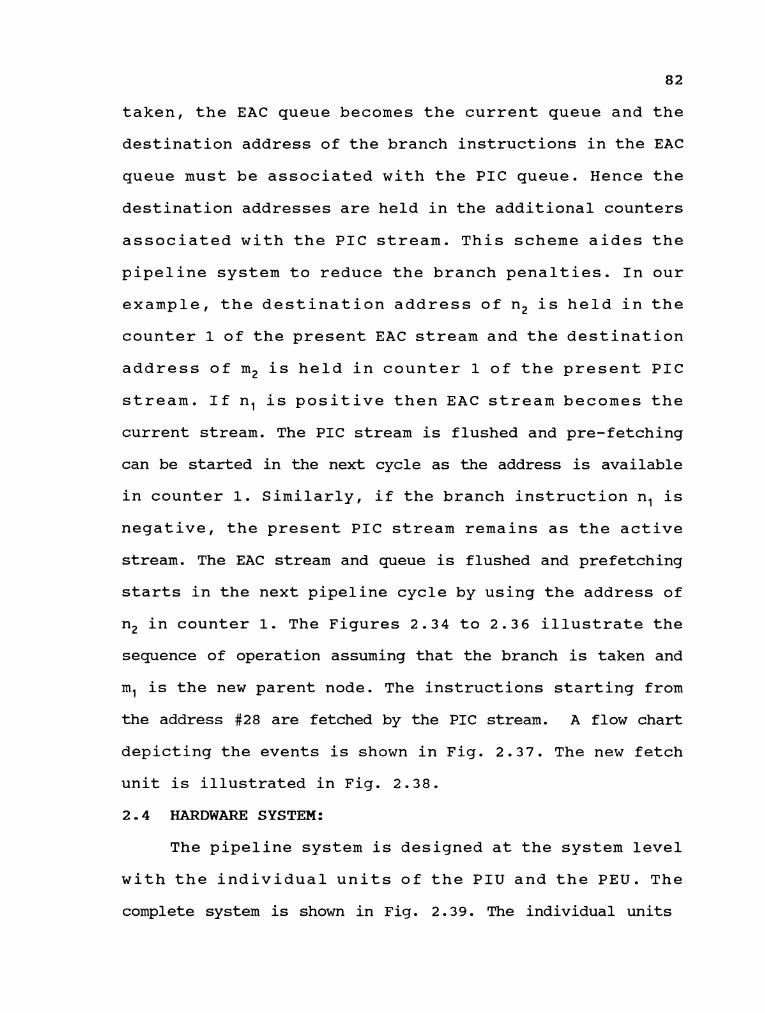
82
taken, the EAC queue becomes the current queue and the
destination address of the branch instructions in the EAC
queue must be associated with the P I C queue. Hence the
destination addresses are held in the additional counters
associated with the P I C stream. This scheme aides the
pipeline system to reduce the branch penalties. In our
example, the destination address of n2 is held in the
counter 1 of the present EAC stream and the destination
address of m2 is held in counter 1 of the present P I C
stream. If nl is positive then E A C stream becomes the
current stream. The P I C stream is flushed and pre-fetching
can be started in the next cycle as the address is available
in counter 1. Similarly, if the branch instruction nl is
negative, the present P I C stream remains as the active
stream. The EAC stream and queue is flushed and prefetching
starts in the next pipeline cycle by using the address of
n2 in counter 1. The Figures 2.34 to 2.36 illustrate the
sequence of operation assuming that the branch is taken and
ml is the new parent node. The instructions starting from
the address #28 are fetched by the P I C stream. A flow chart
depicting the events is shown in Fig. 2.37. The new fetch
unit is illustrated in Fig. 2.38.
2.4 HARDWARE SYSTEM:
The pipeline system is designed at the system level
with the individual units of the P I U and the P E U . The
complete system is shown in Fig. 2.39. The individual units

Instructions strating from address Instructions strating from address 23 in memory 10 in memory
16 Jump (Result = 0) 80 15 Jump (Overflow = 0) 70 14 Jump (Carry = 0) 56 '1 3 12 Jump (Overflow = 0) 33 11 10 Jump (Carry = 0) 23
EAC stream PIC stream
PC 1 60
Fig. 2.34 Sample instructions and the possible data paths
14 PC. 15
EAC stream counter PIC stream counter
Fig. 2.35 The contents of the counter after fetching the last instruction in both the sbeams Assuming the jump is being evaluated in the logic unit
Instructions strating from address Instructions strating from address 23 in memory XXX in memory
EAC stream -b PIC stream PIC stream + EAC stream
PC = Program counter The jump instruction n has been evaluated and the branch is taken. The old PIC stream is the redudant stream and hence it is flushed.
Fig. 2.36 Sequence of updating the counters during the jump operation

Instructions from memory
Counter 1. (PIC I EAC counten)
Path selector and controller
Control Paths
disable individual streams instructions to the instructions to the
EAC queue PIC queue
Fig. 2.37 The fetch unit

4
b
No 4
t
Fetch instruction
Unconditional Place in PIC queue
PC(P1C) <-- PC + 1
EAC stream in
Load the EA into the first available Load the EA into
empty counter of the the program counter
EAC stream of the EAC stream
Yes
Start The EAC stream
u Fig. 2.38 Flow chart for the PIC queue assuming PIC queue is in session

Clear the program counter and the assodated counters 1 -n of the EAC field
Clear the program counter and the associated counters 1-n of the
Load program counter with contents of counter 1
I Move the contents of the / counters one counter to the left
Yes b
Fig. 2.38 The flow chart of the PIC queue assuming PIC queue in session (cont'd)

No 4
Fetch instruction
Unconditional Place in EAC queue
PC(EAC) <-- PC + 1
dad Ihe EA into ;he first available Load the EA inro
mpty counter of tbe the program counter
PIC stream of the PIC stream
Yes
Start The PIC stream -
Fig. 2.38 Flow chart for the EAC queue assuming EAC queue is in session (cont'd)

I yes I
Yes No
Are the counters +
Fig. 2.38 The flow chart of the EAC queue assuming EAC queue in session (cont'd)
* Clear the program counter and the assodata
Ciear the program counter and the associated counters 1-n of the PIC field
counters 1-n of the PIC field + - Load program
counter with contents I of cwnter 1
f'b + J
h
Move the contents of th6 counters one counter to the left

Main Memory Module rn
Fig. 2.39 The proposed look-ahead pipeline computer system

90
are provided with local controllers which are responsible
for the functioning of each unit. The local controllers can
communicate with each other. The system contains five
general purpose registers: R, , RZ , R3, Rq , and R5. Data from
and to these registers are transferred by the common data
bus. Each register is associated with a program status
register that represents the condition of the value in the
register. The instructions enter the pipeline system through
the fetch unit. The address of the instruction to be fetched
is issued by a counter referred to as the program counter,
present in the fetch unit. The opcode of the newly fetched
instruction is checked to determine whether the instruction
is a branch instruction. The non branch instruction is
passed unchanged to the next stage. The branch instruction
is further classified as a conditional or an unconditional
branch instruction. For an unconditional branch instruction,
the program counter is updated with the destination address
from where the instructions are fetched in the pipeline
cycles that follow. The handling of conditional branch
instructions is explained in section 2.4.1. The fetch unit
can fetch two instructions simultaneously to reduce the
branch overheads. The individual data paths of the fetch
unit are termed as instruction streams. The current
operational instruction stream is determined by the logic
unit. The switching of streams is carried out by a path
controller in the fetch unit. The control information from

91
the logic unit is fed to this unit which in turn determines
the current stream. The instruction is forwarded to the
decode stage. The decode unit consists of a local FIFO queue
and an instruction decoder for each of the two streams of
the fetch unit. The instruction first enters FIFO queue and
then reaches the decoder. The current operational stream
is determined by the logic unit and is the same as the fetch
unit. The individual streams of the fetch unit are disabled
if the corresponding queues in the decode unit are filled.
The decode unit splits the instruction into its fundamental
components namely the source operands, destination operands,
and the operation involved. This information is recorded in
the instruction status unit which is a part of the decode
unit and is common to both the streams. The function of this
unit is to supply information to other units about the
specification of the present instruction. The instruction
status unit is a two dimensional array that records the past
and the current history of instructions executed in the
pipeline system. The decode unit is controlled by the logic
unit and is disabled when a branch instruction is being
evaluated in the execution unit. The unit is explained in
section 2.4.2. The decoded instruction is forwarded to the
issue unit after all the relevant information about the
instruction is recorded in the instruction status unit. The
issue unit checks the instruction status unit to determine
dependencies between the current instruction and the

92
instructions that have been issued to the execution unit.
The issue unit schedules the execution time of the
instruction for resolving the hazards. The delay time is
calculated on the information provided by the instruction
status unit. The instruction is set to a certain format and
sent to the execution units. The issue unit is described in
section 2.4.3. The delayed instructions are held in buffers
until the hazards are resolved. The delay stations monitor
the registers to capture the missing operands as they become
available. Data transfer from and to the registers is
carried by the common data bus. The arithmetic instructions
are executed by the arithmetic units and the logic
instructions are executed by the logic unit. These units are
also provided with controllers that monitor the units to
resolve structural hazards. The instructions are initiated
into their units when the appointed time slot has arrived.
The branch instruction is held in the logic unit until it
is resolved. During this time the issue unit along with the
decode unit is disabled. The fetch unit is not dependent on
the execution unit but is dependent on the condition of the
queues in the decode unit. The controllers between the
various units communicate with each other via the common
system control register which has fields associated with
each unit. These fields are write only fields for the
designated unit and read only for the remaining units. The
total system is illustrated in Fig. 2.40. The individual

-- --
Fig. 2.40 The overview of the complete system
Common data bus L Main memory unit
.L T
Counter set 1 Opcode dassifier ---------- and EA generator Fetch unit Counter set 2
Path selector and antroller I 1 I
Decode units
PIC Queue
system status units
Decoder Deader -+ unit 2 unit 1 hstr~ction
I I status unit
I I
7 v 7 7 - issue lssue (; -
Issue units unit 2 unit 1 'I
Logic unit controller
R1 R2 R3 R4
Execution units

units are described in the following sections.
2.4.1 FETCH UNIT:
The fetch unit comprises of the logic to fetch
instructions from memory, two sets of counters, an opcode
classifier, an effective address (EA) generator, and the
path controller. The path controller is also the local
controller for the fetch unit. The function of the opcode
classifier is to determine the type of the present
instruction. The fetch unit is capable of fetching two
instructions simultaneously. This is done to reduce the
branch overheads. Each set of counters consist of 10
individual counters which are identified as counter 0 to
counter 9. The counters referred to as counter 0 are used
as program counters in the individual sets. Each set
supports a single instruction stream. The PIC stream starts
as the current instruction stream. The instruction streams
end up into two FIFO queues in the next stage. The unit is
illustrated in Fig. 2.41. The counters of each stream are
initialized by the instructions passing through the opposite
stream. The counters 1 to 9 are filled with the destination
address held by the branch instructions that are awaiting
execution in the FIFO queues. The fetch unit is disabled if
the queues are filled with instructions. Individual streams
are disabled once the associated queue is full. Branch
instructions are held at the issue unit of the current
stream until the outcome is finalized. The decode unit and

Instructions from memory
Counter 2. (EAC I PIC counten)
Path selector and controller
for path information
C : Control signals to disable individual streams
Fig. 2.41 The fetch unit

96
the issue unit are disabled but the queue is still filled
with instructions. The instructions of both the streams are
classified by the classifier and the various conditional
branch instructions areidentified. When a branch
instruction is encountered in the PIC stream, the
destination address is calculated and placed in a counter
belonging to the EAC stream. The appropriate counter is
determined by the number of branch instructions that are
present between the present instruction in the fetch unit
and the branch instruction that is being currently evaluated
in the logic unit. Thusthe counter 1 of the EAC stream is
initialized by the address of the first branch instruction
in the PIC queue, with respect to the branch instruction
that is in the logicunit. At any instant of time there will
only be a single branch instruction, being evaluated in the
logic unit. Counter 2 (EAC stream) is loaded with the
destination address of the second branch instruction in the
PIC stream and so on. In general, the destination address
of the branch instructions are loaded into the counters of
the EAC stream in the same order as their physical presence
in the PIC stream. This allows the EAC stream to store all
the possible destination addresses. In the event of the
current branch instruction not being valid, the EAC queue
is flushed and the counter 0 is loaded with the value in
counter 1, along with the other address moving up one
counter to the left. This is shown in Fig. 2.42. The

Instructions from s
Path selector and controller
Control Paths T7-T- C : Control signals to disable individual streams
I memory
A : Control signals for path information
Fig. 2.42 The counters associated with each queue

98
same procedure is followed by the EAC stream by loading the
counters 1 to 9 in the PIC stream. If the branch is taken,
the EAC stream becomes the current stream and the PIC queue
is flushed along with the contents of the counters 1 to 9
of the EAC stream. The counter 0 of the PIC stream is loaded
with the address stored in counter 1 and PIC stream starts
fetching instructions starting from the new address. The
other address are also moved up by one counter to the left.
The address present in counter 0 corresponds to the branch
i n s t r u c t i o n in t h e E A C s t r e a m t h a t i s b e i n g
currentlyevaluated or the first jump instruction that will
be evaluated by the EAC stream. The path selector holds the
identity information and is responsible for loading of
addresses into the counters. The path selector monitors the
decode queue and disables the fetch unit or the individual
streams as necessary. The external control signals that are
needed by the fetch unit are: change path, disable EAC
queue, and disable PIC queue.
2.4.2 DECODE UNIT:
The decode unit decodes the instruction and identifies
the sink and the source operands. The decode unit consists
of two instruction queues and two decoder units. Instruction
queue 1 is designated as the PIC queue and instruction queue
2 is designated as the EAC queue. The queues are FIFO in
nature. Two different instructions belonging to two
different streams can be simultaneously decoded by their

Op-code is the opcode of the Instruction. Time: Time is the time required to execute the instruction. R - Field :The field representing the registers in the system. C - Field : Counter fields associated with the registers.
k
Q Code
a d d 6
0: Register used as the sink (destination ) register. 1: Register used as the source register. 3: Not used in the instruction under consideration.
Fig. 2.43 Instruction status unit.
Exec
Time
R - field
R1
C - Field
C1 R2 C2 R3
0 1 1 3 3
R4 R5 C3 C4 C5

100
individual decoders. The decoded information is stored in
the instruction status unit. When the instruction status
unit is filled up, the current decoded information is stored
at the beginning of the array. In this manner the old
records are overwritten with the new ones. The roll over is
necessary so as to limit the size of the unit. Both the
streams use the same unit. For example let the instruction
read from the PIC queue be R1 = R2 + R3. In machine language
mnemonics it would be stated as ADD Rl1R2,R3. R1 is
thedestination or the sink registers. R2 and R3 are the
source registers. The operation specified is ADD. The
decoded instruction in the instruction status unit would
read as inFig. 2.43. The binary digit 0 represents that the
associated register is used as a sink register. The binary
digit 1 indicates the source registers. The binary digit
three is used as a null variable. The decode unit is
controlled by a queue controller that monitors and controls
the FIFO queues. The controller is assigned the duty of
determining whether a particular queue is full, in
operation, and flushing the redundant queue. The control
signals, flush queue one and flush queue two are needed by
the controller to flush the queues. The controller puts out
a control signal which indicate the queues which are full.
The unit is illustrated in Fig. 2.44.
2.3 ISSUE UNIT:
The issue unit issues the instruction to the execution
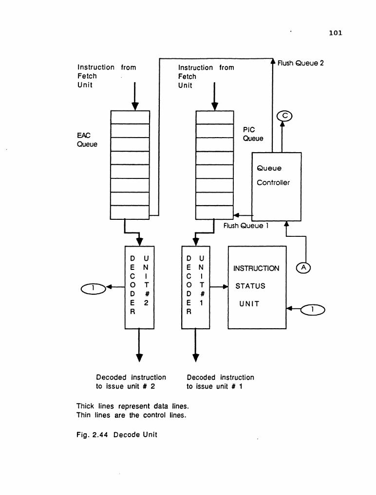
Instruction from flush Queue 2
INSTRUCTION
Decoded instruction Decoded instruction to issue unit # 2 to issue unit # 1
Thick lines represent data lines. Thin lines are the control lines.
Fig. 2.44 Decode Unit

Fig. 2.45 Instruction format issued to the execution unit
r
Opcode ASRl DSRl SD1 ASR2 DSR2 SO2 D DR

103
units. The function of the issue unit is to schedule the
execution of the instructions. Each stream contains its own
issue unit. At any instant of time, the operating issue unit
belongs to the stream that is current. The issue unit
controls the C field in the instruction status unit and the
delay is set according to information that is available. The
issue unit consists of: 1) logic capable of resolving the
RAW and WAW hazards, and 2) the instruction router unit. The
issued instruction is formatted as shown in Fig. 2.45 and
is forwarded to the execution unit. The output of the issue
unit is made up of seven fields: 1) address of source
register one (ASRl), 2) operand of source register one
(DSRl), 3) source delay one (SDl), 4) address of source
register two, 5) data of source register two (DSR2), 6)
source delay two, 7) instruction delay (ID) and 8)
destination register (DR). The instruction is fetched from
the current queue in the decode unit and is simultaneously
fed to the main hazard resolving unit. The various delays
are computed and the instruction is formatted to be issued
to the execution unit in the next pipeline cycle. If the
operands are available, the operands are loaded in the
operand data fields and then issued. For example, let the
ADD Rl,R2,R3 be the present instruction encountered by the
issue unit. If Cl,C2,C3 are all zeros and Rl=R2=R3=5 then
the formatted instruction would read as displayed in Fig.
2.46. On the other hand if the Cl,C2 ,C3 are non zeros, the

Let R1 = 5 and R2 = 5.
R1 = R2 + R3, where R2 and R3 are available.
Fig. 2.46 Formatted instruction for 'add Rl,R2,R3' with no delay
#
OpcOde
ADD
R1 = R2 + R3, where R2 and R3 are not available.
The delay associated with R2 and R3 is 3 and 4 respectively
A S R l
R2
Fig. 2.47 Formatted instruction with delay, forwarded to execution unit
D S R l
0
D R
R1
D
5
Opcode
ADD
SDl
5
A S R l
R2
ASR2
R3
D S R l
3
DSR2
0
SO1
-
SD2
5
ASR2
R3
D
0
D R
R1
DSRP
4
SD2
-
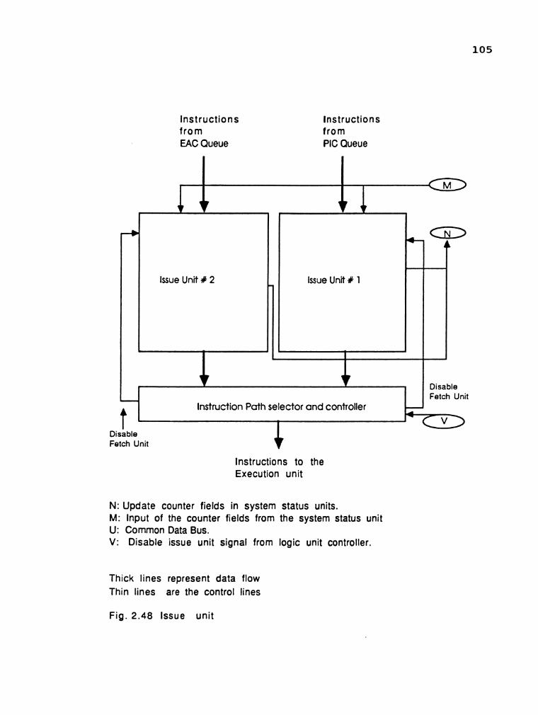
lnstructions from EAC Queue
lnstructions from PIC Queue
lnstructions to the Execution unit
N: Update counter fields in system status units. M: Input of the counter fields from the system status unit U: Common Data Bus. V: Disable issue unit signal from logic unit controller.
Thick lines represent data flow Thin lines are the control lines
Fig. 2.48 Issue unit

106
delays have to be computed and such an instruction would be
forwarded to the execution unit as shown in Fig. 2.47.
Conditional branch instructions are handled in a different
manner. The issue unit calculates the time when the correct
result would be available forwards it to the logic unit. The
issue unit is then disabled along with the decode unit until
the branch instruction is evaluated. The issue unit is
illustrated in Fig. 2.48.
2 .4 .5 EXECUTION UNIT:
The execution unit comprises of three sub units namely:
1) dynamic fixed point arithmetic unit, 2) dynamic floating
point arithmetic unit, and 3) logic unit. The fixed point
arithmetic unit is a pipelined unit with seven stages. The
design is based on the carry save adder tree for multiple
additions of binary numbers. The behavior of the arithmetic
unit is dynamic and it can execute four different
operations: add, subtract, multiply and divide without
reconfiguring the pipeline. It can also handle upto three
different arithmetic operations being processed in the
various stages in the same pipeline cycle. The arithmetic
instructions whose operations are multiplication or division
are allowed to enter the arithmetic unit at stage one.
Addition and subtraction instructions are introduced to the
pipeline at stage six. The results are uploaded to
destination registers at stage 7. Arithmetic instructions
issued by the issue unit that do not contain the appropriate

Instructions from Issue Unit.
t
Dynamic Dynamic Fixed Floating Logic Unit. Point Point Ar i thmet ic Unit Unit
* i
b Controller for the
Controller for floating
+ b Controller for the fixed
e point unit
v v T
To common data bus.
Thin lines: Control signals to control the input and output Thick lines: Instruction flow from issue unit. Very thick lines: Output data lines to the common data bus.
DS: Delay Station.
Fig. 2.49 Dynamic pipelined execution unit.

108
operands are held at stage 1 or stage 6, depending on the
operation specified by the instruction. The floating point
unit is a repetition of the fixed point unit with some
external combination circuitryto take care o f t h e
additional processing. The logic unit is responsible for the
execution of logic instructions and the evaluation of branch
instructions. Branch instructions that have to be evaluated
are held at DS provided in the logic unit. Additional memory
elements are provided in stages oneand six of the arithmetic
units and stage three of the logic unit. These memory
elements store the instructions that are issued by the issue
unit until they are ready to be executed.The execution units
are illustrated in Fig. 2.49. Ten buffers are available at
the entrances to the execution unit. Every DB has equal
access to the execution unit. Priority numbers are assigned
to every DB in the reservation station. The priority number
is used to determine the instruction that has been waiting
for the longest time in delay station. In case of a conflict
between two incompatible instructions that require the use
of the same stage of the execution unit, the instruction
with the highest priority is executed. The priority numbers
are daisy chained as instructions are executed. Each delay
station operates independently of the others in the system.
The individual execution units are provided with
dedicated controllers which provide collision free execution
of instructions in the execution units. The controllers of

109
the arithmetic unit provide collision free execution of
instructions. The logic unit controller is responsible to
evaluate the pending branch instructions and direct the
instructions into their respective buffers. The controllers
communicate with each other by using a common control
register. The detialed design of the controller is beyond
the scope of this research.
The next chapter deals with the structure and design
of the fixed point arithmetic unit.
CHAPTER THREE
DESIGN OF DYNAMIC PIPELINE ARITHMETIC UNIT
3.1 INTRODUCTION:
The arithmetic functions are executed by the arithmetic
units in the execution unit. The design of these units
determine the throughput of the total system. The arithmetic
units are modelled after the static wallace tree structure
capable of performing multiple number additions. The
advantage is that the architecture is pipelined, and
modifications to increase the computing capabilities are
possible. The static unifunction pipeline has to be
converted to a multifunction pipeline capable of handling
addition, subtraction, multiplication and division.
Individual functional units can be provided, but it leads
to increase and redundancy of the hardware. The design
criteria is to model a single arithmetic unit which is
capable of carrying out executions of different arithmetic
instructions at the same time. The algorithms for performing
the arithmetic operations are chosen so as to complement the
structure of the wallace tree.
The wallace tree is first described and the
modifications are carried out depending on each of the four
operations.
3.2 PRINCIPLE OF OPERATION OF THE CSA TREE:
Multiple number addition can be realized with a

multilevel tree adder. The conventional carry propagate
adder (CPA) adds two inputs and yields a single output. A
carry save adder (CSA) receives three inputs and produces
two outputs called the sum vector (SV) and the carry vector
( C V ) . The CSA is a full adder wherein the carry in bit is
treated as an element of the third input vector. The carry
out bit is treated as an output element of the carry vector
and is not forwarded to the next full adder. The sum vector
and the carry vector are treated as individual vectors and
are operated upon in the same manner. A n-bit CSA element
consists of n full adders where in the carry in bits of the
individual adders are used to enter the third vector and all
the carry out terminals act as the output lines of the carry
vector. The carry lines are not internally interconnected
in a carry save adder. The truth table of a single C S A
element is illustrated in Fig. 3.1 along with the C S A
element.
Mathematically the carry save adder is represented as:
A + B + D = S + C ( 3 . 1 )
where + is the arithmetic addition operation. The input
vectors are A, B, and D. The output vectors are S and C. The
total sum of the three input vectors are obtained by adding
the S vector with the C vector. The carry vector is shifted
one bit to the left compared to the sum vector. This
shifting of the carry bit is necessary to maintain the
correct placement of the vectors with respect to each other.

A B D
CARRY SAVE ADDER UNIT.
SUM CARRY
Fig. 3.1 The CSA element and its truth table
Fig. 3.2 CSA operation of adding three elements

In the process of summation, the carry bit of the lowest
significant bit is added along with the next higher order
bits. This principle is illustrated in Fig. 3.2. If it is
necessary to perform multiple number additions, then the
individual C S A elements are configured into stages of a
pipeline. The process of adding n vectors, m bits long is
carried out as follows. The input binary vectors are divided
into k groups consisting of three vectors. If the number of
vectors is not a multiple of three then the value of k is
equal to the highest number of groups that are possible. The
number of C S A elements that are required to start the
process are equal to k, m-bit CSA units. The CSA elements
which perform the operations in parallel are grouped
together into a stage or a level. The ungrouped vectors are
passed undisturbed to the next stage. The aim is to merge
the n input vectors into two vectors S and C, each 2*m bits
long. The process of merging is carried out in stages. The
number of CSA elements in a stage is equal to the highest
number of three vector groups that are possible from the
input vectors to that stage. The ungrouped vectors are
passed on to be processed in the next stage. The final
result is obtained by adding the last sum and the carry
vector. The relative order o f t h e vectors has to be
maintained through out the pipe so as to obtain the correct
result.
Let the eight vectors shown below be the shifted

114
multiplicands of two eight bit binary vectors wherein the
operation between them is multiplication. These partial
products are to be added to obtain the final product and
hence involve multiple additions. The leading and trailing
zeros are added to show the relative displacement of the
vectors to each other.
W1 = 0 0 0 0 0 0 0 0 1 0 1 0 1 0 0 1
W2 = 0 0 0 0 0 0 0 1 0 0 0 1 1 1 1 0
W3 = 0 0 0 0 0 0 1 1 1 0 0 0 1 0 0 0
W4 = 0 0 0 0 0 1 1 0 0 1 1 0 0 0 0 0
W5 = 0 0 0 0 1 1 0 1 0 0 1 1 0 0 0 0
W6 = 0 0 0 1 0 0 0 1 0 0 0 0 0 0 0 0
W7 = 0 0 1 0 1 1 0 1 0 0 0 0 0 0 0 0
W8 = 0 1 0 1 0 0 0 1 0 0 0 0 0 0 0 0
W l t o W8 are the partial products of binary
multiplication of two vectors and in this example they are
treated as 16 bit binary vectors.
If we restrict the operation of the CSA tree to adding
multiple numbers, a wallace tree can be structured. In
general, a V - level wallace tree can add upto N(v) input numbers, where N(v) is evaluated by the following recursive
formula [23] :
N(v) = 0.5 * ( N(v) + ( N(v-1) * mod 2 ) ) (3.2)
with N(1) = 3.
For example, we need 10 CSA tree levels to add 64 to 94
numbers in one pass through the tree.

Mathematical ly f o r e i g h t of t h e e i g h t b i t v e c t o r s we
need a f i v e l e v e l CSA tree. The l e a d i n g z e r o s a r e omi t ted
f o r t h e ca lcula t ions . The process of addi t ion is i l l u s t r a t e d
b e l o w w h e r e i n SV r e p r e s e n t s t h e s u m v e c t o r a n d C V
r e p r e s e n t s t h e c a r r y vec to r . The number of groups of t h r e e
vectors t h a t can be formed a r e two i n number (k=2) and hence
two e i g h t b i t CSA u n i t s a r e requi red t o s t a r t t h e process .
Level 1: The fo l lowing is t h e o p e r a t i o n i n e i g h t b i t CSA
u n i t #1:
The fo l lowing is t h e o p e r a t i o n i n e i g h t b i t CSA u n i t #2:
A t t h e end of l e v e l one t h e r e s u l t s a r e t a b u l a t e d i n t h e i r c o r r e c t order :
These vec tors a r e forwarded t o t h e l e v e l 2 f o r f u r t h e r
processing. A t l e v e l two t h e r e a r e s i x binary vec tors t o be

added. The number of three vector groups that are possible
are two (k=2). They are 1) SVl,CVl,SV2 and 2) CV2, W7,W8.
The operation of the CSA units three and four are as
follows:
Level 2: CSA unit number #3:
CSA unit number #4:
The results of level two are tabulated below :
These results are forwarded to level three . In level three, the three inputs SV3, CV3,and SV4 are
converted into two outputs which are then used to compute
the result. The operation of CSA unit five in level 3 is as
follows:

The results of level 3 are tabulated below:
The above results are forwarded to level 4 along with
CV4.
Level 4 :
The above vectors are forwarded to level 5 for the
final summation.
Level 5:
SUM = 1 0 1 0 0 1 1 1 1 1 0 1 1 1 1 1
The complete structure of the pipelined unit is shown
in Fig. 3 1 3 . Anderson et al. [ 2 2 ] has used this concept and
modified it to suit the needs of IBM System 360/Model 91.
3.3 CONVERSION OF UNIFUNCTION STRUCTURE TO MULTIFUNCTION
STRUCTURE:
The structure discussed is a static unifunction
pipeline. It can carry out only the additions of multiple

LATCH 1
LATCH 2
C C 4 4 C C C C .:.:.:-:.:<...:.:.;<.:.:.:.:.:..-:;.:.;.;< ,... 2,. .............................. ; ............................... ;... ... ...>. .... ...:.:?~::.':.y<::*:::::::::~:~~::::i:::*.: .::.:~:,:>;<:i~>>;i:$i~iyj:.>j~p*::;<:::$*:.:j$:>ii:j:;::;:~i:i<>:*':jj<:.$:j:~>*:::;<:::
4 4 4 4 + 4
S 1 CSA UNIT - 1 CSA UNIT - 2
S 2 C S A UNIT - 4 C S A UNIT - 3
C4 7 S4 r
c 3 T + s3 .
................................................................................................................ ................................... ............................................................................ ................ .'.:<.:.>:; ............ ..................... :s,;. .,.. ....... :..-.:.::; ::::::: .:.:: ..::::::.: -:-::>::.:>::.:;. >.: .,::::;.,. . . . . . . . . . . . . . . . . . . . . . . . . . . . . . . . - . . . . . . . . . . . LATCH 3
S 3
LATCH 4
, . . , . , . ,
4 + 4 ~,
C S A UNIT - 5
CSfl UNIT - 6
C6 S6
w C5 4 '. ...:; \
S5 .................. ........ .;..;. .......... ....................... ,, . .? .................. .......... ....... < <,,.x :A::::-:.:.?.. ............................................................... ;.. .......................................................... ................... .............. :::: :* .......... :.:.:.:.;.:.: ...> :::::;:y:.:::.:.:. .................................................. .................................................... ""'.'i ............................. :::,:::l.:.:,:.:.:.:.:.:.>: .>:.:... ..:.: ,,:. .,: .:.::,.. . .:: ................... &. ...................................
t 4 4 + I
w - - . . . . . . . . . . . t - j LATCH 5
4 . . ........................................... ............ . . . ........... : ........ o:.;r.?,,y+x. .:.. .......................... ::::.:.:.A* . : . ..r .. :.:.,.> .......... .:.,.., ... i;. ..: r............ :... . . . . . . . . . ................................................... . . . . . LATCH 6
TOTRL SUM.
Fig. 3.3 C S A structure to s d d eight, 8-bit binary uectors

119
numbers which are N bits wide. The main aim of the design
is to modify the static structure to support the operations
of addition, subtraction, multiplication and division.
3.3.1 MODIFICATIONS DUE TO ADDITION AND SUBTRACTION:
The last stage of the CSA tree structure can support
addition and subtraction. The addition can be carried out
in the adder unit which sums up the two final vectors from
stage 5. Hence a path has to be created to load the two
vectors from the external sources. A multiplexer is
introduced to choose between the two streams. The changes
are illustrated in Fig. 3.4. The subtraction is carried out
using the two's complement method which means the number to
be subtracted has to be inverted on demand and a value of
one should be added to the least significant binary digit.
The operation of inversion on demand can be achieved by
using XOR gates and controlling one of the inputs. Hence a
XOR gate array is attached to one of the branches of the
external input data stream as shown below in Fig. 3.5.
3.3.2 MULTIPLICATION: T h e o p e r a t i o n o f
multiplication that is being attempted is very similar to
that of the decimal multiplication. When two binary vectors
of lengths m and n are to be multiplied, the final product
will be a vector with the maximum length of (m + n). Let a
vector A of length n be multiplied with another vector B of
length m. Each member of the vector B namely bj (for all
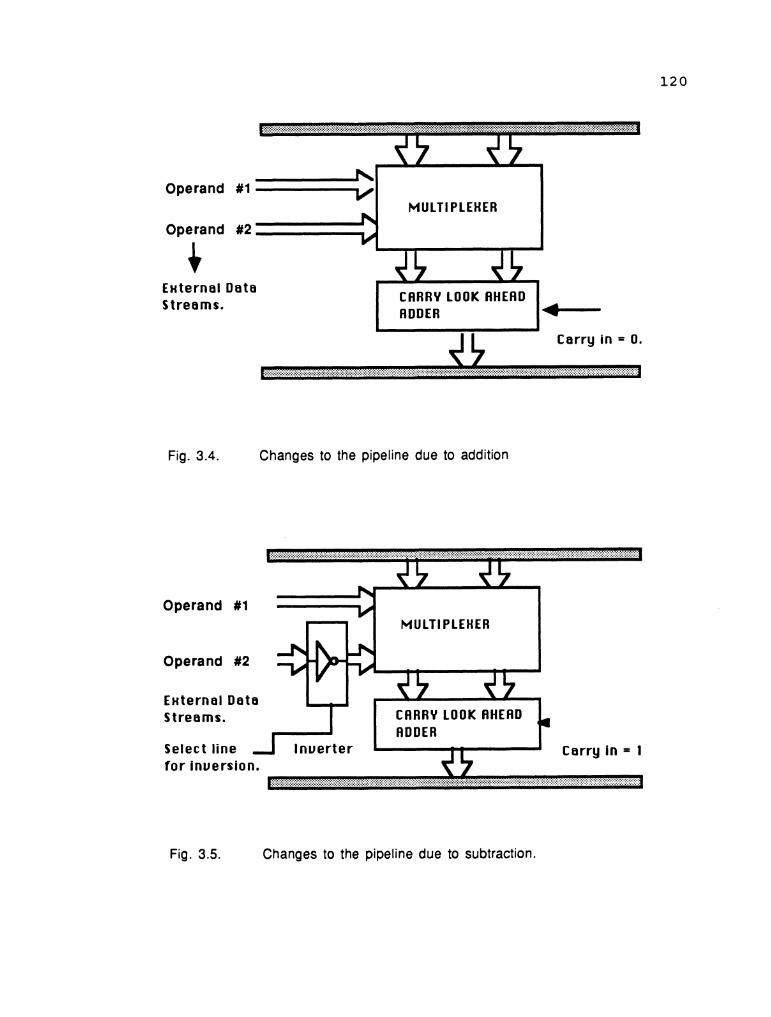
h Operand #I -V I
MULTIPLEXER
Operand #2 I External Data Streams. C A R R Y LOOK flHEAD
RDDER I
Carry in
Fig. 3.4. Changes to the pipeline due to addition
Operand #1 V MULTIPLEXER
Operand #2
External Data Streams. C A R R Y LOOK AHEAD
RDDER Select line Carry in = 1 for inversion.
Fig. 3.5. Changes to the pipeline due to subtraction.

121
j=O,m) is multiplied with each member of vector A namely ai
(for all i = 0,n) to produce m such vectors called the
partial product vectors. The process is illustrated in Fig.
3.6 for m equal to 6 and n equal to 6.
P1O p9 '8 p7 '6 p5 p4 p3 p2 Pl Po
......................................................... P = { PlO P9 P8 P7 P6 P5 P, P3 P2 PI Po ) = Total product.
Fig. 3.6. Multiplication by multiple additions.
The values of i and j were chosen to be 6 and hence the
product vector has eleven elements. This process requires
six shifts and six adds to get the product. The partial
products are necessary to compute the result and they must
be shifted according to the weight of its multiplier namely
bj.

SHIFTED MULTIPLICAND GENERATOR.
W W W W W W W W 1 2 3 4 5 6 7 8
Fig. 3.7 Changes to the pipeline by multiplication

123
3.3.3 MODIFICATIONS DUE TO MULTIPLICATION:
A stage is added at the top of the pipe to calculate
the shifted multiplicands of the input binary vectors. This
stage calculates the partial products of the two binary
vectors that are to be multiplied and presents them as
multiple vectors. The new stage is shown in Fig. 3.7.
3.3.4 DIVISION:
The division process is different from that of the
usual shift and subtract operation. The principle is based
on converting the shift and subtract, to shift and add
operation. In simpler terms, the division operation is
converted into a multiplication operation.
This operation is called the convergence method of
division and it is used in IBM 360/370 and CDC 6600/7700.
The method is described briefly below. We want to compute
the ratio (quotient) Q = N/D where N is the numerator and
D is the denominator. This process is being carried out in
the normalized binary arithmetic form. Hence (0.5 <= N <
1) and (0.5 <= D < 1). In the original method N is always
less than D but this has been modified to accommodate even
if N > D. The only restriction placed on this method is that
both N and D must be normalized before any of the operations
can begin.
Let R i for i = 1,2,3,. . . . . .n be the successive converging factors. One can select
(i-1)
R, = 1 + g 2 for i = 1,2,. ..,k

where 6 = 1 - Dand 0 < 8 <= 0.5.
To evaluate the quotient Q we multiply both N and D by
R i , starting from i = 1 until a certain stage, say k.
Mathematically, we have as follows:
The value of the denominator D is substituted with 1 - 6 and
the resulting equation is shown below
. . . . . ( ( 1 - 6 ) x R x R x R x . X R ) 1 2 3 k
( i - 1 )
Expanding Ri in terms of ( 1 + 6 ) as in equation ( 3 . 3 ) for
i = 1, 2, 3 , ..... kt the above equation is modified as given below:

The denominator can be reduced to one term as shown in
the following: 2 4 (k-1)
N x (l+S)x (l+6 ) x (l+S 1 . . x (l+6 )
The value of (6) cannot execeed 0.5. Hence, the
*(k)
denominator term ( 1-6 ) will tend towards unity when the
value of k is sufficiently large. For an eight bit machine,
the accuracy of 0.996 can be achieved within three
iterations (k = 3). Thus the equation is approximated as
follows
Q =
A table is given below tabulating the convergence
sequence for the maximum value of = 0.5
2k ( 1 - 6
0.75
0.9375
0.996094
0. 9999874
0. 9999999
Iteration #
( k )
1
2
3
4
5 .
6 2k
0.25
0.0625
0.003906
1.526 x 1 0 -
2.32 x 10 ‘' O

There will be an overflow if N > D and this is taken
care of as follows. Since both N and D are bounded by the
limits 0.5 and 1 where 0.5 is the lower bound and 1 the
upper bound. N and D can assume the value of 0.5 but cannot
assume 1. Hence if N > D then N/D can be represented as I1
+ fraction' wherein the fraction is less than 1.
Mathematically we have
Q = N/D = (D + B)/D = 1 + (B/D)
where B = N - D. The operation of B/D is carried out by the
convergence method. The total result can be obtained by
initialising an overflow bit. This overflow bit must be
taken into consideration, when the result of this operation
is required for further operations.
3.3.5 MODIFICATIONS DUE TO DIVISIONS:
The implementation of division by convergence method
using the wallace tree is carried out by splitting the
process into iterations. Each iteration computes the new
partial product and the number of iterations depends on the
convergence factor DELTA. The process is explained below
mathematically.
I 2 L e t P p = P ~ X ( 1 + b )
( 3 8)
4 L e t Pg = - P 2 x ( 1 + 6 ) (3-9)
substituting the value of P3 in the equation (3.6)
127
It is easy to see that the pipeline has to be modified
to achieve division operation. From the discussion above,
the partial product Pk is calculated by placing Pk-, and
as the two input arguments to the pipeline. In the
first iteration, the convergence factor is easily calculated
but in the following iterations the power of delta rises by
the power of 2k . Hence the higher powers of delta for the next iteration is calculated by multiplying the present
value of delta with itself. The purpose of calculating delta
is two fold: 1) for providing the second argument for the
next iteration at the top of the pipe and 2) to find out
whether the convergence has been achieved. The calculation
of the second argument for the next iteration involves delta
being calculated twice at stage six in consecutive clock
cycles. The second delta is used for testing the convergence
and also to realize the next higher power of delta.
The process of calculating the value of delta twice in
stage six is achieved by placing a latch in stage 5 and
holding the value of delta for an extra clock cycle. Hence
there will be an addition of a new latch to the pipeline at
stage five. There is another change that has to be carried
out to ensure the successful operation of division. The
partial product that comes out of stage six cannot be fed
back into the pipe for the next iteration because the second
argument is not yet available. Hence another stage is added
to hold the value of the partial product until the second

128
argument becomes available. The changes made are shown in
Fig. 3.8. Thus the pipe is converted from a unifunction pipe
to that of a multifunction pipe capable of" dynamic behavior
as shown in Fig 3.9. The dynamic operation depends on both
the hardware and the control schemes for its successful
operation. The control is based on the hardware and the
details of how the control was realized is explained in the
next section.
3.4 DYNAMIC EXECUTION OF INSTRUCTIONS :
The dynamic scheduling of data in a multifunction
pipeline is essential for the successful operation of the
pipeline. The scheduling algorithm maintains collision free
execution of instructions in the pipeline system. The
development of such procedures has been studied by several
researchers. Ramamoorthy and Li [15] have shown that general
problem is intrinsically difficult and is a member of the
NP complete class of problems . It is conjectured that any such problem of this class has no fast solution, that is,
a scheduling algorithm is not a polynomial function of the
number of items to be scheduled. Ramamoorthy and Li [16],
Ramamoorhty and Kim [lo], and Sze and Tou [17], have studied
the suboptimal scheduling algorithms and their
characteristics with mixed results. The work performed by
Davidson [18], Shar [19], Pate1 and Davidson [20], and
Thomas and Davidson [21] is taken as the foundation and the
scheduling of the dynamic pipe is developed from it.

CSfl UNIT 6 MULTIPLEHER
MULTIPLEXER
CARRY LOOK AHEAD
Fig. 3.8. Changes to the pipeline due to division.

LATCH 2
S 2 CSA UNlT - 2
LATCH 3
S 3 CSA UNIT - 4 CSA UNIT - 3
4 :~~j~:i:::~~~~:~:~~~~~:~.wlj.:::~~3j~~~~j.;::P,:i'::::~:2~::~jj~~,~:,,~:~:~:~~~~:~:~::t;j.:~~~~:~I~~~~:.;.~~j . . . . . . . . . . . . . . . . . . . . . . . . . . - ::+: :.: ::,,,: . . - ::;::::I:.:;5:::I:::j:;:;:::;:::i::: . . . - . . . . . . ,j:::::::;:::;:F:.... ... ......................... ........... .............................. ....:.:...... ............ LATCH 4
I 4 4
$ 4 I I CSR UNIT- 5 I
CSR UNIT - 6
Inverter CARRY LOOK AHEAD ADDER
C o n y in.
+ P = A ' B .
Fig. 3.9 Multifunction eightbit arithmetic pipeline unit.

131
3.4.1 COLLISION VEXTORS:
Collision vectors are binary vectors that are derived
from the latencies of a given pipeline. Latency is defined
as the number of pipeline cycles between two successful
initiation of instructions in the pipeline. Initiation is
defined as the process wherein an instruction is fed at the
input stage o f t h e pipeline system. An initiation
corresponds to the start of the computation of a single
function. The latency is an integer and is bounded
theoretically from 0 to infinity. Static pipelines are
forbidden to have a latency of 0 as two simultaneous
initiations cannot be performed. The latency can also be
derived from reservation tables. The reservation table is
a two dimensional array representing the usage of the
pipeline stages by the function. It represents the flow of
the instruction from the first stage to the last stage.
Every function has its unique reservation table. The latency
of a given function is determined by using two reservation
tables of the same function. The first reservation table is
shifted one clock cycle to the left and placed on the second
reservation table. If there are any common stages between
the two tables, there is a chance of collision and that time
cycle is a forbidden latency. The shifting and overlaying
is carried out for all the pipeline cycles that the
instruction remains in the pipeline. A static pipeline is
capable of executing only a single function.

132
The collision vectors are unique for any given
function. The cross collision vectors depict the times of
all possible initiations within a time period. It is used
to schedule the instruction flow in any pipeline. They are
derived as follows:
The length of the collision vector of a function is
equal to the difference between the time it is initiated and
the time the final result is obtained. If a function is
present in the pipeline for 10 pipeline cycles, the
collision vector would be 10 bits long.
The elements o f t h e binary vector are assigned
according to the latency sequence. All available latencies
are assigned as 0s and all forbidden latencies are assigned
as Is. The latency sequence is derived by initiating the
function into the pipeline and calculating all the available
latencies for initiating the same function. The available
latencies are bounded by the maximum time that the initiated
function remains in the pipeline. If the function remains
in the pipeline for 10 pipeline cycles, the latency sequence
can be at the most, 10 elements. If the latency sequence of
a pipeline is (0,1,4,6,8) out of a possible 10 clock cycles
then the collision vector will be { 00110101011 ) . Collision
vectors are used to derive the cross collision matrices for
the dynamic pipeline. The collision vector for the
reservation table in the Fig. 3.10 is listed below:
c l = ( 1 1 1 1 0 0 1 0 )

Fig. 3.10
STAGE 4
STAGE 5
A sample reservation table
X
X X
X
.
134
Based on the above concepts, the scheduling of the
pipeline is derived in the next sections.
3.4.2 DESIGN OF CROSS COLLISION MATRICES:
The scheduling of instructions in a dynamic system
cannot be performed by a single collision vector. This is
due to the fact that more than one function is executed in
the pipeline and a single vector cannot represent all the
available latencies of all the functions. The scheduling of
data in a dynamic pipeline is carried out by using a matrix
instead of a vector. The matrix is calledthe cross
collision matrix. The design of the cross collision matrix
is based on four collision vectors. These collision vectors
belong t o t h e four arithmetic operations: addition,
subtraction, multiplication, and division. The collision
vector for the individual functions is derived on the basis
of the reservation table associated with each function. The
collision vectors for the four functions are derived below:
The operation of both addition and subtraction are very
similar to each other. The only difference between addition
and subtraction is that in subtraction, one of the operands
is inverted and the carry in is equal to 1. All this can be
achieved in one clock cycle and therefore no additional
stage is required. The reservation table for addition and
subtraction is shown in Fig. 3.11.
The collision vector for the function of addition and
subtraction is as follows:

135
cad, = { 1 0 0 0 0 0 0 0 0 } (3.11)
'sub = { 1 0 0 0 0 0 0 0 0 } (3.12)
The multiplication operation is initiated at the top
of the pipeline. The function once initiated passes through
the various stages t o t h e end o f t h e pipeline. The
reservation table for the operation of multiplication is
given in Fig. 3.12. From the reservation table it is found
that the latency is 1 and that the collision vector closely
resembles that of addition and subtraction. The collision
vector for multiplication is as follows:
- Cmlt - { 1 0 0 0 0 0 0 0 ) (3.13)
The collision vector for division involves two sets of
computation. The first set is the generation of partial
products and the second set is the generation of the new
convergence factor. This is due to the fact that from
equation (3.5). we have in the convergence method, two
products to be calculated for each iteration. Recalling the
convergence equation (3.3) we see the need to calculate the
new quotient and the convergence factor for each iteration.
The reservation table for this function is the
combination of equations (3.4) and (3.7). First, the partial
quotient is calculated by introducing one of the arguments
N as one of the inputs and the second input is 1+ . This gives the new partial quotient namely N* (1+ ) . This process is illustrated in Fig. 3.13. To calculate ^2 for the next
iteration, the value of is initiated as the two inputs

Stage
Stage
Stage
Stage
Stage
Stage
Stage
Fig. 3.1 1 Reservation table for addition and subtraction.
Stage
Stage
Stage
Stage
Stage
Stage
Stage
Fig. 3.1 2 Reservation table for multiplication.

137
which immediately follows the initiation of the previous
function. This is carried out to have all the operands
available for the next iteration without any undue delay.
The value of delta is held in stage five for two consecutive
clock cycles because of the necessity of obtaining the new
values of 1 + ( )A and ( )A . This is illustrated in Fig. 3.14. In the reservation table the flow of the partial
products is marked with a X and that of delta is marked with
an 0. Even though they are two different subfunctions of the
same main function they are combined together into one
reservation table. The reservation table for division is
shown in Fig. 3.15. The collision vector for division is
given below:
Cdiv = { 1 1 1 0 0 0 0 0 ) (3.16)
DESIGN OF THE CROSS COLLISION MATRIX :
A cross collision matrix is a r x d binary matrix where
r is the number of reservation tables and d the maximum of
the clock cycles of all the tables. In our design the value
of r is 3 and the value of d is 8. The cross collision
matrix represents a state of operation of the pipeline. The
steps of designing the initial cross collision matrices are
as follows [23]:
Step 1: There are r initial states for the r reservation
tables. The table i which assumes the first initiation at
clock cycle 0 is of the type i.
Step 2: The jth row of the ith matrix CMi is the collision
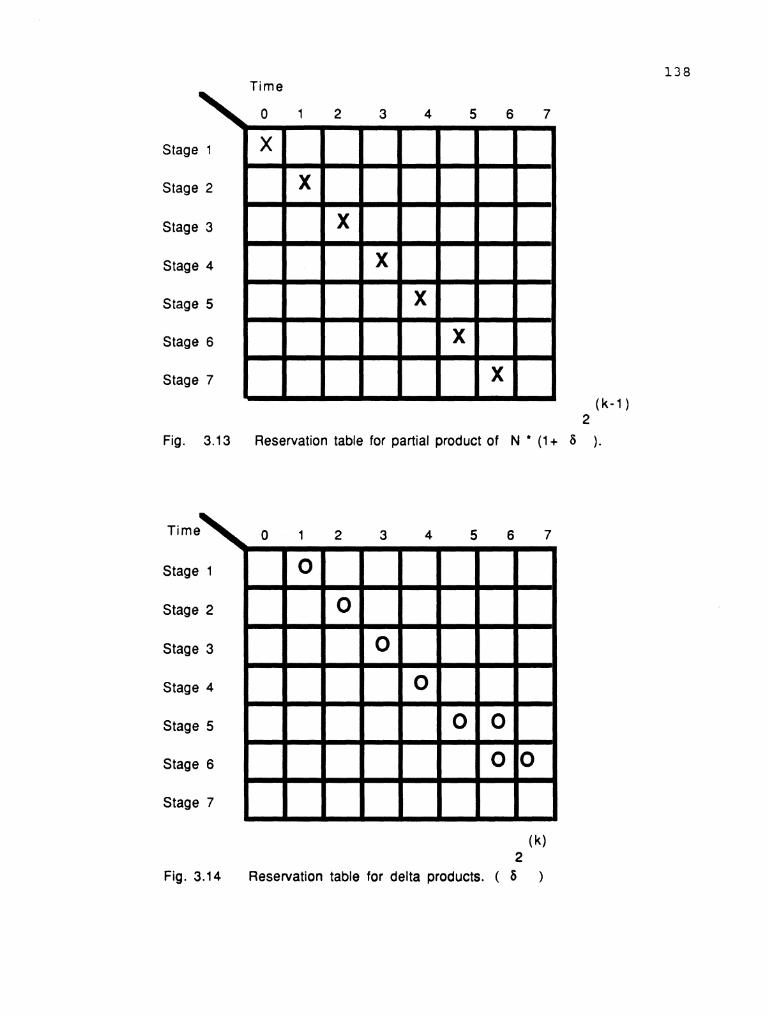
Time
2
Fig. 3.13 Reservation table for partial product of N (I+ 6 ).
(k ) 2
Fig. 3.14 Reservation table for delta products. ( 6 )

Fig. 3.15 The reservation table for the convergence method

140
vector between an initiation of type i and latter initiation
of type j . Thus CMi (j, k) is 0 only if shifting the
respective reservation tables j, k places right, and
overlaying them on a copy of the reservation table if
results in no collision. k denotes the number of clock
cycles from the initial clock cycle 0, when an initiation
of the function j is desired.
Step 3: In all cases the ith row of CMi is the same as the
initial collision vector ofthe function i. It is
equivalent to the reservation table i used in a static
configuration. The other rows are called cross collision
vectors.
Fig. 3.16. shows a sample initial collision matrix for
an operation i. The number of rows depends on the total
number of distinct operations that can be performed by the
pipeline system. In our research the pipeline can perform
three distinct operations and hence the number of rows are
three in number. Let the sample matrix represent the initial
collision matrix of operation divide which is tagged as
operation number 1. Row1 is the initial collision vector of
division operation. Row2 is the cross collision vector
between operation 1 and operation 2. Row3 is the cross
collision vector between operation 2 and operation 3.
The initial collision matrix for division operation is
derived fromthe collision vectors of addition ,
subtraction, multiplication and division. The formulation

The number of columns is equal to maximum compute time of operations 1 to n
- - Cross collision vector between operation (1) and operation i
Cross collision vector between operation (2) and operation i
Cross collision vector between operation (3) and operation i
Collision vector for the operation (i.)
Cross collision vector between operation (n-1) and operation ( i) l
Cross collision vector between operation (n) and operation (i) - -
Total number of operations that can be performed by the system = n
row 1
row 2 row 3
row i
row n-1
Fig. 3.16 Structure of an initial cross collision matrix for operation i.

142
of the initial collision matrix for division is chosen to
illustrate the process. The operations are to be tagged as
i, i+l , i+3 and so on. Each operation has its own initial
collision matrix. In our research the operation of division
is tagged as 1, the operation of multiplication is tagged
as 2, and the operation of addition and subtraction are
tagged as 3. The assignment of the tags is of no consequence
and they can be assigned as desired. Care should be taken
to assign the same numbers to the initial collision matrices
which are associated to each operation. In this case, the
collision matrix 2 represents the initial collision matrix
for multiplication. The rowl of the matrix 1 should be the
cross collision vector of operation 1. The row 2 of matrix
two should also be the cross collision vector of operation
2. This is the same case with all the initial cross
collision matrices.
The rowl of the matrix 1 will be the cross collision
vector of division operation. The elements of rowl are ( 1
1 1 0 0 0 0 0 ) . The row 2 represents the cross collision
vector between multiplication and division. The elements of
this row are obtained by slidingto the right the
reservation table of multiplication in Fig 3.12. over the
reservation table of division in Fig. 3.14 and determining
the available latency sequence. The available latency
sequence between division and multiplication are { 3,4,5,6,7
) and hence the elements of row 2 are { 1 1 1 0 0 0 0 0 ) .

143
Using the same process the cross collision vector between
addition and division is obtained and the elements in row
3 are { 0 0 0 0 0 1 1 1 ). The resulting matrix is given in
Fig. 3.17.
In the proposed pipeline system, there are three
distinct functions which produce three initial collision
matrices and they are presented in Fig. 3.18. The state
diagrams are generated using the initial collision matrices.
3.4.3 GENERATION OF STATE DIAGRAMS:
The state diagrams represent the condition
of stage utilization of the pipeline at any instant of time.
The state diagram gives the controllers useful information
about the state of the system. At each pipeline cycle, the
pipeline configuration corresponds to one of the states.
The generation of state diagrams follows the steps given
below:
Step 1: Each initial cross collision matrix is a single
state. The initiations are controlled by the elements of
individual columns.
Step 2: The next state is determined by looking at the
column 0 of the present collision matrix. For every 0 in the
column there can be an initiation. The function that can be
initiated depends on the row where 0 occurs. If a 0 is
present in row i then an initiation for function i is
possible. This means that the new initiation of function
i will not collide with any of the previous initiations.

Fig. 3.17 Initial cross collision matrix for division
Cross collision matrix for division
Cross collision matrix for multiplication
Cross collision matrix for addition or subtraction
Fig. 3.18 Initial cross collision matrices for the three operations

145
However, this does not guarantee that it will not collide
with any other initiations that may be possible at the same
time. For each initiation there will be a new state. The new
state is determined by ORing the present collision matrix
with initial collision matrix corresponding to the function
i.
Step 3: The compatible initiation set is determined as
follows: The compatible initiation set is basically the set
of functions that can be started at the same time without
any collisions. This is equivalent to placing the associated
reservation tables, one on top of the other and forming a
composite overlay and ensuring that there are no matches.
STEP 4: For a single initiation, the generation of a new
state is explained as in step 2. If the column 0 contains
more than one 0, then multiple initiations of functions are
possible. When multiple initiations are required, the
functions are first checked to see whether they belong to
the class of compatible initiation set. If functions are
compatible , the new state is generated by ORing the present
state matrix with the combined collision matrix. The
combined collision matrix is derived by ORing all the
individual initial collision matrices representing the
functions that are to be currently initiated.
STEP 5: If no initiation is possible in the present cycle,
the collision matrix is shifted one place to the left and
leading zeros are introduced from the right. The pipeline

146
remains in the present state. The column 1 now becomes the
column 0 and the step 1 to step 5 are again followed.
STEP 6: All the new states from the present state matrix
have to be generated. considering the column 0, step 1 to
step 4 are carried out for all permissable initiations. If
no initiations are possible then step 5 is adopted. After
all the new states have been derived from column 0, the
state matrix is shifted one column to the right as in step
5. This process is carried on until all the columns in the
present state matrix have been processed. At the end, the
present state matrix will be a zero matrix.
Step 1 to step 6 are carried out for all the state
matrices that have been generated. This process is stopped,
when there is a state already existing, for every possible
initiations from other states. The state diagrams are linked
to each other by arcs. These arcs are labelled. The
labelling represents the function initiated and the latency.
All the states have to be derived so as to enable the system
to move from one state to another after each initiation.
The compatible initiation set is defined as a set of
functions that can be initiated as a single function or as
multiple functions, and cause no collisions between
themselves. The compatible initiation sets for the pipeline
under consideration are as follows:

I1 = { Addition ) .
I2 = { Subtraction ).
I3 = { Multiplication ).
I4 = { Division )
I5 = { Multiplication, Addition )
I6 = { ~ultiplication, Subtraction )
I7 = { Division, Addition )
I8 = { Division, Subtraction )
The functions are tagged with the following
number representations:
Addition and Subtraction => 1.
Multiplication => 2.
Division => 3.
In the state matrices, the row 1 corresponds to the
division operation. The row 2 corresponds to multiplication.
The row 3 corresponds to addition or subtraction.
A 0 in row 1 implies that an initiation is possible for
the division operation. Similarly a 0 in row 2 implies that
an initiation of multiplication is possible. If there are
two 0s in a column in row 1 and row 3, then both division
and addition (or subtraction) are possible at the same time.
Assuming the initial collision matrix for the division
operation as the current state, the new states are derived
using the steps described above. This example will show how
the various new states are developed. The state matrix is
presented below in Fig. 3.19.:

Fig. 3.1 9 Initial state matrix which is the initial cross collision matrix for division operation
The allowable latencies for each of the rows are listed
below in Fig. 3.20. The maximum table compute time is 8
clock cycles.
Fig. 3.20 The allowable latencies for the state matrix.
Looking at the columns, the compatible initiation set
for each column is shown in Fig. 3.21:

Column 0 :
Column 1:
Column 2:
Column 3:
Column 4:
Column 5:
Column 6:
Column 7:
Initiation set = { 1 )
Initiation set = { 1 )
Initiation set = { 1 )
Initiation set = { 1,2,3,{1,2),{1,3))
Initiation set = { 1,2,3,{1,2),{1,3))
Initiation set = { 1 , 2 )
Initiation set = { 1 , 2 )
Initiation set = { 1 , 2 )
Fig. 3.21. The available initiation sets
For latency 0, the allowable initiation is addition
or subtraction only. For latency 3, all the compatible
operations are possible. In this example the initiation that
will be illustrated for this latency is { 1 , 2 ) . Hence
this example will cover both the single initiation as well
as multiple initiations. Listed in Fig. 3.22 are the initial
collision matrices of addition and multiplication
respectively.
Latency 0 : The state matrix is not shifted to the left,
as the initiation is occurring at latency 0 . The new state
is derived by ORing the present collision matrix with the
initial collision matrix of addition. The resulting
collision matrix is the new state after the initiation of
addition. The operation and the result are listed in Fig.

Initial collision matrix Initial collision matrix for multiplication for addition and
subtraction
Fig. 3.22 lnitial collision matrices for single initiation
Initial state matrix Initial collision matrix for addition and subtraction
The new state matrix
Fig. 3.23 Generation of the new state matrix for single initiation

The shifted state matrix
Fig. 3.24 The new state matrix obtained by shifting left three times
Initial cross collision Initial cross collision Combined cross matrix for multiplication matrix for addition collision matrix for
dual initiation
Fig. 3.25 Process of deriving the combined initial cross collision matrix
The initial state Combined cross matr ix collision matrix
The new state matrix
Fig. 3.26 The new state matrix for combined initiation of distinct functions

152
The process of generating the next state for the double
initiation is not different from that of the single
initiation. The present state matrix is shifted to the left
by three columns for a latency of three. Leading zeros are
introduced at the right. The shifted initial state matrix
is shown below in Fig. 3.24. The two initial collision
matrices for addition and multiplication are ORed together
to generate the combined initial collision matrix for the
double initiation. The new state matrix is derived by oring
the current state matrix with the combined initial collision
matrix. The operation and results are shown in Fig. 3.25 and
Fig. 3.26.
The remaining new states are constructed in this
manner. It should be noted that if more than one initiation
is possible in a column then it is necessary to derive new
states for each of them. All the possible states from the
initial state matrix are illustrated in Fig. 3 -27. The
transition between two states is marked by arrows. The
arrows are labelled on the top by the latency and at the
bottom by the initiation set.
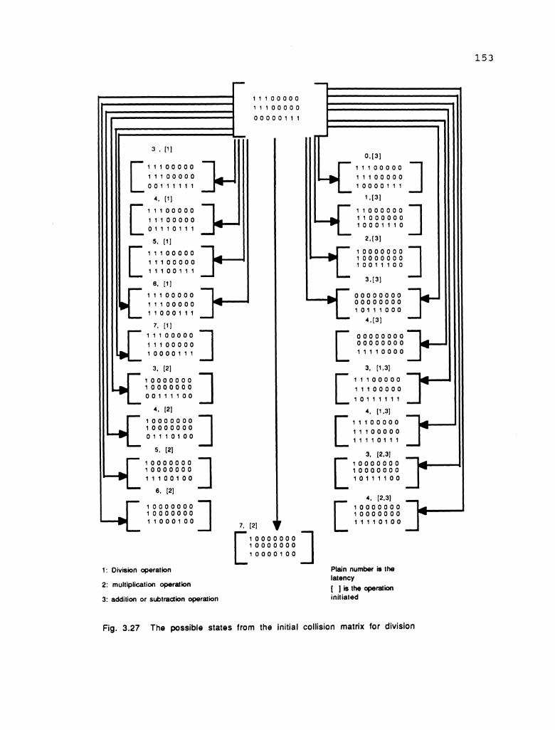
L 1: Division operation
2: multiplication operation
3: addition or subtradion operation
4 Plain number is the latency [ 1 is the cperation initiated
Fig. 3.27 The possible states from the initial collision matrix for division

CHAPTER FOUR
INSTRUCTION EXECUTION I N THE PIPELINE SYSTEM
The execution of instructions in the pipeline is
governed by the issue unit and the controllers in the
execution unit. The instructions are scheduled by resolving
the RAW, WAW and the operational hazard. The general
procedure for the execution of instructions in our proposed
system is recapped below:
An instruction is fetched during every pipeline cycle
from memory by the fetch unit. The fetch unit classifies the
instruction and generates an effective address ( E A ) if
needed. The EA is loaded in the appropriate counter. Two
instructions are fetched from memory when both the streams
are active. The fetch unit feeds two queues in the decode
unit. The individual streams are disabled once the
corresponding queues are filled.
The decode unit decodes the instruction and places the
information in the R field of the system status unit. The
decode unit is disabled if a jump instruction is awaiting
evaluation in the logic unit.
The function of the issue unit is to detect the hazards
and resolve them according to the algorithm developed in
Chapter 2. The issue unit is disabled if any jump
instructions is being evaluated in the logic unit. The issue

unit assigns delay to the instruction and routes them to the
appropriate execution unit.
The instructions that are to be delayed are stored in
buffers provided at the input stages. The controller of the
execution unit is responsible for resolving the operational
hazards. The controller also checks for the available
latencies to accommodate instructions that are ready to be
executed, in the present pipeline cycle. The controller for
the arithmetic unit provides a feedback to the instruction
status unit. This feedback is in the form of updating the
counter fields, depending on the state of the system. The
controllers are also responsible for uploading the
destination register with the result of the instruction, as
soon as they are out o f t h e pipe. A sample set of
instructions are listed below. The operation of the pipeline
is illustrated by executing the sample set. The process of
execution is demonstrated by displaying the flow of
instructions in the pipeline during each pipeline cycle
until all the instructions are executed. Consider the
following set of instructions:
load load load add store add mult j nz
.... store
rl, 20; r2, 30; r3, 40; r4, rl, r2; k, r4; r4, r2, r3; r5, r2, r3; r5, 60;

156
The execution of each instruction is displayed in the
following figures and a brief explanation is provided for
each cycle. The issue unit schedules the instruction one
pipeline cycle later than the decode unit and hence a column
is provided in the instruction status unit which shows the
current instruction being issued. The fields are captioned
in the diagrams for easy identification.
Pipeline cycle # 0:
The instruction 'load rl, 2 0 is fetched by the
fetch unit. The instruction is not a jump instruction and
hence the counters o f t h e counter set 2 are left
undisturbed. The current stream is still the PIC stream.
This is shown in Fig. 4.1.
Pipeline cycle # 1:
The second instruction is fetched from memory. The
first instruction is forwarded to the PIC stack and is
decoded by the decoder. The decoded information is recorded
in the instruction status unit. The second instruction
load r2, 30 is also not a jump instruction. The first load
instruction is initially loaded into the bottom of the PIC
queue. The bottom location is directly connected to the
decoder unit. As a result, the first instruction is decoded
and the decoded information is placed in the instruction
status unit. The Fig. 4.2 and 4.3 illustrate the presence
of the instruction in stages 1 and 2.

Counter 1
Counter 2
load R1, 20;
EAC Queue
Decoder unit 2
issue unit 2
Fixed point unit
PIC Queue
der unit 1
Fetch unit
lssue unit 1
Floating point unit
Logic unit
Register set
Fig. 4.1 The state of the system at pipeline cycle # 0

Counter 1
Counter 2
EAC Queue
load R2, 30;
PIC Queue
Fetch unit
Decoder unit 2 Decoder unit 1
lssue unit 2
Fixed point unit
lssue unit 1
Floating point unit
Logic unit
Register set
Fig. 4.2 The state of the system at pipeline cycle # 1

Op-code is the opcode of the Instruction. Time: Time is the time required to execute the instruction. R - Field : R - field is the field of all registers in the system.. C - Field : C - field is the field of the counters that keep track of the registers.
Fig. 4.3 State of the instruction status unit during pipeline cycle # 1

160
Pipeline cycle # 2:
The first instruction is in the issue unit. The
contents of the counter cl which represents the register rl,
is zero. This implies that there is no RAW or WAW hazard.
The Tinst-delay is calculated as follows:
Csink(old) = O
'test = T
From equation (2.14) Tinse.delay = 0.
~ccording to equation (2.17)
The issue unit issues the instruction 1 to the logic unit
without assigning any delay. The instruction 2 is in the
decode unit and instruction 3 is in the fetch unit. The
instruction 1 would load the register rl with the new value
after it has been executed by the logic unit. The total time
that the load operation would need to execute is 6 pipeline
cycles and hence the counter cl is set to 6. The current
value of cl denotes the number of pipeline cycles needed
(with respect to the present pipeline cycle) for rl to be
loaded with 20. Fig. 4.4, and 4.5 illustrate the state of
the system.
Pipeline cycle # 3:
The instruction 1 is in the logic unit. Instruction 2
is in the issue unit. Instruction 3 is in the decode unit
and instruction 4 is in the fetch unit. Instruction 4 is an
arithmetic instruction. The counters of the EAC stream are

Counter 1
Counter 2
EAC Queue
load R3, 40; Fetch unit
Decoder unit 2 Decoder unit 1
( NO RAW hazard for lnstr # 1 I I No WAW hazard for lnstr # 1
m I = I m m 1 1 ) = 1 - - I I Issue instr # 1 for execution I
Issue unit 2
Fixed point unit
-- - -
Floating
Route instruction to logic unit
point unit
lssue unit 1
Register set
i
Fig. 4.4 The state of the system at pipeline cycle # 2

Op-code is the opcode of the Instruction. Time: Time is the time required to execute the instruction. R - Field : R - field is the field of all registers in the system.. C - Field : C - field is the field of the counters that keep track of the registers.
Fig. 4.5 State of the instruction status unit during pipeline cycle # 2

163
still not operational. The instruction 2 is checked for the
hazards and is issued to the logic unit. c, is decremented
as it represents one less pipeline cycle for rl to be loaded
with the new value. The instruction 2 has no hazards and is
issued to the logic unit by initializing the counter c2, to
a value equal to 6. The delay is calculated as in pipeline
cycle # 2. These are illustrated in Fig. 4.6 and 4.7. The
counter values in the instruction status unit are listed
below:
c 1 = 5 , c 2 = 6
Pipeline cycle # 4:
This is similar to pipeline cycles 2 and 3. The
instruction number 3 is in the issue unit. The initial value
of the counter c3 is 0. NO delay is needed. The instruction
is issued to the logic unit. Fig. 4.8 and 4.9 illustrate the
data flow for this cycle. The instruction in the fetch unit
is not a branch instruction.
Pipeline cycle # 5:
The fifth instruction is in the issue unit. RAW hazard
is detected, as the previous instructions ( #1 and #2) have
not yet initialized the registers with the new value. From
the system status unit cl = 3 and c2 = 4. There is no WAW
hazard as c4 = 0. The delays are calculated as follows:
- 3 csource- reg1 -
- 4 Csource- reg2 -
Csink(old) = 0

Counter 1
Counter 2
add R4, R1, R2; Fetch unit
EAC Queue
PIC Queue
Decoder unit 2 0 Decoder unit 1
Fixed point unit
m - - I ) n -
m ' I n
Floating point un i t
Logic unit
I
Register set
k
No RAW hazard for lnstr # 2 Y Y m m n m m - m m I -
No WAW hazard for lnstr # 2 l m m m m I - . I -
lssue instr # 2 for execution d
lssue unit 2
Fig. 4.6 The state of the system at pipeline cycle # 3
- Route instruction to logic unit
lssue unit 1

Op-code is the opcode of the Instruction. Time: Time is the time required to execute the instruction. R - Field : R - field is the field of all registers in the system.. C - Field : C - field is the field of the counters that keep track of the registers.
Fig. 4.7 State of the instruction status unit during pipeline cycle # 3

Counter 1
Counter 2
EAC Queue
store (K), R4;
Decoder unit 2 Decoder unit 1
Fixed point uni t
Fetch unit
lssue unit 2 Route instruction to logic unit
Floating point uni t
4
I
lssue unit 1
No RAW hazard for lnstr # 3 Y - n ' - - L I I - -
No WAW hazard for lnstr # 3 I H I I - - - - - - - -
lssue instr # 3 for execution
Logic uni t
Register set
Fig. 4.8 The state of the system at pipeline cycle # 4

Op-code is the opcode of the Instruction. Time: Time is the time required to execute the instruction. R - Field : R - field is the field of all registers in the system.. C - Field : C - field is the field of the counters that keep track of the registers.
Fig. 4.9 State of the instruction status unit during pipeline cycle # 4

Tsrc-delay = 5, from equation (2 .20) . 'test = 5 + 3 - 1 = 7 , from equation (2.18) . From equation (2.29),
*test ' Csink(old) and Ttest - Csink(old) > 2. -
Tinst-delay - Tsrc-delay = 5'
from equation (2.18) . -
Csink(new) - T + (Tsr,-d,,a, - 1) = 3 + 4 = 7,
The instruction is issued to the DS in the stage 6 of the
arithmetic unit. The counter c4 is initialized to 7. The
register r, will be initialized to the new value after a
period of 7 pipeline cycles. The instruction in the fetch
unit is not a branch instruction. The process is illustrated
in Fig. 4.10 and 4.11.
Pipeline cycle # 6:
The present instruction in the issue unit is the first
store instruction. The execution of this instruction has to
be delayed. The execution is delayed by 7 pipeline cycles.
The delay is computed as shown in the previous cycle. This
instruction will be held in DS at the UJ unit until the time
the instruction delay counter counts down to zero. The state
of the pipeline is shown in Figs. 4.12, 4.13, 4.14 and 4.15.
Pipeline cycle # 7:
The second add instruction is in the issue unit. The
sink register is r,. The previous write process for r4 has
not been completed. The counter c4 from the instruction
status unit is equal to 5 pipeline cycles. This denotes that
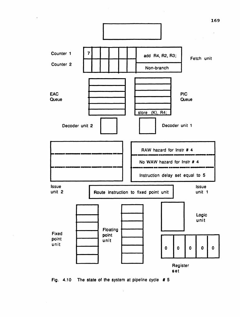
Counter 1
Counter 2
EAC Queue
add R4, R2, R3; Fetch unit
Decoder unit 2 Decoder unit 1
lssue unit 2
Fixed point unit
RAW hazard for lnstr # 4 u - I _ -
No WAW hazard for lnstr # 4 I m I U I m - I I - -
Instruction delay set equal to 5 t I I 1 Issue I Route instruction to fixed point unit 1 unit 1
Floating point unit
Logic un i t
Register set
Fig. 4.10 The state of the system at pipeline cycle # 5

Op-code is the opcode of the Instruction. Time: Time is the time required to execute the instruction. R - Field : R - field is the field of all registers in the system.. C - Field : C - field is the field of the counters that keep track of the registers.
Fig. 4.11 State of the instruction status unit during pipeline cycle # 5
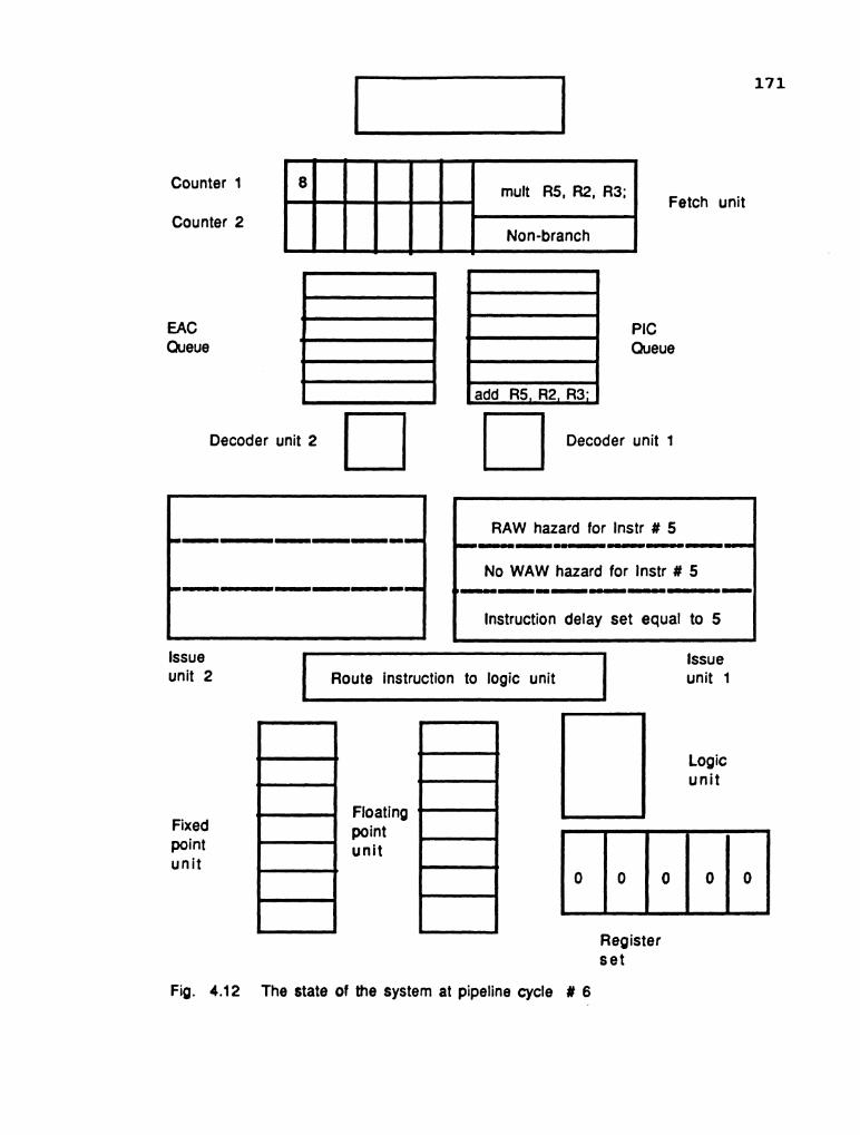
Counter 1
Counter 2
EAC Queue
PIC Queue
add R5 R2 R3. H El Decoder unit 2 Decoder unit 1
Issue unit 2
C RAW hazard for lnstr # 5 I -_ - - - - - -
I No WAW hazard for lnstr # 5 I - - - -
Fetch unit
Instruction delay set equal to 5 i
Fixed point unit
. Route instruction to logic unit
i
Floating point unit
lssue unit 1
Logic unit
Register set
Fig. 4.12 The state of the system at pipeline cycle # 6

Op-code is the opcode of the Instruction. Time: Time is the time required to execute the instruction. R - Field : R - field is the field of all registers in the system.. C - Field : C - field is the field of the counters that keep track of the registers.
Fig. 4.13 State of the instruction status unit during pipeline cycle # 6

Each Unit is a Delay Buffer.
Unit 4
Unit 5
Unit 6
Unit 7 . Pr # : Priority number attached to each unit ASRl : Address of source register 1 ASR2 :Address of source register 2 DSR1 : Delay of source register 1. DSR2 : Delay of source register 2. SD1 : Source Data 1. SD2 : Source Data 2. ID : Instruction Delay. DR : Destination Resource
Fig. 4.14 State of the delay station in stage 1 of the AU during pipeline cycle # 6
Each Unit is a Delay Buffer.
Unit 4
Unit 5
Unit 6
, Unit 7
Pr # : Priority number attached to each unit ASR1 : Address of source register 1 ASR2 :Address of source register 2 DSR1 : Delay of source register 1. DSR2 : Delay of source register 2. SD1 : Source Data 1. SD2 : Source Data 2. ID : Instruction Delay. DR : Destination Resource
Fig. 4.15 State of the delay station in stage 6 of the AU during pipeline cycle # 6
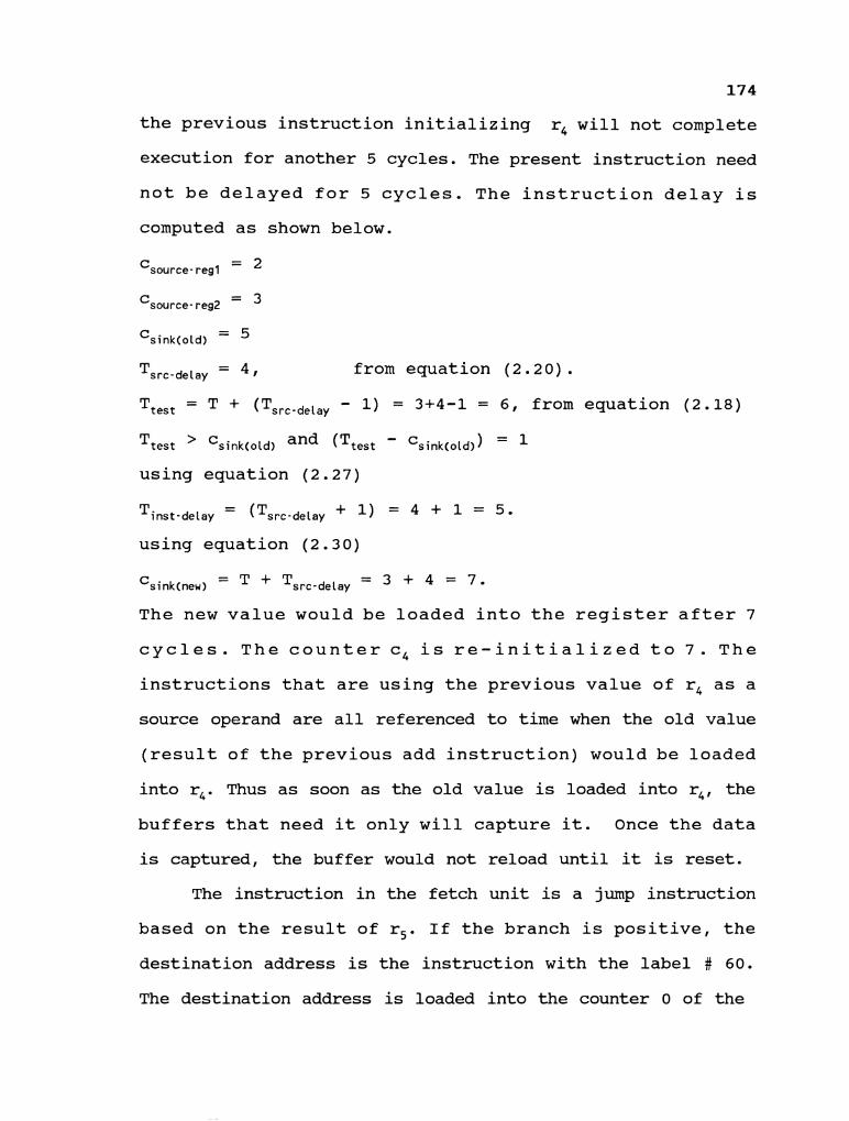
174
the previous instruction initializing r4 will not complete
execution for another 5 cycles. The present instruction need
not be delayed for 5 cycles. The instruction delay is
computed as shown below.
- 2 Csource- reg1 -
Csource- reg2 = 3
Csink(old) =
Tsrc-delay = from equation (2.20) . 'test - + (Tsrc-delay - 1) = 3+4-1 = 6, from equation (2.18)
'test ' Csink(old) and (Ttest - Csink(old) ) = I
using equation (2.27)
- Tinst-delay - (Tsrc-delay + 1 ) = 4 + 1 = 5 .
using equation (2.30)
- Csink(new) - + Tsrc-delay = + = 7'
The new value would be loaded into the register after 7
cycles. The counter c4 is re-initialized to 7. The
instructions that are using the previous value of r4 as a
source operand are all referenced to time when the old value
(result of the previous add instruction) would be loaded
into r4. Thus as soon as the old value is loaded into r4, the
buffers that need it only will capture it. Once the data
is captured, the buffer would not reload until it is reset.
The instruction in the fetch unit is a jump instruction
based on the result of r5. If the branch is positive, the
destination address is the instruction with the label # 60.
The destination address is loaded into the counter 0 of the

Counter 1
Counter 2
EAC Queue
jnz R5, 60;
Branch
Fetch unit
Decoder unit 2 Decoder unit 1
Fixed point uni t
L
L I N
m n 1
Floating point unit
Logic uni t
i
Register set
. RAW hazard for lnstr # 6
- I - - - - - -
WAW hazard for lnstr # 6 l m - I I - - - -
Instruction delay set equal to 5
Issue unit 2
Fig. 4.16 The state of the system at pipeline cycle # 7
Route instruction to fixed point unit . Issue unit 1

Op-code is the opcode of the Instruction. Time: Time is the time required to execute the instruction.' R - Field : R - field is the field of all registers in the system.. C - Field : C - field is the field of the counters that keep track of the registers.
mu l t
Fig. 4.17 State of the instruction status unit during pipeline cycle # 7
8 3 1 1 3 0 1 2 3 7 0 6

Each Unit is a Delay Buffer.
Unit 4
Unit 5
. Unit 6
, Unit 7
Pr # : Priority number attached to each unit ASRl : Address of source register 1 ASR2 :Address of source register 2 DSR1 : Delay of source register 1. DSR2 : Delay of source register 2. SD1 : Source Data 1. SD2 : Source Data 2. ID : Instruction Delay. DR : Destination Resource
Fig. 4.18 State of the delay station in stage 1 of the AU during pipeline cycle # 7
Each Unit is a Delay Buffer.
Unit 4
Unit 5
Unit 6
, Unit 7 . Pr # : Priority number attached to each unit ASRl : Address of source register 1 ASR2 : Address of source register 2 DSR1 : Delay of source register 1. DSR2 : Delay of source register 2. SD1 : Source Data 1. SD2 : Source Data 2. ID : Instruction Delay. DR : Destination Resource
Fig. 4.19 State of the delay station in stage 6 of the AU during pipeline cycle # 7

Each Unit is a Delay Buffer.
Unit 4
Unit 5
Unit 6
Unit 7 2
Pr # : Priority number attached to each unit
ASR1 : Address of source register 1 DSRl : Delay of source register 1. SD1 : Source Data 1.
ID : Instruction Delay. DR : Destination Resource
Fig. 4.20 State of the delay station in the LU during pipeline cycle # 7

179
EAC stream. The EAC stream will become operational in the
following pipeline cycle. This is illustrated in Figs.4.16,
4.17, 4.18, 4.19 and 4.20.
Pipeline cycles # 8:
The multiplication instruction is issued to the DS of
stage 1 in the AU unit. The delay of 3 cycles is necessary
to resolve the RAW hazard. The delay is calculated as shown
in pipeline cycle #5. The counter c5 is initialized with the
value of 10. The EAC stream fetches the instruction starting
from the label 60 along with the PIC stream. Both the
instructions are assumed to be non branch instructions. The
jump instruction is in the decode stage. The register R1 is
loaded with the value of 20. The state of the pipeline is
illustrated in Figs 4.21 to 4.25.
Pipeline cycle # 9:
The jump instruction is in the issue unit. From the
instruction status unit, the value of r5 will be available
only after 11 cycles. Hence the jump instruction can only
be evaluated after 11 cycles. The instruction is issued to
the DS of the LU unit with a delay of 12 cycles. The issue
unit along with the decode unit will be disabled for the
next 11 cycles from the next cycle. The instructions present
at the bottom of both the stacks are decoded and the
information is placed in the instruction status unit. The
register R2 is updated with the value of 30. This is
illustrated in Figs. 4.26 to 4.30.

Counter 1
Counter 2
EAC Queue
Fetch unit
Decoder unit 2 Decoder unit 1
lssue unit 2
C RAW hazard for lnstr # 7 u u m m - w n
I No WAW hazard for lnstr # 7 U U I I H - -
Fixed point uni t
I Instruction delay set equal to 3
Floating point unit
Route instruction to fixed point unit
Logic unit
Issue unit 1
Register set
Fig. 4.21 The state of the system at pipeline cycle # 8
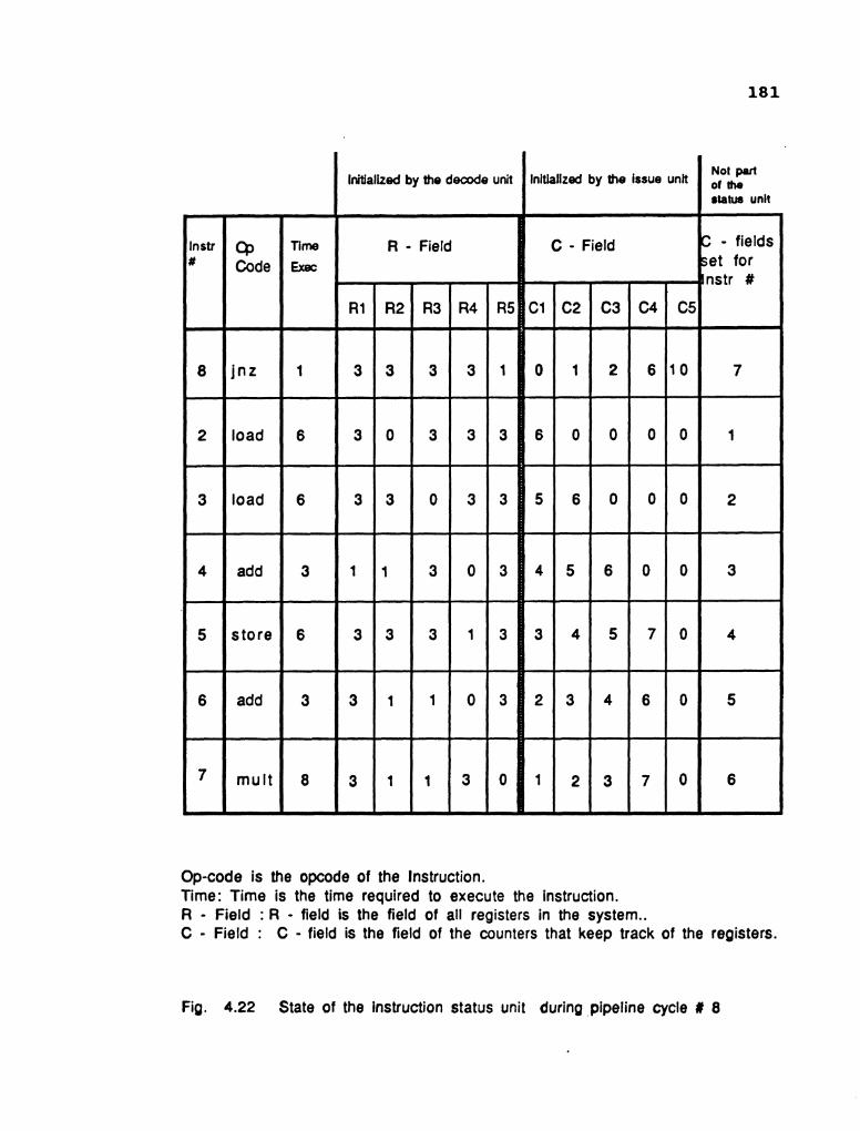
Op-code is the opcode of the Instruction. Time: Time is the time required to execute the instruction. R - Field : R - field is the field of all registers in the system.. C - Field : C - field is the field of the counters that keep track of the registers.
Fig. 4.22 State of the instruction status unit during pipeline cycle # 8

Each Unit is a Delay Buffer.
Unit 4
Unit 5
Unit 6
Unit 7
Pr # : Priority number attached to each unit ASRI : Address of source register 1 ASR2 :Address of source register 2 DSR1 : Delay of source register 1. DSR2 : Delay of source register 2. SD1 :Source Data 1. SD2 : Source Data 2. ID : Instruction Delay. DR : Destination Resource
Fig. 4.23 State of the delay station in stage 1 of the AU during pipeline cycle # 8
Each Unit is a Delay Buffer.
Pr # : Priority number attached to each unit ASR1 : Address of source register 1 ASR2 :Address of source register 2 DSR1 : Delay of source register 1. DSR2 : Delay of source register 2. SD1 : Source Data 1. SD2 : Source Data 2. ID : Instruction Delay. OR : Destination Resource
Fig. 4.24 State of the delay station in stage 6 of the AU during pipeline cycle # 8

Each Unit is a Delay Buffer.
Pr # : Priority number attached to each unit
Unit 4
Unit 5
Unit 6
Unit 7
ASR1 : Address of source register 1 DSRl : Delay of source register 1. SD1 : Source Data 1.
I
ID : Instruction Delay. DR : Destination Resource
Fig. 4.25 State of the delay station in the LU during pipeline cyde # 8

EAC Queue
PIC Queue
Decoder unit 2 Decoder unit 1
Fixed point unit
Hold instruction in issue unit . I I U
r n I ~
.
Floating point unit
r
RAW hazard for lnstr # 8 - - - - - - I B U - - -
Instruction delay set equal to 9 i
Register set
Fig. 4.26 The state of the system at pipeline cycle # 9
Issue unit 1
Issue unit 2 Route instruction to logic unit

Op-code is the opcode of the Instruction. Time: Time is the time required to execute the instruction. R - Field : R - field is the field of all registers in the system.. C - Field : C - field is the field of the counters that keep track of the registers.
mul t
i
Fig. 4.27 State of the instruction status unit during pipeline cycle # 9
8 3 1 1 3 0 1 2 3 7 0 6
-

Each Unit is a Delay Buffer.
Unit 4
Unit 5
, Unit 6
. Unit 7
Pr # : Priority number attached to each unit ASR1 : Address of source register 1 ASR2 :Address of source register 2 DSR1 : Delay of source register 1. DSR2 : Delay of source register 2. SDI : Source Data 1. SD2 : Source Data 2. ID : Instruction Delay. DR : Destination Resource
Fig. 4.28 State of the delay station in stage 1 of the AU during pipeline cycle # 9 - - - - - - - - - - -- -- -
Each Unit is a Delay Buffer.
Unit 4
Unit 5
Unit 6
Unit 7
Pr # : Priority number attached to each unit ASR1 : Address of source register 1 ASR2 :Address of source register 2 DSR1 : Delay of source register 1. DSR2 : Delay of source register 2. SD1 : Source Data 1. SD2 : Source Data 2. ID : Instruction Delay. DR : Destination Resource
Fig. 4.29 State of the delay station in stage 6 of the AU during pipeline cycle # 9

Each Unit is a Delay Buffer.
Unit 4
Unit 5
Unit 6
Unit 7
Pr # : Priority number attached to each unit
ASR1 : Address of source register 1 DSR1 : Delay of source register 1. SD1 : Source Data 1.
ID : Instruction Delay. DR : Destination Resource
Fig. 4.30 State of the delay station in the LU during pipeline cyde # 9

188
Pipeline cycle # 10:
The first add instruction is due for execution. The
initial cross collision matrix was a null matrix until this
cycle. The first instruction to be initiated is the add
instruction. The initial cross collision matrix for addition
will now become the initial state matrix of the pipeline
system. The initial state matrix is shown in Fig. 4.31. The
add instruction is initiated as the latency is available.
The register R3 is updated with a value of 40. The state of
the system is illustrated in Figs. 4.32 to 4.35.
Pipeline cycle # 11:
The multiplication instruction is due for execution.
The state matrix of the previous cycle is shifted one row
to the left. The latency is checked for multiplication by
examining the row 1 and column 0. The latency is available.
The instruction is initiated and the new state matrix is
shown in Fig. 4.36. The data flow in the system is
illustrated in Figs. 4.37 to 4.40
Pipeline cycle # 12:
The second add instruction is due for execution. The
state matrix of the previous cycle is shifted one column to
the left and is illustrated in Fig. 4.41. The latency for
add is available as the element of row 3 and column 0
contains 0. The instruction is initiated and the new state
matrix is obtained as shown in Fig. 4.42. The data flow is
illustrated in Figs. 4.43 to 4.46.

Fig. 4.31 Initial state matrix in cycle # 10

Counter 1
Counter 2
EAC Queue
Fetch unit
Decoder unit 2 Decoder unit 1
1
Hold instruction in issue unit
Disabled
A
Issue unit 2
Fixed point unit
Floating point unit
Disabled -
Logic unit
lssue unit 1
Register set
Fig. 4.32 The state of the system at pipeline cycle # 10

Each Unit is a Delay Buffer
Unit 4
Unit 5
Unit 6
Unit 7
Pr # : Priority number attached to each unit ASRl : Address of source register 1 ASR2 :Address of source register 2 DSR1 : Delay of source register 1. DSR2 : Delay of source register 2. SD1 : Source Data 1. SD2 : Source Data 2. ID : Instruction Delay. DR : Destination Resource
Fig. 4.33 State of the delay station in stage 1 of the AU during pipeline cycle # 10
Each Unit is a Delay Buffer.
Unit 4
Unit 5
Unit 6
Unit 7
Pr # : Priority number attached to each unit ASR1 : Address of source register 1 ASR2 :Address of source register 2 DSR1 : Delay of source register 1. DSR2 : Delay of source register 2. SD1 : Source Data 1. SD2 : Source Data 2. ID : Instruction Delay. DR : Destination Resource
Fig. 4.34 State of the delay station in stage 6 of the AU during pipeline cycle # 10

Each Unit is a Delay Buffer.
Unit 4
Unit 5
Unit 6
Unit 7 i
Pr # : Priority number attached to each unit
ASRl : Address of source register 1 DSR1 : Delay of source register 1. SD1 : Source Data 1.
ID : Instruction Delay. DR : Destination Resource
Fig. 4.35 State of the delay station in the LU during pipeline cyde # 10

Fig. 4.36 The new state matrix in cycle # 11

Counter 1
Counter 2
EAC Queue
Fetch unit
Decoder unit 2 Decoder unit 1
.
Hold instruction in issue unit
Disabled
I
lssue unit 2 I Disabled I lssue
unit 1
Fixed point unit
--- - -
Floating point unit
Logic unit
Register se t
Fig. 4.37 The state of the system at pipeline cycle # 11

Each Unit is a Delay Buffer.
Unit 4
Unit 5
Unit 6
Unit 7 . Pr # : Priority number attached to each unit ASRl : Address of source register 1 ASR2 :Address of source register 2 DSR1 : Delay of source register 1. DSR2 : Delay of source register 2. SD1 : Source Data 1. SD2 : Source Data 2. ID : Instruction Delay. DR : Destination Resource
Fig. 4.38 State of the delay station in stage 1 of the AU during pipeline cycle # 11
Each Unit is a Delay Buffer.
Unit 4
Unit 5
Unit 6
Unit 7
Pr # : Priority number attached to each unit ASR1 : Address of source register 1 ASR2 : Address of source register 2 DSR1 : Delay of source register 1. DSR2 : Delay of source register 2. SDl : Source Data 1. SD2 : Source Data 2. ID : Instruction Delay. DR : Destination Resource
Fig. 4.39 State of the delay station in stage 6 of the AU during pipeline cycle # 11

Each Unit is a Delay Buffer.
Unit 4
Unit 5
Unit 6
Unit 7
Pr # : Priority number attached to each unit
ASR1 : Address of source register 1 DSRl : Delay of source register 1. SD1 : Source Data 1.
ID : Instruction Delay. DR : Destination Resource
Fig. 4.40 State of the delay station in the LU during pipeline cyde # 11

Fig. 4.41 The shifted state matrix of cycle # 11
Fig. 4.42 The new state matrix of cycle # 12

Counter 1
Counter 2
EAC Queue
Fetch unit
Decoder unit 2 Decoder unit 1
Hold instruction in issue unit
Disabled
lssue unit 2
Fixed point unit
Disabled
Floating point unit
rn
Disabled
Logic unit
lssue unit 1
Register set
Fig. 4.43 The state of the system at pipeline cycle # 12

Each Unit is a Delay Buffer.
Unit 4
Unit 5
, Unit 6
Unit 7
Pr # : Priority number attached to each unit ASR1 : Address of source register 1 ASR2 :Address of source register 2 DSR1 : Delay of source register 1. DSR2 : Delay of source register 2. SD1 : Source Data 1. SD2 : Source Data 2. ID : Instruction Delay. DR : Destination Resource
Fig. 4.44 State of the delay station in stage 1 of the AU during pipeline cycle # 12
Each Unit is a Delay Buffer.
Unit 4
Unit 5
Unit 6
Unit 7
Pr # : Priority number attached to each unit ASR1 : Address of source register 1 ASR2 :Address of source register 2 DSR1 : Delay of source register 1. DSR2 : Delay of source register 2. SD1 : Source Data 1. SD2 : Source Data 2. ID : Instruction Delay. DR : Destination Resource
Fig. 4.45 State of the delay station in stage 6 of the AU during pipeline cycle # 12

Each Unit is a Delay Buffer.
Unit 4
Unit 5
Unit 6
Unit 7
Pr # : Priority number attached to each unit
ASR1 : Address of source register 1 DSR1 : Delay of source register 1. SD1 : Source Data 1.
ID : Instruction Delay. DR : Destination Resource
Fig. 4.46 State of the delay station in the LU during pipeline cyde # 12

Pipeline Cycles # 13 - # 20:
The results are updated as they become available and
the branch instruction is evaluated during the pipeline
cycle # 19. These are illustrated in Figs. 4.47 to 4.54.

Counter 1
Counter 2
EAC Queue w w PIC
Queue
Fetch unit
Decoder unit 2 Decoder unit 1
Disabled
t
Hold instruction in issue unit
Disabled
. lssue unit 2
;
Disabled lssue unit 1
Fixed point unit
Floating point unit
Logic unit
Register set
Fig. 4.47 The state of the system at pipeline cycle # 13

Each Unit is a Delay Buffer.
Unit 4
Unit 5
Unit 6 I
Unit 7
Pr # : Priority number attached to each unit
ASR1 : Address of source register 1 DSRl : Delay of source register 1. SD1 : Source Data 1.
ID : Instruction Delay. DR : Destination Resource
Fig. 4.48 State of the delay station in the LU during pipeline cycle # 13

Counter 1
Counter 2
EAC Queue
Decoder unit 2 0
PIC Queue
Fetch unit
Decoder unit 1
Disabled
Fixed point unit
Hold instruction in issue unit
Disabled
Floating point unit
L
+-
Logic unit
Register se t
Issue unit 2
Fig. 4.49 The state of the system at pipeline cycle # 14
m- 4
. Disabled
Issue unit 1
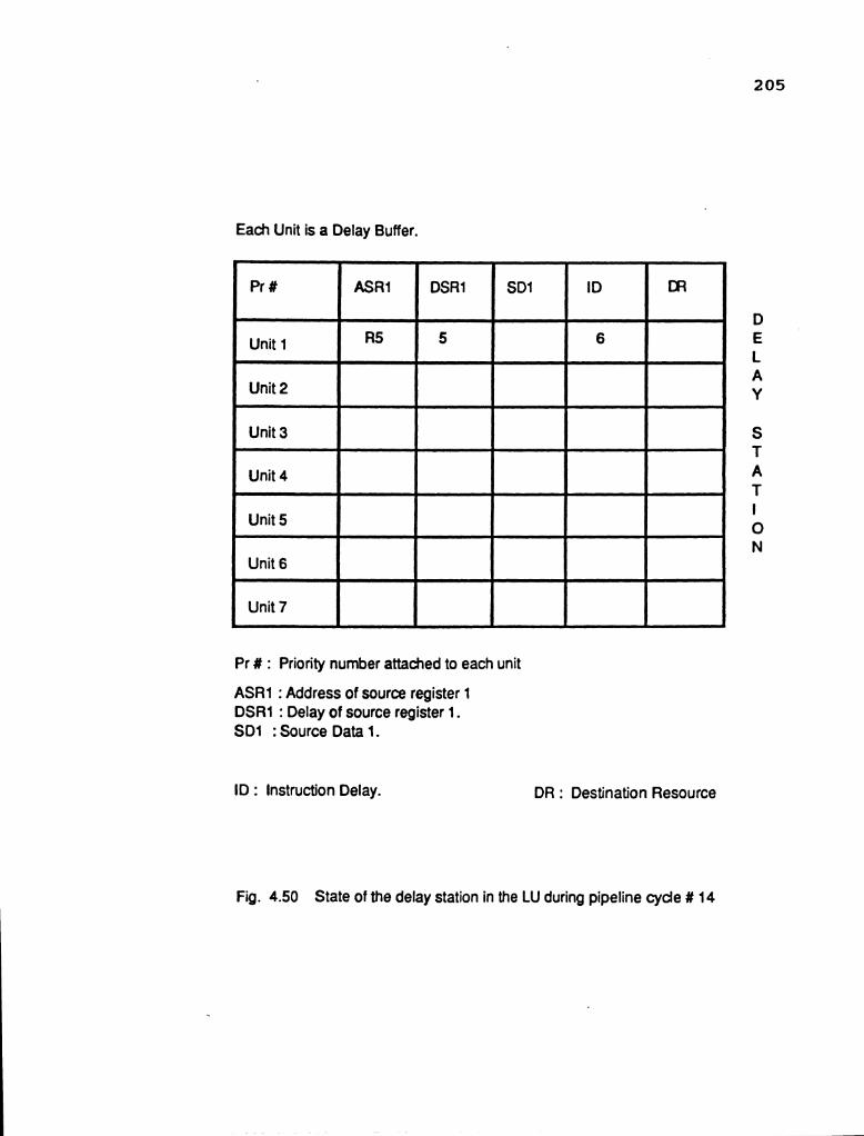
Each Unit is a Delay Buffer.
Unit 4
Unit 5
Unit 6
Unit 7
Pr # : Priority number attached to each unit
ASRl : Address of source register 1 DSR1 : Delay of source register 1. SD1 : Source Data 1.
ID : Instruction Delay. DR : Destination Resource
Fig. 4.50 State of the delay station in the LU during pipeline cyde # 14

Counter 1
Counter 2 etch unit
EAC Queue
Decoder unit 2 Decoder unit 1
Hold instruction in issue unit
Disabled
lssue unit 2
lssue unit 1 Disabled
Fixed point unit
Floating point unit
Register s e t
Fig. 4.51 The state of the system at pipeline cycle # 19

Each Unit is a Delay Buffer.
Pr # : Priority number attached to each unit
Pr #
Unit 1
Unit 2 r
Unit 3
Unit 4 P
Unit 5 I
Unit 6 r
Unit 7 -
ASRl : Address of source register 1 DSR1 : Delay of source register 1. SD1 : Source Data 1.
ID : Instruction Delay. DR : Destination Resource
ASR1
R5
Fig. 4.52 State of the delay station in the LU during pipeline cyde # 19
DSR 1
0
SD1
1200
ID
1
DR

Counter 1
Counter 2
EAC Queue
Fetch unit
PIC Queue
Decoder unit 2 0 Decoder unit 1
Fixed point uni t
. No RAW hazard for instr# 60
n - n u
No WAW hazard for instr# 60 - 1
No delay is assigned
Floating point unit
b
Y ( . I U U - - - -
B Y I = I U U w I - -
Logic unit
Register set
Issue Issue
Fig. 4.53 The state of the system at pipeline cycle, # 20
unit 2 Route the instruction to logic unit unit 1

Op-code is the opcode of the Instruction. Time: Time is the time required to execute the instruction. R - Field : R - field is the field of all registers in the system.. C - Field : C - field is the field of the counters that keep track of the registers.
Fig. 4.54 State of the Instruction status unit during pipeline cycle # 20

CHAPTER FIVE
COMPUTER SIMULATION AND EXPERIMXNTAL RESULTS
The operation of the system is simulated on the DEC VAX
11/750 mini-computer. The simulation program is implemented
in two sections. The first section simulates the PIU and the
second simulates the PEU. In real time operation, the
various units are synchronised. The units are termed as
stages. The total number of stages in the system are ten.
The first three stages are the fetch unit, decode unit and
issue unit respectively. The remaining seven stages
constitute the stages of the pipelined arithmetic unit. The
program is written in C language. Each stage is simulated
by a single function. This is illustrated in Fig. 5.1.
In actual operation, the stages operate concurrently.
For example, let us assume that decode unit will receive an
instruction I from the fetch unit at the begining of the
cycle J. It processes the instruction and forwards it to the
issue unit at the end of the cycle. The issue unit
meanwhile, receives the instruction 1-1 at the begining of
the cycle J. The instruction I will be received by the issue
unit only at the begining of the cycle J+1. The Fig. 5.2
illustrates the data flow. The stages begin processing at
the begining of each cycle and complete processing at the
end of each cycle. This implies that the simulation program
must begin the execution of functions at the same time. The

t
Function Fetch-unit
Function Decode-unit
t
Function Issue-unit *
Function Stage-one
Function Stage-two
Function Stage-three
Function Stage-four >
. Function Stage-five
i
Function Stage-six -
Function Stage-seven 4
Fig. 5.1 Structure of the simulation program

Begining of pipeline cycle # I
Begining of pipeline cycle # I + 1
Fig 5.2 Actual data flow in real time for a pipeline system

213
executions must also end at the same time. This is not
possible in a serial machine. The program is executed in
iterations where each iteration represents one pipeline
cycle. In each iteration, the functions emulating the stages
are executed serially in their physical order. Furthermore,
the input for each function is provided by the preceeding
function. The parallelism of executing the functions will
be lost, if the output of any function is fed directly to
the input of the next function. This will lead to the
pipeline being a large sequential system. The concurrency
is introduced into the serial program by bifurcating the
processing and the data transfer. Each function will read
the input from a buffer called the input buffer. The result
of the function is loaded into an output buffer. The next
function will read the data from the input buffer of the
function but not from the output buffer of the previous
function. For example, the function emulating the decode
unit will read the input from the input buffer specified to
this unit and processes the instruction. The processed
instruction is stored in an output buffer designated to the
decode unit. The next function emulating the issue unit will
read the instruction from its input buffer but not from the
output buffer of the decode unit. This provides isolation
of data between two adjacent functions. The data transfer
is carried out before the begining of the next iteration.
This is shown in Fig. 5.3. The whole program is executed

The data flow in iteration I between functions during operationg mode
lnput buffer Output buffer lnput buffer Output buffer
(result of operation) (result of operation)
Start .-b End Start ,-b End excuting excuting excuting excuting Function decode-unit Function decode-unit Function issue-unit Function issue-unit
I
Program Flow
The data transfer operation during data transfer mode during iteration I:
lnput buffer Output buffer lnput buffer Output buffer
Only data transfer taking place. No function is executed
Fig. 5.3 Emulating the concurrency operation in a serial program.

effectively in two modes: the operating mode and the data
transfer mode. Thus parallelism is obtained by serially
executing the functions and controlling the data transfer.
The program is subdivided into two groups of functions.
The first group is called the Ton group. The Ton group
represents the serial execution of the various emulating
functions. The second group is termed as the TOf, group. Toff
group represents the data transfer functions. The various
functions are described in the following sections:
5.1 FUNCTIONS EMULATING THE STAGES OF THE PIU:
The PIU is emulated by three functions: 1) fetch - unit,
2) decode - unit, and 3) issue - unit. The memory, the input and
the output buffers for each function are held in structures.
A structure is a collection of one or more variables,
possibly of different types, grouped together under a single
name for convenient handling. The structures of the buffers
and the memory are of the same type and is shown below:
struct input inst {
int opcode field; int source-operandl; int source-operand2; int dest operand; int valid;
The various functions are described below.
Function "fetch - unit" :
This function emulates the operation of the fetch unit.
The function is provided with two sets of counters. These

216
counters are used to keep track of the branch instructions.
The counters are stored as structures and are individually
indexed from 0 to 9. The counter indexed as 0 is the program
counter. The instructions are classified by this function.
If a branch instruction is encountered, the effective
address held in the destination operand is loaded into the
appropriate counter. The instruction is classified using the
opcode. The function returns with the processed instruction
loaded into the output buffer. The function is provided with
two ouput buffers, one for each stream.
Function "decode - unit" :
This function emulates the decode unit. It consists of
a two FIFO stacks, which are represented as structures. The
data is read from the input buffer and is loaded into a FIFO
queue. The function contains two queues and two decoding
routines. The decode unit has a queue and a decoder routine
for each stream. Pointers are associated with each queue.
The pointer top - stack indicates the next free location. The
pointer bottom - stack points to the next instruction to be
processed. When the queue is empty, the top - stack is equal
to the bottom - stack. The instruction travels through the
queue before it is decoded. The decoded instruction is
stored in the output buffer. The information that is made
available in the decoding process is stored in a structure
which represents the instruction status unit. This
information is utilized by the issue unit to schedule the

execution of the instruction.
Function " issue - unit ": The function issue - unit emulates the function of the
issue - unit. The functions receives the instruction from the
input buffer and detects the hazard. The hazards are
detected by looking at the counter values which are assigned
to each register. These values are available in the
structure that represents the instruction status unit. The
hazards are resolved and the instruction is issued to the
execution unit. The hazards are resolved by the equations
that have been derived in Chapter 2. The function returns
with the issued instruction placed in the output buffer.
5.2 FUNCTIONS EMULATING THE STAGES OF THE PEU:
The execution unit is the pipelined artihmetic unit.
The logic unit and the floating point unit are treated as
black boxes. The functions emulating the stages of the
execution unit are also named after their respective stage.
For example, the function emulating stage one of the PEU is
called as function stage - one.
Function stage - one ":
The function stage - one emulates the operation of a
shifted multiplicand generator. This function generates the
initial partial products. The partial products are summed
up to derive the final product. The shifted multiplicand
generator is an landt gate array. The vectors that are
generated follow the following equations:

W = a *b. a *b. a2*bj a3*bj a4*bj a5*bj a6*bj a7*bj ( j = 0 ) I O J ~ J
w = a *b- al*b. a2*b. a,*bj a4*bj a,*bj a6*bj a7*bj ( j = 1) 2 0 1 J J
W = a *b. a *b. a2*bj a3*bj a4*bj a5*bj a6*bj a7*bj ( j = 2) 3 O J ~ J
W 4 = ao*b. al*b. a2*bj a3*bj a,*bj a5*bj a6*bj a7*bj ( j = 3 ) J J
W = a *b. a *b. a2*bj a3*bj a4*bj a5*bj a,*bj a7*bj ( j = 4 ) 5 O J ~ J
w = a *b. a *b. a2*b. a3*b. a4*bj a5*bj a6*bj a7*bj ( j = 5 ) 6 O J l J J J
W = a *b. a *b. a2*b. a3*bj a,*bj a,*bj a6*bj a7*bj ( j = 6 ) 7 O J ~ J J
w = a *b. a *b. a 2 * b a3*bj a4*bj a5*bj a6*bj a7*bj ( j = 7 ) 8 O J l J J
The e l e m e n t s a i and b j b e l o n g t o t h e i n p u t
b i n a r y v e c t o r s A and B.
Functions " stage - two to stage - five n:
The s t a g e s two t o f i v e c o n s i s t o f t h e CSA e l e m e n t s .
These func t ions s imulate t h e operat ion of t h e CSA elements.
The c a r r y save adder is rep resen ted by us ing t h e equat ions
o f t h e sum and t h e c a r r y v e c t o r s . These f u n c t i o n s r e t u r n
with t h e r e s u l t i n t h e output b u f f e r s which a r e represented
a s s t r u c t u r e s .
Function " stage - six ":
The c a r r y look ahead adder is a l s o reproduced with t h e
a i d of s t ruc tu res and f i e l d s . The p a r t i a l sum vector and t h e
p a r t i a l c a r r y v e c t o r from t h e f u n c t i o n s t a g e - f i v e , is t h e
input t o t h e present funct ion. This funct ion f i r s t generates
t h e c a r r y e lements us ing t h e i n p u t s , and then t h e a d d i t i o n
t a k e s p l a c e i n t h e f u l l adde r u s i n g t h e s e c a r r y e lements .
The func t ion can a l s o r e c e i v e t h e i n p u t s e x t e r n a l l y . These
inputs a r e not r e l a t e d t o t h e output of s t a g e f i v e . The add

2 19
instruction is introduced to the adder through the above
inputs.
The functions stage - one to stage - six are combined into
a single function called 99pipelineN.
5.3 CONTROL OF THE PIPELINE:
The pipeline activity has to be controlled to avoid the
collisions of the data that is fed into the pipeline. The
control of the pipeline can be broadly classified into the
following control functions namely: 1) load - pipeline, 2)
output - check, 3) set - logg, and 4) shift - track. The function
load - pipeline mainly deals with the initiation of
instructions to the pipeline. The function output - check
loads the results of instructions to their destination. The
function shift - trac is used to monitor the flow of
instructions in the arithmetic unit. The function set logg -
monitors the activity of the function shift - trac.
The following structures are used by the functions to
control the operation of the pipeline: 1) struct reg - stages,
2) struct iter - storage, 3) struct add - trac, 4 ) struct
mult - trac, 5) struct div - trac, 6) struct logg - sheet, 7)
struct multipurpose - registers.
The names of these structures state their respective
operations. Structure reg - stages are the output buffers. The
structures with names ending with 'tract are used to track
the instructions through the pipeline and each operation has
its own tracking registers. The structure logg sheet is used -

220
to monitor the 'tract structures. Each operation has its own
l o g g - s h e e t . O n e o f t h e s t r u c t u r e s o f t h e
multipurpose - registers is used as the control status
register. This register is used to pass control information
between the control functions.
Function loadgipe l ine '#:
The input control deals with the loading of the
arithmetic unit with the instructions from the structure
representing the delay station (struct delay - station). The
function scans the structure delay - station for instructions
that need to be initiated into the pipeline during each
iteration. The instructions that need to be executed are
checked with the available latency. The latency information
is available from the state matrix. If the number of
instructions to be initiated are one and the latency is
available, the instruction is initiated into the pipeline
unit. The token for the destination register is loaded into
the tracking register which tracks this instruction through
the stages. When more than one instruction contends for the
same stage and latency, the instruction with the higher
priority is initiated into the pipeline. The instruction
with the highest priority are those which are being
iterated. If no such instruction is present, then priority
is given to the instruction that has been in the structure
delay - station for the longest time. The instructions that
have not been initiated are reissued additional delays. The

221
counters in the structure instruction-status are updated
with this delay.
Function output - check ":
The output control can be divided into the following
operations namely 1) non-divisional output control and 2)
division output control.
Non-divisional output control:
The non-division operations are addition, subtraction
and multiplication. The output control mainly deals with the
removal of the data from stage seven for the above mentioned
instructions. The information that the instruction has
reached stage seven is given by a tracking register assigned
for that particular instruction. For the multiplication
operation, the result is obtained when the tracking register
indicates stage seven. For addition and subtraction
operations, the result is obtained in the next cycle. The
result is loaded into the register specified by the tracking
register. The tracking register is initialized by the
function load - pipeline.
Division output control:
This deals with the operation of division only. When
the the tracking register pertaining to this instruction
indicates stage 7, the output of the stage six and stage
seven are taken from the pipeline and stored in the
structure priority - stack. The tracking register associated
with this instruction is made inactive. The tracking fields

are reset and the iteration counter is incremented. The
semi-processed instruction is given the highest priority and
will be initiated with the first available latency. The
number of iterations for the division instruction is fixed
at three. If the iteration counter is equal to 3 at the time
it is incremented, then the result is achieved and is
transferred to the appropriate register.
Function shift - trac I@:
The function shift - trac is u s e d t o track the
instructions in the arithmetic unit. Each instruction that
is initiated is assigned a tracking register. The tracking
registers contain seven fields and each field represents a
stage. The tracking register will also contain the
destination register for the result of the instruction. When
an instruction is initiated at stage one, the tracking
register assigned to the instruction is initialized by
placing a token in field one. This function advances the
token to the next field denoting that the instruction has
moved to the next stage. When the token indicates that the
instruction is at the output stage, the function
output - check loads the result into the register specified
by the tracking register.
Function I9 set - logw:
This function keeps track of all the tracking registers
that are in use. This function is used to update the
information of free tracking registers.

Function time - off
The function t
output buffer of one
I1 :
ime - of
stage i
f trans
.nto the
f ers
input
the data
buffer of
from
the
223
the
next
stage. This function maintains the data flow from one stage
to the other. The source code for emulating the PEU and PIU
is listed in appendix C.
5.4 COMPUTER GENERATION OF THE STATE DIAGRAMS:
The generation of the state diagram was implemented on
the VAX 11/750. The exact number of states cannot be
formulated as a general polynomial equation. However we can
calculate the maximum number of states that are possible by
choosing the number of rows and columns. Starting from the
three initial collision matrices (three initial states), the
various state matrices are generated. The program consists
of various functions that are used to generate the state
matrices. The functions are aided by two integer pointers
that monitor the generation of the state matrices. The state
matrices are held in structures. The integer pointers are
briefly described below. The functions are briefly described
below.
Pointer index ":
This is a integer pointer which is continuously updated
as new states are being generated. The function of this
pointer is to determine whether all the possible states have
been derived.

224
Pointer pres - num n:
This is also an integer pointer which counts down from
the state one. It is incremented after all the possible
states formulated from the current state have been derived.
When the value of countdown is equal to the pointer "index1I,
the program is terminated.
Function sleft - bits ":
This function shifts left the present matrix under
consideration to the required number of times. The required
number of times is given by the latency. The leading zeros
are introduced from the right. The resulting matrix is
represented by a structure.
Function " or - cross I*:
In this function, the state matrix which is stored as
a structure is ORed with the required initial collision
matrix. If the initiation is double initiation then the
combined initial matrix is derived and then it is ORed to
the current state matrix.
Function *name - it It:
This function is used to determine whether the new
state matrix is unique and that it does not have a copy of
itself, in the other state matrices that have been generated
earlier. This function generates the link list for the state
matrix under consideration in check - struc. The I*' in the
name indicates that this function is repeated for each
compatible initiation set.

225
Function check struc ":
Function check - struc generates the new state matrices
from the current state. After each new state is created, it
is checked with the states that have been created. If a copy
of this state is not present, then the pointer index is
incremented and the state matrix under consideration is
assigned a new state. Each new state matrix is stored in a
structure. The structure is provided with fields which
correspond to all possible initiations. These fields are
used to store the address of the next state for that
particular initiation. The pointer pres - num indicates the
current state to be investigated. From each state all
possible new states are derived. The function returns with
all the new states. The address fields are used as link
lists and they contain the address of the states. The source
code for generating the state diagram is listed in appendix
B. The state diagrams are presented in appendix A.
5.5 EXPERIMENTAL RESULTS:
The simulation of the system was carried out on three
different instruction sets. The first instruction set
contained only the RAW hazard. The second instruction set
represented the RAW and WAW hazard. The third set has
incorporated the three hazards. The instructions that which
the program is capable of recognizing is shown in Fig. 5.4.
The format for each instruction is shown in Fig. 5.5. The
data is initially loaded as integers. It is converted to the

Fig. 5.4 The instruction set adopted for simulation.
I CPCCOE
0
1
2
3
4
5
6
7
8
9
1 0
1 1
1 2
1 3
1 4
1 5
N M r n I C S
N3P
ADD
SUB
MULT
DIVIDE
SrCRE
LCY\D
LOAD1
INC
E C
AND
a
NCrr
BRANCH
BRANCF1NZ
BRANCHNC
OPmm
NoOPERAm
ADDITION
SUBTRACTION
MULTIPUCATION
DIVISION
STORE ( REGISTER -> MEMORY)
LOAD( REGISTER C- MEMORY )
LOAD ( MEMORY <- DATA )
INCREMENT
DECREMENT
AND
CR
NCrr
UNCONDITIONALBRANCH
BRANCH IF NOT ZERO
BRANCH IF NO CARRY

instruction format adopted for the arithmetic instructions: ADDITION , SUBTRACTION, MULTIPLICATION, DIVISION
Source register1 u Source register2 n instruction format adopted for the data transfer instructions: LOAD:
STORE:
Memory location
Memory location -
Destination reaister
lnstructlon format adopted for the logic instructions: AND, OR :
Destination reaister Source registerl m Source register2 n
instruction format adopted for the logic Instructions: INC, DEC, NOT :
Destination realster ,
instruction format adopted for the logic instructions: BRANCH :
Destination address
lnstruction format adopted for the logic Instructions: BRANCHNZ, BRANCHNC :
Fig. 5.5 Instruct ion format adopted in the s imulat ion program

binary form at the entrance to the execution unit. This is
done to simplify the program.
The first instruction set is listed in Fig. 5.6. The
result was obtained after 19 iterations. Each iteration
represents a single pipeline cycle. The results are
tabulated as shown in Fig. 5.6. The flow diagram is shown
in diagram 5.7. The results of the second and third
instruction sets are also illustrated in the same way. The
results of the second instruction set is shown in Figs. 5.8
and 5.9. The results of the third instruction set is shown
in Figs. 5.10 and 5.11. The timings coincide with the design
values.
The program is capable of handling ten instructions at
a time. It is now being modified to run for larger sets and
involving branch instructions. A sample set of instructions
listed in Smith [14] is being used to run the simulation.
The instruction set is the micro-code for a loop in Fortran.
The macro code is listed below:
Do 10 I = 1,100 10 A(1) = B(1) + C (I) *D(I) .
The micro code for loop section of the macro code is given
below:
100: load r8, (C) ; load r9, (D) ; load r10, (B) ; load rll, (A) ; add r3, r8, r2; add r4, r9, r2; add r12, rll, r2; mult r6, r3, r4; add r7, r6, r5;

store (r12) , r7; dec r2; branchnz 100, r2;
The space time diagram for the static scheduling and
execution of the sample set for two loops is shown in Fig.
5.12. The Fig. 5.13 illustrates the space time flow in the
proposed system. The flow in the figures 5.12 and 5.13
represents the hand simulation based on the proposed system.
Speed up is achieved due to the dynamic scheduling and
execution.

Instruction set # 1:
load r l , (X); load r2, (Y); add r3, r2, r l ; store (Z), r3;
Fig. 5.6 Program results for instruction set # 1
(X) = 20
(Y) = 30
Location
r l
r 2
r 3
(z)
Fig. 5.7 Space time flow of the instructions set # 1
Iteration #
9
10
1 3
1 9
Iteration #
load r l , (X); load R, (Y); add r3, r2, r l ; store (Z), r3;
Contents of the location
20
30
50
50 4
1 2
F D I
3
F D I F
4
D l
5
F D I
6 8
E E E E E E
7
E E E E E E
9
E E E
1 0 1 1 1 2 1 3 1 4 1 5
E E
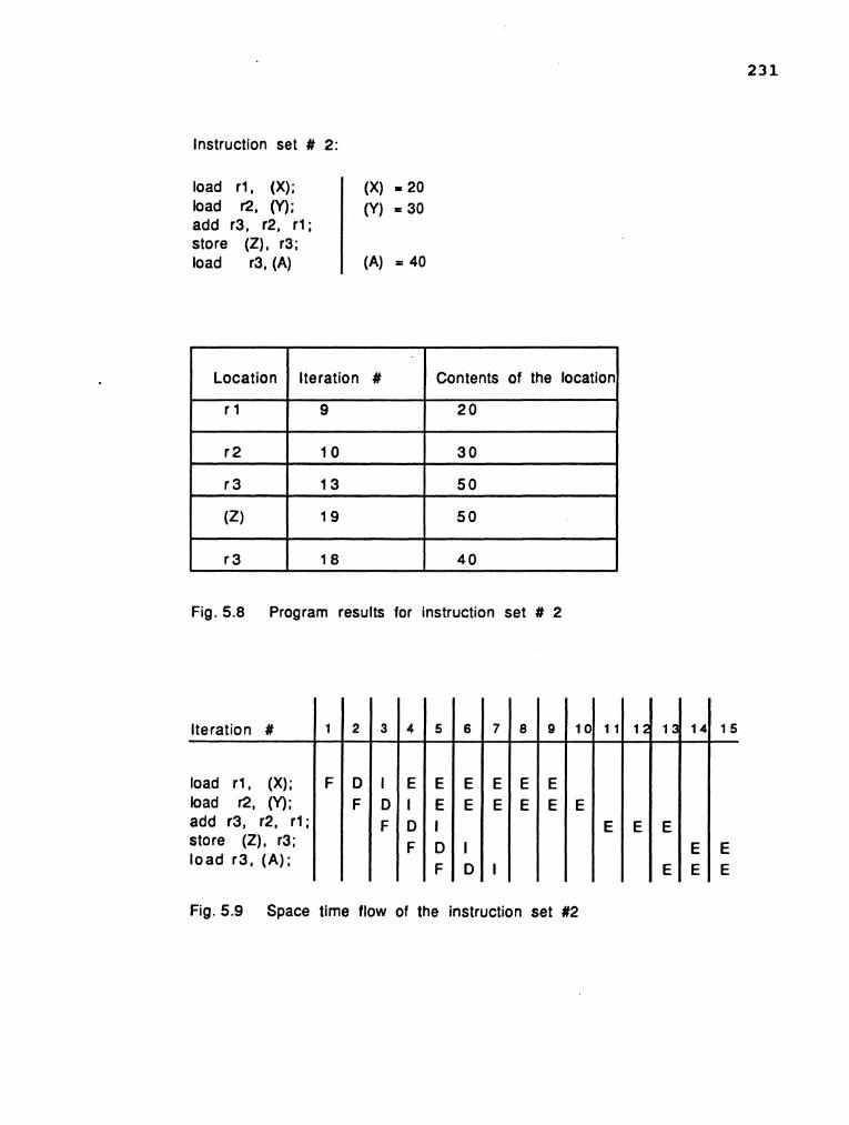
Instruction set # 2:
load r l , (X); load R, (Y); add r3, r2, r l ; store (Z), r3; load r3, (A)
Fig. 5.8 Program results for instruction set # 2
(X) = 20 (Y) = 30
(A) = 40
Location
r l
r 2
r 3
(2)
r 3
Iteration #
load r l , (X); bad r2, (Y); add r3, r2, r l store (Z), r3; load r3, (A);
Iteration #
9
10
13
19
18
Fig. 5.9 Space time flow of the instruction set #2
Contents of the location
2 0
30
50
50
4 0

Instruction set # 3:
load r l , (X); load r2, (Y); add r3, r2, r l ; add r4, r2, r l ; store (Z), r3; load r3, (A)
(X) = 20 (Y) = 30
(A) = 40
Fig. 5.10 Program results for instruction set # 3
Fig. 5.1 1 Space time flow of the instruction set # 3

Iteration #
load r l O,(B);
add r3,r8,r2;
add r4,r9,r2;
add r5,r10,r2;
add r12,rl l ,r2;
mutt r6, r3, r4;
add r7, r6, r5;
store (r12), r7;
branchnz 100, r2 .
I I
Fig. 5.12 Space time flow in case of static scheduling

Iteration #
load r8, (C);
load r9, (D);
load r l O,(B);
load r l l ,(A);
add r3,r8,r2;
add r4,r9,r2;
add r5,r10,r2;
add r12 , r l l ,r2;
mutt r6, r3, r4;
add r7, r6, r5;
store (r12), r7;
dec r2;
branchnz 100, r2
Fig. 5.12 Space time flow in case of static scheduling (Cont'd)

Fig. 5.12 Space time flow in case of static scheduling (Cont'd)
tteration #
load r8, (C);
load r9, (D);
load r l O,(B);
load r l l ,(A);
add r3,r8,r2;
add r4,r9,r2;
add r5,r10,r2;
add r12,r11 ,r2;
mult r6, r3, r4;
add r7, r6, r5;
store (r12), r7;
dec r2;
branchnz 100, r2
2 8 2 9
F D I
30
F D I
31
F D l
34
E E E E E E
32 35
E E E E E E
33 36
E E E E E E
40 37 41 38 42 3 9

Fig. 5.12 Space time flow in case of static scheduling (Cont'd)
Iteration #
load r8, (C);
load a, (D);
load r l O,(B);
load r l 1 ,(A);
add r3,r8,r2;
add r4,r9,r2;
add r5,r10,r2;
add r12,r l l ,r2;
mult r6, r3, r4;
add r7, r6, r5;
store (r12), r7;
dec r2;
Sranchnz 100, r2
4344 45 46 5C51 47 52 48 49 53 54 5556 5 7

Fig. 5.12 Space time flow in case of static scheduling (Cont'd)

Fig. 5.13 Space time flow in case of dynamic scheduling
Iteration #
load r l l ,(A);
add r3,r8,r2;
add r4,r9,r2;
add rS,r10,r2;
add r12 , r l l ,r2;
mult r6, r3, r4;
add 77, r6, r5;
store (r12), r7;
branchnz 100, r2 F D I

Fig. 5.13 Space time flow in case of dynamic scheduling (Cont'd)
Iteration #
load r8, (C);
load r9, (D);
load r l O,(B);
load r l 1 ,(A);
add r3,r8,r2;
add r4,r9,r2;
add rS1r10,r2;
add r12,r l l ,r2;
mutt r6, r3, r4;
add 17, r6, r5;
store (r12), r7;
dec r2;
branchnz 100, r2
1 6 1 7 18
F C I
23
E E E E E E
19 24 20 2122 25 26 27 2829 30

Iteration #
load r8, (C);
load r9, (D);
load r1 O,(B);
load r l l , (A);
add r3,r8,r2;
add r4,r9,r2;
add rS,rlO,r2;
add r12,rll ,r2;
mult r6, r3, r4;
add r7, r6, r5;
store (r12), r7;
dec r2;
branchnz 100, r2
Fig. 5.13 Space time flow in case of dynamic scheduling (Cont'd)

Fig. 5.13 Space time flow in case of dynamic scheduling (Cont'd)
Iteration #
load r8, (C);
load 1'9, (D);
load r l O,(B);
load r l 1 ,(A);
add r3,r8,r2;
add r4,r9,r2;
add r5,r10,r2;
add r12,r l l ,r2;
mutt r6, r3, r4;
add r7, r6, r5;
store (r12), r7;
dec r2;
Dranchnz 100, r2
1
E
E
3839
E
E E E
40
E E E E
41 42
-- ~
43 4445 4 6 4 7 48
--------
49 5 0 5 1 5 2

Iteration #
load r8, (C);
load r9, (D);
load rl O,(B);
load rl 1 ,(A);
add r3,r8,r2;
add r4,r9,r2;
add r5,r10,r2;
add r12,rll ,r2;
muit r6, r3, r4;
add r7, r6, r5;
store (r12). r7;
dec r2;
branchnz 100, r2
Fig. 5.13 Space time flow in case of dynamic scheduling (Cont'd)

CHAPTER SIX
CONCLUSIONS AND DISCUSSION
In this research, we have presented an algorithm for
dynamic instruction scheduling in a pipelined system.
Initially, the instructions fetched by the fetch unit are
classified. This classification is carried out to ascertain
the type of the instruction. If the instruction is found to
be a jump instruction, the second stream is made
operational. The streams are used to reduce the branch
overheads. The fetch unit keeps track of the all the branch
instructions that have passed through it. This ensures that
the prefetching of instruction commences from the correct
location.
The instruction dependencies are solved by using the
pointers associated with the sink registers. The scheduling
of execution of the instructions are gauranteed hazard free
by the equations derived to resolve the hazards. The buffers
also aide the system by capturing the operands as they
become available. The missing operands are tagged with the
counter value. This eliminates the associative tag
comparisons proposed by Tumasulo [5] and Sohi and Vajepeyam
[GI
The execution unit also operates free of any hazard.
The state matrix ensures that the initiation is hazard free.
It also specifies the compatible initiations. The structure

243
of the arithmetic unit allows the execution of two
instructions simultaneously and hence increases the
throughput. The execution unit is also capable of
rescheduling the scheduled instruction. This makes the
system flexible. This flexibility is needed to ensure hazard
free operation of the system.
The dynamic execution of instructions in a pipelined
environment is hardly used in any of the high performance
computers today. The control of such systems is complicated.
This carries the potential for longer control paths and
longer clock periods. This idea is making a comeback in new
generation RISC processors. The advancements in the VLSI
technology is making it possible to realize such systems.
Interrupt handling and indirect addressing modes have
not been taken into consideration. Furthermore, the design
of the floating point unit and the logic unit has not been
discussed. These areas remains as our further research
effort .

REFERENCES
[ 11 Chen, T. C. llUnconventional super speed computer systems, in AFIPS 1971 spring Jt . Computer Conf . , AFIPS Press, Montvale, N.J., 1971, pp. 365-371.
[21 McIntryre, D. "An introduction to the ILLIAC IV computerfW Datamation, April 1970, pp.60-67.
C31 Evensen, A. J. and Troy, J. L. "Introduction to the architecture of a 288-element PEPE," in Proc. 1973 Sagamore Conf. on Parallel Processing, Springer-Verlag, N.Y. 1973, pp. 162-169.
141 Rudolph, J. A. "A production implementation of an associative array processor-STARANfl@ in AFIPS 1972 Fall Jt. Computer Conf., AFIPS press, Montvale, N.J., 1972, pp. 229-241.
Tumasulo, R. M., l1An efficient algorithm for exploiting multiple arithmetic units," IBM Journal of Research and Development, January 1967, pp. 25- 33.
Sohi, G. S. and Vajapeyam, S. llInstruction issue logic for high performance interruptable pipelined processors," ACM, June 1987, pp. 27-34.
Keller, R. M. "Look ahead processors," Computing surveys, Vol. 7, No. 4, December 1975, pp. 177- 195.
Dennis, J. B. ltModular, asynchronous control structures for a high performance processor, It ACM Conf. Record, Project MAC Conf. on concurrent systems and parallel computation, June 1970, pp. 55-80.
[91 Tjaden, G. S. and Flynn, M. J. "Detection and parallel execution of independent instruction^,^^ IEEE Trans. Computers, Vol. c-19, No.10, October 1970, pp. 889-895.
[ 101 Ramamoorthy, C. V. and Kim, K. H. "Pipelining-the generalized concept and sequencing strategiesfVt Proc. NCC. 1974, pp. 289-297
Smith, J. E. and Weiss, S. "Instruction issue logic for super pipelined computers," IEEE Trans. Computers, Sept 1984, pp. 110-118.
Thorton, J. E. Design of a computer - the Control Data - 6600, Scott, Foresman and Co., Glenview, IL, 1970
De~erell,J.~~Pipeline iterative arraysImIEEE Trans. Computers, Vo1.c-23, No.3, March 1975, pp.317-322.
Smith, J. E. I1Dynamic instruction scheduling and Astronautics ZS - 1," Computer, July 1989, pp. 21- 35.
Ramamoorthy, C. V. and Li, H. F. I1Pipelined architecture^,^^ Computing Surveys, Vol - 9, No. 1, March 1977, pp. 61-101.
Ramamoorthy,C.V. and Li, H.F."Efficiency in generalized pipeline network^,^^ National Computer Conference, 1974, pp.625-635.
Sze, D. T. and Tou, J.T. I1Efficient operation sequencing for pipeline machines," Proc. COMPCON, IEEE NO. 72CH 0659 - 3C, 1972, pp 265-268. Davidson E. S. "Scheduling for pipelined processors," Proc. 7th Hawaii Conf.on System Sciences, 1974, pp. 58 - 60. Shar, L. E. nDesign and scheduling of statically configured pipelines,I1 Digital Systems, Lab Report SU-SEL-72-042, Stanford University, Stanford, CA, September 1972.
Patel J. H. and Davidson E. S. "Improving the throughput of a pipeline by insertion of delays, IEEE/ACM 3rd Ann. Symp. Computer Arch., IEEE No. 76CH 0143 - 5C, 1976, pp 159-163. Thomas A. T. and Davidson E. S. llScheduling of multiconfigurable pipelines,I1 Proc. 12th Ann. Allerton Conf. Circuits and System Theory, Univ. of Illinois, Champaign - Urbana, 1974, pp. 658- 669.

1221 Anderson, S.F., Earle J.G., Goldschmidt, and Powers D.M., The IBM System/360 Model 91: Floating Point Execution Unit, " IBM J. Res. Dev., January 1967, pp 34-53.
[231 H w a n g K., a n d B r i g g s F. A., It C o m p u t e r Architecture and Parallel Processing," McGraw-Hill Book Company, 1984.

APPENDIX
A. Cross Collision Matrices
B. Computer Program for Generating State Diagrams
C. Simulation Program

APPENDIX A.
Cross Collision Matrices


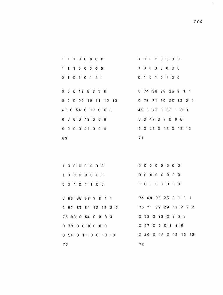


APPENDIX B.
Computer Program for Generating State Diagrams

/ * generation of cross collision matrices */
# include <stdio.h> # include <math.h> # define true 1 # define false 0 struct matrix {
int bits rowl[8]; int bitsMrow2 [8] ; int bits"row3 - [8] ;
> ; struct direction {
int div latency[8]; int mult latency[8]; int add iatency[8]; int div-add[8]; int mult - add[8];
1: struct ident {
int name ; 1: struct collision - matrix {
struct matrix smatrix; struct direction sdirection; struct ident sident;
1 ; struct collision-matrix binary matrix[l50]; struct collision - matrix f~rpresent~upto - next,last - temp; int index, pres-num; / * */ i* */ / * FUNCTION FOR INITIALIZING */ / * */ / * */ struct collision-matrix init - cross(now) struct collision-matrix now; {
static struct collision - matrix new = {
{
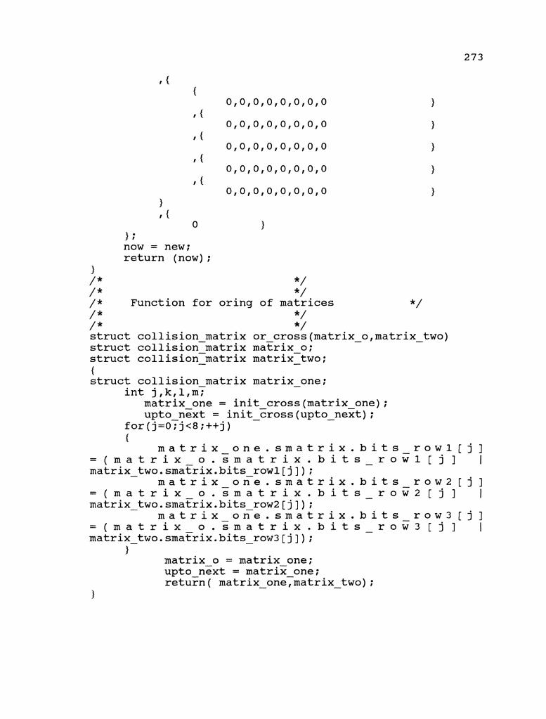
1 f {
0 ); now = new; return (now) ;
1 /* */ / * */ / * Function for oring of matrices */ / * */ / * */ struct collision matrix or cross(matrix - ofmatrix - two) struct collision~matrix matrix o; struct collision-matrix - matrix-two; -
{ struct collision matrix matrix - one;
int j,k,l,m~ matrix one = init-cross(matrix one); upto next = init - cross (upto - next) ;
for(j=o?j<8;++j) {
m a t r i x - o n e . s m a t r i x . b i t s r o w l [ j ] = ( m a t r i x o . s m a t r i x . b i t s - r o w l [ j ] I matrix - two.sma~rix.bits - rowl[j]);
m a t r i x - o n e . s m a t r i x . b i t s r o w 2 [ j ] = ( m a t r i x o . s m a t r i x . b i t s - r o w 2 [ j ] I matrix - two.smatrix.bits - row2[j]);
m a t r i x - o n e . s m a t r i x . b i t s r o w 3 [ j ] = ( m a t r i x o . s m a t r i x . b i t s - r o w 3 [ j ] I matrix - two.sma~rix.bits - row3[j]);
) matrix o = matrix one; upto next = matrix one; return ( matrix - oneymatrix - two) ;
1

/ * */ / * / * FUNCTION FOR SHIFTING THE COLLISION BITS
*/ */
/ * /*
*/ * / , struct collision matrix sleft bits(present,number) struct collision-matrix - present; int number; {
struct collision matrix use once; - - int left; use once = init cross(use once); for(left=o;left<(8 - number);++left) {
u s e once.smatrix.bits rowl[left] = present.smatrix.bits - rowl[left + number];
u s e once.smatrix.bits row2[left] = present.smatric.bits - row2[left + number];
u s e once.smatrix.bits row3[left] = present.smatrix.bits - row3[left + number17
1 present = use once; return (present) ;
1
/ * */ / * */ / * */ / * FUNCTION NAME IT */ / * */ / * */ s t r u c t c o l l i s i o n m a t r i x dname it(present,coming,ineex,pre nutrepeat) struct collision-matrix present,corning[]; int ineex,repeat,pre - nu; f
struct collision matrix temp,templ,temp2[]; int i,j,k,l,m,find - sucess,number,consider; unsigned int flag; flag = 0; find sucess = 0;
number = index; consider = pres num;
for(i=l;i<=number;++i) {
for(j=O;j<8;++j) I

flag = flag << 1; flag = flag I 1;
1 else {
flag = flag << 1; flag = flag I 0;
1 1 if (flag == 255) {
binary - matrix[consider].sdirection.div - latency[repeat] = i;
find sucess = 1; breaE;
1 else {
flag =O; 1
1 if (find - sucess != 1) {
binary matrix[number+l] = present; binarymatrix - [number+l] . sident . name = number + 1 ;
binary matrix[consider].sdirection.div - latency[repeat]= number-+ 1;
index = number + 1; 1
return; 1
/ * */ / * */ /* */ / * FUNCTION NAME IT */ / * */ / * */ s t r u c t c o l l i s i o n m a t r i x mname it(present,coming,ineex,pre nutrepea%) struct collision matrix present1c6ming[]; int ineex,repeatTpre - nu; {
struct collision matrix temp,templ,temp2[]; int i,j,k,l,m,fi~d - sucess,number,consider;

unsigned int flag; flag = 0; find sucess = 0;
number = index; consider = pres num;
for(i=l;i<=number;T+i) {
for(j=O;j<8;++j) {
if (((present.smatrix.bits rowl[j] == c o m i n g [ i ] . s m a t r i x . b i t s - rowl-[j]) & & ( p r e s e n t . s m a t r i x . b i t s r o w 2 [ j ] = = c o m i n g [ i ] . s m a t r i x . b i t s r o w 2 [ j ] ) ) & & ( p r e s e n t . s m a t r i x . b i t s - r o w 3 [ j ] = = coming[i].smatrix.bits - row3[j]))
{ flag = flag << 1; flag = flag I 1;
1 else {
flag = flag << 1; flag = flag I 0;
1 1 if (flag == 255) {
binary - matrix[consider].sdirection.mult - latency[repeat]= i;
find sucess = 1; break;
1 else {
flag =O; 1
1 if (find - sucess != 1) {
binary matrix[number+l] = present; binarymatrix[number+l].sident.name - = number + 1;
binary matrix[consider].sdirection.mult - latency[repeat]= number-+ 1;
index = number + 1; }
return;

/ * */ / * */ / *
FUNCTION NAME IT */
/ * */ / * */ / * s t r u c t
*/ c o l l i s i o n m a t r i x
aname it(present,coming,ineex,pre nutrepea?) struct collision matrix present,c~ming[]; int ineex,repeat,pre - nu; {
struct collision matrix temp,templ,temp2[]; int i,j,k,l,m,fi~d - sucess,number,consider; unsigned int flag; flag = 0; find sucess = 0;
number = index; consider = pres num;
for(i=l;i<=number;T+i) {
for(j=O;j<8;++j) {
if (((present.smatrix.bits rowl[j] == c o m i n g [ i ] . s m a t r i x . b i t s - rowl-[j]) & & ( p r e s e n t . s m a t r i x . b i t s r o w 2 [ j ] = = c o m i n g [ i ] . s m a t r i x . b i t s r o w 2 [ j ] ) ) & & ( p r e s e n t . s m a t r i x . b i t s - r o w 3 [ j ] = = coming[i].smatrix.bits - row3[j]))
{ flag = flag << 1; flag = flag I 1;
) else {
flag = flag << 1; flag = flag 1 0;
1 1 if (flag == 255) {
binary - matrix[consider].sdirection.add - latency[repeat] = i;
find sucess = 1; break;
1 else {
flag =O; 1
1 if (find - sucess != 1)

{ binary-matrix[number+l] = present; binary - matrix[number+l].sident.name = number + 1;
binary matrix[consider].sdirection.add - latency[repeat]= number-+ 1;
index = number + 1; 1
return; 1
/ * */ / * */ / * */ /* FUNCTION NAME IT */ / * */ /* */ s t r u c t c o l l i s i o n m a t r i x daname it (present, coming, ineex, pre nu, repeat) struct-collision matrix present,coming[]; int ineex,repeat:pre - nu; {
struct collision matrix temp,templ,temp2[]; int i,j,k,l,m,fi~d - sucess,number,consider; unsigned int flag; flag = 0; find sucess = 0;
number = index; consider = pres num;
for(i=l;i<=number;T+i)
{ flag = flag << 1; flag = flag I 1;
1 else {
flag = flag << 1; flag = flag 1 0;
1

1 if (flag == 255) {
binary - matrix[consider].sdirection.div - add[repeat] = i; find sucess = 1; break;
1 else {
flag =O; 1
1 if (find - sucess != 1) {
binary matrix[number+l] = present; binarymatrix[number+l].sident.name - = number + 1;
binary - matrix[consider].sdirection.div - add[repeat]= number + 1;
index = number + 1; 1
return;
/ * */ /* */ / * */ / * FUNCTION NAME IT */ / * */ / * */ s t r u c t c o l l i s i o n m a t r i x maname it(present,coming,ineex,pre nutrepeat) struct-collision-matrix present,coming[]; int ineex,repeat,pre - nu; {
struct collision matrix temp,templ,temp2[]; int i,j,k,l,m,fi~d - sucess,number,consider; unsigned int flag; flag = 0; find sucess = 0;
number = index; consider = pres num;
for(i=l;i<=number;T+i) {
for(j=O;j<8;++j) {
if (((present.smatrix.bits rowl[j] == c o m i n g [ i ] . s m a t r i x . b i t s - rowl-[j]) & & ( p r e s e n t . s m a t r i x . b i t s r o w 2 [ j ] = = c o m i n g [ i ] . s m a t r i x . b i t s - r o w 2 [ j ] ) ) & &

( p r e s e n t . s m a t r i x . b i t s - r o w 3 [ j ] = = coming[i].smatrix.bits - row3[j]))
{ flag = flag << 1; flag = flag I 1;
1 else {
flag = flag << 1; flag = flag I 0;
1 1 if (flag == 255) {
binary - matrix[consider].sdirection.mult - add[repeat] = i; find sucess = 1; breaE;
1 else {
flag =O; 1
1 if (find - sucess != 1) {
binary matrix[number+l] = present; binarymatrix - [number+l] . sident. name = number + 1 ;
binary - matrix[consider].sdirection.mult - add[repeat]= number + 1;
index = number + 1; 1
return ; 1
/ * */ / * */ / *
FUNCTION TO GENERATE AND CHECK */
/ * THE STRUCTURES FOR NON REPITITION
*/ / * */ / * */ / * */ struct collision matrix check struc(put,inex,pr-nu) struct collision-matrix - put[]? int inex,pr - nu; {
s t r u c t c o l l i s i o n - m a t r i x temp - struct,sec struc,third - struc;
int i,j,k,~,consider;

consider = pres num; temp struct = init-cross(temp - struct); temp-struct = put[consider]; sec struc = temp struct; /* generation of-new structures */ for(j=O;j<8;++j) {
if (temp - struct. smatrix. bits - row1 [j ] == 0) {
set struc = sleft bits(sec struc,j); sec-struc - = or cross(sec ~truc,~ut[l]);
set struc = upto next; dname - it(sec-struc,put,in&,consider,j) - ;
1 sec - struc = temp - struct;
1
{ set struc = sleft bits(sec struc,j); sec-struc - = or cross(sec struc,put[2]);
set struc = upto next; mname - it(sec-struc,put,in&,consider,j); -
1 sec struc = temp struct; - -
1
set struc = sleft bits(sec struc,j); sec-struc - = or cross(sec struc,put[3]);
set struc = upto next; aname - it(sec-struc,put,in~consider,j); -
1 sec - struc = temp - struct;
1
{ if((temp struct.smatrix.bits - rowl[j]== 0) & &
(temp - struct. smatrik. bits - row3 [ j ] == 0) )
{ set struc = sleft bits(sec struc,j); sec-struc - = or cross(sec struc,put[l]);
set struc = upto next; sec - struc = or - cross(sec - struc,put[3]);

sec-struc = upto next; daname - it(sec - struc,put,i~ex,consider,j);
1 sec - struc = temp - struct;
} for(j=O;j<8;++j) {
if((temp struct.smatrix.bits row2[j]== 0) & & (temp - struct. smatri5. bits - row3 [ j ] == 0) )
{ set struc = sleft bits(sec struc,j); sec-struc - = or cross(sec struc,put[2]);
set struc = upto next; sec - struc = or cross(sec struc,put[3]);
set struc = upto next; maname - it(sec - struc,put,i~ex,consider,j);
1 sec - struc = temp - struct;
1 return;
1
main ( ) {
struct collision - matrix say - one, say - two, say - three;
int i, j ,k,l,v; pres num = 1; index = 3; binary matrix[l] = init cross(binary matrix[l]); binarymatrix[2] = init-cross(binary-matrix[2]); binarymatrix[3] = init-cross(binary-matrix[3]); binary-matrix[l].smatrikbits rowl[07 = 1; binary-matrix[l].smatrix.bits-rowl[l] = 1; binary-matrix[l].smatrix.bits-rowl[2] = 1; binary-matrix[l].smatrix.bits-row2[0] = 1; binary-matrix[l].smatrix.bits-row2[1] = 1; binary-matrix[l].smatrix.bits-row2[2] = 1; binary-matrix[l].smatrix.bits-row3[5] = 1; binary-matrix[l].smatrix.bits-row3[6] = 1; binary-matrix[l].smatrix.bits-row3[7] = 1; binary-matrix[2].smatrix.bits-rowl[0] = 1; binary-matrix[2].smatrix.bits-row2[0] = 1; binary-matrix[2].smatrix.bits-row3[5] = 1; binaryrnatrix[3].smatri~.bits-row3[0] - = 1; binary-~natrix[l].sident.name = 1; binary-matrix[2].sident.name = 2; binary-matrix[3].sident.name - = 3;

while( pres - num <= index ) {
check - struc(binary matrix,index,pres num); - pres num = pres nui + 1; - -
1 printf( the various structures are tabulated
below \nu) ; printf (!I\nw) ; for (v=l; v <= index; v++) {
for (1=0;1<8;++1) {
printf ( "%d ff,binary matrix[v].smatrix.bits rowl[l]);
\b - -
printf ("\nff) ; printf (ff\n") ;
for (1=0;1<8;++1) {
printf ( If%d \b Iffbinary - matrix[v].smatrix.bits row2[1]); -
1 printf (If\nw) ; printf (ff\nff) ;
for (1=0;1<8;++1) {
printf ( "%d \b ff,binary - matrix[v].smatrix.bits row3[1]); -
printf ("\nff) ; printf iff\nff) ; printf (:*\riff) ;
for (1=0;1<8;++1) {
printf ("\nff) ; printf (If \nw ) ;
for (1=0;1<8;++1) {
printf ( If%d ",binary matrix[v].sdirection.mult latency[l]);
\b - -
printf (If\nff) ; printf ( fl\nff) ;
1
for (1=0; 1<8 ;++I) {
printf ( If%d \b ",binary - matrix[v].sdirection.add latency[l]); -

printf ("\nW) ; printf ("\nI1) ;
1
for (1=0;1<8;++1) {
p r i n t f ( I1%d \b ",binary - matrix[v].sdirection.div~add[l]);
1 printf (l1\n") ; printf ("\nn) ;
for (1=0;1<8;++1) {
p r i n t f ( I1%d \b lt,binary - matrix[v].sdirection.mult - add[l]);
1 printf ("\nu) ; printf ("\nV1) ;
p r i n t f ( I1%d \ b I f I
binary matrix[v].sident.name); printf7l1\n1l) ; printf ("\nW) ; printf ("\nn) ; printf (If\n") ; printf ("\nut) ; printf (tt\nN) ;
1

APPENDIX C.
simulation Program

................................................ /***** SIMULATION OF DYNAMIC ARITHMETIC *****/ /***** *****/ /***** PIPLINE *****/ /***** *****/ /***** VERSION 1.0 *****/ .. . . . . . . . . . . . . . . . . . . . . . . . . . . . . . . . . . . . . . . . . . . . . . . ................................................ . . . . . . . . . . . . . . . . . . . . . . . . . . . . . . . . . . . . . . . . . . . . . . . . . . .................................................. / * In this program The Eigth bit is stored in 0 */ / * and the First Bit is stored in 8 */ .................................................. .................................................. # include <stdio.h> # include <math.h> # define true 1 # define false 0
/ * the structure initializations for the instruction unit */ struct input - inst {
int opcode field; int source-operandl; int source-operand2; int dest operand; int valid;
1;
struct instruction - status {
int inst num; int pipe-cyl; int opcode; int exec time: int reg ;ti1 [5 ] ; -
I int count units[5] int decode - ptr; int issue ptr; -
1 ;
struct reg - file {
int reg - units[5]; 1 ;
struct status - reg {
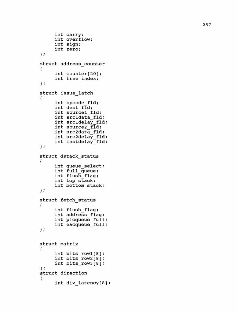
int carry; int overflow; int sign; int zero;
> ;
struct address - counter C
int counter[20]; int free - index;
> ;
struct issue - latch {
int opcode fld; int dest fid; int source1 fld; int srcldata fld; int srcldelay fld; int source2 fid; int src2data fld; int src2delay fld; int instdelay-fld; -
> ; struct dstack - status C
int queue select; int full queue; int flush flag; int top stack; int bottom stack;
1 ;
struct fetch status - C
int flush flag; int address flag; int picqueue full; int eacqueue-full; -
struct matrix C
int bits rowl[8]; int bits-row2 [ 8 ] ; int bits-row3 - [8] ;
1; struct direction C
int div - latency[8];

int mult latency[8]; int add iatency[8]; int div-add[8]; int mult - add[8];
1; struct ident {
int name; 1 ; struct collision - matrix {
struct matrix smatrix; struct direction sdirection; struct ident sident;
1; struct recode {
int bits[15] ; 1; struct reg - stages {
int word [ 17 ] ; 1: struct div - track {
char name one[3]; int number; int st track[10]; int itr track; int address;
1; struct mult track {
char name two[4]; int number; int st track[lO]; int address;
1; struct add - track {
char name three[3]; int number; int st track[lO]; int address;
1; struct logg - sheet {
int logg[10] ; int logg - stat;
1 ; struct input-process {

int location; int func; int num one[lO]; int num-two[l0]; int over flow; int weight;
1: struct itr - storage {
int address; int func; int num one[10]; int num-two[l0]; -
1; struct output - process {
int destination; int overflow; int result[l7]; int wt - factor;
1; typedef struct collision matrix struct0; typedef struct recode structl; typedef struct reg stages struct2; typedef struct div-track struct3; typedef struct mult track struct4; typedef struct add track struct5; typedef struct logg sheet struct6; typedef struct input process struct7; typedef struct output process struct8; typedef struct itr - storage struct9;
typedef struct input inst structi0; typedef struct instruction status structil; typedef struct reg file structi2; typedef struct status reg structi3; typedef struct address counter structi.4; typedef struct issue latch structi5; typedef struct fetch-status structi6; typedef struct dstack - status structi7;
structiO memory[100],decode stackl[20],decode stack2[20]; structi0 *memory ptr,*dstackl ptr,*dstack2 ptr; structiO iunit latches[2~],internarholders[20], - *ilatch ptr,*inhold ptr; structiy status unit[100], *statusu ptr; structi2 gp - reg'lster, *gp - ptr; / * general purpose register */ structi3 register sr,*sr-ptr; structi4 pgm - coun~erlIpgm~counter2,*pgm - ptrl,*pgm - ptr2;

structi5 isunit latch,*isunit ptr; structi6 stream-status, *sstatus ptr; s t r u c t i 7 p i c q u e u e statu-s,eacqueue - s t a t u s , *picstatus - ptr,*eacstatus - ptr;
int queue - select,current - queue,disable - decode,disable - issue;
struct collision matrix binary matrix[l50]; struct collision-matrix for present,upto next,last temp; structl argumentT[20],argum&1t2[20], multipurpose - reg[20], *mpreg ptr; structF latches[30],par product[l0],transfer[30],delay[20]; struct3div follow[l~],delta track[lO],*divflow - ptr, *deltaf low ptr; struct3 *copy seven,*copy eight; struct4 mult follow[10],*~ultflow ptr,*copy nine; struct5 ad3 follow[lO] , *addflow - ptr, *copy - ten, sub follow[l~~, *subflow ptr; strkct6 div - logg,mult - Togg,add - logg,process - logg[lO], *prlogg-ptr; struct7 input stack[41],*instack ptr,*copy eleven; struct8 output stack[41],*outstack ptr,*copy - twelve; struct9 priority ~tack[70],*~rstack ptr; structO *bin pointer; structl *argi pointer,*arg2 pointer,*copy one,*copy - two; struct2 *par pointer,*lat pointer, *copy-four, *copy three,*trans pointer,*copy-five; - struct2 *delay ptr, *copy six; int op code[20r,arg one[2<][9],arg two[20][9]; int *ptr op,*ptr argmntl[20],*ptr argmnt2[20]; int index, pres ium,stk ptr,total,~ultiplication,division; int varl,var2,v~r3,var~init - key, addition, subtraction, delta - flag; i n t g l o b a l o n e [ 2 0 ] , g l o b a l - t w o [ 2 0 ] , global - three [20] , readjust; -
/* Functions of the instruction unit */
/ * */ / * Instruction Fetch Unit */ / * */ structiO fetch unit( ptrl,ptr2,ptr3,ptr41ptr51ptr6) structiO *ptrl, *ptr2 ; /* pointer to the Memory */ structi4 *ptr3,*ptr4; / * pointers to the address counters */ structi6 *ptr5, *ptr6 ; / * The flag which denotes the current queue in session */

{ int i,j,k,l,transfer flag1,transfer flag2; int program ~ounterl7~ro~ram - counter2,queue - select; (ptr2+1) ->valid = 0 ; (ptr2+2)->valid = 0;
/ * To check and flush the redudant queues */ if ( (ptr5) ->flush flag == 1) {
printf("f1ush flag is enabled\nw); if ( (ptr5) ->address - flag == 1) {
/* Flush PIC stream */ printf (99flush PIC stream \nl@) ; (ptr3)->counter[O] = 0; for (i=l;i<=g;i++) { (ptr4) ->counter [i] = 0; 1 (ptr4)->free index = I;/* setting the index
flag of the counter2 to 1 so as to indicate that the counters are flushed and the counter that has to be filled first is counter[l] */
1 if((ptr5)->address - flag == 2) {
/* Flush EAC stream */ (ptr4)->counter[O] = 0; for (i=l;i<=g;i++) { (ptr3)->counter[i] = 0; 1 (ptr3)->free index = I;/* setting the index
flag of the counterl to 1 so as to indicate that the counters are flushed and the counter that has to be filled first is counter[l] */
1 1 / * reading the memory for instructions */ /* instructions will be fetched if the program counter
*/ / * of both the individual streams are non zero */ program counterl = (ptr3)->counter[O]; program-counter2 - = (ptr4)->counter[O];
/ * Fetching of instructions for PIC stream */ if ( (program - counter1 ! = 0) & & ( (ptr5) ->picqueue-full
== 0))

( p t r 2 + 1 ) - > o p c o d e - f i e l d - - (ptrl+program counter1)->opcode - field;
( p t r Z + l ) - > s o u r c e - o p e r a n d 1 = (ptrl+program counter1)->source - operandl;
( p t r Z + l ) - > s o u r c e _ o p e r a n d 2 = (ptrl+program counter1)->source operand2;
( p t r A 2 + 1 ) - > d e s t o p e r a n d - - (ptrl+program counter1)->dest operand;
transferAflagl = I;/* vaiid instruction and pass it to decode unit */
(ptr3)->counter[O]+=l; (ptr2+1) ->valid = 1; 1
/ * Fetching of instructions for EAC stream */ if((program - counter2 != 0) & & ((ptr5)->eacqueue-full
== 0)) { ( p t r 2 + 2 ) - > o p c o d e - f i e l d - -
(ptrl+program counter2)->opcode field; ( p t r z + 2 ) - > s o u r c e - o p e r a n d 1 =
(ptrl+program counter2)->source - operandl; ( p t r Z + 2 ) - > s o u r c e o p e r a n d 2 =
(ptrl+program counter2)->source operand2; ( p t r - 2 + 2 - > d e s t o p e r a n d - -
(ptrl+program counter2) ->dest operand; transferflag2 = I;/* val'ld instruction and pass it to
decode unit */ (ptr4)->counter[O]+=l; (ptr2+2) ->valid = 1; 1
/ * classifying the instruction */ / * checking for jump instructions in the PIC stream
*/ if (((ptr2+1)->opcode - field >= 13) & & (transfer flag1 -
!= 0)) {
printf(" there is a branch instruction detected in the PIC stream\ntl) ;
( p t r 4 ) - > c o u n t e r [ ( p t r 4 ) - > f r e e - index] = (ptr2+1) ->dest operand;
(ptrz) ->free - index += 1;

/ * checking f o r jump i n s t r u c t i o n s i n t h e EAC stream */
i f ( ( (p t r2+2) ->opcode - f i e l d >= 1 3 ) & & ( t r a n s f e r - f lag2 != 0 ) )
{ p r i n t f ( " t h e r e i s a branch i n s t r u c t i o n d e t e c t e d
i n t h e EAC stream\ntl) ;
( p t r 3 ) - > c o u n t e r [ ( p t r 3 ) - > f r e e - i n d e x ] = (p t r2+2) ->des t operand;
( p t r 3 ) - > f r e e - index += 1; 1 p r i n t f ( I t the i n s t r u c t i o n f e t c h e d from memory f o r P I C
s t ream \ntl ) ;
p r i n t f ( " o p c o d e o f p t r 2 + 1 i s % d \nl1, (p t r2+1) ->opcode-f i e l d ) ;
p r i n t f ( l l s o u r c e o p e r a n d 1 o f p t r 2 + 1 % d \nw , ( p t r 2 + l ) ->source - opercndl) ;
p r i n t f ( l l s o u r c e o p e r a n d 2 o f p t r 2 + 1 % d \nw , (p t r2+1) ->source operand2) ;
p r i n t f ( l l d e - s t - o p e r a n d o f p t r 2 + 1 % d
p r i n t f ( I t the i n s t r u c t i o n f e t c h e d from memory f o r EAC stream \nu) ;
p r i n t f ( I 1 o p c o d e o f p t r 2 + 2 i s % d \nt1 , ( p t r 2 + 2 ) ->opcode - f i e l d ) ;
-
- p r i n t f ( l l s o u r c e o p e r a n d 1 o f p t r 2 + 2 % d
\nw , (p t r2+2) ->source - operandl) ; p r i n t f ( l l s o u r c e o p e r a n d 2 o f p t r 2 + 2 % d
\ntl , (p t r2+2) ->source operand2) ; p r i n t f ( " d e - s t - o p e r a n d o f p t r 2 + 2 % d
\nM , (p t r2+2) ->des t - operand) ;
p r i n t f ( I 1 t h e program counters a r e l i s t e d below \ n t l ) ;
f o r ( i=O;i<=g;i++) {
p r i n t f ( I 1 t h e va lue of counter %d of PIC stream is %d \nt l , i, ( p t r 3 ) ->coun te r [ i ] ) ;
1
f o r ( i = O ; i < = g ; i + + ) {
p r i n t f ( I 1 t h e va lue of counter %d of EAC stream is %d \nw , i, ( p t r 4 ) ->counter [ i ] ) ;
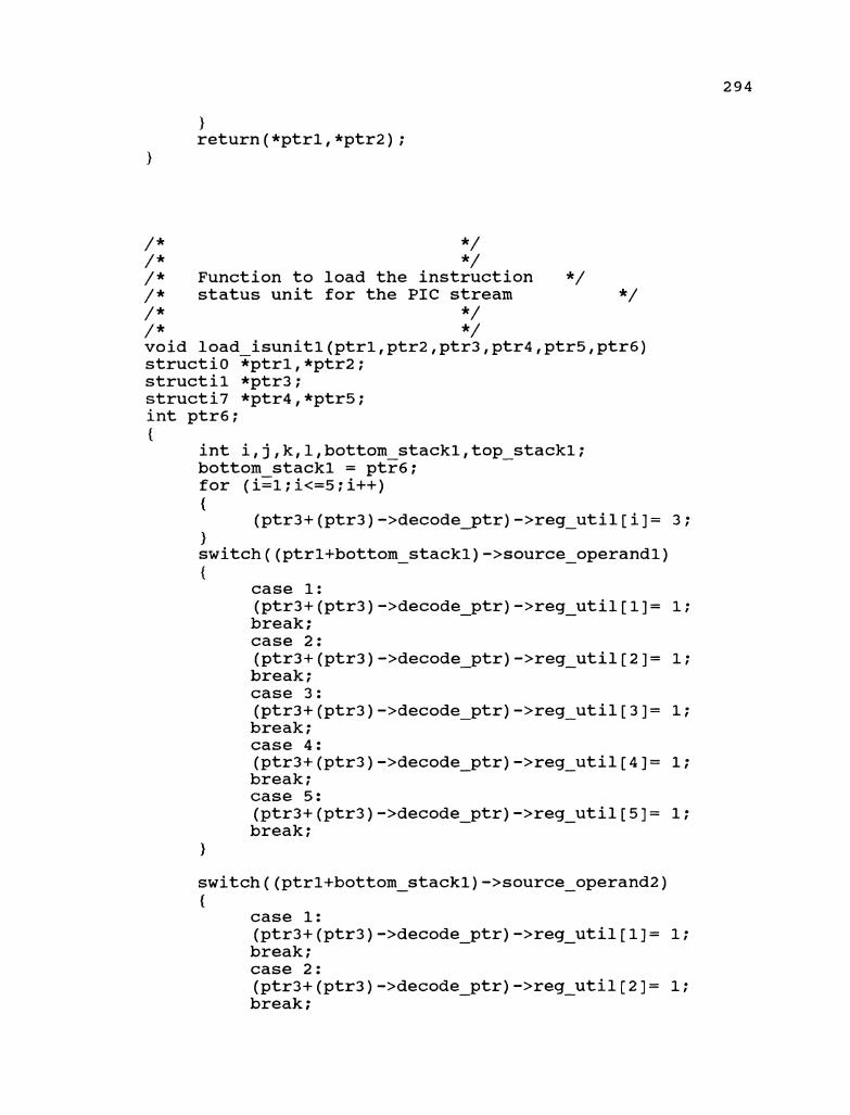
/ * */ / * */ / * Function to load the instruction */ /* status unit for the PIC stream */ /* */ /* */ void load i~unitl(ptrl,ptr2,ptr3~ptr4,ptr5,ptr6) structi0 zptrl, *ptr2 ; structil *ptr3; structi7 *ptr4,*ptr5; int ptr6; I
int i,j,k,l,bottom stack1,top - stackl; bottom stackl = ptr6; for (izl;i<=5;i++) {
(ptr3+ (ptr3) ->decode - ptr) ->reg - util [i] = 3 ; ) switch((ptrl+bottom - stack1)->source - operandl) {
case 1: (ptr3+ (ptr3) ->decode - ptr) ->reg - util [1] = 1 ; break; case 2: (ptr3+ (ptr3) ->decode - ptr) ->reg - util[2]= 1; break; case 3: (ptr3+(ptr3)->decode - ptr)->reg - util[3]= 1; break; case 4: (ptr3+ (ptr3) ->decode - ptr) ->reg - util[4]= 1; break; case 5: (ptr3+ (ptr3) ->decode - ptr) ->reg - util[5] = 1; break;
1
switch((ptrl+bottom - stack1)->source - operand2) {
case 1: (ptr3+ (ptr3) ->decode - ptr) ->reg - util [l] = 1; break; case 2: (ptr3+ (ptr3) ->decode - ptr) ->reg - util[2 ] = 1; break;

2 U (d C, m
-a
> \O
k a
C, F: a fd .
> m d
k X
C, U
a fd
-4J
C
a rn
o
k a
-4
I3 C,
C, cd
a o
U 0
-4J
>>Z$>>Z k
C, m
C,
Q)
m a+,
G 0
- F: ru -4
kO
W
Q)
C, a
G
Q)
a -*
"5 d,
2 k
k
*- ..
C,cu
m
0 0
rl w
ak k
-C,
C,
0 C,
C, -4
%
? *a -4
- .. . C
F:
m a
lkkk
0 " mu+u
-4 m
-4 aaa
C, 5
I*
* * a
. . UC,
C fd
cdOdbQ
5 C,
0 -4
-4 -4
k
h
Fr m
rlC,""C,
uuua
55
33
-
4k
kk"
* * * * * * OC,C,C, F:
-\\\\\\$
m m
m-4
in \O
I k
W"- o a+
C,
+ u II
-4
0
*- arum
- X
II dUV
- fd -4
XC, *-
-U)d
-n I II
- E -4
-4
0 - U

(ptr3+ (ptr3) ->decode ptr) ->reg util [1] = 1; - - break; case 2: (ptr3+ (ptr3) ->decode - ptr) ->reg - util[2]= 1; break; case 3: (ptr3+ (ptr3) ->decode - ptr) ->reg - util[3 I= 1; break; case 4: (ptr3+ (ptr3) ->decode - ptr) ->reg - util[4]= 1; break; case 5: (ptr3+ (ptr3) ->decode - ptr) ->reg - util[5]= 1; break;
}
switch((ptr2+bottom - stack2)->source operand2) - {
case 1: (ptr3+ (ptr3) ->decode ptr) ->reg util [I] = 1; - - break; case 2: (ptr3+ (ptr3) ->decode ptr) ->reg_uti1[2]= 1; - break; case 3: (ptr3+(ptr3)->decode ptr)->reg_util[3]= 1; - break; case 4: (ptr3+ (ptr3) ->decode ptr) ->reg_util[4]= 1; - break; case 5: (ptr3+ (ptr3) ->decode ptr) ->reg util[5] = 1; - - break;
1
case 1: (ptr3+(ptr3)->decode - ptr)->reg-util[l]= 0; break; case 2: (ptr3+ (ptr3) ->decode ptr) ->reg_util[2 ] = 0 ; - break; case 3: (ptr3+ (ptr3) ->decode ptr) ->reg_util[3 ] = 0 ; - break; case 4: (ptr3+ (ptr3) ->decode ptr) ->reg util[4]= 0; - - break; case 5: (ptr3+ (ptr3) ->decode - ptr) ->reg_util[5]= 0; break;
1 1 / * / * Decode unit
*/ */
/ * s t r u c t i 0
*/ decode - unit(ptrl,ptr2,ptr3,ptr4,ptr5,ptr6,ptr7,~tr8,~trg)
structiO *ptrl,*ptr2,*ptr3; / * input from latch, dstackl, dstack2 */ structil *ptr4; / * sytem status pointer */ structi7 *ptr5,*ptr6; / * i n t e g e r p o i n t e r s t o dstackl, dstack2 */ structiO *ptr7;/* general purpose elements */ {
int i,j,k,l; int top stack1,bottom stack1,top - stack2,bottom - stack2; top stack1 = (ptr5) -?top-stack; bottom stack1 = (ptr5)->bottom stack; top stack2 = (ptr6)->top stack? bottom - stack2 = (ptr6)->bottom - stack;
/ * Loading of the PIC queue */ if ( ( (ptr5) ->queue-select == 1) & & ( (ptr5) ->full-queue
!= 1)) { /* check to see whether the instruction is a valid
instruction for PIC stream */ if ( (ptrl + 1) ->valid != 0) {
/* instruction is valid */ (ptr2+top - stack1)->opcode-field =
(ptrl+l) ->opcode field; (ptr2+top - stack1)->source - operand1 =
(ptrl+l)->source operandl; (ptr2+top - stack1)->source - operand2 =
(ptrl+l)->source operand2; (ptr2+top_stackl)->dest - operand =
(ptrl+l)->dest - operand; (ptr5)->top - stack+=l;
1
1 / * Loading of the EAC queue */ if ( ( (ptr6) ->queue - select == 1) & & ( (ptr6) ->full-queue
!= 1)) {

/* check to see whether the instruction is a valid instruction for EAC queue */
if((ptr1 + 2)->valid != 0) {
/* instruction is valid */
(ptr3+top - stack2)->opcode-field = (ptrl+2)->opcode field;
(ptr3+top - stack2)->source - operand1 =
(ptrl+2)->source operandl; (ptr3+top - stack2)->source - operand2 =
(ptrl+2)->source operand2; (ptr3+top - stack2)->dest - operand =
(ptrl+2)->dest - operand; (ptr6)->top - stack+=l;
1
/ * Forwarding the instruction to the decoder */
if (current - queue == 1) {
switch((ptr2+bottom - stack1)->opcode - field) {
case 1: / * */ (ptr4+(ptr4)->decode ptr)->opcode = 1; (ptr4+ (ptr4) ->decode-ptr) ->exec time = 3 ; - -
load - isunitl(ptr2,ptr3,ptr4,ptr5,ptr6,bottom - stackl); break;
case 2: / * */ (ptr4+ (ptr4) ->decode ptr) ->opcode = 2 ; (ptr4+(ptr4)->decodeptr)->exec time = 3; - -
load - isunitl(ptr2,ptr3,ptr4,ptr5,ptr6,bottom - stackl); break;
case 3: /* */ (ptr4+ (ptr4) ->decode ptr) ->opcode = 3 ; (ptr4+(ptr4)->decodeptr)->exec - - time = 8;
load - i~unitl(ptr2,ptr3,ptr4~ptr5~ptr6~bottom - stackl); break;

case 4: / * */ (ptr4+ (ptr4) ->decode-ptr) ->opcode = 4 ; (ptr4+ (ptr4) ->decode ptr) ->exec-time = 23 ; -
load isunitl(ptr2,ptr3,ptr4,ptr5,ptr6,bottom stackl); - - break;
case 5: /* */ (ptr4+ (ptr4) ->decode ptr) -Bopcode = 5; (ptr4+(ptr4)->decode-ptr)->e~ec time = 6; - -
load - isunitl(ptr2,ptr3,ptr4,ptr5,ptr6,bottom stackl): - break;
case 6: / * */ (ptr4+ (ptr4) ->decode ptr) ->opcode = 6; (ptr4+ (ptr4) ->decode-ptr) ->exec time = 6; - -
load - isunitl(ptr2,ptr3,ptr4,ptr5,ptr6,bottom stackl): - break;
case 7: / * */ (ptr4+ (ptr4) ->decode-ptr) ->opcode = 7 ; (ptr4+ (ptr4) ->decode ptr) ->exec time = 3 ; - -
load - isunitl(ptr2,ptr3,ptr4,ptr5,ptr6,bottom stackl): - break;
case 8: / * */ (ptr4+ (ptr4) ->decode-ptr) ->opcode = 8 ; (ptr4+ (ptr4) ->decode ptr) ->exec time = 3 ; - -
load - isunitl(ptr2,ptr3,ptr4,ptr5,ptr6,bottom stackl); - break;
case 9: / * */ (ptr4+ (ptr4) ->decode ptr) ->opcode = 9 ; (ptr4+ (ptr4) ->decode-ptr) ->exec time = 3 ; - -

load - isunitl(ptr2,ptr3,ptr41ptr51ptr61b~tt~m - stackl); break;
case 10: / * */ (ptr4+ (ptr4) ->decode ptr) ->opcode = 10 ; (ptr4+ (ptr4) ->decodeWptr) ->exec time = 3 ; - -
load - isunitl(ptr2,ptr3,ptr4,ptr5,ptr6,bottom - stackl); break;
case 11: / * */ (ptr4+ (ptr4) ->decode ptr) ->opcode = 11; (ptr4+ (ptr4) ->decode-ptr) - ->exec - time = 3 ;
load i~unitl(ptr2,ptr3,ptr4~ptr5~ptr6~bottom - stackl); break;
case 12: /* */ (ptr4+ (ptr4) ->decode ptr) ->opcode = 12 ; (ptr4+ (ptr4) ->decode-~tr) ->exec time = 3 ; - -
load - isunitl(ptr2,ptr3,ptr4,ptr5,ptr6,bottom - stackl); break;
case 13: / * */ (ptr4+ (ptr4) ->decode ptr) ->opcode = 13 ; (ptr4+ (ptr4) ->decode-ptr) ->exec time = 3 ; - -
load - isunitl(ptr2,ptr3,ptr4,ptr5,ptr6,bottom - stackl); break;
case 14: / * */ (ptr4+ (ptr4) ->decode ptr) ->opcode = 14 ; (ptr4+ (ptr4) ->decode7ptr) ->exec time = 3 ; - -
load - isuniti(ptr2,ptr3,ptr4,ptr5,ptr6,bottom - stackl); break;
case 15: / * */
(ptr4+(ptr4)->decode - ptr)->exec - time = 3;
load - is~nitl(ptr2,ptr3,ptr4~ptr5,ptr6~bottom - stackl); break;
/ * forwarding the instruction to the issue unit */
if(disab1e decode != 1) {
( p t r 7 + 3 ) - > o p c o d e - f i e l d = (ptr2+bottom - stack1)->opcode-field;
( p t r 7 + 3 ) - > s o u r c e - o p e r a n d 1 = (ptr2+bottom - stack1)->source - operandl;
( p t r 7 + 3 ) - > s o u r c e - o p e r a n d 2 = (ptr2+bottom stack1)->source operand2;
( p t r 7 + 3 ) - > d e s t - o p e r a n d = (ptr2+bottom - stack1)->dest - operand;
/* rearranging the stack */ for (i=2;i<=20;i++) {
( p t r 2 + ( i - 1 ) ) - > o p c o d e - f i e l d = (ptr2+i)->opcode - field;
(ptr2+(i-1))->source-operand1 = (ptr2+i)->source - operandl;
(ptr2+(i-1))->source - operand2 = (ptr2+i) ->source - operand2 ;
(ptr2+(i-1))->dest - operand = (ptr2+i)->dest - operand;
1 (ptr5) ->top - stack-=l ;
1 }
if(current - queue == 2) {
switch((ptr3+bottom - stack2)->opcode - field) {
case 1: / * */ (ptr4+ (ptr4) ->decode ptr) ->opcode = 1; (ptr4+ (ptr4) ->decode-~tr) - ->exec-time = 3 ;
load - isunit2(ptr2,ptr3,ptr41ptr51ptr61b~tt~m - stack2); break;
case 2: / * */

(ptr4+(ptr4)->decode-ptr)->opcode = 2; (ptr4+ (ptr4) ->decode ptr) ->exec-time = 3 ; -
load - isunit2(ptr2,ptr3,ptr4,ptr5,ptr6,bottom stack2); - break;
case 3: /* */
load - isunit2(ptr2,ptr3,ptr4,ptr5,ptr6,bottom - stack2); break;
case 4: /* */ (ptr4+ (ptr4) ->decode ptr) ->opcode = 4 ; (ptr4+ (ptr4) ->decode ptr) ->exec time = 23 ; - -
load - isunit2(ptr2,ptr3,ptr4,ptr5,ptr6,bottom - stack2); break;
case 5 : /* */
load - isunit2(ptr2,ptr3,ptr4,ptr5,ptr6,bottom - stack2); break;
case 6: /* */ (ptr4+ (ptr4) ->decode ptr) ->opcode = 6 ; (ptr4+ (ptr4) ->decode-ptr) ->exec-time = 6 ; -
load - isunit2(ptr2,ptr3,ptr4,ptr5,ptr6,bottom stack2); - break;
case 7: /* (ptr4+(ptr4)->decode ptr)->opcode = 7; (ptr4+ (ptr4) ->decode-ptr) ->exec time = 3 ; - -
load - i~unit2(ptr2,ptr3,ptr4~ptr5~ptr6,bottom stack2); break;

case 8: / * */ (ptr4+ (ptr4) ->decode ptr) ->opcode = 8 ; (ptr4+ (ptr4) ->decode-ptr) - ->exec-time = 3 ;
load - i~unit2(ptr2,ptr3,ptr4~ptr5~ptr6~bottom - stack2); break;
case 9: /* */ (ptr4+ (ptr4) ->decode ptr) ->opcode = 9 ; (ptr4+ (ptr4) ->decodeptr) - ->exec - time = 3 ;
load - isunit2(ptr2,ptr3,ptr4,ptr5,ptr6,bottom - stack2); break;
case 10: / * */ (ptr4+ (ptr4) ->decode ptr) ->opcode = 10 ; (ptr4+ (ptr4) ->decode-ptr) - ->exec - time = 3 ;
load - i~unit2(ptr2,ptr3,ptr4~ptr5~ptr6~bottom - stack2); break;
case 11: /* */ (ptr4+ (ptr4) ->decode ptr) ->opcode = 11; (ptr4+(ptr4)->decode-ptr)->exec - - time = 3 ;
load - is~nit2(ptr2,ptr3,ptr4~ptr5~ptr6~bottom - stack2); break;
case 12: / * */ (ptr4+ (ptr4) ->decode ptr) ->opcode = 12 ; (ptr4+ (ptr4) ->decode-ptr) - ->exec - time = 3 ;
load - i~unit2(ptr2,ptr3,ptr4~ptr5~ptr6~bottom - stack2); break;
case 13: / * */ (ptr4+ (ptr4) ->decode ptr) ->opcode = 13 ; (ptr4+(ptr4)->decodeptr)->exec - - time = 3;
load - isunit2(ptr2,ptr3,ptr4,ptr5,ptr51ptr61bottom - stack2);
break;
case 14: /* */ (ptr4+ (ptr4) ->decode-ptr) -Bopcode = 14 ; (ptr4+ (ptr4) ->decode ptr) ->exec time = 3 ; - -
load - isunit2(ptr2,ptr3,ptr4,ptr5,ptr6,bottom - stack2); break;
case 15: / * */ (ptr4+ (ptr4) ->decode ptr) ->opcode = 15; (ptr4+(ptr4)->decode-ptr)->exec-time = 3; -
load - isunit2(ptr2,ptr3,ptr4,ptr5,ptr6,bottom - stack2); break;
1 / * forwarding the instruction to the issue unit */
if(disab1e decode != 1) - {
( p t r 7 + 4 ) - > o p c o d e - f i e l d = (ptr3+bottom - stack1)->opcode-field;
( p t r 7 + 4 ) - > s o u r c e - o p e r a n d 1 = (ptr3+bottom - stack1)->source-operandl;
( p t r 7 + 4 ) - > s o u r c e _ o p e r a n d 2 = (ptr3+bottom - stack1)->source operand2;
( p t r 7 + 4 ) - > d e s t o p e r a n d = - (ptr3+bottom - stack1)->dest-operand;
/ * rearranging the stack */ for (i=2 ; i<=20; i++) {
(ptr3+(i-1))->opcode field = - (ptr3+i) ->opcode - field;
(ptr3+(i-1))->source operand1 = - (ptr3+i)->source - operandl;
(ptr3+ (i-1) ) ->source operand2 = - (ptr3+i)->source - operand2;
(ptr3+(i-1))->dest operand = - (ptr3+i)->dest - operand;
1 (ptr6) ->top stack-=l; -
1 1 (ptr4) ->decode ptr+=l; if ((ptr4)->decode - ptr == 20) {
(ptr4)->decode ptr = 0; - 1
return (*ptr7) ; 1
/ * */ / * */ / * Issue unit */ / * */ / * */ structi5 issue unit(ptrl,ptr2,ptr3,ptr4,ptr5,ptr6,ptr7) structiO *ptrlT/* pointers to the latches */ structil *ptr2; structi6 *ptr3,*ptr4;/* decode stack pointers */ structi5 *ptr7; {
int i,j,k,l; int issue - pointer, dest - ptr, srcl - ptr, src2 - ptr; i n t
templ,temp2,temp3,temp4,raw delay,waw delaytinst - delay; issue - pointer = (ptr2)1>issue-ptr;
/ * issue logic for PIC stream */ if((current - queue == 1) && (disable - issue != 1)) {
t e m P 1 = (ptr2+issue - pointer)->count units[(ptrl+3)->dest operand]; - -
temp2 = (ptr2+issue - pointer)->count - units [(ptrl+3)->source operandl];
temp3 =(ptr2+issue - pointer)->count - units [(ptrl+3)->source operand21;
temp4 =-(ptr2+issue - pointer)->exec - time;
/* computing RAW hazards */
if ( (temp2 == 0) & & (temp3 == 0) ) {
raw - delay = 0;
{ raw - delay = temp2;
{ raw - delay = temp3;

{ if (temp2 > temp3) {
raw - delay = temp2; 1 else {
raw - delay = temp3; 1
1
/ * checking for WAR hazards if (templ == 0) {
waw - delay = raw - delay + 1; 1 if((temp1 != 0) & & (temp1 <= (raw - delay+temp4)))
{ waw delay = templ + 2 ; -
1 else {
waw - delay = templ-temp4+3; 1
/ * computing total delay */ if( raw - delay > waw - delay) {
inst delay = raw delay + 1; - 1 else {
inst delay = waw delay + 1; - - }
/ * updating the counter associated with the sink register */
(ptrZ+issue pointer)->count - units[(ptrl+3)->dest-operand] = inst - delay + temp4 - 1;
issue pointer += 1; (ptr2y->issue ptr = issue-pointer; if((ptr2)->is%ue - ptr == 20 ) { (ptr2) ->issue ptr = 0; - 1
1

/ * issue logic for EAC stream */
if((current - queue == 2) & & (disable - issue != 1)) {
templ= (ptr2+issue - pointer)->count units - [(ptrl+4)->dest operand];
tempF= (ptr2+issue - pointer)->count units - [(ptrl+4)->source operandl];
temp3 r(ptr2+issue - pointer)->count - units [(ptrl+4)->source operand2J;
temp4 =-(ptr2+issue - pointer)->exec time; -
/* computing RAW hazards */
if ( (temp2 == 0) & & (temp3 == 0) ) {
raw - delay = 0; 1 if ( (temp2 > 0) & & (temp3 == 0) ) {
raw - delay = temp2;
{ raw - delay = temp3;
1 if ((temp2 > 0) & & (temp3 > 0)) {
if(temp2 > temp3) {
raw delay = temp2; - 1 else {
raw - delay = temp3; 1
/* checking for WAR hazards
if (templ == 0) {
waw delay = raw delay + 1; - - 1 if((temp1 != 0) & & (temp1 <= (raw - delay+temp4)))
{ waw - delay = temp1 + 2;
} else {

waw - delay = templ-temp4+3; 1
/* computing total delay */ if( raw-delay > waw-delay) {
inst - delay = raw - delay + 1; 1 else {
inst - delay = waw - delay + 1; 1
/ * updating the counter associated with the sink register */
(ptr2+issue pointer)->count - units[(ptrl+3)->dest-operand] = inst - delay + temp4 - 1;
issue pointer += 1; (ptr27->issue-ptr = issue pointer; if ( (ptr2) ->issue - ptr == 20 )
1 return (*ptr7) ; }
/* */ / * */ / * Function Initializations / * */ / * */ / * */ void initialize(numl,num2) struct7 *numl; struct8 *num2; {
int i,j,k,l; for(i=l;i<=40;i++)
{ (numl+i)->location = i; (numl+i)->func = 0; (num2+i)->destination = i;
1

/ * */ / * */ / * Function Re-Initializations */ / * */ / * */ / * */ struct7 reinit (numl) struct7 *numl; {
struct7 *temp; int ifjfkfl; temp = numl; 1 = 1; for(i=l;i<=40;i++)
{ if ( (numl+i) ->func == 5) {
(numl+i) ->location = 1 ; 1 = 1+ 1;
1 else if((numl+i)->func == 4) {
(numl+i) ->location = 1; 1 else
1 numl = temp; return (*numl) ;
1
/ * */ / *
Function stage 1 */
/ * */ / * */ / * */ / * */ struct2 stage - one(number - one,number - two,num - three,num - passl, num pass2) structl *number one,*number - two; struct2 *num three; int num - passi,num - pass2; {
int i,jfkfl;

structl *pl,*p2; struct2 *p3; pl = number one; p2 = number-two; p3 = nurn three; for (i=0;i<8 ;++i)
{ (num three + = i) ->word[i+j ] =
( (number one += num - passl) ->bits [j ] ) * ( (number-two += num - pass27->bits [i] ) ;
number one = pl; number-two = p2; num - thTee = p3; 1
1 printf ( " \nw) ; printf(I1 the partial products calculated in function stage1 are as follows \nI1) ; printf ( " \nI1) ; printf(" \nw) ; printf (I1 \nu) ; for(i=O;i<8;++i)
{ printf(I1The partial product W %d is\nw,i); printf ("\nI1) ; for(j=O;j<l6;++j)
{ printf(I1 %d 11, ( n u m - t h r e e + =
i)->word[j]) ; num - three = p3; 1
printf (I1\n1l) ; printf (lt\nll) ;
1 return (*num - three) ;
1 / * */ / * */ / * Function Stage 2 */ / * */ / * */ struct2 stage two(numl,num2,num3,num4,num5,num6, num7, num8, num9, num10) struct2 * n u m l , * n u m 2 , * n u m 3 , * n u m 4 1 * n u m 5 1 * n u m 6 1 *num7,*num8,*num9,*numlO; {
int i,j,k,l,nega,negb,negc; struct2 *pl,*p2,*p3,*p4,*p5,*p6,*p71*p8~*p9,*p10; pl = numl; p2 = num2;

p3 = num3; p4 = num4; p5 = num5; p6 = num6; p7 = num7; p8 = num8; p9 = num9; p10 = numl0;
/ * realization of csa unit number one for(i=O;i<l6;++i)
{ nega = 0; negb = 0; negc = 0; if ( (numl) ->word [i] == 0)
{ nega = 1;
1 if ( (num2) ->word [i] == 0)
{ negb = 1;
1 if ( (num3) ->word[i] == 0)
{ negc = 1;
1 / * realization of csa unit number two */ for(i=o;i<l6;++i)
{ nega = 0; negb = 0; negc = 0; if ( (num4) ->word[i] == 0)
{ nega = 1;
1 if ( (num5) ->word [i] == 0)
{ negb = 1;
1 if ((num6)->word[i] == 0)
{ negc = 1;
1

/ * */ /*
Function Stage 3 */
/* */ /* */ /* */ struct2 stage three(num1,num2,num3~num4,num5,num6, num7,num8,num9,~um10) struct2 * n u m l , * n u m 2 , * n u m 3 , * n u m 4 , * n u m 5 , * n u m 6 , *num7,*num8,*num9,*numlO; {
int i,j,k,l,nega,negb,negc; struct2 *pl,*p2,*p3,*p4,*p5,*p6,*p61*p71*p81*p91*p10; pl = numl; p2 = num2; p3 = num3; p4 = num4; p5 = num5; p6 = num6; p7 = num7; p8 = num8; p9 = num9; p10 = numl0;
/* realization of csa unit number three for(i=O;i<l6;++i)
{ nega = 0; negb = 0; negc = 0; if ( (numl) ->word[i] == 0)
{ nega = 1;
1 if ((num2)->word[i] == 0)
{ negb = 1;
1 if((num3)->word[i] == 0)
{ negc = 1;

1 num7->word[i] = ((((numl->word[i]*negb*negc)
I (num2->word[i]*nega*negc)) ( (num3->word[i]*nega*negb)) I (numl->word[i]*num2->word[i]*num3->word[i]));
n u m 8 - > w o r d [ i + l ] = ( ( n u m l - > w o r d [ i ] * n u m 2 - > w o r d [ i ] ) I ( n u m 3 - > w o r d [ i ] * n u m l - > w o r d [ i ] ) I (num2->word[i]*num3->word[i]));
1 / * realization of csa unit number four */
for(i=O;i<l6;++i) {
nega = 0; negb = 0; negc = 0; if ( (num4) ->word[i] == 0)
{ nega = 1;
1 if ( (num5) ->word[i] == 0)
{ negb = 1;
negc = 1; 1
num9->word[i] = ((((num4->word[i]*negb*negc) I(num5->word[i]*nega*negc)) 1 (num6->word[i]*nega*negb)) 1 (num4->word[i]*num5->word[i]*num6->word[i]));
n u m l 0 - > w o r d [ i + l ] = ( ( n u m 4 - > w o r d [ i ] * n u m 5 - > w o r d [ i ] ) I ( n u m 6 - > w o r d [ i ] * n u m 4 - > w o r d [ i ] ) I (num5->word[i]*num6->word[i]));
1 return(*num7,*num8,*num9,*numl0);
1
/ * */ / * */ / * Function Stage 4 */ / * */ / * */ struct2 stage four(numl,num2,num3,num4,num41num5) struct2 *numl~*num2,*num3,*num4,*num5; {
int i,j,k,l,nega,negb,negc; struct2 *pl1*p2,*p3,*p4,*p5; pl = numl; p2 = num2;

p3 = num3; p4 = num4; p5 = num5;
/* realization of csa unit number five for(i=O;i<16;++i)
{ nega = 0; negb = 0; negc = 0; if ( (numl) ->word[i] == 0)
{ nega = 1;
1 if((num2)->word[i] == 0)
{ negb = 1;
1 if((num3)->word[i] == 0)
{ negc = 1;
1 num4->word[i] = ((((numl->word[i]*negb*negc)
I (num2->word[i]*nega*negc)) I (num3->word[i]*nega*negb)) I (numl->word[i]*num2->word[i]*num3->word[i]));
n u m 5 - > w o r d [ i + l ] = ( ( n u m l - > w o r d [ i ] * n u m 2 - > w o r d [ i ] ) I ( n u m 3 - > w o r d [ i ] * n u m l - > w o r d [ i ] ) 1 (num2->word[i]*num3->word[i]));
1 return(*num4,*num5);
1
/* */ / *
Function Stage 5 */
/ * */ / * */ / * */ struct2 stage five(numl,num2,num31num41num5) struct2 *numl~*num2,*num3,*num4,*num5; {
int i,j,k,l,nega,negb,negc; struct2 *pl,*p2,*p3,*p4,*p5; pl = numl; p2 = num2; p3 = num3; p4 = num4; p5 = num5;
/ * realization of csa unit number six for(i=O;i<l6;++i)
{ nega = 0;

negb = 0; negc = 0; if ( (numl) ->word [i] == 0)
{ nega = 1;
1 if ( (num2) ->word[i] == 0)
{ negb = 1;
1 if ((num3)->word[i] == 0)
{ negc = 1;
1 num4->word[i] = ((((numl->word[i]*negb*negc)
I (num2->word[i]*nega*negc)) I (num3->word[i]*nega*negb)) I (numl->word[i]*num2->word[i]*num3->word[i]));
n u m 5 - > w o r d [ i + l ] = ( ( n u m l - > w o r d [ i ] * n u m 2 - > w o r d [ i ] ) I ( n u m 3 - > w o r d [ i ] * n u m l - > w o r d [ i ] ) I (num2->word[i]*num3->word[i]));
1 return(*num4,*num5);
}
/ * */ / * */ / * Function Stage 6 */ / * */ / * */ struct2 stage six(numl,num2,num3,num4) struct2 *numl~*num2,*num3; structl *num4; {
int i,j,k,lfnegafnegb,negc,carry[l7]; struct2 *pl,*p2,*p3; structl *p4; pl = numl; p2 = num2; p3 = num3; p4 = num4; carry[O] = 0;
/* here the distinction is being made between add & sub and the rest */ if((addition == 1) I I (subtraction == 1)) {
if(addition == 1) { printf (I1 addition is one \nu) ; for(i=O;i<=7;i++) {

(numl) ->word[7-i] = (p4+1) ->bitsCil; (num2) ->word[7-i] = (p4+2) ->bits[il; addition = 0; for(j=8;j<=16;j++) {
1 if(subtraction == 1) {
printf ( " subtraction is one \n1I) ; for(i=O;i<=7;i++) {
(numl) ->word[7-i] = (p4+1) ->bits [i] ; /* inverting the operand */
if ( (p4+2) ->bits [i] == 1) { (p4+2) ->bits[i] = 0;
1 else {
(p4+2) ->bits [i] = 1; 1
carry[O] = 1; subtraction = 0; for(j=8;j<=16;j++) {
1 1 printf ("\nn) ; printf (I1\nl1) ; printf(" the following is the entered numbers\nl1); printf ("\nu) ; printf (I1\nl1) ; printf(I1 the value of numl loaded is (16 - O)\nl1); for(j=O;j<=l6;j++) {
printf (I1 %d 11,numl->word[16-j ] ) ; } printf ("\n") ; printf ("\nI1) ; printf(I1 the value of num2 loaded is (16 - O)\nll); for(j=O;j<=16;j++) {
printf (I1 %d ", num2->word[l6-j ] ) ;

1 printf ("\nl1) ; printf ("\nW) ;
/* realization of carry propagation adder for(i=O;i<16;++i)
{ nega = 0; negb = 0; negc = 0; if ( (numl) ->word [i] == 0)
{ nega = 1;
1 if((num2)->word[i] == 0)
{ negb = 1;
1 if(carry[i] == 0)
{ negc = 1;
1 num3->word[i] = ((((numl->word[i]*negb*negc)
I (num2->word[i]*nega*negc)) I (carry[i]*nega*negb)) I (numl->word[i]*num2->word[i]*carry[i]));
carry[i+l] =((numl->word[i]*num2->word[i]) I (carry[i]*numl->word[i]) 1 (num2->word[i]*carry[i]));
1 return (*num3) ;
1
/* */ /* /* Function Delay One
*/ */
/ * */ /* */ struct2 delay one(numl,num2,num3,num4) struct2 *numl~*num2,*num3,*num4; {
int i,j,k; struct2 *PI, *p2, *p3, *p4 ; pl = numl; p2 = num2; p3 = num3; p4 = num4;
for (i=O;i<l7;i++) {
num3->word[i] = numl->word[i]; num4->word[i] = num2->word[i];
1 return (*num3, *num4) ;
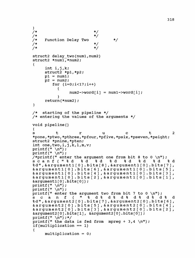
1 / * */ / * */ / * unction Delay Two /* */ / * */ struct2 delay two(numl,num2) struct2 *numl,*num2; {
int i,j,k; struct2 *pl,*p2; pl = numl; p2 = num2 ;
for (i=O; icl7 ; i++) {
num2->word[i] = numl->word[i]; 1
return (*num2) ; 1
/ * starting of the pipeline */ / * entering the values of the arguments */ void pipeline() { s t r u c t 2 *pone,*ptwo,*pthree,*pfourI*pfive,*psix,*pseven,*peight; struct2 *pnine,*pten; int one,two,i,j,k,l,m,v; printf (I1 \nn) ; printf ( " \nu) ; /*printf(" enter the argument one from bit 8 to 0 \nlt); s c a n f ( " % d % d % d % d % d % d % d % d %d~,&argumentl[O].bits[8]I&argument1[O].bits[7], & a r g u m e n t 1 [ 0 ] . b i t s [ 6 ] , & a r g u m e n t 1 [ 0 ] . b i t s [ 5 ] , & a r g u m e n t 1 [ 0 ] . b i t s [ 4 ] , & a r g u m e n t 1 [ 0 ] . b i t s [ 3 ] , & a r g u m e n t l [ O ] . b i t s [ 2 ] I & a r g u m e n t 1 [ O ] . b i t s [ l ] f &argumentl[O].bits[O]); printf (I1 \ntl ) ; printf (It \nw) ; printf(I1 enter the argument two from bit 7 to 0 \nV1); s c a n f ( II % d % d % d % d % d % d % d %d11,&argument2[0].bits[7]I&argument2[O].bits[6], & a r g u m e n t 2 [ 0 ] . b i t s [ 5 ] I & a r g u m e n t 2 [ O ] . b i t s [ 4 ] l & a r g u m e n t 2 [ 0 ] . b i t ~ [ 3 ] ~ & a r g u m e n t 2 [ O ] . b i t s [ 2 ] , &argument2[0].bits[l], &argument2[0].bits[O]); printf ( " \ntl) ; */ printf ( " the data is fed from mpreg + 3,4 \nI1) ; if(multip1ication == 1) {
multiplication = 0;

for(j=O; j<=7; j++) {
(argl - pointer+O)->bits[7-j] = (mpreg ptr + 3)->bits[j]; - (arg2 - pointer+O) ->bits[7-j 1 = (mpreg ptr + 4) ->bits[j 1 ; -
1 1 if ( (division == 1) ( I (delta flag == 1) ) - f
division = 0; delta flag = 0;
for(j=0; j<E7; j++) {
(arg2 - pointer+0) ->bits [7- j 1 = (mpreg-ptr + 3) ->bits [ j ] ;
(argl pointer+0) ->bits [8-j 1 = (mpreg-ptr + 4) ->bits [ j 1 ; -
1 1 if (init key == 1) - { init key = 0; for(T=o;j<=8;j++) {
(argl pointer+O)->bits[8-j] = 0; (arg2pointer+0)->bits[8-j] - = 0;
} printf (I1 the arguments are initialised to zero in
init - key\nI1) ; 1 printf (I1 \nw) ; printf (I1 the argument one is printed below 8 - 0 bits in correct place\nV1) ; printf (I1 \nw) ; printf (I1 \nI1) ; for(j=O;j<=8;j++) { printf (I1 %d 11, (argl - pointer+O) ->bits [8-j 1 ) ; 1 printf (I1 \nI1) ; printf ( " \nw) ; printf (I1 the argument two is printed below 8 - 0 bits in correct place\nI1) ; printf ( " \nw) ; printf (I1 \nI1) ; for(j=O;j<=8;j++) { printf (I1 %d 11, (arg2 - pointer+0) ->bits [8-j 1 ) ;
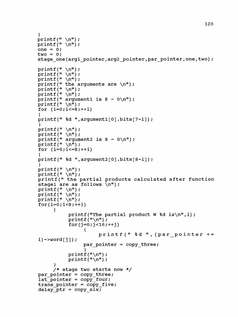
} printf ( " \nn) ; printf (I1 \nl#) ; one = 0; two = 0; stage - one(arg1 - pointer,arg2 pointer,par-pointer,one,two); -
printf (I1 \nn) ; printf (I1 \nw) ; printf (I1 \nl1) ; printf ( " the arguments are \nw) ; printf (I1 \n1#) ; printf (I1 \nw) ; printf(I1 argument1 is 8 - O\nl1); printf (I* \nl@) ; for (i=0; i<=8 ;++i) { printf(I1 %d w,argumentl[O].bits[7-i]); 1 printf ( " \nw) ; printf (I1 \nI1) ; printf (I1 argument2 is 8 - O\nn) ; printf ( " \nu) ; for (i=0; i<=8 ;++i) { printf (I1 %d 11,argument2 [o] .bits[8-i]) ; ) printf ( " \nu) ; printf ( " \nw ) ; printf(I1 the partial products calculated after function stage1 are as follows \n1I) ; printf ( " \ngl) ; printf ( " \nM) ; printf ( " \n1#) ; for(i=O;i<8;++i)
{ printf (nThe partial product W %d is\nV1,i) ; printf (I1\nl1) ; for(j=O;j<l6;++j)
{ printf ( I 1 %d " , (par - pointer + =
par pointer = copy three; - - 1
printf (I1\nt1) ; printf ("\nll) ;
1 / * stage two starts now */
par pointer = copy three; lat-pointer = copy-four; trans pointer = copy five; delayptr - = copy - six:

pone = trans pointer + 0; ptwo = transpointer + 1; pthree = trans pointer + 2; pfour = trans pointer + 3; pfive = transpointer + 4; psix = trans pointer + 5; pseven = lat-pointer + 0; peight = lat-pointer + 1; pnine = lat pointer + 2; pten = lat pointer + 3; stage - t w ~ ( p o n e , p t w o , p t h r e e , p f o u r , p f i v e , p s i x , pseven,peight,pnine,pten); pone = delay ptr + 3; ptwo = delayptr + 4; pthree = delay ptr + 0; pfour = delay ptr + 1; delay one (pone, ptwo, pthree, pfour) ; ~rintf(~ \nn) ; printf ( " \nw) ; printf ( " \nu) ; print£(" THE SUM AND CARRY VECTORS OF STAGE TWO \n1I); printf ( " \nl1) ; printf(I1 FIRST AND THIRD ARE SUM VECTORS S1 AND S2 \n1I); printf ( " \nw) ; printf (I1 SECOND AND FOURTH ARE CARY VECTORS C1 AND C2 \nl') ;
printf (I1 \nu) ; printf ( " \ntl) ; printf (I1 \nM) ; for(i=O;i<4;++i)
{ printf ( " \nw) ; for(j=O;j<l6;++j)
{ printf ( " %d 11, (lat - pointer + =
i)->word[j]) ; lat - pointer = copy - four; 1
printf (I1\nw) ; printf ("\nI1) ;
} /* stage three starts now */ par pointer = copy three; lat-pointer = copy-four; trans pointer = copy - five; delay-ptr - = copy six; pone = trans pointer + 6; ptwo = transpointer + 7; pthree = trans pointer + 8; pfour = trans pointer + 9; pfive = transpointer + 10; psix = trans - pointer + 11;

pseven = lat pointer + 4; peight = latpointer + 5; pnine = lat pointer + 6; pten = lat pointer + 7 ; stage thFee(pone,ptwo,pthree,pfour,pfive,psix, pseven ypeight , pnine, pten) ; printf ( " \nu) ; printf ( " \nI1) ; printf (I1 \nit) ; printf(" THE SUM AND CARRY VECTORS O F STAGE THREE \ n n ) ; printf (I1 \n1I) ; printf(" F I R S T AND THIRD ARE SUM VECTORS S3 AND 54 \nI1); printf ( " \nw) ; printf (I1 SECOND AND FOURTH ARE CARY VECTORS C 3 AND C4 \nrl) ;
print f (I1 \n1I) ; printf (I1 \nw) ; printf ( " \ntl) ; for (i=4 ; ic8 ;++i)
{ printf ( " \nN) ; for(j=O;jc16;++j)
{ printf ( I 1 %d It, (lat - pointer + =
i)->word[j]) ; lat - pointer = copy - four; 1
printf (If\nn) ; printf ("\nW) ;
} / * stage four starts now */ par pointer = copy three; latpointer = copy-four ; trans pointer = copy - five; delay-ptr - = copy six; pone = trans pointer + 12; ptwo = trans-pointer + 13; pthree = trans pointer + 14; pfour = lat pointer + 8; pfive = lat-pointer + 9; stage - four(~one,ptwo,pthree,pfour,pfive); pone = delay ptr + 5; ptwo = delay-ptr + 2; delay two (pone, ptwo) ; printf ( " \nn) ; printf (I1 \nu) ; printf(" THE SUM AND CARRY VECTORS O F STAGE FOUR \n1I); printf (I1 \nw) ; printf ( " F I R S T I S THE SUM VECTOR S5 \nI1) ; printf (I1 \nu) ; printf(" SECOND I S THE CARRY VECTOR C 5 \nVt) ;

printf (I1 \nI1) ; printf ( " \nw) ; printf (I1 \n1I) ; for(i=8;i<lO;++i)
{ printf ( " \nit) ; printf (It the value of pointer is %~\n~~,lat_pointer
+= i); lat pointer = copy - four; printf ("\nll) ; for(j=d; j-<l6;++j)
{ printf (I1 %d It, (lat - pointer + =
i) ->word[j ] ) ; lat - pointer = copy - four; }
printf (n\nll) ; printf ("\nN) ;
1 / * stage five starts now */
par pointer = copy-three; lat-pointer = copy-four; trans pointer = copy - five; delay-ptr - = copy six; pone = trans pointer + 15; ptwo = transpointer + 16; pthree = trans pointer + 17; pfour = lat pointer + 10; pfive = lat-pointer + 11; stage five(~one,ptwo,pthree,pfour,pfive); printf (I1 \nu) ; printf (I1 \nn) ; printf ( " \nw) ; printf (I1 THE SUM AND CARRY VECTORS OF STAGE FIVE \nIf ) ; printf (I1 \ngl) ; printf(I1 FIRST IS THE SUM VECTOR S6 \nn); printf (I1 \nl1) ; printf(I1 SECOND IS THE CARRY VECTOR C6 \nl1); printf ( " \nw) ; printf ( n \nn) ; printf(" \nn) ; for(i=lO;i<l2;++i)
{ printf (If \nv1) ; for(j=O;j<l6;++j)
{ printf ( " %d !I, (lat - pointer + =
i)->word[j]) ; lat pointer = copy four; - - 1
printf (l1\nN) ; printf ("\n1I) ;

1 /* stage six starts now */
par pointer = copy three; lat-~ointer = copyIfour; trans pointer = copy five; - delayxptr = copy six; pone = trans ~ointer + 18; ptwo = transpointer + 19; pthree = lat-pointer + 12; stage ~ix(~o~e,ptwo,pthree,mpreg - ptr);
(I1 \n1I) ; printf (I1 \nI1) ; printf (I1 \nl1) ; printf(" THE PRODUCT O F STAGE S I X \n1I); printf ( I \n1I) ; printf (I1 \nw) ;
for(j=O;j<l6;++j) {
printf ( I 1 %d It, (lat pointer + = - 12)->word[(15-j) 1) ;
lat pointer = copy four; - -
("\nn) ; printf ("\n1I) ; /* stage seven */
par pointer = copy three; lat~ointer = copy-four; trans pointer = copy five; - delay-ptr = copy six; - pone = trans pointer + 20; ptwo = delayPptr + 7; delay t~o(~one,ptwo); ~rintf ( " \nI1) ; printf ( " \nI1) ; printf ( " \nI1) ; printf(" THE RESULT O F STAGE SEVEN \nl'); printf (I1 \nw) ; printf (I1 \nI1) ;
for(j=O;j<16;++j) {
p r i n t f ( I 1 % d It, ( d e l a y p t r + = - 7)->word[(15-j)]) ;
delay ptr = copy-six; - }
return ;
/* this stage represents the off period of the clock cycle

*/ struct2 time - off() { int one,two,i,j,k,l,m,v; for(v=O;v<l7;v++)
{ (trans - pointer += 0)->word[v] = (par - pointer += 0)->word[v];
par pointer = copy three; trans - pointer = copy - five;
1 for(v=O;v<l7;v++)
{ (trans - pointer += 1)->word[v] = (par - pointer += 1)->word[v];
trans pointer = copy five; par - pointer = copy - three;
1 for(v=O;v<l7;v++)
{ (trans - pointer += 2)->word[v] = (par - pointer += 2)->word[v];
trans pointer = copy five; par - = copy - three;
1 for(v=O;v<l7;v++)
{ (trans - pointer += 3)->word[v] = (par - pointer += 3)->word[v];
trans pointer = copy five; par - pointer = copy - three;
1 for(v=O;v<l7;v++)
{ (trans - pointer += 4)->word[v] = (par - pointer += 4)->word[v];
trans pointer = copy five; par - pointer = copy - three;
1 for (v=0 ;v<l7 ;v++)
{ (trans - pointer += 5)->word[v] = (par - pointer += 5)->word[v];
trans pointer = copy five; par-pointer = copy - three;
1 for(v=O;v<l7;v++)
{ (delay ptr += 3)->word[v] = (par - pointer += 6)->word[v]; delay ptr = copy six; par - pointer = copy - three;
1

{ (delay ptr += 4)->word[v] = (par-pointer += 7)->word[v]; delay ptr = copy-six; par - pointer = copy - three;
1 for(v=O;v<l7;v++)
{ (trans - pointer += 10) ->word[v] = (delay - ptr += 0) ->word[v] ;
trans pointer = copy five; dela~-~tr - = copy six?
1 for(v=O;v<l7;v++)
{ (trans - pointer += 11) ->word [v] = (delay-ptr += 1) ->word [v] ;
trans pointer = copy-five; delayptr - = copy-six;
1 for (v=O;v<l7;v++)
{
(transjointer += 6)->word[v] = (lat - pointer += 0)->word[v];
trans pointer = copy five; lat - pointer = copy - four;
1 for(v=O;v<l7;v++)
{ (transjointer += 7)->word[v] = (lat - pointer += 1)->word[v];
trans pointer = copy-five; lat - pointer = copy - four;
{ (trans - pointer += 8)->word[v] = (latjointer += 2)->word[v];
trans pointer = copy five; lat - ~ointer = copy - four;
1 for(v=O;v<l7;v++)
{ (transjointer += 9)->word[v] = (lat-pointer += 3)->word[v];
trans pointer = copy five; lat - pointer = copy - four;
1 for (v=O;v<l7;v++)
{ (trans - pointer += 12)->word[v] = (lat-pointer +=

trans pointer = copy five; latgointer = copy - four;
1 for(v=O;v<l7;v++)
{ (trans pointer += 13)->word[v] = (lat - pointer += 5) ->wordTv] ; trans pointer = copy five; lat - pointer = copy-four;
1 for(v=O;v<l7;v++)
{ (trans pointer += 14)->word[v] = (lat - pointer += 6) ->word[v] ; trans pointer = copy five; lat - pointer = copy - four;
1 for(v=O;v<l7;v++)
{ (delay ptr += 5)->word[v] = (lat - pointer += 7)->word[v]; delay ptr = copy-six; lat - pointer = copy - four;
1 for(v=O;v<l7;v++)
{ (trans - pointer += 15) ->word [v] = (delay - ptr += 2) ->word [v] ;
trans pointer = copy five; delayzptr = copy - six:
\ for (v=O;v<l7;v++)
{ (trans pointer += 16) ->word[v] = (lat - pointer += 9) ->word[v] ; trans pointer = copy five; lat - pointer = copy - four;
1 for(v=O;v<l7;v++)
{ (trans pointer += 17)->word[v] = (lat-pointer += 8) ->word[v] ; trans pointer = copy five; lat - pointer = copy - four;
1 for(v=O;v<l7;v++)
{ (trans pointer += 18)->word[v] = (lat-pointer += 10) ->word[v] ; trans pointer = copy five; lat - pointer = copy-four;
1

{ (trans pointer += 19)->word[v] = (lat - pointer += 11) ->word[v]; trans-pointer = copy-five; lat - pointer = copy - four;
1
{ (trans pointer += 20)->word[v] = (lat - pointer += 12) ->word[v] ; trans pointer = copy five; lat - pointer = copy-four;
1
{ (trans-pointer += 2 1) ->word [v] = (delay - ptr += 7) ->word [v] ;
trans-pointer = copy - five; delay - ptr = copy - six;
1 return; 1
/ * Function cal delta */ struct7 cal delta (bl, b2, b3, b4) struct7 *blj int *b2[20l1b3,b4; /* b3 = ref - num2 , b4 = ref - numl */ {
struct7 *tempi; int *temp2 [81 , temp3 [ 8 ] , temp5 ; int i,j,k,l,carry; /*printf(" entered cal delta\nw);*/ / * inverting of the passed argument */ for(i=l;ic=8;i++) {
if ( * (b2 [b3]+i) == 1) {
temp3[i] = 0; 1
else {
temp3[i] = 1; 1
1 /*printf (Itthe inverted value in cal - delta \nl') ; for (i=l;i<=8;i++) {
printf ( If %d ",temp3[i]) ; 1 printf ("\nl1) ; */
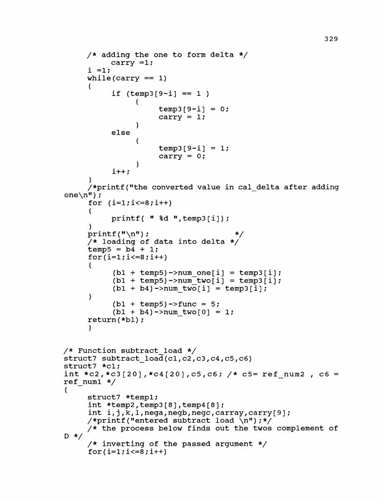
/ * adding the one to form delta */ carry =1;
i =1; while(carry == 1)
temp3[9-i] = 0; carry = 1;
1 else
carry = 0; 1
i++ ; 1 /*printf("the converted value in cal - delta after adding
one\ngg ) ; for (i=l;i<=8;i++) {
printf( " %d gg,temp3[i]); 1 printf (gf\ngg) ; */ / * loading of data into delta */ temp5 = b4 + 1; for(i=l;i<=8;i++) {
(bl + temp5)->num one[i] = temp3[i]; (bl + temp5) ->num-two[i] = temp3 [i] ; (bl + b4) ->num two[i] = temp3[i] ; -
(bl + temp5)->func = 5; (bl + b4)->num two[O] = 1; -
return (*bl) ; 1
/* Function subtract load */ struct7 subtract - load(cl,c2,~3,~4,c5,~6) struct7 *cl; int *c2, *c3 [20], *c4 [20] ,c5,c6; / * c5= ref - num2 , c6 = ref - numl */ {
struct7 *tempi; int *temp2,temp3[8],temp4[8]; int i,j,k,l,nega,negb,negc,carray,carry[93; /*printf("entered subtract load \nn);*/ / * the process below finds out the twos complement of
D */ / * inverting of the passed argument */ for (i=l; i<=8 ; i++)

{ temp3[i] = 0;
1 else
1 1 / * adding the one to form delta */ carray = 1; i = 1; while(carray == 1)
{ temp3[9-i] = 0; carray = 1;
1 else
{ temp3[9-i] = 1; carray = 0;
1 i++ ;
} / * the twos complemnt is calculated */ /*printf (I1 the twos complement of D \nIf) ; for (i=l;i<=8;i++) {
printf ( " the value of i = %d\nfl,i) ; printf ( %d\n If, temp3 [i] ) ;
} printf (ll\nlt) ; */ / * the below segment adds N and D1s 2's complement */ carry[O] = 0; carry[l] = 0; for (i=l; i<=8 ;++i)
{ / * printf (I1 the value of iteration \nl') ; */
nega = 0; negb = 0; negc = 0;
/ * printf (I 1 the value of * (c3 [c5]+ (9-%d) ) = %d\nn,i,*(c3[c5]+(9-i))); */
if ( * (c3 [c5]+ (9-i) ) == 0) {
nega = 1; 1
/ * p r i n t f ( I f t h e v a l u e of temp3 [9-%dl =

{ negb = 1;
1 if(carry[i] == 0)
{ negc = 1;
1 temp4 [i] = ( ( ( ( * (c3 [c5]+(9-i) ) *negb*negc)
I(temp3[9-i]*nega*negc)) I (carry[i]*nega*negb)) I ( * (c3 [c5]+(9-i) ) *temp3 [9-i]*carry[i]) ) ; /* printf(" the partial product of temp 4 with i = %d\nfl, i) ;
printf( %d \nw,temp4[i]); */ carry[i+l] =(*(c3[c5]+(9-i))*temp3[9-i]) I
(carry[i]**(c3[c5]+(9-i)) I (temp3[9-i]*carry[i])); 1
/ * printf (I1 the value of N - D \nl*) ; for (i=l;i<=8;i++) {
printf( %d ",temp4[i]); 1 printf (l1\nW) ; */ / * loading of N - D into num - one */ for(i=l;i<=8;i++)
{ (cl + c6) ->num - one[9-i] = temp4 [i] ;
1 return (*cl) ;
1
/ * Function compare & load */ struct7 compare - load(alIa2,a3,a4,a5,a6) struct7 *al; int *a2 [20], *a3[20] ,a4,a5, *a6; / * a4 -> ref - num2 , a5 -> ref - numl */ { / * a2 -> argl; a3 -> arg2; a6 -> func */
struct7 *tempi; i n t
*temp2,*temp3,temp4,*temp51iIjIk111flag one,flag - two; / * the comparison of the two arguments */ flag one = 0; flag-two = 0 ; for (T=l; i<=8 ; i++) {
if ( * (a2 [a4]+i) > * (a3 [a4]+i) ) {
flag one = 1; - i = 8;
1

if ( * (a2 [a4]+i) < * (a3 [a4]+i) ) {
flag-two = 1; i = 8 ;
1 1 if(f1ag - two == 1) { for (i=l;i<=8;i++) {
(al+a5)->num-one[i] = *(a2[a4]+i);/* argl loaded into numl */
} /*printf(" the value of d is greater than n\nv);*/
(al+a5) ->func = * (a6+a4) ;/* function value is loaded */
/*printf(" the value of opcode loaded in compare&load is %d\nl1, (al+a5) ->func) ; */
cal delta(al,a3, a4, a5) ;/* loading of delta into num2 and creating delta line */
(a1 + a5)->over - flow = 0; 1 else { / * printf (I1 the value of n is greater than d\nn) ;*/
(al+a5) ->func = * (a6+a4) ; /* function value is loaded */
/*printf(" the value of opcode loaded in compare&load is %d\nw , (al+a5) ->func) ; */
cal delta(a1, a3, a4, a5) ;/* loading of delta into num2 and creating delta line */
(a1 + a5)->over - flow = 1; 1 return (*al) ;
1
/ * Function pre processor */ struct7 pre proc(numl,num2,num3,num4) struct7 *numi ; int *num2,*num3[20],*num4[20];/* num2 -> function; num3 -> argumentl; */ { /* num4 -> argument4 */
/ * intialisations */ struct7 *templ,*temp2; int *temp3,*temp4,*temp5; int temp - flagl,temp-flag2,temp-flag3; int i,j,k,l,ref num1,ref - num2,ref_num3;
temp1 = numlT / * the testing of the type of function */

ref numl = I;/* indexing pre processor structure */ ref-num2 = I;/* indexing the data array */ ref-num3 = 0; forTref - num2=l;ref - num2<=stk - ptr;ref - num2++)
/*printf ("the value of the condition is %d\nI1, * (num2 + ref - num2)) ;
printf(I1the present value of ref - numl %d \nn , ref numl) ; */
swTtch (* (num2 + ref-num2) ) { case 1: / * printf(" case number one \nw); */ (numl+ ref numl) ->func = * (num2 + ref - num2) ; for(i=l;i<=8;i++) { (numl+ ref num1)->num one[i] = *(num3[ref num2]+i); (numl+ ref-num1)->num-two[i] - - = *(num4[ref-num2]+i); -
1 (numl+ ref num1)->over flow = 0; (numl+ ref-num1)->weight = 0; / * of the input stack */ /*for(i=l;i<=ref - numl;i++) {
printf (I1 the input stack is printed below with ref - numl as %d \ntl, ref numl) ;
printf (Itthe opcode is %d\nt1 , (numl + i) ->func) ; printf (Itthe value of argument one is as follows
\nu) ; for(j=l;j<=8;j++)
{ p r i n t f ( " % d " , ( n u m l +
i)-mum - one[j]);
printf ("\nW) ; printf(I1the value of argument two is as follows
\nn) ; for(j=l;j<=8;j++)
1 printf ("\nN) ;
1 */ ref numl = ref numl + 1; /*printf ( " reached break at case one \nll) ; */ break;
case 2: / * printf ( " case number two \nw ) ; */
(numl+ ref num1)->func = *(num2 + ref-num2); for (i=l ; icz8 ; i++)

{ (numl+ ref num1)->num one[i] = *(num3[ref num2]+i); (numl+ r e f - numl) ->num-two[i] - = * (num4 [ref-num2]+i) - ; ) (numl+ ref num1)->over flow = 0; (numl+ ref-num1)->weigEt = 0; /*~rintf(~reached the printing stage in case two\nI1);
printf ( " the present value of ref - numl in case 2 %d \ngl, ref numl) ; */
/*-printing of the input stack */ i=O ;
/ * for(i=l;i<=ref - numl;++i) {
printf (I1 the input stack is printed below with ref - numl as %d \nl1,ref numl) ;
printf ("the zpcode is %d\nN, (numl + i) ->func) ; printf("the value of argument one is as follows
\n") ; for(j=l;j<=B;j++)
{ p r i n t f ( " % d " , ( n u m l +
i)->num - one[j]) ; )
printf ("\nu) ; printf("the value of argument two is as follows
\nw ) ; for(j=l;j<=B;j++)
{ p r i n t f ( I 1 % d It, ( n u m l +
i) ->num - two [ j ] ) ; 1
printf (I1\n1l) ; 1 */ ref numl = ref - numl + 1; break;
case 3: / * printf ( " case number three \nu) ;*/
(numl+ ref num1)->func = *(num2 + ref - num2) ; for(i=l;i<EB;i++) { (numl+ ref numl) ->num one[i] = * (num3 [ref num2]+i) ; (numl+ ref-numl) - ->num-two - [i] = * (num4 [ref-num2) - +i) ; 1 (numl+ ref num1)->over flow = 0; (numl+ ref-num1)->weight = 0; / * printing of the input stack */ /*for(i=l;i<=ref - numl;i++) {
printf (I1 the input stack is printed below with ref - numl as %d \nw , ref - numl) ;

printf (Ifthe opcode is %d\nI1, (numl + i) ->func) ; printf (Itthe value of argument one is as follows
\nw) ; for(j=l;j<=8;j++)
{ p r i n t f ( I 1 % d " , ( n u m l +
i)->num - one[j]) ; 1
printf ("\nH) ; printf(I1the value of argument two is as follows
\n") ; for(j=l;j<=8;j++)
{ p r i n t f ( " % d " , ( n u m l +
i)->num - two[j]) ; 1
printf ("\nV1) ; 1 */ ref numl = ref numl + 1; - break ;
case 4: /* the division case */ /*printf ( " case number four \nn) ; printf (I1 entering compare load \nw) ; */ compare load (numl, num3, nui4, ref num2, ref numl , num2) ; - - -
if((num1 + ref - num1)->over - flow == 1) {
subtract - load(numl,num2,num3,num41ref - num2,ref - numl); 1 )* printing of the input stack */ /*for(i=l;i<=ref - numl;i++) {
printf (I1 the input stack is printed below with ref - numl as %d \nw,ref numl);
printf (Ifthe opcode is %d\nl1, (numl + i) ->func) ; printf("the value of argument one is as follows
\nV1 ) ; for(j=l;j<=8;j++)
{ p r i n t f ( " % d " , ( n u m l +
i) ->num - one[j ] ) ; 1
printf (n\nu) ; printf("the value of argument two is as follows
\nW) ; for(j=l;j<=8;j++)
{ p r i n t f ( " % d 11, ( n u m l +
i) ->num - two[ j ] ) ; 1

printf (I1\n") ; 1 */ ref numl = ref - numl + 2; break ; 1 1 return (*numl) ;
1
void print outstack (duml) struct8 *diml; {
struct8 *tempi; int i,j,k,l; templ = duml; for(i=O;i<=2O;i++) { printf ("\nl1) ; printf (ll\nll) ; ~rintf(~ the original 1 . S number \nw); printf (I1 %d \nw , (templ+i) ->destination) ; printf (ll\nM) ; printf ("\nI1) ; printf (I1 The result of the instruction (16 - 0) \nql) ; printf ("\nW) ; printf (ll\nn) ; printf (ll\nll) ;
{ printf (I1 %d It, (templ+i) ->result [l6-j ] ) ;
1 printf ("\nn) ; printf ("\nm) ; printf (ll\nll) ; 1
1
void print-psstack(dum1) struct9 *duml; {
struct9 *tempi; int i,j,k,l; templ = duml; for(i=O;i<=20;i++) { printf ("\nl1) ; printf ("\nfl) ; printf(" the tracking register number \nw); printf (I1 %d \nvl, (templ+i) ->address) ; printf ("\nW) ; printf (I1\nn) ;

printf (I1 the function number \nW ) ; printf (I1 %d \nu, (templ+i) ->func) ; printf ("\nW) ; printf ("\nW) ; printf (If The result of the num - one (0 - 8)\nV1) ; printf ("\nW) ; printf ("\nW) ; printf ("\nW) ; for(j=O;j<=8;j++) {
printf (It %d 11, (templ+i) ->num - one[ j ] ) ; 1 printf (I1\nw) ; printf (I1\nw) ; printf (I1 The result of the num - two (0 - 8) \nw ) ; printf (ll\n") ; printf ("\nI1) ; for(j=O;j<=8; j++) {
printf (I1 %d 11, (templ+i) ->num - two[j ] ) ; 1 printf (ll\n") ; printf ("\nW) ; printf (ll\n") ; printf (l1\nl1) ; 1
}
..........................................
.......................................... /******* Function Output Check **********/ .......................................... ..........................................
struct8 output check(num0,numl,num2,num3,num4,num41num51num61 num7, num8, num9)- struct2 *numO; / * pointer to trans-pointer */ struct9 *numl; /* pointer to priority stack */ struct8 *numa; /* pointer to output structure */ struct3 *num3; / * pointer to div trac */ struct4 *num4; / * pointer to mult trac */ struct5 *num5; / * pointer to add trac */ struct6 *num6; / * pointer to logg sheet */ struct5 *numi'; / * pointer to sub track */ struct3 *num8; / * pointer to delta track */ structl *num9; /* pointer to multi-purpose registers*/ { struct9 *templ; / * pointer to priority registers */ struct2 *tempo; / * pointer to cross collision matrices */
struct8 *temp2; /* pointer to output structure */

struct3 *temp3; / * pointer to div trac */ struct4 *temp4; / * pointer to mult trac */ struct5 *temp5; / * pointer to add trac */ struct6 *temp6; / * pointer to logg sheet */ struct5 *temp7; /* pointer to sub track */ struct3 *temp8; /* pointer to delta track */ structl *temp9; /* pointer to mpreg */ int i,j,k,l,remainder,local - index,future - index,get - out; temp0 = num0; temp2 = num2; temp3 = num3; temp4 = num4; temp5 = num5; temp6 = num6; temp7 = num7; temp8 = num8; temp9 = num9; temp1 = numl;
/ * checking of add trac */ if((temp6+1)->logg - stat-== 1) {
printf(" add output - check is engaged \nw); for(i=l;i<=g?i++) {
if ( (temp6+1) ->logg[i] == 1) {
if ( (temp5+i) ->st - track[l] == 1) {
printf (It the output of add is being
k = (temp5+i) ->address; for(j=O;j<=l6;j++) {
( t e m p 2 + k ) - > r e s u l t [ j ] =
(temp0+2 0) ->word [ j ] ; 1 for(j=O;j<=6;j++) {
(temp5+i) ->st - track[ j ] = 0; 1
(temp6+1) ->logg[i] = 0; 1
1 1 printf(" THE OUTPUT STACK AFTER LOADING ADDITION\nvv);
print - outstack(num2); 1
/* checking of sub trac */ if((temp6+2)->logg - stat-== 1) {
printf(" sub - output - check is engaged \nn);
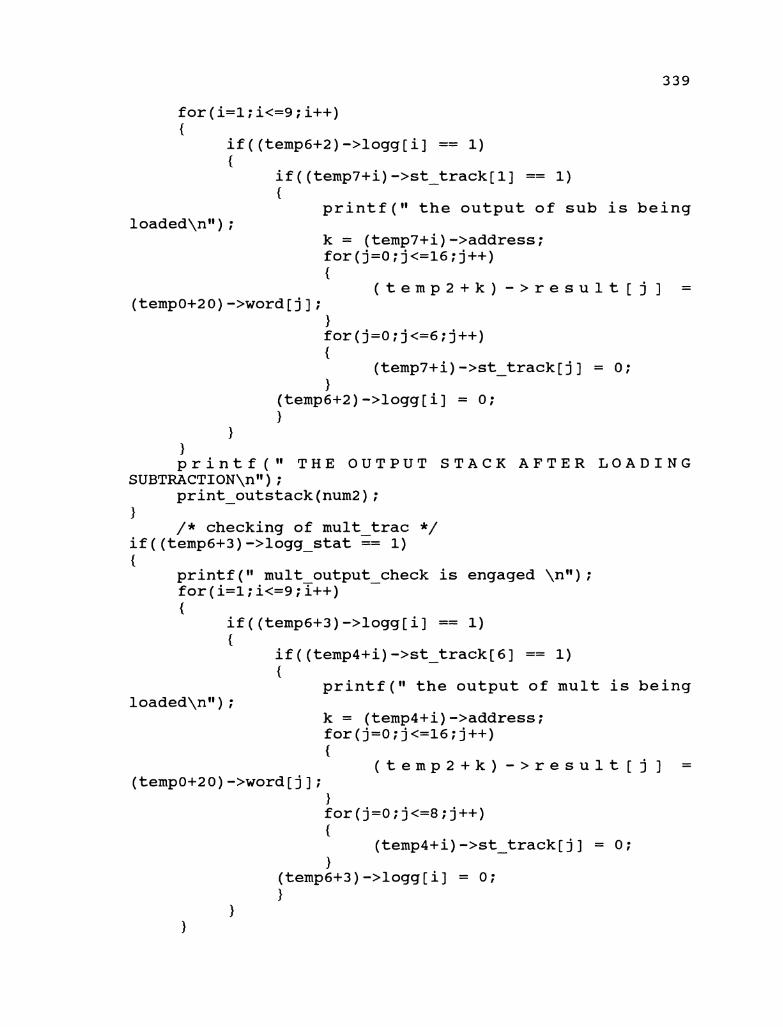
for(i=l;i<=g;i++) {
if ( (temp6+2) ->logg[i] == 1) {
if ( (temp7+i) ->st - track[l] == 1) {
printf (I1 the output of sub is being 1 oaded\ntt ) ;
k = (temp7+i) ->address; for(j=O;j<=l6;j++) {
( t e m p 2 + k ) - > r e s u l t [ j ] = (temp0+20) ->word[ j ] ;
1 for(j=O;j<=6;j++) {
(temp7+i) ->st - track[ j ] = 0; 1
(temp6+2) ->logg[i] = 0; 1
1 1 p r i n t f ( " T H E O U T P U T S T A C K A F T E R LOADING
SUBTRACTION\nl1) ; print - outstack(num2);
1 /* checking of mult trac */ if ( (temp6+3) ->logg - stat := 1) {
print£(" mult output - check is engaged \nw); for(i=l;i<=g;T++) {
if((temp6+3)->logg[i] == 1) {
if((temp4+i)->st - track[6] == 1) {
printf ( " the output of mult is being loaded\nw) ;
k = (temp4+i) ->address; for (j=O;j<=16;j++) {
( t e m p 2 + k ) - > r e s u l t [ j ] =
(temp0+20) ->word[ j ] ; 1 for(j=O;j<=8;j++)

printf(" THE OUTPUT STACK AFTER LOADING MULTIPLICATION \nrl) ;
print - outstack(num2); 1
/ * checking of div trac */ if((temp6+4)->logg - stat-== 1) {
printf(" div output - check is engaged \nu); for(i=l;i<=g?i++)
/ * Division is present and the result */ / * is ready to be iterated or sent to */ / * priority stack. Checking for delta */ / * or for the iteration number in the div
track registers */ /* calculating the remainder */ get out = 0; remainder = 0; for(j=8;j<=15;j++) {
remainder = remainder + (temp0 + 20) ->word[ j ] ;
I
if ( ( (temp3+i) ->itr track == 4) 1 I (remainder - == 0))
{ printf (I1 the output of div is being
loaded\n1I) ; (temp3+i)->itr track = 0; k = (temp3+i) -,address; for(j=O;j<=l6;j++) {
( t e m p 2 + k ) - > r e s u l t [ j ] = (temp0+21) ->word[ j ] ;
1 for(j=O;j<=8;j++) {
(temp3+i) ->st track[ j ] = 0; (temp8+i)->st-track[j] - = 0;
I (temp6+4)->logg[i] = 0; (temp6+5) ->logg[i] = 0;
(temp3+i)->itr track=O; (temp8+i) ->itr-track=0; -
get out = 1; - }

if (get - out == 0) { / * the iteration has to be carried out */ printf(" the data is going to be stored in
P. S\n1I) ;
/ * loading of data in priority stack */ local index = (temp9 + 0)->bits[9]; future index = local index + 1; /* loading of data */ for(j=O;j<=7;j++) { (templ+local index)->num one[j] = - -
(temp0+21) ->word[l5-j ] ; (templ+local index) ->num two [ j+l] = - -
(temp0+20) ->word[15-j ] ; (templ+future index)->num one[j] = - -
(temp0+20) ->word[15-j ] ; (templ+future index)->num two[j+l] = - -
(temp0+20) ->word[15-j ] ; 1 (temp9 + 0)->bits[9] = future index+l ; (templ+local index)->num two[E] = 1; / * setting of priority fiag */ if ( (temp9+0) ->bits [9] == (temp9+0) ->bits [0] )
{ printf(" the priority flag is set to 1
(temp9+0) ->bits[l] = 1; 1 / * Initialising the track register */ (templ+local index)->address = i; (templ+future index) ->address= i; (templ+local Index)->func = 4; (templ+future index)->func = 5; / * initialising the registers to zero */
for(j=O;jc=8;j++)
printf(I1 the priority stack is printed below \nn) ;
print psstack (templ) ; - 1

1 ) printf (I1 THE OUTPUT STACK AFTER WADING DIVISION \ntl) ;
print outstack(num2) ; - 1
return (*num2 ) ; 1
..........................................
.......................................... /******* Function Shift Track **********/ /**********************%*****************I ..........................................
void shift track(numl,num2,num3,num4,num5,num6) struct3 *numl,*num6; /* pointer to div trac and delta track */ struct4 *num2; /* pointer to mult trac */ struct5 *num3,*num5; / * pointer to add trac and sub track */ struct6 *num4; /* pointer to logg sheet */ { struct3 *templ; /* pointer to div track */ struct4 *temp2; / * pointer to mult track */ struct5 *temp3; /* pointer to add track */ struct6 *temp4; /* pointer to logg sheet */ struct5 *temp5; / * pointer to sub track */ struct3 *temp6; / * pointer to delta track */
int i,j,k,l; temp1 = numl; temp2 = num2; temp3 = num3; temp4 = num4; temp5 = num5; temp6 = num6;
/* shifting of add trac */ if ( (temp4+1) ->logg-stat-== 1) {
printf(I1 add - track is engaged to be shifted\nl1); for(i=l;i<=g;i++) {
if((temp4+1)->logg[i] == 1) {
for(j=l;j<=8;j++) { if ( (temp3+i) ->st track[ j ] == 1) - {

1 1
1 1
1 / * shifting of sub trac */
if((temp4+2)->logg - stat-== 1) {
printf (It sub track is engaged to be shifted\nl1) ; for(i=l;i<=gTi++) {
if((temp4+2)->logg[i] == 1) {
for(j=l;j<=8;j++) { if ( (temp5+i) ->st track[ j ] == 1) - {
(temp5+i) ->st track[ j+l] = 1; (temp5+i) ->st-track[ j ] = 0; - j=9;
1 1
1 1
1 / * shifting of mult trac */ - if((temp4+3)->logg-stat == 1) {
printf (If mult track is engaged to be shifted\nIf) ; for(i=l;i<=9;i++)
/ * shifting of div trac */ if((temp4+4)->logg - stat-== 1) f
printf (Ig div track is engaged to be shifted\nl1) ; for(i=l;i<=gYi++) {

/ * shifting of delta trac */ if((temp4+5)->logg-stat =: 1) {
printf(It delta track is engaged to be shifted\ntt); for(i=l;i<=g;iT+) {
if((temp4+5)->logg[i] == 1) {
for(j=l;j<=8;j++) { if ( (temp6+i) ->st-track[ j ] == 1) {
1 1
1 1 1 void status printl(numl,num2,num3) structl *nuil; struct5 *num2; struct6 *num3; {
structl *duml; struct5 *dum2; struct6 *dum3; int iIj,kIl; duml = numl; duma = num2; dum3 = num3;
printf("printing the pipeline register and flag register and tracking registers and status logg\ntt);
printf (tt\ntt) ; printf ("\ntt) ;

printf ( " the input registers ( 8 - 0 )\nI1) ; printf ("\nu) ; printf ("\nM) ; printf(" the input register mpreg + 1 \nw); for(j=O; j<=7; j++) { printf (I1 %d 11, (duml+l) ->bits[7-j ] ) ; 1 printf ("\nW) ; printf (ll\nll) ; printf ( " the input register mpreg + 2 \nV1) ; for(j=O; j<=7; j++) { printf (I1 %d ", (duml+2) ->bits[7-j 1 ) ; 1 printf ("\nW) ; printf (It\nw) ; printf (It 'the flag register \nI1) ; printf ("\nu) ; printf (ll\nll) ; ~rintf(~ the flag register is mpreg + 0 \nw); for(i=O;i<=lO;i++) { printf (I1 %d (duml+O) ->bits [lo-i] ) ; 1 printf (lt\nl1) ; printf (It\nw) ; printf(" the logging register for add\nw); for(i=l;i<=g;i++) { printf ( " %d 11, (dum3+1) ->logg[9-i]) ; 1 printf ("\nW) ; printf ("\nW ) ; printf(" the tracking registers \nw); for(i=l;i<=g;i++) {
if ( (dum3+1) ->logg[i] == 1) {
printf(" the tracking register number is %d and the value of the address is %d \ntl,i, (dum2+i) ->address ) ;
printf (I1\nw) ; for(j=l;j<=8;j++) {
printf (I1 %d ", (dum2+i) ->st - track[8-j ] ) ; 1
printf ("\nM) ; printf ("\nW) ;

void status print2(numllnum2,num3) structl *nuGI; struct5 *num2; struct6 *num3; {
structl *duml; struct5 *dum2; struct6 *dum3; int iljlkll; duml = numl; duma = num2; dum3 = num3;
printf("printing the pipeline register and flag register and tracking registers and status logg\nrr);
printf ("\nrr) ; printf ("\nW) ; printf ( " the input registers ( 8 - 0 )\nn) ; printf ("\nn) ; printf ("\nrr) ; printf(" the input register mpreg + 1 \nw); for(j=O; j<=7; j++) ( printf ( " %d It, (duml+l) ->bits [7-j ] ) ; 1 printf ("\nu) ; printf ("\nW) ; printf(" the input register mpreg + 2 \nw); for(j=O; j<=7; j++) ( printf ( " %d It, (duml+2) ->bits[7-j 1 ) ; 1 printf ("\nu) ; printf ("\nW) ; printf (Ir the flag register \nw) ; printf ("\nW) ; printf ("\nrl) ; printf(" the flag register is mpreg + 0 \nrr); for(i=O;i<=lO;i++) { printf(" %d It, (duml+O) ->bits [lo-i] ) ; 1 printf ("\nu) ; printf ("\nrl) ; printf(" the logging register for sub\nn); for(i=l;i<=9;i++) ( printf (Ir %d , (dum3+2) ->logg[9-i] ) ;
printf ("\nVr) ; printf ("\nW) ; printf (Ir the tracking registers \nw) ;

for(i=l;i<=g;i++) {
if ( (dum3+2) ->logg[i] == 1) {
printf(I1 the tracking register number is %d and the value of the address is %d \nI1,i, (dum2+i) ->address 1 ;
printf ("\ntl) ; for(j=O;j<=8;j++) {
printf ( n %d 11, (dum2+i) ->st track[8-j ] ) ; -
printf (l1\nt1) ; printf ("\nW) ;
1 1
1 void status print3(numl,num2,num3) structl *nuGI; struct4 *num2; struct6 *num3 ; {
structl *duml; struct4 *dum2; struct6 *dum3; int ilj,kll; duml = numl; duma = num2 ; dum3 = num3;
~rintf(~Iprinting the pipeline register and flag register and tracking registers and status logg\nI1);
printf ("\nV1) ; printf ("\nn) ; printf (I1 the input registers ( 8 - 0 )\nI1) ; printf (I1\nl1) ; printf (l1\nl1) ; printf (I1 the input register mpreg + 3 \ntl) ; for(j=O;j<=8;j++) { printf (I1 %d Il l (duml+3) ->bits [8-j ] ) ; 1 printf (ll\nw) ; printf (I1\n1l) ; printf ( " the input register mpreg + 4 \nI1) ; for(j=O;j<=8;j++) { printf ( " %d If, (duml+4) ->bits [8- j ] ) ; 1 printf ("\n1I) ; printf (I1\nw) ; printf(" the flag register \nw); printf ("\n1I) ;

printf (lt\nU) ; printf(It the flag register is mpreg + 0 \nw); for(i=O;i<=lO;i++) { printf(" %d w,(duml+~)->bits[lO-i]); 1 printf ("\nV1) ; printf (I1\nM) ; printf (I1 the logging register for add\nIf) ; for(i=l;i<=lO;i++) { printf (I1 %d ", (dum3+3) ->logg[9-i] ) ; 1 printf ("\nW) ; printf (n\nn) ; printf (It the tracking registers \nH) ; for(i=l;i<=g;i++) {
if ( (dum3+3) ->logg[i] == 1) {
printf(ll the tracking register number is %d and the value of the address is %d \ntt,i, (dum2+i) ->address 1 ;
printf ("\nW) ; for(j=l;j<=8;j++) {
printf (If %d If, (dum2+i) ->st track[8-j ] ) ; -
printf ("\nu) ; printf (I1\n1') ;
1 1
1 Goid status print4 (numl, num2 , num3) structl *nuiil; struct3 *num2; struct6 *num3; {
structl *duml; struct3 *dum2; struct6 *dum3; int i,j,k,l; duml = numl; dum2 = num2; dum3 = nurn3;
printf ("printing the pipeline register and flag register and tracking registers and status logg\nIt);
printf ("\nI8) ; printf ("\n8I) ; printf ( " the input registers ( 8 - 0 )\ntv) ; printf ("\nW) ; printf ("\nW) ;

printf(IV the input register mpreg + 3 \nn); for(j=O; j<=8; j++)
1 printf (Ig\ngt) ; printf (I1\n") ; printf ( " the input register mpreg + 4 \nV1) ; for(j=O; j<=8; j++) { printf (IV %d ", (duml+4) ->bits [8-j 1 ) ; 1 printf ("\nu) ; printf ("\nW) ; printf (It the flag register \ntl) ; printf ("\nW) ; printf ("\nVt) ; printf(lV the flag register is mpreg + 0 \n") ; for(i=O;i<=lO;i++) { printf ( " %d ", (duml+O) ->bits [lo-i] ) ; 1 printf ("\nun) ; printf ("\nW) ; printf ( " the logging register for div\nvv) ; for(i=l;i<=g;i++) { printf(" %d w,(dum3+4)->logg[9-i]); 1 printf ("\nW) ; printf ("\nu) ; printf (Iw the tracking registers \nw) ; for(i=l;i<=g;i++) {
if ( (dum3+4) ->logg[i] == 1) {
printf(" the tracking register number is %d and the value of the address is %d \nw, i, (dum2+i) ->address ) :
printf (n\nw) ; for(j=l;j<=8;j++) {
printf (It %d 'I, (dum2+i) ->st - track[8-j ] ) ; 1
printf ("\nu) ; printf (tV\nll) ;
1 1
1 .......................................... .......................................... ..........................................

/******* Function Load Pipeline *********/ ..........................................
................................... /***** 0. P.F indicator. ********/ /***** 1. Priority Flag. ********/ /***** 2. Stack Index. ********/ /***** 3. CCM Pointer. ********/ /***** 4. ADD Latency. ********/ /***** 5. SUB Latency. ********/ /***** 6. MULT Latency. ********/ /***** 7. DIV Latency. ********/ /***** 8. Priority Index. ********/ /***** 9. Local Index. ********/ ...................................
structlload pipeline(num0,numl,num2,num3,num4,num5, num6,num7,num8,num9,numl0,numll,numl2) structl *numO; / * pointer to input registers */ structO *numl; /* pointer to cross collision matrices */ struct7 *num2; / * pointer to input structure */ struct3 *num3; / * pointer to div trac */ struct4 *num4; / * pointer to mult trac */ struct5 *num5; / * pointer to add trac */ struct6 *num6; / * pointer to logg sheet */ struct9 *numlO; / * pointer to priority structure */ struct5 *numll;/* pointer to subtract trac */ struct3 *numl2;/* pointer to delta trac*/ int num7,num8,num9; / * registers */ { structl *tempo; / * pointer to input registers */ structO *tempi; / * pointer to cross collision matrices */ struct7 *temp2; / * pointer to input structure */ struct3 *temp3; / * pointer to div trac */ struct4 *temp4; / * pointer to mult trac */ struct5 *temp5; / * pointer to add trac */ struct6 *temp6; / * pointer to logg sheet */ struct9 *templo;/* pointer to priority structure*/ struct5 *templl;/* pointer to subtract trac */ struct3 *templ2;/* pointer to delta trac*/ i n t i,j,k,l,priority - flag,stack - index,matrix index,look ahead; - -
intpriority - index,additional - entry,divisional - entry,dis;

init key = 0; delta flag = 0; addition = 0; subtraction = 0; multiplication = 0; division = 0; temp0 = num0; temp1 = numl; temp2 = num2; temp3 = num3; temp4 = num4; temp5 = num5; temp6 = num6; temp10 = numl0; temp11 = numll; temp12 = numl2; priority - flag = (num0+0)->bits[l];/*loading the priority flag */ stack index = (numO+O) ->bits [a] ;/* loading the current instruction location */ matrix index = (num0+0) ->bits [3] ;/* loading the current address of CCM */ priority index = (temp0+0)->bits[8]; look - ahead = stack index + 1;
/ * checking for any priority situation */ if (priority - flag == 1) {
printf (I1 the priority flag is one and entering case f nc\n1I) ;
switch((templ0 + priority - index)->func) { case 4: if((templ+matrix index)->smatrix.bits - row1
[ (temp0+0) ->bits [lo] 1 == 0) {
/ * in here it will be determined wether div */ / * can be added to pipe with add or sub*/ printf(" div is posibble and checking to see if
additional functions are possible and main case is 4 \n1I);
case 1: if((templ+matrix - index)->smatrix.bits - row3
[ (tempO+O) ->bits [lo] 1 == 0) {
divisional entry = 1; printf ( " divisional entry is l\ngl) ; printf (It addition is also possible\nn) ;
1 else

{ divisional entry = 0; printf(I1 though addition is the next
instruction no latency is available \n1I); printf(" divisional entry is O\n1I);
1 break;
case 2: if((templ+matrix - index)->smatrix.bits - row3
[ (tempO+O) ->bits [lo] 1 == 0) {
divisional entry = 2; printf (I1 dTvisional entry is 2\nss) ; printf ( I 1 s u b t r a c t i o n i s also
possible\nw) ; 1 else {
divisional entry = 0; printf ( " though subtraction is the next
instruction no latency is available \nw); printf ( " divisional entry is O\nsl) ;
1 break;
default : divisional entry = 0; printf ( " only division is possible \nI1) ;
printf ( " divisional entry is O\n1l) ; break;
1 1 else {
printf("no latency available to process p.s\nu);
(tempO+O)->bits[10]+=1; p r i n t f ( I 1 t h e n e x t l a t e n c y i s
%d\nn, (tempO+O) ->bits[10] ) ; printf(" initialising the input registers to
0\n1l) ; init key =l; for(T=o;ie=8;i++) {
(tempO+l) ->bits[i] = 0; (temp0+2) ->bits[i] = 0; (temp0+3) ->bits [i] = 0; (temp0+4)->bits[i] = 0;
1 1 break; case 5:

printf(" the case is 5 and delta is being loaded in priority stack is 1 \n1I) ;
for(j=O; j<=7; j++) {
/ * this part will initiate the trackng registers */
dis = (temp10 + priority index)->address; (temp12 + dis)->st track711 =1; -
/* initialising the registers */
(temp0+0) ->bits [8]+=1; divisional entry = 4; delta flag-= 1; -
/* re initialising the priority index */
/* checking and initialising the priority flag */
printf ( " the priority flag is init to 0 \nit); -
(temp~+O) ->bits [1] = 0; / * setting of priority index */ (ternp~+O)->bits[O]+=2;
)
/ * printing of the results of case 5 */ printf("printing the pipeline register and flag
register\nI1) ; printf ("\nu) ; printf ("\n1I) ; printf (I1 the input registers temp0 + 3 (7 -
0) \nll) ; printf ("\nu) ; printf (l1\nl1) ;

for ( j=O; j<=7; j++) { p r i n t f ( I t %d ", (temp0+3) - > b i t s [ 7 - j ] ) ; 1 p r i n t f ( t v \ n w ) ; p r i n t f (" \nu) ; p r i n t f ( " t h e i n p u t r e g i s t e r s t e m p 0 + 4 ( 8 -
0 ) \nl1) ; p r i n t f (" \nW) ; p r i n t f (I1\nw) ; fo r ( j=O; j<=8; j++) { p r i n t f ( " %d ", (temp0+4) - > b i t s [8- j ] ) ; 1 p r i n t f ( l l \nll) ; p r i n t f ("\n1I) ; p r i n t f ( I 1 t h e f l a g r e g i s t e r 8 - O\nfv) ; p r i n t f ( " \nW) ; p r i n t f (" \nW) ; fo r ( i=O; i<=8; i++) { p r i n t f ( I 1 %d I!, (temp0+0) - > b i t s [8- i ] ) ; 1 p r i n t f (" \nW) ; p r i n t f (" \nt t ) ; p r i n t f ( " t h e logging r e g i s t e r s 9 - O\nw); p r i n t f (" \nW) ; p r i n t f (" \nW) ; f o r (i=l; i < = 9 ; i + + ) { p r i n t f ( I 1 %d ", (temp6+5) ->logg[9-i]) ; 1 p r i n t f ( l t \nl l ) ; p r i n t f ( t f \ n w ) ; p r i n t f ( " t h e t r a c k i n g r e g i s t e r s \ n w ) ; p r i n t f (" \nW) ; p r i n t f (" \nu) ; f o r ( i = l ; i < = g ; i + + ) { i f ( (temp6+5) -> logg[ i ] == 1) { p r i n t f ( " t h e t r a c k i n g r e g i s t e r number is %d and
t h e va lue of t h e address is %d \n", i, (templ2+i) ->address) ;
p r i n t f ( l8\nN) ; p r i n t f (" \nW) ; fo r ( j=O; j<=8; j++) { p r i n t f ( " %d I!, ( templ2+i) ->st t rack[8- j ] ) ; - 1 1 1

printf ("\r~*~) ; printf ("\nW) ;
break; 1
/* this section below assigns the values for case 4 */
switch (divisional - entry) { case 0: / * the division is being loaded */
printf ( I 1 t he latency is available for iteration\nI1) ;
/* loading the arguments into the stage div */ for(j=O;j<=7; j++) {
( t e m p 0 + 3 ) - > b i t s [ j ] - - (templO+priority - index)->num - one[j];
1 for(j=O;j<=8;j++) {
( t e m p 0 + 4 ) - > b i t s [ j ] - - (templO+priority - index)->num - two[j];
1 ( t e m p O + O ) - > b i t s [ 3 ] - -
(templ+matrix index)->sdirection.div latency - [(temp0+0)->bits[To]];
/ * this part will initiate the trackng registers */
dis = (temp10 + priority index)->address; (temp3 + dis)->st - track[i] =1;
(temp0+0) ->bits [lo] = 0; (tempO+O)->bits[8]+=1;
printf(I1 the division status is printed below in case O\n iteration \nt1);
status print4(tempO,temp3,temp6); division = 1; break;
case 1: / * the addition is being loaded */ printf ( " the latency is available for
iteration\nl1) ; / * loading the arguments into the stage add */ for(j=O;j<=7; j++) {
( t e m p O + l ) - > b i t s [ j ] - - (temp2+stack - index)->num-one[j+l];
( t e m p 0 + 2 ) - > b i t s [ j ] - - (temp2+stack - index) ->num-two[j+l] ;

1 ( t e m p O + O ) - > b i t s [ 3 ] - -
( t e m p l + m a t r i x i n d e x ) - > s d i r e c t i o n . d i v - add [ (temp0+0) ->bits [lo71 ;
(tempO+O)->bits[2]+=1; addition = 1; / * this part will initiate the trackng
registers */ for(i=l;i<=9;i++) { if ( (temp6+1) ->logg[i] == 0) { (temp6+1)->logg[i] = 1; (temp5+i)->st track[l]=l; ( t e m p 5 q i ) - > a d d r e s s - -
(temp2+look - ahead)->location; i=lO; 1 1
printf(lV the addition status is printed below in case 1 in iteration\nw);
status printl(tempOItemp5,temp6); / * the-division is being loaded */ printf (I1 the latency is available in iteration
\nW) ; /* loading the arguments into the stage div */ for(j=O; j<=7; j++)
( t e m p O + O ) - > b i t s [ 3 ] - - ( t e m p l + m a t r i x i n d e x ) - > s d i r e c t i o n . d i v - a d d [ (temp0+0) ->bits [lo71 ;
/ * this part will initiate the trackng registers */
dis = (temp10 + priority index)->address; (temp3 + dis) ->st-track[i] =l;
(temp0+0) ->bits [lo] = 0; (tempO+O)->bits[8]+=1;
printf(" the division status is printed below in case 1 in iteration\nl@) ;
status print4(tempOItemp3,temp6); division = 1; break;
case 2: /* the subtraction is being loaded */ printf(If the latency is available \nn); /* loading the arguments into the stage sub */ for(j=O; j<=7; j++) {
( t e m p O + l ) - > b i t s [ j ] - - (temp2+stack - index) ->num-one [ j+l] ;
( t e m p 0 + 2 ) - > b i t s [ j ] - - (temp2+stack - index)->num - two[j+l];
1 ( t e m p O + O ) - > b i t s [ 3 ] - -
( t e m p l + m a t r i x i n d e x ) - > s d i r e c t i o n . d i v - add [ (tempO+O) ->bits [lo71 ;
(tempO+O)->bits[2]+=1; subtraction = 1; / * this part will initiate the trackng
registers */ for(i=l;i<=g;i++) { if((temp6+2)->logg[i] == 0) { (temp6+2)->logg[i] = 1; (templl+i)->st track[l]=l; ( t e m p l l q i ) - > a d d r e s s - -
(temp2+look - ahead)->location; i=10; 1 1
printf(" the subtraction status is printed below in case 2 in iteration\nff) ;
status~print2(temp0,templl,temp6); / * the division is beinq loaded */ printf (If the latency is-available. \nff) ; /* loading the arguments into the stage div */ for(j=O; j<=7; j++) {
( t e m p 0 + 3 ) - > b i t s [ j ] - - (templO+priority - index)->num - one[j];
1 for(j=O; j<=8; j++) {
( t e m p 0 + 4 ) - > b i t s [ j ] - - (templO+priority - index)->num - two[j];
1 ( t e m p O + O ) - > b i t s [ 3 ] - -
( t e m p l + m a t r i x i n d e x ) - > s d i r e c t i o n . d i v - add [ (temp0+0) ->bits [lo71 ;
/ * this part will initiate the trackng registers */
dis = (temp10 + priority index)-Baddress; (temp3 + dis)->st - track[i] =l;

(temp0+0) ->bits [lo] = 0; (temp0+0)->bits[8]+=1;
printf(" the division status is printed below in case 12\nl1) ;
status print4(tempO,ternp3,temp6); division = 1; break;
case 4: break;
1 1 else {
/* This condition indicates no division is awaiting */ /* any iterations */
checking for additon or subtraction */ now checking for the type of loading */ case 1 -> add only case 2 -> add and multiplication
*/ case 3 -> add and division
*/ case 4 -> sub only
*/ */
case 5 -> sub and multiplication case 6 -> sub and division
*/ case 7 -> mult only
*/ */
case 8 -> mult and addition */ case 9 -> mult and subtraction */ case 10 -> div only case 11 -> div and addition
*/ */
case 12 -> div and subtraction */ printf(" priority - flag is zero and entering case
fnc\nw) ; switch ( (temp2+stack index) ->func) - { case 1:
/ * in here it will be determined wether add */ / * can be added to pipe with mult or div */
if((templ+matrix index)->smatrix.bits row3 - [ (temp0+0) ->bits[4] 1 == 0)
{ printf ( " add is posibble and checking to see if
additional functions are possible and main case is 1 \riff);
switch((temp2+look - ahead)->func) { case 3 :
if((templ+matrix - index)->smatrix.bits row2 - [ (temp0+0) ->bits [4] 1 == 0)

{ additional entry = 2; printf (I1 additional entry is 2\n1I) ; printf(I1 multiplication is also
possible\nI1) ; 1 else {
additional entry = 1; printf ( " additional entry is l\nV1) ; printf(" though multiplication is the
next instruction no latency is available \nI1); )
break; case 4:
if((templ+matrix - index)->smatrix.bits - row1 [ (temp0+0) ->bits [4] 1 == 0)
{ additional entry = 3; printf (11 additional entry is 3\nw) ; printf (I1 division is also p~ssible\n~~) ;
else {
additional entry = 1; printf (I1 additional entry is l\nI1) ; printf(" though division is the next
instruction no latency is available \nI1); 1
break; default:
additional entry = 1; printf ( " only addition is possible \nI1) ;
break; 1
1 else {
printf (I1 no latency is available for addition\nI1);
(tempO+O)->bits[4]+=1; (temp0+0)->bits[10]+=1; printf (I1 the next latency to look for is %d
\nI1, (tempO+O) ->bits [4] ) ; additional entry = 0; if((tempo+E)->bits[4]==8) { printf ( I 1 no latency is available and
reinitialising to matrix 3 \nI1) ; (temp0+0) ->bits [4] = 0;

1 1 break;
case 2: / * in here it will be determined wether sub */ / * can be added to pipe with mult or div */ if((templ+matrix - index)->smatrix.bits - row3
[ (temp0+0) ->bits [5] 1 == 0) { printf(Iv sub is posibble and checking to see if
additional functions are possible and main case is 2 \nvv);
case 3: if((templ+matrix - index)->smatrix.bits - row2
[ (temp0+0) ->bits[5] 1 == 0) {
additional entry = 5; printf ( " additional entry is 5\nvf) ; printf(Iv multiplication is also
possible\nw) ; 1 else {
additional entry = 4; printf ( n additional entry is 4\nvv) ; printf(Iv though multiplication is the
next instruction no latency is available \nvv); 1
break; case 4:
if((templ+matrix - index)->smatrix.bits - row1 [ (temp0+0) ->bits[5] 1 == 0)
{ additional entry = 6; ~rintf(~ additional entry is 6\nn); printf ( " division is also possible\nvv) ;
1 else {
additional entry = 4; printf (Iv additional entry is 4\nvv) ; printf(Iv though division is the next
instruction no latency is available \nvv); 1 break;
default: additional - entry = 4;
printf(I1 only subtraction is possible
printf (I1 additional entry is 4\nH) ; break;
1 1 else {
printf (I 1 n o latency is available for subtraction\nw) ;
(tempO+O)->bits[5]+=1; (temp0+0)->bits[10]+=1; printf (I1 the next latency to look for is %d
\nV1, (tempO+O) ->bits [5] ) ; additional entry = 0; if((tempo+z)->bits[5]==8) { printf (I1 n o latency is available and
reinitialising to matrix 3 \nu); (temp0+0)->bits[5] = 0; (temp0+0)->bits[3] = 3;
1 1 break;
case 3: / * in here it will be determined wether mult */
/ * can be added to pipe with add or sub*/ if((templ+matrix - index)->smatrix.bits - row2
[ (temp0+0) ->bits [6] 1 == 0) { printf(I1 mult is posibble and checking to see if
additional functions are possible and main case is 3 \nW);
switch ( (temp2+look - ahead) ->func) { case 1:
if((templ+matrix - index)->smatrix.bits - row3 [ (temp0+0) ->bits [6] 1 == 0)
{ additional entry = 8; printf ( " additional entry is 8\nm1) ; printf (I1 addition is also possible\ntl) ;
1 else {
additional entry = 7; printf(" though addition is the next
instruction no latency is available \nn); printf (Is additional entry is 7\nN) ;

1 break; case 2:
if ( (templ+matrix index) ->smatrix. bits row3 - - [ (temp0+0) ->bits [6] ] == 0)
{ additional entry = 9; printf(" additional entry is 9\nw); printf ( I 1 s u b t r a c t i o n i s a l s o
possible\nw) ; 1 else {
additional entry = 7; printf ( " though subtraction is the next
instruction no latency is available \nw); printf (I1 additional entry is 7\nw) ;
1 break;
default: additional entry = 7; printf ( " only multiplication is possible
print£(" additional entry is 7\nw); break;
1 else {
printf (I 1 n o latency is available for multiplication\nw);
(temp0+0)->bits[6]+=1; (tempO+O)->bits[10]+=1; printf ( " the next latency to look for is %d
\n", (tempO+O) ->bits[6] ) ; additional entry = 0; if((tempO+c)->bits[6]==8) { printf ( I 1 no latency is available and
reinitialising to matrix 2 \nv); (temp0+0) ->bits [6] = 0; (tempO+O)->bits[3] = 2;
1 1 break:
case 4: /* in here it will be determined wether div */ / * can be added to pipe with add or sub*/ if((templ+matrix - index)->smatrix.bits - row1
[ (temp0+0) ->bits [7] 1 == 0) {

printf(" div is posibble and checking to see if additional functions are possible and main case is 4 \ntt) ;
switch( (temp2+ (look - ahead+l) ) ->func) { case 1:
if((templ+matrix - index)->smatrix.bits - row3 [ (temp0+0) ->bits [7] 1 == 0)
{ additional entry = 11; printf ( " additional entry is ll\nM) ; printf (It addition is also possible\nn) ;
1 else {
additional entry = 10; printf(It t-hough addition is the next
instruction no latency is available \ntt); printf (It additional entry is 10\ntt) ;
1 break;
case 2: if((templ+matrix - index)->smatrix.bits - row3
[ (temp0+0) ->bits [7] 1 == 0) {
additional entry = 12; printf (It aaditional entry is 12\11") ; printf ( I t s u b t r a c t i o n i s a l s o
possible\nw) ; 1 else {
additional-entry = 10; printf(" though subtraction is the next
instruction no latency is available \nw); printf ( " additional entry is 10\ntt) ;
1 break;
default: additional entry = 10; printf ( " only division is possible \ntt) ;
printf(" additional entry is 10\ntt); break;
1 1 else {
printf(It no latency is available for division\ntt);

(temp0+0) ->bits [lo] +=I; printf ( " the next latency to look for is %d
\nvv, (tempO+O) ->bits[7] ) ; additional entry = 0; if ( (tempo+o) ->bits[7]==8) { printf ( I v n o latency is available and
reinitialising to matrix 1 \nvv) ; (temp0+0) ->bits[7] = 0; (temp0+0) ->bits[3] = 1;
1 1 break; case 5:
printf(" the case is 5 and delta is being loaded wherein the priority index is O\nN);
for(j=O; jc=7; j++)
{ ( t e m p 0 + 4 ) - > b i t s [ j ] - -
(temp2+stack - index)->num-two[j]; 1
if (re-adjust == 1) I
printf ("\nvv) ; printf(Iv the re-adjust is recognised as
1 and re-adjust is assigned 0 and stack index is doubally incremented\nvv) ;
printf ("\nu) ; re - adjust = 0;
1 else { (temp0+0)->bits[2]+=1;
printf (Iv\nw) ; printf(Iv the re-adjust is recognised as
0 and the instruction stack flag is singlely incremented\nvv) ;
printf (Iv\nu) ; 1 delta-flag = 1; additional entry = 0; / * this part will initiate the trackng
registers */ for(i=l;ic=9;i++)

{ (temp6+5)->logg[i] = 1; (templ2+i)->st track[l]=l; ( t e m p 1 2 i ) - > a d d r e s s - -
(temp2+stack - index)->location; i=lO; 1 1
/ * printing of the results of case 5 */ printf ("printing the pipeline register and flag
register\nl1) ; printf ("\nIf) ; printf ("\nlt) ; printf (I8 the input registers temp0 + 3 (7 -
0) \nt') ; printf (lt\nll) ; printf (I1\nf1) ; for(j=O; j<=7;j++) { printf ( " %d ", (temp0+3) ->bits[7-j] ) ; 1 printf ( ll\nvl) ; printf (I1\nt1) ; printf (I1 the input registers temp0 + 4 (8 -
0) \nl1) ; printf (I1\nw) ; printf (l1\nIf) ; for(j=O;j<=8;j++) { printf ( " %d ", (temp0+4) ->bits [8-j ] ) ; 1 printf (ll\nN) ; printf ("\nl1) ; printf (If the flag register 8 - O\nft) ; printf (vt\nN) ; printf ("\nu) ; for(i=O;i<=8;i++) { printf ( " %d It, (temp0+0) ->bits[8-i] ) ; 1 printf (It\nw) ; printf ("\nW) ; printf(" the logging registers 9 - O\nW); printf (ll\nll) ; printf ("\nu) ; for(i=l;i<=g;i++) { printf ( " %d !I, (temp6+5) ->logg[9-i]) ; 1 printf ("\nvr) ; printf ("\nit) ; printf (It the tracking registers \nN) ;

printf ("\nW) ; printf ("\nW) ; for(i=l;i<=g;i++) { if ( (temp6+5) ->logg[i] == 1) { printf(" the tracking register number is %d and
the value of the address is %d \n~lil(temp12+i)->address);
printf ("\nW) ; printf (n\ngg) ; for(j=O;j<=8;j++) { printf ( " %d ", (templ2+i) ->st - track[8-j ] ) ; 1 1 1 printf ("\nl@) ; printf ("\nW) ;
break; 1
switch(additiona1 - entry) { case 1: /* the addition is being loaded */
printf(Ig the additional entry is 1 and addition only \nl') ;
/* loading the arguments into the stage add */ for(j=O; j<=7; j++) {
( t e m p O + l ) - > b i t s [ j ] - - (temp2+stack - index) ->num-one [j+l] ;
( t e m p 0 + 2 ) - > b i t s [ j ] - - (temp2+stack - index) ->num - two [ j+l] ;
} ( t e m p O + O ) - > b i t s [ 3 ] - -
(templ+matrix index)->sdirection.add - latency [(temp0+0)->bits[z]];
(temp0+0) ->bits [4] = 0; (tempO+O)->bits[10] = 0; (tempO+O)->bits[2]+=1; addition = 1; / * this part will initiate the trackng
registers */ for(i=l;i<=g;i++) { if((temp6+1)->logg[i] == 0) { (temp6+1) ->logg[i] = 1; (temp5+i) ->st track[l]=l; ( t e m p 5 T i ) - > a d d r e s s - -

(temp2+stack - index)->location; i=lO ; 1 1
printf(" the addition status is printed below in case l\nIt) ;
status - printl(ternpOttemp5,temp6); break;
case 2: / * the addition is being loaded */ printf(" the latency is available \nn); / * loading the arguments into the stage add */ for(j=O; j<=7; j++) {
( t e m p O + l ) - > b i t s [ j ] - - (temp2+stack - index) ->num-one [ j+l] ;
( t e m p 0 + 2 ) - > b i t s [ j ] - - (temp2+stack - index) ->num - two [ j+l] ;
1 ( t e m p O + O ) - > b i t s [ 3 ] - -
(templ+matrix index)->sdirection.mult - add [ (temp0+0) ->bits [4 r] ;
(temp0+0) ->bits [2]+=1; (tempO+O)->bits[10] = 0; addition = 1; / * this part will initiate the trackng
registers */ for(i=l;i<=g;i++) { if((temp6+1)->logg[i] == 0) { (temp6+1) ->logg[i] = 1; (temp5+i)->st track[l]=l; ( t e m p 5 T i ) - > a d d r e s s - -
(temp2+stack - index)->location; i=lO; 1 1
printf(" the addition status is printed below in case 2\nw) ;
status printl(tempOttemp5,temp6); /* the-multiplication is being loaded */ printf ( " the latency is available \nll) ; /* loading the arguments into the stage mult */ for(j=O;j<=7;j++)

( t e m p O + O ) - > b i t s [ 3 ] - - (templ+matrix index)->sdirection.mult - add [ (tempO+O) ->bits [4 n;
(tempO+O)->bits[4] = 0; (tempO+O)->bits[2]+=1; / * this part will initiate the trackng
registers */ for(i=l;i<=9;i++)
1 printf(" the multiplication status is printed
below in case 2\nn); status print3(tempO,temp4,ternp6);
multiplication = 1; break;
case 3 : / * the addition is being loaded */
printf(" the latency is available \nl'); / * loading the arguments into the stage add */ for(j=O; j<=7; j++) {
( t e m p O + l ) - > b i t s [ j ] - - (temp2+stack - index) ->num-one [ j+l] ;
( t e m p 0 + 2 ) - > b i t s [ j ] - - (temp2+stack - index)->num-two[j+l];
1 ( t e m p O + O ) - > b i t s [ 3 ] - -
( t e m p l + m a t r i x i n d e x ) - > s d i r e c t i o n . d i v - add [ (tempO+O) ->bits [4]3
(temp0+0) ->bits [2] +=I; (temp0+0) ->bits [lo] = 0; addition = 1; / * this part will initiate the trackng
registers */ for(i=l;i<=9;i++) { if ( (temp6+1) ->logg[i] == 0)

1 1
printf (I1 the addittion status is printed below in case 3\nI1) ;
status printl(tempOItemp5,temp6); / * the-division is being loaded */ hrintf (I1 the latency is-available. \n") ; /* loading the arguments into the stage div */ for(j=O;j<=7; j++) {
( t e m p 0 + 3 ) - > b i t s [ j ] - - (temp2+look - ahead) ->num-one [ j+l] ;
for(j=O;j<=8;j++) {
( t e m p 0 + 4 ) - > b i t s [ j ] - - (temp2+look - ahead) ->num - two [ j ] ;
1 ( t e m p O + O ) - > b i t s [ 3 ] - -
( t e m p l + m a t r i x i n d e x ) - > s d i r e c t i o n . d i v - add [ (temp0+0) ->bits [4]>
(temp0+0) ->bits[4] = 0; (temp0+0) ->bits [2]+=1; / * this part will initiate the trackng
registers */ for(i=l;i<=g;i++) { if((temp6+4)->logg[i] == 0) { (temp6+4)->logg[i] = 1; (temp3+i) ->st track[l] =l; ( t e m p 3 T i ) - > a d d r e s s - -
(temp2+look - ahead)->location; i=10; 1 1
printf(" the division status is printed below in case 3\nN) ;
status print4(tempOItemp3,temp4); division = 1; break;
case 4: / * the subtraction is being loaded */ printf(" the latency is available \nI1); / * loading the arguments into the stage add */ for(j=O;j<=7;j++) {
( t e m p O + l ) - > b i t s [ j ] - - (temp2+stack - index)->num-one[j+l];
( t e m p 0 + 2 ) - > b i t s [ j ] - - (temp2+stack - index)->num-two[j+l];

1 ( t e m p O + O ) - > b i t s [ 3 ] - -
(templ+matrix index)->sdirection.add - latency [(temp0+0)->bits[%]];
(temp0+0) ->bits [5] = 0; (tempO+O)->bits[10] = 0; (tempO+O)->bits[2]+=1; subtraction = 1; / * this part will initiate the trackng
registers */ for(i=l;i<=g;i++) { if((temp6+2)->logg[i] == 0) { (temp6+2) ->logg[i] = 1; (templl+i)->st track[l]=l; ( t e m p l l q i ) - > a d d r e s s - -
(temp2+stack - index)->location; i=10; 1 1
printf(It the subtraction status is printed below in case 4\nw) ;
status - print2(tempOftempll,temp6);
break;
case 5: / * the subtraction is being loaded */ printf(I1 the latency is available \nw); / * loading the arguments into the stage sub */ for(j=O;j<=7;j++) {
( t e m p O + l ) - > b i t s [ j ] - - (temp2+stack - index)->num-one[j+l];
( t e m p 0 + 2 ) - > b i t s [ j ] - - (temp2+stack - index) -mum-two [j+l] ;
1 ( t e m p 0 + 0 ) - > b i t s [ 3 ] - -
templ+matrix index)->sdirection.mult - add (tempO+O) ->bits [5r] ;
(tempO+O)->bits[2]+=1; (temp0+0)->bits[10] = 0; subtraction = 1; / * this part will initiate the trackng
registers */ for(i=l;i<=g;i++) { if((temp6+2)->logg[i] == 0)
1 printf(" the subtraction status is printed below
in case 5\nw) ; status print2(tempO,templl,temp6); /* the-multiplication is being loaded */ printf(" the latency is available \nw); / * loading the arguments into the stage mult */ for(j=O; j<=7; j++) {
( t e m p 0 + 3 ) - > b i t s [ j ] - - (temp2+look - ahead)->num one[j+l];
( t e m p O + 4 - > b i t s [ j ] - - (temp2+look - ahead) ->num-two[j+l] ;
1 ( t e m p O + O ) - > b i t s [ 3 ] - -
(templ+matrix index)->sdirection.mult - add [ (tempO+O) ->bits[5r] ;
(temp0+0)->bits[5] = 0; (temp0+0)->bits[2]+=1; / * this part will initiate the trackng
registers */ for(i=l;i<=9;i++) { if((temp6+3)->logg[i] == 0) { (temp6+3) ->logg[i] = 1; (temp4+i)->st track[l]=l; ( t e m p 4 T i ) - > a d d r e s s - -
(temp2+look - ahead)->location; i=lO; 1 1
printf (It the multiplication status is printed below in case 5\nw);
status print3(tempO1temp4,temp6); multiplication = 1;
break; case 6:
/ * the subtraction is being loaded */ printf(" the latency is available \nw); / * loading the arguments into the stage sub */ for(j=O; j<=7; j++) {
( t e m p O + l ) - > b i t s [ j ] - - (temp2+stack - index) ->num one [j+l] ;
( t e m p 0 + 2 ) - > b i t s [ j ] - -

( t e m p O + O ) - > b i t s [ 3 ] - - t e m p l + m a t r i x - i n d e x ) - > s d i r e c t i o n . d i v - add (temp0+0) ->bits[5] 1 ;
(temp0+0) ->bits[2]+=1; (temp0+0) ->bits[10] = 0; subtraction = 1; / * this part will initiate the trackng
registers */ for(i=l;i<=g;i++) { if ( (temp6+2) ->logg[i] == 0) { (temp6+2)->logg[i] = 1; (templl+i)->st track[l]=l; ( t e m p l l - t i ) - > a d d r e s s - -
(temp2+stack - index)->location; i=10 ; 1 }
printf(" the subtraction status is printed below in case 6\nlt) ;
status print2(tempO,templl,temp6); /* the-division is being loaded */ printf(" the latency is available \nu); /* loading the arguments into the stage div */ for(j=O;j<=7; j++) {
( t e m p 0 + 3 ) - > b i t s [ j ] - - (temp2+look - ahead) ->num-one [ j+l] ;
1 for(j=O;j<=8;j++) {
( t e m p 0 + 4 ) - > b i t s [ j ] - - (temp2+look - ahead)->num-two[j];
1 ( t e m p O + O ) - > b i t s [ 3 ] - -
( t e m p l + m a t r i x i n d e x ) - > s d i r e c t i o n . d i v - a d d [ (temp0+0) ->bits[5]>
(tempO+O)->bits[5] = 0; (temp0+0)->bits[2]+=1; / * this part will initiate the trackng
registers */ for(i=l;i<=g;i++) { if((temp6+4)->logg[i] == 0) { (temp6+4)->logg[i] = 1; (temp3+i)->st track[l]=l; ( t e m p 3 q i ) - > a d d r e s s - -
(temp2+look - ahead)->location;

i=10; 1 1
printf(" the division status is printed below in case 6\nl1) ;
status print4(tempO,temp3,temp6); division = 1; break;
case 7: / * the multiplication is being loaded */
printf(" the latency is available \ntt); / * loading the arguments into the stage mult */ for(j=O;j<=7;j++) {
( t e m p 0 + 3 ) - > b i t s [ j l - - (temp2+stack - index) ->num-one[j+l] ;
( t e m p 0 + 4 ) - > b i t s [ j ] - - (temp2+stack - index) -mum-two [ j+l] ;
1 ( t e m p O + O ) - > b i t s [ 3 ] - -
(templ+matrix index)->sdirection.mult - latency [ (tempO+O) ->bits[%] ] ;
(temp0+0) ->bits[6] = 0; (temp0+0) ->bits[lO] = 0; (tempO+O)->bits[2]+=1; / * this part will initiate the trackng
registers */ for(i=l;i<=9;i++) { if ( (temp6+3) ->logg[i] == 0) { (temp6+3) ->logg[i] = 1; (temp4+i)->st track[l]=l; ( t e m p 4 q i ) - > a d d r e s s - -
(temp2+stack - index)->location; i=lO; 1 1
printf (I1 the multiplication status is printed below in case 7\nw);
status print3(ternpO,temp4,temp6); multiplication = 1;
break;
case 8: /* the addition is being loaded */ printf(" the latency is available \nM); / * loading the arguments into the stage add */ for(j=O;j<=7; j++) {
( t e m p O + l ) - > b i t s [ j ] - -

(temp2+look - ahead) ->num-one [ j +1] ; ( t e m p 0 + 2 ) - > b i t s [ j ] - -
(temp2+look - ahead)->num-two[j+l]; 1
( t e m p O + O ) - > b i t s [ 3 ] - - ( t e m p l + m a t r i x i n d e x ) - > s d i r e c t i o n . m u l t - add [ (temp0+0) ->bits [61] ;
(tempO+O)->bits[2]+=1; (temp0+0) ->bits[lO] = 0; addition = 1; / * this part will initiate the trackng
registers */ for(i=l;i<=g;i++) { if((temp6+1)->logg[i] == 0) { (temp6+1) ->logg[i] = 1; (temp5+i)->st track[l]=l; ( t e m p 5 T i ) - > a d d r e s s - -
(temp2+look - ahead)->location; i=10 ; 1 1
printf(" the addition status is printed below in case 8\nw) ;
status printl(ternpO,temp5,temp6); / * the-multiplication is being loaded */ printf (It the latency is available \nI1) ; / * loading the arguments into the stage mult */ for(j=O; j<=7; j++) {
( t e m p 0 + 3 ) - > b i t s [ j ] - - (temp2+stack - index) ->num-one [ j +1] ;
( t e m p 0 + 4 ) - > b i t s [ j ] - - (temp2+stack - index) ->num - two[j+l] ;
1 printf ("\nW) ; printf ("\nW) ; printf(" looking at temp0 + 3 in case 8 \nw); printf ("\n1I) ; printf ("\nW) ; for(j=O; jc=7;j++) {
printf (I1 %d 11, (temp0+3) ->bits [ j ] ) ; 1
printf (n\nv) ; printf (I1\nn) ; printf(It looking at temp0 + 4 in case 8 \nI1) ; printf ("\nu) ; printf (!'\nu) ; for(j=O; j<=7; j++)

{ printf (It %d ", (temp0+4) ->bits [ j I ) ;
1 printf ("\nu) ; printf (I1\nw) ;
( t e m p 0 + 0 ) - > b i t s [ 3 ] - - (templ+matrix index)->sdirection.mult add - [ (temp0+0) ->bits [6]] ;
(temp0+0)->bits[6] = 0; (temp0+0) ->bits[2]+=1; / * this part will initiate the trackng
registers */ for(i=l;i<=g;i++) { if ( (temp6+3) ->logg[i] == 0) { (temp6+3) ->logg[i] = 1; (temp4+i) ->st track[l]=l; ( t e m p 4 q i ) - > a d d r e s s - -
(temp2+stack - index)->location; i=lO; 1 1
printf (It the multiplication status is printed below in case 8\nu);
status print3(tempO,temp4,temp6); multiplication = 1;
break;
case 9: / * the subtraction is being loaded */ printf ( " the latency is available \nV1) ; /* loading the arguments into the stage sub */ for(j=O; j<=7; j++) {
( t e m p O + l ) - > b i t s [ j ] - - (temp2+look - ahead) ->num-one [ j+l] ;
( t e m p 0 + 2 ) - > b i t s [ j ] - - (temp2+look - ahead) ->num-two [ j +1] ;
1 ( t e m p O + O ) - > b i t s [ 3 ] - -
(templ+matrix index)->sdirection.mult add - [ (tempO+O) ->bits [6]] ;
(tempO+O)->bits[2]+=1; (tempO+O)->bits[lO] = 0; subtraction = 1; / * this part will initiate the trackng
registers */ for(i=l;i<=g;i++) { if((temp6+2)->logg[i] == 0) {

1 printf(" the subtraction status is printed below
in case 9\nw) ; status print2(tempOftempll,temp6); /* the-multiplication is being loaded */ printf(" the latency is available \ntt); / * loading the arguments into the stage mult */ for(j=O; j<=7; j++) {
( t e m p 0 + 3 ) - > b i t s [ j ] - - (temp2+stack - index) ->num-one[ j+l] ;
( t e m p 0 + 4 ) - > b i t s [ j ] - - (temp2+stack - index) ->num-two [ j+l] ;
1 ( t e m p O + O ) - > b i t s [ 3 ] - -
(templ+matrix index)->sdirection.mult - add [ (tempO+O) ->bits [6n ;
(temp0+0)->bits[6] = 0; (tempO+O)->bits[2]+=1; / * this part will initiate the trackng
registers */ for(i=l;i<=g;i++) { if ( (temp6+3) ->logg[i] == 0) { (temp6+2)->logg[i] = 1; (temp4+i) ->st track[l]=l; ( t e m p 4 q i ) - > a d d r e s s - -
(temp2+stack - index)->location; i=lO; 1 1
printf(" the multiplication status is printed below in case 9\nn) ;
status print3(tempOftemp4,temp6); m~ltiplication = 1;
break;
case 10: / * the division is being loaded */
printf (lt the latency is available \n1I) ; /* loading the arguments into the stage div */ for(j=O; j<=7; j++) {
( t e m p 0 + 3 ) - > b i t s [ j ] - -
(temp2+stack index) -mum-one[j+l] ; - 1 for(j=0;j<=8;j++)
( t e m p O + O ) - > b i t s [ 3 ] - - (templ+matrix index)->sdirection.div - latency [ (temp0+0) ->bits [?I ] ;
(temp0+0) ->bits[7] = 0; (temp0+0)->bits[10] = 0; (tempO+O)->bits[2]+=1; / * this part will initiate the trackng
registers */ for(i=l;i<=g;i++) { if((temp6+4)->logg[i] == 0) { (temp6+4) ->logg[i] = 1; (temp3+i) ->st track[l]=l; ( t e m p 3 7 i ) - > a d d r e s s - -
(temp2+stack - index)->location; i=lO ; 1 1
printf(I1 the division status is printed below in case 10\nI1) ;
status print4(tempO,temp3,temp6); division = 1; break;
case 11: / * the addition is being loaded */ printf (I1 the latency is available \nP1) ; /* loading the arguments into the stage add */ for(j=0; j<=7;j++) {
( t e m p O + l ) - > b i t s [ j ] - - (temp2+ (look - ahead+l) ) -mum one [j+l] ;
( t e m p o - + 2 ) - > b i t s [ j ] - - (temp2+ (look - ahead+l) ) -mum-two[j+l] ;
1 ( t e m p O + O ) - > b i t s [ 3 ] - -
t e m p l + m a t r i x i n d e x ) - > s d i r e c t i o n . d i v - add (temp0+0) ->bits [7]7;
re adjust = 1; ifTre - adjust == 1) {
printf (Ig\n1l) ; printf ( " re - adjust has been assigned one
in case 1l\nl1) ;

printf (l1\nl1) ; 1 addition = 1; / * this part will initiate the trackng
registers */ for(i=l;i<=g;i++) { if((temp6+1)->logg[i] == 0) { (temp6+1) ->logg[i] = 1; (temp5+i)->st track[l]=l; ( t e m p 5 T i ) - > a d d r e s s - -
(temp2+(look - ahead+l))->location; i=10 ; 1 1
printf(" the addition status is printed below in case ll\nH) ;
status printl(ternpO,temp5,temp6); / * the-division is being loaded */ printf (I1 the latency is available \nI1) ; /* loading the arguments into the stage div */ for(j=O;j<=7; j++) {
( t e m p 0 + 3 ) - > b i t s [ j ] - - (temp2+stack - index) ->num-one[j+l] ;
1 for(j=O;j<=8;j++) {
( t e m p 0 + 4 ) - > b i t s [ j ] - - (temp2+stack - index) ->num-two [ j ] ;
1 ( t e m p 0 + 0 ) - > b i t s [ 3 ] - -
( t e m p l + m a t r i x - i n d e x ) - > s d i r e c t i o n . d i v - a d d [ (temp0+0) ->bits[7] 1 ;
(tempO+O)->bits[7] = 0; (tempO+O)->bits[10] = 0; (tempO+O)->bits[2]+=1; / * this part will initiate the trackng
registers */ for(i=l;i<=g;i++) { if((temp6+4)->logg[i] == 0) { (temp6+4) ->logg[i] = 1; (temp3+i)->st track[l]=l; ( t e m p 3 T i ) - > a d d r e s s - -
(temp2+stack - index)->location; i=lO ; 1 1
printf(I1 the division status is printed below in

case ll\nw) ; status print4(tempOtternp3,temp6); division = 1; break;
case 12: /* the subtraction is being loaded */ printf(" the latency is available \nw); /* loading the arguments into the stage sub */ for(j=O; j<=7;j++) {
( t e m p O + l ) - > b i t s [ j ] - - (temp2+ (look - ahead+l) ) ->num one[j+l] ;
( t e m p o e + 2 ) - > b i t s [ j ] - - (temp2+ (look - ahead+l) ) ->num - two[j+l] ;
1 ( t e m p O + O ) - > b i t s [ 3 ] - -
( t e m p l + m a t r i x i n d e x ) - > s d i r e c t i o n . d i v - add [ (tempO+O) ->bits [7]>
re adjust = 1; if(re - adjust == 1) {
printf ("\nW) ; printf ( " re - adjust has been assigned one
in case 12\ntt) ; printf ("\ntt) ;
1 subtraction = 1; / * this part will initiate the trackng
registers */ for(i=l;i<=g;i++) { if((temp6+2)->logg[i] == 0) { (temp6+2) ->logg[i] = 1; (templl+i)->st track[l]=l; ( t e m p l l ? i ) - > a d d r e s s - -
(temp2+(look - ahead+l))->location; i=lO; 1 1
printf(" the subtraction status is printed below in case 12\11"):
status print2(tempOttempll,temp6); /* thedivision is being loaded */ printf ( " the latency is available \ntt) ; /* loading the arguments into the stage div */ for(j=O; j<=7; j++) {
( t e m p 0 + 3 ) - > b i t s [ j ] - - (temp2+stack - index)->num-one[j+l];
1

for(j=O;j<=8;j++) 1
( t e m p 0 + 4 ) - > b i t s [ j ] - - (temp2+stack - index)->num-two[j];
1 ( t e m p O + O ) - > b i t s [ 3 ] - -
( t e m p l + m a t r i x i n d e x ) - > s d i r e c t i o n . d i v a d d - [ (tempO+O) ->bits [7]>
(temp0+0) ->bits [7] = 0; (tempO+O)->bits[10] = 0; (tempO+O)->bits[2]+=1; / * this part will initiate the trackng
registers */ for(i=l;i<=g;i++) { if((temp6+4)->logg[i] == 0) {
1 printf(" the division status is printed below in
case 12\11") ; status print4(ternpO,temp3,temp6); division = 1; break;
case 0: if(de1ta flag == 0) - { printf(I1 the additional entry = 0 and delta flag
= 0\n1l) ; /* init the input reg to the pipe to 0 */ init key = 1; for(T=o;j<=8;j++) {
(tempO+l) ->bits [ j ] = 0 ; (temp0+2) ->bits [ j ] = 0 ; (temp0+3) ->bits[ j ] = 0; (temp0+4) ->bits [ j ] = 0;
1 1
break; 1 1
return (*numO) ; 1

................................. /****** Function Set Logg ******/ /*******************%***********/ struct6 set logg(num1) struct6 *numl; {
int iljlkfl; struct6 *tempi; temp1 = numl; /* this functions checks to see */ / * wether any of the process loggs */ / * are empty */ for(i=l;i<=E~;i++) {
k = 0; for(j=O; j<=9; j++) (
k = k I (templ+i) ->logg[j ] ; 1 if (k == 0) (
(templ+i)->logg stat = 0; printf ( " logg stat is made 0 \nll) ;
1 else {
(templ+i)->logg stat = 1; printf ( " logg stat is made 1 \nw) ;
1
1 return (*numl) ; 1
main ( ) { int one,twolifj,kll,mfv; FILE *inptr; FILE *read ptr;
int i~dexftestlx,enough; index = 0; test = 0; x = 0; enough = 0; memory ptr = &memory; dstacki ptr = &decode stackl; dstack2-ptr = &decode-stack2; ilatch ptr = &iunit latches; inhold-ptr - = &internal-holders;

statusu - ptr = &status unit; gp-ptr = &gp-register? sr ptr = ®ister sr; pgmptrl = &pgm counterl; pgm_ptr2 = &pgm-counter2; isunit ptr = &isunit latch; sstatug ptr = &stream status; picstatus-ptr = &picqueue status; eacstatus - ptr = &eacqueue-status; -
(sstatus ptr)->picqueue full = 0; (sstatus-ptr)->eacqueue-full = 0; / * enter-the instruction */
par pointer = &par product; argi - pointer = &argumentl;
arg2 pointer = &argument2; lat pointer = &latches; trans pointer = &transfer; delay-ptr = &delay; mpreg-ptr = &multipurpose-reg; divflow ptr = &div follow; deltaflow ptr = &delta track; multflow ptr = &mult follow; addflow ptr = &add follow; subflow-ptr = &sub-follow; prlogg-ptr = &process logg; prstack - ptr = &priority stack; copy one = argl pointer? copy-two = arg2pointer; copy-three = par pointer; copy-four = lat pointer; copy-five = trans pointer; copy-six = delay ptr; / * intialising the pointers to the variables */ for(i=l;i<=20;i++) {
ptr argmntl[i] = &arg one[i][O]; ptr-argmnt2[i] - = &arg-two[i][O]; -
1 ptr op = &op - code; instack ptr = &input stack; outstack ptr = &output stack; bin pointer = &binary matrix; / * Xnitialising all the flags to zero */ printf ("initialising the flags \nl1) ; for(i=O;i<=8;i++) { (mpreg - ptr+O) ->bits[i] = 0;

1 (mpreg ptr+O) ->bits [3] = 3 ; (mpregAptr+O) ->bits [2] = 1; (mpreg-ptr+0) ->bits [o] = 2 ; re-adjust = 0; / * reading in of the instruction stack and control structures */ / * reading of control.dat */ printf(" enter the number of instructions in the stack \nu);
s~anf(~%d~,&stk ptr); inptr = fopen ("control. datw , "rW) ; if (inptr == (FILE *)NULL)
{ printf (I1 error in reading operation \nV1) ; exit (1) ;
1 fread (bin - pointer, sizeof(struct collision - matrix), 89, inptr) ; fclose (inptr) ; /* reading of the instr.dat */ / * reading of the instruction stack */ read ptr = fopen ("instr. datI1, "rgl) ; if(read - ptr == (FILE *)NULL)
{ printf (I1 error in reading operation for
instr. dat\nI1) ; exit (1) ;
1 for(i=l;i<=stk - ptr;i++)
{ f scanf (read ptr, "\nI1) ; fscanf(readptrIW %d\t ll,&op - code[i]); for(j=l; j<=8; j++)
1 fscanf(read - ptrIW\tu);
for(j=l;j<=8;j++) {
f scanf (read - ptr, %d It, &arg - two [ i] [ j ] ) ;
1 f scanf (read ptr, "\ntl) ; f scanf (read-ptr, - "\nll) ;
1 fclose (read ptr) ; /* printing-of the instruction stack */ printf ( the instruction stack is printed below \nt1) ; for(i=l;i<=stk - ptr;i++)
{

printf (I1\nw) ; printf (I1 %d\t ", op - code [ i] ) ; for(j=l;j<=8;j++)
{ printf ( " %d I1,arg-one[i] [j]) ;
I printf (n\tll) ;
for(j=l;j<=8;j++) {
printf (I1 %d n,arg-two[i] [j]) ; 1
printf ("\nl1) ; printf (I1\nt1) ;
} /* printf( the various structures are tabulated below \n1I) ;
printf (I1\nn) ; for (v=l; v <= 88; v++) {
for (1=0;1<8;++1) {
printf ( I1%d \b ",binary - matrix[v].smatrix.bits rowl[l]);
I printf (l1\nv1) ; printf (I1\n1l) ;
for (1=0;1<8;++1) {
printf ( It%d \b n,binary - matrix[v].smatrix.bits - row2[1]);
1 printf (ll\nll) ; printf (I1\nl1) ;
for (1=0;1<8;++1) {
printf ( I1%d ",binary matrix[v].smatrix.bits row3[1]);
\b - -
printf (I1\nM) ; printf (I1\nl1) ; printf (I1\nn) ;
for (1=0;1<8;++1) {
printf ( It%d \b It
,binary - matrix[v].sdirection.div - latency[l]); }
printf ("\nl1) ; printf ("\nW) ;
for (1=0;1<8;++1) {
printf ( I1%d \b

k
fd
k I
C, a
.. . h
rl
= C
, *-
*-F: F
:- . -
r"':
n
+'a
,&
/
= aN
fd
F: I
I U /
Xr
l k
0
Ufd
Uk
C
, fd -
4 a
a
-4
C,C
, - I
F: m -4
a Q
) -4
+
CO
k
a)
7-4
la
k
O
k
-d
c,d
d
-
a
F+
C
,5
-7
7
+
ao
k 0
.-0
-4
Ik
C, k
-k
*-
*d
ad
kd
0
UC
, IC
,C,c
,cJ
f
dX
PI
II
2; :z
X1;:
~m
~m
um
*-
-4
mm
mfd
mrl

{ printf (If %d If, (instack - ptr +
i)->num - one[j]) ; 1
printf (I1\ntf) ; printf(I1the value of argument two is as follows
{ printf (If %d 'I, (instack - ptr +
i)->num two[j]) ;
printf (I1\nw) ; 1
i=O ; while ( (mpreg - ptr+0) ->bits [2] <=13) f
/ * initialising the pointers */ (pgm-ptrl) ->counter [O] = 1; (pgm-ptr2)->counter[O] = 0;
/ * the T ON cycle */
fetch unit(memory ptr,inh0ld-ptr,pgm-ptrl~pgm~ptr2~ picstatus-ptr, eacstatus-ptr) ; load pipeline (mpregptr,bin pointer,instack ptr, divf'iow-ptr, multfloi p t r , a d d f l o w - p t r , p r l o g g w , varl,var2,var3,prstack - pt~,subflow - ptr,deltaflow - ptr); pipeline ( ) ; set - logg (prlogg-ptr) ;
/ * the T OFF cycle */
time off ( ) ; o u t p u t c h e c k ( t r a n s p o i n t e r , p r s t a c k p t r , outstack~ptr,divflow ptr,multflow ptr,addflow-ptr, prlogg ptr,subflow-ptr,deltaflow-ptr,mfieg-ptr) ; shift-track(divf1ow ptr,multflow-ptr,addflow-ptr, prlogg-ptr, - subflow - ptrydeltaf low-ptr) ; 1 }