Long-term microfluidic cultures of myotube microarrays for high-throughput focal stimulation
13
Long-term microfluidic cultures of myotube microarrays for high-throughput focal stimulation Anna Tourovskaia, Xavier Figueroa-Masot & Albert Folch Department of Bioengineering, University of Washington, Box 355061, Seattle, Washington 98195-2255, USA. Correspondence should be addressed to A.F. ([email protected]). Published online 17 August 2006; doi:10.1038/nprot.2006.123 We have developed a microfluidic cell culture method that allows for the formation of linear isolated myotubes organized in a parallel microarray. Attachment and spreading of cells are confined within microtracks of cell-adherent proteins separated by a protein-repellent coating. Signaling molecules or other molecules of interest can be focally delivered to the myotubes using heterogeneous microfluidic streams. We have used the method to focally deliver agrin (a molecule implicated as a postsynaptic organizer), which leads to localized acetylcholine receptor clustering. These techniques can be modified to accommodate other cell types and can be adapted to virtually any bioactive molecule such as signaling factors or drugs. This protocol features two major techniques that can be utilized simultaneously or independently to (i) micropattern cells using surface chemical modification and (ii) use a microfluidic platform for culturing and focal stimulation of cells with molecules of interest. Device design, fabrication and assembly can be completed in 3 days. INTRODUCTION In the development of muscle tissues, embryonic muscle cells adhere to extracellular matrices, align with each other to form linear chains, and fuse to form multinucleated muscle fibers. The formation and orientation of skeletal muscle fibers in vivo is highly regulated, resulting in uniform muscle fibers aligned in parallel. In vitro, muscle cells can be induced to fuse and form myotube-like structures, but in traditional monolayer cultures, the myotubes are randomly oriented and branched and can be interconnected into syncytia-like structures 1 (Fig. 1a). We have developed a soft-lithographic method to produce microarrays of parallel skeletal myotubes 2 , which better mimic muscle architecture and increase the relevance of in vitro studies involving muscle cells 3 (Fig. 1b). In addition, the precise alignment of large numbers of cells with the stimulus and with the imaging field makes the results readily amenable to quantitative, statistically rich analysis. This method is compatible with conventional cell seeding protocols (e.g., medium containing high serum concentra- tions) and is applicable to a variety of adherent cell types 2 . Adhesive micropatterns of various shapes and sizes can be created using this technique. Previously, we have reported isolation of single cells, small clusters of cells and micro-co-cultures on adhesive microis- lands for fibroblasts, endothelial cells, smooth muscle cells and myoblasts 2 . In addition, in our study of axon guidance, we have micropatterned murine embryonic cortical neurons using this technique 4 . Here we give step-by-step instructions for fabrication of adhesive microtracks for directed myotube formation; however, this protocol can be easily modified to create desired geometries for other cell types. Micropatterned cultures have a general applicability in cell biology and biotechnology applications in which addressing and/or tailoring the microenvironment of large numbers of single cells or small clusters of cells is critical. This protocol also includes a technique that allows focal delivery of signaling molecules or other molecules of interest to cells using heterogeneous microfluidic streams 5 . Others have used this approach to selectively label different subpopulations of mitochondria within a single cell, selectively disrupt cytoskeleton 6 , locally stimulate signal- ing pathways 7 , sort out nonmotile spermatozoids from sperm samples 8 and alter embryonic patterning of Drosophila embryos 9,10 . We have used the method to focally deliver agrin (a molecule implicated as a postsynaptic organizer 11 ) to subcellular domains of skeletal myotubes. This represents an attempt to mimic the presence of the neuron in the first stages of the formation of a neuromuscular synapse, leading to localized acetylcholine receptor (AChR) cluster- ing. Even though flow is absent in the synaptic contact, our approach allows for mimicking local presentation of synaptogenic molecules and at the same time provides control over other parameters of stimulation (location, duration, and starting and ending time points) that previously could not be controlled simultaneously. p u o r G g n i h s i l b u P e r u t a N 6 0 0 2 © natureprotocols / m o c . e r u t a n . w w w / / : p t t h a b Figure 1 | C2C12 cells in random and micropatterned microfluidic cultures. Phase- contrast images showing differences in myotube growth on polystyrene plates (a) and patterned microtracks of Matrigel on glass (b). (a) Myoblasts proliferate and differentiate into myotubes with varied sizes, orientations and structures (arrowheads). (b) Myoblasts seeded on microtracks proliferate along the cell-adhering sections and differentiate into myotubes aligned along the microtracks (arrows). Scale bar ¼ 100 mm. 1092 | VOL.1 NO.3 | 2006 | NATURE PROTOCOLS PROTOCOL
-
Upload
washington -
Category
Documents
-
view
0 -
download
0
Transcript of Long-term microfluidic cultures of myotube microarrays for high-throughput focal stimulation

Long-term microfluidic cultures of myotubemicroarrays for high-throughput focal stimulationAnna Tourovskaia, Xavier Figueroa-Masot & Albert Folch
Department of Bioengineering, University of Washington, Box 355061, Seattle, Washington 98195-2255, USA. Correspondence should be addressedto A.F. ([email protected]).
Published online 17 August 2006; doi:10.1038/nprot.2006.123
We have developed a microfluidic cell culture method that allows for the formation of linear isolated myotubes organized in
a parallel microarray. Attachment and spreading of cells are confined within microtracks of cell-adherent proteins separated by
a protein-repellent coating. Signaling molecules or other molecules of interest can be focally delivered to the myotubes using
heterogeneous microfluidic streams. We have used the method to focally deliver agrin (a molecule implicated as a postsynaptic
organizer), which leads to localized acetylcholine receptor clustering. These techniques can be modified to accommodate other cell
types and can be adapted to virtually any bioactive molecule such as signaling factors or drugs. This protocol features two major
techniques that can be utilized simultaneously or independently to (i) micropattern cells using surface chemical modification and
(ii) use a microfluidic platform for culturing and focal stimulation of cells with molecules of interest. Device design, fabrication
and assembly can be completed in 3 days.
INTRODUCTIONIn the development of muscle tissues, embryonic muscle cellsadhere to extracellular matrices, align with each other to formlinear chains, and fuse to form multinucleated muscle fibers. Theformation and orientation of skeletal muscle fibers in vivo is highlyregulated, resulting in uniform muscle fibers aligned in parallel.In vitro, muscle cells can be induced to fuse and form myotube-likestructures, but in traditional monolayer cultures, the myotubes arerandomly oriented and branched and can be interconnected intosyncytia-like structures1 (Fig. 1a).
We have developed a soft-lithographic method to producemicroarrays of parallel skeletal myotubes2, which better mimicmuscle architecture and increase the relevance of in vitro studiesinvolving muscle cells3 (Fig. 1b). In addition, the precise alignmentof large numbers of cells with the stimulus and with the imagingfield makes the results readily amenable to quantitative, statisticallyrich analysis. This method is compatible with conventional cellseeding protocols (e.g., medium containing high serum concentra-tions) and is applicable to a variety of adherent cell types2. Adhesivemicropatterns of various shapes and sizes can be created using thistechnique. Previously, we have reported isolation of single cells,small clusters of cells and micro-co-cultures on adhesive microis-lands for fibroblasts, endothelial cells, smooth muscle cells andmyoblasts2. In addition, in our study of axon guidance, we havemicropatterned murine embryonic cortical neurons using this
technique4. Here we give step-by-step instructions for fabricationof adhesive microtracks for directed myotube formation; however,this protocol can be easily modified to create desired geometriesfor other cell types. Micropatterned cultures have a generalapplicability in cell biology and biotechnology applications inwhich addressing and/or tailoring the microenvironment of largenumbers of single cells or small clusters of cells is critical.
This protocol also includes a technique that allows focal delivery ofsignaling molecules or other molecules of interest to cells usingheterogeneous microfluidic streams5. Others have used this approachto selectively label different subpopulations of mitochondria withina single cell, selectively disrupt cytoskeleton6, locally stimulate signal-ing pathways7, sort out nonmotile spermatozoids from spermsamples8 and alter embryonic patterning of Drosophila embryos9,10.We have used the method to focally deliver agrin (a moleculeimplicated as a postsynaptic organizer11) to subcellular domains ofskeletal myotubes. This represents an attempt to mimic the presenceof the neuron in the first stages of the formation of a neuromuscularsynapse, leading to localized acetylcholine receptor (AChR) cluster-ing. Even though flow is absent in the synaptic contact, our approachallows for mimicking local presentation of synaptogenic moleculesand at the same time provides control over other parameters ofstimulation (location, duration, and starting and ending time points)that previously could not be controlled simultaneously.
p
uor
G g
n ih si l
bu
P eru ta
N 600 2©
nat
ure
pro
toco
ls/
moc.er
ut an.
ww
w//:ptt
h
a bFigure 1 | C2C12 cells in random and
micropatterned microfluidic cultures. Phase-
contrast images showing differences in
myotube growth on polystyrene plates (a) and
patterned microtracks of Matrigel on glass (b).
(a) Myoblasts proliferate and differentiate into
myotubes with varied sizes, orientations and
structures (arrowheads). (b) Myoblasts seeded on
microtracks proliferate along the cell-adhering
sections and differentiate into myotubes
aligned along the microtracks (arrows).
Scale bar ¼ 100 mm.
1092 | VOL.1 NO.3 | 2006 | NATURE PROTOCOLS
PROTOCOL

In this protocol we describe step-by-step instructions onhow to produce arrays of isolated linear myotubes and focallystimulate them by means of a microfluidic device. The protocol
consists of several sub-protocols, including (i) fabrication of micro-fluidic devices3,12 (Steps 1–30), (ii) glass substrate modificationfor directed cell growth (protocol in Box 1 and Steps 31–42,
p
uor
G g
n ih si l
bu
P eru ta
N 600 2©
nat
ure
pro
toco
ls/
moc.er
ut an.
ww
w//:ptt
h
BOX 1 | GRAFTING THE PROTEIN-REPELLENT LAYER ONTO GLASS.
1. Clean glass substrates. We soak substrates for 2 h in Contrad 70 (5% solution) that contains potassium hydroxide. Rinse glasssubstrates with deionized water and dry. Treat with oxygen plasma (10 min, 0.75 Torr oxygen, 200 W); dip in Nano-Strip for10 min, rinse in deionized water and dry under a stream of compressed nitrogen or air.! CAUTION The Nano-Strip contains sulfuric acid and hydrogen peroxide; use laboratory goggles, plastic apron, and thick,chemical-grade gloves (elbow-high).’ PAUSE POINT Keep cleaned substrates in a closed container.! CAUTION Carry out Steps 2–8 (including weighing of chemicals and sonication) inside the fume hood.
2. Quickly mix the ATC-silane with toluene (1.25% (vol/vol), denoted ’Solution A’) under ambient conditions in the fume hood.
Solution Volume
ATC-silane 10 mlToluene 790 ml
3. Soak glass substrates in Solution A for 5 min. We use immersion jars and wafer holders to process the substrates in batches.m CRITICAL STEP The ATC-silane and toluene must be mixed quickly. The silanes readily react with each other in the presenceof water (including the water vapor in ambient air). You can continue to use the ATC-silane/toluene mix as long as it is clear.
4. Rinse substrates by soaking in pure toluene for 1 min. Use a wash bottle to rinse the glass substrates with toluene and thenimmediately with acetone. Finally, dip substrates in deionized water and dry under a stream of filtered air. Cure in an oven at90 1C for 1 h. If the ATC-silane deposition was successful, glass substrates will completely de-wet after dipping in and pullingfrom a beaker of water.’ PAUSE POINT Substrates can be stored for several months at room temperature in a closed container.
5. Prepare Solutions A and B. Use conical flasks. Sonicate at room temperature until dissolved (B 20–30 min). Cover the openingwith Parafilm to limit evaporation. 20 ml of grafting solution is enough to completely submerge four or five 5-cm glass wafersin a 150-mm-diameter glass Petri dish.
6. Transfer glass substrates into a 150 mm-diameter glass Petri dish. Add Solution A to the glass dish and ensure that no bubblesform on the underside of the glass substrates.
7. After 5 min of adsorption time, expose the substrates to UV light using the transilluminator at a high-intensity setting until a cloudy whitegel of PAAm fills the thin gaps between the glass dish bottom and the glass substrates (B 5 min). Remove the samples from the glass dishand rinse off the gel-like materials with acetone (in a wash bottle), dip the samples and rinse them with deionized water and dry them undera stream of filtered air or compressed nitrogen. The side that is in contact with the glass surface of the Petri dish is where the reaction willoccur. The grafted (bottom) side will be very hydrophilic, in contrast to the hydrophobic ungrafted side.
8. Clearly mark the ungrafted (hydrophobic) side by scratching an asymmetrical reference mark (we write ‘‘4’’) with a diamond pen. Transferglass substrates into clean 150-mm-diameter glass dishes.m CRITICAL STEP Make sure that the scratched side is facing up.
9. Add Solution B to the glass dish and ensure that no bubbles are trapped on the underside of the glass substrates. After 5 min of adsorption,expose the samples to UV light at a high setting for 5 min. The new layer of gel will not be as visible as in Step 5.
10. Rinse the substrates with methanol and acetone. Dip the substrates in water and dry. The grafted side will be hydrophilic in contrast to thehydrophobic ungrafted side. At this point, the substrates are now grafted with interpenetrating networks of PAAm and PEG (P(AAm-co-EG)IPN or IPN).
� TIMING Overall, this procedure takes 9–10 h.’ PAUSE POINT These substrates can be stored for several months at room temperature in closed containers.
SOLUTION A SOLUTION BMaterial Amount Material Amount
AAm 3.00 g PEG 0.6 gBIS 0.03 g BIS 0.9 gBenzophenone 1.09 g Benzophenone 1.09 gAcetone 20 ml Methanol 20 ml
NATURE PROTOCOLS | VOL.1 NO.3 | 2006 | 1093
PROTOCOL
(iii) microfluidic micropatterned myotube cultures (Steps 43–61),and (iv) focal stimulation of myotubes with agrin (Step 62–70).
Briefly, we culture myogenic cells (C2C12 cell line) on micro-tracks of Matrigel surrounded by protein-repellent coating. TheC2C12 cells adhere and spread only on the adhesive microtracksand respond to the surface chemistry constraints by fusing alongthe track direction into long (41 mm) myotubes with widthsapproximating the width of the adhesive lines (Fig. 1b). Ourexperiments use multiple laminar streams for stimulatingsubdomains of single cells. In particular, we produce a narrowstream of agrin over micropatterned myotubes, which inducesclustering of AChRs on the areas stimulated by agrin. The micro-fluidic cell culture device consists of a main microchannel formedby three converging inlet channels for focal delivery of signalingmolecules to the myotubes that are micropatterned on the bottomof the main channel (Fig. 2). This microfluidic system providesaccurate control of the perfusion rates and of the chemical micro-environment surrounding the cells and allows for characterizationof synaptogenic molecules presented to the cells in a physiologicallyrelevant manner.
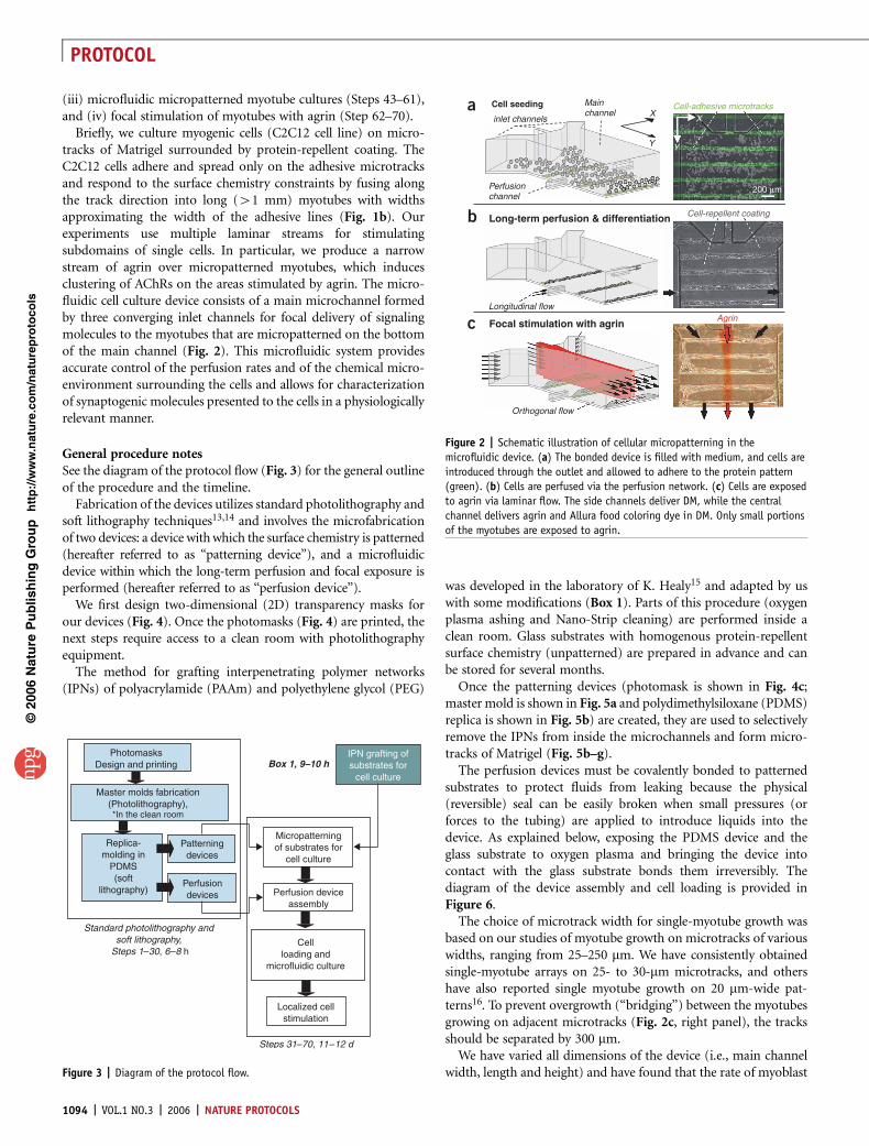
General procedure notesSee the diagram of the protocol flow (Fig. 3) for the general outlineof the procedure and the timeline.
Fabrication of the devices utilizes standard photolithography andsoft lithography techniques13,14 and involves the microfabricationof two devices: a device with which the surface chemistry is patterned(hereafter referred to as ‘‘patterning device’’), and a microfluidicdevice within which the long-term perfusion and focal exposure isperformed (hereafter referred to as ‘‘perfusion device’’).
We first design two-dimensional (2D) transparency masks forour devices (Fig. 4). Once the photomasks (Fig. 4) are printed, thenext steps require access to a clean room with photolithographyequipment.
The method for grafting interpenetrating polymer networks(IPNs) of polyacrylamide (PAAm) and polyethylene glycol (PEG)
was developed in the laboratory of K. Healy15 and adapted by uswith some modifications (Box 1). Parts of this procedure (oxygenplasma ashing and Nano-Strip cleaning) are performed inside aclean room. Glass substrates with homogenous protein-repellentsurface chemistry (unpatterned) are prepared in advance and canbe stored for several months.
Once the patterning devices (photomask is shown in Fig. 4c;master mold is shown in Fig. 5a and polydimethylsiloxane (PDMS)replica is shown in Fig. 5b) are created, they are used to selectivelyremove the IPNs from inside the microchannels and form micro-tracks of Matrigel (Fig. 5b–g).
The perfusion devices must be covalently bonded to patternedsubstrates to protect fluids from leaking because the physical(reversible) seal can be easily broken when small pressures (orforces to the tubing) are applied to introduce liquids into thedevice. As explained below, exposing the PDMS device and theglass substrate to oxygen plasma and bringing the device intocontact with the glass substrate bonds them irreversibly. Thediagram of the device assembly and cell loading is provided inFigure 6.
The choice of microtrack width for single-myotube growth wasbased on our studies of myotube growth on microtracks of variouswidths, ranging from 25–250 mm. We have consistently obtainedsingle-myotube arrays on 25- to 30-mm microtracks, and othershave also reported single myotube growth on 20 mm-wide pat-terns16. To prevent overgrowth (‘‘bridging’’) between the myotubesgrowing on adjacent microtracks (Fig. 2c, right panel), the tracksshould be separated by 300 mm.
We have varied all dimensions of the device (i.e., main channelwidth, length and height) and have found that the rate of myoblast
p
uor
G g
n ih si l
bu
P eru ta
N 600 2©
nat
ure
pro
toco
ls/
moc.er
ut an.
ww
w//:ptt
h
Orthogonal flow
Longitudinal flow
Perfusionchannel
Cell seeding
inlet channels
Mainchannel X
X
Y Y
Long-term perfusion & differentiation
Focal stimulation with agrinAgrin
Cell-repellent coating
200 µm
Cell-adhesive microtracksa
b
c
Figure 2 | Schematic illustration of cellular micropatterning in the
microfluidic device. (a) The bonded device is filled with medium, and cells are
introduced through the outlet and allowed to adhere to the protein pattern
(green). (b) Cells are perfused via the perfusion network. (c) Cells are exposed
to agrin via laminar flow. The side channels deliver DM, while the central
channel delivers agrin and Allura food coloring dye in DM. Only small portions
of the myotubes are exposed to agrin.
PhotomasksDesign and printing
Master molds fabrication(Photolithography),*In the clean room
Replica-molding in
PDMS(soft
lithography)
Patterningdevices
Perfusiondevices
Standard photolithography andsoft lithography,
Steps 1–30, 6–8 h
Box 1, 9–10 hIPN grafting ofsubstrates for
cell culture
Micropatterningof substrates for
cell culture
Perfusion deviceassembly
Cellloading and
microfluidic culture
Localized cellstimulation
Steps 31–70, 11–12 d
Figure 3 | Diagram of the protocol flow.
1094 | VOL.1 NO.3 | 2006 | NATURE PROTOCOLS
PROTOCOL

proliferation and fusion does not depend on the main channeldimensions but is influenced by underlying substrate, seedingdensity and perfusion rate. In this protocol, we have providedoptimal cell density and perfusion rates. The longer the mainchannel, the more cell tracks it can accommodate.
The absolute dimensions of converging inlet channels can also bevaried; however, to provide tighter focusing of the stimulatingstream, the central converging channel should be narrower thanthe side converging channels17. The device dimensions are alsodiscussed elsewhere3,12.
MATERIALSREAGENTS.SU-8 2000 resists (MicroChem). A number of different photoresists exist,
but SU-8 (a negative photoresist; i.e., one that becomes insoluble whenexposed to UV light) provides very good definition and vertical sidewalls forstructures as high as several hundred microns. The thickness of photoresistdefines the master mold height and is given primarily by photoresistviscosity and by the speed at which the wafer is spun. We use theMicroChem website (see below) to obtain the optimized spin speeds andtimes that yield the required heights. m CRITICAL See manufacturer’s datasheets for process guidelines (http://www.microchem.com/products/su_eight.h)
.SU-8 developer (1-methoxy-2-propyl acetate) (MicroChem) ! CAUTION Toxic.
.Tridecafluoro-1,1,2,2-tetrahydrooctyl-1-trichlorosilane (TFOCS; UnitedChemical Technology) ! CAUTION Corrosive, toxic.
.Sylgard 184 Silicone Elastomer Base and Sylgard 184 Elastomer Curing Agent(Dow Corning)
.Duco Cement (Devcon)
.Toluene (EMD) ! CAUTION Toxic.
.Acetone (EMD) ! CAUTION Toxic.
.Methanol (EMD) ! CAUTION Toxic.
.Allyltrichlorosilane (ATC-silane), assay: 95% (Sigma)! CAUTION Corrosive, toxic.
.Acrylamide (AAm; Polyscience) ! CAUTION Carcinogen, toxic.
.N,N¢-methylene bisacrylamide (BIS; Polyscience) ! CAUTION Irritant, toxic.
.Polyethylene glycol 1000 monomethyl ether monomethylacrylate (PEG;Polyscience) ! CAUTION Irritant.
.Benzophenone (Fluka) ! CAUTION Irritant.
.Contrad 70 (Decon Labs)
.Nano-Strip solution (Cyantek Corporation) ! CAUTION Highly caustic.
.a-bungarotoxin Alexa Fluor 488 conjugate (BTX*) (Molecular Probes)
.Bovine serum albumin (BSA), Texas Red conjugate (Molecular Probes)
.Dextran, Oregon Green 514; 70,000 MW (Molecular Probes)
.Agrin (R&D Systems) (cat. #550-AG)
.Growth Factor Reduced Matrigel (BD Biosciences) (cat. #354230)
.Dulbecco’s Modified Eagles’ Medium (DMEM; Invitrogen) (cat. #11965-092)
.Fetal bovine serum (FBS; HyClone)
.Horse serum (HS; ATCC)
.Penicillin/streptomycin or antibiotic-antimycotic (Invitrogen)(cat. #15140-122)
.Bovine serum albumin (BSA; Sigma-Aldrich)
.Food coloring dyeREAGENT SETUPMatrigel Prepare 30-ml aliquots. Store at –20 1C.Growth medium Consists of DMEM, 20% FBS (vol/vol), 1% (vol/vol)penicillin/streptomycin. Store at +4 1C.Differentiating medium Consists of DMEM, 5% HS(vol/vol), 1% (vol/vol)penicillin/streptomycin. Store at +4 1C.EQUIPMENT.Photoresist spinner.UV mask aligner.Plasma processing reactor center (for example, Branson 2000,
Branson Ultrasonics Corporation).Chemical wet bench.Two hot plates.Oven set at 65 1C (for curing PDMS).Water bath sonicator (for example, Branson 5510, Branson Ultrasonics
Corporation).Transilluminator (TFL-40, UVP, Inc.) Provides uniform and intense
ultraviolet radiation. This lamp has a predominant emission peakat 365 nm.
.Phase-contrast and epifluorescence microscope with a CCD camera
.Laminar flow hood
.CO2 water-jacketed incubator set at 37 1C and 10% CO2.
.Syringe pump (for example, Genie Plus, Kent Scientific Corporation)
.Glass discs or microscope slides (Erie Scientific).
. Immersion jars (Wheaton).
.150-mm glass Petri dishes
.Silicon wafers (3-inch diameter, P/Boron; Silicon Sense, Inc.).
.Transparency mask (Figs. 3 and 6)
.Silicone tubing (1.14 mm internal diameter (I.D.); Cole-Palmer Instrument Co.).
.Polyetheretherketone (PEEK) tubing for agrin fluid line (35.5 cm long, 1/16’’outer diameter (O.D.), 75 mm I.D., Upchurch Scientific) m CRITICAL Thechoice of PEEK tubing is critical to prevent nonspecific adsorption of agrin(or another protein of interest) to the walls of the tubing, which reduces theeffective concentration seen by the cells.
.Fluorinated ethylene propylene (FEP) tubing (1/16’’ O.D., 250 mm I.D.;Upchurch Scientific) for medium inlet (14 cm long) and outlet fluid lines(61 cm long)
.Female luer fitting (1/16’’; cat. no. 06359-27, Cole-Palmer Instrument Co.)
.Elbow connector (1/16’’; cat. no. 06365-15, Cole-Palmer Instrument Co.)
.Female luer with thread (cat. no. 30504, Cole-Palmer Instrument Co.)
.Conical adapter (1/16’’; cat. no. P-794, Upchurch Scientific)
.Alligator clips (35 mm, RadioShack)
.Kimwipes, autoclaved
.Petri dishes (p35, 35 mm � 10 mm)
.Flasks (T75 tissue culture flasks, polystyrene) or Petri dishes (100 mm � 15 mmtissue culture dishes, polystyrene)
.Petri dishes (p150, 150 mm � 25 mm)EQUIPMENT SETUPMicrofabrication and photolithography The master molds should be madein a clean-room photolithography facility. Clean rooms are utilized mostlyby the semiconductor industry to manufacture silicon chips. In clean rooms,air is constantly filtered to exclude dust particles that can damage theproduction of the chips, and temperature and humidity are controlled inorder to ensure uniform materials performance over time. Working in adust-free environment is critical because dust particles can be larger thanthe microstructures that we are trying to produce and would interfere withphotoresist coating.Plasma processing reactor center Also referred to as a ‘‘barrel etcher’’ (thechamber has the shape of a barrel) or a ‘‘plasma asher’’, a vacuum chamber whereoxygen radicals are generated to remove (‘‘ash’’) organic matter. The productsgenerated during ashing are pumped away by the vacuum system. We use plasmato clean surfaces and to bond PDMS substrates to glass or to PDMS. Unfortu-nately, the working settings for any particular application are highly dependent onthe geometry of the chamber, the radio frequency coil size, etc., so the parametersgiven below (power, time, and oxygen pressure) are used only for guidance.These parameters should be optimized empirically for each type of experiment.Transparency mask manufacture Also called a photomask, a high-resolution,laser-printed sheet of polyethylene terephthalate (PETE) that contains thedesired opaque features designed by the user and used to generate thephotoresist masters. Typically, a high-resolution printer (5,060 dpi, nominal dotsize of 5 mm) can resolve 30-mm line widths. Smaller features require printerswith higher resolution. The edges that require the best resolution should bedesigned horizontally whenever possible, because for mechanical reasonsthe printer scan head is more accurate on any given printing line thanacross different lines. We design our photomasks using drawing softwareCorelDraw (Corel Corporation) and AutoCAD (Autodesk, Inc.). Thephotomasks are then electronically sent to the printing service. Examples ofsuch services are PageWorks in Boston (http://www.pageworks.com/) orCAD Art Services in California (http://www.outputcity.com/). The latteroffers 20,000 dpi printouts.
p
uor
G g
n ih si l
bu
P eru ta
N 600 2©
nat
ure
pro
toco
ls/
moc.er
ut an.
ww
w//:ptt
h
NATURE PROTOCOLS | VOL.1 NO.3 | 2006 | 1095
PROTOCOL

PROCEDUREFabrication of SU-8 master moldsm CRITICAL STEP Perform Steps 1 through 7 in a clean room.
1| Immerse silicon wafers in Nano-Strip for 10 min, washfor 5 min in distilled or deionized water and dry. Place wafersonto a 205 1C hot plate for 10 min in order to ‘‘singe’’ orcompletely evaporate any water on the surface.
2| Quickly place the wafer on a resist spinner vacuum holder(Figs. 7 and 8). (The heat capacity of silicon is so low thatthe wafer will cool down within a few seconds of removing itfrom the hot plate.) Once the wafer is centered on the holder,apply the photoresist (SU-8 50) and spin (Fig. 7a–c). Twospin phases are required. The first low-rpm phase is called the‘‘spread’’ phase, which allows the resist to cover the wafer and spread from the center. We always spread photoresist at 500 rpmfor 10 s. The high-speed ‘‘spin’’ phase removes the excess resist and evenly distributes it into a film of the desired thickness.The spinning parameters for each master are as follows:
3| Transfer the wafer to a hot plate and soft bake at 65 1C: bake Layer 1 (of the perfusion device) for 3 min and bake patterningdevice for 6 min. Immediately transfer to a 95 1C hot plate to ‘‘set’’ the photoresist: allow Layer 1 to set for 15 min and thepatterning device for 20 min.
4| Place the wafer onto a UV aligner and bring the photomask (emulsion side facing the wafer) into contact with the resist(Figs. 7d and 9). Once the photomask and wafer are aligned, expose to a near-UV light (350–400 nm) (Fig. 7e). We exposed
Layer 1 to 200 mJ/cm2 and patterning device to 400 mJ/cm2.Refer to MicroChem supplemental information to determineexposure times based on film thickness and UV power output.m CRITICAL STEP Exposure for too short a time will result infeatures that are attacked by the developer, whereas exposure fortoo long will broaden the features. If feature size is not critical,overexposure is preferred.
5| Place the wafer onto a 65 1C hot plate for 1 min and thenonto a 95 1C hot plate (Layer 1 for 4 min and the patterningdevice for 5 min). Refer to MicroChem supplemental informationfor bake times. The exposed areas are now cross-linked andinsoluble in the SU-8 developer.
p
uor
G g
n ih si l
bu
P eru ta
N 600 2©
nat
ure
pro
toco
ls/
moc.er
ut an.
ww
w//:ptt
h
+ ++++
+++
+++
+++
+
+a
c
bFigure 4 | Photomasks of the devices. (a) Layer 1 of the microfluidic device
(height ¼ 25 mm). (b) Layer 2 (250 mm) is aligned on top of the Layer 1
(red arrows point to the alignment marks). (c) The microchannels (65 mm
height, 25 mm width and 300 mm separation) are used to selectively etch
IPNs and deposit protein on the exposed glass.
Device Spin speed Spin time
Perfusion device Layer 1 (Fig. 4a; thickness 22 mm) 5,000 rpm 30 sPatterning device (Fig. 4c; thickness 50 mm) 2,100 rpm 30 s
Protein solution
Suction
Suction
dl water
O2 plasma
Glass
MicrochannelsPDMS replica
Si wafer
SU-8 photoresistProtein microtracks
IPN
Bare glass
IPN/glass
Protein trackIPN/glass
a e
f
g
b
c
d
Figure 5 | Procedure for protein micropatterning based on the use of PDMS
microchannels.(a) SU-8 master mold. (b) IPN coating is selectively removed
using microchannel mask. (c) The microchannels are flushed with deionized
water. (d) The microchannels are filled with ECM protein solution. (e) The
microchannels are removed, leaving microtracks of protein surrounded by IPN.
(f) Phase-contrast image of lines of IPN-free glass surrounded by IPN.
(g) Fluorescence microscopy image of microtracks of the adsorbed
fluorescently tagged fibronectin surrounded by IPNs. Scale bars ¼ 100 mm.
1096 | VOL.1 NO.3 | 2006 | NATURE PROTOCOLS
PROTOCOL

6| Allow the wafer to cool to room temperature (20–25 1C) and immerse the wafer in a crystallizing glass dish filled withthe SU-8 developer and covered with a watch glass. Agitate to speed up the development. The development will take about5 min for the patterning device. For processing of the Layer 1 of the perfusion device, skip to Step 11.
7| Once the unexposed photoresist has been washed away, rinse the wafer with fresh SU-8 developer with a wash bottle. Placethe wafer on a piece of absorbent paper and gently blow nitrogen or clean air over the surface to dry off the SU-8 developer.Ensure that both sides are dried. This is the SU-8 master. Once baked, a ‘‘latent’’ pattern should be visible on the resist.Unexposed areas of the resist should be completely removed by the developer. The silicon surface (unexposed areas) should beuniformly shiny (that is, there should be no streaks or shadows).’ PAUSE POINT Store your SU-8 master in a dust-free environment.
8| Place the master in the vacuum jar (we use a desiccator jar without the drying pellets) attached to a vacuum source. Placea small portion of absorbent paper towel inside the desiccator chamber. Add a drop of TFOCS to the paper towel and evacuatethe air from the chamber.! CAUTION The desiccator chamber must be located inside a chemical fume hood owing to the corrosive nature of TFOCS vapors.
9| Apply vacuum for 1 min and turn off. This will vaporize the TFOCS and deposit a monolayer onto the masters. Close thevacuum and allow 40 min for deposition. Once the master has been coated with TFOCS, place it in a weighing boat where it willbe covered with PDMS precursor. The weighing boat is preferred to a rigid dish because it can be cut to facilitate release of thePDMS from the master.m CRITICAL STEP Silicon surfaces exposed to air are covered by a thin layer of SiO2 (glass). Very clean SiO2 can bind to PDMS duringPDMS curing. To prevent bonding, we passivate the oxide layer with a self-assembled monolayer of fluorosilane, TFOCS. TFOCS isa liquid, but the reaction is most efficiently carried on in the gas phase; i.e., by exposing the master to the TFOCS vapor. To createa gas volume saturated with TFOCS vapors, we put TFOCS and the wafer in a vacuum jar.’ PAUSE POINT Master mold preparation is completed. Keep the masters in closed containers to protect them from dust.
Fabrication of two-layer moldsm CRITICAL STEP Perform Steps 10 through 15 in a clean room.
10| Fabricate Layer 1 (Fig. 4a) as described in Steps 2–6.
11| Develop ONLY the alignment marks (Fig. 4a, arrows) by standing the wafer on its end so only the alignment marks areimmersed in the developer. Repeat for both sides.
p
uor
G g
n ih si l
bu
P eru ta
N 600 2©
nat
ure
pro
toco
ls/
moc.er
ut an.
ww
w//:ptt
h
PDMSmicrochannels
Proteinmicropattern
Cell suspension
Perfusion
a b c
Figure 6 | Schematic illustration of the device assembly and cellular micropatterning. (a) The microfluidic device is bonded to protein/IPN patterned substrate
using O2 plasma activation. (b) The bonded device is filled with medium, and cells are introduced through the outlet and allowed to adhere to the protein
pattern. (c) Constant perfusion of cell culture with fresh medium is established after cells adhere to the substrate.
a b c d e
Silicon wafer
Wafer holder
Photoresist
Mask
UVlight
Figure 7 | Process flow in photolithographic fabrication of the master mold. (a) Silicon wafer is placed on wafer holder. (b) Photoresist is dispensed.
(c) Photoresist is spun on the wafer. (d) After the photoresist is soft baked, a transparency mask is placed in contact with the photoresist. (e) The photoresist
is exposed to UV light. UV-exposed regions undergo cross-linking and become insoluble in developer.
NATURE PROTOCOLS | VOL.1 NO.3 | 2006 | 1097
PROTOCOL

12| Cover the alignment marks with a small pieceof Scotch tape.m CRITICAL STEP The tape prevents the developed alignmentmarks from being recoated and is removed after the second layeris spun and BEFORE the soft-bake.
13| To fabricate Layer 2 (Fig. 4b), coat Layer 1 made in Steps1–6 with another layer of SU-8: spread at 500 rpm for 10 s andspin at 1,200 rpm for 30 s. ‘‘Soft bake’’ by incubating for 10 minat 65 1C and then 30 min at 95 1C. Coat again to yield 250 mm:apply photoresist, spread at 500 rpm for 10 s and spin at1,200 rpm for 30 s. ‘‘Soft bake’’ by incubating for 10 min at65 1C and then 30 min at 95 1C. Thicker photoresist (SU-8 100)can be used to achieve 250 mm thickness in one coat.However, it cannot be used for thinner coats, and you willneed two different photoresists, which can be expensive.For our procedure, we needed only one type of photoresist,but it required multiple coating.
14| Align the transparent alignment windows on the Layer 2photomask (Fig. 4b) to the alignment marks in the Layer 1(for example, crosses of matching size) using the contactaligner optics.
15| After UV exposure (600 mJ/cm2) and post-baking (65 1C for 1 min, 95 1C for 10 min), develop the wafer following theprocedure given in Steps 6 and 7. The development will take up to 20 min. The master features should look like thosein Figure 10.
16| Silanize the wafer as in Steps 8 and 9.’ PAUSE POINT Master mold preparation is completed. Keep the masters in closed containers protecting from dust.
Molding of the patterning devices17| Mix the PDMS with the curing agent at a 10:1 ratio (PDMS:curing agent, wt/wt). A weighing boat is a convenientreceptacle for pouring the PDMS. Place the weighing boat on a scale and tare. Add the desired amount of PDMS, followedby the curing agent.
18| Thoroughly mix the compounds. Do this for at least 3 min with, e.g., a wooden tongue depressor to stir PDMS. The mixingof these two compounds generates bubbles that need to be evacuated. Place the PDMS mix in a vacuum jar (e.g., a desiccatorwithout the drying pellets). Evacuate the air from the chamber. Vent the chamber 2–3 times for the first 15 min. Degassing iscomplete when there are no longer bubbles visible in the mixture. Eventually, all the bubbles will surface and pop (20–30 min).
19| Slowly pour PDMS over the patterning device master to a height of approximately 5 mm.
p
uor
G g
n ih si l
bu
P eru ta
N 600 2©
nat
ure
pro
toco
ls/
moc.er
ut an.
ww
w//:ptt
h
Wafer
Wafer holder
Figure 8 | Wafer spin-coater. The spin-coater sits inside a fume hood. A wafer
is placed in the middle of the wafer holder (insert) held in place by vacuum,
and a Teflon shield captures the excess resist that is spun off the wafer.
The control board (far right) sets the spin and time parameters.
Figure 9 | UV aligner. The mask needs to be in direct contact (emulsion down) with the surface of the photoresist. The wafer is held in place by a vacuum
holder while the mask is taped over a glass plate. The wafer is raised to be in contact with the mask, and a shutter is opened to expose the photoresist to
UV light. Once the second layer of photoresist is applied, the aligner is used to match the second-layer mask to the exposed features. The aligner has micron
scale adjustment capabilities that enable precise alignment.
1098 | VOL.1 NO.3 | 2006 | NATURE PROTOCOLS
PROTOCOL
20| Re-degas the PDMS (15–20 min) to remove any bubblesthat may have been created.
21| Once bubbles are removed, place the PDMS-covered master into a 65 1C oven and allow curing for 2 h.
22| Put on a clean pair of gloves.
23| Using a clean, sharp scalpel or a razor blade, cut PDMS from the master. Do not drag the scalpel over photoresist areas; cutsafely around the photoresist features (leave about a 2-mm edge). Make sure that end of the blade reaches the silicon wafer.
24| Carefully peel the PDMS replica off the master using tweezers and transfer it to a clean surface for further cutting. Cut thePDMS replica to make 7-mm-wide (this will define the length of the microchannels for protein patterning) and 2-cm-longindividual patterning devices.’ PAUSE POINT Replica molding of patterning devices is completed. Keep the devices in a dust-free environment.
Molding of the perfusion devices25| Repeat Steps 17–18 using the perfusion device molds. Cut silicone tubing into 1-cm-long pieces. Apply a small amountof Duco Cement to one end of the tubing and affix the tubing to the raised, circular inlet pads of the master (Fig. 7b).Filling the end of the tubing with a small amount of glue prevents PDMS from entering the tube and blocking the port.The glue plug can easily be pushed out with a blunt syringe needle after curing. Let the glue sit for 5 min at roomtemperature.
26| Once the tubing is affixed firmly and the PDMS has been debubbled, pour the PDMS over the photoresist master. Do notpour PDMS over the tubing, as it will seal the access port you are trying to create.
27| Re-degas PDMS (15–20 min).
28| Place the PDMS-covered master into a 65 1C oven and allow curing for 2 h.
29| Cut the device from the master. Leave about 4 mm around the photoresist-defined features.
30| Autoclave the devices (e.g., 20 min at 121 1C, wet cycle).’ PAUSE POINT Replica molding of patterning devices is completed. Keep the devices in a dust-free environment.? TROUBLESHOOTING
Micropatterning of culture substrates31| Take the patterning devices (microchannels) from Steps 17–24 (Fig. 5b) and clean the surface with a piece of tape, gentlyapplying and lifting the sticky tape to remove the dust particles.
32| Take the IPN-coated glass substrates (see protocol in Box 1) and gently remove any dust particles with a few pulsesof filtered compressed air or nitrogen.m CRITICAL STEP PDMS will not seal around the dust particles, which will create defects in micropatterns.
33| Apply the microchannels to the IPN-coated glass substrate (Fig. 5b); it will seal spontaneously. When PDMS makesa conformal contact with a substrate, it minimizes reflection of light at the interface, so when viewed at an angle, the areasof PDMS that contact the surface appear slightly darker than the areas that do not make contact.
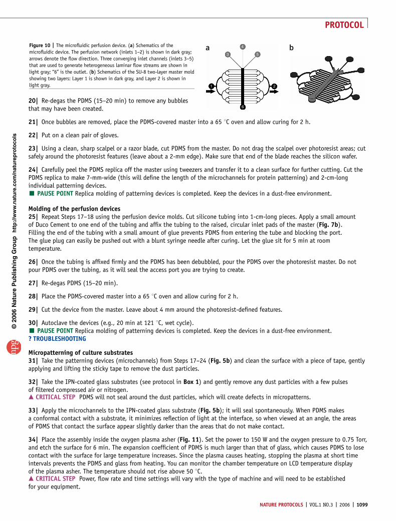
34| Place the assembly inside the oxygen plasma asher (Fig. 11). Set the power to 150 W and the oxygen pressure to 0.75 Torr,and etch the surface for 6 min. The expansion coefficient of PDMS is much larger than that of glass, which causes PDMS to losecontact with the surface for large temperature increases. Since the plasma causes heating, stopping the plasma at short timeintervals prevents the PDMS and glass from heating. You can monitor the chamber temperature on LCD temperature displayof the plasma asher. The temperature should not rise above 50 1C.m CRITICAL STEP Power, flow rate and time settings will vary with the type of machine and will need to be establishedfor your equipment.
p
uor
G g
n ih si l
bu
P eru ta
N 600 2©
nat
ure
pro
toco
ls/
moc.er
ut an.
ww
w//:ptt
h
6
1 2
5
4
3a bFigure 10 | The microfluidic perfusion device. (a) Schematics of the
microfluidic device. The perfusion network (inlets 1–2) is shown in dark gray;
arrows denote the flow direction. Three converging inlet channels (inlets 3–5)
that are used to generate heterogeneous laminar flow streams are shown in
light gray; ‘‘6’’ is the outlet. (b) Schematics of the SU-8 two-layer master mold
showing two layers: Layer 1 is shown in dark gray, and Layer 2 is shown in
light gray.
NATURE PROTOCOLS | VOL.1 NO.3 | 2006 | 1099
PROTOCOL
35| Turn off the power and oxygen flow, break the vacuum andallow enough time for the chamber to cool off (about 5 min).
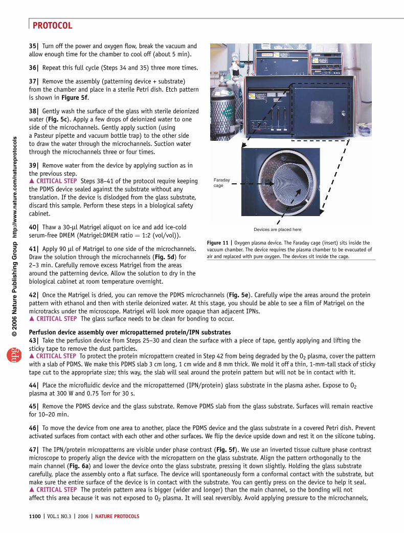
36| Repeat this full cycle (Steps 34 and 35) three more times.
37| Remove the assembly (patterning device + substrate)from the chamber and place in a sterile Petri dish. Etch patternis shown in Figure 5f.
38| Gently wash the surface of the glass with sterile deionizedwater (Fig. 5c). Apply a few drops of deionized water to oneside of the microchannels. Gently apply suction (usinga Pasteur pipette and vacuum bottle trap) to the other sideto draw the water through the microchannels. Suction waterthrough the microchannels three or four times.
39| Remove water from the device by applying suction as inthe previous step.m CRITICAL STEP Steps 38–41 of the protocol require keepingthe PDMS device sealed against the substrate without anytranslation. If the device is dislodged from the glass substrate,discard this sample. Perform these steps in a biological safetycabinet.
40| Thaw a 30-ml Matrigel aliquot on ice and add ice-coldserum-free DMEM (Matrigel:DMEM ratio ¼ 1:2 (vol/vol)).
41| Apply 90 ml of Matrigel to one side of the microchannels.Draw the solution through the microchannels (Fig. 5d) for2–3 min. Carefully remove excess Matrigel from the areasaround the patterning device. Allow the solution to dry in thebiological cabinet at room temperature overnight.
42| Once the Matrigel is dried, you can remove the PDMS microchannels (Fig. 5e). Carefully wipe the areas around the proteinpattern with ethanol and then with sterile deionized water. At this stage, you should be able to see a film of Matrigel on themicrotracks under the microscope. Matrigel will look more opaque than adjacent IPNs.m CRITICAL STEP The glass surface needs to be clean for bonding to occur.
Perfusion device assembly over micropatterned protein/IPN substrates43| Take the perfusion device from Steps 25–30 and clean the surface with a piece of tape, gently applying and lifting thesticky tape to remove the dust particles.m CRITICAL STEP To protect the protein micropattern created in Step 42 from being degraded by the O2 plasma, cover the patternwith a slab of PDMS. We make this PDMS slab 3 cm long, 1 cm wide and 8 mm thick. We mold it off a thin, 1-mm-tall stack of stickytape cut to the appropriate size; this way, the slab will seal around the protein pattern but will not be in contact with it.
44| Place the microfluidic device and the micropatterned (IPN/protein) glass substrate in the plasma asher. Expose to O2
plasma at 300 W and 0.75 Torr for 30 s.
45| Remove the PDMS device and the glass substrate. Remove PDMS slab from the glass substrate. Surfaces will remain reactivefor 10–20 min.
46| To move the device from one area to another, place the PDMS device and the glass substrate in a covered Petri dish. Preventactivated surfaces from contact with each other and other surfaces. We flip the device upside down and rest it on the silicone tubing.
47| The IPN/protein micropatterns are visible under phase contrast (Fig. 5f). We use an inverted tissue culture phase contrastmicroscope to properly align the device with the micropattern on the glass substrate. Align the pattern orthogonally to themain channel (Fig. 6a) and lower the device onto the glass substrate, pressing it down slightly. Holding the glass substratecarefully, place the assembly onto a flat surface. The device will spontaneously form a conformal contact with the substrate, butmake sure the entire surface of the device is in contact with the substrate. You can gently press on the device to help it seal.m CRITICAL STEP The protein pattern area is bigger (wider and longer) than the main channel, so the bonding will notaffect this area because it was not exposed to O2 plasma. It will seal reversibly. Avoid applying pressure to the microchannels,
p
uor
G g
n ih si l
bu
P eru ta
N 600 2©
nat
ure
pro
toco
ls/
moc.er
ut an.
ww
w//:ptt
h
Devices are placed here
Faradaycage
Figure 11 | Oxygen plasma device. The Faraday cage (insert) sits inside the
vacuum chamber. The device requires the plasma chamber to be evacuated of
air and replaced with pure oxygen. The devices sit inside the cage.
1100 | VOL.1 NO.3 | 2006 | NATURE PROTOCOLS
PROTOCOL
it might break the seal, and leakage between the inlet channels will occur. Use vacuum instead to fill the channels andintroduce the cells.
48| After 10 min, check that the bonding is complete by lifting the edge of the device by applying a small amount of force,upward and toward the center of the device, with a finger. If the device is bonded, there should be no separation from the surface.
Loading cells in the devices49| After bonding the device to the glass substrate, fill the device with BSA (1.5 mg/ml in PBS) inside a biological safetycabinet. The microchannels are filled with BSA to prevent cells from attaching to the ‘‘roof’’ of the microchannel. Utilize a25.5-gauge needle and a 3- to 5-ml syringe. Insert the needle into the outlet port 6 (Fig. 10a) (without piercing the innerwalls of the tubing) until the syringe contacts the glass. Slowly fill the tubing of port 6, and then start applying suction(using a Pasteur pipette) to port 3 until you fill the tubing. Next, apply suction to port 5 and then 4. Last, apply suction toports 1 and 2.m CRITICAL STEP Make sure the tubing at the outlet always has liquid; otherwise, air will get sucked in the microchannels.Steps 56–69 should be done in a biological safety cabinet using proper sterile technique to prevent contamination.? TROUBLESHOOTING
50| Place the BSA-filled device in the incubator overnight at 37 1C.
51| Replace BSA with cell culture medium.? TROUBLESHOOTING
52| After filling the device with cell culture medium, close ports 1 and 2 with sterile alligator clips (Fig. 6b).
53| Prepare C2C12 cell suspension as follows: add 3 ml of trypsin to flask/Petri dish with subconfluent C2C12 cells and incubatefor 1 min at room temperature. Remove trypsin and incubate cells under a residual layer of trypsin in the 37 1C incubator for1 min. Add 2 ml of growth medium to suspend the cells, count cells and dilute (if needed) with growth medium to yield thedesired concentration (B1 � 106 cell/ml). You will need approximately 200 ml of cell suspension.
54| Using a 1-ml syringe fitted with a Luer connector or a needle, slowly inject cell suspension into port 6 (Fig. 6b).Apply gentle suction to ports 3 and 5, filling the microchannel with cell suspension.? TROUBLESHOOTING
55| Place the filled device in a p150 dish. Allow the cells to adhere for 30 min in the incubator. Cells will adhere and spreadstrictly on Matrigel microtracks (see Fig. 10b). There should be no need to wash excess cells out of the channel, as all the cellsshould have migrated over to the microtracks.
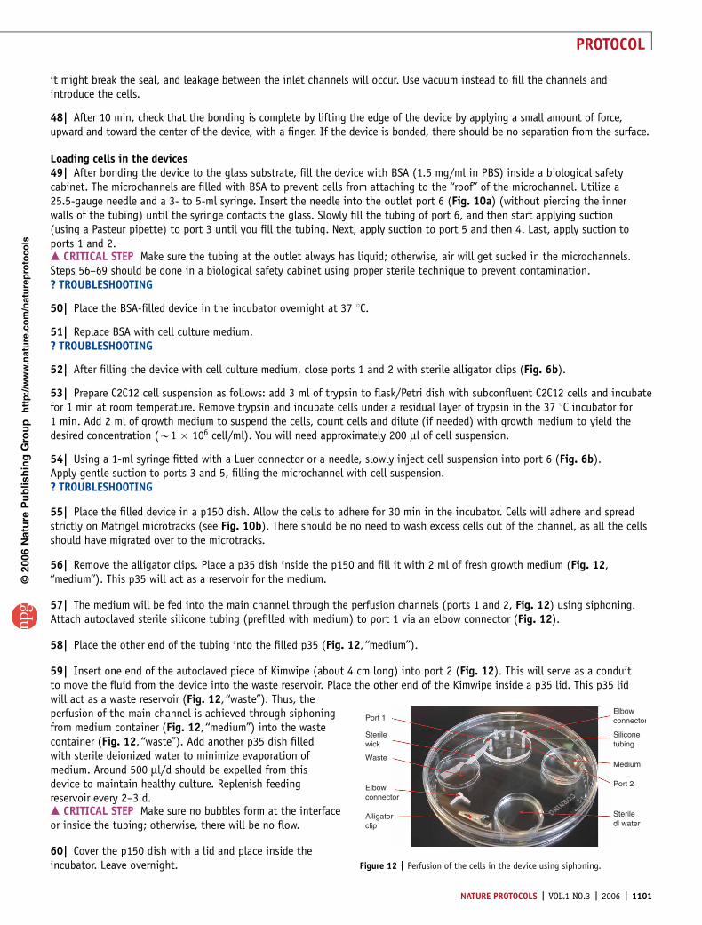
56| Remove the alligator clips. Place a p35 dish inside the p150 and fill it with 2 ml of fresh growth medium (Fig. 12,‘‘medium’’). This p35 will act as a reservoir for the medium.
57| The medium will be fed into the main channel through the perfusion channels (ports 1 and 2, Fig. 12) using siphoning.Attach autoclaved sterile silicone tubing (prefilled with medium) to port 1 via an elbow connector (Fig. 12).
58| Place the other end of the tubing into the filled p35 (Fig. 12, ‘‘medium’’).
59| Insert one end of the autoclaved piece of Kimwipe (about 4 cm long) into port 2 (Fig. 12). This will serve as a conduitto move the fluid from the device into the waste reservoir. Place the other end of the Kimwipe inside a p35 lid. This p35 lidwill act as a waste reservoir (Fig. 12, ‘‘waste’’). Thus, theperfusion of the main channel is achieved through siphoningfrom medium container (Fig. 12, ‘‘medium’’) into the wastecontainer (Fig. 12, ‘‘waste’’). Add another p35 dish filledwith sterile deionized water to minimize evaporation ofmedium. Around 500 ml/d should be expelled from thisdevice to maintain healthy culture. Replenish feedingreservoir every 2–3 d.m CRITICAL STEP Make sure no bubbles form at the interfaceor inside the tubing; otherwise, there will be no flow.
60| Cover the p150 dish with a lid and place inside theincubator. Leave overnight.
p
uor
G g
n ih si l
bu
P eru ta
N 600 2©
nat
ure
pro
toco
ls/
moc.er
ut an.
ww
w//:ptt
h
Steriledl water
Port 2
Medium
Siliconetubing
ElbowconnectorPort 1
Sterilewick
Waste
Elbowconnector
Alligatorclip
Figure 12 | Perfusion of the cells in the device using siphoning.
NATURE PROTOCOLS | VOL.1 NO.3 | 2006 | 1101
PROTOCOL

61| When cells become confluent (usually the day after seeding), switch the growth media to reduced serum media (differentia-tion medium (DM)) to inhibit proliferation and induce fusion of myoblasts. Remove the feeding silicon tubing and the Kimwipe‘‘wick’’ from the device, wash the cells and the perfusion channels with DM, refill the tubing with DM and reconnect the tubingand the wick. The cells will start fusing together within 48 h, and by 8–9 d after seeding, myotubes will form. Fusion can bedetected straightforwardly because it entails a dramatic change in cell morphology: cells form multinucleated tubular assemblies(myotubes), and single-cell borders are absent (see Fig. 1).? TROUBLESHOOTING
Localized delivery to C2C12 cells62| Fill syringe reservoirs with medium and agrin solution and equilibrate in the incubator for at least 15 min.
63| Use alligator clips to close up ports 1 and 2. Connect the pump to the device: insert one end of PFE tubing directly intothe outlet of the device (Fig. 10, port 6) as shown in Figure 13. The outlet of the device has an embedded piece of siliconetubing. Connect the other end of the PFE tubing to the pump as shown in Figure 13.
64| Connect the inlets of the device with appropriate medium and agrin reservoirs (syringes, Fig. 13; ports 3–5 in Fig. 10a).Add a food coloring dye to the agrin solution for visual validation of the stream’s position. We used Allura red food coloring dyeand have not observed any deleterious effects on cells (Fig. 2c).
65| Set the pump to withdraw the fluid from the device. We used flow rate of 7 ml/min. Start the pump. A thin streamof Allura red–labeled cell medium should be visible in the middle of the channel.
66| Place the device inside the incubator for the duration of the experiment. The pump will remain outside at all times.The outlet tubing is stiff FEP tubing, which will not collapse when pressed by the incubator door.
67| After exposing cells to signaling molecule solution for an appropriate amount of time (we used 2–18 h, depending onthe experimental design), disconnect the agrin fluid line from the device inlet and rinse the inlet tubing of the device usinga syringe filled with cell culture medium. Aspirate rinsed solution while injecting buffer solution.
68| Let the pump run for 10 min to wash agrin from the microchannel.
69| Stop the pump and disconnect the device.
70| The agrin flow profile can be quantitatively measured by filling the center channel with Texas red BSA or a fluorescentlylabeled dextran (with a molecular weight similar to that of agrin) and imaging it with fluorescence microscopy. If the camerais operated in its linear regime, after background subtraction (the PDMS areas should be calibrated to zero intensity) theheight-averaged concentration at anygiven point is proportional to thefluorescence intensity value at thatpoint. After stimulation, labeling witha-bungarotoxin conjugated to Alexa488 should reveal that AChRs areclustering exclusively in stimulatedareas of the myotube.
� TIMINGFabrication of SU-8 master molds(Steps 1–7): 3–5 hFabrication of SU-8 master molds(Steps 8–9): 1 hFabrication of two-layer molds(Steps 10–16): 3 h
p
uor
G g
n ih si l
bu
P eru ta
N 600 2©
nat
ure
pro
toco
ls/
moc.er
ut an.
ww
w//:ptt
h
Figure 13 | Fluidic setup used for flow
experiments. The setup consists of a microfluidic
device placed in a holder. An external Genie Plus
syringe pump is connected to the outlet of the
device through FEP fluid line. The inlets of the
device are connected to the reservoirs (modified
syringes) via PEEK (analyte) and FEP (medium)
fluid lines.
1102 | VOL.1 NO.3 | 2006 | NATURE PROTOCOLS
PROTOCOL

Molding of the patterning devices (Steps 17–24): 3 hMolding of the perfusion devices (Steps 25–30): 3 hMicropatterning of culture substrates (Steps 31–42): 12 hPerfusion device assembly over micropatterned protein/IPN substrates (Steps 43–48): 20 minLoading cells (Steps 49–54): 20 minLoading cells (Step 55): 30 minLoading cells (Steps 56–61): 15 minLocalized delivery to cells (Steps 62–70): 1 h
? TROUBLESHOOTINGSee Table 1 for troubleshooting details.
ANTICIPATED RESULTSThe described method allows production of linear isolated myotubes organized in a parallel microarray (Fig. 1b) and focaldelivery of signaling molecules to the myotubes. For example, we have been studying the effects of focal agrin (a moleculeimplicated as a postsynaptic organizer11) on AChR aggregation12 and AChR density (unpublished data). Such focal stimulationof myotubes represents an attempt to mimic the presence of the neuron in the first stages of the formation of a neuromuscularsynapse and leads to localized AChR clustering12 and changes in AChR turnover (in preparation). Individual AChR clusters canbe followed with time (note: no time-lapse apparatus is needed) because the geometrical arrangement of the myotubes andtheir confinement to the precise locations of a cell culture surface allows for easy identification and monitoring of themyotubes. This approach can be further applied to study the effects of other synaptogenic molecules and their combinationson postsynaptic differentiation. In addition, we used the described cell-patterning technique to isolate and position singlecells and cell clusters of different adherent cell types2.
ACKNOWLEDGMENTS We thank K. Healy and T. Barber for the original IPN-graftingprotocol and G. Cooksey for the photographs of microfabrication equipment.
AUTHOR CONTRIBUTIONS A.T.: study concept, design, development andpreparation of manuscript. X.F.M.: preparation of manuscript. A.F.: study conceptand preparation of manuscript.
COMPETING INTERESTS STATEMENT The authors declare that they have nocompeting financial interests.
Published online at http://www.natureprotocols.comReprints and permissions information is available online at http://npg.nature.com/reprintsandpermissions
p
uor
G g
n ih si l
bu
P eru ta
N 600 2©
nat
ure
pro
toco
ls/
moc.er
ut an.
ww
w//:ptt
h
TABLE 1 | Troubleshooting table.
PROBLEM POSSIBLE REASON SOLUTION
When filling the device with solution, manybubbles form in the channels (Steps 50, 52).
� Suction is too fast. � Make sure the tubing at the outlet alwayshas liquid.� Follow the filling instructions precisely.� Remove all the liquid from the deviceand try filling it again.
When filling the device, the solution leaksfrom the device (Steps 50, 52, 56).
� The bonding between glass substrate andthe device did not work owing to the pre-sence of dust or dirt on the bonding surfaces.
� Discard the device.
� Plasma settings are not optimized.
� Make sure you clean surfaces well beforeexposing them to 02 plasma.
� Too much pressure was applied and PDMSruptured.
� Optimize time, flow and power for yourplasma oven before attempting devicebonding.� Try not to apply positive pressure;fill channels by suction.
Cells do not respect the Matrigel/IPN pattern(Step 57).
� IPN-grafted areas are scratched or damagedmechanically.
� Handle grafted substrates with care.
� Matrigel leaked from the patterningchannels onto IPN areas.
� The patterning device was dislodgedfrom the surface; discard this device.
Dead cells (Step 63) � Perfusion is not adequate owing to bubblesin the channels.
� Always make sure there are no bubblesin the tubing.
No myotubes form. � Matrigel pattern is defective.� Peel off patterning device carefully; makesure you protect Matrigel well during02 plasma etching.� Cell density.� Cells must be confluent/superconfluentwhen DM is added
NATURE PROTOCOLS | VOL.1 NO.3 | 2006 | 1103
PROTOCOL

1. Neville, C., Rosenthal, N., McGrew, M., Bogdanova, N. & Hauschka, S. Skeletalmuscle cultures. Methods Cell Biol. 52, 85–116 (1997).
2. Tourovskaia, A. et al.Micropatterns of chemisorbed cell adhesion-repellent films usingoxygen plasma etching and elastomeric stencils. Langmuir 19, 4754–4764 (2003).
3. Tourovskaia, A., Figueroa-Masot, X. & Folch, A. Differentiation-on-a-chip: amicrofluidic platform for long-term cell culture studies. Lab Chip 5, 14–19 (2005).
4. Li, N., Tourovskaia, A. & Folch, A. Biology on a chip: microfabrication for studyingthe behavior of cultured cells. Crit. Rev. Biomed. Eng. 31, 423–488 (2003).
5. Takayama, S. et al. Patterning cells and their environments using multiple laminarfluid flows in capillary networks. Proc. Natl. Acad. Sci. USA 96, 5545 (1999).
6. Takayama, S. et al. Subcellular positioning of small molecules. Nature 411,1016 (2001).
7. Sawano, A., Takayama, S., Matsuda, M. & Miyawaki, A. Lateral propagation of EGFsignaling after local stimulation is dependent on receptor density. Dev. Cell 3,245–257 (2002).
8. Cho, B.S. et al. Passively driven integrated microfluidic system for separation ofmotile sperm. Anal. Chem. 75, 1671–1675 (2003).
9. Lucchetta, E.M., Lee, J.H., Fu, L.A., Patel, N.H. & Ismagilov, R.F. Dynamics ofDrosophila embryonic patterning network perturbed in space and time usingmicrofluidics. Nature 434, 1134–1138 (2005).
10. Lucchetta, E.M., Munson, M.S. & Ismagilov, R.F. Characterization of the localtemperature in space and time around a developing Drosophila embryo ina microfluidic device. Lab Chip 6, 185–190 (2006).
11. McMahan, U.J. The agrin hypothesis. Cold Spring Harb. Symp. Quant. Biol. 55,407–418 (1990).
12. Tourovskaia, A., Kosar, T.F. & Folch, A. Local induction of acetylcholine receptorclustering in myotube cultures using microfluidic application of agrin. Biophys. J.90, 2192–2198 (2006).
13. Xia, Y.N. & Whitesides, G.M. Soft lithography. Angew. Chem. Int. Edn Engl. 37, 551(1998).
14. McDonald, J.C. et al. Fabrication of microfluidic systems inpoly(dimethylsiloxane). Electrophoresis 21, 27–40 (2000).
15. Bearinger, J.P. et al. P(AAm-co-EG) interpenetrating polymer networks grafted tooxide surfaces: Surface characterization, protein adsorption, and cell detachmentstudies. Langmuir 13, 5175 (1997).
16. Griffin, M.A. et al. Patterning, prestress, and peeling dynamics of myocytes.Biophys. J. 86, 1209–1222 (2004).
17. Knight, J.B., Vishwanath, A., Brody, J.P. & Austin, R.H. Hydrodynamic focusingon a silicon chip: Mixing nanoliters in microseconds. Phys. Rev. Lett. 80,3863–3866 (1998).
p
uor
G g
n ih si l
bu
P eru ta
N 600 2©
nat
ure
pro
toco
ls/
moc.er
ut an.
ww
w//:ptt
h
1104 | VOL.1 NO.3 | 2006 | NATURE PROTOCOLS
PROTOCOL