
Calculations of Electrodynamic Forces in Three-Phase ... - MDPI
Available online at www.sciencedirect.com
www.elsevier.com/locate/asr
ScienceDirect
Advances in Space Research 52 (2013) 1530–1544
Long term dynamics and optimal control of nano-satellite deorbit usinga short electrodynamic tether
R. Zhong, Z.H. Zhu ⇑
Department of Earth and Space Science and Engineering, York University, 4700 Keele Street, Toronto, Ontario M3J 1P3, Canada
Received 26 April 2013; received in revised form 21 July 2013; accepted 22 July 2013Available online 29 July 2013
Abstract
This paper studies the long term dynamics and optimal control of a nano-satellite deorbit by a short electrodynamic tether. The longterm deorbit process is discretized into intervals and within each interval a two-phase optimal control law is proposed to achieve librationstability and fast deorbit simultaneously. The first-phase formulates an open-loop fast-deorbit control trajectory by a simplified modelthat assumes the slow-varying orbital elements of electrodynamic tethered system as constant and ignores perturbation forces other thanthe electrodynamic force. The second phase tracks the optimal trajectory derived in the first phase by a finite receding horizon controlmethod while considering a full dynamic model of electrodynamic tether system. Both optimal control problems are solved by directcollocation method base on the Hermite–Simpson discretization schemes with coincident nodes. The resulting piecewise nonlinear pro-graming problems in the sequential intervals reduces the problem size and improve the computational efficiency, which enable an on-orbit control application. Numerical results for deorbit control of a short electrodynamic tethered nano-satellite system in both equa-torial and highly inclined orbits demonstrate the efficiency of the proposed control method. An optimal balance between the librationstability and a fast deorbit of satellite with minimum control efforts is achieved.� 2013 COSPAR. Published by Elsevier Ltd. All rights reserved.
Keywords: Electrodynamic tether; Dynamics; Libration stability; Fast deorbit; Optimal control; Receding horizon control
1. Introduction
Space debris mitigation and removal such as the self-deorbit of end-of-mission spacecraft and spent upper stagesof rockets has emerged as an important objective in majorspace agencies. As the population of space debris is contin-uously increasing, the spacecraft and/or debris collision isinevitable as it is evident by the first ever satellite collisionbetween Iridium 33 and Cosmos 2251 in 2009 (Wang,2010). The electrodynamic tether (EDT) propulsion tech-nology has the near term potential in space debris remov-ing, which generates a wide interest in the academia andindustry recently (National Research Council, 2012; Kimet al., 2010; Covello, 2012). The EDT is especially appealing
0273-1177/$36.00 � 2013 COSPAR. Published by Elsevier Ltd. All rights rese
http://dx.doi.org/10.1016/j.asr.2013.07.031
⇑ Corresponding author. Tel.: +1 416 736 2100x77729; fax: +1 416 7365817.
E-mail address: [email protected] (Z.H. Zhu).
for the fast growing low-cost micro/nano-satellites due totheir advantages of low mass, compact size, fuel-efficiency(little or no propellant required), and ease-of-use (Uphoffet al., 1998; Jablonski and Scott, 2009). However, an EDTsystem is intrinsically unstable due the periodic excitationof electrodynamic force as it orbits the Earth (Pelaezet al., 2000). Thus, it is necessary to control the librationmotion of the tether to make the EDT technology func-tional and practical. However, an EDT system with a fixedlength tether is an under-actuated system and the electricalcurrent is the only controllable input for the libration stabil-ity control if there are no other active forces such as propul-sion acting on the ends of an EDT. Many works have beendevoted to the EDT libration control by regulating the cur-rent across the tether, usually, with energy-based feedbackin this single-input-multiple-output control problem inorder to reduce the current-induced electrodynamic forcewhen it is in phase with libration angles. A brief summary
rved.
R. Zhong, Z.H. Zhu / Advances in Space Research 52 (2013) 1530–1544 1531
of these studies on the EDT libration control in the litera-ture is given in Table 1.
As shown in Table 1, most of the existing approachesfocused on the libration stability control that used a periodicallibration motion of a simplified EDT dynamic model as a con-trol reference. Although effective in maintaining the librationstability, these approaches are unable to assure a fast orbitalmaneuver that is one of the most important indexes for remov-ing debris using EDTs. For instance, Williams (2010c) inves-tigated the deorbiting efficiency (maneuver time) usingoptimal control with timescale separation by ignoring theout-of-plane libration dynamics and assuming a simple spin-ning or hanging tether for the in-plane libration motion. Ste-vens and Baker (2009) studied only the out-of-plane librationcontrol problem. Furthermore, the control methods in theseresearches were open-loop control without considering com-plex environmental model (e.g., accurate geomagnetic filedand complete major perturbation forces), which makes themvulnerable to accumulate errors in the long-term deorbitingprocess. Although these existing works are extendable in
Table 1Existing approaches for EDT dynamic modeling and libration control.
Author(s) Tethermodel*
Magneticfield�
Perturbativeforces§
Librati
Arnold andDobrowolny(1981)
R TDF E,A Curren
Beletsky and Levin(1993)
R NTDF E Curren
Levin (1987) F-I NTDF E CurrenHoyt and Forward
(1998)F-I IGRF E,A Adapti
libratioCorsi and Iess (2001) R NTDF E CurrenLanoix et al. (2005) I-E IGRF E,A,O,S,L CurrenPelaez and Lorenzini
(2005)R NTDF E Force c
rate feeWilliams (2006) R NTDF E CurrenTakeichi (2006) R NTDF E CurrenTortora et al. (2006) R IGRF E CurrenLarsen and Blanke
(2007)R NTDF E Curren
uncontSanjurjo-Rivo (2009) R TDF E CurrenStevens and Baker
(2009)R NTDF E,A Curren
Kojima andSugimoto (2009)
F-I NTDF E Curren
Williams (2009) R TDF E CurrenWilliams (2010a) R NTDF E 5 curreWilliams (2010b) F-I NTDF E CurrenWilliams (2010c) R NTDF E OptimaInarrea and Pelaez
(2010)R NTDF E Force c
EDT enKojima and
Sugimoto (2010)F-I NTDF E Hybrid
Larsen and Blanke(2011)
R NTDF E Curren
Zhong and Zhu(2012)
R IGRF E,A,O,S,L Currenin-plan
* R – rigid tether; F-I – flexible-inextensible tether; I-E – inflexible-extensible� NTDF – Non-tilted dipole field; TDF – Tilted dipole field; IGRF –Internat§ E – Electrodynamic force; A – atmospheric drag; O – Oblateness effect; S –
principle to the closed-loop control together with the consid-eration of both in-plane and out-of-plane libration motionand complex environmental perturbation forces, these studiesleft some important and interesting areas unexplored. In addi-tion to the above unexplored-areas, there might be a size effectin the deorbit of a nanosatellite system with a short EDT,compared with the deorbit of large EDT systems that havebeen frequently studied. For instance, the deorbiting time ofa short EDT system is usually longer due to the much smallerinduced electrodynamic force and the effects of other pertur-bation forces other than electrodynamic force and air dragmay be in the same or similar order of magnitude of the latter.All of these have motivated the current study to find an opti-mal balance between the fast deorbit and the libration stabilityfor the short EDT in complex space environment. A two-phase optimal control scheme has been developed to achievethe objective. Unlike existing approaches, our first phase isconcerned with finding an optimal reference trajectory of fastand stable deorbit where the control input and tether librationmotion are not necessary to be periodical. This is achieved by
on control law
t modulation with out-of-plane control
t modulation, tether’s swing less 45�
t modulation, in-plane control only, 2 rigid linksve current modulation, In-plane control to achieve in-/out-of-planen controlt on/off by Lyapunov (Hamiltonian) functiont modulation with max. current as a function of 3 times true anomalyontrol: 1st law is libration rate feedback; 2nd law is time delayed librationdback. Required propulsion at EDT endst modulation by energy-rate feedbackt on/off by Hamiltonian stability functiont on/off by Lyapunov(Hamiltonian) functiont modulation by LQ, linearized feedback, sliding mode. Out-of-planerollablet modulation to self-torque-balancet modulation, optimal control via fast/slow motion timescale separation
t modulation by delayed feedback of libration rates. 2 rigid links
t modulation by time delayed feedback of predicted libration velocitynt modulations by energy-rate feedbackt modulation by energy-rate feedback. Multiple rigid linksl control using fast/slow motion timescale separationontrol by extended time delayed feedback. Required additional forces atdscurrent on/off and modulation, delayed feedback control. 2 rigid links
t modulation by passivity Hamiltonian stability function
t on/off by max. roll feedback. Out-of-plane control leads to indirecte control
tether.ional Geomagnetic Reference Field.solar radiation pressure; L – Lunisolar attraction.
X
Z
YΩ i
u EDT
OEquatorialPlane
Orbit
βα
x
z
z′
x′
( )y y ′ 1m
2m
CMo
l
s
Prim
e M
erid
ian
NorthPole
φ
θ
zσxσyσ
Fig. 1. Illustration of system coordinates.
1532 R. Zhong, Z.H. Zhu / Advances in Space Research 52 (2013) 1530–1544
minimizing a cost function subject to given constraints via anopen-loop control. The second phase is concerned with track-ing the optimal reference trajectory of paired state and controlinput with minimum efforts. By adopting the finite recedinghorizon control (RHC) method (Lu, 1999), a closed-loopoptimal control problem is formulated in a quadrature form,where the state errors and control modifications with respectto the reference trajectory are minimized after solving thequadrature optimization. The proposed optimal controlscheme is implemented by discretizing the EDT deorbit pro-cess into small intervals for potential online implementation.Within each interval, the orbital and libration dynamics isdecoupled based on a timescale separation to reduce the com-putational load, where the slow varying orbital elements areconsidered constant due to the long deorbit time by a shortEDT. By repeating the process sequentially, where the instan-taneous states of the EDT system at the end of each intervalwill be used as the initial conditions for the optimal controlproblem in the next interval. Finally, numerical simulationsof fast satellite deorbit by an EDT with the proposedapproach are provided. The numerical results demonstratethe effectiveness and robustness of the approach in fast satel-lite deorbit by EDTs with a stable libration motion in equato-rial, highly inclined and polar orbits.
2. Dynamics of electrodynamic tether satellite system
2.1. Orbital dynamic equations
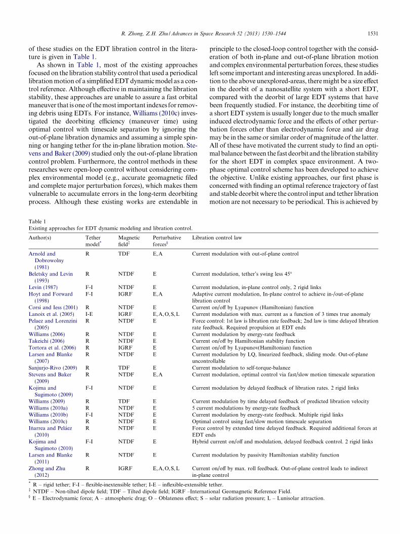
Consider two nano-satellites connected by a bare EDT.One can reasonably simplify the nano-satellites as pointmasses and the connecting EDT as a rigid rod with lengthL and mass mt in the deorbit dynamic analysis, because thelateral deflection of the EDT is relatively small comparedwith its rigid motion. Denoting the upper and lower massesby m1 and m2, we can describe the motion of the EDT satel-lite system in a geocentric inertial frame of the Earth(OXYZ) with the origin at the Earth’s center, the X-axisdirecting to the point of vernal equinox, the Z-axis aligningwith the rotation axis of the Earth, and the Y-axis complet-ing the system with a right-hand coordinate system, seeFig. 1. Eq. (1) gives the orbital dynamic equations of thetwo-body system in the form of the Gaussian perturbationequations (Vallado, 2007), such as,
dadt¼ 2
nffiffiffiffiffiffiffiffiffiffiffiffiffi1� e2p rze sin mþ rx
pr
� �ð1aÞ
dXdt¼ ryr sin u
na2ffiffiffiffiffiffiffiffiffiffiffiffiffi1� e2p
sin ið1bÞ
didt¼ ryr cos u
na2ffiffiffiffiffiffiffiffiffiffiffiffiffi1� e2p ð1cÞ
dex
dt¼
ffiffiffiffiffiffiffiffiffiffiffiffiffi1� e2p
narz sin uþ rx 1þ r
p
� �cos uþ r
pex
� �
þ dXdt
ey cos i ð1dÞ
dey
dt¼
ffiffiffiffiffiffiffiffiffiffiffiffiffi1� e2p
na�rz cos uþ rx 1þ r
p
� �sin uþ r
pey
� �
� dXdt
ex cos i
ð1eÞ
dudt¼ n� 1
narz
2raþ
ffiffiffiffiffiffiffiffiffiffiffiffiffi1� e2p
1þffiffiffiffiffiffiffiffiffiffiffiffiffi1� e2p e cos m
!"
�rx 1þ rp
� � ffiffiffiffiffiffiffiffiffiffiffiffiffi1� e2p
1þffiffiffiffiffiffiffiffiffiffiffiffiffi1� e2p e sin m
#� ryr cos i sin u
na2ffiffiffiffiffiffiffiffiffiffiffiffiffi1� e2p
sin ið1fÞ
where ex ¼ e cos x, ey ¼ e sin x, u ¼ M þ x; (a,e, i,x,X,m,M) are the classical orbital elements that denotesemi-major axis (a), eccentricity (e), orbit inclination (i),argument of perigee (x), longitude of ascending node (X),true anomaly (m) and mean anomaly (M); (r,p,n) are thegeocentric radius of the center of mass (CM) of EDT sys-tem, semilatus rectum, and mean orbit rate; u is the sumof argument of the perigee and the true anomaly; and(rx,ry ,rz) are the three components of perturbative acceler-ations in an orbital coordinate system, respectively. Thefirst two perturbative acceleration components are in theorbital plane with rz is the radial component and rx isthe component perpendicular to rz and pointing in thedirection of satellite motion. The third acceleration compo-nent ry completes a right-hand system.
2.2. Libration dynamic equations
The libration motion of a rigid EDT system is describedin an orbital coordinate system shown in the insert part inFig. 1. The z-axis of the orbital coordinate system pointsfrom the Earth’s center to the CM of EDT system, the x-axis lies in the orbital plane perpendicular to the z-axis,and the y-axis completes a right-hand coordinate system.The unit vectors along each axis are denoted as ~eox, ~eoy ,and ~eoz, respectively. Then, the instantaneous attitudes ofan EDT system are described by an in-plane angle a (pitch
R. Zhong, Z.H. Zhu / Advances in Space Research 52 (2013) 1530–1544 1533
angle, rotating about the y-axis) followed by an out-of-plane angle b (roll angle, rotating about the x0-axis, thex-axis after first rotating about the y-axis). The tether libra-tion dynamics has been well studied by the pioneers in thefield. For the simple model in this paper (a rigid tether run-ning in an elliptical orbit), a direct derivation can be foundas per Zhong and Zhu (2012), and the equations of motionare written as follow
€aþ €m� 2ð _aþ _mÞ _b tan bþ 3lr�3 sin a cos a
¼ Qa
~mL2 cos2 bð2aÞ
€bþ ð _aþ _mÞ2 sin b cos bþ 3lr�3 cos2 a sin b cos b
¼Qb
~mL2ð2bÞ
where ~m is the equivalent mass equal to ½m1m2 þ ðm1 þ m2Þmt=3þ m2
t =12�ðm1 þ m2 þ mtÞ�1, l is the Earth’s gravita-tional constant, and (Qa,Qb) are the perturbative torquesin the roll and pitch motion, respectively.
2.3. Environmental perturbations
The perturbative accelerations (rx,ry ,rz) and the corre-sponding torques (Qa,Qb) in Eqs. (1) and (2) are inducedby environmental perturbative effects. In this work, the fol-lowing major perturbations are considered: namely, (i) theelectrodynamic force exerting on a current-carrying EDTdue to the electromagnetic interaction with the geomagneticfield, (ii) the Earth’s atmospheric drag, (iii) the Earth’s non-homogeneity and oblateness, (iv) the lunisolar gravitationalperturbations, and (v) the solar radiation pressure, respec-tively. The EDT system is assumed thrust-less during thedeorbit process, while the atmosphere, geomagnetic andambient plasma fields are assumed to rotate with the Earthat the same rate. Generally, the environmental perturba-tions (ii) to (v), especially the last two, are rather small com-pared to the electrodynamic force (i). Therefore, they areoften ignored for simplicity in the study of EDT stabilityand control in the literature. However, these perturbationswill have important effects on the EDT dynamics in a longterm deorbit process if the tether is relative short and thecurrent is limited. The perturbative torques can be derivedusing perturbation forces by the virtual work principle.However, the analytical integrals are not easy to obtain inthe calculation considering the nonlinear variation of per-turbation forces along the tether. In this paper, the pertur-bation torques for tether libration motion are evaluatednumerically in a piecewise way, where the EDT is dividedinto several segments and the perturbation torques areassumed constant within each segment. The more segmentsused, the better estimation the perturbation torques.Detailed expressions of theses environmental perturbationsand perturbation torques can be found in the authors’ pre-vious work (Zhong and Zhu, 2012). Finally, it is worth topoint out that the geodetic altitude, instead of geocentric
altitude, should be used in the evaluation of the environ-mental parameters such as air and electron density for thesack of accuracy, such that,
hg ¼ r � rpo 1� e2E cos2 h
� ��1=2 ð3Þ
where h is the latitude and the parameters of polar radiusrpo and the Earth’s eccentricity eE are provided by NASA(2012), respectively. Furthermore, the local strength ofthe geomagnetic field is evaluated by the InternationalGeomagnetic Reference Field IGRF2000 model (Davis,2004) up to 7th order. The authors (Zhong and Zhu,2013) have shown that the 7th order IGRF2000 modelcould accurately model the inhomogeneous variation ofthe geomagnetic field with errors less than 1%. The com-monly used tilted dipole model is unable to account forthe significant inhomogeneous variation of the local geo-magnetic field strength in both longitude and latitude direc-tions, leading to inaccurate variations of orbital parameterssuch as the eccentricity in a long term.
3. Optimal control for fast deorbit by a short electrodynamic
tether
A natural deorbiting limit of 25 years exists for any satel-lite in a specific altitude (close to 600 km, Jablonski andScott, 2009). The target of this part is to find a controlmethod ensuring the bounded libration motion and with afaster deorbiting rate compared to other existing controlschemes only dealing with libration stability. It is desiredto reduce the deorbit time of a short EDT to less than10 years. This can be best realized by a two-phase optimalcontrol strategy. Firstly, a reference optimal trajectory isdetermined quickly in an open-loop control using a simpli-fied EDT dynamic model. This control problem is formu-lated as a performance index minimization problemrepresenting the deorbit efficiency subjected to predeter-mined constraints, which will ensure a fastest deorbit whilekeeping the tether libration stability by the maximum avail-able current. Then, a closed-loop tracking control is appliedto minimize the state errors of the system with respect to thereference optimal trajectory with minimum control efforts.Both optimal control problems are discretized into timeintervals and solved using the same direct method.
As shown in the EDT’s orbital and libration dynamicsequations, Eqs. (1) and (2), the orbital and libration motionsare coupled and have different timescale. The orbital param-eters of a nano-satellite deorbit by a short electrodynamictether changes slowly, except the true anomaly, due to thelimited current available in the EDT, whereas the tether libra-tion angles vary relatively fast. Treating the slow and fastmotions with the same timescale in discretization process isnot only unnecessary but also prone to numerical error accu-mulations due to numerical truncation errors in the slowmotion. In the current work, a simple piecewise treatmentis proposed to separate the EDT’s orbital and librationdynamics. The EDT deorbit process is discretized into a seriesof sequential intervals and a two-phase optimal control
1534 R. Zhong, Z.H. Zhu / Advances in Space Research 52 (2013) 1530–1544
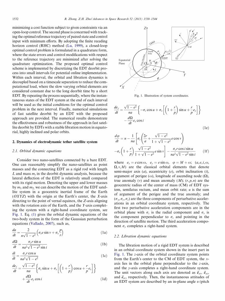
strategy is applied in each interval. In the first phase, the slowvarying orbital parameters are regarded as constant, and onlythe tether libration is formulated for the optimal trajectoryfinding problem that dramatically reduces the size of theproblem. The deorbit height in each interval is pre-deter-mined to ensure the accuracy of the constant orbital param-eter assumption. The corresponding time interval isdetermined iteratively until the estimated deorbit height bythe derived optimal trajectory matches the pre-determineddeorbit height. Then, the output from the open-loop controlproblem, including the optimal states and the electrical cur-rent control input, are used as the reference trajectory forthe closed-loop trajectory tracking in the second phase, wherea full EDT dynamic model is adopted to obtain “real” statesof a deorbiting EDT system. The difference of these “real”states and reference states are used to calculate the optimalcurrent control modification required to track the optimaltrajectory by the infinite receding horizon control method.The instantaneous states at the end of interval under theclosed-loop tracking control are then used as initial condi-tions for the two-phase control in the next interval. By repeat-ing the above process, the optimal deorbit control problem issolved piecewisely until the target height is reached. The flowchart of the control strategy proposed is shown in Fig. 2.
The advantage of this piecewise treatment is that it sig-nificantly reduces the computational efforts and accumula-tive errors, which are especially large considering the longdeorbit time of a short EDT in highly inclined orbits. Ifthe interval is sufficient small relative to the computingpower onboard the satellite and the instantaneous statesat the end of previous interval can be estimated in advanceusing an appropriate filter, the computation for the open-loop optimal trajectory of the next interval can be donein advance or parallel while the closed-loop tracking is stillin process. This could lead to an online implementation ofthe proposed optimal control algorithm for the fast EDTdeorbit if the current regulation is realized by an ammeterand a varistor. The detailed methodology of the open- andclosed-loop control scheme is given as follows.
3.1. Open-loop optimal trajectory determination
3.1.1. Open-loop optimal control problem formulation
In the open-loop optimal control phase, the environ-mental perturbations are simplified to find an optimal fastdeorbit trajectory quickly by considering only the electro-dynamic force with a non-tilted dipole model of geomag-netic field, such that,
~B ¼ lm
r3cos u sin i~eox þ
lm
r3cos i~eoy �
2lm
r3sin u sin i~eoz ð4Þ
where lm is the magnetic moment of the Earth’s dipole. Theaverage current Iave across the tether is the only control inputto the EDT system with a constant tether length L, such that,
Iave ¼1
L
Z L
0
IðsÞds ð5Þ
Accordingly, the electrodynamic force ~Fe exerting on theEDT can be written as,
~Fe ¼ �Z L
0
B*
� I l*
ds ¼ �IaveLB*
� l*
ð6Þ
For generality, introduce the dimensionless times ¼ t
ffiffiffiffiffiffiffiffiffiffilp�3
p, and denote the EDT libration angles and
velocities (a,a0,b,b0) by a state variable vector xðsÞ andthe control input (Iave) by a function nðsÞ in the remainingpart of this paper, where the prime “0” represents the timederivative with respect to the dimensionless time.
The EDT deorbiting over a time interval ½s0; sf � will dis-sipate the orbital energy of an EDT system through the workdone by the electrodynamic force. Therefore, the negativework done by the electrodynamic force within the intervalis chosen as the cost function in this phase, such that
J ¼Z sf
so
~Fe �~mds ¼Z sf
so
Pðx; n; sÞds ð7Þ
where~v is the orbital velocity of the EDT.The optimal trajectory for a fast deorbit using an EDT
can be achieved intuitively by finding a state-control pairfxðsÞ; nðsÞg to minimize the cost function in Eq. (7) (equiv-alent to the maximization of the absolute work done by theelectrodynamic force) when subjected to the nonlinear stateequations of libration motion
_x ¼ Cðx; n; sÞ ð8Þthe initial conditions,
xðs0Þ ¼ xini ð9Þand the box constraints for the states and the control input
jaj 6 amaxj bj 6 bmax Imin 6 Iave 6 Imax ð10ÞAssume all of the slow varying orbital parameters are
constant within the interval. This will result the EDT sys-tem moving in an elliptical orbit. By using the fundamentalorbital equations for the true anomaly, the nonlinear stateequation in Eq. (8) can be expanded from Eq. (2) as
x01 ¼ x2
x02 ¼ 2g3e sin mþ 2ðx2 þ g2Þx4 tan x3 � 3g3 sin x1 cos x1
þ sin i tan x3ð2 sin u cos x1 � cos u sin x1Þ½
� cos i�ð1� kÞIavelm
l~mg3
x03 ¼ x4
x04 ¼ �ðx2 þ g2Þ2 sin x3 cos x3 � 3g3 cos2 x1 sin x3 cos x3
� sin ið2 sin u sin x1 þ cos u cos x1Þð1� kÞIavelm
l~mg3
ð11Þ
where ðx1; x2; x3; x4Þ ¼ ða; b; a0; b0; Þ, g ¼ 1þ e cos m. Themass distribution parameter k and the current distributionparameter 1 are defined as

Beginning ofk-th Interval
Full Dynamic
Model
Optimal TrajectoryMax energy dissipation by
Lorentz force
Optimal Trajectory Tracking
Deorbit Height Estimation
StopYes
(ΔTk)Interval Length
No
Reduce ΔTk
Δhk
Yes
Yes
Phase Two: Closed-loop ControlPhase One: Open-loop Control
If Δhk < Δhmax
No
Increase ΔTkIf Δhk > Δhmin
Stop Open-loop Control
If h (t) < htarget
( ), ( ), ( ), ( )
( ),opt opt opt opt
opt k
t t t tI t Tα β α β
Δ
No
( ), ( ), ( ), ( )t t t tα β α β
Update states for (k+1)-th interval
( )I t
Simplified Dynamic ModelKeep slow varying orbital
parameters (α, e, i, Ω, u) constant
New Orbital Heighth (t)
If t > Tk-1+ΔΤk
Yes
No
Fig. 2. Flow Chart of the two-phase optimal control algorithm in one interval.
R. Zhong, Z.H. Zhu / Advances in Space Research 52 (2013) 1530–1544 1535
k ¼ ðm1 þ 0:5mtÞ=ðm1 þ m2 þ mtÞ;
1 ¼ I�1aveL
�2
Z L
0
sIðsÞds ð12Þ
For simplicity in the study, the 1 is set to be 0.5 as oftenadopted in the existing approaches on the EDT control(Pelaez and Lorenzini, 2005), which implies a constant cur-rent in the EDT.
The upper limit for the libration angles, amax and bmax
are preset to ensure the librational stability, whereas theupper and lower limits for the current Imax and Imin aredetermined by the current available in an EDT system,which can be estimated as follows. Firstly, the absolutevalue of the average current in the open-loop control isset to be less than one half of the maximum available cur-rent IAvl so that there is sufficient room left for the currentregulation resulting from the next phase closed-loop opti-mal trajectory tracking control. Secondly, the maximumavailable current IAvl is set to be one-tenth of the short cir-cuit current Ic, such that,
jIavej 6 0:5IAvl; IAvl ¼ 0:1Ic ¼ j0:1EmLR�1j ð13Þwhere R is the resistance of the tether, Em is the projectionof motional electric field along the EDT length, which canbe expressed as
Imax ¼ 0:05LR�1lml0:5a�3:5 sin i sin bB
_
sinðXG þ aB
_ �XÞ � cosh
Imin ¼ 0;
(
Em ¼ �ð~mr � ~BÞ �~l ð14Þ
The magnitude of Em can be estimated by assuming zerolibration angles and ~mr �~m. By using a tilted dipole geo-magnetic field model (Williams, 2009), Em is derived fromEq. (14) that,
Em ¼ �lm
r3� sin i sin bB
_
sinðXG þ aB
_ �XÞ þ cos i cos bB
_h imx ð15Þ
where mx is the component of orbital velocity~m of the EDTin the~eox direction, XG is the longitude of the prime merid-
ian with respect to the vernal equinox direction, aB
_and bB
_
are the right ascension angle and the tilted angle of the geo-magnetic dipole axis, respectively. It is noted that although
aB
_and bB
_
vary slowly with time, the following values are
usually adopted aB
_ ¼ 4:4680 rad, bB
_
¼ 0:2042 rad.Substituting Eq. (15) into Eq. (13) yields,
Iave6 j0:05LR�1 lm
r3sin isinbB
_
sinðXGþaB
_ �X�cos icosbB
_h imxj ð16Þ
Eq. (16) can be further simplified by substituting the geo-centric radius r by the semi-major axis a, and approximat-
ing the velocity mx byffiffiffiffiffiffiffiffiffiffila�1
pif the orbital eccentricity is
small during deorbit. Then, we can derive Imax and Imin
from Eq. (16), such that
i cos bB
_ i;
if Em > 0 ð17aÞ
1536 R. Zhong, Z.H. Zhu / Advances in Space Research 52 (2013) 1530–1544
or
Imax ¼ 0
Imin ¼ 0:05LR�1lml0:5a�3:5½sin i sin bB
_
sinðXG þ aB
_ �XÞ � cos i cos bB
_
�;
(if Em < 0 ð17bÞ
It is noticed that the current limits in Eq. (17) are gener-ally the function of both orbital altitude and position. Inthe special case of equatorial orbit, the current limits varyonly with respect to the altitude.
3.1.2. Direct solution method
The problem of performance index minimization in theSection 3.1.1 is conducted by a direct solution method thatdiscretizes the continuous optimization problem into a dis-crete parameter optimization problem of nonlinear pro-graming piecewisely. The direct method is adopted hereas it avoids the difficulty usually encountered when usingstandard approaches in derivation of the necessary condi-tions for optimality (Bryson and Ho, 1975). In the currentwork, a direct collocation method based on the Hermite–Simpson scheme (Hargraves and Paris, 1987; Zhong andXu, 2010), among numerous different discretizationschemes (Herman and Conway, 1996; Wen et al.,2008a,b), is adopted because of its simplicity and accuracy.
Discretize the time interval ½s0; sf � into N subintervalswith N þ 1 nodes at the discretized time sk
(k ¼ 0; 1; 2; . . . ;N ; sN ¼ sf ). For simplicity, the discretizednodes are evenly distributed in the time domain and thesubinterval length is ðsN � s0Þ=N . Then, the cost functionEq. (7) can be discretized by the Simpson integration for-mula using programming variables, such as, the state vec-tors and control inputs at nodes (x0; x1; x2; . . . ; xN ) and(n0; n1; n2; . . . ; nN ), and control inputs at mid-pointsbetween adjacent nodes (n0:5; n1:5; n2:5; . . . ; nN�0:5),
J ffi sN � s0
6N
XN�1
0
½Pðxk; nk; skÞ
þ 4Pðxkþ0:5; nkþ0:5; skþ0:5Þ þPðxkþ1; nkþ1; skþ1Þ� ð18Þ
where the mid-point state vectors, xkþ0:5, can be derived bythe Hermite interpolation scheme as
xkþ0:5 ¼1
2ðxk þ xkþ1Þ þ
sN � s0
8N½Cðxk; nk; skÞ
� Cðxkþ1; nkþ1; skþ1Þ� ð19Þ
Similarly, the nonlinear constraints in Eq. (8) arereplaced by a set of discretized equations using the Simp-son integration formula, such that
sN � s0
6NPðxk; nk; skÞ þ 4Pðxkþ0:5; nkþ0:5; skþ0:5Þ½
þPðxkþ1; nkþ1; skþ1Þ� þ xk � xkþ1 ¼ 0 ð20Þ
Finally, the discretization is completed by replacing the
constraints for the initial states in Eq. (9) and the continu-ous box constraints in Eq. (10) with the discretizedconstraints,
x0 ¼ xini xmin 6 xk 6 xmax nmin 6 nk 6 nmax nmin
6 nkþ0:5 6 nmax ð21Þ
The discretization process above transforms the minimi-zation problem of a continuous function into a nonlinearprogramming problem. A commonly used numerical soft-ware package, the sparse sequential quadratic program-ming software SNOPT (Gill et al., 2002), is used tosearch the optimal values for the programming variablessubjected to constraints in Eqs. (20) and (21), which mini-mize the cost function in Eq. (18) and result in an optimaltrajectory including optimal state vectors xopt and optimalcontrol input nopt. Furthermore, the resulted performanceindex J opt, the work done by the electrodynamic force,can be used to estimate the height decadence, Dh, in theinterval with the energy conservation equation as follows,
� lrðs0Þ
þ 1
2v2ðs0Þ þ
J optffiffiffiffiffiffiffiffiffiffilp�3
pðm1 þ m2 þ mtÞ
¼ � lrðsN Þ
þ 1
2v2ðsN Þ ð22Þ
By substituting the initial geocentric radius rðs0Þ withthe semi-major axis aðs0Þ, and the Newton’s lawv2 � l
r �la, it can be derived from Eq. (22) that
Dh ¼ rðs0Þ � rðsNÞ
¼ aðs0Þ �l
la�1ðs0Þ � 2J optðlp�3Þ�0:5ðm1 þ m2 þ mtÞ�1
ð23Þ
3.2. Closed-loop optimal trajectory tracking control
The optimal trajectory found in the Section 3.1 is notgood for a stable and fast EDT system deorbit withoutcontrol feedback because the assumption of constant orbi-tal parameters and simplified environmental perturbativemodels are used in the optimization process. As theopen-loop control cannot correct the errors by itself, aclosed-loop procedure with feedback is required to addressthis issue. The finite receding horizon control (Lu, 1999), afeedback control law effective in tracking a time-varyingreference is adopted to track the resulted optimal trajec-tory. The RHC is solved with the same discretizationmethod in the open-loop optimal trajectory determinationto transform.
R. Zhong, Z.H. Zhu / Advances in Space Research 52 (2013) 1530–1544 1537
3.2.1. Finite receding horizon control method
The classic RHC method is to minimize a quadraticform of state and control errors over a future horizon per-iod sh from the current time s�, such that
G ¼ 1
2dxT ðs� þ shÞSf dxðs� þ shÞ þ
1
2
�Z s�þsh
s�
½dxT ðsÞQdxðsÞ þ dnT ðsÞW nðsÞ�ds ð24Þ
which is subjected to the linearized state equations
dx0 ¼ dCðx; n; sÞ ¼ AðsÞdxþ BðsÞdn ð25Þ
where initial value for Eq. (25), dxðs�Þ, are the deviationsfrom the optimal states at the current time, such as
dxðs�Þ ¼ xðs�Þ � xoptðs�Þ ð26Þ
Here, AðsÞ ¼ @Cðx; n; sÞ=@x and BðsÞ ¼ @Cðx; n; sÞ=@n arethe system state influence matrix and the control influencecoefficient vector, respectively. Sf and Q are the positivesemi-definite weight matrices penalizing the deviations ofthe perturbed states, W is a positive weight penalizing thedeviation of the perturbed control input over the horizoninterval ½s�; s� þ sh� ½s0; sf �, respectively.
By solving the above optimal problem, the RHC methodfinds the electric current control modification dnðs�Þ to theknown open-loop optimal current control input nðs�Þ withthe current state error dxðs�Þ being feedback.
3.2.2. Closed-loop optimal trajectory tracking control usingdirect collocation method
The optimal problem stated in the Section 3.2.1 can besolved using discretization method (Williams, 2004). In thispaper, it is solved by the same direct collocation based onthe Hermite–Simpson method in the Section 3.1.2, becauseit will reduce the computation effort. Firstly, the horizoninterval ½s�; s� þ sh� is divided evenly into �N subintervalswith �N þ 1 discrete nodes at sk (k ¼ 0; 1; 2; . . . ; �N ;s0 ¼ s�,s�N ¼ s� þ sh). Then, the continuous cost minimizationproblem in the RHC method in Eqs. (24)–(26) is trans-formed to the discrete problem, such that,
G ¼ 1
2dxT
�N Sf dx�N þ1
2
sh
6 �N
X�N�1
k¼0
dxTk Qdxk þ 4dxT
kþ0:5Qdxkþ0:5
þdxT
kþ1Qdxkþ1 þ Rðdn2k þ 4dn2
kþ0:5 þ dn2kþ1Þ
�ð27Þ
subject to
dxk � dxkþ1 þsh
6 �NAkdxk þ 4Akþ0:5dxkþ0:5 þ Akþ1dxkþ1½
þBkdnk þ 4Bkþ0:5dnkþ0:5 þ Bkþ1dnkþ1� ¼ 0 ð28Þdx0 ¼ xðs�Þ � xoptðs�Þ ð29Þ
where
dxkþ0:5 ¼1
2ðdxk þ dxkþ1Þ
þ sh
8 �NAkdxk � Akþ1dxkþ1 þ Bkdnk � Bkþ1dnkþ1ð Þ
Ak and Bk are the coefficient influence matrices and vectorsat discrete nodes, whereas Akþ0:5 and Bkþ0:5 represent thevalues at mid-points.
Eqs. (27)–(29) lead to a standard quadratic programmingproblem after derivation to find a programming vectorZ ¼ dxT
0 ; dxT1 ; . . . ; dxT
�N ; dn0; dn1; . . . ; dn�N ; dn0:5;
dn1:5; . . . ; dn�N�0:5�T that minimizes the cost function,
G ¼ 1
2ZT MZ ð30Þ
subject to
CZ ¼ X X ¼ ½dxT0 0 0 . . . 0�T ð31Þ
where C and M are the coefficient matrices. They can be de-rived easily and are not listed here in details.
This standard quadratic programming problem has theanalytical solution (Fletcher, 1989) such as
Z� ¼M�1CT ðCM�1CT Þ�1X ð32Þ
Therefore, the control modification at the current time isderived as
dnðs�Þ ¼ VZ�
¼ VM�1CT ðCM�1CT Þ�1X ¼D Kðs�; �N ; shÞ
� ½xðs�Þ � xoptðs�Þ� ð33Þ
where the row vector V is defined to “choose” the targetvalue from the optimal solution, and the position of “1”
in the row vector V is the same as the position of dn0 inthe column vector Z. Finally, the modified control inputof the closed-loop control is obtained as
nðs�Þ ¼ noptðs�Þ þ dnðs�Þ¼ noptðs�Þ þ Kðs�; �N ; shÞ½xðs�Þ � xoptðs�Þ� ð34Þ
The closed-loop control law in Eq. (34) is a linear pro-portional feedback control, and the feedback gain matrixK is a function of time. Without any explicit integrationof differential equations, K can be either determined offlineor online depending on the computational and restorativecapacities onboard the satellite.
It is noticed that the matrix M and C are both formu-lated by the influence matrices and vectors at discrete nodesor mid-points (Ak;Bk, Akþ0:5, Bkþ0:5). If the discrete nodesare coincident with the nodes in the phase of open-loop tra-jectory determination, then most of these matrices and vec-tors are already calculated and can be used directly in thetracking control phase. This is advantageous in reducingcomputational effort, which is especially helpful consider-ing the limited onboard computing resource. The calcula-tion in the phase of optimal tracking control can befurther simplified by keeping the future horizon interval½s�; s� þ sh� fixed (i.e. s� ¼ s0 and s� þ sh ¼ sf ) while alter-ing the position of “1” in the vector V to obtain the controlcorrection at different times. This means the matrix M isunchanged and its inverse could be calculated only once
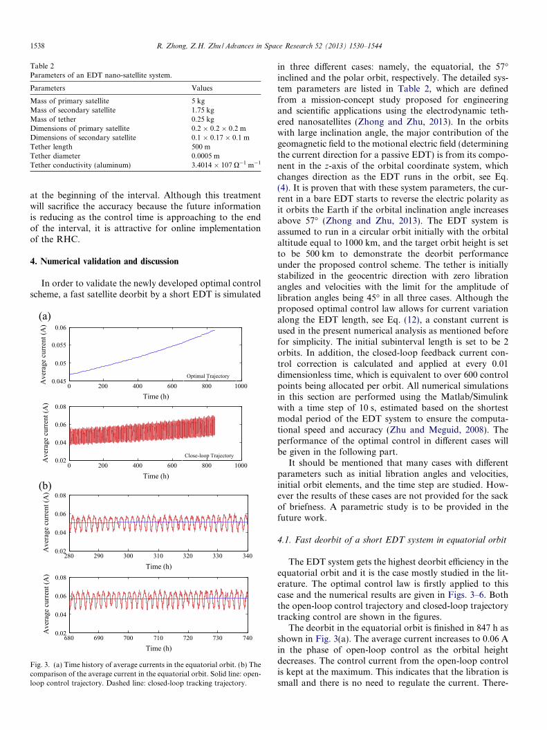
Table 2Parameters of an EDT nano-satellite system.
Parameters Values
Mass of primary satellite 5 kgMass of secondary satellite 1.75 kgMass of tether 0.25 kgDimensions of primary satellite 0.2 � 0.2 � 0.2 mDimensions of secondary satellite 0.1 � 0.17 � 0.1 mTether length 500 mTether diameter 0.0005 mTether conductivity (aluminum) 3.4014 � 107 O�1 m�1
1538 R. Zhong, Z.H. Zhu / Advances in Space Research 52 (2013) 1530–1544
at the beginning of the interval. Although this treatmentwill sacrifice the accuracy because the future informationis reducing as the control time is approaching to the endof the interval, it is attractive for online implementationof the RHC.
4. Numerical validation and discussion
In order to validate the newly developed optimal controlscheme, a fast satellite deorbit by a short EDT is simulated
(a)
(b)
0 200 400 600 800 10000.02
0.04
0.06
0.08
Time (h)
Ave
rage
cur
rent
(A)
0 200 400 600 800 10000.045
0.05
0.055
0.06
Time (h)
Ave
rage
cur
rent
(A)
Optimal Trajectory
Close-loop Trajectory
280 290 300 310 320 330 3400.02
0.04
0.06
0.08
Time (h)
Ave
rage
cur
rent
(A)
680 690 700 710 720 730 7400.02
0.04
0.06
0.08
Time (h)
Ave
rage
cur
rent
(A)
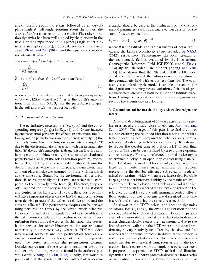
Fig. 3. (a) Time history of average currents in the equatorial orbit. (b) Thecomparison of the average current in the equatorial orbit. Solid line: open-loop control trajectory. Dashed line: closed-loop tracking trajectory.
in three different cases: namely, the equatorial, the 57�inclined and the polar orbit, respectively. The detailed sys-tem parameters are listed in Table 2, which are definedfrom a mission-concept study proposed for engineeringand scientific applications using the electrodynamic teth-ered nanosatellites (Zhong and Zhu, 2013). In the orbitswith large inclination angle, the major contribution of thegeomagnetic field to the motional electric field (determiningthe current direction for a passive EDT) is from its compo-nent in the z-axis of the orbital coordinate system, whichchanges direction as the EDT runs in the orbit, see Eq.(4). It is proven that with these system parameters, the cur-rent in a bare EDT starts to reverse the electric polarity asit orbits the Earth if the orbital inclination angle increasesabove 57� (Zhong and Zhu, 2013). The EDT system isassumed to run in a circular orbit initially with the orbitalaltitude equal to 1000 km, and the target orbit height is setto be 500 km to demonstrate the deorbit performanceunder the proposed control scheme. The tether is initiallystabilized in the geocentric direction with zero librationangles and velocities with the limit for the amplitude oflibration angles being 45� in all three cases. Although theproposed optimal control law allows for current variationalong the EDT length, see Eq. (12), a constant current isused in the present numerical analysis as mentioned beforefor simplicity. The initial subinterval length is set to be 2orbits. In addition, the closed-loop feedback current con-trol correction is calculated and applied at every 0.01dimensionless time, which is equivalent to over 600 controlpoints being allocated per orbit. All numerical simulationsin this section are performed using the Matlab/Simulinkwith a time step of 10 s, estimated based on the shortestmodal period of the EDT system to ensure the computa-tional speed and accuracy (Zhu and Meguid, 2008). Theperformance of the optimal control in different cases willbe given in the following part.
It should be mentioned that many cases with differentparameters such as initial libration angles and velocities,initial orbit elements, and the time step are studied. How-ever the results of these cases are not provided for the sackof briefness. A parametric study is to be provided in thefuture work.
4.1. Fast deorbit of a short EDT system in equatorial orbit
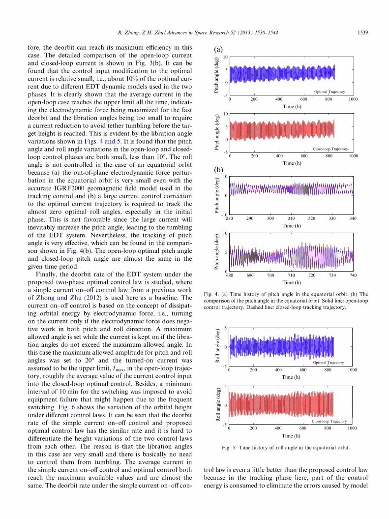
The EDT system gets the highest deorbit efficiency in theequatorial orbit and it is the case mostly studied in the lit-erature. The optimal control law is firstly applied to thiscase and the numerical results are given in Figs. 3–6. Boththe open-loop control trajectory and closed-loop trajectorytracking control are shown in the figures.
The deorbit in the equatorial orbit is finished in 847 h asshown in Fig. 3(a). The average current increases to 0.06 Ain the phase of open-loop control as the orbital heightdecreases. The control current from the open-loop controlis kept at the maximum. This indicates that the libration issmall and there is no need to regulate the current. There-
(a)
(b)
0 200 400 600 800 1000-5
0
5
10
Time (h)
Pitc
h an
gle
(deg
)
0 200 400 600 800 1000-5
0
5
10
Time (h)
Pitc
h an
gle
(deg
)
Close-loop Trajectory
Optimal Trajectory
280 290 300 310 320 330 340-10
0
10
Time (h)
Pitc
h an
gle
(deg
)
680 690 700 710 720 730 7400
5
10
Time (h)
Pitc
h an
gle
(deg
)
Fig. 4. (a) Time history of pitch angle in the equatorial orbit. (b) Thecomparison of the pitch angle in the equatorial orbit. Solid line: open-loopcontrol trajectory. Dashed line: closed-loop tracking trajectory.
0 200 400 600 800 1000-5
0
5
Time (h)
Rol
l ang
le (d
eg)
0 200 400 600 800 1000-5
0
5
Time (h)
Rol
l ang
le (d
eg)
Optimal Trajectory
Close-loop Trajectory
Fig. 5. Time history of roll angle in the equatorial orbit.
R. Zhong, Z.H. Zhu / Advances in Space Research 52 (2013) 1530–1544 1539
fore, the deorbit can reach its maximum efficiency in thiscase. The detailed comparison of the open-loop currentand closed-loop current is shown in Fig. 3(b). It can befound that the control input modification to the optimalcurrent is relative small, i.e., about 10% of the optimal cur-rent due to different EDT dynamic models used in the twophases. It is clearly shown that the average current in theopen-loop case reaches the upper limit all the time, indicat-ing the electrodynamic force being maximized for the fastdeorbit and the libration angles being too small to requirea current reduction to avoid tether tumbling before the tar-get height is reached. This is evident by the libration anglevariations shown in Figs. 4 and 5. It is found that the pitchangle and roll angle variations in the open-loop and closed-loop control phases are both small, less than 10�. The rollangle is not controlled in the case of an equatorial orbitbecause (a) the out-of-plane electrodynamic force pertur-bation in the equatorial orbit is very small even with theaccurate IGRF2000 geomagnetic field model used in thetracking control and (b) a large current control correctionto the optimal current trajectory is required to track thealmost zero optimal roll angles, especially in the initialphase. This is not favorable since the large current willinevitably increase the pitch angle, leading to the tumblingof the EDT system. Nevertheless, the tracking of pitchangle is very effective, which can be found in the compari-son shown in Fig. 4(b). The open-loop optimal pitch angleand closed-loop pitch angle are almost the same in thegiven time period.
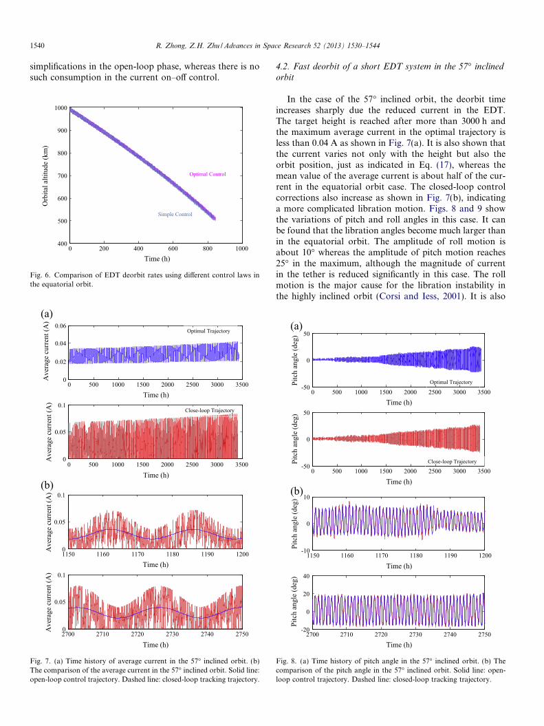
Finally, the deorbit rate of the EDT system under theproposed two-phase optimal control law is studied, wherea simple current on–off control law from a previous workof Zhong and Zhu (2012) is used here as a baseline. Thecurrent on–off control is based on the concept of dissipat-ing orbital energy by electrodynamic force, i.e., turningon the current only if the electrodynamic force does nega-tive work in both pitch and roll direction. A maximumallowed angle is set while the current is kept on if the libra-tion angles do not exceed the maximum allowed angle. Inthis case the maximum allowed amplitude for pitch and rollangles was set to 20� and the turned-on current wasassumed to be the upper limit, Imax, in the open-loop trajec-tory, roughly the average value of the current control inputinto the closed-loop optimal control. Besides, a minimuminterval of 10 min for the switching was imposed to avoidequipment failure that might happen due to the frequentswitching. Fig. 6 shows the variation of the orbital heightunder different control laws. It can be seen that the deorbitrate of the simple current on–off control and proposedoptimal control law has the similar rate and it is hard todifferentiate the height variations of the two control lawsfrom each other. The reason is that the libration anglesin this case are very small and there is basically no needto control them from tumbling. The average current inthe simple current on–off control and optimal control bothreach the maximum available values and are almost thesame. The deorbit rate under the simple current on–off con-
trol law is even a little better than the proposed control lawbecause in the tracking phase here, part of the controlenergy is consumed to eliminate the errors caused by model
1540 R. Zhong, Z.H. Zhu / Advances in Space Research 52 (2013) 1530–1544
simplifications in the open-loop phase, whereas there is nosuch consumption in the current on–off control.
0 200 400 600 800 1000400
500
600
700
800
900
1000
Time (h)
Orb
ital a
ltitu
de (k
m)
Optimal Control
Simple Control
Fig. 6. Comparison of EDT deorbit rates using different control laws inthe equatorial orbit.
(a)
(b)
0 500 1000 1500 2000 2500 3000 35000
0.05
0.1
Time (h)
Ave
rage
cur
rent
(A)
0 500 1000 1500 2000 2500 3000 35000
0.02
0.04
0.06
Time (h)
Ave
rage
cur
rent
(A)
Close-loop Trajectory
Optimal Trajectory
1150 1160 1170 1180 1190 12000
0.05
0.1
Time (h)
Ave
rage
cur
rent
(A)
2700 2710 2720 2730 2740 27500
0.05
0.1
Time (h)
Ave
rage
cur
rent
(A)
Fig. 7. (a) Time history of average current in the 57� inclined orbit. (b)The comparison of the average current in the 57� inclined orbit. Solid line:open-loop control trajectory. Dashed line: closed-loop tracking trajectory.
4.2. Fast deorbit of a short EDT system in the 57� inclined
orbit
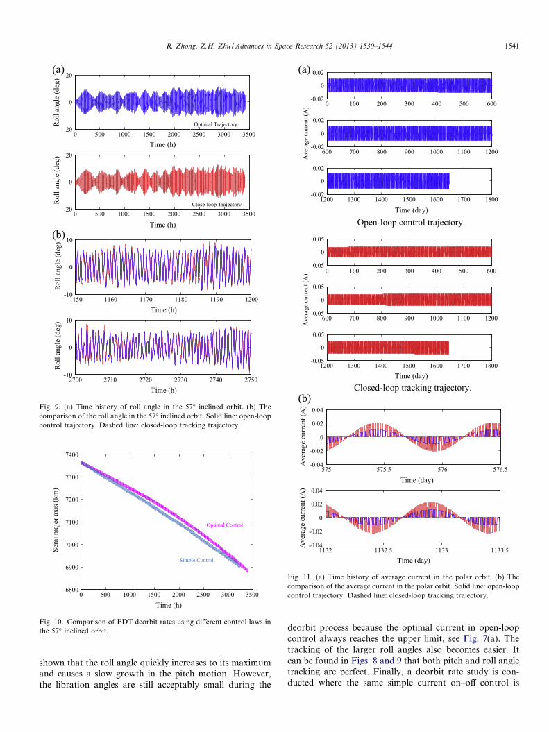
In the case of the 57� inclined orbit, the deorbit timeincreases sharply due the reduced current in the EDT.The target height is reached after more than 3000 h andthe maximum average current in the optimal trajectory isless than 0.04 A as shown in Fig. 7(a). It is also shown thatthe current varies not only with the height but also theorbit position, just as indicated in Eq. (17), whereas themean value of the average current is about half of the cur-rent in the equatorial orbit case. The closed-loop controlcorrections also increase as shown in Fig. 7(b), indicatinga more complicated libration motion. Figs. 8 and 9 showthe variations of pitch and roll angles in this case. It canbe found that the libration angles become much larger thanin the equatorial orbit. The amplitude of roll motion isabout 10� whereas the amplitude of pitch motion reaches25� in the maximum, although the magnitude of currentin the tether is reduced significantly in this case. The rollmotion is the major cause for the libration instability inthe highly inclined orbit (Corsi and Iess, 2001). It is also
(a)
(b)
0 500 1000 1500 2000 2500 3000 3500-50
0
50
Time (h)
Pitc
h an
gle
(deg
)
0 500 1000 1500 2000 2500 3000 3500-50
0
50
Time (h)
Pitc
h an
gle
(deg
)
Optimal Trajectory
Close-loop Trajectory
2700 2710 2720 2730 2740 2750-20
0
20
40
Time (h)
Pitc
h an
gle
(deg
)
1150 1160 1170 1180 1190 1200-10
0
10
Time (h)
Pitc
h an
gle
(deg
)
Fig. 8. (a) Time history of pitch angle in the 57� inclined orbit. (b) Thecomparison of the pitch angle in the 57� inclined orbit. Solid line: open-loop control trajectory. Dashed line: closed-loop tracking trajectory.
(a)
(b)
0 500 1000 1500 2000 2500 3000 3500-20
0
20
Time (h)
Rol
l ang
le (d
eg)
0 500 1000 1500 2000 2500 3000 3500-20
0
20
Time (h)
Rol
l ang
le (d
eg)
Optimal Trajectory
Close-loop Trajectory
1150 1160 1170 1180 1190 1200-10
0
10
Time (h)
Rol
l ang
le (d
eg)
2700 2710 2720 2730 2740 2750-10
0
10
Time (h)
Rol
l ang
le (d
eg)
Fig. 9. (a) Time history of roll angle in the 57� inclined orbit. (b) Thecomparison of the roll angle in the 57� inclined orbit. Solid line: open-loopcontrol trajectory. Dashed line: closed-loop tracking trajectory.
0 500 1000 1500 2000 2500 3000 35006800
6900
7000
7100
7200
7300
7400
Time (h)
Sem
i maj
or a
xis (
km)
Simple Control
Optimal Control
Fig. 10. Comparison of EDT deorbit rates using different control laws inthe 57� inclined orbit.
Open-loop control trajectory.
Closed-loop tracking trajectory.
(a)
(b)
600 700 800 900 1000 1100 1200-0.02
0
0.02
Ave
rage
cur
rent
(A) 0 100 200 300 400 500 600
-0.02
0
0.02
1200 1300 1400 1500 1600 1700 1800-0.02
0
0.02
Time (day)
600 700 800 900 1000 1100 1200-0.05
0
0.05
Ave
rage
cur
rent
(A) 0 100 200 300 400 500 600
-0.05
0
0.05
1200 1300 1400 1500 1600 1700 1800-0.05
0
0.05
Time (day)
575 575.5 576 576.5-0.04
-0.02
0
0.02
0.04
Time (day)
Ave
rage
cur
rent
(A)
1132 1132.5 1133 1133.5-0.04
-0.02
0
0.02
0.04
Time (day)
Ave
rage
cur
rent
(A)
Fig. 11. (a) Time history of average current in the polar orbit. (b) Thecomparison of the average current in the polar orbit. Solid line: open-loopcontrol trajectory. Dashed line: closed-loop tracking trajectory.
R. Zhong, Z.H. Zhu / Advances in Space Research 52 (2013) 1530–1544 1541
shown that the roll angle quickly increases to its maximumand causes a slow growth in the pitch motion. However,the libration angles are still acceptably small during the
deorbit process because the optimal current in open-loopcontrol always reaches the upper limit, see Fig. 7(a). Thetracking of the larger roll angles also becomes easier. Itcan be found in Figs. 8 and 9 that both pitch and roll angletracking are perfect. Finally, a deorbit rate study is con-ducted where the same simple current on–off control is
Open-loop control trajectory.
Closed-loop tracking trajectory.
(a)
(b)
0 100 200 300 400 500 600-50
0
50
1200 1300 1400 1500 1600 1700 1800-50
0
50
Time (day)
600 700 800 900 1000 1100 1200-50
0
50
Pitc
h an
gle
(deg
)
0 100 200 300 400 500 600-50
0
50
600 700 800 900 1000 1100 1200-50
0
50
Pitc
h an
gle
(deg
)
1200 1300 1400 1500 1600 1700 1800-50
0
50
Time (day)
1132 1132.5 1133 1133.5-20
0
20
40
Time (day)
Pitc
h an
gle
(deg
)
575 575.5 576 576.5-20
0
20
Time (day)
Pitc
h an
gle
(deg
)
Fig. 12. (a) Time history of pitch angle in the polar orbit. (b) Thecomparison of the pitch angle in the polar orbit. Solid line: open-loopcontrol trajectory. Dashed line: closed-loop tracking trajectory.
(a)
(b)
600 700 800 900 1000 1100 1200-50
0
50
Rol
l ang
le (d
eg)
1200 1300 1400 1500 1600 1700 1800-50
0
50
Time (day)
0 100 200 300 400 500 600-50
0
50
0 100 200 300 400 500 600-50
0
50
600 700 800 900 1000 1100 1200-50
0
50
Rol
l ang
le (d
eg)
1200 1300 1400 1500 1600 1700 1800-50
0
50
Time (day)
575 575.5 576 576.5-50
0
50
Time (day)
Rol
l ang
le (d
eg)
1132 1132.5 1133 1133.5-50
0
50
Time (day)
Rol
l ang
le (d
eg)
Fig. 13. (a) Time history of roll angle in the polar orbit. (b) Thecomparison of the roll angle in the polar orbit. Solid line: open-loopcontrol trajectory. Dashed line: closed-loop tracking trajectory.
1542 R. Zhong, Z.H. Zhu / Advances in Space Research 52 (2013) 1530–1544
used as comparison. In this highly inclined orbit, the max-imum allowed angle is only set for the roll motion, whereasthe pitch angle is not monitored in the current on–off con-trol as it has been demonstrated that the pitch angle can becontrolled indirectly through the roll-pitch modal couplingin the inclined orbits (Zhong and Zhu, 2012). Fig. 10 com-
pares the deorbit rate of the simple current on–off controland the proposed optimal control by showing the variationof semi-major axis vs. time. It is found that the two controllaws have similar deorbit rate in the staring stage with thesimple current on–off control slightly faster due to the samereason given in the equatorial orbit case. However, the pro-posed optimal control scheme seems to have advantagewhen the libration angles become large in the latter stageof the deorbit process.
R. Zhong, Z.H. Zhu / Advances in Space Research 52 (2013) 1530–1544 1543
4.3. Fast deorbit of short EDT in the polar orbit
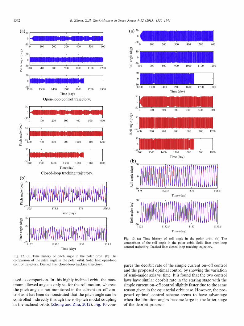
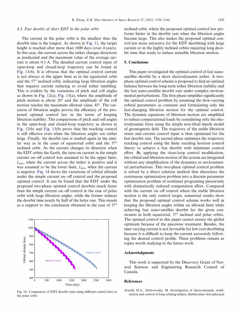
The current in the polar orbit is the smallest thus thedeorbit time is the longest. As shown in Fig. 11, the targetheight is reached after more than 1600 days (over 4 years).In this case, the current across the tether changes directionsas predicated and the maximum value of the average cur-rent is about 0.1 A. The detailed current control input ofopen-loop and closed-loop trajectory can be found inFig. 11(b). It is obvious that the optimal control currentis not always at the upper limit as in the equatorial orbitand the 57� inclined orbit, indicating large libration anglesthat requires current reducing to avoid tether tumbling.This is evident by the variations of pitch and roll anglesas shown in Fig. 12(a), Fig. 13(a), where the amplitude ofpitch motion is about 20� and the amplitude of the rollmotion reaches the maximum allowed value, 45�. The var-iation of libration angles proves the efficiency of the pro-posed optimal control law in the terms of keepinglibration stability. The comparisons of pitch and roll anglesin the open-loop and closed-loop trajectory as shown inFig. 12(b) and Fig. 13(b) prove that the tracking controlis still effective even when the libration angles are ratherlarge. Finally, the deorbit rate is studied again in the simi-lar way as in the cases of equatorial orbit and the 57�inclined orbit. As the current changes its direction whenthe EDT orbits the Earth, the turn-on current in the simplecurrent on–off control was assumed to be the upper limit,Imax, when the current across the tether is positive and itwas assumed to be the lower limit, Imin, when the currentis negative. Fig. 14 shows the variations of orbital altitudeunder the simple current on–off control and the proposedoptimal control. It can be found that the EDT under theproposed two-phase optimal control deorbits much fasterthan the simple current on–off control in the case of polarorbit with large libration angles, while the former reducesthe deorbit time nearly by half of the latter one. This standsas a support to the conclusion obtained in the case of 57�
0 500 1000 1500 2000 2500 3000400
500
600
700
800
900
1000
1100
Time (day)
Orb
ital a
ltitu
de (k
m)
Optimal Control
Simple Control
Fig. 14. Comparison of EDT deorbit rates using different control laws inthe polar orbit.
inclined orbit, where the proposed optimal control law per-forms better in the deorbit rate when the libration anglesbecome large. This also makes the proposed optimal con-trol law more attractive for the EDT deorbiting with largecurrent or in the highly inclined orbits requiring long deor-bit time that tends to induce unstable libration motion.
5. Conclusions
This paper investigated the optimal control of fast nano-satellite deorbit by a short electrodynamic tether. A two-phase optimal control scheme is proposed to find an optimalbalance between the long-term tether libration stability andthe fast nano-satellite deorbit rate under complex environ-mental perturbations. The first phase simplifies significantlythe optimal control problem by assuming the slow-varyingorbital parameters as constant and formulating only thefast-changing libration motion for the optimal control.The dynamic equations of libration motion are simplifiedto reduce computational loads by considering only the elec-trodynamic force using the simple non-tilted dipole modelof geomagnetic field. The trajectory of the stable librationstates and current control input is then optimized for thefast deorbit rate. The second phase optimizes the trajectorytracking control using the finite receding horizon controltheory to achieve a fast deorbit with minimum controleffort. By applying the close-loop control modification,the orbital and libration motion of the system are integratedwithout any simplification of the dynamics or environmen-tal perturbations. This two-phase optimal control problemis solved by a direct solution method that discretizes thecontinuous optimization problem into a discrete parameteroptimization problem of nonlinear programing piecewiselywith dramatically reduced computation effort. Comparedwith the current on–off control where the stable librationmotion is the only control target, numerical results showthat the proposed optimal control scheme works well inkeeping the libration angles within an allowed limit whileachieving fast nano-satellite deorbit for the given con-straints in both equatorial, 57� inclined and polar orbits.The optimal control in this paper cannot ensure the globaloptimum because of the piecewise treatment. Besides, thetime varying current is not favorable for low cost deorbitingbecause it is difficult to keep the current accurately follow-ing the desired control profile. These problems remain astopics worth studying in the future work.
Acknowledgments
This work is supported by the Discovery Grant of Nat-ural Sciences and Engineering Research Council ofCanada.
References
Arnold, D.A., Dobrowolny, M. Investigation of electrodynamic stabil-ization and control of long orbiting tethers, Smithsonian Astrophysical
1544 R. Zhong, Z.H. Zhu / Advances in Space Research 52 (2013) 1530–1544
Observatory, Interim Report on NASA Contract NAS8-33691, ReportNo. NASA-CR-161826, March 1981.
Beletsky V.V., Levin E.M. Dynamics of Space Tether Systems, Univelt,Incorporated for American Astronautical Society, San Diego, CA,Chapter 5, 1993.
Bryson, A.E., Ho, Y.C. Applied Optimal Control, Hemisphere, NewYork, Chapter 2, 1975.
Corsi, J., Iess, L. Stability and control of electrodynamic tethers for de-orbiting application. Acta Astronaut. 48 (5–12), 491–501, 2001.
Covello, F. Application of electrical propulsion for an active debrisremoval system: a system engineering approach. Adv. Space Res. 50(7), 918–931, 2012.
Davis, J. Mathematical Modeling of Earth’s Magnetic Field, TechnicalNote, Virginia Tech., Blacksburg, 2004.
Fletcher, R. Practical Methods of Optimization, 2nd ed Wiley, New York(Chapter 10), 1989.
Gill, P.E., Murray, W., Saunders, M.A. SNOPT: an SQP algorithm forlarge-scale constrained optimization. SIAM J. Optimiz. 12 (4), 979–1006, 2002.
Hargraves, C.R., Paris, S.W. Direct trajectory optimization using nonlin-ear programming and collocation. J. Guid. Control Dyn. 10 (4), 338–342, 1987.
Herman, A.L., Conway, B.A. Direct optimization using collocation basedon high-order Gauss-Lobatto quadrature rules. J. Guid. Control Dyn.19 (3), 592–599, 1996.
Hoyt, R.P., Forward, R.L. The terminator tether: a low-mass system forend-of-life deorbit of LEO spacecraft, Tethers Unlimited, Inc. FinalReport on NASA/MSFC SBIR Phase I, Contract NAS8-98108,October 9, 1998.
Inarrea, M., Pelaez, J. Libration control of electrodynamic tethers usingthe extended time-delayed autosynchronization method. J. Guid.Control Dyn. 33 (3), 923–933, 2010.
Jablonski, A.M., Scott, R. Deorbiting of microsatellites in low earth orbit(LEO) – an introduction. Can. Aeronaut. Space J. 55 (2), 55–67, 2009.
Kim, I., Hirayama, H., Hanada, T. Practical guidelines for electro-dynamic tethers to survive from orbital debris impacts. Adv. SpaceRes. 45 (10), 1292–1300, 2010.
Kojima, H., Sugimoto, T. Stability analysis of in-plane and out-planeperiodic motions of electrodynamic tether system in inclined ellipticorbit. Acta Astronaut. 65 (3–4), 477–488, 2009.
Kojima, H., Sugimoto, T. Switching delayed feedback control for anelectrodynamic tether system in an inclined elliptic orbit. ActaAstronaut. 66 (7–8), 1072–1080, 2010.
Lanoix, E.L.M., Misra, A.K., Modi, V.J., et al. Effect of electrodynamicforces on the orbital dynamics of tethered satellites. J. Guid. ControlDyn. 28 (6), 1309–1315, 2005.
Larsen, M.B., Blanke, M. Nonlinear control of electrodynamic tether inequatorial or somewhat inclined orbits, in: Proceedings of 15th IEEEMediterranean Conference on Control and Automation, T02–005,2007.
Larsen, M.B., Blanke, M. Passivity-based control of a rigid electrody-namic tether. J. Guid. Control Dyn. 34 (1), 118–127, 2011.
Levin, E.M. Stability of the stationary motions of an electrodynamictether system in orbit. Kosmicheskie Issledovaniya 25 (4), 491–501,1987.
Lu, P. Regulation about time-varying trajectories: precision entry guid-ance illustrated. J. Guid. Control Dyn. 22 (6), 784–790, 1999.
NASA. Earth Fact Sheet, <http://nssdc.gsfc.nasa.gov/planetary/fact-sheet/earthfact.html>, (retrieved 16 March 2012).
National Research Council. NASA space technology roadmaps andpriorities: restoring NASA’s technological edge and paving the way fora new era in space, National Academies Press, Washington, DC, 2012.
Pelaez, J., Lorenzini, E.C. Libration control of electrodynamic tethers ininclined orbit. J. Guid. Control Dyn. 28 (2), 269–279, 2005.
Pelaez, J., Lorenzini, E.C., Lopez-Rebollal, O., et al. A new kind ofdynamic instability in electrodynamic tethers. J. Astronaut. Sci. 48 (4),449–476, 2000.
Sanjurjo-Rivo, M. Self-balanced bare electrodynamic tethers: space debrismitigation and other applications, Ph.D. Thesis, Applied PhysicsAerospace Engineering, Department Universidad Politecnica deMadrid, Madrid, Spain, pp. 83–96, 2009.
Stevens, R.E., Baker, W.P. Optimal control of a librating electrodynamictether performing a multirevolution orbit change. J. Guid. ControlDyn. 32 (5), 1497–1507, 2009.
Takeichi, N. Practical operation strategy for deorbit of an electrodynamictethered system. J. Spacecraft Rockets 43 (6), 1283–1288, 2006.
Tortora, P., Somenzi, L., Iess, L., Licata, R. Small mission design fortesting in-orbit an electrodynamic tether deorbiting system. J. Space-craft Rockets 43 (4), 883–892, 2006.
Uphoff, C., Forward, R.L., Hoyt, R.P. The ‘Terminator Tether’: anefficient mechanism for end-of-life deorbit of constellation spacecraft,in: VanDerHa, J.C. (Ed.), Mission Design and Implementation ofSatellite Constellations, 1. Springer, Netherlands, pp. 347–365, 1998.
Vallado, D.A. Fundamentals of Astrodynamics and Applications. Micro-cosm Press, Springer, New York, 2007.
Wang, T. Analysis of debris from the collision of the Cosmos 2251 and theIridium 33 satellites. Science and Global Security 18, 87–118, 2010.
Wen, H., Jin, D.P., Hu, H. Advances in dynamics and control of tetheredsatellite systems. Acta Mech. Sin. 24 (3), 229–241, 2008a.
Wen, H., Jin, D.P., Hu, H. Infinite-horizon control for retrieving atethered subsatellite via an elastic tether. J. Guid. Control Dyn. 31 (4),899–906, 2008b.
Williams, P. Application of pseudospectral methods for receding horizoncontrol. J. Guid. Control Dyn. 27 (2), 310–314, 2004.
Williams, P. Energy rate feedback for libration control of electrodynamictethers. J. Guid. Control Dyn. 29 (1), 221–223, 2006.
Williams, P. Libration control of electrodynamic tethers using predictivecontrol with time-delayed feedback. J. Guid. Control Dyn. 32 (4),1254–1268, 2009.
Williams, P. Electrodynamic tethers under forced-current variations Part1: Periodic solutions for tether librations. J. Spacecraft Rockets 47 (2),308–319, 2010a.
Williams, P. Electrodynamic tethers under forced-current variations Part2: Flexible-tether estimation and control. J. Spacecraft Rockets 47 (2),320–333, 2010b.
Williams, P. Optimal control of electrodynamic tether orbit transfers usingtimescale separation. J. Guid. Control Dyn. 33 (1), 88–98, 2010c.
Zhong, R., Xu, S. Orbit-transfer control for TSS using direct collocationmethod. Acta Aeronaut. Astronaut. Sin. 31 (3), 572–578, 2010.
Zhong, R., Zhu, Z.H. Long-term libration dynamics and stability analysisof electrodynamic tethers in spacecraft deorbit. J. Aerospace Eng.,http://dx.doi.org/10.1061/(ASCE)AS.1943-5525.0000310 (in press),posted online on 29 November, 2012.
Zhong, R., Zhu, Z.H. Dynamics of nanosatellite deorbit by bareelectrodynamic tether in low earth orbit. J. Spacecraft Rockets 50(3), 691–700, 2013.
Zhu, Z.H., Meguid, S.A. Vibration analysis of a new curved beamelement. J. Sound Vib. 309 (1–2), 86–95, 2008.
Copyright © 2022 FDOKUMEN