lms/sysnoise 功能簡介
74
1 LMS/SYSNOISE 功能簡介 LMS/SYSNOISE 功能簡介 System for System for Vibro Vibro - - Acoustic Analysis Acoustic Analysis LMS Numerical Technologies
-
Upload
khangminh22 -
Category
Documents
-
view
1 -
download
0
Transcript of lms/sysnoise 功能簡介
1
LMS/SYSNOISE 功能簡介LMS/SYSNOISE 功能簡介
System forSystem forVibroVibro--Acoustic AnalysisAcoustic Analysis
LMS Numerical Technologies

2
A Few Words About AcousticsA Few Words About Acoustics
sound path & absorptionairbornestructure-bornemixed
SourceSource PropagationPropagation ReceiverReceiver
vibrating bodyspeaker
microphoneear

3
Dealing with Vibration & SoundDealing with Vibration & Sound
Flexible wallRigid wall

4
Vibro - Acoustic Excitation
Structure Fluid
FsFa
Structure
Fluid-Structure CouplingFluid-Structure Coupling
Vibration generates SoundVibration generates Sound
u p
Sound induces vibration Sound induces vibration
5
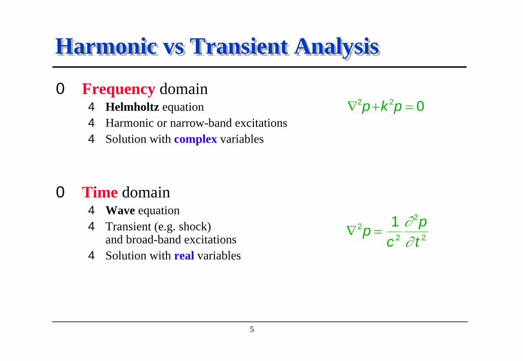
Harmonic vs Transient AnalysisHarmonic vs Transient Analysis
0 Frequency domain4 Helmholtz equation4 Harmonic or narrow-band excitations4 Solution with complex variables
0 Time domain4 Wave equation4 Transient (e.g. shock)
and broad-band excitations4 Solution with real variables
∇ + =2 2 0p k p
∇ =22
2
2
1pc
pt
∂∂

6
Why Numerical Simulation ?Why Numerical Simulation ?
NumericalMethods
Efficiency
ExperimentalTechniques
KNOW UNDERSTAND PREDICT
7
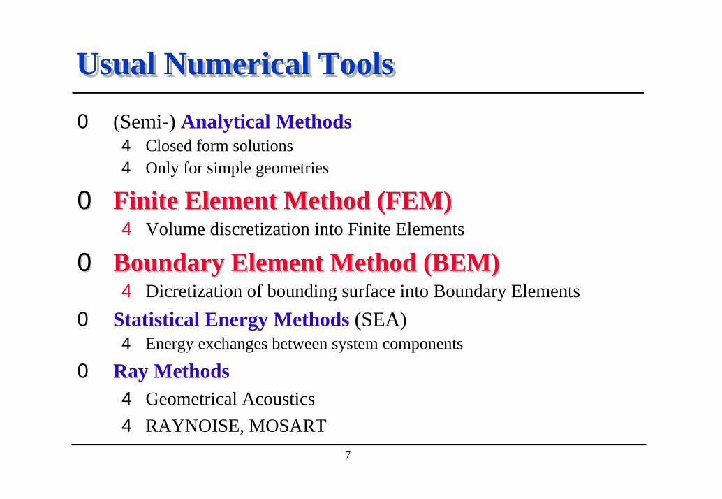
Usual Numerical ToolsUsual Numerical Tools
0 (Semi-) Analytical Methods4 Closed form solutions4 Only for simple geometries
00 Finite Element Method (FEM)Finite Element Method (FEM)4 Volume discretization into Finite Elements
00 Boundary Element Method (BEM)Boundary Element Method (BEM)4 Dicretization of bounding surface into Boundary Elements
0 Statistical Energy Methods (SEA)4 Energy exchanges between system components
0 Ray Methods4 Geometrical Acoustics4 RAYNOISE, MOSART

8
Why Acoustic Analysis ?Why Acoustic Analysis ?
0 Acoustics becomes increasingly important4 Product quality4 Competitive advantage4 Part of design specifications4 Government regulations quality of Life
0 Analysis up-front in the design phase4 Concurrent engineering4 Early interaction with design engineers4 Evaluate design alternatives4 Reduce prototyping4 Significant cost and time savings
9
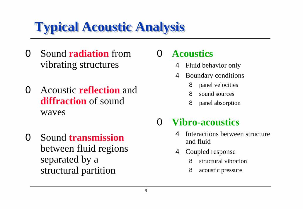
Typical Acoustic AnalysisTypical Acoustic Analysis
0 Sound radiation from vibrating structures
0 Acoustic reflection anddiffraction of sound waves
0 Sound transmissionbetween fluid regions separated by a structural partition
0 Acoustics4 Fluid behavior only4 Boundary conditions
8 panel velocities8 sound sources8 panel absorption
0 Vibro-acoustics4 Interactions between structure
and fluid4 Coupled response
8 structural vibration8 acoustic pressure

10
Why SYSNOISE ?Why SYSNOISE ?
0 Most mature and complete interactive solution today0 The user has the right to choose his method
4 FEM or BEM4 Direct or indirect4 Coupled or uncoupled4 Transient or harmonic
0 Developed for power users as well as occasional users0 Compatible with
4 your hardware environment8 UNIX, CRAY, CONVEX, IBM SP2 and Windows platforms
4 your software investments8 FE packages, TEST softwares (LMS CADA-X)
11
SYSNOISE Offers You ...SYSNOISE Offers You ...
0 Modeling facilities (economy of time) 4 Automatic mesh checking and coarsening4 Optimized solvers for all methods4 Non-linear matrix interpolation
0 Fully Interactive analysis4 Graphical user interface4 Wizards4 Customizable environment
0 Minimum memory requirements0 Maximum speed for calculation0 No inherent limit
4 Dynamic memory allocation4 Out-of-core procedures for all the solvers

12
Methods & FrequenciesMethods & Frequencies
Acoustics
higher frequencyhigher modal density
Vibro-Acoustics
SYSNOISESYSNOISE MOSART, RAYNOISEMOSART, RAYNOISE
SYSNOISESYSNOISE SEASEA

13
FEM & I-FEMFEM & I-FEM
0 interior/exterior domain0 volume mesh : slower0 heterogeneous or
homogeneous fluid0 volume/surface absorber0 solution : fast

14
BEMBEM
IBEMIBEMExterior
DBEMDBEM
Interior0 homogeneous fluid0 surface absorbers0 meshing : faster
15
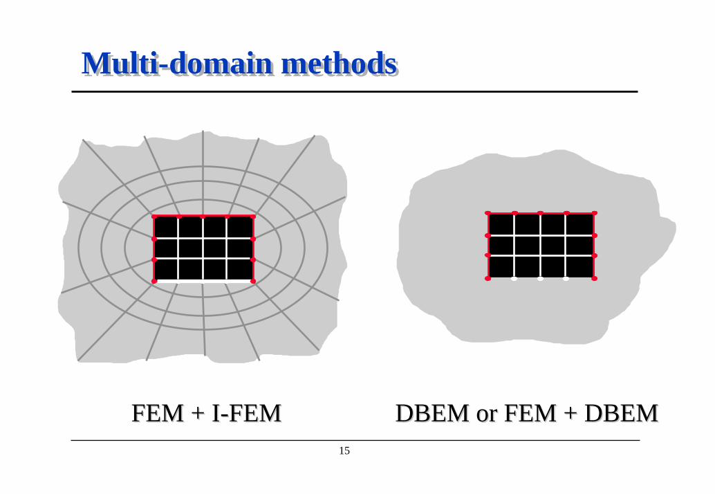
Multi-domain methodsMulti-domain methods
FEM + IFEM + I--FEMFEM DBEM or FEM + DBEMDBEM or FEM + DBEM

16
Available Modules of SYSNOISEAvailable Modules of SYSNOISE
Transient Transient
Acoustic FEM
I-FEM
Struct.FEM
Struct.FEM
DBEM
IBEM Struct.FEM
Struct.FEM
Harm
onic
Har
mon
icTransient

17
Calculation SequenceCalculation SequenceStart
End
Calculation OptionInput Mesh & Field
Fluid PropertiesPanel PropertiesSound Sources
Acoustic AnalysisPost-analysis
Post-processing
e.g. FEM or BEM
Mesh checking & correction
Density and speed of sounStructural and absorption propertiesPanel velocities or nodal forcesSpherical, Planar, User
Modes, Response, Matrice
Directivity, Contribution, Sensitivities
XY, Contours, Vectors, Animation
Meshd
Vibration
s
18
Vibration InputVibration Input
0 From FEA4 Uncoupled (acoustic) analysis : vibration patterns4 Coupled (vibro-acoustic) analysis : str. normal modes
0 From Test (coupling effects included)4 Accelerometer or laser measurements4 Sorted per frequency or per measurement location
0 Manual input4 constant velocity over the considered frequency range4 through frequency dependent tables

19
Available InterfacesAvailable Interfaces
SYSNOISESYSNOISEMesh GeneratorNodes,Elements, Groups
Vibrations, SensitivitiesMode Shapes
Test Data Embedded 2-way interfaces
Pre-processingVibro-Acoustic AnalysisPost-analysisDedicated Post-processing
PrePre--processingprocessingVibroVibro--Acoustic AnalysisAcoustic AnalysisPostPost--analysisanalysisDedicated PostDedicated Post--processing
Structural FEA
processing
• MSC/NASTRAN - MSC/PATRAN• LMS/CADA-X• ANSYS• I-DEAS Master Series• Hypermesh
•ABAQUS• MARC• ProMechanica• FemGen/FemView• SYSTUS

20
Pre-processingPre-processing
0 Import meshes from external mesh generators0 Mesh checking and coarsening0 Automatic search and handling of junction lines0 Automatic search and handling of free edges0 Visual creation of item groups0 Application of boundary conditions
4 panel absorption4 panel vibration4 acoustic sources

21
Vibro-Acoustic AnalysisVibro-Acoustic Analysis
0 Normal modes4 Acoustic mode shapes4 Structural mode shapes (fluid loaded)
0 Vibro-Acoustic response4 Acoustic (and structural) results at nodes and field points
8 uncoupled and coupled analysis8 transient, harmonic and random (BEM) solution8 automatic out-of-core solvers for all modules
0 Matrices4 Compute and export FE and BE matrices4 Added mass matrix

22
Post-analysisPost-analysis
0 Directivity4 polar diagrams4 3D balloons
0 Panel Contribution4 contribution to sound pressure or sound power4 total or effective contribution
0 Sensitivities4 structural and acoustic design variables4 global and acoustic sensitivities

23
Dedicated Post-processingDedicated Post-processing
0 Contour plotting4 pressure4 vector field
components0 Deformed
geometry0 Vector diagram
4 superimposed meshes4 velocities, intensitities, ...
0 Animation4 transient response4 frequency scanning4 phase animation
0 XY plots4 time and frequency dependent
response functions4 weighted or not (dBA, B, C...)4 narrow band, octave, 1/3 octave
0 Polar diagrams4 sound directivity4 complex contribution
0 Bar charts4 panel contributions4 modal participation factors4 sensitivities

24
ConclusionConclusion
00 SYSNOISESYSNOISE is the leading software for computational vibro-acoustics
00 SYSNOISESYSNOISE offers you a broad choice of methods4 to predict sound from vibrating structures4 to simulate the interaction between fluid and structure4 to optimize acoustically your product design
0 Main benefits of using SYSNOISESYSNOISE4 Integrated software l Open architecture4 Ease-of-use l Customization4 Calculation speed l All major computers

25
LMS/SYSNOISE 應用實例LMS/SYSNOISE 應用實例
內部聲場
外部聲場
流場結構互動
設計改善
汽車
航太
家用產品

26
車內噪音分析車內噪音分析
27
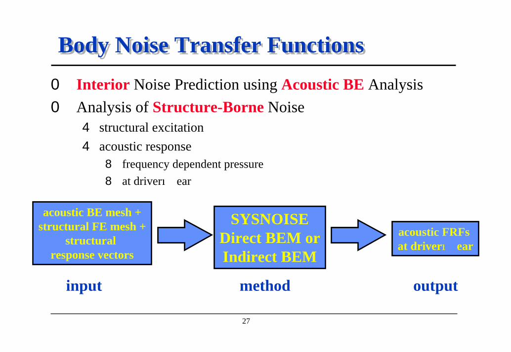
Body Noise Transfer FunctionsBody Noise Transfer Functions0 Interior Noise Prediction using Acoustic BE Analysis0 Analysis of Structure-Borne Noise
4 structural excitation 4 acoustic response
8 frequency dependent pressure8 at driver ear
acoustic BE mesh +structural FE mesh +
structural response vectors
SYSNOISEDirect BEM orIndirect BEM
acoustic FRFs at driver ear
input method output
28
Definition of BNTFDefinition of BNTF
0 What ?4 frequency response function4 of sound pressure at a field point4 caused by a unit force4 at a structural excitation point
8 engine mount8 suspension point
0 Why ?4 if same car body and same acoustic compartment4 but different engines, suspension systems4 you can use the same BNTF !

29
First Step = Structural FE AnalysisFirst Step = Structural FE Analysis
0 Structural FE Mesh4 8914 nodes, 11086 elements4 body in white
0 Excitation4 Unit force (engine mount)
0 Analysis4 Normal modes (up to 120 Hz) 4 Modal superposition
0 Results = Body displacements4 from 5 to 70 Hz, step 1 Hz4 usually limited to 100 ... 150 Hz
Model Courtesy of DaewooModel Courtesy of Daewoo

30
Second Step = Acoustic BE AnalysisSecond Step = Acoustic BE Analysis0 Incompatible Meshes
4 acoustic BE mesh with only 1168 nodes and 1200 elements4 different wavelengths for fluid and structure (bending)4 different geometries and different element densities
0 Automatic Multi-Frequency Transfer4 structural displacements => normal acoustic velocities

31
Acoustic Response CalculationAcoustic Response Calculation0 Acoustic Frequency Response
Function (Field Point)4 driver ear4 pressure (dB)4 all frequencies
0 Acoustic Field (Field Point Mesh)4 whole cavity4 pressure (dB)4 one frequency acoustic
calculation time negligible comparedtostructural analysis

32
ConclusionConclusion
Contribution
0 Driver ear response computed with SYSNOISE0 Further information may be obtained
from a contribution analysis0 A tool for each problem
4 low frequency (Vibro-)Acoustics : SYSNOISE4 medium to high frequency Acoustics : MOSART4 high frequency (Vibro-)Acoustics : SEA
0 Interface to Sound Quality Monitor (LMS CADA-X)0 Equivalent results between acoustic FE and BE0 Very fast acoustic calculation

33
引擎本體輻射噪音引擎本體輻射噪音
Structural FE Mesh Acoustic BE Mesh
7400 grids & 6400 elements
2800 grids & 2800 elements
34
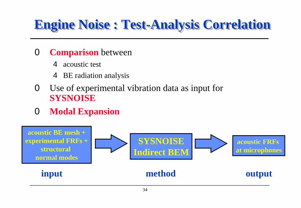
Engine Noise : Test-Analysis Correlation Engine Noise : Test-Analysis Correlation
0 Comparison between4 acoustic test4 BE radiation analysis
0 Use of experimental vibration data as input for SYSNOISE
0 Modal Expansion
acoustic BE mesh +experimental FRFs +
structural normal modes
SYSNOISEIndirect BEM
acoustic FRFs at microphones
input method output
35
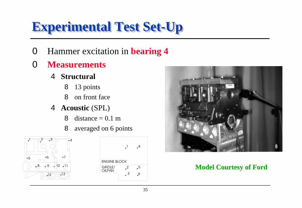
Experimental Test Set-UpExperimental Test Set-Up
0 Hammer excitation in bearing 40 Measurements
4 Structural8 13 points 8 on front face
4 Acoustic (SPL)8 distance = 0.1 m8 averaged on 6 points
Model Courtesy of FordModel Courtesy of Ford

36
Structural and Acoustic MeshesStructural and Acoustic Meshes
Structural FE Mesh Acoustic BE Mesh
7400 grids & 6400 elements
2800 grids & 2800 elements
0 Structural FE mesh4 volume elements4 lumped masses4 beam elements4 interior surfaces
0 Mesh Coarsening4 suppress internal parts4 detect and remove the ribs4 increase the size of the elements (6 elements per acoustic
wavelength is enough for the radiation analysis)4 end up with the radiating surface only = BE Mesh

37
Modal ExpansionModal Expansion
0 Assumptions4 experimental data are reliable and sufficient
8 accurate damping 8 accurate boundary conditions8 accurate load
4 mode shapes are correct8 correlated with measurements
0 For each frequency
0 Singular Value Decomposition
ombine structural mode shapes to match the actual dynamic response of the structure
38
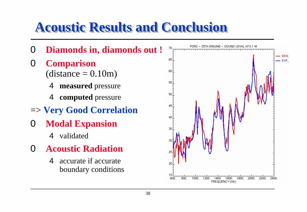
Acoustic Results and ConclusionAcoustic Results and Conclusion0 Diamonds in, diamonds out !0 Comparison
(distance = 0.10m)4 measured pressure4 computed pressure
=> Very Good Correlation0 Modal Expansion
4 validated
0 Acoustic Radiation4 accurate if accurate
boundary conditions

39
消音器傳輸損失計算消音器傳輸損失計算

40
Double Line Exhaust SystemDouble Line Exhaust System0 Many tools for modeling duct noise and shell radiation
4 finite elements8 surface absorption and perforated pipes8 inhomogeneous fluid (porous material, temperature gradients,...)8 flow effects8 time and frequency domain analysis
4 boundary elements8 surface absorption and perforated pipes8 uncoupled or coupled (shell noise) analysis
acoustic FE mesh
+ velocity BCs
IL, TL, attenuation
(dB)
SYSNOISEAcoustic FEM
input outputmethod

41
Acoustic ModelAcoustic Model
0 Acoustic FE Mesh4 46966 nodes and 39254 elements
0 Acoustic Properties4 Acoustic medium = air4 Perforated pipes4 Strong temperature gradient
(500 0C -> 50 0C)
0 Excitation4 2 inlet pipes 4 engine pulsations = velocity BCs4 phase difference : 180 degrees
Model Courtesy ofModel Courtesy of BosalBosal

42
Acoustic Response CalculationAcoustic Response Calculation0 Pipe noise
4 for one single frequency or on a frequency range4 transmission loss (by
combination of FRFs)
43
Flow EffectsFlow Effects0 2-step approach
4 compute flow field8 in SYSNOISE : stationnary, inviscid, irrotational flow8 in CFD package + import to SYSNOISE
4 compute acoustic field (convected wave equation)0 Flow field
4 flow potential and flow velocity BCs4 frequency independent
0 Acoustic field4 influenced by flow field4 frequency domain
44
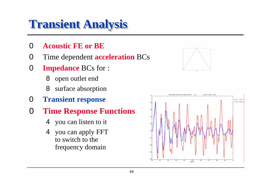
Transient AnalysisTransient Analysis
0 Acoustic FE or BE 0 Time dependent acceleration BCs0 Impedance BCs for :
8 open outlet end8 surface absorption
0 Transient response0 Time Response Functions
4 you can listen to it4 you can apply FFT
to switch to the frequency domain

45
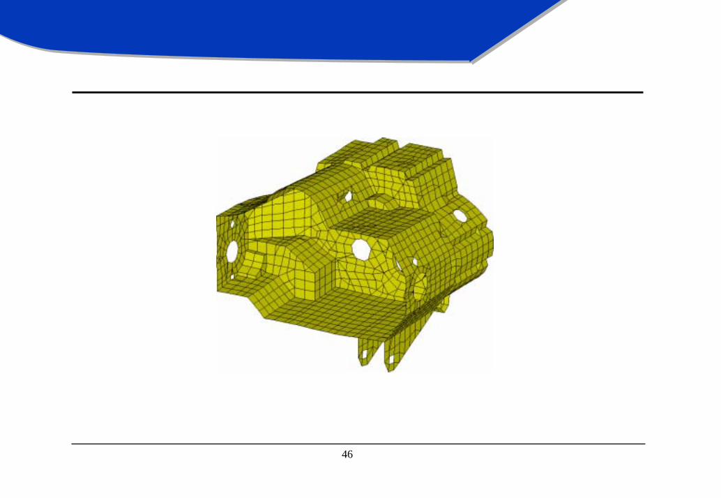
ConclusionConclusion
0 Multitude of tools for duct acoustics4 HVAC systems4 air in-take systems4 exhaust systems
0 Choice of method is application dependent4 flow effects ? temperature effects ?4 transient or harmonic ? uncoupled or coupled ?4 homogeneous fluid ? perforated pipes ? surface absorption ?
0 Further post-processing4 audio replay4 interface to Sound Quality Monitor (SQ-MON of LMS)
46
齒輪箱噪音齒輪箱噪音

47
Gearbox Sound RadiationGearbox Sound Radiation0 Compliance with Pass-by-Noise Regulation0 Automatic Model Handling
4 automatic verification4 automatic correction
0 Non-Linear Matrix Frequency Interpolation 4 faster solution4 same accuracy
acoustic BE mesh +structural
FEA results
directivity diagrams +SPL results
at field points
SYSNOISEIndirect BEM
input method output

48
Pass-By-Noise Test (Europe : ISO 362)Pass-By-Noise Test (Europe : ISO 362)
0 Running Vehicle4 initial speed = 50km/h 4 2 tests : second and third gear4 accelerate at full throttle
0 Measurement Points4 immobile, standardized position4 SPL < 77 dBA during the whole test
0 Many Contributions4 road/wheel noise4 engine noise4 aerodynamic noise 4 noise of components : exhaust, gearbox, ...
Model Courtesy Model Courtesy of BMWof BMW MunchenMunchen

49
Acoustic ModelAcoustic Model
0 Acoustic BE Mesh4 1.827 nodes, 1.899 elements
0 Automatic Mesh Handling4 normals correction4 junctions (523)
8 detection of junctions8 junction constraints
4 free edges
0 Excitation4 vibration of the gearbox shell4 gear noise
0 Frequency : 500 to 1500 (Step 5 Hz) = 201 Stepsfree edges
junctions
50
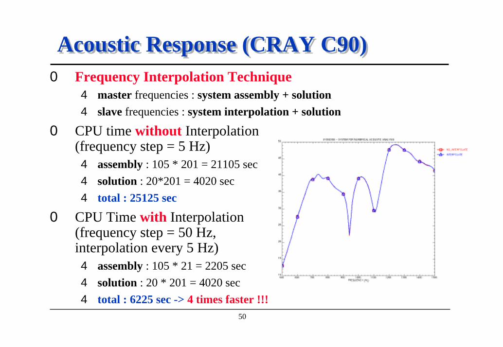
Acoustic Response (CRAY C90)Acoustic Response (CRAY C90)0 Frequency Interpolation Technique
4 master frequencies : system assembly + solution4 slave frequencies : system interpolation + solution
0 CPU time without Interpolation (frequency step = 5 Hz)4 assembly : 105 * 201 = 21105 sec4 solution : 20*201 = 4020 sec4 total : 25125 sec
0 CPU Time with Interpolation (frequency step = 50 Hz, interpolation every 5 Hz)4 assembly : 105 * 21 = 2205 sec4 solution : 20 * 201 = 4020 sec4 total : 6225 sec -> 4 times faster !!!

51
ConclusionConclusion
0 Fully Automatic Mesh Handling4 mesh verification4 mesh correction
0 Matrix Frequency Interpolation4 non linear4 important time saving4 quality of results kept
0 Pass-by-Noise Requirements are Satisfied

52
引擎閥蓋噪音引擎閥蓋噪音

53
Valve Cover RadiationValve Cover Radiation0 Sound Radiated from Truck Engine Valve Cover0 Automatic Mesh Treatment in SYSNOISE
4 normals correction and rib removal
0 Symmetry planes and Reflective Halfspaces0 Analysis
4 radiation from structural normal mode4 comparison of radiation efficiencies
acoustic radiated field +
radiation efficiency
acoustic BE mesh + structural
normal modes
SYSNOISEIndirect BEM
input method output

54
Structural ModelStructural Model
Model Courtesy Model Courtesy of Renault VIof Renault VI
0 Structural FE Mesh4 1771 nodes4 1758 elements 4 symmetric4 contains ribs
0 Structural Deflection4 mode shape 6 - 843.3 Hz
0 Rib Handling4 interior ribs 4 no direct contribution to acoustic field4 mesh coarsener of SYSNOISE
8 automatic rib detection and removal
55
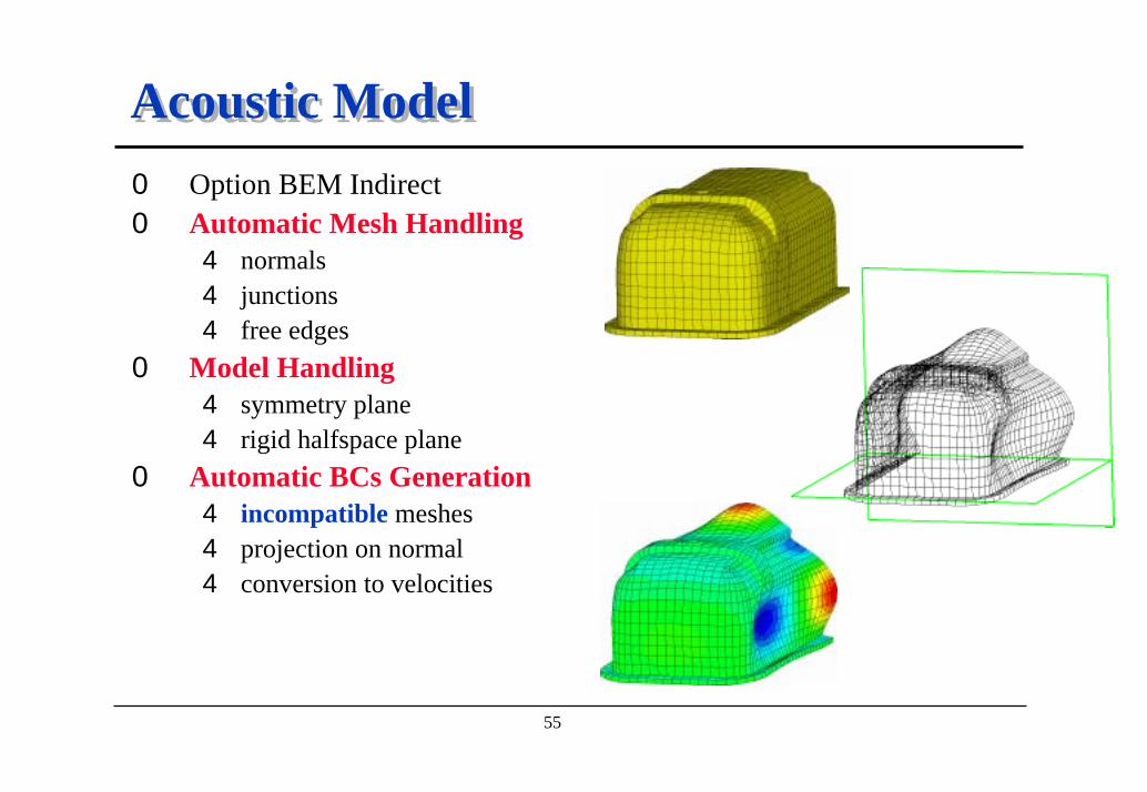
Acoustic ModelAcoustic Model0 Option BEM Indirect0 Automatic Mesh Handling
4 normals4 junctions4 free edges
0 Model Handling4 symmetry plane4 rigid halfspace plane
0 Automatic BCs Generation4 incompatible meshes4 projection on normal4 conversion to velocities

56
Acoustic Radiated FieldAcoustic Radiated Field0 Results
4 mesh8 potentials8 input and radiated power8 power densities8 radiation efficiency
4 field point mesh8 pressure8 velocity8 intensity8 radiated power
57
ConclusionConclusion
0 Starting from a Structural FE Model4 structural FE mesh4 structural modal basis
0 Automatic Handling of the Mesh4 very robust algorithms4 very fast update of the model
0 Easy Transfer of Structural Deflection0 Acoustic Radiation Analysis0 Vibro-Acoustic Results
4 detailled results4 easy representation

58
飛機渦輪葉片噪音飛機渦輪葉片噪音

59
Aircraft Fan NoiseAircraft Fan Noise0 Acoustic Radiation using Indirect BEM0 Axisymmetric Model
4 axisymmetric geometry4 non-axisymmetric excitation4 Fourier decomposition
0 Easy Post-processing
SYSNOISEIndirect BEM
(Axisymmetric)
AcousticField
SPL, ...
acoustic BE mesh (generator line) +field point mesh
input method output

60
Acoustic BE ModelAcoustic BE Model
0 Acoustic BE Mesh (Axisymmetric)4 only 60 nodes, 59 LINE2 elements4 automatic verification of normals
0 Automatic Axisymmetric Mesh Expansion4 3D mesh4 refinement = 5
0 Boundary Conditions4 order 5 => Fourier decomposition4 possible BCs in SYSNOISE
8 velocity, pressure8 impedance/admittance8 continuous or discontinuous8 combination
harmonic order 5

61
Acoustic Field EvaluationAcoustic Field Evaluation0 Very Fast Calculation (like a 2D Model)0 Acoustic Field
4 pure radiation4 scattering on fuselage
Pressure field - 500Hz
Scattered field - 500Hz
62
ConclusionConclusion
0 Unique Features for Solving Axisymmetric Problems like Aircraft Fan Noise Problems4 axisymmetric geometry4 automatic mesh expansion4 boundary condition
8 general 3D8 harmonic (order to be specified)
0 Very Short CPU Time0 Full 3D Post-processing Possible

63
喇叭流場結構互動行為分析喇叭流場結構互動行為分析
64
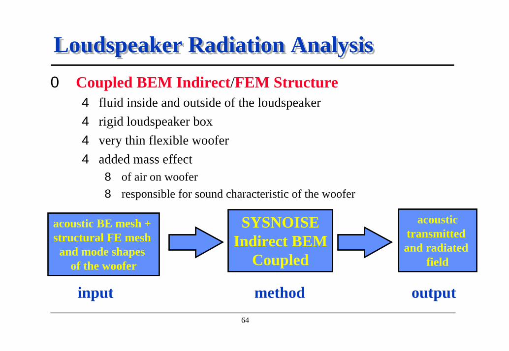
Loudspeaker Radiation AnalysisLoudspeaker Radiation Analysis0 Coupled BEM Indirect/FEM Structure
4 fluid inside and outside of the loudspeaker4 rigid loudspeaker box4 very thin flexible woofer4 added mass effect
8 of air on woofer 8 responsible for sound characteristic of the woofer
acoustictransmitted and radiated
field
SYSNOISEIndirect BEM
Coupled
acoustic BE mesh + structural FE mesh and mode shapes
of the woofer
input method output
65
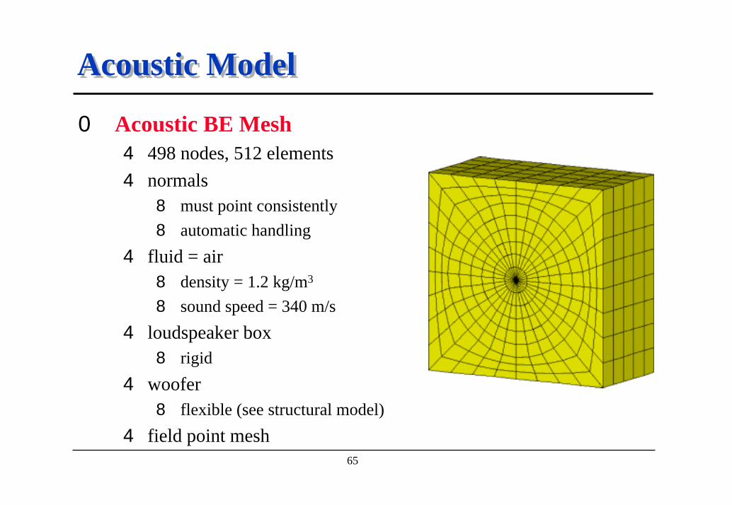
Acoustic ModelAcoustic Model
0 Acoustic BE Mesh4 498 nodes, 512 elements4 normals
8 must point consistently8 automatic handling
4 fluid = air8 density = 1.2 kg/m3
8 sound speed = 340 m/s4 loudspeaker box
8 rigid 4 woofer
8 flexible (see structural model)4 field point mesh

66
Structural FE ModelStructural FE Model
0 Woofer FE Mesh4 shell elements
0 Boundary Conditions4 clamped on the edges4 excitation
8 point force
0 Woofer FE Modal Basis4 10 structural modes 4 up to 1347 Hz
0 Coupling Models4 fluid-structure link 4 on the woofer only

67
Radiated Pressure Field - 500 HzRadiated Pressure Field - 500 Hz

68
ConclusionConclusion
0 Loudspeaker Model4 rigid loudspeaker box4 very flexible and thin woofer (membrane)4 fluid on both sides of the box faces
0 Coupled BEM Indirect/FEM Structure 4 fluid-structure link4 sound transmission (through the woofer)4 exterior acoustic field
8 pressure field8 directivity pattern

69
油底殼設計靈敏度分析油底殼設計靈敏度分析
70
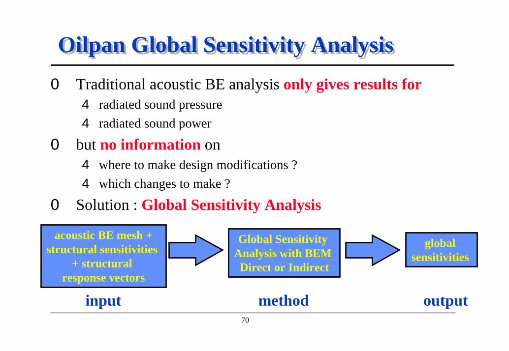
Oilpan Global Sensitivity AnalysisOilpan Global Sensitivity Analysis0 Traditional acoustic BE analysis only gives results for
4 radiated sound pressure4 radiated sound power
0 but no information on 4 where to make design modifications ?4 which changes to make ?
0 Solution : Global Sensitivity Analysis
acoustic BE mesh +structural sensitivities
+ structural response vectors
Global Sensitivity Analysis with BEM Direct or Indirect
global sensitivities
input method output

71
Structural FE ModelStructural FE Model0 Define Thickness Design Variables0 Compute Structural Sensitivities0 Transfer to SYSNOISE
4 for every frequency8 structural sensitivity vectors (1 per design variable)8 response vector
∂∂
∂∂
∂∂
Pa
Pv
vai njj
nj
i
= ∑ .
∂∂
Pbj
∂∂va
nj
i
b j
ai
SYSNOISEStructural FEAStructural DesignVariables (t, E, r, I, ...
Structural DesignSensitivity
Acoustic DesignSensitivities
Acoustic DesignVariables (p, v, A)
Global AcousticSensitivities

72
Acoustic BE ModelAcoustic BE Model
Model Courtesy of HondaModel Courtesy of Honda
0 Acoustic BE Mesh4 radiating surface4 1620 nodes, 1550 elements
0 Problem 4 radiated power too high4 near 1.000 Hz
0 Solution Steps4 compute the sensitivity of radiated
power with respect to panel thickness design variables4 see which part is the most sensitive4 change the thickness (stiffness) of this part4 verify the improved model
73
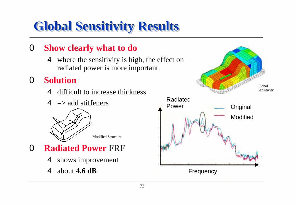
Global Sensitivity ResultsGlobal Sensitivity Results0 Show clearly what to do
4 where the sensitivity is high, the effect onradiated power is more important
0 Solution4 difficult to increase thickness4 => add stiffeners
0 Radiated Power FRF 4 shows improvement 4 about 4.6 dB
Modified Structure
Global Sensitivity
Original
Modified
RadiatedPower
Frequency
74
ConclusionConclusion
0 No more trial-and-error iterations0 SYSNOISE clearly indicates
4 where changes have to be made on the structure4 what is the impact of these changes on the acoustic field
0 Significant cost savings0 Reduced time-to-market0 Further extensions
4 sensitivities on a frequency range4 link to optimization techniques : LMS Optimus