livestock watering requirements - Gov.bc.ca
203
-
Upload
khangminh22 -
Category
Documents
-
view
2 -
download
0
Transcript of livestock watering requirements - Gov.bc.ca


Page 1 of 5
Livestock Watering
Order No. 590.301-1 January 2006
LIVESTOCK WATERING REQUIREMENTS Quantity and Quality
This Factsheet outlines water required for livestock, with tables for estimated daily use. The information here is adapted from Alberta, Ontario, Agriculture & Agri-Food Canada and University of Nebraska factsheets.
Water forms about 50 to 80 percent of an animal's live weight and is an essential nutrient. Whereas an animal may lose almost all of its fat and 50 percent of its body protein and survive, the loss of 10 percent of its body water can be fatal. A 'good' supply of water (both quantity and quality) is required for an animal to maximize feed intake and production. Water is available to livestock in three main ways: • water that is contained in feed consumed • free access to water from natural sources or water troughs • in the winter, free access to clean snow
Livestock consume water based on the combinations of the following: 1. Kind & size of animal 2. Physiological state of animal • lactating cows require an extra 0.86 kg (litre) water per kg of milk
(1 USgal per 10 lb [or 1.2 gal]of milk) • pregnant cows and growing animals 30 to 50% increased consumption
3. Level of animal activity • more active require more water
4. Type of diet & dry matter intake • dry diets require more water than moist diets such as silage or lush pasture • dry matter intake is linked to water (i.e. limiting water will limit feed intake)
5. Water Quality • palatability & salt content affects water consumption
6. Water Temperature • 10 degrees Centigrade desirable; from 4 to 18 degrees acceptable
7. Water trough space • crowding at a trough may limit water to some livestock
8. Air temperature (usually the most important, especially for outdoor livestock) • hot days will increase water consumption • Tables 1 & 2, next pages, show increased water requirement with increased air
temperatures
Importance of Water
Water Sources
Water Quantity Requirements

Page 2 of 5
For many livestock, make initial estimates using this "rule-of-thumb": • cool weather (below150C); 4 L per 45 kg animal weight (1 US gal per 100 lbs) • hot weather (above 250C); 8 L per 45 kg animal weight (2 US gal per 100 lbs)
Also, these two general points apply: • lactating cows require up to twice the water of dry cows • if hauling water during drought conditions, watering every other day could
reduce water intake by 25% without ill effects Daily water requirements for various livestock are shown in Table 1, below, and for beef cattle by air temperature and feed intake in Table 2, next page. In all cases, allow for free choice of water without limiting intake.
TABLE 1 ESTIMATED AVERAGE DAILY WATER CONSUMPTION FOR LIVESTOCK (US GALLONS PER DAY)
TYPE OF ANIMAL DESCRIPTION US GPD TYPE OF ANIMAL DESCRIPTION US GPD BEEF SWINE (with wash water)
cow with calf * 1,300 lb 12 farrow - finish -- 24 / sow dry cow/mature cow * 1,300 lb 10 farrow - late wean 50 lb 8 / sow calf * 250 lb 3 farrow - early wean 15 lb 6.5 / sow feeder – growing ** 400-800 lb 6 - 9 feeder 50 - 250 lb 2 / pig feeder – finishing ** 600-1,200 lb 9 - 12 weaner 15 - 50 lb 0.6 / pig
bull -- 12 POULTRY DAIRY broiler per 100 4.2
milking * (with wash water) holstein 36 roaster/pullet per 100 4.8 dry cow/replacement holstein 12 layer per 100 6.5 calf to 550 lb 3.5 breeder per 100 8.5
SHEEP AND GOATS turkey - grower per 100 15.5 ewe/doe -- 2.5 turkey - heavy per 100 19 milking ewe/doe -- 3.5 OSTRICH -- 1.2
feeder lamb/kid -- 2 DEER, LLAMA, ALPACA -- 2.5
BISON, HORSE, MULE -- 12 ELK, DONKEY -- 6
* For peak water use on days above 250 C multiply gpd by 1.5
** For peak water use on days above 250 C multiply gpd by 2
Sources: Farm Water Supply Requirements, Alberta Agriculture, Food and Rural Development; The Stockman's Guide to Range Livestock Watering From Surface Water Sources, PAMI; Estimated Daily Water Intake of Beef Cattle, Cornell University, New York State
Conversions • lbs x 0.45 = kg
• USgal x 3.785 = litre
• 1 litre of water weights 1 kg
Rule-of-Thumb
Table Values

Page 3 of 5
TABLE 2 ESTIMATED AVERAGE WATER CONSUMPTION FOR BEEF CATTLE COWS (GIVEN BY DRY MATTER FEED INTAKE & BY AIR TEMPERATURE)
AVERAGE DAILY WATER CONSUMPTION 1, 2
kg (litres) of water per kg dry matter feed
(or Imperial gal per 10 lb)
@ 11kg dry matter feed per day
US gal of water per 10 lb dry matter feed
@ 25lb dry matter feed per day
AIR TEMPERATURE (degrees centigrade)
assuming 2½ % of body weight feed consumption per day (may range 2 – 3 %)
over 350 C 8 - 15 9.6 - 18
25 to 350 C 4 - 10 4.8 - 12
15 to 250 C 3 - 5 3.6 - 6
-5 to 150 C 2 - 4 2.4 - 4.8
less than -50 C 3 2 - 3 2.4 - 3.6
1 – typical 450 kb (1,000 lb) cow - young and lactating animals up to 50-100% more water
2 - these estimated daily water consumption values can be adjusted for particular conditions: • to adjust for cow weight – your cow weight / 1,000 lbs x the Table water requirement • to adjust for feed consumption – your daily dry matter feed consumption / 25 lbs x the Table water requirement
3 - increases of 50-100% occur with a rise in air temperature following a period of very cold temperature; eg, from -20 to 00 C Conversion: kg (or litre) water per kg dry matter feed x 1.2 = USgal per 10 lb dry matter feed
Source: Effect of Environment on Nutrient Requirements of Domestic Animals, 1981, NRC
Example – Spring Conditions What is the estimated daily water consumption of a 1,000 lb cow in spring conditions of temperatures from -5 to 150 C and feed intake of 2½ % of body weight?
• using the Rule-of-Thumb from page 2 - cool weather, 1 US gal per 100 lbs = 1 x 1000 / 100 = 10 US gal per day
• using Table 1 - below 250C, a beef cow to 1300 lb = 10 US gal per day
• using Table 2 - a beef cow in these temperatures requires from 6 – 12 US gal per day
Answer: estimate 10 to 12 US gal per day for a beef cow in these conditions. Example – Summer Conditions What is the estimated daily water consumption of a 1,200 lb cow in summer conditions of temperatures from 25 to 350 C and feed intake of 2 % of body weight?
• using the Rule-of-Thumb from page 2 - hot weather, 2 US gal per 100 lbs = 2 x 1200 / 100 = 24 US gal per day
• using Table 1 - above 250C, a beef cow to 1300 lb = 10 x 1.5 = 15 US gal per day
• using Table 2 - above 250C, a beef cow requires from 12 – 29 x 1200 / 1000 US gal per day
= 14 – 35 US gal per day Answer: estimate 15 to 24 US gal per day (with possible 35) for a beef cow in these
conditions.

Page 4 of 5
Water quality affects the quantity of water consumed, and in turn, the quantity of feed consumed. If the water quality is in question, assess it by a lab water analysis. For acceptable levels of the following substances see Factsheet 590.301-2 Water Quality and Cattle, at www.agr.gc.ca/pfra/water/facts/wqcattle.pdf The following is an outline of the main quality concerns with livestock water. Most ground and surface waters are satisfactory for livestock, however, where water quality is a problem, it is commonly excessive salinity. Salinity. Salinity is measured as the concentration of dissolved salts, predominantly calcium, magnesium and sodium chloride. Animals have some ability to adapt to saline water if allowed time to become conditioned to it. Nitrates. Nitrates must be considered together with nitrites. While nitrate toxicity from water is unusual, the combination of nitrates in feed plus those in water can be of concern. In ruminant animals (i.e. dairy, beef cattle and fallow deer), bacteria in the rumen will convert nitrate in the feed or water to nitrite which can diffuse into the blood stream causing respiratory distress and possibly death. The conversion of nitrate to nitrite is not a major problem with monogastric animals (i.e. swine, horses).
Alkalinity. Most waters are alkaline, but very few are too alkaline for livestock. Alkalinity is commonly expressed as pH; 7.0 is neutral, below that is acidic, and above is alkaline. Most waters used by livestock are mildly alkaline with a pH between 7.0 and 8.0. Pesticides. It is recommended that the Canadian guidelines for pesticides in drinking water be used as the maximum limits in livestock water. This will provide a margin of safety for livestock as well as preventing unacceptable residues in animal products. Data for toxicity of pesticides to animal life supports the suggestion that, if a surface water supply supports a population of fish, the water should be safe for consumption by livestock because of the relatively high sensitivity of fish. Bacterial Contamination. Livestock water should not be contaminated with manure, sewage or surface run off. Most water has some level of bacterial contamination, but not generally at levels to harm livestock. Coccidiosis in calves can occur. Using a water trough (generally raised above ground) that is kept clean will reduce the potential for bacterial contamination. “Blue-Green Algae”. Common green algae are not poisonous, but a few strains of “blue-green algae” (not algae but cyanobacteria) occasionally cause sudden death in livestock. These are very small organisms which grow in or on the water surface. Hot, dry weather in summer and early fall enhances their growth in dugouts, ponds and shallow lakes. Heavy growth can occur in stagnant or slow flowing water Although invisible to the naked eye, when they occur in a dense "bloom" they give the water a blue-green discoloration (note that cyanobacteria may be olive, dark green or even purplish in colour). These organisms can multiply at a rate that is too great to support the population and then die off very rapidly. Toxins develop as the organisms die. These toxins are harmful to livestock if ingested through drinking or through skin contact. Also, water that has been treated for control cannot be used to water livestock for 24 hours due to the toxin release.
Water Quality Requirements

Page 5 of 5
Cyanobacteria will often be blown by light breezes into shore causing concentration in locations where cattle are drinking. Occasionally calves get poisoned drinking in the shallow edges of a lake whereas cows that wade out to drink from deeper water are not as affected. Two types of animal deaths occur. Fast death type can develop as quickly as 30 minutes after consumption of the toxin. A 450 kg (1000 lb) cow need only consume 25 litres (6 gallons) of bloom. These toxins affect the nervous and muscular systems, resulting in muscular twitching, staggering, prostration and convulsions, terminating in death due to respiratory paralysis. Slow death type may occur after several hours or days. This toxin causes severe liver damage. Animals that recover may exhibit jaundice and diarrhea. On exposure to sunlight, some recovered animals may develop inflammatory lesions on the light skin of their teats and around their eyes, which may indicate impaired liver function. Animals that did not appear to be affected at the time others were can develop liver problems when under stress at a later time, such as in over wintering conditions. Refer to Factsheet 590.301-3 Algae, Cyanobacteria and Water Quality, at www.agr.gc.ca/pfra/water/facts/algcyano.pdf Toxic Elements. Rarely is livestock water contaminated by toxic elements such as arsenic, mercury, cadmium or radioactive substances. Analysis for these is not normally done and must be specifically requested.
RESOURCE MANAGEMENT BRANCH WRITTEN BY Ministry of Agriculture and Lands Lance Brown 1767 Angus Campbell Road Engineering Technologist Abbotsford, BC V3G 2M3 Phone: (604) 556-3100 Kamloops Office

������������� ������
���������
ENH
-111
-200
1-10
���������������������� �� ����� ������������
Table 1: Water Requirements for Cattle
������������ ���
���������������Water is the nutrient required most by cattle. Wateraccounts for 50-80% of an animal’s weight and is involvedin every physiological process. Feed intake is directlyrelated to water intake. There are many factors which affectwater intake, and also many compounds in surface andwell water which can affect livestock performance andhealth.
Cattle can tolerate poor water quality better than humans,but if concentrations of specific compounds found in waterare high enough, cattle can be affected. Most factorsaffecting water quality are not fatal to cattle. Cattle may notshow clinical signs of illness, but growth, lactation andreproduction may be affected, causing an economic loss tothe producer.
Most common water quality problems on the Prairiesassociated with surface water are:
• Blue-green algae (cyanobacteria)• Bacteria, viruses and parasites• Sulphates• Dissolved solids (TDS).
Some water quality problems associated with groundwaterare:• Sulphates• Dissolved solids (TDS)• Nitrates• Iron and manganese.
Other parameters that may be of concern are:• Taste and odour• Temperature• pH/alkalinity.
��������������The following table outlines water requirements for cattle.
Air Temperature Water Requirements
(water / kg dry matter feed intake)
> 35°C 8 - 15L / kg
25 - 35°C 4 - 10L / kg
15 - 25°C 3 - 5L / kg
-5 - 15°C 2 - 4L / kg
< -5°C 2 - 3L / kg
(adapted from: Effect of Environment on Nutrient Requirements ofDomestic Animals, 1981, National Research Council)
The water requirements in Table 1 should be adjusted withinthe ranges in the following ways:
1) Good quality feed, lactating cows and high growthperiods of an animal’s life cycle increase feed intake.
2) Lactating cows - Increase water consumption by 75%.
Agriculture and Agri-Food Canada
Agriculture et Agroalimentaire Canada

�������������� ������������������������������������������������ ������������
������������
������������Blue-green algal blooms are common in dugouts orreservoirs that are rich in nutrients. Although commonlyreferred to as algae, they are really bacteria that mayproduce foul taste and odour, along with potentially deadlytoxins.
The reason why some water bodies produce mainly non-toxic green or brown algae, while others produce blue-green algae, is unknown. Water with excessive nutrientscause high populations of algae in summer when the wateris warm and ideally suited.
Blue-green algae produce two types of toxins: Neurotoxins,or nerve toxins, which can cause sudden death; andHepatotoxins, or liver toxins, which cause death withinseveral hours and up to two days. Clinical signs ofhepatotoxins may become apparent within 15 minutes ofexposure by cows.
The most common toxin on the Prairies is a liver toxincalled microcystin-LR. It is released by the blue-green algae�����������. In most cases, ����������� in a dugout will beaccompanied by the microcystin-LR toxin. Fortunately, labscan identify ����������� using a microscope and will soonbe able to test for the toxin. Although these toxins arereleased during growth, the rapid release of toxins occurswhen the algae dies.
Algae dies from a lack of nutrients or with a chemicalapplication, such as copper sulphate or Diquat herbicide.
Wind can also concentrate the dead blue-green algaealong the downwind shores of a water body.
Positive identification of blue-green algae is difficult withouta trained eye and a microscope, but there are tell-tale signsthat can be used to identify the bacteria. Often blue-greenalgae die-off is indicated by a slime on the water’s surfaceappearing similar to green, bluish-green or brownishpaint. Also, blue-green algae is composed of tiny cellsclumping together, and unlike green algae, cannot bepicked by hand from the water.
The best way to avoid blue-green algae problems is toprevent blooms. This can be done by limiting nutrientsfrom entering the water source, aerating the water and bypumping the water to a trough for livestock. To date, therehas been no record of blue-green algae poisoning animalsdrinking from a trough. By placing the intake one metrebelow the water surface, the intake avoids the regions ofconcentrated toxins.
Copper sulphate can be applied to dugouts at a rate of onegram per square metre of surface area (a 20 m x 50 mdugout would require 1000 grams or 1 kg). The chemicalshould be used with caution because it also kills thezooplankton that feed on the algae and is toxic to fish.Doses must be reduced by 50% when dugouts are stockedwith fish.
Even with remote watering, water from another sourceshould be used for two weeks following a treatment with achemical or when an algae die-off occurs.
������������������
��������Bacteria, viruses and parasites are common in dugouts andreservoirs that collect runoff from a manure source or thatallow cattle access. There are a large variety of theseorganisms that can cause a number of different symptomsand production loss. A contaminated water source canspread a pathogen quickly throughout the herd.
Guideline recommendations for maximum levels ofcoliforms vary from 10 to 5,000 counts per 100 mL, withthe lower range for calves and higher range for cows.Direct entry dugouts can reach coliform concentrationsexceeding 15,000 counts per mL.
Page 2

SulphateConcentration
500 mg/L1,000 mg/L2,500mg/L
7,000 mg/L
Effects
May affect calvesCanadian Water Quality GuidelineAffects copper metabolism - deficiency of zinc, iron and
manganese - poor conceptionDeath
Table 2: Effects of Sulphate on Cattle
������ ���� ���� ��������� ������� ��������� �������������������� ���������� ��������
��� ��������������������� ������
Water contaminated by feces can transmit many disease-causing organisms such as ����, ��� ��� ������,���������� and �� ��� ������. These organisms generallyaffect young animals but have less effect on matureanimals.
One disease that does affect mature animals is�� ��� ������. �� ��� ������ can be spread though watercontaminated with �� ��� ������ bacteria. �� ��� ������ willresult in increased rates of abortion, usually occurringbetween 2-5 weeks after initial infection.
Cattle often have built-in resistance to many of thesecontaminants, but the introduction of an uncommonpathogen can rapidly spread through the herd and causediseases, especially to young animals. Calves are providedsome immunity from mother’s milk, but are still susceptibleto high concentrations of pathogens.
The easiest way to minimize pathogens in water is to preventinflow from manure sources and prevent direct entry ofanimals. The sun’s ultraviolet rays are effective in killingpathogens in water that is relatively clear. Allowing animalsdirect entry can stir up particles and prevent ultraviolet raysfrom destroying harmful pathogens.
��������High concentrations of sulphates are common ingroundwater on the Prairies, but can also be found insurface sources (drained from saline soils) andgroundwater-fed dugouts. At 500 mg/L, sulphates canaffect calves, but over time they adapt with few healthproblems. Sulphate levels over 800 mg/L can affect tracemineral metabolism and cause a deficiency of copper, zinc,iron and manganese. Trace mineral (TM) deficiencies cancause depressed growth rate, infertility and depressed
immune response. Sulphate levels over 1,000 mg/L mayalso cause thiamin (vitamin B1) deficiency (nutritionalpolia). At 7,000 mg/L it can result in death. Guidelinesusually recommend a maximum sulphate concentration of1,000 mg/L, but the effects for concentrations between1,000 and 2,500 mg/L are not well-documented.
Table 2 outlines the effects of sulphate on cattle.
Reducing sulphates is costly. Present treatmenttechnologies include ion exchange and membranes, suchas nanofiltration, but treatment cost is about $1 per cubicmetre ($4 per 1000 Imp. gal). Due to the high cost, thebest option is to find another source with a lower sulphateconcentration and use a pipeline to distribute the water tothe point of use.
��������������
������������Total dissolved solids (TDS), or salinity, refers to the mineralquantity of water. TDS includes common salts such assodium chloride, calcium, magnesium, sulphates andbicarbonates. The main symptom of effects from salinewater is diarrhea.
If TDS is high enough, cattle will refuse to drink the waterfor days, then drink a large amount at once. This cancauase the animals to become sick, and even die.
Water with TDS higher than 5,000 mg/L should not be usedfor lactating or pregnant cows. Most animals will reduceintake at this level. Water with TDS greater than
Page 3

7,000 mg/L makes it unsuitable by cattle. As with mostcontaminants, calves are more sensitive to salts in waterthan grown animals.
Treatment of high TDS water requires a membrane systemsuch as reverse osmosis. As with sulphates, treatment isexpensive and the best option is to find another watersource.
�������Nitrates are occasionally found in groundwater that hasbeen contaminated by manure or fertilizer. In dugouts andreservoirs, high nitrate concentrations are rarely found,except following direct runoff from manure or a chemicalfertilizer source. Bacteria in the rumen converts nitrates tonitrites, which reduce the oxygen carrying capacity of theblood and can result in cattle suffocating from lack ofoxygen.
Recommended limits of nitrates plus nitrites in water forcattle is 100 mg/L as nitrogen (N) or 450 mg/L as nitrates(NO3). This level is rarely seen on the Prairies except forextreme contamination.
Feed may also contain nitrates, therefore nitrate levels inboth water and feed should be considered. If nitrate levelsin a combined intake of water and feed exceed 0.5 to 1per cent of intake, either the feed, water source or bothshould be changed depending on the level of nitrates inthe individual source.
A combination of nitrates in feed and water can reach toxiclevels and result in death as soon as 3-5 hours afterconsuming extreme levels. Chronic nitrate toxicity can alsooccur where clinical signs are not observed. This canresult in depressed weight gain and appetite, and a greatersusceptibility to infection and abortion. Contaminatedwater will more often cause chronic nitrate toxicity thanacute poisoning.
Removal of nitrates requires an ion exchange, membraneor biological treatment system. Prevention of water sourcecontamination is inexpensive and essential for viable andsustainable farm management.
����������������Iron and manganese are common in groundwater, but canalso be found in dugouts that are poorly aerated. These
compounds are not toxic, but can cause blocked pipes.Iron and manganese precipitates when exposed to air andaccumulates in pipes. Iron is also a nutrient source foriron bacteria, which can further compound the blockedpipe problem.
To prevent problems in distribution pipes, guidelinesrecommend iron levels less than 0.3 mg/L and manganeseconcentrations less than 0.05 mg/L.
Options to remove these vary and may include thefollowing:
• Often aerating or spraying water into a tank canremove significant amounts of iron.
• A softener can also be used for concentrations lessthan 2 mg/L.
• Other options include oxidants such as chlorine orozone, or treatment systems involving manganesegreen sand or biological activity.
�����������������Water pH ranging from 6.0 to 8.5 is consideredacceptable as a water source for most livestock. Waterwith a pH less than 5.5 may cause acidosis in cattle,leading to reduced feed intake and performance.
However, acidic waters are uncommon on the Prairies.Mildly alkaline waters contain bicarbonates, but nocarbonates. Highly alkaline waters (pH approx. 10) willcontain carbonates. Most waters have alkalinities below800ppm, which is measured as calcium carbonate(CaCO3), and is not harmful to cattle. Excessive alkalinityin water can cause physiological and digestive upset inlivestock. Alkalinity can also increase the laxative effects ofwater with high sulfate levels.
��������������Some researchers speculate that cattle are sensitive tocertain taste and odours. Humans identify taste andodours related to blue-green algae, organic matter decaywithout the presence of oxygen and the presence of variousminerals. Whether cattle have similar sensitivities isunknown, but cattle do seem to respond differently tovarious water types. Some farmers and researchers haveidentified a sensitivity to chlorine.
Page 4

Water Constituents Affect Beef Cattle Performance
������������������������������������������ ������ ����������� ������������
Good management practices of water bodies, such askeeping waterways grassed, preventing livestock accessand aerating dugouts are inexpensive ways to minimizetastes and odours and ensure a good quality water source.Treatment to remove taste and odour is expensive butprevention is affordable.
Manure in the water will impact its taste and odour. Cattlehave shown a preference to drink at clean water sourcesover contaminated ones. Cattle will not reduceconsumption of contaminated water until manure exceeds0.25% in the water.
Iron and manganese can affect the odour and taste ofwater. Since cattle are sensitive to both odour and taste,high levels of iron and manganese may cause them toshow preference for one water source over another. It isunknown at this time what levels would result in reducedwater intake.
���� ��������Water temperature may affect water intake by cattle.Research has shown that cool water helps cattle maintaina proper body temperature and can increase water intake,in turn increasing weight gains. If it is possible to maintaincool drinking water, there is a performance advantage toproducers.
Groundwater is naturally cool and maintaining thistemperature is beneficial. Dugouts maintain a constanttemperature during the day, but the temperature does risein the sun.
Deep dugouts do not warm up to the point where they willhave an effect on intake. Small water troughs in thesummer and shallow sloughs and dugouts may be aconcern. Water in troughs heat up by late afternoon, butcool down during the night.
���������������
����������A few studies have been conducted to examine the effect ofwater quality and cattle weight gains. These studies haveshown that the more water an animal drinks, the more feedit consumes, which leads to greater weight gain.
During a study conducted in Alberta, researchersdocumented a nine per cent greater weight gain in calveswith cows drinking water from a trough compared to thosedrinking directly from a pond. Steers in the same studyshowed a 16-19% increase in weight under the sameenvironment.
Constituent
Nitrate (ppm)
Salinity/TDS (ppm)
Sulphate (ppm)
Fecal coliform (No./100ml)
pH
Reduced Performance
450 - 1,300
3,000 - 7,000
500 - 3,300
1,000 - 2,500
>8.5
Unsuitable for Beef Cattle
>1,300
>7,000
>3,300
>5,000
>10
Page 5

AUTHORED BY: L. Braul and B. Kirychuk, PFRA, with thanks to W. Willms, B. Lardner, D. Christensen, B. Klemmer, and D. Corkal.
FUNDING: Strategic support and funding for this project has been provided by the Canada-Saskatchewan Agri-Food Innovation Fund (AFIF).
ENDORSEMENT: This report should not be taken as an endorsement by PFRA or Agriculture and Agri-Food Canada of any of the products or servicesmentioned herein.
Another study in Saskatchewan examined four differentwater treatments and the effect they had on cattle intakeand weight gains. This study found that by aerating orcoagulating water, cattle will increase their water intake by10-20% over unaerated water; however, research on weightgains has been variable. The aeration and coagulationtreatments are removing many contaminants thus improvingtaste and odour, which improves intake.
������������Water is the most important nutrient to cattle. It can havemany health and production effects. There are definiteeconomic gains to providing an unlimited supply of highquality water. Managing water quality should become asimportant as the feed source and ration planning in a beefcattle management program.
For further information on rural Prairie water quality issues:
� read the other publications in PFRA’s�WaterQuality Matters series;
� visit the PFRA Web site at www.agr.gc.ca/pfra;
� read Prairie Water News available from PFRA, or onthe Internet at www.quantumlynx.com/water; or
� contact your local Prairie FarmRehabilitation Administration Office(PFRA is a branch of Agriculture and Agri-FoodCanada).
Page 6

ENH
-118-2
002-0
3
ALGAE, CYANOBACTERIA AND
WATER QUALITY
March 2002
Introduction Algae and cyanobacteria are tiny organisms that occur naturally in saltwater and freshwater. Individual organisms can often only be seen under a microscope, although with some species, individuals can join together to form colonies visible to the naked eye. It is important to understand the similarities and differences between algae and cyanobacteria as both groups can have distinct impacts on surface water quality.
Algae Algae belong to a large group of organisms called eukaryotes - a Latin word meaning ‘true nucleus’. They store their genetic material in a tiny, membrane-bound structure called a nucleus. Algae are divided into groups that reflect the colour most commonly exhibited by members, although not all will be the definitive colour. For example most green algae are green, but some are brown, red, orange, or yellow. Although there are many types of algae, only some groups are important in terms of the impact they can have on freshwater supplies.
Cyanobacteria Cyanobacteria are members of a group known as eubacteria or true bacteria. For a long time they were not recognized as bacteria, more often being referred to as blue-green algae. All bacteria belong to a group of organisms known as prokaryotes, a Latin word meaning ‘before nucleus’. Bacteria have no organized nucleus. Cyanobacteria are classified as bacteria, not algae, since their genetic material is not organized in a membrane-bound nucleus. Unlike other bacteria, they have chlorophyll and use the sun as an energy source. They are often referred to as ‘blue-greens’, since the first cyanobacteria identified were blueish-green in colour. However, not all members are this colour. Some are olive or dark green, and others are even purplish in colour.
Why are they Important? As mentioned, both algae and cyanobacteria occur naturally in surface waters. Although their size is usually microscopic, when conditions are ideal, both can undergo a phenomenon known as bloom. This results when the algae reproduce rapidly and the individuals form clumps visible to the naked eye. Heavy blooms can overtake water bodies, and even choke out portions of streams or rivers.
It is difficult to predict when a bloom will occur. However, all blooms require light, nutrients, and oxygen. Some species bloom only in spring, others more frequently in the fall. These organisms can bloom in flowing or standing water. Blooms may even occur under ice in the middle of winter. Large, nuisance blooms commonly form following periods of hot, calm weather when the water is warm. They are also more likely to occur when water nutrient levels, and in particular phosphorus, are high. Heightened nutrient levels result when water bodies receive runoff
Table 1 Groups of algae commonly occurring in freshwater systems:
Scientific Name Common Name Chlorophytes Green algae Cryptophytes Cryptomonads Dinophytes Dinoflagellates
Euglenophytes Euglenoids Bacillariophytes Diatoms Chrysophytes Yellow-green algae

ENH
-118-2
002-0
3
Page 2
or leaching from such sources as: fertilized fields, lawns, poorly managed manure, storm drain discharges, poorly contained septic systems, or soil and sediment transport in runoff water.
Effects on Water Quality Large blooms of algae and cyanobacteria can clog intake pipes and filter lines, and are aesthetically unappealing. When blooms of algae or cyanobacteria die and decay, the dead cells often produce objectionable odours as a result of oxygen depletion in the surrounding water. When a bloom dies in a pond or shallow lake, severe oxygen depletion can even cause fish kills.
Algae do not produce substances that are toxic to humans or animals. In contrast, some cyanobacteria produce substances that are extremely toxic, and are capable of causing serious illness or even death if consumed. These substances are called cyanotoxins. There are currently over 70 different cyanotoxins, which are grouped by their method of toxicity (Table 2). One cannot tell if a cyanobacterial bloom is producing toxins simply by looking at the bloom. Instead, you should assume toxins are present and avoid using the water.
Telling them Apart Algae and cyanobacteria can be identified using a microscope. However, a microscope is not always available to someone standing at the edge of a water body. Blooms of algae or cyanobacteria are often confused with one another. It is important to recognize
how each group blooms. Blooms assume either planktonic or filamentous forms in water. The following test can be used to distinguish between the two forms:
• Scoop a handful of the bloom with your fingers spread slightly apart. Let the water drain through your fingers and examine what remains in your hand. If long, stringy masses are left dangling from your fingers, it is a filamentous form, and most likely a bloom of green algae. If after straining through your fingers all that’s left are a few bits sticking to your skin, it’s a planktonic form and most likely a cyanobacterial bloom. Wash your hands with soap and hot water following the test.
**CAUTION: this is not a fail-safe method of identification. A qualified person should always be consulted for positive bloom identification. A
Scientific Name Type of toxin Occurrence
in freshwater Saxitoxin/
Neosaxitoxin Neurotoxin not common
Anatoxin-a/ Anatoxin-a(s) Neurotoxin not common Microcystin Hepatoxin common Nodularin Hepatoxin not common
Table 2 - Cyanotoxins and their occurrence in freshwater
**Note - Neurotoxins affect the nervous system Hepatotoxins affect the liver
Top: Example of a filamentous green algae bloom Bottom: Example of a planktonic cyanobacteria bloom

ENH
-118-2
002-0
3
Page 3
Whereas algae blooms may assume either form, cyanobacterial blooms are almost always planktonic. Therefore if a bloom is filamentous, it is most likely an algae bloom. No toxin-producing cyanobacterial blooms are filamentous. Heavy cyanobacterial blooms often make the water look like pea soup. When cyanobacterial blooms are very large, they tend to form solid looking clumps. A slight swishing with the hand will break up the clump, and the bloom will still easily pass through the open fingers of a cupped hand.
Some species of algae can produce planktonic blooms. An example is diatoms that usually bloom in the spring, colouring the water shades of brown. A film of brown sludge on river rocks in early spring is usually left by diatom colonies. Euglenoids create a powdery film on the water’s surface; some can turn the water bright green, similar to that of antifreeze. In intense light, euglenoid blooms shift from bright green to bright red, a pigment response to ultraviolet light stimulation.
Occasionally duckweeds are mistaken for algae. Duckweeds are actually small, floating plants, and can sometimes grow to cover entire water surfaces. They are identified by the tiny white root that hangs from their lower surface into the water column. Duckweeds do not produce the pea soup blooms characteristic of cyanobacteria, or produce toxins. Duckweeds are beneficial plants that remove phosphorus from the water, and can dominate over cyanobacteria and algae if conditions are suitable.
Treatment Options The first treatment step should always be bloom prevention. Natural surface water will occasionally bloom regardless of the best efforts at prevention, but the frequency and severity of the bloom can be reduced by using good management practices. Runoff should be controlled to minimize fertilizer and/or waste inputs, and livestock should not be permitted to water directly from surface water sources. Water should be kept as nutrient-free as possible.
Aeration can also be a valuable tool in combating blooms. Good aeration keeps the water moving and maintains a more constant temperature from top to bottom. This helps to prevent extremely warm layers of water from forming at the surface during the hot summer months. Aeration also prevents severe oxygen depletion initiated by the death and decay of an algal bloom. Although algae may still bloom with aeration, cyanobacteria do not thrive in moving water. Cyanobacteria tend to bloom under warm, calm conditions. Proper aeration helps to prevent these conditions from occurring.
If a bloom begins to form in a surface water source, determine the size and type of the bloom. If it is a filamentous bloom, there are a few options. Small filamentous algal blooms close to shore can be removed with a rake or hoe and placed away from the watershed area to prevent re-entry of the dead bloom into the water. Filamentous algae decompose easily, and can be used for compost if combined with other materials to increase air circulation.
Large blooms of planktonic or filamentous organisms are more difficult to handle. If the situation is severe,
Cyanobacteria often clump together, particularly under calm conditions
Duckweeds are not algae or cyanobacteria. Duckweed can be identified by the tiny white root that hangs from their lower surface into the water

ENH
-118-2
002-0
3
Page 4
there are a number of chemical options available for treating surface water. Be aware that no chemical treatment is completely effective for long term control. Cyanobacteria can build up tolerance to repeated chemical applications. Chemical application should only be used as a last resort, not as routine maintenance.
Chemical treatment options commonly include one of the following four compounds:
· copper sulphate
· lime (as quicklime, or calcium hydroxide)
· alum (as aluminum sulphate)
· ferric chloride
Lime, alum and ferric chloride are all coagulants - they bind with suspended and dissolved particles to form clumps that settle to the bottom of the dugout. This includes binding with algae and cyanobacteria. Copper sulphate, also known as bluestone, kills cyanobacteria, yet is only marginally effective on algae. Following treatment, the dead cells settle to the bottom. There are advantages and disadvantages to each method of chemical control. If the dugout to be treated contains fish, great care should be taken when applying any chemical.
Treatment Results When treating a bloom, one should assume that cells in the bloom have burst and released their contents. If the cells are algae, there will be no toxic contents. However, if the cells are cyanobacteria it is safe to assume that toxins were released into the water. A minimum two week period between chemical treatment and water consumption allows time for the released toxins to degrade. People, livestock, and any family pets should avoid drinking the water during this time. It is not possible to test for all toxins. Microcystin LR is one common toxin that can be tested at some laboratories.
The Big Picture Both algae and cyanobacteria are commonly found in surface water. Although both groups bloom naturally, the size and number of blooms increase with certain human and agricultural activities. Cyanobacterial blooms pose a larger health threat due to the possibility of them producing potent toxins. When cyanobacteria are present, assume the water has toxins and do not use it for domestic or livestock purposes. Careful planning and management practices will help limit repeat, nuisance blooms. A good management plan will include items such as restricted livestock access, careful monitoring, aeration, and chemical control as a last resort.
For further information on rural water quality and treatment technology:
· read the other publications in PFRA’s Water Quality Matters series;
· visit the PFRA Web site at www.agr.gc.ca ; or
· contact your local Prairie Farm Rehabilitation Administration Office (PFRA is a branch of Agriculture and Agri-Food Canada).
AUTHORED BY: N. Scott, PFRA FUNDING: Strategic support and funding for this project has been provided by the Canada-Saskatchewan Agri-Food Innovation Fund (AFIF). ENDORSEMENT:This report should not be taken as an endorsement by PFRA or Agriculture and Agri-Food Canada of any of the products or services mentioned herein.

Page 1 of 4
Livestock Watering Order No. 590.301-4 January 2006
ENHANCING LIVESTOCK WATER QUALITY This Factsheet outlines options to improve the quality of on-farm livestock water sources and water storages.
Water treatments methods, such as filters, distillers, and membranes, etc, (typically used for domestic water use) are higher level processes than enhancement methods. For information on these, refer to: http://www.agr.gc.ca/pfra/water/treatment_e.htm This Factsheet looks at some options to improve or enhance livestock water quality. These methods assist natural processes in purifying and extending the life of water sources, such as dugouts and wells and could be categorized as ‘preventative maintenance’. The following options are best suited for water supplies stored and used on private land. In these self-contained water supplies, no other users of the water are affected. Where the water source is a lake or stream having other uses, notably fisheries, chemical water enhancements are not usually appropriate and should not be done. Although proper siting and construction can reduce the deterioration of stored water supplies by new nutrients flowing into the water, actively growing plants or bacteria, regular maintenance is required. Discoloration, foul odors or taste and the clogging of piping or fixtures can be controlled with a regular schedule of maintenance as is done with domestic water supplies. Depending on the water source, a combination of aeration, mechanical cleaning and chemical treatment may be required. Table 1, below, outlines some basic enhancement methods.
TABLE 1 WATER QUALITY ENHANCEMENT METHODS Water Problem Enhancement Method Enhancement Dosage
Iron Bacteria Chlorine (bleach) see TABLE 2, next page
soft water hard water very hard water
0.3 ppm 0.6 ppm 1.3 ppm
Algae Bluestone (copper sulphate)
1 ppm = 1 part per million 1 ppm = 1 lb per 120,000 US gal or 1 kg per 1,000,000 litres
Algae, Turbidity Lime (calcium hydroxide) 100 - 200 lbs per 120,000 US gal
Aquatic Plants, Algae * Reglone A (diquat) see Field Crop Guide
Odours, Algae, Iron Bacteria Aeration 1 cubic foot minute per 120,000 US gal
Turbidity Alum (aluminum sulphate) 10 lbs per 120,000 US gal
* A pesticide applicator's certificate is required for the purchase and use of Reglone A.
Water Treatment versus
Enhancement

Page 2 of 4
Turbidity is a measurement of the obstruction of light passing through the water due to suspended material. Water may be dark in color but still clear and not turbid. Enhancement Options. Proper siting and runoff management are the best ways to control this but the organic material or silt that causes this cloudiness can be settled out by the application of various compounds. If the water does not clear up by itself, alum (aluminum sulphate) or lime (calcium hydroxide) can be used for this purpose. Try varying dosages in a 5 gallon pail, but a typical dugout will require 10 lbs of alum per 120,000 US gallons. Allow 48 hours before using the water. Characterized by red/brown stains, iron bacteria do not present a health hazard, but can clog pipes and valves and make the water unpalatable. Iron bacteria thrive in water which contains low amounts of dissolved oxygen, very low amounts of dissolved iron and with a temperature range of 5o-15oC. Water wells will almost always provide these conditions. Iron bacteria also create an environment which encourages the growth of sulfate reducing bacteria, some of which can produce hydrogen sulfide or "rotten egg" odor. Others produce small amounts of sulfuric acid which can corrode well casing and pumping components. Enhancement Options. Shock chlorination of the water is recommended for iron bacteria control. Use Table 2, below, for mixtures that give the recommended 200 ppm concentrations. This mixture is flushed into all of the system and allowed to sit a minimum of 12 hours. After this period of time, the system is flushed clean and is ready for use again. Shock chlorination should be performed twice a year, each spring and fall, for water with an iron bacteria problem. Regular use of this process will maintain iron bacteria concentrations to tolerable levels.
TABLE 2 SHOCK CHLORINATION FOR IRON BACTERIA CONTROL The following chlorine concentrations are approximately
200 ppm (2.67 oz/100 gal) or (200 mg/l)
Chlorine Source Mixture 5% chlorine bleach 3 pints/100 US gal water
12 - 17% chlorine solution 1 pint /100 US gal water
25 - 30% chlorine powder 2/3 lb /100 US gal water
65 - 75% chlorine powder or tablets 1/4 lb /100 US gal water
Algae are tiny organisms that occur naturally in water. They are grouped by their colour, mostly green but also brown, red, orange or yellow. “Blue-green” algae are actually bacteria; refer to Factsheet # 590.301-3 for more information. Enhancement Options - Public Water Courses. Chemical control is not possible in public water courses, so access control is the only possible method of stock protection. Shallow lakes which often have "bloom" conditions may have to be fenced off from animals. Non-affected water from the deepest areas can then be pumped to waterers. This may be expensive and limited by the available energy sources to power a pump. Access can also be limited, to a degree, by keeping watering locations free of the floating algae. Log booms placed to protect a small bay, for instance, may be an alternative although one which would require careful monitoring.
Turbidity
Iron Bacteria
Algae

Page 3 of 4
Enhancement Options - On Farm Water Supply. Maintenance is the first step in controlling algae. Measures to be taken include: • keeping livestock area run-off out of the dugout • not allowing animals to drink directly from the dugout • keeping leaves, grass and hay out of the dugout • not using excessive amounts of fertilizer close to the dugout • maintaining grassed waterways feeding into the dugout Lime (calcium hydroxide) and copper sulphate (bluestone) are the most effective chemicals used to control algae in farm ponds. Copper Sulphate (Bluestone). Cooper sulphate, or bluestone, is an effective algae control chemical that is not toxic to man or animals in the concentrations used for water enhancement. It is, however, toxic to fish and for that reason is NOT suitable for use in fish bearing waters. Copper sulphate should not be used on any public waters (such as creeks or lakes) without approval from the Water Management Branch, Ministry of Environment. While copper sulphate is safe in the concentrations used for algae control (0.1 to 1.0 ppm) it is highly toxic to humans and animals in a concentrated form. Use caution when handling or spraying strong solutions and limit use of any treated water for 24 hours to ensure the chemical has completely dispersed leaving no areas of high concentration. In addition, treated water cannot be used by livestock for 24 hours as a toxin develops as the algae dies. Copper sulphate concentrations which are effective in controlling algae vary according to the following conditions: • concentration of algae • type of algae • amounts of other organic matter present • water temperature • exposure time of algae to the chemical • hardness or mineral content of the water For most cases, a maximum concentration of one part per million (1 ppm) will provide effective alga control. This concentration is obtained by dissolving one pound of copper sulphate in 120,000 US gal of water. Applying Copper Sulphate. Copper sulphate should be applied on a sunny afternoon when the water temperature is above 13oC to ensure algae are growing and near the water surface. It can be either sprayed on in a concentrated solution or placed in a porous fabric bag and dragged across the water. If spraying on, 1 pint of boiling water will dissolve 1 lb of copper sulphate to make the spray solution. Large water bodies can be treated from a boat. If flowing water is to be treated, copper sulphate in porous fabric bags can be suspended in the moving water. The size and number of bags required will depend on the water volume to be treated. For more details on copper treatment : Copper Treatments for Dugouts http://www.agr.gc.ca/pfra/water/copper_e.htm

Page 4 of 4
Lime (Calcium Hydroxide). Note: The following discussion does not relate to agricultural lime (calcium carbonate). Lime (calcium hydroxide, slaked lime, hydrated lime or calcium hydrate) is also used to control algae and as for copper sulphate is usually limited to private, non-fish bearing waters. Lime affects fish because it changes the pH of the water and the fine lime particles clog fish gills. Enhancement Options. Liming a pond or dugout will reduce the nutrients available for algae growth and therefore reduce the need for other algae control methods. While the addition of lime is not a health risk, livestock may object to a change of taste of the water. After 3 or 4 days water near the surface should be clear of lime but it may take up to 10 days for the lime to fully settle out. An alternate water source should be used for this period. If a floating intake is used on a dugout, water may be taken near the surface. Farm dugouts (as opposed to “range dugouts or scoop-outs”) are a water source that will most often require some sort of water enhancement. Refer to the following for detailed information. Agriculture and Agri-Food Canada publications For various water quality information Factsheets: http://www.agr.gc.ca/pfra/water/quality_e.htm
Some specific Factsheets available at that site are: For all aspects of farm dugouts: Quality Farm Dugouts http://www.agr.gc.ca/pfra/water/farmdug_e.htm For coagulation treatment details: Dugout Coagulation http://www.agr.gc.ca/pfra/water/dugoutcoag_e.htm For aeration details: Why Aerate Your Dugout http://www.agr.gc.ca/pfra/water/yaerate_e.htm How To Aerate Your Dugout http://www.agr.gc.ca/pfra/water/h2aerate_e.htm
RESOURCE MANAGEMENT BRANCH WRITTEN BY Ministry of Agriculture and Lands Lance Brown 1767 Angus Campbell Road Engineering Technologist Abbotsford, BC V3G 2M3 Phone: (604) 556-3100 Kamloops Office
More Information
Livestock Watering
Order No. 590.302-1 Revised January 2006
WATERING LIVESTOCK DIRECTLY FROM WATERCOURSES
Livestock that have free access to watercourses may impact both the water quality
and the land bordering the watercourse (the riparian area). Impacts can include such things as: direct deposit of urine and manure into the water; deposit of manure onto low land that is seasonally flooded or where it can be washed into a
This Factsheet discusses direct access to watercourses for livestock watering.
Livestock and Watercourses
Page 1 of 6
watercourse; spawning bed trampling; streambank trampling and siltation of the water; and removal of riparian vegetation. Livestock impacts are usually related to the duration and timing of use, the livestock density, and the nature of the watercourse. Good stewardship by the agricultural land user includes preserving the integrity of watercourses, streambanks, and riparian areas through environmentally responsible livestock management. While livestock can cause impacts, this does not mean all livestock need to be denied direct access to watercourses. It does, however, mean that stockmen need to use appropriate, environmentally sound, methods to water livestock.
The Concerns Impacts to a watercourse from livestock are primarily either from manure and urine or from hoof action. Water Quality - Fish. Livestock manure contains a number of contaminants, such as ammonium, nitrates, nutrients, pathogens and solids that degrade water quality and adversely affect fish. Livestock-caused streambank or streambed disturbances can add soil and silt to a watercourse, covering spawning gravel and smothering incubating eggs, reducing survival rates. Manure is a high oxygen demanding substance (measured as biochemical oxygen demand or BOD). It uses oxygen directly as it decays, and indirectly due to its nutrient content (that promotes growth of aquatic organisms that will use oxygen when they die and decay). This results in water with reduced dissolved oxygen levels. Lowered oxygen levels imperil fish. This is particularly sensitive as water temperature increases, as warm water holds less oxygen than cool water.

Page 2 of 6
Water Quality - Domestic. The above contaminants can all adversely affect the domestic use of water and are a human health concern, for instance pathogens such as cryptosporidium parvum (“crypto”). In-Stream Fish Habitat. Livestock that walk on spawning gravel can contribute to egg or hatchling mortality during that period of the year when fish eggs are incubating or recently hatched in the gravel.
Riparian Areas. Riparian areas need to be managed to maintain their functions and values. When livestock use these areas, prevent overgrazing, maintain vegetation cover, prevent erosion and otherwise manage them to prevent riparian degradation. Fish and other marine species rely on the health of the riparian vegetation as it is an important component of fish habitat providing cover, shade and food for fish. Wildlife is attracted to these areas for bedding, nesting, bedding and foraging, as are livestock. Upland Area Livestock Management. The way in which livestock are managed on upland areas adjacent to watercourses is also important to watercourses. How they are fed, mineral site locations, where they bed down, where manure is deposited and spread, the slope of the land toward the watercourse, the rainfall and snowmelt runoff etc., are all management factors that influence the amount of manure and erosion impacting a watercourse.
The Legislation While various acts regulate agriculture and environmental concerns, the following acts are of primary importance to livestock use of watercourses. Environmental Management Act. The Agricultural Waste Control Regulation of this provincial act contains the Code of Agricultural Practice For Waste Management. The Code, administered by the Ministry of Environment, deals with agricultural wastes and pollution concerns. http://www.qp.gov.bc.ca/statreg/reg/W/WasteMgmt/131_92.htm This Code recognizes that the impacts to watercourses from the unrestricted access by livestock vary with how livestock are managed. It describes three types of outdoor feeding areas and limits livestock access to watercourses: • Grazing Areas. Grazing areas are pasture or rangeland where livestock are
primarily sustained by direct consumption of feed growing on the area. Livestock are maintained at a density where no additional feed is provided other than that which is available from grazing.
Livestock in grazing areas may have access to watercourses providing the livestock do not cause pollution (Code, Section 25).
• Seasonal Feeding Areas. These are unique areas as they are used for both
crop production and, during the non-growing season, they are used as livestock feeding areas. They are commonly known as overwintering sites, calving areas, lambing areas, foaling areas, etc.
Livestock in seasonal feeding areas may have access to watercourses provided that feeding is in accordance with Section 26 of the Code and that the access is located and maintained as necessary to prevent pollution (Code, Sections 26 and 27).

Page 3 of 6
• Confined Livestock Areas. These are outdoor, non-grazing, non-crop areas
where livestock are confined by fences, other structures or topography. They are commonly known as feedlots, paddocks, corrals, turn-out areas, exercise yards and holding areas. The manure produced is in excess of the site requirements and must be removed for spreading as a fertilizer onto cropland.
Livestock in a confined livestock area cannot have access to watercourses (Code, Sections 28 and 29).
Producers must install a watering system for livestock in these areas.
Wildlife Amendment Act 2004. This provincial act makes changes to the Wildlife Act to include protection of species at risk on Crown and private lands in BC.
Fisheries Act and Species at Risk Act. These federal acts have sections to
protect wildlife, fish, aquatic life, and their habitats. Impacts to habitat or the deposit of deleterious substances into watercourses are prohibited, both of which could occur from livestock access to watercourses. Fisheries Act: http://laws.justice.gc.ca/en/F-14/59482.html Species at Risk Act: http://www.parl.gc.ca/common/Bills_ls.asp?lang=E&Parl=37&Ses=1&ls=C5&source=Bills_House_Government
Direct Access Practices
While watering livestock directly from natural sources includes a pollution risk, well developed and managed access sites will greatly reduce any environmental impact. Direct access to a watercourse may be classified as either managed or unrestricted. Various factors relating to both the site and the type of livestock management will determine the preferred choice of access such as:
• livestock management, such as the timing, duration and intensity of use • the riparian area soil, moisture and vegetation (bare soil or sparse vegetation;
light sandy soil; saturated soil; or clay soil sites are more prone to erosion and may require improvements)
• the stream bottom composition (solid, gravely areas, while providing good livestock footing, may be good fish habitat sites and may require restricted access in fish-sensitive areas)
• watercourses that experience high flows from storm events (such as winter storms in coastal areas when soil is saturated) or high flows from spring freshets (such as occurs in interior regions of BC) may be more sensitive to livestock impacts
• sensitive riparian areas (such as easily eroded stream banks) • instream and downstream uses of the water
Regardless of the type of livestock access, implement the following practices: • provide good grade and footing for livestock at access points • place salt, minerals or supplemental feed away from the riparian area to
attract livestock away from the watercourse • keep upland surface water from entering the watercourse at the access by
berming the approach to redirect runoff away from the sloped access, as shown in the sketch on page 5
• clean up manure from the sloped access from time to time

Page 4 of 6
• for managed access, where possible, enclose the watercourse end of the access to prevent livestock from entering the watercourse (use removable panels on streams subject to high freshet flows, as shown in the photographs on the next pages)
• unless unrestricted access is chosen, fence or otherwise block unneeded access areas
Choose the following access options by matching the conditions at the watercourse access site to the density, duration and timing of livestock use. (Note that an approval from Ministry of Environment is required for work “in and around” a watercourse.) Managed Access. Restricting access will limit livestock impacts on water quality and sensitive streambank areas but will concentrate impacts onto the access site. Specific, low risk sites should be chosen along the watercourse to be used as access points. They may require some maintenance depending on the concentration of livestock. Use a fence or other means to control access and a small berm to direct upslope surface water away from direct flow into the watercourse at the access location. Refer to pictures on the next pages. In some cases improvements to the access may be needed because of soil, streambank, or intensity of use on the site. High-use, direct access points may benefit from improvements such as improved access grade, or surface improvements such as gravel or geosynthetics and gravel. Refer to Factsheet 590.302-2 Improved Livestock Access to Water Using Geogrids. Unrestricted Access. This option may have the greatest risk of pollution unless carefully matched to the livestock use. Evaluate such access with the characteristics of the site and degree of expected livestock activity in mind. This type of access is commonly used on sites of low density grazing, such as on dryland pastures. It may not be appropriate for high-use sites, such as summer-long grazing on irrigated pastures.
Restricted Livestock Access To A Pond The fence denies livestock access to the pond except at the chosen watering point.
.

Page 5 of 6
Restricted Livestock Access To A Stream - Viewed From the Livestock Side -
Steel panels complete the fence during low water to prevent livestock from entering the stream. They are removed during high water stream flows Wooden fence rails on the approaches to the access are preferred over wire fencing.

Page 6 of 6
Restricted Livestock Access To A Stream
- Viewed From the Water Side -
Wooden fence rails are used on the high pressure approaches to the access point.
Removal steel panels are used into the stream. RESOURCE MANAGEMENT BRANCH WRITTEN BY Ministry of Agriculture and Lands Lance Brown 1767 Angus Campbell Road Engineering Technologist Abbotsford, BC V3G 2M3 Phone: (604) 556-3100 Kamloops Office

Livestock Watering Order No. 590.302-2 January 2006
IMPROVED LIVESTOCK ACCESS TO WATER USING GEOSYNTHETICS AND GRAVEL
Iamltf
Aiswoa Gmsmlwp
AopsoTt Gp"bb
This Factsheet outlines the use of a support material applied under a gravel layer when stabilizing soft ormuddy ground. A description of the material and its uses is followed by an outline of a demonstration project.
While this project used one particular manufacturer’s product, this cannot imply or constitute endorsement of the product by the Ministry.
Page 1 of 2
NTRODUCTION A common problem with direct ccess by livestock to a dugout, pond, or stream is the uddy conditions that sometimes occur. Keeping
ivestock 'out of the mud' is good for the health of both he animal and the environment, improving water quality or all users.
common remedy to reduce the soft ground conditions s to add a layer of gravel over the mud producing a table, firm footing. However, the gravel will often mix ith the mud and the benefit may be quickly lost. To vercome this problem, materials called geosynthetics re available.
EOSYNTHETICS are a range of man-made aterials used in conjunction with gravel to stabilize
oft or muddy ground. Most are composed of polymer aterials (“plastics”) for lightweight, strength and long
ife. They are inert, not reacting or affecting the soil or ater they are placed into. The geogrid used in this roject is one type of geosynthetic.
lthough various manufacturers' products are available, ne particular geogrid is discussed in this demonstration roject concerning range cattle access to a small lake as hown in Figure 1. A developed access site of gravel ver a "Tensar Polygrid GS" geogrid (manufactured by ensar Polytechnologies of the U.S.) shows promise in
hese difficult muddy situations.
EOGRIDS can be used for ground stabilization to rovide a stable underlayer for gravel in otherwise bottomless" mud holes. Gravel laid over the geogrid inds together in the openings as shown in Figure 2. By inding the gravel together, a mat is formed that spreads
out the load over a wide area of the muddy surface, providing support. It is comparable to how snowshoes will support a person in soft snow. Material costs of the geogrid should be paid back in reduced gravel costs and improved access to the water. Roads, feed lot areas etc. can be treated in the same manner.
Figure 1 Turtle Lake - Habitat Protection Site
Figure 2 Gravel Locks into Grid

Page 2 of 2
Geogrid is pulled into place
Gravel is placed directly onto the Geogrid
Figure 3 Installation of Geogrid and Gravel at Turtle Lake Cattle Access Site THE GRID STRENGTH required to stabilize these areas is attributed to the product by its manufacturing process. Rather than extrusion only, a patented process extrudes then stretches the "plastic" in two directions to form a high strength grid. INSTALLATION of the geogrid is quite simple as shown in Figure 3. Available in 3 meter (9.8ft) and 4 meter (13.1 ft) widths, it is rolled out, cut to length and graveled. For areas wider than the roll width, adjacent strips are laid out with a 0.6-metre (2ft) overlap and tied together. The lap joint should face in the direction gravel will be spread. Gravel depth depends on the ground conditions and will vary from 150 to 300 millimeters (6 to 12 inches). No ground preparation is required except removal of any large rocks, etc. that would interfere with the geogrid. THE DEMONSTRATION PROJECT using the geogrid for a cattle watering site was installed at Turtle Lake in the South Okanagan as shown in Figure 3, above. This lake is a Habitat Protection Project of the B.C. Ministry of Environment. It had been fenced off from cattle use in 1991, except for one access site. It was apparent after the first year of use that by concentrating the cattle access, mud was a problem. IN MARCH 1992 before the second year of cattle use of the lake, a mat of geogrid was laid over the access area 10.7 meters wide by 7.6 meters long (35 ft by 25 ft) going from the dry lakeshore into the water. Three lengths of 4 meter (13.1 ft) wide geogrid, 7.6 meters (25 ft) meters long, were tied together with a 0.6 meter (2 ft) overlap. Twenty eight cubic meters (36 yd3) of shale gravel was laid over the grid for an average depth of 300 millimeters (1 ft). A backhoe was used to remove some of the mud to deepen the water access. However, on completion of this installation it was felt that this was not required and would not be recommended in future installations.
COSTS of the geogrid for this project were $240. The cost per areas covered was $2.95 per square meter (27.4 cents per square foot). The gravel cost will depend on local hauling distances. While the backhoe is useful to spread and compact the gravel, it is not considered essential although compaction is recommended where possible. MONITORING of cattle use of this improved water access site is expected to confirm the benefits of this technique. However, it was very apparent when both the gravel truck and the backhoe could back out onto the grid supported area that cattle should easily be able to use this site with continued firm ground conditions. This demonstration was to show the benefits of the geogrid/gravel combination for livestock watering access. Three important points were learned that should be considered:
1. Build the geogrid/gravel area slightly beyond the fenced off area to ensure livestock are not on the edges where the gravel may be pushed off the grid.
2. Anticipate the lowest level of the water source to ensure the developed access area is not left "high & dry".
3. For livestock use, other less costly geosynthetics have been demonstrated since 1992 giving the same benefits. Refer to Factsheet #644.000-1 Geosynthetic Materials.
COOPERATING on this project were: Mike Sarell, Ministry of Environment, Penticton * Coordinator for the Habitat Protection Project Carol Long, Longs Ranch, OK Falls
* Cattle grazier for the area Evelyn Hassell, Tensar Corporation, Calgary, and Shirley Claassen, Twin Maples Marketing, Abbotsford
* Suppliers of Tensar Polygrid GS John Parsons, Ministry of Agriculture and Lands, Oliver
RESOURCE MANAGEMENT BRANCH WRITTEN BY Ministry of Agriculture and Lands Lance Brown 1767 Angus Campbell Road Engineering Technologist Abbotsford, BC V3G 2M3 Phone: (604) 556-3100 Kamloops Office

Livestock Watering Order No. 590.302-3 January 2006
OFFSTREAM WATERING To Reduce Livestock Use of Watercourses
and Riparian Areas
These four projects were installed between 1998 and 2000. While circumstances vary, each involves the installation of a waterer to reduce livestock use of watercourses that are not fenced. Three projects are on private land and oneproject is on Crown land. Funding was from the Ministry of Environment, Kamloops Stock Association (with matched funding from the Beef Cattle Industry Development Fund) and the landowners. Project planning and installation assistance was from the landowners, the Ministries of Agriculture (author) & Environment (Barb John), and fromDucks Unlimited (Ken Johnson).
Page 1 of 6
Why Offstream Watering ?
What was the Goal of These Projects ?
Two reasons for considering offstream livestock watering are: • To provide water that is reliable, of good quality, and easily accessible
- for winter, this is a frost-free waterer, properly sited, with good footing - for summer, this is a waterer, properly sited, with good footing
• To reduce the impact (or risk of impact) that livestock may cause by having direct access to a watercourse
- impacts (or risks of) are moved from the watercourse to the more desirable and manageable location chosen for the waterer
Impact concerns will relate to the type of watercourse, the presence of fish, the downstream use of the water, and the livestock use (livestock density, duration and timing of use). For instance, winter feeding sites may have more risk of impacts to a watercourse than a grazing area on rangeland. While the first thought in water quality and riparian protection may be to fence the watercourse from livestock, this may not be a necessary nor appropriate solution. In some cases fencing may not be practical. Instead, choose an appropriate offstream water system, properly site and install it. After using it for some time, a decision can be made if the site and conditions warrant fencing. A temporary barrier to the watercourse may also be an option. These projects were initiated to document locally the success offstream livestock watering could have in reducing livestock use of watercourses that were not fenced.

Page 2 of 6
Site #1: South Thompson River • Summer Grazing and
Winter Feeding Site • Propane-Heated
Waterer
Wolf Ranch. This site is a post-calving area for approximately 150 cow-calf pairs and is used from late-February to late-April. Summer grazing may also occur. Livestock have easy access to the South Thompson River for water in two or three locations which all have good footing. The rest of the riverbank is too steep for livestock to use as river access. The waterer was installed about 400 feet back from the river on an existing trail to the river. It is a ‘typical’ waterer-on-concrete-pad installation of a Ritchie Model #5 cattle waterer. A water line was trenched approximately 1,000 feet from the ranch water system to the waterer. Electrical power was also this distance away so the propane-heated option was chosen to provide frost protection. The system was installed in November 1998 with the assistance of Wolf Ranch. The feeding locations are 200 to 600 feet back from the waterer (600 to 1200 feet from the river). By mid-April the grass ‘greens up’ and livestock are attracted towards the river as shown below. Before ‘green up’ use of the waterer is approximately 95% but is reduced to 65% as livestock graze near the river. With the installation of the waterer, overall livestock use of the river is estimated to be reduced by 80%.
Wolf Ranch Site along the South Thompson River This picture was taken in Mid-April after morning feeding when approximately 65% continue to use the waterer. Note some livestock are grazing on the lower bench and watering at the river.
Waterer

Site #2: North Thompson River • Fall Grazing and Winter
Feeding Site • “Earth-Heated” Waterer
Puhallo Ranch. This site is a fall grazing and winter feeding area for approximately 175 cows. The area was already fenced from the river with gates used to allow river access. Due to its riparian importance, and to observe livestock response, this site was chosen to demonstrate a unique, ‘earth-heated’ waterer. More information on this trough is on page 3 of Factsheet #590.308-3. The waterer is installed between two fields, 850 feet back from the riparian fence. It is approximately 2000 feet to the main ranch site for the water and electricity. This distance could reasonably be trenched for the water line; it is too far to run electricity. The system was installed in November 1999 with the assistance of the Puhallo Ranch. The waterer consists of three, 8 foot long connected tanks set 6 feet in the ground using ‘earth-heat’ for frost protection. The water supply is connected to the centre tank; the two outside tanks are drinkers, rated for up to 200 cows. No concrete pad is used around the waterer; some sites may require ground reinforcement. The waterer goes by the trade name “Thermo-Sink” and is manufactured in Alberta. A one-drinker version is also available for 100 cows. In the first winter of use, some surface icing on the drinking bowls occurred but was easily managed.
Puhallo Ranch Site along the North Thompson River Forage fields are grazed in fall and wintNote the vegetated riparian area. A Kamloops City domestic water intake
WatererPage 3 of 6
er feeding occurs in the lower field.
is downstream of this site.

Page 4 of 6
Site #3: Campbell Creek • Fall Grazing and Winter
Feeding Site • “Flow-Thru-Heated”
Waterer
Frolek Cattle Co. This site is a fall grazing and winter feeding area for approximately 250 cows along Campbell Creek (south of Kamloops). Access for watering is by a few low-bank areas; the remainder of the creek is mainly high-bank. Although there was a possibility of gravity flow to a waterer, it was more reliable to pump from a shallow well. Electricity was available approximately 180 feet away and groundwater was within 4 to 6 feet. A Ritchie WaterMaster 90 waterer (with flow-through) was installed on a concrete-pad. Instead of using an electrical heat element for frost protection, water is continuously pumped through the waterer with flow back to a rock pit near the well. Heat loss from the waterer is balanced with heat gain from the circulating water. The well pump is wired with a timer that is set for 8am on and 5pm off. The trough was installed so it would self-drain when the pump is shut off. The pumped flow rate was selected considering the waterer insulation and dimensions and local climate norms (refer to Factsheet 590.305-6). The feeding area runs long and narrow along the creek. The waterer is located approximately 1/3 the distance from one end of the site and is approximately 250 feet from the creek, centered between the creek and the upper side of the field. The system was installed in Oct 2000 with the assistance of Frolek Cattle Co. Initial use indicated the flow-through exit point of the trough requires modification to screen floating material such as waste feed, etc.
Frolek Cattle Co. Site along Campbell Creek Forage fields are grazed in the fall and also used as a winter feeding area. Campbell Creek is along the vegetated strip at top of photo. Note the rail-fenced well head.
Campbell Creek
Well

Page 5 of 6
Site #4: Laurie Guichon Memorial Grasslands Interpretive Site • Spring and Fall Grazing
Area • Gravity Energy
“Pumps” Water
Crown land. This site is a grazing area in Lundbom Lake Commonage, south of Merritt, where a public Grasslands Interpretive Site, named in honour of Laurie Guichon, is being developed. A pond and wetland area on this site is the water source for the grazing livestock of Chutter Ranch Ltd. It was decided to make a ‘typical’ gravity-fed livestock watering system part of the public education information at this site. Initially the pond will not be fenced off from the livestock. Approximately 250 cows may use the site in a spring /fall grazing rotation. The technical challenge of this site is the small elevation difference between the pond and a good waterer location. The best site (greatest head) would be too wet in the spring; most uplands sites were too high for gravity flow. The site chosen is 400 feet from the pond with a 1.5 foot elevation between ‘average’ low pond level and full waterer level. To ensure water flow at this low ‘head’, 4 inch diameter PVC pipe is used that has an very low friction loss at the flow rate required. A ‘typical’ culvert-on-end is used for the intake. A screened inlet, shutoff valve and air inlet stand pipe are inside the culvert, which has openings along its side for water entry and is back filled with drain rock. A modified steel waterer (courtesy of Forest Service) is used. The system was installed in November 2000 with the assistance of Ducks Unlimited and with equipment donated by Sanders & Co. of Merritt, BC.
The Laurie Guichon Memorial Grasslands Interpretive Site - Water Supply Pond / Wetland This grazing area water source is gravity fed to a livestock waterer 400 feet away. Note the culvert intake with lid.
Buried Gravity Line
Culvert Intake with Lid
Prior to Backfill

Page 6 of 6
Project Funding Partners
What Has Been Learned ?
What Is Next ?
These four projects grew out of funding for a demonstration project from the Ministry of Environment, Water Quality Section (Non-Point Source Pollution). This funded the first project at the Wolf Ranch in 1998.
Additional Ministry funding became available, along with funds from the Kamloops Stock Association (from the Beef Cattle Industry Development Fund), in-kind assistance from the landowners and, for one project, equipment from Sanders & Co, Merritt. Together with planning and installation assistance from the Ministry of Agriculture (author), the Ministry of Environment (Barb John), as well as Ducks Unlimited (Ken Johnson), three more projects were installed in 1999 and 2000. Total funding was $16,000. With in-kind contributions estimated at $6,000, each installation cost an average of $5,500. To date, observations have been made at the Wolf Ranch, site #1, on the behavior of the cows, as noted. Limited observations have been made on sites #2 and #3. No livestock have used site #4 as of this writing date (spring 2001).
Observations and livestock tendencies noted so far include: • Cows seem to be opportunistic, using the most readily available water
- however, a water source close at hand but with poor access or footing may not be initially chosen
• Drinking patterns (i.e., time of day, herd instinct) may affect whether cows will ‘wait-their-turn’ at a waterer or walk away from it to drink at a somewhat distant, but uncrowded water source
- winter waterers generally have small drinker openings to reduce the heat loss and this requires cows to be patient
- this is not usually a concern once cows know that the waterer is reliable and they can drink whenever they want during the day
- however, if an alternate water source (i.e., an unfenced watercourse) is easily accessible it may reduce their use of the waterer
Agriculture and AgriFood Canada, Kamloops Research Station, is collecting watering behaviour information on the Wolf Ranch, site #1, to more accurately assess livestock choice of either the waterer or the river.
These project sites are representative of many ranch situations that have established watercourse access. A temporary barrier, such as an electric fence, wooden debris, etc., may allow natural vegetation to re-grow, creating a permanent barrier at access points. A temporary barrier would allow a ‘transition’ period that may be necessary to change livestock watering behaviour.
Offstream systems, while potentially reducing watercourse and riparian impacts, (up to 80% reduced use by livestock on site #1 is estimated) come at a cost that can be significant: • Livestock benefits need to be documented • Riparian/water quality benefits need to be documented Costs may need to be shared between landowners and others who benefit.
RESOURCE MANAGEMENT BRANCH WRITTEN BY Ministry of Agriculture and Lands Lance Brown 1767 Angus Campbell Road Engineering Technologist Abbotsford, BC V3G 2M3 Phone: (604) 556-3100 Kamloops Office

Water Supply Order No. 502.100-4 January 2006
UNDERSTANDING A WATER LICENCE
Surface water use requires a water licence from the Ministry of Environment. A licence should be in place or applied for early on in the system design and layout process to avoid delays.
Water Licence
Basics
A water licence is required from the Ministry of Environment for use of any surface water under the B.C. Water Act (ground water licencing is expected in the near future). Water licences are given for "beneficial use" of the water. When applying for a licence indicate the amount of water, the specified purpose, what 'works' will be constructed to access the water and the parcel of land to which ‘works’ are attached. A water licence is attached to the land or "appurtenant" and not the owner of the land or licence. This means that if the land is sold the water licence remains with the property. Part or all of the licence may be moved ("transfer of appurtenancy") as long as the water can be accessed and used beneficially on the new land. A water licence protects rights to continued use of the water for the specified conditions. It also comes with an annual fee consisting of charges for the water quantity, any access across Crown land, any Crown land flooded due to water storage such as a dam reservoir, charges for the land area occupied by a dam, etc. While the actual cost of the water may be reasonable, some of the Crown land costs can add a significant cost to the total annual water licence fee. Three years of nonbeneficial use at any time may result in the loss of the licence. A licence should be applied for well in advance of any system installation to ensure it will not delay the work. For more information on water licencing, go to the province of BC publication Water Rights in British Columbia available at: http://lwbc.bc.ca/03water/licencing/docs/water_rights_in_bc.pdf For water licence holder’s rights and obligations, go to the province of BC publication Water Licence Holders Rights and Obligations available at: http://lwbc.bc.ca/03water/licencing/docs/wl_rights.pdf A water licence doesn’t authorize the licensee to enter upon private land. Before constructing any works get permission of any property owner whose land the licenced works will cross. For information, go to the province of BC publication A Water licensee’s Rights to Expropriate Land available at: http://lwbc.bc.ca/03water/licencing/docs/expropriate.pdf
Page 1 of 4

Conditional
Versus Final Licences
Conditional Licence. When a licence is first issued it is called a Conditional Licence, as at this point no works are in place. This licence has the clauses indicated below, including the intended type and location of the works and land to be supplied with domestic, stock or irrigation water. Where needed, a permit to install the works on Crown land (a “PCL”) to access the water is included with a Conditional Licence. Upon receipt of a conditional water licence, three years are given to complete the works and start beneficial use of the water as licenced. Final Licence. A Final Licence is only issued after the completed works have been completed, the actual water quantity determined and the location of water use verified. No approval to install works is given in a Final Licence (such work having been completed under the Conditional Licence). Although few Final Licences are issued, if an area is having water supply difficulties, licencees could have land areas surveyed and matched to water use. For instance, over use of water could require a cutback of irrigated acreage or under use could see a reduction in licenced water quantity. A Conditional Licence is not inferior and has the same protection of water access and use as a Final Licence. Most water licences in B.C. are Conditional Licences.
Main Clauses on a Water Licence
Terms and conditions on a licence state everything needed to understand how the water is to be used. The following are the main clauses on a typical water licence, not all on which may be on every licence:
(a) The source on which the rights are granted. This may include a number of streams and lakes in a watershed but generally is issued on a single stream or lake source.
(b) The points of diversion and re-diversion (where appropriate) These are indicated on a map attached to the licence. A diversion point indicates where water is taken from the source; re-diversion would be a second location where water is, say pumped or gravity fed to the land it’s to be used on.
(c) The precedence date of the licence. Also called the priority date, his establishes the order or seniority of rights amongst licences on the same stream and is generally the date the water application was received by Water Management. Precedence date becomes important should a water source have reduced supply and rationing be required; the oldest date having the first rights to water on that source.
(d) The purpose for which the water may be used. This may be irrigation, domestic (in a dwelling), industrial (stock watering), etc.
(e) The maximum quantity of water which may be used or stored. Irrigation quantity is given in acre-feet, which is the volume of water covering one acre to a depth of one foot. • 1 ac-ft = 325,800 US gallons = 271,300 Imperial gallons
Domestic and stock watering quantity is given in Imperial gallons per day. • 1 Imperial gallon = 1.2 US gallon
(f) The period of the year during which the water may be used. Domestic use may be for the whole year; stock watering may be for the whole year or part of the year (i.e., winter watering); irrigation is for 1st April to 30th September.
(g) The land upon which the water is to be used and to which the licence is appurtenant.
Page 2 of 4

District lot, Plan, etc will identify the property. The actual irrigated field(s), domestic or stock watering locations may be anywhere on the property. An irrigation licence will indicate the acreage that may be irrigated on the land.
(h) The authorized works to divert and convey the water. This may be a diversion structure, an intake and pump or gravity pipe system, etc. and are identified on the licence map. The water use and storage may be on separate licences or combined on one licence as with recently issued licences. Storage licences may have various dates allowing the storage of water but the period of use will generally be as above.
(i) Many new irrigation water licences have a maximum withdrawal rate stated. This is given in cubic feet per second (see page 4 for details). • 1 ft3/sec = 448.9 US gpm
A Note on Units Units used in water system design and licences are a mixture of Imperial and US:
• licence area units are in acres (ac) • licence volume units are in Imperial gallons (gal) or acre-feet (ac-ft) • licence flow rate units (if given) are in cubic feet per second (ft3/sec) • design units are in acres; US gallons (USgal); US gallons per minute (USgpm) As of January 1, 2006, all new water licence units and water bills will be in metric: • new licence & bill area units will be in hectares (ha) • new licence & bill volume units will be in cubic metres (m3) • new licence & bill flow rate units (if given) will be in cubic metres per second
(m3/sec); per day (m3/day); or per annum (m3/annum)
Conversions to metric units as used on water licences are: 1 acre (ac) = 0.404685 hectare (ha) 1 acre-foot (ac-ft) = 1,233.49 cubic metre (m3) 1 Imperial gal (gal) = 0.00454609 cubic metre (m3) 1 cubic foot (ft3) = 0.0283168 cubic metre (m3)
Other conversions of interest are: 1 cubic metre (m3) = 264.2 US gal (USgal) 1 cubic metre / second (m3/sec) = 35.3 cubic feet per second (ft3/sec) = 13,200 Imperial gal per minute (gpm) = 15,850 US gal per minute (USgpm)
Water Duty The duty is the amount of water (in inches, feet or metres) allowed on a licence to irrigate an acre of land for a year in a given climatic area. The duty is calculated for individual areas of B.C. for maximum water-demand crops, irrigated for the full season, such as alfalfa and tree fruits. The licenced field size is calculated by dividing the licenced water quantity by the duty (see example below). This duty should be the same as was used in designing the irrigation system for that climatic area.
Example of a Typical Irrigation
Licence
The previous eight licence clauses would contain the following information on a typical irrigation licence, for example, in the Kamloops valley: (a) Source - South Thompson River (b) Point of diversion – as indicated on map (c) Precedence - March 10, 1937 (d) Purpose - Irrigation (e) Quantity - 90 acre-feet per annum (f) Period of year - from 1st April 1 to 30th September (g) Land - for D.L. 354 Plan 1421, of which 30 acres may be irrigated (h) Authorized works – pump house located at the river bank (i) Withdrawal Rate – 0.47 ft3/sec (210 US gpm)
Page 3 of 4

This licence allows irrigation each year of 90 acre-feet of water onto 30 acres of District Lot 354 using a pump system from the South Thompson River that has a peak withdrawal (pumping) rate of 210 US gpm. As the normal irrigation duty in that area is 3 feet, this is sufficient water (90 acre-feet divided by 3 feet = 30 acres). Property at a higher elevation will have a reduced duty and a 90 acre-feet licence would irrigate a larger parcel. For instance, where the duty is 2.5 feet, a 90 acre-feet licence would be sufficient water to irrigate 36 acres (2.5 x 36 = 90).
Withdrawal Rates
The licenced amount of irrigation water is expected to be used 'uniformly' through the irrigation season so all users, as well as the instream flow for fish, etc., will have an assured water flow. If, for instance, a pump was to remove a weeks worth of water in a day, serious low stream flows might result. With normal irrigation practices this is not a problem. But as a precaution, some water licences are being issued with maximum withdrawal rates in addition to all the other terms. Calculating this withdrawal rate requires dividing the quantity of water by the actual operating time of the irrigation system for that location. This time is not a given but might vary from about 120 days (likely the maximum period, although the full season is 183 days) to something much less, partly depending on the local climate. For the Kamloops example licence of 90 acre-feet, a flow rate of 210 US gpm would require pumping for 97 days through the growing season (210 US gpm pumped for 97 days = 90 ac-ft). This number of day’s operation per year of an irrigation system is typical for the climatic area in the Kamloops valley. Even if a withdrawal rate is not on your licence, it is useful to check your irrigation flow rate against your licenced quantity. Worksheets for checking irrigation water withdrawal rates and annual water use against the licenced amount have been developed as part of the Environmental Farm Plan (EFP) program.
Checking Irrigation
Water Use EFP Reference Guide. Irrigation Worksheets are discussed in Chapter 9 Water, pages 9-21 to 9-32, and is available at the BC Agricultural Council web site: http://www.bcac.bc.ca/documents/EFP_Reference_Guide_March_2005_part_9.pdf Irrigation System Assessment Guide. Also part of the Environmental Farm Plan program, this publication has a more in-depth review of an irrigation system. It expands on the Reference Guide information and is available from the BC Ministry of Agriculture and Lands, Resource Management Branch, web site: http://www.al.gov.bc.ca/resmgmt/EnviroFarmPlanning/EFP_Irrigation_Guide/Irrig_Guide_toc.htm BC Irrigation Management Guide. For complete irrigation assessment and management information, this contains the above assessment information with more detail, plus it covers scheduling, energy use, chemigation, frost protection and crop cooling as well as the use of reclaimed water. Prepared by the Ministry of Agriculture and Lands, it is available from the Irrigation Industry Association of BC. Go to http://www.irrigationbc.com then click on the BC Irrigation Management Guide link.
RESOURCE MANAGEMENT BRANCH WRITTEN BY Ministry of Agriculture and Lands Lance Brown 1767 Angus Campbell Road Engineering Technologist Abbotsford, BC V3G 2M3 Phone: (604) 556-3001 Kamloops Office
Page 4 of 4

Water Supply Order No. 501.400-1 January 2006
MEASURING WATER FLOW Along Streams, From Pipes, and From Nozzles
Introduction Probably the most important point to consider before designing or installing an
irrigation or livestock watering system is to determine the amount of available water. For existing systems, it may be necessary to determine the quantity of water flowing from pipes or nozzles. Use one of the following eight methods to estimate flows. The accuracy of any method is dependent on closely following the steps.
Method 1: Stream Flow
Estimate
Stream Flow Method. This method times a floating object over a set distance and a given cross-sectional area of a stream to estimate stream flow. 1. Locate a section of the stream with a uniform fall, depth, and width.
Stream Length = a minimum of 10 feet - longer for more accuracy 2. Calculate the cross-sectional area of the stream:
Area = average depth of stream flow x average width of stream flow • average the depth by taking from 2 to 10 depths across the stream width
3. Calculate the average speed of flow: • drop a wood chip into the stream • time the interval it takes the chip to travel 10 feet • repeat three times and average the result
Average speed of flow (ft per sec) = test section (ft) x roughness factor avg. time (seconds)
• roughness factors: 0.6 for rough, rocky stream beds: 0.85 for muddy, smooth 4. Calculate the flow in US gallons per minute (USgpm):
Flow (USgpm) = Area (#2 above) x Avg. Speed (#3 above) x 448.8 (conversion)
Stream Flow Diagram
Stream Flow Example – Rough & Rocky
Avg. Stream Width = 1 foot Avg. Stream Depth = 1/2 foot Speed to travel 10 ft = 5 sec Average cross-sectional area = 1 ft x 1/2 ft. = 1/2 ft2
Average speed of flow = 0.6 x 10 ft. 5 sec = 1.2 ft per sec Stream Flow = 1/2 ft2 x 1.2 ft/sec x 448.8
= 270 USgpm
Page 1 of 9

Weir Method. The flow of a stream can be estimated by constructing a rectangular weir measuring device across the stream (refer to Factsheet #810.210-12 “Changes in and About a Stream” prior to installing). This weir is usually used where it can be left in place for numerous readings over a long period of time. The following points are important for construction and use to ensure accurate results.
Method 2: Stream Flow Using a Weir
1. Construct a bulkhead similar to that shown in the Weir Diagram. The crest of the notch must be level, vertical (no lean) and accurate in length to within 1/8 of an inch. The crest should be above the bottom of the pool 3x the depth of water flowing over the weir crest. The sides of the pond should be a distance from the sides of the notch not less than 2x the depth of water passing over the weir crest. The centerline of the weir must be parallel to the direction of water flow.
The corners of the notch must be square, thus making the sides truly vertical. The downstream 3 sides of the notch should be beveled to 450. Alternately, a sheet metal strip can be nailed and cut out to ensure sharp edges.
2. The velocity of the water approaching the weir should not exceed ½ foot per second, otherwise the true flow will be higher than what will be indicated by the Weir Table, next page.
3. The nappe (the sheet of water flowing over the weir) should free fall and not adhere to the weir.
4. The rate of water flow is found indirectly by measuring the height of the upstream water above the crest of the weir. As the water slopes down noticeably as it approaches the weir, the head must be measured several feet upstream. A permanent gauge can be made by fastening a 12-inch ruler to a post that has been driven into the stream bed five feet from the weir. The “0” reading must be at the same level as the weir crest.
For discharge rates greater than 1300 USgpm the crest length can be increased to 2 or 3 feet and the values in the tables doubled or tripled to give the approximate flow.
Weir Diagram (for flows from 50 – 1,300 USgpm)
Page 2 of 9
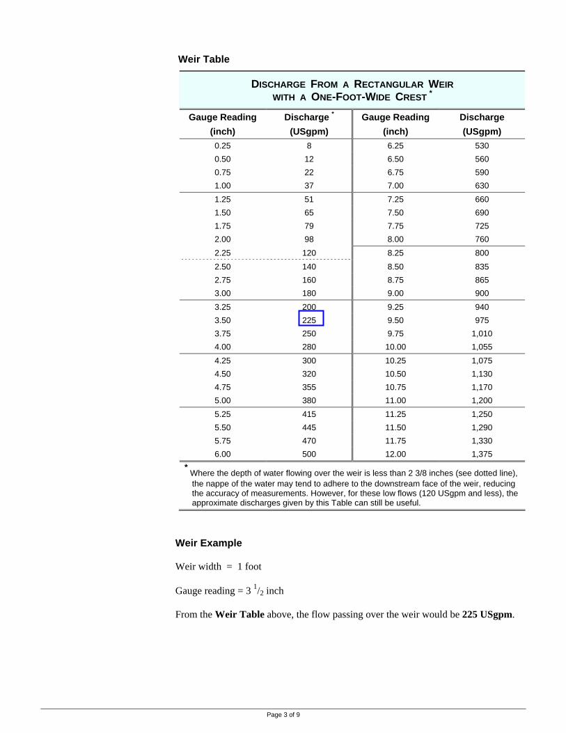
Weir Table
DISCHARGE FROM A RECTANGULAR WEIR WITH A ONE-FOOT-WIDE CREST *
Gauge Reading (inch)
Discharge *
(USgpm) Gauge Reading
(inch) Discharge (USgpm)
0.25 8 6.25 530 0.50 12 6.50 560 0.75 22 6.75 590 1.00 37 7.00 630 1.25 51 7.25 660 1.50 65 7.50 690 1.75 79 7.75 725 2.00 98 8.00 760 2.25 120 8.25 800 2.50 140 8.50 835 2.75 160 8.75 865 3.00 180 9.00 900 3.25 200 9.25 940 3.50 225 9.50 975 3.75 250 9.75 1,010 4.00 280 10.00 1,055 4.25 300 10.25 1,075 4.50 320 10.50 1,130 4.75 355 10.75 1,170 5.00 380 11.00 1,200 5.25 415 11.25 1,250 5.50 445 11.50 1,290 5.75 470 11.75 1,330 6.00 500 12.00 1,375
* Where the depth of water flowing over the weir is less than 2 3/8 inches (see dotted line), the nappe of the water may tend to adhere to the downstream face of the weir, reducing the accuracy of measurements. However, for these low flows (120 USgpm and less), the approximate discharges given by this Table can still be useful.
Weir Example Weir width = 1 foot Gauge reading = 3 1/2 inch From the Weir Table above, the flow passing over the weir would be 225 USgpm.
Page 3 of 9

Method 3: Full Pipe
Full Pipe Method. This method is used to estimate the flow in pipes flowing full (pipe may be level or inclined). 1. For level pipes, place a carpenters square on top of pipe so that the water strikes
the vertical scale at 12 inches and measure the horizontal distance X (in). 2. For inclined pipes, lay a yardstick along the pipe surface so the “plumb” distance
to the water is 12 inches and measure the inclined distance X (in). 3. Using the Full Pipe Table, read the flow for the size of pipe used.
Full Pipe Diagram
Horizontal Pipe (Full) Inclined Pipe (Full) Full Pipe Table
ESTIMATE OF FULL PIPE FLOW IN USGPM Measured Distance X with a Vertical Drop of 12 inches *Nominal
Pipe Size (inch) 4 in 6 in 8 in 10 in 12 in 14 in 16 in 18 in 20 in 22 in 24 in
1 3 1/2 5 7 8 1/2 10 12 13 1/2 15 16 1/2 18 20 1 1/2 8 11 15 19 22 26 30 34 37 40 45
2 14 20 27 34 40 47 55 60 68 74 80 2 1/2 21 32 42 53 64 75 85 95 106 116 126
3 29 45 60 72 87 100 116 130 144 160 173 4 52 78 102 128 153 180 203 230 253 280 305 5 82 120 162 200 240 280 320 355 400 440 470 6 117 177 232 290 345 400 460 520 575 640 690 7 157 235 310 390 470 550 625 705 780 850 940 8 205 305 410 510 615 710 820 920 1020 1110 1220 10 327 500 650 805 980 1120 1310 1500 1620 1770 1950 12 460 690 925 1160 1410 1620 1850 2100 2300 2500 2700
* If a 6 inch vertical drop is used, multiply the table discharge rates by 1.4
Full Pipe Example Pipe size (nominal) = 4 inches Vertical/plumb distance = 12 inches (set) Measured distance X = 16 inches From the Full Pipe Table the flow in the pipe would be approximately 203 USgpm.
Page 4 of 9

Partially Full Pipe Method. This method is used to estimate the flow in pipes flowing partially full. Similar measurements to the Full Pipe Method are taken and the Full Pipe Table values are reduced by a factor calculated for the particular pipe situation.
1. For level pipes, place a carpenter square on top of the pipe so that the water strikes the vertical scale at 12 inches and measure the horizontal distance X (in).
2. For inclined pipes, lay a yardstick along the pipe surface so the “plumb” distance to the water is 12 inches and measure the inclined distance X (in).
3. Measure the ‘empty’ portion at the end of the pipe Y (in).
4. Select the Effective Area Factor from Table below using the value for the Y/D Ratio (the ratio of ‘empty’ portion to diameter of the pipe being measured).
5. Using Full Pipe Table, page 4, read the flow for X and the pipe size.
6. Pipe Flow (USgpm) = Full Pipe Table Flow Rate x Effective Area Factor.
Partially Full Pipe Diagram
Partially Full Pipe Factor Table
EFFECTIVE AREA FACTOR Y/D Ratio Factor Y/D Ratio Factor
0.05 0.981 0.55 0.436 0.10 0.948 0.60 0.373 0.15 0.905 0.65 0.312
0.20 0.858 0.70 0.253
0.25 0.805 0.75 0.195 0.30 0.747 0.80 0.142 0.35 0.688 0.85 0.095 0.40 0.627 0.90 0.052 0.45 0.564 0.95 0.019 0.50 0.500 1.00 0.000
Method 4: Partially Full Pipe
Partially Full Pipe Example (using the same pipe size as Full Pipe Example) Pipe size = 4 inches Vertical distance = 12 inches (set) Measured distance X = 16 inches The measured distance for the ‘empty’ portion Y = 1 inch The Y/D Ratio = 1 inch / 4 inch = 0.25 From Factor Table, above, the Effective Area Factor for a Ratio of 0.25 = 0.805 From Full PipeTable, page 4, the pipe flow would be 203 USgpm if full.
The Partially Full Pipe Flow Rate = 203 USgpm x 0.805 = 163 USgpm
Page 5 of 9

Vertical Pipe Method. This method is used to give an approximation of the flow in vertical pipes flowing full that are from 2 to 10 inches diameter.
1. Measure the height of the water above the end of the pipe, H (in).
2. Using the pipe nominal size, D, select the flow rate from the Table
Vertical Pipe Diagram
Vertical Pipe Table
APPROXIMATE FLOW RATE FROM VERTICAL PIPES IN USGPM *
Nominal Diameter of Pipe (D) Height (H) (in) 2 inch 3 inch2 4 inch2 5 inch2 6 inch2 7 inch2 8 inch2 10 inch
3 35 75 135 215 310 425 570 950 3.5 38 85 150 240 340 465 625 1055 4 41 90 160 250 370 505 690 1115 4.5 44 100 170 270 395 540 735 1200 5 47 105 180 285 420 575 780 1280 5.5 49 110 190 300 445 605 825 1350 6 52 115 200 315 470 640 870 1415 6.5 54 120 210 330 490 665 915 1475 7 57 125 220 345 510 700 950 1530 8 61 135 235 370 550 750 1025 1640 9 65 145 250 395 585 800 1095 1740 10 69 155 265 420 620 850 1155 1840 12 76 170 295 465 685 935 1275 2010 14 83 185 320 500 740 1020 1380 2170 16 89 195 340 540 795 1090 1480 2320 18 95 210 365 575 845 1160 1560 2460 20 101 220 385 605 890 1225 1645 2600 25 113 250 435 680 1000 1375 1840 2900 30 124 275 475 745 1095 1505 2010 3180 35 135 300 515 810 1175 1630 2160 3420 * from US Geological Survey 2 these columns rounded to the nearest 5 gallons
Method 5: Vertical Pipe
Vertical Pipe Example Vertical distance, H = 10 inches Pipe size, D = 6 inches Approximate pipe flow = 620 USgpm
Page 6 of 9

Corrugated Metal Pipe Method. This method is used to estimate the flow in corrugated metal pipes flowing full by the pipe diameter and the grade (slope) of the pipe.
1. Measure the pipe diameter (in).
2. Measure the grade the pipe is on as a percentage: e.g., a 1 inch fall in a 20 foot pipe as a percentage is:
1 / 12 ft x 100 = 0.4 percent grade 20 ft
3. Use the Corrugated Metal Pipe Table for the flow in cubic feet per second (cfs). Conversions: 1 cfs = 448.83 USgpm 1 cfs = 373.2 Imperial gpm 1 cfs = 28.3 litres per sec 1 cfs = 0.0283 cubic metres per second
Corrugated Metal Pipe Table
PIPE DISCHARGE (cubic feet per second - cfs) Pipe Grade (%) Pipe
Dia. (in) 0.05 0.08 0.1 0.2 0.3 0.4 0.5 0.6 0.8 1.0 1.2 1.4 1.6 1.8 2.0
6 -- -- -- -- 0.2 0.2 0.2 0.2 0.3 0.3 0.3 0.4 0.4 0.4 0.5
8 -- 0.2 0.2 0.3 0.4 0.4 0.5 0.5 0.6 0.7 0.8 0.8 0.9 1.0 1.0
10 -- 0.3 0.4 0.6 0.7 0.8 0.9 1.0 1.2 1.3 1.5 1.6 1.7 1.8 1.9
12 0.4 0.6 0.7 1.0 1.3 1.5 1.7 1.9 2.1 2.3 2.4 2.5 2.6 2.6 2.6
15 0.9 1.1 1.3 2.0 2.4 2.8 3.0 3.3 3.7 4.0 4.3 4.4 4.5 4.6 4.6
18 1.4 1.8 2.1 3.1 3.9 4.4 4.9 5.4 6.1 6.5 6.8 7.0 7.1 7.1 7.1
21 2.2 2.8 3.3 4.7 5.9 6.8 7.5 8.1 9.0 9.6 10 10 10 11 11
24 3.1 4.0 4.7 6.8 8.3 9.5 10 11 13 14 14 15 15 15 15
30 5.6 7.1 8.0 12 15 17 19 21 23 24 25 25 26 26 26
36 9.0 11 12 19 25 28 31 33 37 39 40 40 40 40 40
Method 6: Corrugated Metal
Pipe
Corrugated Metal Pipe Example Pipe size = 18 inch Pipe grade = 3 inch in a 50 foot length pipe
= 3 /12 ft x 100 = 0.5 50 ft Pipe flow rate = 4.9 cfs = 4.9 x 448.83 = 2200 USgpm For partially full pipes, an approximation of the flow can be estimated by multiplying the above Table full pipe rates by the Effective Area Factor, page 5 (the ratio of ‘empty’ portion to full portion of the pipe).
Page 7 of 9

Timed Volume Method. This method is used for estimating the flow from: Method 7: Timed Volume • streams, where all the flow goes over a fall
• pipes, flowing full or partially full • nozzles
where the flow can be captured in a container. The time for a known volume of water to be captured in a container such as a bucket is recorded and converted into a flow rate. The larger the container the more accurate the result, but a “5 gallon” bucket may work well for low flow rates. Mark the level on the bucket indicating the volume which will be captured (use a container of known volume to do this). If available use a stop watch for timing. Take the average of three readings.
1. At the water discharge point or stream fall, move the bucket under the flow and at the same time start the stop watch.
2. Stop the watch when the water reaches the marked level on the bucket and note the time.
3. Repeat two more times and average the three readings of time to fill the container.
4. Convert the readings into a flow rate: Flow rate = volume / time
Timed Volume Diagram Timed Volume Example
A bucket marked at 4 Imperial gallons is used. Three readings of water flow averaged 10 seconds to fill the bucket to the mark. Imperial gpm Flow Rate = 4 Igal / 10 sec x 60 sec / min = 24 Igpm If needed, convert to USgpm by multiplying the Imperial rate by 1.2 : USgpm Flow Rate conversion = 24 Igpm x 1.2
= 28.8 USgpm
Page 8 of 9

Nozzle Method. This method can be used for flow from small nozzles knowing the nozzle size and the pressure at the nozzle. Use the stem-end of a steel drill bit to confirm the nozzle size. Measure the pressure as shown in the Nozzle Photo then determine the nozzle flow rate using the Nozzle Table. Nozzle Photo
Nozzle Table FLOW RATE OF SELECTED NOZZLES IN USGPM *
Pressure at Nozzle Nozzle Size (in) 20 psi 25 psi 30 psi 35 psi 40 psi 45 psi 50 psi 55 psi 60 psi
1/16 -- 0.55 0.60 0.65 0.70 0.74 0.78 0.82 0.86
5/64 -- 0.80 0.87 0.95 1.03 1.10 1.16 1.21 1.26
3/32 1.07 1.21 1.34 1.45 1.56 1.66 1.76 1.85 1.94
7/64 1.54 1.73 1.91 2.07 2.22 2.36 2.50 2.62 2.75
1/8 2.03 2.25 2.47 2.68 2.87 3.05 3.22 3.38 3.53
9/64 2.53 2.88 3.15 3.40 3.64 3.86 4.07 4.27 4.46
5/32 3.08 3.52 3.85 4.16 4.45 4.72 4.98 5.22 5.45
11/64 3.62 4.24 4.64 5.02 5.37 5.70 6.01 6.30 6.57
3/16 -- 5.00 5.50 5.96 6.38 6.78 7.16 7.52 7.85
13/64 -- 5.90 6.50 7.05 7.55 8.00 8.45 8.85 9.25
7/32 -- 6.85 7.55 8.20 8.80 9.35 9.90 10.40 10.75
15/64 -- 7.8 8.5 9.2 9.8 10.4 11.0 11.5 12.0
1/4 -- 8.8 9.6 10.4 11.1 11.8 12.4 13.1 13.6
17/64 -- 9.9 10.8 11.7 12.5 13.3 14.0 14.7 15.3
9/32 -- 11.2 12.2 13.2 14.1 15.0 15.8 16.5 17.3
19/64 -- 12.4 13.6 14.7 15.7 16.6 17.5 18.4 19.2
5/16 -- 13.8 15.1 16.3 17.4 18.4 19.4 20.4 21.3
* from Nelson Irrigation Co. for L20W sprinkler (1/16 to 7/64 nozzles); F32 (1/8 to 7/32 nozzles) and F43 (15/64 to 5/16 nozzles) allow for up to +/- 2% variation from these table values for the effect of other sprinkler types, etc, on nozzle flow
Method 8: Nozzle Volume
Nozzle Example A nozzle that is identified as 11/64 inch was confirmed with a 11/64 inch drill bit. The pressure at the nozzle was measured to be 50 psi. From the Nozzle Table, the flow rate is 6.01 USgpm – round off and use 6 USgpm.
RESOURCE MANAGEMENT BRANCH WRITTEN BY Ministry of Agriculture and Lands Lance Brown 1767 Angus Campbell Road Engineering Technologist Abbotsford, BC V3G 2M3 Phone: (604) 556-3001 Kamloops Office
Page 9 of 9

Page 1 of 2
This Factsheet compares water sources and the development methods, advantages and disadvantages.
Livestock Watering
Order No. 590.303-1 January 2006
SOURCES FOR LIVESTOCK WATER
Water for livestock is usually provided by low cost systems using ground or surface water. These systems can allow water use either at the source or by moving water to stock troughs. Water sources can vary from simple dugouts to springs with gravity distribution or pumped systems, or to streams or lakes. The following table looks at the three types of water sources and briefly compares access methods, as well as advantages and disadvantages of each method. Refer to other Livestock Watering Factsheets in this Handbook series for details on developing these water sources. Although livestock may graze a mile or more from water, good management of forage is usually combined with water distribution. Most surface water sources can be used by livestock at or near where the water occurs. Ground water sources require the water be pumped to the surface for use. Water harvesters (precipitation collectors) can usually be located near the livestock area. Water can be lifted to higher areas by pumping, although energy sources in remote areas are limited. Gas or diesel pumping is expensive and alternate energy (wind & solar) may be economic only for low power systems. Other pumping options include stream-powered or livestock-powered pumps. Refer to other Livestock Watering Factsheets in this Handbook series for details on constructing a distribution system. This information should be used when comparing water sources to get a complete comparison of the installed systems. Unrestricted access to a watercourse may cause contamination. In low density grazing situations, such as in many cattle range areas, concerns are generally low. With concentrated access, manure buildup will cause problems. For this reason, care must be used in designing direct water access systems. Fenced off surface water with the use of stock troughs should be considered where practical. Refer to other Livestock Watering Factsheets in this Handbook series for details on direct access to watercourses by livestock when considering this type of system.
RESOURCE MANAGEMENT BRANCH WRITTEN BY Ministry of Agriculture and Lands Lance Brown 1767 Angus Campbell Road Engineering Technologist Abbotsford, BC V3G 2M3 Phone: (604) 556-3100 Kamloops Office
Water Distribution
Water Pollution
Water Sources

Page 2 of 2
COMPARING SOURCES FOR LIVESTOCK WATER
Concern ? Water Access Advantages Disadvantages
all • quantity usually more reliable than surface water • quality usually not affected by surface contaminants
• wells require power to pump
shallow, dug well • water sources are somewhat more reliable than surface water
• somewhat more risky to find than surface water
Gro
und
Wat
er
Fact
shee
t #5
90.3
03-2
water source not usually impacted by livestock use w
ell
deep, drilled well • water source often very reliable • least likely to be affected by surface contaminants
• often risky to find and expensive to develop du
gout
bulldozed or excavated
• inexpensive • livestock can use water directly
• usually seasonal use only • supply may be variable year to year • if directly used, livestock can impact water
quality and damage earthen sides
seep
water collection • little surface impact on water quality • water must be collected • flow may be difficult to measure • possible seasonal flow variation • need to use via a trough
spr
ing
poi
nt single water point • little surface impact on water quality
• flow easy to measure • collection is simple
• expect some seasonal variation • usually need to use via a trough
cree
k
controlled access, pump, or diversion
• historic creek flows may be available to determine reliability of water
• livestock can impact water quality - fishery & pollution concerns
• freshet flows may deteriorate water quality & impact intake works
Surf
ace
Wat
er
Fact
shee
t #59
0.30
3-3
water source may be impacted
by direct livestock access to water source
pond
, la
ke
controlled access or pump
• water supply is known • water can be used where its needed
• pollution concerns • pumping energy required • added costs • frost protection difficult
Prec
ipita
tion
Fact
shee
t #5
90.3
03-4
water source not impacted by
livestock wat
er
harv
este
r catch and store precipitation
• can locate where needed • can water otherwise dry sites
• cost per gallon is high

Page 1 of 6
Ground Water Sourcing
Introduction
Environmental Issues
This Factsheet outlines sourcing and options to develop ground water sources for livestock water use.
Livestock Watering
Order No. 590.303-2 January 2006
ACCESSING GROUND WATER SOURCES
Ground water occurs both in rock and unconsolidated materials. Water in rock occurs in fractures, in the inter-granular openings in the rock and, in the case of limestone, in cavities and channels. The largest amount of ground water comes from unconsolidated materials receiving water from precipitation or from nearby surface watercourses. Refer to Figure 1, next page. The amount of water which can be obtained from a well depends on the permeability of the materials, the thickness of saturated material through which the well passes, and on well construction.
Water Quality Protection. Ground water quality can be impacted by surface activities, such as some farming practices. To protect ground water quality, wells must be located and constructed so as to avoid entrance of contaminated surface water. Wells are vulnerable from the top (condition of well cap and surface seal), side (condition of casing seal) and from below (contaminated ground water): • under the Health Act, Sanitary Regulations, Section 42, wells must be located at
least 30.5 m (100 ft) from any “probable source of contamination” (on farms, things such as manure, petroleum, fertilizer, and pesticide storages, etc.)
• under the Water Act, Ground Water Protection Regulation, well drillers qualification requirements and well construction is specified
Water Quantity Protection. Ground water quantity can be impacted by water withdrawal at rates faster than it can be replaced, lowering the water table, and in turn possibly impacting levels and flows in adjacent watercourses. Indications of a lowering water table include: • the necessity to deepen wells to maintain water flows • wells running dry during times of the year when they previously had flow • nearby bodies of surface water experiencing reduced flows or depths
To reduce overuse of ground water, monitor the water table by measuring the static water level in the well at the same time of year (some variations are normal). Minimize the use of wells near watercourses, especially when their levels are low.
Dowsing. Dowsing is sometimes called water witching or divining while skeptics will call it a hoax. Using a divining rod, forked stick or other items, dowsers believe they can find ground water which cannot otherwise be seen. Not a science but an art, dowsing is generally inexpensive (especially compared to a 'dry' hole) and may be helpful when deciding where to drill for water. Talk to area farmers or others who have used their services for names of local dowsers. A number of books on dowsing are available at the American Society of Dowsers, Inc at http://www.dowsers.org/

Unconfined aquifers are at atmospheric pressure - wells A, B & C are into an unconfined aquifer and must be pumped. Confined aquifers are pressurized above atmospheric pressure - wells D & E are into a confined aquifer. D water level rises above aquifer but not to the well head – it must be pumped. E water level rises above the well head.
Page 2 of 6
Adapted From: Water Wells and Pumps (University of California May 1978)
Figure 1 Ground Water Conditions, Types of Aquifers and Wells Wells may be drilled either vertically (most typical) or horizontal (note that in the petroleum industry a drilled well can consist of both types). Vertical Wells. Most wells for livestock water are drilled vertically. The pump, wire and piping are lowered down the well. Energy is required to power the pump, and this is often the limiting factor to the use of wells in remote areas. Horizontal Wells. These are drilled horizontally into specific geologic formations where water may be trapped. Once drilled, this type of well could be considered a “spring” as water flow will occur due to gravity without pumping energy. A valve is used to control water flow. Horizontal well drilling is a specialized service and may not be available in all parts of BC. Shallow Wells. These wells are less than 10 m (33 ft) deep. Depending on the geologic formation, they may be easily affected by surface conditions such as contaminated runoff and drought conditions. Deep Wells. These wells are usually drilled and are usually less prone to contamination and drought. The water quality may, however, be hard compared to shallow wells as the water has had a long exposure to minerals.
Types of Wells

Page 3 of 6
There are several methods of constructing wells; one may be more suitable than another for conditions at a given location. Consider the volume of water required and the relative costs. Dug Wells. The oldest wells were hand dug and lined with suitable cribbing. Today, dug wells are constructed using power equipment for shallow wells or sumps of less than 6 m (20 feet). Upright steel culverts can be used for lining the well. Driven Wells. Driven wells, also referred to as sand points, gravel points or well points, are often used for farm water supplies when the water table is not far below the surface (10 m or less) and where the aquifer is fairly permeable. Sand points are usually 30 – 50 mm (1¼ to 2 inches) in diameter. A sand point consists of a short length of screened pipe equipped with a sharp point. The point and attached pipe are driven into the ground to the necessary depth with pipe being added to the top end as needed. Well points may be arranged in groups, coupled to a common suction header, to increase the capacity required. Unless a jet pump is to be used, it is essential that the water table be shallow enough (less than 6 m) so that a shallow well pump on the ground surface may develop sufficient suction. Churn (Cable-Tool) Drilled Wells. Drilling by this method is accomplished by raising and dropping a heavy "tool string" equipped with a bit. The tools are suspended by a wire rope. Drilling is done with water in the hole and cuttings are removed by means of a bailer. In deep holes, several sizes of casings may be required increasing the costs. Although somewhat slower than rotary drilling, churn drilled wells may detect water in thin or low producing aquifers. Rotary Drilled Wells. In this method, drill pipe, equipped with a cutter called a bit, is turned in the hole. During drilling, a fluid is pumped down the drill pipe and through the bit in order to transport the well cuttings back to the surface. Mud rotary drilling is inexpensive and rapid, particularly in unconsolidated materials. Air rotary drilling, a common drill method, is well suited for drilling in rock. In addition to the environmental issues previously mentioned, there are other good practices which should be used in constructed a well: • construct wells with durable materials • locate wells in high areas, wherever possible, to prevent runoff from collecting at
the well head and seeping into the water supply • construct well casing 0.3 m (1 ft) above the level of the surrounding land • construct well casing above 100-year-flood levels • construct upland berms, grade land to prevent runoff from contaminating the well
• plant and maintain grass covers around well heads to slow and filter runoff • use a full length casing with a pitless adapter where water lines may freeze
(rather than terminating the casing in the ground below frost level) Well Casing and Screens. Rock wells will usually not require casing except for an upper, short ground seal case section and a means to hang the pump and pipe. In unconsolidated material, casing will usually be required. Minimum casing should be 100 mm (4 inch) diameter; however, a preferred minimum diameter is 150 mm (6 inches). To some extent the amount of water required will determine the well diameter. For most stock water applications, the 150 mm diameter should suffice.
Well Construction Methods
Well Construction and Use
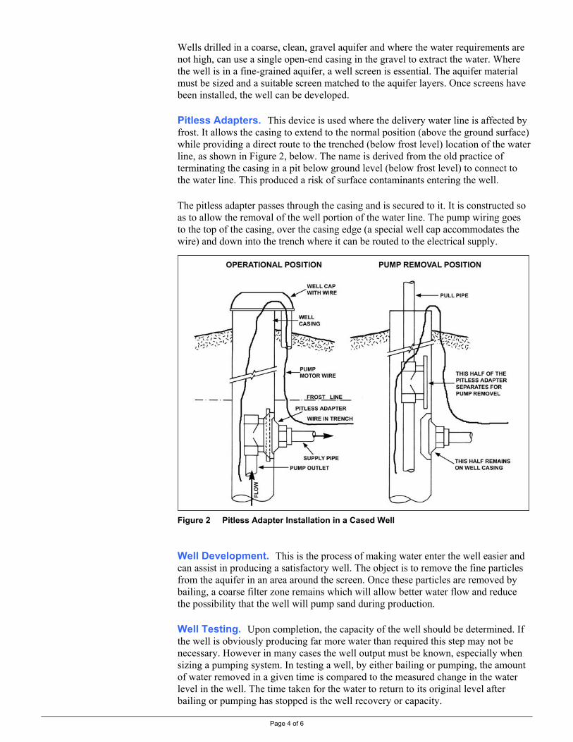
Page 4 of 6
Wells drilled in a coarse, clean, gravel aquifer and where the water requirements are not high, can use a single open-end casing in the gravel to extract the water. Where the well is in a fine-grained aquifer, a well screen is essential. The aquifer material must be sized and a suitable screen matched to the aquifer layers. Once screens have been installed, the well can be developed. Pitless Adapters. This device is used where the delivery water line is affected by frost. It allows the casing to extend to the normal position (above the ground surface) while providing a direct route to the trenched (below frost level) location of the water line, as shown in Figure 2, below. The name is derived from the old practice of terminating the casing in a pit below ground level (below frost level) to connect to the water line. This produced a risk of surface contaminants entering the well. The pitless adapter passes through the casing and is secured to it. It is constructed so as to allow the removal of the well portion of the water line. The pump wiring goes to the top of the casing, over the casing edge (a special well cap accommodates the wire) and down into the trench where it can be routed to the electrical supply.
Figure 2 Pitless Adapter Installation in a Cased Well Well Development. This is the process of making water enter the well easier and can assist in producing a satisfactory well. The object is to remove the fine particles from the aquifer in an area around the screen. Once these particles are removed by bailing, a coarse filter zone remains which will allow better water flow and reduce the possibility that the well will pump sand during production. Well Testing. Upon completion, the capacity of the well should be determined. If the well is obviously producing far more water than required this step may not be necessary. However in many cases the well output must be known, especially when sizing a pumping system. In testing a well, by either bailing or pumping, the amount of water removed in a given time is compared to the measured change in the water level in the well. The time taken for the water to return to its original level after bailing or pumping has stopped is the well recovery or capacity.

Page 5 of 6
Well Logs. A well log is a written description of the drilled well supplied by the contractor on completion of the well. It should contain the details of the well construction (casing size, type and depth), the type of formations the well goes through and the well test results. A copy of the well log is usually registered with the Ministry of Environment. A completed well log is very useful when sizing and installing a well pump. Well Abandonment. Improperly closed or abandoned wells can be sources of ground water pollution and must be sealed as required by the Water Act, Ground Water Protection Regulation. Well Terminology. Figure 3, below illustrates terms related to wells.
Figure 3 Well Terminology

Page 6 of 6
The following are three ways to measure the water level in a well. They can be used to measure the static water level (pump not operating) or to measure the draw down level (pump operating). Note that all three involve lowering something down the well and in operating wells there may not be a lot of space with the delivery pipe and pump wiring hanging in the casing. Steel Tape. A steel measuring tape with a weighted end can be lowered down the well. Note the measurement at the well head, withdraw the tape and subtract the wetted length of the tape from the well head measurement. This process may need to be tried a few times until the tape has been lowered enough to reach the water level.
Electrical Wire. This method uses the electrical conductivity of water. An insulated single-conductor wire with a weighted end is lowered down the well. The wire is connected to one terminal of a battery with the other terminal running to a conductivity gauge then to the well casing. Once the wire touches the water, the meter will indicate a flow of electricity. Mark the point on the well wire, withdraw it and measure the wire distance – this equals the distance down to the water. This device is available as a commercial unit with a battery, gauge and a windup wire marked off in 10 foot intervals. Air Line. This method uses a known length of small diameter air line (say, 1/8 or 1/4 inch copper tubing) set down the well until at least 10 feet is submerged into the water. A pressure gauge is connected at the well head and air is pumped into the line. Air is pumped until a maximum pressure is achieved. This pressure is converted into feet (1 psi = 2.31
feet) and subtracted from the total air line length for the distance from the well head to the water level. This method can be used to determine drawdown if the pressure reading before pumping and during (it will be a lower reading if there is a drawdown) is subtracted - the pressure difference converted to feet is the drawdown. For further information on wells refer to the following publication. • “Water Wells …. that last for generations”, Alberta Agriculture • for information on the Health Act, Sanitary Regulation:
http://www.qp.gov.bc.ca/statreg/reg/H/Health/142_59.htm • for information on the Water Act, Ground Water Protection Regulation:
http://www.qp.gov.bc.ca/statreg/reg/W/Water/Water299_2004/299_2004.htm
RESOURCE MANAGEMENT BRANCH WRITTEN BY Ministry of Agriculture and Lands Lance Brown 1767 Angus Campbell Road Engineering Technologist Abbotsford, BC V3G 2M3 Phone: (604) 556-3100 Kamloops Office
Well Water Level Measurement
Other Information
Electrical Wire
Air Line

Page 1 of 8
This Factsheet outlines options to access and develop surface water sources for livestock watering.
Livestock Watering
Order No. 590.303-3 January 2006
ACCESSING SURFACE WATER SOURCES Dugouts, Springs, Creeks, Rivers and Lakes
The following surface water options should be considered with these points in mind: • water quality will vary and may have to be checked – Factsheet #590.301-2 • direct access of surface water can impact water quality – Factsheet # 590.302-1 • a water licence is required to divert surface water – Factsheet #502.100-4
Collection of surface water in a dug pond can be a cost effective method to provide livestock water. Depending on local conditions and stock requirements, a dugout may provide only the seasonal spring grazing needs. Siting is important to ensure filling from spring snow melt or summer rain storms. Seasonal “Range” Dugouts. These "scoop outs" are the simplest form of dugouts, often used on grazing areas and are discussed in this Factsheet. They may capture ground seepage or surface run-off from snow melt or precipitation. Full Year “Farm” Dugouts. These “prairie-style” dugouts are usually larger and more sophisticated than “scoop outs” and may supply water for domestic as well as livestock uses. These are not discussed in this Factsheet - refer to Quality Farm Dugouts, a publication of Agriculture and Agri-Food Canada. Dugout Sizing. Size the dugout considering both the volume of water available to capture and livestock volume needs. Table 1, next page, gives capacities of various dugout sizes. Make allowance for evaporation losses of 15 to 50%. Constructing long, narrow dugouts at right angles to the prevailing wind and with a shelterbelt of trees back from the water edge can reduce these losses. Fifty percent porous fences upwind or solid fences downwind can help trap snow to fill dugouts. Watershed Sizing. Watershed area requirements to fill dugouts are fairly variable and local consultation is required. For example, in the northeast region of B.C. a rule of thumb is for every 100 square feet of dugout surface area, 1/2 acre of watershed is needed. A 200 ft by 100 ft dugout has a surface area of 20,000 sq ft and would require a minimum watershed of 100 acres. Topography. To reduce evaporation and other water losses, as well as accumulate more snow in winter, dugouts should be located in natural depressions. In Crown grazing areas, consider capturing the flow off forestry road grade ditches, directing water to a dugout set off 15m (50 feet) or so from the road.
Dugouts
Introduction

Page 2 of 8
TABLE 1. APPROXIMATE DUGOUT CAPACITIES * ( MILLION US GAL / MILLION LITRES)
Length Width ft m 60ft 18m 70ft 21m 80ft 24m 90ft 27m 100ft 30m 110ft 33 120ft 36m 60 18 0.14 0.51 0.17 0.64 0.20 0.76 0.24 0.89 0.27 1.02 0.30 1.15 0.34 1.28
80 24 0.20 0.76 0.26 0.97 0.31 1.18 0.37 1.39 0.42 1.59 0.48 1.80 0.53 2.01
100 30 0.27 1.02 0.35 1.31 0.42 1.59 0.50 1.88 0.57 2.17 0.65 2.45 0.72 2.74
120 36 0.34 1.28 0.43 1.64 0.53 2.01 0.63 2.37 0.72 2.74 0.82 3.10 0.92 3.47
140 42 0.40 1.53 0.52 1.98 0.64 2.42 0.76 2.87 0.88 3.31 0.99 3.76 1.11 4.20
160 49 0.47 1.78 0.61 2.31 0.75 2.83 0.89 3.36 1.03 3.88 1.17 4.41 1.30 4.94
180 55 0.54 2.04 0.67 2.64 0.86 3.25 1.02 3.85 1.18 4.45 1.34 5.06 1.50 5.67
200 61 0.61 2.50 0.79 2.98 0.97 3.66 1.15 4.35 1.33 5.03 1.51 5.71 1.69 6.40
230 70 0.71 2.68 0.92 3.48 1.13 4.28 1.34 5.08 1.56 5.89 1.77 6.69 1.98 7.49
260 79 0.81 3.06 1.05 3.98 1.23 4.90 1.54 5.83 1.78 6.75 2.03 7.67 2.27 8.59
300 91 0.94 3.57 1.23 4.65 1.51 5.73 1.80 6.81 2.09 7.89 2.37 8.97 2.66 10.1
* assuming a depth of 4.3m (14 feet) with side and end slopes of 2 horizontal : 1 vertical
Livestock Access. Direct use by livestock is the simplest use of dugout water but can degrade water quality. If possible, a fenced dugout with water flow to a trough should be considered. If direct access is used, limit access to one end and consider improving the access with a geotextile / gravel ramp (refer to Factsheet #590.302-2). Soil Types. When planning large dugouts, soil test holes should be dug in the proposed dugout locations. Once the site is chosen, five test holes, one in each corner and another in the middle, should be dug to warn of impending seepage problems. A soil which is predominantly clay will retain water well. Other soils can be sealed but may only be partially effective and be cost prohibitive. Seepage Control. Sandy soils are permeable and allow seepage, while a layered soil profile permits water loss along the interface between the two soil types. On most “range” dugouts, extensive seepage control may not be warranted, but the following physical and chemical methods can be used. • Gleization. A 150mm (6 in) layer of organic material, usually straw, followed
by another 6 in. layer of clay provides a time-honored method of seepage control, but requires several months to a year to be completed and be effective.
• Clay Lining. Up to a twelve inch thick uniform layer of borrowed clay earth is
laid down and compacted to ensure seepage control. • Bentonite. Bentonite is highly plastic clay that absorbs water and swells many
times its volume. When wetted and mixed with the dugout soil it forms an impermeable seal to water. If it is allowed to dry, bentonite shrinks and cracks which tends to weaken the seal. The seal is reformed when rewetted.
Two types of bentonite are used; high swell which can increase its volume eight to twelve times when wetted and low swell which can increase five to six times. The swell characteristic and purity of the bentonite should be known when calculating the amount to be used.

Page 3 of 8
Bentonite can be applied dry, either as a pure-blanket covered with 100 to 150mm (4 to 6 in) protective soil cover, or as a mixed-blanket worked into the soil and compacted in a 125 to 150mm (5 to 6 in) layer. Either way, the layer should be moistened and compacted. Dry bentonite should not be applied without either mixing it or covering it. Bentonite can also be applied to the water surface in the wet method, either as a slurry or as dry material. A gel forms that settles to the bed surface and is either left to form a natural seal or is incorporated several inches into the bed by underwater harrowing. This method is more difficult to do and not as effective as the dry method. High amounts of soluble calcium in the water may reduce the sealing effectiveness of bentonite. However a dry application of 5 to 10 kg per m2 (1-2 lbs per ft2) or a wet application of 10 to 20 kg per m2 (2-4 lbs per ft2) is usually effective.
• Soil Cement. Used primarily in sandy soils, the surface must first be tilled to a depth of 3-6 inches. The soil cement is broadcast onto dry soil at the rate of 4-6 lb/ft2 and then tilled into the surface. Water should be sprayed on to increase the soil moisture content to 12-15%. A two to four week curing period is required after compaction.
• Sodium Carbonate. As a chemical dispensing agent, sodium carbonate reduces the soil permeability by reorienting clay particles in the soil. The degree of effectiveness of sodium carbonate depends on the percentage of exchangeable calcium in the soil which can be determined from a soil test. Application rates may be determined from the test results. The sodium carbonate is applied by a fertilizer spreader onto the surface of the dugout sides. Tillage and subsequent compaction will seal the dugout in a few days.
• Polyethylene Liner. Polyethylene membrane liners can be purchased in sheets or formed to a semi-spherical shape. The liner should be covered with a 150 to 300mm (6-12 in) layer of soil to reduce chances of damage from puncture or UV radiation. Use a minimum 6 mil thickness.
A spring occurs when the water table is at the ground surface, often along a hillside or in a low area. Although water flow may be quite variable during the year and from year-to-year, even a small flow can be worth developing; for instance a seep of one litre/gallon a minute is over 1400 litres/gallons a day. The usable flow rate, at the time of year the water is required, must be determined before starting development. Artesian Spring. These springs free flow water due to aquifer pressure. They are usually the easiest to develop, requiring no collection just an intake for piping. Seep Spring. These springs have little or no aquifer pressure, being visible only as a wet area or by a difference of vegetation indicating water is present. They usually require a collection system connected to the distribution pipeline. Refer to Figure 1, next page. Determining Flow. It is preferable to measure the water flow rate during the season of intended use. Using a temporary dam and pipe, collect the flow and record the time required to fill a container of known volume (refer to Factsheet #501.400-1). If the flow rate will meet the daily requirement and the peak use rate, the development will be straight forward. If the flow over 24 hours is sufficient for the1 livestock, but the peak use flow rate needs are greater, water storage will be required (refer to Factsheet #590.304-1).
Springs

Page 4 of 8
Figure 1 Spring Development

Page 5 of 8
Developing Springs. Works to access a spring may be partially or totally buried in-ground. Basic development may be just to allow livestock direct access to the spring water. For supply to a trough, an intake and distribution system is installed. The actual surfacing point of the spring may be only a very small section of the potential of the spring. Excavation parallel to the contour of the land, at or slightly below the spring outlet level, may substantially increase the flow of the spring. A series of perforated pipes can be installed in this ditch and backfilled with drain rock or other coarse material. These collector pipes are then joined together at a “spring box” where the water can be gravity fed or pumped to troughs, or to a storage facility. Figure 1 illustrates some good design points for developing springs. Care must be taken to ensure that the water is not lost in any of the following ways: • ensure the spring is free flowing and fully captured, as mentioned above • ensure the water collection is on an impervious layer that will resist seepage • ensure the water cannot seep around the outlet pipe by using a cutoff collar
There are two final parts to a good spring development. Fence the area off to prevent trampling and contamination by livestock, and ditch the site to protect it from surface runoff. Properly developed springs will have a long, low maintenance life. Surface water such as in creeks, rivers or lakes is a good source of livestock water. In low intensity grazing areas, such as on rangeland, livestock may access watercourses directly (refer to Factsheet #590.302-1). As livestock concentrations increase, direct watercourse access may not be appropriate and water should be supplied through water troughs to reduce the livestock impact on the water supply. To remove water from a watercourse, works (such as an intake or diversion structure) is required, and they must be licenced by an appropriate water licence. Water Quality. As discussed in dugouts, direct access by livestock may degrade water quality. With lakes, the reverse can also be true - algae 'blooms' can occur that are toxic to livestock (refer to Factsheet #590.301-3). Intakes. Intakes for gravity feed or pump systems for livestock water are generally very simple structures as the water volumes are not large. Designs can vary greatly depending on the volume of the water source and the volume needs of the intake; debris in the source; high seasonal flows; ice in winter systems; protection of fisheries and compatibility with other water licences on the system. Gravity Intake. Intakes for gravity pipe systems should not be subjected to high flow velocities but limited to a maximum of 0.3 m/sec (1 ft/sec). Stream flow velocities greater than this will require a diversion structure ahead of the intake. Refer to Figure 2, next page, for a drawing of an in-ground intake and to Factsheet #590.304-5 for details of gravity system piping. Intakes can be constructed using poured in place concrete, gabions, upright culverts or, for small systems, driven pilings of sheet metal or treated wood, and must: • allow movement of sufficient water to the distribution system • regulate the volume of water • remove floating debris and/or screen the water • prevent entry of air with submergence of 250 to 300mm (10 to 12 in) • be compatible with fishery requirements, such as screens
Creeks, Rivers and Lakes

Page 6 of 8
Figure 2 In-Ground Gravity Intake
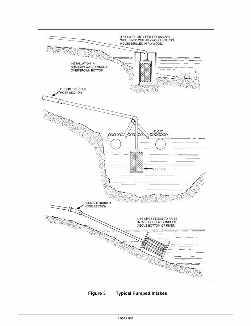
Page 7 of 8
Figure 3 Typical Pumped Intakes

Page 8 of 8
Air Vent. Air must be able to enter a gravity pipeline should the intake become blocked. This prevents damage to the pipeline from a possible vacuum being formed. An air vent can simply be a standpipe open to the atmosphere which extends above the water surface level. It must be positioned after the screen and shut off valve. A 19mm (3/4 in) vent for pipelines 50mm (2 in) or less will be adequate. The vent should be screened. See Figure 2, page 6, for an example of a vented gravity intake. Pumped Intake. For surface mounted pumps, the intake need only be a screen located in the water source. Three typical installations are shown in Figure 3, page 7. The design used will depend on the water depth as well as the lake or creek bottom profile. A section of flexible rubber hose allows the intake to be easily adjusted. Airtight connections must be maintained to prevent air from entering the suction line. Trash Racks. A trash rack located at the entrance to the intake or diversion will remove much of the coarse debris in the water source. Used in conjunction with a screen, the stock water supply system will be adequately protected. Trash racks can be vertical or sloped but should not be horizontal. Sloped racks may be easier to clean. A trash rack may be constructed using 6mm (1/4 in) steel bars spaced 19mm (3/4 in) apart. Intake Screens. A properly sized screen on either gravity or pumped intakes will protect the water system. Screen size is selected for system protection and protection of fish stocks. Fisheries recommendations suggest screen mesh sizes with opening widths under 2.5mm (0.10 in); open screen areas that are not less than 50% of the total screen area and flow velocity through the screen a maximum of 0.03 m/sec (0.1 ft/sec). Refer to “Other Information”, below, for a screen-sizing worksheet. Siphoning Water. If lake water is available for use but pumping is not a viable option, water can be siphoned out to be used in water troughs. A siphon is defined as a pipe flowing water from a supply source to a lower elevation that goes over an intermediate summit point higher than the supply. Before the flow will start, the entire pipe must be filled with water. This can be done at the summit point in conjunction with a foot valve at the inlet and a shut off valve at the outlet. The flow rate is determined by the difference in the inlet and outlet elevations. Siphons may be difficult to operate because any air in the pipe will collect at the summit and can lead to air blockage of the water flow. This will occur more readily the higher the summit is above the supply. Because the pipeline pressure is less than atmospheric in this high section, air trapped here cannot be released but must be either drawn out by a suction pump or flushed down through the pipeline. For details on siphons, refer to Factsheet #590.304-5. Refer to the following for more information on accessing surface water: • Quality Farm Dugouts, a publication of Agriculture and Agri-Food Canada
http://www1.agric.gov.ab.ca/$department/deptdocs.nsf/all/eng4696 • an intake screen-sizing worksheet is available in the Environmental Farm Plan
Reference Guide Chapter 9, Water Supply section, available at http://www.bcac.bc.ca/documents/EFP_Reference_Guide_March_2005_part_9.pdf
• the other Factsheets in this series mentioned in the above text
RESOURCE MANAGEMENT BRANCH WRITTEN BY Ministry of Agriculture and Lands Lance Brown 1767 Angus Campbell Road Engineering Technologist Abbotsford, BC V3G 2M3 Phone: (604) 556-3100 Kamloops Office
Other Information

Page 1 of 4
Livestock Watering
Order No. 590.303-4 January 2006
WATER HARVESTERS Collecting Precipitation
This Factsheet outlines options to capture precipitation to use as a water source for livestock watering.
Water Harvesting describes the process of collecting and storing water from an area that has been treated to increase precipitation runoff. A water harvesting system can be constructed to collect and store precipitation for use by livestock. Two basic designs are typically used: treated ground surfaces or collection on roof-like surfaces. Figure 1 (below) illustrates a treated ground water harvester and Figure 2 (next page) is a catchment using a sheet metal roofing surface located at Cache Creek, British Columbia, Canada. Ground and surface water developments should first be eliminated as possibilities as these are often less expensive. In areas where a dugout can be constructed to capture runoff that may be a better option (refer to Factsheet #590.303-3). from: USDA “Handbook of Water Harvesting”, 1983
Figure 1 Components of a Treated Ground Water Harvester
Introduction

Page 2 of 4
Cattle Drinking from Partially Full Collection Tank Full Collection Tank Showing Floating Evaporation Cover
and Cover Restraint Wires
Water Harvester at Cache Creek, BC
Showing Vinyl-Lined Tank, Wooden Rail Approaches and Livestock Drinking Access
Figure 2 Water Harvester Using Sheet Metal Roofing
FLOATING COVER
RESTRAINT WIRES

Page 3 of 4
TABLE 1 WATER HARVESTER CATCHMENT MATERIALS COMPARISON *
paraffin wax sprayed on
soil
gravel covered membranes on
soil
asphalt – fabric on
soil
butyl rubber on
soil
sheet metal on a frame
concrete formed on
soil
3-5%
catc
hmen
t
slop
e
5-10% x x
silt x
silt loam
sandy loam
sand & loam soil
type
clay/clay loam
rough x x
surf
ace.
smooth
Life years 7 15 20 15 20 20
runoff % 75+ 85+ 95+ 95+ 95+ 60+
* x = probable failure from: USDA “Handbook of Water Harvesting”, 1983 = probable success
Selecting a Site. Many factors will affect the selection of a water harvester site. The following should be evaluated:
• the site’s forage production capabilities
• soil type
• topography
• vegetation
• accessibility
• precipitation
areas of quality grazing not serviced by water
for treated ground harvesters; match to the type of catchment material
for treated ground harvesters; match to the type of catchment material
for treated ground harvesters, must be removed from catchment area
poor access increases development and maintenance costs
avoid rain shadow areas; encourage snow accumulation
In both designs, runoff from the catchment surface is directed into a storage tank. Livestock may either water directly from storage or from a remote stock trough. Catchment areas should be fenced from livestock and protected from possible contaminated runoff by an interception ditch. Types of Catchment Surfaces. Many surfaces can be used to collect precipitation. Cost, durability and life expectancy must be considered. Options range from soil treatments to sheet metal. Soil treatments must be selected for the soil type and slope of the site. Surfaces like sheet metal can be adapted to most any site but are more expensive. Table 1, above, compares catchment materials.

Page 4 of 4
Site Yield. To determine the approximate water yield that can be expected from a site, the precipitation must be known. Monthly averages can be obtained from weather records. With evaporation control, precipitation can be stored for a full year and used to water stock for a short grazing period.
The following equation will give the approximate annual yield of a Water Harvester: A = 1.8 R P where A = catchment area, ft2 R = annual water requirement, US gal. P = average annual precipitation, inch and net yield of precipitation is assumed to be 75% Example – Catchment Area Estimate for a Water Harvester A range area in Cache Creek requires livestock water for one month of spring grazing for 20 beef cattle. What size of catchment area is required if the annual precipitation is stored? • determine the annual precipitation for the site
- the annual precipitation for Cache Creek is 9 inches • determine the livestock water requirement
- from Factsheet #590.301-1, Table 1, in spring assume 12 US gpd per cow - for 20 cows and one month: = 20 x 12 gpd x 30 days
= 7200 US gal • calculate the catchment area
- catchment area = 1.8 x 7200 US gal 9 in. = 1440 ft2 of catchment area For this Cache Creek site, a catchment area of 1440 ft2 will collect 7200 US gal during the year, sufficient to water 20 cows for a month in the spring. Evaporation Reduction. Depending on the storage method used and the term of storage, some type of evaporation reduction may be required where cost effective: • in Figure 1 a roof could be set over the tank • an enclosed tank could be used • in Figure 2 a floating cover is used on a vertical wall tank (but not favorable on
sloped sided reservoirs) • preferred sites will have low prevailing winds to reduce evaporation (consider
wind breaks if necessary) • structures must withstand wind and snow accumulation damages Handbook of Water Harvesting, USDA Agriculture Handbook #600
RESOURCE MANAGEMENT BRANCH WRITTEN BY Ministry of Agriculture and Lands Lance Brown 1767 Angus Campbell Road Engineering Technologist Abbotsford, BC V3G 2M3 Phone: (604) 556-3100 Kamloops Office
Other Information

Livestock Watering Order No. 590.304-1 January 2006
LIVESTOCK WATER SYSTEM DESIGN #1 Selecting Flow Rate, Pressure, Trough Size & Storage
This Factsheet (one in a series of four on design) describes how to estimate flow rate, pressure, water trough, and storage requirements for a livestock watering system used on pasture or range. Two examples are given.
Livestock watering systems vary with different livestock and pastures. When planning a water trough system, flow rate, pressure, storage and trough size must be determined. The following are general guidance "rules-of-thumb" for livestock watering systems - add personal experience to get the final system requirements. Note that: • the following points mainly apply to grazing areas over 20 acres (see below) • the following points apply to systems used year around • the trough sizing points apply to non-freezing conditions
- winter troughs are usually smaller in size than this Factsheet would indicate - refer to Factsheet #590.307-1 for winter condition information and to other Factsheets in this series for guidance with other system components.
The following are some observed livestock watering habits that can influence the layout of a livestock watering system (livestock type, density, pasture size, etc. will affect the following points): • livestock drink individually when on small pastures (20 ac or less)
- these typically use small troughs (25 – 50 USgal) and flow rates (2 – 4 USgpm)
Introduction
Livestock Watering Habits
Page 1 of 6
and shouldn’t be sized using the methods in this Factsheet • the farther that livestock have to move to water the more likely it is they will move as a group (herd drinking) and need larger toughs - use the methods outlined here for distances over 500 feet to troughs
• troughs located inside fenced pastures encourage individual drinking • troughs located outside fenced pastures (alley access) encourage herd drinking • animals may drink up to 1/3 of their daily requirement in a hour • beef cows can drink up to 2 USgpm • low fill rates force livestock to wait - “boss animals” will dominate the trough
To determine the water flow rate to a trough, some assumptions must be made as to the drinking habits of the animals. System costs are reduced if animals spread out their drinking over a long, rather than short, time. However, if too long a time is assumed, livestock may not be adequately watered. Many questions affect the flow rate required, such as: • how often do animals drink in a day? • how much water do they drink at one time? • do they drink singularly or in groups?
Water Flow Rate

The trough supply flow rate must keep up with the draw down rate of the trough when the herd is drinking. The following are methods that will give a range of flow rates; choose the method that best fits the situation or use the "rule-of-thumb": • allow for 10 percent of the herd to drink at once (see Example 1, Step 1, pg 4)
- have a minimum flow rate of 1/2 USgpm per head for this 10 percent group. or • allow the whole herd to get total daily water: (see Example 1, Step 1, pg 4)
- in 4 hours – 240 minutes (preferred flow rate), or - in 6 hours maximum – 360 minutes (minimum flow rate)
• where the water supply rate is low, may use a reduced flow rate by allowing the trough volume to be used up during the drinking period (and refilled later)
• whatever flow rate is chosen, it should fill the trough within 1 hour
Flow Rate “Rule-Of-Thumb” Pressure is required to deliver the water from the source to the trough. While a gravity system may have "free" pressure, pumping water involves an energy cost. To minimize costs, while ensuring adequate water flow, use this "rule-of-thumb": • provide 3 psi per USgpm flow rate (see Example 1, Step 2, pg 4)
- but not less than trough manufacturers recommendation - and usually not over 50 to 60 psi
Note: this is pressure at the trough - account for pipe friction losses in the supply system! (see Factsheet #590.304-2, Livestock Watering System Design #2)
Pressure “Rule-Of-Thumb” The size, location and spacing between troughs depend on many site and herd factors. The following are some "rules-of-thumb" as well as good practices. Trough Volume. Trough volume is a combination of in-flow rate to the trough and
Water Pressure
Water Trough
FLOW RATE (USGPM) = THE DAILY WATER REQUIREMENT (USGAL) ÷ 240 AND, FLOW RATE MUST FILL TROUGH IN 1 HOUR
SYSTEM PRESSURE (PSI) = THE FLOW RATE (USGPM) X 3
Page 2 of 6
the number of animals expected to drink at one time: • volume must be sufficient to water all animals that water in a cycle • low inflow rates and “herd drinking” will require larger volume troughs • high inflow rates and individual drinking will allow smaller volume troughs • provide a minimum trough volume of (see Example 1, Step 3, pg 4)
- 2 USgal per animal for large animals (such as cows) - 1 USgal per animal for smaller animals (such as sheep)
• provide a maximum trough volume of 1/3 of the herd daily requirement Trough Volume “Rule-Of-Thumb” Trough Dimensions. The trough size is mainly determined by livestock size: • provide trough space for 10 percent of the herd to drink at once • provide 1 ft2 water surface area per 25 beef cows (see Example 1, Step 4, pg 4) • provide 1 ft2 water surface area per 50 beef cows for heated winter troughs • provide 1 ft2 water surface area per 40 head sheep
MINIMUM TROUGH SIZE (USGAL) = THE HERD SIZE X 2 (FOR COWS) MAXIMUM TROUGH SIZE (USGAL) = HERD DAILY REQUIREMENT (USGAL) X 1/3

Page 3 of 6
• provide minimum perimeter watering space (see Example 1, Step 4, pg 4) - 20 inches (cows) / 12 inches (sheep) per head on round troughs - 24 - 30 inches (cows) / 16 to 20 inches (sheep) per head on straight side troughs Note: the perimeter needs to be in “complete increments” to be useful
• if both sides are to be used at once, provide a minimum 2 ft width Note: cannot assume use at ends at this width as the corners will be too crowded
• maximum trough throat height (see Example 1, Step 4, pg 4) - 22 inches for mature cattle; 18 inches for calves, heifers, feeders - 15 inches for ewes; 13 inches for lambs
• - provide a 2-inch freeboard to avoid water spillage - maximum water depth is the desired throat height minus this 2-inch freeboard
Note: the trough sizes chosen must be checked for the volume and the surface area needed (see Example 1, Step 5, pg 5) and checked with the flow rate chosen to ensure the trough can be refilled within 1 hour (see Example 1, Step 6, pg 5). Trough Watering Space “Rule-Of-Thumb” Trough Location. Trough location in a pasture will affect grazing patterns and forage utilization: • a "small" square-shaped pasture can have the trough at one corner • a larger, and rectangle-shaped pasture, should have the trough at the midpoint of
the long side • on intensively grazed rotational pastures, moving the trough location to each
pasture will reduce the impacts from a permanent, centralized trough location • locate in shaded areas in summer and behind windbreaks in winter,
but troughs in shaded areas may encourage loitering in summer
Trough Spacing. This will also affect grazing patterns and forage utilization: • 1 trough per site is sufficient when a 20-25 head drink individually • to encourage "even" grazing of pastures, have a maximum distance of
500 - 1,000 feet for animals to walk to water • for large pastures and rangeland areas with multiple troughs, this is a maximum
distance of 1,000 to 2,000 feet between troughs Back Siphoning. Where the water supply is connected to other users (such as domestic) back siphoning should be prevented (i.e., that could occur if a trough float valve is immersed in the water, allowing water to move from the trough back into the supply if a significant line pressure drop occurred). Do one of the following: • keep an air gap between the trough outlet pipe (float valve) and the trough water,
or • install a backflow prevention device in the supply line
If the water supply flow rate is less than the demand (for cows, less than a minimum trough size of 2 USgal per head that can be refilled trough in 1 hour), use one of the following water storage "rules-of-thumb" (see also Factsheet #590.304-7): • have one day storage
- either over-sized trough(s) or in separate water storage tank(s) - storage can be reduced by the water volume coming into the trough over the 4 to 6 hours-allowed drinking time (see Example 2, Step 2, pg 6)
TROUGH DEPTH (FEET) = APPROPRIATE THROAT DEPTH TROUGH WIDTH (FEET) = 2 FEET (MINIMUM) ROUND TROUGH SPACE (FEET) = 10% OF HERD X 1.7 FEET (FOR COWS)
STRAIGHT-SIDE TROUGH SPACE (FEET) = 10% OF HERD X 2.5 FEET (FOR COWS)
Water Storage

• have 2 to 3 days storage for a pumping system using an intermittent energy
Page 4 of 6
source such as solar or wind - usually stored in a separate tank(s) - pumping systems using direct current (DC) electricity may store “energy-in-batteries” rather than “water-in-tanks” (this option requires a higher pumping rate when livestock are drinking which the water supply must be able to supply)
Storage (when required) “Rule-Of-Thumb”
The following two examples put these “design rules-of-thumb” to estimate a livestock watering system requirements: • Example 1, below, sizes flow rate, pressure, volume and the trough • Example 2, page 6, has the same conditions but storage is required
Example 1 – Flow Rate, Pressure and Trough Requirements
Assume a herd of 100 beef cow-calf pairs will summer graze a pasture that has a water trough.
QUESTION What are the flow rate, pressure and trough requirements ?
• select the highest or most appropriate flow rate calculated using one of the following methods
- supply 10% of herd with 1/2 USgpm 10% of 100 head = 10 head; at 1/2 USgpm for each head = 5 USgpm (minimum flow rate) Or, from Factsheet #590.301-1, require 12 x 1.5 = 18 USgal per day per cow-calf in summer - total daily requirement = 100 head x 18 = 1,800 USgal per day - then, choose the maximum daily watering time for the whole herd assume a 4 hr time period: 1,800 USgpd ÷ 240 min = 7.5 USgpm (preferred flow rate) Or, if the trough volume of say, 200 USgal is to be drawn down (‘run dry’), a lower flow rate may be used - 1,800 USgal - 200 USgal trough volume = 1,600 USgal to be supplied during drinking period - assume a 4 hr watering time: 1,600 USgpd ÷ 240 min = 6.7 USgpm - Or, if using the minimum flow rate of 5 USgpm watering time = 1,600 USgpd ÷ 5 ÷ 60 = 5 1/3 hours
- supply rate?? select either the minimum rate of 5 USgpm (for a daily watering time of 6 hours for 1,800 USgal or 5 1/3 hours for 1,600 USgal) Or, select either preferred rate of 7.5 or 6.7 USgpm (for a daily watering time of 4 hours)
• determine the trough pressure - assume 3 psi per USgpm flow rate = 3 x 5 USgpm = 15 psi (minimum trough pressure) - Or, for the shorter, preferred watering time = 3 x 7.5 USgpm = 22 psi (preferred trough pressure)
• determine the trough minimum volume - trough min. volume to be 2 USgal per head x 100 head = 200 USgal (minimum trough vol.) - trough max. volume @ 1/3 of herd daily requirement = 1/3 of 1,800 = 600 USgal (maximum trough vol.)
• determine the trough dimensions 1st. estimate minimum area and trough perimeter space - start off by assuming a single trough will be able to water the herd - provide a minimum 1 ft2 surface area for every 25 head; for 100 head = 4 ft2 - provide a perimeter space for 10% of herd to drink at once = 10 head
Bringing It All Together
SYSTEM STORAGE (USGAL) = HERD DAILY REQUIREMENT (USGAL)INTERMITTENT ENERGY SOURCE SYSTEMS = HERD DAILY REQUIRE.(USGAL) X 3
STEP 1
STEP 2
STEP 3
STEP 4

Page 5 of 6
2nd. choose a rectangular trough - minimum perimeter is 30 inches length / cow x 10 head = 300 inches = 25 ft - in “30 inch increments”, a width of 3 ft and a length of 10 ft would water 10 cows
4 cows per side (and 1 per end) = 10 cows at once = 3 ft x 10 ft - surface area = 3 x 10 = 30 ft2 (OK, as 4 ft2 is minimum) - but this trough may be too crowded at the corners if both ends are used - (a common range trough 4 ft x 8 ft [24 ft perimeter] is often considered OK for 100 head) - alternatively, use 2 troughs 3 ft x 5 ft (5 cows per trough) = 2 troughs @ 3 ft x 5 ft Or, 3rd. choose a round trough - minimum perimeter is 20 inches length / cow x 10 head = 200 inches = 16 2/3 ft perimeter length - a circular trough with 16 2/3 ft perimeter length (16 2/3 ÷ π) = 5.3 ft diameter - surface area = π x 5.32 ÷ 4 = 22 ft2 (OK, as 4 ft2 is minimum) 4th. set trough depth - throat depth for cows is 22 inches maximum - allowing a 2-inch freeboard, trough water depth is 22 - 2 = 20 inch water depth
• check these dimensions: do they provide the required volume? - the rectangular troughs are 3 ft x 5 ft x 20 inches water depth = 25 ft3 each trough - at 7.48 USgal per ft3 = 185 USgal each = 370 USgal total (volume is OK – minimum is 200 USgal) - the circular trough is 5.3 ft diameter x 20 inches water depth = 36 ft3 - at 7.48 USgal per ft3 = 275 USgal (volume is OK – minimum is 200 USgal)
• check the flow rate against the volume: can the trough be filled in 1 hour?
- minimum rate of 5 USgpm = 300 USgal in 1 hour (OK for single round trough option only) - preferred rate of 7.5 USgpm = 450 USgal in 1 hour (OK for both trough options)
ANSWER This livestock watering system should be setup to: • have a flow rate of 5 to 7.5 USgpm
• have a minimum pressure of 15 to 22 psi
• have a trough that is 22 inches deep, with a 2-inch freeboard and 20 inches of water
• have 2 rectangular troughs at 3 ft x 5 ft (185 USgal each - 370 USgal total) - having drinking space for 10 cows at a time at 30-inch space each - with a flow rate of 7.5 USgpm to refill trough in 1 hour (the common 4 ft x 8 ft range trough - with sloped sides - contains 350 USgal)
• Or, have a round trough at 5.3 ft diameter (275 USgal total) - having drinking space for 10 cows at a time at 20-inch space each - with a flow rate of 5 USgpm to refill trough in 1 hour
STEP 5
STEP 6

Page 6 of 6
Example 2 – Water Storage Requirements QUESTION Assuming the same conditions as in the previous example, but the water source has a flow rate of only 3 USgpm ?
• information given: the required flow rate was calculated to be 5 USgpm (minimum – 6 hr watering time) to 7.5
USgpm (preferred – 4 hr watering time) - as only 3 USgpm are available, water storage is required
• determine storage requirements - provide one day storage (from page 3) - from Example 1, for the 100 cows, the daily requirement is 1,800 USgal - this is the maximum volume that must be stored on site to feed the trough
But, this can be reduced by the volume available during the drinking time (3 USgpm from the water source) - calculated in Example 1, to be a maximum time of 6 hrs
- 1,800 gal - (6 hr x 60 min/hr x 3 USgpm) = 1,800 gal – 1080 gal = 720 USgal storage (minimum) - Or, for the minimum watering time of 4 hrs
- 1,800 gal - (4 hr x 60 min/hr x 3 USgpm) = 1,800 gal – 720 gal = 1,080 USgal storage (maximum) - this storage may be as:
- extra rectangular water troughs: 2 more troughs at 360 USgal (for 720 USgal) or 3 (for 1080 USgal) - Or an extra oversized circular trough (8 3/4 ft dia. x 20 inch deep = 740 USgal) - Or 2 oversized circular troughs (7 1/2 ft dia. x 20 inch deep x 2 = 1,100 USgal) - Or any combinations of tanks or troughs giving the required capacity
For a 6-hour drink time, 1,080 USgal will be supplied by the water source (at 3 USgpm) and 720 from storage. After the drinking period, the storage is refilled in 4 hours (at 3 USgpm) for a 10 hour total water delivery period and ready for the next day (10 hr x 3 USgpm = 1,800 USgal). For a 4-hour drink time, 720 USgal will be supplied by the water source (at 3 USgpm) and 1,080 USgal from storage. After the drinking period, the storage is refilled in 6 hours (at 3 USgpm) for a 10-hour total water delivery period and ready for the next day (10 hr x 3 USgpm = 1,800 USgal).
ANSWER
To provide the daily water requirements of the 100 head cow-calf herd, this livestock system, with a low water supply, will require water storage:
• with a flow rate of 5 USgpm (6-hr watering time) - a minimum of 840 USgal storage, or
• with flow rate of 7.5 USgpm (4-hr watering time) - 1,080 USgal storage, or
• a full day water supply - a maximum of 1,800 USgal storage
( The information is adapted from previous Ministry of Agriculture and Lands publications, along with material from Alberta and Ontario agricultural factsheets; Universities of Iowa, Kentucky and Nebraska factsheets; Midwest Plan Service publication and the Canadian Farm Building Code. ) RESOURCE MANAGEMENT BRANCH WRITTEN BY Ministry of Agriculture and Lands Lance Brown 1767 Angus Campbell Road Engineering Technologist Abbotsford, BC V3G 2M3 Phone: (604) 556-3100 Kamloops Office
STEP 1
STEP 2

Page 1 of 7
Livestock Watering Order No. 590.304-2 January 2006
LIVESTOCK WATER SYSTEM DESIGN #2 Selecting Small Diameter Pipe
This Factsheet describes types of pipe, pressure rating systems used, and how to select pipes. It covers pipes of 2-inch diameter, or less, that are used for livestock watering systems. Friction loss tables are given.
What size of pipe do I need? Will this pipe handle the pressure? Having selected the flow rate, pressure, storage and trough size in the Design #1 (Factsheet #590.304-1) the next step in planning a livestock watering system is pipe selection. The following explains how to select pipes based on the size, pressure rating and pressure loss. For sizes up to 2 inches, three types of materials are commonly used for livestock watering system pipes and fittings. Refer to Table 1, page 4, for pipe specifications. Steel. Steel is usually used for fittings and short lengths of pipe that may be installed above ground. Galvanized steel should be used, as the zinc coating greatly increases its working life. Steel pipe and fittings should be used for locations where pipe is easily damaged and should not usually be used in underground installations. Poly Vinyl Chloride. Poly Vinyl Chloride (PVC) is rigid plastic pipe available in pressure ratings from 50 to 315 psi. PVC comes in lengths of 20 feet. Sizes of 2 inch and under are joined by solvent weld. The minimum pressure rating of PVC pipe sizes used for stock water systems is 125 psi; the typical rating used is 160 psi, and 200 psi is also available. PVC pipe and fittings should always be installed underground as the material deteriorates in sunlight and becomes brittle in freezing conditions. Poly. Polyethylene (PE) pipe is available either flexible or rigid, in pressure ratings from 50 to 160 psi. Flexible PE pipe is available in coils up to 1000 ft long depending on diameter, and it is mostly used in systems where the maximum pressure does not exceed 115 psi. For higher pressures, or for sizes greater than 1 1/4 in., PVC pipe offers greater pressure rating and is usually more economical. PE pipe may be installed above or below ground, but is usually buried for protection. Two pressure rating systems are used for Polyethylene and PVC pipe; the schedule system and the class, series or SDR system. Refer to Table 1 for pipe specifications. Schedule System. Two common ratings of this system are Schedule 40 and Schedule 80. It is the designation for pipe in which the outside diameter, wall thickness, and inside diameter are fixed by specification. The dimensions of plastic pipe produced to these schedules are exactly the same as corresponding iron pipe. Working pressure varies for different pipe diameters within any schedule. Each pipe size, in each of these schedules, has a recommended working pressure rating. Schedule rated pipe is used mainly for industrial purposes or high pressure.
Introduction
Types of Pipe
Pipe Rating Systems
Class, Series or SDR System. In this system of classification, plastic pipe is designated with respect to its pressure rating, and the pipe is put into groups all having the same working pressure rating. For example, series or class 160 has a pressure rating of 160 psi regardless of pipe size. All pipes in a given series have the same safety margin and operate at the same fibre stress.
The pipe is grouped according to its Standard Dimensional Ratio (SDR) which is the relationship of outside diameter and pipe wall thickness: • SDR = outside diameter / wall thickness • for example, 1 ¼ inch PVC Series 160 pipe has o.d. of 1.660 and wall of 0.064:
- SDR = 1.660 / 0.064 = 26 - this pipe has a SDR of 26
Polyethylene Grades. In addition to the above ratings, polyethylene pipe may be available in three grades: CSA certified, medium or regular density, and utility. Stock watering systems will normally require the medium density grade. Utility pipe does not have a satisfactory wall thickness and may not endure winter conditions or installation by the ripping method. CSA certified PE pipe is not usually required (unless the system handles domestic water) and may not be cost effective. Note that the grade of a given size does not affect its friction loss as the i.d. is unchanged. These pipes, and their different properties, change with different pressure ratings: • PE pipe is joined with insert fittings so the inside diameter is unchanged
- larger pressure ratings have larger outside diameters
P
Insi
Poly & PVC:de & Outside Diameter
Page 2 of 7
- friction loss for a given pipe size is unchanged by pressure rating • PVC is joined with ‘outside’ couplings so the outside diameter is unchanged
- larger pressure ratings have smaller inside diameters - friction loss for a given pipe size is changed by pressure rating
Refer to Table 1, page 4, for pipe dimensions, etc. and Table 2 for friction loss. Selecting the correct pipe material and size is important to ensure that stock watering system is economical, functional and capable of providing long service. A three-step procedure should be used to determine the correct pipe size and pressure rating.
1. Choose the Type of Pipe. The type of pipe chosen will determine a number of the features of the system, including the following: • cost
- PVC is about one-half the cost of Poly in sizes 1 ¼ or greater • placement
- Poly may be surface laid; PVC degrades in sunlight - PE may be “ripped in” instead of trenching as for PVC - if trenching is not being used, there is no placement advantage of Poly
• connection type - PVC glue joints (every 20 ft) are secure once buried - Poly clamped joints (up to 1,000 ft) may fail (access to buried pipe a concern)
• connection restriction - PVC connections are on the outside of the pipe, allowing ‘clean’ flow - Poly connections are inside with an insert coupling, slightly restricting flow
• ground conditions - flexible Poly can be more tolerant of rocky ground than rigid PVC
• freezing conditions - flexible Poly may be more tolerant of frost than rigid PVC - note that Poly will loose its flexibility and may fail with repeated freezing
ipe Selection

Page 3 of 7
2. Calculate Pipe Size Requirement. Water flowing through a pipe is accompanied by a pressure loss due to friction, which will depend on: • type of pipe
- PVC has about ½ of the pressure loss from friction of PE under many conditions • pipe dimensions
- the length of the pipe and inside diameter • velocity of water in the pipe
- the volume of water flowing in a given pipe diameter determine its velocity Generally, livestock watering systems are designed to limit pipeline flow velocities to a maximum of 5 ft/sec. to minimize friction losses. Flow rates greater than this produce unacceptably high friction loss and may subject the pipeline to water hammer problems if valves or pumps are operated improperly. Conversely, very low flow rates may allow sediments to build up in the pipe.
Pipe sizes are therefore chosen for the required flow rates with acceptable flow velocities. The shaded area on the Friction Loss Table indicates the preferred pipe selections. The example on page 5 outlines the selection process.
For some gravity feed systems with large elevation differences, greater friction losses may be tolerable (i.e., smaller pipe sizes may be selected for a given water flow rate) because pressure loss by friction is "recovered" by elevation drop. Refer to Factsheet #590.304-5 Understanding Gravity-Flow Pipelines for the many concerns of properly designed gravity systems.
3. Calculate Pipe Pressure Requirement. The pipe selected must have a pressure rating that exceeds the total pressure that can be exerted on the system. This total pressure head consists of the sum of the following:
• operating pressure - the pressure required at the waterer • elevation difference - pressure is gained at the rate of 1 psi for every 2.31 feet • pressure surge - the sudden closure of a valve or quick pump start up or shut
down will create pressure surges in the pipeline known as water hammer • pipe friction in a pumping system (a rising main) - pressure must be added
during operation to the system to overcome pressure loss due to water flowing upwards through the pipe (pressure is maximum when the system is operating)
• pipe friction in a gravity system (a falling main) - pressure is lost due to water flowing downwards during operation (pressure is maximum when the system is static)
Table 2, page 5, has friction losses for PE and PVC pipe sizes most commonly used for livestock watering systems.
Maximum vs Working Pressure. The safe working pressure for either PE or PVC pipe must not be greater than 72% of the pipe maximum pressure rating. Safe working pressures of these pipes are reduced to allow for pressure surges, etc. This safety margin is a requirement most often specified for larger diameter pipes than those used in livestock watering systems or for systems subjected to water hammer. Smaller diameter pipes may be operated closer to their maximum pressure ratings, however a safety margin should always be allowed. For an example of pipe selection for a gravity system refer to page 6. For an example of pipe selection for a pump system refer to page 7.

Page 4 of 7
TABLE 1. PE AND PVC PIPE SPECIFICATIONS 1
nominal pipe size
pipe type
PE density
PVC schedule
class or
series
SDR outside diameter
(in)
wall thickness
(in)
inside diameter
(in)
weight per 100ft (lb)
max pressure
(psi)
safe working pressure (psi)
pipe length per USgal (ft)
pvc 40 9.3 1.050 0.113 0.824 23 480 see manufacturer. 36.1
75 14 0.954 0.070 8 75 54
100 41 1.008 0.092 11 100 72
0.75 inch
poly medium
125 32.5 1.056 0.116
0.824 2
14 125 90
36.1
pvc 200 21 1.315 0.063 1.155 20 200 144 18.4
75 15 1.215 0.083 12 75 54
100 41 1.283 0.117 18 100 72
1
inch poly medium
125 32.5 1.343 0.147
1.049 2
23 125 90
22.7
160 26 0.064 1.532 21 160 115 10.5 pvc 200 21
1.660 3 .079 1.500 27 200 144 10.9
75 15 1.598 0.109 21 75 54
100 41 1.688 0.154 31 100 72
1.25 inch
poly medium 125 32.5 1.768 0.194
1.380 2
40 125 90
12.9
160 26 0.080 1.740 31 160 115 8.1 pvc 200 21
1.900 3 0.090 1.720 34 200 144 8.3
75 15 1.866 0.128 29 75 54
100 32.5 1.970 0.180 42 100 72
1.5 inch
poly medium 125 41 2.142 0.266
1.610 2
54 125 90
9.5
160 26 0.091 2.173 44 160 115 5.2 pvc 200 21
2.375 3 0.113 2.149 52 200 144 5.3
75 15 2.395 0.164 48 75 54
100 32.5 2.527 0.230 69 100 72
2 inch
poly medium 125 41 2.645 0.289
2.067 2
89 125 90
5.7
1 pipe and sizes most commonly used in livestock watering systems: PE medium density; PVC Schedule 40, Class 200 and Class 160 2 note that poly pipe of the same size (regardless of series) has the same inside diameter 3 note that pvc pipe of the same size (regardless of series) has the same outside diameter

Page 5 of 7
TABLE 2. PE AND PVC PIPE FRICTION LOSS 1
Pressure Loss from Friction given as Psi per 100 Feet of Pipe 2 Shaded Area Indicates Recommended Pipe Selections 3
Dotted Line Indicates Approximate Minimum Flow to Ensure Air Flushing in Gravity Lines 4 Nominal Pipe Size
0.75 inch 1 inch 1.25 inch 1.5 inch 2 inch Flow
(US gpm) PE PVC
sch. 40 PE PVC
C. 200 PE PVC
C. 160 PE PVC
C. 160 PE PVC
C. 160 1 0.12 0.11 0.04 0.02
2 0.45 0.39 0.14 0.07 0.02 0.02 3 0.95 0.84 0.29 0.14 0.08 0.04 0.04 0.02
4 1.62 1.42 0.50 0.24 0.13 0.07 0.06 0.04 0.02 0.01 5 2.44 2.15 0.76 0.36 0.20 0.11 0.09 0.05 0.03 0.02 6 3.43 3.02 1.06 0.51 0.28 0.15 0.13 0.08 0.04 0.03 7 4.56 4.01 1.41 0.67 0.37 0.20 0.18 0.10 0.05 0.03
8 5.84 5.14 1.80 0.86 0.47 0.25 0.22 0.13 0.07 0.04 9 7.26 6.39 2.24 1.07 0.59 0.31 0.28 0.16 0.08 0.05
10 8.82 7.77 2.73 1.30 0.72 0.38 0.34 0.20 0.10 0.07 11 10.60 9.27 3.27 1.56 0.86 0.45 0.41 0.23 0.12 0.08
12 12.37 10.89 3.82 1.83 1.01 0.53 0.48 0.28 0.14 0.09 14 16.46 14.48 5.08 2.43 1.34 0.71 0.63 0.37 0.19 0.12 16 18.55 6.51 3.11 1.71 0.91 0.81 0.47 0.24 0.16 18 8.10 3.87 2.13 1.13 1.01 0.58 0.30 0.20 20 9.84 4.71 2.59 1.37 1.22 0.71 0.36 0.24 22 11.74 5.62 3.09 1.64 1.46 0.85 0.43 0.29
24 13.79 6.60 3.63 1.92 1.72 1.00 0.51 0.34 26 16.00 7.65 4.21 2.23 1.99 1.15 0.59 0.39 28 8.78 4.83 2.56 2.28 1.32 0.68 0.45
30 9.98 5.49 2.91 2.59 1.50 0.77 0.51 35 7.31 3.87 3.45 2.00 1.02 0.68 40 9.36 4.95 4.42 2.56 1.31 0.86 45 11.64 6.16 5.50 3.19 1.63 1.08 50 14.14 7.49 6.68 3.88 1.98 1.31 55 8.93 7.97 4.62 2.36 1.56 60 10.49 9.36 5.43 2.78 1.83 65 10.86 6.30 3.22 2.12 70 12.46 7.23 3.69 2.44 75 14.16 8.21 4.20 2.77
1 - most commonly used pipe for livestock watering systems: PE medium density; PVC Schedule 40, Class 200 and Class 160 2 - based on: Friction Loss Constants for Poly pipe at C = 140; PVC pipe at C = 150; clear water at 15.60C; pipes flowing full 3 - shaded friction losses values are recommended pipe selections with flow velocities between 1 and 5 feet per second: - low flow velocities (low flows / large pipes – less than 1 ft/sec): may allow sediment to settle in the pipe - high flow velocities (high flows / small pipes – greater than 5 ft/sec): high large friction losses and may have pressure surges
4 - flow rates greater than the dotted lines (for gravity systems) will move air along with the water and out of pockets in the pipe - for detailed air flushing information refer to Factsheet #590.304-5, Understanding Gravity-Flow Pipelines

Page 6 of 7
Example - Gravity System Pipe Selection
A stock watering system is being developed that requires a flow rate of 7.5 USgpm and a minimum pressure of 22 psi at the trough (from Example 1, Design #1 Factsheet). The source of water is a spring located 100 ft (elevation) above the trough location and requires 2,000 ft. of piping. Polyethylene pipe will be used.
QUESTION What pipe size and pressure rating are required ?
Note: this is an example of a “simple” gravity situation, where the slope is considered consistent through out the pipe length. Refer to Factsheet #590.304-5, Understanding Gravity-Flow Pipelines for a more detailed look at gravity piping issues (slope is often not consistent and pipe selection is more complicated).
• information given: 7.5 USgpm at 22 psi with 100 ft head to the trough through 2,000 ft of pipe • calculate the maximum system pressure
- for gravity systems, the maximum pressure is due to the elevation difference; static head = 100 ft elevation x 0.433 psi/ft = 43 psi
- when the system is static (no water flowing) the pressure is maximum - the pipe at the bottom of the system (at the trough) must withstand 43 psi
• select suitable pressure rated pipe - series 75 polyethylene has a maximum pressure rating of 75 psi (Table 1) - this allows for a sufficient safety margin using the 72% rule
• calculate the allowable pipe friction loss - pressure head available (due to elevation) = 100 ft - pressure required at waterer: 22 psi x 2.31 ft/psi = 51 ft - therefore, allowable pipe friction loss = 49 ft
• select the pipe size and calculate the actual system friction loss - from Table 2: smallest pipe size available to maintain 5 ft/sec flow velocity for 7.5 gpm is 0.75 inch - friction loss for 2,000 ft of 0.75” PE at 7.5 gpm is (from Table 2, previous page):
extrapolate friction loss: 7 USgpm = 4.56 and 8 USgpm = 5.84 2,000 ft x 5.20 psi = 104 psi: converted to feet = 104 psi x 2.31 ft/psi = 240 ft 100 ft
- this friction loss exceeds the allowable (49 ft), so a larger pipe must be selected • select 1 inch PE (extrapolate friction loss: 7 USgpm = 1.41 and 8 USgpm = 1.80):
2,000 ft x 1.61 psi = 32 psi: x 2.31 ft/psi = 74 ft – still too large a loss 100 ft • select 1 1/4 inch PE (extrapolate friction loss: 7 USgpm = 0.37 and 8 USgpm = 0.47)
2,000 ft x 0.42 psi = 8.4 psi: x 2.31 ft/psi = 20 ft – OK as less than available 49 ft 100 ft • in this example 1-1/4 inch PE pipe is the minimum size that can be selected - the remaining head of 29
ft (49 ft – 20 ft) is available for other losses (entrance, fittings, etc.) or for more trough pressure • calculate the maximum pressure at the waterer (not counting ‘other’ losses)
- pressure head available (due to elevation) = 100 ft - pipe friction loss (7.5 USgpm in 1¼ PE pipe) = 20 ft - therefore, maximum pressure at the waterer = 80 ft or 34 psi
ANSWER This system should use 1 1/4 inch PE series 75 pipe as a minimum. If the ground the pipe will be buried in is quite rocky, series 100 or 125 could be chosen for the greater wall thickness (refer to Table 1, wall thickness column). The friction loss remains the same.
Note: PVC pipe could be chosen: • 1 inch PVC Class 200 pipe (extrapolated 0.77 psi/100 ft loss) with a friction loss of 36 ft • 1¼ PVC Class 160 pipe (extrapolated 0.225 psi/100 ft loss) with a friction loss of 11 ft

Page 7 of 7
Example - Pump System Pipe Selection Note that the energy in the previous gravity example is limited by the elevation difference of the site. A pump system can be sized to do the work required. A stock watering system is being developed that requires a flow rate of 7.5 USgpm and a minimum pressure of 22 psi at the trough (from Example 1, Design #1 Factsheet). The source of water is a spring located 100 ft below the trough location and requires 2,000 ft. of piping. Polyethylene pipe will be used.
QUESTION What pipe size and pressure rating is required?
• information given: 7.5 USgpm at 22 psi with 100 ft of pump lift to the trough through 2,000 ft of pipe • calculate the maximum system pressure
- for pump systems, the maximum pressure is the lift + pressure + friction losses: - lift due to elevation = 100 ft elevation - pressure head = 22 psi at the trough x 2.31 ft/psi = 51 ft pressure head - lift + pressure heads = 100 + 51 = 151 ft
• calculate the pipe friction loss for pipes suitable for the system - from Table 2: smallest pipe size available to maintain 5 ft/sec flow velocity for 7.5 gpm is ¾ inch - friction loss for 2,000 ft of 0.75” PE at 7.5 gpm - (extrapolate friction loss: 7 USgpm = 4.56 and 8 USgpm = 5.84):
2,000 ft x 5.20 psi = 104 psi: converted to feet = 104 psi x 2.31 ft/psi = 240 ft friction loss 100 ft
- the total lift is 151 ft + 240 ft = 391 ft • this friction loss is too large (greater than the lift + pressure heads); try larger pipe sizes
- select 1 inch PE (extrapolate friction loss: 7 USgpm = 1.41 and 8 USgpm = 1.80): 2,000 ft x 1.61 psi = 32 psi x 2.31 ft/psi = 74 ft friction loss + 151 ft = 225 ft friction loss 100 ft
- select 1¼inch PE (extrapolate friction loss: 7 USgpm = 0.37 and 8 USgpm = 0.47): 2,000 ft x 0.42 psi = 8.4 psi x 2.31 ft/psi = 20 ft friction loss + 151 ft = 171 ft friction loss 100 ft
• select a pipe size - if ¾ inch PE pipe is used, maximum system pressure = 391 ft x 0.433 psi/ft = 170 psi - if 1 inch PE pipe is used, maximum system pressure = 225 ft x 0.433 psi/ft = 98 psi - if 1¼ inch PE pipe is used, maximum system pressure = 171 ft x 0.433 psi/ft = 74 psi
ANSWER In this example, three pipes could be used - two determining factors must be chosen in the final selection: • a pipe pressure rating must be chosen:
- the ¾ inch pipe has an excessive pressure requirement - the 1 inch pipe would require a 160 psi pressure rating (system at 101 psi) - the 1¼ inch pipe could use a 100 psi pressure rating (system at 75 psi)
• a pump horsepower must be chosen: - the pump horsepower required to pump the required 7.5 USgpm at the above pressures must be
determined to be able to select either the 1 or 1¼ inch pipes • refer to Factsheet #590.304-3, Design #3 for pump sizing method and example
The final pipe selection in a pump system should be chosen in conjunction with the pump.
Note: that PVC pipe could also be used where the installation conditions allow. The same friction loss procedure would be completed.
RESOURCE MANAGEMENT BRANCH WRITTEN BY Ministry of Agriculture and Lands Lance Brown 1767 Angus Campbell Road Engineering Technologist Abbotsford, BC V3G 2M3 Phone: (604) 556-3100 Kamloops Office

Page 1 of 4
Livestock Watering Order No. 590.304-3 January 2006
LIVESTOCK WATER SYSTEM DESIGN #3 Calculating Pumping Requirements
This Factsheet outlines how to determine pump and pump motor requirements for a livestock water system.
When water must be raised above the supply point, or pressurized to supply a trough, etc, energy must be supplied by a pump to do so. There are many pump types and many energy possibilities as outlined in Factsheet #590.305-1 to #590.30-10 in this Livestock Watering Handbook series. A pump must be selected to do a specific job for the watering system which has two components (refer to Figure 1, below): • provide water at a flow rate (Q) • lift a quantity of water from the source to the trough plus pressure (L) Flow Rate ‘Q’. This is the water flow rate calculated in Factsheet #590.304-1 for the livestock being watered, in US gallons per minute (USgpm). Lift ‘L’. Also known as the Total Dynamic Head (TDH); it is the total (in feet) of: • pump suction side – lift and friction
- Hs (lift - distance from the water to centre of the pump) + Hf (friction) • pump pressure side – lift, friction and operating pressure = Hd (discharge head)
- discharge head (He) – elevation from the pump to the highest system point - friction head (Hf) – the total friction loss of all discharge fittings and pipe - pressure head (Hop) – the operating pressure required in the system
Hydraulic Power Output ‘P’ This is flow (Q) x total head (TDH) and is the energy the pump motor must provide. (see Pump Motor Horsepower, page 3).
Figure 1 Pump Terms Describing Suction, Head and Power
Water Pumping
What Must A Pump Do?

Page 2 of 4
Note: pressure can be expressed as pounds per square foot (psi) or feet of head (ft) • 1 psi = 2.31 feet of head • 1 foot of head = 0.433 psi Ninety percent of all non-submersible pump operation problems are on the suction side of the pump. Pumps create a lower-than-atmosphere pressure in the suction line and rely on atmosphere pressure to move water up into the pump. For the pump to be able to operate, the suction losses must be less than the atmospheric pressure available at the pump or water will not be available to the pump to pressurize. The atmosphere pressure at the pump depends on the elevation above sea-level. As higher elevations have reduced atmospheric pressure, the suction ability of pumps is reduced at these elevations, as shown by the following Table. Note that this does not apply to submersible pumps (e.g., well pumps) as they have flooded intakes.
Suction Lifts 1 (ft) Practical Suction Lift of Pump 2 Altitude above
Sea Level (ft) Air Pressure
(psi) displacement centrifugal 3 0 (sea level) 14.70 22.0 15.0
500 14.40 21.5 14.5 750 14.30 21.3 14.3
1000 14.20 21.0 14.0 1250 14.00 20.7 13.8 1500 13.90 20.5 13.5 1750 13.80 20.3 13.3 2000 13.60 20.0 13.0 3000 13.20 19.0 12.0 4000 12.60 18.0 11.0
1 does not apply to submersible pumps as they have a flooded suction 2 practical suction lift is equal to the vertical distance (ft) from the water surface to the
centre of the pump plus all friction losses in the suction pipe and fittings 3 note the relatively poor suction abilities of centrifugal pumps
Having satisfied the suction requirements, the next step is the discharge lift of the pump. This is the highest elevation above the pump that water must flow to, and can usually be measured with an altimeter, eye-level, or surveyor’s level. There is usually no need for a high degree of accuracy – a handheld GPS (global positioning system) instrument measuring to the nearest metre is sufficient. For most livestock watering systems the discharge lift is the largest part of the TDH. The other parts (suction, pressure, and friction) are usually small. The following “rule-of-thumb” can be used for initial estimations of the pump needs of ‘simple’ systems that do not have extensive piping distances. Proper pipe sizing to reduce friction losses is assumed – refer to Factsheet #590.304-2.
Pump Suction Lift Limitations
Pump Total Lift

Page 3 of 4
Pump Lift “Rule-Of-Thumb” for Initial Estimations Note this is only for system estimation – actual system conditions must be determined (as in the following example) for an actuate pump lift requirement. With both the flow rate (from Factsheet #590.304-1) and the total lift (estimated above or calculated as in the following example), a pump can be selected (refer to Factsheet #590.305-2 for pump types). But a pump must be powered; both pump and pump motor should be selected to ‘match’ each other. Pump / Motor Units. For the small size of many livestock watering systems, the pump used may be integral with a motor. In other words, pump specifications will include proper motor sizing. Separate Pump / Motors. Larger pumps are selected for their capacity and then a separate motor is selected to power the pump. Ensure the motor has the ability to start the pump, as some pumps have a high startup power requirement. Also ensure the motor can be run for whatever continuous period of time the watering system requires. Energy Source. The energy source available at the livestock watering site will limit the motor options (refer to Factsheet #590.305-1). System efficiency is more important when the energy source is, say solar, then when using the electrical grid. In selecting a pump motor, the horsepower must be calculated that is required to power the pump to provide the determined flow and lift. The pump motor horsepower requirements for a particular site can be calculated using the following formula:
Horsepower (hp) = Flow Rate (Q in USgpm) x Total Lift (TDH in ft) 3960 x Pump Efficiency
- 3960 is a conversion for the different units - pump efficiency is entered as a decimal (e.g., 65% is entered as 0.65) - if the pump efficiency is not known, choose a conservative 50% - the horsepower calculated must be ‘rounded-up’ to a standard motor size (e.g., a calculated 0.8 hp would be rounded-up to 1 hp)
The Example on the next page shows how this equation is used to calculate a pump motor horsepower.
PUMP TOTAL LIFT = ELEVATION TO HIGHEST POINT + 100 FT * (* 100 ft allows for 30 psi at the trough + 30 ft suction, lift, & friction loss)
Pump Motor Horsepower
Pump & Motor Selection
Page 4 of 4
Example - Pump and Pipe Sizing From Design #1 Factsheet #590.304-1 a herd of 100 beef cow-calf pairs will graze a pasture with a water trough. A stock watering system is being developed that requires a flow rate of 7.5 USgpm and a minimum pressure of 22 psi at the trough. From Design #2 Factsheet #590.304-2, page 7, the Pump System Example had a source of water located 100 ft below the trough location and required 2000 ft. of piping. Either 1 or 1¼ inch polyethylene pipe could be selected. The pump sizing was to be done to finalize the pipe size. QUESTION What pump motor size is required for these two pipe sizes on this site ? And knowing the motor sizes, which pipe size is preferred ?
• information given: 7.5 USgpm at 22 psi pumped up a lift of 100 ft through 2000 ft of pipe • calculate the total lift required for each of the twp possible pipe sizes:
- total lift (head) the pump must provide is: assume suction head of 10 ft discharge head is 100 ft pressure head (at the trough) is 22 psi x 2.31 = 51 ft friction head (loss) is 74 ft for 1 inch and 20 ft for 1¼ pipe (from Factsheet #590.304-2 ) for 1 inch = 10 ft + 100 ft + 51 ft + 74 ft = 235 ft total lift for 1¼ inch = 10 ft + 100 ft + 51 ft + 20 ft = 182 ft total lift
• calculate the required motor horsepower to power the pump Horsepower (hp) = Flow Rate (USgpm) x Total Lift (ft) 3960 x Pump Efficiency for 1 inch pipe, hp = 7.5 USgpm x 235 ft = 0.89 hp round-up to 1 hp 3960 x 0.50 for 1¼ inch pipe, hp = 7.5 USgpm x 182 ft = 0.69 hp round-up to 0.75 hp
3960 x 0.50
• the two pipe sizes that where selected from the Design #2 Factsheet #590.304-2 example require two different motor horsepower sizes
ANSWER • either pipe size could be selected depending on the type of energy source available, eg:
- grid electric energy source – either motor size as electrical operation costs are not high - solar energy source – choose the larger 1¼ inch pipe as solar energy costs are usually high and a
smaller motor in a system with lower friction losses is preferred RESOURCE MANAGEMENT BRANCH WRITTEN BY Ministry of Agriculture and Lands Lance Brown 1767 Angus Campbell Road Engineering Technologist Abbotsford, BC V3G 2M3 Phone: (604) 556-3100 Kamloops Office

Page 1 of 4
Livestock Watering Order No. 590.304-4 January 2006
LIVESTOCK WATER SYSTEM DESIGN #4 Design Worksheet
Use this worksheet to do a systematic approach to livestock watering system design.
1. Water Quantity a) Daily Water Requirements (refer to Factsheet #590.301-1, Table 1)
Beef Cattle __________ x see table USgpd = __________ USgpd Bison __________ x 12 USgpd = __________ USgpd Dairy cows __________ x see table USgpd = __________ USgpd Fallow Deer __________ x 2.5 USgpd = __________ USgpd Horses __________ x 12 USgpd = __________ USgpd Swine __________ x 4 USgpd = __________ USgpd Sheep __________ x 2 USgpd = __________ USgpd Chickens __________ x see table USgpd = __________ USgpd Turkeys __________ x see table USgpd = __________ USgpd
Total Daily Requirement = USgpd b) Peak Flow Rates (refer to Factsheet #590.304-1)
From Daily Requirements Minimum Peak Flow Rate = _______USgpd = minimum peak flow rate = ________USgpm
240 OR,
From Fixture Flow Rates
Automatic waterers __________ x 2 USgpm = __________ USgpm Poultry fountain __________ x 1 USgpm = __________ USgpm Dairy hose __________ x 5 USgpm = __________ USgpm Sanitation hose __________ x 10 USgpm = __________ USgpm Outdoor hydrant __________ x 5 USgpm = __________ USgpm Household __________ x 10 USgpm = __________ USgpm Fire hydrant __________ x 10 USgpm = __________ USgpm
Total Peak Flow Rates from Fixtures = USgpm

Page 2 of 4
2. Water Supply c) Wells (refer to Factsheet #590.303-2; for drilled wells, also refer to well log for info)
Type of well (dug, driven, drilled, etc) ________________ Depth of well ________________ ft Diameter of well ________________ in Capacity of well (tested flow rate)
________________ USgpm d) Springs (for measuring flow, refer to Factsheet #502.100-5)
Type of spring (concentrated, seepage, etc.) ________________ Flow capacity (free flowing) ________________ USgpm
e) Flowing Surface Water (for measuring flow, refer to Factsheet #502.100-5)
Type of supply (ditch, creek, river, etc.) ________________ Maximum capacity at low flows ________________ USgpm Licenced capacity ________________ USgpm
f) Intermittent Storages
Daily Water Requirement: from 1(a) ________________ USgpd Minimum Flow Rate = gpd 60 min/hr x 24 hrs/day
= ________________ USgpm
Actual Supply Flow Rate from source ________________ USgpm Peak Flow Rate required: from 1(b) ________________ USgpm
If the water source flow is less than the peak flow requirements, then the minimum intermittent storage required is twice the daily requirement. Intermittent Storage = 2 x ______________ USgpd = ______________ USgallons ( minimum) Note: Storage will assist the daily water supply, but on a daily basis, the Supply Flow Rate from the source
must be greater than the Minimum Peak Flow Rate required. If not, additional source(s) are required. g) Dugout Storages
Capacity = Daily Water Requirement x Number of Days for period of use x 1.1 (for losses) Capacity = ________________ USgpd x ___________ days of use x 1.1 = ________________ USgallons required for period of use Dugout size (refer to Factsheet #590.303-3) Capacity ______________________ USgallons Length ______________________ feet Width ______________________ feet Depth ______________________ feet Side Slopes _________ : __________ ratio of run : rise

Page 3 of 4
h) Water Harvesters (refer to Factsheet #590.303-4)
Water Requirement = Daily Water Requirement x Number of Days for period of use = _____________USgpd x _____________ days of use = _____________USgallons required for period of use Average Annual Precipitation at the site = _____________ inch annually
Catchment area = 1.8 x USgal Required
Inches Annual Precipitation
= _____________square feet Catchment Area i) Tank Storage Size (refer to Factsheet #590.304-7)
Storage Requirement _______________ USgallons
Round Tank Rectangle Tank Tank diameter ___________ ft Tank length ____________ ft
Tank depth ___________ ft Tank width ____________ ft Tank depth ____________ ft
3. Distribution System
For simplicity, set the water source at 0 feet elevation. Elevations below the source are considered negative and pressure is gained. Elevations above the source are positive and pressure is lost (to be supplied by pumping).
j) Elevations
Water source 0 ft 0.433 = 0 psi Storage elevation __________ ft 0.433 = _________ psi Waterer A elevation __________ ft 0.433 = _________ psi Waterer B elevation __________ ft 0.433 = _________ psi Waterer C elevation __________ ft 0.433 = _________ psi Max elevation difference __________ ft
x x x x x
x 0.433 = __________ psi
k) Friction Losses
Pipe section
Comments Max flow (USgpm)
Length (ft)
Pipe size/type
Friction loss (psi/100 ft)
Friction loss (psi)
________ ___________ ________ ______ ________ ___________ ___________ ________ ___________ ________ ______ ________ ___________ ___________ ________ ___________ ________ ______ ________ ___________ ___________ ________ ___________ ________ ______ ________ ___________ ___________ ________ ___________ ________ ______ ________ ___________ ___________
Where is friction loss the worst case? ___________________
Total friction loss in the worst case is ___________________ psi

Page 4 of 4
l) Total Pressure Head Required
Pressure due to elevation differences = ___________________ psi Pressure required at highest outlet = ___________________ psi Friction loss (worst case) = ___________________ psi Miscellaneous losses (allow minimum 3 psi) = ___________________ psi Total Pressure Head Required = ___________________ psi Check to ensure the pipe selected is sufficient for the total pressure head. ___________________ pipe OK
4. Pump Specification
Total head required _____________ psi x 2.31 ft/psi = ___________________ ft Maximum peak flow required = ___________________ USgpm Minimum pump efficiency (from dealer) = ___________________ % Pump model (from dealer) ___________________ The horsepower required can be calculated as follows: H.P. = total head (ft) x maximum flow (USgpm) 3960 x pump efficiency = ft x USgpm = ___________________ h.p. 3960 x Select the nearest size motor ___________________ h.p
5. System Check
Check to ensure pressures and flows are sufficient – are there any problem areas? 6. Schematic Livestock Water System Layout
Include water source, elevations, distances and demand flows.
RESOURCE MANAGEMENT BRANCH WRITTEN BY Ministry of Agriculture and Lands Lance Brown 1767 Angus Campbell Road Engineering Technologist Abbotsford, BC V3G 2M3 Phone: (604) 556-3100 Kamloops Office

Livestock Watering Order No. 590.304-6 January 2006
SELECTING FLOW-THROUGH RATES TO FROST-PROOF WATER TROUGHS
This Factsheet details the requirements to set up a frost-proof winter livestock waterer using the heat of the supply water in a flow-through design. The structural characteristics of the waterer, the air and water temperatures, the wind velocity and the water flow rate are considered in selection tables. These are suggested flow rates only and may vary by other specific site conditions.
A winter livestock waterer can be frost-proofed in a number of ways; by using various methods to supply heat; by reducing the heat loss of the waterer or combinations of these (refer to Factsheet #590.307-3, Winter Outdoor Livestock Watering).
U
Frost-Proofingsing the Supply Water
Page 1 of 4
One frost-proofing method is to use the heat of the supply water, which will usually have a temperature from 10 C to 100 C or more, having been warmed by the earth. If this water is circulated through the waterer at a rate that supplies heat matching the heat loss, it will not freeze. Points to consider : • is there sufficient water in the supply to “waste” as flow-through • can this waste water be handled and disposed of properly • if the water is pumped (i.e., gravity flow not possible), is this less expensive than
directly heating the water in the bowl This flow-through frost-proofing method requires energy only to pressurize the water supply. This pressure may come from either gravity or a pumped system. In situations where the terrain is favorable, the supply water may be pressurized for no energy cost, just the pipe costs. Plumb the supply to the waterer and install a suitably sized overflow pipe to take away the flow. No other energy supply is required for winter operation. These are usually the least expensive systems, especially those requiring large flows. If there is a large flow available, sizing the flow-through rate may not be critical. However, proper sizing will make maximum use of gravity water supplies.
Where gravity is not an option, water must be pumped for the flow-through circulation. These systems should be sized for the actual water flow required for frost protection to avoid unnecessary energy bills.
Gravity Supply
Pumped Supply

Factors Affecting Flow-Through Rates. For a water flow-through design to be successful, a number of factors must be know, including :
O
Flow-ThroughRates
Page 2 of 4
• the structural characteristics of waterer that will be used, including: ∗ the water surface area exposed to the air ∗ the surface area of the walls (including bottom, and top if used) ∗ the insulation value of the walls
• the coldest winter air temperature at the waterer • the wind conditions at the waterer • the temperature of the supply water • the flow rate of the supply water Selecting A Flow-Through Rate. The following two tables give minimum continuous flow-through rates with the following assumptions: • the waterer structural characteristics are simplified by only using
- the open water surface area (the major heat loss factor) up to 8 square feet - and either uninsulated walls or walls insulated to R5 value
• four air temperatures • one wind velocity of 50 kilometers per hour • four water supply temperatures Note that the table rates are continuous flows - if an automatic intermittent flow valve is used it should flow the equivalent volume. Problem-free overflow is critical to these systems: • choose a pipe that is at least one size larger than the supply pipe; even larger for high
flow systems • protect the pipe from plugging by a screen or a “pipe-in-pipe” design as illustrated in
Figure 1, below
verflow Design
Figure 1
“Pipe-In-Pipe” Overflow Design
( Not to Scale )

Page 3 of 4
TABLE 1 MINIMUM CONTINUOUS FLOW RATES (USGPM) FOR FROST PROTECTION WHEN WALLS ARE INSULATED TO R5
Air Wind Water Square Feet of Open Water Surface Area 0C kph 0C 1 2 4 6 8
2 0.2 0.3 0.8 1.2 1.6 -10 50 4 0.1 0.2 0.4 0.7 0.9
6 0.1 0.1 0.3 0.5 0.7 8 0.1 0.1 0.3 0.4 0.5 2 0.3 0.6 1.3 1.9 2.6
-20 50 4 0.1 0.3 0.7 1.0 1.4 6 0.1 0.2 0.5 0.7 1.0 8 0.1 0.2 0.4 0.6 0.8 2 0.3 0.8 1.8 2.8 3.7
-30 50 4 0.2 0.4 0.9 1.5 2.0 6 0.1 0.3 0.7 1.0 1.4 8 0.1 0.2 0.5 0.8 1.1 2 0.5 1.1 2.3 3.6 4.9
-40 50 4 0.2 0.6 1.2 1.9 2.5 6 0.2 0.4 0.8 1.3 1.8 8 0.1 0.3 0.7 1.0 1.4
TABLE 2 MINIMUM CONTINUOUS FLOW RATES (USGPM) FOR FROST PROTECTION WHEN THERE IS NO WALL INSULATION
Air Wind Water Square Feet of Open Water Surface Area 0C kph 0C 1 2 4 6 8 2 0.6 1.0 1.6 2.3 2.8
-10 50 4 0.3 0.5 0.9 1.3 1.6 6 0.2 0.4 0.7 0.9 1.2 8 0.2 0.3 0.5 0.8 0.9 2 1.1 1.8 3.0 4.0 5.0
-20 50 4 0.6 0.9 1.6 2.1 2.7 6 0.4 0.7 1.1 1.5 1.9 8 0.3 0.5 0.9 1.2 1.5 2 1.6 2.6 4.3 5.8 7.3
-30 50 4 0.8 1.3 2.2 3.0 3.8 6 0.6 0.9 1.5 2.1 2.6 8 0.4 0.7 1.2 1.6 2.1 2 2.1 3.4 5.7 7.7 9.5
-40 50 4 1.1 1.8 2.9 4.0 4.9 6 0.7 1.2 2.0 2.7 3.4 8 0.6 0.9 1.5 2.1 2.6
Note: 1. These tables are based on waterers that have: * a fixed 20 inches height; and * a length that is twice the width
2. The flow rates given in these tables are continuous flow rates, in US gallons per minute, required 24 hours a day during the stated conditions to prevent freezing of the waterer.
3. These tables are for a few specific conditions. Flow rates for other combinations of air temperature, wind speed, water temperature and waterer size and open water surface area will require different flow rates.
4. The numbers in these tables have been rounded to one decimal point.

To use the tables, use the following procedure: • first, decide what is the air temperature in the cold of winter • secondly, what is the temperature of the supply water • thirdly, what are the characteristics of the waterer - what is the open surface area of the waterer - what is the insulation value of the walls For waterers with walls insulated to R5 (i.e., 1 inch of extruded polystyrene foam board or equivalent) use Table 1. For waterers with no wall insulation, use Table 2. Example Flow Rate. A waterer is in -300C winter conditions with up to 50 kph wind. The supply water is at 40C. The waterer has R5 insulated walls and two watering bowls, each 15 inches wide by 18 inches long. • as the waterer has insulated walls, use Table 1 • the open water surface area = 2 (15 x 18 /144 ) square feet = 2 (1.9 ) square feet = 3.8 square feet use 4 square feet • using the -300C / 50 kph / 40C line on Table 1, an open water surface area of 4
square feet requires a continuous flow-through rate of 0.9 US gpm to match the heat loss from the waterer and keep it from freezing
• if this waterer has a continuous water flow-through rate of at least 0.9 USgpm the surface will not ice over in the -300C and 50 kph wind winter conditions
System Shut Off. All waterers require a shut off of the pressurized water supply. A
RM1A
Example Selection of a Flow-Through
Rate
Random Pointers
buried “stop and waste” valve (to drain the supply line up to the waterer) may be used that is located below frost level and activated by a rod above ground. The waterer will require draining as well. System Drain. If a “stop and waste” valve (self-draining) is not used, install a drain for both the supply line that is above the frost level and the waterer. Disposal of Overflow Water. All flow-through water must be disposed of properly. Water should be directed back to the same drainage basin where possible. The overflow pipe could also be run to a buried rock pit. Flow must not be allowed to freeze, as the waterer frost protection will be lost. Use of Lid. Heat loss can be reduced by using an insulated lid to cover the open water surface area when the waterer is not used, as at night.For other aspects of winter livestock watering refer to various Livestock Watering
E
7b
More InformationPage 4 of 4
Factsheets in this Handbook series. Producers who have situations that are not covered in the tables of this Factsheet should call their local Ministry of Agriculture and Lands office or call the contact name below. Other flow-through rates can be selected from the design spread sheet for conditions beyond those given here.
SOURCE MANAGEMENT BRANCH WRITTEN BY inistry of Agriculture and Lands Lance Brown 67 Angus Campbell Road Engineering Technologist botsford, BC V3G 2M3 Phone: (604) 556-3100 Kamloops Office

Page 1 of 3
Livestock Watering Order No. 590.304-7 January 2006
STORAGE TANKS FOR LIVESTOCK WATER SYSTEMS
This Factsheet has information and capacities on storage tanks for livestock water use. Examples are given.
Besides storage in dugouts or lakes, water may be stored in tanks. Wood, concrete, steel and polyethylene are some common tank materials. If required, vinyl liners can be custom made to waterproof most any shape of tank. Tanks may be open topped for low cost but water quality can be improved and evaporation reduced with a top or roof. Water storage will normally be less expensive in a pond or lake than in a tank, but tanks will be required if: • the soil is not suited for a pond i.e. too sandy or too rocky • the water loss due to evaporation from a pond is not acceptable due to limited
water supply • the storage is short term and will be relocated • the water quality is important Types of Tanks. While various materials can be used, the shape and size of the tank will limit material choice. Round tanks are inherently stronger than flat sided tanks. For the same water storage, shallow tanks will have a larger surface area and be harder to roof than deep tanks. For example if a low cost plywood tank was to be constructed, the design would be limited to a shallow depth (because of its flat sides) and a low volume. However if a round tank was selected a large volume of water can be economically stored. Round stave tanks of wood or concrete are likely to be too expensive for storing livestock water. Polyethylene tanks may be used if the tank must be moved often but are expensive; approximately $1.50 per stored gallon A low cost-per-gallon storage tank can be constructed using corrugated, galvanized steel grain bins set on a sand covered earth bottom and lined with a 20 mil vinyl liner. The bin roof ensures good water quality and controls evaporation. Because the bin will have a heavier load with water than the design load with grain, caution must be used. Consult professional advise before converting grain bins for water storage. Installation. Unless special pressure rated tanks are used, tanks must be installed so the water line pressure cannot build up in the tank. This can be done either by using a float valve on the tank inlet to shut off the supply or by using a free flowing tank overflow outlet pipe. The following three tables give tank capacities of cylindrical and rectangular tanks with formulas to calculate capacities of tanks of other sizes.
Use of Tanks
Tank Capacities

Page 2 of 3
Cylindrical Tanks. The following are capacities of cylindrical tanks when the inside diameter and depth of water is known. Table 1 gives capacity of vertical tanks (round end on the ground) and Table 2 gives percent capacity of horizontal tanks.
TABLE 1 CAPACITIES OF VERTICAL CYLINDRICAL TANKS * inside diameter
(ft-in) capacity per inch of water (USgal)
inside diameter (ft-in)
capacity per inch of water (USgal)
inside diameter (ft-in)
capacity per inch of water (USgal)
3’-0” 4.41 9’-0” 39.66 15’-0” 110.16 3’-6” 6.00 9’-6” 44.19 15’-6” 117.63 4’-0” 7.83 10’-0” 48.96 16’-0” 125.34 4’-6” 9.91 10’-6” 53.98 16’-6” 133.29 5’-0” 12.24 11’-0” 59.24 17’-0” 141.49 5’-6” 14.81 11’-6” 64.75 17’-6” 149.94 6’-0” 17.63 12’-0” 70.50 18’-0” 158.63 6’-6” 20.69 12’-6” 76.50 18’-6” 167.57 7’-0” 23.99 13’-0” 82.74 19’-0” 176.75 7’-6” 27.54 13’-6” 89.23 19’-6” 186.17 8’-0” 31.33 14’-0” 95.96 20’-0” 195.84 8’-6” 35.37 14’-6” 102.94 20’-6” 205.75
* for other cylindrical tank sizes: Capacity (USgal) = Diameter (ft) x Diameter (ft) x Depth (ft) x 5.875
Horizontal Cylindrical Tanks - Full. The capacity of a full cylindrical tank is the same whether the tank sits vertical or horizontal: Cylindrical Capacity (USgal) = Diameter (ft) x Diameter (ft) x Depth (ft) x 5.875 Horizontal Cylindrical Tanks - Partially Full. The capacity of a partially full horizontal cylindrical tank is: Partially Full Cylindrical Capacity (USgal) = Percent Capacity x Full Capacity find Percent Capacity from Table 2: calculate Depth Ratio D (water depth ÷ tank diameter); then locate Value for Percent Capacity in the Table
TABLE 2 PERCENT CAPACITY OF HORIZONTAL CYLINDRICAL TANKS D % capacity D % capacity D % capacity D % capacity
.02 .48 .28 22.92 .54 55.09 .80 85.77
.04 1.35 .30 25.23 .56 57.63 .82 87.76
.06 2.45 .32 27.57 .58 60.15 .84 89.68
.08 3.75 .34 29.98 .60 62.65 .86 91.49
.10 5.20 .36 32.41 .62 65.13 .88 93.20
.12 6.80 .38 34.87 .64 67.59 .90 94.80
.14 8.51 .40 37.35 .66 70.02 .92 96.25
.16 10.32 .42 39.85 .68 72.43 .94 97.55
.18 12.24 .44 42.37 .70 74.77 .96 98.65
.20 14.23 .46 44.91 .72 77.08 .98 99.52
.22 16.31 .48 46.46 .74 79.35 1.00 100.00
.24 18.45 .50 50.00 .76 81.53
.26 20.65 .52 52.54 .78 83.69

Page 3 of 3
Rectangular Tanks. Table 3, below, gives the capacity of rectangular tanks (per inch of depth) when the inside length and width of the tank is known.
TABLE 3 CAPACITIES OF RECTANGULAR TANKS * Capacity per Inch of Depth (USgal)
Width (ft) Length (ft) 4 5 6 7 8 9 10 12 14 16 4 10.0 5 12.5 15.6 6 15.0 18.7 22.4
7 17.5 21.8 26.2 30.5 8 20.0 24.9 29.9 34.9 39.9 9 22.4 28.1 33.7 39.3 44.9 50.5
10 24.9 31.2 37.4 43.6 49.9 56.1 62.3 12 29.9 37.4 44.9 52.4 59.8 67.3 74.8 89.8 14 34.9 43.6 52.4 61.1 69.8 78.6 87.3 104.7 122.2
16 39.9 49.9 59.8 69.8 79.8 89.8 99.7 119.7 139.6 159.6 18 44.9 56.1 67.3 78.6 89.8 101.0 112.2 134.7 157.1 179.5 20 49.9 62.3 74.8 87.3 99.7 112.2 124.7 149.6 174.6 199.5
* for other rectangular tank sizes: Capacity (USgal) = Length (ft) x Width (ft) x Depth (ft) x 7.4805
Example – Vertical Cylindrical Tank A cylindrical tank is 10 feet in diameter by12 feet long with 8 feet 6 inches of water in it. What is the water volume?
• from Table 1, a 10 ft diameter tank contains 48.96 USgal per inch of water depth • with 8 ft 6 inch depth = 102 inch water depth • water volume = 48.96 USgal per inch x 102 inch = 4994 USgal in a 12 ft x 8 ft tank and 4 ft 6 inch water
depth
Example – Horizontal Cylindrical Tank A horizontal tank is 10 feet in diameter by12 feet long with 8 feet 6 inches of water in it. What is the water volume?
• the Depth Ratio is water depth ÷ tank diameter = 8.5 ft ÷ 10 ft = 0.85 Depth Ratio • from Table 2, extrapolate 0.85 value: between 0.84 and 0.86 = (89.68 + 91.49) ÷ 2 = 90.59 % capacity • water volume = 0.9059 x 10 ft x 10 ft x 12 ft x 5.875 = 6387 USgal in a 10 ft dia. x 12 ft tank and 8 ft 6
inch water depth
Example – Rectangular Tank A rectangular tank is 6 feet wide by12 feet long with 4 feet 6 inches of water in it (depth). What is the water volume?
• from Table 3, a 6 ft wide by 12 ft long tank contains 44.9 USgal per inch of water depth • with 4 ft 6 inch depth = 54 inch water depth • water volume = 44.9 USgal per inch x 54 inch = 2425 USgal in a 12 ft x 6 ft tank and 4 ft 6 in. water depth
RESOURCE MANAGEMENT BRANCH WRITTEN BY Ministry of Agriculture and Lands Lance Brown 1767 Angus Campbell Road Engineering Technologist Abbotsford, BC V3G 2M3 Phone: (604) 556-3100 Kamloops Office

Page 1 of 1
Livestock Watering Order No. 590.304-8 January 2006
CONVERSIONS OF WATER-RELATED UNITS
CONVERSION TABLE UNIT MULTIPLIED BY EQUALS
Length inch (in) 2.54 centimetre (cm) foot (ft) 0.3048 metre (m) mile 1.609 kilometer (km) mile 5,280 feet (ft)
Area acre (ac) 0.404685 hectare (ha) acre (ac) 43,560 square feet (ft2)
Volume acre-foot (ac-ft) 1,233.49 cubic metre (m3) acre-foot (ac-ft) 325,851 US gal acre-foot (ac-ft) 226.3 US gal per min / 24 hrs cubic inch (in3) 16.39 square centimetre cm2 cubic foot (ft3) 0.0283168 cubic metre (m3) cubic foot (ft3) 28.32 litre (L) cubic foot (ft3) 7.48 US gal cubic foot (ft3) 62.4 pound (lb) of water Imperial gal (I gal) 0.00454609 cubic metre (m3) litre of water 1 kilogram (kg) US gal 3.78 litre (L) US gal 0.00378 cubic metre (m3) US gal 0.833 Imperial gal (I gal) US gal 8.35 pound (lb) of water cubic metre (m3) 1,000 litre (L)
Flow cubic feet per second (cfs) 448.8 US gal per min (US gpm) cubic feet per second (cfs) 28.33 litre per second (Lps) cubic feet per second (cfs) 0.02833 cubic metre per second (cms) US gal per min (US gpm) 0.833 Imperial gal per min (I gpm) US gal per min (US gpm) 3.78 litre per min (Lpm)
Velocity feet per second (ft/s) 0.3048 metre per second (m/s) mile per hour (mph) 1.609 kilometer per hour (kph)
Mass pound (lb) 0.454 kilogram (kg)
Pressure pounds per square inch (psi) 2.31 feet of water (head)
Energy horsepower (hp) 0.746 kilowatt (kW)
EQUALS DIVIDED BY UNIT
RESOURCE MANAGEMENT BRANCH WRITTEN BY Ministry of Agriculture and Lands Lance Brown 1767 Angus Campbell Road Engineering Technologist Abbotsford, BC V3G 2M3 Phone: (604) 556-3100 Kamloops Office

Livestock Watering
Order No. 590.305-1 November 2005
PUMPING LIVESTOCK WATER It’s All About the Energy Choices !
This Factsheet outlines some traditional and innovative options for pumping livestock water, especially for remotesites. A chart is given to assist in selecting systems, and a two-page quick reference chart outlines advantages,
disadvantages, capacities, relative costs and general comments.
Page 1 of 6
The following discussion outlines some basic system options and indicates Factsheets that contain more detail. Note that this Factsheet covers many options, not all of which are appropriate for freezing conditions. For those conditions, also see Factsheet #590.307-3, Winter Outdoor Livestock Watering which discusses specific energy options for frost protection. Table 1, on the pages 4 and 5, provides a quick reference to compare systems. Table 2, page 6, illustrates a systematic decision process when choosing a summer livestock watering system. Use these Tables and other system information while also considering the following:
• density, timing, and duration of livestock use may greatly affect decisions • livestock will respond to water quality, temperature, footing, etc • no one approach or system works everywhere - site specifics always dictate
selection • the manager/management may be more important than any particular
approach • as to whether the system chosen is the best for a given site, the adage that “If
you’re not monitoring, you’re not managing” prevails • and finally, there are unfortunately no simple answers to complex situations
It is often necessary to pump surface water and it is the energy source used that defines many of the innovations available. Energy may be:
• supplied on-site by gravity (pipelines, stream-driven pumps, ram pumps, siphons)
• supplied on-site by livestock (nose pumps) • supplied on-site by the sun (wind or photovoltaic panels) • delivered to the site (electrical grid or petroleum fuel)
Gravity. The terrain of a site can be used to “pump” (pipe) water downhill. See Factsheet #590.304-5, Understanding Gravity-Flow Pipelines. The energy in flowing water can be used to operate an electrical generating turbine, a stream-driven pump, or a hydraulic ram pump. See Factsheet #590.305-5, Using Gravity Energy to Pump Livestock Water.
Selecting a System
Pumping Water
On-Site Energy
Sources

Page 2 of 6
Stream-Powered Pumps. A simple pump is available that is operated by the energy in flowing water. It is suspended in a creek where the water drives the propeller blades, rotating the pump. Water moves up to a trough set back from the stream. See Factsheet #590.305-8, Using Stream Energy to Pump Livestock Water.
Stream-Powered Pump ( Sling Pump )
Hydraulic Ram Pump. This is an old concept where a pump uses the "water hammer" effect to force a small amount of drive water up a delivery pipe. The remainder of the water is returned to the source. A modified version of this pumping principle is also available. See Factsheet #590.305-9, Using A Hydraulic Ram to Pump Livestock Water, and also see Factsheet #590.305-10, Using A Modified Hydraulic Ram to Pump Livestock Water.
AHydraulic Ram System
Animal-Driven Pump. For water lifts of less than 20 feet, an animal-driven pump (Nose Pump) is available that will water 20 to 35 animals. The animal uses its nose to push a lever that operates a diaphragm pump to supply water by suction (no lift above the pump). Some training is required. These can pump from shallow wells, dugouts, or other water sources and a winter version is available. See Factsheet #590.305-7, Using Livestock Energy to Pump Livestock Water.
Animal-Driven Water Pump (Nose Pump)

Page 3 of 6
Solar Energy. Energy from the sun can be used as wind (the uneven heating of the earths surface) or directly from sunshine. Unlike most of the previous systems, wind-powered or solar-powered systems can pump surface water or groundwater. Wind-Powered Pumps. These require significant and steady wind to be effective and the wind must be present during the time of year that water needs to be pumped. Water can be directly pumped or a wind generator can charge batteries that power a pump on demand. An accurate assessment of the wind energy potential must be made before development of a site. Interior B.C. is generally poorly suited for wind-driven water pumping but sites have been developed. See Factsheet #590.305-4, Using Wind Energy to Pump Livestock Water.
Wind-Powered Pump
Solar-Powered Pumps. Solar energy can be converted into electricity using photovoltaics. They glass-covered panels face the sun and are either wired directly to a pump or wired to charge batteries. Figure 6 shows a typical photovoltaic water pumping system. See Factsheet #590.305-6, Using Solar Energy to Pump Livestock Water.
Solar-Powered Pump Using Photovoltaic Panels If no on-site energy sources are available, energy can be brought to the site in the form of utility electricity or petroleum fuel. These sources are usually limited to sites near existing energy grids (electricity) or are only practical for small or short term use systems (petroleum). See Factsheet #590.305-3, Powering Livestock Watering Pumps.
Off-Site Energy
Sources

Page 4 of 6
Table 1 QUICK REFERENCE TO COMPARE WATERING OPTION ADVANTAGE DISADVANTAGE
DIRECT ACCESS TO WATERCOURSE Uncontrolled access no costs; suitable for low density use areas water quality & riparian concerns
Controlled access with ramp impact area reduced; can be maintained added costs; may require fencing
Controlled + Improved impact area reduced; footing/access improved added costs
WATER COLLECTION - RUNOFF INTO DUGOUT Direct access least cost dugout water quality affected; added maintenance
Developed access with ramp improved water quality; less maintenance added costs
Pumped from dugout to trough best water quality; distribution possible added costs; equipment concerns
WATER COLLECTION - STORAGE OF PRECIPITATION Water harvesters collect onsite precipitation (rain & snow) limited by site precipitation
- metal surface with tank can supply water exactly where required only low volumes are practical
- coated ground with tank can supply water in otherwise dry sites must have appropriate terrain for collection
WATER HAULING Tanker truck; farm/commercial can supply water where required high cost for remote sites
WATER STORAGE Onsite tank higher peak flows are possible adds cost & complexity
GRAVITY SUPPLY Ground seep no surface contamination once developed may be seasonal, unreliable, hard to assess
Spring no surface contamination once developed may be seasonal, unreliable, hard to assess
- with pond storage storage helps with peak flow demands possible contamination from open surface
- with troughs in series distribution extends benefits to larger area added reliance on water source
- with troughs in parallel distribution extends benefits to larger area added reliance on water source
PUMP SYSTEMS - ONSITE ENERGY Flowing water continuous energy with the water; no cost sites are limited; frost may limit use
- sling pump simple, easy to install & move instream concerns (ie. floating debris)
- hydraulic ram pump pump from 2 -20% of supply flow (10% av.) semi-permanent installation
- turbine generator/electric many possible pumping options w/electricity as above; more costly & complicated
Livestock activated livestock provide pumping energy requires livestock training to use
- nose pump simple; easy to install & move only water suction (less than 20 ft); no lift
- frostfree nosepump for freezing conditions must be mounted on well head; lifts water
Wind powered low energy costs with large systems must have wind when water to be pumped
- directly pumped relatively simple mechanical system must be located over well
- air compressor pumped may be located remote from well usually for smaller water volumes
- generator/electric may be located remote from well more complicated system
Sun powered readily available energy source most practical for small to medium volume
- photovoltaic panels simple; easy to install & move no ‘economy of scale’ in panel costs
PUMP SYSTEMS - OFFSITE ENERGY Electricity low cost energy once at a site; very adaptable not readily available at remote areas
- utility supply can supply high peak loads at no cost penalty high cost to deliver to remote areas
Petroleum common motors available to run pumps fuel not easily supplied to remote areas
- gasoline low cost motor/pumps available costly for long term pumping
- diesel long life motor/pumps available suited for long term pumping
- propane/natural gas low cost fuel requires special delivery to site

Page 5 of 6
LIVESTOCK WATERING SYSTEMSCAPACITY RELATIVE COST COMMENTS
DIRECT ACCESS TO WATERCOURSE (CONT’D) watercourse flow nil possible pollution; greatest concern of environmental regulations
watercourse flow/ramp size $500 and up impact area is reduced but concentrated; improved footing req’d?
watercourse flow/ramp size $1000 and up 'best' direct access achieved
WATER COLLECTION - RUNOFF INTO DUGOUT (CONT’D) dug to match expected runoff $250 and up difficult to estimate runoff; expect yearly variations of volume
dug to match expected runoff $500 and up improved footing; less earth sluffing; better water usage
size pump to match stock numbers $1000 and up pumping requires energy (see Pumping Systems below)
WATER COLLECTION - STORAGE OF PRECIPITATION (CONT’D) sized to precipitation/stock numbers $1500 and up costly per gallon; usually considered after other watering options
as above $1500 and up sloping sheet metal directs water into a storage tank/trough
as above $1500 and up sloping ground is treated to shed water to a storage tank/trough
WATER HAULING (CONT’D) truck tank size (approx. 5000 USgal) $/hr or mile trucking only practical for short hauls or emergencies; need onsite storage
WATER STORAGE (CONT’D) size tank to meet stock numbers $0.20 + per US gal low cost-per-gal vinyl-lined grain bins or stand alone tanks
GRAVITY SUPPLY (CONT’D) wide range possible $250 and up local vegetation a good indicator of water flow reliably
wide range possible $250 and up as above; also surface flow easier to measure
size pond to meet peak flow needs $500 and up allows use of slow flowing seeps/springs; requires pond intake
size troughs as needed $500 each and up flow through from trough-to-trough; can’t shut-off separately
size troughs as needed $500 each and up each is float-controlled; control livestock by shutting off any one
PUMP SYSTEMS - ONSITE ENERGY (CONT’D) wide range available $500 and up low pumping rates OK as 24 hr pumping = high daily volumes
850-4,000 USgal/day @ 26-83 ft $700 to 1000 requires 12-16 inch water @ 2 ft/sec; also wind model for ponds
100-20,000 USgal/day @ 4 -400 ft $500 to 3500 requires 2 to 40 ft fall to pump and pump waste water control
determined by water flow $1000 and up more complicated than sling pump; but also greater potential
approx. 35 cows per unit $500 ea. for surface water pumping to keep livestock from source
approx. 4 strokes per gal $500 ea. usually low water lift sites; can move water laterally 1 mile plus
depends on depth to water $1100 + installation ensure good sealing to casing and drainage away from well
cut-in @ 7 - 13 kph; out @ 30 to 50 $500 and up must have good site wind data; wind on ridges/water in gullies
up to 100 US gal/min & 1000 ft lift $500 and up consistent high wind speeds required for full volume & lift
3 to 5 US gal/min $650 to 800 as above; may use air driven pump or air ‘bubbler’ foot in well
dependent on wind/generator size $1000 and up electricity drives a pump motor; electrical energy may be stored
dependent on panel surface area approx $8/watt need full sun 10 am - 4 pm; max. daily output = 6 hr pumping
from 2 US gal/min $1000 and up for cloudy days: energy stored as pumped water or in batteries
PUMP SYSTEMS - OFFSITE ENERGY (CONT’D) limited mainly by cost $1500 + /pole (300 ft) not practical unless utility is close to site
pump sized for stock numbers $500 and up systems can be automated easily
as above $500 and up difficult to automate engine starting
as above $500 and up as above; fuel must be hand delivered to site
as above $1000 and up as above; diesel engines are designed for long life
as above $1000 and up need site storage; fuel supply not usually available at remote sites

Page 6 of 6
Livestock Watering System Options * : Where’s the Energy ? DIRECT ACCESS Livestock move to the water TO WATERCOURSE access is -managed (with improvements ?) -or unrestricted
OR NO DIRECT ACCESS Water is moved to the livestock TO WATERCOURSE by collecting, hauling or pumping Options Water is ponded or collected COLLECT in dugouts or water harvesters
OR Water is moved by tanker truck HAUL concerns are -truck access? -onsite storage? OR -costs? PUMP
ON SITE Use energy that OFF SITE Bring energy ENERGY is on site ENERGY to the site
Gravity -gravity pipeline Electrical -utility grid Energy -stream-powered pump Energy -hydraulic ram pump -turbine/generator OR OR Livestock -nose pump Petroleum -gas Energy Energy -diesel -propane OR Solar -windmill Energy -photovoltaic electric
Table 2 Livestock Watering System Options RESOURCE MANAGEMENT BRANCH WRITTEN BY Ministry of Agriculture and Lands Lance Brown 1767 Angus Campbell Road Engineering Technologist Abbotsford, BC V3G 2M3 Phone: (604) 556-3100 Kamloops Office
* Note that these options may not all be viable in freezing conditions. Refer to Factsheet #590.307-3, Winter Outdoor Livestock Watering
for pumping and trough heating options.

Page 1 of 12
Livestock Watering
Order No. 590.305-2 January 2006
PUMPS FOR LIVESTOCK WATERING SYSTEMS
This Factsheet outlines the design and operation of pumps that are suited for livestock watering systems.
This Factsheet discusses pump types, characteristics, abilities and limitations. For information on pump suction, lift, and motor horsepower requirements refer to Factsheet #590.304-3, Livestock Water System Design #3: Calculating Pumping Requirements.
Although the following looks at many types of pumps, all can be characterized by: • pump output at various heads (lift) and speeds • energy options to power the pump
Manufacturers will show pump performance as a graph or table giving the volume of water that can be delivered to various heads by operation conditions such as pump speed. Reviewing this information will indicate pump efficiency for the conditions under which it will have to operate. Some pumps operate in a narrow range for best efficiency (such as centrifugal pumps), others will operate in a wide range. For livestock watering systems without ‘grid’ electrical energy, the pump selected must be able to be powered by the available energy options. Refer to Factsheet #590.305-1, Pumping Livestock Water: It’s All About the Energy Choices! Livestock water can be lifted by one (or combination of) the following principles: • direct lift; physically lifting water in a container
- not usually used in livestock watering systems • displacement – pushing water (water is ‘incompressible’) in an enclosed space
- reciprocating pumps like piston, diaphragm, can be used - rotary gear, vane, and mono pumps are less commonly used
• creating a velocity head – propelling water to a high speed and using the momentum to create a flow - centrifugal and jet pumps can be used
• buoyancy of a gas – bubbling air through water to lift a proportion of it - air lift system that pumps from a well
• gravity – manipulating water flow due to gravity to create ‘water hammer’ - hydraulic ram pump and modified ram pump (Glockemann)
There are many types, sizes and drive methods of pumps suitable for livestock watering systems that usually have low daily volume requirements. Whatever the design, pumps can be for surface or ground water; for shallow or deep well applications; submerged or non-submerged. Table 1, next two pages, lists pump characteristics for pumps typically used in livestock watering systems.
Comparing Pumps for Livestock
Watering
Introduction
Principles for Lifting Water
Output & Energy

Page 2 of 12
Table 1 Characteristics of Pumps Typically Used in Livestock Watering Systems Practical Suction Lift 2 Usual Head Pump Type Shown in
Figure 1 m ft Output 3
low / med / high m ft
Displacement / Reciprocating piston
Figs 1 & 2, pg 4, 5 6.7 22 low / med to 200 to 650
diaphragm Fig 3, pg 5 6.7 22 low / med to 10 to 35
Displacement / Rotary progressive cavity
Fig 4, pg 6 usually submerged low / med to 100 to 325
coil 4
Fig 5, pg 7 no suction ability -
inlet submerged low to 25 to 80
Velocity centrifugal
Fig 6, pg 8 4.6 15 med / high to 45 to 150
turbine-centrifugal
Fig 6, pg 8 usually submerged low / med to 275 to 900
4.6 - 6 15 - 20 jet
Fig 7, pg 9 below ejector
low / med to 45 to 150
Air Lift air lift
Fig 8, pg 11 no suction ability low to 50 to 165
Hydraulic Ram hydraulic ram
Fig 9, pg 11 no suction ability –flooded
suction by design low to 100 to 325
hyd. ram w/ piston 5
Fig 10, pg 12 suction usually flooded or
less than 1m (3 ft) lift low to 200 to 650
1 refer to the following Figures and text for pump details 2 at sea level; reduce 0.3m / 300m (1 ft / 1000 ft) elevation above sea level; doesn’t apply to submersible pumps (flooded suction) for details on suction, refer to Factsheet #590.304-3, Livestock Water System Design #3 Calculating Pumping Requirements
3 as pump is typically used for a livestock watering system: low = under 5 USgpm; medium = 5-10 USgpm; high = over 10 USgpm 4 typical coil pump is available as the Sling Pump 5 a modified hydraulic ram (has a diaphragm-driven piston pump) that is available as the Glockemann Pump

Page 3 of 12
Table 1 (Continued) Abilities 1 Limitations 1 Comments 1
Displacement / Reciprocating -high heads possible -needs clean water; filter intake -cylinder version is typical windmill pump
-hand operation possible -will handle most stock water -head limited -available as 12/24 V DC motor/pump unit
Displacement / Rotary -output proportional to rotational speed -needs clean water; filter intake
-high starting resistance; use high torque motor
-suited to solar-direct power that has variable speed due to sunlight conditions
- suited to low volume high head sites -easy to install, maintain, move -900 USgday to 80ft; 4000 USgday to 25ft
-high drive water relative to output - Sling Pump is powered by stream flow
Velocity -handles water with sand and silt -high volume capacity possible
-limited work range; efficiency depends on operation w/design head & speed
-smaller sizes (for stock water) have lower efficiency
-must be primed; need foot valve
-commonly used pump -very efficient above 50 USgpm and up to 150 ft
-pump spiral casing converts water velocity to pressure (volute pump)
-diameter allows use down well casing -typical submersible well pump -stationary diffuser converts water velocity to pressure (turbine pump)
-ability to handle air - self priming
-damaged by sand in water -efficiency reduced as head increased
-used where suction a concern
Air Lift -very simple system -compressor can be offset from well
-may require a deep (costly) well
-low overall efficiency
Hydraulic Ram -drive energy is the supply water -high drive water relative to output
-requires fall in water supply -complete motor / pump system
-as ram above, but higher head possible from larger volume/lower fall of water supply
-as above -as above
1 refer to the following Figures and text for pump details

Page 4 of 12
Surface-mounted pumps create a vacuum in the suction line and atmospheric pressure moves water up to the pump inlet (similar to using a straw to drink a liquid). How well a pump functions depends on its ability to create this vacuum. Positive displacement pumps are preferred over centrifugal pumps when suction lift is important. As suction is due to atmospheric pressure, it has a practical limited of 6.7m (22 ft) maximum at sea level and is reduced with increased elevation above sea level. The efficiency of most pumps will be improved if the suction lift is kept to a minimum. For details on pump suction above sea level, refer to Factsheet #590.304-3, Livestock Water System Design #3 Calculating Pumping Requirements. For situations where the depth to water is greater than 6.7m (22 ft), the pump must be set closer to the water level, possibly lowered into the water. By doing so, the suction lift is reduced (to zero if submerged and the pump inlet is flooded). These pumps can be either driven by a surface-mounted motor or with a submerged motor. One exception to this are Jet pumps which are surface mounted but can lift water from greater depths through the use of their intake design (refer to page 9). Wells/Surface Motor. These pumps use a standard above-ground motor that drives a shaft to power the submerged pump. This allows a wider selection of power units but has the added complication of a driveshaft extending down the well. This restricts the practical depth to water that this combination can be used on. Wells/Submerged Motor. This design allows for maximum well depths to be pumped with relatively simple systems. Both the electric motor and the pump are submerged. While simple, fully submerged pumps (depending on the depth) may be more expensive than surface-driven pumps due to the cost to waterproof the motor. Because water is (for practical purposes) incompressible, any device that acts to push or displace water in a confined area acts as a pump. Reciprocating pumps are positive displacement pumps whose basic internal design is characterized by a cyclic motion (forward/backward or upward/downward). They are often a simple design well suited to low volumes and a wide range of lifts, a good match for livestock watering. Piston Pump. These pumps are usually a very basic design and could be compared to a hand-operated bicycle air pump. Water is delivered with each cycle. Due to the piston-to-wall contact these pumps are not usually suited to water containing dirt or grit. Figure 1 (right) illustrates a piston pump installed down a well. The pump rod could be driven by an electric motor or by a windmill.
Figure 1 Piston Pump
Displacement Pumps -
Reciprocating
Pump Suction Limitations
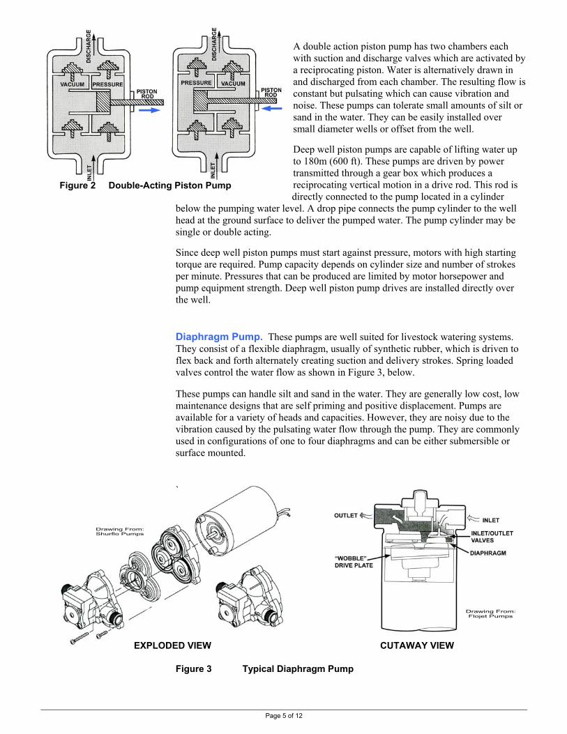
Page 5 of 12
Figure 2 Double-Acting Piston Pump
A double action piston pump has two chambers each with suction and discharge valves which are activated by a reciprocating piston. Water is alternatively drawn in and discharged from each chamber. The resulting flow is constant but pulsating which can cause vibration and noise. These pumps can tolerate small amounts of silt or sand in the water. They can be easily installed over small diameter wells or offset from the well. Deep well piston pumps are capable of lifting water up to 180m (600 ft). These pumps are driven by power transmitted through a gear box which produces a reciprocating vertical motion in a drive rod. This rod is directly connected to the pump located in a cylinder
below the pumping water level. A drop pipe connects the pump cylinder to the well head at the ground surface to deliver the pumped water. The pump cylinder may be single or double acting. Since deep well piston pumps must start against pressure, motors with high starting torque are required. Pump capacity depends on cylinder size and number of strokes per minute. Pressures that can be produced are limited by motor horsepower and pump equipment strength. Deep well piston pump drives are installed directly over the well. Diaphragm Pump. These pumps are well suited for livestock watering systems. They consist of a flexible diaphragm, usually of synthetic rubber, which is driven to flex back and forth alternately creating suction and delivery strokes. Spring loaded valves control the water flow as shown in Figure 3, below. These pumps can handle silt and sand in the water. They are generally low cost, low maintenance designs that are self priming and positive displacement. Pumps are available for a variety of heads and capacities. However, they are noisy due to the vibration caused by the pulsating water flow through the pump. They are commonly used in configurations of one to four diaphragms and can be either submersible or surface mounted. `
EXPLODED VIEW CUTAWAY VIEW
Figure 3 Typical Diaphragm Pump
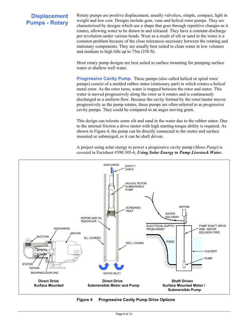
Page 6 of 12
Rotary pumps are positive displacement, usually valveless, simple, compact, light in weight and low cost. Designs include gear, vane and helical rotor pumps. They are characterized by designs which use a shape that goes through repetitive changes as it rotates, allowing water to be drawn in and released. They have a constant discharge per revolution under various heads. Wear as a result of silt or sand in the water is a common problem because of the close tolerances necessary between the rotating and stationary components. They are usually best suited to clean water in low volumes and medium to high lifts up to 75m (250 ft). Most rotary pump designs are best suited to surface mounting for pumping surface water or shallow well water. Progressive Cavity Pump. These pumps (also called helical or spiral rotor pumps) consist of a molded rubber stator (stationary part) in which rotates a helical metal rotor. As the rotor turns, water is trapped between the rotor and stator. This water is moved progressively along the rotor as it rotates and is continuously discharged as a uniform flow. Because the cavity formed by the rotor/starter moves progressively as the pump rotates, these pumps are often referred to as progressive cavity pumps. They could be compared to an auger moving grain. This design can tolerate some silt and sand in the water due to the rubber stator. Due to the internal friction a drive motor with high starting-torque ability is required. As shown in Figure 4, the pump can be directly connected to the motor and surface mounted or submerged, or it can be shaft driven. A project using solar energy to power a progressive cavity pump (Mono Pump) is covered in Factsheet #590.305-6, Using Solar Energy to Pump Livestock Water.
Direct Drive Direct Drive Shaft Driven Surface Mounted Submersible Motor and Pump Surface Mounted Motor /
Submersible Pump
Figure 4 Progressive Cavity Pump Drive Options
Displacement Pumps - Rotary

Page 7 of 12
Coil Pumps. These pumps are a motor / pump system that use specific gravity water flow conditions to drive the pump (similar to hydraulic ram pumps). A small portion of the drive water is pumped. In the case of a Sling Pump, a commercially available coil pump shown in Figure 5, below, the drive water is a flowing stream. The stream at least 400 mm (16 inches) deep and with a 0.6 m/sec (2 ft/sec) flow rate is required. Different pump models offer lifts to 24m (80 ft) and volumes to 15,000 litres (4,000 USgal) per day. The Sling Pump is covered in Factsheet #590.305-8, Using Stream Energy to Pump Livestock Water. Figure 5 Coil (Sling) Pump Centrifugal Pump. These pumps consist of an impellor that rotates within a circular cavity. Water enters the pump through the centre or eye of the impeller, increases in velocity as it moves across the impeller face, and is discharged by the impeller into the diffuser where the water is slowed down, converting some of the velocity into pressure. This is similar to the ‘discharge’ that occurs when a weight on a string is whirled around and released – it will fly away some distance. Water is drawn into the centrifugal pump by atmospheric pressure but these pumps must be manually primed. Suction lift (at sea level) is restricted to 4.6m (15 ft), and at 600m (2000 ft) suction lift is 4m (13 ft). These pumps are used when minimal suction lifts are required, such as lakes, ponds, streams etc. A good foot valve is required on the suction line to prevent lost of prime. A centrifugal pump produces a smooth, uniform flow of water. Open impeller type pumps are capable of pumping water with some sand; however closed impeller (turbine) pumps should be used in clean water conditions. Centrifugal pumps provide good service life and are very reliable. Pump efficiency will depend on the impeller speed, operating head and flow rate delivered. High efficiency is usually only possible for a narrow range of operating conditions so it is very important that pump selection matches site conditions.
Velocity Pump

Page 8 of 12
Turbine-Centrifugal Pump. These pumps consist of centrifugal impellers mounted on a single shaft and all operating at the same speed. Each impeller passes the water to the eye of the next impeller through a diffuser. Each impeller-diffuser combination is called a stage. Pumps can be single or multistage. The capacity is determined by the width of the impeller and diffuser. The pressure is determined by the impeller diameter, rotation speed and the number of stages. Note that additional stages increase pressure but do not increase flow. Some restrictions apply when these pumps are used in well situations. Pump output is partly determined by impeller diameter but this is restricted by the diameter of the well casing. If higher pressures are required for higher lifts more stages are used making the pumps longer. If the pump is going in a drilled well, these long pumps require either a very straight well or a larger diameter well. Deep well centrifugal pumps can be driven by electric motors of two different types: submersible or surface mounted (line shaft driven). • Submersible Deep Well Centrifugal Pumps. These pumps consist of
multistage centrifugal impellers driven by specially designed motors that are capable of operating underwater.
• Vertical Line Shaft Deep Well Submersible Pumps. These pumps are generally used for high capacity, high head installations where the horsepower requirements exceed the capability of submersible motors. A line shaft turbine pump consists of a surface mounted motor driving the submersible pump. These pumps may not be used for the small pumping requirements of many livestock watering systems.
Typical Centrifugal Pump
Submersible Turbine-Centrifugal Pump
Figure 6 Cutaway of Centrifugal Pumps

Page 9 of 12
Jet Pump. These combine two pumping principles, centrifugal action and venturi injection. These pumps are of simple design, low cost and quiet operation, requiring minimum maintenance. Jet pumps consist of a pump (usually centrifugal) and a jet or ejector assembly. The centrifugal pump portion functions as described previously with an impeller and diffuser to produce the required output. However, instead of the total discharge going to the delivery pipe, some is returned to the jet to assist suction. This jet is made up of a body, nozzle and venturi tube. The return portion of the pump output water is forced through the nozzle and into the venturi tube. In passing through the nozzle a partial vacuum is created which assists in the pump suction. The venturi tube, which gradually increases in size, slows the water down converting the velocity into pressure. Drive water and pumped water therefore emerge from the venturi at relatively high pressures. This water once again passes through the centrifugal pump where a portion is returned to the jet and a portion is pumped out the discharge line. The amount of water returned to the ejector must be increased as the lift increases. For example, 50% of the total water pumped is returned to the jet at a 15m (50 ft) lift, but 75% is returned at 30m (100 ft) lift. Therefore efficiency goes down with increased lift. The jet pump action has the advantage of pumping limited amounts of air without difficulty, have relatively few moving parts and have a continuous smooth pumping action. They are easily primed. Jet pumps are easily damaged by sandy water. The flow capacity depends on impeller diameter, speed, and pump design.
Two Pipe Jet
Single Pipe Jet SURFACE WATER OR SHALLOW WELL DEEP WELL
Figure 7 Jet Pump

Page 10 of 12
• Shallow Well Jet Pump. These pumps have the ejector mounted in or attached
to the surface-mounted pump housing. A suction line attached to the jet extends down below the water level. At start up, the centrifugal impeller forces a stream of water through the ejector creating a vacuum which draws water from the well to the pump. Maximum lift for a shallow well jet pump is 4.5 to 6m (15 to 20 ft).
• Deep Well Jet Pump. These pumps have the ejector submerged in the water down the well. They can be equipped with more than one ejector, depending on the well depth, capacity and pressure required. Deep well jets are available in two pipe and single pipe or "packer" systems. In a single pipe system the space between the well casing and the suction pipe serves as the pressure pipe. A well casing adaptor is required to seal the casing to allow it to act as a pipeline.
This pump uses compressed air, delivered to the bottom of a submerged pipe in a well, to lift an air/water mixture to the surface. The pump principle is that an air/water mixture, with as little as half the density of water, will rise to a height above the water level approximately equal to the immersed depth of the pipe. Depending on the lift required, this submersion depth may require a deep well (refer to “Total Length” in Table 2, below). The air line can be placed inside the discharge pipe or, as shown in Fig 8, next page, outside and parallel to it. A ‘foot piece’ breaks the air into small bubbles that conserves air and improves efficiency. A homemade device can be used consisting of 1/16 inch holes in a copper tube that extends at least 2 feet up into the pipe.
The main advantage of this pump is its simplicity. The disadvantages are the very low overall energy efficiency and the well depth for higher lifts. Submergence in Table 2, below, is “minimum” (the least submergence but requires more compressed air per volume of water delivered) or “best” (least amount of compressed air per volume of water delivered but deepest well – “total depth” - required).
Table 2 Air Lift Pump Requirements for Livestock Watering Conditions 1 Water Discharge Pipe Size Pumping Rate
½ inch air line inside water line 1 ½ inch air line outside water line 1 litres per min USgal per min mm inch mm inch
4 to 15 1 to 4 25 1 13 0.5 15 to 26 4 to 7 32 1.25 19 0.75 26 to 42 7 to 11 38 1.5 25 1
Air Lift Performance for Minimum and Best Submergence 1 Depth to Pumping
Water(lift L)
Depth of Air Line Below Pumping Water (submergence S)
Total Length (lift L + submergence S)
Volume of Air Required per Volume Water Pumped
m feet m ft m3/min per m3 ft3/min per USgal m feet min best min best min best min best min best min best
7.6 25 8.8 16.8 29 55 16.4 24.4 54 80 2.06 1.35 0.28 0.18 15.2 50 15.8 28.4 52 93 31.0 43.6 102 143 3.74 2.24 0.50 0.30 30.5 100 27.1 45.7 89 150 57.6 76.2 189 250 6.58 3.52 0.88 0.47 45.7 150 34.5 55.8 113 183 80.2 101.5 263 333 8.83 4.64 1.18 0.62 60.1 200 42.4 65.9 139 216 102.
5 126.0 339 416 10.92 6.21 1.46 0.83
1 refer to Figure 8, next page
Air Lift Pump

Page 11 of 12
Figure 8 Air Lift Pump The following two pumps are actually a motor / pump system. Both use specific gravity water flow conditions to drive a pump that pumps a small portion of the drive water. The traditional ram pump is shown in Figure 9, below, and a modified ram pump is shown in Figure 10, next page. The traditional hydraulic ram pump operation and setup, etc is covered in Factsheet #590.305-9, Using A Hydraulic Ram to Pump Livestock Water. A modification of the traditional hydraulic ram pump is available as a Glockemann Pump. It is covered in Factsheet #590.305-10, Using A Modified Hydraulic Ram to Pump Livestock Water. Figure 9 Hydraulic Ram Pump
Drive Water Source
Hydraulic Ram Pump
Ram Pump
Drive Pipe containingDrive Water
Delivery Pipe containing Pumped Water
Fall
Lift
DRIVE SIDE DELIVERY SIDE

Page 12 of 12
Figure 10 Modified Hydraulic Ram Pump (Glockemann 320) (delivery line not shown)
Refer to the following publications for detailed information on pumps. • Water-Pumping Devices
Peter Fraenkel, Intermediate Technology Publications, 1995 • Internet Glossary of Pumps web site has animated diagrams of how pumps
work http://www.animatedsoftware.com/elearning/All%20About%20Pumps/glossary/aap_glossary.swf
RESOURCE MANAGEMENT BRANCH WRITTEN BY Ministry of Agriculture and Lands Lance Brown 1767 Angus Campbell Road Engineering Technologist Abbotsford, BC V3G 2M3 Phone: (604) 556-3100 Kamloops Office
More Information
Rubber Diaphragm that pushes the Piston in the Cylinder Bore
Drive Water Outlet Cylinder Bore with Piston (changeable diameter to suit requirements)
Pump Suction
Pump Delivery to Trough
This is the Drive End This is the Pump End
Output Adjustments
50mm (4 inch) Drive Pipe / Water Supply

.Page 1 of 4
Livestock Watering
Order No. 590.305-3 January 2006
POWERING LIVESTOCK WATERING PUMPS
This Factsheet outlines motor and engine options to power pumps typically used in livestock watering systems.
The following two pumping energy options were outlined in Table 2 of Factsheet #590.305-1, Pumping Livestock Water: It’s All About the Energy Choices !: • on-site energy (gravity; livestock themselves; solar / wind) • off-site energy brought to the site (electrical grid; petroleum)
This Factsheet looks at the type of motors or engines typically selected to power livestock watering pumps, mostly using off-site energy that can be brought to the site. On-site energy options are covered in other Factsheets in this series. Electricity motors can be energized by either direct current (DC) electricity, typically 12 or 24 volt, or by alternating current (AC), typically from the electrical ‘grid’. DC Electric Power. Direct current electricity can be used to power water pumps. As DC power is usually only transmitted short distances, it is generated on-site from solar energy (photovoltaic panels), wind energy, or gravity water flow (hydroelectricity). These are usually low energy systems. DC Motor Selection. DC motors are unique in that their rotational speed is proportional to the voltage they receive, up to their rated voltage. For instance a 12 volt DC motor will still power a pump when supplied with less than 12 volts; it will just rotate slower (and must be matched to appropriate pumps). This is important in solar systems that directly-power a pump (systems without batteries) as water will be pumped in less than full sunshine. For livestock watering systems, DC motor selection involves decisions on the following specifications: • motor voltage – DC systems are typically 12 or 24 volt, but can be any multiple of
12 volt (e.g. Factsheet #590.305-6, Using Solar Energy to Pump Livestock Water discusses a 180 volt DC system)
• motor size (power); voltage x amperage = wattage (or horsepower) - refer to Factsheet #590.304-3 Livestock Water System Design #3 - Calculating Pumping Requirements for motor sizing information
• consider permanent magnet DC motors for their increased efficiency • other features will depend on the pumping system
Introduction
Electric Motors
.Page 2 of 4
AC Electric Power. Alternating current electricity is a clean, inexpensive (about $0.07 per kilowatt-hour in B.C.) and reliable power source. AC electric motors are very efficient (80-90%+), require minimum maintenance, have a long service life, are easily automated and are available in a wide range of sizes. The main disadvantage to AC electricity is the cost of the power supply line (if the power is not reasonably close to the pumping site) or of on-site generation. A secondary disadvantage is AC motors run at constant speed. Some pumps may require a speed conversion drive to operate at their best rpm. Where readily available, AC electricity should be considered the best power source for water pumping. AC electricity is supplied in two "forms": single phase and three phase. Single Phase AC. The standard electrical distribution system in most areas is single phase power. Generally, motors up to 10 horsepower can be directly hooked to a single phase supply. Motors larger than 10 horsepower will usually require a “soft start” system to operate on a single phase line. Single phase motors are not self starting requiring an auxiliary starting method. A starting capacitor connected to the start winding of the motor is usually used. The capacitor is used to get the motor started and up to running speed at which point a switch disconnects the capacitor and start winding. Three-wire single phase motors have the starting capacitor and control box located above ground away from the motor – a two wire system has the starting device mounted within the motor housing. Three Phase AC. Three phase is usually used for motors larger than 10 horsepower. These motors are self starting and do not require starting capacitors or control boxes. Three phase motors use magnetic starters containing three leg overload protection. Many stock watering systems will not require this size of motor. AC Motor Selection. For livestock watering systems, AC motor selection involves decisions on the following specifications: • motor size (power) - single phase motors under 10 hp
- refer to Factsheet #590.304-3 Livestock Water System Design #3 Calculating Pumping Requirements for motor sizing information
• motor speed - usually 1725 rpm • motor duty - continuous or intermittent • motor start type - depending on pump starting load • motor bearing - sleeve or ball bearings • motor enclosure - depending on operational environment • motor mounting base - rigid or adjustable • motor controls - overload protection or protection from loss of water (an
amperage-sensing device which turns off the motor if low amperage draw occurs – i.e., the pump is no longer ‘working’ and pumping water – with an adjustable re-start timer)
Petroleum-fueled internal combustion engines (natural gas, propane, gasoline or diesel) are not as efficient as electric motors and require additional maintenance. The operating costs can be 5 to 10 times higher than electrically operated systems. They would typically be chosen when: • electricity is not readily available • the system will only be used temporarily or for emergencies • the pump system must be portable
Internal Combustion
Engines
.Page 3 of 4
Engines can operate over a range of speeds with direct pump drives. However the engine output at the speed it will be operated at must be sufficient to power the pump. For instance a 3 horsepower gasoline engine running at half speed will not produce 3 horsepower. The manufacturers’ power curve and specifications should be used to estimate the actual power at the individual systems conditions. Note that the rated power of an engine is usually the maximum output at maximum speed whereas the actual useable power is less. Depending on the annual operation time, life expectancy of engines is less than electric motors: gasoline engines can be as low as a year or two; diesel engines a few years and electric motors up to 20 years. The periodic engine rebuilding costs must be included in the annual operating costs. The main reason for considering internal combustion engines is their quick set up time and portability. For the water volumes usually pumped in livestock watering systems, small gasoline engine/pump units are commercially available. These are typically medium to high volume pumps with low lift. For a particular site condition, the engine and pump must be selected for the system requirements. Gasoline vs Diesel Engines. Diesel engines are usually selected over gasoline engines in larger horsepower systems or systems operating many hours annually. The initial cost of a diesel engine is approximately 3 to 4 times that of a gasoline engine but has a life expectancy equally longer. For small systems, gasoline may offer a greater selection of engines than diesel. In most cases, as system size increases, diesel will typically be preferred. Use Table 1, next page, which outlines the above points and consider the following points when selecting a power system for a pump: • does the watering system need to be automatically started and stopped?
- electrical motors can be easily automated - fuel engines are much more difficult to automate
• is the water volume small (less than 10 USgpm or 5,000 US gal per day)? - small volume systems may not be a good match with fuel engines
• is the system operated for only a few hours daily? - similar to above, small systems may not be a good match with fuel engines
• what ‘duty cycle’ or operation cycle is needed? - whether the pump will be operated intermittently or continuous
• what is the comparison costs of options? - compare the cost of supplying electrical power plus operational cost to the engine cost and operating fuel cost as shown in the Example, next page
If motor and pump speed match, a direct drive can be used. The motor can be coupled directly to the pump with a flexible device that will allow for misalignment. If motor speed doesn't match the required pump speed, a speed conversion drive will be required. Pulley-and-belt drives, gear drives and chain-and-sprocket drives are three common drives for speed conversion.
Selecting a Power System
for a Pump
Motor Drives

.Page 4 of 4
Table 1 Characteristics of Pump Motors and Engines Typically Used in Livestock Watering Systems 1
Power Type
Relative Cost 2
Energy Cost
Efficiency 2 Life 3 Abilities Limitations
DC Motor (fractional horsepower) 4 field wound
mid low/mid -variable-speed with
voltage permanent
magnet mid
generated on-site 5 mid
medium
-variable-speed with voltage
-efficiency makes good match for solar systems
- on-site generation costs
AC Motor single phase low mid -inexpensive; long life
-easy to automate -under 10hp or soft start -electrical supply costs
three phase low
$0.07 per
kWhr 6 high
long
-over 10 hp possible -limited grid available
Gasoline Engine single or multi
cylinder low/mid $0.80 per
litre 6 low/mid short/
medium 7 -matched to small/mid systems (volume, lift, hours of use)
-difficult to automate -fuel delivery issues
Diesel Engine single or multi
cylinder high $0.80 per
litre 6 mid medium/
long 7 -matched to mid/large systems (volume, lift, hours of use)
-difficult to automate -fuel delivery issues
1 refer to the text for engine and motor details 2 as the power unit is typically used for a livestock watering pump: cost and efficiency relative to other choices of equal power lowest cost usually for a manufacturers power unit and pump combination rather than separate components assembled
3 as the power unit is typically used for a livestock watering pump: short = under 4 years; medium = 4-8 years; high = over 8 years 4 DC motors used in livestock watering systems are usually low power motors 5 energy cost varies with cost of typical on-site solar, wind, or hydroelectric generation system 6 electricity and marked fuel costs as of February 2006 7 depending greatly on maintenance done; longer life with regular maintenance, such as oil changes on engines w/o oil filter
A web site on how DC motors work: http://hyperphysics.phy-astr.gsu.edu/hbase/magnetic/motdc.html
A web site on how AC motors work: http://hyperphysics.phy-astr.gsu.edu/hbase/magnetic/motorac.html#c1
A web site with detailed information on electric motors: http://www.electricmotors.machinedesign.com/
A web site on how internal combustion engines work: • gasoline engines http://auto.howstuffworks.com/engine1.htm • diesel engines http://auto.howstuffworks.com/diesel1.htm
RESOURCE MANAGEMENT BRANCH WRITTEN BY Ministry of Agriculture and Lands Lance Brown 1767 Angus Campbell Road Engineering Technologist Abbotsford, BC V3G 2M3 Phone: (604) 556-3100 Kamloops Office
Other Information

Page 1 of 8
Livestock Watering Order No. 590.305-4 January 2006
USING WIND ENERGY TO PUMP LIVESTOCK WATER
This Factsheet outlines the use of wind energy to pump livestock water. Imperial and metric units are used.
The use of mechanical equipment to convert wind energy to pump water goes back many years. By the late nineteenth century there were more than 30,000 windmills operating in Western Europe, many of the Dutch “tower” mill design. In 1854, Daniel Halliday invented the American multiblade windmill using wooden blades. By 1915, Aermotor Company of Chicago had patented the first self-oiling machine, with the open gears enclosed in a water resistant case. Windmills are classified as vertical or horizontal axis machines depending on the axis of rotation of the rotor. Vertical axis wind- mills can obtain power from all wind directions whereas horizontal axis windmills must be able to rotate into the wind to extract power. Windmills are also classified as either electrical power generators or water pumpers. Power generators are typically horizontal axis “propeller” type blade designs or vertical axis “egg beater” designs. Power generators typically operate at high rotational speeds with low starting torques, appropriate for generators. Direct water pumping windmills are characterized by the “old west” style of a multiblade, horizontal axis design set over top of the well (Figure 1). Water pumping requires a high torque to start the pump and this is supplied by the multiblade design.
Figure 1 Components of a Multiblade Windmill For Pumping Water
Introduction to Windmills

Page 2 of 8
The energy available in the wind is proportional to the cube of the wind speed: if the wind speed is doubled, there is eight times the available power. A 12 kph wind has eight times the power of a 6 kph wind and a 24 kph wind has sixty-four times the power of a 6 kph wind! There is 73% more energy in a 12 kph wind than in a 10 kph wind (123 is 1.73 times larger than 103). This is an important characteristic of wind energy. Measurement of the average wind speed of a site is crucial. Generally, winds less than 12 kph are not practical for water pumping. Wind energy is also affected by the density of the air. Lower density air in summer than winter, or at higher elevations, has less wind energy potential. Windmill Power. The power output of a windmill is dependent on the rotor diameter and the wind speed. The energy captured by the rotor is proportional to the square of the rotor diameter (doubled rotor diameter = four times power output) and the cube of the wind speed (doubled wind speed = eight times power output). The potential output of a multiblade windmill is given by this equation:
P = 0.002 D2 V3
where: P = power in watts (note: 746 watts = 1 horsepower) D = rotor diameter in metres V = wind speed in kilometers per hour Assumptions: average air density overall efficiency = 20% (usual range is 10 – 30%) (20% = approx rotor 30% x energy conversion 70%) Note: maximum 59% of wind energy can be extracted (Betz Law)
Tables 1 & 2, next page, provide capacities from this equation and a windmill supplier. Site Location. Site location factors also affect a windmills power output. The terrain affects the wind so windmill location must be considered carefully as illustrated in Figure 2, below. These site considerations highlight a difficult point in using windpower to pump water – is the water source located at the same site as the most favorable wind site? Water may be in a draw or gulley but the wind is up on the ridge or hilltop. Although windmill designs are available to allow the windmill location offset from the water source, most installations are directly over the source, usually a well. If electrical energy is being generated to power an electrical pump, some separation is possible. from Harnessing the Wind for Home Energy, Dermot McGuigan Figure 2 Windmill Site Considerations
Wind Energy Potential
Site 1 - Ideal (benefits from wind in all directions)
Site 2 – Not recommended (wind is usually poor)
Site 3 - Good site (wind from two directions only)
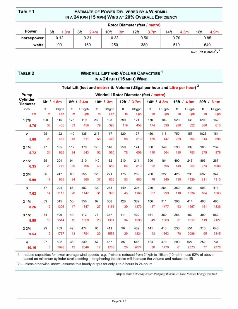
Page 3 of 8
TABLE 1 ESTIMATE OF POWER DELIVERED BY A WINDMILL IN A 24 KPH (15 MPH) WIND AT 20% OVERALL EFFICIENCY
Rotor Diameter (feet / metre) Power 6ft 1.8m 8ft 2.4m 10ft 3m 12ft 3.7m 14ft 4.3m 16ft 4.9m
horsepower 0.12 0.21 0.33 0.50 0.70 0.85
watts 90 160 250 380 510 640
from P = 0.002 D2 V3
TABLE 2 WINDMILL LIFT AND VOLUME CAPACITIES 1 IN A 24 KPH (15 MPH) WIND
Total Lift (feet and metre) & Volume (USgal per hour and Litre per hour) 2 Windmill Rotor Diameter (feet / metre) Pump
Cylinder Diameter 6ft / 1.8m 8ft / 2.4m 10ft / 3m 12ft / 3.7m 14ft / 4.3m 16ft / 4.9m 20ft / 6.1m
inch ft USgph ft USgph ft USgph ft USgph ft USgph ft USgph ft USgph cm m Lph m Lph m Lph m Lph m Lph m Lph m Lph
1 7/8 120 115 175 119 260 103 390 121 570 103 920 138 1200 162
4.76 36 435 53 450 79 390 119 458 174 390 280 522 366 613
2 95 122 140 135 215 117 320 137 456 118 750 157 1026 184
5.08 29 462 43 511 66 443 98 519 139 447 229 594 313 696
2 1/4 77 165 112 170 170 148 250 174 360 149 590 199 903 232
5.72 24 625 34 643 52 560 76 659 110 564 180 753 275 878
2 1/2 65 204 94 210 140 182 210 214 300 184 490 245 896 287
6.35 20 772 29 795 43 689 64 810 92 696 149 927 273 1086
2 3/4 56 247 80 255 120 221 175 259 260 222 425 296 692 347
6.99 17 935 24 965 37 836 53 980 79 840 130 1120 211 1313
3 47 294 68 303 100 263 149 308 220 264 360 353 603 413
7.62 14 1113 20 1147 31 995 45 1166 67 999 110 1336 184 1563
3 1/4 39 345 55 356 87 308 128 362 186 311 305 414 496 485
8.26 12 1306 17 1347 27 1166 39 1370 57 1177 93 1567 151 1836
3 1/2 34 400 49 412 75 357 111 420 161 360 265 480 390 562
8.89 10 1514 15 1559 23 1351 34 1590 49 1363 81 1817 119 2127
3 3/4 29 459 42 474 65 411 96 482 141 413 230 551 310 646
9.53 9 1737 13 1794 20 1556 29 1824 43 1563 70 2086 95 2445
4 27 522 38 539 57 467 85 548 124 470 200 627 252 734
10.16 8 1976 12 2040 17 1768 26 2074 38 1779 61 2373 77 2778
1 – reduce capacities for lower average wind speeds e.g. if wind is reduced from 24kph to 16kph (10mph) – use 62% of above – based on minimum cylinder stroke setting – lengthening the stroke will increase the volume and reduce the lift 2 – unless otherwise known, assume this hourly output for only 4 to 5 hours in 24 hours
adapted from Selecting Water-Pumping Windmills, New Mexico Energy Institute

Page 4 of 8
Solar-powered Data Collection of Wind Speed
The accurate assessment of the average wind speed during the period that water pumping is required cannot be over-stressed. In some cases local weather station information may be applicable, however as wind varies widely over short distances actual site wind readings are preferred. A hand held anemometer can be used but will be too close to the ground and requires considerable onsite time to establish meaningful records. Better results are from a permanent recorder installation. An anemometer can be installed on a simple T.V. antennae tower and when connected to a recorder, wind speeds are continuously monitored, as shown in Figure 3, below. This can then be used to accurately calculate the average wind speed and thereby correctly select the windmill equipment. If needed, adjust site readings to the height of tower to be used using Table 3, next page. Readings should be taken for the period water is required. This wind assessment may have to be contracted from a local company.
Solar-powered Data Collection of Wind Speed
Figure 3 Wind Speed Monitoring Equipment
Wind Speed Assessment

Page 5 of 8
Windmills need to be raised in the air a sufficient height to be able to capture undisturbed wind. But as towers are costly, what height is most effective? Consider: • the windmill wheel must be at least 9m (30 ft) above any obstruction within a
100m (350 ft) radius to give the rotor a free flow of air from all directions • wind speed generally increases with altitude, meaning more power is available • therefore, a higher tower can be a cost effective way to increase power
Figure 4 illustrates increasing to a 18m (60ft) from a 9m (30ft) tower has a +41% wind power increase (increased power due to the effect of wind speed “cubed”). Figure 4 Relationship of Tower Height to Available Wind Power The 1/7 Rule. A method of estimating the wind speed at the elevation of a windmill when it’s at a height other than that which the wind speed is measured, is to use the “1/7 Rule”. This states that the wind speed increases at the 1/7 power of the height (H 1/7) above ground, as shown in Table 3. If the wind speed is measured at 20 ft but the windmill will be at 40 ft, Table 3 indicates the speed at 40 ft will be 1.10 times the measured speed at 20 ft (and as the energy potential increases by the cube of the wind speed, a 1.10 wind speed increase = 1.103 = 1.33 energy increase).
TABLE 3 THE 1/7 WIND SPEED RULE FOR VARIOUS HEIGHTS OF WINDMILLS Height at which Wind was Measured (feet and metre)
15 4.5 20 6.1 25 7.6 30 9.1 35 10.7 40 12.2 45 13.7 50 15.2
20 6.1 1.04 1 0.97 0.94 0.92 0.91 0.89 0.88
30 9.1 1.10 1.06 1.03 1 0.98 0.96 0.94 0.93
40 12.2 1.15 1.10 1.07 1.04 1.02 1 0.98 0.97
50 15.2 1.19 1.14 1.10 1.08 1.05 1.03 1.02 1
60 18.3 1.22 1.17 1.13 1.10 1.08 1.06 1.04 1.03
70 21.3 1.25 1.20 1.16 1.13 1.10 1.08 1.07 1.05
80 24.4 1.27 1.22 1.18 1.15 1.13 1.10 1.09 1.07
90 27.4 1.29 1.24 1.20 1.17 1.14 1.12 1.11 1.09
Hei
ght o
f Tow
er (f
eet a
nd m
etre
)
100 30.5 1.31 1.26 1.22 1.19 1.16 1.14 1.12 1.10
adapted from Wind Power for the Homeowner, Donald Marier: (Height / height measured) 1/7 = Wind Speed / wind speed measured
Tower Height, Wind Speed
and Power

Page 6 of 8
Multiblade windmills traditionally pump water by directly operating a pump cylinder with a drive rod. The pump cylinder is submerged in the well attached to the end of the delivery pipe. It is a very simple pump similar to a hand-operated bicycle pump. The drive rod is operated directly by the windmill rotor through the drive gearing which translates the rotating motion to the up and down reciprocating motion. Two one way valves in the pump direct water through the pump as illustrated in Figure 5. The following design improvements made to the standard multiblade water pumping windmill make use of lighter winds or increase the amount of pumping for each cycle. Fully Counterbalanced Windmill. A standard windmill works on the upstroke; pumping water and lifting the weight of the pump rod. A counterbalanced windmill has part of the pump rod weight and one-half the water weight counterbalanced by counterweights. This results in an approximate two-thirds reduction in starting torque allowing the use of lighter winds. Tests have shown 13 times greater volume pumped at wind speeds below 16 kph and one-third greater volume above 16 kph.
Figure 5 Operation of a Typical Windmill Pump Cylinder
Spring Counterbalanced Windmill. This design achieves similar results as counterbalancing with weights. Two to four extension springs are attached to the top of the tower and the free ends are connected to the pump rod. Energy is stored in the downstroke to assist in the up stroke and tends to even out the work load. The size and number of springs must be determined to suit the individual windmill. Cam-Operated Windmill. In a cam operated windmill, the lift occurs during more than one-half the cycle (standard designs only lift for one-half the cycle). Using a cam that allows for three-quarters of the cycle lifting and one-quarter return, starting torque is reduced by 60 percent. The windmill will start in light winds, and if combined with counterbalancing, starting torque is reduced by 72 percent. Air Lift Pumps. Air lift water pumps are an alternative to the traditional rod driven cylinder pumps. The windmill operates an air compressor which pumps air down a line set in the well. The end of this air line is attached to the "air lift pump" which is actually a specially formed foot piece attached to the water delivery pipe. This must be submerged in the water a depth equal to 30% to 70% of the required lift measured above the water level. For example, to lift 30m (100 ft) above the water level, the air lift pump must be submerged approximately in the water 27 to 45m (90 to 150 ft).
Windmill Design
Variations
Pump Cylinders

Page 7 of 8
As air is discharged into this foot piece, the water column in the outlet pipe becomes less dense and is forced up by the denser water on the outside of the outlet pipe. With no moving or wearing components down the well, servicing is simplified. Also this design allows offsetting the windmill site from the water source. The main drawback is the submergence required as many wells will not have the depth of standing water. For more information on air pumps, refer to Factsheet #590.305-2, Pumps for Livestock Watering Systems. Points to consider when selecting a windmill: 1. First of all, a water source is needed, knowing the volume of water to be pumped
(livestock requirements) and the lift (from water level to top of tank) • if using a well, it should be drilled first to know the lift and volume available
2. Some estimate of available wind must be made, preferably from site readings • select a tower height • adjust site readings to the tower height using Table 3
3. Choose the combination of cylinder size for volume and rotor diameter for lift • use manufacturers tables or Table 2, page 3, for size estimates • usually best to choose the largest rotor and smallest cylinder that will fill the
need, for easy start in lighter winds and minimized strain on the system • as a rule-of-thumb, expect an average of 4 - 5 hours/day of pumping at the
specified rate for 24 kph wind unless local conditions are known 4. Other points:
• windmill pump outlets are normally discharged into an open tank i.e. into the top of the tank - if the outlet is to go into the bottom of the tank or rises above the well head a packer head is installed to seal the drive rod
• hand pumping can be done on some windmills in emergencies - the hand pump is part of the installation and the operating handle is attached when needed
A ranch requires stock water on rangeland for 80 cows grazing for two months in the spring. A well has been drilled 150 feet deep which produces water from 100 feet deep (i.e. has 50 ft. of storage). The well pump test showed that it will produce 5 USgpm or 300 USgph with a drawdown of 15 feet.
Calculations: • Total lift requirement: the pump will be placed at approximately 140 ft down
the well. The pumping lift is taken from the drawdown level which is 100 ft + 15 ft or 115 ft. It has to lift an additional 3 ft above the well head into the stock trough. Allowing 2 ft for pipe losses the total lift is 120 ft (115 + 3 + 2).
• Total daily water requirement: from Factsheet #590.301-1, Table 1, the daily requirement of cows when the air temperature is less than 250 C (spring time) is 12 USgpd/head; for 80 cows = 960 gpd.
• The preferred tower height. Towers range from 22 ft to 40 ft and are selected to ensure the rotor is in undisturbed air as previously discussed. The terrain at the site should be carefully considered when choosing tower height. In this case a 40 foot tower is selected.
• Average wind speed calculation: monitoring the site for the two month period in the spring showed the average wind speed to be 13 mph measured at 15 feet.
• The wind speed at the windmill height. Using Table 3, the 13 mph measured at 15 feet is multiplied by 1.15 for a 40 foot tower = 15 mph wind speed.
Example: Windmill
Selection
Selecting a Windmill

Page 8 of 8
Selection: • Windmill selection: refer to manufactures catalogs for windmill capacities for
the site conditions of wind speed and water volume and lift or use Table 2 for typical specifications (noting that this table is for 15mph wind speed).
• Use Table 2: As this site has 15 mph wind speed, use Table 2, for estimates:
Conditions: Average wind speed 15 mph Well capacity 300 USgph (max) Water requirement 960 USgpd (min) Daily pump time assume 5 hours Hourly pump rate 960 / 5 = 190 USgph (min) Total lift 120 ft
The best match for these lift and water requirements is - a 12 ft diameter windmill operating a 2 1/2 inch diameter pump cylinder - this will produce 214 USgph (more than 190 USgph needed and within the
well capacity of 300 USgph) - at 214 USgph, the 960 USgpd could be pumped in about 4 1/2 hours - it will lift 210 ft lift (which exceeds the required 120 ft, but the diameter rotor
will start easily in light winds) Note: as Table 2 capacities are for minimum pump stroke settings, a longer
stroke setting could be used to increase the pump volume (reducing the hours of pumping per day – an advantage during shorter periods of wind) – this will reduce the lift capacity but it is now greater than required
If extended periods of low winds are expected, water storage should be considered in addition to the storage in the trough(s), as illustrated on page 1. Refer to Factsheet #590.304-7, Storage Tanks for Livestock Watering Systems.
The following publications were used in preparing this Factsheet, or are wind references of note. Refer to them for more information as required. Harnessing The Wind for Home Energy, Dermot McGuigan, 1978 Selecting Water-Pumping Windmills, New Mexico Energy Institute, 1978 Wind Generator Tower Height, Mick Sagrillo, Home Power #21, 1991 Wind Power and Other Energy Options, David R. Inglis, 1978 Wind Power for the Homeowner, Donald Marier, 1981 Wind Power Uses and Potential, TransAlta Utilities, 1992 Many web sites are available: - a good “guided tour” on wind energy http://www.windpower.org/composite-85.htm - animated windmill pump http://www.aermotorwindmill.com/Links/Education/Index.asp - links to many water pumping sites http://www.internationalwindmill.com/links.htm
RESOURCE MANAGEMENT BRANCH WRITTEN BY Ministry of Agriculture and Lands Lance Brown 1767 Angus Campbell Road Engineering Technologist Abbotsford, BC V3G 2M3 Phone: (604) 556-3100 Kamloops Office
Other Information

Livestock Watering Order No. 590.305-5 January 2006
USING GRAVITY ENERGY TO PUMP LIVESTOCK WATER
This factsheet outlines the quantity and quality of water required for livestock, with tables for estimated daily use. Theinformation here is adapted from Alberta Ontario Agriculture & Agri Food Canada and University of Nebraska
This factsheet looks at the various gravity energy options to move water in the low volumes usually required forlivestock use. These options are discussed in general with reference to Factsheets containing specific details.
Page 1 of 2
Introduction
Gravity-Flow Pipeline
Livestock water pumping options are selected with pump-driving energy as the limiting factor, especially remote systems. Where grid-supplied electricity is not available, gravity is usually the first energy option to consider. Like most livestock water pumping systems, the site plays a big part in the energy choice. For a gravity option to be viable, the site terrain must be favorable. Favorable sites for gravity energy use are in one of two categories: where the water supply is either at:
• a higher elevation than required and can be piped down in a Gravity Flow Pipeline, or
• a lower elevation than required and can be pumped up if: - there is sufficient depth/width and velocity in the water supply to drive a Stream-Powered Pump, or
- there is sufficient volume and elevation fall in the water supply to drive a Hydraulic Ram Pump
Piping water from a supply site down to a watering trough is the simplest system as no equipment, etc. is required, other than a water intake and pipe. Although relatively simple, these systems must be installed using proper techniques to be successful. All gravity-flow pipelines require the following:
• an intake that is screened from debris and submerged sufficient to ensure no air enters the pipeline
• a properly sized pipe diameter, considering - the pipeline length, and - the elevation difference (the energy available to move water), and - the water flow required, - together with the pipeline material while
ensuring that the pipe diameter(s) match the hydraulic grade line • the pipeline placement, having
- sufficient grade in first 30m (100 ft) that doesn’t trap air (air release?) - air release at significant high points - drains at significant low points
For details, refer to Factsheet #590.304-5 Understanding Gravity-Flow Pipelines.

Page 2 of 2
Stream-Powered Pump
Hydraulic Ram Pump
These pumps use the energy in flowing water (i.e., flow that’s a result of gravity) to lift water above the supply. One example is the Sling Pump that rotates as the flowing water passes through the drive blades. It can deliver a volume and lift of water well suited for many livestock requirements. It is portable so multiple sites are possible with minimum setup. To operate, the pump requires:
• a minimum water depth of 40cm (16inch) to properly submerge the drive portion
• a minimum water velocity of 60cm per second (2ft per second) to achieve rated output
Depending on the size chosen, the Sling Pump can deliver from 3,500L per day at 25m, to 15,000L per day at 7.6m. The Water Wheel Pump is another example of using the energy in a flowing stream. For details on both these pumps, refer to Factsheet #590.305-8 Using Stream-Powered Pumps to Pump Livestock Water. Ram pumps date back to the 1790’s and early 1800’s and utilizes the water hammer effect. It creates a pressure rise (water hammer) in a falling column of water by alternately opening and closing the column to free flow. Each time the water flow is shut off (quickly) the resulting pressure rise is used to pump a small volume of water. To operate, a Ram Pump requires:
• a drive water volume approximately 10–15 times the volume pumped • a specific length and fall of the drive pipe
Depending on the size chosen and water supply conditions, a Ram Pump can deliver from a few thousand litres per day to tens of thousands of litres per day at lifts of 100m (300ft) or more. For details, refer to Factsheet #590.305-9 Using A Hydraulic Ram to Pump Livestock Water. Glockemann Pump. A modification of the Ram Pump is a recent design from Australia, called the Glockemann Pump. Whereas a traditional ram pumps a portion of its drive water, the Glockemann can pump that way or it can pump separately as a direct intake from the water supply. The pump design uses the same drive principle, but has a diaphragm driving a piston pump. With a piston diameter change it can pump a wide variety of lifts and volumes. Maximum lifts are much higher than traditional rams, up as high as 200m (650ft). For details, refer to Factsheet #590.305-10 Using A Modified Hydraulic Ram to Pump Livestock Water.
RESOURCE MANAGEMENT BRANCH WRITTEN BY Ministry of Agriculture and Lands Lance Brown 1767 Angus Campbell Road Engineering Technologist Abbotsford, BC V3G 2M3 Phone: (604) 556-3100 Kamloops Office

Page 1 of 4
Livestock Watering Order No. 590.305-6 January 2006
USING SOLAR ENERGY TO PUMP LIVESTOCK WATER
This Factsheet looks at two projects using photovoltaics to pump livestock water. Imperial units are used.
Project #1 - A Livestock Watering System - Medium Lift
A field installation of a photovoltaic (PV) powered livestock water pumping system is described. The system is designed to supply water to two locations; 3,200 US gal a day at 55 feet lift, or 1,000 US gal a day at 164 feet lift, or a combination of these two lifts and flows. This is sufficient to water approximately 200 or 65 beef cattle respectively. The system was originally funded by Energy, Mines and Resources Canada, together with the B.C. Ministry of Agriculture, Fisheries and Food, and was located in Cache Creek, B.C. in August 1986. The system was moved to Savona, B.C. in the spring of 1989. Figure 1 500 Watt PV Water Pumping System
INTRODUCTION Bob Haywood-Farmer runs a commercial cattle herd using Crown lease rangeland at Savona, B.C. Stock water distribution is a common problem on these low elevation grasslands. At this site, a good spring is available but pumping is required for water distribution. The site is remote from utility electricity and engine driven pumping was considered too costly and inconvenient. An existing demonstration PV system was available and suitable for this site. It was installed in May 1989. See Figure 1, left. SYSTEM DESIGN Water is pumped only when solar energy is available. The system was sized to deliver sufficient water on sunny days to allow some excess water to be stored for cloudy days. In this manner, energy is stored as pumped water rather than stored in batteries. The PV array powers the pump directly through a maximum power point device, a Wardun WD700 DC-DC converter (transformer). This device ensures sufficient motor starting current and maximum operating power throughout the day. The pump is a Mono P32 progressive cavity unit submerged in the water and shaft driven by a 2 HP permanent magnet DC motor mounted above water level. The Mono pump is well suited for a PV system as it will deliver the full lift over a wide range of speeds. This is important because with a panel-direct design, pump speed varies as sunlight intensity varies on the panels. Both the motor and pump were chosen for their high operating efficiencies.

Page 2 of 4
The array consists of 10 ARCO M-75 panels rated at 50 watts (peak) each. They are wired in series for a nominal output of 165 volts at 3 amps. The array is mounted on a rigid frame with provision for manual adjustment to match the seasonal changes of the sun. WATER SOURCE The water source is a spring fed pond into which 3 foot diameter steel pipe, 12 feet long was vertically submerged 8 feet. The motor and converter are mounted near the top of this pipe (above the water level) with the pump submerged approximately 7 feet. Pond overflow is available for cattle watering.
WATER STORAGE Pumped water is stored in two steel tanks, each at a different elevation and sized for more than a three day requirement. The lower tank (55 feet lift) is 1,000 feet from the pump; the upper tank (164 feet lift) is 1,600 feet away. Polyethylene pipe (1 ¼ inch) was used for the delivery system. LIVESTOCK USE Water from the lower storage tank is gravity fed approximately 2 miles to three float-controlled stock troughs. This allows the grazing use of a large, under used, grass hillside. Water from the upper storage tank is gravity fed to a nearby float-controlled trough to increase grazing on an upper bench area. See Figure 2, below.
Figure 2 Schematic Drawing of a Livestock Watering System - Medium Lift
RESULTS The first year of operation ran from 4 May to 2 June, 1989. Pumping to the lower lift only, 88,760 US gal of water was delivered in 29.5 days. This is an average daily volume of 3,000 US gal. Peak daily rate was measured for a full sunny day (10 May) at 3,600 US gal.
The upper lift tank had not been completed as of June 1989, so no data was taken. However, this pump system was previously installed at Cache Creek, B.C., approximately 40 miles west of the Savona site. At that location, during May 1987, an average 1,600 US gal
per day was pumped a lift of 141 feet. The full season daily average (April-October) was 1,450 US gal. This is very similar to the upper lift at the Savona site so similar results are expected. SYSTEM COSTS The pumping system costs (1989) totaled $8.000. This includes 10 panels, the array frame, converter, motor, pump, mounting assembly and wiring. The delivery pipe and water storage costs will vary between sites; the total cost is approximately $5,000 for the Savona site.

Page 3 of 4
Project #2 - A Livestock Watering System - Low Lift
A field installation of a photovoltaic (PV) powered livestock water pumping system is described. The system is designed to supply an average daily volume of 525 US gal pumped to a maximum lift of 32 feet. This is sufficient to water approximately 35 beef cattle. This project was funded by the B.C. Ministry of Agriculture, Fisheries and Food, the D.A.T.E. program and the cooperating rancher, Hugh Fallis, Monte Creek Herefords. It has been operating since 1989.
Figure 3 100 Watt PV Water Pumping System
INTRODUCTION Monte Creek Herefords is a purebred cattle operation using deeded rangeland. Two adjoining sections of their range are divided by a public road with the main water source near this road. Water distribution is required to utilize the grazing potential. To achieve this, some pumping is required. Because of the distance to utility electricity, and the cost of maintenance of engine driven pumping, a photovoltaic system was chosen to pump this livestock water. See Figure 3, above. WATER REQUIREMENT Beef cattle require water ranging from 8 to 15 US gal per day. For this site, 35 cows are to be watered, requiring a daily maximum volume of 525 US gal. Because of the daily variations in solar radiation, energy must be stored to ensure livestock water will be available on cloudy or low solar energy days.
SYSTEM DESIGN Energy stored in the form of pumped water was chosen over chemical storage in batteries. With adequate water storage, water need only be pumped during the hours of bright sunlight simplifying the design. The PV array powers the pump directly through a transformer (a linear current booster) that ensures sufficient motor starting current. This device transforms the panel output in low light conditions (e.g. morning) and is commonly used in PV water pumping systems. The motor/pump is a low-cost unit manufactured by Flojet. A 12-volt permanent magnet DC motor drives a diaphragm pump capable of 1.9 US gal per min @ 10 psi. The motor draws a maximum of 7 amps and has a fan for cooling under continuous operation. The array consists of 2 ARCO M-75 panels rated at 50 watts (peak) each. They are wired in parallel with one linear current booster per panel for a 100 watt (peak) output. Panels are mounted stationary at approximately 50% (the latitude of the site) with no seasonal angle adjustment. WATER SOURCE The water source is a shallow dug well with a 4 foot diameter culvert pipe 12 feet long, set in place vertically. The culvert is capped with a box to mount the array and to secure the system. To accommodate the changing water level, the motor/pump unit is mounted on a floating plywood/styrofoam raft guided by a centrally fixed pipe. This also ensures a low suction lift. Extra lengths of both supply wires and delivery pipe are provided to accommodate a maximum 10 foot movement of the raft. WATER STORAGE A round corrugated steel grain bin was converted for water storage using a 20 mil vinyl liner. It is located 150 feet from the spring (22 feet above). This provides a low cost storage tank and with the bin roof in place, ensures both clean water as well as a long liner life. At 14 feet in diameter and 4.6 feet deep, the total available storage is 5, 200 US gal. The delivery is into the top of the tank. The required lift into the tank varies from a minimum of 22 feet (spring full) to a maximum of 32 feet (spring empty).

Page 4 of 4
LIVESTOCK USE Water from the storage tank is gravity fed to standard float-controlled stock troughs. With ample storage, livestock can water regardless of the pumping conditions. See Figure 4, below. RESULTS In initial tests during May 1989, the system performed well. During days of full sun, 900 US gal a day were pumped into the tank. The average daily volume over a three week period was approximately 525 US gal a day. Peak flow rate was 1.9 US gpm. Operating until October each year, the volume pumped in 1989 was 44,500 US gal, and in 1990 was 29,000 US gal.
SYSTEM COSTS The pumping systems costs (1989) totaled $1,350. This includes 2 panels, 2 linear current boosters, motor/pump, suction screen, wiring, switch and miscellaneous wood and steel materials. The polyethylene delivery pipe and storage tank costs were approximately $1,000. The water well development costs were approximately $450. These last two costs are site specific and will vary depending on the water source and the distribution required.
Figure 4 Schematic Drawing of Livestock Watering System - Low Lift RESOURCE MANAGEMENT BRANCH WRITTEN BY Ministry of Agriculture and Lands Lance Brown 1767 Angus Campbell Road Engineering Technologist Abbotsford, BC V3G 2M3 Phone: (604) 556-3100 Kamloops Office

Page 1 of 5
Livestock Watering
Order No. 590.305-7 January 2006
USING LIVESTOCK ENERGY TO PUMP LIVESTOCK WATER
This Factsheet outlines options to use livestock to pump their own water with “Nose Pumps”.
Livestock water pumping options are selected with pump-driving energy as the limiting factor, especially remote systems. While other onsite-available energy options may be selected, the use of livestock to pump their own water is a viable choice for some types of livestock (bison, horses, beef or dairy cows) and for ground and surface water sources. Note that the following discussion concerns pumps used in non-freezing conditions; refer to page 4 for a winter-use livestock-operated pump. These pumps are produced by various manufacturers with similar features. Figure 1, below, illustrates two typical nose pumps. Livestock is attracted to the unit as it has a bowl which retains some water (the bowl slopes to the rear). To access this water, they have to push a broad-ended lever that is in the way, and in doing so, a diaphragm is operated, creating suction that draws up water to the bowl. As the nose is used to operate the pump they are called “nose pumps”. The term ‘pump’ is a bit misleading as they do not move water above the pump location but only ‘suck’ water up to the drinker. Suction depends on atmospheric pressure to move water; a maximum 10m or less than 34 feet of lift possible at sea level – less at higher elevations. Practical limits of the pump (through a 25mm / 1 inch polyethylene pipe) are typically lifts to 6m (20 ft) from water supply surface to the nose pump, 60m (200 ft) horizontally, or a combination (with each 10m horizontal approximately equal to 1m of lift).
Figure 1
Typical Nose Pumps from Two Manufacturers
Introduction
Nose Pumps

Page 2 of 5
Livestock best suited to operate a nose pump tend to be larger-sized animals such as bison, horses, beef or dairy cows, as shown in Figure 2, below. This animal size is most able to operate the diaphragm lever. The units are a sturdy construction of steel and cast metal able to withstand the loads, but they must be securely mounted to a rigid base. Figure 2 Nose Pump Use by Cattle Young calves are not suited to operate the pump. However, adding a “catch basin” for overflow water may make water available to calves, as shown in Figure 3, right. One producer has drilled a small hole in the water bowl to ensure some water bleeds into the tray. They should be able to use the pump once a few months old. One manufacturer offers an adaptation for sheep or goats consisting of a confining frame that replaces the operating lever, as shown in Figure 4, below. As the animal steps into the frame, their weight operates the diaphragm, drawing water into the bowl. Figure 3 Catch Basin Figure 4 Nose Pump Adapted for Sheep Use
Livestock Use of Nose Pumps

Page 3 of 5
A nose pump installation allows livestock to be fenced out of the water source avoiding impacts that could reduce water quality, as shown in Figure 5, below. This shows a fenced farm dugout where the water is accessed by cattle via a nose pump. The pump is mounted on wooded timbers. Figure 5 Nose Pump Sourcing Water from a Fenced Dugout To avoid one animal from “controlling” the waterer, two can be provided, as shown in Figure 6, below. Also note that this raised mount will also help prevent livestock from stepping in, or defecating on the water bowl. Figure 6 Dual Nose Pump Installation on a Raised Mount
Typical Nose Pump Installations
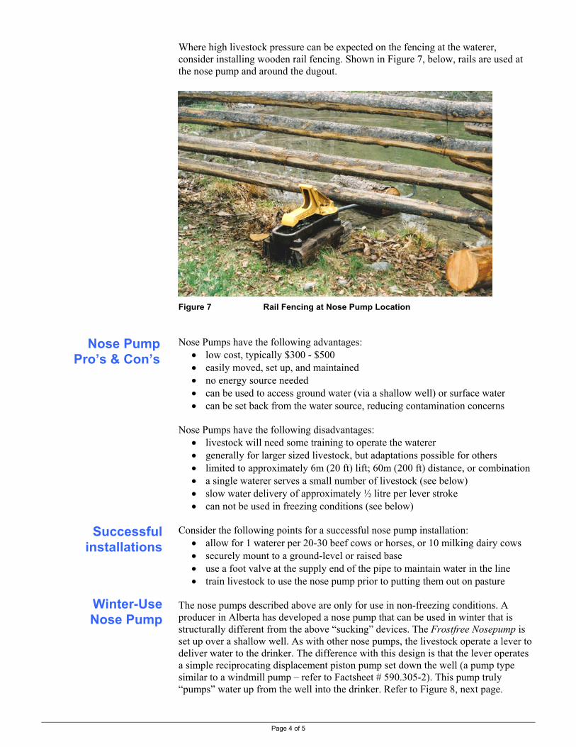
Page 4 of 5
Where high livestock pressure can be expected on the fencing at the waterer, consider installing wooden rail fencing. Shown in Figure 7, below, rails are used at the nose pump and around the dugout. Figure 7 Rail Fencing at Nose Pump Location Nose Pumps have the following advantages:
• low cost, typically $300 - $500 • easily moved, set up, and maintained • no energy source needed • can be used to access ground water (via a shallow well) or surface water • can be set back from the water source, reducing contamination concerns
Nose Pumps have the following disadvantages:
• livestock will need some training to operate the waterer • generally for larger sized livestock, but adaptations possible for others • limited to approximately 6m (20 ft) lift; 60m (200 ft) distance, or combination • a single waterer serves a small number of livestock (see below) • slow water delivery of approximately ½ litre per lever stroke • can not be used in freezing conditions (see below)
Consider the following points for a successful nose pump installation:
• allow for 1 waterer per 20-30 beef cows or horses, or 10 milking dairy cows • securely mount to a ground-level or raised base • use a foot valve at the supply end of the pipe to maintain water in the line • train livestock to use the nose pump prior to putting them out on pasture
The nose pumps described above are only for use in non-freezing conditions. A producer in Alberta has developed a nose pump that can be used in winter that is structurally different from the above “sucking” devices. The Frostfree Nosepump is set up over a shallow well. As with other nose pumps, the livestock operate a lever to deliver water to the drinker. The difference with this design is that the lever operates a simple reciprocating displacement piston pump set down the well (a pump type similar to a windmill pump – refer to Factsheet # 590.305-2). This pump truly “pumps” water up from the well into the drinker. Refer to Figure 8, next page.
Nose Pump Pro’s & Con’s
Successful installations
Winter-Use Nose Pump

Page 5 of 5
The amount of energy required to move water is the volume times the lift so there is a practical limit to the pump depth down the well. The supplier suggests depths of about 10 feet and has units up to 47 feet deep. Well casing must be sized to accommodate the pump diameter. Standard units are 4 inch in diameter with a smaller 2.75 inch diameter unit available. Environmental Conditions. In locating most waterers, sites are chosen that have a low risk on contaminating surface or ground water (such as setback where contaminated runoff will not impact a stream). As this nose pump must be installed on the well head to accommodate the pump drive, there is some degree of risk of ground water contamination from manure that will collect around the waterer. The supplier recommends good sealing to the casing and a 20 feet by 20 feet sloped concrete pad around the well casing thus ensuring drainage away from the casing. It should be noted that such winter waterers are often installed to reduce impacts that may occur to surface water from direct livestock access. The ground water risk of a winter nose pump may be much less than the direct access option. For details go the suppliers’ web site at http://www.frostfreenosepumps.com/ Figure 8 Frostfree Nosepump Installation
RESOURCE MANAGEMENT BRANCH WRITTEN BY Ministry of Agriculture and Lands Lance Brown 1767 Angus Campbell Road Engineering Technologist Abbotsford, BC V3G 2M3 Phone: (604) 556-3100 Kamloops Office

Page 1 of 4
Rotary Seal Delivery Pipe
Rotation
Drive
Livestock Watering Order No. 590.305-8 January 2006
USING STREAM ENERGY TO PUMP LIVESTOCK WATER
This factsheet looks at using gravity energy in the form of a flowing stream to move water in the low volumes usually required for livestock use. Pumps discussed include the Coil (Sling) Pump and “Water Wheel” Pump.
THIS FACTSHEET IS INFORMATIONAL ONLY AND NOT PRODUCT INDORSEMENT BY THE MINISTRY.
Livestock water pumping options are selected with pump-driving energy as the limiting factor, especially remote systems. Where grid-supplied electricity is not available, gravity is usually the first energy option to consider. In this Factsheet, using gravity energy in the form of a flowing stream is considered. Like most livestock water pumping systems, the site plays a big part in the energy choice. For a stream-powered pump to be viable, the sites stream and terrain must be favorable, having • a water supply deep enough to properly submerge the pump, and • a gradient sufficient to generate the water velocity required Pumping water using water flow has similarities to pumping using wind. For small systems, the higher density of water and continuous 24-hour flow offer significant advantages. (For larger systems, wind power may be the choice.) For all such pumps, in-stream debris is a concern and may limit their use. This pump is commonly known by its commercial name of Sling Pump. It is based on a principle similar to the Archimedean screw, except it operates in a horizontal position with coiled pipe, rather than a sloped and open screw. The basic coil pump is illustrated in Figure 1, below. Figure 1 Coil Pump From: Water Pumping Devices by Peter Fraenkel, 1995
Introduction
Coil Pump

Coil Pump Operation. One end of the coiled pipe is open and dips into the stream taking a “gulp” of water with each revolution, sufficient to fill the lower part of a coil, while trapping air in the coil. With each revolution, this water moves along the coil and a new “gulp” of water is taken. As long as the delivery pipe height is no higher than the specified maximum elevation, water (and air) go in with each revolution and water (and air) comes out. This design is limited in available water lift and volume, but is a very simple device, as well as being portable and easy to set up. The one wearing part is the rotary seal in the delivery line (allowing the pumping pipe to rotate while the delivery pipe is stationary). The Sling Pump is a commercial adaptation of the coil pump principle. It has a casing around the coiled pipe and the drive is via a propeller facing into the stream current, as shown in Figures 2 to 4, below. The pump rotates slowly. Figure 2 Sling Pump Operating in a Stream Various water lifts and volumes are possible with different sized coiled pipe. The Sling Pump shown above has 32mm (1.25 inch) polyethylene pipe for the internal coil. It will pump 15,000 litres (4,000 USgal) per day up 6.1m (20 ft).
1360mm (55inch)
620mm
(25inch)
20kg (44lbs)
Stream Flow
Delivery Pipe
Anchor Cable
Pipe Inlet
Coiled Polyethylene Pipe
Delivery Line to Trough
Sling Pump
Figure 4 Sling Pumpwith the Back RemovedPage 2 of 4
1 Back Plate (water entry). 2 Pipe Inlet. 3 Coiled Pipe. 4 Rotary Seal. 5 Delivery Pipe Connection and Anchor Cable Point. 6 Delivery Pipe. 7 Flotation Material. 8 Propeller.
Figure 3 Sling Pump Cutaway Sketch from Canadian Industrial Pumps Ltd
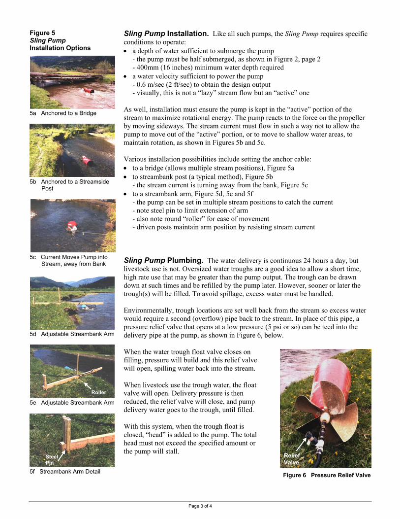
Figure 5 Sling Pump Installation Options 5a Anchored to a Bridge
5b Anchored to a Streamside
Post
5c Current Moves Pump into
Stream, away from Bank
5d Adjustable Streambank Arm
5e Adjustable Stream
5f Streambank Arm D
Sling Pump Installation. Like all such pumps, the Sling Pump requires specific conditions to operate: • a depth of water sufficient to submerge the pump
- the pump must be half submerged, as shown in Figure 2, page 2 - 400mm (16 inches) minimum water depth required
• a water velocity sufficient to power the pump - 0.6 m/sec (2 ft/sec) to obtain the design output - visually, this is not a “lazy” stream flow but an “active” one
As well, installation must ensure the pump is kept in the “active” portion of the stream to maximize rotational energy. The pump reacts to the force on the propeller by moving sideways. The stream current must flow in such a way not to allow the pump to move out of the “active” portion, or to move to shallow water areas, to maintain rotation, as shown in Figures 5b and 5c. Various installation possibilities include setting the anchor cable: • to a bridge (allows multiple stream positions), Figure 5a • to streambank post (a typical method), Figure 5b
- the stream current is turning away from the bank, Figure 5c • to a streambank arm, Figure 5d, 5e and 5f
- the pump can be set in multiple stream positions to catch the current - note steel pin to limit extension of arm - also note round “roller” for ease of movement - driven posts maintain arm position by resisting stream current
Sling Pump Plumbing. The water delivery is continuous 24 hours a day, but livestock use is not. Oversized water troughs are a good idea to allow a short time, high rate use that may be greater than the pump output. The trough can be drawn down at such times and be refilled by the pump later. However, sooner or later the trough(s) will be filled. To avoid spillage, excess water must be handled. Environmentally, trough locations are set well back from the stream so excess water would require a second (overflow) pipe back to the stream. In place of this pipe, a pressure relief valve that opens at a low pressure (5 psi or so) can be teed into the delivery pipe at the pump, as shown in Figure 6, below. When the water trough float valve closes on filling, pressure will build and this relief valve will open, spilling water back into the stream. When livestock use the trough water, the float valve will open. Delivery pressure is then
Steel Pin
r
RollePage 3 of 4
bank Arm
etail
reduced, the relief valve will close, and pump delivery water goes to the trough, until filled. With this system, when the trough float is closed, “head” is added to the pump. The total head must not exceed the specified amount or the pump will stall.
Figure 6 Pressure Relief Valve
Relief Valve

Water Wheel Pump Horizontal-Axis
This device directly uses the energy of a flowing stream and could be called a “sternwheeler-in-reverse”. Rather than the engine-powered stern wheel moving a boat, a frame (anchored to the shore) has a stream-driven wheel that operates a pump. The wheel shaft is on a horizontal axis. The width and depth the wheel is immersed into the stream can be varied to operate different sized pumps. This pump may operate in less water depth than the Sling Pump (e.g. wide wheel in shallow water), but would need the combination of wheel and stream width sufficient to pump the same amount of water. This device may be built to pump larger volumes than the Sling Pump but like it, specific operating conditions are required: • a depth of water sufficient to submerge the wheel
- this will vary with the depth adjustment of the wheel • a water velocity sufficient to rotate the wheel
- this flow may be a “lazy” flow as the wheel can be wide to capture a large portion of stream flow for pumping energy
Various types of pumps could be connected to the drive. They would be matched to the amount of energy produced by the rotating wheel and the volume and lift needed for the livestock being watered. This device could be thought of a as “water windmill”. The axis of the rotating wheel shaft is vertical, extending down into the flowing stream. The top end of the shaft
Water Wheel Pump Vertical-Axis
(above water) drives a pump. The in-stream wheel on the shaft is formed to capture the stream energy. One prototype uses a turbine similar to the Darrieus windmill; a commercial unit (Tyson Turbine) uses a propeller-type shape. As for wind systems, the energy available in a stream is proportional to the density of the drive material (water) and the cube of the stream velocity. As water has a much higher density than air (windmills), similar levels of energy are available in a stream with about 1/9th the velocity of air. The following provide more detailed information on stream-powered pumps:
Other InformationPage 4 of 4
• Water-Pumping Devices – A Handbook for Users and Choosers Peter Fraenkel, Intermediate Technology Publications, 1995 London, UK http://www.developmentbookshop.com/detail.aspx?ID=489
• the Sling Pump – contact the BC supplier at 604-882-8752 or at [email protected]
• the water wheel pump – refer to Cattlemen magazine issues August 2001 and November 2002 for articles on a producer-built pump
• the Tyson Turbine http://www.theramcompany.com/index.html
NO ENDORSEMENT IS IMPLIED BY THE MINISTRY IN PROVIDING THIS SUPPLIER INFORMATION.
RESOURCE MANAGEMENT BRANCH WRITTEN BY Ministry of Agriculture and Lands Lance Brown 1767 Angus Campbell Road Engineering Technologist Abbotsford, BC V3G 2M3 Phone: (604) 556-3100 Kamloops Office

Livestock Watering Order No. 590.305-9 January 2006
USING A HYDRAULIC RAM TO PUMP LIVESTOCK WATER
This Factsheet looks at pumping livestock water using the hydraulic ram principle. These pumps use the energy in a falling column of water to pump water to a higher elevation. Traditional ram pumps are discussed; refer to Factsheet #590.305-10, for information on a commercially-available modified ram .
Page 1 of 6
Introduction
Ram Pump Principle
Livestock watering pumps are often selected with pump-driving energy as the limiting factor. Remote sites, such as many grazing areas of B.C., usually have few energy options which mean few pump choices. On sites that have a flowing stream, water can be piped down a grade to power a hydraulic ram pump (ram pump) that will lift water (24 hours a day) to the chosen (higher) location. Ram pumps use the principle of “water hammer” to pump water. Water hammer may be familiar to anyone who has ever shut off a household water tap quickly and heard the pipes “rattle”. The sound was water hammer as a result of a temporary pressure rise. Ram pumps purposely create this pressure rise in a falling column of water by alternately opening and closing the column to free flow. Each time the water flow is shut off (quickly) a pressure rise is used to pump a small volume of the drive water. The excess drive water is “wasted” and returns to the supply stream. Typically, the ram pump is installed at, or very near the edge of, the supply stream into which this “waste” or drive water empties, as shown in Figure 1, below. Figure 1 Hydraulic Ram Pump Installed Beside a Stream
Drive Line Stream
Hydraulic Ram

Page 2 of 6
Ram Operation Waste Valve Open Waste Valve Closed
Ram Performance
Ram pumps are available from various manufacturers, can be homemade, may appear different, but they operate the same. Figure 2, below, illustrates the operation cycle of a hydraulic ram pump. This cycle repeats from 40 to 60 times per minute; pumping is continuous 24 hours a day. See also Figure 3, next page, for a schematic of a typical installation.
-waste valve open -drive water flows back to ‘waste’ (to stream) -water velocity increasing -discharge valve is closed -pressure in air chamber moves delivery water -water is pumped up delivery pipe to trough
-waste valve closes due to high water velocity -drive water cannot stop instantaneously -therefore pressure opens discharge valve -water goes into air chamber, compressing air -drive pipe pressure is then reduced -waste valve re-opens and cycle re-starts Figure 2 Hydraulic Ram Pump Operation
There is an energy balance between the Drive and Delivery sides of a Ram Pump. Using Figure 3, next page, the Fall (F) times the Drive Water Volume (Dw) and times the Pump Efficiency (Eff%; use Table 1, next page), equals the Lift (L) times the Pumped Water Volume (Pw):
F x Dw x Eff% = L x Pw Therefore, Pumped Water Volume (Pw) can be estimated by:
Pw = Eff% x F x Dw L
• consistent units must be used (i.e., feet and US gpm, or m and L/min) • for simplicity, the pipeline friction losses are not considered

Page 3 of 6
Ram Selection
Figure 3 Hydraulic Ram Pump Installation Schematic Estimating Ram Efficiency. Ram pump operation efficiency changes depending on the relationship of Fall to Lift, as shown in Table 1, below. For example, a site with a Lift of 30 m and a Fall of 5 m has a L / F ratio of 6, and from Table 1 a Ram Pump can be expected to operate at an efficiency of 75 % in those conditions. Note that efficiency is reduced as the Lift to Fall ratio increases (higher Lift compared to Fall). TABLE 1 EFFICIENCY OF COMMERCIAL HYDRAULIC RAM PUMPS* BASED ON THE RATIO OF LIFT (L) TO FALL (F)
L / F Ratio Efficiency % L / F ratio Efficiency % 3 85 10 60 4 80 11 60 5 75 12 55 6 75 13 45 7 70 14 40 8 65 15 40 9 65
* Unless tested, assume ½ of these efficiencies for home built ram pumps
from New Zealand Ministry of Agriculture and Fisheries, Factsheet AST 67, 1985 Two selection methods may be used; by table output or by manufacturers’ information. A selection example is given on page 5. Estimating Output. Table 2, next page, can be used to estimate the output of a Ram Pump when the Fall, Lift, and Drive Water flow rate are known: • locate the Lift (L) and the Fall (F) on the table • select the Pump Output (Pw) for 1 litre per minute Drive Water rate (Dw) • multiply this output by the actual Drive Water rate used Manufactures Output. Commercial Ram Pumps are sized by the Drive Pipe diameter, which in turn is sized by the Drive Water flow rate. Most all makes of Ram Pumps of a given size use the same flow rate. To select a commercial ram pump, use manufacturers’ information. Table 3, next page, gives approximate Ram Pump characteristics.
Drive Water Source
Ram Pump
Drive Pipe containingDrive Water (Dw)
Delivery Pipe containing Pumped Water (Pw)
Fall (F)
Lift (L)
DRIVE SIDE DELIVERY SIDE

Page 4 of 6
TABLE 2. ESTIMATING HYDRAULIC RAM PUMP 24 HOUR OUTPUT1 (Litres per day)
Lift (L) Above Ram 2 (metres)
5 7.5 10 15 20 30 40 50 60 80 100 125
Fall (F)
to Ram 2 (metres) Litres per Day Pumped (Pw) at a Drive Flow Rate (Dw) of 1 Liter per Minute3
1 216 134 87 33 29 20 14 1.5 216 162 86 54 29 22 17
2 307 216 134 86 38 29 23 19 14 2.5 408 270 180 117 66 36 29 24 18 14
3 367 216 151 87 49 34 29 22 17 14 3.5 269 189 109 57 40 34 25 20 16
4 307 216 134 86 63 38 29 23 18 5 408 288 180 117 86 66 36 29 23 6 367 216 151 112 86 54 34 28 7 269 189 141 109 76 40 32 8 216 173 134 86 58 37 9 259 194 151 105 78 41 10 288 216 180 117 86 58 12 367 276 216 162 112 83 14 343 269 189 141 105 16 307 216 172 120 18 367 259 194 145 20 288 216 173
1 pump efficiencies shown in Table 1 are incorporated into these table output rates 2 these are the elevations between supply point and ram & ram and delivery point - not pipe lengths 3 multiply the Table Output by the actual Drive Flow Rate of the system to estimate the actual system output Multiply metres by 3.28 for feet: Divide litres by 3.785 for US gallons
adapted from New Zealand Ministry of Agriculture and Fisheries, Factsheet AST 67, 1985
TABLE 3. TYPICAL HYDRAULIC RAM PUMP SIZES AND APPROXIMATE CHARACTERISTICS
Drive Pipe Delivery Pipe Water Flow Rates
Pumped (Pw)3 Length2
(m)1
Ram Size
Diameter (mm)1
min max
Diameter (mm)1
Drive (Dw) minimum (L/min)1
maximum (L/min)1
range (1000 L/day)1
¾ 18 3 18 13 7.5 2.6 up to 3.8
1 25 4 25 13 23 5.3 0.4 to 7.5
1½ 38 6 38 18 53 10.6 0.5 to 15
2 50 7.5 50 25 95 19 1.3 to 26
2½ 63 10 63 31 130 26.5 2 to 37
3 75 11 75 38 230 53 2.6to 75 6 150 22 150 75 570 190 3.8 to 270
1 Divide mm by 25 for inches; Multiply m by 3.28 for feet; Divide litres by 3.785 for US gal 2 Drive Pipe is to be from minimum 150, and maximum 1,000, times its diameter 3 Pumped Water will be greatest at lowest lifts – refer to Table 1 for estimation of volume versus lift

Page 5 of 6
Ram Installation
Ram Selection Example. A site requires 4,000 litres per day to be pumped a Lift of 30m. The Drive Water supply is 25 litres per minute with a Fall of 5m to the ram pump. What size of Ram Pump should be chosen? • from Table 2, a 30m Lift and a 5m Fall = 180 litres / day / litre supply • with 25 L/m supply, the daily pump rate is 180 x 25 = 4500 L/day • from Table 3, a 1 inch ram size would be chosen
- it requires 23 L/min Drive Water supply (the site has 25) - it will pump the supply required (5.3 L/min x 60 min x 24 hrs = 7632 L/day) - it will need a 25mm Drive Pipe that is between 4 and 25m long - the delivery pipe diameter is 13mm
The following are guidelines for Ram Pump installations. The Drive Water. A ram pump can only be considered on sites that have particular water characteristics. To drive a Ram Pump, the site must have: • sufficient water volume, and • sufficient fall in a ‘reasonable’ distance (gradient) Typical streams at a low gradient (near level), say 1% (1m per 100m), will require significant water delivery line piping to place the pump at the required fall below the water intake. Preferred sites have the fall in as short a distance as possible (i.e., close to the required Drive Pipe length). On low gradient sites, it may be preferred to pipe the Drive Water to a surge tank. From there the Drive Pipe can be installed at the correct length and grade to the ram pump, as shown in Figure 4, page 6. The Drive Pipe. Drive pipe requirements are important to achieve the correct water flow and pressure conditions to power the pump. To pump the desired amount of water, the Drive Pipe must:
• have the required Fall to the pump • have a length from 6 to 12 times the Fall (F)
- also, between 150 and 1,000 times its diameter (a wide range but gives guidance)
• be sized to match the Drive Water flow required, and • be of steel or schedule 40 PVC to withstand pressures encountered
The Delivery Pipe and Lift. Other installation guidelines: • Lift (L) must be 6 to 12 times the Fall (F)
- this is to ensure correct back pressure on the pump • Delivery Pipe diameter is usually ½ of the Drive Pipe diameter

Page 6 of 6
Using a Surge Tank. If the Drive Pipe gradient that is required is greater than the natural gradient of the stream, a surge tank system must be used. The gravity water supply from the stream will have an intake far up the stream, where the head is sufficient to flow the required Drive Water. This flow is piped to a surge tank that is located on the required gradient above the Ram Pump. Refer to Figure 4, below. A surge tank separates the Drive Pipe requirements from the restrictions of a low gradient stream. On very low gradient streams where a high lift of water is desired, this requirement may make a ram pump a poor choice due to these extra Drive Water costs. Figure 4 Surge Tank Supplying Drive Water to Hydraulic Ram Pump
RESOURCE MANAGEMENT BRANCH WRITTEN BY Ministry of Agriculture and Lands Lance Brown 1767 Angus Campbell Road Engineering Technologist Abbotsford, BC V3G 2M3 Phone: (604) 556-3100 Kamloops Office
Hydraulic Ram Pump at Stream
(see Figure 1)
Steel Drive Pipe from Surge Tank to Ram
Surge Tank Drive Water into Surge Tank by Gravity Flow
from Stream
Page 1 of 4
Livestock Watering Order No. 590.305-10 January 2006
USING A MODIFIED HYDRAULIC RAM TO PUMP LIVESTOCK WATER
Introduction Glockemann Pump
Livestock watering pumps are often selected with pump-driving energy as the limiting factor. Remote sites, such as many grazing areas of B.C., usually have few energy options which mean few pump choices. On sites that have a flowing stream, water can be piped down a grade to power a hydraulic ram pump that will lift water to the chosen location (refer to Factsheet #590.306-7). A unique adaptation of these pumps is the Glockemann Pump. As with all hydraulic ram pumps, the Glockemann Pump creates a pressure rise in a falling column of water by alternately opening and closing the column to free flow. Each time the water flow is shut off (quickly) a pressure rise is used to pump a small volume of water up to the water trough. The excess water is “wasted” and returns to the watercourse. Typically, the Glockemann Pump is installed at, or very near the edge of, the watercourse into which this “waste” or drive water empties (refer to Figures 1 and 5). The pumped water is separate water drawn up from the watercourse. The pump may also be installed remote from the watercourse, in which case it pumps part of the drive water (hydraulic rams typically pump part of their drive water) and the “waste” water channeled back to the stream. The Glockemann has the ability to pump with only a small “head” (elevation fall) of drive water to the pump. For example, with a drive head of only 0.6 m (2 ft) it will pump 6,450 litres (1,700 US gal) a day up 10 m (33 ft) with a drive supply of 4 L/s (63 USgpm) using a 100 mm (4 in) drive pipe. Another feature is the high lift possible. With 1.6 m (5.2 ft) drive head, it will pump 2350 litres (620 US gal) up 200 m (650 ft) with 5 L/s (80 USgpm) using a 150 mm (6 in) drive pipe. This is done by changing the cylinder bore and piston size (diameters available from 35mm to 124mm for various volumes and lifts). Contact the supplier regarding high lifts for specific installation requirements. The Glockemann Pump is available in two sizes:
• the 320 Oasis (as noted above): 50cm x 50cm x 78cm; 55kg • the smaller 160 Water Dragon: 26cm x 26cm x 72cm; 10kg
This Factsheet looks at a unique adaptation of the hydraulic ram pumping principle. Hydraulic ram pumps use the energy in a falling column of water to pump a volume of water to a higher elevation. The
Glockemann Pump can deliver a volume and lift of water well suited for livestock watering requirements.
THIS FACTSHEET IS INFORMATIONAL ONLY AND NOT PRODUCT INDORSEMENT BY THE MINISTRY.

Page 2 of 4
Figure 1 Glockemann 320 Oasis Pump Installed Along Watercourse (delivery line not shown) Site Requirements
Pump Operation
All pumps have particular installation requirements. For the Glockemann Pump they fall into two categories; the stream and the drive pipe. To drive the pump, the stream:
► must have sufficient water volume ► must have sufficient fall over a ‘reasonable’ distance (to reduce
complexity & cost) Typical streams at a low gradient, say 1% (1m per 100m), will require significant water delivery line piping to place the pump at the required fall below the water intake (refer to Figure 5). Preferred sites have the fall in as short a distance as possible (i.e., close to the required drive pipe length). To drive the pump, the drive pipe:
► must have the correct fall to the pump ► have a length in a certain proportion to this fall ► and be sized to match the pump (the Oasis requires either 100mm or
150mm pipe; the Water Dragon requires either 50mm or 62mm pipe) Drive pipe requirements are important to achieve the correct water flow and pressure conditions to power the pump (as required by all hydraulic rams). The Glockemann Pump operation is shown in Figures 2, 3 and 4. Contact the supplier for more detailed setup and operational information (refer to page 4).
Rubber Diaphragm that pushes the Piston in the Cylinder Bore
Drive Water Outlet Cylinder Bore with Piston(changeable diameter to suit requirements)
Pump Suction
Pump Delivery to Trough
This is the Drive End This is the Pump End
Return Spring
Output Adjustments
50mm (4 inch) Drive Pipe / Water Supply

Page 3 of 4
From: The Glockemann Water Powered Water Pump Installation Guide
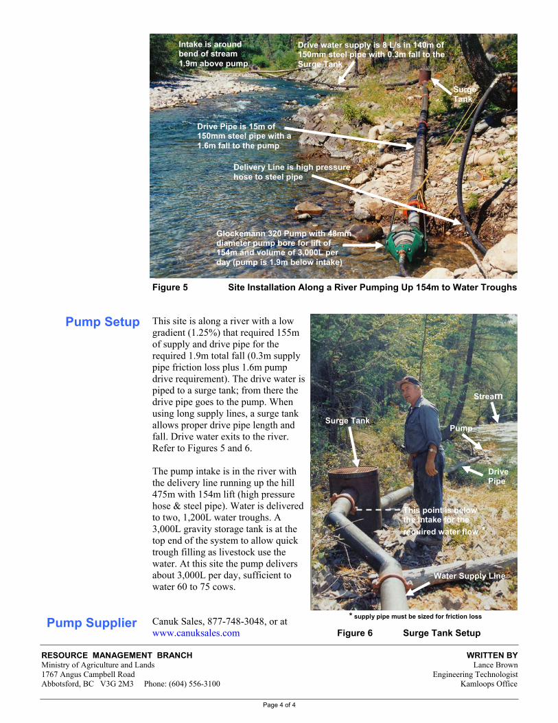
Page 4 of 4
Pump Setup
Figure 5 Site Installation Along a River Pumping Up 154m to Water Troughs
This site is along a river with a low gradient (1.25%) that required 155m of supply and drive pipe for the required 1.9m total fall (0.3m supply pipe friction loss plus 1.6m pump drive requirement). The drive water is piped to a surge tank; from there the drive pipe goes to the pump. When using long supply lines, a surge tank allows proper drive pipe length and fall. Drive water exits to the river. Refer to Figures 5 and 6. The pump intake is in the river with the delivery line running up the hill 475m with 154m lift (high pressure hose & steel pipe). Water is delivered to two, 1,200L water troughs. A 3,000L gravity storage tank is at the top end of the system to allow quick trough filling as livestock use the water. At this site the pump delivers about 3,000L per day, sufficient to water 60 to 75 cows. Canuk Sales, 877-748-3048, or at
www.canuksales.com Figure 6 Surge Tank Setup
RESOURCE MANAGEMENT BRANCH WRIMinistry of Agriculture and Lands La1767 Angus Campbell Road Engineering TeAbbotsford, BC V3G 2M3 Phone: (604) 556-3100 Kamlo
Intake is around bend of stream 1.9m above pump
Drive water supply is 8 L/s in 140m of 150mm steel pipe with 0.3m fall to the Surge Tank
Surge Tank
Drive Pipe is 15m of 150mm steel pipe with a 1.6m fall to the pump
Glockemann 320 Pump with 48mm diameter pump bore for lift of 154m and volume of 3,000L per day (pump is 1.9m below intake)
Delivery Line is high pressurehose to steel pipe
Surge Tank
Water Supply
Pump
Stream
* supply pipe must be sized for friction loss Pump Supplier
Drive Pipe
This point is below the Intake for the required water flow *
TTEN BY nce Brown chnologist ops Office
Line

Page 1 of 5
Livestock Watering Order No. 590.306-1 January 2006
SUMMER LIVESTOCK WATER TROUGHS
This Factsheet outlines options for basic outdoor livestock water troughs used in non-freezing conditions.
There are numerous types, sizes and makes of troughs built to suit livestock in non-freezing conditions. When selecting a trough, consider the following points common to all installations: • the capacity must be suitable for the livestock size and numbers to be watered • the physical size must be suitable for the type of animal - combination troughs
are available for mixed livestock operations such as cattle and sheep etc. • the flow capacity must be suitable to ensure a water filling rate fast enough that
livestock do not have to line up to drink - check that the inlet (valve, pipe, etc.) does not limit flow (points detailed in Factsheet #590.304-1, Livestock Water System Design #1)
• the construction must withstand the abuse of animals and the weather - look for galvanized and stainless steel components with a strong basic frame
• it should be easy to clean and routine maintenance should be straight forward - check that replacement parts are available locally
• it should accommodate the supply and overflow piping arrangement chosen whether a series, parallel, or flow-through
For information on the trough pictured above, see Factsheet #590.306-3, Rangeland Livestock Watering Trough. For winter use troughs see Factsheet #590.307-3, Winter Outdoor Livestock Watering. On-farm locations may be dictated by such restrictions as electrical supply for heated troughs. Otherwise, choose a location that provides good livestock footing, that will drain well and, if possible, is protected from wind. For troughs on extensive cattle grazing areas (such as rangeland), site according to the terrain using the following guidelines for the distances cattle will walk to water: • on rough terrain - 400 to 800 m (1/4 to 1/2 mile) • on rolling terrain - 600 to 1200 m (3/8 to 3/4 mile) • on level terrain - 1200 to 1600 m (3/4 to 1 mile)
These are forage-to-trough distances. Trough spacing can be up to twice these distances, i.e., on rolling terrain, troughs could be spaced from 1200 m (3/4 mile) to 2400 m (1½ mile) apart and cattle would have no greater distance to walk to water than 600 to 1200 m (3/8 to 3/4 mile). Also consider other site factors such as time of year, size and age of livestock, desire to reduce use of watercourses, etc. when locating troughs.
General Trough Conditions
Siting Water
Troughs

Page 2 of 5
Summer troughs are usually a simple design, used only during the frost-free period of the year, and filled automatically from a pressured supply and float-controlled valve.
Supply Piping. The pressured supply line may be plumbed to: • supply one trough (with a valve to start and stop water flow) • supply more than one trough in parallel (each trough supply line is teed-off the
main supply line so all have supply line pressure) • supply more than one trough in series or “flow-through” (water flows from one
trough to the next, to the next, etc – only the first has supply line pressure – the rest have pressure due to the elevation differences between troughs)
Overflow Piping. Overflow water, due to valve leakage, etc., should be plumbed away to prevent muddying at the trough, taking it to a ‘natural drainage’ area or constructed rock pit at least 15m (50 ft) away. There are three basic ways to control the trough water level: • a float-controlled valve (flow is set by a floating ball controlling the inlet valve)
- commonly the valve and float are mounted at the top edge of the trough - or, the valve mounted on the trough bottom and the float on a chain
• a float-controlled switch (flow from a pump is electrically switched on/off) - typically a floating ball containing a mercury switch
• an overflow stand pipe (flow is constant with level set by overflow pipe height) - installed to prevent debris from entering the overflow (see Figure 2, page 3)
Lever Arm Float Controlled Valves. Simple toilet-type float and lever arm valves are commonly used and generally quite effective (picture left). Valves are sometimes supplied with troughs, if not consider high-quality, high-capacity plastic or brass valves. The extended float arm and float must be protected. When selecting and installing float-controlled valves consider the following: • is the valve flow rate capacity sufficient to quickly refill the trough and prevent
livestock lining up or pushing at the tough to access water? • will the float close against the supply line pressure? - larger floats and longer
float arms can be used as line pressure increases • can the float be protected against damage by livestock?
Enclosed Float Controlled Valves. These are available as a single plastic unit which threads onto the supply line. One type has an enclosed float (picture right); another has an internal float that activates a diaphragm to open and close the supply (picture left). This latter type can close under pressures to 140 psi, beyond the normal limits of float/lever arm valves. Under dirty water conditions they may require cleaning. Submerged Float Controlled Valves. These are installed inside the trough at the bottom with a chain from the lever are to the float. As long as the trough is not allow to go dry, this arrangement provides for protection for the valve and any livestock contact with the float ball should not cause damage as the chain offers flexibility. Two variations are a standard float valve with chain (picture left) and commercial valve with cable connection (picture right).
Supply & Overflow
Piping
Water Level Control

Page 3 of 5
Figure 1, below, is a typical float controlled trough: • the supply pipeline is only shallow buried for summer use • the supply line may be to this trough only or teed from a multi-trough supply • the float-controlled valve flow rate is sized to suit the recovery rate required as
determined by livestock type and numbers • protection is installed around the float to prevent damage by livestock - can vary
from a post and rail guard fence to welded in place steel plate • an overflow line is provided should the float valve fail - this line is directed
away from the immediate trough area to prevent mudding • a "bird and critter" escape is installed to ensure wildlife will not become trapped
and drown, contaminating the water • for details refer to Figure 5 in Factsheet 590.306-3, Rangeland Livestock
Water Trough Figure l Float Controlled Trough Figure 2, below, is a typical flow-through trough that has level control features different than the float-controlled trough: • water is continuously flowing through the trough (hence “flow-through”) • the level control is set by the outlet pipe height • the outlet draws water from below the water level keeping out debris • an air bleed hole is drilled in the outlet elbow to prevent air locking • must have a water supply that has the flow capacity • often used as a “pressure break” trough in gravity-pressured systems
Figure 2 Flow Through Trough
Float-Controlled Trough
Flow-Through Trough

Page 4 of 5
A farm-built trough using a ‘retired’ tractor or large equipment rubber tire provides a low-cost, strong trough, one that can even resist some freezing. A poured concrete base, a screened inlet / outlet, and some backfill around the tire complete the trough. Figure 3, below, illustrates this trough and Figure 4 is a sketch of its construction showing an alternative method of keeping floating debris out of the flow-through stand pipe.
Figure 3 Rubber Tire Trough with Protection for Inlet and Outlet Figure 4 Rubber Tire Trough Construction
Rubber Tire Trough

Page 5 of 5
Drains. Troughs used for seasonal periods should have drains installed for frost protection. These should allow both the supply line and the troughs to be drained. Polyethylene pipe can be frozen without damage as the plastic will expand, however this is generally a poor practice. Fittings may crack and repeated freezing may cause failure of pipe connections. Energy-free troughs that have no heat source for frost protection may also require drains should they be taken out of service during the winter months. Wildlife Considerations for Troughs. Many livestock water troughs may be used by wildlife, including birds and small animals. On some Crown cattle grazing areas, the stockman may wish to provide improved access to the water as well as add some safety features. Some considerations for wildlife use and safety are: • provide a "bird and critter" escape to allow animals a safe exit should they
become trapped in the trough • provide wildlife "ladders" to allow easy access to the trough • place troughs at approximately 50 cm (20 in.) high to allow young animals
access • use troughs that are no greater than 50 cm (20 in.) deep to guard against
drowning of young animals which may fall into the trough • place a safety barrier to prevent accidental entry into the trough
System Installation. For details on the many points of a good system installation, see Factsheet #590.306-2, Installing Summer Livestock Watering Systems.
RESOURCE MANAGEMENT BRANCH WRITTEN BY Ministry of Agriculture and Lands Lance Brown 1767 Angus Campbell Road Engineering Technologist Abbotsford, BC V3G 2M3 Phone: (604) 556-3100 Kamloops Office
Other Points

Livestock Watering Order No. 590.306-2 January 2006
INSTALLING SUMMER LIVESTOCK WATERING SYSTEMS
General Specifications and Requirements
This Factsheet concerns livestock water developments on Crown land or private range sites in non-frostconditions. “Pipeline and trough”, “dugout” and “direct access” systems are outlined.
Page 1 of 16
These livestock water systems can provide good water quality, especially from sites that may be small and subject to disturbance if used by direct access. Water sources may vary from developed springs to stream intakes. 1. Fence (refer to Figure 2, page 10) Where the water source is to be left open, a fence is to be erected around the development sufficient to protect it from livestock but allow wildlife use. These would typically be springs or other shallow groundwater or small dugout sites. Unless otherwise specified, a post and rail fence is to be used (posts at 12 feet on center; 2 or 3 rails: measuring from the ground at the post, 18 inch to the bottom of the bottom rail; 42inch to the top of the top rail). For emergency livestock direct access on open water sites, fence rails are to be removable along the access side of the water access ramp. 2. Surface Water Normally, upslope surface runoff will be diverted away from spring developments to reduce contamination, etc. (of course for dugouts, concentration of surface water is necessary for water catchment). 3. Soil Disturbances All soil disturbances (trenching, dugout spoil banks, etc.) are to be reclaimed with an appropriate forage seed mix, within the required time period.
4. Livestock Access Where used, direct stream or dugout access locations are to be constructed for the least impact on water quality and habitat (refer to section “Direct Access” Systems, page 8). All fenced off spring/dugout developments to be excavated with an access ramp for emergency livestock use. This is to align with the removable-rail portion of the fence (item #1 above).
“Pipeline & Trough” Systems
water development site(Refer to Figure 1, page 9)

Page 2 of 16
5. Wildlife Use (refer to Figure 3) Wildlife use will be considered in all developments where appropriate; from “critter escapes” on the troughs for the ‘small guys’, to trough use by deer, etc. This may influence the time of year when systems are drained for the winter (refer to items #32 and #40). 6. Water Licence Where appropriate, a Water License will be held by the Forest Service. 7. Spring Box (refer to Figure 4) Access to inspect the water source is required if it has been covered over after development. Install a 'spring box' or similar structure. 8. Overflow (refer to Figure 1) Overflow piping required on all troughs, some spring boxes, etc. Pipe overflow away from the trough area into a 'waste pit' such as 'natural drainage', a rock pit or similar so as not to create a 'bog' area. 9. Pressure Where possible, a maximum pressure of 50 psi (115 ft head) at float valves. Use pressure reducers, flow-through troughs, etc. if pressure is greater - the need for these will be specified in the design. 10. Pressure Reduction Where pressure reduction is required residential-type units to be used. A 3/4 inch unit will reduce pressures up to 300 psi down to a 25-75 psi range. Note that these units may plug with 'dirty' water; it is preferred to maintain low line pressures without resorting to reducers. 11. Draining Polyethylene pipe can survive freezing when full of water but generally it is desirable to drain these pipes prior to winter. Early spring use may be delayed where frozen lines exist. All steel lines and troughs must be drained (refer to drains section page 6). 12. Excavation Conditions For springs which are not to be buried, the excavation is to be sufficient to contain water for peak flow needs. Unless otherwise specified, this is to be a minimum 30 feet by 30 feet and 6 feet deep. The side slopes are to be dug to 1:1 or steeper where the soil conditions will allow. The livestock access ramp is to be dug to 4:1 (run:rise) or flatter. Improved footing with gravel or gravel and a geosynthetic may be required (refer to Figure 5 and “Direct Access” Systems, page 8). 13. Screen Area Proper screening on all pipeline inlets is essential. Screen area should be approximately 40 to 50 times the pipe area (1 inch polyethylene pipe needs about 35 square inches of screen; 1-1/4 pipe needs 60 sq. inches; 1-1/2 needs 82 sq. inches).
general construction
inlets

Page 3 of 16
14. Screen Construction Screens to be constructed with a galvanized steel 'frame' (as a minimum - plastic or PVC preferred) wrapped with a fine mesh stainless steel screen (similar to a 0.035 inch T316 stainless wire cloth) and mounted so the mesh is removable for cleaning (i.e. use worm gear clamps). 15. Screen Location To prevent plugging, intake screens must be set so as not to rest on the bottom on the pond. This may be done with an outer, open frame around the screen, etc. A floating intake may work but provision must be made to ensure the screen will not 'bottom-out' at low water level. Screens in spring boxes will be installed with the piping so as to be set off the bottom of the box and out of any dirt or debris. 16. Screen Removal In pond systems without a spring box, intake screens (with the attached pipeline) must be removable from open pond water sources to allow system draining. This will require a length of the pipeline in the bottom of the intake pond sufficient to allow the screen to be raised above the highest (springtime?) water level. When the intake is withdrawn to drain, it must be secured in this raised, drain position over winter. Alternatively, the screen can be removed for winter if the pipeline inlet is plugged once drained. The plugged pipeline could be allowed to sink to the bottom of the pond if a rope or other method is used to retrieve it in the springtime. Removal of the screen from the site to safe storage is preferred where vandalism is a concern. 17. Material For buried lines, use 1 inch polyethylene (black plastic) pipe rated for 160psi for it’s wall thickness protection against rock damage, etc. 160psi pipe can be used in systems with up to 115psi or 266 feet of head. Where 1 ¼ or larger pipe is used, a lower pressure rating than 160 psi may be used as wall thickness may be sufficient in these larger sizes for rock protection, etc. Use standard galvanized steel piping at troughs. 18. Minimum Size Trough supply pipe size to be minimum 1 inch diameter. Trough overflow pipe size to be minimum 1 1/4 inch diameter (or 1.5 x the cross sectional area of the supply pipe) for the distance to the ‘waste pit’. Trough flow-through outlet pipe to be a minimum 1 1/4 inch diameter (or 1.5 x the cross sectional area of the supply pipe) for an elevation fall beyond the trough of 25 feet; from there to the next trough use 1 inch minimum. Pipe sizing will be to limit flow velocity to 5 ft/sec and allowed working pressure to 72% of rated pressure. System sizing must allow a flow rate sufficient to water livestock in a reasonable time; i.e. 3 - 5 hours daily (see water storage section, page 5).
pipelines

Page 4 of 16
19. Installation To allow for pipe contraction, the pipe is to be laid in the open trench in a slight 'snaked' manner by bending it from one side of the trench to the other at approximately 30 to 40 foot intervals. Polyethylene pipe shall not normally be unrolled or laid when the air temperature exceeds 35 degrees C or is less than 10 degrees C. Exceptions to this must be authorized. No tension shall be placed on the pipe during laying operations. Tractor 'ripped-in' pipelines will normally be used on long runs; short lines (i.e. less than 200 ft or so) may be dug-in. On rocky sites, an initial pass with the ripper (no pipe) may be required. To allow for pipe contraction, a maximum of 500 feet is to be ripped-in as one piece and lengths are to be joined in ground (i.e. after ripping), and the joint must be 'snaked' to allow for contraction. 20. Connections Polyethylene pipe connections to be made with 'barbed' fittings inserted into the pipe and secured with 'worm-gear' clamps. For lines with less than 50psi a single clamp per connection is sufficient; for higher pressures use double clamps placed so the 'worms' are on opposite sides of the pipe. Polyethylene pipe to be 'snaked' at all connections. The 'barbed' fittings to be either plastic or rust-protected steel and the clamps to be stainless steel. As each connection restricts water flow, as well as being a potential source of problems, connections are to be minimized; i.e. long rolls of pipe are preferred to many short ones. 21. Pressure Test The pipe shall be tested for leaks prior to burial. With all accessories in place, the system is to be held at operating pressure for 3 hours. Leaks are to be repaired and the test repeated. 22. Protection All trenched-in polyethylene pipe to be protected by minimum burial of 8 to 12 inch. Trench width to be no greater than 16 inches. Under roads, whether trenched-in or ripped-in, pass the polyethylene through a steel pipe. Burial depth may be deeper where a continuous-fall gravity line passes through a ridge, etc. 23. Backfill Backfill to be with the excavated material with care to ensure at least 2 inches all around the pipe is free of stones or rocks that may damage the pipe. The trench is to be completely filled. Backfill where the trench enters the water source (spring, pond, dugout, etc.) must be compacted so as to resist water seepage down the trench. If the soil is unsuitable for such compaction it will be replaced with suitable soil or a cutoff collar will be installed (eg. steel plate with a welded-in-place coupling to accept threaded fittings to attach the water line).

Page 5 of 16
24. Air Locks Gravity water flow is easily blocked by air locks (pockets of trapped air). This may be easiest prevented by ensuring no pockets or undulations in the line by laying the line with a continuous fall. This is most critical in gravity lines with very flat grades (i.e. 1% - 1 ft fall per 100 ft), low total elevation fall and ones with very low flow rates for the pipe diameter. Systems with a flat grade in the first 80 to 100 feet will need an air release (in these locations, pressure is very low so a simple stand pipe that rises above the inlet elevation similar to that described in item #26 may be teed into the line). 25. Air Release (refer to Figure 6) Where a continuous fall is not possible, create a deliberate rise and install an air release valve before going down grade again. Keep the valve below ground but open to the air within a standard irrigation box or a box of preservative-treated wood, steel, section of PVC pipe, etc. This pipe layout creates a low point prior to the air release valve. Provision must be made for a drain. 26. Air Inlet (refer to Figure 6) Allowance is to be made for air inlet at gravity water intakes to prevent pipe collapse under vacuum conditions (i.e. should the screen become plugged). This will be specified where necessary. This air inlet to be a stand pipe at the intake open to the atmosphere extending above the water level. It must be located after (downstream) the inlet screen and any shut-off valve. A 3/4 inch pipe is sufficient - it should be 'hooked-over' and screened or a vacuum relief valve (such as used for domestic hot water tanks). 27. Storage Storage should be installed where the water supply cannot allow livestock to water within a reasonable time period daily (i.e. 3 - 5 hours). Storage may be in tanks, ponds or oversized troughs. The storage volume, water source flow rate and livestock water use to be matched. 28. Design One trough design is used with the following plumbing options. The Basic Trough can be set up to allow : option 1: flow-through with continuous overflow to waste pit;
- this option is for a single trough system only.
option 2: flow-through with continuous overflow to second trough; - this option is for series-plumbed troughs, - may be used to 'break 'the pressure on a gravity line.
option 3: float control inlet; outlet acts as overflow protection; - this option is for single or parallel-plumbed troughs.
gravity systems (Refer to Factsheet #590.304-5
Understanding Gravity-Flow Pipelines)
water storage
water troughs

Page 6 of 16
29. Installation (refer to Figure 4) Troughs are to be installed level, on firm, well drained ground. Manured area around the trough must not drain to any watercourse. If required, contour the site to direct drainage. 30. Construction Refer to Factsheet # 590.306-3 Rangeland Livestock Water Trough. 31. Float Valves Float valves are to be installed on systems where the water supply may not be sufficient to allow continuous flow through to a waste pit. Set the float valve for a water level with 2 inches freeboard to minimize spillage. 32. Wildlife Use (refer to Figure 3) Expanded metal wildlife ramps, "critter escapes" or floating wood to be installed on all troughs (refer to item #5). 33. Need For All pipelines, troughs and other equipment subject to frost damage must be drained. This will also usually require a means to close the intake by withdrawing the intake, shutting off at the spring box, etc. 34. Housing Drains to be 'housed' in standard irrigation boxes or similar (as air release valves, item #25). These must allow space for the drain valves and whatever fittings are used and have easy access. 35. Location Marked Drains must be clearly marked on the site plan and on site. If vandalism is a concern the field location of drains may be unmarked, even 'hidden', as long as a site plan is readily available. 36. Fittings Standard-quality galvanized plumbing fittings to be used where steel pipe is required. Steel or plastic barb fittings (male adapters) to be used for polyethylene pipe-to-steel connections. 37. Valves Valves for drains, etc. will be full port ball valve or similar. These ball valves are 1/4 turn, allow full flow, and the handle indicates valve position. If gate valves are used they will be of 'red-white' quality. 38. Thread Seal All threaded connections to be made with a thread seal (teflon tape, brush-on or equivalent). 39. Separation There will be a means of separating the pipeline from the intake and the pipeline from the trough (i.e. a union or similar), for future maintenance. Where the polyethylene pipe-to-steel connection is reasonably accessible this clamped joint will suffice.
drains
pipe fittings
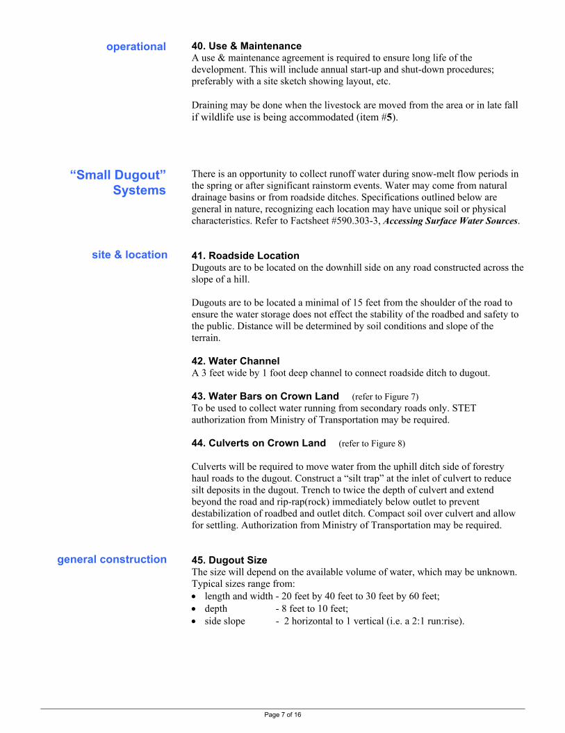
Page 7 of 16
40. Use & Maintenance A use & maintenance agreement is required to ensure long life of the development. This will include annual start-up and shut-down procedures; preferably with a site sketch showing layout, etc. Draining may be done when the livestock are moved from the area or in late fall if wildlife use is being accommodated (item #5). There is an opportunity to collect runoff water during snow-melt flow periods in the spring or after significant rainstorm events. Water may come from natural drainage basins or from roadside ditches. Specifications outlined below are general in nature, recognizing each location may have unique soil or physical characteristics. Refer to Factsheet #590.303-3, Accessing Surface Water Sources. 41. Roadside Location Dugouts are to be located on the downhill side on any road constructed across the slope of a hill. Dugouts are to be located a minimal of 15 feet from the shoulder of the road to ensure the water storage does not effect the stability of the roadbed and safety to the public. Distance will be determined by soil conditions and slope of the terrain. 42. Water Channel A 3 feet wide by 1 foot deep channel to connect roadside ditch to dugout. 43. Water Bars on Crown Land (refer to Figure 7) To be used to collect water running from secondary roads only. STET authorization from Ministry of Transportation may be required. 44. Culverts on Crown Land (refer to Figure 8) Culverts will be required to move water from the uphill ditch side of forestry haul roads to the dugout. Construct a “silt trap” at the inlet of culvert to reduce silt deposits in the dugout. Trench to twice the depth of culvert and extend beyond the road and rip-rap(rock) immediately below outlet to prevent destabilization of roadbed and outlet ditch. Compact soil over culvert and allow for settling. Authorization from Ministry of Transportation may be required. 45. Dugout Size The size will depend on the available volume of water, which may be unknown. Typical sizes range from: • length and width - 20 feet by 40 feet to 30 feet by 60 feet; • depth - 8 feet to 10 feet; • side slope - 2 horizontal to 1 vertical (i.e. a 2:1 run:rise).
operational
“Small Dugout” Systems
general construction
site & location

Page 8 of 16
46. Livestock Access Ramp (refer to Figure 3) One side must have an access ramp, minimum 20 feet wide (up to 50 feet wide for large herds), at a maximum slope of 4 horizontal to 1 vertical (i.e. a 4:1 run:rise); 6:1 is preferred where possible. Where applicable, locate on the lower slope to reduce the ramp length needed to achieve this grade. 47. Dugout Sealing Use clay-type soil to seal the dugout when course soils are encountered. 48. Topsoil Topsoil will be removed and piled during excavation to be spread later on excavated material to establish a seedbed. 49. Excavated Material To be located 15 feet from edge of dugout, bermed and compacted to prevent material running back into the dugout. Soil piles shall not obstruct flow of water into the dugout. 50. Seed All channels, excavated material, sides of dugout and entire area of disturbed soil following excavation using a forage seed mix approved by Ministry of Forests. Livestock access directly to watercourses may be improved with the addition of some access control, such as fencing, in conjunction with some footing improvements, such as gravel, possibly with a geosynthetic material. Refer to Figure 5, page 13. For more details, refer to: Factsheet #590.302-1 Watering Livestock Directly From Watercourses Factsheet #590.302-2 Improved Livestock Access to Water Using Geogrids Factsheet #590.302-3 Offstream Watering to Reduce Livestock Use of
Watercourses and Riparian Areas
“Direct Access” Systems

Page 9 of 16

Page 10 of 16

Page 11 of 16
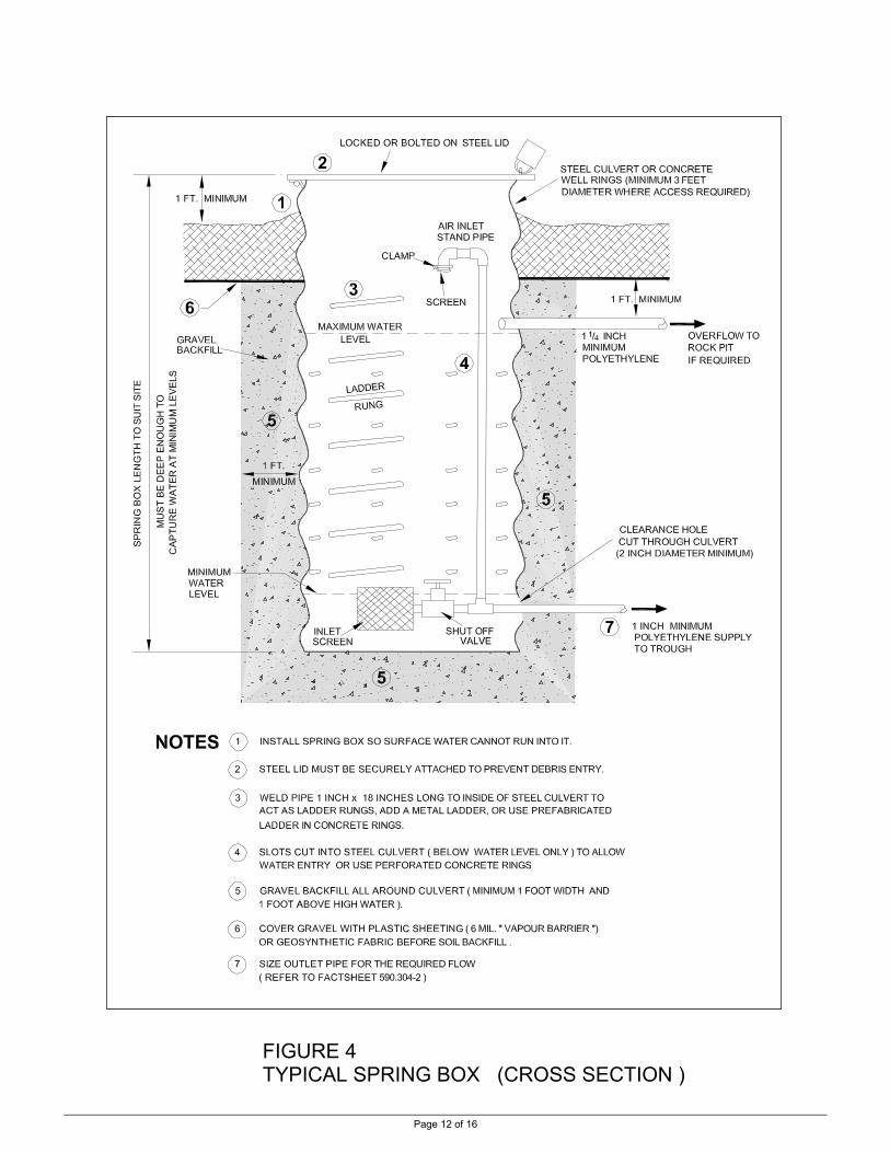
Page 12 of 16
FIGURE 4 TYPICAL SPRING BOX (CROSS SECTION )
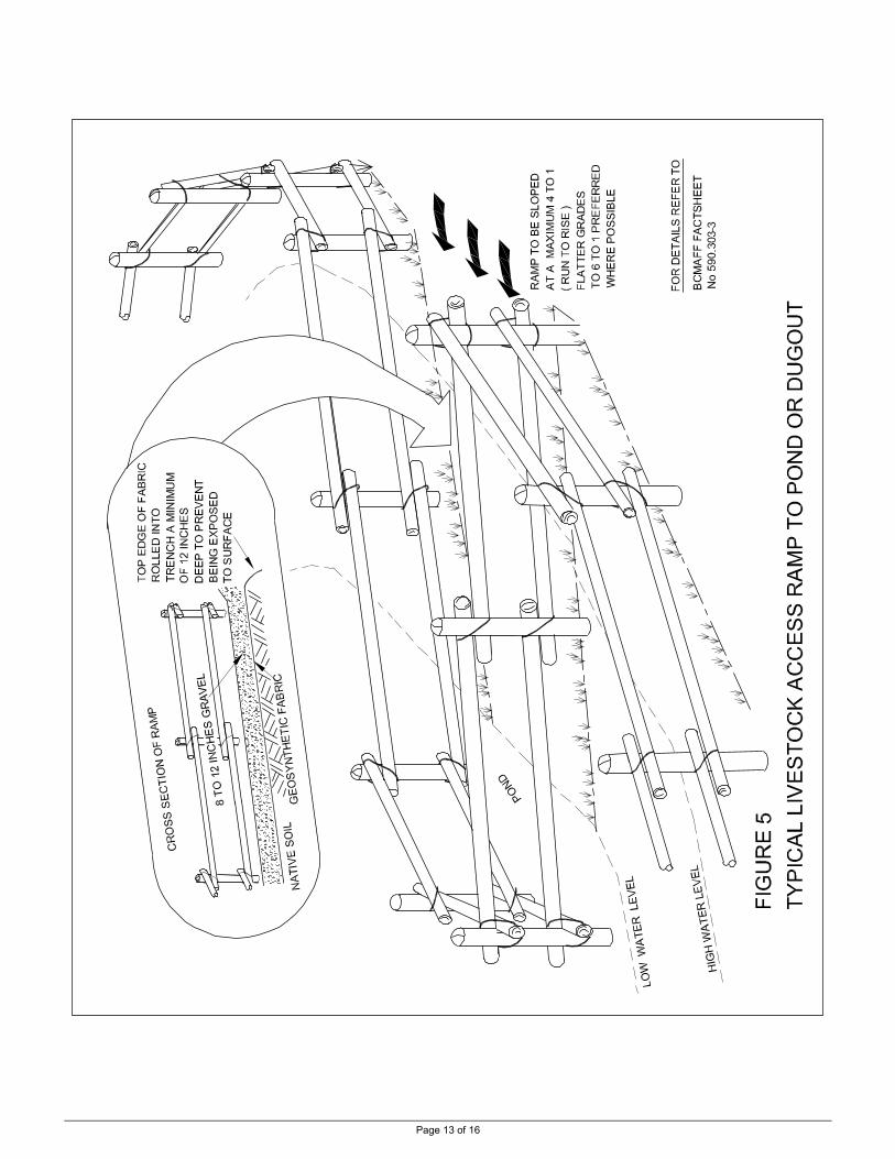
Page 13 of 16

Page 14 of 16
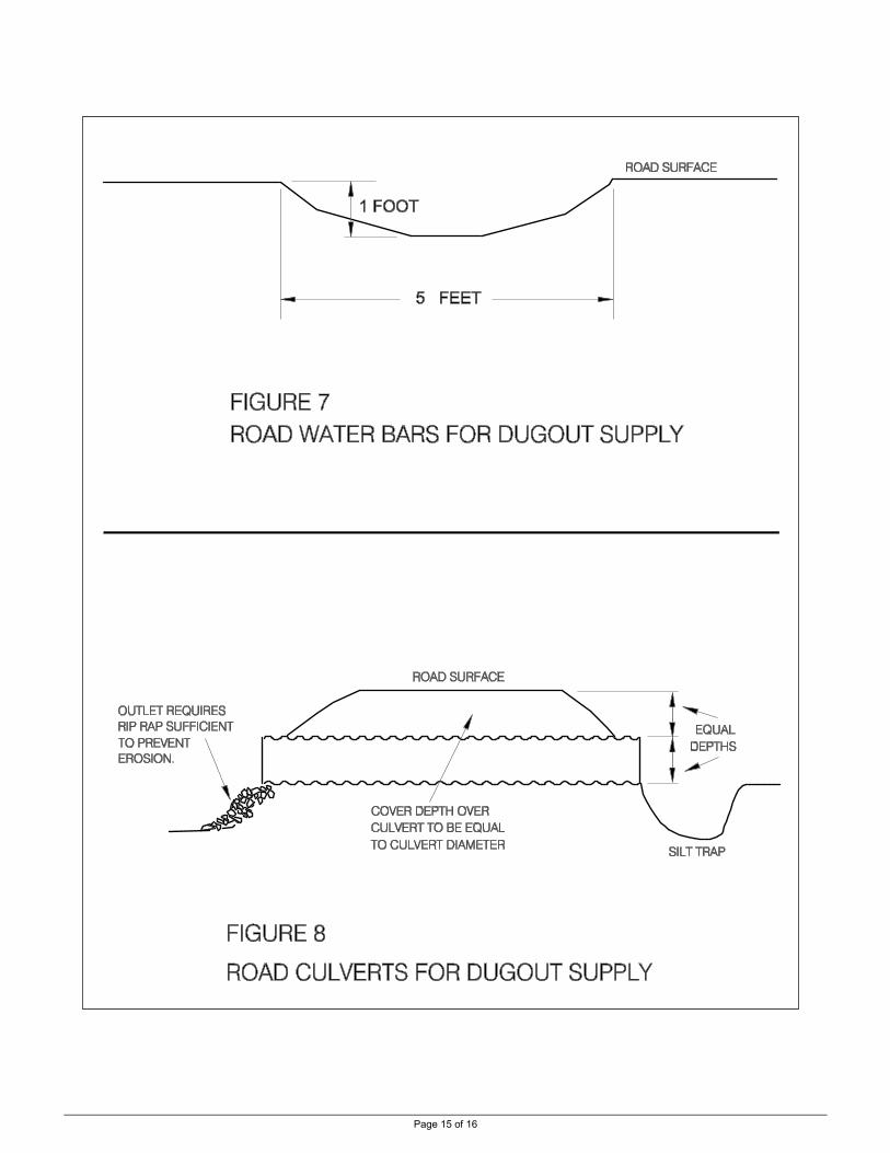
Page 15 of 16

Page 16 of 16
Foot Notes
Other Information
1. Intake frames with screen and clamps cost about $40 for any of the three sizes given. Note: Items 13 & 14 can be met with a commonly available plated steel frame screen wrapped with a stainless screen; Order #579-024: 1 1/2" female pipe inlet, 5" diameter x 3 1/2" long
-this has 37 square inch screen area -use for 1" pipelines
Order #579-032: 2" female pipe inlet, 6" diameter x 4" long
-this has 57 square inch screen area -use for 1 1/4" pipelines
Order #579-064: 3" female pipe inlet, 6 3/4" diameter x 5" long
-this has 85 square inch screen area -use for 1 1/2" pipelines
2. Residential pressure reducers cost about $55. 3. The 1 inch MTCo ball valve costs about $10.
4. For ground boxes for drains, etc. use 6 inch round plastic irrigation boxes that cost about $10. They have a removable lid that may need a locking method. A larger 10 inch plastic box is available that has a built-in lock provision - about $20. Another box choice is a 16 inch x 10 inch x 12 inch deep reinforced plastic box with latched lid for about $40. If these plastic boxes are not considered strong enough, concrete septic distribution boxes with lids are an option. For information specific to the water trough, refer to the Ministry of Agriculture and Lands factsheet # 590.306-3 Rangeland Livestock Water Trough
– Design-Installation-Maintenance.
RESOURCE MANAGEMENT BRANCH WRITTEN BY Ministry of Agriculture and Lands Lance Brown 1767 Angus Campbell Road Engineering Technologist Abbotsford, BC V3G 2M3 Phone: (604) 556-3100 Kamloops Office

Page 1 of 9
Livestock Watering Order No. 590.306-3 January 2006
RANGELAND LIVESTOCK WATER TROUGH Design - Installation - Maintenance
This Factsheet discusses the steel water trough used on Crown land or private range sites in non-frost conditions. The drawings and design points given are sufficient to fabricate the trough. Installation and maintenance information is discussed.
Water Trough Requirements
General Description
The trough is designed to be used on Crown land range sites for spring-summer-fall grazing (the trough is not designed for winter use). Refer to picture of an installed trough in Figure 1, page 4. The trough will: • water at least 6 cows at one time • require no additional post & rail structure for stabilization • have the piping and float valve protected from vandalism • be simple to fabricate, install, winterize and maintain The trough has the following characteristics: • is made of welded 3/16 inch mild steel plate • has flat ends and sloped sides • is approximately 8 feet long, 2 feet high and 4 feet wide at the top
tapering to 3 feet wide at the base • has a removable (bolt-on) lid to protect the plumbing and float valve • has a capacity of approximately 300 US gallons (with a 2 inch freeboard) • weights approximately 700 pounds The trough has two unique features: • the inlet and outlet piping enters from underneath the trough so none is
exposed to potential damage from livestock or vandals • bolt-on extensions to the two end plates extend into the ground to
stabilize the trough Because wildlife use of developed water sites on Crown land is an important factor on these projects, the lid on the piping end includes a “critter escape”. The lid extends down into the water trough for pipe protection reasons and a piece of expanded metal is welded onto this lid face to provide traction for small mammals, etc. that may try to use the water or that may be trying to escape the water having fallen in.

The following drawings are sufficient to fabricate the trough. Note some of
und
Trough Design
the details (the number of the note may be referred to in the drawings): 1. The center section comprises the two sides and bottom bent from onepiece of plate steel. 2. The top of each side is bent to form a one-inch wide reinforcement lip. 3. The ends are welded onto the center section. 4. The end plate extensions are bent with a four inch wide ‘foot’ and bolt
onto the end plates with four, 3/8 inch black steel bolts, 1 inch long. 5. The lid is a separate piece connected onto the side lips with four, 3/8
inch stainless bolts, 1 inch long. 6. To prevent uplift of the lid, it fits under the two short pieces of angle
iron welded onto the inside of each side. 7. Expended metal is welded to the sloped face of the lid to act as a ‘critter
escape’. 8. Chain ‘grabs’ for lifting will be provided at each end plate by either:
• minimum two, 1 ¼ inch holes cut at each lower outside corner (four holes in total), or
• minimum two ‘lift eyes’ welded to opposite top corners of the side plates (two eyes in total) made of bent 1/2 inch round steel or rebar
9. The inlet plumbing coupler (1 inch steel, not cast iron) is welded into
the trough bottom so the coupler is centered through the plate (i.e., the coupler is half in/half out of the trough) and so as the standpipe is plumb.
10. The outlet coupler (1 ¼ inch steel, not cast iron) is similarly welded to the bottom (centered and so the standpipe is plumb).
11. The trough drain coupler (1 inch steel, not cast iron) is welded to the plumbing end plate so as to be centered through the end plate.
12. The trough drain plug is either stainless or galvanized steel to avoid rusting.
13. The water level is controlled by a float valve so as to maintain a minimum of 2 inches of freeboard and is on a stand pipe that is; • 1 inch by 18 3/8 inches long • with a 1 inch 90 degree elbow, bushed as required for the float valve
(i.e., a ¾ inch inlet, Ritchie Co. red plastic valve, or similar) 14. The outlet piping consists of a 180 degree turn and extension down
below the water level to avoid plugging from surface floating debris; • if it is a float controlled trough, the outlet stand pipe is 1 ¼ inch
by 18 3/8 inch long and acts as overflow protection • if the trough is set to have continuous flow-through (either to
another trough or to ‘waste’), the stand pipe length is shorter at 17 inch long so the freeboard can be maintained
15. A ¼ inch air release hole must be drilled at a high point in one of the elbows in this outlet piping to prevent air locking.
16. The inlet and outlet piping underneath the trough is part of the site
installation.
steel plate (refer to Figures 2, 3)
lid (refer to Figure 4)
lifting (refer to Figure 2)
inside plumbing (refer to Figure 5)
erneath plumbing (refer to Figure 5)
p
aintPage 2 of 9
17. The completed trough is to be painted with rust protection paint.

The following list covers all the materials required to fabricate one trough,
W
end
W
B
P
O
Materials List
Page 3 of 9
including the inside plumbing and float valve. 3/16 inch steel plate - 96 inches long by 81 ½ inches wide - bent to shape to form bottom, sides and side lips - four 3/8 inch holes drilled in lips for lid - two holes cut in bottom for inlet and outlet couplings to be welded in 3/16 inch steel plate - 48 inches wide by 23 inches high - each plate cut for two lift holes or one welded lift hook of formed ½ inch round steel or rebar - each plate drilled for two 3/8 inch bolt holes to attach the end plate extensions - plumbing end plate cut for drain coupling to be welded in 3/16 inch steel plate - 48 inches wide by 19 inches high - bent to 90 degrees for 4 inch wide ‘foot’ - each plate drilled for two 3/8 inch bolt holes to attach to end plate 3/16 inch steel plate - 48 inches wide by 30 inches long - cut and bent to shape - four 3/8 inch holes drilled for attachment to trough No. 9 expanded metal - 3 feet wide by 16 inches long - welded onto lid sloping face (do not cut lid) 1/8 inch angle iron - 1 inch by 1 inch by 3 inches long - welded to each inside trough side to retain lid Inlet - 1 inch steel coupling (not cast iron) welded perpendicular into bottom. Outlet - 1 ¼ inch steel coupling (not cast iron) welded perpendicular into bottom Drain - 1 inch steel coupling (not cast iron) welded into plumbing end plate Lid - 4 bolts, 3/8 inch by 1 inch long, with nuts, stainless steel Ends - 4 bolts, 3/8 inch by 1 inch long. with nuts, black steel Inlet - 1 inch galvanized pipe - 18 3/8 inch nipple, 90 degree elbow, 1 inch by ¾ inch bushing (or to suit float valve inlet size) Outlet - 1 ¼ inch galvanized pipe - 18 3/8 inch nipple (or 17 inch - see #14, page 2), 90 degree elbow, 90 degree street elbow, 6 inch nipple Drain - 1 inch plug, stainless or PVC plastic Float valve - plastic type ¾ inch inlet,(Ritchie Co. red plastic valve, or similar) “Lift Eyes” - for each, 7 inches of 1/2 round steel or rebar bent to shape and welded onto side plates; minimum four "lift eyes" required
elded Steel center section
(1 per trough)
end plates (2 per trough)
plate extension (2 per trough)
lid (1 per trough)
“critter escape” (1 per trough)
lid retainers (2 per trough)
elded Fittings (1 each per trough)
olts/Nuts (1 set each per trough)
ipe Fittings (1 each per trough)
ptional

Page 4 of 9
Figure 1 Trough Installed on a Range Site (shown drained for winter)

Page 5 of 9

Page 6 of 9

Page 7 of 9

Page 8 of 9
Trough Installation
lifting the trough locating the supply line locating the trough locating the outlet line
installing the pipeline drain
installing the valves
The trough is designed to as simple as possible to install. 1. Use a machine with lift chain hooked to lift holes or lift eyes. 2. If the supply line runs down to the trough from upslope (as in gravity
systems and possibility some pumped systems), it must first go to a drain box lower than the trough, then up to the trough (to ensure the supply line can be completely drained).
3. If the supply line runs up to the trough from downslope (as in most pumping systems), it need only be laid in a continuous rise to the trough to ensure complete draining.
4. The trough site must be level, firm ground with good site drainage and
sufficient livestock access. 5. Excavate two trenches for the end plates centered 8 feet apart, that are about
1 ½ feet deep by 8 to 12 inches wide by 6 feet long that match the desired trough orientation.
6. Excavate the supply / outlet piping trench to intersect with one of the above trenches (this will be the plumbing end of the trough).
7. Lower the trough in place and level it as required. Note that the trough is meant to lay on the bottom plate so maximum ground contact of this plate is important. Do not use the end plate extension feet as supports - they are only to prevent uplift of the trough not to support its weight.
8. Connect the polyethylene supply and outlet pipes to the underneath plumbing. The trough may need to be partially lifted for access.
9. Bed the pipe, backfill and compact the trenches. 10. The outlet line from the trough is placed on a continuous downslope. There
are three possible plumbing situations: • it is a float controlled trough and the outlet line takes overflow water
to an inground rock pit (likely within 50 feet - use 1 ¼ pipe) • it is a flow-through trough and the outlet water is going back to the
original drainage system from where is was piped (likely no more than 100 feet or so - use 1 ¼ pipe for the first 50 feet then reduce to 1 inch)
• it is a flow-through trough and the water is going to gravity-supply a second trough at a lower site (use 1 ¼ pipe for the first 25 feet of elevation fall then reduce to 1 inch to the next trough)
11. The steel pipe fittings at the trough must be able to be drained for winter.
Part will drain into the trough itself, but the underneath plumping must drain into a lower point than the trough:
• the supply line will drain into the supply drain box when plumbed as required in points #2 or #3 above; and
• the outlet line will drain when installed as in point #10 above. 12. The water inlet point of the supply line will have a supply valve (with an air
inlet downstream from the valve) or the inlet must be able to be removed from the water to allow complete system draining.
13. The drain box (refer to point #2 above) will have a drain valve which directs
the supply water either up to the trough or down to the drain.

Page 9 of 9
Trough Maintenance start of season
Minimal maintenance is required where the trough and piping system have installed properly and no vandalism occurs. The basic maintenance required is: 1. At the start of each season, ensure the inlet screen on the supply line at the
water development is in place and clean. 2. Open the supply valve (or place the inlet screen into the water). 3. Allow some water to flow down to the supply line drain ensuring the line is
running full and free of any blockage. Close the drain valve. 4. Reinstall the trough drain plug and allow the trough to fill. Remove any
accumulated debris from the trough. 5. Remove the trough lid and check the float valve setting for a minimum 2
inch freeboard. 6. Hold the float valve open (depress the float into the water) to allow water to
flow through the outlet pipe to ensure it is not plugged. 7. Check that the air release hole in the outlet elbow is open and free of any
buildup of material. 8. Once the system has filled and pressurized, check the piping from water inlet
to the trough and on to the outlet and drains for leaks and repair as required. 9. Re-install the trough lid ensuring the lower edge is located behind the
sidewall tabs that prevent lifting of the lid. 10. Check to ensure the site drainage is still away from the trough and re-
contour as required (using a hand shovel for minor work; extensive work may require a tractor or backhoe).
11. Where appropriate, check the condition of the fence surrounding the water development and repair as required.
12. During the season, periodically check that the freeboard is being
maintained, the inlet screen is free of blockage and there are no piping leaks. 13. Winterize the system by closing the inlet (or removing the inlet screen,
tying it back from the water) to allow air to enter the pipes. 14. Open the drain valve on the supply pipe below the trough to drain both the
supply line from the water development and from the trough. Leave this valve partially open over winter.
15. Remove the trough drain plug and place in a secure location for the winter. Allow the trough to drain.
Other Information For information specific to installing the complete water system, refer to Factsheet #590.306-3 Installing Summer Livestock Watering Systems – General Specifications and Requirements .
RESOURCE MANAGEMENT BRANCH WRITTEN BY Ministry of Agriculture and Lands Lance Brown 1767 Angus Campbell Road Engineering Technologist Abbotsford, BC V3G 2M3 Phone: (604) 556-3100 Kamloops Office
during use
end of season

Page 1 of 4
Livestock Watering Order No. 590.307-1 January 2006
WINTER CONSIDERATIONS Ice Formation, Freezing Index, and Frost Penetration
This Factsheet outlines winter considerations of on-farm livestock water sources and water systems.
Frost protection for ground water systems is usually for the water line from the well. The use of pitless adapters provides for a frost-free connection between the well and the buried line. Refer to Factsheet #590.303-2, Accessing Ground Water Sources.
Intakes in surface water such as springs, creeks and lakes must be designed for ice conditions if the watering systems are to be used year around. In still water, freezing occurs at the air/water surface, and sheet ice forms. In turbulent water, where cold air is mixed in with the water, ice can form at any depth and is called frazil ice. During freezing, water increases in volume by percent and decreases in density by a similar amount, and therefore the resulting ice floats. It is this volume change that often causes damage to intake structures, directly or through soil upheaval. Water is at its greatest density at 4 degrees C, water at higher or lower temperatures is lighter. This can be used to advantage in systems drawing water from still ponds or lakes. While ice may have formed on the surface, warmer water (4 degrees C vs ice at 0 degrees C) has settled to the bottom of the pond. If this warmer water can be circulated to the surface, ice can be prevented from forming in a small area. The success of this will depend on the air temperatures and the size of this "warm" body of water. Submerged bubbler systems or wind and solar powered lake aeration systems can be used to create this stirring effect.
The effects from winter temperatures can be estimated by knowing the local Freezing Index. This is calculated from the product of the mean daily air temperature below freezing multiplied by the number of days at that temperature. The sum of all these "degree-days" is the Freezing Index. This index is shown in Table 1, next page for various B.C. locations. It can be used to estimate ice thickness and frost penetration.
Sheet ice will form, and keep forming as long as the air temperature is below 0 degrees C. Its maximum thickness is related to the Freezing Index:
Maximum Ice Thickness (in.) = 1.42 √ Freezing Index ( 0C )
For example, in Kamloops with a Freezing Index of 392 ( oC ) – from Table 1:
Maximum Ice Thickness = 1.42 √ 392 = 28.1 in.
An intake drawing water from a pond in Kamloops should be deeper than 28 inches to be secure from maximum ice formation during winter.
Surface Water
Freezing Index
Sheet Ice
Ground Water

Page 2 of 4
Table 1 Freezing Index for Various BC Locations (degree-days below oC) 1
Location Degree Days C Location Degree Days C Location Degree Days C
70 Mile House 1071 * Fauquier 278 Monte Lk Paxton V 673 100 Mile House 834 Fernie 739 * Mt Robson Ranch 964 Abbotsford A 64 Fort Fraser 135 1043 Nakusp 299 ** Agassiz CDA 68 Fort Nelson A 2457 Nelson 250 * Alberni 19 Fort St. John 1582 New Denver 275 Alexis Creek 1406 * Fort St. James 1086 Oliver stp 239 Armstrong 483 * Golden A 865 Osoyoos west 240 Ashcroft 449 * Grand Forks 448 Oyama 339 * Ashcroft Manor 580 * Grasmere 531 * Peachland 221 Barkerville 1008 Hat Creek 953 * Penticton A 239 Barriere 568 ** HazeltonTemlehan 788 Prince George A 920 Bella Coola 162 Hedley 375 Princeton A 566 Big Creek 1139 * Heffley Creek 688 * Quesnel A 787 Blue River A 811 Highland V Lornex 690 Revelstoke A 479 ** Bridge Lake 2 783 Hixon 798 Salmon Arm A 416 Burns Lake 1211 * Horsefly 992 * Sicamous 373 * Campbell River 76 * Joe Rich Creek 642 Smithers A 823 Canal Flats 773 * Kamloops A 392 Spokin Lake 4E 913 Cecil Lake 1840 * Kelowna A 363 Topely Landing 966 Chase 405 * Keremeos 284 * Tatayoko Lake 710 ** Chetwynd A 1234 Kimberley 861 * Valemount 956 * Cranbrook 715 Kleena Kleene 1261 * Vanderhoof 1227 * Creston 291 Likely 827 * Vavenby 601 ** Darfield 515 Lumby 507 * Vernon 389 Dawson Creek A
1652 Lytton 314 Westwold 563
Dog Creek 909 * McBride 865 * Williams Lake 848 Enderby 440 * McLeese Lake 995 * Falkland 455 * Merritt 474
1 – data from Environment Canada 1971-2000 unless noted by: * = data from 1951-1980 - note this older time period usually indicates a colder Freezing Index (by up to 15%)
** = data from 1961-1990 - note this older time period usually indicates a colder Freezing Index (by up to 10%)
A = taken at airport location
CDA = taken at Agriculture and Agri-Food Canada location other notations are specific Environment Canada site location identifiers
Wind removes the thin layer of warm air near a heated object (animal, person, heated trough) increasing its heat loss and is termed wind chill. The object is not cooled below the air temperature; it just loses heat at a faster rate than it would in still air. Once the object reaches the surrounding air temperature it is no longer affected by the wind. Win chill formulas have recently been changed. For current information refer to: http://www.msc-smc.ec.gc.ca/education/windchill/windchill_chart_e.cfm
Wind Chill

Page 3 of 4
Frazil ice forms in turbulent water and at any depth. It can be difficult to predict and deal with. It may adhere to the stream bed or float downstream where it can contact a water intake or diversion. General recommendations such as reducing the turbulent conditions may not be practical except for in the immediate area of the intake. Ensure vortexing at the intake does not occur. Expert advice should be sought for frazil ice problems as they can be very site specific and beyond the scope of this Factsheet. Figure 1, below, can be used as a guide to the formation of frazil ice.
1. High Velocity Free water surface, strong cooling, local ice formation. Some is accumulated as anchor ice; most moves downstream.
2. Medium Velocity Water surface is mostly covered with moving frazil slush, reducing heat loss and ice production. Water temperature is near freezing point. Little anchor ice; tendency for ice to move on.
3. Low Velocity Solid ice cover reduces heat loss; ice production small. Frazil slush deposited underneath this ice cover and accumulates.
Figure 1 Formation of Frazil Ice All pipelines carrying water year around must be frost protected. The standard protection is earth buried to depths below frost penetration as shown in Table 2, below, for general areas of B C. For more accurate estimates, refer to Frost Penetration, next page.
TABLE 2 ESTIMATES OF PIPE BURIAL DEPTH FOR FROST PROTECTION Area Depth (in)
Vancouver Island 24
Fraser Valley 24
Okagagan Valley * 36
Thompson * 48
Central / Peace River 72
* estimate for valley bottoms – use deeper burial out of valley bottom for more actuate depth estimates, use local Freezing Index & Table 3, next page
Frazil Ice
Pipelines

Page 4 of 4
Frost penetration can be estimated more accurately knowing the local Freezing Index and using Table 3, below. In addition to these estimations of burial depth, local conditions must be considered. Soil moisture content, soil compaction due to animal or vehicle traffic, surface cover such as grass or snow and micro-climatic conditions should also be taken into account.
Table 3 Frost Penetration versus Freezing Index
100
80
60
40
20
10
50 100 200 400 800 1600 Fros
t Pen
etra
tion
into
Gro
und
(Inc
hes)
Freezing Index (Degree-Days Celsius)
adapted from: Canadian Small Hydropower Handbook - B.C. Region
Example – Frost Penetration Estimate
What is the safe pipe burial for a proposed water system in Smithers?
• determine the Freezing Index for the site - the Freezing Index for Smithers is 823
• estimate the Frost Penetration for the site - from Table 3, a Freezing Index of 823 equates to frost penetration of 60 inches
A safe pipe burial depth for Smithers is 60 inches. Note that this Freezing Index is taken at the Smithers Airport, and other local areas having significant terrain, etc, differences may have a higher Freezing Index and may require deeper pipe burials. For more details on the above subjects refer to • Climatic data from Environment Canada - Climate Normals and Averages http://www.climate.weatheroffice.ec.gc.ca/Welcome_e.html
• Canadian Small Hydropower Handbook – BC Region Chapter 9, Winter Considerations Energy, Mines and Resources Canada, 1989, ISBN 0-662-17178-0
RESOURCE MANAGEMENT BRANCH WRITTEN BY Ministry of Agriculture and Lands Lance Brown 1767 Angus Campbell Road Engineering Technologist Abbotsford, BC V3G 2M3 Phone: (604) 556-3100 Kamloops Office
Frost Penetration
More Information

Page 1 of 2
Order No. 590.307-2 January 2006
FROST-FREE HYDRANTS
This Factsheet outlines installation and use of frost-free hydrants for winter livestock watering.
These are installed when intermittent winter access to water is required. These hydrants are frost free only to the extent that once turned off, the unit drains down to the depth of the buried supply line. Refer to Figure 1, next page. The hydrant is purchased as a complete unit with a choice of its buried depth. They are installed into the supply line and operated by an above ground handle and lever connected to a buried valve. For continuous summer use the valve can remain open but for winter use frost protection is only obtained upon closure of the valve. To ensure frost protection, the hydrant must drain quickly when closed. This is assured by placing coarse drain rock around the hydrant valve before earth backfilling. A plastic bucket turned upside down can also be used to create an air pocket to ensure hydrant draining. Note that the hydrant may not properly drain (and then be damaged by frost in winter) if air cannot easily enter the hydrant. This can occur if a hose or other device is left connected to the hydrant that blocks air passage.
When a hydrant is closed, water can be siphoned back down to the valve and out the drain. This could be potentially dangerous if the hydrant were installed close to the water source. Contaminated water (e.g. a hose submerged in a sprayer tank of water) could be siphoned out, drain through the hydrant and enter the water source. Anti-siphon or vacuum breaker valves are available to prevent this type of accident occurring. They are installed at the hydrant outlet. In addition, ensuring a hydrant hose is never submerged in contaminated water (an air gap is always maintained) is good practice. These hydrants rely on draining the supply riser after each use for frost protection. A water film can remain on the riser after each use and freeze, and if it accumulates it can block the water flow. This may be prevented if sufficient water is flushed through the riser at each use to remove any accumulated ice build-up. If the hydrant does freeze, it should be thawed out as soon as possible to avoid damage. Remove the handle and lever mechanism then unscrew the head casting from the riser pipe, being careful not to turn the riser pipe. The above ground portion can be thawed by using heat tape, a torch or by pouring hot water over the pipe. The remainder can be thawed using a funnel with a length of 1/4 in. flexible copper
Frost Free Hydrants
Frozen Hydrants
Livestock Watering

Page 2 of 2
tubing soldered to it. Insert the copper tube into the riser pipe and push it down as hot water is poured into the funnel. Once the hydrant starts to flow, allow the water to flow freely to remove all the ice. Once water is flowing normally, check to see if the value shuts off properly and drains quickly. Press down on the plunger rod to close the valve. The water should drain away in a few seconds. If it doesn't, slow drainage is contributing to the icing problem. Improper valve adjustment, a plugged drain hole or a saturated drain bed may be responsible. HYDRANT CLOSED HYDRANT OPEN Figure 1 Frost Free Hydrant Installation
RESOURCE MANAGEMENT BRANCH WRITTEN BY Ministry of Agriculture and Lands Lance Brown 1767 Angus Campbell Road Engineering Technologist Abbotsford, BC V3G 2M3 Phone: (604) 556-3100 Kamloops Office

Page 1 of 12
Livestock Watering Order No. 590.307-3 January 2006
WINTER OUTDOOR LIVESTOCK WATERING
It’s all about the Energy Choices
Water or Snow ?
The Winter Water Problem
Because of the difficulties of providing water in winter in many areas of B.C. snow is sometimes considered as a water source. Research in Alberta has shown cows can substitute snow for water without any detrimental effects. A trial with calves fed hay and grain showed slightly less weight gain than calves with water. Although eating snow should require more energy than drinking water, these trials on cows and calves showed little differences. However, quality and quantity of snow is important : • 10 to 12 inches of snow may have to be melted to get 1 inch of water • fluffy snow may be preferred by livestock but it has a low water content • ‘crusted’ snow may be difficult for livestock to use • some areas may not have sufficient snow some winters • pens areas or small fields may not have sufficient clean snow to use The use of snow as a livestock water supply remains an individual decision. The assumption of this Factsheet is that water will be supplied via some form of waterer and snow used only as an emergency water supply. As we all know, liquid water becomes solid ice at or about zero degrees centigrade. Two things are actually happening : • water expands by about 9% as it freezes into ice • the ice is about 8% lighter (less dense) Besides the water becoming solid and therefore not available to livestock, the expansion property of freezing water causes the physical damage to watering system components such as broken water lines, float valves, etc. Refer to Factsheet #590.307-1 for details on winter considerations.
The Solutions
Of course the solution to this problem is simple - provide energy (as heat) : 1. Supply Heat to keep the water from freezing (refer to pages 3 - 7) 2. Reduce Heat Loss to prevent heat from escaping (refer to page 9) 3. Combinations of these two solutions (refer to pages 9 - 11) And of course these solutions may be easier said than done and have a cost.
This Factsheet outlines options for livestock watering in winter conditions with some ideas and pointers for successful systems. Various energy choices are discussed.

Page 2 of 12
LIVESTOCK WINTER WATERING OPTIONS - A SELECTION CHART
Livestock eat snow SNOW ?? -10-12 inches needed for 1 inch water -fluffy snow has little water -‘crusted’ snow hard to access or -is there sufficient clean snow? WATER ?? Livestock access watercourses -uncontrolled, controlled, or improved Water is moved to the livestock -requires frost-proof waterers OPTIONS TO FROST-PROOF WATERERS
Heat loss can be reduced by REDUCE HEAT LOSS -using a small open bowl area -insulating the walls OR -having a good seal at the concrete pad
SUPPLY HEAT
ON-SITE Use heat already OFF-SITE Bring heat HEAT on the site HEAT to the site
Earth -earth stored water Wood -“batch” heat Heat -heat riser pipe Heat -must tend -low cost or or Water -“energy free” waterers Petroleum -propane Heat -flow-through waterers Heat -automatic or or Solar -limited direct heat Electric -most common Heat -with a windbreak? Heat -safety concern -wire cost limits or distance OR Gas -propane bottle “Bubbler” -gas expansion COMBINATION OF BOTH circulates water REDUCE HEAT LOSS & SUPPLY HEAT

Page 3 of 12
1. SUPPLY HEAT TO THE WATERER
Energy Available
Earth Heat
Figure 1
Commercial “Earth-Heated”
Waterer (not to scale)
There are a number of possible heat energy sources that may be used for livestock waterers. These may be categorized in two ways. 1. Energy available ‘free’ at the waterer :
• earth heat that warms an in-ground extension of the water bowl • earth heat that warms the supply water • earth heat in the air column of the “heat rise pipe” below the waterer
that can circulate from below frost level up to the bottom of waterer • solar heat that the waterer may be exposed to
2. Energy that may be ‘supplied’ to the waterer :
• wood - burnt in a heater • propane - gas fired heater or ‘bubbler’ water circulation • electrical - element heater
‘Free’ At The Waterer The surface of the earth looses heat as the atmosphere cools in winter to a point where the earth freezes (depending on moisture content, compaction, etc.). The depth of this frost is related to the local climate (degree days) and varies from less than 2 feet on the Coast, to 4 feet in the Southern Interior, to 6 feet or greater in the Central and Peace areas. Below these depths the earth has heat which can be used to assist in protecting a waterer from freezing. “Earth-Stored” Water. Waterers that have a special large, in-ground extension of the water bowl (refer to Figure 1, below) use earth heat. This ‘bowl water’ will develop a convection current that will transfer heat from the deep, earth-warmed water, up to the bowl surface replacing the air-cooled surface water. The cooled water in turn falls to the bottom of the ‘bowl’ to be warmed and re-circulated. Float valve Access Lid Drinking Bowl Lid (when bowl not used) Shut Off Handle Drinking Bowl Ground Level Insulation Maximum Frost Depth Approximately 6 ½ feet In Ground Water Supply Shut Off Valve Water Circulation Pipe

Page 4 of 12
Figure 2
Heat Riser Pipe under
a Waterer (not to scale)
Heat Riser Pipe. The earth heat can be transferred from the earth via air (Figure 2, below). An air column or ‘heat riser pipe’ is set in the ground from 2 feet or more below frost level up to the underside of the waterer. The water supply line is run up this column to the waterer. The air in this column will develop a convection current, moving warm air up to the waterer where it will cool (giving off some heat) then fall to be re-warmed by the earth. Research on the Prairies has shown that this column should be a minimum of 14 inches in diameter to be most effective. A good seal between the waterer, the base pad and the heat riser pipe is essential to prevent this heat being ‘lost’. This heat supply should only be relied upon to keep the water supply line in the column from freezing. It likely will have only a small affect on the waterer itself. Commercial heat riser pipes are available that have insulated walls for 2 to 4 feet. This insulated portion could be used in colder climates on the upper portion of the column. Never insulate across the inside of the column as this will block the warm air from the water line and may result in the line freezing. An insulation sleeve around the supply pipe for the top 2 to 3 feet may be worthwhile. Alternately, an electrical ‘heat tape’ may be used.
Earth heat warms air in heat riser pipe
Maximum Frost Depth
Earth Heat
Pressurized Water Supply Line
6 to 8 feet
Heat Riser Pipe(min 14 inch diameter)
Earth Heat
Good seal important
Ground Level
Optional Outside Insulation (refer to item #2, page 9)
Do not insulate this spaceOptional Sleeve Insulation Around Water Line
Waterer
Concrete Base Pad
Heat Riser Pipe

Page 5 of 12
Water Heat
Figure 3
Typical “Energy Free”
Waterers
The water supply to the waterer comes piped through the earth and is warmed by it. This heat can be used to keep a waterer frost free, either by: • insulating the waterer to retain heat as the water sits in the waterer bowl
(“energy free” or highly insulated waterers); or • flowing water through the bowl at a rate to match the heat lost from the
waterer (flow-through waterers); or • using a combination of both. “Energy Free” Waterers. These are highly insulated waterers and use only the heat of the supply water to prevent freezing. Properly selected and installed, these waterers stay ice-free with only some minimal maintenance. They typically (refer to Figure 3, below) : • have thick, well insulated walls • may have walls of a “plastic” material with “foam” insulation • may use some form of lid (floating or hinged) to cover the drinking area • require livestock to push aside the lid for drinking • must be sized for the livestock use (as this ensures proper water inflow to
provide sufficient heat) Hinged lid type
(courtesy Superbowl by Superior Precast)
Floating ball type
(courtesy MiraFount by Miraco)

Page 6 of 12
Figure 4
“Ice Preventer” Valve
Solar Heat
Flow-Through Waterers. These use the heat of the supply water to offset the heat lost from the waterer. Some Points to consider: • is there sufficient water to “waste” as flow-through? • can this “waste” water be handled and disposed of properly? • or can this water be recirculated? • if the water is pumped (ie. gravity flow not possible), is this less expensive
than directly heating the water in the bowl? The water flow-through may be constant, if weather conditions require, or it could be intermittent. An ‘Ice Preventer” valve (refer to Figure 4, below) is available that is installed prior to the float valve in a waterer. As the water cools, a sensor opens the valve flowing water into the waterer (this water will go out the waterer overflow line). As the water warms, the valve closes. The float valve works normally.
(courtesy Walters Control Co.)
Selecting Flow-Through Rates. If a water flow-through design is to be used, a number of factors must be decided upon for a successful system. They include : • the structural characteristics of the waterer, including:
- the water surface area exposed to the air - the surface area of the walls - the insulation value of the walls - the water volume in the waterer
• the coldest winter air temperature at the waterer • the wind conditions at the waterer • the water temperature of the supply water • the flow rate of the supply water These factors in the selection tables available in Factsheet #590.304-6, Selecting Flow-Through Rates to Frost-Proof Water Troughs. Figure 6, page 11, illustrates a flow through waterer that uses a manually operated gate valve located prior to the float valve. This is the heat gained from direct exposure to the sun. In most cases this will be limited, but can be useful, especially when combined with a windbreak fence.

Page 7 of 12
Energy ‘Supplied’
Wood Heat
To The Waterer Waterers have been available that burn wood to heat the water bowl. This is a batch energy supply and must be regularly refilled.
Propane Heat
Waterers are available that have a thermostatic gas control valve and a pilot light. The burner ignites as the water cools. The burner heats up the area under the water bowl and gases exhaust around the edge of the bowl. A baffle-protected side panel lets in combustion air. The propane bottle can be set back from the waterer with a buried supply line running up the heat riser pipe with the water line. Protect the bottle from livestock.
Electrical Heat
The most common energy supply that is brought to a waterer is electrical : • it is easy to use and automate; • it is generally an economical heat source; • but the costs of the supply system to a waterer may be excessive, depending
on the distance to the waterer from the electrical supply. Safety There is a safety concern when using electricity around water : • install the waterer to the manufacturers’ instructions and Electrical Code; • as per Code, ground the waterer with a separate stranded copper ground
conductor of at least number 6 American wire gauge (#6AWG) running from the waterer to the branch circuit supply (electrical panel); and
• consider “equipotential” grounding of the waterer to the concrete base pad rebar.
Estimating Wire Size. Before purchasing an electrically heated waterer find out the element wattage and calculate the wire size and cost. Table 1, next page, may be used to estimate the wire size to supply an electrically heated waterer - confirm with an electrician before purchase or installation. Electrically heated waterers have different wattage elements. For example, a waterer sized for 60 to 75 cattle may have a 400 watt element whereas a larger one for 200 to 250 cattle may have a 1200 watt element. Table 1 can be used knowing the wattage or amperage required for the waterer. Use the wattage and voltage to find the amperage draw of the element. The formula for amperage is : amperage = watts / volts. For the 400 watt element in a 120 volt circuit, divide 400 by 120 for a 3.3 ampere draw (use 4 amperes). The 1200 watt element would draw 10 amperes. Secondly, measure the distance from the electrical panel to the waterer (in feet or meters). Lets say the distance is 200 feet. Using Table 1, the line at 4 amps/400 watts indicates a #14 AWG wire size (2 conductor copper wire) for 200 feet. For the larger waterer, a 10 ampere draw and 200 feet requires a #10 AWG (2 conductor copper wire). Electric wire is available for burial and can be placed in the same trench as the water line. Consult an electrician for the Electrical Code requirements.

Page 8 of 12
Table 1 ESTIMATING COPPER WIRE CONDUCTOR SIZES (For 5 Percent Drop in Potential on 110-120 Volts Single Phase using 2 Single Conductors)
Approximate Distance in Metres or Feet from the Waterer to the Electrical Panel Meters 6 9 12 15 18 21 24 27 30 36 42 48 54 60 72 84 96 108 120 135 150
Feet 20 30 40 50 60 70 80 90 100 120 140 160 180 200 240 280 320 360 400 450 500
amps
wat
ts
American Wire Gauge Number (AWG #) of 2 Single Conductor Copper Wire
1 120 16 16 16 16 16 16 16 16 16 16 16 16 16 16 16 16 16 16 16 16 16 2 240 16 16 16 16 16 16 16 16 16 16 16 16 16 16 16 16 14 14 14 14 12 3 360 16 16 16 16 16 16 16 16 16 16 16 16 16 14 14 14 12 12 12 12 10 4 480 16 16 16 16 16 16 16 16 16 16 16 14 14 14 12 12 12 12 10 10 10 5 600 16 16 16 16 16 16 16 16 16 14 14 14 14 12 12 12 10 10 10 10 8
6 720 16 16 16 16 16 16 16 16 14 14 14 12 12 12 12 10 10 10 8 8 8 7 840 16 16 16 16 16 16 16 14 14 14 12 12 12 12 10 10 10 8 8 8 8 8 960 16 16 16 16 16 16 14 14 14 12 12 12 12 10 10 10 8 8 8 8 6 9 1080 16 16 16 16 16 14 14 14 14 12 12 12 10 10 10 8 8 8 8 6 6 10 1200 16 16 16 16 14 14 14 14 12 12 12 10 10 10 8 8 8 8 6 6 6
12 1440 16 16 16 14 14 14 12 12 12 12 10 10 10 8 8 8 6 6 6 6 6 14 1680 14 14 14 14 14 12 12 12 12 10 10 10 8 8 8 6 6 6 6 4 4 16 1920 14 14 14 14 12 12 12 12 10 10 10 8 8 8 6 6 6 6 4 4 4 18 2160 14 14 14 14 12 12 12 10 10 10 8 8 8 8 6 6 6 4 4 4 4 20 2400 14 14 14 12 12 12 10 10 10 8 8 8 8 6 6 6 4 4 4 4 2
25 3000 12 12 12 12 10 10 10 10 8 8 8 6 6 6 6 4 4 4 2 2 2 30 3600 10 10 10 10 10 10 8 8 8 8 6 6 6 6 4 4 2 2 2 2 2
Table derived from Table D3 and Note 7 of the Canadian Electrical Code (Courtesy Saskatchewan Agriculture)
Propane “Bubbler”
Importance of Wattage. Table 1 indicates how important the wattage size of an element is, especially when long distances separate the electrical supply and the waterer. For long distances, the 240 volt elements will be attractive as they draw lower amperages and will require smaller (less costly) wire sizes. If a waterer is electrically heated, a heat tape may be used for the upper portion of the water supply pipe just below the waterer base pad. Then a smaller diameter riser pipe may be used in place of the 14 inch diameter heat riser pipe (shown in Figure 2, page 4). However, using the smaller pipe is a small installation cost-saving with a loss of the earth heat benefits (which remain even if the power goes off!) and, as the wattage of a heat tape must be included in the wire size calculation (element wattage plus heat tape wattage to estimate the full amperage draw), it may increase the wire size and cost. Where a pond or large trough is freezing over, a “gas-bubbler” device may be used that circulates the warmer, lower level water up to the surface, keeping a watering hole open. A submerged propane bottle (about 5 lb size lasts 3 months) is hose-connected to the bubbler devise which very slowly releases the gas, creating circulation. It is not a safety concern as little gas is released at a time. (Currently this device is not available; it is mentioned here in the expectation that it will be available again.)

Page 9 of 12
2. REDUCE THE HEAT LOSS OF THE WATERER
3. PUTTING IT ALL
TOGETHER
General
With Electricity
Besides supplying heat to the waterer, frost protection is increased when the heat loss is reduced. Heat loss from a waterer is due to a number of factors: • structural characteristics of the waterer, a combination of;
- the water surface area exposed to the air - the surface area of the walls and bottom - the insulation value of the walls and bottom - the water volume in the waterer - the minor losses between the waterer and it’s base pad
• air temperature • wind velocity across the open top of the waterer The rate of heat loss increases as the temperature difference increases. This can be greater between the waterer and the air (which can be -400 C or more in some parts of B.C.) than between the waterer and the earth. For this reason, insulation is usually most effective on the walls exposed to the air. However, the greatest heat loss is usually from the water surface in the open bowl. Heat loss can be reduced by : • selecting a waterer that has as small a bowl surface area as possible for the
livestock numbers • insulating the walls of the waterer (e.g., use a foam type material not affected
by moisture and protected from livestock chewing, etc.) • ensuring a good seal between the waterer and the mounting pad (using a strip
of plastic sill plate gasket will help make a good seal) • using a windbreak to reduce the wind chill factor, where appropriate
Consider these heat loss factors when purchasing and installing a winter waterer to reduce the need or amount of added heat for frost proofing. The following are some selection ideas that can be used to best choose a winter waterer system for particular situations. 1. Setup the waterer with a heat riser pipe with the water supply line inside. 2. Use the Freezing Index to choose heat riser pipe insulation: for climates with
greater than 600 Degree-Days Centigrade, consider insulating the outside top 2 feet of the heat riser pipe: in climates greater than 750 Degree-Days use 4 feet of insulation (refer to Factsheet #590.307-1 Winter Considerations of Livestock Watering).
3. Install the waterer on a solid base pad (such as concrete); seal the joints
between waterer, pad and riser pipe to prevent air movement (heat loss). 4. If electricity is available and if the wire size (from Table 1, page 8) is
reasonable, install an electrically heated waterer. 5. If electricity is available but beyond a distance for 110/220 volt supply, consider a higher line voltage system using transformers at each end (voltage boosted at the supply and reduced to the heater voltage at the waterer) which will reduce amperage and therefore wire size and costs. This must be done as directed by a qualified electrician.

Page 10 of 12
Without Electricity
With Gravity Water Supply
Without Gravity Water Supply or Electricity
6. If electricity is available but the above options are not appropriate, consider pumping water for a flow-through waterer. This system would require the water source within reasonable distance of the electrical supply for the pump. Water lines would be trenched to and from the waterer (these should be less expensive than the electrical wire). The water could be re-circulated or piped to “waste”.
7. If electricity can’t be used for heating as above, consider using propane or
wood heaters. A pressurized water supply is required that would have to come from a separate energy source (that may mean electricity is still required at some point in the system or, if gravity can be used, consider point #8).
A waterer that uses the “stop and waste” self draining principle of a Frost-
Free Hydrant (refer to page 12) but is turned on and off by the livestock themselves is illustrated in Figure 5, next page, sold for horses use under the name “Drinking Post”. It requires energy for the pressurized water supply (min. 45 psi) but not for any heat energy. This type of waterer could also be of some advantage in summer as algae should not grow in the bowl as it is empty when not being used.
8. If a gravity pressured water supply is available consider :
• if the source is above the waterer, using this as the pressure supply for any type of heated waterer; or
• if there is sufficient volume, using it as a pressure supply and flow-through for heating the waterer as in Figure 6 (note that flow-through water can be plumbed to one or more waterers, in parallel or series, depending on water temperature and volume); or
• if the source is below the waterer, use the gravity flow to power a hydraulic ram pump to supply the waterer (waterer pressure supply only or plus flow-through) - note rams pump only about 10% of the water supply – refer to Factsheet 590.305-5, Using Gravity Energy to Pump Livestock Water.
9. If there is neither an electrical supply nor a gravity supply possibility, a
pumping and heating system must be setup that uses the other energy sources, such as : • solar energy (as either wind or photovoltaic electric) for pumping,
possibly with flow-through frost protection (although for photovoltaics, that requires extra, hard-to-get winter solar pumping energy) or in conjunction with a wood or propane heater.
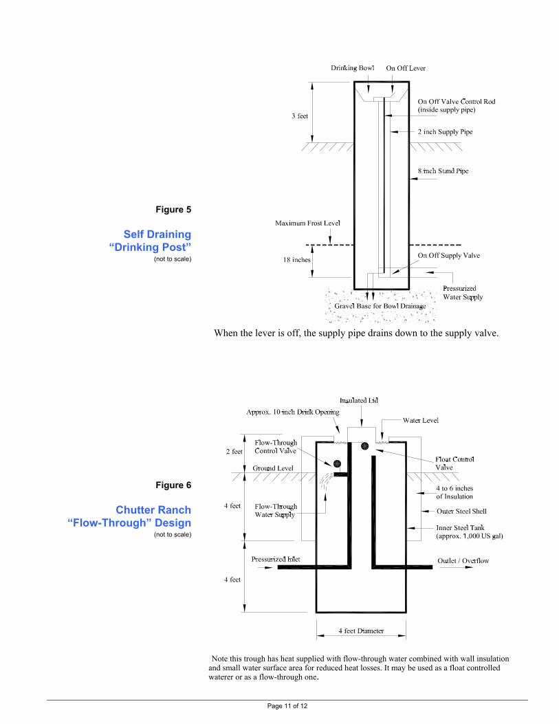
Page 11 of 12
Figure 5
Self Draining “Drinking Post”
(not to scale)
Figure 6
Chutter Ranch “Flow-Through” Design
(not to scale)
When the lever is off, the supply pipe drains down to the supply valve. Note this trough has heat supplied with flow-through water combined with wall insulation
and small water surface area for reduced heat losses. It may be used as a float controlled waterer or as a flow-through one.

Page 12 of 12
Random Pointers
The following are a few pointers for winter watering systems. The Freezing Index. This can be used to estimate frost penetration and ice thickness as well as choosing insulation for the outside of heat riser pipes. Refer to Factsheet #590-307-1, Winter Considerations of Livestock Watering.
Frost-Free Hydrants. A water trough may be filled on a daily basis using a yard frost-free hydrant. This device has an above ground on/off handle which operates a below ground “stop and waste” valve on the water supply. When opened, this valve directs water to the surface outlet (which could empty into a trough). When closed, it allows the riser pipe to drain into the ground back to the depth of the supply line, which is below frost. Refer to Factsheet #590.307-2, Frost Free Hydrants. System Shut Off. All waterers, regardless of how they are heated, require a shut off of the pressured water supply. A buried “stop and waste” valve may be used that is located below frost and activated by a rod above ground. System Drain. If a “stop and waste” valve (self-draining) is not used, provision should be made to drain both the supply line above the frost level and the waterer. “Wind Chill”. This is the effect created when wind increases the rate of heat loss (in everything, including livestock and waterers), making the air feel colder than it actually measures. A waterer will not be cooled below the actual air temperature (the air temperature is not lowered with the wind), but, as the wind increases the rate of heat loss, the heat supply may need to be increased. For example, a waterer in -100C air may be frost proof with a given heat supply. Should the wind blow at, say 40 kmph, the heat loss from the waterer may be the same as if the air were, say -300C. The waterer would not cool below the actual -100C air temperature, but it would be cooling quicker. The heat supply may have to be increased to keep the waterer from freezing. Well designed waterers should be able to supply heat for these conditions. Thermostats may have to set higher than normal during long windy periods. Portions of the supply line, float valve, or other components that normally don’t freeze may freeze in windy conditions. A windbreak fence will reduce the “wind chill” effect. As snow is often moved with wind in winter, a windbreak may “gather” snow so the two must be considered together.
Other Information Check local irrigation and general farm suppliers for equipment described. RESOURCE MANAGEMENT BRANCH WRITTEN BY Ministry of Agriculture and Lands Lance Brown 1767 Angus Campbell Road Engineering Technologist Abbotsford, BC V3G 2M3 Phone: (604) 556-3100 Kamloops Office

1
Research Update
Do Energy Free Fountains Work?
Energy free fountains come in a variety of styles and offer different combinations of features. InPAMI tests, only one fountain didn’t measure up in a Canadian prairie winter. Average tempera-ture during the test period of 22 weeks was 12ºF (-11ºC), with average temperatures as low as-15ºF (-26ºC) over a 4 week period.
EnerEnerEnerEnerEnergy Frgy Frgy Frgy Frgy Free Wee Wee Wee Wee Water Fountainsater Fountainsater Fountainsater Fountainsater FountainsFrom 1990 to 1993 PAMI compared three energy free livestock water foun-
tains and four electrically heated ones. Here’s what we found.
Energy free water fountains do work in cold prairiewinters, but certain critical conditions must be met.Here’s a checklist:
They must be properly designed.Find out where the fountain was manufactured. Someare designed for milder winters, but can’t be relied onduring sustained periods of cold.
They must be properly installed.Close attention to proper installation will help ensuretrouble free operation. See the diagram below andInstallation Tips.
They must be properly maintained.You’ll want to do daily checks on the fountain,especially in extreme cold. Animals are sloppydrinkers, so run off from their mouths tends tofreeze up the drinker lids. Routinely chippingthis ice away helps ensure an uninterruptedwater supply to your animals. See theMaintenance Schedule.
They must be properlyadjusted.Follow the manufacturer’sinstructions to properly adjustthe water level in your particularfountain.
The fountain must be properlysized.A properly sized water fountain for your
herd is important. Too few animals drinking from afountain that is too large can lead to freeze up. See theenergy free fountain sizing guide.
The fountain must be used regularly.If livestock are removed, the water supply must be shutoff, and the valve and water bowl drained to preventfreeze up.
The ground water temperature must be warmenough.In PAMI tests, the ground water came from a well andthe temperature remained constant at around 45°F(7°C). Dugout water or other sources of surface waterwould likely be colder, and may be risky.
Typical installation of Energy Free Fountain
706706706706706Printed: April, 1994ISSN: 1188-4770, Group 5 (h)

2
How Do TheyWork?
Energy free fountains areclosed, insulated containersfilled with water. The walls ofthe containers are constructed ofdouble walled, durable plastic.The space between the walls isfilled with insulatingmaterial. Thesewater fountainsact like a thermos inthat they slow down the cooling of water.
Are Energy Free FountainsCheaper to Operate?
While energy free fountains may save you money onpower, they tend to cost more than heated fountains tobuy.
The purchase prices of the energy free fountainstested by PAMI ranged from $475.00 to $930.00, whileheated fountains ranged from $280.00 to $475.00
Energy savings ranged from $24.00 per year whencompared to the most efficient heated fountain, to$100.00 per year compared to the most power hungryfountain. These savings are based on energy costs of 5.5cents per kilowatt hour. If you live in a region withhigher energy costs, the savings would be greater.
The energy graph at right gives a projection of costsfor energy free fountains versus heated fountains for afive year period, including the initial purchase price.This graph assumes energy rates of 5.5 cents perkilowatt hour, excluding the cost of heat tape on theheated fountains. Based on these costs and assuming aheat tape is on for half of a six month season, energycosts for heat tape would add about $9.00 for anaverage winter.
Energy free fountains may be cheaper to installsince you don’t need to trench in power lines.
Can I Replace my Heated Foun-tain with an Energy Free Unit?
You can, but you’ll still need to wrap the watersupply line with heat tape, and maintain the ice build upon a daily basis.
Most heated installations have smaller heat riserpipes and less insulation, hence the heat tape require-ment.
If you don’t have insulation between the ground andconcrete base, faster cooling may occur.
Energy free fountains use available heat (called geo-thermal heat) from the ground, below the frost line. Groundwater enters the fountain through a float valve assembly at ground temperature, usually about 45°F (7°C). Groundwater acts as the fountain’s heat source. The water slowly cools, but as an animal drinks from the fountain, warmerground water replenishes the fountain. This continual exchange of warm water for cold provides heat to offset theeffects of cooling.
Cost/Time Graph for Energy Free versus HeatedWater Fountains
Fountain FactEnergy free fountains have less algaebuild up and supply cooler water thanheated fountains during the summer.

3
Keeping Out The Cold
Most energy free fountains separateinto two pieces- top and bottom half.The type of joint between the twopieces can dramatically affect coolingcharacteristics. Look for a lapp joint,shown at left. A butt joint can let in toomuch cold air.
Will Animals Learn to DrinkFrom Energy Free Fountains?
PAMI’s tests were conducted using young bulls.Approximately 150 animals used the energy freefountains. (See the fountain sizing guide.) Animals needto learn that pushing down on the floating lids or liftinghinged lids (depending on design) gives access to water.
Only one animal had difficulty learning how toaccess the floating drinker lids.
This animal was moved to another pen where itencountered no difficulty drinking from a heatedfountain, but you may not have this luxury. Giving thisbull a little assistance probably would have solved theproblem.
PAMI did not test the fountains with other types oflivestock.
Installation Tips:
1. Ground riser pipes should be at least 14 inches(360 mm) in diameter.One manufacturer recom-mended an 8 inch (200 mm) riser. This was toosmall, and the unit froze up twice.
2. Some tests have shown a benefit to insulatingthe top 3-4 ft (1m) of riser pipe. If you do,it mustbe insulated with a material that does not absorbmoisture.
3. Make sure the water supply line does not touchthe sides of the riser pipe.
4. Insulation between the concrete pad and theground will help slow down cooling. Make surethe base is level so that float valves and floatinglids function properly.
5. Install drainage tile that slopes away from thebottom of the riser pipe if your soil is poorlydrained. This will ensure adequate drainage ofwater that may collect from the fountain overflowpipe.
An Energy Free Fountain Maintenance Schedule
Daily Weekly Monthly
Clear ice build Clear ice build Inspect unitup from drinker up around base. for damagelids caused by
animalsEnsure lids are Check watermoving freely. levels
Check float forproper operation
Clean out debris
Energy Free Fountain Sizing Guide (based on manu-facturer's recommendations)
Fountain Beef Dairy Hogs Sheep HorsesCapacity
10 gal (45 L) 100 40 100 100 40
12 gal (55 L) 125 50 135 200 50
35 gal (160 L)* 250 90 150+ 225+ 90
* Fountains in this size range should allow access by upto 4 animals at a time.
Fountain FactCool down tests on one energy free foun-tain showed that it could go unaccessedfor about 20 hours at -4ºF (-20ºC) beforefreeze up was imminent.

4
This report is published under the authority of the ministers of Agriculture of Manitoba and Saskatchewan and may not be reproduced in whole or in part without the prior approvalof the Prairie Agricultural Machinery Institute.
Printed in Canada
Test Stations:Test Stations:Test Stations:Test Stations:Test Stations:P.O. Box 1150Humboldt, Saskatchewan, Canada S0K 2A0Telephone: (306) 682-5033FAX: (306) 682-5080
P.O. Box 1060Portage la Prairie, Manitoba, Canada R1N 3C5Telephone: (204) 239-5445FAX: (204) 239-7124
c/o LCC CampusLethbridge, Alberta, Canada T1K 1L6Telephone: (403) 329-1212FAX: (403) 328-5562
AlbertaFarm MachineryResearch Centre
PRAIRIE AGRICULTURAL MACHINERY INSTITUTEPRAIRIE AGRICULTURAL MACHINERY INSTITUTEPRAIRIE AGRICULTURAL MACHINERY INSTITUTEPRAIRIE AGRICULTURAL MACHINERY INSTITUTEPRAIRIE AGRICULTURAL MACHINERY INSTITUTEHead Office:Head Office:Head Office:Head Office:Head Office: P.O. Box 1900, Humboldt, Saskatchewan, Canada S0K 2A0
Telephone: (306) 682-2555 Toll Free: 1-800-567-PAMI
Acknowledgements
The financial contributions made by the following organizations are gratefully acknowledged:
• Canadian Electrical Association• Energy, Mines and Resources Canada• Manitoba Hydro• Ontario Hydro• Horned Cattle Association of Saskatchewan
Equipment and services contributed by the following partners are gratefully acknowledged:
• Franklin Equipment• Hawkeye Steel Products• Hurst Equipment Limited• Miraco, a division of Ahrens Agricultural Industries• Superior Precast• Weather Master Systems Inc.• The Manitoba Bull Test Station
In Depth Information
Detailed information on the PAMI WaterFountain Studies can be obtained (at cost) inthe following reports:
DP0990- Field Study of Electrically Heatedand Energy Free Automated LivestockWater Fountains
DP2791- Effects of Three Ground Riser PipeDesigns on the Performance and Operationof Energy Free Water Fountains -1
RP0292- Effects of Three Ground Riser PipeDesigns on the Performance and Operationof Energy Free Water Fountains -2
Call 1-800-567-PAMI and ask for the re-ports by number and name.
Energy Free Maintenance TipIn case of a power failure, keep livestockaway from the fountain so they can't emptyit. If this has already happened, some hotwater will help thaw the ice and the floatvalve.
NEVER USE AN OPEN FLAME TOTHAW ICE.
Fountain FactKeeping your energy free fountain waterbowl clean and free of debris will helpensure proper operation and a healthywater supply. Also, debris caught in floatvalves can cause valve leakage resulting inwasted water.