Limit States - American Institute of Steel Construction
21
CHAPTER 10 Limit States Steel Bridge Design Handbook February 2022
-
Upload
khangminh22 -
Category
Documents
-
view
0 -
download
0
Transcript of Limit States - American Institute of Steel Construction
CHAPTER 10
Limit States
Steel Bridge Design Handbook
February 2022
© AISC 2022
by
American Institute of Steel Construction
All rights reserved. This book or any part thereof must not be reproduced in any form without the written permission of the publisher.
The AISC and NSBA logos are registered trademarks of AISC.
The information presented in this publication has been prepared following recognized principles of design and construction. While it is believed to be accurate, this information should not be used or relied upon for any specific application without competent professional examination and verification of its accuracy, suitability and applicability by a licensed engineer or architect. The publication of this information is not a representation or warranty on the part of the American Institute of Steel Construction, its officers, agents, employees or committee members, or of any other person named herein, that this information is suitable for any general or particular use, or of freedom from infringement of any patent or patents. All representations or warranties, express or implied, other than as stated above, are specifically disclaimed. Anyone making use of the information presented in this publication assumes all liability arising from such use.
Caution must be exercised when relying upon standards and guidelines developed by other bodies and incorporated by reference herein since such material may be modified or amended from time to time sub-sequent to the printing of this edition. The American Institute of Steel Construction bears no responsibility for such material other than to refer to it and incorporate it by reference at the time of the initial publication of this edition.
Printed in the United States of America

Foreword
The Steel Bridge Design Handbook covers a full range of topics and design examples to provide bridge
engineers with the information needed to make knowledgeable decisions regarding the selection, design,
fabrication, and construction of steel bridges. The Handbook has a long history, dating back to the 1970s
in various forms and publications. The more recent editions of the Handbook were developed and
maintained by the Federal Highway Administration (FHWA) Office of Bridges and Structures as FHWA
Report No. FHWA-IF-12-052 published in November 2012, and FHWA Report No. FHWA-HIF-16-002
published in December 2015. The previous development and maintenance of the Handbook by the
FHWA, their consultants, and their technical reviewers is gratefully appreciated and acknowledged.
This current edition of the Handbook is maintained by the National Steel Bridge Alliance (NSBA), a
division of the American Institute of Steel Construction (AISC). This Handbook, published in 2021, has
been updated and revised to be consistent with the 9th edition of the AASHTO LRFD Bridge Design
Specifications which was released in 2020. The updates and revisions to various chapters and design
examples have been performed, as noted, by HDR, M.A. Grubb & Associates, Don White, Ph.D., and
NSBA. Furthermore, the updates and revisions have been reviewed independently by Francesco Russo,
Ph.D., P.E., Brandon Chavel, Ph.D., P.E., and NSBA.
The Handbook consists of 19 chapters and 6 design examples. The chapters and design examples of the
Handbook are published separately for ease of use, and available for free download at the NSBA website,
www.aisc.org/nsba.
The users of the Steel Bridge Design Handbook are encouraged to submit ideas and suggestions for
enhancements that can be implemented in future editions to the NSBA and AISC at [email protected].

TECHNICAL REPORT DOCUMENTATION PAGE
1. Title and Subtitle
Steel Bridge Design Handbook
Chapter 10: Limit States
2. Report Date
February 2022
3. Original Author(s)
Denis Mertz, Ph.D., PE
(University of Delaware)
4. Revision Author(s)
James Bumstead, EIT (HDR)
5. Sponsoring Agency Name and Address
National Steel Bridge Alliance, a division of the
American Institute of Steel Construction
130 E. Randolph, Suite 2000
Chicago, IL 60601
6. Revision Performing Organization Name
and Address
HDR Engineering, Inc.
301 Grant Street, Suite 1700
Pittsburgh, PA 15216
7. Supplementary Notes
The previous edition of this Handbook was published as FHWA-HIF-16-002 and was developed to be
current with the 7th edition of the AASHTO LRFD Bridge Design Specifications. This edition of the
Handbook was updated to be current with the 9th edition of the AASHTO LRFD Bridge Design
Specifications, released in 2020.
8. Abstract
In the AASHTO LRFD Bridge Design Specifications, a limit state is defined as “a condition beyond
which the bridge or component ceases to satisfy the provisions for which it was designed.” Bridges
designed using the limit-states philosophy of the LRFD Specifications must satisfy “specified limit
states to achieve the objectives of constructability, safety and serviceability.” These objectives are met
through the strength, service, fatigue-and-fracture and extreme-event limit states. This module
provides bridge engineers with the background regarding the development and use of the various limit
states contained in the LRFD Specifications.
9. Keywords
Steel Bridge, Limit States, LRFD, Reliability,
Reliability Index, Strength, Service, Fatigue
10. AISC Publication No.
B910-22

i
Steel Bridge Design Handbook:
Limit States
Table of Contents
1.0 INTRODUCTION ................................................................................................................. 1
1.1 General ............................................................................................................................. 1
1.2 LRFD Equation ................................................................................................................ 1
2.0 LIMIT STATE PHILOSOPHY ............................................................................................. 3
3.0 STRENGTH LIMIT STATES ............................................................................................... 4
3.1 General ............................................................................................................................. 4
3.2 Calibration of the Strength Limit States .......................................................................... 4
4.0 SERVICE LIMIT STATES ................................................................................................... 7
4.1 General ............................................................................................................................. 7
4.2 Service I ........................................................................................................................... 7
4.3 Service II .......................................................................................................................... 7
5.0 FATIGUE AND FRACTURE LIMIT STATES ................................................................... 9
5.1 General ............................................................................................................................. 9
5.2 Infinite Life versus Finite Life ....................................................................................... 11
6.0 EXTREME EVENT LIMIT STATES ................................................................................. 13
6.1 General ........................................................................................................................... 13
7.0 REFERENCES .................................................................................................................... 14

ii
List of Figures
Figure 1 LRFD Equation Superimposed upon the Distributions of Load and Resistance ............. 5
Figure 2 Graphical Representation of the Reliability Index ........................................................... 6
Figure 3 Idealized S-N Curve ....................................................................................................... 10
Figure 4 Relationship between the AASHTO LRFD BDS Fatigue Load and the Standard
Specifications Strength and Fatigue Load .................................................................................... 10
1
1.0 INTRODUCTION
1.1 General
The AASHTO LRFD Bridge Design Specifications, 9th Edition, (referred to herein as the
AASHTO LRFD BDS) [1], employ the Load and Resistance Factor Design (LRFD) format of
what is called “reliability based design.” In the LRFD methodology, “The force effects caused
by the factored loads are not permitted to exceed the factored resistance of the components” [1] .
Meanwhile, the load factors and resistance factors are generally calibrated to achieve a uniform
level of reliability. In other words, the load factors and resistance factor prescribed in the
AASHTO LRFD BDS reflect a statistical assessment of the uncertainties associated with the
values to which the factors are applied. A larger load factor is applied to the nominal value of a
given load when there is more uncertainty associated with the potential magnitude of that load,
and vice versa. For example, the load factor for live load is larger than the load factor for dead
load since there is more uncertainty associated with the prediction of live loads than dead loads.
In a similar manner, a larger resistance factor is applied to the nominal value of a given
resistance when there is less uncertainty associated with the potential magnitude of that
resistance, and vice versa.
The AASHTO LRFD BDS implements the LRFD methodology using a limit states design
approach, where the various design criteria are grouped into various “limit states.” A limit state
is defined as, “A condition beyond which the bridge or component ceases to satisfy the
provisions for which it was designed” [1]. One or more load combinations are evaluated in each
limit state.
1.2 LRFD Equation
The limit states manifest themselves within the AASHTO LRFD BDS in the LRFD Equation
(See Equation 1.3.2.1-1). Components and connections of a bridge are designed to satisfy the
basic LRFD Equation for all specified force effects and limit-states combinations:
i i i n r
i
Q R R = (Equation 1.3.2.1-1)
where:
i = load modifier as defined in Equations 1.3.2.1-2 and 1.3.2.1-3 of the AASHTO LRFD
BDS
i = load factor
Qi = load or force effect
= resistance factor
Rn = nominal resistance
R r = factored resistance: Rn
The LRFD Equation is, in effect, a generalized limit-states function. The left-hand side of LRFD
Equation is the sum of the factored load (force) effects acting on a component; the right-hand

2
side is the factored nominal resistance of the component for the effects. The LRFD Equation
must be considered for all applicable limit state load combinations. “Considered” does not mean
that a calculation is required. If it is evident that the limit-state load combination does not
control, a calculation is not necessary. The designer may consider a given limit-state load
combination and logically dismiss it. The LRFD Equation is applicable to superstructures and
substructures alike.

3
2.0 LIMIT STATE PHILOSOPHY
Bridges designed using the limit-states philosophy of the AASHTO LRFD BDS must satisfy
“specified limit states to achieve the objectives of constructability, safety and serviceability.”
(See Article 1.3.1 of the AASHTO LRFD BDS.) These objectives are met through investigation
of the strength, service, fatigue-and-fracture and extreme-event limit states.
Other, less quantifiable, design provisions address inspectability, economy and aesthetics. (See
Article 2.5 of the AASHTO LRFD BDS.) However, these issues are not part of the limit-state
design philosophy.
The strength and service limit states of the AASHTO LRFD BDS are calibrated, but the nature
of the calibrations is quite different. The strength limit states are calibrated using the theory of
structural reliability to achieve a uniform level of reliability or safety. This is achieved using the
statistics available from laboratory and field experimentation for the strength limit states’
associated loads and resistances.
The service limit states, where the limit state functions are more subjective and thus not so well
defined, were instead calibrated in the past to yield member proportions comparable to those of
the AASHTO Standard Specifications for Highway Bridges [2]. Recent work by Kulicki, et al.
on the SHRP 2 Project R19B [3] used WIM (weigh in motion) from 32 sites to review the
reliability of service and fatigue limit currently prescribed in the AASHTO LRFD BDS. Related
to steel bridge superstructure design, no changes were made to the service limit states (discussed
in Section 4.0) in the AASHTO LRFD BDS; however, a discussion of alternate methods for
assessing live load deflections was added to Article C2.5.2.6.2. For the fatigue limit states, the
resulting recommendations of the project led to an increase in load factors applied to the fatigue
live load, as discussed in Section 5.0.

4
3.0 STRENGTH LIMIT STATES
3.1 General
The strength limit states are used to evaluate strength and stability of the bridge and its
components under the statistically predicted maximum loads during the 75-year life of the
bridge. At the strength limit state (i.e., when the factored load exactly equals the factored
resistance), extensive structural distress and damage may occur, but theoretically structural
integrity will be maintained. The strength limit states do not address durability or serviceability
goals.
Throughout the AASHTO LRFD BDS, the strength limit state functions are typically based upon
loads (for example, moments, shears, etc.) but in limited cases such as in the case of non-
compact girders, stresses are used in the strength limit state function. While contrary to LRFD
philosophy, where moments and shears are typically used as the nominal resistances for the
strength limit states, the use of flange stresses is more practical as these are the analytical results
from the superposition of stresses on different sections; for example, the various stresses
occurring in the short-term composite, long-term composite and non-composite sections.
Converting the controlling flange stress to a moment would only add unnecessary complications
to the calculations.
For the strength limit states, the AASHTO LRFD BDS is basically a hybrid design code in that,
for the most part, the force effect on the left-hand side of the LRFD Equation is based upon
factored elastic structural response, while resistance on the right-hand side of the LRFD Equation
is determined predominantly by applying inelastic response principles. Again, this is not true for
non-compact steel girders. The AASHTO LRFD BDS has adopted the hybrid nature of strength
design on the assumption that the inelastic component of structural performance will always
remain relatively small because of non-critical redistribution of force effects. This non-criticality
is developed by providing adequate redundancy and ductility of the structures, which is a general
requirement for the design of bridges to the AASHTO LRFD BDS. The designer provides for
adequate redundancy by configuring the design in a manner that provides redundant load paths.
The designer provides for adequate ductility by selecting and using materials in a manner that
allows for ductile behavior of structural components and by detailing those components in a
manner that minimizes susceptibility to brittle failure. Structural steel inherently exhibits
relatively superior ductility when properly detailed.
3.2 Calibration of the Strength Limit States
The strength limit states are calibrated to achieve a uniform level of reliability for all bridges and
components. This calibration takes the form of selecting the appropriate load and resistance
factors. These factors were developed under NCHRP Research Project 12-33 and published in
NCHRP Report 368, Calibration of LRFD Bridge Design Code [4].
Figure 1 demonstrates the application of load and resistance factors to the loads and nominal
resistances used in the LRFD Equation. In the figure, load is treated as a single quantity when in
fact it is the sum of the various components of load (for example, live load, dead load, etc.). As

5
such, the load factor, γ, shown in the figure is a composite load factor (in other words a weighted
load factor based upon the magnitude of the various load components).
Figure 1 LRFD Equation Superimposed upon the Distributions of Load and Resistance
While the AASHTO LRFD BDS specifies that load and resistance be calculated as
deterministically appearing single values, load and resistance are actually represented by multi-
valued distributions as shown in the figure. The most likely values of load and resistance are
shown as Qmean and Rmean, respectively. These distributions are not apparent to the user of the
AASHTO LRFD BDS. The user merely calculates the nominal values shown as Qn and Rn. The
code writers chose load factors, represented by γ, and resistance factors, represented by , such
that when the limit state function is satisfied (in other words, γQn ≤ Rn), the distributions of load
and resistance are sufficiently apart to achieve a target level of safety.
The target level of safety or reliability cannot be shown in Figure 1, but the figure does provide
the designer with an appreciation of how the deterministically appearing design process reflected
probabilistic logic. The question of how far apart the distributions of Figure 1 are specified to be
is answered by Figure 2.
Figure 2 graphically represents the target level of reliability. This figure shows the distribution of
resistance minus load. Part of this distribution falls on the negative side of the vertical axis (the
hatched area in Figure 2). This region represents the case when the calculated resistance is less
than the calculated load, which similarly is depicted by the hatched region in Figure 1. Points
falling within these regions represent a failure to satisfy the strength limit state function.
However, this does not necessarily indicate that the bridge or component will actually fail since
the various design idealizations are relatively conservative.

6
Figure 2 Graphical Representation of the Reliability Index
The area on the negative side of the vertical axis (the hatched area in Figure 2) is equal to the
probability of failure. Safety or reliability is defined by the number of standard deviations, σ,
between the mean value of R-Q and the origin. This number is called the reliability index and in
the figure is shown as the variable, β. The greater the reliability index, β, the farther the
distribution is away from the axis and the smaller the negative area or the probability of failure.
The AASHTO LRFD BDS is calibrated (or in other words, the load and resistance factors
chosen) such that, in general, the target reliability index is 3.5.
The concepts of structural reliability presented in this volume are invisible to the designer (i.e.,
the target reliability index is mentioned only briefly in the commentary to Sections 1 and 3 of the
AASHTO LRFD BDS). However, awareness of the calibration of the AASHTO LRFD BDS
contributes to the designer’s confidence that bridges designed to the AASHTO LRFD BDS will
yield adequate and uniform reliability of safety at the strength limit states.
All five of the strength limit-state load combinations of the AASHTO LRFD BDS are potentially
applicable to the design of steel bridges. The NSBA’s Steel Bridge Design Handbook: Loads and
Load Combinations [5] discusses the applicability of each of the strength limit-state load
combinations.
7
4.0 SERVICE LIMIT STATES
4.1 General
The service limit states are used to evaluate the durability and serviceability of the bridge and its
components under typical “everyday” loads, traditionally termed service loads. The AASHTO
LRFD BDS includes four service limit state load combinations, of which only two are applicable
to steel bridges.
Currently, the service limit states for steel bridges are calibrated to result in section proportions
comparable to those of the Standard Specifications.
4.2 Service I
The Service I limit-state load combination is applicable to steel bridge design when the optional
live-load deflection control provisions of Article 2.5.2.6 of the AASHTO LRFD BDS are
invoked by the owner. The provisions of Article 2.5.2.6, and particularly those of Article
2.5.2.6.2, are intended to address human perception of deflection and vibration, but meeting
these deflection control limits does not necessarily mitigate the perception of deflection. As
noted in the Commentary to Article 2.5.2.6.2, alternate criteria based on evaluation of the natural
frequency or period of the bridge exist for evaluating this issue; these alternate criteria are
generally acknowledged to be better measures of performance in this regard and are not
necessarily difficult to evaluate.
The AASHTO LRFD BDS designates the provisions of Article 2.5.2.6 as optional for most
bridges, except for selected provisions specifically identified in Article 2.5.2.6.2. Nonetheless,
most Owner-agencies in the U.S. invoke the live-load deflection control provisions of the
AASHTO LRFD BDS, based on their historical experience with the provisions and the
simplicity of the criteria.
4.3 Service II
The Service II limit state load combination is applicable only to steel bridges. This limit state is
used to check that objectionable permanent deformations due to localized yielding or slip of
connections do not occur to impair rideability. Flexural members and slip-critical bolted
connections must be checked.
The Service II limit state requires that a girder that is allowed to plastically deform in resisting
the largest load it is expected to experience in 75-years of service (i.e. Strength I, γLL=1.75), does
not excessively deform under more typical loads (i.e. Service II, γLL=1.30).
In the case of flexural members, this limit state will in fact only govern for compact steel girders,
such as the positive moment regions of composite girder sections, where the moment resistance
at the strength limit state can exceed the moment due to first yield in cases when re-distribution
of moments to other sections is possible. The AASHTO LRFD BDS does not mention that this
criteria can only govern in the design of these types of compact girders, but studying the Strength

8
I and Service II limit state load combinations reveals that for noncompact girders, whose design
is governed by flange stress limits at the strength limit state, the Strength I load combination will
always govern since its live-load load factor is so much greater than that of the Service II load
combination.
In addition, slip-critical bolted connections (which are allowed to slip into bearing to resist the
75-year largest load under the Strength I limit-states load combination) must be proportioned to
resist the more routine loads defined under the Service II limit-states load combination, without
slip. Repetitive, back and forth, slipping of bolted connections under routing loading is
considered unacceptable, as fretting fatigue due to the rubbing of the faying surfaces may occur.
9
5.0 FATIGUE AND FRACTURE LIMIT STATES
5.1 General
The fatigue-and-fracture limit state is treated separately from the strength and service limit states
since it represents a more severe consequence of failure than the service limit states, but not
necessarily as severe as the strength limit states. Fatigue cracking is certainly more serious than
loss of serviceability as unchecked fatigue cracking can lead to brittle fracture, yet many
passages of trucks are required to cause a critically-sized fatigue crack while only one heavy
truck can lead to a strength limit state failure. The fatigue and fracture limit state is only
applicable where the detail under consideration experiences a net applied tensile stress, as
specified in Article 6.6.1.2.1 of the AASHTO LRFD BDS.
The fatigue provisions of older editions of the AASHTO LRFD BDS were originally calibrated
to produce designs comparable to those of the Standard Specifications. Meanwhile, the fatigue
provisions of the older Standard Specifications were originally written in a manner that allowed
designers to evaluate fatigue performance using the same factored loads used for strength design.
The load factors for the Fatigue I and Fatigue II fatigue and fracture limit states load
combinations were revised in the 8th Edition of the AASHTO LRFD BDS, based on statistical
evaluation of extensive Weigh-In-Motion (WIM) data as summarized in Bridges for Service Life
Beyond 100 Years: Service Limit State Design [3], that more accurately reflects current truck
traffic in the U.S. As a result of the increase in these load factors, designs that satisfied the
fatigue provisions of previous editions of the AASHTO LRFD BDS and the older Standard
Specifications may not satisfy the fatigue provisions of the current AASHTO LRFD BDS.
Understanding the history of the development of the AASHTO fatigue provisions is instructive
in understanding the current fatigue provisions of the AASHTO LRFD BDS.
Figure 3 is an idealized S-N curve representing one of the AASHTO fatigue detail categories.
The vertical axis is stress range, SR, and the horizontal axis is the number of cycles to failure, N.
Combinations of stress range and cycles below the curve represent safe designs. This region is
not deemed “uncracked” as all welded steel details have inherent crack-like flaws, thus it is
simply called the safe region. The region above the curve represents combinations of stress range
and cycles that can be expected to result in cracks of length beyond an acceptable size. This
region is not deemed “unsafe,” as the cracks are merely beyond the acceptable size. The curve
itself represents combinations of stress range and cycles with equal fatigue damage (but on the
verge of unacceptability). This demonstrates that higher stress ranges for fewer cycles will
experience fatigue damage comparable to lower stress ranges for more cycles. The code writers
who developed the fatigue provisions of the Standard Specifications used this fact to allow
designers to use the higher strength load conditions to design for fatigue.

10
SR
N
equal fatigue damage
safe
cracked
Figure 3 Idealized S-N Curve
Figure 4 graphically illustrates the relationship between the strength load of the Standard
Specifications (Δfss) and the fatigue load of the AASHTO LRFD BDS (Δfspec). A simple
calibration of true behavior as now represented by the AASHTO LRFD BDS to the strength load
of the Standard Specifications allowed the code writers to specify that designers use a fictitiously
lower number of design cycles with the higher strength load to design for the true fatigue
resistance. Thus, the need to investigate a special load for fatigue design was avoided.
The problem with this approach to fatigue in the Standard Specifications was that designers did
not realize that, in actuality, they were designing for many more actual cycles (Nspecs) than the
number of design cycles suggested by the provisions (Nss). Consequently, this approach –
originally intended to simplify the design effort – inadvertently resulted in designer confusion.
The bridge actually experienced a far greater number of cycles of loading at a lower stress range,
while the specification suggested that the bridge experienced a smaller number of design cycles
at a fictitiously high stress range.
SR
N
ΔfSS
ΔfSpecs
NSS NSpecs
Figure 4 Relationship between the AASHTO LRFD BDS Fatigue Load and the Standard
Specifications Strength and Fatigue Load

11
The AASHTO LRFD BDS rectified this by requiring the use of a more realistic fatigue load with
a more representative number of actual cycles for fatigue design. Thus, it is clearer that the
design calculations typically account for tens of millions of fatigue cycles, at least in the case of
bridges with higher average daily truck traffic (ADTT) volumes.
The factored fatigue load (in other words, the stress range of the LRFD fatigue truck times the
appropriate load factor) represents the cube-root of the sum of the cubes of the stress-range
distribution that a bridge is expected to experience. This weighed average characterizes the
fatigue damage due to the entire distribution through a single value of effective stress range that
is assumed to occur the total number of cycles in the distribution.
5.2 Infinite Life versus Finite Life
While the fatigue-and-fracture limit state is a single limit state, it is actually comprised of two
distinct limit states: infinite fatigue life and finite fatigue life.
Equation 6.6.1.2.2-1 of the AASHTO LRFD BDS represents the general fatigue design criteria,
in which the factored fatigue stress range, (f), must be less than the nominal fatigue resistance,
(F)n.
( ) ( )n
f F (Eq. 6.6.1.2.2-1)
The load factor, , is dependent on whether the designer is checking for infinite fatigue life
(Fatigue I load combination, = 1.75) or finite fatigue life (Fatigue II load combination, =
0.80). Which fatigue load combination to use is dependent on the detail or component being
designed and the projected 75-year single lane Average Daily Truck Traffic, (ADTT)SL. As
stated in Article 6.6.1.2.3, when the (ADTT)SL is less than or equal to the value specified in
Table 6.6.1.2.3-2 of the AASHTO LRFD BDS, the component or detail should be designed for
finite fatigue life using the Fatigue II load combination. Fracture critical members, regardless of
the (ADTT)SL, as well as those components or details whose (ADTT)SL exceeds the value
specified in Table 6.6.1.2.3-2, shall be designed for infinite fatigue life using the Fatigue I load
combination. The values in Table 6.6.1.2.3-2 were determined by equating infinite and finite
fatigue life resistances with due regard to the difference in load factors used with Fatigue I and
Fatigue II load combinations.
For the Fatigue I load combination and infinite fatigue life, Equation 6.6.1.2.5-1 defines the
nominal fatigue resistance as:
( ) ( )n TH
F F = (Eq. 6.6.1.2.5-
1)
For the Fatigue II load combination and finite fatigue life, Equation 6.6.1.2.5-2 defines the
nominal fatigue resistance as:
12
( )
1
3
n
AF
N
=
(Eq. 6.6.1.2.5-2)
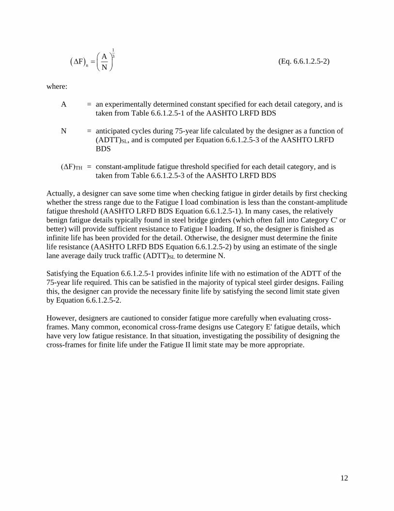
where:
A = an experimentally determined constant specified for each detail category, and is
taken from Table 6.6.1.2.5-1 of the AASHTO LRFD BDS
N = anticipated cycles during 75-year life calculated by the designer as a function of
(ADTT)SL, and is computed per Equation 6.6.1.2.5-3 of the AASHTO LRFD
BDS
(ΔF)TH = constant-amplitude fatigue threshold specified for each detail category, and is
taken from Table 6.6.1.2.5-3 of the AASHTO LRFD BDS
Actually, a designer can save some time when checking fatigue in girder details by first checking
whether the stress range due to the Fatigue I load combination is less than the constant-amplitude
fatigue threshold (AASHTO LRFD BDS Equation 6.6.1.2.5-1). In many cases, the relatively
benign fatigue details typically found in steel bridge girders (which often fall into Category C' or
better) will provide sufficient resistance to Fatigue I loading. If so, the designer is finished as
infinite life has been provided for the detail. Otherwise, the designer must determine the finite
life resistance (AASHTO LRFD BDS Equation 6.6.1.2.5-2) by using an estimate of the single
lane average daily truck traffic (ADTT)SL to determine N.
Satisfying the Equation 6.6.1.2.5-1 provides infinite life with no estimation of the ADTT of the
75-year life required. This can be satisfied in the majority of typical steel girder designs. Failing
this, the designer can provide the necessary finite life by satisfying the second limit state given
by Equation 6.6.1.2.5-2.
However, designers are cautioned to consider fatigue more carefully when evaluating cross-
frames. Many common, economical cross-frame designs use Category E' fatigue details, which
have very low fatigue resistance. In that situation, investigating the possibility of designing the
cross-frames for finite life under the Fatigue II limit state may be more appropriate.
13
6.0 EXTREME EVENT LIMIT STATES
6.1 General
The extreme event limit states for earthquakes (Extreme Event I), and vessel, vehicle or ice-floe
collisions and certain hydraulic events (Extreme Event II), while strength-type provisions, are
very different from the strength limit states as the return period of these extreme events far
exceeds the design life of the bridge. The strength limit states are calibrated for events with 75-
year return periods, in other words events which are expected to occur at least once during the
design life of the bridge. The extreme event limit-states, on the other hand, are intended to
address events which are not statistically likely to occur within the design life of the bridge but if
they did occur would potentially result in catastrophic failure (i.e., collapse) of the structure.
These limit states represent loads or events of such great magnitude that to design for the levels
of reliability or failure rates of the strength limit states would be economically prohibitive. Thus,
at these limit states more risk is accepted along with more potential structural damage. The return
period of the extreme event is typically much greater than the 75-year design life of the bridge.
The AASHTO LRFD BDS approach to seismic design is based on a stepwise approach where
bridges are designed to resist small to moderate earthquakes within the elastic range of the
structural components without significant damage, and are designed to resist exposure to larger
earthquakes without suffering collapse, preferably in a manner where damage that does occur is
readily detectable and accessible for inspection and repair. The AASHTO LRFD BDS are based
on a uniform risk model where the probability that a given seismic coefficient will not be
exceeded at a given project site during a 75-year period is about 93%, which reflects a return
period of about 1000 years.
The AASHTO LRFD BDS approach to vessel collision features a probabilistic approach that
considers typical navigation traffic for determining the design vessel. The procedures are written
such that the probability of collapse is limited to a certain value. A minimum impact vessel is
also considered. For unique situations, site-specific vessel collision studies, including
consideration of vessel-structure interaction, may be warranted.
The AASHTO LRFD BDS approach to vehicle and ice floe impacts are simpler and are typically
based on equivalent static loads which are either directly specified or relatively easy to calculate.
The load effects associated with the extreme event limit state load combinations typically have a
more significant impact on the design of bridge substructures since most of the typical extreme
event load events involve significant horizontal loading. However, in higher seismic regions,
certain elements of the superstructure are to be designed with sufficient capacity to transmit
seismic loads to the substructure.
14
7.0 REFERENCES
1. AASHTO. LRFD Bridge Design Specifications, 9th Edition. American Association of State
Highway and Transportation Officials, Washington, DC, 2020.
2. AASHTO. Standard Specifications for Highway Bridges, 17th Edition. American Association
of State Highway and Transportation Officials, Washington, DC, 2002.
3. Kulicki, J. M., W. G. Wassef, D. R. Mertz, A. S. Nowak, and N. C. Samtani. Bridges for
Service Life Beyond 100 Years: Service Limit State Design. SHRP2, Transportation Research
Board of the National Academies, Washington, DC, 2015.
4. Nowak, A.S., Calibration of LRFD Bridge Design Code, NCHRP Report 368, Transportation
Research Board, National Research Council, Washington, DC, 1999.
5. NSBA. Steel Bridge Design Handbook: Loads and Load Combinations. National Steel
Bridge Alliance, 2021.

B910-22
Smarter. Stronger. Steel.
National Steel Bridge Alliance312.670.2400 | aisc.org/nsba