Lecture Note on Circuit Technology for High Energy Physics ...
40
KEK Report 92-9 July 1992 H Lecture Note on Circuit Technology for High Energy Physics Experiment Hirokazu IKEDA LABORATORY FOR PHYSICS NATIONAL HIGH ENERGY
-
Upload
khangminh22 -
Category
Documents
-
view
2 -
download
0
Transcript of Lecture Note on Circuit Technology for High Energy Physics ...

KEK Report 92-9 July 1992 H
Lecture Note on Circuit Technology for High Energy Physics Experiment
Hirokazu IKEDA
LABORATORY FOR PHYSICS
NATIONAL HIGH ENERGY
copy National Laboratory for High Energy Physics 1992
KEK Reports are available from
Techrrical Information amp Library National Laboratory for High Energy Physics 1- 1 Oho Tsukuba-shi Ibaraki-ken 305 JAPAN
Phone 0298-64-1171 Tel x 3652-534 (Domestic)
(0)3652-534 (In temational) Fax 0298-64-4604 Cable KEKOHO
Lecture Note on Circuit Technology for Hi gh Energy Physics Experiment
HIROJltAZU IKEDA
National Laboratory for High Energy Physics 1-1 Oha Tsukuba Iba raki-ken 305 Japan
ABSTRACT
This lecture gives basic ideas and practice of the circuit technology for high enshy
ergy physics experiment The program of this lecture gives access to the integrated
circuit technology to be applied for a high luminosity hadron coUider experiment
Presented at Univerllity of Trnkubr J uly 1-31992
1 Introduction
11 G ENERAL DESCRIPTION
The design concepts on the electronics system for high energy physics expershy
iment meet with a drastic innovation of methodology andor technology Tradishy
tional way was to put preamplifiers on t he detector end whose outputs are transshy
rcit ted via a large bundle of cables to an electronics hut to be processed by data
acquisition modules The accelerator operation cycle was 5p3 to 20 ps which
was enough to compensate for latency of the trigger decision circuit This apshy
proach docs not work for the recent high luminosity collider experiment In order
to meet with high trigger rate large data size radiation damage issues and an
enormous number of readout channels we have try to apply VLSI technologies to
the detector instrumentation for the high energy physics experiment The front shy
end VLSIs have complicated digital control capabilities as well as analog processing
functions wltich are directly mounted on the high density printed circuit board
The back-end digital circuits are operated with high frequency clock signal where
a pipe-line operation takes an essential role These electronic system are designed
with an aid of circuit simulators based on analog oriented (SPICE) method andor
digjtal oriented (VRD L) method In this text we would like to give access to an
analog circuit design in terms of SPICE We never try to describe circuit in terms
of nequivalent 4-terminal network but to characterize electrollic devices in terms
of mathematical model Basic ideas about radiation measurements are covered
also together with some ideas related with semi-conductor physics Digital circuit
technologies and radiation damage issues are not covered in this text on which
we expect some lectures will be arranged elsewhere You can find some reference
literatures on these items in the reference list of the next section
2
12 REFERENCES
1 Introduction to electronics
PHolowitz and WHillThe art of electronics Cambridge university Press
1980
APMalvino Semiconductor circuit approximations An introduction to
transistors and integrated circuits McGraw-Hill 1980
DLScilling and CBelove Electronic circuits Discrete and integrated
McGraw Hill 1980
KShimoda and KSakurai Fundamentals of electronics Syokabo 1983
KSakmai and KShimoda Fundamentals of electronic instrumentation
Syokabo 1984
2 Electronics for radiation measurement
PW NicholsonNuclear electronics John Wiley amp Sons 1974
EKowalski Nuclear Electronics Springer-Verlag 1970
LMiura Radiation detector and its application Syokabo 1965
3 Integrated circuits
DABodges and HGJackson Analysis and design of digital integrated cirshy
cuits McGraw-Hill Inc 1983
PR Gray and K GMeyer Analysis and design of analog integrated circuits
New york Wiley 1977
CMead and LConway Introduction to VLSI Systems Addison-Wesley
1980
4 Noise
FR ConoorNoise Edward Arnold (Publisher) Ltd 1982
5 Semiconductor physics
ASGrovePhysics and technology of semiconductor devices John Wiley
amp Sons Inc 1961
SMSze Physics of Semiconductor Devices John Wiley amp Sons Inc 1981
6 Radiation effect
GCMessenger and MSAsbTbe effect of radiation on electronic systems
Van Nostrand Reinbold Company Inc 1986
TPMa and PV Dressendorfer Ionizing radiation effects in MOS devices
and circuits John Wiley amp Son 1989
2 Electronic devices
The basic physics constants used in this lecture are listed in Table 1 The basic
equations for the semiconductor are shown in Appendix A The device models are
based on the SPICE model
21 DroDE
The operational behavior of the p-n junction diode is characterized as
VDID = Is(exp(---u-) -1) (21)
nT
Vn
(22)QD = TtID + GjO J 1 dV
o
VD diode voltage
ID diode current
I s saturation current
n emission coefficient
VT kTq
GjO zero-bias depletion capacitance
centB built-in potential
m grading coefficient
Tt transit time
Rs ohmic resistance
43
n intrinsic carrier density
Nc effective density of states in the conduction band
N~ effective density of states in the valence band
Ee band gap energy
The capacitance ( CD) of the diode is defined as a derivative of QD
CD = dQD = ~ + CjO (23)dVD TD (1 - VDcentB)m
where TD is
dVD nVT (24)TD = dID = ID
TD is about 26 n for ID = 1mA n=l and junction temperature of300 OK Taking
into account I s temperature dependence
2 2 BeIs ex Dnnj = KT exp( --) (25 )
VT
VD shows negative temperature coefficient
dVD 1 dT =T(-Ve +VD-2VT) (26)
which is about -2m V rC The emission coefficient comes from two current genershy
ation mechanisms diffusion current (n=l) and recombination current (n=2) The
reality is between the two
In terms of intrinsic carrier concentration the thermal equi1brium is characshy
terized as
pn = n~ (27)
For the intrinsic semiconductor ( ie which has no impurity doping concentration
) there stands
p = TI = Tlj (28)
The origin of the built-in potential is explained in Appendix C The SPICE diode
model parameters are listed in Table 2 A complete set of SPICE model consists
5
of 14 parameters A SPICE deck including diode is shown below
EXAMPLE-1
MODEL M1SXXXX D IS= RS= N= TT= CJO=
RR3 3 1 1K
DD2 1 0 M1SXXXX
VC 230
VA 2 0 PULSE ( -1 1 200N 5N 5N 200N )
TEMP 27
OP
TRAN 5E-B 1E-6 0
END
The zero-voltage power supply VC was introduced to measure the current flow
through this supply Applying a square pulse from the voltage terminal V A
you could find a capacitive nature of diode about the current flow The circuit
schematic is shown in Figure 1
22 BJT
There are two type of Bipolar Junction Transistors they are pnp and npn
transistor The BJT is described as 4-terminal device ie collector base emitter
and substrate The BJTs are characterized as
IE = ~(eVBEVT -1) - I(eVBcVT - 1) CrF (29)
Ie = I(e VBE vT -1) _ I (eVBCVT -1) Crr
(210)
The capacitance characteristics are
CoTj I VBEVT + Je
CBE = VT e (1 - VBENe)m (211 )
6
TrI YSCVT + G) C 0 (212) GBe = VT e (1 - VBCrPc )m
The capacitance between the substrate and the collector terminal is
Gje
Gsc (213) = (1 - Vsc rP )m
The base current is evaluated as
1 1IB = IE - Ie = (3F I (eVsEYr -1) - fiR I (evs cVr - 1) (214)
The forward current gain is defined as
Ic 3F ~ IB (215 )
which is related with erF
erF 3F=l _ aF (216)
In the same way the reverse current is
OcR 3R = 1_ 0 R (217)
The common emitter transconductance (gm) is defined as
1 dIE IE --gt--= - (218) 9m = T VTelVB E
The SPICE parameters for the BJT are listed in Table 3 T he other parameters
VA and VAR are also essential to characterize bipolar transis tor The formula for
Ic and IE could be modified by a factor of 1 + VBCVA andor 1 + VBCVAR for
each term A complete set of SPICE model consists of 40 parameters A SPICE
deck including BJT is shown below
7
EXAMPLE-2
MODEL M2SCxxxx NPN IS= BF= BR= RB= RC =
+ RE= CJE=
QQ13 4 4 1 M2SCxxxx
QQ12 6 5 7 M2SCXXXX
QQll 673 M2SCXXXX
QQlO 2 13 M2SCxxxx
RR98 1 470
RR8 0 5 50
RR7 8 7 470
RR6 8 3 220
RR5 0 2 50
RR4 4 0 50
VV3606
VV2 0 8 52
VA 5 0 P ULSE (0 -08 200N 5N 5N 200N )
TEMP 27
OP
TRAN 5pound-8 Ipound-6 0
END
The circuit is just a toy circuit to demonstrate a NIM-to-ECL and an ECL-to-NIM
converter simultaneously QQ12 is an emitter follower which translate the NIM
level signal to the ECL level signal The switch stage consists of QQl1 and QQ10
T he base of QQ10 is biased at the mid-point of the ECL-logic swing The circuit
schematic ill shown in Figure 2
8
23 MOS
In t he opera tion of BJT the minority carrier takes au esscntial part On the
other band MOS transistor ( MOST ) is a majori ty carrier devke There are two
types of MOS transistor n channel MOST and p channel MOST MOST could be
separated furiherj enhancement MOST and depletion MOST
The characterist ics of MOS transistor are described below The MOST is described
as a 4-terminal devicc ie drain gate source and substrate In the linear region
( or before pinch-off )
1 W 2 (219)In = 2 kly (2(VGS - VTS)VDS - VDS)
In the saturat ion region ( or after pinch-off )
1 W )2 (220)ID = 2kr (VGS - VTS
where 11 is called as process gain ( t ransconductance) factor which depends on
details of semiconductor fabrication The break-down of the process transconducshy
tance factor is shown below
kp = pCax (221 )
c _ f02~O ox - (222)- shy
tor
Co = WLCox (223)
The transconductance of the MOS transistor at the pinch-off condition is
dID (224)9m = dVcs
W 9m = kpr(Vcs - VTS) (225)
9
9m = J2 kpID (226)
T he gate voltage on which the MOS transistor begin to work is VTS
VTS = VTO +(J 4gtB +VSB - ffB) (227)
where VTO is expanded again
1 VTO = VFB +centiB +-C -2qNvh a orPB (228)
oz
where VSB is measured from source to bulk terminal that is usually positive The
parameters that detennines the threshold voltage are the material and doping level
of the gate ie Bat-band voltage ( VFB ) The radiat ion damage incorporates fixed
oxide charge which affects on the threshold voltage also It should be note that
the concept of the MOS transistor based on the effect of surface inversion The
surface inversion changes semiconductor type from p-material to n-matenal The
surface potential of the MOS transistor could be derived from the consideration of
balance between the diffusion current and the drift current
v = VTln nNA (229)n~bull
where V is the surface voltage and n is the surface carrier concentration The
strong inversion layer is generated when
n = N A (230)
The condition to generate strong inversion is
NAV = 2VTln- = 2rpi (231)nj
The SPICE parameters for the MOS transistor are listed in Table 4 These SPICE
parameters are Leel-1 MOS parameters These SPICE parameters has some reshy
dundancy There are many varieties of MOS parameters which are introduced to
10
fit to the most advanced MOS devices A SP ICE deck including MOS transistors
is shown below
EXAMPLE-3
MODEL MPMOS PMOS VTO=-O88 TOX=26N UO=216 PB=
MODEL MNMOS NMOS VTO=O88 TOX=26N UO=661 PB=
YV6 105
MQ54 5 1 1 MPMOS L=14U W=36U
MQ4 4 3 1 1 MPMOS L=14U W=36U
MQ345 2 0 MNMOS L=12U W=36U
MQ2 2 3 0 0 MNMOS L=12U W=36U
TEMP 27
OP
TRAN 5E-8 1E-6 0
END
The circuit is a 2-input NAND circuit The noMOS transistors are located in series
while the jrMOS transistors are in parallel The substrate of nMOS transistor are
tied to ground Cv) and that of pMOS t ransistor are tied to +5V (Vdd) The
circuit conliguration is a Complementary MOS (CMOS) circuit You should note
that the SPICE convention gives negative val ue for VTO of p-MOS while VTO
for noMOS is positive The surface mobility UO of the jrMOS i8 one third of the
no MOS transistor The surface carrier mobility is half or less of the carrier mobility
in the bulk The low power nature of CMOS circuit provides benefit to implement
large scale digital circuits The circuit schematic of the CMOS NAND circuit is
shown in Figure 3
11
24 JFET
The JFET is a depletion mode device in the normal operating condition the
gate voltage is lower than the source voltage for n-channel JFET The charactershy
istics are described below In the linear region ( before pinch-off )
f3 (232) ID == 2VDS(2(Vcs - VTO) - VDs)(l + )VDS)
In the saturation region ( after pinch-off)
f3 (233)ID = 2(VGS - VTO)2(1 + )VDS)
The capacitance characteristics are
Gcso (234)Gcs = (1 _ VcsI4gtB)12
GODO (235)GCD == (1 _ VODcentgtB)lj2
f3 could be evaluated as
W (236)f3 = pGgy
where G is the unit capacitance of the FET gate The total gate capacitance Gc g
IS
(237)Go = WLGg
The SPICE parameters for JFET are listed in Table 5 A SPICE deck including
JFET is shown below
12
EXAMPLE-4
MODEL M2SCXXXX NPN IS= BF==
MODEL M2SAXXXX PNP 1S= BF=
MODEL M2SKXXX NJF VTO== BETA=
QQ21 6 7 8 M2SCXXXX
QQ20 6 2 7 M2SCXXXX
QQ19 2 4 5 M2SCxxxx
QQ18 4 4 9 M2SCXXXX
QQ17 2 1 3 M2SAXXXX
RR16 11 82K
RR15 11 7 72K
RR14 3 6400
RR13 11 5 100
RR12 11 9 100
RRlO 1 647K
RR90 1 33K
RRS 10 8 10MEG
JQ7 3 10 0 M2SKXXX
VV6608
VV5011 8
CC4 1 OOlU
CC3 108 05P
CC2 1012 1P
VA 120 PWL (0 O 400N O 410N middot01)
TEMP 27
OP
TRA N 5E- 7 1E-5 0
END
The circuit consists of a common source nmiddotchannel JFET ( J Q7) a folded cascode
t ransistor ( QQ 17 ) and Darlington transistors for output ( QQ20 and QQ21 )
QQ19 is for a high impedance load The feed back elements consist of RR8 and
CC3 CC2 is for a test pulse injection The circuit schematic is shown in Figure 4
2 5 PASSIVE EL EMENTS
Capacitor The capacitors used for integrated circuit design are diode capacishy
tance MaS capacitance metal-insulator-metal (MIM) and polysilicon-insulatorshy
polysilicon ( double poly capacitor) The diode capacitance and the MOS capacishy
tance have a voltage dependent nature The usable capacitance value for integrated
circuit design is around 1 pF A capacitance of 10pF is quite large A capacitance
of 100pF is almost unrealistic The unit capacitance of MIM andor double poly
capacitor is less than 1 JFJm2
~istor There are two way to fabricate resistor for the integrated circuit One
is to use a process step of p+ diffusion into n-well area for the p-MOS transistor
Another way is to use poly-silicon strip with appropriate impurity dosage These
resistor has inherently temperature dependent nature The absolute value of these
transistor is not better than plusmn 10 Po The design practice of the integrated circuit
is not to rely on the absolute value of the resistor bu t on the relative matching of
the resistors
3 Basic circuits and ideas
31 BUILDING BLOCKS OF CIRCUIT
Follower
Ernitter foUower
The output impedance of the emitter follower is evaluated as
VT ZOKj == re = T (31)
1413
The input impedance is measure from the base node
Zin = flFRL (32)
High drive follower
The characteristics of a high drive follower is hown below
r + Ro (33)Z oal = 1 +RlR2
Zin = flF1(Ro +RL(1 +RdRz )) (34)
Yot 1Vin = lQ(I+RIR2)(l j RL +(1+ Rd Rz)lQ)) (35)
In the limit of RzRl -- 00 the output impedance tends to zero the input imshy
peance goes to infinity and the transfer gain is 1 A SPICE deck including the
high drive follower is shown below
EXAMPLpound5
MODEL M2SCxxxx NPN
MODEL M2SAXXXX P NP
QQ171 56 M2SCXXXX
QQ167 79 M2SCXXXX
QQL~ 6 7 8 M2SCXXXX
QQ14 2 1 3 M2SAXXXX
QQ13 1 1 4 M2SCXXXX
RR12 0550
RRll 2650
RRI00 1250
RR9 10 9 100
RR8 10 8 100
RR77 14 lK
RR64 15500
RR5 3 13 50
VV4 11 0 12
VV30 10 12
VE 014 o VA 5 0 SIN ( o 5E-l 5E+6 1E-7 IE+6)
VB 11 15 o VC 1113 o CC2 12 2 01U
TEMP 27
OP
TRAN 5E-8 1pound6
END
In order to evaluate eq (35) we put lQ = Rll Rl = RR6 R2 = RR5 and
RL = RRlO The circuit schematic is shown in Figure 5
Darlington circuit
Two VBE drop configuration In this circuit the emitter node of one transistor is
connected to the base node of another transistor
VT ZDS j = r == 1 (36)
Zin == flF1 flF2RL (37)
We can obtain very high input impedance andor very high effective forward CUTshy
Tent gain A possible problem is that there is two VBE drop ( ~ 15V ) from the
input node to the output Dode ODe VBE drop configuration In this circuit colshy
lector of the input transis tor is connected to the base node of another transistor
The emit ter of the input transistor and the coUector node of t he second transistor
15 16
are tied together at the output IIode Thi5 configuration could be understood as
the limiting case of the high drive follower The output impedance could be less
than 1 fl
re (38) ZaGl = fJF2
Zin = fJFlfJ F2RL (39)
differential pair
The differential pair of the bipolar transistor is a basic billlding block for anashy
logdigital application Switching
The emitter coupled transistor pair is frequently used for a switch circuit The difshy
ferential input voltage of about 100 m V is sufficient enough to switch the current
flow from one t ransistor to another
Common mode rejedion ratio
The different ial pair is less sensitive for the common mode input voltage The
ra tio of the common gain relative to the differential gain is called common mode
rejection ratio
Power supply noise rejection ratio
The idea of power supply noise rejection ration is not inherent for the differential
amplifier We would like to mention its definition here T he voltage disturbance
of the power supply rail propagates to the output of the amplifier The amplifier
gain from the power rail to the amplifier output is called power supply rejection
ratio The preamplifier circuits are often deteriorated in terms of the power supply
rejectioIl ratio when the detector capacitance is very large
~
The circuits are biased with current mirror circuits and or a voltage reference
circuits We shows here some examples of simple current mirror Wilsons current
mirror and a temperature compensated bias circuit
A SPICE deck including these circuit blocks are shown below
17
EXAMPLE-6
MODEL M2SCXXXX NPN
MODEL M2SAXXXX PNP
QQ21 10 10 14 M2SCXXXX
QQ2D 13 6 10 M2SCxxxX
QQ19 4 12 9 M2SCXXXX
QQ18 6 10 11 M2SCXXXX
QQ17 1 8 9 M2SCXXXX
QQ16 15 4 16 M2SCXXXX
QQ 15 6 3 7 M2S AXXXX
QQ14 4 1 5 M2SAXXXX
QQ13 3 3 0 M2SAXXXX
QQ12 1 1 2 M2SAXXXX
VA 8 0 SIN ( -5E-1 5E-1 5E6 o lE+6 )
RR11 11 17 100
RR1015 2100
RR9 15 5 100
RR8 3 174K
RR7 15 74K
RR6 1417100
RR5 1617 4K
RR4 12 16100
VV3 150 8
VV2 0 178
VC 9 0 O
TEMP 27
OP
TRAN 5E-8 1E-6 O
END
18
The current mirror configuration might be used for a constant current source and
also for a high impedance load The current mirror wi th QQ12 and QQ14 is
for a high impedance load Transistors QQ18 QQ20 and QQ21 are elements
for the Wilsons current mirror to provide a constant current source The circuit
elements RR7 RRB QQ13 and QQ15 provides a temperature compensated current
reference The circuit schematic is shown in Figure 6
32 AMPLIFIER
This section describes basic concept of the feed-back amplifier The negative
feed back stabilizes andor improves
1 DC operation condition
2 Gain versus frequency response
3 Linearity
4 SIN ratio
5 Zjn Z08t characteristics
Operational Amplifier
Inverting amplifier
The inverting amplifier consists of an amplifier with an open loop gain of -G a
feedback resistor of R2 and a input resistor Rl which is series to the input terminal
The amplifier gain is
RzA= (310)
RzG +R1(1 + lG)
which could be written as
T(jw) (311)A = Aoo 1 +T(jw)
19
where
Ao = Rz
- Rl (312)
and
RIG(jW) T(jw) = Rl +Rz
(313)
In general
Zz Ao(jw) = - Zl (314)
Non-inverting amplifier
The amplifier gain is
which could be written as
A = Rl + Rz R1 (1 + lG) +R2G
T(jw) A = Ao 1 +T(jw)
(315)
(316)
where
R2 Aoo = 1 + Rl (317)
and
RIG(jW) T(jw) = Rl +Rz (318)
where RI(Rl +Rz) is a feed- back fraction In general
Aoo(jw) = Zz
1 + ZJ (319)
20
Input impedance The input impedance of the inverting amplifier is
Zin = R1 + R2 + Ro (320) l+G
where liD is the internal impedance series to the output port of the operational
amplifier When RJ = 0 the amplifier is a current sensitive amplifier or fonnalJ y
called M a trans-impedance amplifier When R1 = 0 again and R2 is replace
with a capacitor the circuit is a charge sensitive amplifier or formally called as a
trans-conductance amplifier
Output impedance The output impedance of the inverting amplifier is
Z01lt = liD (R1 + R2) (321)1 +T
Blackmans fo rI1JllJA A general formula to obtain Zin andor ZotJt is due to Blackshy
mlUls formula
Z = Zo 1 + T (322) 1 + To
where
Zo input (output) impedance when amplifier is removed from the circuit
T~ feed-back when input(output) terminal is grounded
To feed-back when input(output) terminal is open
Equations (320) and (3 21) could be confirmed with this Blackmans formula In
the case of the input impedance of the inverting amplilier there stands
Zo = flo + R1 + R2 (323)
R)G (324)T = R RRo + 1+ 2
To = G (325)
21
The output impedance is evaluated with
Zo = Ro (R1 + R2) (326)
T = 0 (327)
RJGTo = ---- (328)
Ro + Rl + R2
Circuit stability
The stabilityinstability condition is analyzed in terms of
1 Bode diagram
If the phase of G(jw) goes near 1800 or G(jw) is on the -12dBoct slope at
the frequency of G(jw) ~ Aoo the amplifier is potentially unstable
2 Nyquist diagram
The circuit is stable when the coordinate (-I D) is outside of the T(jw) trashy
jectory for -00 to 00 of w
3 Zin and ZOtJt
The two-port network is said to be unconditionally stable at a given frequency
if the real part of Z in and Z ol are greater than zero for all passive load
and source impedances If the two-port is not unconditionally stable it is
potentially unstable
The first method will be useful to use an operational amplifier The second
way is quite powerful to analyze the automatic control system in a mathematical
way where the frequency response is known a priori The IMt method with IO
impedance is m06t powerful for circuit simulation withmiddot SPICE The approach is
u~able for non-feed back circuit but with stray feed back loop The approaches to
fix circuit oscillation are
1 Move pole or substitution of pole position
22
2 Polezero cancellation
3 Attenuation of open loop gain
4 and elimination of unwilling feedback route
4 Application for data acquisition
41 DEC1SlON CIRCU1T
The decision circuit generates a logic signal when the input analog signal satmiddot
isfies a certain condition about its pulse beight
Leading edge discriminator The most simple decision circuit is a leading edge
di~criminator which is commonly used for t iming pick-off of the photo-multiplier
signal Because the discrimination condit ion is just a single threshold the timing
edge suffers from Time-walk~ due to pulse height VAriation
Zero cr~sing discriminator The zero crossing discriminator in corporates two Jeadshy
ing edge discriminator internally One discriminator generates a logic high during
a t ime interval wbere t he input signal is larger than t he threshold level Another
discriminator is provided for the differentiated signal of the input to pick-off zeroshy
crossing timing of the sigDal which is insensitive to pulse-bight The output signal
is a Jogical AND from these two discriminators
Constant fract ion discriminator
The other way for pulsemiddotheight insensitive decision circuit is to use an idea of
constant fraction discriminator The output logic signal has a timing edge at a
certain fraction of the peaking time of t he input signal This circuit is superior
th~ the zercgt- crossing discriminato-r because we can set the fraction where the
signal rise time is maximum The jitter due to electronicelectric noise could be
optimized with use of the constant fraction discriminator
Schmitt t rigger circuit The Schmitt trigger circuit employs two threshold levels
one is for low to high transition of decision circuit another is for high to low
tran~i tion Usually the former threshold is chosen as higher than the latter one
which increases noise immuruty of the decision circuit The circuit is commonly
used for a repeater capability for long distance digi tal signal transmission
42 T IME lNT ERVAL MEASUREMENT
We have two ways of time interval measurement one is in fully digital and
another is in analog way
Digital implementation
Interval counter
The number of pulse between a START and a ST OP pulse are directly counted
wi th incorporation of a high frequen cy clock generator and a high speed counter
integrated circuit The technical limitation for measurement resolution is around
10 nsee
Shift register
The input signal ( START ) is shitted-in to a shift register chain for each clock
leading edge The location of the START signal at the timing of STOP signal
gives timing interval information The shift register could be operated with a
clock frequency of 1 GHz
Gate delay with memory (Time-Memory-Cell)
A reference signal is generated for each predetermined time interval to propagate
it t hrough a delay element cbain A coincidence of t he START and the tap signal
from the deJay element chain gives t iming information This idea is quite adequate
for implementat ion with CMOS VLSI technology The reference clock frequency
is not more than 30 or 40 MHz The technical limitation for the measurement
r~lution is around 05 nsee
Analog implementation
The analog circuit to measure t ime interval is base on t he principle of Time-toshy
23 24
Amplitude converter ( TAC ) A constant current source is routed to a capacitor
during t he interval between START and STOP The voltage appeared at the cashy
pacitor terminal is proportional to the timin g interval T he technical limitation
for the measurement resolution is around 25 psec
4 3 _ CHARGE MEASUREMENT
Current splitter A current splitter circuit is employed for a wide range charge
integrator system The circuit is essentially a common base transistor array T he
voltage appeared at the emit ter node is amplified and fed to the base node Witb
this mechanism the illput impedance of the emitter node could be as low as 1 nor
less The transistors shares equal fraction of the input current
There are two ways of charge measurement one is to use a charge integrator
and aoother is to use a peak hold circuit together with an appropriate shaping
amplifier_ The charge integrator circuit accumulates input charge for a certain
gated interval _ The technical limitation for tbe minimum gate widtb is around 20
nsee T he maximum charge which could be measured with resonable measurement
accuracy 15 called dynamic range The linearity of the charge measurement system
is characterized by integral non-linearity and also by differential lineari ty The
integral non-linearity is 11 measure of the m aximum deviation from ao ideal linear
response over the entire region of tbe dynamic range The differential Don-linearity
is a measure of the local monotony The output offset for Dull input signal is called
pedestal level The ideas about hold-settl ing time and droop are specific for the
peak hold circuit The peak hold circuit can not cat ch a very fast signal with
realonable accuracy The technicallirnitation about t he peaking time of the inpu t
8ignal is about 50 nsee
Wave form sampling
The most versatile way of analog signal measurement is due to wave form sampling
which is commonly used for a digit izing oscilloscope Some techical words used for
the wave form sampling are listed below_
25
Sampling theorem
The theorem says that the analog signals whose maximum frequency are less than
balf of the sampling frequency could be reconstruct very precisely
AliASing noise
The higher frequency component than 50 of the sampling frequency generates
a fake signal in the lower frequency region this illusion of reconstructed signal is
called alialing noise
Aperture jitter
The jitter associated with sampling interval deteriorates measurement accuracy
Aperture delay time
The effective sampling timing might be delayed from the nominal sampling timing
which deteriorates phase measurement accuracy of the input wave
Feed-through
The wave form sampling system is driven by a large swing logic signal the intershy
ference through the analog switch is called clock feed-th rough
5 Noise characteristics of electronic devices
5 1 S OU RCE Of ELECTRONIC NOISE
The electronic noise could be subdivided into three parts due to their generation
mechanism ie shot noise thermal noise and Ilf noise
1 Shot noise The power spectrum of the shot noise is characterized as
i~ = 2qI A21Hz (51 )
The origin of the 8hot noise is explained in Appendix D
2 Thermal noise In terms of voltage generator the thermal noise is written
25
as
v~ = 4kTR y2Hz (52)
The thermal noise could be presented as a current generator also
middot2 _ 4kT A2HzIn - R (53)
The origin of the thermal noise is explained in Appendix E
3 lf noise lf noise is characterized as a voltage generator whose noise power
spectrum has lf characteristics
2 _ KIf y2Hz Vn - (54)f
52 PULSE SHAPING
In the case of low input impedance ampUfier the noise sources are characterized
as a crnrent generator 2v2 middot2 + - (55)I = In Z 2 n ~
in parallel noise in AfEZ
Vn series noise in Y[j[
Z sornce impedance
The impulse response of the amplifier chain is h(t) whose Fornier transform is
00
H(w) = Jh(t)e- jw1 dt (56) -00
The signal we use here is an impulse response for simplicity of discussion
00
l (w) = q = Jq8(t)e-Jwtdt (57) -00
27
The signal is evaluated as
00
(58)2~ JJ(w)H(w)ejwtdw -00
for low impedance amplifier The noise power is evaluated as
J00
I~IH(w)12df - JB
2l lt n gt (2B)- 2df = 2q2~gt (59)
-00 -B
where q-Vlt n gt 2B could be interpreted as the eqwvalent noise charge With an
assumption that Z is purely capacitive ie Z = IfjWCD and i~ and v~ have no
frequency dependence
00 00
enc2 = i~ Jh(t)2dt2 + v~c1 Jh (t)2dt2 (510)
-00 -00
where we have used formulae
00 00
(511)JIH(w)1 2df = Jh(t)2dt -00 -00
and 00 00
(512)Jw2IH(w)J 2df = Jh (t)2dt -00 -00
The noise analysis in terms of h(t) ( H(w) ) is called time domain analysis (
frequency domain analysis ) The time domain analysis could handle complicated
signal shapes wruch are quite tedious in the frequency domain analysis Assuming
28
a lowest order shaping function
t th(t) = -exp(l- -) ( 513)
tm tm
or eqillvaleotly
e (514)H(w) = tm(jw + 1tm)2
the input equivalent noise charge is
2 e2 tJ 2C2
enc = -(i~tm + ~)2 (515)4 tm
(J2 tm(opt) = CD (516)
tn
The signal to noise ratio is
q (517)SIN = Venr
On the other hand for the high input impedance amplifier the total noise is evalmiddot
uated in terms of an effective voltage generator
V = Zi~ + tJ~ (518)
The Bignal is amplilied with a voltage amplifier The transfer function for the
anaJog chain is taken 35
eCDjw (519)G(w) = tm(jw + ltm2
This transfer function can keep compatibility with the previous discussion In the
29
time domain that yields
g(t) = CDh (t) (520)
The output noise power is
J00
VIG(w)1 2 dj (521 )
-00
The output signal is 00
2~ JZI(w)G(w)ejw1dw (522)
-00
These results give identical results either for low impedance amplifier chain or high
impedance amplifier chain The last discussion is about lf noise
In terms of I the lf noise is
I~ f = 27rC1K1 fW ( 523)
The contribution to the electronics noise is
2J00
IifIH(w)1 2dj = C1 K lfe 2 (524)
o
which gives a value independent of tm This is a specific characteristics of lf noise
30
6 Fast amplifier system
6 1 LAPLACE TRANSFORMATION
H(s) = J00
h(t)e- ldt
o
Ii we take
t 1 I tmh( t) = _e shytm
its Laplace transform is
e 1 H(s) = tm (s + ltmP
The inverse-Laplace transformation
O+ioo h(t) = ~ e elJ
27rJ t ~ ds m
(7- 100
gives a correct answer for h(t)
6 2 P OLEZERO CANCELLATION
The transfer function to get pole-zero cancellat ion is
1 + t bull d
l+tst
where
t gt t f
31
63 COMMON BASE AMPLIFIER
Input impedance The input node of the common base amplifier is at the emitter
of the base grounded transistor) whose input impedance is
Zin ~ VT (67)IE(61)
Noise characteristics Because this amplifier is an open-loop amplifier the noise
performance is inferior to the common emitter amplifier configuration
(62) Amplifier tail The common base amplifier is easy to be affected by a stray capacishy
tance at the high impedance gain node which is an origin of the so-called amplifier
tail This tall could be compensated for with a scheme of pole-zero cancellation (63) A SPICE deck of the common base amplifier is shown below
EXAMPLE-7
MODEL M2SCXXXX NPN
(64) QQll 4 0 5 M2SCXXXX
QQ10 2 1 3 M2SCXXXX
QQ9 2 4 1 M2SCXXXX
VA 7 0 PWL ( O O 5pound-8 O 51E-8 -2E-2 )
RR8 42 10K
RR7 31 720
RR6 6 310K
RR5 6 5 10K
VV4 2 012(65) VV30 612
CC2 5 71P
TEMP 27 (66)
OP
TRAN 1pound-8 2E-7 0
_END
32
The base of the input transistor Q11 is grounded Transistors QQ10 and QQ9 arc
configured il- a Darlington pair T he circuit schematic is shown in Figure 7
64 C OMMON EMIT TER AM PLIFIER
Input impedance The input impedance of the common emitter amplifier is
RF (68)Zin = 1 +G(jw)
Miller capacitance The effect of Miller capacitance is inherent for the high openmiddot
loop gain amplifier unless a cascode configuration is t aken The input impedance
of the common emitter transistor wi thout an aid of a casco de transistor is
Z in = 1+ jwGBCRL (69)jwGBc(l +9m RL)
The real input capacitance GBe is magnified by a factor of openmiddotloop gain
Gin ~ 9m RLGBC (610)
The high impedance collector load is the direct reason of large Miller capacitance
The cascode conflguration has a lower collector load the collector load of the input
transistor is an emitter impedance of the casco de stage transistor
A SPICE deck of the most primitive common emitter amplifier is shown below
EXAMPLE-8
MODEL M2SCXXXX NPN
QQ9 1 4 0 M2SCxxxx
QQ8 2 1 3 M2SCXXXX
VA 50 PWL ( O O 5E-8o 51E-8 -2E-2)
33
RR71 245K
RR6 0 3 720
RR5 43 20K
VV4 20 6
CC34 51P
CC2 4 3 olP
TEMP 27
OP
TRA N 1E-8 2E-7 0
END
The emitter of the input transistor QQ9 is grounded The feed back element is
RR5 The circuit schematic is shown in Figure 8 The next SPICE deck of the
co=on emitter amplifier has a casco de transistor
EXAMP LE-9
MODEL M2SCXXXX NPN
QQ13 3 2 7 M2SCXXXX
QQ12 7 6 0 M2SCXXXX
QQ11 4 3 5 M2SCXXXX
QQI0 2 2 1 M2SCXXXX
QQ9 1 1 0 M2SCXXXX
VA 8 0 PWL ( O O 5E-8 O 51E-8 -2E-2 )
RRB 24 45K
RR73 4 45K
RR60 5 720
RR5 6 520K
VV4 406
CC3 6 5 01P
CC2 6 8 1P
34
middotTEMP 27
OP
TRAN 1E-8 2E-7 0
END
QQ13 is the cascode transistor which is located just above the input transistor
QQ12 QQ9 and QQlO are incorporated to provide bias voltage for the casco de
transistor The circuit schematic is shown in Figure 9
65 lt TAIL AND ITS CANCELLATION
The signal from the gas ionization chamber with thin wire electrode is
zo (611)i = 1 + tio
where io is
q (612)
io = 2toln(rcra)
to is
ra (613)to = 2p+Ea
It is co=on to approximate the lt tail with a few exponential time constant
07ge-tj16to + 0185e-tjI35to + O024e- tj1l3 to (614)
The origin of the lt tail is explained in Appendix F
66 AMPLIFIER CHAIN
It is usual to use three pole approximation
() (126 250 271) S = loto + + --- (615)
I + 16tos 1 + 135tos 1 + 113tos
The pole-zero cancellation stage compensates for the second pole
1 + 135tos ~ (616) P Z]jt = 1 + st 135tom
Neglecting the contribution of the third term of i the signal response with the
lt tail cancellation is approximately
gelf (617) ipz(s) = 1 + st m
where
ge = ioto(126 + 0185 tm
) ( 618) to
The preamplifier is assumed to have a single pole
~ (619)1 + tps
The pole-zero cancellation for the amplifier tail is
1 + stp tm (620)PZPT = e 1 + st tpm
The total response of the signal processing chain is
qRp elm qRp t I-tltm--------- -+ ---e (621) tp (1 + stm )2 tp tm
35 36
67 NOISE CHAR ACTERISTICS
The possibJe noise source of the common emitter amplifier is characterized as
follows
2 I In == 2q(ID + s + 4kT (622)
f3p Rj )
tI~ == 4kT(rbb +rel2 +R) (623)
ID detector leakage current
f3p forward current gain of the input transistor
Ie collector current of the input transistor
Rj feed-back resistor of the ampGfier
rH base spreading resistance
r inverse of transconductance of the input transistor
R series resistance additionally at tached to the illPut of the ampufier
68 TIMING RESOLUTION
The electronic nois affects on the timing resolution of the decision circuit The
timing jitter due to Vnoiu is
Vnoie (624)ot = dVdt
It is apparent that the steep wave form gives better timing resolution In practice
in the case of lowest order shaping
eSt == - 1 2t3 + u2 C2 t (625)2Q j n m n D m
where the threshold level of the decision circuit is zero and Q is the input impulse
signal charge
37
69 COUNTING RATE DUE TO ELECTRONIC NOISE
It looks something wrong about the previous discussion What is missing is
the counting rate of the decision circuit An ideal timing pick-off circuit should
have higher threshold and keep reasonable timing resolution The counting rate of
the decision circuit is
1In == _Be-vHVj (626)V3
where B is the noise frequency bandwidth VTH the threshold voltage and VN the
rms voltage of noise
Higher order shaping Applying a higher order shaping
t t tmh(t) == (_)e1- (627)tm
the maximum of dVdt appears at finite value of amplitude With an aid of conshy
stant fraction decision circuit we can have lower hit frequency due to noise without
deteriorating timing resolution In practice the most steep slope appears at the
fraction of
1(1- -tefo (628)
Vn
7 Low noise Amplifier system
71 CHARGE SENSITIVE AMPLIFIER
Circuit coufiguration A circuit schematic of a typical charge sensitive ampliiier is
shown in EXAMPLE4
38
Signal chain
Signal source
i = Q8(t) (71)
PreAlTIplifier
R (72)
1 + sCR
Pole-zero canceller
1 +sCRf tm (73)
1 +tm CfRf
Integrator
e (74 )
1 +stm
Total response
Q etm Q t I-tlt ~--= ---gt --e m (75)C (1 + stm)2 Cf tm
Electronic noise
The electronic noise charge of the JFET-input charge sensitive amplifier is
2 e2 24kT(CD +Ce)2 4kT 4kT ene = -4(-3- + (2q(1D + Ie) +-R + -R)tm ))2 (76)
9m tm F B
where
9m transconductance of the input FET
CD detector capacitance
Ce gAte capacitance of the input FET
ID detector leakage current
Ie gate leakage current of the input FET
RF feed back resistor of the amplifier
RB detector biM resistor
7 2 HIGH CAPACITANCE DETECTOR
There are two techniques which are inherent for operation of the high capacishy
tance detector
Capacitance matching Reminding that the transconductance of the JFET is
W 9m = jJCgy(Ves - VTO) (77)
it i~ Apparent that the transconductance is proportional to the total gate capacishy
tance Ce ie W LCg The first tenn of eq (76) is proportional to
(CD +Ge = CDhCDGe + jCeCD)2 (78)
which gives minimum when CD = Ce
Transformer coupling When the source capacitance is very large and it is very
hard to reach the capacitance matching condition the way to solve the problem is
to use a transformer The IV relations of the lossless transformer are
nIh = n2h (79)
Vih = V2h (710)
Then we have a impedance conversion relation
ZI Z2 (711)~= n 2
1 2
The source impedance could be increase by a factor of n2 while the signal is deshy1creased by A factor of n- where n = n2n1 and Z1 = IhwCD We can improve
the SIN ratio by a factor of n The capacitance matching condition is
CD = Ce (712) n2
39 40
73 C OLD T ERMINATION
The detectors which have t ranmission characteristics may be terminated with
their poper impedance at the preamlifier end A resistor is a bad practice for signal
teTITIination because resistive elements are source of electronic noise The cold
termination is an idea to tenninate tbe detector signal mtb no resistive elements
Assuming an effective impedance Z L at the high impedance node of the amplifier
( node 2 in the examplemiddot-4 ) tbe input impedance is evaluated as
Zin = ~ (713)gmZL
where Zf is the impedance of the feed back elements 9m is the transconductance
of t he input transistor Locating a few ten s of pF of capacitor ( CL ) for ZL and
assuming that the feed back impec ~ nce is approximated as capacitive ( Cf ) the
input impedance is purely resistive
CL (714)Zin = gmCf
as far as low frequency cbaracteristics are concerned
74 SUBSIDIARY EFFECTS
pile-up
The output of tbe sbaping amplifier bas commonly slow tail Wben the input signal
rate is very high two or more signals bave a chance to pile up wbich potentially
deteriorates measurement resolution baseline-restorer
It is quite cornmon to have an undershoot in an AC coupled system witb unipolar
shaping The base line restorer suppresses undershoot smng of voltage Tbe
bipolar shaping is free from base-line shift under an ideal condition ballistic deficit
Because the signal from radiation detector takes a fillite period instead of delta
impulse a signal processing system with short integration time uses only a fraction
of the detector generated cbarge Tbe ballistic deficit is a measure of tbe inefficiency
of signal integration
41
8 Silicon strip detector
T he silicon strip detector is reverse biased p-i-n diode whose operational beshy
haviors are cbaracterized in tenns of tbe depletion property of the diode structure
The detector tbickness is 300 flm with n-type bulk material wbose resistivity is 4
to 6 Hl Cill
B1 D EPLET ION PROPERTY
Assuming a step junction the potential filed in the depletion region is
- qNA (x 22 + Ipx)cent- - poundto (81)
- qND(_x 22+l x)cent+ - t~ n (82)
where
cent- potent ial in tbe p-type region
cent+ potential in the n-type region
dielectric constant of silicon
N A acceptor concentration in the p-type material
ND donor concentration in the n-type material
lp width of tbe depletion region developed in the p-type region
In width of the depletion region developed in the n-type region
x coordinate measured from p-side to n-side whose origin is located at the junction
boundary
These solutions are from Poisson equations
tf2cent_ gNA (83)dx2 =~
tf2cent+ gND dx 2 (84)=-~
42
The electric filed is given as
qNA I ) E_ = -(x + P fED
qNDE+ = -(-x + In)
fED
The electric field should be continuoUl at x = 0
E+(o) = E_(o)
NAlp = NDln
The electric field shows its maximlUD at x = 0
qNA qNDEmQ = --Ip = --In
fED Etc
The potential difference across the diode is
p(x = In) - p(x = -Ip) = V6i - V
where Vbi is a build-in potential If we assume
In ~ Ip
and also
NA~ND
for example In 300 pm and Ip 1 pm the potential drop
43
implantation is negjjgible Then we have
Vbi - V = _1_21 (813)(85) PPe ffD
where P is the bulk resistance of sijjcon
(86) 1 (814)
p= qPeND
Jle is the mobijjty of electron carrier and ID is the depletion width
(87)
Id = Ip + In (815)
(88)
82 JUNCTION CAPACITANCE
The junction capacitance is
(89)
c= tEo Fm2 (816)ld
CjO (817)(810) C = 1 _ VVbi
where
2UD CjD = (818)
PJI Vb
(811)
(812)
across the pshy
44
83 LEAKAGE CURRENT
The leakage current of the p-i-n diode under the reverse bias condition is
1 ni 2I gen = -2q-1d Aim (819)
TO
where TO is the effective carrier life time In Appendix B we have shown that the
leakage current is well described by the SHR model
84 CHARGE TRANSPORT
Drift
The carrier velocity is
(820)Veh = Peh E
where pe and JJh are mobilities of electron and hole E is the electric field
Diffusion
The diffusion equation is
an 8t
= Do2n ox2
(821)
where
D = VTJJ (8 22)
Assuming a Gaussian distribution which is centered at x=O
2nO x
(823)n = v27ra(t) exp( - 2cr(t)2)
We obtain an approximate solution
a(t) = 2Dt (824)
45
Hall coefficient
The magnetic field affects on the drift property of carrier this is from the Lorentz
force
tan (B) = JJH B (825)
where PH is a Hail mobility and B is the strength of magnetic field in Tesla
85 SIGNAL GENERATION
An infinitesimal electrode is introduced in the sensitive volume of the detector
where we locate signal charge q bull The readout electrode is indexed as I and the
hypothetical electrode is indexed as 2 When q=O there stands
Ql = Cll VI + C12 V2 (826)
o= C21VI + C22 V2 (827)
where Cij is the capacitance matrix elements between the electrodes When nonshy
zero q is located
Ql + Q = Cl1(VI +6VI) + C12(V2 +6V2) (828)
q = C21(V1 +6VI) +Cn (V2 + 0V2) (829)
Using symmetric property of the capacitance matrix
q-C22612 Q- CU 6Vl (830)
0VI 6 V2
Neglecting the second order infulitesimal term
612 Q = q 6VI (831)
46
Wben q moves towards the readout electrode signal current is induced on there
dQ d dV dx (832)1= dt = qJ dx (dVJt
dE 1=-Jq --v (833)dVl
dE 1 (834)
dVl Id
tJ Zl
q = Jidt = J~dx = t (X2 - Xl ) (835) h X l
The ionization charge which is generated in the vi cinity of the readout electrode
and moves towards the readout electrode does contribute negligible part for signal
generation
9 VLSI electronics for silicon strip detector
In order to meet with narrow pitch of the silicon-micro strip detector an adshy
vanced MOS technology is a m andatory part for electronic system design
91 CMOS AMPLIFIER
The CMOS amplifier chain for the silicon strip detector consists of a large
input PET cascode transistor cascode load feed back capacitor reset switch and
sample hold circuits They are described below separately
Large CMOS input FET
In order to get high value of 9m we use a very large t ransistor with large WL
a5pect rat io
47
Cascode transistor
The Miller capacitance is apprOlcimately
9mlCM= CGD- (91) 9m2
where 9ml is the transconductance of the input transistor and 9m2 is that of the
cascode transistor Without the cascode transistor 9m2 might be replace by an
amplifiers internal load that is larger than 9m2 by 102 to 103
Cascode load
The output impedance of the cascode transistor could be much higher than the
single transistor
Zout = rd l + rd2 + rd] rd29m2 (92)
where rdl and rd2 are drain output impedance In order to drive this result it
should be note that there stands
Vd td = VgJ9m +shy (9 3)
rd
~et lWjtch The restoration mechanism for the ampufier is due to an analog
switch instead of a large feedback resis tance for the JFET charge amplifier
Sample and hold
The sample and hold circuit consists of an analog switch a capacitor and a high
imput impedancce buffer The analog output of the preamplifier is sampled and
held at the capacitor for each predetermined time step
A SPICE deck of the cascode CMOS ampufier is shown below
EXAMPLE-I0
MODEL MPMOS PMOS VTO=-O88 TOX= 26N LEVEL=3
48
MODEL MNMOS NMOS VTO= 088 TOX=26N LEVEL=3
MQ66 389 1 1 MPMOS L=14U W= 9U
MQ65 11 38 1 1 MPMOS L=14U W = 40U
MQ54 11 10 1 1 MP MOS L=14U W =40U
MQ63 10 9 1 1 MPMOS L= 14U W ==40U
MQ62 10 11 1 1 M PMOS L=14U W =40U
MQ61 38 900 MNMOS L=12U W=36U
MQ60 373800 MNMOS L= l2U W=32U
MQ59 11 10370 MNMOS L=12U W=32U
MQ58 10 11 360 MN MOS L=12U W=32U
MQ57 36 900 MN MOS L=12U W=32U
II55 2 0 70U
VV541 05
RR53 27 30 10K
RR52 26 31 10K
RR51 285 2K
MQ50 22 33 3 MP MOS L= l4U W=100U
MQ49 33 35 3 3 MPMOS L=14U W = 100U
MQ48 6 2 35 3 MPMOS L= 14U W =100U
MQ47 35 35 3 3 MPMOS L= 14U W= I 00U
MQ46 5 6 34 3 MP MOS L=42U W=100U
MQ45 34 35 3 3 MP MOS L=42U W=100U
MQ44 31 4 0 0 MNMOS L= 12U W =40U
MQ43 3 30 31 0 MN MOS L=12U W=40U
MQ421 640 MNMOS L=36U W =40U
MQ41 6 6 32 0 MNMOS L= 36U W =40U
MQ404 4 0 0 MNMOS L=12U W=40U
MQ39 324 0 0 MNMOS L=12U W =40U
49
MQ38 29 26 0 0 MNMOS L=12U W =40U
MQ37 56 29 0 MNMOS L= 36U W =40U
MQ36 27 4 00 MNMOS L=12U W= 40U
MQ35 3 5 27 0 MNMOS L=12U W=40U
CC34 50 IP
CC33401P
CC32 350 IP
CC31 30 0 03P
CC30 26 28 02P
CC29 26 27 1P
CC27 7 0 IP
RR26 13 7 2K
RR25 1224 10K
RR24 17 14 10K
MQ23 24 10 22 8 MPMOS L=2U W=36U
MQ22 1510178 MPMOS L=2U W=36U
MQ21 21 10 8 8 MPMOS L=2U W=20U
MQ20 25 5 8 8 MPMOS L=14U W=lOOU
MQ19 7 6 25 8 MPMOS L=42U W=100U
MQ18 19 10 8 8 MPMOS L= 2U W=20U
MQ17 22 11 20 0 MNMOS L=2U W=20U
MQ16 20 4 00 MNMOS L= 12U W=20U
MQ157 6 23 0 MNMOS L= 36U W=40U
MQ14 23 1200 MNMOS L=2U W=1200U
MQ13 0 1 160 MNMOS L=2U W=40U
MQ12 15 11 170 MNMOS L=2U W=36U
MQ11 18 4 0 0 MNMOS L=12U W=20U
50
MQ10 17 11 180 MNMOS L=2U W=20U
MQ9 19 7 170 MNMOS L= 12U W=20U
MQ8 21 14 22 0 MNMOS L= 12U W=20U
MQ724 11 22 0 MNMOS L= 2U W= 36U
CC6 12 16 O2P
CC5 12 15 1P
CC4 140 03P
CC3 12 13 O2P
IF 0 12 AC 1 O
VB 9 0 5
VE 1 8 O
VJ 130
TEMP
OP
AC DEC 17 1000 1E+9
END
The input n-channel MOS FET is MQI4 The bias current for this transistor is
chosen as 70 jlA The cascode transistor MQ15 is located located above MQI4
The cascode load consists of p-MOS transistors MQ19 and MQ20 The feed back
element is a 02 pF capacitor ( CC3) CC6 is provided for test pulse injection
The SPICE deck is organized to study the input impedance under the RESET
condition The SPICE deck includes subsidiary digital circuit to control the reset
circuit of the ampli1ier The schematic appeared in Figure 10 shows only the
amplifier core
51
92 DOUBLE CORRELATED SAMPL1NG AND NOlSE CHARACTER1STICS
The preamplifier gives step-like response for an impulse charge The aIDount of
charge could be mea~ured if we know the output voltage before and after the
signal arrival The scheme is a double correlated sampling The impulse response
of the effective signal filtering function is as follows
h(t) = (1- e-t IO )(1_ e- r to ) Jor t lt T (94)
h(t) = e(r-I)to for t ~ T (95)
where
to rise time of the amplifier
T sampling interval
9 3 NOlSE CHARACTERIST1CS
The equivalent noise charge is
22 Jenc2=ii h(t)2dt+ v(CD+CC)2Jh(t)zdt (96)
The first integral gives
T - 2to (l - exp(-TtO)) + (to2)(1 - exp(-2TtO)) 2 (97) AZ + to
The second integral gives
(98)toA
where
e- r toA = 1 - (99)
52
In the limit of
7~to (910)
the equivalent noise charge is
2 i~ v~ 2 1 enc = 2 7 + 2 (GD + Gc) to (911 )
The noise behavior is quite different from the case of time continuous shaping
scheme The paraDel noise is approximately proportional to T ) while the series
noise is inversely proportional to to
10 Summary
The circuit design is enhanced with aid of SPICE simulation Stability analysis
is an essential part of circuit design Noise could be estimated with SPICE The
analytical formula will help to understand the origin of noise and its optimization
Integrated circuit technology was introduced in the area of high energy physics
to meet with the narrow pitch readout of the Silicon micro-vertex detector The
technology is proliferated to every area of data acquisition system including both
analog and digital This text is just an entrance to wide spread electronics techshy
nology for the high energy physics experiment We would like to encourage you to
consult on the reference literatures for further study
53
APPENDIX A
Continuity equation
an = ~divJn - Un (Al)at q
op __ ~divJp _ Up (A2)at - q
Carrier transport equation
I n = -qjJnVcentn (A3)
Jp = -qjJhPVcentp (A4)
where cent and ltpp are quasi Fermi potential for electrons and holes ( Boltzmann
approximation )
centn = -rjJ - kT In (A5)q nj
kT rpp = -rjJ + -In (A6)q nj
Poisson equation -rjJ is determined from charge distribution
ttoV2-rjJ = -q(p - n + ND - NA ) (A7)
Schockley-Read-Hall recombination The major recombination mechanism is based
on SHR and Auger recombination The SHR recombination is
pn _ n 2
USHR = (A8)I
Tp(n + nexp((Et - E)jkT) + Tn(P + nexp((Ei - Et)jkT))
where
Tp carrier life time of hole
54
Tn carner life time of electron
E1 energy level of the trap
Ej center of the band gap
You should note again that JlTl = nr in the thermal equilibrium USH R has a
finite value for steady state but zero for thermal equilibrium
APPENDIXB
Generation-recombination current in the depletion region In the depletion region
there stands
pn ~ nj (B1)
When the trap band is located at the center of the band gap (ie = Ej )E t
USHR is maximized When we take these approximation there stands
nj (B2)USHR=-Tp+T
n
Assuming a new parameter as an average of Tn and Tp we get
n- 1 n-USHR = --2I ---t I ge n = -2Q--laA (B3)
TO TO
55
APPENDIX C
Built-in potential
The built-in potential comes from balance between the diffusion and the drift due
to electric field
dn dV qD- - qJln- = 0 (Cl)
dx dx
Integrating the equation we get
Xl
J ldn VT-- = V1 - V2 (C2)
ndxX
When Xl is in the n-type region and X2 is in the p-type region nl ND and
n2 = nlNA
VI - V2 = VTln(nln2) = kT In NAND (C3)q n~
I
This intrinsic potential difference is called built-in potential In this discussion we
have assumed 100 ionization of donor andor acceptor
APPENDIXD
Shot noise
The electronic current could be expressed as a series of delta like spike due to
discrete nature of electronic charge The Fourier transform for a single impulse
charge is
qo(t) ---t f(w) = q (Dl)
The power for the frequency bandwidth of B is
B
W = If(w)1 2 df = 2q2B (D2)
- B
56
Assuming the average current is I =lt n gt q the Doise power is
lt n gt W = 2q( lt n gt q)B --+ i~ = 2qIB (D3)
where B is the frequency bandwidth
APPENDIX E
Thermal noise
A~sUIDing that the resistor R is connected to a transmission line with Zo = R the
noise power transmitted via the transmission line is
1 Pn = 2( 2T)B (El)
where the factor of 2 comes from two-component nature of electro-magnetic wave
In terms of resistance R and rms noise voltage Vn due to resistance R the power
fed into the transmission line is
vPn = 4R --+ Vn
Z = 4kTRB (E2)
57
APPENDIX F
Signal Generation of cylindrical ionization chamber Assuming a coaxial geometry
for the ionization chamber the potential is
Voln (rrc) e= (Fl)
In (rcra)
where
Yo voltage on the inner electrode
rc radius of the outer electrode
r radius of the inner electrode
The outer electrode is tied to ground and signals are detected on the inner elecshy
trode The electric field is a derivative of the potential
de YoE --~ (F2)= - dr - rln (rcra )
The current induced on the inner electrode is
dE --v
1 = q dVo (F3)
where v is the velocity of the positive ion moving toward the outer electrode which
IS
v= I-+E (FA)
1-+ mobility for the positive ion
With these equations we get
Yo 1-+ (F5)i = -qr2(ln(r r ))2c a
In order to get a time-dependent development of the current signal we evaluate the
58
relation between time (t) and the racliallocation of the positive ion (r) TABLE CAPTIONS
T 1 Physics constants used in this lecture t = J~dr = In(rclra) 1 (r2 - r~) (F6)
1) 11+ Yo 2 2 SPICE parameters for Diode To
3 SPICE parameters for the BJT which could be reduced to
4 SPICE parameters for MOS transistor 1 + tlto = r2 Ir~ (F7)
5 SPICE parameters for JFET
where
to = ~_r_ _ r~ (F8)2p+Ea - 2p+ Vo In(rcra)
E electric field at the surface of the inner electrode
Eventually we get lit nature of the current signal
to 1= (F9)
1 + tlto
where
q VOI1+ (F1D)10 = rWn(rcJra ))2
59 60
Table 1 Physics parameters used in this led ure Table 2 SPICE parameters for Diode
Properties unit
Pennit t ivi ty of vacuum ( fO )
Dielectric constant of silicon
Dielectric constant of silicon dioxide
Thermal voltage ( kTj q )
Intrinsic carrier concentration( nj)
Energy gap at 300K ( Ee )
Mobility ( IJe Ph )
Hall mobility ( PH )
Diffusion constant ( D )
Break-down voltage of Silicon
Energy to generate ejh pair
Fjcm
V
cm- 3
eV
cm2 jV3ec
T- 1
cm 2 j8ec
Vjpm
eV
8854E-14
119
39
00259
145E+I0
112
1350(electron) 480(hole)
015 (electron) 0035 (bole)middot
35 (electron) 12 (bole)
~ 30
36 -shy
i
I
-
Symbol Name Parameter name Units Default Example
I IS Saturation Current A 10E-14 10pound-14
r RS Ohmic resistance n 0 10
n N Emission coefficient 1 10 I
CjO CJO Zero-bias depletion capacitance F 0 20pound-12
po VJ Built-in potential V 1 08
m M Grading coefficient 05 05
Tt TT Transit time s 0 10pound-10 - -
61 62
Table 3 SPICE parameters for BJT Table 4 SPICE parameter for MOS
Symbol Name Parameter name Example DefaultUnitsUnits Default IExample Symbol Name Parameter name
J IS Saturation current
f3F BF Forward current gain
3R BR Reverse current gain
rb RB Base resistance
re RC Collector resistance
rlt RE Emitter resistance
CJEC jeO
p VJ E
MJE me
CJC GjcfJ
VJCpc
MJCme
CJSGjO
p VJS
TF I TF
TR I TR
BE zero-bias depletion capacitance
BE built-in potential
BE junction grading factor
BC zero- bias depletion capacitance
BC built-in potential
BC j unction grading factor
Zero-bias collector-substrate capacitance
Substrate junction built-in potential
Forward transit time
Reverse transit time
A
n n n F
V
F
V
F
V
s
s
10E-16 10E-15 VT O VTO
100 100 3 KP
1 ( GAMMA
0 100 rp (2pi) PHI
0 50 gt LAMDA
0 1 rD RD
0 10E-12 rs RS
075 08 GBD CBD
033 05 I GBS CBS
0 05E- 12 J IS
075 07 pB PB
033 05 GOSO CGSO
0 30E-12 GODO CGnO
075 06 CCBO CGBO
0 10E-1O rSH RSH
0 10E-8 G ) CJ
m) MJ
G)SW CJSW
m l SW MJSW
J JS
to TOX
n NSUB
Xl XJ
LD LD
UOIJo
T hreshold voltage
Transconductance
Bulk threshold parameter
Surface potential
Channel length modulation
Drain resistance
Source resistance
Zero-bias B-D junction capacitance
Zero-bias B-S junction capacitance
Bulk junction saturation current
Bulk junction potential
Gate-source overlap capacitance
Gate-drain overlap capacitance
Gate- bulk overlap capacitance
Drainsource diffusion sheet resistance
Zero-bias bulk junction bottom capacitance
Bulk junction bottom grading coefficient
Zero-bias bulk junction sidewall capacitance
Bulk junction sidewall grading coefficient
Bulk junction saturation current
Oxide thickness
Substrate doping
Metallurgical junction depth
Lateral diffusion
Surface mobility
V 0 10
20E-5 31E-5 A V 2
Vl 2 03700
06 065V IV-l O 002 I I I
O 1 In o 1 in
I
O 20E-14 F
20E-14OF
10E-15 I10E-14A
087 08V I
40E-11OFm
40E-11 IOFm
OFm 20E-19
10Ofl sq
O 20E-4 Fm2
0505
O 10E-9Fm2
033
- 10E-8 IAm2
i10E-7ill 10E-7 I
40E15 IOlcm 3
10E-6 IOill
08E-6Oill
700600cm2 V s
63 64
Table 4 SPICE parameter for JFET
Symbol Name Parameter name Units Default Example I
VTO
(3
)
rD
rs
Gcs
GCD
cents
1
VTO
BETA
LAMDA
RD
RS
CGS
CGD
PB
IS
Threshold voltage
Transconductance
Channel length modulation
Drain resistance
Source resistance
GS zero-bias depletion capacitance
GD zero-bias depletion capacitanct
Gate junction potential
Gate junction saturation current
V
AjV2
V-I
n
n F
F
V
A
-20
1OE-4
0
O
O
O
o
10
10E-14
-20
10E-3 I
10E-4
I100 I
100
50E-12
10E-12
06
10E-14
FIGURE CAP TIONS
1) Example-I Diode operation
2) Example-2 NIM-to-ECL and ECL-to-NIM converter
3) Example-3 CMOS NAND circuit
4) Example-4 Cbarge amplifier with n-cbannel JFET
5) Example-5 A follower circuit with low impedance cable driving capability
6) Example-6 Unity-gain buffer with current mirror and temperature compenshy
sated bias circuit
7) Example-7 Common base ampliJier
8) Example-8 Common emitter amplifier
9) Example-9 Common emitter amplifier with casco de transistor
10) Example-lO CMOS charge amplifier
65 66
- - --
3 2 1T I 1
lK fr
f ~
Tl Le DATE EXAMPLE 1
ENG1NEtR FlGpound
HROKAZU IKpoundDA
I
00
I- shyf-
Cc
r- shyr- shy
BB
I
f-f-
PoA
I shy 3 2 1I I
13I T 2
0
l shy
fr
c
16 -
I shy
-_- 52B ~
tmiddot ~
-t v
~
~ Q
~
l 7 ~
I-
Po
DATETITLE EXA-1PcE2
PAGErrNGINE~ HIROKAZU lKE~
12 I3 -J J
0
f-
C
H I
I
B
H
Po
1) Example-I Diode operatioD 2) Example-2 NIM-t~ECL and ECL-t~NIM cODverter
68 67
rmiddot
L ~n r~ I 1 Ll-i
IN r1IN -1~ I Ym
i- ~
TITLE EXPl1RE3
[NltIINEEfi HIRCKPZU IKE DA
c
~
B
I-
A
DATE
PAGE
I 3 I I~ 2 2 I1 I 1 shy
0o o (
I shyt-shyI- r-
cc c-
I shyIshyH
L r~lGe
BB B
~ r-I shy - r-
AA A
T lU OAT UAr-PLE 4
tNGJNEER PAGE HIROKAZU IKEDA3 2 3 I2I I IJ J J
3) Example-3 CMOS NAND circuit 4) Example-4 Cbarge amplifier with n-channel JFET
69 70
1 ~
~
~ - n~
n
1 y
100 Jshy1 v
r ~ L
~~
~ ~e
~
~
~ ~
4 3 2 1I I
) 0
~ 12 ft ~
-
~--rw
9 l so Ie I Z
Lj ~ ~
~ _~ Igt
r ~ ~ _-----
TrTLE OA t t
(tNGI N rtH PAGE HIROtltAZu I KEDA
00
fshy -
CC
- -
88
-shy-
A~
4 3 2 1I
5) Exam ple-5 A follower circuit with low impedance cable driving capability
71
23
0
~ ~
~ ~
TIlL DR E
ENGINEER PAGf
HIROKAZU IKEDA
C
8
~
23
6) Exarnple-6 Unlty-gain buffer with current mirror and temperature compenshy
sated bias circuit 72
- -
4 3 24 3 2 1 1I I 1 1 I 1
I I
000 0I I I I
-f-f- r-
cCC c I I
I iiibull1 -
I-r-f- r shy
888
- I shy-
AAA
W ~
01p
r~ B
~
r-
A
TITLE DAT E
ENGI Npound(R PAGE HIROtltAZu HltEC= 3 24 3 2 1 1I ___ I 1 1 I 1
112 -~
V ZSCl424
ltSC14
eh t no ~
f ~ 1~
r
i CRTCf L [XoPLE 7
PAGEIEIGI NEER H[FCltQZU IKEDA
7) Example-7 Common base amplifier 8) Example-8 Common emitter amplipounder
73 74
2 4 3 2 1I I I
~ bull 6 bull--
bull V
V ~- 0 11)
Gf-
I p t1 ~
t ~
Tl TU DA l pound
NG INEE~ fJRGE HIROKAZU IKEDA
DD
--
CC
gt-shy -
8B
-shy
A
4 3 2 1I I I
3
l-iOr-poundg I KOA-9 _L t 8NCOM
D D
C
=-tJe
5 RC~m]
r1
ra~ 0 2p
TlCSr -----l
~ ~N
RESTORE I
Oq
TITLE OATE
SEIKOAL-IB _L 18NPA_V01 M~ 2292
ENG NEER p pound HlROKAZU IKECA
A A
3
10) Example-10 CMOS charge amplifier 9) Example-9 Common emitter amplifier with calcode transistor
76 75
c
2
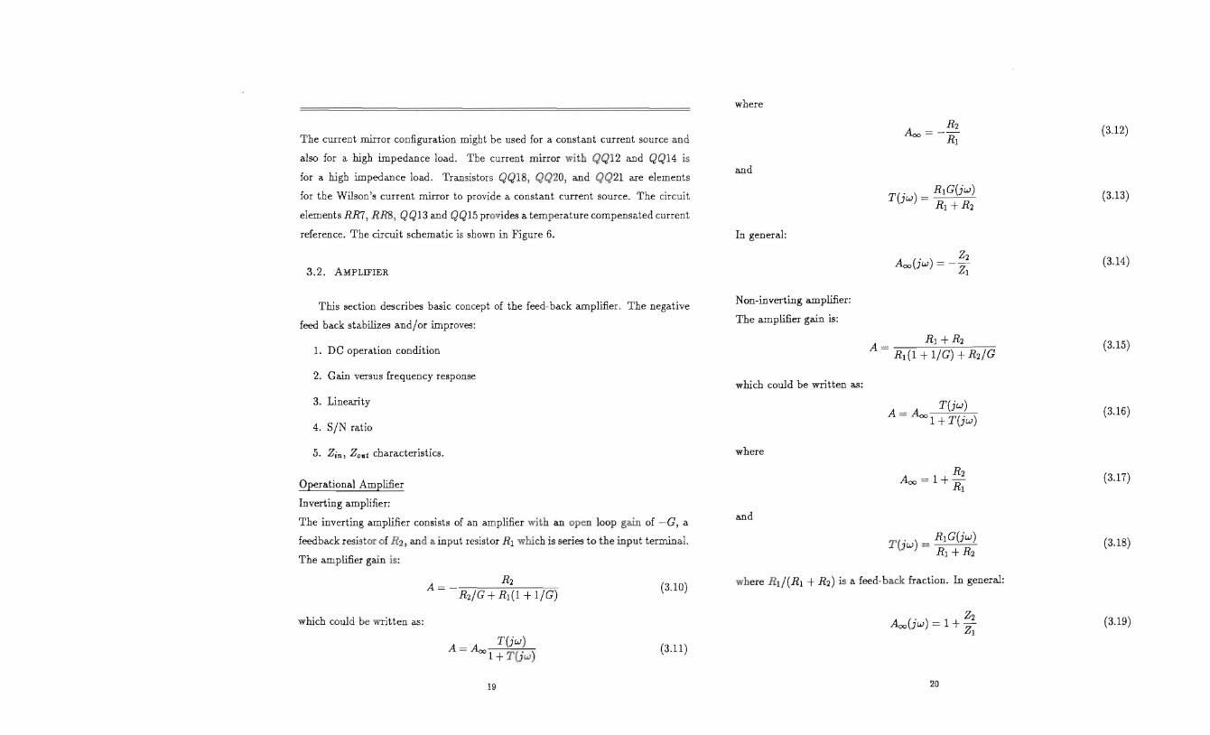